A review on bicycle and motorcycle rider control with ... - TU Delft
Upload
khangminh22Category
view
3download
0
www.americanradiohistory.com

DETROLA PAGE 8-1
DETROLA RADIO CORP.
05G. TRANS.
6A7 i
.05 7.I 200 = 200
50M .,,,.,..
E
o
DET.
75
_-. 4,-, N
J=o
1MEG. r05 200 l
1 2 o f
o .of -200
MODEL 111 Schematic Socket
TRIPLE rwIN OUT.
6135 02 600 .
E r T32
.02'600
r ,dr
UNLESS OThERWISE SPECIFIED, REST. Y.3 W.
MODEL III IF 262 KC
50M RECTIFIE R 300 1'ZW OZ4 250
CO
$ CONrRoL = - HEAD -------
1
SENSITIVITY CONTROL
ANTENNA
STATION SELECTOR
p VOLUME CONTROL
John F. Rider, Publisher
www.americanradiohistory.com

PAGE 8-2 DETROLA
MODEL 117B Schematic,Sockot
VOLUME CONTROL STATION
ON-OFF SWITCH SELECTOR
d Z 00 Yv1-t Nu'O-N Or+CrO.O 00 ¿, OOs.Ov1O 4- a000.D .DaM0000 7 r\
CO 4- Orn y-- N N-. N N N
7:.
CO
L \ V . ~ .. .. d 3
333E O 330 +I > EE.: , t EEv, ,> äd `. :'Q I c EóF-E- -} ,ñó E. - oo eo 0o O E N.F >>>O.O E "o E E "o "Oórn E"' .:' u OOinO. bu- ,a0 ,a ,r, , . OO pN ,O v1NNu' 3-- 3N -.N 3v 3,^,-:r--v,0 >O[..
rtr.; oz CT 7 V1 c, VUUUUUUUUUUUUU
©John F. Rider, Publisher
www.americanradiohistory.com

DETROLA PAGE 8-3
STATION SELECTOR BAND SELECTOR VOLUME CONTROL
MODEL 130 MODEL 134X MODEL 141A MODEL 167A Schematics Sockets
©John F. Rider, Publisher
www.americanradiohistory.com

PAGE 8-4 DETROLA
MODELS 134A,134AZ,134AB MODELS 135, 135E DETROLA RADIO CORP.
o 2575 CIJ
6C6 ( 43
ANTENNA
POWER coax
a.sc. 6 A7
ZY
iF456KC
40141
I
i
C43 I
MODEL 5 / 34.9 /34 AZ /34 Aß
DET. 6C6 05 400
Dual 02 200 ,E
LOOr4Ó10a
R
43o.r.
,.200f 01400 1F -
- ^QA9r
315 MMr
25Z5 --REcr
.05-200
02.5.0 sr -r.
F- _
0 400 A Jtyº,-aº
135 - Lm. Core
J Y to
r
( 'I,
ToTlr
o"
H
v
0t
Cc "mi.. 116
--H!I' i
J 1
!f
.^ 1
W
>=1
of 43
0--3.-1!,.
v II á ul ru
LA-i(...- N 'n ¡ ,.I
QeS N .r000e --F
m r-
0
1ksL,_---`sw='IH!,
' " r I
d
Schena.tics,Sockets
o > 0 0 ve tr1 ll1
CO O'N
U V U U V
LD
©John F. Rider, Publisher
www.americanradiohistory.com

DN:THOI.A PAGE 8-5
DETROLA RADIO CORP.
I. F. Alignment The I.F. frequency of this receiver is 456 K.C.
For realignment, use the following procedure. It is necessary to use an accurately calibrated signal
generator. Couple the signal generator to the grid of the 6A7 tube with a tenth microfarad condenser in series with the "high" lead of the signal generator. Connect the ground side of the signal generator to the chassis. Set the signal generator to 456 K.C. Be sure the wave switch of the set is in the broadcast position and the volume control set at maximum. Attenuate the signal generator so that the signal is just audible in the speaker. If an output meter is used, it should be connected across the voice coil terminals of the speaker. Use % volt as standard output.
Adjust the 2nd I.F. transformer first. Each screw should be adjusted for maximum output. After number two I.F. has been adjusted, number one I.F. should be adjusted .for maximum output. After both transformers have been adjusted, it is necessary to re- check No. 2 transformer and then recheck No. 1.
See TUBE LAYOUT for location of I.F. and R.F. trimmers and padder.
R. F. Alignment
MODELS 136,149,149E Schematic, Socket
Trimmers,Alignment
volume control to maximum. Turn the station se- lector to the highest frequency (as far as it will go) .
Set the signal generator to 1720 K.C. Adjust the oscillator trimmer until the signal is heard. After the oscillator has been set at 1720 K.C., turn the station selector to 1400 K.C. Set the signal generator to 1400 K.C. When the signal is heard, adjust the first detector trimmer for maximum output.
When the set has been adjusted at 1400 K.C., turn the station selector dial to 600 K.C. Set the signal generator to 600 K.C. When the signal is heard, ad- just the padder condenser by rocking the selector back and forth. While adjusting the padder screw, it is necessary to move the selector so that the signal may be kept in tune while adjusting the padder screw. This procedure should be followed until maximum output is obtained.
The foregoing procedure should be repeated. That is, the set is to be rechecked at 1720, 1400 and 600 K.C.
When aligning the R.F., use the same output standard as was used on the I.F. alignment.
Short Wave Alignment Turn the band selector switch of the set to short
To align the broadcast band, proceed as follows: wave. Set the signal generator to 6000 K.C. Connect First, connect the ground side of the signal gen- a 400 ohm resistor in series with the .00025 condenser.
erator to the chassis. Connect the high side of the Tune the set until the signal is heard. If two signals signal generator with a .00025 condenser, in series, are heard, always align to the highest frequency heard to the antenna lead of the set. Make sure the band on the receiver. Adjust the small trimmer on the switch of the set is in the broadcast position. Set the antenna coil for maximum output.
N ? oñn
. C O
WOS NOGG
s0000'
IH1, I/
-,okº -
U Y
V
(p - 00Q9.
VODI JAN. Of
00 1
421
.,
®John F. Rider, Publisher
www.americanradiohistory.com

PAGE 8-6 DETROLA
MODEL 137 Schematic, Socket
Parte DETROLA RADIO CORP.
Cl, C2 .005 - 600 v.
C3 180 mmf. trimmer
C4, C5, C6, C7, 1 - 10 mmf. trimmer
C8 350 mmf. padder
C9 .02 - 600
C10 1150 mmf. mica
C11,C12.05-200
C13, C14, C15, C16 .1 - 200 v.
IF 456 KC
MODEL 13'
No.3335
PARTS LIST - MODEL 137
C17, C18, C19, C20 R4, R5, R6 1 meg. 1/3 w. 100 - 125 trimmer
C21 50 mmf. mica
C22 250 mmf. mica
C23, C24 .01 - 600 v.
C25 16 mfd. 150 v.
C26 24 mfd. 150 v.
C27, C28 variable air
R1, R2, 50M 1/3 w.
R3 20M 1/3 w.
STATION SELECTOR BAND SELECTOR VOLUME CONTROL
ANTENNA
POWER CORDD
R7 500M volume control and switch
R8 500M 1/3 w.
R9 200M 1/3 w.
RIO 300M 1/3 w.
R11 20 ohms. 1/2 w.
R12 100 ohms. 1/3 w.
Tubes required are: 1-6A7 Oscillator -Translator 1-6D6 Intermediate Frequency Amplifier 1- 75 Detector -Automatic Volume Control
First Audio 1- 43 Power Output 1-25Z5 Rectifier 1-BK-42-D Voltage Regulator
NO GROUND IS NECESSARY-Under no con- dition should a ground wire be attached to this re- ceiver.
©John F. Rider, Publisher
www.americanradiohistory.com

DETROL,A PAGE 8-7
WOOS
W OS
WS
Nm 1.41-
r11-11. W 002
P S71
1.`11.'1214<e.º1º AT
011 171
5r -T 1 s I.
vMl
w ool
w
Ua t
U
DETROLA RADIO CORP.
IHI
sfW: 6.w1 'óawl
s I .474 O{I N OT
1 n eD D'
T - ers -n-
'--.1v[[
QQgºº ,4A,
WOO
116LUldi
FWF
ó
ó á >
COf
0,
7`C
e _ -e hé `--E Ri p
0 e (Da
o
r9
W00!
oiwì j
OOf
cDD
60áZti
oc
"°º,-
r> Ñ
If
000
e
eº.
' - ród 0ti-4 T - errs -1.-N
,ni zs `o ,W
0 0a
9.
MODELS 139,139E MODELS 147A-WiR Schematics, Sockets
/`f
0 ee / e
i
O
o Y
o co
CO
Z
Q
W
1
o
ce
1
©John F. Rider, Publisher
www.americanradiohistory.com

'AGE 8-8 DETROLA
MODEL 140 Schematic Socket,Parts
BROADCAST T
T FOREIGN
POUCE
DETROLA RADIO CORP. OSe- rRANS.
6A7
INTERMEDIATE FREQUENCY 456 K.C.
PARTS LIST - MODEL 140
Cl .005 600 y. C2 180 mmf. trimmer C3, C4, C5, C6, C7,
1 to 10 mmf. trimmer C8 3 to 35 mmf. trimmer C9, C-10 350 mmf. air
variable C11 50 mmf. mica C12, C13, .05-200 v. C14 .2 200 C29 C15, C16 120 mmf. C30
trimmer C17, C18 .003 600 v. C31
C19 250 mmf. mica C32
C20 C21 C22, C25 C26 C27
C28
.01 200 v. .01 400 v.
C23, C24 .1 200 v. .2200 v. .02 600 v. 16 mfd. 150 v. wet
electrolytic 24 mfd. 150 v. wet
electrolytic 3 to 35 mmf. trimmer 220 to 550 mmf.
padder 1330 mmf. padder 3850 mmf. padder
Tubes required are:
1-6A7 Oscillator -Translator 1-6D6 Intermediate Frequency Amplifier 1- 76 Detector -Automatic Volume Control 1-6C6 First Audio 1- 43 Power Output 1-25Z5 Rectifier
NO GROUND IS NECESSARY-Under no con- dition should a ground wire be attached to this re- ceiver.
R1, R2 50M ohms R3 20M ohms R4 200 ohms R5, R6, R7, R8 I megohm R9 250M ohms R10 500M ohms R11 300M ohms R12, R13 35 ohms R14 100 ohms line cord R15 10M ohms R16 45 ohms center tapped R17 2 megohms tone control R18 500M ohms vol. control
STATION BAND SELECTOR
SELECTOR SWITCH
TONE VOLUME CONTROL
CONTROL ON OFF SWITCH
o o
o 76
ANTENNA
POWER CORD
©John F. Rider, Publisher
www.americanradiohistory.com

DETROLA PAGE 8-
Aligmaent,Parte, Trimners DETROLA RADIO CORP.
\ 1ef, i>.
83! ill' e
eh 3 I
-U _
-71111 r---.4-1'
@
..---I-- 1 h ! 1Oi i - O + . ..1 ,
d i
- 7' _
°
jx
T r ro .11-111
º db.', ;
D e¡i >.
> _ . >: c 1;1,r I.
N. I " 1000 r .r" L... O E. V i
i bg=vro
ú a.+ 3 ú Ó,Á á, = ä Á '-IÑM IHi ^ foots7
1 --vat, m l a.c o . b Q Ey ú,
1 H" i i O - iyil< I I °' ., r. IHo-
í. N 1...
;H1
CA 1 `IRT `11 p ó
.s.l IOQÇO 00000 f au`
= oor--u, f000a'--I1.
O.
3n3?'S 311NM
I 0 ® \
7 o
.2
ú
ó z
á
d
MODELS 144B,1440 Sche®atie,8ocket
Y ̂ Y ro e
C C O hwu ÿ ÿ v
M%
¿d
Y^ 0 .d i V'^ +IF..^ ºCU J
d. w Ó8e O Ó E V V)hEV ro >^ C. .r-Ì'Ú d a O Ö YN q b0'm00is C
o0020 d.= dÁ pN^r ZZáü w4Ó>ááC]wááá+c$á 00 M a\ V1 V' M N M 1n 0 O O. O^ 00 OD M 00 1n O .: ... .0 OO.-n.+M ....r.r.1...NNlOOODONMM 7 .0 U1 \o 0 e .} ,f 7 i- N1 er e ̀t M V -- N .- .1 -tree M N M MM MN. -NM
r -+E^
N N,a.........-.^ H 0: a -NrOLGLQ:
d Á Y
ú .yi . b EE
ro
.-eá d óó u, W> > > >ó3 o Oo Ey. f -E-ó E + Ea EN E ° WNoO^~O^ o00í 0D0í
MÓNo Eó o--,Oó ENó
b o ...IN^O-d 000 00...pOIMN-,<OT-+ A ^0,11.000h sO,O 0000000.1,0h^0NMM00Nr\ 4 %O fn v1 00 Ks0 V1 tn in N un rn rn ... ef 0 00 t .o O%0 ,O rn A
^N C.4 N1 N -+ N MMM M M M a rn O ON N M
O Ce, oo +n 0ó .. ,r¡
.O N ..NM N _ ^ ̂ fn e 00
E _ - o-:r;vro.-.NM'or . .
a. NMs000 NNNNNNN--.NMfn'.0
Vl UUVUUU C.7(.1UCiVUUUUUOU0ii(X1212G4
E Y o íf0..
ÿ ÿ bo %
- y.L Y 3 d
CyÓ O á TJ
O C v u ro VJ ,a.. E» baó,0
.0 Q W %'C O r7 00.
o'Y - g1.73'0 a C
22p7.4 00"e
00 Vyy Q
%.r O .15,.e
v OY aa a E
a o o bo O Á y ty: aY O d y
dDwb óE d rro+l
.a, C d p c- o ó V ÿ'«.
ro
.. Á Ó ..y, 3LI. º
a. M /0
. v (,L E d C
.oO d o Ç5 Oxi ídi
é=dáw Cfn ÿ
ñ^ O C 1: d 4df
y «
Áoéno;º3 D'A nad"bOEu
1.I T? ° ux %ro;mlc
C ro .+.i ooN 01
O ^' C C¡ E Y + p 00CF-Ì Y.,,^ «?
N
«íai
V .dop I i.e. w.«s
WNOX 9-'a 3 E m"' .-.OW ^ óc)2. - DOM
O ro 4.1
,..(41
ÿ? e.-
52 rop
O
aea
-,150-äd d d ro c ro óc
á 1 ;`
d q O d0.. d Cb 0+ G' 7 M C d C bObo.CC O O Cb ` i7 ro Y
4
ü. áiA [ a Á ö á ó
E o C E Óv DOEd A á p.. a .0 - :' ú 0 d » o: %
©John F. Rider, Publisher
www.americanradiohistory.com

PAGE 8-10 DETROLA MODELS 145B,145CR Scher atio,Socket
Trinmers,Alignment,Parts
.>e
ro rn
Áriáa t^ 0 C7 ^ D x o6Dti,
DETROLA RADIO CORP.
b'' O t' O b- 0 b d á ^ y = 0 ~ EE2 â ó.
N Y N N N E E é 3+1+I3+I. 3 3.ó ó ó -' 2 3 .0 sOXXX e C c « c é é '2;d' e, 2,-..,_= : o ó
.... ó ó
t.1 p á a. ¡
'ú a U 3 3
.M-. + I.
-M\ -i .-M\. V
Id A p. y ú V Vl N N N V 1.. ' (n M M .. .y. .ti b ó$ a " b o0 0o m o0 0o E .-. -., > d> > d '-'.A5> ó ó ó ó ó^ p>.áx A o. o>>0.0--3°.'"2'7-,1 a Cu CJ.ó.......ß.0..ß.ß.ß. ° ef0, 0`0. orzo F. U1 00.-.N p.^ t6 "l'. O O, .6: Qb M NN . .-.in4##acÌ.m<0Uai7asLloo,.o,nväwoo Vo v¢,
0 00 z
{Y. M
00 .+ NN 01 M.InNU\M10?NOIn-'0000M00 0%M10...I0 0 00 00 000 O O-.--Ipf.-.NNI.NeN1.010 N00MNM00 IG V' V1 b111 U1 <eU'1d'1.N1.O007Me-N-NV00V7U\ N M M N M MM re C0 N.-NMN.-+NMN N.-. M MM M
.-..p 0 N
.O .--
N M N. 00 a O- N
Vdß: .O+íY.4:i4i. ß.y.. d y
b - N b Q y Ì ,6 A r0 73
V V O O J C 1E y y f0 a ,
.V.. > .3 ."'
e '"' > V V au- 3 E o 3 3+1 3
w ü, - E E>óóóvol>u. É Ñóóóó9 E\ [-++I\
+ olno+I,°wó,.ówlooóóó.-.-. ó - oó0-02 ...
Q,..,..,10 MIo '".-. ti.. e i/ ó ti.0!.l(1 0 0.4.40 >>`"± > N IoMO -. - GU\O iy s00 InlnInN0000 un O O M^.MM.O 00In000 V1NOQ.-.^' ^OU\NONO--unN-. --^N . In
0 N1. ..O-.M Ino1MU1MON7 Na-+b01010.In^N0. 01e.O ^ z t.OI --. soO, sOt.Ot..0oO,1. 1.1.00e)1.00001.00M.+00 0Nt.00 e- t. CO In 10 In N. N. U\ I/1 O In In N N U\ I/1 U\ In In U1 ID N In ^ O %010 b In In b
ú a NN.N N N MMM NNM M .--. N MM
Y a v1
V '..i ¡r M m
e -N -,1: N
- M M .--.
z N N O N M -
< $ ..N-.
^- N M N M O j M O-Mtn 1000010-.MeIn100001- -+N11IION 000. NNNNNNNNM ^NM 0I- in %.0 N. 00
/ to UVU(.ÌUU UUUVVC.iC.ÌUC.iC.%VU(UUUVVieorcr ieíiieie re
4
0áaó
.cñi..°` m liów
â
11 _p.
--ilr ---1
°' Á á C E .p O O ÿ. C O .°; C C C y P+ 3 ó G ot ó3 ÿÿeAo 't,.= "Fs :ÿd ñpoáá > A
. e. .+T! Z.9:4. a.0 ° api .° a C. y.ti. o á - .d O ÿ 3 a oo - 3.áX' .+ O
tg.",, -.2
0 0 ÿ 0 0" p C D. b i6` ú.00 úpb C CN .ÿ ó
G. .yF. á
C .0 t6 w t6 td eD V .Yi or
tri." l6
.E p . p C ar E pb'C" C V
E? i. 7 abIn E Ccd O EEdCv a[, yÿ 0(7" 0 R ö p O ,y- 0 t6
G
a W.x a E:'0%.3,
oNO > oCooo d o 3 0, 3. ów
d+:0^ .-. 007 ú in 7 áw O C C. a ER C,6 0, " a. 7 u V o, w Y
H, Q. D y b0 ° ' h.p y 0
Oy
O ú 00 `I CG . A0' O" ° D
t6 p or G p `. E "XX o °0v v ót o,A3-.
14 Ea dö ÿ oo a
U "° E v ó+ ú .e aw o a a"`O °° E
3 E. C Á O E A y ÿ .; E C or,,,,.;.-....)
.do u % ÿ 7 O yZ1 O E ÿ...Inr. eoo. ,.y.
A a Oy b0-. ro 7:2-2,-:..."2,i
« y^o ar
E oo .n C -...g ,.II. y g o, ., ., I' 2.'-'::
O O O % T1 ..ÑO w eCo . io oCi p ...°. .. 3o0 O º>X oo ° O ó4:0 ú 00^y T°v Ó
I`ï v ° Á Ñ d .t T 2 X Ä O ÿ 3 ÿ
q X 7 ç y Y 0 ñ,y Á Io a ob o p.áo g o Y
rW./ U ó,= y0 Tad óo á ó2 d
."Y. ÿ Á " . .(2
Ó
^ < 00 00 C.a6 g
Iy .. 10 eM W ÿ ÿ.0 N E(d. Y.. Q tY6 Ä
WJ d dÑ 0-.--.w w óa " N 0o ÿ ó 3O N b
u0 b0 .". á E`n ÿ ÿ 0M
"3"41 F-1 d Ó .b. 4-.. .y+
íA. ."
á O d o Io ó O. won' I X ....9
E.s ÿ Ä d° b b ó d 00 " y-. -2 't ÿ y 'á" db9dÁ dQñÿq o^ óóóÑb
00 "
Ä 00 ° Ñ" > OJ C... E O y ÿ E
m C- yy O e`'''w oa + ..
o+ d C tc.Cd 4 L' -0 t.:53 t0 .C. Á e0 e... C " °
O q
" O .+ o p 00 M
.o -ei b0
C y or 1.
0 eY. E ó C O " Ñ...° 3 C íO.. Y. p
C0 o:d:ºa h ó.eoçq. vo doo°616. ÿ G ( b0 O O ..,. C. O0 Ä or
óI C.G {. .. W
C y y Q `, Y
o .-. u..q u.3;31'4. "dO Ob0aÿ7 w U á c ^'.ÿ «° ' E . 00 d°, Á c 2
M ó.Ñ° 3 ó é b ñ[-' á .°S 2 3-Q ro E a'û
o
-\ 0
^- . M. "" f"" ̀ \ ` V
-iM .i i
©John F. Rider, Publisher
www.americanradiohistory.com

Schematic e,Sockete DETROLA RADIO CORP.
STAND BAND VOLUME SELECTOR SWITCH CONTROL
/YlODEL 3989
/6,Z
DETROLA PAGE 8-11
MODEL 146
MODEL 158A MODEL 162
1-6D6 R. P. Amplifier 1-6C6 Detector 1-43 Power Output 1-25ZS Rectifier 1-BK55B Regulator
ANTENNA f SPEAKER LEAD LEADS
i1
---=--f- %
2525 Ja» =f
ALIGN AT 1500 KC . . STATION WOLUME SELECTOR CONTROL
1-6D6 R. F. Amplifier 1-6C6 Detector 1-43 Power Output ANT SPEAKER MODEL 1-25Z5 Rectifier LEAD LEADS
1-BK55B Regulator 6D6 6C6 43
2525
ALIGN AT 1500 KC
©John F. Rider, Publisher
www.americanradiohistory.com

PAGE 8-12 DETROLA
MODELS 147,147E,147SCR Schematic ,Socket ,Parta klignment,Trimmers
DETROLA RADIO CORP. >Id he w ó /I e o é
.c0 .m>> ; o ú
_____,01"6,____ oó>óóóo YWW.1.'2.: H ;,....ci I. - in^v1^'7¡. d .,_;.--.24
--++ Oc íi a N - . - _ - - a 3 ~ .4 A (n C C e d 00
-I; , < á -333333 ó a:.N d .9.§U CO
i. St
N009 h' MM\,1
2 Ti 2 1-,1.< ,.7 d b Ñ ....!, a. >HT in C a00 C Q
Ki,,, wO9 n Y M H H W NV O O OW __Ur -,ÿ mr.r O W vl.-. á$ _
II Á 00000004 dOctj y ÿ oò ó ó a w9 H II. .ÿ.F,,?'.... .'.
7:7 ,71 C q Qb a ()- 'Q A W
II
Y.-. p-,5.... -, C C O d $_ wear Neal I W ú á ú á d3ôôô t O O.b 0 0 0 O O P.ÿ d p
T wx `-- *l$4 rxu:a:crxc:r:vUUUHHUv,aUUoaWHvW A ,
w aOz be^
I iaw I v t-- Q ÿ d -- N E
B 11, -mw '
.
p" II 4 o o Qc64o Al,x V fl In M a M N- O,O y n N tn Me V, tn bb e W ,O f\ N b0 f\ -0, .aG V t gg
NOK tn 00 W W W W M N M t\ V' V ee n O n n N M M ne 00 -. n Q w t QT 1 t }I 4 fE rr M O o0 00 W W,O t\ W r W M M M M O, M M n f\ t\ t\ b0 Q, 1 M O O.ti {Y NO2 %H MNNNNN NNNNMMMMNMNNN--.MNNMM
C O I 0 óD`-IHk Y es; GD owi ú ú oYi ú ú d
ti joÁ J ` " ááá "áááá .. `°6 ó o;` ,r,u,o á p ° I¡ V;;j I
N ~ 1!, N O M ' - :a - - - - ,,..7>,,-... C
I
i .2_,,r, Y YOO - C y
'ILI =_ . EI `'kJ U áÑ E ; 6 E E oo ÿóóóóóooóoo-,0000 . d.
((
x - ., a N v E E E A- C`rNNONe7 á N2 -Il e=a
I a b '¿,'-.(-i-...d.+..d.bN _.-.,Ory33333 ,w
d.c a+HH` /-+> r.0^O .O . .MMM ':::"Z. b
0k -111.1 f101 I vu. M.G Q °'
_ _ _ _ w O _ ' _ O
Y\\\ 1
I -y > p OG . ̂ V Ñ Ñ ídi Ñ Ñ d d VdJ vdi d fdn - Ñ d ..e°°' A Ll v a av- a a á -V222,00000 v a,
P
_ri,ld d d q ndddwyN u 6 dTJ dT7TJ V T7bTJ O.,1 -,-.....-d-, pTJ MS v, O Ì°- .
Z. b O d 0 0 0 O O OU ,000000 I00000V O O d d á á á [
-á 7M U3HvO0vU0-.>UOUOU-.UUxrxxxx ;l i ^ee^ 1 _-"e a n( C7 I w ¡ r
I -------. II.. [ « qg S Ó ,ÿ .-. .--, e-.4,-.1 N -. .- N « j g 4 > 0 ,.,-,-
so.-., ev,Ot.-.fDO -N ,ONv,.--,NMNt/, d -^O ^I d d
° 1 i q ly. ó N. 1, O O, .r 1f, 00 00 e 1 t I O OO O, O1 V, 1 N M M M .-. i7 u I. ..... ± RS - M n n t1, 1n ,O - N I n o0 tf, V, tn v, f\ f\ ,,,u -, ,O n n b b N w w
:1 O.e pyz NM MM NN-M -.N NN NNM NN Q ú
CL. ><
3 o
® e m q d . MO ..`. C-: íYe Ó w ú .. 1!t .ÿ
O :r5 1Ñ
Fb0 ta
i3 eo e Ei mA O .di g E-oA °: ^ îa w-1 bo ,. b a- ó E c a
lue mw cm g d ÿ g " ÿ º 00 3 . (r`
Ji á 'a °'t d te .a ,,d, ú ° b
S -
i O ^dYm O Ä wA Iti
" V ,d p(n .V".Y$lI I II
Y, áÿá adO A d®
` Ì O d ° ao- ; " º °'; , ° a ô ' >.Ci CS ' áÑ3d°\ óá ooá A
ó á ó'd C. ° ÿ O1 d
g., .C. y m O'
!' el 0 E V ec >a ó 0 Á y. ai N a> OCO r d w
o d 3_ ® I ' O
'.
Y óáó3Á Á... -re;
O HaY vyd
r0
ó ..<4 E.t6 v d d á dº M C ó d q O.0 Ñ ú'ÿYÑr-ú Óap E m ú p Y
E .17;
I 3
A 4u a Y V(1 -y. °+ Y ' ,- > W
E .X O ^ O mw ÿ E p d h p A ay. i e O , vdi ' bo
o m W
m'óhºó ááp áo db $ E d d _ Esi Ú . E áo G a E . . V 0 1d.' y b pY+ .a., q ú 0. Y Q C
I.
O.i-
00\
/. 0®
0 ® W
ú Áú
fi3aú"
o,
tx ia G' x
O"
1U0!j
Ä b Ctn d dQ p dd MWi'3U2óTócI°XO óo c o ó
I': räg"á°LJi º ópy `jYbm
ro Yw°'i d 0> .+ . 'VE b h c XY XYN~V n d Ctid Lt , ...6
Y "Y Yw O
Z " b0 b° q .5 v °p dH a mÿ Y O
en °ILú Z o "75GC ÿ ÿ ;' v
I
CmO á
. ° >
I oO > dv;ñ g
ó° o b v.I á
íi)
>.0 vÓd C " d a vá óEó c od. ," á O; aó O c b Ám° °m .0 O GG a°
7bÑnDó, -o w 1.EAHdu.Y2áº.b.N Hº- m áQ ºó d á á ákNv
o
illJ a
©John F. Rider. Publisher
www.americanradiohistory.com

DETROLA PAGE 8-13
4
..o ";)i`
o
Z º W f- in
DETROLA RADIO CORP.
V')
-3a
= -ei N..
O
H by ag uab So i M f Ó > o 2 o ,, ,"x, Ó Q u Q
U K o ,, fd .
á+ OJ
Y O' b OJ y
W 0 W o Q
k 2 U w 2 a> °d ul q $b :x 7v ro bº i
-r C d v 7,;', Le ,...2 v.) d Cu
k 1.4-1 2 2 2'..'
ro
00 b ÑÓ ~Qw o Z ni 1"4"-.
v _ r.
u, 40 O OQO(.%MtllN
w 0Ñ u'' IIIIIII P'.1 .a O a ß Q H z.s d H Z + co
12 u
MODEL 148 Schematic, Socket Parts
V. def...
f
roo -j
,
W .J
Z u ú ú ú Ñ Ri ¢ p `° s fa ev Q V 3 3 3 " a 4
OM
4., y M M M M i ú+~-' N b, M ó>.v rJ b\ .-. 3 r R 3°
1-.
M
ç +
V \ C E M M F G ~ q V . . r .
.q °á - -Oóóóó.^-.co ; tz> :z1 b'. e'D> > »o ó ° ó ó o°,°ó °> ri
goo -o g g o o o o o o óó q u1 O O O cV um I,. um N : N u1 e3 .r .r N Ln N ul .-. sj- M M 0p ̂ . u1 N LA
~ ' CO O--, Si M'd' tt1 1/40 S. 00 01 O--, N r ä 2 zxxxxxxxxxzzá H
p; J t.ni ,,,,
ÿdÿ Çd¡
d Ú. j 3 M i-,
L ,> .., > :. M 3, e E LMw M ----, 3 o N. U - -\M :4'2 >O 00 OMO g. g. ^, ó MU o ó 0.3
C° \E 00 NNONNONtnOO 0 C:7 " 0 > 0 E N'"'0000 N c0 : O.--, .-r O O.--. um U N um N in .-+
Le co Q\ O-- N r...% ,1- u1 VC t 00 - - N N N N N N N N N N M
`g- u H UUUVUUUVUUU a:cccrx
Lz ,,,
.< ó, z o, O
Olr
0 W L
0 q 1=
-- -
NO
zu (so o, Ifk 4wv.R`.v....+
DA '--II-
s
4-nram--1
00
ooa\--1
:15 ; : N f0 .fl .. a V a :° 2 17-1 e ;
i1/4-1 o>`+.+e e`+.> > >>otf,
Ñ ,`;óóE2óoóoóóÇ; á q r ONN O O NO'd'O N.._,
"11 a- ä Oou1u'1oM uION N,_,, tf1 0E d OOOOMÑO--O-ONO W O- N M 7' um \p N. ,r um oz Cm UUUUUUUUUUUUVUVUU
©John F. Rider, Publisher
www.americanradiohistory.com

PAGE 8-14 DETROLA
MODEL 150 Schenatic,Socket Notes
DETROLA RADIO CORP.
Tubes required are: 1- 75 1- 76
Detector A. V. C. Audio Amplifier Phase Inverter
1-6A7 Oscillator Translator 2- 43 Output 1-6D6 I. F. Amplifier 1-25Z5 Rectifier
K<
<
<
1< <
< d x Q
e
x $A
4!
o 0 111 .444
o 44,
0 0
0 111
o 4-I
o 0
0
o
0
0
o
0
0 u'1 N o 4. 0
U ^U^ ^U^ nU
u ii
rT G
30 ti'
d ó en a
0 ..r
o LITh
.-r
Ó
ó
0 .Nr
o
0 0
o 1-
o
0 N -44
).0
4-4
0
0
o
0
0 uC)
o
0
111
o
0 0
o
0
UUUU < <
©John F. Rider, Publisher
www.americanradiohistory.com

DETROLA PAGE 8-15
OSC - TggNS 6A7 1
Oil MICA
00M
1200 50M
606
02
e0M
DETROLA RADIO CORP.
I mt
MA
1 6G5 ;-
Unless otherlwsc
Meg
spec/red Res if W
IF 456KC
SOMMF
Part No. Req. Description
3873 I Transformer-Power 3356 I Transformer -1st I.F. 3465-2 I Transformer -2nd I.F. 3874 1 Coil-Antenna 3875 1 Coil-Oscillator 3876 1 Condenser-Variable 3877 1 Condenser-Dry Elec.
388 1 Speaker
4147 Schematic Diagram 4148 Tube Sticker
530 2 Bulbs-Pilot Light 2163 I Drive Cable
2908 1 Spring-Drive Cable
2597 1 Condenser-Trimmer 1286 2 Condenser-Mica .00025 3 1 90 1 Condenser-Mica .001
3066 I Switch-Band 3883 1 Control-Tone-Switch 3361 1 Control-Volume and Switch
SOOM Of ZOr
o 'Meg
n1
Part No.
624
602
2730
603
631
636
3893
3402
4145
3889
3890
3891
565
568
576
572
581
2695
STATION BAND TONE VOLUME SELECTOR SWITCH CONTROL CONTRC*
¡Ti
Trimmer
Osc Timm
G
Ant Trerm
G Ist I F
6A7 G
GROUND
ANTENNA
POWER CORD
41) 6D6
8.350 U e-2so
2100 150s r60á0`--.,ee^`.s;. scrr Fr1d
41 4-1
Tubes required are:
1-6A7 Oscillator -Translator 1-6D6 I. F. Amplifier 1- 75 Detector-A.V.C., 1- 41 Output
' 1- 84 Rectifier 1-6G5 Tuning Eye
Req. Description
1 Resistor-%W-1 Meg.
I Resistor-%W-250M 1 Resistor-%W-200M
Resistor-%W-100M I Resistor-%W-50M 1 Resistor-%W-40M I Resistor-%W-350 oms
1 Resistor -1W- 4 0 ohms Flexohm
1 Indicator
1 Gasket-Glass 1 Glass
1 Pointer
1 Condenser-Paper .01-200V 1 Condenser-Paper .01-400V 1 Condenser-Paper .02-400V 1 Condenser-Paper .1-200V 1 Condenser-Paper.005-600V 1 Condenser-Paper.003-600V
2nd I F
G G o
0
6G5
MODEL 154E Sohematic,Socket Trimmere,Alignment Parte
1 w.w ee.r-O C.4 mL
O á i0 ÿ m ÿ
2:07). Y Á
"M á ¡O .C+ n b O YCdE> p'^ n n \ U [r >
C °5ÿ v ^ E
c° o 3 ° Á .. ° Y
éo...CÿE w O Y^ n.c c.^ m
E °Ó ó n.o-nU ó:4=
.Y. ú u A C C ..
,c °._E
.12 U O 7 -0= > ; .
O
n ó .Y+ p> ÿ
úaY
^, .
íni.+.'-`> q ^, d ÿ r1 ..0+ Y
C c n oco..º'h
.
Áó OO Y Y
>..o.rsa ...
.,r4-91 d m O IA C
Audio Amplifier
O ó
á 3
.a
ÿ ó 1 Sc
O
ó " L
3 -c ti o
o ó o
A o
U
c U á
o o
47 Á 0. v c es
E E
w
©John F. Rider. Publisher
www.americanradiohistory.com
PAGE 8-16 DETROLA
MODEL 155X Schematio,Parte DETROLA RADIO CORP.
Ca I6MC
Cs I6MC
Ce IBIMC
C9 e 600 KC
Tubes required are: 1-6K7 Radio frequency amplifier 1-6A7 Oscillator-translator 1-6K7 Intermediate frequency amplifier 1-6H6 Detector-automatic volume control 1-6C5 First audio amplifier
r
L
Tubes 1 6G5 Cathode ray tuning tube (on models
equipped with "eye" tuning indicator) 1-76 Driver 1-76 Driver -phase inverter 2-42 Power output 1-80 Rectifier
O A
6K7 RFAmp.
C12 T
Foreign ',Broadcast Police
C3 6000 KC
Cs 1500 KC.
Cs 6000 KC
Cr 1500 KC.
Cis IBIO KC
C 9 6250 KC
IF PEAK 456 KC Symbol Part No.
Cl C2.3,4 C5,6.7 C8.9.10 C11,21,34 C12,14 C13 C15.24 C16 C17 C18 C19 C20,22 C25,28 C26 C27 C29 C30 C31.33.36 C32 C35 C37,38 C39 C40 C41 C42 C43 R1,5,15,20,26 R2.3.13 R4,14,16,21 R6 R7 R8.17
3814 3822 3822 3822
572 580 575
2780 568
2694 2741 2560
2385 2695
824 576
1286 2600
563 579
3138 3113 3136 3112 3111 3135
603 631 615
2693 3799 2568
6A7 Osc Trans.
IC13 C14
80 Rect
escription
9-400 mmf Variable 2-35 triple trimmer 2-35 triple trimmer 2-35 triple trimmer .1-200 V. .05 200 V. .1 400 V. 50 mmf mica .01 400 V. .005 5% tolerance 1330 mmf 5% tolerance 350 mmf variable padder IF Trimmers .02 200 V. .003 600 V. .002 600 V. .02 400 V. 250 mmf mica .02 600 V. .05 400 V. .25 200 V. .001 800 V. 16 MF regulating 20 MF 25 V. 16 MF 450 V. 16 MF 500 V. .003 800 V. 100 M 1/3 W. 50 M 1/3 W. 500 M 1/3 W. 2 meg 1/3 W. 2 meg tone control 300 M 1/3 W.
--1 6146 bet AVC.
20
'
MN»
C19
III
42 Output
C26 <W::. R 9
D
Rio
C28
76 6C5 Driver Ist Audio
1 R i Rí'l.wC29 dl 'F
6G5 Tube
Symbol Part No. Description
R9.23 RIO R11.12 R18 R19 R22 R24 R25 R27 R28 R29 R30 R31 R32
617 3800
624 2688 2731 2421 3805 3805 3809 3806 3808 3807 3870 3801 3796 3797 3798 2981 3838 2898 3815 3943 3817 3825 3826 3198 3199 3831 3832 3802 3818 3819
0--
20 M 1/3 W. 3 meg volume control 1 meg 1/3 W. 60 M 1/3 W. 10% 500 M 1/3 W. 10% 1 M 1/3 W. 7 M 3.5 W. 8 M 1.5 W. 100 ohms 2 W. 10% 120 ohms 1.5 W. 10% 50 ohms .75 W. 10% 35 ohms .5 W. 10% 15 ohms .5 W. 10% 2 M Variable Power transformer No. 1 IF transformer No. 2 IF transformer Tuning tube cable 12" Speaker Tuning tube clamp RF coil Oscillator coil Antenna coil Planetary drive Drive belt Idler pulley Idler spring Minute pointer Tuning pointer On -off switch RF and Antenna switch Oscillator switch
©John F. Rider, Publisher
www.americanradiohistory.com

DETROLA PAGE 8-17
®John F. Rider, Publisher
www.americanradiohistory.com

PAGE 8-18 DETROLA
MODEL 163 Sohematic Parte
r
DETROLA RADIO CORP.
Tubes Tubes required are:
1-6K7G Radio frequency Amplifier 1-6A7 Oscillator-Translator 2-6K7G Intermediate frequency Amplifiers I-6H6G Detector-AVC-Bias control 1-6G5 Cathode ray tuning tube (on models
equipped with "eye" tuning indicator)
1-76 First Audio Amplifier 1-76 Phase Inverter 2-76 Drivers 4-42 Power Oútput 1 5Z3 Rectifier
o A
Cz16MC ls1
6K7G 1
C122
Cu
6A7 I Czo Czo 6K7G Czi 6K7G Cu Ct2 646G
D G
ForuqO 1 T
Broadcast. Rolloey
Cs 6.000 KC
0 C. 1500 KC
C. 6000 KC
Co 16MC 0 0 CT 1500 KC
Ce18.1MC a0 0 Cio1610KC Co 62 º0 CC
CN 600 KC 0
ZC s
E
iCT
Tri
I ag -72 J r- rapr = .__. `.
= I
Ce I
J
C24
> (R6
R
C23
R R8
Rs
R
665 =J-
42 42
SZ3 C41 F
4C44 uc,]
C41
IF :456 KC
R12
RI
Symbol Part No. Description
Cl 3814 C2,3,4 3822 C5,6,7 3822 C8,9,10 .3822 C11,23 572 C12,14,46 580 C13 575 C15,25 2780 C16 2694 C17 2741 C18 2560 C19,24 568 C20,21,22 C26 563 C27 2695 C28.33 576 C29 824 C30 4072 C31 1286 C32,34,35,36 2600 C37,38 3138 C39,42 4071 C40 3079 C41 4062 C43 3112 C44 3111 C45 3135 R1,4,8,16,19,22,24 603 R2,3 631 R5,6,34 2421 R7,23 615 R9 2693 R10 3799 RI1 3800
40,8
9-400 mmf variable 2-35 triple trimmer 2-35 triple trimmer 2-35 triple trimmer .1 200V. .05 200V. .1 400V. 50 mmf mica .005 5% tolerance 1330 mmf 5% tolerance 350 mmf variable padder .01 400V. IF trimmers .05 400V. .003 600V. .02 200V. .002 600V. .03 200V. 250 mmf mica .02 600V. .001 800V. 20 MF 35 WV. 8 MF 150V. 30 MF 275V. Reg. 16 MF 450V. 16 MF 500V. .003 800V. 100 M 1/3 W. 50 M 1/3 W. 1 M 1/3 W. 500 M 1/3 W. 2 meg 1/3 W. 2 meg tone control 3 meg volume control
o
YC42
!Cn
R29
i
42 i 1-
42 t
R9 C26 I - I ,R,a
R,z
Czz
36
Rz yTº
76
R.
? 76 H C14'
Symbol
R12,20,25 R13,33 R14 R15,21 R17 RI 8 R26 R27 R28 R29 R30 R31 R32 R35
Part No. Description
2568 617 624 614
2731 2880 4068 3808 4069 3801
639 3805 3805 4070 4058 4061 4060 3968 2981 4082 4079 2898 3815 3943 3817 3825 3826 3198 3199 3831 3832 3802 3818 3819
R
Rzl
300 M 1/3 W. 20 M 1/3 W. 1 meg 1/3 W. 5 M 1/3 W. 500 M 10% 1/3 W. 100 M 10% 1/3 W. 300 ohm 10% 3 W. flex. 50 ohm 10% 3/4 W. flex. 200 ohm 10% 2 W. flex. 2 M variable 750 ohm 1/3 W. 8 M 1.5 W. 7 M 3.5 W. 100 ohm 10% 3 W. flex Power transformer No. 1 IF transformer No. 2 IF transformer No. 3 IF transformer Tuning tube cable 12" Dynamic speaker 12" P.M. speaker Tuning tube clamp RF coil Oscillator coil Antenna coil Planetary drive Drive belt Idler pulley Idler spring Minute pointer Tuning pointer On -off switch RF and antenna switch Oscillator switch
©John F. Rider, Publisher
www.americanradiohistory.com

DETROLA PAGE 8-19
DETROLA RADIO CORP.
Bn CON TR0. SWITCH DN OFF SM,TCM
ANT CANA SPEKER LEADS
POWER CORD / / Knq
OSC- TRANS 647 1
elON
T 3647
J3JC
.vtf33 Jr Yx3[ JIYC//x[e,KvJTa3 Ì v.
STATION SELECTOR
4271
as
L
o.-
*
OUTPUT 43
= -et it zoo
00r
RccT, -A 2525
r M - es.' +0,.,.,,xa.a O
4FM- ei
.p 4 ISx3
tr-
ZiJDEiJ 159
VOLUME SAND CONTROL SWITCM
t+®DII1 168
'4270
STATION SELECTOR
D SWITCH
ANTENNA LEAD
RF 6D6
VOLUME CONTROL
SPEAKER LEADS
6C6 - OFT.
MODEL 162-A
STAT1pN SEIEcro R EA77D SftECTOR VOLUME CONTROL
MODEL 159 MODEL 162A MODEL 168 MODEL 172 Schematics Sockets
POWER CORD
OSc- 6A7 -TRANS.
Lf ASi K.C.
1
º"! per. 6C6
'
OUT PUT 43
o, wD
Not 17'21000025 200 01-400 t .
1 ,00 c # , CUM / El
2515-R«T.
.1f-21/ J_4I
/00 n 375 N10 JAI"
-
MODEL 172
©John F. Rider, Publisher
www.americanradiohistory.com

I :AGE 8-20 DETROLA
MODEL 166 Schematic , Socket Trimmere,Alignºnent,Parte
4 E
u
*+ Y p áI. o7
é 'i1 H Iu. 1
L
DETROLA RADIO CORP.
-ZII3 2y 1 - %4
Pló
CO
Ñ ú 0:1; « °
I., OF,..;AO1:4
t- A t- ñ r 00
C
. i g
ó eci iiL-
Ñ J `i 6 li u.
lJ -_NN ìJ OJ
e r
<
t
INC)
ó °iítDncD$ 8 M N N d' N)
I .. .-. .-1 .i ti N
COMn .N-I Nn CQMQC7
V í000! COO íQ0Q-I GO
M M M N CO N + a, .o ° C o° E : d d 5: I w a3
coG :i +. e íC'i L. L. 7 .+ e , C L. ..i m
c dyóFdiy 2. K á é x -o L x9 w N d
.Cir ° °+ ÿa Cf ^ í0-1 . W ß L+ b ij G) d p Y .,
i,c.u,.
C d. O C d
O^O w v7 co O.. vi L. C E a0.. tl C Y Ó ' C ° 8
U úbA U) ma bwb U c c ÿ m
oo c c' b c . "t7/
E" ß. Cn i L. ° ad+ -i cd y L. w al c6
w d 2}; CJ
O 5LV
ñ mU`,,°y 04) tiod á iñ L`. ó c°
Çd G .o N o 9d0
j..°
25ó L.wd c0 al 7.....a .'Ly, d N] ..N, ^ d O O d I I I
n 0 I I
(.d'._ d.' L°. d í0n aCi d .-Yi d ~ u .7J . aCi .rd.' d C y m 7 3 c. ai a, G/ U a ci á, 61'3 ÿ COO e.',4 C7 .+ pp w.0 'L:, ÿ O w . u y w rn a oa rn rn
40 .> S.' C s.
Y a. iial ca C. y f!] U C C C C C
Yu ..0+, E c0 O .-+ c al ar bD ÿ .Z Ñ ^ .d4 a/ a1 CJ C1 d C . d d Ñ .r.dL.C' 7qz .4 L. C `.. G .+ y Ó... a. +-' Q
tO2.C C C= u C C Ld. oao G°° oi m.°K Ly.
Ñ F' d aFi C w ca b 'i. £ o 0 o F ;; o 0
. y;o náA ,d $ C j .+ L ,7..d E. C m:iC7UUUdU]UU k+ -coUóSL: a3ióv "
aFi C " ctl Ñ G aC .)_e f, 4.)-':-. N L. .-.w L Ci h C O a.+
d al ' . L. L Cy 0 00 O.!E u0 `
Cd 3
Qy . 8 U,1
u o LL w 5 ao QQ cD m O c- ti cpDp
OP U,w w -.....1.-g_., rydro
CL c0 b v S G 00 W.N ti. fc. 3
d v: ÿ a Z Ñ N .-0. .0.1 .0-I C. CO 00
Cl O W e L.d 5 á u d b.f., C O t0
QQjj
E Vl Q y tr CL á c.,,,,,,,,,,...- M
V ° N ' w O ° `r U 4 to [" 4 í0ia Cl d C d W .., b rn bCl1 O O + S4 ID
O
H >v."...., °°drut- ccLe:.....-.0-
. g o Q d , w o
ß E s 8 3 .ó L. y d C y O
1' d W -2-e, 3 d d b t6 co m d Ld.
Ln. 0 . .. z: `C ; w E .... ' C ° d G ÿ a7 ß,ó`5 odN Ca b ó á " ó ár E Ñ v 3333333`33 Ñ gcw5. v °3,d, n§ . ..
qbo o .o d ' 4.
Ì I I
I I\N x b°5a, "ya C ó ó.yy.
d ç, ae ó. 8 . I I E E
I x .+ C6 ú.a p 043
OO N a d> cC . d b0 Owe 0 d w C Q'i v Ó Ó OZ O w d C9 G . E C O p }° Cl w d i. a/ U p p p p p O d .--.
el-, C
a/ C F .. W » íy ÿ p O @ y p O S O n O O O O O >> O ^ a` d u ri.1 C u Ci d N 00 F .i N N 0 N M N U7 d ...m ,dc .:1~ d"o. a L. . Ca8 .á
I I I I I I I Ì I Ì >.o -..c12, > b w'k d .N V]
m .. ïy pp C L c L L. L. L. I. zr z ti L.'L1 d q w .0 + . C d tdi .-. N i_°0. ,C, ÿ .°+ ÿ wº O.°a ao+
O° c. - . N u u d
G7 e U d N + C .. p, O y v m , N N vi n
a7 .O+ CI) O c0 a+ d + W d d . +y d b + O p A Ñ Ñ
w sd. d m m yL3 N - 5 J 'L a7 b 3 n %y to ..0.. d al a/ d W N aJ C) W CJ
C ow .ceo I b C C C O C °
v p,w Sp ÿ ai . e v' O
C`i e. p i'tl .- .;
`" Ú odo'3 ado 0.2° y ÿ pp :C7tl ií^L. d Y.1 UO }j U aS y" U1 L. F 3 d d yb' 0 G4
. 1 .-1 ., .-. .1 .-I .-. . , .-,
` 12'
... cC ÿ iE § cOgÉpaw7 çj?°
F G4 .r. "b ¡ ayß
O P. i wS
q d iS [' i a O
..3. r01 M C N T CD
Lñn
co 00
be 5 ~ d ° d F b d ..-d. d Vl í-. O tD W C1. E Ú n z CD cD Ñ tD tD Ñ Ñ N 0 Ñ
. 'in h m > C n =
®John F. Rider, Publisher
www.americanradiohistory.com

I)ETROLA PAGE 8-21
Cu9 600KC Di
I)I+,'l'ROI.A RA1)IO CORP.
Tubes required are: 1-6D6 Radio Frequency Amplifier 1-6A7 Oscillator -translator 2-6D6 Intermediate Frequency Amplifiers I-76 Automatic Bias Control 1-75 Detector AVC-First Audio Amplifier r
Tubes
MODEL 16 5 Schematic ,Parts Trimmers
1-76 Driver-Phase Inverter 2-42 Power Output 1-80 Rectifier 1-6G5 Cathode Ray Tuning Tube (on models
equipped with "eye" tuning indicator)
606 6A7
A D G
_co
Cal R2
I. T
C. o Ct
ó1oÌór ±C13 =C1
T'
Foreign T T Broadcast
Police
Cz I6MC n Ca 6000 KC
n C4 1500 KC
C6 G000 KC
Cs 16MC n 0 0 Ct 1500 KC
Ca 18.1 MC 1® 0 0 CIo 1810 CC C431 Cs 6250 NC
I C 16.
Czo ca. 606 cu . . .. ..9
Rü
c22 6D6 Co 75 O - - O
C35
R14
R6
(24 -11-
R4
';C36 RS
R26
R2t
ri I.
Sp. F Id.
M C39
C4ó
R24
Res
1 6G5 76
11 IC23
Ra
R9 Rio
R22 227 =C25
42 J
R32
I T i RI6
76 R19 TC32
42 R21
C37T '-"" H £ICy Rlt C33 ÿR15 iq g
4096 1 r : 456 K C
29
R I R29 Rte
Symbol Part No. Description Symbol
Cl 3814 9-400 mmf variable R11,12 C2,3,4 3822 2-35 triple trimmer R13,14.22 C5,6,7 3822 2-35 triple trimmer R17 C8,9, l 0 3822 2-35 triple trimmer R18 C11,21,34 572 .1-200 V. R19 C12,14.23 580 .05-200 V. R20 Cl3 575 .1-400 V. R24 C15.24 2780 50 mmf mica R25 C16.35 568 .01-400 V. R27 C17 2694 .005 5% tolerance R28 C18 2741 1330 mmf 5% tolerance R29 C19 2560 350 mmf variable padder R30 C20,22.44. IF Trimmer R31 C25 4072 .03-200 V. R32 C26 2695 .003-600 V. C27 824 .002-600 V. C28,29 576 .02-400 V. C30 1286 250 mmf mica C31.33 2600 .02-600 V. C32.36 563 .05-400 V. C37.38 3138 .001-800 V. C39 3113 16 MF regulating C40 3136 20 MF 25 V. C41 3112 16 MF 450 V. C42 3111 16 MF 500 V. C43 3135 .003-800 V. R1.5,15,26 603 100 M 1/3 W. R2,3 631 50 M 1/3 W. R4.16,21 615 500 M 1/3 W. R6 2693 2 meg 1/3 W. R7 3799 2 meg tone control R8 258 300 M 1/3 W. R9.23 6.17 20 M 1/3 W. RIO 3800 3 meg volume control
Part No. Description
624 1 meg 1/3 W. 2421 1 M 1/3 W. 2880 100 M 1/3 W. 10%
614 5 M 1/3 W. 2731 500 M 1/3 W. 10%
598 200 M 1/3 W. 3805 7 M 3.5 W. 3805 8 M 1.5 W. 3809 100 ohms 2 W. 10% 3806 120 ohms 1.5 W. 10% 4111 85 ohms 1.0 W. 10% 2106 3 meg 1/3 W. 3870 15 ohms .5 W. 10% 3801 2 M variable 3796 Power transformer 4061 No. 1 IF transformer 4060 No. 2 IF transformer 3968 No. 3 IF transformer 2981 Tuning tube cable 3838 12" Speaker 2898 Tuning tube clamp 3815 RF coil 3943 Oscillator coil 3817 Antenná coil 3826 Drive belt 3198 Idler pulley 3199 Idler spring 3831 Minute pointer 4113 Tuning pointer 3802 On -off switch 3818 3819 3825
RF and Antenna switch Oscillator switch Planetary dive
©John F. Rider, Publisher
www.americanradiohistory.com

PAGE 8-22 I)N.TROI.A
MODEL 165 Socket
Alignment
STATION SELECTOR
urnooóa íGiwyJ7wnr.c TOM
ANTENNAr GROUND TERMINALS
4`.4C95
I)ETI OI,A IZAI)IO CORP.
ON OFF SWITCH r FIDELITY VOLUME PROGRAM ADAPTOR CONTROL CONTROL
^BAND n SWITCH \11
/YR e Ames I
!sr IF TRANS
Ant. Cods
RF Cods
2nd IF
TRAMS.
SENSITIVITY CONTROL CZ POWER CORD
3rd. IF Trans
SPEAKER SOCKET '
Tubes must be in proper position and connected as shown.
ALINEMENT PROCEDURE
Warning! This information is to be used by a Competent Service
Man only and not by an untrained person.
Connect a high impedance AC voltmeter across the loudspeaker terminals. Volume control should be
set a few degrees back of maximum volume position. Use a weak signal from the generator, strong signals tend to cause improper adjustments.
Be sure that the fidelity control is NOT in the HIGH FIDELITY position. It will not be possible to properly aline the receiver unless this control is turned part way toward its "bass'' position.
IF. Connect the generator ground to receiver chassis. Using .1 mfd condenser in series with high side of generator, apply 456 kc signal to grid of 6D6 second IF amplifier and aline transformer No. 3. Repeat for transformer No. 2, applying signal to grid of 6D6 first IF amplifier. Repeat for transformer No. 1,
applying signal to grid of 6A7 translator. (See above diagram for location of tubes and transformers.) RF. (See circuit diagram for location of trimmers.) Using a 200 mmf. condenser in series with the
high side of the generator, turn band selector switch all the way to the left, tuning condenser to minimum capacity, feed 1810 kc. signal to antenna terminal and adjust broadcast oscillator trimmer for top frequency. Set generator frequency at some point around 1500-1600 kc., and adjust broadcast antenna and RF trimmers. Set generator for 600 kc., tune receiver to signal and adjust the padder. The tuning condenser should be
rocked back and forth through the signal while varying the padder in order to assure perfect alinement.
A 400 ohm resistor must be used in series with the generator as a "dummy" antenna for proper aline-
ment of the two short wave bands. Set the band selector switch in the center position, adjust the oscillator
top frequency for 6250 kc., then aline the antenna and RF trimmers at about 6000 kc. With the band
selector in the extreme right position, adjust the top frequency of the high frequency to 18.100 kc., and
aline the antenna and RF trimmers at about 16,000 kc. In order to make sure that the top end of the last
band is set properly, it is best to screw the oscillator trimmer down tight, then unscrew to the second peak.
The antenna and RF trimmers should be screwed down tight, then unscrewed to the first peak. This pro-
cedure must be followed in order that the oscillator and RI' circuits will be set in the correct relation to each
other, otherwise a "dead'' spot at a lower frequency will result, and the dial calibration will not be correct.
Usually, it is best to rock the tuning condenser back and forth slightly while making these adjustments at
high frequencies.
©John F. Rider, Publisher
www.americanradiohistory.com

DETROLA PAGE 8-23
0 0.:12$ a.y .. ., ro ooEro.n o Lyo ó Ña E.E a ÿ. ..
0' .=ñ b ÿ Y 5 E.E Da O o, ro 5 y y.v ÿ T
5' y .[ y E Y ro Y W ,Y.. > 0v' A 5'.ÿ O O ro ° U ro''
Ç C Ó 7 D A ó qC s Y= Ó
4U y 5
.r C. , t. 'd'er o0 a ÿ .d 5 5.°Ji, p.
F ,,,t; Á 7...xi.,°' E ÿ.. p.
ea °' ° v, ¡n
d E ó á ó E b é"w- 7 áb'^ O óó$ ap áq0.=o$.móe o- zb°>á=ÁU
Y".«.Eºbá°áa a4á ẠEd`^ .ca'c°x" C (] y oOwN ,c O.p,áp0."...b0 O ro
i+ ei. 0 0 0 y y05 ro ro
3 d,,.+oó W05vyd5a, .r0.4roo0ó,c roó$.ÿ
MZ-" 5' W,-. Y 5 .L; `o O
ÁCádó00óö áºDEdÁÁ>ÿ Y W Y y ro
W ro ÿ...e2 W.d5. d. R,á vw Uwÿ.: >5 [--.áO15;53.wT! P4 "oÓ O
oU .-4.--.
il C h Jó Li. 5"
Pi S< o á /¡/,qá 1.1 6x or
wFéHbO .áEÓa30Yo 'C.< .29 e O o
wwV ôu. 3 rowx-° ó'bCG º° E
"ox ú
áF a ~ oo ew .°112 dp'E 05+ o. d d OU W v°va ..a. ... CO á, .C, co ro E'ti IX ,=1 A G.
w g . s ccGdtim" a
a. Y^ ro ji, W.14 V)
ro a Ñ
rvi, G1. " .G 0 W 5' 0 Y° O
11
° y jd 5 ET/ 5 aa ° 5 E 3.5 y ro
U ú ä I'S Á OOs b . u E.-^.
aU5+
b0 m
v " 3 0 5 a $ÿ 5'-00.,,,a 5 d .c Cro U.á Ñ>. .c .bó
5+ p V 0000ÁwW 5 0 b ' y b b d 1: Ç 4... >. ( Y°U 5 o 2 EQ--:,:i2 3,a, ó ÿ a. ó EÇ.' oó
5 y-
óW °JAw ""áY.8'ºb $ áo° ._.ro°.Y.ÿv h y... E ro O.
V W ro a - .°' ° 'v
ro 3 3 R7 a E 5Y' g 5' G w aca =,..5 á roz a E .a+Ì'"e
a
DETROLA RADIO CORP.
.01.á d. z d -0'
E b 54, D
11.1!`2"2-2 IYi
Y 5 ro >Tf o a.5E3o5 C Ó2ádroa5
--.;eaa ° 3 a . á; 3ó O .,_ x 0
á.çdá5'd O ./+ ro Y .
5 ., G.p ..
ñÁad+
goyH ..
O ro a ° Y W ro Fr O
aWC " H O Y GU o a.zr, d'8 d 5z " =w `Ya^ úSÓWW vA>
b ó R óZw .>t5 a ro^..Ç
Wa v y i dE
. D+
Q' E"' 8.424, ;1.-4
5 a E 5v7F d 2,_c.10 V YW v Wyl"'. 2iooeyd3zA
Ñ y Q lyl x 5 o U
[-ro YoaaS z A< 8 d ., ° 0..
d OF q 5>.+'yer o4 Ǽ p aC7 y y0
4 0 d;? ó YVr aóza .2 0 O d U aM
.G ro ti 2 e. 4.!
1 r z z uJ
MODEL 167 Schematic , Socket Triuuers,Ali gnment,parts
33 O 3 _ 1 -_' Á R> MV333 y y V °U 33; \\ E 3 ro ó 0 ...\.. b0 ... ,. Y `2g
-.%. 000000 00.-.000tnNO .a C y y Q Nu1N V,NN --(QQ.-.N O
NN'-.nObNO.O\00 l/'1Ob,ONDNNNNNN t a0.'GVao~aA4aLe rÿ CacaQQOQAAcacaocacaoo
O -0
hN.r M d r, 00 0, os e
ó--d .--. UoGOG°:u:oGroCrxo:
ro ro »
o . '-m u, ,y,.=. oo.á >[-e a _ ^^>
E ' to É -' E> > EXX
d E E Eo BooÉ E Eow`á E Du, o `oo `EE
poo0o^Oóó^OOóNO
0 O n000 ^"u1aOON oov,u,v,.o00r . ,f,NNNNNu,
o~
y° LaCaLlla(LaCaC]
OsO .--. 00 r..l 0000 0 0. 0h ,!, nN,p,cu,N (N.-.NNN e DrorA~a Ca Ca C] Ca C] Ca
.-.O G N .q N ,O . . O
00 U N N u`
,., . 0.-1,;,....-.....1,4-,,o hl. M 000,...-..+N N NNN N UUUUUUUUUUUUUUU t
f(-4IT { O [V
114 1
111111C=IC
I I
T V
1 :
5-L.7 'C-_h 2.
v . ...
Ñ T?- o f" ú
0
tt.
1 x lp
p p p p -y-Ilx I 'I`.
lQºQ.1RD } -j
J "` UI
t- u
et
©John F. Rider, Publisher
www.americanradiohistory.com

PAGE 8-24 DETROLA
MCCEL 169 Schematic, Socket DETROLA RADIO CORP. Trimmere,Alignment,Parta
.Y a «. T1 ro ,ç ti O p.0 d' 17 tA tY) M
i. O O V'Y
w d E2 w. Á.p a a? O Y- 93.E .9. 0 M \ \ .w+
0 d 0 ÿ d .>0
A 3 ÿ p." .a d3b-:0 0Yi ÿ-.e.8;5 Á.:: 000 a ÓO- W I
u E h D -° ,y a E Z7 a w 10 , Ó c Q p C 0 N 'û '-'.-"-'0U.7
.. .- r. U V~ r. a 3 b C .. ó ÿ ú ér á ro > v ro C ÿ. .;'052- 0.;0 00 -« ó J c.. ÿ O.OC;? Uóx ? a ro a¿aro°Y.0 Y °O`oáC a.b 333 a;.-. M
vO'..'ÌO VUaroeÓÓd0. ad.d o0 . ó Y °ro ro Y i N O O+ d g . M.' ° N I U w M Y OViO ^ EnW I I ro º 2o c dw w o E v a \\\E- °\ ^3 ro óE -.[-c ooeoa000ro [ v á::$ÄMd «T wÿ¿? k a > xxOxxóxwOáEóóóó5i,é ° .,iN á E p i. a q u > u G .G.4
2T1= .. p aG ro ro o< á . u d ro c E Ed`c á.d d 0000000000o c ÿ v o-- d d 'ma-. 0 bOOOdoC+Q Yp .p'á u0 d 700 o000N O ro mc..y,aaWa000(,aa O d . w p E,ÿ a aC+ ú C.'
2 v' ° íd, d q .(S M-. N V1 N u'1 .--. M .--. M M d iYi O--. N w En v0 LL+ ß. E-'
// 0wi 0.E hpow x ro[ o' ro d u 0 0 3 d .n o"
W d0 F, .7 N b0 °,70..°2.5....,1-: Oy N w `d' ti w ÿ .^.. w + M 00 M N
OM OD 00 a 0 0 - 0 11'1 N En D tf1 D\ 00 00
OM . O 00 O O .r
á nV100^nn00V1NM M 00nn000000N7n.-.V1NM70,MM A.pro0' á~opoÄóroÁ2Ec I uagá+ NNNNNNNMd 7, NNNNN, NN N-+Nf,
C> ÿ.,N. 2 in d ÿ'v+ 0wi Y
Y ÿ.0 E N X a é tdi - ((Wl N a
0 .ç oa0 O r. _m p0 :. á..°.. .!] ÿ b En 00 oo ^ .-. N
Y yE°'V%Ä w :O O4.ba":da0n Nda Q 'b E
ti p 0-o Ç 0.,O N íro. ° C E 0J: p .E: iw1 0 ~ M 00 °1 Ñ N N
fi EádXm E,cÿÿ. .4-11...--- oY2""o.. rcro;rxwn:á u: CG
.d+ V íd. " . d d T d ÿ 0 d Y ro 0 w p O p O dáOO Y3ew^o w Éó°pp li 3b .,,ú
.k a 1.5, d.q"Y^'wY01 Ow+bouv 2:7,61"... d a., dE E;b áâUp .. « E Eoa o 00
N aÁ ad
p ó ó E E'Ñ L. 03Ud^ó
Cd. a? 'C ¡E""roro >»>vNEn7\d N .. O roV o Y ÿ-. d wii (, l EQr .Ya`= aa (~ H> 33 d
ego, 2 0 ÿ.ÿT7 E --A41%.--,2 ÿ Q a ',ÿ'á r¡y +4 d >Íl. >ó>óówtr.3r3- 7'..U' o. 2 ro w c O a a o ºb a ro.=° 30 .. ,, d dow 2 w E ,
Z N ro ÿz d
L1 ro Ew ro.. .k a" o d ffio wo> 0->,-,0-0.3--0>2o . >n \\ v ro. 0. o ro w E t. 4,13°°da Ec aádcdd aó ódÿ ó ád AAa oo... o ooo(i. ü.tZ.En Oeólw ...
:; ó a óo°+ o a' E ÿ.....2..- 2 ro 0. I ,w a ov,>co Y ov;`cw oo d d 0. , d E ao" ro;; E F b o - o NE 0N oMl(1 00
v
6. w w.ÿ
Ñ M'~ A dC ÿO.ÿ O rídi
d ÿrod A 0. MMu'1O.-. OÑ+n000Nd'OMON.-.Mu'100 in ....N
+c é .r N 2 .0 C d/.. d d Y rob +.T. EO d 1? y aló
..-. .. . ... ro > > .« y u .ty
ro A ? Y .-. d .3 C 0 Ói .sÓ
t 0 1 .-. .-. O O N +n O D o .-. O t 0o O ... O - 0 O 1`+p ÿ m..... -.0 ~ b0 2 O ro 0.o...,00,.....,, O á ÿ" O ó.
p¡0 ZxMlf\ 0.-100001, N+nu1oN N EnltoOMoOt(, ro; 00O.q -. dÑú éa aO.p F.L0 ... Á YO é - ..2 q íM N NNN,N -. Ni 1- N N N 7 Ni N7 ro Y Cn ro i a V N ro 3 a y i ro ro o U O3 ódaYEÿ ddaa
c ÿ O .. 3
EvC M e h á óL2, p ípa' w w .n OM 14 if; NN -. N.,.. o
° O-w `°w OX pTJi ea.`., ú0C' C N C d^ .O.0 ~'.N7+n00-OMVot0000.-.N .. . U w aRi` o ro N
OOV1 .
r^ a d E Q.-yNMOoa N. -.N N N N N N N M M M--'M.rEn000 d d 0. b d ., 0+' d ro C w
ó.00 ÿ ó :° ÿ..-E ÿ 2 3ÿ Áÿ E á'û UUU CJ(CJCJÚCJCJ CCJCJÚCJCJCJVtÚC)cirxa coCrx V N N .-.
3 . l+.l O ß ( 4
Z o ' + u 00 an,. . a ¢ > v - N o a r tjh
I [ Le nt e/
1/4_,
ó ÌT l' zid rna --Ñ ][W Y
....- g O _ .tq :____22,___,,,,, _ a "la
I4 .. eh/ v .,
i . H,
/1/\/\\/,1 V %wN N-1\ = _
cly O Z -ß-1r 00000
g JWN '1'S +YO OOOC
I
ÑT
}
y1 1w .I--) r--. U *` ¡T
RI w 9' I b -ÿ Ill'
q d£ Alf w"r , ....
T 2 N
O i: Z_r sia
.o
i
I- O.í;:G ú Ow
Sy4 000 za ºö 0 Z w s3l
S Q eil,oy+0_ç79 Cr
CO V)Sur-1 s+J ,
C4 1 á8i ® i / H w o£: ; o.e.--J / 1 n y `r LLiist
CC-, F O
000 i Q ro N --.-r, 0000 ,..7
a ,
H°'
-V y
,/
o.E_ vr+
v
omf
3
d i,,oZ t.co-
W
14Ctf te
I ;'
S i
®I OoO,+Iú v1 400000r }l''
N
th
®&
Y
G
G
G
0 u <
G
N
L, 00000 r
Q
a
©John F. Rider, Publisher
www.americanradiohistory.com

DEWALD PAGE 8-1
DEWALD RADIO
SERVICE NOTES
MODEL 200 ELFDTROCALL.
Failure to Function:
A. B. C.
Defective tube (loose screen grid Cap.) Open resistor line cord. Defective filter condenser: -
If unit does not operate and voltages check 0.3., suggest adding 8 mfd. 200 V oondenser in parallel with filter in unit. If unit operates, replace filter condenser.
D. Defective "Talk -Listen" switch: -
Remove set from cabinet - loosen set screws and remove lever arm - open retainer washer on s'aft - remove rotor of switch - clean contants with Carbone -
bond rotor arma to increase tension - assemble switch making certain lever arm is in original position.
E. Open 1700 ohm resistor or discolored:
Replace both resistor and seven prong tube (seven prong tube has developed internal short).
F. Reverse Line plug if connected to Direct Current.
Failure of Pilot Light:
A. B. C. D.
Pilot lamp burned out or making poor contact. Defective tube or open line cord. Pilot lamp socket opened, shorted, or grounded. Open 25 ohm wire wound resistor.
EXOess Hun:
A. Defective 6 prong tube. B. Defective Filter Condenser: -
To check -- connect 8 mid. 200 volt condenser in parallel with filter in unit. If hum ceases, replace filter condenser.
Weak Response:
A. Check second section of filter cond. B. Check speaker adjustment. C. Check tubes.
Speaker Rattles or Poor Quality:
This may be remedied by adjusting screw as indicated, also check for loose pilot lamp or bracket.
GREW -n/LY CNeaeesr M.wsNET)
If Unit "A" rattles when speaking into Unit "B" recheck adjustments on both speakers as it. nay be either the microphone unit or speaker.
If voice is audible through "ñ" when sneaking into "B" but not vice-versa, then .A's" unit is defective.
ufllfo ,9,oeon oUoo
l °l
MODELS 200,202M Electrocall
Connections, Data
If units howl or squeal due to close proximity, insert 10,000 ohn resistor in series with one side of the cable, as illustrated.
Voltages - taken with 1000 ohm per Volt meter:
Across 1700 ohm resistor 12 to 16 Volta Across 3500 ohm resistor fr to 1 Volt Across B plus to B minus 125 to 150 Volts.
DO NOT SHORTEN LINE CORD UNDER ANY CONDITIONS.
Connect conventional extension cord, should it be necessary to extend length of line cord furnished with units.
Jll
t1H © e /70oEt - 202 /7
POLAR/TY /V07 //TPORT9NT
.S ST/rT /ON I9,9.57ER
9 9 9
Lr
LS'
Li I I
at/7L >viva -57A7/QN-f
alp0o
afila
oQPpü
/Y%E7iYOD OF OH.vECT/NB 6 S7.s7zewS
oJ Oo
I
Moo2`4 - 200
/ /2`74"00 C ONNEC7/N4 77110 J/NGLE 4Y./7-4
I
/iE.vo4uqRT£R ST.+%ON /Qe'/YOTF SPCARER3
Ir%Lr7ittO0 OF"CONNFC7/NB "CEMO7E Sfty.rE.J /7ooeL - 203- 206
©John F. Rider, Publisher
www.americanradiohistory.com

PAGE 8-2 DEWALD MODELS 200A,202A,202M,203A Schematio,Inetallation,Notee DEWALD RADIO
GENERAL INSTRUCTIONS
202-M MASTER UNIT
This device is of a multiple system type, designed to operate on 25-60 cycles A.C. or D.C. 110-220 volts.
The master station may select and hold cwo way con- versation with any one remote station and yet may not be overheard by any other station. Any remote station may also call the master and not be over- heard by other stations.
INSTALLATION:
After locating the units the cables should be run in the most convenient manner. These cables carry no power, but care should be taken that they do not
come in contact with electrical cr telephone lines. It is also advisable not to run them parallel. (If they have to be run parallel, keep them as far sport as possible.)
TO OPERATE:
Snap middle switch to "ON" position and wait from ten to twenty seconds for tubes to heat. 'Phen operating instrument from direct supply line, it nay be necessary to reverse the current plug at
the calling stations if instrument at other and of line fails to respond and vice versa.
CALLING SIGNAL:
Turn Station Selector Switch to station desired, press "Call Listen" lever down and pull out.
Af
6C6 i =1202
MFD
TO TALK:
Press "Talk -Listen" switcn down. This switch must be held down all the while when talking. Each instrument is normally in a position to receive calls regardless of whether the switch is turned on or off. It is only necessary to turn on the instrument When calling.
TO RECEIVE CALLS;
To signal master station from individual outlying station, most convenient practice is to adapt a call system corresponding with the numerals on the master terminal board. That is, if the outlying station is attached to #5 on terminal board, then this station should depress the "Talk -Listen" key five times, When desiring to converse through the master unit.
It is advisable to set station selector switch to neutral position, which is indicated by the small arrow head between station numerals, when master instrument is not in use.
When operating Electrocall, the user should talk about an arm's length away from the grill and in an ordinary conversational tone. Talking loudly into the grill will result in greater amplifica- tion at the receiving end.
Both units must be turned "ON" when holding two way conversation. When continuous service is desired, it is necessary to keep all units turned "ON"
The tubes used for the Electrocall are especially designed for this system and can only be obtained directly from the manufacturer or through any Electrocall distributor, These tubes carry our regular ninety day guarantee.
.0/ MFO
.001 MFO
/2A7 R<eiif..
MFp
T L TL TL =CIS FIFO
: - . >ob
.
/00 00 M.DSW/7c'N
o
6001L «f»
e =5MF0 MFO _
3x5/ MAZDA
CIRCUIT DIAGRAM -
MODELS - 200A- 202A- 203A
300JL
25 A /05-/2,334:1
UN/TED SCIENT/FIC LAB INC. uNCESPÉcÉI óE
a
©John F. Rider, Publisher
www.americanradiohistory.com

DEWALD PAGE 8-3
N
b
'907 `90'/../r/
ANWVAA
W G
/0M0000 --i
o
4/SZ ..ANIMM
.
//////////I,////// V/O / 11,111.11
p,l
m)
e
pr.
P
z°
á
N 00non
,
Um O C O pp
> F m1 K
000m)pp iOm)0.,00
Ne -..,e
Ó
lOeehmr, eerrmw relñÑÑñr
DEWALD RADIO
V
MC
IHU. h I II NU Ill! Ills
dip Iil
IIIII
u-t Jo
Ñ I C`
C C o u i 0
!Pegg Oti F m f.H m
maáAmml ,,A Ñ n m
EpU ÓL.0 OOC1.00
ú, FO^ mi <. C u
á m-a.-i ti ..
.72.tizotim
U0.Óm
mmVF.iFCOi. o. ou o p
0. C
OO-to COOueo P,O Oi
0 pocÿp F Ft+ h mOÑ m..Ci3 É
ÑÉL f.
MODELS 400, 405 Schematic,Notes
PRICES SUBJECT TO CHANGE WITHOUT NOTICE
c 0
O 1
4-4.4 l.F
m c. Oft1. 26 p CO g7 .r+v OÁK m" u d
e2.
GG M V
c r
EOV
Óm N
6 m b O A
áú E4,..
m r a cc .om m i. ~¡. Ur1yp
A t. ., m ti O
9.0 ti r
O. C
¢mó oim. ,.;0
F'.Pi m U.' 5 g2 mm.0 F Ó m aTJY
úáa, Foocro s 7++ç 0 Y: U p OP.
. ".7 15"'A O C C o
O C O
©John F. Rider, Publisher
www.americanradiohistory.com

PAGE 8-4 DEWALD MODEL 522 Schematic Notes Alignment
ó TII°
e
DEWALD RADIO
x
ffiffe111Ar1 P3/////////A
H le
y --f6000°°1
N07
a
u
1a1,11
e00000604, -IU. qtq z,4
b
ó E.ó çp e 0
Ó pmv 0
4 Ó .. ' o.E.K aoO'tl mgo o Cm
CÓÓ el: 40y 'Ña Ó
K ÓyéaÓ0C1.1ÓA Ob aOOao OI1ái.U0
oóó.p ÿ pp o OE 04400H00 00 1. N..000 .aaÑV rCtmiri0l
.0.)Ó..Di s4.eE0Ó m.0.
ñ¡v.E.Óp fiOfioa.BaíE..bá
...sr. ME.OyÓÓ4. 0.O O C 4. á á 0 Oy 30 E. O 30.0 mÓ
Q .°i O
i4 t] 4.Ó O Fi ~ Y
.oiéú'iai'v'eiyóó
ó...
ó 00 ' . äó p 02'-'1iUa
Mm ÑIOo0qE.óópi~8MP
,14 i t, ó O O fi1 0 004. m O.a R) v~O 0.-m.
E..'144Ó eóE.o 3b °P2tm.Ñ .....m
ti t'. Ó e.A. O
ôl0 4.Oo~. >No
O.. E 0 0 44 0 44 (. 4. 0 0
i 44 3
3
e
t1/4.
190
hB
e ti
o sa
G
40444'' ÓE. 0 E. 'O,dC1 m
tl kig!! F44.. o a .0 > a0.Am .4 mti.444 0 o ..mE.aE. oo.Ce'épé E..Oi
ó.-1 b h 044f. 7A015.900:. . t ÿO fi.9p4) pqp.líE.1óR? .iot0.!'.., 44b
0yy0'.00p.0- Ó ó a4'4.1 q
ÓcOf.t m óO oa+isA.y E. 000
.a 00 0
f4qP'7W1 O N rl 4ar1N00 ó DO '
'4
,
©John F. Rider, Publisher
www.americanradiohistory.com

DEWALD PAGE 8-5
DEW ALI) ßAllIO
BACK Of DASHBOARD
Fcz.1TI.
0._yy/1///»
ocVtMN rT I I
a C VV
M 7
pt. to .1.
MODEL 527 Schematic Socket,Chas si s Installation, Notes
FIRE BOARD LOCAT/NG STOP -NUT
MOUNT/NO WASHER
OUNT/NGNUT
MOUNT/NG STUD METHOD OF MOUNTING MODEL Nª 527
UNDER THE DASHBOARD OF CAR DOTTED LINE OF RECEIVER ON DASH SHOWS OTHER LOCATIONS THAN CENTER
M M
F oó""
ó t M
0 5 . á
go
0.
..9
°iíßó o{. 2r
Mo. u O mq L
mÓOH
S.*>:e.O f.v 2'0
O O e. M Ó
d9óó°1
!°'.11a- v
ry
q q q 0 HNml N q 0 qq
1°
° ..v y - u o
0. .I U O O F FOÚ G4y5{.
OCa+r.r.Ai s°
wDFdr61qP
Op mp
N)t7e'tiÑÓ
gOggqqON q N.NC r n.
BBL
U
0.ti F°
(i..:5 c> %arq°Nn nrnnnn.'a
.I....,y...lnt
©John F. Rider, Publisher
www.americanradiohistory.com
PAGE 8-6 DEWALD
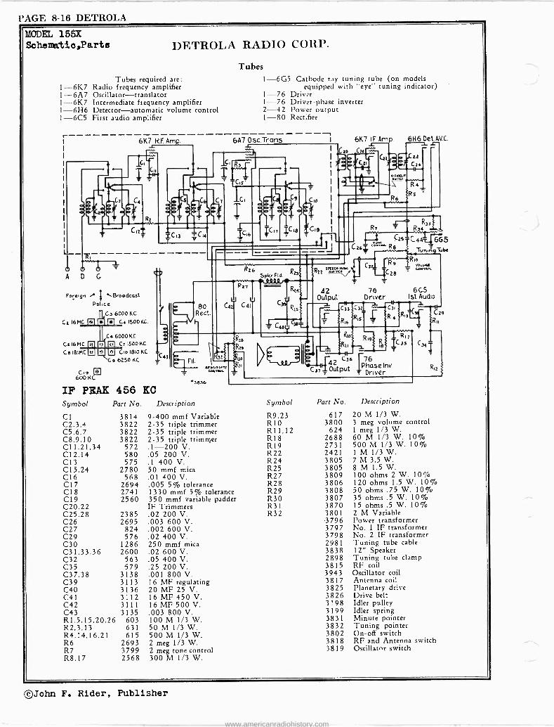
MODMS 528,528LW MODLLi 1200 Schematica
T.,
ti li
6D6- RF
AM'
r
MDDEL 52 8-5 28 Lwl In Model 528 L.w. Ll.C1,12 & C2 are in circuit.
In Model 528 Ll. LE, Cl, k CO are omitted.
Di WALL) RADIO
6C6 -Der. 2SL6G-our-PuT
H)
".(
odo,
5
S/K12A9 6C'6 6D6 2S16G
Rect. 25Z5
.0/
4SOn `.CL i 9tieetartr r-- oT
MtSSF
/e5- /:TV AC -RC IO- dON
I/dMfi3 OAMf)<WARf 3A£f/FdFO
^.0 COI BRATE
Connect external Oscilletor'e hot leed to reel antenne of receiver.
Cannent oscillator cold leed in serle, ith u } or .1 '?D condenser
to receiver ahaeeis. Set oscillator at 7500nC and peak Variable Con-
denser trimmers for Maximum signal with condenser set approximately where 1500 oame. in on focale.
Os C - 6A 7- TRArs. - xr
. 05 /'lF
7,-J0/J1.
ti
1
Ig I ---'-'
6D6 -IF .0o005 -
76-2(22° ét
.05 `MW"
loue
A VC- 76
f-AMMMHIIt OUT- PUT 75
d 25L66
TI.a `TeExrrAna/ Gwowd
s
.00045
w
r /0,00
MODE L 1200
IF PEAK 456 KC.
76Arr 6.47 76A1í' 6D6 7S 2.266
D-200 D1500 r lTecr
25Z5 25Z5
S 450n Fisto
T/d
®D35
Te /0S- /2JV AC-Oi 40-detL (AveC.es O N twX
SArt/,7CO
D-7í0 CO t-nLIOr Tr: -
Set service oenli 'tor to e_h6 R.C. nd tonnent "not" lead to grid of 607 tubs. Orornd stator of front
Ioecillator) section of variable co dancer. Turn vol-
umeontrol for Rsoiean output end eak intermediate fequency trimmer, for mainate gain. Turn wave bud ewiteh knot tocard rigtt. Adjust service oae111ator end receiver to 7 negscleles an0 peak veriaale eon -
denser trtamere for nexlrum gain. turn . e bard
switch toward left ami adjust oecilistor (service) and receiver to 1500 R.C. Peak both trimmers under- esth ntseele for maxi^um gain. Thon adjust sereins reins oscillator std receiver to 600 F.C. and "rock" the variable ondenser end adjust the gadder (near front of chseeie
on top)at the eams time for maximum gain.
©John F. Rider, Publisher
www.americanradiohistory.com

I)1+,1V'Al.l) l'AGE 8-7
r ; ; 02
ose- r?Nns, 6,47
AVL.
I.F. PEAK 456 KC.
LONG WAVE
OPERATION
00/7
,
,
ti e
15er
, 4f , , ;
I)r,WALD RADIO
.
:
MODELS 529,529LW MODELS 629, 629L1P, 703, 70 3L Scher.)atics, 4ligrunent
/F 2,2s. Oer 6D6 Ave -75- x?S HF
AMC.
soy
N
eery
2ME¢.
/00n 200..x-
í ,.
.SP//R. F/ELO 2000JL
fic s
Bf -,Yec/
These receivers are dual wave euperheterodynee with automatic volume control. The 529 covers the following ranges: 1650-550 R.C. and 7-2.4 M.C. The 529 -LW cover. the following ranges: 1650-550 K.C. and 340.150 R.C.
The Model 529 -LW has a long -wave band in place of the 3h.Wave band. Follow same instructions for tuning se for the Sh.Ways. band operation.
LIST PRICES OF REPLACEMENT PARTS.
1440 Power Transformer 1423A let dual I.P. 1424A 2nd "
1438 Ant, coil 1439 Ose. coil 2369 2 Gang var. cond. 2372 Electrolytic cond. 8779 Pilot socket \ / lnios-6A7- osc
, ; 4f; ;12 ; :1%
Mae
: .
o . .
$2.50 3382 comb. bias resistor .35 1.25 7212 Speaker 4.00 1;25 8660 Comb, vol. control 1.00 .70 8662 knob. .10 .65 6041 Scale 1.10
2.00 9823 Pointer .10 1.10 9818 Shaft .10 .10 9799 Drum .05
606-','"
.
. í . . i N
§ //0-/20V..9.0 6012
7
MDDEL-529 529 LW.
TO CALIBRATE: Set service oscillator to 456 R.C. and connect "ROT" lead to grid of 6A7 tube. Ground stator of front
(oscillator) section of variable condenser. Turn volume control for maximum output and peak intermediate frequency trimmers for maximum gain. Turn wave band switch knob toward left. Adjust service os- cillator and receiver to 7 megacycles and peak variable condenser trimmers for maximum gain. Turn wave band switch toward right aryl ad- just eerviee oscillator and receiver to 1500 L. C. Peak the trimmer next to the variable condenser and the one underneath chassis for maxi- mum gain. Then adjust service oscillator and receiver to 600 P.S. and "rock"the variable condenser and adjust the padder (near front of chieei at the same time for maximum gain.
óét 75 ÁF
.05
02 45011-
F/EL D
JM /0/Y 2002
PeC rt5/MA2A4
I.F. PEAK 456 KC. 7s 6A7 606 25L6G
//OV-.4C.-Qc. KSY.
LIST PRICKS OW PEPLACFlxFNT PARTS
1438 Antenna coil 1439 Oscillator Coil 1423A Dual tuned I.P. 1424A 2nd det. coil
2525
4 .70 8662 knobs $ .10 .65 8627A Wave Band Switch .35 1,25 8660 Comb. volume control 1.00 1.25 6041 Scale 1.10
2369 Variable condenser 2.00 9823 vointer .10 2376 Comb. electrolytic 1.00 9818 Shaft .10 7222 Speaker 4.00 9799 Drum .05
These receivers are dual wave superheterodynea with the automatic volume control feature. The frequency ranges are as follow.:
Motels 629 and 703 - 1650-550 R.C. and 7-2.4 N.C. Models 629 -LW and 703 -LW - 1650-550 R.C. and 340-150 R.C.
®BALL.IST q -_f RES. TUBE
.O5
II->
25166 - ouTPuT
p 1665 :
i 6 EYE
U.sev A+' Maaet raw 7LiìLW Ona r
MODELS 629-629 LW 703-703 L.W.
Models 629 and 629 -LW: 1-6A7, 1-6D6, 1-75, 1-25L6, 1-2525, and 1 -M -49-B.
Models 703 and 703 -LW: 1-6A7, 1-6D6, 1-75, 1-25L6, 1-2525, 1 -M -42-B, and 1-605
TO CALIBRATE: Set service oscillator to 456 R.C. and connect "ROT" lead to grid of 6A7 tube. Ground stator of front
(oscillator) section of variable condenser. Turn volume control for maximum output and peak intermediate frequency trimmer. for maximum gain. Turn wave band switch knob toward left. Adjust service os- cillator and receiver to 7 megacycles and peak variable condenser trimmers for maximum gain. Turn wave band switch toward right and ad- just oscillator (service) and receiver to 1600 R.C. Peak both trimmers underneath chassis for maximum gain. Then adjust service oscillator end receiver to 600 R.C. and "rock" the variable condenser and adjust he padder (near front of chassie) at the same tite for maximum gain.
©John F. Rider, Publisher
www.americanradiohistory.com

PAGE 6-8 DEWALD
\17.
MODELS 6 3 3, 6 3 3 L V P, 6 3 3 S
MODELS 635,635L7T Schematics,Alignment
OSC-TRAK3 6A7
(Model 633S is same as Model 633 but without SW Band.
The yodel 635 has the following ranges: TO CALIBRATE:
550-1700 R.C. {550-175 meters) 1700-4800 K.C. (175-62 meters) 5.7-16 M.P. (18-52 meters)
The Model 635LW has the following additional range: 330-150 K.C. (900-2000 meter!)
Police Pend is omitted in Long Wave receiver. 606 -/ F
.01
.01
2523-Ree
I.)r.WAI.I) RADI n MODa, 633,633LW,633S º Npoe'r
6D6-/F Ayc-60715- 9.F
-5- --1
I.F. PEAK 456 KC.
/6\ q50 -d. T FIELD
6076 6.47
.05 T
n07 -PUT 2365
>s/MAZDA
M -49-B1
NOTE:
OSC- Red
-rein/56A7
456 K.L. WAVE TRAP
LM2
50M nANW
L
I.F. PEAK 456 KC.
2ME0.
/10-1201.1 A.C. 40-60Cócmes
Set Se Ground Volume for ms
to1500
FiAs
-In
rvice Oscillator to 456 R.C. end correct "HOT" lend to grid of 607, stator of rear (oscillator) section of variable condenser. Turn
Control for maximum output end peak intermediate frequency trimmers
ximum gain. Remove Variable Condenser short. Adjust service oscllletor end receiver
K.C. end peak variable condenser trimmers for aaximum vain.. e 7S/ Ave 42-ourpuT
I. F. ALICNMFNT: Intermediate frequency peeved nt 454 F.C. rn nect. test oecIlletor to grid
of 647 and chsee]e. Short circuit etetor of front section of variable
condenser during thus operation. Then peak I.P. trimmer. for maximum elgnal.
R. r. ALLOeVSTT: Remove ehort from stator of variable condenser. Turn Wave Bend Switch
to Broadcast. Connect test oscillator to antenna end e*eeele. net
test oscillator and radio dial to 1500 R.C. end peak teo trimmers underneath chess is.
(toward rear) for maximum signal. Set teat oscillator at 600 R.C. eri adluet redder
Orden (nut side) in front o chassie for maximum slang]. wring thus' on.retion, the
veriatle codenger must be rocked. Reedtust 1500 v.r.
1,
e
M
4
MODELS 635-635 L.W.
200 33 7,5
POLTC5 root )Urn ,Ice we d Switch to Polie. Bend. Set test oecilletor end odio
TCk sMm*: dial to 4000 X.C. end peak too trim -ere on soil on top of cheeste. net
test oscille orand radio to 1700 C.C. and adjust nailer (screw side)
for maximum etgrel. The aria le cordenger mat be reeked during the operation. Sr
poceiver hew long waves leste. of po'ice band, e libretti . me truing condenser es on
llee Pend, but set osaiilator and receiver at 300 R.C. for alignment.
Senat nave AL10MM21T:
of by short redder.
Turn 'sane à d .witch to abort sea! Set teat oscillator en! radio dial
to 15 Megecy les and peak trimmer. on bottom of chassis (toward front) for mexlenoa 'anal. Low frequency setting Is an tometicel`y Lebec care
se coils which e e carefully matched for this setting by a fixed calibrated
©John F. Rider, Publisher
www.americanradiohistory.com

DEWALD PAGE 8-9
ö
I.F. PEAK 456 KC.
MODEL- 7 0 700 LW
.01
\0.e0taVa
DEWALD RADIO
reANs-,,4' o3c
ON GONF WAVC RFC!/PZ-eS TAW ,SfaoER/J .0001111
.004
.
1f
MODELS 700,700LW ::iODF72 700A, 700A-LW Sch©matics,Alignment
.93_vvrPUT
/,tlK-AC-QC. 40404.4
I/6 C.,Ckdf 400z
telni` Ili
75
f/ELO
647 606 15
1. I
//lea ^AAA,
25 -ZS
J 665
'46 'Pt6
L 11-C
/.F..ItLirG.NME/NT- A/kTf:.,yEp/..7E F ̀me,E,.rY e...reo /y5- 4J-6-zee.CONNIC>7Tt> G?JC/LL I70.G T. y.!/O Cif OA74Ae0 C/Y.ftt4..S,YO.!>`<et'({/J
/Ti/7/t Of / CON7SfG7/ON OFY/1.l,AOLE CONOENjER OPL.C17/g N,
fAGN/1ET pE/10 7e .*e VJ t,Xf. f<Mo/L«Efyc,//INS
iIL.
Tt B.w
O¡QoRA90C..s7-aAiLit-CTO.f4«,,7-0tf- TAK7-0:4-K4/No A10 T /sao/reAvoiC {/eC7,7rjyVyEt Fqe/fatX/MUM&"7" 717OCiL,A6G ,9/A70/<J>/.iprOI O/O./ER
CANOEN1E.t /NFONTfCY./Lts/iFae .13(47,44.F7/s .44(0" 1.4r, /S00 e "tiL/B/tOAL/0YFF/> /TOW {y4/i! /py.VQJtyCNTt/GEBAHw /No AINO.ILTvov.Y.C
N0 i9R F.eR1.7O^.jSFK,et..V7-E LO/lREd. 70M97iCAGLyAaUs7E0pY/n%/I O C.X/QeNO "eoOEe. /fPECE/slYrt/ylJLaviW.ises>E.rni< Ar<
AtNOLtKVRIE C /2J ON tFOoN Be.T .SE7 OJ47/L/A70.í Attar (/ORT W.fI/EA!/6<Y/IENT T e.
A .500 WB V.W/7/TY.C, C`NR
AGW/9BNYEM
-
EvNf7>. TJ7vC /AN o/P op<ºG T /S/NetWrc9<vtECAoivo
Wrset .einve.es Nc.n.CALs[s,.s Îe.M.r.SiiLN,AZLe.SE77/N` A5.47OMsrt-.k 1-TtOB.So.t AREClCLyF r
SE772:4eÇBrA F,YEO C.o«o...v Eo PAOOE.e 23Z 66 our T/{ANS- 03C
611.7
I.F. PEAK 456 KC.
ti
SM -%/SIVSISANNI.os
8 sffpt 600
T. P. CTICleu77^: Tot.rmed/ete free-enef risked et 456 X. C. Connect teat oscillator to grid of 60.7 and cheerio,. Short circuit stator of front eetien of verl.h`e condeneer during this operation. Then peak I.P. trimmere for maximum .í0u1.
It. P. sLT0ev!wrt Remove short from ateter of vorisbls conden.er. Turn rave Band Switch to Brosdoot. Connect teat oscilla- tor to antenna and ch.s.ls. Set test oacilletòr and radio dial to
1500 r.C. and peat' two primers underneath Chain., (toward rear) for maxima. (lineal. Set test oscillator at 600 R.C. Sol edryet adder con - denier (nut eidel In front of chase!. for maximum stare]. Suring this operation, th- variable condenr.r Suet be rocked. Readjust 1500 E. C.
/F- 6D6/
LO
Ar6 /NA!
ZBOOn. FE<o
7.5" 66S 606 647 zed
/A}/eYAv.{ C. Ot fa-oOCYrJ
'"16,4Jstoa,
P01.ICR 36115 Turn ;nee Band Setter( So Potlee Band. Set test co stsoinewe t cillator end radio dial to 400 R.C. sod peek two Leiaere on coil on top of cheest.. Set teat e cllletor and radio to 1700 R.C. end ad3)uet pod.er (soren side, for maximum .100.1. The variable eondsn.er Aret be reeked during the operation. If receiver ha long in.taad of police band. calibrate e trimming condenser as of Police Bond, but set oscillator and re- ceiver .t 300 F.C. for alignment.
$3.66.2 .2612 Turn Rave band ewitsh to short wave. Set Net o. ALTSw r: eilleter end radio dial to 10 Megacycle. and peak
trimmers on bottom of ch...is (toward front) for maximum signal. Lem frequency Setting in eutomatieelly taken ner of =teed short wave coils chick are earefully for this lotting by a fixed calibrated padd.r.
MN ;48. E YE
MODEL S 700A
700A LW
©John F. Rider, Publisher
www.americanradiohistory.com

PAGE 8-10 DEWALD
4.1l.111.1»
1 T 111Z
deli
1g6 ooww
tail :i iiihi LIST PRICES OF REYLACEVENT PARTS
1431A Power Transformer $ 3.00 3407 Volume Control 1.10
1432A A Choke .30 5077B Antenna Cable .85
5094 Combination A Cable .50
1433 B Choke .95 7194 Speaker 5.50
1486 Antenna Coil .90 3608 Vibrator 5.00
1308D 1st Detector Coil .95 8399 Fuse Retainer .20
1309A Dual I.F. Transformer 1.50 8400 15 Ampere Fuse .05
1310 2nd Detector Coil 1.30 8777 Knob .20
1454 Oscillator Coil .75 8792 Remote Control 5.75
2317 3 Gang Variable Condenser 4.50 9850 Cable and Sheath 1.50
2362 Dual 8 ElActrolytic Condenser... 2.05 9517 Mounting Stud .05
2390 Spark Plate Condenser (Chassis). .25 7/16 Hexagon Nut . 05
2391 Spark Plate Condenser (Can) .25 Pilot Lamps .10
3390A Tone Control .80
©John F. Rider, Publisher
www.americanradiohistory.com

DICTOGRAPH PAGE 8-1
ir)
k/00000000000 Moog,
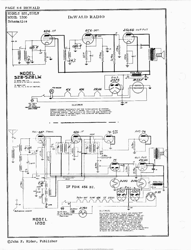
MODELS 91134,91134A DIC'I'OGRAPH PRODUCTS CO., INC. Scheaatic,Parts
WHO OOOE 0131!
co
e"
iF u
1 _ O44 4QQ4.
L e <r 11,.
^vVvvYVYVV II
*N 1
n_y
L_J
6 tJ
913
r
3
L._
.á (' c11 N
1 --k--ii
2Q-440041
OJ 01.0 "JO 0Ó04 - _11
a
a
r
3
ti
33 3
.¡J
O
o Ó
o
8
á
K r.
N
g f O
8
r
H1.
8
9 Ñ N n
gS39:9á A A ^gym -,á vóó P
O o
,., M M 9;
en
g eR O J n
N _ y
S
N
a
i 8 N
e ó i
®John F. Rider, Publisher
www.americanradiohistory.com

PAGE 8-2 DICTOGRAPH
»MODELS 91134,91134A MODELS 91168,91175 DICTOGRAPH PRODUCTS CO" INC. Alignment
This receiver is equipped with an automatic overload control which necessitates
setting the manual volume control of the receiver to its maximum position to
insure accuracy in alignment. To control the signal output of the receiver it
will be necessary to use the attenuator control of the signal generator.
Connect the low potential side of the signal generator to the metal chassis
through a .1 mfd. (400 volt) condenser for the following adjustments.
(a) - Remove (carbon type tential lead tubular 400
Socket,Trimmere
ADJUSTMENT OF I.E. CONDENSERS
the control grid lead of the 6A7 tube and insert a 50,000 ohm
1/3 watt) resistor in series with same. Then connect the high po -
of the signal generator through a .001 mfd. condenser (paper
volt type), directly to the control grid of the 6A7 tube.
(b) - Turn the rotor plates of the ganged variable condenser where no broadcast
station carrier is heard (approximately 1000 KC). If this is not possible
connect a .1 mfd. condenser (paper tubular) from the oscillator stator section
(see sketch) of the ganged variable condenser to chassis.
(c) - Place an output meter (copper oxide type) across the
with the speaker control switch in a clockwise position so
signal output can be noted.
(d) - Place the signal generator in operation, adjust the carrier frequency to
456 KC and regulate the attenuator control of the signal generator so that
the output signal is low enough to insure accuracy in adjusting the I.F.
condenser.
mystic ear terminals
that variations in
(e) - Adjust trimmers T-1, T-2 and T-3 (see alignment layout) to resonance as
indicated by the greatest swing on the output meter.
ADJUSTMENT OF THE GANGED VARIABLE CONDENSERS
(a) - Remove 6A7 tube and
of the receiv
a 200 mmfd. c
the signal generator connection from
replace the control grid lead. Then
er to the high potential lead of the
ondenser (mica type).
the control grid of the
connect the antenna wire
signal generator through
(b) - Set the dial pointer directly at the last long line
side of the dial with the ganged variable condenser fully
rotate the receiver dial to 1,500 KC.
at the right hand meshed. Then
(c) - Adjust the carrier frequency of the signal generator to 1,500 KC and,
starting with trimmer T-4 and then T-5. adjust each for maximum signal output.
,11 MYSTIC EAR TERMINALS
ALIGNMENT LAYOUT
T-1 (456 KC)
T-3(4056 KC)
1" I. F.
Tra ns.
T-2 (456 KC)
r
T-5 1500 KC)
T-4 1500 KC)
©John F. Rider, Publisher
www.americanradiohistory.com

DICTOGRAPH PAGE 8-3
L W N
o U
e
MODELS 91168,91175 I)IC'I'OGRAPH PRODUCTS CO., INC. Schematic,Parts
regle,
0
0
0
.--, º
2q
N.j -_J
I
r Inn-151r);
- _ _
11
Il
D
3
<
` M' --k- -
O \000000,
a IC>
ó,e
J3
L d wN
z
O:
VI
ñ
latrace-
J
s
e
s s s
s
L
` F s.
A 3 N
00 S n
O O O O
Z« A w
h et;. RA
n^wX«
Q
0
RSE R gg
e g Ñ N gg .! f
ti $R YI J Ca
o O
r w O
a .+
i 8
g e
2.
s
$
h
yf
V F
re.) ,B
º.
,41.31:551,
O M
©John F. Rider, Publisher
www.americanradiohistory.com

www.americanradiohistory.com

ELEC. ACM'. PAGE 8-1
0000000000000
mlim0 O MA ló N CC.v
""1
ló U
N ct - á 0.1,
MODEL A1832 Amplifier ELECTRO-ACOITS'l'IC PRODUCTS CO. Schematio,Voltage
111'
` J
woQQ/m 111'
I a ? Ng
^ ¢
p
0 J > Y >
N N
2 Y
'DO I I I
N ©0
Y
O N
© O
O
3 x à4 { 3
> 6 n n
yO
2
rv
,fl g
^ U
Og
yens
m ú
,944, \4494 Qq0494Q94,
©John F. Rider, Publisher
www.americanradiohistory.com

PAGE 8-2 ELEC. ACOU. MODEL A1832 Amplifier MODEL A2023 AmplifierELECTRO-ACOUSTIC PRODUCTS CO. Chassis Layouts
O T2 O 330209
J
SPK
0"0 000
/82567 O 0 O 0
182524,
SPKR 0° O ° 0
182525
m cv á-o
o
----- - O O
T3 300214
102593
O c1á O
1926oó /8240
o 0 00 0
189º90
432857 CHASSIS
C
R 20
350ná O l
e9 C-12
2o2 572
IMeni 202574
C13 R22
o ° oo
2722a.
l C17
279274
R2I
e 2o2S72
C10
R14 0
6L6 4C5 . 61-4-182552 192532 k 18 2 531
10221.
R16
222517
C8
R19
oRMe,A! o2o
182591 R17
RS 22519
R24. RIO
11
222945%,
R
0812
C18
279276
C2
182523
m 284202 / CAnP /
R_ 2o25é 1037
0ó R13 18252'
447690 3 3 02545 46769 : , 4 iò254 j , f
zzzzzz 222520
595/29
182567
1825-25
182525
O
T3 306120
222E117
`102 593 0
'5937301
CHASSIS LAYOUT - MODEL A2023
. I -200v I
Clo 274 224
e9 R13
RH
222547
R12. 202422,,;
F-Rlo R6
CHASSIS LAYOUT - MODEL 1832
R2 2º25/8
,c
202422 N N e N
)6y0
/82523
192522
182529
©John F. Rider, Publisher
www.americanradiohistory.com

ELEC. ACOT . PAGE 8-3
N
F
r1tiM1lM/lNV1M/
4
R «
QQQoQQQi
. l'l'P1 Ï PPPPI I'PPI'11'M'1'PP11
n
ó
MODEL A2023 ELI+;CTRO-r1COt'STIC PRODUCTS CO. Amplifier
Schematic,Voltagea ò
2
tn
©John F. Rider, Publisher
www.americanradiohistory.com

PAGE 8-4 ELEC. ACOU.
MODEL A2232 Amplifier Schsmatic,Voltage ELECTRO -ACOUS'T'IC. PRODUCTS CO.
N
H
dl
r> r
~ U$ .02R
I \XJU 2ó p
ä " c $ c M 0000000e J
: I
00e o 'g
ó5'i'
o % " I L_ ` Y O O
W
!7 00o
N
N N
©John F. Rider, Publisher
www.americanradiohistory.com

ELEC. ACOU. PAGE 8-5
MODEL A2232 Amplifier ELECTRO -ACOUSTIC PRODUCTS MODEL A3041 Amplifier
Chassie Layouts
-1,....S3- /A9453
4" ,1
'-
-
z° \
; , \
\r ,
I'
c4
\oTN.aoTa!\ . , \\\\ 53937é , G' \\ \ \ \ i \ \ ,p l
....------ 2091 S0 \ . .
__-
52
/b95ó52.
*
/89443
162181
SW/i144'AL
/>f40a
I82525
182525
224/94 ----------i
O
27419I/
O' C.11,,
R12
C9 Cb
O L_
T3 300)Ió
0
R13 /02/8'/ 182532 r.>G7 Rll KID 4C5
/92522 /- º2531 202 44,2
CHASSIS LAYOUT R8 6 1.44 -?9 202662 (
MODEL A2232 Rs
5U4G
189290
\1 o 532
202420 QIo
óL6
102181
432945 CHASSS
í57o96 {ó82960 SHELL `TI (189444 PLUG 320219
_157060
iCI
274/99
I-
1-2 330196
CI 27/002
R3
CHASSIS LAYOUT
MODEL A3041
102545 PI10110 r.gioP
60 5073 E 6321353
182759
1ß252L
T3 300101
"I /92537 9 45
/0224 284202D
¡ o o^ ` SgoRTING vai PLUG
182625
152v6ß 1595/37
350114
O
Ti 1 '- R4 32ol9s; _
/82758 /824(4
595117
©John F. Rider, Publisher
www.americanradiohistory.com

PAGE 8-6 ELEC. ACM'.
MODEL A3041 Amplifier Schematic,Voltage ELECTRO -ACOUSTIC PRODUCTS CO.
LL
7
to J
C W Y <
o O
t
r
o J W
W 4 N
©John F. Rider, Publisher
www.americanradiohistory.com
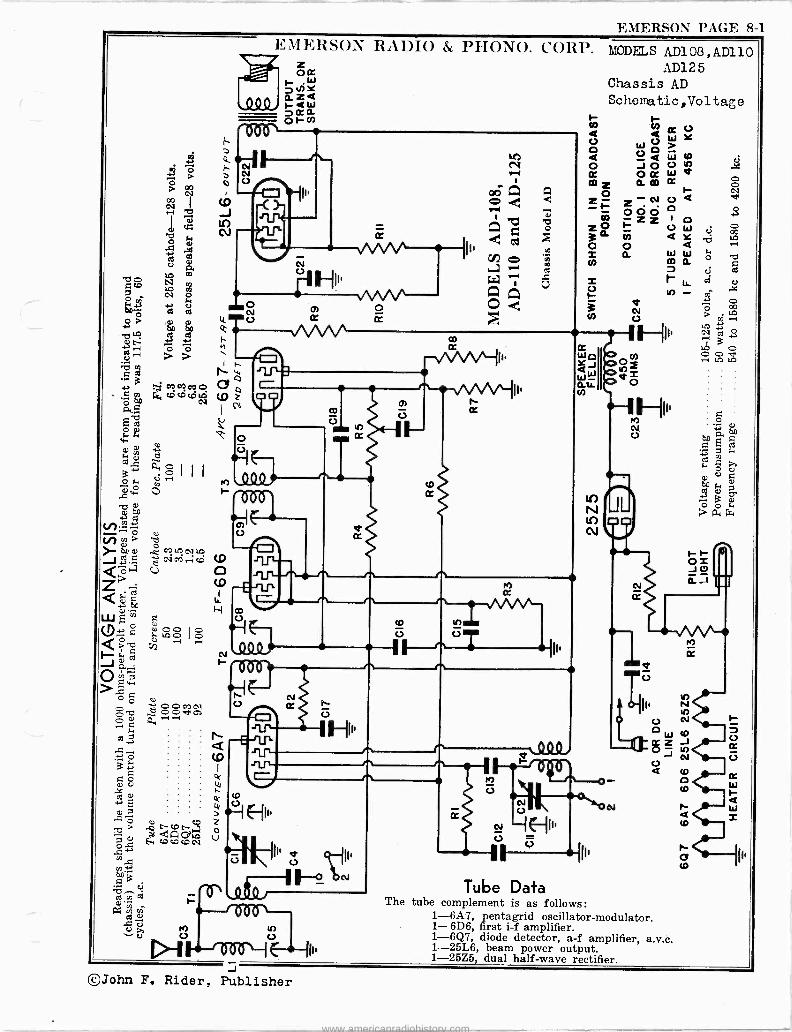
EMERSON PAGE 8-1
0
íó b .N m",
q ce co
ó tel cs, cDcócCÑ
ólg we
d ti a
0 y o O H ÿ
7L1 v9.O .0
N~ tr) w » 64 o ..0 c12? J ̀ , d CD
L)
Qc an . W g
Q» U La ó ó
Jo
o a >,f 00
c> ce ©0 d óóo ¡,
q a
y --i
o
o U U U
E c,a
-c21 Qó, 0 h coCDtDN
ND" a3 c.;
°''m
Ú u
H co
EMERSON RADIO & PHONO. CORP.
}
N o
_ v VV II44
e
p,
ÿ
MODELS AD108,AD110 AD125
Chassis AD Schematic,Voltage
V w Y W V O
O J O V O a' OOC W_ a mz am
O ~ z_ z-N c Q
O O z z o z0 H o W ci ó ó 4 = a W W y m a
X r W F -
-7I
Ñ Ñ o o >
2 7'
I1:1 O 0 0 e
0
a O , ti
^. 03
03
O U Uo
at: L+
-245 d v
rx4
Oi J 0 aJ 1
o o
W CC Z OJ o Q
Tube Data The tube complement is as follows:
1-6A7, pentagrid oscillator -modulator. 1-6D6, first i -f amplifier. 1-6Q7, diode detector, a -f amplifier, a.v.c. 1-25L6, beam power output. 1-25Z5, dual half -wave rectifier.
r C7 CD
o cc
J ©John F. Rider, Publisher
www.americanradiohistory.com

PAGE 8-2 EMERSON
MODELS AD1O8,AD110 AD125 EMERSON RADIO & PHONO. CORP.
Chassis AD Alignment,Notes,Parts
Q.
yoU
W 2,
Q ARggÑH4Ñ- NCb
Ñ O r a ci
1
i
.o oa N
ä 1
e 1 &
C
§ 8 do
L M L L L L ÿ L y 8 m 3"
j flfl éE E a`
"go ogo,wk$m'caaoé3 ;.m 8. EL a 8a áí°".L°"óFóSSóL_ EQ
0>`8`A5C8ô3ááá3.8$ÑBúASÉ áE e a ó3v á° ÿ` ô°. F.o.aa..o ó... '3 a.ÿ ; aee ái v w ",12.,,1-.,..1815.2, F a3 ew m á ô 8 ó ó ó tb. .. ¿8___ B B m á B m B B á m ó a0 e °> a âGw'-eaYpwpp>aC o-^PtKP>;9\_'\B QB_\'_\'BBB,mn« tÓmÓit°E0.0.0.tlM$ÑMNÉEEÓFi\~ 1B
i0m á`EE°'o.;b.,, Ew.,;eoóós?oepsEmB °,ayya EEÉ O ÉNEiEiEp o Eo oos.a+ .Y N. E E EO E b8 S O o9 >°. SabteO° B Sói.C.. S 00000 7 O E pOyObOp.br Ot .- C .rF..FFddFFddóóoddóta$Ol.NNN.° .b &ä
ó N.N-.N N Ái.^ty
Z a? a? °ì a7 FFFFFÚUU Mammamax .aa,,.b.N
dd 6 W S
ce
b q N Ñ
. eA ... 9
UI b'Tam
wmd21 ovgéMWrÑW44w Ñaaa.QOi.Ñ
0 ÚZ .0 W U.6
N ., aó Ú U V~ Ñ
VU ma2
N
af..°aóTONO p °0N° 3á ócoUV000UUábmmmmmFF . ww
8 Á A é.ÿEg msÉ m w 8..ÿÿ:
! 'á m
I Al.31U Q ".
á m É « á° é a E LA aaá° '
Q 0 ">5 $iz aé9>
..Em g.; , spqpq ,B, "ydy :bs
1 E
F 'L bEp xCCy7
Mill . Ç ,Om
p ^dFy awrÿmp E iiü L F .F°.
`° ú W m . 8; a.,° . yE
?:.212
p 4 F óó
CE ó »ópá P. ä9t M Má d :1541 °Sfy ,° ,o, `Jtl 8 Â 8 423 Ñ ` A= Á 3 ai} &3Ge
. Ñ xme . .b yc. áym;
. "e ; .9 . m ¡ g
v a .....
á 33 M
W m9 8 .5 Ew mE m
o ° 8 °bo6 .s°'m
d á« i 1 a14 m o I
E "
A.
°Ó :54.221'8má y $ ?$ " °î.ÿ m. ú . á
0 ó tG
o qi. A W ;9 E Lï.?á =o,e`,$ r.é
c s Co 3 m É nee' á c:" 8 i B d
eg p
{o ii 3
ÿm .. M
F E 3 `, °',m tyl-y E .ó caa
0. P v m v ee.p
Q ° 1.GM ° Cár .0 L e>p
V q 1 Ow'O bg EG°á
9G4 u o N
Ti t E óe9 Eo. . .E é ..Ero áNóF
E 8. E E. .93 E oe m.o.E T. g.. eY dÿ ÿ_: e. E,`^Eyffi gWm bi t= de 2 m'ä .9° ó Eÿ. ,15 m.8.
.ra ° Q ep3 231'g
L ~ a 3ELE o``E 6
a ÿa MF Mm il y- g Ñ~.
G«7 I`
P P
U Q E X Ó .CúE3.-. O BEE
a oS TM tom atE^ti E a«L á e p°e " 3 3a
d v Lw 0 . .°.' .9 . r.3- c v Q c é 4 et. el A`o, m ó ag',áá 3/qt'jS
A Q tui F m p m p
Te bl J .7 ro b 3..°. . ! .. ci eg d .é m ti
©John F. Rider, Publisher
www.americanradiohistory.com
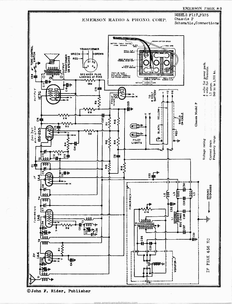
EMERSON PAGE 8-3
EMERSON RADIO & PHONO. CORP.
BATTERY CABLE COMING FROM ORARAIS
TNRE - TRANSFORMER
TEETH OF CLIPS MIST BITE FIRMLY INTO BATTERY TERMINALS FOR PROPER OPERATION
PLUS 0A POSITK TERMINAL ON BATTERY
BATTERY CONNECTIONS
MODELS P117,P135 Chassis P Schematic,Connections
©John F. Rider, Publisher
www.americanradiohistory.com

PAGE 8-4 EMERSON
MODELS P117,P135 Chassis P Voltage,Alignment Notes, Parts
9
Y Y
V C C
3 ú e3
i g q .gJ w A
2-e3 4 '..m $c e°piti ai
EZ sB s i,,,
°s m == â
á0.lel l l l _ v~i 15°'- 2o
É6 VI s
Fm+Y+ Q R"Y2ÍSffi1Ig Vwÿá a
Z-...> 1.1.1; ,g w Q; v
EMERSON RADIO & PHONO. CORP.
fsY^, u Om0ÑbºmlmTyO Oleg mmummmmmmmmmm ti H
rIAN10 ÑNÑÑOOÑN4'N
ai g8mti2,íejry óéÿ m . .
.Ió .r
: z
©John F. Rider, Publisher
www.americanradiohistory.com

.EMERSON PAGE 8-5
Ñ U T
o 1" M-AA
N U /A n
CAD 0
67M1F1II, j N U
J
P
EM ER4O\ RADIO & PIIO\ O. CORP.
OJ r
It'
YODELS Z117,Z122,Z133 Z141,Z150,Z159 Z1G0 Z135
Chassis Z Schematic,Voltage
r 5 U 2 U
II,
T o
V
CILaCDCD+-1 cDcDri
civcivci W C6
M M M M 4040404040
0 0 0 0 0
I I I I
7b (Oto er
er v o to cc Wci N N GV
wô n
y dvA. Ó.
F
á ó Qo
bD y? E aw> I yc ., 6G. -]w g
N 9'
> F â Ñ
60 LA . + + m A m p
W o y
c% `F°
4 "' w a -ti g
c o> ro
rnw cc.c' w
E v ÿ o
M.ºÑo F y ÿ(y'A -~+.
^ E L
'4 N0 mixw W
cv ºF cu
60 s ÿ N m ô ô 22 7 E^ i r Ar:
©John F. Rider, Publisher
www.americanradiohistory.com

PAGE 8-6 EMERSON MCDELS Z117,Z122,Z133
Z141,Z150,Z159FJMFRSON RADIO & PHONO. CORP. Z160 Z136
Chassis Z
Alignment,Changes,Notes Parts
All A4mm..mmmemmmem:
a 3 ,1
1
f
2
ä s
J C _ .
g º
s li
_ 'il/ ;
111 18 1"U" Y 11 Mt:ó É Yeli - 1
.p @æä x ; 98 5b
. Eq KE:G`3 °sa=`ee ye e á
o ; $ s= ssr ses e,.s.. _ a 8 S Sáy'29 55Y' óse -$ Es`y3i=áap8« ._a ° _:
e« ««« «,«6seyE88mge$«Oºéß68 " r s` iÌ }I J0 8«ÿi se_'s .,._;=! Cg ' S$' iti t « 8 = 4`...$áz+.át'Éxé É'>'-. 8 8: Ili 9 « g$ rsmo..82.8. a 8.. ç 8_g
ft W14:
aSJPaóóóóñggs$\pEpÉQQçç E'`.a6ÉéEi$ eEwiMvo$$,$ d::yyb úBOsoS25ée9g
ä9ärN9Eo. E n`6i' 6 e.,ó. _a 8
be9- Eógççg"qx8g'ó'v8ó8ó..me2;q y33 :ÿ5o^.E MñS..Ñ.w>$o_+..3FFdoFdV òFFddddddd....dFBómm.o.LGC1C1[iO W
áó < 0^
t mm$eá.aEa s 3"333a$3 áÑFmmoz Ñ>áÑámW <d pd Jwzz F«.meW a$.°'e xbm,zx,..,.mm <m mr., ..an wN«>a
.. g
Ú
ÚÚ E a o.+woÚVV ñV HFgáMáááámaáoámzáciwddegeg$gURgvegCìy
©John F. Rider, Publisher
www.americanradiohistory.com

EMERSON PAGE 8-7
e fib
111-*
EMERSON RADIO & PHONO. CORP.
J W S M
u
o u
p
Il.
- QQQQQ0.
c() N N
1Wy CD Z Oa
tad- F O b_ 71
O II w_J= U grid
O= i- ! > aO O
G
00 -J
V O }i º ó I HI o.-, w o,
c, m ; m 1:100 00
w f > £-1 +3 .á F+ .-i C7
tai Q 3 C U
m r-10 .7...!
U y) ÿ Opti)
i) O. cd U 9 tc rc a1 m p o m
m K S rl ri O) a O m ZZ CO H orldI á f,i) -PM ',AI
ZÑ p pN p r-O r L I ,.) ;O
r7i Z Z ,-.# .,..4 á U
m£ $ó tio a>mr
5 -t= ;-iocfl w4)..ew e- (D
CT) N Ñ r-1 ß, r1 U í7 U
a 2.o ca---- >9m.ri
LO
MODEL G127 Chassis G
Schematic,Voltage
V 0 0 .2 A
t O
v.2 oti
dooo oi t- ooMoo
C
o
©John F. Rider. Publisher
www.americanradiohistory.com

PAGE 8-8 EMERSON MODEL G127 Chassis G
Alignment,Notes Changes,Parts
EMERSON RADIO & PHONO. CORP.
+9 ú $ge 2:':e.m.m.mm.m 4:194 44 4 444444$44 ip i á 3
3 ó 2 z g
$ 2 $ $ 1 ó lg ó
â @ I @ @
1 liii 1 a
i A_o .
Á
:
ó 1 1 M ' S 1 ... q
% á ! M z !T 3w 'm3`:: cFi
, . . .
P ai.99 é¢@á'
A- éRb; 3ç ° y E cac $cc3ec ¿8 c 88 8868 S 8
. 3 i ßá$$ 8$$°$8 . 8 ÿ_ d5 8pp çç .i El 53` a 'c_.. 2c.S 8_39` ya.F
8`°m8ÿ`ámDu«`á mq8a á 'o$ó'^ áó i m m
H s E,meo ,e pcy ..B..,. .m . 3 ómmc m a8EBd6gw ,y.r ra L sa<m,á A 3rJ' °«BBsssgBE._scc`..,.á 8 8.9a.s.. .+ .a9.. 5 n 3w B.
á- 88G°8 m BóaEm^oegsá ó 3 8 ÿ ß 5a;« ssti.E ' > a_ ç x ^2 s
5.,^cS é6\«aE°s.á'6' eg §
E 3 8 S.5 owp mc$ñae.-e°ró , ó E e 8 a 8 3 P 8' 8 áä..6^ d
° c Ymoó r C p~ $d Ñw¿Emím.0 y
3m..3 ;°°& so.s é &é Eé éé"é 2áÉ3.en 8.3_?rg9áoggikdvó . ó s ; se ágs g9-A -°gg se . ásFBs^e.:.:s '33?qw='ss8,ú FvF..w.'.ro..>aÑ$ww..? Fdd d ódneddccBdáF F F F ßm&OGÔ.,áÚCiWw.ñXC.b<
c,
óóirytiÿ..,óé.'..'..»íiO-w,éá;ó °
.r.. v
3
M
: eie$$jj ``gg$00 ámZ
s FFFE12dC4ÑDCz2ñ»w< wEiaN o C4
e g
eü w< <
Q$
$
g[y;º4}iM Wq V 3cSÚ(jF V "1 N<aFw.,w
9 2z g g a g ge g g g g g x g g
ÑggFááñáááááwáááámvre2rcióFi2=egg g g g
9m i sg g
s' Ed 1'1 gE á° x Q 3= E
á _á ó m
ói Am ] ó9ó
i á g r 5E 5 "a:
.52e3i - 9"
9 9 p. - L.
ggl i LI é m .514 _$ äae óF
m
E$`] mös e
º ~9V9 5Eá :d ° m m11 g 9 v > mm.
8 óe3 Ei o s5 iö9s
.ömá,$9_<`
r x:
:(43 1132I 1:4 9VÚ' E
ég
9wá cä<5a° 3
A áF EçFó9É _ &:
G 11
-. m
gg22253T Umaággggaágge,gWb
$
5 $
e.
re c
á s
E
im 3
S «
a , Ó
2 s
ó A s
s m _r. q < _ U p- a b >
O «g <
Ú : sdá à
E:
E = 3u . 0 6 ó 6Ec9.:
i d + 38EP1á
Éó$`a Y a
a'c> á sg Fs 'Mg_« I 5 . as - 1 E." .,Ne á,e:m5 3
117212/ g mm9 K<3áso
- Pi am.m d
w
: 3
. 1
`° $
c y * - y- a E
.'_t g 9 3« F m9
i. 9 8 ' ó .9 ....b,$ç á
i° ` 9 a 3ó
3 á 6E 5 á 8 á
g 5 a 1
8
; a ; g! g 'g < 1
m ti :e
e
g 5 F
' 9 é 3 . E. ÿ É
. ?i
l ii
..
$ 9c. ó L °: $é 9 j$1 iN
9 9c g
9á8B9= F cif:.
dô 2
O ` ;1 il 9 .5 `
F- m mñ - W :é ,9ó 3 $
Q ggm=
ó s, má ?1 9 .3
Ñ $ 6ñ z ° m? °m 2º .. 32m°'. é Z ,-. os ' E
ä él 3 8` á
J ó. 8 W 3 s9 ' le:. `4
9 o Z ?y 9'm
° óö 3 E yg
5 ó W y s Em m m B tl $: W m= .+< sa s".$ Z 3m: S é 3 %°' 'ö C "g g68q S, Bo n 94 :á z
! « 3 ° 3 w 8 g g
á' Mil
- 3 $ a p 5 ú g 6 .á m E ó Ç Ó 4 m
A ip re y3R
A
` 6m,.á9 m m3 ^m." i L!'9.
bô ° 3 °#O+ Met ê,
9m
g.$ E ,° Eq 7,21 aR_c P. m 8 á m" ó 9 9. $°im. ' EÓ 9m m i ñ$ é ¿c!o ógc .9.
: 221 eh `m 8g V. 9 j E8 al - m 9 9. m ym $ v é á s , $
` B ms e :JE 9 . 5S n. mS 28
$ n a é ,4y
mÁá%48 m ^ _ (($11
mm gqm
4Cy FA i^
"S Óm [-i 5 Fg F ° 9x; " F8 .21
s 8 5 r rom .,m m N ed
®John F. Rider, Publisher
www.americanradiohistory.com

EMERSON PAGE 8-9
(1) o W
tl
o
0
W
z
s4Q9 , 1111
0
U
(
ID_ cc
p
J U
11TiEih t0 U Q 0.x F
K
MODELS AC130,AC149,AC168
EMERSON RADIO & PII ONO. CORPChassis AC Schematic,Voltage,Change
N Nl}IQyy! U F- 1111
I
U
I)
I'
1-
¡asoa-M-
0) U
f- (=>
72/0D
o
Q90,
r--
t0
)
Qols)Q.
II
U
111 II
Y U
ë 111
U Y
10
Q
Ñ 0 00
O W
Z U O Q
m ó Ñ a áw
w Q O W Z
34 CC
m
a - oJ
PRODUCTION CHANGES
- OM
a. J
II,
II.
00 N N
e oNo oNo m
o a NN h totoD4.
00
U
In receivers bearing serial numbers below 1,258,237: a. C17 was a .001 mf, 600 volt tubular condenser. b. R11 and C18 were connected from the plate of the 41 tube to B plus as shown by
the dotted lines on the schematic aiagram.
In receivers bearing serial numbers below 1,333,800: a. The second detector and first audio amplifier was a type 75. b. R9 was a 310 ohm %Z watt wire -wound resistor, part number 3RR-276. c. R10 was a 23 ohm 1/2 watt wire -wound resistor, part number 3RR-266.
©John F. Rider, Publisher
www.americanradiohistory.com

PAGE 8-10 EMERSON
MODELS AC130,AC149,AC168 Chassie AC EMERSON RADIO & PHONO. CORP. Alignment, Note a ,Parte
GENERAL NOTES
1. The wave -trap in the receiver has been adjusted for maximum signal rejection at 466 kc. If, however, persistent in- terference is experienced from some particular telegraphic station, readjust the wave -trap trimmer until the response from the interfering station is at a minimum.
2. The receiver should never be turned on with the 41 tube out of its socket since the rapid rise in rectifier voltage would damage the electrolytic condensers.
3. The two i -f transformers are held to the chassis by snap -on fasteners. To remove an i -f unsolder all the leads under the chassis, pinch together the prongs of the snap -on fastener and lift the i -f can from the chassis.
4. The color coding of the leads of the i -f transformers, is as follows: Grid -green Plate -blue Grid return -black H plus -red
6. The color coding of the power transformer leads is as follows: Primary -two green leads 6.3 v. sec -two heavy blue leads High voltage sec. -two black leads 5 v. sec. -two heavy red leads High voltage sec. center tap -yellow
6. With s few exceptions, the color coding of the general wiring is as follows: Plate -blue A.v.c. and cathode -white or yellow B plus -red Grid -green Screen -brown Filament and ground -black
7. An efficient antenna system is necessary to enable a full realization of the merits of the receiver. For reduction of noise and achievement of high efficiency on all frequency ranges the Emerson All -Wave High -Fidelity Antenna, Model W-78, and the Emerson All -Wave Antenna System, Model W-89, are recommended. Instructions for the installation of these antennas are supplied with each kit.
In congested areas where the installation of a large antenna is not desirable we recommend the nee of the Emerson Flexible Mast Antenna, Model W-82. Instructions for the installation of this compact and efficient antenna are supplied with each kit.
ADJUSTMENTS An oscillator with frequencies of 456 and 1400 kc is required.
An output meter should be used across the voice coil or output transformer for observing maximum response.
Always use as weak a test signal as possible when aligning the receiver.
Location of Coils and Trimmer Adjustments
The two i -f transformers are located on top of the chassis deck. The first i -f transformer is the one directly behind the variable condenser. The trimmers for the two i -f transformers are available through holes in the tops of the cans.
The trimmers for the antenna and oscillator coils are located on the variable condenser. The trimmer on the front section is for the antenna coil.
The 466 kc wave -trap is mounted on the front chassis wall beneath the variable condenser. The trimmer for the 456
kc wave -trap is mounted on the coil and is accessible from the bottom of the cheesier
l -f and Wave -Trap Alignment Rotate the wave -band switch to the broadcast (clockwise) position. Set the variable condenser at the minimum
capacity position and feed 456 kc, through a 0.02 mf paper condenser, to the grid cap of the 6A7 tube (do not remove the grid clip from the tube). Adjust the four i -f trimmers for maximum response. Feed 466 kc to the antenna through a standard dummy antenna (a .0002 mf condenser may be used as a substitute) and adjust the wave -trap trimmer for minimum response. (See General Notes.) R -f Alignment
With the wave -band switch in the broadcast position, clockwise, set the dial pointer at 140. Feed 1400 kc through e
standard dummy antenna (a .0002 mf condenser may be used as a substitute) to the antenna lead and adjust first the oscillator trimmer (on rear section of variable condenser) then the antenna trimmer (on front section of variable con-
denser) for maximum response. The police band is self -tracking and does not require any adjustment.
REPLACEMENT PARTS LIST
*Item Pct No. DESCRIPTION
LMPdoa Et/min o of Auy I.. 19217
(e u o ubie choose orotn hodQ) PRICE
Ll MMT-149A 456 kc wave -trap $ .60 8 Ti SRT384 Two -band antenna coil .
T2 SRT-819A Two -band oscillator coil -8o
T8 3RT-820B 456 kc first i -f transformer. 1.10
T4 3RT-32113 456 kc second i -f transformer 1.10
T5 3BT322A Power transformer 3.30
Rl KR -53U 50,000 ohm 'V watt carbon resistor .16 R2 3LR-265U 40,000 ohm %= watt carbon resistor .16 e R3 HR -2U 2 megohm % watt carbon resistor .16 -D R4 3FR-265B Volume control with switch -260,000 ohms 1.00 E
R6 3RR-274U 5 megohm %4 watt carbon resistor .16 c £ 00 R6 KR -56 260,0 ohm "% watt carbon resistor .16 .
R7 KR -56U 600,000 ohm /4 watt carbon resistor .16 t te
R8 3RR-276U 10 megohm % watt carbon resistor .16 .o 3
R9 4CR-321 290 ohm %z watt wire -wound resistor .16 R10 4CR-820 35 ohm 1/2 watt wire -wound resistor .16 R11 LR -65U 10,000 ohm %a watt carbon resistor .16
fG1 Trimmer, part of 466 kc wave -trap assembly. IC2, C5 Trimmer, part of variable condenser.
CS, C4 4CC-350A Two -gang variable condenser 2.60
tC6, C7 Trimmer, part of first i -f transformer. tC8, C9 Trimmer, part of second i -f transformer.
C10 AAC-114 0.001 mf mica condenser .20 C11, C18 CI8 BC -12 0.06 mf, 200 volt tubular condenser .20 C12 AAC-106A 0.00005 mf mica condenser .20 C14 IC -47A 0.0005 mf mica condenser 20 C16, C17 HC -34 0.006 mf, 600 volt tubular condenser .20 C16 KC -68 0.01 mf, 400 volt tubular condenser .20 C19, C20 3RC318A Dual 6 mf, 300 volt dry electrolytic condenser 1.00
8RS-231 Wave -band switch .85 4CS-269 61/2" dynamic speaker 4.76 XL -9 Pilot light, 6.3 volt, .26 amp., Mazda No. 48 .20 4LZ-582 Dial face
.70 e t. t. 3CZ-886 Drive belt for dial assembly 6 8CZ-337B Drive shaft and pulley for dial assembly .10 o a
SCZ-839 Idler pulley for dial assembly .06 a 8CZ-340 Idler spring for dial assembly .05 0 8 3CZ-841 Condenser shaft pulley .10 ' S 4MZ-688 Dial pointer .25 3FZ351 Escutcheon with crystal (for Models AC -130 and AC -168) 1.05 8FZ-398A Dial crystal (for Model AC -149) .50 8FZ399 Clip for dial crystal (for Model AC -149) .01
C ei
at-.
ú a0 0
m
©John F. Rider, Publisher
www.americanradiohistory.com

EMERSON PAGE 8-11
MODELS AJ130,AJ137, EMERSON RADIO & PHONO. CORP. Chassis AJ AJ149
Schemati c,Vol ta e
tD
rE-3ü o rPU1
. F cr
oórr _s2"
l\¡ Llcobalj(// . rr,5k9d 2,0/ \ V \ i"Om
"U 1
yaóai,,//
b
0 00
R
looc!
--s/VvV`-111, r7ce29 óo/
N nnnU p1/4,,,4r1.
U
HI
>-
0
f Ì t Y U a
j; b
s.; Y H
.;2, OOOOO Cy NNNNCV
t -IIO b h '-1
t- .2 OO[-ON Q.. H .-1 r1
äO O N
b /O1
C CI v
©John F. Rider, Publisher
www.americanradiohistory.com

PAGE 8-12 EMERSON
MODELS AJ130,AJ137,AJ149 Chassis AJ EMERSON RADIO & PIIONO. CORP. Alignment,Notes
1.
Type i% volt "A"
4b1 volt "B"
MODELS AJ-130, AJ-137, and AJ-149 CHASSIS MODEL AJ
Current drain "A" battery-.42 amps. "B" battery-.016 amps. with no signal
Frequency range 640 to 1730 kc.
GENERAL NOTES
The battery complement should be as follows:
Portable (Small Eveready
No. Req. Part No. 2 7111 3 762 (plug-in type)
Batteries) Burgess Part No.
4FA 5308 (plug-in type)
Ray -o -vac Part No.
6 Railroad 5303 (plug-in type)
Home (Heavy Duty Batteries) 3 volt "A" 1 X-125 20F2 P9403
45 volt "B" 3 385 (plug-in type) 22308 (plug-in type) P9303 (plug-in type) The batteries indicated above for portable use are chosen for size so that the entire complement can be housed
by the portable cabinet. In general, it will be found that the "B" batteries will last somewhat longer than the "A" batteries.
2. The receiver is designed for an "A" supply of 2 to 3 volts. If a 2 volt storage battery is used, its positive terminal should be connected to the terminal marked "2" on the metal clad ballast resistor. If a 2%2 volt air -cell battery is used, it should be connected to the terminal marked "2.5". A 3 volt supply should be connected to the terminal marked ,63
3. The i -f transformers are of the snap -on type. To remove, unsolder all leads under the chassis, pinch together the prongs of the snap -on fastener and lift out.
4. The color coding of the i -f transformer leads is as follows: Grid-green Plate-blue Grid return-black B plus-red
5. An efficient antenna system is necessary to enable a full realization of the merits of the receiver. For reduction of noise and achievement of high efficiency on all frequency ranges the Emerson All -Wave High=Fidelity Antenna, Model W-78, and the Emerson All -Wave Antenna System, Model W-89, are recommended. Instructions for the installation of these antennas are supplied with each kit.
ADJUSTMENTS
An oscillator with frequencies of 456 and 1600 kc should be used. An output meter should be used across the voice coil or output transformer for observing maximum response. If the circuit is at all disturbed, the receivers must be realigned. The set's oscillator is higher in frequency than the signal, so images should be observed on the low frequency side
of the signals. Always choose the minimum capacity peak on the oscillator trimmer and the maximum capacity peak on the an-
tenna trimmer. The last motion in adjusting trimmers should always be a tightening one, not a loosening one. Never leave a trimmer with the outside plate so loose that there is no tension on the screw. Either bend the plate
up or remove the screw entirely. Always use as weak a test signal as possible during alignment.
Location of Coils and Trimmer Adjustments
The two i -f transformers are located on top of the chassis deck. The first i -f is the one directly behind the variable condenser. The four trimmers, two for each transformer, are accessible through holes in the tops of the cans.
The antenna and oscillator trimmers are located on the right hand side of the variable condenser. The rear trimmer is the oscillator trimmer.
On portable model AJ-137, the 466 kc wave -trap is located below the chassis deck, directly underneath the variable condenser. Its trimmer is accessible through a hole in the bottom plate.
Alignment Procedure
1. Rotate the variable condenser to the minimum capacity position.
2. Feed 456 kc to the grid cap of the 106 tube.
3. Adjust the four i -f trimmers, repeating for maximum response.
4. If the receiver is portable model AJ-137, feed 456 kc to the antenna through a standard dummy antenna .0002 mf mica condenser may be substituted) and adjust the wave -trap trimmer for minimum response.
5. Set dial pointer to 1600 and feed 1600 kc to the antenna lead through a standard broadcast dummy antenna .0002 mf mica condenser may be used as a substitute).
6. Adjust the oscillator trimmer (on rear section of variable condenser) for maximum response.
7. Adjust the r -f trimmer (on front section of variable condenser) for maximum response.
(a
(a
©John F. Rider, Publisher
www.americanradiohistory.com

EMERSON l'AGE 8-13
MODELS AL130,AL132 AL149,AL168
Chassis AL
YC3 Gem vaRTER
6A7
RI
C13 Cl2
T4
SWITCH SHOWN iN BROADCAST POSITION NO I POLICE
NO 2 BROADCAST I.F. PEAKED AT 458 KC
6 TUBE AC DC RECEIVER
CHASSIS MODEL AL
RI
.."C12 C13
EMERSON RADIO & l'IIONO. CORP.
F2
IF 606
AC OR DC LINE
POSITION CI4
VIEW LOOKING AT PINS OF BALLAST TUBE RI2, WHICH HAS AN OVERALL VOLTAGE DROP OF 49V. AT .3 AMP. VOLTAGE DROP ACROSS PILOT LIGHT IS 4 VOLTS
T3
2iVO OET Aye -157,9F
6Q7
ñLrtT, SFIELÓ R
25Z5 * i T
I 4SO OHMS 7C23 C24
RI2 V 25Z5 25L6 806 847 807
PILOT LIGHT
HEATERS
C3 6A7- Cd N. 6D6-/F T3 6Q7 2.vD DE7
IF PEAKED AT 456 KC
6 TUBE AC OC RECEIVER
CHASSIS MODEL ALLAA
SNITCH SHOWN POSITION NO.1
NO.2
C26
IN LONG WAVE POSITION BROADCAST LONG WAVE
C
AC ,NRE DC
A'tCT. 25Z5
27 CM
VIEW LOOKING AT PINS OF BALLAST TUBE RI2 WHICH HAS AN OVERALL VOLTAGE DROP OF 49V, AT 3 AMP VOLLAGE DROP ACROSS PILOT LIGHT IS 4 VOLTS
R12
SPEAKER FIELD
450 OHMS
=C23
MODELS ALLW130,ALLW132, ALLW149,ALLW168
Chassis ALLW Sc henati c -s ,Vol tage
OUTPUT 25L6
4' O Ñ z
MODELS AL- 130, AL- 132,
AL- I 49, AL- I 68
C20
Y 25Z5 25L6 606 6A7 607
PILOT e / LIGHT
VOLTAGE ANALYSIS Readings should be taken with a 1000 ohms -per -volt meter.
(chassis) with the volume control turned on full and no signal. cycles, a.c.
Voltage Voltage Voltage Voltage
Tube Plate Screen 6A7 100 50 6D6 100 100 6,27 43 0 25L6 92 100
at 25Z5 cathode -130 volts across speaker field -28 volts. drop across ballast tube (pins Nos. 3, 7)-49 volts. drop across pilot light section (pins Nos. 8 and 7)-4 volts.
HEATERS
25L6-GurpoT
OUT PUT TRANSFORMER ON SPEAKER
Voltages listed below are from point indicated to ground Line voltage for these readings was 117.6 volts, 60
Cathode 2.3 3.5 1.2 6.5
Osc. Plate Fil. 100 6.3
6.3 6.3
25.0
Úx xc LO
Ñ o
MODELS ALLW- 130, ALLW-132, ALLW-149, ALLW-168
©John F. Rider, Publisher
www.americanradiohistory.com

PAGE 8-14 EMERSON
MODELS AL130,AL132 MODELS ALLW130,ALLW132 AL149,AL168 EMERSON RADIO & PHONO. CORP. ALLW149,ALLW168
Chassis AL Alignment,Parts,Notes
33 ?
: d: 11,1
iiat "..14:
g`
2g1.1., sd; gám;
c'3 ¡OA I
«Eÿ 8 3E'm y N M
S iÉ3 J ä«Ñ:
2 d1.
E XÿE W
YY4 $BeiEm W
3 s seZ
$ s"sm d E <s,.g$e
oWc E ó:Yd ..a
7s3dEo .,.>.. _.`me °Y S E.o
m8
Zôrig -E41 Y E >E
«i.E cb
'c ó Q 6.° -
m;ác : ºa'«ÿn'E
ëx3sem«s m
= ßc
C 5a c
°6J
5
5
8
Vm
c
991$441 ÿÿ.7.:ÿ.`,.m,WA-miáágiA4 á$gASi44444g3 P9é3WR,92sóé..,íi $ q
R gi E
1 ti
< %
3 iá 1 !
§ < p .{i $
$ , 1h z Ui <
8?á5. ! 3 7e°Y`Y "s áÉ : < R =9'cÉFY° I5E° 5úc= 3 d
: qáLvLvgv 8 .9m.9m 3F o3° 1á .S $ 4 F SF cFs Fc mw :E Á.93w.,`ô e á .°, < x
óBá'o$oó88ó.m$ScvémF«ôa' ° é^gg<< i ` . =-L B"SB ? caa Fba"3_Y8 áia8 A a= r .9e`i cÊó v°öôYñ3aôYCC YY _- V8 éeú- ÿu.9 3>G« aFYV SCL Fo.9`YC1. Fi .9.9Ç.J 66 «+._« F3 é.m.°i1 9_L «YNÿMwTI wM ï«ûy.ó Bá«
88 56 cS.9c°3$ 3« o .> ÿ
O. .: m é«ám0P'63 r6«66«=mgBasáV00000úE« 8_.ô33.`%<á F& le °... m
2:.mo9aé,^pg\é'm 95xxrxºE°>°»º>>a8'::YomËe `s&m6 ó ?,> c EE >EEo.osae. E çççç688: E" áám a_ á .°3.°,°:a 6E\E8 óó\-EEmm.:..,;.;,;.;,;gE gí3íT'i..a .,$om"Y,t>>>=o"3F.3~'
c ccrooEs E 6 cócc E E .. ...vi$Baó,m. '9áñ.`5c<Ta`v áç ñáY c8°ác
oocmmE EYfiÉB6` 26w8éE' _'ev.m._ c$ " c ç pe çç ç 3eY.7« 368e6;e8%òEôá$ççBoSó;;888ççñ4E..óS..óóTSóBóoó Émi.5r..°-ô.e34cSm<r+r FFavFFvalomaN>NN3.'.44....FFodoFHFHFdOdddddddONq .oBßoGGWgG...íO..CgGbO Ci J
óiq< < . 8 zY
ggW%e wi Ñgyq EL.y9..ppy<.} ç-te`-`E N ,<Ñsb2bçç
WsñÁíaaéé NUaWU^a.."'^Ur1.Ri< I I I I
I3<V dóVg UU YWÿÑÑry2NN N!. N
a xNOJxiaOmaiaaOlVina..W..< <ewemwXUSw -2,e2;osgg%F.g:e
"ap pa gp' g gi .:p60G pp V Ú ÚVÚU Cgwgg
ip0
~ I. I O..NaOr I .Q I a.I.r.°ai0eUC1ae
U FFF F ááaá3ááxwasaaa ci c°g I3 ci ovoov U
g
< ,o W
2 á V ÚÚÚ U 3 0 $$¡$$
Ú F IFFF I.7 (kM45áááaa. I IÚ I V I3 i}VUV IUUVUUÜVZJ
m E < Fay71óÿ hi é s« ÿ s 7 7 ó ÿ'g sÿá 4 E F leá Çi e. i â a ó; ¡W ;lei d ^.' $°a ÿ á
$ i 5 JYc .Bg9+' s« M fi
9 i é i $ i6«w$ $ E m c á ÿ
ft 2e 31,
;öâp ç > ° E ÿ ó
:'2'.°. SYqYFYma,
<E aEiáwg .:1
B ÿ,
° °Iá5 óaá a. " SF -e° cC E ` ÿ E 3E d
E Ycp.,á w"SY ¡i .
B "8 Y
É .°. -c2 ºe. ,ta.or My se F e ' et.',-.Y«má.0s
mF c vm3 3 . .. ä6e- 0 3 . mE YE °c
« Y : Y. 8 "d` F_>«s« S3 1réq ° éE m E « $3Em j
a $ m "s 3`3O`e [:ÿ
a pp
ÿÿ c m' c
' 3 y` F? q.F°.gÿ ós J B
o y > á°c 5E5W- i*aiYn¡c i ell= ac $ ó 3 J y 33 amxóeYL
' 6` N:` < J a ó ° x «" .Rsg Q ç«'m°>>3á YE5«3 -ó
ili: 3.9 .i W ó ó ñ3t
1;4g m'c J
m8g`ew E;w oY8 E' Z Er eY 5g 3á a om m < W $8 E 5° a.«e% Wºoe$ 5 E3 0 i; eá °6 9 'E m
e"343p _wa .9 EY î 3 s ii g'sY cm.9;;x° O E._ócwxEÿaÿEeF °óOÉ . oII8 y r ma r.a.. Y.Sw 2
=:?^ j 89aó5sm-'F°g.ä- I @r w ó $ ' y+ «:8pÉ gg9g~
LAMA 3É5$ $..
:412
óg <
S a Q3 ñeY N ot3 u5q 'ád ÿ5 0. á =-é s$ $`: Émé. :m 3 Q in 2
40-soi ;r_ áY ÿ és
$$dg
U "$BC F.
° °Y _ G.9 = º'.:!'e-2.93: °p«$$ á': ei2:3á el d éy i ró PQ9á hit L%
N g& x8 yy"$SM ' `os óY 9 y $á8<'°6 °>$ áF."óCtiv_á
°v3'mgo=É
pq ,Y rii ,3°Ly$Y
m aYaá 5Eó
5=eS.c.r+Y m8i` mL'r"Em 'a" °°5ág9°'á É¡ ám<`i5t~3c..S^óF Y 5«e Y. Y y çç
n c3c- `'äE°4tá E'' vás Bç.áa E 9 Bÿoom ..:E...._....
É wa°ÿ Ioyc3ÉYEmá _ m.. rÉ¿ 8 0. `á.°.5 «3$3mrrS d'eFó .go3 de5E8_... ,r¿« EBJºY Y tv:5.._..3rT4ce..
m mú c o ' S ms gágá m/ Çm :Â9'ÉG
é á89°oc5 ºge¡gkó¡0 ºr'Yrc V> nä:; om+á`cBo`'G gggg CrC dec m 3r«'°.S 3 ";5$c ,« es E E gó.6Eg$..5..
^ács:g$e'.1áY 'ûm °3ó Óoÿ e8«ó'^EESt Ñ, Éseá'E e :qs9e.é8 Y><;3ABgigaS óóÿa`,Ér.. c.;.3 vÿ°m,gos.`. cc Óe«q«ó 411g1:111 ñe.á«Y r «ó.S.vY..E mi>.m.3$ á..ee's sae$Ysó aáá«$a^
}} é = c .9 « YFZ ó«o Ó FS .É.SFÿF YF¡; 1-Fs° CocCdl°rÿrF óx<5.a3.`.. 3 ó. -yY
.. N e. ... .e .- . e c J o < m o 5 le Val áv
Ñ
tffi ; « ;sÇ É
ri
i,h
aló «$mó e s i e> d =<`r. 'gL $º ú
illi > 3` ,,`ée
2,1
°g `$5r 5 ° dE ge áé _ É
Ct :,,E:9:92::
á° ó :s 6"maó{1cA
;II e -;bá Y;& xÉ.m_c k°ca&
aErÿg _0 S..E á7
-8 .8".1 58W «S 3« tc ° °F° , .9
aE g= 39me ` °OE' ág,<,3...m 5`
c 85 il;'
_ á8,E o-' c' dd.:äÉ «E sá m =
_« Y _see `.."-°-
139
° m ör « .«<á `vá = é 'do`« F
m5 s3s3= =ó., á ;° =5`'±` ,có
5«`ácc° o 7
É :g m á m;>F`3, á Y3Y=s "sC; f m 3 a 9- w m«!
E _" '=33 3=m 7 F
3 m4 ósm C S
M M á+aEwc.y5 ÓFG OÓ<á
3fD3 C>
áóáó.oáOBñJe ÿ áá3s"-BÉ«7 E 1 <5=$ ° A«"°^«gom'"w5 3°ó
ÉE.F« 9F?FFáFFvÿ éE u m á=" _m
° $. J ós csfi 5 0 5= $:m
i
t
©John F. Eider, Publisher
www.americanradiohistory.com

EMERSON PAGE 8-15
Below acri Above Serial 1266501 Schematice,Voltages
L
CS
e C7
p 1.Ce o wF
EMERSON RADIO & PHONO. CORP.
C oNVtejst 6A7
C6 - 2
C97
SHORTING SECTION ON BACK OF WAFER
2
C4
:o3
C3
RIB
R2
T3
IF 606
1 C19
CIS
OI@
C23
C20
T4
emo 2 á Ç 1C22
2 N Dr -r. Ave- /sr AF
75
R7 4r
CIT
C18
T2
N.Igzr AIME CII
03 0
01
WAVE BAND SWITCH SHOWN IN SHORT WAVE POSITION. POSITION NO.I SHORT WAVE
NO.2 BROADCAST NO.3 LONG WAVE
IF PEAKED AT 456 KC 5 TUBE AC OC RECEIVER
TO AC OR OC LINE
R3
R6
C24
.r
PILOT LIGHTS
C p
C25
517
RS C28
C27
C2
R12
C28
R20
R13
MODEL AA131 Chassis AA
CUTPT 43
C42
SPEAKER FIELD C38 3000 OHMS
R 22
C40
2525
TC4I
R16
1,013e0
R21 C39
R23
200 OHMS
L3
C33 T TC37
VIEW LOOKING AT PINS OF TUBE. OVERALL VOLTAGE DROP ACROSS BALLAST TUBE 49 V. AT .3AMP.
KEY 2525 43 6De 6A7 75
The tube complement for receivers bearing serial num- bers below 1,266,501 is as follows: 1-6A7 pentagrid oscillator -modulator 1-6D6 first i -f amplifier 1-75 diode detector, a.v.c., audio amplifier 1-43 pentode power output 1-25Z5 dual half -wave rectifier 1-3CR-241 ballast tube.
C oNVERTER-6 A7 TI
LI
L2 IRI
SHORTING SECTION ON BACK OF WAFER
\ I 2 O O
O
O ,t O
0 %." 0 O
3 2
T3 rF-6D6 u e C-1-7-76----- 21a
GC 9
C24
FOR RECEIVERS BEARING WAVE BAND SWITCH SHOWN SERIAL NUMBERS ABOVE IN SHORT WAVE POSITION 1,266,501 KEY POSITION NO.I SHORT WAVE
NO.2 BROADCAST SCHEMATIC DIAGRAM NO.2 PILOTLIGHT 4VOLTS DROP ACROSS N0.3 LONG WAVE PILOT LIGHT
Readings should be taken with a 1000 ohms -per -volt meter. Voltages l'sted below are from point indicated to ground (chassis) with the volume control turned on full and no signal. Line voltage for these readings was 117.5 volts, 60 cycles, a.c.
The following are voltages for receivers bearing serial numbers below 1,266,501: Tube Plate Screen Cathode Osc. Plate Fil.
57
OUTPUT TRANSOM SPEAKER
TC31
SCHEMATICDiAGRAM NO I
FOR RECEIVERS BEARING SERIAL NUMBERS BELOW 1,266, 501
The tube complement for receivers bearing serial num- bers above 1,266,501 is as follows: 1-6A7 pentagrid oscillator -modulator 1-6D6 first i -f amplifier 1-6Q7 diode detector, a.v.c., audio amplifier 1-25L6 beam power output 1-25Z5 dual half -wave rectifier 1-2UR-224 ballast tube.
WoPEr-6Q7- ,JT RF. C28 AVc T' 122
5 TUBE AC DC RECEIVER
O AC OR DC
LINE
25Z5 -REGT
=C32 RIS VIEW LOOKING AT PINS OF TUBE.
' OVERALL VOLTAGE DROP ACROSS BALLAST TUBE RIS 49VOLTS AT .3AMPS.
25Z5 25L6 6D6 647 607G
C 9 OUTPUT OUTPUT
25L6 TRANSFORMER ON SPEAKER
450
-. SPEAKER
C339.6, FIELD w C34
=C31
6A7 96 35 0.6 6.3 6D6 . 96 78 2 6.3 75 35 - 0 6.3 43 85 96 0 24
Voltage across speaker field -125 Voltage across filter choke -11.1 The bias for the 75 and 43 is developed across resistors
R22 and R23 (see schematic diagram). The voltage across R22 is 11 volts and the voltage across R23 is 1 volt.
The voltage drop across the ballast resistor (R16-see schematic) is 49 volts between pins 3 and 7.
6A7 . 100 42 1.6 6D6 ... 100 100 3.6 6Q7 36 - 0.8 25L6 95 100 6.7
Voltage across speaker field -27.5 The voltage drop across the ballast resistor (R15-see
schematic) is 49 volts between pins 3 and 7.
The following are voltages for receivers bearing serial numbers above 1,266,501: Tube Plate Screen Cathode Osc. Plate
75 Fil. 6.3 6.3 6.3
24
©John F. Rider, Publisher
www.americanradiohistory.com

PAGE 8-16 EMERSON MODEL AA131 Chassis AA Below and Above Serial 1266501 Alignment, Note s,Par to
s
Z
tiRdlÑMgROiD.OO
EMERSON RADIO & PHONO. CORP.
E s.«á
p
°
! `
m
ajAdegailhmexAmºé
°6óEE cm>
.t
s
L rrwrma pomF[ . cam4aw aomxea.,eaoo
"<
Oamwm oW
2 eKilhee
2221 12aá11 313 c ...g
-g
E2
Ó :_
e g ggw ryggggg& ógeingg:»tloos2Aá
<
93e «pC
8 Ú
á a a e5 m IÉFÉÉzáuááwdáázáós I 1 I I I I I6ciäägci }ó
e, °j V á FHßäItluI2IRmI2llmzw5Miól ageó
á ô v c5E.5 «á a ? é3,.y ó3
m ç A«3 g. 6w «w
m á 3 9- . d
E $p $« g Ó «m t- ww$ o°
« 6 OA w$ Eé m $S3 > C
qp
S a .S V . xir. F yyy
u ~
ó[sL.
3 _m áu m:
!
c6dçç
c s
o11ám>!$ mw
5.
=r'"ó= á1«WE$
«°19mw w_
X1ex _
Ém
°« - «m .3 Li; 9 ó Z
E1ú413,
E8
s
Ú
Ú
VÚ AVÚ
4.
41 9 4
; igláf88ÿ8g.°> x Y;8º« E g' 3
á oe 88>á.'+pám.°-.ro á a ç
É' = $$6$3é:i,$ E.. ° Fjju =
EwmiG a'x$$ b$ev.r.. > 4` ddóóÑv?ada mWGÔG9gÚL1GW
< n má ` <W IrWw: äg ä
VCJ ÚeäCQQ¡ äÚVooqq I I
88 gg
ggci
B :a .§ s _: d : «« ó ; « m ; ;
ç'ç y3 a a 3 6 ªó a e6 3/ó 2 'm3 ° Ç
É.9 `c m « ,s, 'm á a. m 'Ê.E. éw 6. E E $ q é 3,s`,38tEË 3 3 a 3'2E,..ä, Uhl.
3 6s
m ] xw«m °.E.E .9 3 °ÿ $ = EmO
g .. Ç°° `ud « s.
;;Sil!
m $E 'S á a3r« :° C $p3 m
<° « qW á,$.`ma«.tm..°. . é `4 ó.S &.óEs dal. H.
E.m $° úE>e m. L wRu G'K bm E é °E °m 'vC $ o 3c,
ei d «m.,:3E1 á
c 91 y Eáñ -+SEm E $ c mx x «=rs° m <E mE
eEd 33Ey$ e a ÿ> w °g dsHm ^sa F« 5 > ^'k«x aw e'R
MI o E « ó . .yE..3 "m '" á'o a ',Eli!: «mó óeó 3 x .,° erg-, $gA d' é É:$E 9 .K99ai º yacmó9 E á x9 $pooM áéaE áw..
EO f E° ° 3'3r 9° «m .E cx mE wäÿ $E iw° `o aF3 'E °ro«= óy ° mE eim$ gig" E
ó w>`m $ m° ° emá'Cv`m` °E a
3E 3K3 SxEd drb
Bx É m3'" '=ááyESsd á g8t3,a dc áQ,'e ' ED°E m7dawEEi-« B 3 `wF6.9 ÿ
m° a x
6a« É Ew«ah3ógg E M$ &,3m ° 8' ó« m Veil C$ Eá1i `
g"m« Eyw«ó...6+.. E Ñé 9áEma g lei
$$
,7...
GmwS Cíu+a b.m ° `- ° OE le « ' m $ ó ° m °s° X-« s d$
11.41.ifilli x° oç.0 E.9 é F° á>msEáÓ.fiá.. xrirxoy.9afi ßmw>; qqa..,,.,,Ñ « óó °ÉEáé-d` á m gFE
::all;
3E ó«.« T xgpm9 c_ B`cc y E«_E á s.6 ó3 E iLúo m,4d aoÿ.°, m ^° É$E éc°lem EÂ S TÉ $E«r.aáT $ e .y EB
Bm w 6' é E " m$Éx«°éOefiñ.
ç amd s É c3 E.' v 3mP.^°'ó.
.. E3r E .".o«dy.V m F«6 mv"35.43 m .i y3 _3wE = md >È
áe>, R:¿E3 F«º+«-oEd ç
3°°., Sagy,oa m BxÉ_á ñ,
á 1.2-"I :-. °m
R
m c EE"°E-8 E8 d vm `c .«$nE E ó°ÑÇY Có tñ'ó sc68 9wCw«me«dá.9 m aS; ECxadá O:ma.°>é
m> 'a-... Mil 4.o9MMr-ym' v áo.°. Ta`"7 E"nyyR`Q O. 3 d cE x£ Vx
ú O dE;, .°m v 3md >;<ede o m' LM a vg
á 6mÿ ó 8
« C ó msomm«> á «« Q mm ;o gxg áó .^ú.9 m_ú:vEffi Ó°d.9ú.m^E=-o« ó o«3á
>.`c_o37.éo.r ná.>m$ >`>:
ááágWHámdó< 1«dg.Hm <$e 3ß;ÿ$e E X t m"c ` o r M.y
_ a o 3m' m md r '°
Ex ° E ç J óFó Foá E9 «= wE <yaá BEZó. N;
©John F. Rider, Publisher
www.americanradiohistory.com

EMERSON PACE 8-17
MODELS AM1.31,AM169,1à'l187 I+,JI]N.RSON RAI)IO PHONO. CORI'Chassis AM
Schenm.tic,Voltage,Changea
o In
l' 'v r- el N U U Q
Ñ . Q0
00
0
N rg
,M/wHIn
N AK ¡vvvrlw
¡¡Q4/¡ --i HIl'
JO, U
H u. -'91 1III. M
U dill' The tube complement is as follows:
o4 1 -6A7 pentagrid oscillator -modulator. 4 1-6D6 first i -f amplifier.
in cr 1-6Q7 diode detector, a -f amplifier, a.v.a. *1- 1-25L6 beam power output.
1-25Z5 dual half -wave rectifier. 1-2UR-224 ballast tube (R13 on schematic).
NOTE: All metal tubes may be replaced with equivalent octal base glass tubes.
U o ow 2 Q
ti V
v
W X
M ¢
Il
c
Chassis Model AM
MMMD CL CC; ,15 Cle;
N
e >13 Ne.t0 ò
tDDON c+a>o va
COr-m
dAO.o ti tptptoN
W
3 Q` V U = U3 X N_ O4¢ 00 O U~cc= N p ¡p 030U
O 4 - 0x00
2Z W 2 CO
X m 020 Voltage rating 105-125 volts, a.c. or d.c.
w o f Power consumption 50 watts. a > 0 0 Frequency ranges 540 to 1,730 kc, and 5.6 to 18.0 megacycles.
- i -o3 ma. Tube Data
©John F. Rider, Publisher
www.americanradiohistory.com

PAGE 8-18 EMERSON
MODELS AM131,AM169,A1187 Chassis AM EMERSON RADIO & PHONO. CORP. Ali gnment,Notes ,Parts
9 é É . ñ gdY $ ä1a9
am o p w fiqo` $ ;s:d° á " » '
YÿO
$ L m L tl
<ñá
9;V d B m Y ó
°
EdY
mm-mEy .
y ÿO =E O V G E
á
;z mb'9 or. 9
Sá áó91 99ÿ
YL9
g9 tl OíY. ° $ôa '
ë mam
a? ás` á é . -á $ qqes
oE
E
oil ® 5,.Ym mong:°,.m,:^$;g g titi
o
8 B z LM >id 0.
sWrisÌ"`2 Ym" .V9 V 9CCppS O CpÓ°Cm=LLÓC -fic.u8888,aVVa`c
` m««
st'a 5âmmâ ` m.m.«S« i0m-«aa..<- :33 y«
m.ö= .gYtia3\-\'3Eá .m W=óE m.EÉá$ óEEoL E E `' ?aéá oóó &Eóo ó'Sé°Eçc52Ee
;0$ 38g80g E'é$ççi 2 ó25 Go FeeFieämv....>NNñ..°.FodFd
é
II
my r 8<e
g
ááNá'nAóá RI
g$ 444 ggg88g$8$442ggSps n .+
mgW9Y;ód;;dd=
2_ «o; >a gsmº °>°>__
gámEgoá>° HéáE N É é3é8c'crosgéç-`«E É -áE ..: . m.mm bpY-,e -w_« pmd
c
Ém ÉÉÉcÉÉ.:.r $yú y =_
EBE=ó.EEBócócE°m\-.ÿggómYm odF!ddÉFóddeNóFamP.qqq VGWLI
ÚÚ VVV <x 0
cv ro ü
ç'g-'Qg( < ÚÑÿ .e.77NN~NN <f.V.ñoüi W wFaVelCwUmwaVeñüé
R Ú VÚ+II g$ V VÚÚ g q o-+ao . de..oèuroo-aádí fDáw 9 ÑFHámmmmáámaaaacc3cmi 8toUVVóVúVVV
$g
21
p ími
e m
m4 óá
áw
eÓ
22 ás
.= M5 s1 8.e 99° m m
« E m+ m m
9<` r9 ú 3omcy_m3 vÉ Y mE E ` Trt9- c4' a.F óx5°
p`p
d s c G .._<'- qóáÉdvá: ë;â9d sgm
s ss`m5.=Yÿ dM
Äÿ-;5s'sam é «á¿:mSd'<æ m $$á «qtóüÚÉÉmmá$._m c.
« m >W $a3.5$ .m, g2;:52.1141 :Lÿsá'K
ím. dY ms. á Y- á$ÿa áó
c :EWú- -
öF3aÑ9F $ó3C«
Y YÑYm w:5`ß
mE
áe3ó
Y ole. m 3 F
a
.. ö é
zg
`-- LYá .
bi!óáE
c ÿFm '-iö =^
fim>` ¡lä i8
E,öó - mm- 3Aá
áó9; °ÿQ E`e -i
9pÓd
;_g ó9 Y: á; tlm
fit ói
ñ CL O
g«ó
in! YL$ ª! ö:: 9:g -º9
t e'' áYg Y j E ;
áóF 1á_ .gó, .éñ7ó .. ..mm
. mEmA Lm ó - E E o -r ` om
ºÿ p
M á U rad ógtl., ótó^á
2i41 -li
^^° i o
Ó FL m u Y: J oF3
fi
ó9
E C
V
el iig¡L éEga
só9 öát tq
ËmY $ G Or
=E`^
=órle m -B
á;E S yyy,:
- m d e m
Z 7 O m O Y .''-Hm
B Bó.
g9áo :soeV iá4á =x;9C,71
aa ó F
tlr V l Y
é
i-2!111 gs
I 17;11;1 ;,
"eá
Ó á;á é c m6ñC -° 3.=m
Fº° *ax°.,s; m^ e á "Ex
©Jo2m F. Rider, Publisher
www.americanradiohistory.com

EMERSON PAGE K-19
Chassis DLW Schematic ,Trimmers
M
h J a F(D
La- o 10
II
u
MODELS D134LW,D136LW,D138LW EMERSON RADIO & PHONO. CORP. B139LYP,D140L17,D142LW
D146LW
IA
ú
IL
IA
V
á
000 r o
á
OZö
6 I
W Ir
3 0
d W J >
O R
z W
m K O
01ed
SZu
II
6Zed
218 Z1a J1/NW
11a
N u I
r- N 1 u 1 u
ea n ()_ u
000,
00
Led
6I
Q V
co
ced
1h
9
O
cc"
Sed
In
o ® WI
LL= S ¢O WO
W nNa
a
O O
111
cc
,---011.3401M10.1
n q1
r J ó a
I11
m
Zed
w
N
r Io
caT 11.
1.
N
.6 led
IHiI
~-
Ire> .IHn. U U
90 nr °íé9 f. Hfi1»
. 000 rie,
N
M 06Ò `J 000%-
NvM 9 Z ö
1231-
h`1 V Ñ
Y N zZ.. J G
O taro x
L_ 3 ___
'N - 111 111 .11
Y
060ti
IHIh -INI -1 O .fl U U
aasrJeri su
O awn N
aaa a n ¢ O.1- V I1 a
R
il.
N r ú
U
N
N
M
ü
III
111
3
z
2
g
U
/I
2r0_00 11
u", ó:3
J
©John F. Rider, Publisher
www.americanradiohistory.com

PAGE 8-20 EMERSON
MODELS D134LW,D136LW Chassis DLW
D13& W D139LW,D140LW EMERSON RADIO & PHONO. CORP. Alignment,Voltage D142LW,D146LW Notes ,Change s ,Parts
i::ééj::3 4m2mm2mñ3
cz^xxxwwá.389Ft+ FmmmuVmmm J2 >°>°>°>°
Ten -Tube, A.C., Long, Medium and Short -Wave Superheterodyne
MODELS D134LW, D136LW, D138LW, D139LW, D140LW, Dl41LW and D146LW
8°E
+R úéyx gsEá .`".E $ L : s. eBRsxSé E Eó 3.«S ..E . ó á mS
ÉÉ.' gE°8e .X°ça `i3¢ 5 +Y a $gÉ.SoELB g,"Ó,Ea6EY$:cg.. $): 1
g.e 8e" .a. 8,388 E s... 9
x.°le5g« al
...548 ., á Sx.. 8 c. 9 o88g<
eC
B ógóÓe9:
«'g ÿgáE.B°ÿecE., E ó .eO G
oeS9.oa _8é
2 me-. ¡ 9°mó>°.^a $e '&$ª+Erx$°E, m8 8 = .°
8É. úg8,°,c$qu. let, á
goti xE o. «@ser3`ó$
533s9.;P ell aça<Fx
88+28'^1: Ê 9 + S=e 85
s ' °e 3121, y + 8
F
Fa
ÿ
1 1 t 1 y
9 w
: § " á
D S g
:j
... ....... Rc
7 i °,v 9 $
. . . . . .iybb5
sg. Q.
. . .ó . .
y.
Al!$ ! : : :á _ `i :Sá 8
^ .75 bsa5irss 99.d66 8lls 1 6a lie °?esee
_!i 588 ebeép z:'ä .>ó é°g 8 xE°aé s`s-s;?.
s8 s6ß$B $Bss áss" Eey1`s"á 8-" Q-q ='e's s $s"""58°""".a.a B$ .-yG'ä 8°ßs .,,.3= n 83 ` $955-8 96E3,déÉ y+86 9o'-á868-0 ..A2.22-.15 -2.:-..n
4'0 -s;Ê`sM' s:«áiéqi.g°
.
jÉgBÉSBed°g3"3`BQpösi"s8` . 1";sé , QBB 2 a-" Eg eo39> ó« tiz.x ásá...='°B ,,y,,,-4,?> °>>$Ê'B' ê°Óg E8$ 33éS áéárEz '$aé;goó` ° .i$"88wá8ggeB'>80 4ÉI :. 8ú Bá6 é, cS 3
sic- 6 É2a- é`Êé$éÉé E' É
yy $á mm '°q o M pp' °$á ,,ee e' s..8.,08022 éá"sé eC E p XXs...mmmNÿp°Ñ$.., cì..3>wF .. F-:HFO o00000 000n000n000msG FÓF
chew. Model DLW
tú $ááII!pg.$x8,r,41:91 ffl&UggfflUR$$RQA5,54
MI/
D}
á 61
meÑmeÑ$ yyy$m. yy" em ti g7 P<m"iñg á
FFFFFÉ.E.FFFFFFFF2° 41Y0.S,YWYCCiDqLGPti ó V q3CSVtiV^`Úryy,^ÚV5VÚ(SV w»nwMw °i itl V67iKC«Z6i0.'« Po w
«z ád1U(,,ó<d<1zN«< V . 6:N moxxa.,mzoaumm a'«<7.iw1u...ra4<mlzwmmm ra
áá á á i g
e iwä alámtim
g ÒÒú i; 2ä 3g g A 3" g g $g gg d g flgt1Fg Sgº Y
áN3FÑÑgÑzÑÑÑÑÑrcaámááo:osmxaao:äiM vcic°`o o(7vovìdüüGcüiSác7va3gsÌÿ g
1ÿó,s
Y336 s --ççyy
z 6 0 . .a .
lei 9
$ E.:SBR $ú $Fo3 V) Bc i J.Q l'eé8E.R8e1: S GcSy+- Bi.á 6t(7 e.5 1e á S+c$. Ysáv zc'á á+:.bGnEa.g'8 8
xñ ` -ö:sG gmA g5 'c$8C8w ">.90.8ó 5ó 9jtó `.a0 r`ó: swo
d85 .^--°'$+tlg--éB É',.¡Qo .e$W.°..fi.íí``eg:5$ 8a9..á9..= éed'S
Eç°` q M. .. - á e. §sgsdd ¡w" leek. $Ai~géoe5 e . «, °5sg;FFB'ex $.S Z ús`+. ¿ &'Y...S,<9 xb,'BYY.g<
go 5m`',W +S E.a$5óció ea 3 ':,5&85 - éB;.ó Whin Ila ee . C ca
1.8-22-2. 8° ó $3
E.. 8cc `.ó +o °Gso gg$
mG . ü.$aEe$ +c e. &á .áErse. ci... ">a+ wme x BU E"'9L.aG.,Bc 8v'_ .m yfiâ :óyCOo'Gd Éa=g I ógg - - só9dm:'m'^ 6`áw,"p 3cJ+ '+o S: Em 3á d
xe`;,x,câÉ¡8«óo.ë5«33ó ,a9Ea " E
Dm`c$ . $.«y$ 6ox vvosa . .
5Q !a 30e. 3 m
E ó`+8 p 6. E msBc
et et «s¡t s= « l' é9< 8$
e v.8 v6 vs$ ` 08°
=x'8 `y5ém. g281.e 1tl óóä «8é5. 3°.E 22-. mó...'
-.g° .á««K, ó,má;` wc 's t8,p.$ome ÇE8_ gyg$g tl 5 U 6'.+m3 k.Fó< 3.LE
e Etiq_
Eá ááÉ
- 9 m 5. a° > BES °
r,
...S.amm
*$ÿ "'$s ?$.po.3nál5 1xgs 9..E: . 9 $ 1 G.s.
+Éáe SaE$ .GI'`$xá=mÿÿCaÉ29°s_e,«4"e8
;S. ó g..t$<.se;xga>; 8.a +g.$4ó" l gºéR'veEpYCC°ye9'e'9
Eá égeE H Se.y 8 8.59..:2.° 3`y
$ o.ggm:S asÉg63"i8(éBá °i m.et. ¡,,ce °EeóÉ °S" m$r^>°O. e -E
ó s.Hs`x i. -zie «88cg;e3$>ÿlm¡,87 É<(4
98ám .yem8 55 x.g«r e<wyo."=e- Eá71m881s metkeE4 :lis
m8 ..
g3aezó4S nß2p1<«wS5mÑG63°;"E`. Ñ:«' éwG é$ S3 é o .. d d a.e m n e6
©John F. Rider, Publisher
www.americanradiohistory.com

EMERSON PAGE H-21
-VVWin. 6Ztl
10 U FV HI,' 01 tl
F ><..1)
b
m1(
f-`
UI
ºl000 HM - u
r- -I _ - _ -í O
}
4Q]
2 p o
I+',MI+.IttiON RAI)IO & PIIONO. ('O1tP
II'
zla
ON II
Z 63 tl
6tl
La
I--
hM
O n n
¢ U
4
A
n
O o .--Ilil" o
O I
O Z m O
II
fo ¢
raln N1' tn
1'. (191T --
co m n 00b r Oo0'-r `
M .7.011.41'` nIí iFill o r U I FS» U W a
£a
O 000 r o60`-'00`
-«// \r s a
2IDiF
£o
-Jill .f -IEiI1 iD, /Xl
-j
I
m N I11 oo--iH
" N
I
Y00 Z Z W
j r n OZW W Z
O
N O r r
^I r(umrJ 4
z '0044
R V V Y r
J d
W
o O O
MODELS M134 ,M136 ,M139 M140,M142,M146
Chassis M 11.38 Schematic Trimmers ,Phono Notes
ó
á
co
Ú U 40m O¢ J r0
O z
z J
W I
ál
W m
J J Z W U 1.= r
r
I
__L-2- ..cc.A.o,.o..
= JI
©John F. Rider, Publisher
www.americanradiohistory.com

PAGE 8-22 EMERSON
MODELS M134,M136 M138 ,M139 11140,1e142 M146
Chassis M
EMERSON RADIO & PHONO. CORP. Aligrnnent,Voltage Changes,Notes,Parts
A.C. -D.C., Long, Medium and Short -Wave Superheterodyne
12 Tubes Including Ballast Tubes MODELS M-134, M-136, M-138, M -13e, M-140, M-142, and M-146
Ch,..b Model M
," c m ilA AglgRgllqáRtiÑ$s:, II
s!
` - a;
4'e--e-e-BS4P 2. e; 1J9
sy " l0 33 .=_F 5¿418111113? . ... .... ..
5° éCp rs ... ..
gi i1i $$ ga_
...len7i8S1ll$BQY %1 óa 2é
1 y rg: z>,,
ÉS -snnmq.goo <°> ,-""mgF;>
= e8 gE s .I Oo-aS,.`s ,x
41811111°.1 1 $3-ig stl á
an' sááé sä9o; j4 ~á38:
ÿti F-
>°>°
g gAgA 1 R ASAR gg S SSAgsgggeg
ä
1
M
j^aS`
I ILl!! `°3&a aaa`g
88 ç í$ aa° 58x $ !Ufa §an, °
(ci
a u as
S =g'§ _,CC % t C: a`Fole 3 ë
aC m°o°á8ssáB.é \B é óóEBs< 1211É 6 8
rááCºiieEE°yso0 $ §ä°°
g ói,i,i,y-'= ápSº g1 _ g
i}J;3 1e na
¡aEmmm.9s.$'Aa7lóéé$$ 6$
3 ñgF.iá 3 woS>F8 ó ëE. 0281188 3rsa1 Q§ sgesg 98 B$ÿ_ Z $m$açº qp
x á gs s Neft4!p gSmó$áÑáóii i, FFFFFFHFFFFFF m, R a da a.7.ëaäg dcaScz [S CS 9,9Ea e.. 5Wba;AAbwwWWA;a aa m m7GGaroÁ--.<°e
í<e ii.e < broà:E.lIX71lN Ñÿ3°O.V i4iCmg0. <^MoOFl<Z Fmmme
s
É:ei ágm g Age 8 bE gg g $
«ä -- 1)l ivi I g p p o..a -ggq á à.mw '
s :: xYss ss-s - $i i .7.1aFFFcFÉéÉFF01mRAPP7"wácmaww cicS,3gPScvVcyv Vocm+ o3cácccmS , « [.m.°rosm.i.m,?> p,F
á83s$as"i$ 1$ < 2,"s 0e _ s
é° y vá=
= _ t
y -
el I _
ill E. $s"e
B
.&$ ys ie7"e6e83 8 gß>°"8 ,="8 378Y,-;a 8
ásás emg8`saá"yt . Stiyá 9
j º
B6Y Eçç çç
"'$E6
s§ÉB-$É&&---É Y
óófiéSv8t25óémÉóÉÉ.Ei oi o ddFd 'EFdOidddmdmúñdr-
MU x á§W"Ms q54e= 5.i i ó q "well e r §
I 5á
&"; 5 `éÿ g8 e. --li a_ 1
; : 4-s5es e
1 'x á 8 9 ', é 3 .á s$aoé e§g° g°lß B i ß: §$8ßsli 9 ä 5á $ 5$ G S`8= S$ 9 . at, C c G..B
ásé s; g>
;ill!!!
°$: E é` é>:º?* e E'9 B 9ó 6 ÿ, > = a $ 9agw<"ë fi Ve; eó ' ° $ «?e- j °cGj -Y Ç
!#d && rat $a5E" - B
é A 5 p5; [email protected]_ i C_-.- 94 I- < r 8 F 1 28
X WGM 8"' el-. º á Y^« < º. "" 'c"98 '9 r a ó ° & 8:l:.3e°s° xº>"s"° < o ;
> $ga« s á «
:11;
° e5 §á=e MrpE5": ª 3 6'"E9awEewJsó`"°2és`'"°_°sÿo; s"
m -! .gE °$éa"g33E g5BC8 E,3Fsse._' , "8E B.°
"$ E".- 9E á .«¿ o.3AY "ggCECe. .::E <`.ÿ..5"08E
ÿ á ä°=E9F r ed81. Góo9é,r j gg ó§ 5 $ °s g&83`, = ÉB 8 ._-Bó0°sé` .r ; go -..4.11 ': ee°'é yy°`-. a..E_ çç ÿ .11°w.. .d .EÓg"0. p 3-@-,°j
ÿ°<e O. isy WWI srJ.S $ V7 5y-_ 9i$os°agF ö E B....:.....411,1
: $$°a 2.2. hi QF z 6- e, ' èá,,Ms;a aSÿª_ +i.. 3aá.. <m 8y s v§oo.°" Éor` s=""^ea; c ,à E M5 _a o = a,w" 3="a`s`9e '9 aa III 18 á' "-`` ". 1E5 pe ,d= ,M`" 5°° S;>5 E
é
a8 111 N z E 1e 5 "ag,.F-".y E' E ña 9
?o§ eiTT ixa w°e %ëó: _. - ag«$O'ó>="$áeËö " " ¡ ;,,a-:3C eG5°$ ç' eBZ a85o`;°0 é
SS <sBaB $ÿ iq"$< _ .5 Ii?a 1-° bg0 óñ gç85$"y9E
F.° m
ee
_$m- 5 ° t óoÿ Nm 'óa, `"sCié M, m 7..
ySC«8,v'°".. ::' J B"
°'E.-::3.. NE Ti-, 165°': <5 8" S=5rñ" yÇEÉ`é""
,_y.$°° ªËe 3mE5. Fil! fi. '0 . $s`:i"' C«8ä53 y 8= : a._ ': oe '
-,§1,°.. ó.'.s _ACÿE° . . sB ^E§0; -y ..m 9
8 rJ° J, -ei' ÿW .a«c°3q8 ilia -4 pPéF gM`g95°é S'3$6,`°
ag. «?.° gñia <« g eC W i $30'c . Y2}É._ <eºre LR' « >"5-éóo °"é' C$^° '°E Ç9e19E ..,.e ä `o"BSm
" 5 3 8 r
¡Ea55 ,a°, E.9$,o iÑE W$ .y,ye`3s0.Ys a5É$c0a.5>c s.9g°,«
m.° 9b >5. z> rs &o= '$ §;:5 p.g
S$°5°08 'öó á9,. vvSá óqs: w lÉâeim $ 8^r ;T $=k5 ° 7 i a E°"r. áYgBS° r93ao, " s Fe' '^á YET.ri ea á-`"$- 'Fa C9° ^59 5 .=;eq5e`s:a' 02.7.0i.:2 CE«9 ecC.mE «` _«"°S ÿa 95" E@° a= éé, E° 8éé `..1 E ¡-r, 6.°i E$g..9c°áéM.9°á .á~; ; ,qÉSS 5é5,y d Ma! á5 ; g0
3sÿps .d §_2 "3s5' ,e3 ;BsgE ,.E5 5 F""Mms sräE_§'árgso O:cSE3 Éyy.QFa s E ÿ:'5'é ms`. >:g E egr"3 &5Mx.9°3 96.'.,
B 3 J <a,iQiÿZ c sr- á.$ E¿,, .éeSE"- aC ="$8aoyy Z/C._ m«a 5 __ . - .3F.5 Wt.] PE áó 9:m.°".Sÿó" s= .,`o,:i mJ?d..i é.rmh°o.=7 0.-.1-.5$": v° ,
y}
B 8 ta" $i:G -B °
.'s1'yiv á5's¡gs c'c3LéC c'csÉá 35ªeÉét' °rm553e385ª«.3E i99v I°'-á ' " w;Si<ó3§`vM°i4c o_a2o_. > s8 Ire:1111^d cE m.oe ' VoGJ9$9 ¡ B<,8$y Sy"e= sÉém`m ;.JS°aMm° ''S,<°,''a">gtl <>°§«, 88-mMe. E,.S"lm5d,g os' -'B m 5é3Ég m6,°eE.° mi1$3 .g.i,<c'.X P.>w$$3EEw.3 21M°_ m°^ am5'$o g ,<°,7> r$ °h j5 $ >
.Ee
<0.7F5Aw FK 1Y" <m.-. E0.
slmsE"y=i,0n ° °Ss ;Sc d áea3as° " riy_3ee ;« s3Bs a: -%d' - öe;de°7E°
gO, - te -hill 8mi$iE pÿE"éas f;,c<EZe_ <e°E, m,gF3asi3Ç5É,..a
o5s 95.._E 0E" t°á lªse.n §1 0.y 0 -
©John F. Rider, Publisher
www.americanradiohistory.com

EMERSON PAGE 8-23
Below and Above Set.895962 Schematics, EMERSON RADIO & PHONO. CORP.
MCDII. L143 Chassis L
C
456 K.0
TRAP
C
PLUGGED INTO FEMALE RECEPTACLE
ON MOTOR BOARD
SWITCH SHOWN IN BROADCAST
POSITION
POSITION NO .I - BROADCAST POSITION NO.2-SHORT WAVE
I.F. PEAKED AT 456 K.C.
GonveRTER 6A7
XECT. 80
1
1
iF
Ti 6D6 T4
SPEAKER FIELD
i 06b68 29 1050 OHMS C2B TC27
EL PILOT LIGHT
6¡¡(B^5 7(4^1y¡
1 1_ 1 1_
HEATERCIRCUIT
SCHEMATIC DIAGRAM NO.1
2nD OFT ere -/Sr,}F
85
GREEN
TONE CONTROL Ov TPOT
C25 -SWITCH
C22 41
R9
RED .1- WHITE
+-BLACK
OUTPUT TRANSFORMER ON SPEAKER
TRANSFORMER FIELD
SPEAKER PLUG LOOKING AT PINS. SEE ENCIRCLED NUMBERS ON SCHEMATIC
FOR CONNECTIONS GROUND
1 TO CHASSIS
SHIELD
THREE POLEDOUBLE THROW SWITCH. SHOWN IN PHONO.POSITI
MAGNETIC PICKUP
MOTOR
FEMALE RECEPTACLE
WIRING AND APPARATUS ON MOTOR BOARD
TO A C
LINE
TI
456
TRAP` KC\
LI
PLUGGED INTO FEMALE RECEPTACLE
ON MOTOR BOARD
SWITCH SHOWN IN BROADCAST
POSITION
POSITION NO.I-BROADCAST POSITION NO 2 -SHORT WAVE
CoNVERTLR IF 6A7 T5 6D6 T4 75
2No D.ET Ave -/S 1CAF
TONE CONTROL
oorPM7- C25 /4" SWITCH
C22 41
OUTPUT TRANSFORMER ON SPEAKER
TRANSFORMER FIELD
SPEAKER PLUG LOOKING
RED. BROWN AT PINS. SEE ENCIRCLED
SPEAKER FIELD NUMBERS ON SCHEMATIC (-t1 FOR CONNECTIONS ® I I *GROUND OHMS
H BLUE+ I TO CHASSIS 11050 OHMS 29 =C28 Z. C27 r-1 SHIELD
1 i---1 H II-___ _
yyy TWO POLE DOUBLE THROW SWITCH 1 0 1 0 1. SHOWN IN PHONO . POSITION. - 6A7
/`7//5, `4/1, T` I
11 ( t MAGNETIC
pp _ I PICKUP
44_ b 1 HEATER CIRCUIT
I 1 `MOTOR PILOT LIGHT TO A C.
LINE 1
RECEPTACLE FEMALE
I F PEAKED AT 456 K C WIRING AND APPARATUS f SCHEMATIC DIAGRAM NO.2
ON MOTOR BOARD
©John F. Rider, Publisher
www.americanradiohistory.com
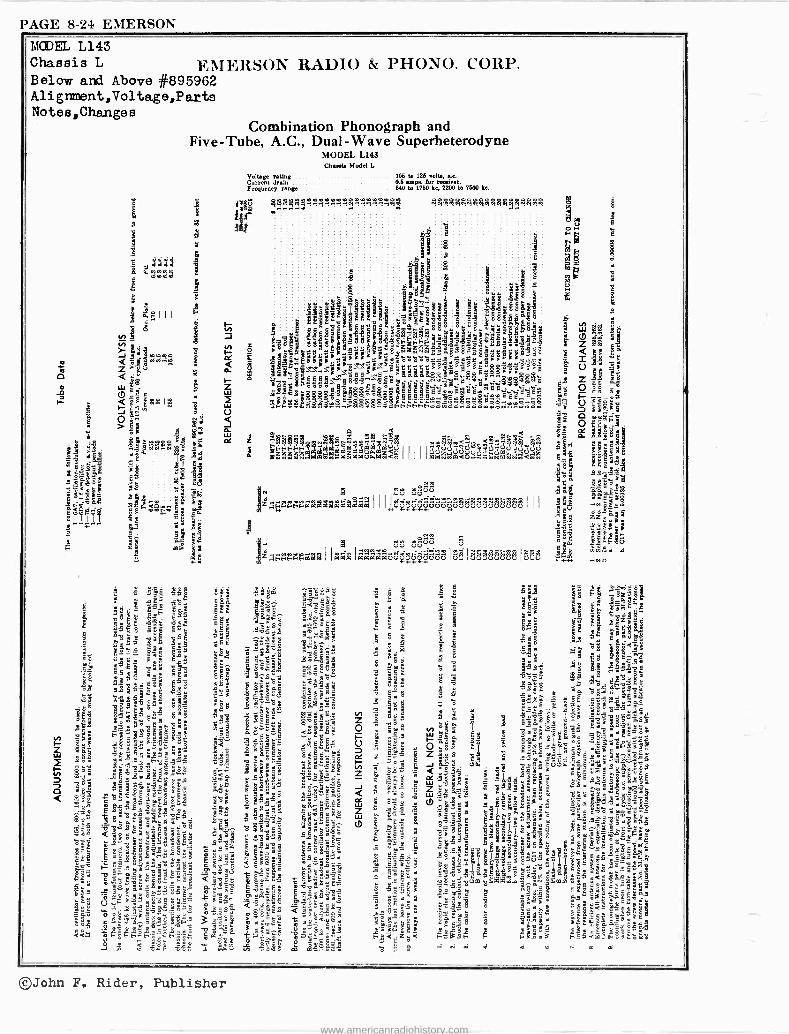
PAGE 8-24 EMERSON
MCDEL L143 Chassis L EMERSON RADIO & PHONO. CORP. Below and Above #895962 Alignment,Voltage,Parts Notes,Changes
Combination Phonograph and Five -Tube, A.C., Dual -Wave Superheterodyne
MODEL L143 Ch..Y Model L
Voltage rating 106 to 126 volt., ac Current drain 0.6 ampo. for receiver.
tFrequency
range 540 to 1750 ke, 2200 to 7500 ke.
'i !M11911.71.1.11.191.111 .14! $4$544444x4$4191181i4
el
3 3 «3` >
á *aa ill gaF es=
5
e III é24 ;$ ÿ s & Iá isxe á
3á céi 9^'y ms
Hi° EA9o'8s .er3
8 8°
ae,Egw gX$
r°`;gggyy AF'Ys °ÉgB 1A6
g«$5egti 3ej gs.«g`°°`
..q . av 95
`9evil': .o ; . S'omB@as:qg<oá
o3_+4.s`s $ < 5; 3
h:é«# m:«ááe3°5 8
j°soBo"=ss'm'9
d
,,FNee
Ñm &
Fa3.,ggop.efigluV3E$s
xSq0G Eg$ihjggeF
Jam7o9
w11 á
i
I
§ . .IuJg
I 11111 f,-95 I . l11E1
: e y[ $pá7°6° C g8e°, g
?: sB°o$$`1eßti ÉÉ .8,.8.68 8E
iJ! °°8°É$sgi9rÁg ggg g-;ó.qE:SSik1:kt 88:8 isr>-
9< E-& Bk'
aááááx>eaá fi p°ê:>'e . ;9-ó^aáÉó~fi"er;$$$$> gg$$é
"aan °gg°° eé 3SéésY é é- ëié$ ç$° ° . ._.5e é.. $ás$ e$fi°e$$$gsd as a$s..,Oee..ss F 4íe$éi: ..> FFhFddYdeddddnddd-...dddd
< eti
F94441 w$$, g
me s" á$ C FFFFF 0t. M OSOÓVCS w Ú (S (ULts CS
á ,:3 aciv á o_ mti ál:ÑÑmázáázzm I I I IieFiriicigówcifflgtiggci$ I I I
eVV p,p 94
.:tiánm i A yyq q q
VjV VVP
t.7ÑggÉgpipiá I ImOC°i IOdp403MOCÚUCVVUVV Igg Ii£'iLiAti Ig3i5
;g5go =«sg Gleiº
go
M7
i ót as
333333hvh5Ó4
3á°é óen yC
: a8'1s" g 8t.fi
e syliÿ ¡LP," '"«5 s1
3°spñ $Ê -.-115s e'gÿág
á SeYa
OA;. sg
Pecgfi.3
m $'8 Lfis - . u `y
38á: "
]°Fqÿy
©John F. Rider, Publisher
www.americanradiohistory.com

EMERSON PAGE 8-25
u
U
EMERSON RADIO & PHONO. CORP.
Voltage rating Power consumption Frequency ranges
M/ /V-^-
vVV y"U e N K
MA,\dp v r á N
ñ V ml ¢ V
Q cD
c
ó 0
co
o_
b0 h
IEtl BIM 'Mn 918
M 0
u o tD
"-11-P.
m"'i
N /-
b A
r
á m u '^ i 11
o
U
aN
4i+
Ñ
IFP
.7 17- 0-ö-Ò --- 4 58 Óà .-4>I U L. 1IP
¢
105-125 volts, 60 cycles, a.c. 130 watts at 117.5 volts. 540 to 1760 kc, 1750 to 6,250 kc and 5.6 to 18.0 megacycles.
ÓY U J J eä
4
.
4._,\;\A.m r
nv O
o I
n n
MODEL X146 Chassis X Schenatic,Voltage
I N I eoc0eD0000 Lei ."4
a 00 I O ,
I I l
18'8 co
ICO000 Nerep0000 CV
C-0010 )00104]00)0)0 Cs'cd.UWODUUfs,.4UU cDtDtDt0cDc0OtDCDtDCDtD
e >
©John F. Rider, Publisher
www.americanradiohistory.com

PAGE 8-26 EMERSON MODEL X146 Chassie X
Align ent,Notes Parts
É
8S c
á ao
1 q . $
1J.:1-721;
$ .É d s @ °i fi «.1Z
º: d. Q O i ó
<5 <a m3á
ó é :E.x' m B dirle "m"$Z y « «
8B 1.55 m «8 1BmEm.S ,e°r.e r«g3 gR o5 ç 1m8-ÿ >4. ` °sr é` s«`3 § ,85 y8e3' .ESB°
pp
._K :óç8¿ö °i 5E55nE "=5°3 6g :E`"9E1« 2 > >.
qaE33°,E$ ó E1°t'.ctg
á Ecai.a«fi"5o
[9 SáBm'«.9ÿcF E v x'S c g$omzm>5
80 -7,e3 g «iP..
h 9
5
B
É
EMERSON RADIO & PHONO. CORP.
=
,p1 Leé4.p:g.m:$ÿ..°.ÿ ÿÿ .mi. 44`tól.ei,.mi,..°i.ÿóÿÿÿÑió Ñ4a."R
L V
e
«rm3o6'wm q - 3
°'..,i ."2:e _ @5
3
«oemo _ m
U 2° -«q 8 0 3m
i3 Fú ° ti á
J°F.É E é..
á
5
3 3 3 3 335s35 i i á'4 x ..e ' .E;.
2
'..a s $
r. qc cE.-ó
ó.aó@ =ó88 c 8 c á.c$ B8c8c".ém" çw8
x"8 S 88 8$8 SS 8 3`.
8t ^` 8` 8 8 8Vç 8ag8°v v" E .. á$g3'a
gám`p"`á:g sx ; pp
' a.ás=8« .,çó S'@áó 66 B 3;6-BBBág\'B«á°'> Ng-.- >xê '6adxo
ii
ç leg' óyó.eEcó°sçrcóE$éávgr
ó°gg _NIoSM$m-ó°8Saæ1gg283
EN FaáWriáúw'Fúñ ÑEÑp G Fd
$ 4 4$44 4a4444441
Z o o- too a m4ci9a9xáa`-o 9 e9z M&42ry.4 n mrywi.g s <
a
gggmaxxxa aklz:x oxox dg o NUw
h w m 43 PA e,«3017:2
a a2 w A go ágoesII 5 588g 3$
' FÑc:FFâwáááááááámááMAáOáAAMci gficiv gógegggg ivg333g3gg
¡V i«[.qM$ gin _ ...74 g ! T3F. _ ,Cm.
á 5E 3x Ea. 3 °m
É 3 y8«E8y ymm 6 °0$'a$ g V
t °_ 6' $ $E. &EcÉ«3 u.KS«
9mg .E« & - _ ó gG@
55 ^ g « .«8 ÿ"°ém k «
g a, Bq pmé $ E y
Ifi
-$,E°c6' q2k$t
SFE q$mc`82 «xEfS ;;;;;`«6ga5
Illi!i
: ,;m':m«ag
ó9Es _á'gw $a-.«á
ó. 13'ó "«3Q« el
xgó: E c xYe w'$ x«. , ti..E
°gx 8
m0.p E
sE5 ag..cm.c
g
E
=,.^ s5«gÉó óE .,m,c"15 9.-m.._y
086 $Scó1.,` ñcmÉEá 9 «R'ú L z" CgK °.. é ám9c aEswm É.éii = a .;$
eiä 3 'm.,mS m8,c
Ev« ÉgcggÉm rf O ó^ xa á em5atl
É >mxgYr i58 ..e. :10i" g3ºw$á Q "-
...c.. é.$3 3 T c
:=F Q5',36x ° g .x
Iw°ó1umÉ Ev,.$E9E ó°'5$.=L
q SE d 3'<E$E m 3º5`:a E. Ñ3
v° Váz awzP;a
II
©John F. Rider, Publisher
www.americanradiohistory.com

EMERSON PAGE 8-27
EMERSON RADIO & PIIONO. CORP.
TRANSFORMER FIELD
BROWN - , e .. BLACK W w GREEN 2 3 - YELLOW
O Q n N á oz rao z O Qr o O r%
Z^laAAw
V V V V 118
h ,900, 000g100,
í--
SPEAKER PLUG LOOKING AT PINS. SEE ENCIRCLED NUMBERS ON SCHEMATIC FOR CONNECTIONS
01 21
--'VVVV i1,* m U
-IIII-Ip,
QQ Q .9E) 0601Z0óötil
In
-- Q991- OOö -1>!Im ñvaJ ía a en 't c
MODELS 5147, 5151 Chassis S
Schematic ,Vol tage Changes
Ol
co ao d wcieir,.-t
U
o éo 1 co
3N I .s
-.-.> o W o á á
i
O0
.= 3 c.) .5 _43 x g á á °
..C:2 á a = 0 C b G wdm'3':,-aó mb
Iá ÿg5ß0g . óóò . ca w mwb á 0 w
zzz t' i: 3I 121 g O I iI áo m
O O Ç 27 2 'Y1 I. F -1- F-
`cri 2''' 0 Q.MriCf10 0 0
GÓ G tx ..h
o co o co o> í7
O.G.Q. .4
©John F. Rider, Publieher
www.americanradiohistory.com

PAGE 8-28 EMERSON
=.9°1 mi .Si .°.`'' ¡°J`1á É`4óá«l é:ó o c L. mi á. ó E
'&m eñ'á ÿ$¡
úb ga $. ° 80
$
A " m gg= s m3m°°g°$ Z66 .« 04 '3- ÿts °.: 3 °>g~'8 i LI mwg ':ló 35 6E ÿgi5E !goEr Liz.
li 'á sgó .9 «osg 3s á ' ç¿
á æ o áb ` EE °8"c3 É ~`.° .9
ii! mÁ 1114 yyg$- 3 8«sb8 _E2VmE,o¡bÿ"o
gogmÉ ¿ Ill'
e&$.30ee 5.°.j.Q5cáE °m a1QE C
igl É°iLá.qFá$«
iv- a9 .9aá«p9é6.F-î
a-" 3.¿, möE«óá$Eag .,gEBe E- me « ; d $3.F0 ;3w z
« F ..« .oF E GE mFaRYm ;;9" ú º oa '-a '-' B " °'
,c " ÉáF9x^tEw ó
8,"°oME wo 0 Sqem sÉ g 'w rJo. ayiá $0E F-
.,óB óÿ g.$mÉ.mECº 7i óyvd 6"SaF3 3
ixz 8se.o,,mo3. 9 ;"Y,xmnm BG F«N«F iFs`a ._ qq á F
g v -803 N $ g& é
.g ómeds« a $m:m SF m9 z _o óóáóóEéÿ'm £ 1g.°m Q 8 b$aáó sF, a
ág8.-Em a'm W ,`m
$ o m`s éssm Om=
sá° E ° v Q a ° ó" £
r.Tâ 3cm° iLS s É gFJrÉF3$F8g 1m«p oa
E ".d Yy .. ó Y ... EF.« «Ém F m g««ám ain
MODELS 8147,5151 Chassis S
Ali griment ,Notes Parts
EMERSON RADIO & PHONO. CORP.
,M $ryÑAaaSme!mgmmm$fflNMl
z o
F
Q
G
fflNha9ti
é
1=7...:' 1 $ ._I 3 º Fxs8888;
«
s
is L
8
I
3EgSE'
ó?sll Q
óom b 3
41 AS j8lvél`88"v" 1ó13 Wa 1. o m_-Bm Lúa W?F
0.y1p «g«mms$$v«azaçB83
d 3b
ÿ"äom$«d g3
'9"B' wú" Êáó 1 5 &
§óúrv 1\_' E i
ie3é3 Y YYY. >g
ear V
i»mlmncçi óoô $ççgâ$EóEág a áámBs gF, môx 9
Q ;ó°`é4E-6-. ro93Cdót
weFFew$Nd$>ide
+ óólge
E EYFá$
j 444.41! Be- ÑaÓeb!g $ggg
e1wmeemY im<b V
i e
áFK VÚ ti Q i Qg Ú Ü
®
Ú
iá áFÉ.FÑázwáz+mdó3icafe ó
!-:ï tl" mg" Y,>'7é
; m z3s °« « ..BmYE° < 3u
g8 ó3 :E . s :«
§ 06 8984Fe cw " "á 9 . g.
agm É
ssaYvGgÉ- 5B m
SÉó'm °FagmgY- ..3d
¡HA MIN V1UJ QNNNNNÑN LOWo%m
MVIWUIVm1V oemmm,mm.w.,
®John F. 'Rider, Publisher
www.americanradiohistory.com

E-TcHls . < V U EMERSON RADIO
I-- J oJ K
N W tm1 O m Y 4.970
o =zv J y ID W OW«
OÚW
Ih oár7
V¢ f V
Q W . 6WQ _/n// i0! r( C KWWZ V LL YyZUO
A F 2 W N U
_ZZW
f1tl M F Z oWOZ Vl O W
U -I hl' o
a ¢ O m o
Fc u
1 6, ---V , ei o G
I- - -o----I -
ti o . ~ J b 1 tQ b
EMERSON PAGE 8-29
Schematic, Triu,mers,Phono Data
O Fo J D AA f <N J i
MODEL AG151 Chassis AG
0,3 4o. * r zn 0 yQ 04 CO iOJ CO ¢N< Y ILI UQOo Z F
J W O 0 O WOooJ
o Z 4W4 a N _O)K>
m O W O F W
zo C O < F r =l tD = O M _ O
Z _ _
Ir W
JO[ 7 F 1 O < W I
WF Y
17 O Z I - W W Z -I-1
1 F COCO
7 I O O 7 7 F z 7 00 y O O
I U
O I W A Z o F 1.,,-Pi{VNO 10.0.
r_
o Il ( Yll,Altll OYO J I I ` 3Vw 111tl0]i W
N W < U U W
IH O W O
<ULL J3 o W
VIm J QN W ZFOo
O <W 11:2123 F Q Y Jo> z
A U 3 W
O. W- a. U JO 7
1 W> _U
Y OFaw F OD: Z ZF ,r,_
U 04 Z^OF WÑFCO F UO oZ
CJ tC > a Z U F
O.
i yyo1N F az.,-.., O o O] W N 7 O
K WONooO W W W W F KZD: G 4 W I N
Ó d ¢ W0
D z NY O - W z OO M10 F JF
U ZÑ »LL
I W J Z 7 Z o 0 ;N 003 Oá H aRNÌ f Z/- ..;L'ä J V W
IF El" WO Wz Wz0 >o U
F >? W O O
ZJwW F F K < W F
J o z W
©John F. Rider, Publisher
www.americanradiohistory.com

PAGE 8-30 EMERSON
EDEL A0151 Chassis AG Alignment,Notes Parta
,,g- s$nq2$wtisx2
ee ~
mti
>9
e
ä
EMERSON RADIO & PHONO. CORP.
.me e22,212:872!1.1eA ' t 888
m9
N
ao
s""w 9
ó
á->°
sa éó B ;
ó
M
z mieeÑ oN e FFtiFFFF FF FFFFd A9em `'váá^a á Ñ z á 14á
á wwmwMei;Io<,óe<imoo .1.12 kág.aaéaa.eCaáá e eáXm w mCVe< .-..,
. ry ry ory ÑR 8 . e$°''.m:o-oinNomJe?R
á
8
8 é
F 8
á
8yy
ié$
@e el t
E v"ó d
jMÿ ú8c°cc 8 V g1lff cF8 ó-° cu,.8R8" 8 85,--F $.
ggyuá gEdz-e' ^ c
oóc au:g rpm:-.,- _A . o:
ocm,óó8 1:'I°>ÿ m>°'F em. â xx._ z«--- Ñxs 3 áñB oiá°zz$ a.ri9 t12
ée
0I1 8 Fdd
< e ee e d z <M" < z<ee w
el z m,.
a i.e
áé
_ E .$gggtD qEx^g c 8 1.1: _EÿE&mY âó
m É ^i 3 xÉ$ mÉÉ"9ó-",``
_
L1 FFd o $$dóC`maÓi4GCä:..g é E
mB « «
EEEE =m. -gvg m
mmw.emm<, áPaP.á kXwwk & j --- c «
2 z m áM 5 ep Li Scióe ZiÇg 8Q1
p}g$
5M yg$sgg ááFÑÑFFÑFÑÑFFmáááMáaaaaaaaaaaaazááá á VVÚÚVSG ÚÚVÚVVÚÚgVeUÜÚ gei3c°iegcmic7c7cici
y-iáxc`«y i ppBEF;'-3 M_fi¿
r [. V V
i$8^sFsGM4tI á
4< ` `é" °4;s.m 2 óÇ"gb3 .5
!389E11LL .
c. -'e stV.c._sO Arel;
ñakO 4ó"y¡m.y
SBá' S0.ppó ..á" g 8 N.°. m9'iarEr9á
L">
.9 ácá .5=
eV«" imE=
1 Z4LLë1sme: C9W8r«11Il«N$
;
$=,
T5`
3
3:á
3AEws r
ir mS°m'âorTsú 65 > c='44 r o.firá^Ém..ó gAoc8 y1./.6
«mmsxyiá9áuaE.9i" i G L S B m ó Ó
g$ V
i. e$ y o>om s_
r,rfa,m;.aé - i '- E 49^m .98"
ó.$é"Çm°o..=ay -.R?y áémg988` gs;gs â
5s< I2ÿÿÿÉ
i É$B i5
;i
E8
Sc 7
tgi ..i
má.
m9Gg
$
.8fiiáóéááEEE ;ÿFmó5 ó'°EßAficó .
<~dAóé_pǺ
c,
si;O"°Oáii
l
9
á.vÑw«'15omór°°ó.rgºEa°.
'"E«'BFWS8`rou.É°c
rßFm'..5°8CeiQ0
._,-?m=,
-ñ=,
iitiL
O,w3e-m>°Eá9
ii! i
4«.
v:>ûca
ç.< 'çEFóm°
_87ysc459,
o.¡oEs°...^e
E y y
I/1:m
8
omVN
mElaE
Em.ÌÌ1Y
Y
I_¡tigÿ $Ég
oEa 1 ta
E4
E.11
9
mdcg$sc E-4.
g^
411km;$6`lEÿ
:Ä
g = mo1Ec8r~e:s
F.8$« îA=m-mmEP`=
<ó 3ïa«ms'&
7
ÿem1" u
EamÓá8élEil'óm9<Z.'J«
ffi
8, g o
3 -3
©John F. Rider, Publisher
www.americanradiohistory.com

EMERSON PAGE H -:ii
Coa. C.)
III,
i\AAV ta
sa
EMERSON RADI() & YH()\(). CORP.
TRANSFORMER
BROWN
GREEN-
FIELD
YELLOW
BLACK
SPEAKER PLUG LOOKING AT PINS. SEE ENCIRCLED NUMBERS ON SCHEMATIC FOR CONNECTIONS
4
I=1
U
178
sa
r-
Q
hl
cv W U^ ce
wQ.--_q11' el)41P-
I
u
lä
NQQQQ. 141
1,
Ola
U
III U U Q N vYac
I. N
II.
U
Fop w ec.
MCDELS R152,R153,R156 R158
Chassis R
Schematic ,Voltage
II
III
HF- ox J( áJ
U
I.
cena
NNND d cocococD ', r. r, a
m .o Eh
'<cc ov
©John F. Rider, Publisher
www.americanradiohistory.com

PAGE 8-32 EMERSON
MODELS R152,R153 R156,R158 EMERSON RADIO & PHONO. CORP.
Chassis R
Ali gnanent, Change s Note s,i^y srt8 O O O pp O O O p O O O p O O O O b O N O b O iwC íod707N.yM ti.4.8.-..Hr4ryy.y NNNNNNNO daOchMO tV CV ?C..¡.O..O O
, . 3j;
li$sa
>.
.3 m
2
w 4t o
t :4 w 00o w
gg"óó."104ÿ g
.9 0 9'F m ' c°.e v s ¡ w
FÓ G
á
z
E.. ii a o c c '.vW°a\\3mxmm>&^>>oñ0.m R` ºm ÿx >mo.mó4EE\\,ficE\Bó.'Ñ Es .°u,dm , a7e°á
M,".óóám,çoosgg\wcgmd`. g.: Émmó mmm 8°'E=ii ¿.ñ.wSoáoESe$§úó.é' ° e EE}ç°¿çbEE°e.dup:csa$g o°° m b g o ó É° E o ó 8 b ó ó ó ^' S
v v m c P m; ó m.S >-m ° baabbodo °Esóo..w'CB'GG'î. ó0 ó0 0ó....:a...00C..Q .,FFaMbem>bNb.+nNFFFFFdódddddLiiomßFWCIÔ..ß.CiUWGGR1Pw1
8
2e23 S g o
..se o;y"fi $$áä$e$ßw°xó9rgBámaÓLRf EY° ,, mqge a°EW°°°p
p°
; U
toppm0!
M e U Y+ iÇ M b > F
0.FgwYmáÑ'~ .mbáV'rWÓÓÓ° EY YOmCg^
Z C 4gr NNdN b Cti ÑÑd F° MI PNN NNbb NN N
óewááááázwáázáá W M M M M i.Ì CO %. W Oi S4 p4 OJ OJ t0 O!
re < w pp'ern ,°°Md-° . Ñ°qq'''222ppç`ygg'¡(
V.n V N4
UVJVJ VJgÄÁ °0.l Ñl.lR/¡iISÑ ÑÑ N 4 iieiír.%4daMMM VaJÑMMYSM oa00> W g éeÑ M
U y " " 8 B pp.
$ Ú V Ú V
r .-INL°àlb.n mti ti »m .O-1.i..ti áFFFFFaaáaáaáaaioUcUVUvoovo
mm9C
mYá m?s 9..°,°vi
amfi,
tgeF " óü '2. E « m
u N ro p C
sms gYm5. mg>, 'mxw Z2-02 emÉ
Lfi
°c"wa C+r7e a.;
3&,b,á 0
«z-Á o0.wá
rgúti
m 5
rn °JEáS Q Ell 7A
mc á w ioy
mdm ; a9w
ég., me .. c «; o
C g'^L
«sC. m
m« E ° t7, 4.3
. Y á á > gm°,.
Z11, m1J
wvv E
tiFw".T1 m ti
m
d asÑw '^ Y E'ag
9=GF
5á m° b
yy 9
s!1.213 5dé ú1 «
1 o r.
aEóa
pma9 v` dL u ó9 w F yA áE>i
S óF o $
o=d É
ECCo, c
m Efi8E t 5.;4. ú 5vs ó äá m óó
il a S
di
e« re w° áw
FE
4 _ F -14 ' , ¿ ^°..U.
T
2.1' Ó '° .d C ?L
°e 3 I
w.L,
e m 6
2,
i 6 .bqq
v 9 D
^ °
Ps z m.° q 2«
Etiÿ Ell
i wF Eu "mel,^.. .211- , 5 0 mc
ú
m. 422 F. b F> °ú w _ ¢
w _5
fis E
G .9
ä W° rm. «w i. M
oE m ...
yC
D00 Q my". m pp ;.l á, 5S ° m
°.a ä, ç 3 d a â°
:ê=° E
. '> m w ° m°...
C~ O V
'-''
9= Ó
ixÉ d
d1 m Ó ' Y w ° m Ú
.0 ÉY av .21 Y L w9 ó "m úm ç°I d ° Q
é' á d E Kg -r .1,"l,i
/m v 5V w4éoi. â,c0 °^a"i °á E6 ee mY9 d ó ö atW mw E" .9 Sm>>
",x,s t`E mg ºEmm á ;.fi' . 3i Y . g ;w"xx W
áE« ó E e m ;Ts
« ° wF'GHF '. 01 Oi V b .L
E
c
e
ë ro
-O Ó
O S
©John F. Rider, Publisher
www.americanradiohistory.com
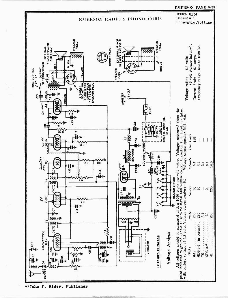
EMERSON rAc.r. 8-33
Lai
-J
O W
o6tt8or U 4 -J
CD
1/40 r- 3 O
O -J J W r
Il?RSON RADIO & PII ONO. C'OKI'.
ZIa
iNw 1
1- rrv\R- N
COMM
1`0- - iD,; r
co
ti 0 c0
xo ( J Z_ W
"- -JO 47 z< Km W I x<L W W
d H W Y U.
> eJ
N)d
IF> sa
I
1
h
ca 8ö
; á U
9 a
U
HM` r Zy I'' Hlh -oiHn'
(Nj U Hu.º0Q ,1/4/1/4/1/4/1/4
ia ZW Q 0 Q a
. HI,, NI, c.,
U p
J
h ce.00
M/bWW
W N W
I
CC W O Na < W W W G. h
11111'
N U
J 2 m
PODII, U154 Chassis U
Schematic ,Voltage
O)
O r .4. w eyi M m V
ÿcoocoD I
O O N CO
oof!on GYJ MC> C1 M CV GV 7 GV
©John F. Rider, Publisher
www.americanradiohistory.com

PAGE 8-34 EMERSON
MODEL U154 Chassis U Alignment,Notes Parte
s
EMERSON RADIO & PHONO. CORP.
IiI 4S$33 dms$3m .] . ..s p 4 1
:.. :$$g 7E. d 'C4TCGCCNw @
.xa 99585w8. 338YQé3`.E3.
y c °x ° . e. 33«.máº'ap,aP o t«°333333i 33Mam4wm
... .:.G ,wacic3á ám3_\'\mroáéáóó -g"3--aa aa';Ozt p $,cdó¿rQççáç$EgÓÓc$Naa .Na`ue.aé,áee$`ÿ°cë5óEti°g?p8$8OpópgE É
P.ÓÑÑa.°...¡dNaaÑÑ.7Ñ.+,OiOb01:.d F
tpO .Nppp
pNpw t-LW N ryeOe..p
F. .MP^Ñp NNE ÑNt.ON ° á7á$E,F..
Ya4Pe záaeC> d .co'c+m.. cnÓá'íI',c`n.a>.o a7M.AeiDe.7AdwoeM
á w
p d
rt
my
o sE >e
$ 4
6 : : ,,
yqd e,; :F¡e¡ eCG $ óidF ó8m;ó
$8ÿ.8r.cU. 8d888.....4 - d3E31 10-1_4$ . . . 3 á G0yedJ 3 . ..Q. C av- 7 O d : . d d 8EdP.8º°.3?ecaéxe aa-> >. 3 S _é QQ«mm;;QQ iÓam` ó 1' >. >ç>>°ÑáÉÉm°°-°cmÁREx ..8;8QEg $ww$3gr2cea
EVy w Ñ.;o-;e` .ddEEe $$w Ñ `uÑmÑM`+C'Em^eK$..ffG,,E,dç¡ 552
gg pi0700. ó o Eo bUoB..$e 7S d dwdC1 dddddmmioe.FmqZF>F
ti y UÚ
aÚ ÚÚU VU Ú
H=F1123 oéMááwááááóegzád geeig gcigä
w.y, ú« m we omdN.E
.e°° mE~É jg.E d_c.eE 33
ppM7ppQMOsM 12
E..°d
> .,
^óúK oeE
óQ E'w « ÓC+Jq G O pn
Le «
g o
a ~~dal 2 eE°>dâ mg eEdE'â gE «r& á m .
'- a,E Ebçça IM
WW1'° S 5J«a".y¿3 M
3 d tt
p« O$Ir d>00e d'.+ ;V
E82 óó.c3Om
UM ít..
W
d 4XO
>me « Bm ( Z-8. m« yÿ«ám 73 .3c ód °~] F3ÿ UtOL^3
rm rÉ=8 o ém óáóE
eXáf $-d 4.d.egE
9 a' d« d' yy".s c«-mâs4d $eea-. q .j ;p;w m
çNçddbd+%« 25«á«a$.... .p.egqd
._ OJC e0Cd
mâw$wd$ÿa C5' «d a 3 c w e. M Qpj i.
cC''ta
.s«4eqáXá gá[8E
Mar7c-Se
, CvxóS a>3d120«.
5du_EE >ai
YL`$Gv°.gaeia' d3+'m7« s..+«.$ 4w$^ w .. 34b. LEOde
G Od7p s ̂ÿ+3+ p S?
40caa. ;d d 4
mmx«ym §e.»_ . e°
a a w3 a
Sa.é,cJ.a-;cacF
sda ÿ4II e$yEaEE ed c«REoEo. m a»
k
lg;E1" á ú.°., ÿ.°c ma.°..
Ú
d
8
3
2 ë x E
3 S w dd
L S eMee2si if
UpUWUÚCU r%! tC%JaCÖS>y
áS e. W m..OÓai000í' vi
57.3>hu
A .+
.+ áa
óâ 4 ú d :.$ $ c md 2,. d 2D
2 .e O a a e $ ^ t.
+? ; 3
.S a 4a ; M3 d á e$ ^ 9 g-
S 234 á 8 d e
a$ p se,..
B 8 G m 3 3 « 9 E E 'NI 1 d;B^3 a;2 ;? 472 c 8 ' -°
M. 13 a..adE "á1 '2wB ii
pc E
'-ia1:;1111epM p pm
d ^e ei
3y
04 C e7 «Oy.i.°OY.$° ma ri a á3 EgT_a a `c óó.°3ó _dE $e`i vo I 3F aú3°`Q $,ó,idc 3 ó a4i
áá e ."O = éá.d 1;â23.Q4$._ d' e 4.Óg B. a:$eiee.+e°E++,,?'gEr,
á d3 m3 s ó°e°.«'$f,31.-.....e3 ` amae ae.ad4 dé ^33.bcdu3óácc
e rsg. O d o.+m c3 «gq..$ "« e.,iJe,ó
m sw 3b; L..23..:2.`:,121 83e $d V
Bd °,â.-m 3 ai úmd $ !ä « 2. 2.35.1 ß r sc
z?J WWdrSFFg{ÁFaimUFUSai« > aá 3s:SE
a mi .ó 3 1.B
$ $ Ú
©John F. Rider, Publisher
www.americanradiohistory.com

EMERSON RADIO & PHONO. CORP.
EMERSON PAGE 8-35
MODEL AIi162 Chassis AH Schematic, Changes Parts
In receivers bearing serial numbers below 1, 102, 142, C11 was an .01 mf, 400 volt tubular condenser. In receivers bearing serial numbers below 1, 149, 148, C22 was connected from plate to B plus.
00000000000010oow1[nowlnool0 1pCqNNCVCVNu?NNO?u?.11c?N.-/.-0.i00.1./M n 0 U 4 .r3 .d 4 Z J F Y0 a W ,C oCrz E c.
óLa
= Úz00 E Á V, W yyONNQ 'Cl
.D
*ice 10c0t0OONM I-O CV N N CO UUUUUUUUUUUUU
q q
g E M ÿ .-1 .Ñá o d o OOtCC.1 Ó ..
C fL+' F Y O~010 up CO 00v áv M ; <v3yzDD00 03
b 1b W Gw-. W(~ MMMMeN..1NNNCVí01qí00NNMN
.M1 IM(7
éo" d a ,Q `F.C'ixWWaѺ:pat,ÑáC0.'P.áU1nU+ I C: .. c E áa CL ae.>'vD13Na,...,x.mmaC:tkmM.lñ n. I ISC
q m ... ÿ p.-+ .---. o 0. b .G 2i Ñ
F4' . .1 1n OO H
n1O NU UU
r-1Ñ+ O.+NMüspÑ c=oi.r 'dACD1naU H .-.NMa.-+NMe10<Dt-oórn r.i..i.1còUUtoUU 1QDCONNM * FFFFW'A:CY,A:A;p:U;fY,CtCL'tl:CLCY.UUr 0i -1-U
s. qô ..,,bgggqqmq oo? u a+q 0O0Óq p q.0.0O Glt.aO ..wO.a.O ON OF.ir syq o` r
.C2 ?..2 u~m vwdt dn.uudao o,03 VNVV+.aya .uÿÿ.~./Vÿq ?0.xro33ÿ3w3?;.rm q m 33..r..nyw qw1cDn 3 ., 3+"-. ,y o 0
móvd33ÿ3""3-00C3 q q a+ a O
. VE Ó Ó.a Opw bb o x q
ááa áóocori° óoccsqä8 ÄÂ00 00 O Gi O m00 O~ N
á oo a ov qwó 3ó.E FFAA.yM .MCNN.rN1n.rA.FóF
©John F. Rider, Publisher
www.americanradiohistory.com

PAGE 8-36 EMERSON
MODEL AH162 Chassis AH Voltage ,Alignment Notes
EMERSON RADIO & PHONO. CORP.
VOLTAGE ANALYSIS Readings should be taken with a 1000 ohms -per -volt meter. Voltages listed below are from point indicated to ground
(chassis) with the volume control turned on full and no signal. Line voltage for these readings was 117.5 volts, 60
cycles, a.c. Tube Plate Screen Cathode Ose. Plate Fil. 6A7 100 55 2.0 77 6.3 6D6 100 100 3.3 - 6.3 6Q7G 38 - 1.0 - 6.3 25L6 96 103 6.7 - 26.0
Voltage at 25Z5 cathode -130 volts. Voltage across speaker field -28 volts. Voltage drop across ballast tube (pins Nos. 3, 7)-49 volts. Voltage drop across each pilot light section (pins Nos. 2, 8 and Nos. 8, 7)-4 volts
1. Íf replacements are made or the wiring disturbed in the r -f portion of the circuit, the receiver should be carefully re -aligned.
2. One side of the power line is directly grounded to the chassis base. Under no circumstances, therefore, should a ground wire be permitted to come in contact with any metal part of the receiver.
3. The filament dropping resistor (R13 on schematic) is in a.special metal tube at the rear of the chassis. This tube will become quite hot under normal operating conditions. For voltage drop specifications, see below.
4. When operating the receiver on d.c. it may be necessary to reverse the line plug to obtain the correct polarity. 5. The color coding of the i -f transformer leads is as follows:
Grid-green Plate-blue Grid return-black B plus-red
6. An efficient antenna system is necessary to enable a full realization of the merits of the receiver. For reduction of noise and achievement of high efficiency on all frequency ranges the Emerson All -Wave High -Fidelity Antenna, Model W-78, and tiffe Emerson All -Wave Antenna System, Model W-89, are recommended. Instructions for the installation of these antennas are supplied with each kit.
In congested areas where the installation of a large antenna is not desirable we recommend the use of the Emerson Flexible Mast Antenna, Model W-82. Instructions for the installation of this compact and efficient antenna are supplied with each kit.
7. The wave -trap in the receiver has been adjusted for maximum signal rejection at 456 kc. If, however, persistent in- terference is experienced from some particular telegraphic station, readjust the wave -trap trimmer until the response from the interfering station is at a minimum.
An oscillator with frequencies of 456, 600, 1600 and 6,000 kc should be used. An output meter should be used across the voice coil or output transformer for observing maximum response. If the circuit is at all disturbed, both the broadcast and short-wave bands must be realigned. The set's oscillator is higher in frequency than the signal, so images should be observed on the low frequency side
of the signals. Always choose the minimum capacity peak on oscillator trimmers and maximum capacity peaks on antenna trim-
mers. The last motion in adjusting trimmers should always be a tightening one, not a loosening one. Never leave a trimmer with the outside plate so loose that there is no tension on the screw. Either bend the plate
up or remove the screw entirely. Always use as weak a test signal as possible during alignment. Use a standard dummy antenna for aligning either of the bands. A .0002 mf condenser may be used for the broad-
cast band dummy antenna and a 400 ohm non -inductive resistor for the short-wave dummy antenna.
Location of Coils and Trimmer Adjustments
The two i -f transformers are located on top of the chassis deck. The second i -f is the one directly behind the variable condenser. The four trimmers, two for each transformer, are accessible through holes in the tops of the cans.
The adjustable padding condenser for the broadcast band is mounted underneath the chassis (in the corner near the 6A7 tube) with the screw adjustment accessible through a hole in the top of the chassis.
The antenna coils for the broadcast and short-wave bands and the 456 kc wave trap are wound on one form and mounted underneath the chassis deck directly behind the adjustable padding condenser. The trimmers for these coils are accessible through holes in the top of the chassis. The trimmer nearest the front of the chassis is the short-wave an- tenna trimmer. The central trimmer is the broadcast antenna trimmer. The trimmer nearest the rear of the chassis is
the 456 kc wave trap. The oscillator coils for the broadcast and short-wave bands are wound on one form and mounted underneath the
chassis deck near the variable condenser. The trimmers for these coils are accessible through holes in the top of the chas- sis. The trimmer nearest the front of the chassis is for the short-wave oscillator coil and the trimmer farthest from the front is for the broadcast oscillator coil.
l -f and Wave -trap Alignment Rotate the wave -band switch to the broadcast (clockwise) position. Set the variable condenser at the minimum
capacity position and feed 456 kc, through a 0.02 mf paper condenser, to the grid cap of the 6A7 tube (do not remove the grid clip from the tube). Adjust the four i -f trimmers for maximum response. Feed 456 kc to the antenna through a standard dummy antenna and adjust the wave -trap trimmer for minimum response. (See General Notes.)
Short -Wave Alignment (Alignment of the short-wave band should precede broadcast alignment)
Rotate the wave -band switch to the short-wave (counter -clockwise) position, and set the dial pointer exactly at t> megacycles. Feed 6,000 kc to the antenna and adjust the short-wave oscillator trimmer for maximum response, and then adjust the short-wave antenna trimmer for maximum response. Be very careful to choose the minimum capacity peak on the oscillator trimmer.
Broadcast Alignment Rotate the wave -band switch to the broadcast position (clockwise) and set the dial pointer at 60. Feed 600 kc through
a standard dummy antenna. Adjust the broadcast series padding condenser for maximum response. Move pointer to 160,
feed 1600 kc and adjust the broadcast oscillator trimmer for maximum response and then adjust the broadcast antenna trimmer for maximum response. Return pointer to 60, feed 600 kc and readjust the series padding condenser rocking the variable condenser for maximum response.
©John F. Rider, Publisher
www.americanradiohistory.com

EMERSON l'AGH. 8-137
1
I, MI fn U IBM
A
EM H,RSO\ 1tA1)IO & PIIO\ O. CORP.
tn
M
o
ai.A.A/ild' r-
r
IY9Vi F 0
m
R 5
iIh
ip
V IN I'S
000 )
I I
ci Y a Ow F
"
n
o U
M
/MODEL AE163 Chassis AE Schematic ,Changes Part s
000000000,e000w,Doo,n N N N N N O) O N 00 '1 'I .-1 .-I 0 0.-i r-1 o u:i a
d VJ
O O
á e ai : : : ú Z oF.Fo CO
y,e,mce/JrenrJOJÇ. NoG CGqWcei Á FF.Na)ala)C1.
w+>'d'D'tiv . ÿ - W 0 0 0 0 0.>, p, ... V V U V^O r
cy
p ca Ca CQ t3 b Ú Noiaoaa aJF.,D F' )AAAA á alN m a O O a 0 4 .-.>i>Y
00
d m-. a P 003 A4 G:a
O - y- - N> w W W W a> Ca CS
OOOOO y y v a a G ',-NNNd, C aJ > ñ> 7 7 g a! CJ 4+ W W -1 .a.b0 V ... .
GL GL VJ'CJ'..
E cEEE Ewb.4, ñ o`ov d 2.2
0 O ú O... EFóoóóóN,nCLAAAA.....AUAW
Ñ G7r-IW .-.-IMOO>r-iMC Na <NO,O ,OM,ANCm,0,0,0 aN NCVN,ObOc.Mc`?VlMC7M
CJÚV) ÑNÑNÑNÑÑNÑ Wf.ÚU-1cioU?Cmcr.mmoUmm
UV U Ú 0 oö.-1me}O U -. .-. -1 .-1 N N 11
W Oa
.-OI .. ,Of> .O. .O..O-1 .-O.1 .-O. a0
.O. .O. .O1 .O.1 OOO O COoo V N N 4., a.4 .... . . . .
co a a Fr o ñ
F.
o
FO.
F. o Ñ
Na
Fa 'O b b M O a
b ó F. ..> mb O ÿ ÿ C ÿ O. VJ
O
Ñrn NmBa`iF°'o
o Ñ
'U d
V
m : d VJ F. VJ
b q 'v b FO. FOib d 17
ir "2'F. C. a)
1~ áF,APCOOÓOOJcoJK ú a Ó Ó o O 7 O.a C ÿ C F. O F, y
3A'á3ñó3mú3w°F..ñ
. .D tl W dVV. .yFF.VA- y
emwYÿ, ,3n">ôi3~V03yedy,>
y .,.w b23 >ú ú +' ai o > e ca
m8 EE^ó óoW
C u m.ope,r ó voo qow . ar
.EX.-. oÓó o ? oóó e óN có O,q,Ìj ÑoO ôñó. 3óaó- <rc0-o,nx,No-.0., óóóF
O C. z ooaao O,O oa cmaov oo,o,nooc- rna> mm rnd,e,N
1,y Nc]mNN2aN4aNNNMNOO EE+E-,E.f ¡¡x p;p C3 WW.fxNUaNUaN> UWxUU
C; mccomm`NmxNm^.4xmmom7. m U'
î [- o4,1,l N a ..0
P3 U U U ... NC+Jd'.-.NmC,f]cC (Y_ 0,.-- ^
-CO ' FFFFfxtYfxxC.1L'C44fXc#L'ULÚC.i
©John F. Rider, Publisher
www.americanradiohistory.com

PAGE 8-38 t l 3~.D i1+.HSON
MODEL AE163 Chassie AE Voltage,Alignment Notes
EMERSO\ RADIO & PILO\O. CORP.
GENERAL NOTES
1. If replacements are made or the wiring distributed in the r -f section of the circuit, the receiver should be carefully re -aligned.
2. One side of the power line is directly grounded to the chassis base. Under no circumstances, therefore, should a
ground wire be permitted to come in contact with any metal part of the receiver.
3. The filament dropping resistor (R12-see schematic) is in a special metal tube at back of the chassis. This tube will, therefore, become quite hot under normal operating conditions. For voltage drop see below.
4. When operating the receiver on d.c. it may be necessary to reverse the line plug for correct polarity.
5. The color coding of the i -f transformer leads is as follows: Grid-green Plate-blue Grid return-black B plus-red
Tube Data
The tube complement is as follows: 1-6A7 pentagrid oscillator -modulator. 1-6D6 first i -f amplifier. 1-6Q7G diode detector, audio amplifier, automatic volume control. 1-25L6 pentode power output. 1-25Z5 dual half -wave rectifier. 1-3CR-241 ballast tube.
VOLTAGE ANALYSIS
Readings should be taken with a 1000 ohms -per -volt meter. Voltages listed below are from point indicated to ground
(chassis) with the volume control turned on full and no signal. Line voltage for these readings was 117.5 volts, 60
cycles, a.c. Tube Plate Screen Osc. Plate Cathode Fil. 6A7 100 50 100 2.4 6.3
6D6 100 100 - 3.8 6.3
6Q7G 45 - 1.1 6.3
25L6 96 100 6.4 26.0
Voltage across speaker field -30 volts. Overall voltage drop across ballast tube, (See R12, schematic) -49 volts at .3 amps. Voltage drop across the pilot light section of ballast tube -4 volts, a.c.
ADJUSTMENTS
An oscillator with frequencies of 456 kc and 1500 kc should be used.
An output meter should be used across the voice coil or output transformer for observing maximum response.
Always use as weak a test signal as possible.
Location of I -f Transformers and Trimmers
The first i -f transformer, part number 4ET-350, is in an oblong coil can located on the top of the chassis directly behind the 6A7 tube. The two trimmers for this i -f are accessible through holes in the top of the coil can.
The second i -f transformer, part number 4ET-351 is in an oblong coil can located on top of the chassis directly behind the speaker. The two trimmers for this i -f are accessible through holes in the top of the coil can.
The oscillator and antenna trimmers are located on the variable condenser. The oscillator trimmer is on the rear section of the variable condenser and the antenna trimmer is on the front section of the variable condenser.
Alignment Procedure
1. Rotate the variable condenser to the minimum capacity position.
2. Feed 456 kc to the grid cap of the 6A7 tube, through a .02 mf paper condenser.
3. Adjust the i -f trimmers, repeating for maximum response.
4. Set the dial pointer to 1500 and feed 1500 kc to the antenna lead through a standard dummy antenna. (A .0001
mf mica condenser may be used as a substitute.)
5. Adjust the oscillator trimmer (on rear section of variable condenser) for maximum response.
6. Adjust the antenna trimmer (on front section of variable condenser) for maximum response.
©John F. Rider, Publisher
www.americanradiohistory.com

EMERSON PAGE 8-39
D '1.11- CO
Q
EMERSON RAll1O & PIIO\O. CORP.
cu2z,7 1' tGd ZO00 '
g (79000 ÓOS' a
r 000 ó.s-Z-
'U'--1
-
__^^II r---. fw, yoóaGd. rv00opo_g-
e
^ AV
1
oi 111
111 J
L
L_ _
T
51 st-
M
k
IF.)12.2_7175 o
4-1" n
I
rl 1
U
X0001
Co
co o
co
N N
U OW I z O J U Q
MODEL AL164 Chassis AL Schematic ,Vol tage
'oo (o
O O
t.22 .8' vb N
c0 ~ o~
a rj w00000
;.á rç, L ei cc!, em Ñ
M4) Wó
Fr n- ,V
w w
ay o ro
Áw
32 d
Ñ p MeoNb tu)w 34, eicg.cd eF
U
N.; 7,j 3c weo E'
.y-. O o c
c á`ö
E° W O ç O ° O d ow
G
at~ a.+O ä; V V
ew
v
V LO O O ti
OOMN e oO.ern
oi
>
u2.2.. h Ot°tOÑ (O m V V NmcO0 N M p Ó a+V Mir id c0 ty'o
m N aw N a
U FO "V O O Q o
sW î CO oz U Q
z
z 3 O _ N
I U
N
z o (N o a
z º N O a
©John F. Rider, Publisher
www.americanradiohistory.com

PAGE 8-40 EMERSON
MODEL AL164 Chassis AL Notes,Alignment
EMERSON RADIO & PHONO. CORP.
Model AL -I64 CHASSIS MODEL AL
Voltage rating 105 to 125 volts a.c. or d.c.
Power consumption 43 watts for receiver and 26 watts for motor
Frequency range 540 to 1580 kc (See paragraph 11 in General Notes below).
GENERAL NOTES 1. If replacements are made or the wiring disturbed in the r -f portion of the circuit, the receiver should be carefully
re -aligned. 2. One side of the power line is directly grounded to the chassis base. Under no circumstances, therefore, should a
ground wire be permitted to come in contact with any metal part of the receiver. 3. The filament dropping resistor (R12 on schematic) is in a special metal tube at the rear of the chassis. This tube
will become quite hot under normal operating conditions. For voltage drop specifications, see below.
4. When operating the receiver on d.c. it may be necessary to reverse the line plug to obtain the correct polarity. 5. The two i -f transformers are held to the chassis by snap -on fasteners. To remove an i -f, unsolder its leads under
the chassis, pinch together the prongs of the snap -on fastener and lift the i -f can from the chassis. 6. The color coding of the i -f transformer leads is as follows:
Grid-green Plate-blue Grid return-black B plus-red
7. The receiver is shipped with an attached antenna wire. In some locations near powerful local stations the addition of a very large antenna may be detrimental to reception, because of the resulting interference. The Emerson Flexible Mast Antenna, Model W-82, has been especially designed for Emerson receivers, featuring compactness and porta- bility while at the same time retaining a high efficiency from the standpoint of performance. Since it functions as an outside antenna the Flexible Mast will substantially improve the receiver performance. Where the Flexible Mast is installed permanently, it is urgently recommended that the receiver antenna wire be cut. Leave just enough of this wire to reach from the receiver to the window strip connector. Instructions for the installation of this compact and efficient outside antenna are supplied with each kit.
8. The wave -trap in the receiver has been adjusted for maximum signal rejection at 456 kc. If, however, persistent in- terference is experienced from some particular telegraphic station, readjust the wave -trap trimmer until the response from the interfering station is at a minimum.
9. The phonograph motor has been adjusted at the factory, to turn at a speed of 78 r.p.m. The speed may be checked by counting the turns per minute or by using a stroboscope disc and a neon light (the stroboscope method will only work when the neon bulb is lighted from a 60 cycle a.c. supply).
10. An a.c.-d.c. switch is provided to switch the motor for a.c. or d.c. power supply. It is important that this switch be in the proper position for the power supply available.
11. The receiver in this combination is designed to cover two frequency ranges, but since it is represented as a single band receiver only, the short-wave band, although available, may be ignored.
ADJUSTMENTS
An oscinator with frequencies of 456, 600 and 1400 kc should be used. An output meter should be used across the voice coil or output transformer for observing
The set's oscillator is higher in frequency than the signal, so images should be observed on
of the signals. The last motion in adjusting trimmers should always be a tightening one, not a loosening o
Never leave a trimmer with the outside plate so loose that there is no tension on the screw. up or remove the screw entirely.
Always use as weak a test signal as possible during alignment. Use a .0001 mf mica condenser as a dummy antenna during alignment.
maximum response. the low frequency side
ne. Either bend the plate
Location of Coils and Trimmer Adjustments
The two i -f transformers are in oblong coil cans located on top of the chassis deck. The first i -f transformer is the
one behind the variable condenser. The trimmers for these transformers are accessible through holes in the tops of the
cans. The 456 kc wave -trap is mounted on the right side of the front chassis wall. Its trimmer is accessible at the bottom
of the chassis. The antenna coils for the broadcast and police bands are wound on one form and are mounted underneath the chas-
sis deck below the variable condenser. The oscillator coils for the broadcast and police bands are wound on one form and are mounted on the rear wall
of the chassis deck near the variable condenser. The trimmers for the broadcast antenna and oscillator coils are located on the variable condenser. The trimmer on
the front section is for the antenna coil.
I -f Transformer and Wave -Trap Alignment
Turn the switch clockwise to the broadcast position and rotate the variable condenser to the minimum capacity position. Feed 456 kc to the grid cap of the 6A7 tube and adjust the four i -f trimmers for maximum response. Feed 456 kc to the antenna and adjust the wave -trap trimmer for minimum response.
R -f Alignment With the wave -band switch in the broadcast position, clockwise, set the dial pointer at 140. Feed 1400 kc through a
.0001 mf condenser to the antenna lead and adjust first the oscillator trimmer on rear section of variable condenser) then the antenna trimmer (on front section of variable condenser) for maximum response. The police band is self - tracking and does not require any adjustment.
©John F. Rider, Publisher
www.americanradiohistory.com

EMERSON PAGE 8-41 MODELS AT170,AT172
AT181 Chassis AT
O
fl J
The tube complement is as follows: á ` Q U î
1-6A7, pentagrid oscillator -modulator. U El 1-6D6, i -f amplifier. 1-76. diode detector and a.v.c. Voltage rating 105-125 volts, 60
(behind second i -f transformer). Power consumption 55 watts 1-76, audio amplifier. Frequency ranges ... .. 540 to 1730 kc 1-41, pentode power output. PRODUCTION CHANGES 1-80, full -wave rectifier.
Model AR -174 receivers differ from the schematic diagram as follows: a. C27 is a 12 mf, 450 volt dry electrolytic condenser, part no. MC -314. b. C28 is a 24 mf, 400 volt dry electrolytic condenser, part no. 3ZC-341. c. A .25 mf, 200 volt condenser is connected from the screen -grid of the 6D6 i -f amplifier to ground. In receivers bearing serial numbers below 1,200,100:
a. Cl and C2 was a two -gang variable condenser, part no. 4HC-343B and the dial face used with this condenser was part no. 4RZ-580.
EMERSON RADIO & PHONO. CORP, MODELS AR171,AR173
AR174,AR176 AR180,AR185
Chassis AR Schematic,Changes Voltage
C o = O J c- W
2 O
Î am .3 o _ e
am ,v ' f j r . id g0q
N a ...v. ! _ .,.r7 y .0 4-2 N
ME a
QW C. C)GCICSCi
1>al Ó J M ° l3 . t{i Ci :0 Q7 j
1 - xi go CO MMMMM <° CC Cp CÓ cÇ O Ó ÿ
F.
DA 0 4 < W 0 . W v
wo O H O áó ó . < .-g yPá - p . F.
A. ` o Z c d d u oOi A e C a0 LLO C rp .ñ ..N o000o áN
al a WAD ^ N
V m ß'i
d e- tn m a doF » ó4 b 3 s.
ti . -J +-`y -;g x Q Q > ál I I I ~Fti z m -, 6oxdW
ò < t; 14 ÿ ° a"i gv ó a..) 2
D cC '. O w E mo cd y+ n d ^
N.e; lJ CO > 40 cO N < .b,-. l.
'.1:' C1.2 I I W N f.
< < i- a)O> 0 i.O ro d
rrrm Ó a^ n . á b M n
á c° < N. > x . d:~ â.
S z °gy á °o e ZH 3 o°c0 y .r, z7 ~ ~ x Cb eMeMOkOCO ..u..
-I, 4-, d HE`r
u ° C ~c°CoÑci OOCNt w
o. s
á alOG W O rti b
W ` d < n o ci .
CO CO CO
+ J i cp ...
QHO ó GC, aqy tiwcá :: 1:$ GA oóv E+a,r-1
CO d p úd ti a ` 2 > d W EA 114 ÓH __> Od -2 CN
O i:.))
A ÚT W
a `} d O 0 0 ° dw O a .of 0 c° oóxz XOf > W 4OWANcobráo ag va' W H U ci Ñás ^ó > °' dAtoco.1 fA cg d^ H Y = m m ~ O a7 64 Eti
cO cO N N eM m p ° ó 0
Q ñ O O + M 00 ..Oi 0
c!] z oag m ggp11 á x H G i= F g03á a) a) "fY. 64 64 ^"
d)Ñua-a á mO bmy ...,as áx
,,,-, a0i y .0 Ó O . c3 +' 40 Pß CO E 7> w° rn e
x ti u cycle a.c. :ó ó É
0
and 5.6 to 18 megacycles o
d . F> a) E.2 E
iz OJ
O W Z J Y u OeW yj O=5 W
0 47 z W Z u u W
z m
O
- W u
a a á-eO N
@John F. Rider, Publisher
www.americanradiohistory.com

PAGE 8-42 EMERSON
MODECIS AT170,AT172 Chassis AT
AT181 EMERSON RADIO & PHONO. CORPAutomatic Dial Detail!
BUTTON PIN
NOTCH IN THIN METAL DISC
FIGURE 2
FOR ADJUSTED
MUST ALWAYSC
tebTTED CIRO É
FLOATING VANE' i i
IIII BUTTON READY FOR CHASSIS AR - SEE INDEX FOR SCHEMATIC ADJUSTMENT
Models AT -170, AT -172 and AT -181
CIRCULAR HOUSING
BUTTON PIN
DIRECT IO ROTATED
FACE NUT THIN METAL DISC
BUTTON UNUSED
AUTOMATIC DIAL MECHANISM
nN,1 I mil
I
e PORTION OF STOP VANE VISIBLE BETWEEN CABINET OPENING AND CIRCULAR
OUSING
//LOGE OF CIRCULAI OPENING IN CABINET
THREADED SCREW OF OF RE ITTE E%
IOR FACE Ui FRONTNT PLATE F M i OIT IES
THESE
EDGE OF CIRCI".AR HOUSING
POSITION OF NOTCH FOR UNUSED LONG PN BUTTON
R DIRECTION ROTATED
FIGURE 5
SHOWING TIP OF PIN HITTING VANE FROM EITHER SIDE WHEN STATION IS TUNED IN
V NE
NE
BUTTON
WITH BLANK SPACE NEAR BOTTOM
WITH BLANK SPACE AT LEFT
ARROWS INDICATE DIRECTION. DIAL IS TO BE TURNED FOR ANY
PARTICULAR BUTTON
FIGURE I
FIGURE 3
LARGE NOTCH
UNUSED HOLE NOTICE ITS POSITION WITH RELATION TO ROLES SHOWN IN LINE ABOVE IT BLANK SPACE ON BAKELITE FRONT PLATE MUST COVER THIS UNUSED HOLE
FRONT OF DIAL WITH METAL DISC REMOVED
TIP OF PIN NOTE: TIP OF PIN IS IN LINE WITH LARGE NOTCH
REAR VIEW OF BAKELITE' FRONT PLATE
FIGURE 7
ADJUST BUTTON SO THAT TIP OF PIN IS IN CENTER OF VANE
BUTTON TO BE ADJUSTED
NOTCH IN BUTTON
NOTCH IN THIN METAL DISC
FIGURE 6
DETAILS OF BUTTONS
S BUTTONN CELLU CARLOAD TTAB N LBUTTONN -TIO FIGURE 4
JOINING LINE OF CABINET VENEERS
©John F. Rider, Publisher
www.americanradiohistory.com

EMERSON PAGE 8-43 MODELS AT170,AT172
EMERSON RADIO & PHONO. CORP. AT181 Chassis AT Automatic Dial Notes
AUTOMATIC DIAL Models AT -170, AT -172 CHASSIS AR - SEE INDEX FOR SCHEMATIC
Automatic Dial Tuning
Insert theline plug into the electric outlet. Turn the receiver on by rotating the volume control knob clockwise until the switch is heard to click. Wait about a minute for the tubes to warm up.
Be sure the wave -band switch is in the broadcast position, clockwise.
(Complete information relative to the pre-setting of the Auto- matic Dial appears on pages 5 to 7 inclusive in this booklet.)
Tuning with the Automatic Dial is very similar to dialing a tele- phone except that only one turn of the dial is necessary. Merely push in the button bearing the call letters of the desired station, and, keep- ing the button pressed in firmly, rotate the dial until it stops with the button near the top. The button may then be released. This procedure automatically tunes in the desired station.
The illustrations, Fig. 1, indicate the proper rotation of the dial for a particular button. Note that the button must always stop near the top of the disc. If the button for the desired station is already at the top, rotate the dial in either direction about a quarter turn and then push the button in and rotate the dial back again until it stops with this button near the top. Broadcast Reception
Broadcast stations may be tuned in the regular manner by means of the station selector knob on the front of the cabinet
STATION PRE-SETTING OF AUTOMATIC DIAL
The bakelite front plate for the dial will be found in the knob envelope. This plate is to be assembled after following the procedure described below. Eight cards of station call letter tabs for the buttons are in a separate envelope packed with the receiver.
The illustrations at the right, Fig. 2 and Fig. 3, show the major parts of the automatic dial. Ten buttons are supplied with each dial. Note that there are eleven button holes in the circular housing. One of these but- ton holes is not to be used. (See Fig. 3). Each of the buttons may be set for a particular station. The sta- tions chosen should be the popular local broadcast stations. The dial cannot be used for automatic tuning of short-wave stations. Each button is adjustable in that it can be rotated in its hole in the housing. This rotation is the means of adjustment for any particular station.
First turn the receiver on. The adjustments should be made with the receiver warmed up. Of the possible ten selected local stations choose five of the more desir- able and determine their frequencies. Station frequencies will usually be found listed in newspapers. The station with the lowest frequency of the first five chosen should be adjusted first. Compare the frequency of this station with the frequency markings on the tab inserts in the buttons. The station frequency will be between the frequency limits marked on one of the buttons and that button should be adiusted for that particular station.
The following procedure should be observed in ad- justing the buttons: 1. Do not remove the thin metal disc which holds
the buttons in the housing until this entire procedure is completely finished. Merely loosen the face nut slightly and rotate the disc until its semi -circular notch falls below the first button to be adjusted. See Fig. 2. (When rotat- ing this disc it is necessary to successively hold each button in place with a finger as the notch in the disc moves past these buttons.) Tighten the face nut again to prevent the disc from fall- ing off. Take out this button and remove the celluloid cap and tab insert by prying with a sharp instrument at the large notch on the side of the button. Tune in the desired station by means of the selector knob on the front of the cabinet.
and AT -181
3. The large notch on the side of the button will indicate the position of the stop pin on the back of the button, see Fig. 4. The tip portion of the stop pin in this drawing is the part that stops against the floating vane. This tip portion in stop- ping against the vane is the action that locates the station once the button is adjusted, see Fig. 5. The vane is visible between the edge of the button hous- ing and the edge of the hole in the cabinet, see Fig. 3.
4. With the station tuned in and without moving the circular housing partially insert the button, lining up the tip portion of the stop pin by eye with the center of the floating vane, and then push the button in, engaging the teeth. See Fig. 6. The center joint of the veneer on the cabinet may be used to assist in this lining up since the joint is approximately at the center of the floating vane. Hold the button in and rotate the thin metal disc a small fraction of a turn, just enough so that it holds the button in place. It is important that when the stop pin is lined up it is either horizontal or pointing at some angle away from the hub of the housing. This precaution may be observed by locating the large notch of the button (which is in line with the tip of the stop pin) outside the dotted circle
through the buttons as shown in Fig. 3. 5. To check if the button has been properly adjusted rotate the entire
housing first in clockwise direction so that the button stop pin is clear of the floating vane. Push the button all the way in with a finger and rotate the housing so that the pin travels toward and stops against the floating vane. The desired station should then be heard. Repeat this procedure on the counter -clockwise side of the vane. The station should again be heard.
6. If the station tunes in perfectly on each side of the vane no further adjustment is necessary. If it does not tune in perfectly, further adjustment should be made by carefully pulling out the button and rotating it one notch in the housing in the direction which will bring in the station more accurately. Check the tuning again by following the procedure outlined in paragraph No. 5. Find the station call let- ters for this button on one of the cards supplied. Remove the tab from the card and insert in the button by pressing in firmly. Replace the clear celluloid cap over the call letter tab, snapping it firmly in place.
7. Adjust four buttons for the other four selected stations following the procedure outlined above. In adjusting these buttons care should be taken, when rotating the thin metal disc, to keep the other
buttons from falling 8. The remaining buttons, five in number, may be adjusted for any
other local stations easily obtainable, or left in reserve for future settings.
9. After the buttons are all adjusted the thin metal disc should be re moved carefully by unscrewing the face nut and replaced by the bakelite front plate. Be very careful in removing the thin metal disc that the tuttons do not spring out from the housing.
The cabinet should he tilted or placed mi its back, when placing the bakelite plate on the dial, to make sure that the buttons do not fall out. Check carefully the drawings in Fig. 3 and Fig. 7 for aligning the bak elite front plate with the circular housing. The plate must fit in easily and snugly. Care should be taken not to damage the locating pins on the back of the front plate. The following additional precautions must be observed when adjust ing the buttons:
The long pin buttons, when adjusted, should have the long length of the pin nearly horizontal. If these long pins, after the button is adjusted,, interefere with any other part of the mechanism when the housing is rotated the buttons cannot be used in these holes.
If no special use is found for the two long pin buttons it is preferable to insert these in unused holes with the pins pointing directly toward the hub of the housing.
When loosening the thin metal disc be sure the face nut is unscrewed only enough to allow the disc to turn. During adjustments check this nut frequently to make sure it is in no danger of falling off. It cannot be emphasized too strongly that the utmost care must be taken to prevent this metal disc or the bakelite front plate from falling off and allowing the adjusted buttons to spring out from the housing. When making adjustments, rotate the thin metal disc very carefully to be sure that the adjusted buttons do not fall out of the housing past the notch in the disc.
After replacing the thin metal disc with the bakelite plate, the disc should not be discarded but should be reserved for future use in resett ing buttons or in the event the receiver is reshipped. The receiver should never be transported with the bakelite plate assembled. Note:-Two of the ten buttons supplied with the dial have long pins. in rare cases
a particular station cannot be reached with a short pin button. The two long pin buttons are available for this purpose.
©John F. Rider, Publisher
www.americanradiohistory.com

PAGE 8-44 EMERSON
1,10DEL S AR171,AR173 AR174,AR176 EMERSON RADIO AR180,AR185
Chassis AR Alignment,Notes,Parts
:;éQsó pp é
r °gqwawF mup°m g§dm%sm
É q
Yq«^$
C80.4ÿ $A7,41,@
d9 F
ó O $
ÿ.F.Ym« VI ÿm9
q^F m Q Y Y
$« c$" s
q W á9gA5 2 .E ° F " EQsÿ ap (W px. Ew
Q m£w£ a
m3«1% -,q
d77dx °F .Esto áácCÿá «m4m É"E_á«'C" «. a m qsg ám
c Ñ`.3^;.ómmm T Cmóámm
+ 9me19pm á m?mLYYm ÿÿ V «mo
m`
gppl?,mma m
wM
_T
yH G
u á
& PHONO. CORP.
gig Ñb11
MODELS AT170,AT172 AT181
Chassis AT
ryÑryíQiÑ$ry°rycb°"AÑc4i1.o-óó.+,c31 bm
E
çç
3
05 8 M
ú ó VV :i
1 Fm w 9 ; S á .d mE m
ii
w dd `EY a "
e "
till d
`ddoá Q?1 s«s«« Is«^«S :FC emFlgYg Y m{'+
V qc F E p gMmtÿmÑ" _' .g'^C .tiiia,«-qgFF".e .FE « - $wwE^T fL ú q
ceFFOFFFmBSFY"Yw°Y
«e. mmYo« F iii a2 o mmws mdV.:.bmw^_. F m 5_@..
9ú98m8"3839úcE^ávEcYáEáó-q a ú « c
úe°.F úYú9'Y9.m o9qa-aqq oçoop««o^m_ e Ñ q ¡lei mmdá$«O«mm:$«ú««_od«E. mú..: m°ora
se `a3AA+«AY«. a«Bgg_ ô0 39 5
c^m«e.E33a3a3á«3« Ló¿ó.«-ÿmóóú°>ô>>^a ^'ám .. 'q,« x aW_Gm_\'__\'.,c3\'3mE$ó$Êááw1$$g>ááóÿ'Êu`6 12m3'F
cc1c`óóóóóssd\..sécgaw,ENwOmEdwEiE 66géá-óáoc.cmwá$s 8ogo£E8o-°88m£óBÉÉYN6m' wÉ Éág.á. gq «
óáaYea"i góQc s^¿ °oo¿E$ E móºóó$Jó£EE ó_ oâââ,_=¿âú `pe
a$? ?w Éoddg oó Co o w'w000 oo.+,p,pó ^ .g,.g. FóM°wáwv >ábw2úaFFòdFòalóFFòeidddóá.,..dFamMfaGL1 UGW
I ¢ 0 NN^bV OOtÑ.b-1 O^
Z ÑN4Ñde-3bNRiTNNNNqj Vti
ÚVÑxLCK1LZáZM'Ñ>M'W.YM'y+ QV OOo>WN {><iNriQ:M-.iMOOWVi'QI1EV QP7
¢¢++m mm s`e °'° ,C, Ç C
1,1 "ac
11 . E
am $
u óâ« i ÿs,5 m
Y,F ¡rat'
g mLe e9 9wp
"QE mE d«smT pd> £EE qA qmw m p Ó^ gsgsa° pa ` =â 03'máam.wsg°ÿ
óWNE éF 9meSmqm.°.
á Szióá£m£mcá W` m . Y.SA'c=L,F°^ áeo xaE
77
Ve °.R99?ÿe°bCbaDbbbbbbe 1'. 4 rr
eo
Ló5 4 . . . . .
E
ó
.g2 mÚÚ pU4ww
1,, VUUVV
I _NtnV10. vt b1°[oqm1.i.~iÑ.b.tioJVt-W.^ieN+b.rÑÑN,ON mp
ÉFFFHaGáf>'.áaaxiG04PiaiP:Pi}UUHUUUUUUÚUC7UViiÚ
e,Nb N; ¢ `< av,9Mu eq1°
bL`LUVU.VJry/tl NeNNNN.Ñ vcFzz.:FFaFwac:mcaa QiC.,.7NNWNNMNFavYC}wnoenlve
ÿ:F `C °q ÿG 9" ;x: ..«
9x - °` má
9i F F
ÿ=g v m
Q m d Y$5Qvwmm,__c ,ámom_, `.°,
W ÿám3^mdú.'`.ú"'3d mó,E - wv m s « 9pd 32.>5.E. á
c^á« cé VI E m .Ei`C`3'S sro'
ú
Ff..«F F
t+J
P.,
3 1
041
EdE
sm
'
E$o F m
Ñ=cáâ We
bm Neeiao.o.Ú VÚ
ÿ m 4
T Y
F q & E
g e
g °; w % a
äW
E lra E a,r4
t V22 ;m Óg;
E
MFE 1
EóE Eq '£"
'
1:32 á b
á m w9
Ñ Ycw<
224E7. c« 6 m
m «m« v,8á Sÿ 1-6...5ü. 4 m Y
11J551. m =4,;.2
2°3:5-5 3 0
mm
L ó 9 c Eo
en.o>L m ÿ Le - Ag Q08d ^G?
âómÿ
á'-w" EJ; Es:ám LEE S« 'eli:m ÿ h Ó ÿ F Fs«ú Y«m
m mE s o0s«m md
ms m ó E.sY, Ê'im aF > a
Ó F 9 e
9 mmmm VL
á m m m
á « ô IU ° a F ,
C9 C
w. EÓT. !il! Oo«. gÿ $
E
mo sw ~ $ É ,EC, E:7;f,
q ÿm
c m
m q t E Yúÿ ásq vie m má
721-1!Fc Eó
s«' ' á ú gFY°cÉ ó?3 Eÿ.;oge- E5 á+.-. °«.oLc omó
ES _áÉ xm
^''O^óºÉc ¡V c
á á8S is
ÿ ow s s«á á
«c Em
Fs m 3 °-« w
,E aÿs m$ o m«m «°á Tms q
O "m
mE °«.v 4 xbS
oád
w1 E
NU' ÿ=ÿmm FF F F m c m YÓ
O w $ m N ce.m
wÑÿ ÿ U mFö:Ymo° '542. E" wm_c w ó cd' âvÉa ó'Ex c 9m,-.mosEx« .p g
y e.0 `4E } FFSt«. vE.yQ
ú FmF«Fáica,F'w
J ÿ £Ym
a
.F
m
E
C
9
mâ 9ÿsF ámÉÉó. ;Óóm
-1.94.1%: E EL`. 'FIY.«
h'" m "6
a 9 EwoJ1
¡ill !Ili aEtá ÿdZ a .3ás>
v "m« «Gâ Y
NW$mó á E«w C q dÇ?_ES
E c Ób.gU1 q O.w ScÉE ÿ aYm«EÉ
xeY"o"Á$. > óá.xEro
EvÉ$Pi
mes. g w ¿ F x.Ew
24! =md:. cgÿvÉ â Ó º'mE
red É^ÿ3TYY"C ;ó'+ÿáOe v w m
E'Q ÓaL+Y F
óÓ
i çcwwÿE3 s:^w.a
3 le:4v 9Q?w W mC
vO .^gMe
F p M 600W Vi
gÿCCP
©John F. Rider, Publisher
www.americanradiohistory.com

EMERSON PAGE 8-45
.944. OUTPUT
TRANSFORMER ON SPEAKER
r 06ÓÒ
a '`'-11 -iF-
. e)11-
O U. e
O\ANV--rNn <<»WOO/
EMERSON RA1)IO Ll
co je
tD
NvMr
d(41.4 005 x Pvvv\,-ek
or=-, ^ 4' u
o lf)
O z
I)II()N ().
VIEW OF BATTERY PLUGS LOOKING AT PINS
SPEAKER PLUG LOOKING AT PINS. SEE ENCIRCLED NUMBERS ON SCHEMATIC FOR CONNECTIONS.
+ z 3 o m
W 0
J m
+ o W
X
O
U
o N
1
e u F 0.3
n
n
_ r.
1-1-1
--tQ 00
o
r
.°.
ó
co. Q'
C)
111
OOQ,
O
o 0 S 1
MODELS AF171,AF173,AF176 AF179,AF180,AF185
Chassis AF Schematic
c ` ó
I I
a
o z mº w
Qtl/ O 34
m . y
L¿2 0...
O
no 2 or O
> Zi M
G O
E>~ °3 O b F CE.^ b
v
"-;o m
Ce
m v
y
1Y
i. w
a 7._;h0
&> ya ó ÿ . O
tf:
EF o c ce © o .
m
o .0 G -
o c^ mw .>
á O
"erl
o r, Ir' Y (ID
(q O IZ0 G O
ú OZ
ae '-. O >
Voltage
+gc°wbo w b m ;'~Ñ b N mmOUlaOicQ,
F+ O .- CV Lg FL.º m O N N G
<U<Q >1 u' E .-( .--1 11 .ti .ti y
m bD O ti 000000
OVCVCVCVNN
ii álolll xb F c
r, e=
o c
LO l0 'v N N N N I
coO .,'
rít IL9 (O mf
d f 'J. o
Ú .
OOOOLoO -0 e CYJCeMCOM N+-+
n r, o ó m
A '^
Ú
vo .--
y Ó
c ww cj>
.
-a. ti ti , b Q c L. "1 Ñ
-0 :4 enC12 c...)<<all=, .,...,'1titi y O
C/31. m
4 O ÿ w m
m u A O r. ^d rn
O Cl
©John F. Rider, Publisher
www.americanradiohistory.com

PAGE 8-46 EMERSON
1/10D MS AF171,AF173,AF176 AF179,AF180,AF185 EMERSON RADIO & PHONO. CORP.
Chassis AF Alignment,Sotes ADJUSTMENTS
An oscillator with frequencies of 456, 600, 1600 and 15,000 kc should be used. An output meter should be used across the voice coil or output transformer for observing maximum response. If the circuit is at all disturbed, both the broadcast and short-wave bands must be realigned. The set's oscillator is higher in frequency than the signal, so images should be observed on the low frequency side
of the signals. Always choose the minimum capacity peak on oscillator trimmers and maximum capacity peaks on antenna trim-
mers. The last motion in adjusting trimmers should always be a tightening one, not a loosening one. Never leave a trimmer with the outside plate so loose that there is no tension on the screw. Either bend the plate
up or remove the screw entirely. Always use as weak a test signal as possible during alignment. Use a standard dummy antenna for aligning either of the bands. A .0002 mf condenser may be used for the broad-
cast band dummy antenna and a 400 ohm non -inductive resistor for the short-wave dummy antenna.
Location of Coils and Trimmer Adjustments
The three i -f transformers are in oblong coil cans located on top of the chassis deck. The first i -f transformer, part number 4ET-350B, is located to the left of the variable condenser. The second i -f transformer, part number 4ET-350B, is located behind the variable condenser. The third i -f transformer, part number 4FT-382, is located to the right of the variable condenser. The trimmers,
two for each transformer, are accessible through holes in the top of the cans. The broadcast series padder is located underneath the chassis (in the corner near the 106 tube). The screw adjust-
ment is accessible through a hole in the top of the chassis. The antenna coil for the two bands is wound on one coil form and mounted underneath the chassis to the right of
the variable condenser. The trimmers are accessible through holes in the top of the chassis. The trimmer nearest the front of the chassis is for the short-wave antenna coil.
The r -f interstage coils for the two bands are wound on one form and mounted underneath the chassis to the left of the first i -f transformer. The trimmers are accessible through holes in the top of the chassis. The trimmer nearest the front of the chassis is for the short-wave interstage coil.
The oscillator coils for the two bands are wound on one coil form and mounted underneath thé chassis to the left of the variable condenser. The trimmers are accessible through holes in the top of the chassis. The trimmer nearest the front of the chassis is for the short-wave oscillator coil.
l -f Alignment Rotate the wave -band switch to the broadcast (clockwise) position. Set the variable condenser at the minimum
capacity position and feed 456 kc through a 0.02 mf paper condenser, to the grid cap of the 106 tube (do not remove the grid clip from the tube). Adjust the six i -f trimmers for maximum response.
Short -Wave Alignment (Short-wave alignment should precede broadcast alignment.)
Set the wave -band switch at the short-wave (counter -clockwise) position. Move pointer to 15, feed 15,000 kc to an- tenna (using a 400 ohm dummy antenna) and adjust the short-wave oscillator for maximum response. If two peaks are obtained choose minimum capacity peak. Then adjust the interstage and antenna trimmers for maximum response. If two peaks are obtained choose the maximum capacity peak.
Broadcast Alignment With the wave -band switch at the broadcast (clockwise) position, set the pointer at 600, feed 600 kc through the
antenna (using a standard dummy antenna), and adjust the broadcast series padder for maximum response. Move pointer to 1600, feed 1600 kc to the antenna and adjust the oscillator trimmer for maximum response, then adjust inter - stage and antenna trimmers. Reset the pointer to 600, feed 600 kc to antenna and rock the variable condenser (rotate the condenser back and forth through a small arc) while resetting the oscillator padder for maximum response. Return to 1600 and check alignment. If readjustment is necessary, return to 600 and repeat entire procedure.
1. The battery complement should be as follows: Battery Manufacturer
Eveready Burgess Ray -o -vac Type No. Required Part No. Part No. Part No.
3 volt "A" 1 X-125 or A-600 20F2 P9403 46 volt "B" 3 ' 385 (plug-in type) 22308 (plug-in type) P9303 (plug-in type)
2. The receiver is designed for an "A" supply of 2 to 3 volts. A 2 volt storage battery may be used, in which case the 1E1 (ballast) tube, in the chassis becomes unnecessary and may be eliminated as follows:
If it is definitely known that a 2 volt storage battery will always be used it is permissable and advisable to short-circuit the two heavy prongs on the 1E1 tube by connecting them with a short piece of bare wire. Be sure that the two small prongs on the tube are free of this bare wire.
3. The color coding of the i -f transformer leads is as follows: Grid-green Plate-blue Grid return-black B plus-red
4. Note that all leads in the battery cable are color coded. The two "A" leads are tagged with small metal markers giving the polarity. The battery cable is equipped with three plugs for "B" battery connections. These plugs are all alike and may be inserted in any order in the sockets of the three "B" batteries. The color coding of the battery cable is as follows:
Red B plus 135 Brown B plus 67.6 Blue B neg. Yellow A plus 3 Black A neg.
5. If replacements are made in the r -f section of the circuit, the receiver should be carefully re -aligned.
6. Be very careful not to remove any of the tubes from their sockets with the power switch turned on, as the rapid rise in filament voltage will damage the remainder of the tubes.
©John F. Rider, Publisher
www.americanradiohistory.com

1;11t':RS(>1 l'A(ì1? 8-47
2 occ
H Jai 0fAX 24 á
VOVV OFtQ
O
saa
rn 938
0--tANV N
E ¢ ffl
to 1
111 a
e --111-111-
fe N
U
13u
MODELS AP171,AP173,AP174 14', 1 ERsOX 1{A1)10 & PITON°. CORI' AP176,AP18O,AP185
Chassis AP Sc hepatic ,Vol tag e
f N yU 13 U
N
ÑLL
f0
- 6£C!
3)000 ,--1
11-U"
9£0 U
N
4 W 2
4.
.-,
:-,''z
0., ß o ß á a ; a
^p ß 4) .. g
ß ß v . ci " ú â ß y u ÿ>a,4. 4.
?ußßuÁ u a v.°.m CLÓ ó ß.a.> >,á
0 03 ß U ß
e ß w L3ß ,n u
0 .^ D.,'. ..i.' ß Á O
. ,a,,..?, ^ A ß C Q ,w. N N F.AbC v -,-
a) Eav `dßu -j aC'LaCDíNnU
p E
~ g I i l I l l s u
u ............ O .n
^ 2 jFW >
TY O ;44 W
zz dfOi-o; W a - Ó02 0 m
0= CC i ,0o01.-) IWt IA ;a_NM FO
W3N O O yw000 4U
0> 2 2 2 0< . 2 W N
O
.O* m; 0 4 w 0Y O H- Wm =U O O wor a O 1-4 O >oao
- m m 3aiiá =n
2 C W
W F 0 z
v ',7 7.r
ô >o v. m > c.....2,r,y
2.E. p er m2 ó ì i "; .. m ^ a c
N y J ..1
4 J co y ß
V, ii-- ßa . .,ó ÿ
> o V C o
o O I ..g.,.9. c.,
1.. .5ó ÿ 2'. ''' 0 ,7 2 m O o .. O v
g f0 I7 -2 oo
ß,3á,-1,113. er to ..+.-. ÿ .-. N a
Y I
i.
c ó ß á u u CL m x u 4. m
ÿE ,xv°. V y y 7 V ß
.ó Nccr,CO,aÑ
2:-!,-_,'?. Ó H cADOÑÑ
ti^ áo CO ^ ß
;D3u ÓG
, 'vß T-322
f:4N cn" >FF ß d V T v V
©John F. Rider, Publisher
www.americanradiohistory.com

PAGE 8-48 EMERSON
MODELS AP171,AP173 Chassis AP
AP174,AP176 EMERSON RADIO & PHONO. CORPAlinment,Pdotes,Parts AP180.AP185
áéy V C1°ÓMbO°Mb.OtOÇbbV00.Gm1 oi.i.i.:
ÑúáM4°yÇ;V ÑÑNO.ryÑNWÑ Ñ.O.°i.ONÑb2BÓ.oiÑ* pj
354
gs 4 úá9m g^' ÿ Ñ' m .°. ` ` rm.
:11~cF c2cccc m É a$2ás9m$óóó$ ÉoyB$9m19¿agg
bEáw.\BÿF.\'m1m -aaa 'cSEóóEEÿó\-» ó Bóá`O bó oE& c° EEE
aúÿiçgóó6ó'acóóóçç éGFééHSSw$Ng..DW4vgác.+3
d Á A gA4_pp p-04^4
pyb.p y NNÑNNNÑ NN'O,OÑÑN G) FÉFFFFá2a1°áWS OGPiáe
ÑMWÑÑWOf'.OWOíieMÑraiiMPVJíi
ti
@ z á
VV
NW V.. OiOO^.iÑÑN19O ááFFHFaÇ,aáaaaxaxaRz
FCq LL ;FY °Óä «m YFôF EE ,9 ó5
tOú1 c .mó0. m9 mm
«°>äáö« s$ v^ 'v
ei:. '44 wá édyáÉ,r4áá$,á 4:w ac
.le°^EmOr 02 Eq 0.442 'á>'có
el m
E9`'gm«óám6 º Y «
we tsdmçE om~ vr
° °> 0.i m>;ÿma 44Y`m6 aa
q c.., a Eóso«° É6É vº 0. J1 cE
« cY Y m ó á«F,o'Ôá°+,m0v w °câ
ó U«« a I w°,°m^ócti`E cW1 =- .ÓO ma.°,-T Oa c
ntlie8iiiIr w 'ó-..
s*d..^. '0323.
m b5 T0.c *84:3T 2 V a m ° ô es c^.°J V:T°.xá ; 3
44 mgyAE ge0omom a F2i
T.. CCá om0.
. T.E i¿Y. 1 13 QGCâ w° d6F 00.
m a `wGY« Ey"c`F ;Yc 3 `d::
vo,ÓÓ 2 'S6mF"Ñ. ceamä«1
¿ i °S1 -zw^á°So £áäs t 2 . c Y cÿ w
00 0 $m C 66<:x m -+ w<ä a áásowt`mdmm= m°eqmWF E °1«-ô'é«súc' 1_1YYm44 á mX
cÉÉ ;w9=« c Y 2+a'ä
',ü -HEI.
^24c c co 1 á$ó,s,m'úÉó mF«$% c6i
m
kÓmaa..`.F 6Éás.°O>>:. á°2ó Wm ^ N we ui b o -
m
át22m óU0.1
c má mm« F 5s m... 6
É ä=$ s ,$
mWñ4.` . vpI
!I!I1 cñÉ 4. cE
Y010 >00 00 > Cw mF
z
A
É a
amo-áme,áág4i á d 9 FaOFinavá.é'áY F,: 'c á
ep° ayy á..á 8ÓwwÓmó
a4' ° V
1' úâo Ó>i »..>a a+ äm44 ^m 0.aM... °>.
qq $>£E6R° ó.E.>Sóó>$áááá'E.Oós ,A.°`m.tc m2 -!lu Neg.g . °FFi>>^.-$E$
8' .:=13 0-00 %ÉóÉ.:eÉÉ~ÉáQÉÉÉ°w.vÿ6o.á' EEEE: > boo2gq255 m N£ ..oEo . .
44ó^^aúá2 dFdddLi dddd$dddwddFFÉFmaFWÓOG.9+..9.VGW
3"Ú
UÚÚVVÚV
Ñ C Ñ m.j°,o .qqyy
4Q U
<0.U16..7»OREá7eUañ
ÑNN ÓóPw m ám
pW3 2NN2 V.WWPWNÚUVmeY
aN NV
Ú
o
CU ÚVVÚ03
'O.1Dií°'-.Ñ Ne.O OCiO1 b
>elE
0.
544
V~;d
a E0 "
;47. ó ó
ú < Ió « PI, .
£.; «Em 44;= F
Iic óvw°
£c °
coE m °
t. C; EO .c
ÿ m
c p c c s 2
am s_yel m
m _ s .
? m 12`a iá23 4E! 3>:
8d>m
'4464
e 'B m
8
sy1 Ó«LL
4m?
amE=v
2sa 1 2c m
ä S ,qn2m-a « a G
4. Éó1c E 11 m 9
ÿ >m
óóv
° m ' $áÑá2.
áá.`1.mQ,;6Zd m' ..
Ee É g
211 T 4 me
9 y
44
eOmi44a V eñ .mF pV 1 Mm
:3L F
ÑLi Ê1 «>B«'"É '« . wc a°t.e áá m wmE9.O.wE
Ó a..m. . 1 V .m 1 1 w$°vsod°
é 2 aF°
m.c3 t q "2,14i -Egri F ç
128:- .. a O Ó w ,.má EYÉ« 9 ^ w«aw ca43.-m
5e á44 2óle*c1g
ó ° ó d.9 ¿ o e' .Fi «w E.9w 7°FJ0 ó« ó a º cá B' ug BYe Y 44p .-' mÉw 1ú¡^jí`oi
b5'^C, ç10ÉsÉw É ° 2s $F"w°' E
YF m«Y«É«4,^« mT. H 9°`44 650
1? m"oF'a£wF1 ól 0.aE msÿw F m 4.b öF
"â c'C5m2ó« .2 =a"c_^m¡Y °B m C mc 44 X 2 F
> 1F°>1 °$ Ó É« 2 É Fb m F F m É gm m >c.1
ÿmáá aw2 Y1m.
$iáffiú 44 mgm
mE a
Ñ~ Y V
m 44 a. -x Pin elá m`
«1 EFm 4mo ó3 ;"««$ 1419. 711:7;,41 Ya aEeN 1
á 44
a2 wá 44m8á MmÓV
:ó3F£ó 0.ÓXw.y Fb44aó.0
+ Effi `3F
E vm3 cb1Yy+.. º+ °>;ôw 1
Q maó$mw
am 1g c qs!sm 3 «csBé
O ô ° m Y J
É«óYyq44 a,büya .$ á s PPPP4444
E5'X36 ua C y m$áj vE! m,o0. £
shx -21. $á£á
1"14.0 ss"s he
o &ao 6a?a "
m d w 44
8Em`d
;PI! pEB.-c
a m «
DPI E Ea., '-£ 'o£cúw 0.KaE^
ä a gib$wc c
9EYE
m
p a « 416F 44
. a m w `21.1
mx ° Ó 9 2 L
4
m°°EY £ a
ó e Ew« P'â >.b.
Q £ved b^,9w 0 3 f,aYa$
__ wá£o4. Y °°J N >99 C
®John F. Rider, Publisher
www.americanradiohistory.com

EMERSON PAGE 8-4
EMERSON RÂ1)IO & PIIONO. CORP.
II'
ÑrN,t, C7AC;t9OS`z UameO
000 pp/ 711-1 il
ó"wsz000' I 111
pL000
ay U
f''o.i/
,71 C
n o L ---
c~n 'IF -^ 0 Ci - t.° J L¡1. 2 U I,.
I
II.
Ole Óá1- N
K V) QO m
W 1 rn ¢ R S°V) Nw r>w w aMa ¢m J J a N mLL2a J
Jill' 1-
,ro a Z m0 MT Y
[ N U KN tn0 ms U fn .1 s- % p \ V a0 W _lo ` p`p p.K r aw pcn
' V oa Ja m0: vn II' .4 Q 2
< III
II'
Ó Q
N_ v v te
ip, CO
(D _ -L
T
n
Uo
O 0 kp, o F F O' o. m
.Gd.i0000 "
1
ce000
I H'' h N Ú
'yln.1j (21.0
r
,ñ
WO a J a
- (',06
L_ _cc --- v -
W
IdODEL AS179 Chassis AS
e Schematic -
IÚ la
Im
z O r O
a U o a
co
z W z>r
o;< 2 U ,prp Q
2 00 U S R win
o z 2
z a z co 0 W
áN ; ©John F. Rider, Publisher
www.americanradiohistory.com

PAGE 8-50 EMERSON
MODEL AS179 Chassis AS Alignment,Notes,Voltage
EMERSON RADIO & PIIONO. CORP.
ADJUSTMENTS An oscillator with frequencies of 456, 600, 1600 and 15,000 kc should be used. An output meter should be used across the voice coil or output transformer for observing maximum response. If the circuit is at all disturbed, both the broadcast and short-wave bands must be realigned. Never leave a trimmer with the outside plate so loose that there is no tension on the screw. Either bend the plate
up or remove the screw entirely. Always use as weak a test signal as possible during alignment. Use a standard dummy antenna for aligning either of the bands. A .0002 mf condenser may be used for the broad-
cast band dummy antenna and a 400 ohm non -inductive resistor for the short-wave dummy antenna.
Location of Coils and Trimmer Adjustments
The first i -f transformer, part number 4ET-350C, is located on top of the chassis to the left of the variable condenser. The second i -f transformer, part number 4ET-350A is located on top of the chassis behind the variable condenser. The third i -f transformer, part number 4FT-382B, is located on top of the chassis to the right of the variable
condenser. The trimmer condensers, two for each transformer, are accessible through holes in the top of the cans. The adjustable padding condenser for the broadcast band is mounted underneath the chassis (in the corner near the
6D8G tube) with the screw adjustment accessible through a hole in the front of the chassis. The antenna coils for the broadcast and short-wave bands and the 456 kc wave -trap are wound on one form and
mounted underneath the chassis deck directly behind the adjustable padding condenser. The trimmers for these coils are accessible through holes in the top of the chassis. The trimmer nearest the front of the chassis is the broadcast an- tenna trimmer. The central trimmer is the short-wave antenna trimmer. The 'trimmer nearest the rear of the chassis is the 456 kc wave -trap.
The oscillator coils for the broadcast and short-wave bands are wound on one form and mounted underneath the chassis deck near the variable condenser. The trimmers for these coils are accessible through holes in the top of the chassis. The trimmer nearest the front of the chassis is for the short-wave oscillator coil and the trimmer farthest from the front is for the broadcast oscillator coil.
l -f and Wave -trap Alignment Rotate the wave -band switch to the broadcast (clockwise) position. Set the variable condenser at the minimum
capacity position and feed 456 kc through a 0.02 mf paper condenser to the grid cap of the 6D8G tube (do not remove the grid clip from the tube). Adjust the six i -f trimmers for maximum response. Feed 456 kc to the antenna through a
standard dummy antenna and adjust the wave -trap trimmer for minimum response. (See General Notes.)
Broadcast Alignment Rotate the wave -band switch to the broadcast position (clockwise) and set the dial pointer at 600. Feed 600 kc through
a standard dummy antenna. Adjust the broadcast series padding condenser for maximum response. Move pointer to 1600,
feed 1600 kc and adjust the broadcast oscillator trimmer for maximum response and then adjust the broadcast antenna
trimmer for maximum response. Return pointer to 600, feed 600 kc and readjust the series padding condenser, rocking
the variable condenser for maximum response. The set's oscillator is higher in frequency than the signal on the broadcast band, so images should be observed on
the low -frequency side of the signals.
Short -Wave Alignment Rotate the wave -band switch to the short-wave (counter -clockwise) position, and set the dial pointer exactly at 15
megacycles. Feed 15,000 kc to the antenna through a 400 ohm non -inductive resistor and adjust the short-wave oscillat-
or trimmer for maximum response, and then adjust the short-wave antenna trimmer for maximum response. Be very
careful to choose the maximum capacity peak on the oscillator trimmer. The set's oscillator is lower in frequency than the signal (on the short-wave band only), so images should be ob-
served on the high frequency side of the signal.
1. The large, oblong metal box behind the speaker contains the power pack. The function of this power pack is to con- vert the 6 volt direct current from the storage battery into 150 volt direct current. The vibrator used is of the syn- chronous type.
2. The wave -trap in the receiver has been adjusted for maximum signal rejection at 456 kc. If, however, persistent in-
terference is experienced from some particular telegraphic station, readjust the wave -trap trimmer until the response from the interfering station is at a minimum.
3. Particular care should be taken in connecting the battery to the receiver. The heavy battery cable emerging from the rear of the receiver terminates in two separate leads with clips attached. Note that the clip at the end of the red
rubber covered lead is marked with a plus sign (+). This clip should be attached to the positive terminal of the six - Volt storage battery. The other clip, on the braid covered lead should be attached to the negative terminal of the storage battery. It is important to observe the proper polarity in connecting the battery. Reversed connections with the receiver turned on will result in serious damage to the receiver.
4. Make certain that all battery connections make good contact, otherwise the receiver may be noisy. The positive term- inal of an unmarked battery may be distinguished by a deposit of green corrosion, which usually collects on this terminal. On most batteries the positive terminal is larger than the negative terminal.
5. The color coding of the leads of the i -f transformers is as follows: Grid-green Plate-blue Grid return-black B plus-red
6. With few exceptions the color coding of the general wiring is as follows: Plate-blue Cathode-white or yellow B plus-red Grid-green Screen-brown Filament and ground-black
7. The color coding of the leads of the power pack is as follows: A plus-blue B plus-red Common neg.-shield
The receiver may be quickly and easily adapted for operation from a 32 volt power supply. A complete kit, Model
W-95, containing the additional parts required for this conversion may be purchased through Emerson dealers. Com-
plete instructions for attaching these additional parts are supplied with each kit.
Readings should be taken with a 1,000 ohms -per -volt meter. Voltages listed below are from point indicated to chassis
with volume control turned on full and no signal. Battery voltage for these readings was 6.1 volts. Tube Plate Screen Cathode Ose. Plate
6D8G ooc.-mod. 6S7G 1st i -f 6S7G 2nd i -f 6Q7G 2nd detector 41 output
150 60 4 120 150 60 4 - VOLTAGE 150 95
60 - 4 1.4 - - ANALYSIS
145 160 10.5
© John F. Rider, Publisher
www.americanradiohistory.com

1:51'l;l' l'AG1'; 8-1
&SPEY JIFG. Co., INC.
ó 0
( rani' .---a (--4
1.
S
ó o
ferin4HJ, -MAI I "
F-
h Ñ N
h N h
MODEL 675 Schematic , Trimmers Alignment
-4)(1-rin
Y _
K 4k y
t `^-
z jj41OI 10
V
14:
1
©John F. Rider, Publisher
www.americanradiohistory.com
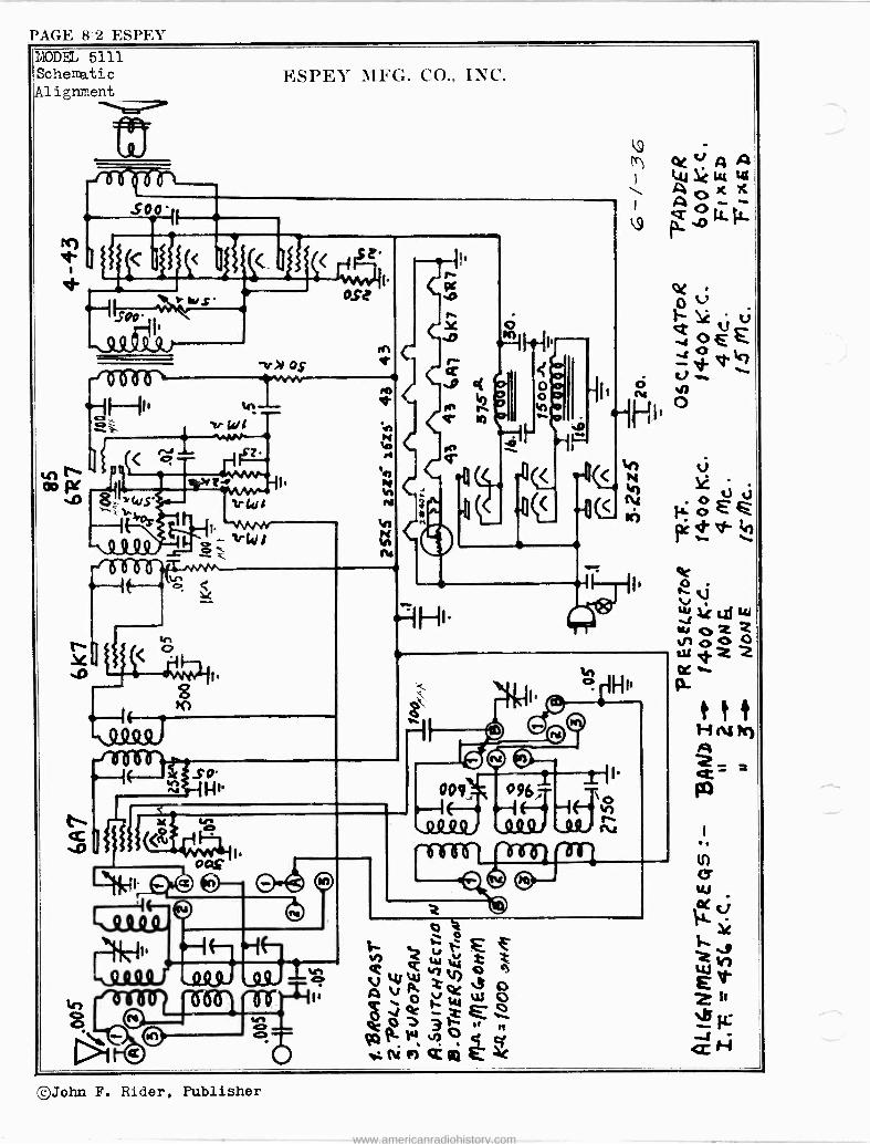
PAGE 8=2 ESPF.I' YODEL 5111 Schematic
Alignment ESPEY MFG. CO., INC.
«MINI tilizim
1 I r 1
*A"--111 r
.C1 -t4
r--
.o
-v os
ose i
2S> y4/S
-- o Q99
vl,i t á i
NtçQq ; oHt.
w
i
o o
.ocri
441. ©0
4:e
009. 096
rI
0
Q h W Ó V 41%4 2 S o e _ r A`° ti W W o0 J
P°.w ,nó ,r
gr eel 4C
©John F. Rider, Publisher
www.americanradiohistory.com

ESPEY PAGE 8-3
to
J
ESPEY MPG, CO., INC.
$92'
ywSE ,
£
rJ1S .D
Inn r
r>el I.
AMA MNv ,rsr ti HI. wks,r
l''IJ \I
N o
J r Ai. rM05 So'
MA ..rid l
}
î
{
0 O
1 1
I
t
yÑ { r
Ms
o
NI
o o
.Ji Ih-1 {H' .sl.s ) .I ...
-re-rrº n
`4e HI» OIHI 00f
e
r- 4
-IHI -iHI- g. -I
o
H
o Q_
! daft e.S 1
n r -1 Ffl.
I.
MODEL 7111 Schematic Trimmers ,Alignment
o o
Hi «11. .1.(113 -in-r1^r6-9- -er ,r vtt
©John F. Rider, Publisher
www.americanradiohistory.com

PAGE 8-4 r.SPES"
3ODFLS 7151,7153 Schematic ,Trimmers Alignment
O ' T
n J 0
n
"trifirrn
}+.SYEY MFG. CO., INC.
1 a
.4.. i- 0
=INS
NI
H* 4t4 ºZ.99 /01fIril 'b ro
1
H.
Q4
HI FM HI
e `aºQ -IHI. "ö-öó ö
2t 0 -v
ai
h
O
IHI . -I ---il .
'NJAhrliLIAJW
J
J a
r-
N .O n
O
` n
.0 W I : h 1.1. e O N
M O
É
Mó
©John F. Rider, Publisher
www.americanradiohistory.com

FADA PAGE H-1
FADA RADIO & ELECTRIC CO MODEL 211(Late) Alignment,Changea Socket, Trimmers
_( LA °=`" ` SOCKET The Schematic of the EARLY model on 1111111111111M»"" page 7-3 is the same as the latest
a . model with the exception,Ref.No.54 ma was.00093 Mf, changed to .0007 MF, (sol me" ---I MICA , the latter value shunted by
+++ 6G5 Ref .No. 89, Padding Condenser of 110 rz e. ü to 250 MMF.
_n2 ,wo INCL_ SERIAL Irk 44041 /N/ 5
GL(BE,. ,S S SAGKY NERF MC e. WAS {E5 -
" _- - The changes in the Flash -o -graph cir- 1LCt,` ru
FLASH -O -GRAPH CIRCUIT CHANGES cuit is given in the insert to the left.
ALIGNMENT TABLE
PARTlie
WAVE BAND
DIAL FRE.
GEN. FRE,.
IMAGE FRE.
DUMMY ANTENNA
GENERATOR CON. TO
ADJUST TRIMMER
BC --- 456KC - - .001 MF 50 M
CG of IF T15,T14
BC - - 456KC - - Same CG of 6A8 T13,T12 4 15 MC 15 VC 15.9?'C 400 "Y" Ant. T7,T4,T1 A 6 MC 6 MC - - Same Same Chk.Sen. B 4.5MC 4.5MC - - Same Same T8,T5,T2 B 1.8MC 1.8MC - - Same Same T9(Rock V.C. C 1500KC 1500KC - - 200 MMF Same T10,T6,T3 C 600KC 600KC - - Same Same T11(Rock VC)
aa:tust men ts mane
o
T-13 ( 456 KC)
'T-12(456KC)
witn selectivity control In
P-15(456KC)
T-14(456KC) o o
T-3(1500KC) T-2(4.5MC) T-1(15 MC)
1st I.F.Trans. 2nd I.F. Trans. Ant. Cnil
e 5 os on
T-6(1500KC) T-10(15001(
T-5 (4. 5MC
T-8(4.5MC)- T-4(15MC )
T-7(15MC )-"
0 ®-
C)
o R. F. çQU. Ost, Co}1
6C5
2nd I . F. TRANS.
Ist I,F, TRANS.
ALIGNMENT LAYOUT
o o
T-11 (.KC) T-9 (1,eMC)
©John F. Rider, Publisher
www.americanradiohistory.com

PAGE 8-2 FADA
MODEL 211(220V) Schematic ,Parts FADA RADIO & ELECTRIC CO.
- (1)
o N
(D
ió
3
ceez- SNMal2G, a OJ5,
a,niñá
49 0 r -e..
Iielier5' F---+ (0
Ln N
-ce
I 1
I I k_uy
141
33
O
TT
Ó
N'
O
-en.
Q
I
_. _ 4.
8
o á &
8 8
N 0
8
Ó
8
O
8 8 8
QQ2
',i'ppf mhR
8 8 8 88 8
s
o
N J W 0 O
ess
a
N
i-
r S
ó-o
8 O
O 8
ä
17..1
ú N
v N
ç
8
dg
.°2
ó
T.
8 8
Ñ
8
aN òò
ÑA Ó 8 O O
L S
N,NÑ.+ege O O Ó O p 01 0
ñmmmm
e.
N
N
x= N
J
ñ
ÑS ee Ññ rri
33 3
3133
YM
f Q8
8 ssi
ç8
ë
i
Q
ó
o
á
<
: 0
L
Ó
$
e
O
7.1
R a
S Q N Ñ
3
7,1 R R m ó
ó
.13
3 h
8 8
R
8 8
8
s
8 8 8
gº H_
i888 o N $
m
8
V
e 7 8 r R gg 8 e R x R
2.4 MRÀ R R m
ö3 a 0 m º o
8']
©John F. Rider, Publisher
www.americanradiohistory.com

raI)A l'A('ii'. 8-3
(D a Q A N O
U (D
E
40Z-" ,jt%
i944 s--h
-6àco_-- (D
Ñ N
MODII, 2118(220V) FADA HAI)IO & I+,I,h:C1'IZ.IC CO, Schematic,Parts
®
W
z
e :
ire o ©
11111 ® 11 iP
(D
e AP
1/
0
1
100
r
r ...... -
- 4 " 111 133 a .,-. a . ì
e
2 O
O G
111=9...-.: N: ._ J 33 men
1111. o
e
á
<
(D N ln N
(D N Ln N r
.
A
e E1 tie n; .
Ñ Ñ i
es
3
Ó
jI3
T1-
TT V
r 31
.Ñ =
3
3
J
3
h
ti r
N
Ñ
pe
t`7
.1 LÓÓNmNNN0------JJ-ÓpOOm
úz. o
:
.
<
M. L
: : :
.....
: , : : .
:
. .
-
32
i ..
3 8.
.
2 vn
, ó
2 .
G R
ti
óg mNNNÑÑwIrrNNNNNÑO?ºNgN2
dódººº JJ
ó
yV,) JJ hh
n.Ó.O.Ppññ2ññrñmPmmap`mappmmm
ól.' - `888o800gNadm
-
«
N«r-
z _
. :
..
.
`
, ,
-
.
..,.__,
: :
v,O,ne
. :
.pn=
88 . .
Ì .
.
à u,
>
^ ¡" oiÿóopii v n>ä
i 'z9e 8 18.;t
=Égñl ^
F LL
1 a `'131,. n°
2 i
`a
s
n u.Wwl:InJNyNj YiN-u1Y1Y1v1,11uíNÑÑry
J`O Jº - e- n,N, CCÑ
Ci
ó
1U o
4'éááávpiñ2í^nhñvi.M,T,.pow.ólw3úú
_<, :
8,8
W
m
,
.
§g8§§2..8 g8§8g rr2%8ii
:
QQgQQ
eilaW
. :
-'3,1
-03I,,,. N N41
.
.é3< SFy->8
l ó
q J
a
ó ti
z .Y.Ç, f0N3W Y
= ñ
g
Jp- ás`
§
N ñ r
:
v N
ó
>
n X
N,mrwlQwe`-A=pNÑ2Ñ4 RR9ºgR'º=F.",g4P,AT22.«g
1Ipp ccO
2ZMÑ^2Ñ2Mr42X ,. ñ ññéoá:1
ó
p
t
s
Kze
; o W Ig:,...........:ss.. m h :i ñi:,:á='-NÌ1wf,0iZvie,J.,OyJJÑw:m"
:
,. e. i s
Np`
e
J
R,.piRA.ñ9$suRxR:ñRg:.4ñRñm
R'R
Opp8NRRÓÓOHQQ0OOÓWÓó§
v
.. -RsRs
. .
..//
_i,.
,:, V
N. .. i
11 p
Ñi,
1
.3 ,N.,o.,.u..o,,,º=.nr_:. ç,.ºm.parvN
©John F. Rider, Publisher
www.americanradiohistory.com

PAGE 8-4 FADA
T:ODF1 212 Schematic Voltage,Parte
JD John F. Rider, Publisher
www.americanradiohistory.com

FADA PAGE 8-5
FADA RADIO & ELECTRIC CO
I. F COILS Iss VIR 335
PRI. BUM t ROO B"
7i 005E - elf 7/J
ern. ern. ie,
.
COUPLING 70110W / OWNER -. 09r
SEC
BRONEN { GR[ER -.W
8
R
I
t$
W W W Ó
'''-o
g sf
X D-SRR .222 2 1£88888888 2222 32 stRa«rvrvN 21,2Ai-,m2e2
2 8 8
-...,-.gg. N
....... :......
3 "_ ,.....
- s2¢i$8g88888§§i
8 °gd LI..............:
..._....,,
-^'=?rSE-^'X^^2== 21 2BgRRR8RRR8siRRRRR : _Nmv,nJnma+4--_ s`J,.m
Y3
5
ó 8 á
r
ä 4
e
8
a
8
3
8
ß
8
8
MODEL 216(lst Prod.) Below Ser460183 MODEL 216(2nd Prod.) Above Sert60183
Schematics Parts
S Ñ
8
á
.
3ç 52
E3 '3 e.
ñ^
8 8 8I8
óIó
8 8 8 8
4
3
hV
Ñ J
Ó
N
É 9 ih
a
&
s
7
i i= Yf
3ee 2w º6 _12
G
22 9. 2
i: ìP
M1
O
re
ñ ñ
aódr
"2 g"3-27;."
ñ3
O
4
ñ
243
á
Ói
2
8
z
8
î 8
m
s
8 ª
eA rva 2
O
8
S
R
8
É
i
ú,íX
L
8
S
8
J
á
P P
á
;ªo
N J º
i óm
e.
S=
O
S
IIM_ t:f f t
1
/
r33.3 /IS 0057-01iW
Hi
H
R 8
©John F. Rider, Publisher
www.americanradiohistory.com

PAGE 8-6 FADA
MODEL 216(3rd Prod.) Schemati c,Parte FADA RADIO & ELECTRIC CO.
z ó
¢
$$§ Ë' ? ?
!_¡i
- '
á
Ì % l. gi23
..1,---1.§
.-..-3.3 u-,. º N
gaá"
s:m
iSS
e 4_ t
º
N
5$03'4,15e24:1,1 - ^r^z! _`= ìºaRS$onsºàd-1.4.1
;
6
ó
ç=;áá z
7-15.,"7,
9,gS
:FS
Ìg3
.
.
nun éóóó .....:
..:..
éó
á;gea1 óg---__
.......
.......
nYw... ^írhÑÑ_ TY
Ñr.....W1u,
-__-__ .n ógªooçg HNNN
s= me.>,,:efia 4.2amxgam,a
,säa:
-
'&
X
=4Y; R.k,8888M'..... nºe
á«m,t.a'-ºsó^óóóó".nn 4. As
,
.
.
. .
.,
:
..>
.
s
'.
ä::..... _
ë=
o
.m=..
..
_ rt
g;
â, '
g
e .n..Ñ.o.ARN...1JJt-Ñ,_ n
Gº.RÑxÑIÑr 3a2^,VarillCR-
n
.ñ
óa..a.._8ºss s.
çç
óèggSÓSçç.yy2¢¢S"yyç4ç
9-'iJ9iv`Añ7.aG3f2244fS
.
ö..........
QQ.
. .
ºº:
.
. .
.
y. .$$
. .
,.Q,
:
.
: .
:
:çç
gií,^..
n
.
LLrM30 .
s..:..:..
a O "5,S. iä
ii Ygm.:.. RÀátSEátRRXRSTái2gggRgAa»Y
«m« ^57m,,,,'.m«..t1C_
ii ntimí9.ñm2x,,,e,,,xÁYtn4ff:` $...a. _.,......:
1:.....ç..
`
...,...
. . .. . .
.ߺ
. . .
.
..*2
...5
R3
:j
3
$ R
N:.p ¡ 1:.
y...
: ú
..
Mai
N
!
"
g
' M g 1#eRRF1SiaFtRSERRRaRgSt
3?-YSt , .hrR= ew.A S.SFRSt
ii _rvnYNyrcp..s=-^S-er,Pa_N.w
©John F. Rider, Publisher
www.americanradiohistory.com

FADA PAGE 8-7
. i. COILS
GRO
.10057-T1V
k.(1C1K,B#11
FADA RADIO & ELECTRIC CO.
PRI. B4.4t REO -BW
COUPLING YELLOW 4 BROWN - O9r
SEC
BROWN 4 GREEN
N' <
\rileV o Y
4. ß 3< Y 4 (' N.
t
x
3
R
3
st
º
N J n
Y R
ñ át
n ^
_ X g
R
R R
2m ñ.ñ
R
5
5
èg gS
z
0
3
g
v! E
DEL 216(220V.) 1st Prod.ßelow Ser.#60182 MODEL 216(220V.) 2nd Prod -Above Ser60182
g
Z
..:..1Schematice g Parts
W ,888Ñ
óg Nº4
>2
t N
x á á e
rymsgs$m¡ry
tyelveei
S
E
sl:
ó S
8 8 8
ó
Z a
rn º Ó
$R
g
E
11ü DMMMMvs OW -MMMMc
I T
p.v
Ned
_L
8
K
ó
Y
-mT.
ee
ß
8
©John F. Rider, Publisher
www.americanradiohistory.com

PAGE 8-8 FADA
MODEL 212 MODEL 216,A11 Prod. MODEL 216(220V) Alignment, Socket Trimmers
N
Ó
FADA RADIO & ELECTRIC CO
N Ñ ät. d
É
M E-.
¿-N.
LO F
É
Ü
n F H
i
0, N m
ó G
O H
F É
> 4.0
Ua 4> x a 2
V0)
. to
N F
É
A
H H
U
U
b
H H F1 [s. O t m ó H <)
C
m
F y O . t-
Ó
af
E m
cm C -t y m C W
m
¢ á
P.
d C
o
á
á
m
á P
K d P
Ó
8
D
N
8
C m
e
m N
e
ó
0 8
U
8 N
Ú
e o
Ó
e
mo
N
x 0
e
Of
H
9
H a o + e cb'
d i Ü W
M
7J
H
9 ao
9 In
9 CO
8 H
t4
8 10 w
9 o N
,
'73 O N W
O 8 H
1n H
CO
9 111
H 8 H
8 CD
9 o
tltl
U U d w cc) U U P D
H [K
A r,
N F H VI
HH
É
H
H D m HH
, Y
m C.)
Ñ In
o
H H OÌ F E+
Y . a),
N U
m
NJ
Ì Ñ d'
HH H
b
H
>a Y
Y .. m t m U
N
m N
10-
J ó co u
cd
Y
K e Y
N ¢ O
e C C V
C d
,C á
e
à oa
m 2 fa
a
m
D.48.
Id
8
- m 4 Oa
e
m
- á
111
m
? oa
O o
'P ó ó VO W E
00 H O Ó 0
LO
o
á
N
.52 0 d 3
.EC Y o o 4 E
i E O L i- o m
o e áe
Ir
E
0
m v
Ó o N U
bt. d
Sm W b
Ñ Ú
.g. t% Y .0 eam1 d' 1.
.g o m
O m0.
d' I.
9 rn
ti
9
NU H
a+
v C tD
TJ 9 m O
9 o o
N
aa á
FiCa.l O O
o 6 H
u
H t0 tn
W O1
X
Ó H
e o N
3m C.) U ¢ w U U
,. m O H H Ho
U
I
m
e M
lm
U
U
o o
t0
F 6 U \aÚ
in
e'10 H \
a
C
©John F. Rider, Publisher
www.americanradiohistory.com

FADA Rt1I)IO & ]+;LECTRIC CO
FADA PAGE $-9
MODEL 242 Schematic
©John F. Rider, Publisher
www.americanradiohistory.com
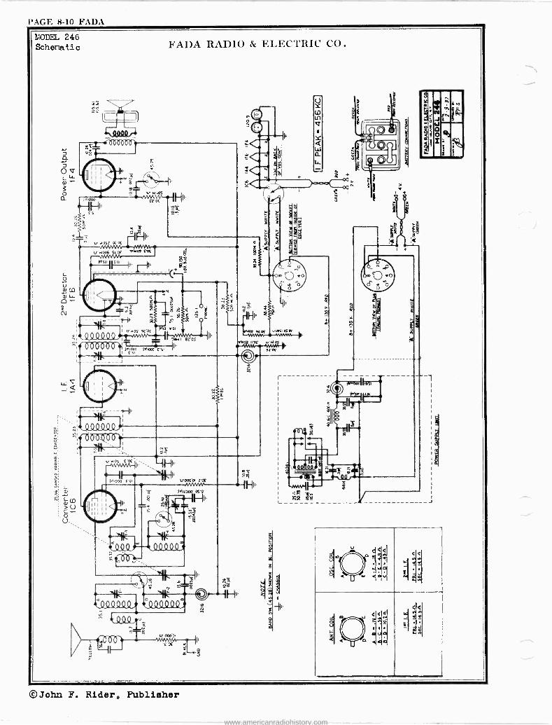
PAGE 8-10 FADA
FADA ItAI)IO & ELFCTRIC CO. MODEL 246 Schematic
li Q
415-07YOI
v u052 02 OE
2
NOS 9Z OE
º º º ti2Y2º5 ºº-1Q!Vi
Id,i000 05'51
- `* 11::2
«)ººººº, .ºººººº, 114
s
I
'kJ
_J
,.sJWa m
`
v o ó<
W s. i
<5 21' r:
:ñ
U
0
I
418
G <AQ
4 :á
S< ee ra
©John F. Rider, Publisher
www.americanradiohistory.com

FADA PAGE 8-11
FADA RADIO & ELECTRIC CO.
ALIGNMF,NT TABLE
MODEL 242 MODEL 246 Alignment Socket,Trimmers
WAVE BAND
DIAL FREQUENCY
GENERATOR FREQUENCY
IMAGE FREQUENCY
DUMMY ANTENNA
GENERATOR CONNECTED
TO
ADJUST TRIMvIER
B.C. 1000 KC 456 KC ___ .001 mfd. 50,000 ohms
Control grid of 1A4 tube
T -8,T-7
B.C. 1000 KC 456 KC -__ .001 mfd. 50,000 ohms
Control grid of 106 tube
T -6,T-5
S.W. 4.5 MC 4.5 MC 3.6 MC 400 ohm resistor
Yellow antenna lead
T -3,T-1
S.W. 1.8 MC 1.8 MC ___ 400 ohm resistor
Yellow antenna lead
Check Sensitivity
B.C. 1500 KC 1500 KC ___ 200 mmfd. condenser
Yellow antenna lead
T -4,T-2
B.C. 600 RC 600 KC ___ 200 mmfd. condenser
Yellow antenna lead
T-9*
*To insure perfect alignment it is necessary to "rock" the ganged variable condenser in order to follow the maximum signal output.
Z Z - n
T-2 (1500 KC)
T -I (4.5 MC.)
ANT. COIL
re
T-4 (1500 KC)
1-3 (4.5 MC.)
OSC. COIL T-9 (600 KC)
Ant. Coi!
1=0=r j -Er ALIGNMENT LAYOUT
©John F. Rider, Publisher
www.americanradiohistory.com

PAGE 8-12 FADA
MODEL 254 Schematic ,Voltage Socket , Trimmers ,Ali grmlent
i2a W[ ó a 3 3` g? CD RU . mj I m 2
UQU S
V
1
3
ó
o o QQQQº0-
s 000 '
4 N
n
vr
I I
11'
FADA RADIO & ELEC TRIC CO
00040400009 T I
111111 !in
14 o rx.ÓH
u --MANN r, ñ, C.0n ó ¢ q a
o . 0I 43
(.,+'m>~ gOU ni
ñe ó O U +
co s.
m I Br .mUCz2Ñ ß F.
1H"
m
11IJ H -;-:,. 43
Cra m CD
AO U M CO m -_, ,D
,--: g ñ ° P. e+'Ub _f: rn cf.,c ad E+ CO F
. , - +' C. m co p r m
Fi f4
11
2
3
o e-,
Oc-+ up U -l' N
x. W 11
08 m + 'r1
C } lA U
4) F.
r--1 +'
ec
-j
Ì O Ì O Ì
r-1 ' r I 1
d, e,-10 1
I
1 `_7 [O aD VZ I
r-1
0 0 0 0 12 1
r-1 r -I Il7 LI) z`) 1
r -I r -i -1 44 1
tD )í) CO LD N < a iD LO up tD C,
J
J
©John F. Rider, Publisher
www.americanradiohistory.com

FADA l'.1(ìl'; 8-1:3
1 1/ 1 1 é,QQ QQQ -4n0001
J^I00
re
ó J }
hADA RADIO & ELECTRIC CO
1,.00,K WMAM
f2 Of
v 000'052 YW1MM
OZOf
j,so v 000'00,
(.(i) 3.1ON 33f) w0001 6'Of
93,41 92'05
)AiiO 03w ¿/, Z' cc
s1 01
8802
80 02
v000'0? vJOJ OS
--WVVV E1 OE 91 O4
ñ
Z'0E
fÁ20
IHJ. 6'01
1^s
IH1
ó ú, P
J ó
Ó
C
92.
Q
C
ò
W
C
c
0
MODEL 255 Schematic
N N
J W 0 0 î
e,
et(
®John F. Rider, Publisher
www.americanradiohistory.com

PAGE 8-14 FADA
MODEL 261 Schematic Parts
I W
ñ
r6 -015-(25-n
0
FADA RADIO & ELECTRIC CO
WHO 000C 01]IJ
f 0 b 0 01-4
o
...O ./1YY-
C Q_Q_Q_Q (. C}¡Db0mb
\
r-
I
c04º400,4 0000001
J
2
in N N N
in
e 1K1'Il 1
ÿ .
e
0
If -
111 1111111
e
Q
dTI.
ó u
N
! i
v M1
n ed
1=
N
s
F
II
ó
0;.1- = ÿl S "ÑiW
ñ <oay >om3e
F J
r5 v
'
I-7,8
¡' z
= e
8
& g 2á
: .
. ,
-óg ó
u
LL
_ Ñ
g i =
f7- v .: ,V 4 s.I. ó ,
r ó.Jriiá9iñlñhn
ZOEEP OE v E á
ñóó á. gs.
ñ
h ñ
? .
1-
-.....
. .
. .
óó--NEn$ ."Ró' . .
. .
ISáoÑÑ
. .
'
.0.;Óó.J=
.i gig i>
c
N : .
x
ñºa_-__-__<__N vºó xst,
IZ
ti2 M T Sa ;3 .7,-.J,
ºiaooW?og - b'
sQ' É
g-ggeo"ó '2_
.
.
..
. ..
o J 1O,
30 -J- . J.,,..., .
4
..g m 111
k"'... LJlno O .$6ä
U
ÿ . .
wE
óó0 o g3
ii
m E
igmcsggsi- ..`/ x N a J Jr f M2 N
il -,,.. -1.0-....,-..,2,
©John F. Rider, Publisher
www.americanradiohistory.com

FAI)A PAGE 8-15
FADA RADIO & ELECTRIC CO
SPEAKER D.C. RESISTANCE VALUES PART NO -FIELD COIL-AUDIO TRAMS. PRI -AUDIO TRANS. SEC.-V.C.
105.27 - 1500 *(cCLo) -- 650 ohms 105.37 -Â1500 * - 400 ohms
ººQQQ9 FLi tn ̂
15:24k
r
BZ'Sb
tXYCXY Q.Q
l QQ º
vJvwn-- II 43N I 90'09
1.,ii0Zf55
v 000.01 4.AMAri
ZOf
.4 ohms ** - 1.8
.58 ohms **->.2
Oco OS
co
-4-1HII L'01
MODEL 265 Schematic ,Socket Trimmers,A1ignment Voltage
W
9G W8 c"- e
; 16VOZ
v000S l'Of
(0 310N 335) 0001 6'0f
v OSZ Sbbf
i,,50' 115'a
v o00'0
©John F. Rider, Publisher
www.americanradiohistory.com

PAGE 8-16 FADA
MODEL 266 Schematic Parts
Wn a O 2 cv
O
® .XI.
2
14
0
0
wr
FAI)A RADIO & EI,h.Cl'HI< CO
e
e t3
1
e
Ei
lOr
r
1 (14_0_0 th
tre 1 1 1 1 1 0 1 I I_
i 4.1[..1[..Qi 71 L_
r QQ444 6ö J a
g
O
04410Q4 O
09p,51
H1
L _J
ú á
a A
2
3
O
§mI .i
C
O
y7N
à
99,, M
e
ó
s
â
A 8
A
ó ó
A A 8
É
8 ó
m
8
>
22 a
é 9 ä
ó
m
_
8
â
5
LL
E
ó
_
A o 8 E 8
r é S g ó 97 M 3
9 X
s
á 8
o
á A 8.
o
8
< ö
m
o
O John F. Rider, Publishc_
www.americanradiohistory.com
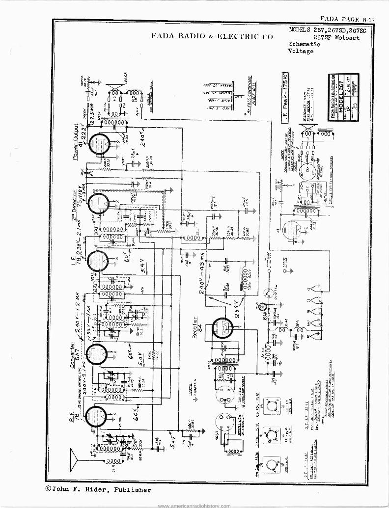
FAI)A RAI)IO & l',l.h,C'l'RIC CO
1'AllA PAGN. 8-17
MODELS 267,267SD,267SG 267SF Motoset
Schematic Voltage
©John F. Rider, Publisher
www.americanradiohistory.com

PAGE 8-18 FADA
MODELS 267,267SD 267SG,267SF Loto set
Socket, Trimtne r s
Al i gnment ,Parts
PRICES SUBJECT TO CHANGE WITHOUT NOTICE
FADA RADIO & ELECTRIC CO
SEPARATE SPEAKERS: Model 267 MOTOSET is also available for
use with separate speakers instead of the standard 61/2 inch speaker
supplied with the standard set. These combinations are available
as follows:
MODEL 267 SD is a two unit receiver in which the speaker is an
8 inch dynamic in a large housing of its own. This housing mounts
on the bulkhead by a single large bolt, and plugs into the recept-
acle provided for this purpose on the side of the case, near the
front. MODEL 267 SG is a two uni+ receiver similar to 267 SF, with
header speaker for installation in 1936 General Motor Cars.
Dial Frequency
1,000 KC
1,500 KC
600 KC
ALIGNMENT TABLE Generator Frequency
175 KC
1,500 KC
600 KC
Dummy Generator Adjust
Antenna Connected To Trimmer
.001 mid. Control grid T-1, T-2
50,000 ohms of 6A7 tube T-3
200 mmfd. Antenna lead T-4, T-6,
condenser socket T-8
200 mmfd. Antenna lead T-55
condenser socket T-8
MODEL 267 SF is a two unit speaker for installation behind the
the same receiver header panel in 1936-37 Ford Cars
as above, but a separate radio employing
unit
*To insure perfect alignment, it is necessary to "rock" the ganged variable
condenser in order to follow the maximum signal output.
PARTS PRICE LIST
PART
NO. 10.3 Capacitor - tubular - (.006 mfd. - 400 Volts)
10.4 Capacitor - tubular - (.01 mfd. - 200 Volts)
10.5 Capacitor - tubular - (.05 mfd. - 200 Volts)
10.7 Capacitor - tubular - (.05 mfd. - 400 Volts) - -
10.10 Capacitor - tubular - (.01 mfd. - 4Q0 Volts) _ -
10.21 Capacitor - tubular - (.5 mfd. - 120 Volts)
10.22 Capacitor - generator - (.5 mfd. - 120 I mfd.ot)400 V.)
10.32 Capacitor - block 25 (.5 mfd. 200 V., .25 mfd. 200 V.)
- tubular - (.004 mfd. - 400 Volts)
- tubular - (.004 mfd. - 1,600 Volts)
- mica - (.00025 mfd. - 10%)
- mica - (.00024 mfd. - 5%) - mica - (.00026 mfd. - 5%)
.25 - mica - (.0002 mfd. - 10%)
r - mica - (.00076 mfd. - 3%) .25
- electrolytic (Dual 8 mfd. 350 W.V.) 1.55
- variable gang 4.10
- padder .30 carbon - (50,000 ohms 1/3W 10%) .20
carbon - (250,000 ohms 1/3 W 10%) .20
carbon - (250,000) ohms 1/3 W 20%) .20
carbon - (1,000,000 ohms 1/3 W 20%) .20
carbon - (500,000 ohms 1/3 W 20%) .20
carbon - (100,000 ohms 1/3 W 20%) .20
distributor suppressor - (15,000 ohms) .35
carbon - (30,000 ohms 1 W 10%) .25
carbon - (20,000 ohms 1/3 W 10%) .20
- carbon - (20 ohms 1/3 W 10`/) .20
carbon - (600 ohms 1/3 W 10'/) .20
- carbon - (30,000 ohms 1/3 W 20%) .20
- carbon - (650 ohms 1/3 W 10%)._ .20
DESCRIPTION
10.33 Capacitor 10.34 Capacitor 15.1 Capacitor 15.33 Capacitor 15.52 Capacitor 15.54 Capacitor 15.70 Capacito 20.59 Capacito 25.63 Capacito 25.100 Capacito 30.3 Resistor -
30.4 Resistor -
30.20 Resistor -
30.22 Resistor -
30.23 Resistor -
30.24 Resistor -
30.27 Resistor -
30.56 Resistor -
30.58 Resistor -
30.81 Resistor 30.82 Resistor -
30.83 Resistor 30.87 Resistor 35.36 35.37 35.38 35.39 35.40 35.41 35.42
Coil - antenna Coil R. F.
Coil - oscillator Spark filter choke R. F. Choke Coil R. F. Choke Coil 1st I. F. Transformer
LIST PART
PRICE NO.
T-3(455,4 '41D IC`1F TRANS/
T-2 (S¿NC )
ALIGNMENT LAYOUT
PARTS PRICE LIST
DESCRIPTION
NOT A BATTERY CONNECTOR
VOLUME
CONTROL
T -s (6o0 I(C )
STATION SELECTOI
r e <cao Nc
ANTENNA
LIST
PRICE
.20 35.43 2nd I. F. Transformer 1.50 .50 .50 .75
3.50 1.30 .85
1.05 55.14 Tone control - (100,000 ohm) 65 65.2 Socket - (6A7)
20 65.4 Socket - (75) 25 65.17 Socket - (78) 25 65.18 Socket - (41 )
.25 65.19 Socket - (84)
.25 65.46 Socket - (vibrator) 65.61 Socket - (external speaker) 75.119 Remote control cable - (station selector) 75.120 Remote control cable - (volume control) 75.122 Volume control unit - (with switch) 75.123 Tuning control unit 80.11 Tube shield - (two sections) 80.13 Tube shield base 80.14 Tube shield' retaining ring 80.16 Tube shield cap 90.2 Cup washer 90.3 Rubber grommet - (Dia. 11/16" Hole 13/32") 90.15 Antenna cable 90.18 Mounting bolt - (5/16" - 18 Thd. x 31/2" L) .04
90.31 Pilot light - (6 volt) 90.54 Grid cap 90.63 Vibrator 90.107 Washer - (7/8" x 1/16" x 11/32" Hole) 90.108 Lockwasher - (11/16" O. D. x 3/32")
110 90.110 Hex nut - (5/16" - 18 Thd.) 1.15 90.153 Speaker cable .75 90.160 Grounding clips - (per doz.) -25 90.159 Vibrator grounding cup .50 90.235 Fuse - 15 Amp. ...
-25 105.68 Speaker - (Model 267) 1.30 140.14 Knob - (tone control)
.20 35.50 "A" Choke .20 35.51 R. F. Choke .
'20 40.IC Choke coil - filter (330 ohm) -
'20 40.56 Power transformer
.40 40.57 Output transformer 50.31 Volume control - (I meg.)
.15
.15 .15 .15 .10 .10 .12
1.25 1.25 2.75 2.60
.09
.04
.02
.04
.05
.05
.60
.20 .07
3.50 Net .01
Net .01
Net .02 .35 .10 .15 .10
5.95 .101,
©John F. Rider, Publisher
www.americanradiohistory.com

FADA PAGE 8-19
gee- .x4 OOS.
+aa/ LJNLJ O1t YC! * dooqboa
th 9
e e,,27
eººº
MCD EL 311(220V),311B(220V) FADA RADIO & ELECEhRIC, CO 8chematice,Parte
/1-/Z-.14
FS
ryOrL VO 5w. 3fYyq IN5, m. /ON L.ECrIvIrY Sw.. - 3HARP
l F TO BE AL/CNED . Pp / (SHARP/ POS e ( 9R?1P). PQT R3 (Nl-FIPEL/rr)
CUAgS/3
SNMO Opf oni i
220 V. MODEL 311 6
-f6 -)C c.ecaw. Zß -we
ffi' 2
á
t8 â
r g .
áö'
i i
'=
3;
.
- 2
2
os
1s..
8ee
v
E
.. . ,----_...
. .
II nlo,nnº.,º
8q .
/ -
^
lar'1"
!
^; §ZÓ 4
I
s 18«m,.
g8888É'8
gg
n2W=
Yu
6 A ó
Ñ g nflri
oo!!
'._'2.<2.2.4 ¡21
4,mlm:g;áiávañ1.,..,N 1
^Ñn , O.
n a n n-- rvÑ mñ2;o
;o 2,^- R:RR
©John F. Rider, Publisher
www.americanradiohistory.com

PAGE 8-20 FADA
MODEL 312 Schematic Farts
, oo.-o,,,,
C <4* OJ-
'0000
FADA RADIO & ELECTRIC CO
e
x17-11-4 e
00
ß
1,1,1
1'1
8
eft*. it--+
Q9 e .909409Q94 e
z
N
J n o
g
á
8
8 8
Ó 8 8
8
3
Ñ
á
77,
0
s
3 3 3
; á 8
Si A
D= á z ª É ª s
E E
2
À
N
8 8 8 8 8 e S
s .
8 3
T.
N 2 º sn
Di
6
s
P
R
LL
oi
w
á
O
8 8
5 I
8 8 8
m
8
"A
8
L
é
8
á
8
P P a
E á
P
W -s P
â 8 8
8 ó
Ó 8
9.
óQ
N
8
S
a $ N
I
J
N
s
C c
5; $_
R R R
$
M
R
A R 8 ñ Ai á S cr
.0 a e; ñ
e 3
7 1
1
3
33, 9
CO
0John F. Rider, Publisher
www.americanradiohistory.com

MODEL 316 Late Above Ser.#60183 Schematics,Parte
©John F. Rider, Publisher
FADA RADIO & ELECTRIC CO
`asUM§ c d
gº :,,':
.n.nu4u4
i. gm ge88
eg $2Ggg
'ref
^` omStRR 9 M_YR oN
M ¡a g.' «I««»»» M` T ...X '.11
z
grek$r8.8,§§§$si;
,Gé
.%5.....,.
:
.........,
.
.
»tm ...
... M"rns3«2,-»Xmmg=== eRASSSfRRSiRRRARR' 88M Nwr.,nJhmmO_N.mVeJn>ml
FADA PAGE 8-21
www.americanradiohistory.com
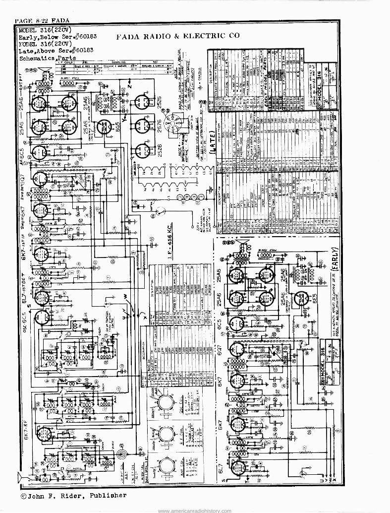
PAGE 8-22 FADA
MODEL 316(220V) Early,Below Serie60183 EODEL 316(220V) Late,Above Ser..60183
Schematics. Parts
©John F. Rider, Publisher
www.americanradiohistory.com

FA DA PAGE 8-23
M0DEL 350 FADA RADIO & ELECTRIC CO Schematic, Changes
ó . J W9,
k00.940, (ro MR)
ó-11-0, -
L (JD
N N
O a_
Wd
Ñ
§52 II= _
2Ft000Q0Q 2[000000y --
30 N
á
2
` O
Ñ'- o --IHII
s,
t.- N N S S
o--¡.M/WVVÿ
O
w
L
w N
crr ÿN
re'
- ' I I
111111
N
N .
IHI1
NV1 Ów
m
fö-Un `9
l I ñ <X.')
--11-111.
IF
LI) I --d 0 0 -
a . vf
II
U
A
. z
N o
ó º O.
O N
1 ,r IO * a
o
d
U
C
a
I\ / a
W
N
z
E a
O _ <'a o a
7
f
S K
Z
Z = Z
©John F. Rider, Publisher
www.americanradiohistory.com

PAGE 8-24 FADA
MODEL 351 Sc hsxm,ti c FADA RADIO & ELECTRIC CO
3 a o(0 L d 3N o a
s"
O d W $
d 606Ö00-1
ó _o II
H1I d X Ñ .i
ai1 22 8Q
'm gº
t 000000 d-ÖÖ0000
rV
Ñ
t 000000 o
606006 N im
11, 1_1-14 II4
Ó
f aoOÚÖóòáÖ3óÖó0A
mÑ
m
U)
o
e
á v
Yf
J W o o ï
co
N
tri
a
©John F. Rider, Publisher
www.americanradiohistory.com

FADA PAGE 8-25
FADA RADIO & ELECTRIC CORI'. MODEL 354 Schematic
a
-c .
fie( ~le /NN/N rQ Cv =a 8^
li Q - rJ 1
;:t 000 QS)
IH
N
C ro
L
Ñ ~
n6óÒ6b Qü o GM o bY 3
G -
m
s
g
ei
a
e J W o O 2
ñ
d N
©John F. Rider, Publisher
www.americanradiohistory.com

l'AGE 8-26 FADA
MODEL 1255 Schexiti o, Socket Ali griment, Trimmers
ck'
ç ó
>
t2_1(10_fr
,
--4000005-1
0 0,
0
-
,---4000005-1
-
- 1 it
-3- I 0 Ç a
o °'
I
t
a
FADA RADIO & ELECTRIC CO
ooti 000 i ó 11 fs0 µo 000 OSZ v000 00
000000 -,41:53-(v5-0
_
02 OF
- roo'S loE
$ g
, oi ros
92 OE
v0oc >sec
x .(5?
X
L, 000 S Z
Il 02
Z 01
N O
?t
a I'9-
-
-` . A
¡ 1
V v ose B>roi
I1 0 l'.
S Tg vo90.oT
e2 sf
11,
iQ94Q4º.
000
2 C( e,I1 >Q L.,s
0.9º4ººS ----e,
ocow oN.
1920
3.'0
X
3t:r >>> N t f « 50
x x
0º k0_09 0.A0
11 1111111
v 00002 v 000 os
E, Of .1 0E
^SO
101
WI
41:
1¡
N J Ó
ty
t
4F .IppTd L-+HUÉEa
t~ a) y c
cl a.1
Ut3 t ,ae tnV1tY] v
,vama)î 06,1
+-19 g 3 g g
m DO CD i+ H w
1
I
I
% 1 I
>
r 11
1
I
I11 I
1
I
1
m
mtp In
üu W
1.0 et
A4UXb4A4 CO LO 944
0ao CO 1-1 CO
Ó0 rl CO
as o ,I -I F. A ri.
A4
0 0 rl
):4XD4 0 pl)1Q0 rirl
0 1
CO
0
r-1
À0 4
p CO
CD P z le co vim - KO n In
_
©John F. Rider, Publisher
www.americanradiohistory.com

FADA PAGE 8-27
F,1
a
i
o
V V V V V V
FADA RADIO & ELECTRIC CO
SNMo 000C 01]11
( óbbb).--1
«
t 04444Qfr áZîO Qó O-
n
U
J
4 ,
k^ Lr e^ xel
o
e
q4-54
u 1111 ' Cs ! 1 1
4f e
ös a
>$ P
i_43131149Q44--iH, 4_40
g 1111
t ,s4 1.)
, J
O AiÑ éñ
v4211.1
tU
444
0o
. A
+a
idwH
; In H
H
r- H
Oto +3
m a ö oÓ U
CO 'CC
a, O
U
V OS e
r-1 m
In
O H
+ó A0413
t3
O Ne 0 @
3 o
m ad g.., H
1
1
1
1
1
1
1
1
1
z Lo e-1
Q% ®y ö I
UW
CD
T4
4U LLJ
e-1
U e4
ó 5rU
4,
jm,
A e
U 0
U 00 lo
U
tO
U
r-1
I
21 7 U P:l
CJ PI
U W
e. d]
MODEL 1262
Schematic,Socket Triamers,Allgnment Parts
W+
? ae
CV.
M
W
o E
A
A
tr
it
Íme
al
9p
0
m
8
re
_ s
2 I.q
4
z
<
iI- 89
$« V3r .r .
g
º º ó
8
»zsow
x S á R S 88
©John F. Rider, Publisher
www.americanradiohistory.com

PAGE 8-28 FADA
YsC)(..;;
non afiH,.
I(6Gbb40-- -111,J
vo0057 -NVNM1r-1
n 00
90 S
MODEL 1265 Schematic ,Socket Trirvner s ,Alignment Voltage
- - co
p
FADA RAI)IO }+:I,EC'I'RIC CO
v C 1\Q a I omf o E N in,-
x, r tno , x
.e up x
,.. ' ro
00ó oos VWM --b
PISO /all. FZ Ht,.
v a052 v000 OZ 0E z'a
II" eH xvs
x -i l'mo 0g9 AS zrss .`"'w`-.a ° `-1F 1
0s 1O 6o I
TTig lg
uF 9VF
o M,1
lt
frr IH1
6'01
x
0o6'öoó
/0 9
99 OZ
I!
v 000 05
Ei OF 91'09
SO. l"o _
1H,,. r01
3
3i o
N Ei
OD
E
m
H
Lo Ei
9,9
CD H
N 'Q W
(4.1 0 ü' U
m
r Ei
E-+
á .P
4
o o
:J
rn
01j r-1
m
U
m 2 m
m
cn
Ei
Ei
m
cn
N o o
U O PG
Ei *
to
cr)
m
m Pw
U CO Lr)
U rY.
cD tn w
U
tn -I
U CU
0 0 tn ri
U =i o o Lo
am HCz.
t) `.r.
o o o ri
U 0 0 0 ri
U 0 :f; ri
U
cD
C.J í1 o o t!3 ri
U >4 0 0 tD
al A yZ U C U a ryM¢
w gnu-) m cQ CO, W+
II
*John F. Rider, Publisher
www.americanradiohistory.com

FAIR. -MORSE PAGE 8-1
V co
V
FAIRBANKS, MORSE & CO.
u
I11 111
1 1 1 1 1 1
Cc')
wdt,aSl - 0`lT)o^ï v.<M crH
'_--"Ooo'OL fi /W
!V fV /
e e
0
II
ry ¢ (NI 0QQQQ.04 ry ó3Ñ
b ö21N i `1-
I Q CP.
m
- ii." QQ º QQ º 1 n 75)
ó re)
e o -
Cr,
e [V
11111 - 1/ 1 111 11 11
i CO
o
i ï -ill. -
u L SLQ99 , .9º
!
f o 6nÓv-l 1{. -
L_ _
0000
W W 2 0
Li W
V 4.;
a,
ge
,IIt U
C C
000 00 Q0 111115 5151511
Ñ > 00 N
MODELS 5C, Fì11 s: Schematic , Socket Trimriers,Color Code
^ N g -Q Q g N N M ees > 0 0 0 0 0 01^
c'ágÑá§< > a W CZ
O . L
O O. t /7,U
w O W z .1 Q . . .1F 2
-.I 11 O o . . w w . 1óI O rou' Z 1 «o. o'
a,
W c p c
"Ti3 -v
A I.Oi V ) 4. mwaÓYC7ºx,
F 1j-Id-á:°p' '.ü.::.1 E E E E
o. ..._.o. ,No. M
.1_0. 0, ._ < ' a 0 0 0 0 0:1 c
O U O Ñ e+Pi Ç I
V t >-
^H
É ',
W V.
¢ U ¿` GY ^sl O ; c,
C -10: ,''. Z"E @,
z . .
-. .
b Z.
pq 3
` I
O o 'wwa
John F. Rider, Publisher
www.americanradiohistory.com

PAGE 8-2 FAIR -MORSE
I.OD a5 S 5C, GA
Alignment,Voltage FAIRBANKS, MORSE & CO. Resistance
ALIGNMENT The models 5C and 6A are AC operated, superheterodyne chassis low range AC voltmeter, preferably about 0-15 volts. It should be con -
with automatic volume control. These receivers operate on three bands nected from the plate of the 6F6G tube to ground with a .1 mfd. con-
-broadcast, police -amateur, and short wave, Figure 4. The 6A has the denser in series with one of the leads. When the hand tends to go off
tuning eye, Figures 3 and 4; the 5C does not. Otherwise, the two chassis scale, reduce the input from the signal generator and keep the volume
are identical. control at maximum. If too strong a signal is fed to the retetver and the
Alignment procedure is given below in chart form, Figures 1 and 2. volume control is used to keep the output meter hand on scale, the
Make adjustments in the order given. The output meter may be any A. V. C. will operate and inaccurate alignment will result.
Ne. Connect
Generator To
Signal Generator Frequency
Dummy Range Switch
Dial Setting Stage
Trimmer No.
AFC Switch
Peak For
Special Instructions
1 6A8G Grid 456 KC .1 mfd. Condenser
Broadcast 530 KC 2nd IF 1 Max.
2 6A8G Grid 456 KC .1 mfd. Condenser
Broadcast 530 KC 2nd IF 2 Max.
3 6A8G Grid 456 KC .1 mfd. Condenser
Broadcast 530 KC 1st IF 3 Max.
4 6A8G Grid 456 KC .1 mfd. Condenser
Broadcast 530 KC 1st IF 4 Ma..
5 Antenna 456 KC 400 ohm Resistor
Broadcast 530 KC Wave Trap
5 Min. Raise input un til signal is heard.
6 Antenna 5.4 MC 400 ohm Resistor
Police Amateur
5.4 MC Police Osc.
6 Max.
7 Antenna 5.4 MC 400 ohm Resistor
Police Amateur
5.4 MC Police Det.
7 Max.
8 Antenna 1.8 MC 400 ohm Resistor
Police Amateur
1.8 MC Police Osc.
8 Maz. *While rocking - Repeat 6, 7 and 8 until no
change is noted.
9 Antenna 1500 KC 200 mmfd. Condenser
Broadcast 1500 KC B. C. Osc.
9 Max.
10 Antenna 1500 KC 200 mmfd. Condenser
Broadcast 1500 KC B. C. Det.
10 Max.
Il Antenna 600 KC 200 mmfd. Condenser
Broadcast 600 KC B. C. Osc.
11 Max. While rocking , - Repeat 9, 10 and 11 until no change is noted.
12 Antenna 18 MC 400 ohm Resistor
Short Wave
18 MC S. W. Osc.
12 Max.
13 Antenna 18 MC 400 ohm Resistor
Short Wave
18 MC S. W. Det.
13 Maz.
14 Antenna 6 MC 400 ohm Resistor
Short Wave
6 MC Check calibra - tlon at 6 MC- Padder is fixed.
FIGURE 2
ALIGNMENT CHART
OHMS VOLTS 6A8G VOLTS OHMS OHMS VOLTS 6F6G VOLTS OHMS OHMS VOLTS 6K7G VOLTS OHMS
255 150M INF. 106 2.15 210 INF. 210 18.2 35M INF. - .10
INF. 253 ^ INF. 255 0 . ( ©
® _135 1PEG INF.
0
235
0
O © © 0 0
O p Ct . 13 125MFá
.5 6.3 0 212.
_
0 0 0 p AC 6.3 . 5 © C+ AC 6.3 .5
210 0 0-- 2.95 220 0 0 z 0 0 0 0 - 2.15
OHMS VOLTS 6C/7G VOLTS OHMS OHMS MOLTS 6G5 VOLTS OHMS OHMS VOLTS 5Y3G VOLTS OHMS
-.05 NOT USED ON
MODEL 5C 500M
INF. 83
- T O5 500M 1251E6 0 255 INF. 1650 138
O
GI
138 1650 p
4 0 .13 500M 68 INF. 255 0 0 0 0 © p
©p 6.3 .5 © O
255 0 0 0 .5 6.3 Ac 0 0 0 0 ---i' INF.
'CONNECTED TO TARGET THRU 1 MEGOHM RESISTOR 30 VOLT SCALE o3 VOLT SCALE
VOLTAGE AND RESISTANCE ANALYSIS CHART
JJohn F. Rider, Publisher
www.americanradiohistory.com

FAIR. -MORSE PAGE 8-3
FAIRBANKS. MORSE & CO.
. Icbg = co
' > cr)
' n
Q ..1 Q i co
1-`< I h
Nr. 1,r cooao 1OL N 0 co I----TCn i
GVi-4, ----- r e000Dzl
r
o
te
0Ln
0º.
Ñ U
Olt ̀ -
o n
°
..9.&41,
cN wee N
M 00
-_ 1
a¿///
óF
Q r---.4- _,. { M
y .11--) f 1 o rl
Q `}{
rn rl 4 aj 1 ,.x.AAii N.li A11' «
brr ó F ..0
u'1
u1.1
N
V\
r J,0NV9Oi
S31á311V9 i ONV9Ol
J J W U
MODEL 5D Schematic I3att.Connections
s _ w` - < s. áÿ : ï .. m : é. .
zzi -
ó C 'Ç S ¿ ó
Q.
:3 . .,¡ g ` r= o?2 s 2 1 -'4.212%A -rim' W Eró e n NO p}
E F s-.;oLº w
ä ` 3
-ö "' a
i .,¿,E^
"E_;o 8á= a <.Yc :r " .< X:ów0 e 3> 3-2
L S < ..._c ;w 3 w oa(-7. .ÿ v.n s d < m<
1.5. 2. -e v =F-_ ÿ
L a ÿ
Y ÁcbÓ.wc<ww d O c C'ñ C > ` m CÓ y .3".5 .e ÿoo-
- o
w á " a w v é Z x Z V : OD Ù mg ">E" !-.w
=ye E ó .. u --E1'11-2 [- Li.
K
°6ï ligt:(21. ¡ F+o,n"_.`L.`Ó°Iii Ó_N.yL¡...1r hór.v<> °; .1wmE"gr <F
"$ r 3-O FyLo'.F ww x eï f- F >L f.- Y'- n" p E,x, y t7 v r i `ÿ-ÿ<s;.,rZ F..< II ms 11 .5- a m 'E c .E
) w
< " út w3 LiyF; °oÿo [;O lï "ö.vV<y.i
H.. a,° rz<, î ..<a2<;< Z º E.EIOEmcCo < r..cHñ tiÓ
` G".. ` E - r 3_ L m ' ", L 6' -F.. < E oo e U <`- m ï' e Z w
- .. w.. . E: -o......3 Fvi
o -V -g ó -.1--6e c+_ ^EL = E . U -" a ó ; 3 3 ó 3 0
< <Qs ^s >ºÓ >° ó ó- "._-.. á c y` +-3 óÿv°v °eº Y. 2
'i.'" .. c Y.E o -.
9>>ó º_` _º ÿ2= º
1
°_ ó r `r .. i-n C !_14,.: " " L ñ _ $- ¿ :, s y á -ö ç a °.E wc '.. c° oc .s. ç y ñó- d e ó 3.c ` ..
L ö 2 É
.9,,-' E
ä -F'..-.P. E 3 ,, °> E
;;;; º . = 3" ̀ m e
,.-:r wco E- E á. _
::'ºº ._ ó> Sc- c º w ."2,e.,
o
cL W ` c E o
=3ó Hoge cce °cE in: o `. <ó21 O"iâe. "É E v
m c c -
m c cv %' F ÿ s o ó` 5 ' e' 2. ' ° ¡+ E c < ú.. ° ev,.. W
. - _ {!y °m=t .. ° ` ,i 'c.v.( " ['i y y L
F+ r." w°4"-°_<m^<V <y E r;t-3 u _C mzit..ÿ_ >' t <.._L <<t c- 1='° .C ` éc OoÑió_0"_Eóp,,m ó.°. c
`
E. ,%, "ü. > . s
<óma-Hm.:>>E-.<N: ,, ` E _ Ó ú r1- o L V L 2 a=u. á 2 L O ä.. H óg F ii % .óc >O-.â>S
y' >_x;>>Fw'g . aw Ua ;öocr3e : `r Ñ u 3 m. .l'. o t-r d r s n m"`nrFFü.sF"c°ci°c3 7
z 3
o o : m o >
S31il311V9 ., S3Ia311V9 J,ONV9,Oi
'John F. Rider, Publisher
www.americanradiohistory.com

PAGE 8-4 FAIR. -MORSE
MODEL 5D
Alignment, Socket FAIRBANKS, MORSE & CO. Trii,uners
The model 5D is a battery operated superhetrodyne with with a .1 mfd. condenser in series with one of the leads. Set the
automatic volume control. It receives signals on three bands- volume at maximum during the alignment and as the meter'
broadcast, police -amateur, and short wave. hand tends to go off scale, decrease the output from the signal
Alignment procedure is given below in chart form, figures generator. If too strong a signal is fed to the receiver and the
1 and 2. Make adjustments in the order given. The output meter volume control is used to keep the output meter hand on scale,
may be any low range AC voltmeter, preferably about 0-15 volts. the AVC will operate and inaccurate alignment will result.
It should be connected across the two plates of the 1j6G tube
BAND TONE VOLUME CONTROL SW ITCH CONTROL & SWITCH o --Yee. TUNING
O i F 7
III l'H4G BROADCASTo SHORT NAVE
TO%3 O>e I I -O POLICE T'
BROADCAST
I!!1OSCILLATOR OSCILLATOR TRIMMERS PAODERS
C7G 8 IJ6G TRI MMERS ON FRONT OF CHASSIS
BROADCASTS O I D5G NAVE
SHORT NAVE ©©©0 TRAP 12 -e... POLICE 5
ANTENNA- BLUE 1
BATTERY, TO GROUND -BLACK CABLE SPEAKER
6
ANTENNA TRIMMERS
TRIMMERS ON SIDE OF CHASSIS Figure 4
TOP, FRONT AND END VIEWS OF THE 5D CHASSIS SHOWING LOCATION OF TRIMMERS, CONTROLS AND COMPONENT PARTS
No. Connect
Generator To
Signal Generator Frequency
Dummy Range Switch
Dial SettingNo. Stage Trimmer AFC Switch
Peak For
Special Instructions
I 6A8G Grid 456 KC .1 mfd. Condenser
Broadcast 530 KC 2nd IF i
1 Max.
6A8G Grid 456 KC .1 mfd. Condenser
Broadcast 530 KC 2nd IF 2 Max.
T 6A8G Grid 456 KC .1 mfd. Condenser
Broadcast 530 KC 1st IF 3 Max.
4 6A8G Grid 456 KC 1 mfd. Condenser
Broadcast 530 KC 1st IF 4 Max.
5 Antenna 456 KC" 400 ohm Resistor
Broadcast 530 KC Wave Trap
5 Min. Raise input un - til signal is
heard. 6 Antenna 5.4 MC 400 ohm
Resistor Police Amateur
5.4 MC Police Osc.
6 Max.
7 Antenna 5.4 MC 400 ohm Resistor
Police Amateur
5.4 MC Police Det.
7 Max.
8 Antenna 1.8 MC 400 ohm Resistor
Police Amateur
1.8 MC Police Osc.
8 'Max. While rocking - Repeat 6, 7 and 8 until no
change is noted. 9 Antenna 1500 KC 200 mmf.
Condenser Broadcast 1500 KC B. C.
Osc. 9 Max.
10 Antenna 1500 KC 200 mmf. Condenser
Broadcast 1500 KC B. C. Det.
I0 Max.
11 Antenna 600 KC 200 mmf. Condenser
Broadcast 600 KC B. C. Osc.
11 Mao. "While rocking - Repeat 9, 10 and 11 until no change is noted.
12 Antenna 18 MC 400 ohm Resistor
Short Wave
18 MC S. W. Osc.
12 Max.
13 Antenna 18 MC 400 ohm Resistor
Short Wave
18 MC S. W. Det.
13 Max.
14 Antenna
-
6 MC 400 ohm Resistor
Short Wave
6 MC S.W. Pad.
' Check calibra -
tion at 6 MC- Padder is fixed.
Figure 5
ALIGNMENT PROCEDURE CHART
John F. Rider, Publisher
www.americanradiohistory.com

FAIR. -MORSE PAGE 8-5
V
o
--
co o
Q
Ge- %;tQ rt
,:reel ósi f)
f°O' osi EE
FAIR13r1\'IsS. MORSE CO.
`{ ' cn N z o o 5 a
ó ú F -J 3o U n
MODEL 6C
Scher.uxtic,Socket
Trimmers
LJ
2
0 z
E n .s
a ZCS V
O
E
y 00 g ÿ "d.1
maáág L .é 8
u ó
w
o< n
m U
r n
',;John F. Rider, Publisher
www.americanradiohistory.com

PAGE 8-6 FAIR. -MORSE
MODEL 6C Alignment,Voltage Resistance
FAIRBANKS, MORSE & CO.
The model 6C is a six -volt battery operated superhetrodyne with automatic volume control and tuning eye. It receives signals on three bands-broadcast, police -amateur, and short wave.
Alignment procedure is given below in chart form, figures 1 and 2. Make adjustments in the order given. The output meter may be any low range AC voltmeter, preferably about 0-15 volts. It should be connected across the two plates of the
1 J6G tube with a .1 mfd. condenser in series with one of the leads. Set the volume at maximum during the alignment and as the meter hand tends to go off scale, decrease the output from the signal generator. If too strong a signal is fed to the receiver and the volume control is used to keep the output meter hand on scale, the AVC will operate and inaccurate alignment will result.
Figure 1
TOP VIEW, FRONT VIEW AND END VIEW OF THE CHASSIS SHOWING THE LOCATION OF TRIMMERS, CONTROLS TUBES AND COMPONENT PARTS
Ne. Connect
Generator To
Signal Generator Frequency
Dummy Range Switch
Dial Setting
Stage Trimmer No.
AFC Switch
Peak For
Special Instructions
2
3
6A8G Grid
6A8G Grid
6A8G Grid
456 KC
456 KC
456 KC
.1 mfd. Broadcast Condenser .1 mfd. Broadcast Condenser .1 mfd. Condenser
Broadcast
530 KC
530 KC
530 KC
2nd IF 1
2nd IF 2
1st IF 3
Max.
Max.
Max.
4
5
6A8G Grid
Antenna
456 KC
456 KC
.1 mfd. Condenser 400 ohm Resistor
Broadcast
Broadcast
530 KC
530 KC
1st IF 4
Wave Trap
5
Max.
Min. Raise input un- til signal is heard.
6
7
8
Antenna
Antenna
Antenna
5.4 MC
5.4 MC
1.8 MC
400 ohm Police Resistor Amateur 400 ohm Resistor 400 ohm Resistor
Police Amateur Police Amateur
5.4 MC
5.4 MC
1.8 MC
Police Osc. Police Det.
6
7
Police 8 Osc.
Max.
Max.
Max. While rocking. Repeat 6, 7 and 8 until no change is noted.
9
IO
11
Antenna
Antenna
Antenna
1500 KC
1500 KC
600 KC
200 mmf. Condenser 200 mmf. Condenser
Broadcast
Broadcast
200 mmf. Broadcast Condenser
1500 KC
1500 KC
600 KC
B. C. Osc. B. C. Det.
9
10
B. C. 11
Osc.
Max.
Max.
Max. While rocking. Repeat 9, 10 and 11 until no change is noted.
12 Antenna 18 MC 400 ohm Resistor
Short Wave
13
14
Antenna
Antenna
18 MC
6 MC
400 ohm Short Resistor Wave 400 ohm Resistor
Short Wave
18 MC
18 MC
6 MC
S. W. 12 Osc.
Max.
S. W. 13 Dec.
Max.
Check calibra- tion at 6 MC. Padder is fixed.
Figure 2
ALIGNMENT PROCEDURE CHART
OHMS VOLTS 608G VOLTS OHMS OHMS VOLTS/ 15 VOLTS OHMS OHMS VOLTS 617G VOLTS OHMS
INF. 83 -.624 41M 83 INF. 450M -.15 .15. 450M
i ' 85 INF. 0O O INF. 125 O
O 125MEG 9 Q- .05' 1MEG INF. 58 O
O O 0ili .3 " 35014 0 0 1' f^
re 6.3 1.5 .
INF. 127 1.25 450 0 0 6.3 1.5 rJ
1.31 135 1.5 2.2 4.1 2.5 0 0 " 0 0
a
OHM VOLTS 6L5G VOLTS OHMS OHMS %OLT 6N5 VOLTS OHMS OHMS VOLTS 1J69 VOLTS OHMS
0 130M 1MEG 0 126 INF. 240 0 0 260
INF. 225 O V @ o
0 INF. 136
O 136 INF.
© O o fJ O0 CH CH
1.5 6.3 0 0
- 0\./ C
4.2 1100 1.5 6.3 0 0
*3 VOLT SCALE e CONNECTED TO TARGET (T) THRU 1 MEGOHM. RESISTOR IN SOCKET
Figure 5
VOLTAGE AND RESISTANCE ANALYSIS CHART
®John F. Rider, Publisher
www.americanradiohistory.com

FAIR. -MORSE PAGE 8-7
o '68o6doov .^ N
V.VA
.I V
o t
V
Y
(-2e2.60',9/
.Q44444,
FAIRBANKS, MORSE & CO.
!Yo'OZZ
(eOOO ,15-
ª t{ ;i 11:2 ,444409_, ,44444, `QQ.
--/-6-0M.Zr 7-0-15-)
-r_
aÓ ÓZl 6Ó 6r En
V
p
ú? o <, p0 no
n
LTODII, 8A Schematic Trimmers
I
©John F. Rider, Publisher
www.americanradiohistory.com

PAGE 8-8 FAIR. -MORSE
MOD EL 8A
Ali gnme nt ,Vol tage Resistance, Socket Trimmers
RANGE 3W TCH
TUNING
O132. C,I ANT BLUE-GROUND / -BLACK /6CRG
O
6L7G
--POWER CORD
FAIRBANKS. MORSE & CO.
SWITCH & TONE CONTROL
VOLUME CONTROL
-607G 6K7G
- 6V6G
DOWER --TRANS
11" -SPE AKER
E z î î
Éz F
r d N T O
taO U. m6 riÓ
E .
áÓ - c á< vi O In p
é VI<
U
o U
o
U
r
U
8
U
8
U Y S
U
r
U U
mL c._ r2 m m m Cq
bE
CO
-ö ó
a
u O A
In
O
E E
C
2
E v ° Eá -V
v2 E ó -U
X C
E -Ú
62 6..e; o. od
6 c E o } Q
Ñ
62 E-ó 0. od
_5 2 E 0 a o0. POL
L o $
L O O
0q7. á OL
01;,' o á v
TAU
c4L.
U V U x
U x
V Y 8
U x S
U Y rU
K cU G
G 2E2
c 0 o
c
.o
v 0 e
2
e-19.
<. 2 Y w C
< .á
Y Á c: 2,
c ^ <á
2
2, C <á
V
<..i
2 Y
< -7
E, 2
2, c:
z r n CO o o
,pÑ{.M Pp
Q Y «Q t0 06 G'.0 ú. ICO
10 d m b y g'w 7 ' t Ju .E & 1.2 'v -v
ñecgac%Vú.;º-' .vé6lia°ó °yc d'vI y C e .-r Ó O p. 0
me b 1; -13 ú Ó '.,',1óc;roc ó°'°>.7°01c=ñ E ro E d8 p.E e wsL á:9
'..'E21,:,.. d 3-ÿ 06.° -D.5.8 Á e ó e
é6 = " > É
<>-9 >, c v ro 2,2 $ c EF E
c ro 3 ro ro ro c e E y- 3 m
&- e C boO e Is .E O v., Á O e p e; e .«3-c,rec^E óc.s -cmá.ÿa,-
42«1:
e w ro C >. e m °'
C
I.
í61, E C ° c:14«9:7.2 bOu. "Lp6c e.Ee.ro
ai7 c.G.íe.u7wTro.....b-C-O-pº ro c'- o3w ÿ° .-..%44.-2-L3 ° ° c-5 .. ó ta cS.. ro me
-2-5 º`, ro i.m E d.Es dc '"E'2° $ S.=ve'°.." E. -5.-t, - -v°°
ú O EL >.ro "" c.ÿ e c ro
ÿ ó 3y ç c ó c b m t° .1" ó b ñ e. 'FF ro e ro
w m ew'E r . E-° P a t áÿ .E Sfa.-.T. 2 ñ,° °°E ee= d= d c 7 ó.g
° ,-"E -,c4 ,--ti
E . 7 e - sL á áov E E á ro
6' d
ó_ó cs ów°-º ó ó ó E ó Éb` 'Ç ó.; E,O `.E^a -x.ÿ.4.-E.)-_.---,A'...o.x12 ca.d m.t" ro ro
C :Jo 3,;_---,7i if 3 3 3 ,_,m m E
E -o C ro o ó dL ;,.á v. :i yv
_.ro e K Ó ÿ pS Ó ro Ó ro~ E 0. G ro Lt E cc
c ro (- E.=L á'-_,á á ó a°. d É r m LI 7.= EÑ v ecu c ÿ V > ;°rop2
o °'1-3: v¢ l',., Ñ ;g,,,: Ç 7a 7,- x"a $
º.E.E-9s.- ecL v a.N º,Es máW ás d
S 2 0 0 f «mm
l ' L ' Lei
CO
OO O Ñ O O
G
2 0 o
O O CJ
111
MON
en o N
If If
Or
Or
$ o 2. v o o
La - 20 .-.
VI Ln Ñ
N
e o
m ti o 0 m. o
us Ly z o 0
©John F. Rider, Publisher
www.americanradiohistory.com

FAIR. -MORSE PAGE 8-9
CS)
ti Ñ
l) r-
<3 L)
h
FAIRBANKS, MORSE & CO.
iwzo n r n
' N
l
m
"S'
00 OZ. fr
t0 -
e. óio u>f.a>tl
iI
l
aaaaaal .l w 1
tO
L
II
J
t_T
040016,)
H
Ì1
m i(`n
90_909Lº o_1i
UäóöY 1
ti. f
19
cry." ºaiQJla ..A_1Á1..
,e Ak-11
Y
Q
m
---- ,°e
10
o o o
m o a á
I:ODZL 9A Schema.t I
3
Fo `\t 34
firnl* X X
©John F. Rider, Publisher
www.americanradiohistory.com

PAGE 8-10 FAIR. -MORSE
MODEL 9A Socket,Trinners FAIRBANKS, MORSE & Co. Alignment, Voltage Resistance
i ee
W 0 W = d o o
d n caca . $ bi
w Of. O 0=9 3 9 >
t` o Z e. e á , ,
Ot N .k 0 2 1ó 0 0 ó o ó
$ o ...i)
Z d i oo _ caca - w _ .
_
!APm 2 e n o
a. en J ®L;
- <
I9 ó E o ó
o ry
A g o ÿr > in e b S
IL{n\ V§ DoE
S .. ó : i 0 0
ky H
Q ..
o o a v.
ro s.
o elá el o 0
r
r¡1_ - O ' i e O 0
\ l9 Z ? Qg
eh ci
izs c
?.
fJr( p. 0s
áo o áo 0 ó
0
O O
- . ©
d
- Q ©
<
X AUTOMATIC DIAL ADJUSTMENT sAn AS GIVEN FOR e THE L'OD13.. 12A (see index) ALIGNMENT NOTES
Ñ OF I OUL 12A ALSO APTLY TO THIS MODEL
ALIGNMENT PROCEDURE CHART
No. Connect
Generator To
Signal Generator Frequency
Dummy Antenna
Range Switch
Dial Setting Stage
Trimmer No.
AFC Switch
Peak For
Special instructions
I 6L7G Grid 456 KC I Mid. Condenser
Broadcast 550 KC Disc. I Out Max.
2 6L7G Grid 456 KC .I Mid. Condenser
Broadcast 550 KC Disc 2 Out Max.
3 6L7G Grid 456 KC .1 Mfd. Condenser
Broadcast 550 KC Disc. 16 Out Man.
4 617G Grid _456 KC .1 Mfd. Condenser
Broadest 550 KC 1st IF 3 Out Max.
5 6L7GGrid 456 KC .1 Mid Condenser
Broadcast 550 KC 1st IF 4 Out Man.
6 Antenna 1500 KC 200 Mmi. Condenser
Broadcast 1500 KC B.C. Osc.
5 Out Man.
7 Antenna 1500 KC 200 Mmf. Condenser
Broadcast 1500 KC B.C. R.F.
6 Out Max.
8 Antenna 1500 KC 200 Mmf. Condenser
Broadcast 1500 KC B.C. Ant.
7 Our Max.
WM 9 Antenna 600 KC 200 Mml.
Condenser Broadest 600 KC B.C.
Pad. 8 Ont Max.
k rocking. Repeat 6, 7, 8,
d 9 until no change s. noted.
10 Antenna 1500 KC 200 Mmf_ Condenser
Broadcast 1500 KC Disc. I In Max.
11 Antenna 5.4 MC 400 Ohm Ranima
Police Amateur
5.4 MC Police Dec
9 Out Max.
12 Antenna 5.4 MC 400 Ohm Resistor
Police Amateur
5.4 MC Police R.F.
10 Out Max.
13 Antenna 5.4 MC 400 Ohm Resistor
Police Amateur
5.4 MC Police Ant.
11 Out Max.
14 Antenna 1.8 MC 400 Ohm Resistor
Police Amateur
1.8 MC Police Pad.
Out Check calibre -
Lion ut 1.8 MC. Padder is fixed.
15 Antenna 18 MC 400 Ohm Resistor
Short Went
18 MC S.W. Oso.
13 Out Max.
16 Antenna 18 MC 400 Ohm Resistor
Short Wave
18 MC S.W. R.F.
14 Out Max.
17 Antenna 18 MC 400 Ohm Resistor
Short Wave
18 MC S.W. Ant.
15 Out Max.
18 Antenna 6.0 MC 400 Ohm Resistor
Short Wave
6.0 MC S.W. Pad.
Out Max. Check calibra - Iton at 6.0 MC. Padder is fixed.
©John F. Rider, Publisher
www.americanradiohistory.com

FAIR. -MORSE PAGE 8-11
3 c o co o h 114.I'1
FAIRBANKS, MORSE & CO.
m co Ct ad
A
O Q Qcr) CO in
41") A M
ry Q
o
3
(1' 'S, . , S.
.L,ßIlIlIlQIl,2,1111,0
(un,- YL
I( e -
-
MODEL 12A Schematic
o z z o ¢
o n V er,
LL
3 3
m rf£ "At') h N lÑÌ
cl
f i
0,
rF -_ aN H. 1 00207 &IIIl0-
*
*\ g o
M'
U
x je -r*
a 0
o Z .. z
O a <
`' z z O W ..
á
zW ó ó
¢ z z H z
®John F. Rider, Publisher
www.americanradiohistory.com

PAGE 8-12 FAIR. -MORSE
MODEL 12A FAIRBANKS, MORSE & CO. Socket, Trimmers Voltage,Resiatance,Data
The Model 12A is an AC operated superheterodyne with automatic POWER SPEAKER volume control, signa -lite band indication, dial - automatic and automatic
frequency control.rwaItand receives signals on four bands broadcast, police -.i14ú amateur, short wave ultra -short wave. OtE0,060,G0 O
Alignment procedure is given in the following pages in chart form. Make adjustments in the order given. The output meter may be any 6LTGo RI
, G tac
low range AC voltmeter, preferably about 0-15 volts. It should be con- nected across the plates of the 6L6G tubes with a .1 mfd. condenser in110 0 series with one of the leads. The volume control should be set atal maximum during the alignment, and as the meter hand tends to go off scale,the output fromf the signalgenerator should be decreased. If too
6L6G GCSG 6L6G I I 6C5G
strong a signal is fed tootheereceiver and the volume control is used to keep the hand on scale, the A.V.C. will operate and inaccurate align- ,,' ment will result. ó 6KTG 6KTG (}
When aligning the police and short wave bands, care must be taken to see that the trimmers frequency
©'a I awi
are set on the proper and not on the image. The signal from the oscillator bearing with the incoming signal 6QTG in the mixer tube produces two 456 kilocycle heterodynes, one equal to the oscllator frequency minus the frequency of the incoming signal and the other equal to the incoming signal minus the oscillator. The former is the one to which the RF and antenna trimirfers must be tuned if the receiver is to work correctly over the entire band. The image falls 912 AUTOMATIC kilocycles below the fundamental signal, so at 18 megacycles the signal TUNING CONTROL should be heard at 18 minus .912 or 17.1 megacycles approximately.
After setting the oscillator trimmer, increase the input from the signal
TUNING
VOL. CONTROL &SWITCH
- TONE
CONTROL
r- SWITCH
- RANGE
generator and make sure that the image comes in at the proper point. When one signal can be heard at the frequency ro which the I generator is set and one at about one megacycle below it the alignment is ready
be finished. 4
to Go back to the fundamental frequency and start peaking the RF trimmer, rocking the tuning condenser slightly at the same time: 'W/hen a peak has been reached, compare the strength of the funda- mental signal and the image. If the image is the stronger, the RF trimmer is at the wrong peak. Find the other peak and again compare the two signals. It will porbablv be necessary to increase the generator input greatly in order even to hear the image when the right peak has been found.
0 O (J ..¿
d
Ñ e- O
j 9. O -
d
3 O w
O C) - O f
orz
OHMS VOLTS 687G VOLT OHMS OHMS VOLT 6L7G VOLT OHMS OHMS VOLTS 6J7G VOLTS OHMS
MOWr a 42,500 5700 100 250 5,700 100 01
3.T 320 5j00
10,000
100
232.Qç .35
13,500 192
- 4.8
10,511 235 0 IMF, 0 0 IMF, Vr70 0 IMF.
0 6.3 Hi C AD 1Y o o
0 0 6.3 0 0 6. 3 AC tom L 0 0
250 o 0 3.7 320 0 0 5.2 500 0 0 4.8*
OHMS VOLTS 6C5G en OHMS OHMS re 6K7G VOLTS OHMS OHMS VOLTS 6K7G VOLTS OHMS
OSC 1ST IF 2ND IF
.05 1,500 5,700 100 PO 8.3 2,901 5,700 ¢ 3.2 1,500
s1 200 O(O ©V
10,500 232 0¡ ©f 0 IMF. 10,500 232 O
©4[G)l 0 7.50 1 6.3 ©v p 0 0
0 6.3 pp 8.3 0 0 0 0 O 6.3 0
1 0 0 0 0 0 2,900 0 0 3.2 1,500
OHMS VOLTS 6H6G VOLTS OHMS OHMS VOLTS 6C5G VOLTS OHMS OHMS VOLTS 607G VOLTS OHMS
as -.13
PHASE IN VERTER
190M 0 500M 0 0
.a -.13
1
O O O
230M
O Or-) 0 500M 0
- O O C° 230M 13,000 108
©© © 190M 0
110 6.3 r'© 0 500M
0 6.3 AC 0 0 0 6.3
AC 0 0 1y 0 0
0 0 0 0 4.8 E25 0 0 1.15 4,500
OHMS VOLTS VOLTS OHMS OHMS VOLTS 6L6G VOLTS OHMS OHMS VOLTS 584G VOLTS OHMS
10,511 215 0 190M 10,500 215
4'
0. 190M 55 AC
n AC 58 13,011 395 O 13,000 395 O
O O
Q 0 6.3 Ojpy 0 0 0
O
a' © 0 QI Ac 6.3 0 13,500 405 v
0 0 18.7 205 0 0 18.7 225 405 13,100
.3 VOLT SCALE VOLTAGE AND RESISTANCE ANALYSIS CHART "30 VOLT SCALE
©John F. Rider, Publisher
www.americanradiohistory.com

FAIR. -MORSE PAGE 8-13
FAIRBANKS, MORSE & CO.
THE AUTOMATIC DIAL Since the Model 12AC6 is to be delivered to the customer with the
dial set up for the locality in which he lives, it is important that the serviceman be thoroughly familiar with the proper set-up procedure so that he can perform the operation accurately and in a small amount of time.
It would be practically impossible to design a mechanical tuning device for a receiver as selective as the 12A which would automatically tune stations to the exact point of resonance every time without the operator's having to watch some sort of resonance indicator. For that reason automatic frequency control (true AFC tuning) has been incor- porated into this model. The automatic frequency control makes up for the slight mechanical tolerances necessary in a device such as the auto- matic dial by shifting the oscillator to the exact frequency of the station to which the dial is tuned. It will be noted that stations can be "pulled" into resonance with the dial as much as 10 kilocycles away from the point where they would come in with the automatic tuning switch in the "out" position, and for that reason accurate setting of the dial might seem unimportant. It must be remembered, however, that the sensitivity of the receiver is best at the point where the stations come in without A.F.C. and that A.F.C. shifts only the oscillator frequency, not the RF and detector stages. Therefore, accurate setting of the dial is impºt'tant if good reception is to be obtained on all the stations.
First, throw the automatic tuning switch to the "OUT" position. Then, by means of the outer tuning knob, tune in a station to which a button is to be assigned. Now, place a finger on the button nearest the "click" point (the mid -point at the bottom) and move it over to the "click" point until the dial locks. Care must be taken at this point that it depressing the button without its pyralin coveting the metal plunger in the center is not pushed to a point where the dial will not lock. If this difficulty is experienced, try depressing the button with the nail of the forefinger against its outer edge.
After the dial has clicked into place and seems to be locking properly,
MODEL 9A,12Á Automatic Dial Notes MODEL 12A Alignment
release the button taking care not to move the dial. Now, with a pencil or screw driver held in the left hand push the metal plunger at the center of the button in as far as it will go. With the right hand retune the station carefully and then release the metal plunger. It may not. come all the way out at first and a slight back and forth motion of the vernier knob may be necessary before it snaps out to its original position. Be sure that he plunger is back into place before the station tab is placed in the button.
To check the setting before putting in the station tab, rotate the dial until the button which was just set is somewhere near the top of the dial. Throw the automatic tuning switch to the "IN" position and use the button to tune in the station just as is described under "Automatic Tuning" in the Operating Instructions. Observe the same precautions as were mentioned before in regard to the metal plunger or the setting will have to be made all over again. With the station still tuned in, throw the automatic tuning switch to the "OUT" position and note the amount of detuning which occurs. If the station is detuned more than 3 or 4 kilocycles or to a point where the side bands are just barely audible, there is a closer setting possible and the button should be reset. When the dial seems to be tuning in the station properly, put in the proper station tab and place one of the pyralin discs over it. The tab should be placed so as to read right side up when the button is at the "click" point. This gives a uniform appearance to the dial when the buttons have all been set. In case any of the buttons are not used, put in one of the blank tabs supplied and a pyralin disc.
Set the remainder of the buttons in exactly the same manner, making sure each time that the switch is in the "OUT" position before an adjustment is started.
When the dial setting has been completed, replace the sheets of station tabs in their envelope and put the envelope, together with the one containing the pyralin discs, into the back of the cabinet beside the chassis so that they will be available later should the customer desire to have the dial set for other stations.
ALIGNMENT PROCEDURE CHART
No. Connect
To
Signal Generator Frequency
r ntenna
Range Switch
Dial Setting Sage Trimmer
No. AFC
Switch Peak For
Special Instructions
6L7G Grid 456 KC Mfd. Condenser
Broad Cost 550 KC 1 Out Max. See foot note below.
2 6L7G Grid 456 KC .1 Mfd. Condenser
Broadcast 550 KC Disc. 2 Out Man. +See foot note below.
3 617G Grid 456 KC .1 Mfd. oadeneer
Broadwet 550 KC Disc. 18 Out Mis. esse foot note belay.
4 6L7G Grid 456 KC .1 Mfd. Condenser
Broadcast 550 KC 2nd IF 3 Out Max.
5 6L7GGrid 456 KC .1 Mfd. Condenser
Broadcast 550 KC 2nd IF 4 Out Ma.
6 617G Grid 456 KC .1 Mfd. Condenser
Broadcast 550 KC 1t IP 5 Out Max.
7 6L7G Grid 456 KC .1 Mfd. Condenser
Broadcast 550 KC 1st IF 6 Out Max.
8 Antenna 1500 KC 200 Mmf. Condenser
Broadcast 1500 ICC Osc.
Out Ma.
9 Antenna 1500 KC 200 Mmf. Condenser
Broadcast 1500 KC B.C. R.P.
e Out Max_
10 Antenna 1500 KC 200 Mmf. Condenser
Broadcast 1500 KC B. Ant.
9 Our Max.
11 Antenna 600 KC 200 Mmf. Condenser
Broadcast 600 KC B.0 Pad.
IO Out Max. *While rocking.
Repeat 8, 9, 10, and 11 until no change le noted.
12 Antenna 5.4 MC 400 Ohm Resistor
Police Amateur
5.4 MC Palia O.c.
11 Out Max.
13 Antenna 5.4 MC 400 Ohm Resistor
Police Amateur
5.4 MC Polio R.F.
12 Out Mas.
14 Antenne 5.4 MC 400 Ohm Resistor
Police Amateur
5.4 MC Polite Ant.
13 Out Max.
15 Antenna 1.8 MC 400 Ohm Resistor
Police Amateur
1.8 MC Palia Pad.
Out Check calibrs then et 1.8 MC. .Paddel ie fùed.
16 Antenna 18 MC 400 Ohm Raietor
Short Wave
18 MC S.W. Ou.
Out Motz
17 Antenna 18 MC 400 Ohm Resistor
Short Wave
18MC S.W. R.F.
16 Out Max.
18 Antenna 18 MC 400 Ohm Resistor
Short Wave
18 MC S.W. Ant.
17 Oat Max.
19 Antenna 6 MC 400 Ohm Resistor
Short Wave
6 MC S.W. Pad.
Out CSeck calibra- tion at 6.0 MC Padder is fiad.
20 Antenna 60 MC 400 Ohm Resistor
Ultra S.W.
60 MC Out "See foot nate below.
21 Antenna 30 MC 400 Ohm Resistor
Ultra S.W.
30 MC Out **See foot tua below.
...No adjustment is required on this band. If signal is not received on or near dial setting, check the oscillator tube, switch contact., the feed padding coodeseer and the coils. To check the setting of the discriminator, tune in a fairly weak oration near 1000 kilocycles with the automatic tuning switch in the "our, position. Peak the station care- fully and tbsnthrow the witch to the "IN" position. If throwing the switch detunea the station, nyeak it carefully using trimmer number I8. A further check may be made by tuning to either side of the station with the switch out until only the side bands are audible and then throwing the sweets in. The atstion should come into resonance es the switch ie thrown in. Failure to do ea indicates that the adjustment just described has not been careful enough and that it should be made over again.
©John F. Rider, Publisher
www.americanradiohistory.com

PAGE 8-14 FAIR. -MORSE
MODEL 12C6 Chassis 120 Socket,Trimmers Voltage,Resistance
LONG WAVE BROADCAST
POLICE SHORT-WAVE
SW
SHORT WAVE
POLIC BROADCAST OSC. TRIMMERS
FAIRBANKS. MORSE & CO.
OMIS VOLTS 667 TUTE VOLTS 04040
511 105 3 300
6011 246 'J ' T
0 :we
.2 6.3 64 '3 O 0 0
O
0 0 --Y 3 300 r 01M3 VOLTS 611 TUBE VOLTSI OMIS
SOI 106 3.5 300
6.4 245 O U 0 , IE6
.2 6.3 OI O 0 0
0 0 3.5 300
01MS VOLTS 6C5 TUBE VOLT OMMS
.0 50014
J {UM 265 1.).,
.2 6.3 O O
Y 0 0
0 0 - 18 10
OMIS¿, OLTS SMa TUBE VOLTS 0015
45 A.C.
i/ A.G. 45
6011 420 J -0
0 0 420 6011
O s
O0i !e
ri
6
6L
GROUND ANTENNA
I. F. TRIMMER CONDENSERS
SPEAKER CABLE
A. G. CORD LONG WAVE POL ICE BROADCAST
USC. PADDERS
1::::11:31 IL7 TUSE
11111
WI 5011
6014
5011
2«E
S00
01MS V 51.4 TUBE O.TS
300
01115
0
4
aM
FIGURE 4
01045 VOLTS 6J7 TUSE VOLTS OMS
6SM
7061
o
04115
1000
25014
.2
o
0005
240 0
155 0 2.5
0 ` O 6.3
VOLTS 6116 TUSE VOLTS
10
o
111
VOLTS 616 TUBE VOLTS
50.
.2
.5
0040
3000
o
1000
01105
601
.2
0
000$
245
355
6.3 O i 0
0 17.5
OLTS 6E5 TURC VOLTS
750
0
200
04140
21E6
.2
0 O O_ 245
2.5 -U' O 0
6.3 ` c o
611
FIGURE 6 VOLTAGE AND RESISTANCE TABLE
The voltage and resistance charts in this manual give detailed information regarding the resistance from various points to various other points in the chassis. The measured voltage from the various tube socket contacts to ground is also given. When these charts are
followed faithfully, littledifficulty should be experienced in finding almost any fault that may develop.
©John F. Rider, Publisher
www.americanradiohistory.com

FAIR. -MORSE PAGE 8-15
U to
n
to
r J
r lo
FAIRBANKS, MORSE & CO.
>II
1/49 4999 ºc 44º0_4.0 --'115-015-01fr
m
m
Ì-I 1 --Ir
IHN
MODEL 12C6 Chassis 120 Schematic
ÎHU Áj ßVVVV VMVaV ßV W fr- 4- 4- 4- 4- 9- ;r- 4-4-4- 4- 4,-
Wrez EEEEEE EEEEE FE
--iH.trti t a,^ v 1100001- 1-69 Ó O t0 0 0
C) 1,_ I 3W N MaD r h 1 1 1 1 1 Utili I I
If
filger-coglo 11111 11111 11 ... ...
r--NM`htl1 t0N O N N N N M M M M M M MM -1 . U
..d v ß4-ß m V M M M ß ß 2 46. -fe -sei-e- 4- 4. 4- 4- 4- 4- 4- 4- 4- 4-
E EEE
É E E E E E E E É É
0 A 00000 Ln In 10 00
-Ni w 00000 000l-01-1-1-00 o N LC) ill 1- In . . r -r- 1 1 1 1 1 1 1 1 1 1 1
1 1 1 1
1 1 1 1 1 1 1 1 1 1 1 1 1 1 1
g 1-NMeIn tOP-co0l0 l-NMeIn ..... 1 -T -1-1-N NNNNN
ß
}
º0_9_4.049 .90J
-rö }
º0
b2900- (1.0.9 º0- 0..0..0 491 111
00
at)
,000000. -- D--- - .--i,-.
00049 0499 000
P1-11 rin n5-1 . -.000,-1
irj }. 'Ire3312n
--I-- --I-- --14-- 00000 000Q) 1 000
1000061 000 1
co
v.'n. jr-Li
<
I(2
1_14' -" Ur:lik. I I"
00
-i HI
--It`-N -It-I 11
^
,0000 600001
oi-i
. . . . . VVVVV '-r4-'4--(I- EEEEE EEEEE É
tn In OLD 00--00 . or.
00 In0000 ONII'1co0 .NP -r -e
1 1 1 1 1 1 1 1 1 1
rNMtln taI`c001O
I N N N N N N V) V! tom E E E E E E E E E E E E E E tts.ct z.cttr ttt.c 0000000000 OOOO X
E 1@XO iXXiO 00XX O 0811O 0 000 r-r-Ine MInlnlnll) tnNr-N
1111111111 1111 1 1 1 1 1 1 1 1 1 1 1 1 1 1
. . . . . .
In tO P- OC! 01 O l- N Me In tO f- c0 iA IA e In In t0 t0 t0 t0 t0 t0 t0 t0 t0
N N N N V) 604,004044 V! N N IA EEEEE EEEEE EEEEE Ztt.Ct ttttt 00000 00000 00000 vlvlm z îzmmm iz O O O E E E 00 00000 O O 0000 M to N to ll'1 tn tn N NI- N r- M M ll)
1 1 1 1 1 1 1 1 1 1 1 1 1 1 1 1 1 1 1 1 1 1 1 1 1 1 1 1 1 1
. . . .
Ol--NMe Il')t01-coo, Ow-NMe eeeee eeeee tnlnlnlntn
©John F. Rider, Publisher
www.americanradiohistory.com

PAGE 8-16 FAIR. -MORSE
MODEL 12C6 Chassis 120 Alignment
FAIRBANKS, MORSE & CO.
THE OSCILLATOR CIRCUIT The oscillator circuit is unconventional in that the tickler colts
are In the cathode circuit of the 6J7 oscillator tube, this Is done to
obtain sufficient band coverage with the additional capacity of the 6LT
tube Injector grid across the tune circuits and also to accommodate the
receiver to operation up to 70 megacycles. One tickler serves for Both
the Broadcast 'and Police -Amateur bands and the second tickler serves
the 'short wave band, being switched in and out by the range switch.
The tuned circuit coil for the Ultra Short Wave band consists of
three pieces of heavy bus wire. The cathode taps into this circuit and
causes oscillation at the high frequency end of the band. In addition,
on this band,a small coil which is Inductively coupled to the bus wire
coil Is switched into the plate circuit and causes the tube to oscillate
at the low frequency end of the band.
On the other bands, the plate of the oscillator tube is by-passed
to ground through the padding condensers of the oscillator tunedcircults
and assists the oscillator at the low frequency end of each band. The
patent on this circuit was Issued to MacNabb.
INTERMEDIATE FREQUENCY ALIGNMENT With the range switch on the broadcast position,the fidelity switch
on 'Sharp' (clockwise) and the gang condenser closed(maximum capacity),
supply a 456 kilocycle signal stage by stage,to the Intermediate fre-
quency amplifier beginning with the grid of the second intermediate
frequency tube. To accomplish this, a .1 Mfd. condenser should be con-
nected between the signal generator supply lead and the second intermedi-
ate frequency tube.
The trimmers of the third intermediate frequency transformer should
be adjusted for maximum output with minimum input from the signal gener-
ator. Then the signal generator lead should be moved to the first in-
termediate frequency tube and the trimmers of the second intermediate
transformer should be adjusted. The next step is to supply the signal
to the grid of the first detector tube and adjust the trimmers of the
first intermediate frequency transformer. This method of procedure is
essential because of the extreme selectivity of the receiver. After
each stage has been allgned,it Is weil to go back over all adjustments
to make sure they are accurate.
The next step in the Intermediate frequency alignment Is to supply
a very strong (about 1000 microvolt) signal to the grid of the first
detector tube through the .1 Mfd. condenser. CAUTION: Before the sig-
nal Is applied to the receiver, the volume control should be retarded
to zero. After the signal Is applied to the receiver,the volume con-
trol should be advanced slowly and carefully until a suitable indica-
tion appears on the output meter. The fidelity switch should be turnedto the high fidelity or Third
Dimension position. Symetrical double humps should appear, one on each
side of where the sharp resonance point appeared on the Sharp' posi-
tion (see Figure 5) when the signal generator is tuned approximately
8 kilocycles on each side of the resonance point. The two humps must
be of equal amplitude. If this is not the case, the trimmers of the
third Intermediate frequency transformer must be adjusted until a con-
dition of equal amplitude Is obtained. This may be found to be a very
difficult adjustment unless an oscillograph is used.
A B
FIGURE 5
USE OF THE OSCILLOGRAPH A signal generator with a sweep circuit must be employed in making
this check. The output of the signal generator should be fed to the
grid of the first detector tube in the receiver. The grid clip must be
removed from the tube,but,since the first detector is one of the A.S.C.
controlled tubes,it Is necessary to complete the grid circuit. To ac-
complish this, connect a large resistor (about 50,000 or 100,000 ohms)
between the grid clip and the grid cap of the tube. The low side of
the signal generator should be connected to the chassis ground.
The 'vertical' binding posts of the osciliograph should be connec-
ted to the audio output of the second detector. The high side connec-
tion from the 'vertical' plates should be made to the point of juncture
between resistors 58 and 59. The low side connection may be made to
ground. Thus, the audio voltage Is applied to the 'vertical' plates
of the oscillograph.
With the receiver operating an the 'Sharp' position,the intermedi-
ate frequency amplifier resonance curve will appear on the screen.When
the receiver is switched to the 3RD DIMENSION' position, symetrical
double humps, approaching a wide flat top resonance curve, should ap-
pear in place of the Sharp' resonance curve (see Figure 5). Each
side of the curve should be of equal amplitude. If this Is not the
case, the trimmers of the third intermediate frequency transformer
should be adjusted until the proper curve Is obtained. The adjustment
of one trimmer, in addition to effecting its own side of the curve,
will reflect in the other side and,far this reason, great care must be
exercised In making these adjustments.
RADIO FREQUENCY ALIGNMENT
The parallel or high frequency trimmer condensers for each coil
are housed In the tame can with the col l,with the exception of the os- cillator trimmers these are air dielectric condensers and are mounted
on the chassis. These trimmers are used for aligning the high frequency end of each band. The location of the various trimmers is shown on
Figure 4. It Is essential that the bands be aligned in the order they
appear in the following instructions. In other words, the police band
alignment must be completed before the broadcast band alignment is
started because of the interlocking effectof the padding condensers on
these bands.
Adjustable series padding condensers are used for tracking the os- cillator at the low frequency end of each band. The padding condensers may be adjusted from the top of the chassis,through the holes indicated In Figure 4, Since a fixed mica padding condenser Is employed on the Short wave band,no adjustment is necessary. While making padding con- denser adjustments, the gang condenser should be rotated back and forth across the signal to Insure adjustment to the peak of greatest Intensity.
POLICE BAND With the band selector switch on the police position and the fidel-
ity switch on the "Sharp' posltion,supply a 5 megacycle signal from the
signal generator to the antenna of the receiver,using a 400 ohm carbon
resistor in series with the signal generator lead. Tune the receiverto
5 megacycles and then adjust the oscillator,radio frequencyand antenna
stage police band trimmers for maximum output with minimum input from
the signal generator. WARNING: Care must be exercised to avoid align-
ing the receiver to the image frequency as outlined under Short wave
Band'.
Supply a 1.8 megacycle signal to the receiver and tune the receiv-
er to 1.8 megacycles. Adjust the police band oscillator padding conden-
ser (see Figure 4.), for the signal of greatest intensity, rocking the
gang condenser back and forth across the signal while making adjustment.
Check at 5 megacycles and then at 1.8 megacycles to correct for any
frequency change.
BROADCAST BAND
With the band selector switch on the broadcast position, supply a
1500 kilocycle signal from the signal generator to the receiver, using
a standard dummy antenna or a200 Mmfd. condenser in series between the
signal generator and the antenna post of the receiver to serve as the
dummy antenna. Wake certain that the fidelity switch is on the Sharp"
Position.
Tune the receiver to 1500 kilocycles and adjust the radio fre-
quency, antenna and oscillator stage broadcast band trimmers for maxi-
mum output with minimum input from the signal generator.
Supply a 600 kilocycle signal to the receiver through the same connections. Tune the receiver to 600 kilocycles. Adjust the broad- cast band oscillator padding condenser (see Figure 4), for the peak of greatest intensity while rocking the tuning condenser back and forth across the signal. Recheck at 1500 kilocycles and then at 600 kilo-
cycles and make any frequency corrections that appear necessary.
LONG WAVE BAND With the band selector switch on the long wave position, supply
a 350 kilocycle signal from the signal generator to the antenna of the receiver using a standard dummy antenna or a 200 Mnfd, condenser in
series with the lead. Make sure the fidelity switch is on the Sharp'
position. Tune the receiver to 350 kilocycles and adjust the oscilla-
tor, radio frequency and antenna stage trimmer condensers for maximum output with minimum Input from the signal generator.
NOTE - The Long Wave oscillator trimmer is accessable through a hole In the chassis bottom shield plate.
Supply a 175 kilocycle signal to the receiver through the same
connectioni used in the previous adjustment. Tune the receiver to 175
kilocycles, Adjust the long wave oscillator padding condenser for the
peak of greatest intensity while rocking the tuning condenser back and
forth across the signal. Readjust at 350 kilocycles and tnen at 175
kilocycles as many times es may be necessary to obtain satisfactory
tracking.
SHORT WAVE BAND
Turn the band selector switch to the short wave position. Supply
an 18 megacycle signal from the signal generator through a 400 ohm
carbon resistor (dummy antenna) to the antenna post of the receiver.
Tune the receiver to 18 megacycles on the dial. Adjust the short wave
band oscillator trimmer condenser for maximum output with minimum Input
from the signal generator, then adjust the short wave band antenna and
Radio Frequency stage trimer condensers for maximum output at the
same time rocking thetuning condenser back and forth across the signal
to insure the peak of. greatest Intensity. The 6 megacycle signal should
be received near 6 megacycles on the dial. if the signal is not re-
ceived check the oscillator tube switch connections, the fixed padding condenser and the coils. No adjustment is required at this point.
Check the calibration and, if necessary, readjust all three stages.
WARNING: The Image signal should be received at approximately 17 mega-
cycles after the above adjustments have been made. If It cannot be
located, the oscillator has probably been aligned to the image frequency
and the oscillator trimmer must be backed out until the proper signal
comes in at 18 megacycles and the somewhat weaker Image Is received at
approximately 17 megacycles. If this readjustment is necessary, it
will also be necessary to again align all three trimmers for maximum
output.
ULTRA SHORT WAVE BAND
No adjustment is required on this band. If signals are not pro-
perly received check the oscillator tube, switch contacts, fixed con-
denser and the coils.
POWER TRANSFORMERS Lead Color voltage
Black 115 volts Primary
Green 6 3 volt Filament
Yellow 5 0 volt Filament
Red High voltage Sec.
Red & White High voltage C.T.
COLOR CODES L F. TRANSFORMERS
FIRST SECOND Plate Blue
Gridlus (Top). f . . Green
Grid Return `A.y.C.) Black -White Switch Lead Brown -White Switch Lead (Sharp) Brown Switch Lead (3rd,Dim) Black
Plate Blue lus Red
Grid (Top). f
Green Grid Return `Ground) Black -White Switch Lead Brown -White Switch Lead (Sharp) Brown Switch Lead (3rd Dim) Black
THIRD Plate Blue 'B' Plus Red Grid Green Grid Return Black -White
John F. Rider, Publisher
www.americanradiohistory.com
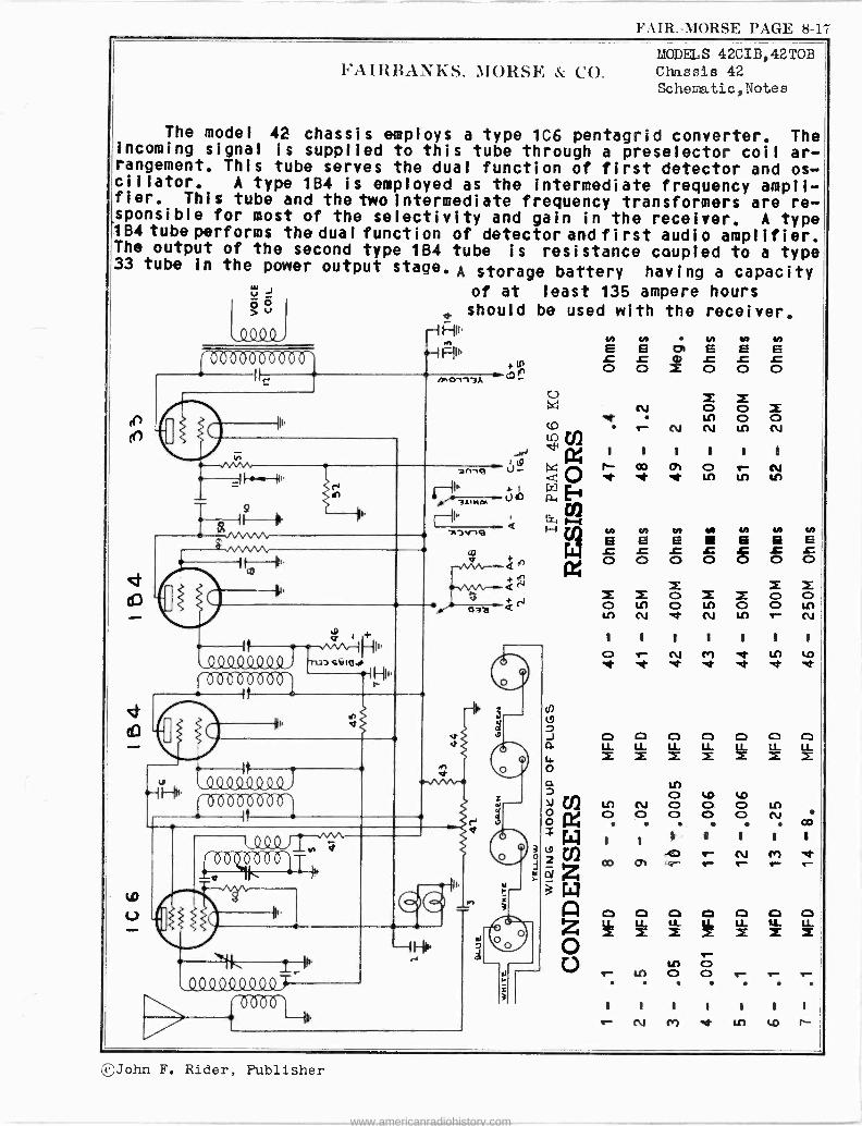
FAIR. -MORSE PAGE 8-17
of at least 135 ampere hours
d should be used with the receiver. -1 fle
N N H N N .H HMI, E E U E E E
O O X 000 Mon91A
-vv v\,---- Q V + NVVQ J
3 + oaa Q
F AIRRANïiS, MORSE CO. MODELS 42CIB,42T0B Chassis 42 Sc1ìe atic,Notes
The model 42 chassis employs a type 106 pentagrid converter. The incoming signal is supplied to this tube through a preselector coil ar- rangement. This tube serves the dual function of first detector and os- cillator. A type 1B4 is employed as the intermediate frequency ampli- fier. This tube and the two intermediate frequency transformers are re- sponsible for most of the selectivity and gain in the receiver. A type 1 B4 tube performs the dual function of detector and fi rst audio amplifier. The output of the second type 1B4 tube is resistance coupled to a type 33 tube in the power output stage. A storage battery having a capacity
O >
J o tJ
1,17-11,
v I
\4/, ¡ / / / ¡ /
/i[1L1L1Ly(/ ll3SVIdJ I'
100000000
,_QOQ40 Q44, I b000b
0b b b1T
} U X X
N O o i e IA O O (.0 N N to N LOVNl
.-y,W W I I I I I I
`'
W
v - .r x ÿwQ
.t Ln tf) n L '
cn s ,-1 F --i Tn N to) Vl M V) Y! N
/W E E E E 6 E O O O 0 8
O O 1
i O X O LA O LO O O LA lf) N 'Kt N Ln r- N I I I I I I 1
O r- N r) U)4p 'et'd `tt e 'tt t
CI o O o CD o C]
w o
413 o 4.0 4.0 Ti) to N O O O LO
o Cy CD O O O O N
CO.
$ w I I I I I I I
" CO -m e- N r) a
2 Z co rn r- .- d
w A o 0 9 0 0 0 co
Z Z o r.. u, o tr LO O O e- tr tr
. . .
I I I I I I I
N r) 't t1) t,p I-
,ç John F. Rider, Publisher
www.americanradiohistory.com

PAGE 8-18 FAIR. -MORSE
MCD .JS 42CIB,42T0B Chassis 42 Socket, Trin mers, Notes Alignment,Batt.Conn.
BATTERIES This receiver has been designed to operate equally well on an Air
Cell A' Battery or a Two Volt Storage Battery as the A' supply,
A three volt dry battery may be used with the receiver but the
life of such a battery Is usually not as long as that of the other types.
AIR CELL "A" BATTERY
If the receiver Is to be operated on an air cell battery only one
section of the resistance link" clrc It should be connected (See X'
Figure 3). The remaining two leads from le positive (+) A' lead should
be taped or otherwise insulated so they will not come in contact with
any of the other battery terminals.
TWO VOLT STORAGE "A" BATTERY
If the receiver Is to be operated on a Two Volt Storage 'A' Battery,
"A'none
of the connectionssareatoe be made asuit shown s
to under."I"used. of Figure
Positive The u
t
used leads should be taped so they will not come In contact with toe
ether battery terminals.
THREE VOLT "A"BATTERY
If the receiver Is to be operated on a Three Volt 'A' Battery the
'resistance link' circuit should be connected as shown under 'Z' of Fig-
ure 3. The unused leads should be taped so they will not come in con-
tact with any of the battery terminals.
When the Three Volt 'A' Battery becomes so low or weak that the re-
ceiver will no longer operate satisfactorily, the connections may then
be changed to conform with X' under Figure 3, thus obtaining a little
more operating time fro* the battery.
When the Three Volt 'A' Battery again becomes s0 low that the re-
ceiver will not operate satisfactorily, the connections may once more
be changed, to conform with 'Y' of Figure 3, thus again obtaining more
operating time from the battery.
NOTE - These changes must not be made until the battery becomes so low
that the receiver does not operate properly, and then the change must
be made one step et a time as described above otherwise the tubes In
the receiver may be damaged.
"B" BATTERIES Three 45 volt 'B' batteries, with standard plug receptacles, are
required with the receiver. Good quality, HEAVY DUTY batteries ere roc -
commended.
"C" BATTERIES 16{ volts of "C" battery are required on the receiver. This volt-
age may be obtained from a standard 22* volt battery, with a standarc
plug receptacle, with a 16* volt top.
BATTERY CABLE CONNECTIONS "A" BATTERY
The Black battery lead is to be connected to 'A' minus (-). The
Red battery lead is to be connected to A' plus (+), See Figure 3.
"B" AND "C" BATTERIES
Four Standard Battery Plugs will be found on the battery cable,
three of these are identical to each other and are to be plugged into
the Standard Receptacles on the three 'B' batteries. The remaining plug,
the one with the different terminal arrangement, should be plugged Into
the 'C" battery.
1VARN I N - DO NOT ALLOW THE 'A" BATTERY LEADS TO COME IN CONTACT WITH ANT
áF TO B BATTERY TERMINALS. IF THIS HAPPENS, THE TUBES, RECEIVER AND
BATTERIES MAY BE SERIOUSLY DAMAGED.
SUGGESTED SERVICE PROCEDURE If the receiver does not operate properly, first test ell batteries
and then test all tubes in a reliable tube tester or, better still, re-
place the tubes In the receiver, one by one, with tubes known to be good.
Rost difficulties will be found In or centered around defective tubes,
or batteries. If, after replacing any defective tubes or batteries,
the receiver Is still Inoperative, reao,e the chassis from the cabinet
and conduct a careful resistance analysis using the resistance values
shown on the schematic diagram as a guide. This will usually reveal
the source of the difficulty.
ALIGNMENT PROCEDURE To insure obtaining the performance the model 42 chassis Is capable
of delivering, It is essential that It be aligned perfectly. For this
reason, It's urged that the following instructions be studied carefully before any alignment adjustments are attempted.
Proper adjusteent of the various tuned circuits will be possible only throuth the use of an accurate and reliable signal generator em-
ployed in conjunction with an output meter, which may be connected from plate to ground on the output tube. A fixed condenser (.1 Rfd.) should
be connected in series with the output meter.
NOTE -All adjustments should be made with the volume control 'full on',
Any desired variation In signal strength should be obtained by adjust- ing the output of the signal generator.
INTERMEDIATE FREQUENCY 1.- Turn the gang condenser to noxious capacity (fully meshed).
2.- Set the dial pointer at 530 kilocycles and then tighten the sat
screw.
3.- Supply e 456 kilocycle signal .from the signal generator to the
grid of the type 106 first detector tube through a .1 Mfd. con-
denser connected In series with the signal generator lead.
4.- Adjust the radio frequency trimmer ("B'.Figure 1) for maximum out-
put with minimum Input from the signal generator.
FAIRBANKS, MORSE & CO.
4,- Adjust the four trisrors of the two intermediate frequency trans- formers (see Figure 1) for panino. output with minimum Input from the service oscillator,
RADIO FREQUENCY ALIGNMENT The parallel or high frequency trimmer condensers for each stage
laceted on the gang condenser (see Figure 1)
1.- Tune the receiver to 1500 kilocycles.
2.- Supply a1500 kilocycle signal from the signal generator to the an-
tenna lead of the receiver through a standard dummy antenna or a
200 Nafd. (.0002 Mfd,) condenser, connected In series with the sig- nal generator lead.
3.- Adjust the oscillator stage trimmer condenser ('A" Figer. 1) for maxima output with minimu. leput from the signal generator.
FIRST L F. TRANSFORMER
Plate "B" Plus Grid Return Grid (Top)
Blue Red Black Green
COLOR CODES SECOND
L F. TRANSFORMER
STANDARD RMA
Plate "B' Plus Diode Return Diodes
RESISTOR AND CONDENSER COLOR CODE 0 Black 1 Brown 2 Red 3 Orange 4 Yellow
5 Green 6 Blue 7 Purple B Grey 9 White
POWER TRANSFORMERS Lead Cofer Voltage
Black Breen Yellow Red Red and White
SECOND I. F.
TRIMMERS
FIGURE 1
TOP VIEW
DIAGRAM X
BROWN D 7APE
TWO VOLT STORAGE "A" BATTERY
TAPE,
DIAGRAM Y
115V, Primary 6.30. Filament 5.0Y. Filament Nigh Voltage Sec. Nigh voltage C.T.
OSC. TRIMMER"A"
R. F. TRIMMER'S"
Blue Red Black Green
SPEAKER CABLE
ATT ERY CABL E
FIRST I. F.
TRIMMERS
E TAPE BATTERY UNUSED ENDS
THREE VOLT DRY "A" BATTERY
DIAGRAM Z
FIGURE 3 BATTERY CABLE CONNECTIONS
©John F. Rider, Publisher
www.americanradiohistory.com

l'AIR.-3IORSE PAGE 8-19
t9
MODELS 43CIB,43TIB FAIRBANKS, MORSE & CO. Chassis 43
Schenatic,Notes The model 43 chassis employs a type 106 pentagrid converter. The
incoming signal is supplied to this tube through a preselector coil ar- rangement. This tube serves the dual function of first detector and os- cillator. A type 1B4 tube is employed as the intermediate frequency amplifier. This tube and the two intermediate frequency transformers are responsible for most of the selectivity and gain in the receiver. A type 1B4 tube performs the dual function of detector and first audio amplifier. The output of the second type 1B4 tubeis resistance coupled to a type 1F4 tube in the power output stage.
d
9QQQY QYY // //
t 3 zu
II --HI.
4QQ 0QQ 0000000á,
It
00
it ',p1 000000003
6600, -111.¡T
-10H1
d
W
nn aQ
7!ä
C] C] O C] C] C] C) C] C] C] LLLLLLLLLLLLLLLLLLLLLL
tI) Ot.O M
LC) 00NOLI) -1-00000Nr- .
CO CO
1 1 1 1 1 1 1 1 1 1 1
N Ce) e1 Lng.O1-000h0 1- (N., N N
C:)OCDC]pC3C]C]C)C] LLLLLLLLLLLLLLLLLLLLLL MiiZiiiiMii
r Ln O U) r- 1 - CD r- O Ln r- N LA O O LA . . . .
Lp
1 1 1 11 1 1 1 1 1 1
0 - r N M ef LI) LO OD O1 r-
N N N N N VL E vbEE@EE .0 m L L t .0 t O X00000
i Z z ó ti LC) LI) OOLY) tO NNNtnLI)Cr)
1 1 1 1 1 1 1
O Qi O r- N (r) ee et et LI) LI) LI) LI) LI)
N V) N VI N V! N N EEEEEEfsE t .c .c t .0 .c t 00000000 OOO MOI.Af-00LL)
M cm n- N I t 1 I I 1 1 1
Or- NMetLI)lOP- nt Kt
®John F. Rider, Publisher
www.americanradiohistory.com

PAGE 8-20 FAIR. -MORSE
MODELS 43CIB, 43i.LL Chassis 43
O L O L 1 L 0 o 4_ Y 4_ 4 o
a 0 o C L 4_c4_ H
O - 4,- L 7 L4_; O E O c O4_ - 4_ q w L co >t RI O 7 L q L >- U G H
CEO u.0 L O 7 to. p 0 UV 14-
....c - -V c C q L q L- v C 1- O C q 0. 4_ 0,0 V L - O .O
C O m in L I- . q 4_ w 7 O 4_ u C O p C w O m L -m
O C V . LL U L q C C y. 0 o E - L u u 0 CO q E 01 L C O7 L4. .--.. 0, L O O L- 4 L L E Y O w L O EDO -4_W -a e O q C L C .-L CL m }.- L. 4-
PCC OH 4_E
w -O P7 >O m u O e u L u 4- - C4.-.
OO.-, wC O -L - 74_ u VC LE UM > 4. q O O a u 0 m 4_L L c OL - O4_ 0-- -Y N -
O L -ÿ O E -,c.- O O - -7 004_ u4_ V 0 O m w 7 O- OVvL Oa LC
io O 4_ - O C O 7 0 -MO LO L
q F 04 4_ 4_L q E E 4- soci- Ñ7 4_- -eOq G w; aOo C 0- 0 atN v -x -4-
D C V q t 7 te, q.ew <0 <a N M
FAIRBANKS, MORSE & CO.
W W ; O V
o e o ; Á c u O- qm-vV V L m O m q D]U>ceK
C
7 V .0 m
mKmfLD
Y C
CZ m um 7 V .O
W CO LC
Z
Ao Z
E- ó z et
7 WHU? m w m N Q 7rew O - : 4_VV E,OdOO fr qm LL,
. 4- A?O VO C F
a. 41, co W -i a. on
O I E O te a- O 61 0
V C m 4_ m C O D L- L m L 7 C- V q W L
q4_ D - 4.- 0 04_ ñ O C L a 4- w L L w
.OLO OV. -7 Y Y 4_ upL 04_m -^ u D m L >a 11.0 a.04_ 7V
- u L u ; O V w o u c O o O O YV C.
o V OCC4 -> w L 4-X12 JE ->O a PCOZ LL EC
g Q7 M4_V - u 4_V E C C' -m mE q u7 C O m E. .- - E L O -a 0- O C > Y U F C .,! C0 u- _L g L - z rIO O P>O O4_ 7- O0,Y YE W YaL wwqw EL v+'C7.OgL
2 4- E C 7 O O.O L -Y -vC -O O C. O nLC Oÿ 17
m O 0 7- L V O O V C- u L 0 C > 2] [e 4- Y p. E Y 11 0 UY L q -O V O O m 7 V E - uv --Lu mv
W q Ld- 4_a á 7 O u - s L- m a L 4- -
O V L 4_ 7 a g 4_0 q e 4_
L Y a v L- O O o 2.0 4_ c - 0 Ymw a O LK4_ LL z
V^ E O. O
ncO eV 0-0 4_w r d oL- o
u O .- {. 7 C 4_ 4 H V 7
- Ea u- 4- w 4- 7 1 CU.O mO a B
u - mL OE O E Y
Cxi
m 7O- Y a v C , w l x O g 4_ Y L x Z L.o ÿ L 0.07 4_ 010g O ^Y - C m 4-, .0
O L O q -L a O 7 E L L E - cT V L2 r., - +- - .._04-.00 4- 0 x _ W L -w i c.1 7 7 w Y O w 4-. - S L F.1 b -o uOYm 0 Y M L; w //- a w C q L -L
L U1 m- w L tJ O O C4-.4-. v.O O 04-0 E L g O -C c W O }. u~ m É O WN L CL
w 4- C aL o O.O w
W Yd4_ RP .0 O -U C q TtUL E Y 7 w 4- _ L w o V N Óvmi L L p[. cu.
miYOV oF;O ÿ w W C i- - ^
L.V 4-0 O w 4.4-O ¡.1-1,11C O O C wY C CL Y V L. m C O ^ - y a- u
. Y 0 w O Y- C O - r..44 d LL ~ .0 V C E- L O- w p Yv 0 0 Y 0 O 4- 7 -C O E4_ W-yN-1 d - PE VOw roo C OOw VyO LC 7 m C -LE, U q dL u
D p. -L D V c D L Y - Y E L--- ¡y O V 4_ - C -- a m v g C Y > W L 01 w- q cm V> F L m 4. C w L 7 C_.0 .0000 < O A 4_ L>0 0 4_ L O w- LO.uLO V W Y
cl. Éw C L. 4_> O D 0,4- -O 4_ C -m-C 0.0C 0-L7 2 d áLN VOL > .O O 4... -O m <- a V1 plw <4 4_ LL 4- C w4_ y H
,...- C O 0-4_V C 1 0 7 O O L O m 0 V o W V 1. 0 >>4_ u W H N r Y q4. O O !- >m y 4- 4. O m C-- O O C L f+ O L O O a an Z< 4_
w
C m V c. o - u
m L L É U w E - O -LL L u } m >
O u >w O C- O L Y 7 O O w O O C O L O 1.11
4- V C O O L u 4_
rn
L CL
m m >
o rn m O -L O
m4_ L -C O q O L ._613
4_ O V am m
4_ C O 43 L u 1- f- O
q
Alignment,`loltage Socket, Trir.::er s
Resistance
d CO
cr W
LL
0 Nf
O N
M o N
O S Ox
Ó Ì < O Lai eix
U
ul J O >
1- O O N J O >
o O Y -
LO
®
ó
O LLLO ª go
,- ©
e O
©
F a F
°
J In W
N l[ CO
S 0=
Ó O n
fN- LA X r O
Li', co r.-
î O
X O .n
X O 0 rl
O .n X O
X X X O O U1 O V O Ul
M
r --
O n O O J
O >
.z. O Uf O
LU m
m
3 O
p O
I
-
W
b A
© ©
O
1
V °
ó
F- J O
N N J O>
Ul O N LO ¡
S xo h h 2
x0
c. O X<
O 0
©John F. Rider, Publisher
www.americanradiohistory.com

FAIR. -MORSE PAGE 8-21
0 4.
r-
Li)
N'AIRBANIiS, AIORSF. & CO.
.00,
(SO 000
II"
1- WO r- (00It
t001 +
Z
u Du
--> il- (D 9 gó
,00
00`
N
11
1_
QQQ4 QQ QSLO
-T öa00031 -4
00
v L ` - N `--i--
en r C
,2.0Q9Q.40 Q0,
MODII., 57T0 Chassis 57 Schenatic,Voltage Resistance
4- 4- 4- 4- 4- 4- 4- 4- ,- 4- E E E E E EEEEE O O O O O N O O o 0 0
1 I ) ) 1
) r r ) )
.- N M `tt N (\.1 N Chi
\O tD N O LO O O N C
I t 1 1 1
I I I I I
LC) tG N N M M M
a /7 V "0 .a 4- 4- 4- 4- 4- 1:) .D .0 E EEEE 4- 4- 4- 4- 4-
E E E EE O e- M O ln O O 0 0 0 o e-
CO
1 1 I I
).
N U") CO O) `- N M
r ) r ) r
r ) r 1 r
co m Cr) "it ui N N Cr) Cr) M
V1 E N V) V) E z E E E
. 0 O t L L O CI) Q O O
E Z 0 0 0 0 0 O o C.") e- tn LO tn
) i ) II -tr to m ó r- e-- e- - CV
VI VI V) N tN E EEEE L .0 L L O O O O O
ó ONUS VOL T3 6A8G TUBE VOLTS OMS. ONTS VOLTS 6F 50 TOOL VOLTS OHMS OHMS VOLTS 5Y3 TUBE VOLTS OUTS
INF. 106 --- ,5 2311 INF. 218 -51UFE; 1900 -95
INF. 218 - OD OO
100 ,,,o.INF. 208 -- O9 AL O -95 1900 O
- O 0 O
6.3 0 0
,
6.3 .5 INF. 222 `O O " --- ` 0 ©
0 0 - 6,2 300 0 0 0 0 0 0 222 INF, 1
OHMS VOIT
FIGURE 5 500.1 .15
VOLTAGE AND 50011 T6
RESISTANCE TABLE 0
0
0
607G TUBE OLTS OHMS ONNS VOLTS 6576 TUBE VOLTS ONUS
-.17 6.3
5n Ill
.5
1'íE6
10 FO
106
213
0
G
2.5
6,3
2.5
300
300
©John F. Rider, Publisher
www.americanradiohistory.com

PAGE 8-22 FAIR. -MORSE
MODEL 57T0 Alignment,Trimmers Socket,Notes
FAIRBANKS, MORSE & CO.
COLOR CODES
FIRST SECOND I. F. TRANSFORMER I. F. TRANSFORMER Plate. . . Blue "B" Plus . . Red Grid Return. . . . Black Grid (Top) . . Green
L 1 not 4-4. M
Ow2
mUe Cel O U
dzL r
w O i1 C 04.10 LzC uoc O 1.110
1:40.0 Cúvc 0 'Cr GLáL wr O
0+' 0 > c o x L CAC -0 w -00 O G U w r O
T- L
Chassis 57
RESISTOR AND CONDENSER COLOR CODE 0 Black 2 Red 4 Yellow 6 Blue 8 Grey
1 Brown 3 Orange 5 Greer. T Purple G White
RESISTORS Plate Blue "B" Plus Red The BODY COLOR represents the FIRST FIGURE of the resistance value Diode Return. Black The END COLOR represents the SECOND FIGURE of the resistance velue Diodes Green The DOT COLOR represents the NUMBER OF CIPHERS following the First
two figures
0 1 1 a< 1 wC0- V120V le 1
O M C 0 U G O r G- 0 0 0 4- U w U- -aii ÑO 'C COC me- rC utrl q
L ó0ió C r ....L.-0 N 0000 N --OG ..-4.. a To 0 < w 010 o L 0 0 4- C
100 La-GLO c CO -0 > U00 C q O 01-4-0.0 O O L o Ñ 0,0 <00 00;F- - uLOr o
V L 1- 0 r w0 ßO Ñ- - C'C a el- g r 0 E
00 0 -- C 0 > Ñ L a- 000 > - M L o.r - ; 3pwLr0r- w cÓ;i - C.OLOUC 0 4-E
m U Ir. ó ú L m L L r m w o> LOO r L r C ry w - L q0 0- uno
in 0 0C
4- N - o00 Or U r 0 i -01-000e0 0 0 0 0 w C C eau C u> --,e a C e.. ---TO O 0 .E g- 0 C
M CV 0-O Lw 00 00Ña0 < 4- 0-.--m 0 SOLL u O Le -rqe oqrmwL; Z T O C -000E i- g L o a O f1CO -[1LE .- C LLL a Z Zee TM q O Ñ 0 O - f-1 OL Cr E a>O> r CO .MO W O - MOO C> ÿ CLmGM OC C>0 'C L C g O -4- r E.y 0 L L LO 0G Og 0- L. -M
E O 0- L L L r ,-1-004+,04... w C O O q r G Eúe LMO 04 O L-r o 0- 0 0.0C 0 0 Q O G 0 O G - O w L 0 OTO Cr -Cor u;- CAM- ,ma Cum o- w 00 c
-O OOw'CL ÿ0 qm .r OO ,y _4- CLO- 0 ...coo-.., W 0 O r a O C O L 0 O r P O T O
w0 Mw 0. -ZU U OT- 000, Owe wGr C 4'LrMMÑ;-L C i- >- 0 N O- COMP 0 0 C q q4- me -CM ;r O -L ÓUL q C O -r r C em rOMCLGN- O-a>-CaM.- C $ V-c g0 - 00 ì -OG q q 00=40 0 aG I Y
-CO T4- ,00.....E. q L so 0-0 00C r0.-00MO-- O -c -a gc 0 -GOC-n-- w M 0 0 ñ O L c c O> N C- V; rwu w>0L 0
Nmi-e00-00 .. r N 0-q OO -1r4q rOCw OC o 4 4-0 O C O rUrO o1-oC0 O- ÓPO
C CGO -C a úOa L G r 0 01-00 4- V O -r E M eV, w ErOL N cam 050 - O C- C 4 M w - >O M O O C. L 0 -0.000 =--; M L.-
RP CPO -O O- LO0Ci1 <c. rcorÑOLu r 00P4- MU - me -CU GrC OB --u0 -q 0c Zw. r0- -wOCMrGar r 0 0 LV c V C T.0 C c._ 4-rNCw mm -.e0.00. 0 r a- g o- a -w 0- L N r N
m Ñ 0 1L
ÑÓ LE M rr CL 0_ÓO-0 ro .»CL ci
q
OC r Ó- GqOu
r 0 Ó 4- C M 0
C G M r O G r V V L =moor - :5, DO.- UM Lw r OE G. -o mrCFO.Ó LC mE r
C - LL"c cCC Tc L0aOOC- MM Ç0 OE wOm CLOai1Ñ u mc 000 0 4 0
M r -r CO L. -p0 CV O- O O Y O C ~ 0 w L U e g O L .O Ó0r PC1,EP
0 r a U C- co m Ó LqO c; EC OTO-O rG o mL0 'CuLCLJ[ E.0 i E
É r C a e~ 3 o m 'C a a LLm rÉ
Eyy qr. v0 ~CLx 11- rLV OLN¡G em D.i 'C Lr
L O C OL áT E c 4- ó 030.m0w a> o L zgnL º q P. r - 0 ,n LL
w Ú C NV
v LOi0 0 00c Cé 0 0 P OL L L E.-0
,,.1 O Cr g4-> 04-
á0w EOq < GOL. rrMOON u0O LL- OCO 0E10GO- 04.0 4...- ,71 O .- 0 0 0 LU U G VCtOOL V M
YOG OLL. yy 0og4-O-P r O o [_ OC - MwOCO W.0.- - O W g> LL L- C C M L 10 q; 00 ,
C F-ou O- 0-OÑ Y ONO
q O rv> OOC
O -G.OmuC-CC rO'C- O V L O r O y `
Co r mom Ix qCLO U COw r a. on D, aOFM Go4-C4--
ç .,,0-<.-4- Mom O LLPNP'Cr0C rq--GCqGEP
1 1 la G r- a w w 11 ., <c o L 0. L L- x2:58GGOG
rr4-0r
r uh- yl
D 0E EOvOfU m J
O EM O e: 103
IL LL M M Y J < I o 6. Z - rrrr u <m 55 W< 000» <al% FO ».> r N ZK
40110 á á ó < V ,-.010sx < /
. O
O4o m C M C 4 - Lr ; 00G J1
O ; 4- O -
u QV 1
s 0 L -0 e r M U r C-0 c_
E L
o ro a 0 wG C ore N
q U 0 q O U r- c O caq
ZO- E i . O -o 010- r 0 u T a O
U q u--
r C O - G O E r u v.w r OEL
; .4-00 . 0f2 L vv0 10
L Ñ ó m
A w C O Choz
'.2%t < O 00 00 C co --E aa q a m C E e E - 0 - (A L O
0g7;37, ,4 47. U O00 L w
gi1 Ó O I. a-
i1i1F W
0
xcó d 5
00 - MO -V.0 mt
U 0
C [11, K . 1 O W U O Z n U o 02 Y N
U R 0 O 0,-
01-0 L 04- 01, 1 1 1 .000 ¡ 0 'C O C O 'C Y E r r L > - a- 0 C 0 000 M 0 O - w C Ci1 0 O Om
OC L4- 0 .--0C o, -..o 0 0 2. r
p -0
r r PL It Cramoo 4..t..
C m COL- 005 LL EGO 00 0F 0
r 0 rwr >O G
C Sq L-qqM 0 - 4- ócL - 000cCL g H
., -._c 0000 co ..- 0 r 00 C 0, a
m Ó 01
Oc Ow C -L- u1- 0 CdZ -L- 00 O; >U OLIO mm 00 C O U 0 um 000 Ott UM CC 4- r 0, 3 u 0 C} r r0 CaE- -- r male w rN U ME CT - 1- 4- q J1 m L Cm
OC COmi. q -w VO C L M O O 0 q C O O g 0 0 O w w w O r r0 0r .00 ajúN Wm t OfG
E 0 co r > L E 0 4- g G 4 Lm . ea 0 0- 0 0r r r0- oL C m L 4-x04 a C;
Ti -0 C- - Oa 000 CO o E0 me O á r -E r w r m 00'. G O i-00
Cr C
w E
u 0 =Le: L 4-4- T L- L OO LE O - u O g L L 0 0 C 0- me U VT u u -4- 0 ->0 w C - c= O q C L r 0 g w U C- Y 00 :li P CL
0E 0 we CC ; ro 000
0 L 0 0 u q ei- m: O Ó r .0 00 a 0 0 0 0 L .O 0 0
U .- O 0- c L LT U O U Vim ; o u c ,00 T c 1- o 00,
0 0 r0.0 PCº u U r -LU O G N- Le U g- C T 00 A O u 0 -r 0 00 L O 01100, -L - L T O C - O L Ea C 0 0 -0 f1 Ñ u G c at.-. 0 0 E 4 -E 00«-Y0 J1 M1 r 0
O 4 - +1w 0000C 4 1 - 0 U O .-.10 O O L w C q OM 00 L 4 U O 0 OC4- OG CO C 0 Et. s 000E O 00 .- C u.4- 0 r. 0OC 00 L an= LwN . 1W 0 L DOO -.- G E r 1 w 0 0 r 4- r ,1 L L 0.0 c qq 0 4-x ¿ 00 wGNN 0C ^V
000. 0E O O V E'C q u 4-
ee se: CO 0 a C q a4N0 - C aL - OCO 00 _ ? C> OC - MO O ÑC OLLOL 0O v.0q. <a F r <0,00 U- a r; 4- 4,, .1.. E
1 1 1 I 1 I O 1 I. 1
1+1 f u1 C r co Zr N 11
©John F. Rider, Publisher
www.americanradiohistory.com

FAIR. -MORSE PAGE 8-23
(9
m
co
co
w
V
f 09 000
FAIRRANIiS, MORSE & CO.
- ,nnnn.
j,ivwe \ ñ
.-vw 1001oo
- ,000 00
f002
e El
1 HII
pI
.90499
1111 11 {
1111 1111 1111
tDll d r t TII
n
O
,QQQ0,1.Q000, 4900, T 1 -}) UI
L 0000 --HU
Cri >- 4n
.99Q4, ,0004000,
IH{u
MODEL S 58T1,58T2 Chassis 58
Schematic Vol tage Resi stance
y N N N E E E E E t t t r .CoO 00 O O
X O E 0 o eoo
(12 te - e- .to ón
N N N N y ry t t t 1 1 E E L E E W it 1 1 1 r.Crtr 00000 tti ti CO m v1
E z z z m o 0 0
F1 000 0 '^ tn ill "it N tn V! y N N N N
á =r= ; ; ; ; ; 00000 or- Nr) XXXI tntntntntn o to o In C9 r) e- Ill Al
11111 1 1 1 1 1
O.-NC7e nI` e .t ̀ d' e
V-0 vvv'o1, . -0ß"C1ß É É-0 4-4-4-4-4- 4- 4- 4- 4- 4- 4- 4- 4- E E E E E EEEEE óóEEE
t.12 'et co 00 N ONto00
CO-.-O.-N 00 O OONOO Q;
co co
^ 1 1 I 1 t 1 111111111 w l t l l l 1 1 1 1 1 1 1 t 1 1
Cn e- N r) 'et t11 4.13II .-C0 01 0.- N Cr) it to j e- e- e- e- N N N N N N
. W ii,121 + ,:, -c, ,:,ßMI V V '0 -0 Fj Z 4- 4- 4- 4- 4- 4- 4- 4- 4- 4-
EÉ@EEÉÉEE O ÉO Ó O e- V OOIANto 0000 NO 0 004.00
N %0 e- C0 e- CO
111111
i i i i i ii i i i
C7 `eh to 1.0 r e- CO 01 O e -
OHMS VOLTS 608G TUBE VOLTS OHMS OHMS VOLTS 6F6G TUBE VOLTS OHMS OHMS VOLTS 5Y3 TUBE VOLTS OHMS
INF. 100 -11 4011 INF. 248 -,3 I MEG 1800 -100 --, INF. 242 155 INF.
INF, 235 , O 0 O
0 100 1800
0 0 OW ` ©© 'pes
A4 0
6.3 1 MEG.
,5 o 0
O A.G 6,3 ,5 IIJF, 248 o ` ©©
` 0
0 0 3.6 300 0 0 0 0 0 0 248 INF. -
FIGURE 5 OHMS OLTS 6070 TUBE OLTS OHMS 'OHMS VOLTS 6K 7G TUBE VOLTS OHMS
500
VOLTAGE AND F.
RESISTANCE TABLE.
90 o- -.1 6,3
50011
.5
INF,
INF,
0
100
245 0
2.2
6.3
2.2
300
MEG
.5
300
©John F. Rider, Publisher
www.americanradiohistory.com

PAGE 8-24 FAIR. -MORSE
MODELS 58T1, 58T2
Chassis 58 Alignment , Trin.er s Socket, Notes
FAIRBANKS. MORSE & CO.
INTERMEDIATE FREQUENCY ALIGNMENT 1.- Turn the gang conderser to maximum capacity (full meshed).
With the Range Switch on the Broadcast position.
2.- Supply a 456 kilocycle signal from the signal generator to the grid
of the first detector tube (6A8G) through a .1 Mfd. condenser con- nected in series with the signal generator lead.
3.- Adjust the four trimmers of the two intermediate frequency trans- formers (see Figure 1) for maximum output with minimum input from the service oscillator.
RADIO FREQUENCY ALIGNMENT The parallel or high frequency trimmer condensers for each coil are
housed in the same shield can with the coil. These trimmers are used for aligning the high frequency end of each band, The location of the
various trimmers is shown in Figure 1,
The oscillator, adjustable, series padding condensers are used for
tracking the oscillator at the low frequency end of each band. The pad-
ding condenser may be adjusted from the top of the chassis through the
holes Indicated in Figure 1. Since a fixed mica padding condenser is
employed on the short wave band, no adjustment Is necessary. While mak-
ing padding condenser adjustments, the gang condenser should be rotated
back and forth across the signal to Insure adjustment to the peak of
greatest Intensity.
DIAL ADJUSTMENT Before making any radio frequency alignment adjustments, close the
variable tuning condenser (maximum capacity), loosen the screw that se-
cures the dial pointer place the pointer In a horizontal position (gang
condenser still closed and then tighten the screw.
NOTE - The three bands must be aligned in the following order: First,
police; second, broadcast; third, short wave.
POLICE BAND 1.- Turn the band selector switch to the police band (center) position.
2.- Tune the receiver to 6 megacycles.
3.- Supply e 6 megacycle signal from the signal generator to the an-
tenna lead of the receiver through a 400 ohm carbon resistor (dummy
antenna), connected in series with the signal generator lead.
4.- Adjust the police band oscillator trimmer condenser (Figure 1)for
maximum output with minimum input from the signal generator, then
adjust the police band antenna stage trimmer for maximum output, et the same time rocking the tuning condenser back and forth across
the signal to Insure the peek of greatest Intensity.
5.- Tune the receiver to 2.4 megacycles.
6.- Supply a 2.4 megacycle signal to the receiver through the same
connections used on the previous adjustment.
7.- Adjust the police band oscillator padding condenser (topof chassis
see Figure 1) for maximum output with minimum Inputfrom the signal
generator, at the same time rocking the tuning condenser back and
forth across the signal to insure the peak of greatest intensity.
8.- Check at 6 megacycles and then et 2.4 megacycles and make any ad-
justments that are necessary to obtain satisfactory calibration.
BROADCAST BAND 1.- Turn the band selector switch to the broadcast (counter -clockwise)
position.
2.- Tune the receiver to 1500 kilocycles.
3.- Supply e 1500 kilocycle signal from the signal generator to the
antenna lead of the receiver through a standard dummy antenna or
a 200 Mefd. (.0002 Mfd.) condenser, connected In serles with the
signal generator lead.
4.- Adjust the broadcast band oscillator trimmer condenser (Figure 1)
for maximum output with minimum input from the signal generator.
Then adjust the broadcast band antenna stage trimmer for maximum
output.
5.- Tune the receiver to 600 kilocycles.
6.- Supply a 600 kilocycle signal to the antenna of the receiver
through the same connections as previously used.
7.- Adjust the broadcast band oscillator padding condenser (top of
chassis, see Figure 1) for maximum output with minimum Input from
the signal generator,at the same time rocking the tuning condens-
er back and forth across the signal to Insure the peak of great-
est intensity.
8.- Check at 1500 kilocycles and then at 600 kilocycles. Make any ad-
justments that are necessary to obtain satisfactory calibration.
9.- Supply a 456 kilocycle signal to the antenna of the receiver
through the dummy antenna with the gang condenser at 600 kilo-
cycles.
10.- Adjust the wave trap trimmer 'A' (see Figure 1) for minimum out-
put.
SHORT WAVE BAND
1.- Turn the band selector switch to the short wave (clockwise) posi-
tion.
2.- Tune the receiver to 20 megacycles.
3.- Supply a 20 megacycle signal from the signal generator to the an-
tenna lead of the receiver through a 400 ohm carbon resistor (dummy
antenna), connected In series with the signal generator lead.
4,- Adjust the short wave band oscillator trimmer condenser (Figure 1)
for maximum output with minimum Input from the signal generator.
Then adjust the short wave band antenna stage trimmer for maximum
output, at the same time rocking the tuning condenser back and
forth across the signal to Insure the pzak of greatest Intensity.
5.- The Bmegacycle signal should be received near 8 megacycles on the
dial. If this is not the case, check the oscillator tube, switch
connections, the fixed padding condenser and the coils. Ho adjust-
ment Is necessary at this point.
WARNING - The image signal should be received at approximately 19 mega-
cycles on the dial. If not, the oscillator has been aligned to the image
frequency and the oscillator trimmer condenser must be backed out until
the correct signal is received at 20 megacycles and thelmage at approxi-
mately 19 megacycles. if readjustment is found necessary, the antenna
stage trimmer should also be checked again.
ANTENNA AND GROUND CONNECTIONS The BLUE wire on the receiver Is to be connected to the antenna.
The BLACK wire on the receiver Is to be connected to the ground. When
e FAIRBANKS -WORSE ANTENNA is used, the BLUE wire from the receiver Is
to be connected to the red wire on the antenna set coupler and the BLACK
wire from the receiver Is to be connected to the black wire on the an-
tenna set coupler and to a good ground.
The most suitable antenna for use in large cities or congested
radio districts,where Interference is a serious problem, is the doublet.
In small centers of population, where interference is not serious, a
single wire antenna having a total length offro 75 to 100 feet, erect-
ed as high as possible, with a good Insulator at Bach end, will prove
satisfactory. The lead-in should go to the receiver by the most direct
route and should be kept away, as far as possible, from obstructions.
Such an antenna will have less directional properties and less tendency
to pick up power line interference than a low antenna with a long hori-
zontal lead.
BROADCAST POLICE
SHORT-WAVE TRIMMERS
WAVE TRAP TRIMMER'A. BROADCAST OSC. PADDERs POLICE
eo7O - ered
Sß_3 e 2NDI.F TRIMMERS
COLOR CODES
FIRST I. F. TRANSFORMER
A A G. CORD 1 ST I F
TRIMMERS
ANTENNA -BLUE
GROUND -BLACK
SECOND I. F. TRANSFORMER
Plate Blue Plate Blue 'B' Plus Red "B' Plus Red
Grid Return Black Diode Return. . . .Black Grid (Top) Green Diodes Green
RESISTOR AND CONDENSER COLOR CODE 0 Black 2 Red 4 Yellow 6 Blue 8 Grey
1 Brown 3 Orange 5 Green 7 Purple 9 White
POWER TRANSFORMER
Lead Color
Black Green Yellow Red
Voltage
115 Volt Primary 6.3 Volt Filament 5.0 volt Filament High Voltage Sec. High Voltage C.T.
Red & White
RESISTORS The BODY COLOR represents the FIRST FIGURE of the resistance value
The END COLOR represents the SECOND FIGURE of the resistance value
The DOT COLOR represents the NUMBER OF CIPHERS following the First
two figures
MICA CONDENSERS (Capacity In Micro-Microfarads)
The FIRST DOT on the condenser represents the FIRST FIGURE of the capa-
city The SECOND DOT on the condenser represents the SECOND FIGURE of the capa-
city The THIRD DOT on the condenser represents the NUMBER OF CIPHERS follow-
ing the first two figures. The colors on the condensers should be read from left to right with the
condenser In an upright position.
©John Fe Rider, Publisher
www.americanradiohistory.com
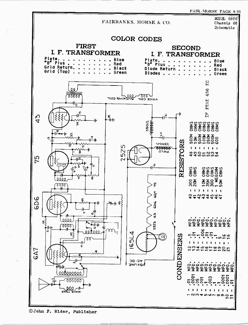
FAIR. -MORSE PAGE 8-25
W
N Q
h'AIRBANKS, NTORSh. & CO. LDDEL 68T6 Chassis 68 Schematic
COLOR CODES FIRST SECOND
I. F. TRANSFORMER I. F. TRANSFORMER Plate Blue Plate Blue B Plus Red "B" Plus Red Grid Return Black Diode Return Black Grid (Top) Green Diodes Green
It.
\ 4Q 1 135- 1"OD 9N1,17f)Q -HOD 3D10/e
.I1, PI. v
1.-1 - 1>-4011444/-+áL
b6`
v
dV13h{1M
e
N
N
-J
DO -DV 3N11'ASII
NN ti) NentP)cn 2 = _ _ _ _ 0 0 0 0 0 0 0
N Cr) .1" LC) tp¡-- .1' "of .t .4-n1-./
CD D O O O D O CD p LLLLLLLLLLLLLLLLLLLLLL ZiMiiXXXX 10.
r- r- Cr) O 0 r -O Lf) 0 0 0 o r- 000Cr-or_.-oo0 . . . . . . .
1 1 1 1 1 1 1 1 1 1 1
"Kt LL)tD1"-00tTOr-
©John F. Rider, Publisher
www.americanradiohistory.com

PAGE rt-'L(i FAIR.-AIORSr.
MODEL 68T6 Chassis 68
Socket,Trinners Alignment r O t AL m } r Ul
L mt 3 . .1-..1-. Y O C -
u0 u 0
3 av 0
m I N- m 4- 4-. A u m C- O 4 m V L C E a J 4 m O N t C v Jrm n vmr r q V N
A V A r -G u C aA V m 10 E O ci .., I- 0, >,0 a -rm
N A V O t m
A - r >au V U A 0 > cu- r V G) - o J E- L - a7r u m E N r Y 4_ x L 3 0
q m N 0 OZ N ¡
C L. V 0 0 A L V r O L m C V r
N O ^ m
C GC)
V us F-1 m m
A V P r Z N > C C C -
cucce C Ú r A m Y P N
E
[. ' . L
A C N
-V ^V
O .0 m7 VA r Lr> U r O u P 0 - m 4-m OC Q L N C m--.- J O J CO a- 3 14 r a h-
e Y O 0 . LO- 1:Z r N ,rr > 41) co- W
FAIRBANKS. JTORSI+, & CO.
I A I L t NL I m Lm 1 P L A I m L
I C P 0 P V / C C L U M L- 4- 7 Ar N
- A 7 C A 4'r A p N 0 t C r C O N E -
o L, U EmN >O L 4 r> C3 Am - L FoV m C. t 7 3 c E ONO t Er C L ^ r o L C r A r r a Y A E Z C4' m L - O A A N r u O N - o L O L a V m m L L o 7 O V V m m rt 74' m o4 L Yd m- O - .0.-.., RI -t
L c4 PA > r J P A- > U V r m U 7 N OA- -L - vaP á- -> E L- >r r E LL o m L G C4- A m U J
v O U - vC V m--0 U U0 E C r L A L O
L E N m N m- - O L N O P O V mEo L P L-
0 C E 7Y N> L- C - O -r mr c7- m ca, mL Y- r rNA EAV
V L m V E m -O m E - '31-
m L -C P O C A L C - m a Ur LO N LL m 10- A
p N m C 4- 0 CL >U r0 L O m C - -L V OI V- r m U A CD 0 a C C m L U^ A A Ç C- ~O E L O G 4- m 0 P A N.D C V O N P Pr -. r 0,0 O I
PCV U A CL c -- AA A -q A m,- -q m m C -r-m Y4 C Nrr Mt C V- YL A C L r 3 AUC VL
N U C r O V ;07 O N m m m r 0 P m r L m m A r V A O N O 4' N L L P E- > m N
tAC PE Co arLG 10C CC 7 O -LN -YN G>
r C O A N 7 - - A m P . G N O m U C
L O m L J L a 4-'E
V N m U m G) U
EPU L4- N m Orm O A4 mC LL mOL mLV > O J 4+ m L> 4 7 E .1-. 21 .0 O m L O r L U C V V
L O 4' - r- AO-
-U C -
- - C 0 rU N r Y O C E .0 m -U E P
4- L L C J U N m m
-rwt 0 O a .- C u 4-*
7- 0 -EmcArr rc -U p 04-.7 0) 0
N P mEo L 0 O P
A C N- O - - VJEP q > L
a A m PL A - :AC
N
c0- L AC
m L .L. > N E A V> P U WL 10 C L A P Lm VC m EY Cc. m O - N N
N>O C E m
m N E L r NN "r E
N
Ñr 4- 0- O N C E mL
-V .D A .0 L r -U L 1D
L O D U r - r U m m r A O m} Y
V m O E - O N > L V U > C - - a 0 0 Cl., L C C C X L U 4- .0 r > C N A O V U 3 A A r r - m- P - E v O I V L r U O ,42,-.L O m > L V U> N 4-
N C
-m E m - L O - V r .U -L U A r Z m L > - E -t N m E 3 m -r V L A - E O C 0 V G G) m m
Y r 0- E A m 0 Y - C M E -G
f v CL
L 0 C O)LL O C
m 01
Cu
m L m U t -r
C M 0 Y m O Lrt r N -
vCU Z C }r 4- O O - m 0
OL41.4 LO r L to t p E 4- C -W
UwN N
"*U"'
lV :: Lm 0
-A i P N eAm
r >
cD
E m r 7 r 0- Ñ N -E 4'0 tm
Am rmPv rr A E V m LI_ C 4-
- Y É ?'VE
t m
m C > ACrN
0-
4 m tLr- A 10 mE A)Or
.,-*O-
Oc
> Oi-. U m rr--
aC 0 a 7-GJL co V r 0. C m - Cr m
aC0- -x c am .- NPVc mN am - Ey L c aA c oACN a 7 o 0 A me J =.0 V - - A m t 7 J L V ,/ 7 J J m m t - 0 7 m
y1rN 0 <6 F en 4- <N N.Or U.- vlr < ai (- F VI -r I- V V- CC
Y to .D r- W Q1 O r N C1 Y et
U)
Cm InO NL L L t ObOPrt RI r C L A r m 4- c 7 Ln r
U A 4 U E A O 7 om L v Pc aL-N LC 4-, 4-. AC- V tV N r C J O- t-
01
mrr A O 0 D.- a L C r N N g-
o V U C 7 A,- L U V r C- -m uymA m 0 L m m -L
NVmOr-Um
L Ñ
4E-
m -
v Y) > O CT r - A q C t r Omr-
m r r c m E L 4- L
Q E L vA 0
4- C L O O O
Lt u VC LO CN
T a 0 0 m E 4-v
0 mN mt .0 4-
rm N At N Ñ.. - L r Gtr V C
m u P
4.-
-ml Ñ 7 A 47..._44-..C_ c4 4-pc- Amr
Pc-
V
W .
vqO
Ñ
LLyy C I P
3EL V O
1-1-1 "¡Ñá u GP
EC r aa A
T1 O m G) -Cr N H E L A- 7 L E
VA>6 Yc rvm4-P CC 4- 0
ErAamJLC, EA rA O
y p4_ O Y m m L ArE
.E
L V l-- ( E L O4...3 ZW LO JPrA E Z rL
Ñ 1 m._L-V- o
O 4- O L W mr L4- m - a rt m
U -L C r A
rL
d L
C s 4- c yr w r Pp L.
N> A N .. -. C L _Q N LVJG)O
ArOr mmP m^ 4 LCD 'QC rt m m .0
V mN E r v 0
LJN4c - U E r O ^V
4- G)
J A> P L m S. L ._CD A L C .0 .- _
cA
C
.- } - V 6V G LL- >.1 POr VL U. r
O m L r 7-
ó - 4- mm O
yy
-OL U cO
r . qq rA-mmL
mc-V'NV- L r U L 4- -- U
Y L J LL N C 0 N C
1-: r0O
Y)l uyG m J -u V r 4 A N L v L-L>-000CJ
Q) W r > W A r V IL H
U- A N G) - - N L L
m C m Pc L r L N Qy A C c O L P C r ?A G1 N y N a0 J- 4. C -- Q
C r a a C N J E -L m
A
Q L O
r N f V
7
UC
:Cr,Ny
rLAV
Lm 4.Lm
r -NO
G J m C v O L 0 L L L L 1- Cl) vlr.- ,C4 -r h -A4-0 f..
0.
©John F. Rider, Publisher
www.americanradiohistory.com

FAIR. -MORSE PAGE 8-27
Upper Voltage Readings A. C.
FAIRBANhS, MORSE & CO.
04145 V0115 606 V01.1500145 01.05NOU5 43 001301145 OHMS 0013S 2525 vOLTs 04445
290019G
2700
la/
08
oe 9G
17.5
17.5
o 0
3.5 24
1.4
lib /2b
19'4 900
ioo
7.6
2100
3M
23
l'6
bi
43 43
0
13 IS
17.5
7.5
5o0M
600
10.2
25
170
34
I 07
!5
4 45
I 07
ns
GG
6G
25
170
23
1 (G
© @
® r© © J
044M5 1/01/3 647 VOLTs 04015 0.105 MI5 75 vtxTLpy{s oH05 11005. 165L4 VOLT504445
125Y
37N
2700106
.8
65
S0 4
96
116 12.G
0 0 2
.IG
I.G 1.3
G.4
G.4
14E6.
215M
300
41
5001n
400"
4
O
25
6.3 6.5
p o O
4 .39
OAC o
SOOH
s005
8500
0 170 II IIS
70k 90
6 66
37
33
ti
7 l3 © ©
6 a
rv
MODEL 68T6 Chassis 68
Model 69T7 Chassis 69
Vol tage, Resistance
Lower Voltage Readings
D. C.
FIGURE 5 VOLTAGE AND RESISTANCE TABLE MODEL 68
011145 VOLTS 606 VOLTS OHMS 01045 VOLTS 43 VOLTS OHMS OHMS VOLTS 25Z5 40175 0.115
2500
2500
450
9]
95 9s
7.0
0 0
5.9
5
9.8
25`450
5000
500
300
1500
3000
45011
%:
87
ZS
e' 0 Q C
0 p
_ -45
1.S
IMLG
0
45011
2500
590
450
95
95
Soc_/
95
5 15''' 5
2500
590
45d
G
a 0 © r, C
T -"-®
© © _
OHMS VOLTS 6A7 WLT50005 OHMS VOLTS 76 601:13014M5 OHMS V005 165L4 VOL15 OHMS
2500
9900
2500
450
95
9]
294c LG
ó
_L75
I.75 2D5© 30"- 19.5
6,g
50M
ISO230M
450 450
7e0 5.1-3 0. -15
0 0
4
jpC -9 450 590 .J5
»'c 53
SOc
490
450 CI%.c
l;, L
( ©
FIGURE 5 VOLTAGE AND RESISTANCE TABLE
MODEL 69
NOTE - The upper voltage readings shown indicate the voltage from each respective prong to ground with the receiver connected to an A.C. (Alter- nating Current) power line.
The lower voltage readings were taken with the receiver connected to a
D.C. (Direct Current) power line.
These Voltage readings may vary with the fluctuation in line voltage.
©John F. Rider, Publisher
www.americanradiohistory.com

PAGE 8-28 FAIR. -MORSE
Li0DEL 69T7 Chassis 69 Schematic, Socket Trinners,Alignment
`6000660'
LD N
N Lo
FAIRl3ANhS, MORSE & CO.
.2 n ó +'
43 P ócróc +° m `
s~ ri .Y t. m M
er) óxgw° cd o Lo Orr mo o 0 0 . O O Al O O MP LO .D c1 .}v t, O -P
I '
A, r 00 ++
1 Ú gj
I-.-Ui wW 1 1 1 1 1 1 1 Ó C. ,-1 0 ,a +
_^ CO 01 0 r N or) `.t. 11) a, p r-1 + It + Z Ó e0 «N :1g nº
O
'; .i
A. . . 44
0 r+ m 0 7 t' C ] C C] ] C C] O ri e z U. 13 p %ao v my
O O me o
OOltOR1Ox' ÓgO O O Cr
d g O a+). 0 m -PC-Pd -,-1 a p LO ..4-.4A 4,9310A) O I 1 1 1 1 1 1 1 a. 3X O 60 0o s,
c..) rNM`dLAtp1`-O e -p 0 íOr) ct-i 0..
P P. m
F r-1 O m
.--1 i., P. a a3 0
$ NNNHN q O ñ Xzssi 00000 j.,01 G'. p a. m O E. .i O rl CO
ÓOÓÓÓ E: 0 0 0 0oLA00 r*+o I O
L7 r N L[) LA R U 7. rC î', a S O
I I I I 1 Ñ40., ni R m U
65 Ln C,D 1- Cp 01 6 m H m 1 Ó .f",
enhet el- el- f. F. +. 0 at ¡+. Fi n O CJ b0
(? C7 4., Ó O ó V) V) N V) V)
4S f. H 0 0 v áiî d + Q o co .a ó _ = = = = x G*.
. m ?+ D + Q1 00000
W .t.z p
m Oîî0 7-4 -P .44 c O m W oº i LA O n tl) P.
LArLAC1L r H y m )0 U
. O
-P q r-1 . W m ' I I I I I r-_--3 4-, l'''0U
O OrN1'7 -N )+ i y ePeht?e m O
U 0? CD Á " O g
H 2 Q Hg)?,6 O
Y C Ny . X C 7 00 N W 7 00 N
mm0 03Ce(D0
. . Fy .
. .
.. . Ó Wz' 4 .L
:
r/ w /i v F+ O L. y {+ 70 1' G"' 7 N
Ce ' CD 11- N 12 13 I'1 4-. "V ID
103 _._ 103. _._ -m L L -Co L L O_ = CD U' H CL a CD CD
©John F. Rider, Publisher
www.americanradiohistory.com

FAIR. -MORSE I'AGE 8-29
Ñ
(o
O
C9
c
O
FAIRBANKS, MORSE & CO.
(Itr° 92
III 11I atitil
S
f 7
-i} nfn I}- , Q Q Q , . n Q ,
<--
N N y) V) M E E E E t .0 O O O O
o El o 11
E EEEE E E E E E O .cL L .0 .l_ .0 t t Z t 00000 N LI) O CT CT
g g g O E E O g g
O
MODELS 72C2,72C3,72T3 Chassis 72 Schematic, Voltage Resistance
. vv 1.3 v a- v- I - º- 4-IrEEEE E E E E Egg
rn O O Crl N e- r- Vt .-00000o.- o
rf,. w ; I 1 1 1 i I 1
rn E E E E E E E l 1 1
col
1 1
,,It!) lC) u p tn Ch Ch `Q' et d' `t ̀ 1.to in W.,O ONN . co
A I 1 I I I I I I
f1 I I I.
I. I I . O r Cr) ;t. tO r hl
-. n N ñ
l 00Q4492Q9.9.
00
I1
Ce.
g g V! VJ W y U) N N
O O O O O
I I O E O O O I. 1 O O O lf) r M tl1 r 01
Cr) tf) If) r r nt. 'I" 1 I 1 1 111111 11111 1 1 1 1 1
N tn t0 r- cov. O (Ni ( ir)
52.-- .01 mfd.
X
1.11
%ID
, ó
1 1111111: . a ti) t0 OD p.' O r Cr) ó N NNNN Cr) Cr) M
el"
X s
S ó
2 U . p
III n .-
i o .-
w
á o
ó
m
w
u d<
O o
© a. °°y
W
en
O
o . 1-
ó p o H ó
y
O p
ó Ñ O o S ó_ S
W p = O
O . o ^ p
tre
^ X
- -
_, ps -o o en I-
o
r`-
.o
In* e e
O E3
©. o F OF,ì
O ©
< e-
>O
LOm P p J o '
CT p .- .o
X ó
r ú, . o
ó o ° o
i o
,ísi W p i o oo n o
. o
a o o
J O D.
Ñ O .-
o N j r p p
I
ó.! <
I.
CSó
O©
w Ch m
m o .- .0 J 0 `^ n .4,,
o
N
ó o . o s i a ,n
. p ,n ,:i
©John F. Rider, Publisher
www.americanradiohistory.com

PAGE 8-30 FAIR.-AMORSE
MODELS 7202,72C3,72T3 Chassis 72 FAIRBANKS, MORSE & CO.
INTERMEDIATE FREQUENCY ALIGNMENT SHORT WAVE BAND
Ali glue nt, Socket Tri>rallers,Data
1.- Turn the gang condenser to maximum capacity (fully meshed). With
the range switch on the broadcast position. 1.- Turn the band selector switch to the short wave (clockwise) posi-
tion.
2.- Supply a 456 kilocycle signal from the signal generator to the
grid of the first detector tube (688G) through a .1 Mfd.condenser
connected In series with the signal generator lead.
3.- Adlust the four trimmers of the two intermediate frequency trans- formers (see Figure 1) for maximum output with minimum Input from
the service oscillator.
RADIO FREQUENCY ALIGNMENT The parallel or high frequency trimmer condensers for each coil
are housed in the same shield can with the coil except the oscillator
trimmers, these are air dielectric condensers and are mounted on the
chassis. These trimmers are used for aligning the high frequency end
of each band. The location of the various trimmers is shown In Figure 1.
The oscillator, adjustable series padding condensers are used for
tracking the oscillator at the low frequency end of each band. The pad- ding condensers may be adjusted from the top of the chassis through the
holes indicated In Figure 1. Since a fixed mica padding condenser is
employed on the short wave band, no adjustment is necessary. While mak-
ing padding condenser adjustments, the gang condenser should be rotated
back and forth across the signal to Insure adjustment to the peak of
greatest intensity.
DIAL ADJUSTMENT Before making any radio frequency alignment adjustments, close the
variable tuning condenser (maximum capacity), loosen the screw that se-
cures the dial pointer, place the pointer in a horizontal position (gang
condenser still closed) and then tighten the screw.
POLICE BAND
1.- Turn the band selector switch to the police band (center)posltlon.
2.- Tune the receiver to 6 megacycles.
3.- Supply a 6 megacycle signal from the signal generator to the an- tenna lead of the receiver through a 400 ohm carbon resistor (dum- my antenna), connected in series with the signal generator lead.
4.- Adjust the police band oscillator trimmer condenser (Figure 1)fer
maximum output with minimum Input from the signal generator, then
adjust the police band radio frequency and antenna stage trimmers
for maximum output.
5.- Tune the receiver to 2.5 megacycles.
6.- Supply a 2.5 megacycle signal to the receiver through the same
connections used on the previous adjustment.
7.- Adjust the police band oscillator padding condenser (top of chas-
sis, see Figure 1) for maximum output with minimum Input from the
signal generator, at the same time rocking the tuning condenser
back and forth across the signal to Insure the peak of greatest
Intensity.
8.- Check at 6 megacycles and then at 2.5 megacycles and make any ad-
justments that are necessary to obtain satisfactory calibration.
BROADCAST BAND
1.- Turn the band selector switch to the broadcast (counter -clockwise)
position.
2.- Tune the receiver to 1500 kilocycles.
3.- Supply a 1500 kilocycle signal from the signal generator to the
antenna lead of the receiver through a standard dummy antenna or
a 200 1Yfd. (.0002 Mfd.) condenser, connected in series with the
signal generator lead.
Adjust the broadcast band oscillator trimmer condenser (Figure 1)
for maximum output with minimum input from the signal generator.
Then adjust the broadcast band radio frequency and antenna stage
trimmers for maximum output.
5.- Tune the receiver to 600 kilocycles.
6.- Supply e 600 kilocycle signal to the antenna of the recelrer
through the same connections as previously used.
T.- Adjust the broadcast band oscillator padding condenser (top of the
chassis, see Figure 1) for masieum output with minimum Input from
the signal generator, at the same time rocking the tuning conden-
ser back and forth across the signal to Insure the peak of greatest
Intensity.
8.- Check et 1500 kilocycles end then at 600 kilocycles. Make any ad-
juatments that are necessary to obtain satisfactory calibration.
2.- Tune the receiver to 20 megacycles.
3.- Supply a 20 megacycle signal from the signal generator to the an-
tenna lead of the receiver through a 400 ohm carbon resistor (dum-
my antenna), connected in series with the signal generator lead.
4.- Adjust the short wave band oscillator trimmer condenser (Figure 1)
for maximum output with minleam Input from the signal generator.
Then adjust the short wave band antenna and radio frequency stage
trimmers for maximum output, at the same time rocking the tuning
condenser back and forth across the signal to Insure the peak of
greatest intensity.
5.- The 8 megacycle signal should be received near 8 megacycles on the
dial. If this is not the case check the oscillator tube, switch
connections, the fixed padding condenser and the coils. No adjust-
ment is required at this point.
WARNING
The Imago signal should be received at approximately 19 megacycles
on the dial. If not, the oscillator has been aligned to the image fre-
quency and the oscillator trimmer condenser must be backed out until the
correct signal Is received at 20 megacycles and the Image at approximate-
ly 19 megacycles. If read)estment Is found necessary, the antenna end
radio frequency stage trimmers should also be checked again.
67G .1 eLe 1ST I.F. TRIMMERS
2 ND I. F
TRIMMERS
BROADCAST R OLICE
SHORT-WAVE TRIMMERS
ip eOA
TOLIC[
COLOR CODES
FIRST I. F. TRANSFORMER
SY3 PEAKER CABLE
A.C. CORD
eAa
OSC. TRIMMERS SHORT-WAVE
BROADCAST POLICE
GROUND -BLACK ANTE NNA-BLUE
SECOND I. F. TRANSFORMER
Plate Blue Plate Blue
"B" Plus Red "8" Plus Red
Grid Return Black Diode Return. . . .Black
Grid (Top) Green Diodes Green
STANDARD RMA
RESISTOR AND CONDENSER COLOR CODE 0 Black 2 Red 4 Yellow 6 Blue 8 Grey
1 Brown 3 Orange 5 Green 7 Purple 9 White
RESISTORS The BODY COLOR represents the FIRST FIGURE of the resistance value
The END COLOR represents the SECOND FIGURE of the resistance value
The DOT COLOR represents the NUMBER OF CIPHERS following the First
two figures
MICA CONDENSERS (Capacity in Micro-Microfarads)
The FIRST DOT on the condenser represents the FIRST FIGURE of the capa-
city The SECOND DOT on the condenser represents the SECOND FIGURE of the capa-
city The THIRD DOT on the condenser represents the NUMBER OF CIPHERS follow-
ing the first two figures. The colors on the condensers should be read from left to right with the
condenser In an upright position.
POWER TRANSFORMER
Lead Color
Black 115 Volt Primary
Green 6.3 Volt Filament
Yellow 5.0 volt Filament
Red High voltage Sec.
Red 8 White High Voltage C.T.
Voltage
John F. Rider, Publisher
www.americanradiohistory.com

FAIR. -MORSE PAGE 8-31
OHMS FAIRßANKS. MORSF. & CO.
300M
O
500M
750M
0
VOLTS
150
2
-.0 5
55
O
v)
(0
(0
tr)
VOLTS 70 o
1
o
15-R.F.
-.03 -J5
O
S
75 2 -DST. I -A.F -- --7
taa ººººº
OHMS 500M 1- MEG.
50
O
500M 750M
o
3.5
OHMS VOLTS O 100
O 70
ISO 4 5
VOLTS
o
-1.2
1
0
A7 OSC.MIXER
300M
o
145
0
o
5
76 DRIVER
r I
w
3 LL\ .0 +
---- -i iuJi
n ur1tr M av
T .
r é
-- QO" 1LL It I 'HI,
7 r l 1^
ui ó -__ -ih
Ii* 7?r 1~-I F- .-i }-- }- LQR4J ,QQO
I
g-i1r
OHMS
1-MEG.
50M
200 0
500M
I -M
3.5
OHMS
MODELS 73C3B, 73T3B C has si s 73 Sc hem. tic,Voltage Resistance
VOLTS VOLTS OHMS o
I 0 0
250 200M 3.5
70
ISO
4
0
155
e
I5-I.F.
19 OUTPUT
-0 "0 '13 1:3 -0 ID 10 -0 MI 4-4-4-4-4- 4-4- E E E E E EEEEE
O
.9
o
o
155
4
1-MEG.
250 200M 100
tn e- Lf) r- r- L17 MY NOONr- OOrO 1:3ß1D r- p co- q_ 1 1 1 1 1 11111 E
er) LC) LON00010 NNN(VN NNNNfo) 1.1) O L[)NOO 1310 1:1 10 13 Mi *C1 9-CY) 4- 4- 4- 4- 4- 4- 4- 4- 4- 4- E EEEE EEEEE 1 1 1 1
9- N M Ce) Ce) ('7Ce) r- r-
r o 0 o L1) L(l 0 0 1-- c:, c> c> c> c> 0--00
i l l l l 1 1 1 1 1 - N('7 et L1) LO P- 00 01 0 - -- - e- N ß 10 ß '0 "0 10 *0 -0 '0 -0 4-4-4-4-4- 4 -4 -4 -,es -4 4- EEEEEo E E É EE
a LC) O L,() r..
y- a L() LC) Lt) L11 O O O O 00e-00 0000 > . CO r.
w H
ñ
1 1 1 1 1 1 1.1 1 1 1
I-- N C7 ,Xt L!) LO N 00 01 O
g N N Ln V) Ln VJ in Ln N .CEEEE EEEEE vl0000 00000 a) E X á XXX 'CD O 0 0 In tn 000 L[)L1)O0 EEE r- Ln LA Lf) N N L1i r- Jr: O L 1 1 1 1 1 1 1 1 1 1
0.>= 0 ONCMer U)LONc001 LT L()L11L11 Ln Ln LnL1) L17 Lí7
O E O N E co) VJ N N Vl N in In O O E.CEEE EEEEE s-Ntn C OL ! C .C.C.=-CL 0p)000 00000 I I
O E :2: LO cl) L1) O O iî00 O O U) O O 00 O
Li) N Ln e- L11 r- L1) Ln 1 1 1 1 1 1 1 1 1 1 Or-N Cr) .t LC) LONc001 et er et eh et et et et st et
©John F. Rider, Publisher
www.americanradiohistory.com

PAGE 8-32 FAIH.-MOHSE
MODELS 73C3B,73T3B Chassis 73
Socket, TriLlaers
Alignment, Data
TRIMMERS 2D 1 E
157 IF
re tie
BROADCAST
POLICE
SHORT-WAVE
TRIMMERS
FAIRBANKS, MORSE &, CO.
V7,7 I
BATRLETERY CA
SPEAKER CABLE
OSC TRIMMERS SNORT -WAVE
BROADCAST
_POLICE GROUND -BLACK ANTENNA -BLUE
POLICE OSC. PADDERS BROADCAST
FIGURE 3 TOP VIEW OF THE MODEL 73 CHASSIS
INTERMEDIATE FREQUENCY ALIGNMENT 1.- Turn the gang condenser to maximum capacity (fully meshed). Set
the band selector switch on the broadcast position. Supply a 456 kilocycle signal from the signal generator to the grid of the first detector tube (6AT) through a .1 Mfd. condenser connected In serles with the signal generator lead.
Adjust the four trimmers of the two intermediate frequency trans- formers (see Figure 3) for maximum output with minimum Input from the service oscillator.
RADIO FREQUENCY ALIGNMENT The parallel or high frequency trimmer condensers for each colt are housed In the same shield can with the coil except the oscillator trim- mers, these are air dielectric condensers and aremounted on the chassis. These trimmers are used for aligning the high frequency end of each band. The location of the various trimmers Is shown in Figure 3.
The oscillator, adjustable, series padding condensers are used for tracking the oscillator at the low frequency end of each band. The pad- ding condensers may be adjusted from the top of the chassis through the holes Indicated In Figure 3. Since a fixed mica padding condenser is employed on the short wave band, no adjustment is necessary. While mak- ing padding condenser adjustments, the gang condenser should be rotated back and forth across the signal to Insure adjustment to the peak of greatest Intensity.
DIAL ADJUSTMENT Before making any radio frequency alignment adjustments, close the
variable tuning condenser (maximum capacity), loosen the screw that se- cures the dial pointer place the pointer in a horizontal position (gang condenser still closed and then tighten the screw.
POLICE BAND
1.- Turn the band selector switch to the police band (center) position.
2.- Tune the receiver to 6 megacycles.
3.- Supply a 6 megacycle signal from the signal generator to the an- tenna lead of the receiver through a 400 ohm carbon resistor (dum- my antenna), connected in series with the signal generator lead.
4.- Adjust the police band oscillator trimmer condenser (Figure 3) for maximum output with minimum Input from the signal generator, then adjust the police band radio frequency and antenna stage trimmers for maximum output.
5.- Tune the receiver to 2.5 megacycles.
6.- Supply a 2.5 megacycle signal to the receiver through the same connections used on the previous adjustment.
T.- Adjust the police band oscillator padding condenser (topof chassis, see Figure 3) for maximum output with minimum input from the sig- nal generator, at the same time rocking the tuning condenser back and forth across the signal to Insure the peak of greatest inten- sity.
8.- Check at 6 megacycles end then at 2.5 megacycles and make any ad- justments that are necessary to obtain satisfactory calibration.
BROADCAST BAND 1.- Turn the band selector switch to the broadcast (counter -clockwise)
position. FIRST .2.- Tune the receiver to 1500 kilocycles.
I. F. TRANSFORMER 3.- Supply a 1500 kilocycle signal from the signal generator to the Plate Blue
antenna lead of the receiver through a standard dummy antenna or or Plus Red a 200 Maid. (.0002 Mfd.) condenser, connected in series with the Grid Return Black signal generator lead. Grid (Top) Green
4.- Adjust the broadcast band oscillator trimmer condenser (Figure 3) for maximum output with minimum Input from the signal generator. Then adjust the broadcast band radio frequency and antenna stage trimmers for maximum output.
5.- Tune the receiver to 600 kilocycles.
6,- Supply e 600 kilocycle signal to the antenna of the receiver through the same connections as previously used.
7.- Adjust the broadcast band oscillator padding condenser (top of chassis, see Figure 3) for maximum output with minimum Input from the signal generator, at the same time rocking the tuning conden- ser back and forth across the signal to Insure the peak of great- est intensity.
8.- Check at 1500 kilocycles and then at 600 kilocycles. Make any ad- justments that are necessary to obtain satisfactory calibration.
SHORT WAVE BAND 1.- Turn the band selector switch to the short wave (clockwise) posi-
tion.
2.- Tune the receiver to 20 megacycles.
3.- Supply a 20 megacycle signal from the signal generator to the an- tenna lead of the receiver through a 400 ohm carbon resistor (dum- my antenna), connected in series with the signal generator lead.
4.- Adjust the short wave band oscillator trimmer condenser (Figure 3) for maximum output with minimum Input from the signal generator. Then adjust the short wave band antenna and radio frequency stage trimmers for maximum output, at the same time rocking the tuning condenser back end forth across the signal to Insure the peak of greatest Intensity.
5.- The /3 megacycle signal should be received near 8 megacycles on the dial. If this Is not the case check the oscillator tube, switch connections, and fixed padding condenser and the coils. No adjust- ment is required at this point.
WARNING The Image signal should be received at approximately 19 megacycles
on the dial. If not, the oscillator hat been aligned to the Image fre- quency and the oscillator trimmer condenser must be backed out until thé correct signal Is received at 20megacycles and the image at approximate- ly 19 megacycles. If readjustment is found necessary, the antenna and radio frequency stage trimmers should also be checked again.
SUGGESTED SERVICE PROCEDURE If the receiver does not operate properly, test all tubes in a re-
liable tube tester or, better still, replace the tubes in the receiver, one by one, with tubes known to be good. Care must be exercised to see that the switch is turned off before any tubes are removed from the re- ceiver, since some of them are two volt tubes, while others are six volt tubes their filaments being connected in a series parallel arrangement. If, after replacing any defective tubes, the receiver Is still Inopera- tive, remove the chassis from the cabinet and conduct a careful resist- ance and voltage analysis.
The voltage and resistance charts in this manual give detailed In- formation regarding the resistance from various points to various other points in the chassis. The measured voltage from the various tube sock- et contacts to ground Is also given. When these charts are followed faithfully, little difficulty should be experienced in finding almost any fault that may develop.
NOTE - All adjustments should bemade with the volume control "full on". Any desired variation Insigne' strength should be obtained by adjusting the output of the signal generator.
FUSE in case of difficulty, the fuse located in a metal cartridge near
the end of the positive (red) battery lead should be checked. A 15 am- pere fuso, FAIRBANKS -MORSE part number 5605, should be used for replace- ment purposes.
BATTERY A storage battery having a capacity of at least 135 ampere hours
should be used with the receiver. The storage battery should be located as far from the chassis of the receiver as the battery cables will per- mit. Attach the long, red lead from the receiver to the positive (+) side of the storage battery. Attach the long, black lead from the re- ceiver to the negative (-) side of the battery.
POWER TRANSFORMERS Lead Color Voltage
Black 115V. Primary Green 6.30. Filament yellow 5.0V. Filament Red High Voltage Sec. Red and White High voltage C.T.
COLOR CODES SECOND
I. F. TRANSFORMER Plate Blue "B" Plus Red Diode Return Black Diodes Green
John F. Rider, Publisher
www.americanradiohistory.com

FAIR. -MORSE PAGE 8-33
Schematic,Voltage Resi stan e
MODELS 91C4,9105,91T4 FAIRBANKS, MORSE & CO. Chassis 91
RESISTORS CONDENSERS 40. -- 41. -- 42.--
300 M ohms 50 M ohms 500 M ohms
55. -- 56. -- 57.--
1 megohm 1 megohm 3 M ohms
43.-- 500 ohms 58.-- 500 M ohms 44.-- 50 M ohms 59.-- 50 M ohms 45.-- 50 M ohms 60.-- 500 M ohms 46.-- 2 M ohms 61.-- 250 M ohms 47.-- 10 M ohms 62.-- 500 M ohms 48.-- 1 megohm 63.-- 250 M ohms 49.-- 2 M ohms 64.-- 10 M ohms 50.-- 300 ohms 65.-- 2 megohms 51.-- 50 M ohms 66.-- 400 M ohms 52.-- 500 M ohms 67.-- 40 M ohms 53.-- 500 ohms 68.-- 5 M ohms
J
x
°0, 92-0,2,5n 3 r
54.- - 50 M ohms
. º º V_ YY I
.0ºoºQº91 ºº0ºbïîbl
é
R
9
$ ó
1 -- .05 mfd. 16.-- .05 mfd. 2.-- .05 mfd. 17.-- .05 mfd. 3.-- .1 mfd. 18.-- .1 mfd. 4.-- 100 mfd. 19.-- 100 mmfd. 5.-- .05 mfd. 20.-- 100 mmfd. 6.-- .05 mfd. 21.-- .01 mfd. . 7.-- 8.--
750 mmfd. 1800 mmfd.
22.-- 23.--
.1
.25 mfd. ti-
E mfd. w E E
9.-- 10.--
.004 mfd. 200 mmfd.
24.-- 25.--
.03 mfd. w
.01 mfd. 0ó CM
11.-- 500 mmfd. 26.-- .25 mfd. Ii 12.-- .1 mfd. 27.-- 4 mfd. I I
13.-- 14.--
500 mmfd. 100 mmfd.
28.-- 29.--
.02
.01 mfd. c) e-
cY) M mfd.
15.-- 50 mmfd.
g o 0
o 0 0
W
zr)
¡li
i I I'
T. Q O ri
-}---.'--It Hi- 000_QºQQe 000 00
0000¡
i . 1 º ó
--it----- -}--»r-,1--: .ºººººQº ººQºº Qºº,
'bÖb, 000`
w
0
º0000 r-01
QQQQQ9º rUI.
e =
ó
O O
o
O
i ó g . o Ñ =
ó u,
o o
. O O N
N
O O
g 1.-^ ,.
O 1.
0© . 0 0
`i
m 1?.O ,.
I.
O© O O
0 0
é
i s g g. o i o m
o
ó N
o
o
©John F. Rider, Publisher
www.americanradiohistory.com

PAGE 8-34 FAIR. -MORSE
MODELS 91C4,9105,91T4 Chassis 91 Socket, Trimmers Alignment, Data
FAIRBANKS, MORSE & CO.
NOTE -Ail adjustments should be made with the volume control "full on". Any desired variation in signal strength should be obtained by adjusting the output of the signal generator.
TRIMER, SL SECOND I.L Ply,
aLr
TRIP YE en 0ROADCAsT
POLICE ERORT-WANG
aPLARER CABLE
SLe au A. c. meo
SSC. TRIM/CS CONDENSERS MORT-NAVE
AOCAST
POLIOL AN rE RNA -awe
GROUND -a LACIt
FIGURE 4 TOP VIEW OF THE MODEL 91 CHASSIS
INTERMEDIATE FREQUENCY ALIGNMENT 1.- TuryN the gang condenser to maximum capacity (fully meshed). Band
switch on broadcast position.
2.- Supply a 456 kilocycle signal from the signal generator to the grid of the first detector tube through a 1 Mfd. condenser con- nected in series with the signal generator lead
T. - Adjust the police band oscillator padding condenser (top of chassis, see Figure 4) for maximum output with minimum Input from the sig- nal generator, at the same time rocking the tuning condenser back and forth across the signal to Insure the peak of greatest inten- sity.
8.- Check at 5.4 megacycles and then at 1.8 megacycles and make any adjustments that are necessary to obtain satisfactory calibration.
SHORT WAVE BAND 1.-
5. -
Turn the band selector switch to the shortwave (clockwise) position.
Tune the receiver to 18 megacycles.
Supply an 18 megacycle signal from the signal generator to the an- tenna lead of the receiver through a 400 ohm carbon resistor (dummy antenna), connected in series with the signal generator lead.
Adjust the short wave band oscillator trimmer condenser (in Figure 4) for maximum output with minimum input from the signal generator. Then adjust the short wave band antenna and radio frequency stage trimmers for maximum output, at the same time rocking the tuning condenser back and forth across the signal to insure the peak of greatest intensity.
The 6 megacycle signal should be received near 6 megacycles on the dial. If the signal is not received check the oscillator tube, switch connections, the fixed padding condenser and the coils. No adjustment is required at this point.
6.- Check and, If necessary, readjust all three stages for maximum output with minimum input from the signal generator.
WARNING 3,- Adjust the four trimmers of the two intermediate frequency trans- The Image signal should be received at approximately 17 megacycles lºs formers (see Figure 4) for maximum output with minimum input from
the service oscillator. on the dial. If not, the oscillator has been aligned to the image fre- quency and the oscillator trimmer condenser must be backed out until the
RADIO FREQUENCY ALIGNMENT correct signal is received at 18 megacycles and the Image at approxi- mately 17 megacycles. If readjustment is found necessary, the antenna
The para t lei or high frequency trimmer condensers for each coil are and radio frequency stage trimmers should also be checked again. housed in the same shield can with the coil, with the exception of the oscillator trimmers, these are air dielectric condensers and are mounted ULTRA SHORT WAVE BAND on the chassis. These trimmers are used for aligning the high frequency end of each band. The location of the various trimmers is shown in Fig- No adjustment Is required on this band. If signals are not pro- ure 4. perly received check the oscillator tube, switch contacts, the fixed
The oscillator, adjustable, series padding condensers are used for padding condenser, and the coils.
tracking the oscillator at the low frequency end of each band. The pad- ding condensers may be adjusted from the top of the chassis through the holes Indicated in Figure 4. Since a fixed mica padding condenser is employed on the short wave band no adjustment Is necessary. While mak- ing padding condenser adjustments, the gang condenser should be rotated back and forth across the signal to Insure adjustment to the peak of FIRST SECOND greatest intensity.
BROADCAST BAND 1.- Turn the band selector switch to the broadcast (clockwise) position.
2.- Tune the receiver to 1500 kilocycles.
3.- Supply a 1500 kilocycle signal from the signal generator tothe antenna lead of the receiver through a standard dummy antenna or a 200 Mmfd. (.0002 Mfd.) condenser, connected in series with the signal generator lead.
4.- Adjust the broadcast band oscillator trimmer condenser (Figure 4) for maximum output with minimum Input from the signal generator. Then adjust the broadcast band radio frequency and antenna stage trimmers for maximum output.
5.- Tune the receiver to 600 kilocycles.
Supply a 600 kilocycle signal to the antenna of the receiver through the same connections as previously used.
Adjust the broadcast band oscillator padding condenser (top of chassis, see Figure 4) for maximum output with minimum input from the signal generator, at the sane time rocking the tuning conden- ser back and forth across the signal to insure the peak of great- est intensity.
8.- Check at 1500 kilocycles and then at 600 kilocycles. Make any ad- justments that are necessary to obtain satisfactory calibration.
POLICE BAND 1.- Turn the band selector switch to the police band (center) position.
2.- Tune the receiver to 5.4 megacycles.
3.- Supply a 5.4 megacycle signal from the signal generator to the an- tenna lead of the receiver through a 400 ohm carbon resistor (dummy antenna), connected in series with the signal generator lead.
4.- Adjust the police band oscillator trimmer condenser (Figure 4) for maximum output with minimum input from the signal generator, then adjust the police band radio frequency and antenna stage trimmers for maximum output.
5.- Tune the receiver to 1.8 megacycles.
6.- Supply a 1.8 megacycle signal to the receiver through the same connections used on the previous adjustment.
COLOR CODES
L F. TRANSFORMER I. F. TRANSFORMER Plate Blue Plate Blue 'B" Plus Red "B" Plus Red Grid Return Black Diode Return. . .Black Grid (T00) Green Diodos Green
STANDARD RMA
RESISTOR AND CONDENSER COLOR CODE 0 Black 2 Red 4 Yellow 6 Blue 8 Grey 1 Brown 3 Orange 5 Green 7 Purple 9 White
RESISTORS The BODY COLOR represents the FIRST FIGURE of the resistance value The END COLOR represents the SECOND FIGURE of the resistance value The DOT COLOR represents the NUMBER OF CIPHERS following the First two figures
MICA CONDENSERS (Capacity in Micro-Microfarads)
The FIRST DOT on the condenser represents the FIRST FIGURE of the capa- city
The SECOND DOT on the condenser represents the SECOND FIGURE of the capa- city
The THIRD DOT on the condenser represents the NUMBER OF CIPHERS follow- ing the first two figures.
The colors on the condensers should be read from left to right with the condenser In an upright position.
POWER TRANSFORMER Lead Color Voltage
Black 115 Volt Primary Green 6.3 Volt Filament Yellow 5.0 Volt Filament Red High Voltage Sec. Red a. White High Voltage C.T.
©John F. Rider, Publisher
www.americanradiohistory.com

FEDERATED PAGE 8-1
to r
F]+al+.RATN.I) Pi"RC'IIASN;R
7504-
t- c.NV.H.NNW.N
1
>. IME
I MEG'
2509,
IH"
i N
o
u
L_ i
_J
W
u
Ì e
á =
`Q Q Q_Q
VI
rti
II
MODEL 49 Schematic
"DJohn F. Rider, Publisher
www.americanradiohistory.com

PAGE 8-2 FEDERATED
MODEL 1940 Schematic FEDERATED PURCHASER
N
'6000-05`'Z
vw5 4w SO 10\/1/\
vuSL'
N ( !n
-lll \o
-,r00521 v1+9' lwSO'
' na£1
sO,NSooa' 4
;
vWSZ'
Pp041
WI, V S 00 1
vw
-AM/. vwSO
n92
çNtl<JlI:sl- l 1 - "
II I
II
N >S
00
"01-
1,00
' n, e4Z
r 9'
W ll- oî -i
r o o
,111 W 1-
W.1
o
a
o
11
V1 Leg r
Ó N
4.14'
vDOZ /inooi'
, WT
i1,4OOZ iw5o_
\ QQQ ß J-O.n.n1/ '$HYbt'1nY vw'I
//
a)t 9Sb
N
P
-Pr
;19,1-
r.
m I I
wISL' E
Ñ
co O
HI
u 1p LL t0
N ce
n0:£
1 1111111111
¡LI In
AB
vhl
0 0
John F. Rider, Publisher
www.americanradiohistory.com

FIRESTONE PAGE 8-1
d .13g9
l A
W p u
0 T Ó.-. .-i U..iéo
. Y d
A$é 0131 i. +
..> ..y si
D O Y
qq sa A fi2 ú..Ñ
Nm.: w
a áia $
b ; 2 O,
rP Y A o qy . M V 4
I. 0 d . o {. O
Y a.0
u w s.a
0o
ó F a ñ {. P 1.91.i*. Ñ Ó
Á
ó n
ºa v.v 03!S
ry 73WS
bIHF Fv
. O Y k n a ! etÓ
L. O O.
I-T o oBÒ J ó L
K
H
F IR E S'l' ON E
b i á 49 Z."4..01
`Oj V 0 .4 9 p
N 4 a 0 O ED
tlm tl0.
O .a1 N
ó . [ p 9 Y eFpp Y O ÿóáé
.r.qYtl
t t`%9' á úá Ali 0 7 f. a
-ill?. . 3 ..
04.0 00 .. IO Y Y I.
>. 4 A6. át. .a
e ç ...Ké >.>
. 04ÓqU .i4. I. a y
q T . y
2.! 3: /9p
O p ] .1
9 s~. .º. `I e g
. C-00 M .. .. +. u
4-.1.4.40 a+ .. 0 0 Y gj .i 0 U e N º . 4 4 A LLTT 0004..1. O Ó
24. 00 y Óÿ
O N O Ñ dd
XNV oa
S .i `- Ó Ñ M t7 .2 0
0
crr
CL
3q
JI-
Y
H
e
'.7,00 70A S
MODEL 7405--1
Schematic,Socket Notes,Parts
- v'i
O.
.t
« wK
ai 6tl@
01
. 3
6'
p
Ç
P
.41
Mn w i
! p
N
w o
w
O O N .4 O 0
.i 0
. d
he
é
N
.
áÑ H W VU1ci
m U T U `'`p
d W S U
có .. W W LN
áá á 4324
R'.
w
.C
P
áaa
.+
V.
á O O
..d O
A Ó fry7 U iYa7OI.
g x
p
e.
O
á
h te
a Ó q
+ ÑE°+
$ e
.^I Ó.. o
O
g m
a ¿ qp
O
O y
0 U y..
U / Ó
aA & ; a 9
21
aáá
4!.1 ea
'O
2 m I.4
.. CN.
z -.ore*
pO
ó)y ó;
, ̂ El y.y
U 07
Bgd Iii
...I IL.
>
. ed k N
e
'ye
etda
IA
:
e0 t`
s
5 r'
';'.
ÿ.1
bO
U e P!
pppó
á t.
ni
p .-1
?; e4
ó
q .44.
5
.-'-11 1<
áñ `f Y1
v a C : C
mé La to
á.
v Py
©John F. Rider, Publisher
www.americanradiohistory.com

PAGE 8-2 FIRESTONE
MODEL 7406-1 MODEL 7407--1
Schematics
VOL TS ea
Eve.
r
Pos. 6 VO LTS
FIRES 'l'ONE
MODEL 7406-1
5 Tube - 6 Volt - D.C.Radio
"10." "1/04" "T5"
I
MODEL 7407-1
7 Tube - 6 Volt - D.C.Radio
30
I.F.7-01 PEAK : 456 kc.
.01
30
"19
M
V - za- lG foik
0000.0 8 -Sn
©John F. Rider, Publisher
www.americanradiohistory.com

FIRESTONE PAGE 8-3
FIRES'T'ONE
Illllqll
to
IIIIQ111 o \17
1
/ 1
.
OR
foÒ(Rib `-
9 00.
{1.
Wi
(el
:11H, -root Nrz
iM 'NMI1
.44 1.
0.
MODEL 7422-3 Schematic ,Socket, Notes,Parts
If) lie an va e: O O Ir in C In In O in O O C O O .- - 1e,-,cc CV M
ti ~ 1./1 tu m c H ewO O a.CacCa;C
^ 1:1 V - E-1 º ° cv óv
Q
+
« Á
G
s $"ózy»."- p $ 01 G 14.44
r'º
W
r+ r p
(,4 LvgCÿ4 a I i d E
d ,5 e, ° J:,.. 0 ó ñd 2d.mÚ3g
a w Z N H dl t C el r- pO CV
M M C- . CV C7 GV M Q rl 1 f- FSi G:i CV el,
t`.` lf Ó Ó Ó D Ó t= co e7 r: v Ó CT M a .1 H .I .H P, .. .-i M ..e. ..d. eP a
- ÿ u
. áu3 c z ' ó . ú Ñ ÿ u Ó
a) c
~
3 V 3
o
1.4
.
1 ° . ó íl ^á h tá . p 5 ÿ H3
I, o In -. í
. .
vy v D c QÌ %. WId
u ÿQ) a
H V Q .rWyy te
y O Hrd
iu Ó QÌ
3 m °; ,.a d.. 41.4 c0 ° 0w ú
H.ó . ó úv vybA ° a
lya, .°L .o >. Q m up
;í. ° H - e, u u
á se''q 'Ç5 5 a eis
CA L : a c. a ` a ^ ÿPa > úe ° º u.,I-.4 ao
ó 4) O v. Id ° In
c0 i JH O r Q n4), ¢ a,u ' Ñ d .-1 e O.2O O
d a) x :° r.,-._, (.; a ° IC o -I; -ii -SwH <Li g . --Ao
Ó é : ° + . 0
E ÿ t0 2 jTbA°N et C t
E m ° :o ó.0
<QH o an tes.; n r ÿ.o8
ú d N +r + ca O Z
.i. a e :1c ó
Z
v ñ u . -5.. á vOáte
'7:12 4) ó > . -1 iò N óú0 Q á ;-bx Q .,
' ..QaxZ 1óOÿ 24 4,e o o ,,
W ; °:-W ,[ c z v ÿAb-5 G4)
14
áO 0 .5 aa)
',2'3 z `ÿ>,W
Q a ... Id
u o=re 0 v
©John F. Rider, Publisher
www.americanradiohistory.com

..-- www.americanradiohistory.com

FREED PAGE 8-1
MODEL FE -33 3 TUBE A.0-D.C. T.R.E RECEIVER
B.C. BAND -550-1600 K.C.
FFEEO MANUFACTURING CO-. INC. NEW YORK, N.Y., U S A.
OCTOBER 1936. PRINTED IN U S.A
MODEL FE -48 4 TUBE AC -0.C. T.R.F. RECEIVER B.C. BAND. 185-550 METERS FREED MANUFACTURING CO .INC
NEW YORK, N.Y., U.S.A. AUGUST 1936 PRINTED IN U.S.A.
©John F. Rider, Publisher
www.americanradiohistory.com

PAGE 8-2 FREED MODEL FE50 MODELS FE51L,P351L Schematice,Socket8
Z5 M VOLUME CONTROL
REAR OF CHASSIS
MODEL FE -50
5 TUBE A.CID.C. TR.F RECEIVER B.C. BAND 185-550 METERS
FREED MANUFACTURING CO., INC. NEW YORK N.Y., U. S A.
AUGUST 1938 PRINTED IN U 5.A
Tv.rE .01 CONTROL
MF
TUBE ARRANGEMENT
MODEL P -351-L
REAR OF CHAS_IS-
REAR OF CHASSIS
FREED DIFG. CO., INC.
6D6
¡
6C6 43
5 M ©
ALIGN AT 1500 SC
6C6 6D6 43 25Z5
FILAMENTS PILOT LIGHT
w Lw o r^L
.05 MF
ALIGN AT 1500 KC
6C6 606 43 25Z5
FILAMENTS
.01 MF
6M 25Z5 Iz
I MF
'II 8MF
bM
25Z5 I2. enne
MF
MODELS P -351-L & FE -51-L
5 TUBE A.C-D.C. TR. F RECEIVER FOR MEDIUM WAVE (190-550M.Ií LONG WAVE (000-2100M.) BANDS.
FREED MANUFACTURING CO.. INC.
NEW YORK N.Y., U.S.A.
AUGUST We PRINTED IN US.A
SPEAKER FIELD
SPEAKER FIELD
*-Z05MF' +m/JJl
105-120V WC OC.
©John F. Rider, Publisher
www.americanradiohistory.com

FREED PAGE 8-3
FREED MFG. CO., INC.
6A7 6D6 75 43
MODEL FE60 MODEL FE62 Schematics Socket
3OLUaE 500J` ONTROL
yy
TUBE SOCKETS SHOWN
rOTTO1:t VIN;W
JG/.222ir Moocul FE -60
TURE,AC.00.RURERnETERODYNL. R.C. RAND (IRa-afON.)
FREEO wANIjrACTuRINS CO ..INC NEW YORK, Y, U 11 A
AWMT IM11 PRINTED IN ufA.
6A7
100 MMF
TUBE ARRANGEMENT
_E
+.Ed tINIW+,V 1.Ñ0, Iunal FE -62
AC.DCRRERODYNE..wos (sso-Iaoonc a woo-DRoon.4
REED N RING CO..INC NEW VOR nNY.uEw
0111 MR PRINTE. IN 0.11.A.
250 MMF
250 !IMF
FZe
.01 fir
I.1.456 K.C.
75 6, 606 43
6 K 7
P2,5M ,sJNR.0511 F
FILAMENT CIRCUIT
75
10 M
2g0 500 M
MMF
TUBE SOCKETS SHOWN
BOTTOM VIEW
1. F. 456 K.C.
75 6A7 657 43 R
FILAMENTS
K49C
L49E
LOT LIGNTS
8MF
25Z5
43
11.
8MF
I3,m F
25Z5
FILTER cNaxE
,2500 ti \ SPEAKER
FIELO
MOW 7-\ ¡¡ f' lo! -u0 U U 30-.10-
A C-0 C
SR A EIEID
MF
/ '
ll U ,05
1$O0 O A.C-D C
©John F. Rider, Publisher
www.americanradiohistory.com

PAGE 8-4 FREED
FREED nIFG. CO., INC.
x o>Q ,o
,
cr h) _>
W U U
l'i Ó Z,
ti Z d U <
di U Z o>
<
o
2
a
m F Z
CI 0 U Y CC
-I I O
w Cr p
> > L'i I=I
CO mH á3 p H W f W
Z > ,O IXw o-
W W - D U)
¢ W m O H U O
©John F. Rider, Publisher
www.americanradiohistory.com
Copyright © 2022 FDOKUMEN