Review of Latest Advances in 3GPP Standardization: D2D ...
18
future internet Review Review of Latest Advances in 3GPP Standardization: D2D Communication in 5G Systems and Its Energy Consumption Models Marko Höyhtyä *, Olli Apilo and Mika Lasanen VTT Technical Research Centre of Finland Ltd., P.O. Box 1100, FI-90571 Oulu, Finland; olli.apilo@vtt.fi (O.A.); mika.lasanen@vtt.fi (M.L.) * Correspondence: marko.hoyhtya@vtt.fi; Tel.: +358-40-548-9204 Received: 23 November 2017; Accepted: 20 December 2017; Published: 3 January 2018 Abstract: Device-to-device (D2D) communication is an essential part of the future fifth generation (5G) system that can be seen as a “network of networks,” consisting of multiple seamlessly-integrated radio access technologies (RATs). Public safety communications, autonomous driving, socially-aware networking, and infotainment services are example use cases of D2D technology. High data rate communications and use of several active air interfaces in the described network create energy consumption challenges for both base stations and the end user devices. In this paper, we review the status of 3rd Generation Partnership Project (3GPP) standardization, which is the most important standardization body for 5G systems. We define a set of application scenarios for D2D communications in 5G networks. We use the recent models of 3GPP long term evolution (LTE) and WiFi interfaces in analyzing the power consumption from both the infrastructure and user device perspectives. The results indicate that with the latest radio interfaces, the best option for energy saving is the minimization of active interfaces and sending the data with the best possible data rate. Multiple recommendations on how to exploit the results in future networks are given. Keywords: D2D communications; 5G systems; power efficiency 1. Introduction Device-to-device (D2D) communications in infrastructure networks have been studied actively since the 1990s [1], due to the potential to reduce delays, increase throughput, and to improve power or energy efficiency. D2D enables cooperative services and data dissemination methods and can be used in coming 5G networks over various radio access technologies (RATs). Actively developed application areas currently include 3GPP proximity services, public safety communications, vehicle-to-everything (V2X) communications, autonomous ships, the Internet of Things (IoT) and wearables [1–9]. For instance, the number of wearable devices is predicted to grow from 325 million in 2016 to 929 million in 2021, when 7% of the devices may use in-built cellular connectivity [10]. Other devices, on the other hand, may obtain cellular access through e.g., smart phones. An essential part of the use of D2D in the mentioned application areas is energy efficiency [11–14], which is heavily dependent on the used radio interfaces. In general, the role of WiFi and other small cell technologies is important, as 60% of mobile data was offloaded onto the fixed network through WiFi or femtocell in 2016 [10]. In addition, computing power is important, especially in short distance communication [15]. Compared to theoretical power control work, such as [16,17], one is able to estimate more accurately the resource use in a practical network if measurement-based models for air interfaces are available. The power consumption of different 3GPP long-term evolution (LTE) and WiFi interfaces has been actively measured and modelled in recent years [18–22]. Both user device and base Future Internet 2018, 10, 3; doi:10.3390/fi10010003 www.mdpi.com/journal/futureinternet
-
Upload
khangminh22 -
Category
Documents
-
view
3 -
download
0
Transcript of Review of Latest Advances in 3GPP Standardization: D2D ...
future internet
Review
Review of Latest Advances in 3GPP Standardization:D2D Communication in 5G Systems and Its EnergyConsumption Models
Marko Höyhtyä *, Olli Apilo and Mika Lasanen
VTT Technical Research Centre of Finland Ltd., P.O. Box 1100, FI-90571 Oulu, Finland; [email protected] (O.A.);[email protected] (M.L.)* Correspondence: [email protected]; Tel.: +358-40-548-9204
Received: 23 November 2017; Accepted: 20 December 2017; Published: 3 January 2018
Abstract: Device-to-device (D2D) communication is an essential part of the future fifth generation(5G) system that can be seen as a “network of networks,” consisting of multiple seamlessly-integratedradio access technologies (RATs). Public safety communications, autonomous driving, socially-awarenetworking, and infotainment services are example use cases of D2D technology. High datarate communications and use of several active air interfaces in the described network createenergy consumption challenges for both base stations and the end user devices. In this paper,we review the status of 3rd Generation Partnership Project (3GPP) standardization, which is the mostimportant standardization body for 5G systems. We define a set of application scenarios for D2Dcommunications in 5G networks. We use the recent models of 3GPP long term evolution (LTE) andWiFi interfaces in analyzing the power consumption from both the infrastructure and user deviceperspectives. The results indicate that with the latest radio interfaces, the best option for energysaving is the minimization of active interfaces and sending the data with the best possible data rate.Multiple recommendations on how to exploit the results in future networks are given.
Keywords: D2D communications; 5G systems; power efficiency
1. Introduction
Device-to-device (D2D) communications in infrastructure networks have been studied activelysince the 1990s [1], due to the potential to reduce delays, increase throughput, and to improvepower or energy efficiency. D2D enables cooperative services and data dissemination methodsand can be used in coming 5G networks over various radio access technologies (RATs). Activelydeveloped application areas currently include 3GPP proximity services, public safety communications,vehicle-to-everything (V2X) communications, autonomous ships, the Internet of Things (IoT) andwearables [1–9]. For instance, the number of wearable devices is predicted to grow from 325 millionin 2016 to 929 million in 2021, when 7% of the devices may use in-built cellular connectivity [10].Other devices, on the other hand, may obtain cellular access through e.g., smart phones.
An essential part of the use of D2D in the mentioned application areas is energy efficiency [11–14],which is heavily dependent on the used radio interfaces. In general, the role of WiFi and other smallcell technologies is important, as 60% of mobile data was offloaded onto the fixed network throughWiFi or femtocell in 2016 [10]. In addition, computing power is important, especially in short distancecommunication [15]. Compared to theoretical power control work, such as [16,17], one is able toestimate more accurately the resource use in a practical network if measurement-based models for airinterfaces are available. The power consumption of different 3GPP long-term evolution (LTE) and WiFiinterfaces has been actively measured and modelled in recent years [18–22]. Both user device and base
Future Internet 2018, 10, 3; doi:10.3390/fi10010003 www.mdpi.com/journal/futureinternet

Future Internet 2018, 10, 3 2 of 18
station power consumption models are available. However, there is a lot of variation in measurementcampaigns between different protocols and between different smart phone models.
Some of the differences can be explained by the new generation of air interfaces and partiallythe power consumption changes are due to the different use of the user devices. For example,social networking [23] generates a constant stream of traffic, causing the mobile device to frequentlymove between idle and connected states. Energy state transitions alone cost energy, but thesetransitions also cause excessive signaling overhead in (3GPP) networks. Mechanisms such as adaptivediscontinuous reception (DRX), user equipment (UE) assistance, energy harvesting, and massivemultiple-input multiple-output (MIMO) antenna systems at the base station side have been proposedto reduce the power consumption of LTE mobiles [24–29].
We analyzed the power consumption of user devices in D2D communications in [30] andstudied the power consumption from the base station perspective in [31] using many differentmeasurement-based LTE and WiFi models. In this paper, we extend and unify analysis of [30]and [31] and update the results with the latest power consumption models [32]. In addition, we reviewthe status in 3GPP standardization of D2D communications, focusing especially on IoT, wearables,and V2X communications [33–38]. The analysis shows where the industry is going and deepens thediscussion on energy efficiency aspects in depicted networks. We believe that quality of service (QoS)and priority management mechanisms such as network slicing [35,36] can also be used to improve theperformance of D2D networks.
We will extend the state-of-the art in [11–32], summarizing the novelty of this paper as: (1) Reviewof the status of the 3GPP standardization, including a summary of D2D features of different releasesof the standard. (2) Definition of a set of D2D application scenarios with multiple data deliveryoptions. (3) Analysis of the power consumption of the network in the depicted scenarios usingmeasurement-based models. The 5G system will be a multi-RAT (radio access technologies (RATs))system that enables seamless interworking between those RATs. Unlike previous works, we willconsider both end user and base station perspectives in this paper. There are no measurement-basedmodels of new 5G interfaces available yet, but there are LTE and WiFi models that will be an essentialpart of the coming 5G system. Therefore, we use the latest LTE-advanced and WiFi power consumptionmodels in the analysis.
The paper is structured as follows. Section 2 reviews the status of 3GPP standardization.The system model and the use cases for analysis are defined in Section 3. The selectedmeasurement-based power consumption models are described in Section 4. Performance analysismodels from base station and end user device perspectives are depicted in Section 5, and the resultsgiven in Sections 6 and 7 provides recommendations based on the conducted analysis. Section 8concludes the paper.
2. Advances within 3GPP Standardization on D2D
3GPP specified the basic functionalities for D2D communications in release 12, where the mainmotivation was to develop a global standard for public safety communications [37]. However,the application scenario of 3GPP proximity services (ProSe) was not limited to public safety,D2D extension of conventional cellular services was also considered [38]. The basic architectureof the 3GPP ProSe is shown in Figure 1. A UE (user equipment) that wants to use ProSe must firstcontact the ProSe function through the logical interface named PC3 to get authorization and securityparameters. After the discovery request and response message exchange via PC3 is completed, the UEcan start the direct discovery process to find other UEs with ProSe cabability in their proximity usingthe PC5 interface. When two (or more) ProSe-enabled UEs have discovered each other, they can startdirect communication over the direct link between them.
Future Internet 2018, 10, 3 3 of 18Future Internet 2018, 10, 3 3 of 17
Figure 1. Architecture and logical interfaces for proximity services (ProSe); PC: Interface between
ProSe components; S1: interface between base station and the core network; Uu: Air interface.
The physical interface between two ProSe UEs is called sidelink. Time-frequency resources for the sidelink are shared with the uplink (UL), and the sidelink waveform is also similar to the single-carrier frequency-division multiple access (SC-FDMA) UL waveform. As ProSe was originally designed for public safety group communications, the sidelink transmission is based on multicasting with no hybrid automatic repeat request (HARQ) feedback. Instead, each medium access control (MAC) protocol data unit (PDU) is retransmitted three times with a different redundancy version for each transmission. Dedicated resource pools are allocated for sidelink transmissions in order to avoid collisions between them and conventional UL transmissions. The subframes and physical resource blocks (PRBs) belonging to sidelink resource pools are broadcasted as system information to UEs. Resources within a resource pool can be allocated by an evolved NodeB (eNB) (Mode 1) or they can be autonomously selected by a UE (Mode 2) [39], which enables sidelink communication when a UE is not within the cell coverage. ProSe communication was further enhanced in release 13 e.g., by allowing a UE to operate as a relay for another UE. The relaying was implemented at layer three in such a simple way that the network cannot differentiate the traffic of the remote UE from that of the relay UE. This limits the ability of the operator to treat the remote UE as a separate device for billing and security [40].
Service requirements related to the 5G system [41] consider D2D in two different ways. The first one uses direct device connection without any network entity in the middle. In the second approach, a relay UE is between a UE and the 5G network. This is called indirect network connection mode. The relay UE may use multiple access schemes such as 5G RAT, LTE, WiFi, and fixed broadband. Service continuity plays a key role when changing from one relay UE to another or to the direct network connection mode. In addition, the 5G system is expected to support the battery consumption optimization of relay UEs.
2.1. IoT and Wearables
IoT devices with a very long expected battery lifetime and wearables with other cellular-connected devices in their proximity would especially benefit from short D2D links. Motivated by this, 3GPP opened a release 15 study item “Study on Further Enhancements to LTE Device to Device, UE to Network Relays for IoT and Wearables” [42]. The primary objective of the study was to improve the power efficiency of the remote UEs (IoT devices and wearables) by allowing them to form a D2D connection with a UE who is willing to act as a relay [40]. Enhancements were planned to release 13 UE-to-network relaying to support end-to-end security and QoS as well as efficient path switching between conventional and D2D air interfaces. In addition, the needed changes for sidelink were studied to provide a reliable D2D communication link for low cost and low power IoT devices.
Evolved packet core (EPC)
ProSeFunction
Uu
UuPC5
Sidelink PC3
PC3
PC4
S1
Figure 1. Architecture and logical interfaces for proximity services (ProSe); PC: Interface betweenProSe components; S1: interface between base station and the core network; Uu: Air interface.
The physical interface between two ProSe UEs is called sidelink. Time-frequency resources for thesidelink are shared with the uplink (UL), and the sidelink waveform is also similar to the single-carrierfrequency-division multiple access (SC-FDMA) UL waveform. As ProSe was originally designedfor public safety group communications, the sidelink transmission is based on multicasting withno hybrid automatic repeat request (HARQ) feedback. Instead, each medium access control (MAC)protocol data unit (PDU) is retransmitted three times with a different redundancy version for eachtransmission. Dedicated resource pools are allocated for sidelink transmissions in order to avoidcollisions between them and conventional UL transmissions. The subframes and physical resourceblocks (PRBs) belonging to sidelink resource pools are broadcasted as system information to UEs.Resources within a resource pool can be allocated by an evolved NodeB (eNB) (Mode 1) or they can beautonomously selected by a UE (Mode 2) [39], which enables sidelink communication when a UE isnot within the cell coverage. ProSe communication was further enhanced in release 13 e.g., by allowinga UE to operate as a relay for another UE. The relaying was implemented at layer three in such asimple way that the network cannot differentiate the traffic of the remote UE from that of the relayUE. This limits the ability of the operator to treat the remote UE as a separate device for billing andsecurity [40].
Service requirements related to the 5G system [41] consider D2D in two different ways. The firstone uses direct device connection without any network entity in the middle. In the second approach,a relay UE is between a UE and the 5G network. This is called indirect network connection mode.The relay UE may use multiple access schemes such as 5G RAT, LTE, WiFi, and fixed broadband.Service continuity plays a key role when changing from one relay UE to another or to the directnetwork connection mode. In addition, the 5G system is expected to support the battery consumptionoptimization of relay UEs.
2.1. IoT and Wearables
IoT devices with a very long expected battery lifetime and wearables with other cellular-connecteddevices in their proximity would especially benefit from short D2D links. Motivated by this, 3GPPopened a release 15 study item “Study on Further Enhancements to LTE Device to Device, UE toNetwork Relays for IoT and Wearables” [42]. The primary objective of the study was to improve thepower efficiency of the remote UEs (IoT devices and wearables) by allowing them to form a D2Dconnection with a UE who is willing to act as a relay [40]. Enhancements were planned to release 13UE-to-network relaying to support end-to-end security and QoS as well as efficient path switching
Future Internet 2018, 10, 3 4 of 18
between conventional and D2D air interfaces. In addition, the needed changes for sidelink werestudied to provide a reliable D2D communication link for low cost and low power IoT devices.
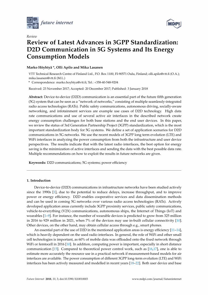
The study considered a diverse group of scenarios that could benefit from UE-to-network relaying.From the coverage point of view, the remote UE could be located within the cell, out of cell, or canbe operating in the coverage-enhanced mode [40]. As cellular IoT devices mainly reach enhancedcoverage by a high number (up to 2048) of repeated transmissions [43], the power efficiency gain ofusing short D2D links with minimal repetitions is obvious in this scenario. Relaying using the sidelinkcan be bi- or uni-directional, as shown in Figure 2. Bidirectional relaying is more straightforwardto implement with minimal signaling from the eNB. However, bidirectional relaying over sidelinkrequires UL waveform reception capabilities for the remote UEs. This would mean implementing aUL receiver for low-cost IoT devices, which may not be feasible from the device cost point of view.Thus, many of the open issues in D2D relaying for IoT are related to the question, how to efficientlyimplement mandatory functionalities, such as discovery, for unidirectional relaying.
Future Internet 2018, 10, 3 4 of 17
The study considered a diverse group of scenarios that could benefit from UE-to-network relaying. From the coverage point of view, the remote UE could be located within the cell, out of cell, or can be operating in the coverage-enhanced mode [40]. As cellular IoT devices mainly reach enhanced coverage by a high number (up to 2048) of repeated transmissions [43], the power efficiency gain of using short D2D links with minimal repetitions is obvious in this scenario. Relaying using the sidelink can be bi- or uni-directional, as shown in Figure 2. Bidirectional relaying is more straightforward to implement with minimal signaling from the eNB. However, bidirectional relaying over sidelink requires UL waveform reception capabilities for the remote UEs. This would mean implementing a UL receiver for low-cost IoT devices, which may not be feasible from the device cost point of view. Thus, many of the open issues in D2D relaying for IoT are related to the question, how to efficiently implement mandatory functionalities, such as discovery, for unidirectional relaying.
Figure 2. Device-to-device (D2D) relaying variants for cellular Internet of Things (IoT) devices; UE: user equipment.
As a result of the 3GPP study, a relaying architecture was proposed. Relaying is done above the radio link control (RLC) layer, i.e., the RLC and lower layers are terminated at the D2D link and higher layers at the remote UE and the eNB [33]. Several solutions for paging and system information transfer for remote UEs as well as path switch and group handover enhancements were also proposed. These layer 2 studies mostly assumed the feasibility of bidirectional relaying; the impact of unidirectional relaying was not fully analyzed in the study item. For example, the discovery procedure for the unidirectional relaying case with remote UEs only capable of receiving downlink (DL) signals was still left open. Another aspect in the 3GPP study was to study the required enhancements to sidelink physical layer operation. The target was to also enable the sidelink support for low-cost UEs with a limited bandwidth of one (narrowband IoT) or six (LTE-M) physical resource blocks (PRBs) and potentially with no sidelink reception capabilities [33]. Enhancements were proposed to the synchronization procedure such that the relay UE can act as a synchronization source for the remote UEs. Also, the needed enhancements for the support of unicast communications over the sidelink were identified and proposed for resource allocation, semi-persistent scheduling, power control, measurements and feedback for link adaptation. Based on the performance evaluation results
Figure 2. Device-to-device (D2D) relaying variants for cellular Internet of Things (IoT) devices; UE:user equipment.
As a result of the 3GPP study, a relaying architecture was proposed. Relaying is done abovethe radio link control (RLC) layer, i.e., the RLC and lower layers are terminated at the D2D linkand higher layers at the remote UE and the eNB [33]. Several solutions for paging and systeminformation transfer for remote UEs as well as path switch and group handover enhancements werealso proposed. These layer 2 studies mostly assumed the feasibility of bidirectional relaying; the impactof unidirectional relaying was not fully analyzed in the study item. For example, the discoveryprocedure for the unidirectional relaying case with remote UEs only capable of receiving downlink (DL)signals was still left open. Another aspect in the 3GPP study was to study the required enhancementsto sidelink physical layer operation. The target was to also enable the sidelink support for low-costUEs with a limited bandwidth of one (narrowband IoT) or six (LTE-M) physical resource blocks(PRBs) and potentially with no sidelink reception capabilities [33]. Enhancements were proposedto the synchronization procedure such that the relay UE can act as a synchronization source for theremote UEs. Also, the needed enhancements for the support of unicast communications over the
Future Internet 2018, 10, 3 5 of 18
sidelink were identified and proposed for resource allocation, semi-persistent scheduling, powercontrol, measurements and feedback for link adaptation. Based on the performance evaluation resultspresented in [33], especially the adaptive modulation and coding together with the adaptive numberof sidelink transmissions provided a significant energy efficiency gain for the remote UEs.
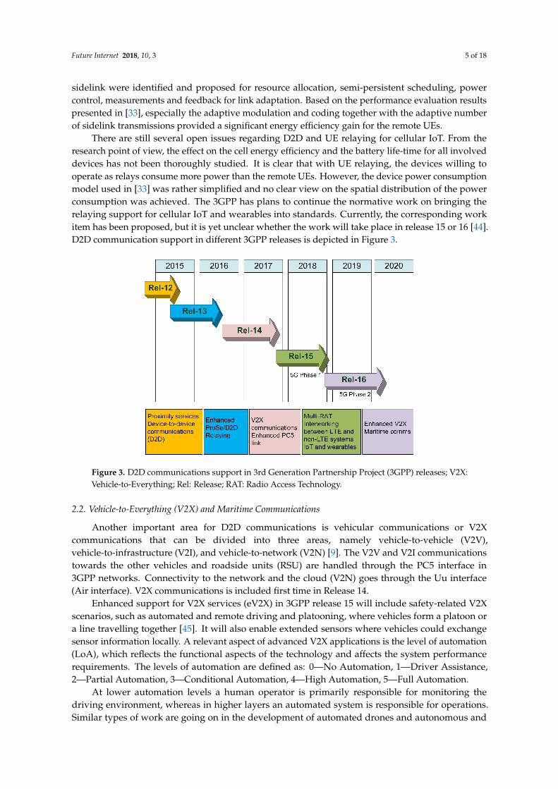
There are still several open issues regarding D2D and UE relaying for cellular IoT. From theresearch point of view, the effect on the cell energy efficiency and the battery life-time for all involveddevices has not been thoroughly studied. It is clear that with UE relaying, the devices willing tooperate as relays consume more power than the remote UEs. However, the device power consumptionmodel used in [33] was rather simplified and no clear view on the spatial distribution of the powerconsumption was achieved. The 3GPP has plans to continue the normative work on bringing therelaying support for cellular IoT and wearables into standards. Currently, the corresponding workitem has been proposed, but it is yet unclear whether the work will take place in release 15 or 16 [44].D2D communication support in different 3GPP releases is depicted in Figure 3.
Future Internet 2018, 10, 3 5 of 17
presented in [33], especially the adaptive modulation and coding together with the adaptive number of sidelink transmissions provided a significant energy efficiency gain for the remote UEs.
There are still several open issues regarding D2D and UE relaying for cellular IoT. From the research point of view, the effect on the cell energy efficiency and the battery life-time for all involved devices has not been thoroughly studied. It is clear that with UE relaying, the devices willing to operate as relays consume more power than the remote UEs. However, the device power consumption model used in [33] was rather simplified and no clear view on the spatial distribution of the power consumption was achieved. The 3GPP has plans to continue the normative work on bringing the relaying support for cellular IoT and wearables into standards. Currently, the corresponding work item has been proposed, but it is yet unclear whether the work will take place in release 15 or 16 [44]. D2D communication support in different 3GPP releases is depicted in Figure 3.
Figure 3. D2D communications support in 3rd Generation Partnership Project (3GPP) releases; V2X: Vehicle-to-Everything; Rel: Release; RAT: Radio Access Technology.
2.2. Vehicle-to-Everything (V2X) and Maritime Communications
Another important area for D2D communications is vehicular communications or V2X communications that can be divided into three areas, namely vehicle-to-vehicle (V2V), vehicle-to-infrastructure (V2I), and vehicle-to-network (V2N) [9]. The V2V and V2I communications towards the other vehicles and roadside units (RSU) are handled through the PC5 interface in 3GPP networks. Connectivity to the network and the cloud (V2N) goes through the Uu interface (Air interface). V2X communications is included first time in Release 14.
Enhanced support for V2X services (eV2X) in 3GPP release 15 will include safety-related V2X scenarios, such as automated and remote driving and platooning, where vehicles form a platoon or a line travelling together [45]. It will also enable extended sensors where vehicles could exchange sensor information locally. A relevant aspect of advanced V2X applications is the level of automation (LoA), which reflects the functional aspects of the technology and affects the system performance requirements. The levels of automation are defined as: 0—No Automation, 1—Driver Assistance, 2—Partial Automation, 3—Conditional Automation, 4—High Automation, 5—Full Automation.
At lower automation levels a human operator is primarily responsible for monitoring the driving environment, whereas in higher layers an automated system is responsible for operations. Similar types of work are going on in the development of automated drones and autonomous and remote-controlled ships [8]. Currently 3GPP is considering and developing systems specifically for maritime communications for release 16 and beyond to support the needs of future maritime users [46]. One of the requirements of this “LTE-Maritime” system is to support 100 km coverage. It will also support
Figure 3. D2D communications support in 3rd Generation Partnership Project (3GPP) releases; V2X:Vehicle-to-Everything; Rel: Release; RAT: Radio Access Technology.
2.2. Vehicle-to-Everything (V2X) and Maritime Communications
Another important area for D2D communications is vehicular communications or V2Xcommunications that can be divided into three areas, namely vehicle-to-vehicle (V2V),vehicle-to-infrastructure (V2I), and vehicle-to-network (V2N) [9]. The V2V and V2I communicationstowards the other vehicles and roadside units (RSU) are handled through the PC5 interface in3GPP networks. Connectivity to the network and the cloud (V2N) goes through the Uu interface(Air interface). V2X communications is included first time in Release 14.
Enhanced support for V2X services (eV2X) in 3GPP release 15 will include safety-related V2Xscenarios, such as automated and remote driving and platooning, where vehicles form a platoon ora line travelling together [45]. It will also enable extended sensors where vehicles could exchangesensor information locally. A relevant aspect of advanced V2X applications is the level of automation(LoA), which reflects the functional aspects of the technology and affects the system performancerequirements. The levels of automation are defined as: 0—No Automation, 1—Driver Assistance,2—Partial Automation, 3—Conditional Automation, 4—High Automation, 5—Full Automation.
At lower automation levels a human operator is primarily responsible for monitoring thedriving environment, whereas in higher layers an automated system is responsible for operations.Similar types of work are going on in the development of automated drones and autonomous and
Future Internet 2018, 10, 3 6 of 18
remote-controlled ships [8]. Currently 3GPP is considering and developing systems specificallyfor maritime communications for release 16 and beyond to support the needs of future maritimeusers [46]. One of the requirements of this “LTE-Maritime” system is to support 100 km coverage.It will also support the interworking between the 3GPP system and the existing/future maritime radiocommunication system for the seamless service of voice communication and data communicationbetween users ashore and at sea or between vessels at sea.
3. System Model and D2D Use Cases for Combined LTE/5G and WiFi
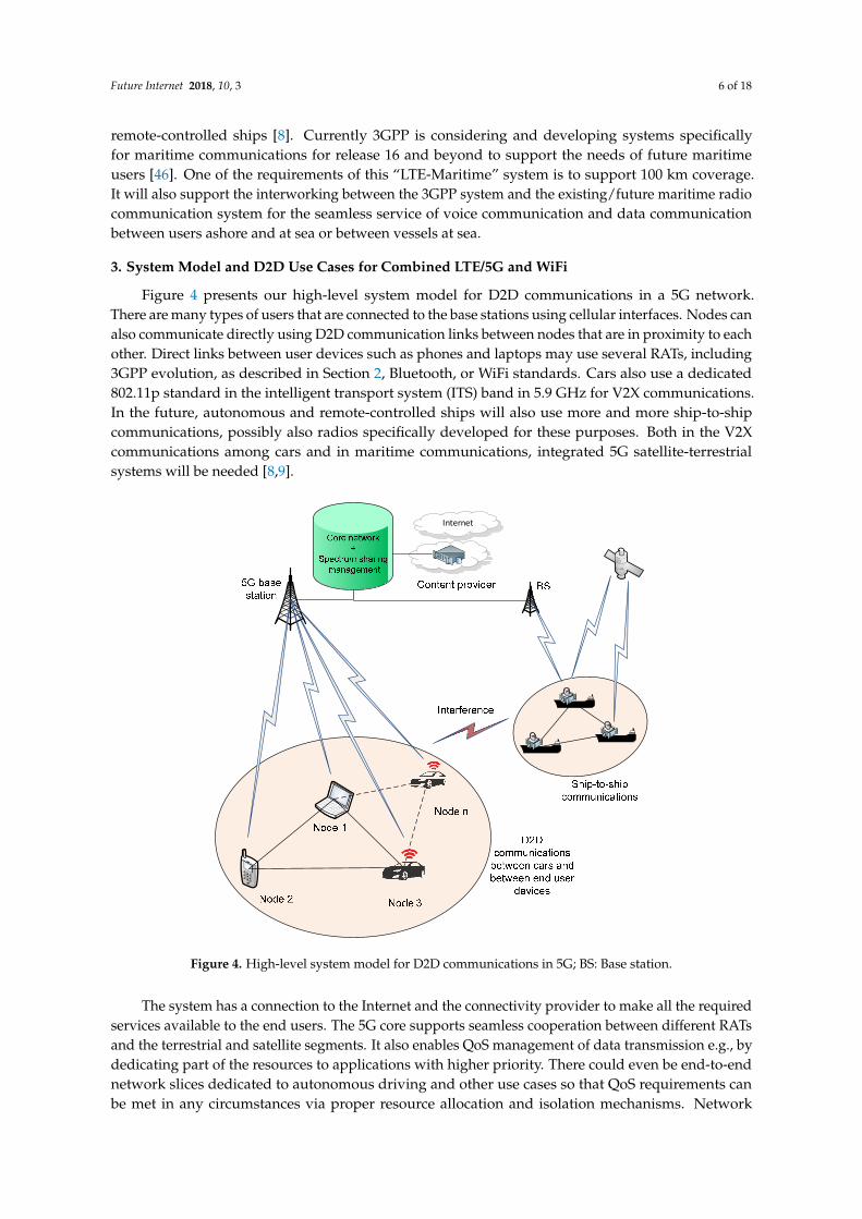
Figure 4 presents our high-level system model for D2D communications in a 5G network.There are many types of users that are connected to the base stations using cellular interfaces. Nodes canalso communicate directly using D2D communication links between nodes that are in proximity to eachother. Direct links between user devices such as phones and laptops may use several RATs, including3GPP evolution, as described in Section 2, Bluetooth, or WiFi standards. Cars also use a dedicated802.11p standard in the intelligent transport system (ITS) band in 5.9 GHz for V2X communications.In the future, autonomous and remote-controlled ships will also use more and more ship-to-shipcommunications, possibly also radios specifically developed for these purposes. Both in the V2Xcommunications among cars and in maritime communications, integrated 5G satellite-terrestrialsystems will be needed [8,9].
Future Internet 2018, 10, 3 6 of 17
the interworking between the 3GPP system and the existing/future maritime radio communication system for the seamless service of voice communication and data communication between users ashore and at sea or between vessels at sea.
3. System Model and D2D Use Cases for Combined LTE/5G and WiFi
Figure 4 presents our high-level system model for D2D communications in a 5G network. There are many types of users that are connected to the base stations using cellular interfaces. Nodes can also communicate directly using D2D communication links between nodes that are in proximity to each other. Direct links between user devices such as phones and laptops may use several RATs, including 3GPP evolution, as described in Section 2, Bluetooth, or WiFi standards. Cars also use a dedicated 802.11p standard in the intelligent transport system (ITS) band in 5.9 GHz for V2X communications. In the future, autonomous and remote-controlled ships will also use more and more ship-to-ship communications, possibly also radios specifically developed for these purposes. Both in the V2X communications among cars and in maritime communications, integrated 5G satellite-terrestrial systems will be needed [8,9].
Figure 4. High-level system model for D2D communications in 5G; BS: Base station.
The system has a connection to the Internet and the connectivity provider to make all the required services available to the end users. The 5G core supports seamless cooperation between different RATs and the terrestrial and satellite segments. It also enables QoS management of data transmission e.g., by dedicating part of the resources to applications with higher priority. There could even be end-to-end network slices dedicated to autonomous driving and other use cases so that QoS requirements can be met in any circumstances via proper resource allocation and isolation mechanisms. Network virtualization and slicing techniques enable different operators to share network resources with other (virtual) operators and to provide end-to-end connectivity across operator boundaries.
Internet
Figure 4. High-level system model for D2D communications in 5G; BS: Base station.
The system has a connection to the Internet and the connectivity provider to make all the requiredservices available to the end users. The 5G core supports seamless cooperation between different RATsand the terrestrial and satellite segments. It also enables QoS management of data transmission e.g., bydedicating part of the resources to applications with higher priority. There could even be end-to-endnetwork slices dedicated to autonomous driving and other use cases so that QoS requirements canbe met in any circumstances via proper resource allocation and isolation mechanisms. Network

Future Internet 2018, 10, 3 7 of 18
virtualization and slicing techniques enable different operators to share network resources with other(virtual) operators and to provide end-to-end connectivity across operator boundaries.
In addition to network management with the core network, the 5G networks will also usespectrum sharing technologies to utilize available radio resources as efficiently as possible. We assumea licensed spectrum access (LSA) approach, where the incumbent operators are required to provide apriori information about their spectrum use over the area of interest to the database. They tell explicitlywhere, when, and which parts of the frequency bands are available for the secondary use. This mostprobably requires a third party to operate the LSA system, since operators are often not willing toshare the information about their spectrum use with other spectrum users.
Let us now look at the simplified model for the analysis that is presented in Figure 5. The modelis based on the high-level system model described above. Wireless mobile users are connected to thebase station using the LTE interface. There are N nodes in the network. We assume that links L12
(between Node 1 and Node 2), L13, L23, L3n can be either LTE or WiFi links. Only user equipment suchas phones, tablets, and laptops are used as nodes in the network. Link attenuations between the basestation and the user equipment are assumed to be equal, as well as the direct links between nodes.All the links between the user equipment and the base station are using 3GPP interfaces.
Future Internet 2018, 10, 3 7 of 17
In addition to network management with the core network, the 5G networks will also use spectrum sharing technologies to utilize available radio resources as efficiently as possible. We assume a licensed spectrum access (LSA) approach, where the incumbent operators are required to provide a priori information about their spectrum use over the area of interest to the database. They tell explicitly where, when, and which parts of the frequency bands are available for the secondary use. This most probably requires a third party to operate the LSA system, since operators are often not willing to share the information about their spectrum use with other spectrum users.
Let us now look at the simplified model for the analysis that is presented in Figure 5. The model is based on the high-level system model described above. Wireless mobile users are connected to the base station using the LTE interface. There are N nodes in the network. We assume that links L12 (between Node 1 and Node 2), L13, L23, L3n can be either LTE or WiFi links. Only user equipment such as phones, tablets, and laptops are used as nodes in the network. Link attenuations between the base station and the user equipment are assumed to be equal, as well as the direct links between nodes. All the links between the user equipment and the base station are using 3GPP interfaces.
Figure 5. Simplified model for analysis. LB1: Link between the base station and the UE 1; LB2: Link between the base station and the UE 2; LB3: Link between the base station and the UE 3; LBn: Link between the base station and the UE n; L12: D2D link between UE 1 and UE 2; L13: D2D link between UE 1 and UE 3; L23: D2D link between UE 2 and UE 3; L3n: D2D link between UE 3 and UE n.
D2D communication is controlled by the base station, which enables interference management and assures QoS to the end users. Nodes can form a cluster around the cluster head which may be the only node discussing with the base station. In order to estimate the power consumption in the depicted system model both from the user device and the base station perspectives, we need to define practical use cases for analysis. Based on Figure 5, we can define several different use cases for delivering Internet data or some other data from the content provider that certain node(s) want to access through the base station. Five different cases are described in the following as [30,31]:
(1) Case 1: The base station sends the data directly to the requesting node(s). (2) Case 2: Nodes with social ties form a cluster. The base station sends the data to the cluster head
that relays the data to other users over WiFi. The data (such as recently popular YouTube videos) is cached in the cluster head for some time in order to serve requesting nodes directly.
(3) Case 3: The base station sends the data to the cluster head that relays the data to requesting nodes over LTE.
Figure 5. Simplified model for analysis. LB1: Link between the base station and the UE 1; LB2: Linkbetween the base station and the UE 2; LB3: Link between the base station and the UE 3; LBn: Linkbetween the base station and the UE n; L12: D2D link between UE 1 and UE 2; L13: D2D link betweenUE 1 and UE 3; L23: D2D link between UE 2 and UE 3; L3n: D2D link between UE 3 and UE n.
D2D communication is controlled by the base station, which enables interference managementand assures QoS to the end users. Nodes can form a cluster around the cluster head which may be theonly node discussing with the base station. In order to estimate the power consumption in the depictedsystem model both from the user device and the base station perspectives, we need to define practicaluse cases for analysis. Based on Figure 5, we can define several different use cases for deliveringInternet data or some other data from the content provider that certain node(s) want to access throughthe base station. Five different cases are described in the following as [30,31]:
(1) Case 1: The base station sends the data directly to the requesting node(s).(2) Case 2: Nodes with social ties form a cluster. The base station sends the data to the cluster head
that relays the data to other users over WiFi. The data (such as recently popular YouTube videos)is cached in the cluster head for some time in order to serve requesting nodes directly.
Future Internet 2018, 10, 3 8 of 18
(3) Case 3: The base station sends the data to the cluster head that relays the data to requesting nodesover LTE.
(4) Case 4: The base station sends 1/N of the required packets to N different nodes requesting thesame data (e.g., certain content in Facebook shared among friends). Different parts are sent todifferent users and the missing parts are shared using D2D connections among nodes over WiFi.
(5) Case 5: Same as case 4, but the sharing is done using an LTE interface.
4. Power Consumption Models
4.1. LTE Base Station Model
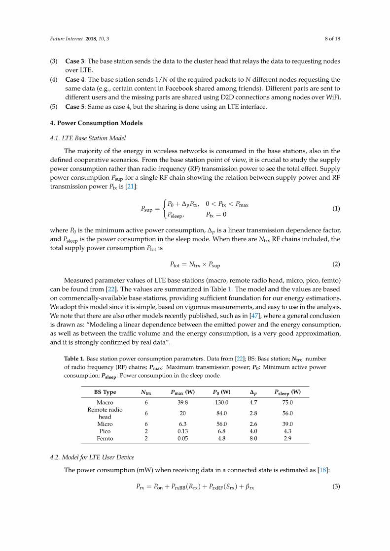
The majority of the energy in wireless networks is consumed in the base stations, also in thedefined cooperative scenarios. From the base station point of view, it is crucial to study the supplypower consumption rather than radio frequency (RF) transmission power to see the total effect. Supplypower consumption Psup for a single RF chain showing the relation between supply power and RFtransmission power Ptx is [21]:
Psup =
{P0 + ∆pPtx, 0 < Ptx < Pmax
Psleep, Ptx = 0(1)
where P0 is the minimum active power consumption, ∆p is a linear transmission dependence factor,and Psleep is the power consumption in the sleep mode. When there are Ntrx RF chains included, thetotal supply power consumption Ptot is
Ptot = Ntrx × Psup (2)
Measured parameter values of LTE base stations (macro, remote radio head, micro, pico, femto)can be found from [22]. The values are summarized in Table 1. The model and the values are basedon commercially-available base stations, providing sufficient foundation for our energy estimations.We adopt this model since it is simple, based on vigorous measurements, and easy to use in the analysis.We note that there are also other models recently published, such as in [47], where a general conclusionis drawn as: “Modeling a linear dependence between the emitted power and the energy consumption,as well as between the traffic volume and the energy consumption, is a very good approximation,and it is strongly confirmed by real data”.
Table 1. Base station power consumption parameters. Data from [22]; BS: Base station; Ntrx: numberof radio frequency (RF) chains; Pmax: Maximum transmission power; P0: Minimum active powerconsumption; Psleep: Power consumption in the sleep mode.
BS Type Ntrx Pmax (W) P0 (W) ∆p Psleep (W)
Macro 6 39.8 130.0 4.7 75.0Remote radio
head 6 20 84.0 2.8 56.0
Micro 6 6.3 56.0 2.6 39.0Pico 2 0.13 6.8 4.0 4.3
Femto 2 0.05 4.8 8.0 2.9
4.2. Model for LTE User Device
The power consumption (mW) when receiving data in a connected state is estimated as [18]:
Prx = Pon + PrxBB(Rrx) + PrxRF(Srx) + βrx (3)

Future Internet 2018, 10, 3 9 of 18
where Pon is the power consumption when the cellular subsystem is active, βrx is the additionalpower consumption of a receiver being active. Parameter PrxRF defines radio frequency (RF) blockpower consumption that is dependent on the received power Srx and PrxBB is the baseband powerconsumption, dependent on the received data rate Rrx. These parameters are given as
PrxRF =
{−0.04 × Srx + 24.8, Srx ≤ −52.5 dBm
−0.11 × Srx + 7.86, Srx > −52.5 dBm
PrxBB = 0.97Rrx + 8.16
Equivalent power consumption (mW) when transmitting data in the connected state is given as:
Ptx = Pon + PtxBB(Rtx) + PtxRF(Stx) + βtx (4)
where same parameters are defined for the transmitter side, respectively. Transmission power Stx
primarily affects the RF block power consumption:
PtxRF =
0.78 × Stx + 23.6, Stx ≤ 0.2 dBm
17.0 × Stx + 45.4, 0.2 dBm < Stx ≤ −11.4 dBm
5.90 × Stx2 − 118 × Stx + 1195, 11.4 dBm < Stx
The data rate does not affect baseband power consumption in the uplink, i.e., PtxBB is constantly0.62 mW. Other parameters are Pon = 853 mW, βrx = 25.1 mW and βtx = 29.9 mW.
4.3. WiFi Power Consumption Models
The power consumption model for LTE and WiFi 802.11g air interfaces has linear dependencyon the data rate in measurements done in [19], as shown in the following. Power consumption (mW)when receiving data is estimated as
Prx = αrxRrx + β (5)
The power consumption (mW) when transmitting data is estimated as
Ptx = αtxRtx + β (6)
The parameters αrx and αtx are linear scaling factors for reception and transmission, Rrx is thereceived data rate, Rtx is the transmitted data rate and β is the basic power consumption in the activemode. Based on several references, parameters for these models are given in Table 2. It can be seenthat the older air interfaces behave according to Equations (5) and (6), including the LTE device modelin [19] and the 802.11g model in the same paper. The more recent 802.11n model that was definedin [30] based on measurements reported in [20] is quite flat.
Table 2. Power consumption parameters of different long term evolution (LTE) and WiFi models;αrx: linear scaling factor for reception; αtx: linear scaling factor for transmission; β: basic powerconsumption in the active mode.
Ref. Air Interface ffrx (mW/Mbps) fftx (mW/Mbps) β (mW)
[19] LTE 51.97 438.39 1288.04WiFi, 802.11g 137.01 283.17 132.86
[20,30] WiFi, 802.11n 6 4 βrx = 450, βtx = 980[32] 802.11ac ~2100 mW * ~2500mW * 287[32] 802.11ad ~2100 mW * ~2000 mW * 1938
* Over a large bit rate range the power consumption is quite flat in recent 802.11ac and ad interfaces.

Future Internet 2018, 10, 3 10 of 18
The most recent 802.11ac and 802.11ad measurements given in [32] show that both receiver powerconsumption and transmitter power consumption are almost flat, regardless of the bit rate. The basicpower consumption is much lower in 802.11ac, but the 802.11ad interface always consumes a lot ofenergy when it is active. There is no big difference when receiving or transmitting data comparedto the basic power consumption according to [32]. However, the results indicate that with the latestmodels, the best option for energy saving is to send the data with the best possible data rate in order tobe able spend more time in the basic power consumption mode.
5. Performance Analysis
5.1. Power Consumption of the End User Device
Mathematically, the power consumption within the cooperative network in defined use cases canbe given as follows: In case 1 the end user devices are only receiving the data using the LTE interface.Thus, the power consumption in this reference case is
Ptot = N × Prx, LTE(R) (7)
where Prx, LTE is the received signal power for a signal coming from the base station. In case 2, one nodeis receiving the data over the LTE link and transmits the data over WiFi to N-1 users, i.e.,
Ptot = Prx, LTE(R) + Ptx, WiFi(R) + (N − 1)× Prx, WiFi(R) (8)
In case 3, the same transmissions are conducted over the LTE interface. Thus, the total powerconsumption is
Ptot = Prx, LTE(R) + Ptx, LTE_D2D(R) + (N − 1)× Prx, LTE_D2D(R) (9)
where Ptx, LTE_D2D is the transmission power consumption of a UE and Prx, LTE_D2D is the receivedpower consumption for a D2D signal. R is the required data rate over the link. In cases 4 and 5,the data rate is divided into multiple R/N rate streams that are then combined at the requestingnode(s). In case 4, the total power consumption is
Ptot = N × Prx, LTE(R/N) + N × Ptx, WiFi(R/N) + N × Prx, WiFi(R − R/N) (10)
and in case 5 it is
Ptot = N × Prx, LTE(R/N) + N × Ptx, LTE_D2D(R/N) + N × Prx, LTE_D2D(R − R/N) (11)
The power consumption of the cluster head is given in Equations (8) and (9) by excluding the lastterm in the equation. In cases 4 and 5, the power consumption is equally shared between the nodes.
5.2. Energy Consumption of a Base Station
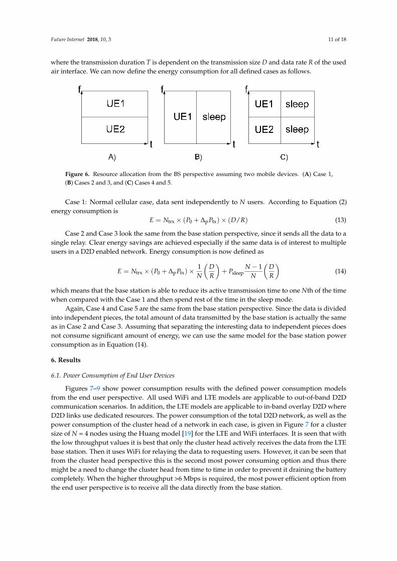
Resource allocations in the time and frequency domains in the defined use cases are presentedin Figure 6. Cooperation leads to a shorter active transmission period of the base station in allco-operative scenarios. The figure shows an example with two nodes (UEs) but the same model can beeasily generalized to N users. The energy required for the transmission of data is the integral of thepower consumption P(t) of the air interface over time
E =∫ t0+T
t0
P(t)dt (12)
Future Internet 2018, 10, 3 11 of 18
where the transmission duration T is dependent on the transmission size D and data rate R of the usedair interface. We can now define the energy consumption for all defined cases as follows.
Future Internet 2018, 10, 3 10 of 17
tot = × rx, LTE( ) (7)
where , is the received signal power for a signal coming from the base station. In case 2, one node is receiving the data over the LTE link and transmits the data over WiFi to N-1 users, i.e.,
tot = rx, LTE( ) + tx, WiFi( ) + ( − 1) × rx, WiFi( ) (8)
In case 3, the same transmissions are conducted over the LTE interface. Thus, the total power consumption is
tot = rx, LTE( ) + tx, LTE_D2D( ) + ( − 1) × rx, LTE_D2D( ) (9)
where tx, LTE_D2D is the transmission power consumption of a UE and rx, LTE_D2D is the received power consumption for a D2D signal. R is the required data rate over the link. In cases 4 and 5, the data rate is divided into multiple R/N rate streams that are then combined at the requesting node(s). In case 4, the total power consumption is
tot = × rx, LTE( ⁄ ) + × tx, WiFi( ⁄ ) + × rx, WiFi( − / ) (10)
and in case 5 it is
tot = × rx, LTE( ⁄ ) + × tx, LTE_D2D( ⁄ ) + × rx, LTE_D2D( − ⁄ ) (11)
The power consumption of the cluster head is given in Equations (8) and (9) by excluding the last term in the equation. In cases 4 and 5, the power consumption is equally shared between the nodes.
5.2. Energy Consumption of a Base Station
Resource allocations in the time and frequency domains in the defined use cases are presented in Figure 6. Cooperation leads to a shorter active transmission period of the base station in all co-operative scenarios. The figure shows an example with two nodes (UEs) but the same model can be easily generalized to N users. The energy required for the transmission of data is the integral of the power consumption ( ) of the air interface over time = ( )dt (12)
where the transmission duration T is dependent on the transmission size D and data rate R of the used air interface. We can now define the energy consumption for all defined cases as follows.
Figure 6. Resource allocation from the BS perspective assuming two mobile devices. (A) Case 1, (B) Cases 2 and 3, and (C) Cases 4 and 5.
Case 1: Normal cellular case, data sent independently to N users. According to Equation (2) energy consumption is = × ( + ∆ ) × ( / ) (13)
Figure 6. Resource allocation from the BS perspective assuming two mobile devices. (A) Case 1,(B) Cases 2 and 3, and (C) Cases 4 and 5.
Case 1: Normal cellular case, data sent independently to N users. According to Equation (2)energy consumption is
E = Ntrx × (P0 + ∆pPtx)× (D/R) (13)
Case 2 and Case 3 look the same from the base station perspective, since it sends all the data to asingle relay. Clear energy savings are achieved especially if the same data is of interest to multipleusers in a D2D enabled network. Energy consumption is now defined as
E = Ntrx × (P0 + ∆pPtx)×1N
(DR
)+ Psleep
N − 1N
(DR
)(14)
which means that the base station is able to reduce its active transmission time to one Nth of the timewhen compared with the Case 1 and then spend rest of the time in the sleep mode.
Again, Case 4 and Case 5 are the same from the base station perspective. Since the data is dividedinto independent pieces, the total amount of data transmitted by the base station is actually the sameas in Case 2 and Case 3. Assuming that separating the interesting data to independent pieces doesnot consume significant amount of energy, we can use the same model for the base station powerconsumption as in Equation (14).
6. Results
6.1. Power Consumption of End User Devices
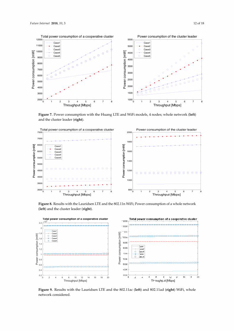
Figures 7–9 show power consumption results with the defined power consumption modelsfrom the end user perspective. All used WiFi and LTE models are applicable to out-of-band D2Dcommunication scenarios. In addition, the LTE models are applicable to in-band overlay D2D whereD2D links use dedicated resources. The power consumption of the total D2D network, as well as thepower consumption of the cluster head of a network in each case, is given in Figure 7 for a clustersize of N = 4 nodes using the Huang model [19] for the LTE and WiFi interfaces. It is seen that withthe low throughput values it is best that only the cluster head actively receives the data from the LTEbase station. Then it uses WiFi for relaying the data to requesting users. However, it can be seen thatfrom the cluster head perspective this is the second most power consuming option and thus theremight be a need to change the cluster head from time to time in order to prevent it draining the batterycompletely. When the higher throughput >6 Mbps is required, the most power efficient option fromthe end user perspective is to receive all the data directly from the base station.
Future Internet 2018, 10, 3 12 of 18
Future Internet 2018, 10, 3 11 of 17
Case 2 and Case 3 look the same from the base station perspective, since it sends all the data to a single relay. Clear energy savings are achieved especially if the same data is of interest to multiple users in a D2D enabled network. Energy consumption is now defined as = × ( + ∆ ) × 1 + − 1
(14)
which means that the base station is able to reduce its active transmission time to one Nth of the time when compared with the Case 1 and then spend rest of the time in the sleep mode.
Again, Case 4 and Case 5 are the same from the base station perspective. Since the data is divided into independent pieces, the total amount of data transmitted by the base station is actually the same as in Case 2 and Case 3. Assuming that separating the interesting data to independent pieces does not consume significant amount of energy, we can use the same model for the base station power consumption as in Equation (14).
6. Results
6.1. Power Consumption of End User Devices
Figures 7–9 show power consumption results with the defined power consumption models from the end user perspective. All used WiFi and LTE models are applicable to out-of-band D2D communication scenarios. In addition, the LTE models are applicable to in-band overlay D2D where D2D links use dedicated resources. The power consumption of the total D2D network, as well as the power consumption of the cluster head of a network in each case, is given in Figure 7 for a cluster size of N = 4 nodes using the Huang model [19] for the LTE and WiFi interfaces. It is seen that with the low throughput values it is best that only the cluster head actively receives the data from the LTE base station. Then it uses WiFi for relaying the data to requesting users. However, it can be seen that from the cluster head perspective this is the second most power consuming option and thus there might be a need to change the cluster head from time to time in order to prevent it draining the battery completely. When the higher throughput >6 Mbps is required, the most power efficient option from the end user perspective is to receive all the data directly from the base station.
Figure 7. Power consumption with the Huang LTE and WiFi models, 4 nodes; whole network (left) and the cluster leader (right).
0 1 2 3 4 5 6 7 82000
3000
4000
5000
6000
7000
8000
9000
10000
11000
12000
Throughput [Mbps]
Pow
er c
onsu
mpt
ion
[mW
]Total power consumption of a cooperative cluster
Case1Case2Case3Case4Case5
0 1 2 3 4 5 6 7 81000
1500
2000
2500
3000
3500
4000
4500
5000
5500
Throughput [Mbps]
Pow
er c
onsu
mpt
ion
[mW
]
Power consumption of the cluster leader
Case1Case2Case3Case4Case5
Figure 7. Power consumption with the Huang LTE and WiFi models, 4 nodes; whole network (left)and the cluster leader (right).Future Internet 2018, 10, 3 12 of 17
Figure 8. Results with the Lauridsen LTE and the 802.11n WiFi; Power consumption of a whole network (left) and the cluster leader (right).
Figure 9. Results with the Lauridsen LTE and the 802.11ac (left) and 802.11ad (right) WiFi, whole network considered.
When the Lauridsen model is adopted for LTE and 802.11n for WiFi, the observations are a bit different, as seen in Figure 8. We have assumed rx = −50 dBm and tx = 10 dBm for a D2D LTE link. The total power consumption in case 2 with a higher number of nodes is even more advantageous due to the lower power consumption of the WiFi. Case 4 demands the active operation of both LTE and WiFi interfaces. This is not good from the power consumption point of view due to the static part of the power consumption that comes from keeping the air interface active, i.e., in Equations (5) and (6). Thus, the latest power consumption models propose that dividing the data into smaller streams and changing the missing packets over the air is not efficient due to the simultaneous use of several active interfaces. WiFi relaying is a good option up to 20 Mbps data rate. However, also in this case, one has to take care that the cluster head is changed from time to time in a mobile network to keep all the nodes alive for longer periods of time.
The situation is quite similar when the 802.11ac and 802.11ad WiFi models are adopted as seen in Figure 9. The results cover the whole network and show that with the latest radios, where the power consumption is static regardless of the data rate, the best option is to use LTE alone. Either the conventional cellular operation or relaying with LTE are the best choices. This is due to the high power consumption of WiFi models with any data rate. An active WiFi interface consumes a lot of power. WiFi could be used to enhance the data rate of the devices if very high data rate services were needed.
The used models are applicable both to LTE and LTE-advanced systems. Only some parameter updates are needed e.g., regarding the power model given in the Equation (1). e.g., release 12
0 1 2 3 4 5 6 7 83000
3500
4000
4500
5000
5500
6000
6500
7000
7500
Throughput [Mbps]
Pow
er c
onsu
mpt
ion
[mW
]
Total power consumption of a cooperative cluster
Case1Case2Case3Case4Case5
0 1 2 3 4 5 6 7 8800
1000
1200
1400
1600
1800
2000
Throughput [Mbps]
Pow
er c
onsu
mpt
ion
[mW
]
Power consumption of the cluster leader
0 2 4 6 8 10 12 14 16 18 20
Throughput [Mbps]
0.2
0.4
0.6
0.8
1
1.2
1.4
1.6
1.8
2
2.2
Pow
er c
onsu
mpt
ion
[mW
]
104Total power consumption of a cooperative cluster
Case1Case2Case3Case4Case5
Pow
er c
onsu
mpt
ion
[mW
]
Figure 8. Results with the Lauridsen LTE and the 802.11n WiFi; Power consumption of a whole network(left) and the cluster leader (right).
Future Internet 2018, 10, 3 12 of 17
Figure 8. Results with the Lauridsen LTE and the 802.11n WiFi; Power consumption of a whole network (left) and the cluster leader (right).
Figure 9. Results with the Lauridsen LTE and the 802.11ac (left) and 802.11ad (right) WiFi, whole network considered.
When the Lauridsen model is adopted for LTE and 802.11n for WiFi, the observations are a bit different, as seen in Figure 8. We have assumed rx = −50 dBm and tx = 10 dBm for a D2D LTE link. The total power consumption in case 2 with a higher number of nodes is even more advantageous due to the lower power consumption of the WiFi. Case 4 demands the active operation of both LTE and WiFi interfaces. This is not good from the power consumption point of view due to the static part of the power consumption that comes from keeping the air interface active, i.e., in Equations (5) and (6). Thus, the latest power consumption models propose that dividing the data into smaller streams and changing the missing packets over the air is not efficient due to the simultaneous use of several active interfaces. WiFi relaying is a good option up to 20 Mbps data rate. However, also in this case, one has to take care that the cluster head is changed from time to time in a mobile network to keep all the nodes alive for longer periods of time.
The situation is quite similar when the 802.11ac and 802.11ad WiFi models are adopted as seen in Figure 9. The results cover the whole network and show that with the latest radios, where the power consumption is static regardless of the data rate, the best option is to use LTE alone. Either the conventional cellular operation or relaying with LTE are the best choices. This is due to the high power consumption of WiFi models with any data rate. An active WiFi interface consumes a lot of power. WiFi could be used to enhance the data rate of the devices if very high data rate services were needed.
The used models are applicable both to LTE and LTE-advanced systems. Only some parameter updates are needed e.g., regarding the power model given in the Equation (1). e.g., release 12
0 1 2 3 4 5 6 7 83000
3500
4000
4500
5000
5500
6000
6500
7000
7500
Throughput [Mbps]
Pow
er c
onsu
mpt
ion
[mW
]
Total power consumption of a cooperative cluster
Case1Case2Case3Case4Case5
0 1 2 3 4 5 6 7 8800
1000
1200
1400
1600
1800
2000
Throughput [Mbps]
Pow
er c
onsu
mpt
ion
[mW
]
Power consumption of the cluster leader
0 2 4 6 8 10 12 14 16 18 20
Throughput [Mbps]
0.2
0.4
0.6
0.8
1
1.2
1.4
1.6
1.8
2
2.2
Pow
er c
onsu
mpt
ion
[mW
]
104Total power consumption of a cooperative cluster
Case1Case2Case3Case4Case5
Pow
er c
onsu
mpt
ion
[mW
]
Figure 9. Results with the Lauridsen LTE and the 802.11ac (left) and 802.11ad (right) WiFi, wholenetwork considered.

Future Internet 2018, 10, 3 13 of 18
When the Lauridsen model is adopted for LTE and 802.11n for WiFi, the observations are a bitdifferent, as seen in Figure 8. We have assumed Srx = −50 dBm and Stx = 10 dBm for a D2D LTE link.The total power consumption in case 2 with a higher number of nodes is even more advantageous dueto the lower power consumption of the WiFi. Case 4 demands the active operation of both LTE andWiFi interfaces. This is not good from the power consumption point of view due to the static part ofthe power consumption that comes from keeping the air interface active, i.e., β in Equations (5) and (6).Thus, the latest power consumption models propose that dividing the data into smaller streams andchanging the missing packets over the air is not efficient due to the simultaneous use of several activeinterfaces. WiFi relaying is a good option up to 20 Mbps data rate. However, also in this case, onehas to take care that the cluster head is changed from time to time in a mobile network to keep all thenodes alive for longer periods of time.
The situation is quite similar when the 802.11ac and 802.11ad WiFi models are adopted as seenin Figure 9. The results cover the whole network and show that with the latest radios, where thepower consumption is static regardless of the data rate, the best option is to use LTE alone. Either theconventional cellular operation or relaying with LTE are the best choices. This is due to the high powerconsumption of WiFi models with any data rate. An active WiFi interface consumes a lot of power.WiFi could be used to enhance the data rate of the devices if very high data rate services were needed.
The used models are applicable both to LTE and LTE-advanced systems. Only some parameterupdates are needed e.g., regarding the power model given in the Equation (1). e.g., release 12equipment in our lab uses the old HW and only the SW is updated in the base station compared tothe older releases. Power consumption is affected by the software as well, but the LTE-A base stationpower consumption can be described with the same model due to the slow evolution of the devices.
6.2. Base Station Energy Consumption in D2D Networks
The energy consumption of cooperative scenarios from the base station perspective is the samefor all depicted D2D scenarios. Thus, we compare here conventional cellular operation with thecooperative scenario as a function of number of nodes in a D2D network. We adopt the energyconsumption metric J/bit [22] that focuses on the amount of energy spent per delivered bit and ishence an indicator of network bit delivery efficiency.
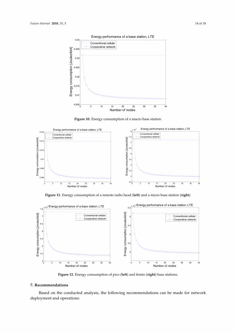
We assume an average bit rate of 10 Mbit/s in the following figures and use the energyconsumption models of Equations (13) and (14). The transmission power Ptx is set according tothe Pmax values in Table 2. The results presented in Figure 10 for a macro base station show that withthis data rate conventional cellular transmission consumes roughly 0.3 J/kbit, whereas the cooperationclearly reduces the energy consumption by sharing the load among cooperative nodes. The effect isthe largest with a few additional cooperative nodes, three nodes already lead to 50% energy savings.When the number of nodes is increased to more than 10 nodes, the energy consumption of a basestation is around 0.1 J/kbit which means that the base station is able to serve the requesting nodeswith one third of the original energy. This is a significant improvement in the energy efficiency.
When the cell size is smaller, the energy efficiency improvement is smaller, as can be seen inFigures 11 and 12. Still, even with the small cell base stations the energy reduction is around 40%,which is significant saving already with a few requesting nodes. The results suggest that cooperativeD2D data dissemination approaches are good for cellular network energy efficiency. The gain isdependent on the D2D link quality, and with poor D2D links the energy savings would be smaller.
Future Internet 2018, 10, 3 14 of 18
Future Internet 2018, 10, 3 13 of 17
equipment in our lab uses the old HW and only the SW is updated in the base station compared to the older releases. Power consumption is affected by the software as well, but the LTE-A base station power consumption can be described with the same model due to the slow evolution of the devices.
6.2. Base Station Energy Consumption in D2D Networks
The energy consumption of cooperative scenarios from the base station perspective is the same for all depicted D2D scenarios. Thus, we compare here conventional cellular operation with the cooperative scenario as a function of number of nodes in a D2D network. We adopt the energy consumption metric J/bit [22] that focuses on the amount of energy spent per delivered bit and is hence an indicator of network bit delivery efficiency.
We assume an average bit rate of 10 Mbit/s in the following figures and use the energy consumption models of Equations (13) and (14). The transmission power is set according to the
values in Table 2. The results presented in Figure 10 for a macro base station show that with this data rate conventional cellular transmission consumes roughly 0.3 J/kbit, whereas the cooperation clearly reduces the energy consumption by sharing the load among cooperative nodes. The effect is the largest with a few additional cooperative nodes, three nodes already lead to 50% energy savings. When the number of nodes is increased to more than 10 nodes, the energy consumption of a base station is around 0.1 J/kbit which means that the base station is able to serve the requesting nodes with one third of the original energy. This is a significant improvement in the energy efficiency.
Figure 10. Energy consumption of a macro base station.
When the cell size is smaller, the energy efficiency improvement is smaller, as can be seen in Figures 11 and 12. Still, even with the small cell base stations the energy reduction is around 40%, which is significant saving already with a few requesting nodes. The results suggest that cooperative D2D data dissemination approaches are good for cellular network energy efficiency. The gain is dependent on the D2D link quality, and with poor D2D links the energy savings would be smaller.
0 5 10 15 20 25 30 35 400.005
0.01
0.015
0.02
0.025
0.03
0.035
0.04
Number of nodes
Ene
rgy
cons
umpt
ion
[Jou
les/
kbit]
Energy performance of a base station, LTE
Conventional cellularCooperative network
Figure 10. Energy consumption of a macro base station.Future Internet 2018, 10, 3 14 of 17
Figure 11. Energy consumption of a remote radio head (left) and a micro base station (right).
Figure 12. Energy consumption of pico (left) and femto (right) base stations.
7. Recommendations
Based on the conducted analysis, the following recommendations can be made for network deployment and operations:
(1) When the power consumption is dependent on the data rate (as in Figure 7), the aim should be to find the sweet spots or data rate regions to use different air interfaces. In multi-RAT 5G networks this would mean analysis of all other radio interface options than the ones analyzed in this paper. However, the most important ones currently are the LTE and WiFi.
(2) With the latest WiFi and LTE models, the best option for cooperative data delivery is to select a relay and then use LTE for D2D transmissions. WiFi is a good option only for very high data rates.
(3) The base station results show that D2D transmission brings the largest gains in macro cells, up to 70% energy reductions. Small cells are already more energy efficient, but energy savings can still be significant, even 40% in the case of femto cells. Thus, it is recommended to use direct communication between devices in all cellular networks regardless of the type of base station.
(4) The best option for energy saving in D2D communications using the latest LTE and WiFi models is to send the data with the best possible data rate.
(5) There is clearly room for the creation of novel models with the latest 3GPP releases after rigorous power consumption measurement work. The measurements should specifically consider D2D measurements with the release 12 and beyond devices.
8. Conclusions
Energy efficiency is an important factor in 5G and beyond networks and one of the drivers in the adoption of D2D technology. This paper has reviewed the potential application areas including
0 5 10 15 20 25 30 35 40
0.006
0.008
0.01
0.012
0.014
0.016
Number of nodes
Ene
rgy
cons
umpt
ion
[Jou
les/
kbit]
Energy performance of a base station, LTE
Conventional cellularCooperative network
0 5 10 15 20 25 30 35 403.5
4
4.5
5
5.5
6
6.5
7
7.5
8x 10
-3
Number of nodes
Ene
rgy
cons
umpt
ion
[Jou
les/
kbit]
Energy performance of a base station, LTE
Conventional cellularCooperative network
0 5 10 15 20 25 30 35 404
4.5
5
5.5
6
6.5
7
7.5x 10
-4
Number of nodes
Ene
rgy
cons
umpt
ion
[Jou
les/
kbit]
Energy performance of a base station, LTE
Conventional cellularCooperative network
0 5 10 15 20 25 30 35 40
3
3.5
4
4.5
5
5.5x 10
-4
Number of nodes
Ene
rgy
cons
umpt
ion
[Jou
les/
kbit]
Energy performance of a base station, LTE
Conventional cellularCooperative network
Figure 11. Energy consumption of a remote radio head (left) and a micro base station (right).
Future Internet 2018, 10, 3 14 of 17
Figure 11. Energy consumption of a remote radio head (left) and a micro base station (right).
Figure 12. Energy consumption of pico (left) and femto (right) base stations.
7. Recommendations
Based on the conducted analysis, the following recommendations can be made for network deployment and operations:
(1) When the power consumption is dependent on the data rate (as in Figure 7), the aim should be to find the sweet spots or data rate regions to use different air interfaces. In multi-RAT 5G networks this would mean analysis of all other radio interface options than the ones analyzed in this paper. However, the most important ones currently are the LTE and WiFi.
(2) With the latest WiFi and LTE models, the best option for cooperative data delivery is to select a relay and then use LTE for D2D transmissions. WiFi is a good option only for very high data rates.
(3) The base station results show that D2D transmission brings the largest gains in macro cells, up to 70% energy reductions. Small cells are already more energy efficient, but energy savings can still be significant, even 40% in the case of femto cells. Thus, it is recommended to use direct communication between devices in all cellular networks regardless of the type of base station.
(4) The best option for energy saving in D2D communications using the latest LTE and WiFi models is to send the data with the best possible data rate.
(5) There is clearly room for the creation of novel models with the latest 3GPP releases after rigorous power consumption measurement work. The measurements should specifically consider D2D measurements with the release 12 and beyond devices.
8. Conclusions
Energy efficiency is an important factor in 5G and beyond networks and one of the drivers in the adoption of D2D technology. This paper has reviewed the potential application areas including
0 5 10 15 20 25 30 35 40
0.006
0.008
0.01
0.012
0.014
0.016
Number of nodes
Ene
rgy
cons
umpt
ion
[Jou
les/
kbit]
Energy performance of a base station, LTE
Conventional cellularCooperative network
0 5 10 15 20 25 30 35 403.5
4
4.5
5
5.5
6
6.5
7
7.5
8x 10
-3
Number of nodes
Ene
rgy
cons
umpt
ion
[Jou
les/
kbit]
Energy performance of a base station, LTE
Conventional cellularCooperative network
0 5 10 15 20 25 30 35 404
4.5
5
5.5
6
6.5
7
7.5x 10
-4
Number of nodes
Ene
rgy
cons
umpt
ion
[Jou
les/
kbit]
Energy performance of a base station, LTE
Conventional cellularCooperative network
0 5 10 15 20 25 30 35 40
3
3.5
4
4.5
5
5.5x 10
-4
Number of nodes
Ene
rgy
cons
umpt
ion
[Jou
les/
kbit]
Energy performance of a base station, LTE
Conventional cellularCooperative network
Figure 12. Energy consumption of pico (left) and femto (right) base stations.
7. Recommendations
Based on the conducted analysis, the following recommendations can be made for networkdeployment and operations:
Future Internet 2018, 10, 3 15 of 18
(1) When the power consumption is dependent on the data rate (as in Figure 7), the aim should be tofind the sweet spots or data rate regions to use different air interfaces. In multi-RAT 5G networksthis would mean analysis of all other radio interface options than the ones analyzed in this paper.However, the most important ones currently are the LTE and WiFi.
(2) With the latest WiFi and LTE models, the best option for cooperative data delivery is to select arelay and then use LTE for D2D transmissions. WiFi is a good option only for very high data rates.
(3) The base station results show that D2D transmission brings the largest gains in macro cells, upto 70% energy reductions. Small cells are already more energy efficient, but energy savings canstill be significant, even 40% in the case of femto cells. Thus, it is recommended to use directcommunication between devices in all cellular networks regardless of the type of base station.
(4) The best option for energy saving in D2D communications using the latest LTE and WiFi modelsis to send the data with the best possible data rate.
(5) There is clearly room for the creation of novel models with the latest 3GPP releases after rigorouspower consumption measurement work. The measurements should specifically consider D2Dmeasurements with the release 12 and beyond devices.
8. Conclusions
Energy efficiency is an important factor in 5G and beyond networks and one of the drivers inthe adoption of D2D technology. This paper has reviewed the potential application areas includingIoT, wearables, and automated driving and reviewed the current status of D2D technology in 3GPPstandardization. In addition, we have analyzed D2D-enhanced cellular networks both from thebase station and from the end user perspectives. The analysis is conducted with several differentmeasurement-based LTE and WiFi models. The results show that significant energy reductions can beachieved with all types of base stations, including macro, pico, and femto base stations. The resultsalso suggest that in order to minimize power consumption, the devices should minimize the numberof active radio interfaces and use the best possible data rates. In our system model this means thateither a LTE or WiFi interface is active in a single device at a given time instant. WiFi could be used tosupport very high data rate services. If there is no need for that, one should keep only the LTE interfaceactive in order to save power. An interesting future topic could be to study the effect of mobility inenergy consumption. This would create new challenges e.g., due to frequent handovers in a multi-RATnetwork. In addition, adaptive power control could be included in the analysis to gain a more detailedunderstanding e.g., on the effect of UL transmissions.
Acknowledgments: This work was supported by the CORNET project, partly funded by Tekes, the FinnishFunding Agency for Innovation.
Author Contributions: Marko Höyhtyä performed the experiments and analyzed the data. He was also the mainauthor of the paper. Olli Apilo wrote a major part of the 3GPP section, especially regarding the IoT and wearables.Mika Lasanen commented on and supported work throughout the paper.
Conflicts of Interest: The authors declare no conflict of interest.
References
1. Adachi, T.; Nakagawa, M. A study on channel usage in a cellular Ad-Hoc united communication system.IEICE Trans. Commun. 1998, 81, 1500–1507.
2. 3rd Generation Partnership Project (3GPP). TR 36.843 V12.0.1, Study on LTE Device to Device ProximityServices, Release 12. March 2014. Available online: http://www.3gpp.org/ftp/Specs/archive/36_series/36.843/36843-c01.zip (accessed on 27 December 2017).
3. Asadi, A.; Wang, Q.; Mancuso, V. A survey on device-to-device communication in cellular networks.IEEE Commun. Surv. Tutor. 2014, 16, 1801–1819. [CrossRef]
4. Usman, M.; Gebremariam, A.A.; Raza, U.; Granelli, F. A software-defined device-to-device communicationarchitecture for public safety applications in 5G networks. IEEE Access 2015, 3, 1649–1654. [CrossRef]

Future Internet 2018, 10, 3 16 of 18
5. Gallo, L.; Härri, J. Unsupervised long-term evolution device-to-device: A case study for safety critical V2Xcommunications. IEEE Veh. Technol. Mag. 2017, 12, 69–77. [CrossRef]
6. Bello, O.; Zeadally, S. Intelligent device-to-device communication in the Internet-of-Things. IEEE Syst. J.2016, 10, 1172–1182. [CrossRef]
7. Alam, M.M.; Arbia, D.B.; Hamida, E.B. Research trends in multi-standard device-to-device communicationin wearable wireless networks. In Proceedings of the International Conference on Cognitive Radio OrientedWireless Networks, Doha, Qatar, 21–23 April 2015.
8. Höyhtyä, M.; Huusko, J.; Kiviranta, M.; Solberg, K.; Rokka, J. Connectivity for autonomous ships:Architecture, use cases, and research challenges. In Proceedings of the 8th International Conference on ICTConvergence, Jeju Island, Korea, 18–20 October 2017.
9. Höyhtyä, M.; Ojanperä, T.; Mäkelä, J.; Ruponen, S.; Järvensivu, P. Integrated satellite-terrestrial systems: Usecases for road safety and autonomous ships. In Proceedings of the 23rd Ka and Broadband CommunicationsConference, Trieste, Italy, 16–19 October 2017.
10. Cisco Systems, Inc. Cisco Visual Networking Index: Global Mobile Data Traffic Forecast Update, 2016–2021 WhitePaper; Cisco: San Jose, CA, USA, 7 February 2017; Available online: https://www.cisco.com/c/en/us/solutions/collateral/service-provider/visual-networking-index-vni/mobile-white-paper-c11-520862.pdf(accessed on 22 December 2017).
11. Chen, T.; Yang, Y.; Zhang, H.; Kim, H.; Horneman, K. Network energy saving technologies for green wirelessaccess networks. IEEE Wirel. Commun. 2011, 18, 30–38. [CrossRef]
12. Zhang, J.; Wang, Z.-J.; Quan, Z.; Yin, J.; Chen, Y.; Guo, M. Optimizing power consumption of mobile devicesfor video streaming over 4G LTE networks. Peer-to-Peer Netw. Appl. 2017. [CrossRef]
13. Militano, L.; Iera, A.; Molinaro, A.; Scarcello, F. Energy-saving analysis in Cellular-WLAN cooperativescenarios. IEEE Trans. Veh. Technol. 2014, 63, 478–484. [CrossRef]
14. Rao, J.B.; Fapojuwo, A.O. A survey of energy efficient resource management techniques for multicell cellularnetworks. IEEE Commun. Surv. Tutor. 2014, 16, 154–180. [CrossRef]
15. Mämmelä, A.; Anttonen, A. Why will computing power need particular attention in future wireless devices?IEEE Circuits Syst. Mag. 2017, 17, 12–26. [CrossRef]
16. Caire, G.; Taricco, G.; Biglieri, E. Optimum power control over fading channels. IEEE Trans. Inf. Theory 1999,45, 1468–1489. [CrossRef]
17. Höyhtyä, M.; Mämmelä, A. A unified framework for adaptive inverse power control. EURASIP J. Wirel.Commun. Netw. 2016, 2016, 41. [CrossRef]
18. Lauridsen, M.; Noël, L.; Sørensen, T.B.; Mogensen, P. An empirical LTE smartphone power model with aview to energy efficiency evolution. Intel Technol. J. 2014, 18, 172–193.
19. Huang, J.; Qian, F.; Gerber, A.; Mao, Z.M.; Sen, S.; Spatscheck, O. A close examination of performanceand power characteristics of 4G LTE networks. In Proceedings of the 10th Mobile Systems, Applications,and Services, Low Wood Bay, UK, 25–29 June 2012.
20. Saha, S.K.; Deshpande, P.; Inamdar, P.P.; Sheshadri, R.K.; Koutsonikolas, D. Power-throughput tradeoffsof 802.11n/ac smartphones. In Proceedings of the 2015 IEEE Computer Communications (INFOCOM),Hong Kong, China, 26 April–1 May 2015.
21. Holtkamp, H.; Auer, G.; Bazzi, S.; Haas, H. Minimizing base station power consumption. IEEE J. Sel.Areas Commun. 2014, 32, 297–306. [CrossRef]
22. EARTH Project Deliverable D2.3. Energy Efficiency Analysis of the Reference Systems, Areas ofImprovements and Target Breakdown. January 2012. Available online: http://cordis.europa.eu/docs/projects/cnect/3/247733/080/deliverables/001-EARTHWP2D23v2.pdf (accessed on 22 December 2017).
23. Zuo, X.; Iamnitchi, A. A survey of socially aware peer-to-peer systems. ACM Comput. Surv. 2016, 49, 9.[CrossRef]
24. Gupta, M.; Jha, S.C.; Koc, A.T.; Vannithamby, R. Energy impact of emerging mobile Internet applications onLTE networks: Issues and solutions. IEEE Commun. Mag. 2013, 51, 90–97. [CrossRef]
25. Koc, A.T.; Jha, S.C.; Vannithamby, R.; Torlak, M. Device power saving and latency optimization in LTE-Anetworks through DRX configuration. IEEE Trans. Wirel. Commun. 2014, 13, 2614–2625.
26. Larsson, E.G.; Edfors, O.; Tufvesson, F.; Marzetta, T.L. Massive MIMO for next generation wireless systems.IEEE Commun. Mag. 2014, 52, 186–195. [CrossRef]
Future Internet 2018, 10, 3 17 of 18
27. Lei, L.; Zhong, Z.; Lin, C.; Shen, X. Operator controlled device-to-device communications in LTE-Advancednetworks. IEEE Wirel. Commun. 2012, 19, 96–104. [CrossRef]
28. Chih-Lin, I.; Rowell, C.; Han, S.; Xu, Z.; Li, G.; Pan, Z. Toward green and soft: A 5G perspective.IEEE Commun. Mag. 2014, 52, 66–73.
29. Zhang, H.; Huang, S.; Jiang, C.; Long, K.; Leung, V.C.M.; Poor, H.V. Energy efficient user association andpower allocation in millimeter-wave-based ultra dense networks with energy harvesting base stations.IEEE J. Sel. Areas Commun. 2017, 35, 1936–1947. [CrossRef]
30. Höyhtyä, M.; Mämmelä, A.; Celentano, U.; Röning, J. Power-efficiency in social-aware D2D communications.In Proceedings of the European Wireless 2016 22th European Wireless Conferences, Oulu, Finland,18–20 May 2016.
31. Höyhtyä, M.; Mämmelä, A. Energy-efficiency in social-aware D2D networks: A base station perspective.In Proceedings of the 2016 Advances in Wireless and Optical Communications (RTUWO), Riga, Latvia,3–4 November 2016.
32. Saha, S.K.; Siddiqui, T.; Koutsonikolas, D.; Loch, A.; Widmer, J.; Sridhar, R. A detailed look into powerconsumption of commodity 60 GHz devices. In Proceedings of the 2017 IEEE 18th International Symposiumon A World of Wireless, Mobile and Multimedia Networks (WoWMoM), Macau, China, 12–15 June 2017.
33. 3rd Generation Partnership Project (3GPP). TR36.746 Study on Further Enhancements to LTE Device toDevice (D2D), UE to Network Relays for IoT (Internet of Things) and Wearables, V2.0.1. October 2017.Available online: http://www.3gpp.org/ftp//Specs/archive/36_series/36.746/36746-201.zip (accessed on27 December 2017).
34. 3rd Generation Partnership Project (3GPP). TS29.214 Policy and Charging Control over Rx Reference Point,V14.3.0. March 2017. Available online: http://www.3gpp.org/ftp//Specs/archive/29_series/29.214/29214-e30.zip (accessed on 27 December 2017).
35. Rost, P.; Mannweiler, C.; Michalopoulos, D.S.; Sartori, C.; Sciancalepore, V.; Sastry, N.; Holland, O.; Tayade, S.;Han, B.; Bega, D.; et al. Network slicing to enable scalability and flexibility in 5G mobile networks. IEEECommun. Mag. 2017, 55, 72–79. [CrossRef]
36. Zhang, H.; Liu, N.; Chu, X.; Long, K.; Aghvami, A.-H.; Leung, V.C.M. Network slicing based 5G and futuremobile networks: Mobility, resource management, and challenges. IEEE Commun. Mag. 2017, 55, 138–145.[CrossRef]
37. Lin, X.; Andrews, J.G.; Ghosh, A.; Ratasuk, R. An overview of 3GPP device-to-device proximity services.IEEE Commun. Mag. 2014, 52, 40–48. [CrossRef]
38. Mach, P.; Becvar, Z.; Vanek, T. In-band device-to-device communication in OFDMA cellular networks:A survey and challenges. IEEE Commun. Surv. Tutor. 2015, 17, 1885–1992. [CrossRef]
39. Rohde & Schwarz. Device to Device Communication in LTE; Rohde & Schwartz Whitepaper; Rohde & SchwarzUSA, Inc.: Columbia, MD, USA, 2015.
40. 3rd Generation Partnership Project (3GPP). RP-170295 Study on Further Enhancements to LTE Device toDevice, UE to Network Relays for IoT and Wearables. March 2017. Available online: http://www.3gpp.org/ftp/tsg_ran/TSG_RAN/TSGR_75/Docs/RP-170295.zip (accessed on 27 December 2017).
41. 3rd Generation Partnership Project (3GPP). TS 22.261 Service Requirements for the 5G System, V16.0.0.June 2017. Available online: http://www.3gpp.org/ftp//Specs/archive/22_series/22.261/22261-g00.zip(accessed on 27 December 2017).
42. 3rd Generation Partnership Project (3GPP). RP-161313 Report of 3GPP TSG RAN Meeting #71. June 2016.Available online: http://www.3gpp.org/ftp/tsg_ran/TSG_RAN/TSGR_72/Docs/RP-161313.zip (accessedon 27 December 2017).
43. Roessel, S.; Sesia, S. Cellular Internet-of-Things—Explained. In Proceedings of the IEEE GlobecomConference, Washington, DC, USA, 4–8 December 2016.
44. 3rd Generation Partnership Project (3GPP). RP-172119 Draft Report of 3GPP TSG RAN Meeting #77.December 2017. Available online: http://www.3gpp.org/ftp/TSG_RAN/TSG_RAN/TSGR_78/Docs/RP-172119.zip (accessed on 27 December 2017).
45. 3rd Generation Partnership Project (3GPP). TS22.186 Enhancement of 3GPP Support for V2X Scenarios,V.15.2.0. September 2017. Available online: http://www.3gpp.org/ftp//Specs/archive/22_series/22.186/22186-f20.zip (accessed on 27 December 2017).

Future Internet 2018, 10, 3 18 of 18
46. 3rd Generation Partnership Project (3GPP). TR 22.819 Feasibility Study on Maritime Communication Servicesover 3GPP System, V0.3.0. August 2017. Available online: http://www.3gpp.org/ftp//Specs/archive/22_series/22.819/22819-030.zip (accessed on 27 December 2017).
47. Capone, A.; D’Elia, S.; Filippini, I.; Redondi, A.E.C.; Zangani, M. Modeling energy consumption of mobileradio networks: An operator perspective. IEEE Wirel. Commun. 2017, 24, 120–126. [CrossRef]
© 2018 by the authors. Licensee MDPI, Basel, Switzerland. This article is an open accessarticle distributed under the terms and conditions of the Creative Commons Attribution(CC BY) license (http://creativecommons.org/licenses/by/4.0/).