Rev 11 to Technical Instruction TI-50B, "ASME Section XI ...
55
... WATTS AAR SITE DIRECTOR PROCEDURE _Safety- C0 Non-Safety NUCLEAR PLANT Related Related T2S 0 1 Quality- 0 Non-Quality UNIT Document Number Revision Related Related SPORC 0 Non-PORC Reviewed Reviewed UTE SSE UJ.A 9 1c 10 Vai 9M aiated VALIDATION Validation Method(s): Checkout: ______________ Signature /Date Scope: 0 Entire 0 Changes Procedure Only Validation: _________________ .1Sianature /Date* WRITTEN~ BY: #.., 4 /Z,.tv. Kevin E, CAsey NDE Section XI Prot -: - - ________ N e Ortanizat ion Dt QUALIFIED REVIEWER QUALIFIED REVIWER CONCURRENCE SIGNATURES DAT CNCRRNCEhIZLS AT ANT/ANT I________aurs q* Chief,_TraininsBranch _________ !4aniser. Construction (NC) _____ S a ( onzibim Suuv') ___ (3M6aner of Projocts 13___ Suerisor PC&S Staff ____ Manater. Pro iect Ent (n) ______________ HManaer, Tachni-cal Services_______________ Approved1 Bry: S slnat-ure. Site Director nt (LAST PAGE 0F THIS PROCEDURE: 266.JL... 3994A 9005070260 900430 POR ADOCK 0500039.') Q PDC.
-
Upload
khangminh22 -
Category
Documents
-
view
1 -
download
0
Transcript of Rev 11 to Technical Instruction TI-50B, "ASME Section XI ...

... WATTS AAR SITE DIRECTOR PROCEDURE _Safety- C0 Non-SafetyNUCLEAR PLANT Related Related
T2S 0 1 Quality- 0 Non-QualityUNIT Document Number Revision Related Related
SPORC 0 Non-PORC Reviewed Reviewed
UTE SSE
UJ.A 9 1c 10 Vai 9M aiated
VALIDATION
Validation Method(s): Checkout: ______________
Signature /Date Scope: 0 Entire 0 Changes
Procedure Only Validation: _________________
.1Sianature /Date* WRITTEN~ BY: #.., 4 /Z,.tv. Kevin E, CAsey NDE Section XI Prot -:
- - ________ N e Ortanizat ion Dt
QUALIFIED REVIEWER QUALIFIED REVIWER
CONCURRENCE SIGNATURES DAT CNCRRNCEhIZLS AT
ANT/ANT I________aurs q*
Chief,_TraininsBranch _________
!4aniser. Construction (NC) _____ S a ( onzibim Suuv') ___
(3M6aner of Projocts 13___ Suerisor PC&S Staff ____
Manater. Pro iect Ent (n) ______________
HManaer, Tachni-cal Services_______________
Approved1 Bry:
S slnat-ure. Site Director nt
(LAST PAGE 0F THIS PROCEDURE: 266.JL...
3994A
9005070260 900430 POR ADOCK 0500039.') Q PDC.

WI' TI-503 Revision 11 Page !ai
rJST
1. Section 6.1.3, Section 6.1.11, snd Drawing CUI-2685-5 will be revised Ue. co"sinpece of Upper lead Injection system removal an receipt of weld mpe shoving as-cusatructed configuration of the Aiilaq lead Adapters.

WBX TI-SOB Page 2 of 266
uRMSPMLOlEVIS ION IFFCTIVE
11 All
DKCn? TO ?rIVISIO
MM.ZLZKIM for teacbsca1 adequacy only. Incorporated IC? 89-097; deleted references and drwavigs to MK due to system removal; revised Section 8.0, Class 3 esminuatiou requirements, removed Class 3 drawings and support tables; orgmnizational changes. Revised punchlist. Conversion to Wang system.

NBN TI-5OD Revision 11 Page 3 of 266
TABLE OF CONTENTS
UIlu
STATOUET OF APPLICABILITY .. .. .. .. ..
PURPOSE...... .... .. ... .. .. .. .. .. ....
CODES OF RECORD AND CODE CASES... .. .. ....
METHOD OF IMPLEMENTATION AND RESPONSIBILITIES.
ABBREVIATIONS AND DEFINITIONS.. .. .. .. ....
COMPONENTS SUBJECT TjO EXAMINATION - ASM4E CLASS COMPOINENTS SUBJECT TO EXAMINATION - ASME CLASS
C POENTS SUBEICT TO EXAMINATION - ASME CLASS9.0 HYDROSTATIC PRESSURE TESTS .. .. ....
0.0 AUTHORIZED INSPECTOR... .. .. ......
1.0 EXAMINATION METHODS.. ......
2.0 QUALIFICATIONS OF NONDESTRUCTIVE EXAM!
3.0 ACCEPTANCE CRITERIA.... .. .. .. ....
4.0 REPAIRS AND REPLACEMENTS.. .. .. ....
5.0 RECORDS AND REPORTS.... .. .. .. ....
6.0 NOTIFICATION OF INDICATION .. .. .... 7.0 CALIBRATION BLOCKS.... .. .. .. ....
1.0 REQESTS FOR RELIEF.... .. .. .. ....
1.0 AUG14ENTED INSPECTIONS... .. .. ......
z0.0 REFERENCES. .. .. ....
AJPPiIXA - Table A. ASME Class
APIM A- Table 8, ASME Class
ANW1I A - TablIt C, Drawings.
NATION PER
ICo"poents.
2 Components.
1.0
2.0
3.0
4.0
5.0
6.0
7.0
8.0
1 400k/0004
.. f -%..., 94 ;t- . . %-. , *1 & *.$.i'e .
7
. . .. . . . 10
I . .... ... . . .12
2 .. .... ...... 24
3 .. .... ...... 33
. . .. . . . 3 3
. . .. . . . 34
. . .. . . . . 34
SONNEL . . . . 35
. .. . . . 36
. .. . . . 36
. .. . . . 3 6
. .. . . . 3 9
. .. . . . 42
. . .. . . . 42
. . .. . . . 42
. .. . . . 42
* .. . . . 55
V
14
E
11
II
I., . . # -

eNP TI-50B Revision 1Il page 4 of 266
TABUE OF CONTENTS (Continued)
APPMNIX A - Table 0. ASMI Class 1 Valves.......
APPENDIX
APPENDIX
APPENDIX
APPENDIX
APPENDIX
APPIENDIX
APPENDIX
APPENDIX
APPENDIX
APPENDIX
Table E. ASKI Class I Valves. .. .. ..
Table F. ASPIC Class 2 Valves. .. .. ..
Table G. ASNE Class 1 Supports .. .. ..
Table H, ASHE Class 2 Supports....
Table 1. A514E Class 2 Exempt Components
Data Sheets.... .. .. .. .. .. ....
Notifice~ion of Indication Form ....
Requests for Relief... .. .. .. ....
National Board Number.... .. .. .. ..
Fleld Corrected drawing Transmittal
. .. . . . . . 142
. .. . . . . . ISO
. .. . . . . . 156
. .. . . . . . 186
. .. . . . . . 217
. .* . . . . 219
. .. . . . . . 226
. .. . . . . ZZ7
... . . . . . . 244
. ... . . . . 264
APPENDIX G - Notification of Indication (NOI) Trending
1 400& COC4

TI-SOB Revision 11 Pa&e S of 266
Preservice InSnectlon Proara.
Ower: Teomessee Valley Authoity
Address of Corporate office:
-law and Address Of flucioar Power Plant:
Tennessee Valley Authority Office of Nuclear Power 6N38 Lookout Place 1101 Market Street Chattanooa. TN 37402-2801
Watts Bar Nuclear Plant
Spring City. TennSSee 37381
Applicable Nuclear Power Units: Watts Bar.Nuclear Plant. Unft 2
I 4O~k/CDC4
I - * ~
7
:-A-*-,,ý,#4,:. ý. 0; , - - , , - - '. , .. ý 0 . - To. .1 , - . ..
Revision II page 6 of 266
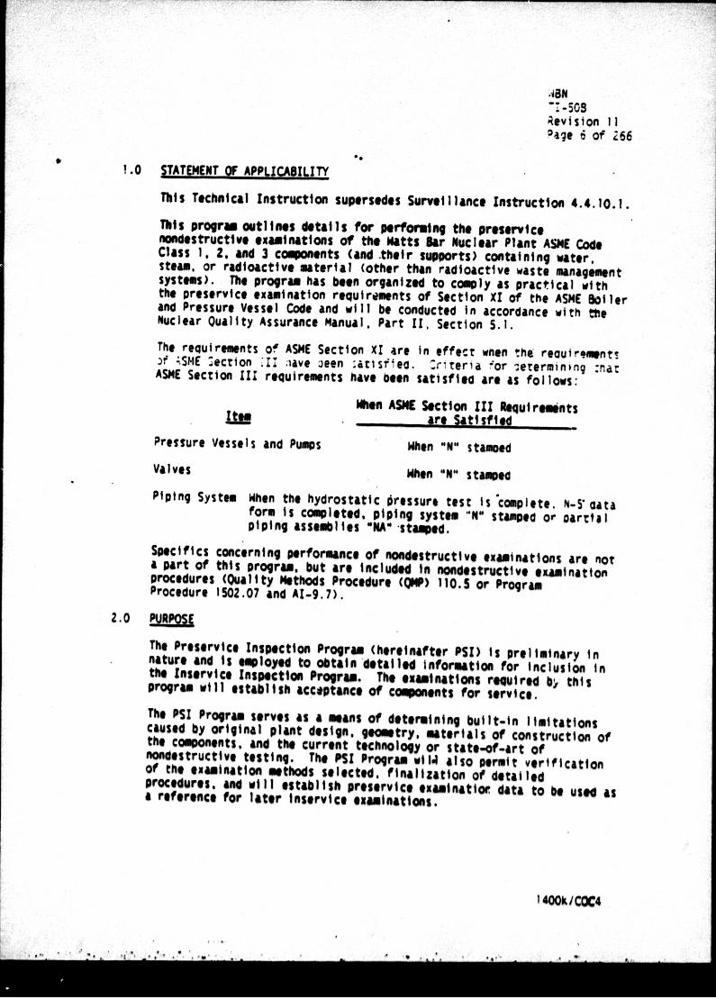
1 .0 STATEMENT OF APPLICAILITY
This Technical Instruction supersedes Survillance Instruction 4.4. 10. 1. This Iprogr outlI Ines deta IlIs for per fovw ng the presevI ce nondestructie eXAMInations Of the biatts Sar Nuclear Plant ASK Code Class 1. 2o and 3 components (and -their supports) containing water, steam, or radioactive material (other than radioactive waste management systems). The program has been organized to comply as practical with the preservIce examination requirements of Section XI of the ASHE Boiler and Pressure Vessel Code and will be conducted In accordance with the Nuclear Quality Assurance mianual. Part 11, Section 5.1.
The requirements of ASME Section XI are In effect wnen thet reautr~ment! )f ;SNE :ection :'I' :iave aeon :atisfilea. 'rireria -;or 4etormininq :nat ASME Section III requirements have been satisfied are as follows:
Mine ASH( Section III R~equiremints itE are Satisfied
Pressure Vessels and Pumps When "NO stamoed
Valves When OMNO Stampe" Piping System When the hydrostatic Oressure testIs 'icomplete. N5* data
form is completed. piping system "N" Stampod or oar~tal piping assemblies 40NA" -Stamped.
Specifics concerning performance of nondestructive examinations are not a part of this program. but are Included In nondestructive eXAmination procedures (Quality Methods Procedure (QHP) 110.5 or Program Procedure 1502.07 and AZ-9.7).
2.0 PUPS
The Preservice Inspection Program (hereinafter PSI) Is preliminary ini naUMe And is employed to obtain detailed Information for Inclusion in the Inservice Inspection Program. The examination$ reqired bý this Program will establish acce#ptance Of Components for service. The PSI Program serves as a means of determining built-in limitations caused by original plant design, geometry, materials of construction of the components. and the current technology or state-of-art of nondestructive testing. The PSI Program wil4 also Permit verification of the examination methods Selected, finalization of detailed procedures. and will establish preservice examination, data to be used as a reference for later Inservice examinations.
lM/COC4
"N TI-508 Revision 11 Page 7 of Z66
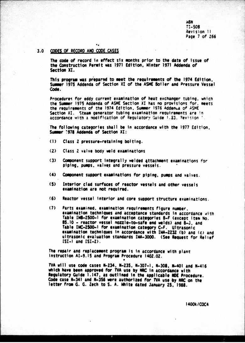
3.0 CODE OF AgCOA AND CODE CASES
The code of record in effect six months prior to the date of Issue of the Construction Permit was 1971 Edition, Winter 1971 Addenda of Sect1" X1.
This program was prepaed to meet the requirements of the 1974 Edition, Sume 1975 Addenda of Section XI of the ASHE Boller and Pressure Vessel Code.
Procedurei for eddy current examination of heat exchanger tubing, which the Sumer 1975 Addenda of ASHE Section XI has no provisions for. meet$ the requirements of the 1974 Edition. Summer 1976 Adden,.a of ASKC Section X1. Steam generator tubing examination recuirements are !m accordance with a modification of Regulatorv Guide 1.23. Ueviston '.
The following categories shall be In accordance with the 1977 Edition. Sow~ 1,78 Addenda of Section XI:
(1) Class 2 pressure-retaining bolting.
(Z) Class 2 valve body Weld examinations
(3) Component support Integrally melded *ttachment examinations f'or piping. pumps. valvts and pressure vessels.
(4) Comonent suport examinations for piping. pumps and valves.
(5) Interior clad surfaces of reactor vessels and other vessels examination are not required.
(6) Reactor vessel Interior and core support structure examinations.
(7) Parts examined, examination requirements figure numer. examination techniques and acceptance standards lin accordance with table W1i1-2500-l for examination categories $4F (except Itge No. 55. 10 - reactor vessel nmozl-to-safe end welds) and S..J. and Table INC-ZMO0.l for examination category C-F. Ultrasonic eXamination4 techniqus In accordance With IWA,42Z3 (b) and (c) and Ultrasonic evaluation standards INA-30. (See Ilequet for Relief lIZ-I And ISI.2).
The repair and replacement program Is In accordance with plant Instruction AI-9.15 and Program Procedure 14M1.02.
TVA will use Code cases 11.134, X:235. N-307-1. N-308. M-401 and N-416 which have been aproved for TVA use by PAC lit accordw#c With Regulatory Guide 1.147. As outlined 14 the applicableI Procedure. Code case N-341 and N-3M wee authorlize for TVA use by MC on the letter from 0. 6. Zqch to S. A. White dated January 25. 1961.
1400ki=O4

WON
levislon 11 page 8 of 266
TVA will utilize Regulatory Guide 1.150 Rev. 1, ltrasoni c Testing Of Reactor Vessel Welds During Preservice and Inservice Examinationo for Its examinations, as outlined In the NOE Procedures.
4.0 00111M OF !WLMWIAT!U AND AIEM LC2SiIT!ES
Fraliminary weld maps and other pertinent component drawings and tables ao Included In Appendix A of this program to define areas subject to exatu'~tion (in addition to sections 5.0, 6.0. 7.0. and 8.0). The preliminary piping weld maps should be established by NDE Section X1 Programs from Nuclear Construction's latest revision weld maps. Prior to performance of the examinations. each system should be walked down by NOE Section X1 Programs to verify that the MDE Section X1 3,oqrams drawings devict ?told configurations. Any Irawiq -#visions Mnat are necessary as a result of the waikoown wiii be maoe before tne drawings are Included In this program. Also each component drawing shall be reviewed by the responsible 11K Section X1 Programs engineer to ensre that the appropriate Information Is Included an the drawing and shail1 be aproved by the IDE Section XI Progras superv isor. Nuclear Quality Assurance (110) Shall prepare scan plans using component listings supplied by NK Section XI Programs using Component drawings for systems or components requiring examinations. The plans shall Include as a minimum references to specific voids op components supports to be examined. ASH[ Code Category. Component drawing number, Nonmliestructive, Examination (11K) procedures to be used. and calibration block ~mber.
Prior to periForming exWamntions on a system or component. the scan plans shallI be aWpoe by N Level III individual from NQA and made available by 110A to the Plant Manager for information. System and component weld mups are Incorporated to Appo~iu A of this program. MOA shall notify the Afthorized Ianspection Agency (ALA) reasonably in advance of when components are scheduled for examination. if variations In piping configurations are discoverd or indificatiops or repairs to piping are made during the course of the PSI. these changes shallI be marked an field copies of drawings. This Information shall be commnicated to NKSection XI Programs. utilizing the Appendix F form, which shall be responsible for revising the original drawings. The IQA scan plan shall also be revised to reflect these changs. Flowing completion Of each System examinatIon, the revised drawings shall be incorporated Into this program as a reference for Inservice Inspections. The preservice examinations will be perf-rm by personnel from eiter OA Personnl or outside contractors. contract preparation. 440n81stvatift. and supervisio will be the responsibility of the Q0. Inspection 0lans submitted by Outside contractors shall be reviewed &d 40proved by NQ prior to use. M verifies the adeeuay of prospective contractor quality assurance programs prior to contract award. All specific UKE procedures used during the inspection program Shall be
I 4M/o~kC4
6 , .. .-. *ft ,~~ I '1*6' .&0'. * 61 . 60" f .La - - - t -
wen
Revision 11 0 ~page 9 of 1466
prepared, reviewed, qualified In accordance with NOAH, Part 11. Section 6.3, and controlled In accordance with ON". part 111. Section 1j.. Certain ASKE Section III eXaminations performed in-shop end/or by WOcea CONstruction will be Identified by NKSection X1 Programs and employed to serv for the ASKE Section XI PSI. *en in-shop examination records are employed, the eXAMination data sheets and the applicable data package form. with the AN! sign-off. shall be Obtained by WOE Section XI Programs. MWe Nuclear Construction examination records are empoyed, Nuclear Construction examination procedures shall be obtained by NOA for reference (excluding pressure test Procedures). ano a random sample review of records shall be done by NOA. :f It Is necessary to us* Construction radiograph~s for ASME Section Al examinations or for information, chose raosioqrapns must be carefully reviewed to Insure that the radiograph matches the weld In question. Additionally, the Site Quality Organization (500) will be responsible for notifying the Plant Mnuager of all unxaccetable Indications found during preservice Inspections as soon as practical. This does not Include preservice examinations following repair and replacements Whenever an unacceptable Indication Is discovered. this procedure (Section 16.0) and the Notificatior of Indication (NOD) fore In Agoendig C shall be utilized. In those eases where an outside contractor Is furnishing prejenvice examination *services, the contractor vill normai~y Initiate the fore In Appendix C under the supervision of the SOO representative. See section 16.0 of this program. Comuter monitor programs are used to Identify any welds or supports that have been reworked by Nuclear Construction after the protervtco examination has been done. The Plant shall Include provisions for notifying SOO In any work Instruction written to modify or rework *#ebs or supports after the preservice examination has been done. Q0 shall maintain the status of completed examinations for each weld or component s1pot reqired to be examined. Individual comonent status Is kept by transferring all the Information from the scan plan to a mister plan, as examinations are performed they are recorde In the master plan for status.
As sectioos are completed, the SCO representative shall sign for comletion the appropriate sections of Data Sheet I in Appendix I of this program. When all examinations of this Program have been completed. Data Shoot I shall be signed for completion by the SOO representative, reviewed by the UK Section XI Programs epreesentaeive amd approved by the Site Quality Nuager. Is the event system or compnent alterations or repairs are made which requir, component reemamination, or comonients are reexamined for other reasons, (new U techniques amipent examutions requred by MC. etc.) following tiln-off of Data sheet 1. the aesroerate Setions of Data Sheet 2Iin Appendix I shallI be copeleted And signed by the SQO representative, reviewed by the UK SeCtion XI Programs 11epreseetativeand aproved by the Site Quality 11116844r. 14I 4 COC'

rv
WBA TI-S08 Revision 11 Page 10 of 266
All preservice examinations shall be comleted prior to Initial plant startup (Operational Mode 2). Prior'to Initial plant startup. Data Sheet 2, In addition to Data Sheet 1. In Appendix I shallI be signed. After the data sheets I and 2 have been approved. the data packsage cover sheet shaill be Oipted by the Site Quality Nmnager. These data sheets shall be filed at the plant site with PSI examination data and final reports discussed in Section 35.0 of this prorm. PSI program preparation Is the responsibility of NOE Section XI Programs. Any revisions Initiated by other groups shall be submitted to NOE Section XI Programs for approval prior to Incorporating the revisions Into this program.
5.0 A08REVIATIONS AND DEFINITIONS
5.L ALA - Authorizec Inspection Agency 5.2 AL - Authorized Inspector (my denote an AN! or ANI!) 5.3 MfL - Authorized Nuclear Inspector
5.4 &U-Authorized Nuclear Inservlce Inspector 5.5 Ca3mtt1- Denotes Items In a power plant such as vessels. 05jiijijstems, Pumps. valyes. and component.supports. 5.6 ExIuf aloom- Denotes the performance of all visual observation
and nondestructive examination. 5.7 ML - Notification Of Indication
* 5.1 2Q - Condition Adverse to guality
5.9 -Condition Adverse to gual~ty Report 5.10 -Unreviewed Safety Question Determination 5.11 -Nuclear Quality Assurance onual
5.12 * 2 Delig r OWe Reeves t
5.13 M - Maintenance Reqest
5.14 is - Work Request
5.15 aric AlJyfLowela n -jiNSj.upections reqired ly ASK Section 11 to tse fet r maWONInspection Intervals for the service lifetim of the ~ee unit. Thes leseecioss Include IN - system pressure tests. and Pp AM Valv" tests.
14I 4O/OC4
.* *~%* .wJ... ' ~3 . a
WIN TI-s0s
SOP Revision 11 Page 11 of 266
5.16 Pririce Inlcio(ML) -Inspect Ions required by ASKE Section X1 o b copleed rio toIniialplant startup, or Inspections
required by ASKE Section X1Iif a component Is replaced, added, or altered during the service lifetime of a power unti. These Inspections Isclude NO. system pressure tests, and pump an valve tests.
5.17 ljjj tion - enotes verifying the performance of examinations and tests byan Inspector representing an Authorized Inspection Agency.
5.16 Maintenance - Routine servicing or work oni an Item undertaken to correct or prevent an unsatisfactory condition. Maintenance does not Include welding. heat treatment, or defect removal which affects the pressure boundary. kýintenance fnc'udes operations such as lapping of seats, adjustment of stem oacking. pump $eal maintenance. Maintenance Wes not require the presence of or verification by the Authorized Nuclear Inspector or Authorized Nuclear InservIce Inspector.
5.19 NomlOrto - NormI plantt operation conditions Include reactor startup. operation at power, hot standby, and reactor cooldown to cold shutdown conditions. Test conditions art excluded.
5.20 PreisuejRe!IgintnS Matrial - Applies to Ittema itch a', vessel heads, nolol. ipes. itubeIs, fittings.- valve bodies, bonnets. disks, puM castings, covers. and boltings which join' pressure-retaining items.
1.21 togj . Those operations Involving welding, heat treatment, or iIIIremoval which are required to restore an Item to a safe and
satisfactory W~erittng condition.
5.22 Aselacont - Spare and reneal componets or pressure retaining parts of a componen t (e.g.. valve body boannt, disc, bolting). it also includes the addition of compnents such as valves, and system changes such as rerouting of pipineg. For the purpose of this procedure, the teom repl Macet shell apply where attachant to tfe presure boundary is by welding or mechanical meaws It dos not include the addition of comlete systems.
5.23 ~hM"ItCU.Ive IfilinatISC (99)- Methods used for the detection am evalhaatllbof discontunuiltles awi the measurement of physical dimensious and properties of Items. These methods Include radiograimy, ultrasonic, edy current. liquid penetrant. magnetic paticle, and visual. moese methos do not impair the serviceability of the Item .
14I 0kCOC4

WON TI-508
d16 Revision If Page 12 of 266
6.0 CONPOENTS SUBJECT TO EXMINATION - ASPI! CLASS I The ASPIC Class I (TVA Safety Class A) compments to be examined for the PSI are outlined In the followi a paragraphs. The e"tire length of each weld described will be examined for the PSI. All Class I components are subject to volumetric and/or surface examination except c~onent connections, piping. and associated valves WaW their supports) that are one-inch nomnal pipe size and smaller (see section 6.7). Class I vessels shall not be examined prior to shop or field hydrostatic tests. When examinations have been completed on, the various comooflents. the data sheests In Appendix 8 shall be completso. Table A in Appenoix A supplies additional information such as reference drawing numbers and Section XI. Table IWS-2600. examination categories. 6.1 bsacla16ni
6.1.1 ReactorVe-s-sel Seam-Weld
6.1.1.1 Circumferentl 41llWed - Beltltne Region
There Is one circufcrontial well1 In the vessel cylinderical shell located behind the neutron shield oads. This weld will be ultrasonically examined using remote Inspection devices from the vessel 1.0. with the core Internals remoed. The vesse shell sections are machined forgings fabricated of SA-SOS, Class 2. Ungmoaeeslyedenum steel and are clad with weld deposited austenitic stainless steel. There are so Uase metal repar welds In the beltilse region where repair depth exceeds 10 percent nominal of vessel wall.
6.1.13 Cir t~eetial Shell Mlelds
Ther are three circumferential welds In the vessel cylinderical shell located outside 4~ the belt.line region. These welds will be ultrasonically lawned 61i.g riMte Inspection devices from the vessel L). wth the care lnternals reowed. The v"MI Shell se0tion aterial Is identified tn lectio e ls~ l

WON As TI1-508
Revision ifl Page 13 of 4266
6.1.1.3 LwNa-~d
There are six meridional voids and one circuferetial weld In the lower head. The welds will be ultrasmnically examined using remote Inspection devices from the vessel I.0. with the core inteirnals reeod.
Sase metal below the lower head circumferential weld (weld No. WOI-02) Is Inaccessible for examination from the vessel 1.0. duo to Instrumentation penetrations. A manual ultrasonic oxamination of this area will be conducved from the vessel 0.0. (So# e40ueSt for Relief !St-4).
The bottom head sections are fabricated of SA-533. Gr. 8. Class 1,%ameaqese-slybedemn steel, and are clad with wed deposited austenitic stainless steel.
6.1.1.4 Clasure edCiM4rcu erental Weld
The head cap weldA will be manually ultrasonically examined from the head 0.0. The closure head does not Include any meridional welds.
The closure head ring Is fabricated of SA-SO. Class 2, manhaSOaleelybedewm. steel. The closure head bemisphe10riCal Section Is fabricated of SA-533. Gr. 11. Class 1, Maganlese.Molybedeee steel. Both sections are clad with weld dep11ostd austenI tic stainless steel. 6.11.5Veselro.FlAe And hleA&T~1o4A=ee Wld9
The vesslmto.fluange weld will be ultrasonically examined from the vessel 1.0. with remote inspection devices. Tho 10ea-tol-flange weld will be WManaly ultrasouically exailnod fromn the head
The vessel and closure hea flange sections are fabricated of SA-log. Class 2. mnaeemlee~ steel and are clad InternallI and an the gasket face with weld deposited a"usiuic stainless s toal
There are few inlet amoule (27.441 iack 1.0.) and four outlet Moazles (21.937 1nc0 1.0.). The mnoazetowvessol
l4MIkiCe

WBN
d1L Revision 11 Page ;4 of Z66
welds and nozZle Inside radilused sections (including outlet nozle Integral extensions) will be ultrasonically examined from the I.D. using remote inspection devices..
The nozle forg ' ng are fabricated of SA-SOS, Class 2. *anganese-molybedenum steel and are clad with weld deposited acstraitic stainless steel.
6.1.3 Reactor Vessel Penetrations And Attachments
The 78 control rod drives, 4 upper head Injection. I vent pipe, and 58 Instrumentation penetrations shall be visually examined by Nuclear Construction for leakage during the ASHE Section III hydrostatic pressure test.
6.1.4 Reactor Vessel Nozzle-To-Safe End Welds
The nozzle-to-safe end welds shall be ultrasonically examined from the I.D. using remote Inspection devices. In addition, these welds will be liquid penetrant examined (from 0.0.).
The nozzle ends Include a buttered safe-and of 309 and 308L and are extended with a stainless steel ring of SA-18Z. TP 304.
6.1.5 Reactr =Ve Presure Retainin Solting Larger Than
All 54 of the vessel closure studs shall be ultrasonically and magnetic particle examined. The closure studs may be ultrasonically examined in place inder tension, when the closure head is removed, or when the gtuds ire removed. The closure nuts shall be magnetic particle examined. The vessel flange ligaments (54) between threaded stud holes shall be ultrasonically examined. This examination is to be done manually. Threads In the base material do not require examination.
The 54 concave washers shall be visually examined.
Studs, nuts, and washers are fabricated of SA-540, GR.B24, nickle-chrome-molybedenum steel with a manganese-phosphat# iurface treatment.
There Is no pressure retaining bolting 2 inches and smaller In diameter.
1400k/COC4

BNN TI-506
Ok Revision It Page 15 of 266
6. .7 Intearally-Ideded jeactor vessel Supports
There are no Integral ly-welded vesel supports. The vossel is suppoted by four support pads located on the bott= of two outlet nozzles and two Ilelt nozzles.
6.1.1 Reactor Vissel And Closure Head Cladding
There are six clad patches (36 square Inches each) In the vessel cladding and six clad patches (36 square Inches each) In the closure head cladding. In accordance with the 1977 Edition. 1978 Summer Addenda of Section X1. No examination Is required.
Reactor vessel and !:!osure head claddinq le. ,f -veld deposited austenitic stainless steel.
The space above and tiflov the reactor corc that Is toade accessible for visual examination by the removal of components during normal refueling outages shall be visually examined using visual examination methoc VT-3.
Visual examination method VT-3 shall also be performed on removable core support structures of the vessel. Tlv examinations shall Include 100 percent of the visually accessible attachment volds and vts'ally accessiblit surfaces of the core support structure. The structures shall be removed from the vessel for thiese, examinations.
6.1.10 Reactor Ve-ssel Control Rod Drive Housings
The pressure-retaining welds In the twenty peripheral control rod drive housings shall be ultrasonically examined. The housings consist of a 6-inch 0.0. adapter of SA-IS1Z. TP 304 and a 4-Inch 0.0. body of 55-167.
6.1.11 Reactor Vessel Auxiliary Head Adapters
The pressure-retaining welds In the four auxiliary head adapters shall be ultrasonically examined. The dissimilar metal welds shall also A liquid penetrant examined. The adapters consist of SA-lSZ, TP 304 stainless steel (upper portion). S11-164 (lower potion), and a weld buildup from the vessel head. The weld buildup Is considered an Integral part of the, vessel head aa does not requre exami nation.
1400k/COC4
'0 1 % ...

WON TI-s08 Rlvis4on 11 Page 16 of 266
6.2 Pressurizer
6.2.1 Pressurizer Lonuitudinal And Circmferential Oblds
There aO four longitudinal welds and ifiv circumierential welds 11 the Shell cylinderl regiOOR. These welds shall be Ultrasonically examined. Ther aneas circkwerential or meridiomal head welds.
All shell And head sections are fabricated of SA-533. Gr. A. Class 2. minganese-uolybedenum steel and are clad with austenitic stainless steel.
6.2.2 Pressurtzer Nozzle-To-Vessel Weld$ And Inside Radlused Sections
There are four 6-Inch nozzles, one 4-Inch nozzle, and ane 14-inch nozzle. The armoze-to-vesel welds and nozzle inside radiused sections will be ultrasonically examined. The nozzles are fabricated of SA-SOS. Class 2. manganesebolIybdemum s tooel.
6.2.3 Pressurizer Heater Penetrations
The pressurizer lower head heater penetrations snail be visually examined by Nuclear Construction for leakage during the ASK4 Section III hydrostatic pressure test.
6.2.4 Pressurizer Rnuzleo-Sa:ft EMd 161411
Each nozzle Includes a welded forging safe end. The nozzle-to-safe end welds shall be ultrasonically and licluid Penetrant examined.
Safe-end connections are SA-182. Gr. F-316L forgings.
There Is no pressure-retaining bolting larger than 2 Inches In diator.
=~urPressurtmRetaining kolting 2 Inches and, Silter
The bGltiM1 on the pressurizer amnwy shall be visually examind. The bolting IS, be 01001"m either in place under tension or W"e the bolting is renoved.
The *anway Intcludes If bolts At 1.88 Inches In dliamter. The bolts are fabricated to ýpe,-193. Gr. 87.
, ~Ev ~~ .. 'J .. *.' 4* 4%*4, ..-.-. , - -- .
:4
6.2.6
WNN
Revision 11 Page 17 of 266
6.2.7 Pressurizer IntearallY41eldid 10u514i. wart The pressurizer stppot skirt-to-vossel wild shallI be ultrasonically examined.
The suppot skirt (1.5 Inches thick) Is fabricated of SA-51l, Gr. 70. carbon steel plate.
6.2.8 Pressurizer Claddine
A clad patch 36 square Inches) Is In the pressurizer Interior cladding near the manway. In acczc'dance with the 1977 Edition. 1978 Addenda of Section XI. no examination is MeutOd.
Interior cladding is of austenitic stainless stool.
5.3 stem Gerts(4)
6.3.1 Stemi Generator Primary Loneitudinal And Circumferential
The primary head-to-tube shoot weld on each generator shallI be ultrasonically examined. There are no primary longitudinal welds.
The tube plate Is a SA-SOS. Class Z. steel forging, clad on the Primary side with NICrF9 allay (Inconel). rhe hemispherical chmber Is a S4-416, Gr. MM. casting. clad with aestenitic stainless %s401.
6.3.2 Wilds And Injtd*
There are no steam geneator primary nozzle-to-head welds. The stem generator primary nozzles are IntegrallIy cast with the hemispherical chamber.
1.3.3 fteam Generator Primary Mozzl-To-Safe End Welds The steam geaerator primary nozzle-to-safe end welds shallI be ultrasonically and liquid penetrant examined. The nazzles have buttered M06 safe ends.
6.3.4 tm% M t os *atnitmlig oa
fThre is me pressure-retaining bolting larger than 2 inches io diameter.
I 4CokIC4
ift" rdaIr IM Friary mazzle-TO-ft" RadiusIg tions

Li,.
NBN TI-508 Revision 11 Page 18 of 266
t
6.3.5 Stei finerator Primary Pro s-x*Rt In t no iting 2 inche
The bolting an the OMaay covers (2) an the primary side of all the generators shall be visually examined. The bolting may be examined either In place under tension or whien the bolting Is removed.
Each manway has 16 bolts at 1.68 Inches In diameter. The bolts are fabricated to SA-193. Gr. 87.
6.3.6 Steam Generator Intearally-Melded Vessel Supports
There are no integrally-welded vessel supports. The four muain suoport Pads are secured to the steam generator fiela support system by high strength bolts.
6.3.7 Stam Generator Vessel Cladding
A clad patch (36 sovare Inches) Is In the steam generator Interior cladding near each generator manway. In accordance with the 1,977 Edition. 1973 Summer Addenda of Section XI. no examination Is req. ired.
The hemispherical chambe is clad with austenitic stainless steel.
6.3.8 Steam Generator Tubina
DO~c steam generator tube bundle cortists of 4,674 NICrFe &C'oy (Inconel S11-163) U-tubes of 0.75 0.0. by 0.042 avdtage wall thickness.
All Mues shall t'udergo an augumented preservice inspection by eMy current examination. The preservice examination shall be performed In accordance with Appendix IV of the 1974 Edl~iv . Summer 1976 Addenda of Section XI and Regulator Guide 1.63. Rev. I.
6 .IlAcceelance Criteria
i.3.a-I-l As Used In This Section:
6.3.6.1.1.1 Ias.r.Zegl means an exception to the dimensions, finish or contour of a tube from that required by fabricati 'on drawings or specifications.
14I 4~COC4

We' TI-50s Revision 11 Page 19 of 266
Eddy-current testing Indications below Z0 percent of the nominal tube wall thickness, If detectable, m~y be considered as imperfectioins.
6.3.8.1.1.2 "rg*kio man" a servicei~I~diodCrkIng. Was tage. wear. or 9enra) corrosion occurring on either Inside or outside of a tube.
6.3.8.1.1.3 Qqqadag Tube means a tube cotininngImperfections greater than or equal to 20 percent of thle nominal wail flhickness caused by degradation.
thickness affected or remioved by degradation.
6.3.8.1.1.5 Def means an Imperfection of iudF-sovority that It ecoceds the plugging limit. A tube containing a defect Is defective.
6.3.8.1.1.6 eJM~iniuJfnI± means the Imperfection. depth at or beyond which the tobe shall be removed from service and Is equal to 40 percent of the nominal tube wall thickness.
6.3.8.1.1.7 Vjs~jrvi*Mj describes thle condition of a tube If It leaks or contains a defect large enaugh to affect its structural Integrity in thme event of an Operating Basis Earthquake, a loss-of- coo lant accident, or a stemn Ine f or feedwater I tne break.
Do.61.. IOMLftm an insectonof hestem
generator tube fron the point of entry (Not leg side) completely around thme U-Men to the top support of the cold 1e".
14M0kCOCa
0 .

HSN TI-S08
dbevision 11 Page 20 of 266
6.3.8.1.1.9 .rsrieInlc pemana, an Inspection of the full1 length of each tube I n each steam genrator performed by eddy curre-nt techniques prior to service to establish a baseline condition of the tubing. This inspection shallI be performed prior to Initial power operation using the equipment and techniques expected to be used during subsequent Inservice Inspections.
6.3.8.1.2 All defective tubes and tubes containing througn-wall craCKS shall be plugged.
6.4 Pinina
All ASNE Class I piping systems to be examined are fabricated of stainless Steel.i The reactor coolant main loop piping straight lengths are centrifugal cast and the elbows are static cast. The upper head Injection auxiliary head adapter Is Included in Section 6.I-fl. Specific material specifications for each piping system are Included In weld map Iswetrics In Appendix A. Some examinations cannot be performed (set Request for Relief ISI-Z). The following Class 1 pi;ýnq systems are subject to examination:
Reactor Coolant Chemical and Volume Control Residual Heat Removal Safety Injection
6.4.1 Chreumftrential And Longitudinal Pipe Melds
The entire lengt of each circumferential and longitudinal plte welds four Inches nominal pipe size and greater shall be ultrasonically and Swrfzce esained. The entire length of each circufereatial And longitudinal pipe weld less than four Inches nominal pipe sine shall be liquid penetrant examined. The following circumferential pipe welds will be radiographically examined (later).
4.4.2 Branch Fiee Connecton Oblds
All birafch Pipe connection welds euceedial two Inches nOMInal Pipe Size shall be ultrasorncally and liquid
l4MO/COC4

WON 7-508
Ak Revision 11 page 21 of 2.56
penetrant examined. Each branch pipe connection veld tut inches no~nal pipe sine and smaller shall be liquid penetrant examined.
6.4.3 Filuto Socket Mields
fadh socket weld shall be liquid penetrant examined as practical. Nuclear Construction examination records will be used for welds doae after 12/79. welds are listed below.
(Later)
6.4.4 Pipina Intogrally-Welded Supports
All plaing integrally-welded extrenal suoporr, attachments whose support base material design thickness Is 5/8 Inch and greater shall be surface examined. Integrally-welded external support attachments Include those supports which have attachment welds to the piping pressure-retaining boundary. (See Appendix A. Table G)
6.4.5 Piping SVcort Coinonents
All piping ;upport components shall be visually examined. This examination Inclueles Integral ly-welded and nouintegrally-welded suport components. The suoport Settings of Constant and variable spring type hangers. snubbers. and shock absorbers sihall also be verified. (So* Append Ix A. Table* G)
6.4.6 101011041 .!!~sure.4e1tatnif. Salting Larger Than Z Inches In
There Is no Class I piping Pressure-retaining bolting larger than 2 Inches In diameter.
Class I bolting 2 Inches and smaller In diameter ý,nall be visually examined. These examinations shall Include balts. Studs. And nuts. (See Weld Map Isometrics In Appendtu A for location of bolted connections).
fth bolting May be examined either In place under tension. wWe tOM connection Is disassembled. or whe the bolting Is reed".
6.4.8 Mhine Safe-En !klds
Mhre are no piping safe-end welds other than those dlicussed In Sections 6.1-., 6.2.4, and 6.3-.3
140OkjMC4
TI-s08 Revision 1, Page 22 of 256
6.5 Reactor Coolant Pumps M4-11M
6.5.1 S rsutft~~ otnLre h nhsI
The main flange an each powp Includes 24 bolts at 4-1/2 Inches in diameter. The bolts shall be ultrasonically examined and shall be surface exasined If removed. Threads In the base material and flab"e ligaments between threaded stud holes shall be visually examined If the connection Is disassembled.
The bolting may be examined either in olace under tension.* when the connection is disassembled, or wnen the bolting is -emoved.
The main flange bolts are fabricated to SA-540. GR B24.
6.5.2!a ms kanm gtra2IceanSalrn
The no. I seal assembly bolting shall be visually ewamined. All bolting may be examined either In place under tension when the connection Is disassembled, or when the bolting is removed.
6.5.3 MCP lnteara-lly-lilded Supports
There are no integrally-welded supports associated with the to .
6.5.4 4CP Subort Commoents
Each W Includes three support Components bolted to pump feet, which are integally cast with the pump. Each suppot component shall be visually examined.
Each Pomp Includes a two-iece welded type 3U4SST Casing. The Casing welds cannot be ultrasonically examined and achiev meaingful results doe to limitations of examining Integrally cast material. In lieu of OtJs requirement the Casing welds Shall be surface examined (see Requst for Relief ISI-S).
6.5.6 RD CASING The Internal presture boundary surfaces of one pomp shall be visually examined.
-M1
WN6
Revision 11 pags 23 Cf Z66
6.571 IV Fl Ywh"el
Each NCP flywheel shall undergo a complete ultrasonic exMlmation and shall also be surface exaMined In accordance with IeMlatory Guide 1.14.
Preservice exam~nation Is not required by TVA.
The flywheel consists of two plates, approximately 5-Inches and S1-inches thick. bolted together. Each plate is fabricated from vacuum degassed A-533. Gr. S. Class I steel.
6.6 valves
6.6.1 lilve Pressure-Retaining Solting -iarger 7han .'7ncnet 4n
There Is no Class 1 valve pressure retaining balting larger than 2 Inches Jn diameter.
6.6.2 1voPressure..Rtaining Bolting 2 [Inches and Smaller in
C''is 1 valve pressure-retaining bolting 2 Inches and smller In diameter shall be visually examined. Those examinations shall Include bolts. studs. and nuts. (See Aepefltv A, Table E for valves).
The bolting may be examined either In place under tension, when the connoection Is disassemled. or when the bolcing is removed.
6.6.3 Valve In~al-t~oSpot
There are no Class 1 valve Integrally-welded supports. (See Aspend Ix A, Tablet E)
6.6.4 valve Support CiOneaPts
There are no Class I valve support components. (See AppendI m A. Tabl It)
6.6.5 Valve so" wldJg
There are no Class I valves with body welds. 6.6.6 Val" Bodie
The Internal prmsure boundary surfaces of one valve in aCh group of valves of the Sam constructional design
(I.#.. globe, gate, Check), manufacturinq method, and
S4OWk/COC4

MWft TI-5OB Revision lle.' Page 24 of Z06
manufacturer that performs similar functions in ftle system shall be visually examined. The examinations shall Include valves exceeding 4-Inch nominal pipe size. (See Appendix A. Table D.)
6.7 Exemeted Comaumats
All comonents exempted fron examination In accordance with TOS- 120 of ASNE Secti on XI shall be v Is uall Iy exami ned for letakage during system hydrostatic pressure *tests. See Section 9.0.
Coroets exempted from examination Include component connections, pipildg. and associated valves (and their supports.) that art i-inch nominal pip* size and smaller.
7.. XM4PNENTS SM8EC7~ 70 z-XAM!tETIN - ASI4E CLASS Z
The ASHE Class 2 (TVA Safety Class 8) components to be examined for the PSI are outlined In the fol lowing paragraphs. All components to be examined for Inservice Inspections during the service life of the plant will be examined for the PSI. Selection of areas for examination will be In accordance with paragraph IWC-Z41 1 and Table IWC-ZSZO of ASHE Section XI. - DE Section XI *Programs shallI select areas to be exaqined or the NQA may assist In selecting areas to be examined. Components that are exempted from examination In accordance with IW(-lZ2o of AS14E Section XI are discussed in Section 7.15 of this program.
Class 2 vessels shall nc.r be examined prior to the field hydrostatic tests.
Where examinations specify a percentage of the total length of weld be examined. the area(s) examined shall be physically marked on the com0onent and documented In the examination report. Where a percentage of weld lent" Is not referenced. the entire weld length shallI be examined.
When examinations have been comleted on the various i..aqonets, the data sheet(s) In Appt'.mex I snall be complete< Table I In Appendix A supplies additional Information such as reference drawing numers and ASK1 Section XI Table-ZSZO examination categories. 7.1 Sta ffars()
7.1.1 Steam Gwnrafor Secondar, Circumerential Iblds
There are five circumferential shell welds located it structural discontinuities on the secondary side of each steam generator. A total of five welds, all at different locations from the four generators, will be selected for
14MIkCOCe

a6N
Palo 25 of Z56
ulirasonic examination and shall be dlitribute#I among ther four generators. The examinations shall cover at least tWenty percent of each weld selected for examination, uniformly distributed a"on thre areas around the vessel circumference.
*0Of the five Wlds selecteld for examination Is partially inaccessible due to the uppr steam generator support arrangement (weld nag. SG-48-5-I, 2. 3. or 4: see Request for felief ISI-3). The weld selected for examination will be ultrasonically examined on a best effort basis. The vessel shell and head sections are fabricated of SA-533. Gr. A, Class Z Steel plate.
7.1.2 Steam Generator Secondry Plozle-To-Vessel Welds
There Is Ofe feedwater nloze (l6I-nch 1.0.). one fetdwater by-pass nozzle (6.-Inch I.D.). and one min steam nozzle (32-Inch I.D.) per generator. A total of three Mozle-to-vessel welds from the four generators will be ultrasonically examined and shall be distributed among three of th~e generators (owe feedwater. one feedwater by-pass, and one main stea m nozl).
The nozzles are fabricated of SA-SOS. Class 2. Steel.
7.1.3 b ma nw l I
Ther are no integral ly-welded vessel supports. 7.1.4 nt ~ @!r Ir Pr r u-g taIninq SI in Exceeding
There Is no steam generator secondary Side bolting larger than two Inches In diameter.
7.2.1 !MU Circumferential Welds
There are two circumferential welds located at structural discontinuities 06 the tube side Of each RHIX. A total of two welds from the two heat exchangers will be selected for ultrasonIC examination aMd %hall be distributed among Mhe two SlUR. The welds Selected shall be located at different areas. The examinations %hall1 cover at least ~towmt Percent of e ach VWed Sole#cteI for #saw nat Ion.
0nifomly distributed ng three areas around the vessel Circumference. The eua1MINAtion Cannot Cover twenty percent Of the weld. channel cylinder section to channel flange (see Request for Relief [SI-w
14I 0kCOC4
*
l4O0kI/rOC4
TI-SOB Revision 11 Page Z6 of Z66
The wld's InciWie tht channel cylinder section to channel flange weld and the channel cylinder section to channel head weld. The channel flange Is fabricated from SS. SA-336-VI. The channel cylinder section and channelW head are frau SS. SA-240, TP-304.
7.2.2 RORM jult=To-Vess*I Helds
The channel cylinder section of each HRHX Includes one Inlet nozzle (14-inch 1.0.) and one outlet nozzle (14-inch !.D.). A total of two nozzle-to-vessel welds from the two RNRNX will be ultrasonically examined and shall be distributed among the two heat exchangers (one inlet nozzle and one outlet nozzle). The examination is limited (see Reuuest for Relief :S!-;o). The nozzle% are fabricated from SS. SA-3364-F8
7.2.3 Mmi Intearally-Melded Slhwmts There are two integrally-welded support attachmerts on each QHRINx. A total of two support pad-to-vessel welds fro, the two heat exchangers will be liquid penetrant examined and shall be distributed among the two heat exchangers (a 'different support on each heat exchanger).
The support pad (attachment plate Is 5/8 inch thick) Is fabricated from SS. SA-240. TP-304.
There is no RHRmx bolting larger than two Inches in diameter.
7.3 egewterAtive Neat Excharmer (1-MiX
7.3.1 ANX-Circum-ferential Welds
The regenerative heat exchanger is saosd of three heat exchangers Interconnected with piping. There are twelve circumferential welds located at structural discontinuities On the heat exchanger. These welds shall be ultrasonically examine11d. The examinations shall cover at least twesty percent of each weld and shall be uniformly distributed
a" three areas arownd the vessel circumference. This examina4tion Cannot be uniformly distributed (see Reoquest for kelief ISI-4).
.. ii
I

WON TI-508 Revision 11
0 Page V7 of 266
These welds include six channel cylinder section to channel head welds and six channel cylinder section to the tube sheet head welds. The channel cylinder sections are fabricated to SS. SA-1311CFU. Th hamel heads are fabi I cated to SS. SA-240-304L. ~.chanelI fl anges are fabricated to SS. SA-162-F304.
7.3.2 RHX Nozzle-to-essel Welds
There are not any nozzles greater than 4 In. diameter. The nozzles art fabricated to SA-479-304 sch 160 material.
7.3.3 RNX Integrally - Welded Supports
There is one Integrally welded support (1/4 'ncn zhictK) attachment and three lugs (51t inch thick) welded to the heat exchanger. The three (5/1 Inch thick) lugs per Westinghouse are not functionally required and no cre~tt has been taken for these welds In' the analysis of the Neat exchanger. Therefore. there Is no Integrally welded support attachments exceeding inch material design thickness.
7.3.4 ANN Pressure Retraining folting Exceeding Z Inches in 01inmter
There is not anv pressure retaining bolting included with the ANN.
7.4 Letdown Heat Exchancler (1-Wu
7.4.1 LO" Ircumferential Welds
There are two circumferential weds located at structural discontinuities on the tube side. These welds shall be ultrasontzally examined. The examinations shall cover at least twenty percent of each weld. uniformly distributed awnu three areas around th. vessel circumference.
This examination cannot be uniformly distributed (see Request for Relief ISI-7).
7.4.2 LOX 11ozzle-To-Vessel Welds
There are not any nozzles greater than 4 in. diameter. The M~les are fabricated to SA-312. rP X14.
7.4.3 NNlnteeal ly-Wil, W Suinmots
There are two Integally..welded support attachments (1/2 Inch and 3/4 inch thick) on the INN. Only the
I 400kiMOC4

WON TI-508 Revision 11 Page 23 of 266
3/4 Inch thick support to vassel welds shall be liqurd penetrant examined.
The supports are fabricated to SA-240. TP M0.
7.4.4 LXPu erlIGBligEltdn nhsi
There Is no UIX bolting larger than two inches In diameter.
7.5 Excess Lettown Heat Exchanger (l)-ELHX
7.5.1 ELMX Circumferential Welds
There :s in* circumferential weid locatez. at :he ;truc:urai discontinuity on the heat exchanger. This weld shall be ultrasonically examined. The examination shall cover at least tVWity pecent of the sold and be uniformly distributed a"en three areas &aro-n the vessel circumference. This examination cannot be uniformly distributed 'see Request for Reliff ISI-7).
The weld IS the channel flange to the channel head weld. The channel flange and the channel head are fabricated to SAIOSI!. F/S and SA-240. TIP 304. respectively.
7.5.2 EU~x MMISl To Vessel W&ldg_ There ire not any nozyles greater than 4 In. diameter. The n"Mies are fabricated to SA-312, TP 304.
7.5.3 ELHX I n tera I IY-Ie I de Supports
There are no Integrally-welded supports to the tube side of the heat exchanger.
There Is no ELNX bolting larger than two Inches In diameter. 7.5 Woon Inj e ct-lon Tank U.-JII
7.6.1 rI Cicgernbal welds
There are two ciriumferentia; welds located at structural dISUatimutties oa the BIT. These welds shall be ultrasonically euAMIned. The examinations shall cover twenty percent am"n three areas around the vessel circierence. There are two head-to-shell welds. The head and shell are fabricated to SA-240. TP304 and SA-351, CF8A respectively.
I 400k/COC4
- -- -W

WON
Revision 11 page 29 of Z56
7.6.2 STNzl-to-Vessel Meldsf
here IS ONe nozzle located On eacII head. both with a 6-in1ch Inside dIMter. These nozzle-to-vessel welds shall be ultrasonically einamIned.
The nozles are fabricated to SA-lIZ2. F304.
7.6.3 SITT 1nteqrallv-Wildftg SeuRts
there are four integrally-welded support attachment cads (5/S Inch thick) wuldtd to the shell. These welds small to liquid penetrant examined.
rhe pads are fabricated to SA-Z40. TIP 304 material.
There are 16 2-Inch diameter manway cover studs and nuts. 7he studs shall be volumetrtcally examined.
The studs AMd nuts are fabricated SA-193. GAS7 anid SA-194 GR-ZN respectively.
The studs may be examined either in oiace under tension, when the Connection Is disassembled. or when the stud is removed.
7.9 Plains
Material soecfications for each piping system are included In WelN map Isometrics In Appendix A. Some examinations cannot be performed (see Request for Relief LSI-21i. The following AS14E ClAss 2 Piping systems are subject to examination:
Residual Neat Rlemoval Safety Injection Ma In S team Fesdwter Aux IlI I y Feedwater Chisical Volume Cantrol
7.9.1 Olline Circumferential Welds
CircumfereatIal welds subject to examination shall include those welds At ttructural 6iscontinuities And welds within three 0ipe diameters of the Centerline of rigid pipe anhor", or anhors at the Penetrations of primary Containment. or at rigidly anchored Components.
I 4M0/C0C4

WNb
flevision 11 Page 30 of 266
Selection of areas to be examined shall be in accor dance with INC-2411 and Table INC-2Z5 of ASME Section X1.
The en~tire length of circufereatial piping welds equal to or less than one-half Inch In mutual wall thicktness shall* be surface examined. The entire length of circmferential piping volds over one-half Inch In nminmal wall thickness shall be surface and vltrasonically examined.
7.9.2 Piping Longitudinal Holds
Areas subject to examination Include longitudinal welds in fittings (h~e.. tees. olbovS. reducersI. Selection -,f areas to be examined shall be in accordance with*IWC-2411 Ina -able :ic-,:szo 3f ASHqE SeCtion ýI. 'he aýnriro "r of chese voids that are one-hialf inch or less in nominal wall ttickness shall be sirface examined. The entire length of these weids ove. one-half inch nominal4 wall thickness shall be surface and ultrasonically examined.
7.9.3 Sranch Plie Connectio aids1
Thy- oi.tle length of all branch pipe connection voids selected for examim~tion In accordlance with IWC-241 1 and Table INC-2520 of Section X1 will be swrface-*xauinod. This Includes both circumferential welds and longitudinal welds In the branch connection.
There Is no pressure-retaining bolting larger than 2 Incens In diameter.
7.9.5 Plume In I I lV-NelIg"d SUMeots
All piping intogvally-We~dod external Support attachments whose base material design thickness exceeds 3/4 inch shall be surface examined. Integral hpweded external support attachments IseClude t110se supports wuich have attarhment welds to the piping pros sure-retalnI nqm boundary. (See Append Ix A. Table N)
7.9.6 Piping Suinmort Camowets
All piping support caonee~ts shall be visually examined. This examination includet intqrally-welded and nhnIntegral"ip-eded support coqoNeIts. The suppot settings of constant and variable spring type hangers, Snubbers. anW shock absorbers shal al&SO be verified. (See AppendIix A. TabI,# N)
1 4O0kiCOC4
S * S . S.
we"
Revision 11 * Page 31 of 266
7. 10 Sus IdualI Neat ReMoVaI PUNDs (2) -RR
7.10.1 FAW Casul Welds
TMe OW casing does nat Include asy casisg Welds.- The cast.g Is a ane piece forging fabricated to SA-182. F304.
7.10.2 * tasg otiaEc in2Inhsn
There is no hRuI bolting larger than two Inches In diameter.
7.10.3 RHRP Integral ly-44lded Sumoort
There ari three integrally-weloeae support, attacflmenrs greater than 3/4 Inch thick associated with the RNRP. TNese welds shall be surface ciasined. The supports are fabricated to SA-240. TIP 304.
7.I0.4.Roff Suboort Coomboents
Each RASP includes one support component bolted to the Cump) feet. which are Integrally welded to the pumn.
Each support component shall' be visually *%amined.
7.11 OCS Cetrifusal Charuing Pums (2) CCP
7.11.1 CC-CAsirA Nelds
The CCP castng does not include any casing welds.
There Is na CCP bolting larger than two inches In diameter.
7.11. gPZterIvIlfd Supports
Mo~re art four integrally-welded supports greater than 3/4 Inch thick associated with the CCP. Tnese sucoorts shall be surface examined.
7.11.4 CCIP-Svemort SSAlowets
Each WC 14IVclude a suppot Component fial ted to the pump feet. which are Integrally welded with the pump. The support coaseset shall be visually exasised.
I 4M0/cC4

Well TI-so' Revision ',I Page 22 of 255
k
7.12 Safety Iniection Pyms (2)-SIP
7.12.1 The SIP casing dos not includ ANY casing welds. The casing consists of two pieces menufacture of SA-182. F304.
7.12.2 JPPesr-eanmfli xedn nei
There Is no SIP bolting larger than two Inches In diameter.
7.12.3 SIP Integrally-welded Suooorts
There are no integral ly-welded suppcrts associatea with the SIP.
7.12.4 SIP Sugamt CaMonefts
Each SIP Includes a support coppeent bolted to the pM casing. The suppot comonmnt shall be visually examimd.
- 13 ~VCS Positive OiSolacetent Pun (Reciprocating Charging Punm) (1)
7.13.1 POP Casino Maids
The POP Casing does not Include any casing welds. The casing is fabricated to SA-iS? F304. SA-204 Type 304. SA-479 T304. and SA-479. 410.
There Is no POP bolting larger than two inches in diameter. 7.13.3 POP Intterally...heled &uMots
There are no integrally-welded supports associated with the POP.
7.13.4 POP Suimort Comayents
The POP Includes A Suport cappanet bolted to the pupp Feet which are integrally forged with the pump. The suport compnent Shall be visually cuamined.
7.14 AIs
7.14.1 VaJl" Body Ibd
There are ASNE Class 2 valves with body welds. Selection of areas to be examined shall be in accordance with
S4M~/0CX4
S - .~' * .. < .

WON
page 2.1',0f -66
INC-2411 ad Table IMC-ZSZO of Section XI. NOse welds shall be surface exalmed. (See Appendix A Table F.)
7.14.2 %"fesr-ltii 1li xNI ZInhsn
Ther Is no ASKC Class 2 valve pressmroqretaiming bolting large than 2 inches In diameter.
7.14.3 Valve Inteaally-WMele Suomoti
There are no Class 2 valve integral ly-wqlaed supports. (Set Appendix A. Table F)
7&.4. Valve Suopor: :jpqwent;
There are no Class 2 valve supot caobonents. (See, Appendix A, Table F)
7.15 Exempted Camomoents
Al I components exempted from examination In acCor~anct vi ro IWC-1220 of ASPIC Section XI shallI be visual ly examinea for lea~age during system hydrostatic pressure test$. See Sectioni 9.0-ana Appendix A. Table 1.
Campondets; exemted from examination Include MI Comonents In systems Ame both the design presttsre and teqevatur, are *"&Il to or less than 27S psig a&d M F. respectively; (2) components In system or portionms of systems. other than sergeacy core cooling Systems. which do not function during nomal reactor operation: (3) compnent connections, piping. aod associatedi valves. and vessels (and their supports), that are 4-icncr lomimal Dipe Size amd smaller.
A. ~ N T S)IDJECT TO CXMh1TION - ASPIC CLASS 3 (DLA SAFETY CLASS
In accordance with IOCFW5. Section 50-55&(q)(Z). a preservIce examination of ASP[C Class 3 c~oneots Is not required.
9.0 HYMOTATIC PqCSSLAE TESTS
ASPK Class I and 2 Components (including deNoqted coqnets) shallI be visually evamined for leakag during system hyrotatic pressure tests. These euaminatious shall be Weform by ftclear Construction during the ASKI Section III hydrostatic tests. Additional presse test shall be performed in ACCordnce with Program Proedure 1102.O$
14I 0kCOCA
usa TI-SOB Revision 11
* Page 34 of 266
10.0 AUTMOIZED INSPECTON
TVA shiall employ as Authorized Inspector(s) In accordance with AS9IE Section X1. The Inspector shall verity. assure. or witness that code requirgmsts have bee met. No shall have the preogative and authorization to require requalficatim of any operator or procedure
whnhe has reason to believ the requiremets are not being met. TVA shall prov Ide access for the AM! I In accordane wi th IMI-2140 of ASPIC Section X1.
eo~uirawmts for interface with the All and ANII are indluCed in A[-9.15 NOWM Part NI. Sections 2.3 amo S.1.
'1.0 SYAN!NATION METHODS
11.1 Visual Examination
A visual examination Is weloyd to provide a report of the geneal condition of the pan. Comonent. or surface to be examined. including such conditions as scratches. wear. cracks. corrosion. or erosion an the surfaces; misallignieent or movement of the part for component: or evidence of leauag.
Visual examination shall be conducted In accordance with Article 9. tection V. of the ASPIC Code, except that ligntinq snaill be suffIiciet'to resolve the 1132-inch wide black line on an l8-.oercent neuvtral gray background.
11.2 VI 161 Examination (VT-))
(a) The VT-3 visual examination shi I be Conducted to eotoruige the general mechanical and stri..tUral Conditions Of COMeeCWftS and the Ir supots such as the Presence of loose parts. debris, or absorMi corrosion products. wear. erosion. corrosion. and the loss of Integrity at bolted or welded conn~ections.
(b) The VT-) visual examination my require. as applicable to determine structural integity, the NNW1'flt of clearantces. detection of Physical displacamnt, structural adequacy of supporting elements. connections beten load carrying structural mgmerS. a"d tightness of bolting.
(c) For couonget suppots and conen-t Interiors, the visual examination my be performud remeately with or without optical aids to verify fth structural integrity of the compnent.
11.3 Visual Examinaition (IVj4
(a) The VT-4 visual examination shall be conducted to determine conditions relating to the operability of camppoets or
l40OI/CM4
-W - 'R. . .
WON TI -SOB 0 Reviiion 11
* Page 35 )f ZSS
devices such as .echauical and hydraulic snubbers, coinponents supports. pimps. valves. and spring loaded and constant weight
(b) The VYT4 visual examimatlem shall confirm funictional adequacy. verification of the settins, or freedom of motion. This exainiation ny reqire (1) disassembly of capponents or devices and (2) opeability test.
11.4 Surface Examination (Magnetic Particle)
Magnetic particle examination shall be conducted in accordance with Article 7, Section V. of the ASPIC Code.
11.5 Surface Exmnination (Liguid Penetrant)
Liquid penetrant examination shallI be conducted In accordance with Article 6. Section V. of the ASNE Code.
11 .6 Volumetric Examination (Waioeraulhic)
Radiographic techniques. emloying penetrating radiation suci as X-rays, gamn rays, or thermallZed neutrons. say be utilized tith appropriate iaeW recording devices such as photographic film or papers, electrostatic systems,. direct-Image orthicons. or image converters. For radiographic exanimattons employing either X-ray equipmnt or radioactive isotopes and photographic file%, the procdur Shall be as Specified In Article 2. Section V. of the ASNE cafde.
11.7 VolIntric ExMination (Ultrasonic)
Ultrasonic examination Shall be conducted in accordance with the provisions of Appendix I or Appedix III of Section xI of the ASKI Code, or Article 4 or Article 5 of Section V of the ASKI Code.
11.8 1 invc 1E&Mamnt (Eddy Carret)
Mdy Curret examination of heat exchanger tubing shallI be conductd In accordance with the provisions of AnoendI% IV of Section XI of the ASPOC Boller and Pressure Vessel Code (Summr 1976 Adde"d).
12.0 aMALIFICATaURS OF idOWSSTRUCTIWE UAIMTIIM PtgSOEKL
Persune performing nondestructive examigation operations shall be qualified to accordance with 104-300 of ASKC Section xI and Ow 102.4 or Pregram Procedur M03.14. Contractor personnel shallI possess evidence of certification.
14I OiCOC4

WNS
Revision ~1 Page 36 of 266
13.0 ACCEPTANCE CRITERIA
All acceptance standards for ASICE Class 1 and 2 components shall be In accordanc with DRV-NO of ASIC Section XI except Wwhre ASPIC Section III esa~natioms ovamp elo.ed to satisfy ASIC Section XI requirginents.
14.0 REPAIRS AN PACET
All repairs and replacenets shall be performed In accordance with plant Instruction AI-9.lS. Program Procedure 1402.02. and NWA. Part :I. Section 2.3. Repairs and replacements as necessary may *e coorlinated with the 1SI Proqraw¶ :ectiofl.
15.0 RECOROS AND REPOTS
15.1 Recording of ONd Resort of Examinations
A detailed report of all *caMiations shall be prepred by the pe. foe alg or respoinsible orpanizatiom and shall contain but not be limited to the following Intformation:
Title Page Table of Contents
I. Introduction a. rhe iontroduction should includo the following informaton: Plant. unit nueor. Oreservice or in-service Inspection and cycle number. systems. c~onents and vessels examinations were performed on. orgaization exinations were performed by. dates examinations were WPerOrNd ASKC Section XI Code of Reord.
11. Sainary r he sumnary should include a brief description of the overall Inspection: orogram, performance. oersonnei. eqipisfit, proceduret, evaluations, and results.
III. OtSCuISSION - The0 discussion Should discuss the governing documnets (ASIC Code, Technical Specifications. etc.). Inspection Schedule. aterials. calibration standards. calibration perfisiunce. reporting. recoding. Interprtation, and brief evaluation.
IV. Evaluation - Evaluation is based on the Indications% location. metal path, genral shape, and any tests that could be applied. Such asl daming. The evaluation section also should contain a listing of each examination performed aMd the evaluated results.
V. Summry of Notifications - noe smnary of notifications shall gove a short sinry of each notification replort
&I n wththe Indication discrepany a"d Its location. It $ also contain the final disposition and the date of Comlet ion.
I 4M~/COC4
WNU "1-508 Revision 11 ;ago 37 2f Z56
.V
V1. Scan Plan - The Scam Plan shall give a detailed description of all areas subject to euinimattwn during the Inspection. It shall mptaim the flollowing tefloustios: QN&Inatlon amea cob categoy. weld sin andler nor. reference
~awi. ammination inthod, precde. calibration black. ad -y referc details "Mtining to the oSMam .aesuh as the Iod ua~e. wridiomal welds. pwstuds.
V11. Mold and Nanger ft" - The Mold and Manger ft" are the reference drawings for the inspection. The weld usos art isometric drawings showing the location of Domn field man shop welds on each V0110l. comeonets. and piping system subject to exanination. The hanger nops are also Isometrics showing the location 7f '%angers. snuaoer-. intl %uports for each vessel. compnent. or piping system subject to euimnation.
VIII. Log by System - The log Is the dal y status of the Ii iipectiom section reprebantative of the areas subject to euanimation during the Inspection. This log keeps an up-to-date status of waf omp lete and incomplete.
IX. Persommel Certifications
X. toutpmet Certifications
X1 .1 Procedw es
XK1. Calibration Block Orawings
Kill.- Calibration Sheets
tV - Examintation newot Fares
for eddy current examination of heat euchange tubing, the report shall tinclude a record Indicating the tues) ewamimed (this GAY 10 marked an a tube Shoet SUMtc or drawing). the *steat to matcht each tube uwas ezatned. the location and depth of each reported Indication. and the Identification of the oweator~s) and data oevalator(s) Weo conducted each evainnatiom or part theoreo. ad magnetic tape amd strip charts.
All reqired and pertinent information will to recorded on the apprprate data shoots by the pfenrfing orgauization. Wen portions of the Inspection vork are chntracted. a detailed report will be silotted to TU by the contractor with all petinent and reqired left mtion. l'% will retain the original copies of all raw data ta.en
14I OI

WNo TI-sos Revision, 11 Page 36 of 266
U~shellI review uM seat*6 theinal repoirt to the Plaint Nuinagr for retention as a qual Ity asseraace, record to accordunce wi th 11". Part 11. Section 4.1. Thes final reorts shall be filed at tin plaot site with the data shaets of Appeui I of this prog. m as d~sussed Is section 4.0 of this popgri. Ma taPckage Cowe Soot in Aoppenm I wil heI copeWs adsved as a cowe shee for Mhe final repot an to te it the review proce, *. 10 shallI maintain a cMopf the i epor t ftr Info ticis.
15.1.1 Nevair OW ftelaceme at knuorts
Repair aW replacement summary repots shell be prepared for all *96 Class I and 2 compoenlts. In Accorlance with Program Proceoure 140M.02.
iS5.-2 PSI ggor for M -C~lass I andZ -nOMe A PSI report(s) for ASKI Class I &W 2 rmolle jts shall be. proeed aind Mobtted to WC within Siaem days after colotioa of the PSI.
The report shall be Vrepreo by 10 and suet tted to the Di rector. CUP %uclear Safety and Licensing for submittal to NRC. * The PSI report shall have Cove, Sheet providing tige following.
information:
(1) Cate Of Conletion of roepot
C2) Newe of 0~ee &W address of corpoate offices
(3) 410 and address of umuclear peeatim, plant in which the neclear pohm uait is located
(4) 010 or Me~ assigned to the "uclear sewer wai't by IVA All reorts shall have a sunnry providing the followinig Inforntion: Cl) National some Wnher assiped by the innufacturer to the
pirelssre, vessel or Comonent C?) Newnsof the cuaeentsor parts of te coabonnts for which this It a reCONd. InCludig such information re~arelangsi@.
capcity. enterial. location. amd rawiags as 4ne aid accurate idhntificatio..
(3) -O adeess of principal unufcture ad the principal contract NeW Which will idenifY the scientvactors.
14I 4S/4
.0 . .. ~ .* &. 6 a . .

W"
Revision 11 Page 39 of Z56
(4) "Amefacturer's cnpmbet Idenification muaer (5) kte of co"letion of the Preseviae inpection
() or ow n of athe IbepeCgur ) dmn rewuired
(in7) .t Imii addrnis of the eeploger~s of the InSPectar(s)
(8) Abstract of #zMinotlons p@1fomea conditions observed. corrective GasW*S reCOMOded amd take"
(9) Signature of Zmseec~or. ~,e reqired
(TO) Competed *exmnation reorts
011) COepletid Calibration reports
(12) List of co-nmint drawings
(13) List of TV1 A UK personnel and/or copies of con~tractor Oersonnel certifications
(14) List of IVA 11 eQUIPMent aftlor copies of contractor equipmet certifications
(IS) List Of TVA UK proced"e used andor copies If contractor U procedures
1`11e PI Wport shall how an MOers data report for Inservice IuSpet~iGR FOsM N15-1 as 11110 IN Appeuuix It of ASK Section X1 13.3 41Oras -for- All6 C Ia&S-1 and 2 CiOnentSa
I'he fol loving records shall be available for review:
(1) Isailnation Plain
(2) 11u004tiom Rosi ts and me"rts
(3) EJMOAtINaftinIthfds and Procedures (4) Evaluation of hesultl
(5) Corretive Action and hepIrs mA ainfnara-g iSICanI
Plont a-- N-,shll be forgelly Aftified of the Presene of "Macept"Fe niCat"Ion fOund during PreserviCe INSuectioas duoring the perp~feeme of nondestructive euamlntions (esCiuding VT.Z. visual
to.. .
AN r: -SM
10 qevisiou il 0 Page 40 Qf Z66
euMInatIONS Werormed Wiag system Pressure test. ani preservice examinatious fol lowing repairs and relilacinnts). Unacceptable Indications are defined by the applicable UKprocedure. Forsoi uotification shall Cunsist of ietteNg aid submitting to Ile Plait ftger or his designee the bttfcattom of tndicationO (11M) fore In AppeudIs C of this propm ath MN form shall oily be OMe to resort unocptale) Indicationso F va teomet within the scoe, of Section EX and oftich. have, 6Me scheduled for examination. Any other di scresanies should be rePorted in accordance with the approriate plant procedure (eog.. me. wtn. etc.). lots initiated Prior to the requirement of a Conditioun Adverse to Quality lleport (CAIP and the implementation of Revision 9 of this instruction st~all be handled as lots for whicht me Condition Adverse to ?uaiitv 'tas Oeen ?denYtifiee.
Part I of the 401 shall In cofleted aid signed by the NE Level 11 or III esanine detecting the Indication. The esamlner detecting the Indication cap initiate a CAG at this time or defer the decision to the individual ressonsible for the0 dispouition In Part It of the NOt form. The 401 for, And the CAOP are to be processed together. If the Indication Is detected by an outside eontractor, the contractor~s field supervisor Shall review ONe sign the StI form. The SOD representati ve 11hall asigr a sequential inumber and reviewgaid sign the Not form. A lo1 log Shall be Glintalned on a plamtiunit/cycle basits by 500 for each lot issued. This log Shall Contain as a minigum: NOI no.. Component 1.0.. date Issued. examination repot ft.. unsatisfaCtory condition. INIM ft.. And Wtr Instruction aidlor OC msfers as applicable. The original Shall be sent to the plait Manager or his desiegne and a copy to WK Section XI Progpn
1n the case Of lOIs for which so Condition Adverse to Quality (CAQ) has bee" Ideet~fied. the luclear Site Director-S organization (plant mnagiaer Or his de01igne0) Shall be responsible11 for determining which orgaizat-On (construction, 00itfICAtion. Plant fiNiteNanCe. etc.) Shall be respo"Sibl# for preparing a disposition in part 1t of the lot form and 0011000 01g the Associated corrective action. If the organization assigned responsibility for dispoition is unable to determine a Satisfactory dispositi1on then the It farm Shall be sent to Nuclear Engineering for dispoiltion.
The organization assigne" responsibili1ty for the disposition shall evaluate the NO1 for the Need of a CAQN in accordance with the NQW Part 1. Secion 2.14 and 6ia0t instruction AI-2.1.14. The CAP Shall be Processed in Accordance with AtwZ.$.14. If a CAM It needed enter the Identifying Mer of the CAI In the spae shown on the Not form. The IN Form and the CO are to be pro"essed together. TMe Individual responsible for prepaation of the disposition shall sign bad date Part II of the SIt Form and ensur that the disposition agrees with the corrective aion Propoed In the CAPR If one vas initiaft.ed.
I 4OO./C4
a Ia
AGN TI -505
S Revision 11 * pig# 41 of :40
The cognizant superviso or his detigriet of time appropriate organization shall review and approve the disposition and sign and date Part II of thme form. Copies of the NO! form shall be distributed to the plant mWMe or his designe and tihe NK Section X1 Programs. The original
%"I be eto to the SOO representative. One copy shall be filed with the examination ."epot. A cMopyf the dispositloned NOI should be attached to the wok generating dacment used In correcting the unaccetable Indication.
Dispositions to correct the condition under the plant maintenance program shall be processed In accordance with 1Al". Part 11. Section 2.1 and Plant Instruction AI-9.2.1. Dispositions other than restoring to original requirements shall be processed as modifications in accorlance with 10nM. Part II. Section 3.0 and Plant Instruction AI-8.8 after licensing. Repair and replacement amc:ivities. ;nciuding coorainatlon with the Authorized Inspection Agency (ALA), shall be performed in accordance with the reqirements of MOAN, Part I1. Section 2.3 and Plant Instruction AI-g.ls.
If %clear Construction Is responsible for corrective action, it shall be performed In accordance with the disposition on the 401 form and to the satisfaction of the SQ~representative. rho organization responsIib for corrective action Shall include preservice examination requirements In the repair or replacement work instruction described in NW~ Part 11. Section 2.3 and Plant Instruction AMA.9.
IN some Instances the NOI may be dispositioned based on additional inforM tion available to the Individual responsible for the disposition (e.g.. design drawings, drawing notes, specifications, etc.). In thiis Case, the NOI should be categorized as Nother,0 and a documented Justification will be Included with the disposition. A USQO Ii not' reqired to disposition Nols categorized as *other." The disposition Shall include reexamination If work was performed (e.g.. tightening of loose bolts, etc.). Re-exmination may be limited to area of component where work was performed.
UPON Completion of corrective action the SQO representative shall verify C01101004ou f corrective action, enter the work Instruction and/or OesigN Chang Aequst (OCR) numbers On the 401 form, enter the elimination report nuAer If re-exmination was Performed, and sign and date the 401 farm, Part Ill. The Signed mol form shall remain with the Originating examination report for use as a quality assurance record. If re-xamination was performed, a covy of the signed ~401 form Shall also remain with time re~eamination reoort. Copies of the NOE form shall also be distributed to the plant manager and MDC Section XT 'warn. PrIer tO closure Of the NO Unit I PSI Program. the NlOs generated during9 the WesrOSice examinations shall be trended per Appendix F.
14IC4~,OC4

WON TI-508 Revision 11 Page 42 of 266
17.0 CALIBRATION esLOIs
Calibration blocks will be used for ultrasonic examinations (a calibration tube will be used for eddy current examination of steam generator tubing). The blocks will be fabricated to the general requiremets of A91E Section V and A9ME Section XI. The blocks shall be fabricated of the material to be examined or equivalent P numbers. Mill test reports shall be obtained and retained by the NQA for all calibration blocks. The blocks shall employ drilled holes and/or notches for calibration reflectors (see Request For Relief ISI-l).
NQA shall ensure that as built calibration block drr~wings are prepared. Copies of the original drawings and any revisions shall be submitted to NDE Section XI Programs. The calibration block drawings snail be maintained in accordance with NOAM. Part II, Section 5.3:
18.0 REQUESTS Raj RELIEF
Where TVA has determined that certain code requirements or examinations are Impractical. TVA will submit the&e request for relief to the NRC for approval via ONP Nuclear Licensing and Regulatory Affairs with information to support the determinations and any proposed alternate examinations. The impractical code requirements or examinations Shall be identifiled In -this program, and references to particular requests for rilief shall be indluded:
When Impractical examination requirements are Identified in the field, "~ shall notify NOE Section XI Programs such that the Information may
be Included in this program and requests for -relief may be prepared If necessary. NQA shall submit sketches to NOE Section XI Programs to Identify areas which caniw4 be examined In~ accordance with code requirements.
19.0 AUGMENTED INSPECTIONS
19.1 Steam Generator Tubes
The augumented examination requirements of the steam gn.erator tubing are included In Technical Specification 4.4.5.;, and Section 6.3.8 of this program. The results of the augumented examination will be included In the PSI Report.
20.0 REFERENCES
20.1 Source Documents
20.1.1 ASME Boiler and Pressure Vessel Code - Section XI through Sumer 1975 addenda. Summer 1976 addenda, Summr 1978 addenda.
I 400kICOC4
WON TI-50B Revision 11 Page 43 of 1-66
20.1.2 ASME Woier and Pressure Vessel Code - Section V through Summer 1975 addenda.
20.1.3 Mitts Bar Nuclear Plant Finail Safety Analysis Report.
20.1.4 Nuclear Quality Assuranc Vanual, Part 1. Section 2.16
20.1.S Nuclear Quality Assurance Manual .part 11. Section 2.1, 2.3, 3.0. 4.1, 5.1, and 6.3.
20.1.6 Nuclear Quality Assurance Manual Part 111. Section 1.1.
20.1.7 Code of Federal Regulatioo, Title 10. Part 50.55a.
20.1.8 U.S. Nluclear Regulatory Commission Regulatory Guide :.4. 1.26, 1.63, and 1.150.
20.1.9 Mitts Bar Nuclear Plant Technical Specifications.
20.2 Other Documents:
20.2.1 Instruction manual - 173-inch 1.0. Reactor Pressurt Vessel - Rotterdam Dockyard Company, Contract No. 71C62-54114-1. 11314-2-3.
20.2.2 Westinghouse Technical Manual - Pressurizer, TM 144o-C225, Contract No. 71C60-54114-1. N39-2-5.
20.2.3 Westinghouse Technical Manual - Vertical Steam Generators, TM 1440-C254, Contract No. 71C62-54114-.l N314-2-4.
O0.2.4 Westinghouse Instruction Manual - Auxiliary Heat Exchangers. Contract *No. 71C62-54114..l, N39-Z-30.
20.2.5 Westinghouse Instruction 8ook - Reactor Coolant Pump, .Contract No. 71C62-54114-., N3H-2-5.
20.2.6 Ingersoll-Rand Instruction Manual - Residual Neat Removal Pmps, Contract No. 71C62-54114-.l 136.2-30.
20.2.7 Watts Bar Nuclear Plant Administrative Instructions AI-2.8.5, AI-2.8.14. At-31.l AI-73.3 Al-IS,. At-9.Z.l, AI-9.7, and AI-9.15.
20.2.8 Area Prooram Procedures 202.14, 1402.02, 1502.07. and 1502.06.
20-2.9 Quality Methods Pmoedure 102.4 and 110.5.
I 4ft/cO
'I' .10 e W
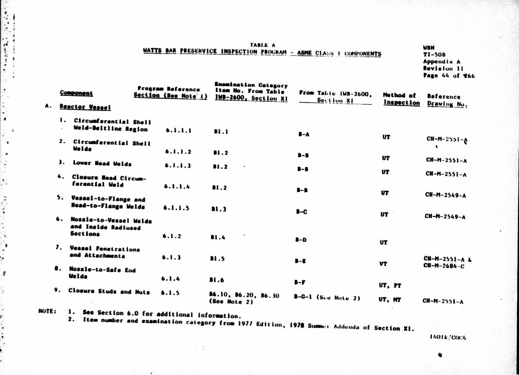
<1
* U
6
4 Ed £ ~
U'
WSW TI-508 Appendix A sevisiuwa Ii Page 44a of 166
preesao Reference Sectiem (See Upote.0i
Hills No. From Table IWS-21OO. SeCtiog, Xl1
From Tables IWS-2500. CAll X1 Method of getferegacli
Drwl u
I.Circumferential shell Meld-Melilime SagA..
2. Circumfrenutil sI hell Welds
3. lower Send Velds
4-. CSOWsur Nead Ciremmforestial weld
S; Vseasl-to-Fla" and Ned-90-Uloag. welIds
6- mosalsm-to-vossel Weida mind Inside Sad lused Sectionas
7. Vessel PSenetration& sad £ttschneatg
S. aless-to-Sate EAd Welds
9.Cleosue Stds sand nuts
5.1.1.1
5.3 .3.2
5.3.1.3
5.1.1.4
6.1.2
6.1.3
6.1.4
21.1
51.2
31.2
81.2
51.3
B1.1
&1.S
11-8CU-N-2SI -A
CU-#4-2f551-A
CU-N-25'.9-A
CU-#S-2 S'9-Arn-c
CU-41-25si1A & CU-H-2554-C
31.6
86-10, 86.20, 86.30o
NOTE: I. Sen section 6.0 for aidditional intonaition. 2. Items numbr sad examination category from 1911 Edillogi,
S-F
8-0-1 (&-e. tIfii. 2)UT, VPT
UT. I"F CN-N-2551-A
1915 SurNAML- Atlelesada of Section X1.
1401 k,'*1g:i.
"M PHTANSI A ~~ IS±ESEMYICK INfIPICT ION .?B(X;NAM A CAsIONNNT

TABLE A WATT M4 MhSHSV ECU JMPWlTIO POG -WMCLS I CMP~WT
1program Nefere"Ce Section(. Nt
A. ftector VMasI (Castlae"")
10. Ligaments Between Tbreaded Stud soles 6.1.S
It. Cleore Washers 6.1.5
1-2. Vessel Interior 6.1.9
13. assmable Core-support Structures 6.1.9
14. Control led Drive Usemaigs 6.1.10
IS. Aulillarpy Mead Adapter 6.1.11
I. Eangitudinal and Cerce reatial melds 6.2.1
2. mosale-to-Vessel Weids end Inside
adImse~d Sections 6.2.2
3. "staer 1pemetrations 6.2.1
NUTE: 1- See Section4 6.0 for additisudal in 2. items nmbmer and examisustisn cahteg
9 mas iatima category Ielm No. From Table
U5.40 (See Note 2)
06. 50 (see note 2)
513.10 (See Note 2)
513.30 (See Note 2)
81.18
B5. S. 54.S
52.1
92.*2
52.3
formal lads. orp trom 1971 kali1iul,,
From Table lWB-26000 st tQ!!. I
8-4-1 (b.
2-0-1 (94'
A-11-I (bs..
Note
Nut*
Mite
54N-3 (b-:u NeiL4 2)
5-0
a-F. B-J
5-11
11-D
11-9
method of
U?
VT
VT-)
VT-)
UT
UTS
UT
VT
W"N TI-Scm Append Ix A Sevislon 11 Page 4.5 uf 266
meference
C11-m-2MI-A
CIN-M2S551-A
a*See 6.L .1. 9
see Svc 6.1.9
I2l-4M1l2-A
Cu-N-26aS-m
C-N-M2, 74.-A
C11-#-z214.-A
CO-S.- 2%14.-A
1915 luimmmata A&Siusidd of Section JjZ.
'4411 L /C"A:4

I'ASL A amAm.I~ P19FVC £6695 A CI.ASNA C (UHIQ~mwl
~~nI Program SIereusc.
3.Pramwome fCu es...d)
£uamlsat ion Category 190 No. From Table From Tails IWII-2q6oO*
SiI till X!I
Tl-%Ohi £esmdlK A
Revsi on a 11
moth"d Of Rets resace kauwimNg
f.toegle-te-safe End Waldo 6.2.4
S- lpreeeregoua i.Sio belting Two mackee MWd Smaller is Diameter 6.2.6
6. lategral ly-welde vessel Suppart
I. Primary ne"a-to-Tuhe $11ee0 Vold
2. Primary Massle-to-Vate Bad Wald.
3. PreeeureO-begaamig. Belting TUO Inches and Smaller In Diameter
4. Tu~ing;
6.2.1Y
6.3.1
6.3.4
52.1. 3-,
81.20 (See Note 2)
36.20 (See Note 2)
53.1
53.3
V1.30 (see Note 2)
See Program Reference Section 6.3.8
UT, IPT
5-C-2 (hue Note 2)
5-0 (lou note 2)
&-I
11-F
VT-I
UT
UT.
15-G-2 (b,:u Note 2)
Sea Provism keisrence Section 1,..3.8
CO-M-j257b-A
CU-N-25 11-A
N/A
NUT: 1. 2.
@Se Section 6.0 for additional Information., ltam nm~r gad Ouami"utiOR Category from 1971 9diti.n.se IM1 SsaM.. r A4duvisda of Section XI.
1401 k /C(X:4

TAOLE A WATT$ D*5 PRRSIVIC5 INBPBTlON PSOOBAM - anS CLASM I CUNPONN MB.
TI-50B Appendix A Revisions 11 PASS 4.1 of 2664
amminet ion Category Program Befereace Item No. From Table
Sectem (ee Htel)i111M~hs -41L
D. PlinA I. eireminriest al, welds
4 lacbee aed greater
2. 1emgitudimmi welds 4 iechoe and greater
3. CircwdereatiaI Meldo Leee tee 4 Inches
4. Leegltudiftal melds Loea themn 4 lainees
S. Braecb Pipe Connection Greater them 2 lnches
6. Braeec Pipe Convecuion Meldo 2 inches and less
F. Socket 618ld1
6.4.1
.4.1.
6..1.
6.4. I
5.9.11 (Ile* Note 2)
59.32 (see noaze 2)
59.21 (See Note 2)
59.22 ('see Note 2)
59.31 (See Note z)
89.32 (See NILE. -2)
59.140 (saw Nutu ;e)
From Table I. W-26OO*
B-J (get Note 2)
2-J (See Note 2)
B-J (Sea. NuL 2)
I-J (see Note. 2)
O-J (See~ Nitai 2)
B-J (S... Notc 2)
methed of Referemnce hJmlumsim Drawl! A &
FT
PT
U?, ??
PT
Appendhs A% Piping Weld Locat ulug DIlag
Appendix A, Pipinag Wedd Locatl is Dw1as
Appuendix A, PIpleag Weld Location1 lUWgs
Appendix A, Piping Wauld Locatlon lDwgAm
Appendix A, Pipins Wald Locatialos Pwgai Appensdix A, Piping Wald Locatilons IDwla
Appenidix A, Piping Weld Locat lug. Dwils
NOTIES: 1. SOO Section 6.0 tor addLtossal iaaforMatLon. 2. Item eemimr and examinatioss category from 1911 Aditius., 191s vumm.e A4141%esda
of section NI.
14011th1
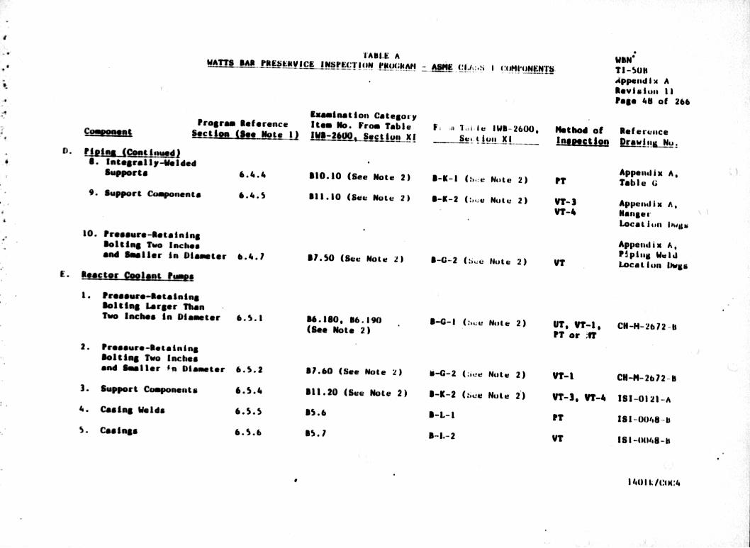
TABLE A WM fLiA!!- vc lSEMie PMMXgeAH~a
TI-SON Append Ix A
F686 4l of 266
D. F~gles (Ceu~ntIM)
supports
9.Support Caopone"
PtOroga Nefereace sectlea MSe Note 1)
its 6.41.S
10. Fresoure4.otaining Setting Two Inches 0001 Smaller in Diameter 6.4.1
E. React emlelats tog
I. Poeawo-Setaiminge Belting Larger Than Two lack** in Dfiametor 6.s.1
2. 11reeeure-Notaining Belting TWO Inches amdl Smaller *n Diameter 6.S.2
3. Support Components 6.5.4
4s. Cealug Welds 6.S.5
S. Cadnge 6.S.6
liuamination Categor-y ItOW No. From Table
510.10 (Sea Note 2)
511.10 (see Note 2)
51.5 (see Note 2e)
116.180, 66.190 (S.. Note 2)
31.60 (Soo Note 2)
311.20 (Sese Not* 2)
15. *
AS.?
F. a 1..i le IWI-2600, eIt ljugl X1
8-9-1 (*i.:e Note 2)
5-1-2 (:..e Note 2)
"--2 No..* lte 2)
"--I (:u Ntsi 2)
O-G-2 (:eie~ Note 2)
5-K-2 (bust Note 2)
I-L-1
I-L-2
Nethod of Reference frmasiha Drawl
PT
VT- 3
VT-4
VT
UT, VT-I, PT or fT
VT-I
WT- 3, VT-Is
IVT
VT
Appendix A, Table u
Appelidill A, Nanger Locatioun 1tiwgu
Appendix A, 11"ipind V.8.1 Location Uimgs
CU-H-2672 -11
C-N-H-2612-rn
131-01 21-A
181-00,46-b
153 -I4148-h
11.01 L./(:41(:s

TABLE A WAIT sas I's EMSYICS WINSF1TION PUGA Cij~~.aj(OftQNWIN TI-SON Append ix A Revision 11 page 1.9 ul 266
program Reference &@ction (ISe tor 1)
F. W
I.piesare-46tainift seating Two Incheg A"d Smaler in Diamenter
2.Volve "adies
9. "Mtind COMPNIONg
6.6.6
6.7
ftiamiest ion C:atelory Itam MD. From Table EV-SMOO Section No
81.10 (See Note 2)
82.10 53.*, 54.11 B5.8 56.4
from Table iWB-26OO. ~t~a 1L
"--2 (SUC Nut. 2)
S-1P
method of Ref erenace Drowia !&_ Mo
Appendix A, TAbW V
Appendix A, Tablet 1)
W1A
NOTE I.Sea Section 6.0 tor additional informatioa. 2. o 1 Nambner and examination category tram 1911 Edition, 1915 Suo.-s Addenida. of section X1.
14001 k/oM49:4

TABL.E u
Vproar
920DM~tsect io
A. Stga @ W VrtorS
I. Circumfe~rential melds
2. Mosul*-to-yossei welds
Nest.l .. t lh e rst o a
I- Citc~dereutial Welds
2. Nossle-tO-y.... 1 Welds
3. IntegrallyVMeld~d
Supports
. enemerag le N
I. circumerential malds
0. Letdeum Sea t xchnaxers
I. Circumerential Melds
2. Integral 11-40elded Supports
Exuamination Category mw Reference Item No. From Table From Table IWC-26(jO, N *(see Note 1) IVC-2600. section X1 Se. jug.l XI
1.1.1
1.1.2
1.2.1
1.2.2
7.2.3
7.3.1
1.4.1
Cl. I
Ci .2
Cl. I C-A
C-8n
C3.10 (sea Note 2)
Cl. I
C3.10 (see Note 2)
C-C (see mute 2)
C-A
C-C (Se. NoLtu 2)
TI-5OD AppenidI x A Reylsiola 11
ethod of R*IS414sille EIW.Liin, Drowl.!M No.
CV-M-2662-A
CN.-4- 2664W
NOTES:1I. See Section 1.0 for additional Information. 2. Ites; nmber and examination category from 197? Vdit olu., 1918 Sm...... I AdeI~sitin of Section XI.
(:04:14/ 14412k
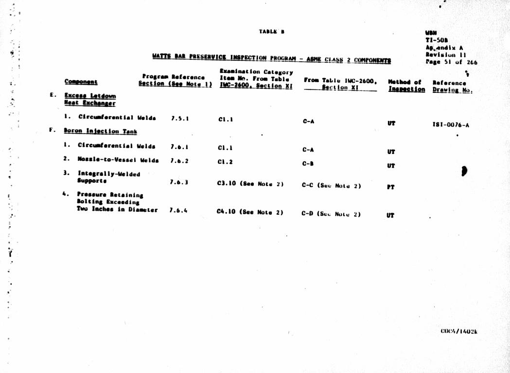
TAIIIA A
Program melee
I. ircumereagial Meldo 1.5.1
F. For"es luectigg T~aIk
I.CirCmer~mti4I Melds 7.6.1
2.masto-Ce-Vessel Welda 1.&.2
3. lstegrally-40olded ownper&@ 1.6.3
4. I.re~w" setsiming 1101,9110 ftcoding Two Inch.s is Diameter 1.6.4.
"BSSSVICK INSEIP C lOI9MS - AM
tsuemmag ion Catellory Oace USEm Un- From Table Frem Table 11K logo MI AM-26O amie. Xi 1.P. .. kip L
C1.2
TI-506 Akbena dlx A sevisiun 11 POSe 51 of 266
:-2600, Hotbed *I Reference hmamus~m REALFILs-ma.
0-A121-0076-A
C-A
C-9
C3.10 (sea Note 2)
04.10 (see Note 2)
C-C (Bev. Nola 2)
CID (Seu Nutu 2)
COCII/1402k

TABLE~ 9
wam A" i"LfEAV ICK "BINSECITON raOmAD A :*lUET
wim Ti-SOP Append ix A Reviaieiis 11 Page S2 ut 26b
Program Aeferencea kset-ion (Se Note 1)
G. Piiiag
I. Circumferential Welds one-half inch or loee mnmiisal waill
2. Circemferemiiai Welda over one-half inch waimimal wall
3. Longitudinal Welds eme-haif inch or loee nominal waill
I.. Longituadinal welds ever rn-bait Inch nomirnal waill
S.Circewnerestial Pipe Branch Connect ion welds
6. Longitudinal Pipe Aramach Connect ion Weld&
1.9.1
1.9.1
1.9.2
1.9.3
1.9.3
Euamination Category It= No. From Table jj~m2iOO, See tloi. X I
CS.ll (See Note 2)
CS.21 (gse Note 2)
CS-12 (See Note 2)
CS.22 (See Note 2)
CS.31 (Sao Note 2)
C5.32 (See Note 2)
Free Tail-l IWC-4600, Be, t 1401a Xl I _
C-F (6&:,: Mute~ 2)
C-F (Set Note 2)
C-F (Se, Note 2)
C-F (Set. Note. 2)
C-F (Be,. Nt~ite 2)
C-F (S~et Note 2)
Nethod of Relferensce D-rawing I&,.
PT or HT Appensdix A, Piping Weld Locatiun IOwli
UTIPT 0S NT Appisudix A, Pipillm WC-141 Locatibn Dwuas
PT or "T Appendix A. Piping Weld Location bwgs
UTOP? ON NT Appendix A Piping weld
IPT or NT Apg~end 13 A, PipW#s Weld Location IWgs
PT or HT Appeeldix A Pipilsa Walid Locat full ~wgab
(101'4/11#'112k
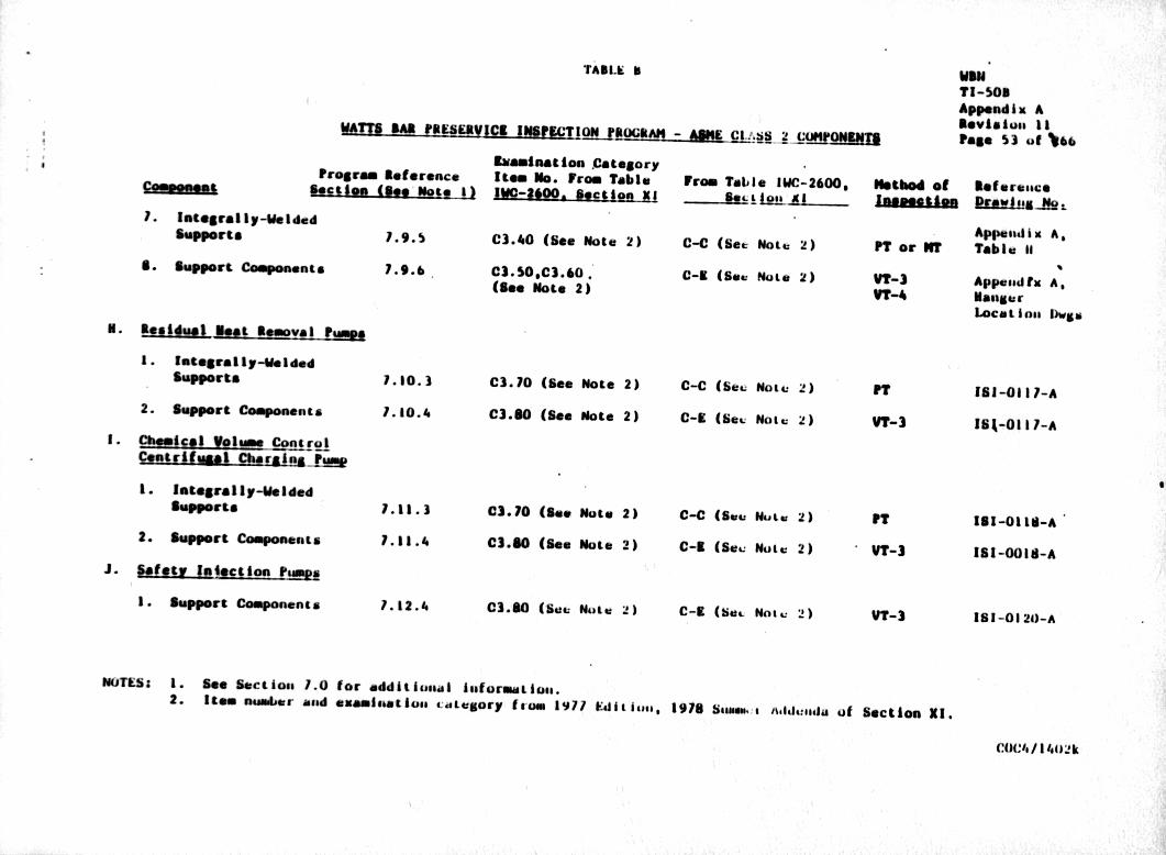
TAILK 11
Prog ra
supports
s. upport components
N. Residual- fast Removal Sum.e
supports
2. support components
I. Chemical volume control CeMtrifusal 0harAiftjrM
supports
2. Suppert components
J. saefty luiecs So. ?Mg.
I. support Components
biaM"Gat ion Csatgory Ssetorence Item No. from Table From Table IWC-2600, N JIhS-J Not 1 IMC-250. Beetles X -- ...... A -h'So AL....
Y. 9. S
71.0.3
Y. 10. 4
7.11.3
7.11.1.
1. 12.4
C3.40 (6*e Note 2)
C3. S0,C3.so.
(See Note 2)
C3.10 (See Hot* 2)
C3.80 (Sea Note 2)
03.70
C3.80-
(See Note 2)
(see Note 2)
03.80 (Buts Woae z)
C-C (see Motu 2)
C-19 (see Note 2)
C-C (Sev, note 2)
C-9 (Bev Motu Z)
C-C (Sees MUNes 2)
C-9 (Sac Note 2)
C-9 (Me.. Motu 2)
WON
Appenid Ix A Seviasosm it Page S3 of *#66
ethod of
PT or NT
VT-A
IPT
VY-3
VT-)
VT-3
Referenace
Tabl Iait
£ppeted tx Mansur Locations Dw&*
131-03 l7-h
161-0l11-A
131-01 18-A,
181-0018-A
18 1-0 1 20-A
NOTESs 1. See Section. 1.0 tar additlunasl iuafornmaiooa. 2. It001 Nmbiier eand emAMlnatflo. Catesgory from 1977 Ed~tiso. 3.. 976 StIum.. Med~ualda of Section XI.
C(JCI,/ 144) 2k
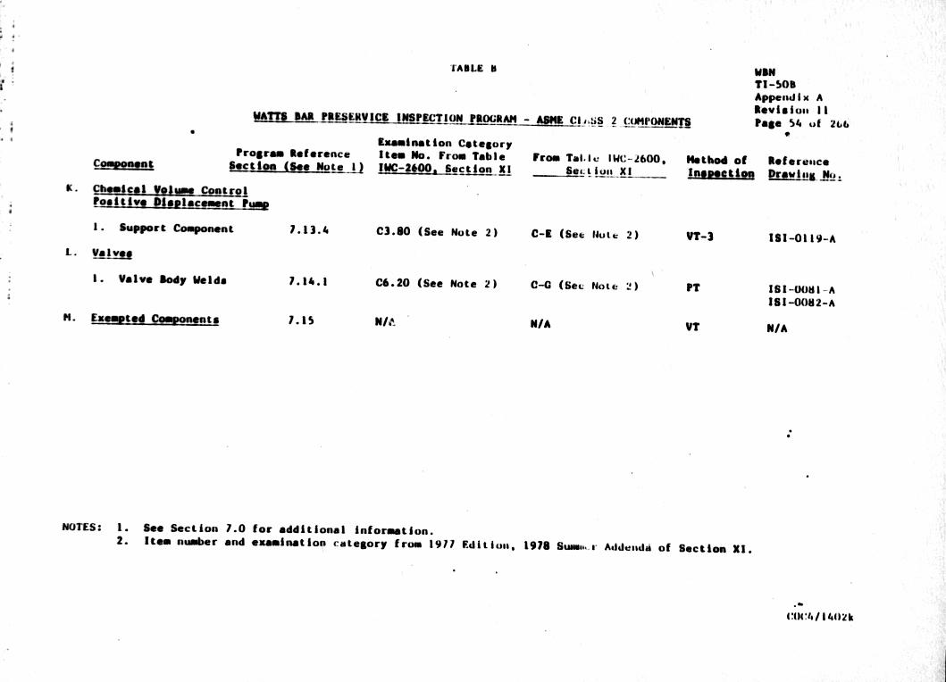
rAILE 6
"AMT IMl IPEEIISISITON1RGM-AMCi 2 CUJWONNE3
WAN TI-5SOS Append Ix A Sevialoms 11 Page 54. ul 2&.b
CommomotProgram Reference section (see Note 1)
g* Chemical yaljm control Pepitive 0160lpcoment P-40
siaminat ion Category lIe" No. From Table !UC-1".Seion 11
From Tall. IWc-2600. -!!d-ML fulX
Notbod ON Imomei
met eresace Drawing- N0.
I. SuqPP~rt Component
L. Vle Iye
I. Volvo Slody Weida
H.Eumted comoseete
7.13.4
7.14.1
LIS5
C3.60 (See Note 2)
C6.20 (See Note 2)
C-9 (Set Ndutt 2)
C-0 (get. Note 2)
N/A
VT-3 113-01 19-A
181-006I-A 181-0082-A
N/A
NOTES: 1. 2.
See Section 7.0 for additional informistion. Item number and examination category from 1917 E~dition., 1976 Swma...m Adduss.dA of Section XI.
.:V ft .l~