Rev 0 to RSA-D-92-06, "HPCI Room Thermal Response W/Loss of ...
85
·' • J. HPCI Room Thermal Response With Loss of HPCI Room Cooler at Dresden Station Prepared by: Reviewed by: Approved by: Document Number RSA-D-92-06 November 13, 1992 Kevin B. Ramsden Nuclear Fuel Services Department Commonwealth Edison Company Chicago, Illinois -""'., __ .......... · _X_· ___ oate: _ 1 2--_/' _ 7 /_ 9 -z.--_ r· \ l / . 921221 I \ p R ADOCK 05000237 I PDR
-
Upload
khangminh22 -
Category
Documents
-
view
1 -
download
0
Transcript of Rev 0 to RSA-D-92-06, "HPCI Room Thermal Response W/Loss of ...

·'
•
J.
HPCI Room Thermal Response With Loss of HPCI Room Cooler at Dresden Station
Prepared by:
Reviewed by:
Approved by:
Document Number RSA-D-92-06
November 13, 1992
Kevin B. Ramsden
Nuclear Fuel Services Department Commonwealth Edison Company
Chicago, Illinois
-""'., __ ~ .......... ?_#~_· · _X_· ----~--;..·-+--___ oate: _12--_/' _7 /_9
-z.--_
r· \
l/ . ~g.01040053 921221 I \
p R ADOCK 05000237 I PDR

Statement of Disclaimer
RSA-D-92-06 Rev.O
This report was prepared by the Nuclear Fuel Services Department for use internal to
Commonwealth Edison Company as applicable to the Dresden Nuclear Generating Station. It
is being made available to others upon the express understanding that neither Commonwealth
Edison Company nor any of its officers, directors, agents, or employees makes any warranty,
representation, or assumes any obligation, responsibility with respect to the contents of this
report, its accuracy, or completeness pertaining to any usage-other than the originally stated
purpose.
ii

RSA-D-92-06 Rev.O
Table of .Contents
Statement of Disclaimer ................................................................................... ii
Abstract ..................................................................................................... iii
Table of Contents .......................................................................................... iv
List of Illustrations ......................................................................................... v
1. Introduction ............................................................................................. 1
2. Description of Analysis ....... _ .......................................................................... 2
2.1 General Input Assumptions Utilized ......... : .................................. 2
2.2 HPCI Room Heatup with Detailed Wall Models ............................. 3
2.3 HPCI Room Heattip with Postulated Gland Seal Leakage; ................. 4
3. 0 Results of Calculations ................................................................................ 8
3.1 HPCI Room Heatup with Detailed Wall Models .............................. 8
3.3 HPCI Room Heatup with Postulated Gland Seal Leakage .................. 8
4.0 Conclusions ............................................................................................ 1_1
References .................................................................................................. 12
Listing of Computer Cases ...................................... : ......................................... 13
Appendix .................................................................................................... 14
Tables

List of Illustrations
RSA-D-92-06 Rev.O
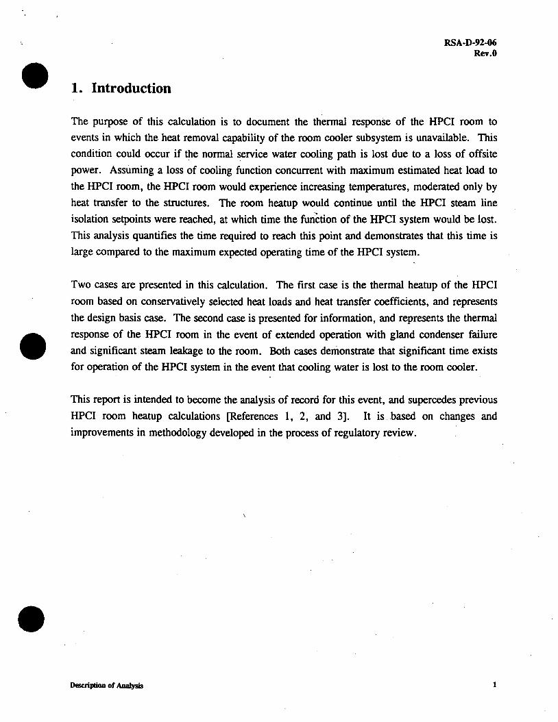
Figure 1 Original HPCI Room Model .................................................................. 5
Figure 2 Diagram of Revised HPCI Room Model .................................................... 6
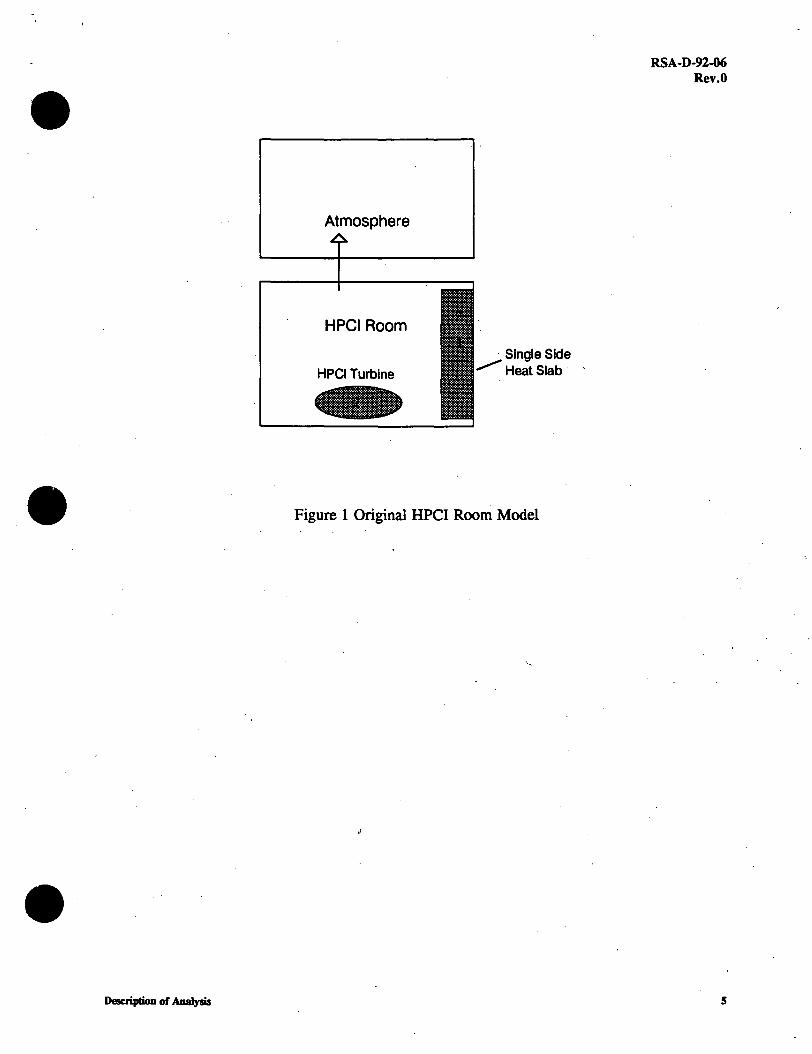
Figure 3 Gland Seal System Flowpaths ................................................................. 7
Figure 4 HPCI Room Thermal Response ............................................................. 9 I
Figure 5 HPCI Room Response to Gland Seal Condenser Leakage ............................... 10
.•
•
•
1. Introduction
RSA-D-92-06 Rev.O
The purpose of this calculation is to document the thermal responSe of the HPCI room to
events in which the heat removal capability of the room cooler subsystem is unavailable. This
condition could occur if the normal service water cooling path is lost due to a loss of offsite
power. Assuming a loss of cooling function concurrent with maximum estimated heat load to
the HPCI room, the HPCI room would experience increasing temperatures, moderated only by
heat transfer to the structures. The room heatup would continue until the HPCI steam line
isolation setpoints were reached, at which time the function of the HPCI system would be lost.
This analysis quantifies the time required to reach this point and demonstrates that this time is
large compared to the maximum expected operating time of the HPCI system.
Two cases are presented in this calculation. The first case is the thermal heatup of the HPCI
room based on conservatively selected heat loads and heat transfer coefficients, and represents
the design basis case. The second case is presented for information, and represents the thermal
response of the HPCI room in the event of extended operation with gland condenser failure
and significant steam leakage to the room. Both cases demonstrate that significant time exists
for operation of the HPCI system in the event that cooling water is lost to the room cooler.
This report is intended to become the analysis of record for this event, and superce.des previous
HPCI room heatup calculations [References 1, 2, and 3]. It is .based on changes and
improvements in methodology developed in the process of regulatory review .
Description of Analysis 1

2. Description of Analysis
RSA-D-92-06 Rev.O
All analyses represented in this report were performed with the RELAP 4 Mod 6 computer
code as installed on the CECo computer system. This version of the code contains an equation
of state for air and has the ability to transport air between nodes. The code has a default
minimum heat transfer coefficient of 5.0 BTU/HR/Fl'2-F, which necessitates adjustment of
the geometry of the heat .slabs to simulate alternative convection coefficients. The validity of
the computer code and attendant methodology is demonstrated in Reference 4.
2.1 General Input Assumptions Utilized
The analyses presented in this report are dependent on several key assumptions, controllable by
station personnel, to ensure validity in application to plant operation. They are:
1. The room cooler is assumed to be functioning as a fan, with a flow rate of 4750 cfm. The
cooling water is assumed to be unavailable throughout the event. This assumption guarantees ·
that the mixing of air in the room is good, and justifies the use of the lumped parameter,
average room temperature treatment performed here.
2. The initial temperature of the room is assumed to be 120 F or less during normal
operation. A sensitivity on the initial temperature of the room is included to demonstrate that .
operability is assured even when performing HPCI surveillance testing that potentially could
lead to temperatures between 120 and 130 F.
3. The HPCI room temperature isolation setpoint is nominally set at 180 F, with an
uncertainty of less than 5 F. A maximum temperature of 175 F is assumed to be the lowest
temperature that would result in isolation of the HPCI steam lines.
Description of Anaiym 2

RSA-D-92-06 Rev.O
Additionally, the following assumptions were utilized in the performance of these calc~lations:
1. The operation of the HPCI system (and therefore the applied heat load) is continuous. The
heat load is assumed to be equal to the designed capacity of the room cooler at
200,000 BTU/HR
2. The thermal properties of the concrete walls are:
Conductivity 1.05 BTU/HR-Ff-F
Heat Capacity 30.24 BTU/Ff3-F
3. The thermal capacity of the steel structures inside the HPCI room are neglected for
conservatism.
4. The soil temperature is assumed to be 65 F. The effective heat transfer coefficient from
the concrete to the soil is dependent on semi-infinite slab dynamic calculations presented in the
Appendix.
5. The temperature of adjacent rooms is assumed to be constant at the EQ zone map
temperatures. This is 104 F for all rooms in this analysis
2.2 HPCI Room Heatup with Detailed Wall Models
The original analyses were based on the use of the simple model depicted in Figure 1. _This _
model relied on limiting h~t transfer through the walls to guarantee conservatism. In this
analysis a more refined model was utilized, subdividing the heat structures representing the
walls, floor and ceiling of the HPCI room into six separate heat structures. This model is
shown in Figure 2. The walls were explicitly modeled to their actual thickness (3 feet for
walls and ceiling, 4 feet for the floor) and two sided conduction was modeled. Heat transfer
to the soil was allowed, although at a greatly reduced heat transfer coefficient
(0.3 BTU/HR/Fl'2-F). The other surfaces used overall heat transfer coefficients determined as
the combination of natural convection and grey gas radiation -components. A detailed
description of the calculation of these overall coefficients is provided in the Appendix. These
coefficients ranged from 0.5 for the floor to 1.0 for the ceiling. The wall heat transfer
coefficient was 0.91 BTU/HR/Ff2-F.
Description or AoaJysb 3

2.3 HPCI Room Heatup with Postulated Gland Seal Leakage
RSA-D-92-06 Rev.O
An additional case was run to provide insight into the room heatup behavior resulting from
postulated leakage of gland seal steam. It is noted that this case yields heat loads beyond those
for which the room coolers were originally designed to accomodate, and is reported here to
support the current EQ classification of the gland exhaust fan and condenser (eg. not qualified
to elevated temperatures). A review of the UFSAR (Section 6.2.5.3.3.5) indicated that for a
fully pressurized turbine casing with a locked turbine rotor, the gland condenser would over
pressurize due to loss of cooling water and seal stealJl would be. released to the room. The
leakage for this case is 2160 lb/hr, and the HPCI system is assumed to isolate on high r09m
temperature within 15 minutes.[Reference 5] Figure 3 provides a diagram of the gland seal
system.
In this scenario, the turbine is assumed to be continuously operating, and cooling water would
be supplied to the gland exhaust condenser. The gland exhaust fan is not currently on the EQ
list and could be postulated to fail eventually due to elevated room temperatures. In the event
of gland exhaust fan failure, the removal of non-condensable from the condenser would be
impaired, which would lead to a degradation of the condensation heat transfer. ·For the
purposes of this evaluation, a constant value of seal leakage to the HPCI room of 10% of the
locked rotor scenario was analyzed.
Since significant steam leakage was postulated in this case, the use of a condensing coefficient
for the heat transfer slabs is warranted. Several values were utilized ranging from the overall .
coefficients used in the above analysis to 2.0 BTU/HR/Ff2-F (the default minimum Uchida
correlation value for high air/water ratios) to 5.0 BTU/HR/Ff2-F (judged to be the most
reasonable average value over time). [Reference 6]
Description of Aoalysb 4
• Description of Analysb
Atmosphere
HPCI Room
· Single Side ~HeatSlab·
Figure 1 Original HPCI Room Model
RSA-D-92-06 Rev.O
5

Adjacent
Rooms
104 F
Description or Analysis
I '
' ' '
'
J1
Atmosphere
104 F
.•
HPCI Room
Soil
65 F
HPCI Turbine
Figure 2 Diagram of Revised HPCI Room Model
I I
RSA-D-92-06 Rev.O
Soil
65 F
6
•
SBGTS
GLAND EXHAUST FAN
Descriptioo of Analysb
HPCI TURBINE
GLAND
EXHAUST CONDENSER
HPCI PUMP
'II I I I
----<-------------~ Cooling Water A
I I I I I I
:·~-----------J ~~
· · 1 Aux Cooling
r Pump (AC) I
------"'
Figure 3 Gland Seal System Flowpaths
RSA-D-92-06 Rev.O
PUMP DISCHARGE
7

•
•
3.0 Results of Calculations
3.1 HPCI Room Heatup with Detailed Wall Models
RSA-D-92-06 Rev.O
Two cases were run covering a range of initial temperatures from 120 F (normal maximum
anticipated) to 130 F (Elevated room temperature due to surveillance testing). The results of
this calculation demonstrate that the heatup of the room from 120 F to 175 F would take over
nineteen hours. Starting at elevated room temperature would reduce this time to nine hours.
It should be noted that this time reduction is overpredicted, .. since the methodology assumes
th.at the concrete walls are in equilibrium with the elevated temperature. The duration of
surveillance is generally far too short to accomplish this equilibrium condition. The results are
shown in Figure 4.
3.3 HPCI Room Heatup with Postulated Gland Seal Leakage
This case builds on the previous case to include the effects of the seal steam leakage into the
room following postulated loss of the gland exhaust fan. For this calculation, a seal leakage of
216 lb/hr was assumed, representing 10% of the locked rotor steam leakage rate for a faulted
condenser and limiting pressure at both ends of the turbine casing. Since steam addition would
lead to condensation on structures, the Uchida correlation was utilized to determine appropriate
values of heat transfer coefficients on the internal HPCI room surfaces. Two cases were run,
one using the default minimum value of the Uchida correlation (h=2.0), and the other using a .
nominal value based on the air steam mass ratios existing (h=5.0) . The results of these cases
are shown in Figure 5. These results clearly demonstrate that significant time (8-16 hours) is
required to reach the isolation limits, even with a high rate of steam leakage to the _room .
Results of AaaJysb 8

LL..
e :J e Q) a. E
-~ E 0 0 a:
HPCI ROOM THERMAL RESPONSE
·.• Loss of Room Cooler Heat Removal ,
RSA-D-92-06 Rev.O
.. 80 L--·--···-=·-······=······-·-=·-·-··=··········=J·--·-1·=·-······=······-·-:;;·-·-·-;;··········=··-·-·-=·-··•.: -~·········-d·-·-·-t::·········=···-·-·-==·-·-···j:····.::_ ···;;-~:::==E~3 I I- ···-·-·-·-············-·r--·-=·::::::·::::::-_:::·::::::+·-·-··
-- _:::;;;"-~""~f ::::~=-~~:=::~:1~:=-~~~~~~:~~;~-- ----- -+- ------: 160
/ ! . : ... :_._: :_._: I : :
t·-·-···············-····-·-···············-·-+.·-····-·······-··········-·····:······-·-·-·-··f···········-····-·- ·········-····-····-·······!·······-·-·-············· .. -·-·-···············-·r·-·-·-············-------···············-·-··
I • I I t40
Q) C> e 120 ---------+- ------ __ j _____ _ _____ )_____ _ ____ _j _______ _ Q)
~ 100t--.._"'-''--'----+__.__.._---1.._._--l-~--'--'-...J-..j---'-..__.._"'--",__.____.,__.__.___,
o· 5 10 15 20 25
Time (hours)
I + 120 F IC -+-130 F IC -Isolation Setpoint I Minimum Temperature limit (with uncertainty)
Figure 4. HPCI Room Thermal Response
Results or AnaJym 9

• HPCI Room Thermal Response
Gland Condenser Failure
RSA-D-92-06 Rev.O
240 ·-·-·-·-············-·-·-·-···············-·-·-·-············-·-·-·-·-·········· .. -·-·-·-···············-·-·-·-············-·-·-·-·"·········· .. -·-·-·-···············-·-·-·-············-·-·-·-·-.. ··········-·-·-·-···············-·-·-·-···
u.. 220 ·-·-·-·-············-·-····-··········'····-·-·-·-············-·-·-·-·-············-·-·-·-···············-·-·-·-············-·-·-·-·-·······-···-·-·-·-···············-·-·-·-············-·-·-·-·-············-·-·-·-···············-·-·-·-··· ~ :::J 200 ····-·-···············-·-·-·-···············-·-·-·-············-·-·-·-·-···············-·-·-···············-·-·-···············-·-·-·-·-············-·-·-·-···············-·-·-·-············-·-·-·-·-············-····-·-···············-·-·-·-··· ~ Q) a. E ~ E 0 0 a:
,.,
180 ........ ··-·-···············-·-·-·-·-···:········-·-=·=·::.:::.::·:;.:·:.=---r.:.::-:.=.-::.=.==·=-~=-·-·-···············-·-·-·-···
160 ·-·-·-···············-· -·············-·-·-·-;_·~·"'·_.ta-:..-:.::.::::._=-~--~--~-=:~.~---······-·-·-·-·-············-·-····-···············-·-·-·-··········-·-·-·-·-··········-·-····-············-·-·-·-··· r_,-.a----
o-~ 140 ·-·· g"'········-·-·-·-···············-·-·-···············-·-·-·-·-············-·-·-·-···············-·-·-·-············-·-·-·-·-············-·-·-·-···············-·-·-·-············-·c·-·-···············-·-·-·-···············-·-·-·-···
120 ·-·-·-·········· .. -·-····-···············-·-·-···············-·-·-·-···············-·-·-·-···············-·-·-·-············-·-·-·-·-············-·-·-·-···············-·-·-·-·······-···-·-·-·-·-············-·-·-·-···············-·-·-·-···
100~---'---'--4--...l-~~--'-_..__._+.--".__.--L--+-....L-..i.-~---'---'-_.._-+-...__..___.~
0 4 8 12 16 20 24
Time {Hours)
I +h=2.0. -&h=S.O -Isolation Setpoint I 216 lb/hr seal leakage.
Figure 5. HPCI Room Response to Gland Seal Condenser Leakage ...
Results of AnaJym 10
4.0 Conclusions
RSA-D-92-06 Rev.O
The HPCI room thermal response has been determined for a range of postulated conditions.
The more detailed consideration of heat transfer structures illustrates that HPCI operation
without ventilation or room coolers could continue for extended periods of time, well beyond
anticipated operational requirements (less than four hours). These calculations have been
performed in a conservative fashion, and assume continuous HPCI operation with heat load to
the room constant at the capacity of the room cooler. In the seal steam leakage case, constant
seal leakage from start of the HPCI was assumed, ignoring both the anticipated cyclic
operation of the HPCI and the time required to achieve degradation of condensation in the .
gland exhaust condenser. This clearly bounds the manner in which HPCI would operate in
transient and accident scenarios, and demonstrates that operation of the HPCI without room
coolers does not compromise the operability of the HPCI system.
Conchniom 11

• RSA-D-92-06
Rev.O
References
1. "ECCS Pump Room Transient Response to Loss of Room Cooler for Dresden Station
Units 2 and 3" , RSA-D-89-01.
2. "ECCS Pump Room Transient Response to Loss of Room Cooler for Dresden Station
Units 2 and 3" , RSA-D-90-01.
3. "An Evaluation of Loss of HPCI Room Cooler at Dresden Station", RSA-D-92-04.
4. "Validation of Loss of HPCI Room Cooler Analysis at Dresden Station"·; RSA-D-92-05.
5. Dresden UFSAR, current to 8/92.
6. "CONTEMPT 4/Mod5: An Improvement to CONTEMPT 4/Mod4 Multicompartment
Containment System Analysis Program for Ice Containment Analysis" , NUREG/CR-4001,
BNL-NUREG-51824, C. C. Lin. Section 3.9.1.2.2
References 12
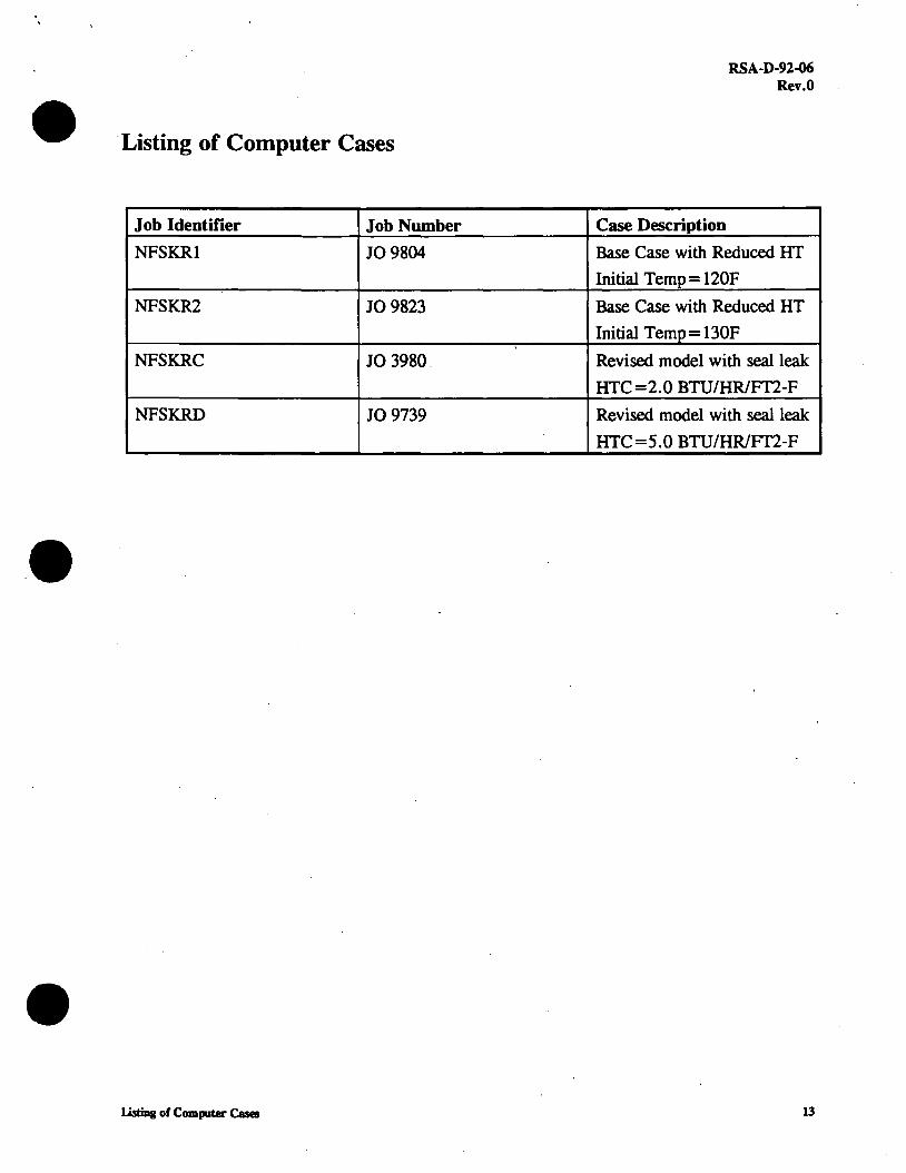
• ·Listing of Computer Cases
Job Identifier Job Number
NFSK.Rl JO 9804
NFSK.R2 JO 9823
NFSK.RC JO 3980.
NFSKRD JO 9739
• LimDg of Computer Cases
.,
RSA-D-92-06 Rev.O
Case Description
Base Case with Reduced HT
Initial Temp= 120F
Base Case with Reduced HT
Initial Temp= 130F
Revised model with seal leak
HTC =2.0 BTU/HR/FT2-F
Revised model with seal leak
HTC =5 .0 BTU/HR/FT2-F
13

• Appendix
RSA-D-92-06 Rev.O
The following pages provide detailed description of the calculation of the surface heat transfer
coefficients used in the analysis.
Appendix 14

•
•
Calculation of Overall Heat Transfer Coefficients This calculation provides the basis for the selection of overall heat transfer coefficients used in the HPCI room heatup RELAP calculations. The overall heat transfer coefficient is based on the sum of the turbulent natural convection coefficient and the equivalent gas radiation heat transfer to the walls. Both of these components is dependent on the temperature difference between the air and the wall surface. Therefore the first step is to determine an appropriate value of temperature difference, based on the heat load and the heat transfer area.
Heat load : = 200000
Area:= 2·( 1274 + 1300 + 612.5)
Heatload a 31.382 Area
Btu/hr·ft2
Given this value of heat flux needed, and an assumed overall coefficient of heat transfer U, the temperature difference can be estimated.
u := 1.0
TD : = Heat load Area-U
TD= 31.382
We will use a value of TD=30F for determining the heat transfer coefficients
•
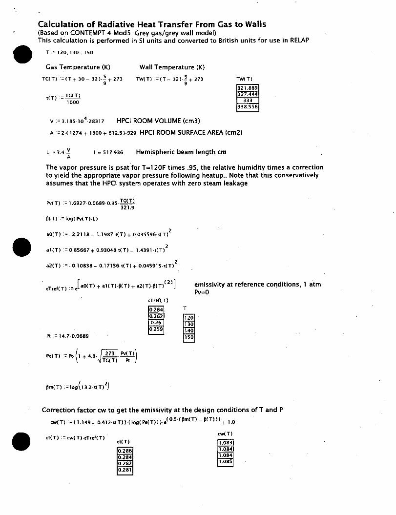
Calculation of Radiative Heat Transfer From Gas io Walls (Based on CONTEMPT 4 Mods Grey gas/grey wall model) This calCulation is performed in SI units and converted to British units for use in RELAP
T := 120, 130 .. 150
Gas Temperature (K)
TG(T) := (T + 30 - 32 ).~ + 273 9
t(T) := TG(T) 1000
Wall Temperature (K)
TW(T) := (T - 32 )-~ + 273 9
v := 3.185-104-28317 HPCI ROOM VOLUME (cm3)
TW(T)
321.889 327.444
333 338.556
A :'=2-c 1274 + noo + 612.5)-929 HPCI ROOM SURFACE AREA (cm2)
L := 3.4-~ A
La 517.936 Hemispheric beam length cm
The vapor pressure is psat for T=120F times .95, the relative humidity times a correction to yield the appropriate vapor pressure following heatup .. Note that this conservatively assumes that the HPCI system operates with zero steam leakage
Pv(T) := 1.6927-0.0689-0.95· TG(T) 321.9
PC Tl =log( Pv( Tl· L)
2 aO( Tl := - 2.2118 - 1.1987-t(T) + 0.035596-t(T)
2 a 1( T) : = 0.85667 + 0.93048-t( T) - 1.4391 · t(T)
2 a2(T) :=. 0.10838- 0.17156-t(Tl + 0.045915-t(T)
. [ ( 2)] &Tref(T) :=e aO(T) + al(T).p(T) + a2(T)·PCT>
&Tref(T)
0.264 T
0.262 120 0.26 130
0.259 140 Pt:= 14.7-0.0689 150
Pe(T) :=Pt· (1 + 4.9·j 273 · Pv(T)) TG(T) Pt
emissivity at reference conditions, 1 atm Pv=O
Correction factor cw to get the emissivity at the design conditions of T and P
cw( Tl := ( 1.149 - 0.412-i(T)).( log( Pe( T)) ).e< o.5 ·< Pm< T) - pc T))) + 1.0
&t(T) : = cw(T). &Tref( T) &t(T)
0.286 0.284 0.282 0.281
cw(T)
1.083

• Now develop absorptivity of water vapor, using the Hottel method described in the Contempt4-MS manual on page 69
t(Tl := lW( Tl 1000
P<Tl := log(Pv( Tl· L· lW( Tl) TG(T)
. 2 aO( Tl := - 2.2118 - l.1987·t( Tl+ 0.035596-t( T)
2 al( Tl:= 0.85667 + 0.93048-t(T) - 1.4391-t(T)
a2(Tl :=-0.10838- 0.17156-t(Tl + 0.045915·t(T)2
[ (2)] tTrefw( T) := e aO( T) +al( Tl·P< Tl+ a2<Tl·P< T)
Pt:= 14.7-0.0689
Pe(T) :=Pt:(1+4.9-j 273 _Pv(T)) TG(Tl Pt
.•
cw( Tl := ( 1.149- 0.412-t(T)).( log( Pe(T)) )·e( o.5 ·< Pm(T) - P<Tl)) + l
ctw(T) :=cw( Tl·tTrefw( T)
ctw(T)
0.291 0.289 0.288 0.286
aT(T) :=t:tw(Tl·(TG(T))0.45
lW(T)
aT(T)
0.298 0.296 0.294 o.293 absorptivity of vapor
cw(T)
1.083 1.083 1.084 1.085

EW := 0.95
a:= 5.67-10- 12
Q(T) :=a·A·r.w· (ttCT>·TG(T) 4 - aT(T)-lW(T) 4)
Q(T)
1.788-104
1.856-104
1.925· 104
1.993-104
Note Q is in units of watts • now converting to BTU/HR yields a total radiant heat transfer for a 30 F delta t
QR(T) := Q(T).3.412
Area• 6.373• 103
DT ::30
QR(T)
6.1.104
ft2 6.333-1 o4
6.567· 104
6.802-104
temperature difference
hr(T) := QR(T) Area-OT
Radiant heat transfer (BTU/HR) .
hr(T) T equivalent radiation "heat transfer coefficient" (BTU/HR-FT2-F) 0.319 120 0.331 130 0.344 140 0.36 0.356 150
0.34
hr( T)
0.32
0.3 120 130 140 150
T
Note that in the application to the HPCI room heatup calculations, the room temperatures typically range from 120 initially to over 175 Fat the conclusion of the calculation. For conservatism the radiation component will be based on the value at 120 F.
•
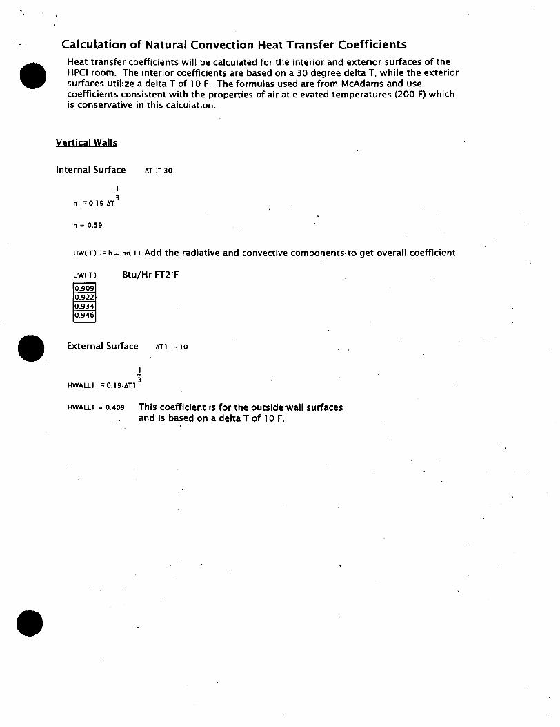
Calculation of Natural Convection Heat Transfer Coefficients
Heat transfer coefficients will be calculated for the interior and exterior surfaces of the HPCI room. The interior coefficients are based on a 30 degree delta T, while the exterior surfaces utilize a delta T of l O F. The formulas used are from McAdams and use coefficients consistent with the properties of air at elevated temperatures (200 F) which is conservative in this calculation.
Vertical Walls
Internal Surface
1
h := 0.19-t.T3
h - 0.59
t.T := 30
uw(Tl := h +hr< Tl Add the radiative and convective components-to get overall coefficient
uwc Tl Btu/Hr-FT2~F
0.909 0.922 0.934 0.946
External Surface
1
HWAlll :=0.19-t.Tl 3
t.Tl := 10
HWAlll a 0.409 This coefficient is for the outside wall surfaces and is based on a delta T of l 0 F .

•
Ceiling
Internal Surface l
h := 0.22·tiT3
ha 0.684
UC( Tl := h + hr( T)
UC(T)
1.003 1.015
1.027 Btu/Hr-FT2-F 1.039
External Surface 1 3
HCElll :: 0.22·tiT1 '--
HCElll a 0.474 This coefficient is for the outside ceiling surface and is based on 10 F delta T and no radiation HT
( )
.25 h :=0.13· ~
8.44
ha 0.178
UF(T) := h + hr(T)
UFCTJ Btu/Hr-FT2-F 0.498 0.51
0.522 0.534
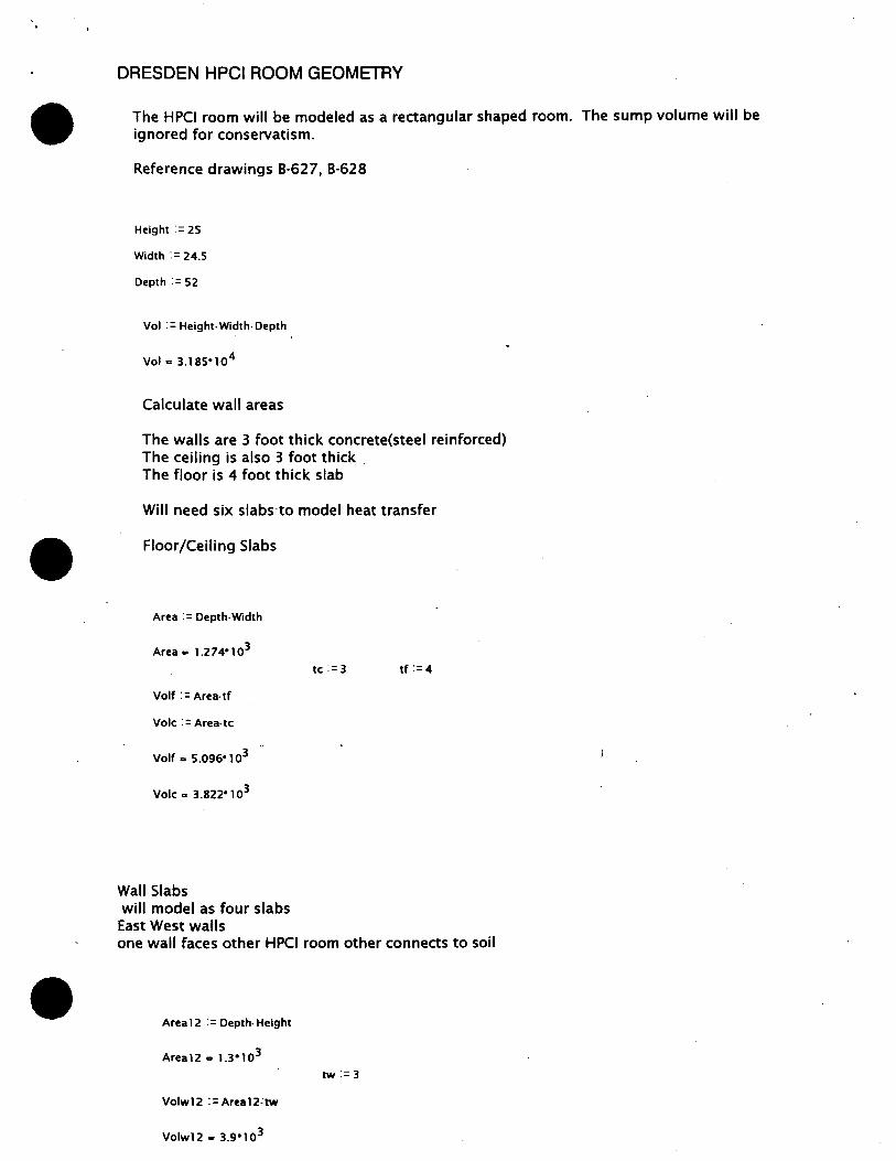
• DRESDEN HPCI ROOM GEOMETRY
The HPCI room will be modeled as a rectangular shaped room. The sump volume will be ignored for conservatism.
Reference drawings B-627, B-628
Height:= 25
Width : = 24.5
Depth := 52
Vol : = Height· Width· Depth
Vol .. 3.1s5•104
Calculate wall areas
The walls are 3 foot thick concrete(steel reinforced) The ceiling is also 3 foot thick . The floor is 4 foot thick slab
Will need six slabs to model heat transfer
Floor/Ceiling Slabs
Area:= Depth· Width
Area .. 1.2 7 4• 1 o3
Volf : = Area· tf
Vole : = Area- tc
Volf., 5.096• 103
Vole .. 3 .s22• 1 o3
Wall Slabs will model as four slabs
East West walls
tc := 3 tf := 4
one wall faces other HPCI room other connects to soil
Area 12 : = Depth· Height
Area12 .. 1.3•103
tw := 3
Volw12 :=Area12:tw
Volwl 2 .. 3.9• 1 o3

North South Walls One wall will face torus room, other ends in soil
Area:= Height· Width
Area .. 612.5
Volw34 : = Area.tw
Volw34 • 1.838" 1 o3
tw := 3
HEAT SLAB INPUT PARAMETERS Since RELAP defaults to 5.0 HTC, we need to adjust the areas accordingly to simulate different values of HTC. Minimal values of radiative plus convective HTCs will be applied in the model.
HWALL := UW( 120) HWALL .. 0.909
HFLOOR := UF( 120)
HCEIL :: UC( 120)
HSOIL :: 0.3
AWALLNS :=612.5
AWAUEN := 1300
AFLOOR := 1274
HFLOOR .. 0.498
HCEIL .. 1.003
HCEILl .. 0.474
North Wall (RELAP Model Slab 6)
AHTL : = HWALL · AWALLNS HRELAP
AHTR :: HWALll ·AWALLNS HRELAP
South Wall (RELAP Model Slab 5)
AHTL := HWALL ·AWALLNS HRELAP
AHTR := HSOIL ·AWALLNS HRELAP
HRELAP :: 5.0
HWALL 1 .. 0.409
AHTL .. 111.406
AHTR .. 50.144
AHTL • 111.406
AHTR .. 36.75
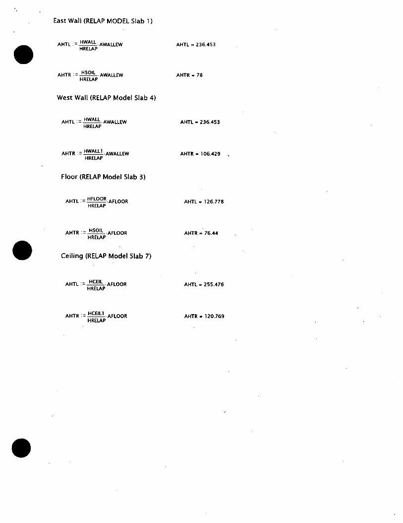
East Wall (RELAP MODEL Slab 1)
AHTL := HWAU -AWALLEW HRELAP
West Wall (RELAP Model Slab 4)
AHTL : = HWAU · AWALLEW HRELAP
AHTR := HWAUl ·AWAUEW HRELAP
Floor (RELAP Model Slab 3)
AHTL := HFLOOR·AFLOOR HRELAP
AHTR := HSOIL ·AFLOOR HRELAP
Ceiling (RELAP Model Slab 7)
AHTL := HCEIL ·AFLOOR HRELAP
AHTR := HCEILl ·AFLOOR HRELAP
AHTL - 236.453
AHTR - 78
AHTL - 236.453
AHTR a 106.429 ,
AHTL - 126.778
AHTR - 76.44
AHTL - 255.476
AHTR a 120.769
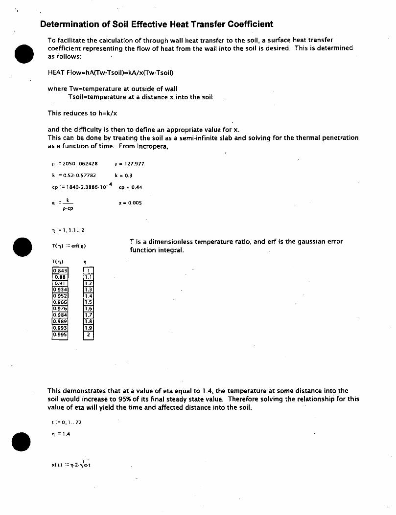
Determination of Soil Effective Heat Transfer Coefficient
To facilitate the calculation of through wall heat transfer to the soil, a surface heat transfer coefficient representing the flow of heat from the wall into the soil is desired. This is determined as follows:
HEAT Flow=hA(Tw-Tsoil)=kA/x(Tw-Tsoil)
where Tw=temperature at outside of wall Tsoil=temperature at a distance x into the soil
This reduces to h=k/x
and the difficulty is then to define an appropriate value for x. This can be done by treating the soil as a semi-infinite slab and solving for the thermal penetration as a function of time. From lncropera,
p : = 2050· .062428 p a 127.977
k := 0.52·0.57782 k a 0.3
cp := 1840-2.3886·10- 4 cp a 0.44
a:= _k_ a a 0.005 p·CP
1J := 1, 1.1 .. 2
T( 1J) : = erf( 1J )
T(!J) 11
1. 1 1.2 1.3
0.952 1.4 0.966 1.5 0.976 1.6 0.984 1.7 0.989 1.8 0.993 1.9 0.995 2
T is a dimensionless temperature ratio, and erf is the gaussian error function integral.
This demonstrates that at a value of eta equal to 1 .4, the temperature at some distance into the soil would increase to 95% of its final steady state value. Therefore solving the relationship for this value of eta will yield the time and affected distance into the soil.
t:=o.i..n
1J := 1.4

•
•
0 20 40 60 80
The HPCI Room heatup calculations typically occur over a span of approximately 24 hours, therefore the value of x at 24 hours will be used.
x( 24) a 1.003
h ::_k_ x(24)
ha 0.3 Btu/h r-ft2-F
Use of this value for the external surface of the HPCI room walls is conservative, since the actual value would be a function of time and start large and -become smaller with time. Since a constant single value selected at the end of an interval desired is being used, this approach is conservative .

• ·ENCLOSURE 2 CECo Calculation RSA-D-92-07
· LPCI Room Temperature Response Due to Loss of Room Cooler at · Dresden Station
•

LPCI Room Temperature Response due to Loss of Room Cooler at Dresden Station
Prepared by:
.•
Document Number RSA-D-92-07
December 14, 1992
Pedro L. Kong Robert W. Tsai
Nuclear Fuel Services Department Commonwealth Edison Company
Chicago, Illinois
-~'J_]{~--------- oate=-~=1~4-l 9~---rb_ J..-JttJ. 7s . 12/1y/qz_
Prepared by: --~----------------------------- Date: ________________ _
Reviewed by:
Approved by:.--~~------ Date: ___ f~~L _
9301040063 921221 PDR ADOCK 05000237 p PDR
•
•
RSA·D-92~07 . Rev.O
Statement of Disclaimer
This report was prepared by the Nuclear Fuel Services Department for use internal to
Commonwealth Edison Company as applicable to the Dresden Nuclear Generating
Station. It is being made available to others upon the express understanding that
neither Commonwealth Edison Company nor any of its officers, directors, agents, or
employees makes any warranty, representation, or assumes any obligation,
responsibility with respect to the contents of this report, its accuracy, or
completeness pertaining to any usage other than the originally stated purpose. "
Disclaimer II

Abstract
RSA·D-92-07 Rev.O
This calcnote documents analysis performed to demonstrate the operability of the
LPCI system is not compromised by the loss of heat removal capability of the room
coolers. This condition could occur if the normal service water is lost due to a loss of
offsite power. The temperature response in the LPCI room due to a loss of room
cooler concurrent with a LOCA was calculated conservatively. It shows that the EQ
temperature is not exceeded during extended LPCI system operation without the
room coolers. The analysis incorporates methods discussed with the NRC reviewers . . in recent meetings. This calcnote provides final documentation .in support of room
cooler operation as related to LPCI system operability and is intended to supersede
the results of previous analyses.
Disclaimer Ill

RSA·D-92-07 Rev.O
Table of Contents
·Table of Contents .................................................................................................................•................... iv
1.0
2.0 lntroduction ............................................•.....................................•....................••............................•... 1
Method of Analysis ..•...•.••.•.•.••••.•••..••••••....•••••••••...•••••...•••••••...••••.•...••.....•••....•••......•.•••••....••••....•••••. 2
2.1
2.2
2.3
2.4
Description of Transient ......................... · .... · ................................................... 2
Computer Code .............................................................................................. 2
Analytical Model ............................................................................................ 2
Input Assumptions and Parameters ...... : ........................................................ 3
3.0 Results .................................................................................................................................................... 7
4.0 Conclusion ····················································································································--~···········-·-····8 5.0 References ····································································································································-·····~9 Listing Of Computer Runs .•••••••••••••••....••••••••••••••••••••.•••••••••.• ·-···················································-.. ·•••• 1 5 Appendix •................................................... -................................................................................................. 16
Contents Iv

List of Tables
RSA-0-92-07 Rev.O
Table 1: Heat -Slab Parameters ............................................................................................................. 9
.>
Tables v

• List of Illustrations
RSA·D-92-07 Rev.O
Figure 1: RELAP4 Model Schematic ................................................................................................. 12
Figure 2: Torus Water Temperature ................................................................................... ·-········· 13
Figure 3: LPCI room temperature response due to loss of room cooler ..................... 14
Illustrations vi
•
•
1.0 Introduction
RSA-D-92-07 Rev.O
The purpose of this calculation is to document the thermal response of the LPCI room
to events in which the heat removal capability of the room cooler subsystem is
unavailable. This condition could occur if the normal service water cooling path is
lost due to a loss of offsite power. Assuming a loss of cooling function concurrent
with maximum estimated heat load to the LPCI room, the LPCI room would
experience increasing temperatures, moderated only by heat and mass transfer out
of the room. In the unlikely event of a LOCA, the room heatup must not exceed the
EQ (equipment qualification) temperature of the essential mechanical, electrical and
structural components located within the room for an extended period of time. This
analysis conservatively calculates the temperature response and demonstrates that
the EQ temperature is not exceeded .
. This report is intended to be the analysis of record for this event, and supersedes the ,
results of previous LPCI room heatup calculations (References 1, 2 and 3). It is based
on changes and improvements in methodology ·developed in the process of
regulatory review .
lntroductlo"!

•
•
•
2.0 Method of Analysis
RSA-0-92-07 Rev.O
The LPCI room temperature response was calculated by a RELAP4 system model. The
following sections describe the transient, computer code, model and the assumptions
used in the analysis.
2.1 Description of Transient
The analysis assumes a LOCA concurrent with the loss of heat removal capability of
the room coolers. This condition could occur if the normal service water path is lost
due to a loss of offsite power. The normal ventilation to the LPCI pump room is also
lost. Upon the initiation of the LPCI system to mitigate the consequences of the
LOCA, the pump room temperature would start to increase due to the heat generated
by the running pump. The pump is assumed to run continuously .
2.2 Computer Code
The RELAP4/MOD6 (Reference 4) computer code was used in this analysis. RELAP4 is
a computer code written to model system fluid conditions including flow, pressure,
temperature, mass inventory, fluid quality, and heat transfer. It is primarily applied in
the study of system transient response to postulated perturbations. This version of ·
the code contains an equation of state for air and has the ability to transport air
between nodes. The code was installed in the CECo computer system in accordance
with approved Company procedures and requirements for design application
computer codes. The name of the current CECo load module is M2720 with site ID of
RELAP/106 02/23/78 (Reference 5).
2.3 Analytical Model
The limiting case that would result in the highest LPCI room temperature is when
both ECCS trains are running because both pump rooms share the same heat sinks in
the reactor building and the torus room. For this case, both pump room temperature
responses are identical or symmetrical. Therefore, only one pump room and one half
Method of Analysis z

•
•
RSA·D-92-07 Rev.O
of the volume and heat sink areas in the reactor building and torus room are used in
the analytical model.
The analytical model is shown in Figure 1. It consists of three volume nodes
representing the LPCI pump room, the reactor building floors above Elevatio,n 51 7,
and the torus room. Five additional nodes are used to model the outdoor air, soil
adjacent to the building walls, soil underneath the floors, the turbine building and the
reactor building of the sister unit. A time dependent volume is used to prescribe the
post-LOCA torus water temperature. .,.
Heat transfer to walls, ceilings and floors is modelled with fourteen heat slabs. The
heat load in the pump room is modelled by a heat slab with constant power
generation. The heat slab dimensions are listed in Table 1.
As the room heats up, the room would act like a chimney by drawing air from the
torus room through openings in the wall and discharging the air·. to the reactor
building. After passing through the reactor building,. the air is returned to the torus
room through openings· between the reactor building and the torus room. Thus an air
circulation path is formed that would 'ontribute to the heat removal in the pump
room. This air circulation path is modelled by three flow junctions: ,Since the amount
of air circulated affects the room temperature, LPCI room 2A which has the smallest
opening was modelled. The results of References 1 and 2 confirm this selection.
2.4 Input Assumptions and Parameters
The following input assumptions and parameters were used in the analysis.
1 . The pump room air temperature is assumed to be uniform and no significant
stratification exist within the room. Data from the Quad Cities test (Reference 6)
shows all sensor readings fall within a 2 degree band around the average room
temperature during a 90 minute run of the RHR pumps without room coolers.
This is due to the thorough mixing of air caused by the ECCS pump motor fan
and the room cooler fans. Measured data from Dresden shows that the exhaust
air flow from each of the three pump motors is approximately 48,000 cfm
Method of Analysis 3
• RSA·D-92-07
Rev.O
(Reference 7). Since the room volume is approximately 25,000 cu ft, thorough
mixing of air can be assumed.
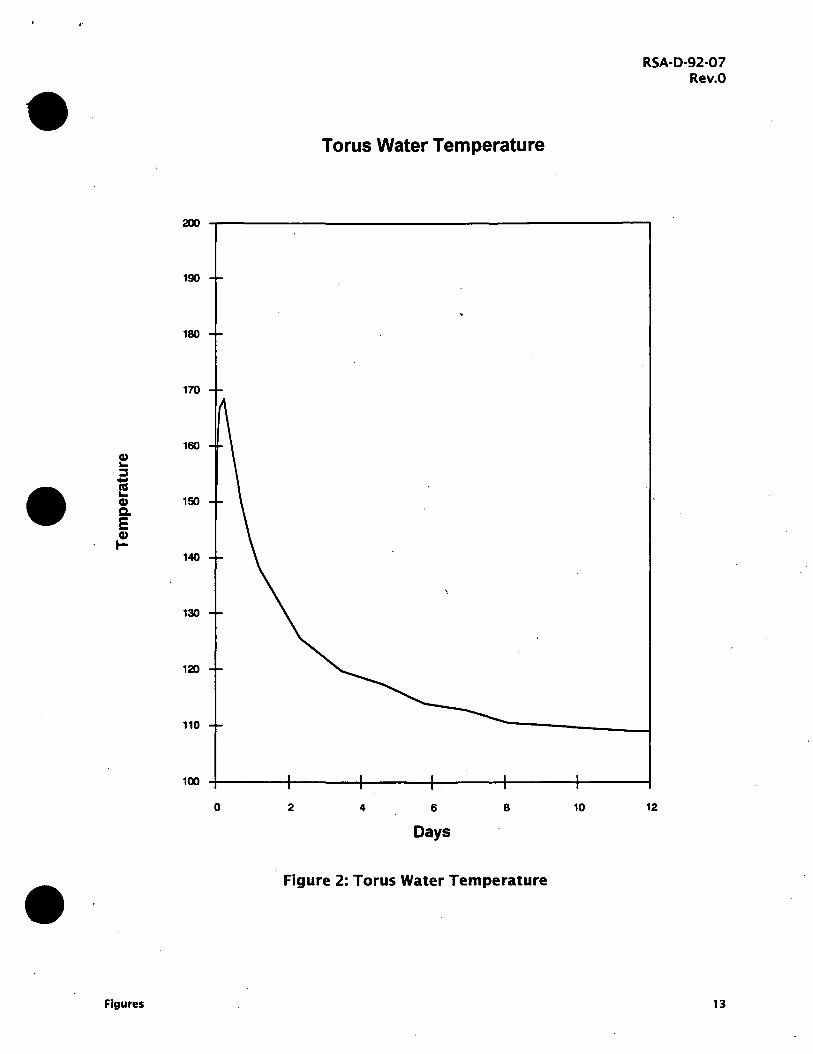
2. The initial pump room and torus room conditions are 14. 7 psia, 104 deg F and
95% relative humidity. The torus water temperature history is taken from the
LOCA analysis which assumed the operation of one RHR cooling loop with one
RHR pump, two RHR service water pumps and one RHR heat exchanger. This
assumption resulted in higher torus water temperature as compared to two RHR
loop operation. The temperature history is g_iven in Figure 5.2.19 (Case d) of the
Quad Cities UFSAR and is reproduced in Figure 2 ..
3. The initial reactor building conditions are 14.7 psia, 104 deg F and 95% relative
humidity. This is the conditions that would exist following a LOCA as listed in the
EQ zone maps (Reference 8). The temperature of the turbine building and the
reactor building of the sister unit is assumed to be constant at 1 04 deg F
throughout the transient.
4. Normal pump room ventilation is assumed to be off throughout the transient.
5. The heat load in the LPCI room was taken from Reference 9. It consists of two
components, a fixed component and a variable component. The heat load from
room lighting, two LPCI pumps, one CS pump and fan motors is fixed at 431,022
. Btu/hr. The· heat load from piping and LPCI heat exchanger shell is variable .
depending on the surface and room temperatures and was calculated in
Reference 9 by assuming surface temperatures of 170 and 165 deg F,
respectively. It varies from 81,446 Btu/hr to zero for room temperatures of 120
and 170 deg F, respectively.
The operation of the LPCl/CS system is assumed continuous. The piping and the
shell side of the LPCI heat exchanger contain water from the suppression pool.
Therefore, the heat load from these sources becomes zero when the room
temperature equals the torus water temperature. Although the piping and heat
exchanger become heat sinks when the room temperature exceeds the torus
water temperature, they are not modelled as heat sinks. Since a temperature
dependent heat load can not be modelled with the RELAP4 code, the maximum
heat load of 512,500 Btu/hr was assumed in the analysis for room temperature
Method of Analysis 4

RSA·D-92·07 Rev.O
below 1 70 deg F. After the room temperature reached 170 deg F, the fixed heat
load value of 431,500 Btu/hr was used.
6. All steel structures are not considered as heat sinks for conservatism.
7. The mechanism of heat transfer between air and the heat sinks in the pump
room is a combination of natural, forced and radiative heat transfer. Based on
the test data obtained in the Quad Cities RHR2B room in 1986, the combined
heat transfer coefficient was determined to ~e 6. 5 Btu/hr-sq ft·F (Reference 6). A
value of 5.0 Btu/hr-sq ft·F was used in the analysis ..
8. The mechanism of heat transfer between air and the heat sinks in the other
rooms is assumed to be a combination of natural and radiative heat transfer. The
RELAP4 code has a default heat transfer coefficient of 5 Btu/hr-sq ft-F, which
requires the adjustment of the heat slab surface area to yield the correct heat
transfer rate. The actual and adjusted heat slab areas are listed in Table 1. The
natural convection heat transfer coefficients were calculated using correlations
found in heat transfer textbooks such as Kreith (Reference 1 0) or McAdams
(Reference 11). The radiative heat transfer.icoefficient is derived by considering
the heat transfer between air and the gray walls. It is defined as the heat transfer
rate per unit area divided by the temperature difference. The heat transfer rate
is calculated using gas emissivity value given by Hottel (Reference 11) or Leckner
(Reference 1 2) and gas absorptivity value calculated by Hottel's method
(Reference 11 ). The methodology of calculating the radiative heat transfer
coefficient is identical to the one used in the CONTEMPT4 code (Reference 12).
9. The thermal conductivity of concrete is assumed to be 1.05 Btu/hr-ft·F and the
volumetric heat capacity is 30.24 Btu/hr-cu ft·F.
10. The soil temperatures are assumed to be 55 and 65 deg F for soil under the floor
and adjacent to walls, respectively. In the Chicago area, the ground water
temperature at depths of 30 to 60 feet is relatively constant at 52 deg year
round (Reference 1 3). The soil temperature under the floor is assumed to be
equal to the ground . water temperature and a value of 5 S deg F is used for
conservatism. The soil temperature adjacent to the wall is· assumed to be equal
to the mean of the temperatures at depths of 4 inches and 30 feet. The
Method of Analysis 5

• RSA-0-92-07
Rev.O
maximum annual soil temperature at a depth of 4 inches is estimated to be
about 77 deg F using data given in Reference 14 (page 25.6).
11. Heat transfer between concrete and soil is modelled by using an effective heat
transfer coefficient which is defined by the soil thermal conductivity divided by a
he~t diffusion length. The diffusion length is determined from semi-infinite heat
slab solution methods. The detailed procedure is described in the Appendix.
Method of Analysis 6
/
3.0 Results
RSA·D-92-07 Rev.O
The LPCI room temperature response as a result of a loss of room cooler heat
removal capability concurrent with a LOCA is shown in Figure 3. The room
temperature at the end of 11. 7 days is 1 78.0 deg F. ·
Because the RELAP4 code has a transient time limitation of 11. 7 days (1 E+6 sec), the
temperature at the end of 30 days was estimated. After 11 days, the room
temperature is increasing, but the rate of increase is decreasing. The torus water
which acts as a heat sink is cooling down resulting in lower torus room temperature.
Thus, cooler air will circulate through the LPCI room. It is · estimated that the
temperature would reach a peak of 1 78.6 deg F in four more days and beyond that
time it would be less than or equal to 1 78.6 deg F.
The calculated LPCI room temperature response shows an abrupt change after it has
reached 1 70 deg F. This is the result of the change in heat load as explained in
Item 5 of the input assumptions. If the heat load were allowed to vary with room
temperature, the temperature response would be smooth. The temperature response
shown as a dotted line in Figure 3 was obtained with a constant heat load equal to
the fixed heat load of 431,500 Btu/hr. Therefore, it represents the lower bound of the
temperature response while the solid curve represents the upper bound.
The dotted curve in Figure 3 provides an insight to the mechanisms of heat removal
for the LPCI room. The temperature increased 54.5 deg from 104 to approximately
165 deg F during the first 12 hours but added only 6 degrees in the next 12 hours ..
During the first 1 2 hours, the major contributor to heat removal i~ heat transfer
through the LPCI room surfaces. As the room air and surface temperatures increase,
the heat removal through the walls decreases but the "chimney effect" air circulation
increases. The increased air circulation carries a major portion of the heat load out of
the LPCI room which slows down the temperature increase. At the end of 6 days the
room temperature added another 10.6 deg to 175.2 deg F. From this point on, the
room temperature starts to level off and would reach a temperature of 177.9 deg F
after 11 . 7 days.
Results 7
4.0 ,Conclusion
RSA-D-92-07 Rev.O
The temperature response in the LPCI room as a result of loss of room cooler
function concurrent with a LOCA has been determined. The results show that the EQ
temperature limit of 185 deg F is not exceeded for an extended period of time.
Therefore, operation of the LPCI system without room coolers does not compromise
the operability of the LPCI system. The temperature response shows that it takes 6
days for the temperature to reach 175 deg. This would allow enough time to restore
the room coolers. The calculations have been performed in a conservative manner by
assuming both ECCS trains are running to maximize the room heat load. The torus
area temperature was maximized by using the torus water temperature for LOCA
with one ECCS train as the forcing function.
References 8

•
5.0 ·References
RSA-D-92-07 Rev.O
1 . "ECCS Pump Room Transient Response to Loss of Room Cooler for Dresden
Station Units 2 and 3," RSA Calcnote RSA-D-89-01, August 1 5, 1989.
2. "ECCS Pump Room Transient Response to Loss of Room Cooler for Dresden
Station Units 2 and 3," RSA Calcnote RSA-D-90-01, April 12, 1990.
3. "An Alternate Method of ECCS Pump Room transient Response for Dresden and
Quad Cities Stations," RSA Calcnote RSA-D-92-02, August 6, 1992.
4. "RELAP4/MOD6 - A Computer Program for Transient Thermal-Hydraulic Analysis
of Nuclear Reactor and Related Systems," EG&G Idaho Inc., CDAP TR 003,
January 1978.
5. "RELAP4/MOD6 Certification," RSA Calcnote RSA-M-85-01, February 28, 1985.
6. "Study of Thermodynamic Characteristics of Quad Cities ECCS Pump Rooms," RSA
Calcnote RSA-Q-86-01, October 14, 1986.
7. "Air Flow Measurements on LPCI and Core Spray Pumps", Documentation of
Telephone Conversation between K. Ramsden and S. Rhee, October 30, 1992.
8. "Response to IE Bulletin 79-01 B Procedure for Use of Environmental Zone Maps
for DNPS Units 2 and 3," Rev. 3, October 21, 1988.
9. "Dresden Maximum Corner Pump Room (CS/LPCI) ·Temperatures,." Bechtel Cale
DR-721-M-001, October 19, 1992.
10. Kreith, F., Principles of Heat Transfer, Second Edition, International Textbook
Company, 1965 .
11. McAdams, W. H., Heat Transmission, Third edition, McGraw-Hill Book Company,
1954.
References 9

RSA-0-92-07 Rev.O
12. "CONTEMPT4/MOD4 A Multicompartment System Analysis Program," NUREG/CR-
3716, page 69.
1 3. Todd, D. K., Ground Water Hydrology, page 1 95, John Wiley & Sons, Inc., 1959.
14. ASHRAE Handbook 1981 Fundamentals, American Society of Heating,
Refrigerating and Air-Conditioning Engineers, Inc., 1981.
1 5. "HPCI Room Thermal Response with Loss of HPCI Room Cooler at Dresden
Station," RSA Calcnote RSA-D-92-06.
References 10
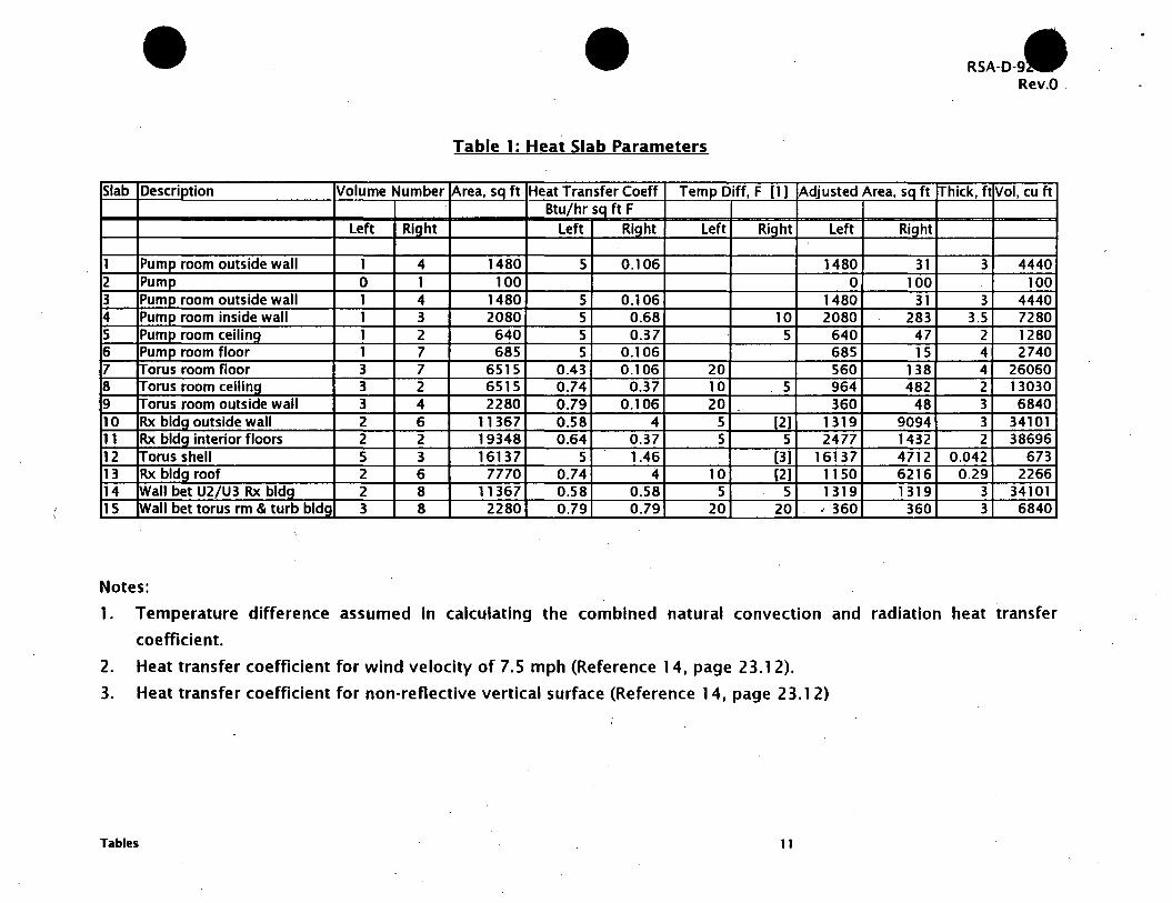
Table 1: Heat Slab Parameters
Slab Description Volume Number ~rea, sq ft Heat Transfer Coeff Temp Diff, F (1) Btu/hr SQ ft F
Left Right Left Right Left Right
1 Pump room outside wall 1 4 1480 5 0.106 2 Pump 0 1 100 3 Pump room outside wall 1 4 1480 5 0.106 4 Pump room inside wall 1 3 2080 5 0.68 10 5 Pump room ceiling 1 2 640 5 0.37 5 6 Pump room floor 1 7 685 5 0.106 7 Torus room floor 3 7 6515 0.43 0.106 20 8 Torus room ceiling 3 2 6515 0.74 0.37 10 5 9 Torus room outside wall 3 4 2280 0.79 0.106 20 --
10 Rx bldg outside wall 2 6 11367 0.58 4 5 [2) 11 Rx bldg interior floors 2 2 19348 0.64 0.37 5 5 12 rrorus shell 5 3 16137 5 1.46 (3) 13 Rx bldg roof 2 6 7770 0.74 4 10 (2) 14 [Wall bet U2/U3 Rx bldg 2 8 11367 0.58 0.58 5 5 15 Wall bet torus rm & turb bldg 3 8 2280 0.79 0.79 20 20
Notes:
Adjusted Area, sq ft
Left Right
1480 31 0 100
1480 31 2080 283
640 47 685 15 560 138 964 482 360 48
1319 9094 2477 1432
16137 4712 1150 6216 1319 1319 ; 360 360
RSA-D-9 Rev.O _
Thick, ft Vol, cu ft
3 4440 100
3 4440 3.5 7280
2 1280 4 2740 4 26060 2 13030 3 6840 3 34101 2 38696
0.042 673 0.29 2266
3 34101 3 6840
1. Temperature difference assumed in calculating the combined natural convection and radiation heat transfer
coefficient.
2. Heat transfer coefficient for wind velocity of 7.5 mph (Reference 14, page 23.12).
3. Heat transfer coefficient for non-reflective vertical surface (Reference 14, page 2 3.1 2)
Tables 11

S-9
S-1
e S-10
E) S-1
Figures
S-15
H•tSlob
e S-15
S-3 S-9
S-13
e e S-11
S-14
-t~' S-8 i., El. 517
J.1 I J.3 e .... S-12
S-2 c) Vols () - S-9
e S-4 e S-6 S-7
Figure 1: RELAP4 Model Schematic
RSA-D-92-07 Rev.O
12
160 Cl) ... ::::s -l! Cl) 150 c. E Cl)
I-140
0
Figures
Torus Water Temperature
2 4 6 8
Days
Figure 2: Torus Water Temperature
10
RSA-0-92-07 Rev.O
12
13

e ::::s -ca ... Ci> c. E Ci> I-
Figures
200
190
180
170
160
150
140
130
120
110
100
0
Dresden LPCI 2A Room Temperature
EQ Temperature
---------------------------'
. .
Torus Room RX Building
Initial Temperature
2 4 6 8 10
Days
RSA-0-92-07 Rev.O
12
Figure 3: LPCI room temperature response due to loss of room cooler.
14
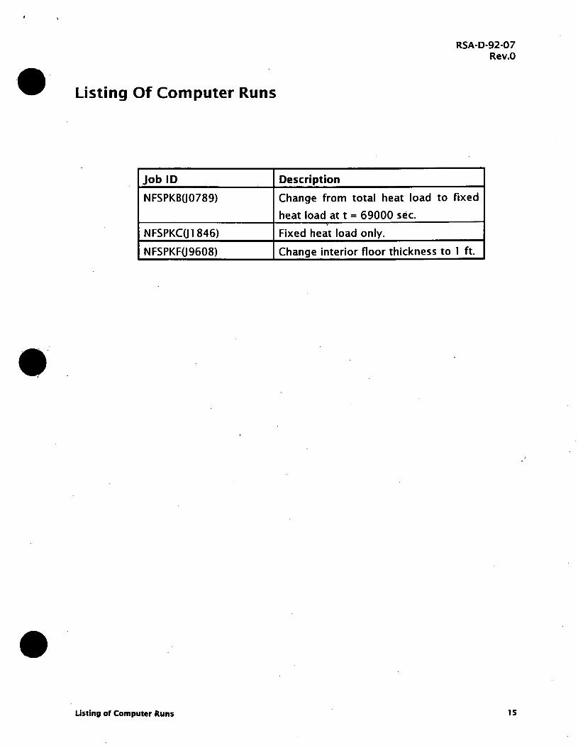
Listing Of Computer Runs
Job ID
NFSPKB(J0789)
NFSPKC(J 1 846)
NFSPKF(J9608)
• Listing of Computer Runs
Description
RSA·D-92-07 Rev.O
Change from total heat load to fixed
heat load at t = 69000 sec.
Fixed heat load only.
Change interior floor thickness to 1 ft.
15

Appendix
Contents
1. Calculation of Combined Heat Transfer Coefficient
2. Determination of Soil Effective Heat Transfer Coefficient
3. Heat Slab Dimensions
4. Volume of Model Volumes
s. Estimation of LPCI Room Temperature at 30 days
Appendix
RSA-D-92-07 Rev.O
4 pages
3 pages
1 S pages
2 pages
2 pages
16
Crn.t.10NWEAL TH ED I SON COMPANY . ·
NUCLEAR FUEL SERVICES DEPARTMENT PROJECT ------ .·DATE ·------
CALCULATl ON NUMBER RrA- D-92-07 FILE------ PAGE --OF --
SUBJECT---------------------------
P. L. KONG n '\I . PREPARED BY -----"'...-.··I' CHECKED BY REVIEWED BY '.2i6£.-.
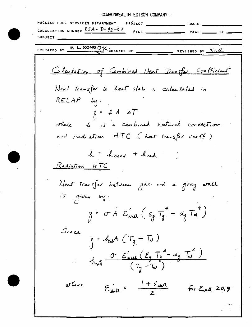
R.ELAf
o.-....J r~' J, ~ H TC . ( ~ ti'~ sj-1-/ Co# f ( )
__t._ ::: _,t u r1 ./ + -/... ro.A.
R~·J.·tno I~ TC
7.J..eJ Tra- sJ~ be . .t""'.u.-.
t's 0,.v'Lo, h1..J .
0 < 0- /1 £,~.a ( £0 TU .. - o(J T/)
,)" -4.tA c 7a - T.i ) . I ( 4 ~) ~ : 0- lwei). [~ ~ - ol.8 ~
rt.A ( 1 -Tc.J )
I + fw.JJ-z.

•
COMMONWEAL TH ED I SON COMPANY .
NUCLEAR FUEL SERVICES DEPARTMENT PROJECT ------ DATE------
CALCULATION NUMBER RSA..-v-92-o7 FILE------ PAGE __ .OF --
SUBJECT---------------------------
, 0 d riJ
PREPARED BY !>N_O_)I __ """'\"""'"·.-.,..... CHECKED BY REVIEWED
~ "--' o(J ~ b~
i°l'l fl.t, CofJTE~Pi4-
CJ.l~..J "-''"o .sr1$ ~cr"h~
i.,(~ • M"----J.. ( /?.e.f 1 z..),
I r'I
I" .,, I> ,, ' - - ~ ~pr,_..~. S !.oic.c.A • ~
L ~ u.J.uJ.J;·~ ef to .1 tt. b~ ~~ oj 17 ft
tAJ"tU usu . TL. s ,:t j:t,u, b.u..,..., 47~ ~ ~
J~ J::lu.. tffC.I r~ ( r<.ef. 1~}, I,t ·'> j~~
/:t J ~ H fCI r"7J'wi· J .. .-~,,·(TY\ ~
1 iCTu,, Cucu- r ~ etc·~) 1°0'""\ I (,..
Lo...ror d.-•~s·'a>tS ~ o~,u
~'"- r.1Z-rr1-sp,JJ,v~
~ Rx ~'"fl. (L.,r b~
tv~ ~ ~L r.L a.. ~ ~J,·,-,. t-f TC,
;f~L ~ !<1< lo~ ,·s ~ Ll.uJ. °'-~
~ 1 ,·t i'S ~ ~r7r··~ ~ t<;L Q..J_ ~ v~ o.-J.. s"-rJ-u !Mu.. ~ cd~.z;_ Lk., 6~
,"CL. (T4.4 ~ ~..U .... ~ lfTc..)_
A b~ ~aw "f 11 f.ur ,.~ u.s.ul j---t ~ t8rJU"
~~ fa ~ ~~ f'"~S<M •
COMMONWEAL TH ED I SON COMPANY .
NUCLEAR FUEL SERVICES DEPARTMENT PROJECT
CALCULATION NUMBER f<..S/t-D-92-07 FILE
DATE
PAGE _OF
SUBJECT -------------------------------------------------------------------------------
PREPARED BY ~NQ~ I "cl o::X:· CHECKED BY REVIEWED BY ;:(,8f2.
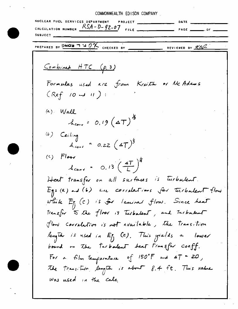
Co,,., b,·~ HTC ~ For"'~j u.)..a.J .:t.r~ Jr~ ko . .1 ·,c"-' ~ A.Ac A-ei< "-' s
(Ref 10 -J ") :
(a..) l;\jdi_ ~
---t... 4'-• II .: 0,1!) (4T)
~ cb) c.i,,),·~ ( &. T )' u ::. 0, z.z A. C(J .. '
(t) Fl~
~ec .. " =
l.J-eJ fra-..~J~
E~1 ca.) _.; (r,)
·c· 4T)~ 0 13 -. L
{)YI Ct, 11 ~ U...1 fei-c.R s
LfL Ur I~,·..,,.>
d r;;rb~.
~ ~,b~rf1"'1J
"'11.;. k ED (c )
tr~.rf~ 18'" Du..
,·s ~ l~·µJ J!nV. £,.,,,C(_ kJ
ff~ 1'S ~(/,~I a-J... 1"-Fb~
ifto-V CtJ-r~~·,,.,, i's ~ l(,.VAA·f,,._ft,/.c, / ~ ir ..... 5,f,·~
4u~ b~
/.r i.tW ,·;1 Eb Ce). T~·i 0 ·tt-lLs .a.. l.wv
0"71 ~ t..,r b~ ~ rr~ sf4' CotLff. f~1 (>... ~/,.,, ~,.,_,-~, ... of 1so°F c-J AT - z.o.)
Z4 t~4-S··~ t>ur::t.. ,·r~ f,+ ft. T/M·s v~
tAJ eJ-.S rA.S~ J. '"" 1'G..t.
CAk.,

Cortg>!Q.ec:1 Heat Transfer Coefficient RSA-0-9 2-07 Revo
Prepared ll'f: ~Ko !Olecked by: Reviewed by: dd{I:-tg, F 150 160 170 180 125 115 110 tw,F 120 130 140 150 105 105 105 Dt 30 30 30 30 20 10 5 Tg,K 338.7056 344.2611 349.8167 355.3722 324.8167 319.2611 316.4833 Tw,K 322.03891 327.5944 333.15 338.7056 313.7056 313.7056 313.7056 L, ft 17 17 17 . 17 17 17 17 L, cm 518.16 518.16 518.16 518.16 518.16 518.16 518.16 tref 120 120 120 120 105 105 105 psat, ref p 1.6933 1.6933 1.6933 1.6933 1.1016 1.1016 1.1016 Rel hum 0.95 0.95 0.95 0.95 0.95 0.95 0.95 pv 1.691888 1.719639 1.747389 1.n514 1.083587 1.065053 1.055787 pv, bar 0.116652 0.118565 0.120478 0.122392 0.074711 0.073433 0.072794 pt 14.7 14.7 14.7 • 14.7 14.7 14.7 14.7 pt, bar 1.013529 1.013529 1.013529 ·1.013529 1.013529 . 1.013529 1.013529 Calculate emmisivity tau 0.338706 0.344261 0.349817 0.355372 0.324817' 0.319261 0.316483 beta 1.7813541 1.78842 1.795373 1.802216 1.587846 1.580354 1.576559 ao -2.613721 -2.62025 -2.626n -2.63329 -2.5974 -2.59087 -2.5876 a1 1.0067331 1.006442 1.006062 1.005594 1.007072 1.007052 1.007009 a2 -0.16122 -0.162 -0.16278 -0.16355 -0.15926 -0.15847 -0.15808 eps,t,ref 0.263958 0.262251 0.260488 0.258671 0.24663 o.24n94 0.248354 pe 1.526694 1.530885 1.535043 1.539168 1.349144 1.346261 1.344811 beta, max 0.180219 0.19435 0.208255 0.221941. 0.143851 0.128866 0.121276 cw 1.083298 1.083944 1.08458 1.085207 1.064139 1.063585 1.063306 eps 0.285946 0.284265 0.28252 0.280712 0.262449 0.26355 0.264076 Calculate absorptivitl tau1 0.322039 0.327594 0.33315 0.338706 0.313706 0.313706 0.313705 beta1 1.75944 1.766869 1.n4112 1.781354 1.57273 1.57273 1.57273 ao -2.59414 -2.60067 -2.6072 -2.61372 -2.58434 -2.58434 -2.58434 a1 1.007073 1.007049 1.006935 1.006733 1.006943 1.006943 1.006943 a2 -0.15887 -0.15965 -0.16044 -0.16122 -0.15768 -0.15768 -0.15768 eps,t,ref 0.268731 0.2672 0.265608 0.263958 0.2489 0.2489 0.2489 pe 1.539805 1.543883 1.547929 1.551945 1.355036 1.349195 1.346274 beta, max 0.136391 0.151247 0.165854 0.180219 0.113618 0.113618 0.113618 cw 1.082951 1.08361 1.08426 1.0849 1.063943 1.063486 1.063255 alpha o.29no6 0.296079 0.294385 0.292626 0.268995 0.2668 0.265695 Calculate Radiation coeff eps,w 0.95 0.95 0.95 0.95 0.95 0.95 0.95 q" 9.740629 10.11287 10.48611 10.85968 5.488458 2.675487 1.320663 hr 0.324688 0.337096 0.349537 0.361989 0.274423 0.267549 0.264133 Calculate combined heat transfer c;oeff wall he 0.590374 0.590374 0.590374 0.590374 0.515739 0.409343 0.324895 h=hr + h 0.915062 0.92747 0.939911 0.952364 0.790162 0.676891 0.589028 ceUing he 0.683591 0.683591 0.683591 0.683591 0.597172 0.473976 0.376195 h=hr + h 1.008279 1.020687 1.033128 1.045581 0.871595 0.741524 0.640327 floor L 8.44 8.44 8.44 8.44 8.44 8.44 8.~
he 0.1785 0.1785 0.1785 0.1785 0.161293 0.135631 0.114051 h=hr + h 0.503188 0.515596 0.528037 0.540489 0.435716 0.403179 0.378184
Page1 HRADJCLS

•
COt.t.40NWEAL TH ED I SON COMPANY .
NUCLEAR FUEL SERVICES DEPARTMENT PROJECT ------ DATE------
CALCULATION NUMBER R5A-D- 9Z-07 FILE ------·.
PAGE .. OF --SUBJECT _____________________________________ _
P. L. KONG("')--/ . PREPARED BY -------,\'~· f' CHECKED BY REV I EW ED BY """zl....,'4~~-----
To ~·J,·tJ~ Ck U1J t:.<J.J,·tTM of ~ fra.-r~fo~ ti l:AL
so,-/ I 0... S1.t.r~ ~I if';_~fL/ CP~ ff,·c.,~ ,·r fA..fU
b.e..
D = ,k,LA ( T.. - r. )
L
=LA (t:o-To)
& L
(z.)
IS "'- ~ ri:'"ff~~I~ Ao·~. I~ ~
frtrM ,fu .rtrfJ;·rJv' oJ ~r ~,·~ ""' "- .S ~;M~ - ~f·""'· CL ~ ~ ( R.e.f 10 1 if'· 15i) ;
~ ,. tksA ( T: r: ) (+) U 1lrrd..t
0
"'-
0
Co7~··u for (1) ,_,, c~) :
L = VT~t

COtJMONWEAL TH ED I SON COMPANY .
NUCLEAR FUEL SERVICES DEPARTMENT PROJECT ------ DATE ·------
CALCULATION NUMBER RSA-V-92.-0] FILE------ PAGE -- OF --
SUBJECT--------------------------
P. L. KONG fl f.... · PREPARED BY ____ I...,..'·- CHECKED BY REV I EWED BY _gJ._~ __ 'fL ___ _
~.I HTC (,.i.)
. . T4 a..~.e'(A.( ~r- fra-,sj.u rA.J:L
~ = 2 ~s A { t;.-T,,) /,,,.~ .. t:
L_ =
l/11<X J4t .
~ tLf f«$11Vt ~~· ,·.r
v 11"~ .d-t z.
..dt d' :
. ,, - .
Us,·0 so 1 I f "Jt-t t.:PJ fr()Nt ~of J.. n... --' Th uJ.· tt ~
I ,..;ff e kc f. 4" f5" J..J.a;r- /;-o-sf£/ 1 ~ o ~ W, · 1() "'" S d>t s /
19~/ t bgo'' .•
f ~ z.oso '?JI ... ~ • o. o{,z.fz.$ • tz8 //,, / fo3
~ = o. 52 w I wi-1< J( 0,S77!2.. = 0. 3 (?JC.. IM- -ft- ·p
C,O ~ t 8-+0 J / ~ -/(. ~ 2. 3!86 x10f = o.f-315" ~/,1.- 'f
o( ::

•
COMMONWEALTH EDISON COMPANY NUCLEAR FUEL SERVICES DEPARTMENT PROJECT DATE ------CALCULATION NUMBER /~SA-D- rz.-07 FILE------ PAGE -- OF --SUBJECT -----------------------------------------------------------
P. '- KO!'I':; n rv . PREPARED BY \·f'. CHECKED BY REV I E WED BY """':f;...,~""',_t2-__ -____ _
So.I ff TC J
~t = .~
l = - - ·-- --"t
1./--rrx O.oo_?.327 x766 703 - . I. I z. =
o. 3
1.79?> = O.lb7 1?:lZ~/.t..r.- ft,;i..-
0 f
N ~ ~r .iv i.J()...i.v; , ,, 1111s2Lo w,:,,Etu ~ •
A v~ oj o. 1ob · was u.s.td lov·~s 0 ~ UJ?tJ .-~ c~4 11'1 It..L. c.M.1 r,,,J c~.
~,·"-Gt. a\.4, -~~.r -r vo...I e..~ clc. . , ILd tco ;J) ·ft... A, ~:-w
'-
~ · VlS .e.. r
°J (.._ J~/ I/~ of ,t._ tS"
c CP1 µ_, v o..-f, · / L.

•
CO~ONWEAL TH ED I SON COMPANY .
NUCLEAR FUEL SERVICES DEPARTMENT PROJECT DA.TE----------CALCULATION NUMBER J<SA- ?)- ?z-07 FILE ----- PAGE ---OF --
SUBJECT-------------------------
P. L- KONG PREPARED BY ----"'l"~ CHECKED BY REVIEWED BY
/.
2.
3
4.
7Jecu ~la.lo I - A R~ OJs,k !)JJ/L ~ l--
A· 38,5" 3t = 1+b3 f'f:
t = 3 ft
v: /1381 ft 3
R.e{: ?:>wd 8- lf7
1..1-w ~'""" z. - !o Use_ A c I oo ft
7J.e4- Sft<t, 3 p~ R..~ e>c.vt;s,·~
a.s lJ.eJ SI o. /, I
l~ Sf-.~ 4 P~ RHW1 .Lu,·u UJa}g_
A = 53,75 )I 38 = 2012. s- ftZ-
t ~ 3. 5 (~ ~ /~. ~,._ t:L • .J -v :. 7If5' f't i
D"'a B-187
~IL
't so~ f ~ j.(~s··~s A../~ .Sf·J~ ~·rf.u~r fr,_,
~ ~ ,·1J v~s. Tk Lf~GJ ~ Hu. rLsJJ:f".s 1'.s
MinA·~

COtJMONWEAL TH ED I SON COMPANY .
NUCLEAR FUEL SERVICES DEPARTMENT PROJECT ------ DATE------
CALCULATl ON NUMBER R.SA-1J• fZ-07 FILE------ PAGE __ OF --
SUBJECT--------------------------
CHECKED BY ----- REV I EWED BY ....;;z:;~~;.;;.~~---
5. ~ Sla.b ~ -- p~') f<..~ c~·t.·0 A = .J ( ~ 8. 5 ;< 3 7, s) = 7 2 z. f 1)-a..
b.
A s:~l.W)e. I 0 fu occ..'01,'.J ~ .Llj-{f~ o,, o~r s··ei.t. . >--
= o.1x 722=- 0?0 ft
t = 2 rt, ( Assu~u() -It v = /300 f-t. 3
Tk "~ oj t ~r ~ . ()_ff4 a.,, ~ ~·.r>'\ • .r.LL r.t. s ,.JJ4 "f em~ r~
P"-f R.~ Flu r
A= ± (3&'.51( 37.5) = 72.Z f'-t~
A-'~~ / o?, o 'eu.r'LJ ~ ~t,....a-t A ,..u- • o. ? Y 7 z Z :II b 5 o ft~
t ::- + ft V = z(,oo (-t;
1
R~f· 7>wo " - 110

•
COMMONWEAL TH ED I SON COMPANY .
NUCLEAR FUEL SERVICES DEPARTMENT PROJECT ------ DATE------
cALCULAT, oN NUMBER RSA- D- 9z-o 7 FILE------ PAGE ___ OF --
SUBJECT---------------------------
PREPARED By P. L. KONG .1'..· . ----i.--. CHECKED BY REV I E WED BY ~:3?..i.;.~~rf'---..---._
7. !W- 5/a.fo 7 Torlti R.~ Fl~r
A = r' o 3 o ft -v (~SLe.. f ? )
Li·~,· /-;·'t . C~JL ,.~ 2 {rq ,·As oj R.tf I( (IA.nn ,·1 S ,-~it~~ IA s l O , Tt .... _,~ f,r~ , o,. ~ · );..A If ~J J:l.JJ..
torK s a.. r.t.A... c~ bL c: r,u).,.. li.-11
ANX: 0.5"'Jf ·A~ 6515 (-t;,~
-t .: f Ft.
I/ :. b5"(5"1< 4" z(, obo /
ft.,'~
R~f: 7) tA) u B- I ro
8. 7~ ~fa.lo 8' - Tor~ra Rfkhol\ G..·/.1
;\~ :: AMF C'J 7~ S/o.k 7
t = v =
= fa S- I 5 f-t ~
2 .ft, ( /tSSµ..~)1' 3
b5"15 "z. ;: J 3 o '30 r-c I
+ TA.a_ "~ oj t ~s ~ ~f J~ µ..,_ .~ f",~,.,,
.s~,.~, S#. rfls~ ~j cy~·'' rt1wrt NF!PKF (J 'll,ol).,

• COtvtviONWEALTH EDISON COMPANY
NUCLEAR FUEL SERVICES DEPARTMENT PROJECT ------DATE -------
CALCULATl ON NUMBER l~~A- P-9z-oz FILE------ PAGE --·OF --
SUBJECT-------------------------------------
PREPARED BY p~ L. KONG (J ~ CHECKED BY
(p, +) , r. l~ sra.b /
0
@ ·.® ;
I
REVIEWED BY-~-.....;.~.:;../_ ___ _
@ Hea..T 5'1G..~ r-J ...... ~1
@ Not cr1eJ.1·~
A = 2 " 00" 38 :: 4~o .Pt'
Fo 1 I ,·t¥1 ,· f;·1 ca.s.e. :
AM-t = i A • zzgo f't2-
t : 3 t't..
V - 0Efo ft/
Ref: ])...,0 8 - 1g 7

•
CO~ONWEAL TH ED I SON COMPANY .
NUCLEAR FUEL SERVICES DEPARTMENT PROJECT -----
CALCULATl ON NUMBER RSA- D- 9z-o1 FILE ------
DATE------
PAGE -- OF --
SUBJECT--------------------------
PREPARED BY P. L. KONG (}. CHECKED BY REV I EWED BY .... @...,··-~__,Gi=L=---
7~t Sia.lo D.·~>··6ns <f· s)
10. lJeo..t Slab 10 - 'Rx Bl~ OJ$,·.,L,_ IA.lo..//$
Ttt..t·.s f....uJ- s/o..l, ~t~s~s ~ t:>JsfrAL
wMf; fr~ E/etJ --~l7. 5 "f5 El. C:,13 1
(Re(v.L/.·0 f fcor ) • · Tk_ ~tM __ s,·c!_.~~i's ~
_J..,/) I ~ . .J ._ ~ ~ fl- . c r.Lt:lc ·o._J ; " ·~ CD- c. ~,,.~,,,, ..... ·
4 D 013- 517,5
= 15.5 f'-t
A: ( '4-7 .. 117. '5) "15.5
• Z5zloo
147 ,
1+1'
For t4 /,·~· t;.d CA.f~ o.-J cu-ru.~··u 10')~
0 b 5 tr ,IA.Ct,. tn1 .·
A ~ ::. 0 I 5 If 0. 9 A & ' I I 3 b 7 f' 1; ..
t : ?; .(~
V :::. 34,., 10 I f-t/
R.~f. 1)..,0 a -1C'5
I
111.5

COMMONWEAL TH ED I SON COMPANY .
NUCLEAR FUEL SERVICES DEPARTMENT PROJECT ----- DATE-----
CALCULATION NUMBER RSA-7)- rz-01 FILE------ PAGE __ .OF --
SUBJECT -----------------------------------------P I.- KONG
PREPARED BY • '
11. 7Je,..,r s ! tt h I/ ( s~ (f 11
~f.e J
545"1 6 ,,
I '' 5700
?8Cf I
GI 3
CHECKED BY
Ar2a_
I I I i5
/0 387
100z4
I 7 2 7 3 ... ---~ 49+"1
REV I EWED BY .... :i!.......,.~_(2__ __ _
fo1 ~ k~t-.·1 CA.r..t. a.4- a.ss~··u 20Jo
i Vt~ : o. 6 x o. g x A .:: I 9. 7 F 8 ft>-
' = 2 ft (Assu~ )A
3/S75'ft3
A,J = / r, 3+8 re' -1 v =- 3 s1 6 ~ & +t 1
w.1u.,_·

COM\10NWEAL TH ED I SON COMPANY .
NUCLEAR FUEL SERVICES DEPARTMENT PROJECT ------DA. TE ------
CALCULATION NUMBER RSA - D- 72-07 FILE------ PAGE __ OF --
SUBJECT--------------------------
PREPARED BY _P_. _1._K_o_N_G....ig _ _.1'_ . CHECKED BY ----- REV I EWED BY _...,~...,,13.._tl-_-__ _
?J..eg- ~la.b 'D.·~s.-"" s cf 7)
. IZ ~ S/,._j, 12 Tot'u..S ~he.I/
( !.u.. u 'f) A.: 32 2. 7 3. b
V= 13. ~ ~!()._ b t 3 ·- R')( Bl"o RIH>f
S..lllL ]),-~ -r;-1 ~I~~ 10
A .. /17. 5 " 14-7 ~ 172 7 z. 5" f't -a-
Frc/I"'\ D,,,,0 B - +3 3.
T7 oj st~I =~I 65'7 16''
L. vJ Po,· .vr of ~1 , . I J. I•
~/ 657 ~~
r-ti01-.. Po.· ...,r oj rw f · FI (, 511 G ~ "
II
t; :: 3,5
COMMONWEALTH EDISON COMPANY
NUCLEAR FUEL SERVICES DEPARTMENT PROJECT ----- DATE-----
CALCULATION NUMBER R!A- 7) .. 12-07 FILE------ PAGE -- OF --
SUBJECT-------------------------
CHECKED BY REV I EWEO BY ......... X..._A....;;~---
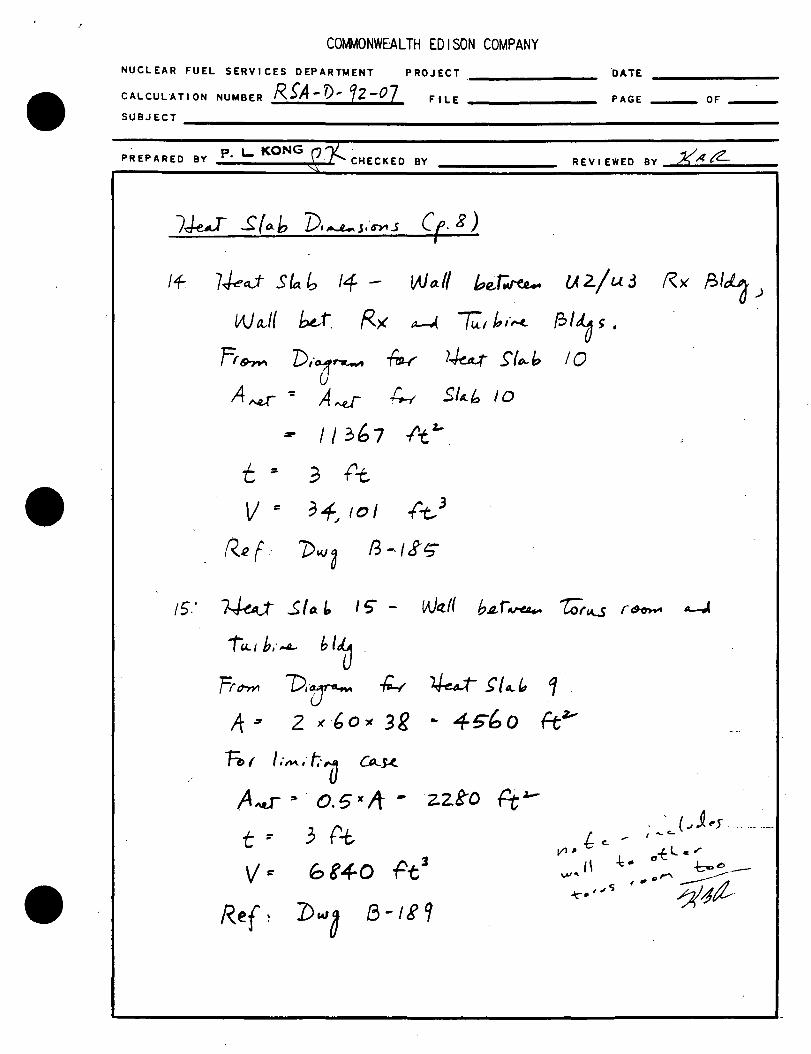
Ce. g)
!+. 7ho.J- Sia b 14 - Wt1.I/ b(l;~ U 2./ u. 3 R>< A>l"o->
lAJa,I{ k,t, f<x a--( -r;_, b,·~ 131~ s .
IQ f,9'71"\ D,·;r....._, ~ }~ S'fr;..h u
A~ -= A-J 4-t st~b 10
- 11367 l'tz-
t :£ 3 t't
v = 34-,, 10 I .(t,3
R2f · 0~3 f3-.f gt;"
15.' ~ S/o. ir, I 5' - Wttlf b.a.r~ "!:Or~ r60'W' ~
Tu.1 b,·,.A.. b I~
fr trn'1 'D,(j'- ~ ~ ~ 14.. ft, 1 . A ; 2 )( 6 o ~ 3 g .. 4 !i"b o ftz,,
7;, ' I.-~,· t.· U LA-s-<.
A,,.;-- ~ · o. 5 JC If .. zz.ko f't 1-
t ~ j P..t v ~ bt+o .Pt3
COMMONWEALTH EDISON COMPANY 'NUCLEAR FUEL SERVICES DEPARTMENT PROJECT D~ DI.TE 4-22.~67.
CAL CUL AT I ON NUMBER FI LE 1-D/2.&. PAGE OF ----
SU BJ ECT B'At..vftr1oN cF #E'A1 1,.,.,,._,5.Ft-~ Cot:=FF-,t:.JEEN~ dt'D ~ F0ie Wl!v:S. @?'?"'!
A-Np §'7,S' Le-lt::L. fOte ~ ttf~I LIIV~ Biee~ n:wo1nof\!S
PREPARED BY J,W1,F. ___ ;,..._ __ _ CHECKED BY REVIEWED BY ,z/A?.
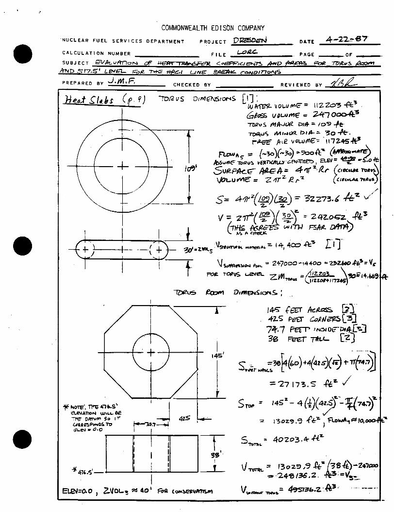
H~o.t .rt(~~ ( f 9) ID12VS D t IVI f7\JS I or-& S [ '1 '. W ~ "Ol..V ffl'C = \I Z Zo"5 -t:'t 'J
\I -+- lc1''
"+/ !
6/<>Sf. V Dt..U~ = ~l 0~-S TDRuS t"ll'rJIXl DI~:. 1oc;> -/t ~uc; Mt...a<Xl. 01~::. °30 -Pf:. ~~ ftd! .. vowt'IE'"= -1112.'\5*'
Fl.DAlfts- :: {-~)(-~ ""~oA:' (~ .. ~\ /f;,svlfl~ 1'!7'211~ ~aznatu.Y·G:.f'N~, a..ev= ~ .t:<,1t; SullPlk..r;- /tile/}:;;; 411' 'Z.. ll.r (,111c.1.1r& l"Da~\ \IOL-u iN'c = z lfr ' I!. ,. -z (',_,.LAA. .,.,11d}
S= 4-/ff-z( /J!2)~) ="" 3ZZ73.4' 4-z. v'. '2. •
V = z~( ~j.£ ~ \z. • 2 qz.ot;;z. .fl: 3
~ ff.[4;- w/m F5M- LA'J'n4) l ,.~ ,. c ft'eV'.
/
r,1-· ' t ·V . . .
'3o'cZ.'IOl..5. 9'fllefW~ M~IAI.:, 141 4C0 .ft'!> ( +
~ ~OTe·. Tl't; lt"i b.S' a.l!llA1'lON ""''-'- ee "'.")fg" DA'N~ So I T"
UIUl~P""O!. T'D G'L-e-.1 .. 0. 0
'j ~7a.7--4
t-IZ)f2US
4z.S
.i.1(41,.s· I I i II I
\Js.i~ .. ,.,~ Pooi.. = 2+7000-14+00 ca131ZJAO~b:!#=Vc
~ ~us L.ela.. z~ = A1zzo' \~=i+,66, 'TWllS (. l1%io:r-t 11-n.t;)
~ D1me11aS1or-.S. ; .
I
I 145
1
I t
T 3S.
' I
I~ f~ k~ [j}. 4-2.S h--U- eo,e,v~(.:3] 77f,·7 ~ l~IOl°:i>t4["=-] 3B ~~'- [~)
S • .;, ~ •+{t.o )+4(4zs)( r.J ~~f 4~ = '27 17'3. s -Pe~ /
s~ = 1452
- 4(i)(4~T.--l{74..,)"&
= 1"3ozc;,.~ f-1::-r..) f"lOwA-,c:::lto,ooo.At:.'
s ::. 40203 .~ .f.1:.7-"Tb~c.
\} TC1T'lh.. == t3oz.':J ,<3 ~- (3s4)-'Z47t:JOO -::r ... 24-'5 /36 .z . .,c\3:=V5 ':;...
~=o.o I Z-Vot..'! ~ 40' FOa COH~e'IUIM1!.M v .,,,,,._. -rw-s.:: 4':1st3b:Z. -.~3 .·

COMMONWEALTH EDISON COMPANY NUCLEAR FUEL SERVICES DEPARTMENT PROJECT Dl?-~:iDGN DA TE 4-Z 2-'i!!J7
CALCULATION NUMBER FILE z..s:;,,ec.. PAGE OF
SUBJECT e.Jlttv/fnON q;= rlelfr trtAroFeZ l'"--"§"FE1£.l(i'l\J1"S ,ANo ~ 'R>t! "Tbeu.S f!.aoApp 571.S Le-IE]. -=oi:Z. ltfC..l '"'"'fi '8!1=-;t/1£ C.aNOmottS
PREPARED BY ...J,M.F. __ _..;. ___ _ CHECKED BY REVIEWED BY ~/2_
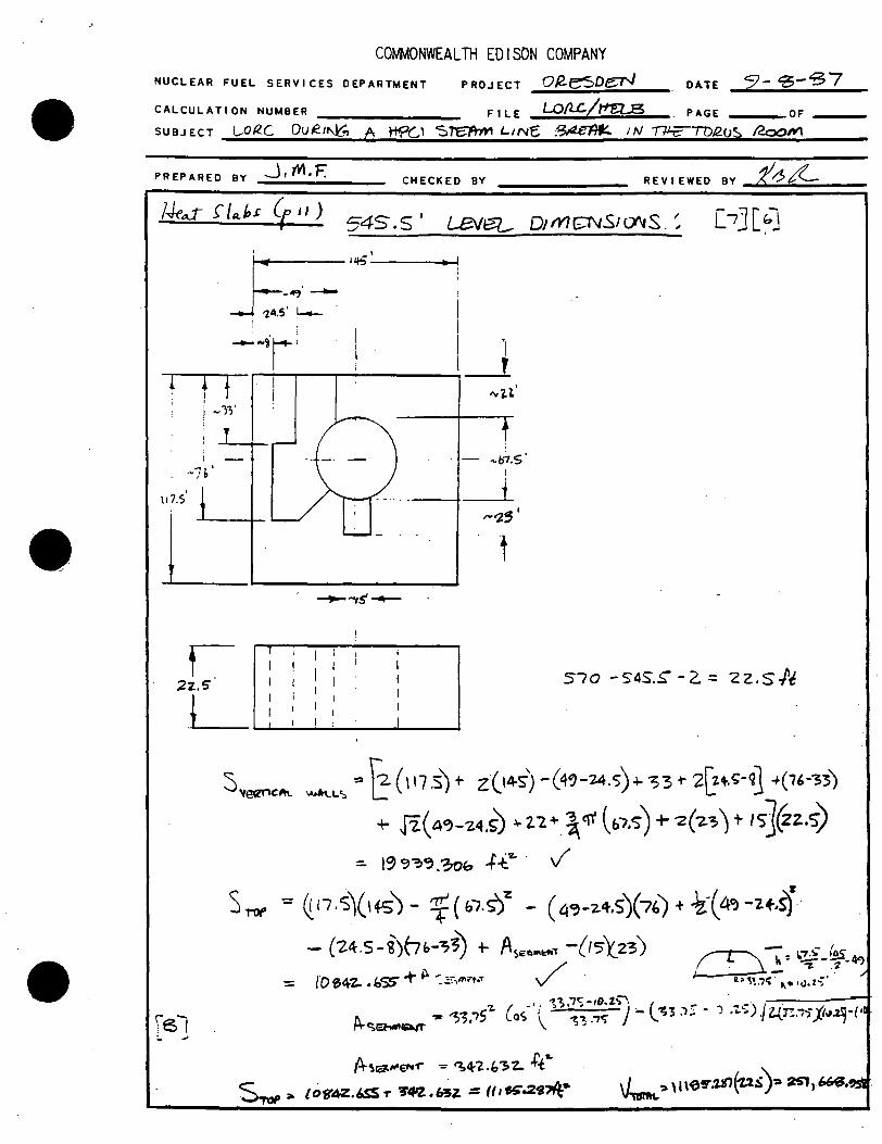
l.J,uJ .(I Abs Cr 10) s- I I. s leYFL D1Mc:N51DNS ~
r 13'
----J.-. T ~ • (f 7,S I
!~~--1 L\-:3 I t l ~ -tl.'-4- =J ' I
' 3-g~
I
i ~ I 4'S' 1
i
[[ ze,'
f
145 R. A<k:&~ [ 4] I Dt- rt IHSIO{? DIA [41
\ 17.S ft. vV1PE. [SJ '26.o+t.. T1tL.L r'-J 4. lt:>INAU.. ,·~ ... 73~ [$) D1~1"'ANle Ac~';) ... ,~[6"1 oePn+- oF- R..aoM. ... '22.ft[s]. /'r;Nf... v L-lrfl ~e.TloN ... , Z 'ft:f S]
54S. S - 5'17 .cs -z.:.. 241
s,_,.._ ~..._ = 2{, I"411.~ .... z c,,.~ - '75.o .... z [ 22-+ rz.(1ij1 +-J.j'.'11'04] = \7 bbl.5t-t--z /
S,,,p =- (l\7.s1(_14~- '1f(M)1• - 3'B ( -z..z) - V-z. oz.Y·
= I os-og, 7 41;-z.. /
\J-rmn.. =- I 0~.7 ft-'" (2-6 J -=- rz.73 ZU. ~ i1t--s J
~\... = 'ZS l 70, S .(l{Z·
•
COtJMONWEALTH EDISON COMPANY NUCLEAR FUEL SERVICES DEPARTMENT PROJECT oR-esoe:N DATE 5J- s-'3 7
CALCULATION NUMBER FILE LOflC/~ PAGE . OF ---
SUBJECT L.ORC Du~1~ A ti90 "$~ L1Ne ;~~ IN ~lD/2.CJ? /2ooN\
PREPARED BY _J' M. F.
~11+5'
r--~·-_.J -z~.s· i-- .
-- ... ~·r· ....,...I----.-f -f-
l -)';' i
I
-7~'
111.s'
I I I : I
I
CHECKED BY
i
;
,,.b7.s· I
t
t
REV I EWEO BY --~._-'?......,/C __ _
I ! I I I I I I I 570 - S4S.S"' - 2. = 2 2. S ./'t
r..:2-:~ I ;. ...
I i I I I
I I I I
I I I I : I
!+"lra.1"£N'r = ';~'2.h3"Z- +'-t~ ~ ::o. {Of(4Z.6SS1' ~'f'Z.~Z. = (11g.29'71t•

COtJMONWEALTH EDISON COMPANY NUCLEAR FUEL SERVICES DEPARTMENT PROJECT \)(<es£)eN DA.TE ":) -~ -~7
F I L E LP IU- I /+'f::L f!:, PAGE OF CALCULATION ~UMBER
SUBJECT Lot_e,_ Dv(lJNM A- !:f C l S I t::-l'tPI. LI N c 1$/2.t-""1H' I I"! '7'r1t" 'T!)AuS /)CJOM
PREPARED BY ._J,fV!.f:". CHECKED BY
lW S/ .. i, (p'!l..., 0 o' U::.'la lJ1MCNS10NS ~ r ~ I •
l
14-S I
-12.~~
·-- --4".>' ..,._ . --.1'i5' ~I I
1 I
'-lb
l I t.
..... 45~ ~~· ~ I J. c;'
'-- ·-(1 . ,_J '-----~ "''l'!J ..
i ~.
I Ii ,----t I I
I
~ 15'f--.,."'a.a I ! I I I I
REVIEWED BY z<1£-.- -
9!
I I I I I I ,
')'bc:J -'570-Z = I( .o .P~-\f.o
I -;-10 (:o\..1?'4 •
: I I I I I
I· I
I I I 1
. \'
slffl;°'l{lo\_ '-'•~L'> :::- (n .o)l -z.(111.5).,..2( \4$) - 55-+- z.(tZ.5) ... ~ 0-(53)
t- "2-( z-3) ~ I 5" J == '-i.~41. 24!1 ..f.e· /
S10p:. (111.s\145)-~)~(S~)~ -(~(7z..5)-(_z3')(1s) -~~)(1~)-6''/. 4~~16)
f 0"3~"· ~o~ ,{'t;" J
\}mff..- = 10'3~.c.>o~ ( 17.of.~:) ~ tf'7Si1.413b -t\? J

COtJMONWEALTH EDISON COMPANY NUCLEAR FUEL SERVICES DEPARTMENT PROJECT Dtz..e"';>De:N DA.TE ~ - 5 - ~ 7 -------------CALCULATION NUMBER FILE f.-0/lC. /l7e:t..Y5 PAGE ____ OF ---
SUBJECT 1_.onc CvQ1N~ A !+f.>l.I S7\...~r_1NP B~~ 1 N /'rh:;---rol2vS 890""
PREPARED BY --J. yV1. F CHECKED BY REVIEWED BY ~;gJ;;!__ -101
:..
____ 1<\S
I I
I I I I
I
_i_ ___ •
I i I I -:o_;o +------
117, .;T
I
'
~ I I
--zz.' I
i I
I 61~ -5~ -2- ~- '2Z.oft
t- I I I I i
s\l'~ICA\_ wPt~ ':;; [4(Ji\5) t- -z(117:5)- SS--301&..-Y ~ - 1(,060.0 -)t-Z v
S,.., : 6-~)(117.s)- f(so')-z -css"t - (30>( ~ -zs) - I o ~,.z +. 005 -f-t-z. J
,
l=l..£-1 -
CO~ONWEALTH EDISON COMPANY NUCLEAR FUEL SERVICES DEPARTMENT PROJECT ~J?;;...;..~..-..-P_et-J..__ ____ _
CALCULATION NUMBER FILE Lol(C/ltt:n,13> PAGE OF ---
SUBJECT l-OfC Que1NI., Tj'CJ ~~ L1NI- ~rZrllf- IN nfF -r->;JR.. u'S:, ea M .
PREPARED BY _ _).-.....,_m._,_i:-__ _ CHECKED BY REV I E WED BY ......,ti_/'5.._t2-____ _
t=:-=============:::::::::--- 65/1
-'J .. (~ Po11oT"o~~ooF)
5EZ7'0N 8-~ M-7 I
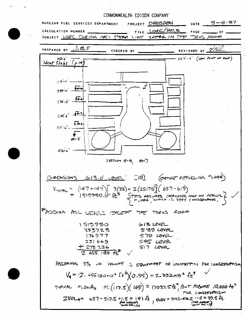
Q1M8-4SIOM'S b I~ .o' L~e:L '. :10} ~~ ~eT'JEl-•r&(.., ~t..aot9
"~-.fn_ ~ (147 +-t41)! 3(-2-z.)+ z(zsns'j( b57-b1:,) = / $°1'04'~0.o'- R;-:; t/TM'::. AS'SvMF.S C~'(()Vert. oNt..r oN 12ti=:vc:'l..5
?- o0/1. Wl"h<:ti Is Vr:fl."( (. c:>l\IS~v~ve. - I •
~f\°'::>i)1t-.tA Prt-L UZlt.:~ i=:;<(...£?1 ~ n2oS /looM
\SI°-> 9So '-~377-~ 176577 -Z.~t 6&9
+ 21'3 '2-"Z. b '2 45"5" I ~O Fe I
v'
f, ' ~ <...€'1eL 5 ~~ 1.-eie=L. 570 UNGL sq.s- k-VeL 517 ~ei_
v" = 17 . ..;.<;.;I 80 YIU" ff~( 0 ,~) = -z. .. '33::2..>tlo" -f t-3'
T'lfJt~'"- FLONA11r ~.'., (t 11.s\( 1~ :: \10'31.~~' f.;"r ~"'~ /O,ooo ~..,_ ) ') I Fu'2.. CGINS(?t?Clfl'\i5'""
zvo4"= 1os7- s-17.s +1,s = 1 'fl .ft a6'I = S•7.s-'1f,.s -1.5 ='3~.s-.tt-~ lfft&U) ) . ( F°;lll ~-)
\IUnl --~ .. t.~ \.lllr•TW '•'- 111f

COMMONWEALTH EDISON COMPANY NUCLEAR FUEL SERVICES DEPARTMENT PROJECT DR~Df-11'1 DATE 4'-"2 2-ir7
CALCULATION NUMBER FILE ~RC../ tfa§ PAGE . OF SUBJECT wRL DvR.INf..., A t+f'Cr · S77:ftM I.ANG° BAffl~ 1N J2"l:::' 7rlPus ~
PREPARED BY J,»1,f. CHECKED BY REVIEWED BY ~/'f;i
[1] P/2E5DEN FsA,e..voi...vwie 1, s~noc-J 5 I f. ~,z..-s-3
[z[
\_3]
f4]
[7~
[~]
[10]
' .Dft'soeN NUCJ..J;;-(K;l.. Po~ Sn9-=ilaN VNC r 2. f' iJP
I ' Vl1-'S'3
Dees~ NtJCl.EM fb wci{L 'S Ttt=n O/\I • UN 1r "Z., {'~ l'C> M-71 I
~ ,.., vc.(£(¥J. ,Ouw~ s-mn~ VN •1"2 I pi tO r ,.,_.os
Qe.¢sO€').J NII~ /0"4.leJl. Silt1'ioN V/v It L {J~ ID tA1-4 I (
\ I
()"'ITS z 'i -s I "z I D W\ - I \ I I
I.JN,.,.~ Z. ~ '5 ft rD M-3 I f
' ! .
D~Ot:.""N Nv,(..<;;l'\.e P-:Jw~ "=>T'J'l'fi""' v1111~ "Z. 't ~ I' f ._, M·'Z... . ( .
I Dl'!eS D €N ,.. IJ c..u=..1 ll. ,)""4J ~ s rtt'T') "N lJ AllT"1 2.. 't. ~
I

CO~ONWEAL TH ED I SON COMPANY .
NUCLEAR FUEL SERVICES DEPARTMENT PROJECT ----- DATE-----
CALCULATION NUMBER f?..$A-'/)-12-01 FILE----- PAGE --·OF --
SUBJECT-------------------------
n ,. "0!'\r! PREPARED BY r. - •" . .J .)[:CHECKED BY REV I EWED BY __...?( .... ~...,t<.._~--
Vo~ o{ MH..tL V~s (J
/. - LPCI
D1,..e.,,.s1trrt ~ a..rL : frt4ij~ s'pul f/H-r 37.5,. 3!.~
.J.ApLr ~ 39' rt. V = t ( 37. s- x 3 i. ~) x 3? = 2 Z 4 3 I ft
3
Ass~ ~10Jo ()C~·~ ·~ rrtM.J v ~ :: 0, 1 v. 24-, &89' f-t
3
Vr.i-r : 2f, 6fZ- f't 3 11,/a.J. u..W LS ,·,_,J'
z. V~ 2 - Rx. r;1tJ · (s.a fr'°- /4 oJ 11
7W Sit>-~ 7),·~s.~ ~ ,, )
El~v V~
517 1 b ,, 273 22,
5"f5 1 6 ,, 25"1 {,6?
;70' 17{:,~77
5"81' 233 72.8'
tira a I,{, 151
190
fo I ~ ~'11 Cl>-J< P-J-. t>..S S K.-.c.·~ I 5fi> oc.~~
~ /fi~ VJ.. 0. 'S" • 0,f'$ If I ~f; 110 = 7i.01 '1-5, ..
VJ: = bf", 000 ft l. ~ ~ "-S ,·1J.

CO~ONWEAL TH ED I SON COMPANY .
NUCLEAR FUEL SERVICES DEPARTMENT PROJECT DATE
CALCULATION NUMBER R~A-!>-12-07 FILE PAGE .OF ----
SUBJECT----------------..,;.------------------------------------------------------------
p L- KONG£~· PREPARED BY "· f' CHECKED BY REVIEWED BY ~4/(__
VD~ ~c M 1-kl vi)~~ (f. 2.)
3 Vo~ 3 · Tor.._s R.~
(Sa -f 9 e>J._ .. 7~-·s1,.,1o a.~s·"-J .. )
v ;: 24-~ 136 f-t3
f&-1 J:1..L. ~.· r,.0 ~s.e... .
v,...J ::: 0, 5 l/ = 12.1; o{,g ft 3 J
4. v~~ +. s~
U~L v =- 9J<t09 1'1;~
5. v~ 5: Torc.t. s
( s.u. f 1 if ''7.J-r s1 .. 1o D,.._r,.,...s ")
V• z,+2 "'Os
v~ 5" ,·$ TT>V~ V' ,·s ~ ~J..
G. v~ '; 0,Js. 'J.J.. · A-.-r
?ASL v~ r J{ 101 {t, 3 J'
7. v~ 1. s~·t
-Us:.t- . v.: '!-~ { 0 'I ptl ./
8. Va~ g~ Rx Bli .,- ~{ h. ·,..._ ~l'-d
/ w~ v = 7., 10" ft_' _ .... ----· ---·-- ....
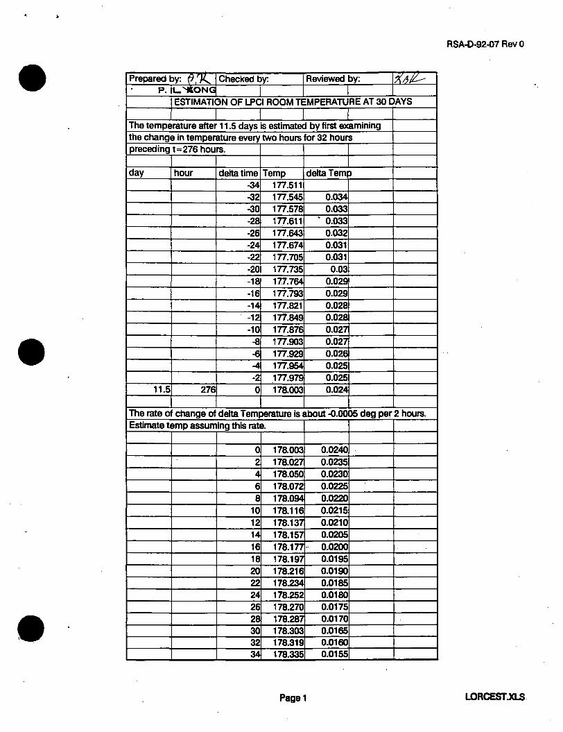
RSA-0-92-07 Rev 0
Prepared by: (J 'JI..... Checked by: Reviewed by: l.XAJi:--P. L. 'tlONGl
ESTIMATION OF LPCI ROOM TEMPERATURE AT 30 DAYS
The temperature after 11.5 days is estimated by first examining the change in temperature every two hours for 32 hours preceding t = 276 hours.
day hour delta time Temp delta Temp -34 177.511 -32 177.545 0.034 -30 177.578 0.033 -28 177.611 ' 0.033
-26 177.643 0.032 -24 177.674 0.031 -22 177.705 0.031 -20 177.735 0.03 -18 177.764 0.029
-16 177.793 0.029 -14 177.821 0.028 -12 177.849 0.028 -10 177.876 0.027
-8 177.903 0.027 -6 177.929 0.026 -4 177.954 0.025 -2 _177.979 0.025
11.5 276 0 178.003 0.024
The rate of change of delta Temperature is about -0.0005 deg pef 2 hours. Estimate temp assuming this rate.
0 178.003 0.0240
2 178.027 0.0235 4 178.050 0.0230
6 178.072 0.0225
8 178.094 0.0220 10 178.116 0.0215 12 178.137 0.0210 14 178.157 0.0205
16 110.1n -- 0.0200 18 178.197 0.0195 20 178.216 0.0190 22 178.234 0.0185 24 178.252 0.0180 26 178.270 0.0175 28 178.287 0.0170 30 178.303 0.0165 32 178.319 0.0160 34 178.335 0.0155
Page1 LORCEST .xLS.

RSA-0-92-07 Rev 0
I
Prepared by: . () .~ Checked by: Reviewed by: l~/IJ/c P. L i-~G 36 178.350 0.0150
38 178.364 0.0145 40 178.378 0.0140 42 178.392 0.0135 44 178.405 0.0130 46 178.417 0.0125 48 178.429 0.0120 50 178.441 0.0115 52 178.452 0.0110 54 178.462 0.0105 56. 178.472 0.0100 58 178.482 0.0095 60 178.491 0.0090 62 178.499 0.0085 64 178.507 0.0080 66 178.515 0.0075 68 178.522 0.0070 70 178.528 0.0065 ,
72 178.534 0.0060 74 178.540 0.0055 76 178.545 0.0050 78 178.549 0.0045 80 178.553 0.0040 82 178.557 0.0035 84 178.560 0.0030 86 178.562 0.0025 88 178.564 0.0020 90 178.566 0.0015 92 178.567 0.0010 94 178.56 0.0005
15.5 372 96 178.567 0.0000
Therefore; the maximum temperature is 178.6 deg F. The temperature at 30 days would be less than or equal to 178.6 deg F.
. Page2 LORCESTJCLS

-·
ENCLOSURE 3 CECo Calculation DSE-Q-004
Evaluation of the Impact of LOCA Combined with a Loss of Room Coolers on Performance of General Electric RHR Pump Motors,
Dresden 2&3/Quad Cities 1 &2
:,

. l ...._,,,,
,u
NUCLEAR ENGINEERING DEPARTMENT
CALCULATION TITLE PAGE
STATION/UNIT
'l>r~en J -2,/ 8 / ~eu;ul e;,L; d6 , ( f' z. CALCULATION TITLE:
Evlll lvdt·t?~ f.: -dZ- ::T 7't?e-f- I( U;e4-ComGf H~ wl:/-h a- L.41.g ~ ~,,,, aobs ~ ~~AV4U!U- " ~al G~1·e.
IZHR- ~""/ NO~. t
EQUIP NUMBER(S) GROUP 2/3-1Sog.A-Z>1 ~-/IJP~4-J
CALC NUMBER · SYSTEM
2/.J-/~O/ A-B rz -1'/()/lf-.8
Exhibit B ENC-QE-51.D Revision 2 Page 2 of 2
PAGE.: _L OF
1,ZI SAFETY RELATED
NON-SAFETY 1=1 RELATED
ENVIRONMENTAL . j5{_j QUALIFICATION
1=1 ASME ~ECTION III
REV • CHRON # PREPARER DATE REVIEWER DATE APPROVER DATE
QE-51.D (20)
l162g-20
. ..._,
NUCLEAR ENGINEERING DEPARTMENT TABLE OF CONTENTS
CALCULATION NO: ::D~G--t(-O{) '-/ REV.{)
' SECTIONS DESCRIPTION
1 CALCULATION TITLE PAGE
2 TABLE OF CONTENTS
3 HISTORICAL DATA (REQUIRED ONLY FOR REVISIONS)
4 CALCULATION SUMMARY SHEET
5 CALCULATION SHEET(S) ..
6 CALCULATION REVIEW CHECKLIST
7 COMPUTER APPLICATION REVIEW CHECKLIST
ATTACHMENTS )
...
QE- 51.D (22)
1162g-22
Exhibit c ENC-QE-51.D Revision 2 Page 2 of 2
PAGE Z OF
PAGES
I z
-~
4, i-
b
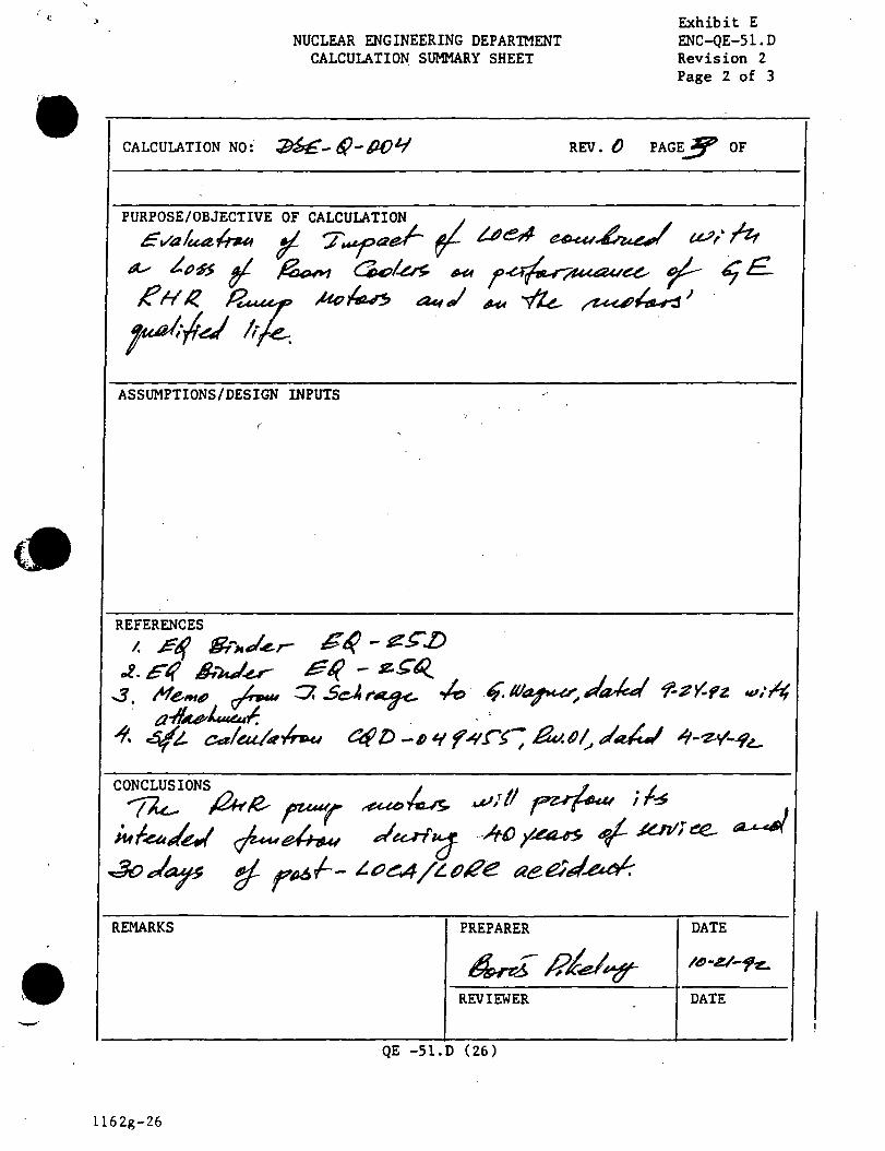
' c >
NUCLEAR ENGINEERING DEPAR1MENT CALCULATION SUMMARY SHEET
CALCULATION NO: U/;- 6;}-PI)'-/
ASSUMPTIONS/DESIGN INPUTS
(
·REMARKS PREPARER
REVIEWER
QE -51. D ( 26 )
ll62g-26
Exhibit E ENC-QE-51.D Revision 2 Page 2 of 3
REV. () PAGEff OF
DATE
DATE

,·I'. _.,,
NUCLEAR ENGINEERING DEPARlMENT CALCULATION SHEET
CALC. NO: 'J>.'!G..~~-l)t) t.f PAGE NO: 4 OF
Exhibit F ENC-QE-51.D Revision 2 Page 2 of 2
-rk. r~I~ ~ ~ ~ ~ ~t:d ~"! are- ~n a..f- Ft;t· d J ~a.& .tt{z._, f~ 3o. Tk ~t/.e. ~ ¥ ~~cf~~~. ~ ~ ./'k- ~~ ~.d ~~ tf Ir~ ,..~ ea.u ~~ 6f; u. ~ al- ~ di~~ . fl /4t!J•e_ .
'1k. 14tJ~ ll- -IU- ·., .. -1_~~ rl ~ /lu#4r wr ... dru-p ~ ~..i......4& cSIJ"e. ~ -r/1<-' . { J¥ -te{z:.,, /U F~ f'~ 17 j /~'e kl ~r. ..;~~ ~ a-~-erd-~~ f-- n •e. (!Lto•e. ""' 4~'c--+ S:tP'c :1tJ'e)
/h.e. IZ,he. ~ -l~r4.-4'-~ pn;f;ks w!uc4 ar~ ~II- f- L..()~ ~fiJ~ wrf-/,,4 ~ ~ ~ eo.o/~ tU'°G- ~ .. HA ~ C/:3 ~ e.tq ,,, ¥~~ ~ ~ . fl ~·,, ~H ~f- -fk_ · ~~~ d.aa &aJl r.eaeh 1fo•p: ( se.z•e.) .J ,,_,·<1 .8--o .I~ ti rlU> .f-_ a eel ,J .eu. f. f«. /4. t/£-~ 7d ,::0 ?~ 17 ~ ~I rl·~ -1~a1ar~ ~ c1u- ,~f.:LIW r""'f' _1...r::, ~
StJ 0e... ~.., ~an~ ~ p~f-aee;J~' ~ ""'!~,dur-e t/- c(1.e_ ,R/r/2 du-94,.s uA1u/,~ l.S: tz.z:."e + ~o"c -t- /tSJ'e .:::::.. /4'L'.'2'e._
REVISION • - I BY /DATE I I I I I CHECKED/DATE
QE- 51.D (29)
1162g-29
I

!
I I
' . I
~ I
l • 1
'•
. .. NUCLEAR ENGINEERING DEPAR'lMENT
CALCULATION SHEET
CALC. NO: :P.s£.-~ - M41-PAGE NO: 5 OF b
Exhibit F ENC-QE-51.D Revision 2 Page 2 of 2
F~ ,~v.L £ {J¥ 14e_//~.3-o) ~ ~/;d cUt,.u-,.,a/ li/e- f}-4k-~ i'*'kllIJ./- 14~.tZ~C :I: l#>''t. k ~I- ~~,o~o ~.
Pu 0fu-.eu~ ~I r~ C,Jt;:, ~ du<'~ ..,Lid. . re.y.'"~~ o.I( Of.~"/ 11µ.oJL-1> +. ~ ~¥ Vf'f~ lb ~,;A)~ -lo
,,) 260 ~ a*- t~"·0e. l~ 7H-~J.wJ ~ ~ 7, ~6 L»~ . aJ- ( 5tt; 0e. ~ c\)ua.J (2.1 ~~ (_ P..1-- 2/
r~ e-1i).
~~ aJ_~ ·~v~~ ·r~."°~ c~A,( 27,~b ~ ~~ t~6°C) Ct.v..~ 1utd;}id
l i -{-.e .Va,( u.e..- l ~ ~ o oo . ~ . " a-.f-- , l ·l{ ~'C) ~ ~ -t-lt- ~e:· .r .. \MUr ~ w:ll
paJtri« i l- r~r~ ~ ~u.u~~ du.r'1"'1f . ~ d~ oJ-- poJ,t-- L.oeA / t..o'2e. {LU(J.w.J- ~ cue- ~r~~ ~ JitO
7~ ~ ~a.t 4e.Met.. 1:fe.
REVISION
, BY/DATE
CHECKED/DATE
QE- 51.D (29)
ll62g-29
I
--
NUCLEAR ENGINEERING DEPARTMENT CALCULATION REVIEW CHECKLIST
CALCULATION NO: 1)fJ£ -. R - D /)lf REV () PAGE
REVIEWED BY: DATE:
YES NO 1. IS THE OBJECTIVE OF THE ANALYSIS
CLEARLY STATED?
2. ARE ASSUMPTIONS AND ENGINEERING ,
JUDGEMENTS VALID AND DOCUMENTED?
3. ARE ANY ASSUMPTIONS THAT NEED REVERIFICATION IDENTIFIED?
4. ARE THE REFERENCES (I.E. DRAWINGS, CODES, STANDARDS,) LISTED BY REVISION EDITION, DATE, ETC.?
5. IS THE DESIGN METHOD CORRECT AND APPROPRIATE FOR THIS ANALYSIS?
6. IS THE CALCULATION IN COMPLIANCE WITH ·DESIGN CRITERIA, CODES, STANDARDS, AND REG. GUIDES?
7. ARE THE UNITS CLEARLY IDENTIFIED, AND EQUATIONS PROPERLY DERIVED AND APPLIED?
8. ARE THE DESIGN INPUTS AND THEIR SOURCES IDENTIFIED AND IN COMPLIANCE WITH UFSAR, TECH SPECS?
.. ,_
9. ARE THE RESULTS COMPATIBLE WITH THE INPUTS AND RECOMMENDATIONS MADE?
10.WAS A DETAILED REVIEW PERFORMED? IF "NO" PROVIDE JUSTIFICATION FOR YOUR REVIEW METHOD.
. QE- 51.D (31)
L 16 Zg-31
6
~ ~
OF
Exhibit G ENC-QE-51.D Revision 2 Page 2 of 2
REMARKS