Residual stresses in Y-TZP crowns due to changes in the thermal contraction coefficient of veneers
8
d e n t a l m a t e r i a l s 2 9 ( 2 0 1 3 ) 594–601 Available online at www.sciencedirect.com jo ur n al homep age : w ww.intl.elsevierhealth.com/journals/dema Residual stresses in Y-TZP crowns due to changes in the thermal contraction coefficient of veneers Josete B.C. Meira a,∗ , Bruno R. Reis a , Carina B. Tanaka a , Rafael Y. Ballester a , Paulo F. Cesar a , Antheunis Versluis b , Michael V. Swain c a Biomaterials and Oral Biology Department, School of Dentistry, University of São Paulo, São Paulo, Brazil b Bioscience Research, College of Dentistry, University of Tennessee Health Science Center, Memphis, TN, USA c Biomaterials Unit, Sydney Dental Hospital, University of Sydney, Sydney, NSW, Australia a r t i c l e i n f o Article history: Received 21 May 2012 Received in revised form 10 December 2012 Accepted 1 March 2013 Keywords: Finite element analysis Veneered zirconia crowns Coefficient of thermal contraction Veneer chipping Glass transition temperature a b s t r a c t Objective. To test the hypothesis that the difference in the coefficient of thermal contraction of the veneering porcelain above (˛ liquid ) and below (˛ solid ) its T g plays an important role in stress development during a fast cooling protocol of Y-TZP crowns. Methods. Three-dimensional finite element models of veneered Y-TZP crowns were devel- oped. Heat transfer analyses were conducted with two cooling protocols: slow (group A) and fast (groups B–F). Calculated temperatures as a function of time were used to determine the thermal stresses. Porcelain ˛ solid was kept constant while its ˛ liquid was varied, creating different ˛/˛ solid conditions: 0, 1, 1.5, 2 and 3 (groups B–F, respectively). Maximum ( 1 ) and minimum ( 3 ) residual principal stress distributions in the porcelain layer were compared. Results. For the slowly cooled crown, positive 1 were observed in the porcelain, orientated perpendicular to the core–veneer interface (“radial” orientation). Simultaneously, negative 3 were observed within the porcelain, mostly in a hoop orientation (“hoop–arch”). For rapidly cooled crowns, stress patterns varied depending on ˛/˛ solid ratios. For groups B and C, the patterns were similar to those found in group A for 1 (“radial”) and 3 (“hoop–arch”). For groups D–F, stress distribution changed significantly, with 1 forming a “hoop-arch” pattern while 3 developed a “radial” pattern. Significance. Hoop tensile stresses generated in the veneering layer during fast cooling pro- tocols due to porcelain high ˛/˛ solid ratio will facilitate flaw propagation from the surface toward the core, which negatively affects the potential clinical longevity of a crown. © 2013 Academy of Dental Materials. Published by Elsevier Ltd. All rights reserved. 1. Introduction Clinical trials have shown that the long-term success of veneered Yttria Tetragonal Zirconia Polycrystal (Y-TZP) crowns or fixed partial dentures is often compromised by chipping of the porcelain [1–3]. The incidence of chipping failure is higher ∗ Corresponding author at: Av. Prof. Lineu Prestes, 2227, Zip Code: 05508-000, São Paulo, SP, Brazil. Tel.: +55 11 30917840x208; fax: +55 11 30917840x201. E-mail addresses: [email protected], [email protected] (J.B.C. Meira). in Y-TZP restorations, in which framework fractures are gen- erally uncommon [2,4]. Depending on the size of the porcelain fragment, the chipped crown often needs to be replaced. Even when a simple polishing or a minor restoration can solve the problem, this clinical incident is very frustrating. The strength of industrial glasses and ceramics can be increased by rapidly cooling the material from a temperature 0109-5641/$ – see front matter © 2013 Academy of Dental Materials. Published by Elsevier Ltd. All rights reserved. http://dx.doi.org/10.1016/j.dental.2013.03.012
Transcript of Residual stresses in Y-TZP crowns due to changes in the thermal contraction coefficient of veneers

d e n t a l m a t e r i a l s 2 9 ( 2 0 1 3 ) 594–601
Available online at www.sciencedirect.com
jo ur n al homep age : w ww.int l .e lsev ierhea l th .com/ journa ls /dema
Residual stresses in Y-TZP crowns due to changes in thethermal contraction coefficient of veneers
Josete B.C. Meiraa,∗, Bruno R. Reisa, Carina B. Tanakaa, Rafael Y. Ballestera,Paulo F. Cesara, Antheunis Versluisb, Michael V. Swainc
a Biomaterials and Oral Biology Department, School of Dentistry, University of São Paulo, São Paulo, Brazilb Bioscience Research, College of Dentistry, University of Tennessee Health Science Center, Memphis, TN, USAc Biomaterials Unit, Sydney Dental Hospital, University of Sydney, Sydney, NSW, Australia
a r t i c l e i n f o
Article history:
Received 21 May 2012
Received in revised form
10 December 2012
Accepted 1 March 2013
Keywords:
Finite element analysis
Veneered zirconia crowns
Coefficient of thermal contraction
Veneer chipping
Glass transition temperature
a b s t r a c t
Objective. To test the hypothesis that the difference in the coefficient of thermal contraction
of the veneering porcelain above (˛liquid) and below (˛solid) its Tg plays an important role in
stress development during a fast cooling protocol of Y-TZP crowns.
Methods. Three-dimensional finite element models of veneered Y-TZP crowns were devel-
oped. Heat transfer analyses were conducted with two cooling protocols: slow (group A) and
fast (groups B–F). Calculated temperatures as a function of time were used to determine
the thermal stresses. Porcelain ˛solid was kept constant while its ˛liquid was varied, creating
different �˛/˛solid conditions: 0, 1, 1.5, 2 and 3 (groups B–F, respectively). Maximum (�1) and
minimum (�3) residual principal stress distributions in the porcelain layer were compared.
Results. For the slowly cooled crown, positive �1 were observed in the porcelain, orientated
perpendicular to the core–veneer interface (“radial” orientation). Simultaneously, negative
�3 were observed within the porcelain, mostly in a hoop orientation (“hoop–arch”). For
rapidly cooled crowns, stress patterns varied depending on �˛/˛solid ratios. For groups B and
C, the patterns were similar to those found in group A for �1 (“radial”) and �3 (“hoop–arch”).
For groups D–F, stress distribution changed significantly, with �1 forming a “hoop-arch”
pattern while �3 developed a “radial” pattern.
Significance. Hoop tensile stresses generated in the veneering layer during fast cooling pro-
tocols due to porcelain high �˛/˛solid ratio will facilitate flaw propagation from the surface
toward the core, which negatively affects the potential clinical longevity of a crown.
emy
when a simple polishing or a minor restoration can solve the
© 2013 Acad
1. Introduction
Clinical trials have shown that the long-term success of
veneered Yttria Tetragonal Zirconia Polycrystal (Y-TZP) crownsor fixed partial dentures is often compromised by chipping ofthe porcelain [1–3]. The incidence of chipping failure is higher∗ Corresponding author at: Av. Prof. Lineu Prestes, 2227, Zip Code: 05508fax: +55 11 30917840x201.
E-mail addresses: [email protected], [email protected] (J.B.C. Meira).0109-5641/$ – see front matter © 2013 Academy of Dental Materials. Puhttp://dx.doi.org/10.1016/j.dental.2013.03.012
of Dental Materials. Published by Elsevier Ltd. All rights reserved.
in Y-TZP restorations, in which framework fractures are gen-erally uncommon [2,4]. Depending on the size of the porcelainfragment, the chipped crown often needs to be replaced. Even
-000, São Paulo, SP, Brazil. Tel.: +55 11 30917840x208;
problem, this clinical incident is very frustrating.The strength of industrial glasses and ceramics can be
increased by rapidly cooling the material from a temperature
blished by Elsevier Ltd. All rights reserved.
2 9
atsiptmttttmT
bfttabticsipikiaodflr
irmpAav
aorccravcTftandca
cooling, it was assumed that all stresses generated above Tg
d e n t a l m a t e r i a l s
bove the glass transition temperature (Tg), the so-calledhermal tempering [5,6]. Between softening (Ts) and glass tran-ition temperatures, atomic rearrangements occur, resultingn significant changes in the material properties. At tem-eratures above Ts, a material is in a liquid state. As theemperature drops below Ts, the liquid densifies and atomic
obility becomes restricted. Below the glass transition region,hese motions are even more difficult [7]. As a consequence ofhese changes during cooling, the coefficient of thermal con-raction of porcelains above their Ts (˛liquid) is much higherhan the coefficient below Tg (˛solid). Meanwhile, the elastic
odulus of a material above its Ts is much lower than below
g.During a well-known glass tempering procedure, achieved
y rapidly cooling glass objects, the temperature decreasesaster at the surface than in the interior [5]. As a consequence,he outer surface solidifies (T < Tg) and contracts first, whilehe interior remains in a liquid-like state, because it is stillbove Tg. Therefore, thermal gradient induced stresses cane initially relaxed because of the viscoelastic behavior ofhe glass and no notable stresses are generated. When thenner part solidifies and tries to contract, the solid, elastic andolder outer surface, with a lower ˛, will not contract at theame rate, nor to the same extent [5]. The contraction of thenner part creates a favorable residual stress field, with com-ressive stresses in the external region and tensile stresses
n the interior. These superficial compressive stresses arenown to strengthen the material, as any applied stress must
nitially overcome these compressive stresses before gener-ting tensile stresses at the surface [8]. Since the inner partf the glass generally does not contain flaws and generallyoes not contribute significantly to internal stresses duringexure, the resultant tempered body offers better fractureesistance [5].
Glass tempering principles have been adopted in Dentistryn order to strengthen veneering porcelain [9–12]. Althoughapid cooling protocols have been successfully used with
etaloceramic systems, they have been associated with chip-ing failures in veneered zirconia-based systems [13,14].s a consequence, some researchers and manufacturersre recommending slow cooling for Y-TZP-core porcelain-eneered restorations [15].
In bilayered crowns, which behave differently from thebove described tempering process in monolithic glassbjects, the porcelain is supported by a stiff framework mate-ial, that will oppose the contraction of the porcelain. In suchases, the mismatch between the core and porcelain coeffi-ient of thermal contraction (˛core − ˛veneer) plays an importantole in the residual stress distributions [9]. It is well known that
small positive mismatch (˛core > ˛veneer) is recommended foreneered dental crowns [16]. However, during the cooling pro-ess the porcelain changes abruptly as it passes through its
g. The ˛liquid (T > Tg) of commercial porcelains recommendedor Y-TZP frameworks can vary between 196% and 420% ofhe ˛solid value [17], depending on the material compositionnd microstructure. Meanwhile, the framework material isot expected to change significantly, as its Tg is not reached
uring porcelain firing. Therefore, the mismatch betweenore and veneer can be highly negative (˛core � ˛veneer)bove Tg.( 2 0 1 3 ) 594–601 595
Hence, the hypothesis of this study is that, dependingon the porcelain � value (˛liquid � ˛solid), fast cooling thecrown from temperatures above porcelain Tg could generatehigh residual tensile stresses at the surface of the veneeringceramic instead of the compressive stresses that would beexpected by the analogy with the tempering process of glass.
The objective of this work was to determine the influenceof porcelain � on the residual stress in Y-TZP crowns. Finiteelement analysis (FEA) was used to study the residual stresseswithin the complex geometries and temperature dependentmaterial properties. Although experimental methodologiescan be used to study residual stress profiles of veneeredcrowns, FEA offers the advantage of considering the complexnature of stress [18], which can be represented by a scalarvalue (when an equivalent stress is adopted) or by a secondrank tensor (where the normal and shear stresses are individ-ualized). Observing the local stress components is very usefulto understand the effects of the cooling protocol and mate-rial properties on residual thermal stresses in veneered Y-TZPcrowns [19], and, consequently, is crucial for designing strate-gies to minimize chipping failures.
2. Materials and methods
The three-dimensional (3D) FEA model was based on an exper-imental study in which the thermal gradient of symmetricveneered zirconia crowns, corresponding with the geometryof a premolar tooth, was measured [24]. The use of rotationallysymmetric crowns instead of anatomically precise ones wasselected by Tholey et al. [24] in order to ensure the productionof identical samples and to simplify the thermocouple place-ment and cross-sectioning. Due to the geometric symmetryand boundary conditions, just 1/4 of the model needed to bemodeled (Fig. 1). The mesh consisted of 9851 four-node tetra-hedral elements. A convergence test showed that no furtherrefinement was necessary. The Y-TZP framework was con-sidered homogeneous, isotropic and linear-elastic (Table 1),while the porcelain thermoelastic properties were considerednon-linear (Figs. 2 and 3). The numerical analyses were per-formed with MSC.Marc (MSC Software, Santa Ana, CA, USA)and consisted of two steps: heat transfer analysis to establishtemperature profiles and then thermal stress analysis.
2.1. Heat transfer analysis
Heat transfer analyses were conducted in accordance with aprevious experimental study [24] in which two cooling proto-cols were compared. In the first protocol a crown was slowlycooled in the furnace until the glass transition temperature(600 ◦C), after which it was removed from the furnace. In thesecond protocol the crown was removed from the furnacebefore reaching the glass transition temperature.
These two different cooling protocols were simulated byFEA. Due to their difference in cooling rates above Tg, the twoprotocols were labeled as slow and fast, respectively. For slow
were relieved due to the viscoelastic behavior of the porce-lain. Therefore, an initial temperature of 600 ◦C (porcelain Tg)was applied. For fast cooling, it was assumed that there was

596 d e n t a l m a t e r i a l s 2 9 ( 2 0 1 3 ) 594–601
Fig. 1 – FEA model. (A) Geometry and mesh of the quarter model. The nodes at the cervical region of the crown were fixed inx-direction. (B and C) Perspective and occlusal view of the model, showing the boundary conditions of fixed displacementsin y- and z-directions, due to geometrical and loading symmetry.
Table 1 – Thermal and mechanical properties of the materials.
Conductivity(W/mm ◦C)
Specificheat(J/kg ◦C)
Density(kg/mm3)
Elasticmodulus
(GPa)
Poisson’sratio
solid(ppm ◦C−1)
References
Y-TZP 2.0 × 10⁻³ 450 6.0 × 10⁻⁶ 205 0.30 10.2 [20–22]Veneering porcelain 1.5 × 10⁻³ 840 2.4 × 10⁻⁶ Fig. 2 0.21 9.2 [22,23]
Fig. 2 – Porcelain elastic modulus (E) change at the glasstransition zone. Tg: glass transition temperature. Ts:
Fig. 3 – Porcelain coefficient of thermal contraction (˛)changes at the glass transition zone. Tg: glass transitiontemperature. Ts: softening temperature. B: �˛/˛solid = 0, C:�˛/˛ = 1, D: �˛/˛ = 1.5, E: �˛/˛ = 2, F: �˛/˛ = 3.
softening temperature.
no time for stress relaxation below porcelain Ts. Therefore,an initial temperature of 700 ◦C (porcelain Ts) was appliedthroughout the FEA model. For both models, the final equi-librium temperature was set at 25 ◦C.
The thermal properties of both materials are presentedin Table 1. Convective cooling was simulated using constant
heat transfer coefficients (42 W/m2 ◦C for the slow model and250 W/m2 ◦C for fast models) at the surface of veneering porce-lain. The interior of the crown was assumed to be insulated.solid solid solid solid
Although the cooling rate below Tg does not influence theresidual stress (it influences only transient stresses), differentheat transfer coefficients were used in order to be consistent.The resultant cooling rates were 10 ◦C s−1 and 100 ◦C s−1 forslow and fast simulations, respectively.
The temperature distributions calculated in this thermalanalysis are not presented in the results section, as they arenot the primary scope of this study. Typically the maximum

2 9
tffbtp(
2
I(m(e
mafittaabcts
swtr�
t
3
FmoTt
wwf�
tovi
twtccth
d e n t a l m a t e r i a l s
emperature difference between the external and internal sur-aces of the crowns were 21 ◦C and 113 ◦C for the slow andast cooling conditions, respectively. The temperature distri-ution as a function of time was used as the input data for thehermal stress analysis, allowing the simulation of changes inorcelain elastic modulus and as a function of temperature
Figs. 2 and 3).
.2. Thermal stress analysis
n order to avoid rigid body motions, the axial displacementx-direction) of the cervical nodes was restricted (Fig. 1A). Sym-
etry ensured the boundary conditions in y- and z-directionsFig. 1B and C). For slow cooling (group A), constant values oflastic modulus, Poisson’s ratio and were applied (Table 1).
For fast cooling models, the large increase in porcelainodulus close to the Tg was taken into account (Fig. 2). In
ddition, the porcelain ˛liquid was varied in order to createve �˛/˛solid conditions: 0, 1, 1.5, 2 and 3 (groups B–F, respec-ively. See Fig. 3). The first condition, �˛/˛solid = 0 was choseno isolate the effects of elastic modulus variation between Ts
nd Tg and the difference in delta temperature between slownd fast protocols. The other four conditions were selectedased on experimental �˛/˛solid measurements of commer-ial veneering porcelain, where values were varied from 0.95o 3.20 [17]. Therefore, the �˛/˛solid conditions tested in thistudy are comparable with the real scenario.
The residual maximum (�1) and minimum (�3) principaltress distributions and their orientation in the porcelain layerere compared. Positive values of �1 correspond to the highest
ensile stress at each region, while negative values of �3 cor-espond to the highest compressive stress [25]. High positive
1 tends to facilitate crack propagation, while high negative �3
ends to close critical flaws, protecting the veneer [26].
. Results
or a better visualization of the results and permitted by sym-etry, the stress distribution and orientation can be shown in
ne half of the crown cross-section parallel to the XY-plane.he �1 and �3 magnitudes are shown in Fig. 4 and their orien-
ations are presented in Fig. 5.For the slowly cooled crown (group A), positive �1 values
ere observed throughout most of the porcelain layer (Fig. 4),ith an orientation perpendicular to the core–veneer inter-
ace (Fig. 5), namely “radial” orientation. The highest values of
1 were at the core/veneer interface and gradually decreasedo zero at the external surface of the porcelain (Fig. 4). Thecclusal surface along with two small regions near the cer-ical area showed negative �1 values (compressive stresses),ndicating absence of tensile stresses at those zones.
Simultaneously, negative �3 values were observed withinhe porcelain layer (Fig. 4), mostly in a hoop orientation (Fig. 5),ith the highest values at the occlusal surface. This �3 dis-
ribution can be visualized three-dimensionally, showing the
rown subdivided into two hollow cylinders at the cuspal andervical areas, and one hollow hemi-sphere located betweenhe cylinders (Fig. 5). For the cervical and cuspal cylinders, theoop component of the stress emerges perpendicular to the( 2 0 1 3 ) 594–601 597
viewing plane, therefore compressive hoop stresses are rep-resented as dots. For the hemi-spherical part of the crown,the compressive stress vectors were oriented parallel to thecore/veneer interface as a semi-arch in the viewing plane. Thisorientation pattern will be called “hoop–arch” from now on.
For rapidly cooled crowns, the stress distribution and ori-entation patterns varied depending on the �˛/˛solid data(Figs. 4 and 5). For groups B and C (�˛/˛solid = 0 and 1,respectively) the patterns were similar to those found ingroup A for �1 (“radial”) and �3 (“hoop-arch”). For groups D–F(�˛/˛solid = 1.5, 2 and 3, respectively), there was a significantchange in the stress pattern in relation to group A, with �1
forming a “hoop–arch” pattern while �3 developed a “radial”pattern.
4. Discussion
The hypothesis was confirmed, as the results showed thatthe change in the coefficient of thermal contraction of theporcelain as it cools from the liquid to solid state signifi-cantly affected the residual thermal stresses developed in theveneering layer of Y-TZP crowns after rapid cooling from atemperature above Tg. This change in porcelain contractioncoefficient has rarely been considered significant for the com-patibility between framework and porcelain veneer [12,27].
When developing new products, manufacturers adjust the of core and veneer in the solid state (T < Tg) in order to gener-
ate a slightly positive mismatch (˛core > ˛veneer). Such positivemismatch generates compressive hoop stresses within theporcelain outer surface, strengthening the porcelain by clos-ing flaws that are oriented perpendicular to these compressivestress vectors [28,29]. However, this adjustment is based oncomparisons of average contraction coefficients measured attemperatures below porcelain Tg [27].
For a slowly cooled crown, it can be assumed that above theporcelain Tg, all stresses can be relieved due to either the vis-coelastic behavior of the porcelain above its Tg or the viscousbehavior above its Ts. Therefore, the porcelain � will havelittle influence on residual stresses, which are solely gener-ated due to the mismatch between core and veneer belowporcelain Tg.
The results confirmed that the positive mismatch betweencore and veneer coefficients below Tg governed the residualstress patterns for slow cooling (Fig. 4A). Compressive hoopstresses were observed at the two extremities of the porcelainlayer, while compressive arch stresses were observed for thehemi-spherical part of the crown (Fig. 5A, �3 orientation). Bothcompressive stress orientations (hoop and arch) will limit flawpropagation from the surface toward the core [19].
One aspect that is not usually emphasized in such cases isthat, simultaneously, the positive mismatch generates radialtensile stresses within the porcelain increasing toward theporcelain–zirconia interface (Fig. 4A), with an orientation per-pendicular to the compressive hoop–arch stresses and to thecore–veneer interface (Fig. 5A, �1 orientation). These tensile
stresses are not so important in terms of external initiation ofporcelain fracture, since they tend to be zero at the porcelainouter surface. However, they could facilitate crack propaga-tion parallel to the core/porcelain interface [19]. Additionally,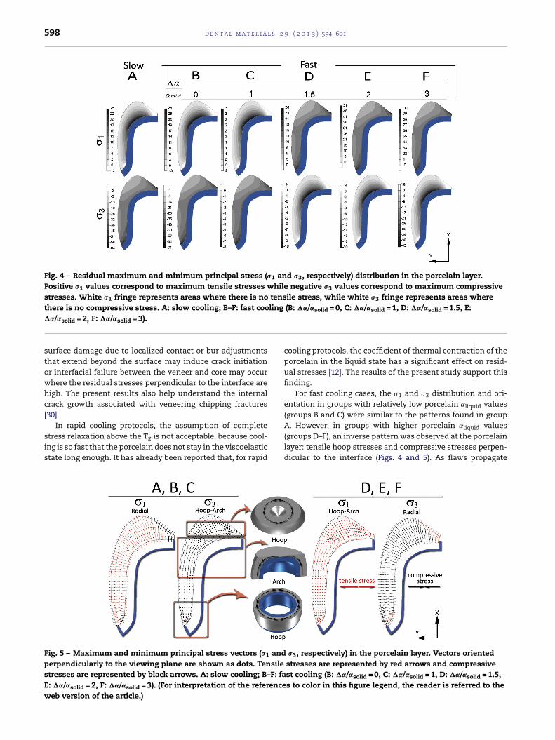
598 d e n t a l m a t e r i a l s 2 9 ( 2 0 1 3 ) 594–601
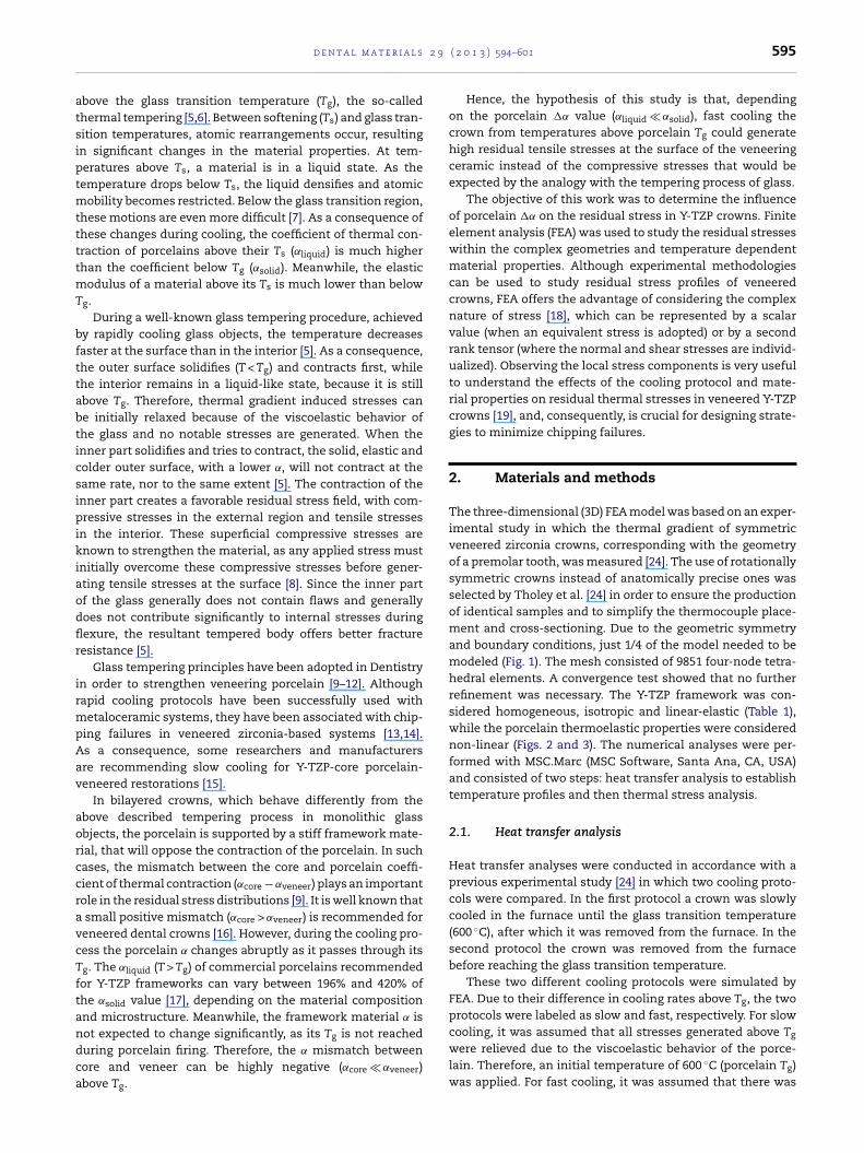
Fig. 4 – Residual maximum and minimum principal stress (�1 and �3, respectively) distribution in the porcelain layer.Positive �1 values correspond to maximum tensile stresses while negative �3 values correspond to maximum compressivestresses. White �1 fringe represents areas where there is no tensile stress, while white �3 fringe represents areas wherethere is no compressive stress. A: slow cooling; B–F: fast cooling (B: �˛/˛solid = 0, C: �˛/˛solid = 1, D: �˛/˛solid = 1.5, E:
�˛/˛solid = 2, F: �˛/˛solid = 3).surface damage due to localized contact or bur adjustmentsthat extend beyond the surface may induce crack initiationor interfacial failure between the veneer and core may occurwhere the residual stresses perpendicular to the interface arehigh. The present results also help understand the internalcrack growth associated with veneering chipping fractures[30].
In rapid cooling protocols, the assumption of complete
stress relaxation above the Tg is not acceptable, because cool-ing is so fast that the porcelain does not stay in the viscoelasticstate long enough. It has already been reported that, for rapidFig. 5 – Maximum and minimum principal stress vectors (�1 andperpendicularly to the viewing plane are shown as dots. Tensilestresses are represented by black arrows. A: slow cooling; B–F: faE: �˛/˛solid = 2, F: �˛/˛solid = 3). (For interpretation of the referenceweb version of the article.)
cooling protocols, the coefficient of thermal contraction of theporcelain in the liquid state has a significant effect on resid-ual stresses [12]. The results of the present study support thisfinding.
For fast cooling cases, the �1 and �3 distribution and ori-entation in groups with relatively low porcelain ˛liquid values(groups B and C) were similar to the patterns found in groupA. However, in groups with higher porcelain ˛liquid values
(groups D–F), an inverse pattern was observed at the porcelainlayer: tensile hoop stresses and compressive stresses perpen-dicular to the interface (Figs. 4 and 5). As flaws propagate�3, respectively) in the porcelain layer. Vectors oriented stresses are represented by red arrows and compressivest cooling (B: �˛/˛solid = 0, C: �˛/˛solid = 1, D: �˛/˛solid = 1.5,s to color in this figure legend, the reader is referred to the

2 9
pscc
ofsatfvr�
ca6wcr
Aotstsftsgflatawtwa
ntsTfacttciripaWss
r
d e n t a l m a t e r i a l s
erpendicularly to the tensile vector, these tensile hooptresses facilitate flaw propagation from surface toward theore, which negatively affects the potential longevity of therown [31].
By analogy with the tempering process of monolithic glassbjects, compressive stresses at the porcelain external sur-ace are expected for rapid cooling protocols instead of tensiletresses. However, there is an important aspect that differenti-tes dental crowns from tempered industrial glasses: the facthat the veneering porcelain solidifies while bonded to a stifframework material. In such cases, the mismatch betweeneneer and framework above porcelain Tg plays an importantole in the residual stress distribution. In fact, the changes in
1 and �3 stress distributions and orientations for groups D–Fan be explained by the high negative mismatch between corend veneer (˛core � ˛veneer) observed at temperatures above00 ◦C (Fig. 3). Although this negative mismatch is observedhen the porcelain still has a low elastic modulus (Fig. 2), it
ould dramatically change the residual stress distribution inapidly cooled porcelains with high ˛liquid values.
The three white regions in the �1 distributions for groups–C are noteworthy because they indicate that there werenly compressive residual stresses present in the porcelains ofhese crowns (Fig. 4). For a crack to propagate in this region, thetresses generated by the applied load will have to overcomehese compressive residual stresses. Therefore, the compres-ive state in these regions will protect the porcelain fromracture. The occlusal area is particularly critical because ofhe presence of masticatory loads. In addition, this area isubjected to physiologic wear as well as occlusal adjustment,enerating facets and damaged zones that may act as initialaws, as reported in fractographic studies [32,33]. The cervicalrea of the crown is also very critical since it has been reportedo contain the origin of clinical fractures [34]. For groups D–F,t the same regions, there were only tensile stresses, whichould assist the propagation of flaws oriented perpendicular
o them, accelerating chipping failure. The risk of chippingould increase for cases with a higher negative mismatch
bove Tg.The residual stress in veneering porcelain bonded to zirco-
ia has been investigated experimentally, using, for example,he hole-drilling method [30,35–37], stress birefringence mea-urements [24,38] and indentation crack measurement [15,19].he hole drilling method was shown to be a useful tool
or studying the influence of cooling rate, and of veneernd framework thicknesses on residual stresses in veneeringeramics [30,36,37]. These studies have confirmed the expec-ation in the literature of compressive residual stresses onhe external surface of veneered zirconia samples using a fastooling protocol. Considering that the veneering material usedn those studies had a �˛/˛solid ratio equal to 1.44 [17], theesults were different from those obtained in our correspond-ng group (group D), in which the tensile hoop stresses wereredominant at the veneer surface. An explanation for thispparent contradiction is the difference in specimen shape.hile the hole-drilling method applied in the experimental
tudy used a bilayered disc, in the present study the FEA modelimulated an axisymmetric crown.
Stress birefringence measurement allows the study ofesidual stress of a crown shaped specimen. Recent studies
( 2 0 1 3 ) 594–601 599
using this method [24,38] found higher residual stresses forfast cooling models. Unfortunately, birefringence measure-ments do not allow distinction between compressive andtensile stresses, but it is possible to observe that the patternof the stress distribution is similar to the �1 radial patternfor groups A–C and to the �3 radial pattern for groups D–Fobserved in the current study. Such agreement between thestress observed by birefringence and the FEA radial stressescan be explained by the fact that hoop stresses are relieved ina birefringence specimen when it is sectioned.
Regarding the indentation crack measurements, they areusually used with flat specimens such as discs or bars[15,39,40]. The method has also been performed on irregularshaped specimens such as dental crowns, which requires cre-ation of flat sections for the indentation without altering theresidual stress conditions [19]. In a recent study Vickers inden-tation method was used to determine the residual stress ofa slowly cooled porcelain-veneered zirconia prosthesis [19].The experimental results were in accordance with the presentFEA outcomes: high compressive hoop stresses and moderateradial tensile stresses in the bulk of the porcelain layer.
The advantage of finite element analysis is that it allowscalculation of the entire stress field caused by dimensionalchanges in structures with complex geometry, such as adental crown [41]. In this method, it is also possible to con-sider the non-linear behavior of porcelain during the coolingprocess. In the present FEA model, the viscoelasticity of porce-lain above Tg was taken into account in the simulation oftwo stress relief extremes: total relief (slow model) or norelief (fast model). Although more comprehensive thermo-rheologically viscoelastic models are available in commercialFEA software, the required input data for modeling stressrelaxation are neither readily found in the literature, noreasily obtained experimentally. Previous studies using vis-coelastic models found compressive residual stresses in theporcelain layer of metal-ceramic discs with cooling rates upto 250 ◦C s−1 [12,42]. However, the �˛/˛solid values used werearound 0.1, which did not reflect the data for veneering porce-lains used with Y-TZP frameworks, and were conducted onbilayer discs. The elastic model used in this study highlightsthe importance of the porcelain ˛liquid value and its relationwith the core for residual stress development in dentalcrowns.
One factor affecting residual stress development in Y-TZPrestorations veneered with dental porcelains that was not rep-resented in this finite element simulation is the possibility ofchanges in the microstructure of the porcelain or of tetrago-nal to monoclinic phase transformation in zirconia during thecooling process [43,44]. In addition, it is important to empha-size that residual thermal stress development is a complexissue that cannot be predicted by a single parameter suchas solid thermal contraction mismatch [12], which is inade-quate in cases of geometrically complex structures. The crowngeometry, core–veneer thickness ratio and the temperaturedependence of material properties must also be considered[13,45–49]. The association of residual thermal stresses withstresses generated by occlusal function is also importantin designing strategies to prevent chipping failures in Y-TZP crowns [50,51]. These factors will be explored in futurestudies.

l s 2
r
600 d e n t a l m a t e r i a
5. Conclusion
Rapidly cooling a bilayered ceramic crown from temperaturesabove porcelain Tg can generate high residual tensile stressesat the veneer surface if a significant change in porcelain�˛/˛solid occurs. When testing thermal compatibility betweencore and veneer materials, it is important to consider thechange in porcelain properties above Tg, especially when rapidcooling protocols are adopted.
The new finding in this study was that it showed theimportance of the porcelain ˛liquid value on the develop-ment of residual stresses in rapidly cooled crowns, which areassociated with clinical chipping of veneered zirconia. Under-standing all the effects of the cooling protocol and materialproperties on residual thermal stresses in veneered Y-TZPcrowns is crucial for designing strategies to minimize the gen-eration of residual stresses and prevent chipping failures.
Acknowledgements
This study was supported by FAPESP (2009/06266-7). Theauthors gratefully acknowledge Michael J. Tholey for his con-tribution to the study design.
e f e r e n c e s
[1] Al-Amleh B, Lyons K, Swain M. Clinical trials in zirconia: asystematic review. Journal of Oral Rehabilitation2010;37:641–52.
[2] Rekow ED, Silva N, Coelho PG, Zhang Y, Guess P, ThompsonVP. Performance of dental ceramics: challenges forimprovements. Journal of Dental Research 2011;90:937–52.
[3] Della Bona A, Kelly JR. The clinical success of all-ceramicrestorations. Journal of the American Dental Association2008;139:8S–13S.
[4] Guess PC, Schultheis S, Bonfante EA, Coelho PG, Ferencz JL,Silva NR. All-ceramic systems: laboratory and clinicalperformance. Dental Clinics of North America 2011;55,333–52, ix.
[5] Haldimann M, Luible A, Overend M. Structural use of glass.Zurich: International Association for Bridge and StructuralEngineering; 2008.
[6] Nielsen JH, Olesen JF, Poulsen PN, Stang H. Simulation ofresidual stresses at holes in tempered glass: a parametricstudy. Materials and Structures 2010;43:947–61.
[7] Scherer G. Relaxation in glass and composites. Illustrated.New York: Wiley; 1986.
[8] Anderson TL. Fracture mechanics: fundamentals andapplications. Boca Raton, FL: Taylor & Francis Books LTD;2005621.
[9] Anusavice KJ, DeHoff PH, Hojjatie B, Gray A. Influence oftempering and contraction mismatch on crack developmentin ceramic surfaces. Journal of Dental Research1989;68:1182–7.
[10] Anusavice KJ, Gray A, Shen C. Influence of initial flaw size oncrack growth in air-tempered porcelain. Journal of Dental
Research 1991;70:131–6.[11] Asaoka K, Tesk JA. Transient and residual-stress in aporcelain-metal strip. Journal of Dental Research1990;69:463–9.
9 ( 2 0 1 3 ) 594–601
[12] DeHoff PH, Anusavice KJ, Vontivillu SB. Analysis oftempering stresses in metal-ceramic disks. Journal of DentalResearch 1996;75:743–51.
[13] Swain MV. Unstable cracking (chipping) of veneeringporcelain on all-ceramic dental crowns and fixed partialdentures. Acta Biomater 2009;5:1668–77.
[14] Taskonak B, Borges GA, Mecholsky Jr JJ, Anusavice KJ, MooreBK, Yan J. The effects of viscoelastic parameters on residualstress development in a zirconia/glass bilayer dentalceramic. Dental Materials 2008;4:1149–55.
[15] Choi JE, Waddell JN, Swain MV. Pressed ceramics ontozirconia. Part 2: Indentation fracture and influence of coolingrate on residual stresses. Dental Materials 2011;27:1111–8.
[16] Coffey JP, Anusavice KJ, DeHoff PH, Lee RB, Hojjatie B.Influence of contraction mismatch and cooling rate onflexural failure of PFM systems. Journal of Dental Research1988;67:61–5.
[17] Gostemeyer G, Jendras M, Dittmer MP, Bach FW, Stiesch M,Kohorst P. Influence of cooling rate on zirconia/veneerinterfacial adhesion. Acta Biomater 2010;6:4532–8.
[18] Boresi AP, Chong KP. Elasticity in engineering mechanics.2nd ed. Hoboken, NJ: John Wiley & Sons Inc.; 1999.
[19] Baldassarri M, Stappert CF, Wolff MS, Thompson VP, ZhangY. Residual stresses in porcelain-veneered zirconiaprostheses. Dental Materials 2012;28:873–9.
[20] Guazzato M, Albakry M, Ringer SP, Swain MV. Strength,fracture toughness and microstructure of a selection ofall-ceramic materials. Part I. Pressable and aluminaglass-infiltrated ceramics. Dental Materials 2004;20:441–8.
[21] Guazzato M, Albakry M, Ringer SP, Swain MV. Strength,fracture toughness and microstructure of a selection ofall-ceramic materials. Part II. Zirconia-based dentalceramics. Dental Materials 2004;20:449–56.
[22] O’Brien WJ. Dental materials and their selection. 3rd ed.Hanover Park, IL: Quintessence Publishing Co., Inc.; 2002.
[23] Suansuwan N, Swain MV. Determination of elasticproperties of metal alloys and dental porcelains. Journal ofOral Rehabilitation 2001;28:133–9.
[24] Tholey MJ, Swain MV, Thiel N. Thermal gradients andresidual stresses in veneered Y-TZP frameworks. DentalMaterials 2011;27:1102–10.
[25] Boresi AP, Chong KP, Lee JD. Elasticity in engineeringmechanics. 3rd ed. Hoboken, NJ: John Wiley & Sons Inc.;2010.
[26] Barsoum MW. Fundamental of ceramics. Singapore:McGraw-Hill; 1997.
[27] DeHoff PH, Barrett AA, Lee RB, Anusavice KJ. Thermalcompatibility of dental ceramic systems using cylindricaland spherical geometries. Dental Materials 2008;24:744–52.
[28] Nielsen JP, Tuccillo JJ. Calculation of interfacial stress indental porcelain bonded to gold alloy substrate. Journal ofDental Research 1972;51:1043–7.
[29] Isgro G, Kleverlaan CJ, Wang H, Feilzer AJ. Thermaldimensional behavior of dental ceramics. Biomaterials2004;25:2447–53.
[30] Mainjot AK, Schajer GS, Vanheusden AJ, Sadoun MJ.Influence of cooling rate on residual stress profile inveneering ceramic: measurement by hole-drilling. DentalMaterials 2011;27:906–14.
[31] Quinn GD. Fractography of ceramics and glasses. A NISTrecommended practice guide, NISTSP 960-16; 2007.
[32] Scherrer SS, Quinn JB, Quinn GD, Wiskott HW. Fractographicceramic failure analysis using the replica technique. DentalMaterials 2007;23:1397–404.
[33] Chang CW, Waddell JN, Lyons KM, Swain MV. Cracking of
porcelain surfaces arising from abrasive grinding with adental air turbine. Journal of Prosthodontics 2011;20:613–20.
2 9
d e n t a l m a t e r i a l s[34] Quinn JB, Quinn GD, Kelly JR, Scherrer SS. Fractographicanalyses of three ceramic whole crown restoration failures.Dental Materials 2005;21:920–9.
[35] Mainjot AK, Schajer GS, Vanheusden AJ, Sadoun MJ. Residualstress measurement in veneering ceramic by hole-drilling.Dental Materials 2011;27:439–44.
[36] Mainjot AK, Schajer GS, Vanheusden AJ, Sadoun MJ.Influence of zirconia framework thickness on residual stressprofile in veneering ceramic: measurement by hole-drilling.Dental Materials 2012;28:378–84.
[37] Mainjot AK, Schajer GS, Vanheusden AJ, Sadoun MJ.Influence of veneer thickness on residual stress profile inveneering ceramic: measurement by hole-drilling. DentalMaterials 2012;28:160–7.
[38] Belli R, Monteiro Jr S, Baratieri LN, Katte H, Petschelt A,Lohbauer U. A photoelastic assessment of residual stressesin zirconia–veneer crowns. Journal of Dental Research2012;91:316–20.
[39] Marshall DB, Lawn BR. Indentation technique for measuringstresses in tempered glass surfaces. Journal of the AmericanCeramic Society 1977;60:86–7.
[40] Taskonak B, Mecholsky Jr JJ, Anusavice KJ. Residual stressesin bilayer dental ceramics. Biomaterials 2005;26:3235–41.
[41] Toparli M, Sasaki S. Finite element analysis of thetemperature and thermal stress in a postrestored tooth.Journal of Oral Rehabilitation 2003;30:921–6.
[42] Asaoka K, Kuwayama N, Tesk JA. Influence of tempering
method on residual-stress in dental porcelain. Journal ofDental Research 1992;71:1623–7.[43] Tholey MJ, Swain MV, Thiel N. SEM observations of porcelainY-TZP interface. Dental Materials 2009;25:857–62.
( 2 0 1 3 ) 594–601 601
[44] de Kler M, de Jager N, Meegdes M, van der Zel JMD. Influenceof thermal expansion mismatch and fatigue loading onphase changes in porcelain veneered Y-TZP zirconia discs.Journal of Oral Rehabilitation 2007;34:841–7.
[45] Silva NR, Bonfante EA, Rafferty BT, Zavanelli RA, Rekow ED,Thompson VP, et al. Modified Y-TZP core design improvesall-ceramic crown reliability. Journal of Dental Research2011;90:104–8.
[46] Arman Y, Zor M, Gungor MA, Akan E, Aksoy S. Elastic–plasticfinite elements analysis of transient and residual stresses inceramo-metal restorations. Journal of Biomechanics2009;42:2104–10.
[47] Schmitter M, Mussotter K, Rammelsberg P, Stober T,Ohlmann B, Gabbert O. Clinical performance of extendedzirconia frameworks for fixed dental prostheses: two-yearresults. Journal of Oral Rehabilitation 2009;36:610–5.
[48] Larsson C, Holm L, Lovgren N, Kokubo Y, Vult von Steyern P.Fracture strength of four-unit Y-TZP FPD cores designedwith varying connector diameter: an in-vitro study. Journalof Oral Rehabilitation 2007;34:702–9.
[49] Kokubo Y, Tsumita M, Sakurai S, Torizuka K, Vult vonSteyern P, Fukushima S. The effect of core frameworkdesigns on the fracture loads of all-ceramic fixed partialdentures on posterior implants. Journal of OralRehabilitation 2007;34:503–7.
[50] Silva NR, Bonfante EA, Zavanelli RA, Thompson VP, FerenczJL, Coelho PG. Reliability of metalloceramic andzirconia-based ceramic crowns. Journal of Dental Research
2010;89:1051–6.[51] Coelho PG, Bonfante EA, Silva NR, Rekow ED, Thompson VP.Laboratory simulation of Y-TZP all-ceramic crown clinicalfailures. Journal of Dental Research 2009;88:382–6.