
Real-time acquisition of multi-view face images to support ...
51
Graduate Theses, Dissertations, and Problem Reports 2011 Real-time acquisition of multi-view face images to support robust Real-time acquisition of multi-view face images to support robust face recognition using a wireless camera network face recognition using a wireless camera network Srikanth Parupati West Virginia University Follow this and additional works at: https://researchrepository.wvu.edu/etd Recommended Citation Recommended Citation Parupati, Srikanth, "Real-time acquisition of multi-view face images to support robust face recognition using a wireless camera network" (2011). Graduate Theses, Dissertations, and Problem Reports. 4764. https://researchrepository.wvu.edu/etd/4764 This Thesis is protected by copyright and/or related rights. It has been brought to you by the The Research Repository @ WVU with permission from the rights-holder(s). You are free to use this Thesis in any way that is permitted by the copyright and related rights legislation that applies to your use. For other uses you must obtain permission from the rights-holder(s) directly, unless additional rights are indicated by a Creative Commons license in the record and/ or on the work itself. This Thesis has been accepted for inclusion in WVU Graduate Theses, Dissertations, and Problem Reports collection by an authorized administrator of The Research Repository @ WVU. For more information, please contact [email protected].
-
Upload
khangminh22 -
Category
Documents
-
view
3 -
download
0
Transcript of Real-time acquisition of multi-view face images to support ...

Graduate Theses, Dissertations, and Problem Reports
2011
Real-time acquisition of multi-view face images to support robust Real-time acquisition of multi-view face images to support robust
face recognition using a wireless camera network face recognition using a wireless camera network
Srikanth Parupati West Virginia University
Follow this and additional works at: https://researchrepository.wvu.edu/etd
Recommended Citation Recommended Citation Parupati, Srikanth, "Real-time acquisition of multi-view face images to support robust face recognition using a wireless camera network" (2011). Graduate Theses, Dissertations, and Problem Reports. 4764. https://researchrepository.wvu.edu/etd/4764
This Thesis is protected by copyright and/or related rights. It has been brought to you by the The Research Repository @ WVU with permission from the rights-holder(s). You are free to use this Thesis in any way that is permitted by the copyright and related rights legislation that applies to your use. For other uses you must obtain permission from the rights-holder(s) directly, unless additional rights are indicated by a Creative Commons license in the record and/ or on the work itself. This Thesis has been accepted for inclusion in WVU Graduate Theses, Dissertations, and Problem Reports collection by an authorized administrator of The Research Repository @ WVU. For more information, please contact [email protected].

Real-time acquisition of multi-view face
images to support robust face recognition
using a wireless camera network
by
Srikanth Parupati
Thesis submitted to theCollege of Engineering and Mineral Resources
at West Virginia Universityin partial fulfillment of the requirements
for the degree of
Master of Sciencein
Electrical Engineering
Dr. Arun A. Ross, Ph.D.Dr. David W. Graham, Ph.D.
Dr. Vinod Kulathumani, Ph.D., Chair
Lane Department of Computer Science and Electrical Engineering
Morgantown, West Virginia2011
Keywords: Camera network, Multi-view face detection, Face recognition, Buffermanagement, Opportunistic acquisition, Embedded camera
Copyright 2011 Srikanth Parupati

Abstract
Real-time acquisition of multi-view face images to support robust face recognition using awireless camera network
by
Srikanth ParupatiMaster of Science in Electrical Engineering
West Virginia University
Dr. Vinod Kulathumani, Ph.D., Chair
Recent terror attacks, intrusion attempts and criminal activities have necessitated atransition to modern biometric systems that are capable of identifying suspects in real time.But real-time biometrics is challenging given the computationally intensive nature of videoprocessing and the potential occlusions and variations in pose of a subject in an unconstrainedenvironment. The objective of this dissertation is to utilize the robustness and parallelcomputational abilities of a distributed camera network for fast and robust face recognition.
In order to support face recognition using a camera network, a collaborative middle-wareservice is designed that enables the rapid extraction of multi-view face images of multiplesubjects moving through a region. This service exploits the epipolar geometry between cam-eras to speed up multi view face detection rates. By quickly detecting face images withinthe network, labeling the pose of each face image, filtering them based on their suitabilityof recognition and transmitting only the resultant images to a base station for recognition,both the required network bandwidth and centralized processing overhead are reduced. Theperformance of the face image acquisition system is evaluated using an embedded cameranetwork that is deployed in indoor environments that mimic walkways in public places. Therelevance of the acquired images for recognition is evaluated by using a commercial softwarefor matching acquired probe images. The experimental results demonstrate significant im-provement in face recognition system performance over traditional systems as well as increasein multi-view face detection rate over purely image processing based approaches.

iii
Acknowledgements
First and foremost, I would like to express my sincere gratitude to my advisor, Dr.Vinod
kulathumani for giving me an opportunity to conduct research on camera sensor networks.
It has been privilege to work under him and being a part of his research. His problem solving
approach, technical expertise and hard work inspired me to do my best. I always remain
grateful to him for supporting throughout my master’s program, helping me to improve
programming, presentation skills and making those days memorable. This thesis would have
not been possible without his insightful suggestions and discussions .
My special thanks to Dr. Arun Ross for helping me to understand the importance of
physical interpretation of mathematical equations during pattern recognition course work.
I would like to thank Dr. David W. Graham for his valuable inputs and time.
I would like to acknowledge our research group members Sricharan Ramagiri, Sriram
Sankar, Rahul kavi and Rohith Bakkannagari for their support and valuable discussions.
I would like to appreciate Image acquisition toolbox team at The Mathworks Inc for
offering an internship opportunity, which exposed me to gain hands on experience with
several industrial cameras.
I am always grateful to all of my friends and relatives for their help and support.
Last, but not the least, I am always indebted to my parents and sister for their incredible
love, constant support and encouragement to pursue a career of my interest.

iv
Contents
Acknowledgements iii
List of Figures vi
List of Tables viii
Notation ix
1 Introduction 1
1.1 Motivation . . . . . . . . . . . . . . . . . . . . . . . . . . . . . . . . . . . . . 11.2 Thesis contributions . . . . . . . . . . . . . . . . . . . . . . . . . . . . . . . 21.3 Thesis Outline . . . . . . . . . . . . . . . . . . . . . . . . . . . . . . . . . . . 4
2 Background information and Related work 5
2.1 Background information . . . . . . . . . . . . . . . . . . . . . . . . . . . . . 52.1.1 Related work on multi-view face detection . . . . . . . . . . . . . . . 7
2.2 Other related work . . . . . . . . . . . . . . . . . . . . . . . . . . . . . . . . 10
3 Opportunustic face acquisition system 13
3.1 System model . . . . . . . . . . . . . . . . . . . . . . . . . . . . . . . . . . . 133.1.1 Assembly of camera platform . . . . . . . . . . . . . . . . . . . . . . 143.1.2 Assembly of multi-camera network . . . . . . . . . . . . . . . . . . . 153.1.3 Software implementation . . . . . . . . . . . . . . . . . . . . . . . . . 16
3.2 Performance evaluation . . . . . . . . . . . . . . . . . . . . . . . . . . . . . . 183.2.1 Experiment setup . . . . . . . . . . . . . . . . . . . . . . . . . . . . . 183.2.2 Results . . . . . . . . . . . . . . . . . . . . . . . . . . . . . . . . . . . 19
4 Collaborative multi-view face acquisition system 23
4.1 System model . . . . . . . . . . . . . . . . . . . . . . . . . . . . . . . . . . . 234.1.1 Epipolar geometry . . . . . . . . . . . . . . . . . . . . . . . . . . . . 25
4.2 System operation . . . . . . . . . . . . . . . . . . . . . . . . . . . . . . . . . 274.2.1 Capture . . . . . . . . . . . . . . . . . . . . . . . . . . . . . . . . . . 284.2.2 Frontal face detection . . . . . . . . . . . . . . . . . . . . . . . . . . . 284.2.3 Message listening . . . . . . . . . . . . . . . . . . . . . . . . . . . . . 294.2.4 Side face detection . . . . . . . . . . . . . . . . . . . . . . . . . . . . 29

CONTENTS v
4.2.5 Buffer management . . . . . . . . . . . . . . . . . . . . . . . . . . . . 304.3 Performance evaluation . . . . . . . . . . . . . . . . . . . . . . . . . . . . . . 33
4.3.1 Experimental setup . . . . . . . . . . . . . . . . . . . . . . . . . . . . 334.3.2 Results . . . . . . . . . . . . . . . . . . . . . . . . . . . . . . . . . . . 34
5 Conclusions and Future work 36
5.1 Conclusions . . . . . . . . . . . . . . . . . . . . . . . . . . . . . . . . . . . . 365.2 Future work . . . . . . . . . . . . . . . . . . . . . . . . . . . . . . . . . . . . 37
References 38

vi
List of Figures
2.1 Face recognition system . . . . . . . . . . . . . . . . . . . . . . . . . . . . . 62.2 Classifier structures for multi-view face detection: Each circle indicates
a classifier. The solid arrows are pass route, and the dashed arrows are rejectroute. (a) Parallel cascade, (b) Detector-pyramid, (c) Decision tree I, (d)Decision tree II . . . . . . . . . . . . . . . . . . . . . . . . . . . . . . . . . . 9
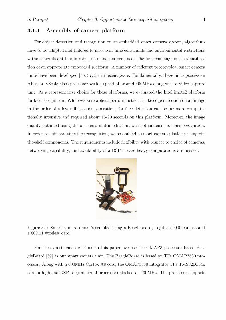
3.1 Smart camera unit: Assembled using a Beagleboard, Logitech 9000 cameraand a 802.11 wireless card . . . . . . . . . . . . . . . . . . . . . . . . . . . . 14
3.2 Schematics for network based face recognition . . . . . . . . . . . . . . . . . 153.3 (Top) Deployment of smart camera network with 7 cameras for face recog-
nition experiments. (Bottom) close-up view of individual camera; camerasdeployed on 6.5 feet lamp posts . . . . . . . . . . . . . . . . . . . . . . . . . 16
3.4 Images that did not qualify for transmission to the base station due to: Badpose (top); motion blur (middle); poor illumination (bottom) . . . . . . . . . 17
3.5 Achieved Frame rate vs Capture resolution . . . . . . . . . . . . . . . . . . . 203.6 Correct recognition rate vs number of available cameras . . . . . . . . . . . . 213.7 ROC curve of distributed face recognition system with different number of
cameras activated . . . . . . . . . . . . . . . . . . . . . . . . . . . . . . . . . 22
4.1 Our experimental deployment of 3 cameras. The cameras are deployed alongan arc of radius 10 feet with a separation of 6 feet between the cameras alongthe arc as shown. The angles made by the principal axes of cameras C2 andC3 with that of camera C1 are 40o and 80o respectively. The cameras aredeployed on tripods at a height of 7 feet from the ground. All cameras runa frontal face detector. When a frontal face is detected on any camera, anotification is broadcast to other cameras. . . . . . . . . . . . . . . . . . . . 24
4.2 We classify faces into front, profile and partial profile based on the yaw angles 254.3 Point correspondence: The two cameras are indicated by their centers C
and C ′ and image planes. The camera centers, 3-D space point X, and itsimage points x and x′ lie in a common plane . . . . . . . . . . . . . . . . . . 26

LIST OF FIGURES vii
4.4 Pseudo-code for operations on each embedded camera. each node executes 4threads: capture, frontal face detection, message listening and side-face de-tection. The capture thread samples images at F fps and queues them in Bff .The frontal face detection thread dequeues frames from Bff and applies frontalface detector on background subtracted images. If a face is detected, a noti-fication is broadcast to other cameras, otherwise the background subtractedframe is stored in Bsf . The message listening thread queues any incomingmessage into Q. The side-face detection thread dequeues messages from Q,retrieves the synchronous frame corresponding to the message from Bsf andperforms the side-face detection procedure. . . . . . . . . . . . . . . . . . . . 27
4.5 Using camera network geometry for side face detection. When a frontal faceis detected on any camera, a notification is broadcast to other cameras spec-ifying the center of the detected face. Epipolar geometry is used to projectthis point to a corresponding epipolar line (shown as AB) in the other cam-eras. The other cameras apply a pose-specific side-face detector in a smallregion surrounding the segment of the epipolar line that intersects with thebackground subtracted image. . . . . . . . . . . . . . . . . . . . . . . . . . . 30
4.6 Example face images detected by our acquisition service. The white rectanglesindicate the box enclosing the detected faces in each pose. Face images ineach column are extracted from synchronous frames in the three cameras.(a) Images acquired with subjects facing C2: (Top) Frontal face (Middle) Leftpartial profile face (Bottom) Right partial profile face. (b) Images acquiredwith subjects facing C1: (Top) Frontal face (Middle) Right partial profile face(Bottom) Right profile face. . . . . . . . . . . . . . . . . . . . . . . . . . . . 33

viii
List of Tables
3.1 Time taken for various processing operations on the assembled smart cameraplatform . . . . . . . . . . . . . . . . . . . . . . . . . . . . . . . . . . . . . . 20
4.1 Processing times: Multi-view face detection in clear and cluttered background 344.2 Detection rates for frontal and side faces . . . . . . . . . . . . . . . . . . . . 35

ix
Notation
We use the following notation and symbols throughout this thesis.
PTZ - Pan, tilt and zoom
F - Fundamental matrix
l - Epipolar line
Q - Message queue length
NTP - Network time protocol
fps - Frames processed per second
Bff - Frontal face buffer
Bsf - Side face buffer
tnd - Network delay in ms
tff - Average time to detect a face in a background subtracted image in ms
tsf - Average time to detect a side face
ts - Network clock synchronization error in ms
Nff - Frontal face processing rate
Nsf - Side face processing rate in fps
t(x) - Time stamp of a frame
w(x) - Width of a detected face
gim - M th galley image of subject i pn - N th probe image of a subject

1
Chapter 1
Introduction
1.1 Motivation
Facial recognition systems have evolved significantly into the most common and reliable
mechanism for establishing identity of individuals in the context of applications such as access
control, identification of criminals in public places. Traditionally these have been applied
for identification from previously acquired photographs, surveillance video tapes that are
mostly under controlled environments. Recent terrorist activities and security threats at
airports have necessitated a transition to modern facial recognition systems that are capable
of identifying suspects in real time. An example scenario is that of raising an alert if any
individual from a watch-list database has been detected in the region being monitored, before
the subject has moved too far away from the region. But real-time human identification is
challenging given the computationally intensive nature of video processing and the potential
occlusions and variations in pose of a subject in an unconstrained environment.
Distributed camera networks are ideally suited for such scenarios because they can be
deployed to provide coverage from different views of a scene, thus providing tolerance against
variable pose, poor illumination and possible occlusions. But realizing such a camera network
based human identification system poses the following challenges. (1) Given the bandwidth
intensive nature of video data originated from a camera, it is essential to perform local
processing within the network before transmitting data to a fusion center. At the same
time, a high frame rate of acquisition is required for robust recognition because there may

S. Parupati Chapter 1. Introduction 2
be a small duration when a subjects pose is appropriate for recognition and it is desirable
to acquire these frames. There is no problem when system is designed to operate in off-line
mode based on recorded videos because processing time is not an important factor and all
the samples can be used for identification. Hence there is a critical need for distributed
algorithms that exploit data obtained from multiple views and simultaneously reduce the
processing time and network load.
The objective of this thesis is to support robust face recognition by designing network
algorithms for rapid acquisition of multi-view images using a distributed camera network.
1.2 Thesis contributions
In order to meet the thesis objective I exploit the following two key insights
• In order to balance the trade-off between local processing at each camera and central
computation at the base station, my approach is to use the local resources to perform
face detection and to transmit only face images to the base station, by doing so I
expect significant reduction in network bandwidth utilization as well as centralized
processing overhead in order to maximize the probability of acquiring suitable face
image for recognition. The main idea of this approach is to use a densely deployed
multi camera network that opportunistically acquire frontal face images of a subject
moving through the region covered by the cameras. In order to test the achievable
recognition performance using such an opportunistic face acquisition system I have
designed embedded camera testbed and used this to perform face recognition in an
indoor environments that mimics hallways in public places. Using this set up, overall
network bandwidth utilization can be saved up to 90% by transmitting only face images
and it is possible to acquire at least one good face image which is suitable for robust
face recognition.
• In unconstrained environments it is not always possible to obtain high quality frontal
face images for face recognition. Under such circumstances, non frontal face images
acquired from a camera network can be used to improve confidence of face recognition.

S. Parupati Chapter 1. Introduction 3
Recent studies[1, 2, 3, 4, 5] have shown that non frontal views and partial views can
be used for reliable face recognition, but acquiring multi-view face images in real time
is a challenging problem due to computational complexity and diversity in appear-
ance of face images[6]. In this thesis I have designed a collaborative multi-view face
acquisition service that uses the geometry of multi-camera network to collaboratively
acquire frontal and non-frontal face images in real-time while maintaining high acqui-
sition rate.
The Main idea of the approach is to utilize the multi-view camera geometry
and inter camera communication to reduce the computational overhead involved in
multi-view face detection. An overview of our approach is as follows: We first train
face detectors based on Haar-like features [7, 8] for each pose class that is required
to be detected and then run a frontal-face detector on each camera in the network.
Whenever a frontal face has been detected on any camera, say Cf , it broadcasts a
notification to other cameras to narrow down their search to the region surrounding
the epipolar line corresponding to the point where the frontal face is detected in Cf .
By applying a pose-specific face detector on this much smaller region in the image, the
cameras are able to quickly extract non-frontal face images and simultaneously index
these faces into the corresponding face pose. Using this approach, it is possible to
detect non-frontal faces at almost the same rate as for frontal faces. This system is
easy to setup, does not require camera calibration and only depends on fundamental
matrices of transformation between camera pairs.
• In order to evaluate the above face acquisition service in real time I have designed a
portable embedded camera network testbed. This testbed consists a set of embedded
cameras, and each camera assembled using Logitech pro 9000 web camera for imaging,
802.11 based wireless card for communication and ARM or Intel atom processor based
embedded system for local processing. I have designed software that allows the cameras
to automatically self configure in the network and to transmit data to base station for
recognition and it also allows the remote programming of individual camera from the
base station thus providing flexible and convenient framework. I have also integrated

S. Parupati Chapter 1. Introduction 4
embedded camera with a create iRobot platform thus yielding mobile camera platform.
In this thesis I have used this testbed in the context of face recognition but in general it
can be used for any event surveillance applications. The testbed provides foundational
infrastructure for camera networks based biometric and surveillance research and I
also expect that this testbed will provide hands on experience for the students in the
department.
1.3 Thesis Outline
The rest of this thesis is organized as follows. The chapter 2 discusses background
information and related work. Chapter 3 describes opportunistic frontal face acquisition
system and chapter 4 describes collaborative multi-view face acquisition system. The chapter
5 concludes this thesis and provides directions for the future work.

5
Chapter 2
Background information and Related
work
In the past decade, significant advances have taken place in the design of biometric sys-
tems that establish human identity based on physiological and behavioral characteristics
such as face, iris, finger prints, voice, key stroke, gait and ear. In comparison with other
modalities, human identification systems based on face and soft biometric features are more
relevant in the context of unconstrained scenarios since they can be collected without knowl-
edge or co-operation of a subject. This thesis primarily focuses on the use of a distributed
camera network for human identification based on the face biometric, although methods
developed in this thesis are also applicable for acquiring other soft biometric data and using
these to support (and augment the accuracy of) identification based on the face biometric.
2.1 Background information
The operation of a facial recognition system can be broadly divided into two subsystems:
1. Face detection and 2. Face recognition.
• Face detection: A face detector is used to detect and extract face images present in
an image. Face detection in an unconstrained environment considered as a challenging
problem due to the following reasons:
Change of scale and pose: A face may appear in different poses because of in-plane

S. Parupati Chapter 2. Background information and Related work 6
Figure 2.1: Face recognition system
.
and out of plane rotation w.r.t to the camera optical axis and the size of a face varies
with user distance from the camera.
Expressions of face: Facial expressions such as laughing, talking cause significant
variations in facial appearance.
Illumination and background complexity: Illumination variations and cluttered
background environment also pose challenges to detection algorithms.
Occlusions: In real time, face images can be occluded by other people or objects in
the scene.
• Face recognition: The face recognition subsystem first normalizes and aligns a probe
face image, and then performs matching with the pre-acquired gallery database to
determine the identity of the probe image. It establishes identity based on a similarity
score between probe and gallery images. A face recognition algorithm must be robust
to face variations due to pose, expression, resolution and resolution.
A distributed camera network can alleviate challenges posed by face detection in an uncon-
strained environment due to the redundancy offered by multiple views which can provide
robustness against occlusions, variations in pose and illumination. However, such a multi-
camera setup also poses some challenges. The amount of data generated by multiple cameras
can be too large to be transmitted and processed at a single location. If every frame captured

S. Parupati Chapter 2. Background information and Related work 7
by a camera is processed in a central location for face recognition, the system is unlikely to
be capable of operating in real time. Therefore, local processing is needed prior to invoking
the services of a fusion center. On the other hand, the local processing units are likely to be
resource-constrained in order to be cost-efficient; further, too much of local processing will
increase the overall recognition time. Hence, a balance between local processing capabilities
and centralized fusion is needed. To achieve this balance, this work proposes the use of the
multi-camera network to collaboratively acquire multi-view face images at a fast rate and
the use of the central location (hereby referred to as base station) to perform matching of
the opportunistically acquired probe images.
2.1.1 Related work on multi-view face detection
The goal of face detection is to determine whether a face exists in a given image or
not, and to return the coordinates of the face if a face exists. In the last few years several
face detection techniques have been proposed to detect faces in images. Image based face
detection algorithms can be broadly classified into four categories [9]:
• Knowledge-based methods: These methods utilize a set of rules framed by the
algorithm designer based on intuition of facial appearance to detect a face in an image.
Kotropoulos and Pitas[10] et al. proposed a rule based face detection and it uses
projection method to localize the facial features. Yang and Huang[11] et al. proposed
hierarchical knowledge-based face detection method to localize face in an image and in
this method set of rules are categorized into three levels to reduce the computational
complexity. At the highest level general facial features such as uniform intensity regions
and at the lowest level features such as eyes, nose and mouth regions are searched for
candidate’s face. These techniques are suitable for single face and simple background
scenario.
• Feature invariant methods: These methods make use of facial features which are
invariant to illumination and pose to localize the face in a given input image. In
[12, 13] morphological and edge detection operations have been performed to extract
facial features such as hair line, eyebrows, and mouth. The relation between extracted

S. Parupati Chapter 2. Background information and Related work 8
features studied to determine the existence of face. Even though these methods are
robust to illumination they suffer from image noise and occlusion of facial features.
• Template matching methods: These methods utilize predefined face and facial
feature templates for face detection. Sakai[14] used face contour and eyes template
to model a face. In order to detect a face in an image, the image is scanned by a
small window and correlation between the window region of an image and face contour
template is computed to determine the regions which are likely to contain a face. Then
eye and mouth templates are applied to detect a face. These methods are suitable for
images which contain fixed size face images.
• Appearance-based methods: Appearance-based methods have shown superior per-
formance over the above methods in terms of accuracy and computational speed. These
techniques utilize machine learning algorithms and probabilistic models to build a clas-
sifier from a training dataset. In [15][16][17] authors proposed artificial neural network
architectures for frontal face detection. To detect a face, neural networks are trained
with positive and negative images to adjust the weights of nodes. Osuna et. al devel-
oped an efficient support vector machines training technique(SVM) and successfully
applied it to detect frontal faces in gray level images. Support vector machine is a
linear classifier and in the training phase optimal hyperplane computed to separate
the face and non-face classes. Yang [18] used Sparse Network of Winnows learning
architecture to localize faces with different face expressions and under different illumi-
nation conditions. Their method has shown improved face detection rate over SVM
and neural network techniques but suffers from more false positive rate. In [7] Viola
and Jones proposed rapid object detection using haar-like features to detect faces in
images. It has been considered as a state of art algorithm till today, since it can able
to detect faces rapidly while maintaining the accuracy.
The above techniques are proposed to detect frontal face images, but in real time 75%
of face images are reported to be non-frontal. In the next section we discuss about various
approaches towards multi-view face detection. Multi-view face detection techniques are
broadly classified into two categories:

S. Parupati Chapter 2. Background information and Related work 9
Figure 2.2: Classifier structures for multi-view face detection: Each circle indicatesa classifier. The solid arrows are pass route, and the dashed arrows are reject route. (a)Parallel cascade, (b) Detector-pyramid, (c) Decision tree I, (d) Decision tree II
.
Image based approaches
Image based approaches are further classified into four categories based on classifiers
arrangement in a detector:
• Parallel cascade structure: In [19] Huang et al. extended Viola and Jones frame
work for multi-view face detection by training haar cascade classifier corresponding to
each pose. In this method image sub window passes through all view based detectors
as shown in figure. 2.2 and all classifiers results are combined to detect a face. This
approach shows good performance but fails to perform in real time beacause all pose
detectors are applied sequentially in order to search for a face in given sub window.
• Pyramid structure: In [20] Li proposed a pyramid structure to detect faces as shown
in figure. 2.2. Their method uses hierarchical classifiers . First level is used to detect
faces and non face patterns, second level to handle in-plane rotations (-90 to +90) and
the third level is used to detect specific pose of a face. This technique shows good
performance over parallel cascade structure.

S. Parupati Chapter 2. Background information and Related work 10
• Decision tree structure - I: In [21] Viola and Jones extended their frame work in
[7] for multi-view face detection. Their work uses decision tree structure - I as shown
in figure. 2.2 to detect faces. The classifier in the early stages estimates the face pose
and then applies pose specific classifier to detect a face in a sub-window. This method
is robust and accurate but it results in false negatives since if the pose of a test image
is misclassified whole detection process goes wrong.
• Decision tree structure - II: To overcome the problem in the above approach [21],
Huang et al. [22] used vector boosting technique to build a decision tree classifier.
In their approach each node computes determinative vector G(x) to determine sub
branches in a next level, to pass test image for face detection. In this approach output
of multiple branch classifiers are fused to take a decision instead of considering an
output from a single branch.
Video based approaches
To improve detection speed associated with the image based approaches video based
techniques have been proposed in [23, 24]. In this approach, first face is detected and then it
is tracked continuously in subsequent frames. These approaches work well for few subjects
in a frame and tracking becomes complex when multiple people are present in a frame.
All of the above approaches use a video or image from a single camera for face
detection and takes significant amount of time for detection. In contrast, the collaborative
face acquisition framework proposed in this thesis exploits the multi-view geometry between
cameras to acquire multi-view face images rapidly and accurately.
2.2 Other related work
Early surveillance systems [25, 26, 27, 28, 29, 30, 31] are centralized, in which cameras
acquire the data and send the whole data to a server for face detection and recognition. This
approach takes significant amount of bandwidth which in turn increases network congestion
and load on the server. Thus system performance deteriorates as the number of cameras

S. Parupati Chapter 2. Background information and Related work 11
increase in the network. In contrast, video analytic systems [32]are used for surveillance pur-
poses and these systems employ a camera and dedicated hardware to acquire and perform
face recognition task locally to overcome network problems. But these systems are incur
heavy costs and do not collaborate with neighboring cameras to increase the performance
of the system which is the focus of this thesis. In recent years, a number of different pro-
totypical camera network systems have been developed to acquire face images in real time
for recognition. However, face recognition imposes stringer requirements on the quality of
acquired face images and therefore the use of a camera network for face recognition is much
more challenging. To counter this challenge, many active vision based network systems have
been proposed [33, 34, 35] for face recognition. These systems use master-slave architecture
in which combination of a fixed camera and a pan-tilt-zoom(PTZ) cameras are used to cover
an assigned target area. In the above architecture fixed cameras continuously track the
subjects and actively controls the PTZ camera to get a close up view of assigned subject.
Each PTZ camera is typically assigned to acquire face images of a single subject at a time
and configured continuously to cover multiple subjects in the scene. As a result, only short
amount of time can be allocated to each subject and successful acquisition of suitable face
images is contingent upon the subject retaining a suitable face pose while a camera is being
configured. Also for reasons of scalability, typically a single camera is allocated per subject,
thereby not utilizing the multiple views offered by the network to improve the chances of ac-
quiring high quality face image. Instead of continuously tracking a subject at close quarters
to eventually get a good view that is suitable for face recognition, the proposed approach
relies on redundancy offered by multiple camera views to opportunistically acquire a suitable
face image for identification.
Camera networks have been used for passive tracking of individuals to monitor their
activities [25, 26, 27, 28]. Different techniques have been proposed to deal with overlapping
field of views, handling occlusions and facilitating camera hand-offs in the context of track-
ing. There has also been research on deployment of camera networks to guarantee persistent
surveillance as an object moves from one field of view to another. Above approaches uti-
lize overlapping views to track the subject successfully but none of them used multi-view
geometry to acquire face images. The proposed approach addresses the new frame work to

S. Parupati Chapter 2. Background information and Related work 12
collaboratively utilize the information between overlapping views in order to detect multi
view face images.

13
Chapter 3
Opportunustic face acquisition system
This section discusses the design of network infrastructure for face acquisition in real
time and then describes software implementation for the same.
3.1 System model
The system that we consider in this project consists of a long linear network of embedded
cameras deployed along both sides of a secured passageway such as an aisle or a corridor.
Such a deployment models secured walkways at indoor public places. The embedded cameras
are connected wireless to a central server either through one hop or multiple hops. As one
or more human subjects walk through the network, cameras capture images of the subject
under possibly different poses, resolution and even illumination. The requirement is for the
subject to be recognized with high confidence using the series of images captured within the
camera network. The system is subject to failures of individual units and occlusion effects.
In this chapter, we specifically focus on the problem of distributed face recognition when a
single person is within the camera network at any given time. Extending this to a multi-
person recognition system is a subject of our future work. Note that the cameras that we
place along the sides are passive cameras and do not track a subject upon detection. Instead
we rely on opportunistically collected images from a dense set of cameras for identification.
S. Parupati Chapter 3. Opportunistic face acquisition system 14
3.1.1 Assembly of camera platform
For object detection and recognition on an embedded smart camera system, algorithms
have to be adapted and tailored to meet real-time constraints and environmental restrictions
without significant loss in robustness and performance. The first challenge is the identifica-
tion of an appropriate embedded platform. A number of different prototypical smart camera
units have been developed [36, 37, 38] in recent years. Fundamentally, these units possess an
ARM or XScale class processor with a speed of around 400MHz along with a video capture
unit. As a representative choice for these platforms, we evaluated the Intel imote2 platform
for face recognition. While we were able to perform activities like edge detection on an image
in the order of a few milliseconds, operations for face detection can be far more computa-
tionally intensive and required about 15-20 seconds on this platform. Moreover, the image
quality obtained using the on-board multimedia unit was not sufficient for face recognition.
In order to suit real-time face recognition, we assembled a smart camera platform using off-
the-shelf components. The requirements include flexibility with respect to choice of cameras,
networking capability, and availability of a DSP in case heavy computations are needed.
Figure 3.1: Smart camera unit: Assembled using a Beagleboard, Logitech 9000 camera anda 802.11 wireless card
For the experiments described in this paper, we use the OMAP3 processor based Bea-
gleBoard [39] as our smart camera unit. The BeagleBoard is based on TI’s OMAP3530 pro-
cessor. Along with a 600MHz Cortex-A8 core, the OMAP3530 integrates TI’s TMS320C64x
core, a high-end DSP (digital signal processor) clocked at 430MHz. The processor supports

S. Parupati Chapter 3. Opportunistic face acquisition system 15
Linux operating system and can be integrated with off-the-shelf USB enabled cameras gen-
erating medium or high resolution images. For our experiments we use the Logitech 9000
camera. While currently we use an 802.11 based wireless card, we can easily replace this with
a low power wireless network using IEEE 802.15.4 enabled transceiver. Thus the assembled
system provides us with flexibility with respect to camera as well as radio platforms. The
assembled platform can be powered by a 5V battery or external AC power.
Figure 3.2: Schematics for network based face recognition
3.1.2 Assembly of multi-camera network
Next, we assemble a camera network using the above platform. Individual units are
portable and self-configured into a programmable network that is attached to a centralized
server. Figure 3.2 shows a schematic of the camera network for face recognition as described
in this paper. Seven cameras are placed at a height of 6.5 feet from the ground with a 9
feet spacing long a length of 40 feet. In this work, we specifically consider the case where
the cameras are placed at a height of 6.5 feet and are therefore able to acquire facial images
that are frontal or side view. Using overhead or ceiling placed cameras for face recognition
is beyond the scope of this work.
We do not use camera calibration information for face recognition. Therefore, the cameras

S. Parupati Chapter 3. Opportunistic face acquisition system 16
Figure 3.3: (Top) Deployment of smart camera network with 7 cameras for face recognitionexperiments. (Bottom) close-up view of individual camera; cameras deployed on 6.5 feetlamp posts
do not have to be tightly calibrated, thereby allowing approximate alignment and simplifying
the deployment. The cameras are deployed facing the covered area but angled toward the
direction of the entrance at angle of 30 degrees to be able to acquire frontal face images when
the subject is staring at the direction of the exit. This is highlighted in Figure 3.2. The
individual camera units can be programmed at run time. The cameras form a 1-hop network,
but can be extended to form a multi-hop network. Figure 3.3 shows the deployment of our
actual camera network for face recognition. The cost of an individual embedded camera unit
along with accessories was $200 and thus the total system cost for our 7 camera network is
$1400. We expect that with mass production of individual micro-controller boards, the cost
will be significantly lower than this.
3.1.3 Software implementation
The software for face recognition is implemented over multiple devices: on the embedded
devices and on the centralized PC. The objectives behind our distributed implementation are
to reduce data transfer rates to the centralized processing unit and to exploit the redundancy
offered by the network. On the embedded devices, we first implement an activity detector
which is activated whenever a significant scene change is observed in consequent frames.

S. Parupati Chapter 3. Opportunistic face acquisition system 17
This event triggers a face detector algorithm which determines if any frontal views of faces
are present in the frame. A simple Haar cascade based face detector is implemented on the
individual units. By computing only relative changes from a static background, the time
required for face detection is significantly reduced. The captured images are scaled down
to 320 x 240 pixels before transmitting them to the face detector module and this results
in significant reduction in processing time while retaining the accuracy of face detection.
We use an OpenCV based implementation of the Haar Cascade detector that is tuned to
extract face segments that can be used for frontal face recognition. By virtue of the Haar
Cascade detector (that is designed based on a set of training images), faces of small size,
poor pose, illumination and resolution are filtered out. We specify a size of 22 x 22 as the
minimum dimension for a detected face. The detected and extracted image sections are then
transmitted to the central unit. This local processing serves to drastically cut down the data
rate of transfer to the central unit. Moreover, by limiting the number of cropped images
transmitted to the central unit, the computations that are to be performed by the central
server are significantly reduced.
Figure 3.4: Images that did not qualify for transmission to the base station due to: Badpose (top); motion blur (middle); poor illumination (bottom)
S. Parupati Chapter 3. Opportunistic face acquisition system 18
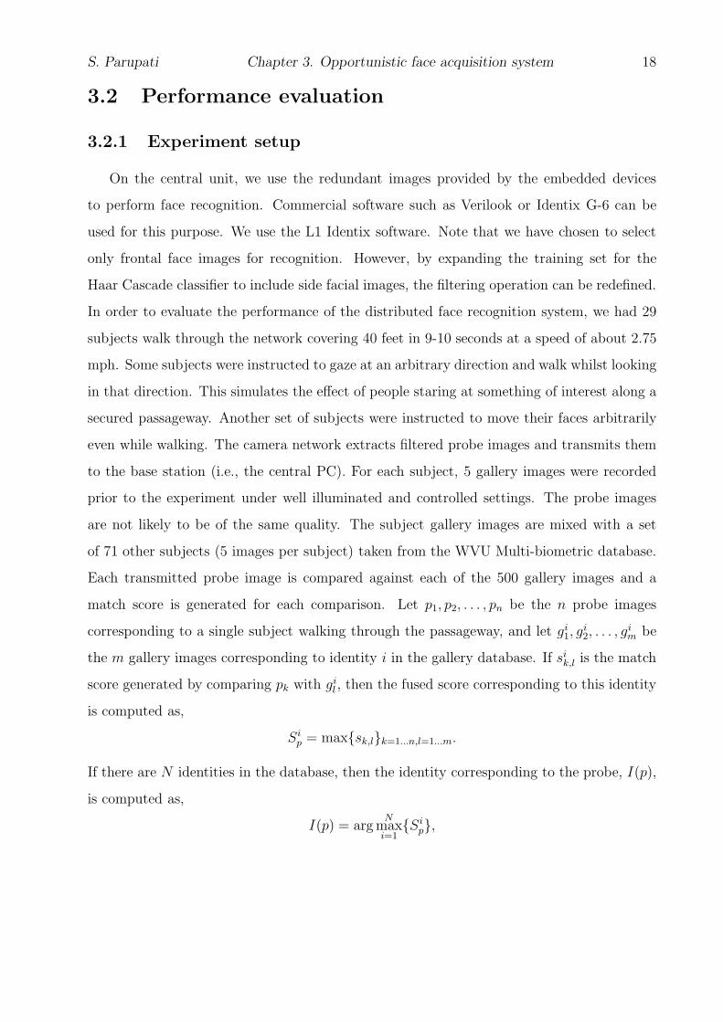
3.2 Performance evaluation
3.2.1 Experiment setup
On the central unit, we use the redundant images provided by the embedded devices
to perform face recognition. Commercial software such as Verilook or Identix G-6 can be
used for this purpose. We use the L1 Identix software. Note that we have chosen to select
only frontal face images for recognition. However, by expanding the training set for the
Haar Cascade classifier to include side facial images, the filtering operation can be redefined.
In order to evaluate the performance of the distributed face recognition system, we had 29
subjects walk through the network covering 40 feet in 9-10 seconds at a speed of about 2.75
mph. Some subjects were instructed to gaze at an arbitrary direction and walk whilst looking
in that direction. This simulates the effect of people staring at something of interest along a
secured passageway. Another set of subjects were instructed to move their faces arbitrarily
even while walking. The camera network extracts filtered probe images and transmits them
to the base station (i.e., the central PC). For each subject, 5 gallery images were recorded
prior to the experiment under well illuminated and controlled settings. The probe images
are not likely to be of the same quality. The subject gallery images are mixed with a set
of 71 other subjects (5 images per subject) taken from the WVU Multi-biometric database.
Each transmitted probe image is compared against each of the 500 gallery images and a
match score is generated for each comparison. Let p1, p2, . . . , pn be the n probe images
corresponding to a single subject walking through the passageway, and let gi1, gi
2, . . . , gi
m be
the m gallery images corresponding to identity i in the gallery database. If sik,l is the match
score generated by comparing pk with gil , then the fused score corresponding to this identity
is computed as,
Sip = max{sk,l}k=1...n,l=1...m.
If there are N identities in the database, then the identity corresponding to the probe, I(p),
is computed as,
I(p) = argN
maxi=1
{Sip},

S. Parupati Chapter 3. Opportunistic face acquisition system 19
i.e., the gallery identity with the highest score is deemed to be the identity of the probe
image.
During the process of filtering images prior to transmission to the base station, we apply
a predetermined threshold on the resolution of a face image and the blur factor to discard
frames. These thresholds are estimated based on an off-line analysis of the impact of different
quality images on the match scores. If blurred and poor resolution images were to be
transmitted to the base station, it will result in excessive processing time at the base station
without adding value to the fusion. Fig. 3.4 shows example face images that were dropped
due to poor pose, resolution and illumination respectively.
3.2.2 Results
Using the above experimental setup, we now describe both the network performance as
well as the performance of face recognition in terms of accuracy and latency.
Network performance
Table 3.1 lists the time taken by individual camera units for various operations on the
embedded camera. From the table we note the following. By using the background sub-
tracted image for face detection, we cut down the processing time from 1.9 seconds to less
than 500 ms. We save 90% of the bandwidth on each transmitted frame by extracting only
the face portion of the image. Further, by transmitting only a small subset of frames we
reduce the network level to a significantly low value thereby eliminating the probability of
congestion at a central unit. By utilizing only the ARM processor, we are able to achieve
about 1.5 frames per second when face detection is being performed and 8fps when no face
recognition is performed. Transferring images from the ARM to the DSP requires significant
memory transfer time and is therefore not deemed as practical for improving the speed of
operations. However, if the cameras were directly interfaced to the DSP for image processing
and only the network operations were handled by the ARM processor, the frame rates could
be significantly enhanced. This requires porting of the face detector to the DSP and we are
currently working on this implementation.

S. Parupati Chapter 3. Opportunistic face acquisition system 20
Operation Time
Camera Initialization 100msFrame capture time (960 by 720) 35ms
Background subtraction 70msface detection (entire image) 1200ms
Face detection (segmented image) 470ms
Table 3.1: Time taken for various processing operations on the assembled smart cameraplatform
Figure 3.5: Achieved Frame rate vs Capture resolution
Figure 3.5 shows the average frame rate at different face capture resolutions. Increasing
resolution requires more processing time but is likely to yield better recognition accuracies.
In our experiments, we choose a resolution of 960 x 720 and notice that it is sufficient
for accurate face recognition under our current deployment scenario where cameras capture
images at a distance of about 10 feet.
Face recognition performance
In Fig. 3.6 This section provides the details of the performance of the face recognition
system as the number of cameras is varied. The figure shows the performance corresponding
to rank 1, i.e., only when the top match from the gallery is considered. With all the seven

S. Parupati Chapter 3. Opportunistic face acquisition system 21
cameras, we are able to achieve perfect recognition rate since all subjects are classified
accurately. We then determine the accuracy when one camera fails. From our collected data
we identify the camera that collected the most number of probes and in the figure we show
the worst performance when that camera is assumed to have. We notice that the system is
able to tolerate individual failures. We also see that when the system contains only one or
two cameras, the recognition performance is rather poor.
Figure 3.6: Correct recognition rate vs number of available cameras
In Figure 3.7, we show the ROC curves with different number of cameras in the system.
We notice that we are able to achieve the good performance when all cameras are present
and when one camera has failed.
Note that Fig. 3.7 represents a closed set analysis where the subject is always assumed
to be present in the database and therefore a rank-1 evaluation suffices.
Real time capability
A single score generation on a 2.0GHz PC running face recognition software takes about
0.5 seconds. Thus by reducing the number of potential images transmitted to the base
station, we are able to significantly reduce the processing time for face recognition. Now
consider the case when the system is required to determine if the probe face is one among
S. Parupati Chapter 3. Opportunistic face acquisition system 22
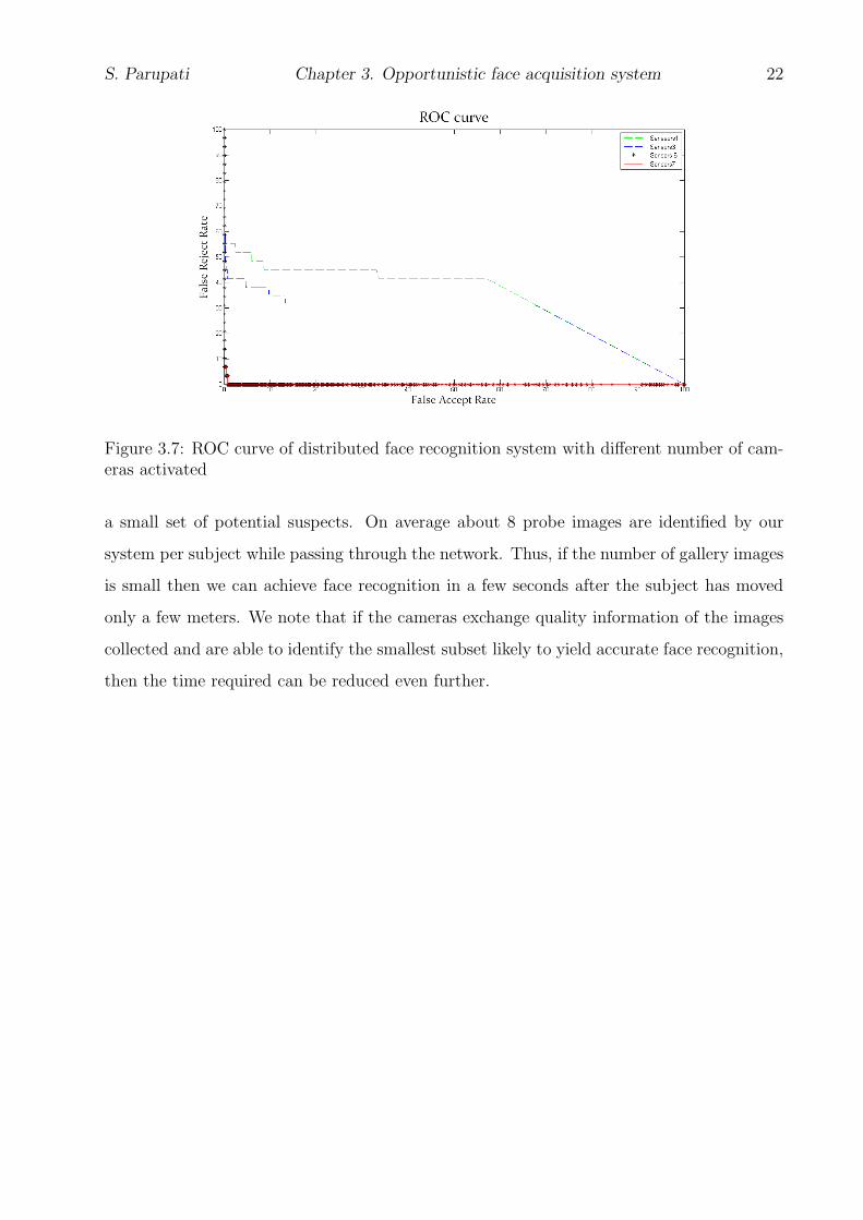
Figure 3.7: ROC curve of distributed face recognition system with different number of cam-eras activated
a small set of potential suspects. On average about 8 probe images are identified by our
system per subject while passing through the network. Thus, if the number of gallery images
is small then we can achieve face recognition in a few seconds after the subject has moved
only a few meters. We note that if the cameras exchange quality information of the images
collected and are able to identify the smallest subset likely to yield accurate face recognition,
then the time required can be reduced even further.

23
Chapter 4
Collaborative multi-view face
acquisition system
In this chapter we discuss in detail about our network service for collaborative acquisi-
tion of multi-view face image. We describe system in two parts 1. System Model 2. system
Operation
4.1 System model
Collaborative face acquisition system consists of a network of Nc cameras with overlap-
ping views that all are focused on a critical region such as entrances to public places and
narrow corridors or walkways. The allowable distances between the cameras and the height
of deployment will depend on the parameters of the cameras used for the system. For exam-
ple if pan, tilt and zoom cameras are used, the cameras could be physically distant from the
region and set to focus on the critical region. If fixed focal length, and low resolution cameras
such as Logitech web cameras are used, they will have to be closer together. However, we
do require that the cameras are able to acquire facial images that are either frontal view or
side view (but not top view). For our specific experimental setting, we use a network of 3
cameras located along an arc of radius 10 feet. The cameras are deployed on tripods at a
height of 7 feet from the ground with their principal axes parallel to the horizontal plane

S. Parupati Chapter 4. Multiview Face Detection System 24
C1
C3
C2
6 ft
6 ft
80
40
Front face detectedby camera C1
Figure 4.1: Our experimental deployment of 3 cameras. The cameras are deployed along anarc of radius 10 feet with a separation of 6 feet between the cameras along the arc as shown.The angles made by the principal axes of cameras C2 and C3 with that of camera C1 are40o and 80o respectively. The cameras are deployed on tripods at a height of 7 feet fromthe ground. All cameras run a frontal face detector. When a frontal face is detected on anycamera, a notification is broadcast to other cameras.
and with a separation of 6 feet between the cameras along the arc as shown in Fig. 4.1.
The angles made by the principal axes of cameras C2 and C3 with that of camera C1 are
40o and 80o respectively. We arrange cameras in a specific configuration, which provides
maximum variation between face poses so relative orientations between the cameras (the
angles between principal axes of each pair of cameras) are assumed to be known. We assume
that a clock synchronization algorithm is running on the nodes but we note that the clocks
of any two nodes may not be in perfect synchronization at any time instant. Let ts denote
the maximum clock synchronization error between any pair of cameras in milliseconds. This
implies that the local clocks of any two cameras in network can be out of synchronization at
most ts apart. The cameras are connected wirelessly to a fusion center where the transmit-
ted face images are collected and may be used for face recognition. Our goal is to acquire
face images corresponding to the following poses: frontal, left (or right) profile, partial left
(or partial right) profile using camera network to improve the overall performance rate of
surveillance system. We use the yaw angle (that measures the rotation of a face image along
the vertical axis) to define front, profile and partial profile faces (illustrated in Fig. 4.2). We

S. Parupati Chapter 4. Multiview Face Detection System 25
− 30 <−> +30 30 <−> 60 60 <−> +120
Front Face Partial Right Profile Face Right Profile Face
Figure 4.2: We classify faces into front, profile and partial profile based on the yaw angles
define a face image of a subject acquired by a camera to be frontal if the yaw angle made by
the subject’s pose ranges from −30o to 30o. We define a face image of a subject acquired by
a camera to be partial left (partial right) profile if the yaw angle made by the the subject’s
pose ranges from −30o to −60o (30o to 60o). We define a face image of a subject acquired by
a camera to be left (right) profile if the yaw angle made by the subject’s pose ranges from
−60o to −120o (60o to 120o). We have used the term side face to denote any non-frontal
pose of the face.
4.1.1 Epipolar geometry
When two cameras observe a same point X(x,y,z) in 3D space, then the corresponding
imaged points in two camera views are projectively equivalent and denoted as x, x′. Epipolar
geometry is used to describe projective mapping between the points x, x′, which is indepen-
dent of scene structure, camera internal parameters and relative pose. Epipolar geometry
reduces corresponding point search space from 2D image to 1D epipolar line since point x in
one camera is constrained to lie on a epipolar line l′ in the other image. Fundamental matrix
is used to compute projective mapping between uncalibrated views and it is an algebraic
representation of a epipolar geometry [40]. Properties of the Fundamental matrix given as:
• Epipolar constraint between corresponding points of two images of given as
x′T Fx = 0 (4.1)

S. Parupati Chapter 4. Multiview Face Detection System 26
C C /
π
x x
X
epipolar plane
/
Figure 4.3: Point correspondence: The two cameras are indicated by their centers C andC ′ and image planes. The camera centers, 3-D space point X, and its image points x and x′
lie in a common plane
• For any point in one view, the corresponding epipolar line in another view given as
l′ = Fx (4.2)
• The relation between epipole and fundamental matrix given as
Fe = 0 (4.3)
Fundamental matrix computation:
Fundamental matrix is a 3x3 matrix of rank 2 and its computed based on corresponding
image points between images and independent of camera calibration and camera internal
parameters. Several techniques have been proposed to compute the F, but normalized-8
point algorithm has shown superior performance since input data normalized before solving
linear equations for F.
• Compute the feature points in an image using scale invariant feature transform[41],
because common feature points in both images can be used to find the projective
transformation between two views.
S. Parupati Chapter 4. Multiview Face Detection System 27
• Use RANSAC algorithm to find the inliers, here inliers implies corresponding feature
points in both images. Use 8-point algorithm method a fitting function for RANSAC
to find matching feature points.
• Use normalized 8-point algorithm to find the fundamental matrix transformation be-
tween two views for a given set of matching features in two images.
4.2 System operation
In this section we discuss in detail about system that we use for multi-view face detection
in real time. In camera network each embedded camera performs same operation and the
operations performed on the embedded cameras are classified into the following four threads.
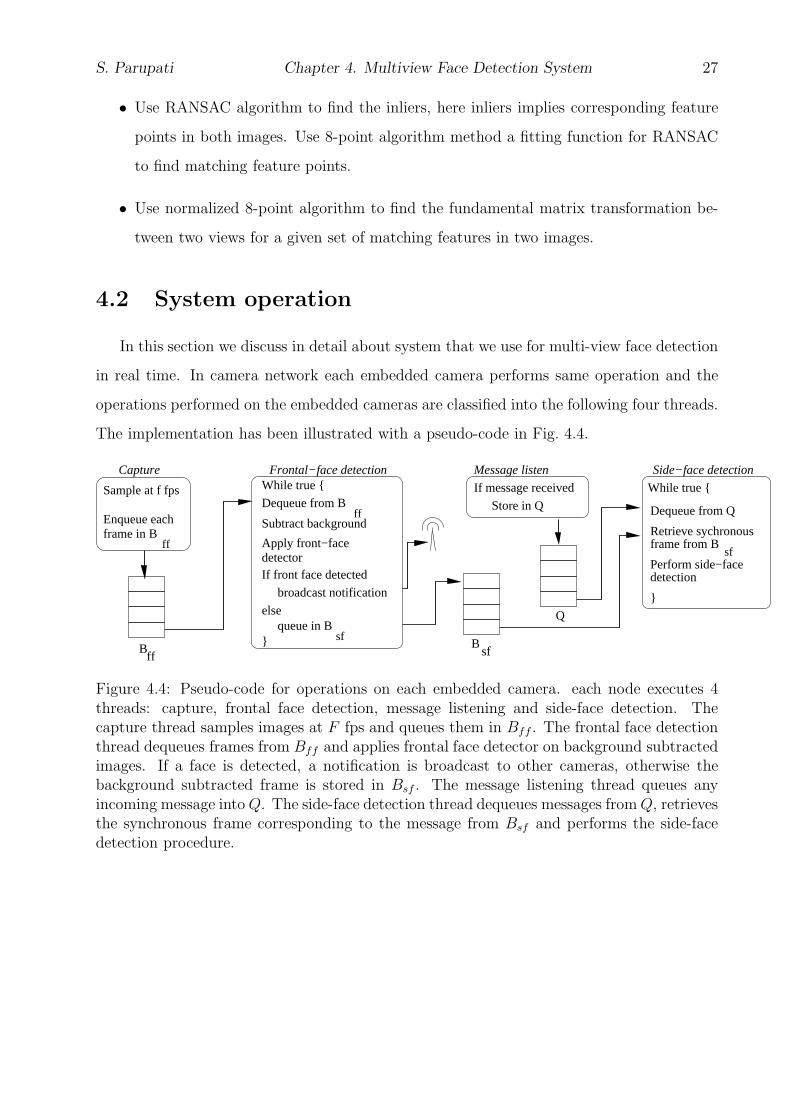
The implementation has been illustrated with a pseudo-code in Fig. 4.4.
detector
Sample at f fps
Enqueue each
While true {
Apply front−face
broadcast notification
else
Subtract background
}
Store in Q
Bff
Bsf
Q
If message received
}
Dequeue from Q
Capture Message listen Side−face detection
detectionIf front face detected
frame in Bframe from Bff
Dequeue from Bff
queue in Bsf
Perform side−facesf
Retrieve sychronous
While true {
Frontal−face detection
Figure 4.4: Pseudo-code for operations on each embedded camera. each node executes 4threads: capture, frontal face detection, message listening and side-face detection. Thecapture thread samples images at F fps and queues them in Bff . The frontal face detectionthread dequeues frames from Bff and applies frontal face detector on background subtractedimages. If a face is detected, a notification is broadcast to other cameras, otherwise thebackground subtracted frame is stored in Bsf . The message listening thread queues anyincoming message into Q. The side-face detection thread dequeues messages from Q, retrievesthe synchronous frame corresponding to the message from Bsf and performs the side-facedetection procedure.

S. Parupati Chapter 4. Multiview Face Detection System 28
4.2.1 Capture
The capture thread acquires images of the scene at F fps and queues them into Bff
buffer. Time taken by the camera to capture a frame can be given as tf = 1
F.We set the
individual cameras to capture images whenever the local clock value is a multiple of tf , and
if there is any delay in capturing due to camera hardware then we encode timestamp value
to closet multiple of tf from the time of capture. The timestamp of frame x is defined as the
time of capture of frame x and denoted as t(x). Also, we call frames x and y captured in
two different cameras to be synchronous if t(x) = t(y). Each image acquired by the capture
thread is stored in buffer Bff along with its timestamp. Let |Bff | denote the maximum
number of such images that can be stored in buffer Bff . Also, recall that there could be a
maximum clock synchronization error of ts time units between cameras. Due to both these
reasons, images acquired by different cameras in the network with the same timestamp may
not correspond to the same global time.
4.2.2 Frontal face detection
The frontal face detection thread dequeues the oldest frame from Bff to detect if a frontal
face exists in the image. To detect frontal faces, it first perform background subtraction
on an acquired frame. We consider initial set of frames to model the background based
on median filtering and apply a threshold based differencing with respect to this image.
Next, we apply morphological filters such as dilation and erosion to remove noisy pixels
in background subtracted image and we use connected components labeling to find blob
regions, where a face image could be present. We then apply an OpenCV implementation
of the Haar Cascade based face detector [7] in each of the estimated foreground blobs. If
a frontal face has been detected in a frame x, a notification message M(c(x), t(x), w(x)) is
broadcast to all other cameras in the system, specifying the frame time t(x), the location of
the center of the face c(x) and the width w(x) of the bounding square around the detected
face. If a frontal face is not detected, the background subtracted image is stored in side face
buffer Bsf . Let |Bsf | denote the maximum number of such background subtracted images
that can be stored in buffer Bsf .

S. Parupati Chapter 4. Multiview Face Detection System 29
4.2.3 Message listening
Each camera runs a server thread to listen messages from neighboring cameras upon
receiving a message M(c(x), t(x), w(x)) from another camera, the message listening thread
simply queues the message in a buffer Q with maximum number of elements denoted by |Q|.
4.2.4 Side face detection
The side face detection thread retrieves messages from Q one at a time for side face
detection. The timestamp t(x) in the message M is used to retrieve the frame y in the buffer
Bsf whose timestamp t(y) is equal to the time t(x) corresponding to frame x. Frame y is
then removed from the buffer Bsf and a side-face detection procedure is run on frame y.
We use epipolar geometry to detect the side face in the frame y: if two cameras C1 and C2
observe the same scene point W (X, Y, Z) and if the image point corresponding to W in C1
is P1(x, y), then the image point P2(x, y) corresponding to W in C2 must lie on the epipolar
line corresponding to P1(x, y) [42]. The fundamental matrix is an algebraic representation
of this epipolar geometry. Given the fundamental matrix F12 between cameras C1 and C2,
the relation between P1 and P2 is given by the following equation:
P ′
2F12P1 = 0 (4.4)
The epipolar line corresponding to point P1 in camera C2 is described by:
l2 = F12P1 (4.5)
For our experimental setting, we compute the fundamental matrices between each pair
of cameras off-line by using SIFT features for finding corresponding points, estimating the
matrices using the normalized 8-point algorithm and then using RANSAC [43] to remove
outliers from the detected keypoints [42]. We provide the fundamental matrices to the
cameras before the experiments. Using the fundamental matrix Frs we project the point c(x)
(the centroid of the frontal face detected) to a corresponding epipolar line in the synchronous
frame y of the camera receiving the message (Fig. 4.5). We then determine the segment of
the epipolar line that intersects with the background subtracted image retrieved from Bsf

S. Parupati Chapter 4. Multiview Face Detection System 30
A B
Figure 4.5: Using camera network geometry for side face detection. When a frontal face isdetected on any camera, a notification is broadcast to other cameras specifying the center ofthe detected face. Epipolar geometry is used to project this point to a corresponding epipolarline (shown as AB) in the other cameras. The other cameras apply a pose-specific side-facedetector in a small region surrounding the segment of the epipolar line that intersects withthe background subtracted image.
and extract a square block of size W × W pixels around the center of this segment, where
W is set to be equal to the width of the detected frontal face image. Based on the relative
camera orientations, we determine the expected pose of a side face and apply the side-face
detector corresponding to the particular pose class on the extracted square block. For our
experiments, we have trained face detectors for the left partial profile and left profile faces
using an OpenCV implementation of the method described in [8]. To detect right partial
profile and right profile faces, we apply the same detectors on the mirror images of the block.
4.2.5 Buffer management
Let tnd denote the maximum network delay incurred between transmission and reception
of a notification message. Let tff and tsf denote the processing times for frontal face detection
and side face detection respectively. In this section, we analyze requirements on |Bsf | to
ensure that synchronous frames always exist in the respective buffer Bsf of a camera when
a notification message is being processed. We also analyze impact of tnd, ts, tff , tsf and tf
on the expected number of frontal face and side face images that can be processed. For ease
of presentation, we divide our analysis into the following cases.

S. Parupati Chapter 4. Multiview Face Detection System 31
R1: tnd = 0, ts = 0, tsf + tff < tf In this case both the side-face and frontal-face processing
can be finished before a new frame is sampled. Moreover the network delay is 0. Hence we
only need to set |Bff | = 1, |Bsf | = 1 and |Q| = 1. The expected number of frontal (Nff )
and non-frontal (Nsf) faces that can be detected by a camera over a time T is given by the
following equations.
NR1
ff =T
tf(4.6)
NR1
sf =T
tf(4.7)
R2: tnd > 0, ts > 0, tsf + tff < tf In this case also, a camera can finish both frontal and
side-face processing before a new frame is sampled. But since tnd > 0, any message retrieved
from Q will have a timestamp that is old by at most tnd + tff (since it takes at most tff time
for frontal face processing). Moreover, if ts > 0 and the camera detecting the frontal face
lags behind any side face processing camera by ts units, then the message retrieved from Q
could have a timestamp that is old by at most tnd + tff + ts. Therefore, in order to be able
to retrieve a frame from Bsf corresponding to the timestamp of the incoming message, the
condition on |Bsf | is given by the following equation.
|Bsf | >tnd + tff + ts
tf(4.8)
Note that if the camera detecting the frontal face is ahead of the other cameras by ts
units and if ts > tnd + tff , then the frame corresponding to the timestamp in the incoming
message will not be found in the side face processing cameras. The clocks in the side-face
processing cameras in this case have not reached the clock value in the frontal face processing
camera. In this case, the image with the most recent timestamp in Bsf is used for performing
side-face detection. Thus we see that the clock synchronization error between cameras causes
the processing of side-faces to occur on frames that are apart by at most ts time units.
The expected number of frontal (Nff ) and non-frontal (Nsf) faces that can be detected
by a camera over a time T remain unchanged from case R1 and are given by Eq. 4.6 and
Eq. 4.7 respectively.

S. Parupati Chapter 4. Multiview Face Detection System 32
R3: tnd > 0, ts > 0, tff > tf In this case, the frontal face processing time is greater than
tf . The side-face processing time tsf can be greater or smaller than tf . However, since each
side-face processing camera also runs a frontal face detector, the average time to process each
message from Q is tsf + tff which is greater than tf . Therefore, new frames will be captured
into Bff and new messages can arrive in Q before the earlier ones are processed. Now, if
we assume that the system will always remain active (in other words, there will be a human
subject in the scene at all times), then even if we buffer frames in Bff and Q, there will be
no idle time to process these frames. We can therefore set |Bff | = 1, and |Q| = 1. Thus the
frames cannot be processed at the sampling rate and only the most recently acquired frame
and most recently received message are queued in Bff and Q respectively.
We now determine the size of Bsf required so that for any frame in which a frontal face
has been detected, we can find the corresponding synchronous frame in Bsf . We note that
|Q| = 1 and the maximum time before which this message is retrieved by a camera for
detecting non-frontal faces is bounded by tff + tsf . Now from the discussion in case R2, we
note that the timestamp in the message that is retrieved is old by tnd + tff + ts. So, the
required size of buffer Bsf is determined by the following equation.
|Bsf | >2tff + tsf + tnd
tf(4.9)
The expected number of frontal (Nff ) and non-frontal (Nsf) faces that can be detected
by a camera over a time T are given by the following equations.
NR3
ff =T
tff
(4.10)
NR3
sf =T
tff + tsf(4.11)

S. Parupati Chapter 4. Multiview Face Detection System 33
4.3 Performance evaluation
4.3.1 Experimental setup
In order to evaluate the performance of our data acquisition system, we implement it
on a 3 node embedded camera network (schematics shown in Fig. 4.1). We assemble an
embedded camera using a Logitech 9000 camera, a 1.6 GHz Intel Atom 230 processor based
motherboard from Acer [] and an IEEE 802.11 based wireless card. We consider one human
subject in the scene at a time. Each subject stands at a distance of approximately 10 feet
from the cameras (close to the center of the arc) facing any one of the 3 cameras. Note that,
if the subject is facing camera C1 as shown in Fig. 4.1, then the pose estimated by camera
C2 and C3 are right partial profile and right profile respectively. We have tested the system
with 10 different subjects with approximately 15 minutes of data collected for each subject.
(a) (b)
Figure 4.6: Example face images detected by our acquisition service. The white rectanglesindicate the box enclosing the detected faces in each pose. Face images in each column areextracted from synchronous frames in the three cameras. (a) Images acquired with subjectsfacing C2: (Top) Frontal face (Middle) Left partial profile face (Bottom) Right partial profileface. (b) Images acquired with subjects facing C1: (Top) Frontal face (Middle) Right partialprofile face (Bottom) Right profile face.
We use the Network Time Protocol (NTP) [44] for achieving clock synchronization be-
tween nodes and empirically observe a synchronization error of < 12 ms. Alternatively
we could also use a completely decentralized clock synchronization protocol and recent pa-
pers have demonstrated sub-millisecond accuracies [45] with extremely small communication
costs and synchronization messages sent only once every 10 seconds. The impact of the clock
synchronization error is that images grabbed at two cameras with the same timestamp may

S. Parupati Chapter 4. Multiview Face Detection System 34
not correspond to the same global time. However, we note that with an error of even a few
milli-seconds, a subject could not have moved much in that time.
4.3.2 Results
We perform experiments in two environments: one with a lot of clutter in the background
(this environment is shown in Fig. 4.5) and the other one with a relatively plain background.
Images are sampled by each camera at 25 fps. Thus tf = 40ms. In Table 4.1, we show the
average execution times for the different processing modules in our system. In Table 4.2, we
show the number of frames that are processed per second for detecting frontal faces and side
faces. The frontal face detector is applied on background subtracted regions and sometimes
applied even on spurious blobs detected as the foreground. The side-face detector on the
other hand is applied only on a much smaller region that is corroborated by the frontal face
detecting camera. We note from Table 4.2 that the number of frames processed per second
for detecting frontal and side faces conform to the rates shown in Eq. 4.10 and Eq. 4.11
respectively when accounting for the operating system overhead. For instance in a clear
background we observe that the average value of tff = 81 ms and average value of tsf = 15
ms and accordingly 11 frames can be processed per second for detecting frontal faces and 10
frames can be processed per second for detecting side faces in a clear background.
Operation Time (ms) Time (ms)
(clear) (cluttered)
Image capture and storage 2 2Background subtraction 2 3
Dilation 2 2Frontal face detection 75 102
Total tff 81 109
Total tsf 15 15
Table 4.1: Processing times: Multi-view face detection in clear and cluttered background
The actual number of frontal and side faces detected correspond to the output of the
detector itself. The difference between frames processed and faces detected gives a measure
of the false negatives for the respective detectors. In a clear background, the number of
frontal faces detected per second are almost equal to the number of frames processed per

S. Parupati Chapter 4. Multiview Face Detection System 35
second. All the frontal faces detected are notified to the other cameras and the number of
side faces detected per second in each camera matches the frontal face detection rate. In a
cluttered background, the number of missed detections for frontal faces are high and yields
a frontal face detection rate of 6 faces per second and as seen in Table 4.2, the side face
detecting cameras are able to match this detection rate.
Rates per second Clear Cluttered
Frontal face processed 11.1 8Frontal face detected 10.2 6.05Side-face processed 10 5.5Side-face detected 9.7 5.2
Table 4.2: Detection rates for frontal and side faces
The number of falsely detected side-faces using our acquisition service were negligible
(close to 1% of the total number of side faces detected in our experiments). By selectively
applying the side-face detector on regions corroborated by the frontal face detecting camera,
we are able to achieve this low false alarm rate. The maximum network delay is observed to
be 50ms, but we note that this only affects the size of Bsf and not the overall face detection
rate. We also note that the required buffering is very low (approximately 10 frames). By
transmitting only the face images, that are on average 60 × 60 pixels in size, we are able
to reduce communication bandwidth by 98% compared with transmitting the entire image
(640×480 pixels) and by 80% when compared with transmitting the background subtracted
image (100 × 200 pixels on average). By performing face detection and simultaneously
estimating the pose, we are also able to reduce significant processing time at the fusion
center for face recognition.

36
Chapter 5
Conclusions and Future work
5.1 Conclusions
This thesis presented the collaborative multi-view face acquisition service that can be
used to support face recognition system. To evaluate the opportunistic frontal face detection
system, we considered a system with a fixed set of cameras deployed along the sides of a
corridor to acquire face images while people walking through the network in the corridor.
Experiment was conducted with 29 subjects walking through the network in isolation cover-
ing a distance of 35 feet in 7 to 8 seconds. The redundant views offered by different cameras
enable face acquisition even when subjects were walking arbitrarily through the network.
Experimental results show that the system was able to tolerate individual camera failure
and also reduce the bandwidth utilization by transmitting face images only. We also note
the limitations of our current approach. Currently, we utilize only the ARM processor on
the Beagleboard which results in low frame rates. As a result, the system is likely to yield
good performance only when the subjects move slowly across the network. The above prob-
lem can be alleviated by utilizing Beagleboard DSP processor for image processing. The
above system performance relies on frontal face acquired by the system. However, in un-
constrained environments it is not always possible to get high quality face images, in which
case multi pose faces images can be used to yield high recognition rates. To acquire multi
pose images we proposed a new framework for multi-view face acquisition which utilizes
multi-view geometry and inter-camera communication to decrease computation complexity.

S. Parupati Chapter 5. Conclusions and Future Work 37
Experimental results show that multi pose face detection rate was approximately equal to
the frontal face detection rate, and face acquisition service was light-weight in terms of pro-
cessing complexity. It has low buffering requirements and is appropriate for implementing
on resource constrained smart camera platforms [27]. It has to be noted that face detec-
tors based on haar-like features are used in the experiments for face detection, instead they
could be replaced with other pose-specific face detectors to enhance the detection speed.
Buffer management scheme is proposed to maintain frame synchronization between cameras
in order to overcome network and camera hardware delays. This approach can be efficiently
utilized when cameras have an overlapping field-of-view and works for fixed cameras only.
5.2 Future work
As a next step, we would like to integrate multi-view face image acquisition framework
with multi pose face recognition techniques [46] to quantify the performance of a face recog-
nition system and would like to evaluate the system performance with multiple subjects in
the network. There has been significant research in image and score level fusion[47, 48], but
these techniques work well for off-line data and we would like to investigate fusion techniques
in dynamic scenarios where data is continuously updated for recognition.

38
References
[1] U. Park and A. K. Jain. Face matching and retrieval using soft biometrics. IEEETransactions on Information Forensics and Security (TIFS), 5(3):406–415, 2010.
[2] I.A.Kakadiaris, H.Abdelmunim, W.Yang, and T.Theoharis. Profile-based face recogni-tion. In 8th IEEE international Conference on Automatic Face and Gesture Recognition,pages 1–8, 2008.
[3] K.W Cheung, J. Chen, and Y.S. Moon. Pose-tolerant Non-frontal Face Recognition us-ing EBGM. In 2nd IEEE International Conference on Biometrics: Theory, Applicationsand Systems, 2008.
[4] F.Yang, M.Paindavoine, H.Abdi, and D.Arnoult. Fast image mosaicing for panoramicface recognition. Journal of Multimedia, 1(2):14–20, 2006.
[5] B. Bhanu and X. Zhou. Face recognition from face profile using dynamic time warping.In International Conference on Pattern Recognition, volume 4, pages 499–502, 2004.
[6] C. Huang, H. Ai, Y. Li, and S. Lao. High-performance rotation invariant multiview facedetection. IEEE Transactions on Pattern Analysis and Machine Intelligence, 29(4):671–686, April 2007.
[7] P. Viola and M. Jones. Robust real-time face detection. International Journal of Com-puter Vision, 57:137–154, 2004.
[8] R. Lienhart and J. Maydt. An extended set of haar-like features for rapid object detec-tion. In IEEE ICIP, 2002.
[9] M. Yang, David J. Kriegman, and N. Ahuja. Detecting faces in images: A survey. IEEETransactions on Pattern Analysis and Machine Intelligence, 24:34–58, 2002.
[10] C. Kotropoulos and I. Pitas. Rule-based face detection in frontal views. Acoustics,Speech, and Signal Processing, IEEE International Conference on, 4:2537, 1997.
[11] Guangzheng Yang and Thomas S. Huang. Human face detection in a complex back-ground. Pattern Recognition, 27:53–63, 1994.
[12] H. P. Graf, T. Chen, E. Petajan, and E. Cosatto. Locating faces and facial parts. InIEEE International Conference on Automatic Face and Gesture Recognition, 1995.

REFERENCES 39
[13] S. Sirohey, M. Begum, A. Sirohey, and Z. Sirohey. Human Face segmentation andidentification. Technical Report CS-TR-3176, University of Maryland, 1993.
[14] T. Sakai, M. Nagao, and S. Fujibayashi. Line extraction and pattern detection in aphotograph. Pattern Recognition, 1:233–248, 1969.
[15] H. Rowley, S. Baluja, and T. Kanade. Neural network-based face detection. In Pro-ceedings of the IEEE Computer Society Conference on Computer Vision and PatternRecognition, pages 203–208, 1996.
[16] T. Agui, Y. Kokubo, H. Nagashashi, and T. Nagao. Extraction of facerecognition frommonochromatic photographs using neural networks. 1992.
[17] Christophe Garcia and Manolis Delakis. A neural architecture for fast and robust facedetection. In International Conference on Pattern Recognition, pages 44–47, 2002.
[18] M. Yang, D. Roth, and N. Ahuja. A snow-based face detector. In Advances in NeuralInformation Processing Systems 12, pages 855–861. MIT Press, 2000.
[19] B. Wu, H. Ai, C. Huang, and S. Lao. Fast rotation invariant multi-view face detectionbased on real adaboost. In In Sixth IEEE International Conference on Automatic Faceand Gesture Recognition, pages 79–84, 2004.
[20] S. Li, L. Zhu, Z. Zhang, A. Blake, H. Zhang, and H. Shum. Statistical learning ofmulti-view face detection. In European Conference on Computer Vision, pages 67–81,2002.
[21] Michael J. Jones and Paul Viola. Fast multi-view face detection. In Computer Visionand Pattern Recognition.
[22] Chang Huang, Haizhou Ai, Yuan Li, and Shihong Lao. High-performance rotationinvariant multiview face detection. IEEE Transactions on Pattern Analysis and MachineIntelligence, 29:671–686, 2007.
[23] J. Wu and M. Trivedi. An integrated two-stage framework for robust head pose esti-mation. In AMFG’05, pages 321–335, 2005.
[24] Z. Zhang, G. Potamianos, M. Liu, and T. Huang. Robust multi-view multi-camera facedetection inside smart rooms using spatio-temporal dynamic programming. In FG’06,pages 407–412, 2006.
[25] Y. Yao, C. Chen, B. Abidi, D. Page, A. Koschan, and M. Abidi. Sensor planningfor automated and persistent object tracking with multiple cameras. In Internationalconference on Computer Vision and Pattern Recognition (CVPR), 2008.
[26] H. Jin and G. Qian. Robust Multi-Camera 3D People Tracking with Partial OcclusionHandling. In International conference on Acoustics, Speech and Signal Processing, 2007.
[27] S. Khan and M. Shah. Consistent labeling of tracked objects in multiple cameras withoverlapping fields of view. IEEE Transactions on PAMI, 25(10):1355–1360, 2003.

REFERENCES 40
[28] C. Chen, Y. Yao, D. Page, B. Abidi, A. Koschan, and M. Abidi. Camera Handoffwith Adaptive Resource Management for Multi-camera Multi-target Surveillance. InInternational conference on Advanced Video and Signal Based Surveillance, 2008.
[29] U. Erdem and S. Sclaroff. Optimal placement of cameras in floorplans to satisfy taskrequirements and cost constraints. In OMNIVIS Workshop, 2004.
[30] E. Horster and R. Lienhart. On the optimal placement of multiple visual sensors. InFourth workshop in Video networks and sureveillance systems, 2006.
[31] J. Zhao, S. Cheung, and T. Nguyen. Optimal Camera Network Configurations for VisualTagging. IEEE Journal of Selected Topics in Signal Processing, 2(4):464–479, 2008.
[32] Agent-vi. Video Analytic Systems.
[33] N. Krahnstoever, T. Yu, S. Lim, K. Patwardhan, and P. Tu. Collaborative real-timecontrol of active cameras in large scale surveillance systems. In Workshop on Multi-camera and Multi-modal Sensor Fusion Algorithms and Applications, 2008.
[34] A. del Bimbo and F. Pernici. Distant targets identification as an on-line dynamic vehiclerouting problem using an active-zooming camera. In VS-PETS, 2005.
[35] X. Zhou, R. Collins, T. Kanade, and P. Metes. A master-slave system to acquirebiometric imagery of humans at distance. In ACM International Workshop on VideoSurveillance, 2003.
[36] P. Chen, P. Ahammad, C. Boyer, S. Huang, L. Lin, E. Lobaton, M. Meingast, S. Oh,S. Wang, P. Yan, A. Yang, C. Yeo, L. Chang, and S. Sastry. Citric: A low-bandwidthwireless camera network platform. In International Conference on Distributed SmartCameras (ICDSC), 2008.
[37] S. Hengstler, D. Prashanth, S. Fong, and H. Aghajan. MeshEye: A Hybrid-resolutionsmart camera mote for applications in distributed intelligent surveillance. In Interna-tional conference on Information processing in sensor networks (IPSN), 2007.
[38] T. Teixeira, D. Lymberopoulos, E. Culurciello, Y. Aloimonos, and A. Savvides.A Lightweight Camera Sensor Network Operating on Symbolic Information. InACM/IEEE Conference on Distributed Smart Cameras (ICDSC), 2006.
[39] BeagleBoard. Beagle Board System reference Manual Revision C 3.0 2009.
[40] R. I. Hartley and A. Zisserman. Multiple View Geometry in Computer Vision. Cam-bridge University Press, ISBN: 0521540518, second edition, 2004.
[41] David G. Lowe. Distinctive image features from scale-invariant keypoints. Int. J. Com-put. Vision, 60:91–110, 2004.
[42] R. Hartley and A. Zisserman. Multiple View Geometry in Computer Vision. CambridgeUniversity Press, 2000.

REFERENCES 41
[43] A. Fischler and C. Bolles. Random sample consensus: a paradigm for model fitting withapplications to image analysis and automated cartography. Communications of ACM,24, June 1981.
[44] D. Mills. RFC 1305: Network Time Protocol, 1992.
[45] T. Schmid, P. Dutta, and m. Srivastava. High-resolution, low-power time synchroniza-tion: an oxymoron no more. In International Conference on Information Processing inSensor Networks (IPSN), 2010.
[46] R. Singh, M. Vatsa, A. Ross, and A. Noore:. A Mosaicing Scheme for Pose-Invariant FaceRecognition. IEEE Transactions on Systems, Man, and Cybernetics, 37(5):1212–1225,2007.
[47] Kalyan Veeramachaneni, Lisa Osadciw, Arun Ross, and Nisha Srinivas. Decision-levelfusion strategies for correlated biometric classifiers. Computer Vision and Pattern Recog-nition Workshop, 0:1–6, 2008.
[48] Ayman Abaza and Arun Ross. Quality based rank-level fusion in multibiometric sys-tems, 2009.