RC2100 Series 2000 Wireless Steam or Hot Water Receiver
10
Installation and Operation Instructions RC2100 Series 2000 Wireless Steam or Hot Water Receiver - Controller AUTOMATION COMPONENTS, INC Version : 6.0 2305 Pleasant View Road I0000708 Middleton, Wisconsin 53562 Page 1 of 10 www.workaci.com (888) 967-5224 9.43" 8.92" 4.72" 3.54" 4.72" TOP VIEW SIDE VIEW 2.38" Control & Alarm Terminals Power Input Terminals Alarm LEDs Status LEDs Operation Keys Display Status LEDs Figure #1
-
Upload
khangminh22 -
Category
Documents
-
view
3 -
download
0
Transcript of RC2100 Series 2000 Wireless Steam or Hot Water Receiver
Installation and Operation Instructions
RC2100 Series 2000 Wireless Steam or
Hot Water Receiver - Controller
AUTOMATION COMPONENTS, INC Version : 6.0
2305 Pleasant View Road I0000708
Middleton, Wisconsin 53562 Page 1 of 10 www.workaci.com (888) 967-5224
9.43" 8.92"
4.72"
3.54"
4.72"
TOP VIEW
SIDE VIEW
2.38"
Control & Alarm
Terminals
Power Input
Terminals
Alarm LEDs
Status LEDs
Operation
Keys
Display
Status LEDs
Figure #1
AUTOMATION COMPONENTS, INC Version : 6.0
2305 Pleasant View Road I0000708 Middleton, Wisconsin 53562 Page 2 of 10
www.workaci.com (888) 967-5224
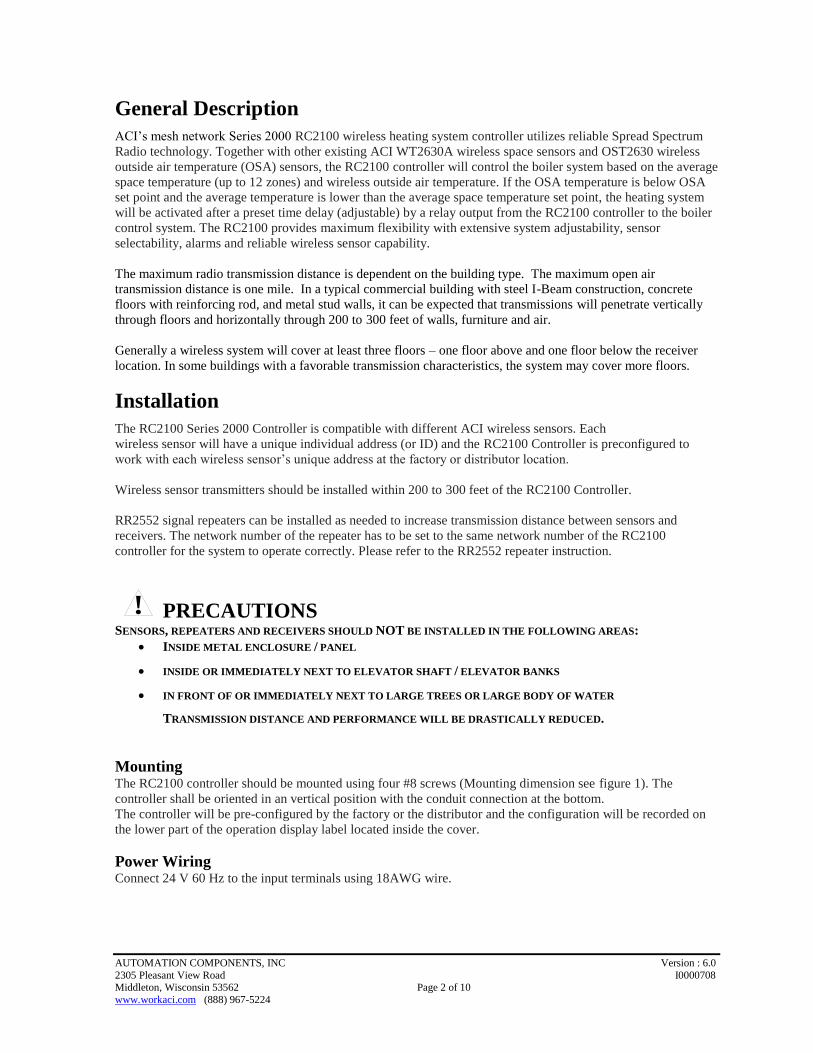
General Description
ACI’s mesh network Series 2000 RC2100 wireless heating system controller utilizes reliable Spread Spectrum
Radio technology. Together with other existing ACI WT2630A wireless space sensors and OST2630 wireless
outside air temperature (OSA) sensors, the RC2100 controller will control the boiler system based on the average
space temperature (up to 12 zones) and wireless outside air temperature. If the OSA temperature is below OSA
set point and the average temperature is lower than the average space temperature set point, the heating system
will be activated after a preset time delay (adjustable) by a relay output from the RC2100 controller to the boiler
control system. The RC2100 provides maximum flexibility with extensive system adjustability, sensor
selectability, alarms and reliable wireless sensor capability.
The maximum radio transmission distance is dependent on the building type. The maximum open air
transmission distance is one mile. In a typical commercial building with steel I-Beam construction, concrete
floors with reinforcing rod, and metal stud walls, it can be expected that transmissions will penetrate vertically
through floors and horizontally through 200 to 300 feet of walls, furniture and air.
Generally a wireless system will cover at least three floors – one floor above and one floor below the receiver
location. In some buildings with a favorable transmission characteristics, the system may cover more floors.
Installation
The RC2100 Series 2000 Controller is compatible with different ACI wireless sensors. Each
wireless sensor will have a unique individual address (or ID) and the RC2100 Controller is preconfigured to
work with each wireless sensor’s unique address at the factory or distributor location.
Wireless sensor transmitters should be installed within 200 to 300 feet of the RC2100 Controller.
RR2552 signal repeaters can be installed as needed to increase transmission distance between sensors and
receivers. The network number of the repeater has to be set to the same network number of the RC2100
controller for the system to operate correctly. Please refer to the RR2552 repeater instruction.
PRECAUTIONS SENSORS, REPEATERS AND RECEIVERS SHOULD NOT BE INSTALLED IN THE FOLLOWING AREAS:
• INSIDE METAL ENCLOSURE / PANEL
• INSIDE OR IMMEDIATELY NEXT TO ELEVATOR SHAFT / ELEVATOR BANKS
• IN FRONT OF OR IMMEDIATELY NEXT TO LARGE TREES OR LARGE BODY OF WATER
TRANSMISSION DISTANCE AND PERFORMANCE WILL BE DRASTICALLY REDUCED.
Mounting The RC2100 controller should be mounted using four #8 screws (Mounting dimension see figure 1). The
controller shall be oriented in an vertical position with the conduit connection at the bottom.
The controller will be pre-configured by the factory or the distributor and the configuration will be recorded on
the lower part of the operation display label located inside the cover.
Power Wiring Connect 24 V 60 Hz to the input terminals using 18AWG wire.
!
AUTOMATION COMPONENTS, INC Version : 6.0
2305 Pleasant View Road I0000708 Middleton, Wisconsin 53562 Page 3 of 10
www.workaci.com (888) 967-5224
CAUTION DISCONNECT POWER BEFORE INSTALLATION TO PREVENT ELECTICAL
SHOCK OR EQUIPMENT DAMAGE.
CAUTION DO NOT USE THIS PRODUCT IN ANY SAFETY RELATED APPLICATIONS
WHERE HUMAN LIFE MAY BE AFFECTED.
For WT2630 wireless temperature sensor, OST2630 wireless compact OSA sensor, and RR2552 Signal
Repeater, please refer to the respective product specifications for installation information.
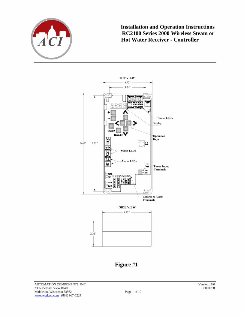
120VAC
Control
Relay
To
Boiler
Control
24 VACCommon
Manual
Auto
Power failure
relay
Manual
Override
SwitchAuto
Controller
Boiler System
Control RelayContact
RC2100 Controller
Input Voltage24VAC 60HZ
Relay Contact Ratings:
1 amp max @ 24 VAC
Ambient Temperature:15°F to 125°F Boiler
Panel
RC2100A Wireless Steam/Hot Water ControllerAutomation Components Inc. Middleton, WI 53562
Aquastat
Control Wiring
R
Important:
Control Power Transformer
Should be located at the
Boiler Panel
Figure #2
Configuration
The RC2100 Series 2000 controller is preconfigured at the factory or the distributor location. If reconfiguration
is needed, please refer to the software configuration manual or call your local distributor.
System Overview
Figure #3
!
!
AUTOMATION COMPONENTS, INC Version : 6.0
2305 Pleasant View Road I0000708 Middleton, Wisconsin 53562 Page 4 of 10
www.workaci.com (888) 967-5224
Description/Operation
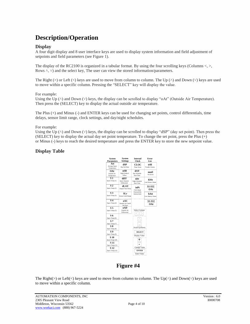
Display A four digit display and 8 user interface keys are used to display system information and field adjustment of
setpoints and field parameters (see Figure 1).
The display of the RC2100 is organized in a tabular format. By using the four scrolling keys (Columns <, >,
Rows ˄, ˅) and the select key, The user can view the stored information/parameters.
The Right (>) or Left (<) keys are used to move from column to column. The Up (˄) and Down (˅) keys are used
to move within a specific column. Pressing the “SELECT” key will display the value.
For example:
Using the Up (˄) and Down (˅) keys, the display can be scrolled to display “oAt” (Outside Air Temperature).
Then press the (SELECT) key to display the actual outside air temperature.
The Plus (+) and Minus (-) and ENTER keys can be used for changing set points, control differentials, time
delays, sensor limit range, clock settings, and day/night schedules.
For example:
Using the Up (˄) and Down (˅) keys, the display can be scrolled to display “dSP” (day set point). Then press the
(SELECT) key to display the actual day set point temperature. To change the set point, press the Plus (+)
or Minus (-) keys to reach the desired temperature and press the ENTER key to store the new setpoint value.
Display Table
System
Parameters
System
SettingsInternal
Clock
Error
List
AstAverage Space
Temperature
dSPDay Set Point
CLOCTime Clock
trblTrouble Alarms
OAtOutside Air
Temperature
nSBNight Setback
Offset
dAYDay Schedule
Start Time
lOStLost Sensor Alarm
S 1Space Temp (1)
S 2Space Temp (2)
S 3Space Temp (3)
S 4Space Temp (4)
S 5Space Temp (5)
S 6Space Temp (6)
S 7Space Temp (7)
S 8Space Temp (8)
S 9Space Temp (9)
S 10Space Temp (10)
S 11Space Temp (11)
S 12Space Temp (12)
diFFSpace Setpoint
Differential
dLAYOutput Time Delay
SLrSensor Limit Range
oACOutside Air Cutoff
Set Point
oADOutside Air
Differential
niteNight Schedule
Start Time
inPtClock Input
External (tb)
Internal (int)
S1-S12
bAttLow Battery Alarm
OAt
Select Column
Scroll Up/Down
Display Value
Change Value
Enter Value
ENTER
SELECT
+-
nonENo Errors
S1-S12
OAt
Figure #4
The Right(>) or Left(<) keys are used to move from column to column. The Up(˄) and Down(˅) keys are used
to move within a specific column.
AUTOMATION COMPONENTS, INC Version : 6.0
2305 Pleasant View Road I0000708 Middleton, Wisconsin 53562 Page 5 of 10
www.workaci.com (888) 967-5224
Space Temperature and Outside Air Temperature
The basic RC2100YA-2K can support up to 4 zones (one sensor per zone). RC2100YB-2K can support up to 8
zones and RC2100YC-2K can support up to 12 zones.
The RC2100 controller is located next to the boiler control panel. The wireless room sensors will transmit space
temperature information to the controller every minute and the controller will calculate the average space
temperature (based on up to 12 space sensors).
If any one of the space sensors is out of Temperature Limit Range (SLr), that particular sensor will be removed
from the average temperature calculation. The sensor will be included again for the calculation when the value
returns to the limit range. The sensor Temperature Limit Range is defined as degrees from set point. The default
value is 10 degrees F above or below Day/Night Set Point.
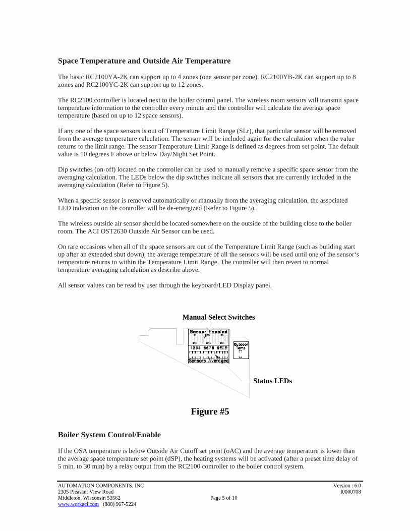
Dip switches (on-off) located on the controller can be used to manually remove a specific space sensor from the
averaging calculation. The LEDs below the dip switches indicate all sensors that are currently included in the
averaging calculation (Refer to Figure 5).
When a specific sensor is removed automatically or manually from the averaging calculation, the associated
LED indication on the controller will be de-energized (Refer to Figure 5).
The wireless outside air sensor should be located somewhere on the outside of the building close to the boiler
room. The ACI OST2630 Outside Air Sensor can be used.
On rare occasions when all of the space sensors are out of the Temperature Limit Range (such as building start
up after an extended shut down), the average temperature of all the sensors will be used until one of the sensor‘s
temperature returns to within the Temperature Limit Range. The controller will then revert to normal
temperature averaging calculation as describe above.
All sensor values can be read by user through the keyboard/LED Display panel.
Manual Select Switches
Status LEDs
Figure #5
Boiler System Control/Enable
If the OSA temperature is below Outside Air Cutoff set point (oAC) and the average temperature is lower than
the average space temperature set point (dSP), the heating systems will be activated (after a preset time delay of
5 min. to 30 min) by a relay output from the RC2100 controller to the boiler control system.
AUTOMATION COMPONENTS, INC Version : 6.0
2305 Pleasant View Road I0000708 Middleton, Wisconsin 53562 Page 6 of 10
www.workaci.com (888) 967-5224
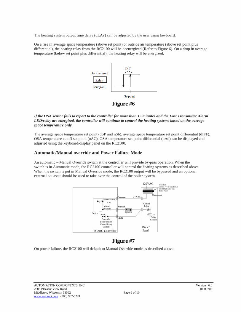
The heating system output time delay (dLAy) can be adjusted by the user using keyboard.
On a rise in average space temperature (above set point) or outside air temperature (above set point plus
differential), the heating relay from the RC2100 will be deenergized (Refer to Figure 6). On a drop in average
temperature (below set point plus differential), the heating relay will be energized.
Figure #6
If the OSA sensor fails to report to the controller for more than 15 minutes and the Lost Transmitter Alarm
LED/relay are energized, the controller will continue to control the heating systems based on the average
space temperature only.
The average space temperature set point (dSP and nSb), average space temperature set point differential (dIFF),
OSA temperature cutoff set point (oAC), OSA temperature set point differential (oAd) can be displayed and
adjusted using the keyboard/display panel on the RC2100.
Automatic/Manual override and Power Failure Mode
An automatic – Manual Override switch at the controller will provide by-pass operation. When the
switch is in Automatic mode, the RC2100 controller will control the heating systems as described above.
When the switch is put in Manual Override mode, the RC2100 output will be bypassed and an optional
external aquastat should be used to take over the control of the boiler system.
120VAC
Control
Relay
To
Boiler
Control
24 VACCommon
Manual
Auto
Power failure
relay
Manual
Override
SwitchAuto
Controller
Boiler System
Control RelayContact
RC2100 Controller
Boiler
Panel
Aquastat
R
Important:
Control Power Transformer
Should be located at the
Boiler Panel
Thermostat
Figure #7
On power failure, the RC2100 will default to Manual Override mode as described above.
AUTOMATION COMPONENTS, INC Version : 6.0
2305 Pleasant View Road I0000708 Middleton, Wisconsin 53562 Page 7 of 10
www.workaci.com (888) 967-5224
Low Limit Control
If any space temperature drops below 35 deg. F and the outside air temperature is below 32 degree F, the heating
systems relay and the Low Limit Alarm LED (figure 9) will be activated.
On a rise of the space temperature (above 35 deg F plus differential) the heating system relay from the RC2100
will be de-energized. The alarm indication will also be turned off.
The space low limit protection set point of 35 deg F, space temperature differential of 4 degree and the OSA
temperature set point of 32 degree F are non-adjustable by user.
If the OSA sensor fails to report to the controller for more than 15 minutes and the Lost Transmitter Alarm
LED/relay are energized, this Low Limit Control feature will be disabled.
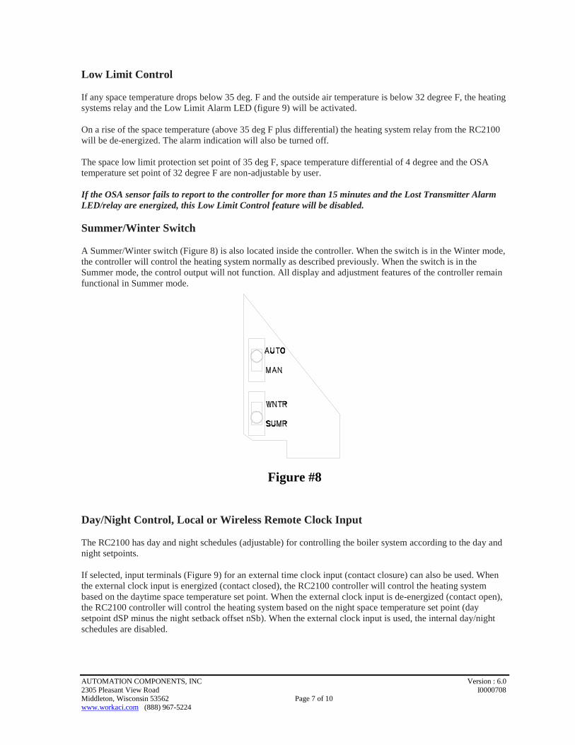
Summer/Winter Switch
A Summer/Winter switch (Figure 8) is also located inside the controller. When the switch is in the Winter mode,
the controller will control the heating system normally as described previously. When the switch is in the
Summer mode, the control output will not function. All display and adjustment features of the controller remain
functional in Summer mode.
Figure #8
Day/Night Control, Local or Wireless Remote Clock Input
The RC2100 has day and night schedules (adjustable) for controlling the boiler system according to the day and
night setpoints.
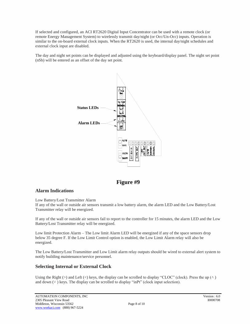
If selected, input terminals (Figure 9) for an external time clock input (contact closure) can also be used. When
the external clock input is energized (contact closed), the RC2100 controller will control the heating system
based on the daytime space temperature set point. When the external clock input is de-energized (contact open),
the RC2100 controller will control the heating system based on the night space temperature set point (day
setpoint dSP minus the night setback offset nSb). When the external clock input is used, the internal day/night
schedules are disabled.
AUTOMATION COMPONENTS, INC Version : 6.0
2305 Pleasant View Road I0000708 Middleton, Wisconsin 53562 Page 8 of 10
www.workaci.com (888) 967-5224
If selected and configured, an ACI RT2620 Digital Input Concentrator can be used with a remote clock (or
remote Energy Management System) to wirelessly transmit day/night (or Occ/Un-Occ) inputs. Operation is
similar to the on-board external clock inputs. When the RT2620 is used, the internal day/night schedules and
external clock input are disabled.
The day and night set points can be displayed and adjusted using the keyboard/display panel. The night set point
(nSb) will be entered as an offset of the day set point.
Alarm LEDs
Status LEDs
Figure #9
Alarm Indications
Low Battery/Lost Transmitter Alarm
If any of the wall or outside air sensors transmit a low battery alarm, the alarm LED and the Low Battery/Lost
Transmitter relay will be energized.
If any of the wall or outside air sensors fail to report to the controller for 15 minutes, the alarm LED and the Low
Battery/Lost Transmitter relay will be energized.
Low limit Protection Alarm – The Low limit Alarm LED will be energized if any of the space sensors drop
below 35 degree F. If the Low Limit Control option is enabled, the Low Limit Alarm relay will also be
energized.
The Low Battery/Lost Transmitter and Low Limit alarm relay outputs should be wired to external alert system to
notify building maintenance/service personnel.
Selecting Internal or External Clock
Using the Right (>) and Left (<) keys, the display can be scrolled to display “CLOC” (clock). Press the up (˄ )
and down (˅ ) keys. The display can be scrolled to display “inPt” (clock input selection).
AUTOMATION COMPONENTS, INC Version : 6.0
2305 Pleasant View Road I0000708 Middleton, Wisconsin 53562 Page 9 of 10
www.workaci.com (888) 967-5224
Press and hold the Time Set button until the Time Set LED is energized (refer to Figure 9). Press the “SELECT”
key. The current clock selection will be displayed (“int” –internal clock or “tb” – external clock using terminal
block).To change the selection, press the Plus (+) or Minus (-) keys to the desired clock option and press the
ENTER key to set.
Press and hold the Time Set button until the Time Set LED is de-energized (refer to Figure 9). Press SELECT
key to verify the setting has been changed.
Setting the Real Time Clock
Using the Right (>) and Left (<) keys, the display can be scrolled to display “CLOC” (clock).
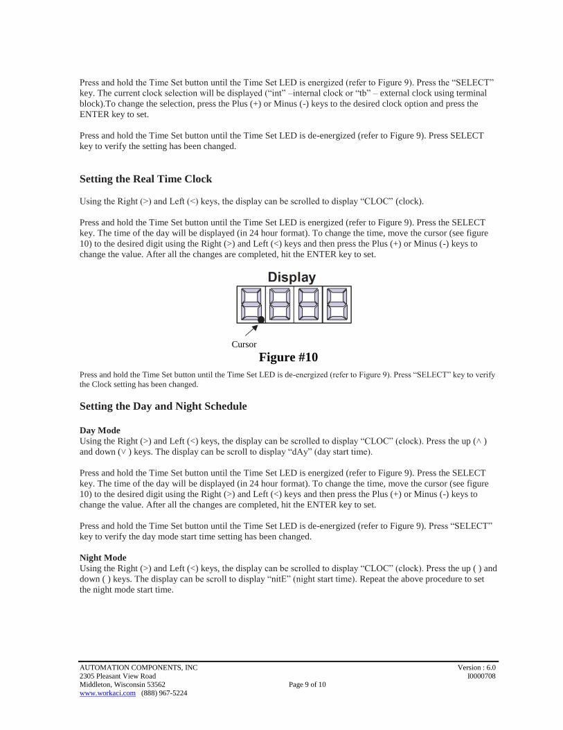
Press and hold the Time Set button until the Time Set LED is energized (refer to Figure 9). Press the SELECT
key. The time of the day will be displayed (in 24 hour format). To change the time, move the cursor (see figure
10) to the desired digit using the Right (>) and Left (<) keys and then press the Plus (+) or Minus (-) keys to
change the value. After all the changes are completed, hit the ENTER key to set.
Cursor
Figure #10
Press and hold the Time Set button until the Time Set LED is de-energized (refer to Figure 9). Press “SELECT” key to verify
the Clock setting has been changed.
Setting the Day and Night Schedule
Day Mode
Using the Right (>) and Left (<) keys, the display can be scrolled to display “CLOC” (clock). Press the up (˄ )
and down (˅ ) keys. The display can be scroll to display “dAy” (day start time).
Press and hold the Time Set button until the Time Set LED is energized (refer to Figure 9). Press the SELECT
key. The time of the day will be displayed (in 24 hour format). To change the time, move the cursor (see figure
10) to the desired digit using the Right (>) and Left (<) keys and then press the Plus (+) or Minus (-) keys to
change the value. After all the changes are completed, hit the ENTER key to set.
Press and hold the Time Set button until the Time Set LED is de-energized (refer to Figure 9). Press “SELECT”
key to verify the day mode start time setting has been changed.
Night Mode
Using the Right (>) and Left (<) keys, the display can be scrolled to display “CLOC” (clock). Press the up ( ) and
down ( ) keys. The display can be scroll to display “nitE” (night start time). Repeat the above procedure to set
the night mode start time.

AUTOMATION COMPONENTS, INC Version : 6.0
2305 Pleasant View Road I0000708 Middleton, Wisconsin 53562 Page 10 of 10
www.workaci.com (888) 967-5224
PRODUCT SPECIFICATIONS
Supply Voltage 24VAC 60Hz
Power Consumption 3VA Maximum
RF Data Protocol IEEE 802.15.4-2003/2006
Operating Frequency 902-928 MHz
Output Power +11 dBm
Receiver Sensitivity -110 dBm
Open Field Range One mile (line of sight)
Sensor Indicating Ranges
Outside Air Sensor -40 to 160°F (-40 to 71°C)
Space Temperature 32 to 104°F (0 to 40°C)
Accuracy +/- 1°F
Boiler System Control Output 3 terminals for heating system enable output
(Common, Manual, & Auto) – SPST N.O.
Pilot Duty (1 Amp max. at 24VAC)
Error Outputs
Low Battery/Lost Transmitter Alarm Output/ Low Limit Alarm Output
Pilot Duty Relay Contact (SPST N.O., 1 Amp max. at 24VAC)
Set Point Adjustment Range 35 to 95°F
Enclosure Material Polycarbonate (Nema 4X)
Rating UL 94 HB (Nema 4X)
Environment Operating Temperature
15 to 125°F (-9 to 51°C)
Operating Humidity 5 to 95% RH (non-condensing)
WARRANTY SPECIFICATION
The ACI Wireless Series is covered by ACI’s Two (2) Year Limited Warranty, which is located in the front of
ACI’S SENSORS & TRANSMITTERS CATALOG or can be found on ACI’s web site: www.workaci.com.
WEEE Directive
At the end of their useful life the packaging and product should be disposed of via a suitable recycle
center. Do not dispose of with household waste. Do not burn.