
RADIO SET AN/PRC-5
87
WAR DEPARTMENT TECHNICAL MANUAL RADIO SET AN/PRC-5 WAR DEPARTMENT 0 JUNE 1944
-
Upload
khangminh22 -
Category
Documents
-
view
2 -
download
0
Transcript of RADIO SET AN/PRC-5

WAR DEPARTMENT TECHNICAL MANUAL
RADIO SET
AN/PRC-5
WAR DEPARTMENT 0 JUNE 1944

WAR - DEPARTMENT TECHNICAL MANUAL
TK11-265
RADIO SET AN/PRC-5
WAR DEPARTMENT -
I
. ~ . '
21 JUNE 194-4-
•'' •..: · .. ~·· ~ . ,_. : _,.,_ ' ·:~· .. ~...,~·· ···~ ';· .,

WAR DEPARTMENT,
WASHINGTON 25, n: C., 21 JUNE 194-4-.
'Jl4 11-265, Radio Set AN/PRC-5, ie published for tho information and
guidance of all concerned.
[i.. G. 300.7 (11 May 1944) .J BY ORDER OF THE SECRETARY OF WAR:
OFFICIAL:
J. A. ULIO,
Major General,
The Adjutant General.
DISTRIOOTIOH:
I
(For explanation of symbols see FM 21-6.)
II
G. C • MARSHALL,
Chief of Staff.

WARNING
HIGH VOLTAGE
is used in the operation of this equirment.
DEATH ON CONTACT
may result if operating personnel fail to observe safety precautions.
III

SECTION I.
TABLE OF CONTENTS
Description.
General .................... · • · • · · ·
Table of components •••••••••••••••
Total weights •••••••••••••••••••••
Frequency coverage ••••••••••••••••
Source of power •••••••.•••••••• • • •
Power input . ....••................
Transceiver •••••••••••••••••••••• •
Carrying case •••••••••••••••••••••
Headset •••••••••••••••••••••••••••
Key • ••••••••••••••••••••••••••••••
Antenna •• •.••.......••••••••.••.•.
Vacuum tubes .•••••.•••••••••••••••
Adapters • ••••••••.••••••••••••••••
Crystals ••••.•••••••••••••••••••••
Transmitter plug-in coils •••••••••
Operating spares ••••••••••••••••••
II. Installation and operation.
Initial procedure •••••••••••••••••
Installation of antenna •••••••••••
Power line connection •••••••••••••
Transmitter crystal and coil units
Receiver operation ••••••••••••••••
Transmitter operation •••.••••••••••
IV
Paragraph
1
2
3
4
5
6
7
8
9
10
11
12
13
14-
15
16
17 18
19
20
21
22
1
2
3
3
4
4
5
10
11
11
11
11
12
12
12
13
14
15
16
16
17 18

Paragraph Page
SECTION II. Installation and operation (contd}.
Operating precautions •••.••••••••
III. Functioning of parts.
23 20
General. . . . • . . . . . . • . . . . • . . . . . . . . . 24- 23
Receiver functioning............. 25 23
Radio-frequency amplifier........ 26 23
Converter. • • • • • • • • • • • • . • • • • • • • • • • 27 24
High-frequency oscillator circuit 28 25
I-f amplifier. • • • • • . • • • • • • • • • • • • • 29 26
Diode detector................... 30 27
A-f amplifier stages............. 31 28
Beat-frequency oscillator........ 32 28
Power supply..................... 33 29
Transmitter functioning.......... 34 31
Crystal oscillator............... 35 31
Power amplifier.................. 36 32
Antenna circuit.................. 37 34
IV. Maintenance.
General •••••••••••••••••••••••••• 38 36
Operational inspection........... 39 36
Replacement of tubes, fuses, and
indicator lamps................ 40 37
Receiver alignment............... 41 38
Procedure in locating trouble.... 42 43
Voltage measurements............. 43 47
v

Paragraph Page
SECTION IV. Maintenance (contd).
Fig.
l
2
3
4
5
6
7
8
Point-to-point resistance measurements •. • 44 47
v. Supplementary data.
Resistor and capacitor color-code charts. 45 49
Maintenance parts list for
Radio Set AN/PRC- 5. . . • • . . . . • • . • • • • . . . • . 46 61
LIST OF ILLUSTRATIONS
No. Title Page
Radio Set AN/PRC-5, front pe.nel and operating components IX
Radio Set AN/PRC-5, front panel details .••...........•.. 7
Radio Set AN/PRC-5, receiver chas s is .................... 22
Radio Set AN/PRC-5, transmitter and power-supply chassis 30
Radio Set AN/PRC:-5, functional diagram of plRte-tank and
Antenna circuits........................................ 34
RRdio Set AN/PRC-5,
RA.dio Set AN/PRC-5,
Radio Set AN/PRC-5,
chassis tube-socket
location of trimmer adjustments .••..
receiver chassis tube-socket layout.
transmitter and power-supply
layout .. ............................
41
47
47
9 Molded-mica capacitors, three-dot color code............ 70
10 Molded-mica capacitors, RMA six-dot color code.......... 51
11 Molded-mica capacitors, AWS six-dot color code.......... 53
12 Molded-paper capacitors, AWS si x-dot color code......... 55
13 Tubular ceramic capacitors, RMA color code.............. 57
14 Fixed resistors, RMA and AWS color codes................ 59
15 Radio Set AN/PRC-5, schematic diagram................... 77
VI

;
DESTRUCTION NOTICE
WHY - To prevent the enemy from using or salvaging this equipment for his
own benefit.
WHEN- As ordered by your commander.
HOW - l. Smash - Use any heavy instrument at hand.
2. Cut - Use any sharp instrument at hand.
3. Burn - Use gasoline, kerosene, oil, any incendiary material
at hand.
4. Explosives - Use firearms.
5. Disposal - Obliterate: bury, scatter, or throw into any body of
water.
USE ANYTHING IMMEDIATELY AVAILABLE FOR DESTRUCTION OF THIS EQUIPMENT.
WHAT-1. Smash- Receiver, transmitter, antenna, power transformer,
crystals, tubes, headphones, telegraph key,
resistors, capacitors, coils, switches, etc.
2. Cut - -~~ iring and line cords.
3. Burn - Capacitors, canvas bags and equipment receptacles in
carrying case.
4. Bury or scatter - Any or all of above pieces.
DESTROY EVERYTHING
VII

. . ~.
.. ,
~. t, . . ·: ,~ . • ... :
... ~ ... ' . '·' .
. , , . \' ~ ·~' ' . ,'· •. ~ '
'. . ...
. ' . ···~. .
... - .
. ' . ' - ~ . - .... ·-·.
-·~ '.... . . ' . ' . '. ' . .. •, .
..... ·-· ' ...
!• . -~ . ~ ~ j
\ '" ~ .. . ~ -~ . .. . .
.. ~-~::;~ .,~: ~~· :.:. ' : .
. ··~ '
,· ·.
SAFETY NOTICE
THIS EQUIPMENT USES DANGEROUSLY HIGH VOLTAGES. DO NOT
CHANGE VACUUM TUBES OR MAKE CHANGES INSIDE OF THE TRANSCE;IVER
UNIT \'liTH THE PQll'lm PLUG PLUGGED INTO A POWER SOURCE, EXCEPT
'AS SPEtiFICJ.Li.Y DIRECTED IN THIS MANUAL.
A )t()DERATELY HIGH VOLTAGE IS PRESENT ACROSS THE T''NO
SIDES ·OF 'l'HE KEY. IT IS NOT LIKELY THAT EXPOSURE TO THIS
VbLTA<lE WILL BE FATAL BUT 'IT WILL CAUSE A PAINFUL SHOCK UNDER
ClliTAIN CONDITIONS. DO NOT TOUGH OOTH SIDES OF THE KEY WITH
THE :EQU!P»£NT ±N OPERATION; Do NOT TOt£H ONE SIDE OF THE KEY
AND THE CHASSIS AT THE SAlLE TIME.
THE PLUG-IN CO!LS OF THE TRANSMITTER ARE ISOLATED m:J1L
THE HIGH-VOLTAGE SOUBCE BUT THEY CAN CAUSE PAINFUL RADio-
. FREQUENCY BURNS IF TOUCHED WHILE THE EQU:IPMENT IS IN
0~1'ION' AS A TRANSMITTER •
VIII

~
H ><:
KEY-J47
CORD CD201A
I
ANTENNA
/
·', ~ -- •' ~ • ~ ' "'" ~ ""
. ............._ " TRANSMITTING COILS
•• '-CRYSTALS FT-2"43
HEADSET HS-30
CORDCD605 TL 14520 -··
Figure 1. Radio Set AN/PRC-5, front papel and operating
components.
.· ·,

SECTION I
DESCRIPTION
1. GENERAL. Radio Set AN/PRC-5 is designed for short-wave communication
over medium distances from variable points. It is a portable transceiver,
the component parts of which are a radio telegraph transmitter, a radio
receiver, and a power-supply unit common to both. All three are constr
ucted in one unit which is mounted in a luggage-type carrying case. The
carrying case also houses other associated equipment such as the tele
graph key, headset, antenna, and various spare parts such as fuses,
indicator lamps, and vacuum tubes.
!• The transmitter is of the radio-telegraph type, with a power output
of 16 watts when the output frequency is the same as that of the crystal,
and an output of 10 watts when the output frequency is twice that of the
crystal. The transmitter i~ composed of two stages: a crystal-controlled
oscillator stage followed by a power-amplifier stage. Both of these stages
are keyed during periods of transmission.
£. The receiver is of the superheterodyne type, and contains enough audio
frequency amplification to operate the headset provided with the equipment.
1

2. TABLE OF COMPONENTS.
Quan-tity Name of comoonent
1
5
6
1
1
1
1
1
1
Antenna
Adapters, plug-in, socket power
Crystals, mounted in Ft-243 holders, one e~. 4635, 5263, 5925, 6525, 7150, and 7825 ke
Case, portable luggage type
Cord CD-201-A, for key, with Plug PL-55
Cord CD-605, for headset, with Transformer C-410 and Plug PL-55
Headset Hs-30 (less cord, transformer, and plug)
Key J-47, radio telegraph
Radio receiver and transmitter, Radio Set AN/PRC-5 Includes: 1 set of
vacuum tubes as follows:
Quan- JAN tity type
2 6SK7 1 6SA7 1 6SR7 1 6N7
Dimensions in.J Unit
weight Height Width Depth Length Diam (lb)
- 1800 1/16
-- --
1-3/16 7/8 7/16 --
0.3
72 0.22
1-1/8 2-3/4 5-3/8 --
ll.C 10.0 4-1/8 --
2
0.4
0.05
Variable
0.2
0.6
0.15
0.6
15.0

Quan~
tity Name of comnonent Dimensions in.) Unit
HeiKht weight
Width Depth Length Diam. (lb)
Quan- JAN tity type
1 6V6 l 6L6 1 5Z4
and also 4 Plug-in ~e coils
for transmitter l Pilot Lamp Pl l Pilot Lamp P2
2 Technical Manuals 9.0 5-7/8 - -- -- 0.25 ll-265, Radio Set AN/PRC-5
l Set vf vacuum tubes, -- -- -- -- - 0.1 running spares, as follows:
Quan- JAN tity type
2 6SK7 l 6SA7 1 6SR7 l 6N7 l 6V6 1 6L6 l 5Z4
3. TOTAL WEIGHTS. The transceiver unit alone weighs 15 pounds.
The complete assembly, including the carrying case and associat
ed operating components and spare parts, weighs approximately
25 pounds (subject to slight variation).
~. FREQUENCY COVERAGE.
a. The transmitter covers ~.ooo to 16,000 kilocycles in four
bands: 3

(1) 4,000 to 6,000 kilocycles.
(2) 6,000 to 8,000 kilocycles.
(3) 8,000 to 12,000 kilocycles.
(4) 12,000 to 16,000 kilocycles.
E• The receiver covers 4,500 to 16,000 kilocycles in two bands:
(1) 4,500 to 8,000 kilocycles.
(2) 8,000 to 16,000 kilocycles.
5. SOURCE OF POWER (fig. 1). The equipment is designed for operation from a
110- or 220-volt, 50- to 60-cycle, single-phase source. The equipment is
set for· operation from a source of either volta.ge by manipulation of the
switch marked 110-220, located near the FUSE receptacle in the upper left
hand corner of the transceiver unit.
CAUTION: THIS EQUIPMENT IS DESIGNED FOR OPERATION FROM 110-VOLT OR
220-VOLT, 50- TO 60-CYCLE A-c POWER ONLY. IF OPERATION IS
ATTEMPTED ON A D-e POWER SOURCE OR ON AN A-c SOURCE OF WIDELY
DIFFERENT VOLTAGE AND FREQUENCY, THE EQUIPMENT MAY BE PERMANENTLY
DAMAGED.
6. POWER INPUT. The line currents and power consumption are as follows:
Item llO volts 220 volts
Line current (receiver on) 0.51 ampere 0.25 ampere
Line current (transmitter on) No load 0.55 ampere 0.30 ampere
Line current (transmitter on) Full load 0.86 ampere 0.46 ampere
Power input (receiver on) 41.0 watts 46.0 watts
Power input (transmitter on) No load 45.0 watts 51.0 watts
Power input (transmitter on) Full load 78.0 watts 84.0 watts
4

7. TRANSCEIVER (fig. 1). The transmitter and the power supply form the
upper half of the transceiver unit, and the receiver forms the lower half.
All of the controls for the transceiver unit are mounted on a single panel
covering the face of the unit (fig. 1).
!· Power Supply. The power supply portion of the transceiver unit supplies
all operating voltages for both the transmitter and receiver portions of the
unit. It consists of a power transformer, a full-wave vacuum-tube rectifier,
and a capacitor-input filter consisting of three capacitors (two in series)
and one choke coil.
(1) The 110-220 toggle selector switch on the upper left-hand side of the
transceiver panel permits operation on either 110-volt or 220-volt, 50- to
60-cycle a-c power source. The power transformer has two 110-volt
primary windings. The toggle selector switch connects the two primary
windings in parallel for operation from a 110-volt power line, and connects
them in series for operation from a 220-volt line.
(2) A fuse, located on the upper left-hand side of the transceiver panel in
the holder marked FUSE, is connected between one side of the power input
cord and the primary circuit of the power transformer for protection of the
equipment from short circuits or accident~ overloads.
(3) The green pilot light, located immediately below the FUSE receptacle
and the 110-220 toggle switch, is connected across one of the filament
windings of the power transformer, and lights when the transformer is
energized.
(4) The power cord, which is permanently attached to the transceiver unit,
may be adapted for use with various types of power outlet sockets by means
of the adapters furnished with the equipment (par. 2).
5

(5) The OFF-REC-SEND switch, located above the FUSE holder and the 110-220
switch near the upper left-hand corner of the panel, disconnects the primary
circuit of the power transformer from the power cord in the OFF position,
causes power to be applied to the receiver in the REC position, and causes
power to be applied to the transmitter in the SEliD position. The fila
ments of the vacuum tubes in both the receiver and the transmitter circuits
are energized at both the REC and SEND positions of the switch. In
addition to the above functions, this switch also transfers the antenna
connection from the receiver to the transmitter, and vice versa.
(6) The GND and ANT binding posts, located in the upper left-hand corner of
the panel, provide a means of connecting the ground and antenna leads to
the transceiver unit.
E• Transmitter. The transmitter portion of the transceiver unit consists
of a two-tube (crystal-controlled master oscillator followed by a power
amplifier stage), four-band circuit arrangement covering a frequency range
of 4,000 to 16,000 kilocycles.
(1) A change from one band to another is accomplished by inserting the
proper crystal and the oscillator and power-amplifier coil units into their
proper receptacles on the front panel. The oscillator and amplifier coil
units are completely interchangeable with each other, and the operating
circuits have been designed so that only four coils are required to cover
the entire range of the transmitter (par. 20£).
(2) The following transmitter controls and receptacles are located on the
front panel of the transceiver unit (fig. 2):
6

GND ANT C40 C41 C4 7
SW3 Rl6
Figure 2. Radio Set AN/PRC-5, f ront panel details.
7
I.
Jl
SW5
J2
SW4

(!) ANT CURRENT. An indication of transmitter antenna current is provided
by a pilot lamp connected in series with the transmitter antenna lead.
This lamp is installed near the top edge of the transceiver unit behind the
clear jewel indicator. This lamp is shunted by a small inductor which will
maintain operation of the transceiver unit in the event of failure of the
lamp filament •
(£) AMP COIL. This receptacle, located immediately below the ANT CURRENT
indicator, receives the power-amplifier plate coil required for operation
at a given frequency.
(£) OFF-REC-SEND Switch. Refer to subparagraph !(5) above for a descrip
tion of this switch.
(d) ANT COUPLING. This control, located at the top-center portion of the
transceiver unit, provides a means of adjusting the antenna loading
capacitor and, in turn, the load on the transmitter power-amplifier
circuits (pars. 22g and !) .
(~) .AlP TUNING. This control, located below the ANT COUPLING control,
provides a means of tuning the power-amplifier plate circuit to resonance.
The tuning capacitor controlled by this knob is similar to that used in the
ANT COUPLING control.
(!) OX TUNING. This control, located below the i\1lP TUNING control, is
attached to the oscillator plate circuit tuning capacitor, and provides a
means of bringing this circuit into resonance.
(g) CRYSTAL. This receptacle, located near the upper right-hand corner
of the panel, receives the crystal unit required for operation on a given
frequency. Six crystals are furnished with ' the unit, and the frequency
of each is marked directly on the crystal holder (par. 2).
8

(h) OSC COIL. This receptacle, located immediately below the CRYSTAL
receptacle, receives the oscillator plate coil req1thed for operation at a
given frequeney.
(!) OSC-A1~ Switch. This slide-type switch, located below the OSC COIL
receptacle, provides a means of switching the d-e milliammeter, located
below the receiver tuning dial, from the oscillator cathode circuit to the
power-amplifier cathode circuits or vice versa. In the OSC position of
this switch, the cathode current of the oscillator tube is indicated by the
meter. In the AMP position, the cathode current of the power-amplifier tube
is indicated.
(j) KEY Jack. This jack, located below the OSC COIL receptacle and to the
right of the OSC-AMF switch, receives Plug PL-55 on the end of the cord
attached to Key J-47.
£• Receiver. The receiver por~ion of the transceiver unit consists of a
five-tube superheterodyne circuit arrangement, with automatic volume
control (ave), a beat-frequency oscillator, and a frequency range of 4,500
to 16,000 kilocycles covered by two bands. The beat-frequency oscillator
is provided for the reception of c-w signals. When the reception of voice
or tone-modulated s~gnals is desired, this oscillator may be switched off
as described below (subpar. £(4)). The following receiver controls (fig. 2)
are located on the lower portion of the transceiver unit:
(1) RreEIVER TUNING. The RECEIVER TUNING control, located to the left of
the d-e milliammeter in the center of the panel, controls the 3-gang
variable tuning capacitor in the receiver circuits as well as the cali
brated dial which is visible in the small window directly above the d-e
milliammeter. This dial is calibrated directly in megacycles (me), with
9

band 2 (8.0 to 16.0 me) on the top portion of the dial, and band 1 (4.5 to
8.0 me) on the bottom portion.
(2) BAND SWITCH. The BAND change switch, located in the lower left-hand
corner of the panel, has two positions marked 1 and 2. The frequency ranges
covered in these two positions are as follows: position 1: 4,500 to 8,000
kilocycles; position 2: 8,000 to 16,000 kilocycles. The BAND switch is
protected by a rectangular cover fastened to the panel qy screws. Under
neath this cover are several adjustment screws used in aligning the
receiver circuits. Immediately above the BAND switch is another square
cover plate over trimmer capacitor adjustment screws also used in aligning
the receiver circuit. For the location of these adjustments refer to
figure 6.
(3) VOLUME CONTROL. The receiver VOLUME control, located to the right and
below the d-e milliammeter, controls the amount of a-f voltage fed to the
grid of the first audio-amplifier stage and the level of sound in the head
set.
(4) BFO OFF-oN SWITCH. This switch, located to the right of the VOLUME
control and immediately below the OSC-AMP switch, controls the operation
of the beat-frequency oscillator by opening or closing its plate voltage
circuit.
(5) PHONES JACK. The PHONES jack, located in ~he bottom right-hand corner
of the panel immediately below the KEY jack, receives Plug PL-55 attached
to the end of the headset cord.
8. CARRYING CASE. The transceiver assembly is mounted on slip-hinges in a
luggage-type carrying case, and it is held in place in the case by a spring
tension latch. Folding-type brackets on the two sides of the trans-
10

ceiver unit are attached to the side walls of the transceiver compartment of
the carrying case to permit tilting of the transceiver unit for greater
convenience in operating. The antenna wire, with one insulator attached,
is wound on blocks, attached to the inside of the carrying-case lid, for
carrying purposes only. Several canvas bags attached to the inside of
the carrying case, at several convenient points, house Headset HS-30,
Key J-47, the extra crystal and transmitter coil units, and spare fuses,
pilot lamps, and tubes.
9. HEADSET (fig. 1). Headset H5-30, furnished with the equipment, plugs
into the PHONES jack on the transceiver unit by means of Plug PL-55
attached to the end of headset Cord CD-605. The 256-ohm primary winding
of Transformer C-410 is connected to the headset, and the 8 ,000-ohm
secondar,y winding is connected to the receiver output by means of the
complete headset and cord assembly.
10. KEY (fig. 1). Key J-47, furnished with the equipment, plugs into the
KEY jack on the transceiver unit by means of Plug PL-55 attached to the
end of Cord CD-201-A.
ll. ANTENNA. The antenna consists of a 150-foot length of flexible
insulated wire. The antenna is equipped with a s.mal.l airplane-type
insulator and a 20-foot length of chalk-line cord for attachment of the
remote end of the antenna wire to a suitable support. When the equipment
is being transported, the antenna wire is coiled around. blocks attached
to the lid of the carrying-case (par. 8).
12. VACUUK TUBES. The vacuum tubes used in Radio Set AN/PRC-5 are shown in
the following tabulation:
11

Signal Corps JAN Reference Function type t~e Base
Vl Receiver r-f VT-117 6S¥:7 Octal amplifier
V2 Receiver VT-150 6SA7 Octal converter
V3 Receiver i-f VT-117 6S¥:7 Octal amplifier
V4 Receiver detector VT-233 6Sf(f Octal and BFO
V5 Receiver a-t VT-96 6N7 Octal amplifier .stages
V6 Transmitter crystal VT-107 6V6 Octal oscillator
V7 Transmitter power- VT-115 616 Octal amplifier
vs Full wave rectifier VT-74 5Z4 Octal
13. ADAPTERS. A set of five adapters is furnished so that the plug on the
end of the power cord may be adapted to fit into various types of power
outlet sockets that may be encountered while using the equipment.
14. CRYSTALS (fig. 1). A set of six crystals, mounted in FT-243 holders,
are furnished with the equipment. These crystals permit fundamental
frequency operatiou on the following frequencies: 4635; 5263; 5925; 6525;
7150; am 7825 kllocyeles. The crystals also permit operation at the
se~ond harmonic frequencies of the crystals as follows: 9270; 10,526;
11,850; 13,050; 14,300; and 15,650 kilocycles.
15. TRANSMITTER PLUG-IN COILS {fig. 1). A set of four transmitter coil
units ' turnished with the equipment. These coils are wound on clear
phenolic f orma attached to a cerdmic·plug strip having four pin-type
plugs. The coils plug into ceramic jack strips installed in the trane-
12

ceiver unit. Identification o! the four coils ie marked on the bottom of'
the ceramic plug strip; two coils are marked Band 0 and one each Band B
and Band C • All of the coils are completely interchangeable so far as
insertion into the jack strips is concerned.
16. OPERATING SPA.'FtES. The operating spare parts, housed in canvas bags
attached to the inside of the carrying case, are as follows:
.!• A complete duplicate set of vacuum tubes as listed in paragraph 12.
b. Two spare fuses, 2-ampere, 250-volt type.
£.. One antenna loading indicator pilot lamp, 0 .06-ampere, 2-volt type,
with bayonet base.
5!· One power indicating pilot lamp, 0.15-ampere, 6- to 8-volt type, with
bayonet base.
13

17. INITIAL PROOEDURE.
SEX:TION II
INSTALLATION AND OPERATION
!• Unpack the box which contains Radio Set AN/PRC-.5 and check to see
that the following items are included:
(1) The transceiver unit with fuse, pilot lights, and a set of vacuum tubes
installed; mo\Ulted in a portable luggage-type carrying case.
(2) One complete set of spare tubes (pars. 12 and 16).
(3) One Headset HS-30.
(4) One Key J-47.
(5) One set of six crystals (par. 14).
(6) One set of four transmitting coila (par. 15).
(7) Two spare fuses {par. 16).
{8) Two spare pilot lamps (par. 16).
{9) One set ot five socket adapters (par. 13).
(10) One antenna, wound on blocks inside ot carrying-case cover {par. 11).
(11) Two copies ot Technical Manual 'Ill ll-26.5 1 Radio Set AN/PRC-5.
~· Inspect the equipment for any damage that may have occurred in transit.
~· In otder to make sure that each vacuum tube is seated tirml.y in its
socket, it will be necessary to remove the transceiver unit from the carrying
case. To do this proceed as follows:-
(1) Release the spring-tension latch holding·the top end of the transceiver
unit and raise the top end of the transceiver unit as far as possible
(tilt it up).
(2) Disengage the folding brackets, which hold the transceiver unit, from
the heads ot the holding screws in the side walls of the transceiver
14

compartment.
(3) Lift the traneceiver unit still further and slip it off the slip-hinges
attached to the bottom edge of the transceiver unit and the front edge of
the carrying case.
(4) Inspect the interior portion of the unit for possible damage during
ehi}DBnt and make sure that all vacuum tubes are seated firmly in their
correct sockets. Ka.ke sure that the pilot lamps have been installed in
their proper positions.
(5) Replace the transceiver unit on the slip-hinges.
(6) Lower the unit carefully until the folding brackets can be reinstalled
properly, and engage the lower ends of the brackets with the heads of the
holding screws.
(7) If immediate operation of the equipment is desired, the transceiver unit
111.83 be left in this tilted. position for convenience in operating. If the
equipment is to be carried or stored., lower the transceiver unit until the
spril)g-tenaion latch engages the top edge of the unit.
18. INSTALLATION OF ANTENNA. Unwind the antenna wire from the supporting
blocks attached to the inside of the lid of the carrying case, and attach
the end with the insulator to a suitable support by means of the cord
,.ttached to the insulator. For best results, this end of the antenna
should be as high as possible above the earth and surrounding buildings or
other objects. Under certain conditions it may not be possible to install
the antenna in such a manner. Under such conditions it may be necessary to
coil the antenna wire around the molding in a room or to drop as much as
possible of its total length out of a window. No hard and fast rules can
be given for the installation of the antenna under such conditions, and
15

successful operation of the equipment will depend on the skill and
ingenuity of the operator. Remember that the entire length of the
antenna should be in free space so far as physically possible. If it is
necessary to support the wire at points along its length, these additional
points ot support should be insulated as well as possible either by
supporting the wire with pieces of cord or rope or by tying the wire to
wooden objects. Do not attach the wire directly to metal objects. Attach
the other end of the antenna wire to the binding post marked ANT, located
in the upper lett-hand corner of the transceiver unit. If a good growld
connection such as a water pipe is available, connect the GND post which is
adjacent to the ANT post to the pipe by means of a short length of wire
(not furnished with the equipment) •
19. POWER LINE CONN&:TION (fig. 2). Determine the voltage and the frequency
of the source of power to be used. For Radio Set AN/PRC-5 to operate
properly, the line frequency must be between 50 and 60 cycles and the line
voltage must be between llO and 120 volts or between 220 and 240 volts.
Then proceed as follows:
!• Throw the OFF-.REX:..SEND switch (SWl) to the OFF position.
£. Throw the 11o-220 toggle switch (SW2) to the position corresponding
to the voltage of the available power source.
~· Determine what adaptt3r is needed, if &ey", to connect the power cord
to the power outlet, and fit the adapter on the power cord plug.
g. Connect the power cord to the power outlet.
20. TRANSMITTER CRYSTAL AND COIL UNITS (fig. 2).
!• Crystal. The frequency of each crystal is marked on the outside of
Crystal Holder FT-243. Select the crystal of the desired operating
16

frequency, or one-half the value of the desired output frequency ~par. 14),
and insert it in the CRYSTAL receptacle near the upper right-hand. corner
of the transceiver panel.
_2. Transmitter Coils. Four transmitting coils (112 and Ll4) are furnished
with Radio Set AN/PRC-5 (par. 15). To operate on a given frequency,
determine the coils required for operation at that frequency from the
following table, and. inse~ the coils selected in the ~ COIL and AMP COIL
receptacles, respectively.
c. Frequency-coil Table.
Output Crystal Oscillator Amplifier frequency (me) frequency (roc} coil coil
4.0 to 6.0 4.0 to 6.0 Band c Band B
6.0 to s.o 6.0 to 8.0 BandD Band C
8.0 to 12.0 4.0 to 6.0 Band C Band D
12.0 to 16.0 6.0 to 8.0 Band D Bani D
~· Example. If the desired transmitting frequency is 5,263 kilocycles,
proceed as follows:
(1) Insert the crystal marked 5,263 kc into the CRYSTAL receptacle.
(2) Use the above table to determine the proper coils:
(!) 5,263 kc lies between 4.0 and 6.0 me.
(£) The 4.0 to 6.0 me band requires BAND C coil for the oscillator and
BAND B coil for the amplifier.
(3) Insert the BAND C coil in the OSC COIL receptacle.
(4) Insert. the BAND B coil in the Al4P COIL receptacle.
21. R&:EIVER OPmATION.
!• Throw the BAND switch (SW3) to the desired position.
17

•
(1) Position 1 for frequencies between 4,500 and 8,000 kilocycles.
(2) Position 2 for frequencies between 8,000 and 16,000 kilocycles.
~· The frequency received is indicated on the dial, visible through the
small window located above the d-e milliammeter. Rotate the REX::EIVER
TUNING knob to the desired receiving frequency.
£• Adjust the BFO OFF-QN switch (S!N4) for the desired operation:
{1) Throw to ON when receiving c-w signals.
{2) Throw to OFF when receiving voice~modulated signals.
~· Turn the VOLUME control to the right (clockwise) to the ~ volume
position. With the receiver in operation the volume level may be adjusted
to suit the convenience of the operator.
!• Plug Headset HS-30 into the PHONES jack.
!• Throw the OFF-REX:-s.END switch to the R1!X: position.
&• Allow approximately 1 minute for the vacuum tube filaments to reach
their proper operating temperature. The receiver now should be in operating
condition, which will be evidenced by the presence of hiss and crackling
sounds due to static and other forms of interference. If signals are not
heard at the setting of the RECEIVER TUNING knob, try other settings until
a signal is picked up. If it is impossible to pick up a.ny signals or if
the headset is dead, refer to paragraph 42 •
22. TRANSWITmR OPERATION· (fig. 2).
!• Plug telegraph Key J-47 into the KEY jack.
!!• Throw the OFF-REt-SEND switch to the SEND position.
£• Tune the cry~al oscillator as follows:
(1) Throw the 000-AMP switch (SW5) to the a&; position.
(2) Press Key J-47 while rotating the OSC TUNING knob. Rotate the knob
18

until a pronounced dip is indicated by the d-e millimmeter. This
dip in current indicates that the oscillator is operating.
(3) In order to insure rapid starting of the crystal oscillator while
keying, rotate the knob slightly away from the minimum current position in
the low-capacitance direction (towards 0 on the dial scale).
£!. Tune the power amplifier ae follows:
(1) Throw the OSC-AMP switch to the AMP position.
{2) Rotate the ANT COUPLING control knob to the ~apacitance position
(knob pointer at 5 on the dial scale).
{3) Press Key J-47 while rotating the .AMP TUNING knob. Rotate the knob
until a pronounced dip is indicated by the d-e milliammeter. This dip in
current indicates that the power-amplifier plate circuit is in resonance
with the output frequency of the crystal oscillator or with the second
harmonic of the crystal frequency.
(4) Set the AMP TUNING knob for a minimum current indication on the
milliammeter.
NOTE: THE PLATE-TANK CIRCUIT OF THE CRYSTAL O~Il.J.,ATOR IS ALWAYS
TUNW TO RESONANCE AT THE FREQUENCY OF THE CRYSTAL. THE PLATE
TANK CIRCUIT OF THE POWER AMPLIFIER MAY BE TUNID TO ~ITHER THE
CRYSTAL FREQUENCY OR TO TWICE THE CRYSTAL FREQUENCY (s&;OND
HARMONIC), DEPENDING ON THE COIL IN USE IN 'IRE POWER-AMPLIFIER
STAGE.
~· Tune the antenna circuit as follows:
(1) Rotate the ANT COUPLING knob to the left (counterc.lockwise) until the
milliammeter indication is approximately 80 milliamperes.
(2) Readjust the AMP TUNING control knob for a minimum indication on the
19

milliS~~~Deter.
(J) Then repeat steps (1) and (2) above until the minimum current indication
on the milliammeter, while performing step (2), is 80 milliamperes.
CAUTION: DO NOT ALLOW THE HAND OR FINGERS TO FALL ACROSS :OOTH SIDES
OF KEY J -4 7. APPROX!l&ATELY 45 VOLTS ARE PRESENT. ALTHOUGH NOT
PARTICULARLY HARl!FUL THIS VOLTAGE CAN DELIVER A SERIOUS SaxK
UNDER CERTAIN CONDITIONS.
23. OPERATING PRECAUTIONS •
.!• OFF-REC-S§ND Switch.
(1) For transmitting, make sure that the switch is in the SEND position.
(2) For receiving, make sure that the switch is in the ~ position.
~· 0&:-AMP Switch.
(1) OSC position. This position is used only for tuning the oscillator.
(2) AMP position. The switch must be placed in this position for· tuning
operations on the power-amplifier and antenna circuits. It must be left in
this position while transmitting.
~· ANT CURRENT Pilot !..am£. Assuming that the light filament is not open, I
the lamp should light every time the key is pressed, indicating that
current is fiowing in the antenna. If the lamp does not light under these
conditions, the 0&: TUNING knob has not been adjusted properly. Rotate the
knob slightly toward the left (counterclockwise) until the lamp flashes every time
the key is pressed (par. 22~(3)).
NOTE: THE IIUGHTNESS OF THIS LAMP WILL NOT BE THE SAME UNDER ALL
CONDITIONS OF NOru,w. OPERATION. THE BRIGIITNESS OF THE LAMP IS
DEPENDENT ON THE POSITION OF MAXDlUlL CURRENT ON THE ANTENNA
20

AND WIIJ.. VARY CONSIDERABLY WITH THE FREQUENCY AND THE LENG'm OF THE
ANTENNA IN USE. IN ANY CASE, TUNE THE Otrl'PUT CIRCUITS FOR MAXIMU!4
IRILLIANCE OF THE LAl4P WITHOUT REGARD TO THE RELATIVE ffiiLLIANCE
OBTAINED AT ANOTHER FREQUENCY OR WITH ANOTHER ANTENNA INSTALLATION.
"/ i .
21

1'\) 1'\)
C5 ~-?¢Mh" C\4
' ~ \
Rl6 SW4
Figure 3. Radio Set AN/PRC-5, receiver chassis.
Cl7 C21
TL\4522

SllX:TION III
FUNCTIONING OF PARTS
24. GENERAL. The schematic diagram of Radio Set AN/PRC-5 is shown on
figure 15. The symbol numbers used in ~he following circuit descriptions
are the same as those appearing on this diagram.
25. ~EIVm FUNCTIONING (fig. 3). In the RID position of the OFF-RIDJ-sEND
switch, the set acts as a five-tube superheterodyne receiver, exclusive of
the power supply which is common to both the receiver and tran8Dlitter,
consisting of one r-r amplifier stage, using a 6S¥:7 tube; on~ converter
stage 1 using a 6SA7 tube; one i-f amplifier stage, using another 6S¥:7
tube; one combined diode detector and beat-frequency oscillator stage,
using a 6Srt:7 tube; and two stages of a-f amplification using both portions
ot a twin-triode 6N7 tube.
26. RADIO-FREQUENCY .AMPLIFlili. The signal input to the receiver through the
binding post marked ANT is connected through OFF-tm:-SEND switch 5Wl to the
primary windings of antenna input transformers Ll and L2 which are connected
in series to grown. The r-f signal voltages present in these primarr
windings are inductively coupled into the secondary windings of Ll and L2
tor bands 2 and 1, respectively. The secondary winding ot Ll together with
section C4 ot the 3-gang variable tuning capacitor, fixed capacitor Cl, and
triDmer capacitor C5 constitute the first tuned circuit for band 2. The
secondary winding of L2 together with section C4 of the variable tuning capacitor
and triamer capacitors C2 and C5 constitute the first tuned circuit tor
23

band 1. The signal voltage developed across the tuned circuit in use is
coupled to the grid of a 6Sf:l tube Vl by blocking capacitor CJ. Ave bias
voltage is fed to the grid of tube V1 through grid-return resi stor Rl.
The secondary windings of transformers 11 and L2 are provided with
adjustable iron cores for inductance trimming. These trimner elements in
conjunction with trimmer capacitors C2 and C 5 permit accurate alignment
of the tuned circuits with the succeeding tuned circuits at both ends ot
the frequency bands. Either transformer L2 for band 1 or transformer L1
for band 2 is placed in operation by section A of the BAND switch SW3.
Note that the a~tion of this switch is to short circuit the transformer
winding not in use. Plate vol~age from the high-voltage d-e supply line is
applied to the plate of tube V1 through r-f choke coil 13, the lower end
of which is bypassed to ground by capacitor C7. Screen grid voltage is
obtained trom the high-voltage supply line through a decoupling and voltage
divider network consisting of resistors R2 and RJ in series with the screen
grid connected to the junction of the two resistors. C6 is the screen-grid
b.ypass capacitor to ground. The suppressor grid, cathode, one side of the
heater, and the tube shell are all connected to ground.
27 • CONVERTER. The amplified signal voltag~ from the plate of r-f amplifier
tube Vl u coupled to the r-f tuned circuits using coils 14 and 15 by
blocking capacitor C8. Coll L4 toget}ler with section Cll of the 3-gang
variable tuning capacitor and trimmer capacitor Cl2 constitute the second
tuned ci%-cuit for band 2. Coll 1.5 together with section Cll of the
variable tuni.ng capacitor and tri.Jimer capacitors C9 and Cl2 constitute the
second tuned circuit for band 1. The signal voltage developed across the
tuned circuit in use is coupled to the signal grid of the 6SA7 converter
24

tube V2 by blocking capacitor Cl.O. Ave bias voltage is fed to this same
grid through grid-return resistor R4. Adjustable iron cores in coils 1.4
and 15 permit inductance trimming which together with trinmer capacitors
C9 and Cl2 permit s accurate alignment of these circuits with the other circuits
in the receiver at both ends of the frequency bands. Either coil 15 for
band 1 or coil L4 for band 2 is placed in operation by section B of the
BAND switch SW3. The action of the switch is to short circuit the coil not
in use. Plate voltage from the high-voltage d-e supply line is applied to
the plate of tube V2 through the primary winding of intermediate frequency
transformer 181 the lower end of which is bypassed to ground by capacitor
C2S. R5 is the scr een-grid volta~e-dropping and decoupling resistor and
capacitor Cl3 bypasses the screen grid to ground. The suppressor grid, one
side of the heater, and the tube shell are also connected to ground.
28. HIGH-FREQUENCY OSCILLATOR CIRCUIT. The high-frequency oscil
lator circuit uses the remaining elements of conver~er tube V2
connected in a separate and independent oscillator circuit. By
this means the functions of a mixer and an oscillator are com
bined in the one tube V2. The signal frequency coupled into the
signal grid of tube V2 and the oscillator output frequency of the
oscillator circuit combine in the tube because of electron coupling
to produce the intermediate frequency which is the difference between the
other two frequencies. The secondary winding ot oscillator transformer
L6 together with section Cl5 or the 3-gang· tuning capacitor, fixed
ca.pacitor Cl8, and trimmer capacitor Cl4 constitute the oscillator tuned
circuit for band 2. The secondary winding of oscillator transformer 17
together with section Cl5 of the variable tuning capacitor and trimmer
25

capacitors C14 and Cl9 constitute the oscillator tuned circuit for band 1.
Trimmer capacitors Cl4 and Cl9 permit capacitance trimming at the high
frequency end of both bands. ··An adjustable iron core in each transformer
secondary winding permits variable inductance trinnung for accurate
alj,gnment of the tuned circuits at the low-frequency end of each band.
Fixed capacitors C20 and C37 (tracking capacitors) are used to
modify the tuning of the high-frequency oscillator circuit so
that it will maintain a fixed frequency difference of ~55 kilo
cycles with respect to the signal frequency when the 3-gang
tuning oapaoitar is varied from minimum to maximum ca~acitance
on each band. Oscillation is caused and maintained by the feed
back created by the primary windings of transformers L6 and L7 •
These primary coils are connected between the cathode of tube V2 and
ground, and are closely coupled to the secondary windings of their
respective transformers. The secondary windings are coupled to the
oscillator grid of tube V2 by blocking capacitor CSl. R6 is the oscillator
grid-leak resistor 1 and develops the necessary operating grid-bias voltage
by- virtue of the rectified grid current flowing through it. Both the
primary and secondary windings of the transformers not in use are short
circuited by. sections D and C 1 respectively, of BAND switch SW3.
29. I-F AYPLIFIER. The signal frequency arriving at the signal grid of
converter tube V2 and the high-frequency oscillator frequency developed in
this same tube are .m:l.xed (or heterodyned) and the resultant difference
(455 kilocycles) is fed to the input of the i-f amplifier. Transfer of i-f
energy from the plate of converter tube V2 to the diode detector tube V4 is
accomplished by inductive coupling through i-f transformers L8 and 19 am
26

•
amplification supplied by tube V3. I-f transformers LS and L9 consist of
two tuned circuits, primary and secondary, both of which are tuned to the
i-f of 455 kilocycles by means of fixed padder capacitors and adjustable
iron cores. The adjustment screws for the iron cores are accessible at the
top and bottom of the transformer shield can. The high potential ends of
th~ primary windings of both transformers connect to the plates of tubes
V2 and V3, respectively. The low potential ends of both primary windings
are connected to the high-voltage d-e supply line which is bypassed to
ground by capacitor C2S. The high-potential end of the secondary winding
of transformer L8 is connected to the control grid of the 6SK7 tube V3
while the low-potential end of this same winding is connected to the ave
voltage supply line, and is bypassed to ground by capacitor C26. R7 is the.
screen-grid voltage-dropping and decoupling resistor, and capacitor C23
bypasses the screen grid to ground. The suppressor grid, cathode, one
side of the heater, and the tube shell are all connected to ground. The
high-potential end of the secondary winding of transformer 19 is connected
to one of the diodes in tube V4, while the low-potential end of this same
winding is connected to diode load resistor RS.
30. DIODE DET~'IDR. The 6SR7 tube V4 is a duo-diode-triode type. One of the
diode plates is grounded while the other is connected to the high-potential
end of i-f transformer 19 to detect the incoming i-f signals. Since the
cathode is grounded the tube acts as a half-wave rectifier. The voltage
developed across the diode-load resistors R8 and Rl6 is filtered by resistor
Rl7 and capacitor C26, and the resulting direct-current ave voltage is used
to control the gain of tubes Vl, V2, and V3, the degree of this control
being dependent upon the strength of the incoming signal. Resistor R8
27

together with capacitors C24 and C25 comprise a filter which prevents ~he
i-f voltages present in the diode circuit from getting into the ave and
audio-frequency circuits.
31. A-F AMPLIFIER STAGES. A dual-triode type 6N7 tube V5 is used for both
stages of a-f amplification. The a-f voltage developed across diode-load
resistor Rl6 (the receiver VOLUME control), as a result of the rectifying
action of the diode circuit, is coupled to the control grid of one section
of tube V5 by blocking capacitor C27. Rl4 is the grid-return resistor and
Rl3 is the cathode-biasing resistor for both sections of the tube. This
biasing resistor is bypassed for a-f voltages by capacitor C30. The a-f
voltage developed across plate-load resistor Rl5 of the first section of
tube V5 is coupled to the grid of the second section of the tube by blocking
capacitor C31. The plate of the first section is also b,ypassed to ground
for r-f and i-f currents by capacitor C29. Rl2 is the grid-return resistor
of the second. section. The a-f voltage developed across plate-load
resistor Rll of the second section is coupled to the PHONES jack through
blocking capacitor C34. The PHONES jack is bypassed for r-f and i-f
currents by capacitor C35.
32. BEAT-FREQUENCY OSCILLATOR. The triode section of tube V4 is used in
conjunction with transformer LlO to form an oscillator circuit operating
~ear the intermediate frequency of 455 kc. The oscillator signal so
produced is heterodyned with the i-f signal frequency because of capacitance
couP,ling within the tube between the detector diode and the elements of the , oscillator portion of the tube to produce a beat note for the reception of
c-w signals. The oscillator circuit is of the tuned-grid, untuned-plate
type. The plate winding of the transformer is shunted by a fixedcapacitance.
28

'
The inductance of the grid winding is varied over a limited range by an
adjustable iron core. The oscillator circuit is usually tuned to operate at
about 1 kilocycle (1,000 cycles) difference from the intermediate frequency.
The plate of tube V4 is connected to the high-voltage d-e supply line
through the primary windine of 110, decoupling and voltage-dropping
resistor RlO, and the BFO OFF-oN switch SW4. The lower end of the primary
winding is bypassed to ground by capacitor C33. The grid of tube V4 is
coupled to the secondary winding of transformer 110 by capacitor C32, and
R9 is the oscillator grid-leak resistor.
33. POWER SUPPLY. The proper a-c voltage for operation of all the vacuum
tube heaters in both the receiver and transmitter sections is obtained from
a common secondary winding on power transformer TR. One side of this
secondary is connected to ground. The cathode of the 5Z4 rectifier tube V8
is heated by another secondary winding of the proper potential. A third
secondary winding supplies high-voltage alternati·ng current to the plates
of rectifier tube V8. The center tap of this high-voltage secondary winding
is grounded. The rectified pulsating d-e voltage is taken from the cathode
of tube V8 and is filtered (smoothed) by the capacitor-input filter
composed of capacitors Cl6, Cl?, and C21, and the choke coil 116. The
input capacitors Cl7 and C21 are connected in series so that the total
voltage appearing across each will be smaller. Resistors R20 and R34
connected across these capacitors equalize the voltages appearing across
them. Cl6 is the output capacitor. Rl9 is a bleeder-resistor across the
filter. The filtered high-voltage d-e output of the power supply is always
applied to the receiver section of the transceiver through series-dropping
resistor Rl8 when the equipment is in use, and is applied to the trans-
29

\Jol 0
V6
C40 PI
Figure ~. Radio Se~ AN/PRC-5, transmitter and power-supply chassis.

mitter section through OFF~-SEND switch SWl only when this switch is
in the SEND position. Transformer TR has two separate 110-volt primary
windings. By means of the 110-220 toggie switch SW2, these primary windings
are connected in parallel for operation on a 110-volt power source, and the
windings are connected in series for operation on a 220-volt power source.
These primary windings are disconnected from the power line by the OFF-Rro
SEND switch SWl when it is in the OFF position. A power line fuse F, in
the primary circuit, provides protection from momentary overloads and short
circuits. The green pilot lamp P2 is connected across the secondary winding
supplying the vacuum-tube heaters to indicate when the power is on.
34. TRANSMITTER FUNCTIONING (fig. 4). In the SE:t-c'D position of the OFF-Rro
SEND switch, the set acts as a two-stage crystal-oscillator power-amplifier
(liOPA) transmitter, exclusive of the power supply which is common to both
the receiver and the transmitter. It. consists of a 6V6 tube V6 in the
crystal-oscillator stage, and a 6L6 tube V? in the power-amplifier stage.
35. CRYSTAL OSCll.LATOR. The oscillator circuit uses a 6V6 tube V6 in a
conventional crystal-controlled tetrode-type arrangement. The quart~ crystal
X, ground to the operating frequency (or to one-half the output frequency),
is used for increased frequency stability. Variable tuning capacitor C47
and plug-in coil L12 form a plate tank circuit which is tuned to resonance
with the crystal frequency. Voltage is applied to the plate of tube V6
from the high-voltage d-e supply line through r-f choke coil Lll and
voltage-dropping resistor R33. The lower end of this choke coil is bypassed
to the cathode by capacitor C36. Capacitor C4S couples the plate of tube V6
to the plate tank circuit and isola tea the tank circuit from the high d-e
voltage so that the low-potential end of th61 tank circuit m.ay be ground-
)1

ed. This ie also a safety feature in that the operator will not receive
a high-voltage shock if he should touch the tank coil with the power on.
The screen-grid voltage is supplied b,y the voltage divider network
composed of resistors R28 and R29. The screen grid is bypassed to the
cathode by capacitor C49. An initial bias voltage is developed across
cathode-bias resistor R30, bypassed by capacitor C50, in the cathode
circuit of tube V6. Additional operating bias voltage is developed in
grid-leak resistor R32 by the flow of rectified grid current through it.
The cathode current of tube V6 is indicated by d-e milliammeter M when it
is connected in series with the cathode circuit by OSC-.AMP switch SW5 in
the OSC position, and the circuit is completed to ground by pressing Key
J-47. The cathode circuit returns to ground through resistors R31 and R23
when the OSC-AMP switch is in the Al&P position. Resistor R23, shunted
around KEY jack Jl, develope& additional cathode bias when the key is up
so that operation of t~e oscillator and amplifier tubes will be completely
blocked.
36, POWER AMPLIFIER. The r-f voltage developed across the oscillator plate
tank circuit composed of capacitor C47 and coil Ll2 is coupled to the grid
of the 6L6 power amplifier tube V7 b,y blocking capacitor C45. This voltage
is amplified by be~power amplifier tube V7, the output of which is developed
across the amplifier plate tank circuit consisting of plug-in coil Ll4 and
variable tuning capacitors C40 am C41. When the proper plug-in coil Ll4 is
used, the tank circuit may be tuned to resonance with the output frequency
of the oscillator circuit (crystal frequency operation) or it may be tuned
to resonance at twice the fundamental frequency of the crystal for operation
on the second harmonic of the output frequency of the crystal oscillator.
32

Refer to paragraph 20£ for selection of proper coils. Thus two output
frequencies are obtainable from the power amplifier circuit for each quartz
crystal used. Voltage is applied to the plate of tube V7 from the high
voltage d-e supply line through r-f choke coil Ll3. The lower end of this
choke coil is bypassed to ground by capacitor C43. Blocking capacitor C39
couples the plate of tube V7 to the plate tank circuit and isolates the
tank circuit from the high d-e voltage so that the antenna wire and the
tank coil Ll4 will be free of this voltage.
CAUTION: IF THE ANTENNA WIRE OR TANK COIL IS TOUCHED OORING
OPERATION A SEVERE R-F BURN MAY RESULT IN SPITE OF THE FACT
THAT THE HIGH-VOLTAGE DIRECT CURRENT IS NOT PRESENT.
The screen-grid voltage is supplied by the voltage divider network composed
of resistors R21 and R22. The screen @"id is bypassed to ground by
capacitor C42. An initial bias voltage is developed across cathode-bias
resistor R24, bypassed by capacitor C44, in the cathode circuit of tube V?.
Additional oper&ting bias voltage is developed in grid-leak resistors R26
and R27 by the flow of rectified grid current through them. Resistor R27
is bypassed for r-f current and voltage by capacitor C46 • . The cathode
) current of tube V7 is indicated by d-e milliammeter M when it is connected
in series with the cathode circuit by OSC-AMP switch SW5 in the Al4P
position, and the circuit is completed to ground by pressing Key J-47. When
the OS::-AMP switch is placed in the OS: position, resistor R25 is connected
in series with cathode-bias resistor R24 for the purpose of applying a high
bias to tube V7 while the oscillator circuit is being tuned. This prevents
the plate current of tube V7 from rising to high values while oscillator
tuning adjustments are being made.
33

V7 ANT
B+
V7 C39
Ll4
® TL 14524
Figure 5. Radio Set AN/ PRC-5, functional diagram of plate
tank and antenna circuits.
37. ANTENNA CIRCUIT. The plate output circuit is unusual because the dual
!unction of the plate-tank and antenna-tuning circuits are combined into
one simple circuit (fig. 5a). I! ANT COUPLING capacitor C40 and Ca
(antenna capacitance to ground) are combined into one variable capacitance
C4D, and the antenna resistance Ra is neglected, the circuit in figure 5a
reduces to figure 5b. This can be done because the resistance Ra is very
low as compared to the reactance of capacitor C40. This is recognizable as
a parallel resonant circuit whose capacitive branch is made up of AMP TUNING
capacitor C41 in series with ANT COUPLING capacitor C40, and whose inductive
branch is coil Ll4. When properly tuned, this resonant circuit must satisfy
the two following conditions:
34

!· Capacitors C41 and C40 in series must resonate 114 to the operating
frequency.
£. The ratio C41: C40 must be of such value that the power-amplifier
tube V7 works into the correct load impedance as viewed from the antenna.
Theref0re, for each setting of capacitor C40 there is also a setting of
capacitor C41 which produces resonance (as indicated by a minimum value of
the power-amplifier plate current). Only one value of C40 and C41 will
satisfy both of the above conditions. For the proper method of tuning this
circuit, refer to paragraphs 22~ and !• It is possible to provide suitable
loading of an antenna of given length throughout the entire frequency range
of the transmitter. The antenna is connected to the transmitter portion of
the transceiver, and likewise plate voltage is applied to the transmitter,
only when the OFF-R2x;-SEND switch SWl is in the SEND position. Antenna
current is indicated by ANT CURRENT lamp Pl. Coil 115 connected across this
indicator lamp prevents loss of operation in case of lamp filament failure,
and the size of the coil is such as to provide sufficient r-f voltage to
light the lamp under normal antenna current output. The brightness of this
lamp will not be the same under all conditions of normal operation. The
brightness of illumination produced depends on the position of maximum
current on the antenna and will vary considerably with the frequency and
the length of the antenna in use. In any case, the antenna circuit is
tuned for ~ brilliance of the lamp ~thout regard to the relative
brilliance obtained at another frequency or with a different antenna
installation.
35

SECTION IV
MAINTENANCE
NOTE: Unsatisfactory performance of this equipment will be reported
immediately on W.D., A.G.o. Form No. 468. If Form No. 4-68 is not
available, see TM 38-250.
38. GENERAL. Adjustments, repairs, or disassembly of the equipment
should not be attempted by personnel not trained to service this
type of equipment. Trained personnel and suitable equipment must
be available before the equipment can be tested for major faults.
Adequate test equipment for the maintenance and repair of Radio
Set AN/PRC-5 should include the following items:
l• An r-f standard signal generator.
~. An a-r output meter.
~· A universal analyzer capable of indicatin~ all a-c and d-o voltages,
neoessaey direct-current values, and the resists.nce value ot all resistors.
d· A 40D-ohm dummy antenna, transmitting type.
e. An r-t milliammeter, range 0 to 500 milliamperes.
39. OPERATIONAL INSPECTION.
l• Check the mounting of all components. Inspect all nuts, bolts, and
screws for tightness. Inspect all soldered joints and wiring. Remove all
traces of corrosion. Clean the equipment thoroughly and touch up scratched
paint.
~. Inspect all plugs ane ·knobs. Make sure that plugs are clean and that
knobs are tight. Check headset and key cords. Check the power cord, the
power-cord plug, and the adapter plugs furnished with the equipment.

~· Check the antenna wir e for br eaks and fr ayed points, and check the
connection of the anten~a wire at the ANT post.
g. Make sure that all tubes , plug-in coils, and the crystal are properly
seated in their respective sockets.
~· Operate the equipment as a r eceiver. Tune in different stations in
each band. Select stations providing weak signals and check the receiver
sensitivity. Check t he noi~e level in the receiver and turn on the beat
frequency oscillator and check for the 'beat note agai.nst ineo111ing sign.e.ls.
!,. Operate the equipment as a transmitter. Make the proper tuning adjust
ments while using various crystal s and plug-in coi.ls. Make sure that the ANT
CURRENT indicator lamp lights when the key is pressed.
g. Check the bulh of t he green pilot- light lamp P2.
40. REPLACEMENT OF TUBES, FUSES, AND INDICA'T'OR LAMPS.
A• Failure of a vacuum tube in the r eceiver may reduce the sensitivity of
the receiver to received signals, may produce intermittent operation, may
cause noise or hum, or may cause t~e receiver to be completely inoperative.
In such cases, make substi tutions f.or the tubes in use from the tubes supplied
with the equipment as operating spares until the defective tube is located.
h· Failure of a vaeuum tube in the transmitter may cause reduced power
output, improper reading of t he d- e milliammeter M, or complete inoperation
of the transmitter. In suoh oases, make substitutions for the tubes in use
from the tubes furnished as operating spares.
~· Failure of the rectifier tube in t he power supply will cause poor oper
ation or complete inoperation of bot h the receiver and the transmi tter . In
such a case, make a subst itution from the operating spares furnish
ed with the equipment .
37

£. The primary fuse F will blow when the primary circuit of transformer TR
is overloaded either because of some defective tube or part in the equipment,
momentary overloads, or because of the use of an improper line voltage or
frequency. To replace the fuse, remove the small red insert marked FUSE,
at the upper left-hand portion of the front ~nel,with a small screwdriver.
Replace it with a new fuse supplied with the equipment as an operating spare.
Replace the insert.
A• To replace the green pilot lamp, at the center left-hand side of the
front panel, remove the six screws holding the chassis-supporting side plate.
Push in on the lamp and turn it to the left. The lamp will now lift out
easily. Replace it with a lamp of the same voltage and current rating,
furnished with the eqUipment as an operating spare. To replace the lamp,
guide protrusions on the Ride of the lamp base into slots in the socket,
press in, and turn the lamp to the right. Replace the side plate and the
six screws.
!• To replace the ANT CURRENT indicator lamp, at the center top-side of the
front panel, press the lamp down into its socket and turn it slightly to the
left. The lamp will now lift out easily. Replace it with a lamp of the
same voltage and current rating, furnished with the equipment as an operating
spare. To replace the lamp, guide protrusions on the side of the lamp base
into slots in the socket, press in, and turn the lamp to the right.
41. RECEIVER ALIGNMENT. Should realignment cf the receiver section of Radio
Set AN/PRC-5 become necessary, the following alignment procedure should be
followed.
A• General. All adjustments should be made with an output meter connected to
the PHONES jack J2 with a 10,000-ohm load resistor connected across the term-

inals of the plug inserted in the jack. Make all adjustments with the BFO
switch (SW4) in the OFF position and with the VOLUME control knob set for
maximum volume (extreme cJ.ockwise position).
£. I-f Alignment, The intermediate frequency of the receiver is 455 kilo
cycles. Tuning adj11stments are provided for both the primary and secondary
windings of i-f transformers 18 and 19. One adjustment is made on top of
ee.ch transformer while the other adjustment is made on the bottom of each. The
adjusting devices consist of hexagonal-head sc~ews which slide iron cores in
and out of t he coil windings. Set the s-tandard signal generator for an output
of 455 kilocycles and connect its high-potential output lead to the signal
egrid (terminal No. 8) of converter tube V2. Connect the low-potential output
lead from the signal generator to any metal part making direct co~ection
to the chassis. Adjust the output voltage of the signal generator for an
indication of approximately 10 volts on the output meter. Adjust the i-f
triiDJner adjustment screws for a maximum output indication on the output meter.
Readjust the output of the signal generator from time to time while making
these adjustments in order to keep the output meter indication at or near
10 volts.
£• Beat-frecuencv Oscillator Alig~ The beat-frequency oscillator should
not require adjustment except when the set has been subjected to extremely
rough handling or possibly after tube V4 has been changed. The following
procedure nust be followed in case it is foun(] necessary to align the beat
frequency oscillator. With the stand8rd signal generator set for en output
of /._ 55 kilocycles, connect it to the radio set as described in subparagraph £
above. Remove the plug connected to the output meter from the PHONES jack
and insert the headset plug into the PHONES jack. Adjust the trimmer screw
39

.on top of transformer LlO until the most plecsing beat note is obtained.
(This adjustment is not critical. A !;eat- not e fre quency of about 1,000 cycles
is found to be satisfactory in most cases.)
~. High-frequency Oscillator Alignment. RealigTh~ent of the high-frequency
oscillator circuits for either frequency band is seldom nece3sary lmless
the resonant frequency of the receiver, as indicated by the reading of the
tuning dial, is greatly in error with· respect to the actual f r equency being
received. The following procedure must be foUowed in ad just i ng the high
frequency oscillator trir.~ers. All adjustments a~A made with the output of
the signal generator connected to the ANT and Gl~ posts, i n the upper right-
hand corner of the front panel, and with the output meter connected as •
described in subparagraph ~ above. Always make the adjustments on ha.nd
2 first, since trimm~r capacitors C5, C12, and Cl4 are common to both bands
and their adjustment will, therefore, also affect tre alignment of band 1.
For location of the oscillator trimmer adjusting screws refer to f igures 3 and 6.
40

Figure 6. Radio Set AN/PRC-5, location of trimmer adjustments.
41

(1) ALIGNMENT PROCEDURE FOR BAND 2.
(A) Place the receiver BAND switch in position 2, and set the receiver
dial to 16.0 me.
(~) Set the signal generator for output at 16.0 me.
(.Q) Adjust trimmer capac! tor C14 for maximum output.
(4) Set receiver ttial to 8.2 me.
(s) Set the signal generator for output at 8.2 me.
(!) Adjust iron core trimmer in transformer L6 for maximum output.
(~) Repeat steps (J) through (!) above, inclusive, until the dial markings
correspond to these two frequencies without further adjustment.
(2) ALIGNMENT PROCEDURE FOR BAND 1.
(A) Place the receiver B~ID switch in position 1, and set the r eceiver
dial to 8.0 me.
(~) Set the signal generator for output at 8.0 me.
(~) Adjust trimmer capacitor Cl9 for maximum output.
(4) Set receiver dial to 4.5 me.
(J) Set the signal generator for output at 4.5 me.
(!) Adjust iron core trimmer in transformer L? for maximum output.
(g) Repeat steps (J) through (~) above, inclusive, until the dial markings
correspond to these two frequencies without further adjustment.
e. R-t Amplifier Alignment. With the signal generator connected to the ANT
and GND posts, and with the output meter connected as above, align the r-f
stage in accordance with the following .proeedure:
(1) ALIGNMENT PROCEDURE FOR BAND 2.
(a) Place the receiver BAND switch in position 2, and set the receiver
dial to 16.0 me.
42

(~) Set the signal generator for output at 16.0 mo.
(~) Adjust trimmer capacitors C5 and Cl2 for maxiiiUlft output.
(4) Set receiver dial to 8.2 me.
(J) Set the signal generator for output at 8.2 me.
<:> Adjust the iron core trimmers in coila Ll and L4 for maximum output.
(&) Repeat steps (a) through (f) above, inclusive, until maximum output is
obtained at both dial settings.
(2) ALIGNMENT PROCEDURE FOR BAND 1.
(a) Place the receiver BAND switch in position 1, and set the receiver
dial to 8.0 me.
(~) Set the signal generator for output at 8.0 me.
(Q) Adjust triiiDiler capacitors C2 and C9 tor maxiiiWII output.
(4) Set receiver dial to 4.5 me.
(J) Set the signal generator tor output at 4.5 me.
(!) Adjust the iron core trimmers in coila L2 and L5 tor maximum output.
(&) Repeat steps (a) through (!) above, inclusive, until maximlm output is
obtained at both dial settings.
f. Precautions I?uring Alignment. It is essential that the input signal troa
the signal generator be kept below th~ threshold or operation of the ave
circuit. Maintain an output aeter indication of 10 volta or leas. Excessive
signal inputs will cause overload or either the diode detector or audio
amplifier circuits, and must be avoided because of incorrect alignment
indications.
42. PROCEDURE IN LOCATING TROUBLE.
A• Speed in locating trouble in equipment is essential. Frequently after
much time has been wasted searching for the cause of equipment failure, the
43

trouble is found to be so minor that only a few minutes are required to
correct it. Follow a systematic process in eliminating possible causes of
trouble when failure does occur. It is useless to remove the shields from
the transceiver unit and to institue a thorough-going continuity check of
the circuits when the symptom of trouble is a lack of voltage or current
indication. The common-sense thing to do first is to check the cords,
plugs, jacks, switches, and fus~s in the unit. They often are sources of
trouble. If they are not at fault, the simple act of checking, which takes
a few minutes, eliminates them as a possible cause of the trouble. Always
check the obvious and simple things first. Make sure that t~e power cord
is actually connected to the power source, and make sure that all plugs are
making good contact in their sockets or jacks. When this has been done, and
' not before, it is time to undertake a close examination of the complete
transceiver unit. Daily inspection of the equipment will serve to minimize
failures due to minor faults, such as breaks in connecting cords and poor
contacts.
~. The trouble chart below lists a number of typical troubles which may
occur in this equipment. Note that some of tnese are caused by failure
to adjust the equipment properly when setting it up for use. Always re
check the installation and tune-up procedure before operating the equip
ment.
44

Trouble
Receiver dead.
Receiver weak.
TROUBLE CHART
Probable causes
Power switch OFF.
Headset plug not inserted in PHONES jack.
Defective Headset HS-30.
Antenna lead disconnected, loose, or shorted.
Antenna wire touching metallic material 'or wet foliage.
Defective or burned-out tube or tubes.
Fuse burned out.
VOLUME control turned orr.
One or more tubes not . ~ ...... "'"""''"Jv in socket.
VOLUME control set too low.
Antenna lead disconnected, loose, or shorted.
Antenna wire touching metallic material or wet foliage.
Detective or burned-out tube or tubes.
Power switch in SEND position.
Defective Headset HS-30.
Receiver out or alignment.
Excessive moisture in carrying case as a result or exposure.
45
Remedy
Turn OFF-REC-SEND switch to REC position.
Insert headset plug in PHONES jack.
Replace headset.
Check antenna connection.
Cheek antenna installation and keep clear ot objects. See paragraph 18.
Replace tubes.
Replace f'use.
Turn VOLUME control to the right (clockwise).
Push tubes firmly into their sockets • Turn VOLUME control to the right.
Check antenna connection.
Check antenna installation and keep clear or objects. See paragraph 18.
Replace tubes.
Turn OFF-REO-SEND switch to REO position.
Replace headset.
Align receiver. Se~paragraph 41.
Allow equipment to dry out in a well-ventilated place.
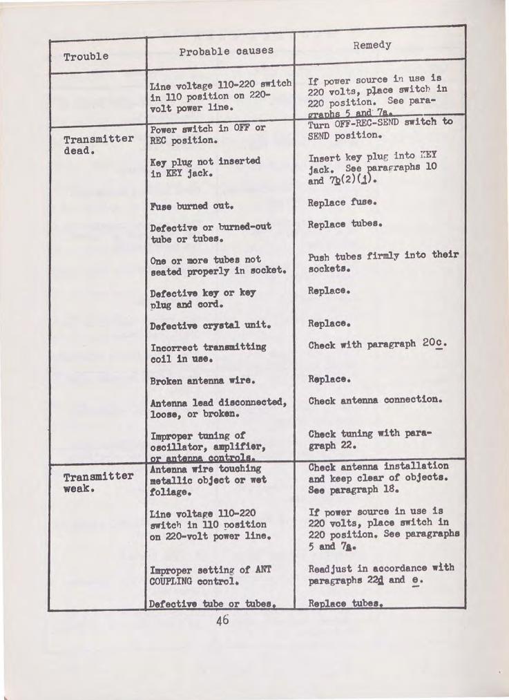
Trouble
Transmitter dead.
Transmitter weak.
Probable causes
Line voltage 110-220 switch in 110 position on 220-volt power line.
Power switch in OFF or REC position.
Key plug not inserted in KEY jack.
Fuse burned out.
Detective or burned-out tube or tubes.
One or more tubes not seated properly in socket.
Detective key or key plug and cord.
Detective crystal unit.
Incorrect transmitting coil in use.
Broken antenna wire.
Antenna lead disconnected, loose, or broken.
Improper tuning ot oscillator, amplifier, 01" __ ... ___ ---~~,.
Antenna wire touching metallic object or wet foliage.
Line vol tap:e no-220 switch in 110 ~sition on 22o-vo1 t power line.
Improper setting ot ANT COUPLING control.
Defective tube or tubes.
Remedy
If povrer source i n use is 220 volts, plftce switch in 220 position. See paragranhs S ~tnd· 7e. Turn OFF-REC-SEND swi teh to SEND position.
Insert key plw; into ~~EY jack. See parafraphs 10 and ?R(2)(j).
Replace f'use.
Replace tubes.
Push tubes firmly into their sockets.
Replace.
Replace.
Check with paragraph 20£•
Replace.
Cheek antenna connection.
Check tuning with paragraph 22.
Check antenna installation and keep clear of' objects. See paragraph 18.
It power source in use is 220 volts, place switch in 220 position. See paragraphs 5 and 7a. Readjust in accordance with paragraphs 224 and e.
Re'Dlflce tubes.

4J. VOLTAGE MEASUREMENTS. The following tube-socket layout diagrams show
voltages obtained from each tube-socket pin to chassis, under the specified
conditions, for the receiver, transmitter, and power supply portions of the
transceiver unit.
I I I I I I I UK7
FRONT
: . ~- ·:, ®.&SA7 0
0 0 ... , ..,,., •oool f)A C. ,0 (4 a
0 _ ,
&SK7 &SR7
BACK
NOTE : VOLTAGES MEASURED WITH SWITCH SW-t IN RE.CEIVE POSITION
ALL ~EASUREt-AENTS MADE WITH 1000 OHMS-PER-VOLT VOLTMETER
&N7
Figure 7. Radio set AN/PRC-5, receiver chassis tube-socket
layout.
@
@
fRONT
@
@ BACK
NOTE . VOLTAGES MEASURED WITH SW-1 IN TRANSMIT POSITION AND TRANSMITTING KEY NOT DEPRESSED. ALL MEASUREMENTS MADE WITH tDOO OHMS- PER -VOLT VOLTMETER
Figure B. Radio Set AN/PRC-5, transmitter and power-supply
chassis tube-socket layout.
44. POINT-TO-POINT RESISTANCE MEASUREMENTS. The following table gives aver-
age point-to-point resistance values measured from the chassis to the indi-
cated terminals on the various vacuum-tube sockets. Make all measurements
with the power cord disconnected and the various controls set as indicated
in the third column of the chart.
47

SOCKET VARIABLE CONTROL RESISTANCE TUBE ELEMENT TERMINAL SYMBOL SETTING
Vl Grid 4- --- ---- 4-.5 meg Cathode ~ --- ---- 0 Screen SW 1 REC. 180,000 suppressor ~ --- ---- 0 Plate SW 1 REC. 26,000
V2 Grid 8 --- ---- 4-.5 meg Cathode 6 SW 3 Band 1 0.3 ohms Cathode 6 SW3 Band 2 0.2 ohms screen 4- sw 1 REC. 50,000 Osc. Grid 5 --- ---- 100,000 Plate 3 sw 1 REC. 28,000
V3 Grid 4- --- ---- 2.5 meg Cathode ~ --- ---- 0 Screen sw 1 REC. 115,000 suppressor ~ --- ---- 0 Plate S\'{ 1 REC. 28,000
v4- Grid 2 --- ---- 100,000 Cathode ~ --- ~--- 0 Diode --- ---- 0 Diode ~ --- ---- 550,000 Plate SIN ij. ON '50,000 Plate 6 SW ij. OFF INF.
V5 Grid ij. --- ---- 1.0 meg Plate a SW l REC. 120,000 Cathode --- ---- 750 Grid ~ --- ---- 250,000 Plate S\'1 1 REC. 60,000
v6 Grid ~ --- ---- 32,500 cathode SW5 osc. 100,000 cathode 8 sw 5 AMP. 100,000 screen ij. SWl SEND 16,500 Plate 3 SWl SEND 15,000
V7 Grid ~ --- ---- ij.2,000 Cathode sw 5 osc. 100,000 Cathode 8 sw 5 AMP. 100,000 screen ij. sw 1 SEND 18,000 Plate 3 sw 1 SEND 16,000
v8 Plate ij. --- ---- q.5 ohms Plate 6 --- ---- 50 ohms Cathode 8 S\'1 1 OFF 15,000 Cathode 8 SW 1 REC. 35,000 Cathode 8 f!JN 1 SEND 15,000

SECTION V
SUPPLEMENTARY DATA
45. RESISTOR Ai\TD CAPACITOR COLOR-CODE CHARTS. Several systems are in use for
marking the values of resistance and capacitance. Some resisters and capa
ei tors have their values stamped on, but in many eases colored bands and
dots are used instead. The following charts provide a means for determin
ing the values of resistor:. and capaci tcrs frorn the color markinf!l!l on them.
A• Tbe Ibree-dot Color Cgde for Mica Capacitors. (1) This code is gradu
ally being replaced by more involved codes. The basis of this
code (fig. 9) is a series of three colored dots which indicate
the capacitance in micromicrofarads. Two auxiliary colored
dots indicating the voltage rating and the capacitance toler
ance are sometimes added. Usually an arrow is molded or
stamped on the case of the capacitor to indicate the sequence
in which the dots are to be read. Dots 1 and 2 show the first
two digits of the capacitance in micromicrofarads, while dot 3
indicates the decimal multiplier to be used. As an example,
a o.oo6-microfarad capacito~ (6,000 micromiorofarads) is marked
by the three dots in sequence, as follows:
blue (6), black (o), red (100).
(2) When the dot indicatin~ tolerance is used, it is usually located above
or below the third (decimal multiplier) dot. The color or the tolerance
dot corresponds to tolerance betweep plus or minus 1 percent and plus or
minus 20 peroent. For example: a green tolerance dot is used on capacitors
having a tolerance ot plus or minus 5 percent (fig. 9).
49

(3) When the voltage dot is used, it is located above or below the first
(first digit) dot. According to the code of figure 9, the various colors
denote the d-e working voltage.
(4) Both or the auxiliary dots are omitted for capacitors having a tolerance
3-DOT COLOR CODE CHART
For Capacitors
DOT DOT DOT VOLTAGE NO I 2 3 RATING COLOR TOLERANCE
OR
VOLTAGE NO TOLERANCE RATING COLOR
DOT DOT DOT I 2 3 TL-10~60
Figure 9. Molded-mica capacitors, t=ree-dot color code.
3rd Dot 1st Dot 2nd Dot
COLOR Decimal Tolerance Voltage 1st Digit 2nd Digit Mulliplt'er Rating
Black 0 0 1 20%
Brown 1 1 10 1% 100v.
Red 2 2 100 2% 200v.
Orange 3 3 1,000 3% 300v. ·-
Yellow 4 4 10,000 4% 400v.
Green 5 5 100,000 5% 500v. -
Blue 6 6 1,000,000 6% 600v.
Violet 7 7 10,000,000 7% 700v.
Gray 8 8 100,000,000 8% 800v.
White 9 9 1,000,000,000 9% 900v.
Gold ... . .. 0.1 5% 1000v.
Silver . . . . . . 0.01 10% 2000v .
Body . . . . .. . ... '. 20% • •When no Color is indicated the Voltage Rating may be as low as 300 volts.

ot plus or minus 20 percent, and a d-e working voltage rating which is the
lowest used for that type and size of capacitor.
(5) When no color i s indicated, the voltage rating may be as low as 300 volts.
~. The RMA Code for Mic§ Capacitors. The RMA (Radio Manufacturers Associ-
R MA STANDARD 6-DOT COLOR CODE CHART
For Capacitors (Molded Mica)
DOT DOT DOT I 2 3
DOT DOT DOT 6 5 4 TL-IOB61
Figure 10. Molded-mica capacitors, RN~ six-dot color code.
1st Dot 2nd Dot 3rd Dot! 4th Dot 5th Dot 6th Dot
Color 1st 2nd 3rd Decimal Toler- Voltage D£g£t Dig£t Digit Multiplier a nee -
Black 0 0 0 1 . . . . .. . .
Brown 1 1 1 10 1% lOOv.
Red 2 2 2 100 2% 200v.
Orange 3 3 3 1,000 3% 300v.
Yellow 4 4 4 10,000 4% 400v.
Green 5 5 5 100,000 5% 500v.
Blue 6 6 6 1,000,000 6% 600v.
Violet 7 7 7 10,000,000 7% 700v.
G ray 8 8 8 100,000,000 8% 800v.
White 9 9 9 1,000,000,000 9% 900v.
Gold . . . . . . .. . 0.1 5% 1,000v.
Silver . . . . . . .. . 0.01 10% ,2,000v.
Body . . . . . . . . . ... . 20% 500v.
51

ation) code is illustrated in ~igure 10. This code uses six colored dots
with an arrow to show the sequence. The/first three dots give the first
three digits of the capacitance 1n micromicrofarads, the fourth dot (directly
below the third) gives the decimal multiplier, the fifth indicates the tol-
erance in capacitance, and the sixth indicates the d-e working volte.ge.
For example: a capacitor of 0.006 microfarads (6,000 rnicromicrofarads)
plus or minus 10 percent, SOO volts d·c working voltage, would be marked:
blue (6), black (0), black (0), brown (multiplier 10), silver (plus or
minus 10 percent), gray (SOO volts), in that order.
~· the AWS C9de for Mica Capacitor§. (1) The AWS (American War Standard)
code tor molded-mica capac! tors is shown in figure 11. Like the RJAA code,
it makes use of six colored dots, but with somewhat different significance.
The first tour dots give the capacitance in micromicrofarads as follows:
first significant figure, second significant figure, third significant fipure,
and the decimal multiplier. It will be noted that t~is scheme makes provision
for marking units with three signiticant figures. However, none of the
capacitors standardized under ~~e AWS code requires more than two sip,ni-
ficant digits to specifY its capacitance. The first dot on nll molded•
mica capo.gitor&. prke<i with the AWS code. !§ black, and the two necessary
significant figures are given b.Y the second and third dots. As a result
the black first dot becomes an important feature or identification symbol
tor a molded-mica capacitor marked according to the AWS code. A few ex-
amples may serve to make this clear. A 120.micromicrofarad capacitor is
marked as follows: black (0), brown (1), red (2), brown (10), indicating
a molded-mica capacitor of 120 micromicrofarads. A 9,100-micromicrofarad
capacitor will be marked black (0), white (9), brown (1), red (100), in-
52

dieating 9,100 micromicrofareds. It will be noted that in each instance
the first dot is black.
AMERICAN WAR STANDARD 6-DOT COLOR CODE CHART
For Capacitors (Molded Mica)
DOT DOT DOT I 2 3
DOT DOT DOT 6 5 4
TL-10862
Figure 11. Molded-mica capacitors. AWS six-dot color code.
1st Dot 2nd Dot 3rd Dot 4th Dot 5th Dot ----
Color 1st 2nd Jrd Decimal Toler-Digit Digit Digit Multiplier a nee
----------Black 0 0 0 1 ±20%
Brown 1 1 1 10
Red 2 2 2 100 ± 2%
Orange 3 3 3 1,000
Yellow 4 4 4 10,000
Green 5 5 5 100,000 -·-Blue 6 6 6 1,000,000
Violet 7 7 7 10,000,000
Gray 8 R 8 100,000,000
White 9 9 9 1,000,000,000
Gold . . . . . - ... 0.1 =*= 5%
Silver . . . . . - ... 0.01 ±10%
• A-Drdinary Mica By-pass. B-Same as A- Low Loss Case. C-By-pass <?r Silver ~ica Capacitor ( ,., ~_parts/Million/C) D-Silver Mtca Capacttor ( '*' 100 Parts/ Mtlhon/C) E- Silver Mica Capac! tor (0 to + 100 Parts/Million/C) F- Silver Mtca Capacttor (0 to +50 Parts/ Mtlhon/C) G- Silver Mica Capacitor (0 to -50 parts/Million/C)
53
6th Dot --
Charac-teristics
·~ B
c D
E
F
G

(2) !he titth dot in the AlfS color coda indicates the capacitance tolerance
in percent ot rated capacitance. The sixth dot denotes characteristics or
design. For eD.IIlple: a 0.006-miorotarad (6,000 aicromicrorarads) plus or
miJme 10 percent mica capac! tor wottld be marked: black ( 0), blue ( 6),
black (o), red (100), silver (plue or minus 10 percent), black (mica br
paas, with no temperatura coetticient specitied).
(3) It will be noted that this color code does not include the voltage
ratiDg. This is considered unnecessar;r since, with raw exceptions, all
capacitors marked with the AWS color code are rated at 500 d-o working
volts. The exceptions, all or which are rated at 300 volta, are: AWS type
Cl35 capacitors with capacitances ot 6,800, 7,500, and 8,200 micromicro
taradsJ AWS type CM40 capacitors with capacitances or 9,100 and 10,000
aicroaiororarads.
d. The AWS Co.de for Molded-paper Capacitors. ( 1) the AWS color
tor molded-paper dielectric capacitors is shown in tigure 12.
Like the code tor mica capacitors, referred to in subparagraph c
above, it uses six colored dots, with an arrow to indicate the
sequence. Units marked according to this system can readily be
identified by the tact that both the first and titth dots are
always silver. The other dots are used as tollows: the second
dot gives the first digit of the capacitance in micromicrotarads;
the third dot gives the second significant figure; the fourth
dot indicates the decimal multiplier; and the sixth dot shows
whether the unit has a maximum operating temperature of 167° or
185° F.
54

AMERICAN WAR STANDARD 6-DOT COLOR CODE CHART
FOR CAPACITORS (MoLDED-PIPER)
DOT OOT DOT I 2 3
DOT DOT DOT e S 4 TL-10863
Figure 12. Molded-paper capacitors, AWS six-dot color code.
1sT DOT 2D DOT 3D DOT 4TH DOT 5TH DOT 6TH DOT
1sT 2D DEc I MAL CHARACTER• CoLOR DIGIT DIGIT MULTI• ISTICS
PLIER
BLACIC a: 0 0 1 *A
"' a: Q. "' BROWN ~ 1 1 10 Q. B Q. ~
Q.
RED ~ 2 <
"' 2 100 ~ -
ORANGE ...
~ 3 1 .. 000 Ill ~ ... -0 c - 0
YELLOW Q
4 4 -z - Q -- z -GREEN 0 5 s - -... 0 a: ...
a: 0 c cr BLUE "' ...
6 6 0 -> - - "' ... .., 0 > -- c .., u VIOLET
Cl) CL 7 7 - c ~ - ., CL -... 0 c
8 ... u GRAY 8 8 - 8 -...
Cl) z WHIJE
a:: ~. 9 ... -- - ~
\.a. -\.a.
GoLD - - - -SILVER - - - -
*A-MAXIMUM OPERATING TEMPERATURE IS 185° f. B•MAXIMUM OPERATING TEMPERATURE IS 167° f.
55

(2) No indication of the working voltage is given by this color code. How
ever, all AWS molded-paper capacitors have d•c working voltages between JOO
and 800 volts. In general the lower voltage rating applies to units with
high-capaci~nce ratings; the higher voltage rating applies to units with
low-capacitance ratings as shown in figure 12.
e. Tubular Ceramic-dielectric Capacitors. Tubular ceramic-dielec
tric capacitors are sometimes marked according to the RMA color code
shown in figure 13. The negative temperature coefficient is indica
ted by the color of the band or tips at one end of the unit; the cap
acitance in micromicrofarads is shown by the first three dots; the
capacitance tolerance, either in percent or tenths of a micromicro-
farad, depending upon the size of the unit, is indicated by the
fourth and last dot. For example, a 30-micromicrofarad, plus or
m1.nus 5 percent capacitor with a negative temperature coefficient
of 80 parts per million per der.ree centiP-rade woulrl be marked as follows:
tip, red (-80); first dot, orange (3); second dot, black (0}; third dot,
black (1); fourth dot, preen (plus or minus 5 percent). The abbreviation
neg. (negative) in firure 13 indicates that the capacitance varies inversely
with temperature. T~e temperature coefficient is expressed in micromicro
farads per micromicrofarad per degree centigrade. Some capacitors are marked
with a numeral instead of a color code; for example, N-030 represents
0.00003 neg. Tolerances for caoacito s of 10 micromicrotarads or less are
expressed in tenths of a micromlcrofarad instead of percenta~es.

COLOR CODE CHART
For Capacitors (Tubular Ceramic)
TIP DOT DOT DOT DOT I 2 3 4 TL-IOB64
Figure 13. Tubular ceramic capacitors, R~~ color code.
Tip 1st Dot 2nd Dot 3rd Dot 4th Dot
Color Temperature 1st 2nd Decimal ---Coefficient Digit Digit Multiplier Tolerance
Black 0 0 0 1
Brown .00003 Neg. 1 1 10 1%
Red .00008 .. 2 2 100 2%
Orange .00015 .. 3 3 1,000 3%
Yellow . 00022 .. 4 4 10,000 4%
Green .00033 .. 5 5 100,000 5%
Blue . 00047 .. 6 6 1,000,000 6%
Violet . 00075 .. 7 7 10,000,000 7% -
Gray 8 8 0.1
White I 9 9 0.01 10%
t.• lixed Resistors. (1) Small fixed resistors, both composition ty-pe and
wire-wound, are frequently marked with colored bands and dots to indicate the
resistenee ard tolerance. Two color codes are widely used, the RMA and the
AWS. The two codes are not identical in all particulars, but they are simi
lar in many respects. One chart, applicable to both, is shown in figure
57

14. It will be seen that in all cases the various combinations of body
color, bands, and dots indicate the resistance to two significant fi~res
(the first two digits), the decimal multiplier, and the percent tolerance
in resistance.
(2) As illustrated by figure 14, t~o methods are used for indicetin~ the
resistance and tolerance:
Method 1. This method makes use of four colored bands, starting at
one end of the unit, to show resistance and tolerance
(A of fig. 14). The banda, reading from left to right,
indicate: first significant figure, second significant
figure, decimal multiplier, and percent tolerance.
(The significance of the body color under this method
will be explained later.)
Method 2. Several variations of this method are in use (Bl, B2, and B)
ot fig. 14). With all of these variations, however, the inter
pretation of the code is practically the same: the left end gives
tolerance; the body, the first significant figure; the right end,
the second significant figure; and the central dot or band, the
decimal multiplier.
To illustrate, consider a 5,600-ohm, plus or minus 10-percent fixed resistor.
It would be marked:
Method 1. First band, green ( 5); second band, blue ( 6); third barxl, red ( 100);
tourtb be.nd, silver (plus or minus 10 percent).
Method 2. !Attt end, silver (plus or minus 10 percent); body, green (5);
right end, blue (6); central band or dot, red (100).

SIGNIFICANT FIGURES: FIRST (BODY) SECOND
TOLERANCE DECIMAL MULTIPLIER
Bl
RMA STANDARD COLOR CODE CHART
For Resistors
SIGNIFICANT FI~URES :
FIRST 5ECONO BODY
DECIMAL MULTIPLIER
A
TOLERANCE
SIGNIFICANT FIGURES:
TOLERANCE
FIRST (BODY) SECOND
DECIMAL MULTIPLIER
82
SIGNIFICANT FIGURES: FIRST (BODY) SECOND
DECIMAL MULTIPLIER
B3
Figure 14. Fixed resistors, IDAA and AWS color codes. TL-10865
' I .e------
COLOR
Black
Brown
Red
Orange
Yellow
Green
Blue
Violet
Gray
White
Gold
Silver
No Color
1st Band
1st Digit
0
1
2
3
4
5
6
7
8
9
. . .
. . .
2nd Band 3rd Band 4th Band
2nd Digit Decimal Multiplier Tolerance
0 1
1 10
2 100
3 1,000
4 10,000
5 100,000
6 1,000,000
7 10,000,000
8 100,000\000
9 1, 000, ()()(),000
. . . .. . . ... :1: 5%
. . .
I . .. .... ±10%
. . . . ..... . ±20%
59

Ill method 1, where the bod7 color plars llO part in illdicating resistance or
tolerance, it aq be used to indicate the type or resi1tor unit. Ullder the
Rill code, a black body is frequently used to indicate an uninsulated composi
tion unit; a tan, olive, or white boclr usually indicates an insulated wire
wound unit. !he .AWS code requires that an innla·ted unit using method 1
have a black body; the bodr or an Ullinsulated unit •Y be any color, although
a natural tan 11 preferred.
(3) When there is doubt as to wbtrther a particular resistor is eompositioll or
wire-wound, it is well to remember that any resistor of 100
ohms or less is most likely wire-wound, and is probabl.y wuund
inductively.
60

0'1 1-'
46. MAINTENANCE PARTS LIST FOR RADIO SET AN/PRC-5
NOTE: Order maintenance parts by stock number, name, and description. Only maintenance parts listed can be requisitioned.
Quan Bet Signal Co rp8 per Runnin,; Orgn 3d 4th 5th
symbol atodc No. !lame of part and deacription equip spare a stock ech ech ech
01 3D9101-:n CAPACITOR: ceramic; 10-mmt :J: 1 10~ 500 Yol h de (working) ; Durez-coated.
oa 3D9030V-7 .1 CAPACITOR: variable; trimmer; 3 3- to 30-mmt.
03 3D9100-15A CAPAOiiOR: ceramic; 100-mmt 5 :1:. 10~; 500 volta de (working); Dures-oo a ted.
04,011, 3D9lfOV-21 CAPACI'lnR ASSEMBLY: variable; 1 And Cl5 3-gang 9- to 150-J:m:f; and 3-t;;f), Cl2, gang trimmer f>-mmf', complete and 014 with gear and worm d.riYe.
06 3DA20-l. 3.1 OAPAOI'IOR: paper: 0.02-mf; 2 tubular; 600 volta de (working).
C7 3DMJO-l CAPACI'IOR: paper; 0.05-mf; 5 tubular; 600 volta de (working).
ce 3D9100-1SA Same ae C3.
• Indice.tee stock available.
Depot stock
•
•
•
•
•
•
•

Ol 1'\)
46. MAIN1~NANCE PARTS LIST FOR R~DIO S~T AN/PRC-5. (contd).
NOTE: Order maintenance parts by stock n1Jmber, name, and description. Only maintenance parts listed can be requisitioned.
Qul'ln Ref Sie;nal Co~s per Running Orgn 3d 4th
symbol· stock l~o. Name of part end description eauip sparee stock eel: ech
09 3D90ZOV-7 .1 Ssme as 02.
010 3D9100-15A Same as 03.
011 Part of 04 assembly.
012 Part of 04 assembly.
013 3DAEO-l Same e.s 07.
014 Part of 04 assembly.
015 Part of 04 assembly.
016. 017 3DB20-29 OAPACI'IDR: electrolytic; 2-sec- 1 tion; 20-wf; 450 volts de (working).
018 3D9020-5.1 CAPACI'IDR: ceramic; 20-mmf ~ 1 10~; 500 volts de (working ; IN.rez- co a ted.
019 3D90ZOV-7.1 Same as 02.
C20 3DA.2-103 OAPAOI'IDR: mica; 0.002-mf; 2 600 Tolte de (working).
"'Indicates stock available.
5th Depot ech stock
"' •
• • •
• • "'
"'
• •
--

0'1 \Jo.l
~6. MAINTENANCE PARTS LIST FOR RADIO SET AN/PRC-5 (contd).
NOTE: Order maintenance parts by stock number, name, and description. Only maintenance parts listed can be requisitioned.
Qu.an Be! Signal. Corps per Bunning Orgn 3d 4th 5th Depot
eymbol stock Ko. Name of part and description equip eparee stock ech ech ech stock
021 3D:Bl0-57 CAP AOI 'IOR: electrolytic; 2- 1 • section; 10-mf; 450 volta de (working); (sections connected in parallel).
023 3DASO-l Same as 07. • 024 3D9050-49 CAPAOI'IORr ceramic; 50-mmf ~ 3 •
10~; 500 volts de (working ; Durez-coated.
025 31>9050-49 Same as 024. • 026 3DA50-l Same as 07. • 027 3D9f00-89 CAPAOI'IOR: ceramic; 500-IIIJD! .:J:. 2 •
10~; 500 volts de (working); Durez-coated.
028 3DA50-l Same as 07. • 029 3D9250-5l O.APAOI'roR: ceramic; 250-mmf .t. 1 •
10~; 500 volts de (working); Durez-coated.
030 3D:Bl00-10 O.A:P AOI 'lOR: electrolytic; 100- 1 • m!; 6 volts de (working).
~-c__
• Indicates stock available.
./

0'\ ~
~6. MAINTENANCE PARTS LIST FOR RADIO SET AN/PRC-5 (contd}.
NOTE: Order maintenance parts by stock number, name, and description. Only maintenance parts listed can be requisitioned.
Q)Jan Ret Signal Corpe per Running Orgn 3d 4th 5th Depot
eymbol etock No. Neme of part and description equip spare a stock . ech ech ech stock
031 ~51 CAPAOimR: paper; 0.003-mt J:. l • 20~; 600 vol tl de (working).
032 3D9250-46 CAPACITOR: ceramic; 250-ll'lmf .:J:. l • 20~; 500 vol te de ( workin.«); Dures-coated.
033 3DA20-l3.l Same aa 06. • 034 3DA100-lb CAPACITOR: paper; 0.1 mfd 1 •
tubular• ~00 volts de (working).
'
035 3DA287.l CAPACITOR: paper; 0.002-:t; l • tubu1ar; 600 volts de (working).
036 3D.A5-38 OAPACimR: mica; 0.005-mf; 600 volts de (working).
7 •
C37 3DA2-103 Same as C20 •
C39 3D9500..89 Same aa 027. • 040 3D9140V-3 CAPACI'IOR: Tariable; 140-mmf; 3 •
2000 Tolt.
041 3D9140V-3 Same as 040. • •Indicates etock available.

""' t..T1
~6. MAINTENANCE PARTS LIST FOR RADIO SET AN/PRC-5 (contd).
NOTE: Order maintenance parts by stock number, name, and description. Only maintenance parts listed can be requisitioned.
Ref Signal Corp1 r~ Running Orgn 3d 4th 5th symbol stock No. Name of part and description equip spares stock ech eeh eeh
C42 3DA5-38 Same as C36.
043 3DA5-38 Same as C36.
C44 3DA5-38 Same as C36.
C45 3D9100-16A Seme as C3.
C46 3DA5-38 Same ae C36.
047 3D9140V-3 Same as C40.
048 3D9100-15A Same as C3.
C49 3DA5-38 Same as 036.
050 3DA5-38 Same as C36.
C51 3D9050-49 Same ae C24.
ANT 3Z737-17 BINDING POST 1
( an ten.na). bakelite head; 1
GBOID."D 3Z737-17 BINDING POST: bakelite head; 1 (ground).
• Indicates stock available.
Depot stock
• • • • • • •
' • • • •
•

I
0" CY\
'
~6. MAINTENANCE ~ARTS LIST FOR RADIO SET AN/PRC-5 {contd).
NOTE: Order maintenance parts by stock number, name, and description. Only maintenance parts listed can be requisitioned.
Q1.um Ref Signal Corp e per Running Crgn 3d 4th 5th
symbol stock No. Name of part and description eauip spares stock ech ech ech
J 3Z2602.1 FUSE: 2-amp; 250 volts; 1 2 (1ittelfuse type No. BAG).
F 3Z3275-8 FUSE EXTRAC'IOR POST: bekeli te; 1 brass; tinned terminals.
Jl 2Z5534 JACK JK-34: 2-conductor; 2 accommodates Plut; PL-.55.
J2 2Z5534 SR:De as J1.
Ll 3C302V 00!1: (antenna); for 1 receiver band 2.
12 3C30~V-1 OOIL: (an tenne.); for 1 receiver band 1.
13 30326-100 OOIL: r-f choke; National 3 type B-100.
14 3Cl084Z4-1 0011: r-f amplifier; for 1 receiver band 2.
15 3Cl084Z4 0011: r-f amplifier; for 1 receiver band 1.
• Indicates stock available.
Depot stock
•
•
•
• •
•
•
•
•

0'1 -..:J
4-6. MAINTENANCE PARTS LIST FOR RADIO SET AN/PRC-5 ( contd).
NOTE: Order maintenance parts by stock number, name and description. Only maintenance parts listed can be requisitioned.
Signal Corps ~
Ref ~er Running Orgn 3d 4th 5th symbol stock No. Name of part and description ~quip spares stock ech ech ech
L6 3Cl08l-20D OOIL: oscillator; for recei ve.r l bend 2.
L? 30108l-20lC OOIL: oscillator; for receiver l band l.
La 2Z9641.67 TRANSFORMER ASSEMBLY: let i-f 1 amplifier; in Shielded can.
L9 2Z9641.68 TBANSR)R.~ ASSEMBLY: 2d i-f 1 amplifier; in shielded can.
LlO 2Z9644.5 OOIL ASSEMBLY: (beat-fre- 1 queney oscillator); in shielded can.
Lll 30326-100 Same as L3.
Ll2,Ll4 301081-20:8 OOIL ASSEMBLY: band C, for 1 tranam~tter oscillator or power amplifier.
Ll2,Ll4 301081-200 OOIL ASSEM3LT: band D, for 2 transmitter oscillator or power amplifier.
- ---- -------- ------------ - - - --- -------- --- ------ - - -- L__ ___
• Indicates stock available.
Depot sbck:
•
•
•
•
•
• •
•
-

(J)
co
46. MAINTENANCE PARTS LIST FOR RADIO SET AN/PRC-5 ( contd}.
NOTE: Order maintenance parts by stock number, name, and description. Only maintenance parts listed can be requisitioned.
Q)l.an Ref Signal Corps per Running Orgn 3d 4th 5th
symbol stock No. Name of part end description equip spares stock ech ech ech
Ll3 30326-100 Same as L3.
Ll4 3Cl081-3:>A OOIL ASSEMBLY: hnd 13, for 1 transmitter power amplifier.
Ll2,Ll4 2Z8675.55 SOCKET ASSEMm.Y: ceramic; 2 plug-in; complete with stand-off ineul.ators.
Ll6 3C342-ll OOIL: choke; filter for power 1 supply.
M 3F915-30 .AMl-!ETER: Q-15) ma de; 2-inch 1 diam.
Pl 2Z5985.4 LIGHT ASSEMBLY: pilo t; green 1 jewel; miniature bayonet aocket.
Pl 2Z5891-4 JEWEL IDLDER: green. 1
P2 2Z5985.4 LIGHT ASSEl.ffiLY: pilot; white jewel; miniature bayonet socket.
P2 2Z589l-4 JEWEL BOLDER: white. 1 ---- - - -- - -- --~-~
• Indicates stock available.
Depot stock
• •
•
•
•
•
• 'It
•

0"1 \.0
~6. MAINTENANCE PARTS LIST FOR RADIO SET AN/PRC-5 (contd).
NOTE: Order maintenance parts by stock number, name and description. Only maintenance parts listed can be requisitioned.
Qwm Ref Signal Corps per Running Orgn 3d 4th 5th
symbol stock No. Name of part and de•cription equip spares stock ech ech ech
lU. 3Z6802-l7 RESIS'roR: carbon; ! watt; 2- 3 meg J:. ro~; AWS type R02lHEro5M.
R2 3Z67S0-47 RESISTOR: carbon; }. watt; l 000,000-ohm ~ 10~; AWS type B.021BE504J.
B.3 3Z6725-l0 RESISTOR: carbon;~ watt; 2 2SO,OQO-obm %_ 10 ; AWS type B.021BE244J.
R4 3Z6802-17 Same as B.l.
li5 3Z6625-53 RESIS'IOR: carbon; 2 watt· 25,0QO-obm.!, 10~; AWS tyPe
1
RC4l:B¥243J •
R6 3Z6700-61 RESISTOR: carbon; i watt; 4 100, OOQ-obm ~ 10~; AWS type RC2l:BEl.04K.
R? 3Z6680-2.l RESIS'IOR: carbon; 1. watt; 1 80, 000-ohm .i, 10%; AWS type RC31BE823J.
-"-----~ ~-
• Indicates stock available.
Depot stock
•
• I
•
• •
•
•
--

-...:] 0
~6. MAINTENANCE PARTS LIST FOR RADIO SET AN/PRC-5 {contd).
NOTE: Order maintenance parts by stock number, name, and description. Only maintenance parts listed can be requisitioned.
Qu.an Running Orgn 3d 4th 5th Ref Signal Corps :per spares stock ech ech ech symbol stock No. Name of part and description equip
R8 3Z6650-78 RESISTOR : carbon; ~ watt; l 50,000-ohm i 20~; AWS type RC2l.BE473K.
R9 3Z6700-6l Same as R6.
RlO 3Z6625-84 RESISTOR: carbon; ~ watt; 2 25,000-ohm i 10~; AWS type RC2l.BE243J.
Rll 3Z6640-l4 RESISTOR: carbon; l watt; l 40,000-ohm! 10~; AWS type RC3l.BE393J.
Rl2 3Z6725-l0 Same as R3.
Rl3 3Z6075-8 RESISTOR: carbon; ~watt; l 7 50-ohm i- l~.
Rl4 3Z680l-54 RESISTOR: carbon; ~watt; l- l meg f 2~; AWS type RC2lBEl05M.
Rl5 3Z6700-6l Same as R6.
Rl6 2Z7272-l POTENTIOMETER: 500,000-ohm; l (volume control).
Rl7 3Z6802-l7 Same as Rl. --
Depot stock
*
* *
*
*
*
*
* *
*

~ ~
4-6. MAINTENANCE PARTS LIST FOR RADIO SET AN/FRC-5 ( contd).
NOTE: Order maintenance parts by stock number, name, and description. Only maintenance parts listed can be requisitioned.
Qwm Ret Sipal. Oorpe per Running Orgn 3d 4th 5\h
eymbol •took •o. Name of part and de•cription equip spare• •tock ech ech ech
Bl8 3Z66l0-108 DSIS10Rt vi treoua enamel: 1 10 watt; 10,000-oha.
Bl9 3Z6630-67 Bl:SI S'roR: vi treou• enamel; 1 10 watt; 30,000-ohll.J:: 10~.
B3) 3Z67a>-8 USIS1l>Rt carbon;~ watt; a a>O,OOO-ohll£ 10 •
ll2l. 3ZM40-8 BESI S'lOR: vi treoue enamel~ a 5 watt; -40, OC>O-ohm & 10 •
ll23 3Z6560-6 RJlSIS!OB: wir&-wound; 10 l watt; 6, OOO..Oba J:. 10~.
ll23 3Z67Q0-6l Same aa :as.
B24 3Z6040-53 RESIS'roRz vi treoua enamel; l 5 watt; 400-ohm .:1:. 10~.
B26 3Z63)()..9"7 USIS'D:>lh carbon; 2 watt l 2, 000-ohm ..l:. 20~; AWS t)"pe RC41.BJ:l82X.
ll26 3Z6626-84 Same a• BJ.o.
• Indioatee •tock available.
Depot •tock
•
• I
•
•
•
• •
•
•

-...J 1'\)
~6. N.AINTENANCE PARTS LIST FOR RADIO SET AN/PRC-5. ( contd).
NOTE: Order maintenance parts by stock number, name, and description. Only maintenance parts listed can be requisitioned.
Qu.an Ref Signal Corps per Running Orgn 3d 4th 5th
symbol stock No. Name of part and description equip spare a stock ech ech ech
R27 3Z6570-19 .aESIS'IDR: carbon; -j. wat\; 1 7 .ooo-ohm *- 10~; AWS tn>• RC21BE682J.
R28 3Z6640-6 Same aa R2l.
R29 3Z6?10-16 BESIS'mR: carbon; 2 watt; 1 10 • 000-ohm .i:. 10~; AWS type R04l.BEl.03X.
R30 3Z6040-l RESIS'mR: carbon; 1 watt; 1 400-ohm-*. 10~; AWS type RC31BE391J.
R31 3Z6005-34 RESIS'mR: wit"e-wound; -i- 1 watt; EO-ohm.! 10~.
R32 3Z6640-35 RESIS'IDR: carbon; ! watt; 1 40,000-ohm .t. 10~; AWS type RC21BE393J.
R33 3Z6250-50 RES! S'l'OR: wire-wound; 10. wa. t •; 1 2, 500-ohm :£ 10~.
R34 3Z67ro-s Seme as Ra:>.
• Indicates stock available.
Depot st.ock
•
• •
•
•
•
•
•

-.J \..N
4-6. MAINTENANCE PARTS LIST FOR RADIO SET AN/PRC-5 ( contd).
NOTE: Order maintenance parts by stock number, name, and description. Only maintenance parts listed can be requisitioned.
Quan Ref' Signal Corps per Running Orgn 3d 4th 5th
symbol stock No. Name of part and description equip spares stock ech ech ech
SWl 3Z9825-58.23 SWITCH: ceramic; 4-circuit; 3-position; (of'f'-rec-send).
l
SW2 3Z9857.27 SWITCH: toggle; double-pole, 1 double-throw; 125 volts.
SW3 3Z9827.33 SWITCH: band. l
SW4 3Z9835-l SWITCH: snap; single-pole, single-throw; ( BFO ON-OFF).
l
SW5 3Z9835-l.l SWITCH: snap; single-pole, l double-tb.row; {OSC-Al-!P).
TR 2Z9608-l5 TRANS:roRMER: power; 110-220 1 volt primary.
~7186-8 OORD: a-c line; 6 feet; 2- l conductor; No. 18 wire; color coded with rubber jacket.
3llll605-6. 5 OORD CD-605: 2-conductor; ~ 1 feet; with Transformer C-410 and Plug PL-55.
-- --
• Indicates stock available.
Depot stock
•
•
• •
•
•
•
•

4-6. MAINTENANCE PARTS LIST FOR RADIO SET AN/PRC-5 ( contd}.
NOTE: Order maintenance parts by stock number, name, and description. Only maintenance parts listed can be requisitioned.
Qwm Bet Signal Corpa per Bunnin& Orgn 3d 4th 5th Depot
8711bo1 atoclt Bo. Heme of part and deacription equip spare a stock ech ech ech stock
~201.6. CX)lU) CD-201-.A.J 2--conc!uctor; 1 • 5 feet; P1U« PL-65 on one end and terminala on other end for Xq J-47.
2Z354Z.8 CRYSTAL IDLDBR l'T-243r aet of 6 ,. 1 each for all authorised frequencies.
~ 215830( ) HUDSJil' BS-30-( )I component, 1 •
HEADSET BS-30-( ) : repair parte.
3Z3447.1 DY J-47: telegraph; complete 1 • vi th Cord CD-201-A.
2ZK:5748.15 IJl)B: receiver. 1 • 2Z584B.l9 KNOB WITH POIB'BR: bakelite. IS • 6Z7565.3 PLUG: 2-eonnectorl parallel 1 •
bladed; rubber; power cord).
2Z7156 PLUG PI-55: a-conductor. 3 • • Indicates stock available.

~ \J1
46. MAINTENANCE PARTS LIST FOR RADIO SET AN/PRC-5 ( contd).
NOTE: Order maintenance parts by stock number, name, and description. Only maintenance parts listed can be requisitioned.
Q)1.8ll Bet Signal Corpa per Running Orgn 3c1 4th 5th
qmbol atock lio. ll'ame of part and deacr1pt1on equip ~area stock ech ech ech
2ZIB674.17 fk>OI:E'!J ~be; octal; ceramic. 3
2Z8650.1 OOOK:mr tube; octal; bakelite; 5 w1 th ring containing 3 grounding luge.
2ZX8650.6 SOCK:li:T: C!7Btal bolder; molded 1 phcolic.
2Z8675.55 SOCKm ASSEMBLY& plt~g-in; cere.- 2 mlc; mmplete w1 th stand.-off 1n8Ulatore; National tJpe XL 16.
2Z5952 LAMP: 6-8 volts; 0.15 amp; 1 2 ~net base; GJ: tn>e 47.
2Z58?9-=: LAMP: 2 volts; 0.06 amp; 1 2 bqonet base; G~ tn>e 48.
2J5Z4 TUD JAN 5Z4: (VT-74). 1 1
2J6L6 Ttml JJ.Jl 6L6& (V!-115). 1 1
2J6U7 TUBII JJ.Jl 61i7a ( V'l!-96). 1 1 --- -
• Incllcatea atock available.
Depo' atock
• •
•
•
•
•
• • •
-

-.;J
""'
4-6. MAINTENANCE PARTS LIST FOR RADIO SET AN/PRC-5 ( contd).
NOTE: Order maintenance parts by stock number, name, and description. Only maintenance parts listed can be requisitioned.
(b1an Bet Signal Corp• per Running Orgn 3d 4th 5th
81lllbo1 stock No. Name of pert and description equip spare a stock ech ech ech
2J6SA7 TUBE J JJl 6SA 7: (VT-150). 1 1
2J6SX7 '1'Ul3E JAN 6SK7: (VT-117). 2 2
2J6SR7 TUBE JJJl 6Sll7: (VT-223). 1 1
2J6V6 TU1Dl J JJ1 6V6: (V'l-107). 1 1
- --- - - ----- ------
• Indicates •took aTa11able.
Depot stock
• • • •

=::J CRYSTAL
I I t t I I I I I
I Ill ZM!G I 1
I · . I _J L--- --A"iCiiviit-iUN'ING ____ ---t
CIO IOOww,
I I I I I I I I I
I : I = o.oo'i2~, -=- 1 L---~~~~~~~-----------~---------~---------~
Cll
O.DOSMI'
AU •oon
Ll r-------, I I I I I I I R L. __
I I I I I I
111 I -...I
C21 O.O!IMF
AI? Z MEG.
Cl4 I•IOMWI'
Cll I•I!MIMM'
C40 10•140MM'
ANT COUPLING
~Cat O.OSMF
0
11 11 !10011
' '
I
' I '~ SWI
I I
I I I I
' ,,J
RADIO SET AN/PRC-!!1, SCHEMATIC DIAGRAM
CGND.
FUSE
IIO•Z20V !MI-10 cv.
Figure 15. Radio Set AN/PRC-5, schematic diagram.
C)4
SW4 .,0 OFF·ON
' _ _J
TO UNGROUNDED SIDE OF ALL ---, HEATERS
Cll Cl7 CZI ZOMF ZOMF ZOMF
OJn, 11111011 Cll • JZ
0.003MF ~ PHONU JACII
lOll -=:;:- 20011 ZOO II
AIZ CU Z!MIII ·:,z
TL 14SZI
"/7 -tf U. S. GOYERNIIEIIT PRINTING OfflC£ : 11155 o-350223


![BcPcT]TTSbc^PRc U^a_dQ[XRV^^S - Daily Pioneer](https://static.fdokumen.com/doc/165x107/631a951119373759090e7f60/bcpctttsbcprc-uadqxrvs-daily-pioneer.jpg)