
Rack And Pinion Mechanism for Continuous Variable Valve Timing of IC Engines
11
Dhruv Chawda et al Int. Journal of Engineering Research and Applications www.ijera.com ISSN : 2248-9622, Vol. 4, Issue 11( Version 1), November 2014, pp.48-58 www.ijera.com 48|Page Rack And Pinion Mechanism for Continuous Variable Valve Timing of IC Engines Dhruv Chawda 1 , Salman Husain 2 , K.Krishnamurthy 3 1, Student, 2 Student, 3 Associate Professor, Mechanical Engineering Department, Manipal University, Karnataka, India Abstract The valve timing is a very closely studied event and effects the performance of an IC Engine greatly with respect to the Brake Power Produced, Volumetric Efficiency and Emissions etc. The valve event if varied and experimented with, can result in higher efficiencies and overall improved performance of the Engine. Hence, various researchers have attempted to temper with the valve timing and thus many Variable Valve Timing systems have been proposed till date with many of them being implemented by various manufacturers. However, on reviewing the presently employed systems, the lack of existence of a single system capable of independently altering both the timing and the lift of the valves was recognized. Thus, a single system capable of achieving the above was thought of and designed. A rack and pinion mechanism powered by a programmed servo motor mounted vertically seemed most practical in achieving this within the size and space constraints. A single cylinder diesel Engine was simulated with „Lotus Engine Simulation‟ software to derive the optimum valve angles and lifts for a range of the Engine operating speed and the system was accordingly programmed and designed to achieve them. The system was designed in „Creo‟ software and analysed correspondingly in „Ansys‟ software and then finally assembled on a Diesel Engine in the lab. Keywords: Variable Valve Timing, Rack and Pinion Gear system, Servo Motor, Crankshaft position sensor, volumetric efficiency I. Introduction In internal combustion engines, Valve timing is the event of the opening and closing of the inlet and exhaust valves respectively. It is denoted in terms of the crank angle at which the event occurs with respect to the TDC and BDC positions. It is one of the most important parameters in the Suction process and influences the Engine performance up to a great extent. It is found that the Optimum Valve Timing, Lift and duration settings at low engine speeds are quite different from those at high engine speeds. Any optimal setting accordingly would cause lesser amount of Air and fuel at high speeds resulting in loss of power output. Similarly, any setting for high speeds would result in difficult idling and very rough engine performance at low speeds. Thus most cars use a setting which is in the mid-Engine speed range thus compromising on the low and high speed ends vehicle performance. Thus a need for a Variable type of valve timing setting was recognized which would thus not compromise on the Engine performance over the spectrum. Variable Valve timing (VVT) is the process of altering the timing and/or Lift of a valve lift event and is often used to improve performance, fuel economy and emissions. There are many ways in which this can be achieved, ranging from mechanical devices to electro-hydraulic and cam-less systems. Increasingly strict emissions regulations are causing many automotive manufacturers to use VVT systems although; their use is still limited to high-end cars due to cost considerations. II. Literature Review First, a basic understanding of the impact of the change in opening and closing timings of both the inlet and the exhaust valves was felt to be acquired. Upon researching it was realized that in general at low engine rpms, it is desirable to have lesser valve opening angles i.e. lesser IVO (bTDC), lesser IVC (aBDC), lesser EVO (bBDC) and lesser EVC (aBDC). The reverse is the case at higher engine rpms where higher amounts of all the above angles are desirable [1]. There are many ways in which VVT can be implemented. Many of these methods have thus been developed and put in use by Car manufacturers. The first among them is Cam switching where an actuator is used to swap between two or more Cam profiles. The actuation is done by mainly pneumatic or hydraulic means. This system is mainly adopted by manufacturers like Honda and Fiat (i-VTEC which stands for intelligent Variable Valve Timing and lift Electronic Control). However, the major problems with these systems are viscosity change of the oil in hydraulic systems with temperature needing expensive insulation techniques and large power needed for an air compressor in case of the pneumatic ones and the major problem is the discrete nature of RESEARCH ARTICLE OPEN ACCESS
Transcript of Rack And Pinion Mechanism for Continuous Variable Valve Timing of IC Engines
Dhruv Chawda et al Int. Journal of Engineering Research and Applications www.ijera.com
ISSN : 2248-9622, Vol. 4, Issue 11( Version 1), November 2014, pp.48-58
www.ijera.com 48|P a g e
Rack And Pinion Mechanism for Continuous Variable Valve
Timing of IC Engines
Dhruv Chawda1, Salman Husain
2, K.Krishnamurthy
3
1, Student,
2 Student,
3Associate Professor, Mechanical Engineering Department, Manipal University, Karnataka,
India
Abstract The valve timing is a very closely studied event and effects the performance of an IC Engine greatly with
respect to the Brake Power Produced, Volumetric Efficiency and Emissions etc. The valve event if varied and
experimented with, can result in higher efficiencies and overall improved performance of the Engine. Hence,
various researchers have attempted to temper with the valve timing and thus many Variable Valve Timing
systems have been proposed till date with many of them being implemented by various manufacturers.
However, on reviewing the presently employed systems, the lack of existence of a single system capable of
independently altering both the timing and the lift of the valves was recognized. Thus, a single system capable
of achieving the above was thought of and designed. A rack and pinion mechanism powered by a programmed
servo motor mounted vertically seemed most practical in achieving this within the size and space constraints. A
single cylinder diesel Engine was simulated with „Lotus Engine Simulation‟ software to derive the optimum
valve angles and lifts for a range of the Engine operating speed and the system was accordingly programmed
and designed to achieve them. The system was designed in „Creo‟ software and analysed correspondingly in
„Ansys‟ software and then finally assembled on a Diesel Engine in the lab.
Keywords: Variable Valve Timing, Rack and Pinion Gear system, Servo Motor, Crankshaft position sensor,
volumetric efficiency
I. Introduction In internal combustion engines, Valve timing is
the event of the opening and closing of the inlet and
exhaust valves respectively. It is denoted in terms of
the crank angle at which the event occurs with
respect to the TDC and BDC positions. It is one of
the most important parameters in the Suction process
and influences the Engine performance up to a great
extent. It is found that the Optimum Valve Timing,
Lift and duration settings at low engine speeds are
quite different from those at high engine speeds. Any
optimal setting accordingly would cause lesser
amount of Air and fuel at high speeds resulting in
loss of power output. Similarly, any setting for high
speeds would result in difficult idling and very rough
engine performance at low speeds. Thus most cars
use a setting which is in the mid-Engine speed range
thus compromising on the low and high speed ends
vehicle performance. Thus a need for a Variable type
of valve timing setting was recognized which would
thus not compromise on the Engine performance over
the spectrum. Variable Valve timing (VVT) is the
process of altering the timing and/or Lift of a valve
lift event and is often used to improve performance,
fuel economy and emissions. There are many ways in
which this can be achieved, ranging from mechanical
devices to electro-hydraulic and cam-less systems.
Increasingly strict emissions regulations are causing
many automotive manufacturers to use VVT systems
although; their use is still limited to high-end cars due
to cost considerations.
II. Literature Review First, a basic understanding of the impact of the
change in opening and closing timings of both the
inlet and the exhaust valves was felt to be acquired.
Upon researching it was realized that in general at
low engine rpms, it is desirable to have lesser valve
opening angles i.e. lesser IVO (bTDC), lesser IVC
(aBDC), lesser EVO (bBDC) and lesser EVC
(aBDC). The reverse is the case at higher engine
rpms where higher amounts of all the above angles
are desirable [1].
There are many ways in which VVT can be
implemented. Many of these methods have thus been
developed and put in use by Car manufacturers. The
first among them is Cam switching where an
actuator is used to swap between two or more Cam
profiles. The actuation is done by mainly pneumatic
or hydraulic means. This system is mainly adopted by
manufacturers like Honda and Fiat (i-VTEC which
stands for intelligent Variable Valve Timing and lift
Electronic Control). However, the major problems
with these systems are viscosity change of the oil in
hydraulic systems with temperature needing
expensive insulation techniques and large power
needed for an air compressor in case of the pneumatic
ones and the major problem is the discrete nature of
RESEARCH ARTICLE OPEN ACCESS

Dhruv Chawda et al Int. Journal of Engineering Research and Applications www.ijera.com
ISSN : 2248-9622, Vol. 4, Issue 11( Version 1), November 2014, pp.48-58
www.ijera.com 49|P a g e
these type of systems with the use of at most 2-3 Cam
lobes possible due to space constraints and hence
optimization only for 2-3 rpms, i.e. generally one for
low speed and one for high speed.
Another method implemented is the Cam
Phasing. This is done by giving a slight rotation to
the Cam shaft with respect to the Crank shaft by a
device known as a variator to create a phase change
between them thus varying the opening and closing
angles of the valve but maintaining the total duration
of the valve lift event constant. This allows
continuous adjustment of the cam timing however the
duration and lift cannot be adjusted which is a
disadvantage. A typical type of this system was
proposed by Osama H.M Ghazal and Mohammed
S.H Dado in their paper “Gear drive mechanism for
continuous variable valve timing. [2]
Another system employed is the Oscillating
Cam mechanism which uses an oscillating or rocking
motion in a part cam lobe, which acts on a
follower.This follower then opens and closes the
valve. The BMW (valvetronic), Nissan (VVEL), and
Toyota (valvematic) oscillating cam systems act on
the intake valves only.The advantage of this design is
that adjustment of lift and duration is continuous.
However in these systems, lift is proportional to
duration, so lift and duration cannot be separately
adjusted.
The most new and novel method in VVT are the
Camless systems. These do not rely on a camshaft to
operate the valves and have greater flexibility in
achieving variable valve timing and variable valve
lift [3].Camless systems use electromagnetic,
hydraulic, or pneumatic actuators to open the poppet
valves instead. Common problems include high
power consumption, accuracy at high speed,
temperature sensitivity, weight and packaging issues,
high noise, high cost, and unsafe operation in case of
electrical problems as reported by Chihaya Sugimoto
et al.in their paper “Study of Variable Valve timing
using Electromagnetic Mechanism”[4].
Thus on reviewing each of the above systems and
examining their advantages and disadvantages we
hereby propose a system attempting to do away or
minimize the disadvantages while ameliorating the
advantages.
III. The Need to Develop a new VVT
system On reviewing the systems in the Literature
review we concluded that all the presently proposed
systems vary either only the timing of the valve
opening and closing event by either Cam phasing
(Prof. Dado), Cam Switching (i-VTEC) or eccentric
Cam (Toyota) or only the valve lift (BMW‟s Double
Vanos and Ferrari‟s 3D Cam lobe) but until now
there is no one single system which has the capability
of changing the valve timing as well as the valve lift
independently of each other. Also, most of the above
systems achieve discrete VVT i.e. optimized for 2 or
3 rpms, generally one for low speed and one for high
speed like the Honda‟si-VTEC technology, but this
leads to a considerable loss of efficiency at other
engine rpms which is thus overcome by the new
Continuously Variable Valve Timing systems
(CVVT) which vary the valve timing continuously
over the Engine rpm range rather than at discrete
levels. Therefore, the need to develop and synthesize
a system which could vary the Valve Lift and Timing
both, independently of each other and also do so
Continuously rather than in 2 or 3 discrete steps was
felt and hence attempted for.
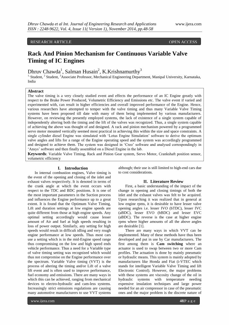
IV. Working of The proposed System As shown in the Cad model below (Fig.1), it
consists of a Servo motor connected to a Rack and
Pinion arrangement which is in turn connected to the
lever arm of the Valve Arrangement.
The crankshaft position sensor gives input data
of the current engine rpm and the crankshaft position
(degrees) as input to the Arduino microcontroller of
the servo motor. The data regarding the valve timing
and lift at different engine rpms is already pre-fed to
the microcontroller based on the simulation of the
Engine by the LOTUS Engine Simulation Software.
Thus depending on the Engine speed the
microcontroller chooses the correct valve actuation
timing and lift and with the crank position input
(degrees) from the crankshaft position sensor, rotates
the servo motor at the required time for the desired
amount of angle. This rotation of the servo motor
then translates into the rotation of the pinion gear of
the rack and pinion arrangement, which is keyed to
its shaft, which thus causes an equivalent translatory
movement of the rack. As the rack is connected to the
lever arm it thus causes a differential actuation of the
valve depending upon the amount moved by the
Rack. Thus a differential amount of rotation of the
servo motor will amount to a different valve lift at
each rpm. As the servo motor is made to rotate
precisely at the desired angle by input from the
crankshaft position sensor and the microcontroller,
Valve Timing is possible to be varied for many rpms.
Thus in the above way, this system can provide a
variable valve Timing along with a variable valve lift
with a high accuracy due to the use of a
microcontroller powered servo motor. How this
system was synthesized as shown in the methodology
below and the corresponding results obtained are
discussed later.
Dhruv Chawda et al Int. Journal of Engineering Research and Applications www.ijera.com
ISSN : 2248-9622, Vol. 4, Issue 11( Version 1), November 2014, pp.48-58
www.ijera.com 50|P a g e
Fig 1. – CAD Model of System
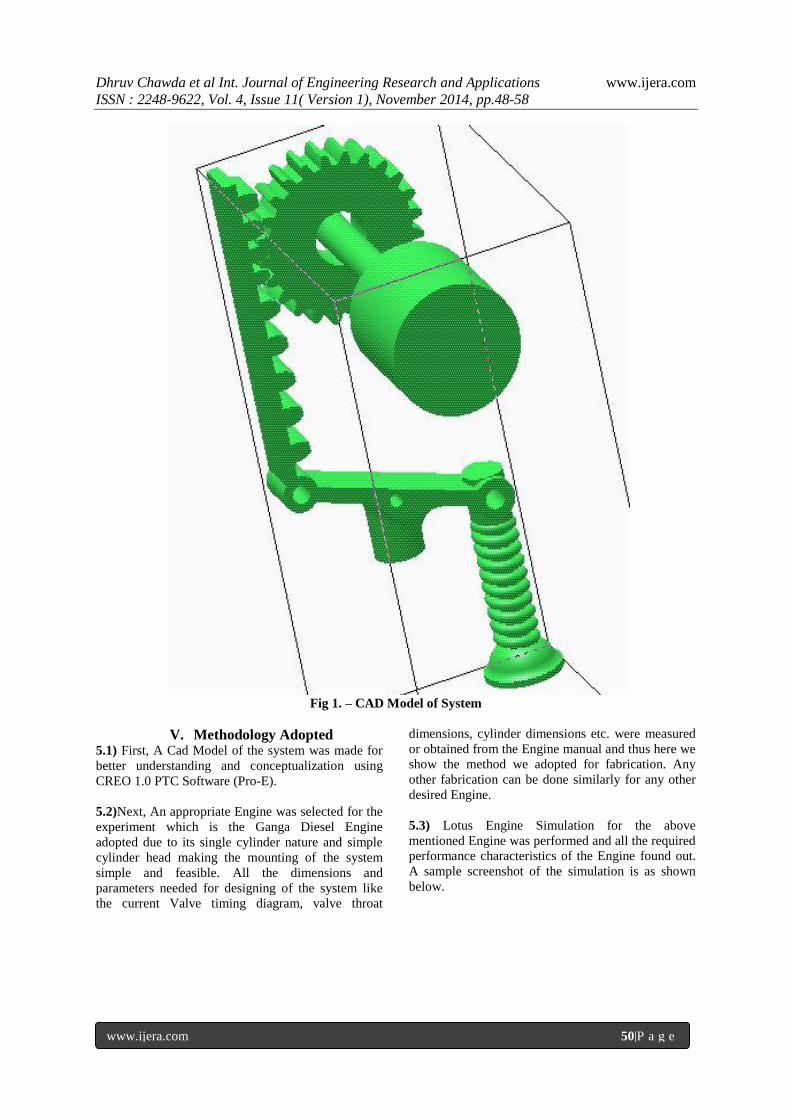
V. Methodology Adopted 5.1) First, A Cad Model of the system was made for
better understanding and conceptualization using
CREO 1.0 PTC Software (Pro-E).
5.2)Next, An appropriate Engine was selected for the
experiment which is the Ganga Diesel Engine
adopted due to its single cylinder nature and simple
cylinder head making the mounting of the system
simple and feasible. All the dimensions and
parameters needed for designing of the system like
the current Valve timing diagram, valve throat
dimensions, cylinder dimensions etc. were measured
or obtained from the Engine manual and thus here we
show the method we adopted for fabrication. Any
other fabrication can be done similarly for any other
desired Engine.
5.3) Lotus Engine Simulation for the above
mentioned Engine was performed and all the required
performance characteristics of the Engine found out.
A sample screenshot of the simulation is as shown
below.

Dhruv Chawda et al Int. Journal of Engineering Research and Applications www.ijera.com
ISSN : 2248-9622, Vol. 4, Issue 11( Version 1), November 2014, pp.48-58
www.ijera.com 51|P a g e
Fig.2- Lotus Software Simulation
5.4) Using the parametric option of the Lotus
software, a variable valve timing experiment was
carried out in which, keeping all the other parameters
constant, the valve opening and closing times and the
Valve Lift were varied for a range of Engine rpms
and the corresponding change in the Volumetric
efficiency noted. (Fig 7).Then the valve opening,
closing and Lift Values which provided the
maximum volumetric efficiency for each rpm were
selected and the corresponding graphs were
plotted.(Fig 3)
Fig 3 – Volumetric Efficiency curves for optimum Inlet valve opening and closing angles.
Dhruv Chawda et al Int. Journal of Engineering Research and Applications www.ijera.com
ISSN : 2248-9622, Vol. 4, Issue 11( Version 1), November 2014, pp.48-58
www.ijera.com 52|P a g e
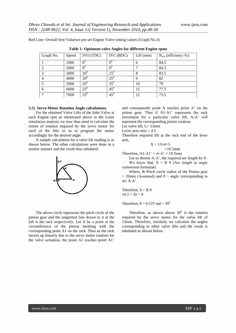
Red Line- Overall best Valuesor pre-set Engine Valve timing values (Graph No.3)
Table 1- Optimum valve Angles for different Engine rpms
5.5) Servo Motor Rotation Angle calculations.
For the obtained Valve Lifts of the Inlet Valve at
each Engine rpm as mentioned above in the Lotus
simulation analysis we now thus need to calculate the
extent of rotation required by the servo motor for
each of the lifts so as to program the motor
accordingly for the desired angle.
A sample calculation for a valve lift reading is as
shown below. The other calculations were done in a
similar manner and the result thus tabulated.
The above circle represents the pitch circle of the
pinion gear and the tangential line drawn to it at the
left is the rack respectively. Let A be a point at the
circumference of the pinion meshing with the
corresponding point A1 on the rack. Thus as the rack
moves up linearly due to the servo motor rotation for
the valve actuation, the point A1 reaches point A1‟
and consequently point A reaches point A‟ on the
pinion gear. Thus if A1-A1‟ represents the rack
movement for a particular valve lift, A-A‟ will
represent the corresponding pinion rotation.
Let valve lift, L= 13mm
Lever arm ratio = 4:5
Therefore required lift at the rack end of the lever
arm,
X = 13×4÷5
=10.5mm
Therefore, A1-A1‟ = A-A‟ = 10.5mm
Let us denote A-A‟, the required arc length by S.
We know that, S = R θ (Arc length to angle
conversion formulae)
Where, R=Pitch circle radius of the Pinion gear
= 20mm (Assumed) and θ = angle corresponding to
arc A-A‟
Therefore, S = R θ
10.5 = 20 × θ
Therefore, θ = 0.525 rad = 300
Therefore, as shown above 300 is the rotation
required by the servo motor for the valve lift of
13mm. Therefore, similarly we calculate the angles
corresponding to other valve lifts and the result is
tabulated as shown below.
Graph No. Speed IVO (TDC) IVC (BDC) Lift (mm) Nvol (efficiency %)
1 1000 00
00
6 84.5
2 2000 00
00
7 84.5
3 3000 100
150
8 83.5
4 4000 200
250
9 82
5 5000 200
350
10 79
6 6000 250
450
11 77.5
7 7000 250
450
12 73.5
Dhruv Chawda et al Int. Journal of Engineering Research and Applications www.ijera.com
ISSN : 2248-9622, Vol. 4, Issue 11( Version 1), November 2014, pp.48-58
www.ijera.com 53|P a g e
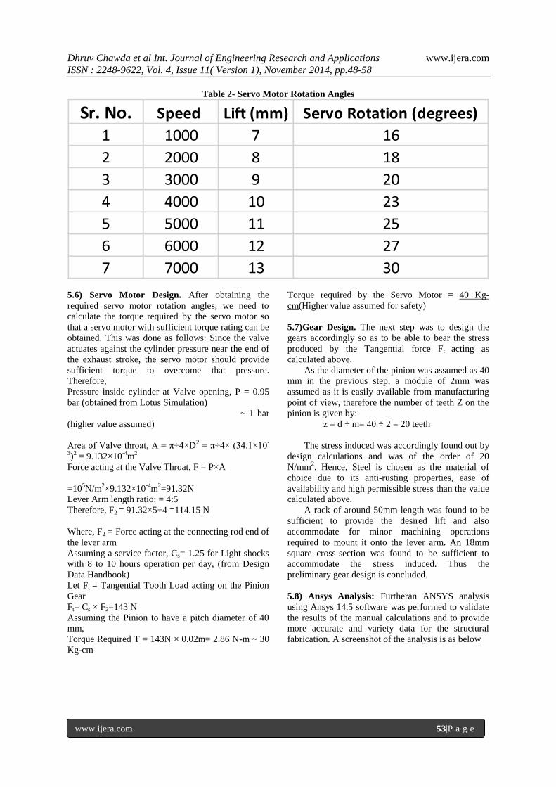
Table 2- Servo Motor Rotation Angles
Sr. No. Speed Lift (mm) Servo Rotation (degrees)
1 1000 7 16
2 2000 8 18
3 3000 9 20
4 4000 10 23
5 5000 11 25
6 6000 12 27
7 7000 13 30
5.6) Servo Motor Design. After obtaining the
required servo motor rotation angles, we need to
calculate the torque required by the servo motor so
that a servo motor with sufficient torque rating can be
obtained. This was done as follows: Since the valve
actuates against the cylinder pressure near the end of
the exhaust stroke, the servo motor should provide
sufficient torque to overcome that pressure.
Therefore,
Pressure inside cylinder at Valve opening, P = 0.95
bar (obtained from Lotus Simulation)
~ 1 bar
(higher value assumed)
Area of Valve throat, A = π†4×D2 = π†4× (34.1×10
-
3)
2 = 9.132×10
-4m
2
Force acting at the Valve Throat, F = P×A
=105N/m
2×9.132×10
-4m
2=91.32N
Lever Arm length ratio: = 4:5
Therefore, F2 = 91.32×5÷4 =114.15 N
Where, F2 = Force acting at the connecting rod end of
the lever arm
Assuming a service factor, Cs= 1.25 for Light shocks
with 8 to 10 hours operation per day, (from Design
Data Handbook)
Let Ft = Tangential Tooth Load acting on the Pinion
Gear
Ft= Cs × F2=143 N
Assuming the Pinion to have a pitch diameter of 40
mm,
Torque Required T = 143N × 0.02m= 2.86 N-m ~ 30
Kg-cm
Torque required by the Servo Motor = 40 Kg-
cm(Higher value assumed for safety)
5.7)Gear Design. The next step was to design the
gears accordingly so as to be able to bear the stress
produced by the Tangential force Ft acting as
calculated above.
As the diameter of the pinion was assumed as 40
mm in the previous step, a module of 2mm was
assumed as it is easily available from manufacturing
point of view, therefore the number of teeth Z on the
pinion is given by:
z = d ÷ m= 40 ÷ 2 = 20 teeth
The stress induced was accordingly found out by
design calculations and was of the order of 20
N/mm2. Hence, Steel is chosen as the material of
choice due to its anti-rusting properties, ease of
availability and high permissible stress than the value
calculated above.
A rack of around 50mm length was found to be
sufficient to provide the desired lift and also
accommodate for minor machining operations
required to mount it onto the lever arm. An 18mm
square cross-section was found to be sufficient to
accommodate the stress induced. Thus the
preliminary gear design is concluded.
5.8) Ansys Analysis: Furtheran ANSYS analysis
using Ansys 14.5 software was performed to validate
the results of the manual calculations and to provide
more accurate and variety data for the structural
fabrication. A screenshot of the analysis is as below
Dhruv Chawda et al Int. Journal of Engineering Research and Applications www.ijera.com
ISSN : 2248-9622, Vol. 4, Issue 11( Version 1), November 2014, pp.48-58
www.ijera.com 54|P a g e
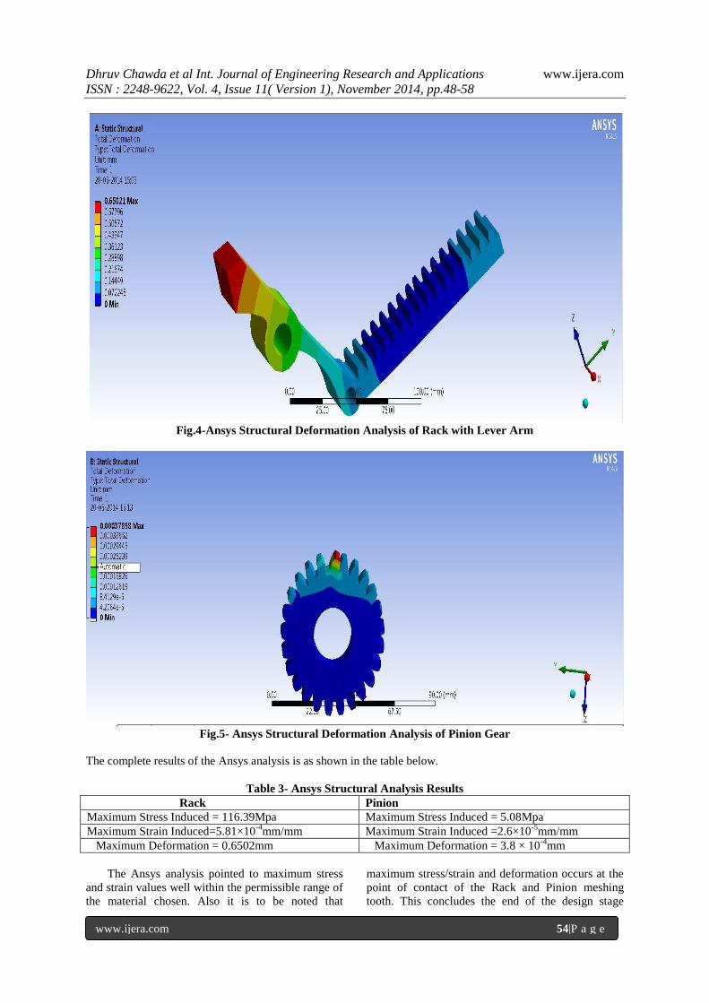
Fig.4-Ansys Structural Deformation Analysis of Rack with Lever Arm
Fig.5- Ansys Structural Deformation Analysis of Pinion Gear
The complete results of the Ansys analysis is as shown in the table below.
Table 3- Ansys Structural Analysis Results
Rack Pinion
Maximum Stress Induced = 116.39Mpa Maximum Stress Induced = 5.08Mpa
Maximum Strain Induced=5.81×10⁻⁴
mm/mm Maximum Strain Induced =2.6×10⁻⁵
mm/mm
Maximum Deformation = 0.6502mm Maximum Deformation = 3.8 × 10⁻⁴
mm
The Ansys analysis pointed to maximum stress
and strain values well within the permissible range of
the material chosen. Also it is to be noted that
maximum stress/strain and deformation occurs at the
point of contact of the Rack and Pinion meshing
tooth. This concludes the end of the design stage
Dhruv Chawda et al Int. Journal of Engineering Research and Applications www.ijera.com
ISSN : 2248-9622, Vol. 4, Issue 11( Version 1), November 2014, pp.48-58
www.ijera.com 55|P a g e
which was then followed by fabrication and
assembly.
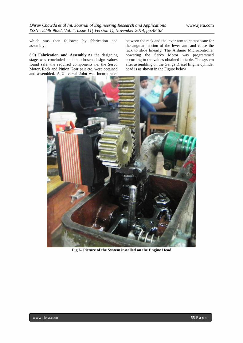
5.9) Fabrication and Assembly.As the designing
stage was concluded and the chosen design values
found safe, the required components i.e. the Servo
Motor, Rack and Pinion Gear pair etc. were obtained
and assembled. A Universal Joint was incorporated
between the rack and the lever arm to compensate for
the angular motion of the lever arm and cause the
rack to slide linearly. The Arduino Microcontroller
powering the Servo Motor was programmed
according to the values obtained in table. The system
after assembling on the Ganga Diesel Engine cylinder
head is as shown in the Figure below
Fig.6- Picture of the System installed on the Engine Head
Dhruv Chawda et al Int. Journal of Engineering Research and Applications www.ijera.com
ISSN : 2248-9622, Vol. 4, Issue 11( Version 1), November 2014, pp.48-58
www.ijera.com 56|P a g e
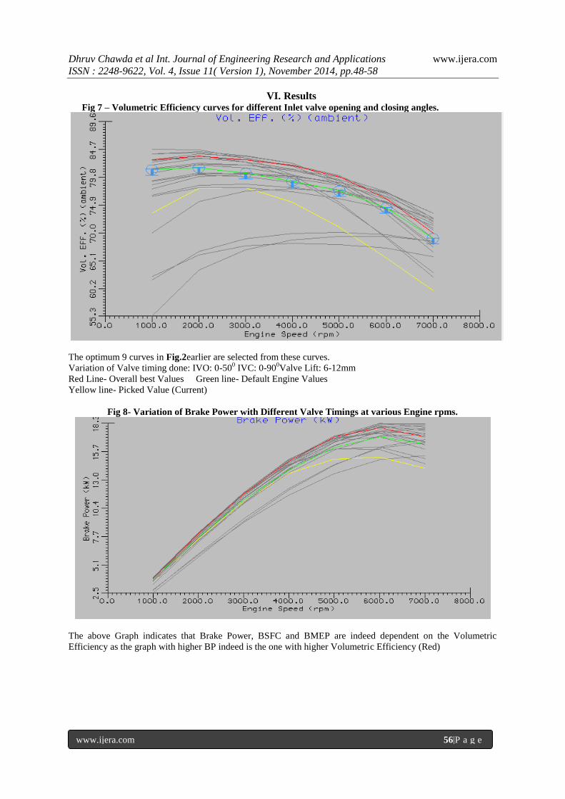
VI. Results Fig 7 – Volumetric Efficiency curves for different Inlet valve opening and closing angles.
The optimum 9 curves in Fig.2earlier are selected from these curves.
Variation of Valve timing done: IVO: 0-500 IVC: 0-90
0Valve Lift: 6-12mm
Red Line- Overall best Values Green line- Default Engine Values
Yellow line- Picked Value (Current)
Fig 8- Variation of Brake Power with Different Valve Timings at various Engine rpms.
The above Graph indicates that Brake Power, BSFC and BMEP are indeed dependent on the Volumetric
Efficiency as the graph with higher BP indeed is the one with higher Volumetric Efficiency (Red)
Dhruv Chawda et al Int. Journal of Engineering Research and Applications www.ijera.com
ISSN : 2248-9622, Vol. 4, Issue 11( Version 1), November 2014, pp.48-58
www.ijera.com 57|P a g e
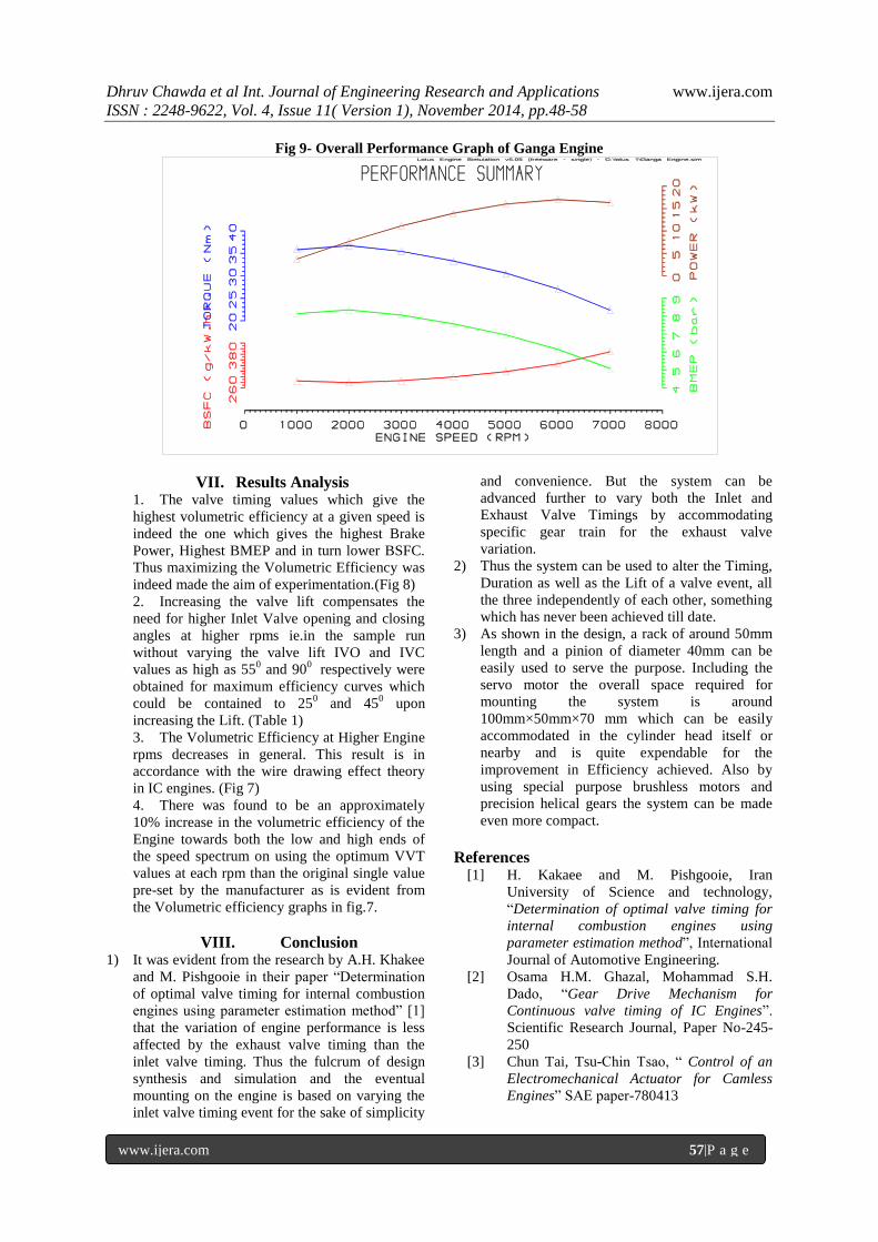
Fig 9- Overall Performance Graph of Ganga Engine
VII. Results Analysis 1. The valve timing values which give the
highest volumetric efficiency at a given speed is
indeed the one which gives the highest Brake
Power, Highest BMEP and in turn lower BSFC.
Thus maximizing the Volumetric Efficiency was
indeed made the aim of experimentation.(Fig 8)
2. Increasing the valve lift compensates the
need for higher Inlet Valve opening and closing
angles at higher rpms ie.in the sample run
without varying the valve lift IVO and IVC
values as high as 550 and 90
0 respectively were
obtained for maximum efficiency curves which
could be contained to 250 and 45
0 upon
increasing the Lift. (Table 1)
3. The Volumetric Efficiency at Higher Engine
rpms decreases in general. This result is in
accordance with the wire drawing effect theory
in IC engines. (Fig 7)
4. There was found to be an approximately
10% increase in the volumetric efficiency of the
Engine towards both the low and high ends of
the speed spectrum on using the optimum VVT
values at each rpm than the original single value
pre-set by the manufacturer as is evident from
the Volumetric efficiency graphs in fig.7.
VIII. Conclusion 1) It was evident from the research by A.H. Khakee
and M. Pishgooie in their paper “Determination
of optimal valve timing for internal combustion
engines using parameter estimation method” [1]
that the variation of engine performance is less
affected by the exhaust valve timing than the
inlet valve timing. Thus the fulcrum of design
synthesis and simulation and the eventual
mounting on the engine is based on varying the
inlet valve timing event for the sake of simplicity
and convenience. But the system can be
advanced further to vary both the Inlet and
Exhaust Valve Timings by accommodating
specific gear train for the exhaust valve
variation.
2) Thus the system can be used to alter the Timing,
Duration as well as the Lift of a valve event, all
the three independently of each other, something
which has never been achieved till date.
3) As shown in the design, a rack of around 50mm
length and a pinion of diameter 40mm can be
easily used to serve the purpose. Including the
servo motor the overall space required for
mounting the system is around
100mm×50mm×70 mm which can be easily
accommodated in the cylinder head itself or
nearby and is quite expendable for the
improvement in Efficiency achieved. Also by
using special purpose brushless motors and
precision helical gears the system can be made
even more compact.
References [1] H. Kakaee and M. Pishgooie, Iran
University of Science and technology,
“Determination of optimal valve timing for
internal combustion engines using
parameter estimation method”, International
Journal of Automotive Engineering.
[2] Osama H.M. Ghazal, Mohammad S.H.
Dado, “Gear Drive Mechanism for
Continuous valve timing of IC Engines”.
Scientific Research Journal, Paper No-245-
250
[3] Chun Tai, Tsu-Chin Tsao, “ Control of an
Electromechanical Actuator for Camless
Engines” SAE paper-780413
Dhruv Chawda et al Int. Journal of Engineering Research and Applications www.ijera.com
ISSN : 2248-9622, Vol. 4, Issue 11( Version 1), November 2014, pp.48-58
www.ijera.com 58|P a g e
[4] Chihaya Sugimoto, Hisao Sakai, Atsushi
Umemoto, Yasuo Shimizu and Hidetaka
Ozawa, Honda R&D international Ltd.
“Study on Variable Valve Timing System
UsingElectromagnetic Mechanism”, SAE
paper- 2004-01-1869
[5] Osama H. M. Ghazal, Yousef S. H. Najjar,
Kutaeba J. M. Al-Khishali, University of
Jordan, “Modeling the Effect of Variable
Timing of the Exhaust Valves on SI Engine
Emissions for Greener Vehicles”, Scientific
Research Journal, Paper No- 2013, 5, 181-
189.
http://dx.doi.org/10.4236/epe.2013.53018
[6] S.ChakradharGoud, G.SureshPatil,
Dr.D.Maheshwar, Dr. B. Anjaneya Prasad,
“An Investigation of Variable Valve Timing
application for controlling the HCCI
Combustion. International Journal of
Engineering Research &
Applications(IJERA) ISSN:2248-9622
[7] C. Gray, “A Review of Variable Engine
Valve Timing,” SAE Technical Paper No.
880386, 1988.
[8] T. Dresner and P. Barkan, “A Review and
Classification of Variable Valve Timing
Mechanisms,” SAE Paper, No. 890667,
1989
[9] H. Hong, G. B. Parvate-Patil and B. Gordon,
“Review and Analysis of Variable Valve
Timing Strategies-Eight Ways to Approach,”
Proceedings of the Institution of Mechanical
Engineers, Part D: Journal of Automobile
Engineering, Vol. 218, No. 10, 2004, pp.
1179-1200.
doi:10.1177/095440700421801013
[10] H. S. Yan and W. R. Chen, “On the Output
Motion Characteristics of Variable Speed
Input Servo-Controlled Slider- Crank
Mechanisms,” Mechanism and Machine
Theory, Vol. 35, No. 4, 2000, pp. 541-561.
doi:10.1016/S0094-114X(99)00023-3