QuantaMesh Layer 2/3/4 Managed Switch User's Guide - of /sup
1020
___________________________________________________________________________________________ UANTA COMPUTER INC. _________________________________________________________________ QuantaMesh Layer 2/3/4 Managed Switch User’s Guide Applicable Products * T5032-LY6 * T3096-LY5 Edition April 2014
-
Upload
khangminh22 -
Category
Documents
-
view
0 -
download
0
Transcript of QuantaMesh Layer 2/3/4 Managed Switch User's Guide - of /sup
___________________________________________________________________________________________
UANTA COMPUTER INC.
_________________________________________________________________
QuantaMesh Layer 2/3/4 Managed Switch
User’s Guide
Applicable Products
* T5032-LY6
* T3096-LY5
Edition April 2014
UANTA COMPUTER INC.
Layer 2/3/4 Managed Switch
QuantaMesh | Introduction 2
Comments… Suggestions… Corrections…
The User documentation Department would like to know your opinion on this manual. Your feedback helps us to optimize our documentation to suit your individual needs.
Fax forms for sending us your comments are included at the back of the manual.
There you will also find the addresses of the relevant User documentation Department.
Copyright and Trademarks
Copyright © 2014 Quanta Computer Inc.
All rights reserved.
Delivery subject to availability; right of technical modifications reserved.
All hardware and software names used are trademarks of their respective manufacturers.
UANTA COMPUTER INC.
Layer 2/3/4 Managed Switch
QuantaMesh | Introduction 3
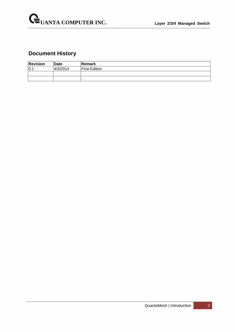
Document History
Revision Date Remark 0.1 4/3/2014 First Edition -
UANTA COMPUTER INC.
Layer 2/3/4 Managed Switch
QuantaMesh | Introduction 4
CONTENTS
1 INTRODUCTION ......................................................................................................................................... 10
1.1 PRODUCT OVERVIEW ..................................................................................................................................... 10 1.2 FEATURES .................................................................................................................................................... 12 1.3 MANAGEMENT OPTIONS ................................................................................................................................ 14 1.4 COMMAND LINE CONSOLE INTERFACE THROUGH THE SERIAL PORT OR TELNET ......................................................... 14 1.5 SNMP-BASED MANAGEMENT ........................................................................................................................ 15
2 INSTALLATION AND QUICK STARTUP ........................................................................................................ 18
2.1 PACKAGE CONTENTS ..................................................................................................................................... 18 2.2 SWITCH INSTALLATION ................................................................................................................................... 19 2.3 INSTALLING THE SWITCH IN A RACK .................................................................................................................. 20 2.4 QUICK STARTING THE SWITCH ......................................................................................................................... 21 2.5 SYSTEM INFORMATION SETUP ......................................................................................................................... 22
2.5.1 Quick Start up Software Version Information .................................................................................. 22 2.5.2 Quick Start up Physical Port Data .................................................................................................... 22 2.5.3 Quick Start up User Account Management ..................................................................................... 23 2.5.4 Quick Start up IP Address ................................................................................................................. 24 2.5.5 Quick Start up Uploading from Switch to Out-of-Band PC ............................................................... 25 2.5.6 Quick Start up Downloading from Out-of-Band PC to Switch .......................................................... 25 2.5.7 Quick Start up Downloading from TFTP Server ................................................................................ 25 2.5.8 Quick Start up Factory Defaults ....................................................................................................... 26
3 CONSOLE AND TELNET ADMINISTRATION INTERFACE ............................................................................... 27
3.1 LOCAL CONSOLE MANAGEMENT ...................................................................................................................... 27 3.2 SET UP YOUR SWITCH USING CONSOLE ACCESS .................................................................................................. 27 3.3 SET UP YOUR SWITCH USING TELNET ACCESS ..................................................................................................... 29
3.3.1 Accessing the Switch CLI through the Network ................................................................................ 29 3.3.2 Using the Service Port or Netowrk Interface for Remote Management .......................................... 29
4 COMMAND LINE INTERFACE STRUCTURE AND MODE-BASED CLI .............................................................. 31
4.1 CLI COMMAND FORMAT ................................................................................................................................ 31 4.2 CLI MODE-BASED TOPOLOGY ......................................................................................................................... 32
5 SWITCHING COMMANDS .......................................................................................................................... 34
5.1 SYSTEM INFORMATION AND STATISTICS COMMANDS ........................................................................................... 34 5.1.1 show arp .......................................................................................................................................... 34 5.1.2 show calendar .................................................................................................................................. 35 5.1.3 show process cpu ............................................................................................................................. 36 5.1.4 show eventlog .................................................................................................................................. 38 5.1.5 show running-config ........................................................................................................................ 39 5.1.6 show sysinfo ..................................................................................................................................... 40 5.1.7 show system ..................................................................................................................................... 41 5.1.8 show tech-support ........................................................................................................................... 42 5.1.9 show hardware ................................................................................................................................ 43 5.1.10 show version .................................................................................................................................... 45 5.1.11 show loginsession ............................................................................................................................ 46 5.1.12 show command filter ....................................................................................................................... 47 5.1.13 Digital Optical Monitor .................................................................................................................... 48
5.2 DEVICE CONFIGURATION COMMANDS .............................................................................................................. 50 5.2.1 Interface ........................................................................................................................................... 50 5.2.2 L2 MAC Address and Multicast Forwarding Database Tables ......................................................... 71 5.2.3 VLAN Management .......................................................................................................................... 79
UANTA COMPUTER INC.
Layer 2/3/4 Managed Switch
QuantaMesh | Introduction 5
5.2.4 Double VLAN commands ................................................................................................................ 103 5.2.5 GVRP and Bridge Extension............................................................................................................ 105 5.2.6 IGMP Snooping .............................................................................................................................. 116 5.2.7 IGMP Snooping Querier ................................................................................................................. 132 5.2.8 MLD Snooping ................................................................................................................................ 139 5.2.9 MLD Snooping Querier ................................................................................................................... 153 5.2.10 Port Channel .................................................................................................................................. 160 5.2.11 Storm Control ................................................................................................................................. 176 5.2.12 L2 Priority ....................................................................................................................................... 185 5.2.13 Port Mirror ..................................................................................................................................... 187 5.2.14 Link State ....................................................................................................................................... 190 5.2.15 Port Backup .................................................................................................................................... 193 5.2.16 Expandable Port Configuration ...................................................................................................... 195
5.3 MANAGEMENT COMMANDS ......................................................................................................................... 197 5.3.1 Network Commands ...................................................................................................................... 197 5.3.2 Serial Interface Commands ............................................................................................................ 202 5.3.3 Telnet Session Commands.............................................................................................................. 206 5.3.4 SSH Client Session Commands ....................................................................................................... 214 5.3.5 SNMP Server Commands ............................................................................................................... 217 5.3.6 SNMP Trap Commands .................................................................................................................. 233 5.3.7 SNMP Inform Commands ............................................................................................................... 243 5.3.8 Secure Shell (SSH) Commands ........................................................................................................ 244 5.3.9 Management Security Commands ................................................................................................. 247 5.3.10 DHCP Client Commands ................................................................................................................. 248 5.3.11 DHCPv6 Client Commands ............................................................................................................. 249 5.3.12 DHCP Relay Commands ................................................................................................................. 251 5.3.13 sFlow Commands ........................................................................................................................... 253 5.3.14 Service Port Commands ................................................................................................................. 264 5.3.15 Time Range Commands ................................................................................................................. 270 5.3.16 Command Scheduler Commands ................................................................................................... 274
5.4 SPANNING TREE COMMANDS ........................................................................................................................ 277 5.4.1 Show Commands ........................................................................................................................... 277 5.4.2 Configuration Commands .............................................................................................................. 287
5.5 SYSTEM LOG MANAGEMENT COMMANDS ....................................................................................................... 301 5.5.1 Show Commands ........................................................................................................................... 301 5.5.2 Configuration Commands .............................................................................................................. 304
5.6 EMAIL ALERTING AND MAIL SERVER COMMANDS ............................................................................................. 311 5.6.1 Show Commands ........................................................................................................................... 311 5.6.2 Configuration Commands .............................................................................................................. 314
5.7 SCRIPT MANAGEMENT COMMANDS ............................................................................................................... 321 5.7.1 script apply ..................................................................................................................................... 321 5.7.2 script delete ................................................................................................................................... 321 5.7.3 script show ..................................................................................................................................... 322 5.7.4 script validate ................................................................................................................................ 323
5.8 USER ACCOUNT MANAGEMENT COMMANDS ................................................................................................... 324 5.8.1 Show Commands ........................................................................................................................... 324 5.8.2 Configuration Commands .............................................................................................................. 327
5.9 SECURITY COMMANDS ................................................................................................................................. 334 5.9.1 Show Commands ........................................................................................................................... 334 5.9.2 Configuration Commands .............................................................................................................. 356 5.9.3 Dot1x Configuration Commands .................................................................................................... 361 5.9.4 Interface ConfigRadius Configuration Commands ......................................................................... 371 5.9.5 TACACS+ Configuration Commands ............................................................................................... 379 5.9.6 Port Security Configuration Commands ......................................................................................... 384
UANTA COMPUTER INC.
Layer 2/3/4 Managed Switch
QuantaMesh | Introduction 6
5.9.7 Denial Of Service Commands ......................................................................................................... 388 5.10 CDP (CISCO DISCOVERY PROTOCOL) COMMANDS ............................................................................................ 399
5.10.1 Show Commands ........................................................................................................................... 399 5.10.2 Configuration Commands .............................................................................................................. 403
5.11 SNTP (SIMPLE NETWORK TIME PROTOCOL) COMMANDS .................................................................................. 406 5.11.1 Show Commands ........................................................................................................................... 406 5.11.2 Configuration Commands .............................................................................................................. 409
5.12 LLDP (LINK LAYER DISCOVERY PROTOCOL) COMMANDS .................................................................................... 417 5.12.1 Show Commands ........................................................................................................................... 417 5.12.2 Configuration Commands .............................................................................................................. 434
5.13 VTP (VLAN TRUNKING PROTOCOL) COMMANDS ............................................................................................. 446 5.13.1 Show Commands ........................................................................................................................... 446 5.13.2 Configuration Commands .............................................................................................................. 449
5.14 PROTECTED PORTS COMMANDS .................................................................................................................... 454 5.14.1 Show Commands ........................................................................................................................... 454 5.14.2 Configuration Commands .............................................................................................................. 456
5.15 STATIC MAC FILTERING COMMANDS ............................................................................................................. 457 5.15.1 Show Commands ........................................................................................................................... 457 5.15.2 Configuration Commands .............................................................................................................. 458
5.16 SYSTEM UTILITIES ....................................................................................................................................... 461 5.16.1 clear ............................................................................................................................................... 461 5.16.2 copy ................................................................................................................................................ 475 5.16.3 delete ............................................................................................................................................. 478 5.16.4 dir ................................................................................................................................................... 479 5.16.5 whichboot ...................................................................................................................................... 480 5.16.6 boot-system ................................................................................................................................... 480 5.16.7 ping ................................................................................................................................................ 481 5.16.8 traceroute ...................................................................................................................................... 484 5.16.9 logging cli-command ..................................................................................................................... 486 5.16.10 calendar set................................................................................................................................ 487 5.16.11 reload ......................................................................................................................................... 487 5.16.12 configure .................................................................................................................................... 488 5.16.13 disconnect .................................................................................................................................. 488 5.16.14 hostname ................................................................................................................................... 489 5.16.15 quit ............................................................................................................................................. 489 5.16.16 cablestatus ................................................................................................................................. 490 5.16.17 AutoInstall Commands ............................................................................................................... 491 5.16.18 Capture CPU packet Commands ................................................................................................ 495
5.17 DHCP SNOOPING COMMANDS ..................................................................................................................... 500 5.17.1 Show Commands ........................................................................................................................... 501 5.17.2 Configuration Commands .............................................................................................................. 508
5.18 IP SOURCE GUARD (IPSG) COMMANDS ......................................................................................................... 518 5.18.1 Show Commands ........................................................................................................................... 519 5.18.2 Configuration Commands .............................................................................................................. 521
5.19 DYNAMIC ARP INSPECTION (DAI) COMMAND ................................................................................................. 522 5.19.1 Show Commands ........................................................................................................................... 523 5.19.2 Configuration Commands .............................................................................................................. 527
5.20 DIFFERENTIATED SERVICE COMMAND ............................................................................................................. 532 5.20.1 General Commands........................................................................................................................ 534 5.20.2 Class Commands ............................................................................................................................ 535 5.20.3 Policy Commands ........................................................................................................................... 554 5.20.4 Service Commands ......................................................................................................................... 565 5.20.5 Show Commands ........................................................................................................................... 568
5.21 ACL COMMAND ......................................................................................................................................... 576
UANTA COMPUTER INC.
Layer 2/3/4 Managed Switch
QuantaMesh | Introduction 7
5.21.1 Show Commands ........................................................................................................................... 576 5.21.2 Configuration Commands .............................................................................................................. 583
5.22 IPV6 ACL COMMAND ................................................................................................................................. 593 5.22.1 Show Commands ........................................................................................................................... 593 5.22.2 Configuration Commands .............................................................................................................. 595
5.23 COS (CLASS OF SERVICE) COMMAND .............................................................................................................. 599 5.23.1 Show Commands ........................................................................................................................... 599 5.23.2 Configuration Commands .............................................................................................................. 604
5.24 AUTO-VOICE OVER IP COMMANDS ................................................................................................................ 610 5.24.1 Show Commands ........................................................................................................................... 611 5.24.2 Configuration Commands .............................................................................................................. 612
5.25 ISCSI OPTIMIZATION COMMANDS ................................................................................................................. 613 5.25.1 Show Commands ........................................................................................................................... 613 5.25.2 Configuration Commands .............................................................................................................. 615
5.26 DOMAIN NAME SERVER RELAY COMMANDS .................................................................................................... 619 5.26.1 Show Commands ........................................................................................................................... 619 5.26.2 Configuration Commands .............................................................................................................. 622
5.27 UDLD COMMANDS .................................................................................................................................... 630 5.27.1 Show command ............................................................................................................................. 630 5.27.2 Configuration Commands .............................................................................................................. 632
5.28 MULTI CHASSIS LINK AGGREGATION COMMANDS ............................................................................................. 635 5.28.1 Show Commands ........................................................................................................................... 635 5.28.2 Configuration Commands .............................................................................................................. 639
5.29 CONTROL PLANE PROTECTION COMMANDS ..................................................................................................... 643 5.29.1 Show Commands ........................................................................................................................... 643 5.29.2 Configuration Commands .............................................................................................................. 643
6 ROUTING COMMANDS ............................................................................................................................ 645
6.1 ADDRESS RESOLUTION PROTOCOL (ARP) COMMANDS ...................................................................................... 645 6.1.1 Show Commands ........................................................................................................................... 645 6.1.2 Configuration Commands .............................................................................................................. 648
6.2 IP ROUTING COMMANDS ............................................................................................................................. 653 6.2.1 Show Commands ........................................................................................................................... 653 6.2.2 Configuration Commands .............................................................................................................. 668
6.3 OPEN SHORTEST PATH FIRST (OSPF) COMMANDS ........................................................................................... 675 6.3.1 Show Commands ........................................................................................................................... 675 6.3.2 Configuration Commands .............................................................................................................. 695
6.4 BOOTP/DHCP RELAY COMMANDS .............................................................................................................. 724 6.4.1 Show Commands ........................................................................................................................... 724 6.4.2 Configuration Commands .............................................................................................................. 725
6.5 IP HELPER COMMANDS ............................................................................................................................... 728 6.5.1 Show Commands ........................................................................................................................... 728 6.5.2 Configuration Commands .............................................................................................................. 730
6.6 ROUTING INFORMATION PROTOCOL (RIP) COMMANDS ..................................................................................... 733 6.6.1 Show Commands ........................................................................................................................... 733 6.6.2 Configuration Commands .............................................................................................................. 736
6.7 ROUTER DISCOVERY PROTOCOL COMMANDS ................................................................................................... 745 6.7.1 Show Commands ........................................................................................................................... 745 6.7.2 Configuration Commands .............................................................................................................. 746
6.8 VLAN ROUTING COMMANDS ....................................................................................................................... 749 6.8.1 Configuration Commands .............................................................................................................. 749
6.9 VIRTUAL ROUTER REDUNDANCY PROTOCOL (VRRP) COMMANDS ....................................................................... 750 6.9.1 Show Commands ........................................................................................................................... 750 6.9.2 Configuration Commands .............................................................................................................. 755
UANTA COMPUTER INC.
Layer 2/3/4 Managed Switch
QuantaMesh | Introduction 8
6.10 POLICY BASED ROUTING (PBR) COMMANDS ................................................................................................... 763 6.10.1 Show Commands ........................................................................................................................... 763 6.10.2 Configuration Commands .............................................................................................................. 765
6.11 BORDER GATEWAY PROTOCOL (BGP) COMMANDS ........................................................................................... 778 6.11.1 Show Commands ........................................................................................................................... 778 6.11.2 Configuration Commands .............................................................................................................. 798
7 IP MULTICAST COMMANDS..................................................................................................................... 819
7.1 DISTANCE VECTOR MULTICAST ROUTING PROTOCOL (DVMRP) COMMANDS ........................................................ 819 7.1.1 Show Commands ........................................................................................................................... 819 7.1.2 Configuration Commands .............................................................................................................. 825
7.2 INTERNET GROUP MANAGEMENT PROTOCOL (IGMP) COMMANDS ..................................................................... 827 7.2.1 Show Commands ........................................................................................................................... 827 7.2.2 Configuration Commands .............................................................................................................. 834
7.3 MLD COMMANDS ...................................................................................................................................... 839 7.3.1 Show Commands ........................................................................................................................... 839 7.3.2 Configuration Commands .............................................................................................................. 843
7.4 MULTICAST COMMANDS .............................................................................................................................. 847 7.4.1 Show Commands ........................................................................................................................... 847 7.4.2 Configuration Commands .............................................................................................................. 853
7.5 IPV4 PROTOCOL INDEPENDENT MULTICAST (PIM) COMMANDS .......................................................................... 856 7.5.1 Show Commands ........................................................................................................................... 856 7.5.2 Configuration Commands .............................................................................................................. 863
7.6 IPV6 PROTOCOL INDEPENDENT MULTICAST COMMANDS ................................................................................... 871 7.6.1 Show Commands ........................................................................................................................... 871 7.6.2 Configuration Commands .............................................................................................................. 878
7.7 IGMP PROXY COMMANDS ........................................................................................................................... 886 7.7.1 Show Commands ........................................................................................................................... 886 7.7.2 Configuration Commands .............................................................................................................. 890
7.8 MLD PROXY COMMANDS ............................................................................................................................ 892 7.8.1 Show Commands ........................................................................................................................... 892 7.8.2 Configuration Commands .............................................................................................................. 896
8 IPV6 COMMANDS ................................................................................................................................... 898
8.1 TUNNEL INTERFACE COMMANDS ................................................................................................................... 898 8.1.1 Show Commands ........................................................................................................................... 898 8.1.2 Configuration Commands .............................................................................................................. 900
8.2 LOOPBACK INTERFACE COMMANDS ................................................................................................................ 902 8.2.1 Show Commands ........................................................................................................................... 902 8.2.2 Configuration Commands .............................................................................................................. 903
8.3 IPV6 ROUTING COMMANDS ......................................................................................................................... 904 8.3.1 Show Commands ........................................................................................................................... 904 8.3.2 Configuration Commands .............................................................................................................. 917
8.4 OSPFV3 COMMANDS ................................................................................................................................. 930 8.4.1 Show Commands ........................................................................................................................... 930 8.4.2 Configuration Commands .............................................................................................................. 948
8.5 RIPNG COMMANDS .................................................................................................................................... 972 8.5.1 Show Commands ........................................................................................................................... 972 8.5.2 Configuration Commands .............................................................................................................. 974
8.6 ROUTING POLICY COMMANDS ...................................................................................................................... 981 8.6.1 Show Commands ........................................................................................................................... 981 8.6.2 Configuration Commands .............................................................................................................. 982
9 DATA CENTER BRIDGING COMMANDS .................................................................................................... 985
UANTA COMPUTER INC.
Layer 2/3/4 Managed Switch
QuantaMesh | Introduction 9
9.1 FIP SNOOPING ........................................................................................................................................... 985 9.1.1 show dcb fip-snooping ................................................................................................................... 985 9.1.2 show fip-snooping enode ............................................................................................................... 985 9.1.3 show dcb fip-snooping session ....................................................................................................... 987 9.1.4 show dcb fip-snooping fcf .............................................................................................................. 988 9.1.5 show dcb fip-snooping vlan ........................................................................................................... 989 9.1.6 fip-snooping ................................................................................................................................... 989 9.1.7 fip-snooping vlan ........................................................................................................................... 990
9.2 PRIORITY-BASED FLOW CONTROL ................................................................................................................... 991 9.2.1 show dcb priority-flow-control ....................................................................................................... 991 9.2.2 priority-flow-control mode ............................................................................................................. 991 9.2.3 priority-flow-control priority .......................................................................................................... 992 9.2.4 clear priority-flow-control statistics ............................................................................................... 992
9.3 ENHANCED TRANSMISSION SELECTION (ETS) ................................................................................................... 993 9.3.1 show dcb ets classofservice traffic-class-group ............................................................................. 993 9.3.2 show dcb ets traffic-class-group .................................................................................................... 993 9.3.3 ets classofservice traffic-class-group ............................................................................................. 995 9.3.4 ets traffic-class-group max-bandwidth .......................................................................................... 995 9.3.5 ets traffic-class-group min-bandwidth ........................................................................................... 996 9.3.6 ets traffic-class-group strict ........................................................................................................... 996 9.3.7 ets traffic-class-group weight ........................................................................................................ 997
9.4 ETHERNET VIRTUAL BRIDGING ....................................................................................................................... 998 9.4.1 show evb status ............................................................................................................................. 998 9.4.2 show evb status ............................................................................................................................. 999 9.4.3 show evb vsi-profile ..................................................................................................................... 1000 9.4.4 evb enable .................................................................................................................................... 1000 9.4.5 evb rte .......................................................................................................................................... 1001
9.5 VM TRACER COMMANDS ........................................................................................................................... 1002 9.5.1 Show Commands ......................................................................................................................... 1002 9.5.2 Configuration Commands ............................................................................................................ 1006
10 OPENFLOW COMMANDS ................................................................................................................... 1011
10.1 SHOW COMMANDS ................................................................................................................................... 1011 10.1.1 show openflow instance .............................................................................................................. 1011 10.1.2 show openflow controller ............................................................................................................ 1012 10.1.3 show openflow installed flows ..................................................................................................... 1013 10.1.4 show openflow installed meters .................................................................................................. 1014 10.1.5 show openflow table status ......................................................................................................... 1015
10.2 CONFIGURATION COMMANDS ..................................................................................................................... 1016 10.2.1 OpenFlow Instance....................................................................................................................... 1016 10.2.2 OpenFlow Enable/Disable ............................................................................................................ 1016 10.2.3 OpenFlow Controller .................................................................................................................... 1017 10.2.4 OpenFlow Hybrid Mode ............................................................................................................... 1017 10.2.5 OpenFlow VLAN in Per-VLAN mode instance ............................................................................... 1018 10.2.6 OpenFlow PORT in Per-PORT mode instance ............................................................................... 1018 10.2.7 OpenFlow Variant ........................................................................................................................ 1019 10.2.8 OpenFlow Fail Mode .................................................................................................................... 1019 10.2.9 OpenFlow ignore-legacy-protocol ................................................................................................ 1019
UANTA COMPUTER INC.
Layer 2/3/4 Managed Switch
QuantaMesh | Introduction 10
1 Introduction
1.1 Product Overview
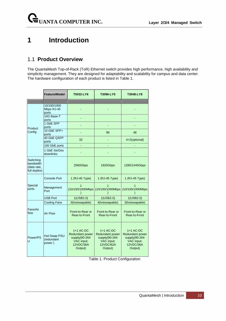
The QuantaMesh Top-of-Rack (ToR) Ethernet switch provides high performance, high availability and simplicity management. They are designed for adaptability and scalability for campus and data center. The hardware configuration of each product is listed in Table 1.
Feature/Model T5032-LY6 T3096-LY5 T3048-LY8
Product Config
10/100/1000 Mbps RJ-45 ports
- - -
10G Base-T ports - -
1 GbE SFP ports - - -
10 GbE SFP+ ports
- 96 48
40 GbE QSFP ports 32 - 4+2(optional)
100 GbE ports - - -
1 GbE SerDes downlinks
- - -
Switching bandwidth (data rate, full duplex)
2560Gbps 1920Gbps 1280/1440Gbps
Special ports
Console Port 1 (RJ-45 Type) 1 (RJ-45 Type) 1 (RJ-45 Type)
Management Port
1 (10/100/1000Mbps
)
1 (10/100/1000Mbps
)
1 (10/100/1000Mbps
)
USB Port 1(USB2.0) 1(USB2.0) 1(USB2.0)
Fans/Air flow
Cooling Fans 3(hotswapable) 4(hotswapable) 3(hotswapable)
Air Flow Front-to-Rear or Rear-to-Front
Front-to-Rear or Rear-to-Front
Front-to-Rear or Rear-to-Front
Power/PSU
Hot-Swap PSU (redundant power )
1+1 AC-DC Redundant power
supply(90-264 VAC input; 12VDC/36A
Output)
1+1 AC-DC Redundant power
supply(90-264 VAC input; 12VDC/62A
Output)
1+1 AC-DC Redundant power
supply(90-264 VAC input; 12VDC/36A
Output)
Table 1. Product Configuration
UANTA COMPUTER INC.
Layer 2/3/4 Managed Switch
QuantaMesh | Introduction 11
Simplicity The QuantaMesh switch can be managed through industry standard command-line interface (CLI) which reduces the training and operating costs. It supports Simple Network Management Protocol (SNMP) both from standard MIB and private MIB for network administrator to easily configure, monitor, and manage remotely. The Auto-installation feature implemented helps centralized management to simplify deployment of a truly plug-and-play experience. With the evolution from IPv4 to IPv6, the QuantaMesh switch is a IPv6 integrated management device. High Availability The QuantaMesh switch is designed for high availability from both hardware and software perspective. The key features include: - 1+1 hot-swappable power supplies - Out-of-band management supported - 802.1D, 802.1w and 802.1s supported - Up to 32 ports per link aggregation group (LACP) and up to 64 groups - Multi-chassis LAG (MLAG) for preventing the risks of single point failure - Up to 32 paths ECMP routing for load balancing and redundancy - Virtual Router Redundancy Protocol (VRRP) supported High-Performance L2/L3 access deployments With the compact 1U form factor, high desity ports in the front panel, fron to back or back to front airflow design, the QuantaMesh switch is idea for top-of-rack deployments in high-performance, highly demanding data centers. The high switching capacity to be a powerful solution to aggregate high-performance servers in the data center. Advance IPv4 and IPv6 Routing The QuantaMesh switch is a full layer 2 and layer 3 routing switch that supports advanced IPv4 and IPv6 routing features such as RIP v1/v2, OSPF/ECMP, RIPng and OSPFv3. The multicast routing features for IGMP v1/v2/v3, DVMRP, PIM-DM.SM, MLD v1/v2 and PIM-DM6/SM6 are all supported. Data Center Application The QuantaMesh switch is an IEEE DCB-based switch delivering a high-performance solution to integrate server edge access. The key features include: - Congestion Notification (CN, 802.1Qau) - Enhanced Transmission Selection (ETS, 802.1Qaz) - Priority-based Flow Control (PFC, 802.1Qbb) - Data Center Bridging Extension (DCBX, 802.1Qaz) - FCoE Initiation Protocol (FIP) snooping - Ethernet Virtual Bridging (EVB, 802.1Qbg)
UANTA COMPUTER INC.
Layer 2/3/4 Managed Switch
QuantaMesh | Introduction 12
1.2 Features
• IEEE 802.3z and IEEE 802.3x compliant Flow Control for all ethernet ports
• Supports 802.1D STP, 802.1S MSTP, and 802.1w Rapid Spanning Tree for redundant back up bridge paths
• Supports 802.1Q VLAN, Protocol-based VLAN, Subnet-based VLAN, MAC-based VLAN, Protected Port, Double VLAN, Voice VLAN, GVRP, GMRP, IGMP snooping, 802.1p Priority Queues, Port Channel, port mirroring
• Link Agregation (802.1ad LACP)
• Multi-chassis Link Aggregation (MLAG)
• Supports VTP (VLAN Trunking Protocol)
• Supports CDP
• Supports LLDP with potential communication problems detection
• Supports Port Security
• Multi-layer Access Control (based on MAC address, IP address, VLAN, Protocol, 802.1p, DSCP)
• Quality of Service (QoS) customized control
• AAA support
• 802.1x access control and RADIUS client support
• TACACS+ support
• UDLD support
• Error Disable Recovery support
• Supports DHCP Snooping
• Dynamic ARP Inspection (DAI) and IP Source Guard (IPSG)
• IP ARP support
• IP Routing support
• VLAN Routing support
• OSPF v2 and v3 support
• RIP v1/v2 and RIPng support
• BGP4 support
• Router Discovery Protocol support
• Virtual Router Redundancy Protocol (VRRP) support
• 32-way ECMP support
• /31 subnets support
• Source IP configuration support
• Poilcy Based Routing (PBR)
• IP Multicast support
UANTA COMPUTER INC.
Layer 2/3/4 Managed Switch
QuantaMesh | Introduction 13
• IGMP v1, v2, and v3 support
• DVMRP support
• Protocol Independent Multicast - Dense Mode (PIM-DM) support for IPv4 and IPv6
• Protocol Independent Multicast - Sparse Mode (PIM-SM) support for IPv4 and IPv6
• IPv6 function Supports DHCPv6 protocol, OSPFv3 protocol, Tunneling, loopback Provides to configure IPv6 rotuing interface, routing preference
• DHCP Client and Relay support
• IP Helper (BOOTP/DHCP Relay)
• DNS Client and Relay support
• Per-port bandwidth control
• iSCSI Optimization support
• Auto VoIP support
• SNMP v1, v2, v3 network management, RMON support
• CLI management support
• Fully configurable either in-band or out-of-band control via RS-232 console serial connection
• Telnet remote control console
• TraceRoute support
• Traffic Segmentation
• TFTP/FTP/SCP/SFTP upgrade
• SysLog support
• Email Alerting support
• Simple Network Time Protocol support
• SSH Secure Shell version 1 and 2 support
• SSL Secure HTTP TLS Version 1 and SSL version 3 support
• Auto Install support
• Fibre Channel Over Ethernet(FCoE) FIP Snooping
• Data Center Bridge (DCB) Enhanced Transmission Selection (ETS, IEEE 802.1Qaz) Priority Flow Control (PFC, IEEE 802.1Qbb)
• Data Center Bridge Exchange (DCBX, IEEE802.1Qaz)
• Ethenet Virtual Bridge (EVB) VEB/VEPA bridge support
• OpenFlow support
• Control Plane Protection (CoPP)
UANTA COMPUTER INC.
Layer 2/3/4 Managed Switch
QuantaMesh | Introduction 14
1.3 Management Options
The system may be managed by using one Service Ports through a Telnet, SNMP function and using the console port on the front panel through CLI command.
1.4 Command Line Console Interface through the Serial P ort or Telnet
You can also connect a computer or terminal to the serial console port or use Telnet to access the Switch. The command-line-driven interface provides complete access to all switch management features.
UANTA COMPUTER INC.
Layer 2/3/4 Managed Switch
QuantaMesh | Introduction 15
1.5 SNMP-Based Management
You can manage the Switch with an SNMP-compatible console program. The Switch supports SNMP version 1.0, version 2.0, and version 3.0. The SNMP agent decodes the incoming SNMP messages and responds to requests with MIB objects stored in the database. The SNMP agent updates the MIB objects to generate statistics The Switch supports a comprehensive set of MIB extensions:
• RFC1493 Bridge
• RFC 2819 RMON-MIB
• RFC 2233 Interface MIB
• RFC 2618 (Radius-Auth-Client-MIB)
• RFC 2620 (Radius-Acc-Client-MIB)
• RFC 1724 (RIPv2-MIB)
• RFC 1850 (OSPF-MIB)
• RFC 1850 (OSPF-TRAP-MIB)
• RFC 2787 (VRRP-MIB)
• RFC 3289 - DIFFSERV-DSCP-TC
• RFC 3289 - DIFFSERV-MIB
• QoS-DIFFSERV-EXTENSIONS-MIB
• QoS-DIFFSERV-PRIVATE-MIB
• RFC 2674 802.1p
• RFC 2932 (IPMROUTE-MIB)
• Quanta Enterprise MIB
• ROUTING-MIB
• MGMD-MIB
• RFC 2934 PIM-MIB
• DVMRP-STD-MIB
• IANA-RTPROTO-MIB
• MULTICAST-MIB
• ROUTING6-MIB
• IEEE8021-PAE-MIB
• INVENTORY-MIB
• MGMT-SECURITY-MIB
• QoS-MIB
• QoS-ACL-MIB
• QoS-COS-MIB
• QoS-AUTOVOIP-MIB

UANTA COMPUTER INC.
Layer 2/3/4 Managed Switch
QuantaMesh | Introduction 16
• QoS-DIFFSERV-PRIVATE-MIB
• QoS-ISCSI-MIB
• RFC 1907 - SNMPv2-MIB
• RFC 2465 - IPV6-MIB
• RFC 2466 - IPV6-ICMP-MIB
• TACACS-MIB
• IGMP/MLD Snooping
• IGMP/MLD Layer2 Multicast
• QoS – IPv6 ACL
• Voice VLAN
• Guest VLAN
• LLDP-MIB
• LLDP MED
• RFC 2925 (DISMAN-TRACEROUTE-MIB)
• RFC 2080 (RIPng)
• OSPFV3-MIB
• RFC 2571 - SNMP-FRAMEWORK-MIB
• RFC 2572 - SNMP-MPD-MIB
• RFC 2573 - SNMP-NOTIFICATION-MIB
• RFC 2573 - SNMP-TARGET-MIB
• RFC 2574 - SNMP-USER-BASED-SM-MIB
• RFC 2576 - SNMP-COMMUNITY-MIB
• RFC 2263 - USM-TARGET-TAG-MIB
• RFC 3176 - SFLOW-MIB
• IEEE8023-LAG-MIB (IEEE Std 802.3ad)
• RFC 2674 - P-BRIDGE-MIB
• RFC 2674 - Q-BRIDGE-MIB
• RFC 2737 - ENTITY-MIB
• RFC 2863 - IF-MIB
• RFC 3635 - Etherlike-MIB
• PORTSECURITY-PRIVATE-MIB
• RADIUS-CLIENT-PRIVATE-MIB
• RFC 5060 - PIM-STD-MIB
• RFC 5240 - PIM-BSR-MIB
• RFC 3419 - TRANSPORT-ADDRESS-MIB
• IANA-MAU-MIB

UANTA COMPUTER INC.
Layer 2/3/4 Managed Switch
QuantaMesh | Introduction 17
UANTA COMPUTER INC.
Layer 2/3/4 Managed Switch
QuantaMesh | Installation and Quick Startup 18
2 Installation and Quick Startup
2.1 Package Contents
Before you begin installing the Switch, confirm that your package contains the following items:
• One Layer 2/3/4 Managed ToR Switch
• Mounting kit: 2 mounting brackets and screws
• Four rubber feet with adhesive backing
• Redundant AC power cord
UANTA COMPUTER INC.
Layer 2/3/4 Managed Switch
QuantaMesh | Installation and Quick Startup 19
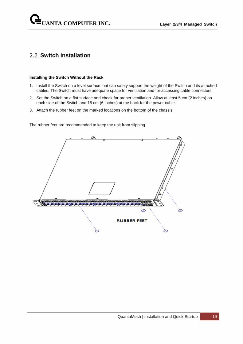
2.2 Switch Installation
Installing the Switch Without the Rack
1. Install the Switch on a level surface that can safely support the weight of the Switch and its attached cables. The Switch must have adequate space for ventilation and for accessing cable connectors.
2. Set the Switch on a flat surface and check for proper ventilation. Allow at least 5 cm (2 inches) on each side of the Switch and 15 cm (6 inches) at the back for the power cable.
3. Attach the rubber feet on the marked locations on the bottom of the chassis.
The rubber feet are recommended to keep the unit from slipping.
UANTA COMPUTER INC.
Layer 2/3/4 Managed Switch
QuantaMesh | Installation and Quick Startup 20
2.3 Installing the Switch in a Rack
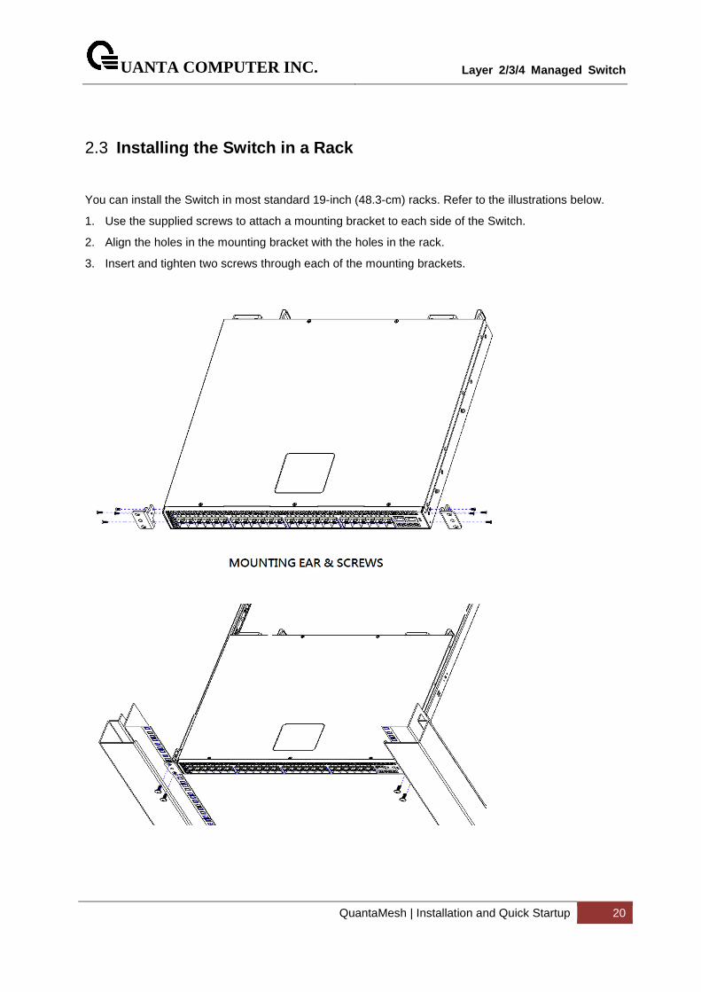
You can install the Switch in most standard 19-inch (48.3-cm) racks. Refer to the illustrations below.
1. Use the supplied screws to attach a mounting bracket to each side of the Switch.
2. Align the holes in the mounting bracket with the holes in the rack.
3. Insert and tighten two screws through each of the mounting brackets.
UANTA COMPUTER INC.
Layer 2/3/4 Managed Switch
QuantaMesh | Installation and Quick Startup 21
2.4 Quick Starting the Switch
1. Read the device Installation Guide for the connectivity procedure. In-band connectivity allows access to the Switch locally. From a remote workstation, the device must be configured with IP information (IP address, subnet mask, and default gateway).
2. Turn the Power ON.
3. Allow the device to load the software until the login prompt appears. The device initial state is called the default mode.
4. When the prompt asks for operator login, do the following:
• Type the word admin in the login area. Since a number of the Quick Setup commands require administrator account rights, suggesting logging into an administrator account.
• Do not enter a password because there is no password in the default mode.
• Press the <Enter> key
• The CLI Privileged EXEC mode prompt will be displayed.
• Use “configure” to switch to the Global Config mode from Privileged EXEC.
• Use “exit” to return to the previous mode.
UANTA COMPUTER INC.
Layer 2/3/4 Managed Switch
QuantaMesh | Installation and Quick Startup 22
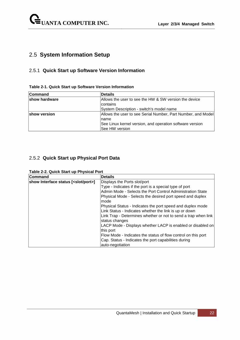
2.5 System Information Setup
2.5.1 Quick Start up Software Version Information
Table 2-1. Quick Start up Software Version Informat ion
Command Details show hardware Allows the user to see the HW & SW version the device
contains System Description - switch's model name
show version Allows the user to see Serial Number, Part Number, and Model name See Linux kernel version, and operation software version See HW version
2.5.2 Quick Start up Physical Port Data
Table 2-2. Quick Start up Physical Port Command Details show Interface status [<slot/port>] Displays the Ports slot/port
Type - Indicates if the port is a special type of port Admin Mode - Selects the Port Control Administration State Physical Mode - Selects the desired port speed and duplex mode Physical Status - Indicates the port speed and duplex mode Link Status - Indicates whether the link is up or down Link Trap - Determines whether or not to send a trap when link status changes LACP Mode - Displays whether LACP is enabled or disabled on this port Flow Mode - Indicates the status of flow control on this port Cap. Status - Indicates the port capabilities during auto-negotiation
UANTA COMPUTER INC.
Layer 2/3/4 Managed Switch
QuantaMesh | Installation and Quick Startup 23
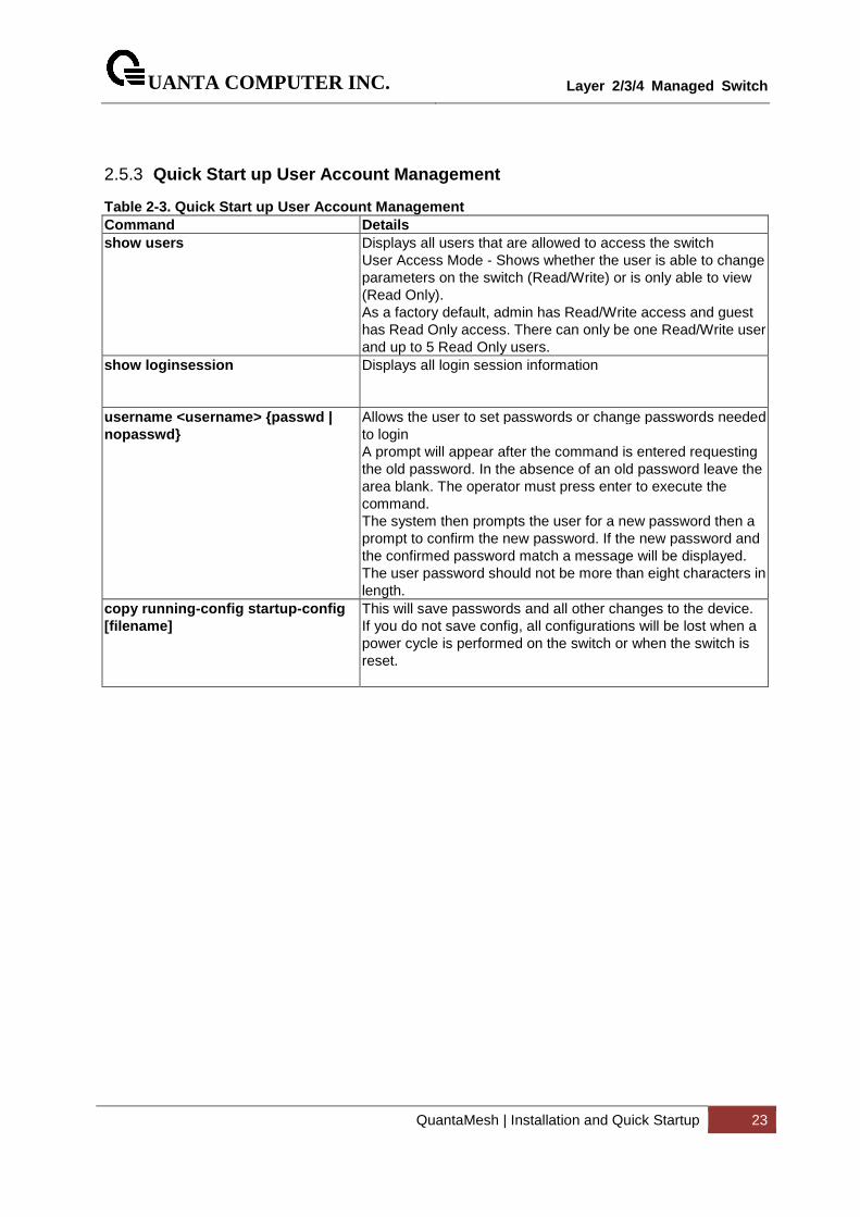
2.5.3 Quick Start up User Account Management
Table 2-3. Quick Start up User Account Management Command Details show users Displays all users that are allowed to access the switch
User Access Mode - Shows whether the user is able to change parameters on the switch (Read/Write) or is only able to view (Read Only). As a factory default, admin has Read/Write access and guest has Read Only access. There can only be one Read/Write user and up to 5 Read Only users.
show loginsession
Displays all login session information
username <username> {passwd | nopasswd}
Allows the user to set passwords or change passwords needed to login A prompt will appear after the command is entered requesting the old password. In the absence of an old password leave the area blank. The operator must press enter to execute the command. The system then prompts the user for a new password then a prompt to confirm the new password. If the new password and the confirmed password match a message will be displayed. The user password should not be more than eight characters in length.
copy running-config startup-config [filename]
This will save passwords and all other changes to the device. If you do not save config, all configurations will be lost when a power cycle is performed on the switch or when the switch is reset.
UANTA COMPUTER INC.
Layer 2/3/4 Managed Switch
QuantaMesh | Installation and Quick Startup 24
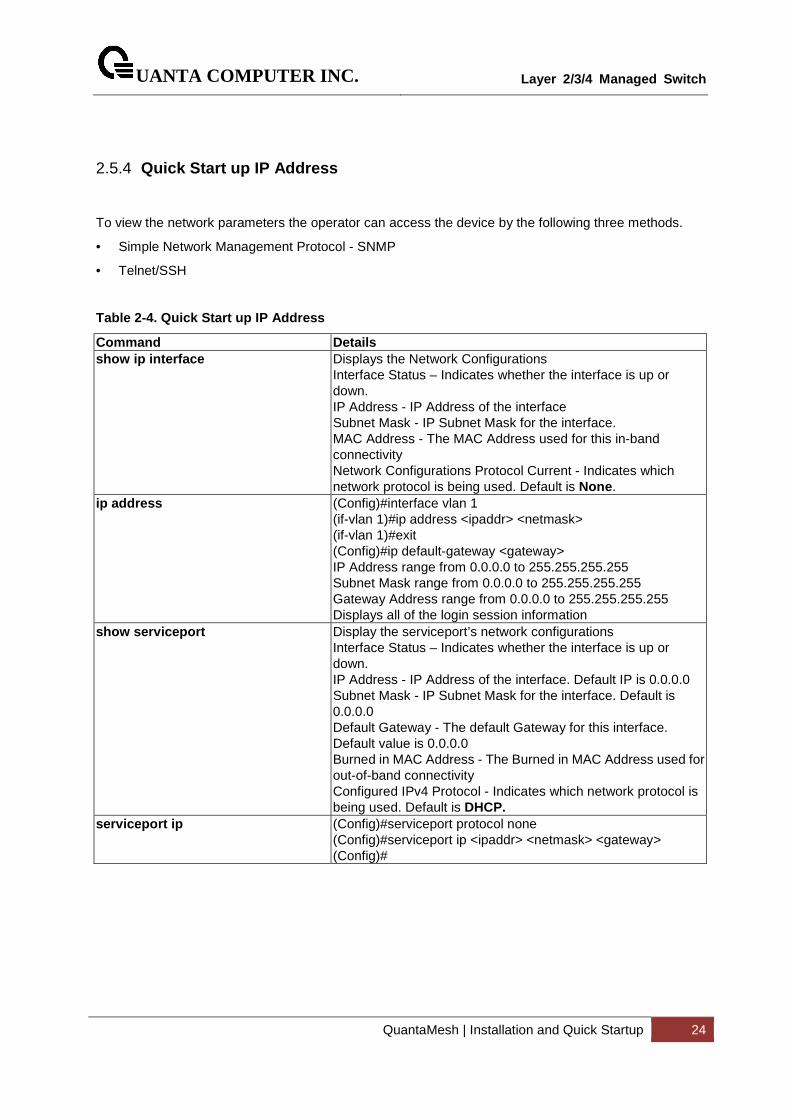
2.5.4 Quick Start up IP Address
To view the network parameters the operator can access the device by the following three methods.
• Simple Network Management Protocol - SNMP
• Telnet/SSH
Table 2-4. Quick Start up IP Address
Command Details show ip interface Displays the Network Configurations
Interface Status – Indicates whether the interface is up or down. IP Address - IP Address of the interface Subnet Mask - IP Subnet Mask for the interface. MAC Address - The MAC Address used for this in-band connectivity Network Configurations Protocol Current - Indicates which network protocol is being used. Default is None .
ip address (Config)#interface vlan 1 (if-vlan 1)#ip address <ipaddr> <netmask> (if-vlan 1)#exit (Config)#ip default-gateway <gateway> IP Address range from 0.0.0.0 to 255.255.255.255 Subnet Mask range from 0.0.0.0 to 255.255.255.255 Gateway Address range from 0.0.0.0 to 255.255.255.255 Displays all of the login session information
show serviceport Display the serviceport’s network configurations Interface Status – Indicates whether the interface is up or down. IP Address - IP Address of the interface. Default IP is 0.0.0.0 Subnet Mask - IP Subnet Mask for the interface. Default is 0.0.0.0 Default Gateway - The default Gateway for this interface. Default value is 0.0.0.0 Burned in MAC Address - The Burned in MAC Address used for out-of-band connectivity Configured IPv4 Protocol - Indicates which network protocol is being used. Default is DHCP.
serviceport ip (Config)#serviceport protocol none (Config)#serviceport ip <ipaddr> <netmask> <gateway> (Config)#
UANTA COMPUTER INC.
Layer 2/3/4 Managed Switch
QuantaMesh | Installation and Quick Startup 25
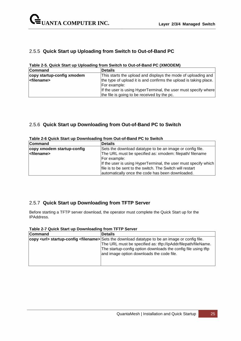
2.5.5 Quick Start up Uploading from Switch to Out-of-Band PC
Table 2-5. Quick Start up Uploading from Switch to Out-of-Band PC (XMODEM) Command Details copy startup-config xmodem <filename>
This starts the upload and displays the mode of uploading and the type of upload it is and confirms the upload is taking place. For example: If the user is using HyperTerminal, the user must specify where the file is going to be received by the pc.
2.5.6 Quick Start up Downloading from Out-of-Band PC to S witch
Table 2-6 Quick Start up Downloading from Out-of-Ba nd PC to Switch Command Details copy xmodem startup-config <filename>
Sets the download datatype to be an image or config file. The URL must be specified as: xmodem: filepath/ filename For example: If the user is using HyperTerminal, the user must specify which file is to be sent to the switch. The Switch will restart automatically once the code has been downloaded.
2.5.7 Quick Start up Downloading from TFTP Server
Before starting a TFTP server download, the operator must complete the Quick Start up for the IPAddress.
Table 2-7 Quick Start up Downloading from TFTP Serv er Command Details copy <url> startup-config <filename>
Sets the download datatype to be an image or config file. The URL must be specified as: tftp://ipAddr/filepath/fileName. The startup-config option downloads the config file using tftp and image option downloads the code file.
UANTA COMPUTER INC.
Layer 2/3/4 Managed Switch
QuantaMesh | Installation and Quick Startup 26
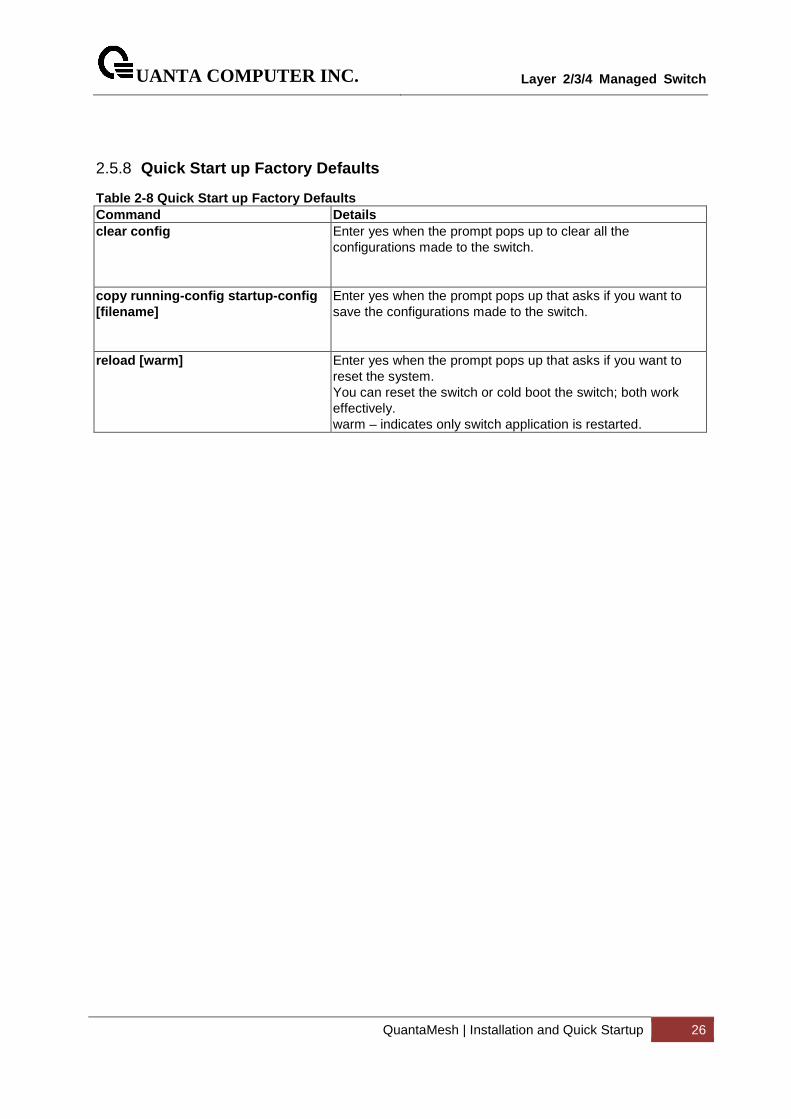
2.5.8 Quick Start up Factory Defaults
Table 2-8 Quick Start up Factory Defaults Command Details clear config
Enter yes when the prompt pops up to clear all the configurations made to the switch.
copy running-config startup-config [filename]
Enter yes when the prompt pops up that asks if you want to save the configurations made to the switch.
reload [warm] Enter yes when the prompt pops up that asks if you want to reset the system. You can reset the switch or cold boot the switch; both work effectively. warm – indicates only switch application is restarted.
UANTA COMPUTER INC.
Layer 2/3/4 Managed Switch
QuantaMesh | Console and Telnet Administration Interface 27
3 Console and Telnet Administration Interface This chapter discusses many of the features used to manage the Switch, and explains many concepts and important points regarding these features. Configuring the Switch to implement these concepts is discussed in detail in chapter 6.
The command-line interface (CLI) provides a text-based way to manage and monitor the switch features. You can access the CLI by using a direct connection to the console port or by using a Telnet or SSH client. To access the switch by using Telnet or Secure Shell (SSH), the switch must have an IP address configured on either the service port or the network interface, and the management station you use to access the device must be able to ping the switch IP address. DHCP is enabled by default on the service port. It is disabled on the network interface.
3.1 Local Console Management
Local console management involves the administration of the Switch via a direct connection to the RS-232 DCE console port. This is an Out-of-band connection, meaning that it is on a different circuit than normal network communications, and thus works even when the network is down.
The local console management connection involves a terminal or PC running terminal emulation software to operate the Switch’s built-in console program (see Chapter 6). Using the console program, a network administrator can manage, control, and monitor many functions of the Switch. Hardware components in the Switch allow it to be an active part of a manageable network. These components include a CPU, memory for data storage, other related hardware, and SNMP agent firmware. Activities on the Switch can be monitored with these components, while the Switch can be manipulated to carry out specific tasks.
3.2 Set Up your Switch Using Console Access
Out-of-band management requires connecting a terminal, such as a VT-100 or a PC running a terminal-emulation program (such as HyperTerminal, which is automatically installed with Microsoft Windows) to the RS-232 DCE console port of the Switch. Switch management using the RS-232 DCE console port is called Local Console Management to differentiate it from management done via management platforms, such as DView or HP OpenView.
Make sure the terminal or PC you are using to make this connection is configured to match these settings. If there are problems making this connection on a PC, make sure the emulation is set to VT-100 or ANSI. If you still don’t see anything, try pressing <Ctrl> + r to refresh the screen.
First-time configuration must be carried out through a console, that is, either (a) a VT100-type serial data terminal, or (b) a computer running communications software set to emulate a VT100. The console must
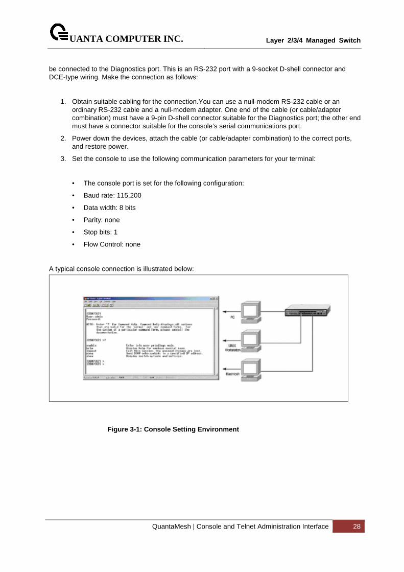
UANTA COMPUTER INC.
Layer 2/3/4 Managed Switch
QuantaMesh | Console and Telnet Administration Interface 28
be connected to the Diagnostics port. This is an RS-232 port with a 9-socket D-shell connector and DCE-type wiring. Make the connection as follows:
1. Obtain suitable cabling for the connection.You can use a null-modem RS-232 cable or an ordinary RS-232 cable and a null-modem adapter. One end of the cable (or cable/adapter combination) must have a 9-pin D-shell connector suitable for the Diagnostics port; the other end must have a connector suitable for the console’s serial communications port.
2. Power down the devices, attach the cable (or cable/adapter combination) to the correct ports, and restore power.
3. Set the console to use the following communication parameters for your terminal:
• The console port is set for the following configuration:
• Baud rate: 115,200
• Data width: 8 bits
• Parity: none
• Stop bits: 1
• Flow Control: none
A typical console connection is illustrated below:
Figure 3-1: Console Setting Environment
UANTA COMPUTER INC.
Layer 2/3/4 Managed Switch
QuantaMesh | Console and Telnet Administration Interface 29
3.3 Set Up your Switch Using Telnet Access
Once you have set an IP address for your Switch, you can use a Telnet program (in a VT-100 compatible terminal mode) to access and control the Switch. Most of the screens are identical, whether accessed from the console port or from a Telnet interface.
3.3.1 Accessing the Switch CLI through the Network
Remote management of the switch is available through the service port or through the network interface. To use telnet, SSH, SNMP for swith management, the switch must be connected to the network, and you must know the IP or IPv6 address of the management interface. The switch has no IP address by default. The DHCP client on the service port is enabled, and the DHCP client on the network interface is disaled.
3.3.2 Using the Service Port or Netowrk Interface for Rem ote Management
The service port is a dedicated Ethernet port for out-of-band management. We recommend that you use the service port to manage the switch. Traffic on this port is segregated from operational network traffic on the switch ports and cannot be switched or routed to the operational network. Additonally, if the production network is experiencing problems, the service port still allows you to access the switch management interface and troubleshoot issues. Configuration options on the service port are limited, which makes it difficult to accidentally cut off management access to the switch.
Alternatively, you can choose to manage the switch through the production network, which is known as in-band management, Bacuse in-nbad management traffic is mixed in with production netowork traffic, it is subject to all of the filtering rules usually applied on a switched/routed port such as ACLs and VLAN tagging. You can access the in-band network management interface through a connection to any front-panel port.
3.3.2.1 Configuring Service Port Information
To disable DHCP/BootP and manually assign an IPv4 address, enter commands under Global Configuration mode:
serviceport protocol none
serviceport ip ipaddress netmask
For example, serviceport ip 192.168.2.22 255.255.255.0
To disable DHCP/BootP and manually assign an IPv6 address, enter commands under Global Configuration mode:
serviceport protocol none dhcp6
UANTA COMPUTER INC.
Layer 2/3/4 Managed Switch
QuantaMesh | Console and Telnet Administration Interface 30
serviceport ipv6 enable
serviceport ipv6 address address/prefix-length
serviceport ipv6 gateway ipv6-address
To view the assigned or configured network address, use:
show serviceport
To enable the DHCP/DHCPv6 client on the service port, use:
serviceport protocol dhcp
serviceport protocol dhcp6
To enable the BootP client on service port, use:
serviceport protocol bootp
3.3.2.2 Configuring the In-Band Netowrk Interface
To use a DHCP server to obtain the IP address, subnet mask, and default gateway information, use:
interface vlan 1
ip address dhcp
ipv6 address dhcp
To manually configure the IPv4 address, subnet mask, use:
interface vlan 1
ip address ipaddress netmask
To manually configure the IPv6 address, subnet mask, use:
interface vlan 1
ipv6 address address/prefix-length
UANTA COMPUTER INC.
Layer 2/3/4 Managed Switch
QuantaMesh | Command Line Interface Structure and Mode-based CLI 31
4 Command Line Interface Structure and Mode-based CLI
The Command Line Interface (CLI) syntax, conventions, and terminology are described in this section. Each CLI command is illustrated using the structure outlined below.
4.1 CLI Command Format
Commands are followed by values, parameters, or both.
Example 1
ip address <ipaddr> <netmask> [<gateway>]
• ip address is the command name.
• <ipaddr> <netmask> are the required values for the command.
• [<gateway>] is the optional value for the command.
Example 2
snmp-server location <loc>
• snmp-server location is the command name.
• <loc> is the required parameter for the command.
Example 3
clear vlan
• clear vlan is the command name.
Command
The text in bold, non-italic font must be typed exactly as shown.
UANTA COMPUTER INC.
Layer 2/3/4 Managed Switch
QuantaMesh | Command Line Interface Structure and Mode-based CLI 32
4.2 CLI Mode-based Topology
Parameters
Parameters are order dependent. The text in bold italics should be replaced with a name or number. To use spaces as part of a name parameter, enclose it in double quotes like this: "System Name with Spaces". Parameters may be mandatory values, optional values, choices, or a combination.
− <parameter>. The <> angle brackets indicate that a mandatory parameter must be entered in place of the brackets and text inside them.
− [parameter]. The [] square brackets indicate that an optional parameter may be entered in place of the brackets and text inside them.
− {choice1 | choice2}. The | indicates that only one of the parameters should be entered.The {} curly braces indicate that a parameter must be chosen from the list of choices.
Values
ipaddr This parameter is a valid IP address, made up of four decimal bytes ranging from 0 to 255. The default for all IP parameters consists of zeros (that is, 0.0.0.0). The interface IP address of 0.0.0.0 is invalid.
macaddr The MAC address format is six hexadecimal numbers separated by colons, for example 00:06:29:32:81:40.
areaid Area IDs may be entered in dotted-decimal notation (for example, 0.0.0.1). An area ID of 0.0.0.0 is reserved for the backbone. Area IDs have the same form as IP addresses, but are distinct from IP addresses. The IP network number of the sub-netted network may be used for the area ID.
routerid The value of <router id> must be entered in 4-digit dotted-decimal notation (for example, 0.0.0.1). A router ID of 0.0.0.0 is invalid.
slot/port This parameter denotes a valid slot number, and a valid port number. For example, 0/1 represents unit number 1, slot number 0 and port number 1. The <slot/port> field is composed of a valid slot number and a valid port number separated by a forward slash (/).
logical slot/port This parameter denotes a logical slot number, and logical port number assigned. This is applicable in the case of a port-channel (LAG). The operator can use the logical slot number, and the logical port number to configure the port-channel.
Conventions

UANTA COMPUTER INC.
Layer 2/3/4 Managed Switch
QuantaMesh | Command Line Interface Structure and Mode-based CLI 33
Network addresses are used to define a link to a remote host, workstation, or network. Network addresses are shown using the following syntax:
Table 5-1. Network Address Syntax Address Type Format Range IPAddr A.B.C.D 0.0.0.0 to 255.255.255.255 MacAddr YY:YY:YY:YY:YY:YY hexidecimal digit pairs
Double quotation marks such as "System Name with Spaces" set off user defined strings. If the operator wishes to use spaces as part of a name parameter then it must be enclosed in double quotation marks.
Empty strings (““) are not valid user defined strings. Command completion finishes spelling the command when enough letters of a command are typed to uniquely identify the command word. The command may be executed by typing <enter> (command abbreviation) or the command word may be completed by typing the <tab> (command completion).
The value 'Err' designates that the requested value was not internally accessible. This should never happen and indicates that there is a case in the software that is not handled correctly.
The value of '-----' designates that the value is unknown.
Annotations
The CLI allows the user to type single-line annotations at the command prompt for use when writing test or configuration scripts and for better readability. The exclamation point (‘!’) character flags the beginning of a comment. The comment flag character can begin a word anywhere on the command line and all input following this character is ignored. Any command line that begins with the character ‘!’ is recognized as a comment line and ignored by the parser.
Some examples are provided below: ! Script file for displaying the ip interface ! Display information about interfaces show ip interface 0/1 !Displays the information abo ut the first interface ! Display information about the next interface show ip interface 0/2 ! End of the script file

UANTA COMPUTER INC.
Layer 2/3/4 Managed Switch
QuantaMesh | Switching Commands 34
5 Switching Commands
5.1 System Information and Statistics commands
5.1.1 show arp
This command displays connectivity between the switch and other devices. The Address Resolution Protocol (ARP) cache identifies the MAC addresses of the IP stations communicating with the switch.
Syntax
show arp
Default Setting
None
Command Mode
Privileged Exec
Display Message
MAC Address: A unicast MAC address for which the switch has forwarding and/or filtering information. The format is 6 two-digit hexadecimal numbers that are separated by colons. For example: 00:23:45:67:89:AB
IP Address: The IP address assigned to each interface.
Interface: Valid slot number and a valid port number.
UANTA COMPUTER INC.
Layer 2/3/4 Managed Switch
QuantaMesh | Switching Commands 35
5.1.2 show calendar
This command displays the system time.
Syntax
show calendar
Default Setting
None
Command Mode
Privileged Exec
Display Message
Current Time: displays system time
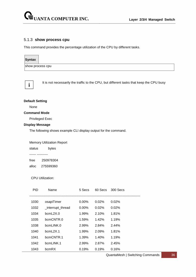
UANTA COMPUTER INC.
Layer 2/3/4 Managed Switch
QuantaMesh | Switching Commands 36
5.1.3 show process cpu
This command provides the percentage utilization of the CPU by different tasks.
Syntax
show process cpu
It is not necessarily the traffic to the CPU, but different tasks that keep the CPU busy
Default Setting
None
Command Mode
Privileged Exec
Display Message
The following shows example CLI display output for the command.
Memory Utilization Report
status bytes
------ ----------
free 250978304
alloc 275599360
CPU Utilization:
PID Name 5 Secs 60 Secs 300 Secs
-----------------------------------------------------------------------------------------------------
1030 osapiTimer 0.00% 0.02% 0.02%
1032 _interrupt_thread 0.00% 0.02% 0.02%
1034 bcmL2X.0 1.99% 2.10% 1.81%
1035 bcmCNTR.0 1.59% 1.42% 1.19%
1038 bcmLINK.0 2.99% 2.84% 2.44%
1040 bcmL2X.1 1.99% 2.09% 1.81%
1041 bcmCNTR.1 1.39% 1.40% 1.19%
1042 bcmLINK.1 2.99% 2.87% 2.45%
1043 bcmRX 0.19% 0.19% 0.16%
i
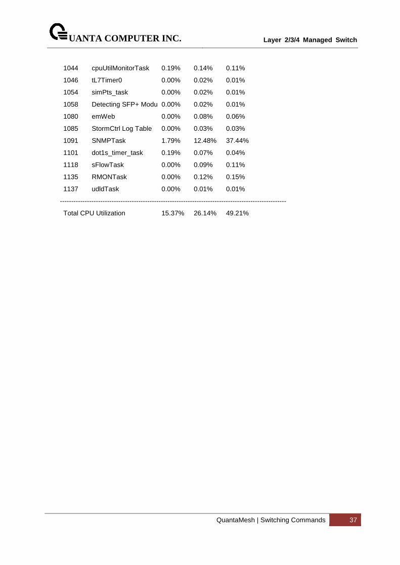
UANTA COMPUTER INC.
Layer 2/3/4 Managed Switch
QuantaMesh | Switching Commands 37
1044 cpuUtilMonitorTask 0.19% 0.14% 0.11%
1046 tL7Timer0 0.00% 0.02% 0.01%
1054 simPts_task 0.00% 0.02% 0.01%
1058 Detecting SFP+ Modu 0.00% 0.02% 0.01%
1080 emWeb 0.00% 0.08% 0.06%
1085 StormCtrl Log Table 0.00% 0.03% 0.03%
1091 SNMPTask 1.79% 12.48% 37.44%
1101 dot1s_timer_task 0.19% 0.07% 0.04%
1118 sFlowTask 0.00% 0.09% 0.11%
1135 RMONTask 0.00% 0.12% 0.15%
1137 udldTask 0.00% 0.01% 0.01%
-----------------------------------------------------------------------------------------------------
Total CPU Utilization 15.37% 26.14% 49.21%
UANTA COMPUTER INC.
Layer 2/3/4 Managed Switch
QuantaMesh | Switching Commands 38
5.1.4 show eventlog
This command displays the event log, which contains error messages from the system, in the Primary Management System or in the specified unit. The event log is not cleared on a system reset.
Syntax
show eventlog [unit]
unit - The unit number of the remote system. The range is 1 to 8.
unit parameter is only support for stacking platform.
Default Setting
None
Command Mode
Privileged Exec
Display Message
File : The file in which the event originated.
Line : The line number of the event.
Task Id : The task ID of the event.
Code : The event code.
Time : The time this event occurred.
Event log information is retained across a switch reset.
!
!
UANTA COMPUTER INC.
Layer 2/3/4 Managed Switch
QuantaMesh | Switching Commands 39
5.1.5 show running-config
This command is used to display/capture the current setting of different protocol packages supported on switch. This command displays/captures only commands with settings/configurations with values that differ from the default value. The output is displayed in script format, which can be used to configure another switch with the same configuration.
When a script name is provided, the output is redirected to a configuration script. The option [all] will also enable the display/capture of all commands with settings/configurations that include values that are same as the default values. If the optional <scriptname> is provided with a file name extension of “.scr”, the output will be redirected to a script file.
Syntax
show running-config [all | <scriptname>]
all - enable the display/capture of all commands with settings/configurations that include values that are same as the default values.
<scriptname> - redirect the output to the file <scriptname>.
Default Setting
None
Command Mode
Privileged Exec
UANTA COMPUTER INC.
Layer 2/3/4 Managed Switch
QuantaMesh | Switching Commands 40
5.1.6 show sysinfo
This command displays switch brief information and MIBs supported.
Syntax
show sysinfo
Default Setting
None
Command Mode
Privileged Exec
Display Message
System Description: The text used to identify this switch.
System Name: The name used to identify the switch.
System Location: The text used to identify the location of the switch. May be up to 255 alpha-numeric characters. The factory default is blank.
System Contact: The text used to identify a contact person for this switch. May be up to 255 alphanumeric characters. The factory default is blank.
System Object ID: The manufacturing ID.
System Up Time: The time in days, hours and minutes since the last switch reboot.
Current SNTP Synchronized Time: The time which is synchronized from SNTP server.
UANTA COMPUTER INC.
Layer 2/3/4 Managed Switch
QuantaMesh | Switching Commands 41
5.1.7 show system
This command displays switch system information.
Syntax
show system
Default Setting
None
Command Mode
Privileged Exec
Display Message
System Description: Text used to identify this switch.
System Object ID: The manufacturing ID
System Information
System Up Time: The time in days, hours and minutes since the last switch reboot.
System Name: Name used to identify the switch.
System Location: Text used to identify the location of the switch. May be up to 255 alpha-numeric characters. The factory default is blank.
System Contact: Text used to identify a contact person for this switch. May be up to 255 alphanumeric characters. The factory default is blank.
MAC Address: The burned in MAC address used for in-band connectivity.
Protocol Current: Indicates which network protocol is being used. The options are bootp | dhcp | none.
DHCP Client Identifier TEXT: DCHP client identifier for this switch.
UANTA COMPUTER INC.
Layer 2/3/4 Managed Switch
QuantaMesh | Switching Commands 42
5.1.8 show tech-support
This command displays system and configuration information when you contact technical support. The output of the show tech-support command combines the output of the following commands: show version, show sysinfo, show interface status, show logging, show event log, show logging buffered, show trap log, show running config, … etc.
Syntax
show tech-support
Default Setting
None
Command Mode
Privileged Exec
This command is only support on console port.
!
UANTA COMPUTER INC.
Layer 2/3/4 Managed Switch
QuantaMesh | Switching Commands 43
5.1.9 show hardware
This command displays inventory information for the switch.
Syntax
show hardware
Default Setting
None
Command Mode
Privileged Exec
Display Message
System Description: Text used to identify the product name of this switch.
Machine Type: Specifies the machine model as defined by the Vital Product Data.
Machine Model: Specifies the machine model as defined by the Vital Product Data.
Serial Number: The unique box serial number for this switch.
Label Revision Number: The label revision serial number of this switch is used for manufacturing purposes.
Part Number: Manufacturing part number.
Hardware Version: The hardware version of this switch. It is divided into four parts. The first byte is the major version and the second byte represents the minor version.
ADT7470_1: Sensor 1 Now Temperature: The temperature of sensor 1 of ADT7470.
ADT7470_1: Sensor 2 Now Temperature: The temperature of sensor 2 of ADT7470.
ADT7470_1: Sensor 3 Now Temperature: The temperature of sensor 3 of ADT7470.
ADT7470_1: Sensor 4 Now Temperature: The temperature of sensor 4 of ADT7470.
Depend on air flow FAN 1 – 4 connected ADT7470-1 or ADT7470-2:
Front-To-Back: (Connected ADT7470-1)
ADT7470_1: FAN 1 Status: Status of FAN1. It could be active or inactive.
ADT7470_1: FAN 2 Status: Status of FAN2. It could be active or inactive.
ADT7470_1: FAN 3 Status: Status of FAN3. It could be active or inactive.
Back-To-Front: (Connected ADT7470-2)
ADT7470_2: FAN 1 Status: Status of FAN1. It could be active or inactive.

UANTA COMPUTER INC.
Layer 2/3/4 Managed Switch
QuantaMesh | Switching Commands 44
ADT7470_2: FAN 2 Status: Status of FAN2. It could be active or inactive.
ADT7470_2: FAN 3 Status: Status of FAN3. It could be active or inactive.
Switch Power+ y………………Active/Inactive (The yth power supply information of switch 1).
Name: Name provided by Power Supply vendor.
Model: Model Number provided by Power Supply vendor.
Revision Number: Revision Number provided by Power Supply vendor.
Manufacturer Location: Location provided by Power Supply vendor.
Date of Manufacturing: Date of Manufacturing provided by Power Supply vendor.
Serial Number: Serial Number provided by Power Supply vendor.
Temperature 1: . Inner temperature 1 of Power Supply now
Temperature 2: Inner temperature 2 of Power Supply now
Fan Speed: Inner fan speed(rpm) of Power Supply now
Fan Duty: Inner fan duty(%) of Power Supply now
Below 10-Giga Interface information depend on plugging SFP+ Transceiver
Interface y: (The yth 10-Giga information of switch 1).
10 Gigabit Ethernet Compliance Codes : Transceiver’s compliance codes.
Vendor Name: The SFP transceiver vendor name shall be the full name of the corporation, a commonly accepted abbreviation of the name of the corporation, the SCSI company code for the corporation, or the stock exchange code for the corporation.
Vendor Part Number : Part number provided by SFP transceiver vendor.
Vendor Serial Number : Serial number provided by vendor.
Vendor Revision Number : Revision level for part number provided by vendor.
Vendor Manufacturing Date : The vendor’s manufacturing date.
Additional Packages: This displays the additional packages that are incorporated into this system.
!
UANTA COMPUTER INC.
Layer 2/3/4 Managed Switch
QuantaMesh | Switching Commands 45
5.1.10 show version
This command displays inventory information for the switch.
Syntax
show version
Default Setting
None
Command Mode
Privileged Exec
Display Message
System Description: Text used to identify the product name of this switch.
Machine Type: Specifies the machine model as defined by the Vital Product Data.
Machine Model: Specifies the machine model as defined by the Vital Product Data.
Serial Number: The unique box serial number for this switch.
FRU Number: The field replaceable unit number.
Part Number: Manufacturing part number.
Maintenance Level: The identification of the hardware change level.
Manufacturer: The two-octet code that identifies the manufacturer.
Burned In MAC Address: The burned-in universally administered MAC address of this switch.
Software Version: The platform.function.release. maintenance number of the code currently running on the switch.
Operating System: The operating system currently running on the switch.
Network Processing Device: Identifies the network processor hardware.
Additional Packages: A list of the optional software packages installed on the switch, if any. For example, QoS, Routing, IPv6, IPv6 Management, Multicast or Data Center.
UANTA COMPUTER INC.
Layer 2/3/4 Managed Switch
QuantaMesh | Switching Commands 46
5.1.11 show loginsession
This command displays current telnet and serial port connections to the switch.
Syntax
show loginsession
Default Setting
None
Command Mode
Privileged Exec
Display Message
ID: Login Session ID
User Name: The name the user will use to login using the serial port or Telnet. A new user may be added to the switch by entering a name in a blank entry. The user name may be up to 8 characters, and is not case sensitive. Two users are included as the factory default, admin, and guest.
Connection From: IP address of the telnet client machine or EIA-232 for the serial port connection.
Idle Time: Time this session has been idle.
Session Time: Total time this session has been connected.
Session Type: Shows the type of session: telnet, serial port, SSH or HTTP/HTTPS.
UANTA COMPUTER INC.
Layer 2/3/4 Managed Switch
QuantaMesh | Switching Commands 47
5.1.12 show command filter
This command displays the information that begin/include/exclude/redirect the regular expression.
Syntax
show command [| {begin | include | exclude | redirect} <LINE>]
Default Setting
None
Command Mode
Privileged Exec
Display Message
command: Any show command of the CLI
begin: Begin with the line that matches
include: Include lines that match
exclude: Exclude lines that match
redirect: output the lines to the specified URL
<LINE>: Regular Expression
UANTA COMPUTER INC.
Layer 2/3/4 Managed Switch
QuantaMesh | Switching Commands 48
5.1.13 Digital Optical Monitor
5.1.13.1 show transceiver
This command displays Digital Optical Monitor information for the switch.
Syntax
show transceiver {interface [<slot/port>] [detail]}
Default Setting
None
Command Mode
Privileged Exec
Display Message
DOM Admin Mode: This displays the administrative mode of Digital Optical Monitor (DOM) for the system.
Polling Interval: Polling interval. The range of value is 300 to 1800.
Interface: Valid slot number and a valid port number.
Temperature: Internally measured module temperature from transceiver.
Voltage: Internally measured module supply voltage from transceiver.
Tx bias current: Internally measured module tx bias from transceiver.
Tx Power: Internally measured module tx power from transceiver.
Rx Power: Internally measured module rx power from transceiver.
UANTA COMPUTER INC.
Layer 2/3/4 Managed Switch
QuantaMesh | Switching Commands 49
5.1.13.2 monitoring
This command enables monitoring on all ports. The default value is disabled.
Syntax
monitoring [interval <interval>] no monitoring [interval]
< interval> - Polling interval. The range of value is 300 to 1800.
no - This command disables monitoring on all ports.
Default Setting
Admin mode: Disable
Interval: 600 sec.
Command Mode
Transceiver Config
UANTA COMPUTER INC.
Layer 2/3/4 Managed Switch
QuantaMesh | Switching Commands 50
5.2 Device Configuration Commands
5.2.1 Interface
5.2.1.1 show interface status
This command displays the Port monitoring information for the system.
Syntax
show interface status [{<slot/port> | loopback <loopback-id> | port-channel <portchannel-id> | tunnel <tunnel-id> | vlan <vlan-id>}]
<slot/port> - is the desired interface number.
<loopback-id> - Disaplys information for the loopback interfaces. The range of the loopback ID is 0 to 7.
<portchannel-id> - Displays information for the port-channel interfaces. The range of the port-channel ID is 1 to 64.
<tunnel-id> - Displays information for the tunnel interfaces. The range of the tunnel ID is 0 to 7.
<vlan-id> - Displays information for the vlan interfaces. The range of the VLAN ID is 1 to 4093.
no parameter - Displays information for all interfaces.
Default Setting
None
Command Mode
Privileged Exec
Display Message
Intf: The physical slot and physical port.
Type: If not blank, this field indicates that this port is a special type of port. The possible values are:
Source: This port is a monitoring port.
PC Mbr: This port is a member of a port-channel (LAG).
Dest: This port is a probe port.
Admin Mode: Selects the Port control administration state. The port must be enabled in order for it to be allowed into the network. It may be enabled or disabled. The factory default is enabled.
Physical Mode: Selects the desired port speed and duplex mode. If auto-negotiation support is selected, then the duplex mode and speed will be set from the auto-negotiation process. Note that the port's maximum capability (full duplex 100M) will be advertised. Otherwise, this object will determine the port's duplex mode and transmission rate. The factory default is Auto.
Physical Status: Indicates the port speed and duplex mode.
UANTA COMPUTER INC.
Layer 2/3/4 Managed Switch
QuantaMesh | Switching Commands 51
Link Status: Indicates whether the Link is up or down.
Link Trap: This object determines whether to send a trap when link status changes. The factory default is enabled.
LACP Mode: Displays whether LACP is enabled or disabled on this port.
Flow Control Mode: Displays flow control mode. The possible values are:
Disable: This port is disabled flow control.
Enable: This port is enabled flow control.
Capabilities Status: Displays interface capabilities.
UANTA COMPUTER INC.
Layer 2/3/4 Managed Switch
QuantaMesh | Switching Commands 52
5.2.1.2 show interface counters
This command displays a summary of statistics for a specific interface or all interfaces.
Syntax
show interface counters [{<slot/port> | [port-channel <portchannel-id>]}]
<slot/port> - is the desired interface number.
<portchannel-id > - is the desired port-channel interface number. The range of the port-channel ID is 1 to 64.
no paramter - Displays statistics information for all interfaces.
Default Setting
None
Command Mode
Privileged Exec
Display Message
The display parameters when the argument is '<slot/port>' or port-channel are as follows:
Packets Received Without Error: The total number of packets (including broadcast packets and multicast packets) received by the processor.
Packets Received With Error: The number of inbound packets that contained errors preventing them from being deliverable to a higher-layer protocol.
Broadcast Packets Received: The total number of packets received that were directed to the broadcast address. Note that this does not include multicast packets.
Packets Transmitted Without Error: The total number of packets transmitted out of the interface.
Transmit Packets Errors: The number of outbound packets that could not be transmitted because of errors.
Collisions Frames: The best estimate of the total number of collisions on this Ethernet segment.
Time Since Counters Last Cleared: The elapsed time, in days, hours, minutes, and seconds since the statistics for this port were last cleared.
The display parameters if no argument is used are as follows:
Interface: The physical slot and physical port or the logical slot and logical port.
Packets Received Without Error: The total number of packets (including broadcast packets and multicast packets) received.
UANTA COMPUTER INC.
Layer 2/3/4 Managed Switch
QuantaMesh | Switching Commands 53
Packets Received With Error: The number of inbound packets that contained errors preventing them from being deliverable to a higher-layer protocol.
Broadcast Packets Received: The total number of packets received that were directed to the broadcast address. Note that this does not include multicast packets.
Packets Transmitted Without Error: The total number of packets transmitted.
Transmit Packets Errors: The number of outbound packets that could not be transmitted because of errors.
Collisions Frames: The best estimate of the total number of collisions on this Ethernet segment.
Time Since Counters Last Cleared: The elapsed time, in days, hours, minutes, and seconds since the statistics for this port were last cleared.
This command displays detailed statistics for a specific port or for all CPU traffic based upon the argument.
Syntax
show interface counters detailed {<slot/port> | port-channel <portchannel-id> | switchport}
<slot/port> - is the desired interface number.
<portchannel-id> - is the desired port-channel interface number. The range of the port-channel ID is 1 to 64.
switchport - This parameter specifies whole switch or all interfaces.
Default Setting
None
Command Mode
Privileged Exec
Display Message
The display parameters when the argument is ' <slot/port>' or port-channel are as follows:
Total Packets Received (Octets): The total number of octets of data (including those in bad packets) received on the network (excluding framing bits but including FCS octets). This object can be used as a reasonable estimate of Ethernet utilization. If greater precision is desired, the etherStatsPkts and etherStatsOctets objects should be sampled before and after a common interval. The result of this equation is the value Utilization which is the percent utilization of the Ethernet segment on a scale of 0 to 100 percent.
Packets Received 64 Octets: The total number of packets (including bad packets) received that were 64 octets in length (excluding framing bits but including FCS octets).
Packets Received 65-127 Octets: The total number of packets (including bad packets) received that were between 65 and 127 octets in length inclusive (excluding framing bits but including FCS octets).
UANTA COMPUTER INC.
Layer 2/3/4 Managed Switch
QuantaMesh | Switching Commands 54
Packets Received 128-255 Octets: The total number of packets (including bad packets) received that were between 128 and 255 octets in length inclusive (excluding framing bits but including FCS octets).
Packets Received 256-511 Octets: The total number of packets (including bad packets) received that were between 256 and 511 octets in length inclusive (excluding framing bits but including FCS octets).
Packets Received 512-1023 Octets: The total number of packets (including bad packets) received that were between 512 and 1023 octets in length inclusive (excluding framing bits but including FCS octets).
Packets Received 1024-1518 Octets: The total number of packets (including bad packets) received that were between 1024 and 1518 octets in length inclusive (excluding framing bits but including FCS octets).
Packets Received > 1522 Octets: The total number of packets received that were longer than 1522 octets (excluding framing bits, but including FCS octets) and were otherwise well formed.
Packets RX and TX 64 Octets: The total number of packets (including bad packets) received that were 64 octets in length (excluding framing bits but including FCS octets).
Packets RX and TX 65-127 Octets: The total number of packets (including bad packets) received that were between 65 and 127 octets in length inclusive (excluding framing bits but including FCS octets).
Packets RX and TX 128-255 Octets: The total number of packets (including bad packets) received that were between 128 and 255 octets in length inclusive (excluding framing bits but including FCS octets).
Packets RX and TX 256-511 Octets: The total number of packets (including bad packets) received that were between 256 and 511 octets in length inclusive (excluding framing bits but including FCS octets).
Packets RX and TX 512-1023 Octets: The total number of packets (including bad packets) received that were between 512 and 1023 octets in length inclusive (excluding framing bits but including FCS octets).
Packets RX and TX 1024-1518 Octets: The total number of packets (including bad packets) received that were between 1024 and 1518 octets in length inclusive (excluding framing bits but including FCS octets).
Packets RX and TX 1519-1522 Octets: The total number of packets (including bad packets) received that were between 1519 and 1522 octets in length inclusive (excluding framing bits but including FCS octets).
Packets RX and TX 1523-2047 Octets: The total number of packets (including bad packets) received that were between 1523 and 2047 octets in length inclusive (excluding framing bits but including FCS octets).
Packets RX and TX 2048-4095 Octets: The total number of packets (including bad packets) received that were between 2048 and 4095 octets in length inclusive (excluding framing bits but including FCS octets).
Packets RX and TX 4096-9216 Octets: The total number of packets (including bad packets) received that were between 4096 and 9216 octets in length inclusive (excluding framing bits but including FCS octets).
Total Packets Received Without Errors
UANTA COMPUTER INC.
Layer 2/3/4 Managed Switch
QuantaMesh | Switching Commands 55
Unicast Packets Received: The number of subnetwork-unicast packets delivered to a higher-layer protocol.
Multicast Packets Received: The total number of good packets received that were directed to a multicast address. Note that this number does not include packets directed to the broadcast address.
Broadcast Packets Received: The total number of good packets received that were directed to the broadcast address. Note that this does not include multicast packets.
Total Packets Received with MAC Errors
Jabbers Received: The total number of packets received that were longer than 1518 octets (excluding framing bits, but including FCS octets), and had either a bad FCS with an integral number of octets (FCS Error) or a bad FCS with a non-integral number of octets (Alignment Error). Note that this definition of jabber is different than the definition in IEEE-802.3 section 8.2.1.5 (10BASE5) and section 10.3.1.4 (10BASE2). These documents define jabber as the condition where any packet exceeds 20 ms. The allowed range to detect jabber is between 20 ms and 150 ms.
Undersize Received: The total number of packets received that were less than 64 octets in length with GOOD CRC(excluding framing bits but including FCS octets).
Fragments Received: The total number of packets received that were less than 64 octets in length with ERROR CRC(excluding framing bits but including FCS octets).
Alignment Errors: The total number of packets received that had a length (excluding framing bits, but including FCS octets) of between 64 and 1518 octets, inclusive, but had a bad FCS with a non-integral number of octets.
FCS Errors: The total number of packets received that had a length (excluding framing bits, but including FCS octets) of between 64 and 1518 octets, inclusive, but had a bad FCS with an integral number of octets
Overruns: The total number of frames discarded as this port was overloaded with incoming packets, and could not keep up with the inflow.
Total Packets Transmitted (Octets)
Packets Transmitted 64 Octets: The total number of packets (including bad packets) received that were 64 octets in length (excluding framing bits but including FCS octets).
Packets Transmitted 65-127 Octets: The total number of packets (including bad packets) received that were between 65 and 127 octets in length inclusive (excluding framing bits but including FCS octets).
Packets Transmitted 128-255 Octets: The total number of packets (including bad packets) received that were between 128 and 255 octets in length inclusive (excluding framing bits but including FCS octets).
Packets Transmitted 256-511 Octets: The total number of packets (including bad packets) received that were between 256 and 511 octets in length inclusive (excluding framing bits but including FCS octets).
Packets Transmitted 512-1023 Octets: The total number of packets (including bad packets) received that were between 512 and 1023 octets in length inclusive (excluding framing bits but including FCS octets).
Packets Transmitted 1024-1518 Octets: The total number of packets (including bad packets) received that were between 1024 and 1518 octets in length inclusive (excluding framing bits but including FCS octets).
UANTA COMPUTER INC.
Layer 2/3/4 Managed Switch
QuantaMesh | Switching Commands 56
Packets Transmitted 1519-1522 Octets: The total number of packets (including bad packets) received that were between 1519 and 1522 octets in length inclusive (excluding framing bits but including FCS octets).
Max Info: The maximum size of the Info (non-MAC) field that this port will receive or transmit.
Total Packets Transmitted Successfully
Unicast Packets Transmitted: The total number of packets that higher-level protocols requested be transmitted to a subnetwork-unicast address, including those that were discarded or not sent.
Multicast Packets Transmitted: The total number of packets that higher-level protocols requested be transmitted to a Multicast address, including those that were discarded or not sent.
Broadcast Packets Transmitted: The total number of packets that higher-level protocols requested be transmitted to the Broadcast address, including those that were discarded or not sent.
Total Transmit Errors
FCS Errors: The total number of packets transmitted that had a length (excluding framing bits, but including FCS octets) of between 64 and 1518 octets, inclusive, but had a bad FCS with an integral number of octets
Tx Oversized: The total number of frames that exceeded the max permitted frame size. This counter has a max increment rate of 815 counts per sec. at 10 Mb/s.
Underrun Errors: The total number of frames discarded because the transmit FIFO buffer became empty during frame transmission.
Total Transmited Packets Discards
Single Collision Frames: A count of the number of successfully transmitted frames on a particular interface for which transmission is inhibited by exactly one collision.
Multiple Collision Frames: A count of the number of successfully transmitted frames on a particular interface for which transmission is inhibited by more than one collision.
Excessive Collisions: A count of frames for which transmission on a particular interface fails due to excessive collisions.
GVRP PDUs Received: The count of GVRP PDUs received in the GARP layer.
GVRP PDUs Transmitted: The count of GVRP PDUs transmitted from the GARP layer.
GVRP Failed and Registrations: The number of times attempted GVRP registrations could not be completed.
GMRP PDUs received: The count of GMRP PDUs received in the GARP layer.
GMRP PDUs Transmitted: The count of GMRP PDUs transmitted from the GARP layer.
GMRP Failed Registrations: The number of times attempted GMRP registrations could not be completed.
STP BPDUs Transmitted: Spanning Tree Protocol Bridge Protocol Data Units sent.
STP BPDUs Received: Spanning Tree Protocol Bridge Protocol Data Units received.
RSTP BPDUs Transmitted: Rapid Spanning Tree Protocol Bridge Protocol Data Units sent.
RSTP BPDUs Received: Rapid Spanning Tree Protocol Bridge Protocol Data Units received.
UANTA COMPUTER INC.
Layer 2/3/4 Managed Switch
QuantaMesh | Switching Commands 57
MSTP BPDUs Transmitted: Multiple Spanning Tree Protocol Bridge Protocol Data Units sent.
MSTP BPDUs Received: Multiple Spanning Tree Protocol Bridge Protocol Data Units received.
EAPOL Frames Received: The number of valid EAPOL frames of any type that have been received by this authenticator.
EAPOL Frames Transmitted: The number of EAPOL frames of any type that have been transmitted by this authenticator.
Time Since Counters Last Cleared: The elapsed time, in days, hours, minutes, and seconds since the statistics for this port were last cleared.
The display parameters when the argument is ‘switchport’ are as follows:
Total Packets Received (Octets): The total number of octets of data received by the processor (excluding framing bits but including FCS octets).
Packets Received Without Error: The total number of packets (including broadcast packets and multicast packets) received by the processor.
Unicast Packets Received: The number of subnetwork-unicast packets delivered to a higher-layer protocol.
Multicast Packets Received: The total number of packets received that were directed to a multicast address. Note that this number does not include packets directed to the broadcast address.
Broadcast Packets Received: The total number of packets received that were directed to the broadcast address. Note that this does not include multicast packets.
Receive Packets Discarded: The number of inbound packets which were chosen to be discarded even though no errors had been detected to prevent their being deliverable to a higher-layer protocol. A possible reason for discarding a packet could be to free up buffer space.
Octets Transmitted: The total number of octets transmitted out of the interface, including framing characters.
Packets Transmitted without Errors: The total number of packets transmitted out of the interface.
Unicast Packets Transmitted: The total number of packets that higher-level protocols requested be transmitted to a subnetwork-unicast address, including those that were discarded or not sent.
Multicast Packets Transmitted: The total number of packets that higher-level protocols requested be transmitted to a Multicast address, including those that were discarded or not sent.
Broadcast Packets Transmitted: The total number of packets that higher-level protocols requested be transmitted to the Broadcast address, including those that were discarded or not sent.
Transmit Packets Discarded: The number of outbound packets which were chosen to be discarded even though no errors had been detected to prevent their being deliverable to a higher-layer protocol. A possible reason for discarding a packet could be to free up buffer space.
Most Address Entries Ever Used: The highest number of Forwarding Database Address Table entries that have been learned by this switch since the most recent reboot.
Address Entries Currently in Use: The number of Learned and static entries in the Forwarding Database Address Table for this switch.
UANTA COMPUTER INC.
Layer 2/3/4 Managed Switch
QuantaMesh | Switching Commands 58
Maximum VLAN Entries: The maximum number of Virtual LANs (VLANs) allowed on this switch.
Most VLAN Entries Ever Used: The largest number of VLANs that have been active on this switch since the last reboot.
Static VLAN Entries: The number of presently active VLAN entries on this switch that have been created statically.
Dynamic VLAN Entries: The number of presently active VLAN entries on this switch that have been created by GVRP registration.
VLAN Deletes: The number of VLANs on this switch that have been created and then deleted since the last reboot.
Time Since Counters Last Cleared: The elapsed time, in days, hours, minutes, and seconds, since the statistics for this switch were last cleared.
UANTA COMPUTER INC.
Layer 2/3/4 Managed Switch
QuantaMesh | Switching Commands 59
5.2.1.3 show interface counters rate
This command displays a summary of port rate statistics for a specific interface or all interfaces.
Syntax
show interface counters rate [{<slot/port> | [port-channel <portchannel-id>]}]
<slot/port> - is the desired interface number.
<portchannel-id > - is the desired port-channel interface number. The range of the port-channel ID is 1 to 64.
no paramter - Displays port rate statistics information for all interfaces.
Default Setting
None
Command Mode
Privileged Exec
Display Message
Interface: The physical slot and physical port or the logical slot and logical port.
Minutes: Load interval. The range of value is 30 seconds to 600 seconds.
Input rate: Average number of bits and packets received per second in the interval.
Output rate: Average number of bits and packets transmitted per second in the interval.
UANTA COMPUTER INC.
Layer 2/3/4 Managed Switch
QuantaMesh | Switching Commands 60
5.2.1.4 load-interval
The load-interval change the length of time for which data is used to compute load port rate statistics.
Syntax
load-interval <30-600> no load-interval
<interval> - Load interval. The range of value is 30 seconds to 600 seconds.
no - This command will be back to 300 seconds load-interval on a port.
Default Setting
300
Command Mode
Interface Config
UANTA COMPUTER INC.
Layer 2/3/4 Managed Switch
QuantaMesh | Switching Commands 61
5.2.1.5 show interface switch
This command displays a summary of statistics for all CPU traffic.
Syntax
show interface switch
Default Setting
None
Command Mode
Privileged Exec
Display Message
Broadcast Packets Received: The total number of packets received that were directed to the broadcast address. Note that this does not include multicast packets.
Packets Received With Error: The number of inbound packets that contained errors preventing them from being deliverable to a higher-layer protocol.
Packets Transmitted Without Error: The total number of packets transmitted out of the interface.
Broadcast Packets Transmitted: The total number of packets that higher-level protocols requested to be transmitted to the Broadcast address, including those that were discarded or not sent.
Transmit Packet Errors: The number of outbound packets that could not be transmitted because of errors.
Address Entries Currently In Use: The total number of Forwarding Database Address Table entries now active on the switch, including learned and static entries.
VLAN Entries Currently In Use: The number of VLAN entries presently occupying the VLAN table.
Time Since Counters Last Cleared: The elapsed time, in days, hours, minutes, and seconds since the statistics for this switch were last cleared.
UANTA COMPUTER INC.
Layer 2/3/4 Managed Switch
QuantaMesh | Switching Commands 62
5.2.1.6 interface
This command is used to enter Interface configuration mode.
Syntax
interface {<slot/port> | loopback <loopback-id> | port-channel <portchannel-id> | tunnel <tunnel-d> | vlan <vlan-id>}
<slot/port> - is the desired interface number.
<loopback-id > - is the desired loopback interface number. The range of loopback ID is 0 to 7.
<portchannel-id> - is the desired port-channel interface number. The range of port-channel ID is 1 to 64.
<tunnel-id> - is the desired tunnel interface number. The range of tunnel ID is 0 to 7.
<vlan-id> - is the desired vlan interface number. The range of VLAN ID is 1 to 4093.
Default Setting
None
Command Mode
Global Config
UANTA COMPUTER INC.
Layer 2/3/4 Managed Switch
QuantaMesh | Switching Commands 63
5.2.1.7 speed-duplex
This command is used to set the speed and duplex mode for the interface.
The 10-Giga interfaces could be configured to operate at 10-Giga or 1-Giga speed. Use ‘speed-duplex 1000’ to change the speed of 10-Giga port to 1G speed.
The speed of 40-Giga interfaces can not be changed by this command.
Syntax
speed-duplex 1000 no speed-duplex 1000
1000 – 1000 Mbps, only valid for 10G ports.
no - This command will be back to 10G speed from 1G speed on a port.
Default Setting
None
Command Mode
Interface Config
i
UANTA COMPUTER INC.
Layer 2/3/4 Managed Switch
QuantaMesh | Switching Commands 64
This command is used to set the speed and duplex mode for all interfaces.
Syntax
speed-duplex all 1000 no speed-duplex all 1000
1000 – 1000 Mbps, only valid for 10G ports.
all - This command represents all interfaces.
no - This command will be back to 10G speed from 1G speed for all 10G ports.
Default Setting
None
Command Mode
Global Config
5.2.1.8 negotiate
This command enables automatic negotiation on a port. The default value is enabled.
The 10-Giga and 40-Giga interfaces do not provide the following command.
Syntax
negotiate no negotiate
no - This command disables automatic negotiation on a port.
Default Setting
Disable
Command Mode
Interface Config
i
UANTA COMPUTER INC.
Layer 2/3/4 Managed Switch
QuantaMesh | Switching Commands 65
This command enables automatic negotiation on all interfaces. The default value is enabled.
Syntax
negotiate all no negotiate all
all - This command represents all interfaces.
no - This command disables automatic negotiation on all interfaces.
Default Setting
Disable
Command Mode
Global Config
UANTA COMPUTER INC.
Layer 2/3/4 Managed Switch
QuantaMesh | Switching Commands 66
5.2.1.9 capabilities
This command is used to set the capabilities on specific interface.
The 10-Giga and 40-Giga interfaces do not provide the following command.
Syntax
capabilities {{10 | 100 } {full-duplex | half-duplex}} | {1000 full-duplex } no capabilities {{10 | 100 } {full-duplex | half-duplex}} | {1000 full-duplex }
10 - 10BASE-T
100 - 100BASE-T
1000 - 1000BASE-T
full-duplex - Full duplex
half-duplex - Half duplex
no - This command removes the advertised capability with using parameter.
Default Setting
10G full-duplex for 10G ports
40G full-duplex for 40G ports
Command Mode
Interface Config
This command is used to set the capabilities on all interfaces.
Syntax
capabilities all {{10 | 100} {full-duplex | half-duplex}} | {1000 full-duplex } no capabilities all {{10 | 100} {full-duplex | half-duplex}} | {1000 full-duplex }
10 - 10BASE-T
100 - 100BASE-T
1000 - 1000BASE-T
full-duplex - Full duplex
half-duplex - Half duplex
all - This command represents all interfaces.
i
UANTA COMPUTER INC.
Layer 2/3/4 Managed Switch
QuantaMesh | Switching Commands 67
no - This command removes the advertised capability with using parameter
Default Setting
10 full/half duplex, 100 full/half duplex and 1000 full duplex for 1G ports.
10G full-duplex for 10G ports
40G full-duplex for 40G ports
Command Mode
Global Config
UANTA COMPUTER INC.
Layer 2/3/4 Managed Switch
QuantaMesh | Switching Commands 68
5.2.1.10 storm-control flowcontrol
This command enables 802.3x flow control for the switch.
802.3x flow control only applies to full-duplex mode ports. If PFC feature is enabled on the same interface, 802.3x flow control will be disabled internally.
Syntax
storm-control flowcontrol no storm-control flowcontrol
no - This command disables 802.3x flow control for the switch.
Default Setting
Disabled
Command Mode
Global Config
This command enables 802.3x flow control for the specific interface.
802.3x flow control only applies to full-duplex mode ports. If PFC feature is enabled on the same interface, 802.3x flow control will be disabled internally.
Syntax
storm-control flowcontrol no storm-control flowcontrol
no - This command disables 802.3x flow control for the specific interface.
Default Setting
Disabled
Command Mode
Interface Config
5.2.1.11 shutdown
This command is used to disable a port.
i
i
UANTA COMPUTER INC.
Layer 2/3/4 Managed Switch
QuantaMesh | Switching Commands 69
Syntax
shutdown no shutdown
no - This command enables a port.
Default Setting
Enabled
Command Mode
Interface Config
This command is used to disable all ports.
Syntax
shutdown all no shutdown all
all - This command represents all ports.
no - This command enables all ports.
Default Setting
Enabled
Command Mode
Global Config
UANTA COMPUTER INC.
Layer 2/3/4 Managed Switch
QuantaMesh | Switching Commands 70
5.2.1.12 description
This command is used to create an alpha-numeric description of the port.
Syntax
description <description> no description
no - This command removes the description of the port.
Default Setting
None
Command Mode
Interface Config
5.2.1.13 mdi
This command is used to configure the physical port MDI/MDIX state.
Syntax
mdi {auto|across|normal} no mdi
auto - This type is auto selecting cable type.
across - This type is only allowed the Across-over cable.
normal - This type is only allowed the Normal cable.
no - This command restore the port mode to Auto.
Default Setting
Auto
Command Mode
Interface Config
This command is not provided for the 10-Giga SFP+ interface and 40G QSFP interface.
i
UANTA COMPUTER INC.
Layer 2/3/4 Managed Switch
QuantaMesh | Switching Commands 71
5.2.2 L2 MAC Address and Multicast Forwarding Database Ta bles
5.2.2.1 show mac-addr-table
This command displays the forwarding database entries. If the command is entered with no parameter, the entire table is displayed. The administrator can enter a MAC Address to display the table entry for the requested MAC address and all entries following the requested MAC address.
Syntax
show mac-addr-table [{<macaddr> <vlan-id>}]
<macaddr> - enter a MAC Address to display the table entry for the requested MAC address.
<vlan-id> - VLAN ID (Range: 1 – 4093)
no parameter – Displays the entire table.
Default Setting
None
Command Mode
Privileged Exec
Display Message
Mac Address: A unicast MAC address for which the switch has forwarding and/or filtering information. The format is 6 or 8 two-digit hexadecimal numbers that are separated by colons, for example 01:23:45:67:89:AB. In an IVL system the MAC address will be displayed as 8 bytes. In an SVL system, the MAC address will be displayed as 6 bytes. Note: This software version only supports IVL systems.
Interface: The port on which this L2 MAC address was learned.
IfIndex: This object indicates the if Index of the interface table entry associated with this port.
Status: The status of this entry.
The meanings of the values are:
Static: The value of the corresponding instance was added by the system or a user when a static MAC filter was defined. It cannot be relearned.
Learned: The value of the corresponding instance was learned by observing the source MAC addresses of incoming traffic, and is currently in use.
Management: The value of the corresponding instance (system MAC address) is also the value of an existing instance of dot1dStaticAddress. It is identified with interface 3/1 and is currently used when enabling VLANs for routing.
Self: The value of the corresponding instance is the address of one of the switch’s physical interfaces (the system’s own MAC address).
GMRP Learned: The value of the corresponding instance was learned via GMRP and applies to Multicast.
UANTA COMPUTER INC.
Layer 2/3/4 Managed Switch
QuantaMesh | Switching Commands 72
Other: The value of the corresponding instance does not fall into one of the other categories.
5.2.2.2 show mac-addr-table count
This command displays the total forwarding database entries, the number of static and learnning mac address, and the max address available on the switch.
Syntax
show mac-addr-table count
Default Setting
None
Command Mode
Privileged Exec
Display Message
Address Entries Currently in Use: The number of active entry in FDB Table.
Dynamic Address count: The total learning mac addresses on the L2 MAC address Table.
Static Address (User-defined) count: The total user-defined addresses on the L2 MAC address Table.
Total MAC Addresses in use: This number of addresses are used on the L2 MAC address table.
Total MAC Addresses available: The switch supports max value on the L2 MAC address table.
UANTA COMPUTER INC.
Layer 2/3/4 Managed Switch
QuantaMesh | Switching Commands 73
5.2.2.3 show mac-addr-table interface
This command displays the forwarding database entries. The user can search FDB table by using interface number <slot/port>.
Syntax
show mac-addr-table interface {<slot/port> | port-channel <portchannel-id> | vlan <vlan-id>}
<slot/port> - Specifies the desired interface.
<portchannel-id> - Specifies the desired port-channel interface. The range of port-channel ID is 1 to 64.
<vlan-id> - Specifies the desired VLAN interface. The range of VLAN ID is 1 to 4093.
Default Setting
None
Command Mode
Privileged Exec
Display Message
Mac Address: A unicast MAC address for which the switch has forwarding and/or filtering information. The format is 6 or 8 two-digit hexadecimal numbers that are separated by colons, for example 01:23:45:67:89:AB. In an IVL system the MAC address will be displayed as 8 bytes. In an SVL system, the MAC address will be displayed as 6 bytes. Note: This software version only supports IVL systems.
VLAN ID: The vlan id of that mac address.
Status: The status of this entry.
The meanings of the values are:
Static: The value of the corresponding instance was added by the system or a user when a static MAC filter was defined. It cannot be relearned.
Learned: The value of the corresponding instance was learned by observing the source MAC addresses of incoming traffic, and is currently in use.
Management: The value of the corresponding instance (system MAC address) is also the value of an existing instance of dot1dStaticAddress. It is identified with interface 3/1 and is currently used when enabling VLANs for routing.
Self: The value of the corresponding instance is the address of one of the switch’s physical interfaces (the system’s own MAC address).
GMRP Learned: The value of the corresponding instance was learned via GMRP and applies to Multicast.
Other: The value of the corresponding instance does not fall into one of the other categories.
UANTA COMPUTER INC.
Layer 2/3/4 Managed Switch
QuantaMesh | Switching Commands 74
5.2.2.4 show mac-address-table gmrp
This command displays the GARP Multicast Registration Protocol (GMRP) entries in the Multicast Forwarding Database (MFDB) table.
Syntax
show mac-address-table gmrp
Default Setting
None
Command Mode
Privileged Exec
Display Message
MAC Address: A unicast MAC address for which the switch has forwarding and or filtering information. The format is 6 or 8 two-digit hexadecimal numbers that are separated by colons, for example 01:23:45:67:89:AB. In an IVL system the MAC address is displayed as 8 bytes.
Type: This displays the type of the entry. Static entries are those that are configured by the end user. Dynamic entries are added to the table as a result of a learning process or protocol.
Description: The text description of this multicast table entry.
Interfaces: The list of interfaces that are designated for forwarding (Fwd:) and filtering (Flt:).
UANTA COMPUTER INC.
Layer 2/3/4 Managed Switch
QuantaMesh | Switching Commands 75
5.2.2.5 show mac-address-table igmpsnooping
This command displays the IGMP Snooping entries in the Multicast Forwarding Database (MFDB) table.
Syntax
show mac-address-table igmpsnooping
Default Setting
None
Command Mode
Privileged Exec
Display Message
Mac Address: A unicast MAC address for which the switch has forwarding and/or filtering information. The format is 6 or 8 two-digit hexadecimal numbers that are separated by colons, for example 01:23:45:67:89:AB. In an IVL system the MAC address will be displayed as 8 bytes. In an SVL system, the MAC address will be displayed as 6 bytes. Note: This software version only supports IVL systems.
Type: This displays the type of the entry. Static entries are those that are configured by the end user. Dynamic entries are added to the table as a result of a learning process or protocol.
Description: The text description of this multicast table entry.
Interfaces: The list of interfaces that are designated for forwarding (Fwd:) and filtering (Flt:).
UANTA COMPUTER INC.
Layer 2/3/4 Managed Switch
QuantaMesh | Switching Commands 76
5.2.2.6 show mac-address-table multicast
This command displays the MFDB information. If the command is entered with no parameter, the entire table is displayed. This is the same as entering the all parameter. The user can display the table entry for one MAC Address by specifying the MAC address as an optional parameter.
Syntax
show mac-address-table multicast [{<macaddr> <vlan-id>]]
<macaddr> - enter a MAC Address to display the table entry for the requested MAC address
<vlan-id> - VLAN ID (Range: 1 – 4093)
no parameter – Displays the entire table.
Default Setting
None
Command Mode
Privileged Exec
Display Message
Mac Address: A unicast MAC address for which the switch has forwarding and/or filtering information. The format is 6 or 8 two-digit hexadecimal numbers that are separated by colons, for example 01:23:45:67:89:AB. In an IVL system the MAC address will be displayed as 8 bytes. In an SVL system, the MAC address will be displayed as 6 bytes. Note: This software version only supports IVL systems.
Type: This displays the type of the entry. Static entries are those that are configured by the end user. Dynamic entries are added to the table as a result of a learning process or protocol.
Source: The component that is responsible for this entry in the Multicast Forwarding Database. Possible values are IGMP Snooping, GMRP, and Static Filtering.
Description: The text description of this multicast table entry.
Interfaces: The list of interfaces that are designated for forwarding (Fwd:) and filtering (Flt:).
Forwarding Interfaces: The resultant forwarding list is derived from combining all the component’s forwarding interfaces and removing the interfaces that are listed as the static filtering interfaces.
UANTA COMPUTER INC.
Layer 2/3/4 Managed Switch
QuantaMesh | Switching Commands 77
5.2.2.7 show mac-address-table stats
This command displays the MFDB statistics.
Syntax
show mac-address-table stats
Default Setting
None
Command Mode
Privileged Exec
Display Message
Max MFDB Table Entries: This displays the total number of entries that can possibly be in the MFDB.
Most MFDB Entries Since Last Reset: This displays the largest number of entries that have been present in the Multicast Forwarding Database table. This value is also known as the MFDB high-water mark.
Current Entries: This displays the current number of entries in the Multicast Forwarding Database table.

UANTA COMPUTER INC.
Layer 2/3/4 Managed Switch
QuantaMesh | Switching Commands 78
5.2.2.8 show mac-addr-table agetime
This command displays the forwarding database address aging timeout.
Syntax
show mac-addr-table agetime
Default Setting
None
Command Mode
Privileged Exec
Display Message
Address Aging Timout: This displays the total number of seconds for Forwarding Database table.
5.2.2.9 mac-addr-table aging-time
This command configures the forwarding database address aging timeout in seconds.
Syntax
mac-addr-table aging-time <10-1000000> no mac-addr-table aging-time
<10-1000000> - aging-time (Range: 10-1000000) in seconds
no - This command sets the forwarding database address aging timeout to 300 seconds.
Default Setting
300
Command Mode
Global Config
UANTA COMPUTER INC.
Layer 2/3/4 Managed Switch
QuantaMesh | Switching Commands 79
5.2.3 VLAN Management
5.2.3.1 show vlan
This command displays brief information on a list of all configured VLANs.
Syntax
show vlan
Default Setting
None
Command Mode
Privileged Exec
Display Message
VLAN ID: There is a VLAN Identifier (vlanid) associated with each VLAN. The range of the VLAN ID is 1 to 4093.
VLAN Name: A string associated with this VLAN as a convenience. It can be up to 16 alphanumeric characters, including blanks. The default is blank. VLAN ID 1 is always named `Default`. This field is optional.
VLAN Type: Type of VLAN, which can be Default, (VLAN ID = 1), can be static (one that is configured and permanently defined), or Dynamic (one that is created by GVRP registration).
Interface(s): Indicates by slot id and port number which port belongs to this VLAN.

UANTA COMPUTER INC.
Layer 2/3/4 Managed Switch
QuantaMesh | Switching Commands 80
5.2.3.2 show vlan id
This command displays detailed information, including interface information, for a specific VLAN.
Syntax
show vlan {id <vlanid> | name <vlanname>}
<vlanid> - VLAN ID (Range: 1 – 4093)
<vlanname> - vlan name (up to 32 alphanumeric characters)
Default Setting
None
Command Mode
Privileged Exec
Display Message
VLAN ID: There is a VLAN Identifier (VID) associated with each VLAN. The range of the VLAN ID is 1 to 4093.
VLAN Name: A string associated with this VLAN as a convenience. It can be up to 32 alphanumeric characters, including blanks. The default is blank. VLAN ID 1 is always named `Default`. This field is optional.
VLAN Type: Type of VLAN, which can be Default, (VLAN ID = 1), can be static (one that is configured and permanently defined), or Dynamic (one that is created by GVRP registration).
Interface: Indicates by slot id and port number which port is controlled by the fields on this line.
It is possible to set the parameters for all ports by using the selectors on the top line.
Current: Determines the degree of participation of this port in this VLAN. The permissible values are:
Include: This port is always a member of this VLAN. This is equivalent to registration fixed in the IEEE 802.1Q standard.
Exclude: This port is never a member of this VLAN. This is equivalent to registration forbidden in the IEEE 802.1Q standard.
Autodetect: Specifies to allow the port to be dynamically registered in this VLAN via GVRP. The port will not participate in this VLAN unless a join request is received on this port. This is equivalent to registration normal in the IEEE 802.1Q standard.
Configured: Determines the configured degree of participation of this port in this VLAN. The permissible values are:
Include: This port is always a member of this VLAN. This is equivalent to registration fixed in the IEEE 802.1Q standard.
Exclude: This port is never a member of this VLAN. This is equivalent to registration forbidden in the IEEE 802.1Q standard.
UANTA COMPUTER INC.
Layer 2/3/4 Managed Switch
QuantaMesh | Switching Commands 81
Autodetect: Specifies to allow the port to be dynamically registered in this VLAN via GVRP. The port will not participate in this VLAN unless a join request is received on this port. This is equivalent to registration normal in the IEEE 802.1Q standard.
Tagging: Select the tagging behavior for this port in this VLAN.
Tagged: Specifies to transmit traffic for this VLAN as tagged frames.
Untagged: Specifies to transmit traffic for this VLAN as untagged frames.
UANTA COMPUTER INC.
Layer 2/3/4 Managed Switch
QuantaMesh | Switching Commands 82
5.2.3.3 show vlan association mac
This command displays the VLAN associated with a specific configured MAC address. If no MAC address is specified, the VLAN associations of all the configured MAC addresses are displayed.
Syntax
show vlan association mac [<macaddr>]
<macaddr> - Enter a MAC Address to display the table entry for the requested MAC address.
Default Setting
None
Command Mode
Privileged Exec
Display Message
MAC Address: A unicast MAC address for which the switch has forwarding and/or filtering information. The format is 6 or 8 two-digit hexadecimal numbers that are separated by colons, for example 01:23:45:67:89:AB. In an IVL system the MAC address will be displayed as 8 bytes. In an SVL system, the MAC address will be displayed as 6 bytes. Note: This software version only supports IVL systems.
VLAN ID: There is a VLAN Identifier (VID) associated with each VLAN. The range of the VLAN ID is 1 to 4093.
Priority: There is a priority for each MAC-based.
UANTA COMPUTER INC.
Layer 2/3/4 Managed Switch
QuantaMesh | Switching Commands 83
5.2.3.4 show vlan association subnet
This command displays the VLAN associated with a specific configured IP-Address and net mask. If no IP Address and net mask are specified, the VLAN associations of all the configured IP-subnets are displayed.
Syntax
show vlan association subnet [<ipaddr> <netmask>]
<ipaddr> - The IP address.
<netmask> - The subnet mask.
Default Setting
None
Command Mode
Privileged Exec
Display Message
IP Subnet: The IP address assigned to each interface.
IP Mask: The subnet mask.
VLAN ID: There is a VLAN Identifier (VID) associated with each VLAN. The range of the VLAN ID is 1 to 4093.
Priority: There is a priority for each IPsubnet-based.
UANTA COMPUTER INC.
Layer 2/3/4 Managed Switch
QuantaMesh | Switching Commands 84
5.2.3.5 show vlan internal usage
This command displays the VLAN assigned to port-based routing interfaces.
Syntax
show vlan internal usage
Default Setting
None
Command Mode
Privileged Exec
Display Message
Base VLAN ID: This is the Base VLAN ID for Internal allocation of VLANs to the routing interface.
Allocation Policy: Allocation Policy for VLAN ID in ascending or descending order.
VLAN: This is the Used Internal VLAN ID for the Interface.
Usage: This is the switch interface.
UANTA COMPUTER INC.
Layer 2/3/4 Managed Switch
QuantaMesh | Switching Commands 85
5.2.3.6 show protocol group
This command displays the Protocol-based VLAN information for either the entire system, or for the indicated group.
Syntax
show protocol group [<group-name>]
<group-name> - The group name of an entry in the Protocol-based VLAN table.
no parameter – Displays the entire table.
Default Setting
None
Command Mode
Privileged Exec
Display Message
Group Name: This field displays the group name of an entry in the Protocol-based VLAN table.
Group ID: This field displays the group identifier of the protocol group.
Protocol(s): This field indicates the type of protocol(s) for this group.
VLAN: This field indicates the VLAN associated with this protocol group.
Interface(s): This field lists the slot/port interface(s) that are associated with this protocol group.
UANTA COMPUTER INC.
Layer 2/3/4 Managed Switch
QuantaMesh | Switching Commands 86
5.2.3.7 show interface switchport
This command displays VLAN port information.
Syntax
show interface switchport [{<slot/port> | port-channel <portchannel-id>}]
<slot/port> - Interface number.
<portchannel-id> - port-channel interface number. The range of port-channel ID is 1 to 64.
no parameter – Display the entire table.
Default Setting
None
Command Mode
Privileged Exec
Display Message
Interface: Indicates by slot id and port number which port is controlled by the fields on this line. It is possible to set the parameters for all ports by using the selectors on the top line.
Port VLAN ID: The VLAN ID that this port will assign to untagged frames or priority tagged frames received on this port. The value must be for an existing VLAN. The factory default is 1.
Acceptable Frame Types: Specifies the types of frames that may be received on this port. The options are 'VLAN only' and 'Admit All'. When set to 'VLAN only', untagged frames or priority tagged frames received on this port are discarded. When set to 'Admit All', untagged frames or priority tagged frames received on this port are accepted and assigned the value of the Port VLAN ID for this port. With either option, VLAN tagged frames are forwarded in accordance to the 802.1Q VLAN specification.
Ingress Filtering: May be enabled or disabled. When enabled, the frame is discarded if this port is not a member of the VLAN with which this frame is associated. In a tagged frame, the VLAN is identified by the VLAN ID in the tag. In an untagged frame, the VLAN is the Port VLAN ID specified for the port that received this frame. When disabled, all frames are forwarded in accordance with the 802.1Q VLAN bridge specification. The factory default is disabled.
GVRP: May be enabled or disabled.
Mode: Indicates this interface is operating on Access mode or General mode.
Default Priority: The 802.1p priority assigned to untagged packets arriving on the port.
UANTA COMPUTER INC.
Layer 2/3/4 Managed Switch
QuantaMesh | Switching Commands 87
5.2.3.8 vlan database
This command is used to enter VLAN Interface configuration mode.
Syntax
vlan database
Default Setting
None
Command Mode
Global Config
5.2.3.9 vlan
This command creates a new VLAN and assigns it an ID. The ID is a valid VLAN identification
number (ID 1 is reserved for the default VLAN). VLAN range is 2-4093.
Syntax
vlan <vlan-list> no vlan <vlan-list>
<vlan-list> - VLAN ID (Range: 2 – 4093) – separate non-consecutive IDs with ',' and no spaces and no zeros in between the range; Use '-' for range.
no - This command deletes an existing VLAN. The ID is a valid VLAN identification number (ID 1 is reserved for the default VLAN). VLAN range is 2-4093.
Default Setting
None
Command Mode
VLAN database
UANTA COMPUTER INC.
Layer 2/3/4 Managed Switch
QuantaMesh | Switching Commands 88
5.2.3.10 vlan name
This command changes the name of a VLAN. The name is an alphanumeric string of up to 32 characters, and the ID is a valid VLAN identification number. ID range is 1- 4093.
Syntax
vlan name <vlan-id> <newname> no vlan name <vlan-id>
<vlan-id> - VLAN ID (Range: 1 – 4093).
<newname> - Configure a new VLAN Name (up to 32 alphanumeric characters).
no - This command sets the name of a VLAN to a blank string. The VLAN ID is a valid VLAN identification number. ID range is 1-4093.
Default Setting
The name for VLAN ID 1 is always Default. The name for other VLANs is defaulted to a blank string.
Command Mode
VLAN database
5.2.3.11 vlan association mac
This command associates a MAC address to a VLAN.
Syntax
vlan association mac <macaddr> <vlan-id> [<priority>] no vlan association mac <macaddr>
<macaddr> - Enter a MAC Address to display the table entry for the requested MAC address.
<vland-id> - VLAN identification number. ID range is 1-4093.
< priority> - The priority value for untagged frames received. Valid priority value is 0 to 7.
no - This command removes the association of a MAC address to a VLAN.
Default Setting
None
Command Mode
VLAN database
UANTA COMPUTER INC.
Layer 2/3/4 Managed Switch
QuantaMesh | Switching Commands 89
5.2.3.12 vlan association subnet
This command removes the association of a MAC address to a VLAN.
Syntax
vlan association subnet <ipaddr> <netmask> <vlan-id> [<priority>] no vlan association subnet <ipaddr> <netmask>
<ipaddr> - The IP address.
<netmask> - The subnet mask.
<vland-id> - VLAN identification number. ID range is 1-4093.
<priority> - The priority value for untagged frames received. Valid priority value is 0 to 7.
no - This command removes association of a specific IP-subnet to a VLAN.
Default Setting
None
Command Mode
VLAN database
5.2.3.13 vlan makestatic
This command changes a dynamically created VLAN (one that is created by GVRP registration) to a static VLAN (one that is permanently configured and defined). The ID is a valid VLAN identification number. VLAN range is 2-4093.
Syntax
vlan makestatic <vlan-id>
<vlan-id> - VLAN ID (Range: 2 –4093).
Default Setting
None
Command Mode
VLAN database
UANTA COMPUTER INC.
Layer 2/3/4 Managed Switch
QuantaMesh | Switching Commands 90
5.2.3.14 protocol group
This command attaches a <vlan-id> to the protocol-based VLAN identified by <group-name>. A group may only be associated with one VLAN at a time, however the VLAN association can be changed.
Syntax
protocol group <group-name> <vlan-id> no protocol group <group-name> <vlan-id>
<vlan-id> - VLAN ID (Range: 1 – 4093).
<group-name> - a VLAN Group Name (a character string of 1 to 16 characters).
no - This command removes the <vlanid> from this protocol-based VLAN group that is identified by this <group-name>.
Default Setting
None
Command Mode
VLAN database
UANTA COMPUTER INC.
Layer 2/3/4 Managed Switch
QuantaMesh | Switching Commands 91
5.2.3.15 switchport acceptable-frame-type
This command sets the frame acceptance mode per interface. For VLAN Only mode, untagged frames or priority frames received on this interface are discarded. For Admit All mode, untagged frames or priority frames received on this interface are accepted and assigned the value of the interface VLAN ID for this port. With either option, VLAN tagged frames are forwarded in accordance with the IEEE 802.1Q VLAN specification.
Syntax
switchport acceptable-frame-type {tagged | all} no switchport acceptable-frame-type {tagged | all}
tagged - VLAN only mode.
all - Admit all mode.
no - This command sets the frame acceptance mode per interface to Admit All . For Admit All mode, untagged frames or priority frames received on this interface are accepted and assigned the value of the interface VLAN ID for this port. With either option, VLAN tagged frames are forwarded in accordance with the IEEE 802.1Q VLAN Specification.
Default Setting
Admit all
Command Mode
Interface Config
This command sets the frame acceptance mode for all interfaces. For VLAN Only mode, untagged frames or priority frames received on this interface are discarded. For Admit All mode, untagged frames or priority frames received on this interface are accepted and assigned the value of the interface VLAN ID for this port. With either option, VLAN tagged frames are forwarded in accordance with the IEEE 802.1Q VLAN specification.
Syntax
switchport acceptable-frame-type all {tagged | all} no switchport acceptable-frame-type all {tagged | all}
tagged - VLAN only mode.
all – One is for Admit all mode. The other one is for all interfaces.
no - This command sets the frame acceptance mode for all interfaces to Admit All . For Admit All mode, untagged frames or priority frames received on this interface are accepted and assigned the value of the interface VLAN ID for this port. With either option, VLAN tagged frames are forwarded in accordance with the IEEE 802.1Q VLAN Specification.
UANTA COMPUTER INC.
Layer 2/3/4 Managed Switch
QuantaMesh | Switching Commands 92
Default Setting
Admit all
Command Mode
Global Config
UANTA COMPUTER INC.
Layer 2/3/4 Managed Switch
QuantaMesh | Switching Commands 93
5.2.3.16 switchport ingress-filtering
This command enables ingress filtering. If ingress filtering is disabled, frames received with VLAN IDs that do not match the VLAN membership of the receiving interface are admitted and forwarded to ports that are members of that VLAN.
Syntax
switchport ingress-filtering no switchport ingress-filtering
no - This command disables ingress filtering. If ingress filtering is disabled, frames received with VLAN IDs that do not match the VLAN membership of the receiving interface are admitted and forwarded to ports that are members of that VLAN.
Default Setting
Disabled
Command Mode
Interface Config
This command enables ingress filtering for all ports. If ingress filtering is disabled, frames received with VLAN IDs that do not match the VLAN membership of the receiving interface are admitted and forwarded to ports that are members of that VLAN.
Syntax
switchport ingress-filtering all no switchport ingress-filtering all
all - All interfaces.
no - This command disables ingress filtering for all ports. If ingress filtering is disabled, frames received with VLAN IDs that do not match the VLAN membership of the receiving interface are admitted and forwarded to ports that are members of that VLAN.
Default Setting
Disabled
Command Mode
Global Config
UANTA COMPUTER INC.
Layer 2/3/4 Managed Switch
QuantaMesh | Switching Commands 94
5.2.3.17 switchport mode access
This command configures the an interface to be operated on VLAN access mode. In this mode, only one VLAN could be assigned to this interface. Use ‘switchport access vlan <vlan-id>’ to configure the access VLAN. In VLAN access mode, only the untagged packets are handled.
Syntax
switchport mode access no switchport mode access
no - This command sets the mode to General.
Default Setting
General Mode
Command Mode
Interface Config
5.2.3.18 switchport access vlan
This command configures the access VLAN ID for an interface if it is operated on access VLAN mode.
Syntax
switchport access vlan <vlan-id> no switchport access vlan
<vlan-id> - VLAN ID (Range: 1 – 4093).
no - This command sets the access VLAN ID to 1.
Default Setting
1
Command Mode
Interface Config
UANTA COMPUTER INC.
Layer 2/3/4 Managed Switch
QuantaMesh | Switching Commands 95
5.2.3.19 switchport native vlan
This command changes the VLAN ID which will be assigned to untagged or priority tagged frames per interface.
Syntax
switchport native vlan <vlan-id> no switchport native vlan <vlan-id>
<vlan-id> - VLAN ID (Range: 1 – 4093).
no - This command sets the VLAN ID per interface to 1.
Default Setting
1
Command Mode
Interface Config
This command changes the VLAN ID which will be assigned to untagged or priority tagged frames for all interfaces.
Syntax
switchport native vlan all <vlan-id>
<vlan-id> - VLAN ID (Range: 1 – 4093).
all - All interfaces.
no - This command sets the VLAN ID for all interfaces to 1.
Default Setting
1
Command Mode
Global Config
UANTA COMPUTER INC.
Layer 2/3/4 Managed Switch
QuantaMesh | Switching Commands 96
5.2.3.20 switchport allowed vlan
This command configures the degree of participation for a specific interface in a VLAN. The ID is a valid VLAN identification number, and the interface is a valid interface number.
Syntax
switchport allowed vlan {add [tagged | untagged] | remove} <vlan-list>
<vlan-list> - VLAN ID (Range: 1 – 4093) – separate non-consecutive IDs with ',' and no spaces and no zeros in between the range; Use '-' for range.
add - The interface is always a member of this VLAN. This is equivalent to registration fixed.
tagged - All frames transmitted for this VLAN will be tagged.
untagged - All frames transmitted for this VLAN will be untagged.
remove - The interface is removed from the member of this VLAN. This is equivalent to registration forbidden.
Default Setting
None
Command Mode
Interface Config
UANTA COMPUTER INC.
Layer 2/3/4 Managed Switch
QuantaMesh | Switching Commands 97
This command configures the degree of participation for all interfaces in a VLAN. The ID is a valid VLAN identification number.
Syntax
switchport allowed vlan {add {tagged | untagged} | remove} all <vlan-id>
<vlan-id> - VLAN ID (Range: 1 – 4093).
all - All interfaces.
add - The interface is always a member of this VLAN. This is equivalent to registration fixed.
tagged - all frames transmitted for this VLAN will be tagged.
untagged - all frames transmitted for this VLAN will be untagged.
remove - The interface is removed from the member of this VLAN. This is equivalent to registration forbidden.
Default Setting
None
Command Mode
Global Config
UANTA COMPUTER INC.
Layer 2/3/4 Managed Switch
QuantaMesh | Switching Commands 98
5.2.3.21 switchport tagging
This command configures the tagging behavior for a specific interface in a VLAN to enable. If tagging is enabled, traffic is transmitted as tagged frames. If tagging is disabled, traffic is transmitted as untagged frames. The ID is a valid VLAN identification number.
Syntax
switchport tagging <vlan-list> no switchport tagging <vlan-list>
<vlan-list> - VLAN ID (Range: 1 – 4093) – separate non-consecutive IDs with ',' and no spaces and no zeros in between the range; Use '-' for range.
no - This command configures the tagging behavior for a specific interface in a VLAN to disabled. If tagging is disabled, traffic is transmitted as untagged frames. The ID is a valid VLAN identification number.
Default Setting
Disabled
Command Mode
Interface Config
This command configures the tagging behavior for all interfaces in a VLAN to be enabled. If tagging is enabled, traffic is transmitted as tagged frames. If tagging is disabled, traffic is transmitted as untagged frames. The ID is a valid VLAN identification number.
Syntax
switchport tagging all <vlan-id>
<vlan-id> - VLAN ID (Range: 1 – 4093).
all - All interfaces
no - This command configures the tagging behavior for all interfaces in a VLAN to disabled. If tagging is disabled, traffic is transmitted as untagged frames. The ID is a valid VLAN identification number.
Default Setting
Disabled
Command Mode
Global Config
UANTA COMPUTER INC.
Layer 2/3/4 Managed Switch
QuantaMesh | Switching Commands 99
5.2.3.22 switchport forbidden vlan
This command used to configure forbidden VLANs.
Syntax
switchport forbidden vlan {add | remove} <vlan-list> no switchport forbidden
<vlan-list> - VLAN ID (Range: 1 – 4093) – separate non-consecutive IDs with ',' and no spaces and no zeros in between the range; Use '-' for range.
add - VLAND ID to add.
remove - VLAND ID to remove.
no - Remove the list of forbidden VLANs.
Default Setting
None
Command Mode
Interface Config
5.2.3.23 switchport priority
This command configures the default 802.1p port priority assigned for untagged packets for a specific interface.
Syntax
switchport priority <0-7> no switchport priority
<0-7> - The range for the priority is 0 - 7.
no – This command restore the priority configuration to default value.
Default Setting
0
Command Mode
Interface Config
UANTA COMPUTER INC.
Layer 2/3/4 Managed Switch
QuantaMesh | Switching Commands 100
This command configures the port priority assigned for untagged packets for all ports presently plugged into the device. Any subsequent per port configuration will override this configuration setting.
Syntax
switchport priority all <0-7> no switchport priority all
<0-7> - The range for the priority is 0-7.
all – All interfaces
no – This command restores the priority value to default value for all interfaces.
Default Setting
0
Command Mode
Global Config
5.2.3.24 switchport protocol group
This command adds the physical interface to the protocol-based VLAN identified by <group-name>. A group may have more than one interface associated with it. Each interface and protocol combination can only be associated with one group. If adding an interface to a group causes any conflicts with protocols currently associated with the group, this command will fail, and the interface(s) will not be added to the group.
Syntax
switchport protocol group <group-name> no switchport protocol group <group-name>
<group-name> - a VLAN Group Name (a character string of 1 to 16 characters).
no - This command removes the interface from this protocol-based VLAN group that is identified by this <group-name>.
Default Setting
None
Command Mode
Interface Config
UANTA COMPUTER INC.
Layer 2/3/4 Managed Switch
QuantaMesh | Switching Commands 101
This command adds a protocol-based VLAN group to the system. The <group-name> is a character string of 1 to 16 characters. When it is created, the protocol group will be assigned a unique number that will be used to identify the group in subsequent commands.
Syntax
switchport protocol group <group-name> no switchport protocol group <group-name>
<group-name> - a VLAN Group Name (a character string of 1 to 16 characters).
no - This command removes the protocol-based VLAN group that is identified by this <group-name>.
Default Setting
None
Command Mode
Global Config
This command adds all physical interfaces to the protocol-based VLAN identified by <group-name>. A group may have more than one interface associated with it. Each interface and protocol combination can only be associated with one group. If adding an interface to a group causes any conflicts with protocols currently associated with the group, this command will fail, and the interface(s) will not be added to the group.
Syntax
switchport protocol group all <group-name> no switchport protocol group all <group-name>
<group-name> - a VLAN Group Name (a character string of 1 to 16 characters).
all - All interfaces.
no - This command removes all interfaces from this protocol-based VLAN group that is identified by this <group-name>.
Default Setting
None
Command Mode
Global Config
UANTA COMPUTER INC.
Layer 2/3/4 Managed Switch
QuantaMesh | Switching Commands 102
This command adds the <protocol> to the protocol-based VLAN identified by <group-name>. A group may have more than one protocol associated with it. Each interface and protocol combination can only be associated with one group. If adding a protocol to a group causes any conflicts with interfaces currently associated with the group, this command will fail, and the protocol will not be added to the group. The possible values for protocol are ip, arp, and ipx.
Syntax
switchport protocol group add protocol <group-name> {ip | arp | ipx} no switchport protocol group add protocol <group-name> {ip | arp | ipx}
<group-name> - a VLAN Group Name (a character string of 1 to 16 characters).
ip - IP protocol.
arp - ARP protocol.
ipx - IPX protocol.
no - This command removes the <protocol> from this protocol-based VLAN group that is identified by this <group-name>. The possible values for protocol are ip, arp, and ipx.
Default Setting
None
Command Mode
Global Config
UANTA COMPUTER INC.
Layer 2/3/4 Managed Switch
QuantaMesh | Switching Commands 103
5.2.4 Double VLAN commands
5.2.4.1 show dvlan-tunnel/ dot1q-tunnel
This command is used without the optional parameters to display all interfaces enabled for Double VLAN Tunneling. Use the optional parameters to display detailed information about Double VLAN Tunneling for the specified interface or all interfaces.
Syntax
show {dot1q-tunnel | dvlan-tunnel} [interface {<slot/port> | port-channel <portchannel-id>}]
<slot/port> - Specifies the desired interface.
<portchannel-id > - Specifies the desired port-channel interface. The range of port-channel ID is 1 to 64.
Default Setting
None
Command Mode
Privileged Exec
Display Message
Interfaces Enabled for DVLAN Tunneling: Valid interface(s) support(s) DVLAN Tunneling.
When using ‘show {dot1q-tunnel|dvlan-tunnel} interf ace’:
Interface: Valid slot and port number separated by forward slashes.
Mode: This field specifies the administrative mode through which Double VLAN Tunneling can be enabled or disabled. The default value for this field is disabled.
EtherType This field represents a 2-byte hex EtherType to be used as the first 16 bits of the DVLAN tunnel. There are three different EtherType tags. The first is 802.1Q, which represents the commonly used value of 0x8100. The second is vMAN, which represents the commonly used value of 0x88A8. If EtherType is not one of these two values, then it is a custom tunnel value, representingany value in the range of 0 to 65535.
UANTA COMPUTER INC.
Layer 2/3/4 Managed Switch
QuantaMesh | Switching Commands 104
5.2.4.2 switchport dvlan-tunnel/ dot1q-tunnel
This command is used to enable Double VLAN Tunneling on the specified interface.
Syntax
switchport {dvlan-tunnel | dot1q-tunnel} no switchport {dvlan-tunnel | dot1q-tunnel}
Default Setting
Disable
Command Mode
Interface Config
5.2.4.3 switchport dvlan-tunnel/ dot1q-tunnel ethertype
This command configures the ether-type for specific interface. The ether-type may have the values of 802.1Q, vMAN, or custom. If the ether-type has a value of custom, the optional value of the custom ether type must be set to a value from 0 to 65535.
Syntax
switchport {dvlan-tunnel | dot1q-tunnel } [ethertype {802.1Q | custom <0-65535> | vman}] no switchport {dvlan-tunnel | dot1q-tunnel} [ethertype]
Default Setting
802.1Q
Command Mode
Interface Config
UANTA COMPUTER INC.
Layer 2/3/4 Managed Switch
QuantaMesh | Switching Commands 105
5.2.5 GVRP and Bridge Extension
5.2.5.1 show bridge-ext
This command displays Generic Attributes Registration Protocol (GARP) information.
Syntax
show bridge-ext
Default Setting
None
Command Mode
Privileged Exec
User Exec
Display Message
GMRP Admin Mode: This displays the administrative mode of GARP Multicast Registration Protocol (GMRP) for the system.
GVRP Admin Mode: This displays the administrative mode of GARP VLAN Registration Protocol (GVRP) for the system.
UANTA COMPUTER INC.
Layer 2/3/4 Managed Switch
QuantaMesh | Switching Commands 106
5.2.5.2 show gvrp configuration
This command displays Generic Attributes Registration Protocol (GARP) information for one or all interfaces.
Syntax
show gvrp configuration [{<slot/port> | port-channel <portchannel-id>}]
<slot/port> - Specifies the desired interface.
<portchannel-id> - Specifies the port-channel interface. The range of port-channel ID is 1 to 64.
no parameter - All interfaces.
Default Setting
None
Command Mode
Privileged Exec
User Exec
Display Message
Interface: This displays the slot/port of the interface that this row in the table describes.
Join Timer: Specifies the interval between the transmission of GARP PDUs registering (or re-registering) membership for an attribute. Current attributes are a VLAN or multicast group. There is an instance of this timer on a per-Port, per-GARP participant basis. Permissible values are 10 to 100 centiseconds (0.1 to 1.0 seconds). The factory default is 20 centiseconds (0.2 seconds). The finest granularity of specification is 1 centisecond (0.01 seconds).
Leave Timer: Specifies the period of time to wait after receiving an unregister request for an attribute before deleting the attribute. Current attributes are a VLAN or multicast group. This may be considered a buffer time for another station to assert registration for the same attribute in order to maintain uninterrupted service. There is an instance of this timer on a per-Port, per-GARP participant basis. Permissible values are 20 to 600 centiseconds (0.2 to 6.0 seconds). The factory default is 60 centiseconds (0.6 seconds). The finest granularity of specification is 1 centisecond (0.01 seconds).
LeaveAll Timer: This Leave All Time controls how frequently LeaveAll PDUs are generated. A LeaveAll PDU indicates that all registrations will shortly be deregistered. Participants will need to rejoin in order to maintain registration. There is an instance of this timer on a per-Port, per-GARP participant basis. The Leave All Period Timer is set to a random value in the range of LeaveAll- Time to 1.5*LeaveAllTime. Permissible values are 200 to 6000 centiseconds (2 to 60 seconds). The factory default is 1000 centiseconds (10 seconds). The finest granularity of specification is 1 centisecond (0.01 seconds).
Port GVRP Mode: Indicates the GVRP administrative mode for the port. It may be enabled or disabled. If this parameter is disabled, Join Time, Leave Time, and Leave All Time have no effect. The factory default is disabled.

UANTA COMPUTER INC.
Layer 2/3/4 Managed Switch
QuantaMesh | Switching Commands 107
5.2.5.3 show gmrp configuration
This command displays Generic Attributes Registration Protocol (GARP) information for one or All interfaces.
Syntax
show gmrp configuration [{<slot/port> | port-channel <portchannel-id>}]
<slot/port> - Specifies the desired interface.
<portchannel-id> - Specifies the desired port-channel interface. The range of port-channel ID is 1 to 64.
no parameter - All interfaces.
Default Setting
None
Command Mode
Privileged Exec
User Exec
Display Message
Interface: This displays the slot/port of the interface that this row in the table describes.
Join Timer: Specifies the interval between the transmission of GARP PDUs registering (or re-registering) membership for an attribute. Current attributes are a VLAN or multicast group. There is an instance of this timer on a per-Port, per-GARP participant basis. Permissible values are 10 to 100 centiseconds (0.1 to 1.0 seconds). The factory default is 20 centiseconds (0.2 seconds). The finest granularity of specification is 1 centisecond (0.01 seconds).
Leave Timer: Specifies the period of time to wait after receiving an unregister request for an attribute before deleting the attribute. Current attributes are a VLAN or multicast group. This may be considered a buffer time for another station to assert registration for the same attribute in order to maintain uninterrupted service. There is an instance of this timer on a per-Port, per-GARP participant basis. Permissible values are 20 to 600 centiseconds (0.2 to 6.0 seconds). The factory default is 60 centiseconds (0.6 seconds). The finest granularity of specification is 1 centisecond (0.01 seconds).
LeaveAll Timer: This Leave All Time controls how frequently LeaveAll PDUs are generated. A LeaveAll PDU indicates that all registrations will shortly be deregistered. Participants will need to rejoin in order to maintain registration. There is an instance of this timer on a per-Port, per-GARP participant basis. The Leave All Period Timer is set to a random value in the range of LeaveAll- Time to 1.5*LeaveAllTime. Permissible values are 200 to 6000 centiseconds (2 to 60 seconds). The factory default is 1000 centiseconds (10 seconds). The finest granularity of specification is 1 centisecond (0.01 seconds).
Port GMRP Mode: Indicates the GMRP administrative mode for the port. It may be enabled or disabled. If this parameter is disabled, Join Time, Leave Time, and Leave All Time have no effect. The factory default is disabled.
UANTA COMPUTER INC.
Layer 2/3/4 Managed Switch
QuantaMesh | Switching Commands 108
5.2.5.4 show garp configuration
This command displays GMRP and GVRP configuration information for one or all interfaces.
Syntax
show garp configuration [{<slot/port> | port-channel <portchannel-id>}]
<slot/port> - Specifies the desired interface.
<portchannel-id > - Specifies the desired port-channel interface. The range of port-channel ID is 1 to 64.
no parameter - All interfaces.
Default Setting
None
Command Mode
Privileged Exec
User Exec
Display Message
Interface: This displays the slot/port of the interface that this row in the table describes.
GVRP Mode: Indicates the GVRP administrative mode for the port. It may be enabled or disabled. If this parameter is disabled, Join Time, Leave Time, and Leave All Time have no effect. The factory default is disabled.
GMRP Mode: Indicates the GMRP administrative mode for the port. It may be enabled or disabled. If this parameter is disabled, Join Time, Leave Time, and Leave All Time have no effect. The factory default is disabled.
UANTA COMPUTER INC.
Layer 2/3/4 Managed Switch
QuantaMesh | Switching Commands 109
5.2.5.5 bridge-ext gvrp
This command enables GVRP.
Syntax
bridge-ext gvrp no bridge-ext gvrp
no - This command disables GVRP.
Default Setting
Disabled
Command Mode
Global Config
5.2.5.6 bridge-ext gmrp
This command enables GARP Multicast Registration Protocol (GMRP) on the system. The default value is disabled.
Syntax
bridge-ext gmrp no bridge-ext gmrp
no - This command disables GARP Multicast Registration Protocol (GMRP) on the system.
Default Setting
Disabled
Command Mode
Global Config
UANTA COMPUTER INC.
Layer 2/3/4 Managed Switch
QuantaMesh | Switching Commands 110
5.2.5.7 switchport gvrp
This command enables GVRP (GARP VLAN Registration Protocol) for a specific port.
Syntax
switchport gvrp no switchport gvrp
no - This command disables GVRP (GARP VLAN Registration Protocol) for a specific port. If GVRP is disabled, Join Time, Leave Time, and Leave All Time have no effect.
Default Setting
Disabled
Command Mode
Interface Config
This command enables GVRP (GARP VLAN Registration Protocol) for all ports.
Syntax
switchport gvrp all no switchport gvrp all
all - All interfaces.
no - This command disables GVRP (GARP VLAN Registration Protocol) for all ports. If GVRP is disabled, Join Time, Leave Time, and Leave All Time have no effect.
Default Setting
Disabled
Command Mode
Global Config
UANTA COMPUTER INC.
Layer 2/3/4 Managed Switch
QuantaMesh | Switching Commands 111
5.2.5.8 switchport gmrp
This command enables GMRP Multicast Registration Protocol on a selected interface. If an interface which has GMRP enabled is enabled for routing or is enlisted as a member of a port-channel (LAG), GMRP functionality will be disabled on that interface. GMRP functionality will subsequently be re-enabled if routing is disabled or port-channel (LAG) membership is removed from an interface that has GMRP enabled.
Syntax
switchport gmrp no switchport gmrp
no - This command disables GMRP Multicast Registration Protocol on a selected interface. If an interface which has GMRP enabled is enabled for routing or is enlisted as a member of a port-channel (LAG), GMRP functionality will be disabled on that interface. GMRP functionality will subsequently be re-enabled if routing is disabled or port-channel (LAG) membership is removed from an interface that has GMRP enabled.
Default Setting
Disabled
Command Mode
Interface Config
This command enables GMRP Multicast Registration Protocol on all interfaces. If an interface which has GMRP enabled is enabled for routing or is enlisted as a member of a port-channel (LAG), GMRP functionality will be disabled on that interface. GMRP functionality will subsequently be re-enabled if routing is disabled and port-channel (LAG) membership is removed from an interface that has GMRP enabled.
Syntax
switchport gmrp all no switchport gmrp all
all - All interfaces.
no - This command disables GMRP Multicast Registration Protocol on all interfaces.
Default Setting
Disabled
Command Mode
Global Config
UANTA COMPUTER INC.
Layer 2/3/4 Managed Switch
QuantaMesh | Switching Commands 112
5.2.5.9 garp timer
This command sets the GVRP join time per port and per GARP. Join time is the interval between the transmission of GARP Protocol Data Units (PDUs) registering (or re-registering) membership for a VLAN or multicast group.
This command has an effect only when GVRP and GMRP are enabled. The time is from 10 to 100 (centiseconds).
Syntax
garp timer join <10-100> no garp timer join
<10-100> - join time (Range: 10 – 100) in centiseconds.
no - This command sets the GVRP join time per port and per GARP to 20 centiseconds (0.2 seconds). This command has an effect only when GVRP and GMRP are enabled.
Default Setting
20 centiseconds (0.2 seconds)
Command Mode
Interface Config
This command sets the GVRP join time for all ports and per GARP. Join time is the interval between the transmission of GARP Protocol Data Units (PDUs) registering (or re-registering) membership for a VLAN or multicast group.
This command has an effect only when GVRP and GMRP are enabled. The time is from 10 to 100 (centiseconds).
Syntax
garp timer join all < 10-100 > no garp timer join all
<10-100> - join time (Range: 10 – 100) in centiseconds.
all - All interfaces.
no - This command sets the GVRP join time for all ports and per GARP to 20 centiseconds (0.2 seconds). This command has an effect only when GVRP and GMRP are enabled.
Default Setting
UANTA COMPUTER INC.
Layer 2/3/4 Managed Switch
QuantaMesh | Switching Commands 113
20 centiseconds (0.2 seconds)
Command Mode
Global Config
This command sets the GVRP leave time per port. Leave time is the time to wait after receiving an unregister request for a VLAN or a multicast group before deleting the VLAN entry. This can be considered a buffer time for another station to assert registration for the same attribute in order to maintain uninterrupted service. The time is from 20 to 600 (centiseconds).
This command has an effect only when GVRP and GMRP are enabled.
Syntax
garp timer leave < 20-600 > no garp timer leave
<20-600> - leave time (Range: 20 – 600) in centiseconds.
no - This command sets the GVRP leave time per port to 60 centiseconds (0.6 seconds).
Default Setting
60 centiseconds (0.6 seconds)
Command Mode
Interface Config
This command sets the GVRP leave time for all ports. Leave time is the time to wait after receiving an unregister request for a VLAN or a multicast group before deleting the VLAN entry. This can be considered a buffer time for another station to assert registration for the same attribute in order to maintain uninterrupted service. The time is from 20 to 600 (centiseconds).
This command has an effect only when GVRP and GMRP are enabled.
Syntax
garp timer leave all < 20-600 > no garp timer leave all
<20-600> - leave time (Range: 20 – 600) in centiseconds.
all - All interfaces.
i
i
UANTA COMPUTER INC.
Layer 2/3/4 Managed Switch
QuantaMesh | Switching Commands 114
no - This command sets the GVRP leave time for all ports to the default 60 centiseconds (0.6 seconds).
Default Setting
60 centiseconds (0.6 seconds)
Command Mode
Global Config
This command sets how frequently Leave All PDUs are generated per port. A Leave All PDU indicates that all registrations will be unregistered. Participants would need to rejoin in order to maintain registration. The value applies per port and per GARP participation. The time may range from 200 to 6000 (centiseconds).
This command has an effect only when GVRP and GMRP are enabled.
Syntax
garp timer leaveall < 200-6000 > no garp timer leaveall
<200-6000> - leave time (Range: 200 – 6000) in centiseconds.
no - This command sets how frequently Leave All PDUs are generated per port to 1000 centiseconds (10 seconds).
Default Setting
1000 centiseconds (10 seconds)
Command Mode
Interface Config
i
UANTA COMPUTER INC.
Layer 2/3/4 Managed Switch
QuantaMesh | Switching Commands 115
This command sets how frequently Leave All PDUs are generated for all ports. A Leave All PDU indicates that all registrations will be unregistered. Participants would need to rejoin in order to maintain registration. The value applies per port and per GARP participation. The time may range from 200 to 6000 (centiseconds).
This command has an effect only when GVRP and GMRP are enabled.
Syntax
garp timer leaveall all < 200-6000 > no garp timer leaveall all
<200-6000> - leave time (Range: 200 – 6000) in centiseconds.
all - All interfaces.
no - This command sets how frequently Leave All PDUs are generated for all ports to 1000 centiseconds (10 seconds).
Default Setting
1000 centiseconds (10 seconds)
Command Mode
Global Config
i
UANTA COMPUTER INC.
Layer 2/3/4 Managed Switch
QuantaMesh | Switching Commands 116
5.2.6 IGMP Snooping
5.2.6.1 ip igmp snooping
The user can go to the CLI Global Configuration Mode to set IGMP Snooping on the system, use the ip igmp snooping global configuration command. Use the no ip igmp snooping to disable IGMP Snooping on the system.
Syntax
ip igmp snooping no ip igmp snooping
Default Setting
Disabled
Command Mode
Global Config
5.2.6.2 clear igmp snooping
The user can go to the CLI Privilege Exec to clear IGMP Snooping entries from the MFDB table, use the clear igmp snooping priviledge configuration command.
Syntax
clear igmp snooping
Default Setting
None
Command Mode
Privilege Exec
UANTA COMPUTER INC.
Layer 2/3/4 Managed Switch
QuantaMesh | Switching Commands 117
5.2.6.3 ip igmp snooping interfacemode
The user can go to the CLI Global/Interface Configuration Mode to set IGMP Snooping on one interface or all interfaces, use the ip igmp snooping interfacemode global/interface configuration command. Use the no ip igmp snooping interfacemode disable IGMP Snooping on all interfaces.
Syntax
ip igmp snooping interfacemode all no ip igmp snooping interfacemode all ip igmp snooping interfacemode no ip igmp snooping interfacemode
Default Setting
None
Command Mode
Global Config
Interface Config
5.2.6.4 ip igmp snooping fast-leave
The user can go to the CLI Global/Interface Configuration Mode to set IGMP Snooping fast-leave admin mode on a selected interface or all interfaces, use the ip igmpsnooping fast-leave global/interface configuration command. Use the no ip igmp snooping fast-leave disable IGMP Snooping fast-leave admin mode.
Syntax
ip igmp snooping fast-leave no ip igmp snooping fast-leave
Default Setting
Disabled
Command Mode
Global Config
Interface Config
5.2.6.5 ip igmp snooping groupmembershipinterval
The user can go to the CLI Global/Interface Configuration Mode to set the IGMP Group Membership Interval time on one interface or all interfaces, use the ip igmp snooping groupmembershipinterval
UANTA COMPUTER INC.
Layer 2/3/4 Managed Switch
QuantaMesh | Switching Commands 118
<2-3600> global/interface configuration command. Use the no ip igmp snooping groupmembershipinterval return to default value 260.
Syntax
ip igmp snooping groupmembershipinterval <2-3600> no ip igmp snooping groupmembershipinterval
<2-3600> -- This value must be greater than the IGMPv3 Maximum Response time value. The range is 2 to 3600 seconds.
Default Setting
260
Command Mode
Global Config
Interface Config
5.2.6.6 ip igmp snooping mcrtrexpiretime
The user can go to the CLI Interface Global/Interface Configuration Mode to set the Multicast Router Present Expiration time for the system or on a particular interface, use the ip igmp snooping mcrtrexpiretime <0-3600> global/interface configuration command. Use the no ip igmp snooping mcrtrexpiretime to return to default value 0.
Syntax
ip igmp snooping mcrtrexpiretime <0-3600> no ip igmp snooping mcrtrexpiretime
<0-3600> - The range is 0 to 3600 seconds. A value of 0 indicates an infinite time-out, i.e. no expiration.
Default Setting
0
Command Mode
Global Config
Interface Config

UANTA COMPUTER INC.
Layer 2/3/4 Managed Switch
QuantaMesh | Switching Commands 119
5.2.6.7 ip igmp snooping mrouter interface
The user can go to the CLI Interface Configuration Mode to configure the interface as a multicast router-attached interface or configure the VLAN ID for the VLAN that has the multicast router attached mode enabled, use the ip igmp snooping mrouter interface|<vlaniid> interface configuration command. Use the no ip igmp snooping mrouter interface|<vlan-id> disable multicast router attached mode for the interface or a VLAN.
Syntax
ip igmp snooping mrouter interface|<vlan-id> no ip igmp snooping mrouter interface|<vlan-id>
<vlan-id> - VLAN ID (Range: 1 – 4093).
Default Setting
None
Command Mode
Interface Config
5.2.6.8 set igmp
The user can go to the CLI VLAN database Mode to set IGMP Snooping on a particular VLAN, use the set ipgm <vlan-id> vlan configuration command. Use the no set igmp <vlan-id> to disable IGMP Snooping on a particular VLAN.
Syntax
set igmp <vlan-id> no set igmp <vlan-id>
<vlan-id> - VLAN ID (Range: 1 – 4093).
Default Setting
Disabled
Command Mode
VLAN database
UANTA COMPUTER INC.
Layer 2/3/4 Managed Switch
QuantaMesh | Switching Commands 120
5.2.6.9 set igmp fast-leave
The user can go to the CLI VLAN Configuration Mode to set IGMP Snooping fast-leave admin mode on a particular VLAN, use the set igmp fast-leave <vlan-id> vlan configuration command. Use the no set igmp fast-leave <vlan-id> disable IGMP Snooping fast-leave admin mode.
Syntax
set igmp fast-leave <vlan-id> no set igmp fast-leave <vlan-id>
<vlan-id> - VLAN ID (Range: 1 – 4093).
Default Setting
Disabled
Command Mode
VLAN database
UANTA COMPUTER INC.
Layer 2/3/4 Managed Switch
QuantaMesh | Switching Commands 121
5.2.6.10 set igmp groupmembership-interval
The user can go to the CLI VLAN Configuration Mode to set the IGMP Group Membership Interval time on a particular VLAN, use the set igmpgroupmembership-interval <vlan-id> <2-3600> vlan configuration command. Use the no set igmp groupmembership-interval <vlan-id> return to default value 260.
Syntax
set igmp groupmembership-interval <vlan-id> <2-3600> no set igmp groupmembership-interval <vlan-id>
<vlan-id> - VLAN ID (Range: 1 – 4093).
<2-3600> - The range of group membership interval time is 2 to 3600 seconds.
Default Setting
260
Command Mode
VLAN database
5.2.6.11 set igmp maxresponse
The user can go to the CLI Interface VLAN database Mode to set the IGMP Maximum Response time on a particular VLAN, use the set igmp maxresponse <vlan-id> <1-25> vlan configuration command. Use the no set igmp maxresponse <vlan-id> return to default value 10
Syntax
set igmp maxresponse <vlan-id> <1-25> no set igmp maxresponse <vlan-id>
<vlan-id> - VLAN ID (Range: 1 – 4093).
<1-25> - This value must be less than the IGMP Query Interval time value. The range is 1 to 25 seconds.
Default Setting
10
Command Mode
VLAN database
UANTA COMPUTER INC.
Layer 2/3/4 Managed Switch
QuantaMesh | Switching Commands 122
5.2.6.12 set igmp mcrtrexpiretime
The user can go to the CLI Interface VLAN Configuration Mode to set the Multicast Router Present Expiration time on a particular VLAN, use the set igmp mcrtrexpiretime <vlan-id> <0-3600> vlan configuration command. Use the no set igmp mcrtrexpiretime <vlan-id> to return to default value 0.
Syntax
set igmp mcrtrexpiretime <vlan-id> <0-3600> no set igmp mcrtrexpiretime <vlan-id>
<vlan-id> - VLAN ID (Range: 1 – 4093).
<0-3600> - The range of the Multicat Router Present Expire time is 0 to 3600 seconds
Default Setting
0
Command Mode
VLAN database
5.2.6.13 set igmp report-suppression
The user can go to the CLI VLAN Configuration Mode to set IGMP Snooping report-suppression admin mode on a particular VLAN, use the set igmp report-suppression <vlan-id> vlan configuration command. Use the no set igmp report-suppression <vlan-id> disable IGMP Snooping report-suppression admin mode.
Syntax
set igmp report-suppression <vlan-id> no set igmp report-suppression <vlan-id>
<vlan-id> - VLAN ID (Range: 1 – 4093).
Default Setting
Disable
Command Mode
VLAN database
UANTA COMPUTER INC.
Layer 2/3/4 Managed Switch
QuantaMesh | Switching Commands 123
5.2.6.14 set snoop-vlan-block
The user can go to the CLI VLAN Configuration Mode to set IGMP/MLD Snooping snoop-vlan-block admin mode on a particular VLAN, use the set snoop-vlan-block <vlan-id> vlan configuration command. Use the no set snoop-vlan-block <vlan-id> disable IGMP Snooping snoop-vlan-block admin mode.
Syntax
set snoop-vlan-block <vlan-id> no set snoop-vlan-block <vlan-id>
<vlan-id> - VLAN ID (Range: 1 – 4093).
Default Setting
Disable
Command Mode
VLAN database
5.2.6.15 ip igmp snooping static
The user can go to the Global Mode and add a port to multicast group, use the ip igmp snooping static Global command. The MAC address of the L2Mcast Group in the format 01:00:5e:xx:xx:xx.
Syntax
ip igmp snooping static <macaddr> vlan <vlan-id> interface {<slot/port> | port-channel <portchannel-id>} no ip igmp snooping static <macaddr> vlan <vlan-id> interface {<slot/port> | port-channel <portchannel-id>}
<vlan-id> - VLAN ID (Range: 1 – 4093).
<macaddr> - Static MAC address.
<slot/port> - Interface number.
<portchannel-id > - Port-channel interface number. The range of port-channel ID is 1 to 64.
Default Setting
None
Command Mode
Global Config
UANTA COMPUTER INC.
Layer 2/3/4 Managed Switch
QuantaMesh | Switching Commands 124
5.2.6.16 ip igmp snooping router-alert-check
The user can go to the CLI Global Configuration Mode to set IGMP Snooping router-alert-check admin mode on the system, use the ip igmpsnooping router-alert-check global configuration command. Use the no ip igmp snooping router-alert-check disable IGMP Snooping router-alert-check admin mode.
Syntax
ip igmp snooping router-alert-check no ip igmp snooping router-alert-check
Default Setting
Disabled
Command Mode
Global Config
5.2.6.17 show ip igmp snooping
The user can go to the CLI Privilege Exec to get all of igmp snooping information, use the show ip igmp snooping Privilege command.
Syntax
show ip igmp snooping [interface <slot/port> | vlan <vlan-id> | port-channel <portchannel-id>]
<slot/port> - Interface number.
<vlan-id> - VLAN ID (Range: 1 – 4093).
<portchannel-id > - Port-channel interface number. The range of port-channel ID is 1 to 64.
Default Setting
None
Command Mode
Privilege Exec
Display Message
When the optional arguments <slot/port>, <portchannel-id> or <vlan-id> are not used, the command displays the following information.
Admin Mode : Indicates whether or not IGMP Snooping is active on the switch.
Interfaces Enabled for IGMP Snooping : Interfaces on which IGMP Snooping is enabled.
UANTA COMPUTER INC.
Layer 2/3/4 Managed Switch
QuantaMesh | Switching Commands 125
Multicast Control Frame Count : Displays the number of IGMP Control frames that are processed by the CPU.
IGMP Snooping Router-Alert check : Admin mode of IGMP Snooping Router-Alert check.
VLANs Enabled for IGMP Snooping : VLANs on which IGMP Snooping is enabled.
VLANs Block enabled for snooping : VLANs on which IGMP/MLD Snooping is blocked.
When you specify the <slot/port> or <portchannel-id> values, the following information displays.
IGMP Snooping Admin Mode : Indicates whether IGMP Snooping is active on the interface.
Fast Leave Mode : Indicates whether IGMP Snooping Fast Leave is active on the interface.
Group Membership Interval : Shows the amount of time in seconds that a switch will wait for a report from a particular group on a particular interface, which is participating on the interface, before deleting the interface from the entry. This value may be configured.
Multicast Router Expiry Time : Displays the amount of time to wait before removing an interface that is participating on the interface from the list of interfaces with multicast routers attached. The interface is removed if a query is not received. This value may be configured.
When you specify a value for <vlan-id>, the following information appears.
VLAN ID : VLAN Id
IGMP Snooping Admin Mode : Indicates whether IGMP Snooping is active on the VLAN.
Fast Leave Mode : Indicates whether IGMP Snooping Fast Leave is active on the VLAN.
Group Membership Interval : Shows the amount of time in seconds that a switch will wait for a report from a particular group on a particular interface, which is participating in the VLAN, before deleting the interface from the entry. This value may be configured.
Max Response Time : VLANs on which IGMP Snooping is enabled.
Multicast Router Expiry Time : Displays the amount of time to wait before removing an interface that is participating in the VLAN from the list of interfaces with multicast routers attached. The interface is removed if a query is not received. This value may be configured.
Report Suppression Mode : Admin mode of IGMP Snooping Report Suppression Mode.
Vlan Block Mode : VLANs on which IGMP/MLD Snooping is blocked.
UANTA COMPUTER INC.
Layer 2/3/4 Managed Switch
QuantaMesh | Switching Commands 126
5.2.6.18 show ip igmp snooping mrouter interface
The user can go to the CLI Privilege Exec to display information about statically configured multicast router-attached interfaces, use the show ip igmp snooping mrouter interface Privilege command.
Syntax
show ip igmp snooping mrouter interface {<slot/port> | port-channel <portchannel-id>}
<slot/port> - Interface number.
<portchannel-id > - Port-channel interface number. The range of port-channel ID is 1 to 64.
Default Setting
None
Command Mode
Privilege Exec
Display Message
Interface : Shows the interface on which multicast router information is being displayed.
Multicast Router Attached : Indicates whether multicast router is statically enabled on the interface.
UANTA COMPUTER INC.
Layer 2/3/4 Managed Switch
QuantaMesh | Switching Commands 127
5.2.6.19 show ip igmp snooping mrouter vlan
The user can go to the CLI Privilege Exec to display information about statically configured multicast router-attached interfaces, use the show ip igmp snooping mrouter vlan Privilege command.
Syntax
show ip igmp snooping mrouter vlan {<slot/port> | port-channel <portchannel-id>}
<slot/port> - Interface number.
<portchannel-id > - Port-channel interface number. The range of port-channel ID is 1 to 64.
Default Setting
None
Command Mode
Privilege Exec
Display Message
VLAN ID : Displays the list of VLANs of which the interface is a member.
Interface : Shows the interface on which multicast router information is being displayed.
UANTA COMPUTER INC.
Layer 2/3/4 Managed Switch
QuantaMesh | Switching Commands 128
5.2.6.20 show ip igmp snooping static
The user can go to the Privilege Exec to display IGMP snooping static information, use the show ip igmp snooping static Privilege command.
Syntax
show ip igmp snooping static
Default Setting
None
Command Mode
Privilege Exec
Display Message
VLAN: The VLAN ID used with the MAC address to fully identify packets you want L2Mcast Group.
MAC Address: The MAC address of the L2Mcast Group in the format 01:00:5e:xx:xx:xx.
Port : List the ports you want included into L2Mcast Group.
State: The active interface number belongs to this Multicast Group.

UANTA COMPUTER INC.
Layer 2/3/4 Managed Switch
QuantaMesh | Switching Commands 129
5.2.6.21 show mac-address-table igmpsnooping
The user can go to the CLI Privilege Exec to display the IGMP Snooping entries in the Multicast Forwarding Database (MFDB) table, use the show mac-address-table igmpsnooping Privilege command.
Syntax
show mac-address-table igmpsnooping
Default Setting
None
Command Mode
Privilege Exec
Display Message
MAC Address : A multicast MAC address for which the switch has forwarding or filtering information. The format is twodigit hexadecimal numbers that are separated by colons, for example 01:00:5e:67:89:AB.
Type : The type of entry, which is either static (added by the user) or dynamic (added to the table as a result of a learning process or protocol.)
Description : The text description of this multicast table entry.
Interfaces : The list of interfaces that are designated for forwarding (Fwd:) and filtering (Flt:).
5.2.6.22 show ip igmp snooping ssm entries
The user can go to the CLI Privilege Exec to display the IGMP Snooping ssm entries in the Source Specific Multicast Forwarding Database (MFDB) table, use the show ip igmp snooping ssm entries Privilege command.
Syntax
show ip igmp snooping ssm entries
Default Setting
None
Command Mode
Privilege Exec
Display Message
UANTA COMPUTER INC.
Layer 2/3/4 Managed Switch
QuantaMesh | Switching Commands 130
VLAN ID : The VLAN on which the entry is learned.
Group : The IP multicast group address.
Source Ip : The IP source address.
Source Filter Mode : The source filter mode (Include/Exclude) for the specified group.
Interfaces :
1) If Source Filter Mode is “include ”, specifies the list of interfaces on which a incoming packet is forwarded. If it’s source IP address is equal to the current entry’s Source, the destination IP address is equal to the current entry’s Group and the VLAN ID on which it arrived is current entry’s VLAN.
2) If Source Filter Mode is “Exclude”, specifies the list of interfaces on which a incoming packet is forwarded. If it’s source IP address is *not* equal to the current entry’s Source, the destination IP address is equal to the current entry’s Group and the VLAN ID on which it arrived is current entry’s VLAN.
5.2.6.23 show ip igmp snooping ssm groups
The user can go to the CLI Privilege Exec to display the IGMP Snooping ssm groups in the Source Specific Multicast Forwarding Database (MFDB) table, use the show ip igmp snooping ssm groups Privilege command.
Syntax
show ip igmp snooping ssm groups
Default Setting
None
Command Mode
Privilege Exec
Display Message
VLAN ID : VLAN on which the IGMPv3 report is received.
Group : The IP multicast group address.
Interface : The interface on which the IGMP v3 report is received.
Reporter : The IP address of the host that sent the IGMPv3 report.
Source Filter Mode : The source filter mode (Include/Exclude) for the specified group.
Source Address List : List of source IP addresses for which source filtering is requested.

UANTA COMPUTER INC.
Layer 2/3/4 Managed Switch
QuantaMesh | Switching Commands 131
5.2.6.24 show ip igmp snooping ssm stats
The user can go to the CLI Privilege Exec to display the IGMP Snooping ssm stats in the Source Specific Multicast Forwarding Database (MFDB) table, use the show ip igmp snooping ssm stats Privilege command.
Syntax
show ip igmp snooping ssm stats
Default Setting
None
Command Mode
Privilege Exec
Display Message
Total Entries : The total number of entries that can possibly be in the IGMP snooping’s SSMFDB.
Most SSM FDB Entries Ever Used : The largest number of entries that have been present in the IGMP snooping’s SSMFDB.
Current Entries : The current number of entries in the IGMP snooping’s SSMFDB.
UANTA COMPUTER INC.
Layer 2/3/4 Managed Switch
QuantaMesh | Switching Commands 132
5.2.7 IGMP Snooping Querier
5.2.7.1 ip igmp snooping querier
The user can go to the CLI Global Configuration Mode to set IGMP snooping querier admin mode, use the ip igmp snooping querier global configuration command. Use the no ip igmp snooping querier to disable.
Syntax
ip igmp snooping querier no ip igmp snooping querier
Default Setting
Disabled
Command Mode
Global Config
5.2.7.2 ip igmp snooping querier address
The user can go to the CLI Global Configuration Mode to set IGMP snooping querier address, use the ip igmp snooping querier address <ip-address> global configuration command. Use the no ip igmp snooping querier address return to default value.
Syntax
ip igmp snooping querier address <ip-address> no ip igmp snooping querier address
<ip-address> - ip address
Default Setting
0.0.0.0
Command Mode
Global Config
UANTA COMPUTER INC.
Layer 2/3/4 Managed Switch
QuantaMesh | Switching Commands 133
5.2.7.3 ip igmp snooping querier query-interval
The user can go to the CLI Global Configuration Mode to set IGMP snooping querier query interval, use the ip igmp snooping querier query-interval <1-1800> global configuration command. Use the no ip igmp snooping querier query-interval return to default value.
Syntax
ip igmp snooping querier query-interval <1-1800> no ip igmp snooping querier query-interval
<1-1800> - set IGMP snooping querier query interval
Default Setting
60
Command Mode
Global Config
5.2.7.4 ip igmp snooping querier querier-expiry-interval
The user can go to the CLI Global Configuration Mode to set IGMP snooping querier querier expiry interval, use the ip igmp snooping querier querier-expiry-interval <6 0-300> global configuration command. Use the no ip igmp snooping querier query-interval return to default value.
Syntax
ip igmp snooping querier querier-expiry-interval <60-300> no ip igmp snooping querier querier-expiry-interval
<60-300> - set igmp querier timer expiry
Default Setting
125 seconds
Command Mode
Global Config
UANTA COMPUTER INC.
Layer 2/3/4 Managed Switch
QuantaMesh | Switching Commands 134
5.2.7.5 ip igmp snooping querier version
The user can go to the CLI Global Configuration Mode to set IGMP snooping querier version, use the ip igmp snooping querier version <1-2> global configuration command. Use the no ip igmp snooping querier version return to default value.
Syntax
ip igmp snooping querier version <1-2> no ip igmp snooping querier version
<1-2> - set IGMP version of the querier
Default Setting
2
Command Mode
Global Config
5.2.7.6 ip igmp snooping querier vlan
The user can go to the CLI Global Configuration Mode to set IGMP snooping querier vlan admin mode, use the ip igmp snooping querier vlan <vlan-id> global configuration command. Use the no ip igmp snooping querier vlan <vlan-id> return to disable.
Syntax
ip igmp snooping querier vlan <vlan-id> no ip igmp snooping querier vlan <vlan-id>
<vlan-id> - VLAN ID (Range: 1 - 4093).
Default Setting
Disabled
Command Mode
Global Config
UANTA COMPUTER INC.
Layer 2/3/4 Managed Switch
QuantaMesh | Switching Commands 135
5.2.7.7 ip igmp snooping querier vlan address
The user can go to the CLI Global Configuration Mode to set IGMP snooping querier vlan address, use the ip igmp snooping querier vlan <vlan-id> address <ip -address> global configuration command. Use the no ip igmp snooping querier vlan <vlan-id> address return to default value zero.
Syntax
ip igmp snooping querier vlan <vlan-id> address <ip-address> no ip igmp snooping querier vlan <vlan-id> address
<vlan-id> - VLAN ID (Range: 1 - 4093).
<ip-address> - ip address
Default Setting
0.0.0.0
Command Mode
Global Config
5.2.7.8 ip igmp snooping querier vlan election participate
The user can go to the CLI Global Configuration Mode to set IGMP snooping querier vlan election participate mode, use the ip igmp snooping querier vlan election participate <vlan-id> global configuration command. Use the no ip igmp snooping querier vlan election particip ate <vlan-id> return to disable.
Syntax
ip igmp snooping querier vlan election participate <vlan-id> no ip igmp snooping querier vlan election participate <vlan-id>
<vlan-id> - VLAN ID (Range: 1 - 4093).
Default Setting
Disabled
Command Mode
Global Config
5.2.7.9 show ip igmp snooping querier
This command display IGMP snooping querier global information on the system.
UANTA COMPUTER INC.
Layer 2/3/4 Managed Switch
QuantaMesh | Switching Commands 136
Syntax
show ip igmp snooping querier
Command Mode
Privilege Exec
Display Information
IGMP Snooping Querier Mode: Administrative mode for IGMP Snooping. The default is disable.
Querier Address: Specify the Snooping Querier Address to be used as source address in periodic IGMP queries. This address is used when no address is configured on the VLAN on which query is being sent.
IGMP Version: Specify the IGMP protocol version used in periodic IGMP queries.
Querier Query Interval: Specify the time interval in seconds between periodic queries sent by the snooping querier. The Query Interval must be a value in the range of 1 and 1800. The default value is 60.
Querier Expiry Interval: Specify the time interval in seconds after which the last querier information is removed. The Querier Expiry Interval must be a value in the range of 60 and 300. The default value is 125.
UANTA COMPUTER INC.
Layer 2/3/4 Managed Switch
QuantaMesh | Switching Commands 137
5.2.7.10 show ip igmp snooping querier vlan
This command display IGMP snooping querier vlan information on the system.
Syntax
show ip igmp snooping querier vlan <vlan-id>
<vlan-id> - VLAN ID (Range: 1 - 4093).
Command Mode
Privilege Exec
Display Information
IGMP Snooping Querier Vlan Mode: Display the administrative mode for IGMP Snooping for the switch.
Querier Election Participation Mode: Displays the querier election participate mode on the VLAN. When this mode is disabled, up on seeing a query of the same version in the vlan, the snooping querier move to non querier state. Only when this mode is enabled, the snooping querier will participate in querier election where in the least ip address will win the querier election and operates as the querier in that VLAN. The other querier moves to non-querier state.
Querier Vlan Address: Displays the Snooping Querier Address to be used as source address in periodic IGMP queries sent on the specified VLAN.
Operational State: Specifies the operational state of the IGMP Snooping Querier on a VLAN.
Operational Version: Displays the operational IGMP protocol version of the querier.
UANTA COMPUTER INC.
Layer 2/3/4 Managed Switch
QuantaMesh | Switching Commands 138
5.2.7.11 show ip igmp snooping querier detail
This command display all of IGMP snooping querier information on the system.
Syntax
show ip igmp snooping querier detail
Command Mode
Privilege Exec
Display Information
IGMP Snooping Querier Mode: Administrative mode for IGMP Snooping. The default is disable.
Querier Address: Specify the Snooping Querier Address to be used as source address in periodic IGMP queries. This address is used when no address is configured on the VLAN on which query is being sent.
IGMP Version: Specify the IGMP protocol version used in periodic IGMP queries.
Querier Query Interval: Specify the time interval in seconds between periodic queries sent by the snooping querier. The Query Interval must be a value in the range of 1 and 1800. The default value is 60.
Querier Expiry Interval: Specify the time interval in seconds after which the last querier information is removed. The Querier Expiry Interval must be a value in the range of 60 and 300. The default value is 120.
UANTA COMPUTER INC.
Layer 2/3/4 Managed Switch
QuantaMesh | Switching Commands 139
5.2.8 MLD Snooping
5.2.8.1 show ipv6 mld snooping
The user can go to the CLI Privilege Exec to get all of mld snooping information, use the show ipv6 mld snooping Privilege command.
Syntax
show ipv6 mld snooping [interface {<slot/port> | vlan <vlan-id> | port-channel <portchannel-id>}]
<slot/port> - Interface number.
<vlan-id> - VLAN ID (Range: 1 – 4093).
<portchannel-id > - Port-channel interface number. The range of port-channel ID is 1 to 64.
Default Setting
None
Command Mode
Privileged Exec
User Exec
Display Message
When the optional arguments <slot/port>, <portchannel-id> or <vlan-id> are not used, the command displays the following information.
Admin Mode: Indicates whether or not MLD Snooping is active on the switch.
Interfaces Enabled for MLD Snooping: Interfaces on which MLD Snooping is enabled.
Multicast Control Frame Count: Displays the number of MLD Control frames that are processed by the CPU.
VLANs Enabled for MLD Snooping: VLANs on which MLD Snooping is enabled.
VLANs Block enabled for snooping : VLANs on which IGMP/MLD Snooping is blocked.
When you specify the <slot/port> or <portchannel-id> values, the following information displays.
MLD Snooping Admin Mode: Indicates whether MLD Snooping is active on the interface.
Fast Leave Mode: Indicates whether MLD Snooping Fast Leave is active on the interface.
Group Membership Interval: Shows the amount of time in seconds that a switch will wait for a report from a particular group on a particular interface, which is participating on the interface, before deleting the interface from the entry. This value may be configured.
Multicast Router Expiry Time: Displays the amount of time to wait before removing an interface that is participating on the interface from the list of interfaces with multicast routers attached. The interface is removed if a query is not received. This value may be configured.
UANTA COMPUTER INC.
Layer 2/3/4 Managed Switch
QuantaMesh | Switching Commands 140
When you specify a value for <vlan-id>, the following information appears.
VLAN ID: VLAN ID.
MLD Snooping Admin Mode: Indicates whether MLD Snooping is active on the VLAN.
Fast Leave Mode: Indicates whether MLD Snooping Fast Leave is active on the VLAN.
Group Membership Interval: Shows the amount of time in seconds that a switch will wait for a report from a particular group on a particular interface, which is participating in the VLAN, before deleting the interface from the entry. This value may be configured.
Max Response Time: VLANs on which MLD Snooping is enabled.
Multicast Router Expiry Time: Displays the amount of time to wait before removing an interface that is participating in the VLAN from the list of interfaces with multicast routers attached. The interface is removed if a query is not received. This value may be configured.
Report Suppression Mode : Admin mode of MLD Snooping Report Suppression Mode.
Vlan Block Mode : VLANs on which IGMP/MLD Snooping is blocked.
5.2.8.2 show ipv6 mld snooping mrouter interface
The user can go to the CLI Privilege Exec to display information about statically configured multicast router-attached interfaces, use the show ipv6 mld snooping mrouter interface Privilege command.
Syntax
show ipv6 mld snooping mrouter interface {<slot/port> | port-channel <portchannel-id>}
<slot/port> - Interface number.
<portchannel-id > - Port-channel interface number. The range of port-channel ID is 1 to 64.
Default Setting
None
Command Mode
Privileged Exec
User Exec
Display Message
Interface: Shows the interface on which multicast router information is being displayed.
Multicast Router Attached: Indicates whether multicast router is statically enabled on the interface.
UANTA COMPUTER INC.
Layer 2/3/4 Managed Switch
QuantaMesh | Switching Commands 141
5.2.8.3 show ipv6 mld snooping mrouter vlan
The user can go to the CLI Privilege Exec to display information about statically configured multicast router-attached interfaces, use the show ipv6 mld snooping mrouter vlan Privilege command.
Syntax
show ipv6 mld snooping mrouter vlan {<slot/port> | port-channel <portchannel-id>}
<slot/port> - Interface number.
<portchannel-id> - Port-channel interface number. The range of port-channel ID is 1 to 64.
Default Setting
None
Command Mode
Privileged Exec
User Exec
Display Message
VLAN ID: Displays the list of VLANs of which the interface is a member.
Interface: Shows the interface on which multicast router information is being displayed.
UANTA COMPUTER INC.
Layer 2/3/4 Managed Switch
QuantaMesh | Switching Commands 142
5.2.8.4 show ipv6 mld snooping static
The user can go to the Privilege Exec to display MLD snooping static information, use the show ipv6 mld snooping static Privilege command.
Syntax
show ipv6 mld snooping static
Default Setting
None
Command Mode
Privilege Exec
User Exec
Display Message
VLAN: The VLAN ID used with the MAC address to fully identify packets you want L2Mcast Group.
MAC Address: The MAC address of the L2Mcast Group in the format 33:33:xx:xx:xx:xx.
Port: List the ports you want included into L2Mcast Group.
State: The active interface number belongs to this Multicast Group.
UANTA COMPUTER INC.
Layer 2/3/4 Managed Switch
QuantaMesh | Switching Commands 143
5.2.8.5 show mac-address-table mldsnooping
The user can go to the CLI Privilege Exec to display the MLD Snooping entries in the Multicast Forwarding Database (MFDB) table, use the show mac-address-table mldsnooping Privilege command.
Syntax
show mac-address-table mldsnooping
Default Setting
None
Command Mode
Privileged Exec
Display Message
MAC Address: A multicast MAC address for which the switch has forwarding or filtering information. The format is twodigit hexadecimal numbers that are separated by colons, for example 33:33:45:67:89:AB.
Type: The type of entry, which is either static (added by the user) or dynamic (added to the table as a result of a learning process or protocol.)
Description: The text description of this multicast table entry.
Interfaces: The list of interfaces that are designated for forwarding (Fwd:) and filtering (Flt:).
UANTA COMPUTER INC.
Layer 2/3/4 Managed Switch
QuantaMesh | Switching Commands 144
5.2.8.6 show ipv6 mld snooping ssm entries
The user can go to the CLI Privilege Exec to display the MLD Snooping ssm entries in the Source Specific Multicast Forwarding Database (MFDB) table, use the show ipv6 mld snooping ssm entries Privilege command.
Syntax
show ipv6 mld snooping ssm entries
Default Setting
None
Command Mode
Privilege Exec
Display Message
VLAN ID : The VLAN on which the entry is learned.
Group : The IPv6 multicast group address.
Source Ip : The IPv6 source address.
Source Filter Mode : The source filter mode (Include/Exclude) for the specified group.
Interfaces :
3) If Source Filter Mode is “include ”, specifies the list of interfaces on which a incoming packet is forwarded. If it’s source IP address is equal to the current entry’s Source, the destination IP address is equal to the current entry’s Group and the VLAN ID on which it arrived is current entry’s VLAN.
4) If Source Filter Mode is “Exclude”, specifies the list of interfaces on which a incoming packet is forwarded. If it’s source IP address is *not* equal to the current entry’s Source, the destination IP address is equal to the current entry’s Group and the VLAN ID on which it arrived is current entry’s VLAN.
UANTA COMPUTER INC.
Layer 2/3/4 Managed Switch
QuantaMesh | Switching Commands 145
5.2.8.7 show ipv6 mld snooping ssm groups
The user can go to the CLI Privilege Exec to display the MLD Snooping ssm groups in the Source Specific Multicast Forwarding Database (MFDB) table, use the show ipv6 mld snooping ssm groups Privilege command.
Syntax
show ipv6 mld snooping ssm groups
Default Setting
None
Command Mode
Privilege Exec
Display Message
VLAN ID : VLAN on which the MLDv2 report is received.
Group : The IPv6 multicast group address.
Interface : The interface on which the MLDv2 report is received.
Reporter : The IPv6 address of the host that sent the MLDv2 report.
Source Filter Mode : The source filter mode (Include/Exclude) for the specified group.
Source Address List : List of source IP addresses for which source filtering is requested.
UANTA COMPUTER INC.
Layer 2/3/4 Managed Switch
QuantaMesh | Switching Commands 146
5.2.8.8 show ipv6 mld snooping ssm stats
The user can go to the CLI Privilege Exec to display the MLD Snooping ssm stats in the Source Specific Multicast Forwarding Database (MFDB) table, use the show ipv6 mld snooping ssm stats Privilege command.
Syntax
show ipv6 mld snooping ssm stats
Default Setting
None
Command Mode
Privilege Exec
Display Message
Total Entries : The total number of entries that can possibly be in the MLD snooping’s SSMFDB.
Most SSM FDB Entries Ever Used : The largest number of entries that have been present in the MLD snooping’s SSMFDB.
Current Entries : The current number of entries in the MLD snooping’s SSMFDB.
5.2.8.9 ipv6 mld snooping
The user can go to the CLI Global Configuration Mode to set MLD Snooping on the system , use the ipv6 mld snooping global configuration command. Use the no ipv6 mld snooping to disable MLD Snooping on the system.
Syntax
ipv6 mld snooping no ipv6 mld snooping
Default Setting
Disabled
Command Mode
Global Config
UANTA COMPUTER INC.
Layer 2/3/4 Managed Switch
QuantaMesh | Switching Commands 147
5.2.8.10 clear mld snooping
The user can go to the CLI Privilege Exec to clear MLD Snooping entries from the MFDB table, use the clear mld snooping priviledge configuration command.
Syntax
clear mld snooping
Default Setting
None
Command Mode
Privilege Exec
5.2.8.11 ipv6 mld snooping interfacemode
The user can go to the CLI Global/Interface Configuration Mode to set MLD Snooping on one interface or all interfaces, use the ipv6 mld snooping interfacemode to enable MLD snooping on global/interface. Use the no ipv6 mld snooping interfacemode to disable MLD Snooping on global/ interfaces.
Syntax
ipv6 mld snooping interfacemode [<all>] no ipv6 mld snooping interfacemode [<all>]
Default Setting
Disabled
Command Mode
Global Config
Interface Config
UANTA COMPUTER INC.
Layer 2/3/4 Managed Switch
QuantaMesh | Switching Commands 148
5.2.8.12 ipv6 mld snooping fast-leave
The user can go to the CLI Global/Interface Configuration Mode to set MLD Snooping fast-leave admin mode on a selected interface or all interfaces, use the ipv6 mld snooping fast-leave global/interface configuration command. Use the no ipv6 mld snooping fast-leave disable MLD Snooping fast-leave admin mode.
Syntax
ipv6 mld snooping fast-leave no ipv6 mld snooping fast-leave
Default Setting
Disabled
Command Mode
Global Config
Interface Config
5.2.8.13 ipv6 mld snooping groupmembershipinterval
The user can go to the CLI Global/Interface Configuration Mode to set the MLD Group Membership Interval time on one interface or all interfaces, use the ipv6 mld snooping groupmembershipinterval <2-3600> global/interface configuration command. Use the no ipv6 mld snooping groupmembershipinterval return to default value 260.
Syntax
ipv6 mld snooping groupmembershipinterval <2-3600> no ipv6 mld snooping groupmembershipinterval
<2-3600> - The range of group membership interval time is 2 to 3600 seconds.
Default Setting
260
Command Mode
Global Config
Interface Config

UANTA COMPUTER INC.
Layer 2/3/4 Managed Switch
QuantaMesh | Switching Commands 149
5.2.8.14 ipv6 mld snooping mcrtrexpiretime
The user can go to the CLI Interface Global/Interface Configuration Mode to set the Multicast Router Present Expiration time for the system or on a particular interface, use the ipv6 mld snooping mcrtrexpiretime <0-3600> global/interface configuration command. Use the no ipv6 mld snooping mcrtrexpiretime to return to default value 0.
Syntax
ipv6 mld snooping mcrtrexpiretime <0-3600> no ipv6 mld snooping mcrtrexpiretime
<0-3600> - The range is 0 to 3600 seconds. A value of 0 indicates an infinite time-out, i.e. no expiration.
Default Setting
0
Command Mode
Global Config
Interface Config
5.2.8.15 ipv6 mld snooping mrouter interface
The user can go to the CLI Interface Configuration Mode to configure the interface as a multicast router-attached interface or configure the VLAN ID for the VLAN that has the multicast router attached mode enabled, use the ipv6 mld snooping mrouter {interface | <vlan-id>} interface configuration command. Use the no ipv6 mld snooping mrouter {interface | <vlan-id> } disable multicast router attached mode for the interface or a VLAN.
Syntax
ipv6 mld snooping mrouter {interface |<vlan-id>} no ipv6 mld snooping mrouter {interface|<vlan-id>}
<vlan-id> - VLAN ID (Range: 1 – 4093).
Default Setting
None
Command Mode
Interface Config
UANTA COMPUTER INC.
Layer 2/3/4 Managed Switch
QuantaMesh | Switching Commands 150
5.2.8.16 ipv6 mld snooping static
The user can go to the Global Mode and add a port to ipv6 multicast group, use the ipv6 mld snooping static Global command.
Syntax
ipv6 mld snooping static <macaddr> vlan <vlan-id> interface {<slot/port> | port-channel <portchannel-id>} no ipv6 mld snooping static <macaddr> vlan <vlan-id> interface {<slot/port> | port-channel <portchannel-id>}
<macaddr> - Static MAC address.
<vlan-id> - VLAN ID (Range: 1 – 4093).
<slot/port> - Interface number.
<portchannel-id > - Port-channel interface number. The range of port-channel ID is 1 to 64.
Default Setting
None
Command Mode
Global Config
5.2.8.17 set mld
The user can go to the CLI VLAN database Mode to set MLD Snooping on a particular VLAN, use the set mld <vlan-id> vlan configuration command. Use the no set mld <vlan-id> to disable MLD Snooping on a particular VLAN.
Syntax
set mld <vlan-id> no set mld <vlan-id>
<vlan-id> - VLAN ID (Range: 1 – 4093).
Default Setting
Disabled
Command Mode
VLAN database
UANTA COMPUTER INC.
Layer 2/3/4 Managed Switch
QuantaMesh | Switching Commands 151
5.2.8.18 set mld fast-leave
The user can go to the CLI VLAN Configuration Mode to set MLD Snooping fast-leave admin mode on a particular VLAN, use the set mld fast-leave <vlan-id> vlan configuration command. Use the no set mld fast-leave <vlan-id> disable MLD Snooping fast-leave admin mode.
Syntax
set mld fast-leave <vlan-id> no set mld fast-leave <vlan-id>
<vlan-id> - VLAN ID (Range: 1 – 4093).
Default Setting
Disabled
Command Mode
VLAN database
5.2.8.19 set mld groupmembership-interval
The user can go to the CLI VLAN Configuration Mode to set the MLD Group Membership Interval time on a particular VLAN, use the set mld groupmembership-interval <vlan-id> <2-3600> vlan configuration command. Use the no set mld groupmembership-interval <vlan-id> return to default value 260.
Syntax
set mld groupmembership-interval <vlan-id> <2-3600> no set mld groupmembership-interval <vlan-id>
<vlan-id> - VLAN ID (Range: 1 – 4093).
<2-3600> - The range of group membership interval time is 2 to 3600 seconds.
Default Setting
260
Command Mode
VLAN database

UANTA COMPUTER INC.
Layer 2/3/4 Managed Switch
QuantaMesh | Switching Commands 152
5.2.8.20 set mld maxresponse
The user can go to the CLI Interface VLAN database Mode to set the MLD Maximum Response time on a particular VLAN, use the set mld max-response-time <vlan-id> <1-65> vlan configuration command. Use the no set mld max-response-time <vlan-id> return to default value 10.
Syntax
set mld max-response-time <vlan-id> <1-65> no set mld max-response-time <vlan-id>
<vlan-id> - VLAN ID (Range: 1 – 4093).
<1-65> - This value must be less than the MLD Query Interval time value. The range is 1 to 65 seconds.
Default Setting
10
Command Mode
VLAN database
5.2.8.21 set mld mcrtrexpiretime
The user can go to the CLI Interface VLAN Configuration Mode to set the Multicast Router Present Expiration time on a particular VLAN, use the set mld mcrtrexpiretime <vlan-id> <0-3600> vlan configuration command. Use the no set mld mcrtrexpiretime <vlan-id> to return to default value 0.
Syntax
set mld mcrtrexpiretime <vlan-id> <0-3600> no set mld mcrtrexpiretime <vlan-id>
<vlan-id> - VLAN ID (Range: 1 – 4093).
<0-3600> - The range is 0 to 3600 seconds. A value of 0 indicates an infinite time-out, i.e. no expiration.
Default Setting
0
Command Mode
VLAN database
UANTA COMPUTER INC.
Layer 2/3/4 Managed Switch
QuantaMesh | Switching Commands 153
5.2.9 MLD Snooping Querier
5.2.9.1 show ipv6 mld snooping querier
This command display MLD snooping querier global information on the system.
Syntax
show ipv6 mld snooping querier
Default Setting
None
Command Mode
Privileged Exec
User Exec
Display Message
MLD Snooping Querier Mode: Specify the Snooping Querier Address to be used as source address in periodic MLD queries. This address is used when no address is configured on the VLAN on which query is being sent.
Querier Address: Specify the Snooping Querier Address to be used as source address in periodic MLD queries. This address is used when no address is configured on the VLAN on which query is being sent.
MLD Version: Specify the MLD protocol version used in periodic MLD queries.
Querier Query Interval: Specify the time interval in seconds between periodic queries sent by the snooping querier. The Query Interval must be a value in the range of 1 and 1800. The default value is 60.
Querier Expiry Interval: Specify the time interval in seconds after which the last querier information is removed. The Querier Expiry Interval must be a value in the range of 60 and 300. The default value is 60.

UANTA COMPUTER INC.
Layer 2/3/4 Managed Switch
QuantaMesh | Switching Commands 154
5.2.9.2 show ipv6 mld snooping querier vlan
This command display MLD snooping querier vlan information on the system.
Syntax
show ipv6 mld snooping querier vlan <vlan-id>
<vlan-id> - VLAN ID (Range: 1 – 4093).
Default Setting
None
Command Mode
Privileged Exec
User Exec
Display Message
MLD Snooping Querier Vlan Mode: Displays the querier election participate mode on the VLAN. When this mode is disabled, up on seeing a query of the same version in the vlan, the snooping querier move to non querier state. Only when this mode is enabled, the snooping querier will participate in querier election where in the least ip address will win the querier election and operates as the querier in that VLAN. The other querier moves to non-querier state.
Querier Election Participation Mode: Displays the querier election participate mode on the VLAN. When this mode is disabled, up on seeing a query of the same version in the vlan, the snooping querier move to non querier state. Only when this mode is enabled, the snooping querier will participate in querier election where in the least ip address will win the querier election and operates as the querier in that VLAN. The other querier moves to non-querier state.
Querier Vlan Address: Displays the Snooping Querier Address to be used as source address in periodic MLD queries sent on the specified VLAN.
Operational State: Specifies the operational state of the MLD Snooping Querier on a VLAN.
Operational Version: Displays the operational MLD protocol version of the querier.
UANTA COMPUTER INC.
Layer 2/3/4 Managed Switch
QuantaMesh | Switching Commands 155
5.2.9.3 show ipv6 mld snooping querier detail
This command display all of MLD snooping querier information on the system.
Syntax
show ipv6 mld snooping querier detail
Default Setting
None
Command Mode
Privileged Exec
User Exec
Display Message
MLD Snooping Querier Mode: Administrative mode for MLD Snooping. The default is disable
Querier Address: Specify the Snooping Querier Address to be used as source address in periodic MLD queries. This address is used when no address is configured on the VLAN on which query is being sent.
MLD Version: Specify the MLD protocol version used in periodic IGMP queries.
Querier Query Interval: Specify the time interval in seconds between periodic queries sent by the snooping querier. The Query Interval must be a value in the range of 1 and 1800. The default value is 60.
Querier Expiry Interval: Specify the time interval in seconds after which the last querier information is removed. The Querier Expiry Interval must be a value in the range of 60 and 300. The default value is 60.
UANTA COMPUTER INC.
Layer 2/3/4 Managed Switch
QuantaMesh | Switching Commands 156
5.2.9.4 ipv6 mld snooping querier
The user can go to the CLI Global Configuration Mode to set MLD snooping querier admin mode, use the ipv6 mld snooping querier global configuration command. Use the no ipv6 mld snooping querier to disable.
Syntax
ipv6 mld snooping querier no ipv6 mld snooping querier
Default Setting
Disabled
Command Mode
Global Config
5.2.9.5 ipv6 mld snooping querier address
The user can go to the CLI Global Configuration Mode to set MLD snooping querier address, use the ipv6 mld snooping querier address <ipv6-address> global configuration command. Use the ipv6 mld snooping querier address <ipv6-address> return to default value zero.
Syntax
ipv6 mld snooping querier address <ipv6-address> no ipv6 mld snooping querier address <ipv6-address>
<ipv6-address> - The IPv6 address of the MLD querier on the subnet the interface is associated with.
Default Setting
::
Command Mode
Global Config
UANTA COMPUTER INC.
Layer 2/3/4 Managed Switch
QuantaMesh | Switching Commands 157
5.2.9.6 ipv6 mld snooping querier querier-interval
The user can go to the CLI Global Configuration Mode to set MLD snooping querier querier interval, use the ipv6 mld snooping querier querier-interval <1-1800> global configuration command. Use the no ipv6 mld snooping querier query-interval return to default value.
Syntax
ipv6 mld snooping querier querier-interval <1-1800> no ipv6 mld snooping querier querier-interval
<1-1800> - set MLD snooping querier query interval
Default Setting
60
Command Mode
Global Config
5.2.9.7 ipv6 mld snooping querier querier-expiry-interval
The user can go to the CLI Global Configuration Mode to set MLD snooping querier querier expiry interval, use the ipv6 mld snooping querier querier-expiry-interval < 60-300> global configuration command. Use the no ipv6 mld snooping querier querier-expiry-interva l return to default value.
Syntax
ipv6 mld snooping querier querier-expiry-interval <60-300> no ipv6 mld snooping querier querier-expiry-interval
<60-300> - set igmp querier timer expiry
Default Setting
60
Command Mode
Global Config
UANTA COMPUTER INC.
Layer 2/3/4 Managed Switch
QuantaMesh | Switching Commands 158
5.2.9.8 ipv6 mld snooping querier vlan
The user can go to the CLI Global Configuration Mode to set MLD snooping querier vlan admin mode, use the ipv6 mld snooping querier vlan <vlan-id> global configuration command. Use the no ipv6 mld snooping querier vlan <vlan-id> return to disable.
Syntax
ipv6 mld snooping querier vlan <vlan-id> no ipv6 mld snooping querier vlan <vlan-id>
<vlan-id> - VLAN ID (Range: 1 – 4093).
Default Setting
::
Command Mode
Global Config
5.2.9.9 ipv6 mld snooping querier vlan address
The user can go to the CLI Global Configuration Mode to set MLD snooping querier vlan address, use the ipv6 mld snooping querier vlan <vlan-id> address <i p-address> global configuration command. Use the no ipv6 mld snooping querier vlan <vlan-id> address <ip-address> return to default value zero.
Syntax
ipv6 mld snooping querier vlan <vlan-id> address <ipv6-address> no ipv6 mld snooping querier vlan <vlan-id> address <ipv6-address>
<vlan-id> - VLAN ID (Range: 1 – 4093).
<ipv6-address> - The IPv6 address will be used in the IPv6 header while sending out MLD queries on this VLAN.
Default Setting
Disabled
Command Mode
Global Config
UANTA COMPUTER INC.
Layer 2/3/4 Managed Switch
QuantaMesh | Switching Commands 159
5.2.9.10 ipv6 mld snooping querier vlan election participate
The user can go to the CLI Global Configuration Mode to set MLD snooping querier vlan election participate mode, use the ipv6 mld snooping querier vlan election-participate <vlan-id> global configuration command. Use the no ipv6 mld snooping querier vlan election particip ate <vlan-id> return to disable.
Syntax
ipv6 mld snooping querier vlan election participate <vlan-id> no ipv6 mld snooping querier vlan election participate <vlan-id>
<vlan-id> - VLAN ID (Range: 1 – 4093).
Default Setting
Disabled
Command Mode
Global Config
UANTA COMPUTER INC.
Layer 2/3/4 Managed Switch
QuantaMesh | Switching Commands 160
5.2.10 Port Channel
5.2.10.1 show interface port-channel
This command displays the capability of all port-channels (LAGs) on the device as well as a summary of individual port-channels.
Syntax
show interface port-channel brief
Default Setting
None
Command Mode
Privileged Exec
Display Message
For each port-channel the following information is displayed:
Channel ID: The field displays the port-channel’s ID.
Port-Channel Name: This field displays the name of the port-channel.
Link State: This field indicates whether the link is up or down.
Trap Flag: This object determines whether or not to send a trap when link status changes. The factory default is enabled.
Type: This field displays the status designating whether a particular port-channel (LAG) is statically or dynamically maintained. The possible values of this field are Static, indicating that the port-channel is statically maintained; and Dynamic, indicating that the port-channel is dynamically maintained.
Mbr Ports: This field lists the ports that are members of this port-channel, in slot/port notation.
Active Ports: This field lists the ports that are actively participating in this port-channel.
UANTA COMPUTER INC.
Layer 2/3/4 Managed Switch
QuantaMesh | Switching Commands 161
This command displays an overview of a specified port-channel (LAG) on the switch.
Syntax
show interface port-channel <ID>
<ID> - The port-channel interface number. The range of port-channel ID is 1 to 64.
Default Setting
None
Command Mode
Privileged Exec
Display Message
Port Channel ID: The ID of this port-channel.
Channel Name: The name of this port-channel (LAG). You may enter any string of up to 15 alphanumeric characters.
Link State: Indicates whether the Link is up or down.
Admin Mode: May be enabled or disabled. The factory default is enabled.
Type: This field displays the status designating whether a particular port-channel (LAG) is statically or dynamically maintained. The possible values of this field are Static, indicating that the port-channel is statically maintained; and Dynamic, indicating that the port-channel is dynamically maintained.
Load Balance Option: This field displays the load-balance status whether a particular port-channel (LAG) is maintained.
Mbr Ports: A listing of the ports that are members of this port-channel (LAG), in slot/port notation. There can be a maximum of eight ports assigned to a given port-channel (LAG).
Device Timeout: Thie field displays the device timout value of actor and parter. The value of device timeout should be short(1 second) or long(30 seconds).
Port Speed: Speed of the port-channel port.
Port Active: This field lists the ports that are actively participating in the port-channel (LAG).
UANTA COMPUTER INC.
Layer 2/3/4 Managed Switch
QuantaMesh | Switching Commands 162
This command displays an overview of all port-channels (LAGs) on the switch.
Syntax
show interface port-channel
Default Setting
None
Command Mode
Privileged Exec
Display Message
Channel ID: The ID of this port-channel.
Channel Name: The name of this port-channel (LAG). You may enter any string of up to 15 alphanumeric characters.
Link: Indicates whether the Link is up or down.
Admin Mode: May be enabled or disabled. The factory default is enabled.
Type: This field displays the status designating whether a particular port-channel (LAG) is statically or dynamically maintained. The possible values of this field are Static, indicating that the port-channel is statically maintained; and Dynamic, indicating that the port-channel is dynamically maintained.
Mbr Ports: A listing of the ports that are members of this port-channel (LAG), in slot/port notation. There can be a maximum of eight ports assigned to a given port-channel (LAG).
Device Timeout: This field displays the device timeout value of actor and partner. The value of device timeout should be short(1 second) or long(30 seconds).
Port Speed: Speed of the port-channel port.
Port Active: This field lists the ports that are actively participating in the port-channel (LAG).
UANTA COMPUTER INC.
Layer 2/3/4 Managed Switch
QuantaMesh | Switching Commands 163
5.2.10.2 Interface port-channel
This command configures a new port-channel (LAG) with the specified ID. Display the information of this port-channel using the show interface port-channel <portchannel-id>.
Before including a port in a port-channel, set the port physical mode. See speed command.
Syntax
interface port-channel <portchannel-id> no interface port-channel <portchannel-id>
<portchannel-id> - The port-channel interface number to be created. The range of the port-channel ID is 1 to 64.
no - This command delete the specified port-channel.
Default Setting
None
Command Mode
Global Config
Command Usage
Max number of port-channels could be created by user are 64 and maximum number of members for each port-channel are 8.
i
UANTA COMPUTER INC.
Layer 2/3/4 Managed Switch
QuantaMesh | Switching Commands 164
5.2.10.3 port-channel adminmode all
This command sets every configured port-channel with the same administrative mode setting.
Syntax
port-channel adminmode all no port-channel adminmode all
no - This command disables a port-channel (LAG). The option all sets every configured port-channel with the same administrative mode setting.
Default Setting
Enabled
Command Mode
Global Config
5.2.10.4 staticcapability
This command enables the static function to support on specific port-channel (static link aggregations - LAGs) on the device. By default, the static capability for all of port-channels is disabled.
Syntax
staticcapability no staticcapability
no - This command disables to support static function on specific port-channel on this device.
Default Setting
Disabled
Command Mode
Interface Config
UANTA COMPUTER INC.
Layer 2/3/4 Managed Switch
QuantaMesh | Switching Commands 165
5.2.10.5 port-channel linktrap
This command enables link trap notifications for the port-channel (LAG). The interface is a ID for a configured port-channel. The option all sets every configured port-channel with the same administrative mode setting.
Syntax
port-channel linktrap {<ID> | all} no port-channel linktrap {<ID> | all}
<ID> - The port-channel interface number. The range of the port-channel ID is 1 to 64.
all - all port-channel interfaces.
no - This command disables link trap notifications for the port-channel (LAG). The interface is a ID for a configured port-channel. The option all sets every configured port-channel with the same administrative mode setting.
Default Setting
Enabled
Command Mode
Global Config
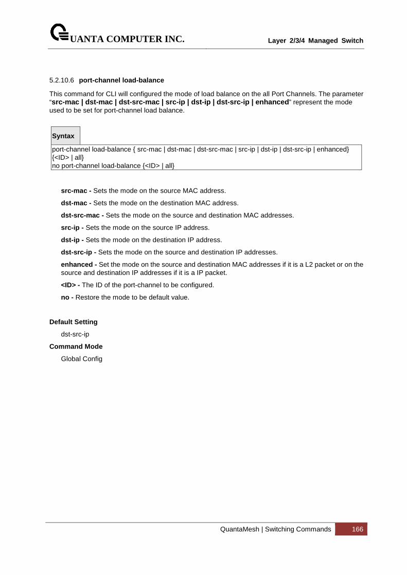
UANTA COMPUTER INC.
Layer 2/3/4 Managed Switch
QuantaMesh | Switching Commands 166
5.2.10.6 port-channel load-balance
This command for CLI will configured the mode of load balance on the all Port Channels. The parameter “src-mac | dst-mac | dst-src-mac | src-ip | dst-ip | dst-src-ip | enhanced ” represent the mode used to be set for port-channel load balance.
Syntax
port-channel load-balance { src-mac | dst-mac | dst-src-mac | src-ip | dst-ip | dst-src-ip | enhanced} {<ID> | all} no port-channel load-balance {<ID> | all}
src-mac - Sets the mode on the source MAC address.
dst-mac - Sets the mode on the destination MAC address.
dst-src-mac - Sets the mode on the source and destination MAC addresses.
src-ip - Sets the mode on the source IP address.
dst-ip - Sets the mode on the destination IP address.
dst-src-ip - Sets the mode on the source and destination IP addresses.
enhanced - Set the mode on the source and destination MAC addresses if it is a L2 packet or on the source and destination IP addresses if it is a IP packet.
<ID> - The ID of the port-channel to be configured.
no - Restore the mode to be default value.
Default Setting
dst-src-ip
Command Mode
Global Config
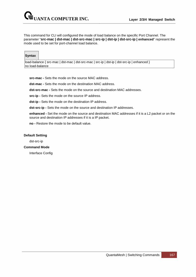
UANTA COMPUTER INC.
Layer 2/3/4 Managed Switch
QuantaMesh | Switching Commands 167
This command for CLI will configured the mode of load balance on the specific Port Channel. The parameter “src-mac | dst-mac | dst-src-mac | src-ip | dst-ip | dst-src-ip | enhanced ” represent the mode used to be set for port-channel load balance.
Syntax
load-balance { src-mac | dst-mac | dst-src-mac | src-ip | dst-ip | dst-src-ip | enhanced } no load-balance
src-mac - Sets the mode on the source MAC address.
dst-mac - Sets the mode on the destination MAC address.
dst-src-mac - Sets the mode on the source and destination MAC addresses.
src-ip - Sets the mode on the source IP address.
dst-ip - Sets the mode on the destination IP address.
dst-src-ip - Sets the mode on the source and destination IP addresses.
enhanced - Set the mode on the source and destination MAC addresses if it is a L2 packet or on the source and destination IP addresses if it is a IP packet.
no - Restore the mode to be default value.
Default Setting
dst-src-ip
Command Mode
Interface Config
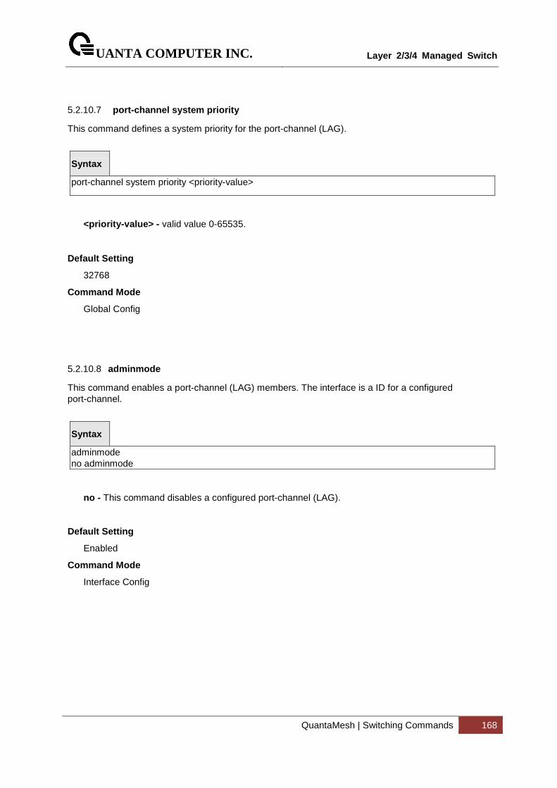
UANTA COMPUTER INC.
Layer 2/3/4 Managed Switch
QuantaMesh | Switching Commands 168
5.2.10.7 port-channel system priority
This command defines a system priority for the port-channel (LAG).
Syntax
port-channel system priority <priority-value>
<priority-value> - valid value 0-65535.
Default Setting
32768
Command Mode
Global Config
5.2.10.8 adminmode
This command enables a port-channel (LAG) members. The interface is a ID for a configured port-channel.
Syntax
adminmode no adminmode
no - This command disables a configured port-channel (LAG).
Default Setting
Enabled
Command Mode
Interface Config
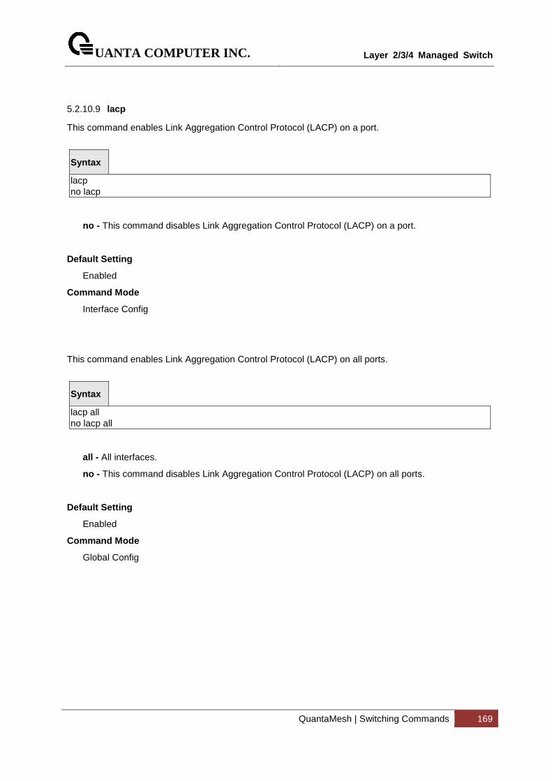
UANTA COMPUTER INC.
Layer 2/3/4 Managed Switch
QuantaMesh | Switching Commands 169
5.2.10.9 lacp
This command enables Link Aggregation Control Protocol (LACP) on a port.
Syntax
lacp no lacp
no - This command disables Link Aggregation Control Protocol (LACP) on a port.
Default Setting
Enabled
Command Mode
Interface Config
This command enables Link Aggregation Control Protocol (LACP) on all ports.
Syntax
lacp all no lacp all
all - All interfaces.
no - This command disables Link Aggregation Control Protocol (LACP) on all ports.
Default Setting
Enabled
Command Mode
Global Config
UANTA COMPUTER INC.
Layer 2/3/4 Managed Switch
QuantaMesh | Switching Commands 170
5.2.10.10 lacp actor or lacp partner
This command set <actor | partner> admin key value of Link Aggregation Control Protocol (LACP) on a port.
Syntax
lacp <actor|partner> admin key <key-value> no lacp <actor|partner> admin key
<key-value> : 0-65535
no - This command restores <actor | partner> admin key value of Link Aggregation Control Protocol (LACP) on a port.
Default Setting
Interface Number
Command Mode
Interface Config
This command set <actor | partner> admin state value of Link Aggregation Control Protocol (LACP) on a port.
Syntax
lacp <actor|partner> admin state <individual | longtimeout | passive> no lacp <actor|partner> admin state <individual | longtimeout | passive>
individual - Set lacp admin state to individual. Use no form to set to aggregation.
longtimeout - Set lacp admin state longtimeout. Use no form to set to shorttimeout.
passive - Set lacp admin state passive. Use no form to set to active.
no - This command restores <actor | partner> admin state value of Link Aggregation Control Protocol (LACP) on a port.
Default Setting
no lndividual (aggregation)
no longtimeout (shorttimeout)
no passive (active)
Command Mode
Interface Config
UANTA COMPUTER INC.
Layer 2/3/4 Managed Switch
QuantaMesh | Switching Commands 171
This command set <actor | partner> port priority value of Link Aggregation Control Protocol (LACP) on a port.
Syntax
lacp <actor|partner> port priority <priority-value> no lacp <actor|partner> port priority
<priority-value> – range 0-65535.
no - This command restores <actor | partner> port priority value of Link Aggregation Control Protocol (LACP) on a port.
Default Setting
128
Command Mode
Interface Config
This command set <actor | partner> system priority value of Link Aggregation Control Protocol (LACP).
Syntax
lacp <actor|partner> system priority <priority-value> no lacp <actor|partner> system priority
<priority-value> – range 0-65535.
no - This command restores <actor | partner> system priority value of Link Aggregation Control Protocol (LACP).
Default Setting
32768
Command Mode
Interface Config
UANTA COMPUTER INC.
Layer 2/3/4 Managed Switch
QuantaMesh | Switching Commands 172
This command set collector max-delay time of Link Aggregation Control Protocol (LACP) on a port-channel.
Syntax
lacp collector max-delay <delay-value> no lacp collector max-delay
<delay-value> : 0-65535
no - This command restores collector max-delay time of Link Aggregation Control Protocol (LACP) on a port-channel
Default Setting
0
Command Mode
Interface Config
5.2.10.11 lacp min-links
This command configures the minimum links for Link Aggregation.
Syntax
lacp min-links <1-32> no lacp
no - This command resotre the min-links to default value.
Default Setting
1
Command Mode
Interface Port-channel Config
Command Usage
The maximum number of members for each port-channel is 32. For T1048-LB9/T1048-LB9A, the maximum number of members is 8.
UANTA COMPUTER INC.
Layer 2/3/4 Managed Switch
QuantaMesh | Switching Commands 173
5.2.10.12 lacp fallback
This command configures the fallback feature for Link Aggregation.
Syntax
lacp fallback no lacp fallback
no - This command resotre the fallback feature to default value.
Default Setting
Disabled
Command Mode
Interface Port-channel Config
5.2.10.13 lacp fallback timeout
This command configures the fallback timeout value for Link Aggregation.
Syntax
lacp fallback timeout <1-100> no lacp fallback
no - This command resotre the fallback feature to default value.
Default Setting
5
Command Mode
Interface Port-channel Config
UANTA COMPUTER INC.
Layer 2/3/4 Managed Switch
QuantaMesh | Switching Commands 174
5.2.10.14 channel-group
This command assigns and configures an interface to a port-channel (LAG) group. The interface is a ID of a configured port-channel.
Before adding a port to a port-channel, set the physical mode of the port. See ‘speed ’ command.
You can change the mode for an interface only if it is the only interface designated to the specified channel group. If you enter this command on an interface that is added to a channel with a different protocol (than the protocol you are entering), the command is rejected.
Syntax
channel-group <ID> mode {active | on} no channel-group <ID>
<ID> - Port-Channel Interface number. The range of the port-channel ID is 1 to 64.
active - Enables LACP unconditionally.
on - Enables static mode (Cisco EtherChannel-like).
no - Removes the interface from the specified channel group.
Default Setting
None
Command Mode
Interface Config
Command Usage
The maximum number of members for each port-channel is 32. For T1048-LB9/T1048-LB9A, the maximum number of members is 8.
i
UANTA COMPUTER INC.
Layer 2/3/4 Managed Switch
QuantaMesh | Switching Commands 175
5.2.10.15 delete-channel-group
This command deletes all configured ports from the port-channel (LAG). The interface is a ID of a configured port-channel.
Syntax
delete-channel-group <ID> all
<ID> - Port-channel Interface number. The range of the port-channel ID is 1 to 64.
all - All members for specific Port-channel.
Default Setting
None
Command Mode
Global Config
UANTA COMPUTER INC.
Layer 2/3/4 Managed Switch
QuantaMesh | Switching Commands 176
5.2.11 Storm Control
5.2.11.1 show storm-control
This command is used to display broadcast storm control information.
Syntax
show storm-control broadcast
Default Setting
None
Command Mode
Privileged Exec
Display Message
Intf: Displays interface number.
Mode: Displays status of storm control broadcast.
Rate: Displays rate in pps (packet per second) for storm control broadcast.
Action: Shutdown or send trap when storm is detected.
This command is used to display multicast storm control information.
Syntax
show storm-control multicast
Default Setting
None
Command Mode
Privileged Exec
Display Message
Intf: Displays interface number.
Mode: Displays status of storm control multicast.
Rate: Displays rate in pps (packet per second) for storm control multicast.
Action: Shutdown or send trap when storm is detected.
UANTA COMPUTER INC.
Layer 2/3/4 Managed Switch
QuantaMesh | Switching Commands 177
This command is used to display unicast storm control information
Syntax
show storm-control unicast
Default Setting
None
Command Mode
Privileged Exec
Display Message
Intf: Displays interface number.
Mode: Displays status of storm control unicast.
Rate: Displays rate in pps (packet per second) for storm control unicast.
Action: Shutdown or send trap when storm is detected.
UANTA COMPUTER INC.
Layer 2/3/4 Managed Switch
QuantaMesh | Switching Commands 178
5.2.11.2 storm-control broadcast
This command enables broadcast storm recovery mode on the selected interface. If the mode is enabled, broadcast storm recovery with high threshold is implemented. The threshold implementation follows a percentage pattern. If the broadcast traffic on any Ethernet port exceeds the high threshold percentage (as represented in “Broadcast Storm Recovery Thresholds” table) of the link speed, the switch discards the broadcasts traffic until the broadcast traffic returns to the threshold percentage or less. The full implementation is depicted in the “Broadcast Storm Recovery Thresholds” table.
Syntax
storm-control broadcast no storm-control broadcast
no - This command disables broadcast storm recovery mode on the selected interface. The threshold implementation follows a percentage pattern. If the broadcast traffic on any Ethernet port exceeds the high threshold percentage (as represented in “Broadcast Storm Recovery Thresholds” table) of the link speed, the switch discards the broadcasts traffic until the broadcast traffic returns to the threshold percentage or less. The full implementation is depicted in the “Broadcast Storm Recovery Thresholds” table.
Default Setting
Disabled
Command Mode
Interface Config
This command enables broadcast storm recovery mode on all interfaces.
Syntax
storm-control broadcast no storm-control broadcast
no - This command disables broadcast storm recovery mode on all interfaces.
Default Setting
Disabled
Command Mode
GlobaI Config
UANTA COMPUTER INC.
Layer 2/3/4 Managed Switch
QuantaMesh | Switching Commands 179
5.2.11.3 storm-control multicast
This command enables multicast storm recovery mode on the selected interface.
Syntax
storm-control multicast no storm-control multicast
no - This command disables multicast storm recovery mode on the selected interface.
Default Setting
None
Command Mode
Interface Config
This command enables multicast storm recovery mode on all interfaces.
Syntax
storm-control multicast no storm-control multicast
no - This command disables multicast storm recovery mode on all interfaces.
Default Setting
None
Command Mode
Global Config
UANTA COMPUTER INC.
Layer 2/3/4 Managed Switch
QuantaMesh | Switching Commands 180
5.2.11.4 storm-control unicast
This command enables unicast storm recovery mode on the selected interface.
Syntax
storm-control unicast no storm-control unicast
no - This command disables unicast storm recovery mode on the selected interface.
Default Setting
None
Command Mode
Interface Config
This command enables unicast storm recovery mode on all interfaces.
Syntax
storm-control unicast no storm-control unicast
no - This command disables unicast storm recovery mode on all interfaces.
Default Setting
None
Command Mode
Global Config
UANTA COMPUTER INC.
Layer 2/3/4 Managed Switch
QuantaMesh | Switching Commands 181
5.2.11.5 storm control action
This command configure what actions will be performed while the storm control is detected. The actions include shutdown the interfae and send a SNMP trap if the storm occurs.
Syntax
storm-control action {shutdown | trap} no storm-control {shutdown | trap}
shutdown – To shutdown the interface if the storm occurs.
trap – To send SNMP trap if the storm occurs.
no - This command disables unicast storm recovery mode on all interfaces.
Default Setting
None
Command Mode
Interface Config
UANTA COMPUTER INC.
Layer 2/3/4 Managed Switch
QuantaMesh | Switching Commands 182
5.2.11.6 switchport broadcast rate
This command will protect your network from broadcast storms by setting a threshold level for broadcast traffic on each port.
Syntax
switchport broadcast rate <1-14880000>
<1-14880000> - Specify the threshold for broadcast traffic.
Note: pps (packet per second)
Default Setting
4160 for 10G interfaces
512 for 1G interfaces
Command Mode
Interface Config
This command will protect your network from broadcast storms by setting a threshold level for broadcast traffic on all ports.
Syntax
switchport broadcast all rate <1-14880000>
<1-14880000> - Specify the threshold for broadcast traffic.
all - This command represents all interfaces.
Note: pps (packet per second)
Default Setting
4160 for 10G interfaces
512 for 1G interfaces
Command Mode
Global Config

UANTA COMPUTER INC.
Layer 2/3/4 Managed Switch
QuantaMesh | Switching Commands 183
5.2.11.7 switchport multicast rate
This command will protect your network from multicast storms by setting a threshold level for multicast traffic on each port.
Syntax
switchport multicast rate <1-14880000>
<1-14880000> - Specify the threshold for multicast traffic
Note: pps (packet per second)
Default Setting
4160 for 10G interfaces
512 for 1G interfaces
Command Mode
Interface Config
This command will protect your network from multicast storms by setting a threshold level for multicast traffic on all ports.
Syntax
switchport multicast all rate <1-14880000>
<1-14880000> - Specify the threshold for multicast traffic.
all - This command represents all interfaces.
Note: pps (packet per second)
Default Setting
4160 for 10G interfaces
512 for 1G interfaces
Command Mode
Global Config
UANTA COMPUTER INC.
Layer 2/3/4 Managed Switch
QuantaMesh | Switching Commands 184
5.2.11.8 switchport unicast rate
This command will protect your network from unicast storms by setting a threshold level for unicast traffic on each port.
Syntax
switchport unicast rate <1-14880000>
<1-14880000> - Specify the threshold for unicast traffic
Note: pps (packet per second)
Default Setting
4160 for 10G interfaces
512 for 1G interfacces
Command Mode
Interface Config
This command will protect your network from unicast storms by setting a threshold level for unicast traffic on all ports.
Syntax
switchport unicast all rate <1-14880000>
<1-14880000> - Specify the threshold for unicast traffic.
all - This command represents all interfaces.
Note: pps (packet per second)
Default Setting
4160 for 10G interfaces
512 for 1G interfaces
Command Mode
Global Config
UANTA COMPUTER INC.
Layer 2/3/4 Managed Switch
QuantaMesh | Switching Commands 185
5.2.12 L2 Priority
5.2.12.1 show queue cos-map
This command displays the class of service priority map on specific interface.
Syntax
show queue cos-map {<slot/port> | port-channel <portchannel-id>}
<slot/port> - Interface number.
<portchannel-id > - Port-channel interface number. The range of port-channel ID is 1 to 64.
Default Setting
None
Command Mode
Privileged Exec
Display Message
User Priority: Displays the 802.1p priority to be mapped.
Traffic Class: Displays internal traffic class to map the corresponding 802.1p priority.
UANTA COMPUTER INC.
Layer 2/3/4 Managed Switch
QuantaMesh | Switching Commands 186
5.2.12.2 queue cos-map
This command is used to assign class of service (CoS) value to the CoS priority queue.
Syntax
queue cos-map <priority> <queue-id> no queue cos-map
<queue-id> - The queue id of the CoS priority queue (Range: 0 - 7 ).
<priority> - The CoS value that is mapped to the queue id (Range: 0 - 7 ).
no - Sets the CoS map to the default values.
Default Setting
priority queue
0 1
1 0
2 0
3 1
4 2
5 2
6 3
7 3
Command Mode
Interface Config

UANTA COMPUTER INC.
Layer 2/3/4 Managed Switch
QuantaMesh | Switching Commands 187
5.2.13 Port Mirror
5.2.13.1 show monitor session
This command displays the Port monitoring information for the specified session.
Syntax
show monitor session <session-id>
<session-id> - session ID. The range of session ID is 1 to 4.
Default Setting
None
Command Mode
Privileged Exec
Display Message
Session ID: indicates the session ID.
Admin Mode: indicates whether the Port Monitoring feature is enabled or disabled. The possible values are enabled and disabled.
Dest. Port: is the slot/port that is configured as the probe port. If this value has not been configured, 'Not Configured' will be displayed.
Source Port: is the slot/port that is configured as the monitored port. If this value has not been configured, 'Not Configured' will be displayed.
Type: Direction in which source port configured for port mirroring.Types are tx for transmitted packets and rx for receiving packets.
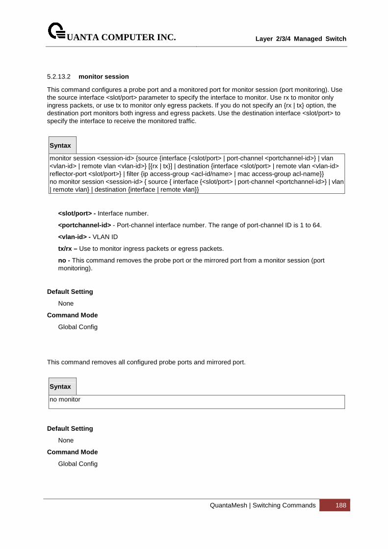
UANTA COMPUTER INC.
Layer 2/3/4 Managed Switch
QuantaMesh | Switching Commands 188
5.2.13.2 monitor session
This command configures a probe port and a monitored port for monitor session (port monitoring). Use the source interface <slot/port> parameter to specify the interface to monitor. Use rx to monitor only ingress packets, or use tx to monitor only egress packets. If you do not specify an {rx | tx} option, the destination port monitors both ingress and egress packets. Use the destination interface <slot/port> to specify the interface to receive the monitored traffic.
Syntax
monitor session <session-id> {source {interface {<slot/port> | port-channel <portchannel-id>} | vlan <vlan-id> | remote vlan <vlan-id>} [{rx | tx}] | destination {interface <slot/port> | remote vlan <vlan-id> reflector-port <slot/port>} | filter {ip access-group <acl-id/name> | mac access-group acl-name}} no monitor session <session-id> { source { interface {<slot/port> | port-channel <portchannel-id>} | vlan | remote vlan} | destination {interface | remote vlan}}
<slot/port> - Interface number.
<portchannel-id> - Port-channel interface number. The range of port-channel ID is 1 to 64.
<vlan-id> - VLAN ID
tx/rx – Use to monitor ingress packets or egress packets.
no - This command removes the probe port or the mirrored port from a monitor session (port monitoring).
Default Setting
None
Command Mode
Global Config
This command removes all configured probe ports and mirrored port.
Syntax
no monitor
Default Setting
None
Command Mode
Global Config
UANTA COMPUTER INC.
Layer 2/3/4 Managed Switch
QuantaMesh | Switching Commands 189
5.2.13.3 monitor session mode
This command configures the mode parameter to enabled the administrative mode of the session. If enabled, the probe port monitors all the traffic received and transmitted on the physical monitored port.
Syntax
monitor session <session-id> mode no monitor session <session-id> mode
<session-id> - Session ID.
no - This command disables port-monitoring function for a monitor session.
Default Setting
None
Command Mode
Global Config
UANTA COMPUTER INC.
Layer 2/3/4 Managed Switch
QuantaMesh | Switching Commands 190
5.2.14 Link State
5.2.14.1 show link state
Show link state information.
Syntax
show link state
Command Mode
Global Config
Display Message
Admin Mode: the link state admin mode.
Group ID : The group ID for each displayed row.
Mode : This group was set which mode.
UpStream : Display such port was included to UpStream set.
DownStream : Display such port was included to DownStream set.
UANTA COMPUTER INC.
Layer 2/3/4 Managed Switch
QuantaMesh | Switching Commands 191
5.2.14.2 link state
Enable/Disable the link state admin mode. Use ‘link state’ to enable the admin mode of redundant function, and use no command to disable the function.
Create/Destroy the link state group. Use ‘link state group’ to create a group. Use no command to destroy the group.
Enable/Disable a link state group. Use link state group enable <group id> to enable individual group, and use no command to disable a group.
Syntax
link state [group | [enable <1-6>]] no link state [group <1-6> | [enable <1-6>]]
no - This command disables link state function.
Command Mode
Global Config
UANTA COMPUTER INC.
Layer 2/3/4 Managed Switch
QuantaMesh | Switching Commands 192
5.2.14.3 link state group
Set upstream port or downstream port for a link state group. Use ‘link state group <group id> upstream’ to set the port to be monitored.
Syntax
link state group <1-6> {downstream | upstream} no link state group <1-6> {downstream | upstream}
no - This command disables link state group function.
Command Mode
Interface Config
UANTA COMPUTER INC.
Layer 2/3/4 Managed Switch
QuantaMesh | Switching Commands 193
5.2.15 Port Backup
5.2.15.1 show port-backup
Show port-backup information.
Syntax
show port-backup
Command Mode
Privileged EXEC
Display Message
Admin Mode : Indicates whether or not port-backup is active on the switch.
Group ID : The Group ID for each displayed row.
Mode : Indicates whether or not the group is active.
MAC Update : Indicates whether or not mac-move-update is enable on the group.
Active Port : Display the active port number.
Backup Port : Display the active port number.
Current Active Port : Display the current active port number.
UANTA COMPUTER INC.
Layer 2/3/4 Managed Switch
QuantaMesh | Switching Commands 194
5.2.15.2 port-backup
Enable/Disable the port backup admin mode. Use ‘port-backup’ to enable the admin mode of function, and use no command to disable the function.
Create/Destroy the port backup group. Use ‘port-backup group’ to create a group. Use no command to destroy the group.
Enable/Disable a port-backup group. Use ‘port-backup group enable <group id> to enable individual group, and use no command to disable a group.
Enable/Disable a port-backup group support the mac-move-update. Use ‘port-backup group <group id> mac-move-update to enable individual group, and use no command to disable a group.
Syntax
port-backup [group | {enable <1 - 6> | <1 - 6> [failback-time <0 - 60> | mac-move-update]}] no port-backup [group | {enable <1 - 6> | <1 - 6> [failback-time <0 - 60> | mac-move-update]}]
no - This command disables port-backup function.
Command Mode
Global Config
5.2.15.3 port-backup group
Set active port or backup port for a port-backup group. Use ‘port-backup group <group id> <active | backup>’ to set the port to be configured active or configured backup port.
Syntax
port-backup group <1-6> {active | backup} no port-backup group <1-6> {active | backup}
no - This command disables port-backup group function.
Command Mode
Interface Config
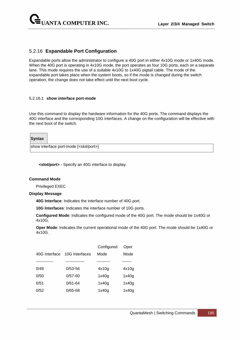
UANTA COMPUTER INC.
Layer 2/3/4 Managed Switch
QuantaMesh | Switching Commands 195
5.2.16 Expandable Port Configuration
Expandable ports allow the administrator to configure a 40G port in either 4x10G mode or 1x40G mode. When the 40G port is operating in 4x10G mode, the port operates as four 10G ports, each on a separate lane. This mode requires the use of a suitable 4x10G to 1x40G pigtail cable. The mode of the expandable port takes place when the system boots, so if the mode is changed during the switch operation, the change does not take effect until the next boot cycle.
5.2.16.1 show interface port-mode
Use this command to display the hardware information for the 40G ports. The command displays the 40G interface and the corresponding 10G interfaces. A change on the configuration will be effective with the next boot of the switch.
Syntax
show interface port-mode [<slot/port>]
<slot/port> - Specify an 40G interface to display.
Command Mode
Privileged EXEC
Display Message
40G Interface : Indicates the interface number of 40G port.
10G Interfaces : Indicates the interface number of 10G ports.
Configured Mode : Indicates the configured mode of the 40G port. The mode should be 1x40G or 4x10G.
Oper Mode : Indicates the current operational mode of the 40G port. The mode should be 1x40G or 4x10G.
Configured Oper
40G Interface 10G Interfaces Mode Mode
------------- -------------- ---------- -------
0/49 0/53-56 4x10g 4x10g
0/50 0/57-60 1x40g 1x40g
0/51 0/61-64 1x40g 1x40g
0/52 0/65-68 1x40g 1x40g
UANTA COMPUTER INC.
Layer 2/3/4 Managed Switch
QuantaMesh | Switching Commands 196
5.2.16.2 port-mode
Use this command to configure a 40G QSFP port in either 4x10G mode or 1x40G mode. After the mode is changed, it will not take effect immediately until the next boot cycle.
Syntax
port-mode {1x40g | 4x10g}
1x40g – Configure the port as a single 40G port using four lanes.
4x10g – Configure the port as a four 10G ports, each on a separate lane. This mode requires the use of a suitable 4x10G to 1x40G pigtail cable..
no - This command resets to the default value. The default value is 1x40g.
Command Mode
Interface Config

UANTA COMPUTER INC.
Layer 2/3/4 Managed Switch
QuantaMesh | Switching Commands 197
5.3 Management Commands
5.3.1 Network Commands
5.3.1.1 show ip interface
This command displays configuration settings associated with the switch's network interface. The network interface is the logical interface used for in-band connectivity with the switch via any of the switch's front panel ports. The configuration parameters associated with the switch's network interface do not affect the configuration of the front panel ports through which traffic is switched or routed.
Syntax
show ip interface
Default Setting
None
Command Mode
Privileged Exec
User Exec
Display Message
VLAN ID: Indicates whether the VLAN ID is used for this vlan interface.
Interface: Indicates whether the interface number for this interface.
Interface Status: Indicates whether the interface is up or down.
IP Address: The IP address of the interface. The factory default value is 0.0.0.0
Subnet Mask: The IP subnet mask for this interface. The factory default value is 0.0.0.0
MAC Address: The MAC address used for in-band connectivity.
Network Configuration Protocol Current: Indicates which network protocol is being used. The options are bootp | dhcp | none.
UANTA COMPUTER INC.
Layer 2/3/4 Managed Switch
QuantaMesh | Switching Commands 198
5.3.1.2 show ip filter
This command displays management IP filter status and all designated management stations.
Syntax
show ip filter
Default Setting
None
Command Mode
Privileged Exec
Display Message
Manegement IP Filter Address Table: The admin mode status for IP filter.
Index: The index of stations.
IP Address: The IP address of stations that are allowed to make configuration changes to the Switch.
5.3.1.3 mtu
This command sets the maximum transmission unit (MTU) size (in bytes) for physical and port-channel (LAG) interfaces. For the standard implementation, the range of <1518-12288> is a valid integer between 1518-12288.
Syntax
mtu <1518-12288> no mtu
<1518-12288> - Max frame size (Range: 1518 - 12288).
no - This command sets the default maximum transmission unit (MTU) size (in bytes) for the interface.
Default Setting
1518
Command Mode
Interface Config
UANTA COMPUTER INC.
Layer 2/3/4 Managed Switch
QuantaMesh | Switching Commands 199
5.3.1.4 interface vlan
This command is used to create a vlan interface and enter Interface-vlan configuration mode.
Syntax
interface vlan <vlan-id>
<vlan-id> - VLAN ID (Range: 1 - 4093).
Default Setting
None
Command Mode
Global Config
5.3.1.5 ip address
This command sets the IP Address, and subnet mask. The IP Address and the gateway must be on the same subnet.
Syntax
ip address <ipaddr> <netmask> no ip address
<ipaddr> - IP address
<netmask> - Subnet Mask
no - Restore the default IP address and Subnet Mask
Default Setting
IP address: 0.0.0.0
Subnet Mask: 0.0.0.0
Command Mode
Interface-Vlan Config
Command Usage
Once the IP address is set, the VLAN ID’s value will be assigned to management VLAN.
UANTA COMPUTER INC.
Layer 2/3/4 Managed Switch
QuantaMesh | Switching Commands 200
5.3.1.6 ip default-gateway
This command sets the IP Address of the default gateway.
Syntax
ip default-gateway <gateway> no ip default-gateway
< gateway > - IP address of the default gateway
no - Restore the default IP address of the default gateway
Default Setting
IP address: 0.0.0.0
Command Mode
Global Config
5.3.1.7 ip address dhcp
This command specifies the network configuration protocol to be used. If you modify this value, the change is effective immediately.
Syntax
ip address dhcp [restart]
<dhcp> - Obtains IP address from DHCP.
<restart> - To restart the DHCP process.
Default Setting
None
Command Mode
Interface-Vlan Config
UANTA COMPUTER INC.
Layer 2/3/4 Managed Switch
QuantaMesh | Switching Commands 201
5.3.1.8 ip filter
This command is used to enable the IP filter function.
Syntax
ip filter no ip filter
no – Disable ip filter.
Default Setting
Disabled
Command Mode
Global Config
This command is used to set an IP address to be a filter.
Syntax
ip filter <name> {ipv4 | ipv6} <ipAddr> [<mask>] no ip filter <name>
<name> - The name of the IP filter.
<ipAddr> - Configure a IP address to the filter.
<mask> - Specifies the mask for a range filter.
no - Remove this IP address from filter.
Default Setting
None
Command Mode
Global Config
UANTA COMPUTER INC.
Layer 2/3/4 Managed Switch
QuantaMesh | Switching Commands 202
5.3.2 Serial Interface Commands
5.3.2.1 show line console
This command displays serial communication settings for the switch.
Syntax
show line console
Default Setting
None
Command Mode
Privileged Exec
Display Message
Serial Port Login Timeout (minutes): Specifies the time, in minutes, of inactivity on a Serial port connection, after which the Switch will close the connection. Any numeric value between 0 and 160 is allowed, the factory default is 5. A value of 0 disables the timeout.
Baud Rate: The default baud rate at which the serial port will try to connect. The available values are 1200, 2400, 4800, 9600, 19200, 38400, 57600, and 115200 bauds.
Character Size: The number of bits in a character. The number of bits is always 8.
Flow Control: Whether Hardware Flow-Control is enabled or disabled. Hardware Flow Control is always disabled.
Stop Bits: The number of Stop bits per character. The number of Stop bits is always 1.
Parity: The Parity Method used on the Serial Port. The Parity Method is always None.
Password Threshold: When the logon attempt threshold is reached on the console port, the system interface becomes silent for a specified amount of time before allowing the next logon attempt. (Use the silent time command to set this interval.) When this threshold is reached for Telnet, the Telnet logon interface closes.
Silent Time (sec): Use this command to set the amount of time the management console is inaccessible after the number of unsuccessful logon attempts exceeds the threshold set by the password threshold command.
Terminal Length: The columns per page for terminal serial port.
UANTA COMPUTER INC.
Layer 2/3/4 Managed Switch
QuantaMesh | Switching Commands 203
5.3.2.2 line console
This command is used to enter Line configuration mode
Syntax
line console
Default Setting
None
Command Mode
Global Config
5.3.2.3 baudrate
This command specifies the communication rate of the terminal interface. The supported rates are 1200, 2400, 4800, 9600, 19200, 38400, 57600, 115200.
Syntax
baudrate {1200 | 2400 | 4800 | 9600 | 19200 | 38400 | 57600 | 115200} no baudrate
no - This command sets the communication rate of the terminal interface to 115200.
Default Setting
115200
Command Mode
Line Config
UANTA COMPUTER INC.
Layer 2/3/4 Managed Switch
QuantaMesh | Switching Commands 204
5.3.2.4 exec-timeout
This command specifies the maximum connect time (in minutes) without console activity. A value of 0 indicates that a console can be connected indefinitely. The time range is 0 to 160.
Syntax
exec-timeout <0-160>
<0-160> - max connect time (Range: 0 -160), 0: forever.
no - This command sets the maximum connect time (in minutes) without console activity to 5.
Default Setting
5
Command Mode
Line Config
5.3.2.5 password-threshold
This command is used to set the password instruction threshold limiting the number of failed login attempts.
Syntax
password-threshold <0-120> no password-threshold
<threshold> - max threshold (Range: 0 - 120).
no - This command sets the maximum value to the default.
Default Setting
3
Command Mode
Line Config
UANTA COMPUTER INC.
Layer 2/3/4 Managed Switch
QuantaMesh | Switching Commands 205
5.3.2.6 silent-time
This command uses to set the amount of time the management console is inaccessible after the number of unsuccessful logon tries exceeds the threshold value.
Syntax
silent-time <0-65535>
<0-65535> - silent time (Range: 0 - 65535) in seconds.
no - This command sets the maximum value to the default.
Default Setting
0
Command Mode
Line Config
5.3.2.7 terminal length
This command uses to configure the columns per page for the management console.
Syntax
terminal-length <0 | 5-48>
<0 | 5-48> - Columns per page (Range: 0 or 5 - 48).
no - This command sets the value to the default.
Default Setting
24
Command Mode
Line Config
UANTA COMPUTER INC.
Layer 2/3/4 Managed Switch
QuantaMesh | Switching Commands 206
5.3.3 Telnet Session Commands
5.3.3.1 telnet
This command establishes a new outbound telnet connection to a remote host.
Syntax
telnet <ip-address|hostname> [port] [debug] [line]
<ip-address|hostname> - A hostname or a valid IP address.
port - A valid decimal integer in the range of 0 to 65535, where the default value is 23.
debug - Display current enabled telnet options.
line - Set the outbound telnet operational mode as ‘linemode’, where by default, the operational mode is ‘character mode’.
Default Setting
None
Command Mode
Privileged Exec
User Exec
5.3.3.2 show line vty
This command displays telnet settings.
Syntax
show line vty
Default Setting
None
Command Mode
Privileged Exec
Display Message
Remote Connection Login Timeout (minutes): This object indicates the number of minutes a remote connection session is allowed to remain inactive before being logged off. A zero means there will be no timeout. May be specified as a number from 0 to 160. The factory default is 5.
Maximum Number of Remote Connection Sessions: This object indicates the number of simultaneous remote connection sessions allowed. The factory default is 5.
UANTA COMPUTER INC.
Layer 2/3/4 Managed Switch
QuantaMesh | Switching Commands 207
Allow New Telnet Sessions: Indicates that new telnet sessions will not be allowed when set to no. The factory default value is yes.
Telnet Server Admin Mode: The telnet server admin mode status. The factory default is enable.
Password Threshold: When the logon attempt threshold is reached on the console port, the system interface becomes silent for a specified amount of time before allowing the next logon attempt. (Use the silent time command to set this interval.) When this threshold is reached for Telnet, the Telnet logon interface closes.
Terminal Length: The columns per page for terminal vty port.
5.3.3.3 line vty
This command is used to enter vty (Telnet) configuration mode.
Syntax
line vty
Default Setting
None
Command Mode
Global Config
UANTA COMPUTER INC.
Layer 2/3/4 Managed Switch
QuantaMesh | Switching Commands 208
5.3.3.4 exec-timeout
This command sets the remote connection session timeout value, in minutes. A session is active as long as the session has been idle for the value set. A value of 0 indicates that a session remains active indefinitely. The time is a decimal value from 0 to 160.
Changing the timeout value for active sessions does not become effective until the session is reaccessed. Any keystroke will also activate the new timeout duration.
Syntax
exec-timeout <1-160> no exec-timeout
<sec> - max connect time (Range: 1 -160).
no - This command sets the remote connection session timeout value, in minutes, to the default.
Default Setting
5
Command Mode
Line Vty
5.3.3.5 password-threshold
This command is used to set the password instruction threshold limited for the number of failed login attempts.
Syntax
password-threshold <0-120> no password-threshold
<threshold> - max threshold (Range: 0 - 120).
no - This command sets the maximum value to the default.
Default Setting
3
Command Mode
Line Vty
i

UANTA COMPUTER INC.
Layer 2/3/4 Managed Switch
QuantaMesh | Switching Commands 209
5.3.3.6 terminal length
This command uses to configure the columns per page for the vty session.
Syntax
terminal-length <0 | 5-48>
<0 | 5-48> - Columns per page (Range: 0 or 5 - 48).
no - This command sets the value to the default.
Default Setting
24
Command Mode
Line Vty
5.3.3.7 maxsessions
This command specifies the maximum number of remote connection sessions that can be established. A value of 0 indicates that no remote connection can be established. The range is 0 to 5.
Syntax
maxsessions <0-5> no maxsessions
<0-5> - max sessions (Range: 0 - 5).
no - This command sets the maximum value to be 5.
Default Setting
5
Command Mode
Line Vty
UANTA COMPUTER INC.
Layer 2/3/4 Managed Switch
QuantaMesh | Switching Commands 210
5.3.3.8 server enable
This command enables/disables telnet server. If telnet server is enabled, all telnet sessions can be established until there are no more sessions available. If telnet server is disabled, all telnet sessions are closed.
Syntax
server enable no server enable
no - This command disables telnet server. If telnet server is disabled, all telnet sessions are droped.
Default Setting
Enabled
Command Mode
Line Vty
5.3.3.9 sessions
This command regulates new telnet sessions. If sessions are enabled, new telnet sessions can be established until there are no more sessions available. If sessions are disabled, no new telnet sessions are established. An established session remains active until the session is ended or an abnormal network error ends it.
Syntax
sessions no sessions
no - This command disables telnet sessions. If sessions are disabled, no new telnet sessions are established.
Default Setting
Enabled
Command Mode
Line Vty
UANTA COMPUTER INC.
Layer 2/3/4 Managed Switch
QuantaMesh | Switching Commands 211
5.3.3.10 telnet sessions
This command regulates new outbound telnet connections. If enabled, new outbound telnet sessions can be established until it reaches the maximum number of simultaneous outbound telnet sessions allowed. If disabled, no new outbound telnet session can be established. An established session remains active until the session is ended or an abnormal network error ends it.
Syntax
telnet sessions no telnet sessions
no - This command disables new outbound telnet connections. If disabled, no new outbound telnet connection can be established.
Default Setting
Enabled
Command Mode
Global Config
5.3.3.11 telnet maxsessions
This command specifies the maximum number of simultaneous outbound telnet sessions. A value of 0 indicates that no outbound telnet session can be established.
Syntax
telnet maxsessions <0-5> no maxsessions
<0-5> - max sessions (Range: 0 - 5).
no - This command sets the maximum value to be 5.
Default Setting
5
Command Mode
Global Config
UANTA COMPUTER INC.
Layer 2/3/4 Managed Switch
QuantaMesh | Switching Commands 212
5.3.3.12 telnet exec-timeout
This command sets the outbound telnet session timeout value in minute.
Changing the timeout value for active sessions does not become effective until the session is reaccessed. Any keystroke will also activate the new timeout duration.
Syntax
telnet exec-timeout <1-160> no telnet exec-timeout
<1-160> - max connect time (Range: 1 -160).
no - This command sets the remote connection session timeout value, in minutes, to the default.
Default Setting
5
Command Mode
Global Config
i

UANTA COMPUTER INC.
Layer 2/3/4 Managed Switch
QuantaMesh | Switching Commands 213
5.3.3.13 show telnet
This command displays the current outbound telnet settings.
Syntax
show telnet
Default Setting
None
Command Mode
Privileged Exec
User Exec
Display Message
Outbound Telnet Login Timeout (in minutes) Indicates the number of minutes an outbound telnet session is allowed to remain inactive before being logged off. A value of 0, which is the default, results in no timeout.
Maximum Number of Outbound Telnet Sessions Indicates the number of simultaneous outbound telnet connections allowed.
Allow New Outbound Telnet Sessions Indicates whether outbound telnet sessions will be allowed.
UANTA COMPUTER INC.
Layer 2/3/4 Managed Switch
QuantaMesh | Switching Commands 214
5.3.4 SSH Client Session Commands
5.3.4.1 ssh
This command establishes a new outbound ssh connection to a remote host.
Syntax
ssh <ip-address|hostname> <username> { [port <port-id>] [protocol <protocollevel>] | [protocol <protocollevel>] [port <port-id>]}
<ip-address|hostname> - A hostname or a valid IP address.
<username> - user account.
<port-id> - A valid decimal integer in the range of 1 to 65535, where the default value is 22.
<protocollevel> - SSH Protocol Level (Version) 1 or 2.
Default Setting
None
Command Mode
Privileged Exec
Display Message
Connected to 192.168.2.200, use ~. to terminate connection.
UANTA COMPUTER INC.
Layer 2/3/4 Managed Switch
QuantaMesh | Switching Commands 215
5.3.4.2 sshc sessions
This command regulates new outbound ssh connections. If enabled, new outbound ssh sessions can be established until it reaches the maximum number of simultaneous outbound ssh sessions allowed. If disabled, no new outbound ssh session can be established. An established session remains active until the session is ended or an abnormal network error ends it.
Syntax
sshc sessions no sshc sessions
no - This command disables new outbound ssh connections. If disabled, no new outbound ssh connection can be established.
Default Setting
Enabled
Command Mode
Global Config
5.3.4.3 sshc maxsessions
This command specifies the maximum number of simultaneous outbound ssh sessions. A value of 0 indicates that no outbound ssh session can be established.
Syntax
sshc maxsessions <0-5> no maxsessions
<0-5> - max sessions (Range: 0 - 5).
no - This command sets the maximum value to be 5.
Default Setting
5
Command Mode
Global Config
UANTA COMPUTER INC.
Layer 2/3/4 Managed Switch
QuantaMesh | Switching Commands 216
5.3.4.4 sshc exec-timeout
This command sets the outbound ssh session timeout value in minute.
Changing the timeout value for active sessions does not become effective until the session is reaccessed. Any keystroke will also activate the new timeout duration.
Syntax
sshc exec-timeout <1-160> no sshc exec-timeout
<1-160> - max connect time (Range: 1 -160).
no - This command sets the remote connection session timeout value, in minutes, to the default.
Default Setting
5
Command Mode
Global Config
5.3.4.5 show sshc
This command displays the current outbound sshc settings.
Syntax
show sshc
Default Setting
None
Command Mode
Privileged Exec
User Exec
Display Message
Outbound SSH Login Timeout (in minutes) Indicates the number of minutes an outbound ssh session is allowed to remain inactive before being logged off. A value of 0, which is the default, results in no timeout.
Maximum Number of Outbound SSH Sessions Indicates the number of simultaneous outbound ssh connections allowed.
Allow New Outbound SSH Sessions Indicates whether outbound ssh sessions will be allowed.
i
UANTA COMPUTER INC.
Layer 2/3/4 Managed Switch
QuantaMesh | Switching Commands 217
5.3.5 SNMP Server Commands
5.3.5.1 show snmp
This command displays SNMP community information and SNMP trap/inform receivers. Trap/Inform messages are sent across a network to an SNMP Network Manager. These messages alert the manager to events occurring within the switch or on the network. Six trap/inform receivers are simultaneously supported.
Six communities are supported. You can add, change, or delete communities. The switch does not have to be reset for changes to take effect.
The SNMP agent of the switch complies with SNMP versions 1, 2c, and 3 (for more about the SNMP specification, see the SNMP RFCs). The SNMP agent sends traps through TCP/IP to an external SNMP manager based on the SNMP configuration (the trap receiver and other SNMP community parameters).
Syntax
show snmp
Default Setting
None
Command Mode
Privileged Exec
Display Message
Community-String: The community string to which this entry grants access. A valid entry is a case-sensitive alphanumeric string of up to 20 characters. Each row of this table must contain a unique community name.
Community-Access: The access level for this community string.
Group Name: The community this mapping configures.
View Name: The view this community has access to.
IP Address: Access to this community is limited to this IP address.
Target Address: An IP address (or portion thereof) from which this device will accept SNMP packets with the associated community.
Type: The type of message that will be sent, either traps or informs.
Community: The community traps will be sent to.
Version: The version of SNMP the trap will be sent as.
SNMP v1 – Uses SNMP v1 to send traps to the receiver.
SNMP v2 – Uses SNMP v2 to send traps to the receiver.
UANTA COMPUTER INC.
Layer 2/3/4 Managed Switch
QuantaMesh | Switching Commands 218
SNMP v3 – Uses SNMP v3 to send traps to the receiver.
UDP Port: The UDP port the trap or inform will be sent to.
Filter name: The filter the traps will be limited by for this host.
TO Sec: The number of seconds before informs will time out when sending to this host.
Retries: The number of times informs will be sent after timing out.
Username: The user this mapping configures.
Security Level: The authentication and encryption level for snmpv3.
NoAuth-N – no authentication checksum and no encryption algorithm assigned.
Auth-NoP – md5 or sha authentication checksum assigned and no encryption algorithm assigned.
Auth-Pri – md5 or sha authentication checksum and des encryption algorithm assigned.
UANTA COMPUTER INC.
Layer 2/3/4 Managed Switch
QuantaMesh | Switching Commands 219
5.3.5.2 snmp-server sysname
This command sets the name of the switch. The range for name is from 1 to 255 alphanumeric characters.
Syntax
snmp-server sysname <name>
<name> - Range is from 1 to 255 alphanumeric characters.
Default Setting
None
Command Mode
Global Config
5.3.5.3 snmp-server location
This command sets the physical location of the switch. The range for name is from 1 to 255 alphanumeric characters.
Syntax
snmp-server location <loc>
<loc> - range is from 1 to 255 alphanumeric characters.
Default Setting
None
Command Mode
Global Config
UANTA COMPUTER INC.
Layer 2/3/4 Managed Switch
QuantaMesh | Switching Commands 220
5.3.5.4 snmp-server contact
This command sets the organization responsible for the network. The range for contact is from 1 to 255 alphanumeric characters.
Syntax
snmp-server contact <con>
<con> - Range is from 1 to 255 alphanumeric characters.
Default Setting
None
Command Mode
Global Config
UANTA COMPUTER INC.
Layer 2/3/4 Managed Switch
QuantaMesh | Switching Commands 221
5.3.5.5 snmp-server community
This command adds (and names) a new SNMP community, and optionally sets the access mode, allowed IP address, and create a view for the community.
Community names in the SNMP community table must be unique. If you make multiple entries using the same community name, the first entry is kept and processed and all duplicate entries are ignored.
Syntax
snmp-server community <community-string> [ipaddress <ipaddress> | ro | rw | su | view <viewname>] no snmp-server community <community-string>
<community-string> - A name associated with the switch and with a set of SNMP managers that manage it with a specified privileged level. The length of community-name can be up to 20 case-sensitive characters.
<ro | rw | su> - The access mode of the SNMP community, which can be public (Read-Only/RO), private (Read-Write/RW), or Super User (SU).
<ipaddress> - The associated community SNMP packet sending address and is used along with the client IP mask value to denote a range of IP addresses from which SNMP clients may use that community to access the device. A value of 0.0.0.0 allows access from any IP address. Otherwise, this value is ANDed with the mask to determine the range of allowed client IP addresses.
<viewname> - The name of the view to create or update.
no - This command removes this community name from the table. The name is the community name to be deleted.
Default Setting
Two default community names:
‧public, with read-only permissions, a view name of Default, and allows access from all IP addresses.
‧private, with read/write permissions, a view name of Default, and allows access from all IP addresses.
Command Mode
Global Config
5.3.5.6 snmp-server community-group
This command configures a community access string to permit access via the SNMPv1 and SNMPv2c protocols.
i
UANTA COMPUTER INC.
Layer 2/3/4 Managed Switch
QuantaMesh | Switching Commands 222
Syntax
snmp-server community-group <community-string> <group-name> [ipaddress <ip-address>]
<community-string> - The community which is created and then associated with the group. The range is 1 to 20 characters.
<group-name> - The name of the group that the community is associated with. The range is 1 to 30 characters.
<ip-address> - Optionally, the IPv4 address that the community may be accessed from.
Default Setting
None
Command Mode
Global Config
5.3.5.7 show snmp engineid
This command displays the currently configured SNMP engineID.
Syntax
show snmp engineid
Default Setting
None
Command Mode
Privileged Exec
Display Message
Local SNMP EngineID: The current configuration of the displayed SNMP engineID.
UANTA COMPUTER INC.
Layer 2/3/4 Managed Switch
QuantaMesh | Switching Commands 223
5.3.5.8 snmp-server engineID
This command configures snmp engineID on the local device.
Changing the engineID will invalidate all SNMP configuration that exists on the box.
Syntax
snmp-server engineID local {<engine-id> | default} no snmp-server engineID remote <ipAddr|ipv6Addr> <engineid-string>
<engine-id> - A hexadecimal string identifying the engine-id. Engine-id must be an even length in the range of 6 to 32 hexadecimal characters.
default - Sets the engine-id to the default string, based on the device MAC address.
no - This command removes snmp engineID.
Default Setting
The engineID is configured automatically, based on the device MAC address.
Command Mode
Global Config
5.3.5.9 show snmp filters
This command displays the configured filters used when sending traps.
Syntax
show snmp filters [<filter-name>]
Default Setting
None
Command Mode
Privileged Exec
Display Message
Name: The filter name for this entry.
OID Tree: The OID tree this entry will include or exclude.
Type: Indicates if this entry includes or excludes the OID Tree.
i

UANTA COMPUTER INC.
Layer 2/3/4 Managed Switch
QuantaMesh | Switching Commands 224
UANTA COMPUTER INC.
Layer 2/3/4 Managed Switch
QuantaMesh | Switching Commands 225
5.3.5.10 snmp-server filter
This command creates a filter entry for use in limiting which traps will be sent to a host.
Syntax
snmp-server filter <filter-name> <oid-tree> [excluded | included]
<filter-name> - The label for the filter being created. The range is 1 to 30 characters.
<oid-tree> - The OID subtree to include or exclude from the filter. Subtrees may be specified by numerical (1.3.6.2.4) or keywords (system), and asterisks may be used to specify a subtree family (1.3.*.4).
excluded - The tree is excluded from the filter.
included - The tree is included in the filter.
Default Setting
None
Command Mode
Global Config
5.3.5.11 show snmp user
This command displays the currently configured SNMPv3 users.
Syntax
show snmp user [<username>]
Default Setting
None
Command Mode
Privileged Exec
Display Message
Name: The name of the user.
Group Name: The group that defines the SNMPv3 access parameters.
Auth Method: The authentication algorithm configured for this user.
Privilege Method: The encryption algorithm configured for this user.
Remote Engine ID: The engineID for the user defined on the client machine.

UANTA COMPUTER INC.
Layer 2/3/4 Managed Switch
QuantaMesh | Switching Commands 226
UANTA COMPUTER INC.
Layer 2/3/4 Managed Switch
QuantaMesh | Switching Commands 227
5.3.5.12 snmp-server user
This command creates an SNMPv3 user for access to the system.
Syntax
snmp-server user <name> <group-name> [remote <engine-idstring>] {[auth-md5 <password> | auth-md5-key <md5-key> | auth-sha <password> | auth-sha-key <sha-key>] [priv-des <password> | priv-des-key <des-key>]}
<name> - The username the SNMPv3 user will connect to the switch as. The range is 1 to 30 characters.
<group-name> - The name of the group the user belongs to. The range is 1 to 30 characters.
<engineid-string> - The engine-id of the remote management station that this user will be connecting from. The range is 5 to 32 characters.
<password> - password The password the user will use for the authentication or encryption mechanism. The range is 1 to 32 characters.
md5-key - A pregenerated MD5 authentication key. The length is 32 characters.
sha-key - A pregenerated SHA authentication key. The length is 48 characters.
des-key - A pregenerated DES encryption
no - This command removes snmp user.
Default Setting
None
Command Mode
Global Config
5.3.5.13 show snmp group
This command displays the configured groups.
Syntax
show snmp group [<groupname>]
Default Setting
None
Command Mode
Privileged Exec

UANTA COMPUTER INC.
Layer 2/3/4 Managed Switch
QuantaMesh | Switching Commands 228
Display Message
Name: The name of the group.
Security Model: Indicates which protocol can access the system via this group.
Security Level: Indicates the security level allowed for this group.
Read View: The view this group provides read access to.
Write View: The view this group provides write access to.
Notify View: The view this group provides trap access to.

UANTA COMPUTER INC.
Layer 2/3/4 Managed Switch
QuantaMesh | Switching Commands 229
UANTA COMPUTER INC.
Layer 2/3/4 Managed Switch
QuantaMesh | Switching Commands 230
5.3.5.14 snmp-server group
This command creates an SNMP access group.
Syntax
snmp-server group <group-name> [v1 | v2 | v3] {[read <readview>] | [write <writeview>] | [context <contextprefix>] | [notify <notifyview>]}
<group-name> - The group name to be used when configuring communities or users. The range is 1 to 30 characters.
v1 - This group can only access via SNMPv1.
v2 - This group can only access via SNMPv2c.
v3 - This group can only access via SNMPv3.
<readview> - The view this group will use during GET requests. The range is 1 to 30 characters.
<writeview> - The view this group will use during SET requests. The range is 1 to 30 characters.
<contextprefix> - The SNMPv3 context used during access. Applicable only if SNMPv3 is selected.
<notifyview> - The view this group will use when sending out traps. The range is 1 to 30 characters.
no - This command removes the specified group.
Default Setting
Generic groups are created for all versions and privileges using the default views.
Command Mode
Global Config
5.3.5.15 show snmp views
This command displays the currently configured views.
Syntax
show snmp views [<viewname>]
Default Setting
None
Command Mode
Privileged Exec
Display Message

UANTA COMPUTER INC.
Layer 2/3/4 Managed Switch
QuantaMesh | Switching Commands 231
Name: The view name for this entry.
OID Tree: The OID tree that this entry will include or exclude.
Type: Indicates if this entry includes or excludes the OID tree.
UANTA COMPUTER INC.
Layer 2/3/4 Managed Switch
QuantaMesh | Switching Commands 232
5.3.5.16 snmp-server view
This command creates or modifies an existing view entry that is used by groups to determine which objects can be accessed by a community or user.
Syntax
snmp-server view <view-name> <oid-tree> [excluded | included]
<view-name> - The label for the view being created. The range is 1 to 30 characters.
<oid-tree> - The OID subtree to include or exclude from the view. Subtrees may be specified by numerical (1.3.6.2.4) or keywords (system), and asterisks may be used to specify a subtree family (1.3.*.4).
excluded - The tree is excluded from the view.
included - The tree is included in the view.
no - This command removes the specified view.
Default Setting
Views are created by default to provide access to the default groups.
Command Mode
Global Config
UANTA COMPUTER INC.
Layer 2/3/4 Managed Switch
QuantaMesh | Switching Commands 233
5.3.6 SNMP Trap Commands
5.3.6.1 snmp-server host <host-addr> traps
This command configures traps to be sent to the specified host.
Syntax
snmp-server host <host-addr> traps version {1 <community> | 2 <community> | 3 <username> [auth | noauth | priv]} [filter <filtername>] [udp-port <1-65535>] no snmp-server host <host-addr>
<host-addr> - The IPv4 or IPv6 address of the host to send the trap to.
<community> - Community string sent as part of the notification. The range is 1 to 20 characters.
version 1 - Sends SNMPv1 traps.
version 2 - Sends SNMPv2 traps.
version 3 - Sends SNMPv3 traps.
<username> - Username of SNMPv3.
auth - Enables authentication but not encryption.
noauth - No authentication or encryption. This is the default.
priv - Enables authentication and encryption.
<filtername> - The filter name to associate with this host. Filters can be used to specify which traps aresent to this host. The range is 1 to 30 characters.
<udp-port> - The SNMP Trap receiver port. The default is port 162.
no - This command deletes trap receivers.
Default Setting
None
Command Mode
Global Config
5.3.6.2 show trapflags
This command displays trap conditions. Configure which traps the switch should generate by enabling or disabling the trap condition. If a trap condition is enabled and the condition is detected, the switch's SNMP agent sends the trap to all enabled trap receivers. The switch does not have to be reset to implement the changes. Cold and warm start traps are always generated and cannot be disabled.
Syntax
UANTA COMPUTER INC.
Layer 2/3/4 Managed Switch
QuantaMesh | Switching Commands 234
show trapflags
Default Setting
None
Command Mode
Privileged Exec
Display Message
Authentication Flag: May be enabled or disabled. The factory default is enabled. Indicates whether authentication failure traps will be sent.
Link Up/Down Flag: May be enabled or disabled. The factory default is enabled. Indicates whether link status traps will be sent.
Multiple Users Flag: May be enabled or disabled. The factory default is enabled. Indicates whether a trap will be sent when the same user ID is logged into the switch more than once at the same time (either via telnet or serial port).
Spanning Tree Flag: May be enabled or disabled. The factory default is enabled. Indicates whether spanning tree traps will be sent.
ACL Traps: May be enabled or disabled. The factory default is disabled. Indicates whether ACL traps will be sent.
BGP Traps: May be enabled or disabled. The factory default is disabled. Indicates whether BGP traps will be sent.
DVMRP Traps: May be enabled or disabled. The factory default is disabled. Indicates whether DVMRP traps will be sent.
OSPFv2 Traps: May be enabled or disabled. The factory default is disabled. Indicates whether OSPF traps will be sent.
PIM Traps: May be enabled or disabled. The factory default is disabled. Indicates whether PIM traps will be sent.
Transceiver Traps: May be enabled or disabled. The factory default is disabled. Indicates whether Transceiver traps will be sent.
UANTA COMPUTER INC.
Layer 2/3/4 Managed Switch
QuantaMesh | Switching Commands 235
5.3.6.3 snmp trap link-status
5.3.6.3.1 snmptrap link-status
This command enables link status traps by interface.
This command is valid only when the Link Up/Down Flag is enabled. See ‘snmpserver
enable traps linkmode’ command.
Syntax
snmptrap link-status no snmptrap link-status
no - This command disables link status traps by interface.
Default Setting
Disabled
Command Mode
Interface Config
5.3.6.3.2 snmptrap link-status all
This command enables link status traps for all interfaces.
This command is valid only when the Link Up/Down Flag is enabled. See ‘snmpserver
enable traps linkmode’ command.
Syntax
snmp trap link-status all no snmp trap link-status all
all - All interfaces.
no - This command disables link status traps for all interfaces.
Default Setting
Disabled
Command Mode
Global Config
i
i
UANTA COMPUTER INC.
Layer 2/3/4 Managed Switch
QuantaMesh | Switching Commands 236
5.3.6.4 snmp-server enable traps
This command enables the acl trap.
Syntax
snmp-server enable traps acl-trapflags no snmp-server enable traps acl-trapflags
no - This command disables the acl trap.
Default Setting
Disabled
Command Mode
Global Config
This command enables the Authentication trap.
Syntax
snmp-server enable traps authentication no snmp-server enable traps authentication
no - This command disables the Authentication trap.
Default Setting
Enabled
Command Mode
Global Config
This command enables the BGP trap.
Syntax
snmp-server enable traps bgp state-changes limited no snmp-server enable traps bgp state-changes limited
no - This command disables the BGP trap.
UANTA COMPUTER INC.
Layer 2/3/4 Managed Switch
QuantaMesh | Switching Commands 237
Default Setting
Disabled
Command Mode
Global Config
This command enables the DVMRP trap.
Syntax
snmp-server enable traps dvmrp no snmp-server enable traps dvmrp
no - This command disables the DVMRP trap.
Default Setting
Disabled
Command Mode
Global Config
This command enables Link Up/Down traps for the entire switch. When enabled, link traps are sent only if the Link Trap flag setting associated with the port is enabled (see ‘snmp trap link-status’ command).
Syntax
snmp-server enable traps linkmode no snmp-server enable traps linkmode
no - This command disables Link Up/Down traps for the entire switch.
Default Setting
Enabled
Command Mode
Global Config
UANTA COMPUTER INC.
Layer 2/3/4 Managed Switch
QuantaMesh | Switching Commands 238
This command enables Multiple User traps. When the traps are enabled, a Multiple User Trap is sent when a user logs in to the terminal interface (EIA 232 or telnet) and there is an existing terminal interface session.
Syntax
snmp-server enable traps multiusers no snmp-server enable traps multiusers
no - This command disables Multiple User trap.
Default Setting
Enabled
Command Mode
Global Config
This command enables OSPF traps.
Syntax
snmp-server enable traps ospf {all | errors {all | authentication-failure | bad-packet | config-error | virtauthentication-failure | virt-bad-packet | virt-config-error} | if-rx {all | if-rx-packet} | lsa {all | lsa-maxage | lsa-originate} | overflow {all | lsdb-overflow | lsdb-approaching-overflow} | retransmit {all | packets | virt-packets} | rtb {all, rtb-entry-info} | state-change {all | if-state-change | neighbor-state-change | virtif-statechange | virtneighbor-state-change}} no snmp-server enable traps ospf {all | errors {all | authentication-failure | bad-packet | config-error | virtauthentication-failure | virt-bad-packet | virt-config-error} | if-rx {all | if-rx-packet} | lsa {all | lsa-maxage | lsa-originate} | overflow {all | lsdb-overflow | lsdb-approaching-overflow} | retransmit {all | packets | virt-packets} | rtb {all, rtb-entry-info} | state-change {all | if-state-change | neighbor-state-change | virtif-statechange | virtneighbor-state-change}}
no - This command disables OSPF trap.
Default Setting
Disabled
Command Mode
Global Config
UANTA COMPUTER INC.
Layer 2/3/4 Managed Switch
QuantaMesh | Switching Commands 239
This command enables PIM traps.
Syntax
snmp-server enable traps pim no snmp-server enable traps pim
no - This command disables PIM trap.
Default Setting
Disabled
Command Mode
Global Config
UANTA COMPUTER INC.
Layer 2/3/4 Managed Switch
QuantaMesh | Switching Commands 240
This command enables the sending of new root traps and topology change notification traps.
Syntax
snmp-server enable traps stpmode no snmp-server enable traps stpmode
no - This command disables the sending of new root traps and topology change notification traps.
Default Setting
Enabled
Command Mode
Global Config
This command enables the transceiver trap.
Syntax
snmp-server enable traps transceiver no snmp-server enable traps transceiver
no - This command disables the transceiver trap.
Default Setting
Disabled
Command Mode
Global Config
This command enables the violation trap.
Syntax
snmp-server enable traps violation no snmp-server enable traps violation
no - This command disables the violation trap.
Default Setting
UANTA COMPUTER INC.
Layer 2/3/4 Managed Switch
QuantaMesh | Switching Commands 241
Disabled
Command Mode
Global Config
5.3.6.5 show snmp source-interface
This command displays the configured global source interface used for the SNMP client. The IP address of the selected interface is used as source IP for all communications with the server.
Syntax
show snmp source-interface
Default Setting
None
Command Mode
Privileged Exec
Display Message
SNMP trap Client Source Interface: The interface configured as the source interface for the SNMP trap/inform client.
SNMP trap Client IPv4 Address: The IP address configured on the SNMP client source interface.
UANTA COMPUTER INC.
Layer 2/3/4 Managed Switch
QuantaMesh | Switching Commands 242
5.3.6.6 snmptrap source-interface
Use this command in Global configuration mode to configure the global source-interface (Source IP address) for all SNMP communications between the SNMP client and the server. This command takes effect for both SNMP trap and inform client.
.
Syntax
snmptrap source-interface {<slot/port> | loopback <loopback-id> | tunnel <tunnel-id> | vlan <vlan-id>} no snmptrap source-interface
<slot/port> - Specifies the interface to use as the source interface.
<loopback-id> - Specifies the loopback interface to use as the source interface. The range of the loopback ID is 0 to 7.
<tunnel-id> - Specifies the tunnel interface to use as the source interface. The range of the tunnel ID is 0 to 7.
<vlan-id > - Specifies the VLAN interface to use as the source interface. The range of VLAN ID is 1 to 4093.
no - This command removes the global source-interface for all SNMP communication between the SNMP client and the server.
Default Setting
None
Command Mode
Global Config
UANTA COMPUTER INC.
Layer 2/3/4 Managed Switch
QuantaMesh | Switching Commands 243
5.3.7 SNMP Inform Commands
5.3.7.1 snmp-server host <host-addr> informs
This command configures informs to be sent to the specified host.
Syntax
snmp-server host <host-addr> informs version {2 <community> | 3 <username> [auth | noauth | priv]} [filter <filtername>] [udp-port <1-65535>] [retries <0-255>] [timeout <1-300>] no snmp-server host <host-addr>
<host-addr> - The IPv4 or IPv6 address of the host to send the inform to.
<community> - Community string sent as part of the notification. The range is 1 to 20 characters.
version 1 - Sends SNMPv1 informs.
version 2 - Sends SNMPv2 informs.
version 3 - Sends SNMPv3 informs.
<username> - Username of SNMPv3.
auth - Enables authentication but not encryption.
noauth - No authentication or encryption. This is the default.
priv - Enables authentication and encryption.
<filtername> - The filter name to associate with this host. Filters can be used to specify which informs aresent to this host. The range is 1 to 30 characters.
<udp-port> - The SNMP Inform receiver port. The default is port 162.
<retries> - The number of times to resend an Inform. The default is 3 attempts. The range is 0 to 255 retries.
<timeout> - The number of seconds to wait for an acknowledgement before resending the Inform. The default is 15 seconds. The range is 1 to 300 seconds.
no - This command deletes inform receivers.
Default Setting
None
Command Mode
Global Config
5.3.8
UANTA COMPUTER INC.
Layer 2/3/4 Managed Switch
QuantaMesh | Switching Commands 244
Secure Shell (SSH) Commands
5.3.8.1 show ip ssh
This command displays the SSH settings.
Syntax
show ip ssh
Default Setting
None
Command Mode
Privileged Exec
Display Message
Administrative Mode: This field indicates whether the administrative mode of SSH is enabled or disabled.
Protocol Levels: The protocol level may have the values of version 1, version 2, or both versions.
SSH Sessions Currently Active: This field specifies the current number of SSH connections.
Max SSH Sessions Allowed: The maximum number of inbound SSH sessions allowed on the switch.
SSH Timeout: This field is the inactive timeout value for incoming SSH sessions to the switch.
Keys Present: Indicates whether the SSH RSA and DSA key files are present on the device.
Key Generation in Progress: Indicates whether RSA or DSA key files generation is currently in progress.
UANTA COMPUTER INC.
Layer 2/3/4 Managed Switch
QuantaMesh | Switching Commands 245
5.3.8.2 ip ssh
This command is used to enable SSH.
Syntax
ip ssh no ip ssh
no - This command is used to disable SSH.
Default Setting
Enabled
Command Mode
Global Config
5.3.8.3 ip ssh protocol
This command is used to set or remove protocol levels (or versions) for SSH. Either SSH1 (1), SSH2 (2), or both SSH 1 and SSH 2 (1 and 2) can be set.
Syntax
ip ssh protocol <protocollevel1> [protocollevel2]
<protocollevel1 - 2> - The protocol level can be set to SSH1, SSH2 or to both SSH 1 and SSH 2.
Default Setting
SSH1 and SSH2
Command Mode
Global Config
UANTA COMPUTER INC.
Layer 2/3/4 Managed Switch
QuantaMesh | Switching Commands 246
5.3.8.4 ip ssh maxsessions
This command specifies the maximum number of SSH connection sessions that can be established. A value of 0 indicates that no ssh connection can be established. The range is 0 to 5.
Syntax
ip ssh maxsessions <0-5> no ip ssh maxsessions
<0-5> - maximum number of sessions.
no - This command sets the maximum number of SSH connection sessions that can be established to the default value.
Default Setting
5
Command Mode
Global Config
5.3.8.5 ip ssh timeout
This command sets the SSH connection session timeout value, in minutes. A session is active as long as the session has been idle for the value set. A value of 0 indicates that a session remains active indefinitely. The time is a decimal value from 0 to 160. Changing the timeout value for active sessions does not become effective until the session is reaccessed. Any keystroke will also activate the new timeout duration.
Syntax
ip ssh timeout <1-160> no ip ssh timeout
<1-160> - timeout interval in seconds.
no - This command sets the SSH connection session timeout value, in minutes, to the default. Changing the timeout value for active sessions does not become effective until the session is reaccessed. Any keystroke will also activate the new timeout duration.
Default Setting
5
Command Mode
Global Config
UANTA COMPUTER INC.
Layer 2/3/4 Managed Switch
QuantaMesh | Switching Commands 247
5.3.9 Management Security Commands
5.3.9.1 crypto certificate generate
This commands is used to generation self-signed certificate for HTTPS.
Syntax
crypto certificate generate no crypto certificate generate
no- This command is used to delete the HTTPS certificate file from the device, regardless of whether they are self-signed or download from an outside source.
Default Setting
None
Command Mode
Global Config
5.3.9.2 crypto key generate
This command is used to generate an RSA or DSA key pair for SSH.
Syntax
crypto key generate {RSA | DSA} no crypto key generate {RSA | DSA}
no- This command is used to delete the RSA or DSA key from the device.
Default Setting
None
Command Mode
Global Config
UANTA COMPUTER INC.
Layer 2/3/4 Managed Switch
QuantaMesh | Switching Commands 248
5.3.10 DHCP Client Commands
5.3.10.1 ip dhcp restart
This command is used to initiate a BOOTP or DCHP client request.
Syntax
ip dhcp restart
Default Setting
None
Command Mode
Global Config
5.3.10.2 ip dhcp client-identifier
This command is used to specify the DCHP client identifier for this switch. Use the no form to restore to default value.
Syntax
ip dhcp client-identifier {text <text> | hex <hex>} no ip dhcp client-identifier
<text> - A text string. (Range: 1-32 characters).
<hex> - The hexadecimal value (00:00:00:00:00:00).
no - This command is used to restore to default value.
Default Setting
A text string : “Default”
Command Mode
Global Config
UANTA COMPUTER INC.
Layer 2/3/4 Managed Switch
QuantaMesh | Switching Commands 249
5.3.11 DHCPv6 Client Commands
5.3.11.1 ipv6 address dhcp
This command specifies the network of IPv6 configuration protocol to be used . If you modify this value, the change is effective immediately.
Syntax
ipv6 address dhcp [restart]
<dhcp> - Obtains IPv6 address from DHCPv6.
<restart> - To restart the DHCPv6 process.
Default Setting
None
Command Mode
Interface-Vlan Config
Interface Config
UANTA COMPUTER INC.
Layer 2/3/4 Managed Switch
QuantaMesh | Switching Commands 250
5.3.11.2 serviceport protocol
This command specifies the service port configuration protocol to be used. If you modify this value, the change is effective immediately.
Syntax
serviceport protocol {bootp | dhcp | dhcp6 | none [dhcp6]}
<bootp> - Obtains IP address from BOOTP.
<dhcp> - Obtains IP address from DHCP.
<dhcp6> - Obtains IPv6 address from DHCPv6.
<none> - Obtains IP address by setting configuration.
<none dhcp6> - Obtains IPv6 address by setting configuration.
Default Setting
None
Command Mode
Global Config
5.3.11.3 serviceport protocol dhcp6 restart
This command is used to initiate a DHCPv6 client request by service port interface.
Syntax
serviceport protocol dhcp6 restart
Default Setting
None
Command Mode
Global Config
UANTA COMPUTER INC.
Layer 2/3/4 Managed Switch
QuantaMesh | Switching Commands 251
5.3.12 DHCP Relay Commands
5.3.12.1 show bootpdhcprelay
This command is used to display the DHCP relay agent configuration information on the system.
Syntax
show bootpdhcprelay
Default Setting
None
Command Mode
Privileged Exec
Display Message
Maximum Hop Count - The maximum number of Hops a client request can go without being discarded.
Minimum Wait Time (Seconds) - The Minimum time in seconds. This value will be compared to the time stamp in the client's request packets, which should represent the time since the client was powered up. Packets will only be forwarded when the time stamp exceeds the minimum wait time.
Admin Mode - Administrative mode of the relay. When you select 'enable' BOOTP/DHCP requests will be forwarded to the IP address you entered in the 'Server IP address' field.
Circuit Id Option Mode - This is the Relay agent option which can be either enabled or disabled. When enabled Relay Agent options will be added to requests before they are forwarded to the server and removed from replies before they are forwarded to clients.
Requests Received - The total number of BOOTP/DHCP requests received from all clients since the last time the switch was reset.
Requests Relayed - The total number of BOOTP/DHCP requests forwarded to the server since the last time the switch was reset.
Packets Discarded - The total number of BOOTP/DHCP packets discarded by this Relay Agent since the last time the switch was reset.

UANTA COMPUTER INC.
Layer 2/3/4 Managed Switch
QuantaMesh | Switching Commands 252
5.3.12.2 bootpdhcprelay maxhopcount
This command is used to set the maximum relay agent hops for BootP/DHCP Relay on the system.
Syntax
bootpdhcprelay maxhopcount <1-16> no bootpdhcprelay maxhopcount
<1-16> - maximum number of hops. (Range: 1-16).
no - This command is used to reset to the default value.
Default Setting
4
Command Mode
Global Config
UANTA COMPUTER INC.
Layer 2/3/4 Managed Switch
QuantaMesh | Switching Commands 253
5.3.13 sFlow Commands
5.3.13.1 show sflow agent
The user can go to the CLI Privilege Exec to get the sFlow agent information, use the show sflow agent Privilege command.
Syntax
show sflow agent
Default Setting
None
Command Mode
Privilege Exec
Display Message
sFlow Version: Uniquely identifies the version and implementation of this MIB.
IP Address: The IP address associated with this agent.
5.3.13.2 show sflow pollers
The user can go to the CLI Privilege Exec to get the sFlow polling instances created on the switch, use the show sflow pollers Privilege command.
Syntax
show sflow pollers
Default Setting
None
Command Mode
Privilege Exec
Display Message
Poller Data Source: The sFlowDataSource (slot/port) for this sFlow sampler. This agent will support Physical ports only.
Receiver Index: The sFlowReceiver associated with this sFlow counter poller.
Poller Interval: The number of seconds between successive samples of the counters associated with this data source.
UANTA COMPUTER INC.
Layer 2/3/4 Managed Switch
QuantaMesh | Switching Commands 254
5.3.13.3 show sflow receivers
The user can go to the CLI Privilege Exec to get the configuration information related to the sFlow receivers, use the show sflow receivers Privilege command.
Syntax
show sflow receivers
Default Setting
None
Command Mode
Privilege Exec
Display Message
Receiver Index: The sFlow Receiver associated with the sampler/poller.
Owner String: The identity string for receiver, the entity making use of this sFlowRcvrTable entry.
Time Out: The time (in seconds) remaining before the receiver is released and stops sending samples to sFlow receiver.
Max Datagram Size: The maximum number of bytes that can be sent in a single sFlow datagram.
Port: The destination Layer4 UDP port for sFlow datagrams.
IP Address: The sFlow receiver IP address.
UANTA COMPUTER INC.
Layer 2/3/4 Managed Switch
QuantaMesh | Switching Commands 255
5.3.13.4 show sflow samplers
The user can go to the CLI Privilege Exec to get the sFlow sampling instances created on the switch, use the show sflow samplers Privilege command.
Syntax
show sflow samplers
Default Setting
None
Command Mode
Privilege Exec
Display Message
Sampler Data Source: The sFlowDataSource (slot/port) for this sFlow sampler. This agent will support Physical ports only.
Receiver Index: The sFlowReceiver configured for this sFlow sampler.
Packet Sampling Rate: The statistical sampling rate for packet sampling from this source.
Max Header Size: The maximum number of bytes that should be copied from a sampled packet to form a flow sample.
UANTA COMPUTER INC.
Layer 2/3/4 Managed Switch
QuantaMesh | Switching Commands 256
5.3.13.5 show sflow rate
Use this command to display the sFlow traffic rate summary on the switch.
Syntax
show sflow rate interface [<slot/port>]
<slot/port> - An interface number.
no parameter - All interfaces.
Command Mode
Privilege Exec
Display Message
Octets Received Rate
The number of octets rate received on the interface including framing characters.
Unicast Packets Received Rate
The number of unicast packets rate delivered by this sub-layer to a higher sub-layer.
Multicast Packets Received Rate
The number of multicast packets rate delivered by this sub-layer to a higher sub-layer.
Broadcast Packets Received Rate
The number of broadcast packets rate delivered by this sub-layer to a higher sub-layer.
Discarded Packets Received Rate
The number of inbound packets rate which were chosen to be discarded.
Errors Received Rate
The number of the counter rate IfInErrors.
Unknown Protocols Packets Received Rate
The number of packets rate received via the interface which were discarded because of an unknown or unsupported protocol.
Octets Transmitted Rate
The total number of octets rate transmitted out of the interface, including framing characters.
Unicast Packets Transmitted Rate
The total number of unicast packets rate that higher-level protocols requested be transmitted.
Multicast Packets Transmitted Rate
The total number of multicast packets rate that higher-level protocols requested be transmitted.
Broadcast Packets Transmitted Rate
The total number of broadcast packets rate that higher-level protocols requested be transmitted.
UANTA COMPUTER INC.
Layer 2/3/4 Managed Switch
QuantaMesh | Switching Commands 257
5.3.13.6 show sflow source-interface
The user can go to the CLI Privilege Exec to get the configured source interface for sFlow, use the show sflow source-interface Privilege command.
Syntax
show sflow source-interface
Default Setting
None
Command Mode
Privilege Exec
Display Message
sFlow Client Source interface: The interface ID of the physical or logical interface configured as the sFlow client source interface.
sFlow Client Source IPv4 Address: The IP address of the interface configured as the sFlow client source interface.
5.3.13.7 set sflow rate
The user can go to the CLI Interface Configuration Mode to set sampling rate, use the sflow rate <0-3600> interface configuration command. Use the no sflow rate return to default value zero.
Syntax
sflow rate <0-3600> no sflow rate
Default Setting
0
Command Mode
Global Config
UANTA COMPUTER INC.
Layer 2/3/4 Managed Switch
QuantaMesh | Switching Commands 258
5.3.13.8 set sflow maximum header size
The user can go to the CLI Interface Configuration Mode to set maximum header size, use the sflow maximum-header <20-256> interface configuration command. Use the no sflow maximum-header return to default value 128.
Syntax
sflow sampler maxheadersize <20-256> no sflow sampler maxheadersize
Default Setting
128
Command Mode
Interface Config
UANTA COMPUTER INC.
Layer 2/3/4 Managed Switch
QuantaMesh | Switching Commands 259
5.3.13.9 set sflow maximum datagram size
The user can go to the CLI Global Configuration Mode to set maximum datagram size, use the sflow receiver <index> maxdatagram <200-9116> global configuration command. Use the no sflow receiver <index> maxdatagram return to default value 1400.
Syntax
sflow receiver <index> maxdatagram <200-9116> no sflow receiver <index> maxdatagram
Default Setting
1400
Command Mode
Global Config
5.3.13.10 set sflow receiver
The user can go to the CLI Global Configuration Mode to create a receiver session, use the sflow receiver <index> owner <owner> {notimeout | timeout <timeout>} global configuration command. Use the no sflow receiver <index> to remove the session.
Syntax
sflow receiver <index> owner <owner> {notimeout | timeout <timeout>} no sflow receiver <index>
Default Setting
None
Command Mode
Global Config

UANTA COMPUTER INC.
Layer 2/3/4 Managed Switch
QuantaMesh | Switching Commands 260
5.3.13.11 set sflow receiver address
The user can go to the CLI Global Configuration Mode to set receiver ip address, use the sflow receiver <index> ip <ip> global configuration command. Use the no sflow receiver <index> ip to clear collector ip address.
Syntax
sflow receiver <index> ip <ip> no sflow receiver <index> ip
Default Setting
None
Command Mode
Global Config
UANTA COMPUTER INC.
Layer 2/3/4 Managed Switch
QuantaMesh | Switching Commands 261
5.3.13.12 set sflow receiver port
The user can go to the CLI Global Configuration Mode to set collector UDP port, use the sflow receiver <index> port <1-65535> global configuration command. Use the no sflow collector-port return to default UDP port 6343.
Syntax
sflow receiver <index> port <1-65535> no sflow receiver <index> port
Default Setting
6343
Command Mode
Global Config
5.3.13.13 set sflow interval
The user can go to the CLI Interface Configuration Mode to set polling interval, use the sflow poller interval <0-86400> interface configuration command. Use the no sflow poller interval return to default value zero.
Syntax
sflow poller interval <0-86400> no sflow poller interval
Default Setting
0
Command Mode
Interface Config

UANTA COMPUTER INC.
Layer 2/3/4 Managed Switch
QuantaMesh | Switching Commands 262
5.3.13.14 set sflow sampler index
The user can go to the CLI Interface Configuration Mode to configure a new sFlow sampler instance, use the sflow sampler <index> interface configuration command. Use the no sflow sampler return to default setting.
Syntax
sflow sampler <index> no sflow sampler
Default Setting
None
Command Mode
Interface Config
5.3.13.15 set sflow poller index
The user can go to the CLI Interface Configuration Mode to configure a new sFlow poller instance, use the sflow poller <index> interface configuration command. Use the no sflow poller return to default setting.
Syntax
sflow poller <index> no sflow poller
Default Setting
None
Command Mode
Interface Config
UANTA COMPUTER INC.
Layer 2/3/4 Managed Switch
QuantaMesh | Switching Commands 263
5.3.13.16 Set sflow source-interface
Use this command to specify the physical or logical routing interface to use as the sFlow client source interface. If configured, the address of source interface is used for all sFlow communications between the sFlow receiver and the sFlow client. Otherwise there is no change in behavior. If the configured interface is down, the sFlow client falls back to normal behavior. User can go to the CLI Interface Configuration Mode to configure a new sFlow source interface, use the sflow source-interface global configuration command. Use the no sflow source-interface remove the source interface setting
Syntax
sflow source-interface {<slot/port> | loopback <loopback-id> | tunnel <tunnel-id> | vlan <vland-id>} no sflow source-interface
<slot/port> - Specifies the interface to use as the source interface.
<loopback-id > - Specifies the loopback interface to use as the source interface. The range of the loopback ID is 0 to 7.
<tunnel-id > - Specifies the tunnel interface to use as the source interface. The range of the tunnel ID is 0 to 7.
<vlan-id > - Specifies the VLAN interface to use as the source interface. The range of the VLAN ID is 1 to 4093.
Default Setting
None
Command Mode
Global Config
UANTA COMPUTER INC.
Layer 2/3/4 Managed Switch
QuantaMesh | Switching Commands 264
5.3.14 Service Port Commands
5.3.14.1 show serviceport
This command displays service port configuration information.
Syntax
show serviceport
Default Setting
None
Command Mode
Privileged Exec
Display Message
Interface Status: Indicates whether the interface is up or down.
IP Address: The IP address of the interface. The factory default value is 0.0.0.0.
Subnet Mask: The IP subnet mask for this interface. The factory default value is 0.0.0.0.
Default Gateway: The default gateway for this IP interface. The factory default value is 0.0.0.0.
IPv6 Administrative Mode: Whether enabled or disabled. Default value is enabled.
IPv6 Prefix is: The IPv6 address and length. Default is Link Local format.
IPv6 Default Router: The default gateway address on the service port. The factory default value is an unspecified address.Configured IPv4 Protocol: Indicate what IPv4 network protocol was used on the last, or current power-up cycle, if any.
Configured IPv6 Protocol: Indicate what IPv6 network protocol was used on the last, or current power-up cycle, if any.
IPv6 AutoConfig Mode: Whether enabled or disabled. Default value is disabled.
IPv6 Link-local Scope ID: The scope ID for this interface
Burned In MAC Address: The burned in MAC address used for in-band connectivity.
UANTA COMPUTER INC.
Layer 2/3/4 Managed Switch
QuantaMesh | Switching Commands 265
5.3.14.2 show serviceport ndp
This command displays IPv6 Neighbor entries.
Syntax
show serviceport ndp
Default Setting
None
Command Mode
Privileged Exec
Display Message
IPv6 Address: Specifies the IPv6 address of neighbor or interface.
MAC Address: Specifies MAC address associated with an interface.
isRtr: . Specifies router flag.
Neighbor State:
Incmp - Address resolution is being performed on the entry. A neighbor solicitation message has been sent to the solicited-node multicast address of the target, but the corresponding neighbor advertisement message has not yet been received.
Reach - Positive confirmation was received within the last Reachable Time milliseconds that the forward path to the neighbor was functioning properly. While in REACH state, the device takes no special action as packets are sent.
Stale - More than ReachableTime milliseconds have elapsed since the last positive confirmation was received that the forward path was functioning properly. While in STALE state, the device takes no action until a packet is sent.
Delay - More than ReachableTime milliseconds have elapsed since the last positive confirmation was received that the forward path was functioning properly. A packet was sent within the last DELAY_FIRST_PROBE_TIME seconds. If no reachability confirmation is received within DELAY_FIRST_PROBE_TIME seconds of entering the DELAY state, send a neighbor solicitation message and change the state to PROBE.
Probe - A reachability confirmation is actively sought by resending neighbor solicitation messages every RetransTimer milliseconds until a reachability confirmation is received.
Age Updated: Time since the address was confirmed to be reachable.
UANTA COMPUTER INC.
Layer 2/3/4 Managed Switch
QuantaMesh | Switching Commands 266
5.3.14.3 serviceport ip
This command sets the IP address, the netmask and the gateway of the network management
port.
Syntax
serviceport ip <ipaddr> <netmask>
<ipaddr> - The user manually configures IP address for this switch.
<netmask> - The user manually configures Subnet Mask for this switch.
Default Setting
None
Command Mode
Global Config
5.3.14.4 serviceport protocol
This command specifies the network management port configuration protocol. If you modify this value, the change is effective immediately. If you use the bootp parameter, the switch periodically sends requests to a BootP server until a response is received. If you use the dhcp parameter, the switch periodically sends requests to a DHCP server until a response is received. If you use the none parameter, you must configure the network information for the switch manually.
Syntax
serviceport protocol {none | bootp | dhcp | dhcp6}
none - Configure the network information for the switch manually.
bootp - Periodically sends requests to a BootP server until a response is received.
dhcp - Periodically sends requests to a DHCP server until a response is received.
dhcp6 - Periodically sends requests to a DHCPv6 server until a response is received.
Default Setting
None
Command Mode
Global Config
UANTA COMPUTER INC.
Layer 2/3/4 Managed Switch
QuantaMesh | Switching Commands 267
5.3.14.5 serviceport ipv6 enable
Use this command to enable IPv6 operation on the service port.
Syntax
serviceport ipv6 enable no serviceport ipv6 enable
no - This command is disable IPv6 operation on the service port.
Default Setting
None
Command Mode
Global Config
UANTA COMPUTER INC.
Layer 2/3/4 Managed Switch
QuantaMesh | Switching Commands 268
5.3.14.6 serviceport ipv6 address
Use this command to configure IPv6 global addressing (i.e. Default routers) information for the service port.
Syntax
serviceport ipv6 address <address>/<prefix-length> [eui64] no serviceport ipv6 address [<address>/<prefix-length>]
no - This command remove all IPv6 prefixes on the service port interface.
<address> : IPv6 prefix in IPv6 global address format.
<prefix-length> : IPv6 prefix length value.
[eui64] : Formulate IPv6 address in eui64 address format.
Multiple IPv6 prefixes can be configured for the service port.
Default Setting
None
Command Mode
Global Config
i
UANTA COMPUTER INC.
Layer 2/3/4 Managed Switch
QuantaMesh | Switching Commands 269
5.3.14.7 serviceport ipv6 gateway
Use this command to configure IPv6 gateway (i.e. Default routers) information for the service port.
Syntax
serviceport ipv6 gateway <gateway-address> no serviceport ipv6 gateway
<gateway-address> : Gateway address in IPv6 global or link-local address format.
no - This command remove IPv6 gateways on the service port interface.
Only a single IPv6 gateway address can be configured for the service port. There may be a combination of IPv6 prefixes and gateways that are explicitly configured and those that are set through auto-address configuration with a connected IPv6 router on their service port interface.
Default Setting
None
Command Mode
Global Config
i
UANTA COMPUTER INC.
Layer 2/3/4 Managed Switch
QuantaMesh | Switching Commands 270
5.3.15 Time Range Commands
Time-based ACLs allow one or more rules within an ACL to be based on time. Each ACL rule within an ACL except for the implicit deny all rule can be configured to be active and operational only during a specific time period. The time range commands allow you to define specific times of the day and week in order to implement time-based ACLs. The time range is identified by a name and can then be referenced by an ACL rule defined with in an ACL.
5.3.15.1 Show Commands
5.3.15.1.1 show time-range
Use this command to display a time range and all the absolute/periodic time entries that are defined for the time range. Use the name parameter to identify a specific time range to display. When name is not specified, all the time ranges defined in the system are displayed.
Syntax
show time-range [<name>]
<name> - time-range name.
Default Setting
None
Command Mode
Privileged Exec
Display Message
Number of Time Ranges: Number of time ranges configured in the system.
Time Range Name: Name of the time range.
Time Range Status: Status of the time range (active/inactive).
Absolute start: Start time and day for absolute time entry.
Absolute end: End time and day for absolute time entry.
Periodic Entries: Number of periodic entries in a time-range.
Periodic start: Start time and day for periodic entry.
Periodic end: End time and day for periodic entry.
UANTA COMPUTER INC.
Layer 2/3/4 Managed Switch
QuantaMesh | Switching Commands 271
5.3.15.2 Configuration Commands
5.3.15.2.1 time-range
Use this command to enable or disable the time range Admin mode.
Syntax
time-range no time-range
no - This command sets the time-range Admin mode to disalbe.
Default Setting
None
Command Mode
Global Config
5.3.15.2.2 time-range <name>
Use this command to create a time range identified by name, consisting of one absolute time entry and/or one or more periodic time entries. The name parameter is a case-sensitive, alphanumeric string from 1 to 31 characters that uniquely identifies the time range. An alpha-numeric string is defined as consisting of only alphabetic, numeric, dash, underscore, or space characters.
If a time range by this name already exists, this command enters Time-Range config mode to allow updating the time range entries
Syntax
time-range <name> no time-range <name>
<name> - The time range name.
no - This command deletes a time-range identified by name.
Default Setting
None
Command Mode
Global Config
UANTA COMPUTER INC.
Layer 2/3/4 Managed Switch
QuantaMesh | Switching Commands 272
5.3.15.2.3 absolute
Use this command to add an absolute time entry to a time range. Only one absolute time entry is allowed per time-range. The time parameter is based on the currently configured time zone.
The [start time date] parameters indicate the time and date at which the configuration that referenced the time range starts going into effect. The time is expressed in a 24-hour clock, in the form of hours:minutes. For example, 8:00 is 8:00 am and 20:00 is 8:00 pm. The date is expressed in the format day month year. If no start time and date are specified, the configuration statement is in effect immediately.
The [end time date] parameters indicate the time and date at which the configuration that referenced the time range is no longer in effect. The end time and date must be after the start time and date. If no end time and date are specified, the configuration statement is in effect indefinitely.
Syntax
absolute { [start time date] [end time date] } no absolute
no - This command deletes the absolute time entry in the time range.
Default Setting
None
Command Mode
Time-Range Config
UANTA COMPUTER INC.
Layer 2/3/4 Managed Switch
QuantaMesh | Switching Commands 273
5.3.15.2.4 periodic
Use this command to add a periodic time entry to a time range. The time parameter is based off of the currently configured time zone.
The first occurrence of the days-of-the-week argument is the starting day(s) from which the configuration that referenced the time range starts going into effect. The second occurrence is the ending day or days from which the configuration that referenced the time range is no longer in effect. If the end days-of-the-week are the same as the start, they can be omitted
This argument can be any single day or combinations of days: Monday, Tuesday, Wednesday, Thursday, Friday, Saturday, Sunday. Other possible values are:
� daily — Monday through Sunday
� weekdays — Monday through Friday
� weekend — Saturday and Sunday
If the ending days of the week are the same as the starting days of the week, they can be omitted. The first occurrence of the time argument is the starting hours:minutes which the configuration that referenced the time range starts going into effect. The second occurrence is the ending hours:minutes at which the configuration that referenced the time range is no longer in effect.
The hours:minutes are expressed in a 24-hour clock. For example, 8:00 is 8:00 am and 20:00 is 8:00 pm.
Syntax
periodic {days-of-the-week time} to {[days-of-the-week] time} no periodic {days-of-the-week time} to {[days-of-the-week] time}
no - This command deletes a periodic time entry from a time range.
Default Setting
None
Command Mode
Time-Range Config

UANTA COMPUTER INC.
Layer 2/3/4 Managed Switch
QuantaMesh | Switching Commands 274
5.3.16 Command Scheduler Commands
The Command Scheduler feature provides the ability to schedule some EXEC command-line interface (CLI) commands to run at specific calendar dates and times or at specified intervals. Command Scheduler has two basic processes. One or more policy list is configured containing lines of fully-qualified EXEC CLI to be run at the same time or interval. Each scheduled occurrence can be set to run once only or on a recurring basis.
5.3.16.1 Configuration Commands
5.3.16.1.1 Command Scheduler Occurrences
An occurrence for Command Scheduler is defined as a scheduled event. Policy lists are configured to run after a period of time since the scheduling was set, or at a specified calendar date and time.
Syntax
kron occurrence <name> at <hh:mm> {[<1-31> <month> <year> | <DAY> of week] {oneshot | recurring}} kron occurrence <name> in <ddd:hh:mm> {oneshot | recurring} no kron occurrence <name>
at – Indicates that the occurrence is to run at a specified calendar date and time.
in – Indicates that the occurrence is to run after a specified time interval.
<hh:mm> - Number of hours : Number of minutes.
<ddd:hh:mm> - Number of days : Number of hours : Number of munites.
<1-31><month><year> - Specifies the calendar date.
<DAY> - Day of week name.
oneshot – Indicates that the occurrence is to run only one time. After the occurrence has run, the configuration will be removed.
recurring – Indicates that occurrence is to run on a recurring basis.
no - This command deletes a occurrence entry.
Default Setting
None
Command Mode
Global Config
UANTA COMPUTER INC.
Layer 2/3/4 Managed Switch
QuantaMesh | Switching Commands 275
5.3.16.1.2 Command Scheduler Policy-list
Policy lists consist of one or more lines of fully-quanlified EXEC CLI commands. All commands in a policy list are executed when the policy list is run by Command Scheduler using the kron occurrence command. The policy list is run in the order in which it was configured.
One policy-list could be allowed to add to one occurrence.
Syntax
kron policy-list <name> no policy-list <name>
<name> - Specifies the policy-list name which is to be used in the occurrence.
no - This command deletes the policy-list.
Default Setting
None
Command Mode
Global Config
Specify the EXEC CLI commands to a policy list. Maximum 16 EXEC CLI commands could be added into a policy-list.
Syntax
cli <LINE> <LINE> <LINE> …
Default Setting
None
Command Mode
Kron-policy Config Mode
UANTA COMPUTER INC.
Layer 2/3/4 Managed Switch
QuantaMesh | Switching Commands 276
5.3.16.1.3 Occurrences and Policy-list
To associate the policy-list with a occurrence. When the occurrence is fired, the policy-list will be executed. Maximum 16 policy-lists could be added into an occurrence.
Syntax
policy-list <name> no policy-list <name>
<name> - Specifies the policy-list name which is to be run when the occurrence fires.
no - This command remove the policy-list from a occurrence entry.
Default Setting
None
Command Mode
Kron-occurrence Config Mode
UANTA COMPUTER INC.
Layer 2/3/4 Managed Switch
QuantaMesh | Switching Commands 277
5.4 Spanning Tree Commands
This section provides detailed explanation of the spanning tree commands. The commands are divided into two functional groups:
− Show commands display spanning tree settings, statistics, and other information.
− Configuration Commands configure features and options of the switch. For every configuration command there is a show command that displays the configuration setting.
5.4.1 Show Commands
5.4.1.1 show spanning-tree
This command displays spanning tree settings for the common and internal spanning tree. The following details are displayed.
Syntax
show spanning-tree
Default Setting
None
Command Mode
Privileged Exec
Display Message
Bridge Priority: Configured value.
Bridge Identifier: The MAC Address for the Bridge from which the Bridge Identifiers used by the Spanning Tree Algorithm and Protocol.
Time Since Topology Change: In seconds.
Topology Change Count: Number of times changed.
Topology Change in progress: Boolean value of the Topology Change parameter for the switch indicating if a topology change is in progress on any port assigned to the common and internal spanning tree.
Designated Root: The Bridge Identifier of the Root Bridge for the spanning tree instance identified by the MSTID.
Root Path Cost: Value of the Root Path Cost parameter for the common and internal spanning tree.
Root Port Identifier: The Root Port for the spanning tree instance identified by the MSTID.
Bridge Max Age: Maximum message age.
Bridge Max Hops: The maximum number of hops for the spanning tree.
Max Tx Hold Count: The max value of bridge tx hold count for the spanning tree.
UANTA COMPUTER INC.
Layer 2/3/4 Managed Switch
QuantaMesh | Switching Commands 278
Bridge Forwarding Delay: A timeout value to be used by all Bridges in the Bridged LAN. The value of Forward Delay is set by the Root.
Hello Time: The time interval between the generations of Configuration BPDUs.
Bridge Hold Time: Minimum time between transmissions of Configuration Bridge Protocol Data Units (BPDUs).
CST Regional Root: The Bridge Identifier of the current CST Regional Root.
Regional Root Path Cost: The path cost to the regional root.
Associated FIDs: List of forwarding database identifiers currently associated with this instance.
Associated VLANs: List of VLAN IDs currently associated with this instance.
UANTA COMPUTER INC.
Layer 2/3/4 Managed Switch
QuantaMesh | Switching Commands 279
5.4.1.2 show spanning-tree interface
This command displays the settings and parameters for a specific switch port within the common and internal spanning tree. The <slot/port> is the desired switch port. The following details are displayed on execution of the command.
Syntax
show spanning-tree interface {<slot/port> | port-channel <portchannel-id>}
<slot/port> - is the desired interface number.
<portchannel-id> - is the desired port-channel interface number. The range of port-channel ID is 1 to 64.
Default Setting
None
Command Mode
Privileged Exec
Display Message
Hello Time: The hello time value. Not Configured means using default value.
Port Mode: The administration mode of spanning tree.
BPDU Guard: Enabled or disabled.
ROOT Guard: Enabled or disabled.
LOOP Guard: Enabled or disabled.
TCN Guard: Enabled or disabled.
BPDU Filter Mode: Enabled or disabled.
BPDU Flood Mode: Enabled or disabled.
Auto Edge: True or false.
Port Up Time Since Counters Last Cleared: Time since the port was reset, displayed in days, hours, minutes, and seconds.
STP BPDUs Transmitted: Spanning Tree Protocol Bridge Protocol Data Units sent.
STP BPDUs Received: Spanning Tree Protocol Bridge Protocol Data Units received.
RSTP BPDUs Transmitted: Rapid Spanning Tree Protocol Bridge Protocol Data Units sent.
RSTP BPDUs Received: Rapid Spanning Tree Protocol Bridge Protocol Data Units received.
MSTP BPDUs Transmitted: Multiple Spanning Tree Protocol Bridge Protocol Data Units sent.
MSTP BPDUs Received: Multiple Spanning Tree Protocol Bridge Protocol Data Units received.
UANTA COMPUTER INC.
Layer 2/3/4 Managed Switch
QuantaMesh | Switching Commands 280
5.4.1.3 show spanning-tree vlan
This command displays the association between a VLAN and a multiple spanning tree instance. The <vlan-id> corresponds to an existing VLAN ID.
Syntax
show spanning-tree vlan <vlan-id>
<vlan-id> - VLAN ID (Range: 1 - 4093).
Default Setting
None
Command Mode
Privileged Exec
Display Message
VLAN Identifier : displays VLAN ID.
Associated Instance : Identifier for the associated multiple spanning tree instance or "CST" if associated with the common and internal spanning tree.
UANTA COMPUTER INC.
Layer 2/3/4 Managed Switch
QuantaMesh | Switching Commands 281
5.4.1.4 show spanning-tree mst
This command displays settings and parameters for the specified multiple spanning tree instance. The instance <0-4094> is a number that corresponds to the desired existing multiple spanning tree instance ID. The following details are displayed.
Syntax
show spanning-tree mst detailed <0-4094>
<0-4094> - multiple spanning tree instance ID.
Default Setting
None
Command Mode
Privileged Exec
Display Message
MST Instance ID: The multiple spanning tree instance ID.
MST Bridge Priority: The bridge priority of current MST.
MST Bridge Identifier: The bridge ID of current MST.
Time Since Topology Change: In seconds.
Topology Change Count: Number of times the topology has changed for this multiple spanning tree instance.
Topology Change in Progress: Value of the Topology Change parameter for the multiple spanning tree instance.
Designated Root: Identifier of the Regional Root for this multiple spanning tree instance.
Root Path Cost: Path Cost to the Designated Root for this multiple spanning tree instance.
Root Port Identifier: Port to access the Designated Root for this multiple spanning tree instance
Associated FIDs: List of forwarding database identifiers associated with this instance.
Associated VLANs: List of VLAN IDs associated with this instance.
UANTA COMPUTER INC.
Layer 2/3/4 Managed Switch
QuantaMesh | Switching Commands 282
This command displays summary information about all multiple spanning tree instances in the switch. On execution, the following details are displayed.
Syntax
show spanning-tree mst summary
Default Setting
None
Command Mode
Privileged Exec
Display Message
MST Instance ID List: List of multiple spanning trees IDs currently configured.
For each MSTID : The multiple spanning tree instance ID.
Associated FIDs: List of forwarding database identifiers associated with this instance.
Associated VLANs: List of VLAN IDs associated with this instance.
This command displays the detailed settings and parameters for a specific switch port within a
particular multiple spanning tree instance. The instance <mstid> is a number that corresponds to the desired existing multiple spanning tree instance. The <slot/port> is the desired switch port.
Syntax
show spanning-tree mst port detailed <0-4094> {<slot/port> | port-channel <portchannel-id>}
<0-4094> - multiple spanning tree instance ID.
<slot/port> - is the desired interface number.
<portchannel-id> - is the desired port-channel interface number. The range of port-channel ID is 1 to 64.
Default Setting
None
Command Mode
Privileged Exec
Display Message
MST Instance ID: The multiple spanning tree instance ID.
Port Identifier: The unique value to identify a port on that Bridge.
UANTA COMPUTER INC.
Layer 2/3/4 Managed Switch
QuantaMesh | Switching Commands 283
Port Priority: The priority of the port within the MST.
Port Forwarding State: Current spanning tree state of this port.
Port Role: Indicate the port role is root or designate.
Auto-calculate Port Path Cost: Indicate the port auto-calculate port path cost.
Port Path Cost: Configured value of the Internal Port Path Cost parameter.
Designated Root: The Identifier of the designated root for this port.
Designated Port Cost: Path Cost offered to the LAN by the Designated Port.
Designated Bridge: Bridge Identifier of the bridge with the Designated Port.
Designated Port Identifier: Port on the Designated Bridge that offers the lowest cost to the LAN.
If 0 (defined as the default CIST ID) is passed as the <0-4094>, then this command displays the settings and parameters for a specific switch port within the common and internal spanning tree. The <slot/port> is the desired switch port. In this case, the following are displayed.
Port Identifier: The port identifier for this port within the CST.
Port Priority: The priority of the port within the CST.
Port Forwarding State: The forwarding state of the port within the CST.
Port Role: The role of the specified interface within the CST.
Auto-calculate Port Path Cost: Indicate the port auto-calculate port path cost
Port Path Cost: The configured path cost for the specified interface.
Auto-calculate External Port Path Cost - Displays whether the external path cost is automatically calculated (Enabled) or not (Disabled). External Path cost will be calculated based on the link speed of the port if the configured value for External Port Path Cost is zero.
External Port Path Cost - The External Path Cost of the specified port in the spanning tree.
Designated Root: Identifier of the designated root for this port within the CST.
Designated Port Cost: Path Cost offered to the LAN by the Designated Port.
Designated Bridge: The bridge containing the designated port.
Designated Port Identifier: Port on the Designated Bridge that offers the lowest cost to the LAN.
Topology Change Acknowledgement: Value of flag in next Configuration Bridge Protocol Data Unit (BPDU) transmission indicating if a topology change is in progress for this port.
Hello Time: The hello time in use for this port.
Edge Port: The configured value indicating if this port is an edge port.
Edge Port Status: The derived value of the edge port status. True if operating as an edge port; false otherwise.
Point To Point MAC Status: Derived value indicating if this port is part of a point to point link.
CST Regional Root: The regional root identifier in use for this port.
CST Port Cost: The configured path cost for this port.
Transitions Into Loop Inconsistent State : The count number of transitions into loop inconsistent state.
UANTA COMPUTER INC.
Layer 2/3/4 Managed Switch
QuantaMesh | Switching Commands 284
Transitions Out Of Loop Inconsistent State : The count number of transitions out of loop inconsistent state.
This command displays the settings of one or all ports within the specified multiple spanning tree instance. The parameter <0-4094> indicates a particular MST instance. The parameter {<slot/port>} indicates the desired switch port.
If 0 (defined as the default CIST ID) is passed as the <0-4094>, then the status summary is displayed for one or all ports within the common and internal spanning tree.
Syntax
show spanning-tree mst port summary <0-4094> [{<slot/port> | active | port-channel <portchannel-id>}]
<0-4094> - multiple spanning tree instance ID.
<slot/port> - is the desired interface number.
active - All active interfaces.
<portchannel-id> - is the desired port-channel interface number. The range of port-channel ID is 1 to 64.
no parameter - All interfaces.
Default Setting
None
Command Mode
Privileged Exec
Display Message
MST Instance ID: The MST instance associated with this port.
Interface: The interface being displayed.
STP Mode: Indicate STP mode.
Type: Currently not used.
STP State: The forwarding state of the port in the specified spanning tree instance.
Port Role: The role of the specified port within the spanning tree.
Desc: The port in loop inconsistence state will display “*LOOP_Inc”.
UANTA COMPUTER INC.
Layer 2/3/4 Managed Switch
QuantaMesh | Switching Commands 285
5.4.1.5 show spanning-tree summary
This command displays spanning tree settings and parameters for the switch. The following details are displayed on execution of the command.
Syntax
show spanning-tree summary
Default Setting
None
Command Mode
Privileged Exec
Display Message
Spanning Tree Adminmode : Enabled or disabled.
Spanning Tree Forward BPDU : Enabled or disabled
Spanning Tree Version : Version of 802.1 currently supported (IEEE 802.1s, IEEE 802.1w, or IEEE 802.1d) based upon the Force Protocol Version parameter.
BPDU Guard Mode :Enabled or disabled.
BPDU Filter Mode : Enabled or disabled.
BPDU Uplinkfast Mode : Enabled or disabled.
Configuration Name : TConfigured name.
Configuration Revision Level : Configured value.
Configuration Digest Key : Calculated value.
Configuration Format Selector : Configured value.
MST Instances : List of all multiple spanning tree instances configured on the switch.
UANTA COMPUTER INC.
Layer 2/3/4 Managed Switch
QuantaMesh | Switching Commands 286
5.4.1.6 show spanning-tree brief
This command displays spanning tree settings for the bridge. In this case, the following details are displayed.
Syntax
show spanning-tree brief
Default Setting
None
Command Mode
Privileged Exec
Display Message
Bridge Priority: Configured value.
Bridge Identifier: The bridge ID of current Spanning Tree.
Bridge Max Age: Configured value.
Bridge Max Hops: Configured value.
Bridge Hello Time: Configured value.
Bridge Forward Delay: Configured value.
Bridge Hold Time: Minimum time between transmission of Configuration Bridge Protocol Data Units (BPDUs).

UANTA COMPUTER INC.
Layer 2/3/4 Managed Switch
QuantaMesh | Switching Commands 287
5.4.2 Configuration Commands
5.4.2.1 spanning-tree
This command sets the spanning-tree operational mode to be enabled.
Syntax
spanning-tree no spanning-tree
no - This command sets the spanning-tree operational mode to be disabled. While disabled, the spanning-tree configuration is retained and can be changed, but is not activated.
Default Setting
Disabled
Command Mode
Global Config
5.4.2.2 spanning-tree protocol-migration
This command enables BPDU migration check on a given interface. The all option enables BPDU migration check on all interfaces.
Syntax
spanning-tree protocol-migration {<slot/port> | port-channel <portchannel-id> | all} no spanning-tree protocol-migration {<slot/port> | port-channel <portchannel-id> | all}
<slot/port> - is the desired interface number.
<portchannel-id> - is the desired interface number. The range of port-channel ID is 1 to 4.
all - All interfaces.
no - This command disables BPDU migration check on a given interface. The all option disables BPDU migration check on all interfaces.
Default Setting
None
Command Mode
Global Config
UANTA COMPUTER INC.
Layer 2/3/4 Managed Switch
QuantaMesh | Switching Commands 288
5.4.2.3 spanning-tree configuration
This command sets the Configuration Identifier Name for use in identifying the configuration that this switch is currently using. The <name> is a string of at most 32 alphanumeric characters.
Syntax
spanning-tree configuration name <name> no spanning-tree configuration name
<name> - is a string of at most 32 alphanumeric characters.
no - This command resets the Configuration Identifier Name to its default.
Default Setting
The base MAC address displayed using hexadecimal notation as specified in IEEE 802 standard.
Command Mode
Global Config
This command sets the Configuration Identifier Revision Level for use in identifying the configuration that this switch is currently using. The Configuration Identifier Revision Level is a number in the range of 0 to 65535.
Syntax
spanning-tree configuration revision <0-65535> no spanning-tree configuration revision
<value> - Revision Level is a number in the range of 0 to 65535.
no - This command sets the Configuration Identifier Revision Level for use in identifying the configuration that this switch is currently using to the default value, that is, 0.
Default Setting
0
Command Mode
Global Config

UANTA COMPUTER INC.
Layer 2/3/4 Managed Switch
QuantaMesh | Switching Commands 289
5.4.2.4 spanning-tree mode
This command sets the Force Protocol Version parameter to a new value. The Force Protocol Version can be one of the following:
1. stp - ST BPDUs are transmitted rather than MST BPDUs (IEEE 802.1d functionality supported)
2. rstp - RST BPDUs are transmitted rather than MST BPDUs (IEEE 802.1w functionality supported)
3. mstp - MST BPDUs are transmitted (IEEE 802.1s functionality supported)
Syntax
spanning-tree mode {stp | rstp | mstp} no spanning-tree mode
no - This command sets the Force Protocol Version parameter to the default value, that is, mstp.
Default Setting
mstp
Command Mode
Global Config
5.4.2.5 spanning-tree forward-time
This command sets the Bridge Forward Delay parameter to a new value for the common and internal spanning tree. The forward-time value is in seconds within a range of 4 to 30, with the value being greater than or equal to "(Bridge Max Age / 2) + 1".
Syntax
spanning-tree forward-time <4-30> no spanning-tree forward-time
<4-30> - forward time value (Range: 4 – 30).
no - This command sets the Bridge Forward Delay parameter for the common and internal spanning tree to the default value, that is, 15.
Default Setting
15
Command Mode
Global Config
UANTA COMPUTER INC.
Layer 2/3/4 Managed Switch
QuantaMesh | Switching Commands 290
5.4.2.6 spanning-tree max-age
This command sets the Bridge Max Age parameter to a new value for the common and internal spanning tree. The max-age value is in seconds within a range of 6 to 40, with the value being less than or equal to "2 times (Bridge Forward Delay - 1)" and greater than or equal to “2 times (Bridge Hello Time + 1)”.
Syntax
spanning-tree max-age <6-40> no spanning-tree max-age
<6-40> - the Bridge Max Age value (Range: 6 – 40).
no - This command sets the Bridge Max Age parameter for the common and internal spanning tree to the default value, that is, 20.
Default Setting
20
Command Mode
Global Config
5.4.2.7 spanning-tree max-hops
This command sets the MSTP Max Hops parameter to a new value for the common and internal spanning tree. The max-hops value is in a range of 6 to 40.
Syntax
spanning-tree max-hops <6-40> no spanning-tree max-hops
<6-40> - the Maximum hops value (Range: 6-40).
no - This command sets the Bridge Max Hops parameter for the common and internal spanning tree to the default value.
Default Setting
20
Command Mode
Global Config
UANTA COMPUTER INC.
Layer 2/3/4 Managed Switch
QuantaMesh | Switching Commands 291
5.4.2.8 spanning-tree hold-count
This command sets the Bridge Tx Hold Count parameter to a new value for the common and internal spanning tree. The Tx Hold Count value is in a range of 1 to 110.
Syntax
spanning-tree hold-count <1-10> no spanning-tree hold-count
<1-10> - the Maximum hold-count value (Range: 1-110).
no - This command sets the Bridge Tx Hold Count parameter for the common and internal spanning tree to the default value.
Default Setting
6
Command Mode
Global Config
5.4.2.9 spanning-tree mst
This command adds a multiple spanning tree instance to the switch. The instance <1-4094> is a number within a range of 1 to 4094 that corresponds to the new instance ID to be added. The maximum number of multiple instances supported is 4.
Syntax
spanning-tree mst instance <1-4094> no spanning-tree mst instance <1-4094>
<1-4094> - multiple spanning tree instance ID.
no - This command removes a multiple spanning tree instance from the switch and reallocates all VLANs allocated to the deleted instance to the common and internal spanning tree. The instance <1-4094> is a number that corresponds to the desired existing multiple spanning tree instance to be removed.
Default Setting
None
Command Mode
Global Config
UANTA COMPUTER INC.
Layer 2/3/4 Managed Switch
QuantaMesh | Switching Commands 292
This command sets the bridge priority for a specific multiple spanning tree instance. The instance <mstid> is a number that corresponds to the desired existing multiple spanning tree instance. The priority value is a number within a range of 0 to 61440 in increments of 4096.
If 0 (defined as the default CIST ID) is passed as the <mstid>, then this command sets the Bridge Priority parameter to a new value for the common and internal spanning tree. The bridge priority value again is a number within a range of 0 to 61440. The twelve least significant bits will be masked according to the 802.1s specification.
This will cause the priority to be rounded down to the next lower valid priority.
Syntax
spanning-tree mst priority <0-4094> <0-61440> no spanning-tree mst priority <0-4094>
<0-4094> - multiple spanning tree instance ID.
<0-61440> - priority value (Range: 0 – 61440).
no - This command sets the bridge priority for a specific multiple spanning tree instance to the default value, that is, 32768. The instance <0-4094> is a number that corresponds to the desired existing multiple spanning tree instance.
If 0 (defined as the default CIST ID) is passed as the <0-4094>, then this command sets the Bridge Priority parameter for the common and internal spanning tree to the default value, that is, 32768.
Default Setting
32768
Command Mode
Global Config
This command adds an association between a multiple spanning tree instance and a VLAN. The VLAN will no longer be associated with the common and internal spanning tree. The instance <0-4094> is a number that corresponds to the desired existing multiple spanning tree instance. The <1-4093> corresponds to an existing VLAN ID.
Syntax
spanning-tree mst vlan <0-4094> <vlan-list> no spanning-tree mst vlan <0-4094> <vlan-list>
<0-4094> - multiple spanning tree instance ID.
<vlan-list> - VLAN ID (Range: 1 – 4093).
UANTA COMPUTER INC.
Layer 2/3/4 Managed Switch
QuantaMesh | Switching Commands 293
no - This command removes an association between a multiple spanning tree instance and a VLAN. The VLAN will again be associated with the common and internal spanning tree. The instance <0-4094> is a number that corresponds to the desired existing multiple spanning tree instance. The <1-4093> corresponds to an existing VLAN ID.
Default Setting
None
Command Mode
Global Config
This command sets the Path Cost or Port Priority for this port within the multiple spanning tree instance or in the common and internal spanning tree. If the <1-4094> parameter corresponds to an existing multiple spanning tree instance, then the configurations are done for that multiple spanning tree instance. If however 0 (defined as the default CIST ID) is passed as the <1-4094>, then the configurations are performed for the common and internal spanning tree instance.
If the ‘cost’ token is specified, this command sets the path cost for this port within a multiple spanning tree instance or the common and internal spanning tree instance, depending on the <1-4094> parameter. The pathcost can be specified as a number in the range of 1 to 200000000 or auto. If "auto" is specified, the pathcost value will be set based on Link Speed.
Syntax
spanning-tree mst <1-4094> cost {<1-200000000> | auto} no spanning-tree mst <1-4094> cost
<1-4094> - multiple spanning tree instance ID.
no - This command sets the Path Cost or Port Priority for this port within the multiple spanning tree instance or in the common and internal spanning tree to the respective default values. If the <1-4094> parameter corresponds to an existing multiple spanning tree instance, then the configurations are done for that multiple spanning tree instance. If however, 0 (defined as the default CIST ID) is passed as the <1-4094>, then the configurations are performed for the common and internal spanning tree instance.
If the ‘cost’ token is specified, this command sets the path cost for this port within a multiple spanning tree instance or the common and internal spanning tree instance, depending on the <1-4094> parameter, to the default value, that is, a pathcost value based on the Link Speed.
Default Setting
Cost : auto
Command Mode
Interface Config

UANTA COMPUTER INC.
Layer 2/3/4 Managed Switch
QuantaMesh | Switching Commands 294
This command sets the Path Cost or Port Priority for this port within the multiple spanning tree instance or in the common and internal spanning tree. If the <1-4094> parameter corresponds to an existing multiple spanning tree instance, then the configurations are done for that multiple spanning tree instance. If however 0 (defined as the default CIST ID) is passed as the <1-4094>, then the configurations are performed for the common and internal spanning tree instance.
If the ‘port-priority’ token is specified, this command sets the priority for this port within a specific multiple spanning tree instance or the common and internal spanning tree instance, depending on the <1-4094> parameter. The port-priority value is a number in the range of 0 to 240 in increments of 16.
Syntax
spanning-tree mst <1-4094> port-priority <0-240> no spanning-tree mst <1-4094> port-priority
<1-4094> - multiple spanning tree instance ID.
no - This command sets the Path Cost or Port Priority for this port within the multiple spanning tree instance or in the common and internal spanning tree to the respective default values. If the <1-4094> parameter corresponds to an existing multiple spanning tree instance, then the configurations are done for that multiple spanning tree instance. If however, 0 (defined as the default CIST ID) is passed as the <1-4094>, then the configurations are performed for the common and internal spanning tree instance.
If the ‘port-priority’ token is specified, this command sets the priority for this port within a specific multiple spanning tree instance or the common and internal spanning tree instance, depending on the <1-4094> parameter, to the default value, that is, 128.
Default Setting
port-priorty : 128
Command Mode
Interface Config
UANTA COMPUTER INC.
Layer 2/3/4 Managed Switch
QuantaMesh | Switching Commands 295
5.4.2.10 spanning-tree port mode
This command sets the Administrative Switch Port State for this port to enabled.
Syntax
spanning-tree port mode no spanning-tree port mode
no - This command sets the Administrative Switch Port State for this port to disabled.
Default Setting
Disabled
Command Mode
Interface Config
This command sets the Administrative Switch Port State for all ports to enabled.
Syntax
spanning-tree port mode all no spanning-tree port mode all
all - All interfaces.
no - This command sets the Administrative Switch Port State for all ports to disabled.
Default Setting
Disabled
Command Mode
Global Config
UANTA COMPUTER INC.
Layer 2/3/4 Managed Switch
QuantaMesh | Switching Commands 296
5.4.2.11 spanning-tree auto-edge
This command sets the auto-edge for this port to enabled.
Syntax
spanning-tree auto-edge no spanning-tree auto-edge
no - This command sets the auto-edge for this port to disabled.
Default Setting
Disabled
Command Mode
Interface Config
5.4.2.12 spanning-tree edgeport
This command sets the edguport function to Enabled or Disabled on this switch.
Syntax
spanning-tree edgeport no spanning-tree edgeport
no - This command sets the Edgeport function to the default value, that is Enabled.
Default Setting
Enabled
Command Mode
Global Config
UANTA COMPUTER INC.
Layer 2/3/4 Managed Switch
QuantaMesh | Switching Commands 297
This command specifies that this port is an Edge Port within the common and internal spanning tree. This will allow this port to transition to Forwarding State without delay.
Syntax
spanning-tree edgeport no spanning-tree edgeport
no - This command specifies that this port is not an Edge Port within the common and internal spanning tree.
Default Setting
None
Command Mode
Interface Config
This command sets the Edgeport BPDU Filter enable/disable parameter for sending/receiving BPDUs on this switch. This command only works on dot1d mode.
Syntax
spanning-tree edgeport bpdufilter no spanning-tree edgeport bpdufilter
no - This command sets the Edgeport BPDU Filter to the default value, that is Disabled.
Default Setting
Disabled
Command Mode
Global Config

UANTA COMPUTER INC.
Layer 2/3/4 Managed Switch
QuantaMesh | Switching Commands 298
This command sets the Edgeport BPDU Guard enable/disable parameter for accepting BPDUs on this switch. This command only works on dot1d mode.
Syntax
spanning-tree edgeport bpduguard no spanning-tree edgeport bpduguard
no - This command sets the Edgeport BPDU Guard to the default value, that is, Disabled.
Default Setting
Disabled
Command Mode
Global Config
This command sets the Edgeport BPDU Filter enable/disable parameter for sending/receiving BPDUs on this interface. This command only works on dot1d mode.
Syntax
spanning-tree bpdufilter no spanning-tree bpdufilter
no - This command sets the Edgeport BPDU Filter to the default value, that is Disabled.
Default Setting
Disabled
Command Mode
Interface Config
UANTA COMPUTER INC.
Layer 2/3/4 Managed Switch
QuantaMesh | Switching Commands 299
This command sets the Edgeport BPDU Guard enable/disable parameter for accepting BPDUs on this interface. This command only works on dot1d mode.
Syntax
spanning-tree bpduguard no spanning-tree bpduguard
no - This command sets the Edgeport BPDU Guard to the default value, that is, Disabled.
Default Setting
Disabled
Command Mode
Interface Config
5.4.2.13 spanning-tree uplinkfast
This command sets the Uplink Fast parameter to a new value on this switch. This command only works on dot1d mode.
Syntax
spanning-tree uplinkfast no spanning-tree uplinkfast
no - This command sets the Uplink Fast parameter to the default value, that is Disabled.
Default Setting
Disabled
Command Mode
Global Config
UANTA COMPUTER INC.
Layer 2/3/4 Managed Switch
QuantaMesh | Switching Commands 300
5.4.2.14 spanning-tree guard {loop|none|root}
This command sets the Guard Mode parameter to a new value on this interface.
Syntax
spanning-tree guard {loop|none|root} no spanning-tree guard
loop –This command sets the Guard Mode to loop guard on this interface.
none –This command sets the Guard Mode to none.
root – This command sets the Guard Mode to root guard on this interface.
no - This command sets the Guard Mode to the default value, that is none.
Default Setting
None
Command Mode
Interface Config
5.4.2.15 spanning-tree tcnguard
This command sets the TCN Guard parameter to prevent a port from propagating topology change notifications.
Syntax
spanning-tree tcnguard no spanning-tree tcnguard
no - This command sets the tcnguard parameter to the default value, that is Disabled.
Default Setting
Disabled
Command Mode
Interface Config
UANTA COMPUTER INC.
Layer 2/3/4 Managed Switch
QuantaMesh | Switching Commands 301
5.5 System Log Management Commands
5.5.1 Show Commands
5.5.1.1 show logging
This command displays logging.
Syntax
show logging
Default Setting
None
Command Mode
Privileged Exec
Display Message
Logging Client Local Port The port on the collector/relay to which syslog messages are sent
CLI Command Logging The mode for CLI command logging.
Console Logging The mode for console logging.
Console Logging Severity Filter The minimum severity to log to the console log. Messages with an equal or lower numerical severity are logged.
Buffered Logging The mode for buffered logging.
Syslog Logging The mode for logging to configured syslog hosts. If set to disable logging stops to all syslog hosts.
Terminal Monitor The mode for terminal logging.
Terminal Logging Severity Filter The minimum severity to log to the terminal log. Messages with an equal or lower numerical severity are logged.
Log Messages Received The number of messages received by the log process. This includes messages that are dropped or ignored
Log Messages Dropped The number of messages that could not be processed.
Log Messages Relayed The number of messages that are relayed.
Logging Client Source Interface The interface configured as the source interface for the syslog client.
Logging Client Source IPv4 Address The IP address configured on the syslog client source interface.
UANTA COMPUTER INC.
Layer 2/3/4 Managed Switch
QuantaMesh | Switching Commands 302
5.5.1.2 show logging buffered
This command displays the message log maintained by the switch. The message log contains system trace information.
Syntax
show logging buffered
Default Setting
None
Command Mode
Privileged Exec
Display Message
Message: The message that has been logged.
Message log information is not retained across a switch reset.
5.5.1.3 show logging traplog
This command displays the trap log maintained by the switch.
The trap log contains a maximum of 256 entries that wrap.
Syntax
show logging traplogs
Default Setting
None
Command Mode
Privileged Exec
Display Message
Number of Traps since last reset: The number of traps that have occurred since the last reset of this device.
Trap Log Capacity: The maximum number of traps that could be stored in the switch.
Log: The sequence number of this trap.
System Up Time: The relative time since the last reboot of the switch at which this trap occurred.
i
UANTA COMPUTER INC.
Layer 2/3/4 Managed Switch
QuantaMesh | Switching Commands 303
Trap: The relevant information of this trap.
Trap log information is not retained across a switch reset.
5.5.1.4 show logging hosts
This command displays all configured logging hosts.
Syntax
show logging hosts
Default Setting
None
Command Mode
Privileged Exec
Display Message
Index : used for deleting.
IP Address :IP Address of the configured server.
Severity : The minimum severity to log to the specified address.
Port Server Port Number :This is the port on the local host from which syslog messages are sent.
Status : The state of logging to configured syslog hosts. If the status is disable, no logging occurs.
i

UANTA COMPUTER INC.
Layer 2/3/4 Managed Switch
QuantaMesh | Switching Commands 304
5.5.2 Configuration Commands
5.5.2.1 logging buffered
This command enables logging to in-memory log where up to 128 logs are kept.
Syntax
logging buffered no logging buffered
no - This command disables logging to in-memory log.
Default Setting
None
Command Mode
Global Config
This command enables wrapping of in-memory logging when full capacity reached. Otherwise when full capacity is reached, logging stops.
Syntax
logging buffered wrap no logging buffered wrap
no - This command disables wrapping of in-memory logging when full capacity reached.
Default Setting
None
Command Mode
Global Config
UANTA COMPUTER INC.
Layer 2/3/4 Managed Switch
QuantaMesh | Switching Commands 305
5.5.2.2 logging console
This command enables logging to the console.
Syntax
logging console [<severitylevel> | <0-7>] no logging console
[<severitylevel> | <0-7>] - The value is specified as either an integer from 0 to 7 or symbolically through one of the following keywords: emergency (0), alert (1), critical (2), error (3), warning (4), notice (5), informational (6), debug (7).
no - This command disables logging to the console.
Default Setting
None
Command Mode
Global Config
5.5.2.3 logging monitor
This command enables logging to the terminal monitor.
Syntax
logging monitor [<severitylevel> | <0-7>] no logging monitor
[<severitylevel> | <0-7>] - The value is specified as either an integer from 0 to 7 or symbolically through one of the following keywords: emergency (0), alert (1), critical (2), error (3), warning (4), notice (5), informational (6), debug (7).
no - This command disables logging to the terminal monitor.
Default Setting
None
Command Mode
Globla Config
UANTA COMPUTER INC.
Layer 2/3/4 Managed Switch
QuantaMesh | Switching Commands 306
5.5.2.4 terminal monitor
This command enables logging for the terminal session.
Syntax
terminal monitor no terminal monitor
no - This command disables logging for the terminal session.
Default Setting
None
Command Mode
Privileged Exec
5.5.2.5 logging host
This command enables logging to a host where up to eight hosts can be configured.
Syntax
logging host <hostaddress> [ <port>] [[<severitylevel> | <0-7>]]
<hostaddress> - IP address of the log server.
<port> - Port number.
[<severitylevel> | <0-7>] - The value is specified as either an integer from 0 to 7 or symbolically through one of the following keywords: emergency (0), alert (1), critical (2), error (3), warning (4), notice (5), informational (6), debug (7).
Default Setting
None
Command Mode
Globla Config
UANTA COMPUTER INC.
Layer 2/3/4 Managed Switch
QuantaMesh | Switching Commands 307
This command disables logging to hosts.
Syntax
logging host remove <hostindex>
<hostindex> - Index of the log server.
Default Setting
None
Command Mode
Globla Config
This command reconfigures the IP address of the log server.
Syntax
logging host reconfigure <hostindex> <hostaddress>
<hostindex> - Index of the log server.
<hostaddress> - New IP address of the log server.
Default Setting
None
Command Mode
Globla Config
UANTA COMPUTER INC.
Layer 2/3/4 Managed Switch
QuantaMesh | Switching Commands 308
5.5.2.6 logging syslog
This command enables syslog logging.
Syntax
logging syslog no logging syslog
no - Disables syslog logging.
Default Setting
None
Command Mode
Globla Config
This command sets the local port number of the LOG client for logging messages.
Syntax
logging syslog port <portid> no logging syslog port
no - Resets the local logging port to the default.
Default Setting
None
Command Mode
Globla Config
UANTA COMPUTER INC.
Layer 2/3/4 Managed Switch
QuantaMesh | Switching Commands 309
Use this command to specify the physical or logical interface to use as the Syslog client source interface. If configured, the address of source interface is used for all Syslog communications between the Syslog server and the Syslog client. Otherwise there is no change in behavior. If the configured interface is down, the Syslog client falls back to normal behavior.
Syntax
logging syslog source-interface {<slot/port> | loopback <loopback-id> | tunnel <tunnel-id> | vlan <vlan-id>} no logging syslog source-interface
<slot/port> - Specifies the interface to use as the source interface.
<loopback-id> - Specifies the loopback interface to use as the source interface. The range of the loopback ID is 0 to 7.
<tunnel-id> - Specifies the tunnel interface to use as the source interface. The range of the tunnel ID is 0 to 7.
<vlan-id> - Specifies the VLAN interface to use as the source interface. The range of VLAN ID is 1 to 4093.
no – To remove the configured source interface for all Syslog communications between the Syslog client and the server.
Default Setting
None
Command Mode
Globla Config
UANTA COMPUTER INC.
Layer 2/3/4 Managed Switch
QuantaMesh | Switching Commands 310
5.5.2.7 clear logging buffered
This command clears all in-memory log.
Syntax
clear logging buffered
Default Setting
None
Command Mode
Privileged Exec
UANTA COMPUTER INC.
Layer 2/3/4 Managed Switch
QuantaMesh | Switching Commands 311
5.6 Email Alerting and Mail Server Commands
Email Alert is an extension of the logging system. This feature can immediately send urgent log messages to a specified mail address by email. It also can send non-urgent log messages created in a specified interval to a specified address. If there is no buffer to keep non-urgent log messages in the specified interval, the log messages will be sent and cleared.
5.6.1 Show Commands
5.6.1.1 Show logging email config
This command displays information about the email alert configuration.
Syntax
show logging email config
Default Setting
None
Command Mode
Privileged Exec
Display Message
Email Alert Logging The administrative status of the feature: enabled or disabled.
Email Alert Form Address The email address of the sender (the switch).
Email Alert Urgent Severity Level The lowest severity level that considered urgent. Messages of this type are sent immediately.
Email Alert Non Urgent Severity Level The lowest severity level that is considered non-urgent. Messages of this type, up to the urgent level, are collected and sent in a batch email. Log messages that are less severe are not sent in an email message at all.
Email Alert Trap Severity Level The lowest severity level at which traps are logged.
Email Alert Notification Period The amount of time to wait between non-urgent messages.
Email Alert To Address Table The configured email recipients.
Email Alert Subject Table The subject lines included in urgent and non-urgent messages.
For Msg Type urgent, subject is The configured email subject for sending urgent messages.
For Msg Type non-urgent, subject is The configured email subject for sending non-urgent messages.
UANTA COMPUTER INC.
Layer 2/3/4 Managed Switch
QuantaMesh | Switching Commands 312
5.6.1.2 Show logging email statistics
This command displays email alerting statistics.
Syntax
show logging email statistics
Default Setting
None
Command Mode
Privileged Exec
Display Message
Email Alert Operation Status The operational status of the email alerting feature.
No of Email Failures The number of email messages that have attempted to be sent but were unsuccessful.
No of Email Sent The number of email messages that were sent from the switch since the counter was cleared.
Time Since Last Email Sent The amount of time that has passed since the last email was sent from the switch.
UANTA COMPUTER INC.
Layer 2/3/4 Managed Switch
QuantaMesh | Switching Commands 313
5.6.1.3 Show mail server config
This command displays information about email server configuration.
Syntax
show mail-server config
Default Setting
None
Command Mode
Privileged Exec
Display Message
No of mail servers configured The number of SMTP servers configured on the switch.
Email Alert Mail Server Address The IPv4/IPv6 address or DNS hostname of the configured SMTP server.
Email Alert Mail Server Port The TCP port the switch uses to send email to the SMTP server.
Email Alert Security Protocol The security protocol the switch uses to authenticate with the SMTP server.
Email Alert Username The username the switch uses to authenticate with the SMTP server.
Email Alert Password The password the switch uses to authenticate with the SMTP server.
UANTA COMPUTER INC.
Layer 2/3/4 Managed Switch
QuantaMesh | Switching Commands 314
5.6.2 Configuration Commands
5.6.2.1 Logging email
This command enables email alerting and sets the lowest serverity level for which log messages are emailed. If you specify a severity level, log messages at or above this severity level, but below the urgent severity level, are emailed in a non-urgent manner by collecting them together until the log time expires. You can specify the severitylevel value as either an integer from 0 to 7 or symbolically through one of the following keywords: emergency(0), alert(1), critical(2), error(3), warning(4), notice(5), info(6), or debug(7).
Syntax
logging email [{urgent | non-urgent} {<severity> | none}] no logging email [{urgent | non-urgent}]
urgent - Specify the severity level for the urgent messsages. The logging messages’ severity is lower than urgent severity level will be treated as urgent message and the logging message will be sent immediately in a single email message if the email logging is enabled.
non-urgent - Specify the severity level for the non-urgent messsages. The log messages at or above this severity level, but below the urgent servrity level, are emailed in a non-urgent manner.
none - Do not send logging messages if urgent or non-urgent severity level is set to none.
no parameter - Indicates that to enable the logging email feature.
no - This command restore the setting to default value.
Default Setting
Email logging is disabled
Urgent severity level is alert
Non-urgent severity level is warning
Command Mode
Global Config
UANTA COMPUTER INC.
Layer 2/3/4 Managed Switch
QuantaMesh | Switching Commands 315
This command is used to configure how frequently non-urgent email messages are sent. Non-urgent messages are collected and sent in a batch email at the specified interval. The valid range is every 3- to 1440 minutes.
Syntax
logging email logtime <interval> no logging email logtime
<interval> - Specify how frequently non-urgent email messages are sent. The valid interval is 30 to 1440 minutes.
no - This command resets the non-urgent log time to the default value.
Default Setting
30 minutes
Command Mode
Global Config
This command is used to configure the email address to which messages are sent. The message types supported are urgent, non-urgent, and both. For each supported severity level, multiple email addresses can be configured.
Syntax
logging email message-type {both | urgent | non-urgent} to-addr <to-addr> no logging email message-type {both | urgent | non-urgent} to-addr <to-addr>
<to-addr> - Specify a standard email address, for example [email protected].
no - This command removes the configured to-addr field of email.
Default Setting
None
Command Mode
Global Config
UANTA COMPUTER INC.
Layer 2/3/4 Managed Switch
QuantaMesh | Switching Commands 316
This command is used to configure the email source address (the address of the sender, i.e., switch) to which messages are sent.
Syntax
logging email from-addr <from-address> no logging email from-addr
<from-address> - Specify a standard email address for the source address of the email, for example [email protected].
no - This command removes the configured email source address.
Default Setting
None
Command Mode
Global Config
This command is used to configure the subject line of the email for the specified type.
Syntax
logging email message-type {both | urgent | non-urgent} subject <subject> no logging email message-type {both | urgent | non-urgent} subject <subject>
<subject> - Specify the subject line of the email. The length of the subject is 1 to 255 characters.
no - This command removes the configured email subject for the specified message type and restores it to the default email subject.
Default Setting
For urgent, the default subject is “Urgent Log Messages”
For non-urgent, the default subject is “Non Urgent Log Messages”
Command Mode
Global Config
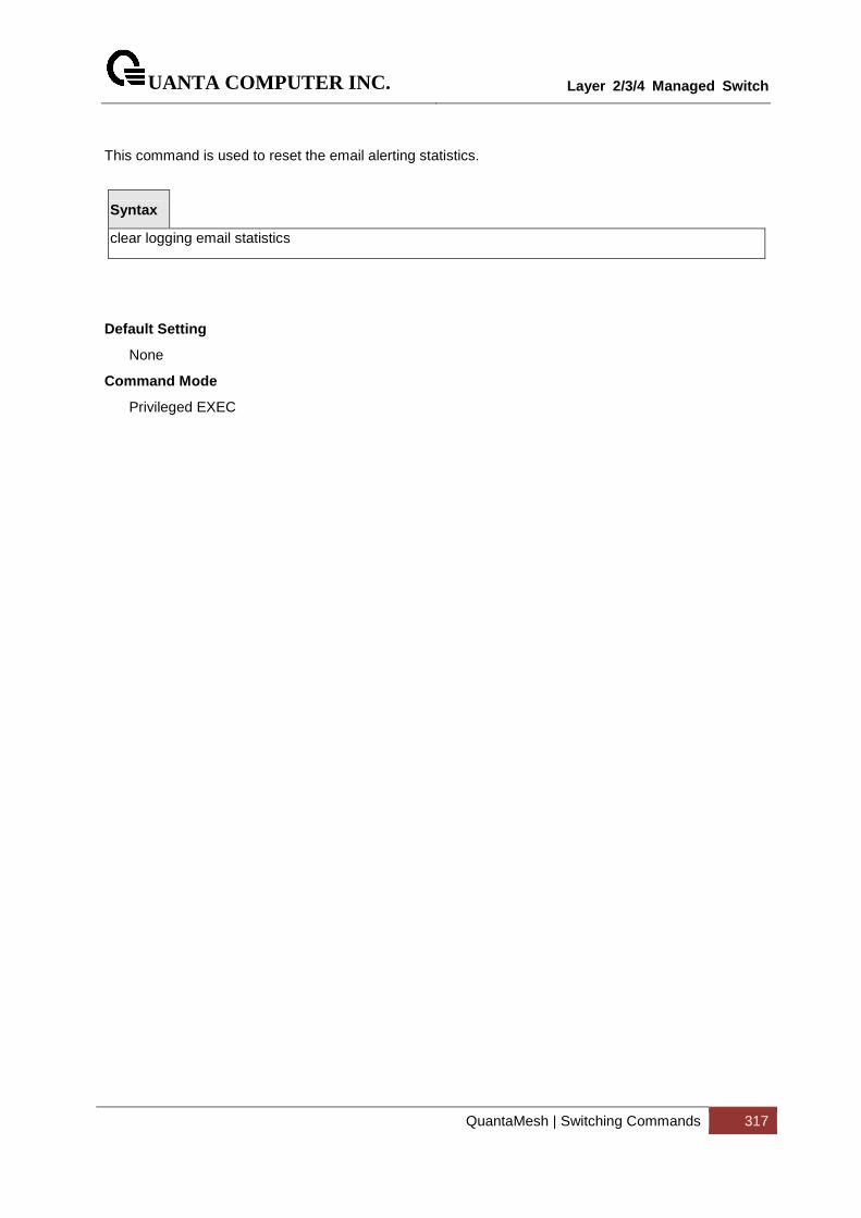
UANTA COMPUTER INC.
Layer 2/3/4 Managed Switch
QuantaMesh | Switching Commands 317
This command is used to reset the email alerting statistics.
Syntax
clear logging email statistics
Default Setting
None
Command Mode
Privileged EXEC
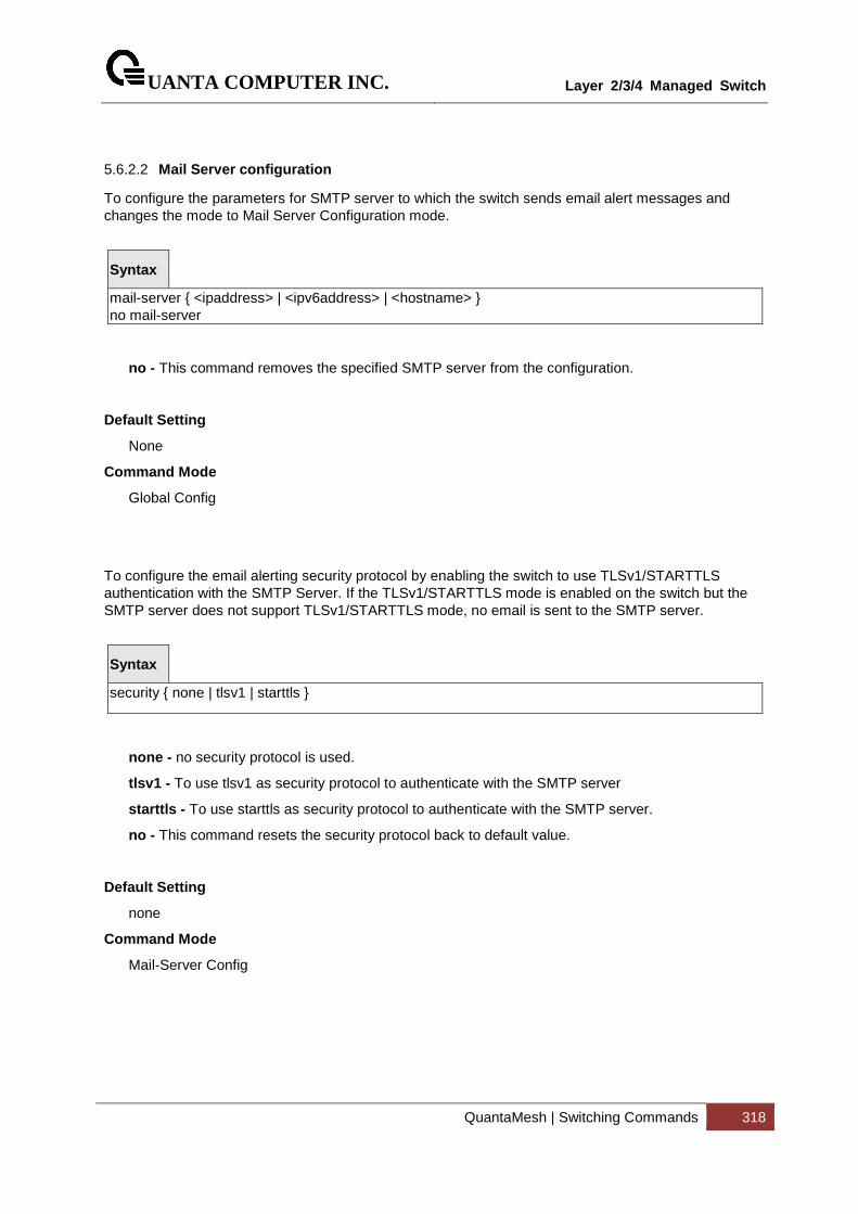
UANTA COMPUTER INC.
Layer 2/3/4 Managed Switch
QuantaMesh | Switching Commands 318
5.6.2.2 Mail Server configuration
To configure the parameters for SMTP server to which the switch sends email alert messages and changes the mode to Mail Server Configuration mode.
Syntax
mail-server { <ipaddress> | <ipv6address> | <hostname> } no mail-server
no - This command removes the specified SMTP server from the configuration.
Default Setting
None
Command Mode
Global Config
To configure the email alerting security protocol by enabling the switch to use TLSv1/STARTTLS authentication with the SMTP Server. If the TLSv1/STARTTLS mode is enabled on the switch but the SMTP server does not support TLSv1/STARTTLS mode, no email is sent to the SMTP server.
Syntax
security { none | tlsv1 | starttls }
none - no security protocol is used.
tlsv1 - To use tlsv1 as security protocol to authenticate with the SMTP server
starttls - To use starttls as security protocol to authenticate with the SMTP server.
no - This command resets the security protocol back to default value.
Default Setting
none
Command Mode
Mail-Server Config
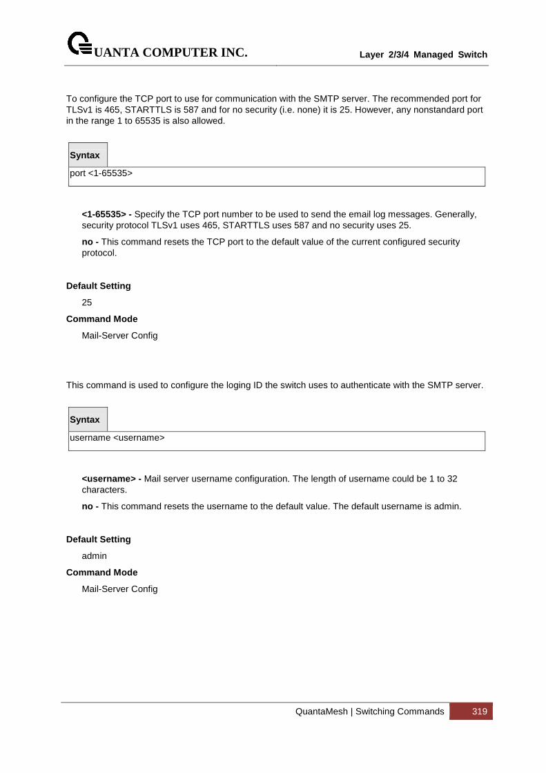
UANTA COMPUTER INC.
Layer 2/3/4 Managed Switch
QuantaMesh | Switching Commands 319
To configure the TCP port to use for communication with the SMTP server. The recommended port for TLSv1 is 465, STARTTLS is 587 and for no security (i.e. none) it is 25. However, any nonstandard port in the range 1 to 65535 is also allowed.
Syntax
port <1-65535>
<1-65535> - Specify the TCP port number to be used to send the email log messages. Generally, security protocol TLSv1 uses 465, STARTTLS uses 587 and no security uses 25.
no - This command resets the TCP port to the default value of the current configured security protocol.
Default Setting
25
Command Mode
Mail-Server Config
This command is used to configure the loging ID the switch uses to authenticate with the SMTP server.
Syntax
username <username>
<username> - Mail server username configuration. The length of username could be 1 to 32 characters.
no - This command resets the username to the default value. The default username is admin.
Default Setting
admin
Command Mode
Mail-Server Config
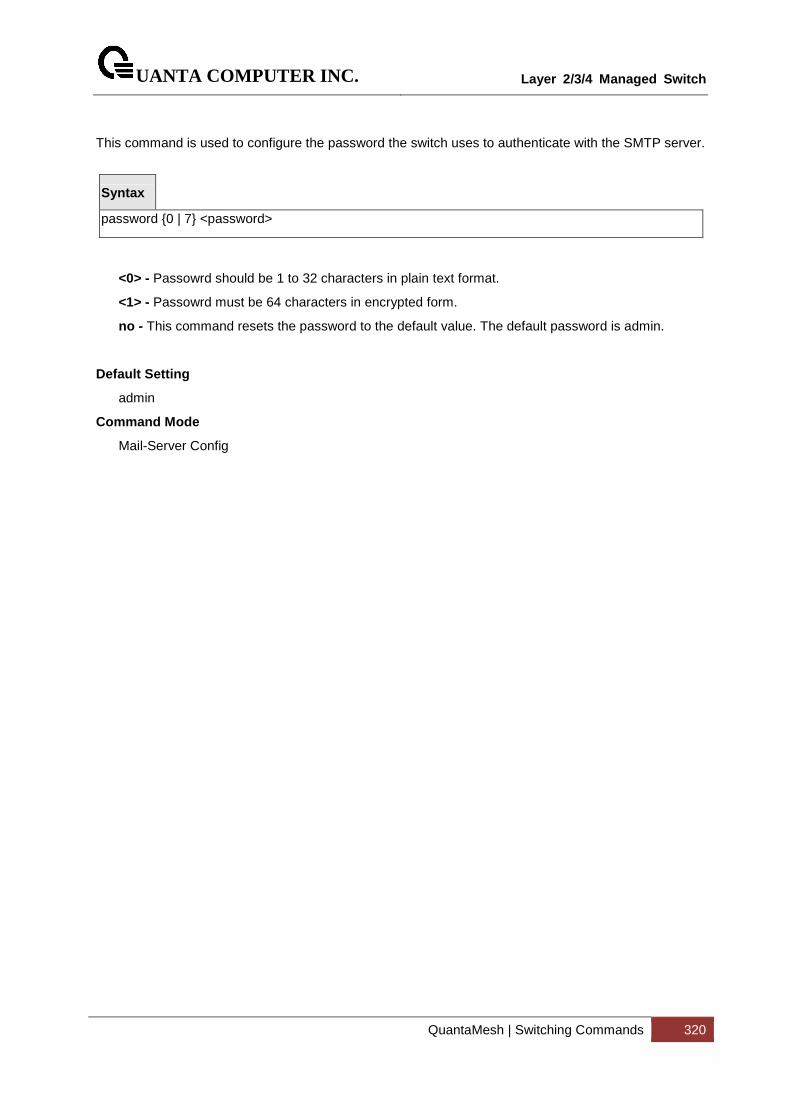
UANTA COMPUTER INC.
Layer 2/3/4 Managed Switch
QuantaMesh | Switching Commands 320
This command is used to configure the password the switch uses to authenticate with the SMTP server.
Syntax
password {0 | 7} <password>
<0> - Passowrd should be 1 to 32 characters in plain text format.
<1> - Passowrd must be 64 characters in encrypted form.
no - This command resets the password to the default value. The default password is admin.
Default Setting
admin
Command Mode
Mail-Server Config
UANTA COMPUTER INC.
Layer 2/3/4 Managed Switch
QuantaMesh | Switching Commands 321
5.7 Script Management Commands
5.7.1 script apply
This command applies the commands in the configuration script to the switch. The apply command backs up the running configuration and then starts applying the commands in the script file. Application of the commands stops at the first failure of a command.
Syntax
script apply <scriptname>
<scriptname> - The name of the script to be applied.
Default Setting
None
Command Mode
Privileged Exec
5.7.2 script delete
This command deletes a specified script or all the scripts presented in the switch.
Syntax
script delete {<scriptname> | all}
<scriptname> - The name of the script to be deleted.
all - Delete all scripts presented in the switch.
Default Setting
None
Command Mode
Privileged Exec
UANTA COMPUTER INC.
Layer 2/3/4 Managed Switch
QuantaMesh | Switching Commands 322
5.7.2.1 script list
This command lists all scripts present on the switch as well as the total number of files present.
Syntax
script list
Default Setting
None
Command Mode
Privileged Exec
Display Message
Configuration Script Name : The filename of the script file.
Size(Bytes) : The size of the script file.
5.7.3 script show
This command displays the content of a script file.
Syntax
script show <scriptname>
<scriptname> - Name of the script file.
Default Setting
None
Command Mode
Privileged Exec
UANTA COMPUTER INC.
Layer 2/3/4 Managed Switch
QuantaMesh | Switching Commands 323
5.7.4 script validate
This command displays the content of a script file.
Syntax
script validate <scriptname>
<scriptname> - Name of the script file.
Default Setting
None
Command Mode
Privileged Exec
UANTA COMPUTER INC.
Layer 2/3/4 Managed Switch
QuantaMesh | Switching Commands 324
5.8 User Account Management Commands
5.8.1 Show Commands
5.8.1.1 show users
This command displays the configured user names and their settings. This command is only available for users with readwrite privileges. The SNMPv3 fields will only be displayed if SNMP is available on the system.
Syntax
show users
Default Setting
None
Command Mode
Privileged Exec
Display Message
User Name: The name the user will use to login using the serial port, Telnet. A new user may be added to the switch by entering a name in a blank entry. The user name may
be up to eight characters, and is not case sensitive. Two users are included as the factory
default, admin, and guest.
User Access Mode: Shows whether the operator is able to change parameters on the switch (Read/Write) or is only able to view them (Read Only). As a factory default, admin has Read/Write access and guest has Read Only access. There can only be one Read/Write user and up to five Read Only users.
SNMPv3 AccessMode: This field displays the SNMPv3 Access Mode. If the value is set to Read- Write, the SNMPv3 user will be able to set and retrieve parameters on the system. If the value is set to ReadOnly, the SNMPv3 user will only be able to retrieve parameter information. The SNMPv3 access mode may be different from the CLI.
SNMPv3 Authentication: This field displays the authentication protocol to be used for the specified login user.
SNMPv3 Encryption: This field displays the encryption protocol to be used for the specified login user.
UANTA COMPUTER INC.
Layer 2/3/4 Managed Switch
QuantaMesh | Switching Commands 325
5.8.1.2 show users account information
The user can go to the CLI Privilege Exec to get all of user information, use the show users accounts Privilege command.
Syntax
show users accounts
Default Setting
None
Command Mode
Privileged Exec
Display Message
User Name: The local user account’s user name.
Privilege: The user’s privilege level. The range of privilege level is 1 to 15. Access mode for privilege level 15 is read/write, the others is read-only.
Password Aging: Indicates number of days, since the password was configured, until the password expires.
Password Expiration Date: The current password expiration date in date format.
Lockout: Indicates whether the user account is locked out (true or false).
5.8.1.3 show passwords configuration
Use this command to display the configured password management settings.
Syntax
show passwords configuration
Default Setting
None
Command Mode
Privileged Exec
Display Message
Minimum Password Length: Minimum number of characters required when changing passwords.
Password History: Number of passwords to store for reuse prevention.
Password Aging: Length in days that a password is valid.
UANTA COMPUTER INC.
Layer 2/3/4 Managed Switch
QuantaMesh | Switching Commands 326
Lockout Attempts: Number of failed password login attempts before lockout.
Password Strength Check: The user to configure passwords that comply with the strong password configuration.
Minimum Password Uppercase Letters: Minimum number of uppercase characters required when changing passwords.
Minimum Password Lowercase Letters: Minimum number of lowercase characters required when changing passwords.
Minimum Password Numeric Characters: Minimum number of numeric characters required when changing passwords.
Minimum Password Special Characters: Minimum number of special characters required when changing passwords.
Maximum Password Repeated Characters: Maximum number of characters cannot repeated when changing passwords.
Maximum Password Consecutive Characters: Maximum number of characters cannot consecutive when changing passwords.
Minimum Password Character Classes: Valid range for user passwords.
Password Exclude Keywords: The password to be configured should not contain the keyword mentioned in this field.
5.8.1.4 Show password result
Use this command to display the last password set result information.
Syntax
show passwords result
Default Setting
None
Command Mode
Privileged Exec
Display Message
Last User Whose Password Is Set: Shows the name of the user with the most recently set password.
Password Strength Check: Shows whether password strength checking is enabled.
Last Password Set Result: Shows whether the attempt to set a password was successful. If the attempt failed, the reason for the failure is include.

UANTA COMPUTER INC.
Layer 2/3/4 Managed Switch
QuantaMesh | Switching Commands 327
5.8.2 Configuration Commands
5.8.2.1 username
This command adds a new user (account) if space permits. The default privilege level is 1. The account <username> can be up to eight characters in length. The name may be comprised of alphanumeric characters as well as the dash (‘-’) and underscore (‘_’). The <username> is not case-sensitive. Six user names can be defined.
This command changes the password of an existing operator. User password should not be more than eight characters in length. If a user is authorized for authentication or encryption is enabled, the password must be eight alphanumeric characters in length. The username and password are not case-sensitive. When a password is changed, a prompt will ask for the operator’s former password. If none, press enter.
Syntax
username <username> {passwd <0|7> <password> | nopasswd | level <level>} no username <username>
<username> - is a new user name (Range: up to 8 characters).
<0|7> - 0 means the password is plain-text. 7 means the password is encrypted. When 7 is used, the password must be exactly 128 hexadeciaml characters in length. Maximum plain-text password length is 64 characters.
no - This command removes a user name created before.
nopassword - This command sets the password of an existing operator to blank. When a password is changed, a prompt will ask for the operator's former password. If none, press enter.
<level> - The user level. Level 0 can be assigned by a level 15 user to another user to suspend that user’s access. Range 0-15. Enter access level 1 for Read Access or 15 for Read/Write Access. If not specified where it is optional, the privilege level is 1.
The admin user account cannot be deleted.
The special characters allowed in the password include ! # $ % & ‘ ( ) * + , - / ; < = > @ [ \ ] ^ _ ` { | } ~
Default Setting
No password
Command Mode
Global Config
i
UANTA COMPUTER INC.
Layer 2/3/4 Managed Switch
QuantaMesh | Switching Commands 328
5.8.2.2 Unlock a locked user account
The user can go to the CLI Global Configuration Mode to unlock a locked user account, use the username <name> unlock global configuration command.
Syntax
username <username> unlock
<name> - is a user name (Range: up to 8 characters).
Default Setting
None
Command Mode
Global Config
5.8.2.3 username snmpv3 authentication
This command specifies the authentication protocol to be used for the specified login user. The valid authentication protocols are none , md5 or sha . If md5 or sha are specified, the user login password will be used as the snmpv3 authentication password. The <username> is the login user name for which the specified authentication protocol will be used.
Syntax
username snmpv3 authentication <username> {none | md5 | sha} no username snmpv3 authentication <username>
<username> - is the login user name.
md5 - md5 authentication method.
sha - sha authentication method.
none - no use authentication method.
no - This command sets the authentication protocol to be used for the specified login user to none . The <username> is the login user name for which the specified authentication protocol will be used.
Default Setting
No authentication
Command Mode
Global Config
UANTA COMPUTER INC.
Layer 2/3/4 Managed Switch
QuantaMesh | Switching Commands 329
5.8.2.4 username snmpv3 encryption
This command specifies the encryption protocol and key to be used for the specified login user. The valid encryption protocols are none or des . The des protocol requires a key , which can be specified on the command line. The key may be up to 16 characters. If the des protocol is specified but a key is not provided, the user will be prompted to enter the key. If none is specified, a key must not be provided. The <username> is the login user name for which the specified encryption protocol will be used.
Syntax
username snmpv3 encryption <username> {none | des [<key>]} no username snmpv3 encryption <username>
<username> - is the login user name.
des - des encryption protocol.
none - no encryption protocol.
<key> - A key 128 alphanumeric characters in length.
no - This command sets the encryption protocol to none . The <username> is the login user name for which the specified encryption protocol will be used.
Default Setting
No encryption
Command Mode
Global Config
UANTA COMPUTER INC.
Layer 2/3/4 Managed Switch
QuantaMesh | Switching Commands 330
5.8.2.5 Set the password aging
If the passwords aging is set, the local user will be prompted to change it before logging in again when the local user’s password expires.
The user can go to the CLI Global Configuration Mode to set the password aging, use the passwords aging <1-365> Global configuration command. Use the no passwords aging return to default value 0.
Syntax
passwords aging <1-365> no passwords aging
<1-365> - Number of days until password expires.
Default Setting
0, no aging
Command Mode
Global Config
5.8.2.6 Set the password history
Use this command to set the number of previous passwords that shall be stored for each user account. If password history is set, the local user will not be able to reuse any password stored in password history when the local user changes his or her password.
The user can go to the CLI Global Configuration Mode to set the password history, use the passwords history <0-10> Global configuration command. Use the no passwords history return to default value 0.
Syntax
passwords history <0-10> no passwords history
<0-10> - Number of passwords to be used in password history check.
Default Setting
0
Command Mode
Global Config
UANTA COMPUTER INC.
Layer 2/3/4 Managed Switch
QuantaMesh | Switching Commands 331
5.8.2.7 Set the password lock-out count
Use this command to strengthen the security of the switch by locking user accounts that have failed login due to wrong passwords. When a lockout count is configured, a user that is logged in must enter the correct password within that count. Otherwise the user will be locked out from further switch access. Only a user with read/write access can re-activate a locked user account. The user can go to the CLI Global Configuration Mode to set the password lock-out count, use the passwords lock-out <1-5> Global configuration command. Use the no passwords lock-out to return to default value 0.
Syntax
passwords lock-out <1-5> no passwords lock-out
<1-5> - the number of password failures before account lock.
Default Setting
0
Command Mode
Global Config
5.8.2.8 Set the minimum password length
The user can go to the CLI Global Configuration Mode to set the minimum password length, use the passwords min-length <8-64> Global configuration command. Use the no passwords min-length return to default value 8.
Syntax
passwords min-length <8-64> no passwords min-length
Default Setting
8
Command Mode
Global Config

UANTA COMPUTER INC.
Layer 2/3/4 Managed Switch
QuantaMesh | Switching Commands 332
5.8.2.9 Set the password strength policy enforcement.
The user can go to the CLI Global Configuration Mode to set the password strength policy enforcement, use the passwords strength-check Global configuration command. Use the no passwords strength-check return to default disable.
Syntax
passwords strength-check no passwords strength-check
Default Setting
Disable
Command Mode
Global Config
5.8.2.10 Set the password strength maximum.
The user can go to the CLI Global Configuration Mode to set the password strength, use the passwords strength maximum {consecutive-characters | repeated} [<0-15>] Global configuration command. Use the no passwords strength maximum {consecutive-characters | repeated} return to default value 0.
Syntax
passwords strength maximum {consecutive-characters | repeated} [<0-15>] no passwords strength maximum {consecutive-characters | repeated}
Default Setting
0
Command Mode
Global Config
UANTA COMPUTER INC.
Layer 2/3/4 Managed Switch
QuantaMesh | Switching Commands 333
5.8.2.11 Set the password strength minimum.
The user can go to the CLI Global Configuration Mode to set the password strength, use the passwords strength minimum {character-classes | lowercase-letters | numeric-characters | special-characters | uppercase-letters} [<0-15>] Global configuration command. Use the no passwords strength minimum {character-classes | lowercase-letters | numeric-characters | special-characters | uppercase-letters} return to default value 2.
Syntax
passwords strength minimum {character-classes | lowercase-letters | numeric-characters | special-characters | uppercase-letters} [<0-15>] no passwords strength minimum {character-classes | lowercase-letters | numeric-characters | special-characters | uppercase-letters}
Default Setting
2
Command Mode
Global Config
5.8.2.12 Set the password strength exclude-keyword.
The user can go to the CLI Global Configuration Mode to set the password strength, use the passwords strength exclude-keyword <keyword> Global configuration command. Use the no passwords strength exclude-keyword <keyword> return to default none.
Syntax
passwords strength exclude-keyword <keyword> no passwords strength exclude-keyword <keyword>
Default Setting
None
Command Mode
Global Config
UANTA COMPUTER INC.
Layer 2/3/4 Managed Switch
QuantaMesh | Switching Commands 334
5.9 Security Commands
5.9.1 Show Commands
5.9.1.1 show users authentication
This command displays all users and all authentication login information. It also displays the authentication login list assigned to the default user.
Syntax
show users authentication
Default Setting
None
Command Mode
Privileged Exec
Display Message
User: This field lists every user that has an authentication login list assigned.
System Login: This field displays the authentication login list assigned to the user for system login.
802.1x: This field displays the authentication login list assigned to the user for 802.1x port security.
UANTA COMPUTER INC.
Layer 2/3/4 Managed Switch
QuantaMesh | Switching Commands 335
5.9.1.2 show authentication methods
This command displays the ordered authentication methods for all authentication login lists.
Syntax
show authentication methods
Default Setting
None
Command Mode
Privileged Exec
Display Message
Login Authentication Method Lists: This displays the authentication login listname.
Enable Authentication Method Lists: This displays the authentication enable listname.
5.9.1.3 show authentication users
This command displays information about the users assigned to the specified authentication login list. If the login is assigned to non-configured users, the user “default” will appear in the user column.
Syntax
show authentication users <listname>
<listname> - the authentication login listname.
Default Setting
None
Command Mode
Privileged Exec
Display Message
User Name: This field displays the user assigned to the specified authentication login list.
Component: This field displays the component (User or 802.1x) for which the authentication login list is assigned.
UANTA COMPUTER INC.
Layer 2/3/4 Managed Switch
QuantaMesh | Switching Commands 336
5.9.1.4 show accounting
Use this command to display ordered methods for accounting lists.
Syntax
show accounting
Default Setting
None
Command Mode
Privileged Exec
Display Message
Number of Accounting Notifications sent at beginnin g of an EXEC session: 0
Errors when sending Accounting Notifications beginn ing of an EXEC session: 0
Number of Accounting Notifications at end of an EXE C session: 0
Errors when sending Accounting Notifications at end of an EXEC session: 0
Number of Accounting Notifications sent at beginnin g of a command execution: 0
Errors when sending Accounting Notifications at beg inning of a command execution: 0
Number of Accounting Notifications sent at end of a command execution: 0
Errors when sending Accounting Notifications at end of a command execution: 0
5.9.1.5 show accounting methods
Use this command to display configured accounting method lists.
Syntax
show accounting methods
Default Setting
None
Command Mode
Privileged Exec
UANTA COMPUTER INC.
Layer 2/3/4 Managed Switch
QuantaMesh | Switching Commands 337
5.9.1.6 show dot1x
This command is used to show the status of the dot1x Administrative mode.
Syntax
show dot1x
Default Setting
None
Command Mode
Privileged Exec
Display Message
Administrative mode: Indicates whether authentication control on the switch is enabled or disabled.
VLAN Assignment Mode : Indicates whether assignment of an authorized port to a RADIUS assigned VLAN is allowed (enabled) or not (disabled).
Dynamic VLAN Creation Mode : Indicates whether the switch can dynamically create a RADIUS-assigned VLAN if it does not currently exist on the switch.
Monitor Mode : Indicates whether the Dot1x Monitor mode on the switch is enabled or disabled.
UANTA COMPUTER INC.
Layer 2/3/4 Managed Switch
QuantaMesh | Switching Commands 338
5.9.1.7 show dot1x authentication-history
This command is used to display the Dot1x Authentication History Log for the specified port or all ports.
Syntax
show dot1x authentication-history <all | <slot/port>>
Default Setting
None
Command Mode
Privileged Exec
Display Message
Time Stamp: The exact time at which the event occurs.
Interface : Physical Port on which the event occurs.
MAC-Address : The supplicant/client MAC address.
VLANID : The VLAN assigned to the client/port on authentication.
Auth Status : The authentication status.
UANTA COMPUTER INC.
Layer 2/3/4 Managed Switch
QuantaMesh | Switching Commands 339
5.9.1.8 show dot1x client
This command is used to display client information.
Syntax
show dot1x clients [<slot/port>]
<slot/port> - is the desired interface number.
no parameter - All interfaces.
Default Setting
None
Command Mode
Privileged Exec
Display Message
Clients Authenticated using Monitor Mode: Indicates the number of the Dot1x clients authenticated using Monitor mode.
Clients Authenticated using Dot1x : Indicates the number of Dot1x clients authenticated using 802.1x authentication process.
Logical Interface : The logical port number associated with a client.
Interface : The physical port to which the supplicant is associated.
User Name : The user name used by the client to authenticate to the server.
Supp MAC Address : The supplicant device MAC address.
Session Time : The time since the supplicant is logged on.
VLAN Id : The VLAN assigned to the port.
VLAN Assigned : The reason the VLAN identified in the VLAN ID field has been assigned to the port. Possible values are RADIUS, Unauthenticated VLAN, Monitor Mode, or Default. When the VLAN Assigned reason is Default, it means that the VLAN was assigned to the port because the P-VID of the port was that VLAN ID.
Session Timeout : This value indicates the time for which the given session is valid. The time period in seconds is returned by the RADIUS server on authentication of the port. This value is valid for the port only when the port-control mode is not MAC-based.
Session Termination Action : This value indicates the action to be taken once the session timeout expires. Possible values are Default and Radius-Request. If the value is Default, the session is terminated and client details are cleared. If the value is Radius-Request, then a reauthentication of the client is performed.
UANTA COMPUTER INC.
Layer 2/3/4 Managed Switch
QuantaMesh | Switching Commands 340
5.9.1.9 show dot1x detail
This command is used to show a summary of the global dot1x configuration and the detailed dot1x configuration for a specified port.
Syntax
show dot1x detail <slot/port>
<slot/port> - is the desired interface number.
Default Setting
None
Command Mode
Privileged Exec
Display Message
Port: The interface whose configuration is displayed
Protocol Version: The protocol version associated with this port. The only possible value is 1, corresponding to the first version of the dot1x specification.
PAE Capabilities: The port access entity (PAE) functionality of this port. Possible values are Authenticator or Supplicant.
Control Mode - The configured control mode for this port. Possible values are force-unauthorized, force-authorized, auto and mac-based.
Authenticator PAE State: Current state of the authenticator PAE state machine. Possible values are Initialize, Disconnected, Connecting, Authenticating, Authenticated, Aborting, Held, ForceAuthorized, and ForceUnauthorized.
Backend Authentication State: Current state of the backend authentication state machine. Possible values are Request, Response, Success, Fail, Timeout, Idle, and Initialize.
Quiet Period: The timer used by the authenticator state machine on this port to define periods of time in which it will not attempt to acquire a supplicant. The value is expressed in seconds and will be in the range of 0 to 65535.
Transmit Period: The timer used by the authenticator state machine on the specified port to determine when to send an EAPOL EAP Request/Identity frame to the supplicant. The value is expressed in seconds and will be in the range of 1 to 65535.
Guest VLAN ID: The guest VLAN identifier configured on the interface.
Guest VLAN Period: The timer used by authenticator state machine on this port.
Supplicant Timeout: The timer used by the authenticator state machine on this port to timeout the supplicant. The value is expressed in seconds and will be in the range of 1 to 65535.
Server Timeout: The timer used by the authenticator on this port to timeout the authentication server. The value is expressed in seconds and will be in the range of 1 to 65535.
Maximum Requests: The maximum number of times the authenticator state machine on this port will retransmit an EAPOL EAP Request/Identity before timing out the supplicant. The value will be in the range of 1 to 10.
UANTA COMPUTER INC.
Layer 2/3/4 Managed Switch
QuantaMesh | Switching Commands 341
Vlan ID : The VLAN assigned to the port by the radius server.
VLAN Assigned Reason : The reason the VLAN identified in the VLAN-assigned field has been assigned to the port. Possible values are RADIUS, Unauthenticated VLAN, Guest VLAN, default, and Not Assigned. When the VLAN Assigned Reason is ‘Not Assigned’t, it means that the port has not been assigned to any VLAN by dot1x.
Reauthentication Period: The timer used by the authenticator state machine on this port to determine when reauthentication of the supplicant takes place. The value is expressed in seconds and will be in the range of 1 to 65535.
Reauthentication Enabled: Indicates if reauthentication is enabled on this port. Possible values are True or False.
Key Transmission Enabled: Indicates if the key is transmitted to the supplicant for the specified port. Possible values are True or False.
Control Direction: Indicates the control direction for the specified port or ports. Possible values are both or in.
Maximum Users - The maximum number of clients that can get authenticated on the port in the MAC-based dot1x authentication mode.
Unauthenticated VLAN ID - Indicates the unauthenticated VLAN configured for this port.
Session Timeout - Indicates the time for which the given session is valid. The time period in seconds is returned by the RADIUS server on authentication of the port.
Session Termination Action - This value indicates the action to be taken once the session timeout expires. Possible values are Default, Radius-Request. If the value is Default, the session is terminated the port goes into unauthorized state. If the value is Radius-Request, then a reauthentication of the client authenticated on the port is performed.

UANTA COMPUTER INC.
Layer 2/3/4 Managed Switch
QuantaMesh | Switching Commands 342
5.9.1.10 show dot1x statistics
This command is used to show a summary of the global dot1x configuration and the dot1x statistics for a specified port.
Syntax
show dot1x statistics <slot/port>
<slot/port> - is the desired interface number.
Default Setting
None
Command Mode
Privileged Exec
Display Message
Port: The interface whose statistics are displayed.
PAE Capabilities: The port access entity (PAE) functionality of this port. Possible values are Authenticator or Supplicant.
EAPOL Frames Received: The number of valid EAPOL frames of any type that have been received by this authenticator.
EAPOL Frames Transmitted: The number of EAPOL frames of any type that have been transmitted by this authenticator.
EAPOL Start Frames Received: The number of EAPOL start frames that have been received by this authenticator.
EAPOL Logoff Frames Received: The number of EAPOL logoff frames that have been received by this authenticator.
Last EAPOL Frame Version: The protocol version number carried in the most recently received EAPOL frame.
Last EAPOL Frame Source: The source MAC address carried in the most recently received EAPOL frame.
EAP Response/Id Frames Received: The number of EAP response/identity frames that have been received by this authenticator.
EAP Response Frames Received: The number of valid EAP response frames (other than resp/id frames) that have been received by this authenticator.
EAP Request/Id Frames Transmitted: The number of EAP request/identity frames that have been transmitted by this authenticator.
EAP Request Frames Transmitted: The number of EAP request frames (other than request/identity frames) that have been transmitted by this authenticator.
Invalid EAPOL Frames Received: The number of EAPOL frames that have been received by this authenticator in which the frame type is not recognized.
UANTA COMPUTER INC.
Layer 2/3/4 Managed Switch
QuantaMesh | Switching Commands 343
EAP Length Error Frames Received: The number of EAPOL frames that have been received by this authenticator in which the frame type is not recognized.
5.9.1.11 show dot1x summary
This command is used to show a summary of the global dot1x configuration and summary information of the dot1x configuration for a specified port or all ports.
Syntax
show dot1x summary [<slot/port>]
<slot/port> - is the desired interface number.
no parameter - All interfaces.
Default Setting
None
Command Mode
Privileged Exec
Display Message
Interface: The interface whose configuration is displayed.
Control Mode: The configured control mode for this port. Possible values are force-unauthorized / force-authorized / auto / mac-based.
Operating Control Mode: The control mode under which this port is operating. Possible values are authorized / unauthorized.
Reauthentication Enabled: Indicates whether re-authentication is enabled on this port.
Port Status: Indicates if the key is transmitted to the supplicant for the specified port.
UANTA COMPUTER INC.
Layer 2/3/4 Managed Switch
QuantaMesh | Switching Commands 344
5.9.1.12 show dot1x users
This command displays 802.1x port security user information for locally configured users.
Syntax
show dot1x users <slot/port>
<slot/port> - is the desired interface number.
Default Setting
None
Command Mode
Privileged Exec
Display Message
User: Users configured locally to have access to the specified port.
UANTA COMPUTER INC.
Layer 2/3/4 Managed Switch
QuantaMesh | Switching Commands 345
5.9.1.13 show radius
This command is used to display the various RADIUS configuration items for the switch.
Syntax
show radius
Default Setting
None
Command Mode
Privileged Exec
Display Message
Number of Configured Authentication Servers: The number of RADIUS Authentication servers that have been configured.
Number of Configured Accounting Servers: The number of RADIUS Accounting servers that have been configured.
Number of Named Authentication Server Groups: The number of configured named RADIUS Authentication server groups.
Number of Named Accounting Server Groups: The number of configured named RADIUS Accounting server groups.
Number of Retransmits: The configured value of the maximum number of times a request packet is retransmitted.
Timeout Duration: The configured timeout value, in seconds, for request re-transmissions.
Dead Time: The configured timeout value, in mins, for the time duration after a RADIUS sever is found non-responsive or dead.
RADIUS Accounting Mode: A global parameter to indicate whether the accounting mode for all the servers is enabled or not.
RADIUS Attribute 4 Mode: A global parameter to indicate whether the NAS-IP-Address attribute has been enabled to use in RADIUS requests.
RADIUS Attribute 4 Value: A global parameter that specifies the IP address to be used in the NAS-IP-Address attribute to be used in RADIUS requests.
RADIUS Attribute 95 Mode: A global parameter to indicate whether the NAS-IPv6-Address attribute has been enabled to use in RADIUS requests.
RADIUS Attribute 95 Value: A global parameter that specifies the IPv6 address to be used in the NAS-IP-Address attribute to be used in RADIUS requests.
UANTA COMPUTER INC.
Layer 2/3/4 Managed Switch
QuantaMesh | Switching Commands 346
5.9.1.14 show radius accounting
This command is used to display the configured RADIUS accounting mode, accounting server, and the statistics for the configured accounting server.
Syntax
show radius accounting [{<ipaddr | ipv6addr | hostname> | name <servername> | statistics {<ipaddr| ipv6addr | hostname> | name <servername>}}]
<ipaddr | ipv6addr | hostname> - is an IPv4/v6 Address or hostname.
Default Setting
None
Command Mode
Privileged Exec
Display Message
If you do not specify any parameters, then only the accounting mode and the RADIUS accounting server details are displayed.
RADIUS Accounting Mode: Enabled or disabled
Host Address: The configured IP address of the RADIUS accounting server
Port: The port in use by the RADIUS accounting server
Secret Configured: Yes or No
If the optional token ' ipaddr| ipv6addr| hostname ' or name <servername> is included.
RADIUS Accounting Server IP Address: IP Address of the configured RADIUS accounting server.
RADIUS Accounting Server Name: The name of the configured RADIUS accounting server.
RADIUS Accounting Mode: Enabled or disabled
Port: The port in use by the RADIUS accounting server.
Secret Configured: Yes or No Boolean value indicating whether this server is configured with a secret.
If the optional token 'statistics <ipaddr| ipv6addr | hostname>' is included, the statistics for the configured RADIUS accounting server are displayed. The IP address parameter must match that of a previously configured RADIUS accounting server. The following information regarding the statistics of the RADIUS accounting server is displayed.
RADIUS Accounting Server Host Address: IP Address of the configured RADIUS accounting server
UANTA COMPUTER INC.
Layer 2/3/4 Managed Switch
QuantaMesh | Switching Commands 347
Round Trip Time: The time interval in centiseconds, between the most recent Accounting- Response and the Accounting-Request that matched it from the RADIUS accounting server.
Requests: The number of RADIUS Accounting-Request packets sent to this accounting server. This number does not include retransmissions.
Retransmission: The number of RADIUS Accounting-Request packets retransmitted to this RADIUS accounting server.
Responses: The number of RADIUS packets received on the accounting port from this server.
Malformed Responses: The number of malformed RADIUS Accounting-Response packets received from this server. Malformed packets include packets with an invalid length. Bad authenticators and unknown types are not included as malformed accounting responses.
Bad Authenticators: The number of RADIUS Accounting-Response packets containing invalid authenticators received from this accounting server.
Pending Requests: The number of RADIUS Accounting-Request packets sent to this server that have not yet timed out or received a response.
Timeouts: The number of accounting timeouts to this server.
Unknown Types: The number of RADIUS packets of unknown types, which were received from this server on the accounting port.
Packets Dropped: The number of RADIUS packets received from this server on the accounting port and dropped for some other reason.
UANTA COMPUTER INC.
Layer 2/3/4 Managed Switch
QuantaMesh | Switching Commands 348
5.9.1.15 show radius servers
This command is used to display items of the configured RADIUS servers.
Syntax
show radius servers [{<ipaddr | ipv6addr | hostname> | name <servername>}]
Default Setting
None
Command Mode
Privileged Exec
Display Message
RADIUS Server Name: The Name of the authenticating server.
RADIUS Server IP Address: The IP address or host name of the authenticating server.
Current Server IP Address: The ‘*’ symbol preceeding the server host address specifies that the server is currently active.
Number of Retransmits: The configured value of the maximum number of times a request packet is retransmitted.
Timeout Duration: The configured timeout value, in seconds, for request re-transmissions.
Dead Time: The configured timeout value, in mins, for the time duration after a RADIUS sever is found non-responsive or dead.RADIUS Accounting Mode: A global parameter to indicate whether the accounting mode for all the servers is enabled or not.
RADIUS Attribute 4 Mode: A global parameter to indicate whether the NAS-IP-Address attribute has been enabled to use in RADIUS requests.
RADIUS Attribute 4 Value: A global parameter that specifies the IP address to be used in the NAS-IP-Address attribute to be used in RADIUS requests.
RADIUS Attribute 95 Mode: A global parameter to indicate whether the NAS-IPv6-Address attribute has been enabled to use in RADIUS requests.
RADIUS Attribute 95 Value: A global parameter that specifies the IPv6 address to be used in the NAS-IP-Address attribute to be used in RADIUS requests.
Port: The port in use by this server
Type: Primary or secondary
Secret Configured: Yes / No
Message Authenticator: The message authenticator attribute configured for the radius server.
UANTA COMPUTER INC.
Layer 2/3/4 Managed Switch
QuantaMesh | Switching Commands 349
5.9.1.16 show radius statistics
This command is used to display the statistics for RADIUS or configured server. To show the configured RADIUS server statistic, the IP Address specified must match that of a previously configured RADIUS server. On execution, the following fields are displayed.
Syntax
show radius statistics {<ipaddr|ipv6addr|hostname> | name <servername> }
<ipaddr|ipv6addr|hostname> - is an IPv4/v6 Address or a hostname.
Default Setting
None
Command Mode
Privileged Exec
Display Message
If you do not specify the IP address, then only Invalid Server Address field is displayed. Otherwise other listed fields are displayed.
RADIUS Server Name: The Name of the authenticating server.
Server Host Address - IP address or hostname of the Server.
Round Trip Time - The time interval, in hundredths of a second, between the most recent Access-Reply, Access - Challenge and the Access-Request that matched it from the RADIUS authentication server.
Access Requests - The number of RADIUS Access-Request packets sent to this server. This number does not include retransmissions.
Access Retransmission - The number of RADIUS Access-Request packets retransmitted to this RADIUS authentication server.
Access Accepts - The number of RADIUS Access-Accept packets, including both valid and invalid packets, which were received from this server.
Access Rejects - The number of RADIUS Access-Reject packets, including both valid and invalid packets, which were received from this server.
Access Challenges - The number of RADIUS Access-Challenge packets, including both valid and invalid packets, which were received from this server.
Malformed Access Responses - The number of malformed RADIUS Access-Response packets received from this server. Malformed packets include packets with an invalid length. Bad authenticators or signature attributes or unknown types are not included as malformed access responses.
Bad Authenticators - The number of RADIUS Access-Response packets containing invalid authenticators or signature attributes received from this server.
UANTA COMPUTER INC.
Layer 2/3/4 Managed Switch
QuantaMesh | Switching Commands 350
Pending Requests - The number of RADIUS Access-Request packets destined for this server that have not yet timed out or received a response.
Timeouts - The number of authentication timeouts to this server.
Unknown Types - The number of RADIUS packets of unknown types, which were received from this server on the authentication port.
Packets Dropped - The number of RADIUS packets received from this server on the authentication port and dropped for some other reason.
5.9.1.17 show radius source-interface
This command is used to display the configured global source interface details used for a RADIUS client. The IP address of the selected interface is used as source IP for all communications with the server.
Syntax
show radius source-interface
Default Setting
None
Command Mode
Privileged Exec
Display Message
RADIUS Client Source Interface: The interface to use as the source interface for RADIUS client.
RADIUS Client Source IPv4 Address: The IP address of the interface configured as the RADIUS client source interface.
5.9.1.18 show tacacs
This command display configured information and statistics of a TACACS+ server.
Syntax
show tacacs [<ipaddr|ipv6Addr|hostname>]
<ipaddr|ipv6Addr|hostname> - is an IPv4/v6 Address or a hostname.
UANTA COMPUTER INC.
Layer 2/3/4 Managed Switch
QuantaMesh | Switching Commands 351
Default Setting
None
Command Mode
Privileged Exec
Display Message
Host address - The IP address or hostname of the configured TACACS+ server.
Port: Shows the configured TACACS+ server port number.
Timeout: Shows the timeout in seconds for establishing a TCP connection.
Priority: Shows the preference order in which TACACS+ servers are contacted. If a server connection fails, the next highest priority server is contacted.
5.9.1.19 show tacacs source-interface
This command is used to display the configured global source interface details used for a RADIUS client. The IP address of the selected interface is used as source IP for all communications with the server.
Syntax
show tacacs source-interface
Default Setting
None
Command Mode
Privileged Exec
Display Message
TACACS Client Source Interface: The interface to use as the source interface for TACACS client.
TACACS Client Source IPv4 Address: The IP address of the interface configured as the TACACS client source interface.
UANTA COMPUTER INC.
Layer 2/3/4 Managed Switch
QuantaMesh | Switching Commands 352
5.9.1.20 show port-security
This command shows the port-security settings for the entire system.
Syntax
show port-security
Default Setting
None
Command Mode
Privileged Exec
Display Message
Port Security Administration Mode: Port lock mode for the entire system.
UANTA COMPUTER INC.
Layer 2/3/4 Managed Switch
QuantaMesh | Switching Commands 353
5.9.1.21 show port-security interface
This command shows the port-security settings for a particular interface or all interfaces.
Syntax
show port-security { <slot/port> | all | port-channel < portchannel-id >}
<slot/port> - is the interface number.
<portchannel-id> - is the desired port-channel ID. The port-channel ID is range from 1 to 64.
Default Setting
None
Command Mode
Privileged Exec
Display Message
Intf Interface Number.
Admin Mode Port Locking mode for the Interface.
Dynamic Limit Maximum dynamically allocated MAC Addresses.
Static Limit Maximum statically allocated MAC Addresses.
Violation Trap Mode Whether violation traps are enabled.
Sticky Mode Whether sticky mode is enabled.
Violation Shutdown Whether violation shutdowns are enabled.
UANTA COMPUTER INC.
Layer 2/3/4 Managed Switch
QuantaMesh | Switching Commands 354
5.9.1.22 show port-security dynamic
This command shows the dynamically locked MAC addresses for port.
Syntax
show port-security dynamic <slot/port>
<slot/port> - is the interface number.
Default Setting
None
Command Mode
Privileged Exec
Display Message
MAC address Dynamically locked MAC address.
5.9.1.23 show port-security static
This command shows the statically locked MAC addresses for port.
Syntax
show port-security static <slot/port>
<slot/port> - is the interface number.
Default Setting
None
Command Mode
Privileged Exec
Display Message
Number of static MAC addresses configured: Number of static MAC addresses configured.
Statically configured MAC Address: Statically locked MAC address.
VLAN ID: Vlan ID of the Statically configured MAC Address.
Sticky: Sticky mode of the Statically configured MAC Address.
UANTA COMPUTER INC.
Layer 2/3/4 Managed Switch
QuantaMesh | Switching Commands 355
5.9.1.24 show port-security violation
This command displays the source MAC address of the last packet that was discarded on a locked port.
Syntax
show port-security violation { <slot/port> | port-channel <portchannel-id>}
<slot/port> - is the interface number.
<portchannel-id> - is the desired port-channel ID. The port-channel ID is range from 1 to 64.
Default Setting
None
Command Mode
Privileged Exec
Display Message
MAC address MAC address of discarded packet on locked ports.
UANTA COMPUTER INC.
Layer 2/3/4 Managed Switch
QuantaMesh | Switching Commands 356
5.9.2 Configuration Commands
5.9.2.1 aaa authentication login <method>
This command creates an authentication login list. The <listname> is up to 12 alphanumeric characters and is not case sensitive. Up to 5 authentication login lists can be configured on the switch.
If the authentication login list does not exist, a new authentication login list is first created and then the authentication methods are set in the authentication login list. The possible method values are enable, line, local, radius, noneand tacacs.
The value of local indicates that the user’s locally stored ID and password are used for authentication. The value of radius indicates that the user’s ID and password will be authenticated using the RADIUS server. The value of none indicates that the user is never authenticated. The value of tacacs indicates that the user’s ID and password will be authenticated using the TACACS.
To authenticate a user, the authentication methods in the user’s login will be attempted in order until an authentication attempt succeeds or fails.
The default login list included with the default configuration cannot be changed.
Syntax
aaa authentication login <listname> { enable | line | local | none | radius | tacacs} no aaa authentication login <listname>
<listname> - creates an authentication login list (Range: up to 12 characters).
no - This command deletes the specified authentication login list. The attempt to delete will fail if any of the following conditions are true:
1. The login list name is invalid or does not match an existing authentication login list
2. The specified authentication login list is assigned to any user or to the nonconfigured user for any component.
3. The login list is the default login list included with the default configuration and was not created using ‘config authentication login create’. The default login list cannot be deleted.
Default Setting
None
Command Mode
Global Config
i
UANTA COMPUTER INC.
Layer 2/3/4 Managed Switch
QuantaMesh | Switching Commands 357
5.9.2.2 aaa accounting
Use this command in Global config mode to create an accounting method list for either user EXEC sessions or for user-executed commands. This list is identified by default or a user-specified list_name . Accounting records, when enabled for a line-mode, can be sent at both the beginning and at the end (start-stop ) or only at the end (stop-only ). If none is specified, then accounting is disabled for the specified list. If tacacs is specified as the accounting method, accounting records are notified to a TACACS+ server. If radius is the specified accounting method, accounting records are notified to a RADIUS server.
- A maximum of five Accounting Method lists can be created for each exec and commands type.
- The same list-name can be used for both exec and commands accounting type.
- AAA Accounting for commands with RADIUS as the accounting method is not supported.
Syntax
aaa accounting {exec | commands} {default | <list_name>} { start-stop | stop-only | none} method1 [method2...] no aaa accounting {exec | commands} {default | <list_name>}
exec - Provide accounting for a user EXEC terminal sessions.
commands - Provide accounting for all user executed commands.
default - The default list of methods for accounting services.
<listname> - Character string used to name the list of accounting methods.
start-stop - Send a start accounting notice at the beginning of a process and a stop accounting notice at the end of a process.
stop-only - Sends a stop accounting notice at the end of the requested user process.
none - Disables accounting services on this line.
method - Use either TACACS or RADIUS server for accounting purposes.
no – This command deletes the accounting method list.
Default Setting
None
Command Mode
Global Config
5.9.2.3 accounting
i
UANTA COMPUTER INC.
Layer 2/3/4 Managed Switch
QuantaMesh | Switching Commands 358
Use this command in Line Configuration mode to apply the accounting method list to a line config (console/telnet/ssh).
Syntax
accounting {exec | commands} {default | <list_name>} no accounting
exec – Causes accounting for an EXEC session.
commands – This causes accounting for each command execution attempt. If a user is enabling accounting for exec mode for the current line-configuration type, the user will be logged out..
default - The default Accounting List.
<listname> - Enter a string of not more than 15 characters.
no – This command removes accounting from a Line Configuration mode.
Default Setting
None
Command Mode
Line Configuration Mode
UANTA COMPUTER INC.
Layer 2/3/4 Managed Switch
QuantaMesh | Switching Commands 359
5.9.2.4 username defaultlogin
This command assigns the authentication login list to use for non-configured users when attempting to log in to the system. This setting is overridden by the authentication login list assigned to a specific user if the user is configured locally. If this value is not configured, users will be authenticated using local authentication only.
Syntax
username defaultlogin <listname>
<listname> - an authentication login list.
Default Setting
None
Command Mode
Global Config

UANTA COMPUTER INC.
Layer 2/3/4 Managed Switch
QuantaMesh | Switching Commands 360
5.9.2.5 username login
This command assigns the specified authentication login list to the specified user for system login. The <username> must be a configured <username> and the <listname> must be a configured login list.
If the user is assigned a login list that requires remote authentication, all access to the interface from all CLI, and telnet sessions will be blocked until the authentication is complete.
The login list associated with the ‘admin’ user cannot be changed to prevent accidental lockout from the switch.
Syntax
username login <user> <listname>
<user> - is the login user name.
<listname> - an authentication login list.
Default Setting
None
Command Mode
Global Config
i
UANTA COMPUTER INC.
Layer 2/3/4 Managed Switch
QuantaMesh | Switching Commands 361
5.9.3 Dot1x Configuration Commands
5.9.3.1 dynamic-vlan
This command enable dot1x dynamic vlan creation configuration.
Syntax
dot1x dynamic-vlan enable no dot1x dynamic-vlan enable
Default Setting
None
Command Mode
Global Config
5.9.3.2 dot1x port-control
This command sets the authentication mode to be used on all ports. The control mode may be one of the following.
force-unauthorized: The authenticator PAE unconditionally sets the controlled port to unauthorized.
force-authorized: The authenticator PAE unconditionally sets the controlled port to authorized.
auto: The authenticator PAE sets the controlled port mode to reflect the outcome of the authentication exchanges between the supplicant, authenticator, and the authentication server.
mac-based: The authenticator PAE sets the controlled port mode to reflect the outcome of the authentication exchanges between the supplicant, authenticator, and the authentication server on a per supplicant basis.
Syntax
dot1x port-control all {auto | force-authorized | force-unauthorized | mac-based} no dot1x port-control all
all - All interfaces.
no - This command sets the authentication mode to be used on all ports to 'auto'.
Default Setting
auto
Command Mode
UANTA COMPUTER INC.
Layer 2/3/4 Managed Switch
QuantaMesh | Switching Commands 362
Global Config
This command sets the authentication mode to be used on the specified port. The control mode may be one of the following.
force-unauthorized: The authenticator PAE unconditionally sets the controlled port to unauthorized.
force-authorized: The authenticator PAE unconditionally sets the controlled port to authorized.
auto: The authenticator PAE sets the controlled port mode to reflect the outcome of the authentication exchanges between the supplicant, authenticator, and the authentication server.
mac-based: The authenticator PAE sets the controlled port mode to reflect the outcome of the authentication exchanges between the supplicant, authenticator, and the authentication server on a per supplicant basis.
Syntax
dot1x port-control {auto | force-authorized | force-unauthorized | mac-based} no dot1x port-control
no - This command sets the authentication mode to be used on the specified port to 'auto'.
Default Setting
auto
Command Mode
Interface Config
UANTA COMPUTER INC.
Layer 2/3/4 Managed Switch
QuantaMesh | Switching Commands 363
5.9.3.3 dot1x system-auth-control
This command is used to enable the dot1x authentication support on the switch. By default, the authentication support is disabled. While disabled, the dot1x configuration is retained and can be changed, but is not activated.
Syntax
dot1x system-auth-control [monitor] no dot1x system-auth-control [monitor]
no - This command is used to disable the dot1x authentication support on the switch.
Default Setting
Disabled
Command Mode
Global Config
5.9.3.4 dot1x user
This command adds the specified user to the list of users with access to the specified port or all ports. The <username> parameter must be a configured user.
Syntax
dot1x user <user> {<slot/port> | all} no dot1x user <user> {<slot/port> | all}
<user> - Is the login user name.
<slot/port> - Is the desired interface number.
all - All interfaces.
no - This command removes the user from the list of users with access to the specified port or all ports.
Default Setting
None
Command Mode
Global Config
UANTA COMPUTER INC.
Layer 2/3/4 Managed Switch
QuantaMesh | Switching Commands 364
5.9.3.5 dot1x guest vlan
This command configures the Guest VLAN capability on the interface. The command specifies an active VLAN as an IEEE 802.1x guest VLAN.
Syntax
dot1x guest- vlan <vlan-id> no dot1x guest-vlan
no - This command disables the Guest VLAN capability on this interface.
Default Setting
Disabled
Command Mode
Interface Config
5.9.3.6 dot1x max-req
This command sets the maximum number of times the authenticator state machine on this port will transmit an EAPOL EAP Request/Identity frame before timing out the supplicant. The <1-10> value must be in the range 1 - 10.
Syntax
dot1x max-req <1-10> no dot1x max-req
<1-10> - maximum number of times (Range: 1 – 10).
no - This command sets the maximum number of times the authenticator state machine on this port will transmit an EAPOL EAP Request/Identity frame before timing out the supplicant to the default value, that is, 2.
Default Setting
2
Command Mode
Interface Config
UANTA COMPUTER INC.
Layer 2/3/4 Managed Switch
QuantaMesh | Switching Commands 365
5.9.3.7 dot1x max-user
This command configures the maximum users to a specified port, The system’s default maximum users of an interface has no limitation. If ‘no dot1x max-users ’ command is executed, the system will reset the maximum users to infinity. If the maximum users is specified or modified, the system should use the new one.
Syntax
dot1x max-user <count> no dot1x max-user
<count> - maximum users (Range: 1 – 48).
no - This command sets the system will reset the maximum users to infinity
Default Setting
48
Command Mode
Interface Config
5.9.3.8 dot1x pae
This command set the PAE capability mode on the specified port.
Syntax
dot1x pae <authenticator| supplicant>
Default Setting
authenticator
Command Mode
Interface Config

UANTA COMPUTER INC.
Layer 2/3/4 Managed Switch
QuantaMesh | Switching Commands 366
5.9.3.9 dot1x re-authentication
This command enables re-authentication of the supplicant for the specified port.
Syntax
dot1x re-authentication no dot1x re-authentication
no - This command disables re-authentication of the supplicant for the specified port.
Default Setting
Disabled
Command Mode
Interface Config
5.9.3.10 dot1x supplicant max-start
This command configure the maximum number of Start EAPOL messages to be sent in the absence of Authenticator.
Syntax
dot1x supplicant max-start <1-10> no dot1x supplicant max-start
Default Setting
3
Command Mode
Interface Config
UANTA COMPUTER INC.
Layer 2/3/4 Managed Switch
QuantaMesh | Switching Commands 367
5.9.3.11 dot1x supplicant port-control
This command set the authentication mode on the specified port.
Syntax
dot1x supplicant port-control < auto| force-authorized|force-unauthorized> no dot1x supplicant port-control
Default Setting
auto
Command Mode
Interface Config
5.9.3.12 dot1x supplicant timeout auth-period
This command configure the auth period value.
Syntax
dot1x supplicant timeout auth-period <seconds> no dot1x supplicant timeout auth-period
<seconds> - Range: 1-65535.
Default Setting
30
Command Mode
Interface Config
UANTA COMPUTER INC.
Layer 2/3/4 Managed Switch
QuantaMesh | Switching Commands 368
5.9.3.13 dot1x supplicant timeout held-period
This command configure the held period value.
Syntax
dot1x supplicant timeout held-period <seconds> no dot1x supplicant timeout held -period
<seconds> - Range: 1-65535.
Default Setting
60
Command Mode
Interface Config
5.9.3.14 dot1x supplicant timeout start-period
This command configure the start period value.
Syntax
dot1x supplicant timeout start-period <seconds> no dot1x supplicant timeout start-period
<seconds> - Range: 1-65535.
Default Setting
30
Command Mode
Interface Config
UANTA COMPUTER INC.
Layer 2/3/4 Managed Switch
QuantaMesh | Switching Commands 369
5.9.3.15 dot1x supplicant user
This command configure Supplicant user.
Syntax
dot1x supplicant user <user> no dot1x supplicant user <user>
Default Setting
None
Command Mode
Interface Config
5.9.3.16 dot1x timeout
This command sets the value, in seconds, of the timer used by the authenticator state machine on this port. Depending on the token used and the value (in seconds) passed; various timeout configurable parameters are set. The following tokens are supported.
guest-vlan-period: The time, in seconds, for which the authenticator waits to see if any EAPOL packets are received on a port before authorizing the port and placing the port in the guest vlan (if configured). The guest vlan timer is only relevant when guest vlan has been configured on that specific port.
reauth-period: Sets the value, in seconds, of the timer used by the authenticator state machine on this port to determine when re-authentication of the supplicant takes place. The reauth-period must be a value in the range 1 - 65535.
quiet-period: Sets the value, in seconds, of the timer used by the authenticator state machine on this port to define periods of time in which it will not attempt to acquire a supplicant. The quiet-period must be a value in the range 0 - 65535.
tx-period: Sets the value, in seconds, of the timer used by the authenticator state machine on this port to determine when to send an EAPOL EAP Request/Identity frame to the supplicant. The quiet-period must be a value in the range 1 - 65535.
supp-timeout: Sets the value, in seconds, of the timer used by the authenticator state machine on this port to timeout the supplicant. The supp-timeout must be a value in the range 1 - 65535.
server-timeout: Sets the value, in seconds, of the timer used by the authenticator state machine on this port to timeout the authentication server. The supp-timeout must be a value in the range 1 - 65535.
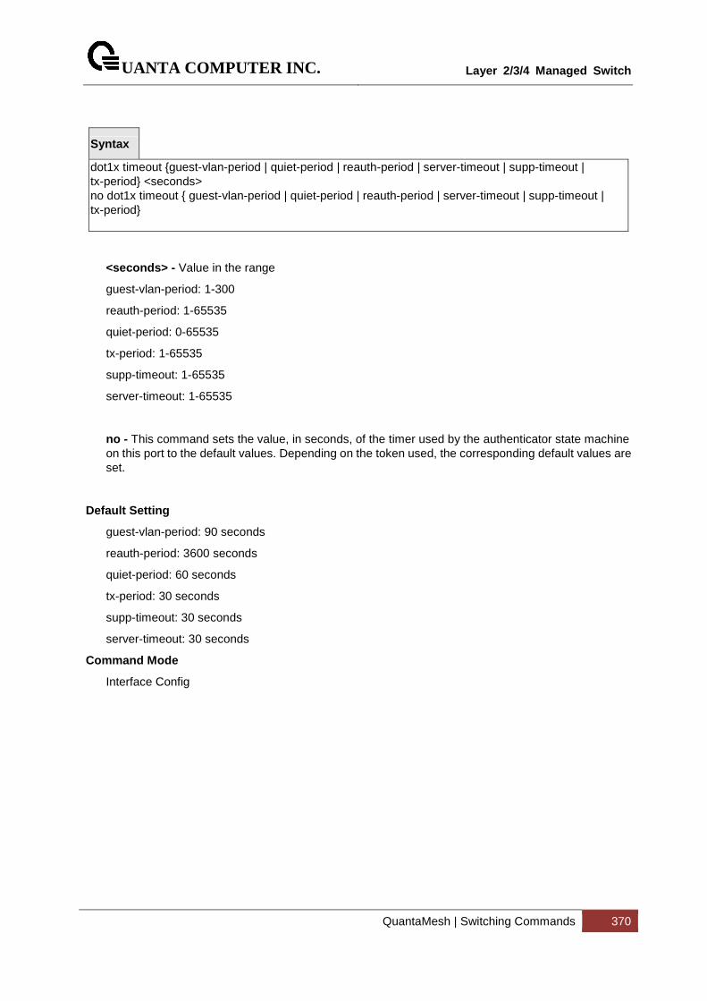
UANTA COMPUTER INC.
Layer 2/3/4 Managed Switch
QuantaMesh | Switching Commands 370
Syntax
dot1x timeout {guest-vlan-period | quiet-period | reauth-period | server-timeout | supp-timeout | tx-period} <seconds> no dot1x timeout { guest-vlan-period | quiet-period | reauth-period | server-timeout | supp-timeout | tx-period}
<seconds> - Value in the range
guest-vlan-period: 1-300
reauth-period: 1-65535
quiet-period: 0-65535
tx-period: 1-65535
supp-timeout: 1-65535
server-timeout: 1-65535
no - This command sets the value, in seconds, of the timer used by the authenticator state machine on this port to the default values. Depending on the token used, the corresponding default values are set.
Default Setting
guest-vlan-period: 90 seconds
reauth-period: 3600 seconds
quiet-period: 60 seconds
tx-period: 30 seconds
supp-timeout: 30 seconds
server-timeout: 30 seconds
Command Mode
Interface Config
UANTA COMPUTER INC.
Layer 2/3/4 Managed Switch
QuantaMesh | Switching Commands 371
5.9.3.17 dot1x unauthenticated-vlan
This command configure Unauthenticated VLAN for the port.
Syntax
dot1x unauthenticated-vlan <vlan-id> no dot1x unauthenticated-vlan
Default Setting
0
Command Mode
5.9.4 Interface Config
UANTA COMPUTER INC.
Layer 2/3/4 Managed Switch
QuantaMesh | Switching Commands 372
Radius Configuration Commands
5.9.4.1 radius accounting mode
This command is used to enable the RADIUS accounting function.
Syntax
radius accounting mode no radius accounting mode
no - This command is used to set the RADIUS accounting function to the default value - that is, the RADIUS accounting function is disabled.
Default Setting
Disabled
Command Mode
Global Config
5.9.4.2 authorization network radius
Use this command to enable the switch to accept VLAN assignment by the radius server.
Syntax
authorization network radius no authorization network radius
no - Use this command to disable the switch to accept VLAN assignment by the radius server.
Default Setting
Disabled
Command Mode
Global Config
UANTA COMPUTER INC.
Layer 2/3/4 Managed Switch
QuantaMesh | Switching Commands 373
5.9.4.3 radius server attribute 4
This command to set the NAS-IP address for the radius server.
Syntax
radius server attribute 4 [<ipaddr>] no radius server attribute 4
no – use this command to reset the NAS-IP address for the radius server.
Default Setting
None
Command Mode
Global Config
5.9.4.4 radius server attribute 95
This command to set the NAS-IPv6 address for the radius server.
Syntax
radius server attribute 95 [ipv6 address] no radius server attribute 95
no – use this command to reset the NAS-IPv6 address for the radius server.
Default Setting
None
Command Mode
Global Config
UANTA COMPUTER INC.
Layer 2/3/4 Managed Switch
QuantaMesh | Switching Commands 374
5.9.4.5 radius server dead-time
This command cnfiguresradius server dead time.
Syntax
radius server dead-time <minutes> no radius server dead-time
minutes - Set radius server dead time (minutes). Range 0 - 2000.
no - This command is used to set dead time to the default value.
Default Setting
0
Command Mode
Global Config
5.9.4.6 radius server host
This command is used to configure the RADIUS authentication and accounting server.
If the 'auth' token is used, the command configures the IP address to use to connect to a RADIUS authentication server. Up to 3 servers can be configured per RADIUS client. If the maximum number of configured servers is reached, the command will fail until one of the servers is removed by executing the no form of the command. If the optional <port> parameter is used, the command will configure the UDP port number to use to connect to the configured RADIUS server. In order to configure the UDP port number, the IP address must match that of a previously configured RADIUS authentication server. The port number must lie between 1 - 65535, with 1812 being the default value.
If the 'acct' token is used, the command configures the IP address to use for the RADIUS accounting server. Only a single accounting server can be configured. If an accounting server is currently configured, it must be removed from the configuration using the no form of the command before this command succeeds. If the optional <port> parameter is used, the command will configure the UDP port to use to connect to the RADIUS accounting server. The IP address specified must match that of a previously configured accounting server. If a port is already configured for the accounting server then the new port will replace the previously configured value. The port must be a value in the range 1 - 65535, with 1813 being the default value.
Syntax
radius server host {acct | auth} <ipaddr| ipv6addr|hostname> [name <servername>] [port <port>] no radius server host {acct | auth} <ipaddr| ipv6addr|hostname>
<ipaddr| ipv6addr|hostname > - is a IPv4/IPv6 address or a hostname.
UANTA COMPUTER INC.
Layer 2/3/4 Managed Switch
QuantaMesh | Switching Commands 375
<servername> - Server name
<port> - Port number (Range: 1 – 65535)
no - This command is used to remove the configured RADIUS authentication server or the RADIUS accounting server. If the 'auth' token is used, the previously configured RADIUS authentication server is removed from the configuration. Similarly, if the 'acct' token is used, the previously configured RADIUS accounting server is removed from the configuration. The <ipaddr> parameter must match the IP address of the previously configured RADIUS authentication / accounting server.
Default Setting
None
Command Mode
Global Config
5.9.4.7 radius sever key
This command is used to configure the shared secret between the RADIUS client and the RADIUS accounting / authentication server. Depending on whether the 'auth' or 'acct' token is used, the shared secret will be configured for the RADIUS authentication or RADIUS accounting server. The IP address provided must match a previously configured server. When this command is executed, the secret will be prompted. The secret must be an alphanumeric value not exceeding 20 characters.
Syntax
radius server key {acct | auth} <ipaddr|ipv6addr|hostname> [encrypted <password>]
<ipaddr|ipv6addr| hostname > - is a IPv4/IPv6 address or hostname.
<password> is the password in encrypted format.
Default Setting
None
Command Mode
Global Config
UANTA COMPUTER INC.
Layer 2/3/4 Managed Switch
QuantaMesh | Switching Commands 376
5.9.4.8 radius server retransmit
This command sets the maximum number of times a request packet is re-transmitted when no response is received from the RADIUS server. The retries value is an integer in the range of 1 to 15.
Syntax
radius server retransmit <retries> no radius server retransmit
<retries> - the maximum number of retransmit times (Range: 1 - 15).
no - This command sets the maximum number of times a request packet is re-transmitted, when no response is received from the RADIUS server, to the default value, that is, 4.
Default Setting
4
Command Mode
Global Config
5.9.4.9 radius server timeout
This command sets the timeout value (in seconds) after which a request must be retransmitted to the RADIUS server if no response is received. The timeout value is an integer in the range of 1 to 30.
Syntax
radius server timeout <seconds> no radius server timeout
<seconds> - the maximum timeout (Range: 1 - 30).
no - This command sets the timeout value (in seconds) after which a request must be retransmitted to the RADIUS server if no response is received, to the default value, that is, 5.
Default Setting
5
Command Mode
Global Config
UANTA COMPUTER INC.
Layer 2/3/4 Managed Switch
QuantaMesh | Switching Commands 377
5.9.4.10 radius server msgauth
This command enables the message authenticator attribute for a specified server.
Syntax
radius server msgauth <ipaddr| ipv6addr| hostname >
<ipaddr| ipv6addr| hostname > - is a IPv4/v6 address or hostname.
Default Setting
None
Command Mode
Global Config
5.9.4.11 radius server primary
This command is used to configure the primary RADIUS authentication server for this RADIUS client. The primary server is the one that is used by default for handling RADIUS requests. The remaining configured servers are only used if the primary server cannot be reached. A maximum of three servers can be configured on each client. Only one of these servers can be configured as the primary. If a primary server is already configured prior to this command being executed, the server specified by the IP address specified used in this command will become the new primary server. The IP address must match that of a previously configured RADIUS authentication server.
Syntax
radius server primary <ipaddr| ipv6addr| hostname>
<ipaddr | ipv6addr | hostname > - is a IPv4/v6 address or a hostname.
Default Setting
None
Command Mode
Global Config
5.9.4.12 radius source-interface
Use this command to specify the physical or logical interface to use as the RADIUS client source interface (Source IP address). If configured, the address of source interface is used for all RADIUS
UANTA COMPUTER INC.
Layer 2/3/4 Managed Switch
QuantaMesh | Switching Commands 378
communications between the RADIUS server and the RADIUS client. The selected source-interface IP address is used for filling the IP header of RADIUS management protocol packets. This allows security device (firewalls) to identify the source packets coming from the specific switch.
If a source-interface is not specified, the primary IP address of the originating (outbound) interface is used as the source address. If the configured interface is down, the RADIUS client falls back to its default behavior.
Syntax
radius source-interface {<slot/port> | loopback <loopback-id> | vlan <vlan-id>}
<slot/port> - Specifies the interface to use as the source interface.
<loopback-id> - Specifies the loopback interface to use as the source interface. The range of the loopback ID is 0 to 7.
<vlan-id> - Specifies the VLAN interface to use as the source interface. The range of VLAN ID is 1 to 4093.
Default Setting
None
Command Mode
Global Config
UANTA COMPUTER INC.
Layer 2/3/4 Managed Switch
QuantaMesh | Switching Commands 379
5.9.5 TACACS+ Configuration Commands
5.9.5.1 tacacs-server host
This command is used to enable /disable TACACS+ function and to configure the TACACS+ server IP address. The system has not any TACACS+ server configured for its initialization and support 5 TACACS+ servers.
Syntax
tacacs-server host <ipAddr | ipv6Addr | hostname> no tacacs-server host <ipAddr | ipv6Addr | hostname>
<ipAddr|ipv6Addr|hostname> - The IPv4/v6 address or hostname of the TACACS+ server.
no - This command is used to remove all of configuration.
Default Setting
None
Command Mode
Global Config
5.9.5.2 tacacs-server key
This command is used to configure the TACACS+ authentication and encryption key.
Syntax
tacacs-server key [<key-string>|encrypted <key-string>] no tacacs-server key
Note that the length of the secret key is up to 128 characters.
< key-string > - The valid value of the key.
encrypted - the key string is encrypted.
no - This command is used to remove the TACACS+ server secret key.
Default Setting
None
Command Mode
Global Config
UANTA COMPUTER INC.
Layer 2/3/4 Managed Switch
QuantaMesh | Switching Commands 380
This command is used to configure the TACACS+ authentication and encryption key.
Syntax
key [<key-string> | encrypted <key-string>]
Note that the length of the secret key is up to 128 characters.
< key-string > - The valid value of the key.
encrypted - the key string is encrypted.
Default Setting
None
Command Mode
TACACS Host Config
This command is used to configure the TACACS+ authentication host port.
Syntax
port [<port-number>]
<port-number> - The valid port number. Range (0 – 65535)>
Default Setting
49
Command Mode
TACACS Host Config
UANTA COMPUTER INC.
Layer 2/3/4 Managed Switch
QuantaMesh | Switching Commands 381
This command is used to configure the TACACS+ authentication host priority.
Syntax
priority [<priority>]
<priority> - The valid priority number. Range (0 – 65535)>
Default Setting
0
Command Mode
TACACS Host Config
This command is used to configure the TACACS+ connection timeout value.
Syntax
timeout [<timeout>]
<timeout> - The connection timeout value. Max timeout (Range: 1 to 30).
Default Setting
5
Command Mode
TACACS Host Config
UANTA COMPUTER INC.
Layer 2/3/4 Managed Switch
QuantaMesh | Switching Commands 382
5.9.5.3 tacacs-server keystring
This command is used to configure the TACACS+ authentication and encryption key in re-confirm format.
Syntax
tacacs-server keystring
Default Setting
None
Command Mode
Global Config
5.9.5.4 tacacs-server timeout
This command is used to configure the TACACS+ connection timeout value.
Syntax
tacacs-server timeout [<timeout>] no tacacs-server timeout
<timeout> - The connection timeout value. Max timeout (Range: 1 to 30).
no - This command is used to reset the timeout value to the default value.
Default Setting
5
Command Mode
Global Config
UANTA COMPUTER INC.
Layer 2/3/4 Managed Switch
QuantaMesh | Switching Commands 383
5.9.5.5 tacacs-server source-interface
Use this command in Global config mode to configure the source interface (Source IP address) for TACACS+ server configuration. The selected source-interface IP address is used for filling the IP header of management protocol packets. This allows security devices (firewalls) to identify the source packets coming from the specific switch.
If a source-interface is not specified, the primary IP address of the originating (outbound) interface is used as the source address.
Syntax
tacacs-server source-interface {<slot/port> | loopback <loopback-id> | vlan <vlan-id>} no tacacs-server source-interface
<slot/port> - Specifies the interface to use as the source interface.
<loopback-id> - Specifies the loopback interface to use as the source interface. The range of the loopback ID is 0 to 7.
<vlan-id> - Specifies the VLAN interface to use as the source interface. The range of VLAN ID is 1 to 4093.
no - Use this command to remove the global source interface for all TACACS+ communications between the TACACS+ client and the server.
Default Setting
None
Command Mode
Global Config
UANTA COMPUTER INC.
Layer 2/3/4 Managed Switch
QuantaMesh | Switching Commands 384
5.9.6 Port Security Configuration Commands
5.9.6.1 port-security
This command enables port locking at the system level (Global Config) or port level (Interface Config).
Syntax
port-security no port-security
Default Setting
None
Command Mode
Global Config
Interface Config
5.9.6.2 port-security max-dynamic
This command sets the maximum of dynamically locked MAC addresses allowed on a specific port.
Syntax
port-security max-dynamic [<0-600>] no port-security max-dynamic
no - This command resets the maximum of dynamically locked MAC addresses allowed on a specific port to its default value.
Default Setting
600
Command Mode
Interface Config
UANTA COMPUTER INC.
Layer 2/3/4 Managed Switch
QuantaMesh | Switching Commands 385
5.9.6.3 port-security max-static
This command sets the maximum number of statically locked MAC addresses allowed on a specific port.
Syntax
port-security max-static [<0-20>] no port-security max-static
no - This command resets the maximum number of statically locked MAC addresses allowed on a specific port to its default value.
Default Setting
20
Command Mode
Interface Config
5.9.6.4 port-security mac-address
This command adds a MAC address to the list of statically locked MAC addresses.
Syntax
port-security mac-address <mac-addr> <1-4093> no port-security mac-address <mac-addr> <1-4093>
<1-4093> - VLAN ID
<mac-addr> - The statically locked MAC address.
no - This command removes a MAC address from the list of statically locked MAC addresses.
Default Setting
None
Command Mode
Interface Config
UANTA COMPUTER INC.
Layer 2/3/4 Managed Switch
QuantaMesh | Switching Commands 386
5.9.6.5 port-security mac-address move
This command converts dynamically locked MAC addresses to statically locked addresses.
Syntax
port-security mac-address move
Default Setting
None
Command Mode
Interface Config
5.9.6.6 port-security mac-address sticky
This command enables sticky mode Port MAC Locking on a port.
Syntax
port-security mac-address sticky [<mac-addr> <1-4093>] no port-security mac-address sticky
<1-4093> - VLAN ID
<mac-addr> - The statically locked MAC address.
no - This command disable sticky mode Port MAC Locking on a port.
Default Setting
None
Command Mode
Global Config
Interface Config
UANTA COMPUTER INC.
Layer 2/3/4 Managed Switch
QuantaMesh | Switching Commands 387
5.9.6.7 port-security violation shutdown
This command configures the port violation shutdown mode. Once the violation happens, the interface will be shutdown.
Syntax
port-security violation shutdown no port-security violation
no - This command restore violation mode to be default.
Default Setting
None
Command Mode
Interface Config

UANTA COMPUTER INC.
Layer 2/3/4 Managed Switch
QuantaMesh | Switching Commands 388
5.9.7 Denial Of Service Commands
5.9.7.1 Show Commands
5.9.7.1.1 show dos-control
This command displays the Denial of Service configurations for the entire system.
Syntax
show dos-control
Default Setting
None
Command Mode
Privileged Exec
Display Message
TCP Fragment Mode: May be enabled or disabled. The factory default is disabled.
Min TCP Hdr Size: The range is 0-255. The factory default is 20.
ICMPv4 Mode: May be enabled or disabled. The factory default is disabled.
Max ICMPv4 Payload Size: The range is 0-16376. The factory default is 512.
ICMPv6 Mode: May be enabled or disabled. The factory default is disabled.
Max ICMPv6 Payload Size: The range is 0-16376. The factory default is 512.
ICMP Fragment Mode: May be enabled or disabled. The factory default is disabled.
TCP Port Mode: May be enabled or disabled. The factory default is disabled.
UDP Port Mode: May be enabled or disabled. The factory default is disabled.
SIPDIP Mode: May be enabled or disabled. The factory default is disabled.
SMACDMAC Mode: May be enabled or disabled. The factory default is disabled.
TCP FIN&URG&PSH Mode: May be enabled or disabled. The factory default is disabled.
TCP Flag&Sequence Mode: May be enabled or disabled. The factory default is disabled.
TCP SYN Mode: May be enabled or disabled. The factory default is disabled.
TCP SYN&FIN Mode: May be enabled or disabled. The factory default is disabled.
First Fragment Mode: May be enabled or disabled. The factory default is disabled.
TCP Fragment Offset Mode: May be enabled or disabled. The factory default is disabled.
UANTA COMPUTER INC.
Layer 2/3/4 Managed Switch
QuantaMesh | Switching Commands 389
5.9.7.2 Configuration Commands
5.9.7.2.1 dos-control sipdip
This command enables Source IP Address = Destination IP Address (SIP=DIP) Denial of Service protection. If the mode is enabled, Denial of Service prevention is active for this type of attack. If packets ingress with SIP=DIP, the packets will be dropped if the mode is enabled.
Syntax
dos-control sipdip no dos-control sipdip
no - This command disables Source IP Address = Destination IP Address (SIP=DIP) Denial of Service prevention.
Default Setting
Disabled
Command Mode
Global Config
5.9.7.2.2 dos-control tcpfrag
This command enables Minimum TCP Header Size Denial of Service protection. If the mode is enabled, Denial of Service prevention is active for this type of attack. If packets ingress having a TCP Header Size smaller then the configured value, the packets will be dropped if the mode is enabled. The default is disabled. If you enable dos-control tcpfrag, but do not provide a Minimum TCP Header Size, the system sets that value to 20.
Syntax
dos-control tcpfrag [<0-255>] no dos-control tcpfrag
<0-255> - This command sets minimum TCP header length
no - This command sets Minimum TCP Header Size Denial of Service protection to the default value of disabled.
Default Setting
Disabled, 20
Command Mode
Global Config
UANTA COMPUTER INC.
Layer 2/3/4 Managed Switch
QuantaMesh | Switching Commands 390
5.9.7.2.3 dos-control firstfrag
This command enables IP First Fragment Denial of Service protection. If the mode is enabled, Denial of Service prevention is active for this type of attack. If packets ingress having More Fragments(MF) equal to 1 and coorperate with other DoS options, the packets will be dropped if the mode is enabled.
Syntax
dos-control firstfrag no dos-control firstfrag
no - This command disabled IP First Fragment Denial of Service protection.
Default Setting
Disabled
Command Mode
Global Config
5.9.7.2.4 dos-control tcpflag
This command enables TCP Flag Denial of Service protections. If the mode is enabled, Denial of Service prevention is active for this type of attacks. If packets ingress having TCP Flag SYN set and a source port less than 1024 or having TCP Control Flags set to 0 and TCP Sequence Number set to 0 or having TCP Flags FIN, URG, and PSH set and TCP Sequence Number set to 0 or having TCP Flags SYN and FIN both set, the packets will be dropped if the mode is enabled.
Syntax
dos-control tcpflag no dos-control tcpflag
no - This command sets disables TCP Flag Denial of Service protections.
Default Setting
Disabled
Command Mode
Global Config
UANTA COMPUTER INC.
Layer 2/3/4 Managed Switch
QuantaMesh | Switching Commands 391
5.9.7.2.5 dos-control l4port
This command enables L4 Port Denial of Service protections. If the mode is enabled, Denial of Service prevention is active for this type of attack. If packets ingress having Source TCP/UDP Port Number equal to Destination TCP/UDP Port Number, the packets will be dropped if the mode is enabled.
Some applications mirror source and destination L4 ports - RIP for example uses 520 for both. If you enable dos-control l4port, applications such as RIP may experience packet loss which would render the application inoperable.
Syntax
dos-control l4port no dos-control l4port
no - This command disables L4 Port Denial of Service protections.
Default Setting
Disabled
Command Mode
Global Config
5.9.7.2.6 dos-control tcpport
This command enables the TCP L4 source = destination port number (Source TCP Port = Destination TCP Port) Denial of Service protection. If the mode is enabled, Denial of Service prevention is active for this type of attack. If packets ingress with Source TCP Port =Destination TCP Port, the packets will be dropped if the mode is enabled.
Syntax
dos-control tcpport no dos-control tcpport
no - This command disables the TCP L4 source = destination port number (Source TCP Port =Destination TCP Port) Denial of Service protection.
Default Setting
Disabled
Command Mode
Global Config
!
UANTA COMPUTER INC.
Layer 2/3/4 Managed Switch
QuantaMesh | Switching Commands 392
5.9.7.2.7 dos-control udpport
This command enables the UDP L4 source = destination port number (Source UDP Port = Destination UDP Port) Denial of Service protection. If the mode is enabled, Denial of Service prevention is active for this type of attack. If packets ingress with Source UDP Port =Destination UDP Port, the packets will be dropped if the mode is enabled.
Syntax
dos-control udpport no dos-control udpport
no - This command disables the UDP L4 source = destination port number (Source UDP Port =Destination UDP Port) Denial of Service protection.
Default Setting
Disabled
Command Mode
Global Config
5.9.7.2.8 dos-control icmpv4
This command enables Maximum ICMPv4 Payload Size Denial of Service protections. If the mode is enabled, Denial of Service prevention is active for this type of attack. If ICMP Echo Request (PING) packets ingress having a payload size greater than the configured value, the packets will be dropped if the mode is enabled.
Syntax
dos-control icmpv4 no dos-control icmpv4
no - This command disables Maximum ICMPv4 Payload Size Denial of Service protections.
Default Setting
Disabled
Command Mode
Global Config
UANTA COMPUTER INC.
Layer 2/3/4 Managed Switch
QuantaMesh | Switching Commands 393
5.9.7.2.9 dos-control icmpv6
This command enables Maximum ICMPv6 Payload Size Denial of Service protections. If the mode is enabled, Denial of Service prevention is active for this type of attack. If ICMP Echo Request (PING) packets ingress having a payload size greater than the configured value, the packets will be dropped if the mode is enabled.
Syntax
dos-control icmpv6 no dos-control icmpv6
no - This command disables Maximum ICMPv6 Payload Size Denial of Service protections.
Default Setting
Disabled
Command Mode
Global Config
5.9.7.2.10 dos-control icmpv4
This command enables Maximum ICMPv4 Payload Size Denial of Service protections. If the mode is enabled, Denial of Service prevention is active for this type of attack. If ICMPv4 Echo Request (PING) packets ingress having a payload size greater than the configured value, the packets will be dropped if the mode is enabled.
Syntax
dos-control icmpv4 [<0-16376>] no dos-control icmpv4
<0-16376> - This command sets maximum ICMPv4 payload size.
no - This command resets the Maximum ICMPv4 Payload Size Denial of Service protections to its default value.
Default Setting
512
Command Mode
Global Config
UANTA COMPUTER INC.
Layer 2/3/4 Managed Switch
QuantaMesh | Switching Commands 394
5.9.7.2.11 dos-control icmpv6
This command enables Maximum ICMPV6 Payload Size Denial of Service protections. If the mode is enabled, Denial of Service prevention is active for this type of attack. If ICMPV6 Echo Request (PING) packets ingress having a payload size greater than the configured value, the packets will be dropped if the mode is enabled.
Syntax
dos-control icmpv6 [<0-16376>] no dos-control icmpv6
<0-16376> - This command sets maximum ICMPV6 payload size.
no - This command resets the Maximum ICMPV6 Payload Size Denial of Service protections to its default value.
Default Setting
512
Command Mode
Global Config
5.9.7.2.12 dos-control icmpfrag
This command enables the ICMP Fragment Denial of Service protection. If the mode is enabled, Denial of Service prevention is active for this type of attack. If packets ingress has fragmented ICMP packets, the packets will be dropped if the mode is enabled.
Syntax
dos-control icmpfrag no dos-control icmpfrag
no - This command disables the ICMP Fragment Denial of Service protection.
Default Setting
Disabled
Command Mode
Global Config
UANTA COMPUTER INC.
Layer 2/3/4 Managed Switch
QuantaMesh | Switching Commands 395
5.9.7.2.13 dos-control smacdmac
This command enables the Source MAC address = Destination MAC address (SMAC=DMAC) Denial of Service protection. If the mode is enabled, Denial of Service prevention is active for this type of attack. If packets ingress with SMAC=DMAC, the packets will be dropped if the mode is enabled.
Syntax
dos-control smacdmac no dos-control smacdmac
no - This command disables the Source MAC address = Destination MAC address (SMAC=DMAC) Denial of Service protection.
Default Setting
Disabled
Command Mode
Global Config
5.9.7.2.14 dos-control tcpfinurgpsh
This command enables the TCP FIN and URG and PSH and SEQ=0 checking Denial of Service protections. If the mode is enabled, Denial of Service prevention is active for this type of attack. If packets ingress having TCP FIN, URG, and PSH all set and TCP Sequence Number set to 0, the packets will be dropped if the mode is enabled.
Syntax
dos-control tcpfinurgpsh no dos-control tcpfinurgpsh
no - This command disables the TCP FIN and URG and PSH and SEQ=0 checking Denial of Service protections.
Default Setting
Disabled
Command Mode
Global Config
UANTA COMPUTER INC.
Layer 2/3/4 Managed Switch
QuantaMesh | Switching Commands 396
5.9.7.2.15 dos-control tcpflagseq
This command enables the TCP Control Flags=0 and SEQ=0 checking Denial of Service protections. If the mode is enabled, Denial of Service prevention is active for this type of attack. If packets ingress having TCP Control Flags set to 0 and TCP Sequence Number set to 0, the packets will be dropped if the mode is enabled.
Syntax
dos-control tcpflagseq no dos-control tcpflagseq
no - This command disables the TCP Control Flags=0 and SEQ=0 checking Denial of Service protections.
Default Setting
Disabled
Command Mode
Global Config
5.9.7.2.16 dos-control tcpsyn
This command enables the TCP SYN and L4 source port = 0-1023 Denial of Service protection. If the mode is enabled, Denial of Service prevention is active for this type of attack. If packets ingress having TCP flag SYN set and an L4 source port from 0 to 1023, the packets will be dropped if the mode is enabled.
Syntax
dos-control tcpsyn no dos-control tcpsyn
no - This command disables the TCP SYN and L4 source port = 0-1023 Denial of Service protection.
Default Setting
Disabled
Command Mode
Global Config
UANTA COMPUTER INC.
Layer 2/3/4 Managed Switch
QuantaMesh | Switching Commands 397
5.9.7.2.17 dos-control tcpsynfin
This command enables the TCP SYN and FIN Denial of Service protection. If the mode is enabled, Denial of Service prevention is active for this type of attack. If packets ingress having TCP flags SYN and FIN set, the packets will be dropped if the mode is enabled.
Syntax
dos-control tcpsynfin no dos-control tcpsynfin
no - This command disables the TCP SYN & FIN Denial of Service protection.
Default Setting
Disabled
Command Mode
Global Config
5.9.7.2.18 dos-control tcpoffset
This command enables the TCP Fragment Offset Denial of Service protection. If the mode is enabled, Denial of Service prevention is active for this type of attack. If packets ingress having TCP Header Offset equal to one (1), the packets will be dropped if the mode is enabled.
Syntax
dos-control tcpoffset no dos-control tcpoffset
no - This command disables the TCP Fragment Offset Denial of Service protection.
Default Setting
Disabled
Command Mode
Global Config
UANTA COMPUTER INC.
Layer 2/3/4 Managed Switch
QuantaMesh | Switching Commands 398
5.9.7.2.19 dos-control all
This command enables the Denial of Service protection checks globally.
Syntax
dos-control all no dos-control all
no - This command disables the Denial of Service protection checks globally.
Default Setting
Disabled
Command Mode
Global Config
UANTA COMPUTER INC.
Layer 2/3/4 Managed Switch
QuantaMesh | Switching Commands 399
5.10 CDP (Cisco Discovery Protocol) Commands
5.10.1 Show Commands
5.10.1.1 show cdp
This command displays the CDP configuration information.
Syntax
show cdp
Default Setting
None
Command Mode
Privileged Exec
Display Message
CDP Admin Mode: CDP enable or disable
CDP Holdtime (sec): The length of time a receiving device should hold the L2 Network Switch CDP information before discarding it
CDP Transmit Interval (sec): A period of the L2 Network Switch to send CDP packet
Ports: Port number vs CDP status
CDP: CDP enable or disable
UANTA COMPUTER INC.
Layer 2/3/4 Managed Switch
QuantaMesh | Switching Commands 400
5.10.1.2 show cdp neighbors
This command displays the CDP neighbor information.
Syntax
show cdp neighbors
Default Setting
None
Command Mode
Privileged Exec
Display Message
Device Id: Identifies the device name in the form of a character string.
Local Intf: The CDP neighbor information receiving port.
Holdtime: The length of time a receiving device should hold CDP information before discarding it.
Capability: Describes the device's functional capability in the form of a device type, for example, a switch.
Platform: Describes the hardware platform name of the device, for example, Quanta the L2 Network Switch.
Port Id: Identifies the port on which the CDP packet is sent.
UANTA COMPUTER INC.
Layer 2/3/4 Managed Switch
QuantaMesh | Switching Commands 401
5.10.1.3 show cdp neighbors detail
This command displays the CDP neighbor detail information.
Syntax
show cdp neighbors detail
Default Setting
None
Command Mode
Privileged Exec
Display Message
Device Id: Identifies the device name in the form of a character string.
Entry Address(es): The L3 addresses of the interface that has sent the update.
Platform: Describes the hardware platform name of the device, for example, Quanta the L2 Network Switch.
Capability: Describes the device's functional capability in the form of a device type, for example, a switch.
Local Interface: The CDP neighbor information receiving port.
Port Id: Identifies the port on which the CDP packet is sent.
Holdtime: The length of time a receiving device should hold CDP information before discarding it.
Management Address: The first address of IP address which can use management address connect to switch.
UANTA COMPUTER INC.
Layer 2/3/4 Managed Switch
QuantaMesh | Switching Commands 402
5.10.1.4 show cdp traffic
This command displays the CDP traffic counters information.
Syntax
show cdp traffic
Default Setting
None
Command Mode
Privileged Exec
Display Message
Incoming packet number: Received legal CDP packets number from neighbors.
Outgoing packet number: Transmitted CDP packets number from this device.
Error packet number: Received illegal CDP packets number from neighbors.
UANTA COMPUTER INC.
Layer 2/3/4 Managed Switch
QuantaMesh | Switching Commands 403
5.10.2 Configuration Commands
5.10.2.1 cdp
This command is used to enable CDP Admin Mode.
Syntax
cdp no cdp
no - This command is used to disable CDP Admin Mode.
Default Setting
Enabled
Command Mode
Global Config
5.10.2.2 cdp run
This command is used to enable CDP on a specified interface.
Syntax
cdp run no cdp run
no - This command is used to disable CDP on a specified interface.
Default Setting
Enabled
Command Mode
Interface Config
UANTA COMPUTER INC.
Layer 2/3/4 Managed Switch
QuantaMesh | Switching Commands 404
This command is used to enable CDP for all interfaces.
Syntax
cdp run all no cdp run all
all - All interfaces.
no - This command is used to disable CDP for all interfaces.
Default Setting
Enabled
Command Mode
Global Config
5.10.2.3 cdp timer
This command is used to configure an interval time (seconds) of the sending CDP packet.
Syntax
cdp timer <5-254> no cdp timer
<5-254> - interval time (Range: 5 – 254).
no - This command is used to reset the interval time to the default value.
Default Setting
60
Command Mode
Global Config
UANTA COMPUTER INC.
Layer 2/3/4 Managed Switch
QuantaMesh | Switching Commands 405
5.10.2.4 cdp holdtime
This command is used to configure the hold time (seconds) of CDP.
Syntax
cdp holdtime <10-255>
<10-255> - interval time (Range: 10 – 255).
no - This command is used to hold time to the default value.
Default Setting
180
Command Mode
Global Config
UANTA COMPUTER INC.
Layer 2/3/4 Managed Switch
QuantaMesh | Switching Commands 406
5.11 SNTP (Simple Network Time Protocol) Commands
5.11.1 Show Commands
5.11.1.1 show sntp
This command displays the current time and configuration settings for the SNTP client, and indicates whether the local time has been properly updated.
Syntax
show sntp
Default Setting
None
Command Mode
Privileged Exec
Display Message
Last Update Time Time of last clock update.
Last Unicast Attempt Time Time of last transmit query (in unicast mode).
Last Attempt Status Status of the last SNTP request (in unicast mode) or unsolicited message (in broadcast mode).
Broadcast Count Current number of unsolicited broadcast messages that have been received and processed by the SNTP client since last reboot.
Multicast Count Current number of unsolicited multicast messages that have been received and processed by the SNTP client since last reboot.
Time Zone Time zone configured.
This command displays SNTP client settings.
Syntax
show sntp client
Default Setting
None
Command Mode
UANTA COMPUTER INC.
Layer 2/3/4 Managed Switch
QuantaMesh | Switching Commands 407
Privileged Exec
Display Message
Client Supported Modes Supported SNTP Modes (Broadcast, Unicast, or Multicast).
SNTP Version The highest SNTP version the client supports.
Port SNTP Client Port
Client Mode: Configured SNTP Client Mode.
Unicast Poll Interval Poll interval value for SNTP clients in seconds as a power of two.
Poll Timeout (Seconds) Poll timeout value in seconds for SNTP clients.
Poll Retry Poll retry value for SNTP clients.
Broadcast Poll Interval Poll interval value for SNTP clients in seconds as a power of two.
Multicast Poll Interval Poll interval value for SNTP clients in seconds as a power of two.
This command displays configured SNTP servers and SNTP server settings.
Syntax
show sntp server
Default Setting
None
Command Mode
Privileged Exec
Display Message
Server IP Address IP Address of configured SNTP Server
Server Type Address Type of Server.
Server Stratum Claimed stratum of the server for the last received valid packet.
Server Reference ID Reference clock identifier of the server for the last received valid packet.
Server Mode SNTP Server mode.
Server Maximum Entries Total number of SNTP Servers allowed.
Server Current Entries Total number of SNTP configured.
For each configured server:
IP Address IP Address of configured SNTP Server.
Address Type Address Type of configured SNTP server.
Priority IP priority type of the configured server.
Version SNTP Version number of the server. The protocol version used to query the server in unicast mode.
Port Server Port Number
UANTA COMPUTER INC.
Layer 2/3/4 Managed Switch
QuantaMesh | Switching Commands 408
Last Attempt Time Last server attempt time for the specified server.
Last Update Status Last server attempt status for the server.
Total Unicast Requests Number of requests to the server.
Failed Unicast Requests Number of failed requests from server.
5.11.1.2 show sntp source-interface
Use this command to display the SNTP client source interface configured on the switch.
Syntax
show sntp source-interface
Default Setting
None
Command Mode
Privileged Exec
Display Message
SNTP Client source Interface The interface ID of the physical or logical interface configured as the SNTP client source interface.
SNTP Client Source IPv4 Address The IP address of the interface configured as the SNTP client source interface.
UANTA COMPUTER INC.
Layer 2/3/4 Managed Switch
QuantaMesh | Switching Commands 409
5.11.2 Configuration Commands
5.11.2.1 sntp broadcast client poll-interval
This command will set the poll interval for SNTP broadcast clients in seconds as a power of two where <poll-interval> can be a value from 6 to 10.
Syntax
sntp broadcast client poll-interval <6-10> no sntp broadcast client poll-interval
<6-10> - The range is 6 to 10.
no - This command will reset the poll interval for SNTP broadcast client back to its default value.
Default Setting
6
Command Mode
Global Config
UANTA COMPUTER INC.
Layer 2/3/4 Managed Switch
QuantaMesh | Switching Commands 410
5.11.2.2 sntp client mode
This command will enable Simple Network Time Protocol (SNTP) client mode and optionally setting the mode to either broadcast, multicast, or unicast.
Syntax
sntp client mode [broadcast | unicast | multicast] no sntp client mode
no - This command will disable Simple Network Time Protocol (SNTP) client mode.
The SNTP IPv4 multicast address is 224.0.1.1.
The SNTP IPv6 multicast address is ff05::101.
IPv6 address doesn’t support broadcast mode.
Default Setting
None
Command Mode
Global Config
5.11.2.3 sntp client port
This command will set the SNTP client port id and polling interval in seconds.
Syntax
sntp client port <portid> no sntp client port
<portid> - SNTP client port id.
no - Resets the SNTP client port id.
Default Setting
The default portid is 123.
Command Mode
Global Config
i

UANTA COMPUTER INC.
Layer 2/3/4 Managed Switch
QuantaMesh | Switching Commands 411
UANTA COMPUTER INC.
Layer 2/3/4 Managed Switch
QuantaMesh | Switching Commands 412
5.11.2.4 sntp unicast client poll-interval
This command will set the poll interval for SNTP unicast clients in seconds.
Syntax
sntp unicast client poll-interval <6-10> no sntp unicast client poll-interval
<6-10> - Polling interval. It's 2^(value) seconds where value is 6 to 10.
no - This command will reset the poll interval for SNTP unicast clients to its default value.
Default Setting
The default value is 6.
Command Mode
Global Config
5.11.2.5 sntp unicast client poll-timeout
This command will set the poll timeout for SNTP unicast clients in seconds.
Syntax
sntp unicast client poll-timeout <poll-timeout> no sntp unicast client poll-timeout
< poll-timeout > - Polling timeout in seconds. The range is 1 to 30.
no - This command will reset the poll timeout for SNTP unicast clients to its default value.
Default Setting
The default value is 5.
Command Mode
Global Config
UANTA COMPUTER INC.
Layer 2/3/4 Managed Switch
QuantaMesh | Switching Commands 413
5.11.2.6 sntp unicast client poll-retry
This command will set the poll retry for SNTP unicast clients in seconds.
Syntax
sntp unicast client poll-retry <poll-retry> no sntp unicast client poll-retry
< poll-retry> - Polling retry in seconds. The range is 0 to 10.
no - This command will reset the poll retry for SNTP unicast clients to its default value.
Default Setting
The default value is 1.
Command Mode
Global Config
UANTA COMPUTER INC.
Layer 2/3/4 Managed Switch
QuantaMesh | Switching Commands 414
5.11.2.7 sntp server
This command configures an SNTP server (with a maximum of three) where the server address can be an ip address or a domain name and the address type either IPv4, IPv6, dnsv6 or dns. The optional priority can be a value of 1-3, the version is a value of 1-4, and the port id is a value of 1-65535.
Syntax
sntp server <ipaddress/ipv6address/domain-name> <addresstype> [<1-3> [<version> [<portid>]]] no sntp server remove <ipaddress/ipv6address/domain-name>
<ipaddress/ipv6address/domain-name > - IPv4 or IPv6 address or domain name of the SNTP server.
<addresstype > - The address type is ipv4 or ipv6 or dns or dnsv6.
<1-3> - The range is 1 to 3.
<version> - The range is 1 to 4.
<portid> - The range is 1 to 65535.
no - This command deletes an server from the configured SNTP servers.
Default Setting
None
Command Mode
Global Config
UANTA COMPUTER INC.
Layer 2/3/4 Managed Switch
QuantaMesh | Switching Commands 415
5.11.2.8 sntp clock timezone
This command sets the time zone for the switch’s internal clock.
Syntax
sntp clock timezone <name> <0-12> <0-59> {before-utc | after-utc}
<name> - Name of the time zone, usually an acronym. (Range: 1-15 characters)
<0-12> - Number of hours before/after UTC. (Range: 0-12 hours)
<0-59> - Number of minutes before/after UTC. (Range: 0-59 minutes)
before-utc - Sets the local time zone before (east) of UTC.
after-utc - Sets the local time zone after (west) of UTC.
Default Setting
Taipei 08:00 After UTC
Command Mode
Global Config
5.11.2.9 sntp multicast client poll-internal
This command will set the poll interval for SNTP multicast clients in seconds.
Syntax
sntp multicast client poll-interval <poll-interval> no sntp multicast client poll-interval
<poll-interval> - Polling interval. It’s 2^(value) seconds where the range of value is 6 to 10.
no – This command will reset the poll interval for SNTP multicast client to its default value.
Default Setting
The default value is 6.
Command Mode
Global Config
UANTA COMPUTER INC.
Layer 2/3/4 Managed Switch
QuantaMesh | Switching Commands 416
5.11.2.10 sntp source-interface
Use this command to specify the physical or logical interface to use as the SNTP client source interface. If configured, the address of source interface is used for all SNTP communications between the SNTP server and the SNTP client. Otherwise, there is no change in behavior. If the configured interface is down, the SNTP client falls back to its default behavior.
Syntax
sntp source-interface {<slot/port> | loopback <loopback-id> | tunnel <tunnel-id> | vlan <vlan-id>} no sntp source-interface
<slot/port> - Specifies the port to use as the source interface.
<loopback-id> - Specifies the loopback interface to use as the source interface. The range of the loopback ID is 0 to 7.
<tunnel-id> - Specifies the tunnel interface to use as the source interface. The range of the tunnel ID is 0 to 7.
<vlan-id> - Specifies the VLAN interface to use as the source interface. The range of the VLAN ID is 1 to 4093.
no - This command will reset the SNTP source interface to its default settings.
Default Setting
None
Command Mode
Global Config
UANTA COMPUTER INC.
Layer 2/3/4 Managed Switch
QuantaMesh | Switching Commands 417
5.12 LLDP (Link Layer Discovery Protocol) Commands
5.12.1 Show Commands
5.12.1.1 show lldp
This command uses to display a summary of the current LLDP configuration.
Syntax
show lldp
Default Setting
None
Command Mode
Privileged Exec
Display Message
Transmit Interval: Shows how frequently the system transmits local data LLDPDUs, in seconds.
Transmit Hold Multiplier: Shows the multiplier on the transmit interval that sets the TTL in local data LLDPDUs.
Reinit Delay : Shows the delay before re-initialization, in seconds.
Notification Interval: Shows how frequently the system sends remote data change notifications, in seconds.
Transmit Delay: Shows how frequently the system transmits local data LLDPDUs after a change is made in a TLV (type, length, or value) element in LLDP, in seconds.
UANTA COMPUTER INC.
Layer 2/3/4 Managed Switch
QuantaMesh | Switching Commands 418
5.12.1.2 show lldp interface
This command uses to display a summary of the current LLDP configuration for a specific interface or for all interfaces.
Syntax
show lldp interface [<slot/port>]
<slot/port> - Configs a specific interface.
Default Setting
None
Command Mode
Privileged Exec
Display Message
Interface: Shows the interface in a slot/port format.
Link: Shows whether the link is up or down.
Transmit: Shows whether the interface transmits LLDPDUs.
Receive: Shows whether the interface receives LLDPDUs.
Notify: Shows whether the interface sends remote data change notifications.
TLVs: Shows whether the interface sends optional TLVs in the LLDPDUs. The TLV codes can be 0 (Port Description), 1 (System Name), 2 (System Description), or 3 (System Capability).
Mgmt: Shows whether the interface transmits system management address information in the LLDPDUs.
UANTA COMPUTER INC.
Layer 2/3/4 Managed Switch
QuantaMesh | Switching Commands 419
5.12.1.3 show lldp statistics
This command uses to display the current LLDP traffic and remote table statistics for a specific interface or for all interfaces.
Syntax
show lldp statistics [<slot/port>]
<slot/port> - Configs a specific interface.
Default Setting
None
Command Mode
Privileged Exec
Display Message
Last Update: Shows the amount of time since the last update to the remote table in days, hours, minutes, and seconds.
Total Inserts: Total number of inserts to the remote data table.
Total Deletes: Total number of deletes from the remote data table.
Total Drops: Total number of times the complete remote data received was not inserted due to insufficient resources.
Total Ageouts: Total number of times a complete remote data entry was deleted because the Time to Live interval expired.
The table contains the following column headings:
Interface: Shows the interface in slot/port format.
Tx Total: Total number of LLDP packets transmitted on the port.
Rx Total: Total number of LLDP packets received on the port.
Discards: Total number of LLDP frames discarded on the port for any reason.
Errors: The number of invalid LLDP frames received on the port.
Ageout: Total number of times a complete remote data entry was deleted for the port because the Time to Live interval expired.
TLV Discards: Shows the number of TLVs discarded
TLV Unknowns: Total number of LLDP TLVs received on the port where the type value is in the reserved range, and not recognized.
TLV MED: Total number of LLDP TLVs received on the port where the type value is 127 and OUI type is 00-12-BB.
TLV 802.1: Total number of LLDP TLVs received on the port where the type value is 127 and OUI type is 00-80-C2.
UANTA COMPUTER INC.
Layer 2/3/4 Managed Switch
QuantaMesh | Switching Commands 420
TLV 802.3: Total number of LLDP TLVs received on the port where the type value is 127 and OUI type is 00-12-0F.
5.12.1.4 show lldp remote-device
This command uses to display summary information about remote devices that transmit current LLDP data to the system. You can show information about LLDP remote data received on all ports or on a specific port.
Syntax
show lldp remote-device [<slot/port>]
<slot/port> - Displays a specific interface.
Default Setting
None
Command Mode
Privileged Exec
Display Message
Local Interface: Identifies the interface that received the LLDPDU from the remote device.
Rem ID: Shows the ID of the remote device.
Chassis ID: The ID that is sent by a remote device as part of the LLDP message, it is usually a MAC address of the device.
Port ID: Shows the port number that transmitted the LLDPDU.
System Name: Shows the system name of the remote device.
UANTA COMPUTER INC.
Layer 2/3/4 Managed Switch
QuantaMesh | Switching Commands 421
5.12.1.5 show lldp remote-device detail
This command uses to display detailed information about remote devices that transmit current LLDP data to an interface on the system.
Syntax
show lldp remote-device detail <slot/port>
<slot/port> - Displays a specific interface.
Default Setting
None
Command Mode
Privileged Exec
Display Message
Local Interface: Identifies the interface that received the LLDPDU from the remote device.
Remote Identifier: An internal identifier to the switch to mark each remote device to the system.
Chassis ID Subtype: Shows the type of identification used in the Chassis ID field.
Chassis ID: Identifies the chassis of the remote device.
Port ID Subtype: Identifies the type of port on the remote device.
Port ID: Shows the port number that transmitted the LLDPDU.
System Name: Shows the system name of the remote device.
System Description: Describes the remote system by identifying the system name and versions of hardware, operating system, and networking software supported in the device.
Port Description: Describes the port in an alpha-numeric format. The port description is configurable.
System Capabilities Supported: Indicates the primary function(s) of the device.
System Capabilities Enabled: Shows which of the supported system capabilities are enabled.
Management Address: For each interface on the remote device with an LLDP agent, lists the type of address the remote LLDP agent uses and specifies the address used to obtain information related to the device.
Time To Live: Shows the amount of time (in seconds) the remote device's information received in the LLDPDU should be treated as valid information.
MAC/PHY Configuration/Status
Auto-Negetitation: Identifies the auto-negotiation support and current status of the remote device.
PMD Auto-Negetitation: The duplex and bit-rate capability of the port of the remote device.
UANTA COMPUTER INC.
Layer 2/3/4 Managed Switch
QuantaMesh | Switching Commands 422
Operational MAU Type: Displays the MAU type. The MAU performs physical layer functions, including digital data conversion from the Ethernet interfaces’ collision detection and bit injection into the network.
Power Via MDI
MDI Power Support: The MDI power capabilities and status.
PSE Power Pair: Indicates the way of feeding the voltage to the data cable.
Power Class: PoE power class.
Link Aggregation
Aggregation Status: Indicates the link aggregation capabilities and the current aggregation status.
Aggregation Port Id: Aggregated port identifier.
Maximum Frame Size: Shows the maximum frame size capability of the implemented MAC and PHY of the remote device.
Port VLAN Identity: Shows the PVID of the connected port of the remote device.
Protocol VLAN
Status: Indicates the port and protocol VLAN capability and status.
ID: The PPVID number for the port of the remote device.
VLAN Name: Shows the name of the VLAN which the connected port is in.
Protocol Identity: Shows the particular protocols that are accessible through the port of the remote device.
UANTA COMPUTER INC.
Layer 2/3/4 Managed Switch
QuantaMesh | Switching Commands 423
5.12.1.6 show lldp local-device
This command uses to display summary information about the advertised LLDP local data. This command can display summary information or detail for each interface.
Syntax
show lldp local-device [<slot/port>]
<slot/port> - Displays a specific interface.
Default Setting
None
Command Mode
Privileged Exec
Display Message
Interface: Identifies the interface in a slot/port format.
Port ID: Shows the port ID associated with this interface.
Port Description: Shows the port description associated with the interface.
5.12.1.7 show lldp local-device detail
This command uses to display detailed information about the LLDP data a specific interface transmits.
Syntax
show lldp local-device detail <slot/port>
<slot/port> - Displays a specific interface.
Default Setting
None
Command Mode
Privileged Exec
Display Message
Interface: Identifies the interface that sends the LLDPDU.
Chassis ID Subtype: Shows the type of identification used in the Chassis ID field.
UANTA COMPUTER INC.
Layer 2/3/4 Managed Switch
QuantaMesh | Switching Commands 424
Chassis ID: Identifies the chassis of the local device.
Port ID Subtype: Identifies the type of port on the local device.
Port ID: Shows the port number that transmitted the LLDPDU.
System Name: Shows the system name of the local device.
System Description: Describes the local system by identifying the system name and versions of hardware, operating system, and networking software supported in the device.
Port Description: Describes the port in an alpha-numeric format.
System Capabilities Supported: Indicates the primary function(s) of the device.
System Capabilities Enabled: Shows which of the supported system capabilities are enabled.
Management Address: Lists the type of address and the specific address the local LLDP agent uses to send and receive information.
MAC/PHY Configuration/Status
Auto-Negetitation: Identifies the auto-negotiation support and current status of the local device.
PMD Auto-Negetitation: The duplex and bit-rate capability of the port of the local device.
Operational MAU Type: Displays the MAU type. The MAU performs physical layer functions, including digital data conversion from the Ethernet interfaces’ collision detection and bit injection into the network.
Power Via MDI
MDI Power Support: The MDI power capabilities and status.
PSE Power Pair: Indicates the way of feeding the voltage to the data cable.
Power Class: PoE power class.
Link Aggregation
Aggregation Status: Indicates the link aggregation capabilities and the current aggregation status.
Aggregation Port Id: Aggregated port identifier.
Maximum Frame Size: Shows the maximum frame size capability of the implemented MAC and PHY of the remote device.
Port VLAN Identity: Shows the PVID of the connected port of the local device.
VLAN Name: Shows the name of the VLAN which the connected port is in.
Protocol Identity: Shows the particular protocols that are accessible through the port of the local device.
UANTA COMPUTER INC.
Layer 2/3/4 Managed Switch
QuantaMesh | Switching Commands 425
5.12.1.8 show lldp med
The user can go to the CLI Privilege Exec to display a summary of the current LLDP-MED configuration, use the show lldp med Privilege command.
Syntax
show lldp med
Default Setting
None
Command Mode
Privileged Exec
Display Message
Fast Start Repeat Count: Specifies the number of LLDP PDUs that will be transmitted when the protocol is enabled. The range is from (1 to 10). Default value of fast repeat count is 3.
Device Class: Specifies local device's MED Classification. There are four different kinds of devices, three of them represent the actual end points (classified as Class I Generic [IP Communication Controller etc.], Class II Media [Conference Bridge etc.], Class III Communication [IP Telephone etc.]). The fourth device is Network Connectivity Device, which is typically a LAN Switch/Router, IEEE 802.1 Bridge, IEEE 802.11 Wireless Access Point etc.
UANTA COMPUTER INC.
Layer 2/3/4 Managed Switch
QuantaMesh | Switching Commands 426
5.12.1.9 show lldp med interface
The user can go to the CLI Privilege Exec to d display a summary of the current LLDP-MED configuration for a specific interface, use the show lldp med interface [</slot/port>] Privilege command.
Syntax
show lldp med interface [<slot/port>]
<slot/port> - Displays a specific interface.
Default Setting
None
Command Mode
Privileged Exec
Display Message
Interface: Specifies all the ports on which LLDP-MED can be configured.
Link: Specifies the link status of the ports whether it is Up/Down.
configMED: Specifies the LLDP-MED mode is enabled or disabled on this interface.
OperMED: Specifies the LLDP-MED TLVs are transmitted or not on this interface
ConfigNotify: Specifies the LLDP-MED topology notification mode of the interface.
TLVsTx: Specifies the LLDP-MED transmit TLV(s) that are included

UANTA COMPUTER INC.
Layer 2/3/4 Managed Switch
QuantaMesh | Switching Commands 427
5.12.1.10 show lldp med local-device detail
The user can go to the CLI Privilege Exec to display detailed information about the LLDP-MED data, use the show lldp med local-device detail <slot/port> Privilege command.
Syntax
show lldp med local-device detail <slot/port>
<slot/port> - Displays a specific interface.
Default Setting
None
Command Mode
Privileged Exec
Display Message
Interface: Identifies the interface.
Network Policies Specifies if network policy TLV is present in the LLDP frames.
Media Policy Application Type: Specifies the application type. Types of application types are unknown, voicesignaling, guestvoice, guestvoicesignalling, softphonevoice, videoconferencing, streammingvideo, vidoesignalling. Each application type that is received has the VLAN id, priority, DSCP, tagged bit status and unknown bit status. A port may receive one or many such application types. If a network policy TLV has been transmitted only then would this information be displayed.
Vlan ID: Specifies the VLAN id associated with a particular policy type.
Priority: Specifies the priority associated with a particular policy type.
DSCP: Specifies the DSCP associated with a particular policy type.
Unknown: Specifies the unknown bit associated with a particular policy type.
Tagged: Specifies the tagged bit associated with a particular policy type.
Inventory Specifies if inventory TLV is present in LLDP frames.
Hardware Rev: Specifies hardware version.
Firmware Rev: Specifies Firmware version.
Software Rev: Specifies Software version.
Serial Num: Specifies serial number.
Mfg Name: Specifies manufacturers name.
Model Name: Specifies model name.
Asset ID: Specifies asset id.

UANTA COMPUTER INC.
Layer 2/3/4 Managed Switch
QuantaMesh | Switching Commands 428
Location Specifies if location TLV is present in LLDP frames.
Subtype: Specifies type of location information.
Info: Specifies the location information as a string for given type of location id.
Extended POE Specifies if local device is a PoE device.
Device Type: Specifies power device type.
Extended POE PSE Specifies if extended PSE TLV is present in LLDP frame.
Available: Specifies available power sourcing equipment's power value in tenths of watts on the port of local device.
Source: Specifies power source of this port.
Priority: Specifies PSE port power priority.
Extended POE PD Specifies if extended PD TLV is present in LLDP frame.
Required: Specifies required power device power value in tenths of watts on the port of local device.
Source: Specifies power source of this port.
Priority: Specifies PD port power priority.
UANTA COMPUTER INC.
Layer 2/3/4 Managed Switch
QuantaMesh | Switching Commands 429
5.12.1.11 show lldp med remote-device
The user can go to the CLI Privilege Exec to d display the summary information about remote devices that transmit current LLDP-MED data to the system. use the show lldp med remote-device [<slot/port>] Privilege command.
Syntax
show lldp med remote-device [<slot/port>]
Default Setting
None
Command Mode
Privileged Exec
Display Message
Interface: Specifies the list of all the ports on which LLDP-MED is enabled.
Remote ID: An internal identifier to the switch to mark each remote device to the system.
Device Class: Specifies local device's MED Classification. There are four different kinds of devices, three of them represent the actual end points (classified as Class I Generic [IP Communication Controller etc.], Class II Media [Conference Bridge etc.], Class III Communication [IP Telephone etc.]). The fourth device is Network Connectivity Device, which is typically a LAN Switch/Router, IEEE 802.1 Bridge, IEEE 802.11 Wireless Access Point etc.
UANTA COMPUTER INC.
Layer 2/3/4 Managed Switch
QuantaMesh | Switching Commands 430
5.12.1.12 show lldp med remote-device detail
The user can go to the CLI Privilege Exec to d display detailed information about remote devices that transmit current LLDP-MED data to an interface on the system, use the show lldp med remote-device detail <slot/port> Privilege command.
Syntax
show lldp med remote-device detail <slot/port>
Default Setting
None
Command Mode
Privileged Exec
Display Message
Term Definition:
Capabilities : Specifies the supported and enabled capabilities that was received in MED TLV on this port.
MED Capabilities Supported : Specifies supported capabilities that was received in MED TLV on this port.
MED Capabilities Enabled: Specifies enabled capabilities that was received in MED TLV on this port.
Device Class : Specifies device class as advertised by the device remotely connected to the port.
Network Policies Specifies if network policy TLV is received in the LLDP frames on this port.
Media Policy Application Type: Specifies the application type. Types of application types are unknown, voicesignaling, guestvoice, guestvoicesignalling, softphonevoice, videoconferencing, streammingvideo, vidoesignalling. Each application type that is received has the VLAN id, priority, DSCP, tagged bit status and unknown bit status. A port may receive one or many such application types. If a network policy TLV has been receive on this port only then would this information be displayed.
Vlan ID: Specifies the VLAN id associated with a particular policy type.
Priority: Specifies the priority associated with a particular policy type.
DSCP: Specifies the DSCP associated with a particular policy type.
Unknown: Specifies the unknown bit associated with a particular policy type.
Tagged: Specifies the tagged bit associated with a particular policy type.
Inventory Specifies if inventory TLV is received in LLDP frames on this port.
Hardware Rev: Specifies hardware version of the remote device.
UANTA COMPUTER INC.
Layer 2/3/4 Managed Switch
QuantaMesh | Switching Commands 431
Firmware Rev: Specifies Firmware version of the remote device.
Software Rev: Specifies Software version of the remote device.
Serial Num: Specifies serial number of the remote device.
Mfg Name: Specifies manufacturers name of the remote device.
Model Name: Specifies model name of the remote device.
Asset ID: Specifies asset id of the remote device.
Location Specifies if location TLV is received in LLDP frames on this port.
Subtype: Specifies type of location information.
Info: Specifies the location information as a string for given type of location id.
Extended POE Specifies if remote device is a PoE device.
Device Type: Specifies remote device's PoE device type connected to this port.
Extended POE PSE Specifies if extended PSE TLV is received in LLDP frame on this port.
Available: Specifies the remote ports PSE power value in tenths of watts.
Source: Specifies the remote ports PSE power source.
Priority: Specifies the remote ports PSE power priority.
Extended POE PD Specifies if extended PD TLV is received in LLDP frame on this port.
Required: Specifies the remote port's PD power requirement.
Source: Specifies the remote port's PD power source.
Priority: Specifies the remote port's PD power priority.
5.12.1.13 show lldp dcbx
The user can go to the CLI Privilege Exec to d display the local Data Center Bridging Capability Exchange (DCBX) control status of an interface on the system, use the show lldp dcbx interface [<slot/port>] Privilege command.
Syntax
show lldp dcbx interface [<slot/port> [detail]]
Default Setting
None
Command Mode
UANTA COMPUTER INC.
Layer 2/3/4 Managed Switch
QuantaMesh | Switching Commands 432
Privileged Exec
Display Message
Is configuration source selected: Is any interface configured configuration source or not.
Configuration source port: Which interfaces are configured as configuration source.
Interface: Specifies all the ports on which DCBX can be configured.
Status: Specifies the DCBX status of the interfaces.
Role: Specifies the DCBX role on the interfaces.
Version: Specifies the DCBX version on the interfaces.
DCBX Tx: Total number of transmitted DCBX TLV(s) on the interfaces.
DCBX Rx: Total number of received DCBX TLV(s) on the interfaces.
DCBX Error: Total number of error DCBX TLV(s) on the interfaces.
uknown TLV: Total number of unknown DCBX TLV(s) on the interfaces.
DCBX operational status: Specifies the DCBX status of the interface.
Configured DCBX version: Specifies the DCBX version on this interface.
Peer DCBX version: Specifies the DCBX version of the peer device.
Peer MAC: Specifies the MAC address of the peer device.
Peer Description: Specifies the description of the peer device.
Auto-configuration Port Role: Specifies the DCBX role on this interface.
Peer Is configuration Source: Is peer device configured configuration source or not.
Error counters: Total number of error DCBX TLV(s) on this interface as following.
ETS incompatible configuration: Total number of ETS incompatible configuration on this interface.
PFC incompatible configuration: Total number of PFC incompatible configuration on this interface.
Disappearing neighbor: Total number of Disappearing neighbor on this interface.
Multiple neighbors detected: Total number of Multiple neighbors detected on this interface.
UANTA COMPUTER INC.
Layer 2/3/4 Managed Switch
QuantaMesh | Switching Commands 433
5.12.1.14 show lldp tlv-select
The user can go to the CLI Privilege Exec to d display the DCBX TLV configuration of an interface on the system, use the show lldp tlv-select interface [ <slot/port>] Privilege command.
Syntax
show lldp tlv-select interface [<slot/port>]
Default Setting
None
Command Mode
Privileged Exec
Display Message
Interface: Specifies all the ports on which DCBX TLV can be configured.
ETS Config: Specifies the DCBX ets-configuration TLV status of the interfaces.
ETS Recommend: Specifies the DCBX DCBX ets-recommendation TLV on the interfaces.
PFC: Specifies the DCBX priority flow control TLV on the interfaces.
App priority: Specifies the DCBX application-priority TLV on the interfaces.
5.12.1.15 show lldp remote-comparison
The user can go to the CLI Privilege Exec to d display LLDP comparison between remote & local interface on the system, use the show lldp remote-comparison [ <slot/port>] Privilege command.
Syntax
show lldp remote-comparison [<slot/port>]
Default Setting
None
Command Mode
Privileged Exec
Display Message
LLDP Comparison: Specifies all the difference of TLVs between remote interface & local interface.
UANTA COMPUTER INC.
Layer 2/3/4 Managed Switch
QuantaMesh | Switching Commands 434
5.12.2 Configuration Commands
5.12.2.1 lldp notification
This command uses to enable remote data change notifications.
Syntax
lldp notification no lldp notification
no - This command is used to disable notifications.
Default Setting
Disbaled
Command Mode
Interface Config
5.12.2.2 lldp notification-interval
This command is used to configure how frequently the system sends remote data change notifications. The <interval-seconds> parameter is the number of seconds to wait between sending notifications. The valid interval range is 5-3600 seconds.
Syntax
lldp notification-interval <interval-seconds> no lldp notification-interval
<interval-seconds> - Configures the number of seconds to wait between sending notifications.
no - This command is used to return the notification interval to the default value.
Default Setting
5
Command Mode
Global Config
UANTA COMPUTER INC.
Layer 2/3/4 Managed Switch
QuantaMesh | Switching Commands 435
5.12.2.3 lldp receive
This command uses to enable the LLDP receive capability.
Syntax
lldp receive no lldp receive
no - This command is used to return the reception of LLDPDUs to the default value.
Default Setting
Disabled
Command Mode
Interface Config
5.12.2.4 lldp transmit
This command uses to enable the LLDP advertise capability.
Syntax
lldp transmit no lldp transmit
no - This command is used to return the local data transmission capability to the default.
Default Setting
Disabled
Command Mode
Interface Config
UANTA COMPUTER INC.
Layer 2/3/4 Managed Switch
QuantaMesh | Switching Commands 436
5.12.2.5 lldp transmit-mgmt
This command uses to include transmission of the local system management address information in the LLDPDUs.
Syntax
lldp transmit-mgmt no lldp transmit-mgmt
no - This command is used to cancel inclusion of the management information in LLDPDUs.
Default Setting
None
Command Mode
Interface Config
5.12.2.6 lldp transmit-tlv
This command is used to specify which optional type length values (TLVs) in the 802.1AB basic management set are transmitted in the LLDPDUs. Use sys-name to transmit the system name TLV. To configure the system name, please refer to “snmp-server” command. Use sys-descto transmit the system description TLV. Use sys-cap to transmit the system capabilities TLV. Use port-desc to transmit the port description TLV. To configure the port description, please refer to “description” command. Use org-spec to transmit the organization specific TLV.
Syntax
lldp transmit-tlv [sys-desc] [sys-name] [sys-cap] [port-desc] [org-spec] no lldp transmit-tlv [sys-desc] [sys-name] [sys-cap] [port-desc] [org-spec]
no - This command is used to remove an optional TLV from the LLDPDUs. Use the command without parameters to remove all optional TLVs from the LLDPDU.
Default Setting
None
Command Mode
Interface Config
UANTA COMPUTER INC.
Layer 2/3/4 Managed Switch
QuantaMesh | Switching Commands 437
5.12.2.7 lldp timers
This command is used to set the timing parameters for local data transmission on ports enabled for LLDP. The <interval-seconds> determines the number of seconds to wait between transmitting local data LLDPDUs. The range is 1-32768 seconds. The <hold-value> is the multiplier on the transmit interval that sets the TTL in local data LLDPDUs. The multiplier range is 2-10. The <reinit-seconds> is the delay before re-initialization, and the range is 1-0 seconds.
Syntax
lldp timers [interval <interval-seconds>] [hold <hold-value>] [reinit <reinit-seconds>] no lldp timers [interval] [hold] [reinit]
<interval-seconds> - Configures the number of seconds to wait between transmitting local data LLDPDUs
<hold-value> - Configures the multiplier on the transmit interval that sets the TTL in local data LLDPDUs
<reinit-seconds> - Configures the delay before re-initialization
no - This command is used to return any or all timing parameters for local data transmission on ports enabled for LLDP to the default values.
Default Setting
Interval-seconds 30
Hold-value 4
Reinit-seconds 2
Command Mode
Global Config
UANTA COMPUTER INC.
Layer 2/3/4 Managed Switch
QuantaMesh | Switching Commands 438
5.12.2.8 lldp tx-delay
This command is used to set the timing parameters for data transmission delay on ports enabled for LLDP. The <delay-seconds> determines the number of seconds to wait between transmitting local data LLDPDUs. The range is 1-8192 seconds.
Syntax
lldp tx-delay <delay-seconds> no lldp tx-delay
no - This command is used to return return the transmit delay to the default value.
Default Setting
2
Command Mode
Global Config
5.12.2.9 lldp med
The user can go to the CLI Interface Configuration Mode to set MED to enable, use the lldp med Interface configuration command. Use the no lldp med to disable med function.
Syntax
lldp med no lldp med
Default Setting
Disabled
Command Mode
Interface Config

UANTA COMPUTER INC.
Layer 2/3/4 Managed Switch
QuantaMesh | Switching Commands 439
5.12.2.10 lldp med confignotification
The user can go to the CLI Interface Configuration Mode to set all the ports to send the topology change notification, use the lldp med confignotification Interface configuration command. Use the no lldp med confignotification to disable notifications.
Syntax
lldp med confignotification no lldp med confignotification
Default Setting
Disabled
Command Mode
Interface Config
UANTA COMPUTER INC.
Layer 2/3/4 Managed Switch
QuantaMesh | Switching Commands 440
5.12.2.11 lldp med transmit-tlv
The user can go to the CLI Interface Configuration Mode to set Type Length Values (TLVs) in the LLDP MED, use the lldp med transmit-tlv [capabilities] [ex-pd] [ex-ps e] [inventory] [location][network-policy] Interface configuration command. Use the no lldp med transmit-tlv [capabilities] [ex-pd] [ex-pse] [inventory] [locati on][network-policy] to remove the TLVs.
Syntax
lldp med transmit-tlv [capabilities] [ex-pd] [ex-pse] [inventory] [location] [network-policy] no lldp med transmit-tlv [capabilities] [ex-pd] [ex-pse] [inventory] [location] [network-policy]
capabilities - Transmit the LLDP capabilities TLV.
ex-pd - Transmit the LLDP extended PD TLV.
ex-pse - Transmit the LLDP extended PSE TLV.
inventory - Transmit the LLDP inventory TLV.
location - Transmit the LLDP location TLV.
network-policy - Transmit the LLDP network policy TLV.
Default Setting
None
Command Mode
Interface Config
UANTA COMPUTER INC.
Layer 2/3/4 Managed Switch
QuantaMesh | Switching Commands 441
5.12.2.12 lldp med all
The user can go to the CLI Global Configuration Mode to set LLDP-MED on all the ports, use the lldp med all Global configuration command. Use the no lldp med all to disable LLDP-MED on all the ports.
Syntax
lldp med all no lldp med all
Default Setting
Disabled
Command Mode
Global config
5.12.2.13 lldp med confignotification all
The user can go to the CLI Global Configuration Mode to set all the ports to send the topology change notification, use the lldp med confignotification all Global configuration command. Use the no lldp med confignotification all to remove all the ports to send the topology change notification.
Syntax
lldp med confignotification all no lldp med confignotification all
Default Setting
None
Command Mode
Global Config
UANTA COMPUTER INC.
Layer 2/3/4 Managed Switch
QuantaMesh | Switching Commands 442
5.12.2.14 lldp med faststartrepeatcount
The user can go to the CLI Global Configuration Mode to set the fast start repeat count, use the lldp med faststartrepeatcount Global configuration command. Use the no lldp med faststartrepeatcount to return the default value 3.
Syntax
lldp med faststartrepeatcount <1-10> no lldp med faststartrepeatcount
Default Setting
3
Command Mode
Global Config

UANTA COMPUTER INC.
Layer 2/3/4 Managed Switch
QuantaMesh | Switching Commands 443
5.12.2.15 lldp med transmit-tlv all
The user can go to the CLI Global Configuration Mode to set Type Length Values (TLVs) in the LLDP-MED, use the lldp med transmit-tlv all [capabilities] [ex-pd] [e x-pse] [inventory][location] [network-policy] Global configuration command. Use the no lldp med transmit-tlv all [capabilities] [ex-pd] [ex-pse] [inventory] [location] [network-po licy] to remove Type Length Values (TLVs) in the LLDP-MED
Syntax
lldp med transmit-tlv all [capabilities] [ex-pd] [ex-pse] [inventory] [location] [network-policy] no lldp med transmit-tlv all [capabilities] [ex-pd] [ex-pse] [inventory] [location] [network-policy]
capabilities - Transmit the LLDP capabilities TLV.
ex-pd - Transmit the LLDP extended PD TLV.
ex-pse - Transmit the LLDP extended PSE TLV.
inventory - Transmit the LLDP inventory TLV.
location - Transmit the LLDP location TLV.
network-policy - Transmit the LLDP network policy TLV.
Default Setting
None
Command Mode
Global Config
5.12.2.16 lldp dcbx version
This command is used to configure DCBX protocol version. Use the no lldp dcbx version to reset the value to default.
Syntax
lldp dcbx version <auto | cee | cin | ieee> no lldp dcbx version
auto - Configurethe switch to auto detect the peer DCBX version.
cee - Configure the switch to operate according to standard cee 1.06.
cin - Configure the switch to operate according to DCBX standard CIN 1.0 .
ieee - Configure the switch to operate according to standard IEEE 802.1Qaz.
UANTA COMPUTER INC.
Layer 2/3/4 Managed Switch
QuantaMesh | Switching Commands 444
Default Setting
auto
Command Mode
Global Config
5.12.2.17 lldp dcbx port-role
The user can go to the CLI Interface Configuration Mode to configure DCBX auto configuration port role by using the lldp dcbx port-role Interface configuration command. Use the no lldp dcbx port-role to reset this function to default.
Syntax
lldp dcbx port-role <auto-down | auto-up | configuration-source | manual> no lldp dcbx port-role
auto-down - Configure interface as auto-down stream.
auto-up - Configure interface as auto-up stream.
configuration-source - Configure interface as configuration source.
manual - Configure interface as manual port.
Default Setting
manual
Command Mode
Interface Config
UANTA COMPUTER INC.
Layer 2/3/4 Managed Switch
QuantaMesh | Switching Commands 445
5.12.2.18 lldp tlv-select
This command is used to configure lldp to transmit-tlv DCBX TLV(s). Use the no lldp tlv-select to disable this function.
Syntax
lldp tlv-select dcbxp [application-priority | ets-config | ets-recommend | pfc] no lldp tlv-select dcbxp
application-priority - Include DCBX application-priority TLV.
ets-config - Include DCBX ets-configuration TLV.
ets-recommend - Include DCBX ets-recommendation TLV.
pfc - Include DCBX priority flow control TLV.
Default Setting
manual
Command Mode
Interface Config, Global Config
UANTA COMPUTER INC.
Layer 2/3/4 Managed Switch
QuantaMesh | Switching Commands 446
5.13 VTP (VLAN Trunking Protocol) Commands
5.13.1 Show Commands
5.13.1.1 show vtp counters
This command displays the VTP packet statistics.
Syntax
show vtp counters
Default Setting
None
Command Mode
Privileged Exec
Display Message
Summary advertisements received: Number of summary advertisements received by this switch on its trunk ports.
Subset advertisements received: Number of subset advertisements received by this switch on its trunk ports.
Request advertisements received: Number of advertisement requests received by this switch on its trunk ports.
Summary advertisements transmitted: Number of summary advertisements sent by this switch on its trunk ports.
Subset advertisements transmitted: Number of subset advertisements sent by this switch on its trunk ports.
Request advertisements transmitted: Number of advertisement requests sent by this switch on its trunk ports.
Number of config revision errors: Number of revision errors.
Number of config digest errors: Number of MD5 digest errors.
UANTA COMPUTER INC.
Layer 2/3/4 Managed Switch
QuantaMesh | Switching Commands 447
5.13.1.2 show vtp password
This command displays the VTP domain password.
Syntax
show vtp password
Default Setting
None
Command Mode
Privileged Exec
Display Message
VTP Password: Displays the VTP domain password.
5.13.1.3 show vtp status
This command displays the VTP domain status.
Syntax
show vtp status
Default Setting
None
Command Mode
Privileged Exec
Display Message
VTP Status: Indicates whether VTP is enabled or disabled.
VTP Version: Displays the VTP version operating on the switch.
Configuration Revision: Displays the current configuration revision number on this switch.
Maximum VTP supported VLANs: Maximum number of VLANs supported locally.
VTP support VLAN number: Number of existing VLANs.
VTP Operating Mode: Displays the VTP operating mode, which can be server, client, or transparent.
VTP Domain Name: Displays the name that identifies the administrative domain for the switch.
UANTA COMPUTER INC.
Layer 2/3/4 Managed Switch
QuantaMesh | Switching Commands 448
VTP Pruning Mode: Displays whether pruning is enabled or disabled.
VTP V2 Mode: Displays if VTP version 2 mode is enabled. By default, all VTP version 2 switches operate in version 1 mode.
MD5 digest: Displays the checksum values for the VTP domain status.
Configuration last modified: Displays the time stamp of the last configuration modification and the IP address of the switch that caused the configuration change to the database.
Local updater ID: Displays the Local updater ID for the VTP domain status.
5.13.1.4 show vtp trunkport
This command displays the VTP trunkport status.
Syntax
show vtp trunkport
Default Setting
None
Command Mode
Privileged Exec
Display Message
Port: Displays the interface number.
Trunkport: Displays the trukport status (enable or disable) on the interface number.
UANTA COMPUTER INC.
Layer 2/3/4 Managed Switch
QuantaMesh | Switching Commands 449
5.13.2 Configuration Commands
5.13.2.1 vtp
This command uses to configure global VTP administrative mode.
Syntax
vtp no vtp
no - This command disables global VTP administrative mode.
Default Setting
Disabled
Command Mode
Global Config
UANTA COMPUTER INC.
Layer 2/3/4 Managed Switch
QuantaMesh | Switching Commands 450
5.13.2.2 vtp domain
This command uses to set VTP administrative domain name.
Syntax
vtp domain <string> no vtp domain
<string> - Configures the string for domain name. (maximum length 32 bytes)
no - This command resets the domain name to NULL.
The system disables the VTP for its initialization.
The maximum length of administrative domain name is 32 bytes.
The system’s default administrative domain name is NULL.
Default Setting
None
Command Mode
Global Config
UANTA COMPUTER INC.
Layer 2/3/4 Managed Switch
QuantaMesh | Switching Commands 451
5.13.2.3 vtp mode
This command uses to set VTP device mode. There are theree modes you can configure, Client , Server , and Transparent .
Syntax
vtp mode { client | server | transparent } no vtp mode
<client> - This command set client mode for VTP.
<server> - This command set server mode for VTP.
<transparent> - This command set transparent mode for VTP.
no - This command resets the VTP mode to default value.
Default Setting
Server
Command Mode
Global Config
5.13.2.4 vtp version
Use the no vtp version to reset the VTP version number to default value..
Syntax
vtp version <1-2> no vtp version
no - This command resets the VTP version to default value.
Default Setting
1
Command Mode
Global Config
UANTA COMPUTER INC.
Layer 2/3/4 Managed Switch
QuantaMesh | Switching Commands 452
5.13.2.5 vtp password
This command uses to configure the VTP administrative domain password.
Syntax
vtp password <password> no vtp password
<password> - Configures VTP administrative domain password.(Max. length 64 bytes)
no - This command resets the VTP domain password to default value.
Default Setting
None
Command Mode
Global Config
5.13.2.6 vtp pruning
This command uses to configure the adminstrative domain to permit pruning
Syntax
vtp pruning no vtp pruning
no - This command resets the pruning mode to default value.
Default Setting
Disabled
Command Mode
Global Config
UANTA COMPUTER INC.
Layer 2/3/4 Managed Switch
QuantaMesh | Switching Commands 453
5.13.2.7 vtp trunkport
This command uses to configure the adminstrative domain trunk port for all of interfaces.
Syntax
vtp trunkport all no vtp trunkport all
no - This command resets the adminstrative domain trunk port to default value.
Default Setting
Disabled
Command Mode
Global Config
This command uses to configure the adminstrative domain trunk port on specific interfaces.
Syntax
vtp trunkport no vtp trunkport
no - This command resets the adminstrative domain trunk port to default value.
Default Setting
Disabled
Command Mode
Interface Config
UANTA COMPUTER INC.
Layer 2/3/4 Managed Switch
QuantaMesh | Switching Commands 454
5.14 Protected Ports Commands
5.14.1 Show Commands
5.14.1.1 show switchport protected
This command displays the status of all the interfaces, including protected and unprotected interfaces.
Syntax
show switchport protected [<0-2>]
Default Setting
None
Command Mode
Privileged Exec
Display Message
Name: An name of the protected port group.
Member Ports: List of ports, which are configured as protected for the group identified with <groupid>. If no port is configured as protected for this group, this field is blank.
UANTA COMPUTER INC.
Layer 2/3/4 Managed Switch
QuantaMesh | Switching Commands 455
5.14.1.2 show interface switchport protected
This command displays the status of the interface (protected/unprotected) under the groupid.
Syntax
show interface switchport protected <slot/port> <groupid>
Default Setting
None
Command Mode
Privileged Exec
Display Message
Name: An name of the protected port group.
Protected: Indicates whether the interface is protected or not. It shows TRUE or FALSE. If the group is a multiple groups then it shows TRUE in Group <groupid>.

UANTA COMPUTER INC.
Layer 2/3/4 Managed Switch
QuantaMesh | Switching Commands 456
5.14.2 Configuration Commands
5.14.2.1 switchport protected
This command used to modify a protected port group name. The <groupid> parameter identifies the set of protected ports. Use the name <name> pair to assign a name to the protected port group. The name can be up to 32 alphanumeric characters long, including blanks. The default is blank.
Port protection occurs within a single switch. Protected port configuration does not affect traffic between ports on two different switches. No traffic forwarding is possible between two protected ports.
Syntax
switchport protected <0-2> name <name> no switchport protected <0-2> name
<name> - Assigns a name to the protected port group.
no - Remove a name from the protected port group.
Default Setting
None
Command Mode
Global Config
This command uses to add an interface to a protected port group. The <groupid> parameter
identifies the set of protected ports to which this interface is assigned. You can only configure
an interface as protected in one group.
Syntax
switchport protected <0-2> no switchport protected <0-2>
no - This command uses to configure a port as unprotected.
Default Setting
None
Command Mode
Interface Config
!
UANTA COMPUTER INC.
Layer 2/3/4 Managed Switch
QuantaMesh | Switching Commands 457
5.15 Static MAC Filtering Commands
5.15.1 Show Commands
5.15.1.1 show mac-addr-table static
This command displays the Static MAC Filtering information for all Static MAC Filters. If you select <all>, all the Static MAC Filters in the system are displayed. If you supply a value for <macaddr>, you must also enter a value for <vlan-id>, and the system displays Static MAC Filter information only for that MAC address and VLAN.
Syntax
show mac-addr-table static [<macaddr> <vlan-id>]
<macaddr> - Static MAC address.
<vlan-id> - VLAN ID. The range of VLAN ID is 1 to 4093.
Default Setting
None
Command Mode
Privileged Exec
Display Message
MAC Address: Is the MAC Address of the static MAC filter entry.
VLAN ID: Is the VLAN ID of the static MAC filter entry.
Source Port(s): Indicates the source port filter set's slot and port(s).
UANTA COMPUTER INC.
Layer 2/3/4 Managed Switch
QuantaMesh | Switching Commands 458
5.15.2 Configuration Commands
5.15.2.1 macfilter
This command adds a static MAC filter entry for the MAC address <macaddr> on the VLAN <vlan-id>. The value of the <macaddr> parameter is a 6-byte hexadecimal number in the format of b1:b2:b3:b4:b5:b6.
The restricted MAC Addresses are: 00:00:00:00:00:00, 01:80:C2:00:00:00 to 01:80:C2:00:00:0F, 01:80:C2:00:00:20 to 01:80:C2:00:00:21, and FF:FF:FF:FF:FF:FF. The <vlan-id> parameter must identify a valid VLAN. You can create up to 100 static MAC filters.
Syntax
macfilter <macaddr> <vlan-id> no macfilter <macaddr> <vlan-id>
<macaddr> - Specified a 6-byte hexadecimal number in the format of b1:b2:b3:b4:b5:b6.
<vlan-id> - VLAN ID. The range of VLAN ID is 1 to 4093.
no - This command removes all filtering restrictions and the static MAC filter entry for the MAC address <macaddr> on the VLAN <vlan-id>.
Default Setting
None
Command Mode
Global Config
UANTA COMPUTER INC.
Layer 2/3/4 Managed Switch
QuantaMesh | Switching Commands 459
5.15.2.2 macfilter addsrc
This command adds the interface to the source filter set for the MAC filter with the MAC address of <macaddr> and VLAN of <vlan-id>. The <macaddr> parameter must be specified as a 6-byte hexadecimal number in the format of b1:b2:b3:b4:b5:b6. The <vlan-id> parameter must identify a valid VLAN.
Syntax
macfilter addsrc <macaddr> <vlan-id> no macfilter addsrc <macaddr> <vlan-id>
<macaddr> - Specified a 6-byte hexadecimal number in the format of b1:b2:b3:b4:b5:b6.
<vlan-id> - VLAN ID. The range of VLAN ID is 1 to 4093.
no - This command removes a port from the source filter set for the MAC filter with the MAC address of <macaddr> and VLAN of <vlan-id>.
Default Setting
None
Command Mode
Interface Config
UANTA COMPUTER INC.
Layer 2/3/4 Managed Switch
QuantaMesh | Switching Commands 460
5.15.2.3 macfilter addsrc all
This command adds all interfaces to the source filter set for the MAC filter with the MAC address of <macaddr> and <vlan-id>. You must specify the <macaddr> parameter as a 6-byte hexadecimal number in the format of b1:b2:b3:b4:b5:b6. The <vlan-id> parameter must identify a valid VLAN.
Syntax
macfilter addsrc all <macaddr> <vlan-id> no macfilter addsrc all <macaddr> <vlan-id>
<macaddr> - Specified a 6-byte hexadecimal number in the format of b1:b2:b3:b4:b5:b6.
<vlan-id> - VLAN ID. The range of VLAN ID is 1 to 4093.
no - This command removes all interfaces to the source filter set for the MAC filter with the MAC address of <macaddr> and VLAN of <vlan-id>.
Default Setting
None
Command Mode
Global Config
UANTA COMPUTER INC.
Layer 2/3/4 Managed Switch
QuantaMesh | Switching Commands 461
5.16 System Utilities
5.16.1 clear
5.16.1.1 clear arp
This command causes all ARP entries of type dynamic to be removed from the ARP cache.
Syntax
clear arp
Default Setting
None
Command Mode
Privileged Exec
5.16.1.2 clear traplog
This command clears the trap log.
Syntax
clear traplog
Default Setting
None
Command Mode
Privileged Exec
UANTA COMPUTER INC.
Layer 2/3/4 Managed Switch
QuantaMesh | Switching Commands 462
5.16.1.3 clear eventlog
This command is used to clear the event log, which contains error messages from the system.
Syntax
clear eventlog
Default Setting
None
Command Mode
Privileged Exec
5.16.1.4 clear logging buffered
This command is used to clear the message log maintained by the switch. The message log contains system trace information.
Syntax
clear logging buffered
Default Setting
None
Command Mode
Privileged Exec
UANTA COMPUTER INC.
Layer 2/3/4 Managed Switch
QuantaMesh | Switching Commands 463
5.16.1.5 clear config
This command resets the configuration to the factory defaults without powering off the switch. The switch is automatically reset when this command is processed. You are prompted to confirm that the reset should proceed.
Syntax
clear config
Default Setting
None
Command Mode
Privileged Exec
5.16.1.6 clear pass
This command resets all user passwords to the factory defaults without powering off the switch. You are prompted to confirm that the password reset should proceed.
Syntax
clear pass
Default Setting
None
Command Mode
Privileged Exec
UANTA COMPUTER INC.
Layer 2/3/4 Managed Switch
QuantaMesh | Switching Commands 464
5.16.1.7 clear counters
This command clears the stats for a specified <slot/port> or for all the ports or for the entire switch based upon the argument.
Syntax
clear counters [<slot/port> | port-channel <portchannel-id> | all]
<slot/port> - is the desired interface number.
<portchannel-id> - is the desired port-channel ID. The port-channel ID is range from 1 to 64.
all - All interfaces.
Default Setting
None
Command Mode
Privileged Exec
5.16.1.8 clear dns
This command sets the DNS configuration to default value. The command will only clear the DNS statistics(used option command counter ) or only clear all entries from the DNS cache(used option command cache ).
Syntax
clear dns [counter | cache]
counter - this command clear the DNS statistics.
cache - this command clear all entries from the DNS cache.
Default Setting
None
Command Mode
Privileged Exec

UANTA COMPUTER INC.
Layer 2/3/4 Managed Switch
QuantaMesh | Switching Commands 465
5.16.1.9 clear cdp
This command is used to clear the CDP neighbors information and the CDP packet counters.
Syntax
clear cdp [traffic]
traffic - this command is used to clear the CDP packet counters.
Default Setting
None
Command Mode
Privileged Exec
5.16.1.10 clear vlan
This command resets VLAN configuration parameters to the factory defaults.
Syntax
clear vlan
Default Setting
None
Command Mode
Privileged Exec
UANTA COMPUTER INC.
Layer 2/3/4 Managed Switch
QuantaMesh | Switching Commands 466
5.16.1.11 clear igmp snooping
This command clears the tables managed by the IGMP Snooping function and will attempt to delete these entries from the Multicast Forwarding Database.
Syntax
clear igmp snooping
Default Setting
None
Command Mode
Privileged Exec
5.16.1.12 clear port-channel
This command clears all port-channels (LAGs).
Syntax
clear port-channel
Default Setting
None
Command Mode
Privileged Exec
UANTA COMPUTER INC.
Layer 2/3/4 Managed Switch
QuantaMesh | Switching Commands 467
5.16.1.13 clear ip filter
This command is used to clear all ip filter entries.
Syntax
clear ip filter
Default Setting
None
Command Mode
Privileged Exec
5.16.1.14 clear dot1x authentication-history
This command resets the 802.1x authenticaiton-history.
Syntax
clear dot1x authentication-history [<slot/port>]
<slot/port> - is the desired interface number.
Default Setting
None
Command Mode
Privileged Exec
UANTA COMPUTER INC.
Layer 2/3/4 Managed Switch
QuantaMesh | Switching Commands 468
5.16.1.15 clear dot1x statistics
This command resets the 802.1x statistics for the specified port or for all ports.
Syntax
clear dot1x statistics {all | <slot/port>}
<slot/port> - is the desired interface number.
all - All interfaces.
Default Setting
None
Command Mode
Privileged Exec
5.16.1.16 clear radius statistics
This command is used to clear all RADIUS statistics.
Syntax
clear radius statistics
Default Setting
None
Command Mode
Privileged Exec
UANTA COMPUTER INC.
Layer 2/3/4 Managed Switch
QuantaMesh | Switching Commands 469
5.16.1.17 clear domain-list
This command is used to clear all entries domain names for incomplete host names.
Syntax
clear domain-list
Default Setting
None
Command Mode
Privileged Exec
5.16.1.18 clear hosts
This command is used to clear all static host name-to-address mapping.
Syntax
clear hosts
Default Setting
None
Command Mode
Privileged Exec
UANTA COMPUTER INC.
Layer 2/3/4 Managed Switch
QuantaMesh | Switching Commands 470
5.16.1.19 clear port-security dynamic address
This command is used to clear the Dynamic MAC address by using the specified port (interface <slot/port> ) or mac address (address <mac-addr> ).
Syntax
clear port-security dynamic {address <mac-addr> | interface <slot/port> }
<mac-addr> - mac address you want to remove.
<slot/port> - mac address learning on this interface will be removed.
Default Setting
None
Command Mode
Privileged Exec
5.16.1.20 clear ip arp-cache
This command causes all ARP entries of type dynamic to be removed from the ARP cache. If
the gateway keyword is specified, the dynamic entries of type gateway are purged as well. If interface keyword is specified, he dymanic entries of that interface on the ARP cache Table are purged.
Syntax
clear ip arp-cache [gateway | interface {<slot/port> | vlan <vlan-id>}]
<slot/port> - Interface number.
<vlan-id> - The VLAN interface number. The range of VLAN ID is 1 to 4093.
Default Setting
None
Command Mode
Privileged Exec
UANTA COMPUTER INC.
Layer 2/3/4 Managed Switch
QuantaMesh | Switching Commands 471
5.16.1.21 clear lldp statistics
This command will use to reset all LLDP statistics.
Syntax
clear lldp statistics
Default Setting
None
Command Mode
Privileged Exec
5.16.1.22 clear lldp remote-data
This command will use to delete all information from the LLDP remote data table.
Syntax
clear lldp remote-data
Default Setting
None
Command Mode
Privileged Exec

UANTA COMPUTER INC.
Layer 2/3/4 Managed Switch
QuantaMesh | Switching Commands 472
5.16.1.23 enable passwd
This command changes Privileged EXEC password.
Syntax
enable passwd 0 <password>
0 – Plain text password
Default Setting
None
Command Mode
Global Config.
5.16.1.24 enable passwd encrypted
This command allows the administrator to transfer the enable password between devices without having to know the password. The <password> parameter must be exactly 128 hexidecimal characters.
Syntax
enable passwd 7 <password>
7 – entrypted password
Default Setting
None
Command Mode
Global Config.
UANTA COMPUTER INC.
Layer 2/3/4 Managed Switch
QuantaMesh | Switching Commands 473
5.16.1.25 clear ipv6 neighbors
This command will use to clear all entries IPv6 neighbor table or an entry on a specific interface. Use the <slot/port> parameter to specify the interface.
Syntax
clear ipv6 neighbors [{<slot/port> | vlan <vlan-id>]
<slot/port> - Specify the interface.
<vlan-id> - Specifies the VLAN interface. The range of the VLAN ID is 1 to 4093.
Default Setting
None
Command Mode
Privileged Exec
5.16.1.26 clear ipv6 statistics
This command will use to clear IPv6 statistics for all interfaces or for a specific interface, including loopback and tunnel interfaces. IPv6 statistics display in the output of the show ipv6 traffic command. If you do not specify an interface, the counters for all IPv6 traffic statistics reset to zero.
Syntax
clear ipv6 statistics [{<slot/port> | loopback <loopback-id> | tunnel <tunnel-id> | vlan <vlan-id>}]
<slot/port> - Specify the interface.
<loopback-id > - Specify loopback Interface ID. Range 0 -7.
<tunnel-id > - Specify the Tunnel ID. Range 0 -7.
<vlan-id> - Specifies the VLAN interface. The range of the VLAN ID is 1 to 4093.
Default Setting
None
Command Mode
UANTA COMPUTER INC.
Layer 2/3/4 Managed Switch
QuantaMesh | Switching Commands 474
Privileged Exec
5.16.1.27 clear ipv6 dhcp
This command will use to clear DHCPv6 statistics for all interfaces or for a specific interface. Use the <slot/port> parameter to specify the interface.
Syntax
clear ipv6 dhcp {statistics | interface {<slot/port> | vlan <vlan-id>} statistics}
<slot/port> - Specify the interface.
<vlan-id> - Specifies the VLAN interface. The range of the VLAN ID is 1 to 4093.
Default Setting
None
Command Mode
Privileged Exec
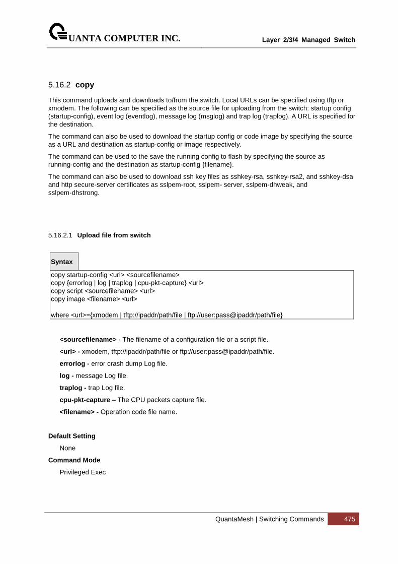
UANTA COMPUTER INC.
Layer 2/3/4 Managed Switch
QuantaMesh | Switching Commands 475
5.16.2 copy
This command uploads and downloads to/from the switch. Local URLs can be specified using tftp or xmodem. The following can be specified as the source file for uploading from the switch: startup config (startup-config), event log (eventlog), message log (msglog) and trap log (traplog). A URL is specified for the destination.
The command can also be used to download the startup config or code image by specifying the source as a URL and destination as startup-config or image respectively.
The command can be used to the save the running config to flash by specifying the source as running-config and the destination as startup-config {filename}.
The command can also be used to download ssh key files as sshkey-rsa, sshkey-rsa2, and sshkey-dsa and http secure-server certificates as sslpem-root, sslpem- server, sslpem-dhweak, and sslpem-dhstrong.
5.16.2.1 Upload file from switch
Syntax
copy startup-config <url> <sourcefilename> copy {errorlog | log | traplog | cpu-pkt-capture} <url> copy script <sourcefilename> <url> copy image <filename> <url> where <url>={xmodem | tftp://ipaddr/path/file | ftp://user:pass@ipaddr/path/file}
<sourcefilename> - The filename of a configuration file or a script file.
<url> - xmodem, tftp://ipaddr/path/file or ftp://user:pass@ipaddr/path/file.
errorlog - error crash dump Log file.
log - message Log file.
traplog - trap Log file.
cpu-pkt-capture – The CPU packets capture file.
<filename> - Operation code file name.
Default Setting
None
Command Mode
Privileged Exec
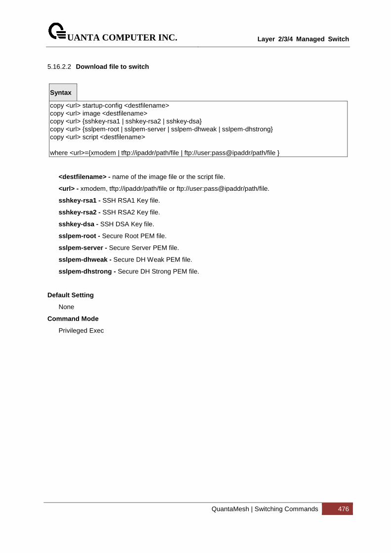
UANTA COMPUTER INC.
Layer 2/3/4 Managed Switch
QuantaMesh | Switching Commands 476
5.16.2.2 Download file to switch
Syntax
copy <url> startup-config <destfilename> copy <url> image <destfilename> copy <url> {sshkey-rsa1 | sshkey-rsa2 | sshkey-dsa} copy <url> {sslpem-root | sslpem-server | sslpem-dhweak | sslpem-dhstrong} copy <url> script <destfilename> where <url>={xmodem | tftp://ipaddr/path/file | ftp://user:pass@ipaddr/path/file }
<destfilename> - name of the image file or the script file.
<url> - xmodem, tftp://ipaddr/path/file or ftp://user:pass@ipaddr/path/file.
sshkey-rsa1 - SSH RSA1 Key file.
sshkey-rsa2 - SSH RSA2 Key file.
sshkey-dsa - SSH DSA Key file.
sslpem-root - Secure Root PEM file.
sslpem-server - Secure Server PEM file.
sslpem-dhweak - Secure DH Weak PEM file.
sslpem-dhstrong - Secure DH Strong PEM file.
Default Setting
None
Command Mode
Privileged Exec
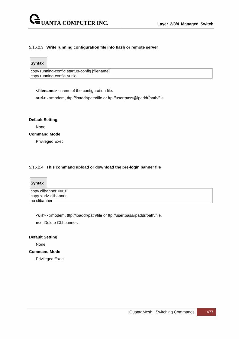
UANTA COMPUTER INC.
Layer 2/3/4 Managed Switch
QuantaMesh | Switching Commands 477
5.16.2.3 Write running configuration file into flash or remo te server
Syntax
copy running-config startup-config [filename] copy running-config <url>
<filename> - name of the configuration file.
<url> - xmodem, tftp://ipaddr/path/file or ftp://user:pass@ipaddr/path/file.
Default Setting
None
Command Mode
Privileged Exec
5.16.2.4 This command upload or download the pre-login banne r file
Syntax
copy clibanner <url> copy <url> clibanner no clibanner
<url> - xmodem, tftp://ipaddr/path/file or ftp://user:pass/ipaddr/path/file.
no - Delete CLI banner.
Default Setting
None
Command Mode
Privileged Exec
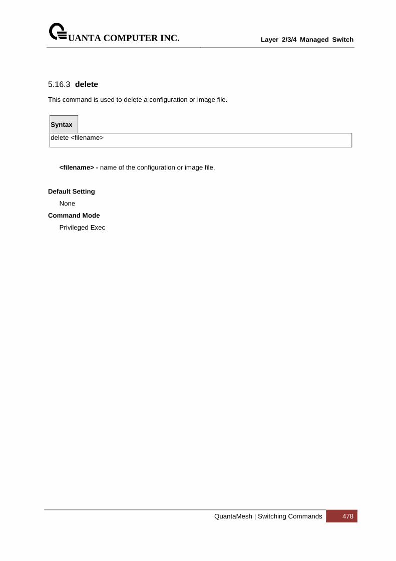
UANTA COMPUTER INC.
Layer 2/3/4 Managed Switch
QuantaMesh | Switching Commands 478
5.16.3 delete
This command is used to delete a configuration or image file.
Syntax
delete <filename>
<filename> - name of the configuration or image file.
Default Setting
None
Command Mode
Privileged Exec
UANTA COMPUTER INC.
Layer 2/3/4 Managed Switch
QuantaMesh | Switching Commands 479
5.16.4 dir
This command is used to display a list of files in Flash memory.
Syntax
dir [config | opcode [<filename>] ]
<filename> - name of the configuration or image file.
config - configuration file.
opcode - run time operation code.
Default Setting
None
Command Mode
Privileged Exec
Display Message
Column Heading Description date The date that the file was created. file name The name of the file. file type File types: Boot-Rom, Operation Code, and Config file. startup Shows if this file is used when the system is started. size The length of the file in bytes.
UANTA COMPUTER INC.
Layer 2/3/4 Managed Switch
QuantaMesh | Switching Commands 480
5.16.5 whichboot
This command is used to display which files were booted when the system powered up.
Syntax
whichboot
Default Setting
None
Command Mode
Privileged Exec
5.16.6 boot-system
This command is used to specify the file or image used to start up the system.
Syntax
boot-system {config | opcode} <filename>
<filename> - name of the configuration or image file.
config - configuration file.
opcode - run time operation code.
Default Setting
None
Command Mode
Privileged Exec
UANTA COMPUTER INC.
Layer 2/3/4 Managed Switch
QuantaMesh | Switching Commands 481
5.16.7 ping
5.16.7.1 ping <ipaddress|host>
This command checks if another computer is on the network and listens for connections. To use this command, configure the switch for network (in-band) connection. The source and target devices must have the ping utility enabled and running on top of TCP/IP. The switch can be pinged from any IP workstation with which the switch is connected through the default VLAN (VLAN 1), as long as there is a physical path between the switch and the workstation. The terminal interface sends, three pings to the target station.
Syntax
ping <ipaddress|hostname> count <0-20000000> [size <32-512>] ping <ipaddress|hostname> size <32-512> [count <0-20000000>]
< ipaddress|hostname> - a host name or an IP address.
<0-20000000> - number of pings (Range: 0 - 20000000). Note that 0 means infinite.
<size> - packet size (Range: 32 - 512).
Default Setting
Count = 5
Size = 32
Command Mode
Privileged Exec
UANTA COMPUTER INC.
Layer 2/3/4 Managed Switch
QuantaMesh | Switching Commands 482
5.16.7.2 ping ipv6 <ipv6-address|hostname>
This command use to determine whether another computer is on the network. To use the command, configure the switch for network (in-band) connection. The source and target devices must have the ping utility enabled and running on top of TCP/IP. The switch can be pinged from any IP workstation with which the switch is connected through the default VLAN (VLAN 1), as long as there is a physical path between the switch and the workstation. The terminal interface sends three pings to the target station. Use the <ipv6-address> parameter to ping an interface by using the global IPv6 address of the interface, or use the <hostname> parameter to ping a interface by using the hostname of the target. Use the optional size keyword to specify the size of the ping packet.
Syntax
ping ipv6 <ipv6-address|hostname> [size <datagram-size>]
<ipv6-address|hostname> - A global IPv6 address or valid hostname.
<datagram-size> - Datagram size. Range 48 - 2048.
Default Setting
None
Command Mode
Privileged Exec
UANTA COMPUTER INC.
Layer 2/3/4 Managed Switch
QuantaMesh | Switching Commands 483
5.16.7.3 ping ipv6 interface
This command use to determine whether another computer is on the network. To use the command, configure the switch for network (in-band) connection. The source and target devices must have the ping utility enabled and running on top of TCP/IP. The switch can be pinged from any IP workstation with which the switch is connected through the default VLAN (VLAN 1), as long as there is a physical path between the switch and the workstation. The terminal interface sends three pings to the target station. Use the interface keyword to ping an interface by using the link-local address. You can use a loopback, tunnel, or logical interface as the source. Use the optional size keyword to specify the size of the ping packet.
Syntax
ping ipv6 interface {<slot/port> | serviceport | switchport | tunnel <tunnel-id>} | loopback <loopback-id>} {<link-local-address>} [size <datagram-size>]
<slot/port> - Specify the interface.
<tunnel-id > - Specify the Tunnel ID. Range 0 -7.
<loopback-id > - Specify loopback Interface ID. Range 0 -7.
<link-local-address> - Specify link-local address.
<ipv6-address> - Specify the IPv6 address of the device.
<datagram-size> - Datagram size. Range 48 - 2048.
Default Setting
None
Command Mode
Privileged Exec
UANTA COMPUTER INC.
Layer 2/3/4 Managed Switch
QuantaMesh | Switching Commands 484
5.16.8 traceroute
5.16.8.1 traceroute
Use the traceroute command to discover the routes that packets actually take when traveling to their destination through the network on a hop-by-hop basis. Traceroute continues to provide a synchronous response when initiated from the CLI.
Syntax
traceroute <ipaddr|hostname> [initTtl <initTtl>] [maxTtl <maxTtl>] [interval <interval>] [count <count>]
<ipaddr|hostname> - The IP address or destination host you want to trace.
<initTtl> - The Use initTtl to specify the initial time-to-live (TTL), the maximum number of router hops between the local and remote system. Range is 1 to 255.
<maxTtl> - Use maxTtle to specify the maximum TTL. Range is 1 to 255.
<interval> - Use interval to specify the time between probes, in seconds. Range is 1 to 60 seconds.
<count> - Use the optional count parameter to specify the number of probes to send for each TTL value. Range is 1 to 10 probes.
Default Setting
None
Command Mode
Previledge Mode
UANTA COMPUTER INC.
Layer 2/3/4 Managed Switch
QuantaMesh | Switching Commands 485
5.16.8.2 traceroute ipv6
This command is used to discover the routes that packets actually take when traveling to their destination through the network on a hop-by-hop basis. The <ipv6-address|hostname> parameter must be a valid IPv6 address|hostname.
Syntax
traceroute ipv6 <ipv6-address|hostname > [initTtl <initTtl>] [maxTtl <maxTtl>] [interval <interval>] [count <count>]
<ipv6-address|hostname> - A valid IPv6 address or hostname.
<ipaddr> - The IP address or destination host you want to trace.
<initTtl> - The Use initTtl to specify the initial time-to-live (TTL), the maximum number of router hops between the local and remote system. Range is 1 to 255.
<maxTtl> - Use maxTtle to specify the maximum TTL. Range is 1 to 255.
<interval> - Use interval to specify the time between probes, in seconds. Range is 1 to 60 seconds.
<count> - Use the optional count parameter to specify the number of probes to send for each TTL value. Range is 1 to 10 probes.
Default Setting
None
Command Mode
Privileged Exec
UANTA COMPUTER INC.
Layer 2/3/4 Managed Switch
QuantaMesh | Switching Commands 486
5.16.9 logging cli-command
This command enables the CLI command Logging feature. The Command Logging component enables the switch to log all Command Line Interface (CLI) commands issued on the system.
Syntax
logging cli-command
Default Setting
None
Command Mode
Global Config
UANTA COMPUTER INC.
Layer 2/3/4 Managed Switch
QuantaMesh | Switching Commands 487
5.16.10 calendar set
This command is used to set the system clock.
Syntax
calendar set <mm/dd/yyy> <hh:mm:ss>
<mm/dd/yyyy> - Date Time <mm/dd/yyyy> format. (Month <1-12>. Day <1-31>. Year <2000-2037>
<hh:mm:ss> - hh in 24-hour format (Range: 0 - 23), mm (Range: 0 - 59), ss (Range: 0 - 59)
Default Setting
None
Command Mode
Privileged Exec
5.16.11 reload
This command resets the switch without powering it off. Reset means that all network connections are terminated and the boot code executes. The switch uses the stored configuration to initialize the switch. You are prompted to confirm that the reset should proceed. A successful reset is indicated by the LEDs on the switch.
Syntax
reload [<warm>]
<warm> - To only restart the operation software without rebooting whole system.
Default Setting
None
Command Mode
Privileged Exec
UANTA COMPUTER INC.
Layer 2/3/4 Managed Switch
QuantaMesh | Switching Commands 488
5.16.12 configure
This command is used to activate global configuration mode.
Syntax
configure
Default Setting
None
Command Mode
Privileged Exec
5.16.13 disconnect
This command is used to close a telnet session.
Syntax
disconnect {<0-58> | all}
<0-58> - telnet session ID.
all - all telnet sessions.
Default Setting
None
Command Mode
Privileged Exec
UANTA COMPUTER INC.
Layer 2/3/4 Managed Switch
QuantaMesh | Switching Commands 489
5.16.14 hostname
This command is used to set the prompt string.
Syntax
hostname <prompt_string>
<prompt_string> - Prompt string.
Default Setting
Quanta
Command Mode
Global Config
5.16.15 quit
This command is used to exit a CLI session.
Syntax
quit
Default Setting
None
Command Mode
Privileged Exec
UANTA COMPUTER INC.
Layer 2/3/4 Managed Switch
QuantaMesh | Switching Commands 490
5.16.16 cablestatus
This command returns the status of the specified port.
Syntax
cablestatus <slot/port>
<slot/port> - Interface Number.
Default Setting
None
Command Mode
Privileged Exec
Display Message
Cable Status : One of the following statuses is returned:
Normal : The cable is working correctly.
Open : The cable is disconnected or there is a faulty connector.
Short : There is an electrical short in the cable.
Cable Test Failed : The cable status could not be determined. The cable may in fact be working.
Cable Length : If this feature is supported by the PHY for the current link speed, the cable length is displayed as a range between the shortest estimated length and the longest estimated length. Note that if the link is down and a cable is attached to a 10/100 Ethernet adapter, then the cable status may display as Open or Short because some Ethernet adapters leave unused wire pairs unterminated or grounded. Unknown is displayed if the cable length could not be determined.
UANTA COMPUTER INC.
Layer 2/3/4 Managed Switch
QuantaMesh | Switching Commands 491
5.16.17 AutoInstall Commands
The AutoInstall feature enables the automatic update of the image and configuration of the switch. This feature enables touchless or low-touch provisioning to simplify switch configuration and imaging.
AutoInstall includes the following support:
� Downloading an image from TFTP server using DHCP option 125. The image update can result in a downgrade or upgrade of the firmware on the switch.
� Automatically downloading a configuration file from a TFTP server when the switch is booted with no saved configuration file.
When the switch boots, it attempts to obtain an IP address from a network DHCP server. The response from the DHCP server includes the IP address of the TFTP server where the image and configuration flies are located.
After acquiring an IP address and the additional relevant information from the DHCP server, the switch downloads the image file or configuration file from the TFTP server. A downloaded image is utomatically installed. A downloaded configuration file is saved to non-volatile memory
5.16.17.1 Show Commands
5.16.17.1.1 show autoinstall
This command displays the current status of the AutoInstall process.
Syntax
show autoinstall
Default Setting
None
Command Mode
Privileged Exec
Display Message
AutoInstall Operation: Displays the autoinstall operation is started or stoped.
AutoInstall Persistent Mode: Displays the autoinstall persistently for next reboot cycle.
AutoSave Mode: Displays the autoinstall persistently for next reboot cycle.
AutoReboot Mode: Displays the auto-save of downloaded configuration.
AutoUpgrade Mode: Displays the upgrade mode, which is used to allow to download the newer image.
AutoInstall Retry Count: Retry Count The number of times the switch has attempted to contact the TFTP server during the current AutoInstall session.
UANTA COMPUTER INC.
Layer 2/3/4 Managed Switch
QuantaMesh | Switching Commands 492
5.16.17.2 AutoInstall State: The status of the current or mos t recently completed AutoInstall session.Configuration Commands
5.16.17.2.1 boot-system autoinstall
Use this command to operationally start or stop the AutoInstall process on the switch. The command is non-persistent and is not saved in the startup or running configuration file.
Syntax
boot-system autoinstall { start | stop }
Default Setting
None
Command Mode
Privileged Exec
Display Message
None
5.16.17.2.2 boot-system host autoinstall
Use this command to enable AutoInstall on the switch for the next reboot cycle. The command does not change the current behavior of AutoInstall and saves the command to NVRAM.
Syntax
boot-system host autoinstall no boot-system host autoinstall
no - Use this command to disable AutoInstall for the next reboot cycle.
Default Setting
None
Command Mode
Privileged Exec
Display Message
None
UANTA COMPUTER INC.
Layer 2/3/4 Managed Switch
QuantaMesh | Switching Commands 493
5.16.17.2.3 boot-system host autosave
Use this command to automatically save the downloaded configuration file to the startup-config file on the switch. When autosave is disabled, you must explicitly save the downloaded configuration to non-volatile memory. If the switch reboots and the downloaded configuration has not been saved, the AutoInstall process begins, if the feature is enabled.
Syntax
boot-system host autosave no boot-system host autosave
no - Use this command to disable automatically saving the downloaded configuration on the switch.
Default Setting
None
Command Mode
Privileged Exec
Display Message
None
5.16.17.2.4 boot-system host autoreboot
Use this command to allow the switch to automatically reboot after successfully downloading an image. When auto reboot is enabled, no administrative action is required to activate the image and reload the switch.
This command only work on the autoupgrade is enable.
Syntax
boot-system host autoreboot no boot-system host autoreboot
no - Use this command to prevent the switch from automatically rebooting after the image is downloaded by using the AutoInstall feature.
Default Setting
None
Command Mode
Privileged Exec
Display Message
None
UANTA COMPUTER INC.
Layer 2/3/4 Managed Switch
QuantaMesh | Switching Commands 494
5.16.17.2.5 boot-system host upgrade
Use this command to allow the switch only to upgrade the newer image version.
Syntax
boot-system host upgrade no boot-system host upgrade
no - Use this command to disable this function.
Default Setting
None
Command Mode
Privileged Exec
Display Message
None
5.16.17.2.6 boot-system host retrycount
Use this command to set the number of attempts to download a configuration file from the TFTP server.
Syntax
boot-system host retrycount <1-3>
Default Setting
3
Command Mode
Privileged Exec
Display Message
None
UANTA COMPUTER INC.
Layer 2/3/4 Managed Switch
QuantaMesh | Switching Commands 495
5.16.18 Capture CPU packet Commands
5.16.18.1 Show commands
5.16.18.1.1 show capture
Use this command to display packets captured and save to RAM, It is possible to capture and save into RAM, packets that are received or transmitted throuph the CPU. A maximum 128 packets can be saved into RAM per capturing session. A maximum 128 bytes per packet can be saved into the RAM. If a packet holds more than 128 bytes, only the first 128 bytes are saved; data more than 128 bytes is skipped and cannot be displayed in the CLI.
Capturing packets is stopped automatically when 128 packets are captured and have not yet been displayed during a capture session. Captured packets are not retained after a reload cycle.
Syntax
show capture [packets]
<packets> - Specifies this parameter to display the captured packets on the CLI.
Default Setting
None
Command Mode
Privileged Exec
Display Message
Operational Status: Displays capture status.
Current Capturing Type: Displays the current capturing type. Possible types are Line, File, and Remote.
Capturing Traffic Mode: Displays the capturing traffic mode. Possible modes are Rx, Tx, or Tx/Rx.
Line Wrap Mode: Displays the line wrap mode for Line capturing type. Default is disabled.
RPCAP Listening Port: Displays the pcap listening port number. Default listening port number is 2002.
RPCAP dump file size (KB): Disaply the capture packet file size. Default file size is 512KB.
Capturing Interface: Display the capturing interface.
UANTA COMPUTER INC.
Layer 2/3/4 Managed Switch
QuantaMesh | Switching Commands 496
5.16.18.2 Configuration Command
5.16.18.2.1 capture start
Use this command to manually start capturing CPU packets for packets for trace. The packet capture operates in three modes: capture file, remote capture and capture line.
This command is not persistent across a reboot cycle.
Syntax
capture start [{all | received | transmit}]
<all> - Specifies all to capture packets for both transmitted and received packets.
<received> - Specifies received to capture only received packets.
<transmit> - Specifies transmit to capture only transmitted packets.
Default Setting
None
Command Mode
Privileged Exec
5.16.18.2.2 capture stop
Use this command to manually stop capturing CPU packets for packets for trace.
Syntax
capture stop
Default Setting
None
Command Mode
Privileged Exec
UANTA COMPUTER INC.
Layer 2/3/4 Managed Switch
QuantaMesh | Switching Commands 497
5.16.18.2.3 Capture packet to file, remote or line
Use this command to configure packet capture options. This command is persistent across a reboot cycle.
Syntax
capture {file | remote | line}
file – In the capture file mode, the captured packets are stored in a file on Flash. The maximum file size defaults to 512KB. The switch can transfer the file to a TFTP server via TFTP, FTP via CLI. The file is formatted in pcap format, is name cpu-pkt-capture.pcap, and can be examined using network analyzer tools such as Wireshark or Ethereal. Starting a file capture automatically terminates any remote capture sessions and line captureing. After the packet capture is activated, the capture proceeds until the capture file reaches its maimum size, or until the capture is stopped manually using CLI command „capture stop“.
Remote – In the remote capture mode, the captured packets are redirected in real time to an external PC running the wireshark tool for Microsoft Windows. A packet capture server runs on the switch side and sends the captured packets via a TCP connection to the Wireshark tool. The remote capture can be enabled or disable using the CLI. There should be a Windows PC with the Wireshark tool to display the captured file. When using the remote capture mode, the switch does not sotre any captured data locally on its file system.
You can configure the IP port number for connecting Wireshark to the switch. The default port number is 2002. If a firewall is installed between the Wireshark PC and the switch, then these ports must be allowed to pass through the firewall.
If the client successfully connects to the switch, the CPU packets are sent to the client PC, then Wireshark receives the packets and displays them. This continues until the session is terminated by either end.
line – In the capture line mode, the captured packets are saved into the RAM and can be displayed on the CLI. Starting a line capture automatically terminates any remote capture dession and capturing into a file. There is a maximum 128 packets of maximum 128 btes that can be captured and displayed in Line mode.
Default Setting
Remote
Command Mode
Global Config
UANTA COMPUTER INC.
Layer 2/3/4 Managed Switch
QuantaMesh | Switching Commands 498
5.16.18.2.4 capture remote port
Use this command to configure file capture options. This command is persistent across a reboot cycle.
Syntax
capture remote [port <port-id>]
<port-id> - Configure the listening port for remote Wireshark tool. The range of port ID is 1024 to 49151.
Default Setting
2002
Command Mode
Global Config
5.16.18.2.5 capture file size
Use this command to configure file capture options. This command is persistent across a reboot cycle.
Syntax
capture file [size <file-size>]
<file-size> - Configure the file size in KB. The range of file size is 2 to 512KB.
Default Setting
512
Command Mode
Global Config
UANTA COMPUTER INC.
Layer 2/3/4 Managed Switch
QuantaMesh | Switching Commands 499
5.16.18.2.6 capture line warp
This command enables wrapping of captured packets in line mode when the captured packets reaches full capacity. This command is persistent across a reboot cycle.
Syntax
capture line [wrap] no capture line wrap
Default Setting
Disable
Command Mode
Global Config
UANTA COMPUTER INC.
Layer 2/3/4 Managed Switch
QuantaMesh | Switching Commands 500
5.17 DHCP Snooping Commands
DHCP snooping is a security feature that monitors DHCP messages between a DHCP client and DHCP servers to filter harmful DHCP messages and to build a bindings database of {MAC address, IP address, VLAN ID, port} tuples that are considered authorized. You can enable DHCP snooping globally and on specific VLANs, and configure ports within the VLAN to be trusted or untrusted. DHCP servers must be reached through trusted ports.
The DHCP snooping binding table contains the MAC address, IP address, lease time, binding type, VLAN number, and interface information that corresponds to the local untrusted interfaces of a switch; it does not contain information regarding hosts interconnected with a trusted interface. An untrusted interface is an interface that is configured to receive messages from outside the network or firewall. A trusted interface is an interface that is configured to receive only messages from within the network.
DHCP snooping acts like a firewall between untrusted hosts and DHCP servers. It also gives you a way to differentiate between untrusted interfaces connected to the end-user and trusted interfaces connected to the DHCP server or another switch.
DHCP snooping enforces the following security rules:
• DHCP packets from a DHCP server (DHCPOFFER, DHCPACK, DHCPNAK, DHCPRELEASEQUERY) are dropped if received on an untrusted port.
• DHCPRELEASE and DHCPDECLINE messages are dropped if for a MAC address in the snooping database, but the binding's interface is other than the interface where the message was received.
• On untrusted interfaces, the switch drops DHCP packets whose source MAC address does not match the client hardware address. This feature is a configurable option.
The hardware identifies all incoming DHCP packets on ports where DHCP snooping is enabled. DHCP snooping is enabled on a port if (a) DHCP snooping is enabled globally, and (b) the port is a member of a VLAN where DHCP snooping is enabled. On untrusted ports, the hardware traps all incoming DHCP packets to the CPU. On trusted ports, the hardware forwards client messages and copies server messages to the CPU so that DHCP snooping can learn the binding.
You can enable the switch to operate as a DHCP Layer 2 relay agent to relay DHCP requests from clients to a Layer 3 relay agent or server. The Circuit ID and Remote ID can be added to DHCP requests relayed from clients to a DHCP server. This information is included in DHCP Option 82, as specified in sections 3.1 and 3.2 of RFC3046.

UANTA COMPUTER INC.
Layer 2/3/4 Managed Switch
QuantaMesh | Switching Commands 501
5.17.1 Show Commands
5.17.1.1 show ip dhcp snooping
This command displays the DHCP Snooping global configurations and per port configurations.
Syntax
show ip dhcp snooping
Default Setting
None
Command Mode
Privileged Exec
Display Message
Interface: The interface for which data is displayed.
Trusted: If it is enabled, DHCP snooping considers the port as trusted. The factory default is disabled.
Log Invalid Pkts: If it is enabled, DHCP snooping application logs invalid packets on the specified interface.
UANTA COMPUTER INC.
Layer 2/3/4 Managed Switch
QuantaMesh | Switching Commands 502
5.17.1.2 show ip dhcp snooping binding
This command displays the DHCP Snooping binding entries. To restrict the output, use the following options:
• Dynamic: Restrict the output based on DCHP snooping.
• Interface: Restrict the output based on a specific interface.
• Static: Restrict the output based on static entries.
• VLAN: Restrict the output based on VLAN.
Syntax
show ip dhcp snooping binding [{static | dynamic}] [interface <slot/port>] [vlan id]
Default Setting
None
Command Mode
Privileged Exec
Display Message
MAC Address: Displays the MAC address for the binding that was added. The MAC address is the key to the binding database.
IP Address: Displays the valid IP address for the binding rule.
VLAN: The VLAN for the binding rule.
Interface: The interface to add a binding into the DHCP snooping interface.
Type: Binding type; statically configured from the CLI or dynamically learned.
Lease (Secs): he remaining lease time for the entry.
UANTA COMPUTER INC.
Layer 2/3/4 Managed Switch
QuantaMesh | Switching Commands 503
5.17.1.3 show ip dhcp snooping database
This command displays the DHCP Snooping configuration related to the database persistency.
Syntax
show ip dhcp snooping database
Default Setting
None
Command Mode
Privileged Exec
Display Message
Agent URL: Bindings database agent URL.
Write Delay: The maximum write time to write the database into local or remote.
Abort Timer: The maximum time to abort the database transfer process.
UANTA COMPUTER INC.
Layer 2/3/4 Managed Switch
QuantaMesh | Switching Commands 504
5.17.1.4 show ip dhcp snooping statistics
This command lists statistics for DHCP Snooping security violations on untrusted ports.
Syntax
show ip dhcp snooping statistics
Default Setting
None
Command Mode
Privileged Exec
Display Message
Interface: The IP address of the interface in slot/port format.
MAC Verify Failures: Represents the number of DHCP messages that were filtered on an untrusted interface because of source MAC address and client HW address mismatch.
Client Ifc Mismatch: Represents the number of DHCP release and Deny messages received on the different ports than learned previously.
DHCP Server Msgs Rec'd: Represents the number of DHCP server messages received on untrusted ports.
5.17.1.5 show ip dhcp snooping information all
This command display the summary of DHCP Option-82 configuration.
Syntax
show ip dhcp snooping information all
Default Setting
None
Command Mode
Privileged Exec
UANTA COMPUTER INC.
Layer 2/3/4 Managed Switch
QuantaMesh | Switching Commands 505
5.17.1.6 show ip dhcp snooping information stats interface
This command display statistics specific to DHCP Option-82 configuration interface.
Syntax
show ip dhcp snooping information stats interface [<slot/port>]
<slot/port> - Interface number.
Default Setting
None
Command Mode
Privileged Exec
5.17.1.7 show ip dhcp snooping information agent-option vlan
This command display the DHCP Option-82 configuration specific to VLAN.
Syntax
show ip dhcp snooping information agent-option vlan <vlan-list>
<vlan-list> - Specifies VLAN ID in a list. The range of VLAN ID is 1 to 4093.
Default Setting
None
Command Mode
Privileged Exec
UANTA COMPUTER INC.
Layer 2/3/4 Managed Switch
QuantaMesh | Switching Commands 506
5.17.1.8 show ip dhcp snooping information vlan
This command display the DHCP Option-82 configuration specific to VLAN.
Syntax
show ip dhcp snooping information vlan <vlan-list>
<vlan-list> - Specifies VLAN ID in a list. The range of VLAN ID is 1 to 4093.
Default Setting
None
Command Mode
Privileged Exec
5.17.1.9 show ip dhcp snooping information circuit-id vlan
This command display the DHCP Option-82 circuit-id configuration specific to VLAN.
Syntax
show ip dhcp snooping information circuit-id vlan <vlan-list>
<vlan-list> - Specifies VLAN ID in a list. The range of VLAN ID is 1 to 4093.
Default Setting
None
Command Mode
Privileged Exec
UANTA COMPUTER INC.
Layer 2/3/4 Managed Switch
QuantaMesh | Switching Commands 507
5.17.1.10 show ip dhcp snooping information remote-id vlan
This command display the DHCP Option-82 remote-id configuration specific to VLAN.
Syntax
show ip dhcp snooping information remote-id vlan <vlan-list>
<vlan-list> - Specifies VLAN ID in a list. The range of VLAN ID is 1 to 4093.
Default Setting
None
Command Mode
Privileged Exec
5.17.1.11 show ip dhcp snooping information interface
This command display DHCP Option-82 configuration interface.
Syntax
show ip dhcp snooping information interface [<slot/port>]
<slot/port> - Specifies the interface number.
Default Setting
None
Command Mode
Privileged Exec
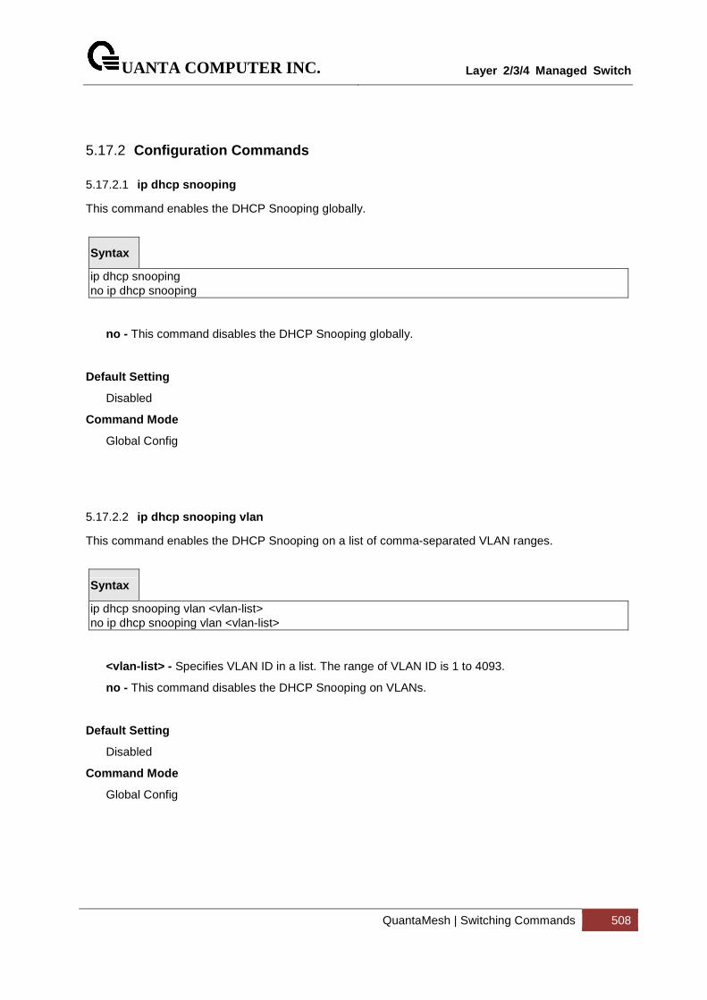
UANTA COMPUTER INC.
Layer 2/3/4 Managed Switch
QuantaMesh | Switching Commands 508
5.17.2 Configuration Commands
5.17.2.1 ip dhcp snooping
This command enables the DHCP Snooping globally.
Syntax
ip dhcp snooping no ip dhcp snooping
no - This command disables the DHCP Snooping globally.
Default Setting
Disabled
Command Mode
Global Config
5.17.2.2 ip dhcp snooping vlan
This command enables the DHCP Snooping on a list of comma-separated VLAN ranges.
Syntax
ip dhcp snooping vlan <vlan-list> no ip dhcp snooping vlan <vlan-list>
<vlan-list> - Specifies VLAN ID in a list. The range of VLAN ID is 1 to 4093.
no - This command disables the DHCP Snooping on VLANs.
Default Setting
Disabled
Command Mode
Global Config
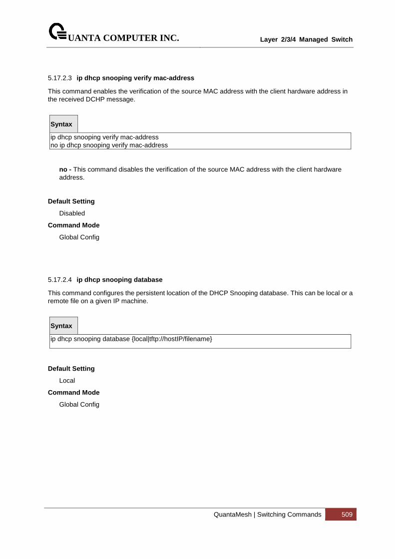
UANTA COMPUTER INC.
Layer 2/3/4 Managed Switch
QuantaMesh | Switching Commands 509
5.17.2.3 ip dhcp snooping verify mac-address
This command enables the verification of the source MAC address with the client hardware address in the received DCHP message.
Syntax
ip dhcp snooping verify mac-address no ip dhcp snooping verify mac-address
no - This command disables the verification of the source MAC address with the client hardware address.
Default Setting
Disabled
Command Mode
Global Config
5.17.2.4 ip dhcp snooping database
This command configures the persistent location of the DHCP Snooping database. This can be local or a remote file on a given IP machine.
Syntax
ip dhcp snooping database {local|tftp://hostIP/filename}
Default Setting
Local
Command Mode
Global Config
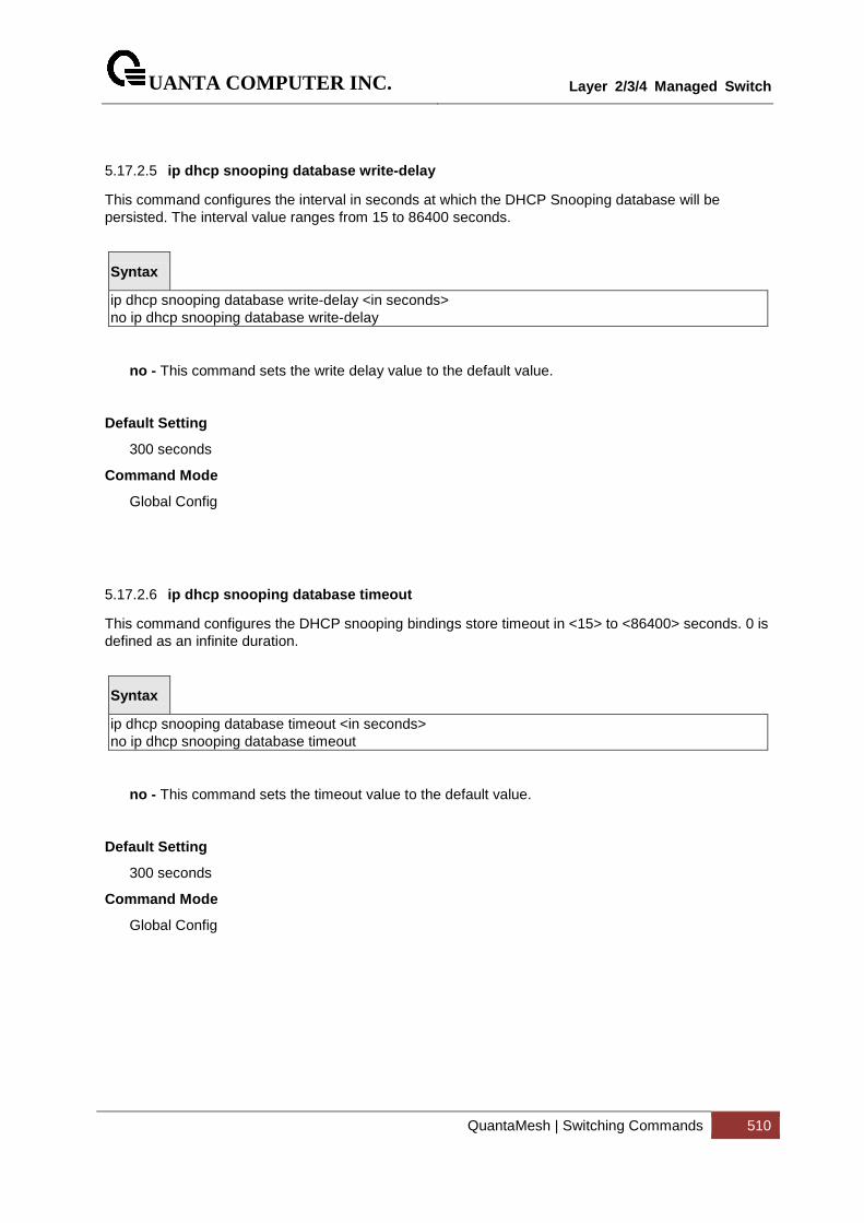
UANTA COMPUTER INC.
Layer 2/3/4 Managed Switch
QuantaMesh | Switching Commands 510
5.17.2.5 ip dhcp snooping database write-delay
This command configures the interval in seconds at which the DHCP Snooping database will be persisted. The interval value ranges from 15 to 86400 seconds.
Syntax
ip dhcp snooping database write-delay <in seconds> no ip dhcp snooping database write-delay
no - This command sets the write delay value to the default value.
Default Setting
300 seconds
Command Mode
Global Config
5.17.2.6 ip dhcp snooping database timeout
This command configures the DHCP snooping bindings store timeout in <15> to <86400> seconds. 0 is defined as an infinite duration.
Syntax
ip dhcp snooping database timeout <in seconds> no ip dhcp snooping database timeout
no - This command sets the timeout value to the default value.
Default Setting
300 seconds
Command Mode
Global Config
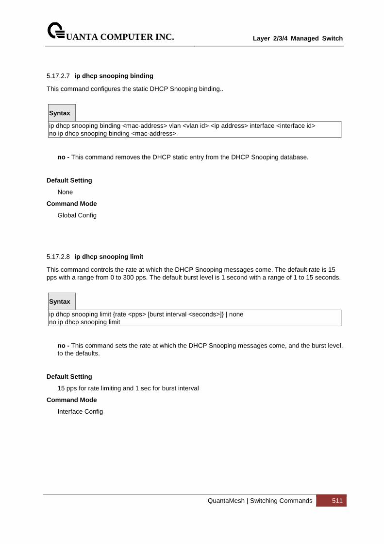
UANTA COMPUTER INC.
Layer 2/3/4 Managed Switch
QuantaMesh | Switching Commands 511
5.17.2.7 ip dhcp snooping binding
This command configures the static DHCP Snooping binding..
Syntax
ip dhcp snooping binding <mac-address> vlan <vlan id> <ip address> interface <interface id> no ip dhcp snooping binding <mac-address>
no - This command removes the DHCP static entry from the DHCP Snooping database.
Default Setting
None
Command Mode
Global Config
5.17.2.8 ip dhcp snooping limit
This command controls the rate at which the DHCP Snooping messages come. The default rate is 15 pps with a range from 0 to 300 pps. The default burst level is 1 second with a range of 1 to 15 seconds.
Syntax
ip dhcp snooping limit {rate <pps> [burst interval <seconds>]} | none no ip dhcp snooping limit
no - This command sets the rate at which the DHCP Snooping messages come, and the burst level, to the defaults.
Default Setting
15 pps for rate limiting and 1 sec for burst interval
Command Mode
Interface Config
UANTA COMPUTER INC.
Layer 2/3/4 Managed Switch
QuantaMesh | Switching Commands 512
5.17.2.9 ip dhcp snooping log-invalid
This command controls the logging DHCP messages filtration by the DHCP Snooping application.
Syntax
ip dhcp snooping log-invalid no ip dhcp snooping log-invalid
no - This command disables the logging DHCP messages filtration by the DHCP Snooping application.
Default Setting
Disabled
Command Mode
Interface Config
5.17.2.10 ip dhcp snooping trust
This command configures the port as trusted.
Syntax
ip dhcp snooping trust no ip dhcp snooping trust
no - This command configures the port as untrusted.
Default Setting
Disabled
Command Mode
Interface Config
UANTA COMPUTER INC.
Layer 2/3/4 Managed Switch
QuantaMesh | Switching Commands 513
5.17.2.11 clear ip dhcp snooping binding
Use this command to clear all DHCP Snooping bindings on all interfaces or on a specific interface.
Syntax
clear ip dhcp snooping binding [interface <slot/port>]
<slot/port> - Specifies the interface number.
Command Mode
Privileged EXEC
5.17.2.12 clear ip dhcp snooping statistics
Use this command to clear all DHCP Snooping statistics.
Syntax
clear ip dhcp snooping statistics
Command Mode
Privileged EXEC
5.17.2.13 ip dhcp snooping information option
This command ip dhcp snooping information option enables the DHCP L2 option mode on the system.
Syntax
ip dhcp snooping information option no ip dhcp snooping information option
no - This command disables the DHCP L2 option mode.
Default Setting
Disabled
Command Mode

UANTA COMPUTER INC.
Layer 2/3/4 Managed Switch
QuantaMesh | Switching Commands 514
Global Config
UANTA COMPUTER INC.
Layer 2/3/4 Managed Switch
QuantaMesh | Switching Commands 515
5.17.2.14 ip dhcp snooping information option
This command ip dhcp snooping information option enables the DHCP L2 option mode on the interface.
Syntax
ip dhcp snooping information option no ip dhcp snooping information option
no - This command disables the DHCP L2 option mode.
Default Setting
Disabled
Command Mode
Interface Config
5.17.2.15 ip dhcp snooping information option circuit-id
Use this command to enable the DHCP Snooping information option circuit-id on a range of VLANs.When enabled, the circuit ID is added in DHCP Option-82.
Use this command with no argument to disable the DHCP Snooping information option circuit-id on a range of VLANs. Clear the DHCP Option-82 circuit ID for a VLAN.
The circuit ID format should be in the form of LLLLVVVVXXYYZZ (LLLL: is the length from V to Z, VVVV: VLAN ID, XX is the Unit ID, YY is the function/module ID and ZZ is the Port number)
Syntax
ip dhcp snooping information option circuit-id vlan <vlan-list>
no ip dhcp snooping information option circuit-id vlan <vlan-list>
<vlan-list> - Specifies VLAN ID in a list. The range of VLAN ID is 1 to 4093.
no - Clear the DHCP Option-82 circuit ID for a VLAN..
Default Setting
Disabled
Command Mode
Global Config
UANTA COMPUTER INC.
Layer 2/3/4 Managed Switch
QuantaMesh | Switching Commands 516
5.17.2.16 ip dhcp snooping information option remote-id
Use this command to enable the DHCP Snooping information option remote-id on a range of VLANs. When remote-id string is set using this command, all Client DHCP requests that fall under this service subscription are added with Option-82 Remote-id as the configured remote-id string.
Use this command with no argument to disable the DHCP Snooping information option remote-id on a range of VLANs. When remote-id string is reset using this command, the Client DHCP requests that fall under this service subscription are not added with Option-82 Remote-id.
The remote ID format should be in the form of LLLLXXXXX (LLLL: is the length from remote-id strings)
Syntax
ip dhcp snooping information option remote-id <remoteId string> vlan <vlan-list>
no ip dhcp snooping information option remote-id vlan <vlan-list>
<vlan-list> - Specifies VLAN ID in a list. The range of VLAN ID is 1 to 4093.
no - Clear the DHCP Option-82 remoteId ID for a VLAN..
Default Setting
Disabled
Command Mode
Global Config
5.17.2.17 ip dhcp snooping information option vlan
Use this command to enable the DHCP Snooping information option on a range of VLANs.
Syntax
ip dhcp snooping information option vlan <vlan-list>
no ip dhcp snooping information option vlan <vlan-list>
<vlan-list> - Specifies VLAN ID in a list. The range of VLAN ID is 1 to 4093.
no - This command with no argument to disable the DHCP Snooping information option on a range of VLANs..
Default Setting
Disabled
Command Mode
Global Config
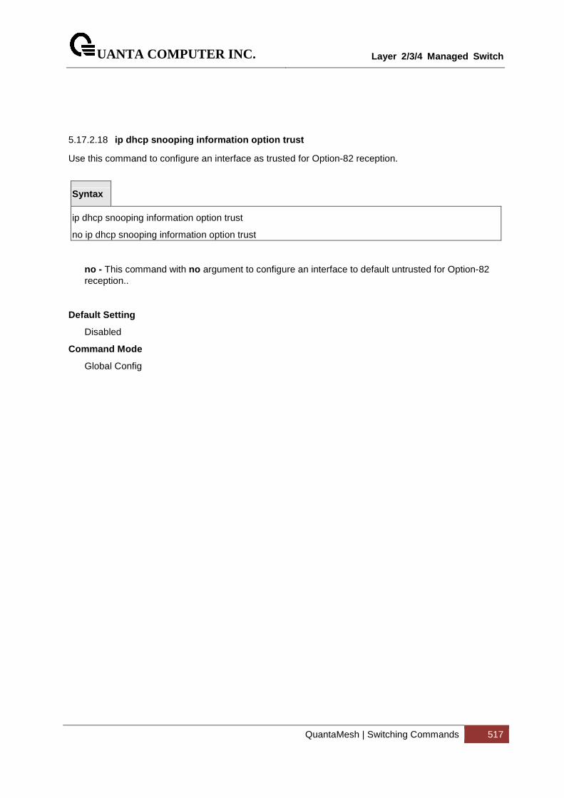
UANTA COMPUTER INC.
Layer 2/3/4 Managed Switch
QuantaMesh | Switching Commands 517
5.17.2.18 ip dhcp snooping information option trust
Use this command to configure an interface as trusted for Option-82 reception.
Syntax
ip dhcp snooping information option trust
no ip dhcp snooping information option trust
no - This command with no argument to configure an interface to default untrusted for Option-82 reception..
Default Setting
Disabled
Command Mode
Global Config
UANTA COMPUTER INC.
Layer 2/3/4 Managed Switch
QuantaMesh | Switching Commands 518
5.18 IP Source Guard (IPSG) Commands
IP Source Guard (IPSG) is a security feature that filters IP packets based on source ID. The source ID may be either the source IP address or a {source IP address, source MAC address} pair. The DHCP snooping binding database and static IPSG entries identify authorized source IDs. You can configure:
• Whether enforcement includes the source MAC address.
• Static authorized source IDs.
Similar to DHCP snooping, this feature is enabled on a DHCP snooping untrusted Layer 2 port. Initially, all IP traffic on the port is blocked except for DHCP packets that are captured by the DHCP snooping process. When a client receives a valid IP address from the DHCP server, or when a static IP source binding is configured by the user, a per-port and VLAN Access Control List is installed on the port. This process restricts the client IP traffic to those source IP addresses configured in the binding; any IP traffic with a source IP address other than that in the IP source binding is filtered out. This filtering limits a host’s ability to attack the network by claiming a neighbor host's IP address.
IPSG can be enabled on physical or LAG ports. IPSG is disabled by default. If you enable IPSG on a port where DHCP snooping is disabled or where DHCP snooping is enabled but the port is trusted, all IP traffic received on that port is dropped depending on the admin-configured IPSG entries. IPSG cannot be enabled on a port-based routing interface.
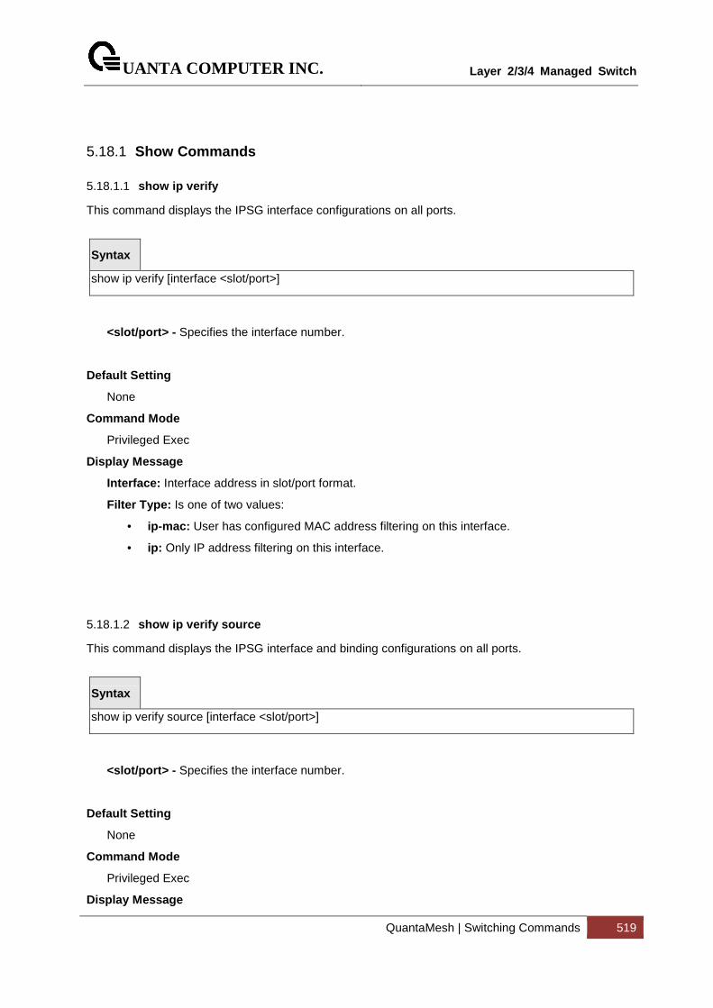
UANTA COMPUTER INC.
Layer 2/3/4 Managed Switch
QuantaMesh | Switching Commands 519
5.18.1 Show Commands
5.18.1.1 show ip verify
This command displays the IPSG interface configurations on all ports.
Syntax
show ip verify [interface <slot/port>]
<slot/port> - Specifies the interface number.
Default Setting
None
Command Mode
Privileged Exec
Display Message
Interface: Interface address in slot/port format.
Filter Type: Is one of two values:
• ip-mac: User has configured MAC address filtering on this interface.
• ip: Only IP address filtering on this interface.
5.18.1.2 show ip verify source
This command displays the IPSG interface and binding configurations on all ports.
Syntax
show ip verify source [interface <slot/port>]
<slot/port> - Specifies the interface number.
Default Setting
None
Command Mode
Privileged Exec
Display Message
UANTA COMPUTER INC.
Layer 2/3/4 Managed Switch
QuantaMesh | Switching Commands 520
Interface: Interface address in slot/port format.
Filter Type: Is one of two values:
• ip-mac: User has configured MAC address filtering on this interface.
• ip: Only IP address filtering on this interface.
IP Address: IP address of the interface.
MAC Address: If MAC address filtering is not configured on the interface, the MAC Address field is empty. If port security is disabled on the interface, then the MAC Address field displays "permit-all".
VLAN: The VLAN for the binding rule.
5.18.1.3 show ip source binding
This command displays the IPSG bindings.
Syntax
show ip source binding [{static | dhcp-snooping}] [interface <slot/port>] [vlan <vlan-id>]
Default Setting
None
Command Mode
Privileged Exec
Display Message
MAC Address: The MAC address for the entry that is added.
IP Address: The IP address of the entry that is added.
Type: Entry type; statically configured from CLI or dynamically learned from DHCP Snooping.
VLAN: VLAN for the entry.
Interface: IP address of the interface in slot/port format.
UANTA COMPUTER INC.
Layer 2/3/4 Managed Switch
QuantaMesh | Switching Commands 521
5.18.2 Configuration Commands
5.18.2.1 ip verify source
This command configures the IPSG source ID attribute to filter the data traffic in the hardware. Source ID is the combination of IP address and MAC address. Normal command allows data traffic filtration based on the IP address. With the "port-security" option, the data traffic will be filtered based on the IP and MAC addresses.
Syntax
ip verify source [port-security] no ip verify source [port-security]
no - This command disables the IPSG configuration in the hardware.
Default Setting
Disabled
Command Mode
Interface Config
5.18.2.2 ip verify binding
This command configures static IP source guard (IPSG) entries.
Syntax
ip verify binding <mac-address> vlan <vlan-id> <ip address> interface <slot/port> no ip verify binding <mac-address> vlan <vlan-id> <ip address> interface <slot/port>
no - This command removes the IPSG static entry from the IPSG database.
Default Setting
None
Command Mode
Global Config
UANTA COMPUTER INC.
Layer 2/3/4 Managed Switch
QuantaMesh | Switching Commands 522
5.19 Dynamic ARP Inspection (DAI) Command
Dynamic ARP Inspection (DAI) is a security feature that rejects invalid and malicious ARP packets. DAI prevents a class of man-in-the-middle attacks, where an unfriendly station intercepts traffic for other stations by poisoning the ARP caches of its unsuspecting neighbors. The miscreant sends ARP requests or responses mapping another station's IP address to its own MAC address.
To prevent ARP poisoning attacks, a switch must ensure that only valid ARP requests and responses are relayed. DAI prevents these attacks by intercepting all ARP requests and responses. Each of these intercepted packets is verified for valid MAC address to IP address bindings before the local ARP cache is updated or the packet is forwarded to the appropriate destination. Invalid ARP packets are dropped.
DAI determines the validity of an ARP packet based on valid MAC address to IP address bindings stored in a trusted database. This database is built at runtime by DHCP snooping, provided this feature is enabled on VLANs and on the switch. DAI relies on DHCP snooping. DHCP snooping listens to DHCP message exchanges and builds a binding database of valid {MAC address, IP address, VLAN, and interface} tuples. In addition, in order to handle hosts that use statically configured IP addresses, DAI can also validate ARP packets against user-configured ARP ACLs.
When DAI is enabled, the switch drops ARP packets whose sender MAC address and sender IP address do not match an entry in the DHCP snooping bindings database. You can optionally configure additional ARP packet validation.
UANTA COMPUTER INC.
Layer 2/3/4 Managed Switch
QuantaMesh | Switching Commands 523
5.19.1 Show Commands
5.19.1.1 show ip arp inspection statistics
This command displays the statistics of the ARP packets processed by Dynamic ARP Inspection. Give the vlan-list argument and the command displays the statistics on all DAI-enabled VLANs in that list. Give the single vlan argument and the command displays the statistics on that VLAN. If no argument is included, the command lists a summary of the forwarded and dropped ARP packets.
Syntax
show ip arp inspection statistics [vlan <vlan-list>]
<vlan-list> - Specifies VLAN ID in a list. The range of VLAN ID is 1 to 4093.
Default Setting
None
Command Mode
Privileged Exec
Display Message
VLAN: The VLAN ID for each displayed row.
Forwarded: The total number of valid ARP packets forwarded in this VLAN.
Dropped : The total number of not valid ARP packets dropped in this VLAN.
DHCP Drops: The number of packets dropped due to DHCP snooping binding database match failure.
ACL Drops: The number of packets dropped due to ARP ACL rule match failure.
DHCP Permits: The number of packets permitted due to DHCP snooping binding database match.
ACL Permits: The number of packets permitted due to ARP ACL rule match.
Bad Src MAC: The number of packets dropped due to Source MAC validation failure.
Bad Dest MAC: The number of packets dropped due to Destination MAC validation failure.
Invalid IP: The number of packets dropped due to invalid IP checks.
UANTA COMPUTER INC.
Layer 2/3/4 Managed Switch
QuantaMesh | Switching Commands 524
5.19.1.2 show ip arp inspection
This command displays the Dynamic ARP Inspection global configuration and configuration on all the VLANs. With the vlan-list argument (i.e. comma separated VLAN ranges), the command displays the global configuration and configuration on all the VLANs in the given VLAN list. The global configuration includes the source mac validation, destination mac validation and invalid IP validation information.
Syntax
show ip arp inspection [vlan <vlan-list>]
<vlan-list> - Specifies VLAN ID in a list. The range of VLAN ID is 1 to 4093.
Default Setting
None
Command Mode
Privileged Exec
Display Message
Source MAC Validation: Displays whether Source MAC Validation of ARP frame is enabled or disabled.
Destination MAC Validation: Displays whether Destination MAC Validation is enabled or disabled.
IP Address Validation : Displays whether IP Address Validation is enabled or disabled.
VLAN: The VLAN ID for each displayed row.
Configuration: Displays whether DAI is enabled or disabled on the VLAN.
Log Invalid: Displays whether logging of invalid ARP packets is enabled on the VLAN.
ACL Name: The ARP ACL Name, if configured on the VLAN.
Static Flag: If the ARP ACL is configured static on the VLAN.
UANTA COMPUTER INC.
Layer 2/3/4 Managed Switch
QuantaMesh | Switching Commands 525
5.19.1.3 show ip arp inspection interfaces
This command displays the Dynamic ARP Inspection configuration on all the DAI-enabled interfaces. An interface is said to be enabled for DAI if at least one VLAN, that the interface is a member of, is enabled for DAI. Given a slot/port interface argument, the command displays the values for that interface whether the interface is enabled for DAI or not.
Syntax
show ip arp inspection interfaces [<slot/port>]
<slot/port> - Interface Number.
Default Setting
None
Command Mode
Privileged Exec
Display Message
Interface: The interface ID for each displayed row.
Trust State: Whether the interface is trusted or untrusted for DAI.
Rate Limit : The configured rate limit value in packets per second.
Burst Interval: The configured burst interval value in seconds.
UANTA COMPUTER INC.
Layer 2/3/4 Managed Switch
QuantaMesh | Switching Commands 526
5.19.1.4 show arp access-list
This command displays the configured ARP ACLs with the rules. Giving an ARP ACL name as the argument will display only the rules in that ARP ACL.
Syntax
show arp access-list [acl-name]
Default Setting
None
Command Mode
Privileged Exec

UANTA COMPUTER INC.
Layer 2/3/4 Managed Switch
QuantaMesh | Switching Commands 527
5.19.2 Configuration Commands
5.19.2.1 ip arp inspection validate
This command enables additional validation checks like source-mac validation, destination-mac validation, and ip address validation on the received ARP packets.
Syntax
ip arp inspection validate {[src-mac] [dst-mac] [ip]} no ip arp inspection validate {[src-mac] [dst-mac] [ip]}
no - This command disables the additional validation checks on the received ARP packets.
Default Setting
Disabled
Command Mode
Global Config
5.19.2.2 ip arp inspection vlan
This command enables Dynamic ARP Inspection on a list of comma-separated VLAN ranges.
Syntax
ip arp inspection vlan <vlan-list> no ip arp inspection vlan <vlan-list>
no - This command disables Dynamic ARP Inspection on a list of comma-separated VLAN ranges.
Default Setting
Disabled
Command Mode
Global Config
UANTA COMPUTER INC.
Layer 2/3/4 Managed Switch
QuantaMesh | Switching Commands 528
5.19.2.3 ip arp inspection vlan logging
This command enables logging of invalid ARP packets on a list of comma-separated VLAN ranges.
Syntax
ip arp inspection vlan <vlan-list> logging no ip arp inspection vlan <vlan-list> logging
no - This command disables logging of invalid ARP packets on a list of comma-separated VLAN ranges.
Default Setting
Disabled
Command Mode
Global Config
5.19.2.4 ip arp inspection filter
This command configures the ARP ACL used to filter invalid ARP packets on a list of comma-separated VLAN ranges. If the static keyword is given, packets that do not match a permit statement are dropped without consulting the DHCP snooping bindings.
Syntax
ip arp inspection filter <acl-name> vlan <vlan-list> [static] no ip arp inspection filter <acl-name> vlan <vlan-list> [static]
no - This command unconfigures the ARP ACL used to filter invalid ARP packets on a list of comma-separated VLAN ranges.
Default Setting
No ARP ACL is configured on a VLAN
Command Mode
Global Config
UANTA COMPUTER INC.
Layer 2/3/4 Managed Switch
QuantaMesh | Switching Commands 529
5.19.2.5 ip arp inspection trust
This command configures an interface as trusted for Dynamic ARP Inspection.
Syntax
ip arp inspection trust no ip arp inspection trust
no - This command configures an interface as untrusted for Dynamic ARP Inspection.
Default Setting
Disabled
Command Mode
Interface Config
5.19.2.6 ip arp inspection limit
This command configures the rate limit and burst interval values for an interface. Configuring none for the limit means the interface is not rate limited for Dynamic ARP Inspections.
Syntax
ip arp inspection limit {rate <pps> [burst interval <seconds>] | none} no ip arp inspection limit
no - This command sets the rate limit and burst interval values for an interface to the default values of 15 pps and 1 second, respectively.
Default Setting
15 pps for rate and 1 second for burst-interval
Command Mode
Interface Config
UANTA COMPUTER INC.
Layer 2/3/4 Managed Switch
QuantaMesh | Switching Commands 530
5.19.2.7 arp access-list
This command creates an ARP ACL.
Syntax
arp access-list <acl-name> no arp access-list <acl-name>
no - This command deletes a configured ARP ACL.
Default Setting
None
Command Mode
Global Config
5.19.2.8 permit ip host mac host
This command configures a rule for a valid IP address and MAC address combination used in ARP packet validation.
Syntax
permit ip host <sender-ip> mac host <sender-mac> no permit ip host <sender-ip> mac host <sender-mac>
no - This command deletes a rule for a valid IP and MAC combination.
Default Setting
None
Command Mode
ARP Access-list Config
UANTA COMPUTER INC.
Layer 2/3/4 Managed Switch
QuantaMesh | Switching Commands 531
5.19.2.9 clear ip arp inspection statistics
This command resets the statistics for Dynamic ARP Inspection on all VLANs.
Syntax
clear ip arp inspection statistics
Default Setting
None
Command Mode
Privileged Exec
UANTA COMPUTER INC.
Layer 2/3/4 Managed Switch
QuantaMesh | Switching Commands 532
5.20 Differentiated Service Command
This Switching Command function can only be used on the QoS software version.
This chapter contains the CLI commands used for the QoS Differentiated Services (DiffServ) package.
The user configures DiffServ in several stages by specifying:
1. Class
− creating and deleting classes
− defining match criteria for a class
The only way to remove an individual match criterion from an existing class definition is to delete the class and re-create it.
2. Policy
− creating and deleting policies
− associating classes with a policy
− defining policy statements for a policy/class combination
3. Service
− adding and removing a policy to/from a directional (that is, inbound, outbound) interface
Packets are filtered and processed based on defined criteria. The filtering criteria are defined by a class. The processing is defined by a policy's attributes. Policy attributes may be defined on a per class instance basis, and it is these attributes that are applied when a match occurs.
Packet processing begins by testing the match criteria for a packet. A policy is applied to a packet when a class match within that policy is found.
Note that the type of class - all, any, or acl - has a bearing on the validity of match criteria specified when defining the class. A class type of 'any' processes its match rules in an ordered sequence; additional rules specified for such a class simply extend this list. A class type of ‘acl’ obtains its rule list by interpreting each ACL rule definition at the time the Diffserv class is created. Differences arise when specifying match criteria for a class type 'all', since only one value for each non-excluded match field is allowed within a class definition. If a field is already specified for a class, all subsequent attempts to specify the same field fail, including the cases where a field can be specified multiple ways through alternative formats. The exception to this is when the 'exclude' option is specified, in which case this restriction does not apply to the excluded fields.
!
!
UANTA COMPUTER INC.
Layer 2/3/4 Managed Switch
QuantaMesh | Switching Commands 533
The following class restrictions are imposed by the LB8 Series L3 Switch DiffServ design:
• nested class support limited to:
− 'all' within 'all'
− no nested 'not' conditions
− no nested 'acl' class types
− each class contains at most one referenced class
• hierarchical service policies not supported in a class definition
• access list matched by reference only, and must be sole criterion in a class
− that is, ACL rules copied as class match criteria at time of class creation, with class type 'any'
− implicit ACL 'deny all' rule also copied
− no nesting of class type 'acl'
Regarding nested classes, referred to here as class references, a given class definition can contain at most one reference to another class, which can be combined with other match criteria. The referenced class is truly a reference and not a copy, since additions to a referenced class affect all classes that reference it. Changes to any class definition currently referenced by any other class must result in valid class definitions for all derived classes otherwise the change is rejected. A class reference may be removed from a class definition.
The user can display summary and detailed information for classes, policies, and services. All configuration information is accessible via the CLI, and SNMP user interfaces.
UANTA COMPUTER INC.
Layer 2/3/4 Managed Switch
QuantaMesh | Switching Commands 534
5.20.1 General Commands
The following characteristics are configurable for the platform as a whole.
5.20.1.1 diffserv
This command sets the DiffServ operational mode to active. While disabled, the DiffServ configuration is retained and can be changed, but it is not activated. When enabled, Diffserv services are activated.
Syntax
diffserv
Command Mode
Global Config
5.20.1.2 no diffserv
This command sets the DiffServ operational mode to inactive. While disabled, the DiffServ configuration is retained and can be changed, but it is not activated. When enabled, Diffserv services are activated.
Syntax
no diffserv
Command Mode
Global Config
UANTA COMPUTER INC.
Layer 2/3/4 Managed Switch
QuantaMesh | Switching Commands 535
5.20.2 Class Commands
The 'class' command set is used in DiffServ to define:
Traffic Classification specifies Behavior Aggregate (BA) based on DSCP, and Multi- Field (MF) classes of traffic (name, match criteria)
Service Levels specifies the BA forwarding classes / service levels. Conceptually, DiffServ is a two-level hierarchy of classes: 1. Service/PHB, 2. Traffic Class
This set of commands consists of class creation/deletion and matching, with the class match commands specifying layer 3, layer 2, and general match criteria. The class match criteria are also known as class rules, with a class definition consisting of one or more rules to identify the traffic belonging to the class. Note that once a class match criterion is created for a class, it cannot be changed or deleted - the entire class must be deleted and re-created.
The CLI command root is class-map.
5.20.2.1 class-map
This command defines a new DiffServ class of type match-all, match-any or match-access-group.
Syntax
class-map [ match-all ] <class-map-name> [{ipv4 | ipv6}]
<class-map-name> is a case sensitive alphanumeric string from 1 to 31 characters uniquely identifying the class.
When used without any match condition, this command enters the class-map mode. The <class-map-name> is the name of an existing DiffServ class.
The class name 'default' is reserved and is not allowed here. The class type of match-all indicates all of the individual match conditions must be true for a packet to be considered a member of the class.
The optional keywords [{ipv4 | ipv6}] specify the Layer 3 protocol for this class. If not specified, this parameter defaults to ‘ipv4’. This maintains backward compatibility for configurations defined on systems before IPv6 match items were supported.
The CLI mode is changed to Class-Map Config or Ipv6-Class-Map Config when this command is successfully executed depending on the [{ipv4 | ipv6}] keyword specified.
Command Mode
Global Config
!
UANTA COMPUTER INC.
Layer 2/3/4 Managed Switch
QuantaMesh | Switching Commands 536
5.20.2.2 no class-map
This command eliminates an existing DiffServ class.
Syntax
no class-map <class-map-name>
<class-map-name> is the name of an existing DiffServ class.
The class name 'default' is reserved and is not allowed here. This command may be issued at any time; if the class is currently referenced by one or more policies or by any other class, this deletion attempt shall fail.
Command Mode
Global Config
5.20.2.3 class-map rename
This command changes the name of a DiffServ class.
Syntax
class-map rename <new-class-map-name>
<new-class-map-name> is a case-sensitive alphanumeric string from 1 to 31 characters uniquely identifying the class.
The class name ‘default’ is reserved and must not be used here.
Default Setting
None
Command Mode
Class-Map Config / Ipv6-Class-Map Config
!
!
UANTA COMPUTER INC.
Layer 2/3/4 Managed Switch
QuantaMesh | Switching Commands 537
5.20.2.4 match any
This command adds to the specified class definition a match condition whereby all packets are considered to belong to the class.
Syntax
match any
Default Setting
None
Command Mode
Class-Map Config / Ipv6-Class-Map Config
5.20.2.5 match class-map
This command adds to the specified class definition the set of match conditions defined for another class.
Syntax
match class-map <refclassname>
<refclassname> is the name of an existing DiffServ class whose match conditions are being referenced by the specified class definition.
There is no [not ] option for this match command.
Default Setting
None
Command Mode
Class-Map Config / Ipv6-Class-Map Config
Restrictions The class types of both <classname> and <refclassname> must be identical (that is, any vs. any, or all vs. all). A class type of acl is not supported by this command.
Cannot specify <refclassname> the same as <classname> (that is, self-referencing of class name not allowed). At most one other class may be referenced by a class. Any attempt to delete the <refclassname> class while still referenced by any <classname> shall fail.
i
UANTA COMPUTER INC.
Layer 2/3/4 Managed Switch
QuantaMesh | Switching Commands 538
The combined match criteria of <classname> and <refclassname> must be an allowed combination based on the class type. Any subsequent changes to the <refclassname> class match criteria must maintain this validity, or the change attempt shall fail. The total number of class rules formed by the complete reference class chain (includes both predecessor and successor classes) must not exceed a platform-specific maximum. In some cases, each removal of a refclass rule reduces the maximum number of available rules in the class definition by one.
5.20.2.6 no match class-map
This command removes from the specified class definition the set of match conditions defined for another class.
Syntax
no match class-map <refclassname>
<refclassname> is the name of an existing DiffServ class whose match conditions
are being referenced by the specified class definition.
There is no [not ] option for this match command.
Default Setting
None
Command Mode
Class-Map Config / Ipv6-Class-Map Config
i
UANTA COMPUTER INC.
Layer 2/3/4 Managed Switch
QuantaMesh | Switching Commands 539
5.20.2.7 match cos
This command adds to the specified class definition a match condition for the Class of Service value (the only tag in a single tagged packet or the first or outer 802.1Q tag of a double VLAN tagged packet). The value may be from 0 to 7.
This command is not available on the Broadcom 5630x platform.
Syntax
match cos <0-7>
Default Setting
None
Command Mode
Class-Map Config
5.20.2.8 match secondary-cos
This command adds to the specified class definition a match condition for the secondary Class of Service value (the inner 802.1Q tag of a double VLAN tagged packet). The value may be from 0 to 7.
This command is supported on the Broadcom 56314, 56504, 56214, 56224 platform.
Syntax
match secondary-cos <0-7>
Default Setting
None
Command Mode
Class-Map Config
i
i
UANTA COMPUTER INC.
Layer 2/3/4 Managed Switch
QuantaMesh | Switching Commands 540
5.20.2.9 match destination-address mac
This command adds to the specified class definition a match condition based on the destination MAC address of a packet. The <address> parameter is any layer 2 MAC address formatted as six, two-digit hexadecimal numbers separated by colons (e.g., 00:11:22:dd:ee:ff). The <mac-mask> parameter is a layer 2 MAC address bit mask, which need not be contiguous, and is formatted as six, two-digit hexadecimal numbers separated by colons (e.g., ff:07:23:ff:fe:dc).
This command is not available on the Broadcom 5630x platform.
Syntax
match destination-address mac <address> <mac-mask>
<address> - Specifies any layer 2 MAC address.
<mac-mask> - Specifies a layer 2 MAC address bit mask.
Default Setting
None
Command Mode
Class-Map Config
i

UANTA COMPUTER INC.
Layer 2/3/4 Managed Switch
QuantaMesh | Switching Commands 541
5.20.2.10 match dstip
This command adds to the specified class definition a match condition based on the destination IP address of a packet.
Syntax
match dstip <ipaddr> <ipmask>
<ipaddr> specifies an IP address.
<ipmask> specifies an IP address bit mask; note that although similar to a standard subnet mask, this bit mask need not be contiguous.
Default Setting
None
Command Mode
Class-Map Config
UANTA COMPUTER INC.
Layer 2/3/4 Managed Switch
QuantaMesh | Switching Commands 542
5.20.2.11 match dstl4port
This command adds to the specified class definition a match condition based on the destination layer 4 port of a packet using a single keyword or numeric notation or a numeric range notation.
Syntax
match dstl4port {<portkey> | <0-65535>}
To specify the match condition as a single keyword, the value for <portkey> is one of the supported port name keywords. The currently supported <portkey> values are: domain, echo, ftp, ftpdata, http, smtp, snmp, telnet, tftp, www . Each of these translates into its equivalent port number, which is used as both the start and end of a port range.
To specify the match condition using a numeric notation, one layer 4 port number is required.
The port number is an integer from 0 to 65535.
To specify the match condition using a numeric range notation, two layer 4 port numbers are required and together they specify a contiguous port range. Each port number is an integer from 0 to 65535, but with the added requirement that the second number be equal to or greater than the first.
Default Setting
None
Command Mode
Class-Map Config / Ipv6-Class-Map Config
UANTA COMPUTER INC.
Layer 2/3/4 Managed Switch
QuantaMesh | Switching Commands 543
5.20.2.12 match ethertype
This command adds to the specified class definition a match condition based on the value of the ethertype. The <ethertype> value is specified as one of the following keywords: appletalk, arp, ibmsna, ipv4, ipv6, ipx, mplsmcast, mplsucast, netbios, nov ell, pppoe, rarp or as a custom ethertype value in the range of 0x0600-0xFFFF.
This command is not available on the Broadcom 5630x platform.
Syntax
match ethertype {<keyword> | <0x0600-0xFFFF>}
<keyword> - Specifies appletalk, arp, ibmsna, ipv4, ipv6, ipx, mplsmcast etc
<0x0600-0xFFFF> - Specifies ethertype value.
Default Setting
None
Command Mode
Class-Map Config
i
UANTA COMPUTER INC.
Layer 2/3/4 Managed Switch
QuantaMesh | Switching Commands 544
5.20.2.13 match ip dscp
This command adds to the specified class definition a match condition based on the value of the IP DiffServ Code Point (DSCP) field in a packet, which is defined as the high-order six bits of the Service Type octet in the IP header (the low-order two bits are not checked).
Syntax
match ip dscp <value>
<dscpval> - value is specified as either an integer from 0 to 63, or symbolically through one of the following keywords: af11, af12, af13, af21, af22, af23, af31, af32, af33, af41, af42, af43, be, cs0, cs1, cs2, cs3, cs4, cs5, cs6, cs7, ef.
The ip dscp, ip precedence, and ip tos match conditions are alternative ways to specify a match criterion for the same Service Type field in the IP header, but with a slightly different user notation.
To specify a match on all DSCP values, use the match [not] ip tos <tosbits> <tosmask> command with <tosbits > set to 0 and <tosmask > set to 03 (hex).
Default Setting
None
Command Mode
Class-Map Config / Ipv6-Class-Map Config
i
UANTA COMPUTER INC.
Layer 2/3/4 Managed Switch
QuantaMesh | Switching Commands 545
5.20.2.14 match ip precedence
This command adds to the specified class definition a match condition based on the value of the IP Precedence field in a packet, which is defined as the high-order three bits of the Service Type octet in the IP header (the low-order five bits are not checked). The precedence value is an integer from 0 to 7.
Syntax
match ip precedence <0-7>
The ip dscp, ip precedence, and ip tos match conditions are alternative ways to specify a match criterion for the same Service Type field in the IP header, but with a slightly different user notation.
To specify a match on all Precedence values, use the match [not] ip tos <tosbits> <tosmask> command with <tosbits> set to 0 and <tosmask> set to 1F (hex).
Default Setting
None
Command Mode
Class-Map Config
i
UANTA COMPUTER INC.
Layer 2/3/4 Managed Switch
QuantaMesh | Switching Commands 546
5.20.2.15 match ip tos
This command adds to the specified class definition a match condition based on the value of the IP TOS field in a packet, which is defined as all eight bits of the Service Type octet in the IP header.
Syntax
match ip tos <tosbits> <tosmask>
<tosbits> is a two-digit hexadecimal number from 00 to ff.
<tosmask> is a two-digit hexadecimal number from 00 to ff.
The <tosmask> denotes the bit positions in <tosbits> that are used for comparison against the IP TOS field in a packet. For example, to check for an IP TOS value having bits 7 and 5 set and bit 1 clear, where bit 7 is most significant, use a <tosbits> value of a0 (hex) and a <tosmask> of a2 (hex).
The ip dscp, ip precedence, and ip tos match conditions are alternative ways to specify a match criterion for the same Service Type field in the IP header, but with a slightly different user notation.
In essence, this the “free form” version of the IP DSCP/Precedence/TOS match specification in that the user has complete control of specifying which bits of the IP Service Type field are checked.
Default Setting
None
Command Mode
Class-Map Config
i
UANTA COMPUTER INC.
Layer 2/3/4 Managed Switch
QuantaMesh | Switching Commands 547
5.20.2.16 match protocol
This command adds to the specified class definition a match condition based on the value of the IP Protocol field in a packet using a single keyword notation or a numeric value notation.
Syntax
match protocol {<protocol-name> | <0-255>}
<protocol-name> is one of the supported protocol name keywords. The currently supported values are: icmp, igmp, ip, tcp, udp . Note that a value of ip is interpreted to match all protocol number values. To specify the match condition using a numeric value notation, the protocol number is a standard value assigned by IANA and is interpreted as an integer from 0 to 255.
This command does not validate the protocol number value against the current list defined by IANA.
Default Setting
None
Command Mode
Class-Map Config / Ipv6-Class-Map Config
i
UANTA COMPUTER INC.
Layer 2/3/4 Managed Switch
QuantaMesh | Switching Commands 548
5.20.2.17 match source-address mac
This command adds to the specified class definition a match condition based on the source MAC address of a packet. The <address> parameter is any layer 2 MAC address formatted as six, two-digit hexadecimal numbers separated by colons (e.g., 00:11:22:dd:ee:ff). The <macmask> parameter is a layer 2 MAC address bit mask, which may not be contiguous, and is formatted as six, two-digit hexadecimal numbers separated by colons (e.g., ff:07:23:ff:fe:dc).
This command is not available on the Broadcom 5630x platform.
Syntax
match source-address mac <address> <macmask>
<address> - Specifies any layer 2 MAC address.
<macmask> - Specifies a layer 2 MAC address bit mask.
Default Setting
None
Command Mode
Class-Map Config
i
UANTA COMPUTER INC.
Layer 2/3/4 Managed Switch
QuantaMesh | Switching Commands 549
5.20.2.18 match srcip
This command adds to the specified class definition a match condition based on the source IP address of a packet.
Syntax
match srcip <ipaddr> <ipmask>
<ipaddr> - specifies an IP address.
<ipmask> - specifies an IP address bit mask; note that although it resembles a standard subnet mask, this bit mask need not be contiguous.
Default Setting
None
Command Mode
Class-Map Config
UANTA COMPUTER INC.
Layer 2/3/4 Managed Switch
QuantaMesh | Switching Commands 550
5.20.2.19 match srcl4port
This command adds to the specified class definition a match condition based on the source layer 4 port of a packet using a single keyword or numeric notation or a numeric range notation.
Syntax
match srcl4port {<portkey> | <0-65535>}
<portkey> is one of the supported port name keywords (listed below).
The currently supported <portkey> values are: domain, echo, ftp, ftpdata, http, smtp, snmp, telnet, tftp, www. Each of these translates into its equivalent port number, which is used as both the start and end of a port range.
To specify the match condition as a numeric value, one layer 4 port number is required. The port number is an integer from 0 to 65535.
To specify the match condition as a range, two layer 4 port numbers are required and together they specify a contiguous port range. Each port number is an integer from 0 to 65535, but with the added requirement that the second number be equal to or greater than the first.
Default Setting
None
Command Mode
Class-Map Config / IPv6-Class-Map Config
UANTA COMPUTER INC.
Layer 2/3/4 Managed Switch
QuantaMesh | Switching Commands 551
5.20.2.20 match vlan
This command adds to the specified class definition a match condition based on the value of the layer 2 VLAN Identifier field (the only tag in a single tagged packet or the first or outer tag of a double VLAN tagged packet). The VLAN ID is an integer from 1 to 4093.
This command is not available on the Broadcom 5630x platform.
Syntax
match vlan <1-4093>
Default Setting
None
Command Mode
Class-Map Config
5.20.2.21 match secondary-vlan
This command adds to the specified class definition a match condition based on the value of the layer 2 secondary VLAN Identifier field (the inner 802.1Q tag of a double VLAN tagged packet). The VLAN ID is an integer from 1 to 4093.
Syntax
match secondary-vlan <1-4093>
Default Setting
None
Command Mode
Class-Map Config
i
UANTA COMPUTER INC.
Layer 2/3/4 Managed Switch
QuantaMesh | Switching Commands 552
5.20.2.22 match dstip6
This command adds to the specified class definition a match condition based on the destination IPv6 address of a packet.
Syntax
match dstip6 <destination-ipv6-prefix/prefix-length>
Default Setting
None
Command Mode
IPv6-Class-Map Config
UANTA COMPUTER INC.
Layer 2/3/4 Managed Switch
QuantaMesh | Switching Commands 553
5.20.2.23 match srcip6
This command adds to the specified class definition a match condition based on the source IP address of a packet.
Syntax
match srcip6 <source-ipv6-prefix/prefix-length>
Default Setting
None
Command Mode
IPv6-Class-Map Config
5.20.2.24 match ip6flowlbl
This command adds to the specified class definition a match condition based on the IPv6 flow label value.
Syntax
match ip6flowlbl <0- 1048575>
Default Setting
None
Command Mode
IPv6-Class-Map Config
UANTA COMPUTER INC.
Layer 2/3/4 Managed Switch
QuantaMesh | Switching Commands 554
5.20.3 Policy Commands
The 'policy' command set is used in DiffServ to define:
Traffic Conditioning Specify traffic conditioning actions (policing, marking, shaping) to apply to traffic classes
Service Provisioning Specify bandwidth and queue depth management requirements of service levels (EF, AF, etc.)
The policy commands are used to associate a traffic class, which was defined by the class command set, with one or more QoS policy attributes. This association is then assigned to an interface in a particular direction to form a service. The user specifies the policy name when the policy is created.
The DiffServ CLI does not necessarily require that users associate only one traffic class to one policy. In fact, multiple traffic classes can be associated with a single policy, each defining a particular treatment for packets that match the class definition. When a packet satisfies the conditions of more than one class, preference is based on the order in which the classes were added to the policy, with the foremost class taking highest precedence.
This set of commands consists of policy creation/deletion, class addition/removal, and individual policy attributes. Note that the only way to remove an individual policy attribute from a class instance within a policy is to remove the class instance and re-add it to the policy. The values associated with an existing policy attribute can be changed without removing the class instance.
The CLI command root is policy-map.
UANTA COMPUTER INC.
Layer 2/3/4 Managed Switch
QuantaMesh | Switching Commands 555
5.20.3.1 assign-queue
This command modifies the queue id to which the associated traffic stream is assigned. The queueid is an integer from 0 to n-1, where n is the number of egress queues supported by the device.
Syntax
assign-queue <0-7>
<0-7> - Queue ID.
Command Mode
Policy-Class-Map Config
Incompatibilities
Drop
5.20.3.2 drop
This command specifies that all packets for the associated traffic stream are to be dropped at ingress.
Syntax
drop
Command Mode
Policy-Class-Map Config
Incompatibilities
Assign Queue, Mark (all forms), Mirror, Police, Redirect

UANTA COMPUTER INC.
Layer 2/3/4 Managed Switch
QuantaMesh | Switching Commands 556
5.20.3.3 mirror
This command specifies that all incoming packets for the associated traffic stream are copied to a specific egress interface (physical port or LAG).
This command is not available on the Broadcom 5630x platform.
Syntax
mirror {<slot/port> | port-channel <portchannel-id>}
<slot/port> - Specifies the physical interface where the mirrored packet send to.
<portchannel-id> - Specifies the port-channel interface where the mirrorred packet send to. The range of the port-channel ID is 1 to 64.
Default Setting
None
Command Mode
Policy-Class-Map Config
Incompatibilities
Drop, Redirect
5.20.3.4 redirect
This command specifies that all incoming packets for the associated traffic stream are redirected to a specific egress interface (physical port or port-channel).
Syntax
redirect {<slot/port> | port-channel <portchannel-id>}
<slot/port> - Specifies which physical interface that traffic stream are redirected to.
<portchannel-id> - Specifies which port-channel interface that traffic stream are directed to. The range of the port-channel ID is 1 to 64.
Command Mode
Policy-Class-Map Config
Incompatibilities
i
UANTA COMPUTER INC.
Layer 2/3/4 Managed Switch
QuantaMesh | Switching Commands 557
Drop, Mirror
5.20.3.5 conform-color
This command is used to enable color-aware traffic policing and define the conform-color class maps used. Used in conjunction with the police command where the fields for the conform level (for simple, single-rate, and two-rate policing) are specified. The <class-map-name> parameter is the name of an existing Diffserv class map, where different ones must be used for the conform and exceed colors.
Syntax
conform-color <class-map-name>
<class-map-name> - Name of an existing Diffserv class map, where different ones must be used for the conform colors.
Command Mode
Policy-Class-Map Config
Incompatibilities
Drop, Mirror
5.20.3.6 mark cos
This command marks all packets for the associated traffic stream with the specified class of service value in the priority field of the 802.1p header. If the packet does not already contain this header, one is inserted. The CoS value is an integer from 0 to 7.
Syntax
mark cos <0-7>
<0-7> - The range of COS value is 0 to 7.
Command Mode
Policy-Class-Map Config
Incompatibilities
Drop, Mark IP DSCP, IP Precedence, Police
UANTA COMPUTER INC.
Layer 2/3/4 Managed Switch
QuantaMesh | Switching Commands 558
5.20.3.7 mark cos-as-sec-cos
This command marks outer VLAN tag priority bits of all packets as the inner VLAN tag priority, marking CoS as Secondary CoS. This essentially means that the inner VLAN tag CoS is copied to the outer VLAN tag CoS.
Syntax
mark cos-as-sec-cos <0-7>
<0-7> - The range of COS value is 0 to 7.
Command Mode
Policy-Class-Map Config
Incompatibilities
Drop, Mark IP DSCP, IP Precedence, Police
UANTA COMPUTER INC.
Layer 2/3/4 Managed Switch
QuantaMesh | Switching Commands 559
5.20.3.8 class
This command creates an instance of a class definition within the specified policy for the purpose of defining treatment of the traffic class through subsequent policy attribute statements.
Syntax
class <classname>
<classname> is the name of an existing DiffServ class. Note that this command causes the specified policy to create a reference to the class definition.
Command Mode
Policy-Class-Map Config
5.20.3.9 no class
This command deletes the instance of a particular class and its defined treatment from the specified policy.
Syntax
no class <classname>
<classname> is the name of an existing DiffServ class. Note that this command removes the reference to the class definition for the specified policy.
Command Mode
Policy-Class-Map Config

UANTA COMPUTER INC.
Layer 2/3/4 Managed Switch
QuantaMesh | Switching Commands 560
5.20.3.10 mark ip-dscp
This command marks all packets for the associated traffic stream with the specified IP DSCP value.
Syntax
mark ip-dscp <value>
<value> - is specified as either an integer from 0 to 63, or symbolically through one of the following keywords: af11, af12, af13, af21, af22, af23, af31, af32, af33, af41, af42, af43, be, cs0, cs1, cs2, cs3, cs4, cs5, cs6, cs7, ef.
Command Mode
Policy-Class-Map Config
Incompatibilities
Drop, Mark CoS, Mark IP Precedence, Police
5.20.3.11 mark ip-precedence
This command marks all packets for the associated traffic stream with the specified IP Precedence value. The IP Precedence value is an integer from 0 to 7.
Syntax
mark ip-precedence <0-7>
Command Mode
Policy-Class-Map Config
Incompatibilities
Drop, Mark (all forms)
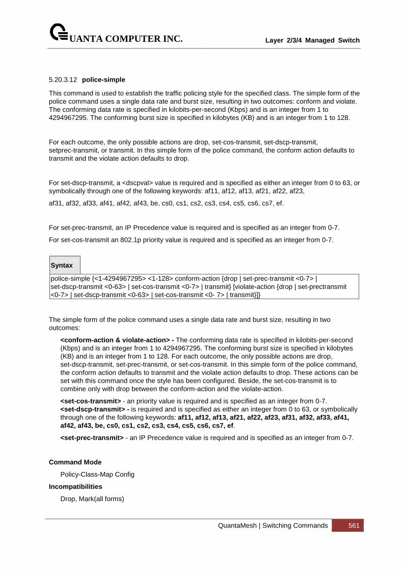
UANTA COMPUTER INC.
Layer 2/3/4 Managed Switch
QuantaMesh | Switching Commands 561
5.20.3.12 police-simple
This command is used to establish the traffic policing style for the specified class. The simple form of the police command uses a single data rate and burst size, resulting in two outcomes: conform and violate. The conforming data rate is specified in kilobits-per-second (Kbps) and is an integer from 1 to 4294967295. The conforming burst size is specified in kilobytes (KB) and is an integer from 1 to 128.
For each outcome, the only possible actions are drop, set-cos-transmit, set-dscp-transmit, setprec-transmit, or transmit. In this simple form of the police command, the conform action defaults to transmit and the violate action defaults to drop.
For set-dscp-transmit, a <dscpval> value is required and is specified as either an integer from 0 to 63, or symbolically through one of the following keywords: af11, af12, af13, af21, af22, af23,
af31, af32, af33, af41, af42, af43, be, cs0, cs1, cs2, cs3, cs4, cs5, cs6, cs7, ef.
For set-prec-transmit, an IP Precedence value is required and is specified as an integer from 0-7.
For set-cos-transmit an 802.1p priority value is required and is specified as an integer from 0-7.
Syntax
police-simple {<1-4294967295> <1-128> conform-action {drop | set-prec-transmit <0-7> | set-dscp-transmit <0-63> | set-cos-transmit <0-7> | transmit} [violate-action {drop | set-prectransmit <0-7> | set-dscp-transmit <0-63> | set-cos-transmit <0- 7> | transmit}]}
The simple form of the police command uses a single data rate and burst size, resulting in two outcomes:
<conform-action & violate-action> - The conforming data rate is specified in kilobits-per-second (Kbps) and is an integer from 1 to 4294967295. The conforming burst size is specified in kilobytes (KB) and is an integer from 1 to 128. For each outcome, the only possible actions are drop, set-dscp-transmit, set-prec-transmit, or set-cos-transmit. In this simple form of the police command, the conform action defaults to transmit and the violate action defaults to drop. These actions can be set with this command once the style has been configured. Beside, the set-cos-transmit is to combine only with drop between the conform-action and the violate-action.
<set-cos-transmit> - an priority value is required and is specified as an integer from 0-7. <set-dscp-transmit> - is required and is specified as either an integer from 0 to 63, or symbolically through one of the following keywords: af11, af12, af13, af21, af22, af23, af31, af32, af3 3, af41, af42, af43, be, cs0, cs1, cs2, cs3, cs4, cs5, cs6, cs7, ef .
<set-prec-transmit> - an IP Precedence value is required and is specified as an integer from 0-7.
Command Mode
Policy-Class-Map Config
Incompatibilities
Drop, Mark(all forms)
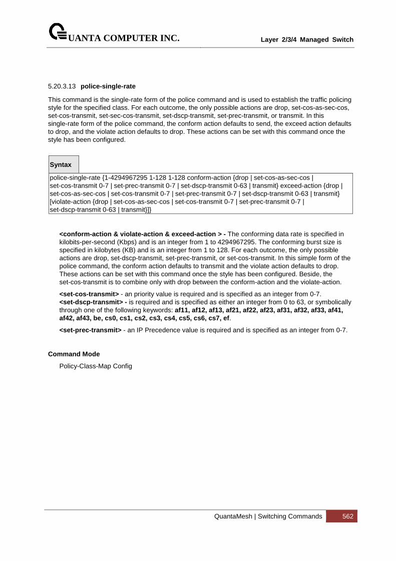
UANTA COMPUTER INC.
Layer 2/3/4 Managed Switch
QuantaMesh | Switching Commands 562
5.20.3.13 police-single-rate
This command is the single-rate form of the police command and is used to establish the traffic policing style for the specified class. For each outcome, the only possible actions are drop, set-cos-as-sec-cos, set-cos-transmit, set-sec-cos-transmit, set-dscp-transmit, set-prec-transmit, or transmit. In this single-rate form of the police command, the conform action defaults to send, the exceed action defaults to drop, and the violate action defaults to drop. These actions can be set with this command once the style has been configured.
Syntax
police-single-rate {1-4294967295 1-128 1-128 conform-action {drop | set-cos-as-sec-cos | set-cos-transmit 0-7 | set-prec-transmit 0-7 | set-dscp-transmit 0-63 | transmit} exceed-action {drop | set-cos-as-sec-cos | set-cos-transmit 0-7 | set-prec-transmit 0-7 | set-dscp-transmit 0-63 | transmit} [violate-action {drop | set-cos-as-sec-cos | set-cos-transmit 0-7 | set-prec-transmit 0-7 | set-dscp-transmit 0-63 | transmit}]}
<conform-action & violate-action & exceed-action > - The conforming data rate is specified in kilobits-per-second (Kbps) and is an integer from 1 to 4294967295. The conforming burst size is specified in kilobytes (KB) and is an integer from 1 to 128. For each outcome, the only possible actions are drop, set-dscp-transmit, set-prec-transmit, or set-cos-transmit. In this simple form of the police command, the conform action defaults to transmit and the violate action defaults to drop. These actions can be set with this command once the style has been configured. Beside, the set-cos-transmit is to combine only with drop between the conform-action and the violate-action.
<set-cos-transmit> - an priority value is required and is specified as an integer from 0-7. <set-dscp-transmit> - is required and is specified as either an integer from 0 to 63, or symbolically through one of the following keywords: af11, af12, af13, af21, af22, af23, af31, af32, af3 3, af41, af42, af43, be, cs0, cs1, cs2, cs3, cs4, cs5, cs6, cs7, ef .
<set-prec-transmit> - an IP Precedence value is required and is specified as an integer from 0-7.
Command Mode
Policy-Class-Map Config
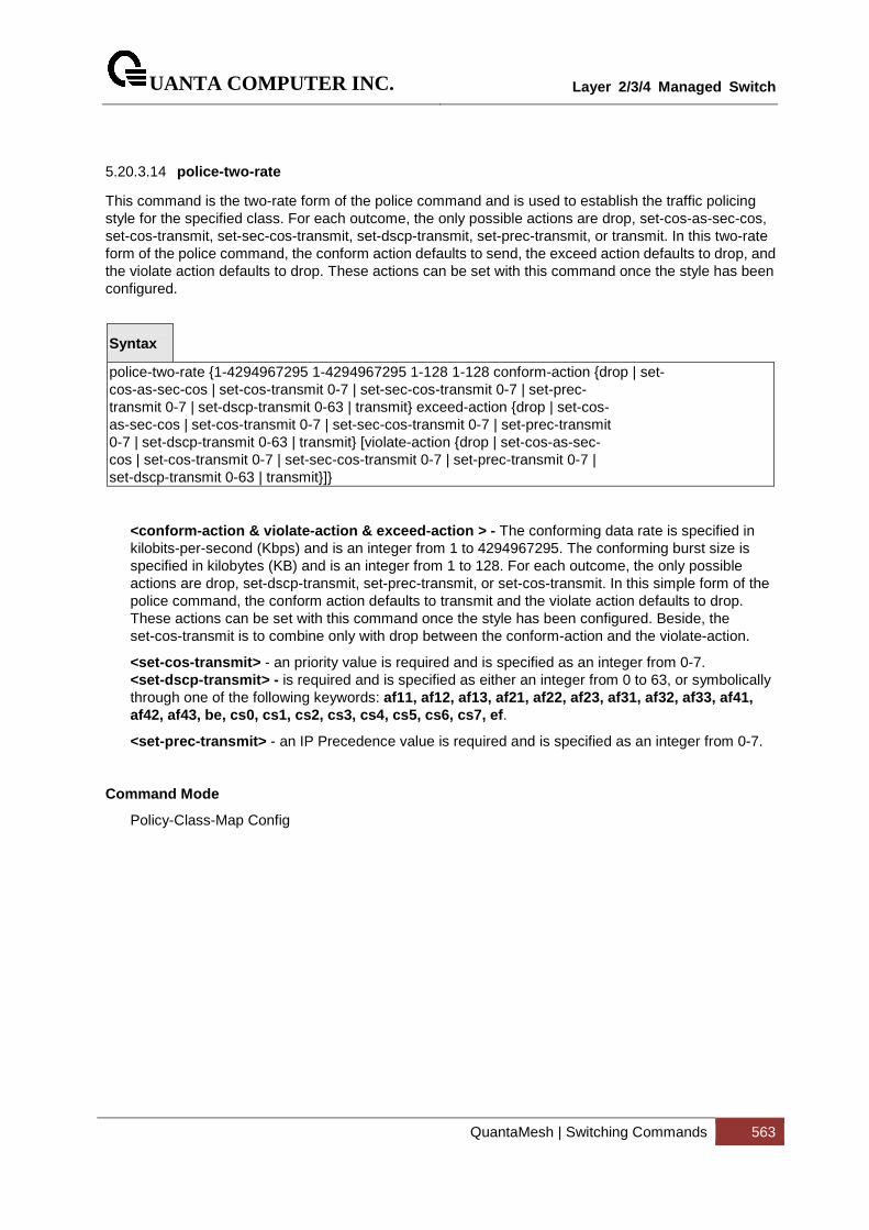
UANTA COMPUTER INC.
Layer 2/3/4 Managed Switch
QuantaMesh | Switching Commands 563
5.20.3.14 police-two-rate
This command is the two-rate form of the police command and is used to establish the traffic policing style for the specified class. For each outcome, the only possible actions are drop, set-cos-as-sec-cos, set-cos-transmit, set-sec-cos-transmit, set-dscp-transmit, set-prec-transmit, or transmit. In this two-rate form of the police command, the conform action defaults to send, the exceed action defaults to drop, and the violate action defaults to drop. These actions can be set with this command once the style has been configured.
Syntax
police-two-rate {1-4294967295 1-4294967295 1-128 1-128 conform-action {drop | set- cos-as-sec-cos | set-cos-transmit 0-7 | set-sec-cos-transmit 0-7 | set-prec- transmit 0-7 | set-dscp-transmit 0-63 | transmit} exceed-action {drop | set-cos- as-sec-cos | set-cos-transmit 0-7 | set-sec-cos-transmit 0-7 | set-prec-transmit 0-7 | set-dscp-transmit 0-63 | transmit} [violate-action {drop | set-cos-as-sec- cos | set-cos-transmit 0-7 | set-sec-cos-transmit 0-7 | set-prec-transmit 0-7 | set-dscp-transmit 0-63 | transmit}]}
<conform-action & violate-action & exceed-action > - The conforming data rate is specified in kilobits-per-second (Kbps) and is an integer from 1 to 4294967295. The conforming burst size is specified in kilobytes (KB) and is an integer from 1 to 128. For each outcome, the only possible actions are drop, set-dscp-transmit, set-prec-transmit, or set-cos-transmit. In this simple form of the police command, the conform action defaults to transmit and the violate action defaults to drop. These actions can be set with this command once the style has been configured. Beside, the set-cos-transmit is to combine only with drop between the conform-action and the violate-action.
<set-cos-transmit> - an priority value is required and is specified as an integer from 0-7. <set-dscp-transmit> - is required and is specified as either an integer from 0 to 63, or symbolically through one of the following keywords: af11, af12, af13, af21, af22, af23, af31, af32, af3 3, af41, af42, af43, be, cs0, cs1, cs2, cs3, cs4, cs5, cs6, cs7, ef .
<set-prec-transmit> - an IP Precedence value is required and is specified as an integer from 0-7.
Command Mode
Policy-Class-Map Config
UANTA COMPUTER INC.
Layer 2/3/4 Managed Switch
QuantaMesh | Switching Commands 564
5.20.3.15 policy-map
This command establishes a new DiffServ policy. The <policyname> parameter is a case-sensitive alphanumeric string from 1 to 31 characters uniquely identifying the policy. The type of policy is specific to the inbound traffic direction as indicated by the in parameter.
Syntax
policy-map <policyname> [{in | out} ] no policy-map <policyname>
no – this command is to delete this policy.
in|out - The direction value is either in or out
Command Mode
Global Config
5.20.3.16 policy-map rename
This command changes the name of a DiffServ policy. The <policyname> is the name of an existing DiffServ class. The <newpolicyname> parameter is a case-sensitive alphanumeric string from 1 to 31 characters uniquely identifying the policy.
Syntax
policy-map rename <policyname> <newpolicyname>
<policyname> - Old Policy name.
<newpolicyname> - New policy name.
Command Mode
Global Config
UANTA COMPUTER INC.
Layer 2/3/4 Managed Switch
QuantaMesh | Switching Commands 565
5.20.4 Service Commands
The 'service' command set is used in DiffServ to define:
Traffic Conditioning Assign a DiffServ traffic conditioning policy (as specified by the policy commands) to an interface in the incoming direction.
Service Provisioning Assign a DiffServ service provisioning policy (as specified by the policy commands) to an interface in the outgoing direction
The service commands attach a defined policy to a directional interface. Only one policy may be assigned at any one time to an interface in a particular direction. The policy type (in, out) must match the interface direction to which it is attached.
This set of commands consists of service addition/removal.
The CLI command root is service-policy
UANTA COMPUTER INC.
Layer 2/3/4 Managed Switch
QuantaMesh | Switching Commands 566
5.20.4.1 service-policy
This command attaches a policy to an interface in a particular direction.
Syntax
service-policy {in | out} <policy-map-name>
The command can be used in the Interface Config mode to attach a policy to a specific interface. Alternatively, the command can be used in the Global Config mode to attach this policy to all system interfaces. The direction value is either in or out.
<policy-map-name> - is the name of an existing DiffServ policy, whose type must match the interface direction. Note that this command causes a service to create a reference to the policy.
This command effectively enables DiffServ on an interface (in a particular direction). There is no separate interface administrative 'mode' command for DiffServ.
This command shall fail if any attributes within the policy definition exceed the capabilities of the interface. Once a policy is successfully attached to an interface, any attempt to change the policy definition such that it would result in a violation of said interface capabilities shall cause the policy change attempt to fail.
Command Mode
Global Config (for all system interfaces)
Interface Config (for a specific interface)
Restrictions Only a single policy may be attached to a particular interface in a particular direction at any one time.
i
UANTA COMPUTER INC.
Layer 2/3/4 Managed Switch
QuantaMesh | Switching Commands 567
5.20.4.2 no service-policy
This command detaches a policy from an interface in a particular direction.
Syntax
no service-policy {in | out} <policy-map-name>
The command can be used in the Interface Config mode to detach a policy from a specific interface. Alternatively, the command can be used in the Global Config mode to detach this policy from all system interfaces to which it is currently attached. The direction value is either in or out.
<policy-map-name> - is the name of an existing DiffServ policy. Note that this command causes a service to remove its reference to the policy.
This command effectively disables DiffServ on an interface (in a particular direction).There is no separate interface administrative 'mode' command for DiffServ.
Command Mode
Global Config (for all system interfaces)
Interface Config (for a specific interface)
i

UANTA COMPUTER INC.
Layer 2/3/4 Managed Switch
QuantaMesh | Switching Commands 568
5.20.5 Show Commands
The 'show' command set is used in DiffServ to display configuration and status information for:
• Classes
• Policies
• Services
This information can be displayed in either summary or detailed formats. The status information is only shown when the DiffServ administrative mode is enabled; it is suppressed otherwise. There is also a 'show' command for general DiffServ information that is available at any time.
5.20.5.1 show class-map
This command displays all configuration information for the specified class.
Syntax
show class-map [<classname>]
<classname> is the name of an existing DiffServ class.
Default Setting
None
Command Mode
Privileged Exec
User Exec
Display Message
Class Name: The name of this class.
Class Type: The class type (all, any, or acl) indicating how the match criteria are evaluated for this class. A class type of all means every match criterion defined for the class is evaluated simultaneously they must all be true to indicate a class match. For a type of any each match criterion is evaluated sequentially and only one need be true to indicate a class match. Class type acl rules are evaluated in a hybrid manner, with those derived from each ACL Rule grouped and evaluated simultaneously, while each such grouping is evaluated sequentially.
L3 Proto: The Layer 3 protocol for this class. Possible values are IPv4 and IPv6.
Match Criteria: The Match Criteria fields will only be displayed if they have been configured. They will be displayed in the order entered by the user. These are evaluated in accordance with the class type. The possible Match Criteria fields are: Class of Service, Destination IP Address, Destination Layer 4 Port, Destination MAC Address, Every, IP DSCP, IP Precedence, IP TOS, Protocol
UANTA COMPUTER INC.
Layer 2/3/4 Managed Switch
QuantaMesh | Switching Commands 569
Keyword, Reference Class, Source IP Address, Source Layer 4 Port, Source MAC Address, and VLAN.
Values: This field displays the values of the Match Criteria.
Class Name: The name of this class. (Note that the order in which classes are displayed is not necessarily the same order in which they were created.)
Class Type: A class type of 'all' means every match criterion defined for the class is evaluated simultaneously and must all be true to indicate a class match.
Reference Class Name: The name of an existing DiffServ class whose match conditions are being referenced by the specified class definition.
5.20.5.2 show diffserv
This command displays the DiffServ General Status Group information, which includes the current administrative mode setting as well as the current and maximum number of rows in each of the main DiffServ private MIB tables.
Syntax
show diffserv
Default Setting
None
Command Mode
Privileged Exec
User Exec
Display Message
DiffServ Admin mode: The current value of the DiffServ administrative mode.
Class Table Size Current/Max: The current or maximum number of entries (rows) in the Class Table.
Class Rule Table Size Current/Max: The current or maximum number of entries (rows) in the Class Rule Table.
Policy Table Size Current/Max: The current or maximum number of entries (rows) in the Policy Table.
Policy Instance Table Size Current/Max: The current or maximum number of entries (rows) in the Policy Instance Table.
Policy Attribute Table Size Current/Max: The current or maximum number of entries (rows) in the Policy Attribute Table.
Service Table Size Current/Max: The current or maximum number of entries (rows) in the Service Table.
UANTA COMPUTER INC.
Layer 2/3/4 Managed Switch
QuantaMesh | Switching Commands 570
5.20.5.3 show diffserv service
This command displays policy service information for the specified interface and direction.
Syntax
show diffserv service {<slot/port> | port-channel <portchannel-id>} {in | out}
<slot/port> - specifies a valid slot number and port number for the system. The direction parameter indicates the interface direction of interest.
<portchannel-id> - Specifies the port-channel interface. The range of the port-channel ID is 1 to 64.
Default Setting
None
Command Mode
Privileged Exec
Display Message
DiffServ Admin Mode: The current setting of the DiffServ administrative mode. An attached policy is only in effect on an interface while DiffServ is in an enabled mode.
Interface: The slot number and port number of the interface (slot/port).
Direction: The traffic direction of this interface service.
Operational Status: The current operational status of this DiffServ service interface.
Policy Name: The name of the policy attached to the interface in the indicated direction.
Policy Details: Attached policy details, whose content is identical to that described for the show policy-map <policymapname> command (content not repeated here for brevity).
UANTA COMPUTER INC.
Layer 2/3/4 Managed Switch
QuantaMesh | Switching Commands 571
5.20.5.4 show diffserv service brief
This command displays all interfaces in the system to which a DiffServ policy has been attached. The direction parameter is optional; if specified, only services in the indicated direction are shown.
Syntax
show diffserv service brief [ in | out ]
Default Setting
None
Command Mode
Privileged Exec
Display Message
DiffServ Admin Mode: The current setting of the DiffServ administrative mode. An attached policy is only active on an interface while DiffServ is in an enabled mode.
The following information is repeated for interface and direction (only those
interfaces configured with an attached policy are s hown):
Interface: The slot number and port number of the interface (slot/port).
Direction: The traffic direction of this interface service.
OperStatus: The current operational status of this DiffServ service interface.
Policy Name: The name of the policy attached to the interface in the indicated direction.
UANTA COMPUTER INC.
Layer 2/3/4 Managed Switch
QuantaMesh | Switching Commands 572
5.20.5.5 show policy-map
This command displays all configuration information for the specified policy.
Syntax
show policy-map [<policy-map-name>]
<policy-map-name> - is the name of an existing DiffServ policy.
Default Setting
None
Command Mode
Privileged Exec
Display Message
Policy Name: The name of this policy.
Policy Type: The policy type, namely whether it is an inbound or outbound policy definition.
The following information is repeated for each clas s associated with this policy
(only those policy attributes actually configured a re displayed):
Class Name: The name of this class.
Mark CoS: Denotes the class of service value that is set in the 802.1p header of outbound packets. This is not displayed if the mark cos was not specified.
Mark IP DSCP: Denotes the mark/re-mark value used as the DSCP for traffic matching this class. This is not displayed if mark ip description is not specified using the police-two-rate command, or if policing is in use for the class under this policy.
Mark IP Precedence: Denotes the mark/re-mark value used as the IP Precedence for traffic matching this class. This is not displayed if either mark DSCP or policing is in use for the class under this policy.
Policing Style: This field denotes the style of policing, if any, used simple.
Committed Rate (Kbps): This field displays the committed rate, used in simple policing, single-rate policing, and two-rate policing.
Committed Burst Size (KB): This field displays the committed burst size, used in simple policing.
Conform Action: The current setting for the action taken on a packet considered to conform to the policing parameters. This is not displayed if policing is not in use for the class under this policy.
Conform COS Value: This field shows the priority mark value if the conform action is markcos.
Conform DSCP Value: This field shows the DSCP mark value if the conform action is markdscp.
Conform IP Precedence Value: This field shows the IP Precedence mark value if the conform action is markprec.
UANTA COMPUTER INC.
Layer 2/3/4 Managed Switch
QuantaMesh | Switching Commands 573
Non-Conform Action: The current setting for the action taken on a packet considered to not conform to the policing parameters. This is not displayed if policing not in use for the class under this policy.
Non-Conform DSCP Value: This field displays the DSCP mark value if this action is markdscp.
Non-Conform IP Precedence Value: This field displays the IP Precedence mark value if this action is markprec.
Assign Queue: Directs traffic stream to the specified QoS queue. This allows a traffic classifier to specify which one of the supported hardware queues are used for handling packets belonging to the class.
Drop: Drop a packet upon arrival. This is useful for emulating access control list operation using DiffServ, especially when DiffServ and ACL cannot co-exist on the same interface.
Mirror: Copies a classified traffic stream to a specified egress port (physical port or LAG). This can occur in addition to any marking or policing action. It may also be specified along with a QoS queue assignment.
Redirect: Forces a classified traffic stream to a specified egress port (physical port or LAG). This can occur in addition to any marking or policing action. It may also be specified along with a QoS queue assignment.
Policy Name: The name of this policy. (Note that the order in which the policies are displayed is not necessarily the same order in which they were created.)
Policy Type: The policy type, namely whether it is an inbound or outbound policy definition.
Class Members: List of all class names associated with this policy.
UANTA COMPUTER INC.
Layer 2/3/4 Managed Switch
QuantaMesh | Switching Commands 574
5.20.5.6 show policy-map interface
This command displays policy-oriented statistics information for the specified interface and direction.
Syntax
show policy-map interface {<slot/port> | port-channel <portchannel-id>} {in | out}
<slot/port> - specifies a valid slot number and port number for the system. The direction parameter indicates the interface direction of interest.
<portchannel-id> - Specifies the port-channel interface. The range of port-channel ID is 1 to 64.
Command Mode
Privileged Exec
Display Message
Interface: The slot number and port number of the interface (slot/port).
Direction: The traffic direction of this interface service, either in or out.
Operational Status: The current operational status of this DiffServ service interface.
Policy Name: The name of the policy attached to the interface in the indicated
direction.
The following information is repeated for each clas s instance within this policy:
Class Name: The name of this class instance.
In Offered Packets: A count of the packets offered to this class instance before the defined DiffServ treatment is applied. Only displayed for the 'in' direction.
In Discarded Packets: A count of the packets discarded for this class instance for any reason due to DiffServ treatment of the traffic class. Only displayed for the 'in' direction.
None of the counters listed here are guaranteed to be supported on all platforms. Only supported counters are shown in the display output.
i
UANTA COMPUTER INC.
Layer 2/3/4 Managed Switch
QuantaMesh | Switching Commands 575
5.20.5.7 show service-policy
This command displays a summary of policy-oriented statistics information for all interfaces in the specified direction. The direction parameter indicates the interface direction of interest. This command enables or disables the route reflector client. A route reflector client relies on a route reflector to re-advertise its routes to the entire AS. The possible values for this field are enable and disable.
Syntax
show service-policy {in | out}
Command Mode
Privileged Exec
Display Message
The following information is repeated for each interface and direction (only those interfaces configured with an attached policy are shown):
Interface: The slot number and port number of the interface (slot/port).
Operational Status: The current operational status of this DiffServ service interface.
Policy Name: The name of the policy attached to the interface.
None of the counters listed here are guaranteed to be supported on all platforms. Only supported counters are shown in the display output.
i
UANTA COMPUTER INC.
Layer 2/3/4 Managed Switch
QuantaMesh | Switching Commands 576
5.21 ACL Command
5.21.1 Show Commands
5.21.1.1 show mac access-lists name
This command displays a MAC access list and all of the rules that are defined for the ACL. The
<name> parameter is used to identify a specific MAC ACL to display.
Syntax
show mac access-lists <name>
<name> - ACL name which uniquely identifies the MAC ACL to display.
Default Setting
None
Command Mode
Privileged Exec
Display Message
MAC ACL Name: The name of the MAC ACL rule.
Rule Number: The ordered rule number identifier defined within the ACL.
Action: Displays the action associated with each rule. The possible values are Permit or
Deny.
Source MAC Address: Displays the source MAC address for this rule.
Source MAC Mask: Displays the source MAC mask for this rule.
Destination MAC Address: Displays the destination MAC address for this rule.
Destination MAC Mask: Displays the destination MAC mask for this rule.
Ethertype: Displays the Ethertype keyword or custom value for this rule.
VLAN ID: Displays the VLAN identifier value or range for this rule.
CoS Value: Displays the COS (802.1p) value for this rule.
Assign Queue: Displays the queue identifier to which packets matching this rule are assigned.
Redirect Interface: Displays the slot/port to which packets matching this rule are forwarded.
Mirror Interface: Displays the slot/port to which packets matching this rule are copied.
Time Range Name: Displays the name of the time-range if the MAC ACL rule has referenced a time range.
Rule Status: Status (Active/Inactive) of the MAC ACL rule.

UANTA COMPUTER INC.
Layer 2/3/4 Managed Switch
QuantaMesh | Switching Commands 577
redirectExtAgent: Indicates whether matching flow packets are allowed to be sent to external applications running alongside ICOS on a control CPU.
Committed Rate: The committed rate defined by the rate-limit attribute.
Committed Burst: The committed burst size defined by the rate-limit attribute.
UANTA COMPUTER INC.
Layer 2/3/4 Managed Switch
QuantaMesh | Switching Commands 578
5.21.1.2 show mac access-lists
This command displays a summary of all defined MAC access lists in the system.
Syntax
show mac access-lists
Default Setting
None
Command Mode
Privileged Exec
Display Message
Current number of all ACLs: The number of user-configured rules defined for this ACL.
Maximum number of all ACLs: The maximum number of ACL rules.
MAC ACL Name: The name of the MAC ACL rule.
Rules: The number of rule in this ACL.
Direction: Denotes the direction in which this MAC ACL is attached to the set of interfaces listed. The value is Inbound or Outbound.
Interfaces: Displays the list of interfaces (slot/port) to which this MAC ACL is attached in a given direction.
VLANs: VLAN(s) to which the MAC ACL applies.
UANTA COMPUTER INC.
Layer 2/3/4 Managed Switch
QuantaMesh | Switching Commands 579
5.21.1.3 show ip access-lists
This command displays an Access Control List (ACL) and all of the rules that are defined for the ACL.
Syntax
show ip access-lists [<1-199> | <name>]
<1-199> - is the number used to identify the ACL.
<name> - is the name of the ACL.
Default Setting
None
Command Mode
Privileged Exec
User Exec
Display Message
Current number of ACLs: The number of user-configured rules defined for this ACL.
Maximum number of ACLs: The maximum number of ACL rules.
ACL ID: The identifier of this ACL.
Rule: This displays the number identifier for each rule that is defined for the ACL.
Action: This displays the action associated with each rule. The possible values are Permit or Deny.
Match ALL: Match all packets or not.
IPv4 Protocol: This displays the protocol to filter for this rule.
Source IP Address: This displays the source IP address for this rule.
Source IP Mask: This field displays the source IP Mask for this rule.
Source L4 Port Keyword: This field displays the source port for this rule.
Destination IP Address: This displays the destination IP address for this rule.
Destination IP Mask: This field displays the destination IP Mask for this rule.
Destination L4 Port Keyword: This field displays the destination port for this rule.
IP DSCP: This field displays the IP DSCP value for this rule.
IP Precedence: This field displays the IP Precedence value for this rule.
IP TOS: This field displays the IP TOS value for this rule.
Log: This field displays when you enable logging for this rule.
Assign Queue: This field displays the queue identifier to which packets matching this rule are assigned.
Mirror Interface: This field displays the slot/port to which packets matching this rule are copied.
UANTA COMPUTER INC.
Layer 2/3/4 Managed Switch
QuantaMesh | Switching Commands 580
Redirect Interface: This field displays the slot/port to which packets matching this rule are forwarded.
Time Range Name: Displays the name of the time-range if the IP ACL rule has referenced a time range.
Direction: Shows whether the ACL is applied to traffic coming into the interface (ingress)
or leaving the interface (egress).
Rule Status: Status (Active/Inactive) of the MAC ACL rule.
redirectExtAgent: Indicates whether matching flow packets are allowed to be sent to external applications running alongside ICOS on a control CPU.
Committed Rate: The committed rate defined by the rate-limit attribute.
Committed Burst: The committed burst size defined by the rate-limit attribute.
UANTA COMPUTER INC.
Layer 2/3/4 Managed Switch
QuantaMesh | Switching Commands 581
5.21.1.4 show access-lists interface
This command displays IP ACLs, IPv6 ACLs, and MAC access control lists information for a designated interface and direction. Use the control-plane keyword to display the ACLs applied on the CPU port.
Syntax
show access-lists {{ interface <slot/port> | port-channel <portchannel-id> } {in | out} | control-plane}
<slot/port> - is the interface number.
<portchannel-id> - is the port-channel ID. The port-channel ID is range from 1 to 64.
control-plane – is the management (CPU) port.
in | out - The direction value is either in or out
Default Setting
None
Command Mode
Privileged Exec
Display Message
ACL Type: This displays ACL type is IP, IPv6 or MAC.
ACL ID: Access List name for a MAC or IPv6 access list or the numeric identifier for an IP access list.
Sequence Number: An optional sequence number may be specified to indicate the order of this access list relative to other access lists already assigned to this interface and direction. A lower number indicates higher precedence order. If a sequence number is already in use for this interface and direction, the specified access list replaces the currently attached access list using that sequence number. If the sequence number is not specified by the user, a sequence number that is one greater than the highest sequence number currently in use for this interface and direction is used. Valid range is (1 to 4294967295).
5.21.1.5 show access-lists vlan
This command displays Access List information for a particular VLAN ID.
Syntax
show access-lists {{ interface <slot/port> | port-channel <portchannel-id> } {in | out} | control-plane}
<slot/port> - is the interface number.
<portchannel-id> - is the port-channel ID. The port-channel ID is range from 1 to 64.
UANTA COMPUTER INC.
Layer 2/3/4 Managed Switch
QuantaMesh | Switching Commands 582
control-plane – is the management (CPU) port.
in | out - The direction value is either in or out
Default Setting
None
Command Mode
Privileged Exec
Display Message
ACL Type: This displays ACL type is IP, IPv6 or MAC.
ACL ID: Access List name for a MAC or IPv6 access list or the numeric identifier for an IP access list.
Sequence Number: An optional sequence number may be specified to indicate the order of this access list relative to other access lists already assigned to this interface and direction. A lower number indicates higher precedence order. If a sequence number is already in use for this interface and direction, the specified access list replaces the currently attached access list using that sequence number. If the sequence number is not specified by the user, a sequence number that is one greater than the highest sequence number currently in use for this interface and direction is used. Valid range is (1 to 4294967295).
UANTA COMPUTER INC.
Layer 2/3/4 Managed Switch
QuantaMesh | Switching Commands 583
5.21.2 Configuration Commands
5.21.2.1 mac access-list extended
This command creates a MAC Access Control List (ACL) identified by <name>, consisting of
classification fields defined for the Layer 2 header of an Ethernet frame. The <name> parameter is a case-sensitive alphanumeric string from 1 to 31 characters uniquely identifying the MAC access list. If a MAC ACL by this name already exists, this command enters Mac-Access-List config mode to allow updating the existing ACL.
Syntax
mac access-list extended <name> no mac access-list extended <name>
<name> - It uniquely identifies the MAC access list.
Default Setting
None
Command Mode
Global Config
UANTA COMPUTER INC.
Layer 2/3/4 Managed Switch
QuantaMesh | Switching Commands 584
5.21.2.2 mac access-list extended rename
This command changes the name of a MAC Access Control List (ACL). The <name> parameter is the name of an existing MAC ACL. The <newname> parameter is a case-sensitive alphanumeric string from 1 to 31 characters uniquely identifying the MAC access list. This command fails if a MAC ACL by the name <newname> already exists.
Syntax
mac access-list extended rename <oldname> <newname>
<oldname> - Old name which uniquely identifies the MAC access list.
<newname> - New name which uniquely identifies the MAC access list.
Default Setting
None
Command Mode
Global Config
UANTA COMPUTER INC.
Layer 2/3/4 Managed Switch
QuantaMesh | Switching Commands 585
5.21.2.3 mac access-group
This command attaches a specific MAC Access Control List (ACL) identified by <name> to an
interface, or associates it with a VLAN ID, in a given direction. The <name> parameter must be the name of an exsiting MAC ACL.
An optional sequence number may be specified to indicate the order of this access list relative to other access lists already assigned to this interface and direction. A lower number indicates higher precedence order. If a sequence number is already in use for this interface and direction, the specified access list replaces the currently attached access list using that sequence number. If the sequence number is not specified for this command, a sequence number that is one greater than the highest sequence number currently in use for this interface and direction will be used.
This command specified in 'Interface Config' mode only affects a single interface, whereas the 'Global Config' mode setting is applied to all interfaces. The 'Interface Config' mode command is only available on platforms that support independent per-port class of service queue configuration. The VLAN keyword is only valid in the 'Global Config' mode.
Syntax
mac access-group <name> [vlan <vlan-id>] {in |out} [<1-4294967295>] no mac access-group <name> [vlan <vlan-id>] {in | out}
<no> - This command removes a MAC ACL identified by <name> from the interface or vlan in a given direction.
in|out - The direction value is either in or out
Default Setting
None
Command Mode
Global Config
Interface Config
UANTA COMPUTER INC.
Layer 2/3/4 Managed Switch
QuantaMesh | Switching Commands 586
5.21.2.4 mac access-list
This command creates a new rule for the current MAC access list. Each rule is appended to the list of configured rules for the list. Note that an implicit 'deny all' MAC rule always terminates the access list. Note: The 'no' form of this command is not supported, as the rules within an ACL cannot be deleted individually. Rather, the entire ACL must be deleted and re-specified.
A rule may either deny or permit traffic according to the specified classification fields. At a minimum, the source and destination MAC value and mask pairs must be specified, each of which may be substituted using the keyword any to indicate a match on any value in that field. The bpdu keyword may be specified for the destination MAC value/mask pair indicating a well-known BPDU MAC value of 01-80-c2-xx-xx-xx (hex), where 'xx' indicates a don't care. The remaining command parameters are all optional.
The Ethertype may be specified as either a keyword or a four-digit hexadecimal value from 0x0600-0xFFFF. The currently supported <ethertypekey> values are: appletalk, arp, ibmsna, ipv4, ipv6, ipx, mplsmcast, mplsucast, netbios, novell, pppoe, rarp. Each of these translates into its equivalent Ethertype value(s).
The vlan and cos parameters refer to the VLAN identifier and 802.1p user priority fields, respectively, of the VLAN tag. For packets containing a double VLAN tag, this is the first (or outer) tag.
The assign-queue parameter allows specification of a particular hardware queue for handling traffic that matches this rule. The allowed <queue-id> value is 0-(n-1), where n is the number of user configurable queues available for the hardware platform.
The mirror parameter allows the traffic matching this rule to be copied to the specified <slot/port>, while the redirect parameter allows the traffic matching this rule to be forwarded to the specified <slot/port> The assign-queue and redirect parameters are only valid for a 'permit' rule.
The time-range parameter allows imposing time limitation on the MAC ACL rule as defined by the parameter time-range-name. If a time range with the specified name does not exist and the MAC ACL containing this ACL rule is applied to an interface or bound to a VLAN, then the ACL rule is applied immediately. If a time range with specified name exists and the MAC ACL containing this ACL rule is applied to an interface or bound to a VLAN, then the ACL rule is applied when the time-range with specified name becomes active. The ACL rule is removed when the time-range with specified name becomes inactive.
The redirectExtAgent optional parameter allows matching flow packets to be sent to external applications running alongside ICOS on a control CPU. agent-id is a unique identifier for the external receive client application. agent-id is an integer in the range 1 to 100. The redirectExtAgent action is mutually exclusive with the mirror and redirect parameters.
The rate-limit option allows the device to permit only the allowed rate of traffic as per the configured rate in kpbs, and burst-size in kbytes.

UANTA COMPUTER INC.
Layer 2/3/4 Managed Switch
QuantaMesh | Switching Commands 587
Syntax
{del-rule-id | deny | permit} {{<srcmac> <srcmask>} | any} {{<dstmac> <dstmask>} | any | bpdu} [<ethertypekey> | <0x0600-0xFFFF>] [vlan {{eq <0-4095>}} [ cos <0-7>] [log] [time-range time-range-name] [assign-queue <queue-id>] [{mirror | redirect} {<slot/port> | port-channel <portchannel-id>}] [<rule-id>] | redirectExtAgent <agent-id> | rate-limit rate burst-size
Default Setting
None
Command Mode
Mac Access-list Config
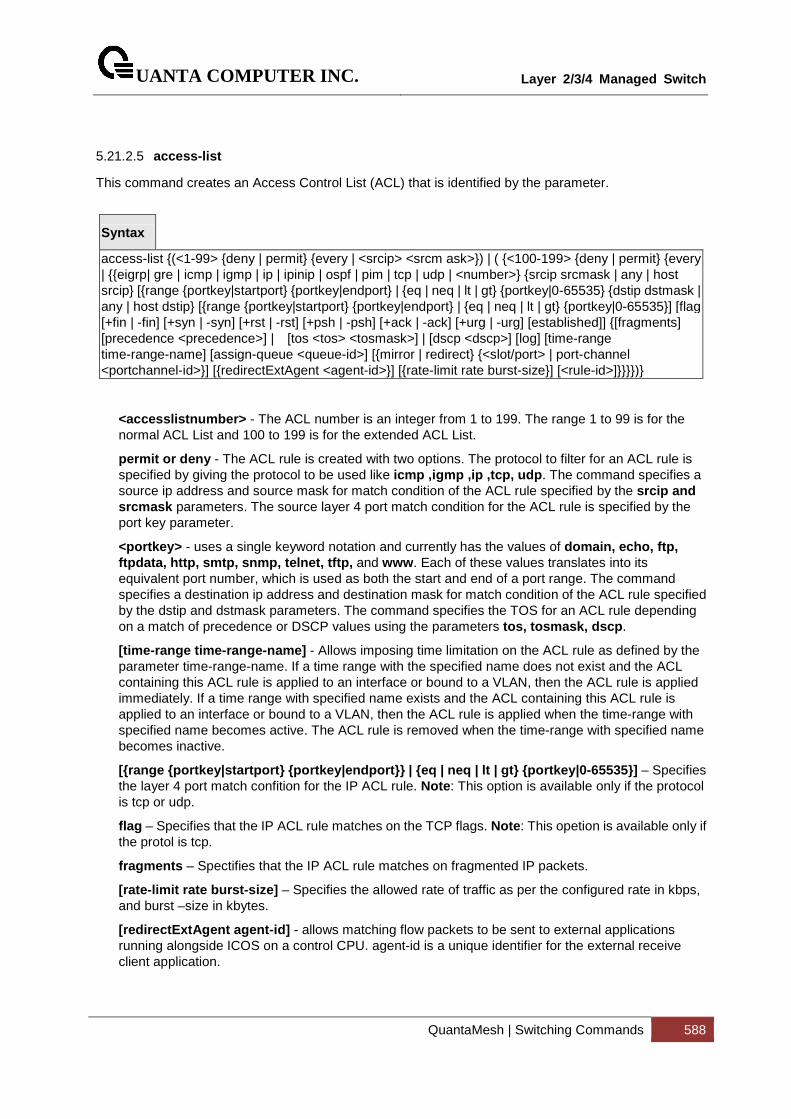
UANTA COMPUTER INC.
Layer 2/3/4 Managed Switch
QuantaMesh | Switching Commands 588
5.21.2.5 access-list
This command creates an Access Control List (ACL) that is identified by the parameter.
Syntax
access-list {(<1-99> {deny | permit} {every | <srcip> <srcm ask>}) | ( {<100-199> {deny | permit} {every | {{eigrp| gre | icmp | igmp | ip | ipinip | ospf | pim | tcp | udp | <number>} {srcip srcmask | any | host srcip} [{range {portkey|startport} {portkey|endport} | {eq | neq | lt | gt} {portkey|0-65535} {dstip dstmask | any | host dstip} [{range {portkey|startport} {portkey|endport} | {eq | neq | lt | gt} {portkey|0-65535}] [flag [+fin | -fin] [+syn | -syn] [+rst | -rst] [+psh | -psh] [+ack | -ack] [+urg | -urg] [established]] {[fragments] [precedence <precedence>] | [tos <tos> <tosmask>] | [dscp <dscp>] [log] [time-range time-range-name] [assign-queue <queue-id>] [{mirror | redirect} {<slot/port> | port-channel <portchannel-id>}] [{redirectExtAgent <agent-id>}] [{rate-limit rate burst-size}] [<rule-id>]}}}})}
<accesslistnumber> - The ACL number is an integer from 1 to 199. The range 1 to 99 is for the normal ACL List and 100 to 199 is for the extended ACL List.
permit or deny - The ACL rule is created with two options. The protocol to filter for an ACL rule is specified by giving the protocol to be used like icmp ,igmp ,ip ,tcp, udp. The command specifies a source ip address and source mask for match condition of the ACL rule specified by the srcip and srcmask parameters. The source layer 4 port match condition for the ACL rule is specified by the port key parameter.
<portkey> - uses a single keyword notation and currently has the values of domain, echo, ftp, ftpdata, http, smtp, snmp, telnet, tftp, and www. Each of these values translates into its equivalent port number, which is used as both the start and end of a port range. The command specifies a destination ip address and destination mask for match condition of the ACL rule specified by the dstip and dstmask parameters. The command specifies the TOS for an ACL rule depending on a match of precedence or DSCP values using the parameters tos, tosmask, dscp.
[time-range time-range-name] - Allows imposing time limitation on the ACL rule as defined by the parameter time-range-name. If a time range with the specified name does not exist and the ACL containing this ACL rule is applied to an interface or bound to a VLAN, then the ACL rule is applied immediately. If a time range with specified name exists and the ACL containing this ACL rule is applied to an interface or bound to a VLAN, then the ACL rule is applied when the time-range with specified name becomes active. The ACL rule is removed when the time-range with specified name becomes inactive.
[{range {portkey|startport} {portkey|endport}} | {e q | neq | lt | gt} {portkey|0-65535}] – Specifies the layer 4 port match confition for the IP ACL rule. Note : This option is available only if the protocol is tcp or udp.
flag – Specifies that the IP ACL rule matches on the TCP flags. Note : This opetion is available only if the protol is tcp.
fragments – Spectifies that the IP ACL rule matches on fragmented IP packets.
[rate-limit rate burst-size] – Specifies the allowed rate of traffic as per the configured rate in kbps, and burst –size in kbytes.
[redirectExtAgent agent-id] - allows matching flow packets to be sent to external applications running alongside ICOS on a control CPU. agent-id is a unique identifier for the external receive client application.
UANTA COMPUTER INC.
Layer 2/3/4 Managed Switch
QuantaMesh | Switching Commands 589
Default Setting
None
Command Mode
Global Config
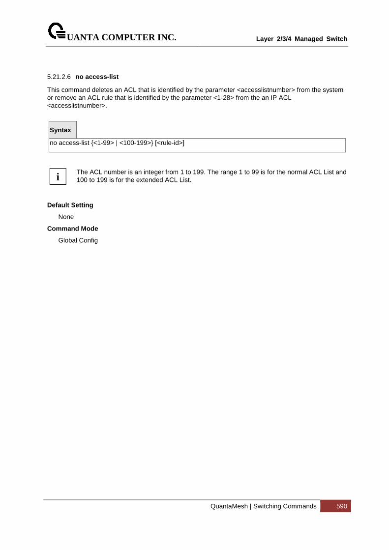
UANTA COMPUTER INC.
Layer 2/3/4 Managed Switch
QuantaMesh | Switching Commands 590
5.21.2.6 no access-list
This command deletes an ACL that is identified by the parameter <accesslistnumber> from the system or remove an ACL rule that is identified by the parameter <1-28> from the an IP ACL <accesslistnumber>.
Syntax
no access-list {<1-99> | <100-199>} [<rule-id>]
The ACL number is an integer from 1 to 199. The range 1 to 99 is for the normal ACL List and 100 to 199 is for the extended ACL List.
Default Setting
None
Command Mode
Global Config
i
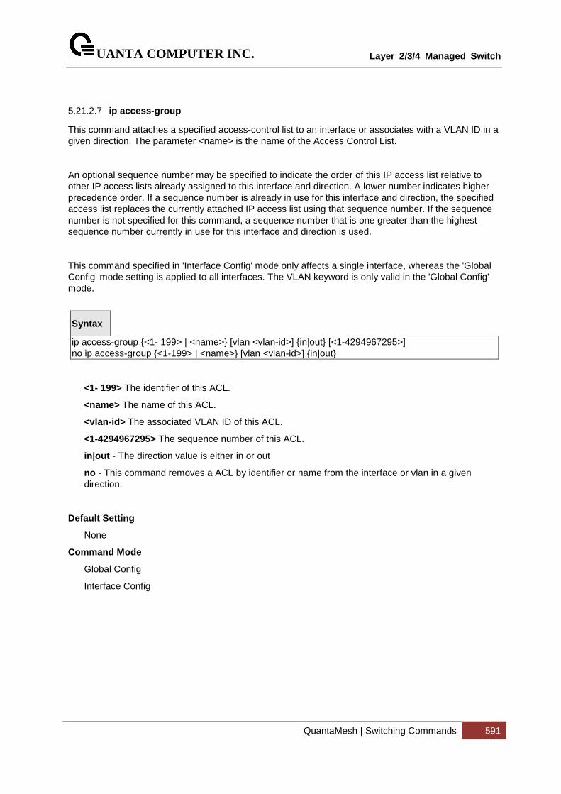
UANTA COMPUTER INC.
Layer 2/3/4 Managed Switch
QuantaMesh | Switching Commands 591
5.21.2.7 ip access-group
This command attaches a specified access-control list to an interface or associates with a VLAN ID in a given direction. The parameter <name> is the name of the Access Control List.
An optional sequence number may be specified to indicate the order of this IP access list relative to other IP access lists already assigned to this interface and direction. A lower number indicates higher precedence order. If a sequence number is already in use for this interface and direction, the specified access list replaces the currently attached IP access list using that sequence number. If the sequence number is not specified for this command, a sequence number that is one greater than the highest sequence number currently in use for this interface and direction is used.
This command specified in 'Interface Config' mode only affects a single interface, whereas the 'Global Config' mode setting is applied to all interfaces. The VLAN keyword is only valid in the 'Global Config' mode.
Syntax
ip access-group {<1- 199> | <name>} [vlan <vlan-id>] {in|out} [<1-4294967295>] no ip access-group {<1-199> | <name>} [vlan <vlan-id>] {in|out}
<1- 199> The identifier of this ACL.
<name> The name of this ACL.
<vlan-id> The associated VLAN ID of this ACL.
<1-4294967295> The sequence number of this ACL.
in|out - The direction value is either in or out
no - This command removes a ACL by identifier or name from the interface or vlan in a given direction.
Default Setting
None
Command Mode
Global Config
Interface Config
UANTA COMPUTER INC.
Layer 2/3/4 Managed Switch
QuantaMesh | Switching Commands 592
5.21.2.8 ip access-list
Use this command to create an extended IP Access Control List (ACL) identified by <name>, consisting of classification fields defined for the IP header of an IPv4 frame. The <name> parameter is a case-sensitive alphanumeric string from 1 to 31 characters uniquely identifying the IP access list.
If an IP ACL by this name already exists, this command enters IPv4-Access_List config mode to allow updating the existing IP ACL.
The CLI mode changes to IPv4-Access-List Configuration mode when you successfully execute this command.
Syntax
Ip access-list <name> no ip access-list <name>
no - This command removes the IP ACL identified by <name> from the system.
Default Setting
None
Command Mode
Global Config
5.21.2.9 ip access-list rename
Use this command to change the name of an IP Access Control List (ACL). The <name> parameter is the names of an existing IP ACL. The <newname> parameter is a case-sensitive alphanumeric string from 1 to 31 characters uniquely identifying the IP access list.
Syntax
ip access-list rename <name> <newname>
Default Setting
None
Command Mode
Global Config

UANTA COMPUTER INC.
Layer 2/3/4 Managed Switch
QuantaMesh | Switching Commands 593
5.22 IPv6 ACL Command
5.22.1 Show Commands
5.22.1.1 show ipv6 access-lists
This command displays an IPv6 access list and all of the rules that are defined for the IPv6 ACL. Use the [name] parameter to identify a specific IPv6 ACL to display.
Syntax
show ipv6 access-lists [<name>]
<name> - ACL name which uniquely identifies the IPv6 ACL to display.
Default Setting
None
Command Mode
Privileged EXEC
User EXEC
Display Message
Rule Number: The ordered rule number identifier defined within the IPv6 ACL.
Action: The action associated with each rule. The possible values are Permit or Deny.
Match All: Indicates whether this access list applies to every packet. Possible values are True or False.
IPv6 Protocol: The protocol to filter for this rule.
Source IP Address: The source IP address for this rule.
Source L4 Port Keyword: The source port for this rule.
Destination IP Address: The destination IP address for this rule.
Destination L4 Port Keyword: The destination port for this rule.
IP DSCP: The value specified for IP DSCP.
Flow Label: The value specified for IPv6 Flow Label.
Log: Displays when you enable logging for the rule.
Assign Queue: The queue identifier to which packets matching this rule are assigned.
Mirror Interface: The slot/port to which packets matching this rule are copied.
Redirect Interface: The slot/port to which packets matching this rule are forwarded.
Time Range Name: Displays the name of the time-range if the Ipv6 ACL rule has referenced a time range.
UANTA COMPUTER INC.
Layer 2/3/4 Managed Switch
QuantaMesh | Switching Commands 594
Direction: Shows whether the ACL is applied to traffic coming into the interface (ingress)
or leaving the interface (egress).
Rule Status: Status (Active/Inactive) of the MAC ACL rule.
redirectExtAgent: Indicates whether matching flow packets are allowed to be sent to external applications running alongside ICOS on a control CPU.
Committed Rate: The committed rate defined by the rate-limit attribute.
Committed Burst: The committed burst size defined by the rate-limit attribute.
UANTA COMPUTER INC.
Layer 2/3/4 Managed Switch
QuantaMesh | Switching Commands 595
5.22.2 Configuration Commands
5.22.2.1 ipv6 access-list
This command creates an IPv6 Access Control List (ACL) identified by <name>, consisting of classification fields defined for the IP header of an IPv6 frame. The <name> parameter is a case-sensitive alphanumeric string from 1 to 31 characters
uniquely identifying the IPv6 access list.
If an IPv6 ACL by this name already exists, this command enters IPv6-Access-List config mode to allow updating the existing IPv6 ACL.
Syntax
ipv6 access-list <name> no ipv6 access-list <name>
<name> - access-list name up to 31 characters in length.
no - This command deletes the IPv6 ACL identified by <name> from the system.
The CLI mode changes to IPv6-Access-List Config mode when you successfully execute this command.
Default Setting
None
Command Mode
Global Config
i
UANTA COMPUTER INC.
Layer 2/3/4 Managed Switch
QuantaMesh | Switching Commands 596
5.22.2.2 ipv6 access-list rename
This command changes the name of an IPv6 ACL. The <name> parameter is the name of an existing IPv6 ACL. The <newname> parameter is a case-sensitive alphanumeric string from 1 to 31 characters uniquely identifying the IPv6 access list.
This command fails is an IPv6 ACL by the name <newname> already exists.
Syntax
ipv6 access-list rename <oldname> <newname>
<oldname> - current Access Control List name.
<newname> - new Access Control List name.
Default Setting
None
Command Mode
Global Config
UANTA COMPUTER INC.
Layer 2/3/4 Managed Switch
QuantaMesh | Switching Commands 597
5.22.2.3 {deny | permit}
This command creates a new rule for the current IPv6 access list. Each rule is appended to the list of configured rules for the list.
The ‘no’ form of this command is not supported, since the rules within an IPv6 ACL cannot be deleted individually. Rather, the entire IPv6 ACL must be deleted and respecified.
An implicit ‘deny all’ IPv6 rule always terminates the access list.
A rule may either deny or permit traffic according to the specified classification fields. At a minimum, either the ‘every’ keyword or the protocol, source address, and destination address values must be specified. The source and destination IPv6 address fields may be specified using the keyword ‘any’ to indicate a match on any value in that field. The remaining command parameters are all optional, but the most frequently used parameters appear in the same relative order as shown in the command format.
The assign-queue parameter allows specification of a particular hardware queue for handling traffic that matches this rule. The allowed <queue-id> value is 0-(n-1), where n is the number of user configurable queues available for the hardware platform. The assign-queue parameter is valid only for a permit rule.
The mirror parameter allows the traffic matching this rule to be copied to the specified <slot/port>, while the redirect parameter allows the traffic matching this rule to be forwarded to the specified <slot/port>. The assign-queue and redirect parameters are only valid for a permit rule.
The time-range parameter allows imposing time limitation on the IPv6 ACL rule as defined by the parameter time-range-name . If a time range with the specified name does not exist and the IPv6 ACL containing this ACL rule is applied to an interface or bound to a VLAN, then the ACL rule is applied immediately. If a time range with specified name exists and the IPv6 ACL containing this ACL rule is applied to an interface or bound to a VLAN, then the ACL rule is applied when the time-range with specified name becomes active. The ACL rule is removed when the time-range with specified name becomes inactive.
Syntax
{del-rule-id | deny | permit} {every | {{icmpv6 | ipv6 | tcp | udp | <number>} {source-ipv6-prefix/prefix-length | any | host soure-ipv6-address} [{range {portkey | startport} {portkey | endport} | eq | neq | lt | gt} {portkey | 0-65535}] {destination-ipv6-prefix/prefix-length} | any | host destination-ipv6-address} [{range {portkey | startport} {portkey | endport} | eq | neq | lt | gt} {portkey | 0-65535}] [flag [+fin | -fin] [+syn | -syn] [+rst | -rst] [+psh | -psh] [+ack | -ack] [+urg | -urg] [established]] [flow-label value] [fragments] [log] [time-range time-range-name] [assign-queue <queue-id>] [{mirror | redirect} {<slot/port> | port-channel <portchannel-id>}] [rate-limit rate burst-size] [rule-id]
Default Setting
None
Command Mode
IPv6-Access-List Config
!
UANTA COMPUTER INC.
Layer 2/3/4 Managed Switch
QuantaMesh | Switching Commands 598
5.22.2.4 ipv6 traffic-filter
This command either attaches a specific IPv6 ACL identified by <name> to an interface or associates with a VLAN ID in a given direction. The <name> parameter must be the name of an existing IPv6 ACL.
An optional sequence number may be specified to indicate the order of this mac access list relative to other IPv6 access lists already assigned to this interface and direction. A lower number indicates higher precedence order. If a sequence number
is already in use for this interface and direction, the specifiedIPv6 access list replaces the currently attached IPv6 access list using that sequence number. If the sequence number is not specified for this command, a sequence number that is one greater than the highest sequence number currently in use for this interface and direction is used.
This command specified in Interface Config mode only affects a single interface, whereas the Global Config mode setting is applied to all interfaces. The vlan keyword is only valid in the Global Config mode. The Interface Config mode command is only available on platforms that support independent per-port class of service queue configuration.
Syntax
ipv6 traffic-filter <name> [vlan <vlan-id>] {in|out} [<1-4294967295>] no ipv6 traffic-filter <name> [vlan <vlan-id>] {in|out} [<1-4294967295>]
in|out - The direction value is either in or out
no - This command removes an IPv6 ACL identified by <name> from the interface(s) in a given direction
Default Setting
None
Command Mode
Global Config
Interface Config

UANTA COMPUTER INC.
Layer 2/3/4 Managed Switch
QuantaMesh | Switching Commands 599
5.23 CoS (Class of Service) Command
5.23.1 Show Commands
5.23.1.1 show queue cos-map
This command displays the current Dot1p (802.1p) priority mapping to internal traffic classes for a specific interface. The slot/port parameter is optional and is only valid on platforms that support independent per-port class of service mappings. If specified, the 802.1p mapping table of the interface is displayed. If omitted, the most recent global configuration settings are displayed.
Syntax
show queue cos-map {<slot/port> | port-channel <portchannel-id>}
< slot/port > - The interface number.
<portchannel-id> - The port-channel interface number. The range of the ID is 1 to 64.
Default Setting
None
Command Mode
Privileged EXEC
User EXEC
Display Message
The following information is repeated for each user priority.
User Priority: The 802.1p user priority value.
Traffic Class: The traffic class internal queue identifier to which the user priority value is mapped.
UANTA COMPUTER INC.
Layer 2/3/4 Managed Switch
QuantaMesh | Switching Commands 600
5.23.1.2 show queue ip-dscp-mapping
This command maps an IP DSCP value to an internal traffic class. The <ipdscp> value is specified as either an integer from 0 to 63, or symbolically through one of the following keywords: af11, af12, af13, af21, af22, af23, af31, af32, af33, af41, af42, af43, be, cs0, cs1, cs2, cs3, cs4, cs5, cs6, cs7, ef.
The <trafficclass> values can range from 0-6, although the actual number of available traffic classes depends on the platform.
Syntax
show queue ip-dscp-mapping
Default Setting
None
Command Mode
Privileged EXEC
Display Message
IP DSCP: Displays IP DSCP value.
Traffic Class: Displays the queue mapping.
UANTA COMPUTER INC.
Layer 2/3/4 Managed Switch
QuantaMesh | Switching Commands 601
5.23.1.3 show queue trust
This command displays the current trust mode setting for a specific interface. The slot/port parameter is optional and is only valid on platforms that support independent per-port class of service mappings. If specified, the port trust mode of the interface is displayed. If omitted, the port trust mode of each interface in the system is shown. If the platform does not support independent per-port class of service mappings, the output represents the system-wide port trust mode used for all interfaces.
Syntax
show queue trust {<slot/port> | port-channel <portchannel-id>}
< slot/port > - The interface number.
<portchannel-id> - The port-channel interface number. The range of port-channel ID is 1 to 64.
Default Setting
None
Command Mode
Privileged Exec
User Exec
Display Message
Class of Service Trust Mode: The trust mode of this interface.
Non-IP Traffic Class: The traffic class used for non-IP traffic. This is only displayed when the COS trust mode is set to either 'trust ip-dscp' or 'trust ip-precedence'.
Untrusted Traffic Class: The traffic class used for all untrusted traffic. This is only displayed when the COS trust mode is set to 'untrusted'.
UANTA COMPUTER INC.
Layer 2/3/4 Managed Switch
QuantaMesh | Switching Commands 602
5.23.1.4 show queue cos-queue
This command displays the class-of-service queue configuration for the specified interface. The slot/port parameter is optional and is only valid on platforms that support independent per-port class of service mappings. If specified, the class-of-service queue configuration of the interface is displayed. If omitted, the most recent global configuration settings are displayed.
Syntax
show queue cos-queue {<slot/port> | port-channel <portchannel-id>}
< slot/port > The interface number.
<portchannel-id> - The port-channel interface number. The range of port-channel ID is 1 to 64.
Default Setting
None
Command Mode
Privileged Exec
Display Message
Interface: This displays the slot/port of the interface. If displaying the global configuration, this output line is replaced with a Global Config indication.
Interface Shaping Rate: The maximum transmission bandwidth limit for the interface as a whole. It is independent of any per-queue maximum bandwidth value(s) in effect for the interface. This is a configured value.
The following information is repeated for each queue on the interface.
Queue Id: An interface supports n queues numbered 0 to (n-1). The specific n value is platform dependent.
Minimum Bandwidth: The minimum transmission bandwidth guarantee for the queue, expressed as a percentage. A value of 0 means bandwidth is not guaranteed and the queue operates using best-effort. This is a configured value.
Scheduler Type: Indicates whether this queue is scheduled for transmission using a strict priority or a weighted scheme. This is a configured value.
Queue Mgmt Type: The queue depth management technique used for this queue, either tail drop or weighted random early discard (WRED). This is a configured value.
UANTA COMPUTER INC.
Layer 2/3/4 Managed Switch
QuantaMesh | Switching Commands 603
5.23.1.5 show queue random-detect
This command displays the global WRED settings for each CoS queue. If you specify the slot/port, the command displays the WRED settings for each CoS queue on the specified interface.
Syntax
show queue cos-queue {<slot/port> | port-channel <portchannel-id>}
< slot/port > The interface number.
<portchannel-id> - The port-channel interface number. The range of port-channel ID is 1 to 64.
Default Setting
None
Command Mode
Privileged Exec
Display Message
Queue Id: An interface supports n queues numbered 0 to (n-1). The specific n value is platform dependent.
WRED Minimum Threshold: The configured minimum threshold the queue depth (as a percentage) where WRED starts marking and dropping traffic.
WRED Maximum Threshold: The configured maximum threshold is the queue depth (as a percentage) above which WRED marks/drops all traffic.
WRED Drop Probability: The configured percentage probability that WRED will mark/drop a packet, when the queue depth is at maximum threshold. (The drop probability increases linearly from 0 just before the minimum threshold, to this value at the maximum threshold, then goes to 100% for larger queue depths.
UANTA COMPUTER INC.
Layer 2/3/4 Managed Switch
QuantaMesh | Switching Commands 604
5.23.2 Configuration Commands
5.23.2.1 queue cos-map
This command maps an 802.1p priority to an internal traffic class on a "per-port" basis.
Syntax
queue cos-map <0-7> <0-7> no queue cos-map
< 0-7 > - The range of queue priority is 0 to 7.
< 0-7 > - The range of mapped traffic class is 0 to 7.
no - Reset to the default mapping of the queue priority and the mapped traffic class.
Default Setting
None
Command Mode
Interface Config.
This command maps an 802.1p priority to an internal traffic class for a device.
Syntax
queue cos-map all <0-7> <0-7> no queue cos-map all
< 0-7 > - The range of queue priority is 0 to 7.
< 0-7 > - The range of mapped traffic class is 0 to 7.
no - Reset to the default mapping of the queue priority and the mapped traffic class.
Default Setting
None
Command Mode
Global Config.
UANTA COMPUTER INC.
Layer 2/3/4 Managed Switch
QuantaMesh | Switching Commands 605
5.23.2.2 queue trust
This command sets the class of service trust mode of an interface. You can set the mode to trust one of the Dot1p (802.1p) or IP DSCP packet markings. You can also set the interface mode to untrusted. If you configure an interface to use Dot1p, the mode does not appear in the output of the show running config command because Dot1p is the default.
Syntax
queue trust {dot1p | ip-dscp | untrusted } all no queue trust all
no - This command sets the class of service trust mode to untrusted for all interfaces.
Default Setting
dot1p
Command Mode
Global Config.
Syntax
queue trust {dot1p | ip-dscp | untrusted } no queue trust
no - This command sets the class of service trust mode to untrusted for all interfaces.
Default Setting
dot1p
Command Mode
Interface Config.
UANTA COMPUTER INC.
Layer 2/3/4 Managed Switch
QuantaMesh | Switching Commands 606
5.23.2.3 queue cos-queue min-bandwidth
This command specifies the minimum transmission bandwidth guarantee for each interface queue.
Syntax
queue cos-queue min-bandwidth <bw-0> <bw-1> … <bw-7> no queue cos-queue min-bandwidth
<bw-0> <bw-1> ………… <bw-7>- Each Valid range is (0 to 100) in increments of 5 and the total sum is less than or equal to 100.
no - This command restores the default for each queue's minimum bandwidth value.
Default Setting
None
Command Mode
Interface Config.
This command specifies the minimum transmission bandwidth guarantee for each interface queue in the device.
Syntax
queue cos-queue min-bandwidth all <bw-0> <bw-1> … <bw-7> no queue cos-queue min-bandwidth all
<bw-0> <bw-1> ………… <bw-7>- Each Valid range is (0 to 100) in increments of 1 and the total sum is less than or equal to 100.
no - This command restores the default for each queue's minimum bandwidth value in the device.
Default Setting
None
Command Mode
Global Config.
UANTA COMPUTER INC.
Layer 2/3/4 Managed Switch
QuantaMesh | Switching Commands 607
5.23.2.4 queue cos-queue strict
This command activates the strict priority scheduler mode for each specified queue on a "per-port" basis.
Syntax
queue cos-queue strict <queue-id-0> [<queue-id-1> … <queue-id-7>] no queue cos-queue strict <queue-id-0> [<queue-id-1> … <queue-id-7>]
no - This command restores the default weighted scheduler mode for each specified queue on a "per-port" basis.
Default Setting
None
Command Mode
Interface Config.
This command activates the strict priority scheduler mode for each specified queue on a device.
Syntax
queue cos-queue strict all <queue-id-0> [<queue-id-1> … <queue-id-7>] no queue cos-queue strict all <queue-id-0> [<queue-id-1> … <queue-id-7>]
no - This command restores the default weighted scheduler mode for each specified queue on a device.
Default Setting
None
Command Mode
Global Config.
UANTA COMPUTER INC.
Layer 2/3/4 Managed Switch
QuantaMesh | Switching Commands 608
5.23.2.5 queue cos-queue traffic-shape
This command specifies the maximum transmission bandwidth limit for the interface as a whole. Also known as rate shaping, this has the effect of smoothing temporary traffic bursts over time so that the transmitted traffic rate is bounded.
Syntax
queue cos-queue traffic-shape <bw> no queue cos-queue traffic-shape
<bw> - Valid range is (0 to 100) in increments 1.
no - This command restores the default shaping rate value.
Default Setting
None
Command Mode
Interface Config.
This command specifies the maximum transmission bandwidth limit for all interfaces. Also known as rate shaping, this has the effect of smoothing temporary traffic bursts over time so that the transmitted traffic rate is bounded.
Syntax
queue cos-queue traffic-shape all <bw> no queue cos-queue traffic-shape all
<bw> - Valid range is (0 to 100) in increments 1.
no - This command restores the default shaping rate value for all interfaces.
Default Setting
None
Command Mode
Global Config.
UANTA COMPUTER INC.
Layer 2/3/4 Managed Switch
QuantaMesh | Switching Commands 609
5.23.2.6 queue cos-queue random-detect
This command activates weighted random early discard (WRED) for each specified queue on the interfaces. Specific WRED parameters are configured using the random-detect queue-parms and the random-detect exponential-weighting-constant commands.
Syntax
queue cos-queue random-detect <queue-id-0> [<queue-id-1> … <queue-id-7>] no queue cos-queue random-detect <queue-id-0> [<queue-id-1> … <queue-id-7>]
<queue-id> - queue ID from 0 to 7.
no - This command restores the default value.
Default Setting
None
Command Mode
Interface Config.
Global Config.
UANTA COMPUTER INC.
Layer 2/3/4 Managed Switch
QuantaMesh | Switching Commands 610
5.24 Auto-Voice over IP Commands
This section describes the commands you use to configure Auto-Voice over IP (VoIP) commands. The Auto-VoIP feature explicitly matches VoIP streams in Ethernet switches and provides them with a better class-of-service than ordinary traffic. When you enable the Auto-VoIP feature on an interface, the interface scans incoming traffic for the following call-control protocols:
� Session Initiation Protocol (SIP) � H.323 � Skinny Client Control Protocol (SCCP)
When a call-control protocol is detected, the switch assigns the traffic in that session to the highest CoS queue, which is generally used for time-sensitive traffic.
UANTA COMPUTER INC.
Layer 2/3/4 Managed Switch
QuantaMesh | Switching Commands 611
5.24.1 Show Commands
5.24.1.1 show auto-voip
Use this command to display the VoIP Profile settings on the interface or interfaces of the switch.
Syntax
show auto-voip {oui-based [interface [{< slot/port > | port-channel <portchannel-id>}]] | protocol-based interface [{< slot/port > | port-channel <portchannel-id>}] | oui-table}
< slot/port > - The interface number.
<portchannel-id> - The port-channel interface number. The range of port-channel ID is 1 to 64.
oui-based - Show OUI based auto VoIP
oui-table - Show Auto VoIP OUI Table
protocol-based - Show call control protocol based auto VoIP
Default Setting
None
Command Mode
Privileged EXEC
Display Message
AutoVoIP Mode: The Auto VoIP mode on the interface.
Traffic Class: The CoS Queue or Traffic Class to which all VoIP traffic is mapped to. This is not configurable and defaults to the highest CoS queue available in the system for data traffic.
UANTA COMPUTER INC.
Layer 2/3/4 Managed Switch
QuantaMesh | Switching Commands 612
5.24.2 Configuration Commands
5.24.2.1 auto-voip
Use this command to enable VoIP Profile on the interfaces of the switch.
Syntax
auto-voip {{oui <oui-prefix> oui-desc <string>} | {oui-based [priority <priority-value>]} | {protocol-based [remark <0-7> | traffic-class <0-7>]} | {vlan <vlan-id>}} no auto-voip {{oui <oui-prefix>} | {oui-based [priority]} | {[protocol-based {remark| traffic-class}]} | vlan}
no - Use this command to disable VoIP Profile on the interfaces of the switch.
Default Setting
Disable
Command Mode
Global Config.
5.24.2.2 auto-voip
Use this command to enable VoIP Profile on an interface or range of interfaces.
Syntax
auto-voip {oui-based | protocol-based} no auto-voip {oui-based | protocol-based}
no - Use this command to disable VoIP Profile on the interface.
Default Setting
Disable
Command Mode
Interface Config.
UANTA COMPUTER INC.
Layer 2/3/4 Managed Switch
QuantaMesh | Switching Commands 613
5.25 iSCSI Optimization Commands
This section describes commands you use to monitor iSCSI sessions and prioritize iSCSI packets. iSCSI Optimzation provides a means of giving traffic between iSCSI initiator and target systems special Quality of Service (QoS) treatment. This is accomplished by monitoring traffic to detect packets used by iSCSI stations to establish iSCSI sessions and connections. Data from these exchanges is used to create classification rules that assign the traffic between the stations to a configured traffic class. Packets in the flow are queued and scheduled for egress on the destination port based on these rules.
5.25.1 Show Commands
5.25.1.1 show iscsi
This command displays the iSCSI settings.
Syntax
show iscsi
Default Setting
None
Command Mode
Privileged EXEC
Display Message
Example : show iscsi iSCSI enabled iSCSI vpt is 5 Session aging time: 10 min Maximum number of sessions is 192 ------------------------------------------------ iSCSI Targets and TCP Ports: ------------------------------------------------ TCP Port Target IP Address Name 860 - - 3260 - -
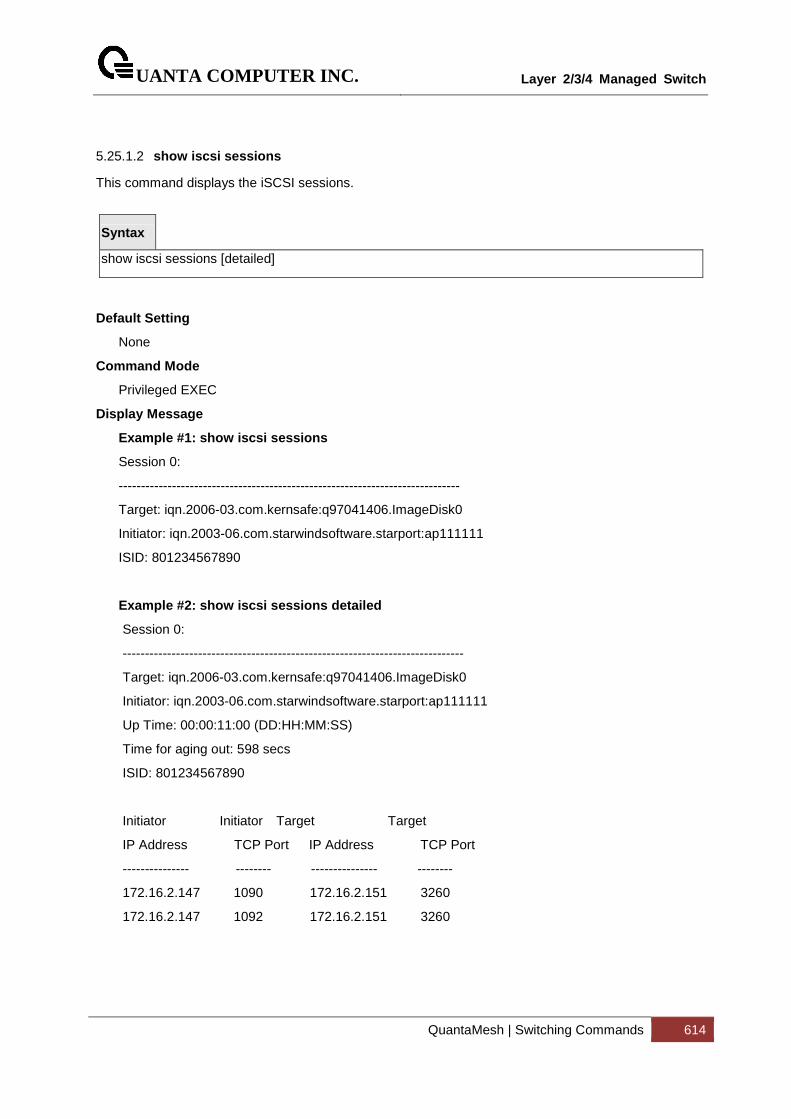
UANTA COMPUTER INC.
Layer 2/3/4 Managed Switch
QuantaMesh | Switching Commands 614
5.25.1.2 show iscsi sessions
This command displays the iSCSI sessions.
Syntax
show iscsi sessions [detailed]
Default Setting
None
Command Mode
Privileged EXEC
Display Message
Example #1: show iscsi sessions
Session 0:
-----------------------------------------------------------------------------
Target: iqn.2006-03.com.kernsafe:q97041406.ImageDisk0
Initiator: iqn.2003-06.com.starwindsoftware.starport:ap111111
ISID: 801234567890
Example #2: show iscsi sessions detailed
Session 0:
-----------------------------------------------------------------------------
Target: iqn.2006-03.com.kernsafe:q97041406.ImageDisk0
Initiator: iqn.2003-06.com.starwindsoftware.starport:ap111111
Up Time: 00:00:11:00 (DD:HH:MM:SS)
Time for aging out: 598 secs
ISID: 801234567890
Initiator Initiator Target Target
IP Address TCP Port IP Address TCP Port
--------------- -------- --------------- --------
172.16.2.147 1090 172.16.2.151 3260
172.16.2.147 1092 172.16.2.151 3260
UANTA COMPUTER INC.
Layer 2/3/4 Managed Switch
QuantaMesh | Switching Commands 615
5.25.2 Configuration Commands
5.25.2.1 iscsi enable
This command globally enables iSCSI awareness.
Syntax
iscsi enable no iscsi enable
no - This command disables iSCSI awareness. When you use the no iscsi enable command, iSCSI resources will be released.
Default Setting
Disable
Command Mode
Global Config.
UANTA COMPUTER INC.
Layer 2/3/4 Managed Switch
QuantaMesh | Switching Commands 616
5.25.2.2 iscsi cos
This command sets the quality of service profile that will be applied to iSCSI flows. iSCSI flows are assigned by default to the highest VPT/DSCP mapped to the highest queue not used for stack management. The user should also take care of configuring the relevant Class of Service parameters for the queue in order to complete the setting.
Setting the VPT/DSCP sets the QoS profile which determines the egress queue to which the frame is mapped. The switch default setting for egress queues scheduling is Weighted Round Robin (WRR).
You may complete the QoS setting by configuring the relevant ports to work in other scheduling and queue management modes via the Class of Service settings. Depending on the platform, these choices may include strict priority for the queue used for iSCSI traffic. The downside of strict priority is that, in certain circumstances (under heavy high priority traffic), other lower priority traffic may get starved. In WRR the queue to which the flow is assigned to can be set to get the required percentage.
Syntax
iscsi cos { dscp <dscp> [remark] | vpt <vpt> } no iscsi cos
vpt/dscp - The VLAN Priority Tag or DSCP to assign iSCSI session packets.
remark - Mark the iSCSI frames with the configured VPT/DSCP when egressing the switch.
no - Use this command to disable VoIP Profile on the interface.
Default Setting
5 (vpt)
Command Mode
Global Config.
UANTA COMPUTER INC.
Layer 2/3/4 Managed Switch
QuantaMesh | Switching Commands 617
5.25.2.3 iscsi aging time
This command sets the aging time for iSCSI sessions. Behavior when changing aging time:
� When aging time is increased, current sessions will be timed out according to the new value.
� When aging time is decreased, any sessions that have been dormant for a time exceeding the new setting will be immediately deleted from the table. All other sessions will continue to be monitored against the new time out value.
Syntax
iscsi aging time <time> no iscsi aging time
time - The number of minutes a session must be inactive prior to its removal. Range: 1-43,200.
no - Use the no form of the command to reset the aging time value to the default value.
Default Setting
10 minutes
Command Mode
Global Config.
UANTA COMPUTER INC.
Layer 2/3/4 Managed Switch
QuantaMesh | Switching Commands 618
5.25.2.4 iscsi target port
This command configures an iSCSI target port and, optionally, a target system’s IP address and IQN name. When working with private iSCSI ports (not IANA-assigned ports 3260/860), it is recommended to specify the target IP address as well, so that the switch will only snoop frames with which the TCP destination port is one of the configured TCP ports, and the destination IP is the target’s IP address. This way the CPU will not be falsely loaded by non-iSCSI flows (if by chance other applications also choose to use these un-reserved ports.
When a port is already defined and not bound to an IP address, and you want to bind it to an IP address, you should first remove it by using the no form of the command and then add it again, this time together with the relevant IP address.
Target names are only for display when using the show iscsi command. These names are not used to match with the iSCSI session information acquired by snooping.
A maximum of 16 TCP ports can be configured either bound to IP or not.
Syntax
iscsi target port tcp-port-1 [tcp-port-2...tcp-port-16] [address ip-address] [name targetname] no iscsi target port tcp-port-1 [tcp-port-2...tcp-port-16] [address ip-address]
tcp-port-n - TCP port number or list of TCP port numbers on which the iSCSI target listens to requests. Up to 16 TCP ports can be defined in the system in one command or by using multiple commands.
ip-address - IP address of the iSCSI target. When the no form of this command is used, and the tcp port to be deleted is one bound to a specific IP address, the address field must be present.
Targetname - iSCSI name of the iSCSI target. The name can be statically configured; however, it can be obtained from iSNS or from sendTargets response. The initiator must present both its iSCSI Initiator Name and the iSCSI Target Name to which it wishes to connect in the first login request of a new session or connection.
no - Use the no form of the command to delete an iSCSI target port, address, and name.
Default Setting
iSCSI well-known ports 3260 and 860 are configured as default but can be removed as any
other configured target.
Command Mode
Global Config.
UANTA COMPUTER INC.
Layer 2/3/4 Managed Switch
QuantaMesh | Switching Commands 619
5.26 Domain Name Server Relay Commands
5.26.1 Show Commands
5.26.1.1 show hosts
This command displays the static host name-to-address mapping table.
Syntax
show hosts
Default Setting
None
Command Mode
Privileged Exec
Display Message
Domain Name List: Domain Name.
IP Address: IPv4 or IPv6 address of the Host.
UANTA COMPUTER INC.
Layer 2/3/4 Managed Switch
QuantaMesh | Switching Commands 620
5.26.1.2 show dns
This command displays the configuration of the DNS server.
Syntax
show dns
Default Setting
None
Command Mode
Privileged Exec
Display Message
Domain Lookup Status: Enable or disable the IP Domain Naming System (DNS)-based host name-to-address translation function.
Domain Relay Status: Enable or disable the IP Domain Naming System (DNS)-based host name-to-address relay function.
Default Domain Name: The default domain name that will be used for querying the IP address of a host.
DNS Client Source Interface: The interface to use as the source interface.
DNS Client Source IPv4 Address: The IPv4 address used for the DNS client to send packets.
DNS Client Source IPv6 Address: The IPv6 address used for the DNS client to send packets.
Domain Name List: A list of domain names that will be used for querying the IP address of a host.
Name Server List: A list of domain name servers, including IPv4 and IPv6.
Request: Number of the DNS query packets been sent.
Response: Number of the DNS response packets been received.
UANTA COMPUTER INC.
Layer 2/3/4 Managed Switch
QuantaMesh | Switching Commands 621
5.26.1.3 show dns cache
This command displays all entries in the DNS cache table.
Syntax
show dns cache
Default Setting
None
Command Mode
Privileged Exec
Display Message
Domain Name List: Domain Name
IP Address: IP address of the corresponding domain name, including IPv4 and IPv6.
TTL: Time in seconds that this entry will remain in the DNS cache table
Flag: Indicates if this entry is reliable. A value of 8 is not as reliable as a value of 10.
UANTA COMPUTER INC.
Layer 2/3/4 Managed Switch
QuantaMesh | Switching Commands 622
5.26.2 Configuration Commands
5.26.2.1 ip hosts
This command creates a static entry in the DNS table that maps a host name to an IP address.
There are maximum 8 entries for IPv4 and 8 entries for IPv6.
Syntax
ip host <name> <ipaddr | ipv6addr > no ip host <name>
<name> - Host name.
<ipaddr|ipv6addr > - IPv4 or IPv6 address of the host.
<no> - Remove the corresponding name to IP address mapping entry.
Default Setting
None
Command Mode
Global Config
5.26.2.2 clear hosts
This command clears the entire static host name-to-address mapping table.
Syntax
clear hosts
Default Setting
None
Command Mode
Privileged Exec
UANTA COMPUTER INC.
Layer 2/3/4 Managed Switch
QuantaMesh | Switching Commands 623
5.26.2.3 ip domain-name
This command defines the default domain name to be appended to incomplete host names (i.e., host names passed from a client are not formatted with dotted notation).
Syntax
ip domain-name <name> no ip domain-name <name>
<name> - Default domain name used to complete unqualified host names. Do not include the initial period that separates an unqualified name from the domain name. (Range: 1-64 characters)
Default Setting
None
Command Mode
Global Config
UANTA COMPUTER INC.
Layer 2/3/4 Managed Switch
QuantaMesh | Switching Commands 624
5.26.2.4 ip domain-list
This command defines the domain name that can be appended to incomplete host names (i.e., host names passed from a client are not formatted with dotted notation). The domain name table can contain maximum 6 entries.
Syntax
ip domain-list <name> no ip domain-list <name>
<name> - Default domain name used to complete unqualified host names. Do not include the initial period that separates an unqualified name from the domain name. (Range: 1-64 characters)
When an incomplete host name is received by the DNS server on this switch, it will work through the domain name list, append each domain name in the list to the host name, and check with the specified name servers for a match. If there is no domain name list, the domain name specified with the "ip domain-name" command is used. If there is a domain name list, the default domain name is not used.
Default Setting
None
Command Mode
Global Config
i
UANTA COMPUTER INC.
Layer 2/3/4 Managed Switch
QuantaMesh | Switching Commands 625
5.26.2.5 ip name-server
This command specifies the address of one or more domain name servers to use for name-to-address resolution. There are maximum 6 entries for IPv4 and 6 entries for IPv6 in the Domain Name Server Table.
Syntax
ip name-server <ipaddr> no ip name-server <ipaddr>
< ipaddr > - IP address of the Domain Name Servers.
<no> - Remove the corresponding Domain Name Server entry from the table.
Note - The listed name servers are queried in the specified sequence until a response is received, or the end of the list is reached with no response.
Default Setting
None
Command Mode
Global Config
5.26.2.6 ip name-server source-interface
This command specifies the source address of dns client to use for name-to-address resolution.
Syntax
ip name-server source-interface {<slot/port> | loopback <loopback-id> | tunnel <tunnel-id> | vlan <vlan-id>} no ip name-server source-interface
<slot/port> - Specifies the interface to use as the source interface.
<loopback-id> - Specifies the loopback interface to use as the source interface. The range of the loopback ID is 0 to 7.
<tunnel-id> - Specifies the tunnel interface to use as the source interface. The range of the tunnel ID is 0 to 7.
<vlan-id> - Specifies the VLAN interface to use as the source interface. The range of the VLAN ID is 1 to 4093.
<no> - Remove the corresponding Domain Name Server entry from the table.
Default Setting
None
UANTA COMPUTER INC.
Layer 2/3/4 Managed Switch
QuantaMesh | Switching Commands 626
Command Mode
Global Config
UANTA COMPUTER INC.
Layer 2/3/4 Managed Switch
QuantaMesh | Switching Commands 627
5.26.2.7 ip domain-lookup
This command enables the IP Domain Naming System (DNS)-based host name-to-address translation.
Syntax
ip domain-lookup no ip domain-lookup
<no> - This command disables the IP Domain Naming System (DNS)-based host name-to-address translation.
Default Setting
Enabled
Command Mode
Global Config
5.26.2.8 ip domain-lookup relay
This command enables the IP Domain Naming System (DNS)-based host name-to-address relay translation.
Syntax
ip domain-lookup relay no ip domain-lookup realy
<no> - This command disables the IP Domain Naming System (DNS)-based host name-to-address relay translation.
Default Setting
Disabled
Command Mode
Global Config
UANTA COMPUTER INC.
Layer 2/3/4 Managed Switch
QuantaMesh | Switching Commands 628
5.26.2.9 clear domain-list
This command clears all entries in the domain name list table.
Syntax
clear domain-list
Default Setting
None
Command Mode
Privileged Exec
5.26.2.10 clear dns
This command sets the DNS configuration to default value.
Syntax
clear dns
Default Setting
None
Command Mode
Privileged Exec
UANTA COMPUTER INC.
Layer 2/3/4 Managed Switch
QuantaMesh | Switching Commands 629
5.26.2.11 clear dns cache
This command clears all entries in the DNS cache table.
Syntax
clear dns cache
Default Setting
None
Command Mode
Privileged Exec
5.26.2.12 clear dns counter
This command clears the statistics of all entries in the DNS cache table.
Syntax
clear dns counter
Default Setting
None
Command Mode
Privileged Exec
UANTA COMPUTER INC.
Layer 2/3/4 Managed Switch
QuantaMesh | Switching Commands 630
5.27 UDLD Commands
5.27.1 Show command
5.27.1.1 show udld
Show UDLD information in all interfaces or specific interface
Syntax
show udld {< slot/port>}
<slot/port> - The interface number.
Default Setting
None
Command Mode
Privileged Exec
Display Message
Port enable operational state: Specifies the Port Enable Operational State of the selected port.
Current bidirectional state: Specifies the Bidirectional State of the selected port.
Current operational state: Specifies the runtime Operational State of the selected port. This section will be hidden if the port doesn't enable udld.
Message interval: Specifies the runtime Message Interval of the selected port. This section will be hidden if the port doesn't enable udld.
Timeout interval: Specifies the runtime Timeout Interval of the selected port. This section will be hidden if the port doesn't enable udld.
Remote Entry: Display all the remote entry information if received.
Expiration time: Specifies the runtime Expiration Time of the remote entry.
Device ID: Specifies the Device Id associated with the remote system.
Device Name: Specifies the Device Name associated with the remote system.
Port ID: Specifies the Port Id associated with the remote system.
Neighbor echo device: Specifies the Device Id included in Echo TLV associated with the remote system.
Neighbor echo port: Specifies the port Id included in Echo TLV associated with the remote system.
Message interval: Specifies the Message Interval associated with the remote system.
Timeout interval: Specifies the Message Interval associated with the remote system.
CDP Device Name: Specifies the CDP Device Name associated with the remote system.

UANTA COMPUTER INC.
Layer 2/3/4 Managed Switch
QuantaMesh | Switching Commands 631
UANTA COMPUTER INC.
Layer 2/3/4 Managed Switch
QuantaMesh | Switching Commands 632
5.27.2 Configuration Commands
5.27.2.1 udld aggressive
Enable/Disable UDLD protocol in aggressive mode on fiber ports except where locally configured
Syntax
udld aggressive
no udld aggressive
Default Setting
Disabled
Command Mode
Global Config.
5.27.2.2 udld enable
Enable/Disable UDLD protocol on fiber ports except where locally configured
Syntax
udld enable
no udld enable
Default Setting
Disabled
Command Mode
Global Config.
UANTA COMPUTER INC.
Layer 2/3/4 Managed Switch
QuantaMesh | Switching Commands 633
5.27.2.3 udld message time
Set UDLD message time period in <7-90> range. The message time is to use between sending of messages in steady. Default value of UDLD message time is 15.
Syntax
udld message time <7-90>
no udld message time
Default Setting
15 sec
Command Mode
Global Config.
5.27.2.4 udld port
Enable/Disable UDLD protocol on the interface.
Syntax
udld port
no udld port
Default Setting
Disable
Command Mode
Interface Config.
UANTA COMPUTER INC.
Layer 2/3/4 Managed Switch
QuantaMesh | Switching Commands 634
5.27.2.5 udld port aggressive
Enable/Disable UDLD protocol in aggressive mode on the interface
Syntax
udld port aggressive
no udld port aggressive
Default Setting
Disable
Command Mode
Interface Config.
UANTA COMPUTER INC.
Layer 2/3/4 Managed Switch
QuantaMesh | Switching Commands 635
5.28 Multi Chassis Link Aggregation Commands
5.28.1 Show Commands
5.28.1.1 show mlag
This command displays detailed information about the Multi-chassis Link Aggregation (MLAG) configured on the switch.
Syntax
show mlag <mlag-number>
Default Setting
None
Command Mode
Privileged Exec
Display Message
Admin Mode: Displays the administrative mode for MLAG functionality on the switch.
Domain Id: Represents the domain identify number of MLAG peer devices.
MLAG Status: Represents the operation status of MLAG.
Configuration Consistency Status: Represents the configuration consistency status of MLAG peer devices.
MLAG Role: Represents the role of MLAG peer device.
MLAG System-Mac: Represents the operation system MAC address of MLAG peer devices.
MLAG Local Syatem-Mac: Represents the statically defined system MAC address of MLAG peer devices.
Number of MLAG Configured: Represents the number of MLAG port-channel member.
Peer Gateway Mode: To enable Layer 3 forwarding for packets destined to the gateway MAC address of the MLAG.
Delay Restore Time: To delay the MLAG from coming up on the restored MLAG peer device after a reload when the peer adjacency is already established. The range is from 5 to 600 seconds.
Keepalive Timeout: To specify the timeout (in seconds) between re-transmissions to the MLAG peer device. The range is from 3 to 20.
Interface: Shows the interface on which MLAG information is being displayed.
Status: Represents the link status of MLAG peer link port or port-channel member.
ID: Represents the identify number of MLAG port-channel member.
Consistency: Represents the configuration consistency status of MLAG port-channel member.
Active Vlan: Represents the VLAN which MLAG peer link port or port-channel member belong to.

UANTA COMPUTER INC.
Layer 2/3/4 Managed Switch
QuantaMesh | Switching Commands 636
UANTA COMPUTER INC.
Layer 2/3/4 Managed Switch
QuantaMesh | Switching Commands 637
5.28.1.2 show mlag consistency-parameters
This command displays the consistency of parameters that must be compatible across the Multi-chassis Link Aggregation (MLAG).
Syntax
show mlag consistency-parameters <mlag-number>
Default Setting
None
Command Mode
Privileged Exec
Display Message
Spanning Tree Admin Mode: Indicates whether administrative mode is enabled or disabled of MLAG peer devices.
Spanning Tree Version : Represents the version of 802.1 currently supported (IEEE 802.1s, IEEE 802.1w, or IEEE 802.1d) based upon the Force Protocol Version parameter of MLAG peer devices.
Spanning Tree Configuration Name : Represents the configured name of MLAG peer devices.
Spanning Tree BPDU Guard Mode: Indicates whether BPDU guard mode is enabled or disabled of MLAG peer devices.
Spanning Tree BPDU Filter Mode: Indicates whether BPDU filter mode is enabled or disabled of MLAG peer devices.
Spanning Tree Peer-Link Port Mode: Indicates whether port mode on peer link port is enabled or disabled of MLAG peer devices.
Spanning Tree Peer-Link Root Guard: Indicates whether root guard mode on peer link port is enabled or disabled of MLAG peer devices.
Spanning Tree Peer-Link Loop Guard: Indicates whether loop guard mode on peer link port is enabled or disabled of MLAG peer devices.
Spanning Tree Peer-Link BPDU Guard: Indicates whether BPDU guard mode on peer link port is enabled or disabled of MLAG peer devices.
Spanning Tree Peer-Link BPDU Filter Mode: Indicates whether BPDU filter mode on peer link port is enabled or disabled of MLAG peer devices.
Spanning Tree Peer-Link BPDU Flood Mode: Indicates whether BPDU flood mode on peer link port is enabled or disabled of MLAG peer devices.
VTP Admin Status: Indicates whether administrative mode is enabled or disabled of MLAG peer devices.
VTP Operating Mode: Displays the VTP operating mode of MLAG peer devices, which can be server, client, or transparent.
VTP Pruning Mode: Displays whether pruning is enabled or disabled of MLAG peer devices.
VTP V2 Mode: Displays if VTP version 2 mode is enabled of MLAG peer devices.
UANTA COMPUTER INC.
Layer 2/3/4 Managed Switch
QuantaMesh | Switching Commands 638
VTP Domain Name: Displays the name that identifies the administrative domain of MLAG peer devices.
VTP Password: Displays the VTP domain password of MLAG peer devices.
IGMP Snooping Admin Mode : Indicates whether or not IGMP Snooping is active on the switch of MLAG peer devices.
MLD Snooping Admin Mode : Indicates whether or not MLD Snooping is active on the switch of MLAG peer devices.
GMRP Admin Mode: This displays the administrative mode of GARP VLAN Registration Protocol (GVRP) for the system of MLAG peer devices..
GVRP Admin Mode: This displays the administrative mode of GARP Multicast Registration Protocol (GMRP) for the system of MLAG peer devices..
When you specify a value for <mlag-number>, the following information appears.
Spanning Tree Port Mode: Indicates whether port mode on MLAG member is enabled or disabled of MLAG peer devices.
Spanning Tree Root Guard: Indicates whether root guard mode on MLAG member is enabled or disabled of MLAG peer devices.
Spanning Tree Loop Guard: Indicates whether loop guard mode on MLAG member is enabled or disabled of MLAG peer devices.
Spanning Tree BPDU Guard: Indicates whether BPDU guard mode on MLAG member is enabled or disabled of MLAG peer devices.
Spanning Tree BPDU Filter Mode: Indicates whether BPDU filter mode on MLAG member is enabled or disabled of MLAG peer devices.
Spanning Tree BPDU Flood Mode: Indicates whether BPDU flood mode on MLAG member is enabled or disabled of MLAG peer devices.
VTP Port Trunk Mode: Indicates whether trunk mode is enabled or disabled on MLAG member of MLAG peer devices.
IGMP Snooping Mode : Indicates whether or not IGMP Snooping is active on MLAG member of MLAG peer devices.
MLD Snooping Mode : Indicates whether or not MLD Snooping is active on MLAG member of MLAG peer devices.
GMRP Mode: This displays the administrative mode of GARP VLAN Registration Protocol (GVRP) for MLAG member of MLAG peer devices..
GVRP Mode: This displays the administrative mode of GARP Multicast Registration Protocol (GMRP) for MLAG member of MLAG peer devices..
UANTA COMPUTER INC.
Layer 2/3/4 Managed Switch
QuantaMesh | Switching Commands 639
5.28.2 Configuration Commands
5.28.2.1 mlag
This command enables a Multi-chassis Link Aggregation (MLAG), which allows links that are physically connected to two different devices to appear as a single port channel to a third device.
To disable MLAG on the switch, use the no form of this command.
Syntax
mlag no mlag
Default Setting
Disabled
Command Mode
Global Config
5.28.2.2 mlag domain
This command creates a Multi-chassis Link Aggregation (MLAG) domain and assign a domain ID. The range is from 1 and 1000.
To revert to the default mlag configuration, use the no form of this command
Syntax
mlag domain <domain-id> no mlag domain
<domain-id> - Domain identify number of MLAG (Range: 1 – 1000).
Default Setting
1
Command Mode
Global Config
UANTA COMPUTER INC.
Layer 2/3/4 Managed Switch
QuantaMesh | Switching Commands 640
5.28.2.3 mlag system-mac
This command manually configures the Multi-chassis Link Aggregation (MLAG) domain MAC address.
To restore the default system MAC address, use the no form of this command.
Syntax
mlag system-mac <mac-address> no mlag system-mac
<mac-address> - Syatem MAC adress.
Default Setting
None
Command Mode
Global Config
5.28.2.4 mlag peer-link
This command creates a Multi-chassis Link Aggregation (MLAG) peer link by designating the port channel that you want on each device as the peer link for the specified MLAG domain.
To remove the peer link, use the no form of this command.
Syntax
mlag peer-link no mlag peer-link
Default Setting
Disabled
Command Mode
Interface Config
UANTA COMPUTER INC.
Layer 2/3/4 Managed Switch
QuantaMesh | Switching Commands 641
5.28.2.5 mlag <mlag-number>
This command moves other port channels into a Multi-chassis Link Aggregation (MLAG) to connect to the downstream device. The range is from 1 and 4096.
To remove the port channels from the mlag, use the no form of this command.
Syntax
mlag <mlag-number> no mlag
<mlag-number> - Domain identify number of MLAG port-channel member (Range: 1 – 4096).
Default Setting
Disabled
Command Mode
Interface Config
5.28.2.6 mlag peer-gateway
This command enable Layer 3 forwarding for packets destined to the gateway MAC address of the MLAG. Use no form to disable it.
Syntax
mlag peer-gateway no mlag peer-gateway
no – This command disable the peer-gateway.
Default Setting
Enabled
Command Mode
Global Config
UANTA COMPUTER INC.
Layer 2/3/4 Managed Switch
QuantaMesh | Switching Commands 642
5.28.2.7 mlag keepaliv-timeout
This command is used to specify the timeout (in seconds) between re-transmissions to the MLAG peer device.
Syntax
mlag keepalive-timeout <3-20> no mlag keepalive-timeout
<3-20> - Specify the timeout value between re-transmissions.
no – This command restore the setting to default value.
Default Setting
5
Command Mode
Global Config
5.28.2.8 mlag delay-restore
This command is used to specify the time to delay the MLAG from coming up on the restored MLAG peer device aftera reload when the peer adjacency is already established.
Syntax
mlag delay-restore <5-600> no mlag delay-restore
<5-600> - Specify the number of seconds to delay bringing up the restored MLAG peer device.
no – This command restore the setting to default value.
Default Setting
10
Command Mode
Global Config
UANTA COMPUTER INC.
Layer 2/3/4 Managed Switch
QuantaMesh | Switching Commands 643
5.29 Control Plane Protection Commands
5.29.1 Show Commands
5.29.1.1 show access-lists interface control-plane
This command displays IP ACLs, IPv6 ACLs, and MAC access control lists information for CPU port.
Syntax
show access-lists interface control-plane
Default Setting
None
Command Mode
Privileged Exec
Display Message
ACL Type : Type of access list (IP, IPv6 or MAC).
ACL ID : Access List name for a MAC or IPv6 access list or the numeric identifier for an IP access list.
Sequence Number: An optional sequence number may be specified to indicate the order of this access list relative to other access lists already assigned to this interface. A lower number indicates higher precedence order. If a sequence number is already in use for this interface, the specified ccess list replaces the currently attached access list using that sequence number. If the sequence number is not specified by the user, a sequence number that is one greater than the highest sequence number currently in use for this interface is used. Valid range is (1 to 4294967295).
5.29.2 Configuration Commands
5.29.2.1 interface control-plane
To enter control-plane configuration mode and apply a IP, IPv6 or MAC access list to police traffic destined for the CPU port, use the interface control-plane command in global configuration mode.
Syntax
Interface control-plane
Default Setting
No control plane access lists are defined.
Command Mode

UANTA COMPUTER INC.
Layer 2/3/4 Managed Switch
QuantaMesh | Switching Commands 644
Global Config
UANTA COMPUTER INC.
Layer 2/3/4 Managed Switch
QuantaMesh | Routing Commands 645
6 Routing Commands
6.1 Address Resolution Protocol (ARP) Commands
6.1.1 Show Commands
6.1.1.1 show ip arp
This command displays the Address Resolution Protocol (ARP) cache.
Syntax
show ip arp
Default Setting
None
Command Mode
Privileged Exec
Display Message
Age Time: Is the time it takes for an ARP entry to age out. This value was configured into the unit. Age time is measured in seconds.
Response Time: Is the time it takes for an ARP request timeout. This value was configured into the unit. Response time is measured in seconds.
Retries: Is the maximum number of times an ARP request is retried. This value was configured into the unit.
Cache Size: Is the maximum number of entries in the ARP table. This value was configured into the unit.
Dynamic renew mode: Displays whether the ARP component automatically attempts to renew dynamic ARP entries when they aged out.
Total Entry Count Current/Peak: Field listing the total entries in the ARP table and the peak entry count in the ARP table.
Static Entry Count Configured/Active/Max: Field listing configured static entry count, active static entry count, and maximum static entry count in the ARP table.
The following are displayed for each ARP entry.
IP Address: Is the IP address of a device on a subnet attached to an existing routing interface.
MAC Address: Is the hardware MAC address of that device.
Interface: Is the routing slot/port associated with the device ARP entry
UANTA COMPUTER INC.
Layer 2/3/4 Managed Switch
QuantaMesh | Routing Commands 646
Type: Is the type that was configured into the unit. The possible values are Local, Gateway, Dynamic and Static.
Age: This field displays the current age of the ARP entry since last refresh (in hh:mm:ss format).
6.1.1.2 show ip arp brief
This command displays the brief Address Resolution Protocol (ARP) table information.
Syntax
show ip arp brief
Default Setting
None
Command Mode
Privileged Exec
Display Message
Age Time: Is the time it takes for an ARP entry to age out. This value was configured into the unit. Age time is measured in seconds.
Response Time: Is the time it takes for an ARP request timeout. This value was configured into the unit. Response time is measured in seconds.
Retries: Is the maximum number of times an ARP request is retried. This value was configured into the unit.
Cache Size: Is the maximum number of entries in the ARP table. This value was configured into the unit.
Dynamic renew mode: Displays whether the ARP component automatically attempts to renew dynamic ARP entries when they aged out.
Total Entry Count Current/Peak: Field listing the total entries in the ARP table and the peak entry count in the ARP table.
Static Entry Count Configured/Active/Max: Field listing the configured static entry count, active static entry count, and maximum static entry count in the ARP table.
UANTA COMPUTER INC.
Layer 2/3/4 Managed Switch
QuantaMesh | Routing Commands 647
6.1.1.3 show ip arp static
This command displays the static Address Resolution Protocol (ARP) table information.
Syntax
show ip arp static
Default Setting
None
Command Mode
Privileged Exec
Display Message
IP address: Is the IP address of a device on a subnet attached to an existing routing interface.
MAC address: Is the MAC address for that device.
UANTA COMPUTER INC.
Layer 2/3/4 Managed Switch
QuantaMesh | Routing Commands 648
6.1.2 Configuration Commands
6.1.2.1 arp
This command creates an ARP entry. The value for <ipaddress> is the IP address of a device on a subnet attached to an existing routing interface. The value for <macaddress> is a unicast MAC address for that device.
Syntax
arp <ipaddr> <macaddr> no arp <ipaddr> <macaddr>
<ipaddr> - Is the IP address of a device on a subnet attached to an existing routing interface.
<macaddr> - Is a MAC address for that device. The format is 6 two-digit hexadecimal numbers that are separated by colons, for example, 00:06:29:32:81:40.
no - This command deletes an ARP entry.
Default Setting
None
Command Mode
Global Config
6.1.2.2 arp cachesize
This command configures the maximum number of entries in the ARP cache.
Syntax
arp cachesize <767-4096> no arp cachesize
<767-3968> - The range of cache size is 767 to 4096.
no - This command configures the default ARP cache size.
Default Setting
The default cache size is 4096.
Command Mode
Global Config
UANTA COMPUTER INC.
Layer 2/3/4 Managed Switch
QuantaMesh | Routing Commands 649
6.1.2.3 arp dynamicrenew
This command enables ARP component to automatically renew ARP entries of type dynamic when they age out.
Syntax
arp dynamicrenew no arp dynamicrenew
no - This command disables ARP component from automatically renewing ARP entries of type dynamic when they age out.
Default Setting
Disabled
Command Mode
Global Config
UANTA COMPUTER INC.
Layer 2/3/4 Managed Switch
QuantaMesh | Routing Commands 650
6.1.2.4 arp resptime
This command configures the ARP request response timeout.
Syntax
arp resptime <1-10> no arp resptime
<1-10> - The range of default response time is 1 to 10 seconds.
no - This command configures the default response timeout time.
Default Setting
The default response time is 1.
Command Mode
Global Config
6.1.2.5 arp retries
This command configures the ARP count of maximum request for retries.
Syntax
arp retries <0-10> no arp retries
<0-10> - The range of maximum request for retries is 0 to 10.
no - This command configures the default count of maximum request for retries.
Default Setting
The default value is 4.
Command Mode
Global Config
UANTA COMPUTER INC.
Layer 2/3/4 Managed Switch
QuantaMesh | Routing Commands 651
6.1.2.6 arp timeout
This command configures the ARP entry ageout time.
Syntax
arp timeout <15-21600> no arp timeout
<15-21600> - Represents the IP ARP entry ageout time in seconds. The range is 15 to 21600 seconds.
no - This command configures the default ageout time for IP ARP entry.
Default Setting
The default value is 1200.
Command Mode
Global Config
6.1.2.7 arp access-list
Use this command to create an ARP ACL
Syntax
arp access-list <name> no arp access-list <name>
no – Use this command to delete a configured ARP ACL.
Default Setting
None
Command Mode
Global Config
6.1.2.8 permit ip host mac host
Use this command to configure a rule for a valid IP address and MAC address combination used in ARP packet validation.
UANTA COMPUTER INC.
Layer 2/3/4 Managed Switch
QuantaMesh | Routing Commands 652
Syntax
permit ip host <sender-ip> mac host <sender-mac> no permit ip host <sender-ip> mac host <sender-mac>
no – Use this command to delete a rule for a valid IP and MAC combination.
Default Setting
None
Command Mode
ARP Access-list Config
6.1.2.9 clear ip arp-cache
This command causes all ARP entries of type dynamic to be removed form the ARP cache. If the [gateway] parameter is specified, the dynamic entries of type gateway are purged as well.
Syntax
clear ip arp-cache [gateway | interface {<slot/port> | vlan <vlan-id>}]
Default Setting
None
Command Mode
Privileged Exec
UANTA COMPUTER INC.
Layer 2/3/4 Managed Switch
QuantaMesh | Routing Commands 653
6.2 IP Routing Commands
6.2.1 Show Commands
6.2.1.1 show ip brief
This command displays all the summary information of the IP.
Syntax
show ip brief
Default Setting
None
Command Mode
Privileged Exec
User Exec
Display Message
Default Time to Live: The computed TTL (Time to Live) of forwarding a packet from the local router to the final destination.
Routing Mode: Show whether the routing mode is enabled or disabled.
Maximum Next Hops: The maximum number of hops supported by this switch.
Maximum Routes: The maximum number of routes the packet can travel.
ICMP Rate Limit Interval: Shows how often the token bucket is initialized with burst-size tokens. Burst-interval is from 0 to 2147483647 milliseconds. The default burst-interval is 1000 msec.
ICMP Rate Limit Burst Size: Shows the number of ICMPv4 error messages that can be sent during one burst-interval. The range is from 1 to 200 messages. The default value is 100 messages.
ICMP Echo Replies: Shows whether ICMP Echo Replies are enabled or disabled.
ICMP Redirects: Shows whether ICMP Redirects are enabled or disabled.
Dead Gateway Detection: Show whether Dead Gateway Detection is enabled or disabled.
Dead Gateway Detection Probe Interval: Shows the interval that ARP request is sent.
UANTA COMPUTER INC.
Layer 2/3/4 Managed Switch
QuantaMesh | Routing Commands 654
6.2.1.2 show ip interface port
This command displays all pertinent information about the IP interfaces.
Syntax
show ip interface port <slot/port>
Default Setting
None
Command Mode
Privileged Exec
User Exec
Display Message
Routing Interface Status: Determine the operational status of IPv4 routing Interface. The possible values are Up or Down.
Primary IP Address: The primary IP address and subnet masks for the interface. This value appears only if you configure it.
Method: Shows whether the IP address was configured manually or acquired from a DHCP server.
Secondary IP Address: One or more secondary IP addresses and subnet masks for the interface. This value appears only if you configure it.
Helper IP Address: The helper IP addresses configured by the command “ip helper-address (Interface Config)”.
Routing Mode: The administrative mode of router interface participation. The possible values are enable or disable. This value is configurable.
Administrative Mode: The administrative mode of the specified interface. The possible values of this field are enable or disable. This value is configurable.
Forward Net Directed Broadcasts: Displays whether forwarding of network-directed broadcasts is enabled or disabled. This value is configurable.
Proxy ARP: Displays whether Proxy ARP is enabled or disabled on the system.
Local Proxy ARP: Displays whether Local Proxy ARP is enabled or disabled on the interface.
Active State Displays whether the interface is active or inactive. An interface is considered active if its link is up and it is in forwarding state.
Link Speed Data Rate: An integer representing the physical link data rate of the specified interface. This is measured in Megabits per second (Mbps).
MAC Address: The burned in physical address of the specified interface. The format is 6 two-digit hexadecimal numbers that are separated by colons.
Encapsulation Type: The encapsulation type for the specified interface. The types are: Ethernet or SNAP.
IP MTU: The maximum transmission unit (MTU) size of a frame, in bytes.
Bandwidth: Shows the bandwidth of the interface.
UANTA COMPUTER INC.
Layer 2/3/4 Managed Switch
QuantaMesh | Routing Commands 655
Destination Unreachables: Displays whether ICMP Destination Unreachables may be sent (enabled or disabled).
ICMP Redirects: Displays whether ICMP Redirects may be sent (enabled or disabled).
6.2.1.3 show ip interface vlan
This command displays all pertinent information about the VLAN routing interfaces.
Syntax
show ip interface vlan <1-4093>
Default Setting
None
Command Mode
Privileged Exec
User Exec
Display Message
Routing Interface Status: Determine the operational status of IPv4 routing Interface. The possible values are Up or Down.
Primary IP Address: The primary IP address and subnet masks for the interface. This value appears only if you configure it.
Method: Shows whether the IP address was configured manually or acquired from a DHCP server.
Secondary IP Address: One or more secondary IP addresses and subnet masks for the interface. This value appears only if you configure it.
Helper IP Address: The helper IP addresses configured by the command “ip helper-address (Interface Config)”.
Routing Mode: The administrative mode of router interface participation. The possible values are enable or disable. This value is configurable.
Administrative Mode: The administrative mode of the specified interface. The possible values of this field are enable or disable. This value is configurable.
Forward Net Directed Broadcasts: Displays whether forwarding of network-directed broadcasts is enabled or disabled. This value is configurable.
Proxy ARP: Displays whether Proxy ARP is enabled or disabled on the system.
Local Proxy ARP: Displays whether Local Proxy ARP is enabled or disabled on the interface.
Active State Displays whether the interface is active or inactive. An interface is considered active if its link is up and it is in forwarding state.
Link Speed Data Rate: An integer representing the physical link data rate of the specified interface. This is measured in Megabits per second (Mbps).
UANTA COMPUTER INC.
Layer 2/3/4 Managed Switch
QuantaMesh | Routing Commands 656
MAC Address: The burned in physical address of the specified interface. The format is 6 two-digit hexadecimal numbers that are separated by colons.
Encapsulation Type: The encapsulation type for the specified interface. The types are: Ethernet or SNAP.
IP MTU: The maximum transmission unit (MTU) size of a frame, in bytes.
Bandwidth: Shows the bandwidth of the interface.
Destination Unreachables: Displays whether ICMP Destination Unreachables may be sent (enabled or disabled).
ICMP Redirects: Displays whether ICMP Redirects may be sent (enabled or disabled).
6.2.1.4 show ip interface loopback
This command displays information about configured loopback interfaces.
Syntax
show ip interface loopback [<0-7>]
Default Setting
None
Command Mode
Privileged Exec
User Exec
Display Message
Loopback Id: The loopback ID associated with the rest of the information in the row..
Interface: The interface name.
IP Address: The IPv4 address of the interface.
If you specify a loopback ID, the following information appears:
Interface Link Status: Shows whether the link is up or down.
IP Address: The IPv4 address of the interface.
MTU size: The maximum transmission size for packets on this interface, in bytes..
UANTA COMPUTER INC.
Layer 2/3/4 Managed Switch
QuantaMesh | Routing Commands 657
6.2.1.5 show ip interface brief
This command displays summary information about IP configuration settings for all ports in the router.
Syntax
show ip interface brief
Default Setting
None
Command Mode
Privileged Exec
User Exec
Display Message
Interface: Valid slot, and port number separated by forward slashes or VLAN routing interface.
State: Indicate the operational state of the routing interface.
IP Address: The IP address of the routing interface.
IP Mask: The IP mask of the routing interface.
Method: Is the way to get the IP Address. The possible value is “Manual”, “DHCP” or “None”.Netdir Bcast: Indicates if IP forwards net-directed broadcasts on this interface. Possible values are Enable or Disable.
MultiCast Fwd: Indicates the multicast forwarding administrative mode on the interface. Possible values are Enable or Disable.
UANTA COMPUTER INC.
Layer 2/3/4 Managed Switch
QuantaMesh | Routing Commands 658
6.2.1.6 show ip route
This command displays the routing table. The <ip-address> specifies the network for which the route is to be displayed and displays the best matching best-route for the address. The <mask> specifies the subnet mask for the given <ip-address>. When you use the longerprefixes keyword, the <ip-address> and <mask> pair becomes the prefix, and the command displays the routes to the addresses that match that prefix. Use the <protocol> parameter to specify the protocol that installed the routes. The value for <protocol> can be connected, ospf, rip, or static . Use the all parameter to display all routes including best and nonbest routes. If you do not use the all parameter, the command only displays the best route.
If you use the connected keyword for <protocol> , the all option is not available because there are no best or non-best connected routes.
Syntax
show ip route [{<ip-address> [<protocol>] | {<ip-address> <mask> [longer-prefixes] [<protocol>] | <protocol>} [all] | all}]
Default Setting
None
Command Mode
Privileged Exec
Display Message
Route Codes: Displays the key for the routing protocol codes that might appear in the routing table output.
The command displays the routing tables in the following format:
Code IP-Address/Mask [Preference/Metric] via Next-Hop, Interface
Code: The codes for the routing protocols that created the routes.
IP-Address/Mask: The IP-Address and mask of the destination network corresponding to this route.
Preference: The administrative distance associated with this route. Routes with low values are preferred over routes with higher values.
Metric: The cost associated with this route.
via Next-Hop: The outgoing router IP address to use when forwarding traffic to the next router (if any) in the path toward the destination
Interface: The outgoing router interface to use when forwarding traffic to the next destination
!
UANTA COMPUTER INC.
Layer 2/3/4 Managed Switch
QuantaMesh | Routing Commands 659
6.2.1.7 show ip route bestroutes
This command displays router route table information for the best routes.
Syntax
show ip route bestroutes
Default Setting
None
Command Mode
Privileged Exec
Display Message
Total Number of Routes: The total number of routes.
Network Address: Is an IP route prefix for the destination.
Subnet Mask: Is a mask of the network and host portion of the IP address for the router interface.
Protocol: Tells which protocol added the specified route. The possibilities are: local, static, OSPF, or RIP.
for each next hop
Next Hop Intf: The outgoing router interface to use when forwarding traffic to the next destination.
Next Hop IP Address: The outgoing router IP address to use when forwarding traffic to the next router (if any) in the path toward the destination.
UANTA COMPUTER INC.
Layer 2/3/4 Managed Switch
QuantaMesh | Routing Commands 660
6.2.1.8 show ip route entry
This command displays the router route entry information.
Syntax
show ip route entry <networkaddress>
<networkaddress> - Is a valid network address identifying the network on the specified interface.
Default Setting
None
Command Mode
Privileged Exec
Display Message
Network Address: Is a valid network address identifying the network on the specified interface.
Subnet Mask: Is a mask of the network and host portion of the IP address for the attached network.
Protocol: Tells which protocol added the specified route. The possibilities are: local, static, OSPF, or RIP.
Total Number of Routes: The total number of routes.
for each next hop
Next Hop Intf: The outgoing router interface to use when forwarding traffic to the next destination.
Next Hop IP Address: The outgoing router IP address to use when forwarding traffic to the next router (if any) in the path toward the destination.
Metric: Specifies the metric for this route entry.
Pref: The preference value that is used for this route entry.
UANTA COMPUTER INC.
Layer 2/3/4 Managed Switch
QuantaMesh | Routing Commands 661
6.2.1.9 show ip route connected
This command displays directly connected routes.
Syntax
show ip route connected
Default Setting
None
Command Mode
Privileged Exec
Display Message
Route Codes: Displays the key for the routing protocol codes that might appear in the routing table output.
The command displays the routing tables in the following format:
Code IP-Address/Mask [Preference/Metric] via Next-Hop, Interface
Code: The codes for the routing protocols that created the routes.
IP-Address/Mask: The IP-Address and mask of the destination network corresponding to this route.
Preference: The administrative distance associated with this route. Routes with low values are preferred over routes with higher values.
Metric: The cost associated with this route.
via Next-Hop: The outgoing router IP address to use when forwarding traffic to the next router (if any) in the path toward the destination.
Interface: The outgoing router interface to use when forwarding traffic to the next destination.

UANTA COMPUTER INC.
Layer 2/3/4 Managed Switch
QuantaMesh | Routing Commands 662
6.2.1.10 show ip route ospf
This command displays Open Shortest Path First (OSPF) routes. The option all command displays all (best and non-best) routes.
Syntax
show ip route ospf [all]
Default Setting
None
Command Mode
Privileged Exec
Display Message
Route Codes: Displays the key for the routing protocol codes that might appear in the routing table output.
The command displays the routing tables in the following format:
Code IP-Address/Mask [Preference/Metric] via Next-Hop, Interface
Code: The codes for the routing protocols that created the routes.
IP-Address/Mask: The IP-Address and mask of the destination network corresponding to this route.
Preference: The administrative distance associated with this route. Routes with low values are preferred over routes with higher values.
Metric: The cost associated with this route.
via Next-Hop: The outgoing router IP address to use when forwarding traffic to the next router (if any) in the path toward the destination.
Interface: The outgoing router interface to use when forwarding traffic to the next destination.
UANTA COMPUTER INC.
Layer 2/3/4 Managed Switch
QuantaMesh | Routing Commands 663
6.2.1.11 show ip route rip
This command displays Routing Information Protocol (RIP) routes. The option all command displays all (best and non-best) routes.
Syntax
show ip route rip [all]
Default Setting
None
Command Mode
Privileged Exec
Display Message
Route Codes: Displays the key for the routing protocol codes that might appear in the routing table output.
The command displays the routing tables in the following format:
Code IP-Address/Mask [Preference/Metric] via Next-Hop, Interface
Code: The codes for the routing protocols that created the routes.
IP-Address/Mask: The IP-Address and mask of the destination network corresponding to this route.
Preference: The administrative distance associated with this route. Routes with low values are preferred over routes with higher values.
Metric: The cost associated with this route.
via Next-Hop: The outgoing router IP address to use when forwarding traffic to the next router (if any) in the path toward the destination.
Interface: The outgoing router interface to use when forwarding traffic to the next destination.
UANTA COMPUTER INC.
Layer 2/3/4 Managed Switch
QuantaMesh | Routing Commands 664
6.2.1.12 show ip route static
This command displays Static Routes. The option all command displays all (best and non-best) routes.
Syntax
show ip route static [all]
Default Setting
None
Command Mode
Privileged Exec
Display Message
Route Codes: Displays the key for the routing protocol codes that might appear in the routing table output.
The command displays the routing tables in the following format:
Code IP-Address/Mask [Preference/Metric] via Next-Hop, Interface
Code: The codes for the routing protocols that created the routes.
IP-Address/Mask: The IP-Address and mask of the destination network corresponding to this route.
Preference: The administrative distance associated with this route. Routes with low values are preferred over routes with higher values.
Metric: The cost associated with this route.
via Next-Hop: The outgoing router IP address to use when forwarding traffic to the next router (if any) in the path toward the destination.
Interface: The outgoing router interface to use when forwarding traffic to the next destination.
UANTA COMPUTER INC.
Layer 2/3/4 Managed Switch
QuantaMesh | Routing Commands 665
6.2.1.13 show ip route summary
This command displays the routing table summary. Use the optional all parameter to show the number of all routes, including best and non-best routes. To include only the number of best routes, do not use the optional parameter.
Syntax
show ip route summary [all]
Default Setting
None
Command Mode
Privileged Exec
Display Message
Connected Routes: The total number of connected routes in the routing table.
Static Routes: Total number of static routes in the routing table.
RIP Routes: Total number of routes installed by RIP protocol.
OSPF Routes: Total number of routes installed by OSPF protocol.
Reject Routes: Total number of reject routes installed by all protocols.
Total Routes: Total number of routes in the routing table.
UANTA COMPUTER INC.
Layer 2/3/4 Managed Switch
QuantaMesh | Routing Commands 666
6.2.1.14 show ip route preferences
This command displays detailed information about the route preferences. Route preferences are used in determining the best route. Lower router preference values are preferred over higher router preference values.
Syntax
show ip route preferences
Default Setting
None
Command Mode
Privileged Exec
User Exec
Display Message
Local: This field displays the local route preference value.
Static: This field displays the static route preference value.
OSPF Intra: This field displays the OSPF intra route preference value.
OSPF Inter: This field displays the OSPF inter route preference value.
OSPF External: The OSPF External route preference value.
RIP: This field displays the RIP route preference value.
Configured Default Gateway: The route preference value of the statically-configured default gateway
DHCP Default Gateway: The route preference value of the default gateway learned from the DHCP
server.
UANTA COMPUTER INC.
Layer 2/3/4 Managed Switch
QuantaMesh | Routing Commands 667
6.2.1.15 show ip stats
This command displays IP statistical information. Refer to RFC 1213 for more information about the fields that are displayed.
Syntax
show ip stats
Default Setting
None
Command Mode
Privileged Exec
UANTA COMPUTER INC.
Layer 2/3/4 Managed Switch
QuantaMesh | Routing Commands 668
6.2.2 Configuration Commands
6.2.2.1 routing
This command enables routing for an interface.
Syntax
routing no routing
no - Disable routing for an interface.
Default Setting
Disabled
Command Mode
Interface Config
6.2.2.2 ip routing
This command enables the IP Router Admin Mode for the master switch.
Syntax
ip routing no ip routing
no - Disable the IP Router Admin Mode for the master switch.
Default Setting
Disabled
Command Mode
Global Config

UANTA COMPUTER INC.
Layer 2/3/4 Managed Switch
QuantaMesh | Routing Commands 669
6.2.2.3 ip address
This command configures an IP address on an interface. The IP address may be a secondary IP address.
Syntax
ip address <ipaddr> <subnet-mask> [secondary] no ip address <ipaddr> <subnet-mask> [secondary]
<ipaddr> - IP address of the interface.
<subnet-mask> - Subnet mask of the interface.
[secondary] - It is a secondary IP address.
no - Delete an IP address from an interface.
Default Setting
None
Command Mode
Interface Config
6.2.2.4 ip address dhcp
This command enables the DHCPv4 client on an in-band interface so that it can acquire network information, such as the IP address, subnet mask, and default gateway, from a network DHCP server. When DHCP is enabled on the interface, the system automatically deletes all manually configured IPv4 addresses on the interface.
Syntax
ip address dhcp [restart] no ip address <ipaddr> <subnet-mask> [secondary]
[secondary] - To restart IP Address given by DHCP server.
no - This command releases a leased address and disables DHCPv4 on an interface.
Default Setting
Disabled
Command Mode
Interface Config
UANTA COMPUTER INC.
Layer 2/3/4 Managed Switch
QuantaMesh | Routing Commands 670
6.2.2.5 ip route
This command configures a static route.
Syntax
ip route <networkaddr> <subnetmask> [ {<nexthopip>|Null0} [<1-255 >] ] no ip route <networkaddr> <subnetmask> [ { <nexthopip> | <1-255 > | Null0 } ]
<ipaddr> - A valid IP address .
<subnetmask> - A valid subnet mask.
<nexthopip> - IP address of the next hop router.
<1-255> - The precedence value of this route. The range is 1 to 255.
Null0 – Null interface.
no - delete all next hops to a destination static route. If the optional <nextHopRtr> parameter is designated, the next hop is deleted and if the optional precedence value is designated, the precedence value of the static route is reset to its default value 1.
Default Setting
None
Command Mode
Global Config
6.2.2.6 ip route default
This command configures the default route.
Syntax
ip route default <nexthopip> [1-255]
<nexthopip> - IP address of the next hop router.
<1-255> - Precedence value of this route.
Default Setting
None
Command Mode
Global Config
UANTA COMPUTER INC.
Layer 2/3/4 Managed Switch
QuantaMesh | Routing Commands 671
6.2.2.7 ip route distance
This command sets the default distance (preference) for static routes. Lower route distance values are preferred when determining the best route. The ip route and ip route default commands allow you to optionally set the distance (preference) of an individual static route. The default distance is used when no distance is specified in these commands. Changing the default distance does not update the distance of existing static routes, even if they were assigned the original default distance. The new default distance will only be applied to static routes created after invoking the ip route distance command.
Syntax
ip route distance <1-255>
<1-255> - Default the Distance value of static routes. The range is 1 to 255.
Default Setting
The default preference value is 1.
Command Mode
Global Config
UANTA COMPUTER INC.
Layer 2/3/4 Managed Switch
QuantaMesh | Routing Commands 672
6.2.2.8 ip mtu
This command sets the IP Maximum Transmission Unit (MTU) on a routing interface or range of interfaces. The IP MTU is the size of the largest IP packet that can be transmitted on the interface without fragmentation. Forwarded packets are dropped if they exceed the IP MTU of the outgoing interface.
Packets originated on the router, such as OSPF packets, may be fragmented by the IP stack.
OSPF advertises the IP MTU in the Database Description packets it sends to its neighbors during database exchange. If two OSPF neighbors advertise different IP MTUs, they will not form an adjacency. (unless OSPF has been instructed to ignore differences in IP MTU with the ip ospf mtu-ignore command.)
Syntax
ip mtu <68-12270> no ip mtu <68-12270>
<68-12270> - The IP MTU on a routing interface. The range is 68 to 12270.
no - Reset the ip mtu to the default value.
Default Setting
The default value is 1500.
Command Mode
Interface Config
UANTA COMPUTER INC.
Layer 2/3/4 Managed Switch
QuantaMesh | Routing Commands 673
6.2.2.9 encapsulation
This command configures the link layer encapsulation type for the packet.
Syntax
encapsulation {ethernet | snap}
ethernet - The link layer encapsulation type is ethernet.
snap - The link layer encapsulation type is SNAP.
Default Setting
The default value is ethernet.
Command Mode
Interface Config
Restrictions
Routed frames are always Ethernet encapsulated when a frame is routed to a VLAN.
6.2.2.10 ip dead-gateway-detection
This command configures the Dead Gateway Detection feature.
Syntax
ip dead-gateway-detection no ip dead-gateway-detection
Default Setting
Disabled.
Command Mode
Global Config
UANTA COMPUTER INC.
Layer 2/3/4 Managed Switch
QuantaMesh | Routing Commands 674
6.2.2.11 ip dead-gateway-detection probe-interval
This command configures the probe interval for Dead Gateway Detection feature.
Syntax
ip dead-gateway-detection probe-interval <1-30> no ip dead-gateway-detection probe-interval
Default Setting
3.
Command Mode
Global Config
UANTA COMPUTER INC.
Layer 2/3/4 Managed Switch
QuantaMesh | Routing Commands 675
6.3 Open Shortest Path First (OSPF) Commands
6.3.1 Show Commands
6.3.1.1 show ip ospf
This command displays information relevant to the OSPF router.
Syntax
show ip ospf
Default Setting
None
Command Mode
Privileged Exec
Display Messages
Some of the information below displays only if you enable OSPF and configure certain features.
Router ID : A 32-bit integer in dotted decimal format identifying the router, about which information is displayed. This is a configured value.
OSPF Admin Mode : Shows whether the administrative mode of OSPF in the router is enabled or disabled. This is a configured value.
RFC 1583 Compatibility : Indicates whether 1583 compatibility is enabled or disabled. This is a configured value.
External LSDB Limit : The maximum number of non-default AS-external-LSA (link state advertisement) entries that can be stored in the link-state database.
Exit Overflow Interval : The number of seconds that, after entering overflow state, a router will attempt to leave overflow state.
Spf Delay Time : The number of seconds between two subsequent changes of LSAs, during which time the routing table calculation is delayed.
Spf Hold Time: The number of seconds between two consecutive spf calculations.
Flood Pacing Interval: The average time, in milliseconds, between LS Update packet transmissions on an interface. This is the value configured with the timers pacing flood command.
LSA Refresh Group Pacing Time: The size of the LSA refresh group window, in seconds. This is the value configured with the timers pacing lsa-group command.Opaque Capability: Shows whether the router is capable of sending Opaque LSAs. This is a configured value.
!
UANTA COMPUTER INC.
Layer 2/3/4 Managed Switch
QuantaMesh | Routing Commands 676
Autocost Ref BW: Shows the value of auto-cost reference bandwidth configured on the router.
Default Passive Setting: Shows whether the interfaces are passive by default.
Maximum Paths: The maximum number of paths that OSPF can report for a given destination.
Default Metric: Default value for redistributed routes.
Network Area: Shows area for the Network Area setting.
Stub Router Configuration: One of Always, Startup, or None.
Summary LSA Metric Override: One of Enabled (met), Disabled, where met is the metric to be
sent in summary LSAs when in stub router mode.Default Route Advertise: Indicates whether the default routes received from other source protocols are advertised or not.
Always: Shows whether default routes are always advertised.
Metric: The metric of the routes being redistributed. If the metric is not configured, this field is blank.
Metric Type: Shows whether the routes are External Type 1 or External Type 2.Number of Active
Number of Active Areas: The number of OSPF areas to which the router is attached on interfaces that are up.
ABR Status: Shows whether the router is an OSPF Area Border Router.
ASBR Status: Reflects whether the ASBR mode is enabled or disabled. Enable implies that the router is an autonomous system border router. The router automatically becomes an ASBR when it is configured to redistribute routes learnt from other protocols. The possible values for the ASBR status is enabled (if the router is configured to redistribute routes learned by other protocols) or disabled (if the router is not configured for the same).
Stub Router Status: When OSPF runs out of resources to store the entire link state database, or any other state information, OSPF goes into stub router mode. As a stub router, OSPF re-originates its own router LSAs, setting the cost of all non-stub interfaces to infinity. To restore OSPF to normal operation, disable and re-enable OSPF.
Stub Router Reason: One of Configured, Startup, or Resource Limitation. This row is only listed if stub router is active.
External LSDB Overflow: When the number of non-default external LSAs exceeds the configured limit, External LSDB Limit, OSPF goes into LSDB overflow state. In this state, OSPF withdraws all of its self-originated non-default external LSAs. After the Exit Overflow Interval, OSPF leaves the overflow state, if the number of external LSAs has been reduced.
External LSA Count: The number of external (LS type 5) link-state advertisements in the link-state database.
External LSA Checksum: The sum of the LS checksums of external link-state advertisements contained in the link-state database.
AS_OPAQUE LSA Count: Shows the number of AS Opaque LSAs in the link-state database.
AS_OPAQUE LSA Checksum: Shows the sum of the LS Checksums of AS Opaque LSAs contained in the link-state database.
New LSAs Originated: The number of new link-state advertisements that have been originated.
LSAs Received: The number of link-state advertisements received determined to be new instantiations.
LSA Count: The total number of link state advertisements currently in the link state database.
Maximum Number of LSAs: The maximum number of LSAs that OSPF can store.
LSA High Water Mark: The maximum size of the link state database since the system started.
UANTA COMPUTER INC.
Layer 2/3/4 Managed Switch
QuantaMesh | Routing Commands 677
AS Scope LSA Flood List Length: Length of global flood list for LSAs with AS scope.
Retransmit List Entries: The total number of LSAs waiting to be acknowledged by all neighbors. An LSA may be pending acknowledgment from more than one neighbor.
Maximum Number of Retransmit Entries: The maximum number of LSAs that can be waiting for acknowledgment at any given time.
Retransmit Entries High Water Mark: The highest number of LSAs that have been waiting for acknowledgment.
NSF Helper Support: Whether this router is configured to act as a graceful restart helpful neighbor. Possible values are: Helper Support Always, Disabled, or Planned.
NSF Helper Strict LSA Checking: . As a graceful restart helpful neighbor, whether to terminate the helper relationship if a topology change occurs during a neighbor's graceful restart.
UANTA COMPUTER INC.
Layer 2/3/4 Managed Switch
QuantaMesh | Routing Commands 678
6.3.1.2 show ip ospf abr
This command displays the internal OSPF routing table entries to Area Border Routers (ABR). This command takes no options
Syntax
show ip ospf abr
Default Setting
None
Command Mode
Privileged Eexc
User Exec
Display Messages
Type: The type of the route to the destination. It can be either:
• intra — Intra-area route
• inter — Inter-area route
Router ID: Router ID of the destination.
Cost: Cost of using this route.
Area ID: The area ID of the area from which this route is learned.
Next Hop: Next hop toward the destination.
Next Hop Intf: The outgoing router interface to use when forwarding traffic to the next hop.
UANTA COMPUTER INC.
Layer 2/3/4 Managed Switch
QuantaMesh | Routing Commands 679
6.3.1.3 show ip ospf area
This command displays information about the area. The <areaid> identifies the OSPF area that is being displayed.
Syntax
show ip ospf area <areaid>
Default Setting
None
Command Mode
Privileged Exec
User Exec
Display Messages
AreaID: The area id of the requested OSPF area.
External Routing: A number representing the external routing capabilities for this area.
Spf Runs: The number of times that the intra-area route table has been calculated using this area's link-state database.
Area Border Router Count: The total number of area border routers reachable within this area.
Area LSA Count: Total number of link-state advertisements in this area's link-state database, excluding AS External LSA’s.
Area LSA Checksum: A number representing the Area LSA Checksum for the specified AreaID excluding the external (LS type 5) link-state advertisements.
Flood List Length: Length of the area's LSA flood list.
Import Summary LSAs: Shows whether to import summary LSAs.
The following OSPF NSSA specific information displays only if the area is configured as an NSSA:
Import Summary LSAs: Shows whether to import summary LSAs into the NSSA.
No-Redistribute into NSSA: Shows whether to redistribute information into the NSSA.
Default Information Originate: Shows whether to advertise a default route into the NSSA.
Default Metric: The metric value for the default route advertised into the NSSA.
Default Metric Type: The metric type for the default route advertised into the NSSA.
Translator Role: The NSSA translator role of the ABR, which is always or candidate.
Translator Stability Interval: The amount of time that an elected translator continues to perform its duties after it determines that its translator status has been deposed by another router.
Translator State: Shows whether the ABR translator state is disabled, always, or elected.
UANTA COMPUTER INC.
Layer 2/3/4 Managed Switch
QuantaMesh | Routing Commands 680
6.3.1.4 show ip ospf asbr
This command displays the internal OSPF routing table entries to Autonomous System Boundary Routers (ASBR). This command takes no options.
Syntax
show ip ospf asbr
Default Setting
None
Command Mode
Privileged Exec
User Exec
Display Messages
Type: The type of the route to the destination. It can be one of the following values:
• intra — Intra-area route
• inter — Inter-area route
Router ID: Router ID of the destination.
Cost: Cost of using this route.
Area ID: The area ID of the area from which this route is learned.
Next Hop: Next hop toward the destination.
Next Hop Intf: The outgoing router interface to use when forwarding traffic to the next hop.
UANTA COMPUTER INC.
Layer 2/3/4 Managed Switch
QuantaMesh | Routing Commands 681
6.3.1.5 show ip ospf database
This command displays information about the link state database when OSPF is enabled. If you do not enter any parameters the command displays the LSA headers for all areas. Use the optional <areaid> parameter to display database information about a specific area. Use the optional parameters to specify the type of link state advertisements to display.
Syntax
show ip ospf [<areaid>] database [adv-router | asbr-summary | external | network | nssa-external | opaque-area | opaque-as | opaque-link | router | self-originate | summary] [<lsid>] [{adv-router [<ipaddr>] | self-originate}]}]
adv-router - Display the LSAs that are restricted by the advertising router. To specify a router, enter the IP address of the router.
asbr-summary - Use asbr-summary to show the autonomous system boundary router (ASBR) summary LSAs.
external - Use external to display the external LSAs.
network - Use network to display the network LSAs.
nssa-external - Use nssa-external to display NSSA external LSAs.
opaque-area - Use opaque-area to display area opaque LSAs.
opaque-as - Use opaque-as to display AS opaque LSAs.
opaque-link - Use opaque-link to display link opaque LSAs.
router - Use router to display router LSAs.
summary - Use summary to show the LSA database summary information.
lsid - Use <lsid> to specify the link state ID (LSID). The value of <lsid> can be an IP address or an integer in the range of 0-4294967295.
adv-router - Use adv-router to show the LSAs that are restricted by the advertising router.
self-originate - Use self-originate to display the LSAs in that are self originated. The information below is only displayed if OSPF is enabled
Default Setting
None
Command Mode
Privileged Exec
User Exec
Display Messages
Ls Id: A number that uniquely identifies an LSA that a router originates from all other self originated LSAs of the same LS type.
Adv Router: The Advertising Router. Is a 32 bit dotted decimal number representing the LSDB interface.
UANTA COMPUTER INC.
Layer 2/3/4 Managed Switch
QuantaMesh | Routing Commands 682
Age: A number representing the age of the link state advertisement in seconds.
Sequence: A number that represents which LSA is more recent.
Chksm: The total number LSA checksum.
Options: This is an integer. It indicates that the LSA receives special handling during routing calculations.
Rtr Opt: Router Options are valid for router links only.
6.3.1.6 show ip ospf database database-summary
Use this command to display the number of each type of LSA in the database for each area and for the router. The command also displays the total number of LSAs in the database.
Syntax
show ip ospf database database-summary
Default Setting
None
Command Mode
Privileged Exec
User Exec
Display Messages
Router: Total number of router LSAs in the OSPF link state database.
Network: Total number of network LSAs in the OSPF link state database.
Summary Net: Total number of summary network LSAs in the database.
Summary ASBR: Number of summary ASBR LSAs in the database.
Type-7 Ext: Total number of Type-7 external LSAs in the database.
Opaque Link: Number of opaque link LSAs in the database.
Opaque Area: Number of opaque area LSAs in the database.
Type-5 Ext: Total number of Type-5 external LSAs in the database.
Self-Originated Type-5 Ext: Total number of self originated Type-5 external LSAs in the database.
Subtotal: Number of entries for the identified area.
Opaque AS: Number of opaque AS LSAs in the database.
Total: Number of entries for all areas.
UANTA COMPUTER INC.
Layer 2/3/4 Managed Switch
QuantaMesh | Routing Commands 683
6.3.1.7 show ip ospf interface
This command displays the information for the IFO object or virtual interface tables.
Syntax
show ip ospf interface {<slot/port> | loopback <loopback-id> | vlan <vlan-id>}
Default Setting
None
Command Mode
Privileged Exec
User Exec
Display Messages
IP Address: The IP address for the specified interface.
Subnet Mask: A mask of the network and host portion of the IP address for the OSPF interface.
Secondary IP Address(es): The secondary IP addresses if any are configured on the interface.
OSPF Admin Mode: States whether OSPF is enabled or disabled on a router interface.
OSPF Area ID: The OSPF Area ID for the specified interface.
OSPF Network Type: The type of network on this interface that the OSPF is running on.
Router Priority: A number representing the OSPF Priority for the specified interface.
Retransmit Interval: A number representing the OSPF Retransmit Interval for the specified interface.
Hello Interval: A number representing the OSPF Hello Interval for the specified interface.
Dead Interval: A number representing the OSPF Dead Interval for the specified interface.
LSA Ack Interval: A number representing the OSPF LSA Acknowledgment Interval for the specified interface.
Transit Delay Interval: A number representing the OSPF Transit Delay for the specified interface.
Authentication Type: The OSPF Authentication Type for the specified interface are: none, simple, and encrypt.
Metric Cost: The cost of the OSPF interface.
Passive Status: Shows whether the interface is passive or not.
OSPF MTU-ignore: Indicates whether to ignore MTU mismatches in database descriptor packets sent from neighboring routers.
Flood Blocking: Indicates if flood blocking is enabled or disabled.
The information below will only be displayed if OSPF is enabled.
State: The OSPF Interface States are: down, loopback, waiting, point-to-point, designated router, and backup designated router.
UANTA COMPUTER INC.
Layer 2/3/4 Managed Switch
QuantaMesh | Routing Commands 684
Designated Router: The router ID representing the designated router.
Backup Designated Router: The router ID representing the backup designated router.
Number of Link Events: The number of link events.
Local Link LSAs: The number of Link Local Opaque LSAs in the link-state database.
Local Link LSA Checksum: The sum of LS Checksums of Link Local Opaque LSAs in the link-state database.
6.3.1.8 show ip ospf interface brief
This command displays brief information for the IFO object or virtual interface tables.
Syntax
show ip ospf interface brief
Default Setting
None
Command Mode
Privileged Exec
User Exec
Display Messages
Interface: Valid slot and port number separated by a forward slash.
OSPF Admin Mode: States whether OSPF is enabled or disabled on a router interface.
OSPF Area ID: The OSPF Area Id for the specified interface.
Router Priority: A number representing the OSPF Priority for the specified interface.
Hello Interval: A number representing the OSPF Hello Interval for the specified interface.
Dead Interval: A number representing the OSPF Dead Interval for the specified interface.
Retransmit Interval: A number representing the OSPF Retransmit Interval for the specified interface.
Retransmit Delay Interval: A number representing the OSPF Transit Delay for the specified interface.
LSA Ack Interval: A number representing the OSPF LSA Acknowledgment Interval for the specified interface.
UANTA COMPUTER INC.
Layer 2/3/4 Managed Switch
QuantaMesh | Routing Commands 685
6.3.1.9 show ip ospf interface stats
This command displays the statistics for a specific interface. The information below will only be displayed if OSPF is enabled.
Syntax
show ip ospf interface stats {<slot/port> | loopback <loopback-id> | vlan <vlan-id>}
Default Setting
None
Command Mode
Privileged Exec
User Exec
Display Messages
OSPF Area ID: The area id of this OSPF interface.
Area Border Router Count: The total number of area border routers reachable within this area. This is initially zero, and is calculated in each SPF pass.
AS Border Router Count: The total number of Autonomous System border routers reachable within this area.
Area LSA Count: The total number of link-state advertisements in this area's link-state database, excluding AS External LSAs.
IP Address: The IP address associated with this OSPF interface.
OSPF Interface Events: The number of times the specified OSPF interface has changed its state, or an error has occurred.
Virtual Events: The number of state changes or errors that occurred on this virtual link.
Neighbor Events: The number of times this neighbor relationship has changed state, or an error has occurred.
External LSA Count: The number of external (LS type 5) link-state advertisements in the link-state database.
Sent Packets: The number of OSPF packets transmitted on the interface.
Received Packets: The number of valid OSPF packets received on the interface.
Discards: Discards The number of received OSPF packets discarded because of an error in the packet or an error in processing the packet.
Bad Version: Bad Version The number of received OSPF packets whose version field in the OSPF header does not match the version of the OSPF process handling the packet.
Source Not On Local Subnet: The number of received packets discarded because the source IP address is not within a subnet configured on a local interface.
Virtual Link Not Found: The number of received OSPF packets discarded where the ingress interface is in a non-backbone area and the OSPF header identifies the packet as belonging to the backbone, but OSPF does not have a virtual link to the packet’s sender.
UANTA COMPUTER INC.
Layer 2/3/4 Managed Switch
QuantaMesh | Routing Commands 686
Area Mismatch: The number of OSPF packets discarded because the area ID in the OSPF header is not the area ID configured on the ingress interface.
Invalid Destination Address: The number of OSPF packets discarded because the packet’s destination IP address is not the address of the ingress interface and is not the AllDrRouters or AllSpfRouters multicast addresses.
Wrong Authentication Type: The number of packets discarded because the authentication type specified in the OSPF header does not match the authentication type configured on the ingress interface.
Authentication Failure: The number of OSPF packets dropped because the sender is not an existing neighbor or the sender’s IP address does not match the previously recorded IP address for that neighbor.
No Neighbor at Source Address: The number of OSPF packets dropped because the sender is not an existing neighbor or the sender’s address does not match the previously recorded IP address for that neighbor.
Invalid OSPF Packet Type: The number of OSPF packets discarded because the packet type field in the OSPF header is not a known type.
Hellos Ignored: The number of received Hello packets that were ignored by this router from the new neighbors after the limit has been reached for the number of neighbors on an interface or on the system as a whole.

UANTA COMPUTER INC.
Layer 2/3/4 Managed Switch
QuantaMesh | Routing Commands 687
6.3.1.10 show ip ospf neighbor
This command displays information about OSPF neighbors. If you do not specify a neighbor IP address, the output displays summary information in a table. If you specify an interface or tunnel, only the information for that interface or tunnel displays.The <ip-address> is the IP address of the neighbor, and when you specify this, detailed information about the neighbor displays. The information below only displays if OSPF is enabled and the interface has a neighbor.
Syntax
show ip ospf neighbor [interface {<slot/port> | vlan <vlan-id>}] [<ip-address>]
Default Setting
None
Command Mode
Privileged Exec
User Exec
Display Messages
If you do not specify an IP address, a table with the following columns displays for all neighbors or the neighbor associated with the interface that you specify:
Router ID: The 4-digit dotted-decimal number of the neighbor router.
Priority: The OSPF priority for the specified interface. The priority of an interface is a priority integer from 0 to 255. A value of '0' indicates that the router is not eligible to become the designated router on this network.
IP Address: The IP address of the neighbor.
Interface: The interface of the local router in slot/port format.
State: The state of the neighboring routers. Possible values are:
• Down - initial state of the neighbor conversation - no recent information has been received from the neighbor.
• Attempt - no recent information has been received from the neighbor but a more concerted effort should be made to contact the neighbor.
• Init - an Hello packet has recently been seen from the neighbor, but bidirectional communication has not yet been established.
• 2 way - communication between the two routers is bidirectional.
• Exchange start - the first step in creating an adjacency between the two neighboring routers, the goal is to decide which router is the master and to decide upon the initial DD sequence number.
• Exchange - the router is describing its entire link state database by sending Database Description packets to the neighbor.
• Loading - Link State Request packets are sent to the neighbor asking for the more recent LSAs that have been discovered (but not yet received) in the Exchange state.
UANTA COMPUTER INC.
Layer 2/3/4 Managed Switch
QuantaMesh | Routing Commands 688
• Full - the neighboring routers are fully adjacent and they will now appear in router-LSAs and network-LSAs.
Dead Time: The amount of time, in seconds, to wait before the router assumes the neighbor is unreachable.
If you specify an IP address for the neighbor router, the following fields display:
Interface: Valid slot and port number separated by a forward slash.
Neighbor IP Address: The IP address of the neighbor router.
Interface Index: The interface ID of the neighbor router.
Area ID: The area ID of the OSPF area associated with the interface.
Options: An integer value that indicates the optional OSPF capabilities supported by the neighbor. The neighbor's optional OSPF capabilities are also listed in its Hello packets. This enables received Hello Packets to be rejected (i.e., neighbor relationships will not even start to form) if there is a mismatch in certain crucial OSPF capabilities.
Router Priority: The OSPF priority for the specified interface. The priority of an interface is a priority integer from 0 to 255. A value of '0' indicates that the router is not eligible to become the designated router on this network.
Dead Timer Due: The amount of time, in seconds, to wait before the router assumes the neighbor is unreachable.
Up Time: Neighbor uptime; how long since the adjacency last reached the Full state.
State: The state of the neighboring routers.
Events: The number of times this neighbor relationship has changed state, or an error has occurred.
Retransmission Queue Length: An integer representing the current length of the retransmission queue of the specified neighbor router Id of the specified interface.
UANTA COMPUTER INC.
Layer 2/3/4 Managed Switch
QuantaMesh | Routing Commands 689
6.3.1.11 show ip ospf range
This command displays information about the area ranges for the specified <areaid>. The <areaid> identifies the OSPF area whose ranges are being displayed..
Syntax
show ip ospf range <areaid>
Default Setting
None
Command Mode
Privileged Exec
User Exec
Display Messages
Area ID: The area id of the requested OSPF area.
IP Address: An IP address which represents this area range.
Subnet Mask: A valid subnet mask for this area range.
Lsdb Type: The type of link advertisement associated with this area range.
Advertisement: The status of the advertisement. Advertisement has two possible settings: enabled or disabled.
UANTA COMPUTER INC.
Layer 2/3/4 Managed Switch
QuantaMesh | Routing Commands 690
6.3.1.12 show ip ospf statistics
This command displays information about recent Shortest Path First (SPF) calculations. The SPF is the OSPF routing table calculation. The output lists the number of times the SPF has run for each OSPF area. A table follows this information. For each of the 15 most recent SPF runs, the table lists how long ago the SPF ran, how long the SPF took, and the reasons why the SPF was scheduled.
Syntax
show ip ospf statistics
Default Setting
None
Command Mode
Privileged Exec
User Exec
Display Messages
Delta T: How long ago the SPF ran. The time is in the format hh:mm:ss, giving the hours, minutes, and seconds since the SPF run.
SPF Duration: How long the SPF took in milliseconds.
Reason: The reason the SPF was scheduled. Reason codes are as follows:
• R - a router LSA has changed
• N - a network LSA has changed
• SN - a type 3 network summary LSA has changed
• SA - a type 4 ASBR summary LSA has changed
• X - a type 5 or type 7 external LSA has changed
UANTA COMPUTER INC.
Layer 2/3/4 Managed Switch
QuantaMesh | Routing Commands 691
6.3.1.13 show ip ospf stub table
This command displays the OSPF stub table. The information below will only be displayed if OSPF is initialized on the switch..
Syntax
show ip ospf stub table
Default Setting
None
Command Mode
Privileged Exec
User Exec
Display Messages
Area ID: A 32-bit identifier for the created stub area.
Type of Service: The type of service associated with the stub metric. only supports Normal TOS.
Metric Val: The metric value is applied based on the TOS. It defaults to the least metric of the type of service among the interfaces to other areas. The OSPF cost for a route is a function of the metric value.
Import Summary LSA: Controls the import of summary LSAs into stub areas.
UANTA COMPUTER INC.
Layer 2/3/4 Managed Switch
QuantaMesh | Routing Commands 692
6.3.1.14 show ip ospf virtual-link
This command displays the OSPF Virtual Interface information for a specific area and neighbor. The <areaid> parameter identifies the area and the <neighbor> parameter identifies the neighbor's Router ID.
Syntax
show ip ospf virtual-link <areaid> <neighbor>
Default Setting
None
Command Mode
Privileged Exec
User Exec
Display Messages
Area ID: The area id of the requested OSPF area.
Neighbor Router ID: The input neighbor Router ID.
Hello Interval: The configured hello interval for the OSPF virtual interface.
Dead Interval: The configured dead interval for the OSPF virtual interface.
Iftransit Delay Interval: The configured transit delay for the OSPF virtual interface.
Retransmit Interval: The configured retransmit interval for the OSPF virtual interface.
Authentication Type: The configured authentication type of the OSPF virtual interface.
State: The OSPF Interface States are: down, loopback, waiting, point-to-point, designated router, and backup designated router. This is the state of the OSPF interface.
Neighbor State: The neighbor state.
UANTA COMPUTER INC.
Layer 2/3/4 Managed Switch
QuantaMesh | Routing Commands 693
6.3.1.15 show ip ospf virtual-link brief
This command displays the OSPF Virtual Interface information for all areas in the system.
Syntax
show ip ospf virtual-link brief
Default Setting
None
Command Mode
Privileged Exec
User Exec
Display Messages
Area ID: The area id of the requested OSPF area.
Neighbor: The neighbor interface of the OSPF virtual interface.
Hello Interval: The configured hello interval for the OSPF virtual interface.
Dead Interval: The configured dead interval for the OSPF virtual interface.
Retransmit Interval: The configured retransmit interval for the OSPF virtual interface.
Transit Delay: The configured transit delay for the OSPF virtual interface.
6.3.1.16 show ip ospf lsa-group
This command displays the number of self-originated LSAs within each LSA group.
Syntax
show ip ospf lsa-group
Default Setting
None
Command Mode
Privileged Exec
User Exec
Display Messages
Total self-originated LSAs: The number of LSAs originated from self.
Average LSAs per group: The average number of LSAs per group.

UANTA COMPUTER INC.
Layer 2/3/4 Managed Switch
QuantaMesh | Routing Commands 694
Pacing group limit: The maximum number for pacing group.
Number of self-originated LSAs within each LSA grou p: The detail number of self-originated LSAs.
Group Start Age: The start time of LSA Group aged.
Group End Age: The end time of LSA Group aged.
Count: The number of LSA Group aged.
UANTA COMPUTER INC.
Layer 2/3/4 Managed Switch
QuantaMesh | Routing Commands 695
6.3.2 Configuration Commands
6.3.2.1 router ospf
Use this command to enter Router OSPF mode.
Syntax
router ospf
Default Setting
None
Command Mode
Global Config
6.3.2.2 enable
Use enable command resets the default administrative mode of OSPF in the router (active). no enable command sets the administrative mode of OSPF in the router to inactive
Syntax
enable no enable
Default Setting
Enabled
Command Mode
Router OSPF Config Mode
UANTA COMPUTER INC.
Layer 2/3/4 Managed Switch
QuantaMesh | Routing Commands 696
6.3.2.3 network area
Use network area command to enable OSPFv2 on an interface and set its area ID if the IP address of an interface is covered by this network command. Use no network area command to disable the OSPFv2 on a interface if the IP address of an interface was earlier covered by this network command
Syntax
network <ip-address> <wildcard-mask> area <area-id> no network <ip-address> <wildcard-mask> area <area-id>
Default Setting
Disabled
Command Mode
Router OSPF Config Mode
6.3.2.4 ip ospf area
Use ip ospf area command to enable OSPFv2 and set the area ID of an interface. The <area-id> is an IP address formatted as a 4-digit dotted-decimal number or a decimal value in the range of <0-4294967295>. This command supersedes the effects of the network area command. It can also be used to configure the advertiseability of the secondary addresses on this interface into the OSPFv2 domain. Use no ip ospf area command to disable OSPF on an interface.
Syntax
ip ospf area <area-id> [secondaries none] no ip ospf area [secondaries none]
Default Setting
Disabled
Command Mode
Interface Config
UANTA COMPUTER INC.
Layer 2/3/4 Managed Switch
QuantaMesh | Routing Commands 697
6.3.2.5 1583compatibility
1583 compatibility mode is enabled by default. If all OSPF routers in the routing domain are capable of operating according to RFC 2328, OSPF 1583 compatibility mode should be disabled. 1583compatibility command enables OSPF 1583 compatibility. no 1583compatibility command disables OSPF 1583 compatibility
Syntax
1583compatibility no 1583compatibility
Default Setting
Enabled
Command Mode
Router OSPF Config Mode
6.3.2.6 area default-cost
This command configures the default cost for the stub area. You must specify the area ID and an integer value between 1-16777215
Syntax
area <areaid> default-cost <1-16777215>
Default Setting
None
Command Mode
Router OSPF Config Mode
UANTA COMPUTER INC.
Layer 2/3/4 Managed Switch
QuantaMesh | Routing Commands 698
6.3.2.7 area nssa
area nssa command configures the specified areaid to function as an NSSA. no area nssa command disables nssa from the specified area id.
Syntax
area <areaid> nssa no area <areaid> nssa
Default Setting
None
Command Mode
Router OSPF Config Mode
6.3.2.8 area nssa default-info-originate
area nssa default-info-originate command configures the metric value and type for the default route advertised into the NSSA. The optional metric parameter specifies the metric of the default route and is to be in a range of 1-16777214. If no metric is specified, the default value is ****. The metric type can be comparable (nssa-external 1) or non-comparable (nssa-external 2). This command disables the default route advertised into the NSSA . no area nssa default-info-originate command disables the default route advertised into the NSSA.
Syntax
area <areaid> nssa default-info-originate [<metric>] [{comparable | noncomparable}] no area <areaid> nssa default-info-originate [<metric>] [{comparable | noncomparable}]
Default Setting
None
Command Mode
Router OSPF Config Mode
UANTA COMPUTER INC.
Layer 2/3/4 Managed Switch
QuantaMesh | Routing Commands 699
6.3.2.9 area nssa no-redistribute
area nssa no-redistribute command configures the NSSA Area Border router (ABR) so that learned external routes will not be redistributed to the NSSA. no area nssa no-redistribute command disables the NSSA ABR so that learned external routes are redistributed to the NSSA
Syntax
area <areaid> nssa no-redistribute no area <areaid> nssa no-redistribute
Default Setting
None
Command Mode
Router OSPF Config Mode
6.3.2.10 area nssa no-summary
area nssa no-summary command configures the NSSA so that summary LSAs are not advertised into the NSSA. no area nssa no-summary command disables nssa from the summary LSAs
Syntax
area <areaid> nssa no-summary no area <areaid> nssa no-summary
Default Setting
None
Command Mode
Router OSPF Config Mode
UANTA COMPUTER INC.
Layer 2/3/4 Managed Switch
QuantaMesh | Routing Commands 700
6.3.2.11 area nssa translator-role
area nssa translator-role command configures the translator role of the NSSA. A value of always causes the router to assume the role of the translator the instant it becomes a border router and a value of candidate causes the router to participate in the translator election process when it attains border router status. no area nssa translator-role command disables the nssa translator role from the specified area id.
Syntax
area <areaid> nssa translator-role {always | candidate} no area <areaid> nssa translator-role {always | candidate}
Default Setting
None
Command Mode
Router OSPF Config Mode
6.3.2.12 area nssa translator-stab-intv
area nssa translator-stab-intv command configures the translator <stabilityinterval> of the NSSA. The <stabilityinterval> is the period of time that an elected translator continues to perform its duties after it determines that its translator status has been deposed by another router. no area nssa translator-stab-intv command disables the nssa translator’s <stabilityinterval> from the specified area id.
Syntax
area <areaid> nssa translator-stab-intv <stabilityinterval> no area <areaid> nssa translator-stab-intv <stabilityinterval>
Default Setting
None
Command Mode
Router OSPF Config Mode
UANTA COMPUTER INC.
Layer 2/3/4 Managed Switch
QuantaMesh | Routing Commands 701
6.3.2.13 area range
area range command creates a specified area range for a specified NSSA. The <ipaddr> is a valid IP address. The <subnetmask> is a valid subnet mask. The LSDB type must be specified by either summarylink or nssaexternallink , and the advertising of the area range can be allowed or suppressed. no area range command deletes a specified area range. The <ipaddr> is a valid IP address. The <subnetmask> is a valid subnet mask.
Syntax
area <areaid> range <ipaddr> <subnetmask> {summarylink | nssaexternallink} [advertise | not-advertise] no area <areaid> range <ipaddr> <subnetmask>
Default Setting
None
Command Mode
Router OSPF Config Mode
6.3.2.14 area stub
area stub command creates a stub area for the specified area ID. A stub area is characterized by the fact that AS External LSAs are not propagated into the area. Removing AS External LSAs and Summary LSAs can significantly reduce the link state database of routers within the stub area. no area stub command deletes a stub area for the specified area ID.
Syntax
area <areaid> stub no area <areaid> stub
Default Setting
None
Command Mode
Router OSPF Config Mode
UANTA COMPUTER INC.
Layer 2/3/4 Managed Switch
QuantaMesh | Routing Commands 702
6.3.2.15 area stub no-summary
area stub no-summary command configures the Summary LSA mode for the stub area identified by <areaid>. Use this command to prevent LSA Summaries from being sent. no area stub no-summary command configures the default Summary LSA mode for the stub area identified by <areaid>.
Syntax
area <areaid> stub no-summary no area <areaid> stub no-summary
Default Setting
Disabled
Command Mode
Router OSPF Config Mode
6.3.2.16 area virtual-link
area virtual-link command creates the OSPF virtual interface for the specified <areaid> and <neighbor>. The <neighbor> parameter is the Router ID of the neighbor. no area virtual-link command deletes the OSPF virtual interface from the given interface, identified by <areaid> and <neighbor>. The <neighbor> parameter is the Router ID of the neighbor.
Syntax
area <areaid> virtual-link <neighbor> no area <areaid> virtual-link <neighbor>
Default Setting
None
Command Mode
Router OSPF Config Mode
UANTA COMPUTER INC.
Layer 2/3/4 Managed Switch
QuantaMesh | Routing Commands 703
6.3.2.17 area virtual-link authentication
area virtual-link authentication command configures the authentication type and key for the OSPF virtual interface identified by <areaid> and <neighbor>. The <neighbor> parameter is the Router ID of the neighbor. The value for <type> is either none, simple, or encrypt. The [key] is composed of standard displayable, non-control keystrokes from a Standard 101/102-key keyboard. The authentication key must be 8 bytes or less if the authentication type is simple. If the type is encrypt, the key may be up to 16 bytes. Unauthenticated interfaces do not need an authentication key. If the type is encrypt, a key id in the range of 0 and 255 must be specified.The default value for authentication type is none. Neither the default password key nor the default key id are configured.
no area virtual-link authentication command configures the default authentication type for the OSPF virtual interface identified by <areaid> and <neighbor>. The <neighbor> parameter is the Router ID of the neighbor.
Syntax
area <areaid> virtual-link <neighbor> authentication {none | {simple <key>} | {encrypt <key> <keyid>}} no area <areaid> virtual-link <neighbor> authentication
Default Setting
None
Command Mode
Router OSPF Config Mode
6.3.2.18 area virtual-link dead-interval
area virtual-link dead-interval command configures the dead interval for the OSPF virtual interface on the virtual interface identified by <areaid> and <neighbor>. The <neighbor> parameter is the Router ID of the neighbor. The range for seconds is 1 to 65535. no area virtual-link dead-interval command configures the default dead interval for the OSPF virtual interface on the virtual interface identified by <areaid> and <neighbor>. The <neighbor> parameter is the Router ID of the neighbor
Syntax
area <areaid> virtual-link <neighbor> dead-interval <seconds> no area <areaid> virtual-link <neighbor> dead-interval
Default Setting
40
Command Mode
Router OSPF Config Mode
UANTA COMPUTER INC.
Layer 2/3/4 Managed Switch
QuantaMesh | Routing Commands 704
6.3.2.19 area virtual-link hello-interval
area virtual-link hello-interval command configures the hello interval for the OSPF virtual interface on the virtual interface identified by <areaid> and <neighbor>. The <neighbor> parameter is the Router ID of the neighbor. The range for <seconds> is 1 to 65535. no area virtual-link hello-interval command configures the default hello interval for the OSPF virtual interface on the virtual interface identified by <areaid> and <neighbor>. The <neighbor> parameter is the Router ID of the neighbor
Syntax
area <areaid> virtual-link <neighbor> hello-interval <1-65535> no area <areaid> virtual-link <neighbor> hello-interval
Default Setting
10
Command Mode
Router OSPF Config Mode
6.3.2.20 area virtual-link retransmit-interval
area virtual-link retransmit-interval command configures the retransmit interval for the OSPF virtual interface on the virtual interface identified by <areaid> and <neighbor>. The <neighbor> parameter is the Router ID of the neighbor. The range for seconds is 0 to 3600.. no area virtual-link retransmit -interval command configures the default retransmit interval for the OSPF virtual interface on the virtual interface identified by <areaid> and <neighbor>. The <neighbor> parameter is the Router ID of the neighbor
Syntax
area <areaid> virtual-link <neighbor> retransmit-interval <seconds> no area <areaid> virtual-link <neighbor> retransmit-interval
Default Setting
5
Command Mode
Router OSPF Config Mode
UANTA COMPUTER INC.
Layer 2/3/4 Managed Switch
QuantaMesh | Routing Commands 705
6.3.2.21 area virtual-link transmit-delay
area virtual-link transmit-delay command configures the transmit delay for the OSPF virtual interface on the virtual interface identified by <areaid> and <neighbor>. The <neighbor> parameter is the Router ID of the neighbor. The range for seconds is 0 to 3600 (1 hour). no area virtual-link transmit-delay command resets the default transmit delay for the OSPF virtual interface to the default value.
Syntax
area <areaid> virtual-link <neighbor> transmit-delay <seconds> no area <areaid> virtual-link <neighbor> transmit-delay
Default Setting
1
Command Mode
Router OSPF Config Mode
6.3.2.22 auto-cost
By default, OSPF computes the link cost of each interface from the interface bandwidth. Faster links have lower metrics,making them more attractive in route selection. The configuration parameters in the auto-cost reference bandwidth and bandwidth commands give you control over the default link cost. You can configure for OSPF an interface bandwidth that is independent of the actual link speed. A second configuration parameter allows you to control the ratio of interface bandwidth to link cost. The link cost is computed as the ratio of a reference bandwidth to the interface bandwidth (ref_bw /interface bandwidth), where interface bandwidth is defined by the bandwidth command. Because the default reference bandwidth is 100 Mbps, OSPF uses the same default link cost for all interfaces whose bandwidth is 100 Mbps or greater. Use the auto-cost command to change the reference bandwidth, specifying the reference bandwidth in megabits per second (Mbps). The reference bandwidth range is 1-4294967 Mbps. The different reference bandwidth can be independently configured for OSPFv2 and OSPFv3.
Use no auto-cost command to set the reference bandwidth to the default value.
Syntax
auto-cost reference-bandwidth <1 to 4294967> no auto-cost reference-bandwidth
Default Setting
100Mbps
Command Mode
Router OSPF Config Mode
UANTA COMPUTER INC.
Layer 2/3/4 Managed Switch
QuantaMesh | Routing Commands 706
6.3.2.23 bandwidth
By default, OSPF computes the link cost of an interface as the ratio of the reference bandwidth to the interface bandwidth. Reference bandwidth is specified with the auto-cost command. For the purpose of the OSPF link cost calculation, use the bandwidth command to specify the interface bandwidth. The bandwidth is specified in kilobits per second. If no bandwidth is configured, the bandwidth defaults to the actual interface bandwidth for port-based routing interfaces and to 10 Mbps for VLAN routing interfaces. This command does not affect the actual speed of an interface. Use no bandwidth command to set the interface bandwidth to its default value
Syntax
bandwidth <1-10000000> no bandwidth
Default Setting
Actual interface bandwidth
Command Mode
Interface Config
6.3.2.24 capability opaque
Use capability opaque command to enable Opaque Capability on the Router. The information contained in Opaque LSAs may be used directly by OSPF or indirectly by an application wishing to distribute information throughout the OSPF domain. Supports the storing and flooding of Opaque LSAs of different scopes. Use no capability opaque command to disable opaque capability on the router
Syntax
capability opaque no capability opaque
Default Setting
Disabled
Command Mode
Router OSPF Config Mode
UANTA COMPUTER INC.
Layer 2/3/4 Managed Switch
QuantaMesh | Routing Commands 707
6.3.2.25 clear ip ospf
Use this command to disable and re-enable OSPF.
Syntax
clear ip ospf
Default Setting
None
Command Mode
Privileged Exec
6.3.2.26 clear ip ospf configuration
Use this command to reset the OSPF configuration to factory defaults.
Syntax
clear ip ospf configuration
Default Setting
None
Command Mode
Privileged Exec
UANTA COMPUTER INC.
Layer 2/3/4 Managed Switch
QuantaMesh | Routing Commands 708
6.3.2.27 clear ip ospf counters
Use this command to reset global and interface statistics
Syntax
clear ip ospf counters
Default Setting
None
Command Mode
Privileged Exec
6.3.2.28 clear ip ospf neighbor
Use this command to drop the adjacency with all OSPF neighbors. On each neighbor’s interface, send a one-way hello.Adjacencies may then be re-established. To drop all adjacencies with a specific router ID, specify the neighbor’s Router ID using the optional parameter [neighbor-id].
Syntax
clear ip ospf neighbor [neighbor-id]
Default Setting
None
Command Mode
Privileged Exec
UANTA COMPUTER INC.
Layer 2/3/4 Managed Switch
QuantaMesh | Routing Commands 709
6.3.2.29 clear ip ospf neighbor interface
To drop adjacency with all neighbors on a specific interface, use the optional parameter [slot/port]. To drop adjacency with a specific router ID on a specific interface, use the optional parameter [ipaddr].
Syntax
clear ip ospf neighbor [interface {{<slot/port> | vlan <vlan-id>} [ipAddr] | <ipaddr>}]
Default Setting
None
Command Mode
Privileged Exec
6.3.2.30 clear ip ospf redistribution
Use this command to flush all self-originated external LSAs. Reapply the redistribution configuration and re-originate prefixes as necessary.
Syntax
clear ip ospf redistribution
Default Setting
None
Command Mode
Privileged Exec
UANTA COMPUTER INC.
Layer 2/3/4 Managed Switch
QuantaMesh | Routing Commands 710
6.3.2.31 default-information originate
default-information originate command is used to control the advertisement of default routes.
no default-information originate command is used to control the advertisement of default routes.
Syntax
default-information originate [always] [metric <0-16777214>] [metric-type {1 | 2}] no default-information originate [metric] [metric-type]
Default Setting
metric—unspecified
type—2
Command Mode
Router OSPF Config Mode
6.3.2.32 default-metric
default-metric command is used to set a default for the metric of distributed routes.
no default-metric command is used to set a default for the metric of distributed routes.
Syntax
default-metric <1-16777214> no default-metric
Default Setting
None
Command Mode
Router OSPF Config Mode
UANTA COMPUTER INC.
Layer 2/3/4 Managed Switch
QuantaMesh | Routing Commands 711
6.3.2.33 distance ospf
distance ospf command sets the route preference value of OSPF in the router. Lower route preference values are preferred when determining the best route. The type of OSPF route can be intra, inter, or external. All the external type routes are given the same preference value. The range of <preference> value is 1 to 255. no distance ospf command sets the default route preference value of OSPF routes in the router. The type of OSPF can be intra, inter, or external. All the external type routes are given the same preference value.
Syntax
distance ospf {intra-area <1-255> | inter-area <1-255> | external <1-255>} no distance ospf {intra-area | inter-area | external}
Default Setting
110
Command Mode
Router OSPF Config Mode
6.3.2.34 distribute-list out
Use distribute-list out command to specify the access list to filter routes received from the source protocol.
no distribute-list out command to specify the access list to filter routes received from the source protocol.
Syntax
distribute-list <1-199> out {rip | bgp | static | connected} no distribute-list <1-199> out {rip | bgp | static | connected}
Default Setting
None
Command Mode
Router OSPF Config Mode
UANTA COMPUTER INC.
Layer 2/3/4 Managed Switch
QuantaMesh | Routing Commands 712
6.3.2.35 exit-overflow-interval
exit-overflow-interval command configures the exit overflow interval for OSPF. It describes the number of seconds after entering overflow state that a router will wait before attempting to leave the overflow state. This allows the router to again originate non-default AS-external-LSAs. When set to 0, the router will not leave overflow state until restarted. The range for seconds is 0 to 2147483647 seconds. no exit-overflow-interval command configures the default exit overflow interval for OSPF.
Syntax
exit-overflow-interval <seconds> no exit-overflow-interval
Default Setting
0
Command Mode
Router OSPF Config Mode
6.3.2.36 external-lsdb-limit
external-lsdb-limit command configures the external LSDB limit for OSPF. If the value is -1, then there is no limit. When the number of non-default AS-external-LSAs in a router's link-state database reaches the external LSDB limit, the router enters overflow state. The router never holds more than the external LSDB limit non-default AS-external-LSAs in it database. The external LSDB limit MUST be set identically in all routers attached to the OSPF backbone and/or any regular OSPF area. The range for limit is -1 to 2147483647. no external-lsdb-limit command configures the default external LSDB limit for OSPF.
Syntax
external-lsdb-limit <limit> no external-lsdb-limit
<limit> - The range for limit is -1 to 2147483647. If the value is -1, then there is no limitation.
Default Setting
-1
Command Mode
Router OSPF Config Mode
UANTA COMPUTER INC.
Layer 2/3/4 Managed Switch
QuantaMesh | Routing Commands 713
6.3.2.37 ip ospf authentication
ip ospf authentication command sets the OSPF Authentication Type and Key for the specified interface. The value of <type> is either none, simple or encrypt. The <key> is composed of standard displayable, non-control keystrokes from a Standard 101/102-key keyboard. The authentication key must be 8 bytes or less if the authentication type is simple. If the type is encrypt, the key may be up to 16 bytes. If the type is encrypt a <keyid> in the range of 0 and 255 must be specified. Unauthenticated interfaces do not need an authentication key or authentication key ID. There is no default value for this command.
no ip ospf authentication command sets the default OSPF Authentication Type for the specified interface.
Syntax
ip ospf authentication {none | {simple <key>} | {encrypt <key> <keyid>}} no ip ospf authentication
Default Setting
None
Command Mode
Interface Config
6.3.2.38 ip ospf cost
ip ospf cost command configures the cost on an OSPF interface. The <cost> parameter has a range of 1 to 65535. no ip ospf cost command configures the default cost on an OSPF interface.
Syntax
ip ospf cost <1–65535> no ip ospf cost
Default Setting
10
Command Mode
Interface Config
UANTA COMPUTER INC.
Layer 2/3/4 Managed Switch
QuantaMesh | Routing Commands 714
6.3.2.39 ip ospf dead-interval
ip ospf dead-interval command sets the OSPF dead interval for the specified interface. The value for <seconds> is a valid positive integer, which represents the length of time in seconds that a router's Hello packets have not been seen before its neighbor routers declare that the router is down. The value for the length of time must be the same for all routers attached to a common network. This value should be some multiple of the Hello Interval (i.e. 4). Valid values range in seconds from 1 to 2147483647. no ip ospf dead-interval command sets the default OSPF dead interval for the specified interface.
Syntax
ip ospf dead-interval <seconds> no ip ospf dead-interval
Default Setting
40
Command Mode
Interface Config
6.3.2.40 ip ospf hello-interval
ip ospf hello-interval command sets the OSPF hello interval for the specified interface. The value for seconds is a valid positive integer, which represents the length of time in seconds. The value for the length of time must be the same for all routers attached to a network. Valid values range from 1 to 65535. no ip ospf hello-interval command sets the default OSPF hello interval for the specified interface.
Syntax
ip ospf hello-interval <seconds> no ip ospf hello-interval
Default Setting
10
Command Mode
Interface Config
UANTA COMPUTER INC.
Layer 2/3/4 Managed Switch
QuantaMesh | Routing Commands 715
6.3.2.41 ip ospf network
ip ospf network command to configure OSPF to treat an interface as a point-to-point rather than broadcast interface. The broadcast option sets the OSPF network type to broadcast. The point-to-point option sets the OSPF network type to point-to-point. OSPF treats interfaces as broadcast interfaces by default. (Loopback interfaces have a special loopback network type, which cannot be changed.) When there are only two routers on the network, OSPF can operate more efficiently by treating the network as a point-to-point network. For point-to-point networks, OSPF does not elect a designated router or generate a network link state advertisement (LSA). Both endpoints of the link must be configured to operate in point-to-point mode..
no ip ospf network command to return the OSPF network type to the default.
Syntax
ip ospf network {broadcast|point-to-point} no ip ospf network
Default Setting
Broadcast
Command Mode
Interface Config
6.3.2.42 ip ospf priority
ip ospf priority command sets the OSPF priority for the specified router interface. The priority of the interface is a priority integer from 0 to 255. A value of 0 indicates that the router is not eligible to become the designated router on this network. no ip ospf priority command sets the default OSPF priority for the specified router interface.
Syntax
ip ospf priority <0-255> no ip ospf priority
Default Setting
1, which is the highest router priority
Command Mode
Interface Config
UANTA COMPUTER INC.
Layer 2/3/4 Managed Switch
QuantaMesh | Routing Commands 716
6.3.2.43 ip ospf retransmit-interval
ip ospf retransmit command sets the OSPF retransmit Interval for the specified interface. The retransmit interval is specified in seconds. The value for <seconds> is the number of seconds between link-state advertisement retransmissions for adjacencies belonging to this router interface. This value is also used when retransmitting database description and link-state request packets. Valid values range from 0 to 3600 (1 hour). no ip ospf retransmit command sets the default OSPF retransmit Interval for the specified interface.
Syntax
ip ospf retransmit-interval <0-3600> no ip ospf retransmit-interval
Default Setting
5
Command Mode
Interface Config
6.3.2.44 ip ospf transmit-delay
ip ospf transmit-delay command sets the OSPF Transit Delay for the specified interface. The transmit delay is specified in seconds. In addition, it sets the estimated number of seconds it takes to transmit a link state update packet over this interface. Valid values for <seconds> range from 1 to 3600 (1 hour). no ip ospf transmit-delay command sets the default OSPF Transit Delay for the specified interface
Syntax
ip ospf transmit-delay <1-3600> no ip ospf transmit-delay
Default Setting
1
Command Mode
Interface Config
UANTA COMPUTER INC.
Layer 2/3/4 Managed Switch
QuantaMesh | Routing Commands 717
6.3.2.45 ip ospf mtu-ignore
ip ospf mtu-ignore command disables OSPF maximum transmission unit (MTU) mismatch detection. OSPF Database Description packets specify the size of the largest IP packet that can be sent without fragmentation on the interface. When a router receives a Database Description packet, it examines the MTU advertised by the neighbor. By default, if the MTU is larger than the router can accept, the Database Description packet is rejected and the OSPF adjacency is not established. no ip ospf mtu-ignore command enables the OSPF MTU mismatch detection.
Syntax
ip ospf mtu-ignore no ip ospf mtu-ignore
Default Setting
Enabled
Command Mode
Interface Config
6.3.2.46 ip ospf database-filter
ip ospf database-filter command disables OSPFv2 LSA flooding on this interface. This means that you can still establish adjacencies (since hellos are still sent), but you won't send your neighboring router any
LSA's. Therefore you will receive all the LSA's in their database, but they will not receive any of yours. no ip ospf database-filter command enables OSPFv2 LSA flooding on this interface.
Syntax
ip ospf database-filter all out no ip ospf database-filter all out
Default Setting
Disabled
Command Mode
Interface Config
UANTA COMPUTER INC.
Layer 2/3/4 Managed Switch
QuantaMesh | Routing Commands 718
6.3.2.47 router-id
router-id command sets a 4-digit dotted-decimal number uniquely identifying the router ospf id. The <ipaddress> is a configured value.
Syntax
router-id <ipaddress>
Default Setting
None
Command Mode
Router OSPF Config Mode
UANTA COMPUTER INC.
Layer 2/3/4 Managed Switch
QuantaMesh | Routing Commands 719
6.3.2.48 redistribute
redistribute command configures OSPF protocol to allow redistribution of routes from the specified source protocol/routers. no redistribute command configures OSPF protocol to prohibit redistribution of routes from the specified source protocol/routers.
Syntax
redistribute {rip | bgp | static | connected} [metric <0-16777214>] [metric-type {1 | 2}] [tag <0-4294967295>] [subnets] no redistribute {rip | bgp | static | connected} [metric <0-16777214>] [metric-type {1 | 2}] [tag <0-4294967295>] [subnets]
Default Setting
metric—unspecified
type—2
tag—0
Command Mode
Router OSPF Config Mode
6.3.2.49 maximum-paths
maximum-paths command sets the number of paths that OSPF can report for a given destination where maxpaths is platform dependent. no maximum-paths command resets the number of paths that OSPF can report for a given destination back to its default value.
Syntax
maximum-paths <maxpaths> no maximum-paths
Default Setting
4
Command Mode
Router OSPF Config Mode
UANTA COMPUTER INC.
Layer 2/3/4 Managed Switch
QuantaMesh | Routing Commands 720
6.3.2.50 passive-interface default
passive-interface default command to enable global passive mode by default for all interfaces. It overrides any interface level passive mode. OSPF will not form adjacencies over a passive interface. no passive-interface default command to disable the global passive mode by default for all interfaces. Any interface previously configured to be passive reverts to non-passive mode.
Syntax
passive-interface default no passive-interface default
Default Setting
Disabled
Command Mode
Router OSPF Config Mode
6.3.2.51 passive-interface
passive-interface command to set the interface or tunnel as passive. It overrides the global passive mode that is currently effective on the interface or tunnel. no passive-interface command to set the interface or tunnel as non-passive. It overrides the global passive mode that is currently effective on the interface or tunnel..
Syntax
passive-interface {<slot/port> | vlan <vlan-id>} no passive-interface {<slot/port> | vlan <vlan-id>}
Default Setting
Disabled
Command Mode
Router OSPF Config Mode
UANTA COMPUTER INC.
Layer 2/3/4 Managed Switch
QuantaMesh | Routing Commands 721
6.3.2.52 timers spf
Use this command to configure the SPF delay time and hold time. The valid range for both parameters is 0-65535 seconds..
Syntax
timers spf <delay-time> <hold-time>
Default Setting
delay-time—5
hold-time—10
Command Mode
Router OSPF Config Mode
6.3.2.53 timers pacing flood
Use this command to configure the LS Update transmit pacing time to adjust the rate at which OSPFv2 sends LS Update packets. The valid range for both parameters is 5-100 seconds. Use the no timers pacing flood command to return the timer pacing to the default.
value.
Syntax
timers pacing flood <flood-pacing-interval> no timer pacing flood
Default Setting
33
Command Mode
Router OSPF Config Mode
UANTA COMPUTER INC.
Layer 2/3/4 Managed Switch
QuantaMesh | Routing Commands 722
6.3.2.54 timers pacing lsa-group
Use this command to tune how OSPF groups LSAs for periodic refresh. The valid range for both parameters is 10-1800 seconds. Use the no timers pacing lsa-group command to return the timer pacing to the default.
Syntax
timers pacing lsa-group <lsa-refresh-group-pacing-time> no timers pacing lsa-group
Default Setting
60
Command Mode
Router OSPF Config Mode
6.3.2.55 max-metric
Use max-metric command to configure OSPF to enable stub router mode. Use no max-metric command to disable stub router mode.
Syntax
max-metric router-lsa [on-startup <seconds> [summary-lsa] | summary-lsa [<metric> [on-startup <seconds>] | on-startup <seconds>] no max-metric router-lsa [on-startup] [summary-lsa]
on-startup - OSPF starts in stub router mode after a reboot.
seconds - The number of seconds that OSPF remains in stub router mode after a reboot. The range is 5 to 86,400 seconds. There is no default value.
summary-lsa - Set the metric in type 3 and 4 summary LSAs to LsInfinity (0xFFFFFF).
metric - Metric to send in summary LSAs when in stub router mode. Range is 1 to 16,777,215. Default is 16,711,680(0xFF0000).
Default Setting
None
Command Mode
Router OSPF Config Mode
UANTA COMPUTER INC.
Layer 2/3/4 Managed Switch
QuantaMesh | Routing Commands 723
6.3.2.56 log-adjacency-changes
log-adjacency-changes command logs OSPFv2 neighbor state changes. no log-adjacency-changes command disables logging OSPFv2 neighbor state changes.
Syntax
log-adjacency-changes [detail]
detail—Sends a syslog message for each state change, not just when a neighbor goes up or down.
Default Setting
Disable
Command Mode
Router OSPF Config Mode
UANTA COMPUTER INC.
Layer 2/3/4 Managed Switch
QuantaMesh | Routing Commands 724
6.4 BOOTP/DHCP Relay Commands
6.4.1 Show Commands
6.4.1.1 show bootpdhcprelay
This command displays the BootP/DHCP Relay information.
Syntax
show bootpdhcprelay
Default Setting
None
Command Mode
Privileged Exec
User Exec
Display Message
Maximum Hop Count: Is the maximum allowable relay agent hops.
Minimum Wait Time (Seconds) Is the minimum wait time.
Admin Mode Represents whether relaying of requests is enabled or disabled.
Server IP Address Is the IP Address for the BootP/DHCP Relay server.
Circuit Id Option Mode Is the DHCP circuit Id option which may be enabled or disabled.
Requests Received Is the number of requests received.
Requests Relayed Is the number of requests relayed.
Packets Discarded Is the number of packets discarded.
UANTA COMPUTER INC.
Layer 2/3/4 Managed Switch
QuantaMesh | Routing Commands 725
6.4.2 Configuration Commands
6.4.2.1 bootpdhcprelay cidoptmode
This command enables the circuit ID option mode for BootP/DHCP Relay on the system.
Syntax
bootpdhcprelay cidoptmode no bootpdhcprelay cidoptmode
no - This command is used to disable the circuit ID option mode for BootP/DHCP Relay on the system.
Default Setting
Disabled
Command Mode
Global Config
6.4.2.2 bootpdhcprelay enable
This command enables the forwarding of relay requests for BootP/DHCP Relay on the system.
Syntax
ip helper enable no ip helper enable
no - Disable the forwarding of relay requests for BootP/DHCP Relay on the system.
Default Setting
Disabled
Command Mode
Global Config
6.4.2.3 bootpdhcprelay maxhopcount
This command configures the maximum allowable relay agent hops for BootP/DHCP Relay on the system.
UANTA COMPUTER INC.
Layer 2/3/4 Managed Switch
QuantaMesh | Routing Commands 726
Syntax
bootpdhcprelay maxhopcount <hops> no bootpdhcprelay maxhopcount
<hops> - The range of maximum hop count is 1 to 16.
no - Set the maximum hop count to 4.
Default Setting
The default value is 4.
Command Mode
Global Config
6.4.2.4 bootpdhcprelay minwaittime
This command configures the minimum wait time in seconds for BootP/DHCP Relay on the system. When the BOOTP relay agent receives a BOOTREQUEST message, it may use the seconds-since-client-began-booting field of the request as a factor in deciding whether to relay the request or not.
Syntax
bootpdhcprelay minwaittime <minwaittime> no bootpdhcprelay minwaittime
<minwaittime> - The range of minimum wait time is 0 to 100.
no - Set the minimum wait time to 0 seconds.
Default Setting
The default value is 0.
Command Mode
Global Config
UANTA COMPUTER INC.
Layer 2/3/4 Managed Switch
QuantaMesh | Routing Commands 727
6.4.2.5 bootpdhcprelay serverip
This command configures the server IP Address for BootP/DHCP Relay on the system.
Syntax
bootpdhcprelay serverip <ipaddr> no bootpdhcprelay serverip
<ipaddr> - The IP address of the BootP/DHCP server.
no - Clear the IP address of the BootP/DHCP server.
Default Setting
None
Command Mode
Global Config
UANTA COMPUTER INC.
Layer 2/3/4 Managed Switch
QuantaMesh | Routing Commands 728
6.5 IP Helper Commands
6.5.1 Show Commands
6.5.1.1 show ip helper-address
Use this command to display the IP helper address configuration.
Syntax
show ip helper-address
Default Setting
None
Command Mode
Privileged Exec
User Exec
Display Message
Interface: The relay configuration is applied to packets that arrive on this interface. This field is set to ‘any’ for global IP helper entries.
UDP Port: The relay configuration is applied to packets whose destination UDP port is this port.
Discard: Indicate discard the UDP packets or not.
Hit Count: The number of times the IP helper entry has been used to relay or discard a packet.
Server Address: The IPv4 address of the server to which packets are relayed.

UANTA COMPUTER INC.
Layer 2/3/4 Managed Switch
QuantaMesh | Routing Commands 729
6.5.1.2 show ip helper statistics
Use this command to display the number of UDP packets processed and relayed.
Syntax
show ip helper statistics
Default Setting
None
Command Mode
Privileged Exec
User Exec
Display Message
DHCP client messages received: The number of valid messages received form a DHCP client
DHCP client messages relayed: The number of DHCP client messages relayed to a server.
DHCP server messages received The number of DHCP responses received from the server.
DHCP server messages relayed The number of DHCP server messages relayed to a client.
UDP client messages received The number of valid UDP messages received.
UDP client messages relayed The number of valid UDP messages relayed
DHCP messages hop count exceeded max The number of DHCP client messages received whose hop count is larger than the maximum allowed.
DHCP messages with secs field below min The number of DHCP client messages received whose Second field is less than the minimum value.
DHCP message with giaddr set to local address The number of DHCP client messages received whose gateway address, giaddr, is already set to an IP address configured on one of the relay agent’s own IP address.
Packets with expired TTL The number of packets received with TTL of 0 or 1 that otherwise have been relayed.
Packets that matched a discard entry The number of packets ignored by the relay agent because they match a discard entry.
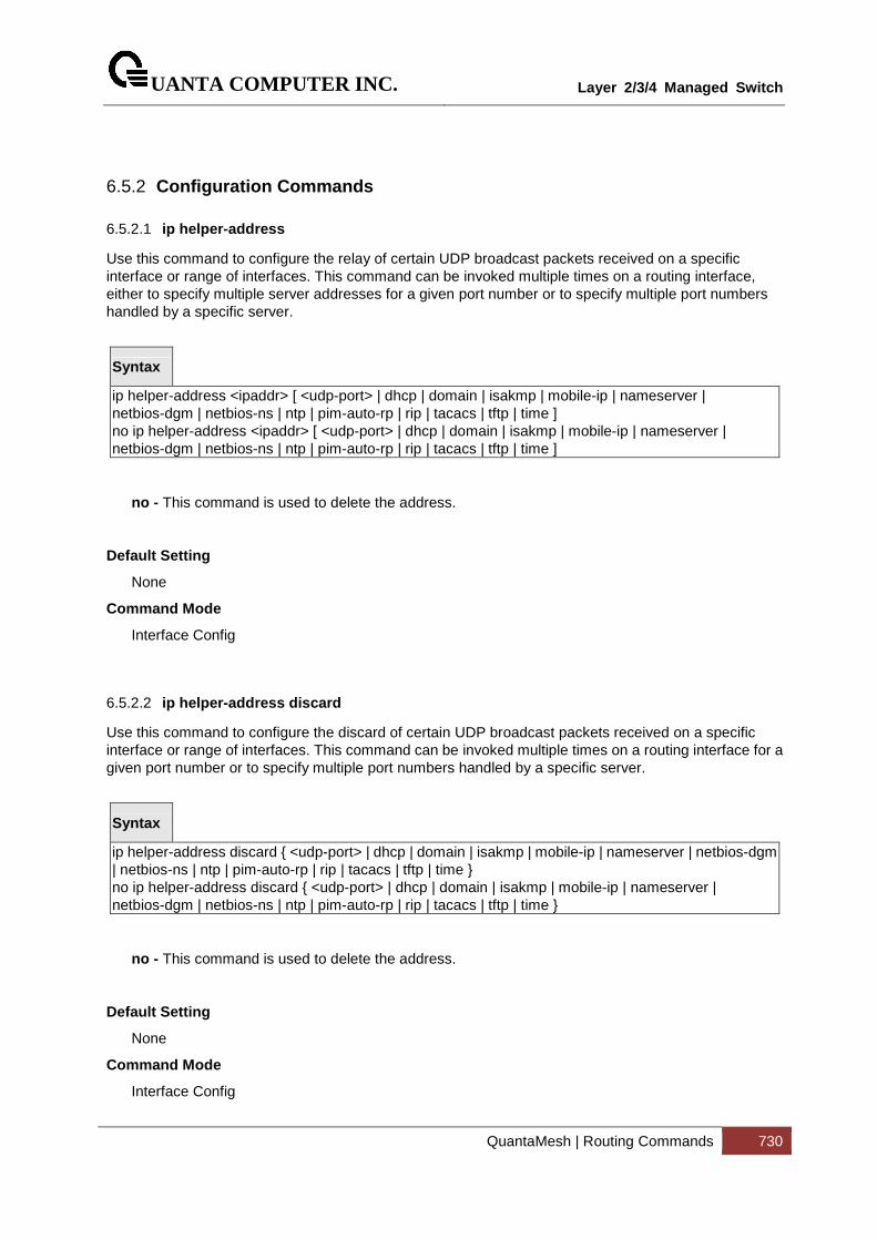
UANTA COMPUTER INC.
Layer 2/3/4 Managed Switch
QuantaMesh | Routing Commands 730
6.5.2 Configuration Commands
6.5.2.1 ip helper-address
Use this command to configure the relay of certain UDP broadcast packets received on a specific interface or range of interfaces. This command can be invoked multiple times on a routing interface, either to specify multiple server addresses for a given port number or to specify multiple port numbers handled by a specific server.
Syntax
ip helper-address <ipaddr> [ <udp-port> | dhcp | domain | isakmp | mobile-ip | nameserver | netbios-dgm | netbios-ns | ntp | pim-auto-rp | rip | tacacs | tftp | time ] no ip helper-address <ipaddr> [ <udp-port> | dhcp | domain | isakmp | mobile-ip | nameserver | netbios-dgm | netbios-ns | ntp | pim-auto-rp | rip | tacacs | tftp | time ]
no - This command is used to delete the address.
Default Setting
None
Command Mode
Interface Config
6.5.2.2 ip helper-address discard
Use this command to configure the discard of certain UDP broadcast packets received on a specific interface or range of interfaces. This command can be invoked multiple times on a routing interface for a given port number or to specify multiple port numbers handled by a specific server.
Syntax
ip helper-address discard { <udp-port> | dhcp | domain | isakmp | mobile-ip | nameserver | netbios-dgm | netbios-ns | ntp | pim-auto-rp | rip | tacacs | tftp | time } no ip helper-address discard { <udp-port> | dhcp | domain | isakmp | mobile-ip | nameserver | netbios-dgm | netbios-ns | ntp | pim-auto-rp | rip | tacacs | tftp | time }
no - This command is used to delete the address.
Default Setting
None
Command Mode
Interface Config
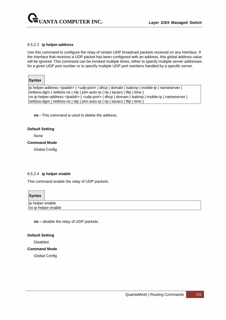
UANTA COMPUTER INC.
Layer 2/3/4 Managed Switch
QuantaMesh | Routing Commands 731
6.5.2.3 ip helper-address
Use this command to configure the relay of certain UDP broadcast packets received on any interface. If the interface that receives a UDP packet has been configured with an address, this global address value will be ignored. This command can be invoked multiple times, either to specify multiple server addresses for a given UDP port number or to specify multiple UDP port numbers handled by a specific server.
Syntax
ip helper-address <ipaddr> { <udp-port> | dhcp | domain | isakmp | mobile-ip | nameserver | netbios-dgm | netbios-ns | ntp | pim-auto-rp | rip | tacacs | tftp | time } no ip helper-address <ipaddr> { <udp-port> | dhcp | domain | isakmp | mobile-ip | nameserver | netbios-dgm | netbios-ns | ntp | pim-auto-rp | rip | tacacs | tftp | time }
no - This command is used to delete the address.
Default Setting
None
Command Mode
Global Config
6.5.2.4 ip helper enable
This command enable the relay of UDP packets.
Syntax
ip helper enable no ip helper enable
no – disable the relay of UDP packets.
Default Setting
Disabled.
Command Mode
Global Config
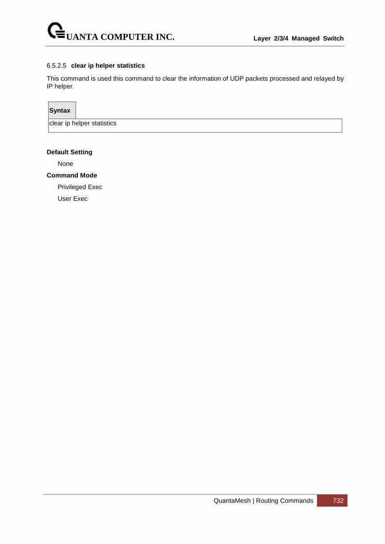
UANTA COMPUTER INC.
Layer 2/3/4 Managed Switch
QuantaMesh | Routing Commands 732
6.5.2.5 clear ip helper statistics
This command is used this command to clear the information of UDP packets processed and relayed by IP helper.
Syntax
clear ip helper statistics
Default Setting
None
Command Mode
Privileged Exec
User Exec
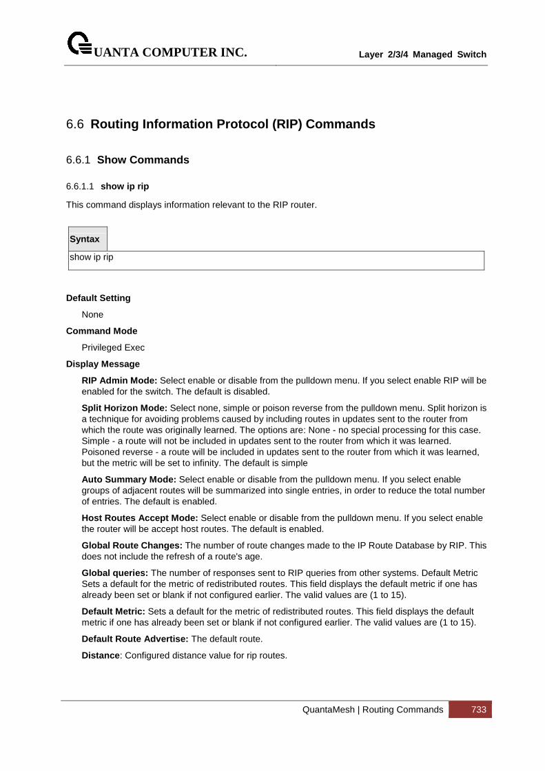
UANTA COMPUTER INC.
Layer 2/3/4 Managed Switch
QuantaMesh | Routing Commands 733
6.6 Routing Information Protocol (RIP) Commands
6.6.1 Show Commands
6.6.1.1 show ip rip
This command displays information relevant to the RIP router.
Syntax
show ip rip
Default Setting
None
Command Mode
Privileged Exec
Display Message
RIP Admin Mode: Select enable or disable from the pulldown menu. If you select enable RIP will be enabled for the switch. The default is disabled.
Split Horizon Mode: Select none, simple or poison reverse from the pulldown menu. Split horizon is a technique for avoiding problems caused by including routes in updates sent to the router from which the route was originally learned. The options are: None - no special processing for this case. Simple - a route will not be included in updates sent to the router from which it was learned. Poisoned reverse - a route will be included in updates sent to the router from which it was learned, but the metric will be set to infinity. The default is simple
Auto Summary Mode: Select enable or disable from the pulldown menu. If you select enable groups of adjacent routes will be summarized into single entries, in order to reduce the total number of entries. The default is enabled.
Host Routes Accept Mode: Select enable or disable from the pulldown menu. If you select enable the router will be accept host routes. The default is enabled.
Global Route Changes: The number of route changes made to the IP Route Database by RIP. This does not include the refresh of a route's age.
Global queries: The number of responses sent to RIP queries from other systems. Default Metric Sets a default for the metric of redistributed routes. This field displays the default metric if one has already been set or blank if not configured earlier. The valid values are (1 to 15).
Default Metric: Sets a default for the metric of redistributed routes. This field displays the default metric if one has already been set or blank if not configured earlier. The valid values are (1 to 15).
Default Route Advertise: The default route.
Distance : Configured distance value for rip routes.
UANTA COMPUTER INC.
Layer 2/3/4 Managed Switch
QuantaMesh | Routing Commands 734
6.6.1.2 show ip rip interface
This command displays information related to a particular RIP interface.
Syntax
show ip rip interface {<slot/port> | loopback <loopback-id> | vlan <vlan-id>}
< slot/port > - Interface number
Default Setting
None
Command Mode
Privileged Exec
Display Message
Interface: Valid slot and port number separated by forward slashes. This is a configured value.
IP Address: The IP source address used by the specified RIP interface. This is a configured value.
Send version: The RIP version(s) used when sending updates on the specified interface. The types are none, RIP-1, RIP-1c, and RIP-2. This is a configured value.
Receive version: The RIP version(s) allowed when receiving updates from the specified interface. The types are none, RIP-1, RIP-2, Both. This is a configured value.
RIP Admin Mode: RIP administrative mode of router RIP operation; enable, disable it. This is a configured value.
Link State: Indicates whether the RIP interface is up or down. This is a configured value.
Authentication Type: The RIP Authentication Type for the specified interface. The types are none, simple, and encrypt. This is a configured value.
Authentication Key: 16 alpha-numeric characters for authentication key when uses simple or encrypt authentication.
Authentication Key ID: It is a Key ID when uses MD5 encryption for RIP authentication.
Default Metric: A number which represents the metric used for default routes in RIP updates originated on the specified interface. This is a configured value. The following information will be invalid if the link state is down.
Bad Packets Received: The number of RIP response packets received by the RIP process which were subsequently discarded for any reason.
Bad Routes Received: The number of routes contained in valid RIP packets that were ignored for any reason.
Updates Sent: The number of triggered RIP updates actually sent on this interface.
UANTA COMPUTER INC.
Layer 2/3/4 Managed Switch
QuantaMesh | Routing Commands 735
6.6.1.3 show ip rip interface brief
This command displays general information for each RIP interface. For this command to display successful results routing must be enabled per interface (i.e. ip rip).
Syntax
show ip rip interface brief
Default Setting
None
Command Mode
Privileged Exec
Display Message
Interfacet: Valid slot and port number separated by forward slashes.
IP Address: The IP source address used by the specified RIP interface.
Send Version: The RIP version(s) used when sending updates on the specified interface. The types are none, RIP-1, RIP-1c, RIP-2.
Receive Version: The RIP version(s) allowed when receiving updates from the specified interface. The types are none, RIP-1, RIP-2, Both
RIP Mode: RIP administrative mode of router RIP operation; enable, disable it.
Link State: The mode of the interface (up or down).
UANTA COMPUTER INC.
Layer 2/3/4 Managed Switch
QuantaMesh | Routing Commands 736
6.6.2 Configuration Commands
6.6.2.1 enable rip
This command resets the default administrative mode of RIP in the router (active).
Syntax
enable no enable
no - This command sets the administrative mode of RIP in the router to inactive.
Default Setting
Enabled
Command Mode
Router RIP Config
6.6.2.2 ip rip
This command enables RIP on a router interface.
Syntax
ip rip no ip rip
no - This command disables RIP on a router interface.
Default Setting
Disabled
Command Mode
Interface Config
UANTA COMPUTER INC.
Layer 2/3/4 Managed Switch
QuantaMesh | Routing Commands 737
6.6.2.3 auto-summary
This command enables the RIP auto-summarization mode.
Syntax
auto-summary no auto-summary
no - This command disables the RIP auto-summarization mode.
Default Setting
Disabled
Command Mode
Router RIP Config
6.6.2.4 default-information originate
This command is used to set the advertisement of default routes.
Syntax
default-information originate no default-information originate
no - This command is used to cancel the advertisement of default routes.
Default Setting
Not configured
Command Mode
Router RIP Config

UANTA COMPUTER INC.
Layer 2/3/4 Managed Switch
QuantaMesh | Routing Commands 738
6.6.2.5 default-metric
This command is used to set a default for the metric of distributed routes.
Syntax
default-metric <1-15> no default-metric
<1 - 15> - a value for default-metric.
no - This command is used to reset the default metric of distributed routes to its default value.
Default Setting
Not configured
Command Mode
Router RIP Config
6.6.2.6 distance rip
This command sets the route preference value of RIP in the router. Lower route preference values are preferred when determining the best route.
Syntax
distance rip <1-255> no distance rip
<1 - 255> - the value for distance.
no - This command sets the default route preference value of RIP in the router.
Default Setting
15
Command Mode
Router RIP Config
UANTA COMPUTER INC.
Layer 2/3/4 Managed Switch
QuantaMesh | Routing Commands 739
6.6.2.7 hostrouteaccept
This command enables the RIP hostroutesaccept mode.
Syntax
hostrouteaccept no hostrouteaccept
no - This command disables the RIP hostroutesaccept mode.
Default Setting
Enabled
Command Mode
Router RIP Config
6.6.2.8 split-horizon
This command sets the RIP split horizon mode. None mode will not use RIP split horizon mode. Simple mode will be that a route is not advertised on the interface over which it is learned. Poison mode will be that routes learned over this interface should be re-advertised on the interface with a metric of infinity (16).
Syntax
split-horizon {none | simple | poison} no split-horizon
none - This command sets without using RIP split horizon mode.
simple - This command sets to use simple split horizon mode.
poison - This command sets to use poison reverse mode.
no - This command cancel to set the RIP split horizon mode and sets none mode.
Default Setting
Simple
Command Mode
Router RIP Config
UANTA COMPUTER INC.
Layer 2/3/4 Managed Switch
QuantaMesh | Routing Commands 740
6.6.2.9 distribute-list
This command is used to specify the access list to filter routes received from the source protocol. Source protocols have OSPF, Static, and Connected.
Syntax
distribute-list <1-199> out {ospf | static | connected} no distribute-list <1-199> out {ospf | static | connected}
<1 - 199> - Access List ID value. The Access List filters the routes to be redistributed by the source protocol.
no - This command is used to cancel the access list to filter routes received from the source protocol.
Default Setting
0
Command Mode
Router RIP Config
UANTA COMPUTER INC.
Layer 2/3/4 Managed Switch
QuantaMesh | Routing Commands 741
6.6.2.10 redistribute
This command configures RIP protocol to redistribute routes from the specified source protocol/routers. There are five possible match options. When you submit the command redistribute ospf match <matchtype> the match-type or types specified are added to any match types presently being redistributed. Internal routes are redistributed by default. Source protocols have OSPF, Static, and Connetced. Match types will have internal, external 1, external 2, nssa-external 1, and nssa-external 2.
Syntax
Format for OSPF as source protocol: redistribute ospf [metric <1-15>] [match [internal] [external 1] [external 2] [nssa-external 1] [nssa-external 2]] Format for other source protocols: redistribute {static | connected} [metric <1-15>] no redistribute {ospf | static | connected} [metric] [match [internal] [external 1] [external 2] [nssa-external 1] [nssa-external 2]]
<1 - 15> - a value for metric.
no - This command de-configures RIP protocol to redistribute routes from the specified source protocol/routers.
Default Setting
Metric - not-configured
Match - internal
Command Mode
Router RIP Config
UANTA COMPUTER INC.
Layer 2/3/4 Managed Switch
QuantaMesh | Routing Commands 742
6.6.2.11 ip rip authentication
This command sets the RIP Version 2 Authentication Type and Key for the specified interface. The value of <type> is either none , simple , or encrypt .
The value for authentication key [key] must be 16 bytes or less. The [key] is composed of standard displayable, non-control keystrokes from a Standard 101/102-key keyboard. If the value of <type> is encrypt, a keyid in the range of 0 and 255 must be specified.
Syntax
ip rip authentication {none | {simple <key>} | {encrypt <key> <keyid>}} no ip rip authentication
none - This command uses no authentication.
simple - This command uses simple authentication for RIP authentication .
encrypt - This command uses MD5 encryption for RIP authentication.
<key> - 16 alpha-numeric characters to be used for authentication key.
<keyid> - a value in the range of 0 – 255 to be used for MD5 encryption.
no - This command sets the default RIP Version 2 Authentication Type.
Default Setting
None
Command Mode
Interface Config
UANTA COMPUTER INC.
Layer 2/3/4 Managed Switch
QuantaMesh | Routing Commands 743
6.6.2.12 ip rip receive version
This command configures the interface to allow RIP control packets of the specified version(s) to be received.
The value for <mode> is one of: rip1 to receive only RIP version 1 formatted packets, rip2 for RIP version 2, both to receive packets from either format, or none to not allow any RIP control packets to be received
Syntax
ip rip receive version {rip1 | rip2 | both | none} no ip rip receive version
no - This command configures the interface to allow RIP control packets of the default version(s) to be received.
Default Setting
Both
Command Mode
Interface Config
UANTA COMPUTER INC.
Layer 2/3/4 Managed Switch
QuantaMesh | Routing Commands 744
6.6.2.13 ip rip send version
This command configures the interface to allow RIP control packets of the specified version to be sent.
The value for <mode> is one of: rip1 to broadcast RIP version 1 formatted packets, rip1c (RIP version 1 compatibility mode) which sends RIP version 2 formatted packets via broadcast, rip2 for sending RIP version 2 using multicast, or none to not allow any RIP control packets to be sent.
Syntax
ip rip send version {rip1 | rip1c | rip2 | none} no ip rip send version
no - This command configures the interface to allow RIP control packets of the default version to be sent.
Default Setting
rip2
Command Mode
Interface Config
UANTA COMPUTER INC.
Layer 2/3/4 Managed Switch
QuantaMesh | Routing Commands 745
6.7 Router Discovery Protocol Commands
6.7.1 Show Commands
6.7.1.1 show ip irdp
This commands displays the router discovery information for all interfaces, or a specified interface.
Syntax
show ip irdp [{<slot/port> | vlan <vlan-id>}]
<slot/port> - Show router discovery information for the specified interface.
no parameter - Show router discovery information for all interfaces.
Default Setting
None
Command Mode
Privileged Exec
User Exec
Display Message
Ad Mode: Displays the advertise mode which indicates whether router discovery is enabled or disabled on this interface.
Advertise Address: Addresses to be used to advertise the router for the interface.
Max Int: Displays the maximum advertise interval which is the maximum time allowed
between sending router advertisements from the interface in seconds.
Min Int: Displays the minimum advertise interval which is the minimum time allowed
between sending router advertisements from the interface in seconds.
Hold Time: Displays advertise holdtime which is the value of the holdtime field of the router advertisement sent from the interface in seconds.
Preferences: Displays the preference of the address as a default router address, relative to other router addresses on the same subnet.
UANTA COMPUTER INC.
Layer 2/3/4 Managed Switch
QuantaMesh | Routing Commands 746
6.7.2 Configuration Commands
6.7.2.1 ip irdp
This command enables Router Discovery on an interface.
Syntax
ip irdp no ip irdp
<no> - Disable Router Discovery on an interface.
Default Setting
Disabled
Command Mode
Interface Config
6.7.2.2 ip irdp address
This command configures the address to be used to advertise the router for the interface.
Syntax
ip irdp address <address> no ip irdp address
<address> - The address used is 224.0.0.1 or 255.255.255.255.
no - The address used is 224.0.0.1.
Default Setting
The default address is 224.0.0.1
Command Mode
Interface Config
UANTA COMPUTER INC.
Layer 2/3/4 Managed Switch
QuantaMesh | Routing Commands 747
6.7.2.3 ip irdp holdtime
This commands configures the value, in seconds, of the holdtime field of the router advertisement sent from this interface.
Syntax
ip irdp holdtime < maxadvertinterval-9000 > no ip irdp holdtime
< maxadvertinterval-9000 > The range is the maxadvertinterval to 9000 seconds.
no - This command configures the default value, in seconds, of the holdtime field of the router advertisement sent from this interface.
Default Setting
The default value is 3* maxadvertinterval (600) =1800.
Command Mode
Global Config
6.7.2.4 ip irdp maxadvertinterval
This commands configures the maximum time, in seconds, allowed between sending router
advertisements from the interface.
Syntax
ip irdp maxadvertinterval < minadvertinterval-1800 > no ip irdp maxadvertinterval
< minadvertinterval-1800 > - The range is 4 to 1800 seconds.
no - This command configures the default maximum time, in seconds.
Default Setting
The default value is 600.
Command Mode
Global Config
UANTA COMPUTER INC.
Layer 2/3/4 Managed Switch
QuantaMesh | Routing Commands 748
6.7.2.5 ip irdp minadvertinterval
This command configures the minimum time, in seconds, allowed between sending router
advertisements from the interface.
Syntax
ip irdp minadvertinterval < 3-maxadvertinterval> no ip irdp minadvertinterval
< 3-maxadvertinterval> - The range is 3 to maxadvertinterval seconds.
no - This command sets the minimum time to 450.
Default Setting
The default value is 450.
Command Mode
Global Config
6.7.2.6 ip irdp preference
This command configures the preferability of the address as a default router address, relative to other router addresses on the same subnet.
Syntax
ip irdp preference < -2147483648-2147483647> no ip irdp preference
< -2147483648-2147483647> - The range is -2147483648 to 2147483647.
no - This command sets the preference to 0.
Default Setting
The default value is 0.
Command Mode
Global Config
UANTA COMPUTER INC.
Layer 2/3/4 Managed Switch
QuantaMesh | Routing Commands 749
6.8 VLAN Routing Commands
6.8.1 Configuration Commands
6.8.1.1 Interface vlan
This command creates a VLAN routing interface.
Syntax
interface vlan <vlan-id> no interface vlan <vlan-id>
<vlan-id> - The VLAN ID used for this interface. The range of VLAN ID is 1 to 4093.
no - Delete a VLAN routing interface.
Default Setting
None
Command Mode
Global Config
UANTA COMPUTER INC.
Layer 2/3/4 Managed Switch
QuantaMesh | Routing Commands 750
6.9 Virtual Router Redundancy Protocol (VRRP) Commands
6.9.1 Show Commands
6.9.1.1 show ip vrrp
This command displays whether VRRP functionality is enabled or disabled. It also displays some global parameters which are required for monitoring.
Syntax
show ip vrrp
Default Setting
None
Command Mode
Privileged Exec
User Exec
Display Message
Admin Mode: Displays the administrative mode for VRRP functionality on the switch.
Router Checksum Errors: Represents the total number of VRRP packets received with an invalid VRRP checksum value.
Router Version Errors: Represents the total number of VRRP packets received with Unknown or unsupported version number.
Router VRID Errors: Represents the total number of VRRP packets received with invalid VRID for this virtual router.
UANTA COMPUTER INC.
Layer 2/3/4 Managed Switch
QuantaMesh | Routing Commands 751
6.9.1.2 show ip vrrp brief
This command displays information about each virtual router configured on the switch.
Syntax
show ip vrrp brief
Default Setting
None
Command Mode
Privileged Exec
User Exec
Display Message
Interface: Valid slot and port number separated by forward slashes.
VRID: Represents the router ID of the virtual router.
IP Address: Is the IP Address that was configured on the virtual router
Mode: Represents whether the virtual router is enabled or disabled.
State: Represents the state (Master/backup) of the virtual router.
UANTA COMPUTER INC.
Layer 2/3/4 Managed Switch
QuantaMesh | Routing Commands 752
6.9.1.3 show ip vrrp interface
This command displays all configuration information of a virtual router configured on a specific interface. Note that the information will be displayed only when the IP address of the specific interface is configured.
Syntax
show ip vrrp interface {<slot/port> | vlan <vlan-id>} [<vrid>]
<slot/port> - Valid slot and port number separated by forward slashes.
<vrid> - Virtual router ID.
<vlan-id> - VLAN ID. The range of VLAN ID is 1 to 4093.
Default Setting
None
Command Mode
Privileged Exec
User Exec
Display Message
VRID: Represents the router ID of the virtual router.
Primary IP Address: This field represents the configured IP Address for the Virtual router.
VMAC address: Represents the VMAC address of the specified router.
Authentication type: Represents the authentication type for the specific virtual router.
Priority: Represents the priority value for the specific virtual router.
Configured Priority: The priority configured through the ip vrrp vrid priority 1-254 command.
Advertisement interval: Represents the advertisement interval for the specific virtual router.
Pre-Empt Mode: Is the preemption mode configured on the specified virtual router.
Pre-Empt Delay: How much time to be delayed before becoming the active router. It only performs the delay when the preemption is first attempted.
Administrative Mode: Represents the status (Enable or Disable) of the specific router.
Accept Mode: When enabled, the VRRP Master can accept ping packets sent to one of the virtual router’s IP addresses.
State: Represents the state (Master/backup) of the specific virtual router
UANTA COMPUTER INC.
Layer 2/3/4 Managed Switch
QuantaMesh | Routing Commands 753
6.9.1.4 show ip vrrp interface stats
This command displays the statistical information about each virtual router configured on the switch.
Syntax
show ip vrrp interface stats {<slot/port> | vlan <vlan-id>} [<vrid>]
<slot/port> - Valid slot and port number separated by forward slashes.
<vrid> - Virtual router ID.
<vlan-id> - VLAN ID. The range of VLAN ID is 1 to 4093.
Default Setting
None
Command Mode
Privileged Exec
User Exec
Display Message
VRID: Represents the router ID of the virtual router.
Uptime: Is the time that the virtual router has been up, in days, hours, minutes and seconds.
Protocol: Represents the protocol configured on the interface.
State Transitioned to Master: Represents the total number of times virtual router state has changed to MASTER.
Advertisement Received: Represents the total number of VRRP advertisements received by this virtual router.
Advertisement Interval Errors: Represents the total number of VRRP advertisements received for which advertisement interval is different than the configured value for this virtual
router.
Authentication Failure: Represents the total number of VRRP packets received that don't pass the authentication check.
IP TTL errors: Represents the total number of VRRP packets received by the virtual router with IP TTL (time to live) not equal to 255.
Zero Priority Packets Received: Represents the total number of VRRP packets received by virtual router with a priority of '0'.
Zero Priority Packets Sent: Represents the total number of VRRP packets sent by the virtual router with a priority of '0'
Invalid Type Packets Received: Represents the total number of VRRP packets received by the virtual router with invalid 'type' field.
Address List Errors: Represents the total number of VRRP packets received for which address list does not match the locally configured list for the virtual router.
UANTA COMPUTER INC.
Layer 2/3/4 Managed Switch
QuantaMesh | Routing Commands 754
Invalid Authentication Type: Represents the total number of VRRP packets received with
unknown authentication type.
Authentication Type Mismatch: Represents the total number of VRRP advertisements received for which 'auth type' not equal to locally configured one for this virtual router.
Packet Length Errors: Represents the total number of VRRP packets received with packet length less than length of VRRP header.
UANTA COMPUTER INC.
Layer 2/3/4 Managed Switch
QuantaMesh | Routing Commands 755
6.9.2 Configuration Commands
6.9.2.1 ip vrrp
This command enables the administrative mode of VRRP in the router.
Syntax
ip vrrp no ip vrrp
Default Setting
Disabled
Command Mode
Global Config
This command sets the virtual router ID on an interface for Virtual Router configuration in the router.
Syntax
ip vrrp <1-255> no ip vrrp <1-255>
<1-255> - The range of virtual router ID is 1 to 255.
<no> - This command removes all VRRP configuration details of the virtual router configured on a specific interface.
Default Setting
None
Command Mode
Interface Config
UANTA COMPUTER INC.
Layer 2/3/4 Managed Switch
QuantaMesh | Routing Commands 756
6.9.2.2 ip vrrp ip
This commands also designates the configured virtual router IP address as a secondary IP address on an interface.
Syntax
ip vrrp <1-255> ip <addr> [secondary] no ip vrrp <1-255> ip <addr> [secondary]
<1-255> - The range of virtual router ID is 1 to 255.
<addr> - Secondary IP address of the router ID.
<no> - This command removes all VRRP configuration details of the virtual router configured on a specific interface.
Default Setting
None
Command Mode
Interface Config
6.9.2.3 ip vrrp mode
This command enables the virtual router configured on the specified interface. Enabling the status field starts a virtual router.
Syntax
ip vrrp <1-255> mode no ip vrrp <1-255> mode
<1-255> - The range of virtual router ID is 1 to 255.
<no> - Disable the virtual router configured on the specified interface. Disabling the status field stops a virtual router.
Default Setting
Disabled
Command Mode
Interface Config
UANTA COMPUTER INC.
Layer 2/3/4 Managed Switch
QuantaMesh | Routing Commands 757
6.9.2.4 ip vrrp accept-mode
Use this command to allow the VRRP Master to accept ping packets sent to one of the virtual router's IP addresses.
Syntax
ip vrrp <1-255> accept-mode no ip vrrp <1-255> accept-mode
<1-255> - The range of virtual router ID is 1 to 255.
<no> - Use this command to prevent the VRRP Master from accepting ping packets sent to one of the virtual router's IP addresses.
Default Setting
Disabled
Command Mode
Interface Config
6.9.2.5 ip vrrp authentication
This command sets the authorization details value for the virtual router configured on a specified interface.
Syntax
ip vrrp <1-255> authentication <key> no ip vrrp <1-255> authentication
<1-255> - The range of virtual router ID is 1 to 255.
<key> - A text password used for authentication.
<no> - This command sets the default authorization details value for the virtual router configured on a specified interface.
Default Setting
no authentication
Command Mode
Interface Config
UANTA COMPUTER INC.
Layer 2/3/4 Managed Switch
QuantaMesh | Routing Commands 758
6.9.2.6 ip vrrp preempt
This command sets the preemption mode value for the virtual router configured on a specified interface.
Syntax
ip vrrp <1-255> preempt [delay <0-3600>] no ip vrrp <1-255> preempt [delay]
<1-255> - The range of virtual router ID is 1 to 255.
<0-3600> - The time to be delayed to become active router.
<no> - This command sets the default preemption mode value for the virtual router configured on a specified interface.
Default Setting
Preempt mode: Enabled
Preempt delay: 0
Command Mode
Interface Config
UANTA COMPUTER INC.
Layer 2/3/4 Managed Switch
QuantaMesh | Routing Commands 759
6.9.2.7 ip vrrp priority
This command sets the priority value for the virtual router configured on a specified interface.
The router with the highest priority is elected master. If a router is configured with the address used as the address of the virtual router, the router is called the "address owner". The priority of the address owner is always 255 so that the address owner is always master. If the master has a priority less than 255 (it is not the address owner) and you configure the priority of another router in the group higher than the master's priority, the router will take over as master only if preempt mode is enabled.
Syntax
ip vrrp <1-255> priority <1-254> no ip vrrp <1-255> priority
<1-255> - The range of virtual router ID is 1 to 255.
<1-254> - The range of priority is 1 to 254.
<no> - This command sets the default priority value for the virtual router configured on a specified interface.
Default Setting
The default priority value is 100 unless the router is the address owner, in which case its priority is automatically set to 255.
Command Mode
Interface Config
UANTA COMPUTER INC.
Layer 2/3/4 Managed Switch
QuantaMesh | Routing Commands 760
6.9.2.8 ip vrrp timers advertise
This command sets the advertisement value for a virtual router in seconds.
Syntax
ip vrrp <1-255> timers advertise <1-255> ip vrrp <1-255> timers advertise
<1-255> - The range of virtual router ID is 1 to 255.
< 1-255 > - The range of advertisement interval is 1 to 255.
<no> - This command sets the default advertisement value for a virtual router.
Default Setting
The default value of advertisement interval is 1.
Command Mode
Interface Config
UANTA COMPUTER INC.
Layer 2/3/4 Managed Switch
QuantaMesh | Routing Commands 761
6.9.2.9 ip vrrp track interface
This command alters the priority of the VRRP router based on the availability of its interfaces. This command is useful for tracking interfaces that are not configured for VRRP. Only IP interfaces are tracked. A tracked interface is up if the IP on that interface is up. Otherwise, the tracked interface is down.
When the tracked interface is down or the interface has been removed from the router, the priority of the VRRP router will be decremented by the value specified in the decrement argument. When the interface is up for IP protocol, the priority will be incremented by the decrement value.
A VRRP configured interface can track more than one interface. When a tracked interface goes down, then the priority of the router will be decreased by 10 (the default priority decrement) for each downed interface. The default priority decrement is changed using the decrement argument. The default priority of the virtual router is 100, and the default decrement priority is 10. By default, no interfaces are tracked. If you specify just the interface to be tracked, without giving the optional priority, then the default priority will be set. The default priority decrement is 10.
Syntax
ip vrrp <1-255> track interface {<slot/port> | vlan <vlan-id>} [decrement <1-254>] no ip vrrp <1-255> track interface {<slot/port> | vlan <vlan-id>} [decrement]
<1-255> - The range of virtual router ID is 1 to 255.
< 1-254 > - The range of decrement is 1 to 254.
<vlan-id> - VLAN ID. The range of VLAN ID is 1 to 4093.
<no> - This command removes the interface from the tracked list or to restore the priority decrement to its default.
Default Setting
Decrement: 10
Command Mode
Interface Config

UANTA COMPUTER INC.
Layer 2/3/4 Managed Switch
QuantaMesh | Routing Commands 762
6.9.2.10 ip vrrp track ip route
This command tracks the route reachability. When the tracked route is deleted, the priority of the VRRP router will be decremented by the value specified in the decrement argument. When the tracked route is added, the priority will be incremented by the same.
A VRRP configured interface can track more than one route. When a tracked route goes down, then the priority of the router will be decreased by 10 (the default priority decrement) for each downed route. By default no routes are tracked. If you specify just the route to be tracked, without giving the optional priority, then the default priority will be set. The default priority decrement is 10. The default priority decrement is changed using the decrement argument.
Syntax
ip vrrp <1-255> track ip route <ip-address/prefix-length> [decrement <1-254>] no ip vrrp <1-255> track ip route <ip-address/prefix-length> [decrement]
<1-255> - The range of virtual router ID is 1 to 255.
< 1-254 > - The range of decrement is 1 to 254.
<no> - This command removes the route from the tracked list or to restore the priority decrement to its default. When removing a tracked IP route from the tracked list, the priority should be incremented by the decrement value if the route is not reachable.
Default Setting
Decrement : 10
Command Mode
Interface Config

UANTA COMPUTER INC.
Layer 2/3/4 Managed Switch
QuantaMesh | Routing Commands 763
6.10 Policy Based Routing (PBR) Commands
6.10.1 Show Commands
6.10.1.1 show ip policy
This command lists the route map associated with each interface.
Syntax
show ip policy
Default Setting
None
Command Mode
Privileged Exec
Display Message
Interface: The interface.
Route-map: The route map.
6.10.1.2 show ip prefix-list
This command displays configuration and status for a prefix list.
Syntax
show ip prefix-list [detail | summary] [prefix-list-name] [network/length] [seq sequencenumber] [longer] [first-match]
Default Setting
None
Command Mode
Privileged Exec
Parameter
detail | summary: (Optional) Displays detailed or summarized information about all prefix lists.
prefix-list-name: (Optional) The name of a specific prefix list.
network/length: (Optional) The network number and length (in bits) of the network mask.
seq: (Optional) Applies the sequence number to the prefix list entry.
sequence-number: (Optional) The sequence number of the prefix list entry.
UANTA COMPUTER INC.
Layer 2/3/4 Managed Switch
QuantaMesh | Routing Commands 764
longer: (Optional) Displays all entries of a prefix list that are more specific than the given network/length.
first-match: (Optional) Displays the entry of a prefix list that matches the given network/length.
6.10.1.3 show route-map
To display a route map, use the show route-map command in Privileged EXEC mode.
Syntax
show route-map [map-name]
Default Setting
None
Command Mode
Privileged Exec
Parameter
map-name: (Optional) Name of a specific route map.
UANTA COMPUTER INC.
Layer 2/3/4 Managed Switch
QuantaMesh | Routing Commands 765
6.10.2 Configuration Commands
6.10.2.1 ip policy route-map
Use this command to identify a route map to use for policy-based routing on an interface specified by <route-map-name>. Policy-based routing is configured on the interface that receives the packets, not on the interface from which the packets are sent.
When a route-map applied on the interface is changed, that is, if new statements are added to route-map or match/set terms are added/removed from route-map statement, and also if route-map that is applied on an interface is removed, route-map needs to be removed from interface and added back again in order to have changed route-map configuration to be effective.
In order to disable policy based routing from an interface, use no form of this command.
Syntax
ip policy route-map <route-map-name> no ip policy route-map <route-map-name>
Default Setting
None
Command Mode
Interface Config
6.10.2.2 ip prefix-list
To create a prefix list or add a prefix list entry, use the ip prefix-list command in Global Configuration mode.
Prefix lists allow matching of route prefixes with those specified in the prefix list. Each prefix list includes of a sequence of prefix list entries ordered by their sequence numbers. A router sequentially examines each prefix list entry to determine if the route's prefix matches that of the entry. An empty or nonexistent prefix list permits all prefixes. An implicit deny is assume if a given prefix does not match any entries of a prefix list. Once a match or deny occurs the router does not go through the rest of the list.
A prefix list may be used within a route map to match a route's prefix using the command "match ip address"
Up to 128 prefix lists may be configured. The maximum number of statements allowed in prefix list is 64.
To delete a prefix list or a statement in a prefix list, use the no form of this command. The command no ip prefix-list list-name deletes the entire prefix list. To remove an individual statement from a prefix list, you must specify the statement exactly, with all its options.
Syntax
ip prefix-list <list-name> {[seq number] {permit | deny} network/length [ge length] [le length] | renumber renumber-interval first-statement-number} no ip prefix-list <list-name> [seq number] {permit | deny} network/length [ge length] [le length]
UANTA COMPUTER INC.
Layer 2/3/4 Managed Switch
QuantaMesh | Routing Commands 766
Default Setting
No prefix lists are configured by default. When neither the ge nor the le option is configured, the destination prefix must match the network/length exactly. If the ge option is configured without the le option, any prefix with a network mask greater than or equal to the ge value is considered a match. Similarly, if the le option is configured without the ge option, a prefix with a network mask less than or equal to the le value is considered a match.
Command Mode
Global Config
Parameter
list-name: The text name of the prefix list. Up to 32 characters.
seq number: (Optional) The sequence number for this prefix list statement. Prefix list statements are ordered from lowest sequence number to highest and applied in that order. If you do not specify a sequence number, the system will automatically select a sequence number five larger than the last sequence number in the list. Two statements may not be configured with the same sequence number. The value ranges from 1 to 4,294,967,294.
permit: Permit routes whose destination prefix matches the statement.
deny: Deny routes whose destination prefix matches the statement.
network/length: Specifies the match criteria for routes being compared to the prefix list statement. The network can be any valid IP prefix. The length is any IPv4 prefix length from 0 to 32.
ge length: (Optional) If this option is configured, then a prefix is only considered a match if its network mask length is greater than or equal to this value. This value must be longer than the network length and less than or equal to 32.
le length: (Optional) If this option is configured, then a prefix is only considered a match if its network mask length is less than or equal to this value. This value must be longer than the ge length and less than or equal to 32.
renumber: (Optional) Provides the option to renumber the sequence numbers of the IP prefix list statements with a given interval starting from a particular sequence number. The valid range for renumber-interval is 1 - 100, and the valid range for first-statement-number is 1 - 1000.
6.10.2.3 ip prefix-list description
To apply a text description to a prefix list, use the ip prefix-list description command in Global Configuration mode.
To remove the text description, use the no form of this command.
Syntax
ip prefix-list <list-name> description <text> no ip prefix-list <list-name> description
Default Setting
No description is configured by default.
Command Mode
Global Config

UANTA COMPUTER INC.
Layer 2/3/4 Managed Switch
QuantaMesh | Routing Commands 767
Parameter
list-name: The text name of the prefix list.
description text: Text description of the prefix list. Up to 80 characters.
6.10.2.4 route-map
To create a route map and enter Route Map Configuration mode, use the route-map command in Global Configuration mode. One use of a route map is to limit the redistribution of routes to a specified range of route prefixes. The redistribution command specifies a route map which refers to a prefix list. The prefix list identifies the prefixes that may be redistributed. It accepts up to 64 route maps.
To delete a route map or one of its statements, use the no form of this command.
Syntax
route-map <map-tag> [permit|deny] [sequence-number] no route-map <map-tag> [permit|deny] [sequence-number]
Default Setting
No route maps are configured by default. If no permit or deny tag is given, permit is the default.
Command Mode
Global Config
Parameter
map-tag: Text name of the route map. Route maps with the same name are grouped together in order of their sequence numbers. A route map name may be up to 32 characters long.
permit: (Optional) Permit routes that match all of the match conditions in the route map.
deny: (Optional) Deny routes that match all of the match conditions in the route map.
sequence-number: (Optional) An integer used to order the set of route maps with the same name. Route maps are ordered from lowest to greatest sequence number, with lower sequence numbers being considered first. If no sequence number is specified, the system assigns a value ten greater than the last statement in the route map. The range is 0 to 65,535.
6.10.2.5 match as-path
This route map match term matches BGP autonomous system paths against an AS path access list. If you enter a new match as-path term in a route map statement that already has a match as-path term, the AS path list numbers in the new term are added to the existing match term, up to the maximum number of lists in a term. A route is considered a match if it matches any one or more of the AS path access lists the match term refers to.
To delete the match as-path term that matches BGP autonomous system paths against an AS path access list, use the no form of this command.
Syntax
match as-path <as-path-list-number> no match as-path
UANTA COMPUTER INC.
Layer 2/3/4 Managed Switch
QuantaMesh | Routing Commands 768
Default Setting
None
Command Mode
Route Map Config
Parameter
as-path-list-number: An integer from 1 to 500 identifying the AS path access list to use as match criteria.
6.10.2.6 match community
To configure a route map to match based on a BGP community list, use the match community command in Route Map Configuration mode. If the community list returns a permit action, the route is considered a match. If the match statement refers to a community list that is not configured, no routes are considered to match the statement.
To delete a match term from a route map, use the no form of this command. The command no match community list exact-match removes the match statement from the route map. (It does not simply remove the exact-match option.) The command no match community removes the match term and all its community lists.
Syntax
match community <community-list> [community-list...] [exact-match] no match community <community-list> [community-list...] [exact-match]
Default Setting
None
Command Mode
Route Map Config
Parameter
community-list: The name of a standard community list. Up to eight names may be included in a single match term.
exact-match: (Optional) When this option is given, a route is only considered a match if the set of communities on the route is an exact match for the set of communities in one of the statements in the community list.
6.10.2.7 match ip address
To configure a route map to match based on a destination prefix, use the match ip address command in Route Map Configuration mode. If you specify multiple prefix lists in one statement, then a match occurs if a prefix matches any one of the prefix lists. If you configure a match ip address statement within a route map section that already has a match ip address statement, the new prefix lists are added to the existing set of prefix lists, and a match occurs if any prefix list in the combined set matches the prefix.
To delete a match statement from a route map, use the no form of this command.
UANTA COMPUTER INC.
Layer 2/3/4 Managed Switch
QuantaMesh | Routing Commands 769
Syntax
match ip address prefix-list <prefix-list-name> [prefix-list-name...] no match ip address prefix-list <prefix-list-name> [prefix-list-name...]
Default Setting
No match criteria are defined by default.
Command Mode
Route Map Config
Parameter
prefix-list-name: The name of a prefix list used to identify the set of matching routes. Up to eight prefix lists may be specified.
6.10.2.8 match ip address <access-list-number | access-list-name>
Use this command to configure a route map in order to match based on the match criteria configured in an IP access-list. Note that an IP ACL must be configured before it is linked to a route-map. Actions present in an IP ACL configuration are applied with other actions involved in route-map. If an IP ACL referenced by a route-map is removed or rules are added or deleted from that ACL, the configuration is rejected.
If there are a list of IP access-lists specified in this command and the packet matches at least one of these access-list match criteria, the corresponding set of actions in route-map are applied to packet.
If there are duplicate IP access-list numbers/names in this command, the duplicate configuration is ignored.
To delete a match statement from a route map, use the no form of this command.
Syntax
match ip address <access-list-number | access-list-name> [...access-list-number | name ] no match ip address <access-list-number | access-list-name> [...access-list-number | name ]
Default Setting
No match criteria are defined by default.
Command Mode
Route Map Config
Parameter
access-list-number: The access-list number that identifies an access-list configured through access-list CLI configuration commands. This number is 1 to 99 for standard access list number. This number is 100 to 199 for extended access list number.
access-list-name: The access-list name that identifies named IP ACLs. Access-list name can be up to 31 characters in length. A maximum of 16 ACLs can be specified in this 'match' clause.
UANTA COMPUTER INC.
Layer 2/3/4 Managed Switch
QuantaMesh | Routing Commands 770
6.10.2.9 match length
Use this command to configure a route map to match based on the Layer 3 packet length between specified minimum and maximum values. min specifies the packet’s minimum Layer 3 length, inclusive, allowed for a match. max specifies the packet’s maximum Layer 3 length, inclusive, allowed for a match. Each route-map statement can contain one ‘match’ statement on packet length range.
To delete a match statement from a route map, use the no form of this command.
Syntax
match length <min> <max> no match length
Default Setting
No match criteria are defined by default.
Command Mode
Route Map Config
6.10.2.10 match mac-list
Use this command to configure a route map in order to match based on the match criteria configured in an MAC access-list.
A MAC ACL is configured before it is linked to a route-map. Actions present in MAC ACL configuration are applied with other actions involved in route-map. When a MAC ACL referenced by a route-map is removed, the route-map rule is also removed and the corresponding rule is not effective. When a MAC ACL referenced by a route-map is removed or rules are added or deleted from that ACL, the configuration is rejected.
To delete a match statement from a route map, use the no form of this command.
Syntax
match mac-list <mac-list-name> [mac-list-name] no match mac-list <mac-list-name> [mac-list-name]
Default Setting
No match criteria are defined by default.
Command Mode
Route Map Config
Parameter
mac-list-name: The mac-list name that identifies MAC ACLs. MAC Access-list name can be up to 31 characters in length.
UANTA COMPUTER INC.
Layer 2/3/4 Managed Switch
QuantaMesh | Routing Commands 771
6.10.2.11 set as-path
To prepend one or more AS numbers to the AS path in a BGP route, use the set as-path command in Route Map Configuration mode. This command is normally used to insert one or more instances of the local AS number at the beginning of the AS_PATH attribute of a BGP route. Doing so increases the AS path length of the route. The AS path length has a strong influence on BGP route selection. Changing the AS path length can influence route selection on the local router or on routers to which the route is advertised.
When prepending an inbound route, if the first segment in the AS_PATH of the received route is an AS_SEQUENCE, as-path-string is inserted at the beginning of the sequence. If the first segment is an AS_SET, as-path-string is added as a new segment with type AS_SEQUENCE at the beginning of the AS path. When prepending an outbound route to an external peer, as-path-string follows the local AS number, which is always the first ASN.
To remove a set command from a route map, use the no form of this command.
Syntax
set as-path prepend <as-path-string> no set as-path prepend
Default Setting
None.
Command Mode
Route Map Config
Parameter
as-path-string: A list of AS path numbers to insert at the beginning of the AS_PATH attribute of matching BGP routes. To prepend more than one AS number, separate the ASNs with a space and enclose the string in quotes. Up to ten AS numbers may be prepended.
6.10.2.12 set comm-list delete
To remove BGP communities from an inbound or outbound UPDATE message, use the set comm-list delete command in Route Map Configuration mode. A route map with this set command can be used to remove selected communities from inbound and outbound routes. When a community list is applied to a route for this purpose, each of the route's communities is submitted to the community list one at a time. Communities permitted by the list are removed from the route. Because communities are processed individually, a community list used to remove communities should not include the exact-match option on statements with multiple communities. Such statements can never match an individual community.
When a route map statement includes both set community and set comm-list delete terms, the set comm-list delete term is processed first, and then the set community term (meaning that, communities are first removed, and then communities are added).
To delete the set command from a route map, use the no form of this command.
Syntax
set comm-list <community-list-name> delete no set comm-list
UANTA COMPUTER INC.
Layer 2/3/4 Managed Switch
QuantaMesh | Routing Commands 772
Default Setting
None.
Command Mode
Route Map Config
Parameter
community-list-name: A standard community list name.
6.10.2.13 set community
To modify the communities attribute of matching routes, use the set community command in Route Map Configuration mode. The set community command can be used to assign communities to routes originated through BGP's network and redistribute commands, and to set communities on routes received from a specific neighbor or advertised to a specific neighbor. It can also be used to remove all communities from a route.
To remove a subset of the communities on a route, use the command "set comm-list delete ".
To remove a set term from a route map, use the no form of this command.
Syntax
set community <community-number [additive] | no-advertise | no-export | none> no set community
Default Setting
None.
Command Mode
Route Map Config
Parameter
community-number: One to sixteen community numbers, either as a 32-bit integers or in AA:NN format. Communities are separated by spaces. The well-known communities no advertise and no-export are also accepted.
additive: (Optional) Communities are added to those already attached to the route.
no-advertise: Matching route not to be advertised to any BGP peer.
no-export: Matching route not to be advertised to external BGP peer.
none: Removes all communities from matching routes.
6.10.2.14 set interface
If network administrator does not want to revert to normal forwarding but instead want to drop a packet that does not match the specified criteria, a set statement needs to be configured to route the packets to interface null 0 as the last entry in the route-map. set interface null0 needs to be configured in a
UANTA COMPUTER INC.
Layer 2/3/4 Managed Switch
QuantaMesh | Routing Commands 773
separate statement. It should not be added along with any other statement having other match/set terms.
A route-map statement that is used for PBR is configured as permit or deny. If the statement is marked as deny, traditional destination-based routing is performed on the packet meeting the match criteria. If the statement is marked as permit, and if the packet meets all the match criteria, then set commands in the route-map statement are applied. If no match is found in the route-map, the packet is not dropped; instead the packet is forwarded using the routing decision taken by performing destination-based routing.
To remove a set term from a route map, use the no form of this command.
Syntax
set interface null0 no set interface null0
Default Setting
None.
Command Mode
Route Map Config
6.10.2.15 set default interface
A packet is dropped by this command only if there is no explicit route for the packet's destination address in the routing table. A default route in the routing table is not considered an explicit route for an unknown destination address.
In a route-map statement, 'set interface null0' and 'set default interface null0' terms are mutually exclusive.
To remove a set term from a route map, use the no form of this command.
Syntax
set default interface null0 no set default interface null0
Default Setting
None.
Command Mode
Route Map Config
6.10.2.16 set ip next-hop
Use this command to specify the adjacent next-hop router in the path toward the destination to which the packets should be forwarded. If more than one IP address is specified, the ECMP rule is used to route the packets.
UANTA COMPUTER INC.
Layer 2/3/4 Managed Switch
QuantaMesh | Routing Commands 774
This command affects all incoming packet types and is always used if configured. If configured next-hop is not present in the routing table, an ARP request is sent from the router.
In a route-map statement, 'set ip next-hop' and 'set ip default next-hop' terms are mutually exclusive. However, a 'set ip default next-hop' can be configured in a separate route-map statement.
To remove a set command from a route map, use the no form of this command.
Syntax
set ip next-hop <next-hop-address> [...next-hop-address] no set ip next-hop <next-hop-address> [...next-hop-address]
Default Setting
None.
Command Mode
Route Map Config
Parameter
next-hop-address: The IP address of the next hop to which packets are output. It must be the address of an adjacent router. A maximum of 16 next-hop IP addresses can be specified in this 'set' clause.
6.10.2.17 set ip default next-hop
Use this command to set a list of default next-hop IP addresses. If more than one IP address is specified, the ECMP rule is used.
A packet is routed to the next hop specified by this command only if there is no explicit route for the packet's destination address in the routing table. A default route in the routing table is not considered an explicit route for an unknown destination address.
In a route-map statement, 'set ip next-hop' and 'set ip default next-hop' terms are mutually exclusive. However, a 'set ip next-hop' can be configured in a separate route-map statement.
To remove a set command from a route map, use the no form of this command.
Syntax
set ip default next-hop <next-hop-address> [...next-hop-address] no set ip default next-hop <next-hop-address> [...next-hop-address]
Default Setting
None.
Command Mode
Route Map Config
Parameter
UANTA COMPUTER INC.
Layer 2/3/4 Managed Switch
QuantaMesh | Routing Commands 775
next-hop-address: The IP address of the next hop to which packets are output. It must be the address of an adjacent router. A maximum of 16 next-hop IP addresses can be specified in this 'set' clause.
6.10.2.18 set ip precedence
Use this command to set the three IP precedence bits in the IP packet header. With three bits, you have eight possible values for the IP precedence; values 0 through 7 are defined. This command is used when implementing QoS and can be used by other QoS services, such as weighted fair queuing (WFQ) and weighted random early detection (WRED).
To reset the three IP precedence bits in the IP packet header to the default, use the no form of this command.
Syntax
set ip precedence 0-7 no set ip precedence
Default Setting
None.
Command Mode
Route Map Config
Parameter
0: Sets the routine precedence.
1: Sets the priority precedence.
2: Sets the immediate precedence.
3: Sets the Flash precedence.
4: Sets the Flash override precedence.
5: Sets the critical precedence.
6: Sets the internetwork control precedence.
7: Sets the network control precedence.
6.10.2.19 set local-preference
To set the local preference of specific BGP routes, use the set local-preference command in Route Map Configuration mode. The local preference is the first attribute used to compare BGP routes. Setting the local preference can influence which route BGP selects as the best route.
When used in conjunction with a 'match as-path' or 'match ip address' command, this command can be used to prefer routes that transit certain ASs or to make the local router a more preferred exit point to certain destinations.
To remove a set command from a route map, use the no form of this command.

UANTA COMPUTER INC.
Layer 2/3/4 Managed Switch
QuantaMesh | Routing Commands 776
Syntax
set local-preference <value> no set local-preference
Default Setting
None.
Command Mode
Route Map Config
Parameter
value: A local preference value, from 0 to 4,294,967,295 (any 32-bit integer).
6.10.2.20 set metric
To set the metric of a route, use the set metric command in Route Map Configuration mode. This command sets the Multi Exit Discriminator (MED) when used in a BGP context. When there are multiple peering points between two autonomous systems (AS), setting the MED on routes advertised by one router can influence the other AS to send traffic through a specific peer.
To remove a set command from a route map, use the no form of this command.
Syntax
set metric <value> no set metric
Default Setting
None.
Command Mode
Route Map Config
Parameter
value: A metric value, from 0 to 4,294,967,295 (any 32-bit integer).
6.10.2.21 clear ip prefix-list
To reset IP prefix-list counters, use the clear ip prefix-list command in Privileged EXEC mode. This command is used to clear prefix-list hit counters. The hit count is a value indicating the number of matches to a specific prefix list entry.
Syntax
clear ip prefix-list [[prefix-list-name] [network/length]]

UANTA COMPUTER INC.
Layer 2/3/4 Managed Switch
QuantaMesh | Routing Commands 777
Command Mode
Privileged Exec
Parameter
prefix-list-name: (Optional) Name of the prefix list from which the hit count is to be cleared.
network/length: (Optional) Network number and length (in bits) of the network mask. If this option is specified, hit counters are only cleared for the matching statement.
UANTA COMPUTER INC.
Layer 2/3/4 Managed Switch
QuantaMesh | Routing Commands 778
6.11 Border Gateway Protocol (BGP) Commands
6.11.1 Show Commands
6.11.1.1 show ip bgp
This command displays information relevant to the BGP router.
Syntax
show ip bgp
Default Setting
None
Command Mode
Privileged Exec
Display Messages
BGP table version: The BGP Table Version is the main number used. This number is the same as the Generation ID of any BGP prefix for a specific address family and is used to track changes to the BGP route table.
Local Route ID: A 32-bit integer in dotted decimal format identifying the router, about which information is displayed. This is a configured value.
Status Codes : Status of the table entry. The status is displayed at the beginning of each line in the table. It can be one of the following values:
• s — The table entry is suppressed.
• * — The table entry is valid.
• > — The table entry is the best entry to use for that network.
• I — The table entry was learned via an internal BGP (iBGP) session.
Origin codes: Origin of the entry. The origin code is placed at the end of each line in the table. It can be one of the following values:
• i — Entry originated from an Interior Gateway Protocol (IGP) and was advertised with a network router configuration command.
• e — Entry originated from an Exterior Gateway Protocol (EGP).
• ? — Origin of the path is not clear. Usually, this is a router that is redistributed into BGP from an IGP.
Network: IP address of a network entity.
Next Hop: IP address of the next system that is used when forwarding a packet to the destination network. An entry of 0.0.0.0 indicates that the router has some non-BGP routes to this network.
Metric: If shown, the value of the interautonomous system metric.
LocPref: Local preference value as set with the set local-preference route-map configuration command. The default value is 100.

UANTA COMPUTER INC.
Layer 2/3/4 Managed Switch
QuantaMesh | Routing Commands 779
Path: Autonomous system paths to the destination network. There can be one entry in this field for each autonomous system in the path.
UANTA COMPUTER INC.
Layer 2/3/4 Managed Switch
QuantaMesh | Routing Commands 780
6.11.1.2 show ip bgp <prefix/length>
This command displays the BGP routing table entries which are filtered the display output with a prefix/length.
Syntax
show ip bgp <prefix/length>
Default Setting
None
Command Mode
Privileged Eexc
User Exec
Display Messages
Prefix/Prefix Length: IP prefix and prefix length entered to filter the output to display only a particular host or network in the BGP routing table.
Generation ID: Incremented each time phase 2 of the decision process runs and whenever an aggregate address changes. Used to track changes to the BGP route table.
Forwarding: Yes if RTO has selected this route as the best route.
Advertised to Update Groups: The number of update groups reported.
Best Path: Show best path information as following.
Non-Best Paths: Show non-best path information as following.
Local Preference: Local preference value as set with the set local-preference route-map configuration command. The default value is 100.
AS Path: An Autnonomous System path is a list of all the autonomous systems that a specific route passes through to reach one destination.
Origin: Indicates the origin of the entry. It can be IGP, EGP, and Incomplete .
Metric: The value of the interautonomous system metric.
Type: Type of peer (internal or external).
IGP Cost: The cost of Interior Gateway Protocol (IGP).
Peer (Peer ID): The IP Address of the Peer's BGP interface (The Router ID of the Peer's BGP).
BGP Next Hop: IP address of the next system that is used when forwarding a packet to the destination network.
Atomic Aggregate: Include atomic-aggregate routes or not.
Aggregator (AS, Router ID): The information of the speaker that aggregated the routes.
Communities: Valid value is a community number in the range from 1 to 4294967200, or AA:NN (autonomous system-community number/2-byte number), no-peer , no-export , no-export-subconfed , or no-advertise .
UANTA COMPUTER INC.
Layer 2/3/4 Managed Switch
QuantaMesh | Routing Commands 781
6.11.1.3 show ip bgp aggregate-address
This command displays information about the aggregate-address.
Syntax
show ip bgp aggregate-address
Default Setting
None
Command Mode
Privileged Exec
User Exec
Display Messages
Aggregation of routes with different MED values is allowed: The aggregate-different-meds is enabled.
Prefix/Len: IP prefix and prefix length of the entry.
AS Set: With AS Set feature or not.
Summary Only: With Summary Only feature or not.
Active: The aggregate address is active or not.
UANTA COMPUTER INC.
Layer 2/3/4 Managed Switch
QuantaMesh | Routing Commands 782
6.11.1.4 show ip bgp community
This command display routes that belong to specified BGP communities.
Syntax
show ip bgp community <community-number> [exact-match | local-as | no-advertise | no-export]
< community-number > - Valid value is a community number in the range from 1 to 4294967200, or AA:NN (autonomous system-community number/2-byte number).
exact-match - Display only routes that have an exact match.
local-as - Display only routes that are not sent outside of the local AS.
no-advertise - Display only routes that are not advertised to any peer.
no-export - Display only routes that are not exported outside of the local AS.
Default Setting
None
Command Mode
Privileged Exec
User Exec
Display Messages
BGP table version: The BGP Table Version is the main number used. This number is the same as the Generation ID of any BGP prefix for a specific address family and is used to track changes to the BGP route table.
Local Route ID: A 32-bit integer in dotted decimal format identifying the router, about which information is displayed. This is a configured value.
Status Codes: Status of the table entry. The status is displayed at the beginning of each line in the table. It can be one of the following values:
• s — The table entry is suppressed.
• * — The table entry is valid.
• > — The table entry is the best entry to use for that network.
• I — The table entry was learned via an internal BGP (iBGP) session.
Origin codes: Origin of the entry. The origin code is placed at the end of each line in the table. It can be one of the following values:
• i — Entry originated from an Interior Gateway Protocol (IGP) and was advertised with a network router configuration command.
• e — Entry originated from an Exterior Gateway Protocol (EGP).
• ? — Origin of the path is not clear. Usually, this is a router that is redistributed into BGP from an IGP.
Network: IP address of a network entity.
UANTA COMPUTER INC.
Layer 2/3/4 Managed Switch
QuantaMesh | Routing Commands 783
Next Hop: IP address of the next system that is used when forwarding a packet to the destination network. An entry of 0.0.0.0 indicates that the router has some non-BGP routes to this network.
Metric: If shown, the value of the interautonomous system metric.
LocPref: Local preference value as set with the set local-preference route-map configuration command. The default value is 100.
Path: Autonomous system paths to the destination network. There can be one entry in this field for each autonomous system in the path.
UANTA COMPUTER INC.
Layer 2/3/4 Managed Switch
QuantaMesh | Routing Commands 784
6.11.1.5 show ip bgp community-list
This command display routes that are permitted by the Border Gateway Protocol (BGP) community list.
Syntax
show ip bgp community-list community-list-name [exact-match]
community-list-name - Community list name. The community list name can be standard or expanded.
exact-match - Displays only routes that have an exact match.
Default Setting
None
Command Mode
Privileged Exec
User Exec
Display Messages
BGP table version: The BGP Table Version is the main number used. This number is the same as the Generation ID of any BGP prefix for a specific address family and is used to track changes to the BGP route table.
Local Route ID: A 32-bit integer in dotted decimal format identifying the router, about which information is displayed. This is a configured value.
Status Codes: Status of the table entry. The status is displayed at the beginning of each line in the table. It can be one of the following values:
• s — The table entry is suppressed.
• * — The table entry is valid.
• > — The table entry is the best entry to use for that network.
• I — The table entry was learned via an internal BGP (iBGP) session.
Origin codes: Origin of the entry. The origin code is placed at the end of each line in the table. It can be one of the following values:
• i — Entry originated from an Interior Gateway Protocol (IGP) and was advertised with a network router configuration command.
• e — Entry originated from an Exterior Gateway Protocol (EGP).
• ? — Origin of the path is not clear. Usually, this is a router that is redistributed into BGP from an IGP.
Network: IP address of a network entity.
Next Hop: IP address of the next system that is used when forwarding a packet to the destination network. An entry of 0.0.0.0 indicates that the router has some non-BGP routes to this network.
Metric: If shown, the value of the interautonomous system metric.

UANTA COMPUTER INC.
Layer 2/3/4 Managed Switch
QuantaMesh | Routing Commands 785
LocPref: Local preference value as set with the set local-preference route-map configuration command. The default value is 100.
Path: Autonomous system paths to the destination network. There can be one entry in this field for each autonomous system in the path.
UANTA COMPUTER INC.
Layer 2/3/4 Managed Switch
QuantaMesh | Routing Commands 786
6.11.1.6 show ip bgp filter-list
Use this command to display routes that conform to a specified filter list.
Syntax
show ip bgp filter-list access-list-number
access-list-number - Number of an autonomous system path access list. It can be a number from 1 to 500.
Default Setting
None
Command Mode
Privileged Exec
User Exec
Display Messages
BGP table version: The BGP Table Version is the main number used. This number is the same as the Generation ID of any BGP prefix for a specific address family and is used to track changes to the BGP route table.
Local Route ID: A 32-bit integer in dotted decimal format identifying the router, about which information is displayed. This is a configured value.
Status Codes: Status of the table entry. The status is displayed at the beginning of each line in the table. It can be one of the following values:
• s — The table entry is suppressed.
• * — The table entry is valid.
• > — The table entry is the best entry to use for that network.
• I — The table entry was learned via an internal BGP (iBGP) session.
Origin codes: Origin of the entry. The origin code is placed at the end of each line in the table. It can be one of the following values:
• i — Entry originated from an Interior Gateway Protocol (IGP) and was advertised with a network router configuration command.
• e — Entry originated from an Exterior Gateway Protocol (EGP).
• ? — Origin of the path is not clear. Usually, this is a router that is redistributed into BGP from an IGP.
Network: IP address of a network entity.
Next Hop: IP address of the next system that is used when forwarding a packet to the destination network. An entry of 0.0.0.0 indicates that the router has some non-BGP routes to this network.
Metric: If shown, the value of the interautonomous system metric.
LocPref: Local preference value as set with the set local-preference route-map configuration command. The default value is 100.

UANTA COMPUTER INC.
Layer 2/3/4 Managed Switch
QuantaMesh | Routing Commands 787
Path: Autonomous system paths to the destination network. There can be one entry in this field for each autonomous system in the path.
UANTA COMPUTER INC.
Layer 2/3/4 Managed Switch
QuantaMesh | Routing Commands 788
6.11.1.7 show ip bgp neighbors
This command displays information about Border Gateway Protocol (BGP) and TCP connections to neighbors.
Syntax
show ip bgp neighbors [<ip-address> [advertised-routes | policy | received-routes | rejected-routes | routes] | policy]
ip-address - Displays information about the IPv4 neighbor. If this argument is omitted, information about all neighbors is displayed.
policy - Display inbound and outbound policies for all neighbors or the specified neighbor.
advertised-routes - Display routes advertised to a neighbor.
received-routes - Display routes received from a neighbor.
rejected-routes - Display routes rejected by inbound policy.
routes - Display routes accepted by inbound policy.
Default Setting
None
Command Mode
Privileged Exec
User Exec
Display Messages
Remote Address: The IP Address of the Peer's BGP interface.
Remote AS: Autonomous system number of the neighbor.
Peer ID: Router ID of the neighbor.
Peer Admin Status: States whether BGP is enabled or disabled of the neighbor.
Peer State: Finite state machine (FSM) stage of session negotiation.
Local Port: The port number of the local port.
Remote Port: The port number of the remote port.
Connection Retry Interval: Time interval, in seconds, at which the device resend messages to this neighbor.
Neighbor Capabilities: BGP capabilities advertised and received from this neighbor.
IPv4 Unicast Support: Support IPv4 unicast packets or not. The valid value will be Both, Sent, Received or None.
IPv6 Unicast Support: Support IPv6 unicast packets or not. The valid value will be Both, Sent, Received or None..
Template Name: Name of a locally configured peer policy template.
Update Source: Allowed interface for TCP connections to the neighbor.
UANTA COMPUTER INC.
Layer 2/3/4 Managed Switch
QuantaMesh | Routing Commands 789
Local Interface Address: The IPv4 Address of the local BGP interface.
Local IPv6 Interface Address: The IPv6 Address of the local BGP interface.
Global Hold Time: Default time, in seconds, that BGP will maintain the session with this neighbor without receiving a messages.
Global Keep Alive Time: Default time interval, in seconds, at which keepalive messages are transmitted to this neighbor.
Configured Hold Time: Configured time for this neighbor, in seconds, that BGP will maintain the session with this neighbor without receiving a messages.
Configured Keep Alive Time: Configured time interval for this neighbor, in seconds, at which keepalive messages are transmitted to this neighbor.
Negotiated Hold Time: Negotiated time with this neighbor, in seconds, that BGP will maintain the session with this neighbor without receiving a messages.
Negotiated Keep Alive Time: Negotiated time interval with this neighbor, in seconds, at which keepalive messages are transmitted to this neighbor.
Password: MD5 authentication on a TCP connection for this neighbor.
eBGP-MultiHop Configured TTL value of the external BGP for this neighbor.
Last Error (): Last error from received or sent for this neighbor.
Last SubError: Last sub error for this neighbor.
Time Since Last Error: The time stamps in which the last error occurred.
Established Transitions: The number of connections established.
Established Time: The time from the last connection established.
Time Since Last Update: The time from the last Update message received.
IPv4 Outbound Update Group: The corresponding index number of the IPv4 update group.
IPv6 Outbound Update Group: The corresponding index number of the IPv6 update group.
Msgs Sent: Total number of transmitted messages.
Msgs Rcvd: Total number of received messages.
Open: Number of open messages sent and received.
Update: Number of update messages sent and received.
Keepalive: Number of keepalive messages sent and received.
Notification: Number of notification (error) messages sent and received.
Refresh: Number of route refresh request messages sent and received.
Total: Total number of messages sent and received.
Received UPDATE Queue: The statistics of received UPDATE queue (Size, High, Limit, Drops).
IPv4 Prefix Statistics: The statistics of the IPv4 prefix.
IPv6 Prefix Statistics: The statistics of the IPv6 prefix.
Prefixes Advertised: Number of prefixes advertised.
Prefixes Withdrawn: Number of prefixes withdrawn.
Prefixes Current: Number of prefixes current kept.
Prefixes Accepted: Number of prefixes accepted.
UANTA COMPUTER INC.
Layer 2/3/4 Managed Switch
QuantaMesh | Routing Commands 790
Prefixes Rejected: Number of prefixes rejected.
Max NLRI per Update: Maximum number of network layer reachability attributes in UPDATEs.
Min NLRI per Update: Minimum number of network layer reachability attributes in UPDATEs.
Inbound: Received from the peer.
Outbound: Transmitted to the peer.
UANTA COMPUTER INC.
Layer 2/3/4 Managed Switch
QuantaMesh | Routing Commands 791
6.11.1.8 show ip bgp prefix-list
This command displays information about a prefix list or prefix list entries.
Syntax
show ip prefix-list <prefix-list-name>
prefix-list-name - Displays the entries in a specific prefix list.
Default Setting
None
Command Mode
Privileged Exec
User Exec
Display Messages
BGP table version: The BGP Table Version is the main number used. This number is the same as the Generation ID of any BGP prefix for a specific address family and is used to track changes to the BGP route table.
Local Route ID: A 32-bit integer in dotted decimal format identifying the router, about which information is displayed. This is a configured value.
Status Codes: Status of the table entry. The status is displayed at the beginning of each line in the table. It can be one of the following values:
• s — The table entry is suppressed.
• * — The table entry is valid.
• > — The table entry is the best entry to use for that network.
• I — The table entry was learned via an internal BGP (iBGP) session.
Origin codes: Origin of the entry. The origin code is placed at the end of each line in the table. It can be one of the following values:
• i — Entry originated from an Interior Gateway Protocol (IGP) and was advertised with a network router configuration command.
• e — Entry originated from an Exterior Gateway Protocol (EGP).
• ? — Origin of the path is not clear. Usually, this is a router that is redistributed into BGP from an IGP.
Network: IP address of a network entity.
Next Hop: IP address of the next system that is used when forwarding a packet to the destination network. An entry of 0.0.0.0 indicates that the router has some non-BGP routes to this network.
Metric: If shown, the value of the interautonomous system metric.
LocPref: Local preference value as set with the set local-preference route-map configuration command. The default value is 100.
Path: Autonomous system paths to the destination network. There can be one entry in this field for each autonomous system in the path.
UANTA COMPUTER INC.
Layer 2/3/4 Managed Switch
QuantaMesh | Routing Commands 792
6.11.1.9 show ip bgp statistics
This command displays the recent decision process history.
Syntax
show ip bgp statistics
Default Setting
None
Command Mode
Privileged Exec
User Exec
Display Messages
Delta T: The time values since decision process ran.
Phase: Decision process phase that ran.
Upd Grp: Outbound update group ID. Only set when decProcPhase is 3.
GenId: Generation ID of BGP routing table when decision process was run.
Reason: Why decision process was triggered.
Peer: Only set if decProcPhase is 1. Identifies the peer whose paths are reprocessed.
Duration: How long the decision process phase took.
Adds: Number of routes added during decision process phase.
Mods: Number of routes modified during decision process phase.
Dels: Number of routes deleted during decision process phase.
UANTA COMPUTER INC.
Layer 2/3/4 Managed Switch
QuantaMesh | Routing Commands 793
6.11.1.10 show ip bgp summary
This command displays the status of all Border Gateway Protocol (BGP) connections.
Syntax
show ip ospf neighbor [interface {<slot/port> | vlan <vlan-id>}] [<ip-address>]
Default Setting
None
Command Mode
Privileged Exec
User Exec
Display Messages
Admin Mode: Shows whether the administrative mode of BGP in the router is enabled or disabled.
BGP Router ID: Router ID for the current BGP.
Local AS Number: Autonomous system number of the current BGP.
Number of Network Entries: Number of unique prefix entries in the BGP database.
Number of AS Paths: Number of path entries in the BGP database.
Neighbor: IP address of the neighbor.
ASN: Autonomous system number of the neighbor.
MsgRcvd: Number of messages received from the neighbor.
MsgSent: Number of messages sent to the neighbor.
State: The area ID of the OSPF area associated with the interface.
Up/Down Time: The length of time that the BGP session has been in the Established state, or the current status if not in the Established state.
Pfx Rcvd: The number of prefixes that have been received from a neighbor.
UANTA COMPUTER INC.
Layer 2/3/4 Managed Switch
QuantaMesh | Routing Commands 794
6.11.1.11 show ip bgp template
This command displays peer policy template configurations.
Syntax
show ip bgp template [<template-name>]
template-name - Displays the configurations in a specific template.
Default Setting
None
Command Mode
Privileged Exec
User Exec
Display Messages
Template Name: Name of the peer template.
AF: Address Family (IPv4 or IPv6).
Configuration: The configuration information of the peer template.

UANTA COMPUTER INC.
Layer 2/3/4 Managed Switch
QuantaMesh | Routing Commands 795
6.11.1.12 show ip bgp traffic
This command displays global BGP message counters.
Syntax
show ip bgp traffic
Default Setting
None
Command Mode
Privileged Exec
User Exec
Display Messages
Time Since Counters Cleared: How long ago the SPF ran. The time is in the format hh:mm:ss, giving the hours, minutes, and seconds since the SPF run.
BGP Message Statistics: The statistics of BGP messages sent/received.
Msgs Sent: Total number of transmitted messages.
Msgs Rcvd: Total number of received messages.
Open: Number of open messages sent and received.
Update: Number of update messages sent and received.
Keepalive: Number of keepalive messages sent and received.
Notification: Number of notification (error) messages sent and received.
Refresh: Number of route refresh request messages sent and received.
Total: Total number of messages sent and received.
Max Received UPDATE rate: Maximum rate of received UPDATE messages.
Max Send UPDATE rate: Maximum rate of sent UPDATE messages.
BGP Queue Statistics: The queue statistics of BGP protocol thread.
Events: Holds configuration events, timer expiration events and TCP status reports.
Keepalive Tx: Keepalive timer event expirations.
Dec Proc: Holds events to trigger one of the 3 phases of the decision proces.
Rx Data: Incoming data.
RTO Notifications: RTO notifications. Redistributed routes and next hop resolution changes.
MIB Queries: BGP MIB path queries.
Current: Number of messages in queue currently.
Max: Maximum number of messages in queue.
Drops: Number of messages dropped.
Limit: Maximum size of queue.
UANTA COMPUTER INC.
Layer 2/3/4 Managed Switch
QuantaMesh | Routing Commands 796
6.11.1.13 show ip bgp update-group
This command displays information about the Border Gateway Protocol (BGP) update groups.
Syntax
show ip bgp update-group [index-group | peeripadd]
index-group - Update group type with its corresponding index number. The range of update-group index numbers is from 1 to 4294967295.
peeripadd - IP address of a single neighbor who is a member of an update group.
Default Setting
None
Command Mode
Privileged Exec
User Exec
Display Messages
Update Group: Update-group number.
Peer Type: Update-group type (internal or external).
Minimum Advertisement Interval: Minimum time, in seconds, between update advertisements.
Neighbor AS Path Access List Out: Neighbor AS Path list out. All members of the group use the same.
Neighbor Prefix List Out: Neighbor prefix list out. All members of the group use the same.
Neighbor Route Map Out: Neighbor route map out. All members of the group use the same.
Members Added: Number of members added to the group.
Members Removed: Number of members removed from the group.
Update Version: Number of times phase 3 of the decision process has run for the group.
Number of UPDATES Sent: Number of UPDATE packets sent to this group.
Time Since Last UPDATE: Number of seconds since last UPDATE sent to group.
Current Prefixes: Number of prefixes currently advertised to the group.
Current Paths: Number of paths in update group's Adj-RIB-Out.
Prefixes Advertised: Number of prefixes advertised.
Prefixes Withdrawn: Number of prefixes withdrawn.
UPDATE Send Failures: Tx of UPDATE message failed to one or more group members.
Current Members: Number of member listed by IP address in the update group.
Version: The number of times decision process phase 3 had run before this history table entry.
Delta T: When update send occured.
UANTA COMPUTER INC.
Layer 2/3/4 Managed Switch
QuantaMesh | Routing Commands 797
Duration: How long the update send process took.
UPD Built: Number of UPDATE messages constructed during this update send.
UPD Sent: Number of UPDATE messages transmitted during this update send. Generally each UPDATE built is sent once to each member of the update group.
Paths Sent: Number of prefixes advertised during this update send.
Pfxs Adv: Number of prefixes withdrawn during this update send.
Pfxs Wd: Number of paths advertised.

UANTA COMPUTER INC.
Layer 2/3/4 Managed Switch
QuantaMesh | Routing Commands 798
6.11.2 Configuration Commands
6.11.2.1 router bgp
Use this command to the Border Gateway Protocol (BGP) routing mode.
Syntax
router bgp <autonomous-system-number>
autonomous-system-number - Number of an autonomous system that identifies the router to other BGP routers and tags the routing information that is passed along. Number in the range from 1 to 65535.
Default Setting
None
Command Mode
Global Config
6.11.2.2 enable
Use enable command resets the default administrative mode of BGP in the router (active). no enable command sets the administrative mode of BGP in the router to inactive
Syntax
enable no enable
Default Setting
Enabled
Command Mode
Router BGP Config Mode
UANTA COMPUTER INC.
Layer 2/3/4 Managed Switch
QuantaMesh | Routing Commands 799
6.11.2.3 aggregate-address
Use aggregate-address command to create an aggregate entry in a Border Gateway Protocol (BGP) database. Use no aggregate-address command to disable an aggregate entry in a Border Gateway Protocol (BGP) database.
Syntax
aggregate-address <address> <mask> [as-set] [summary-only] no aggregate-address <address> <mask> [as-set] [summary-only]
address - Aggregate address.
mask - Aggregate mask.
as-set - Generates autonomous system set path informatio.
summary-only - Filters all more-specific routes from update.
Default Setting
The atomic aggregate attribute is set automatically when an aggregate route is created with this command unless the as-set keyword is specified.
Command Mode
Router BGP Config Mode
6.11.2.4 bgp aggregate-different-meds
Use bgp aggregate-different-meds command to allow aggregation of routes with different MED values. Use no bgp aggregate-different-meds command to disable this function.
Syntax
bgp aggregate-different-meds no bgp aggregate-different-meds
Default Setting
Disabled
Command Mode
Router BGP Config Mode
UANTA COMPUTER INC.
Layer 2/3/4 Managed Switch
QuantaMesh | Routing Commands 800
6.11.2.5 bgp always-compare-med
Use bgp always-compare-med command to compare MED values always from peers in different ASes. Use no bgp always-compare-med command to disable this function.
Syntax
bgp always-compare-med no bgp always-compare-med
Default Setting
Disabled
Command Mode
Router BGP Config Mode
6.11.2.6 bgp default local-preference
This command change the default local preference value. To return the local preference value to the default setting, use the no form of this command.
Syntax
bgp default local-preference <number> no bgp default local-preference
number - Local preference value from 0 to 4294967295.
Default Setting
100
Command Mode
Router BGP Config Mode
UANTA COMPUTER INC.
Layer 2/3/4 Managed Switch
QuantaMesh | Routing Commands 801
6.11.2.7 bgp fast-external-failover
This command configures Border Gateway Protocol (BGP) routing process to immediately reset external BGP peering sessions if the link used to reach these peers goes down. no bgp fast-external-failover command disables this function.
Syntax
bgp fast-external-failover no bgp fast-external-failover
Default Setting
Enabled
Command Mode
Router BGP Config Mode
6.11.2.8 bgp fast-internal-failover
This command configures Border Gateway Protocol (BGP) routing process to immediately reset internal BGP peering sessions if the link used to reach these peers goes down. no bgp fast-internal-failover command disables fast failover for internal peers.
Syntax
bgp fast-internal-failover no bgp fast-internal-failover
Default Setting
Enabled
Command Mode
Router BGP Config Mode

UANTA COMPUTER INC.
Layer 2/3/4 Managed Switch
QuantaMesh | Routing Commands 802
6.11.2.9 bgp log-neighbor-changes
This command enable logging of BGP neighbor resets . To disable the logging of changes in BGP neighbor adjacencies, use the no form of this command.
Syntax
bgp log-neighbor-changes no bgp log-neighbor-changes
Default Setting
Disabled
Command Mode
Router BGP Config Mode
6.11.2.10 bgp router-id
This command sets a 4-digit dotted-decimal number uniquely identifying the router bgp id. The <router-id> is a configured value.
Syntax
bgp <router-id> no bgp <router-id>
Default Setting
None
Command Mode
Router BGP Config Mode
6.11.2.11 bgp maxas-limit
This command configures Border Gateway Protocol (BGP) to discard routes that have a number of autonomous system numbers in AS-path that exceed the specified value. To return the router to default operation, use the no form of this command.
Syntax
bgp maxas-limit <number> no bgp maxas-limit

UANTA COMPUTER INC.
Layer 2/3/4 Managed Switch
QuantaMesh | Routing Commands 803
number - Maximum number of autonomous system numbers in the AS-path attribute of the BGP Update message, ranging from 1 to 100.
Default Setting
75
Command Mode
Router BGP Config Mode
UANTA COMPUTER INC.
Layer 2/3/4 Managed Switch
QuantaMesh | Routing Commands 804
6.11.2.12 exit
This command is used to exit bgp configuration mode.
Syntax
exit
Default Setting
None
Command Mode
Router BGP Config Mode
6.11.2.13 timers bgp
This command is used to set the keepalive and holdtime timers. To return the router to default operation, use the no form of this command.
Syntax
timers bgp <keepalive> <holdtime> no timers bgp
keepalive : The number of seconds this BGP speaker waits for a keepalive message before deciding that the connection is down. We recommend you configure the keepalive parameter as 1/3 of the holdtime parameter.
holdtime : The number of seconds this BGP speaker waits for a keepalive, update, or notification message before deciding that the connection is down. We recommend you configure the holdtime parameter as 3 times the keepalive parameter.
Default Setting
The default value of keepalive is 60 seconds.
The default value of holdtime is 180 seconds.
Command Mode
Router BGP Config Mode

UANTA COMPUTER INC.
Layer 2/3/4 Managed Switch
QuantaMesh | Routing Commands 805
6.11.2.14 neighbor default-originate route-map
This command is used to allow a BGP speaker (the local router) to send the default route 0.0.0.0 to a neighbor for use as a default route, use the neighbor default-originate command in address family or router configuration mode. To send no route as a default, use the no form of this command.
Syntax
neighbor <peeripaddr> default-originate [route-map <route-map-name>] no neighbor <peeripaddr> default-originate [route-map <route-map-name>]
peeripaddr : IP address of the neighboring router.
route-map-name : Identifier of a configured route map. The route map should be examined to filter the networks to be advertised.
Default Setting
None
Command Mode
Router BGP Config Mode
6.11.2.15 neighbor inherit peer
This command is used to inherit neighbor configuration from template.
Syntax
neighbor <peeripaddr> inherit peer <templatename> no neighbor <peeripaddr> inherit peer <templatename>
peeripaddr : IP address of the neighboring router.
templatename : Name for the peer session template.
Default Setting
None
Command Mode
Router BGP Config Mode
UANTA COMPUTER INC.
Layer 2/3/4 Managed Switch
QuantaMesh | Routing Commands 806
6.11.2.16 neighbor update-source
This command is used to allow BGP sessions to use any operational interface for TCP connections, use the neighbor update-source command in Router BGP Config Mode. To restore the interface assignment to the closest interface, which is called the best local address, use the no form of this command.
Syntax
neighbor <peeripaddr> update-source {<slot/port> | loop <loop interface number>} no neighbor <peeripaddr> update-source
peeripaddr : IP address of the neighboring router.
slot/port : Valid slot and port number separated by forward slashes.
loop interface number : The valid value is 0 to 7.
Default Setting
None
Command Mode
Router BGP Config Mode
6.11.2.17 neighbor description
This command is used to associate a description with a neighbor, use the neighbor description command in router configuration mode. To remove the description, use the no form of this command.
Syntax
neighbor <peeripaddr> description <description> no neighbor <peeripaddr> description <description>
peeripaddr : IP address of the neighboring router.
description : Text (up to 80 characters) that describes the neighbor
Default Setting
None
Command Mode
Router BGP Config Mode
UANTA COMPUTER INC.
Layer 2/3/4 Managed Switch
QuantaMesh | Routing Commands 807
6.11.2.18 neighbor password
This command is used to enable Message Digest 5 (MD5) authentication on a TCP connection between two BGP peers, use the neighbor password command in Router BGP Config Mode. To disable this function, use the no form of this command.
Syntax
neighbor <peeripaddr> password <string> no neighbor < peeripaddr> password <string>
peeripaddr : IP address of the neighboring router.
string : Case-sensitive password of up to 25 characters in length.
Default Setting
None
Command Mode
Router BGP Config Mode
6.11.2.19 neighbor connect-retry-interval
This command is used to specify a time interval at which the router attempts to open sessions to peers that are not fully established. To return the router to default operation, use the no form of this command.
Syntax
neighbor <peeripaddr> connect-retry-interval <connection-retry-interval> no neighbor <peeripaddr> connect-retry-interval
peeripaddr : IP address of the neighboring router.
connection-retry-interval : The valid range is 1 to 65535 seconds.
Default Setting
connection-retry-interval : The default is 2 seconds.
Command Mode
Router BGP Config Mode
UANTA COMPUTER INC.
Layer 2/3/4 Managed Switch
QuantaMesh | Routing Commands 808
6.11.2.20 neighbor maximum-prefix
This command is used to control how many prefixes can be received from a neighbor, use the neighbor maximum-prefix command in Router BGP Config Mode.
Syntax
neighbor <peeripaddr> maximum-prefix {<maximum> | unlimited} [<threshold> | warning-only]
peeripaddr : IP address of the neighboring router.
maximum : Maximum number of prefixes allowed from this neighbor.
unlimited : Don’t restric the number of prefixes from this neighbor.
threshold : Integer specifying at what percentage of maximum the router starts to generate a warning message. The range is from 1 to 100.
warning-only : Allows the router to generate a log message when the maximum is exceeded, instead of terminating the peering.
Default Setting
maximum : default is 8160
threshold : default is 75
Command Mode
Router BGP Config Mode
UANTA COMPUTER INC.
Layer 2/3/4 Managed Switch
QuantaMesh | Routing Commands 809
6.11.2.21 neighbor nexthopself
This command is used to configure the router as the next hop for a BGP-speaking neighbor, use the neighbor nexthopself command in Router BGP Config Mode. To disable this feature, use the no form of this command.
Syntax
neighbor <peeripaddr> nexthopself no neighbor <peeripaddr> nexthopself
peeripaddr : IP address of the neighboring router.
Default Setting
None
Command Mode
Router BGP Config Mode
6.11.2.22 neighbor filter-list
This command is used to set up a BGP filter, use the neighbor filter-list command in Router BGP Config Mode. To disable this function, use the no form of this command.
Syntax
neighbor <peeripaddr> filter-list <listnum> {in | out} no neighbor <peeripaddr> filter-list <listnum> {in | out}
peeripaddr : IP address of the neighboring router.
listname: Number of an autonomous system path access list. You define this access list with the ip as-path access-list command.
in : Access list is applied to incoming routes.
out : Access list is applied to outgoing routes.
Default Setting
None
Command Mode
Router BGP Config Mode
UANTA COMPUTER INC.
Layer 2/3/4 Managed Switch
QuantaMesh | Routing Commands 810
6.11.2.23 neighbor prefix-list
This command is used to prevent distribution of Border Gateway Protocol (BGP) neighbor information as specified in a prefix list, use the neighbor prefix-list command Router BGP Config Mode. To remove a filter list, use the no form of this command.
Syntax
neighbor <peeripaddr> prefix-list <listname> {in | out} no neighbor <peeripaddr> prefix-list <listname> {in | out}
peeripaddr : IP address of the neighboring router.
listname : Name of a prefix list.
in : Applied to incoming advertisements from that neighbor.
out : Applied to outgoing advertisements to that neighbor.
Default Setting
None
Command Mode
Router BGP Config Mode
6.11.2.24 neighbor remoteas
This command is used to add an entry to the BGP or multiprotocol BGP neighbor table, use the neighbor remote-as command in Router BGP Config Mode. To remove an entry from the table, use the no form of this command.
Syntax
neighbor <peeripaddr> remote-as <as-number> no neighbor <peeripaddr> remote-as <as-number>
peeripaddr : IP address of the neighboring router.
As-number : Number of an autonomous system to which the neighbor belongs in the range from 1 to 65535.
Default Setting
None
Command Mode
Router BGP Config Mode
UANTA COMPUTER INC.
Layer 2/3/4 Managed Switch
QuantaMesh | Routing Commands 811
6.11.2.25 neighbor route-map
This command is used to apply a route map to incoming or outgoing routes, use the neighbor route-map command in Router BGP Config Mode. To remove a route map, use the no form of this command.
Syntax
neighbor <peeripaddr> route-map <route-map-name> { in | out } no neighbor <peeripaddr> route-map <route-map-name> { in | out }
peeripaddr : IP address of the neighboring router.
route-map-name : Identifier of a configured route map. The route map should be examined to filter the networks to be advertised.
in : Applies route map to incoming routes.
out : Applies route map to outgoing routes.
Default Setting
None
Command Mode
Router BGP Config Mode
6.11.2.26 neighbor shutdown
This command is used to disable a neighbor, use the neighbor shutdown command in Router BGP Config Mode. To reenable the neighbor, use the no form of this command.
Syntax
neighbor <peeripaddr> shutdown no neighbor <peeripaddr> shutdown
peeripaddr : IP address of the neighboring router.
Default Setting
None
Command Mode
Router BGP Config Mode
UANTA COMPUTER INC.
Layer 2/3/4 Managed Switch
QuantaMesh | Routing Commands 812
6.11.2.27 neighbor timers
This command is used to set the timers for a specific BGP peer, use the neighbor timers command in Router BGP Config Mode. To clear the timers for a specific BGP peer, use the no form of this command.
Syntax
neighbor <peeripaddr> timers <keepalive> <holdtime> no neighbor <peeripaddr> timers <keepalive> <holdtime>
peeripaddr : IP address of the neighboring router.
keepalive : Frequency (in seconds) with which the router sends keepalive messages to its peer. The range is from 0 to 65535.
holdtime : Interval (in seconds) after not receiving a keepalive message that the router declares a peer dead. The range is from 0 to 65535.
Default Setting
The default value of <keepalive> is 60 seconds.
The default value of <holdtime> is 180 seconds.
Command Mode
Router BGP Config Mode
6.11.2.28 neighbor advertisement-interval
This command is used to set the minimum interval between the sending of BGP routing updates, use the neighbor advertisement-interval command in Router BGP Config Mode. To remove an entry, use the no form of this command.
Syntax
neighbor <peeripaddr> advertisement-interval <seconds> no neighbor <peeripaddr> advertisement-interval <seconds>
peeripaddr : IP address of the neighboring router.
seconds : Time (in seconds) is specified by an integer ranging from 0 to 600.
Default Setting
30 seconds for external peers and 5 seconds for internal peers.
Command Mode
Router BGP Config Mode
UANTA COMPUTER INC.
Layer 2/3/4 Managed Switch
QuantaMesh | Routing Commands 813
6.11.2.29 neighbor send-community
This command is used to specify that communities attribute should be sent to a BGP neighbor, use the neighbor send-community command in router configuration mode. To remove the entry, use the no form of this command.
Syntax
neighbor <peeripaddr> send-community no neighbor <peeripaddr> send-community
peeripaddr : IP address of the neighboring router.
Default Setting
None
Command Mode
Router BGP Config Mode
6.11.2.30 distance
This command is used to set the distance based on source and destination information obtained from the routes. To return to the default values, use the no form of this command.
Syntax
distance <1-255> <ipv4-prefix> <wildcard-mask> [prefix-list] no distance
Default Setting
None
Command Mode
Router BGP Config Mode
UANTA COMPUTER INC.
Layer 2/3/4 Managed Switch
QuantaMesh | Routing Commands 814
6.11.2.31 distance bgp
This command is used to allow the use of external, internal, and local administrative distances that could be a better route than other external, internal, or local routes to a node, use the distance bgp command in address family or router configuration mode. To return to the default values, use the no form of this command.
Syntax
distance bgp <external-distance> <internal-distance> <local-distance> no distance bgp
external-distance: Administrative distance for external BGP routes. Routes are external when learned from an external autonomous system. The range of values for this argument are from 1 to 255.
internal-distance: Administrative distance for internal BGP routes. Routes are internal when learned from peer in the local autonomous system. The range of values for this argument are from 1 to 255.
local-distance: Administrative distance for local BGP routes. Local routes are those networks listed with a network router configuration command, often as back doors, for the router or for the networks that is being redistributed from another process. The range of values for this argument are from 1 to 255.
Default Setting
external-distance: default is 20
internal-distance: default is 200
local-distance: default is 200
Command Mode
Router BGP Config Mode
UANTA COMPUTER INC.
Layer 2/3/4 Managed Switch
QuantaMesh | Routing Commands 815
6.11.2.32 default-information originate
This command is used to control the redistribution of a protocol or network into the BGP, use the default-information originate command in address family or router configuration mode. To disable this function, use the no form of this command.
Syntax
default-information originate <always> no default-information originate
<always>: Originate a default route even if routing table doesn't have one.
Default Setting
Disabled
Command Mode
Router BGP Config Mode
6.11.2.33 maximum-paths
This command is used to configure the maximum number of parallel routes that an IP routing protocol will install into the routing table, use the maximum-paths command in router bgp configuration. To restore the default value, use the no form of this command.
Syntax
maximum-paths [ibgp] <number> no maximum-paths [ibgp] <number>
<number>: Specifies the number of routes to install to the routing table. The range is from 1 to 32.
Default Setting
None
Command Mode
Router BGP Config Mode
UANTA COMPUTER INC.
Layer 2/3/4 Managed Switch
QuantaMesh | Routing Commands 816
6.11.2.34 default-metric
This command is used to set a default metric for routes redistributed into Border Gateway Protocol (BGP), use the default-metric command in Router BGP Config Mode. To remove the configured value and return BGP to default operation, use the no form of this command.
Syntax
default-metric <number> no default-metric
<number> : Default metric value applied to the redistributed route. The range of values for this argument is from 1 to 4294967295.
Default Setting
The metric of redistributed connected and static routes is set to 0.
Command Mode
Router BGP Config Mode
6.11.2.35 redistribute
This command is used to redistribute routes from one routing domain into another routing domain, use the redistribute command in router configuration mode. To disable redistribution, use the no form of this command.
Syntax
redistribute <protocol> [metric <0-4294967295>][match {internal | external 1 | external 2 | nssa-external 1 | nssa-external 2}] [route-map <route-map-name>] no redistribute <protocol> [metric <0-4294967295>][match {internal | external 1 | external 2 | nssa-external 1 | nssa-external 2}] [route-map <route-map-name>]
protocol : Source protocol from which routes are being redistributed. It can be one of the following keywords: connected, ospf, static, rip.
route-map-name : Identifier of a configured route map. The route map should be examined to filter the networks to be advertised.
Default Setting
None
Command Mode
Router BGP Config Mode
UANTA COMPUTER INC.
Layer 2/3/4 Managed Switch
QuantaMesh | Routing Commands 817
6.11.2.36 distribute-list in
This command is used to filter routes or networks received in incoming Border Gateway Protocol (BGP) updates, use the distribute-list in command in router configuration mode. To delete the distribute list and remove it from the running configuration file, use the no form of this command.
Syntax
distribute-list <prefix list-name> in no distribute-list <prefix list-name> in
prefix list-name: Name of a prefix list. The list defines which networks are to be received and which are to be suppressed in routing updates, based upon matching prefixes in the prefix list.
Default Setting
None
Command Mode
Router BGP Config Mode
6.11.2.37 distribute-list out
This command is used to suppress networks from being advertised in outbound Border Gateway Protocol (BGP) updates, use the distribute-list out command in router configuration mode. To delete the distribute list and remove it from the running configuration file, use the no form of this command.
Syntax
distribute-list <prefix list-name> out <protocol> no distribute-list <prefix list-name> out <protocol>
protocol: The source protocol shall be applied with the filter. It can be one of the following keywords: connected, ospf, static, rip.
prefix list-name: Name of a prefix list. The list defines which networks are to be received and which are to be suppressed in routing updates, based upon matching prefixes in the prefix list.
Default Setting
None
Command Mode
Router BGP Config Mode
UANTA COMPUTER INC.
Layer 2/3/4 Managed Switch
QuantaMesh | Routing Commands 818
6.11.2.38 network
This command is used to specify the networks to be advertised by the Border Gateway Protocol (BGP) routing processes, use the network command in address family or router configuration mode. To remove an entry from the routing table, use the no form of this command.
Syntax
network <ipaddress> mask <mask> [route-map <route-map-name>] no network <ipaddress> mask <mask> [route-map <route-map-name>]
ipaddress : Network that BGP will advertise..
mask : Network mask with mask address..
route-map-name : Identifier of a configured route map. The route map should be examined to filter the networks to be advertised.
Default Setting
None
Command Mode
Router BGP Config Mode
6.11.2.39 template peer
This command is used to enter bgp peer template mode for the specified template. Use the no form of this command to remove the specified template. Peer template is a configuration feature that allows you to share policies between neighbors. This has the advantage of being reusable and with inheritance support that also provides better optimizations regarding building bgp updates.
Syntax
template peer <template name> no template peer <template name>
template name : Name of the peer template.
Default Setting
None
Command Mode
Router BGP Config Mode
UANTA COMPUTER INC.
Layer 2/3/4 Managed Switch
QuantaMesh | IP Multicast Commands 819
7 IP Multicast Commands
7.1 Distance Vector Multicast Routing Protocol (DVMRP) Commands
This section provides a detailed explanation of the DVMRP commands. The commands are divided into the following different groups:
Show commands are used to display device settings, statistics and other information. Configuration commands are used to configure features and options of the switch. For every configuration command there is a show command that will display the configuration setting.
7.1.1 Show Commands
7.1.1.1 show ip dvmrp
This command displays the system-wide information for DVMRP.
Syntax
show ip dvmrp
Default Setting
None
Command Mode
Privileged Exec
User EXEC
Admin Mode This field indicates whether DVMRP is enabled or disabled. This is a configured value.
Display Message
Admin Mode: Enable or disable DVMRP function.
Version: This field indicates the version of DVMRP being used.
Total Number of Routes: This field indicates the number of routes in the DVMRP routing table.
Reachable Routes: This field indicates the number of entries in the routing table with non-infinitemetrics. The following fields are displayed for each interface.
Slot/Port: Valid slot and port number separated by forward slashes.
Interface Mode: This field indicates the mode of this interface. Possible values are Enabled and Disabled.
State: This field indicates the current state of DVMRP on this interface. Possible values are Operational or Non-Operational.
UANTA COMPUTER INC.
Layer 2/3/4 Managed Switch
QuantaMesh | IP Multicast Commands 820
7.1.1.2 show ip dvmrp interface
This command displays the interface information for DVMRP on the specified interface.
Syntax
show ip dvmrp interface {<slot/port> | vlan <vlan-id>}
<slot/port> - Valid slot and port number separated by forward slashes.
<vlan-id> - VLAN ID. The range of VLAN ID is 1 to 4093.
Default Setting
None
Command Mode
Privileged Exec
User EXEC
Display Message
Interface Mode: This field indicates whether DVMRP is enabled or disabled on the specified interface. This is a configured value.
Interface Metric: This field indicates the metric of this interface. This is a configured value.
Local Address: This is the IP Address of the interface.
This Field is displayed only when DVMRP is operational on the interface.
Generation ID: This is the Generation ID value for the interface. This is used by the neighboring routers to detect that the DVMRP table should be resent.
The following fields are displayed only if DVMRP is enabled on this interface.
Received Bad Packets: This is the number of invalid packets received.
Received Bad Routes: This is the number of invalid routes received.
Sent Routes: This is the number of routes that have been sent on this interface.
UANTA COMPUTER INC.
Layer 2/3/4 Managed Switch
QuantaMesh | IP Multicast Commands 821
7.1.1.3 show ip dvmrp neighbor
This command displays the neighbor information for DVMRP.
Syntax
show ip dvmrp neighbor
Default Setting
None
Command Mode
Privileged Exec
User EXEC
Display Message
IfIndex: This field displays the value of the interface used to reach the neighbor.
Nbr IP Addr: This field indicates the IP Address of the DVMRP neighbor for which this entry contains information.
State: This field displays the state of the neighboring router. The possible value for this field
are ACTIVE or DOWN.
Up Time: This field indicates the time since this neighboring router was learned.
Expiry Time: This field indicates the time remaining for the neighbor to age out. This field is not
applicable if the State is DOWN.
Generation ID: This is the Generation ID value for the neighbor.
Major Version: This shows the major version of DVMRP protocol of neighbor.
Minor Version: This shows the minor version of DVMRP protocol of neighbor.
Capabilities: This shows the capabilities of neighbor.
Received Routes: This shows the number of routes received from the neighbor.
Rcvd Bad Pkts: This field displays the number of invalid packets received from this neighbor.
Rcvd Bad Routes: This field displays the number of correct packets received with invalid routes.
UANTA COMPUTER INC.
Layer 2/3/4 Managed Switch
QuantaMesh | IP Multicast Commands 822
7.1.1.4 show ip dvmrp nexthop
This command displays the next hop information on outgoing interfaces for routing multicast
datagrams.
Syntax
show ip dvmrp nexthop
Default Setting
None
Command Mode
Privileged Exec
User Exec
Display Message
Source IP: This field displays the sources for which this entry specifies a next hop on an outgoing interface.
Source Mask: This field displays the IP Mask for the sources for which this entry specifies a next hop on an outgoing interface.
Next Hop Interface: This field displays the interface in slot/port format for the outgoing interface for this next hop.
Type: This field states whether the network is a LEAF or a BRANCH.
UANTA COMPUTER INC.
Layer 2/3/4 Managed Switch
QuantaMesh | IP Multicast Commands 823
7.1.1.5 show ip dvmrp prune
This command displays the table listing the router’s upstream prune information.
Syntax
show ip dvmrp prune
Default Setting
None
Command Mode
Privileged Exec
User Exec
Display Message
Group IP: This field identifies the multicast Address that is pruned.
Source IP: This field displays the IP Address of the source that has pruned.
Source Mask: This field displays the network Mask for the prune source. It should be all 1s or both the prune source and prune mask must match.
Expiry Time (secs): This field indicates the expiry time in seconds. This is the time remaining for this prune to age out.

UANTA COMPUTER INC.
Layer 2/3/4 Managed Switch
QuantaMesh | IP Multicast Commands 824
7.1.1.6 show ip dvmrp route
This command displays the multicast routing information for DVMRP.
Syntax
show ip dvmrp route
Default Setting
None
Command Mode
Privileged Exec
User Exec
Display Message
Source Address: This field displays the multicast address of the source group.
Source Mask: This field displays the IP Mask for the source group.
Upstream Neighbor: This field indicates the IP Address of the neighbor which is the source for the packets for a specified multicast address.
Interface: This field displays the interface used to receive the packets sent by the sources.
Metric: This field displays the distance in hops to the source subnet. This field has a different
meaning than the Interface Metric field.
Expiry Time(secs): This field indicates the expiry time in seconds. This is the time remaining for this route to age out.
Up Time(secs): This field indicates the time when a specified route was learnt, in seconds.
UANTA COMPUTER INC.
Layer 2/3/4 Managed Switch
QuantaMesh | IP Multicast Commands 825
7.1.2 Configuration Commands
7.1.2.1 ip dvmrp
This command sets administrative mode of DVMRP in the router to active. IGMP must be enabled before DVMRP can be enabled.
Syntax
ip dvmrp no ip dvmrp
no - This command sets administrative mode of DVMRP in the router to inactive. IGMP must be enabled before DVMRP can be enabled.
Default Setting
Disabled
Command Mode
Global Config
This command sets the administrative mode of DVMRP on an interface to active.
Syntax
ip dvmrp no ip dvmrp
no - This command sets administrative mode of DVMRP on an interface to inactive.
Default Setting
Disabled
Command Mode
Interface Config
UANTA COMPUTER INC.
Layer 2/3/4 Managed Switch
QuantaMesh | IP Multicast Commands 826
7.1.2.2 ip dvmrp metric
This command configures the metric for an interface. This value is used in the DVMRP messages as the cost to reach this network.
Syntax
ip dvmrp metric <value> no ip dvmrp metric <value>
<value> - This field has a range of 1 to 31.
no - This command resets the metric for an interface to the default value. This value is used in the DVMRP messages as the cost to reach this network.
Default Setting
1
Command Mode
Interface Config
UANTA COMPUTER INC.
Layer 2/3/4 Managed Switch
QuantaMesh | IP Multicast Commands 827
7.2 Internet Group Management Protocol (IGMP) Commands
This section provides a detailed explanation of the IGMP commands. The commands are divided into the following different groups:
Show commands are used to display device settings, statistics and other information.
Configuration commands are used to configure features and options of the switch. For every configuration command there is a show command that will display the configuration setting.
7.2.1 Show Commands
7.2.1.1 show ip igmp
This command displays the system-wide IGMP information.
Syntax
show ip igmp
Default Setting
None
Command Mode
Privileged Exec
User EXEC
Display Message
IGMP Admin Mode: This field displays the administrative status of IGMP. This is a configured
value.
IGMP Router-Alert check: This field displays the administrative status of Router-Alert validation for IGMP packets.
Interface: Valid slot and port number separated by forward slashes.
Interface Mode: This field indicates whether IGMP is enabled or disabled on the interface. This is a configured value.
Operational-Status: This field indicates the current state of IGMP on this interface. Possible values are Operational or Non-Operational.
UANTA COMPUTER INC.
Layer 2/3/4 Managed Switch
QuantaMesh | IP Multicast Commands 828
7.2.1.2 show ip igmp groups
This command displays the registered multicast groups on the interface. If “detail” is specified this command displays the registered multicast groups on the interface in detail.
Syntax
show ip igmp groups {<slot/port> | vlan <vlan-id>} [detail]
<slot/port> - Valid slot and port number separated by forward slashes.
<vlan-id> - VLAN ID. The range of VLAN ID is 1 to 4093.
[detail] - Display details of subscribed multicast groups.
Default Setting
None
Command Mode
Privileged Exec
Display Message
IP Address: This displays the IP address of the interface participating in the multicast group.
Subnet Mask: This displays the subnet mask of the interface participating in the multicast group.
Interface Mode: This displays whether IGMP is enabled or disabled on this interface.
The following fields are not displayed if the interface is not enabled:
Querier Status: This displays whether the interface has IGMP in Querier mode or Non-Querier mode.
Groups: This displays the list of multicast groups that are registered on this interface.
If detail is specified, the following fields are di splayed:
Multicast IP Address: This displays the IP Address of the registered multicast group on this interface.
Last Reporter: This displays the IP Address of the source of the last membership report received for the specified multicast group address on this interface.
Up Time: This displays the time elapsed since the entry was created for the specified multicast group address on this interface.
Expiry Time: This displays the amount of time remaining to remove this entry before it is aged out.
Version1 Host Timer: This displays the time remaining until the local router will assume that there are no longer any IGMP version 1 multicast members on the IP subnet attached to this interface. This could be an integer value or “-----” if there is no Version 1 host present.
Version2 Host Timer: TThis displays the time remaining until the local router will assume that there are no longer any IGMP version 2 multicast members on the IP subnet attached to this interface.This could be an integer value or “-----” if there is no Version 2 host present.

UANTA COMPUTER INC.
Layer 2/3/4 Managed Switch
QuantaMesh | IP Multicast Commands 829
Group Compatibilty Mode: The group compatibility mode (v1, v2 or v3) for this group on the specified interface.
UANTA COMPUTER INC.
Layer 2/3/4 Managed Switch
QuantaMesh | IP Multicast Commands 830
7.2.1.3 show ip igmp interface
This command displays the IGMP information for the interface.
Syntax
show ip igmp interface {<slot/port> | vlan <vlan-id>}
<slot/port> - Valid slot and port number separated by forward slashes.
<vlan-id> - VLAN ID. The range of VLAN ID is 1 to 4093.
Default Setting
None
Command Mode
Privileged Exec
User EXEC
Display Message
Interface: Valid slot and port number separated by forward slashes.
IP Address: This displays the IP address of the interface participating in the multicast group.
Subnet Mask: This displays the subnet mask of the interface participating in the multicast group.
IGMP Admin Mode: This field displays the administrative status of IGMP. This is a configured
value.
Interface Mode: This field indicates whether IGMP is enabled or disabled on the interface. This is a configured value.
IGMP Version: This field indicates the version of IGMP running on the interface. This value can be configured to create a router capable of running either IGMP version 1 or 2.
Query Interval (secs): This field indicates the frequency at which IGMP Host-Query packets are transmitted on this interface. This is a configured value.
Query Max Response Time (1/10 of a second): This field indicates the maximum query response time advertised in IGMPv2 queries on this interface. This is a configured value.
Robustness: This field displays the tuning for the expected packet loss on a subnet. If a subnet is expected to be have a lot of loss, the Robustness variable may be increased for that interface. This is a configured value.
Startup Query Interval (secs): This value indicates the interval between General Queries sent by a Querier on startup. This is a configured value.
Startup Query Count: This value is the number of Queries sent out on startup, separated by the Startup Query Interval. This is a configured value.
Last Member Query Interval (1/10 of a second): This value indicates the Maximum Response Time inserted into Group-Specific Queries sent in response to Leave Group messages. This is a configured
value.

UANTA COMPUTER INC.
Layer 2/3/4 Managed Switch
QuantaMesh | IP Multicast Commands 831
Last Member Query Count: This value is the number of Group-Specific Queries sent before the router assumes that there are no local members. This is a configured value.
UANTA COMPUTER INC.
Layer 2/3/4 Managed Switch
QuantaMesh | IP Multicast Commands 832
7.2.1.4 show ip igmp interface membership
This command displays the list of interfaces that have registered in the multicast group.
Syntax
show ip igmp interface membership <multiipaddr> [detail]
< multiipaddr > - A multicast IP address..
[detail] - Display details of subscribed multicast groups.
Default Setting
None
Command Mode
Privileged Exec
User EXEC
Display Message
Iinterface: Valid slot and port number separated by forward slashes.
Interface IP: This displays the IP address of the interface participating in the multicast group.
State: This displays whether the interface has IGMP in Querier mode or Non-Querier mode.
Group Compatibility Mode: The group compatibility mode (v1, v2 or v3) for the specified group on this interface.
Source Filter Mode: The source filter mode (Include/Exclude) for the specified group on this interface. This is “-----” for IGMPv1 and IGMPv2 Membership Reports.
If detail is specified, the following fields are displayed:
Interface: Valid slot and port number separated by forward slashes.
Group Compatibility Mode: The group compatibility mode (v1, v2 or v3) for the specified group on this interface.
Source Filter Mode: The source filter mode (Include/Exclude) for the specified group on this interface. This is “-----” for IGMPv1 and IGMPv2 Membership Reports.
Source Hosts: This displays the list of unicast source IP Addresses in the group record of the IGMPv3 Membership Report with the specified multicast group IP Address. This is “-----” for IGMPv1 and IGMPv2 Membership Reports.
Expiry Time: This displays the amount of time remaining to remove this entry before it is aged out. This is “- ----” for IGMPv1 and IGMPv2 Membership Reports.

UANTA COMPUTER INC.
Layer 2/3/4 Managed Switch
QuantaMesh | IP Multicast Commands 833
7.2.1.5 show ip igmp interface stats
This command displays the IGMP statistical information for the given interface. The statistics are only displayed when the interface is enabled for IGMP.
Syntax
show ip igmp interface stats {<slot/port> | vlan <vlan-id>}
<slot/port> - Valid slot and port number separated by forward slashes.
<vlan-id> - VLAN ID. The range of VLAN ID is 1 to 4093.
Default Setting
None
Command Mode
Privileged Exec
User EXEC
Display Message
Querier Status: This field indicates the status of the IGMP router, whether it is running in Querier mode or Non-Querier mode.
Querier IP Address: This field displays the IP Address of the IGMP Querier on the IP subnet to
which this interface is attached.
Querier Up Time: This field indicates the time since the interface Querier was last changed.
Querier Expiry Time: This field displays the amount of time remaining before the Other Querier
Present Timer expires. If the local system is the querier, the value of this object is
zero.
Wrong Version Queries: This field indicates the number of queries received whose IGMP version does not match the IGMP version of the interface.
Number of Joins: This field displays the number of times a group membership has been added on this interface.
Number of Groups: This field indicates the current number of membership entries for this interface.
UANTA COMPUTER INC.
Layer 2/3/4 Managed Switch
QuantaMesh | IP Multicast Commands 834
7.2.2 Configuration Commands
7.2.2.1 ip igmp
This command sets the administrative mode of IGMP in the router to active.
Syntax
ip igmp no ip igmp
no - This command sets the administrative mode of IGMP in the router to inactive.
Default Setting
Disabled
Command Mode
Global Config
This command sets the administrative mode of IGMP on an interface to active.
Syntax
ip igmp no ip igmp
no - This command sets the administrative mode of IGMP on an interface to inactive.
Default Setting
Disabled
Command Mode
Interface Config
UANTA COMPUTER INC.
Layer 2/3/4 Managed Switch
QuantaMesh | IP Multicast Commands 835
7.2.2.2 ip igmp router-alert-check
This command Disables/Enables Router-Alert validation for IGMP packets.
Syntax
ip igmp router-alert-check no ip igmp router-alert-check
no - This command disables/Enables Router-Alert validation for IGMP packets.
Default Setting
Disabled
Command Mode
Global Config
7.2.2.3 ip igmp version
This command configures the version of IGMP for an interface.
Syntax
ip igmp version {1 | 2 | 3} no ip igmp version
<1- 3> - The igmp version number.
no - This command resets the version of IGMP for this interface. The version is reset to the default value.
Default Setting
3
Command Mode
Interface Config
UANTA COMPUTER INC.
Layer 2/3/4 Managed Switch
QuantaMesh | IP Multicast Commands 836
7.2.2.4 ip igmp last-member-query-count
This command sets the number of Group-Specific Queries sent before the router assumes that there are no local members on the interface.
Syntax
ip igmp last-member-query-count <1-20> no ip igmp last-member-query-count
<1-20> - The range for <1-20> is 1 to 20.
no - This command resets the number of Group-Specific Queries to the default value.
Default Setting
2
Command Mode
Interface Config
7.2.2.5 ip igmp last-member-query-interval
This command configures the Maximum Response Time being inserted into Group-Specific Queries sent in response to Leave Group messages on the interface.
Syntax
ip igmp last-member-query-interval <0-255> no ip igmp last-member-query-interval
<0-255> - The range for <0-255> is 0 to 255 tenths of a second.
no - This command resets the Maximum Response Time being inserted into Group-Specific Queries sent in response to Leave Group messages on the interface to the default value.
Default Setting
10 tenths of a second
Command Mode
Interface Config
UANTA COMPUTER INC.
Layer 2/3/4 Managed Switch
QuantaMesh | IP Multicast Commands 837
7.2.2.6 ip igmp query-interval
This command configures the query interval for the specified interface. This is the frequency at which IGMP Host-Query packets are transmitted on this interface.
Syntax
ip igmp query-interval <1-31744> no ip igmp query-interval
<1-31744> - The range for <1-31744> is 1 to 31744 seconds.
IGMP version 3: range 1-31744, version 2: range 1-3600, version 1: range 1-3600
no - This command resets the query interval for the specified interface to the default value. This is the frequency at which IGMP Host-Query packets are transmitted on this interface.
Default Setting
125 seconds
Command Mode
Interface Config
7.2.2.7 ip igmp query-max-response-time
This command configures the maximum response time interval for the specified interface, which is the maximum query response time advertised in IGMPv2 queries on this interface.The time interval is specified in tenths of a second.
Syntax
ip igmp query-max-response-time <0-31744> no ip igmp query-max-response-time
<0-31744> - The range for <0-31744> is 0 to 31744 tenths of a second.
IGMP version 3: range 0-31744, version 2: range 0-255, version 1: range 0-255
no - This command resets the maximum response time interval for the specified interface, which is the maximum query response time advertised in IGMPv2 queries on this interface to the default value. The maximum response time interval is reset to the default time.
Default Setting
100
Command Mode
Interface Config
UANTA COMPUTER INC.
Layer 2/3/4 Managed Switch
QuantaMesh | IP Multicast Commands 838
7.2.2.8 ip igmp robustness
This command configures the robustness that allows tuning of the interface. The robustness is the tuning for the expected packet loss on a subnet. If a subnet is expected to have a lot of loss, the Robustness variable may be increased for the interface.
Syntax
ip igmp robustness <1-255> no ip igmp robustness
<1-255> - The range for <1-255> is 1 to 255.
no - This command sets the robustness value to default.
Default Setting
2
Command Mode
Interface Config
7.2.2.9 ip igmp startup-query-count
This command sets the number of Queries sent out on startup, separated by the Startup Query Interval on the interface.
Syntax
ip igmp startup-query-count <1-20> no ip igmp startup-query-count
<1-20> - The range for <1-20> is 1 to 20.
no - This command resets the number of Queries sent out on startup, separated by the Startup Query Interval on the interface to the default value.
Default Setting
2
Command Mode
Interface Config
UANTA COMPUTER INC.
Layer 2/3/4 Managed Switch
QuantaMesh | IP Multicast Commands 839
7.2.2.10 ip igmp startup-query-interval
This command sets the interval between General Queries sent by a Querier on startup on the interface. The time interval value is in seconds.
Syntax
ip igmp startup-query-interval <1-300> no ip igmp startup-query-interval
<1-300> - The range for <1-300> is 1 to 300 seconds.
no - This command resets the interval between General Queries sent by a Querier on startup on the interface to the default value.
Default Setting
31
Command Mode
Interface Config
7.3 MLD Commands
This section provides a detailed explanation of the MLD commands. The commands are divided into the following different groups:
Show commands are used to display device settings, statistics and other information.
Configuration commands are used to configure features and options of the switch. For every configuration command there is a show command that will display the configuration setting.
7.3.1 Show Commands
7.3.1.1 show ipv6 mld groups
Use this command to display information about multicast groups that MLD reported. The information is displayed only when MLD is enabled on at least one interface. If MLD was not enabled on even one interface, there is no group information to be displayed.
Syntax
show ipv6 mld groups {<slot/port> | vlan <vlan-id> | <group-address>}
<slot/port> - Valid slot and port number separated by forward slashes.
UANTA COMPUTER INC.
Layer 2/3/4 Managed Switch
QuantaMesh | IP Multicast Commands 840
<vlan-id> - VLAN ID. The range of VLAN ID is 1 to 4093.
Default Setting
None
Command Mode
Privileged Exec
Display Message
The following fields are displayed as a table when <slot/port> is specified.
Group Address: The address of the multicast group.
Interface: Interface through which the multicast group is reachable.
Up Time: Time elapsed in hours, minutes, and seconds since the multicast group has been known.
Expiry Time: Time left in hours, minutes, and seconds before the entry is removed from the MLD membership table.
When <group-address> is specified, the following fields are displayed for each multicast group and each interface.
Interface: Interface through which the multicast group is reachable.
Group Address: The address of the multicast group.
Last Reporter: The IP Address of the source of the last membership report received for this multicast group address on that interface.
Filter Mode: The filter mode of the multicast group on this interface. The values it can take are include and exclude.
Version 1 Host Timer: The time remaining until the router assumes there are no longer any MLD version-1 Hosts on the specified interface.
Group Compat Mode: The compatibility mode of the multicast group on this interface. The values it can take are MLDv1 and MLDv2
The following table is displayed to indicate all the sources associated with this group.
Source Address: The IP address of the source.
Uptime: Time elapsed in hours, minutes, and seconds since the source has been known.
Expiry Time: Time left in hours, minutes, and seconds before the entry is removed.
UANTA COMPUTER INC.
Layer 2/3/4 Managed Switch
QuantaMesh | IP Multicast Commands 841
7.3.1.2 show ipv6 mld interface
Use this command to display MLD-related information for the interface.
Syntax
show ipv6 mld interface [{<slot/port> | vlan <vlan-id>}]
<slot/port> - Valid slot and port number separated by forward slashes.
<vlan-id> - VLAN ID. The range of VLAN ID is 1 to 4093.
Default Setting
None
Command Mode
Privileged Exec
Display Message
The following information is displayed for each of the interfaces or for only the specified interface.
Interface: The interface number in slot/port format.
MLD Global Admin Mode: Displays the configured administrative status of MLD.
MLD Interface Admin Mode: Displays the configured administrative status of MLD on the interface.
MLD Operational Mode: The operational status of MLD on the interface.
MLD Version: Indicates the version of MLD configured on the interface.
Query Interval: Indicates the configured query interval for the interface.
Query Max Response Time: Indicates the configured maximum query response time (in seconds) advertised in MLD queries on this interface.
Robustness: Displays the configured value for the tuning for the expected packet loss on a subnet attached to the interface.
Startup Query interval: This valued indicates the configured interval between General Queries sent by a Querier on startup.
Startup Query Count: This value indicates the configured number of Queries sent out on startup, separated by the Startup Query Interval.
Last Member Query Interval: This value indicates the configured Maximum Response Time inserted into Group-Specific Queries sent in response to Leave Group messages.
Last Member Query Count: This value indicates the configured number of Group-Specific Queries sent before the router assumes that there are no local members.
The following information is displayed if the operational mode of the MLD interface is enabled.
Querier Status: This value indicates whether the interface is an MLD querier or non-querier on the subnet it is associated with.

UANTA COMPUTER INC.
Layer 2/3/4 Managed Switch
QuantaMesh | IP Multicast Commands 842
Querier IP Address: The IP address of the MLD querier on the subnet the interface is associated with.
Querier Up Time: Time elapsed in seconds since the querier state has been updated.
Querier Expiry Time: Time left in seconds before the Querier loses its title as querier.
Wrong Version Queries: Indicates the number of queries received whose MLD version does not match the MLD version of the interface.
Number of Joins Received: The number of times a group membership has been added on this interface.
Number of Groups: The current number of membership entries for this interface.
7.3.1.3 show ipv6 mld traffic
Use this command to display MLD statistical information for the router.
Syntax
show ipv6 mld traffic
Default Setting
None
Command Mode
Privileged Exec
Display Message
Valid MLD Packets Received: The number of valid MLD packets received by the router.
Valid MLD Packets Sent: The number of valid MLD packets sent by the router.
Queries Received: The number of valid MLD queries received by the router.
Queries Sent: The number of valid MLD queries sent by the router.
Reports Received: The number of valid MLD reports received by the router.
Reports Sent: The number of valid MLD reports sent by the router.
Leaves Received: The number of valid MLD leaves received by the router.
Leaves Sent: The number of valid MLD leaves sent by the router.
Bad Checksum MLD Packets: The number of bad checksum MLD packets received by the router.
Malformed MLD Packets: The number of malformed MLD packets received by the router.
UANTA COMPUTER INC.
Layer 2/3/4 Managed Switch
QuantaMesh | IP Multicast Commands 843
7.3.2 Configuration Commands
7.3.2.1 ipv6 mld query-interval
Use this command to set the MLD router’s query interval for the interface. The query-interval is the amount of time between the general queries sent when the router is the querier on that interface.
Syntax
ipv6 mld query-interval <1-31744> no ipv6 mld query-interval
<1-31744> - The range for <1-31744> is 1 to 31744 seconds.
MLD version 2: range 1-31744, version 1: range 1-3600
no – Use this command to reset the MLD query interval to the default value for that interface.
Default Setting
125
Command Mode
Interface Config
7.3.2.2 ipv6 mld query-max-response-time
Use this command to set the MLD querier’s maximum response time for the interface and this value is used in assigning the maximum response time in the query messages that are sent on that interface.
Syntax
ipv6 mld query-max-response-time <0-8387584> no ipv6 mld query-max-response-time
<1-8387584> - The range for <1-8387584> is 1 to 8387584 milliseconds.
MLD version 2: range 1-8387584, version 1: range 1-65535
no - This command resets the MLD query max response time for the interface to the default value.
Default Setting
10000 milliseconds
Command Mode
Interface Config
UANTA COMPUTER INC.
Layer 2/3/4 Managed Switch
QuantaMesh | IP Multicast Commands 844
7.3.2.3 ipv6 mld last-member-query-interval
Use this command to set the last member query interval for the MLD interface, which is the value of the maximum response time parameter in the group specific queries sent out of this interface. The range for <last-member-query-interval> is 0 to 65535 milliseconds.
Syntax
ipv6 mld last-member-query-interval <0-65535> no ipv6 mld last-member-query-interval
no - Use this command to reset the <last-member-query-interval> parameter of the interface to the default value.
Default Setting
1000 milliseconds
Command Mode
Interface Config
7.3.2.4 ipv6 mld last-member-query- count
Use this command to set the number of listener-specific queries sent before the router assumes that there are no local members on the interface. The range for <last-member-query-count> is 1 to 20.
Syntax
ipv6 mld last-member-query-count <1-20> no ipv6 mld last-member-query-count
no - Use this command to reset the <last-member-query-count> parameter of the interface to the default value.
Default Setting
2
Command Mode
Interface Config
UANTA COMPUTER INC.
Layer 2/3/4 Managed Switch
QuantaMesh | IP Multicast Commands 845
7.3.2.5 ipv6 mld router
Use this command, in the administrative mode of the router, to enable MLD in the router.
Syntax
ipv6 mld router no ipv6 mld router
Default Setting
Disabled
Command Mode
Global Config
Interface Config
7.3.2.6 clear ipv6 mld counters
The user can go to the CLI Privilege Configuration Mode to clear MLD counters on the system, use the clear ipv6 mld counters [<slot/port>] priviledge configuration command.
Syntax
clear ipv6 mld counters [{<slot/port> vlan <vlan-id>}]
<slot/port> - Specify the interface.
<vlan-id> - Specifies the VLAN interface. The range of the VLAN ID is 1 to 4093.
Default Setting
None
Command Mode
Privilege Exec
UANTA COMPUTER INC.
Layer 2/3/4 Managed Switch
QuantaMesh | IP Multicast Commands 846
7.3.2.7 clear ipv6 mld traffic
The user can go to the CLI Privilege Configuration Mode to clear MLD traffec on the system, use the clear ipv6 mld traffic priviledge configuration command.
Syntax
clear ipv6 mld traffic
Default Setting
None
Command Mode
Privilege Exec
7.3.2.8 ipv6 mld version
This command configures the version of MLD for an interface.
Syntax
ipv6 mld version {1 | 2} no ipv6 mld version
<1- 2> - The mld version number.
no - This command resets the version of MLD for this interface. The version is reset to the default value.
Default Setting
2
Command Mode
Interface Config
UANTA COMPUTER INC.
Layer 2/3/4 Managed Switch
QuantaMesh | IP Multicast Commands 847
7.4 Multicast Commands
7.4.1 Show Commands
7.4.1.1 show ip mcast
This command displays the system-wide multicast information
Syntax
show ip mcast
Default Setting
None
Command Mode
Privileged Exec
User Exec
Display Message
Admin Mode: This field displays the administrative status of multicast. This is a configured value.
IPv4 Protocol State: This field indicates the current state of the IPv4 multicast protocol. Possible values are Operational or Non-Operational.
IPv6 Protocol State: This field indicates the current state of the IPv6 multicast protocol. Possible values are Operational or Non-Operational.Table Max Size: This field displays the maximum number of entries allowed in the multicast table.
IPv4 Protocol: This field displays the multicast protocol running on the router. Possible values are PIMDM, PIMSM, or DVMRP.
IPv6 Protocol: This field displays the multicast protocol running on the router. Possible values are PIMDM or PIMSM,
Multicast Forwarding Cache Entry Count: This field displays the number of entries in the multicast table.
UANTA COMPUTER INC.
Layer 2/3/4 Managed Switch
QuantaMesh | IP Multicast Commands 848
7.4.1.2 show ip mcast boundary
This command displays all the configured administrative scoped multicast boundaries.
Syntax
show ip mcast boundary [{<slot/port> | vlan <vlan-id>}]
<slot/port > - Interface number.
<vlan-id> - VLAN ID. The range of VLAN ID is 1 to 4093.
no parameter - Represents all interfaces.
Default Setting
None
Command Mode
Privileged Exec
User Exec
Display Message
Interface: Valid slot and port number separated by forward slashes.
Group IP: The group IP address.
Mask: The group IP mask.
UANTA COMPUTER INC.
Layer 2/3/4 Managed Switch
QuantaMesh | IP Multicast Commands 849
7.4.1.3 show ip mcast interface
This command displays the multicast information for the specified interface.
Syntax
show ip mcast interface {<slot/port> | vlan <vlan-id>}
<slot/port > - Interface number.
<vlan-id> - VLAN ID. The range of VLAN ID is 1 to 4093.
Default Setting
None
Command Mode
Privileged Exec
User Exec
Display Message
Interface: Valid slot and port number separated by forward slashes.
TTL: This field displays the time-to-live value for this interface.
UANTA COMPUTER INC.
Layer 2/3/4 Managed Switch
QuantaMesh | IP Multicast Commands 850
7.4.1.4 show ip mcast mroute
This command displays a summary or all the details of the multicast table.
Syntax
show ip mcast mroute {detail | summary}
detail - displays the multicast routing table details.
summary - displays the multicast routing table summary.
Default Setting
None
Command Mode
Privileged Exec
User Exec
Display Message
If the “detail ” parameter is specified, the following fields are displayed:
Source IP: This field displays the IP address of the multicast data source.
Group IP: This field displays the IP address of the destination of the multicast packet.
Expiry Time (secs): This field displays the time of expiry of this entry in seconds.
Up Time (secs): This field displays the time elapsed since the entry was created in seconds.
RPF Neighbor: This field displays the IP address of the RPF neighbor.
Flags: This field displays the flags associated with this entry.
If the “summary ” parameter is specified, the following fields are displayed:
Source IP: This field displays the IP address of the multicast data source.
Group IP: This field displays the IP address of the destination of the multicast packet.
Protocol: This field displays the multicast routing protocol by which this entry was created.
Incoming Interface: This field displays the interface on which the packet for this source/group arrives.
Outgoing Interface List: This field displays the list of outgoing interfaces on which this packet is forwarded.
This command displays the multicast configuration settings such as flags, timer settings, incoming and outgoing interfaces, RPF neighboring routers, and expiration times of all the entries in the multicast mroute table containing the given <groupipaddr>.
UANTA COMPUTER INC.
Layer 2/3/4 Managed Switch
QuantaMesh | IP Multicast Commands 851
Syntax
show ip mcast mroute group <groupipaddr> {detail |summary}
< groupipaddr > - the IP Address of the destination of the multicast packet.
detail - Display the multicast routing table details.
summary - Display the multicast routing table summary.
Default Setting
None
Command Mode
Privileged Exec
User Exec
Display Message
If the detail parameter is specified the follow fields are displayed:
Source IP: This field displays the IP address of the multicast data source.
Group IP: This field displays the IP address of the destination of the multicast packet.
Expiry Time (secs): This field displays the time of expiry of this entry in seconds.
Up Time (secs): This field displays the time elapsed since the entry was created in seconds.
RPF Neighbor: This field displays the IP address of the RPF neighbor.
Flags: This field displays the flags associated with this entry.
If the summary parameter is specified the follow fields are displayed:
Source IP: This field displays the IP address of the multicast data source.
Group IP: This field displays the IP address of the destination of the multicast packet.
Protocol This field displays the multicast routing protocol by which this entry was created.
Incoming Interface: This field displays the interface on which the packet for this group arrives.
Outgoing Interface List: This field displays the list of outgoing interfaces on which this packet is forwarded.
UANTA COMPUTER INC.
Layer 2/3/4 Managed Switch
QuantaMesh | IP Multicast Commands 852
This command displays the multicast configuration settings such as flags, timer settings, incoming and outgoing interfaces, RPF neighboring routers, and expiration times of all the entries in the multicast mroute table containing the given <sourceipaddr>.
Syntax
show ip mcast mroute source <sourceipaddr> {summary | detail}
< sourceipaddr > - the IP Address of the multicast data source.
summary - display the multicast routing table summary
detail - Display the multicast routing table details.
Default Setting
None
Command Mode
Privileged Exec
User Exec
Display Message
If the < groupipaddr > parameter is specified the follow fields are displayed:
Source IP: This field displays the IP address of the multicast data source.
Group IP: This field displays the IP address of the destination of the multicast packet.
Expiry Time (secs): This field displays the time of expiry of this entry in seconds.
Up Time (secs): This field displays the time elapsed since the entry was created in seconds.
RPF Neighbor: This field displays the IP address of the RPF neighbor.
Flags: This field displays the flags associated with this entry.
If the summary parameter is specified the follow fields are displayed:
Source IP: This field displays the IP address of the multicast data source.
Group IP: This field displays the IP address of the destination of the multicast packet.
Protocol: This field displays the multicast routing protocol by which this entry was created.
Incoming Interface: This field displays the interface on which the packet for this source arrives.
Outgoing Interface List: This field displays the list of outgoing interfaces on which this packet is forwarded.
UANTA COMPUTER INC.
Layer 2/3/4 Managed Switch
QuantaMesh | IP Multicast Commands 853
7.4.2 Configuration Commands
7.4.2.1 ip multicast
This command sets the administrative mode of the IP multicast forwarder in the router to active. For multicast routing to become operational, IGMP must be currently enabled. An error message will be displayed on the CLI if multicast routing is enabled while IGMP is disabled. However, the IP multicast mode configuration is stored in the multicast configuration file and is automatically enabled once IGMP is enabled.
Syntax
ip multicast no ip multicast
no - This command sets the administrative mode of the IP multicast forwarder in the router to inactive . For multicast routing to become operational, IGMP must be currently enabled. An error message will be displayed on the CLI if multicast routing is enabled while IGMP is disabled. However, the IP multicast mode configuration is stored in the multicast configuration file and is automatically enabled once IGMP is enabled.
Default Setting
Disbaled
Command Mode
Global Config
UANTA COMPUTER INC.
Layer 2/3/4 Managed Switch
QuantaMesh | IP Multicast Commands 854
7.4.2.2 ip mcast boundary
This command adds an administrative scope multicast boundary specified by <groupipaddr> and <mask> for which this multicast administrative boundary is applicable. <groupipaddr> is a group IP address and <mask> is a group IP mask.
Syntax
ip mcast boundary <groupipaddr> <mask> no ip mcast boundary <groupipaddr> <mask>
<groupipaddr> - the multicast group address for the start of the range of addresses to be excluded. The address must be in the range of 239.0.0.0 through 239.255.255.255.
<mask> - mask to be applied to the multicast group address.
no - This command deletes an administrative scope multicast boundary specified by <groupipaddr> and <mask> for which this multicast administrative boundary is applicable. <groupipaddr> is a group IP address and <mask> is a group IP mask.
Default Setting
None
Command Mode
Interface Config
UANTA COMPUTER INC.
Layer 2/3/4 Managed Switch
QuantaMesh | IP Multicast Commands 855
7.4.2.3 ip multicast ttl-threshold
This command applies the given <ttlthreshold> to a routing interface. The <ttlthreshold> is the
TTL threshold which is to be applied to the multicast Data packets which are to be forwarded from the interface. The value for <ttlthreshold> has range from 0 to 255.
Syntax
ip multicast ttl-threshold <0 - 255> no ip multicast ttl-threshold
<0 - 255> - the TTL threshold.
no - This command applies the default <ttlthreshold> to a routing interface. The <ttlthreshold> is the TTL threshold which is to be applied to the multicast Data packets which are to be forwarded from the interface.
Default Setting
1
Command Mode
Interface Config
UANTA COMPUTER INC.
Layer 2/3/4 Managed Switch
QuantaMesh | IP Multicast Commands 856
7.5 IPv4 Protocol Independent Multicast (PIM) Commands
7.5.1 Show Commands
7.5.1.1 show ip pim
This command displays the system-wide information for PIM-DM or PIM-SM.
Syntax
show ip pim
Default Setting
None
Command Mode
Privileged Exec, User Exec
Display Message
PIM Mode: Indicates whether the PIM mode is dense (PIM-DM) or sparse (PIM-SM)
Data Threshold: Rate (in kbps) of SPT Threshold
Register Rate-limit: Rate (in kbps) of the Register Threshold
Interface: slot/port
Interface Mode: Indicates whether PIM is enabled or disabled on this interface
Operational Status: The current state of PIM on this interface: Operational or Non-Operational.
UANTA COMPUTER INC.
Layer 2/3/4 Managed Switch
QuantaMesh | IP Multicast Commands 857
7.5.1.2 show ip pim bsr-router
This command displays the bootstrap router (BSR) information.
Syntax
show ip pim bsr-router {candidate | elected}
Default Setting
None
Command Mode
Privileged Exec, User Exec
Display Message
BSR Address: IP address of the BSR
BSR Priority: Priority as configured in the „ip pim bsr-candidate“ command
BSR Hash Mask Length: Length of a mask (maximum 32 bits) that is to be ANDed with the group address before the hash function is called. This value is configured in the ip pim bsrcandidate command
Next Bootstrap Message: Time (in hours, minutes, and seconds) in which the next bootstrap message is due from this BSR
Next Candidate RP advertisement: Time (in hours, minutes, and seconds) in which the next candidate RP advertisement will be sent
UANTA COMPUTER INC.
Layer 2/3/4 Managed Switch
QuantaMesh | IP Multicast Commands 858
7.5.1.3 show ip pim interface
This command displays the interface information for PIM on the specified interface. If no interface is specified, the command displays the status parameters for all PIM-enabled interfaces.
Syntax
show ip pim interface [{<slot/port> | vlan <vlan-id>}]
<slot/port> - Interface number.
<vlan-id> - VLAN ID. The range of VLAN ID is 1 to 4093.
Default Setting
None
Command Mode
Privileged Exec, User Exec
Display Message
Interface: slot/port
Mode: Indicates whether the PIM mode enabled on the interface is dense or sparse
Hello Interval: The frequency at which PIM hello messages are transmitted on this interface. By default, the value is 30 seconds
Join Prune Interval: The join/prune interval for the PIM router. The interval is in seconds
DR Priority: The priority of the Designated Router configured on the interface. This field is not applicable if the interface mode is Dense
BSR Border: Identifies whether this interface is configured as a bootstrap router border interface
Neighbor Count: The number of PIM neighbors learned on this interface. This is a dynamic value and is shown only when a PIM interface is operational
Designated Router: The IP address of the elected Designated Router for this interface. This is a dynamic value and will only be shown when a PIM interface is operational. This field is not applicable if the interface mode is Dense
UANTA COMPUTER INC.
Layer 2/3/4 Managed Switch
QuantaMesh | IP Multicast Commands 859
7.5.1.4 show ip pim neighbor
This command displays PIM neighbors discovered by PIMv2 Hello messages. If the interface number is not specified, this command displays the neighbors discovered on all the PIM enabled interfaces.
Syntax
show ip pim neighbor [{<slot/port> | vlan <vlan-id>}]
<slot/port > - Interface number.
<vlan-id> - VLAN ID. The range of VLAN ID is 1 to 4093.
Default Setting
None
Command Mode
Privileged Exec, User Exec
Display Message
Neighbor Address: The IP address of the neighbor on an interface
Interface: slot/port
Up Time: The time since this neighbor has become active on this interface
Expiry Time: The expiry time of the neighbor on this interface
DR Priority: The DR Priority configured on this Interface (PIM-SM only)
DR Priority is applicable only when sparse-mode configured routers areneighbors. Otherwise, NA is displayed in this field
i
UANTA COMPUTER INC.
Layer 2/3/4 Managed Switch
QuantaMesh | IP Multicast Commands 860
7.5.1.5 show ip pim rp mapping
Use this command to display all active group-to-RP mappings of which the router is a aware (either configured or learned from the bootstrap router (BSR)). Use the optional parameters to limit the display to a specific RP address or to view group-to-candidate RP or group to Static RP mapping information.
Syntax
show ip pim rp mapping [{<rp-address> | candidate | static}]
Default Setting
None
Command Mode
Privileged Exec, User Exec
Display Message
RP Address: The IP address of the RP for the group specified
Group Address: The IP address and prefix length of the multicast group
Group Mask: The subnet mask associated with the group
Origin: Indicates the mechanism (BSR or static) by which the RP was selected
Expiry Time: The expiry time of the RP mapping
UANTA COMPUTER INC.
Layer 2/3/4 Managed Switch
QuantaMesh | IP Multicast Commands 861
7.5.1.6 show ip pim rp-hash
This command displays which rendezvous point (RP) is being used for a specified group.
Syntax
show ip pim rp-hash <group-address>
<group-address> - the multicast group address for the start of the range of addresses to be excluded. The address must be in the range of 239.0.0.0 through 239.255.255.255.
Default Setting
None
Command Mode
Privileged Exec, User Exec
Display Message
RP Address: The IP address of the RP for the group specified
Type: Indicates the mechanism (BSR or static) by which the RP was selected
7.5.1.7 show ip pim ssm
This command displays the configured source specific IP multicast addresses. If no SSM Group range is configured, this command output is No SSM address range is configured.
Syntax
show ip pim ssm
Default Setting
None
Command Mode
Privileged Exec, User Exec
Display Message
Group Address: The IP multicast address of the SSM group
Prefix Length: The network prefix length

UANTA COMPUTER INC.
Layer 2/3/4 Managed Switch
QuantaMesh | IP Multicast Commands 862
UANTA COMPUTER INC.
Layer 2/3/4 Managed Switch
QuantaMesh | IP Multicast Commands 863
7.5.2 Configuration Commands
7.5.2.1 ip pim bsr-candidate
This command is used to configure the router to announce its candidacy as a bootstrap router (BSR).
Syntax
ip pim bsr-candidate interface {<slot/port> | vlan <vlan-id>} <hash-mask-length> [<priority>] no ip pim bsr-candidate interface {<slot/port> | vlan <vlan-id>} <hash-mask-length> [<priority>]
<slot/port> - Valid slot and port number separated by forward slashes.
<vlan-id> - VLAN ID. The range of VLAN ID is 1 to 4093.
<hash-mask-length> - BSR hash-mask length. The range of the mask is 0 to 32.
<priority> - BSR priority. The range of the priority is 0 to 255.
no - This command is used to disable the router to announce its candidacy as a bootstrap router (BSR).
Default Setting
Disabled
Command Mode
Global Config
Parameters
hash-mask-length: Length of a mask (32 bits maximum) that is to be ANDed with the group address before the hash function is called. All groups with the same seed hash correspond to the same RP. For example, if this value was 24, only the first 24 bits of the group addresses matter. This allows you to get one RP for multiple groups.
priority: Priority of the candidate BSR. The range is an integer from 0 to 255. The BSR with the larger priority is preferred. If the priority values are the same, the router with the larger IP address is the BSR. The default value is 0.
This command takes effect only when PIM-SM is configured as the PIM mode
i
UANTA COMPUTER INC.
Layer 2/3/4 Managed Switch
QuantaMesh | IP Multicast Commands 864
7.5.2.2 ip pim dense
This command enables the administrative mode of PIM-DM in the router.
Syntax
ip pim dense no ip pim dense
no - This command disables the administrative mode of PIM-DM in the router.
Default Setting
Disabled
Command Mode
Global Config
7.5.2.3 ip pim rp-address
This command is used to statically configure the RP address for one or more multicast groups. The parameter rp-address is the IP address of the RP. The parameter groupaddress is the group address supported by the RP. The parameter groupmask is the group mask for the group address. The optional keyword override indicates that if there is a conflict, the RP configured with this command prevails over the RP learned by BSR.
Syntax
ip pim rp-address <rp-address> <group-address> <group-mask> [override] no ip pim rp-address <rp-address> <group-address> <group-mask>
<rp-address> - Specifies the rp address.
<group-address> - Specifies the group address.
<group-mask> - Specifies the group mask.
no - This command is used to statically remove the RP address for one or more multicast groups.
Default Setting
0
Command Mode
Global Config

UANTA COMPUTER INC.
Layer 2/3/4 Managed Switch
QuantaMesh | IP Multicast Commands 865
This command takes effect only when PIM-SM is configured as the PIM mode
i
UANTA COMPUTER INC.
Layer 2/3/4 Managed Switch
QuantaMesh | IP Multicast Commands 866
7.5.2.4 ip pim rp-candidate
This command is used to configure the router to advertise itself as a PIM candidate rendezvous point (RP) to the bootstrap router (BSR).
Syntax
ip pim rp-candidate interface {<slot/port> | vlan <vlan-id>} <group-address> <group-mask> no ip pim rp-candidate interface {<slot/port> | vlan <vlan-id>} <group-address> <group-mask>
<slot/port> - Valid slot and port number separated by forward slashes.
<vlan-id> - VLAN ID. The range of VLAN ID is 1 to 4093.
<group-address> - Specifies the group address.
<group-mask> - Specifies the group mask.
no - This command is used to disable the router to advertise itself as a PIM candidate rendezvous point (RP) to the bootstrap router (BSR).
Default Setting
None
Command Mode
Global Config
This command takes effect only when PIM-SM is configured as the PIM mode
7.5.2.5 ip pim sparse
This command enables the administrative mode of PIM-SM in the router.
Syntax
ip pim sparse no ip pim sparse
no - This command disables the administrative mode of PIM-SM in the router.
Default Setting
Disabled
Command Mode
Global Config
i
UANTA COMPUTER INC.
Layer 2/3/4 Managed Switch
QuantaMesh | IP Multicast Commands 867
7.5.2.6 ip pim spt-threshold
Use this command to configure the Data Threshold rate for the last-hop router to switch to the shortest path. The possible values are 0 or Infinity.
Syntax
ip pim spt-threshold {0 | Infinity} no ip pim spt-threshold
no - This command is used to set the Data Threshold rate for the RP router to the default value.
Default Setting
0
Command Mode
Global Config
This command takes effect only when PIM-SM is configured as the PIM mode
7.5.2.7 ip pim ssm
Use this command to define the Source Specific Multicast (SSM) range of IP multicast addresses.
Syntax
ip pim ssm {default | <group-address> <group-mask>} no ip pim ssm {default | <group-address> <group-mask>}
<group-address> - Specifies the group address.
<group-mask> - Specifies the group-mask.
no - This command is used to disable the specified Source Specific Multicast (SSM) range.
Default Setting
Disabled
Command Mode
Global Config
Parameters
default - Defines the SSM range access list to 232/8.
i
UANTA COMPUTER INC.
Layer 2/3/4 Managed Switch
QuantaMesh | IP Multicast Commands 868
7.5.2.8 ip pim
This command administratively enables PIM on an interface or range of interfaces.
Syntax
ip pim no ip pim
no - This command sets the administrative mode of PIM on an interface to disabled.
Default Setting
Disabled
Command Mode
Interface Config
7.5.2.9 ip pim bsr-border
Use this command to prevent bootstrap router (BSR) messages from being sent or received through an interface or range of interfaces.
Syntax
ip pim bsr-border no ip pim bsr-border
no - Use this command to disable the interface from being the BSR border.
Default Setting
Disabled
Command Mode
Interface Config
This command takes effect only when PIM-SM is configured as the PIM mode
i
UANTA COMPUTER INC.
Layer 2/3/4 Managed Switch
QuantaMesh | IP Multicast Commands 869
7.5.2.10 ip pim dr-priority
Use this command to set the priority value for which a router is elected as the designated router (DR). This command can be configured on a single interface or a range of interfaces.
Syntax
ip pim dr-priority <0-4294967294> no ip pim dr-priority
no - Use this command to reset the priority value for which a router is elected as the designated router (DR).
Default Setting
1
Command Mode
Interface Config
This command takes effect only when PIM-SM is configured as the PIM mode
7.5.2.11 ip pim hello-interval
Use this command to configure the PIM hello interval for the specified router interface or range of interfaces. The hello-interval is specified in seconds and is in the range 10–18000.
Syntax
ip pim hello-interval <10–18000> no ip pim hello-interval
no - Use this command to set the PIM hello interval to the default value.
Default Setting
30
Command Mode
Interface Config
i

UANTA COMPUTER INC.
Layer 2/3/4 Managed Switch
QuantaMesh | IP Multicast Commands 870
7.5.2.12 ip pim join-prune-interval
This command is used to configure the join/prune interval for the PIM-SM router on an interface or range of interfaces. The join/prune interval is specified in seconds. This parameter can be configured to a value from 0 to 18000.
Syntax
ip pim join-prune-interval <0-18000> no ip pim join-prune-interval
no - Use this command to set the join/prune interval to the default value.
Default Setting
60
Command Mode
Interface Config
This command takes effect only when PIM-SM is configured as the PIM mode
7.5.2.13 ip pim-trapflags
This command enables the PIM trap mode for both Sparse Mode (SM) and Dense Mode. (DM).
Syntax
ip pim-trapflags no ip pim-trapflags
no - This command sets the PIM trap mode to the default
Default Setting
Disabled
Command Mode
Global Config
i
UANTA COMPUTER INC.
Layer 2/3/4 Managed Switch
QuantaMesh | IP Multicast Commands 871
7.6 IPv6 Protocol Independent Multicast Commands
7.6.1 Show Commands
7.6.1.1 show ipv6 pim
Use this command to display the system-wide information for PIM-DM or PIM-SM.
Syntax
show ipv6 pim
Default Setting
None
Command Mode
Privileged Exec
User Exec
Display Message
PIM Mode: Indicates whether the PIM mode is dense (PIM-DM) or sparse (PIM-SM)
Data Threshold Rate: Indicates the data threshold rate for PIM.
Interface: Valid slot, and port number separated by forward slashes.
Interface-Mode: Indicates whether PIM is enabled or disabled on this interface.
Operational-State: The current state of PIM on this interface. Possible values are Operational or Non-Operational.
UANTA COMPUTER INC.
Layer 2/3/4 Managed Switch
QuantaMesh | IP Multicast Commands 872
7.6.1.2 show ipv6 pim ssm
Use this command to displays the configured source specific IPv6 multicast addresses. If no SSM Group range is configured, this command output is No SSM address range is configured.
Syntax
show ipv6 pim ssm
Default Setting
None
Command Mode
Privileged Exec
User Exec
Display Message
Group Address: The IPv6 multicast address of the SSM group.
Prefix Length: The network prefix length.
UANTA COMPUTER INC.
Layer 2/3/4 Managed Switch
QuantaMesh | IP Multicast Commands 873
7.6.1.3 show ipv6 pim interface
Use this command to displays the interface information for PIM on the specified interface. If no interface is specified, the command displays the status parameters for all PIM-enabled interfaces.
Syntax
show ipv6 pim interface [{<slot/port> | vlan <vlan-id>}]
<slot/port> - Valid slot and port number separated by forward slashes.
<vlan-id> - VLAN ID. The range of VLAN ID is 1 to 4093.
Default Setting
None
Command Mode
Privileged Exec
User Exec
Display Message
Interface: slot/port.
Mode: Indicate whether the PIM mode enabled on the interface is dense or sparse.
Hello Interval: The frequency at which PIM hello messages are transmitted on this interface. By default, the value is 30 seconds.
Join Prune Interval: The join/prune interval for the PIM router. The interval is in seconds. By default, the value is 60 seconds.
DR Priority: The priority of the Designated Router configured on the interface. This field is not applicable if the interface mode is Dense.
BSR Border: Identifies whether this interface is configured as a bootstrap router border interface.
Neighbor Count: The number of PIM neighbors learned on this interface. This is a dynamic value and is shown only when a PIM interface is operational.
Designated Router: The IP address of the elected Designated Router for this interface. This is a dynamic value and will only be shown when a PIM interface is operational. This field is not applicable if the interface mode is Dense.
UANTA COMPUTER INC.
Layer 2/3/4 Managed Switch
QuantaMesh | IP Multicast Commands 874
7.6.1.4 show ipv6 pim neighbor
Use this command to display PIM neighbors discovered by PIMv2 Hello messages. If the interface number is not specified, this command displays the neighbors discovered on all the PIM-enabled interfaces.
Syntax
show ipv6 pim neighbor [{<slot/port> | vlan <vlan-id>}]
<slot/port> - Valid slot and port number separated by forward slashes.
<vlan-id> - VLAN ID. The range of VLAN ID is 1 to 4093.
Default Setting
None
Command Mode
Privileged Exec
User Exec
Display Message
Interface: Slot, and port number separated by forward slashes.
Neighbor Address: The IP address of the neighbor on an interface.
Up Time: The time since this neighbor has become active on this interface.
Expiry Time: The expiry time of the neighbor on this interface.
DR Priority: The DR Priority configured on this interface (PIM-SM only).
UANTA COMPUTER INC.
Layer 2/3/4 Managed Switch
QuantaMesh | IP Multicast Commands 875
7.6.1.5 show ipv6 pim bsr-router
This command displays the bootstrap router (BSR) information.
Syntax
show ipv6 pim bsr-router {candidate | elected}
Default Setting
None
Command Mode
Privileged Exec
User Exec
Display Message
BSR Address: IPv6 address of the BSR.
BSR Priority: Priority as configured in the ipv6 pim bsr-candidate command.
BSR Hash Mask Length: Length of a mask (maximum 32 bits) that is to be ANDed with the group address before the hash function is called. This value is configured in the ipv6 pim bsr-candidate command.
Next Bootstrap Message: Time (in hours, minutes, and seconds) in which the next bootstrap message is due from this BSR.
C-BSR Advertisement Interval: Indicates the configured C-BSR Advertisement interval with which the router, acting as a C-BSR, will periodically send the C-BSR advertisement messages.
UANTA COMPUTER INC.
Layer 2/3/4 Managed Switch
QuantaMesh | IP Multicast Commands 876
7.6.1.6 show ipv6 pim rp-hash
This command displays which rendezvous point (RP) is being used for a specified group.
Syntax
show ipv6 pim rp-hash <group-address>
<group-address> - The IPv6 address of the RP for the group specified.
Default Setting
None
Command Mode
Privileged Exec
User Exec
Display Message
RP Address: The IPv6 address of the RP for the group specified.
Type: Indicates the mechanism (BSR or static) by which the RP was selected.
UANTA COMPUTER INC.
Layer 2/3/4 Managed Switch
QuantaMesh | IP Multicast Commands 877
7.6.1.7 show ipv6 pim rp mapping
Use this command to display all active group-to-RP mappings of which the router is a aware (either configured or learned from the bootstrap router (BSR)). Use the optional parameters to limit the display to a specific RPaddress or to view group-to-candidate RP or group to Static RP mapping information.
Syntax
show ipv6 pim rp mapping [{rp-address | candidate | static}]
Default Setting
None
Command Mode
Privileged Exec
User Exec
Display Message
RP Address: The IPv6 address of the RP for the group specified.
Group Address: The IPv6 address and prefix length of the multicast group.
Origin: Indicates the mechanism (BSR or static) by which the RP was selected.
Expiry Time: The expiry time of the RP mapping.
If detail is specified, the following fields are displayed:
C-RP Advertisement Interval: Indicates the configured C-RP Advertisement interval with which the router, acting as a Candidate RP will periodically send the C-RP advertisement messages to the elected BSR.
UANTA COMPUTER INC.
Layer 2/3/4 Managed Switch
QuantaMesh | IP Multicast Commands 878
7.6.2 Configuration Commands
7.6.2.1 ipv6 pim dense
This command enables the administrative mode of PIM-DM in the router.
Syntax
ipv6 pim dense no ipv6 pim dense
no - This command disables the administrative mode of PIM-DM in the router.
Default Setting
Disabled
Command Mode
Global Config
7.6.2.2 ipv6 pim sparse
This command enables the administrative mode of PIM-SM in the router.
Syntax
ipv6 pim sparse no ipv6 pim sparse
no - This command disables the administrative mode of PIM-SM in the router.
Default Setting
Disbaled
Command Mode
Global Config
UANTA COMPUTER INC.
Layer 2/3/4 Managed Switch
QuantaMesh | IP Multicast Commands 879
7.6.2.3 ipv6 pim
This command administratively enables PIM on an interface or range of interfaces.
Syntax
ipv6 pim no ipv6 pim
no - This command sets the administrative mode of PIM on an interface to disabled.
Default Setting
Disbaled
Command Mode
Interface Config
7.6.2.4 ipv6 pim hello-interval
Use this command to configure the PIM hello interval for the specified router interface or range of interfaces. The hello-interval is specified in seconds and is in the range 0–18000.
Syntax
ipv6 pim hello-interval <0–18000> no ipv6 pim hello-interval
no - Use this command to set the PIM hello interval to the default value.
Default Setting
30
Command Mode
Interface Config
UANTA COMPUTER INC.
Layer 2/3/4 Managed Switch
QuantaMesh | IP Multicast Commands 880
7.6.2.5 ipv6 pim bsr-border
Use this command to prevent bootstrap router (BSR) messages from being sent or received through an interface or range of interfaces. Note that this command takes effect only when PIM-SM is enabled in the Global mode.
Syntax
ipv6 pim bsr-border no ipv6 pim bsr-border
no - Use this command to disable the interface from being the BSR border.
Default Setting
Disbaled
Command Mode
Interface Config
7.6.2.6 ipv6 pim bsr-candidate
This command is used to configure the router to announce its candidacy as a bootstrap router (BSR). The argument <slot/port> corresponds to a physical routing interface or VLAN routing interface.
Syntax
ipv6 pim bsr-candidate interface {<slot/port> | vlan <vlan-id>} <hash-mask-length> [<priority>] no ipv6 pim bsr-candidate interface {<slot/port> | vlan <vlan-id>}
<slot/port> - Interface number on this router from which the BSR address is derived, to make it a candidate. This interface must be enabled with PIM..
<vlan-id> - VLAN ID. The range of VLAN ID is 1 to 4093.
<hash-mask-length> - BSR hash-mask length. The range of the mask is 0 to 128. The length of a mask that is to be ANDed with the group address before the hash function is called. All groups with the saem seed hash correspond to the same RP. For example, if this value was 24, only the first 24 bits of the group addresses matter. This allows you to get one RP for multiple groups.
<priority> - Priority of the candidate BSR. The range of the priority is 0 to 255. The BSR with the larger priority is preferred. If the priority values are the same, the router with the larger IP address is the BSR. The default value is 0.
no - This command is used to remove the configured PIM candidate BSR router.
Default Setting

UANTA COMPUTER INC.
Layer 2/3/4 Managed Switch
QuantaMesh | IP Multicast Commands 881
None
Command Mode
Global Config
UANTA COMPUTER INC.
Layer 2/3/4 Managed Switch
QuantaMesh | IP Multicast Commands 882
7.6.2.7 ipv6 pim dr-priority
Use this command to set the priority value for which a router is elected as the designated router (DR). This command can be configured on a single interface or a range of interfaces.
Syntax
ipv6 pim dr-priority <0-4294967294> no ipv6 pim dr-priority
no - Use this command to disable the interface from being the BSR border.
Default Setting
1
Command Mode
Interface Config
7.6.2.8 ipv6 pim join-prune-interval
This command is used to configure the interface join/prune interval for the PIM-SM router on an interface or range of interfaces. The join/prune interval is specified in seconds. This parameter can be configured to a value from 0 to 18000.
Syntax
ipv6 pim join-prune-interval <0-18000> no ipv6 pim join-prune-interval
no - Use this command to set the join/prune interval to the default value.
Default Setting
60
Command Mode
Interface Config
7.6.2.9 ipv6 pim rp-address
This command is used to define the address of a PIM Rendezvous point (RP) for a specific multicast group range. The parameter <rp-address> is the IPv6 address of the RP. The parameter <group-address> is the group address supported by the RP. The parameter <prefix-length> is the group
UANTA COMPUTER INC.
Layer 2/3/4 Managed Switch
QuantaMesh | IP Multicast Commands 883
mask for the group address. The optional keyword override indicates that if there is a conflict, the RP configured with this command prevails over the RP learned by BSR.
Syntax
ipv6 pim rp-address <rp-address> <group-address/prefix-length> [override] no ipv6 pim rp-address <rp-address> <group-address/prefix-length>
<rp-address> - The IPv6 address of the RP.
<group-address> - The group address supported by the RP.
<prefix-length> - The group mask for the group address.
override - Indicates that if there is a conflict, the RP configured with this command prevails over the RP learned by BSR.
no - This command is used to remove the address of the configured PIM Rendezvous point (RP) for the specified multicast group range.
Default Setting
None
Command Mode
Global Config
7.6.2.10 ipv6 pim rp-candidate
This command is used to configure the router to advertise itself as a PIM candidate rendezvous point (RP) to the bootstrap router (BSR) for a specific multicast group range.
Syntax
ipv6 pim rp-candidate interface {<slot/port> | vlan <vlan-id>} <group-address/prefix-length> [interval <interval>] no ipv6 pim rp-candidate interface {<slot/port> | vlan <vlan-id>} <group-address/prefix-length>
<slot/port> - The IP address associated with this interface type and number is advertised as a candidate RP address. This interface must be enabled with PIM.
<vlan-id> - VLAN ID. The range of VLAN ID is 1 to 4093.<group-address> - The multicast group address that is advertised in association with the RP address.
<prefix-length> - The multicast group prefix that is advertised in association with the RP address.
<interval> - Configure the C-RP advertisement interval. The range of interval is 1 to 16383, and the default value is 60.
no - This command is used to disable the router to advertise itself as a PIM candidate rendezvous point (RP) to the bootstrap router (BSR).
UANTA COMPUTER INC.
Layer 2/3/4 Managed Switch
QuantaMesh | IP Multicast Commands 884
Default Setting
None
Command Mode
Global Config
7.6.2.11 ipv6 pim spt-threshold
This command is used to configure the Data Threshold rate for the last-hop router to switch to the shortest path. Now support to enable (0) or disable(Infinity).
Syntax
iipv6 pim spt-threshold <0 | Infinity> no ipv6 pim spt-threshold
<0> - This is 0 kilobits per seconds.
<Infinity> - This command will disable the function.
no - This command is used to reset the Data Threshold rate for the last-hop router to switch to the shortest path to the default value.
Default Setting
0
Command Mode
Global Config
UANTA COMPUTER INC.
Layer 2/3/4 Managed Switch
QuantaMesh | IP Multicast Commands 885
7.6.2.12 ipv6 pim ssm
Use this command to define the Source Specific Multicast (SSM) range of IPv6 multicast addresses on the router. Note that this command takes effect only when PIM-SM is configured as the PIM mode.
Syntax
ipv6 pim ssm {default | <group-address>/<prefix-length>} no ipv6 pim ssm {default | <group-address>/<prefix-length>}
default - Defines the SSM range access list FF3x::/32.
no - This command is used to disable the Source Specific Multicast (SSM) range.
Default Setting
Disbaled
Command Mode
Global Config
UANTA COMPUTER INC.
Layer 2/3/4 Managed Switch
QuantaMesh | IP Multicast Commands 886
7.7 IGMP Proxy Commands
The IGMP Proxy is used by IGMP Router (IPv4 system) to enable the system to issue IGMP host messages on behalf of hosts that the system discovered through standard IGMP router interfaces. With IGMP Proxy enabled, the system acts as proxy to all the hosts residing on its router interfaces.
7.7.1 Show Commands
7.7.1.1 show ip igmp-proxy
This command displays a summary of the host interface status parameters. It displays the following parameters only when you enable IGMP Proxy.
Syntax
show ip igmp-proxy
Default Setting
None
Command Mode
Privileged Exec
User Exec
Display Message
Interface Index : The interface number of the IGMP Proxy.
Admin Mode: States whether the IGMP Proxy is enabled or not. This is a configured value.
Operational Mode: States whether the IGMP Proxy is operationally enabled or not. This is a status parameter.
Version: The present IGMP host version that is operational on the proxy interface.
Number of Multicast Groups: States the number of multicast groups that are associated with the IGMP Proxy interface.
Unsolicited Report Interval: The time interval at which the IGMP Proxy interface sends unsolicited group membership report.
Querier IP Address on Proxy Interface: The IP address of the Querier, if any, in the network attached to the upstream interface (IGMP-Proxy interface).
Older Version 1 Querier Timeout: The interval used to timeout the older version 1 queriers.
Older Version 2 Querier Timeout: The interval used to timeout the older version 2 queriers.
Proxy Start Frequency: The number of times the IGMP Proxy has been stopped and started.
UANTA COMPUTER INC.
Layer 2/3/4 Managed Switch
QuantaMesh | IP Multicast Commands 887
7.7.1.2 show ip igmp-proxy groups
This command displays information about the subscribed multicast groups that IGMP Proxy
reported. It displays a table of entries with the following as the fields of each column.
Syntax
show ip igmp-proxy groups
Default Setting
None
Command Mode
Privileged Exec
User Exec
Display Message
Interface: The interface number of the IGMP Proxy.
Group Address: The IP address of the multicast group.
Last Reporter: The IP address of host that last sent a membership report.
Up Time (in secs): The time elapsed since last created.
Member State: The status of the entry. Possible values are IDLE_MEMBER or DELAY_MEMBER.
• IDLE_MEMBER - interface has responded to the latest group membership query for this group.
• DELAY_MEMBER - interface is going to send a group membership report to respond to a group membership query for this group.
Filter Mode: Possible values are Include or Exclude.
Sources: The number of sources attached to the multicast group.
UANTA COMPUTER INC.
Layer 2/3/4 Managed Switch
QuantaMesh | IP Multicast Commands 888
7.7.1.3 show ip igmp-proxy groups detail
This command displays complete information about multicast groups that IGMP Proxy reported. It displays a table of entries with the following as the fields of each column.
Syntax
show ip igmp-proxy groups detail
Default Setting
None
Command Mode
Privileged Exec
User Exec
Display Message
Interface Index: The interface number of the IGMP Proxy.
Group Address: The IP address of the multicast group.
Last Reporter: The IP address of host that last sent a membership report for the current
group, on the network attached to the IGMP-Proxy interface (upstream interface).
Up Time (in secs): The time elapsed since last created.
Member State: The status of the entry. Possible values are IDLE_MEMBER or DELAY_MEMBER.
• IDLE_MEMBER - interface has responded to the latest group membership query for this group.
• DELAY_MEMBER - interface is going to send a group membership report to respond to a group membership query for this group.
Filter Mode: Possible values are include or exclude.
Sources: The number of sources attached to the multicast group.
Group Source List: The list of IP addresses of the sources attached to the multicast group.
Expiry Time: Time left before a source is deleted.
UANTA COMPUTER INC.
Layer 2/3/4 Managed Switch
QuantaMesh | IP Multicast Commands 889
7.7.1.4 show ip igmp-proxy interface
This command displays a detailed list of the host interface status parameters. It displays the following parameters only when you enable IGMP Proxy.
Syntax
show ip igmp-proxy interface
Default Setting
None
Command Mode
Privileged Exec
User Exec
Display Message
Interface Index: Shows the slot/port of the IGMP proxy.
The column headings of the table associated with th e interface are as follows:
Ver: Shows the IGMP version.
Query Rcvd: Number of IGMP queries received.
Report Rcvd: Number of IGMP reports received.
Report Sent: Number of IGMP reports sent.
Leaves Rcvd: Number of IGMP leaves received.
Leaves Sent: Number of IGMP leaves sent.
UANTA COMPUTER INC.
Layer 2/3/4 Managed Switch
QuantaMesh | IP Multicast Commands 890
7.7.2 Configuration Commands
7.7.2.1 ip igmp-proxy
This command enables the IGMP Proxy on the router. To enable the IGMP Proxy on the router, you must enable multicast forwarding. Also, make sure that there are no multicast routing protocols enabled on the router.
Syntax
ip igmp-proxy no ip igmp-proxy
no - This command disables the IGMP Proxy on the router.
Default Setting
Disabled
Command Mode
Interface Config
7.7.2.2 ip igmp-proxy reset-status
This command resets the host interface status parameters of the IGMP Proxy router. This command is valid only when you enable IGMP Proxy on the interface.
Syntax
ip igmp-proxy reset-status
Default Setting
None
Command Mode
Interface Config
UANTA COMPUTER INC.
Layer 2/3/4 Managed Switch
QuantaMesh | IP Multicast Commands 891
7.7.2.3 ip igmp-proxy unsolicit-rprt-interval
This command sets the unsolicited report interval for the IGMP Proxy router. This command is valid only when you enable IGMP Proxy on the interface. The value of <interval> can be 1-260 seconds.
Syntax
ip igmp-proxy unsolicit-rprt-interval <1-260> no ip igmp-proxy unsolicit-rprt-interval
no - This command resets the unsolicited report interval of the IGMP Proxy router to the default value.
Default Setting
1
Command Mode
Interface Config
UANTA COMPUTER INC.
Layer 2/3/4 Managed Switch
QuantaMesh | IP Multicast Commands 892
7.8 MLD Proxy Commands
MLD-Proxy is the IPv6 equivalent of IGMP-Proxy. MLD-Proxy commands allow you to configure the network device as well as to view device settings and statistics using either serial interface or telnet session. The operation of MLD-Proxy commands is the same as for IGMP-Proxy: MLD is for IPv6 and IGMP is for IPv4.MGMD is a term used to refer to both IGMP and MLD.
7.8.1 Show Commands
7.8.1.1 show ipv6 mld-proxy
This command displays a summary of the host interface status parameters.
Syntax
show ipv6 mld-proxy
Default Setting
None
Command Mode
Privileged Exec
User Exec
Display Message
Interface Index : The interface number of the MLD-Proxy.
Admin Mode: States whether the MLD-Proxy is enabled or not. This is a configured value.
Operational Mode: States whether the MLD-Proxy is operationally enabled or not. This is a status parameter.
Version: The present MLD host version that is operational on the proxy interface.
Number of Multicast Groups: States the number of multicast groups that are associated with the MLD-Proxy interface.
Unsolicited Report Interval: The time interval at which the MLD-Proxy interface sends unsolicited group membership report.
Querier IP Address on Proxy Interface: The IP address of the Querier, if any, in the network attached to the upstream interface (MLD-Proxy interface).
Older Version 1 Querier Timeout: The interval used to timeout the older version 1 queriers.
Proxy Start Frequency: The number of times the MLD-Proxy has been stopped and started.
UANTA COMPUTER INC.
Layer 2/3/4 Managed Switch
QuantaMesh | IP Multicast Commands 893
7.8.1.2 show ipv mld-proxy groups
This command displays information about multicast groups that the MLD-Proxy reported.
Syntax
show ipv6 mld-proxy groups
Default Setting
None
Command Mode
Privileged Exec
User Exec
Display Message
Interface Index: The interface number of the MLD-Proxy.
Group Address: The IP address of the multicast group.
Last Reporter: The IP address of the host that last sent a membership report for the current group, on the network attached to the MLD-Proxy interface (upstream interface).
Up Time (in secs): The time elapsed since last created.
Member State: Possible values are:
• Idle_Member - interface has responded to the latest group membership query for this group.
• Delay_Member - interface is going to send a group membership report to respond to a group membership query for this group.
Filter Mode: Possible values are Include or Exclude.
Sources: The number of sources attached to the multicast group.

UANTA COMPUTER INC.
Layer 2/3/4 Managed Switch
QuantaMesh | IP Multicast Commands 894
7.8.1.3 show ipv6 mld-proxy groups detail
This command displays information about multicast groups that MLD-Proxy reported.
Syntax
show ipv6 mld-proxy groups detail
Default Setting
None
Command Mode
Privileged Exec
User Exec
Display Message
Interface: The interface number of the MLD-Proxy.
Group Address: The IP address of the multicast group.
Last Reporter: The IP address of host that last sent a membership report for the current
group, on the network attached to the MLD-Proxy interface (upstream interface).
Up Time (in secs): The time elapsed since last created.
Member State: Possible values are:
• Idle_Member - interface has responded to the latest group membership query for this group.
• Delay_Member - interface is going to send a group membership report to respond to a group membership query for this group.
Filter Mode: Possible values are include or exclude.
Sources: The number of sources attached to the multicast group.
Group Source List: The list of IP addresses of the sources attached to the multicast group.
Expiry Time: Time left before a source is deleted.
UANTA COMPUTER INC.
Layer 2/3/4 Managed Switch
QuantaMesh | IP Multicast Commands 895
7.8.1.4 show ipv6 mld-proxy interface
This command displays a detailed list of the host interface status parameters. It displays the following parameters only when you enable MLD-Proxy.
Syntax
show ipv6 mld-proxy interface
Default Setting
None
Command Mode
Privileged Exec
User Exec
Display Message
Interface Index: Shows the slot/port of the MLD-proxy.
The column headings of the table associated with th e interface are as follows:
Ver: Shows the MLD version.
Query Rcvd: Number of MLD queries received.
Report Rcvd: Number of MLD reports received.
Report Sent: Number of MLD reports sent.
Leaves Rcvd: Number of MLD leaves received. Valid for version 2 only.
Leaves Sent: Number of MLD leaves sent on the Proxy interface. Valid for version 2 only.
UANTA COMPUTER INC.
Layer 2/3/4 Managed Switch
QuantaMesh | IP Multicast Commands 896
7.8.2 Configuration Commands
7.8.2.1 ipv6 mld-proxy
This command enables MLD-Proxy on the router. To enable MLD-Proxy on the router, you must enable multicast forwarding. Also, make sure that there are no other multicast routing protocols enabled n the router.
Syntax
ipv6 mld-proxy no ipv6 mld-proxy
no - This command disables the MLD-Proxy on the router.
Default Setting
Disabled
Command Mode
Interface Config
7.8.2.2 ipv6 mld-proxy reset-status
This command resets reset the host interface status parameters of the MLD-Proxy router. This command is only valid when you enable MLD-Proxy on the interface.
Syntax
ipv6 mld-proxy reset-status
Default Setting
None
Command Mode
Interface Config

UANTA COMPUTER INC.
Layer 2/3/4 Managed Switch
QuantaMesh | IP Multicast Commands 897
7.8.2.3 ipv6 mld-proxy unsolicit-rprt-interval
This command sets the unsolicited report interval for the MLD-Proxy router. This command is only valid when you enable MLD-Proxy on the interface. The value of <interval> is 1-260 seconds.
Syntax
ipv6 mld-proxy unsolicit-rprt-interval <1-260> no ipv6 mld-proxy unsolicit-rprt-interval
no - This command resets the unsolicited report interval of the MLD-Proxy router to the default value.
Default Setting
1
Command Mode
Interface Config
UANTA COMPUTER INC.
Layer 2/3/4 Managed Switch
QuantaMesh | IPv6 Commands 898
8 IPv6 Commands
8.1 Tunnel Interface Commands
The commands in this section describe how to create, delete, and manage tunnel interfaces.Several different types of tunnels provide functionality to facilitate the transition of IPv4 networks to IPv6 networks. These tunnels are divided into two classes: configured and automatic. The distinction is that configured tunnels are explicitly configured with a destination or endpoint of the tunnel. Automatic tunnels, in contrast, infer the endpoint of the tunnel from the destination address of packets routed into the tunnel. To assign an IP address to the tunnel interface, please refer to “ip address” command. To assign an IPv6 address to the tunnel interface, please refer to “ipv6 address” command.
8.1.1 Show Commands
8.1.1.1 show interface tunnel
This command displays the parameters related to tunnel such as tunnel mode, tunnel source address and tunnel destination address.
Syntax
show interface tunnel [<0-7>]
Default Setting
None
Command Mode
Privileged Exec
Display Message
If you do not specify a tunnel ID, the command shows the following information for each configured tunnel:
Tunnel ID: Shows the tunnel identification number.
Interface: Shows the name of the tunnel interface.
Tunnel Mode: Shows the tunnel mode.
Source Address: Shows the source transport address of the tunnel.
Destination Address: Shows the destination transport address of the tunnel.
If you specify a tunnel ID, the command shows the following information for the tunnel:
Interface Link Status: Shows whether the link is up or down.
UANTA COMPUTER INC.
Layer 2/3/4 Managed Switch
QuantaMesh | IPv6 Commands 899
MTU Size: Shows the maximum transmission unit for packets on the interface.
IPv6 Address/Length: If you enable IPv6 on the interface and assign an address, the IPv6
address and prefix display.
UANTA COMPUTER INC.
Layer 2/3/4 Managed Switch
QuantaMesh | IPv6 Commands 900
8.1.2 Configuration Commands
8.1.2.1 interface tunnel
This command uses to enter the Interface Config mode for a tunnel interface. The <tunnel-id> range is 0 to 7.
Syntax
interface tunnel <0-7> no interface tunnel <0-7>
no - This command removes the tunnel interface and associated configuration parameters for the specified tunnel interface.
Default Setting
None
Command Mode
Global Config
8.1.2.2 tunnel source
This command specifies the source transport address of the tunnel, either explicitly or by reference to an interface.
Syntax
tunnel source {<ipv4-address> | <ethernet> {<slot/port> | vlan <vlan-id>}}
<slot/port> - The Interface number.
<vlan-id> - VLAN ID. The range of VLAN ID is 1 to 4093.
<ipv4-address> - A valid IP Address.
Default Setting
None
Command Mode
Interfacel Tunnel Mode
UANTA COMPUTER INC.
Layer 2/3/4 Managed Switch
QuantaMesh | IPv6 Commands 901
8.1.2.3 tunnel destination
This command specifies the destination transport address of the tunnel.
Syntax
tunnel destination {<ipv4-address>}
<ipv4-address> - A valid IP Address.
Default Setting
None
Command Mode
Interfacel Tunnel Mode
8.1.2.4 tunnel mode ipv6ip
This command specifies the mode of the tunnel. With the optional 6to4 argument, the tunnel mode is set to 6to4 automatic. Without the optional 6to4 argument, the tunnel mode is configured.
Syntax
tunnel mode ipv6ip [6to4]
Default Setting
None
Command Mode
Interfacel Tunnel Mode
UANTA COMPUTER INC.
Layer 2/3/4 Managed Switch
QuantaMesh | IPv6 Commands 902
8.2 Loopback Interface Commands
The commands in this section describe how to create, delete, and manage loopback interfaces. A loopback interface is always expected to be up. This interface can provide the source address for sent packets and can receive both local and remote packets. The loopback interface is typically used by routing protocols. To assign an IP address to the loopback interface, please refer to “ip address” command. To assign an IPv6 address to the loopback interface, please refer to “ipv6 address” command.
8.2.1 Show Commands
8.2.1.1 show interface loopback
This command displays information about configured loopback interfaces.
Syntax
show interface loopback [<0-7>]
Default Setting
None
Command Mode
Privileged Exec
Display Message
If you do not specify a loopback ID, the following information appears for each loopback
interface on the system:
Loopback ID: Shows the loopback ID associated with the rest of the information in the row.
Interface: Shows the interface name.
IP Address: Shows the IPv4 address of the interface
Received Packets: Shows the number of packets received on this interface.
Sent Packets: Shows the number of packets transmitted from this interface.
IPv6 Address: Shows the IPv6 address of this interface
If you specify a loopback ID, the following information appears:
Interface Link Status: Shows whether the link is up or down.
IP Address: Shows the IPv4 address of the interface.
IPv6 is enabled (disabled): Show whether IPv6 is enabled on the interface
IPv6 Address/Length : Shows the IPv6 address of the interface.
UANTA COMPUTER INC.
Layer 2/3/4 Managed Switch
QuantaMesh | IPv6 Commands 903
MTU size: Shows the maximum transmission size for packets on this interface, in bytes.
8.2.2 Configuration Commands
8.2.2.1 interface loopback
This command uses to enter the Interface Config mode for a loopback interface. The range of
the loopback ID is 0 to 7.
Syntax
interface loopback <0-7> no interface loopback <0-7>
no - This command removes the loopback interface and associated configuration parameters for the specified loopback interface.
Default Setting
Disabled
Command Mode
Global Config
UANTA COMPUTER INC.
Layer 2/3/4 Managed Switch
QuantaMesh | IPv6 Commands 904
8.3 IPv6 Routing Commands
This section describes the IPv6 commands you use to configure IPv6 on the system and on the interfaces. This section also describes IPv6 management commands and show commands.
8.3.1 Show Commands
8.3.1.1 show ipv6 brief
This command displays the IPv6 status and IPv6 unicast routing mode.
Syntax
show ipv6 brief
Default Setting
None
Command Mode
Privileged Exec
User Exec
Display Message
IPv6 Unicast Routing Mode: Shows whether the IPv6 unicast routing mode is enabled.
IPv6 Hop Limit ::::Shows the unicast hop count used in IPv6 packets originated by the node. For more information, see “ipv6 hot-limit”
ICMPv6 Rate Limit Error Interval ::::Shows how often the token bucket is initialized with burst-size tokens. For more information, see “ipv6 icmp error-interval”
ICMPv6 Rate Limit Burst Size ::::Shows the number of ICMPv6 error messages that can be sent during one burst-interval. For more information, see “ipv6 icmp error-interval”
Maximum Routes ::::Shows the maximum IPv6 route table size.

UANTA COMPUTER INC.
Layer 2/3/4 Managed Switch
QuantaMesh | IPv6 Commands 905
8.3.1.2 show ipv6 interface port
This command displays the usability status of IPv6 interfaces and whether ICMPv6 Destination Unreachable messages may be sent.
Syntax
show ipv6 interface [{ brief | {port <slot/port> | vlan <vlan-id>} [prefix] }]
<slot/port> - Valid slot and port number separated by forward slashes.
<vlan-id> - VLAN ID. The range of VLAN ID is 1 to 4093.
Default Setting
None
Command Mode
Privileged Exec
User Exec
Display Message
If you use the brief parameter, the following information displays for all configured IPv6 interfaces:
Interface: Shows the interface in slot/port format.
IPv6 Routing Operational Mode: Shows whether the mode is enabled or disabled.
IPv6 Address/Length : Shows the IPv6 address and length on interfaces with IPv6 enabled.
If you specify an interface, the following information also appears.
Routing Mode: Shows whether IPv6 routing is enabled or disabled.
IPv6 Routing Operational Mode: Shows whether the operational state of an interface is enabled or disabled.
Bandwidth: Shows the bandwidth of the interface.
Interface Maximum Transmission Unit: Shows the MTU size, in bytes.
Router Duplicate Address Detection Transmits: Shows the number of consecutive duplicate address detection probes to transmit.
Router Advertisement NS Interval: Shows the interval, in milliseconds, between router advertisements for advertised neighbor solicitations.
Router Lifetime Interval: Shows the router lifetime value of the interface in router advertisements
Router Advertisement Reachable Time: Shows the amount of time, in milliseconds, to consider a neighbor reachable after neighbor discovery confirmation.
Router Advertisement Interval: Shows the frequency, in seconds, that router advertisements are sent.
Router Advertisement Managed Config Flag: Shows whether the managed configuration flag is set (enabled) for router advertisements on this interface.
UANTA COMPUTER INC.
Layer 2/3/4 Managed Switch
QuantaMesh | IPv6 Commands 906
Router Advertisement Other Config Flag: Shows whether the other configuration flag is set (enabled) for router advertisements on this interface.
Router Advertisement Suppress Flag: Shows whether router advertisements are suppressed (enabled) or sent (disabled).
Router Advertisement Router Preference: Shows router preference value in IPv6 router advertisements.
IPv6 Destination Unreachables: Shows whether ICMPv6 Destination Unreachable messages may be sent (enabled) or not (disabled).
If an IPv6 prefix is configured on the interface, the following information also appears.
IPv6 Prefix: Shows the IPv6 prefix for the specified interface.
Preferred Lifetime: Shows the amount of time the advertised prefix is a preferred prefix.
Valid Lifetime: Shows the amount of time the advertised prefix is valid.
Onlink Flag: Shows whether the onlink flag is set (enabled) in the prefix.
Autonomous Flag: Shows whether the autonomous address-configuration flag (autoconfig) is set (enabled) in the prefix.
UANTA COMPUTER INC.
Layer 2/3/4 Managed Switch
QuantaMesh | IPv6 Commands 907
8.3.1.3 show ipv6 interface neighbors
This command displays information about the IPv6 neighbors.
Syntax
show ipv6 interface neighbors
Default Setting
None
Command Mode
Privileged Exec
Display Message
Count of Learned Neighbors the number of neighbor mac address be learned.
Interface: Shows the interface in slot/port format.
IPv6 Address: IPV6 address of neighbor or interface.
MAC Address: Link-layer Address.
IsRtr: Shows whether the neighbor is a router. If the value is TRUE, the neighbor is known to be a router, and FALSE otherwise. A value of FALSE might not mean Note that routers are not always known to be routers.
Neighbor State: State of neighbor cache entry. Possible values are Incomplete, Reachable, Stale, Delay, Probe, and Unknown.
Age(Seconds): The time in seconds that has elapsed since an entry was added to the cache.
UANTA COMPUTER INC.
Layer 2/3/4 Managed Switch
QuantaMesh | IPv6 Commands 908
8.3.1.4 show ipv6 ndp
This command displays NDP cache information for the management port.
Syntax
show ipv6 ndp
Default Setting
None
Command Mode
Privilege Exec
Display Message
IPv6 Address: The IPv6 address of the interface.
MAC Address: The MAC Address used.
isRtr: Specifies the router flag.
Neighbor State: The state of the neighbor cache entry. Possible values are: Reachable, Delay.
Age Updated: The time in seconds that has elapsed since an entry was added to the cache.
UANTA COMPUTER INC.
Layer 2/3/4 Managed Switch
QuantaMesh | IPv6 Commands 909
8.3.1.5 show ipv6 route
This command displays the IPv6 routing table The <ipv6-address> specifies a specific IPv6 address for which the best-matching route would be displayed. The <ipv6-prefix/ipv6-prefix-length> specifies a specific IPv6 network for which the matching route would be displayed. The <interface> specifies that the routes with next-hops on the <interface> be displayed. The <protocol> specifies the protocol that installed the routes. The <protocol> is one of the following keywords: connected, ospf, static, 6to4. The all specifies that all routes including best and non-best routes are displayed. Otherwise, only the best routes are displayed.
If you use the connected keyword for <protocol>, the all option is not available because there are no best or non-best connected routes.
Syntax
show ipv6 route [{<ipv6-address> [<protocol>] | {{<ipv6-prefix/ipv6-prefix-length> | <slot/port> | vlan <vlan-id>} [<protocol>] | <protocol> | summary} [all] | all}]
Default Setting
None
Command Mode
Privileged Exec
User Exec
Display Message
The show ipv6 route command displays the routing tables in the following format:
Codes: C - connected, S – static, 6To4 – 6to4 Route, RG - RIPng
O - OSPF Intra, OI - OSPF Inter, OE1 - OSPF Ext 1, OE2 - OSPF Ext 2
ON1 - OSPF NSSA Ext Type 1, ON2 - OSPF NSSA Ext Type 2
The columns for the routing table display the following information:
Code: The code for the routing protocol that created this routing entry.
IPv6-Prefix/IPv6-Prefix-Length: The IPv6-Prefix and prefix-length of the destination IPv6 network corresponding to this route.
Preference/Metric: The administrative distance (preference) and cost (metric) associated with this route. An example of this output is [1/0], where 1 is the preference and 0 is the metric.
Tag: Displays the decimal value of the tag associated with a redistributed route, if it is not 0.
Next-Hop: The outgoing router IPv6 address to use when forwarding traffic to the next router (if any) in the path toward the destination
Route-Timestamp: The last updated time for dynamic routes. The format of Route-Timestamp will be
• Days:Hours:Minutes if days > = 1
!
UANTA COMPUTER INC.
Layer 2/3/4 Managed Switch
QuantaMesh | IPv6 Commands 910
• Hours:Minutes:Seconds if days < 1
Interface: The outgoing router interface to use when forwarding traffic to the next destnation.
To administratively control the traffic destined to a particular network and prevent it from being forwarded through the router, you can configure a static reject route on the router. Such traffic would be discarded and the ICMP destination unreachable message is sent back to the source. This is typically used for preventing routing loops. The reject route added in the RTO is of the type OSPF Inter-Area. Reject routes (routes of REJECT type installed by any protocol) are not redistributed by OSPF/RIP. Reject routes are supported in both OSPFv2 and OSPFv3.
8.3.1.6 show ipv6 route preferences
This command displays the preference value associated with the type of route. Lower numbers have a greater preference. A route with a preference of 255 cannot be used to forward traffic.
Syntax
show ipv6 route preferences
Default Setting
None
Command Mode
Privileged Exec
Display Message
Local: Preference of directly-connected routes.
Static: Preference of static routes.
OSPF Intra: Preference of routes within the OSPF area.
OSPF Inter: Preference of routes to other OSPF routes that are outside of the area.
OSPF External: Preference of OSPF external routes.
RIPng: Preference of RIPng routes.
UANTA COMPUTER INC.
Layer 2/3/4 Managed Switch
QuantaMesh | IPv6 Commands 911
8.3.1.7 show ipv6 route summary
This command displays the summary of the routing table. Use all to display the count summary for all routes, including best and non-best routes. Use the command without parameters to display the count summary for only the best routes.
Syntax
show ipv6 route summary [all]
Default Setting
None
Command Mode
Privileged Exec
Display Message
Connected Routes: Total number of connected routes in the routing table.
Static Routes: Shows whether the IPv6 unicast routing mode is enabled.
RIPng Routes: Total number of routes installed by RIPng protocol.
6to4 Routes: Total number of 6to4 routes in the routing table.
OSPF Routes: Total number of routes installed by OSPFv3 protocol.
Reject Routes : Total number of reject routes installed by all protocols.
Number of Prefixes: Summarizes the number of routes with prefixes of different lengths.
Total Routes: Shows the total number of routes in the routing table.

UANTA COMPUTER INC.
Layer 2/3/4 Managed Switch
QuantaMesh | IPv6 Commands 912
8.3.1.8
UANTA COMPUTER INC.
Layer 2/3/4 Managed Switch
QuantaMesh | IPv6 Commands 913
show ipv6 traffic
This command displays traffic and statistics for IPv6 and ICMPv6. Specify a logical, loopback, or tunnel interface to view information about traffic on a specific interface. If you do not specify an interface, the command displays information about traffic on all interfaces.
Syntax
show ipv6 traffic [{<slot/port> | loopback <loopback-id> | tunnel <tunnel-id> | vlan <vlan-id>}]
Default Setting
None
Command Mode
Privileged Exec
Display Message
IPv6 STATISTICS
Total Datagrams Received: Total number of input datagrams received by the interface, including those received in error.
Received Datagrams Locally Delivered: Total number of datagrams successfully delivered to IPv6 user-protocols (including ICMP). This counter increments at the interface to which these datagrams were addressed, which might not necessarily be the input interface for some of the datagrams.
Received Datagrams Discarded Due To Header Errors: Number of input datagrams discarded due to errors in their IPv6 headers, including version number mismatch, other format errors, hop count exceeded, errors discovered in processing their IPv6 options, etc.
Received Datagrams Discarded Due To MTU: Number of input datagrams that could not be forwarded because their size exceeded the link MTU of outgoing interface.
Received Datagrams Discarded Due To No Route: Number of input datagrams discarded because no route could be found to transmit them to their destination.
Received Datagrams With Unknown Protocol: Number of locally-addressed datagrams received successfully but discarded because of an unknown or unsupported protocol. This counter increments at the interface to which these datagrams were addressed, which might not be necessarily the input interface for some of the datagrams.
Received Datagrams Discarded Due To Invalid Address : Number of input datagrams discarded because the IPv6 address in their IPv6 header's destination field was not a valid address to be received at this entity. This count includes invalid addresses (for example, ::0) and unsupported addresses (for example, addresses with unallocated prefixes). Forentities which are not IPv6 routers and therefore do not forward datagrams, this counter includes datagrams discarded because the destination address was not a local address.
Received Datagrams Discarded Due To Truncated Data: Number of input datagrams discarded because datagram frame didn't carry enough data.
Received Datagrams Discarded Other: Number of input IPv6 datagrams for which no problems were encountered to prevent their continue processing, but which were discarded (e.g., for lack of buffer space). Note that this counter does not include datagrams discarded while awaiting re-assembly.
Received Datagrams Reassembly Required: Number of IPv6 fragments received which needed to be reassembled at this interface. Note that this counter increments at the interface to which these
UANTA COMPUTER INC.
Layer 2/3/4 Managed Switch
QuantaMesh | IPv6 Commands 914
fragments were addressed, which might not be necessarily the input interface for some of the fragments.
Datagrams Successfully Reassembled: Number of IPv6 datagrams successfully reassembled. Note that this counter increments at the interface to which these datagrams were addressed, which might not be necessarily the input interface for some of the fragments.
Datagrams Failed To Reassemble: Number of failures detected by the IPv6 reassembly algorithm (for whatever reason: timed out, errors, etc.). Note that this is not necessarily a count of discarded IPv6 fragments since some algorithms (notably the algorithm in by combining them as they are received. This counter increments at the interface to which these fragments were addressed, which might not be necessarily the input interface for some of the fragments.
Datagrams Forwarded: Number of output datagrams which this entity received and forwarded to their final destinations. In entities which do not act as IPv6 routers, this counter will include only those packets which were Source-Routed via this entity, and the Source-Route processing was successful. Note that for a successfully forwarded datagram the counter of the outgoing interface increments.
Datagrams Locally Transmitted: Total number of IPv6 datagrams which local IPv6 user-protocols (including ICMP) supplied to IPv6 in requests for transmission. Note that this counter does not include any datagrams counted in ipv6IfStatsOutForwDatagrams.
Datagrams Transmit Failed: Number of output IPv6 datagrams for which no problem was encountered to prevent their transmission to their destination, but which were discarded (e.g., for lack of buffer space). Note that this counter would include datagrams counted in ipv6IfStatsOutForwDatagrams if any such packets met this (discretionary) discard criterion.
Fragments Created: Number of output datagram fragments that have been generated as a result of fragmentation at this output interface.
Datagrams Successfully Fragmented: Number of IPv6 datagrams that have been successfully fragmented at this output interface.
Datagrams Failed To Fragment: Number of IPv6 datagrams that have been discarded because they needed to be fragmented at this output interface but could not be.
Multicast Datagrams Received: Number of multicast packets received by the interface.
Multicast Datagrams Transmitted: Number of multicast packets transmitted by the interface.
ICMPv6 STATISTICS
Total ICMPv6 Messages Received: Total number of ICMP messages received by the interface which includes all those counted by ipv6IfIcmpInErrors. Note that this interface is the interface to which the ICMP messages were addressed which may not be necessarily the input interface for the messages.
ICMPv6 Messages With Errors Received: Number of ICMP messages which the interface received but determined as having ICMP-specific errors (bad ICMP checksums, bad length, etc.).
ICMPv6 Destination Unreachable Messages Received: Number of ICMP Destination Unreachable messages received by the interface.
ICMPv6 Messages Prohibited Administratively Receive d: Number of ICMP destination unreachable/communication administratively prohibited messages received by the interface.
ICMPv6 Time Exceeded Messages Received: Number of ICMP Time Exceeded messages received by the interface.
ICMPv6 Parameter Problem Messages Received: Number of ICMP Parameter Problem messages received by the interface.
UANTA COMPUTER INC.
Layer 2/3/4 Managed Switch
QuantaMesh | IPv6 Commands 915
ICMPv6 Packet Too Big Messages Received: Number of ICMP Packet Too Big messages received by the interface.
ICMPv6 Echo Request Messages Received: Number of ICMP Echo (request) messages received by the interface.
ICMPv6 Echo Reply Messages Received: Number of ICMP Echo Reply messages received by the interface.
ICMPv6 Router Solicit Messages Received: Number of ICMP Router Solicit messages received by the interface.
ICMPv6 Router Advertisement Messages Received: Number of ICMP Router Advertisement messages received by the interface.
ICMPv6 Neighbor Solicit Messages Received: Number of ICMP Neighbor Solicit messages received by the interface.
ICMPv6 Neighbor Advertisement Messages Received: Number of ICMP Neighbor Advertisement messages received by the interface.
ICMPv6 Redirect Messages Received: Number of Redirect messages received by the interface.
ICMPv6 Group Membership Query Messages Received: Number of ICMPv6 Group Membership Query messages received by the interface.
ICMPv6 Group Membership Response Messages Received: Number of ICMPv6 Group Membership Response messages received by the interface.
ICMPv6 Group Membership Reduction Messages Received : Number of ICMPv6 Group Membership Reduction messages received by the interface.
Total ICMPv6 Messages Transmitted: Total number of ICMP messages which this interface attempted to send. Note that this counter includes all those counted by icmpOutErrors.
ICMPv6 Messages Not Transmitted Due To Error: Number of ICMP messages which this interface did not send due to problems discovered within ICMP such as a lack of buffers. This value should not include errors discovered outside the ICMP layer such as the inability of IPv6 to route the resultant datagram. In some implementations there may be no types of error which contribute to this counter's value.
ICMPv6 Destination Unreachable Messages Transmitted : Number of ICMP Destination Unreachable messages sent by the interface.
ICMPv6 Messages Prohibited Administratively Transmi tted: Number of ICMP destination unreachable/communication administratively prohibited messages sent.
ICMPv6 Time Exceeded Messages Transmitted: Number of ICMP Time Exceeded messages sent by the interface.
ICMPv6 Parameter Problem Messages Transmitted: Number of ICMP Parameter Problem messages sent by the interface.
ICMPv6 Packet Too Big Messages Transmitted: Number of ICMP Packet Too Big messages sent by the interface.
ICMPv6 Echo Request Messages Transmitted: Number of ICMP Echo (request) messages sent by the interface.ICMP echo messages sent.
ICMPv6 Echo Reply Messages Transmitted: Number of ICMP Echo Reply messages sent by the interface.
ICMPv6 Router Solicit Messages Transmitted: Number of ICMP Router Solicitation messages sent by the interface.

UANTA COMPUTER INC.
Layer 2/3/4 Managed Switch
QuantaMesh | IPv6 Commands 916
ICMPv6 Router Advertisement Messages Transmitted: Number of ICMP Router Advertisement messages sent by the interface.
ICMPv6 Neighbor Solicit Messages Transmitted: Number of ICMP Neighbor Solicitation messages sent by the interface.
ICMPv6 Neighbor Advertisement Messages Transmitted: Number of ICMP Neighbor Advertisement messages sent by the interface.
ICMPv6 Redirect Messages Transmitted: Number of Redirect messages sent. For a host, this object will always be zero, since hosts do not send redirects.
ICMPv6 Group Membership Query Messages Transmitted: Number of ICMPv6 Group Membership Query messages sent.
ICMPv6 Group Membership Response Messages Transmitt ed: Number of ICMPv6 Group Membership Response messages sent.
ICMPv6 Group Membership Reduction Messages Transmit ted: Number of ICMPv6 Group Membership Reduction messages sent.
ICMPv6 Duplicate Address Detects: Number of duplicate addresses detected by interface.
UANTA COMPUTER INC.
Layer 2/3/4 Managed Switch
QuantaMesh | IPv6 Commands 917
8.3.2 Configuration Commands
8.3.2.1 ipv6 hop-limit
This command defines the unicast hop count used in ipv6 packets originated by the node. The value is also included in router advertisements. Valid values for <hops> are 1-64 inclusive. The default “not configured” means that a value of zero is sent in router advertisements and a value of 64 is sent in packets originated by the node. Note that this is not the same as configuring a value of 64.
Syntax
ipv6 hop-limit <hops> no ipv6 hop-limit
no – Use this command to disable the forwarding of IPv6 hop-limit.
Default Setting
not configured
Command Mode
Global Config
8.3.2.2 ipv6 unicast-routing
Use this command to enable the forwarding of IPv6 unicast packets.
Syntax
ipv6 unicast-routing no ipv6 unicast-routing
no – Use this command to disable the forwarding of IPv6 unicast packets.
Default Setting
Disabled
Command Mode
Global Config
UANTA COMPUTER INC.
Layer 2/3/4 Managed Switch
QuantaMesh | IPv6 Commands 918
8.3.2.3 ipv6 enable
Use this command to enable IPv6 routing on an interface, including a tunnel and loopback interface that has not been configured with an explicit IPv6 address. When you use this command, the interface is automatically configured with a link-local address. You do not need to use this command if you configured an IPv6 global address on the interface.
Syntax
ipv6 enable no ipv6 enable
no – Use this command to disable IPv6 routing on an interface.
Default Setting
Disabled
Command Mode
Interface Config
Interface VLAN
UANTA COMPUTER INC.
Layer 2/3/4 Managed Switch
QuantaMesh | IPv6 Commands 919
8.3.2.4 ipv6 address
Use this command to configure an IPv6 address on an interface, including tunnel and loopback interfaces, and to enable IPv6 processing on this interface. You can assign multiple globally reachable addresses to an interface by using this command. You do not need to assign a linklocal address by using this command since one is automatically created. The <prefix> field consists of the bits of the address to be configured. The <prefix_length> designates how many of the high-order contiguous bits of the address make up the prefix.
You can express IPv6 addresses in eight blocks. Also of note is that instead of a period, a colon now separates each block. For simplification, leading zeros of each 16 bit block can be omitted. One sequence of 16 bit blocks containing only zeros can be replaced with a double colon "::", but not more than one at a time (otherwise it is no longer a unique representation).
• Dropping zeros: 3ffe:ffff:100:f101:0:0:0:1 becomes 3ffe:ffff:100:f101::1
• Local host : 0000:0000:0000:0000:0000:0000:0000:0001 becomes ::1
• Any host: 0000:0000:0000:0000:0000:0000:0000:0000 becomes ::
The hexadecimal letters in the IPv6 addresses are not case-sensitive. An example of an IPv6 prefix and prefix length is 3ffe:1::1234/64.
The optional [eui-64] field designates that IPv6 processing on the interfaces was enabled using an EUI-64 interface ID in the low order 64 bits of the address. If you use this option, the value of <prefix_length> must be 64 bits.
Syntax
ipv6 address <prefix> / <prefix_length> [eui64] no ipv6 address [<prefix> / <prefix_length>] [eui64]
<prefix> - parameter consists of the bits of the address to be configured.
<prefix_length> - It designates how many of the high-order contiguous bits of the address comprise the prefix.
[eui-64] – This field designates that IPv6 processing on the interfaces was enabled using an EUI-64 interface ID in the low order 64 bits of the address. If you do not supply any parameters, the command deletes all the IPv6 addresses on an interface.
no – Use this command to remove all IPv6 addresses on an interface or specified IPv6 address.
Default Setting
None
Command Mode
Interface Config
Interface VLAN
UANTA COMPUTER INC.
Layer 2/3/4 Managed Switch
QuantaMesh | IPv6 Commands 920
8.3.2.5 ipv6 gateway
Use this command to configure IPv6 gateway (i.e. default routers) information for the network port.
Syntax
ipv6 gateway <gateway-address> no ipv6 gateway
<gateway-address> - Gateway address in IPv6 global or link-local address format.
no – Use this command remove IPv6 gateways on the network port interface.
Command Mode
Interface vlan
UANTA COMPUTER INC.
Layer 2/3/4 Managed Switch
QuantaMesh | IPv6 Commands 921
8.3.2.6 ipv6 route
Use this command to configure an IPv6 static route. The <ipv6-prefix> is the IPv6 network that is the destination of the static route. The <prefix_length> is the length of the IPv6 prefix — a decimal value (usually 0-64) that shows how many of the high-order contiguous bits of the address comprise the prefix (the network portion of the address). A slash mark must precede the <prefix_length>. The <next-hop-address> is the IPv6 address of the next hop that can be used to reach the specified network. The <preference> parameter is a value the router uses to compare this route with routes from other route sources that have the same destination. The range for <preference> is 1 - 255, and the default value is 1. The interface <slot/port> identifies direct static routes from point-to-point and broadcast interfaces, and must be specified when using a link-local address as the next hop. A route with a preference of 255 cannot be used to forward traffic.
Syntax
ipv6 route <ipv6-prefix>/<prefix_length> {<next-hop-address> [<preference>] | interface {<slot/port> | tunnel <tunnel-id> | vlan <vlan-id>} <next-hop-address> [<preference>]} no ipv6 route <ipv6-prefix>/<prefix_length> [{<next-hopaddress> | interface {<slot/port> | tunnel <tunnel-id> | vlan <vlan-id>} <next-hop-address> | <preference>}]
no – Use this command to delete an IPv6 static route. Use the command without the optional parameters to delete all static routes to the specified destination. Use the <preference> parameter to revert preference of a route to default preference.
Default Setting
Disabled
Command Mode
Global Config
UANTA COMPUTER INC.
Layer 2/3/4 Managed Switch
QuantaMesh | IPv6 Commands 922
8.3.2.7 ipv6 route distance
This command sets the default distance (preference) for IPv6 static routes. Lower route distance values are preferred when determining the best route. The ipv6 route command allows you to optionally set the distance (preference) of an individual static route. The default distance is used when no distance is specified in this command.
Changing the default distance does not update the distance of existing static routes, even if they were assigned the original default distance. The new default distance will only be applied to static routes created after invoking the ipv6 route distance command.
Syntax
ipv6 route distance <1-255> no ipv6 route distance
no – This command resets the default static route preference value in the router to the original default preference. Lower routepreference values are preferred when determining the best route.
Default Setting
1
Command Mode
Global Config
UANTA COMPUTER INC.
Layer 2/3/4 Managed Switch
QuantaMesh | IPv6 Commands 923
8.3.2.8 ipv6 mtu
This command sets the maximum transmission unit (MTU) size, in bytes, of IPv6 packets on an interface. This command replaces the default or link MTU with a new MTU value.
Syntax
ipv6 mtu <1280-1500> no ipv6 mtu
no – This command resets maximum transmission unit value to default value.
Default Setting
0 or link speed (MTU value is 1500)
Command Mode
Interface Config
8.3.2.9 ipv6 nd dad attempts
This command sets the number of duplicate address detection probes transmitted. Duplicate address detection verifies that an IPv6 address on an interface is unique.
Syntax
ipv6 nd dad attempts <0 – 600> no ipv6 nd dad attempts
no – This command resets to number of duplicate address detection value to default value.
Default Setting
1
Command Mode
Interface Config

UANTA COMPUTER INC.
Layer 2/3/4 Managed Switch
QuantaMesh | IPv6 Commands 924
8.3.2.10 ipv6 nd managed-config-flag
This command sets the “managed address configuration” flag in router advertisements. When the value is true, end nodes use DHCPv6. When the value is false, end nodes automatically configure addresses.
Syntax
ipv6 nd managed-config-flag no ipv6 nd managed-config-flag
no – This command resets the “managed address configuration” flag in router advertisements to the default value.
Default Setting
False
Command Mode
Interface Config
8.3.2.11 ipv6 nd ns-interval
This command sets the interval between router advertisements for advertised neighbor solicitations, in milliseconds. An advertised value of 0 means the interval is unspecified.
Syntax
ipv6 nd ns-interval { <1000 – 4294967295> | 0 } no ipv6 nd ns-interval
no – This command resets the neighbor solicit retransmission interval of the specified interface to the default value.
Default Setting
0
Command Mode
Interface Config
UANTA COMPUTER INC.
Layer 2/3/4 Managed Switch
QuantaMesh | IPv6 Commands 925
8.3.2.12 ipv6 nd other-config-flag
This command sets the “other stateful configuration” flag in router advertisements sent from the interface.
Syntax
ipv6 nd other-config-flag no ipv6 nd other-config-flag
no – This command resets the “other stateful configuration” flag back to its default value in router advertisements sent from the interface.
Default Setting
False
Command Mode
Interface Config
8.3.2.13 ipv6 nd ra-interval
This command sets the transmission interval between router advertisements.
Syntax
ipv6 nd ra-interval <4 – 1800 > no ipv6 nd ra-interval
no – This command sets router advertisement interval to the default.
Default Setting
600
Command Mode
Interface Config
UANTA COMPUTER INC.
Layer 2/3/4 Managed Switch
QuantaMesh | IPv6 Commands 926
8.3.2.14 ipv6 nd ra-lifetime
This command sets the value, in seconds, that is placed in the Router Lifetime field of the router advertisements sent from the interface. The <lifetime> value must be zero, or it must be an integer between the value of the router advertisement transmission interval and 9000. A value of zero means this router is not to be used as the default router.
Syntax
ipv6 nd ra-lifetime <lifetime> no ipv6 nd ra-lifetime
no – This command resets router lifetime to the default value.
Default Setting
1800
Command Mode
Interface Config
8.3.2.15 ipv6 nd reachable-time
This command sets the router advertisement time to consider a neighbor reachable after neighbor discovery confirmation. Reachable time is specified in milliseconds. A value of zero means the time is unspecified by the router.
Syntax
ipv6 nd reachable-time <0 - 3600000> no ipv6 nd reachable-time
no – This command means reachable time is unspecified for the router.
Default Setting
0
Command Mode
Interface Config
UANTA COMPUTER INC.
Layer 2/3/4 Managed Switch
QuantaMesh | IPv6 Commands 927
8.3.2.16 ipv6 nd router-preference
This command sets the router preference for Default Router.
Syntax
ipv6 nd router-preference <high | low | medium> no ipv6 nd router-preference
no – This command resets router preference to default.
Default Setting
Medium
Command Mode
Interface Config
8.3.2.17 ipv6 nd suppress-ra
This command suppresses router advertisement transmission on an interface.
Syntax
ipv6 nd suppress-ra no ipv6 nd suppress-ra
no –This command enables router transmission on an interface.
Default Setting
Disabled
Command Mode
Interface Config
UANTA COMPUTER INC.
Layer 2/3/4 Managed Switch
QuantaMesh | IPv6 Commands 928
8.3.2.18 ipv6 nd prefix
This command sets the IPv6 prefixes to include in the router advertisement. The first optional parameter is the valid lifetime of the router, in seconds. You can specify a value or indicate that the lifetime value is infinite. The second optional parameter is the preferred lifetime of the router.
Syntax
ipv6 nd prefix <prefix/prefix_length> [{<0-4294967295> | infinite} {<0-4294967295> | infinite}] [no-autoconfig off-link] no ipv6 nd prefix
no – This command sets prefix configuration to default values.
The router advertises its global IPv6 prefixes in its router advertisements (RAs). An RA only includes the prefixes of the IPv6 addresses configured on the interface where the RA is transmitted. Addresses are configured using the ipv6 address interface configuration command. Each prefix advertisement includes information about the prefix, such as its lifetime values and whether hosts should use the prefix for on-link determination or address auto-configuration. Use the ipv6 nd prefix command to configure these values.
The ipv6 nd prefix command allows you to preconfigure RA prefix values before you configure the associated interface address. In order for the prefix to be included in RAs, you must configure an address that matches the prefix using the ipv6 address command. Prefixes specified using ipv6 nd prefix without associated interface address will not be included in RAs and will not be committed to the device configuration.
Default Setting
Valid-lifetime –2592000
Preferred-lifetime –604800
Autoconfig – enabled
On-link - enabled
Command Mode
Interface Config
UANTA COMPUTER INC.
Layer 2/3/4 Managed Switch
QuantaMesh | IPv6 Commands 929
8.3.2.19 ipv6 unreachables
Use this command to enable the generation of ICMPv6 Destination Unreachable messages. By default, the generation of ICMPv6 Destination Unreachable messages is enabled.
Syntax
ipv6 unreachables no ipv6 unreachables
no – This command prevent the generation of ICMPv6 Destination Unreachable messages.
Default Setting
Enabled
Command Mode
Interface Config
8.3.2.20 ipv6 icmp error-interval
Use this command to limit the rate at which ICMPv6 error messages are sent. The rate limit is configured as a token bucket, with two configurable parameters, burst-size and burst-interval.
Syntax
ipv6 icmp error-interval <burst-interval> [<burst-size>] no ipv6 icmp error-interval
<burst-interval> - Specifies how often the token bucket is initialized with burst-size tokens. burst-interval is from 0 to 2147483647 milliseconds (msec).
<burst-size> - The number of ICMPv6 error messages that can be sent during one burst-interval. The range is from 1 to 200 messages. To disable ICMP rate limiting, set burst-interval to zero (0).
no – This command return burst-interval and burst-size to their default values.
Default Setting
burst-interval of 1000 msec.
burst-size of 100 messages
Command Mode
Global Config
UANTA COMPUTER INC.
Layer 2/3/4 Managed Switch
QuantaMesh | IPv6 Commands 930
8.4 OSPFv3 Commands
This section describes the commands you use to configure OSPFv3, which is a link-state routing protocol that you use to route traffic within a network.
8.4.1 Show Commands
8.4.1.1 show ipv6 ospf
This command displays information relevant to the OSPF router.
Syntax
show ipv6 ospf
Default Setting
None
Command Mode
Privileged Exec
Display Messages
NOTE: Some of the information below displays only if you enable OSPF and configure certain features.
Router ID: Is a 32 bit integer in dotted decimal format identifying the router, about which information is displayed. This is a configured value.
OSPF Admin Mode: Shows whether the administrative mode of OSPF in the router is enabled or disabled. This is a configured value.
External LSDB Limit: Shows the maximum number of non-default AS-external-LSAs entries that can be stored in the link-state database.
Exit Overflow Interval: Shows the number of seconds that, after entering Overflow State, a router will attempt to leave Overflow State.
Autocost Ref BW: Shows the value of auto-cost reference bandwidth configured on the router.
Default Passive Setting: Shows whether the interfaces are passive by default.
Maximum Paths: The maximum number of paths that OSPF can report for a given destination.
Default Metric: Default value for redistributed routes.
Default Route Advertise: Indicates whether the default routes received from other source protocols are advertised or not.
Always: Shows whether default routes are always advertised.
Metric: The metric of the routes being redistributed. If the metric is not configured, this field is blank.
Metric Type: Shows whether the routes are External Type 1 or External Type 2.Number of Active
UANTA COMPUTER INC.
Layer 2/3/4 Managed Switch
QuantaMesh | IPv6 Commands 931
Number of Active Areas: The number of active OSPF areas. An “active” OSPF area is an area with at least one interface up.
ABR Status: Shows whether the router is an OSPF Area Border Router.
ASBR Status: Reflects whether the ASBR mode is enabled or disabled. Enable implies that the router is an autonomous system border router. The router automatically becomes an ASBR when it is configured to redistribute routes learnt from other protocols. The possible values for the ASBR status is enabled (if the router is configured to redistribute routes learned by other protocols) or disabled (if the router is not configured for the same).
Stub Router: When OSPF runs out of resources to store the entire link state database, or any other state information, OSPF goes into stub router mode. As a stub router, OSPF re-originates its own router LSAs, setting the cost of all non-stub interfaces to infinity. To restore OSPF to normal operation, disable and re-enable OSPF.
External LSDB Overflow: When the number of non-default external LSAs exceeds the configured limit, External LSDB Limit, OSPF goes into LSDB overflow state. In this state, OSPF withdraws all of its self-originated non-default external LSAs. After the Exit Overflow Interval, OSPF leaves the overflow state, if the number of external LSAs has been reduced.
External LSA Count: Shows the number of external (LS type 5) link-state advertisements in the link-state database.
External LSA Checksum: Shows the sum of the LS checksums of external link-state advertisements contained in the link-state database.
New LSAs Originated: Shows the number of new link-state advertisements that have been originated.
LSAs Received: Shows the number of link-state advertisements received determined to be new instantiations.
LSA Count: The total number of link state advertisements currently in the link state database.
Maximum Number of LSAs: The maximum number of LSAs that OSPF can store.
LSA High Water Mark: The maximum size of the link state database since the system started.
Retransmit List Entries: The total number of LSAs waiting to be acknowledged by all neighbors. An LSA may be pending acknowledgment from more than one neighbor.
Maximum Number of Retransmit Entries: The maximum number of LSAs that can be waiting for acknowledgment at any given time.
Retransmit Entries High Water Mark: The highest number of LSAs that have been waiting for acknowledgment.
NSF Helper Support: Configure graceful restart.
NSF Helper Strict LSA Checking: Terminate graceful restart helper on topology change.

UANTA COMPUTER INC.
Layer 2/3/4 Managed Switch
QuantaMesh | IPv6 Commands 932
8.4.1.2 show ip ospf abr
This command displays the internal OSPFv3 routes to reach Area Border Routers (ABR).This command takes no options.
Syntax
show ipv6 ospf abr
Default Setting
None
Command Mode
Privileged Exec
User Exec
Display Messages
Type: The type of the route to the destination. It can be either:
• intra — Intra-area route
• inter — Inter-area route
Router ID: Router ID of the destination
Cost: Cost of using this route
Area ID: The area ID of the area from which this route is learned.
Next Hop: Next hop toward the destination
Next Hop Intf: The outgoing router interface to use when forwarding traffic to the next hop.
UANTA COMPUTER INC.
Layer 2/3/4 Managed Switch
QuantaMesh | IPv6 Commands 933
8.4.1.3 show ipv6 ospf area
This command displays information about the area. The <areaid> identifies the OSPF area that is being displayed.
Syntax
show ipv6 ospf area <areaid>
Default Setting
None
Command Mode
Privileged Exec
User Exec
Display Messages
AreaID: Is the area id of the requested OSPF area.
External Routing: Is a number representing the external routing capabilities for this area.
Spf Runs: Is the number of times that the intra-area route table has been calculated using this area's link-state database.
Area Border Router Count: The total number of area border routers reachable within this area.
Area LSA Count: Total number of link-state advertisements in this area's link-state database, excluding AS External LSAs.
Area LSA Checksum: A number representing the Area LSA Checksum for the specified AreaID excluding the external (LS type 5) link-state advertisements.
Stub Mode: Represents whether the specified Area is a stub area or not. The possible values are enabled and disabled. This is a configured value.
Import Summary LSAs: Shows whether to import summary LSAs (enabled).
The following OSPF NSSA specific information displa ys only if the area is configured as an NSSA.
Import Summary LSAs: Shows whether to import summary LSAs into the NSSA.
No-Redistribute into NSSA: Shows whether to redistribute information into the NSSA.
Default Information Originate: Shows whether to advertise a default route into the NSSA
Default Metric: Shows the metric value for the default route advertised into the NSSA.
Default Metric Type: Shows the metric type for the default route advertised into the NSSA.
Translator Role Shows the NSSA translator role of the ABR, which is always or candidate.
Translator Stability Interval: Shows the amount of time that an elected translator continues to perform its duties after it determines that its translator status has been deposed by another router.
Translator State: Shows whether the ABR translator state is disabled, always, or elected.

UANTA COMPUTER INC.
Layer 2/3/4 Managed Switch
QuantaMesh | IPv6 Commands 934
8.4.1.4 show ipv6 ospf asbr
This command displays the internal OSPFv3 routes to reach Autonomous System Boundary Routers (ASBR). This command takes no options.
Syntax
show ipv6 ospf asbr
Default Setting
None
Command Mode
Privileged Exec
User Exec
Display Messages
Type: The type of the route to the destination. It can be either:
• intra — Intra-area route
• inter — Inter-area route
Router ID: Router ID of the destination
Cost: Cost of using this route
Area ID: The area ID of the area from which this route is learned.
Next Hop: Next hop toward the destination
Next Hop Intf: The outgoing router interface to use when forwarding traffic to the next hop.
UANTA COMPUTER INC.
Layer 2/3/4 Managed Switch
QuantaMesh | IPv6 Commands 935
8.4.1.5 show ipv6 ospf database
This command displays information about the link state database when OSPFv3 is enabled. If you do not enter any parameters, the command displays the LSA headers for all areas. Use the optional <areaid> parameter to display database information about a specific area. Use the other optional parameters to specify the type of link state advertisements to display. Use external to display the external LSAs. Use inter-area to display the inter-area LSAs. Use link to display the link LSAs. Use network to display the network LSAs. Use nssa-external to display NSSA external LSAs. Use prefix to display intra-area Prefix LSAs. Use router to display router LSAs. Use unknown area, unknown as, or unknown link to display unknown area, AS or link-scope LSAs, respectively. Use <lsid> to specify the link state ID (LSID). Use adv-router to show the LSAs that are restricted by the advertising router. Use selforiginate to display the LSAs in that are self originated. The information below is only displayed if OSPF is enabled.
Syntax
show ipv6 ospf [<areaid>] database [{external | inter-area {prefix | router} | link | network | nssa-external | prefix | router | unknown {area | as | link}}] [<lsid>] [{adv-router [<rtrid>] | self-originate}]
<areaid> - Configures to display database information about a specific area.
<lsid>- Specify the link state ID.
<rtrid>- Specify an IP Address.
Default Setting
None
Command Mode
Privileged Exec
User Exec
Display Messages
Ls Id: Is a number that uniquely identifies an LSA that a router originates from all
other self originated LSA's of the same LS type.
Adv Router: The Advertising Router. Is a 32 bit dotted decimal number representing the
LSDB interface.
Age: Is a number representing the age of the link state advertisement in seconds.
Sequence: Is a number that represents which LSA is more recent.
Csum: Is the total number LSA checksum.
Options: This is an integer. It indicates that the LSA receives special handling during
routing calculations.
Rtr Opt: Router Options are valid for router links only.

UANTA COMPUTER INC.
Layer 2/3/4 Managed Switch
QuantaMesh | IPv6 Commands 936
8.4.1.6 show ipv6 ospf database database-summary
This command displays the number of each type of LSA in the database and the total number of LSAs in the database.
Syntax
show ipv6 ospf database database-summary
Default Setting
None
Command Mode
Privileged Exec
User Exec
Display Messages
Router: Total number of router LSAs in the OSPFv3 link state database.
Network: Total number of network LSAs in the OSPFv3 link state database.
Inter-area Prefix: Total number of inter-area prefix LSAs in the OSPFv3 link state database.
Inter-area Router: Total number of inter-area router LSAs in the OSPFv3 link state database.
Type-7 Ext: Total number of NSSA external LSAs in the OSPFv3 link state database.
Link: Total number of link LSAs in the OSPFv3 link state database.
Intra-area Prefix: Total number of intra-area prefix LSAs in the OSPFv3 link state database.
Link Unknown: Total number of link-source unknown LSAs in the OSPFv3 link state database.
Area Unknown: Total number of area unknown LSAs in the OSPFv3 link state database.
AS Unknown: Total number of as unknown LSAs in the OSPFv3 link state database.
Subtotal: Number of entries for the identified area.Self-Originated Type-7 Ext: Total number of self originated Type-7 external LSAs in the database.
Type-5 Ext: Total number of Type-5 external LSAs in the database.
Self-Originated Type-5 Ext: Total number of self originated Type-5 external LSAs in the database.
Total: Total number of router LSAs in the OSPFv3 link state database.
UANTA COMPUTER INC.
Layer 2/3/4 Managed Switch
QuantaMesh | IPv6 Commands 937
8.4.1.7 show ipv6 ospf interface
This command displays the information for the IFO object or virtual interface tables.
Syntax
show ipv6 ospf interface {<slot/port> | loopback <0-7> | tunnel <0-7> | vlan <vlan-id>}
<slot/port> - Interface number.
<0-7> - Loopback/Tunnel Interface ID.
Default Setting
None
Command Mode
Privileged Exec
User Exec
Display Messages
IPv6 Address: Shows the IPv6 address of the interface.
ifIndex: Shows the interface index number associated with the interface.
OSPF Admin Mode: Shows whether the admin mode is enabled or disabled.
OSPF Area ID: Shows the area ID associated with this interface.
Router Priority: Shows the router priority. The router priority determines which router is the
designated router.
Retransmit Interval: Shows the frequency, in seconds, at which the interface sends LSA.
Hello Interval: Shows the frequency, in seconds, at which the interface sends Hello packets.
Dead Interval: Shows the amount of time, in seconds, the interface waits before assuming a
neighbor is down.
LSA Ack Interval: Shows the amount of time, in seconds, the interface waits before sending
an LSA acknowledgement after receiving an LSA.
Transmit Delay Interval: A number representing the OSPF Transmit Delay for the specified interface.
Authentication Type: Shows the type of authentication the interface performs on LSAs it
receives.
Metric Cost: Shows the priority of the path. Low costs have a higher priority than high
costs.
OSPF MTU-ignore: Shows whether to ignore MTU mismatches in database descriptor
packets sent from neighboring routers.
UANTA COMPUTER INC.
Layer 2/3/4 Managed Switch
QuantaMesh | IPv6 Commands 938
The following information only displays if OSPF is initialized on the interface:
OSPF Interface Type: Broadcast LANs, such as Ethernet and IEEE 802.5, take the value
broadcast. The OSPF Interface Type will be 'broadcast'.
State: The OSPF Interface States are: down, loopback, waiting, point-to-point, designated
router, and backup designated router.
Designated Router: The router ID representing the designated router.
Backup Designated Router: The router ID representing the backup designated router.
Number of Link Events: The number of link events.
UANTA COMPUTER INC.
Layer 2/3/4 Managed Switch
QuantaMesh | IPv6 Commands 939
8.4.1.8 show ipv6 ospf interface brief
This command displays brief information for the IFO object or virtual interface tables.
Syntax
show ipv6 ospf interface brief
Default Setting
None
Command Mode
Privileged Exec
User Exec
Display Messages
Interface: Valid slot and port number separated by forward slashes.
OSPF Admin Mode: States whether OSPF is enabled or disabled on a router interface. This is a configured value.
OSPF Area ID: Represents the OSPF Area Id for the specified interface. This is a configured value.
Router Priority: Shows the router priority. The router priority determines which router is the designated router.
Hello Interval: Shows the frequency, in seconds, at which the interface sends Hello packets.
Dead Interval: Shows the amount of time, in seconds, the interface waits before assuming a neighbor is down.
Retransmit Interval: Shows the frequency, in seconds, at which the interface sends LSA.
Retransmit Delay Interval: Shows the number of seconds the interface adds to the age of LSA packets before transmission.
LSA Ack Interval: Shows the amount of time, in seconds, the interface waits before sending an LSA acknowledgement after receiving an LSA.
UANTA COMPUTER INC.
Layer 2/3/4 Managed Switch
QuantaMesh | IPv6 Commands 940
8.4.1.9 show ipv6 ospf interface stats
This command displays the statistics for a specific interface. The command only displays
information if OSPF is enabled
Syntax
show ipv6 ospf interface stats {<slot/port> | loopback <loopback-id> | tunnel <tunnel-id> | vlan <vlan-id>}
<slot/port> - Interface number.
Default Setting
None
Command Mode
Privileged Exec
User Exec
Display Messages
OSPFv3 Area ID: The area id of this OSPF interface.
IP Address: The IP address associated with this OSPF interface.
OSPFv3 Interface Events: The number of times the specified OSPF interface has changed its state, or an error has occurred.
Virtual Events: The number of state changes or errors that occurred on this virtual link.
Neighbor Events: The number of times this neighbor relationship has changed state, or an error has occurred.
Packets Received: The number of OSPFv3 packets received on the interface.
Packets Transmitted: The number of OSPFv3 packets sent on the interface.
LSAs Sent: The total number of LSAs flooded on the interface.
LSA Acks Received: The total number of LSA acknowledged from this interface.
LSA Acks Sent: The total number of LSAs acknowledged to this interface.
Sent Packets: The number of OSPF packets transmitted on the interface.
Received Packets: The number of valid OSPF packets received on the interface.
Discards: The number of received OSPF packets discarded because of an error in the packet or an error in processing the packet.
Bad Version: The number of received OSPF packets whose version field in the OSPF header does not match the version of the OSPF process handling the packet.
Virtual Link Not Found: The number of received OSPF packets discarded where the ingress interface is in a non-backbone area and the OSPF header identifies the packet as belonging to the backbone, but OSPF does not have a virtual link to the packet’s sender.
UANTA COMPUTER INC.
Layer 2/3/4 Managed Switch
QuantaMesh | IPv6 Commands 941
Area Mismatch: The number of OSPF packets discarded because the area ID in the OSPF header is not the area ID configured on the ingress interface.
Invalid Destination Address: The number of OSPF packets discarded because the packet’s destination IP address is not the address of the ingress interface and is not the AllDrRouters or AllSpfRouters multicast addresses.
No Neighbor at Source Address: The number of OSPF packets dropped because the sender is not an existing neighbor or the sender’s IP address does not match the previously recorded IP address for that neighbor. NOTE: Does not apply to Hellos.
Invalid OSPF Packet Type The number of OSPF packets discarded because the packet type field in the OSPF header is not a known type.
UANTA COMPUTER INC.
Layer 2/3/4 Managed Switch
QuantaMesh | IPv6 Commands 942
8.4.1.10 show ipv6 ospf neighbor
This command displays information about OSPF neighbors. If you do not specify a neighbor IP address, the output displays summary information in a table. If you specify an interface or tunnel, only the information for that interface or tunnel displays. The <ipaddr> is the IP address of the neighbor, and when you specify this, detailed information about the neighbor displays. The information below only displays if OSPF is enabled and the interface has a neighbor.
Syntax
show ipv6 ospf neighbor [{interface {<slot/port> | tunnel <0-7> | vlan <vlan-id>} | <ipaddr>}]
<ipaddr> - IP address of the neighbor.
<slot/port> - Interface number.
Default Setting
None
Command Mode
Privileged Exec
User Exec
Display Messages
If you do not specify an IP address, a table with the following columns displays for all neighbors or the neighbor associated with the interface that you specify:
Router ID : Shows the 4-digit dotted-decimal number of the neighbor router.
Priority: Displays the OSPF priority for the specified interface. The priority of an interface is a priority integer from 0 to 255. A value of '0' indicates that the router is not eligible to become the designated router on this network.
Intf ID: Shows the interface ID of the neighbor.
Interface : Shows the interface of the local router in slot/port format.
State : Shows the state of the neighboring routers. Possible values are:
• Down - initial state of the neighbor conversation - no recent information has been received from the neighbor.
• Attempt - no recent information has been received from the neighbor but a more concerted effort should be made to contact the neighbor.
• Init - an Hello packet has recently been seen from the neighbor, but bidirectional communication has not yet been established.
• 2 way - communication between the two routers is bidirectional.
• Exchange start - the first step in creating an adjacency between the two neighboring routers, the goal is to decide which router is the master and to decide upon the initial DD sequence number.
• Exchange - the router is describing its entire link state database by sending Database Description packets to the neighbor.

UANTA COMPUTER INC.
Layer 2/3/4 Managed Switch
QuantaMesh | IPv6 Commands 943
• Loading - Link State Request packets are sent to the neighbor asking for the more recent LSAs that have been discovered (but not yet received) in the Exchange state.
• Full - the neighboring routers are fully adjacent and they will now appear in router-LSAs and network-LSAs.
Dead Time : Shows the amount of time, in seconds, to wait before the router assumes the neighbor is unreachable.
If you specify an IP address for the neighbor router, the following fields display:
Interface : Shows the interface of the local router in slot/port format.
Area ID : The area ID associated with the interface.
Options: An integer value that indicates the optional OSPF capabilities supported by the neighbor. These are listed in its Hello packets. This enables received Hello Packets to be rejected (i.e., neighbor relationships will not even start to form) if there is a mismatch in certain crucial OSPF capabilities.
Router Priority : Displays the router priority for the specified interface.
Dead Timer Due: Shows the amount of time, in seconds, to wait before the router assumes the neighbor is unreachable.
State: Shows the state of the neighboring routers.
Events : The number of times this neighbor relationship has changed state, or an error has occurred.
Retransmission Queue Length : An integer representing the current length of the retransmission queue of the specified neighbor router Id of the specified interface.
UANTA COMPUTER INC.
Layer 2/3/4 Managed Switch
QuantaMesh | IPv6 Commands 944
8.4.1.11 show ipv6 ospf range
This command displays information about the area ranges for the specified <areaid>. The <areaid> identifies the OSPF area whose ranges are being displayed.
Syntax
show ipv6 ospf range <areaid>
<areaid> - The area id of the requested OSPF area
Default Setting
None
Command Mode
Privileged Exec
User Exec
Display Messages
Area ID: The area id of the requested OSPF area.
IP Address: An IP Address which represents this area range.
Subnet Mask: A valid subnet mask for this area range.
Lsdb Type: The type of link advertisement associated with this area range.
Advertisement: The status of the advertisement. Advertisement has two possible settings: enabled or disabled.
UANTA COMPUTER INC.
Layer 2/3/4 Managed Switch
QuantaMesh | IPv6 Commands 945
8.4.1.12 show ipv6 ospf stub table
This command displays the OSPF stub table. The information bello will only be displayed if OSPF is initialized on the switch.
Syntax
show ipv6 ospf stub table
Default Setting
None
Command Mode
Privileged Exec
User Exec
Display Messages
Area ID: Is a 32-bit identifier for the created stub area.
Type of Service: Is the type of service associated with the stub metric. Only supports Normal TOS.
Metric Val: The metric value is applied based on the TOS. It defaults to the least metric of the
type of service among the interfaces to other areas. The OSPF cost for a route is a
function of the metric value.
Import Summary LSA: Controls the import of summary LSAs into stub areas.
UANTA COMPUTER INC.
Layer 2/3/4 Managed Switch
QuantaMesh | IPv6 Commands 946
8.4.1.13 show ipv6 ospf virtual-link
This command displays the OSPF Virtual Interface information for a specific area and neighbor.
Syntax
show ip ospfv6 virtual-link <areaid> <neighbor>
<areaid> - Area ID.
<neighbor> - Neighbor's router ID.
Default Setting
None
Command Mode
Privileged Exec
User Exec
Display Messages
Area ID: The area id of the requested OSPF area.
Neighbor Router ID: The input neighbor Router ID.
Hello Interval: The configured hello interval for the OSPF virtual interface.
Dead Interval: The configured dead interval for the OSPF virtual interface.
Iftransit Delay Interval: The configured transit delay for the OSPF virtual interface.
Retransmit Interval: The configured retransmit interval for the OSPF virtual interface.
Authentication Type: Shows the type of authentication the interface performs on LSAs it receives.
State: The OSPF Interface States are: down, loopback, waiting, point-to-point, designated
router, and backup designated router. This is the state of the OSPF interface.
Neighbor State: The neighbor state.
UANTA COMPUTER INC.
Layer 2/3/4 Managed Switch
QuantaMesh | IPv6 Commands 947
8.4.1.14 show ipv6 ospf virtual-link brief
This command displays the OSPFv4 Virtual Interface information for all areas in the system.
Syntax
show ipv6 ospf virtual-link brief
Default Setting
None
Command Mode
Privileged Exec
User Exec
Display Messages
Area Id: Is the area id of the requested OSPFv3 area.
Neighbor: Is the neighbor interface of the OSPFv3 virtual interface.
Hello Interval: Is the configured hello interval for the OSPFv3 virtual interface.
Dead Interval: Is the configured dead interval for the OSPFv3 virtual interface.
Retransmit Interval: Is the configured retransmit interval for the OSPFv3 virtual interface.
Transit Delay: Is the configured transit delay for the OSPFv3 virtual interface.
UANTA COMPUTER INC.
Layer 2/3/4 Managed Switch
QuantaMesh | IPv6 Commands 948
8.4.2 Configuration Commands
8.4.2.1 ipv6 ospf
This command enables OSPF on a router interface or loopback interface.
Syntax
ipv6 ospf no ipv6 ospf
<no> - This command disables OSPF on a router interface or loopback interface.
Default Setting
Disabled
Command Mode
Interface Config
8.4.2.2 ipv6 ospf areaid
This command sets the OSPF area to which the specified router interface belongs. The <areaid> is an IPv6 address, formatted as a 4-digit dotted-decimal number or a decimal value in the range of <0-4294967295>. The <areaid> uniquely identifies the area to which the interface connects. Assigning an area id, which does not exist on an interface, causes the area to be created with default values.
Syntax
ipv6 ospf areaid <areaid>
<areaid> - is an IPv6 address, formatted as a 4-digit dotted-decimal number or a decimal value in the range of <0-4294967295>.
Default Setting
None
Command Mode
Interface Config
UANTA COMPUTER INC.
Layer 2/3/4 Managed Switch
QuantaMesh | IPv6 Commands 949
8.4.2.3 ipv6 ospf cost
This command configures the cost on an OSPF interface. The <cost> parameter has a range of 1 to 65535.
Syntax
ipv6 ospf cost <1-65535> no ipv6 ospf cost
<no> - This command configures the default cost on an OSPF interface.
Default Setting
None
Command Mode
Interface Config
8.4.2.4 ipv6 ospf dead-interval
This command sets the OSPF dead interval for the specified interface. The value for <seconds> is a valid positive integer, which represents the length of time in seconds that a router's Hello packets have not been seen before its neighbor routers declare that the router is down. The value for the length of time must be the same for all routers attached to a common network. This value should be some multiple of the Hello Interval (i.e. 4). Valid values range for <seconds> is from 1 to 2147483647.
Syntax
ipv6 ospf dead-interval <seconds> no ipv6 ospf dead-interval
<no> - This command sets the default OSPF dead interval for the specified interface.
Default Setting
40
Command Mode
Interface Config
UANTA COMPUTER INC.
Layer 2/3/4 Managed Switch
QuantaMesh | IPv6 Commands 950
8.4.2.5 ipv6 ospf hello-interval
This command sets the OSPF hello interval for the specified interface. The value for <seconds> is a valid positive integer, which represents the length of time in seconds. The value for the length of time must be the same for all routers attached to a network. Valid values for <seconds> range from 1 to 65535.
Syntax
ipv6 ospf hello-interval <seconds> no ipv6 ospf hello-interval
<no> - This command sets the default OSPF hello interval for the specified interface.
Default Setting
10
Command Mode
Interface Config
8.4.2.6 ipv6 ospf mtu-ignore
This command disables OSPF maximum transmission unit (MTU) mismatch detection. OSPF Database Description packets specify the size of the largest IP packet that can be sent without fragmentation on the interface. When a router receives a Database Description packet, it examines the MTU advertised by the neighbor. By default, if the MTU is larger than the router can accept, the Database Description packet is rejected and the OSPF adjacency is not established.
Syntax
ipv6 ospf mtu-ignore no ipv6 ospf mtu-ignore
<no> - This command enables the OSPF MTU mismatch detection.
Default Setting
Enabled
Command Mode
Interface Config
UANTA COMPUTER INC.
Layer 2/3/4 Managed Switch
QuantaMesh | IPv6 Commands 951
8.4.2.7 ipv6 ospf network
This command changes the default OSPF network type for the interface. Normally, the network type is determined from the physical IP network type. By default all Ethernet networks are OSPF type broadcast. Similarly, tunnel interfaces default to point-to-point. When an Ethernet port is used as a single large bandwidth IP network between two routers, the network type can be point-to-point since there are only two routers. Using point-to-point as the network type eliminates the overhead of the OSPF designated router election. It is normally not useful to set a tunnel to OSPF network type broadcast.
Syntax
ipv6 ospf network {broadcast | point-to-point} no ipv6 ospf network {broadcast | point-to-point}
<no> - This command sets the interface type to the default value.
Default Setting
Broadcast
Command Mode
Interface Config
8.4.2.8 ipv6 ospf priority
This command sets the OSPF priority for the specified router interface. The priority of the interface is a priority integer from 0 to 255. A value of 0 indicates that the router is not eligible to become the designated router on this network.
Syntax
ipv6 ospf priority <0-255> no ipv6 ospf priority
<no> - This command sets the default OSPF priority for the specified router interface.
Default Setting
1, which is the highest router priority
Command Mode
Interface Config
UANTA COMPUTER INC.
Layer 2/3/4 Managed Switch
QuantaMesh | IPv6 Commands 952
8.4.2.9 ipv6 ospf retransmit-interval
This command sets the OSPF retransmit Interval for the specified interface. The retransmit interval is specified in seconds. The value for <seconds> is the number of seconds between link-state advertisement retransmissions for adjacencies belonging to this router interface. This value is also used when retransmitting database description and link-state request packets. Valid values range from 0 to 3600 (1 hour).
Syntax
ipv6 ospf retransmit-interval <seconds> no ipv6 ospf retransmit-interval
<no> - This command sets the default OSPF retransmit Interval for the specified interface.
Default Setting
5
Command Mode
Interface Config
8.4.2.10 ipv6 ospf transmit-delay
This command sets the OSPF Transit Delay for the specified interface. The transmit delay is specified in seconds. In addition, it sets the estimated number of seconds it takes to transmit a link state update packet over this interface. Valid values for <seconds> range from 1 to 3600 (1 hour).
Syntax
ipv6 ospf transmit-delay <seconds> no ipv6 ospf transmit-delay
<no> - This command sets the default OSPF Transit Delay for the specified interface.
Default Setting
1
Command Mode
Interface Config
UANTA COMPUTER INC.
Layer 2/3/4 Managed Switch
QuantaMesh | IPv6 Commands 953
8.4.2.11 ipv6 router ospf
Use this command to enter Router OSPFv3 Config mode.
Syntax
ipv6 router ospf
Default Setting
None
Command Mode
Global Config
8.4.2.12 area default-cost
This command configures the monetary default cost for the stub area. The operator must specify the area id and an integer value between 1-16777215.
Syntax
area <areaid> default-cost <1-16777215>
<areaid> - Area ID.
Default Setting
None
Command Mode
Router OSPFv3 Config
UANTA COMPUTER INC.
Layer 2/3/4 Managed Switch
QuantaMesh | IPv6 Commands 954
8.4.2.13 area nssa
This command configures the specified areaid to function as an NSSA.
Syntax
area <areaid> nssa no area <areaid> nssa
<areaid> - Area ID.
no - This command disables nssa from the specified area id.
Default Setting
None
Command Mode
Router OSPFv3 Config
8.4.2.14 area nssa default-info-originate
This command configures the metric value and type for the default route advertised into the NSSA. The optional metric parameter specifies the metric of the default route and is to be in a range of 1-16777214. If no metric is specified, the default value is 10. The metric type can be comparable (nssa-external 1) or non-comparable (nssa-external 2).
Syntax
area <areaid> nssa default-info-originate [<1-16777215>] [{comparable | non-comparable}] no area <areaid> nssa default-info-originate [<1-16777215>] [{comparable | non-comparable}]
<areaid> - Area ID.
<1-16777215> - The metric of the default route. The range is 1 to 16777215.
comparable - It's NSSA-External 1.
non-comparable - It's NSSA-External 2.
no - This command disables the default route advertised into the NSSA.
Default Setting
None
Command Mode
Router OSPFv3 Config
UANTA COMPUTER INC.
Layer 2/3/4 Managed Switch
QuantaMesh | IPv6 Commands 955
8.4.2.15 area nssa no-redistribute
This command configures the NSSA ABR so that learned external routes will not be redistributed to the NSSA.
Syntax
area <areaid> nssa no-redistribute no area <areaid> nssa no-redistribute
<areaid> - Area ID.
no - This command disables the NSSA ABR so that learned external routes are redistributed to the NSSA.
Default Setting
None
Command Mode
Router OSPFv3 Config
8.4.2.16 area nssa no-summary
This command configures the NSSA so that summary LSAs are not advertised into the NSSA
Syntax
area <areaid> nssa no-summary no area <areaid> nssa no-summary
<areaid> - Area ID.
no - This command disables nssa from the summary LSAs.
Default Setting
None
Command Mode
Router OSPFv3 Config
UANTA COMPUTER INC.
Layer 2/3/4 Managed Switch
QuantaMesh | IPv6 Commands 956
8.4.2.17 area nssa translator-role
This command configures the translator role of the NSSA. A value of always causes the router to assume the role of the translator the instant it becomes a border router and a value of candidate causes the router to participate in the translator election process when it attains border router status.
Syntax
area <areaid> nssa translator-role {always | candidate} no area <areaid> nssa translator-role
<areaid> - Area ID.
always - A value of always will cause the router to assume the role of the translator when it becomes a border router.
candidate - a value of candidate will cause the router to participate in the translator election process when it attains border router status.
no - This command disables the nssa translator role from the specified area id.
Default Setting
None
Command Mode
Router OSPFv3 Config
UANTA COMPUTER INC.
Layer 2/3/4 Managed Switch
QuantaMesh | IPv6 Commands 957
8.4.2.18 area nssa translator-stab-intv
This command configures the translator stability interval of the NSSA. The <stabilityinterval> is the period of time that an elected translator continues to perform its duties after it determines that its translator status has been deposed by another router.
Syntax
area <areaid> nssa translator-stab-intv <0-3600> no area <areaid> nssa translator-stab-intv
<areaid> - Area ID.
<0-3600> - The range is 0 to 3600.
no - Disables the nssa translator’s <stabilityinterval> from the specified area id.
Default Setting
None
Command Mode
Router OSPFv3 Config
UANTA COMPUTER INC.
Layer 2/3/4 Managed Switch
QuantaMesh | IPv6 Commands 958
8.4.2.19 area range
This command creates a specified area range for a specified NSSA. The <ipv6-prefix> is a valid IPv6 address. The <prefix-length> is a valid subnet mask. The LSDB type must be specified by either summarylink or nssaexternallink, and the advertising of the area range can be allowed or suppressed.
Syntax
area <areaid> range <ipv6-prefix>/<prefix-length> {summarylink | nssaexternallink} [advertise | not-advertise] no area <areaid> range <ipv6-prefix>/<prefix-length>
<areaid> - Area ID.
<ipv6-prefix> - IP Address.
<prefix-length> - The subnetmask.
summarylink - The lsdb type. The value is summarylink or nssaexternallink
nssaexternallink - The lsdb type. The value is summarylink or nssaexternallink
advertise - Allow advertising the specified area range.
not-advertise - Disallow advertising the specified area range.
no - This command deletes a specified area range.
Default Setting
None
Command Mode
Router OSPFv3 Config
UANTA COMPUTER INC.
Layer 2/3/4 Managed Switch
QuantaMesh | IPv6 Commands 959
8.4.2.20 area stub
This command creates a stub area for the specified area ID. A stub area is characterized by the fact that AS External LSAs are not propagated into the area. Removing AS External LSAs and Summary LSAs can significantly reduce the link state database of routers within the stub area.
Syntax
area <areaid> stub no area <areaid> stub
<areaid> - Area ID.
<no> - This command deletes a stub area for the specified area ID.
Default Setting
None
Command Mode
Router OSPFv3 Config
8.4.2.21 area stub no-summary
This command disables the import of Summary LSAs for the stub area identified by <areaid>.
Syntax
area <areaid> stub no-summary no area <areaid> stub no-summary
<areaid> - Area ID.
no - This command sets the Summary LSA import mode to the default for the stub area identified by <areaid>.
Default Setting
Enabled
Command Mode
Router OSPFv3 Config
UANTA COMPUTER INC.
Layer 2/3/4 Managed Switch
QuantaMesh | IPv6 Commands 960
8.4.2.22 area virtual-link
This command creates the OSPF virtual interface for the specified <areaid> and <neighbor>. The <neighborid> parameter is the Router ID of the neighbor.
Syntax
area <areaid> virtual-link <neighborid> no area <areaid> virtual-link <neighborid>
<areaid> - Area ID.
<neighborid> - Router ID of the neighbor.
no - This command deletes the OSPF virtual interface from the given interface, identified by <areaid> and <neighborid> . The <neighborid> parameter is the Router ID of the neighbor.
Default Setting
The default authentication type is none.
Command Mode
Router OSPFv3 Config
UANTA COMPUTER INC.
Layer 2/3/4 Managed Switch
QuantaMesh | IPv6 Commands 961
8.4.2.23 area virtual-link dead-interval
This command configures the dead interval for the OSPF virtual interface on the virtual interface identified by <areaid> and <neighborid> .
Syntax
area <areaid> virtual-link <neighborid> dead-interval <1-65535> no area <areaid> virtual-link <neighborid> dead-interval
<areaid> - Area ID.
<neighborid> - Router ID of the neighbor.
<1-65535> - The range of the dead interval is 1 to 65535.
no - This command configures the default dead interval for the OSPF virtual interface on the virtual interface identified by <areaid> and <neighbor> . The <neighbor> parameter is the Router ID of the neighbor.
Default Setting
40 seconds.
Command Mode
Router OSPFv3 Config
UANTA COMPUTER INC.
Layer 2/3/4 Managed Switch
QuantaMesh | IPv6 Commands 962
8.4.2.24 area virtual-link hello-interval
This command configures the hello interval for the OSPF virtual interface on the interface identified by <areaid> and <neighborid> .
Syntax
area <areaid> virtual-link <neighborid> hello-interval <1-65535> no area <areaid> virtual-link <neighborid> hello-interval
<areaid> - Area ID.
<neighborid> - Router ID of the neighbor.
<1-65535> - The range of the hello interval is 1 to 65535.
no - This command configures the default hello interval for the OSPF virtual interface on the interface identified by <areaid> and <neighborid> .
Default Setting
10 seconds.
Command Mode
Router OSPFv3 Config
UANTA COMPUTER INC.
Layer 2/3/4 Managed Switch
QuantaMesh | IPv6 Commands 963
8.4.2.25 area virtual-link retransmit-interval
This command configures the retransmit interval for the OSPF virtual interface on the interface identified by <areaid> and <neighborid> .
Syntax
area <areaid> virtual-link <neighborid> retransmit-interval <0-3600> no area <areaid> virtual-link <neighborid> retransmit-interval
<areaid> - Area ID.
<neighborid> - Router ID of the neighbor.
<0-3600> - The range of the retransmit interval is 0 to 3600.
no - This command configures the default retransmit interval for the OSPF virtual interface on the interface identified by <areaid> and <neighborid>.
Default Setting
5 seconds.
Command Mode
Router OSPFv3 Config
UANTA COMPUTER INC.
Layer 2/3/4 Managed Switch
QuantaMesh | IPv6 Commands 964
8.4.2.26 area virtual-link transmit-delay
This command configures the transmit delay for the OSPF virtual interface on the virtual interface identified by <areaid> and <neighborid> .
Syntax
area <areaid> virtual-link <neighborid> transmit-delay <0-3600> no area <areaid> virtual-link <neighborid> transmit-delay
<areaid> - Area ID.
<neighborid> - Router ID of the neighbor.
<0-3600> - The range of the transmit delay is 0 to 3600.
no - This command configures the default transmit delay for the OSPF virtual interface on the virtual interface identified by <areaid> and <neighborid>.
Default Setting
1 second.
Command Mode
Router OSPFv3 Config
UANTA COMPUTER INC.
Layer 2/3/4 Managed Switch
QuantaMesh | IPv6 Commands 965
8.4.2.27 auto-cost
By default, OSPF computes the link cost of each interface from the interface bandwidth. Faster links have lower metrics, making them more attractive in route selection. The configuration parameters in the auto-cost reference bandwidth and bandwidth commands give you control over the default link cost. You can configure for OSPF an interface bandwidth that is independent of the actual link speed. A second configuration parameter allows you to control the ratio of interface bandwidth to link cost. The link cost is computed as the ratio of a reference bandwidth to the interface bandwidth (ref_bw /interface bandwidth), where interface bandwidth is defined by the bandwidth command. Because the default reference bandwidth is 100 Mbps, OSPF uses the same default link cost for all interfaces whose bandwidth is 100 Mbps or greater. Use the auto-cost command to change the reference bandwidth, specifying the reference bandwidth in megabits per second (Mbps). The reference bandwidth range is 1–4294967 Mbps. The different reference bandwidth can be independently configured for OSPFv2 and OSPFv3.
Syntax
auto-cost reference-bandwidth <1 to 4294967> no auto-cost reference-bandwidth
Default Setting
100Mbps
Command Mode
Router OSPFv3 Config
UANTA COMPUTER INC.
Layer 2/3/4 Managed Switch
QuantaMesh | IPv6 Commands 966
8.4.2.28 default-information originate
This command is used to control the advertisement of default routes.
Syntax
default-information originate [always] [metric <1-16777215>] [metric-type {1 | 2}] no default-information originate [metric] [metric-type]
[always] - Sets the router advertise 0.0.0.0/0.0.0.0.
metric - The range of the metric is 1 to 16777215.
metric type - The value of metric type is type 1 or type 2.
no - This command configures the default advertisement of default routes.
Default Setting
Metric: unspecified
Type: 2
Command Mode
Router OSPFv3 Config
8.4.2.29 default-metric
This command is used to set a default for the metric of distributed routes.
Syntax
default-metric <1-16777215> no default-metric
<1-16777215> - The range of default metric is 1 to 16777215.
<no> - This command is used to set a default for the metric of distributed routes.
Default Setting
None
Command Mode
Router OSPFv3 Config
UANTA COMPUTER INC.
Layer 2/3/4 Managed Switch
QuantaMesh | IPv6 Commands 967
8.4.2.30 distance ospf
This command sets the route preference value of OSPF in the router. Lower route preference values are preferred when determining the best route. The type of OSPF can be intra, inter, type-1, or type-2. The OSPF specification (RFC 2328) requires that preferences must be given to the routes learned via OSPF in the following order: intra < inter < type-1 < type-2. The <preference> range is 1 to 255. A route with a preference of 255 cannot be used to forward traffic.
Syntax
distance ospf {intra | inter | type1 | type2} <preference> no distance ospf {intra | inter | type1 | type2}
<preference> - The range for intra is 1 to 252. The range for inter is 2 to 253. The range for type1 is 3 to 254. The range for type2 is 4 to 255.
no - This command sets the default route preference value of OSPF in the router.
Default Setting
Intra is 8.
Inter is 10.
Type 1 is 13.
Type 2 is 150.
Command Mode
Router OSPFv3 Config
UANTA COMPUTER INC.
Layer 2/3/4 Managed Switch
QuantaMesh | IPv6 Commands 968
8.4.2.31 enable
This command resets the default administrative mode of OSPF in the router (active).
Syntax
enable no enable
<no> - This command sets the administrative mode of OSPF in the router to inactive.
Default Setting
Enabled
Command Mode
Router OSPFv3 Config
8.4.2.32 exit-overflow-interval
This command configures the exit overflow interval for OSPF. It describes the number of seconds after entering Overflow state that a router will wait before attempting to leave the Overflow State. This allows the router to again originate non-default AS-external-LSAs. When set to 0, the router will not leave Overflow State until restarted.
Syntax
exit-overflow-interval <0-2147483647> no exit-overflow-interval
<0-2147483674> - The range of exit overflow interval for OSPF is 0 to 2147483674.
no - This command configures the default exit overflow interval for OSPF.
Default Setting
0
Command Mode
Router OSPFv3 Config

UANTA COMPUTER INC.
Layer 2/3/4 Managed Switch
QuantaMesh | IPv6 Commands 969
8.4.2.33 external-lsdb-limit
This command configures the external LSDB limit for OSPF. If the value is -1, then there is no limit. When the number of non-default AS-external-LSAs in a router's link-state database reaches the external LSDB limit, the router enters overflow state. The router never holds more than the external LSDB limit non-default AS-external-LSAs in it database. The external LSDB limit MUST be set identically in all routers attached to the OSPF backbone and/or any regular OSPF area.
Syntax
external-lsdb-limit <-1-2147483647> no external-lsdb-limit
<-1-2147483647> - The range of external LSDB limit for OSPF is -1 to 2147483674.
no - This command configures the default external LSDB limit for OSPF.
Default Setting
-1
Command Mode
Router OSPFv3 Config
8.4.2.34 maximum-paths
This command sets the number of paths that OSPF can report for a given destination where <maxpaths> is platform dependent.
Syntax
maximum-paths <1-2> no maximum-paths
<1-2> - The maximum number of paths that OSPF can report for a given destination. The range of the value is 1 to 2.
no - This command resets the number of paths that OSPF can report for a given destination back to its default value.
Default Setting
1
Command Mode
Router OSPFv3 Config.
UANTA COMPUTER INC.
Layer 2/3/4 Managed Switch
QuantaMesh | IPv6 Commands 970
8.4.2.35 passive-interface default
Use this command to enable global passive mode by default for all interfaces. It overrides any interface level passive mode.OSPF shall not form adjacencies over a passive interface.
Syntax
passive-interface default no passive-interface default
Default Setting
Disabled
Command Mode
Router OSPFv3 Config.
8.4.2.36 passive-interface
Use this command to set the interface or tunnel as passive. It overrides the global passive mode that is currently effective on the interface or tunnel.
Syntax
passive-interface {< slot/port> | default | tunnel <tunnel-id> | vlan <vlan-id>} no passive-interface {< slot/port> | default | tunnel <tunnel-id> | vlan <vlan-id>}
Default Setting
Disabled
Command Mode
Router OSPFv3 Config.

UANTA COMPUTER INC.
Layer 2/3/4 Managed Switch
QuantaMesh | IPv6 Commands 971
8.4.2.37 redistribute
This command configures the OSPFv3 protocol to allow redistribution of routes from the specified source protocol/routers.
Syntax
redistribute {static | connected} [metric <0-16777214>] [metric-type {1 | 2}] [tag <0-4294967295>] no redistribute { static | connected} [metric] [metric-type] [tag]
<0-16777215> - The range of metric is 0 to 16777214.
<0-4294967295> - The range of tag is 0 to 4294967295.
Default Setting
Metric is unspecified.
Type is 2.
Tag is 0.
Command Mode
Router OSPFv3 Config
8.4.2.38 router-id
This command sets a 4-digit dotted-decimal number uniquely identifying the router ospf id.
Syntax
router-id <ipaddress>
<ipaddress> - IP Address.
Default Setting
None
Command Mode
Router OSPFv3 Config
UANTA COMPUTER INC.
Layer 2/3/4 Managed Switch
QuantaMesh | IPv6 Commands 972
8.5 RIPng Commands
RIPng is intended to allow routers to exchange information for computing routes through an IPv6-based network. RIPng is a distance vector protocol. RIPng should be implemented only in routers. Any router that uses RIPng is assumed to have interfaces to one or more networks, otherwise it isn’t really a router. These are referred to as its directly-connected networks. The protocol relies on access to certain information about each of these networks, the most important of which is its metric. The RIPng metric of a network is an integer between 1 and 15, inclusive. It is set in some manner not specified in this protocol; however, given the maximum path limit of 15, a value of 1 is usually used. Implementations should allow the system administrator to set the metric of each network. In addition to the metric, each network will have an IPv6 destination address prefix and prefix length associated with it. These are to be set by the system administrator in a manner not specified in this protocol.
8.5.1 Show Commands
8.5.1.1 show ipv6 rip
This command displays information relevant to the RIPng router
Syntax
show ipv6 rip
Default Setting
None
Command Mode
Privileged Exec
Display Messages
RIPng Admin Mode: Select enable or disable from the pulldown menu. If you select enable RIPng will be enabled for the switch. The default is disabled.
Split Horizon Mode: Select none, simple or poison reverse from the pulldown menu. Split horizon is a technique for avoiding problems caused by including routes in updates sent to the router from which the route was originally learned. The options are: None - no special processing for this case. Simple - a route will not be included in updates sent to the router from which it was learned. Poisoned reverse - a route will be included in updates sent to the router from which it was learned, but the metric will be set to infinity. The default is simple.
Default Metric: Sets a default for the metric of redistributed routes. This field displays the default metric if one has already been set or blank if not configured earlier. The valid values are (1 to 15).
Default Route Advertise: The default route.
Distance: Configured value.
Update Time: Configured value.
Garbage Time: Configured value.

UANTA COMPUTER INC.
Layer 2/3/4 Managed Switch
QuantaMesh | IPv6 Commands 973
Info Time: Configured value.
Enable Ripng of interfaces: List all interfaces enabled RIPng.
Enable passive mode of interfaces: List all interfaces enabled RIPng passive.
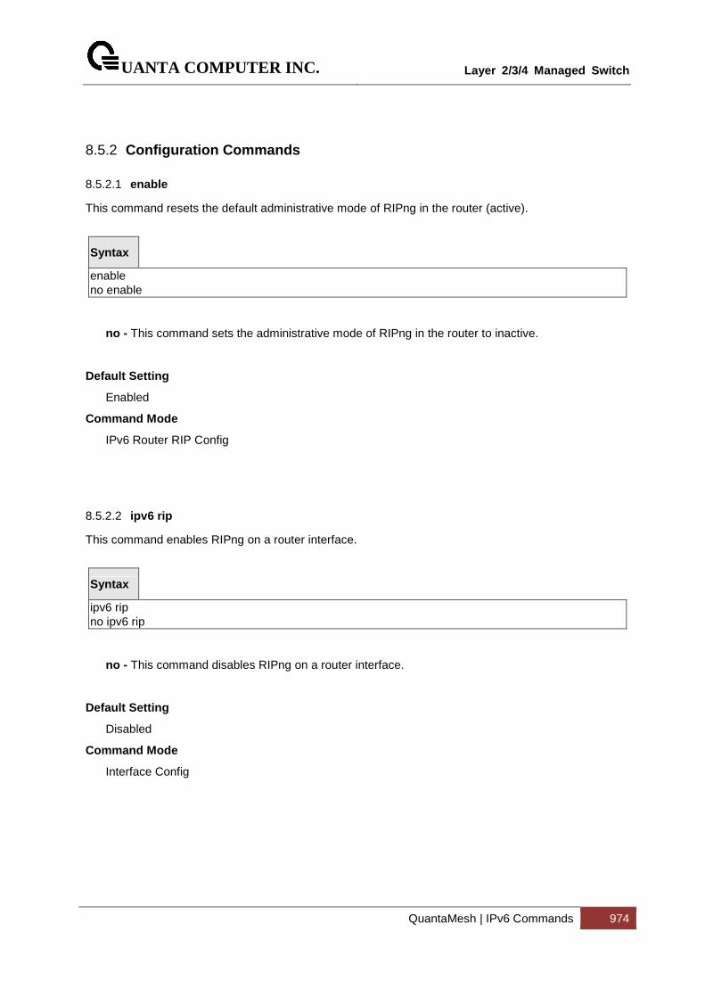
UANTA COMPUTER INC.
Layer 2/3/4 Managed Switch
QuantaMesh | IPv6 Commands 974
8.5.2 Configuration Commands
8.5.2.1 enable
This command resets the default administrative mode of RIPng in the router (active).
Syntax
enable no enable
no - This command sets the administrative mode of RIPng in the router to inactive.
Default Setting
Enabled
Command Mode
IPv6 Router RIP Config
8.5.2.2 ipv6 rip
This command enables RIPng on a router interface.
Syntax
ipv6 rip no ipv6 rip
no - This command disables RIPng on a router interface.
Default Setting
Disabled
Command Mode
Interface Config
UANTA COMPUTER INC.
Layer 2/3/4 Managed Switch
QuantaMesh | IPv6 Commands 975
8.5.2.3 ipv6 router rip
Use this command to enter Router RIPng mode.
Syntax
ipv6 router rip
Default Setting
Disabled
Command Mode
Global Config
8.5.2.4 default-information originate
This command is used to set the advertisement of default routes.
Syntax
default-information originate no default-information originate
no - This command is used to cancel the advertisement of default routes.
Default Setting
Disabled
Command Mode
IPv6 Router RIP Config
UANTA COMPUTER INC.
Layer 2/3/4 Managed Switch
QuantaMesh | IPv6 Commands 976
8.5.2.5 default-metric
This command is used to set a default for the metric of distributed routes.
Syntax
default-metric <1-15> no default-metric
<1-15> - a value for default-metric.
no - This command is used to reset the default metric of distributed routes to its default value.
Default Setting
Not configured
Command Mode
IPv6 Router RIP Config
8.5.2.6 distance rip
This command sets the route preference value of RIPng in the router. Lower route preference values are preferred when determining the best route.
Syntax
distance rip <1-255> no distance rip
<1-255> - the value for distance.
no - This command sets the default route preference value of RIPng in the router.
Default Setting
15
Command Mode
IPv6 Router RIP Config
UANTA COMPUTER INC.
Layer 2/3/4 Managed Switch
QuantaMesh | IPv6 Commands 977
8.5.2.7 split-horizon
This command sets the RIPngplit horizon mode. None mode will not use RIPngplit horizon mode. Simple mode will be that a route is not advertised on the interface over which it is learned. Poison mode will be that routes learned over this interface should be re-advertised on the interface with a metric of infinity (16).
Syntax
split-horizon {none | simple | poison} no split-horizon
none - This command sets without using RIPngplit horizon mode.
simple - This command sets to use simple split horizon mode.
poison - This command sets to use poison reverse mode.
no - This command cancel to set the RIPngplit horizon mode and sets none mode.
Default Setting
Simple
Command Mode
IPv6 Router RIP Config
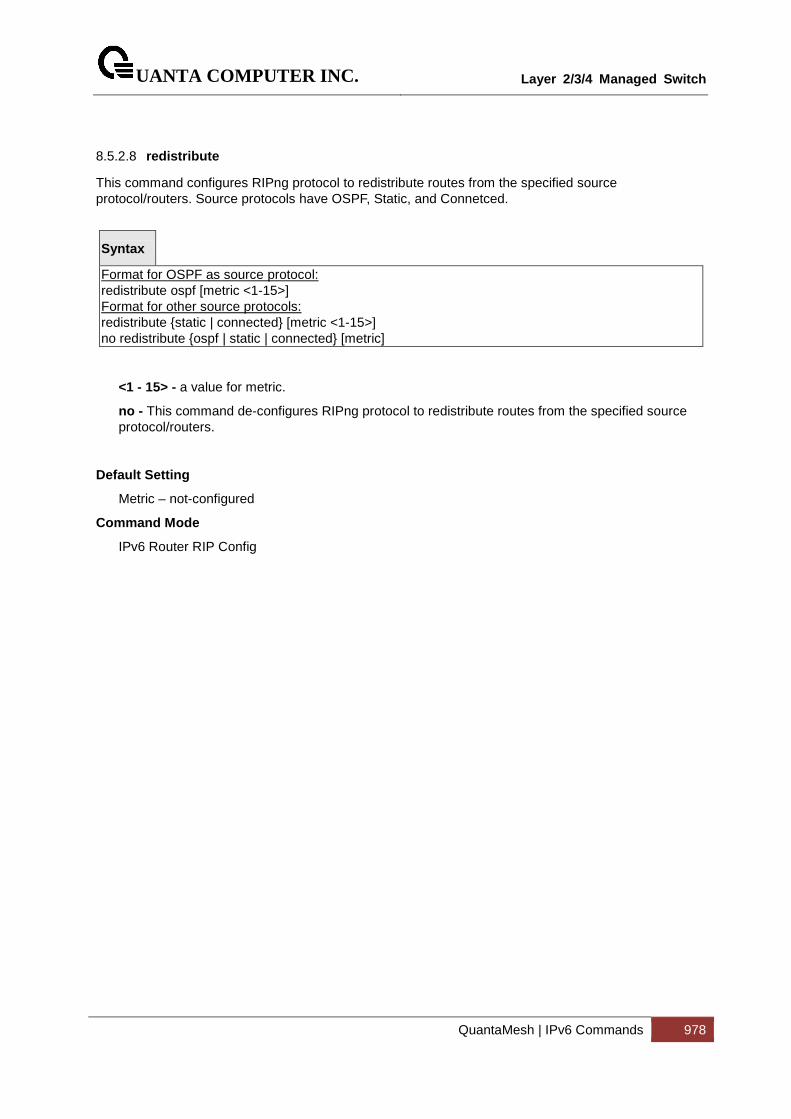
UANTA COMPUTER INC.
Layer 2/3/4 Managed Switch
QuantaMesh | IPv6 Commands 978
8.5.2.8 redistribute
This command configures RIPng protocol to redistribute routes from the specified source protocol/routers. Source protocols have OSPF, Static, and Connetced.
Syntax
Format for OSPF as source protocol: redistribute ospf [metric <1-15>] Format for other source protocols: redistribute {static | connected} [metric <1-15>] no redistribute {ospf | static | connected} [metric]
<1 - 15> - a value for metric.
no - This command de-configures RIPng protocol to redistribute routes from the specified source protocol/routers.
Default Setting
Metric – not-configured
Command Mode
IPv6 Router RIP Config
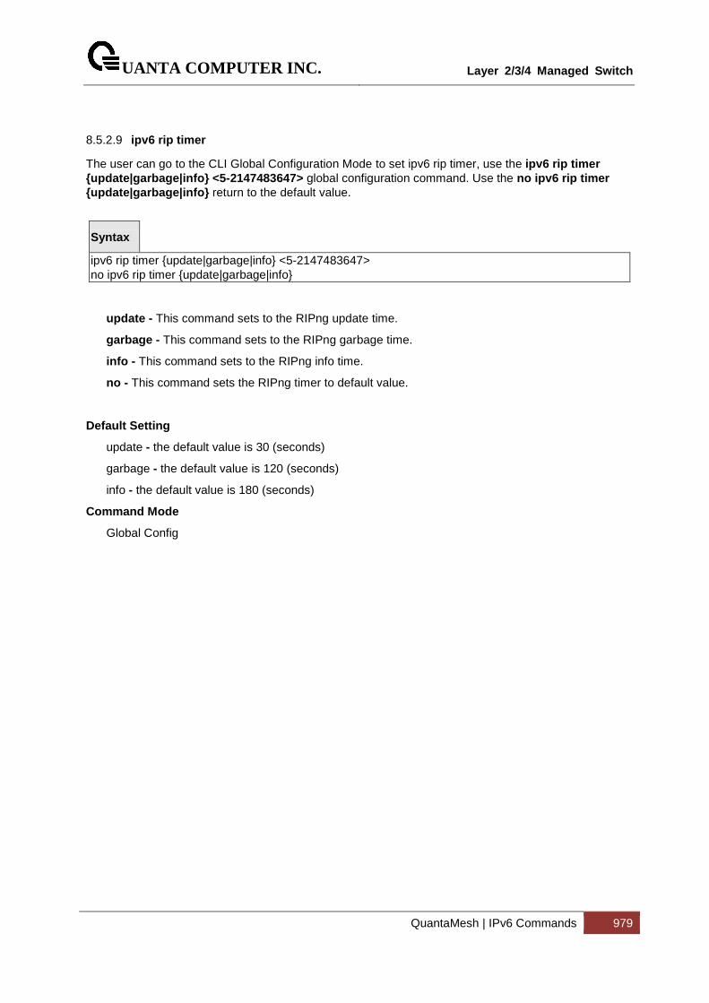
UANTA COMPUTER INC.
Layer 2/3/4 Managed Switch
QuantaMesh | IPv6 Commands 979
8.5.2.9 ipv6 rip timer
The user can go to the CLI Global Configuration Mode to set ipv6 rip timer, use the ipv6 rip timer {update|garbage|info} <5-2147483647> global configuration command. Use the no ipv6 rip timer {update|garbage|info} return to the default value.
Syntax
ipv6 rip timer {update|garbage|info} <5-2147483647> no ipv6 rip timer {update|garbage|info}
update - This command sets to the RIPng update time.
garbage - This command sets to the RIPng garbage time.
info - This command sets to the RIPng info time.
no - This command sets the RIPng timer to default value.
Default Setting
update - the default value is 30 (seconds)
garbage - the default value is 120 (seconds)
info - the default value is 180 (seconds)
Command Mode
Global Config
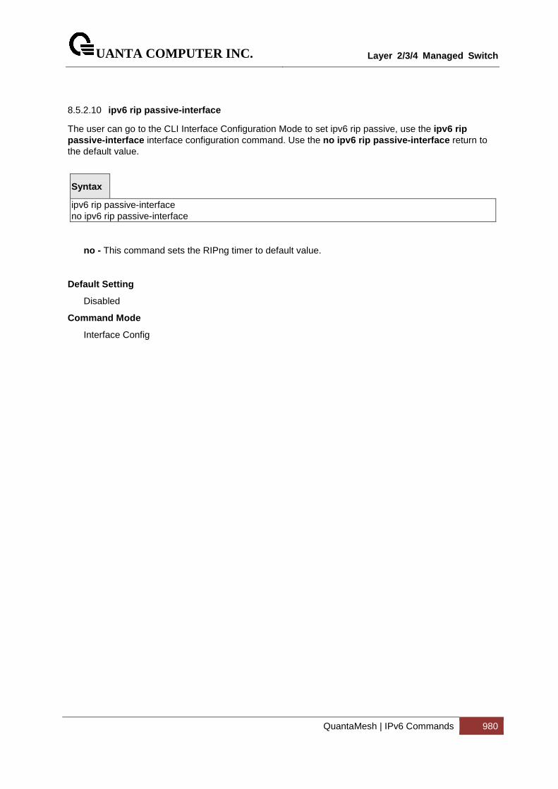
UANTA COMPUTER INC.
Layer 2/3/4 Managed Switch
QuantaMesh | IPv6 Commands 980
8.5.2.10 ipv6 rip passive-interface
The user can go to the CLI Interface Configuration Mode to set ipv6 rip passive, use the ipv6 rip passive-interface interface configuration command. Use the no ipv6 rip passive-interface return to the default value.
Syntax
ipv6 rip passive-interface no ipv6 rip passive-interface
no - This command sets the RIPng timer to default value.
Default Setting
Disabled
Command Mode
Interface Config
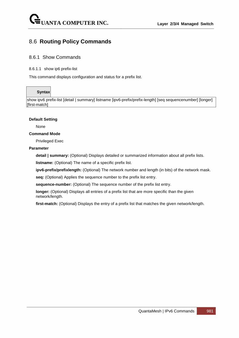
UANTA COMPUTER INC.
Layer 2/3/4 Managed Switch
QuantaMesh | IPv6 Commands 981
8.6 Routing Policy Commands
8.6.1 Show Commands
8.6.1.1 show ip6 prefix-list
This command displays configuration and status for a prefix list.
Syntax
show ipv6 prefix-list [detail | summary] listname [ipv6-prefix/prefix-length] [seq sequencenumber] [longer] [first-match]
Default Setting
None
Command Mode
Privileged Exec
Parameter
detail | summary: (Optional) Displays detailed or summarized information about all prefix lists.
listname: (Optional) The name of a specific prefix list.
ipv6-prefix/prefixlength: (Optional) The network number and length (in bits) of the network mask.
seq: (Optional) Applies the sequence number to the prefix list entry.
sequence-number: (Optional) The sequence number of the prefix list entry.
longer: (Optional) Displays all entries of a prefix list that are more specific than the given network/length.
first-match: (Optional) Displays the entry of a prefix list that matches the given network/length.
UANTA COMPUTER INC.
Layer 2/3/4 Managed Switch
QuantaMesh | IPv6 Commands 982
8.6.2 Configuration Commands
8.6.2.1 Ipv6 prefix-list
Use this command to create IPv6 prefix lists. An IPv6 prefix list can contain only ipv6 addresses. Prefix lists allow matching of route prefixes with those specified in the prefix list. Each prefix list includes of a sequence of prefix list entries ordered by their sequence numbers. A router sequentially examines each prefix list entry to determine if the route's prefix matches that of the entry. For IPv6 routes, only IPv6 prefix lists are matched. An empty or nonexistent prefix list permits all prefixes. An implicit deny is assumed if a given prefix does not match any entries of a prefix list. Once a match or deny occurs the router does not go through the rest of the list. An IPv6 prefix list may be used within a route map to match a route's prefix using the match ipv6 address command. A route map may contain both IPv4 and IPv4 prefix lists. If a route being matched is an IPv6 route, only the IPv6 prefix lists are matched.
Up to 128 prefix lists may be configured. The maximum number of statements allowed in prefix list is 64. These numbers indicate only IPv6 prefix lists. IPv4 prefix lists may be configured in appropriate numbers independently..
To delete a deletes either the entire prefix list or an individual statement from a prefix list, use the no form of this command. The description must be removed using the no ip prefix-list description before using this command to delete an IPv6 Prefix List.
Syntax
ipv6 prefix-list list-name [seq seq-number] { {permit/deny} ipv6-prefix/prefix-length [ge ge-value] [le le-value] | description text | renumber renumber-interval first-statement-number} no ipv6 prefix-list <list-name>
Default Setting
No prefix lists are configured by default. When neither the ge nor the le option is configured, the destination prefix must match the network/length exactly. If the ge option is configured without the le option, any prefix with a network mask greater than or equal to the ge value is considered a match. Similarly, if the le option is configured without the ge option, a prefix with a network mask less than or equal to the le value is considered a match.
Command Mode
Global Config
Parameter
list-name: The text name of the prefix list. Up to 32 characters.
seq number: (Optional) The sequence number for this prefix list statement. Prefix list statements are ordered from lowest sequence number to highest and applied in that order. If you do not specify a sequence number, the system will automatically select a sequence number five larger than the last sequence number in the list. Two statements may not be configured with the same sequence number. The value ranges from 1 to 4,294,967,294.
permit: Permit routes whose destination prefix matches the statement.
deny: Deny routes whose destination prefix matches the statement.
ipv6-prefix/prefix-length: Specifies the match criteria for routes being compared to the prefix list statement. The ipv6-prefix can be any valid IPv6 prefix where the address is specified in hexadecimal using 16-bit values between colons. The prefix-length is the The length of the IPv6

UANTA COMPUTER INC.
Layer 2/3/4 Managed Switch
QuantaMesh | IPv6 Commands 983
prefix, given as a decimal value that indicates how many of the high-order contiguous bits of the address comprise the prefix (the network portion of the address). A slash mark must precede the decimal value.
ge length: (Optional) If this option is configured, specifies a prefix length greater than or equal to the ipv6-prefix/prefix-length. It is the lowest value of a range of the length.
le length: (Optional) If this option is configured, specifies a prefix length less than or equal to the ipv6-prefix/prefix-length. It is the highest value of a range of the length.
description: A description of the prefix list. It can be up to 80 characters in length..
renumber: (Optional) Provides the option to renumber the sequence numbers of the IPv6 prefix list statements with a given interval starting from a particular sequence number. The valid range for renumber-interval is 1 - 100, and the valid range for first-statement-number is 1 - 1000.
8.6.2.2 match ipv6 address
Use this command to configure a route map to match based on a destination prefix. prefix-list prefix-listname identifies the name of an IPv6 prefix list used to identify the set of matching routes. Up to eight prefix lists may be specified. If multiple prefix lists are specified, a match occurs if a prefix matches any one of the prefix lists. If you configure a match ipv6 address statement within a route map section that already has a match ipv6 address statement, the new prefix lists are added to the existing set of prefix lists, and a match occurs if any prefix list in the combined set matches the prefix.
To delete a match statement from a route map, use the no form of this command.
Syntax
match ipv6 address prefix-list <prefix-list-name> [prefix-list-name...] no match ipv6 address prefix-list <prefix-list-name> [prefix-list-name...]
Default Setting
No match criteria are defined by default.
Command Mode
Route Map Config
Parameter
prefix-list-name: The name of a prefix list used to identify the set of matching routes. Up to eight prefix lists may be specified.
8.6.2.3 set ipv6 next-hop (BGP)
To set the IPv6 next hop of a route, use the set ipv6 next-hop command in Route Map Configuration mode. When used in a route map applied to UPDATE messages received from a neighbor, the command sets the next hop address for matching IPv6 routes received from the neighbor.
When used in a route map applied to UPDATE messages sent to a neighbor, the command sets the next hop address for matching IPv6 routes sent to the neighbor. If the address is a link local address, the address is assumed to be on the interface where the UPDATE is sent or received. If the command specifies a global IPv6 address, the address is not required to be on a local subnet.
To remove a set command from a route map, use the no form of this command.
UANTA COMPUTER INC.
Layer 2/3/4 Managed Switch
QuantaMesh | IPv6 Commands 984
Syntax
set ipv6 next-hop <ipv6-address> no set ipv6 next-hop
Default Setting
None.
Command Mode
Route Map Config
Parameter
Ipv6-address: The IPv6 address set as the Network Address of Next Hop field in the MP_NLRI attribute of an UPDATE message.
8.6.2.4 clear ipv6 prefix-list
Use this command to reset and clear IPv6 prefix-list hit counters. The hit count is a value indicating the number of matches to a specific prefix list entry.
Syntax
clear ipv6 prefix-list [prefix-list-name] [ipv6-prefix/prefix-length]
Command Mode
Privileged Exec
Parameter
prefix-list-name: (Optional) Name of the prefix list from which the hit count is to be cleared.
ipv6-prefix/prefixlength: (Optional) IPv6 prefix number and length (in bits) of the network mask. If this option is specified, hit counters are only cleared for the matching statement.
UANTA COMPUTER INC.
Layer 2/3/4 Managed Switch
QuantaMesh | Data Center Bridging Commands 985
9 Data Center Bridging Commands
9.1 FIP Snooping
9.1.1 show dcb fip-snooping
This command displays fip-snooping whether enable or disable.
Syntax
show dcb fip-snooping
Default Setting
None
Command Mode
Privileged Exec
Display Message
FIP Snooping: fip-snooping function status.
9.1.2 show fip-snooping enode
This command displays the ENode connections for the entire system.
Syntax
show dcb fip-snooping enode
Default Setting
None
Command Mode
Privileged Exec
Display Message
ENode MAC: MAC address of the ENode.
ENode Interface Number: Name of the interface to which the ENode is connected.

UANTA COMPUTER INC.
Layer 2/3/4 Managed Switch
QuantaMesh | Data Center Bridging Commands 986
VLAN ID: ID number of the VLAN to which the ENode belongs.
ENode Name ID: Name ID.
UANTA COMPUTER INC.
Layer 2/3/4 Managed Switch
QuantaMesh | Data Center Bridging Commands 987
9.1.3 show dcb fip-snooping session
This command displays all FIP snooping sessions for the entire system.
Syntax
show dcb fip-snooping session
Default Setting
None
Command Mode
Privileged Exec
Display Message
VN Port MAC: FCoE MAC address that is used to send the FCoE packets.
FCF Interface Number: The interface to which the FCF is connected
FCF MAC address: MAC address of the FCF..
ENode MAC address: MAC address of the ENode.
ENode Interface Number: The interface to which the ENode is connected
UANTA COMPUTER INC.
Layer 2/3/4 Managed Switch
QuantaMesh | Data Center Bridging Commands 988
9.1.4 show dcb fip-snooping fcf
This command displays to what interfaces the FCFs are connected for the entire system.
Syntax
show dcb fip-snooping fcf
Default Setting
None
Command Mode
Privileged Exec
Display Message
FCF MAC: MAC address of the FCF.
FCF Interface Number: Name of the interface to which the FCoE Forwarder (FCF) is connected.
VLAN ID: ID number of the VLAN to which the FCF belongs.
FC MAP: May FC-Map value used by the FCF.
Switch Name: Name ID.
Fabric Name: Name of the FCF.

UANTA COMPUTER INC.
Layer 2/3/4 Managed Switch
QuantaMesh | Data Center Bridging Commands 989
9.1.5 show dcb fip-snooping vlan
This command displays FIP snooping whether enable or disable on specific VLAN.
Syntax
show dcb fip-snooping vlan {< 1-4093> | all}
<1 - 4093> - VLAN ID.
all - This command represents all interfaces.
Default Setting
None
Command Mode
Privileged Exec
Display Message
Vlan ID: fip-snooping function status on the specific VLAN.
9.1.6 fip-snooping
The FIP snooping function is disabled by default. Only after enabling it, are the FIP related CLIs under VLAN and interface mode visible. The FIP-snoop process also starts after the “fip-snooping” command is enabled. Once the feature is enabled, the FIP-snoop packets and FCoE packets are dropped, unless explicitly enabled on a per-VLAN basis. If FIP snooping is enabled, all the FIP frames are snooped and security ACLs are added. FCoE traffic is blocked on all ports until the device re-initializes with FIP. If the feature is disabled, snooping is removed and all programmed ACLs and internal data are cleaned up.
Syntax
fip-snooping no fip-snooping
no - This command disables fip snooping function.
Default Setting
Disabled
Command Mode
DCB (Data Center Bridging) Config

UANTA COMPUTER INC.
Layer 2/3/4 Managed Switch
QuantaMesh | Data Center Bridging Commands 990
9.1.7 fip-snooping vlan
This command enables FIP snooping on a VLAN. VLAN must be configured before it can be used. Once VLAN is enabled, the FIP packets will be snooped only on the configured VLANs. FIP snooping is disabled on VLANs by default.
Syntax
fip-snooping vlan <1-4093>
no fip-snooping vlan <1-4093>
<1 - 4093> - VLAN ID.
no - This command disable snooping on a specific VLAN.
Default Setting
Disabled
Command Mode
DCB (Data Center Bridging) Config
UANTA COMPUTER INC.
Layer 2/3/4 Managed Switch
QuantaMesh | Data Center Bridging Commands 991
9.2 Priority-based Flow Control
9.2.1 show dcb priority-flow-control
Display the PFC information of a given interface or all interface.
Syntax
show dcb priority-flow-control {<interface> | all }
Default Setting
None
Command Mode
Privileged Exec
9.2.2 priority-flow-control mode
Set Priority-Flow-Control (PFC) to be enabled, disabled, or atuo on the interface.
Both PFC and 802.3x flow control are enabled, PFC will take effect.
Syntax
priority-flow-control mode { on | auto}
no priority-flow-control mode
no - This command auto the Priority-Flow-Control (PFC) on the interface.
Default Setting
Auto
Command Mode
DCB (Data Center Bridging) interface mode
i

UANTA COMPUTER INC.
Layer 2/3/4 Managed Switch
QuantaMesh | Data Center Bridging Commands 992
9.2.3 priority-flow-control priority
Enable or disable the priority group for lossless (no-drop) or lossy (drop) behavior on the selected interface.
Syntax
priority-flow-control priority <priority_id> { drop | no-drop }
no priority-flow-control priority
Default Setting
The default behavior for priority(3,4,5,6) are no-drop
Command Mode
DCB (Data Center Bridging) interface mode
9.2.4 clear priority-flow-control statistics
Clear all global and interface PFC statistics
Syntax
clear priority-flow-control statistics
Command Mode
Privileged EXEC

UANTA COMPUTER INC.
Layer 2/3/4 Managed Switch
QuantaMesh | Data Center Bridging Commands 993
9.3 Enhanced Transmission Selection (ETS)
9.3.1 show dcb ets classofservice traffic-class-group
This command displays ETS classofservice traffic-class-group.
Syntax
show dcb ets classofservice traffic-class-group [<slot/port>]
<slot/port> - Interface number.
Default Setting
None
Command Mode
Privileged Exec
Display Message
Traffic Class: The Traffic Class can range from 0-7, although the actual number of available traffic classes depends on the platform.
Traffic Class Group: The Traffic Class Group can range from 0-7, although the actual number of available traffic classes depends on the platform..
9.3.2 show dcb ets traffic-class-group
This command displays ETS traffic-class-group.
Syntax
show dcb ets traffic-class-group [<slot/port>]
<slot/port> - Interface number.
Default Setting
None
Command Mode
Privileged Exec
Display Message
Interface: The slot/port of the interface.
UANTA COMPUTER INC.
Layer 2/3/4 Managed Switch
QuantaMesh | Data Center Bridging Commands 994
Traffic Class Group: The Traffic Class Group identifier.
Min. Bandwidth: The minimum transmission bandwidth, expressed as a percentage. A value of zero means bandwidth is not guaranteed and the TCG operates using best-effort.
Max. Bandwidth: The maximum transmission bandwidth, expressed as a percentage. A value of zero means no upper limit is enforced, so the queue may use any or all of the available bandwidth of the interface.
Weight: .The weight of the TCG used during non-strict scheduling.
Scheduler Type: Indicates whether this queue is scheduled for transmission using a strict priority or a weighted scheme.
UANTA COMPUTER INC.
Layer 2/3/4 Managed Switch
QuantaMesh | Data Center Bridging Commands 995
9.3.3 ets classofservice traffic-class-group
Use the ets classofservice traffic-class-group command to map the internal Traffic Class Group.
Syntax
ets classofservice traffic-class-group <0-7> <0-2>
<0 – 7>: Traffic Class number.
<0 – 2>: Traffic Class Group number.
Default Setting
None
Command Mode
Data-Center-Bridging Interface Mode
9.3.4 ets traffic-class-group max-bandwidth
Use the ets traffic-class-group max-bandwidth command to specify the maximum transmission bandwidth limit for each Traffic Class Group.
Syntax
ets traffic-class-group max-bandwidth <bw-0> <bw-1> <bw-2>
<bw-0>: The maximum bandwidth percentage for TCG 0.
<bw-1>: The maximum bandwidth percentage for TCG 1.
<bw-2>: The maximum bandwidth percentage for TCG 2.
Default Setting
None
Command Mode
Data-Center-Bridging Interface Mode
UANTA COMPUTER INC.
Layer 2/3/4 Managed Switch
QuantaMesh | Data Center Bridging Commands 996
9.3.5 ets traffic-class-group min-bandwidth
Use the ets traffic-class-group min-bandwidth command to specify the minimum transmission bandwidth guarantee for each Traffic Class Group.
Syntax
ets traffic-class-group min-bandwidth <bw-0> <bw-1> <bw-2>
<bw-0>: The minimum bandwidth percentage for TCG 0.
<bw-1>: The minimum bandwidth percentage for TCG 1.
<bw-2>: The minimum bandwidth percentage for TCG 2.
Default Setting
None
Command Mode
Data-Center-Bridging Interface Mode
9.3.6 ets traffic-class-group strict
Use the ets traffic-class-group strict command to activate the strict priority scheduler mode for each Traffic Class Group.
Syntax
ets traffic-class-group strict <TCG-id> [<TCG-id>] [<TCG-id>]
< TCG ID >: The number of TCG ID from 0 to 2.
Default Setting
None
Command Mode
Data-Center-Bridging Interface Mode
UANTA COMPUTER INC.
Layer 2/3/4 Managed Switch
QuantaMesh | Data Center Bridging Commands 997
9.3.7 ets traffic-class-group weight
Use the ets traffic-class-group weight command to specify the weight for each interface Traffic Class Group.
Syntax
ets traffic-class-group weight < wp-0> <wp-1> <wp-2>
<wp-0>: The number of weight for queue 0.
<wp-1>: The number of weight for queue 1.
<wp-2>: The number of weight for queue 2.
Default Setting
None
Command Mode
Data-Center-Bridging Interface Mode
UANTA COMPUTER INC.
Layer 2/3/4 Managed Switch
QuantaMesh | Data Center Bridging Commands 998
9.4 Ethernet Virtual Bridging
9.4.1 show evb status
This command displays EVB function global parameter on system.
Syntax
show evb status
Default Setting
None
Command Mode
Privileged Exec
Display Message
Interface: Displays the interface number.
Link: Displays the link status of this interface
Admin Mode: Displays the administrative mode of EVB on this interface.
UANTA COMPUTER INC.
Layer 2/3/4 Managed Switch
QuantaMesh | Data Center Bridging Commands 999
9.4.2 show evb status
This command displays EVB function interface parameter on system.
Syntax
show evb status <slot/port>
Default Setting
None
Command Mode
Privileged Exec
Display Message
Admin Mode: Display the administrative mode of this interface
Remote Sync: Displays the synchronization status
Support Capability: Displays the support capabilities of EVB on this interface.
Configure Capability: Displays the configured capabilities of EVB on this interface.
Support Mode: Display the support mode of EVB on this interface.
Configure Mode: Display the configured mode of EVB on this interface.
Configure RTE: Display the configured RTE of EVB on this interface.
Current RTE: Display the current RTE of EVB on this interface.
UANTA COMPUTER INC.
Layer 2/3/4 Managed Switch
QuantaMesh | Data Center Bridging Commands 1000
9.4.3 show evb vsi-profile
This command displays VSI profile paramters on system.
Syntax
show evb vsi-profile [<slot/port> | detailed <slot/port>]
Default Setting
None
Command Mode
Privileged Exec
Display Message
Interface: Display the interface number.
Instance ID: Displays the instance ID of the VSI profile.
MAC address: Displays the MAC address of VSI profile.
VLAN: Displays the VLAN information of VSI profile.
9.4.4 evb enable
This command sets the administrative mode of EVB for an interface.
Syntax
evb enable no evb enable
no - This command sets administrative mode to disable for the interface.
Default Setting
Disabled
Command Mode
Interface Config
UANTA COMPUTER INC.
Layer 2/3/4 Managed Switch
QuantaMesh | Data Center Bridging Commands 1001
9.4.5 evb rte
This command sets the Retransmission Timer Exponent of EVB for an interface.
Syntax
evb rte <16-31> no evb rte
<16-31>: Retransmission timer Exponent (RTE) ranged from 16 to 31.
no - This command sets RTE to default setting.
Default Setting
16
Command Mode
Interface Config

UANTA COMPUTER INC.
Layer 2/3/4 Managed Switch
QuantaMesh | Data Center Bridging Commands 1002
9.5 VM Tracer Commands
9.5.1 Show Commands
9.5.1.1 show vmtracer interface
This command displays VM Tracer interface mode on all interfaces or the VM interface (Vnics) that are on the specific switch interface where the VM Tracer interface mode is enabled.
Syntax
show vmtracer interface [<slot/port>]
<slot/port> - show the VM interface (Vnics) that are on the <slot/port> where the VMTracer interface mode is enabled.
Default Setting
None
Command Mode
Privileged Exec
Display Message
Port: the physical interface number of the device.
VM Tracer: the VM Tracer interface mode state. The value should be Enable or Disable .
VM Name: the name of attached VM.
VM Adapter: the adapter name of the VM interface.
VLAN: the VLAN value of the VM interface.
UANTA COMPUTER INC.
Layer 2/3/4 Managed Switch
QuantaMesh | Data Center Bridging Commands 1003
9.5.1.2 show vmtracer session
This command displays information about a specified VM Tracer session on the system.
Syntax
show vmtracer session [<name>]
<name> - displays the specific configured VM Tracer session with the name.
Default Setting
None
Command Mode
Privileged Exec
Display Message
Session Name: the configured name of the VM Tracer session.
vCenter URL: the url address of vCenter. It should be start with https:// .
Username: the login username of vCenter on the VM Tracer session
Password: the login password of vCenter on the VM Tracer session.
AutoVlan: the mode of AutoVlan. The value should be Enable of Disable .
Allow-Vlan: allow-vlan list of the VM Tracer session.
Session Status: the link state of the VM Tracer session.
UANTA COMPUTER INC.
Layer 2/3/4 Managed Switch
QuantaMesh | Data Center Bridging Commands 1004
9.5.1.3 show vmtracer vm
The command displays VMs interfaces (Vnics) that are accessible to the switch interfaces where the VM Tracer interface mode is enabled.
Syntax
show vmtracer vm [detail <vm_name>]
<vm_name> - displays information for the specific VM.
Default Setting
None
Command Mode
Privileged Exec
Display Message
VM Name: the name of attached VM.
VM Adapter: the adapter name of the VM interface.
Interface: the associated switch interface of attached VM.
VLAN: the VLAN value of the VM interface.
Vnic: the adapter name of the VM interface.
Mac: the network mac address of vnic.
Portgroup: the portgroup of the VM.
Vlan: the vlan value of the VM interface.
Switch: the vSwitch of the VM.
Host: the host of the VM.
UANTA COMPUTER INC.
Layer 2/3/4 Managed Switch
QuantaMesh | Data Center Bridging Commands 1005
9.5.1.4 show vmtracer host
The command displays information about the hosts associated to the VM Tracer enabled interface.
Syntax
show vmtracer host
Default Setting
None
Command Mode
Privileged Exec
Display Message
Interface: the associated switch interface of the host device.
Host: the host name
Manufacturer: the manufacture vendor of the host device
Model: the model name of host device.
CPU Speed: the cpu speed of the host device.
CPUs: the number of cpu inside the host device.
CPU Cores: the cpu cores of the host device.
Memory: the memory size of the host device.

UANTA COMPUTER INC.
Layer 2/3/4 Managed Switch
QuantaMesh | Data Center Bridging Commands 1006
9.5.2 Configuration Commands
9.5.2.1 vmtracer session
This command places the switch in vmtracer mode for the specified session. The command creates a new session or loads an existing session for editing.
The switch supports total four VM Tracer sessions.
Syntax
vmtracer session <name> no vmtracer session <name>
no - This command removes a existed VM Tracer session.
<name> - The label assigned to the VM Tracer session.
Default Setting
None
Command Mode
Global Config
When the switch in vmtracer mode, it can configure the following commands:
� allow-vlan
� autovlan disable
� exit (vmtracer mode)
� password (vmtracer mode)
� url
� username (vmtracer mode)
UANTA COMPUTER INC.
Layer 2/3/4 Managed Switch
QuantaMesh | Data Center Bridging Commands 1007
9.5.2.2 allow-vlan
The command specifies the VLANs that may be added when a VM is added or moved from the hypervisor connected to the session specified by the vmtracer mode. By default, all VLANs are allowed.
Syntax
allow-vlan {<vlan-list> | {add | remove <vlan-list>} | none | all}
<vlan-list> - Enter VLAN IDs in range <1-4093>. Use ‘-‘ to specify a range, or ‘,’ to separate VLAN IDs in a list. Spaces and Zeros are not permitted.
<add> - Add VLAN IDs to current allow-vlan list.
<remove> - Remove VLAN IDs from current allow-vlan list.
<none> - Make allow-vlan list to be empty.
<all> - Add all VLAN IDs to current allow-vlan list.
Default Setting
all
Command Mode
VM Tracer Config
UANTA COMPUTER INC.
Layer 2/3/4 Managed Switch
QuantaMesh | Data Center Bridging Commands 1008
9.5.2.3 autovlan disable
This command disable vlan auto provisioning which allows the dynamic assignment and pruning of VLANs when a VM attached to the ESX connected to the switch is created, deleted, or moved to a different ESX host. The autovlan setting controls auto provisioning.
Syntax
autovlan disable no autovlan disable
no - this command enables vlan auto provisioning.
Default Setting
no autovlan disable
Command Mode
VM Tracer Config
9.5.2.4 password
The command specifies the token that authorizes the username to the vCenter associated with the VM Tracer session.
Syntax
password {0 | 7 <password>}
<0 | 7> - This command sets encryption level of the password.0 - the password is a clear text string.
7 - the password is an encrypted string.
<password> - text that authenticates the username.
Default Setting
None
Command Mode
VM Tracer Config
UANTA COMPUTER INC.
Layer 2/3/4 Managed Switch
QuantaMesh | Data Center Bridging Commands 1009
9.5.2.5 username
The command identifies the switch’s account name on the vCenter server. The switch uses this user name to access vCenter information.
Syntax
username <name>
<name> - vCenter account username. Parameter must match the username configured on the vCenter.
Default Setting
None
Command Mode
VM Tracer Config
9.5.2.6 url
The command specifies the vCenter server location that is monitored by the session being edited by the current vmtracer mode. The command must reference a fully formed secure url.
Syntax
url <url_name>
<url_name> - the location value of the vCenter server. Valid formats include IP address (dotted decimal notation) and fully qualified domain name.
Default Setting
None
Command Mode
VM Tracer Config
UANTA COMPUTER INC.
Layer 2/3/4 Managed Switch
QuantaMesh | Data Center Bridging Commands 1010
9.5.2.7 exit
This command returns the switch to Global Configuration mode and enables the VM Tracer session. Changes to the VM Tracer session that were made in vmtracer mode are stored when the mode is exited.
Syntax
exit
Default Setting
None
Command Mode
VM Tracer Config
9.5.2.8 vmtracer
The command enables vmtracer mode on the interface configuration mode. Interfaces with vmtracer mode enabled send discovery packets to the connected host device.
The no vmtracer command disables vmtracer mode on the configuration mode interface.
Syntax
vmtracer
no vmtracer
no - This command disables VM Tracer mode on the configuration mode interface
Default Setting
Disable
Command Mode
Interface Config
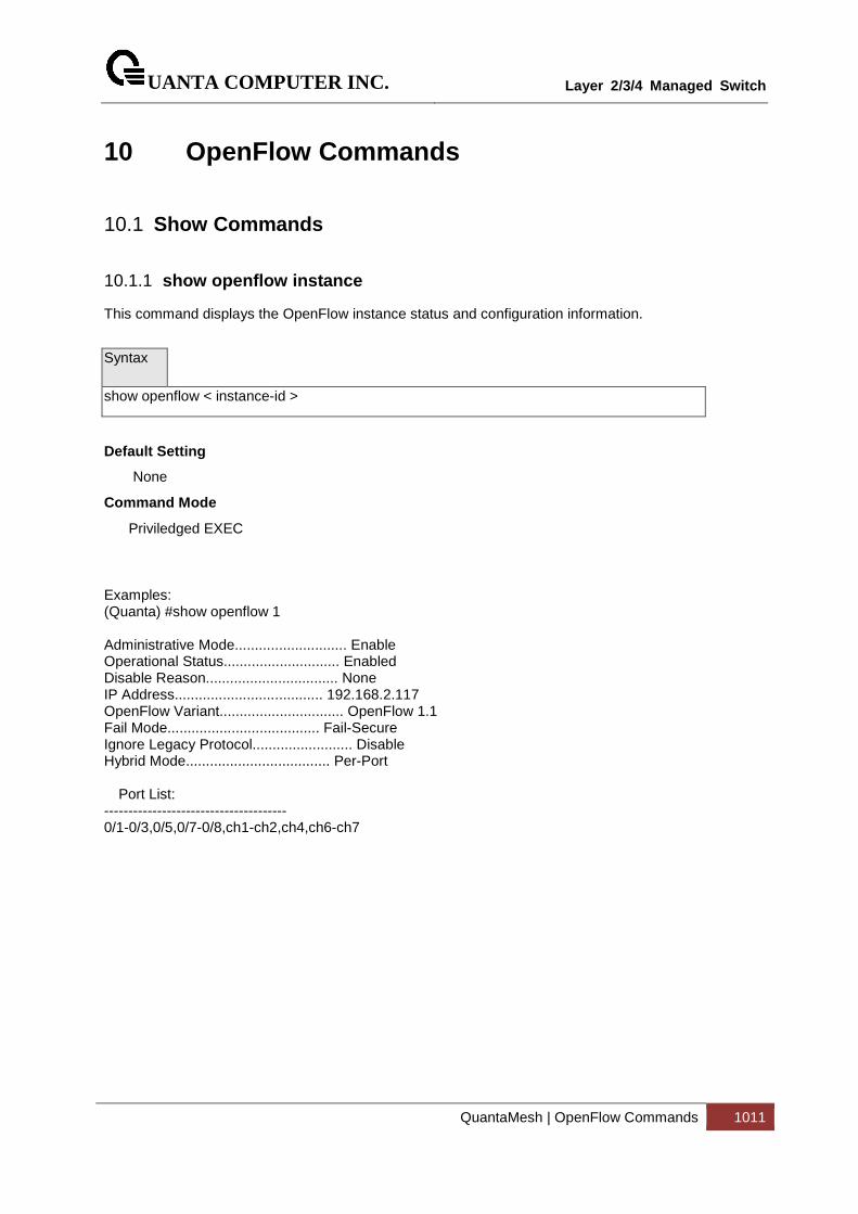
UANTA COMPUTER INC.
Layer 2/3/4 Managed Switch
QuantaMesh | OpenFlow Commands 1011
10 OpenFlow Commands
10.1 Show Commands
10.1.1 show openflow instance
This command displays the OpenFlow instance status and configuration information.
Syntax
show openflow < instance-id >
Default Setting
None
Command Mode
Priviledged EXEC Examples: (Quanta) #show openflow 1 Administrative Mode............................ Enable Operational Status............................. Enabled Disable Reason................................. None IP Address..................................... 192.168.2.117 OpenFlow Variant............................... OpenFlow 1.1 Fail Mode...................................... Fail-Secure Ignore Legacy Protocol......................... Disable Hybrid Mode.................................... Per-Port Port List: -------------------------------------- 0/1-0/3,0/5,0/7-0/8,ch1-ch2,ch4,ch6-ch7
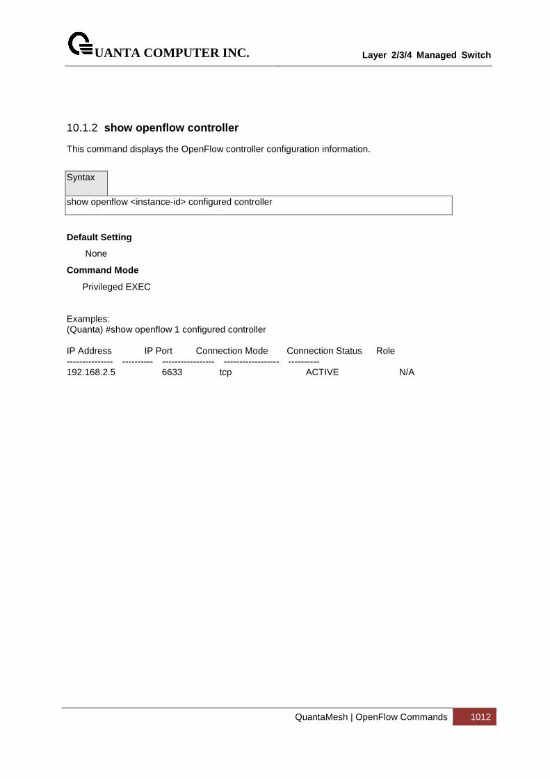
UANTA COMPUTER INC.
Layer 2/3/4 Managed Switch
QuantaMesh | OpenFlow Commands 1012
10.1.2 show openflow controller
This command displays the OpenFlow controller configuration information.
Syntax
show openflow <instance-id> configured controller
Default Setting
None
Command Mode
Privileged EXEC Examples: (Quanta) #show openflow 1 configured controller IP Address IP Port Connection Mode Connection Status Role --------------- ---------- ----------------- ------------------ ---------- 192.168.2.5 6633 tcp ACTIVE N/A
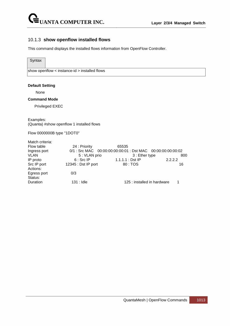
UANTA COMPUTER INC.
Layer 2/3/4 Managed Switch
QuantaMesh | OpenFlow Commands 1013
10.1.3 show openflow installed flows
This command displays the installed flows information from OpenFlow Controller.
Syntax
show openflow < instance-id > installed flows
Default Setting
None
Command Mode
Privileged EXEC Examples: (Quanta) #show openflow 1 installed flows Flow 0000000B type "1DOT0" Match criteria: Flow table 24 : Priority 65535 Ingress port 0/1 : Src MAC 00:00:00:00:00:01 : Dst MAC 00:00:00:00:00:02 VLAN 5 : VLAN prio 3 : Ether type 800 IP proto 6 : Src IP 1.1.1.1 : Dst IP 2.2.2.2 Src IP port 12345 : Dst IP port 80 : TOS 16 Actions: Egress port 0/3 Status: Duration 131 : Idle 125 : installed in hardware 1
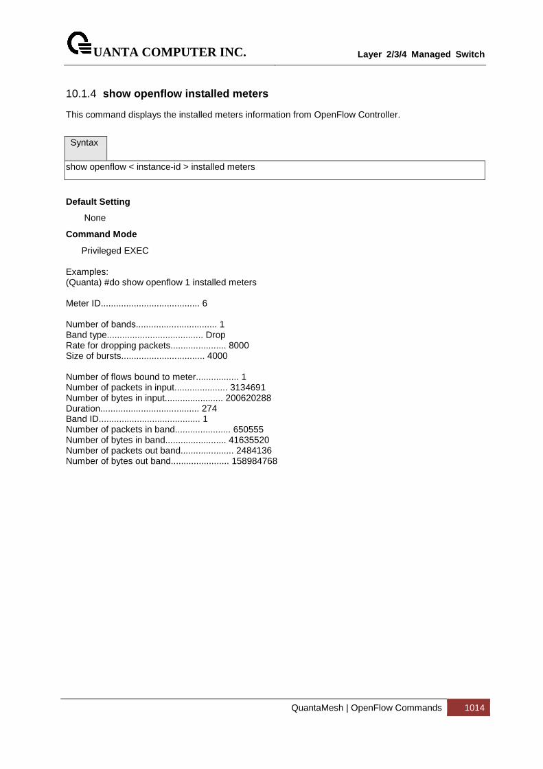
UANTA COMPUTER INC.
Layer 2/3/4 Managed Switch
QuantaMesh | OpenFlow Commands 1014
10.1.4 show openflow installed meters
This command displays the installed meters information from OpenFlow Controller.
Syntax
show openflow < instance-id > installed meters
Default Setting
None
Command Mode
Privileged EXEC Examples: (Quanta) #do show openflow 1 installed meters Meter ID....................................... 6 Number of bands................................ 1 Band type...................................... Drop Rate for dropping packets...................... 8000 Size of bursts................................. 4000 Number of flows bound to meter................. 1 Number of packets in input..................... 3134691 Number of bytes in input....................... 200620288 Duration....................................... 274 Band ID........................................ 1 Number of packets in band...................... 650555 Number of bytes in band........................ 41635520 Number of packets out band..................... 2484136 Number of bytes out band....................... 158984768
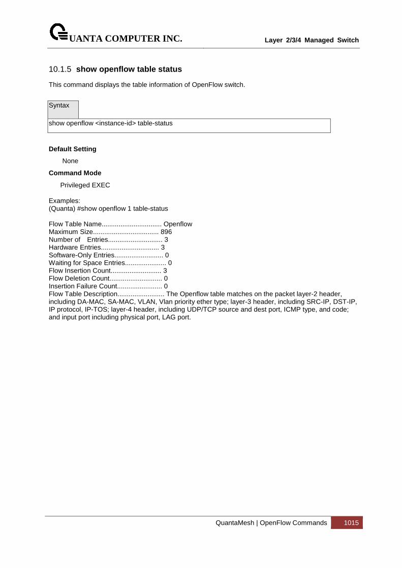
UANTA COMPUTER INC.
Layer 2/3/4 Managed Switch
QuantaMesh | OpenFlow Commands 1015
10.1.5 show openflow table status
This command displays the table information of OpenFlow switch.
Syntax
show openflow <instance-id> table-status
Default Setting
None
Command Mode
Privileged EXEC Examples: (Quanta) #show openflow 1 table-status Flow Table Name................................ Openflow Maximum Size................................... 896 Number of Entries............................. 3 Hardware Entries............................... 3 Software-Only Entries.......................... 0 Waiting for Space Entries...................... 0 Flow Insertion Count........................... 3 Flow Deletion Count............................ 0 Insertion Failure Count........................ 0 Flow Table Description......................... The Openflow table matches on the packet layer-2 header, including DA-MAC, SA-MAC, VLAN, Vlan priority ether type; layer-3 header, including SRC-IP, DST-IP, IP protocol, IP-TOS; layer-4 header, including UDP/TCP source and dest port, ICMP type, and code; and input port including physical port, LAG port.
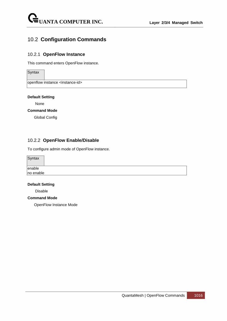
UANTA COMPUTER INC.
Layer 2/3/4 Managed Switch
QuantaMesh | OpenFlow Commands 1016
10.2 Configuration Commands
10.2.1 OpenFlow Instance
This command enters OpenFlow instance. Syntax
openflow instance <instance-id>
Default Setting
None
Command Mode
Global Config
10.2.2 OpenFlow Enable/Disable
To configure admin mode of OpenFlow instance. Syntax
enable no enable
Default Setting
Disable
Command Mode
OpenFlow Instance Mode
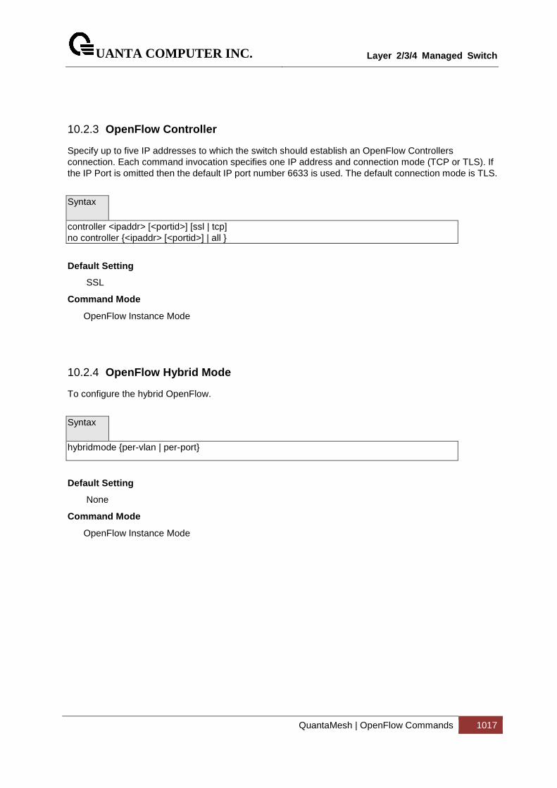
UANTA COMPUTER INC.
Layer 2/3/4 Managed Switch
QuantaMesh | OpenFlow Commands 1017
10.2.3 OpenFlow Controller
Specify up to five IP addresses to which the switch should establish an OpenFlow Controllers connection. Each command invocation specifies one IP address and connection mode (TCP or TLS). If the IP Port is omitted then the default IP port number 6633 is used. The default connection mode is TLS.
Syntax
controller <ipaddr> [<portid>] [ssl | tcp] no controller {<ipaddr> [<portid>] | all }
Default Setting
SSL
Command Mode
OpenFlow Instance Mode
10.2.4 OpenFlow Hybrid Mode
To configure the hybrid OpenFlow.
Syntax
hybridmode {per-vlan | per-port}
Default Setting
None
Command Mode
OpenFlow Instance Mode

UANTA COMPUTER INC.
Layer 2/3/4 Managed Switch
QuantaMesh | OpenFlow Commands 1018
10.2.5 OpenFlow VLAN in Per-VLAN mode instance
To add/remove VLAN to OpenFlow per-VLAN instance.
Syntax
vlan <vlan-list> no vlan <vlan-list>
Default Setting
None
Command Mode
OpenFlow Instance per-VLAN Mode
10.2.6 OpenFlow PORT in Per-PORT mode instance
To add/remove PORT to OpenFlow per-PORT instance.
Syntax
port {<port-list> | port-channel <ChId-List> } no port {<port-list> | port-channel <ChId-List> }
Default Setting
None
Command Mode
OpenFlow Instance per-PORT Mode
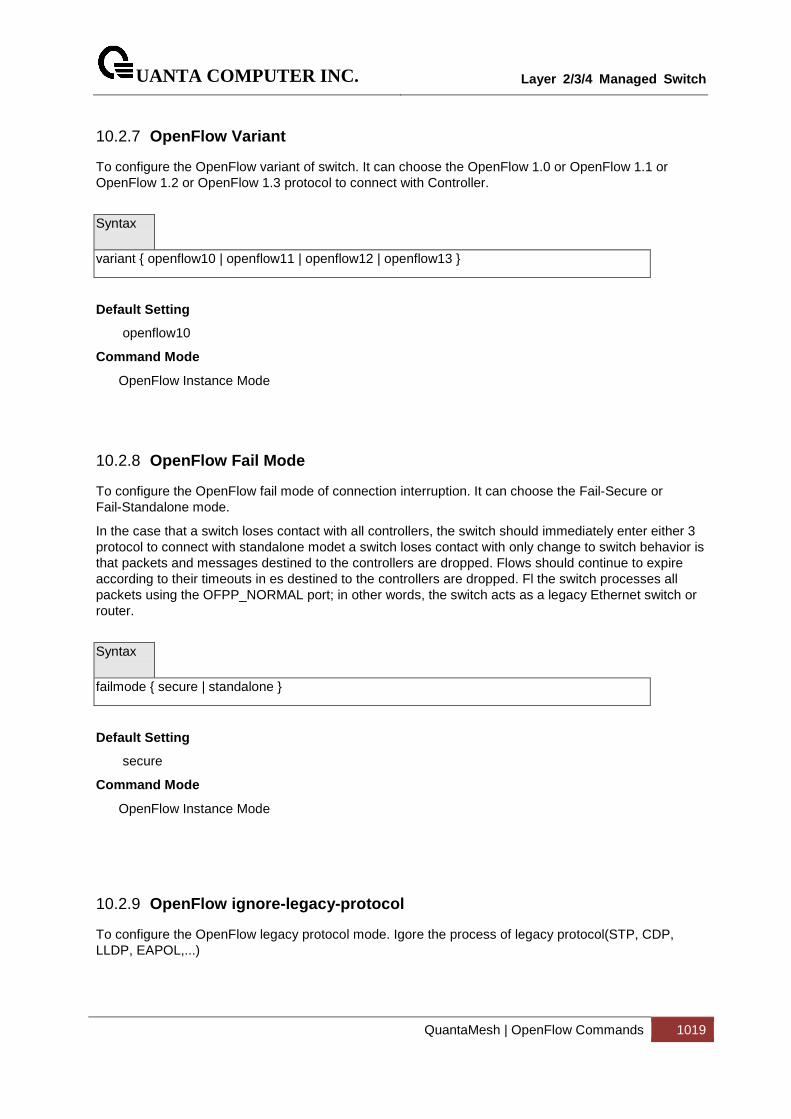
UANTA COMPUTER INC.
Layer 2/3/4 Managed Switch
QuantaMesh | OpenFlow Commands 1019
10.2.7 OpenFlow Variant
To configure the OpenFlow variant of switch. It can choose the OpenFlow 1.0 or OpenFlow 1.1 or OpenFlow 1.2 or OpenFlow 1.3 protocol to connect with Controller.
Syntax
variant { openflow10 | openflow11 | openflow12 | openflow13 }
Default Setting
openflow10
Command Mode
OpenFlow Instance Mode
10.2.8 OpenFlow Fail Mode
To configure the OpenFlow fail mode of connection interruption. It can choose the Fail-Secure or Fail-Standalone mode.
In the case that a switch loses contact with all controllers, the switch should immediately enter either 3 protocol to connect with standalone modet a switch loses contact with only change to switch behavior is that packets and messages destined to the controllers are dropped. Flows should continue to expire according to their timeouts in es destined to the controllers are dropped. Fl the switch processes all packets using the OFPP_NORMAL port; in other words, the switch acts as a legacy Ethernet switch or router.
Syntax
failmode { secure | standalone }
Default Setting
secure
Command Mode
OpenFlow Instance Mode
10.2.9 OpenFlow ignore-legacy-protocol
To configure the OpenFlow legacy protocol mode. Igore the process of legacy protocol(STP, CDP, LLDP, EAPOL,...)
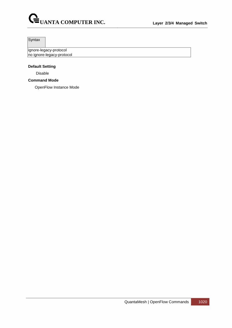
UANTA COMPUTER INC.
Layer 2/3/4 Managed Switch
QuantaMesh | OpenFlow Commands 1020
Syntax
ignore-legacy-protocol no ignore-legacy-protocol
Default Setting
Disable
Command Mode
OpenFlow Instance Mode