PSE-6(C)(E)(R) & PSE-10(E)(C)(R) - Instruction Manual
48
Power Supply Expanders PSE-6(C)(E)(R) & PSE-10(E)(C)(R) Instruction Manual Document LS10227-000NF-E Rev: B 3/29/2021 ECN: 2939
-
Upload
khangminh22 -
Category
Documents
-
view
4 -
download
0
Transcript of PSE-6(C)(E)(R) & PSE-10(E)(C)(R) - Instruction Manual

Power Supply Expanders
PSE-6(C)(E)(R) & PSE-10(E)(C)(R)Instruction Manual
Document LS10227-000NF-E Rev: B 3/29/2021 ECN: 2939
2 PSE Series Instruction Manual — P/N LS10227-000NF-E:B 3/29/2021
Fire Alarm & Emergency Communication System LimitationsWhile a life safety system may lower insurance rates, it is not a substitute for life and property insurance!
An automatic fire alarm system—typically made up of smoke detectors, heat detectors, manual pull stations, audible warning devices, and a fire alarm control panel (FACP) with remote notification capability—can provide early warning of a developing fire. Such a system, however, does not assure protection against property damage or loss of life resulting from a fire. An emergency communication system—typically made up of an automatic fire alarm system (as described above) and a life safety communication system that may include an autonomous control unit (ACU), local operating console (LOC), voice communication, and other various interoperable communication methods—can broadcast a mass notification message. Such a system, however, does not assure protection against property damage or loss of life resulting from a fire or life safety event. The Manufacturer recommends that smoke and/or heat detectors be located throughout a protected premises following the recommendations of the current edition of the National Fire Protection Association Standard 72 (NFPA 72), manufacturer's recommendations, State and local codes, and the recommendations contained in the Guide for Proper Use of System Smoke Detectors, which is made available at no charge to all installing dealers. This document can be found at http://www.systemsensor.com/appguides/. A study by the Federal Emergency Management Agency (an agency of the United States government) indicated that smoke detectors may not go off in as many as 35% of all fires. While fire alarm systems are designed to provide early warning against fire, they do not guarantee warning or protection against fire. A fire alarm system may not provide timely or adequate warning, or simply may not function, for a variety of reasons: Smoke detectors may not sense fire where smoke cannot reach the detectors such as in chimneys, in or behind walls, on roofs, or on the other side of closed doors. Smoke detectors also may not sense a fire on another level or floor of a building. A second-floor detector, for example, may not sense a first-floor or basement fire. Particles of combustion or “smoke” from a developing fire may not reach the sensing chambers of smoke detectors because:• Barriers such as closed or partially closed doors, walls, chim-
neys, even wet or humid areas may inhibit particle or smoke flow.
• Smoke particles may become “cold,” stratify, and not reach the ceiling or upper walls where detectors are located.
• Smoke particles may be blown away from detectors by air out-lets, such as air conditioning vents.
• Smoke particles may be drawn into air returns before reaching the detector.
The amount of “smoke” present may be insufficient to alarm smoke detectors. Smoke detectors are designed to alarm at various levels of smoke density. If such density levels are not created by a developing fire at the location of detectors, the detectors will not go into alarm. Smoke detectors, even when working properly, have sensing limitations. Detectors that have photoelectronic sensing chambers tend to detect smoldering fires better than flaming fires, which have little visible smoke. Detectors that have ionizing-type sensing chambers tend to detect fast-flaming fires better than smoldering fires. Because fires develop in different ways and are often unpredictable in their growth, neither type of detector is necessarily best and a given type of detector may not provide adequate warning of a fire. Smoke detectors cannot be expected to provide adequate warning of fires caused by arson, children playing with matches (especially in bedrooms), smoking in bed, and violent explosions (caused by escaping gas, improper storage of flammable materials, etc.). Heat detectors do not sense particles of combustion and alarm only when heat on their sensors increases at a predetermined rate or reaches a predetermined level. Rate-of-rise heat detectors may
year by a qualified fire protection specialist. Heat detectors are designed to protect property, not life. IMPORTANT! Smoke detectors must be installed in the same room as the control panel and in rooms used by the system for the connection of alarm transmission wiring, communications, signaling, and/or power. If detectors are not so located, a developing fire may damage the alarm system, compromising its ability to report a fire. Audible warning devices such as bells, horns, strobes, speakers and displays may not alert people if these devices are located on the other side of closed or partly open doors or are located on another floor of a building. Any warning device may fail to alert people with a disability or those who have recently consumed drugs, alcohol, or medication. Please note that:• An emergency communication system may take priority over a
fire alarm system in the event of a life safety emergency.• Voice messaging systems must be designed to meet intelligibility
requirements as defined by NFPA, local codes, and Authorities Having Jurisdiction (AHJ).
• Language and instructional requirements must be clearly dis-seminated on any local displays.
• Strobes can, under certain circumstances, cause seizures in people with conditions such as epilepsy.
• Studies have shown that certain people, even when they hear a fire alarm signal, do not respond to or comprehend the meaning of the signal. Audible devices, such as horns and bells, can have different tonal patterns and frequencies. It is the property owner's responsibility to conduct fire drills and other training exercises to make people aware of fire alarm signals and instruct them on the proper reaction to alarm signals.
• In rare instances, the sounding of a warning device can cause temporary or permanent hearing loss.
A life safety system will not operate without any electrical power. If AC power fails, the system will operate from standby batteries only for a specified time and only if the batteries have been properly maintained and replaced regularly. Equipment used in the system may not be technically compatible with the control panel. It is essential to use only equipment listed for service with your control panel. Alarm Signaling Communications:• IP connections rely on available bandwidth, which could be lim-
ited if the network is shared by multiple users or if ISP policies impose restrictions on the amount of data transmitted. Service packages must be carefully chosen to ensure that alarm signals will always have available bandwidth. Outages by the ISP for maintenance and upgrades may also inhibit alarm signals. For added protection, a backup cellular connection is recommended.
• Cellular connections rely on a strong signal. Signal strength can be adversely affected by the network coverage of the cellu-lar carrier, objects and structural barriers at the installation loca-tion. Utilize a cellular carrier that has reliable network coverage where the alarm system is installed. For added protection, utilize an external antenna to boost the signal.
• Telephone lines needed to transmit alarm signals from a prem-ise to a central monitoring station may be out of service or tem-porarily disabled. For added protection against telephone line failure, backup alarm signaling connections are recommended.
The most common cause of life safety system malfunction is inadequate maintenance. To keep the entire life safety system in excellent working order, ongoing maintenance is required per the manufacturer's recommendations, and UL and NFPA standards. At a minimum, the requirements of NFPA 72 shall be followed. Environments with large amounts of dust, dirt, or high air velocity require more frequent maintenance. A maintenance agreement should be arranged through the local manufacturer's representative. Maintenance should be scheduled as required by National and/or local fire codes and should be performed by authorized professional
PSE Series Instruction Manual — P/N LS10227-000NF-E:B 3/29/2021 3
Installation PrecautionsAdherence to the following will aid in problem-free installation with long-term reliability:WARNING - Several different sources of power can be con-nected to the fire alarm control panel. Disconnect all sources of power before servicing. Control unit and associated equipment may be damaged by removing and/or inserting cards, modules, or inter-connecting cables while the unit is energized. Do not attempt to install, service, or operate this unit until manuals are read and understood.
CAUTION - System Re-acceptance Test after Software Changes: To ensure proper system operation, this product must be tested in accordance with NFPA 72 after any programming opera-tion or change in site-specific software. Re-acceptance testing is required after any change, addition or deletion of system compo-nents, or after any modification, repair or adjustment to system hardware or wiring. All components, circuits, system operations, or software functions known to be affected by a change must be 100% tested. In addition, to ensure that other operations are not inadver-tently affected, at least 10% of initiating devices that are not directly affected by the change, up to a maximum of 50 devices, must also be tested and proper system operation verified.
This system meets NFPA requirements for operation at 0-49º C/32-120º F and at a relative humidity 93% ± 2% RH (non-condens-ing) at 32°C ± 2°C (90°F ± 3°F). However, the useful life of the sys-tem's standby batteries and the electronic components may be adversely affected by extreme temperature ranges and humidity. Therefore, it is recommended that this system and its peripherals be installed in an environment with a normal room temperature of 15-27º C/60-80º F.
Verify that wire sizes are adequate for all initiating and indicating device loops. Most devices cannot tolerate more than a 10% I.R. drop from the specified device voltage.
Like all solid state electronic devices, this system may operate erratically or can be damaged when subjected to lightning induced transients. Although no system is completely immune from lightning transients and interference, proper grounding will reduce suscepti-bility. Overhead or outside aerial wiring is not recommended, due to an increased susceptibility to nearby lightning strikes. Consult with the Technical Services Department if any problems are anticipated or encountered.
Disconnect AC power and batteries prior to removing or inserting circuit boards. Failure to do so can damage circuits.
Remove all electronic assemblies prior to any drilling, filing, reaming, or punching of the enclosure. When possible, make all cable entries from the sides or rear. Before making modifications, verify that they will not interfere with battery, transformer, or printed circuit board location.
Do not tighten screw terminals more than 9 in-lbs. Over-tighten-ing may damage threads, resulting in reduced terminal contact pressure and difficulty with screw terminal removal.
This system contains static-sensitive components. Always ground yourself with a proper wrist strap before handling any cir-cuits so that static charges are removed from the body. Use static suppressive packaging to protect electronic assemblies removed from the unit.
Units with a touchscreen display should be cleaned with a dry, clean, lint free/microfiber cloth. If additional cleaning is required, apply a small amount of Isopropyl alcohol to the cloth and wipe clean. Do not use detergents, solvents, or water for cleaning. Do not spray liquid directly onto the display.
Follow the instructions in the installation, operating, and pro-gramming manuals. These instructions must be followed to avoid damage to the control panel and associated equipment. FACP operation and reliability depend upon proper installation.
Precau-D2-11-2017
FCC WarningWARNING: This equipment generates, uses, and can radi-ate radio frequency energy and if not installed and used in accordance with the instruction manual may cause interfer-ence to radio communications. It has been tested and found to comply with the limits for class A computing devices pur-suant to Subpart B of Part 15 of FCC Rules, which is designed to provide reasonable protection against such interference when devices are operated in a commercial environment. Operation of this equipment in a residential area is likely to cause interference, in which case the user will be required to correct the interference at his or her own expense.
Canadian RequirementsThis digital apparatus does not exceed the Class A limits for radiation noise emissions from digital apparatus set out in the Radio Interference Regulations of the Canadian Depart-ment of Communications.
Le present appareil numerique n'emet pas de bruits radio-electriques depassant les limites applicables aux appareils numeriques de la classe A prescrites dans le Reglement sur le brouillage radioelectrique edicte par le ministere des Communications du Canada.
HARSH™, NIS™, NOTIFIER INSPIRE™, and NOTI•FIRE•NET™ are all trademarks; and Acclimate® Plus™, eVance®, FlashScan®, FAAST Fire Alarm AspirationSensing Technology®, Honeywell®, Intelligent FAAST®, NOTIFIER®, ONYX®, ONYXWorks®, SWIFT®, VeriFire®, and VIEW® are all registered trademarks ofHoneywell International Inc. Microsoft® and Windows® are registered trademarks of the Microsoft Corporation. Chrome™ and Google™ are trademarks of Google Inc.Firefox® is a registered trademark of The Mozilla Foundation. ©2021 by Honeywell International Inc. All rights reserved. Unauthorized use of this document is strictly prohibited.
4 PSE Series Instruction Manual — P/N LS10227-000NF-E:B 3/29/2021
Software DownloadsIn order to supply the latest features and functionality in fire alarm and life safety technology to our customers, we make frequent upgrades to the embedded software in our products. To ensure that you are installing and programming the latest features, we strongly recommend that you download the most current version of software for each product prior to commissioning any system. Contact Technical Support with any questions about software and the appropriate version for a specific application.
Documentation FeedbackYour feedback helps us keep our documentation up-to-date and accurate. If you have any comments or suggestions about our online Help or printed manuals, you can email us.
Please include the following information:
• Product name and version number (if applicable)• Printed manual or online Help• Topic Title (for online Help)• Page number (for printed manual)• Brief description of content you think should be improved or corrected• Your suggestion for how to correct/improve documentation
Send email messages to:
Please note this email address is for documentation feedback only. If you have any technical issues, please contact Technical Services.
This symbol (shown left) on the product(s) and / or accompanying documents means that used electrical and electronic products should not be mixed with general household waste. For proper treatment, recovery and recycling, contact your local authorities or dealer and ask for the correct method of disposal.
Electrical and electronic equipment contains materials, parts and substances, which can be dangerous to the environment and harmful to human health if the waste of electrical and electronic equipment (WEEE) is not disposed of correctly.
Table of ContentsSection 1: System Overview............................................................................................................................................. 8
1.1: General...............................................................................................................................................................................................................81.2: Features..............................................................................................................................................................................................................81.3: Specifications.....................................................................................................................................................................................................81.4: Open/Short/Ground Fault Trip Values in Standby.............................................................................................................................................91.5: Switch SW1 - Ground Fault Detection............................................................................................................................................................101.6: Applications .....................................................................................................................................................................................................111.7: Start-up Procedure ...........................................................................................................................................................................................11
Section 2: Installation ..................................................................................................................................................... 122.1: Backbox Mounting ..........................................................................................................................................................................................122.2: NAC Circuit Wiring.........................................................................................................................................................................................13
2.2.1: Class B ..................................................................................................................................................................................................132.2.2: ZNAC-PS Class A Option Module.......................................................................................................................................................13
2.3: Addressable Module Mounting........................................................................................................................................................................142.4: NEC Power-limited (Class 2) Wiring Requirements .......................................................................................................................................152.5: FACP with PSE Power Supply in Slave Mode................................................................................................................................................162.6: PSE Power Supply in Master Mode Connected to FACP................................................................................................................................162.7: Connecting to an External Charger..................................................................................................................................................................17
2.7.1: CHG-120...............................................................................................................................................................................................172.7.2: CHG-75.................................................................................................................................................................................................17
2.8: Cascading Multiple Units ................................................................................................................................................................................182.9: Canadian Applications .....................................................................................................................................................................................19
Section 3: Programming Options .................................................................................................................................. 223.1: S1 Global Options DIP Switch ........................................................................................................................................................................23
3.1.1: Global Programmable Features Description.........................................................................................................................................23Input Debounce/Dejitter/Delay...............................................................................................................................................................23Command Input #1 .................................................................................................................................................................................24Charger Enable/Disable ..........................................................................................................................................................................24AC Loss Door Holder Dropout Timer....................................................................................................................................................24AC Fail Indication Delay........................................................................................................................................................................24Special Operating Modes........................................................................................................................................................................24
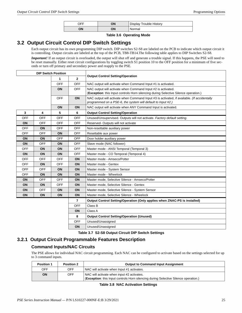
3.2: Output Circuit Control DIP Switch Settings....................................................................................................................................................253.2.1: Output Circuit Programmable Features Description ............................................................................................................................25
Command Inputs/NAC Circuits..............................................................................................................................................................25Unused Outputs.......................................................................................................................................................................................26Remote Supply with Resettable and Non-resettable Power ...................................................................................................................26Door Holder ............................................................................................................................................................................................26Synchronization Mode - Master/Slave ...................................................................................................................................................26Master Mode - Selective Silence ............................................................................................................................................................27Command Input #1 - Normal/Sync Mode of Operation .........................................................................................................................27Class A Wiring........................................................................................................................................................................................28
Section 4: LED Indicators ............................................................................................................................................... 29Section 5: Trouble Supervision...................................................................................................................................... 31
5.1: Trouble Supervision Using Input Circuits .......................................................................................................................................................315.2: Trouble Relay...................................................................................................................................................................................................315.3: AC Trouble Relay ............................................................................................................................................................................................315.4: Ground Fault Relay (Canadian Applications Only).........................................................................................................................................32
Section 6: Power Supply Requirements........................................................................................................................ 336.1: Overview..........................................................................................................................................................................................................336.2: Calculating the AC Branch Circuit ..................................................................................................................................................................336.3: Calculating the System Current Draw .............................................................................................................................................................33
6.3.1: Overview...............................................................................................................................................................................................336.3.2: How to Calculate System Current Draw ..............................................................................................................................................34
6.4: Selecting and Locating Batteries .....................................................................................................................................................................346.4.1: NFPA Battery Requirements ................................................................................................................................................................346.4.2: Maximum Battery Standby Load..........................................................................................................................................................35
Section 7: Testing and Maintenance ............................................................................................................................. 357.1: Periodic Testing and Service............................................................................................................................................................................35
PSE Series Instruction Manual — P/N LS10227-000NF-E:B 3/29/2021 5
Table of Contents
7.2: Battery Checks and Maintenance ....................................................................................................................................................................35
Appendix A: Wire Requirements.................................................................................................................................... 36Appendix B: Application Examples ............................................................................................................................... 37
B.1: Controlling NACs For Selective Silence Operation Using a Control Module ...............................................................................................37B.2: Controlling NACs For Sync Follower Operation Using a Control Module ...................................................................................................38B.3: Controlling NACs, Aux Power, or Door Holders Using a Control Module ...................................................................................................39B.4: Controlling NACs, Aux Power, and Door Holders with NAC Sync ..............................................................................................................40B.5: Controlling all Three Inputs with One Control Module..................................................................................................................................41B.6: AC Trouble Reporting with a Conventional FACP.........................................................................................................................................42B.7: Canadian Two-Stage .......................................................................................................................................................................................43B.8: Canada Two-Stage Application Using XP6-C ................................................................................................................................................44
Index ................................................................................................................................................................................. 45
6 PSE Series Instruction Manual — P/N LS10227-000NF-E:B 3/29/2021
It is imperative that the installer understand the requirements of the Authority Having Jurisdiction (AHJ) and be familiar with the stan-dards set forth by the following regulatory agencies:• Underwriters Laboratories Standards• NFPA 72 National Fire Alarm Code
NFPA StandardsNFPA 72 National Fire Alarm CodeNFPA 70 National Electrical Code
Underwriters Laboratories Documents:UL 464 Audible Signaling AppliancesUL 864 Standard for Control Units for Fire Protective Signaling SystemsUL 1638 Visual Signaling AppliancesUL 1971 Signaling Devices for Hearing ImpairedUL 2572 Standard for Mass Notification Systems
CAN/ULC - S524 Standard for Installation of Fire Alarm SystemsCAN/ULC - S527 Standard for Control Units for Fire Alarm Systems
Other:NEC Article 250 GroundingNEC Article 300 Wiring MethodsNEC Article 760 Fire Protective Signaling SystemsApplicable Local and State Building CodesRequirements of the Local Authority Having Jurisdiction (LAHJ)Canadian Electrical Code, Part 1
Other Notifier Documents:Device Compatibility Document Document #15378SLC Wiring Manual Document #51253CHG-75 Manual Document #51315CHG-120 Manual Document #50641
This product has been certified to comply with the requirements in the Standard for Control Units and Accessories for Fire Alarm Sys-tems, UL 864, 10th Edition. Operation of this product with products not tested for UL 864, 9th/10th Edition has not been evaluated. Such operation requires the approval of the local Authority Having Jurisdiction (AHJ).
This symbol (shown left) on the product(s) and / or accompanying documents means that used electrical and electronic products should not be mixed with general household waste. For proper treatment, recovery and recycling, contact your local authorities or dealer and ask for the correct method of disposal.Electrical and electronic equipment contains materials, parts and substances, which can be dangerous to the environment and harmful to human health if the waste of electrical and electronic equipment (WEEE) is not disposed of correctly.
Before proceeding, the installer should be familiar with the following documents.
PSE Series Instruction Manual — P/N LS10227-000NF-E:B 3/29/2021 7
Section 1: System OverviewThe PSE-6 is a 6 amp and the PSE-10 is a 10 amp remote power supply with battery charger. Both models provide ADA compatible strobe synchronization and a filtered 24 VDC output that can be configured to drive five (6 amp model) or seven (10 amp model) Class B NACs (Notification Appliance Circuits). NAC circuits can be configured for Class A wiring with the optional ZNAC-PS Class A con-verter module. NAC output circuits may be configured as 24 VDC resettable or non-resettable power outputs, or Class D door holder outputs. The input circuits, which control the power supply operation, are triggered by the reverse polarity of a NAC or by a 12 VDC or 24 VDC power source. The PSE power supplies are compatible with 12 VDC and 24 VDC control panels.The PSE-6E and PSE-10E offer the same features as the PSE-6 and PSE-10 respectively, but allow connection to 240 VAC. Unless oth-erwise specified, the information in this manual applies to both the 120 VAC models and the 240 VAC models.The PSE-6C and PSE-10C offer the same features as the PSE-6 and PSE-10 respectively, but are intended for Canadian applications and adds an additional relay for ground fault reporting. Unless otherwise specified, the information in this manual applies to all models.The PSE-6R and PSE-10R offer the same features as the PSE-6 and PSE-10 respectively, but come installed in a red cabinet.
1.1 GeneralPSE power supplies can be used as remotely mounted power supplies and battery chargers to power non-coded or coded NACs. The Main FACP (Fire Alarm Control Panel) NAC(s) is connected to the remote power supply input circuit(s). When the command input cir-cuit activates due to reverse polarity of the NAC from the FACP, the power supply will activate its Notification Appliance Circuits.During the inactive or non-alarm state, the power supply supervises its NAC field wiring for short and open conditions. AC fail, battery, charger and ground fault troubles will also be monitored by the power supply and will activate the AC Fail, Battery Fault, and Ground Fault relay, respectively. If a NAC fault is detected, the input end-of-line will open to indicate the fault to the main panel. If an alarm condition occurs and the NAC is activated, the supervision is disabled and the Notification Appliance Circuit is no longer supervised (except for shorts). Supervision of other power supply faults such as low battery, overcharged battery, ground fault, and bat-tery charger trouble will continue and will be monitored by their respective trouble relays.
1.2 Features• Self-contained in a lockable cabinet• 24 VDC remote power supply• Outputs are completely power-limited (Class 2)• Two (PSE-6) or three (PSE-10) optically-isolated input/command circuits, compatible with 12 VDC and 24 VDC control panel
NACs• Five (PSE-6) or seven (PSE-10) output circuits:
– Fully filtered power– Five or seven 24 VDC Class B NACs – Optional ZNAC-PS Class A converter module for conversion to Class A NACs– Alternatively, all output circuits may be configured as 24 VDC special application power outputs or Class D door holder power
outputs– Output circuits may be configured as resettable or non-resettable
• Individual NAC Power (red) and Trouble (yellow) LEDs for each output• Maximum current available:
– PSE-6: TB8-TB9 – 1A Regulated, 3A special applications; TB10-TB12 – 0.3A Regulated, 3A special applications– PSE-10: TB8-TB11 – 1.5A Regulated, 3A special applications; TB12-TB14 – 0.3A Regulated, 3A special applications
• Maximum total current available (alarm and standby): – 6.0 amps for PSE-6 alarm; 3.0 amps standby– 10.0 amps for PSE-10 alarm; 3.0 amps standby
• Integral supervised battery charger for lead acid batteries only• Capable of charging 7.0 AH - 33.0 AH (Amp Hour) batteries (cabinet fits 7 or 18 AH batteries)• Fully supervised power supply, battery and NACs• Selectable Strobe Synchronization for NACs (System Sensor, Gentex, Wheelock, and Amseco)• Coded signal synchronization• Removable terminal blocks for field wiring capable of accepting 12 - 18 AWG wire• Selectable Ground Fault detection by switch SW1• LED trouble diagnostics and history• Power supply trouble, AC Loss, and Ground Fault (Canadian models only) Form-C relay contacts (fail-safe)• Optional delay of AC loss reporting for 0, 2, 12, or 30 hours• Mounting location for optional addressable module• Up to four PS Series units can be cascaded
1.3 SpecificationsRefer to Figure 1.1 on page 10 for terminal locations.
NOTE: The PSE-6 uses the same PCB layout as the PSE-10, however some terminals will be depopulated, leaving the PSE-6 with five output circuits and two input circuits.
8 PSE Series Instruction Manual — P/N LS10227-000NF-E:B 3/29/2021
Open/Short/Ground Fault Trip Values in Standby System Overview
Primary AC Power - TB4• PSE-6(C): 120 VAC, 50/60 Hz, 5.0 amps maximum• PSE-10(C): 120 VAC, 50/60 Hz, 6.2 amps maximum• PSE-6E: 240 VAC, 50/60 Hz, 2.7 amps maximum• PSE-10E: 240 VAC, 50/60 Hz, 3.5 amps maximum• Wire size: #12-14 AWG wire with 600V insulationCommand Input Circuits - TB5, TB6, TB7• Trigger Input Voltage: 9 - 32 VDC• Input Current Draw in Alarm Polarity: 9 - 32 volts, 14.0 mA maximum per inputOutput Circuits - TB8-TB14• Supervised and power-limited• Voltage Rating: 24 VDC filtered• Current:
– PSE-6: TB8-TB9 – 1A Regulated, 3A special applications; TB10-TB12 – 0.3A Regulated, 3A special applications– PSE-10: TB8-TB11 – 1.5A Regulated, 3A special applications; TB12-TB14 – 0.3A Regulated, 3A special applications– Maximum total alarm current for all output:
PSE-6 - 6.0 ampsPSE-10 - 10.0 amps
• Output Circuit Types:– Class B NACs (require 2kΩ - 27kΩ End-of-Line Resistors) and/or Class A NACs using the optional ZNAC-PS Class A
converter module. Use Listed ELRs supplied by the FACP or compatible equipment manufacturer. – Resettable or non-resettable outputs for 24 VDC power outputs or Class D door holder (max ripple voltage: 780mVRMS)
• Refer to the Notifier Device Compatibility Document #15378 for listed compatible devices.• For wiring requirements, refer to “Wire Requirements” on page 36.Trouble, AC Loss, and Ground Fault (Canadian models only) Relay Contact Rating - TB1-TB3• Fail-safe Form-C relay (normally energized, transfers with loss of power) for AC Loss and Trouble • 4.0 amps @ 30 VDC resistiveSecondary Power (battery) Charging Circuit - TB15• Supervised, non-power-limited• Supports lead acid type batteries only• Float Charge Voltage: 27.6 VDC• Maximum Peak Charge Current: 2.47A• Maximum Nominal Charge Current: 1.5 A• Maximum Battery Capacity: 33.0 AH (with onboard battery charger)• Minimum Battery Capacity: 7.0 AH
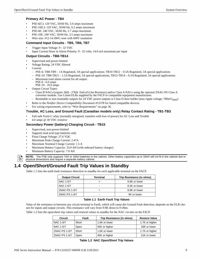
1.4 Open/Short/Ground Fault Trip Values in StandbyTable 1.1 lists the earth fault resistance detection in standby for each applicable terminal on the FACP.
Value of the resistance in between any circuit terminal to Earth, which will cause the Ground Fault detection, depends on the ELR cho-sen for inputs and output circuits. This resistance will vary from 9.9K down to 0 Ohm.Table 1.2 lists the open/short trip values and restoral values in standby for the NAC circuits on the FACP.
NOTE: The PSE only supports 7AH or 18AH batteries in the cabinet. Other battery capacities up to 33AH will not fit in the cabinet due to physical dimensions and require a separate battery cabinet.
Output Circuit Terminal Trip Resistance (in ohms)NAC 1-5/7 + 9.9K or lowerNAC 1-5/7 - 9.2K or lowerZNAC-PS 1-5/7 + 9.9K or lowerZNAC-PS 1-5/7 - 9K or lower
Table 1.1 Earth Fault Trip Values
Circuit Fault Trip Resistance (in ohms) Restore ValueNAC 1-5/7 Short 1.6K or lower 1.7K or higherNAC 1-5/7 Open 55K or higher 33K or lowerZNAC-PS 1-5/7 Short 1.6K or lower 1.7K or higherZNAC-PS 1-5/7 Open 45K or higher 21K or lower
Table 1.2 NAC Open/Short Trip Values
PSE Series Instruction Manual — P/N LS10227-000NF-E:B 3/29/2021 9

System Overview Switch SW1 - Ground Fault Detection
1.5 Switch SW1 - Ground Fault DetectionThe Ground Fault Detection circuit monitors for ground faults. Switch SW1 is located on the lower left section of the power supply cir-cuit board. Sliding SW1 to the left will disable ground fault detection by the power supply. This should only be done if ground faults are being monitored by an FACP connected to the PSE power supply or in a cascading application as shown in Section 2.8 on page 18.
AC1 AC2 TB4
TB15
TB3
TB2
TB1
OU
T 6
OU
T5
OU
T4
OU
T3
OU
T2
OU
T1
Figure 1.1 PSE-10 Board Layout
NAC/Out 7 -NAC/Out 7 +NAC/Out 6 -NAC/Out 6 +NAC/Out 5 -NAC/Out 5 +NAC/Out 4 -NAC/Out 4 +NAC/Out 3 -NAC/Out 3 +NAC/Out 2 -NAC/Out 2 +NAC/Out 1 -NAC/Out 1 +
TB4 AC Power Supervised,Non-power-limited AC2 (Neutral)EarthAC1 (Hot) Form-C Relays
Non-supervised
SW1 Ground Fault Detection(slide left to disable)(slide right to enable)
TB5, TB6, TB7Command InputsInput #1EOL-+EOLInput #2EOL-+EOLInput #3EOL-+EOL
TB15 Supervised+ Battery- Battery24 VDC
Non-power-limitedS2-S8Programming DIP SwitchesActivate output DIP switch changes by setting S1 positions 9 and 10 appropriately. Refer to page 24 for DIP Switch programming settings.Each output circuit has its own dedicated programming DIP switch
J8 ZNAC-PS Connector
Power-limited (Class 2), Supervised, Special Application or Regulated Outputs
LEDsPower (green)
Batt/Chgr Fault (yellow)
Ground Fault (yellow)
Global Options
Output 7 Output 6 Output 5 Output 4 Output 3 Output 2 Output 1
S1Programming DIP Switch for global options
Output Status LEDs Trouble (yellow)Power (red)
Note: The PSE-6 uses the same PCB layout, however some terminals will be depopulated, leaving the PSE-6 with five output circuits and two inputs circuits.
AC Trouble and Trouble relays are Fail-safe, shown energized
(Optional relay for Canadian applications)
10 PSE Series Instruction Manual — P/N LS10227-000NF-E:B 3/29/2021
Applications System Overview
1.6 ApplicationsThe PSE may be used in a number of different applications. It may be used as a remotely-mounted power supply and battery charger where it can provide up to seven coded or non-coded, synchronized or non-synchronized NACs (Notification Appliance Circuits). Alter-natively, any output can be used as a door holder circuit which will provide a steady 24 VDC output until an alarm condition or AC fail condition causes it to drop to 0 VDC following a selectable delay. See the DIP switch settings for S1 global options on page 23. All out-puts can also provide power. One possible application for the PSE remote power supply utilizes the NAC repeater feature. In this application, one or two NACs are connected from the main FACP to the remote power supply command input circuits. When the command input circuits are activated by the reverse polarity of the NACs, the power supply will activate its corresponding output circuits as programmed by its DIP switch con-figuration (refer to Table 3.7 on page 25).During the inactive state, the remote power supply supervises its NAC field wiring for short and open conditions. If a fault is detected, the power supply will enter a trouble condition and illuminate the NAC Trouble LED. When the NACs are activated, the supervision is disabled and the circuits are no longer supervised (except for short circuit conditions). Supervision of other power supply faults such as low battery, battery charger trouble, ground fault and AC loss will continue and may be monitored via their respective trouble relay.If an application requires that all outputs activate at the same time, only one NAC is required from the FACP. For this application, the NAC is connected to command input circuit #1 and the DIP switch is set for this operation.
1.7 Start-up Procedure1. Configure the power supply switch as described in “Switch SW1 - Ground Fault Detection” on page 10.2. Install the power supply as described in “Installation” on page 12.3. Program the power supply as described in “Programming Options” on page 22.4. Wire the power supply circuits, referring to the options described in “Trouble Supervision” on page 31 and the application examples
in “Application Examples” on page 37.5. Connect primary power source wiring while observing the following:
– Ensure the AC mains circuit breaker is off before making any wiring connections between the mains and the power supply.– Make certain primary power source is:
120 VAC, 50/60 Hz, 5.0 (6 amp model) 6.2 amps (10 amp model) or 240 VAC, 50/60 Hz, 2.7 (6 amp model) 3.5 (10 amp model)
– Run a pair of wires (with ground conductor) from the protected premises main breaker box to TB4 of the power supply main circuit board.
– Use #12-14 AWG gauge wire with 600V insulation.6. Apply power to the power supply using the following procedure:
– Apply AC power by turning on the AC mains circuit breaker connected to the power supply.– Connect a properly charged battery to connector TB15 on the power supply main circuit board.
7. Clear trouble history using global DIP switch S1 positions 9 and 10. See DIP switch settings in Table 3.6 on page 24.
PSE Series Instruction Manual — P/N LS10227-000NF-E:B 3/29/2021 11
12 PSE Series Instruction Manual — P/N LS10227-000NF-E:B 3/29/2021
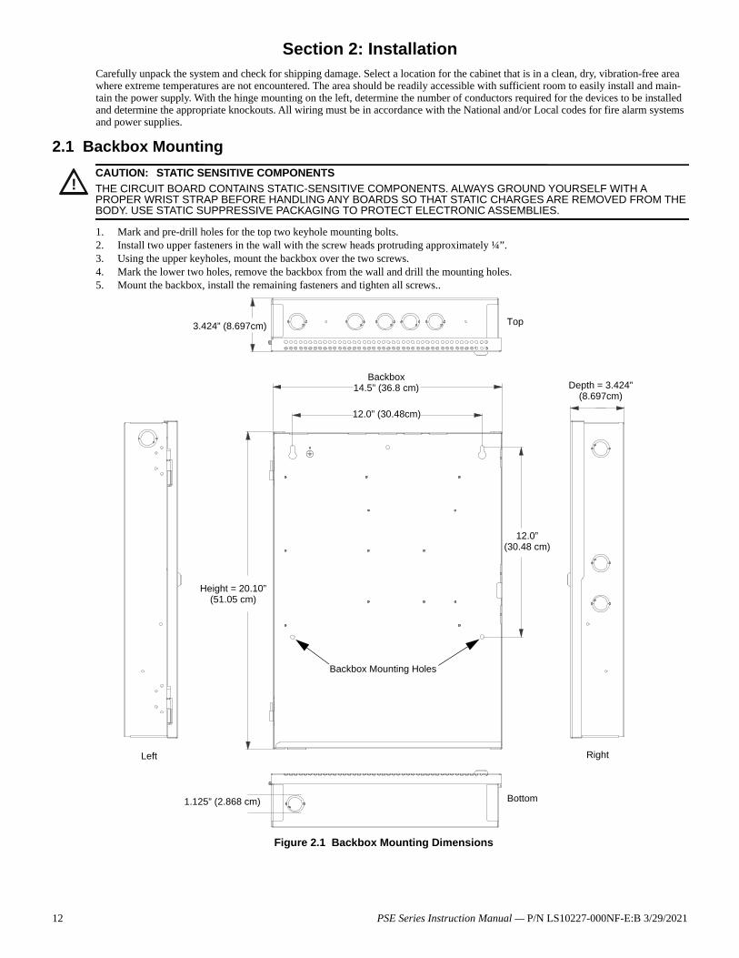
Section 2: InstallationCarefully unpack the system and check for shipping damage. Select a location for the cabinet that is in a clean, dry, vibration-free area where extreme temperatures are not encountered. The area should be readily accessible with sufficient room to easily install and main-tain the power supply. With the hinge mounting on the left, determine the number of conductors required for the devices to be installed and determine the appropriate knockouts. All wiring must be in accordance with the National and/or Local codes for fire alarm systems and power supplies.
2.1 Backbox Mounting
1. Mark and pre-drill holes for the top two keyhole mounting bolts.2. Install two upper fasteners in the wall with the screw heads protruding approximately ¼”.3. Using the upper keyholes, mount the backbox over the two screws.4. Mark the lower two holes, remove the backbox from the wall and drill the mounting holes.5. Mount the backbox, install the remaining fasteners and tighten all screws..
!CAUTION: STATIC SENSITIVE COMPONENTSTHE CIRCUIT BOARD CONTAINS STATIC-SENSITIVE COMPONENTS. ALWAYS GROUND YOURSELF WITH A PROPER WRIST STRAP BEFORE HANDLING ANY BOARDS SO THAT STATIC CHARGES ARE REMOVED FROM THE BODY. USE STATIC SUPPRESSIVE PACKAGING TO PROTECT ELECTRONIC ASSEMBLIES.
Figure 2.1 Backbox Mounting Dimensions
Bottom
Height = 20.10”(51.05 cm)
12.0”(30.48 cm)
3.424” (8.697cm)
Backbox14.5” (36.8 cm) Depth = 3.424”
(8.697cm)
Top
12.0” (30.48cm)
1.125” (2.868 cm)
Backbox Mounting Holes
Left Right
PSE Series Instruction Manual — P/N LS10227-000NF-E:B 3/29/2021 13
NAC Circuit Wiring Installation
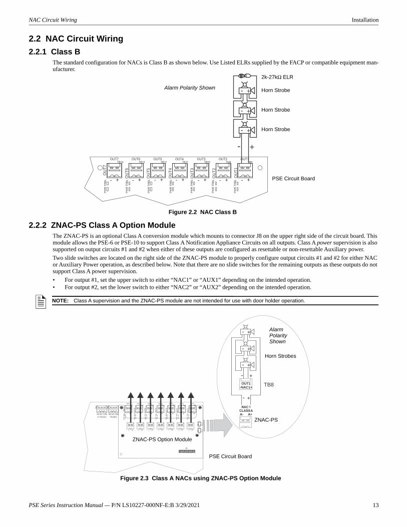
2.2 NAC Circuit Wiring2.2.1 Class B
The standard configuration for NACs is Class B as shown below. Use Listed ELRs supplied by the FACP or compatible equipment man-ufacturer.
2.2.2 ZNAC-PS Class A Option ModuleThe ZNAC-PS is an optional Class A conversion module which mounts to connector J8 on the upper right side of the circuit board. This module allows the PSE-6 or PSE-10 to support Class A Notification Appliance Circuits on all outputs. Class A power supervision is also supported on output circuits #1 and #2 when either of these outputs are configured as resettable or non-resettable Auxiliary power.Two slide switches are located on the right side of the ZNAC-PS module to properly configure output circuits #1 and #2 for either NAC or Auxiliary Power operation, as described below. Note that there are no slide switches for the remaining outputs as these outputs do not support Class A power supervision.• For output #1, set the upper switch to either “NAC1” or “AUX1” depending on the intended operation.• For output #2, set the lower switch to either “NAC2” or “AUX2” depending on the intended operation.
+-
+-
+-
+-O
UT6
OU
T5
OU
T4
OU
T3
OU
T2
OU
T1
Figure 2.2 NAC Class B
2k-27kΩ ELR
Horn Strobe
Horn Strobe
Horn Strobe
Alarm Polarity Shown
PSE Circuit Board
NOTE: Class A supervision and the ZNAC-PS module are not intended for use with door holder operation.
OUT1-NAC1+ TB8
+
+
-
-
+-
+-
+-
NAC1
AUX1NAC2
AUX2
TB2
T B1
OU
T 6
OU
T5
OU
T4
OU
T3
OU
T2
OU
T1
Figure 2.3 Class A NACs using ZNAC-PS Option Module
ZNAC-PS Option Module
Horn Strobes
ZNAC-PS
Alarm Polarity Shown
PSE Circuit Board
14 PSE Series Instruction Manual — P/N LS10227-000NF-E:B 3/29/2021
Installation Addressable Module Mounting
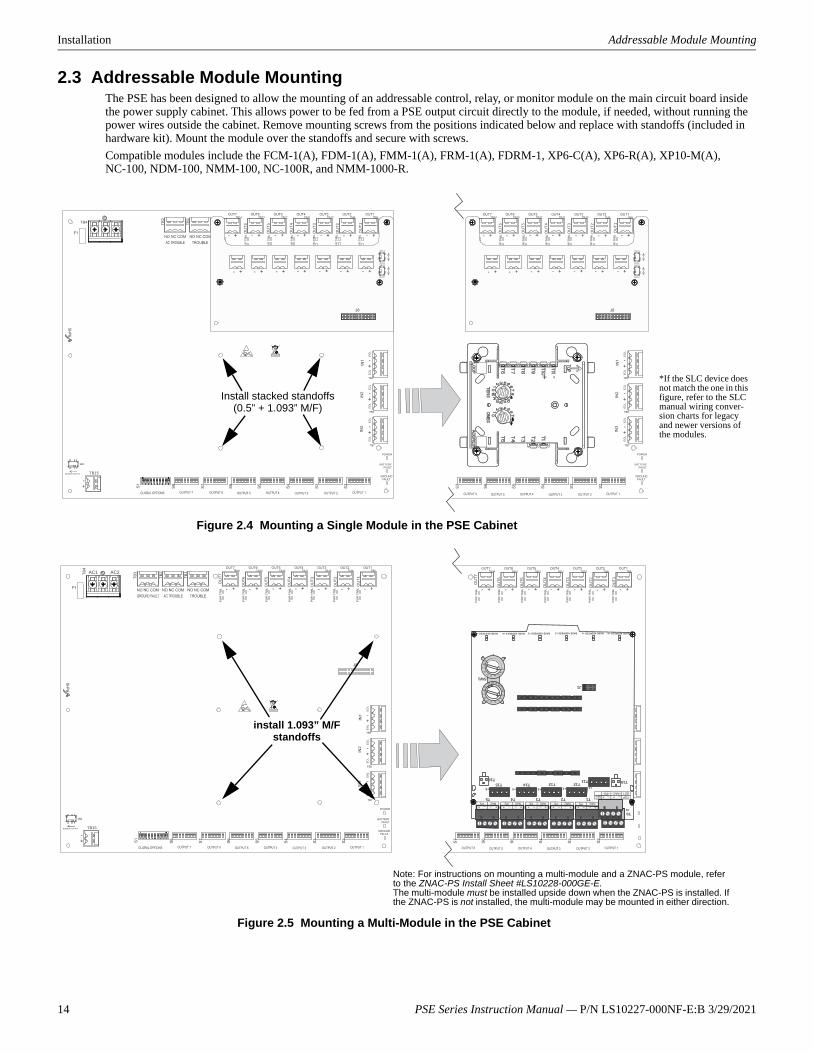
2.3 Addressable Module MountingThe PSE has been designed to allow the mounting of an addressable control, relay, or monitor module on the main circuit board inside the power supply cabinet. This allows power to be fed from a PSE output circuit directly to the module, if needed, without running the power wires outside the cabinet. Remove mounting screws from the positions indicated below and replace with standoffs (included in hardware kit). Mount the module over the standoffs and secure with screws. Compatible modules include the FCM-1(A), FDM-1(A), FMM-1(A), FRM-1(A), FDRM-1, XP6-C(A), XP6-R(A), XP10-M(A), NC-100, NDM-100, NMM-100, NC-100R, and NMM-1000-R.
TB4
TB15
TB2
TB1
OU
T6
OU
T5
OU
T4
OU
T3
OU
T2
OU
T1
NAC1
AUX1NAC2
AUX2
OU
T6
OU
T5
OU
T4
OU
T3
OU
T2
OU
T1
NAC1
AUX1NAC2
AUX2
*If the SLC device does not match the one in this figure, refer to the SLC manual wiring conver-sion charts for legacy and newer versions of the modules.
Figure 2.4 Mounting a Single Module in the PSE Cabinet
Install stacked standoffs (0.5” + 1.093” M/F)
– +
–+– +–+– +–+– +–+– +–+
–+–+
T10
J1
BASEADDRESS+0BASEADDRESS+1BASEADDRESS+2BASEADDRESS+3BASEADDRESS+4BASEADDRESS+5
SW1
T1
+1
+0
+2+3+4+5
T0
T2T3T4T5
T11T12T13T14T15
T16
01
23456
78
9 10 11 1314
15
12
01
23456
78
9
AC1 AC2 TB4
TB15
TB3
TB2
TB1
OU
T6
OU
T 5
OU
T4
OU
T 3
OU
T2
OU
T1
OU
T6
OU
T5
OU
T4
OU
T3
OU
T2
OU
T1
install 1.093” M/F standoffs
Note: For instructions on mounting a multi-module and a ZNAC-PS module, refer to the ZNAC-PS Install Sheet #LS10228-000GE-E.The multi-module must be installed upside down when the ZNAC-PS is installed. If the ZNAC-PS is not installed, the multi-module may be mounted in either direction.
Figure 2.5 Mounting a Multi-Module in the PSE Cabinet
PSE Series Instruction Manual — P/N LS10227-000NF-E:B 3/29/2021 15
NEC Power-limited (Class 2) Wiring Requirements Installation
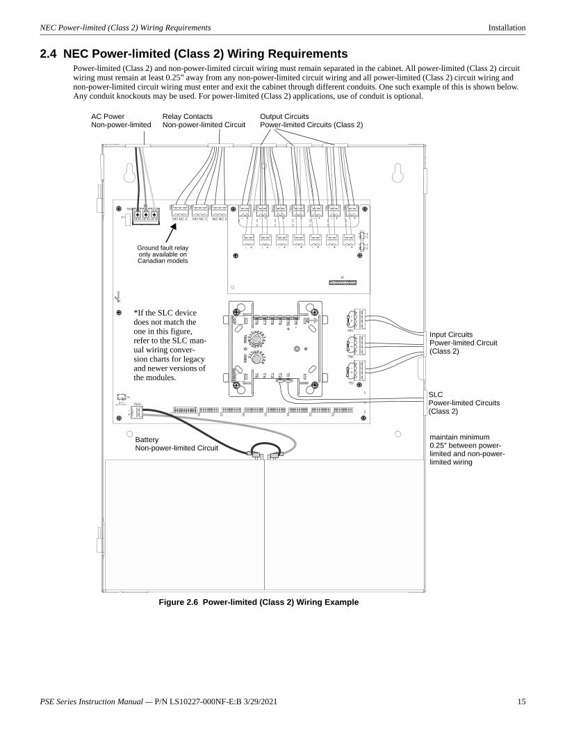
2.4 NEC Power-limited (Class 2) Wiring RequirementsPower-limited (Class 2) and non-power-limited circuit wiring must remain separated in the cabinet. All power-limited (Class 2) circuit wiring must remain at least 0.25” away from any non-power-limited circuit wiring and all power-limited (Class 2) circuit wiring and non-power-limited circuit wiring must enter and exit the cabinet through different conduits. One such example of this is shown below. Any conduit knockouts may be used. For power-limited (Class 2) applications, use of conduit is optional.
NO NC C NO NC C
TB4
TB15
TB2
TB1
TB13
TB12
TB11
T B10
TB9
TB8
NO NC C
TB3
NAC1
AUX1NAC2
AUX2
Figure 2.6 Power-limited (Class 2) Wiring Example
AC PowerNon-power-limited
Output CircuitsPower-limited Circuits (Class 2)
Relay ContactsNon-power-limited Circuit
Input CircuitsPower-limited Circuit (Class 2)
SLCPower-limited Circuits(Class 2)
*If the SLC device does not match the one in this figure, refer to the SLC man-ual wiring conver-sion charts for legacy and newer versions of the modules.
maintain minimum 0.25” between power-limited and non-power-limited wiring
Ground fault relay only available on Canadian models
BatteryNon-power-limited Circuit
16 PSE Series Instruction Manual — P/N LS10227-000NF-E:B 3/29/2021
Installation FACP with PSE Power Supply in Slave Mode
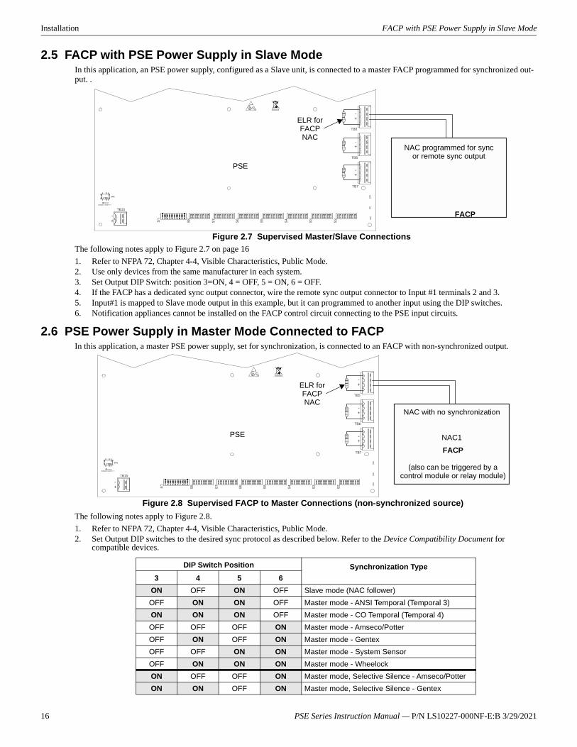
2.5 FACP with PSE Power Supply in Slave ModeIn this application, an PSE power supply, configured as a Slave unit, is connected to a master FACP programmed for synchronized out-put. .
The following notes apply to Figure 2.7 on page 161. Refer to NFPA 72, Chapter 4-4, Visible Characteristics, Public Mode.2. Use only devices from the same manufacturer in each system.3. Set Output DIP Switch: position 3=ON, 4 = OFF, 5 = ON, 6 = OFF.4. If the FACP has a dedicated sync output connector, wire the remote sync output connector to Input #1 terminals 2 and 3. 5. Input#1 is mapped to Slave mode output in this example, but it can programmed to another input using the DIP switches.6. Notification appliances cannot be installed on the FACP control circuit connecting to the PSE input circuits.
2.6 PSE Power Supply in Master Mode Connected to FACPIn this application, a master PSE power supply, set for synchronization, is connected to an FACP with non-synchronized output.
The following notes apply to Figure 2.8.1. Refer to NFPA 72, Chapter 4-4, Visible Characteristics, Public Mode.2. Set Output DIP switches to the desired sync protocol as described below. Refer to the Device Compatibility Document for
compatible devices.
TB15
PSE
FACP
NAC programmed for sync or remote sync output
ELR for FACP NAC
Figure 2.7 Supervised Master/Slave Connections
DIP Switch Position Synchronization Type3 4 5 6
ON OFF ON OFF Slave mode (NAC follower)OFF ON ON OFF Master mode - ANSI Temporal (Temporal 3)ON ON ON OFF Master mode - CO Temporal (Temporal 4)OFF OFF OFF ON Master mode - Amseco/PotterOFF ON OFF ON Master mode - GentexOFF OFF ON ON Master mode - System SensorOFF ON ON ON Master mode - WheelockON OFF OFF ON Master mode, Selective Silence - Amseco/PotterON ON OFF ON Master mode, Selective Silence - Gentex
TB15
PSE
Figure 2.8 Supervised FACP to Master Connections (non-synchronized source)
FACP
(also can be triggered by a control module or relay module)
NAC with no synchronization
NAC1
ELR for FACP NAC
PSE Series Instruction Manual — P/N LS10227-000NF-E:B 3/29/2021 17
Connecting to an External Charger Installation
3. Use only devices from the same manufacturer in each zone or field of view.4. Input#1 is mapped to Master mode output in this example, but it can programmed to another input using the DIP switches.5. Notification appliances cannot be installed on the FACP control circuit connecting to the PSE input circuits.
2.7 Connecting to an External ChargerThe PSE Power Supply can be connected to an external charger to charge systems requiring over 33AH batteries. Ensure all power has been disconnected before wiring. Observe polarity when making connections. Wiring must be in conduit within 20 feet (6.096m) in the same room.
2.7.1 CHG-1201. Set S1 position 4 on the PSE Power Supply to the OFF position to disable the onboard battery charger.2. Connect the battery cables between TB15 (+ and –) on the PSE and the CHG-120 charger output circuit (TB2: Out 1+ and Out 1–)
as shown in Figure 2.9. Be certain to observe polarity.3. Connect the batteries to the charger.4. Connect the battery interconnect cable only after AC power is applied and batteries are connected. Refer to the CHG-120 Manual
for more information.
2.7.2 CHG-751. Set S1 position 4 on the PSE Power Supply to the OFF position to disable the onboard battery charger.2. Connect the battery cables between TB15 (+ and –) on the PSE and the CHG-75 charger output circuit (TB2: Out+ and Out–) as
shown in Figure 2.10. Be certain to observe polarity.3. Connect the batteries to the charger.4. Connect the battery interconnect cable only after AC power is applied and batteries are connected. Refer to the CHG-75 Manual for
more information.
ON OFF ON ON Master mode, Selective Silence - System SensorON ON ON ON Master mode, Selective Silence - Wheelock
– + – +
TB1
–+–+–+
NO NC C NO NC C
TB4
TB15
TB2
TB1
T B13
OU
T6
TB12
OU
T5
TB11
OU
T4
TB10
OU
T3
TB9
OU
T2
T B8
OU
T1
TB2
CHG-120Charger
PS Series Power Supply
Set S1 position 4 to the OFF position to
disable chargerBattery interconnect cable
12V battery12V battery
Figure 2.9 Connecting the Power Supply to a CHG-120 Charger
Note: If batteries are disconnected at the CHG-120 terminals, battery supervision will be managed by the CHG-120
- +- +
JP1
SW1
TB3 TB4
TB2
TENS
ONES
CUT FOR240VAC
ADDRESS
ON OFF
AM-1F1
J4
J1 J2 J3
TB1HOT
OUT
+B
AT +
OUT
-B
AT -
EAR
THN
EUT
A- B- A+ B+ NC NO C
0
4 39 261
5 78
1213
15
141011
0
4 39 261
5 78
1213
15
141011
TB2CHG-75Charger PS Series Power Supply
Set S1 position 4 to the OFF position to
disable chargerBattery interconnect cable
12V battery
12V battery
Figure 2.10 Connecting the Power Supply to a CHG-75 Charger
+-+-
-+
18 PSE Series Instruction Manual — P/N LS10227-000NF-E:B 3/29/2021
Installation Cascading Multiple Units
2.8 Cascading Multiple UnitsUp to four PSE power supplies can be cascaded together to provide additional NAC extenders for a system. Maintain separation of power-limited and non-power-limited wiring as shown in Figure 2.6 on page 15.Figures 2.11 and 2.12 show the controlling signal connected to Input 1 of PSE1. However, typically any available Input of PSE1 can be used. Figures 2.11 and 2.12 show NAC7 of PSE1 - PSE3 as the cascading output. However, any available Output of PSE1 – PSE3 can be used.
The following notes apply to Figure 2.11.1. Set all PSE units to Slave (sync follower) mode.2. The debounce/dejitter setting must be set to 1 msec on all cascaded units. See Table 3.3 on page 23. 3. Any output used for remote sync applications cannot have notification appliances installed on the same circuit.4. Notification appliances cannot be installed on the interconnecting control circuits.5. The total line impedance for interconnected units cannot be such that it creates a voltage drop > 3.2 VDC. 6. Ground fault supervision is provided via the general trouble relay for domestic and export models and via the dedicated ground
fault relay in the Canadian models. Enable ground fault detection on PSE1 and disable detection on PSE2-4 with negative (-) battery terminals tied together. FACP ground fault supervision will be independent of cascaded PSE1-4. (FACP negative battery terminal is not tied to PSE1).
The following notes apply to Figure 2.12.1. Set PSE1 to Master Mode, and the desired strobe/horn type. Set remaining PSE units to Slave (sync follower) mode.2. The debounce/dejitter setting must be set to 1 msec on PSE2 – PSE4 units. See Table 3.3 on page 23. 3. Strobe/Horn devices connected to the PSE units are not guaranteed to be in sync with FACP devices when using this configuration4. Any output used for remote sync applications cannot have notification appliances installed on the same circuit.5. Notification appliances cannot be installed on the interconnecting control circuits.6. The total line impedance for interconnected units cannot be such that it creates a voltage drop > 3.2 VDC. 7. Ground fault supervision is provided via the general trouble relay for domestic and export models and via the dedicated ground
fault relay in the Canadian models. Enable ground fault detection on PSE1 and disable detection on PSE2-4 with negative (-) battery terminals tied together. FACP ground fault supervision will be independent of cascaded PSE1-4. (FACP negative battery terminal is not tied to PSE1).
NOTE: Any mode of operation that requires an additional control signal (i.e. a trigger signal), such as Selective Silence or Sync Mode, will affect which Inputs may be available on PSE1 for use with cascading. (Triggers signals are usually assigned to Input 2.) Refer to those sections of the manual for specifics.
NO NC C NO NC C NO NC C
TB4
TB15
TB3
TB2
TB1
TB13
OU
T6
TB12
OUT
5
TB11
OUT
4
TB10
OU
T3
TB9
OU
T2
TB8
OU
T1
NO NC C NO NC C NO NC C
TB4
TB15
TB3
TB2
TB1
TB13
OU
T6
TB12
OUT
5
TB11
OUT
4
TB10
OU
T3
TB9
OU
T2
TB8
OU
T1
NO NC C NO NC C NO NC C
TB4
TB15
TB3
TB2
TB1
TB13
OU
T6
TB12
OUT
5
TB11
OUT
4
TB10
OU
T3
TB9
OU
T2
TB8
OU
T1
NO NC C NO NC C NO NC C
TB4
TB15
TB3
TB2
TB1
TB1 3
OU
T6
TB12
OUT
5
TB11
OUT
4
TB10
OU
T3
TB9
OU
T2
TB8
OU
T1
FACP
NAC or remote sync output
Figure 2.11 System Sync Connections Triggered by FACP
PSE1PSE2PSE3PSE4PSE4
NO NC C NO NC C NO NC C
TB4
TB15
TB3
TB2
TB1
TB13
OU
T6
TB12
OU
T5
T B11
OU
T4
TB10
OU
T3
TB9
OU
T2
TB8
OU
T1
NO NC C NO NC C NO NC C
TB4
TB15
TB3
T B2
TB1
TB13
OU
T6
TB12
OU
T5
TB11
OU
T4
TB10
OU
T3
TB9
OU
T2
TB8
OU
T1
NO NC C NO NC C NO NC C
TB4
TB15
TB3
TB2
TB1
TB13
OU
T6
TB12
OU
T5
TB11
OU
T4
TB10
OU
T3
TB9
OU
T2
TB8
OU
T1
NO NC C NO NC C NO NC C
TB4
TB15
TB3
TB2
TB1
TB13
OU
T6
TB12
OU
T 5
TB11
OU
T4
TB10
OU
T3
TB9
OU
T2
TB8
OU
T 1
FACP
SLC
Figure 2.12 System Sync Connections Triggered by Control Module
Control Module
Regulated 24VDC UL864 listed power supply
PSE1PSE2PSE3PSE4
PSE Series Instruction Manual — P/N LS10227-000NF-E:B 3/29/2021 19
Canadian Applications Installation
2.9 Canadian ApplicationsInstallation shall be in accordance with ULC S524. Wiring methods shall be in accordance with CSA C22.1, Safety Standard for Electri-cal Installations, Canadian Electrical Code, Part I, Section 32.
Canadian applications, per ULC, require the following:• Connect the AC ground wire to the Ground Stud located at the top left of the backbox as shown below. Connect the incoming earth
ground wire to supplied cable #71073 with a wire nut. Position the ring terminal end over the grounding stud. Secure with one of the keps nuts. Place the ring terminal from the other supplied ground cable #71073 over the ground stud and secure with the second keps nut. Wire the ground cable to the middle position of TB4. Ensure that the ground for incoming AC mains is the first wire installed, closest to the backbox. This connection is vital in reducing the panel’s susceptibility to transients generated by lightning and electrostatic discharge. Apply AC power to the panel only after the system is completely installed and visually checked. Note that AC power must be applied to the panel before installing the battery interconnect cable.
• Refer to Section 5.1 for instructions to meet ULC requirements for trouble monitoring of each zone.
NOTE: Mass Notification is not for use in Canadian applications.
grounding stud
Grounding Cable#71073
keps nut
keps nut
Figure 2.13 Earth Ground Connection
20 PSE Series Instruction Manual — P/N LS10227-000NF-E:B 3/29/2021
Installation Canadian Applications
Ground Fault DetectionWhen connected to an FACP, the host FACP must monitor for all ground fault conditions. There are three ways to monitor for ground faults when cascading multiple power supply units (up to four).
The negative (-) battery terminal of the PSE power supply must be connected to the negative (-) battery terminal of the host FACP. Battery wiring is non-power-limited. Power-limited and non-power-limited wiring must be wired with a minimum of 0.25” spacing in between and enter/exit through different knockouts. When cascading multiple power supply units, continue connecting the negative battery terminals, including FACP battery terminal. Ground faults must then be detected by the first PSE in the chain. Disable ground fault detection on other PSE units by sliding SW1 to the left. Ensure ground fault detection is enabled on PSE1, the first power supply from the FACP, by sliding SW1 to the right. 18 AWG wire minimum must be used.
NO NC C NO NC C
TB4
TB15
NO NC C
TB3
TB2
TB1
TB13
TB12
TB11
TB10
TB9
T B8
NAC1
AUX1NAC2
AUX2
Host FACP Power Supply
optional ZNAC-PS converter
card
SW1 ground fault detection switch
wire nut, ground cables, and ground stud
Figure 2.14 Canadian Applications Option 1
Battery - Battery -
to next negative battery terminal
PSE Series Instruction Manual — P/N LS10227-000NF-E:B 3/29/2021 21
Canadian Applications Installation
Ground fault monitoring may be accomplished by mapping an annunciator point on a ULC S527-listed FACP as ground fault. The annunciator shall be wired adjacent to the FACP so all displays are grouped for viewing and operation by one person.Addressable FACP: The FACP must be programmed to turn on the common trouble LED, trouble tone, and a separate yellow annunciator point when the monitor module connected to the PSE ground fault relay is initiated. The annunciator point must also be labeled as “XXX Ground Fault” where “XXX” describes ground fault origin.
Conventional FACP: The FACP must be programmed to turn on the common trouble LED, trouble tone, and a separate yellow annunciator point when the input connected to the PSE ground fault relay is initiated. Use one input per PSE power supply.
NO NC C NO NC C
TB4
TB15
NO NC C
TB3
TB2
TB1
TB13
TB12
TB11
TB10
TB9
TB8
NAC1
AUX1NAC2
AUX2
NO NC C NO NC C
TB4
TB15
NO NC C
TB3
TB2
TB1
TB13
TB12
T B11
TB10
TB9
TB8
NAC1
AUX1NAC2
AUX2
ULC S527-listed addressable control
panel
ULC S527-listed annunciator
SLC-+
Figure 2.15 Canadian Applications Option 2 - Addressable FACP
Maintain 0.25” spacing between power-limited and non-power-limited wiring.
to next monitor module
NO NC C NO NC C
TB4
TB15
NO NC C
TB3
TB2
TB1
TB13
TB12
TB11
TB10
TB9
T B8
NAC1
AUX1NAC2
AUX2
NO NC C NO NC C
TB4
TB15
NO NC C
TB3
TB2
TB1
TB13
TB12
TB11
TB10
TB9
TB8
NAC1
AUX1NAC2
AUX2 ULC S527-listed conventionalcontrol panel
ULC S527-listed annunciator
Input 1
Figure 2.16 Canadian Applications Option 3 - Conventional FACP
Maintain 0.25” spacing between power-limited and non-power-limited wiring.
Input 2
22 PSE Series Instruction Manual — P/N LS10227-000NF-E:B 3/29/2021
Section 3: Programming Options
This section describes the programming options available via DIP switch settings. The PSE can be field programmed using DIP switches S1-S8 which are located at the bottom of the circuit board. S1 controls the global options of the power supply and S2-S8 control the functions of each output circuit, respectively. Refer to the following illustration for switch locations and DIP switch placement in the ON and OFF positions.Important: Activate output DIP switch changes by setting S1 positions 9 and 10 appropriately. Refer to Table 3.6 on page 24 for DIP Switch programming settings.
NOTICE TO USERS, INSTALLERS, AUTHORITIES HAVING JURISDICTION AND OTHER INVOLVED PARTIES
This product incorporates field-programmable software. In order for the product to comply with the requirements in the Standard for Control Units and Accessories for Fire Alarm Systems, UL 864, certain programming features or options must be limited to specific values or not used at all as indicated below:
Program feature or option
Permitted in UL864/2572 and ULC S527? (Y/N)
Possible settingsSettings
permitted inUL 864/ UL2572
Settings permitted inULC S527
Door Holder Dropout Delay
Y Refer to “AC Loss Door Holder Dropout Timer” on page 24.• Does not drop• 15 seconds• 5 minutes• 60 seconds
• Does not drop• 15 seconds• 60 seconds• 5 minutes
• Does not drop• 15 seconds• 60 seconds• 5 minutes
AC Loss Delay Timer Y Refer to “AC Fail Indication Delay” on page 24.• 30 hours• 12 hours• 2 hours• none
• 2 hours1
• none
1 A two hour delay is only permitted on an addressable FACP.
• 2 hours• none
Table 3.1 Agency-Permitted Programming Settings
ON
1 2 3 4 5 6 7 8 9 10
ON
1 2 3 4 5 6 7 8
TB15
Switches 1 through 7 shown in OFF (Open) position
Switch 8 shown in ON (Closed) position
Figure 3.1 Field Programming DIP Switches
Switch 10 shown in ON (Closed) position
Switches 1 through 9 shown in OFF (Open) position
S1 S2-S8
PSE Series Instruction Manual — P/N LS10227-000NF-E:B 3/29/2021 23
S1 Global Options DIP Switch Programming Options
3.1 S1 Global Options DIP SwitchThe following table lists the global control options for the PSE programmable features and the switch settings required to select a partic-ular feature. A detailed description of each feature is presented in the following pages. Refer to Table 3.1 for UL-compliant settings.
3.1.1 Global Programmable Features DescriptionInput Debounce/Dejitter/DelaySignals from electronic circuits or relay contacts can have a small unstable time when changing state (OFF to ON, or ON to OFF). This means the signal can briefly “bounce” between states before stabilizing to the desired state, causing signal “jitter” during this time. The PSE provides four “debounce/dejitter” settings, as shown in the table below. These settings provide time for a NAC Input signal to stabi-lize before that NAC Input will recognize it as a valid signal, and not just “noise”, so as to prevent false activation of Output circuits. Input debounce settings can be used as needed. Unless the system experiences input “noise” issues, apply 1ms setting for general use.
S1 DIP Switch OFF ON1, 2 These switches determine the command input debounce/dejitter setting (Setting applies to ALL inputs)1.
1 OFF, 2 OFF = Temporal (for ANSI temporal signals) 1 ON, 2 OFF = 50Hz (20 msec, for full wave rectified signals) 1 OFF, 2 ON = 6 msec (for strobe sync signals, control/relay modules) 1 ON, 2 ON = 1 msec (for strobe sync signals, control/relay modules)
3 Command Input #1 configured for Slave Mode Sync2 input3 Command Input #1 configured as normal4 Internal battery charger = disabled Internal battery charger = enabled
5, 6 These switches determine door holder dropout delay after AC power loss 5 OFF, 6 OFF= Power does not drop out 5 ON, 6 OFF = 5 minutes 5 OFF, 6 ON = 60 seconds 5 ON, 6 ON = 15 seconds
7, 8 These switches determine the AC loss delay timer 7 OFF, 8 OFF = 30 hours 7 ON, 8 OFF = 12 hours 7 OFF, 8 ON = 2 hours 7 ON, 8 ON = none
9, 10 These switches determine the operating mode of the power supply.Return switches to normal mode to exit change output circuit configurations and display trouble history modes! 9 OFF, 10 OFF = normal 9 ON, 10 OFF = change output circuit configurations 9 OFF, 10 ON = display trouble history 9 ON, 10 ON = normal
Table 3.2 S1 Global Options DIP Switch Settings1 Debounce/dejitter provides settling time for input signals to avoid false triggers.2 Strobe synchronization only works with non-coded NACs.3 Output circuit(s) must be set to activate on Input #2. See, "Command Input #1" below.
Position 1 Position 2 Setting NotesOFF OFF Temporal Debounces ANSI temporal signals. Allows for a 0.5 second ON signal with
an almost 2 second OFF signal to trigger a continuous ON input signal. Do not use for strobe sync signals.
ON OFF 50Hz (20msec) Debounces FWR (full wave rectified signals). Allows an input signal with 50Hz, 33% duty cycle to trigger a continuous (i.e. filters FWR input signal to appear constantly on) ON input signal. May apply to legacy panels. Do not use for strobe sync signals.
OFF ON 6 msec Input delay for strobe sync signals (i.e. Slave mode using sync input), or control/relay modules (i.e. Master or Aux. power mode using trigger input).
ON ON 1 msec Input delay for strobe sync signals (i.e. Slave mode using sync input), or control/relay modules (i.e. Master or Aux. power mode using trigger input). Must be the only one used when cascading Power Strike units. Refer to Section 2.8, “Cascading Multiple Units”, on page 18.
Table 3.3 Debounce/Dejitter Settings
24 PSE Series Instruction Manual — P/N LS10227-000NF-E:B 3/29/2021
Programming Options S1 Global Options DIP Switch
Command Input #1Power supply Output circuits can be configured to “follow” a sync pattern that is input to Command Input #1 (TB5), either immediately (Normal Mode), or only after a trigger signal (Sync Input Mode) is applied at Command Input #2 (TB6). In Sync Input Mode an output circuit will only output the Command Input #1 sync pattern when Command Input #2 is receiving a valid (9V - 32V) trigger signal. See “Command Input #1 - Normal/Sync Mode of Operation” on page 27 for additional information.
Charger Enable/DisableThe PSE battery charger can be disabled to accommodate an external battery charger, such as the CHG-75 or CHG-120. Setting DIP switch position 4 to the OFF position will disable the charger. Setting DIP switch position 4 to the ON position will enable the charger. It should only be disabled if an external battery charger is being used for the PSE.
AC Loss Door Holder Dropout TimerAny output can be configured as a NAC, aux power, or door closer circuit. Configuring an output circuit as a door closer circuit will pro-vide a steady 24 VDC to door holders until an alarm condition or an AC fail condition. Upon an alarm condition, power to door holder circuits will be removed, causing doors to close immediately. During an AC fail condition, the door holder will remain energized until the programmed AC fail indication delay expires. Programmed delays are only applicable to AC loss conditions. Refer to Table 3.1 for UL-compliant settings. DIP switch positions 5 and 6 are used to select the door holder dropout timer as listed below:
AC Fail Indication DelayThe AC Fail Indication Delay feature provides the option to delay generation of a trouble signal upon the loss of AC power. Refer to Table 3.1 for UL-compliant settings. DIP switch positions 7 and 8 are used to select the AC Fail Indication Delay as listed below:
Refer to “AC Trouble Relay” on page 31, for operation of internal NAC trouble relay in response to AC loss.
Special Operating ModesThe power supply can be placed in two special operating modes per settings in Table 3.6. They are Change Output Circuit Configura-tions and Display Trouble History. Upon completion of either of these two modes, the system must be placed back in normal operating mode. Note that the current operation of all outputs will not be affected or disturbed while in either of these two special operating modes.Change Output Circuit Configurations mode:
1. Enter this mode via the setting shown in Table 3.6. Once entered, the Output trouble LEDs will continually flash from right to left to confirm the PSE is in Change Output Configuration mode.
2. Configure settings on the Output DIP switches as needed (see Note above).3. Return to Normal Operating mode via either of the two settings shown in Table 3.6. The output trouble LEDs will stop the flash
pattern described above to confirm Normal mode has been restored.The PSE power supply offers a trouble history mode. To see past troubles on the system, place position 9 to OFF and position 10 to ON. Refer to Section 4 for descriptions of troubles. Trouble history will be erased upon returning to Normal operating mode.DIP switch positions 9 and 10 are used to select the type of operating mode as listed below:
Position 5 Position 6 Door holder dropout delay after AC lossOFF OFF Power does not drop out with AC lossON OFF 5 minutesOFF ON 60 secondsON ON 15 seconds
Table 3.4 Door Holder Dropout Settings
Position 7 Position 8 AC Fail Indication DelayOFF OFF 30 hoursON OFF 12 hoursOFF ON 2 hoursON ON none
Table 3.5 AC Loss Delay Settings
NOTE: DIP switch settings may be changed to the desired configuration either before or after entering Change Output Circuit Configurations mode.
Position 9 Position 10 Operating ModeOFF OFF NormalON OFF Change output circuit configurations
Table 3.6 Operating Mode
PSE Series Instruction Manual — P/N LS10227-000NF-E:B 3/29/2021 25
Output Circuit Control DIP Switch Settings Programming Options
3.2 Output Circuit Control DIP Switch SettingsEach output circuit has its own programming DIP switch. DIP switches S2-S8 are labeled on the PCB to indicate which output circuit it is controlling. Output circuits are labeled at the top of the PCB, TB8-TB14.The following table applies to DIP Switches S2-S8.Important! If an output circuit is overloaded, the output will shut off and generate a trouble signal. If this happens, the PSE will need to be reset manually. Either reset circuit configurations by toggling switch S1 position 10 to the OFF position for a minimum of five sec-onds or turn off primary and secondary power and reapply to the PSE.
3.2.1 Output Circuit Programmable Features DescriptionCommand Inputs/NAC CircuitsThe PSE allows for individual NAC circuit programming. Each NAC can be configured to activate based on the settings selected for up to 3 command inputs.
OFF ON Display Trouble History ON ON Normal
Table 3.6 Operating Mode
DIP Switch PositionOutput Control Setting/Operation
1 2OFF OFF NAC output will activate when Command Input #1 is activated.ON OFF NAC output will activate when Command Input #2 is activated.
(Exception: this Input controls Horn silencing during Selective Silence operation.)OFF ON NAC output will activate when Command Input #3 is activated, if available. (If accidentally
programmed on a PSE-6, the system will default to Input #2.)ON ON NAC output will activate when ANY Command Input is activated.
3 4 5 6 Output Control Setting/OperationOFF OFF OFF OFF Unused/Unsupervised. Outputs will not activate. Factory default setting.ON OFF OFF OFF Reserved- Outputs will not activateOFF ON OFF OFF Non-resettable auxiliary powerOFF OFF ON OFF Resettable aux powerON ON OFF OFF Door holder auxiliary powerON OFF ON OFF Slave mode (NAC follower)OFF ON ON OFF Master mode - ANSI Temporal (Temporal 3)ON ON ON OFF Master mode - CO Temporal (Temporal 4)OFF OFF OFF ON Master mode - Amseco/PotterOFF ON OFF ON Master mode - GentexOFF OFF ON ON Master mode - System SensorOFF ON ON ON Master mode - WheelockON OFF OFF ON Master mode, Selective Silence - Amseco/PotterON ON OFF ON Master mode, Selective Silence - GentexON OFF ON ON Master mode, Selective Silence - System SensorON ON ON ON Master mode, Selective Silence - Wheelock
7 Output Control Setting/Operation (Only applies when ZNAC-PS is installed)OFF Class BON Class A
8 Output Control Setting/Operation (Unused)OFF Unused/UnassignedON Unused/Unassigned
Table 3.7 S2-S8 Output Circuit DIP Switch Settings
Position 1 Position 2 Output to Command Input AssignmentOFF OFF NAC will activate when Input #1 activates.ON OFF NAC will activate when input #2 activates.
(Exception: this Input controls Horn silencing during Selective Silence operation.)
Table 3.8 NAC Activation Settings
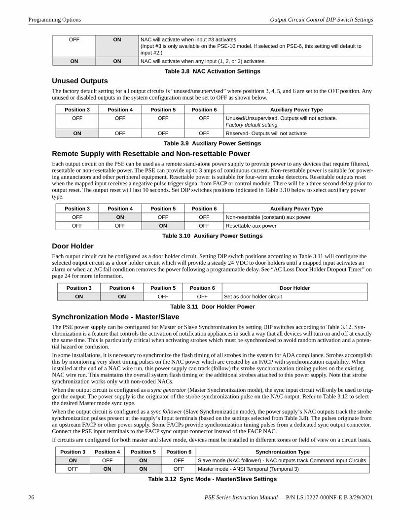
26 PSE Series Instruction Manual — P/N LS10227-000NF-E:B 3/29/2021
Programming Options Output Circuit Control DIP Switch Settings
Unused OutputsThe factory default setting for all output circuits is “unused/unsupervised” where positions 3, 4, 5, and 6 are set to the OFF position. Any unused or disabled outputs in the system configuration must be set to OFF as shown below.
Remote Supply with Resettable and Non-resettable PowerEach output circuit on the PSE can be used as a remote stand-alone power supply to provide power to any devices that require filtered, resettable or non-resettable power. The PSE can provide up to 3 amps of continuous current. Non-resettable power is suitable for power-ing annunciators and other peripheral equipment. Resettable power is suitable for four-wire smoke detectors. Resettable outputs reset when the mapped input receives a negative pulse trigger signal from FACP or control module. There will be a three second delay prior to output reset. The output reset will last 10 seconds. Set DIP switches positions indicated in Table 3.10 below to select auxiliary power type.
Door HolderEach output circuit can be configured as a door holder circuit. Setting DIP switch positions according to Table 3.11 will configure the selected output circuit as a door holder circuit which will provide a steady 24 VDC to door holders until a mapped input activates an alarm or when an AC fail condition removes the power following a programmable delay. See “AC Loss Door Holder Dropout Timer” on page 24 for more information.
Synchronization Mode - Master/SlaveThe PSE power supply can be configured for Master or Slave Synchronization by setting DIP switches according to Table 3.12. Syn-chronization is a feature that controls the activation of notification appliances in such a way that all devices will turn on and off at exactly the same time. This is particularly critical when activating strobes which must be synchronized to avoid random activation and a poten-tial hazard or confusion.In some installations, it is necessary to synchronize the flash timing of all strobes in the system for ADA compliance. Strobes accomplish this by monitoring very short timing pulses on the NAC power which are created by an FACP with synchronization capability. When installed at the end of a NAC wire run, this power supply can track (follow) the strobe synchronization timing pulses on the existing NAC wire run. This maintains the overall system flash timing of the additional strobes attached to this power supply. Note that strobe synchronization works only with non-coded NACs.When the output circuit is configured as a sync generator (Master Synchronization mode), the sync input circuit will only be used to trig-ger the output. The power supply is the originator of the strobe synchronization pulse on the NAC output. Refer to Table 3.12 to select the desired Master mode sync type.When the output circuit is configured as a sync follower (Slave Synchronization mode), the power supply’s NAC outputs track the strobe synchronization pulses present at the supply’s Input terminals (based on the settings selected from Table 3.8). The pulses originate from an upstream FACP or other power supply. Some FACPs provide synchronization timing pulses from a dedicated sync output connector. Connect the PSE input terminals to the FACP sync output connector instead of the FACP NAC.If circuits are configured for both master and slave mode, devices must be installed in different zones or field of view on a circuit basis.
OFF ON NAC will activate when input #3 activates.(Input #3 is only available on the PSE-10 model. If selected on PSE-6, this setting will default to input #2.)
ON ON NAC will activate when any input (1, 2, or 3) activates.
Position 3 Position 4 Position 5 Position 6 Auxiliary Power TypeOFF OFF OFF OFF Unused/Unsupervised. Outputs will not activate.
Factory default setting.ON OFF OFF OFF Reserved- Outputs will not activate
Table 3.9 Auxiliary Power Settings
Position 3 Position 4 Position 5 Position 6 Auxiliary Power TypeOFF ON OFF OFF Non-resettable (constant) aux powerOFF OFF ON OFF Resettable aux power
Table 3.10 Auxiliary Power Settings
Position 3 Position 4 Position 5 Position 6 Door HolderON ON OFF OFF Set as door holder circuit
Table 3.11 Door Holder Power
Position 3 Position 4 Position 5 Position 6 Synchronization TypeON OFF ON OFF Slave mode (NAC follower) - NAC outputs track Command Input CircuitsOFF ON ON OFF Master mode - ANSI Temporal (Temporal 3)
Table 3.12 Sync Mode - Master/Slave Settings
Table 3.8 NAC Activation Settings
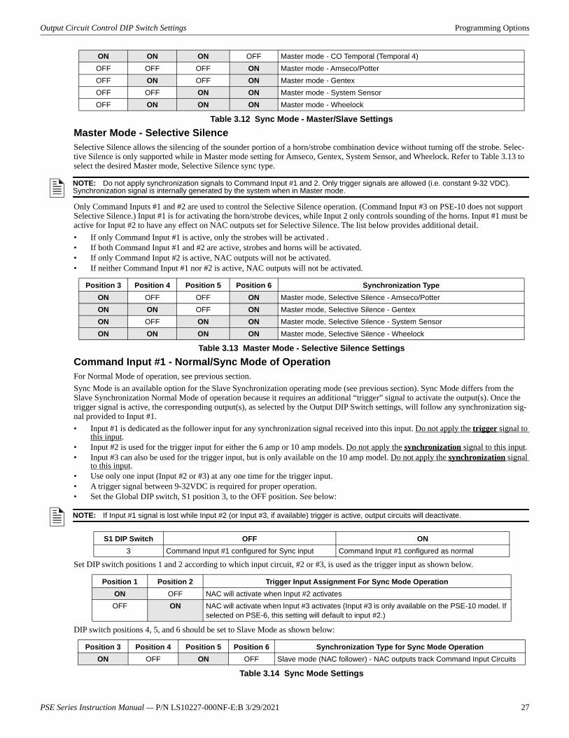
PSE Series Instruction Manual — P/N LS10227-000NF-E:B 3/29/2021 27
Output Circuit Control DIP Switch Settings Programming Options
Master Mode - Selective SilenceSelective Silence allows the silencing of the sounder portion of a horn/strobe combination device without turning off the strobe. Selec-tive Silence is only supported while in Master mode setting for Amseco, Gentex, System Sensor, and Wheelock. Refer to Table 3.13 to select the desired Master mode, Selective Silence sync type.
Only Command Inputs #1 and #2 are used to control the Selective Silence operation. (Command Input #3 on PSE-10 does not support Selective Silence.) Input #1 is for activating the horn/strobe devices, while Input 2 only controls sounding of the horns. Input #1 must be active for Input #2 to have any effect on NAC outputs set for Selective Silence. The list below provides additional detail.• If only Command Input #1 is active, only the strobes will be activated .• If both Command Input #1 and #2 are active, strobes and horns will be activated.• If only Command Input #2 is active, NAC outputs will not be activated.• If neither Command Input #1 nor #2 is active, NAC outputs will not be activated.
Command Input #1 - Normal/Sync Mode of OperationFor Normal Mode of operation, see previous section.Sync Mode is an available option for the Slave Synchronization operating mode (see previous section). Sync Mode differs from the Slave Synchronization Normal Mode of operation because it requires an additional “trigger” signal to activate the output(s). Once the trigger signal is active, the corresponding output(s), as selected by the Output DIP Switch settings, will follow any synchronization sig-nal provided to Input #1. • Input #1 is dedicated as the follower input for any synchronization signal received into this input. Do not apply the trigger signal to
this input.• Input #2 is used for the trigger input for either the 6 amp or 10 amp models. Do not apply the synchronization signal to this input.• Input #3 can also be used for the trigger input, but is only available on the 10 amp model. Do not apply the synchronization signal
to this input.• Use only one input (Input #2 or #3) at any one time for the trigger input.• A trigger signal between 9-32VDC is required for proper operation.• Set the Global DIP switch, S1 position 3, to the OFF position. See below:
Set DIP switch positions 1 and 2 according to which input circuit, #2 or #3, is used as the trigger input as shown below.
DIP switch positions 4, 5, and 6 should be set to Slave Mode as shown below:
ON ON ON OFF Master mode - CO Temporal (Temporal 4)OFF OFF OFF ON Master mode - Amseco/PotterOFF ON OFF ON Master mode - GentexOFF OFF ON ON Master mode - System SensorOFF ON ON ON Master mode - Wheelock
Table 3.12 Sync Mode - Master/Slave Settings
NOTE: Do not apply synchronization signals to Command Input #1 and 2. Only trigger signals are allowed (i.e. constant 9-32 VDC). Synchronization signal is internally generated by the system when in Master mode.
Position 3 Position 4 Position 5 Position 6 Synchronization TypeON OFF OFF ON Master mode, Selective Silence - Amseco/PotterON ON OFF ON Master mode, Selective Silence - GentexON OFF ON ON Master mode, Selective Silence - System SensorON ON ON ON Master mode, Selective Silence - Wheelock
Table 3.13 Master Mode - Selective Silence Settings
NOTE: If Input #1 signal is lost while Input #2 (or Input #3, if available) trigger is active, output circuits will deactivate.
S1 DIP Switch OFF ON3 Command Input #1 configured for Sync input Command Input #1 configured as normal
Position 1 Position 2 Trigger Input Assignment For Sync Mode OperationON OFF NAC will activate when Input #2 activatesOFF ON NAC will activate when Input #3 activates (Input #3 is only available on the PSE-10 model. If
selected on PSE-6, this setting will default to input #2.)
Position 3 Position 4 Position 5 Position 6 Synchronization Type for Sync Mode OperationON OFF ON OFF Slave mode (NAC follower) - NAC outputs track Command Input Circuits
Table 3.14 Sync Mode Settings
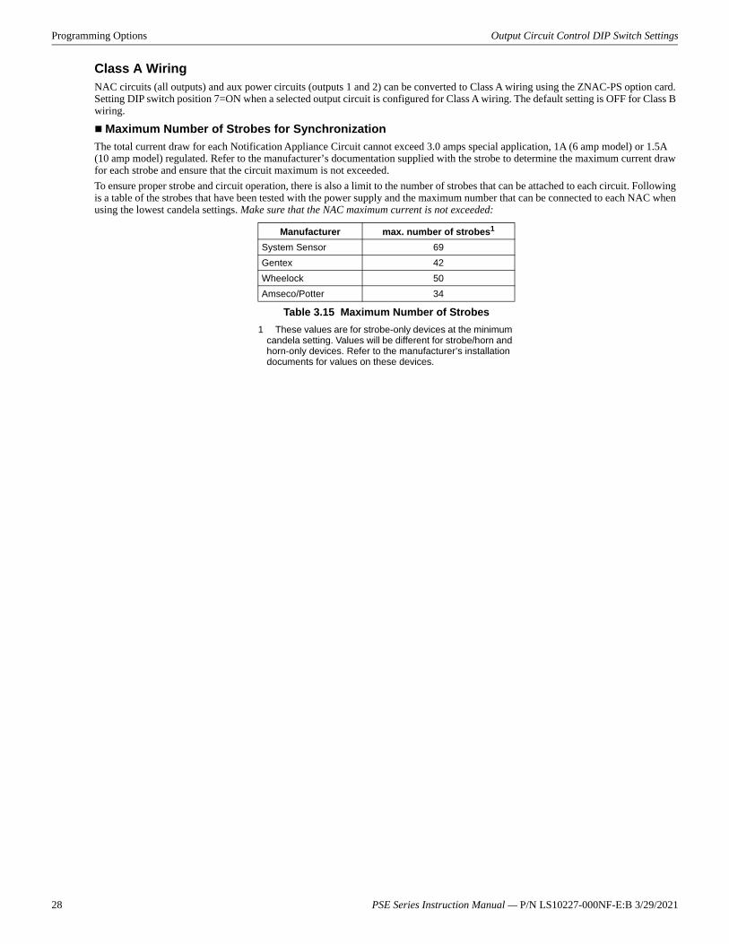
28 PSE Series Instruction Manual — P/N LS10227-000NF-E:B 3/29/2021
Programming Options Output Circuit Control DIP Switch Settings
Class A WiringNAC circuits (all outputs) and aux power circuits (outputs 1 and 2) can be converted to Class A wiring using the ZNAC-PS option card. Setting DIP switch position 7=ON when a selected output circuit is configured for Class A wiring. The default setting is OFF for Class B wiring.
Maximum Number of Strobes for SynchronizationThe total current draw for each Notification Appliance Circuit cannot exceed 3.0 amps special application, 1A (6 amp model) or 1.5A (10 amp model) regulated. Refer to the manufacturer’s documentation supplied with the strobe to determine the maximum current draw for each strobe and ensure that the circuit maximum is not exceeded.To ensure proper strobe and circuit operation, there is also a limit to the number of strobes that can be attached to each circuit. Following is a table of the strobes that have been tested with the power supply and the maximum number that can be connected to each NAC when using the lowest candela settings. Make sure that the NAC maximum current is not exceeded:
Manufacturer max. number of strobes1
1 These values are for strobe-only devices at the minimum candela setting. Values will be different for strobe/horn and horn-only devices. Refer to the manufacturer’s installation documents for values on these devices.
System Sensor 69Gentex 42Wheelock 50Amseco/Potter 34
Table 3.15 Maximum Number of Strobes
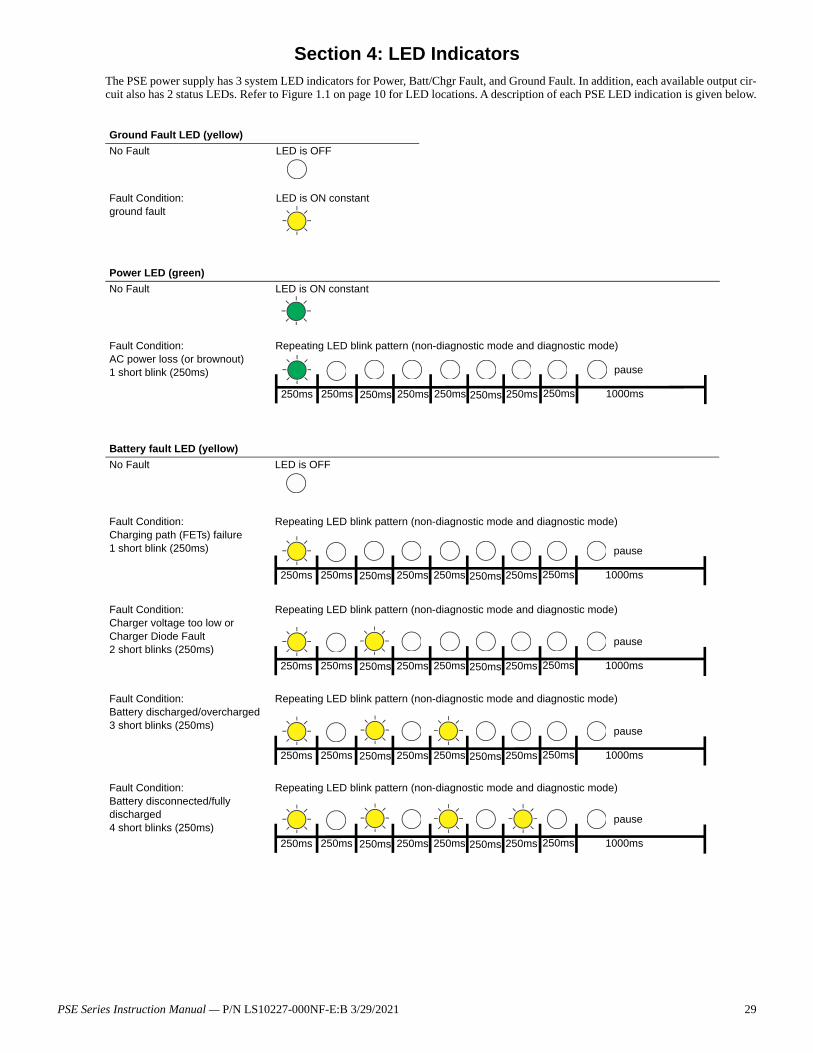
Section 4: LED IndicatorsThe PSE power supply has 3 system LED indicators for Power, Batt/Chgr Fault, and Ground Fault. In addition, each available output cir-cuit also has 2 status LEDs. Refer to Figure 1.1 on page 10 for LED locations. A description of each PSE LED indication is given below.
Ground Fault LED (yellow)No Fault LED is OFF
Fault Condition:ground fault
LED is ON constant
Power LED (green)No Fault LED is ON constant
Fault Condition:AC power loss (or brownout)1 short blink (250ms)
Repeating LED blink pattern (non-diagnostic mode and diagnostic mode)
Battery fault LED (yellow)No Fault LED is OFF
Fault Condition:Charging path (FETs) failure1 short blink (250ms)
Repeating LED blink pattern (non-diagnostic mode and diagnostic mode)
Fault Condition:Charger voltage too low or Charger Diode Fault2 short blinks (250ms)
Repeating LED blink pattern (non-diagnostic mode and diagnostic mode)
Fault Condition:Battery discharged/overcharged3 short blinks (250ms)
Repeating LED blink pattern (non-diagnostic mode and diagnostic mode)
Fault Condition:Battery disconnected/fully discharged4 short blinks (250ms)
Repeating LED blink pattern (non-diagnostic mode and diagnostic mode)
250ms 250ms 250ms 250ms 250ms 250ms 250ms 250ms 1000ms
pause
250ms 250ms 250ms 250ms 250ms 250ms 250ms 250ms 1000ms
pause
250ms 250ms 250ms 250ms 250ms 250ms 250ms 250ms 1000ms
pause
250ms 250ms 250ms 250ms 250ms 250ms 250ms 250ms 1000ms
pause
250ms 250ms 250ms 250ms 250ms 250ms 250ms 250ms 1000ms
pause
PSE Series Instruction Manual — P/N LS10227-000NF-E:B 3/29/2021 29
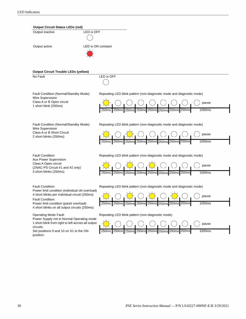
LED Indicators
Output Circuit Status LEDs (red)Output inactive LED is OFF
Output active LED is ON constant
Output Circuit Trouble LEDs (yellow)No Fault LED is OFF
Fault Condition (Normal/Standby Mode):Wire SupervisionClass A or B Open circuit1 short blink (250ms)
Repeating LED blink pattern (non-diagnostic mode and diagnostic mode)
Fault Condition (Normal/Standby Mode):Wire SupervisionClass A or B Short Circuit2 short blinks (250ms)
Repeating LED blink pattern (non-diagnostic mode and diagnostic mode)
Fault Condition:Aux Power SupervisionClass A Open circuit (ZNAC-PS Circuit #1 and #2 only)3 short blinks (250ms)
Repeating LED blink pattern (non-diagnostic mode and diagnostic mode)
Fault Condition:Power limit condition (individual ckt overload)4 short blinks per individual circuit (250ms)
Repeating LED blink pattern (non-diagnostic mode and diagnostic mode)
Fault Condition:Power limit condition (panel overload)4 short blinks on all output circuits (250ms)
Operating Mode Fault:Power Supply not in Normal Operating mode1 short blink from right to left across all output circuits.Set positions 9 and 10 on S1 to the ON position.
Repeating LED blink pattern (non-diagnostic mode)
250ms 250ms 250ms 250ms 250ms 250ms 250ms 250ms 1000ms
pause
250ms 250ms 250ms 250ms 250ms 250ms 250ms 250ms 1000ms
pause
250ms 250ms 250ms 250ms 250ms 250ms 250ms 250ms 1000ms
pause
250ms 250ms 250ms 250ms 250ms 250ms 250ms 250ms 1000ms
pause
250ms 250ms 250ms 250ms 250ms 250ms 250ms 250ms 1000ms
pause
30 PSE Series Instruction Manual — P/N LS10227-000NF-E:B 3/29/2021
Section 5: Trouble SupervisionThe FACP will detect PSE power supply faults. Any of the following conditions will cause the trouble contact to open, provided the FACP Notification Appliance Circuit is not in alarm.
5.1 Trouble Supervision Using Input CircuitsThe FACP (Fire Alarm Control Panel) supervises the connection between itself and the PSE via the control panel’s NAC End-of-Line Resistor (ELR). To supervise the PSE, an ELR must be installed across terminals 1 & 4 of Command Inputs #1 and #2 (and #3 for the 10 amp models). A field wiring fault on the NAC output of the PSE will trigger a disconnection of the ELR at the related Command Input, causing a general NAC trouble at the FACP provided the FACP’s NAC is not in alarm. Refer to Section 3.2, “Output Circuit Control DIP Switch Settings”, on page 25 for input/output configuration assignment. The following are exceptions.1. Resettable Aux Power, Non-Resettable Aux Power, and Door Holder Aux Power outputs that trigger the Trouble relay during an
output trouble instead of breaking the ELR connection at the Command Input regardless of the output to input relationship (i.e. mapping). Refer to 5.2, "Trouble Relay" below.
2. Faults are only reported by Command Input #1 when Selective Silence output mode is controlled by Command Input #1 and #2.3. Faults are only reported by the trigger input when Command Input #1 is configured for Sync Input mode operation controlled by a
sync and trigger input.If the PSE is in alarm, only a short circuit on the NAC will be detected as a trouble.If other trouble monitoring is required when the power supply is in alarm, the Trouble Relay at TB1, and AC Trouble at TB2, and Ground Fault Trouble at TB3 (Canadian applications only) can be used for this purpose.
5.2 Trouble RelayThe PSE power supply has a fail-safe Form-C trouble relay located at TB1. The contacts can be monitored by an FACP input circuit or an addressable monitor module as illustrated in Figure 5.1. Note that any faults reported by Command Inputs are not repeated by the trouble relay, offering limited trouble reporting.Trouble conditions that will cause the normally energized trouble relay to change states regardless of whether the panel is in alarm or standby:
• A battery fail condition at the power supply• A battery charger fail on the power supply• A ground fault condition on the power supply (non-Canadian models only)• A field wiring fault on the PSE output in Resettable Aux Power, Non-Resettable Aux Power, or Door Holder Aux Power mode• A total panel overload fault
If trouble monitoring is required when the power supply is in alarm, the Trouble Relay at TB1 can be used for this purpose. Refer to Figure 5.1 below.
5.3 AC Trouble RelayThe PSE power supply has a fail-safe Form-C trouble relay located at TB2. The contacts can be monitored by an FACP input circuit or an addressable monitor module similar to the drawing illustrated in Figure 5.1. The AC Trouble Relay responds to an AC fail condition on the PSE immediately, or after a programmed delay time, depending on the setting of S1 switches 7 and 8.The reporting of AC loss to a central station is usually delayed in order to prevent multiple transmissions of AC loss and restoral, allow-ing AC power to stabilize. When a host FACP is programmed to delay AC loss reporting, the PSE must be configured to delay the reporting of AC fail. This is accomplished by setting S1 positions 7 and 8. Refer to the DIP switch setting chart in Table 3.5 on page 24. This will prevent AC loss from being reported as a trouble condition for 30, 12, 2, or 0 hours. Note that only no delay and the 2 hour delay are acceptable per UL 864 and UL 2572.
NOTE: The individual NAC Trouble LED will indicate which NAC circuit is in trouble.
NO NC C NO NC C
TB4 TB2
TB1
T1T11
T2T10
T3T9
T4T8
T5T7T6
NO NC C
TB3
SLC
Monitor Module*P-6/10C
T7
T6
NC
C
*If the SLC device does not match the one in this figure, refer to the SLC man-ual wiring conversion charts for legacy and newer versions of the modules.
AC Trouble
TroubleTrouble Relay
Figure 5.1 Monitoring the Trouble Relay
TB3 is only populated on Canadian models.
Monitor Module ELR
PSE Series Instruction Manual — P/N LS10227-000NF-E:B 3/29/2021 31

Trouble Supervision Ground Fault Relay (Canadian Applications Only)
5.4 Ground Fault Relay (Canadian Applications Only)The PSE-6/10C power supply has a form-C trouble relay located at TB3. The contacts can be monitored by an FACP input circuit or an addressable monitor module similar to the drawing illustrated in Figure 5.1. Ground fault conditions will cause the relay to change states regardless of whether the panel is in alarm or standby.
32 PSE Series Instruction Manual — P/N LS10227-000NF-E:B 3/29/2021
Section 6: Power Supply Requirements
6.1 OverviewThis section contains instructions and tables for calculating power supply currents in alarm and standby conditions. This is a four-step process, consisting of the following:1. Calculating the total amount of AC branch circuit current required to operate the system2. Calculating the power supply load current for secondary non-fire and fire alarm conditions 3. Calculating the size of batteries required to support the system if an AC power loss occurs4. Selecting the proper batteries for your system
6.2 Calculating the AC Branch CircuitThe power supply requires connection to a separate, dedicated AC branch circuit, which must be labeled FIRE ALARM. This branch circuit must connect to the line side of the main power feed of the protected premises. No other non-fire alarm equipment may be pow-ered from the fire alarm branch circuit. The branch circuit wire must run continuously, without any disconnect devices, from the power source to the power supply. Overcurrent protection for this circuit must comply with Article 760 of the National Electrical Codes as well as local codes. Use a minimum of 14 AWG (2.00 mm2) wire with 600 volt insulation for this branch circuit. Use Table 6.1 to determine the total amount of current, in AC amperes, that must be supplied to the system.
6.3 Calculating the System Current Draw6.3.1 Overview
The power supply must be able to power all internal and external devices continuously during a fire alarm condition. The secondary power source (batteries) must be able to power the system during a primary power loss.To calculate the non-fire alarm load on the power supply when secondary power is applied, use Calculation Column 1 in Table 6.3 on page 34. The power supply must support a larger load current during a fire alarm condition. To calculate the fire alarm load on the power supply as secondary power, use Calculation Col-umn 2 in Table 6.3 on page 34. When calculating current draw and the battery size, note the following:• Primary refers to the main power source for the power supply.• Secondary refers to the power supply’s backup batteries.• All currents are given in amperes (A). Table 6.2 shows how to convert milliamperes and microamperes to full amperes.
Device Type Number of Devices
Current Draw(AC amps)
Total Current per Device
PSE-6(C)(R)or
PSE-10(C)(R)or
PSE-6Eor
PSE-10E
1 x
5.0or6.2or2.7or3.5
=
[ ] [ ] x [ ] =[ ] [ ] x [ ] =
Sum Column for AC Branch Current Required =
Table 6.1 120/240 VAC Branch Circuit Requirements
To convert... Multiply ExampleMilliamperes (mA) to amperes (A) mA x 0.001 3 mA x 0.001 = 0.003 AMicroamperes (μA) to amperes (A) μA x 0.000001 300 μA x 0.000001 = 0.0003 A
Table 6.2 Converting to Full Amperes
PSE Series Instruction Manual — P/N LS10227-000NF-E:B 3/29/2021 33
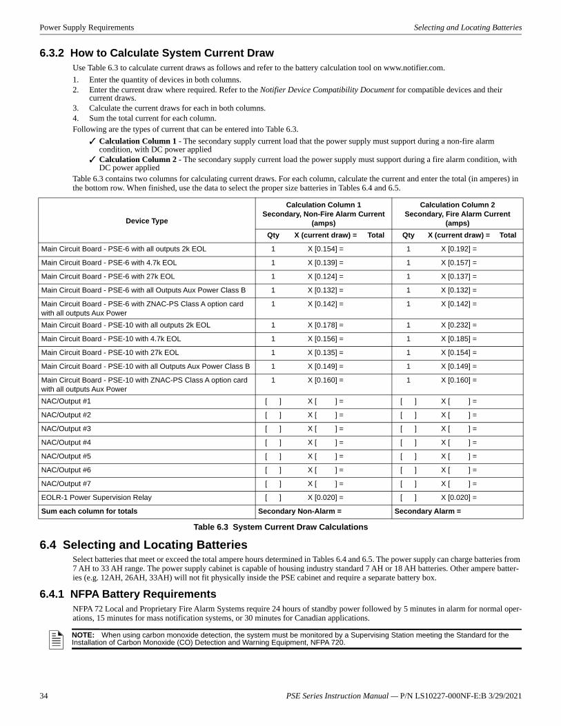
Power Supply Requirements Selecting and Locating Batteries
6.3.2 How to Calculate System Current DrawUse Table 6.3 to calculate current draws as follows and refer to the battery calculation tool on www.notifier.com.1. Enter the quantity of devices in both columns.2. Enter the current draw where required. Refer to the Notifier Device Compatibility Document for compatible devices and their
current draws.3. Calculate the current draws for each in both columns.4. Sum the total current for each column.Following are the types of current that can be entered into Table 6.3.
Calculation Column 1 - The secondary supply current load that the power supply must support during a non-fire alarm condition, with DC power appliedCalculation Column 2 - The secondary supply current load the power supply must support during a fire alarm condition, with DC power applied
Table 6.3 contains two columns for calculating current draws. For each column, calculate the current and enter the total (in amperes) in the bottom row. When finished, use the data to select the proper size batteries in Tables 6.4 and 6.5.
6.4 Selecting and Locating BatteriesSelect batteries that meet or exceed the total ampere hours determined in Tables 6.4 and 6.5. The power supply can charge batteries from 7 AH to 33 AH range. The power supply cabinet is capable of housing industry standard 7 AH or 18 AH batteries. Other ampere batter-ies (e.g. 12AH, 26AH, 33AH) will not fit physically inside the PSE cabinet and require a separate battery box.
6.4.1 NFPA Battery RequirementsNFPA 72 Local and Proprietary Fire Alarm Systems require 24 hours of standby power followed by 5 minutes in alarm for normal oper-ations, 15 minutes for mass notification systems, or 30 minutes for Canadian applications.
Device Type
Calculation Column 1Secondary, Non-Fire Alarm Current
(amps)
Calculation Column 2Secondary, Fire Alarm Current
(amps)Qty X (current draw) = Total Qty X (current draw) = Total
Main Circuit Board - PSE-6 with all outputs 2k EOL 1 X [0.154] = 1 X [0.192] =
Main Circuit Board - PSE-6 with 4.7k EOL 1 X [0.139] = 1 X [0.157] =
Main Circuit Board - PSE-6 with 27k EOL 1 X [0.124] = 1 X [0.137] =
Main Circuit Board - PSE-6 with all Outputs Aux Power Class B 1 X [0.132] = 1 X [0.132] =
Main Circuit Board - PSE-6 with ZNAC-PS Class A option card with all outputs Aux Power
1 X [0.142] = 1 X [0.142] =
Main Circuit Board - PSE-10 with all outputs 2k EOL 1 X [0.178] = 1 X [0.232] =
Main Circuit Board - PSE-10 with 4.7k EOL 1 X [0.156] = 1 X [0.185] =
Main Circuit Board - PSE-10 with 27k EOL 1 X [0.135] = 1 X [0.154] =
Main Circuit Board - PSE-10 with all Outputs Aux Power Class B 1 X [0.149] = 1 X [0.149] =
Main Circuit Board - PSE-10 with ZNAC-PS Class A option card with all outputs Aux Power
1 X [0.160] = 1 X [0.160] =
NAC/Output #1 [ ] X [ ] = [ ] X [ ] =
NAC/Output #2 [ ] X [ ] = [ ] X [ ] =
NAC/Output #3 [ ] X [ ] = [ ] X [ ] =
NAC/Output #4 [ ] X [ ] = [ ] X [ ] =
NAC/Output #5 [ ] X [ ] = [ ] X [ ] =
NAC/Output #6 [ ] X [ ] = [ ] X [ ] =
NAC/Output #7 [ ] X [ ] = [ ] X [ ] =
EOLR-1 Power Supervision Relay [ ] X [0.020] = [ ] X [0.020] =
Sum each column for totals Secondary Non-Alarm = Secondary Alarm =
Table 6.3 System Current Draw Calculations
NOTE: When using carbon monoxide detection, the system must be monitored by a Supervising Station meeting the Standard for the Installation of Carbon Monoxide (CO) Detection and Warning Equipment, NFPA 720.
34 PSE Series Instruction Manual — P/N LS10227-000NF-E:B 3/29/2021

6.4.2 Maximum Battery Standby LoadTables 6.4 and 6.5 show the standby load calculations for the power supply based on 24 hours of standby. The standby load calculations in the Table 6.3 must be less than the number shown in Tables 6.4 and 6.5 for the selected battery size, standby hour and alarm time. The numbers below have a built in 20% derating factor for the battery ampere capacity.
Section 7: Testing and Maintenance
7.1 Periodic Testing and ServicePeriodic testing and servicing of equipment is essential to ensure proper and reliable operation. Test and service the power supply according to the schedules and procedures outlined in the following documents:• NFPA Standard 72’s section on Inspection, Testing and Maintenance• All test and maintenance instruction codes and software necessary to provide test and inspection requirements of CAN/ULC-S536,
Standard for the Inspection and Testing of Fire Alarm Systems
7.2 Battery Checks and MaintenanceMaintenance-free sealed lead-acid batteries used in the system do not require the addition of water or electrolyte. These batteries are charged and maintained in a fully charged state by the main power supply’s charger during normal system operation. A discharged bat-tery typically reaches the voltage of 27.6 VDC within 48 hours;. Sealed lead-acid batteries must be replaced within at most 5 years from their date of manufacture. Minimal replacement battery capacity appears on the control panel marking label. Immediately replace a leak-ing or damaged battery. Replacement batteries are available from the manufacturer.
Battery Capacity
(AH)
Alarm Time (min)
5 10 15 20 30
7 0.212 A 0.190 A 0.169 A 0.147 A N/A
12 0.379 A 0.357 A 0.336 A 0.314 A 0.271 A
18 0.579 A 0.557 A 0.536 A 0.514 A 0.471 A
33 1.079 A 1.057 A 1.036 A 1.014 A 0.971 A
75 2.479 A 2.457 A 2.436 A 2.414 A 2.371 A
120 3.000 A 3.000 A 3.000 A 3.000 A 3.000 A
Table 6.4 Maximum Battery Standby Loads for 24 Hour Standby on the PSE-6
Battery Capacity
(AH)
Alarm Time (min)
5 10 15 20 30
7 0.198 A 0.162 A N/A N/A N/A
12 0.364 A 0.329 A 0.293 A 0.258 A 0.187 A
18 0.564 A 0.529 A 0.493 A 0.458 A 0.387 A
33 1.064 A 1.029 A 0.993 A 0.958 A 0.887 A
75 2.464 A 2.429 A 2.393 A 2.358 A 2.287 A
120 3.000 A 3.000 A 3.000 A 3.000 A 3.000 A
Table 6.5 Maximum Battery Standby Loads for 24 Hour Standby on the PSE-10
!WARNING: SULFURIC ACIDBATTERIES CONTAIN SULFURIC ACID WHICH CAN CAUSE SEVERE BURNS TO THE SKIN AND EYES AND DAMAGE TO FABRICS.
F1 Fuse Replacement Not AllowedRechargeable Battery Replacement Recommended Part Numbers:
• BAT-1270 (12V,7AH)• BAT-12120 (12V, 12AH)• BAT-12180 (12V 18AH) • BAT-12260 (12V, 26AH) • BAT-12330 (12V, 33AH)
PSE Series Instruction Manual — P/N LS10227-000NF-E:B 3/29/2021 35

36 PSE Series Instruction Manual — P/N LS10227-000NF-E:B 3/29/2021
Appendix A: Wire RequirementsConnecting external system accessories to the main circuits must be carefully considered to ensure proper operation. It is important to use the correct type of wire, gauge and run length for each circuit. The following table lists NAC wiring requirements for the PSE-6 and PSE-10 Power Supply. The numbers documented in this chart are worst case numbers, based on the conditions listed below. The maximum voltage drop, maxi-mum loop resistance, and wire length ratings can be increased with lower system current loading.1. The PSE-6/10 is full capacity loaded at 6A/10A.2. The PSE-6/10 is running at the Low Battery voltage of 20.4VDC (at Battery Connector TB15). Wire lengths apply to Class B wiring, and to Class A wiring returned to the ZNAC-PS card.
Max Load (Amps)
Max Loop Resistance (Ohms) AWG 12 (Solid) AWG 14 (Solid) AWG 16 (Solid) AWG 18 (Solid)
0.25 12.804 3320 2087 1310 823
0.50 6.402 1660 1044 655 412
0.75 4.268 1107 696 437 274
1.00 3.201 830 522 327 206
1.25 2.561 664 417 262 165
1.50 2.134 553 348 218 137
1.75 1.829 474 298 187 118
2.00 1.601 415 261 164 103
2.25 1.423 369 232 146 91
2.50 1.280 332 209 131 82
2.75 1.164 302 190 119 75
3.00 1.067 277 174 109 69
Table A.1 Wiring Requirements for Power Supply
NOTE: Calculations are based on Direct-Current Resistance data for uncoated copper wire, per National Electrical Code (2005 Edition) Table 8, Conductor Properties.
NOTE: These distances reflect the worst case scenario and are based on the correct draw of the highest candela strobes at the low end of the supported NAC voltage with the entire load at the end of the circuit. Further distances can be achieved by performing a point to point voltage calculation that more accurately reflects the specific devices used and how they are dispersed on the circuit.
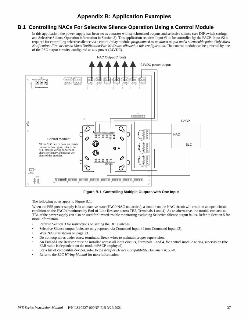
Appendix B: Application Examples
B.1 Controlling NACs For Selective Silence Operation Using a Control ModuleIn this application, the power supply has been set as a master with synchronized outputs and selective silence (see DIP switch settings and Selective Silence Operation information in Section 3). This application requires Input #1 to be controlled by the FACP. Input #2 is required for controlling selective silence via a control/relay module, programmed as an alarm output and a silenceable point. Only Mass Notification, Fire, or combo Mass Notification/Fire NACs are allowed in this configuration. The control module can be powered by one of the PSE output circuits, configured as aux power (24VDC).
The following notes apply to Figure B.1.When the PSE power supply is in an inactive state (FACP NAC not active), a trouble on the NAC circuit will result in an open circuit condition on the FACP (monitored by End-of-Line Resistor across TB5, Terminals 1 and 4). As an alternative, the trouble contacts at TB1 of the power supply can also be used for limited trouble monitoring excluding Selective Silence output faults. Refer to Section 5 for more information.• Refer to Section 3 for instructions on setting the DIP switches.• Selective Silence output faults are only reported via Command Input #1 (not Command Input #2). • Wire NACs as shown on page 13.• Do not loop wires under screw terminals. Break wires to maintain proper supervision.• An End-of-Line Resistor must be installed across all input circuits, Terminals 1 and 4, for control module wiring supervision (the
ELR value is dependent on the module/FACP employed).• For a list of compatible devices, refer to the Notifier Device Compatibility Document #15378.• Refer to the SLC Wiring Manual for more information.
NO NC C NO NC C
TB4
TB15
TB2
TB1
T B13
TB12
TB1 1
TB10
TB9
TB8
T1T11
T2T10
T3T9
T4T8
T5T7T6
Figure B.1 Controlling Multiple Outputs with One Input
Control Module*
SLC*If the SLC device does not match the one in this figure, refer to the SLC manual wiring conversion charts for legacy and newer ver-sions of the modules.
NAC Output Circuits
24VDC power output
NAC
FACP
PSE Series Instruction Manual — P/N LS10227-000NF-E:B 3/29/2021 37
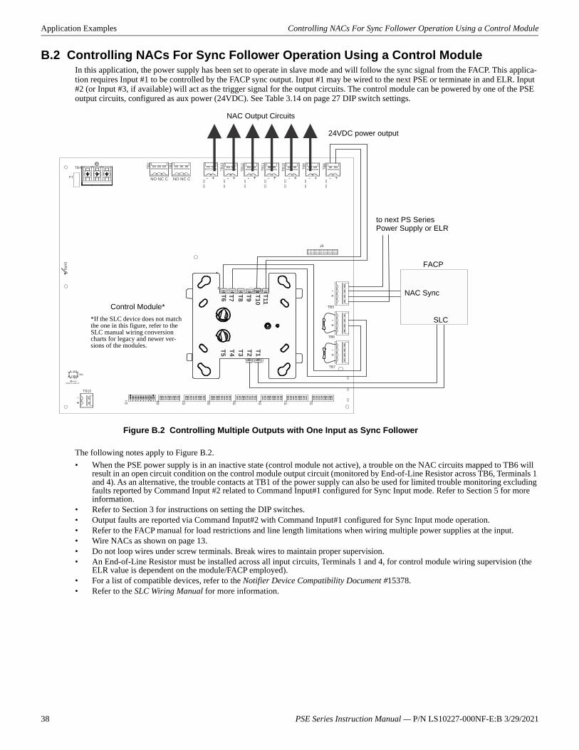
Application Examples Controlling NACs For Sync Follower Operation Using a Control Module
B.2 Controlling NACs For Sync Follower Operation Using a Control ModuleIn this application, the power supply has been set to operate in slave mode and will follow the sync signal from the FACP. This applica-tion requires Input #1 to be controlled by the FACP sync output. Input #1 may be wired to the next PSE or terminate in and ELR. Input #2 (or Input #3, if available) will act as the trigger signal for the output circuits. The control module can be powered by one of the PSE output circuits, configured as aux power (24VDC). See Table 3.14 on page 27 DIP switch settings.
The following notes apply to Figure B.2.• When the PSE power supply is in an inactive state (control module not active), a trouble on the NAC circuits mapped to TB6 will
result in an open circuit condition on the control module output circuit (monitored by End-of-Line Resistor across TB6, Terminals 1 and 4). As an alternative, the trouble contacts at TB1 of the power supply can also be used for limited trouble monitoring excluding faults reported by Command Input #2 related to Command Input#1 configured for Sync Input mode. Refer to Section 5 for more information.
• Refer to Section 3 for instructions on setting the DIP switches.• Output faults are reported via Command Input#2 with Command Input#1 configured for Sync Input mode operation.• Refer to the FACP manual for load restrictions and line length limitations when wiring multiple power supplies at the input.• Wire NACs as shown on page 13.• Do not loop wires under screw terminals. Break wires to maintain proper supervision.• An End-of-Line Resistor must be installed across all input circuits, Terminals 1 and 4, for control module wiring supervision (the
ELR value is dependent on the module/FACP employed).• For a list of compatible devices, refer to the Notifier Device Compatibility Document #15378.• Refer to the SLC Wiring Manual for more information.
NO NC C NO NC C
TB4
TB15
TB2
TB1
T B13
TB12
TB1 1
TB10
TB9
TB8
T1T11
T2T10
T3T9
T4T8
T5T7T6
Figure B.2 Controlling Multiple Outputs with One Input as Sync Follower
Control Module*
SLC*If the SLC device does not match the one in this figure, refer to the SLC manual wiring conversion charts for legacy and newer ver-sions of the modules.
NAC Output Circuits
24VDC power output
NAC Sync
FACP
to next PS Series Power Supply or ELR
38 PSE Series Instruction Manual — P/N LS10227-000NF-E:B 3/29/2021
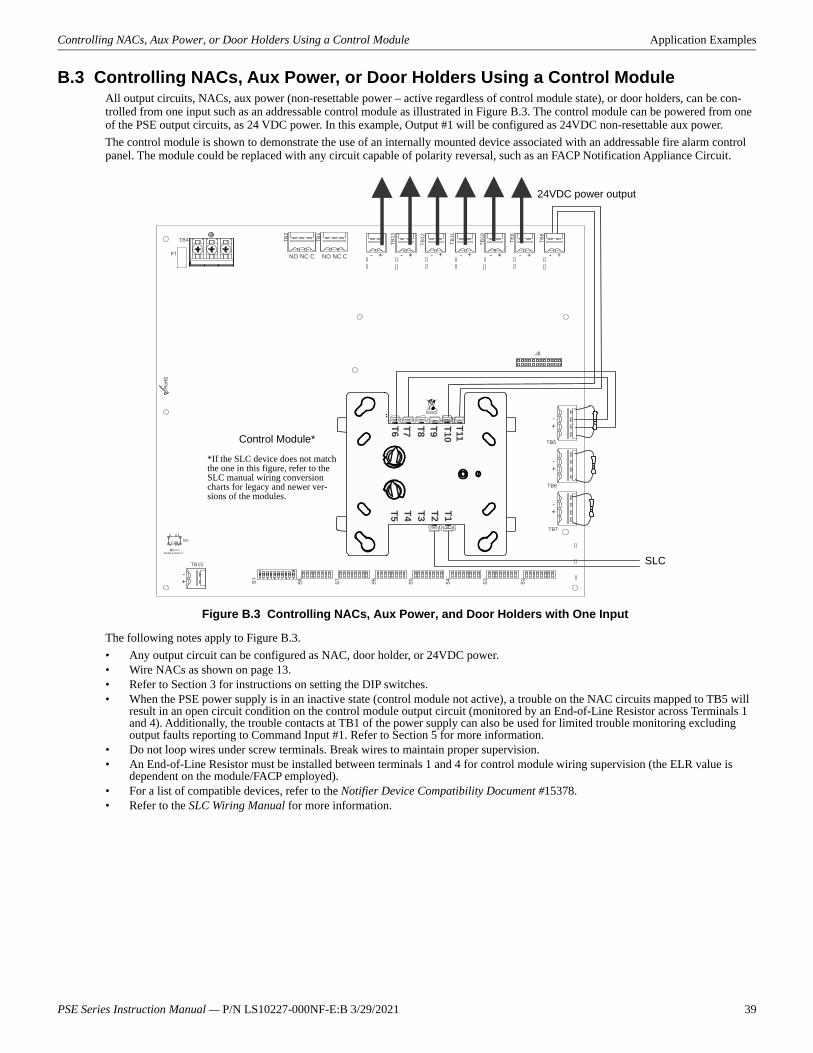
Controlling NACs, Aux Power, or Door Holders Using a Control Module Application Examples
B.3 Controlling NACs, Aux Power, or Door Holders Using a Control ModuleAll output circuits, NACs, aux power (non-resettable power – active regardless of control module state), or door holders, can be con-trolled from one input such as an addressable control module as illustrated in Figure B.3. The control module can be powered from one of the PSE output circuits, as 24 VDC power. In this example, Output #1 will be configured as 24VDC non-resettable aux power.The control module is shown to demonstrate the use of an internally mounted device associated with an addressable fire alarm control panel. The module could be replaced with any circuit capable of polarity reversal, such as an FACP Notification Appliance Circuit.
The following notes apply to Figure B.3.• Any output circuit can be configured as NAC, door holder, or 24VDC power.• Wire NACs as shown on page 13.• Refer to Section 3 for instructions on setting the DIP switches.• When the PSE power supply is in an inactive state (control module not active), a trouble on the NAC circuits mapped to TB5 will
result in an open circuit condition on the control module output circuit (monitored by an End-of-Line Resistor across Terminals 1 and 4). Additionally, the trouble contacts at TB1 of the power supply can also be used for limited trouble monitoring excluding output faults reporting to Command Input #1. Refer to Section 5 for more information.
• Do not loop wires under screw terminals. Break wires to maintain proper supervision.• An End-of-Line Resistor must be installed between terminals 1 and 4 for control module wiring supervision (the ELR value is
dependent on the module/FACP employed).• For a list of compatible devices, refer to the Notifier Device Compatibility Document #15378.• Refer to the SLC Wiring Manual for more information.
NO NC C NO NC C
TB4
TB15
TB2
TB1
TB13
TB12
TB11
TB10
TB9
T B8
T1T11
T2T10
T3T9
T4T8
T5T7T6
Control Module*
SLC
*If the SLC device does not match the one in this figure, refer to the SLC manual wiring conversion charts for legacy and newer ver-sions of the modules.
Figure B.3 Controlling NACs, Aux Power, and Door Holders with One Input
24VDC power output
PSE Series Instruction Manual — P/N LS10227-000NF-E:B 3/29/2021 39
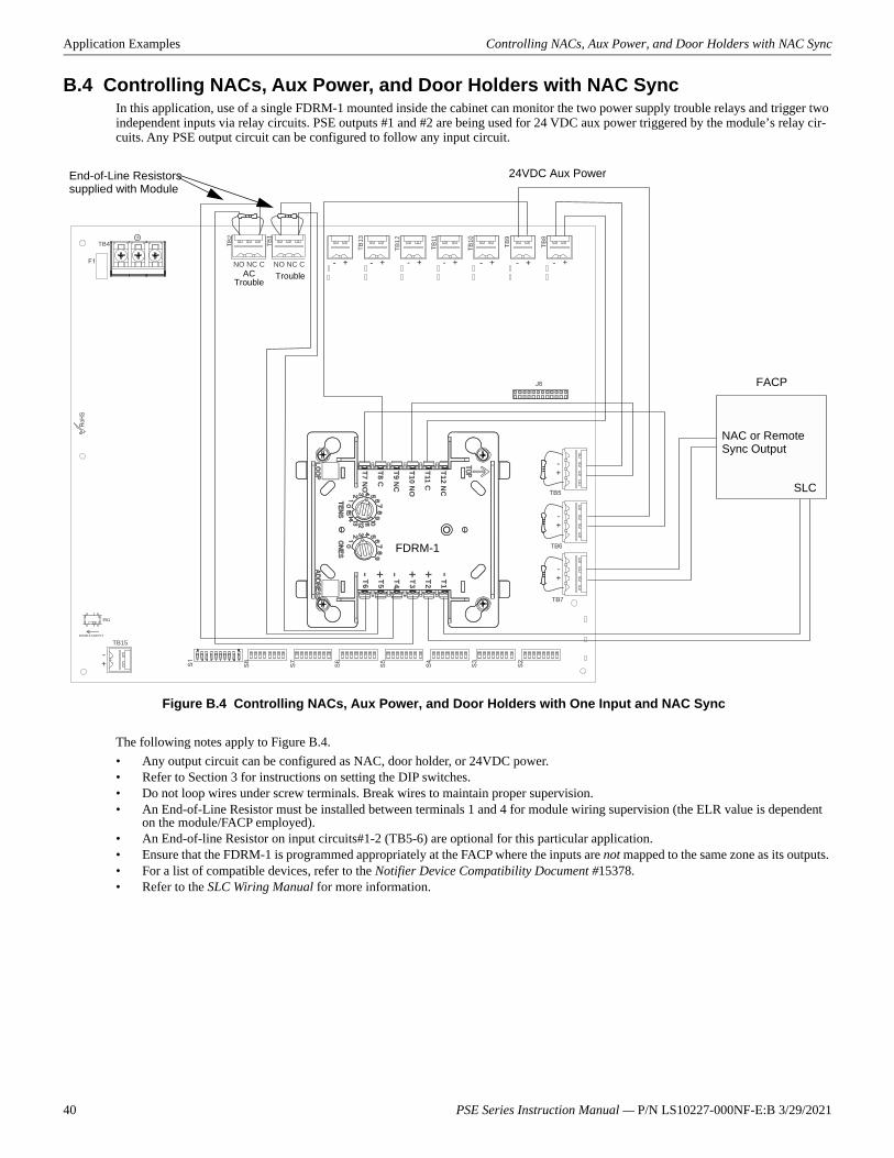
Application Examples Controlling NACs, Aux Power, and Door Holders with NAC Sync
B.4 Controlling NACs, Aux Power, and Door Holders with NAC SyncIn this application, use of a single FDRM-1 mounted inside the cabinet can monitor the two power supply trouble relays and trigger two independent inputs via relay circuits. PSE outputs #1 and #2 are being used for 24 VDC aux power triggered by the module’s relay cir-cuits. Any PSE output circuit can be configured to follow any input circuit.
The following notes apply to Figure B.4.• Any output circuit can be configured as NAC, door holder, or 24VDC power.• Refer to Section 3 for instructions on setting the DIP switches.• Do not loop wires under screw terminals. Break wires to maintain proper supervision.• An End-of-Line Resistor must be installed between terminals 1 and 4 for module wiring supervision (the ELR value is dependent
on the module/FACP employed).• An End-of-line Resistor on input circuits#1-2 (TB5-6) are optional for this particular application.• Ensure that the FDRM-1 is programmed appropriately at the FACP where the inputs are not mapped to the same zone as its outputs. • For a list of compatible devices, refer to the Notifier Device Compatibility Document #15378.• Refer to the SLC Wiring Manual for more information.
NO NC C NO NC C
TB4
TB15
TB2
TB1
TB1 3
TB12
TB11
TB10
TB9
TB8
T1T2T3T4T5T6
T12 NC
T11 C
T10 NO
T9 NC
T8 C
T7 NO
NAC or Remote Sync Output
FACP
SLC
FDRM-1
Figure B.4 Controlling NACs, Aux Power, and Door Holders with One Input and NAC Sync
End-of-Line Resistors supplied with Module
24VDC Aux Power
AC Trouble
Trouble
40 PSE Series Instruction Manual — P/N LS10227-000NF-E:B 3/29/2021
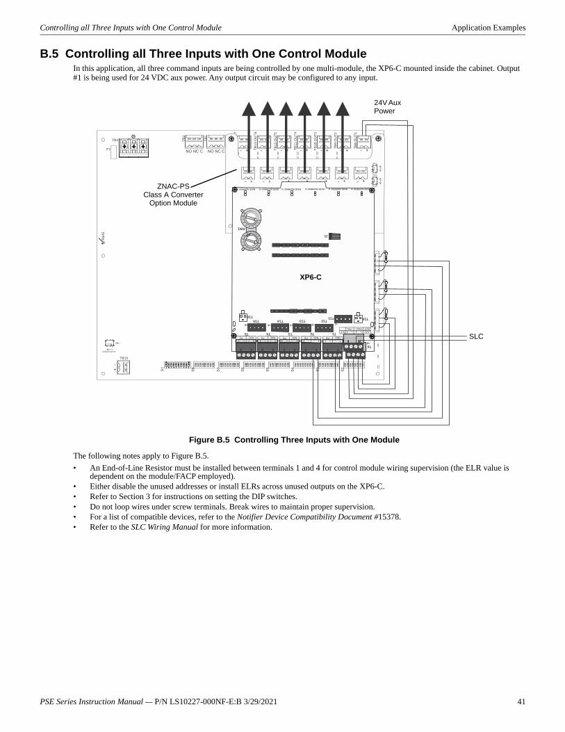
Controlling all Three Inputs with One Control Module Application Examples
B.5 Controlling all Three Inputs with One Control ModuleIn this application, all three command inputs are being controlled by one multi-module, the XP6-C mounted inside the cabinet. Output #1 is being used for 24 VDC aux power. Any output circuit may be configured to any input.
The following notes apply to Figure B.5.• An End-of-Line Resistor must be installed between terminals 1 and 4 for control module wiring supervision (the ELR value is
dependent on the module/FACP employed).• Either disable the unused addresses or install ELRs across unused outputs on the XP6-C. • Refer to Section 3 for instructions on setting the DIP switches.• Do not loop wires under screw terminals. Break wires to maintain proper supervision.• For a list of compatible devices, refer to the Notifier Device Compatibility Document #15378.• Refer to the SLC Wiring Manual for more information.
NO NC C NO NC C
TB4
TB15
TB2
TB1
T B13
OU
T 6
T B12
OU
T5
TB11
OU
T4
T B10
OU
T3
T B9
OU
T2
TB8
OU
T1
– +
–+– +–+– +–+– +–+– +–+
–+–+
T10
J1
BASEADDRESS+0BASEADDRESS+1BASEADDRESS+2BASEADDRESS+3BASEADDRESS+4BASEADDRESS+5
SW1
T1
+1
+0
+2+3+4+5
T0
T2T3T4T5
T11T12T13T14T15
T16
01
23456
78
9 10 11 1314
15
12
01
23456
78
9
NAC1
AUX1NAC2
AUX2
24V Aux Power
SLC
XP6-C
ZNAC-PS Class A Converter
Option Module
Figure B.5 Controlling Three Inputs with One Module
PSE Series Instruction Manual — P/N LS10227-000NF-E:B 3/29/2021 41
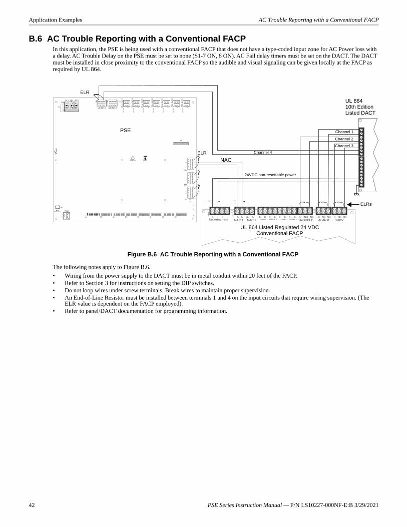
Application Examples AC Trouble Reporting with a Conventional FACP
B.6 AC Trouble Reporting with a Conventional FACPIn this application, the PSE is being used with a conventional FACP that does not have a type-coded input zone for AC Power loss with a delay. AC Trouble Delay on the PSE must be set to none (S1-7 ON, 8 ON). AC Fail delay timers must be set on the DACT. The DACT must be installed in close proximity to the conventional FACP so the audible and visual signaling can be given locally at the FACP as required by UL 864.
The following notes apply to Figure B.6.• Wiring from the power supply to the DACT must be in metal conduit within 20 feet of the FACP.• Refer to Section 3 for instructions on setting the DIP switches.• Do not loop wires under screw terminals. Break wires to maintain proper supervision.• An End-of-Line Resistor must be installed between terminals 1 and 4 on the input circuits that require wiring supervision. (The
ELR value is dependent on the FACP employed).• Refer to panel/DACT documentation for programming information.
NO NC C NO NC C
TB4
TB15
TB2
TB1
TB13
OU
T6
TB12
OU
T5
TB11
OU
T4
TB10
OU
T3
T B9
OU
T2
TB8
OU
T1AC1 AC2
TB1
TB2
B+ B- B+ B-NAC 1 NAC 2
+ - + -Nonreset Reset
B+ B- B+ B- ZONE 1 ZONE 2
B+ B- B+ B- ZONE 3 ZONE 4
C NO NC C NC NO C NC NOTROUBLE ALARM SUPV
UL 864 Listed Regulated 24 VDC Conventional FACP
UL 86410th Edition Listed DACT
Channel 1
Channel 2
Channel 3Channel 4
NAC
+ -
24VDC non-resettable power
+ -
PSE
ELR
ELR
ELRs
Figure B.6 AC Trouble Reporting with a Conventional FACP
42 PSE Series Instruction Manual — P/N LS10227-000NF-E:B 3/29/2021
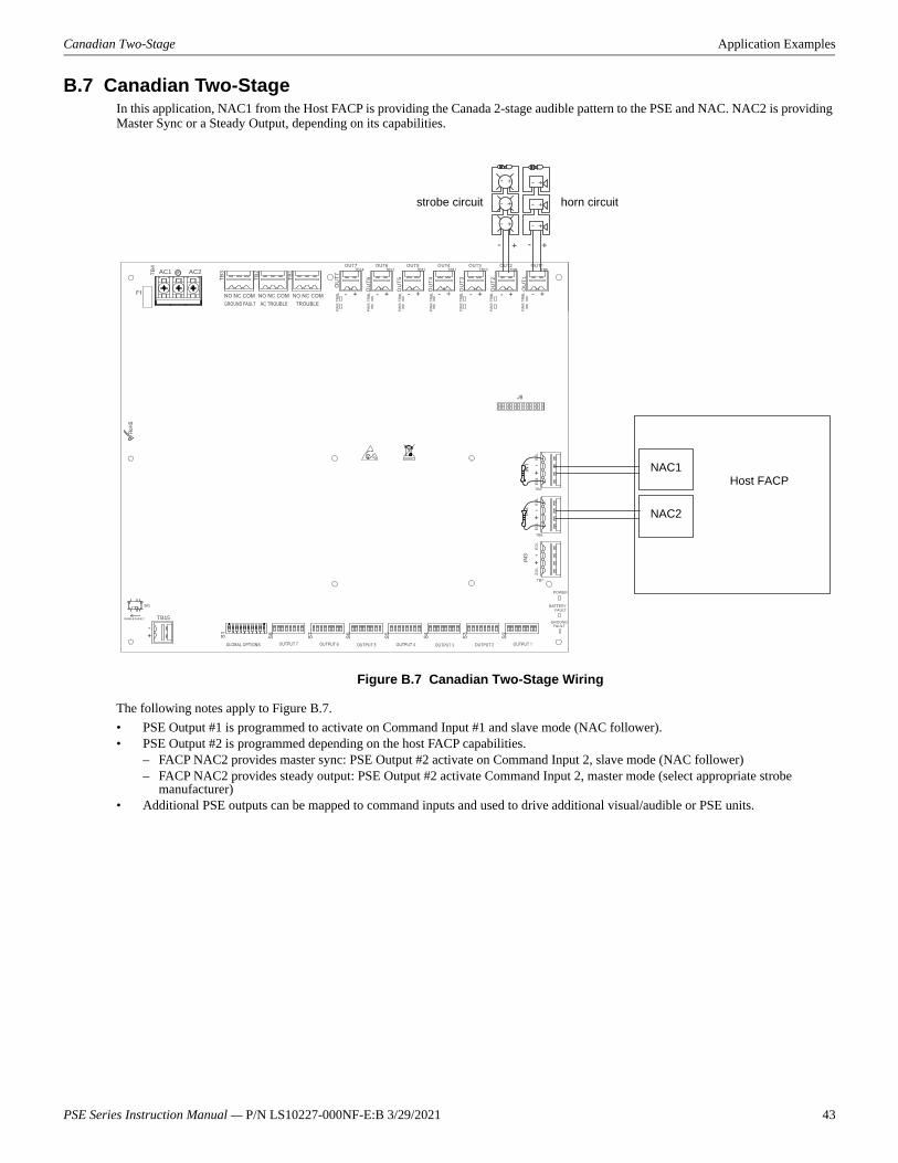
Canadian Two-Stage Application Examples
B.7 Canadian Two-StageIn this application, NAC1 from the Host FACP is providing the Canada 2-stage audible pattern to the PSE and NAC. NAC2 is providing Master Sync or a Steady Output, depending on its capabilities.
The following notes apply to Figure B.7.• PSE Output #1 is programmed to activate on Command Input #1 and slave mode (NAC follower).• PSE Output #2 is programmed depending on the host FACP capabilities.
– FACP NAC2 provides master sync: PSE Output #2 activate on Command Input 2, slave mode (NAC follower)– FACP NAC2 provides steady output: PSE Output #2 activate Command Input 2, master mode (select appropriate strobe
manufacturer)• Additional PSE outputs can be mapped to command inputs and used to drive additional visual/audible or PSE units.
AC1 AC2 TB4
TB15
TB3
TB2
TB1
OU
T6
OU
T5
OU
T4
OU
T3
OU
T 2
OU
T1
++ --
+-+-
+
+
-
-
+-
+-
Host FACPNAC1
NAC2
horn circuitstrobe circuit
Figure B.7 Canadian Two-Stage Wiring
PSE Series Instruction Manual — P/N LS10227-000NF-E:B 3/29/2021 43
Application Examples Canada Two-Stage Application Using XP6-C
B.8 Canada Two-Stage Application Using XP6-CIn this application, two outputs are being controlled by an XP6-C multi-module inside the cabinet. NAC1 from the host FACP is provid-ing the Canada two-stage audible pattern to the PSE. NAC2 is providing master sync or a steady output, depending on its capabilities. Additional PSE outputs can be used to connect to XP6-C modules outside the cabinet.
The following notes apply to Figure B.8.• PSE Output #1 is programmed to activate on Command Input #1 and Slave Mode (NAC Follower).• PSE Output #2 is programmed depending on host FACP capabilities:
– FACP NAC2 provides master sync: PSE output #2 activate on Command Input 2, slave mode (NAC follower)– FACP NAC2 provides steady output: PSE output #2 activate Command Input 2, master mode (select appropriate strobe
manufacturer)• Jumpers must be installed on terminals T11, T12, T14, and T15 of the XP6-C module.• Unused control module NAC outputs need ELRs installed or must be disabled.• PSE outputs going to XP6-C need ELRs installed.• Due to the reverse-polarity supervision of the PSE outputs, the XP6-C points must have the type code, “Bell Circuit”, to prevent
“Ext Power Loss” troubles.
NO NC C NO NC C
TB4
TB15
TB2
TB1
TB13
OU
T6
TB12
OU
T5
TB11
OU
T4
TB10
OU
T3
TB9
OU
T2
TB8
OU
T1
–+
– + –+ – + –+ – + –+ – + –+ – +
– + – +
T10
J1
BASE ADDRESS +0 BASE ADDRESS +1 BASE ADDRESS +2 BASE ADDRESS +3 BASE ADDRESS +4 BASE ADDRESS +5
SW1
T1
+1
+0
+2 +3 +4 +5
T0
T2 T3 T4 T5
T11T12 T13 T14 T15
T16
01
2 3 4 56
78
91011
1314
15
12
01
2 3 4 56
78
9
T0, T1, T2visual appliance circuits
T3, T4, T5audible appliance circuits
NAC1
NAC2
SLC
Host FACP
Figure B.8 Canadian Two-Stage Wiring Using an XP6-C
44 PSE Series Instruction Manual — P/N LS10227-000NF-E:B 3/29/2021

IndexAAC power 9
calculations 33current 9fail 24fail delay 24loss 8loss relay 9loss reporting delay 8, 31loss timer 23voltage 9
activationreverse polarity 8
alarm condition 8applications 8aux power 25aux power control
see also resettable or non-resettable power26
Bbackbox dimensions 12battery 20
capacity 9charge current 9charger capacity 8float charge voltage 9lead acid 8, 9maximum capacity 8see also secondary power 9trouble 8
Ccabinet
see also backbox 12Canadian applications 19capacity
battery 9cascading 18, 20charge current
maximum 9nominal 9
chargerenable/disable 24
charger trouble 8circuit board
layout 10Class A Converter Module 13
see also ZNAC-PS 8Class B 8coding
NAC 8command circuit 8
current 9see also input circuit 9voltage 9
command input 24compatibility
input circuit 8current
maximum continuous 8maximum short term 8standby 9total continuous 9total short term 9
Ddebounce/dejitter 23dimensions
backbox 12DIP switch
settings 23, 25disable outputs 26door holder 26
dropout delay 23
EELR 9, 13, 31, 37, 38, 39, 40, 41, 42
Ffactory default 26faults 31features 8filtered power 8float charge voltage 9form-C
see also relay 8
Gground fault 8, 18, 20ground fault detection 8, 10
switch SW1 10
Iinput 24
current 9settings 25voltage 9
input circuit 8activation 8compatibility 8see also control 9
installation 12
Mmaster mode 26module
mounting 14mounting
see also installation 12multi-module
mounting 14
NNAC
activation 8circuit wiring 13Class
see also NFPA Class 8coding 8output
see also output circuit 9see also Notification Appliance Circuit 8
NEC power-limited wiring requirements 15non-alarm state 8non-resettable power 25, 26notification appliance circuit
see also NAC 8
Ooperating mode 23, 24output
disable 26unused 26
output circuit 9Class 9current 9maximum current 8, 9see also NAC output 9types 9voltage rating 9
output power 8
Ppower
non-resettable 8resettable 8
power supply 33board layout drawing 10connectors and switches 10
power-limited outputs 8power-limited wiring 15PSE-10 8PSE-6 8
Rrelay
trouble 8, 9, 31reporting delay
AC loss 31requirements 33resettable power 25, 26
Ssecondary power
see also battery 9selective silence 27slave mode 25, 26special operating mode 24specifications 8startup procedure 10strobe synchronization 8supervision 8
trouble 31SW1
ground fault detection 10switch
PSE Series Instruction Manual — P/N LS10227-000NF-E:B 3/29/2021 45
Index
SW1 ground fault detection 8, 10sync 26sync mode 24sync type 16, 26, 27synchronization
ADA compatible 8selectable 8
Ttrouble 31
power supply 8supervision 31
trouble relay 8, 9, 31contact rating 9
trouble supervision 8
Wwiring 8
AC power 9power-limited 15
ZZNAC-PS 13, 14
see also Class A Converter Module 8
46 PSE Series Instruction Manual — P/N LS10227-000NF-E:B 3/29/2021

Manufacturer Warranties and Limitation of LiabilityManufacturer Warranties. Subject to the limitations set forth herein, Manufacturerwarrants that the Products manufactured by it in its Northford, Connecticut facilityand sold by it to its authorized Distributors shall be free, under normal use andservice, from defects in material and workmanship for a period of thirty six months(36) months from the date of manufacture (effective Jan. 1, 2009). The Productsmanufactured and sold by Manufacturer are date stamped at the time of production.Manufacturer does not warrant Products that are not manufactured by it in itsNorthford, Connecticut facility but assigns to its Distributor, to the extent possible,any warranty offered by the manufacturer of such product. This warranty shall bevoid if a Product is altered, serviced or repaired by anyone other than Manufactureror its authorized Distributors. This warranty shall also be void if there is a failure tomaintain the Products and the systems in which they operate in proper workingconditions.
MANUFACTURER MAKES NO FURTHER WARRANTIES, AND DISCLAIMS ANYAND ALL OTHER WARRANTIES, EITHER EXPRESSED OR IMPLIED, WITHRESPECT TO THE PRODUCTS, TRADEMARKS, PROGRAMS AND SERVICESRENDERED BY MANUFACTURER INCLUDING WITHOUT LIMITATION,INFRINGEMENT, TITLE, MERCHANTABILITY, OR FITNESS FOR ANYPARTICULAR PURPOSE. MANUFACTURER SHALL NOT BE LIABLE FOR ANYPERSONAL INJURY OR DEATH WHICH MAY ARISE IN THE COURSE OF, OR ASA RESULT OF, PERSONAL, COMMERCIAL OR INDUSTRIAL USES OF ITSPRODUCTS.
This document constitutes the only warranty made by Manufacturer with respect toits products and replaces all previous warranties and is the only warranty made byManufacturer. No increase or alteration, written or verbal, of the obligation of thiswarranty is authorized. Manufacturer does not represent that its products willprevent any loss by fire or otherwise.
Warranty Claims. Manufacturer shall replace or repair, at Manufacturer's discretion,each part returned by its authorized Distributor and acknowledged by Manufacturerto be defective, provided that such part shall have been returned to Manufacturerwith all charges prepaid and the authorized Distributor has completed Manufacturer'sReturn Material Authorization form. The replacement part shall come fromManufacturer's stock and may be new or refurbished. THE FOREGOING ISDISTRIBUTOR'S SOLE AND EXCLUSIVE REMEDY IN THE EVENT OF AWARRANTY CLAIM.
Warn-HL-08-2009.fm
PSE Series Instruction Manual — P/N LS10227-000NF-E:B 3/29/2021 47

NOTIF12 ClinNorthf203-48www.n
IERtonville Road
ord, CT 06472-1610 USA4-7161otifier.com