Proposed Tech Spec 2.1.F re generator load rejection scram ...
28
' " . • .. , . • ..... • • ATTACHMENT C PROPOSED CHANGES TO APPENDIX A, TECHNICAL SPECIACATIONS, OF ' OPERATING LICENSES DPR-19 AND DPR-25 UNIT 2 (DPR-19) 1/2.1-5 B 1/2.1-15 3/4.1-5 3/4.1-7 3/4.1-10 B. 3/4.1-16 B 3/4.1-20 /scl:703:22 ; PDR 05000237 . p PDR 1 REVISED PAGES UNIT 3 (DPR-25) 1/2.1-5 B 112.1-15 3/4.1-5 3/4.1-7 3/4.1-10 B 3/4.1-16 B 3/4.1-20
-
Upload
khangminh22 -
Category
Documents
-
view
0 -
download
0
Transcript of Proposed Tech Spec 2.1.F re generator load rejection scram ...
' " . •
.. ,
. • ..... • • ATTACHMENT C
PROPOSED CHANGES TO APPENDIX A,
TECHNICAL SPECIACATIONS, OF '
OPERATING LICENSES DPR-19 AND DPR-25
UNIT 2 (DPR-19)
1/2.1-5 B 1/2.1-15
3/4.1-5 3/4.1-7 3/4.1-10
B. 3/4.1-16 B 3/4.1-20
/scl:703:22
~9Tro-r:3UO')'J§-'11TQT.q;FI{i ; PDR ADO~ 05000237 . ~
p PDR 1
REVISED PAGES
UNIT 3 (DPR-25)
1/2.1-5 B 112.1-15
3/4.1-5 3/4.1-7 3/4.1-10
B 3/4.1-16 B 3/4.1-20
' '•
•,
•,, ·-1.1 SAFETY LIMIT (CQnt'd.)
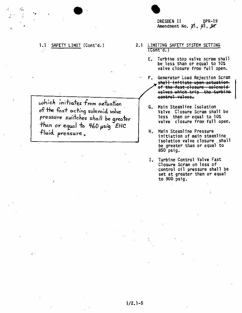
whic.~ ;nit;Cl,+es fyom o.cfuo.fton of the fo.s+ a.cf1n9 solenoid. volve pressuye switches sJ,o..11 be
9reater-
tho.n OY eiua.I fo Lf-60 psi9 EHC -fluid. pYessu.Ye 0
• DRESDEN II _QPR-19 Amendment No. jf , fJ , jK
2.1 LIMITING SAFETY SYSTEM SETTING (Cont'd.)
E. Turbine stop valve scram shall be less than or equal to 10% valve closure from full open.
F. Generator Load Rejection Scram shall iAitiate u~eA aetuatiaR of the fast elesuPe seleRaiS. valves wRisR tri~ tRe twrbiR& eaRtPal vah·es,
G. Main Steamline Isolation Valve Closure Scram shall be less than or equal to 10% valve closure from full open.
H. Main Steamline Pressure initiation of main steamline isolation valve closure shall be greater than or equal' to 850 psig.
I. Turbine Control Valve Fast Closure Scram on loss of control oil pressure shall be set at greater than or equal to 900 psig.
1/2.1-5
·: ,.
·.,
i .. i. 'f. i • r t r i l ~·
i
____ .....
c' '"
I'.'·. 2. 'J. LDIIT. SA.PITY SYSTEM SrrTIHC: BA.SIS
OUSDIDI U
.. ndment
<Cont'd.)
DPi-19 lo. ~. ]IS. '2· .»!
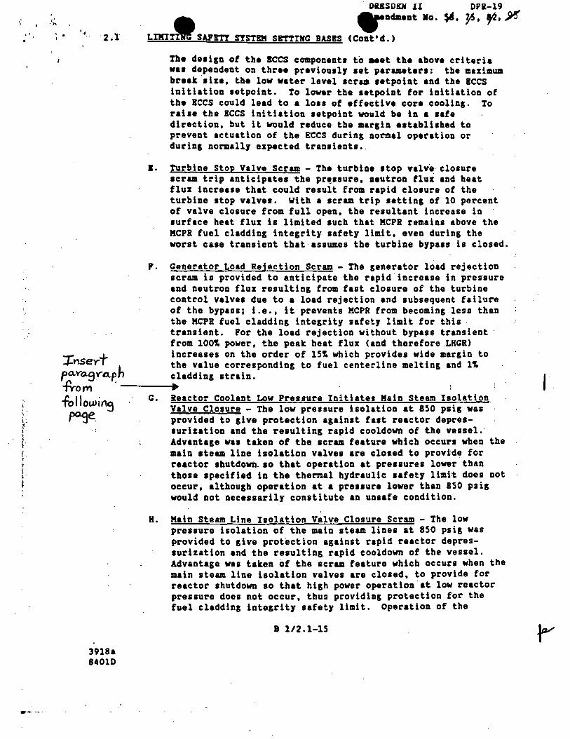
Th• de1ign of the secs component• to ... t th• above criteria va1 dependent on three previou1lJ 1et parameter1: the maximum break 1ize, the lov vater level 1crua 1etpoint and the ICCS initiation 1etpoint. To lower the 1etpoint for initiation of the ICCS could lead to a loss of effective core cooling. To raise the !CCS initiation setpoint would be in a safe direction, but it would reduce the margin established to prevent actuation of the ECCS during normal operation or during normally expected transients.
1. Turbine Stop Valve Scram - The turbine 1top valv·e· closure 1crua trip anticipate• tbe pr~saure, neutron flux and beat fluz increase that could result from rapid clo1ure of the turbine 1top valve•. With a 1cram trip setting of 10 percent of valve closure from full open, the resultant increase in 1urface heat flux is limited 1uch that KCPR remains above the MCPR fuel cladding integrity safety limit, even during the worst case transient that assumes the turbine bypa1s is closed.
F. Generator Load Rejection Scram - The generator load rejection scram is provided to anticipate the rapid· increase in pressure and neutron fluz resulting from fast closure of the turbine control valves due to a load rejection and subsequent failunt of the bypass; i.e., it prevents KCPR from becoming less than the KCPR fuel cladding integrity safety limit for this transient. For the load rejection without bypass transient from 100~ power, the peak heat flux <and therefore .LHGR)
....,.nser-t increases on the order of 15~ which provides wide margin to -l-1
6 the value corresponding to fuel centerline melting and l~ pa.Yo.9Yo...pn cladding strain. ..PY.om , ---__.• 1
fol lowin9
G. Reactor Coolant Low Pressure Ini thtes Main Steam Isolation Valve Closure - The low pressure isolation at 850 p1ig was
~e. provided to give protection against fast reactor depres-1urization and the resulting rapid cooldown of the vessel.· Advantage wa1 taken of the scram feature which occur• vben the main steam line holation valves are closed to provi:de for reactor 1hutdown.so that operation at pressures lover than those specified in the thermal hydraulic safety limi:t does not occur, although operation at a pressure lower than 850 psig would not necessarily constitute an unsafe condition.
3918a 84010
H. Kain Steam Line Isolation Valve Closure Scram - The low pressure isolation of the main steam lines at 850 psig was provided to give protection against rapid reactor depressurization and the resulting rapid cooldown of the vessel. Advantage was taken of the scram feature which occurs when the main steam line isolation valves are closed, to provide for reactor shutdown so that high power operation.at low reactor pressure does not occur, thus providing protection for the fuel cladding lnteg~lty safety limit. Operation of the
8 1/2.1-15
I
.... ~ ·•. •
Insert for Page B 1/2.1-15 (DPR-19)
• The trip setpoint of greater than or equal to 460 psig EHC fluid pressure was developed to ensure that the pressure switch is actuated prior to closure of the turbine control valves (at approximately 400 psig EHC fluid pressure) yet assure that the system is not actuated unnecessarily due to EHC system pressure transients which may cause EHC system pressure to momentarily decrease.
/scl:703:24
.. . , . DRESDEN II DPR-19 Amendment No. JK. p,)Jlr. ~
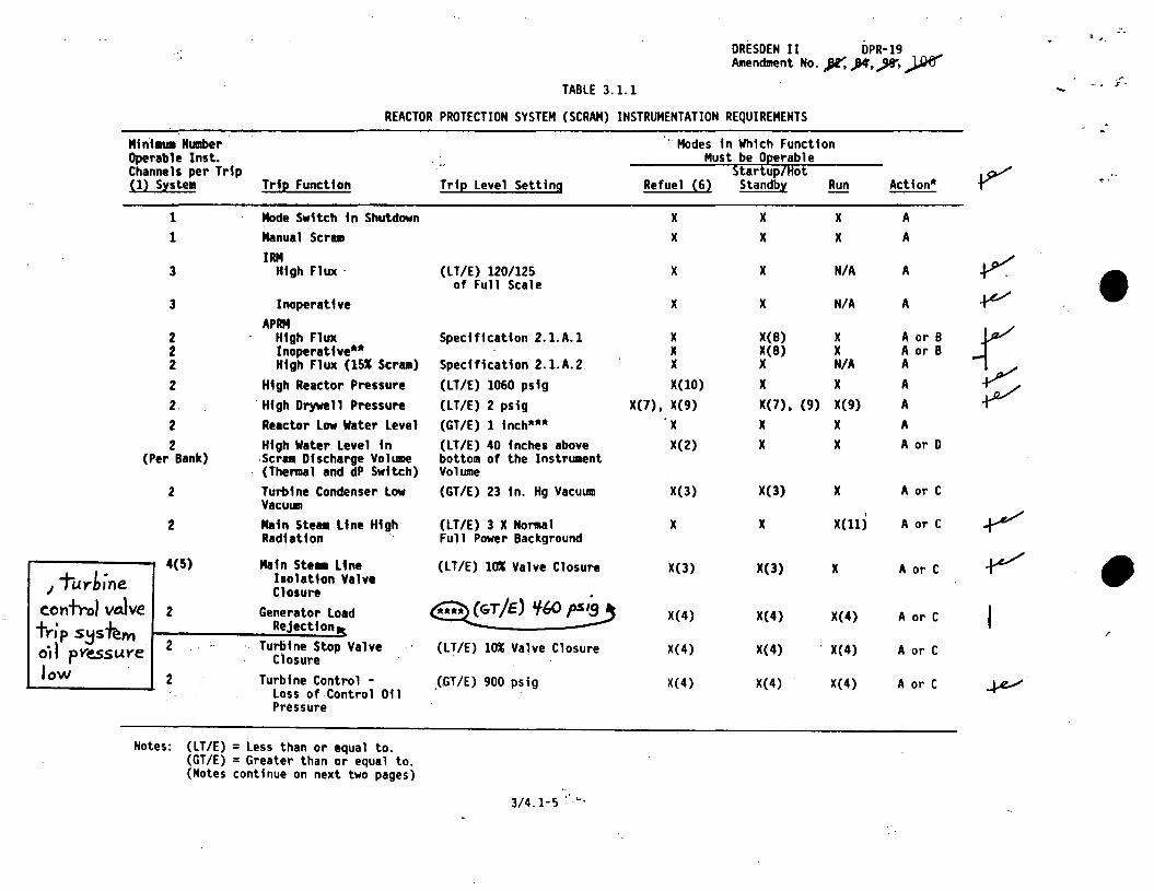
TABLE 3.1.l ;. .....
REACTOR PROTECTION SYSTEM (SCRAM) INSTRUMENTATION REQUIREMENTS . . Mint ... Number ··Modes in Which Function Operable Inst. Must be Oeerable Channels per Trip Startup/Hot {12 S,xstem Trie Function Trie Level Setting Refuel (62 Standb,x Run Action*
1 Mode Switch in Shutdown x x x A 1 Manual Scrui x x x A
IRM ~ 3 High Flux · (LT/E) 120/125 x x N/A A • of Full Scale
3 Inoperative x x N/A A +v APRM
t 2 High Flux Specification 2.1.A.l x X(8) x A or B 2 Inoperative** x X(8) x A or B 2 High Flux (151 Scr1111) Specification 2.1.A.2 x x N/A A 2 High Reactor Pressure (LT/E) 1060 psig X(lO) x x A 2. · Ht gh Drywe 11 Pressure (LT/E) 2 pstg X(7), X(9) X(7), (9) X(9) A ~ 2 Reactor Low Water Level (GT/E) 1 inch*** x x x A 2 High Water Level in (LT/E) 40 inches above X(2) x x A or D
(Per Bank) -Ser .. Discharge Volume bottom of the Instrument (Thermal and dP Switch) Volume
2 Turbine Condenser Low (GT/E) 23 in. Hg Vacuum X(3) X(3) x A or C Vacuum
I F 2 Main Ste1111 Line High (LT/E) 3 X Nol"llal x x X(ll) A or C Radiation Full Power Background
4(5) Main Stea Line (LT/E) lOI Valve Closure ~ • 1 Turbine Isolation Valve X(3) X(3) x A or C
Closure cot1+rol va.lve 2 Generator Load X(4) X(4) X(4) A or C frj p S!JS~M Reject tonk
/
o·tl pYe.ssu.Ye 2 Turbine Stop Valve (LT/E) 10% Valve Closure X(4) X(4) X(4) A or C Closure
low 2 Turbine Control - _(.GT/E) 900 ps;g X( 4) X(4) X(4) A or C ~ Loss of Control Oil Pressure
Notes: (LT/E) = Less than or equal to. (GT/E) = Greater than or equal to. (Notes continue on next two pages)
3/4.1-5 •'y,
" I:;
. · .. •
DRESDEN II DPR-19 Amendment No. }a', X, )15, ~. %'
~
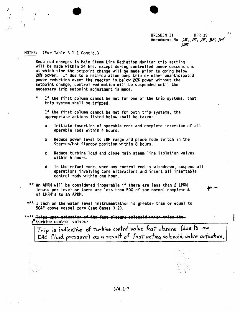
NOTES: (For Table 3.1.1 Cont'd.)
Required changes in Main Steam Line Radiation Monitor trip setting will be made within 24 hrs. except during controlled power descensions at which time the setpoint change will ~e made prior to going below 20% power. If due to a recirculation pump tri.p or other unanticipated power reduction event the reactor is below 20% power without the setpoint change, control rod motion will be suspended until the necessary trip setpoint adjustment is made.
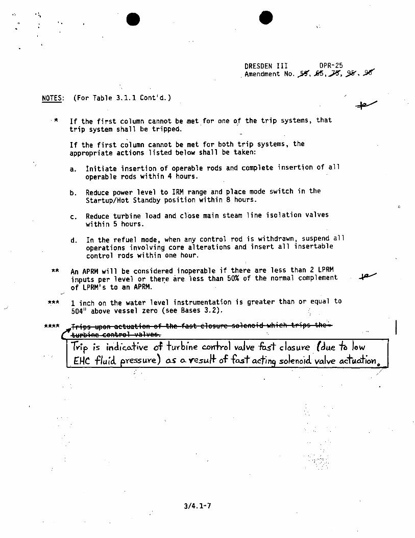
If the first column cannot be met for one of the trip systems, that trip system shall be tripped.
If the first column cannot be met for both trip systems, the appropriate actions listed below shall be taken:
a. Initiate insertion of operable rods and complete insertion of all operable rods within 4 hours.
b. Reduce power level to IRM range and place mode switch in the Startup/Hot Standby position within 8 hours.
c. Reduce turbine load and cl-0se main.steam line isolation valves within 5 hours. "'
d. In the refuel mode, when any control rod is withdrawn, suspend all operations involving core alterations and insert all insertable control rods within one hour.
** An APRM will be considered inoperable if there are less than 2 LPRM _aa...--inputs per level or there are less than 50% of the normal complement ~ of LPRM's to an APRM.
*** 1 inch on the water level instrumentation is greater than or equal to 504" above vessel zero (see Bases 3.2).
****,,Trips YpeA astYatieA ef tAe fast slesYre seleAei~ wAieh tPips tAe r ·t~P~iAe eeAtrel valves, .
Tvip is indic.Q.five of +uybine control va.lve fast closure (di..te fo low · EHC -fluid. pvessuye) as a. yesult of fas+ o.cfin~ so lenoicl. vo.lve acfuJ-,·cmo
'. " ~ . . ~;· : .
3/4.1-7
.: ·'
... ...
-..
• • DRESDEN II DPR-19 Amendment No. Ji ,j,I("
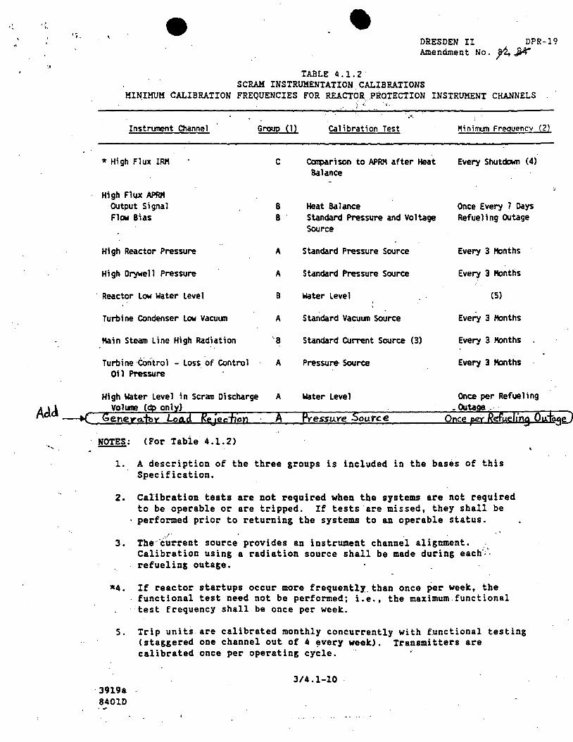
TABLE 4 .1. 2 SCRAM INSTRUMENTATION CALIBRATIONS
MINIMUM CALIBRATION FREQUENCIES FOR REACTOR .PROTECTION INSTRUMENT CHANNELS
· .•. Instrument Channel Group (1) cat;brat;on Test
* H;gh Flux IRH
High Flux APRM output s;gnal Fl~ e;as
Hf gh Reactor Pressure
High Orywell Pressure
· Reactor Low Water Level
Turbine Condenser Low Vacu1.111
Kain Steam Line High Radiation
Turbine ·control - Loss of Control Oil Pressure
High Water Level in Scram Discharge
C ~r;son to APRH after Heat Balance
B Heat Balance B Standard Pressure and Voltage
Source
A Standard Pressure Source
A Standard Pressure Source
B Water Level
A Standard Vacu\111 Source
··a Standard current Source (3)
A Pressure- Source
A Water Level
M;nirTl.1111 Freguencv (2)
Every Shutdown (4)
Once Every 7 Days Refueling Outage
Every 3 Months
Every 3 Months
(5)
Every 3 Months
Every 3 Honths
Every 3 Months
Once per Refue 1 i ng Add Vo 1 lllle ~ on 1 y)
--to(: Gener~ Y L>o.d RfJec"fJ~n A PY:essu.Ye Source -Ou~-
Once =Refueling Ouf~;J
......... ~: CFor Tabie 4.l.2)
l. A description of the three groups is included in the bases of this Specification.
2. Calibration tests are not required when the systems are not required to be operable or are tripped. If tests are missed, they shall be performed prior to returning the systems to an operable status.
3. The'°current source provides an instrument channel alignment •. Calibration using a radiation source shall be made during each~~ refueling outage.
•4. If reactor startups occur more frequently. than once per week, the functional test need not be performed; i.e., the maximum functional test frequency shall be once per week.
s. Trip units are calibrated monthly concurrently with functional testing (staggered one channel out of 4 ~very week). Transmitters·are calibrated once per operating cycle.
·J919a 84010
3/4.l-10

• • DRESDEN II DPR-19 Amendment No. )Pf
4.1 SURVEILLANCE REQUIREMENT BASES (Cont'd.)
of the sensor failure rate and the test interval. A threemonth test interval was planned for group (A) sensors. This is in keeping with good operating practice, and satisfies the design goal for the logic configuration utilized in the Reactor Protection System.
To satisfy the long-tenn objective of maintaining an adequate level of safety throughout the plant lifetime, a minimum goal of 0.9999 at the 951 confidence level is proposed. With the (1 out of 2) X (2) logic, this requires that each sensor have an availability of 0.993 at the 951 confidence level. This level of availability may be maintained by adjusting the test interval as a function of the observed failure history (See Reference 6). To facilitate the implementation of this technique, Figure 4.1.1 is provided to indicate an appropriate trend in test interval. The procedure is as follows:
1. Like sensors are pooled into one group for the purpose of data acquisition.
2~ The factor Mis the exposure hours and is equal to the number of sensors in a group, n, times the elapsed time T ( M = nT).
3. The accumulated number of unsafe failures is plotted as an ordinate against M as an abscissa on Figure 4. 1. 1.
4. After a trend is established, the appropriate monthly test interval to satisfy the goal will be the test interval tq the left of the plotted points .
..:Z:nser-f- 5. A t~st interval of one month will be used initially po.r~Yo.ph unti 1 a trend is established • .f.rom: ...,.....----...~ (
Group B) devices utilize an analog sensor followed by an followin~ amplifier and a bi-stable trip circuit. The sensor and
PO.Se amplifier are active components and a failure is almost always accompanied by an alann and an indication of the source of trouble. In the event of failure, repair or substitution can start immediately. An 11 as-is 11 failure is one that 11 sticks 11
Reference 6: Reliability of Engineered Safety Features as a Function of Testing Frequency, I.M. Jacobs, Nuclear Safety, Vol. 9, No. 4, July-Aug. 1968, pp. 310-312.
B 3/4.1-16
('
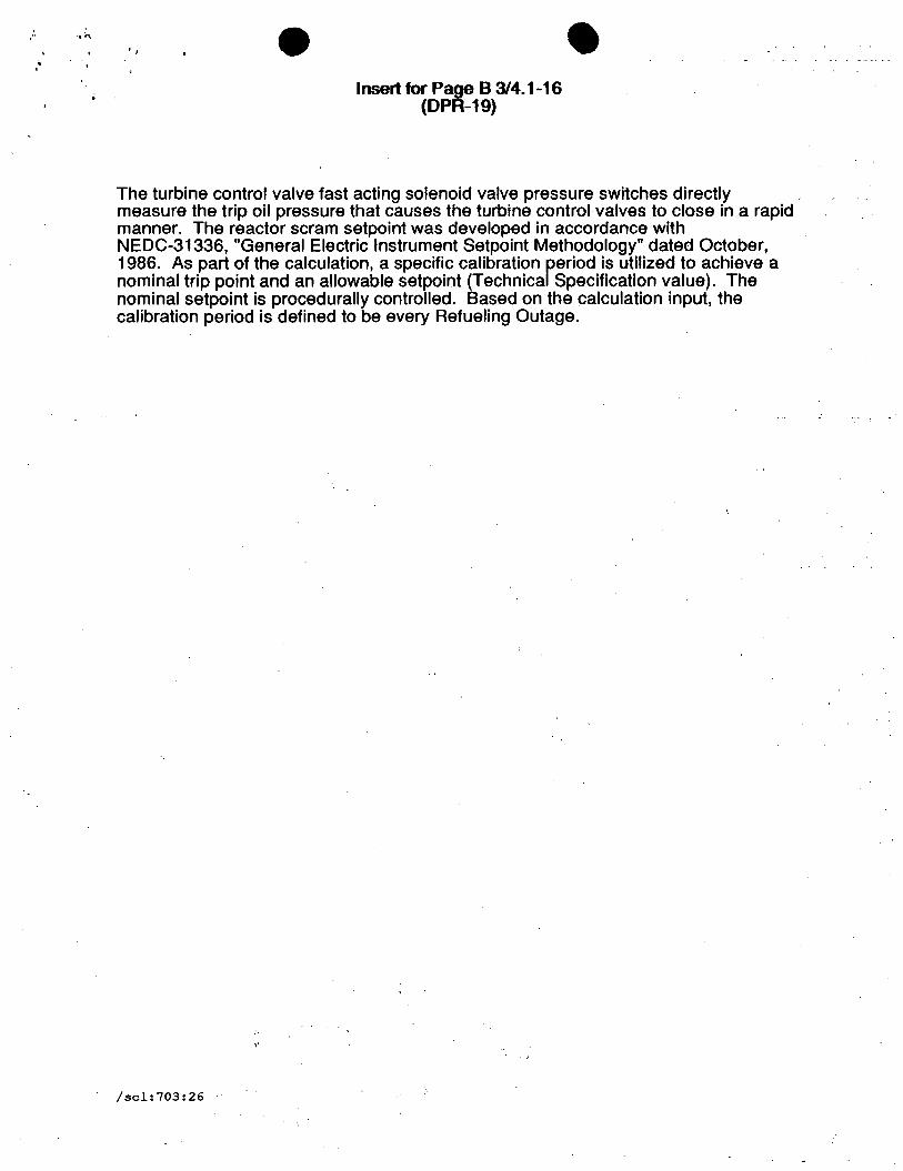
'I • Insert for Page B 3/4. 1-16
(DPR-19)
• The turbine control valve fast acting solenoid valve pressure switches directly measure the trip oil pressure that causes the turbine control valves to close in a rapid manner. The reactor scram setpoint was developed in accordance with NEDC-31336, "General Electric Instrument Setpoint Methodology" dated October, 1986. As part of the calculation, a specific calibration reriod is utilized to achieve a nominal trip point and an allowable setpoint (Technica Specification value). The nominal setpoint is procedurally controlled. Based on the calculation input, the calibration period is defined to be every Refueling Outage.
,.
/scl:703:26
'·•
'I • • DRESDEN II DPR-19 Amendment No. M, JM, ~' J,.94
4.1 SURVEILLANCE REQUIREMENT BASES (Cont'd.)
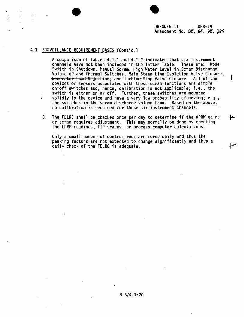
A comparison of Tables 4.1.1 and 4.1.2 indicates that six instrument channels have not been included in the latter Table. These are: Mode Switch in Shutdown, Manual Scram, High Water Level in Scram Discharge Volume dP and Thermal Switches, Main Steam Line Isolation Valve Closure, 6e"ePateP. Lea~ Rejeet~eA, and Turbine-Stop Valve Closure .. All of the I devices or sensors associated with these scram functions are simple on-off switches and, hence, calibration is not applicable; i.e., the switch is either on or off. Further, these switches are mounted · solidly to the device and have a very low probability of moving; e.g., the switches in the scram discharge volume tank. Based on the above, no calibration is required for these six instrument channels.
B. The FDLRC shall be checked once per day to determine if the APRM gains fe--or scram requires adjustment. This may normally be done by checking the LPRM readings, TIP traces, or process computer calculations.
Only a small number of control rods are moved daily and thus the peaking factors are not expected to change significantly and thus a daily check of the FDLRC is adequate.
B 3/4.1-20
•·, •• • DRESDEN III DPR-25 Amendment No. ~' SJ, ¢, ,)'!
1.1 SAFETY LIMIT (Cont'd.) 2.1 LIMITING SAFETY SYSTEM SETTING {Cont'd.)
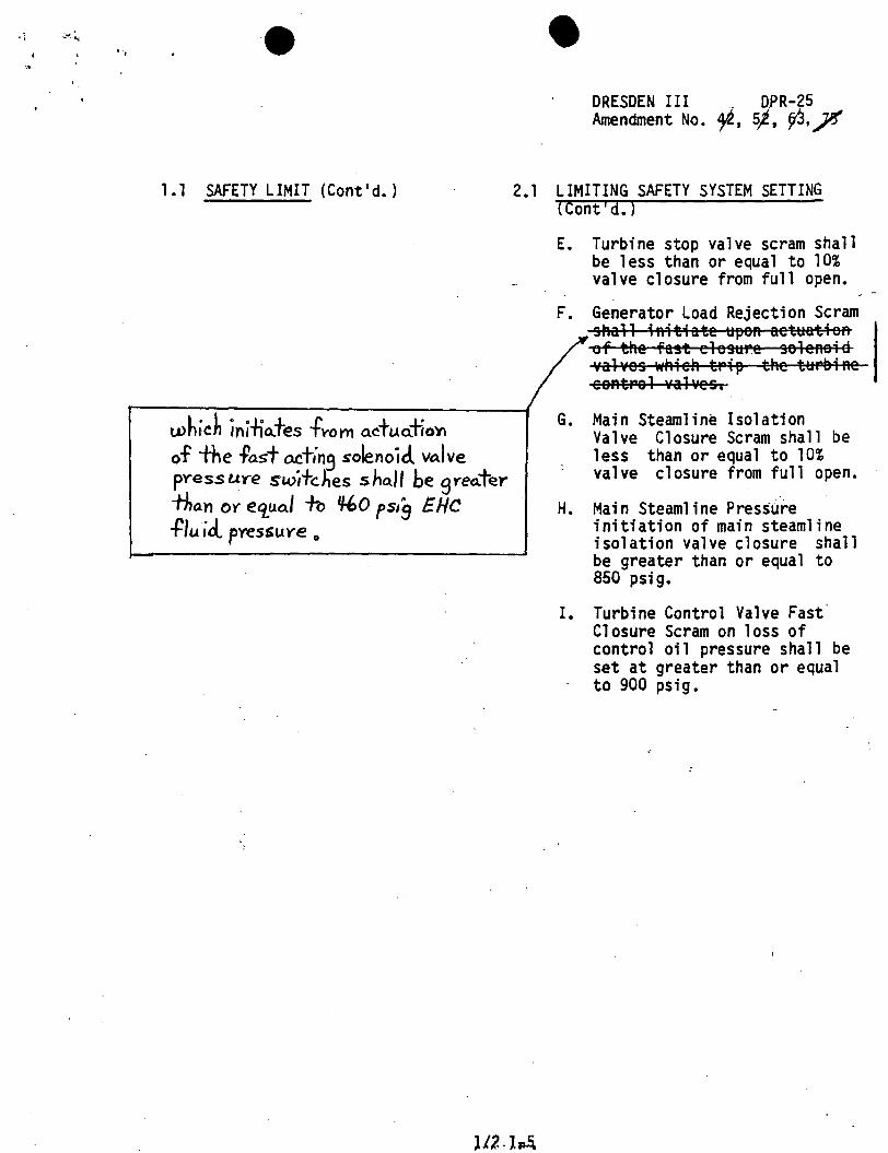
whic~ ini"lio..+es -h.-om o.ctuo..Tro'r\ of the .Past act;n9 solenoid. vo.lve pYess uye switches sha.11 be gYeCl.ter . than OY eq_ua.l -lb 1/-bO ps/g E HC flu id. pvessu.ye 11
lfZ.l~
E. Turbine stop valve scram shall be less than or equal to 10% valve closure from full open.
F. Generator Load Rejection Scram shall ;Aitiate ~peft aetuatieft of the fast elesure seleAei Ii valves whieh trip the turaiRe ceRtPel Yal vesa
G. Main Steamline Isolation Valve Closure Scram shall be less than or equal to 10% valve closure from full open.
H. Main Steamline Pressure initiation of main steamline isolation valve closure shall be greater than or equal to 850 psi g.
I. Turbine Control Valve Fast· Closure Scram on loss of control oil pressure shall be set at greater than or equal to 900 psig.
'" • DR.EN III Amendment No~
DPR-25 Y,pr
2.1 LIMITING SAFETY SYSTEM SETTING BASES (Cont'd.)
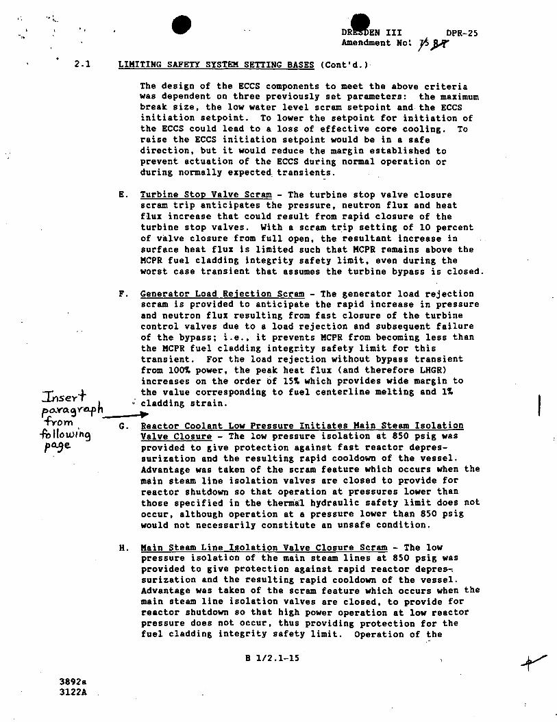
The design of the ECCS components to meet the above criteria was dependent on three previously set parameters: the maximum break size, the low water level scram setpoint and the ECCS initiation setpoint. To lower the setpoint for initiation of the ECCS could lead to a loss of effective core cooling. To raise the ECCS initiation setpoint would be in a safe direction, but it would reduce the margin established to prevent actuation of the ECCS during normal operation or during normally expected, transients.
E. Turbine Stop Valve Scram - The turbine stop valve closure scram trip anticipates the pressure, neutron flux and heat flux increase that could result from rapid closure of the turbine stop valves. With a scram t~ip setting of 10 percent of valve closure from full open, the resultant increase in surface heat flux is limited such that KCPR remains above the KCPR fuel cladding integrity safety limit, even during the worst case transient that assumes the turbine bypass is closed.
F. Generator Load Rejection Scram - The generator load rejection scram is provided to anticipate the rapid increase in pressure and neutron flux resulting from fast closure of the turbine control valves due to a load rejection and subsequent failure of the bypass; i.e., it prevents KCPR from becoming less than the MCPR fuel cladding integrity safety limit for this transient. For the load rejection without bypass transient from 100~ power, the peak heat flux (and therefore LHGR) increases on the order ~f 15~ which provides wide margin to
:friseyf the value corresponding to fuel centerline melting and l~ po..YCl~Ytlfh • cladding strain . .LO""' __ __,~~
TY "' G. Reactor Coolant Low Pressure Initiates Main Steam Isolation fr> llow1'n9 Valve Closure - The low pressure isolation at 850 psig was p~e provided to give protection against fast reactor depres
surization and the resulting rapid cooldown of the vessel. Advantage was taken of the scram feature which occurs when the main steam line isolation valves are closed to provide for reactor shutdown so that operation at pressures lower than those specified in the thermal hydraulic safety limit does not occur, although operation at a pressure lower than 850 psig would not necessarily constitute an unsafe condition.
3892a 3122A
H. Main Steam Line Isolation Valve Closure Scram - The low pressure isolation of the main steam lines at 850 psig was provided to give protection against rapid reactor depre&, surization and the resulting rapid cooldown of the vessel. Advantage was taken of the scram feature which occurs when the main steam line isolation valves are closed, to provide for reactor shutdown so that high power operation at low reactor pressure does not occur, thus providing protection for the fuel cladding integrity safety limit. Operation of the
B 1/2.1-15

'• . ' "
... •
Insert for Page B 1/2.1-15 (DPR-25)
• The trip setpoint of greater than or equal to 460 psig EHC fluid pressure was developed to ensure that the pressure switch is actuated prior to closure of the turbine control valves (at approximately 400 psig EHC fluid pressure) yet assure that the system is not actuated unnecessarily due to EHC system pressure transients which may cause EHC system pressure to momentarily decrease.
/scl:703:25
DRESDEN III DPR-25 Amendlnent No. H, SB, 71, ~ ~
.. •j - - 1;-
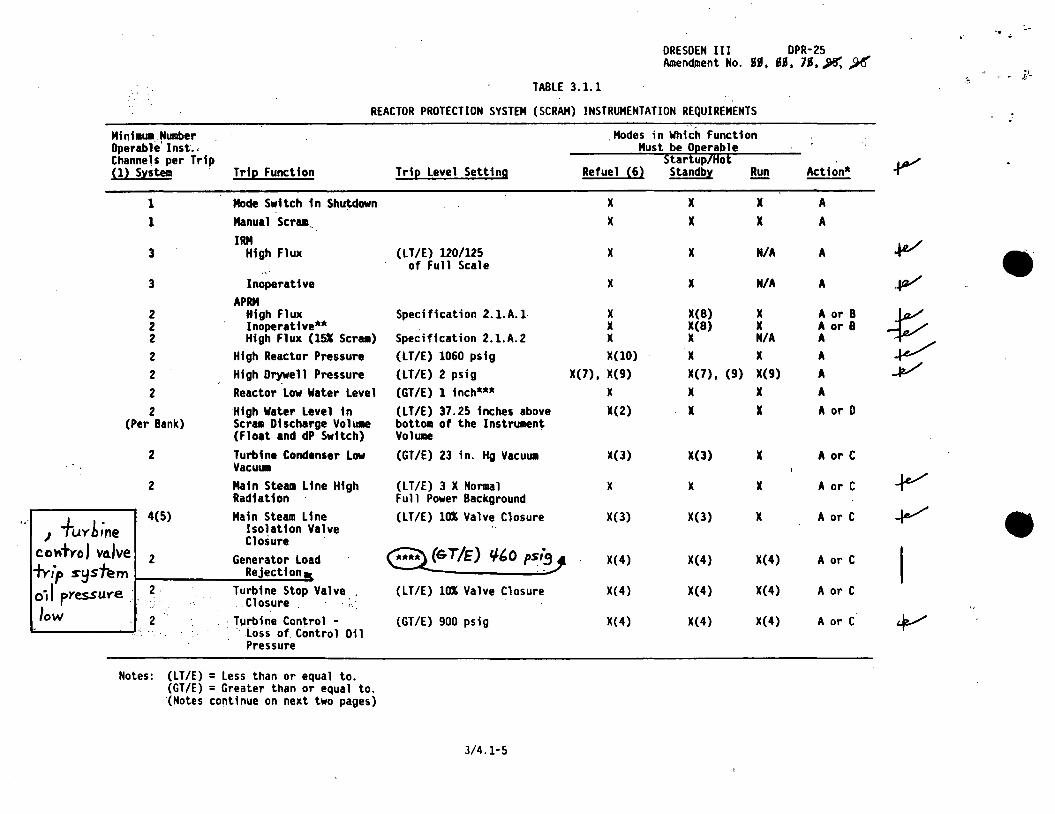
TABLE 3.1.1
REACTOR PROTECTION SYSTEM (SCRAM) INSTRUMENTATION REQUIREMENTS "
Mini•im.Number Modes in Which Function Operable' Inst·., Must be O~erable Channels per Trip Startup/Hot (1) System Trip Function Trip Level Setting Refuel (6) Standby !!!!! Action*
1 Mode Switch in Shutdown x x x A l Manua 1 Scrua .. x x x A
IRM 3 High Flux (LT/E) 120/125 x x N/A A
of Full Scale • 3 Inoperative x x N/A A APRM
2 High Flux Specification 2.1.A.l x X(B) x A or 8 2 Inoperative** x X(B) x A or B 2 High Flux (151 Scr1111) Specification 2.1.A.2 x x N/A A 2 High Reactor Pressure (LT/E) 1060 psig X(lO) x x A 2 High Drywell Pressure (LT/E) 2 psig X(7), X(9) X(7), (9) X(9) A 2 Reactor Low Water Level (GT/E) 1 inch*** x x x A 2 High Water level in (LT/E) 37.25 inches above X(2) x x A or D
(Per Bank) Scram Dtscharge VolUlle bottoe of the Instrumen~ (Float and dP Swttch) Volume
2 Turbine Condenser Low (GT/E) 23 in. Hg VacuUll X(3) X(3) x A or C Vacum
2 Main Steam Line Htgh (LT/E) 3 X Normal x x x A or C Radtatton Full Power Background
... J fuYbine
4(5) Main Steam Line (LT/E) 10% Valve Closure X(3) X(3) x A or C Isolation Valve Closure
coniYo J va.lve 2 Generator Load **** (Gi/E) tl&O psi~ X(4) X(4) X(4) A or C -tYi°p s~s"h!m Rejection a
0·1 I pYessuye .• 2 Turbine Stop Valve (LT/E) 10% Valve Closure X(4) X(4) X(4) A or C .Closure ...
low 2 · Turbine Contro 1 - (GT/E) 900 psig X(4) X(4) X(4) A or C ·. -· · Loss of Control Oil
• Pressure
Notes: (LT/E) = less than or equal to. (GT/E) = Greater than or equal to. '(Notes co~tinue on next two pages)
3/4.1-5
•'.. . . • DRESDEN III DPR-25 Amendment No. %. ,fJ5, ..)/!{, jlh', :¥'
NOTES: (For Table 3.1.1 Cont'd.)
If the first column cannot be met for one of the trip systems, that trip system shall be tripped. · -
If the first column cannot be met for both trip systems, the appropriate actions listed below shall be taken:
a. Initiate insertion of operable rods and complete insertion of all operable rods within 4 hours.
b. Reduce power level to IRM range and place mode switch in the Startup/Hot Standby position within 8 hours.
c. Reduce turbine load and cl~se main steam line isolation valves within 5 hours.
d. In the refuel mode, when any control rod is withdrawn, suspend all operations involving core alterations and insert all insertable control rods within one hour.
** An APRM will be considered inoperable if there are less than 2 LPRM inputs per level or ther:e are less than 50% of the normal complement of LPRM's to an APRM.
*** 1 inch on the water level instrumentation is greater than or equal to 504" above vessel zero (see Bases 3.2).
**** Trips ~peA aet~atieA ef the fast ~les~re seleAei~ w~ie~ tri~s i~e~ iYP~iRe eeRiPel valve&.
Tw-ip is incllc.o..tive OT tuv-bine c:.onf....ol v~lve -fust closuYe (due fo low £~C fluid.. yessu-Ye) o.s o. -resuH- of -fa.st actin soleno'1d. valve o.ctu.o.fio't'J •
/
- .
·.·'. ··.
3/4.1-7
[:
,\ •·' 'l ..
TABLE 4 . 1. 2 · SCRAM INSTRUMENTATION CALIBRATIONS
.DRESDEN III Amendment No.
DPR-25 ¥5 ~
MINIMUM CALIBRATION FREQUENCIES FOR REACTOR PROTECTION INSTRUMENT CHANNELS
lnstrunent Channel
*High Flux 1Rf4
High Flux APRM output Signal Fl<* Bias
High Reactor Pressure
High Drywell Pressure
Reactor LON water Level
Turbine Condenser L<* Vacu1.111
Main Steam Line High Radiation
Tu1. Control - loss of Control Oi 1 Pressure
Group (1)
c
B B
A
A
B
A
B
A·
calibration Test
~rison to ~ after Heat Balance
Heat Balance Standard Pressure and Voltage Source
Standard Pressure Source
Standard Pressure Source
water Level
Standard Vacu1.111 Source
Standard current Source (3)
Pressure Source
"inillllll Frequency (2}
Every Shutdown (4)
Once Every 7 Days Refueling outage
Every 3 "°nths
Every 3 "°nths
(5)
Every 3 "°nths
Every 3."°nths
Every 3 "°nths
High water Level in Scram Discharge Yoh111e (~ only)
A water Level once per Refueling outage
Adel
' Ger.era.-h>Y LooJ. Re 'ec.non A Pressuye Souvce Once
3893a ~,.,.,.
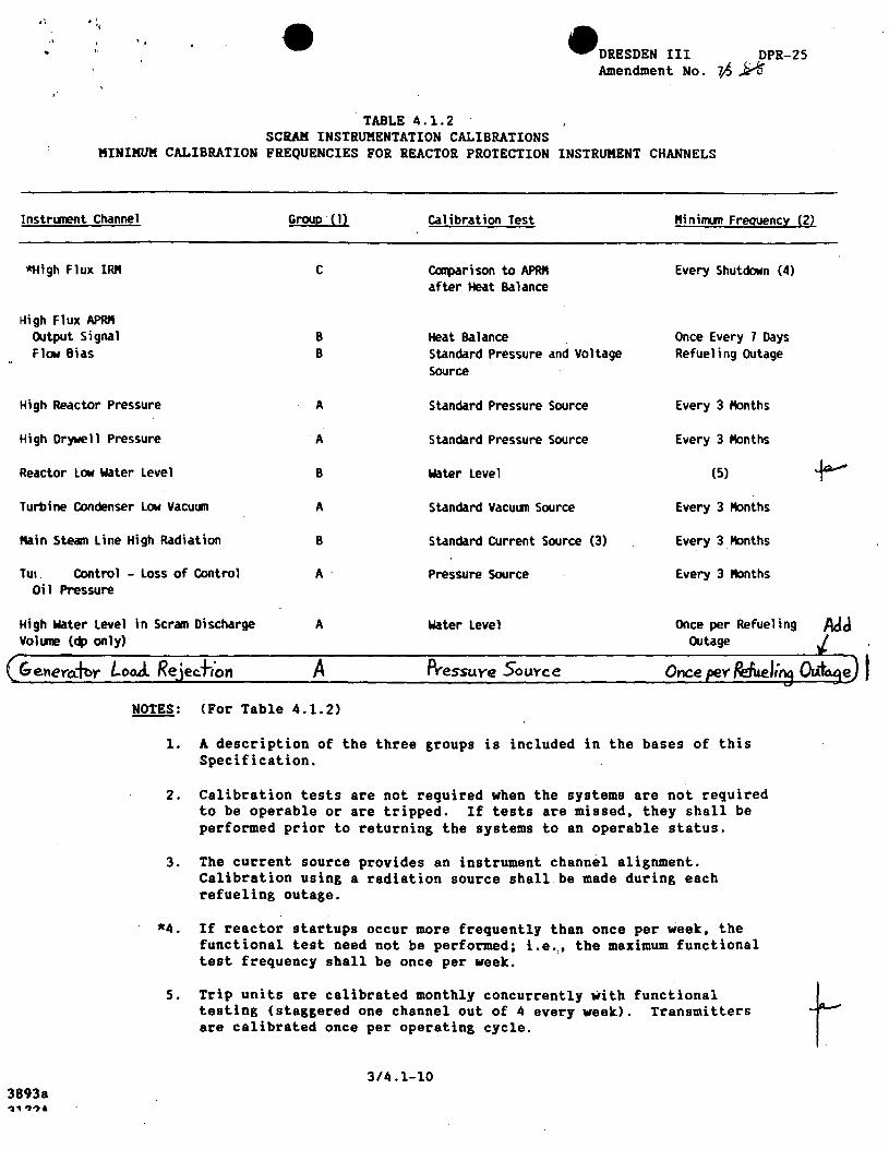
~: (For Table 4.1.2)
1. A description of the three groups is included in the bases of this Specification.
2. Calibration tests are not required when the systems are not required to be operable or are tripped. If tests are missed, they shall be performed prior to returning the systems to an operable status.
3. The current source provides an instrument channel alignment. Calibration using a radiation source shall.be made during each refueling outage.
*4. If reactor startups occur more frequently than once per week, the functional test need not be performed; i.e.,, the maximum functional test frequency shall be once per week.
5. Trip units are calibrated monthly concurrently with functional ttesting (staggered one channel out of 4 every week). Transmitters are calibrated once per operating cycle. .
3/4.1-10
e
f' .. DRESDEN III DPR-25 Amendment No. )9, )5
4.1 SURVEILLANCE REQUIREMENT BASES (Cont'd.)
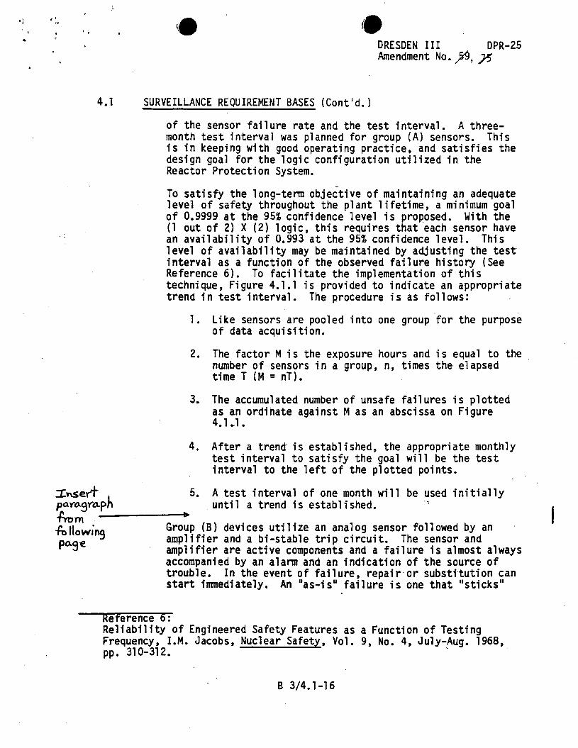
of the sensor failure rate and the test interval. A threemonth test interval was planned for group (A) sensors. This is in keeping with good operating practice, and satisfies the design goal for the logic configuration utilized in the Reactor Protection System.
To satisfy the long-tenn objective of maintaining an adequate level of safety throughout the plant lifetime, a minimum goal of 0.9999 at the 95% confidence level is proposed. With the (l out of 2) X (2) logic, this requires that each sensor have an availability of 0.993 at the 95% confidence level. This level of availability may be maintained by adjusting the test interval as a function of the observed failure history (See Reference 6). To facilitate the implementation of this technique, Figure 4.1.l is provided to indicate an appropriate trend in test interval. The procedure is as follows:
l. Like sensors are pooled into one group for the purpose of data acquisition.
2. The factor Mis the exposure hours and is equal to the number of sensors in a group, n, times the elapsed ti me T { M = n T) •
3. The accumulated number of unsafe failures is plotted as an ordinate against M as an abscissa on Figure 4.1 .. l.
4. After a trend is established, the appropriate monthly test interval to satisfy the goal will be the test interval to the left of the plotted points.
:tnsert 5. A test interval of one month will be used initially f>O.Yo.9Yo..ph . until a trend is established. ·· ti-om ----------~ ~llowino Group (B) devices utilize an analog sensor followed by an
··~ amplifier and a bi-stable trip circuit. The sensor and po.ge amplifier are active components and a failure is almost always
accompanied by an alann and an indication of the source of trouble. In the event of failure, repair or substitution can start immediately. An "as-is" failure is one that· "sticks"
Reference 6: Reliability of Engineered Safety Features as a Function of Testing Frequency, I.M. Jacobs, Nuclear Safety, Vol. 9, No. 4, July-Aug. 1968, pp. 310-312. .
B 3/4.1-16
. ' ,.
..
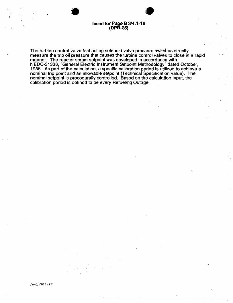
Insert for Page B 3/4. 1-16 (DPR-25)
The turbine control valve fast acting solenoid valve pressure switches directly measure the trip oil pressure that causes the turbine control valves to close in a rapid manner. The reactor scram setpoint was developed in accordance with NEDC-31336, "General Electric Instrument Setpoint Methodology" dated October, 1986. As part of the calculation, a specific calibration reriod is utilized to achieve a nominal trip point and an allowable setpoint (Technica Specification value). The nominal setpoint is procedurally controlled. Based on the calculation input, the calibration period is defined to be every Refueling Outage.
/scl:703:27
.. ' ..
DRESDEN III DPR-25 Amendment No. }15, Ji'(, ~, };'(
4.1 SURVEILLANCE REQUIREMENT BASES (Cont'd.)
A comparison of Tables 4.1.1 and 4.1.2 indicates that six instrument channels have not been included in the latter Table. .These are: Mode Switch in Shutdown, Manual Scram, High Water Level in Scram Discharge Volume Float Switches, Main Steam Line Isolation Valve. Closure, 6eAePateP Leas RejeeiieR; and Turbine Stop Val~e Closure. All of the devices or sensors associated w-ith these scram functions are simple on-off swi.tches and, hence, calibration is not applicable; i.e., the switch is either on or off. Further, these switches are mounted solidly to the device and have a very low probability of moving; e.g., the switches in the scram discharge volume tank. Based on the above, no calibration is required for these six instrument channels.
B. The FDLRC shall be checked once per day to determine if the APRM gains or scram requires adjustment. This may normally be done by checking in the LPRM readings, TIP traces, or process computer calculations.
Only a small number of control rods are moved daily and thus the peaking factors are not expected to change significantly and thus a daily check of the FDLRC is adequate.
B 3/4.1-20
... •I . •.. '. • • ATTACHMENT D
EVALUATION OF SIGNIFICANT HAZARDS CONSIDERATION
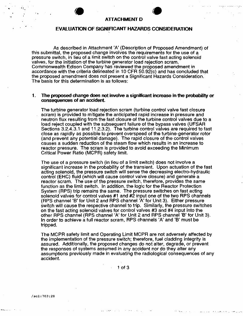
As described in Attachment 'A' (Description of Proposed Amendment) of this submittal, the proposed change involves the requirements for the use of a pressure switch, in lieu of a limit switch on the control valve fast acting solenoid valves, for the initiation of the turbine generator load rejection scram. Commonwealth Edison Company has reviewed the proposed amendment in accordance with the criteria delineated in 10 CFR 50.92(c) and has concluded that the proposed amendment does not present a Significant Hazards Consideration.· The basis for this determination is as follows:
1. The proposed change does not involve a significant increase in the probability or consequences of an accident.
The turbine generator load rejection scram (turbine control valve fast closure scram) is provided to mitigate the anticipated rapid increase in pressure and neutron flux resulting from the fast closure of the turbine control valves due to a load reject coupled with the subsequent failure of the bypass valves (UFSAR Sections 3.2.4.3.1 and 11.2.3.2). The turbine control valves are required to fast close as rapidly as possible to prevent overspeed of the turbine-generator rotor (and prevent any potential damage). The rapid closure of the control valves causes a sudden reduction of the steam flow which results in an increase to reactor pressure. The scram is provided to avoid exceeding the Minimum Critical Power Ratio (MCPR) safety limit.
The use of a pressure switch (in lieu of a limit switch) does not involve a significant increase in the probability of the transient. Upon actuation of the fast acting solenoid, the pressure switch will sense the decreasing electro-hydraulic control (EHC) fluid (which will cause control valve closure) and generate a reactor scram. The use of the pressure switch, therefore, provides the same function as the limit switch. In addition, the logic for the Reactor Protection System (RPS) trip remains the same. The pressure switches on fast acting solenoid valves for control valves #1 and #2 input one of the two RPS channels (RPS channel 'B' for Unit 2 and RPS channel 'A' for Unit 3). Either pressure switch will cause the respective channel to trip. Similarly, the pressure switches on the fast acting solenoid valves for control valves #3 and #4 input into the other RPS channel (RPS channel 'A' for Unit 2 and RPS channel 'B' for Unit 3). In order to achieve a full reactor scram, RPS channels 'A' and 'B' must be tripped.
The MCPR safety limit and Operating Limit MCPR are not adversely affected by the implementation of the pressure switch; therefore, fuel cladding integrity is assured. Additionally, the proposed changes do not alter, degrade, or prevent the responses of systems assumed in any accident nor do they alter any assumptions previously made in evaluating the radiological consequences of any accident.
1 of 3
/scl:703:28
_,._- ..... -· - ..... '
•I"
'• -' . • • AlTACHMENT D (Cont'd)
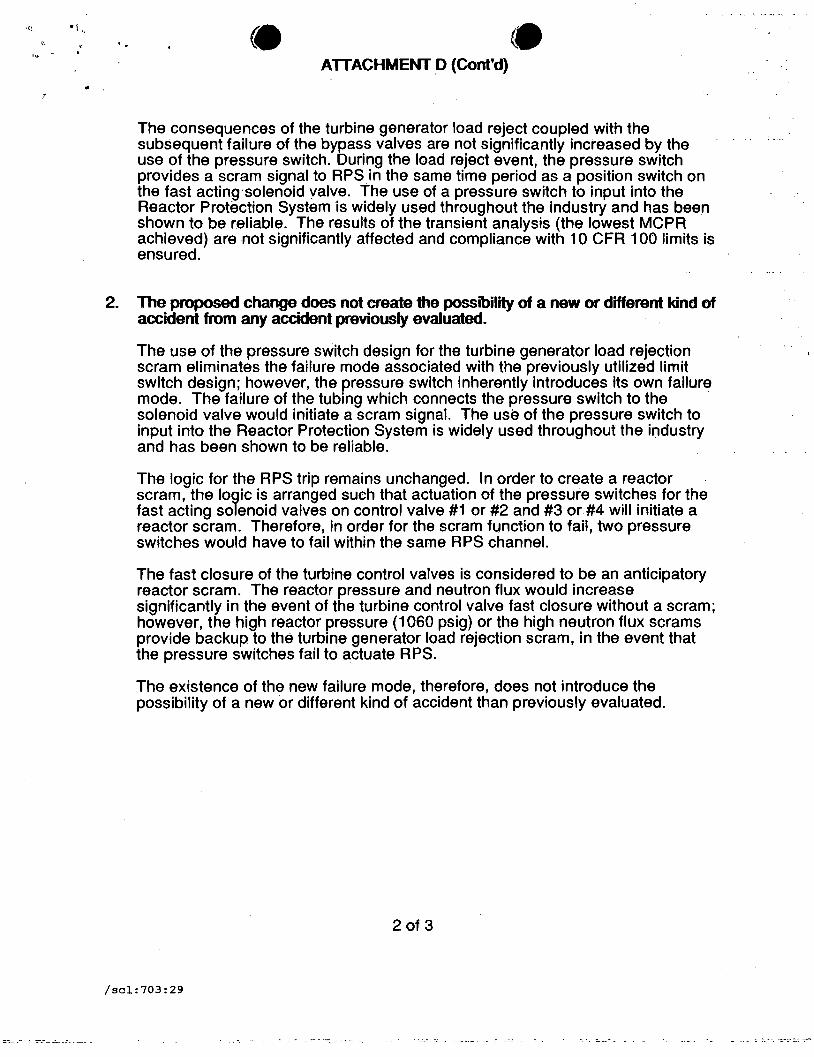
The consequences of the turbine generator load reject coupled with the subsequent failure of the bypass valves are not significantly increased by the use of the pressure switch. During the load reject event, the pressure switch provides a scram signal to RPS in the same time period as a position switch on the fast acting·solenoid valve. The use of a pressure switch to input into the Reactor Protection System is widely used throughout the industry and has been shown to be reliable. The results of the transient analysis (the lowest MCPR achieved) are not significantly affected and compliance with 10 CFR 100 limits is ensured.
2. The proposed change does not create the possibility of a new or different kind of accident from any accident previously evaluated.
The use of the pressure switch design for the turbine generator load rejection scram eliminates the failure mode associated with the previously utilized limit switch design; however, the pressure switch inherently introduces its own failure mode. The failure of the tubing which connects the pressure switch to the solenoid valve would initiate a scram signal. The use of the pressure switch to input into the Reactor Protection System is widely used throughout the industry and has been shown to be reliable.
The logic for the RPS trip remains unchanged. In order to create a reactor scram, the logic is arranged such that actuation of the pressure switches for the fast acting solenoid valves on control valve #1 or #2 and #3 or #4 will initiate a reactor scram. Therefore, in order for the scram function to fail, two pressure switches would have to fail within the same RPS channel.
The fast closure of the turbine control valves is considered to be an anticipatory reactor scram. The reactor pressure and neutron flux would increase significantly in the event of the turbine control valve fast closure without a scram; however, the high reactor pressure (1060 psig) or the high neutron flux scrams provide backup to the turbine generator load rejection scram, in the event that the pressure switches fail to actuate RPS.
The existence of the new failure mode, therefore, does not introduce the possibility of a new or different kind of accident than previously evaluated.
2 of 3
/scl:703:29
...,.1 ' .
... • • .ATTACHMENT D (Cont'd)
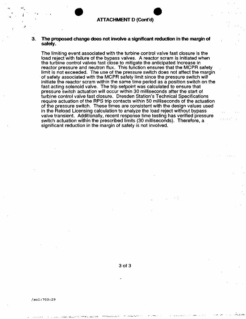
3. The proposed change does not involve a significant reduction in the margin of safety.
The limiting event associated with the turbine control valve fast closure is the load reject with failure of the bypass valves. A reactor scram is initiated when the turbine control valves fast close to mitigate the anticipated increase in reactor pressure and neutron flux. This function ensures that the MCPR safety limit is not exceeded. The use of the pressure switch does not affect the margin of safety associated with the MCPR safety limit since the pressure switch will initiate the reactor scram within the same time period as a position switch on the fast acting solenoid valve. The trip setpoint was calculated to ensure that pressure switch actuation will occur within 30 milliseconds after the start of turbine control valve fast closure. Dresden Station's Technical Specifications require actuation of the RPS trip contacts within 50 milliseconds of the actuation of the pressure switch. These times are consistent with the design values used in the Reload Licensing calculation to analyze the load reject without bypass . valve transient. Additionally, recent response time testing has verified pressure switch actuation within the prescribed limits (30 milliseconds). Therefore, a · significant reduction in the margin of safety is not involved.
3 of 3
/scl:703:29
- -- - ~:___:- - __ . _-::__
·)
:.r
. . • ATTACHMENT E • OPERATION OF THE ELECTRO-HYDRAULIC CONTROL (EHC) SYSTEM
The following provides a brief synopsis of the operation of the EHC System as it relates to the control valves and the load reject signal to assist in the review of the proposed amendment. The EHC pressure control and logic system, and the EHC hydraulic system, work in conjunction to control turbine operation. .
I. EHC Pressure Control and logic System
The purpose of the EHC pressure control and logic system is to position the turbine control valves, intercept valves, arid bypass valves in order to achieve the. turbine speed or load which is consistent with the ability of the reactor to supply adequate steam. The system also controls and maintains reactor pressure during plant startup, heatup and cooldown. The EHC pressure control and logic system Is comprised of five (5) subsystems which includes the pressure control unit, bypass control unit, load control unit, speed and acceleration control unit and the valve flow control unit.
The purpose of the load control unit is to develop a steam flow signal which represents the desired load to be placed on the turbine. The load control unit of the EHC pressure control and logic system will develop a power/load unbalance (load reject) signal when the mismatch between turbine crossover pressure and generator· load (stator amps) exceeds 40%. The load unbalance signal actuates relays which send a signal to the turbine fast acting solenoid valves. The fast acting solenoid valves energize which causes the fast closure of the turbine control valves by rapidly decreasing the EHC fluid pressure, as detailed in the following sections of this discussion. ·
II. EHC Hydraulic System
The purpose of the EHC hydraulic system is to supply cooled, filtered, high pressure fluid for the control of the turbine valves.
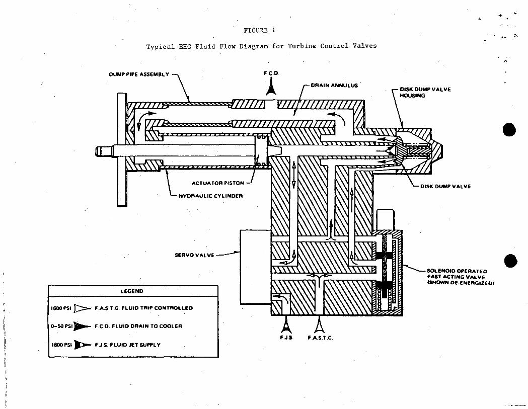
The turbine control valve hydraulic positioning unit contains two ports which are supplied by high pressure hydraulic fluid (as shown on Figure 1 ). The Fluid Jet Supply (FJS) enters one of the ports of the positioning unit (pressure rated at 1600 psig) and is directed to a servo-valve. The purpose of the servo-valve is to convert low level input signals from the EHC pressure control logic into high level hydraulic outputs which are used to position the control valves. The second .. hydraulic fluid supply is the Fluid Actuator Supply Trip Control (FASTC) fluid which is also rated at 1600 psig. The FASTC fluid enters the positioning unit and is directed to the servo-valve and the fast acting solenoid valve. The FASTC fluid is transmitted through the fast acting solenoid valve (in the de-energized state) to close the disk dump valve, sealing the end of the hydraulic positioning cylinder. With the disk dump valve sealing the end of the hydraulic positioning cylinder, the servo-valve (with the aid of the FJS fluid pressure) controls FASTC to the single acting actuator piston for positioning of the control valve. The FASTC pressure opens/positions the turbine control valve against the closing spring force and steam pressure. When the fast acting solenoid valves are energized, the disk dump valve will open to exhaust the positioning cylinder pressure and cause a rapid closure of the turbine control valve.
1 of 2
/scl:703:30
' - - - -- -~ --=~~===-==--=.::=_:==-~ ..::-==--".__-....:_:__~..........:=.=~-::::'.--==..:: -_·_;~..::· _-:--=.:.~- ·_-:;::__ ___ ·:.=:..-=::...=..::. - ·---.::----==~-__:::::-".:..._"::-~'.::=. --=-=--~~...: -='.--'....:..;.:::--=---=-·~-=:...=.- ':-.:..-_ -- - - . ---- -· .. -·· -
. . AlTACHMENT E (Cont'd) •
.r Ill. Operation during the Turbine/Generator Load Mismatch
When the load control unit of the EHC logic system senses the turbine/generator load mismatch, the logic system sends a signal to the fast acting solenoid valves to energize and reposition. When the fast acting solenoid valves reposition, the following occurs:
a. The FASTC fluid, which holds the disk dump valve seated, begins to drain as a result of the repositioned fast acting solenoid valve; causing a rapid pressure decrease.
b. The fast acting solenoid valve pressure switch senses decreasing FASTC fluid pressure and at a pressure equal to or greater than 460 psig initiates a scram signal to the Reactor Protection System. · ·
c.
d.
*
Under the original design, a position switch on the fast acting solenoid valve sensed that the fast acting solenoid valve had repositioned and initiated the scram signal to the Reactor Protection System.
When the FASTC fluid pressure decreases to approximately 400 psig, the disk dump valve is forced away from its seat and the FASTC fluid in the hydraulic positioning cylinder is rapidly drained.*
The control valve closes rapidly.
The F ASTC fluid pressure which holds the disk dump valve closed/seated (referred to as the 'trip system') must decrease to approximately one-fourth of the FASTC fluid pressure in the hydraulic positioning cylinder before the disk dump valve is opened (or forced away from its seat) to allow for control valve fast closure. This is due to the 4-to-1 area ratio between the top and bottom of the disk dump valve. When a control valve is full open (against its mechanical stop) the positioning cylinder fluid pressure would be approximately 1600 psig, necessitating the 'trip system' fluid pressure to decrease to approximately 400 psig before control valve fast closure can begin. However, during normal plant operating conditions at Dresden Station, the control valves are always in a controlling state or less than full open (all control valves are approximately 60% open at full load conditions). With the control valves less than full open, the positioning cylinder fluid pressure would be less than 1600 psig (approximately 800 to 1000 psig), necessitating the 'trip system' fluid pressure to decrease to a lower pressure (approximately 200 to 250 psig) before control valve fast closure can begin.
2 of 2
/scl:703:32
:..--=::- =......:-=-----~---~ "._ -- - :'.--
\! I\ 1:
It " ,, ,. " i!
FIGURE 1
Typical EHC Fluid Flow Diagram for Turbine Control Valves
DUMP PIPE ASSEMBLY
AC TUA TOR PISTON
HYDRAULIC CYLINDER
SERVO VALVE
LEGEND
1600PSI }::::::-· F.A.S.T.C. FLUID TRIP CONTROLLED
0-SO PSI~ F .C.0. FLUID DRAIN TO COOLER
1600 PSI ~ F .J.S. FLUID JET SUPPLY
DRAIN ANNULUS .
F.J.S. F.A.S.T.C.
DISK DUMP VAL VE HOUSING
DISK DUMP VAL VE
SOLENOID OPERATED . FAST ACTING VALVE
ISHOWN OE-ENERGIZED!
•
••

•• U.1
. . - • ATTACHMENT F
PRESSURE SWITCH SETPOINT DETERMINATION
/scl:703:33
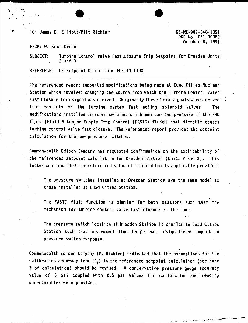
. ( ., .... • • TO: James D. Elliott/Milt Richter GE-NE-909-048-1091
ORF No. C71-00089 October 8, 1991
FROM: W. Kent Green
SUBJECT: Turbine Control Valve Fast .Closure Trip Setpoint for Dresden Units 2 and 3
REFERENCE: GE Setpoint Calculation EDE-40-1190
The referenced report supported modifications being made at Quad Cities Nuclear Stat1on which involved changing the source from which th~ Turbine Control Valve Fast Closure Trip signal was derived·. Originally these trip signals were derived from contacts on the turbine system fast acting solenoid valves. The
·modifications installed pressure switches which monitor the pressure of the EHC fl~id [Fluid Actuator Supply Trip Control (FASTC) fluid] that directly causes turbine control valve f~st closure. The referenced report provides the setpoint calculation for the new pressure switches.
Commonwealth Edison Company has requested confirmation on the applicability of · the referenced setpoint calculation for Dresden Station (Units 2 and 3). This
letter confirms that the referenced setpoint calculation is applicable provided:
The pressure switches installed at Dresden Station are the same model as those.installed at Quad Cities Station.
The FASTC fluid function is similar for both stations such that the mechanism for turbine control valve fast c'"fosure is the same.
The pressure switch location. at Dresden Station is similar to Quad Cities Station such that instrument line length has insignificant impact on pressure switch response.
Commonwealth Edison Company (M. Richter) indicated that the assumptions for the calibration accuracy tenn (Cy) in the referenced setpoint calculation (see page 3 of calculation) should be revised .. A conservative pressure gauge accuracy value of 5 psi coupled with 2.5 psi values for calibration and reading uncertainties were provided.
"' ~I ~ ... , l• • I
·1..?., •.\ i .
<" • • The setpoint calculation identifies a calibration accuracy for the pressure switch of 1% of full range (30 psi); therefore, a 5 psi pressure gauge accuracy is bounded by the calculation. Additionally, the required limit (RL) term in the setpoint calculation only changed from 520.03 psig to 520.31 psig as a result of the changes in the calibration accuracy term. An RL value of 540 psig is utilized in the calculation to meet the 90% probabi.lity requirement for LER avoidance.
Therefore, the increase in calibration accuracy uncertainties has no effect on the setpoint calculations.
Prepared by: -~~ N,,,..._/ W:i<nt Green Lead System En ineer -Reactor Pr. te ion System
--- ---~~--~-::-- -=-:::::-:~--=-=------- .:::=-- - -- -