Project Work Plan - SNU OPEN COURSEWARE
52
Week 5 Project Work Plan 457.657 Civil and Environmental Project Management Department of Civil and Environmental Engineering Seoul National University Prof. Seokho Chi [email protected] 건설환경공학부 35동 304호
-
Upload
khangminh22 -
Category
Documents
-
view
1 -
download
0
Transcript of Project Work Plan - SNU OPEN COURSEWARE
Week 5
Project Work Plan
457.657 Civil and Environmental Project ManagementDepartment of Civil and Environmental Engineering
Seoul National University
Prof. Seokho [email protected]
건설환경공학부 35동 304호
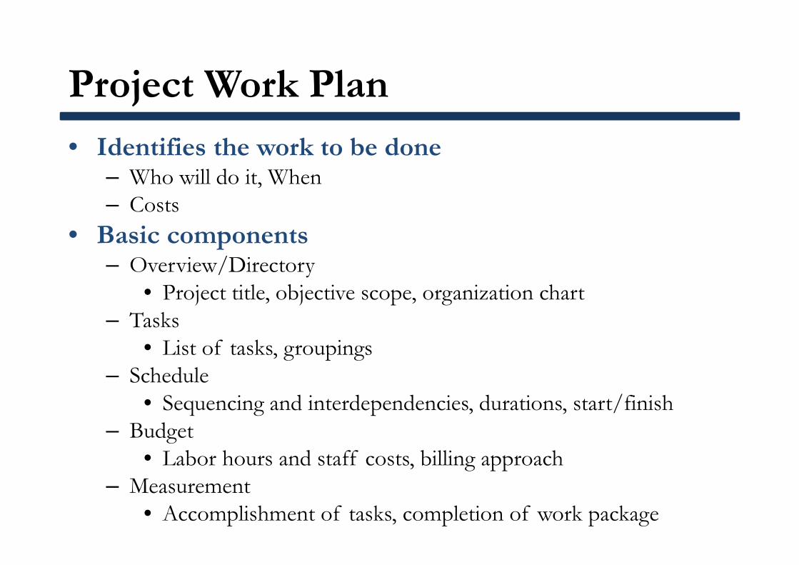
Project Work Plan
• Identifies the work to be done– Who will do it, When– Costs
• Basic components– Overview/Directory
• Project title, objective scope, organization chart– Tasks
• List of tasks, groupings– Schedule
• Sequencing and interdependencies, durations, start/finish– Budget
• Labor hours and staff costs, billing approach– Measurement
• Accomplishment of tasks, completion of work package
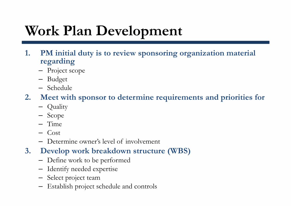
Work Plan Development1. PM initial duty is to review sponsoring organization material
regarding– Project scope– Budget– Schedule
2. Meet with sponsor to determine requirements and priorities for– Quality– Scope– Time– Cost– Determine owner’s level of involvement
3. Develop work breakdown structure (WBS)– Define work to be performed– Identify needed expertise– Select project team– Establish project schedule and controls
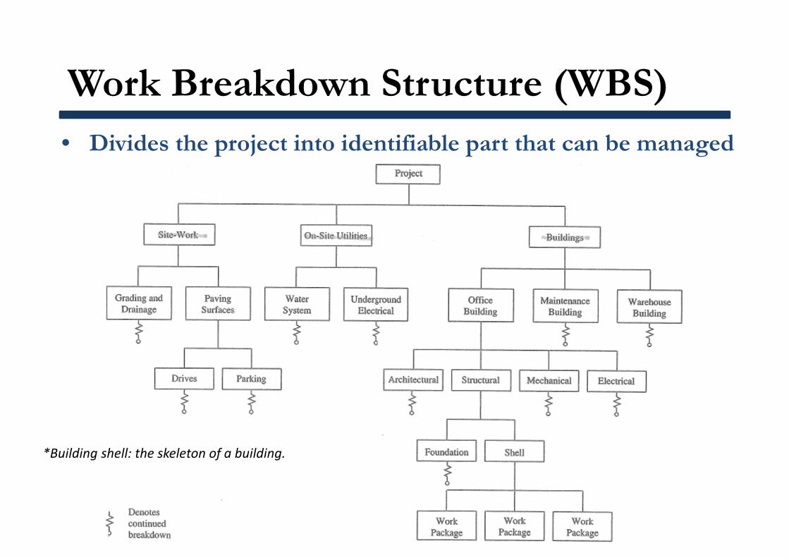
Work Breakdown Structure (WBS)• Divides the project into identifiable part that can be managed
*Building shell: the skeleton of a building.
Work Breakdown Structure (WBS)
• Divides the project into identifiable part that can be managed
• Concept of WBS is simple: to manage the whole project must control each of the parts
• All the work contained within the WBS is to be identified, estimated, scheduled, budgeted, and controlled– Identifying work, compiling the budget, and developing an
integrated schedule• Shown in graphical display to organize and subdivide
the total scope of work
Work Breakdown Structure (WBS)
• Project work is structured into WBS elements (work packages) must be:– Definable: easily described and understood– Manageable: meaningful unit of work where specific
responsibility can be assigned– Estimateable: duration and costs can be estimated– Independent: minimum interface with or dependence on
other ongoing elements– Integratable: integrates with other project work elements– Measureable: has start and completion dates and interim
milestones– Adaptable: flexible so the addition/elimination of work
scope can be accommodated
Work Breakdown Structure (WBS)
• Characteristics of WBS– Most commonly produced in the form of a table or chart– Procedure in the associated work flow is used to produce this
work product– Progresses downward from the general to the specific– Provides a framework for turning project objectives into
specific deliverables
Work Breakdown Structure (WBS)
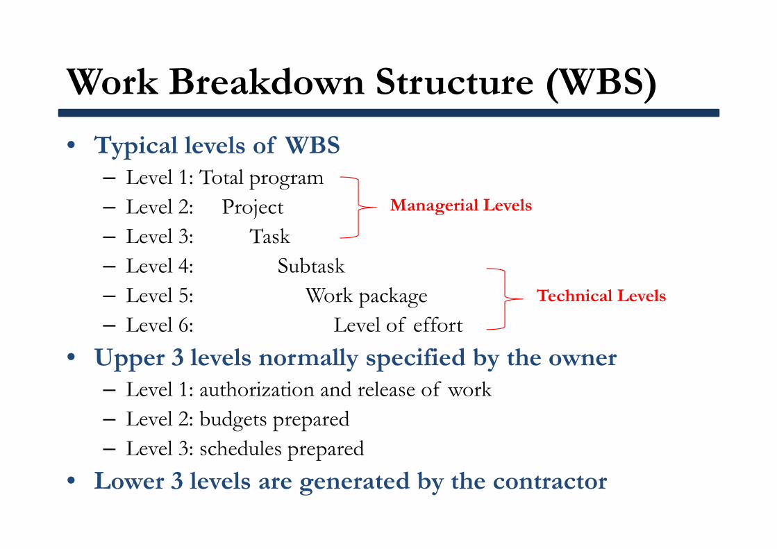
• Typical levels of WBS– Level 1: Total program– Level 2: Project– Level 3: Task– Level 4: Subtask– Level 5: Work package– Level 6: Level of effort
• Upper 3 levels normally specified by the owner– Level 1: authorization and release of work– Level 2: budgets prepared– Level 3: schedules prepared
• Lower 3 levels are generated by the contractor
Managerial Levels
Technical Levels
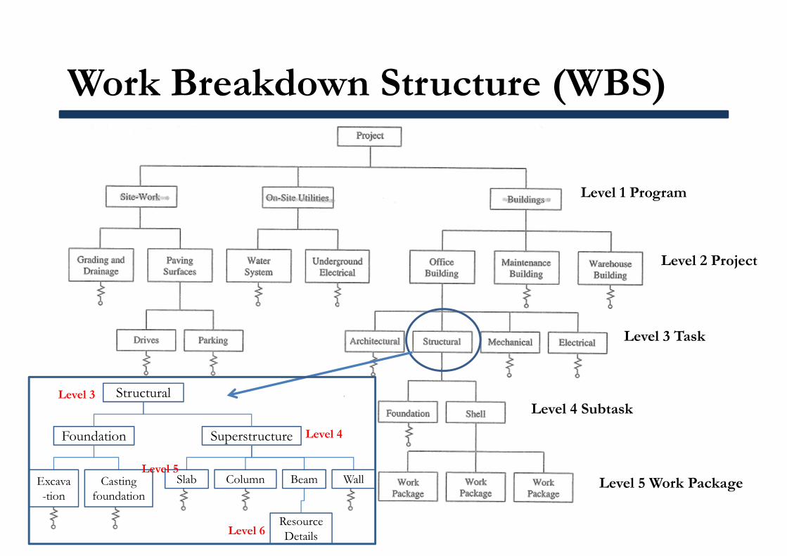
Work Breakdown Structure (WBS)
Level 1 Program
Level 2 Project
Level 3 Task
Level 4 Subtask
Level 5 Work Package
Structural
Foundation Superstructure
Resource Details
Excava-tion
Casting foundation
Slab Column Beam Wall
Level 3
Level 4
Level 5
Level 6

Superstructure
A girder is the primary horizontal member carrying loads from other beams and slabs connected to it. That is a girder has other beams connecting to it on its sides .Typically beams do not have other beams connecting to it but generally have only slabs transferring the loads to it.
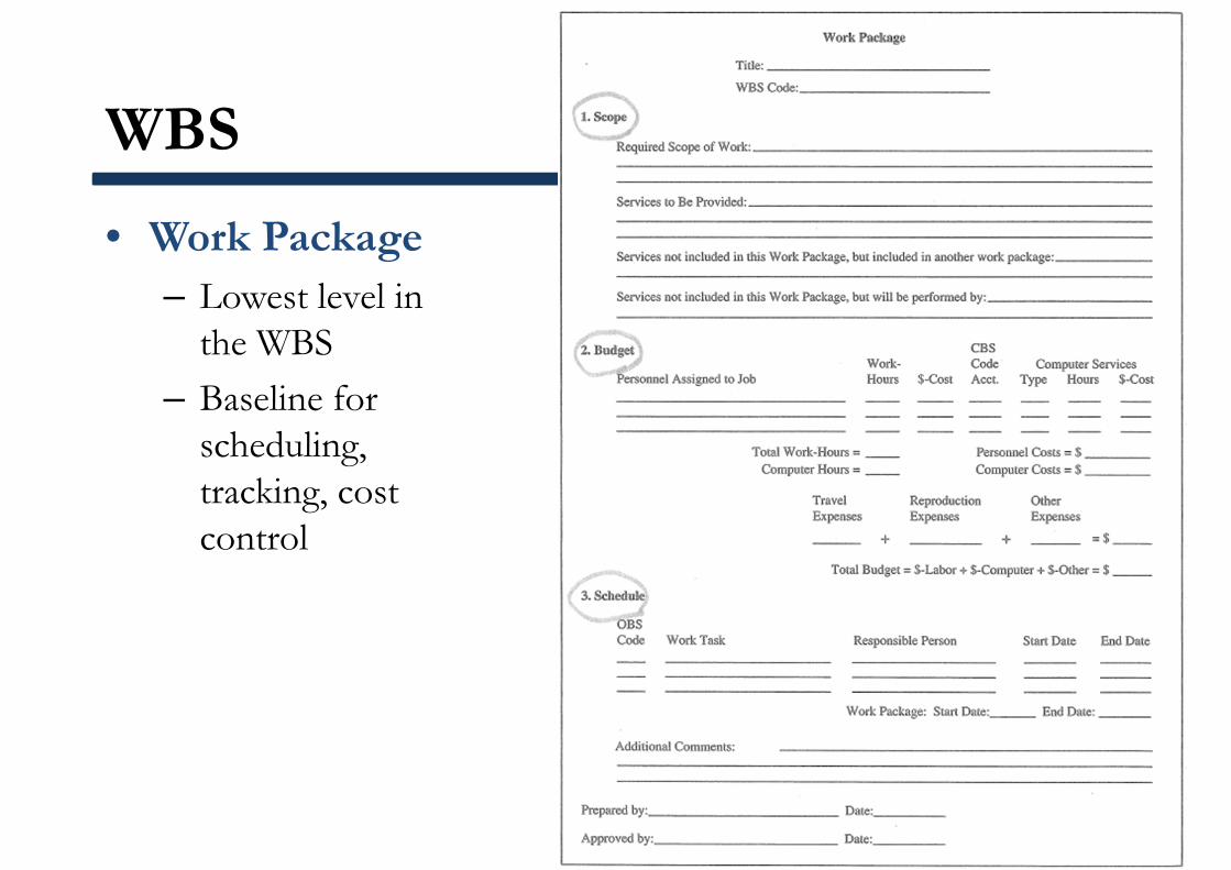
WBS
• Work Package– Lowest level in
the WBS– Baseline for
scheduling, tracking, cost control
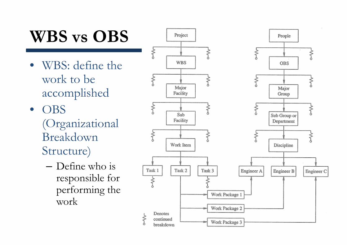
WBS vs OBS
• WBS: define the work to be accomplished
• OBS (Organizational Breakdown Structure)– Define who is
responsible for performing the work
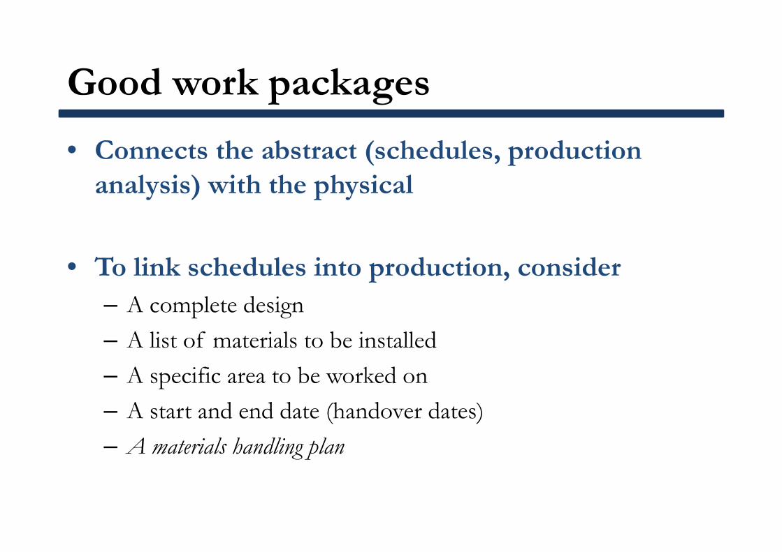
Good work packages
• Connects the abstract (schedules, production analysis) with the physical
• To link schedules into production, consider– A complete design– A list of materials to be installed– A specific area to be worked on– A start and end date (handover dates)– A materials handling plan
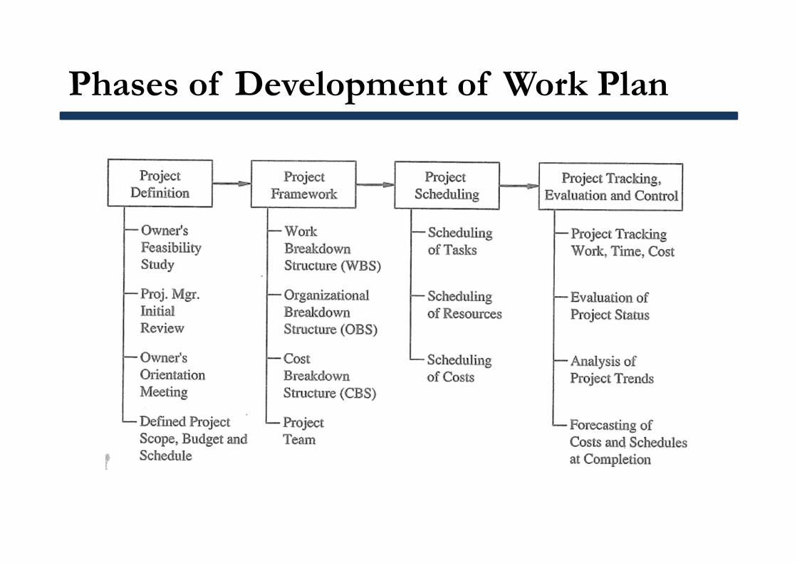
Phases of Development of Work Plan
Site Layout
• Definition:– Assigning areas to staging, materials storage, and shared
resources (e.g., cranes)• Site layout is:
– Dynamic; can cause access conflicts– Should be considered with work packaging when developing
construction plan– Site layout (big picture) constraints, then
• Work packaging <--> Site layout (micro analysis)
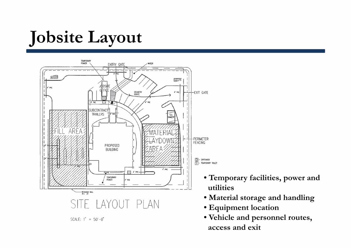
Jobsite Layout
• Temporary facilities, power andutilities
• Material storage and handling• Equipment location• Vehicle and personnel routes, access and exit
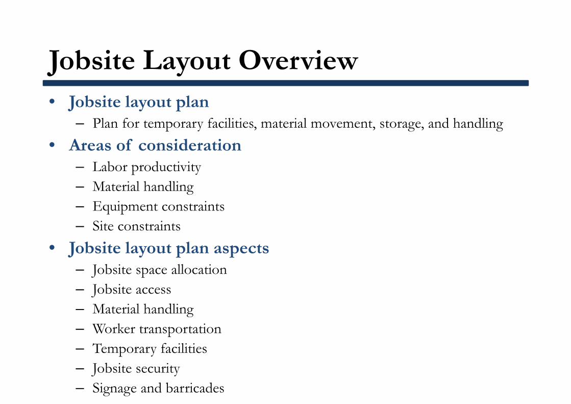
• Jobsite layout plan– Plan for temporary facilities, material movement, storage, and handling
• Areas of consideration– Labor productivity– Material handling– Equipment constraints– Site constraints
• Jobsite layout plan aspects– Jobsite space allocation– Jobsite access– Material handling– Worker transportation– Temporary facilities– Jobsite security– Signage and barricades
Jobsite Layout Overview
• Travel time: non-productive time elements– From gate to worksite– To sanitary facilities (for toilet, gas, water, etc.)– Coffee breaks and lunch– Moving material and asking questions– Need to be minimum!
Labor Productivity
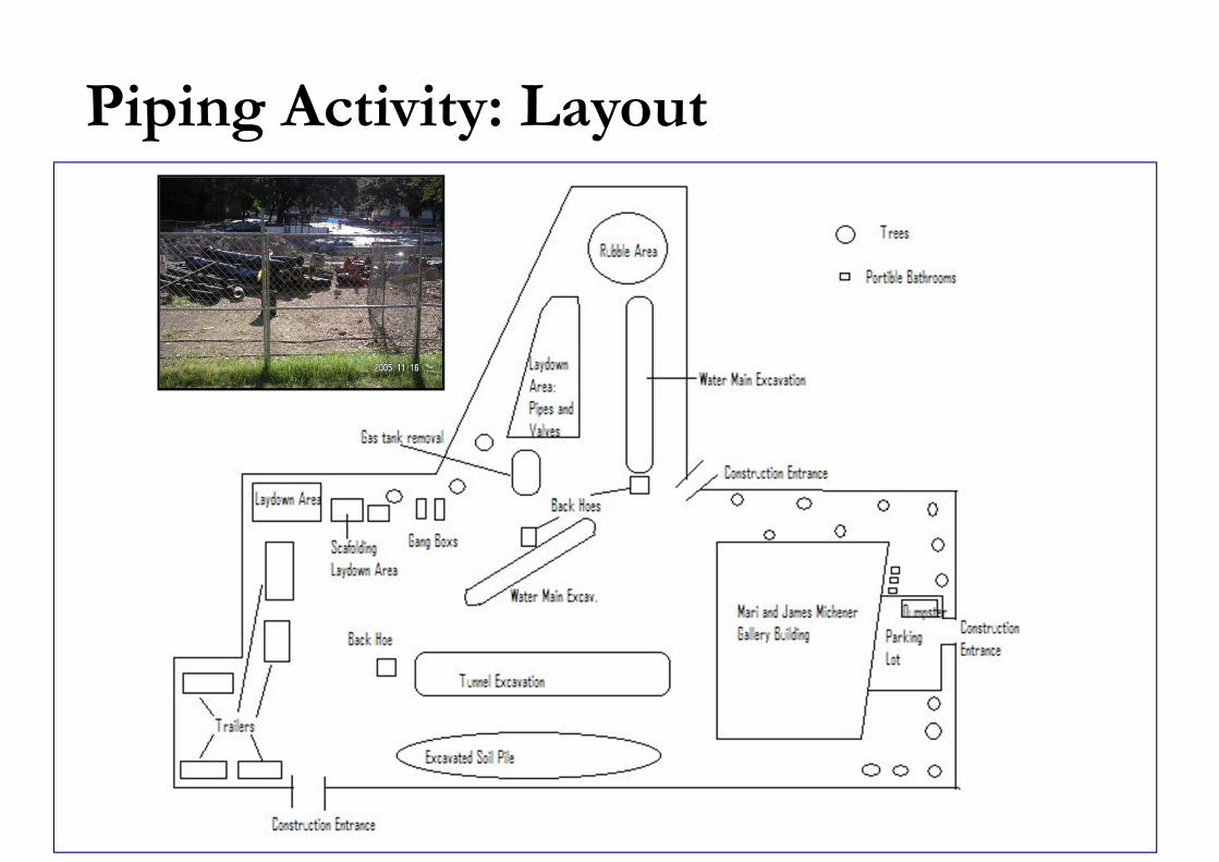
Piping Activity: Layout
Week 5
Project Scheduling (1)
457.657 Civil and Environmental Project ManagementDepartment of Civil and Environmental Engineering
Seoul National University
Prof. Seokho [email protected]
건설환경공학부 35동 304호
Project Scheduling (PMBOK Chapter 6)
• Project Time Management– Includes the process required to ensure timely completion of
the project
• Major Processes1. Activity definition2. Activity sequencing3. Activity duration estimation4. Schedule development5. Schedule control
Project Scheduling – Activity Definition
• WBS being the basis for development of the final activity list
• Tools and Techniques– Decomposition
• Involves subdividing project elements into smaller, more manageable components in order to provide better management control
– Templates• An activity list, or a portion of an activity list from a
previous project, is often usable as a template for a new project
• Resource skills, required hours of effort, risk identification, expected deliverables, etc.
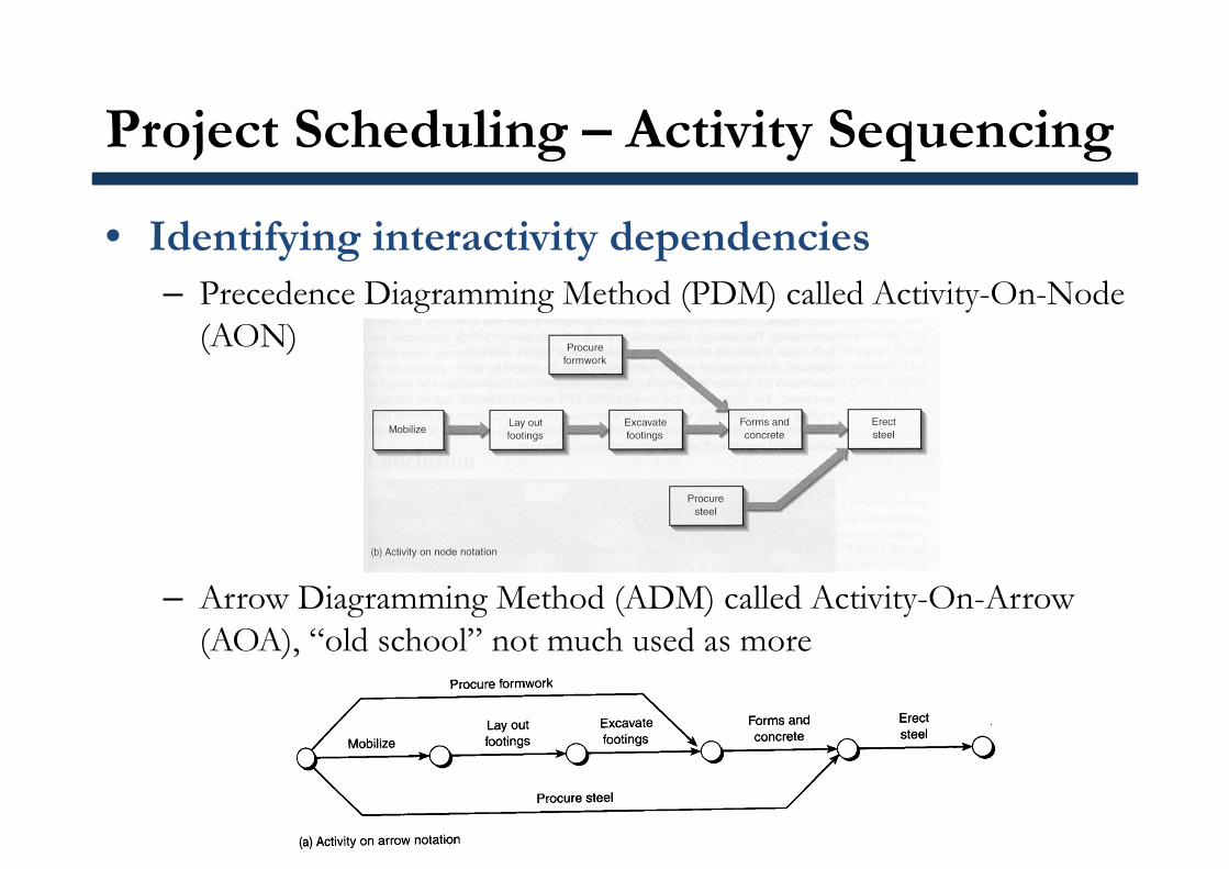
Project Scheduling – Activity Sequencing
• Identifying interactivity dependencies– Precedence Diagramming Method (PDM) called Activity-On-Node
(AON)
– Arrow Diagramming Method (ADM) called Activity-On-Arrow (AOA), “old school” not much used as more
Project Scheduling – Activity Sequencing
• Precedence Notation– Activities or operations are placed on nodes– Arrows defines relationships between activities
• Finish to Start• Start to Start• Finish to Finish• Start to Finish
– Apply “leads” and “lags” provide ability to overlap activities, allowing the scheduler to model more accurately the project’s operation
Project Scheduling – Duration Estimate
• Estimating the number of work periods which will be needed to complete individual activities
• Tools and Techniques– Expert judgment: historical information may be used– Analogous estimating: called top-down estimation, means
using the actual duration of a previous, similar activity– Simulation: involves calculating multiple durations with
different sets of assumptions
Project Scheduling – Duration Estimate
• Duration of an activity varies according to the activity type– Production
• Consult subcontractors• Calculate based on quantity and productivity• Job conditions, new construction vs. renovation, crew size,
work schedule, weather, project calendar, resource calendar– Procurement
• Consult suppliers• Review contract documents
– Administrative• Consult agencies• Past projects
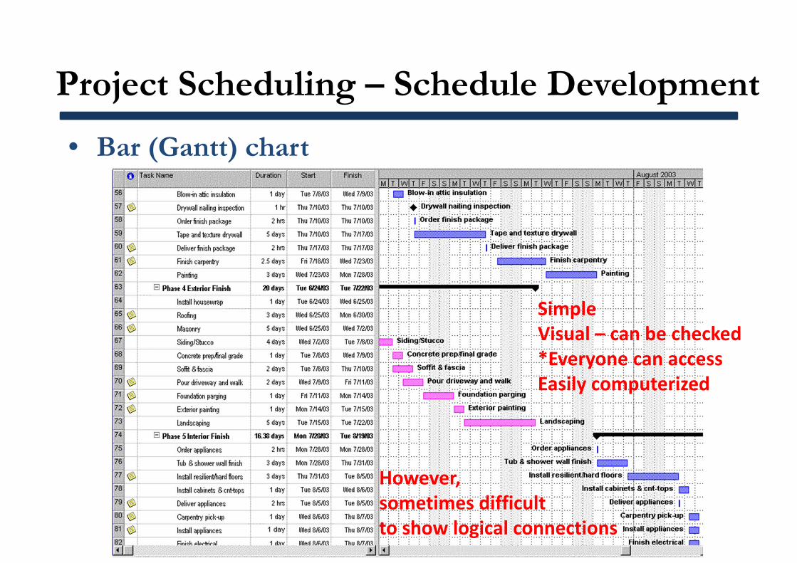
Project Scheduling – Schedule Development
• Bar (Gantt) chart
SimpleVisual – can be checked*Everyone can accessEasily computerized
However, sometimes difficult to show logical connections
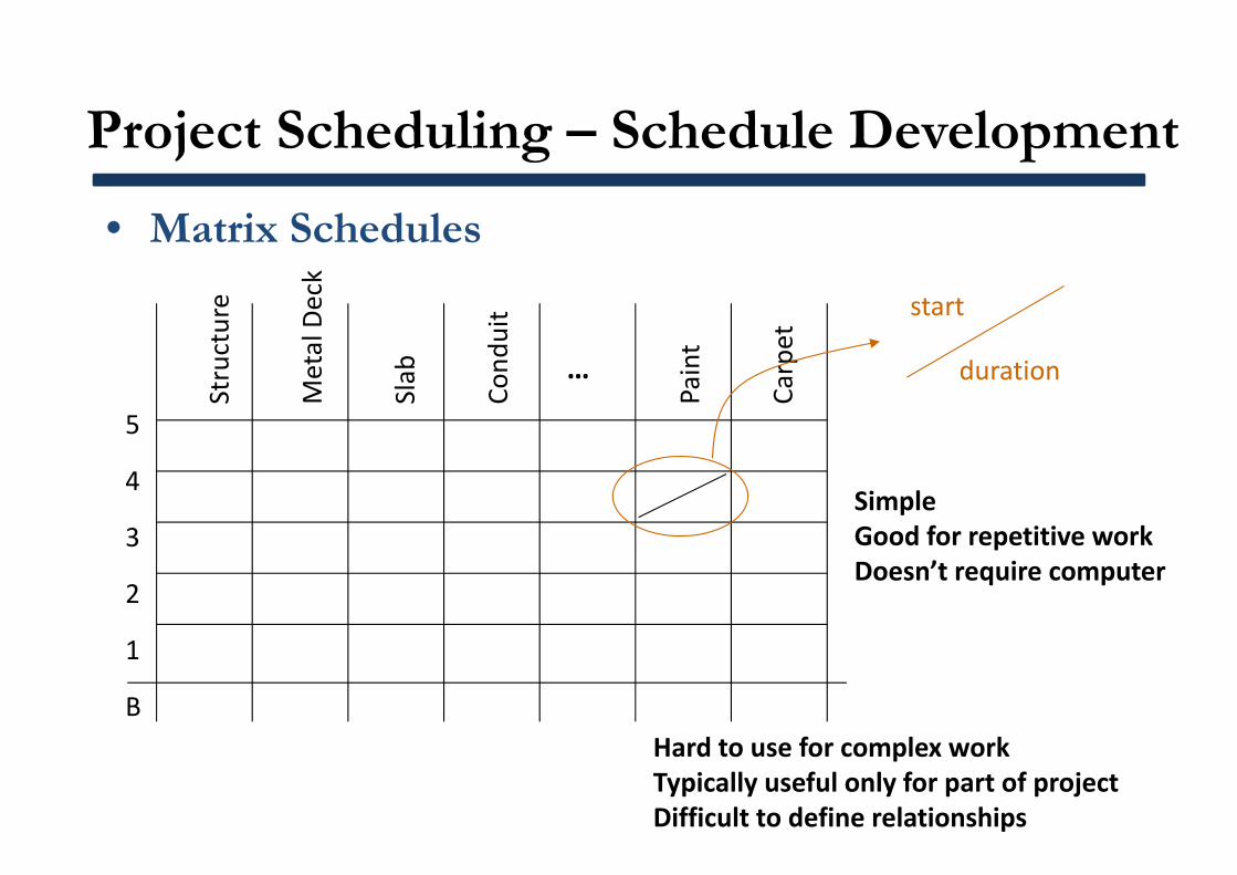
Project Scheduling – Schedule Development
• Matrix SchedulesStructure
Metal Deck
Slab
Cond
uit
Paint
Carpet
…
B
1
2
3
4
5
start
duration
SimpleGood for repetitive workDoesn’t require computer
Hard to use for complex workTypically useful only for part of projectDifficult to define relationships
Project Scheduling – Schedule Development
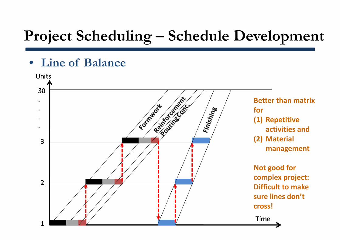
• Line of Balance
Better than matrix for (1) Repetitive
activities and(2) Material
management
Not good for complex project: Difficult to make sure lines don’t cross!
Project Scheduling – Schedule Development
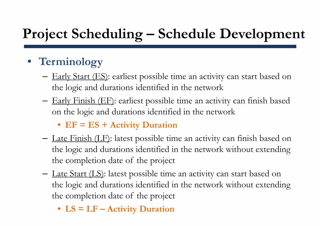
• Terminology– Early Start (ES): earliest possible time an activity can start based on
the logic and durations identified in the network– Early Finish (EF): earliest possible time an activity can finish based
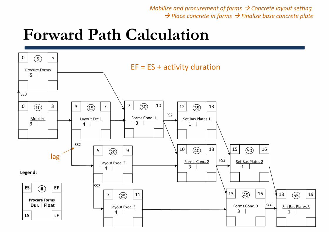
on the logic and durations identified in the network• EF = ES + Activity Duration
– Late Finish (LF): latest possible time an activity can finish based on the logic and durations identified in the network without extending the completion date of the project
– Late Start (LS): latest possible time an activity can start based on the logic and durations identified in the network without extending the completion date of the project
• LS = LF – Activity Duration
Project Scheduling – Schedule Development
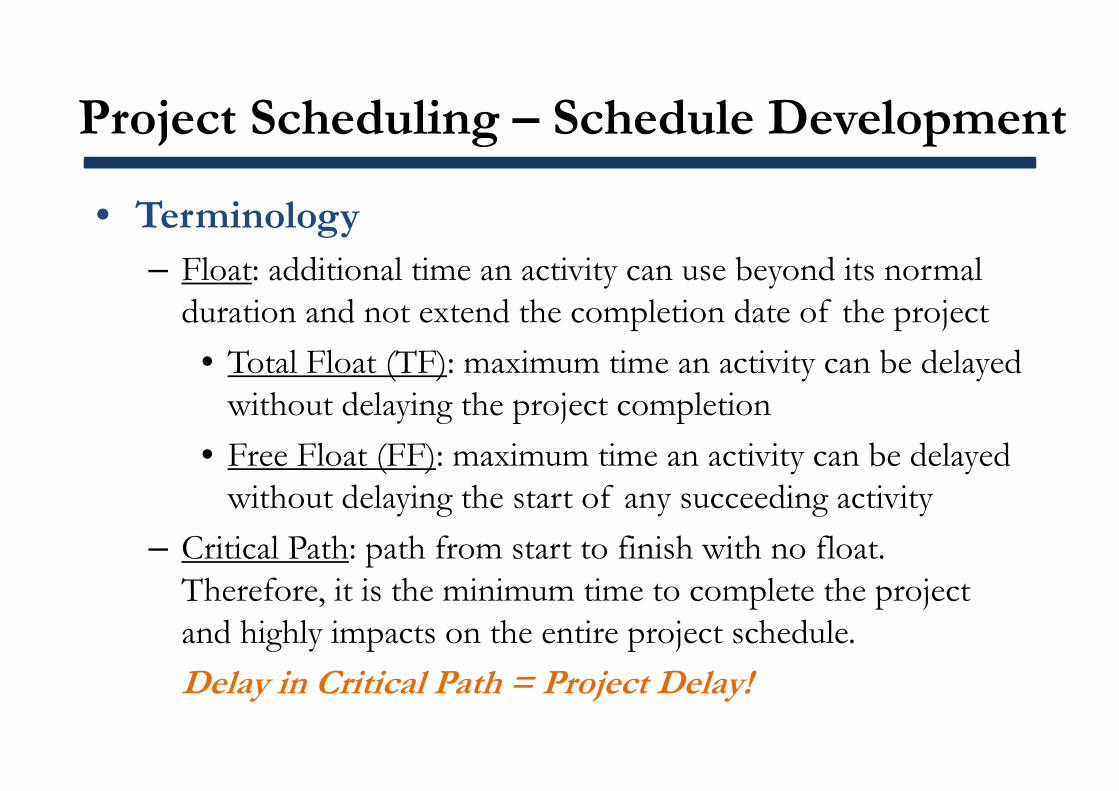
• Terminology– Float: additional time an activity can use beyond its normal
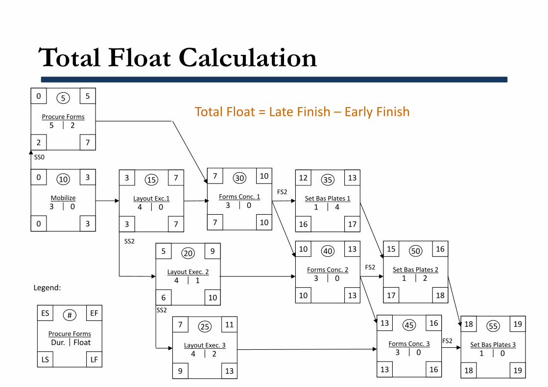
duration and not extend the completion date of the project• Total Float (TF): maximum time an activity can be delayed
without delaying the project completion• Free Float (FF): maximum time an activity can be delayed
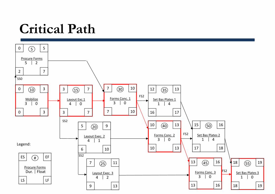
without delaying the start of any succeeding activity– Critical Path: path from start to finish with no float.
Therefore, it is the minimum time to complete the project and highly impacts on the entire project schedule. Delay in Critical Path = Project Delay!
Project Scheduling – Schedule Development
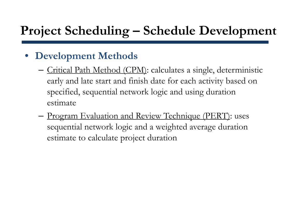
• Development Methods– Critical Path Method (CPM): calculates a single, deterministic
early and late start and finish date for each activity based on specified, sequential network logic and using duration estimate
– Program Evaluation and Review Technique (PERT): uses sequential network logic and a weighted average duration estimate to calculate project duration
Project Scheduling – Schedule Development
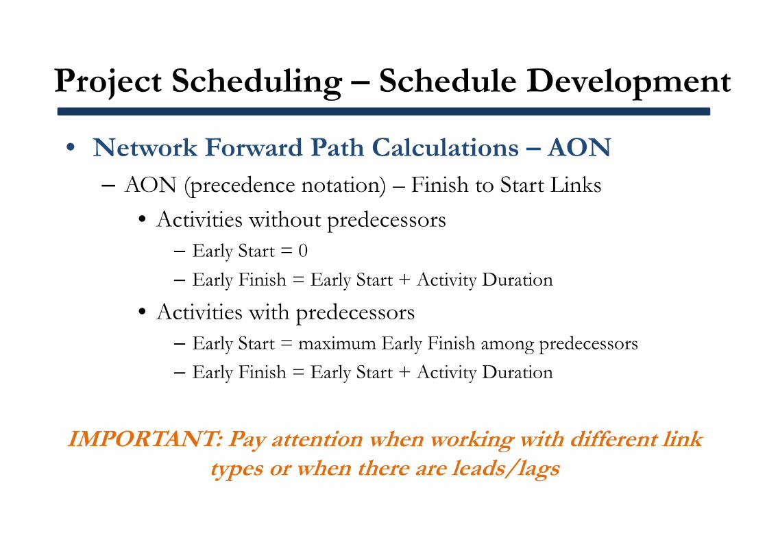
• Network Forward Path Calculations – AON– AON (precedence notation) – Finish to Start Links
• Activities without predecessors– Early Start = 0– Early Finish = Early Start + Activity Duration
• Activities with predecessors– Early Start = maximum Early Finish among predecessors– Early Finish = Early Start + Activity Duration
IMPORTANT: Pay attention when working with different link types or when there are leads/lags
Forward Path Calculation0
Procure Forms
5 5
5
0
Mobilize
10 3
3
5
Layout Exec. 2
20 9
4
3
Layout Exc.1
15 7
4
7
Layout Exec. 3
25 11
4
7
Forms Conc. 1
30 10
3
10
Forms Conc. 2
40 13
3
12
Set Bas Plates 1
35 13
1
13
Forms Conc. 3
45 16
3
18
Set Bas Plates 3
55 19
1
15
Set Bas Plates 2
50 16
1
ES
Procure Forms
# EF
LS LF
Dur. Float
Legend:
SS0
SS2
SS2
FS2
FS2
FS2
EF = ES + activity duration
lag
Mobilize and procurement of forms Concrete layout setting Place concrete in forms Finalize base concrete plate
Project Scheduling – Schedule Development
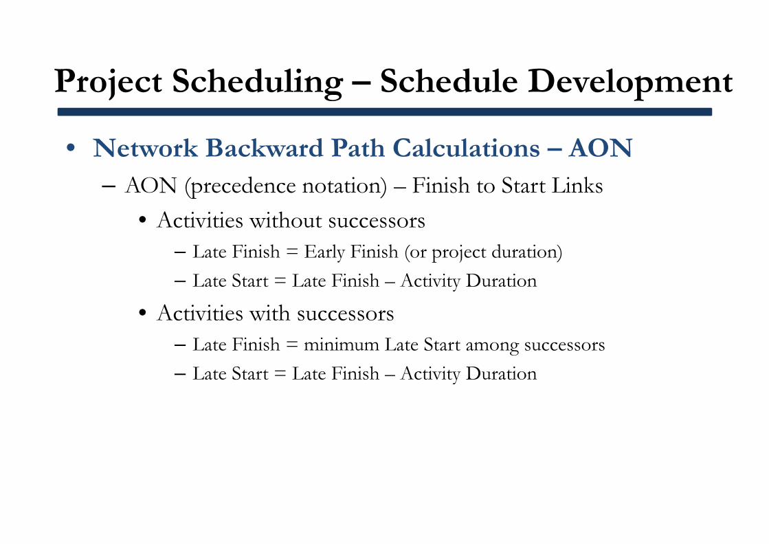
• Network Backward Path Calculations – AON– AON (precedence notation) – Finish to Start Links
• Activities without successors– Late Finish = Early Finish (or project duration)– Late Start = Late Finish – Activity Duration
• Activities with successors– Late Finish = minimum Late Start among successors– Late Start = Late Finish – Activity Duration
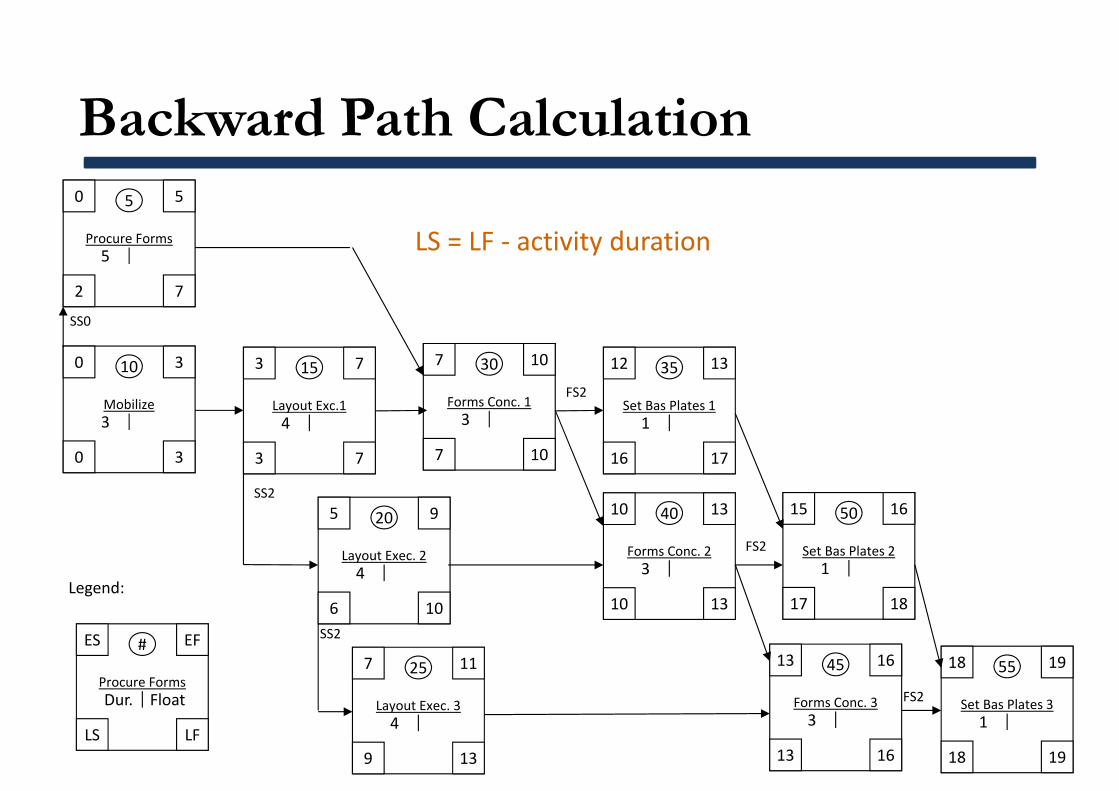
Backward Path Calculation0
Procure Forms
5 5
2 7
5
0
Mobilize
10 3
0 3
3
5
Layout Exec. 2
20 9
6 10
4
3
Layout Exc.1
15 7
3 7
4
7
Layout Exec. 3
25 11
9 13
4
7
Forms Conc. 1
30 10
7 10
3
10
Forms Conc. 2
40 13
10 13
3
12
Set Bas Plates 1
35 13
16 17
1
13
Forms Conc. 3
45 16
13 16
3
18
Set Bas Plates 3
55 19
18 19
1
15
Set Bas Plates 2
50 16
17 18
1
ES
Procure Forms
# EF
LS LF
Dur. Float
Legend:
SS0
SS2
SS2
FS2
FS2
FS2
LS = LF ‐ activity duration
Total Float Calculation0
Procure Forms
5 5
2 7
5 2
0
Mobilize
10 3
0 3
3 0
5
Layout Exec. 2
20 9
6 10
4 1
3
Layout Exc.1
15 7
3 7
4 0
7
Layout Exec. 3
25 11
9 13
4 2
7
Forms Conc. 1
30 10
7 10
3 0
10
Forms Conc. 2
40 13
10 13
3 0
12
Set Bas Plates 1
35 13
16 17
1 4
13
Forms Conc. 3
45 16
13 16
3 0
18
Set Bas Plates 3
55 19
18 19
1 0
15
Set Bas Plates 2
50 16
17 18
1 2
ES
Procure Forms
# EF
LS LF
Dur. Float
Legend:
SS0
SS2
SS2
FS2
FS2
FS2
Total Float = Late Finish – Early Finish
Critical Path0
Procure Forms
5 5
2 7
5 2
0
Mobilize
10 3
0 3
3 0
5
Layout Exec. 2
20 9
6 10
4 1
3
Layout Exc.1
15 7
3 7
4 0
7
Layout Exec. 3
25 11
9 13
4 2
7
Forms Conc. 1
30 10
7 10
3 0
10
Forms Conc. 2
40 13
10 13
3 0
12
Set Bas Plates 1
35 13
16 17
1 4
13
Forms Conc. 3
45 16
13 16
3 0
18
Set Bas Plates 3
55 19
18 19
1 0
15
Set Bas Plates 2
50 16
17 18
1 4
ES
Procure Forms
# EF
LS LF
Dur. Float
Legend:
SS0
SS2
SS2
FS2
FS2
FS2
Project Scheduling – Schedule Development
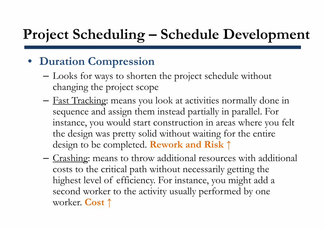
• Duration Compression– Looks for ways to shorten the project schedule without
changing the project scope– Fast Tracking: means you look at activities normally done in
sequence and assign them instead partially in parallel. For instance, you would start construction in areas where you felt the design was pretty solid without waiting for the entire design to be completed. Rework and Risk ↑
– Crashing: means to throw additional resources with additional costs to the critical path without necessarily getting the highest level of efficiency. For instance, you might add a second worker to the activity usually performed by one worker. Cost ↑
Project Scheduling – Schedule Control
• Controlling changes to the project schedule
• Tools and Techniques– Schedule change control system: includes the paperwork,
tracking systems, and approval levels– Performance measurement: assesses the magnitude of any
variations– Additional planning: due to prospective changes
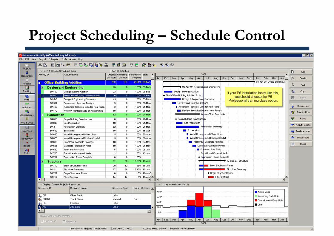
Project Scheduling – Schedule Control
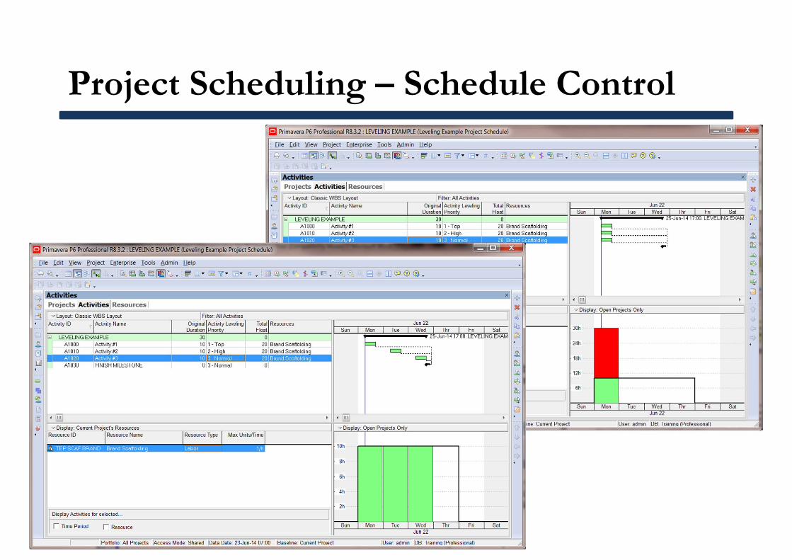
Project Scheduling – Schedule Control
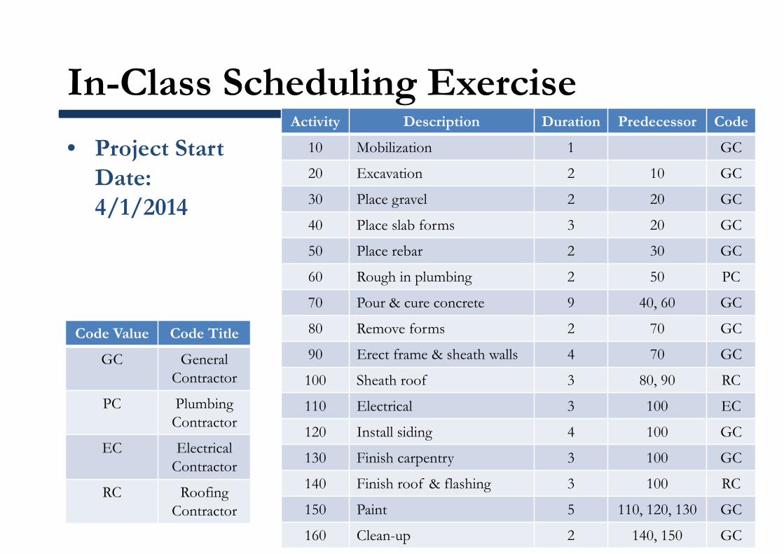
In-Class Scheduling Exercise
• Project Start Date: 4/1/2014
Code Value Code Title
GC General Contractor
PC Plumbing Contractor
EC ElectricalContractor
RC Roofing Contractor
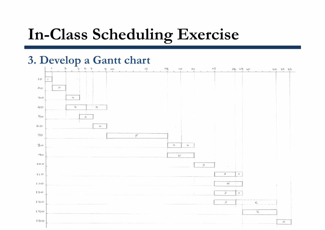
Activity Description Duration Predecessor Code
10 Mobilization 1 GC
20 Excavation 2 10 GC
30 Place gravel 2 20 GC
40 Place slab forms 3 20 GC
50 Place rebar 2 30 GC
60 Rough in plumbing 2 50 PC
70 Pour & cure concrete 9 40, 60 GC
80 Remove forms 2 70 GC
90 Erect frame & sheath walls 4 70 GC
100 Sheath roof 3 80, 90 RC
110 Electrical 3 100 EC
120 Install siding 4 100 GC
130 Finish carpentry 3 100 GC
140 Finish roof & flashing 3 100 RC
150 Paint 5 110, 120, 130 GC
160 Clean-up 2 140, 150 GC
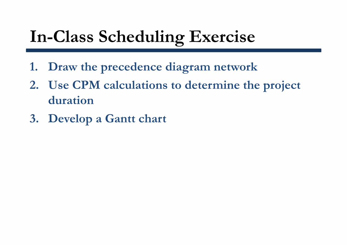
In-Class Scheduling Exercise
1. Draw the precedence diagram network
2. Use CPM calculations to determine the project duration
3. Develop a Gantt chart
In-Class Scheduling Exercise
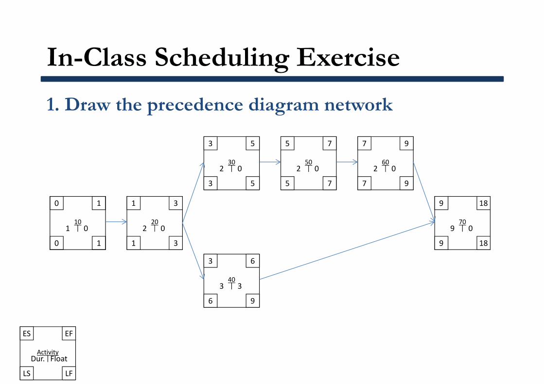
1. Draw the precedence diagram network
ES
Activity
EF
LS LF
Dur. Float
0
10
1
0 1
1 0
1
20
3
1 3
2 0
3
30
5
3 5
2 0
5
50
7
5 7
2 0
7
60
9
7 9
2 0
9
70
18
9 18
9 0
3
40
6
6 9
3 3
In-Class Scheduling Exercise
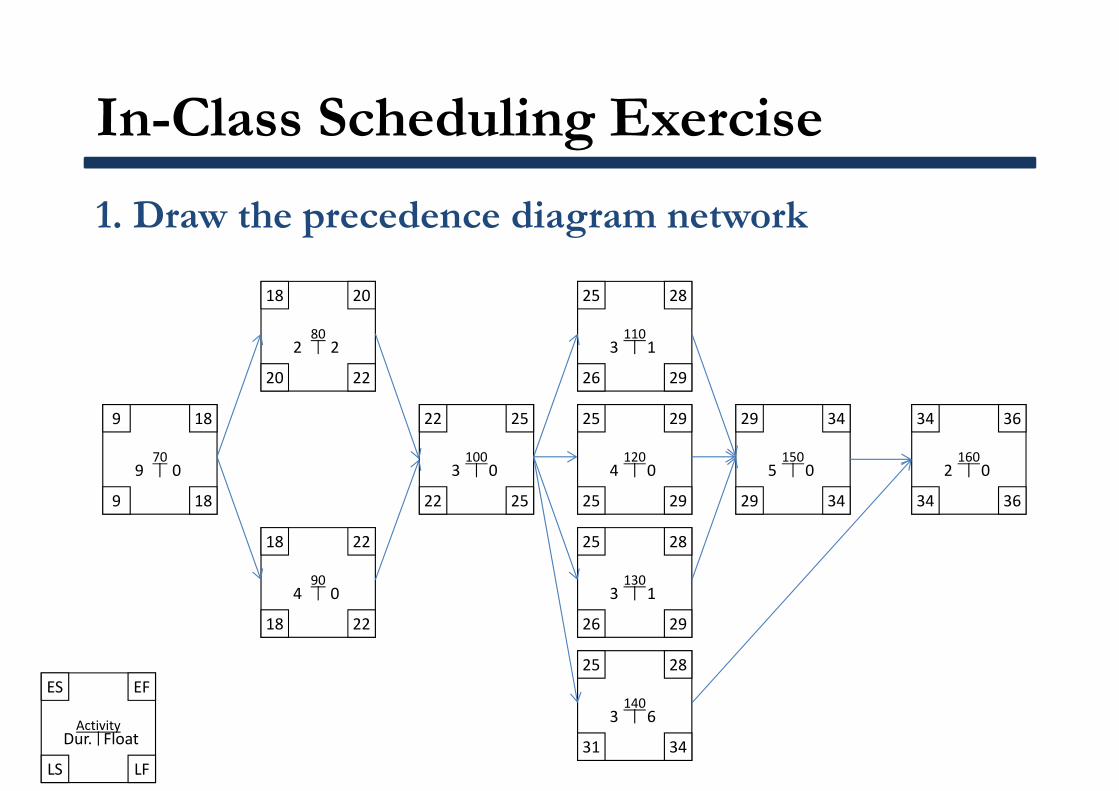
1. Draw the precedence diagram network
ES
Activity
EF
LS LF
Dur. Float
9
70
18
9 18
9 0
18
80
20
20 22
2 2
22
100
25
22 25
3 0
25
110
28
26 29
3 1
29
150
34
29 34
5 0
34
160
36
34 36
2 0
18
90
22
18 22
4 0
25
120
29
25 29
4 0
25
130
28
26 29
3 1
25
140
28
31 34
3 6
In-Class Scheduling Exercise
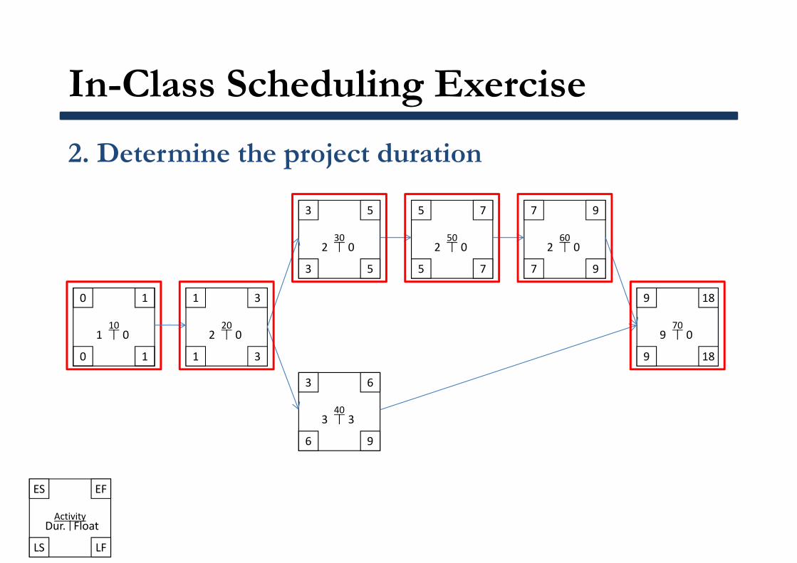
2. Determine the project duration
ES
Activity
EF
LS LF
Dur. Float
0
10
1
0 1
1 0
1
20
3
1 3
2 0
3
30
5
3 5
2 0
5
50
7
5 7
2 0
7
60
9
7 9
2 0
9
70
18
9 18
9 0
3
40
6
6 9
3 3
In-Class Scheduling Exercise
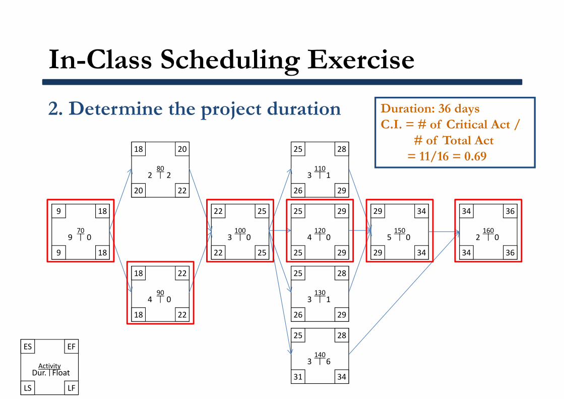
2. Determine the project duration
ES
Activity
EF
LS LF
Dur. Float
9
70
18
9 18
9 0
18
80
20
20 22
2 2
22
100
25
22 25
3 0
25
110
28
26 29
3 1
29
150
34
29 34
5 0
34
160
36
34 36
2 0
18
90
22
18 22
4 0
25
120
29
25 29
4 0
25
130
28
26 29
3 1
25
140
28
31 34
3 6
Duration: 36 daysC.I. = # of Critical Act /
# of Total Act= 11/16 = 0.69
In-Class Scheduling Exercise
3. Develop a Gantt chart
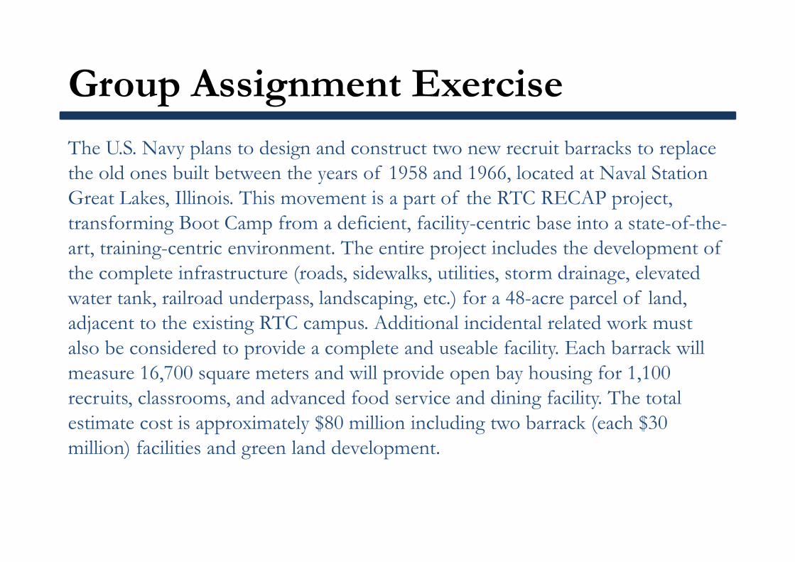
Group Assignment Exercise
The U.S. Navy plans to design and construct two new recruit barracks to replace the old ones built between the years of 1958 and 1966, located at Naval Station Great Lakes, Illinois. This movement is a part of the RTC RECAP project, transforming Boot Camp from a deficient, facility-centric base into a state-of-the-art, training-centric environment. The entire project includes the development of the complete infrastructure (roads, sidewalks, utilities, storm drainage, elevated water tank, railroad underpass, landscaping, etc.) for a 48-acre parcel of land, adjacent to the existing RTC campus. Additional incidental related work must also be considered to provide a complete and useable facility. Each barrack will measure 16,700 square meters and will provide open bay housing for 1,100 recruits, classrooms, and advanced food service and dining facility. The total estimate cost is approximately $80 million including two barrack (each $30 million) facilities and green land development.
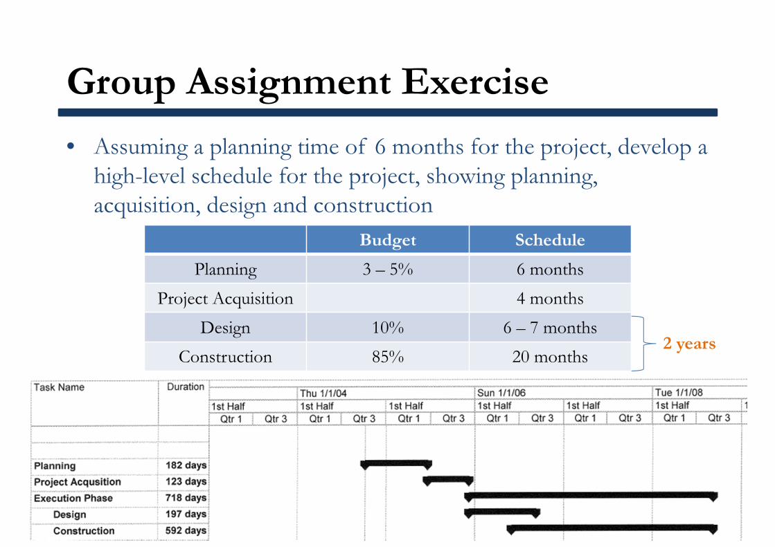
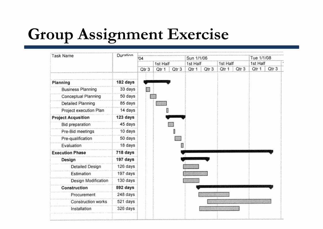
Group Assignment Exercise
• Assuming a planning time of 6 months for the project, develop a high-level schedule for the project, showing planning, acquisition, design and construction
Budget Schedule
Planning 3 – 5% 6 monthsProject Acquisition 4 months
Design 10% 6 – 7 monthsConstruction 85% 20 months
2 years
Group Assignment Exercise