PROFICIENCY LINKED INTEGRATED COURSE AIRPORTS AUTHORITY OF INDIA
226
PROFICIENCY LINKED INTEGRATED COURSE ON Vol‐I Hkkjrh; foekuiRRku Ikzkf/kdj.k AIRPORTS AUTHORITY OF INDIA Ukkxj foekuu Áf'k{k.k dkyst bykgkckn Òkjr Civil Aviation Training College, Allahabad, India Edition: January, 2012
Transcript of PROFICIENCY LINKED INTEGRATED COURSE AIRPORTS AUTHORITY OF INDIA

PROFICIENCY LINKED INTEGRATED COURSE
ON
Vol‐I
Hkkjrh; foekuiRRku Ikzkf/kdj.k
AIRPORTS AUTHORITY OF INDIA
Ukkxj foekuu Áf'k{k.k dkyst bykgkckn Òkjr
Civil Aviation Training College, Allahabad, India
Edition: January, 2012

VOL‐I CONCEPT
Table of Contents
Chapter No.
Chapter Name PageNo.
1. Modulation Technique 12. Concept to VOR 343. ICAO Specification 714. Error Analysis 825. Sitting Criteria & Maintenance of Site 100
CNS Circular No: 01/2008 – Maintenance of Navigational Aids Site 1066. Flight Calibration & Doc 8071 111
AnnexurePhasing in VOR 138DGCA CAR :‐ Requirements to be complied with. 147DGCA CAR:‐ Requirements of Maintenance/ inspection of Communication, Navigation, Landing and other equipment installed at Airports and en‐route.
153
DGCA CAR:‐ Aeronautical Telecommunications – Radio Navigation Aids.
157
CNS Manual Volume‐V:‐ Lightning & Surge Protection and Earthing System of CNS Installation.
166
CNS Circular No: 01/2011 – Guidelines for provision of power supply system for CNS/ATM automation system/facilities.
189
CNS Circulars 02/2012: Standard Operating Procedures (SOP) 210 CNS Circulars 03/2012: Alternate means for provision of
information on the operational status of Radio Navigation Aids. 220
Chapter-01 Modulation Technique
Civil Aviation Training College, Allahabad, India Page 1
Chapter-01
Modulation Technique Amplitude Modulation Amplitude Modulation and Carrier: Remembering again that modulation is the systematic alteration of one waveform according to the characteristics of the message waveform we are to be ready for some quantitative discussion and analysis of modulation system, the ‘how’ and the ‘why’.
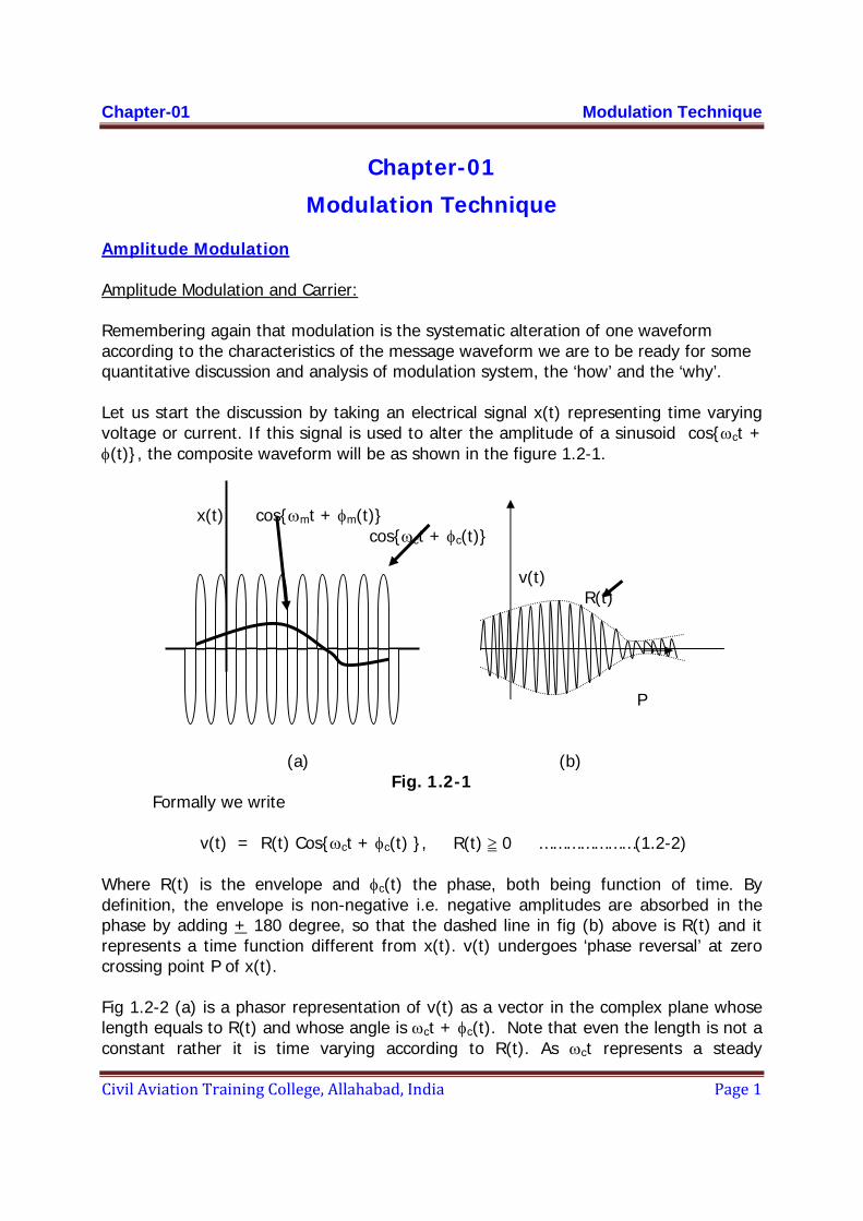
Let us start the discussion by taking an electrical signal x(t) representing time varying voltage or current. If this signal is used to alter the amplitude of a sinusoid cos{ωct + φ(t)}, the composite waveform will be as shown in the figure 1.2-1.
x(t) cos{ωmt + φm(t)} cos{ωct + φc(t)} v(t)
R(t) P (a) (b)
Fig. 1.2-1 Formally we write v(t) = R(t) Cos{ωct + φc(t) }, R(t) ≥ 0 …………………(1.2-2)
Where R(t) is the envelope and φc(t) the phase, both being function of time. By definition, the envelope is non-negative i.e. negative amplitudes are absorbed in the phase by adding + 180 degree, so that the dashed line in fig (b) above is R(t) and it represents a time function different from x(t). v(t) undergoes ‘phase reversal’ at zero crossing point P of x(t).
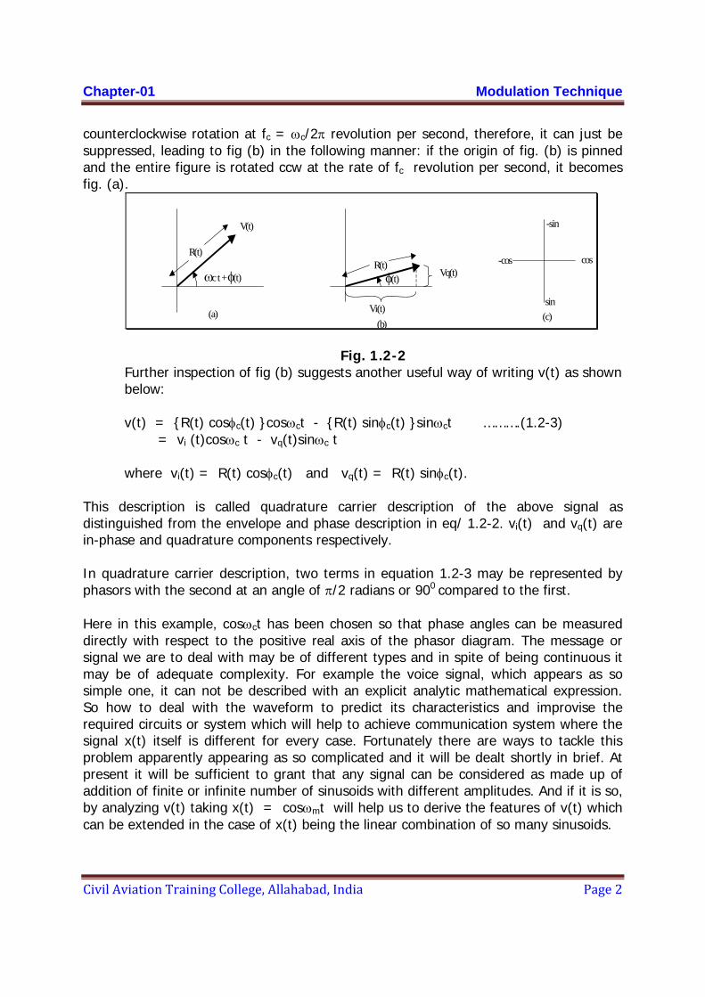
Fig 1.2-2 (a) is a phasor representation of v(t) as a vector in the complex plane whose length equals to R(t) and whose angle is ωct + φc(t). Note that even the length is not a constant rather it is time varying according to R(t). As ωct represents a steady
Chapter-01 Modulation Technique
Civil Aviation Training College, Allahabad, India Page 2
counterclockwise rotation at fc = ωc/2π revolution per second, therefore, it can just be suppressed, leading to fig (b) in the following manner: if the origin of fig. (b) is pinned and the entire figure is rotated ccw at the rate of fc revolution per second, it becomes fig. (a).
R(t)
V(t)
ωc t + φ(t)
(a)
R(t)φ(t)
Vi(t)
Vq(t)
(b)
cos-cos
-sin
sin(c)
Fig. 1.2-2 Further inspection of fig (b) suggests another useful way of writing v(t) as shown below:
v(t) = {R(t) cosφc(t) }cosωct - {R(t) sinφc(t) }sinωct ……….(1.2-3) = vi (t)cosωc t - vq(t)sinωc t where vi(t) = R(t) cosφc(t) and vq(t) = R(t) sinφc(t). This description is called quadrature carrier description of the above signal as distinguished from the envelope and phase description in eq/ 1.2-2. vi(t) and vq(t) are in-phase and quadrature components respectively. In quadrature carrier description, two terms in equation 1.2-3 may be represented by phasors with the second at an angle of π/2 radians or 900 compared to the first. Here in this example, cosωct has been chosen so that phase angles can be measured directly with respect to the positive real axis of the phasor diagram. The message or signal we are to deal with may be of different types and in spite of being continuous it may be of adequate complexity. For example the voice signal, which appears as so simple one, it can not be described with an explicit analytic mathematical expression. So how to deal with the waveform to predict its characteristics and improvise the required circuits or system which will help to achieve communication system where the signal x(t) itself is different for every case. Fortunately there are ways to tackle this problem apparently appearing as so complicated and it will be dealt shortly in brief. At present it will be sufficient to grant that any signal can be considered as made up of addition of finite or infinite number of sinusoids with different amplitudes. And if it is so, by analyzing v(t) taking x(t) = cosωmt will help us to derive the features of v(t) which can be extended in the case of x(t) being the linear combination of so many sinusoids.
Chapter-01 Modulation Technique
Civil Aviation Training College, Allahabad, India Page 3
Therefore to start with, let us simplify the problem by taking special case where φc(t) = 0 in the equation 1.2-1 and x(t) = cosωmt a tone of frequency ωm/2π keeping the carrier cosωct. This is referred as tone modulation.
AM Tone Modulation At present the initial phase of the tone has also been taken as zero with a purpose to start the analysis with simplicity. Carrier and Modulating signal
In the previous analysis we have taken the carrier as cosωct and the modulating tone as cosωmt. The product cosωmt cosωct is the modulated waveform (without adding the carrier). There we have pointed out by the subscripts ‘m’ and ‘c’ that which one is the modulating signal and which one is the carrier. If two sinusoids with frequency ω1 and ω2 is multiplied like cosω1t cosω2t it is obvious there is no way to tell whether cosω1t is multiplied by cosω2t or cosω2t is multiplied by cosω1t and therefore there will be no way to decide which one is the modulating signal or carrier. That means it is required to be predetermined that if our signal is cosω1t then it will be multiplied with the sinusoidal carrier whose frequency is to be chosen based on so many factors detailed in the article 1.1 and say that angular frequency is ω2 and then only we can designate ω1 = ωm and ω2 = ωc for the ease of understanding. There may be sum presumption that in the product cosω1t cosω2t the lower frequency is modulating signal and the higher one is the carrier. But theoretically there is no such restriction at all, though matching the signal to the transmission medium may require in almost all the cases, the carrier frequency to be higher.
To recover the tone say ω1, at the receiving end, one can simply multiply the product with cosω2 t, irrespective of whether ω1< ω2 or ω1> ω2.
cosω1t cosω2t cosω2t = cosω1t cos2ω2t = cosω1t ½ (1 + cos2ω2t) = ½ cosω1t + ½ [cos(2ω2 - ω1)t + cos(2ω2 + ω1)t] [Note that cos(2ω2 - ω1)t = cos(ω1 - 2ω2 )t and for sine function also the negative frequency is absorbed by introduction of opposite phase thereby putting no restrictions regarding which ω is higher one.] After filtering now at the receiver end the tone can be recovered provided the frequencies are adequately apart. This establishes that for receiving it is necessarily required to know the carrier frequency definitely and not to derive by logic that the higher or lower one will be the carrier frequency. The signal can be recovered by
Chapter-01 Modulation Technique
Civil Aviation Training College, Allahabad, India Page 4
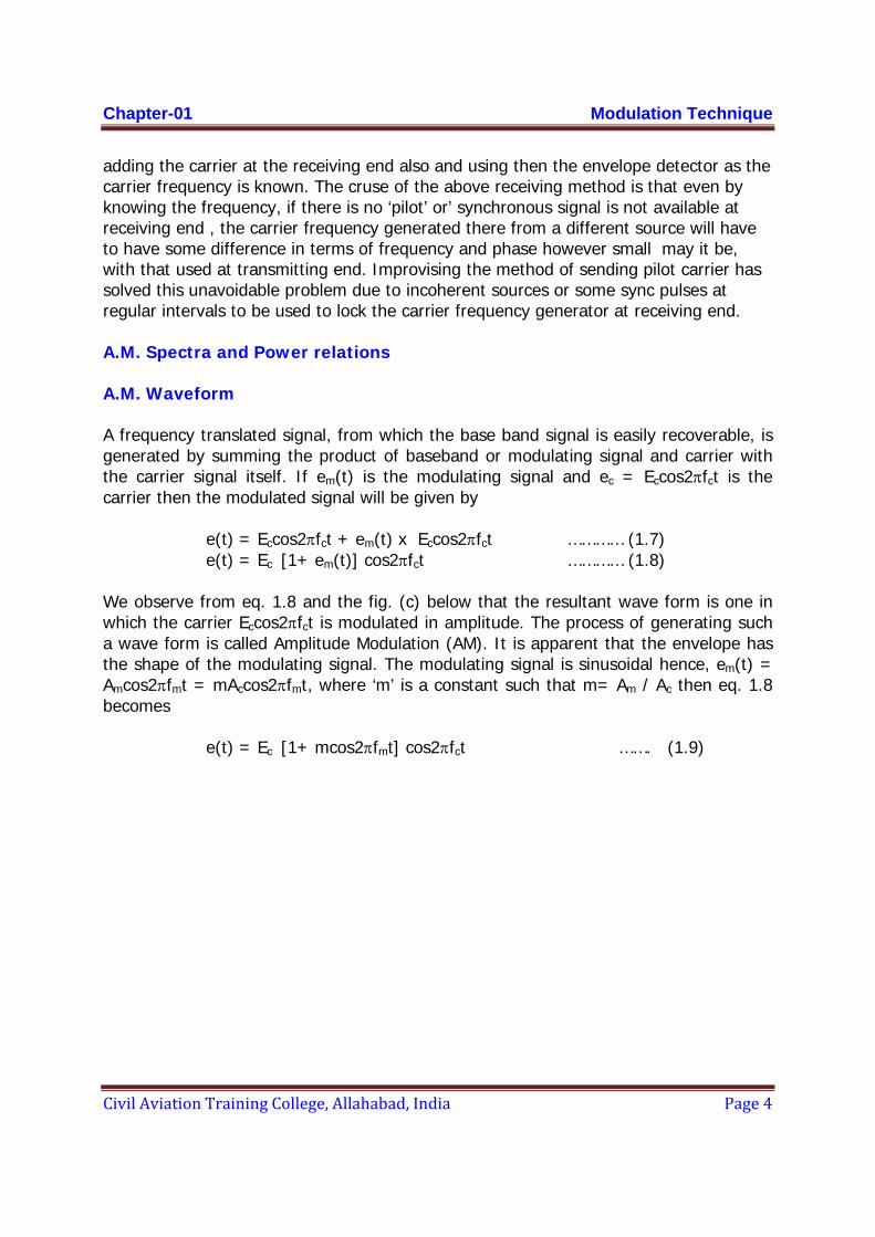
adding the carrier at the receiving end also and using then the envelope detector as the carrier frequency is known. The cruse of the above receiving method is that even by knowing the frequency, if there is no ‘pilot’ or’ synchronous signal is not available at receiving end , the carrier frequency generated there from a different source will have to have some difference in terms of frequency and phase however small may it be, with that used at transmitting end. Improvising the method of sending pilot carrier has solved this unavoidable problem due to incoherent sources or some sync pulses at regular intervals to be used to lock the carrier frequency generator at receiving end. A.M. Spectra and Power relations A.M. Waveform A frequency translated signal, from which the base band signal is easily recoverable, is generated by summing the product of baseband or modulating signal and carrier with the carrier signal itself. If em(t) is the modulating signal and ec = Eccos2πfct is the carrier then the modulated signal will be given by
e(t) = Eccos2πfct + em(t) x Eccos2πfct ………… (1.7) e(t) = Ec [1+ em(t)] cos2πfct ………… (1.8)
We observe from eq. 1.8 and the fig. (c) below that the resultant wave form is one in which the carrier Eccos2πfct is modulated in amplitude. The process of generating such a wave form is called Amplitude Modulation (AM). It is apparent that the envelope has the shape of the modulating signal. The modulating signal is sinusoidal hence, em(t) = Amcos2πfmt = mAccos2πfmt, where ‘m’ is a constant such that m= Am / Ac then eq. 1.8 becomes
e(t) = Ec [1+ mcos2πfmt] cos2πfct ……. (1.9)
Chapte
Civil Av
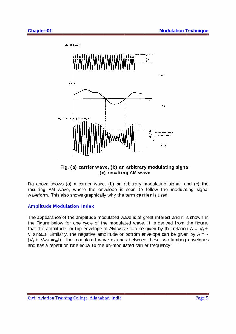
Fig aboresultinwavefo
Amplit
The apthe Figthat thVmsinω(Vc + Vand ha
er-01
viation Tra
F
ove showsng AM waorm. This a tude Mod
ppearance gure belowhe amplitudωmt. SimilarVmsinωmt).as a repetit
ining Colle
Fig. (a) ca
s (a) a caave, wheralso shows
dulation I
of the ampw for one cde, or top rly, the ne The mod
tion rate eq
ge, Allahab
arrier wav(c
rrier wavere the envgraphicall
ndex
plitude mocycle of thenvelope o
egative amdulated waqual to the
bad, India
ve, (b) anc) resultin
e, (b) an avelope is y why the
odulated wahe modulaof AM wavplitude or ve extend
e un-modul
arbitraryng AM wav
arbitrary mseen to term carr
ave is of gted wave.ve can be bottom ens betweenlated carrie
Mo
y modulatve
modulatingfollow the
rier is used
great intere It is derivgiven by tnvelope can these twer frequenc
dulation T
ting signa
g signal, ae modulatd.
est and it isved from tthe relationan be givenwo limiting cy.
Technique
Page 5
al
nd (c) theting signa
s shown inthe figure,n A = Vc +n by A = -envelopes
e
5
e l
n ,
+ - s

Chapte
Civil Av
Modul
where,percen
From t
Divide
er-01
viation Tra
lation Ind
m = m is a ntage and c Vm = he wavefo Vm =
and
Vc =
= Eq.(1.12 )
m =
ining Colle
F
dex
= Vm / Vc
number lyicalled perc
= m Vc
rm
=
= Vmax – Vm
Vmax +
= 2
by Eq. (1.
Vm
= Vc
Vmax 2
ge, Allahab
Fig. Ampli
ng betweeentage of
m = Vmax – Vmin
.13).
(Vmax –= ( Vmax +
- Vmin 2
bad, India
itude Mod
en 0 and modulation
Vmax – V– 2
– Vmin )/ 2
+ Vmin )/ 2
dulated w
1, and it n.
Vmin
2
2
Mo
wave
………
is very of
…………
…………
…………
dulation T
…. (1.10)
ften expre
… (1.11)
… (1.12)
… (1.13)
Technique
Page 6
essed as a
e
6
a
Chapter-01 Modulation Technique
Civil Aviation Training College, Allahabad, India Page 7
Vmax – Vmin = ………… (1.14)
Vmax + Vmin
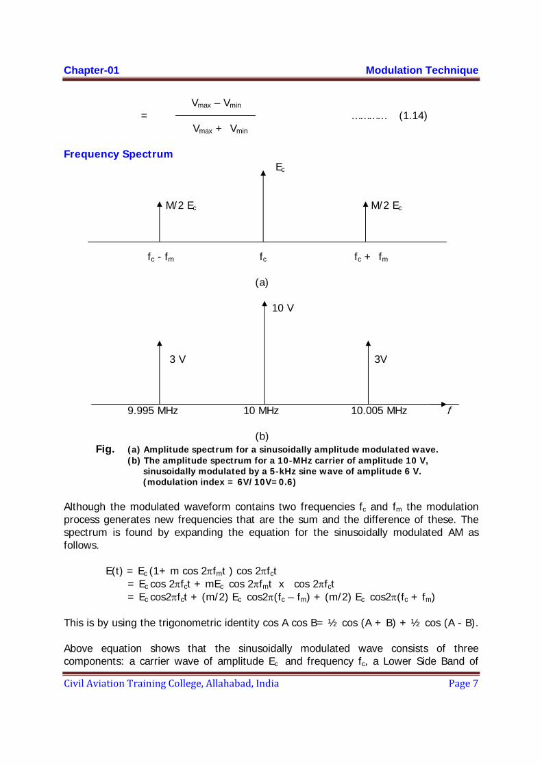
Frequency Spectrum Ec
M/2 Ec M/2 Ec
fc - fm fc fc + fm (a)
10 V
3 V 3V
9.995 MHz 10 MHz 10.005 MHz f
(b)
Fig. (a) Amplitude spectrum for a sinusoidally amplitude modulated wave. (b) The amplitude spectrum for a 10-MHz carrier of amplitude 10 V, sinusoidally modulated by a 5-kHz sine wave of amplitude 6 V. (modulation index = 6V/10V=0.6)
Although the modulated waveform contains two frequencies fc and fm the modulation process generates new frequencies that are the sum and the difference of these. The spectrum is found by expanding the equation for the sinusoidally modulated AM as follows.
E(t) = Ec (1+ m cos 2πfmt ) cos 2πfct = Ec cos 2πfct + mEc cos 2πfmt x cos 2πfct = Ec cos2πfct + (m/2) Ec cos2π(fc – fm) + (m/2) Ec cos2π(fc + fm)
This is by using the trigonometric identity cos A cos B= ½ cos (A + B) + ½ cos (A - B). Above equation shows that the sinusoidally modulated wave consists of three components: a carrier wave of amplitude Ec and frequency fc, a Lower Side Band of
Chapte
Civil Av
amplituand fre
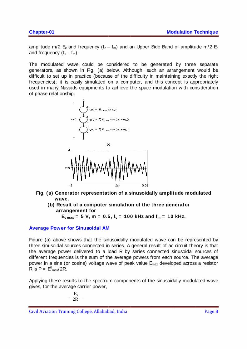
The mgeneradifficultfrequenused inof phas
Fig
Averag
Figure three sthe avdifferenpower R is P =
Applyingives, f
er-01
viation Tra
ude m/2 Ec
equency (fc
modulated ators, as st to set upncies); it in many Nase relations
. (a) Gene wave (b) Res arra
Ec
ge Power (a) above
sinusoidal sverage pownt frequenin a sine (= E2
max/2R
ng these refor the ave
ining Colle
c and freqc – fm).
wave coshown in p in practicis easily savaids equship.
-2
erator repe.
sult of a coangementc max = 5 V
r for Sinus
e shows thsources cower delivercies is the
(or cosine)R.
esults to therage carri
PC = Ec 2R
ge, Allahab
uency (fc –
ould be cFig. (a) bce (becaus
simulated oipments to
presentat
omputer t for V, m = 0.5
soidal AM
hat the sinonnected inred to a l
e sum of th voltage w
he spectruer power,
bad, India
– fm) and a
considered below. Althse of the don a compo achieve t
t(s)
tion of a s
simulatio
5, fc = 10
M
nusoidally n series. A oad R by he average
wave of pea
m compon
an Upper S
to be ghough, sucdifficulty inputer, andthe space
0.01
sinusoida
on of the t
0 kHz and
modulatedgeneral reseries co
e powers fak value E
nents of th
Mo
Side Band
generated ch an arran maintaind this concmodulatio
lly amplit
three gen
d fm = 10
d wave canesult of ac nnected s
from each max develo
e sinusoid
dulation T
of amplitu
by threeangement ing exactlycept is apon with con
tude mod
nerator
kHz.
n be reprecircuit the
sinusoidal ssource. Thped across
ally modul
Technique
Page 8
ude m/2 Ec
e separatewould be
y the rightpropriatelynsideration
dulated
esented byeory is thatsources ofhe averages a resistor
lated wave
e
8
c
e e t y n
y t f e r
e

Chapter-01 Modulation Technique
Civil Aviation Training College, Allahabad, India Page 9
and for each side frequency PSF =
Hence the total average power is
PT = PC + 2 x PSF = PC (1 + m2/2)
At 100% modulation (m = 1), the power in any one side frequency component is PSF = PC/4 and the total power is PT = 1.5 PC. The ratio of power in any one side frequency to the total power transmitted is therefore 1/6. The significance of this result is that all the original modulating information is contained in the one side frequency, and therefore a considerable savings in power can be achieved by transmitting just the side frequency rather than the total modulated wave. In practice, the modulating signal generally contains a band of frequencies that results in sidebands rather than single side frequencies, but, again, single-sideband (SSB) transmission results in more efficient use of available power and spectrum space.
Effective Voltage and Current for Sinusoidal AM
The effective or rms voltage E of the modulated wave is defined by the equation
………. (1.15)
Likewise, the effective voltage EC of the carrier component is defined by It follows from Eq. (1.15) that ……….. (1.16)
From which E = EC √ 1 + m2/2
(mEc /2)2 2R
E2 = PT R
E2C
= PC R
E2 R = PC ( 1 + m2/2)
= (E 2C /R) ( 1 + m2/2)
Chapter-01 Modulation Technique
Civil Aviation Training College, Allahabad, India Page 10
A similar arrangement applied to current yields I = IC √ 1 + m2/2
where, I is the rms current of the modulated wave and IC the rms current of the un-modulated carrier. The current equation provides one method of monitoring modulation index, by measuring the antenna current with and without modulation applied.
m = √ 2[( I/IC )2 – 1]
The method is not as sensitive or useful as the method described earlier, but it provides a convenient way of monitoring modulation where an ammeter can be inserted in series with the antenna. A true rms reading ammeter must be used, and care must be taken to avoid current overload because such instruments are easily damaged by overload.
Non sinusoidal Modulation
Non-sinusoidal modulation produces upper and lower sidebands, corresponding to the upper and lower side frequencies produced with sinusoidal modulation. Suppose, for example, that the modulating signal has a line spectrum, which is represented as
em(t) = E1 cos 2πf1t + E2 cos 2πf2t + E3 cos 2πf3t + ….
As before, the AM wave is
e(t) = [Ec + em(t)] cos 2πfct
If in general the ith component is denoted by subscript i, then individual modulation indexes may be defined as mi = Ei / Ec and the trigonometric expansion for above equation yields a spectrum with side frequencies at fc ± fi and amplitudes mEc/2. Thus, taken together, the side frequencies form sidebands either side of the carrier component. Again, the practicalities of AM demand that the carrier frequency should be much greater than the highest frequency in the modulating wave, so the side bands are band limited about the carrier frequency as shown.
The total average power can be obtained by adding the average power for each component (just as was done for single-tone modulation), which results in
PT = PC ( 1 + m1
2/2 + m22/2 + m3
2/2 +…… ) ……. 1.17
Hence an effective modulation index or modulation depth can be defined in this case as m effect. = √ m1
2 + m22 + m3
2 + …… ……. 1.18
Chapter-01 Modulation Technique
Civil Aviation Training College, Allahabad, India Page 11
It follows that the effective voltage and current in this case is E = Ec √ 1 + m2
eff / 2 ……. 1.19
I = Ic √ 1 + m2eff / 2 …….. 1.20
When the modulating signal is a random power signal such as speech or music, then the concept of power spectral density must be used. When it is used to amplitude modulate the carrier, double sidebands are generated. Again it is assumed that the modulating signal is band limited such that the highest frequency in its spectrum is much less than the carrier frequency.
It will be seen therefore that standard AM produces upper and lower sidebands about the carrier and hence the R.F band width required is double of that for the modulating waveform.
BRF = (fc + fm max) – (fc – fm max) = 2 fm max
Where, the fm max is the highest frequency in the modulating spectrum.
Phase and Amplitude Relationships
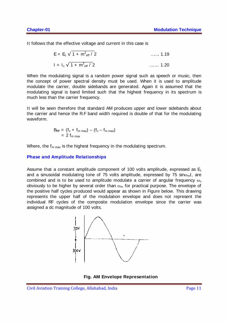
Assume that a constant amplitude component of 100 volts amplitude, expressed as Ec and a sinusoidal modulating tone of 75 volts amplitude, expressed by 75 sinωmt, are combined and is to be used to amplitude modulate a carrier of angular frequency ωc obviously to be higher by several order than ωm for practical purpose. The envelope of the positive half cycles produced would appear as shown in Figure below. This drawing represents the upper half of the modulation envelope and does not represent the individual RF cycles of the composite modulation envelope since the carrier was assigned a dc magnitude of 100 volts.
Fig. AM Envelope Representation
Chapte
Civil Av
By the envelop
For the
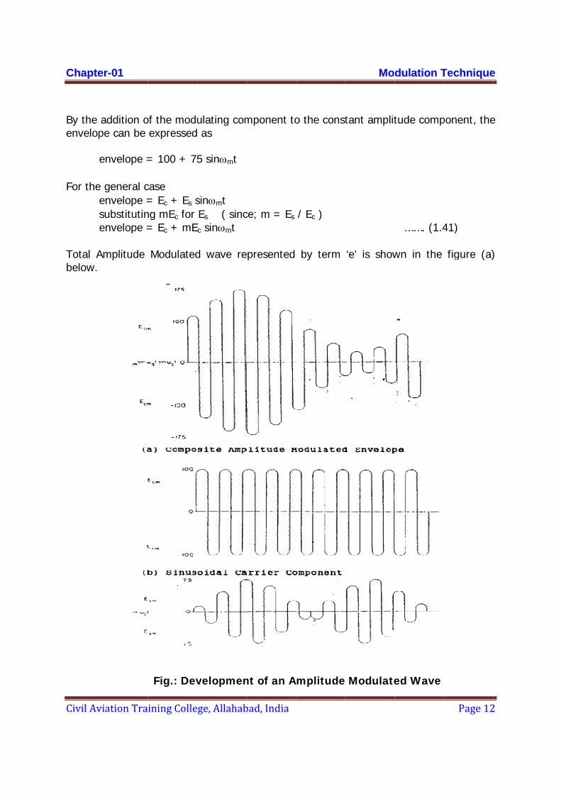
Total Abelow.
er-01
viation Tra
addition ope can be
envelope =
e general cenvelope =substitutinenvelope = Amplitude
ining Colle
of the moduexpressed
= 100 + 75
case = Ec + Es sng mEc for = Ec + mE
Modulated
Fig.: Dev
ge, Allahab
ulating com as
5 sinωmt
sinωmt Es ( sincc sinωmt
d wave re
velopmen
bad, India
mponent to
ce; m = Es
epresented
nt of an A
o the const
/ Ec )
by term
Amplitude
Mo
tant amplit
‘e’ is show
Modulate
dulation T
tude comp
……. (1.4
wn in the
ed Wave
Technique
Page 12
ponent, the
41)
figure (a)
e
2
e
)

Chapter-01 Modulation Technique
Civil Aviation Training College, Allahabad, India Page 13
Term Ec sin ωct representing carrier as shown in the above figure (b) and term m Ec sin ωct sin ωmt representing total sideband is shown in Fig.(c). Equation 1.41 describes the envelope; however, the envelope shows only the effect of the modulating component and does not allow for the RF variations of the total wave. The RF variations of the resultant wave must be considered when finding the instantaneous value of the total wave shape. Applying an RF factor (sin ωct) to Equation 8 yields an equation for the instantaneous variation of the amplitude modulated wave.
e = (Ec + mEc sin ωmt) sinωct
Expanding the above equation yields, e = Ec sinωct + mEc sin ωmt sinωct ......(1.42)
The waveforms shown in Figure above (b) and (c) represent two distinct parts of the complete amplitude modulated waveform shown in Figure (a) and may be radiated in combined form from a single antenna or may be radiated individually from separate antennas where the addition will take place in space to form an amplitude modulating signal. Here the carrier and sidebands are combined upon reception to make up the conventional Amplitude Modulated wave.
When the carrier Ecsinωct and the TSB mEcsinωmtsinωct are radiated from separated antenna, the addition of these two components at any point space may not be, in general, with same phase (i.e. with different φc) due to the different paths to be traveled by those components to reach at a point (receiving point). The path difference is resulted due to the antenna orientation and the direction of traveling of the waves, i.e. in general the phase difference between the carrier and the TSB at the receiving end will be different from that with which those were transmitted and will be dependant on the coordinate of the receiving point with antenna as reference. In other words the modulation will be achieved by addition of the carrier and TSB components in “space” and therefore this way of achieving the modulation is called “space modulation” in contrast with “equipment modulation” where the addition (in addition to generation of TSB) is taking place within the equipment. The purpose of navigational aids is to provide the information to the moving receiver about its location, rather its coordinates in cylindrical or convenient system with respect to the transmitting antenna, the fixed reference point. Therefore the “space modulation” where the modulation parameter at the receiving end depends on its coordinates becomes so useful in Navaids like ILS and VOR.
Equation (1.42) shows the presence of a total sideband component as drawn in Figure (c).This equation can easily be developed to show the upper and lower sidebands as has done previously.

Chapter-01 Modulation Technique
Civil Aviation Training College, Allahabad, India Page 14
e = Ec sinωct + mEc sin ωmt sinωct = Ec sin2πf ct – (1/2) mEc cos2πt(f c+f m) + (1/2) mEc cos2πt(f c -f m) …… (1.43) CARRIER + UPPER SIDEBAND + LOWER SIDEBAND
Equation 1.43 states that: • The upper sideband (USB) is sinusoidal with a frequency of fc + fm
• The lower sideband (LSB) is sinusoidal with a frequency of f c - f m
• The USB phase is - cos at time 0 of the audio modulating cycle. • The LSB phase is + cos at time 0 of the audio modulating cycle. • The carrier phase is + sin at time 0 of the audio modulating cycle.
A modification of Equation (1.43) substituting the equality Esm = mEc gives e = Ec sin2πf ct – (1/2) Esm cos2πt(f c+f m) + (1/2) Esm cos2πt(f c -f m) … (1.44)
This provides a coefficient of Esm which specifically states that one half of the total sideband voltages are contained in the upper sideband and one half of the total sideband voltages are contained in the lower sideband.
It is now possible to apply Equation (11) to the actual waveforms shown in the figure next page which uses 20 cycles of carrier frequency and 2 cycles of audio for simplicity of a graphing though practically it becomes necessarily required in almost every cases to select the carrier frequency higher by several orders than the highest modulating frequency component.

Chapte
Civil Av
er-01
viation Tra
F
i. Wav
ec = ii. Wav
eu =
ining Colle
Fig.: Comp
veform (a)
= Ec sin2πf
veform (b)
= cos
ge, Allahab
ponent of
) is the car
f ct
) is the upp
s2πt(f c+f m
bad, India
f an Ampl
rrier compo
per sideba
m)
itude Mod
onent (fc)
nd compon
Mo
dulated w
nent (fc +
dulation T
wave
fm)
Technique
Page 15
e
5
Chapter-01 Modulation Technique
Civil Aviation Training College, Allahabad, India Page 16
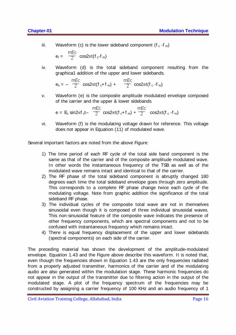
iii. Waveform (c) is the lower sideband component (f c -f m)
el = cos2πt(f c-f m)
iv. Waveform (d) is the total sideband component resulting from the graphica1 addition of the upper and lower sidebands.
es = – cos2πt(f c+f m) + cos2πt(f c -f m)
v. Waveform (e) is the composite amplitude modulated envelope composed
of the carrier and the upper & lower sidebands
e = Ec sin2πf ct– cos2πt(f c+f m) + cos2πt(f c -f m) vi. Waveform (f) is the modulating voltage drawn for reference. This voltage
does not appear in Equation (11) of modulated wave.
Several important factors are noted from the above Figure:
1) The time period of each RF cycle of the total side band component is the
same as that of the carrier and of the composite amplitude modulated wave. In other words the instantaneous frequency of the TSB as well as of the modulated wave remains intact and identical to that of the carrier.
2) The RF phase of the total sideband component is abruptly changed 180 degrees each time the total sideband envelope goes through zero amplitude. This corresponds to a complete RF phase change twice each cycle of the modulating voltage. Note from graphic addition the significance of the total sideband RF phase.
3) The individual cycles of the composite total wave are not in themselves sinusoidal even though it is composed of three individual sinusoidal waves. This non-sinusoidal feature of the composite wave indicates the presence of other frequency components, which are spectral components and not to be confused with instantaneous frequency which remains intact.
4) There is equal frequency displacement of the upper and lower sidebands (spectral components) on each side of the carrier.
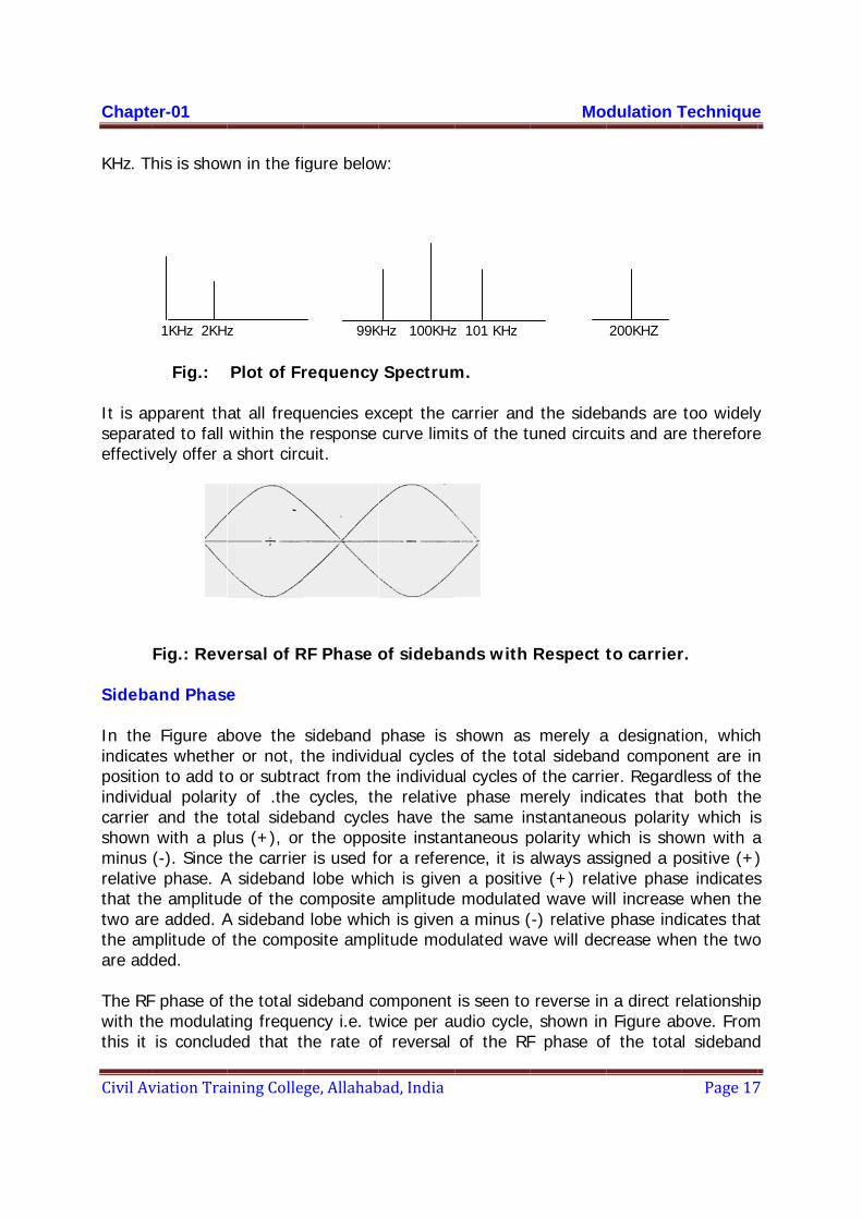
The preceding material has shown the development of the amplitude-modulated envelope. Equation 1.43 and the Figure above describe this waveform. It is noted that, even though the frequencies shown in Equation 1.43 are the only frequencies radiated from a properly adjusted transmitter, harmonics of the carrier and of the modulating audio are also generated within the modulation stage. These harmonic frequencies do not appear in the output of the transmitter due to filtering action in the output of the modulated stage. A plot of the frequency spectrum of the frequencies may be constructed by assigning a carrier frequency of 100 KHz and an audio frequency of 1
Chapte
Civil Av
KHz. T
It is apseparateffectiv
Sideba
In the indicatepositionindividucarrier shown minus relativethat thtwo arethe amare add
The RFwith ththis it
er-01
viation Tra
his is show
1KHz 2KHz
Fig.: pparent thted to fall vely offer a
Fig.: Reve and Phase Figure ab
es whethen to add toual polaritand the twith a plu(-). Since e phase. Ahe amplitude added. A
mplitude of ded.
F phase of he modulatis conclud
ining Colle
wn in the fi
z
Plot of Fr
at all frequwithin the
a short circ
ersal of R
e
bove the er or not, to or subtraty of .the total sidebus (+), orthe carrier
A sidebandde of the cA sideband
the comp
the total sting frequeded that t
ge, Allahab
gure below
99K
requency
uencies exe response cuit.
RF Phase o
sideband the individact from th
cycles, thband cycler the oppor is used fod lobe whiccomposite d lobe whicosite ampl
sideband coency i.e. twthe rate of
bad, India
w:
KHz 100KHz
y Spectrum
xcept the ccurve limit
of sideba
phase is ual cycles
he individuahe relativees have thosite instanor a referech is givenamplitude
ch is given litude mod
omponent wice per auf reversal
z 101 KHz
m.
carrier andts of the tu
nds with
shown as of the tot
al cycles oe phase mhe same inntaneous pence, it is an a positiv modulatea minus (
dulated wa
is seen to udio cycle,of the RF
Mo
d the sidebuned circu
Respect t
merely atal sideban
of the carriemerely indinstantaneopolarity whalways ass
ve (+) relaed wave wi(-) relative ve will dec
reverse in, shown inF phase of
dulation T
200KHZ
bands are its and are
to carrier
a designatind componer. Regardcates that
ous polarityhich is shosigned a pative phaseill increasephase ind
crease whe
n a direct ren Figure abf the tota
Technique
Page 17
too widelye therefore
r.
ion, whichnent are indless of thet both they which is
own with aositive (+)e indicatese when theicates thaten the two
elationshipbove. Froml sideband
e
7
y e
h n e e s a ) s e t o
p m d
Chapter-01 Modulation Technique
Civil Aviation Training College, Allahabad, India Page 18
component is dependent on the audio frequency.
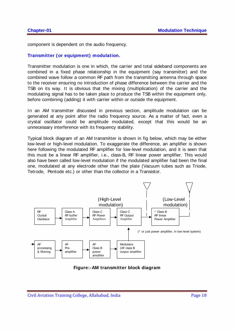
Transmitter (or equipment) modulation. Transmitter modulation is one in which, the carrier and total sideband components are combined in a fixed phase relationship in the equipment (say transmitter) and the combined wave follow a common RF path from the transmitting antenna through space to the receiver ensuring no introduction of phase difference between the carrier and the TSB on its way. It is obvious that the mixing (multiplication) of the carrier and the modulating signal has to be taken place to produce the TSB within the equipment only, before combining (adding) it with carrier within or outside the equipment.
In an AM transmitter discussed in previous section, amplitude modulation can be generated at any point after the radio frequency source. As a matter of fact, even a crystal oscillator could be amplitude modulated, except that this would be an unnecessary interference with its frequency stability.
Typical block diagram of an AM transmitter is shown in fig below, which may be either low-level or high-level modulation. To exaggerate the difference, an amplifier is shown here following the modulated RF amplifier for low-level modulation, and it is seen that this must be a linear RF amplifier, i.e., class-B, RF linear power amplifier. This would also have been called low-level modulation if the modulated amplifier had been the final one, modulated at any electrode other than the plate (Vacuum tubes such as Triode, Tetrode, Pentode etc.) or other than the collector in a Transistor.
(High-Level (Low-Level modulation) modulation) (* or just power amplifier, in low-level system) AF In
Figure:-AM transmitter block diagram
* Class B RF linear Power Amplifier
RF Crystal Oscillator
Class C RF Power Amplifiers
Class A RF buffer Amplifier
Class C RF Output Amplifier
AF processing & filtering
AF Pre-amplifier
AF Class B power amplifier
Modulator (AF class B output amplifier
Chapter-01 Modulation Technique
Civil Aviation Training College, Allahabad, India Page 19
Space Modulation
Another type of amplitude modulation process may be required to be used in many places like Navaids where the combination (addition) of sideband only (SBO comprising one or more TSB(s)) and the carrier with or without the transmitter modulated sidebands takes place in space. Note that both of the SBO or carrier with sidebands (CSB) are transmitter modulated but when all the required signals out of these three namely SBO, CSB or carrier are not radiated from the same antenna the complete modulation process will be realized rather the composite modulated waveform will be formed at the receiving point by the process of addition of all the carriers and all the sidebands (TSBs). The process of achieving the complete modulation process by the process of addition of carriers and sidebands (TSBs) at the receiving point in space is called the “Space Modulation” which means only that modulation process is achieved or completed in space rather than in equipment itself but not at all that space is modulated.
RF Phase Relationships
In the space modulation process, the separate sidebands combine with the carrier outside the transmitter and the RF phase relationships between separate sidebands and carrier can vary widely. The total sideband component will combine with the carrier component in space either exactly in-phase, 180° out-of-phase or at some phase angle, φ. This phase angle may vary from 0 to 360 electrical degrees. The desired objective is that the total sideband component will combine precisely in-phase or 180° out-of-phase with the carrier depending on the specific system. Under these conditions, the resultant modulated wave is the same as would be produced as a result of transmitter modulation. It should be recalled that for transmitter modulation the total sideband component is always phase-locked to the carrier. However, it is obvious that in space modulation two or more components can combine at some phase angle other than 0°.
Thus, the resultant RF modulated wave at the receiver may differ from that of a wave modulated at the transmitter. Before continuing this discussion the question might arise: “What causes the total sideband component to be other than in-phase with the carrier component?” This can be explained as follows: the phase difference φc may occur simply by the relative phase of currents in the antennas, a function of transmission line length for example, or the carrier and total sideband components radiated from separate antennas may travel unequal distances in reaching the receiver. This could be due to proximity effect or due to reflection. If the two components travel different distances from radiating antennas to the receiver, one component must take longer to reach the receiver than the other since both radiation travel with the same propagation velocity. Assuming that the relative phase of the RF currents being fed to the transmitting antennas are the same, the relative phase of the radiation which travels the greater distance in reaching the receiver must be such that it will lag the other component by the angleφc. This angle φc is the phase difference with which the
Chapter-01 Modulation Technique
Civil Aviation Training College, Allahabad, India Page 20
total sideband component combines with the carrier and is an important factor in determining the shape and amplitude of the modulated wave. It should be emphasized at this time that any misphasing is an undesirable condition in almost all of the uses but it can be judiciously used for testing or confirming about the transmission line length etc.
Space Modulation Phasors.
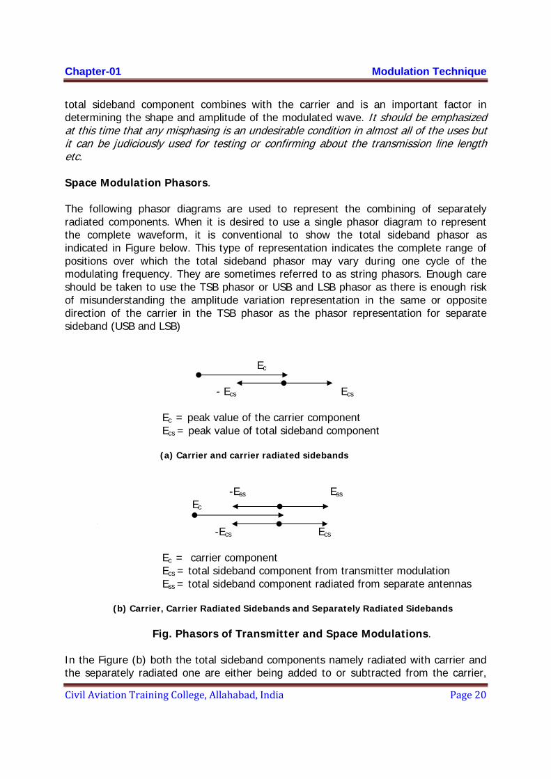
The following phasor diagrams are used to represent the combining of separately radiated components. When it is desired to use a single phasor diagram to represent the complete waveform, it is conventional to show the total sideband phasor as indicated in Figure below. This type of representation indicates the complete range of positions over which the total sideband phasor may vary during one cycle of the modulating frequency. They are sometimes referred to as string phasors. Enough care should be taken to use the TSB phasor or USB and LSB phasor as there is enough risk of misunderstanding the amplitude variation representation in the same or opposite direction of the carrier in the TSB phasor as the phasor representation for separate sideband (USB and LSB)
Ec
- Ecs Ecs
Ec = peak value of the carrier component Ecs = peak value of total sideband component
(a) Carrier and carrier radiated sidebands -Ess Ess Ec [
-Ecs Ecs
Ec = carrier component Ecs = total sideband component from transmitter modulation Ess = total sideband component radiated from separate antennas
(b) Carrier, Carrier Radiated Sidebands and Separately Radiated Sidebands
Fig. Phasors of Transmitter and Space Modulations.
In the Figure (b) both the total sideband components namely radiated with carrier and the separately radiated one are either being added to or subtracted from the carrier,
Chapter-01 Modulation Technique
Civil Aviation Training College, Allahabad, India Page 21
depending upon the position along the audio cycle. In other words with using the terms used in previous section CSB (Carrier with equipment modulated TSB) and SBO are transmitted from separate antennas. Here in this example the SBO amplitude vector is also shown as in phase with the carrier which, though desired in most of the cases, may not be true everywhere generally. Therefore, both sets of sideband components are shown properly phased to the carrier component. The separately radiated total sideband component is designated Ess to differentiate it from Ecs, the total sideband component which is radiated along the carrier component.
Combining of separately radiated sidebands with the carrier energy to form a modulated RF wave, RF phase relationships become important. The desired condition is for Ess to combine at a phase angle of 0° with Ec as indicated in Figure above.
The space modulation factor is designated to differentiate it from the transmitter modulation factor, m. By definition, the modulation factor is the ratio of the total sideband component to the carrier component. In equation form for space modulation:
S = Ess / Ec
This equation is valid only where the total sideband component is combined exactly in phase, or exactly 180° out-of-phase with the carrier component. When this is the case, the phase angle φ will be 0° or 180° and only the fundamental modulating frequency is recovered upon detection of the combined signal.
However, if φ is other than 0° or 180°, thus is, not in phase with Ec, (1800 is considered as in phase as there will quadrature component) harmonics of the modulating frequency will be produced upon detection. Though these harmonics may not directly affect the output of receivers since they may be rejected by suitable filter circuits but since misphasing attenuates the recovered fundamental modulating frequencies the output amplitudes of the modulating signal are weakened.
Space Modulation Misphasing
A more general equation for space modulation factor Sf can be obtained by referring to Figure below. It is based upon that component of the total sidebands which is in phase with the carrier. As shown vectorially in the Figure it is the cosine projection of Ess
divided by Ec or in equation form:
Sf = Ess cos φ / Ec
Which was already established earlier from the trigonometric expression as meffective = mcos φ in general.
Here the symbol Sf represents the space modulation factor at the fundamental modulating frequency.

Chapter-01 Modulation Technique
Civil Aviation Training College, Allahabad, India Page 22
An examination of the above equation indicates that, maximum space modulation is attained when the separately radiated sidebands are in phase with the carrier, and minimum effective space modulation will be obtained when the sidebands are in quadrature or 90° out-of-phase with the carrier, the later being an abnormal condition in most of the uses. Since space modulation determines aircraft instrument deflection, it should be clear that any amount of misphasing is undesirable in that use.
Ess Ec φ Ess cos φ -Ess
Fig. Effective Space Modulation Phasors.
In the localizer (or glide slope), decreased space modulation causes broadening of the course (or path) width and reduces the sensitivity of the aircraft instrument. This could cause an aircraft flying an ILS approach to be too far left or right or too low, and fly into an area of obstructions (trees, hills, buildings, etc.), Also in capture effect and sideband reference glide slopes, misphasing can cause glide angle shifts. Therefore you can see that proper RF phasing in the ILS is critical.
Earlier it was mentioned that if the separately radiated sidebands (Ess) are not properly phased to the carrier (Ec), harmonics of the modulating frequency will be produced.
FREQUENCY MODULATION
Introduction
Frequency modulation is a system in which the amplitude of the modulated carrier is kept constant, while its frequency is varied by the modulating signal. Phase modulation is a similar system in which The theory and generation of FM are more complex to think about and visualize than those of AM .This is because FM involves minute frequency variation of the carrier , as where AM results in large- scale amplitude variation of the carrier. FM is more difficult to treat mathematically and has sideband behaviour that is complex. Compared to amplitude modulation, FM has certain advantages. Mainly, the signal- to -noise ratio can be increased without increasing transmitted power (but at the expense of an increase in frequency bandwith required); certain forms of interference at the receiver are more easily suppressed; and the modulation process can take place at a low level power stage in the transmitter, thus avoiding the need for large amounts of modulating power.
Chapter-01 Modulation Technique
Civil Aviation Training College, Allahabad, India Page 23
BASIC CONCEPT
By the definition of frequency modulation, the amount by which the carrier frequency is varied from its unmodulated value, called the deviation is made proportional to the instantaneous value of the modulating voltage. The rate at which this frequency variation takes place is naturally equal to that of the modulating frequency.
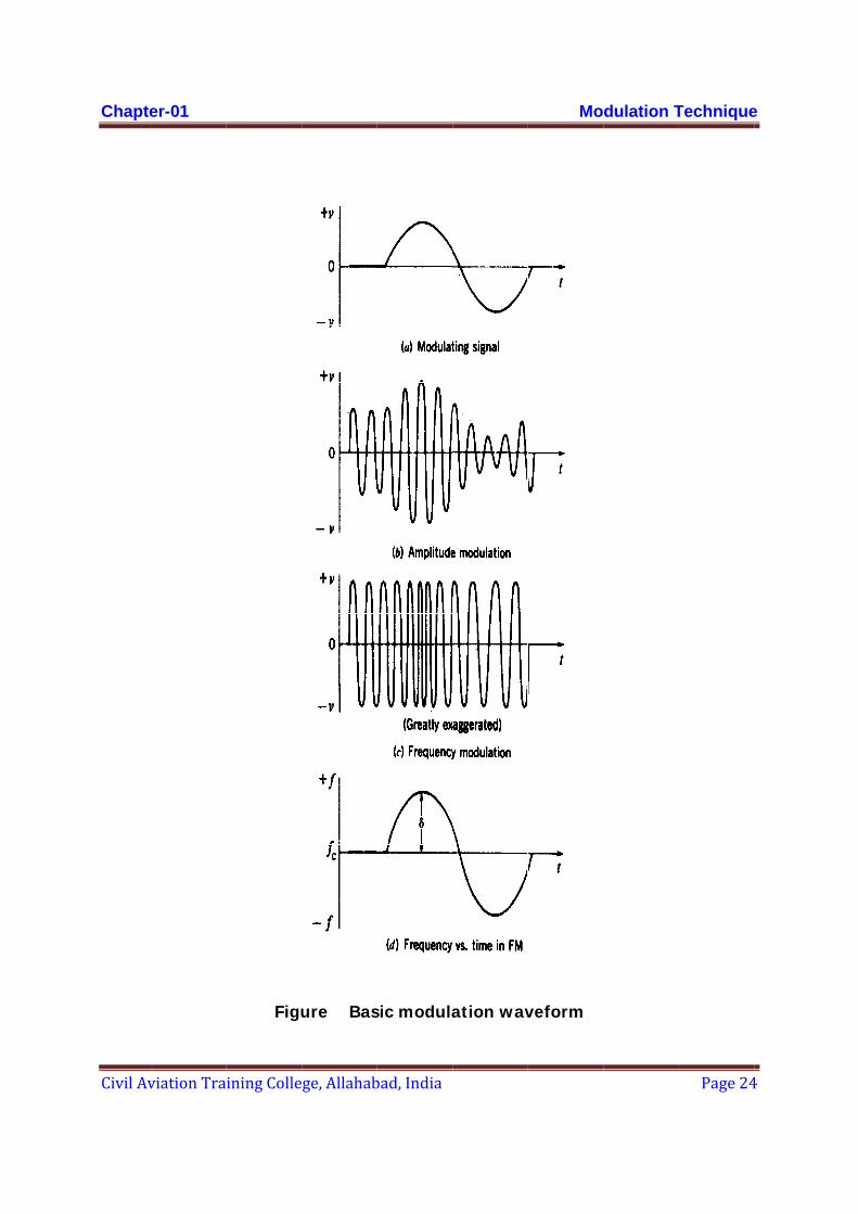
As an example of FM, all signals having the same amplitude will deviate the carrier frequency by same amount, say 45 kHz, no matter what there frequencies. Similarly, all signals of the same frequency, say2 KHz, will deviate the carrier at the same rate of 2000 times per second, no matter what there individual amplitudes .The amplitude of the frequency –modulated wave remains constant at all times ;This is ,in fact ,the greatest single advantage of FM.
The modulating signal em is used to vary the carrier frequency and may be used to alter the capacitance of the carrier frequency oscillator circuit. From the figure below, it is seen that the instantaneous frequency f of the frequency –modulated wave is given by
f = fc(1 +k.Vm Cosωm t) …. (1.52)
Chapte
Civil Av
er-01
viation Training Colle
Figu
ge, Allahab
ure Bas
bad, India
sic modula
ation wav
Mo
veform
dulation TTechnique
Page 24
e
4
Chapte
Civil Av
The mavalues,
so that
The ins
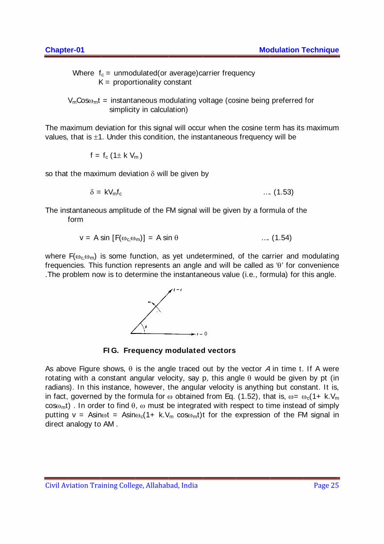
where frequen.The pr
As aborotatingradiansin fact,cosωmtputtingdirect a
er-01
viation Tra
Where f K
VmCosωmt aximum de, that is ±1
f = t the maxim
δ = stantaneouform v = A s F(ωc,ωm) incies. Thisroblem now
ove Figure g with a cs). In this , governedt) . In ordeg v = Asinanalogy to
ining Colle
fc = unmodK = propor
= instanta simplicit
eviation for1. Under th
fc (1± k Vm
mum devia
kVmfc
us amplitud
sin [F(ωc,ω
is some fus function w is to det
FIG. Fre
shows, θ constant aninstance, h
d by the forer to find θnωt = Asin
AM .
ge, Allahab
dulated(or tionality co
aneous moty in calcul
r this signahis conditio
m )
ation δ will
de of the F
ωm)] = A sin
unction, asrepresentstermine the
equency m
is the angngular velohowever, trmula for ω, ω must b
nωc(1+ k.V
bad, India
average)caonstant
odulating vation)
al will occuon, the inst
be given b
FM signal w
n θ
s yet undes an angle e instantan
modulated
gle traced ocity, say the angulaω obtainedbe integratVm cosωmt)
arrier frequ
oltage (cos
ur when thetantaneous
by
will be give
etermined, and will b
neous value
0
d vectors
out by thep, this ang
ar velocity d from Eq. ted with ret for the e
Mo
uency
sine being
e cosine tes frequency
….
en by a form
….
of the carbe called ase (i.e., form
e vector Agle θ woulis anything(1.52), tha
espect to tiexpression
dulation T
preferred
erm has itsy will be
. (1.53)
mula of the
(1.54)
rrier and ms ‘θ’ for comula) for t
in time t.d be giveng but consat is, ω= ωme instead of the FM
Technique
Page 25
for
s maximum
e
modulatingonveniencethis angle.
If A weren by pt (instant. It is,ωc(1+ k.Vm
d of simplyM signal in
e
5
m
g e
e n ,
m y n
Chapter-01 Modulation Technique
Civil Aviation Training College, Allahabad, India Page 26
Thus θ = ∫ω dt. =∫ ωc(1+ k.VmCosωmt)dt. = ωc ∫ (1+ k.Vmsinωmt)dt. =ωc ( t + k.Vm sinωm t ) +φ , where φ is the constant of integration. ωm k.Vm ωc sinωm t = ωc t + ------------------ ωm
k.Vm fc sinωm t = ωc t + fm
the constant φ may be made equal to zero by appropriate choice of reference axis.
δ
= ωc t + sinωm t … (1.55) fm
The derivation utilized, in turn, the fact that ωc is constant, the formula f cos nx dx = (sin nx)/n and from equation kVmfc = δ. Equation (1.22) may now be substituted into (1.21) to give the instantaneous value of the FM voltage; thus
δ v = A sin (ωc t + sinωm t ) …. (1.56) fm
Attention is required to understand that had the FM been defined as v = Asinωc(1+ k.Vm cosωmt)t
it would have been impossible to realise the instantaneous frequency over the time domain because it would have been as
f(t) = (1/2π) d/dt [ωc(1+ k.Vm cosωmt)t] = fc + fc k.Vm cosωmt – fc k.Vmt sinωmt
so | f(t)| → α when t → α
it also reveals that the instantaneous frequency (angular) of a wave represented by sine or cosine only the time derivative of its argument (or angle) and is not definitely equal to the quotient when the angle is divide by ‘t’. It becomes equal to the quotient in
Chapter-01 Modulation Technique
Civil Aviation Training College, Allahabad, India Page 27
the case of a pure sinusoid only because there the time derivative of the angle is the coefficient of time and consequently the coefficient is not the function of the time.
FM MODULATION INDEX
The modulation index for FM, mf ,is defined as
(maximum) frequency deviation δ mf = = …. (1.57) modulating frequency fm
Substituting eq.(1.57) into (1.56), we obtain v = A sin(ωc t + mf sinωm t) = A [cos(mf sinωm t) sinωc t + sin(mf sinωm t) cosωc t ] …. (1.58)
It is important to note that as the modulating frequency decreases and the modulating voltage amplitude (that is, δ) remains constant, the modulating index increases .This will be the basis for disguising frequency modulation from phase modulation. Note also that mf which is the ratio of two frequencies, is measured in radians. Frequency deviation associated parameters
The change in carrier frequency is called the frequency deviation. For a sample transmitter with an assigned rest frequency of 100 MHz deviated by +/- 25 KHz , the carrier changes frequency with modulation between the limits of 99.975 MHz and 100.025 MHz. The total frequency change of 2 * 25 KHz = 50 KHz is called the carrier swing.
Deviation Limits: A logical question at this time is, “How far can the carrier change frequency?” There is no technical limit to the frequency change. A carrier oscillator of 5 MHz could change down to zero cycles and upto two times of 5 MHz (that is 10 MHz) without distorting the modulated signal. It is easy to see that a deviation of +/- 5 MHz (a carrier swing of 10 MHz) for one station would be an undesirable waste of frequency spectrum. Moreover, if frequencies of all stations deviate down to zero cycles, they would have overlapping frequency bands, and it would be impossible to separate them. Therefore the FCC has set legal limits of deviation for each of the different services that use FM as the form of modulation. The deviation limits are based on the quality of the intended transmission, where wider deviation usually results in higher fidelity. The deviation limit is the term used to express 100% modulation of the FM carrier signal.

Chapter-01 Modulation Technique
Civil Aviation Training College, Allahabad, India Page 28
SIDEBAND ANALYSIS IN FM.
The mathematical analysis shows that dealing with a frequency spectrum for a frequency modulated wave may appear more difficult than the corresponding amplitude-analysis. The spectrum for only a sinusoidally frequency modulated wave (eq. 1.56) is found to consist of a carrier component, and side frequencies at harmonics of the modulating frequency, even though no harmonics are present in the original modulating tone. The amplitude of the various spectral components are given by mathematical function ,known as Bessel Function of the first kind, here denoted by Jn(mf), mf is the modulating index and n is the order of side frequencies. (eq. 1.58) may be expanded by observing that cos(mfsinωmt) and sin(mfsinωmt) are periodic and therefore can be expanded as trigonometric Fourier series f0 = fm. Indeed, a well known result states that
α
cos(mfsinωmt) = J0(mf) + Σ2Jk(mf) cos kωmt k=even α
and sin(mfsinωmt) = Σ Jk(mf)sin kωmt. k=odd
using this relation the expression for frequency modulated signal (tone modulated) become as
v = A{Jo(mf )sinωc t
+ J1(mf) [sin(ωc+ωm)t – sin((ωc -ωm )t ]
+ J2(mf ) [sin(ωc+2 ωm)t + sin((ωc -2ωm )t ]
+ J3(mf ) [sin(ωc+3ωm)t – sin((ωc -3ωm )t ]
+ J4(mf ) [sin(ωc+4ωm)t+ sin((ωc -4ωm )t ] …….} ……(1.59)
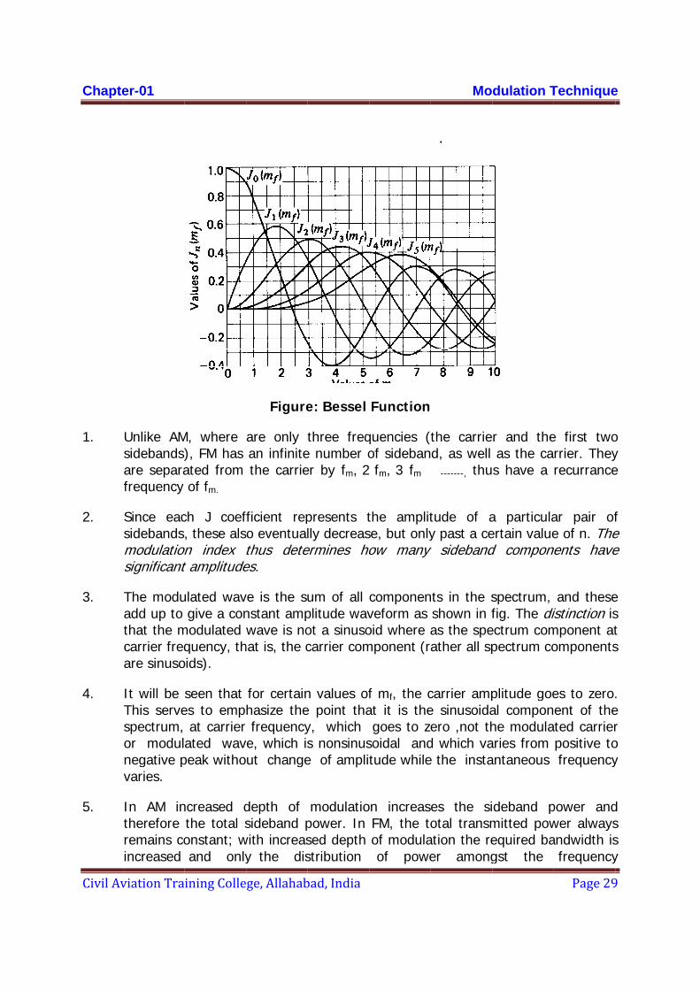
Jo(mf ) gives the amplitude of the carrier component. Bessel function is available in graphical form in fig. below; the observations are as follows
Chapte
Civil Av
1.
2.
3.
4.
5.
er-01
viation Tra
Unlike AMsidebands)are separafrequency
Since eacsidebands,modulationsignificant
The moduadd up to that the mcarrier freqare sinuso
It will be This servespectrum, or modulnegative pvaries.
In AM intherefore remains coincreased
ining Colle
M, where ), FM has ated from of fm.
ch J coef, these als
on index tt amplitude
ulated wavgive a con
modulated quency, th
oids).
seen that es to emp
at carrier ated wav
peak witho
ncreased dthe total sonstant; wand only
ge, Allahab
Figure
are only tan infinitethe carrie
fficient repo eventualthus detees.
ve is the sunstant ampwave is no
hat is, the c
for certainhasize thefrequency
ve, which isut change
depth of sideband p
with increasy the dis
bad, India
e: Bessel
three freqe number oer by fm, 2
presents tlly decreas
ermines ho
um of all plitude wavot a sinusocarrier com
n values ofe point thay, which s nonsinuse of amplit
modulatiopower. In sed depth stribution
Function
quencies (tof sideban fm, 3 fm
the amplitse, but only
how many
componenveform as oid where amponent (ra
f mf, the cat it is thegoes to ze
soidal andtude while
on increasFM, the toof modulaof powe
Mo
the carried, as well -------, thu
tude of ay past a ce
y sideband
nts in the sshown in fas the speather all sp
carrier ampe sinusoidaero ,not thd which vae the insta
es the siotal transm
ation the reer among
dulation T
r and theas the cas have a
a particulaertain valued compone
spectrum, fig. The di
ectrum compectrum co
plitude goeal componhe modulaaries from antaneous
deband pmitted powequired bagst the
Technique
Page 29
e first tworrier. Theyrecurrance
ar pair ofe of n. The
nents have
and theseistinction ismponent atomponents
es to zero.ent of theted carrierpositive tofrequency
power andwer alwaysandwidth is
frequency
e
9
o y e
f e e
e s t s
. e r o y
d s s y
Chapter-01 Modulation Technique
Civil Aviation Training College, Allahabad, India Page 30
components changes keeping the total power constant. To be quite specific, what increases is the bandwidth required to transmit relatively the undistorted signal. This is true because increased depth of modulation means increased deviation, and therefore an increased modulation index, so that the more distant sidebands acquire significant amplitudes.
6. As it is evident from Eq. (1.59) the theoretical bandwidth required in FM is infinite but in practice, the bandwidth is one that has been calculated to allow for all significant amplitudes of sideband components under the most adverse conditions. This really means ensuring that, with maximum deviation by the highest modulating frequency, no significant sideband components are looped off.
7. Since the overall amplitude of the FM wave remains constant ,it would be very odd indeed if the amplitude of the carrier were not reduced when the amplitude of the various sideband is increased, and vice versa.
8. It is possible for the carrier components of the FM wave to disappear completely. This happens for certain values of modulating index, called Eigen values. Fig. ‘Bessel Function’ shows that these are approximately 2.4, 5.5, 8.6, 11.8, and so on. These disappearances of the carrier for specific values of mf form a handy basis for measuring deviation.
9. It is evident from the expression for the modulated wave, Eq. (1.59) that in FM the even sidebands more correctly even pair of sidebands or even total sidebands are in phase (RF), or out of phase (if the signs of corresponding J coefficients are opposite to that of Jo) with the carrier and odd sidebands are in quadrature (leading or lagging that depends on the relative signs like that even sidebands).
The Fourier series technique use to arrive at Eq. 1.59 also can be applied to the case of Frequency Modulation with multi tone signasl.
Suppose x(t) = A1cosω1t + A2cosω2t, wher f1 and f2 are not harmonically related. The modulated wave can be written as (taking cosine carrier)
V(t) = Ac[cos(mf1sinω1t + mf2sinω2t) cos ωct - sin(mf1sinω1t
+ mf2sinω2t) sinωct] …..(1.60)
by expanding the terms like cos(mfsinωt) and sin(mfsinωt) with the help of Fourier series expansions (which comprises here Bessel Function) and after some routine manipulation we get the compact result as
α α
v(t) = Ac Σ Σ Jn (mf1) Jm (mf2) cos(ωc + nω1 + mω2)t … (1.61) n= -α m= -α
Chapter-01 Modulation Technique
Civil Aviation Training College, Allahabad, India Page 31
this technique can be extended to include tree or more number of non-harmonic tones. The procedure is straight forward but definitely tedious.
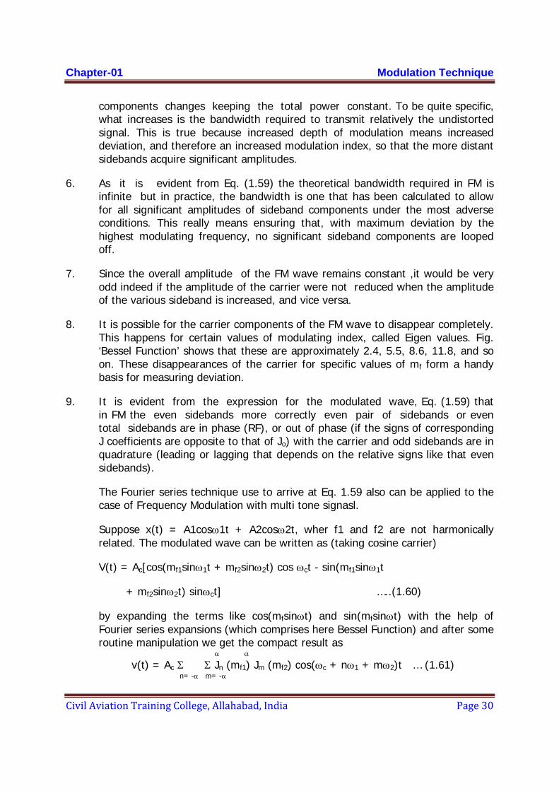
To interpret the above equation in the frequency domain the spectral line can be categorized as four types.
1) The carrier line of amplitude AcJ0(mf1)J0(mf2) 2) Sideband lines at fc±nf1 due to one tone alone 3) Sideband lines at fc±mf2 due to other tone alone 4) Sideband lines at fc±nf1±mf2 which appears to be beat frequency modulation at
the sum and difference frequencies of the modulating tones and their harmonics. The last category would not appear in linear modulation where simple superposition of sideband line is applicable.
f fc - 2f2 fc - f2 fc fc + f2 fc+ 2f2 fc-f1 fc+f1 In the figure above you see the curious property of double tone modulated sideband lines when f2 >> f1. Each sideband line at fc±mf2 looks line another FM carrier with tone modulation of frequency f1. If the tone frequencies are harmonically related, that is, the modulating signal is periodic waveform (non-sinusoidal) the ejφ(t) becomes periodic (as φis periodic) and eφ(t) can be expressed by Fourier coefficients where
Cn = 1/T0 ∫ exp j{φ(t) - nω0t}dt
T0 α
And v(t) = AcRc [Σ Cn exp j(ωc + nω0)t] … (1.62) n = - α
consequently Ac | Cn| equals the magnitude of the spectral line at f = fc + nf0.
BANDWIDTH IN FM
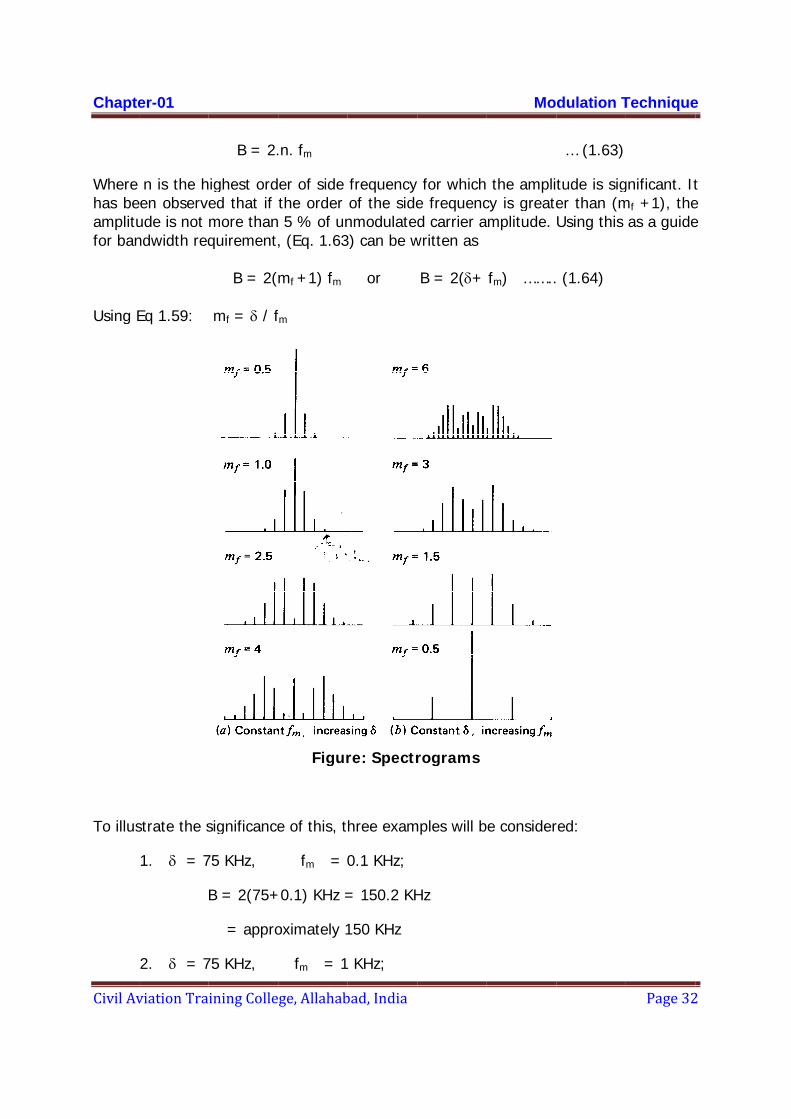
It is possible to evalute the size of the carrier and each sideband for each specific or interesting value of modulating index. This is done in the figure below, which shows these spectrograms. In each case the spectra lines are spaced by fm, and the bandwidth B occupied by the spectrum is seen to be
Chapte
Civil Av
Where has beamplitufor ban
Using E
To illus
er-01
viation Tra
n is the heen observeude is not ndwidth req
Eq 1.59:
strate the s
1. δ = 7
2. δ = 7
ining Colle
B = 2.
ighest orded that if more thanquirement,
B = 2(
mf = δ / f
significance
75 KHz,
B = 2(75+
= appro
75 KHz,
ge, Allahab
.n. fm
er of side the order 5 % of un, (Eq. 1.63
mf +1) fm
fm
Figur
e of this, t
fm = 0
+0.1) KHz =
oximately 1
fm = 1
bad, India
frequency of the sidenmodulated3) can be w
or
re: Spectr
hree exam
0.1 KHz;
= 150.2 KH
150 KHz
KHz;
for which e frequencd carrier a
written as
B = 2(δ+
rograms
mples will b
Hz
Mo
the amplicy is greatemplitude.
fm) ……..
e consider
dulation T
… (1.63)
tude is siger than (mUsing this
(1.64)
red:
Technique
Page 32
gnificant. Itmf +1), the
as a guide
e
2
t e e

Chapter-01 Modulation Technique
Civil Aviation Training College, Allahabad, India Page 33
B = 2(75+1)
= 152 KHz
3. δ = 75 KHz, fm = 10 KHz;
B = 2(75+10)
= 170 KHz
Thus, although the modulation frequency changes from 0.1 KHz to 10 KHz, or by a factor of 100:1, the bandwidth occupied by the spectrum alters very little from 150 KHz to 170 KHz. These examples illustrate why frequency modulation is sometimes referred to as a constant- bandwidth system.
It is also observed that increased depth modulation means, increased deviation, so does bandwidth as seen in fig.(a) above, and also that reduction in modulating frequency increases the number of sidebands, though not necessarily the bandwidth - fig.(b). Although the number of sideband components is theoretically infinite, in practice a lot of higher sidebands have insignificant relative amplitudes.
When the modulating signal comprises more than one frequency (or tone) the superposition principle does not become applicable for frequency and phase modulation and therefore, as has been explained earlier, the frequency modulation (or phase modulation, rather all angular modulation) is non-linear modulation process. The reader may also note that the frequency and phase modulation are not the only possible types of angular modulation; rather they are only two members of a theoretically infinite set of angular modulations. One member of this group is angular acceleration modulation in which the second time derivative of φ is directly proportional to the signal variation. The relation between the carrier phase change and the modulating signal may, therefore, be expressed as
d2φ/dt2 = kfm(t)
where the modulation index will be inversely proportion to the square of the modulating frequency. As a general form, for nth order angular modulation dnφ/dtn = knfm(t) will be the angular modulation to signal relationship where the nth order modulation index mn would be inversely proportion to the nth power of the modulating frequency.

Chapter-02 Concept to VOR
Civil Aviation Training College, Allahabad, India Page 34
Chapter-02 Concept to VOR
HISTORY AND DEVELOPMENT OF VOR:
VORs became the major radio navigation system in the 1960s, when they took over from the older radio beacon system. The older system retroactively became known as non-directional beacons, or NDBs. VOR's major advantage is that the radio signal provides more information, allowing pilots to follow a line in the sky more easily than with an NDB. A major network of "air highways", known as airways, were set up linking the VORs and airports. On any particular part of the journey the airway would say to fly at a specific angle from a particular station, in which case the pilot simply tunes in the station on the radio, dials that angle into the indicator, and then keeps a pointer centered in a display.
PURPOSES AND USE OF VOR:
1. The main purpose of the VOR is to provide the navigational signals for an aircraft receiver, which will allow the pilot to determine the bearing of the aircraft to a VOR facility.
2. In addition to this, VOR enables the Air Traffic Controllers in the Area Control Radar (ARSR) and ASR for identifying the aircraft in their scopes easily. They can monitor whether aircraft are following the radials correctly or not.
3. VOR located outside the airfield on the extended Centre line of the runway would be useful for the aircraft for making a straight VOR approach. With the help of the AUTO PILOT aircraft can be guided to approach the airport for landing.
4. VOR located enroute would be useful for air traffic 'to maintain their PDRS (PRE DETERMINED ROUTES) and are also used as reporting points.
5. VORs located at radial distance of about 40 miles in different directions around an International Airport can be used as holding VORs for regulating the aircraft for their landing in quickest time. They would be of immense help to the aircraft for holding overhead and also to the ATCO for handling the traffic conveniently.
MODELS OF VOR IN USE IN AAI:
Different make and models of CVORs and DVORs are installed at various locations in AAI.
In CVOR prominent models were of LORENZ, WILCOX, CARDION & BEL (LVC-151); presently we have ASI CVOR 1150.
Chapter-02 Concept to VOR
Civil Aviation Training College, Allahabad, India Page 35
In DVOR prominent models are of AWA, GCEL, and ASI, specifically GCEL – 755 / 757, ASI 1150, THALES-432.
VOR AIRBORNE RECEIVER
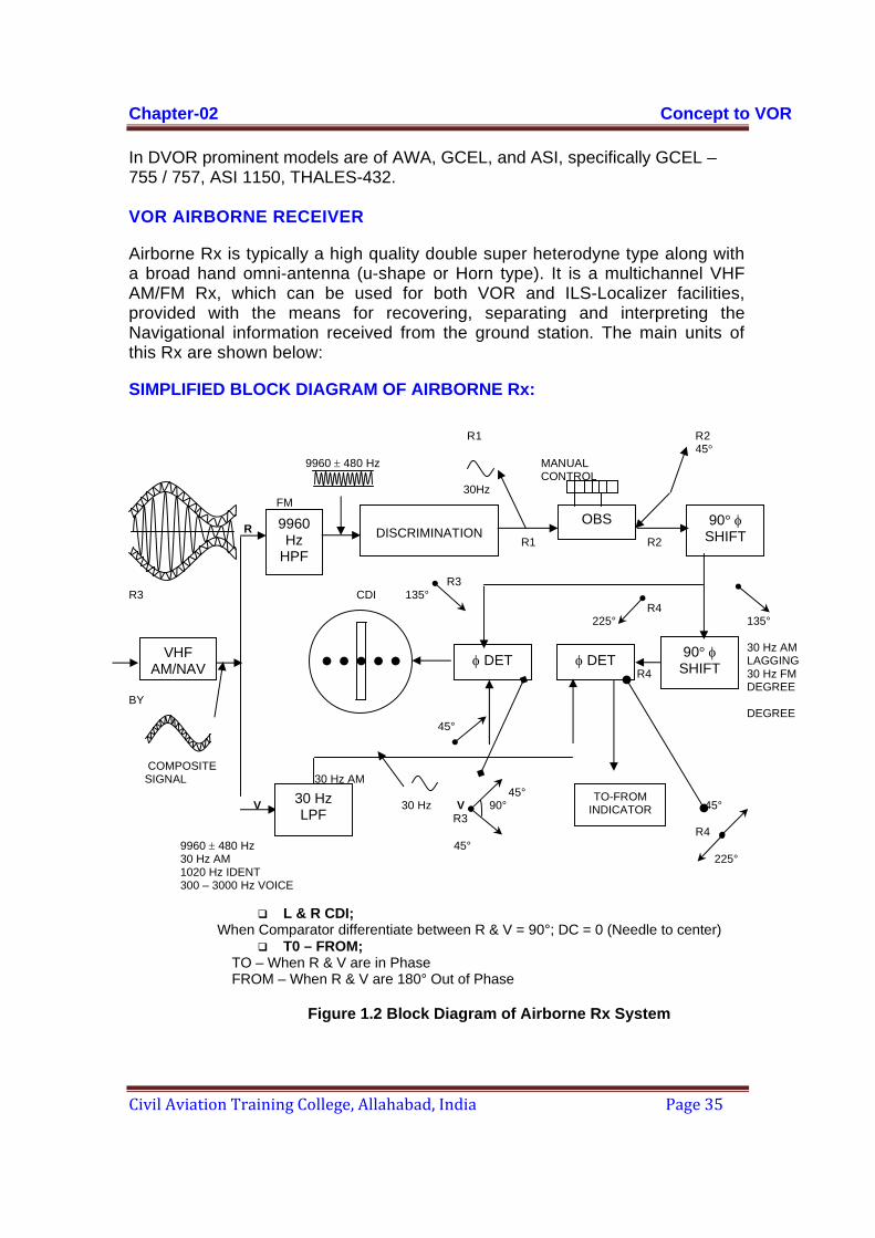
Airborne Rx is typically a high quality double super heterodyne type along with a broad hand omni-antenna (u-shape or Horn type). It is a multichannel VHF AM/FM Rx, which can be used for both VOR and ILS-Localizer facilities, provided with the means for recovering, separating and interpreting the Navigational information received from the ground station. The main units of this Rx are shown below:
SIMPLIFIED BLOCK DIAGRAM OF AIRBORNE Rx:
R1 R2
45° 9960 ± 480 Hz MANUAL CONTROL 30Hz FM R R1 R2 R3 R3 CDI 135° R4 225° 135° 30 Hz AM LAGGING R4 30 Hz FM DEGREE BY DEGREE 45° COMPOSITE SIGNAL 30 Hz AM 45° V 30 Hz V 90° 45° R3 R4
9960 ± 480 Hz 45° 30 Hz AM 225° 1020 Hz IDENT 300 – 3000 Hz VOICE
L & R CDI;
When Comparator differentiate between R & V = 90°; DC = 0 (Needle to center) T0 – FROM;
TO – When R & V are in Phase FROM – When R & V are 180° Out of Phase
Figure 1.2 Block Diagram of Airborne Rx System
9960 Hz
HPF
DISCRIMINATION
VHF AM/NAV
OBS 90° φ SHIFT
30 Hz LPF
φ DET φ DET
TO-FROM INDICATOR
90° φ SHIFT

Chapter-02 Concept to VOR
Civil Aviation Training College, Allahabad, India Page 36
CONTROLS AND INDICATIONS: TUNING (The ON/OFF VOLUME) CONTROL turns-ON the Navigational Rx as well as controls the audio volume. "ID" Tone control is also adjusted to the required level. Then the station is identified through coding or automatic voice transmissions, after selecting the desired frequency channel of the V.O.R. to be used, on the window of the frequency selector section with the help of two knobs as indicated.
• FREQUENCY SELECTOR The left knob selects Megacycles and the right knob selects tenth MC/S and Kilo Hertz. This particular Model covers 200-channel VOR/LOC frequency range of 108 MHz 117.95 MHz with 50 KHz channel spacing.
• OIMNI BEARING SELECTOR (OBS) The OBS knob drives the omni bearing indicator dial for selection of any desired Radial to be flown, under the course Index, with the reciprocal of the selected course shown under the lower Index. After Rx warming up and usable signal strength received, the "OFF" flag will disappear, and the course deviation indicator (CDI) will move to a stable position and it will eventually center by the rotation of the OBS Knob. A steady flag will appear either in the "To" or "FROM" window, indicating, whether the bearing selected is the course "To" or "from" the VOR station.
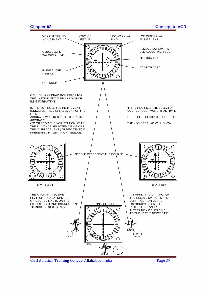
• COURSE DEVIATION INDICATOR (CDI) It is often known as ILS meter, the vertical needle being used for V.O.R. and Localizer purposes. The needle is centered, when the aircraft is on the selected course and when aircraft is "Off Course", the C.D.I. shows "Fly left" or "Fly right" indication. The rule is to follow the needle and bring it to Centre position to regain the selected course by making the Magnetic Heading of the aircraft in RMI and the OBS selection in general agreement, with "TO-FROM" reading as "TO". Full needle deflection from the Centre position to either side indicates that the aircraft is 10 degree off course from the selected course as the horizontal line has 4 dot or 5-dot scale on either side of the vertical line. The Horizontal pointer is connected to the Glide Path Rx.
Figure 1.3; A MECHANICAL VOR DISPLAY
Chapter-02 Concept to VOR
Civil Aviation Training College, Allahabad, India Page 37
VOR CENTERING VOR/LOC LOC WARNING LOC CENTERING ADJUSTMENT NEEDLE FLAG ADJUSTMENT REMOVE SCREW AND GLIDE SLOPE USE ADJUSTING TOOL WARNING FLAG TO-FROM FLAG AZIMUTH CARD GLIDE SLOPE NEEDLE OBS OBS KNOB CDI = COURSE DEVIATION INDICATOR THIS INSTRUMENT DISPLAYS VOR OR ILS INFORMATION. IN THE VOR ROLE THE INSTRUMENT IF THE PILOT SET THE SELECTOR INDICATES THE DISPLACEMENT OF THE COURSE (OBS) MORE THAN 10° L OR R AIRCRAFT WITH RESPECT TO BEARING OF THE HEADING OF THE AIRCRAFT (TO OR FROM THE VOR STATION) WHICH THE VOR OFF FLAG WILL SHOW. THE PILOT HAS SELECTED ON HIS OBS. THIS DISPLACEMENT (OR DEVIATION) IS PRESENTED BY LEFT/RIGHT NEEDLE. NEEDLE REPRESENT THE COURSE OBS OBS FLY - RIGHT FLY - LEFT THE AIRCRAFT RECEIVE A IF DURING FINAL APPROACH FLY RIGHT INDICATION, THE NEEDLE SWING TO THE ON-COURSE LINE IS ON THE LEFT (POSITION 2), THE PILOT’S RIGHT AND CORRECTION ON – COURSE ON-COURSE IS ON THE TO RIGHT IS NECESSARY. PILOT’S LEFT AND AN ALTERATION OF HEADING TO THE LEFT IS NECESSARY. OBS
1 2
3
Cha
Civi
•
Thiandtowin wbelo
TO
In tinsiairc090cou
"FRhem090
Movi.e. Somupospetimestat
apter-02
il Aviation
TO-FR
s instrumed sometim
wards or mwhich it isow:
- FROM I
this examide circuitcrafts i.e. 0° to 270°urse.
ROM" will misphere c0°.
vements aa steady
metimes thon the disteed e.g. Ate taken btion is abo
Training C
ROM INDIC
ent contaies called oving awas flying an
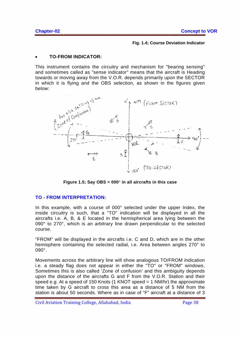
Figure 1.5
NTERPRE
ple, with atry is sucA, B, & E, which is
be displaycontaining
across they flag doehis is alsotance of tt a speed oy G aircra
out 50 sec
ollege, Alla
CATOR:
ins the ciras "sense
ay from thend the OB
; Say OBS
ETATION:
a course h, that a
E located s an arbitr
yed in the g the selec
arbitrary s not app
o called ‘Zohe aircraftof 150 Knoaft to crosonds. Whe
ahabad, Ind
rcuitry ande indicatore V.O.R. dBS select
S = 000° in
:
of 000° s"TO" indin the he
rary line d
aircrafts cted radia
line will shpear in eitone of conts G and ots (1 KNOss this areere as in c
dia
Fig. 1.4;
d mechanr" means tdepends prion, as sh
all aircraft
elected unication wimispherica
drawn perp
i.e. C andl, i.e. Area
how analother the "Tnfusion’ anF from the
OT speed =ea as a dcase of “F”
; Course D
nism for "bhat the airimarily uphown in th
ts in this c
nder the ull be dispal area lypendicular
D, whicha between
ogous TO/FTO" or "Fnd this ame V.O.R. S= 1 NM/hr)istance of” aircraft a
Con
Pag
Deviation In
bearing sercraft is H
pon the SEhe figures
case
upper Indeplayed in ing betwer to the se
are in then angles 2
FROM indFROM" winmbiguity deStation an) the approf 5 NM froat a distan
ncept to VO
e 38
ndicator
ensing" eading
ECTOR s given
ex, the all the
een the elected
e other 270° to
dication ndows. epends nd their oximate om the ce of 3
OR
Cha
Civi
NMvarinsutypeaircmovunbthisthatRadto babo
So the Magis tthe
•
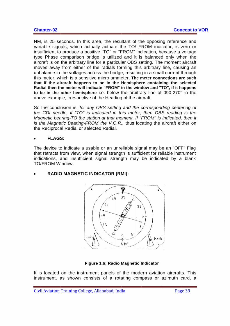
ThethatindiTO/
•
It isinst
apter-02
il Aviation
M, is 25 seiable signufficient toe Phase ccraft is on ves away balance in s meter, wht if the aidial then thbe in the ove examp
the concluCDI need
gnetic beathe MagneReciproca
FLAGS
e device tot retracts fications, a/FROM W
RADIO
s located trument, a
Training C
econds. In als, which
o produce acomparisothe arbitrafrom eiththe voltaghich is a srcraft hap
he meter wother hem
ple, irrespe
usion is, fdle, if "TO
aring-TO thetic Bearinal Radial o
S:
o indicate from view,and insuffindow.
O MAGNET
on the insas shown
ollege, Alla
this areah actually a positive
on bridge ary line forer of the
ges across ensitive m
ppens to bwill indicatemisphere i.ective of th
for any OBO" is indiche station g-FROM t
or selected
a usable o when sigficient sig
TIC INDIC
Figure 1
strument consists
ahabad, Ind
, the resuactuate th"TO" or "Fis utilized
r a particulradials forthe bridge
micro ammebe in the e "FROM" e. below te Heading
BS setting cated in that that mothe V.O.R Radial.
or an unrenal strengtnal streng
CATOR (RM
.6; Radio M
panels of of a rota
dia
ultant of thhe TO/ FFROM" indd and it islar OBS serming thise, resultingeter. The mHemispherin the windthe arbitra
g of the air
and the chis meter, oment, If "F., thus loc
eliable signth is sufficgth may
MI):
Magnetic I
the modeating com
he opposinROM indicdication, bes balancedetting. The arbitrary
g in a smameter connre containdow and "Tary line of craft.
correspondthen OBS
FROM" is cating the
nal may bcient for rebe indica
Indicator
ern aviatiompass or a
Con
Pag
ng referencator, is zecause a vd only whe moment
line, causll current t
nections arning the seTO", if it ha090-270°
ding centeS readingindicated,aircraft eit
e an "OFFeliable instrted by a
on aircraftsazimuth c
ncept to VO
e 39
ce and zero or voltage
hen the aircraft
sing an hrough re such elected appens in the
ering of g is the
then it ther on
F" Flag rument
blank
s. This card, a
OR

Chapter-02 Concept to VOR
Civil Aviation Training College, Allahabad, India Page 40
double barred Bearing indicator, and a simple barred indicator. The compass card, actuated by the aircrafts compass system, rotates as the aircraft turns its Nose. The Magnetic Heading of the aircraft is always directly under the index at the top of the instrument, assuming no compass deviation error.
Normally, the double barred indicator gives the Magnetic bearing to the V.O.R. to which the Receiver is tuned and the ‘Tail' tells you the Radial you are on. The single barred needle gives the Magnetic bearing to the selected LF/MF facility i.e. NDB. The tail of this needle gives the magnetic bearing of the aircraft from NDB station.
Some RMI has got selector switches permitting the Pilot to use both indicator needles in conjunction with dual VOR Rx's or both, indicators as ADF needles, by putting the switches on appropriate positions. All functions are being done automatically.

Chapter-02 Concept to VOR
Civil Aviation Training College, Allahabad, India Page 41
VOR PRINCIPLE Operation of the CVOR is based on the phase difference between two 30 Hz signals modulated on the carrier, called the reference phase and the variable phase (Figure 2-1). Aircraft determines it’s bearing by comparing phase of reference 30 Hz and variable 30 Hz signals. Reference 30 Hz signal has the same phase at all the 360 degrees points around VOR whereas the phase of variable 30 Hz changes at the rate of 1 degree for one degree deviation of azimuth angle. The reference 30 Hz signal and variable 30 Hz signal are in the same phase in the direction of magnetic north. In fact this direction is taken as zero degree for VOR and other azimuth angles measured in clockwise direction.
The reference phase signal is obtained by amplitude modulating the carrier with a 9960 Hz sine wave signal that is frequency modulated by a 30 Hz audio tone that is referred to as the FM sub carrier. This amplitude modulated FM sub carrier signal is radiated omni directionally in the horizontal plane from all four loops forming the carrier antenna. The radiation pattern is a circle, and produces in the aircraft receiver a 30 Hz signal with a phase independent of azimuth (Figure 2-2) (Also Refer Figure 2.8).
Figure 2-1. RF Spectrum of a Conventional VOR
Chapter-02 Concept to VOR
Civil Aviation Training College, Allahabad, India Page 42
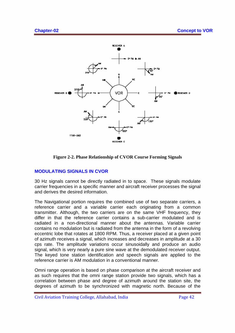
Figure 2-2. Phase Relationship of CVOR Course Forming Signals
MODULATING SIGNALS IN CVOR
30 Hz signals cannot be directly radiated in to space. These signals modulate carrier frequencies in a specific manner and aircraft receiver processes the signal and derives the desired information.
The Navigational portion requires the combined use of two separate carriers, a reference carrier and a variable carrier each originating from a common transmitter. Although, the two carriers are on the same VHF frequency, they differ in that the reference carrier contains a sub-carrier modulated and is radiated in a non-directional manner about the antennas. Variable carrier contains no modulation but is radiated from the antenna in the form of a revolving eccentric lobe that rotates at 1800 RPM. Thus, a receiver placed at a given point of azimuth receives a signal, which increases and decreases in amplitude at a 30 cps rate. The amplitude variations occur sinusoidally and produce an audio signal, which is very nearly a pure sine wave at the demodulated receiver output. The keyed tone station identification and speech signals are applied to the reference carrier is AM modulation in a conventional manner.
Omni range operation is based on phase comparison at the aircraft receiver and as such requires that the omni range station provide two signals, which has a correlation between phase and degree of azimuth around the station site, the degrees of azimuth to be synchronized with magnetic north. Because of the
Chapter-02 Concept to VOR
Civil Aviation Training College, Allahabad, India Page 43
rotational characteristics of the variable carrier, the 30 cps variable phase receiver output has azimuth sensitivity, which is measurable.
The reference carrier provides a magnetic north (zero degrees) reference phase by virtue of the sub-carrier modulation applied. This sub-carrier modulation consists of a 9960 cps signal frequency modulated by 30 cps to a mod index of 16. Thus, the frequency deviation is plus or minus 480 cps. The sub-carrier signal is applied to the reference carrier as AM modulation, and the 30 cps reference phase output of the receiver demodulator is in-phase with the 30 cps variable phase at magnetic north only.
Receiver placement at specific points of azimuth around the omni range antenna results in a varying amount of lag of the 30 cps variable phase behind the reference phase. This lag is due to the time element required for the variable carrier to be to rotate around the azimuth to the receiver location. At the point 90 degrees from the receiver location the variable phase signal is at zero amplitude, as the lobe rotates towards the receiver location the variable phase output builds up in a positive direction, and through maximum. Further rotation of the' lobe causes the variable phase- output to go in the negative direction, through maximum to zero, to complete the cycle.
The conditions just described are present due to space modulation, which is the algebraic addition that takes place between the reference and variable carrier.
REFERENCE SIGNAL BY FM
30Hz sinusoidal signal frequency modulates 9960Hz, this Sub carrier modulation consists of a 9960 plus and minus 480 Hz at 30 Hz rate is shown in figure. This 9960 Hz sub-carrier Amplitude Modulates on R.F. frequency of VOR.

Chapter-02 Concept to VOR
Civil Aviation Training College, Allahabad, India Page 44
Figure: 2.3 Reference Carrier Modulating Signal
VARIABLE SIGNAL BY AM
Variable 30 Hz signal is obtained by technique known as space modulation, which means the modulation is not generated inside transmitter but it is achieved by combination or R.F. signals in space. An earlier version of VOR (LORENZ VOR) does it by rotating dipole fed with pure carrier at the rate of 30 revolutions per seconds. The radiation patter of dipole is as shown in Figure 2-4
10440
Highest Frequency
Centre Frequency
9960
Centre Frequency
9960
Lowest frequency
9480 96219621
30Hz
SUBCARRIER 9960 Hz
9960 Hz frequency Modulated by 30 Hz
+-
Figure 2.4 Radiation Pattern Due to a Dipole
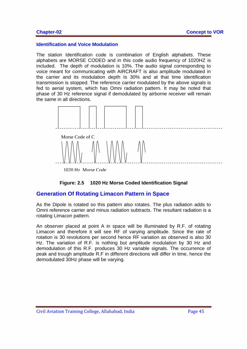
Chapter-02 Concept to VOR
Civil Aviation Training College, Allahabad, India Page 45
Identification and Voice Modulation
The station Identification code is combination of English alphabets. These alphabets are MORSE CODED and in this code audio frequency of 1020HZ is included. The depth of modulation is 10%. The audio signal corresponding to voice meant for communicating with AIRCRAFT is also amplitude modulated in the carrier and its modulation depth Is 30% and at that time identification transmission is stopped. The reference carrier modulated by the above signals is fed to aerial system, which has Omni radiation pattern. It may be noted that phase of 30 Hz reference signal if demodulated by airborne receiver will remain the same in all directions.
Figure: 2.5 1020 Hz Morse Coded Identification Signal
Generation Of Rotating Limacon Pattern in Space
As the Dipole is rotated so this pattern also rotates. The plus radiation adds to Omni reference carrier and minus radiation subtracts. The resultant radiation is a rotating Limacon pattern.
An observer placed at point A in space will be illuminated by R.F. of rotating Limacon and therefore it will see RF of varying amplitude. Since the rate of rotation is 30 revolutions per second hence RF variation as observed is also 30 Hz. The variation of R.F. is nothing but amplitude modulation by 30 Hz and demodulation of this R.F. produces 30 Hz variable signals. The occurrence of peak and trough amplitude R.F in different directions will differ in time, hence the demodulated 30Hz phase will be varying.
Morse Code of C
1020 Hz Morse Code
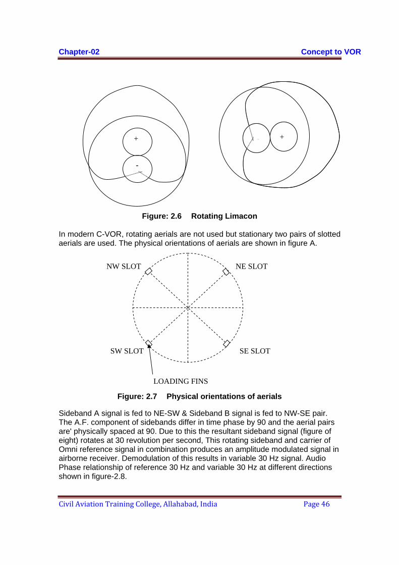
Chapter-02 Concept to VOR
Civil Aviation Training College, Allahabad, India Page 46
Figure: 2.6 Rotating Limacon In modern C-VOR, rotating aerials are not used but stationary two pairs of slotted aerials are used. The physical orientations of aerials are shown in figure A.
Figure: 2.7 Physical orientations of aerials
Sideband A signal is fed to NE-SW & Sideband B signal is fed to NW-SE pair. The A.F. component of sidebands differ in time phase by 90 and the aerial pairs are' physically spaced at 90. Due to this the resultant sideband signal (figure of eight) rotates at 30 revolution per second, This rotating sideband and carrier of Omni reference signal in combination produces an amplitude modulated signal in airborne receiver. Demodulation of this results in variable 30 Hz signal. Audio Phase relationship of reference 30 Hz and variable 30 Hz at different directions shown in figure-2.8.
- +++
-
NW SLOT NE SLOT
SE SLOTSW SLOT
LOADING FINS

Chapter-02 Concept to VOR
Civil Aviation Training College, Allahabad, India Page 47
AIRCRAFT RX SEES VARIABLE PHASE SIGNAL IN PHASE WITH REFERENCE PHASE SIGNAL REFERENCE REFERENCE PHASE SIGNAL PHASE SIGNAL VARIABLE PHASE SIGNAL VARIABLE PHASE SIGNAL N AIRCRAFT RX SEES VARIABLE PHASE SIGNAL LAGGING REFERENCE PHASE SIGNAL BY 270° W E AIRCRAFT RX SEES VARIABLE PHASE S SIGNAL LAGGING REFERENCE PHASE SIGNAL BY 90° AIRCRAFT RX SEES VARIABLE PHASE SIGNAL LAGGING REFERENCE PHASE SIGNAL BY 180°
Figure: 2.8 Audio Phase relationships at different
Chapter-02 Concept to VOR
Civil Aviation Training College, Allahabad, India Page 48
Requirement of Modulation Eliminator
The Navigational portion requires the combined use of two separate carriers, a reference carrier and a variable carrier each originating from a common transmitter (to have a constant phase relationship between the two). Although the two carriers are on the same VHF frequency, they differ in that the reference carrier contains a sub-carrier modulated and is radiated in a non-directional manner about the antennas. Variable carrier contains no modulation but is radiated from the antenna in the form of a revolving eccentric lobe that rotates at 1800 RPM. Since both the reference and the variable carriers must have a constant phase relationship in order to produce a definite space modulation, a portion of the reference carrier is taken and applied to the modulation eliminator to remove all modulations. After removal of modulation the output of the modulation eliminator becomes pure carrier, which is applied to the side band antennas in a desired manner.
Accuracy, Precision, Resolution, Frequency band and spacing:
Accuracy:
Closeness with which equipment’s reading approaches the true value of the variable being measured.
Precision:
Given a fixed value of a variable, precision is a measure of the degree to which successive measurements differ from one another.
Resolution:
The smallest change in measured value to which the equipment will respond.
Frequency Band and Spacing:
FREQUENCY BAND: 111.975 MHz to 117.975 MHz
HIGHEST ASSIGNABLE FREQUENCY: 17.950 MHz
CHANNEL SEPARATION: In increments of 50 KHz referred to the highest assignable frequency
Chapter-02 Concept to VOR
Civil Aviation Training College, Allahabad, India Page 49
In areas where 100 KHz or 200 KHz channel spacing is in general use, the frequency tolerance of the radio frequency carrier shall be plus or minus 0.005 per cent.
The frequency tolerance of the radio frequency carrier of all new installations implemented after 23 May 1974 in areas where 50 KHz channel spacing is in use shall be plus or minus 0.002 per cent.
In areas where new VOR installations are implemented and are assigned frequencies spaces at 50 KHz from existing VOR-s in the same area, priority shall be given to ensuring that the frequency tolerance of the radio frequency carrier of the existing VORs is reduced to plus or minus 0.002 per cent.
ERROR SUSCEPTIBILITY
Phase Of 30 Hz Being The Information In Azimuth:
The bearing information from CVOR is contained in the amplitude-modulated signal obtained by the space modulation. Due to the presence of large structures near the VOR installation the phase of this signal is susceptible to errors due to traversing multiple paths before reaching to an observer. Also the growth of bushes and trees near the VOR installation may add to the problem. By suitable choice of the VOR site and preventing vegetation growth, these types of errors can be minimized. Why It Is Not Possible To Get FM By Space Modulation:
In frequency modulation we have ideally infinite number of sidebands, which have certain phase relationship with the carrier. Though for practical purposes finite number of sidebands (much more than two even for tone modulation) can serve the purpose by restraining the bandwidth within workable limit.
It becomes impractical as well as too difficult to produce larger number of sidebands and to radiate through an antenna system in such a way that the addition of all these sidebands with the carrier will take place in proper and desired phase, resulting the frequency modulation taking place in space.
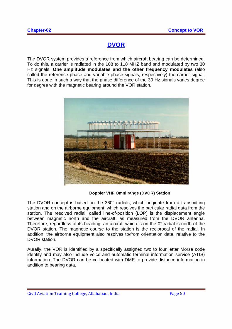
Chapter-02 Concept to VOR
Civil Aviation Training College, Allahabad, India Page 50
DVOR
The DVOR system provides a reference from which aircraft bearing can be determined. To do this, a carrier is radiated in the 108 to 118 MHZ band and modulated by two 30 Hz signals. One amplitude modulates and the other frequency modulates (also called the reference phase and variable phase signals, respectively) the carrier signal. This is done in such a way that the phase difference of the 30 Hz signals varies degree for degree with the magnetic bearing around the VOR station.
Doppler VHF Omni range (DVOR) Station
The DVOR concept is based on the 360° radials, which originate from a transmitting station and on the airborne equipment, which resolves the particular radial data from the station. The resolved radial, called line-of-position (LOP) is the displacement angle between magnetic north and the aircraft, as measured from the DVOR antenna. Therefore, regardless of its heading, an aircraft which is on the 0° radial is north of the DVOR station. The magnetic course to the station is the reciprocal of the radial. In addition, the airborne equipment also resolves to/from orientation data, relative to the DVOR station.
Aurally, the VOR is identified by a specifically assigned two to four letter Morse code identity and may also include voice and automatic terminal information service (ATIS) information. The DVOR can be collocated with DME to provide distance information in addition to bearing data.
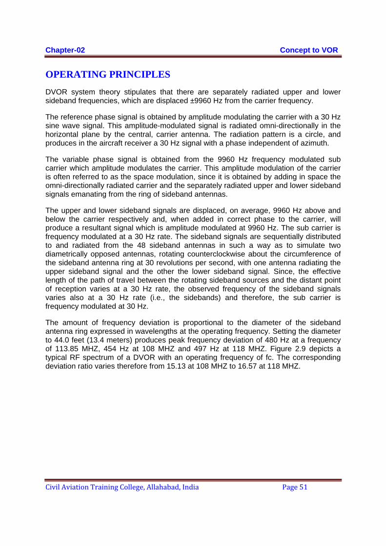
Chapter-02 Concept to VOR
Civil Aviation Training College, Allahabad, India Page 51
OPERATING PRINCIPLES
DVOR system theory stipulates that there are separately radiated upper and lower sideband frequencies, which are displaced ±9960 Hz from the carrier frequency.
The reference phase signal is obtained by amplitude modulating the carrier with a 30 Hz sine wave signal. This amplitude-modulated signal is radiated omni-directionally in the horizontal plane by the central, carrier antenna. The radiation pattern is a circle, and produces in the aircraft receiver a 30 Hz signal with a phase independent of azimuth.
The variable phase signal is obtained from the 9960 Hz frequency modulated sub carrier which amplitude modulates the carrier. This amplitude modulation of the carrier is often referred to as the space modulation, since it is obtained by adding in space the omni-directionally radiated carrier and the separately radiated upper and lower sideband signals emanating from the ring of sideband antennas.
The upper and lower sideband signals are displaced, on average, 9960 Hz above and below the carrier respectively and, when added in correct phase to the carrier, will produce a resultant signal which is amplitude modulated at 9960 Hz. The sub carrier is frequency modulated at a 30 Hz rate. The sideband signals are sequentially distributed to and radiated from the 48 sideband antennas in such a way as to simulate two diametrically opposed antennas, rotating counterclockwise about the circumference of the sideband antenna ring at 30 revolutions per second, with one antenna radiating the upper sideband signal and the other the lower sideband signal. Since, the effective length of the path of travel between the rotating sideband sources and the distant point of reception varies at a 30 Hz rate, the observed frequency of the sideband signals varies also at a 30 Hz rate (i.e., the sidebands) and therefore, the sub carrier is frequency modulated at 30 Hz.
The amount of frequency deviation is proportional to the diameter of the sideband antenna ring expressed in wavelengths at the operating frequency. Setting the diameter to 44.0 feet (13.4 meters) produces peak frequency deviation of 480 Hz at a frequency of 113.85 MHZ, 454 Hz at 108 MHZ and 497 Hz at 118 MHZ. Figure 2.9 depicts a typical RF spectrum of a DVOR with an operating frequency of fc. The corresponding deviation ratio varies therefore from 15.13 at 108 MHZ to 16.57 at 118 MHZ.

Chapter-02 Concept to VOR
Civil Aviation Training College, Allahabad, India Page 52
The deviation frequency is determined by the formula:
In the aircraft receiver, a 30 Hz signal is extracted from the 9960 Hz FM sub carrier. The phase of this second 30 Hz signal varies linearly with the change of the azimuth bearing of the receiving point; for each degree of azimuth change, the phase of the 30 Hz variable phase signal changes by one degree.
Figure 2.9 RF Spectrum of a Doppler VOR
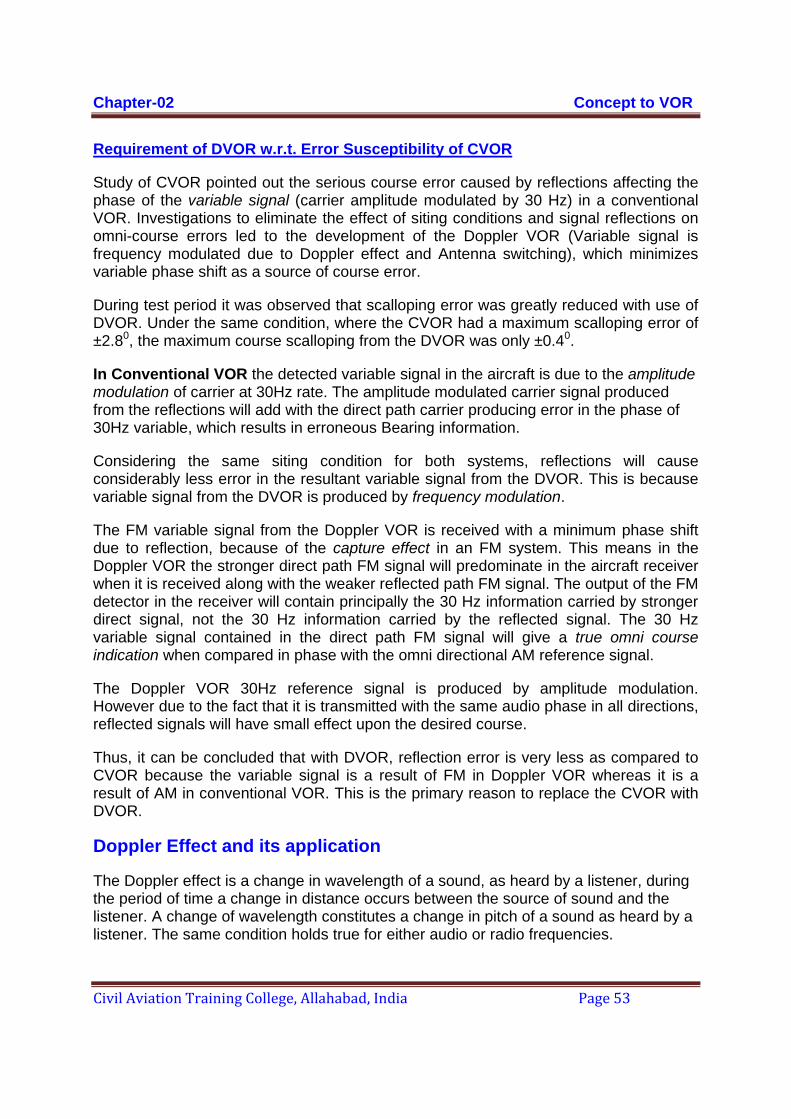
Chapter-02 Concept to VOR
Civil Aviation Training College, Allahabad, India Page 53
Requirement of DVOR w.r.t. Error Susceptibility of CVOR
Study of CVOR pointed out the serious course error caused by reflections affecting the phase of the variable signal (carrier amplitude modulated by 30 Hz) in a conventional VOR. Investigations to eliminate the effect of siting conditions and signal reflections on omni-course errors led to the development of the Doppler VOR (Variable signal is frequency modulated due to Doppler effect and Antenna switching), which minimizes variable phase shift as a source of course error.
During test period it was observed that scalloping error was greatly reduced with use of DVOR. Under the same condition, where the CVOR had a maximum scalloping error of ±2.80, the maximum course scalloping from the DVOR was only ±0.40.
In Conventional VOR the detected variable signal in the aircraft is due to the amplitude modulation of carrier at 30Hz rate. The amplitude modulated carrier signal produced from the reflections will add with the direct path carrier producing error in the phase of 30Hz variable, which results in erroneous Bearing information.
Considering the same siting condition for both systems, reflections will cause considerably less error in the resultant variable signal from the DVOR. This is because variable signal from the DVOR is produced by frequency modulation.
The FM variable signal from the Doppler VOR is received with a minimum phase shift due to reflection, because of the capture effect in an FM system. This means in the Doppler VOR the stronger direct path FM signal will predominate in the aircraft receiver when it is received along with the weaker reflected path FM signal. The output of the FM detector in the receiver will contain principally the 30 Hz information carried by stronger direct signal, not the 30 Hz information carried by the reflected signal. The 30 Hz variable signal contained in the direct path FM signal will give a true omni course indication when compared in phase with the omni directional AM reference signal.
The Doppler VOR 30Hz reference signal is produced by amplitude modulation. However due to the fact that it is transmitted with the same audio phase in all directions, reflected signals will have small effect upon the desired course.
Thus, it can be concluded that with DVOR, reflection error is very less as compared to CVOR because the variable signal is a result of FM in Doppler VOR whereas it is a result of AM in conventional VOR. This is the primary reason to replace the CVOR with DVOR.
Doppler Effect and its application
The Doppler effect is a change in wavelength of a sound, as heard by a listener, during the period of time a change in distance occurs between the source of sound and the listener. A change of wavelength constitutes a change in pitch of a sound as heard by a listener. The same condition holds true for either audio or radio frequencies.
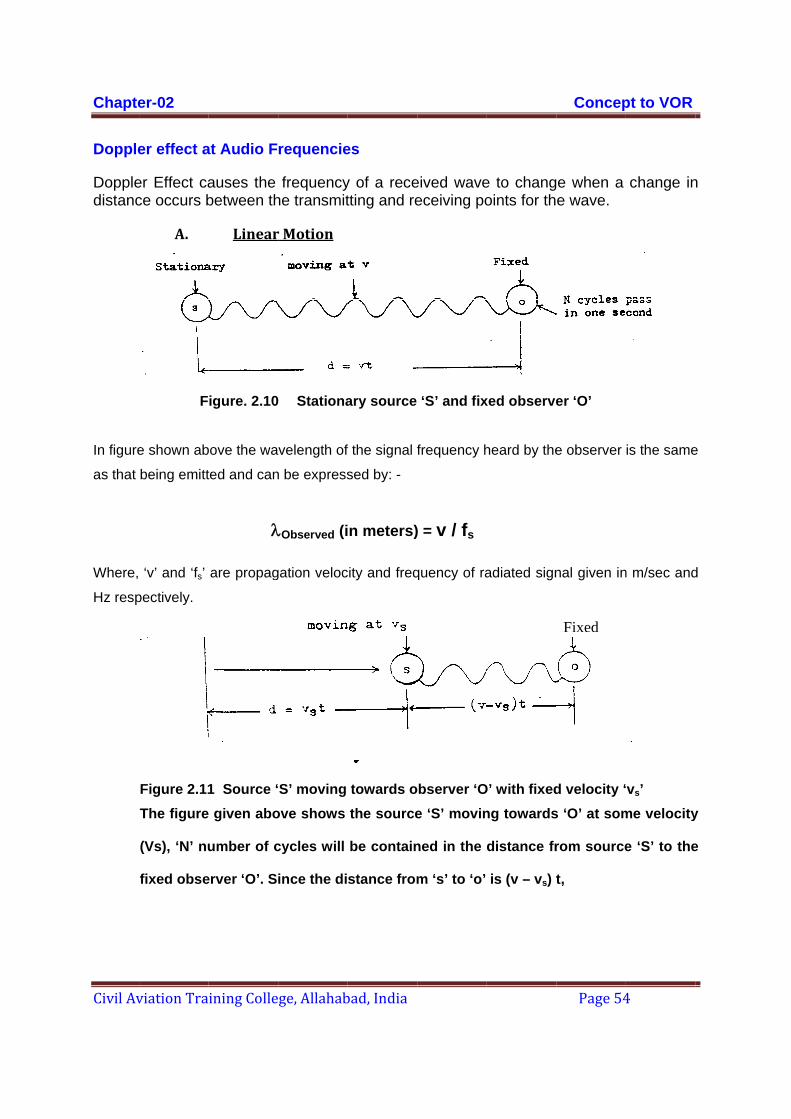
Chapte
Civil Av
Dopple
Doppledistanc
In figure
as that
Where,
Hz resp
er-02
viation Tra
er effect a
er Effect cace occurs b
A.
F
e shown ab
being emitt
‘v’ and ‘fs’
pectively.
Figure 2.11The figure
(Vs), ‘N’ nu
fixed obse
ining Colle
at Audio F
auses the between th
Linear
igure. 2.10
bove the wa
ted and can
are propag
1 Source ‘ given abo
umber of c
erver ‘O’. S
λ
ge, Allahab
requencie
frequencyhe transmit
r Motion
Stationa
velength of
n be express
gation veloc
S’ moving ove shows
cycles will
ince the di
λObserved (i
bad, India
es
y of a recetting and re
ary source
f the signal f
sed by: -
city and freq
towards othe source
be contain
stance from
n meters)
eived waveeceiving po
‘S’ and fix
frequency h
quency of ra
observer ‘Oe ‘S’ movin
ned in the
m ‘s’ to ‘o’
) = v / fs
e to changoints for th
xed observe
heard by the
adiated sign
O’ with fixedng towards
distance fr
is (v – vs) t
Concep
Page 54
e when a e wave.
er ‘O’
e observer
nal given in
d velocity ‘s ‘O’ at som
rom source
t,
Fixed
pt to VOR
4
change in
is the same
n m/sec and
‘vs’ me velocity
e ‘S’ to the
n
e
d
y
e
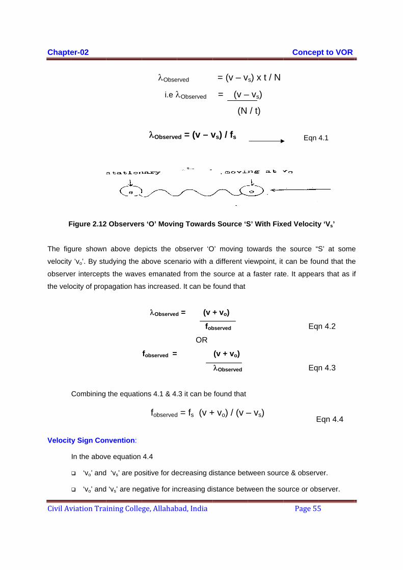
Chapte
Civil Av
F
The fig
velocity
observe
the velo
Velocit
er-02
viation Tra
Figure 2.12
gure shown
y ’vo’. By stu
er intercept
ocity of prop
Combining
ty Sign Con
In the abov
‘vo’ and
‘vo’ and
ining Colle
Observers
above de
udying the a
s the wave
pagation ha
the equatio
nvention:
ve equation
‘vs’ are po
‘vs’ are neg
ge, Allahab
λObse
i.e λ
s ‘O’ Movin
epicts the o
above scen
es emanated
as increased
λObserved
fobserved =
ons 4.1 & 4.
4.4
ositive for de
gative for in
λObserve
fobserved
bad, India
erved
λObserved
ng Towards
observer ‘O
nario with a
d from the
d. It can be
d = (v
fob
OR
.3 it can be
ecreasing d
ncreasing di
ed = (v – v
d = fs (v +
= (v – v
= (v –
(N
s Source ‘S
O’ moving t
a different v
source at a
found that
+ vo)
bserved
(v + vo)
λObserved
found that
istance betw
stance betw
vs) / fs
+ vo) / (v –
s) x t / N
– vs)
/ t)
S’ With Fixe
towards the
iewpoint, it
a faster rate
ween sourc
ween the so
– vs)
Concep
Page 55
Eqn 4
ed Velocity
e source “S
can be fou
e. It appear
Eqn
Eqn
E
ce & observ
ource or obs
pt to VOR
5
4.1
y ‘Vs’
S’ at some
und that the
rs that as if
n 4.2
n 4.3
Eqn 4.4
ver.
server.
e
e
f
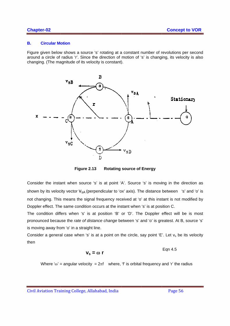
Chapte
Civil Av
B.
Figure garound changin
Conside
shown
not cha
Dopple
The co
pronoun
is movin
Conside
then
er-02
viation Tra
Circular Mo
given belowa circle of
ng. (The ma
er the insta
by its veloc
anging. This
r effect. The
ondition diff
nced becau
ng away fro
er a genera
Where ‘ω’ =
ining Colle
otion
w shows a sradius ‘r’. S
agnitude of
Fig
ant when s
city vector vs means the
e same con
fers when
use the rate
om ‘o’ in a s
al case whe
= angular ve
ge, Allahab
source ‘s’ rSince the dits velocity
ure 2.13
ource ‘s’ is
vsA (perpend
e signal fre
ndition occu
‘s’ is at po
e of distance
straight line.
en ‘s’ is at a
elocity = 2π
vs = ω
bad, India
rotating at adirection of is constant)
Rotating
s at point ‘A
dicular to ‘o
quency rec
rs at the ins
osition ‘B’
e change be
a point on t
πf where,
r
a constant nmotion of ‘).
source of
A’. Source
ox’ axis). Th
ceived at ‘o’
stant when
or ‘D’. The
etween ‘s’ a
the circle, s
‘f’ is orbital
number of rs’ is chang
Energy
‘s’ is movi
he distance
’ at this inst
‘s’ is at pos
e Doppler
and ‘o’ is gr
say point ‘E
frequency
Concep
Page 56
revolutions ing, its velo
ing in the d
between ‘
tant is not m
sition C.
effect will
reatest. At B
E’. Let vs be
Eqn 4.5
and ‘r’ the r
pt to VOR
6
per secondocity is also
direction as
‘s’ and ‘o’ is
modified by
be is most
B, source ‘s
e its velocity
radius
d o
s
s
y
t
’
y
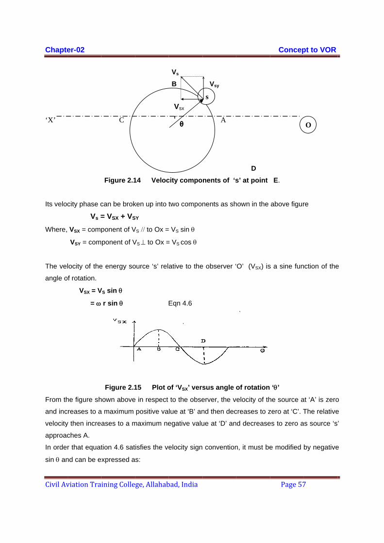
Chapte
Civil Av
‘X’
Its veloc
Where,
The vel
angle o
From th
and inc
velocity
approac
In order
sin θ an
er-02
viation Tra
city phase c
Vs =VSX = comp
VSY = com
locity of the
of rotation.
VSX = V
= ω
he figure sh
reases to a
y then increa
ches A.
r that equat
nd can be e
ining Colle
C
Figure 2.1
can be brok
= VSX + VS
ponent of V
ponent of V
e energy so
VS sin θ
r sin θ
Figure 2.1
hown above
a maximum
ases to a m
tion 4.6 sat
xpressed a
ge, Allahab
14 Veloc
ken up into t
SY VS // to Ox =
VS ⊥ to Ox =
ource ‘s’ rel
15 Plot o
e in respect
positive va
maximum ne
isfies the ve
s:
bad, India
Vsx r
θ
Vs B
city compo
two compon
VS sin θ
= VS cos θ
ative to the
Eqn 4.6
of ‘VSX’ vers
to the obse
lue at ‘B’ an
egative valu
elocity sign
s
Vsy
A
nents of ‘s
nents as sh
e observer ‘
sus angle o
erver, the v
nd then dec
ue at ‘D’ an
convention
D s’ at point
hown in the
O’ (VSX) is
of rotation
elocity of th
creases to z
d decrease
n, it must be
Concep
Page 57
E.
above figur
s a sine fun
‘θ’
he source a
zero at ‘C’. T
es to zero a
e modified
pt to VOR
7
re
ction of the
at ‘A’ is zero
The relative
s source ‘s
by negative
O
e
o
e
’
e
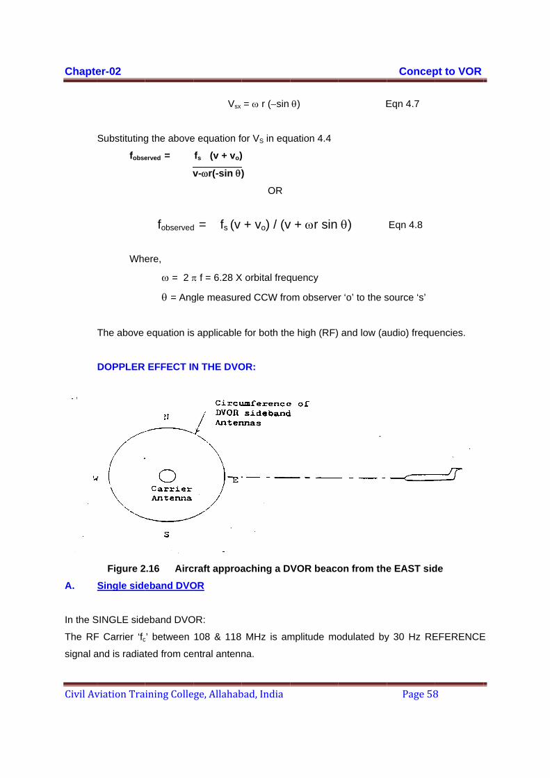
Chapte
Civil Av
A.
In the S
The RF
signal a
er-02
viation Tra
Substituting
fobse
Whe
The above
DOPPLER
Figure 2Single side
SINGLE side
F Carrier ‘fcand is radiat
ining Colle
g the above
erved =
v
ere,
ω = 2 π
θ = Ang
equation is
EFFECT IN
2.16 Airceband DVO
eband DVO
c’ between
ted from ce
fobserved
ge, Allahab
Vsx
e equation fo
fs (v + vo)
v-ωr(-sin θ)
π f = 6.28 X
gle measure
s applicable
N THE DVO
craft approaOR
OR:
108 & 118
entral antenn
d = fs (v
bad, India
= ω r (−sin
or VS in equ
)
)
OR
X orbital freq
ed CCW fro
for both the
OR:
aching a D
MHz is am
na.
+ vo) / (v
θ)
uation 4.4
quency
om observe
e high (RF)
VOR beaco
mplitude mo
v + ωr sin
E
r ‘o’ to the s
and low (a
on from the
odulated by
θ)
Concep
Page 58
Eqn 4.7
Eqn 4.8
source ‘s’
udio) freque
e EAST sid
y 30 Hz RE
pt to VOR
8
encies.
de
EFERENCE
E

Chapter-02 Concept to VOR
Civil Aviation Training College, Allahabad, India Page 59
The Sideband energy source (fc+9960 Hz) or (fc−9960 Hz), is electrically rotated by the action
of the distributor feeding a large number of sideband antennas which are mounted on the
circumference of a circle with radius ‘r’.
In DVOR, the observer (aircraft receiver) is also moving. It would appear that the speed of the
aircraft, particularly if it is going very fast, would affect the Doppler frequency shift and cause
errors. However, for all practical purposes, the movement of the aircraft may be ignored.
The shift in received frequency in the aircraft due to the Doppler effect can be understood by
studying the example given below.
1. Carrier frequency: 113.000000 MHz
2. Sideband frequency: 113.009960 MHz rotating at 30 cycles / sec around a ring of
antennas having a diameter of 13.5 meters.
3. Aircraft approaching from the EAST at a speed of 1000 m / sec.
Doppler effect on the Carrier Frequency
For convenience, let us recall the equation 4.8,
fobserved = fs (v + vo) / (v + ωr sin θ)
fobserved = 113 X (3x 108) + 1000
(3x 10⁸) + 2π x 30 x 13.5/2 x 0
= 113 (1 + 0.00000333)
= 113.0003763 MHz
Doppler Effect on Sideband:
a. East Sideband Antenna being radiated.
fobserved = fs (v + vo) / (v + ωr sin θ)
Δ fcarrier = 376.3 Hz
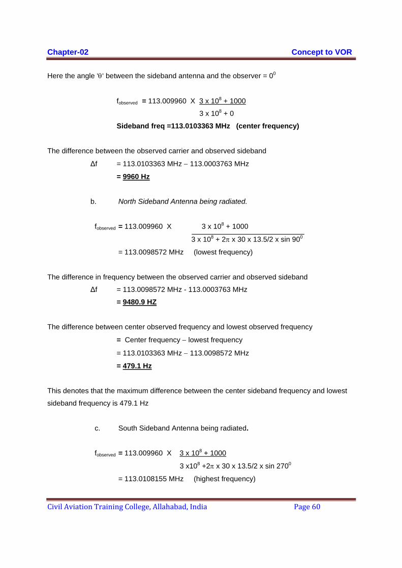
Chapter-02 Concept to VOR
Civil Aviation Training College, Allahabad, India Page 60
Here the angle ‘θ‘ between the sideband antenna and the observer = 00
fobserved = 113.009960 X 3 x 108 + 1000
3 x 10⁸ + 0
Sideband freq =113.0103363 MHz (center frequency)
The difference between the observed carrier and observed sideband
Δf = 113.0103363 MHz − 113.0003763 MHz
= 9960 Hz
b. North Sideband Antenna being radiated.
fobserved = 113.009960 X 3 x 108 + 1000
3 x 10⁸ + 2π x 30 x 13.5/2 x sin 900
= 113.0098572 MHz (lowest frequency)
The difference in frequency between the observed carrier and observed sideband
Δf = 113.0098572 MHz - 113.0003763 MHz
= 9480.9 HZ
The difference between center observed frequency and lowest observed frequency
= Center frequency − lowest frequency
= 113.0103363 MHz − 113.0098572 MHz
= 479.1 Hz
This denotes that the maximum difference between the center sideband frequency and lowest
sideband frequency is 479.1 Hz
c. South Sideband Antenna being radiated.
fobserved = 113.009960 X 3 x 108 + 1000
3 x10⁸ +2π x 30 x 13.5/2 x sin 2700
= 113.0108155 MHz (highest frequency)
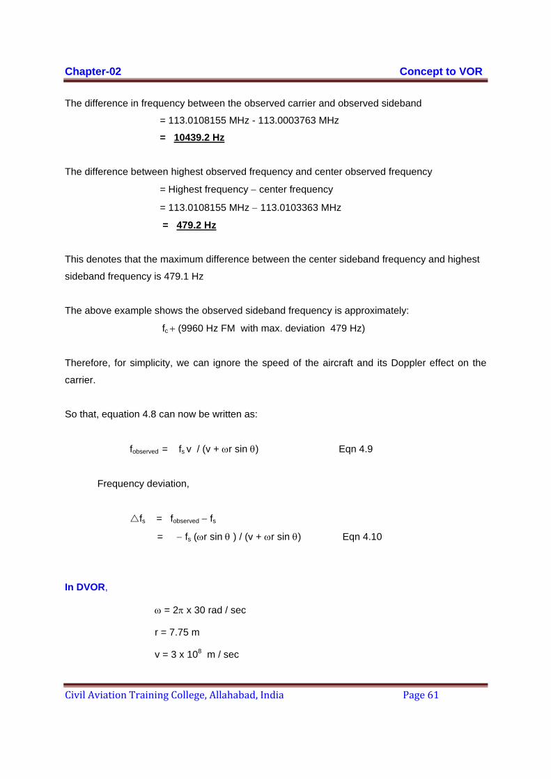
Chapter-02 Concept to VOR
Civil Aviation Training College, Allahabad, India Page 61
The difference in frequency between the observed carrier and observed sideband
= 113.0108155 MHz - 113.0003763 MHz
= 10439.2 Hz The difference between highest observed frequency and center observed frequency
= Highest frequency − center frequency
= 113.0108155 MHz − 113.0103363 MHz
= 479.2 Hz
This denotes that the maximum difference between the center sideband frequency and highest
sideband frequency is 479.1 Hz
The above example shows the observed sideband frequency is approximately:
fc + (9960 Hz FM with max. deviation 479 Hz)
Therefore, for simplicity, we can ignore the speed of the aircraft and its Doppler effect on the
carrier.
So that, equation 4.8 can now be written as:
fobserved = fs v / (v + ωr sin θ) Eqn 4.9
Frequency deviation,
fs = fobserved − fs
= − fs (ωr sin θ ) / (v + ωr sin θ) Eqn 4.10
In DVOR,
ω = 2π x 30 rad / sec
r = 7.75 m
v = 3 x 10⁸ m / sec
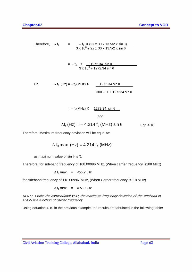
Chapter-02 Concept to VOR
Civil Aviation Training College, Allahabad, India Page 62
Therefore, Δ fs = − fs X (2π x 30 x 13.5/2 x sin θ) 3 x 10⁸ + 2π x 30 x 13.5/2 x sin θ
= − fs X 1272.34 sin θ 3 x 10⁸ + 1272.34 sin θ
Or, Δ fs (Hz) = − fs (MHz) X 1272.34 sin θ
300 + 0.00127234 sin θ
= − fs (MHz) X 1272.34 sin θ
300
Eqn 4.10
Therefore, Maximum frequency deviation will be equal to:
as maximum value of sin θ is ‘1’
Therefore, for sideband frequency of 108.00996 MHz, (When carrier frequency is108 MHz)
Δ fs max = 455.2 Hz
for sideband frequency of 118.00996 MHz, (When Carrier frequency is118 MHz)
Δ fs max = 497.3 Hz
NOTE: Unlike the conventional VOR, the maximum frequency deviation of the sideband in DVOR is a function of carrier frequency.
Using equation 4.10 in the previous example, the results are tabulated in the following table:
Δfs (Hz) = − 4.214 fs (MHz) sin θ
Δ fs max (Hz) = 4.214 fs (MHz)
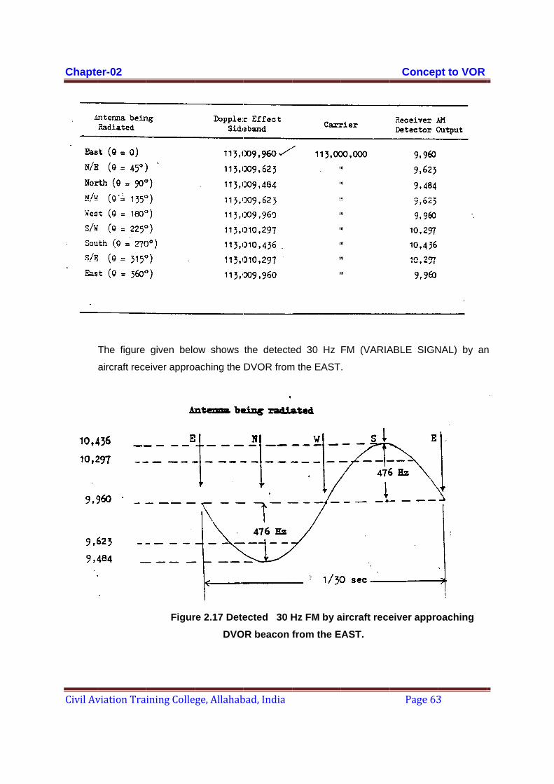
Chapte
Civil Av
er-02
viation Tra
The figure
aircraft rece
ining Colle
given belo
eiver appro
Figur
ge, Allahab
ow shows
aching the
re 2.17 DeteDVO
bad, India
the detecte
DVOR from
ected 30 HOR beacon f
ed 30 Hz
m the EAST
Hz FM by afrom the E
FM (VARIA
.
aircraft receAST.
Concep
Page 63
ABLE SIGN
eiver appro
pt to VOR
3
NAL) by an
oaching
n
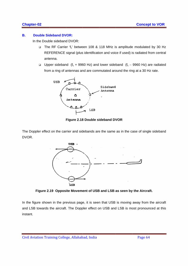
Chapte
Civil Av
B. I
The Do
DVOR.
In the f
and LS
instant.
er-02
viation Tra
Double SidIn the Doub
The
REF
ante
Upp
from
oppler effect
Figure 2.
figure show
B towards
ining Colle
deband DVble sideband
e RF Carrie
FERENCE
enna.
per sideban
m a ring of a
F
t on the car
19 Oppos
wn in the pre
the aircraft
ge, Allahab
VOR: d DVOR:
er ‘fc’ betwe
signal (plus
nd (fc + 996
antennas an
Figure 2.18
rrier and sid
ite Moveme
evious page
. The Dopp
bad, India
een 108 &
s identificati
60 Hz) and
nd are comm
8 Double si
debands are
ent of USB
e, it is seen
pler effect o
118 MHz is
on and voic
lower side
mutated aro
ideband DV
e the same
B and LSB a
n that USB
on USB and
s amplitude
ce if used) i
band (fc −
ound the rin
VOR
as in the ca
as seen by
is moving
d LSB is mo
Concep
Page 64
e modulated
s radiated f
9960 Hz) a
ng at a 30 H
ase of sing
y the Aircra
away from
ost pronoun
pt to VOR
4
d by 30 Hz
from centra
are radiated
Hz rate.
le sideband
aft.
the aircraft
nced at this
z
l
d
d
t
s

Chapter-02 Concept to VOR
Civil Aviation Training College, Allahabad, India Page 65
However, the observed frequency of the USB decreases while the observed frequency of the
LSB increases by exactly the same amount. Hence the correct relationship is maintained for all
positions around the ring.
Observed LSB frequency Carrier Observed USB frequency
fc - 9960Hz fc fc + 9960Hz Figure 2.20 Spectrum showing correct relationship between carrier and
sidebands.
SIGNALS IN DVOR
As it has already been explained, The DVOR ground beacon radiates complex double sideband
signals from which two 30Hz signals are derived in the aircraft. The phase of one of these
signals, called the reference signal, is independent of the azimuth bearing. The phase of the
other signal, called the variable signal, has a one-to-one relationship with the magnetic bearing
of the aircraft relative to the beacon. This information is obtained by measuring the phase
difference between the reference and variable 30 Hz signals.
30 Hz Reference Signal
The DVOR reference signal is produced by Amplitude Modulating the carrier frequency
signal by a 30Hz-modulating signal. The modulated carrier is radiated from the central omni-
directional antenna. The phase of 30 Hz AM is therefore constant irrespective of direction,
hence the term 30 Hz reference.
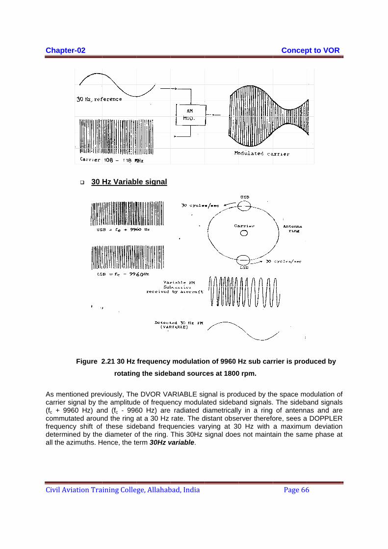
Chapte
Civil Av
As mencarrier s(fc + 99commufrequendetermiall the a
er-02
viation Tra
30
Figure 2
ntioned prevsignal by th960 Hz) antated aroun
ncy shift of ined by theazimuths. H
ining Colle
Hz Variab
2.21 30 Hz rotating
viously, Thehe amplitudnd (fc - 996nd the ring f these side diameter o
Hence, the te
ge, Allahab
le signal
frequency g the sideb
e DVOR VAe of freque60 Hz) are at a 30 Hz eband freqof the ring. erm 30Hz v
bad, India
modulatioband sourc
ARIABLE sigency modula
radiated drate. The duencies vaThis 30Hz
variable.
on of 9960 Hces at 1800
gnal is prodated sidebadiametricallydistant obsearying at 30signal does
Hz sub car0 rpm.
duced by thand signals.y in a ring
erver therefo0 Hz with s not mainta
Concep
Page 66
rrier is prod
he space mo The sidebof antenna
ore, sees aa maximumain the sam
pt to VOR
6
duced by
odulation ofand signalsas and are DOPPLERm deviation
me phase at
f s e R n t

Chapte
Civil Av
The DO
the airc
directio
In the a
detecte
carrier c
of the f
9960Hz
VARIAB
bearing
for the p
er-02
viation Tra
NOTE:
Thecon
TheEFF
OPPLER VO
craft. This
onally from
Figure 4.15
aircraft rece
ed to obtain
contains the
This signal
ilters produ
z output. Th
BLE signal.
g of the airc
pilot.
ining Colle
In DVOR
e REFERENnstant.
e VARIABLEFECT). Its p
OR beacon
informatio
m the centra
Receive
eiver the co
the 30 Hz
e variable s
is fed to tw
ces a 30Hz
he 9960Hz,
The relativ
craft (corres
ge, Allahab
NCE SIGN
E SIGNAL iphase is rela
n also trans
on amplitu
al antenna
ed carrier w(30 H
omplex VH
AM (REFE
signal. The d
Figure 2.2
wo sets of fil
z output the
which cont
ve phase dif
spondent to
bad, India
AL is a re
is a result oated to azim
smits VOIC
de modula
, along wit
with 9960 HzHz AM is no
F signal as
ERENCE) s
detected sig
22 Detected
ters to sepa
e REFEREN
tains 30 Hz
fference be
o phase diff
esult of AM
of FM (ON Smuth.
CE and COD
ates the RF
h the 30 Hz
z sub carrierot shown)
s shown in
signal and t
gnal would
d Signal in
arate the 30
NCE signal
z FM is freq
etween the t
ference) is
M (ON CA
SUB-CARR
DE identifi
F carrier a
z AM REFE
r frequency
the above
the 9960 Hz
be as show
Rx
0Hz and 996
whereas; t
quency dem
two 30 Hz i
converted i
Concep
Page 67
RRIER). Its
RIER due to
cation info
and is radia
ERENCE Si
y modulated
figure is fi
z sub carrie
wn in the figu
60 Hz sub c
the other pr
modulated to
is then mea
into a visua
pt to VOR
7
s phase is
DOPPLER
ormation to
ated omni-
gnal.
with 30 Hz
rst envelop
er. The sub
ure below.
carrier. One
roduces the
o obtain the
asured. The
al indication
s
R
o
-
p
b
e
e
e
e
n
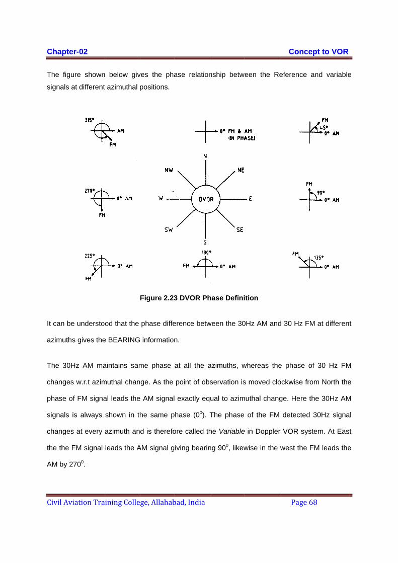
Chapte
Civil Av
The fig
signals
It can b
azimuth
The 30
change
phase o
signals
change
the the
AM by 2
er-02
viation Tra
gure shown
at different
be understoo
hs gives the
0Hz AM ma
es w.r.t azim
of FM signa
is always
es at every a
FM signal
2700.
ining Colle
below giv
azimuthal
od that the
e BEARING
aintains sam
muthal chan
al leads the
shown in th
azimuth an
leads the A
ge, Allahab
ves the pha
positions.
Figure 2.23
phase diffe
information
me phase a
nge. As the
e AM signal
he same p
d is therefo
AM signal g
bad, India
ase relation
3 DVOR Ph
erence betw
n.
at all the a
point of obs
exactly eq
hase (00). T
ore called th
iving bearin
nship betwe
hase Defini
ween the 30
azimuths, w
servation is
ual to azim
The phase
he Variable
ng 900, likew
een the Re
tion
0Hz AM and
whereas the
s moved clo
uthal chang
of the FM
in Doppler
wise in the
Concep
Page 68
eference a
d 30 Hz FM
e phase of
ockwise from
ge. Here th
detected 3
r VOR syste
west the FM
pt to VOR
8
nd variable
at different
30 Hz FM
m North the
e 30Hz AM
30Hz signa
em. At East
M leads the
e
t
M
e
M
l
t
e
Chapter-02 Concept to VOR
Civil Aviation Training College, Allahabad, India Page 69
Advantages of DVOR over CVOR
The scalloping error in the course information has been greatly reduced in DVOR. Maximum scalloping error observed is only +/- 0.4% whereas, in conventional VOR it is +/- 2.4%.
The error due to the reflections in the variable signal is almost negligible. This is due to the fact that the variable signal obtained in the receiver is the result of Frequency modulated sidebands due to the Doppler effect. This ultimately results in the error reduction in the Bearing information in the airborne receiver.
Siting criteria for DVOR installation is very much less critical than the conventional VOR but the restricted area limitation (area proximity to the VOR) is as same as the conventional VOR.
Compatibility of signal between CVOR & DVOR
The course forming signals received by an aircraft from a Doppler VOR are compatible with the signals received from an conventional VOR. The aircraft receiver should respond in the same manner to the signals received from either systems. Considering the same siting conditions for both the systems.
Figure 2.23 shows phasors representing the 30Hz course forming signals from both the conventional and Doppler VOR systems at eight points of magnetic azimuth. The figure assumes both VORs to be free from course errors.
The definition for omnicourse in the conventional VOR is the number of degrees the detected 30 Hz variable signal lags the detected 30Hz reference signal at some particular azimuth. Part of the figure shows the 30Hz signal produced by space modulation (labelled AM) laging the FM produced reference signal as a receiver is moved clockwise around the VOR. The degree of lag increases with a greate clockwise movement around the VOR. It can be noted that that the FM detected 30Hz signal is always shown in the same phase (00) and is therefore called as reference signal. The phase of the AM 30Hz signal is different at every azimuth and is therfore called as variable signal.
Referring to the parts of the figure (labelled Doppler) it can be seen that the FM produced signal leads the AM produced signal as a receiver is moved clockwise around the VOR. The degree of lead increases with greater clockwise movement around the VOR. Here the 30Hz AM signal is always shown in the same phase and therfore is called as reference signal. The phase of FM detected 30Hz signal changes at every azimuth and is therefore called as variable signal in the Doppler VOR system. By comparison, the 30Hz variable is AM produced in the conventional VOR and the 30Hz variable signal is FM produced in the Doppler VOR.
This condition of the FM variable signal leading with a clockwise movement is necessary in order to have the Doppler system compatible with the Conventional VOR system. This means a VOR receiver NE of conventional VOR will receive an AM 30Hz signal that lags the received FM signal by 450. The same receiver NE of a Doppler VOR will receive an FM detected 30Hz signal that leads the received AM detected 30Hz signal by 450. This is the same as the AM signal

Chapte
Civil Av
lagging receive
The two30Hz sThe FMoriginalby the sthe FM
er-02
viation Tra
behind ther will be 450
o systems aignal wheth
M detector ly generatespecial metsignal in th
Fi
ining Colle
e FM signa0 in either ca
are compatiher the origi
in the VOed by the elthod employe Doppler V
igure 2.24 P
from the D
ge, Allahab
al as in thease.
ible becausinal source
OR receiver lectromechayed in the DVOR system
Phasor Dia
Doppler an
bad, India
e conventio
se the AM dof signal is
r will produanical actioDoppler VOm utilizes th
agrams sho
d Convent
nal VOR. T
etected 30Hs from a couce a 30Hzon of a toneR system. Te Doppler e
owing the 3
tional VOR
The omnico
Hz signal wnventional Vz signal whe wheel in aThe speciaeffect.
30Hz Cours
Systems a
Concep
Page 70
ourse indiac
will lag the FVOR or Dohether the a conventiol method of
se Forming
at eight azi
pt to VOR
0
cted by the
FM detectedoppler VOR
signal wasnal VOR orf generating
g Signals
muths.
e
d . s r g
Chapter-03
ICAO Specifications
INTERNATIONAL STANDARDS AND RECOMMENDED PRACTICES
AERONAUTICAL TELECOMMUNICATIONS
ANNEX 10
TO THE CONVENTION ON INTERNATIONAL CIVIL AVIATION
VOLUME I
(RADIO NAVIGATION AIDS)
FIFTH EDITION OF VOLUME I — JULY 1996
This edition incorporates all amendments adopted by the Council prior to 13 March 1996 and supersedes, on 7 November 1996, all previous editions of Annex 10,
Volume I.
For information regarding the applicability of the Standards and Recommended Practices, see Foreword.
INTERNATIONAL CIVIL AVIATION ORGANIZATION
Chapter -03 ICAO Specification
Civil Aviation Training College, Allahabad, India Page 71
Chapter -03 ICAO Specification
Civil Aviation Training College, Allahabad, India Page 72

Chapter -03 ICAO Specification
Civil Aviation Training College, Allahabad, India Page 73
Chapter -03 ICAO Specification
Civil Aviation Training College, Allahabad, India Page 74

��
Chapter -03 ICAO Specification
Civil Aviation Training College, Allahabad, India Page 75

��
Chapter -03 ICAO Specification
Civil Aviation Training College, Allahabad, India Page 76

��
Chapter -03 ICAO Specification
Civil Aviation Training College, Allahabad, India Page 77
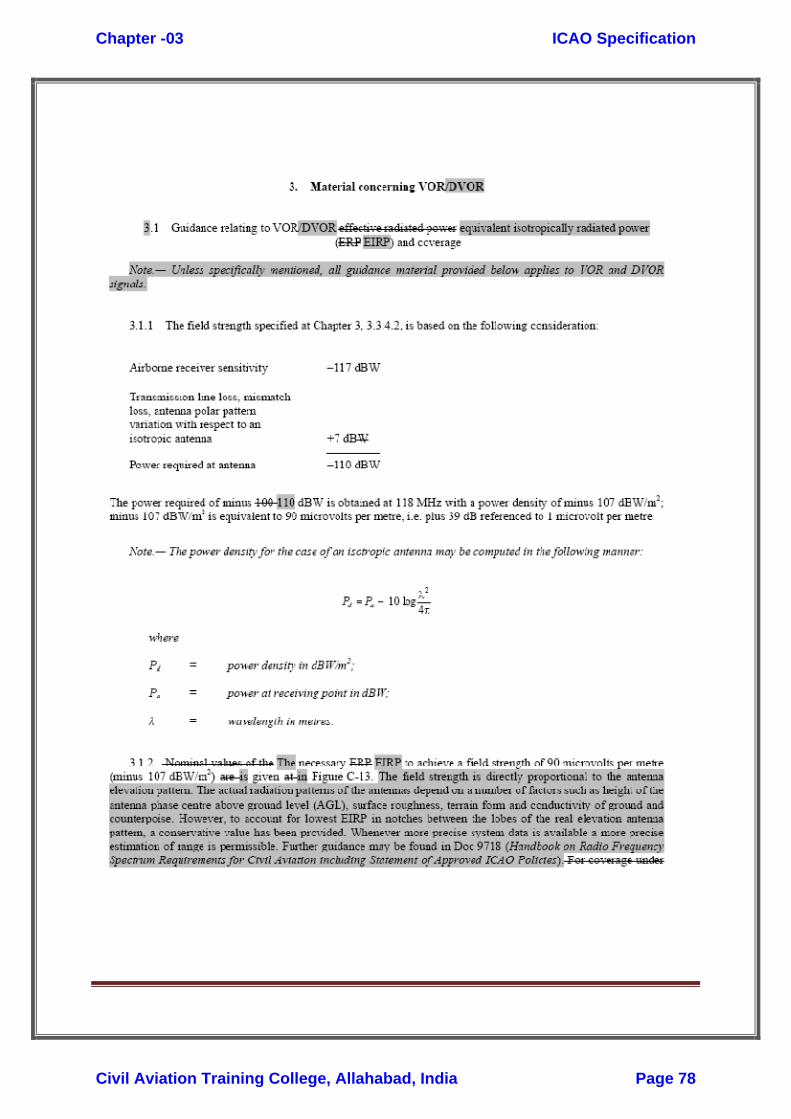
��
Chapter -03 ICAO Specification
Civil Aviation Training College, Allahabad, India Page 78

��
Chapter -03 ICAO Specification
Civil Aviation Training College, Allahabad, India Page 79

��
Chapter -03 ICAO Specification
Civil Aviation Training College, Allahabad, India Page 80

��
Chapter -03 ICAO Specification
Civil Aviation Training College, Allahabad, India Page 81

Chapter – 4 Error Analysis
Civil Aviation Training College, Allahabad, India Page 82
Chapter-04
Error Analysis CVOR ERROR ANALYSIS
INTRODUCTION
There are six chief effects that produce inaccuracies in the bearing indication obtained with the VOR. Some of them are because of instrumental and other are due to propagation mechanism.
Types of Error:
A) Instrumental error or equipment error
B) Propagation effect error
THE INSTRUMENTAL ERROR OR EQUIPMENT ERROR
These errors are broadly classified into three categories:
1.Receiver indication error
2. Polarization error
3. Ground station error
PROPAGATIONAL EFFECT ERROR
These errors are broadly classified into three categories
1.Vertical –pattern effect
2. Terrain effect
3. Site effect.
THE INSTRUMENTAL ERROR OR EQUIPMENT ERROR
1. Receiver Indication Error.
Receiver indication errors are due to failure of the receiving equipment to translate accurately the bearing information contained in the VOR signal from the ground equipment. These errors are caused by unequal phase shifts in the receiver channels for the variable phase and reference phase signal errors in the phase detector and inaccuracy in the revolver or in case of motor driven revolvers inaccuracy in the servo-loop that drives the revolver.
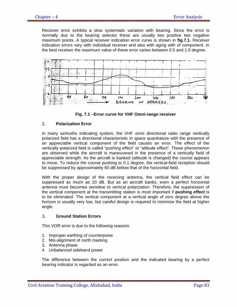
Chap
Civil Avi
Rnminth
2
Inpaveaatob
Wsuathtoha
3
T
1234
Tb
pter – 4
ation Train
Receiver erroormally due
maximum pondication errhe best rece
. Polar
n many azimolarized fieldn appreciabertically polare observedppreciable s
o move. To re suppresse
With the prouppressed antenna mus
he vertical co be eliminaorizon is usngle.
. Groun
This VOR err
. Improper
. Mis-alignm
. Antenna p
. Unbalanc
The differencearing indica
ing College,
or exhibits e to the beoints. A typicrors vary witiver the max
Fig. 7.1
rization Erro
muths indicad has a direble vertical arized field isd while the strength. As reduce the ced by approx
oper designas much as
st becomes omponent a
ated. The veually very lo
nd Station E
ror is due to
earthing of cment of nortphase
ced sideband
ce between ator is regar
, Allahabad,
a slow sysearing seleccal receiver th individual ximum value
1 –Error cur
or
ating systemectional char
components called “pusaircraft is mthe aircraft
course pushximately 60 d
n of the res 20 dB. Busensitive to
at the transmertical compoow, but care
Errors
the following
counterpoiseh marking
d power
the correcrded as an e
India
stematic varctor these aindication ereceiver an
e of these er
rve for VHF
m, the VHF racteristic in t of the fielshing effect“
maneuvered is banked (
hing to 0.1 ddB bellow th
ceiving antut as an aivertical pol
mitting statioonent at a vful design is
g reasons
e
ct position aerror.
riation with are usually
error curve isnd also with ror varies be
Omni-rang
omni direcspace quar
ld causes a“ or “altitudein the pres
(altitude is cegree, the v
hat of the ho
enna, the vrcraft banksarization. Thn is most imvertical angls required to
and the indi
Er
bearing. Sitwo positiv
s shown in aging with o
etween 0.5 a
ge receiver
ctional radiordrature withan error. Th
e effect“. Thesence of a hanged) the
vertical-field rizontal field
vertical fields, even a pherefore, the
mportant if ple of zero do minimize th
icated beari
rror Analysi
Pag
nce the errve two negfig.7.1. Recof componeand 1.0 degr
o range verth the presenhe effect oese phenomvertically fie
e course appreception sh
d.
d effect caperfect horize suppressio
pushing effeegree abovehe field at h
ing by a pe
is
ge 83
ror is gative ceiver nt. In ree.
tically nce of f the
menon eld of pears hould
n be zontal on of ect is e the
higher
erfect
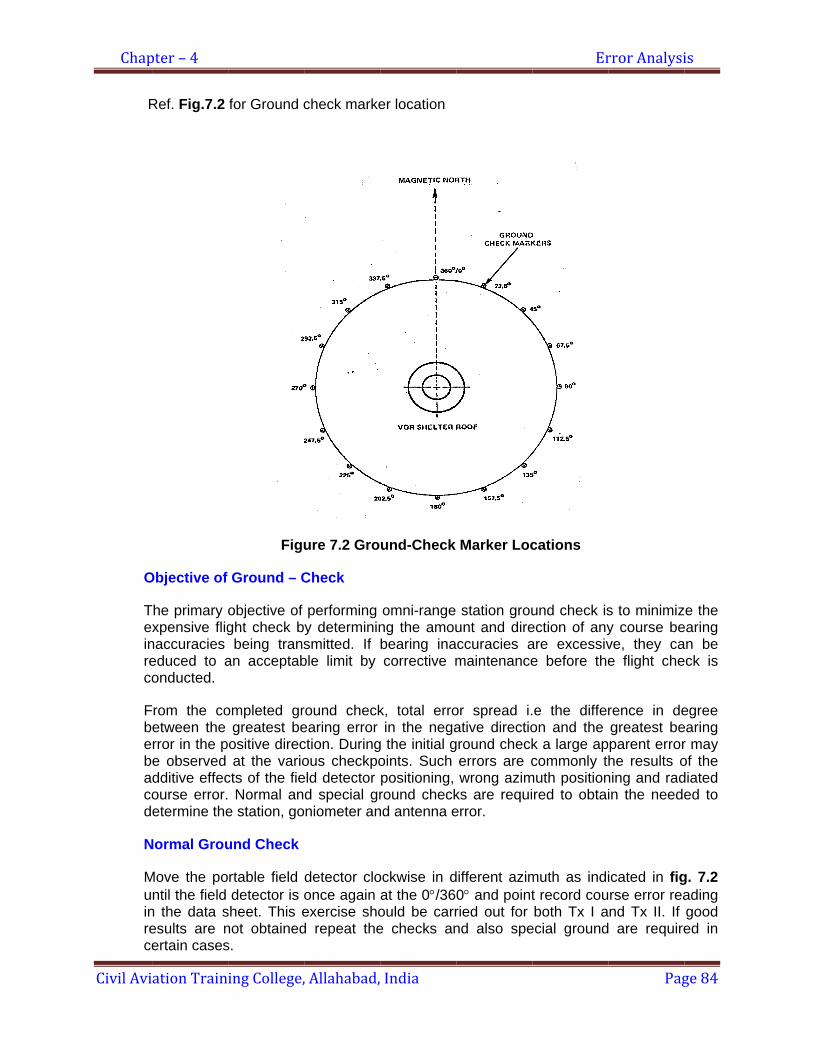
Chap
Civil Avi
R
O
Texinreco
Fbebacod
N
Muinrece
pter – 4
ation Train
Ref. Fig.7.2
Objective of
The primary oxpensive flig
naccuracies educed to aonducted.
rom the coetween the rror in the pe observed dditive effecourse error.etermine the
Normal Grou
Move the pontil the field
n the data sesults are nertain cases
ing College,
for Ground c
Figu
Ground – C
objective of ght check bbeing trans
an acceptab
ompleted grgreatest beositive direcat the vario
cts of the fie Normal ane station, go
und Check
rtable field detector is o
sheet. This enot obtaineds.
, Allahabad,
check marke
ure 7.2 Gro
Check
performing y determininsmitted. If ble limit by
round checkearing error ction. Duringous checkpoeld detector d special grniometer an
detector cloonce again exercise shod repeat the
India
er location
und-Check
omni-range ng the amoubearing inacorrective m
k, total erroin the nega
g the initial goints. Such positioning, round check
nd antenna e
ockwise in dat the 0°/36ould be carre checks an
Marker Loc
station grouunt and direccuracies amaintenance
or spread i.ative directioground check
errors are cwrong azim
ks are requierror.
different azim0° and pointried out for nd also spe
Er
cations
und check isection of anyare excessive before the
e the differon and the k a large apcommonly t
muth positionred to obtai
muth as indit record couboth Tx I a
ecial ground
rror Analysi
Pag
s to minimizy course beve, they cae flight che
rence in degreatest beparent errorhe results o
ning and radin the neede
icated in figrse error reand Tx II. If are require
is
ge 84
ze the earing an be eck is
egree earing r may of the diated ed to
g. 7.2 ading good ed in
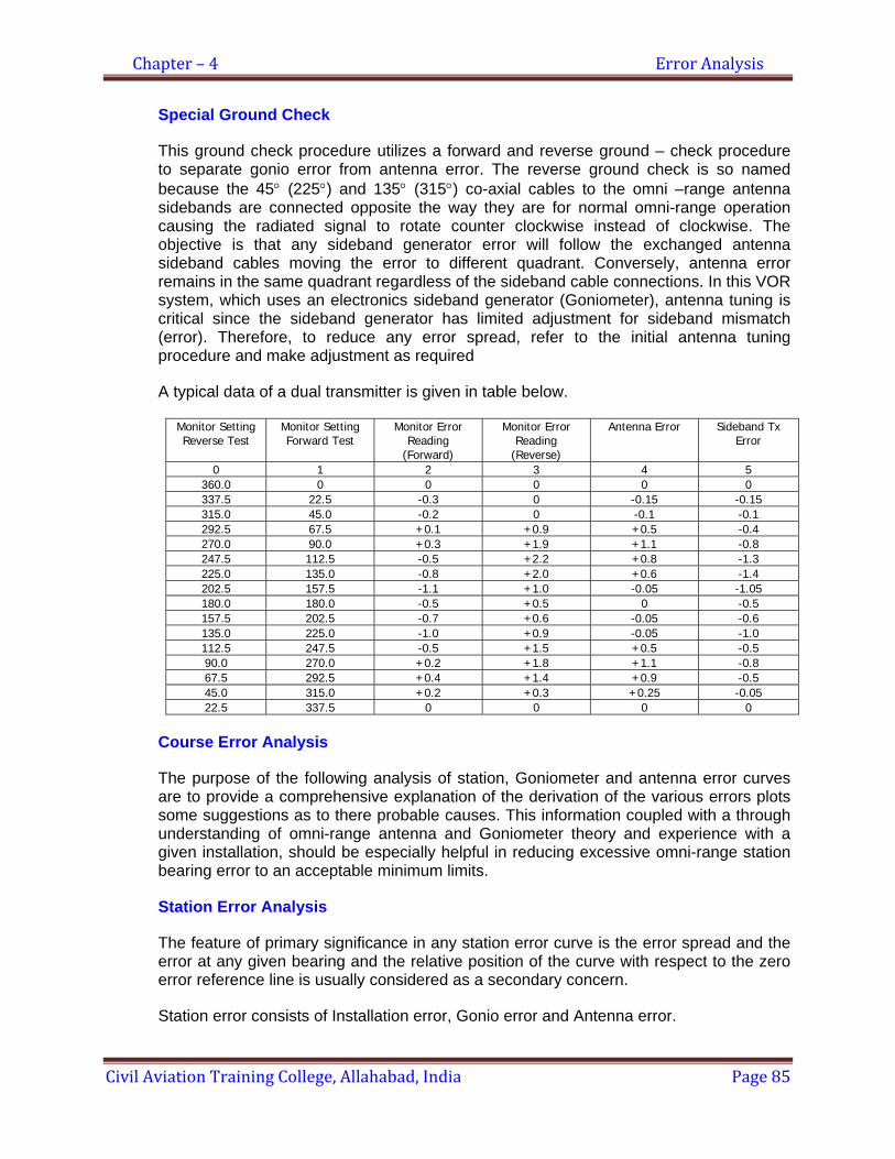
Chapter – 4 Error Analysis
Civil Aviation Training College, Allahabad, India Page 85
Special Ground Check
This ground check procedure utilizes a forward and reverse ground – check procedure to separate gonio error from antenna error. The reverse ground check is so named because the 45° (225°) and 135° (315°) co-axial cables to the omni –range antenna sidebands are connected opposite the way they are for normal omni-range operation causing the radiated signal to rotate counter clockwise instead of clockwise. The objective is that any sideband generator error will follow the exchanged antenna sideband cables moving the error to different quadrant. Conversely, antenna error remains in the same quadrant regardless of the sideband cable connections. In this VOR system, which uses an electronics sideband generator (Goniometer), antenna tuning is critical since the sideband generator has limited adjustment for sideband mismatch (error). Therefore, to reduce any error spread, refer to the initial antenna tuning procedure and make adjustment as required
A typical data of a dual transmitter is given in table below.
Monitor Setting Reverse Test
Monitor Setting Forward Test
Monitor Error Reading
(Forward)
Monitor Error Reading
(Reverse)
Antenna Error Sideband Tx Error
0 1 2 3 4 5 360.0 0 0 0 0 0 337.5 22.5 -0.3 0 -0.15 -0.15 315.0 45.0 -0.2 0 -0.1 -0.1 292.5 67.5 +0.1 +0.9 +0.5 -0.4 270.0 90.0 +0.3 +1.9 +1.1 -0.8 247.5 112.5 -0.5 +2.2 +0.8 -1.3 225.0 135.0 -0.8 +2.0 +0.6 -1.4 202.5 157.5 -1.1 +1.0 -0.05 -1.05 180.0 180.0 -0.5 +0.5 0 -0.5 157.5 202.5 -0.7 +0.6 -0.05 -0.6 135.0 225.0 -1.0 +0.9 -0.05 -1.0 112.5 247.5 -0.5 +1.5 +0.5 -0.5 90.0 270.0 +0.2 +1.8 +1.1 -0.8 67.5 292.5 +0.4 +1.4 +0.9 -0.5 45.0 315.0 +0.2 +0.3 +0.25 -0.05 22.5 337.5 0 0 0 0
Course Error Analysis
The purpose of the following analysis of station, Goniometer and antenna error curves are to provide a comprehensive explanation of the derivation of the various errors plots some suggestions as to there probable causes. This information coupled with a through understanding of omni-range antenna and Goniometer theory and experience with a given installation, should be especially helpful in reducing excessive omni-range station bearing error to an acceptable minimum limits.
Station Error Analysis
The feature of primary significance in any station error curve is the error spread and the error at any given bearing and the relative position of the curve with respect to the zero error reference line is usually considered as a secondary concern.
Station error consists of Installation error, Gonio error and Antenna error.

Chapter – 4 Error Analysis
Civil Aviation Training College, Allahabad, India Page 86
Datum North adjustment
Attention should be concentrated on reducing the error spread and any adjustment of this control should be left until the flight check because due to site or terrain errors it may be preferable not to center the ground check station error around the reference line In dual transmitting equipment though the antenna can be considered as introducing practically identical error, the goniometer in each transmitting equipment has a separate and distinct error. Therefore it can readily be seen that the algebraic addition of the given antenna and one sideband curve might reduce to a practical minimum while the algebraic addition of the same antenna curve and a second sideband curve might cause an excessive station error spread.
Primary objective, then, is to obtain station error curves for both transmitting equipments that are as nearly identical as possible and yet maintain the error spread for each curve at an acceptable minimum. It is important to keep in mind that station error curves for both transmitting equipments are within acceptable limits only when a flight check shows that
The omni-range station meets the following criteria (where usually no large site or terrain errors are present).
a. The course error spread for each transmitting equipment shall not exceed 2 degree.
b. The course error differential between transmitting equipments on any radial shall not exceed 2 degree.
Sideband Error Analysis
A typical sideband error curve is shown in fig. Goniometer error should not exceed more than 1.5°. Make sure that such errors are due to goniometer before doing any adjustment or change. The more common cause of Goniometer errors is:
a. Defective and corroded antenna relay contacts
b. Defective coaxial cables and /or coaxial connectors between outputs of the goniometer and the coaxial antenna cables.
c. Defective sideband output balance
Antenna Error Analysis
In the slotted antenna, errors are appeared at four principal points i.e. (0°, 90°, 180° and 270°). This type of error is called quardrantal error. But if the antenna errors appear to be positive in one half of the curve and on the other half of the curve, the error curve is called duantal curve. Before any other type of error reduction is attempted the duantal error must be removed. Once this is done, only the characteristics quardrantal error should remain.

Chapter – 4 Error Analysis
Civil Aviation Training College, Allahabad, India Page 87
Duantal and Quardrantal Error Analysis
Duantal error
The common cause of duantal errors is
1. Sub carrier signal (9960 Hz) on the Sideband 2. Incorrect antenna tuning 3. Defective or corroded parts and/or connection on interior of antenna.
Whenever the power radiated by the antenna slots are unequal in any combination, producing unequal lobe and a proportional increase in antenna error. Fig. 7.3 shows the duantal error curve that is caused by abnormal antenna slots radiation. Note carefully that at the cardinal points (0°, 90°, 180° and 270°) the course radiated by the antenna are always bent in the direction of the smaller of any two adjacent lobes. This is also apparent by an inspection of the relative amount and polarity of the error at the cardinal points on the corresponding error curves. Therefore, it is important when analyzing a particular error curve for the amount and location of the lobe inequality.
In normal antenna duantal fine-tuning of antenna can eliminate error. If duantal error can not be eliminated by fine tuning, the interior of the antenna should be thoroughly inspected for detection or corroded points and/ or otherwise connection associated with the two adjacent slots which produce the smaller than the normal lobes.
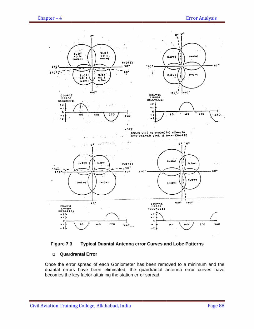
Chap
Civil Avi
Odb
pter – 4
ation Train
Figure 7.3
Quard
Once the erruantal erroecomes the
ing College,
3 Typica
drantal Erro
ror spread ors have bekey factor a
, Allahabad,
l Duantal A
or
of each Goneen eliminaattaining the
India
Antenna erro
niometer hasted, the qustation erro
or Curves a
s been remouardrantal ar spread.
Er
nd Lobe Pa
oved to a mantenna err
rror Analysi
Pag
atterns
minimum andror curves
is
ge 88
d the have
Chapter – 4 Error Analysis
Civil Aviation Training College, Allahabad, India Page 89
More common causes of quardrantal errors are:
1. Incorrect antenna tuning 2. Defective antenna coaxial feeding 3. Antenna sideband feedlnes out of phase with each other and also out of phase
with the reference feedline. 4. Defective or corroded parts and /or connection on interior on antenna.
Before tuning of antenna for reducing antenna error spread, attempt should be made to equalize and minimize the reflected power in the A & B sideband elements of the antenna. Maximum possible reflected power is 0.8 percent (VSWR less than 1.1:1)
Maximum possible reflected power in the reference elements of antenna is 0.5 percent (VSWR less than 1.1:1). Changing co-axial cables and / or careful trial and error adjustment of antenna can reduce excessive reflected power. It can be seen from Fig 7.4, that both the lobes in one pair are smaller than the normal by equal amount. Fig 7.5, shows that one lobe of one slot pair is larger than the normal and the opposite lobe is smaller than the normal. This illustrate that a portion of the power that is radiated normally from the smaller than normal lobe is being radiated from the longer than normal lobe. Observe in Fig 7.6, in which both lobes in one slot pair are smaller than normal by unequal amounts.
It is further observed that at cardinal points (0°, 90°, 180°, 270°), the course radiated by the antenna is always bent in the direction of the smaller of any two adjacent lobes. This is also apparent by an inspection of the relative amount and the polarity of the errors at the cardinal points on the corresponding error curves. Both of these factors are extremely important when attempting to analyze any particular quardrantal error curve for the amount and location of lobe inequality. Exclusive of site and terrain error, the final error curve for any given station will depend upon the minimum Goniometer and antenna errors obtainable for that particular station. Ground check error spread always be reduced to less than 2.5 degree to give reasonable assurance that the station will meet the minimum flight check critical of 2 degree error spread.
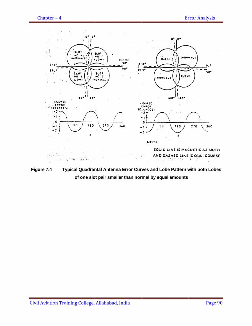
Chap
Civil Avi
Figure 7
pter – 4
ation Train
7.4 Typi
ing College,
ical Quadraof one slo
, Allahabad,
ntal Antennot pair small
India
na Error Curler than nor
rves and Lobrmal by equa
Er
be Pattern wal amounts
rror Analysi
Pag
with both Lo
is
ge 90
obes

Chap
Civil Avi
Figure
pter – 4
ation Train
7.5 TypLobe of on
ing College,
pical Quadrane slot is lar
, Allahabad,
antal Antenrger than no
India
na Error Cuormal and th
urves and Lohe opposite
Er
obe Patternis smaller t
rror Analysi
Pag
s in which othan normal
is
ge 91
one l
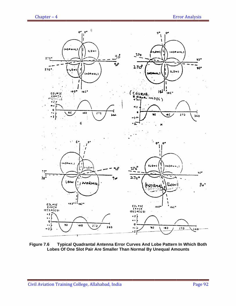
Chap
Civil Avi
Figure 7
pter – 4
ation Train
7.6 TypicLobes Of
ing College,
cal QuadranOne Slot Pa
, Allahabad,
ntal Antennair Are Sma
India
na Error Curaller Than N
rves And LoNormal By U
Er
obe PatternUnequal Am
rror Analysi
Pag
n In Which Bmounts
is
ge 92
Both

Chapter – 4 Error Analysis
Civil Aviation Training College, Allahabad, India Page 93
Ground Check /Flight Check Comparison
After station errors have been reduced to a minimum by the adjust and /or maintenance indication by ground check error analysis a flight check must be conducted by an authorized flight check crew to obtain final acceptance of the station. The ground check error curve can then be compared with the flight check curve to see how closely they coincide. The degree to which the ground check error curve and flight check error curve coincide depends to a large extend on site and terrain errors which will be reflected primarily in the flight check curve. A careful comparison of the flight check curve with the site and terrain features should show the major causes of discrepancies between the two types of error curves.
PROPAGATIONAL EFFECT ERROR
1. Vertical Pattern Effect
The field strength at any point in space resulting from radiation from a source located above a ground plane is the algebraic sum of two waves. The first wave travels directly to the point in question while the second travels from the radiation source to the ground plane and reaches the point after reflection. The relative phase between the direct and reflected waves is a function of the relative length of the two paths over which the waves travel and the change in phase of the reflected wave that occurs at the point of reflection.
It is obvious that the relative length of the paths changes for various points in space.
For me points in space, the direct and reflected waves will add, thus producing signals with intensities equal to approximately twice those due to propagation via the direct path. At other points the two waves will subtract producing field strengths that may be very small. The number of lobes is a function of the height of the radiator above the ground plane. When the radiator is very close to the ground plane a single lobe will be present. But as the height of the radiator is increased, the number of lobes will increase.
Consider now the case of an aircraft flying at an altitude and the direction such that it enters the null between two lobes that are present in the vertical field pattern of an omni-directional range (VOR) transmitting station. It might be assumed that there would be momentary loss of signal and that such a loss would not be very serious. Actually, however a much more serious effect is present. When the signals coming directly from the range station reach at low value, other signal reaching the receiver via reflection from nearby areas and which are normally insignificant, now assumes a major importance. The result is an irregular departure of the bearing indication from its true value. This departure resembles very closely a phenomenon sometimes known as “Scalloping” that is due to site effects.

Chap
Civil Avi
R
Fha
FdseAtha(aloveTeewd
Isodwsoreafth
pter – 4
ation Train
Relative Fiel
ig 7.7 verticeight of 30 ntennas hav
F
ig (7.7-A) irectional-raeen that at
Aircraft flyinghis null. At thntenna was an antenna ocal obstrucertical-patte
The vertical plevation thencountered
when it is neetrimental e
2. Terra
n consideriometimes bistinction is
whereas, terrource of theeal differencfter reflectio
he path of pr
ing College,
d Strength
cal radiationfeet and pr
ve been lowe
Fig 7.7 VER
shows the nge installaan angle of at an altitud
his altitude thoriginally in
located highctions as onrn effect. Hopattern resule first null by an aircra
ear the coneffects are ne
in Error
ing propagabeen a distthat site er
rain errors ae signal. It is ce actually en by verticaropagation in
, Allahabad,
n patterns ofoduce a shaered to 15 fe
RTICAL RAD
vertical pation having f about 5 dede of about he area wasnstalled at thh above thene that is loowever it walting is showhas been
aft flying at e of confusioegligible.
ation errorstinction ma
rrors are thoare those ca
felt howeveexisting is thl projectionsn non-unifor
India
f VOR statioarp null at aeet.
DIATION PA
ttern for a an antenna
egrees abov15,000 feet
s quite broadhis relativelye ground plaocated nears necessary
wn in Fig (7moved to 15,000 feeton. Further,
s of very-hde between
ose caused used by terr
er that such hat in the cas of the terram.
on. At ‘A’ than angle of
ATTERN OF
Civil Aerona mounted ove the verticand a dista
d and producy high elevatane does norer the grouy to reduce t7.7-B). It wil
about 12 t at a distan the null is
high-frequenn site errorby terrain nrain located a distinctionase of site e
ain, whereas
Er
e antennas about 5 de
VOR STAT
nautics Admon a 30-footcal a very dnce of 30 mced troublestion to minim
ot radiate asund faced whe antenna l be seen thdegrees. T
nce of aboutnow not ve
cy omni-ranrs and terrnear the tran
at a great dn is artificial errors the s
s, in the case
rror Analysi
Pag
are locatedegrees. At ‘B
TION
ministration t tower. It wdeep null oc
miles encounsome resultsmize siting e much enerwith this seheight to 15at with this l
This null is t 10 miles thery deep and
nges there rain errors. nsmitting stadistance fromand that the
signal is recee of terrain e
is
ge 94
d at a B’ the
omni will be ccurs. tered . The
errors rgy to erious 5 feet. lower
now hat is d the
has This
ation, m the e only eived errors
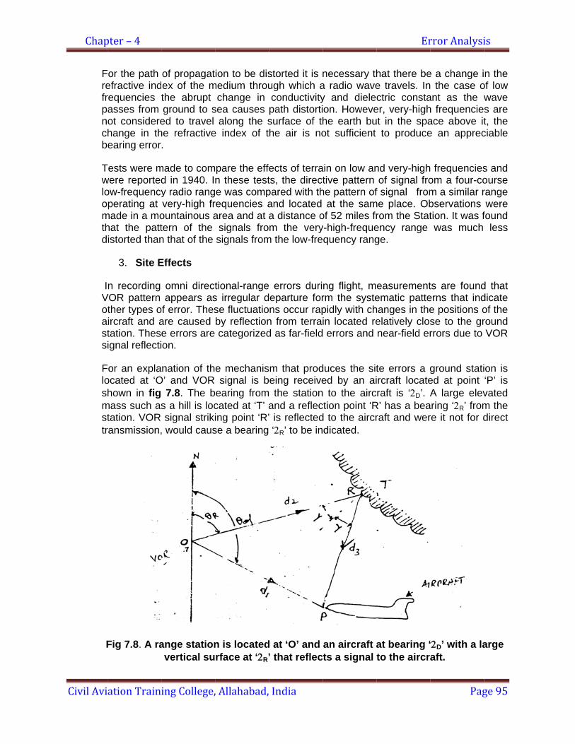
Chap
Civil Avi
Frefrpnchb
Twloomthd
IVoastsi
Floshmsttr
F
pter – 4
ation Train
or the path efractive indrequencies asses from ot considerehange in thearing error
Tests were mwere reportedow-frequencyperating at
made in a mohat the pattistorted than
3. Site E
n recording VOR pattern
ther types oircraft and atation. Thesignal reflecti
or an explaocated at ‘Ohown in fig
mass such astation. VOR ransmission,
Fig 7.8. A ra
ing College,
of propagatex of the mthe abrupt ground to s
ed to travel he refractive.
made to comd in 1940. Iy radio rangvery-high fr
ountainous atern of the n that of the
Effects
omni directappears as
of error. Thesare caused e errors are on.
nation of thO’ and VOR
7.8. The bs a hill is locsignal striki
, would caus
ange stationvertical su
, Allahabad,
ion to be dismedium throu
change in sea causes
along the se index of t
pare the effen these teste was comp
requencies aarea and at a
signals frosignals from
tional-ranges irregular dse fluctuatioby reflectioncategorized
e mechanissignal is b
earing fromcated at ‘T’ aing point ‘R’se a bearing
n is locatedrface at ‘2R’
India
storted it is nugh which aconductivitypath distortisurface of thhe air is no
ects of terrats, the directpared with thand located a distance om the very
m the low-fre
errors durieparture forns occur rapn from terrad as far-field
m that prodeing receive the stationand a reflec’ is reflected ‘2R’ to be in
d at ‘O’ and ’ that reflec
necessary tha radio wavey and dieleon. Howevehe earth buot sufficient
ain on low antive pattern
he pattern ofat the sam
of 52 miles fry-high-frequequency rang
ng flight, mrm the systepidly with chin located re errors and
duces the sited by an ai to the airc
ction point ‘Rd to the aircrdicated.
an aircraft ats a signal
Er
hat there bee travels. Inctric consta
er, very-highut in the spa
to produce
nd very-highof signal fro
f signal fromme place. Ob
rom the Statency range ge.
easurementematic pattehanges in theelatively closnear-field er
te errors a gircraft locateraft is ‘2D’. A
R’ has a bearaft and wer
at bearing ‘to the aircra
rror Analysi
Pag
e a change i the case o
ant as the wh frequencieace above ite an apprec
frequenciesom a four-com a similar rbservations tion. It was fwas much
ts are founderns that inde positions ose to the grrrors due to
ground statied at point A large elev
aring ‘2R’ fromre it not for d
‘2D’ with a laaft.
is
ge 95
n the of low wave s are t, the ciable
s and ourse range were
found less
d that dicate of the round VOR
ion is ‘P’ is vated m the direct
arge
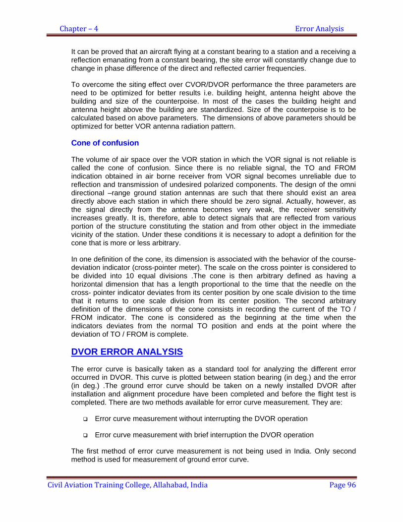
Chapter – 4 Error Analysis
Civil Aviation Training College, Allahabad, India Page 96
It can be proved that an aircraft flying at a constant bearing to a station and a receiving a reflection emanating from a constant bearing, the site error will constantly change due to change in phase difference of the direct and reflected carrier frequencies.
To overcome the siting effect over CVOR/DVOR performance the three parameters are need to be optimized for better results i.e. building height, antenna height above the building and size of the counterpoise. In most of the cases the building height and antenna height above the building are standardized. Size of the counterpoise is to be calculated based on above parameters. The dimensions of above parameters should be optimized for better VOR antenna radiation pattern.
Cone of confusion
The volume of air space over the VOR station in which the VOR signal is not reliable is called the cone of confusion. Since there is no reliable signal, the TO and FROM indication obtained in air borne receiver from VOR signal becomes unreliable due to reflection and transmission of undesired polarized components. The design of the omni directional –range ground station antennas are such that there should exist an area directly above each station in which there should be zero signal. Actually, however, as the signal directly from the antenna becomes very weak, the receiver sensitivity increases greatly. It is, therefore, able to detect signals that are reflected from various portion of the structure constituting the station and from other object in the immediate vicinity of the station. Under these conditions it is necessary to adopt a definition for the cone that is more or less arbitrary.
In one definition of the cone, its dimension is associated with the behavior of the course- deviation indicator (cross-pointer meter). The scale on the cross pointer is considered to be divided into 10 equal divisions .The cone is then arbitrary defined as having a horizontal dimension that has a length proportional to the time that the needle on the cross- pointer indicator deviates from its center position by one scale division to the time that it returns to one scale division from its center position. The second arbitrary definition of the dimensions of the cone consists in recording the current of the TO / FROM indicator. The cone is considered as the beginning at the time when the indicators deviates from the normal TO position and ends at the point where the deviation of TO / FROM is complete.
DVOR ERROR ANALYSIS
The error curve is basically taken as a standard tool for analyzing the different error occurred in DVOR. This curve is plotted between station bearing (in deg.) and the error (in deg.) .The ground error curve should be taken on a newly installed DVOR after installation and alignment procedure have been completed and before the flight test is completed. There are two methods available for error curve measurement. They are:
Error curve measurement without interrupting the DVOR operation
Error curve measurement with brief interruption the DVOR operation
The first method of error curve measurement is not being used in India. Only second method is used for measurement of ground error curve.
Chapter – 4 Error Analysis
Civil Aviation Training College, Allahabad, India Page 97
This method is carried out wholly within the shelter and uses the built in bearing test facility to electronically rotate the DVOR station. The normal monitor antenna is used and bearing measurements are carried out using the DVOR monitor. The bearing facility provides simulated station rotation in 15-degree steps.
An error curve may be recorded by this method in matter of minute and without leaving the equipment shelter. It is there fore a very much quicker method but it does require that the DVOR be out of service for a brief period. It may not detect certain antenna fault system faults (single antenna fault) due to the fixed relation ship of the monitor antenna to the antenna ring.
PREPARATION FOR ERROR CURVE MEASUREMENT:
Before error curve measurement the following parameters are particularly important and should be checked:
1. 30 Hz AM modulation depth 2. Side band phase 3. Sub carrier modulation depth
Interpretation Of Error Curves:
Plotting a graph between station bearing and error in degree and then observing the characteristics of the resulting curve best evaluate the ground error of the DVOR station. If the error spread is excessive, it usually means that there is some fault or misalignment in the DVOR system. It is not possible to define the cause of every perturbation in the curve.
Types of Errors in DVOR:
1. Alignment error 2. Quardrantal error 3. Duantal error 4. Large error at one bearing
Alignment Error:
This is shown by a displacement of the error curve to one side of zero axis.
CORRECTIVE ACTION: The station needs to be rotated slightly to equalize the error. This may be done by an adjustment of the station bearing control.
Quardrantal Error:
This is characterized by two positive and two negative peaks on the error curve. It is the most common type of error curve obtained from a DVOR and even a properly adjusted DVOR will exhibit some quardrantal error.
Excessive quardrantal error is caused by unwanted 60 Hz components in the VOR
Chapter – 4 Error Analysis
Civil Aviation Training College, Allahabad, India Page 98
signal. This may be caused by followings:
1. Incorrect phasing of side bands 2. Excessive 60 Hz AM on the subcarrier 3. Faulty antenna switch driver
Duantal Error:
This is characterized by one positive and one negative peak on the error curve. It is caused by an unwanted 30 Hz component in the VOR signal and there is usually a small duantal component in the error curve of a properly adjusted DVOR.
Excessive duantal error may be caused by:
1. Incorrect side band balance 2. Faulty side band switch
Large Error at one bearing:
A large excursion of the error curve in a localized area usually indicates a fault in the antenna system. Some possibilities are:
1. Faulty antenna or feeder 2. Feed cables from two adjacent antennas interchanged.
Some other sources of error in DVOR:
The following errors are observed due to switching of side bands around the ring antenna:
1. Antenna array effect 2. Proximity effect
Antenna Array Effect:
The effect of antenna array (antenna coupling) causes the signal radiated from the tangential antennas to lag the signal radiated from the in-line antennas( with respect to receiver).This means that if the carrier and the side bands are in-phase when the side bands are radiated from the in-line antennas, then the carrier will be leading the side bands when the radiation will take place from the tangential antennas. This error has been measured to be typically 16 degree for a normal DVOR station.
CORRECTIVE ACTION: This effect is minimized by adjusting the phase to be mid way between these two points, so that the error is reduced to ±8 degrees. The 8-degree offset (from the in line phasing point) is established by using a fix phase shift of 82 degree instead of 90 degree.
Proximity Effect:
The proximity effect only occurs when the receiver is near field. It is due to distance from the receiver to the carrier antenna being less than the distance from the receiver to the
Chapter – 4 Error Analysis
Civil Aviation Training College, Allahabad, India Page 99
tangential ring antennas. For a far field receiver (1500 mtrs), this error is negligible. This effect causes the side bands to lag the carrier when radiated from the tangential antennas. It is about 40 degrees for a monitor antenna 80 meters from the carrier antenna. Ideally the side bands phase of the DVOR should be adjusted using a far field receiver. However, the proximity effect only misphases the tangential antennas, satisfactory results can be obtained by using the normal monitor antennas (at 80 meters) and observing the signal from the in-line antennas for the phasing adjustment.
Chapter – 5 Sitting Criteria & Maintenance of Site
Civil Aviation Training College, Allahabad, India Page 100
Chapter-05
Sitting Criteria & Maintenance of Site INTRODUCTION:
We have studied in the previous lesson regarding the principle of operation of both CVOR and DVOR. As you know that the performance of CVOR is dependent on the site because the 30 Hz variable phase signal is generated as a result of Amplitude modulation, which is very much sensitive to the reflection from the surrounding reflecting objects, so to improve the performance of CVOR, there is requirement of obstruction free site for the installation of CVOR. As far as DVOR operation is concerned, the performance of DVOR is not that much site sensitive like CVOR because the variable phase signal is generated as a result of Frequency modulation, being unaffected by reflection. The quality of VOR course is largely determined by terrain within the area adjacent to the antenna, but prominent terrain features at greater distance may cause disturbance of considerable magnitude. So the terrain condition must be taken into account while selecting the site for installation of VOR/DVOR.
In recent times, scientists have used computers to help predict the performance of navigational aid with respect to a particular site. The reliability of such predictions is yet to be ascertained.
Following information regarding CVOR and DVOR constitute the guidelines to be used in planning and cannot be taken as guarantee of operational performance.
CONVENTIONAL VOR (CVOR)
The terrain adjacent to the VOR antenna should have the following characteristics:
1. The ground should be flat. It should lie in a plain parallel with and having minimum of discontinuities visible to the antenna.
Reason: The warped ground surfaces, either concave or convex (like twisting ridges or hollows) will cause course roughness or scalloping provided it exceeds the Rayleigh roughness criteria limit.
2. Except for the mountain top sides, the terrain should not slope upward from the ground level at the antenna and should be level for a radius of at least 150 ft. Beyond 150 ft, a level ground will be greatly preferred and even a downward slope may be tolerated if the contours are circular around the antenna and the maximum gradient is 4 in 100 out to a radius of at least 1000ft. A ground surface like that of truncated cone is satisfactory provided a level area of 150 ft. minimum radius is obtained.
3. The surface of the terrain beyond the level area should be clear and reasonably smooth. It should not have irregularity such as ravines, ditches, rock outcroppings, embankments, trees, bushes etc.
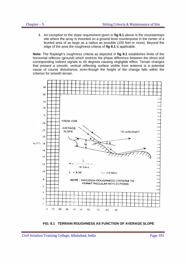
Chapter – 5 Sitting Criteria & Maintenance of Site
Civil Aviation Training College, Allahabad, India Page 101
4. An exception to the slope requirement given in fig 8.1 above is the mountaintops site where the array is mounted on a ground level counterpoise in the center of a leveled area of as large as a radius as possible (150 feet or more). Beyond the edge of the area the roughness criteria of fig 8.1 is applicable.
Note: The Rayleigh’s roughness criteria as depicted in fig 8.1 establishes limits of the horizontal reflector (ground) which restricts the phase difference between the direct and corresponding indirect signals to 45 degrees causing negligible effect. Terrain changes that present a smooth, vertical reflecting surface visible from antenna is a potential cause of course disturbance, even-though the height of the change falls within the criterion for smooth terrain.
FIG. 8.1 TERRAIN ROUGHNESS AS FUNCTION OF AVERAGE SLOPE
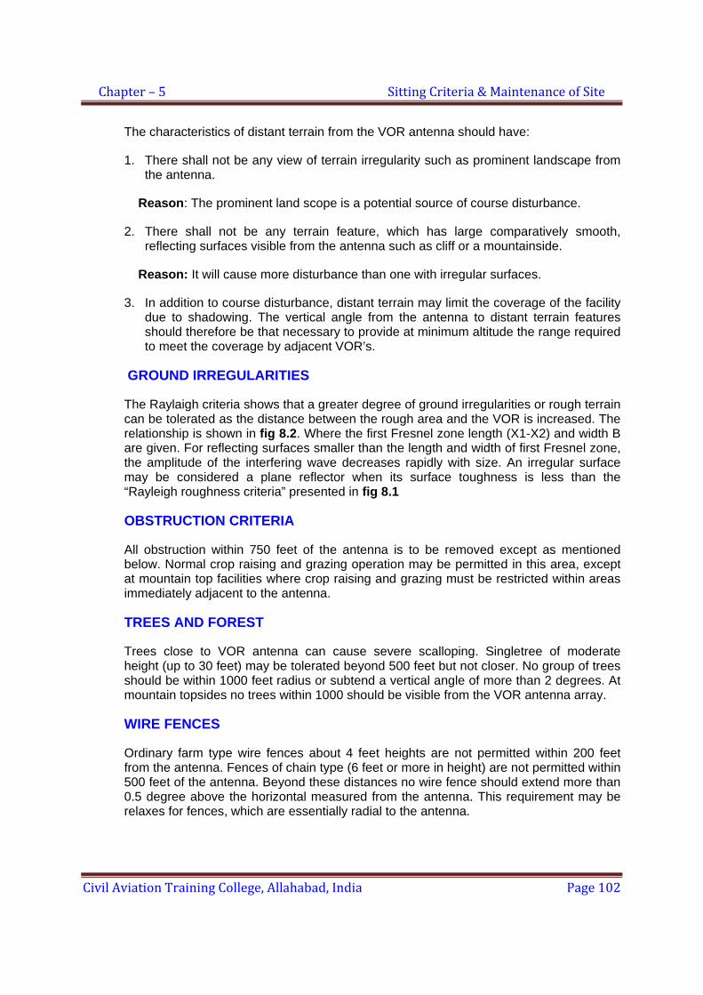
Chapter – 5 Sitting Criteria & Maintenance of Site
Civil Aviation Training College, Allahabad, India Page 102
The characteristics of distant terrain from the VOR antenna should have:
1. There shall not be any view of terrain irregularity such as prominent landscape from the antenna.
Reason: The prominent land scope is a potential source of course disturbance.
2. There shall not be any terrain feature, which has large comparatively smooth, reflecting surfaces visible from the antenna such as cliff or a mountainside.
Reason: It will cause more disturbance than one with irregular surfaces.
3. In addition to course disturbance, distant terrain may limit the coverage of the facility due to shadowing. The vertical angle from the antenna to distant terrain features should therefore be that necessary to provide at minimum altitude the range required to meet the coverage by adjacent VOR’s.
GROUND IRREGULARITIES
The Raylaigh criteria shows that a greater degree of ground irregularities or rough terrain can be tolerated as the distance between the rough area and the VOR is increased. The relationship is shown in fig 8.2. Where the first Fresnel zone length (X1-X2) and width B are given. For reflecting surfaces smaller than the length and width of first Fresnel zone, the amplitude of the interfering wave decreases rapidly with size. An irregular surface may be considered a plane reflector when its surface toughness is less than the “Rayleigh roughness criteria” presented in fig 8.1
OBSTRUCTION CRITERIA
All obstruction within 750 feet of the antenna is to be removed except as mentioned below. Normal crop raising and grazing operation may be permitted in this area, except at mountain top facilities where crop raising and grazing must be restricted within areas immediately adjacent to the antenna.
TREES AND FOREST
Trees close to VOR antenna can cause severe scalloping. Singletree of moderate height (up to 30 feet) may be tolerated beyond 500 feet but not closer. No group of trees should be within 1000 feet radius or subtend a vertical angle of more than 2 degrees. At mountain topsides no trees within 1000 should be visible from the VOR antenna array.
WIRE FENCES
Ordinary farm type wire fences about 4 feet heights are not permitted within 200 feet from the antenna. Fences of chain type (6 feet or more in height) are not permitted within 500 feet of the antenna. Beyond these distances no wire fence should extend more than 0.5 degree above the horizontal measured from the antenna. This requirement may be relaxes for fences, which are essentially radial to the antenna.
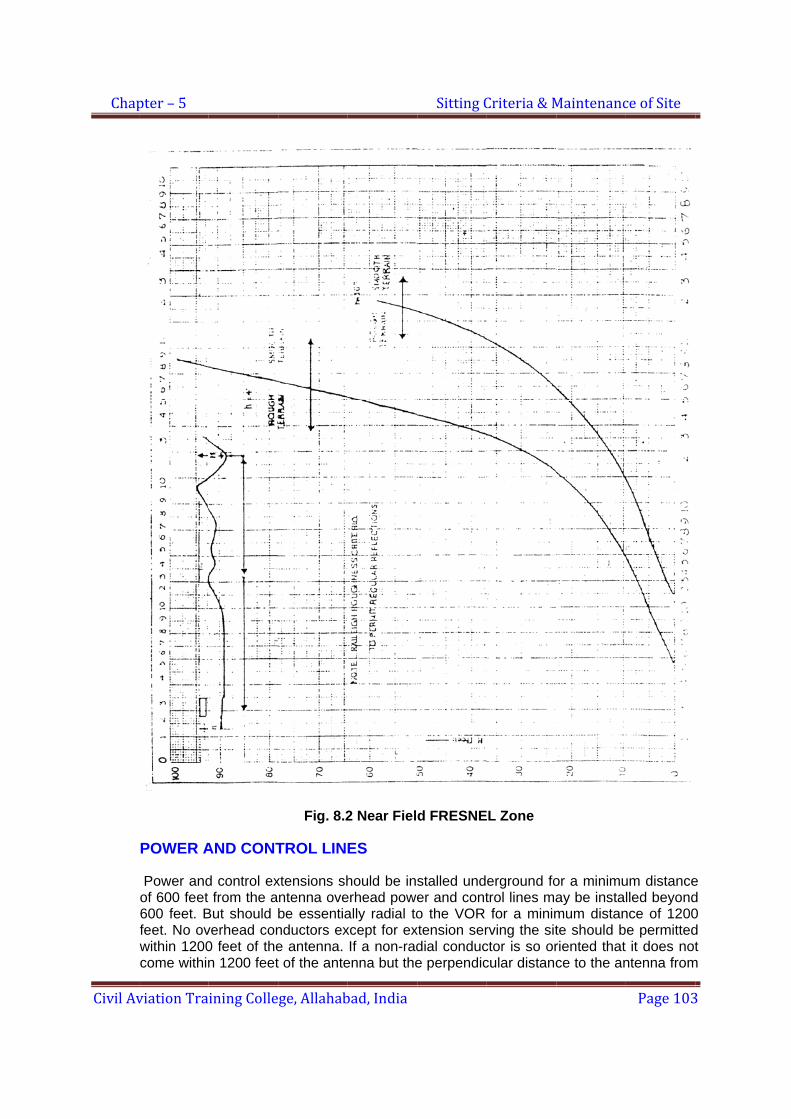
Chap
Civil Av
pter – 5
viation Tra
POWER A
Power andof 600 feet 600 feet. Bfeet. No ovwithin 1200come within
ining Colle
AND CONT
d control exfrom the a
But should verhead con0 feet of then 1200 feet
ge, Allahab
Fig. 8.2
TROL LIN
xtensions shntenna ovebe essentianductors exe antenna. t of the ante
bad, India
2 Near Fiel
ES
hould be inserhead poweally radial toxcept for exIf a non-rad
enna but the
Sitting C
d FRESNE
stalled under and conto the VOR
xtension serdial conduce perpendic
Criteria & M
L Zone
erground fotrol lines mafor a minim
rving the sitctor is so orcular distanc
Maintenanc
or a minimuay be instamum distante should briented that ce to the an
ce of Site
Page 103
um distancelled beyond
nce of 1200e permittedit does not
ntenna from
3
e d 0 d t
m
Chapter – 5 Sitting Criteria & Maintenance of Site
Civil Aviation Training College, Allahabad, India Page 104
its imaginary extensions is less than 1200 feet, then the vertical angle subtended by the uppermost conductor and / earth the top of the pole (measured from ground elevation at the VOR antenna site) should not exceed 1 degree. Also no conductor should extend above the horizontal plane of the antenna other than the foregoing, there should be no lines or supporting structures so located that they subtend a vertical angle (measured from ground elevation at the site) of greater than 1.5 degree. In addition no conductor should extent more than 0.5 degree above the horizontal plane containing the antenna unless they are essentially radial (within +_ 10 degrees) to the antenna array. At mountain topside the conductors will be permitted within 1200 feet of the antenna provides they do not extend above the conical surface formed by the top of the antenna and the edge of the leveled areas.
STRUCTURES
No structure should be permitted within 750 ft. of the antenna,. Except for the buildings located on a slope below the ground level of antenna so that they are not visible from the antenna such as the transmitter building at a mountain top site. All structures, which are partly or entirely metallic, shall subtend vertical angle of 1.2 degree or less measured from the ground elevation at the antenna site. Wooden structures with negligible metallic content and with a little prospect of future metallic additions (such as roof and wiring) may be tolerated if subtending vertical angle of less than 2.5 degree.
DOPPLER VOR (DVOR)
1. The sitting criteria of DVOR are very much less critical than that of conventional VOR, but it is not as precise as in the other case. The following information is based on information about single and alternate side band system and with double side band system.
2. An area of 65 meters radius from the center of counterpoise should be kept clear of all obstructions higher than 3 mtrs. Outside 65 mtrs radius, structures, power lines, telephone lines, single trees etc should be tolerable provided they do not subtend an angle of elevation greater than 3.5 deg. above the ground at the center of the antenna system.
3. Generally the site selected should be reasonably level, have adequate drainage, be above the local flood level of rivers or sea and should not have an excess of vegetation such as high grass or trees. In addition it is desirable that the site be reasonable close to electric power and telephone lines and be accessible from the existing roads.
4. Incase of relatively level terrain, the site should be chosen to keep hills, mountains, large building, power lines and other reflecting objects as far distance as possible. The optical horizon should preferably not extend above an elevation angle of 0.75 deg. When measured from a position of 2 mtrs above the center of site. Distant mountains exceeding this angle will not usually affect the quality of VOR course, but will reduce the usable coverage of the aid Hills and mountains within 16 Kms are potential source of course scalloping. Trees, fences, over head lines etc in the vicinity of DVOR site.

Chapter – 5 Sitting Criteria & Maintenance of Site
Civil Aviation Training College, Allahabad, India Page 105
5. In mountainous country the site should be located on the highest hills or mountains within the tolerance area. Ideally there should be no other hills or mountain range of comparable height within 16 Kms. The immediate site area should be clear and level for radius 0f at least 50 mtrs or be capable of improvement to meet this requirement.
6. Wherever possible the object infringing limitations are to be removed prior to DVOR commissioning. In heavily timber country, clearing rights are to be negotiated covering a radius of 150 mtrs from the center of the site lopping rights above 4 deg. elevation from center antenna.
7. Airports taxi ways and run ways, public roads, trams and railways should not be closer than 150 mtrs. Vehicles used by maintenance staff should be parked as close to counterpoise as possible preferable under the counterpoise.
8. All power and control cables are to be laid under ground from a distance of 150 mtrs and should approach radially.
RESTRICTED AREA FOR VOR AND DVOR
Area: 230 mtrs (750 feet) radius circle centered on the VOR aerial.
Restrictions:
No building, permanent or temporary
No over head metallic cable
No trees and hedges
File No. AAI/NS/ILS/General/04 Date: 7/01/2008
CNS CIRCULAR No. 01of 2008
Sub: Maintenance of Navigational Aids Site
In order to prevent unacceptable interference to ILS and other navigational Aids signals, areas around antenna shall be protected as per provisions of ICAO Annex 10 Vol I.
For the above purp oses following guidelines shall be followed for maintenance of Critical and Sensitive Area of Instrument Landing System, restricted area around VOR (As defined in Annexure1) DME, NDB and Marker beacons and Area around DGPS/LT point used for flight calibration by FIU at the airports.
1. Localizer and glide path: 1.1. The height of grass is not to exceed 150mm in the critical area of ILS. 1.2. During ILS operation access of personnel and vehicle and performance of
maintenance activities in the critical area of ILS shall be done as per following procedure.
Access control to critical and sensitive area of ILS operating as CAT-II and CAT-III will be as per promulgated provisions of Low Visibility Procedure (LVP) of the airport in the absence of such procedure access to the area shall be done with prior coordination with ATC tower.
Maintenance activities like grass mowing maintenance of airport lighting etc in the critical area of ILS shall be carried out in coordination with CNS personnel. During watch hours of ILS operation, CNS personnel shall have prior coordination with ATC for execution of work.
No metallic objects i ncluding vehicles shall be permitted to enter into critical area of ILS. For operational reasons if entry of vehicle into critical area becomes necessary, prior coordination will be done with CNS personnel. Before issuing permission guideline contained above shall be kept in view.
Chapter - 05 Sitting Criteria & Maintenance of Site
Civil Aviation Training College, Allahabad, India Page 106
2. VOR 2.1.1. Site maintenance: 2.1.2. Grass and shrubs within 305m radius of the site must be mown or cut regularly
so that their heights do not exceed 600mm. 2.1.3. Grass cutting equipment is not to be parked within 305m radius of the VOR
building. 2.1.4. The vehicles used by airport maintenance staff are to be parked underneath the
counterpoised or beyond the radius of 305m
3. NDB , Marker Beacons And DME Facilities:- The height of grass and other vegetation over the protected area (within 30mt rs of 100 watt NDB and 100mtrs for 500 watt NDB ) covering the Antenna Mast (s), the earth mat buildings is not to exceed 600 mm.
4. DGPS/LT point maintenance:- 4.1. The DGPS point marked by FIU for flight inspection of Radio Navigational aids
shall be maintained by suitable marking for future flight inspection of the facilities of the airport.
4.2. Grass and other vegetation at the site must be mown or cut regularly. The height of grass and other vegetation around the point is not to exceed 100 mm.
5. Signage: - proper signage shall be provided to delineate the boundaries of critical and sensitive areas of navigational aids Sign boards shall be made of non metallic material.
6. Water logging: - Actions shall be taken so to avoid water logging in critical and sensitive area and around antenna systems of Nav-aids.
7. Foreign objects:- Nav-aids sites viz ILS, VOR, DME and NDB shall be free from all foreign objects.
8. Construction of structures: - Const ruction of any structure in the vicinity of NAV aids are to be cont rolled as per DARA circular 5/2005. Unauthorized constructions/ obstruction which is likely to affect the performance of NAVAIDS, is to be brought to the notice of station in charge for immediate action.
9. No drainage/water pipe should be allowed to pass through the critical area of ILS, if this is already existing necessary actions are to be taken so that water logging does not take place in the area.
Chapter - 05 Sitting Criteria & Maintenance of Site
Civil Aviation Training College, Allahabad, India Page 107

10. Normally no electrical power line to be permitted to pass through critical area of ILS and in the protected area in case of VOR, DME, NDB and Markers.
11. Civil work like new construction, excavation, digging and leveling is no t allowed in Critical and Sensitive Areas and around antenna system of ILS and in the pr otected area as mentioned above for VOR, DME, NDB and Markers. (V K Chaudhary) Executive Director (CNS-OM)
Chapter - 05 Sitting Criteria & Maintenance of Site
Civil Aviation Training College, Allahabad, India Page 108
Annexure-A
1. Instrument landing system The occurrence of interference to ILS signals is dependent on the total environment around the ILS antennas and antenna characteristics. Any large reflecting objects including the a ircraft vehicle or fixed objects could potentially cause multi-pat h interference to the ILS course and path stru cture affecting its performance. The environment for the purpose of developing protective zoning criteria can be divided into two types of area the critical area and sensitive area-
a) Critical area: - the critical area is an area of defined dimensions about t he localizer and glide path antennas where vehicles, including aircraft, are excluded during all ILS operations. The critical area is protected because the presence of vehicles and/or aircraft inside its boundaries will c ause unacceptable disturbance to the ILS signal in space.
b) Sensitive area: - The sensitive area is an area extending beyond the critical area where t he parking and/or movement of vehicles in cluding aircraft is controlled to prevent the possibility of una cceptable interference to the IL S signal during ILS operations. The s ensitive area i s protected against interference caused by large moving objec ts outside critical a rea but sti ll normally within the airfield boundary.
1.1. Critical and Sensitive Area Dimension:- Depending of the type of ILS antenna system, category of ILS operation and aircraft operation the critical and sensitive area should be establ ished and properly designated at an ai rport to protect ILS operation from multi path ef fects. The typical dimensions as per ICAO ANNEX 10/VOL I/ attachment C and DARA circular 5/2005 are as given below.
1.2. LLZ Critical Area:- The area bounded by i. A line 300meter in the direction of approaches from localizer antenna and
perpendicular to the runway. ii. A line 60m from the centerline of localizer antenna on either side and
parallel to the runway. iii. A line containing the centerline of localizer antenna and perpendicular to
the runway. iv. Area within a circle of 75 meter radius with center at middle of antenna
system.
1.3. LLZ Sensitive Area: - The typical LLZ sensitive area for 12 and 14 elements directional dual frequ ency LLZ antenna sys tem which are used in AAI are as given below for a 3000m runway. The area bounded by:- Category I ILS: - An area of 600M X 60M from center of LLZ array towards approach end of runway.
Chapter - 05 Sitting Criteria & Maintenance of Site
Civil Aviation Training College, Allahabad, India Page 109
Category II ILS: - An area of 1220M X 90M from center of LLZ array towards approach end of runway. Category III ILS: - An area of 2750M X 90M from center of LLZ array towards approach end runway.
1.4. GP Critical Area :- The area bounded by- i. A line 300meter in the direction of approach from the glide path facility
and perpendicular to the runway. ii. A line containing glide path antenna and perpendicular of runway iii. Near edge of runway from glide path. iv. A line 30 meter in the directions away from the antenna and parallel to it.
1.5. GP Sensitive Area :- the area bounded by-
a) For Category I ILS :- i. A line 900 meter in the direction of approach from the glide path
facility and perpendicular to the runway. ii. A line containing glide path antenna and perpendicular of runway iii. Near edge of runway from glide path including runway towards
direction of approach. iv. A line 300 meter in the directions away from the antenna and
parallel to it.
b) CATEGORY II/III ILS :- i. A line976 meter in the direction of approach from the glide path
facility and perpendicular to the runway. ii. A line containing glide path antenna and perpendicular of runway. iii. Near edge of runway from glide path including runway towards
direction of approach. iv. A line 300 meter in the directions away from the antenna and
parallel to it. 2. DVOR Restricted/Protected area :-
An area within a 305 meter radius from the centre of antenna of the facility.
3. NDB protected area :- a) Self radiating mast -30 meter radius from the centre of the radiating mast
of the facility. b) Cage/ T antennae – the area bounded by
1. 30 meter radius from each mast 2. lines joining the locus of each circle made by above 1.
Chapter - 05 Sitting Criteria & Maintenance of Site
Civil Aviation Training College, Allahabad, India Page 110
Chapter – 6 Flight Calibration & Doc 8071
Civil Aviation Training College, Allahabad, India Page 111
Chapter-06 Flight Calibration & Doc 8071
Introduction Flight Inspection of Radio and Visual 'Navigation aids’ involves flight evaluation and certification of the signal-in-space. The evaluation process utilizes specially equipped instrumented aircraft, which carries out specific flight maneuvers. Data acquired thus on the quality of signal in space, is analyzed to arrive at the specific performance Parameters. These parameters, in turn, determine the certification of facility status. Flight inspection is mandatory as per International Civil Aviation Organization (ICAO).
Type of Inspection As needed the flight inspection team may be required to undertake any of the following five types of inspection.
1. Site Evaluation 2. Engineering Support 3. Commissioning / Re-commissioning 4 Routine 5. Special
1 Site Evaluation Inspection: Site Evaluation flight inspections are carried out to determine the suitability of a site for installation of a nav-aid. . 2 Engineering Support Inspection: Engineering support inspection is done towards evolving an engineering solution to the imperfect installation site. It may involve, for example, modification to the Antenna system of Glide Path or minor improvement in the site for optimizing “a within tolerance” performance. 3 Commissioning / Re- Commissioning: Commissioning / Re- Commissioning inspection is a comprehensive check designed to obtain complete information regarding all aspects of performance of a nav-aid. The facility cannot be declared operational before this check. 4 Routine Inspection: Routine inspection is carried out to ensure that nav-aid facility is maintained within tolerance limits in spite of the inherent drift in the equipment. Routine inspections do not normally involve major adjustments unless the performance is observed to have drifted either close to, or beyond the applicable tolerance limits.

Chapter – 6 Flight Calibration & Doc 8071
Civil Aviation Training College, Allahabad, India Page 112
5 Special Flight Inspection: Special flight inspection is made on special request to confirm satisfactory performance. It may follow a major maintenance on the equipment especially the antenna system. Special Flight Inspection may also be carried out for investigation purpose after any incident or accident. Periodicity of Flight Inspection The establishment of generally applicable check interval depends on:
a. The checking method used. b Reliability of ground equipment. c Extent and fidelity of monitoring capability. d Proficiency of maintenance personnel.
e Extent of correlation established between ground check and Flight check.
A new facility requires shorter interval than a proven one. Valve type equipment and those involving mechanical sub-system need more frequent check than solid state equipment.
Following are the periodicities being followed by AAI
Facility Periodicity
a. ILS 150+ 30 days
b. DVOR 720+ 60 days
c. CVOR 240+ 30 days
d. DME As per the associated facility.
e. NDB As and when required
f. Radar As and when required
g. VGSI (VASI/PAPI) As and when required Maintenance team can draw a schedule for flight inspection as per the data above. In case the established intervals are exceeded because of weather or other factors the facility status (Certification) shall not be changed for the sole reason that the inspection could not be carried out within the maximum allowable intervals. The facility may continue to remain in service, provided the ground checks indicate normal performance.
Chapter – 6 Flight Calibration & Doc 8071
Civil Aviation Training College, Allahabad, India Page 113
VOR Flight Inspection 1. VOR Parameters Checks Following are the various Flight Inspection Checks carried on VOR. a. Sensing and Rotation check.
b. Identification Coding Check c. Modulation Level Check d. Orbit Check e. Radial check
f. Polarization Check g Coverage Check
h. Monitor Alarm check
1.1 Sensing and rotation: The purpose of this check is to assure proper orientation of the antenna; Proper connection of its RF feed lines. Course azimuth increases in a clockwise direction and ‘TO-FROM’ indications are correct. Flight Inspection aircraft flies any outbound radial to check sensing. After sensing is checked, Orbit check starts. If it is found to be incorrect, the most probable cause would be reversed sideband antenna feed cables.
1.2 Identification check Identification check is carried out to see the correctness, clarity and to ensure that there is no adverse effect on VOR course structure. This check is performed anytime while flying a radial. 1.3 Modulation Levels Check
1.3.1 Purpose: To confirm that modulation levels of 30 Hz AM, 9960 KHz Sub-carrier and the 30 Hz FM (deviation ratio of 9960 KHz sub-carrier) are set properly.
Chapter – 6 Flight Calibration & Doc 8071
Civil Aviation Training College, Allahabad, India Page 114
1.3.2 Flight Procedure: Calibration aircraft flies on any radial and modulation levels of the parameters are checked and adjusted accordingly
Mod. Depth of 30 Hz AM adjusted for 30% ± 2 %
9960 KHz adjusted for 30% ± 2% Deviation ratio 30 Hz FM 16 ± 1 Final adjustments are carried out during Orbit check.
1.4 Orbit Checks
1.4.1 5 Nm Orbit : 1.4.1.1 Purpose:
i To evaluate the error in azimuth alignment , the roughness and scalloping of sectors and the signal strength over the orbit.
ii To determine the accuracy and overall alignment error distribution of the radials over 360 degrees. This check is carried out during Commissioning and routine flight checks.
1.4.1.2 Flight Procedure:
Calibration aircraft flies an orbit radius of normally 5 Nm or more in a Counter Clock wise direction at a minimum altitude of 1000' AGL or above.
1.4.1.3 Position reference system:
Calibration Aircraft is automatically tracked by GPS available on board with AFIS. Its omnistar GPS receiver receives correctional data from service provider via satellite to give submeter accuracy under DGPS mode.
1.4.1.4 Ground Facility Adjustment
Adjustments are made on the basis of analysis of flight inspection data to establish and maintain optimum error distribution. Ground staff is required 1. To adjust modulation levels of 30 Hz AM, 9960 Subcarrier, the FMI of 30Hz
FM and 1020 Hz Ident. 2. To adjust the north bearing for alignment with magnetic north and to optimize
the error distribution throughout radials .
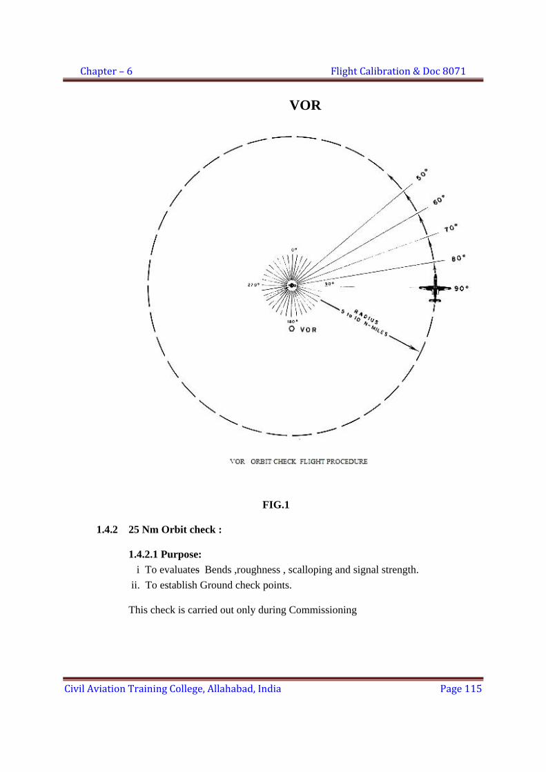
Chapter – 6 Flight Calibration & Doc 8071
Civil Aviation Training College, Allahabad, India Page 115
VOR
FIG.1
1.4.2 25 Nm Orbit check :
1.4.2.1 Purpose: i To evaluates Bends ,roughness , scalloping and signal strength. ii. To establish Ground check points. This check is carried out only during Commissioning
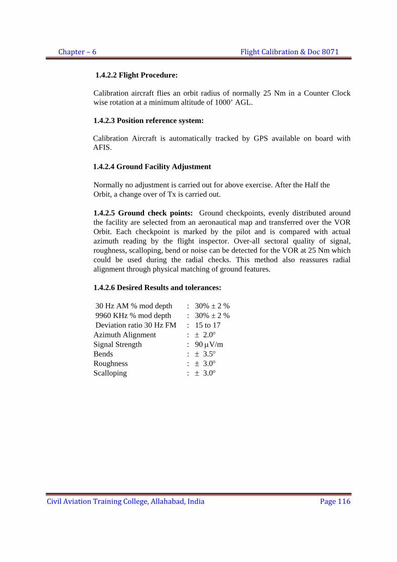
Chapter – 6 Flight Calibration & Doc 8071
Civil Aviation Training College, Allahabad, India Page 116
1.4.2.2 Flight Procedure:
Calibration aircraft flies an orbit radius of normally 25 Nm in a Counter Clock wise rotation at a minimum altitude of 1000’ AGL.
1.4.2.3 Position reference system:
Calibration Aircraft is automatically tracked by GPS available on board with AFIS.
1.4.2.4 Ground Facility Adjustment
Normally no adjustment is carried out for above exercise. After the Half the Orbit, a change over of Tx is carried out.
1.4.2.5 Ground check points: Ground checkpoints, evenly distributed around the facility are selected from an aeronautical map and transferred over the VOR Orbit. Each checkpoint is marked by the pilot and is compared with actual azimuth reading by the flight inspector. Over-all sectoral quality of signal, roughness, scalloping, bend or noise can be detected for the VOR at 25 Nm which could be used during the radial checks. This method also reassures radial alignment through physical matching of ground features.
1.4.2.6 Desired Results and tolerances:
30 Hz AM % mod depth : 30% ± 2 % 9960 KHz % mod depth : 30% ± 2 % Deviation ratio 30 Hz FM : 15 to 17
Azimuth Alignment : ± 2.0° Signal Strength : 90 μV/m Bends : ± 3.5° Roughness : ± 3.0° Scalloping : ± 3.0°
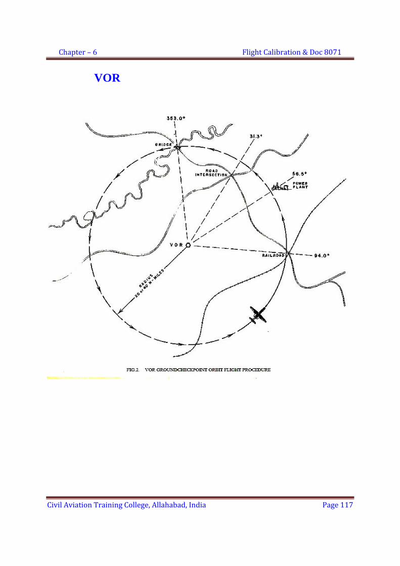
Chapter – 6 Flight Calibration & Doc 8071
Civil Aviation Training College, Allahabad, India Page 117
VOR

Chapter – 6 Flight Calibration & Doc 8071
Civil Aviation Training College, Allahabad, India Page 118
1.5 Radial Checks
1.5.1 Purpose:
i To check that the quality of course signals is satisfactory. Course bends, roughness, scalloping (all combined together) should be within tolerance limits
ii Minimum 8 radials with at least one radial in each quadrant including PDRs are checked during commissioning. During Routine inspections , only PDRs are checked .
1.5.2 Flight Procedure
i Calibration A/C flies on enroute radials either inbound or outbound along the radial to a distance of 40 Nm. The minimum altitude is 1000ft above the highest terrain. .
1.5.3 Ground Adjustment
Normally no adjustment is carried out for above exercise. .
1.5.4 Desired Results and Tolerances i. Alignment
Signal strength > 90 µv/m Bends : ± 3.5° Roughness : ± 3.0° Scalloping : ± 3.0°
1.6 Polarization Check
1.6.1 Purpose: To confirm, that no adverse effect will be encountered, while flying on course due to undesired vertical polarization component. The desired polarization of VOR is HORIZONTAL
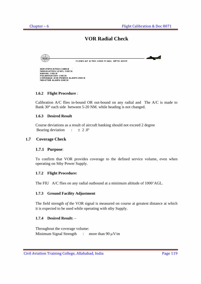
Chapter – 6 Flight Calibration & Doc 8071
Civil Aviation Training College, Allahabad, India Page 119
VOR Radial Check
1.6.2 Flight Procedure : Calibration A/C flies in-bound OR out-bound on any radial and The A/C is made to Bank 30° each side between 5-20 NM. while heading is not changed. 1.6.3 Desired Result Course deviations as a result of aircraft banking should not exceed 2 degree Bearing deviation : ± 2 .0°
1.7 Coverage Check
1.7.1 Purpose: To confirm that VOR provides coverage to the defined service volume, even when operating on Stby Power Supply. 1.7.2 Flight Procedure: The FIU A/C flies on any radial outbound at a minimum altitude of 1000’AGL. 1.7.3 Ground Facility Adjustment The field strength of the VOR signal is measured on course at greatest distance at which it is expected to be used while operating with stby Supply.
1.7.4 Desired Result: – Throughout the coverage volume: Minimum Signal Strength : more than 90 μV/m
Chapter – 6 Flight Calibration & Doc 8071
Civil Aviation Training College, Allahabad, India Page 120
1.8 Bearing Monitor alarm check Monitor alarm limits are cross checked. Ground maintenance personnel actuate
alignment monitor alarm condition with North Alignment Control. Calibration aircraft detects the deviation to confirm that the deviation is within the tolerance limits.
Calibration A/C flies on any radial either inbound or outbound. Give the
equipment on alarm with north alignment control when advised by flight inspector. Normalise the equipment after Alarm check.
Tolerance: Bearing Monitor : ± 1 .0°
1.9 FLYABILITY - Must be Satisfactory
Flyability is a subjective assessment by the Pilot during the inspection. Assessment of Flyability is performed on operational radials and during procedures based on the VORs.
1.10 RECEIVER CHECK POINTS: Fixed check points are established both on the ground and in the air where pilots
may check the accuracy of their aircraft VOR Receivers. These points are established during Commissioning check.
1.10.1 Airborne Check Points: The aircraft flies either inbound or outbound directly over easily identified ground features at specific altitudes near the airport at a distance between 5 Nm to 30 Nm. The radial and distance above the check point will be published as Receiver air check point azimuth.
1.10.2 Ground Check points: The aircraft position on the ramp or on a taxiway over a selected location. The indicated radial and distance will be published as Ground check point.
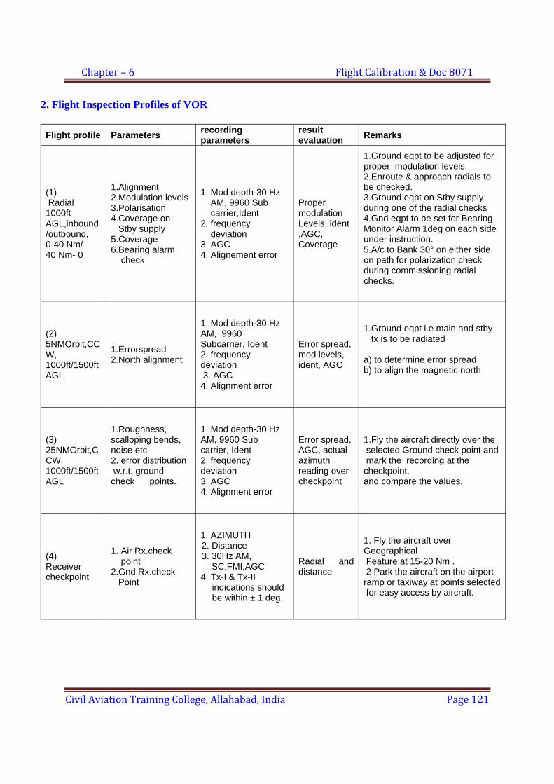
Chapter – 6 Flight Calibration & Doc 8071
Civil Aviation Training College, Allahabad, India Page 121
2. Flight Inspection Profiles of VOR
Flight profile Parameters recording parameters
result evaluation Remarks
(1) Radial 1000ft AGL,inbound /outbound, 0-40 Nm/ 40 Nm- 0
1.Alignment 2.Modulation levels 3.Polarisation 4.Coverage on Stby supply 5.Coverage 6.Bearing alarm check
1. Mod depth-30 Hz AM, 9960 Sub carrier,Ident 2. frequency deviation 3. AGC 4. Alignement error
Proper modulation Levels, ident ,AGC, Coverage
1.Ground eqpt to be adjusted for proper modulation levels. 2.Enroute & approach radials to be checked. 3.Ground eqpt on Stby supply during one of the radial checks 4.Gnd eqpt to be set for Bearing Monitor Alarm 1deg on each side under instruction. 5.A/c to Bank 30° on either side on path for polarization check during commissioning radial checks.
(2) 5NMOrbit,CCW, 1000ft/1500ft AGL
1.Errorspread 2.North alignment
1. Mod depth-30 Hz AM, 9960 Subcarrier, Ident 2. frequency deviation 3. AGC 4. Alignment error
Error spread, mod levels, ident, AGC
1.Ground eqpt i.e main and stby tx is to be radiated a) to determine error spread b) to align the magnetic north
(3) 25NMOrbit,CCW, 1000ft/1500ft AGL
1.Roughness, scalloping bends, noise etc 2. error distribution w.r.t. ground check points.
1. Mod depth-30 Hz AM, 9960 Sub carrier, Ident 2. frequency deviation 3. AGC 4. Alignment error
Error spread, AGC, actual azimuth reading over checkpoint
1.Fly the aircraft directly over the selected Ground check point and mark the recording at the checkpoint. and compare the values.
(4) Receiver checkpoint
1. Air Rx.check point 2.Gnd.Rx.check Point
1. AZIMUTH
2. Distance 3. 30Hz AM, SC,FMI,AGC 4. Tx-I & Tx-II
indications should be within ± 1 deg.
Radial and distance
1. Fly the aircraft over Geographical Feature at 15-20 Nm . 2 Park the aircraft on the airport ramp or taxiway at points selected for easy access by aircraft.
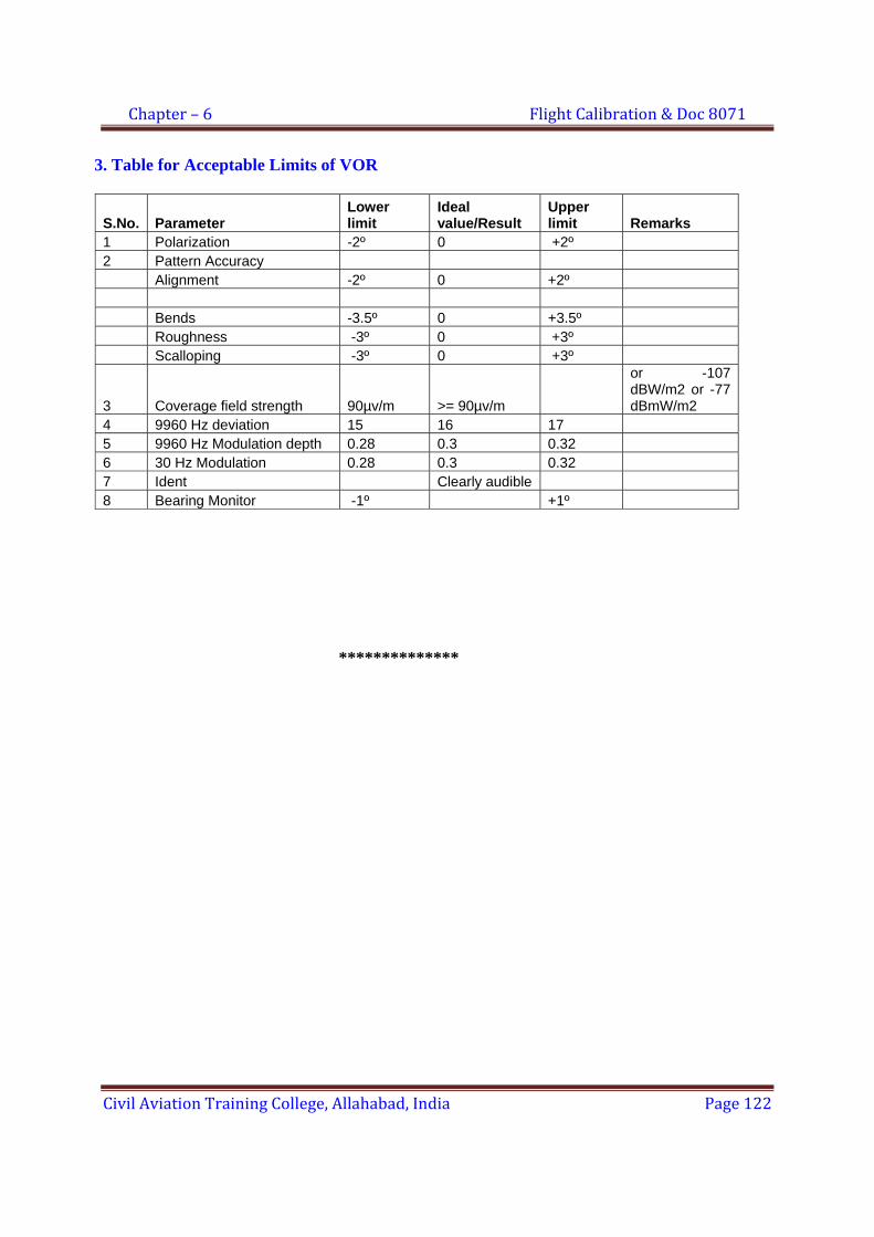
Chapter – 6 Flight Calibration & Doc 8071
Civil Aviation Training College, Allahabad, India Page 122
3. Table for Acceptable Limits of VOR
S.No. Parameter Lower limit
Ideal value/Result
Upper limit Remarks
1 Polarization -2º 0 +2º 2 Pattern Accuracy Alignment -2º 0 +2º Bends -3.5º 0 +3.5º Roughness -3º 0 +3º Scalloping -3º 0 +3º
3 Coverage field strength 90µv/m >= 90µv/m
or -107 dBW/m2 or -77 dBmW/m2
4 9960 Hz deviation 15 16 17 5 9960 Hz Modulation depth 0.28 0.3 0.32 6 30 Hz Modulation 0.28 0.3 0.32 7 Ident Clearly audible 8 Bearing Monitor -1º +1º **************
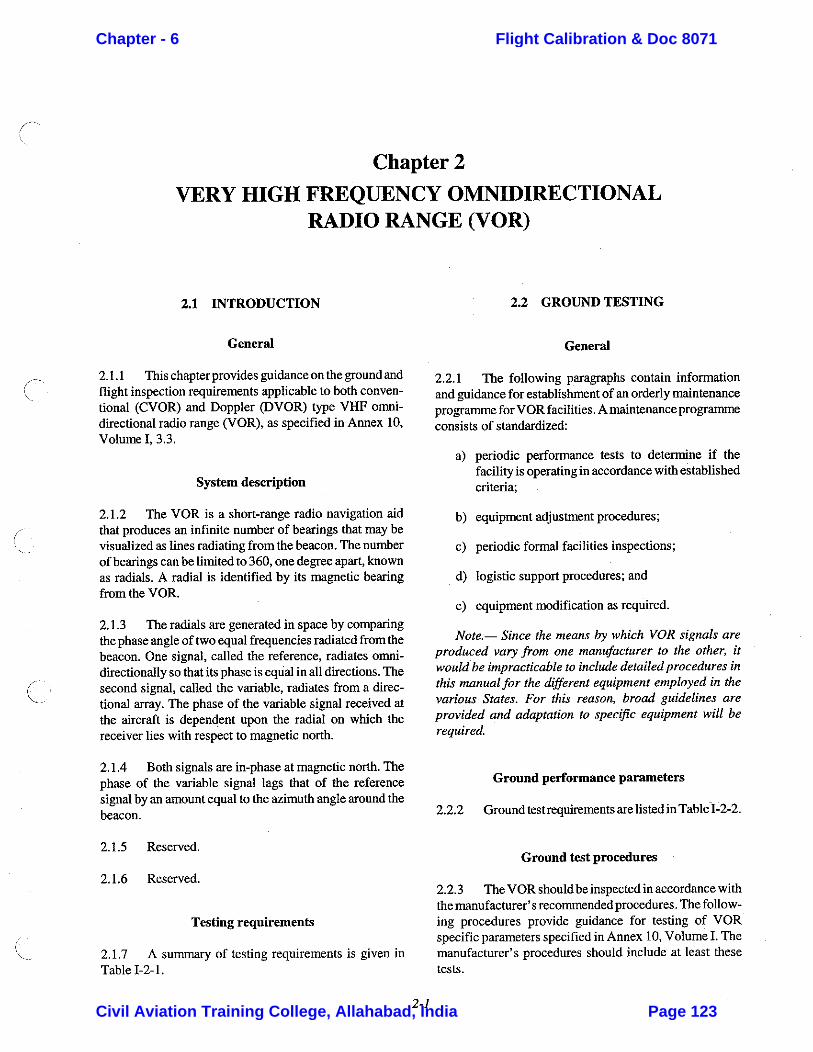
Chapter - 6 Flight Calibration & Doc 8071
Civil Aviation Training College, Allahabad, India Page 123
CDRC
Typewritten Text
DOC 8071

Chapter - 6 Flight Calibration & Doc 8071
Civil Aviation Training College, Allahabad, India Page 124
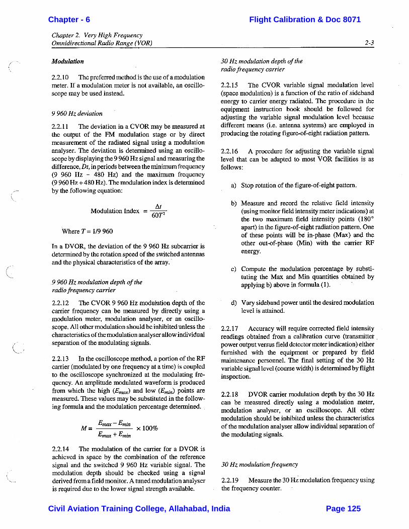
Chapter - 6 Flight Calibration & Doc 8071
Civil Aviation Training College, Allahabad, India Page 125
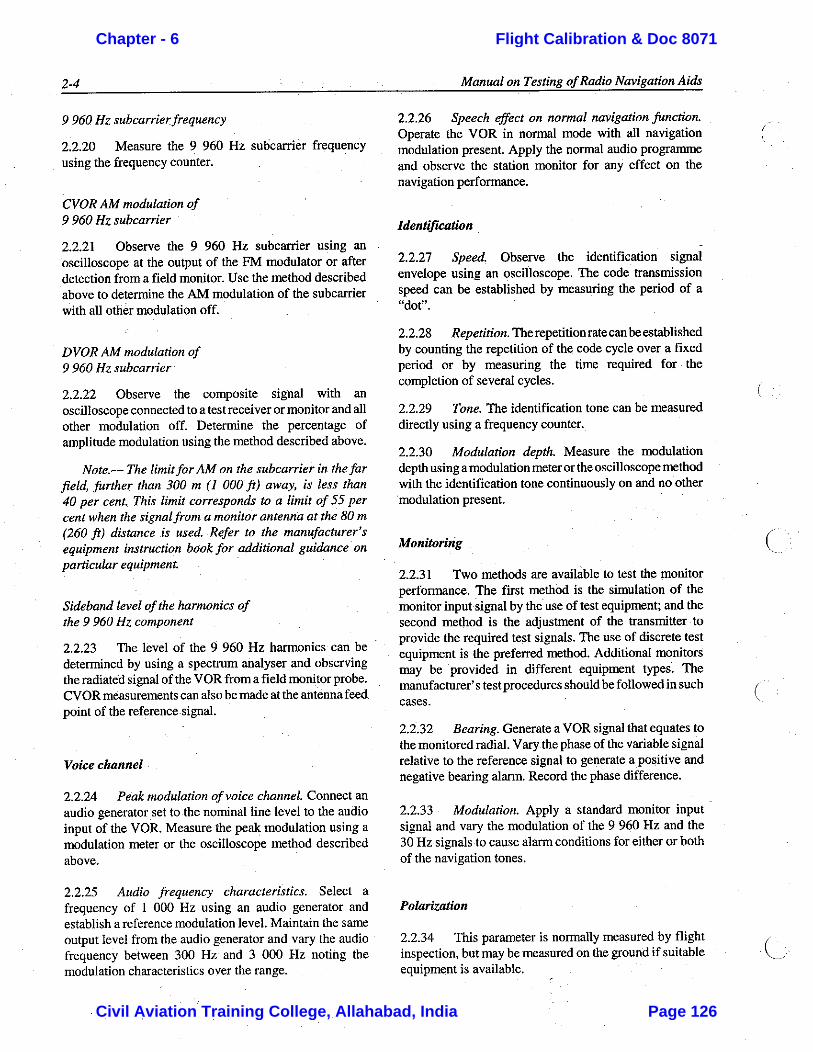
Chapter - 6 Flight Calibration & Doc 8071
Civil Aviation Training College, Allahabad, India Page 126

Chapter - 6 Flight Calibration & Doc 8071
Civil Aviation Training College, Allahabad, India Page 127
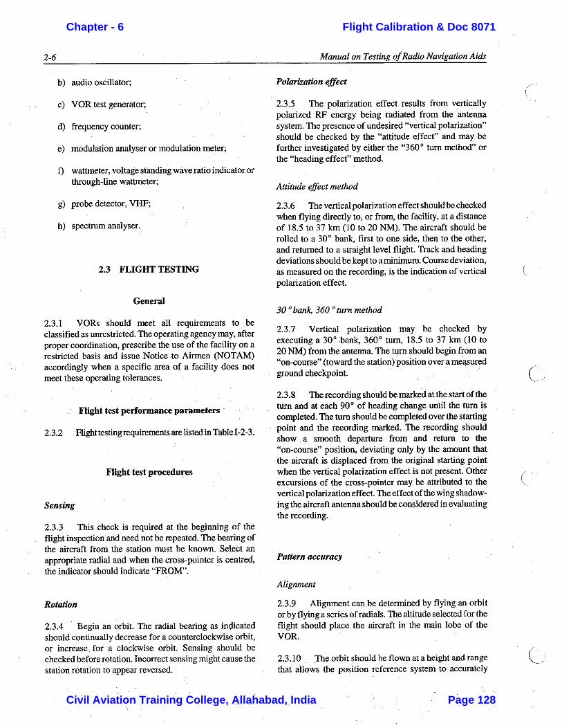
Chapter - 6 Flight Calibration & Doc 8071
Civil Aviation Training College, Allahabad, India Page 128
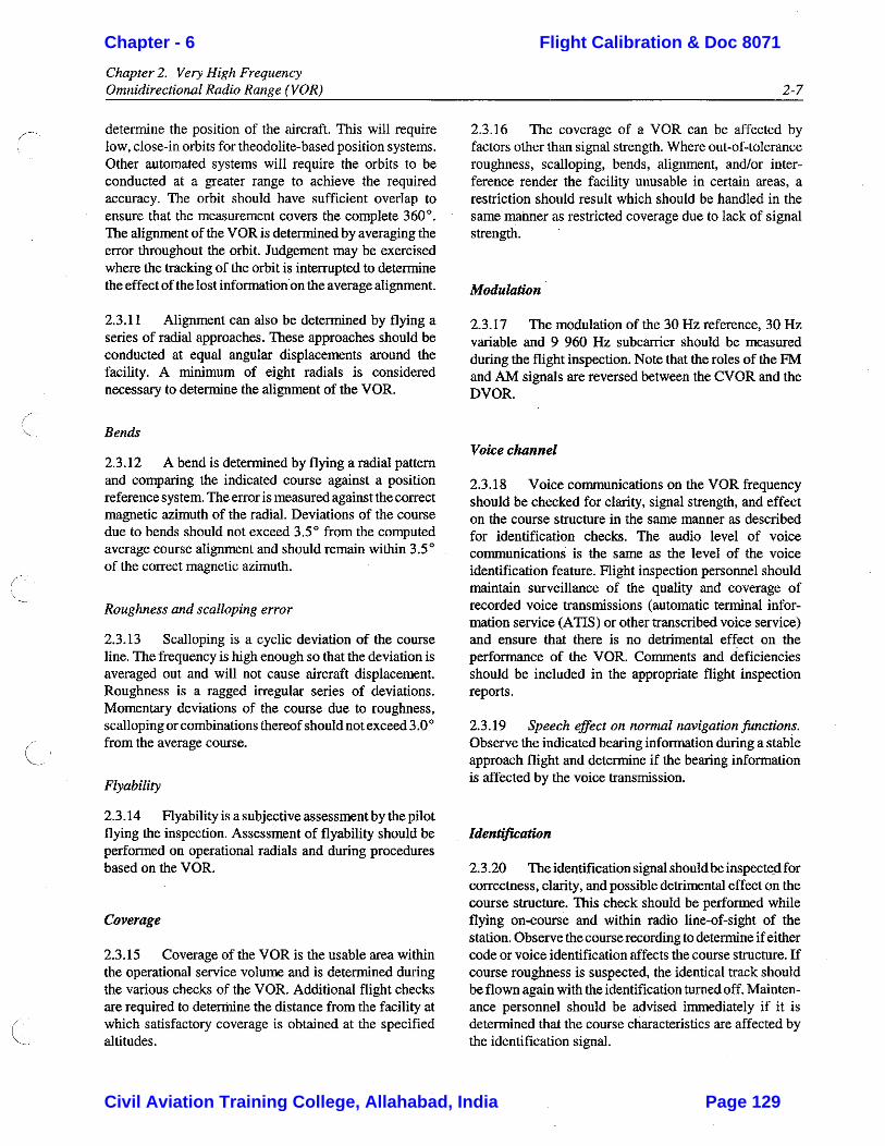
Chapter - 6 Flight Calibration & Doc 8071
Civil Aviation Training College, Allahabad, India Page 129
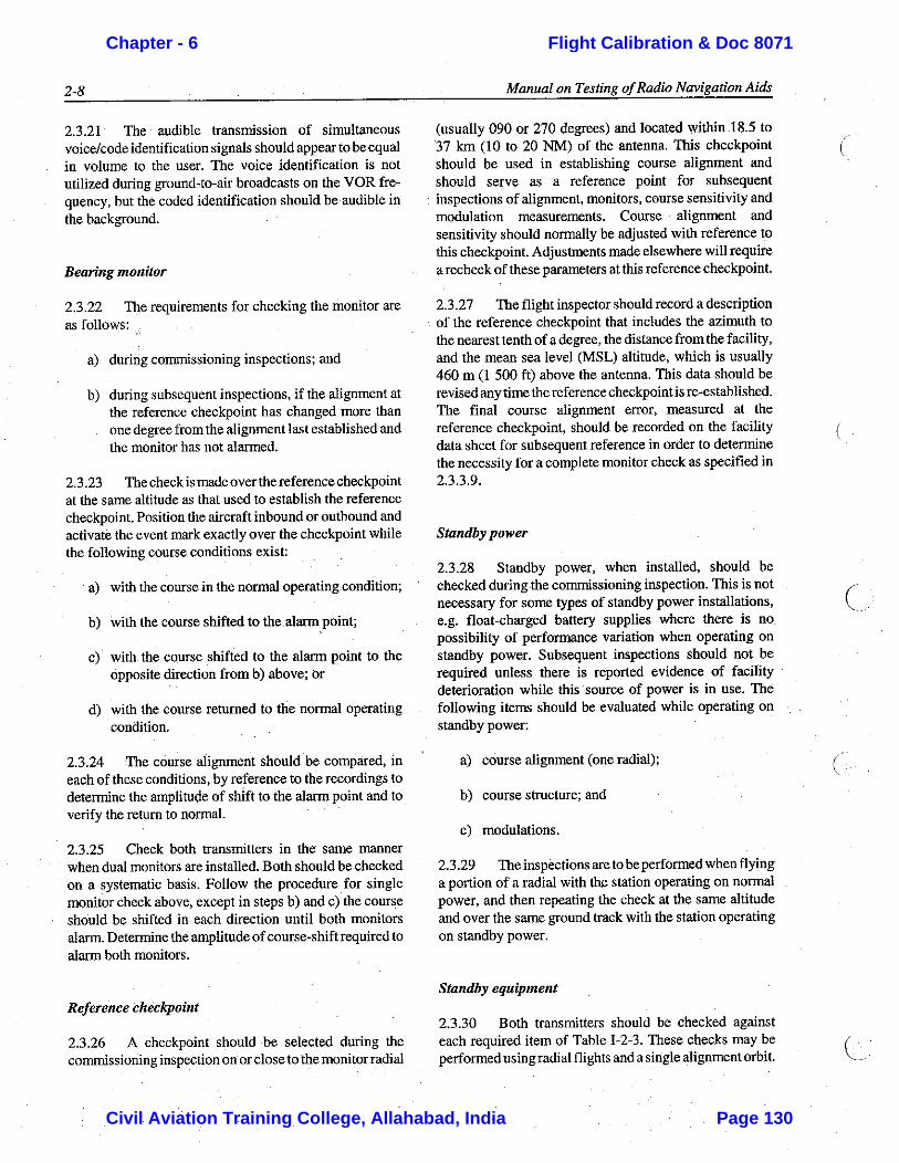
Chapter - 6 Flight Calibration & Doc 8071
Civil Aviation Training College, Allahabad, India Page 130
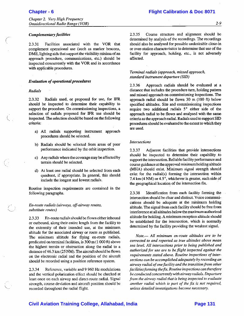
Chapter - 6 Flight Calibration & Doc 8071
Civil Aviation Training College, Allahabad, India Page 131

Chapter - 6 Flight Calibration & Doc 8071
Civil Aviation Training College, Allahabad, India Page 132
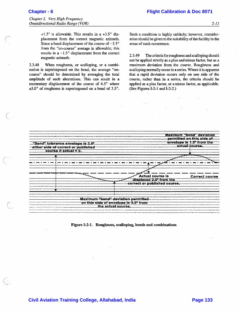
Chapter - 6 Flight Calibration & Doc 8071
Civil Aviation Training College, Allahabad, India Page 133
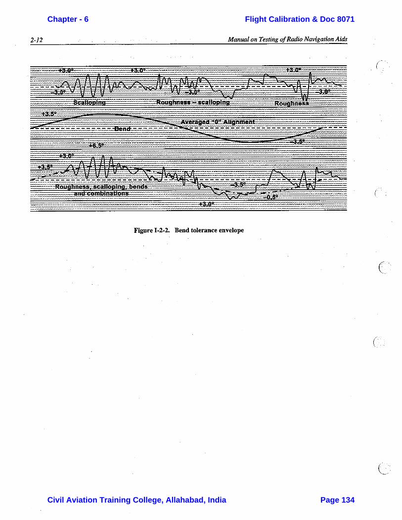
Chapter - 6 Flight Calibration & Doc 8071
Civil Aviation Training College, Allahabad, India Page 134

Chapter - 6 Flight Calibration & Doc 8071
Civil Aviation Training College, Allahabad, India Page 135
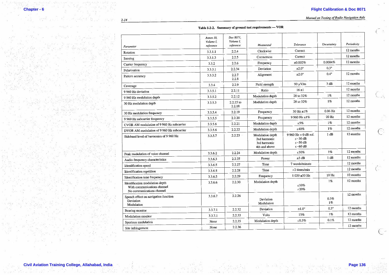
Chapter - 6 Flight Calibration & Doc 8071
Civil Aviation Training College, Allahabad, India Page 136
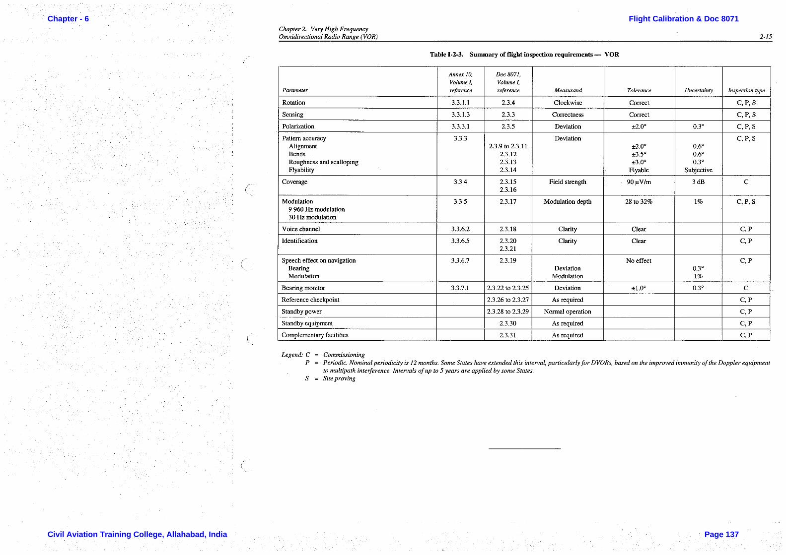
Chapter - 6 Flight Calibration & Doc 8071
Civil Aviation Training College, Allahabad, India Page 137


Civil Aviation Training College, Allahabad, India Page 138
Phasing in VOR Requirement & Principle of Phasing; Preference Of Null Over Maxima
The following has already been studied in Communication Principles “Space Modulation” chapter. However, the same is briefly discussed once again for better understanding of the requirement of phasing in VOR.
Where the carrier and sideband mixing takes place in a non-linear circuit within the transmitter itself, the AM process is referred to as "transmitter modulation". In this process, the carrier and total sideband components are combined in a fixed phase relationship and follow a common RF path from the transmitting antennas through space to the receiver. A second type of modulation process utilizes sidebands only, unmixed with carrier. These sidebands follow an RF path through the transmitter separate from that of the transmitter modulation and may either be radiated from separate antennas or from antennas common with the transmitter modulation. Since these sidebands are not modulated with the carrier to which they are related in the transmitter itself, they may be considered to mix with the carrier in space in a process referred to as "space modulation", Since at least a part of their RF path of travel is always different from that of the carrier and its transmitter modulated sidebands, their total RF path length must be carefully established by an adjustable line length device known as a "phaser". This adjustment produces an RF phase relationship between the space modulation sidebands and carrier yielding maximum amplitude modulation. Phasing is therefore a procedure necessary to insure optimum amplitude modulation of the carrier by the separately radiated sidebands in the space modulation process.
o Space Modulation Process:
In the space modulation process, the sidebands combine with the carrier outside the transmitter and the RF phase relationships between sidebands and carrier can vary widely. The total sideband component will combine with the carrier component in space either exactly in-phase, 180° out-of-phase, or at some phase angle φ. This phase angle may vary from 0 to 360 electrical degrees. The desired objective is that the total sideband components combine precisely in-phase or 180° out-of-phase with the carrier. Under these conditions, the resultant modulated wave is the same as would be produced as a result of transmitter modulation. For transmitter modulation, the total sideband component is always phase-locked to the carrier. However, it will be seen that it is possible when producing space modulation for the two or more components to combine at some phase angle other than 0°. Thus, the resultant RF modulated wave at the receiver may differ from that of a wave modulated at the transmitter.
The question might arise "What causes the total sideband component to be other than in-phase with the carrier component?" This can be explained as follows: The phase angle φ may occur simply by the relative phase of currents in the antennas, a function of transmission line length for example; or the carrier and total sideband components, if radiated from separate antennas, may travel unequal distances in reaching the receiver. This could be due to proximity effect or due to reflections. If the two components travel different distances from radiating antennas to receiver, one component must take longer to reach the receiver than the other since both radiations travel with the same propagation velocity. Assuming that the relative phase of the RF currents being fed to the transmitting antennas are the same, the relative phase of the radiation which travels the greater distance in reaching the receiver must be such that it will lag the other
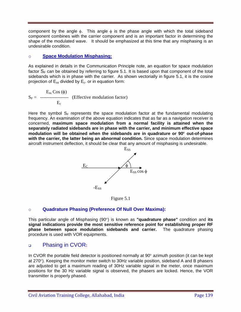
Civil Aviation Training College, Allahabad, India Page 139
component by the angle φ. This angle φ is the phase angle with which the total sideband component combines with the carrier component and is an important factor in determining the shape of the modulated wave. It should be emphasized at this time that any misphasing is an undesirable condition.
o Space Modulation Misphasing:
As explained in details in the Communication Principle note, an equation for space modulation factor SF can be obtained by referring to figure 5.1. It is based upon that component of the total sidebands which is in phase with the carrier. As shown vectorially in figure 5.1, it is the cosine projection of Ess divided by Ec. or in equation form:
Ess Cos (φ) SF = ------------------ (Effective modulation factor) Ec Here the symbol SF represents the space modulation factor at the fundamental modulating frequency. An examination of the above equation indicates that as far as a navigation receiver is concerned, maximum space modulation from a normal facility is attained when the separately radiated sidebands are in phase with the carrier, and minimum effective space modulation will be obtained when the sidebands are in quadrature or 90° out-of-phase with the carrier, the latter being an abnormal condition. Since space modulation determines aircraft instrument deflection, it should be clear that any amount of misphasing is undesirable. ESS EC φ ESS cos φ -ESS
Figure 5.1 o Quadrature Phasing (Preference Of Null Over Maxima):
This particular angle of Misphasing (90°) is known as "quadrature phase" condition and its signal indications provide the most sensitive reference point for establishing proper RF phase between space modulation sidebands and carrier. The quadrature phasing procedure is used with VOR equipments.
Phasing in CVOR:
In CVOR the portable field detector is positioned normally at 90° azimuth position (it can be kept at 270°). Keeping the monitor meter switch to 30Hz variable position, sideband A and B phasers are adjusted to get a maximum reading of 30Hz variable signal in the meter, once maximum positions for the 30 Hz variable signal is observed, the phasers are locked. Hence, the VOR transmitter is properly phased.
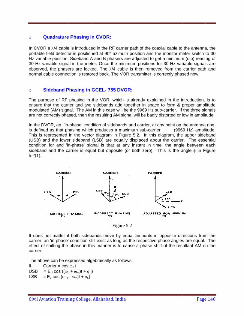
Civil Avi
o Q In CVORportable Hz variab30 Hz vaobservednormal c o S
The purpensure thmodulateare not c
In the DVis defineThis is re(USB) anconditionsideband5.2(1).
It does ncarrier; aeffect of carrier.
The abovIf, CUSB =LSB =
ation Train
Quadrature
R a λ/4 cablefield detectoble position.ariable signad, the phaseable connec
Sideband P
pose of RF hat the carred (AM) signcorrectly pha
VOR, an 'in-d as that phepresented nd the lowen for and 'ind and the ca
not matter ifan 'in-phase'
shifting the
ve can be exCarrier = cos = EU cos ((ωc
EL cos ((ωc
ing College,
e Phasing I
e is introduceor is position Sideband A
al in the meters are lockction is resto
Phasing in
phasing in rier and twonal. The AMased, then th
-phase' condhasing whichin the vecto
er sideband n-phase' sigarrier is equ
f both sideb condition stphase in th
xpressed algωc t
c + ωm)t + φU
- ωm)t + φL)
, Allahabad,
n CVOR:
ed in the RFned at 90° aA and B phater. Once th
ked. The λ/4ored back. Th
GCEL- 755
the VOR, w sidebands
M in this casehe resulting A
dition of sideh produces or diagram i(LSB) are e
gnal is that ual but oppo
F
bands movetill exist as l
his manner is
gebraically a
)
India
F carrier pathazimuth posasers are adjhe minimum 4 cable is thhe VOR tran
5 DVOR:
which is alreadd togethe
e will be the AM signal w
ebands and a maximum
in Figure 5.2equally disp
at any insosite (or bot
Figure 5.2
by equal aong as the rs to cause a
as follows:
h of the coaxition and thejusted to gepositions fo
hen removensmitter is co
eady explainer in space 9969 Hz subill be badly d
carrier, at am sub-carrier
2. In this dplaced aboustant in timeth zero). T
amounts in orespective pa phase shif
xial cable to e monitor m
et a minimumor 30 Hz vared from the orrectly phas
ned in the into form & p
b-carrier. If distorted or l
ny point on tr (996diagram, thet the carriere, the angle
This is the a
opposite dirphase anglesft of the res
Page
the antennaeter switch
m (dip) readiriable signalcarrier path
sed now.
ntroduction, proper amplthe three sig
low in amplit
the antenna9 Hz) ampli
e upper sider. The essee between
angle φ in F
rections froms are equal. ultant AM o
e 140
a, the to 30 ng of s are
h and
is to litude gnals tude.
a ring, itude.
eband ential each
Figure
m the The n the
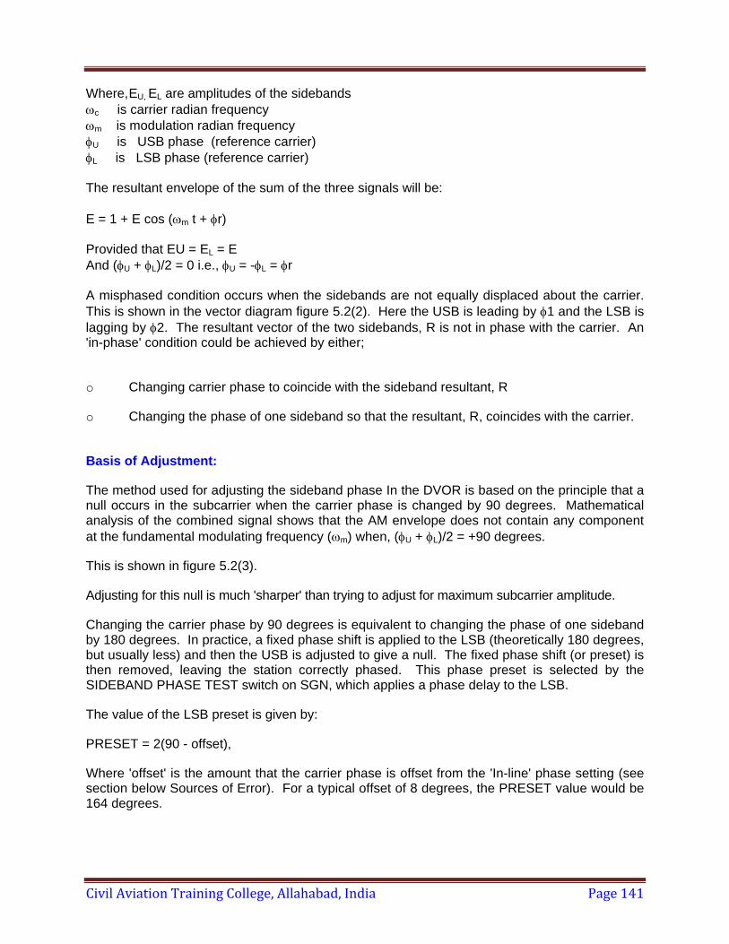
Civil Aviation Training College, Allahabad, India Page 141
Where, EU, EL are amplitudes of the sidebands ωc is carrier radian frequency ωm is modulation radian frequency φU is USB phase (reference carrier) φL is LSB phase (reference carrier) The resultant envelope of the sum of the three signals will be: E = 1 + E cos (ωm t + φr) Provided that EU = EL = E And (φU + φL)/2 = 0 i.e., φU = -φL = φr A misphased condition occurs when the sidebands are not equally displaced about the carrier. This is shown in the vector diagram figure 5.2(2). Here the USB is leading by φ1 and the LSB is lagging by φ2. The resultant vector of the two sidebands, R is not in phase with the carrier. An 'in-phase' condition could be achieved by either;
o Changing carrier phase to coincide with the sideband resultant, R
o Changing the phase of one sideband so that the resultant, R, coincides with the carrier.
Basis of Adjustment:
The method used for adjusting the sideband phase In the DVOR is based on the principle that a null occurs in the subcarrier when the carrier phase is changed by 90 degrees. Mathematical analysis of the combined signal shows that the AM envelope does not contain any component at the fundamental modulating frequency (ωm) when, (φU + φL)/2 = +90 degrees.
This is shown in figure 5.2(3).
Adjusting for this null is much 'sharper' than trying to adjust for maximum subcarrier amplitude.
Changing the carrier phase by 90 degrees is equivalent to changing the phase of one sideband by 180 degrees. In practice, a fixed phase shift is applied to the LSB (theoretically 180 degrees, but usually less) and then the USB is adjusted to give a null. The fixed phase shift (or preset) is then removed, leaving the station correctly phased. This phase preset is selected by the SIDEBAND PHASE TEST switch on SGN, which applies a phase delay to the LSB.
The value of the LSB preset is given by:
PRESET = 2(90 - offset),
Where 'offset' is the amount that the carrier phase is offset from the 'In-line' phase setting (see section below Sources of Error). For a typical offset of 8 degrees, the PRESET value would be 164 degrees.
Civil Aviation Training College, Allahabad, India Page 142
Sources Of Error
The ideal conditions described above only apply at one point on the antenna ring. As the sidebands are switched around the ring variations in phase occur. This leads to two sources of phase error, Antenna Array Effect and Proximity Effect.
Antenna Array
o Antenna Array Effect:
The effect of the antenna array (i.e., antenna coupling) causes the signal radiated from the 'tangential' antennas to lag the signal radiated from the 'in-line' antennas (with respect to a receiver, see figure 5.3 a). This means that if the carrier and sidebands are in-phase when sidebands are radiated from the 'in-line' antennas, then the carrier will be leading the sidebands when radiation takes place from the 'tangential' antennas. This error has been measured to be typically 16 degrees for a normal DVOR station.
This effect is minimized by adjusting the phase to be midway between these two points, so that the error is reduced to ±8 degrees. The 8 degrees offset (from the 'in-line' phasing point) is established by using a fixed phase shift of 82 degrees instead of 90 degrees, as described in section Basis of Adjustment (b) above (i.e., shift the LSB by 164 degrees).
o Proximity Effect:
The proximity effect only occurs when the receiver is near-field. It is due to the distance from the receiver to the carrier antenna being less than the distance from the receiver to the 'tangential' ring antennas. This is the distance 'D' shown in figure 5.3 a. For a far field receiver (greater than 1500 meters) this error is negligible.
This effect causes the sidebands to lag the carrier when radiated from the tangential antennas. It is about 40 degrees for a monitor antenna 80 meters from the carrier antenna. Ideally, the sideband phase of the beacon should be adjusted using a far field receiver. Since, the proximity effect only misphases the 'tangential' antennas, satisfactory results can be obtained by using the normal monitor antenna (at 80 meters) and observing the signal from the 'in-line' antennas for the phasing adjustment.

Civil Avi
o E
The subcmodulatiosidebandMisphasiincrease (greater t80 meter
• S
a. P
Ccarrier ph
Note: Th
If power sh
Cmonitor s
ation Train
Effect of Ne
carrier signaon on it thads when rading causes ain AM on t
than 1500 mrs.
Sideband P
Preliminary
Check that thhase offset o
his setting m
f the subcarhould be initi
Check that tsignal level s
ing College,
ear Field Mo
al received an that recediated froma decrease the subcarrimeters) it wil
hase Adjus
y
he φ PRESEof 82 degree
may need to b
rrier modulaially set for 4
the monitor should be wi
, Allahabad,
Fig
onitor
at the neareived in the the 'tangein subcarrieer. When tl be less tha
stment
ET switcheses (i.e., LSB
be changed
ation depth h4 watts peak
antenna caithin the limi
India
gure 5.3 (a)
r field monitfar field. Th
ntial' antennr amplitude the subcarrian 55% whe
s, switch banφ PRESET
later - see S
has not alrek output from
able has bets.
tor antenna his is becaunas, due to(at the 'tanger AM is le
en observed
nk S1 insideis 164 degre
Section ‘Vari
eady been am the SMA m
een connect
has more 6use of the po the Proximgential' pointss than 40%from the mo
e SGN, are ees).
iations to Ph
adjusted, thmodules.
ted to the M
Page
60 Hz amplphase lag omity Effect. ts) and henc% In the faronitor anten
initially set
hase Preset’
en the side
MRF input.
e 143
litude of the
This ce an r field na at
for a
.
eband
The
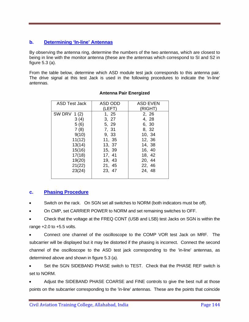
Civil Aviation Training College, Allahabad, India Page 144
b. Determining ‘In-line’ Antennas
By observing the antenna ring, determine the numbers of the two antennas, which are closest to being in line with the monitor antenna (these are the antennas which correspond to SI and S2 in figure 5.3 (a).
From the table below, determine which ASD module test jack corresponds to this antenna pair. The drive signal at this test Jack is used in the following procedures to indicate the 'in-line' antennas.
Antenna Pair Energized
ASD Test Jack ASD ODD(LEFT)
ASD EVEN(RIGHT)
SW DRV 1 (2) 3 (4) 5 (6) 7 (8) 9(10) 11(12) 13(14) 15(16) 17(18) 19(20) 21(22) 23(24)
1, 253, 27 5, 29 7, 31 9, 33
11, 35 13, 37 15, 39 17, 41 19, 43 21, 45 23, 47
2, 264, 28 6, 30 8, 32
10, 34 12, 36 14, 38 16, 40 18, 42 20, 44 22, 46 24, 48
c. Phasing Procedure • Switch on the rack. On SGN set all switches to NORM (both indicators must be off).
• On CMP, set CARRIER POWER to NORM and set remaining switches to OFF.
• Check that the voltage at the FREQ CONT (USB and LSB) test Jacks on SGN is within the
range +2.0 to +5.5 volts.
• Connect one channel of the oscilloscope to the COMP VOR test Jack on MRF. The
subcarrier will be displayed but it may be distorted if the phasing is incorrect. Connect the second
channel of the oscilloscope to the ASD test jack corresponding to the 'in-line' antennas, as
determined above and shown in figure 5.3 (a).
• Set the SGN SIDEBAND PHASE switch to TEST. Check that the PHASE REF switch is
set to NORM.
• Adjust the SIDEBAND PHASE COARSE and FINE controls to give the best null at those
points on the subcarrier corresponding to the 'in-line' antennas. These are the points that coincide
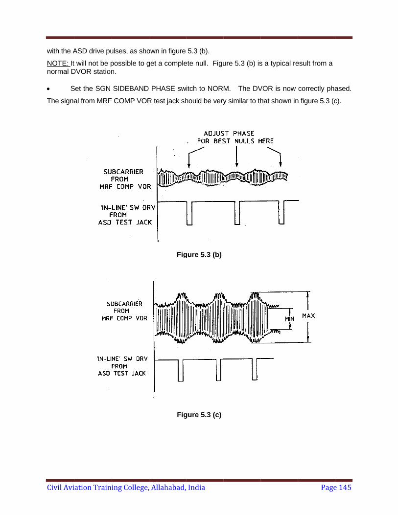
Civil Avi
with the A
NOTE: It normal D • S
The signa
ation Train
ASD drive pu
will not be pDVOR station
Set the SGN
al from MRF
ing College,
ulses, as sho
possible to gn.
SIDEBAND
COMP VOR
, Allahabad,
own in figure
get a comple
PHASE sw
R test jack sh
Fig
Fig
India
5.3 (b).
ete null. Figu
itch to NOR
hould be very
gure 5.3 (b)
gure 5.3 (c)
ure 5.3 (b) is
M. The DV
y similar to th
s a typical re
VOR is now
hat shown in
Page
esult from a
correctly pha
n figure 5.3 (c
e 145
ased.
c).
Civil Aviation Training College, Allahabad, India Page 146
d. Variations to Phase Preset
• The criteria used for assessing the beacon RF phase are the AM on the subcarrier and the station error curve.
• If the amplitude modulation on the subcarrier is excessive, then the RF phase may be adjusted using an offset greater than 8 degrees (see section Antenna Array Effect). As the phase offset is increased, the AM on the subcarrier will be reduced, but the station bearing error (the so-called 'error curve') will increase. If a satisfactory compromise between these two parameters cannot be achieved, then it indicates an error in some other part of the installation, perhaps feed cables or sideband matching. The phase offset may be increased to a maximum of 15 degrees.
• To change the beacon phase, first change the phase preset in SGN then proceed as in section Phasing Procedure.
The phase-preset value is found from PRESET = 2 (90- offset) This value is selected on the PRESET switch in SGN.
GOVERNMENT OF INDIA OFFICE OF THE DIRECTOR GENERAL OF CIVIL AVIATION
TECHNICAL CENTRE, OPPOSITE SAFDARJUNG AIRPORT, NEW DELHI – 11 0 003 CIVIL AVIATION REQUIREMENTS SECTION 1 – GENERAL SERIES 'A' PART I ISSUE 2, 8th January 2010 EFFECTIVE: FORTHWITH
F.No.9/38/2009-IR
Subject: Issuance of the Civil Aviation Requirements and revisions
thereof etc. – Requirements to be complied with. 1. INTRODUCTION 1.1 Section 4 of the Aircraft Act, 1934 enabl es the Central Government to make
rules to implement the Convention relati ng to International Civil Aviation signed at Chicago on the 7 th day of December, 1944 in cluding any Annex thereto relating to International standards and recommended practices as amended from time to time. Section 5A of the said Act empowers the Director General to issue directions for securing the safety of aircraft operations. Rule 29C of the Aircraft Rules 1937 enables DGCA to la y down standards and procedures not inconsistent with the Aircraft Act, 1934 and the rules made thereunder to carry out the Convention and any Annex ther eto referred to above. Finally in accordance with rule 133A of the Airc raft Rules, 1937, the Director General may issue, interalia, Civil Aviation R equirements not inconsistent with the Aircraft Act, 1934 and the rules made thereunder.
1.2 While the broad principles of law are contained in the Aircraft Rules, 1937, Civil Aviation Requirements are issued to specify the detailed requirements and compliance procedures so as to –
a) fulfil the duties and obligations of India as a Contracting State under the
convention relating to International Civil Aviation signed at Chicago on the 7 th day of December, 1944.
b) standardize and harmonize the require ments taking into account the rules
and regulations of other regulatory authorities. c) implement the recommendati ons of the Courts of Inqui ry or any other
committee constituted by the Central Government/ Director General.
1
Civil Aviation Training College, Allahabad, India Page 147
CIVIL AVIATION REQUIREMENTS SECTION 1 – GENERAL SERIES 'A' PART I 8TH JANUARY 2010
d) To address any other issues related to safety of aircraft operations as may be
considered necessary by the Director General. 1.3 This CAR describes the procedure fo r issue and revision of Civil Aviation
Requirements and their dissemination to various organizations and is issued under rule 133A.
1.4 This CAR cancels AIC 4 of 2001. 2. PROMULGATION OF CIVIL AVIATION REQUIREMENTS 2.1 The Civil Aviation Requirements (CARs) are promulgated under the following
sections:-
Section 1 – General Section 2 – Airworthiness Section 3 – Air Transport Section 4 – Aerodrome Standards and Licensing Section 5 – Air Safety Section 6 – Design standards and Type Certification Section 7 – Flight Crew Standards, Training and Licensing Section 8 – Aircraft Operations Section 9 – Air Space and Air Traffic Management Section 10 – Aviation Environment Protection Section 11 – Safe Transport of Dangerous Goods by Air
3. PROCEDURE FOR PROMULGATION OF CAR 3.1 Civil Aviation Requirements under various sections are issued bearing
different “series” identified by alphabetic al letters, namely Series A, B, C etc. and under the same Series, various ”Parts ” are issued, such as Part I, II, III, etc. Details of the “Series” are given in the Annexure.
3.2 Every existing and new CAR shall hav e an office file maintained by the
concerned directorate and the file number shall be indi cated at the top right hand corner of the CAR. Any amendment in future shall be processed on the same file.
3.3 The first page of the CAR shall indica te the Section, Series, Part and date of
issue along with the date of applicability. Subsequent pages shall indicate the date of issue only.
3.4 Whenever a change/revision is affected to a CAR, it shall be termed as
revision and the revision number along with date of revision and effective date of revised CAR shall be indicated on the first page of the CAR and also on the concerned pages. Consequently, the revi sion number and date of revision shall be reflected only on such pages, wh ich are affected by the revision. Pages, which have not been affected by any revision, shall contain initial date of issue/revision only.
2
Civil Aviation Training College, Allahabad, India Page 148
CIVIL AVIATION REQUIREMENTS SECTION 1 – GENERAL SERIES 'A' PART I 8TH JANUARY 2010
3.5 Every revision shall be accompani ed by a “Revision Notice”, which shall
indicate the pages affected and the justific ation for the revision. The Revision Notice shall be filed along with the revision CAR in the folder.
3.6 Whenever there is a major change/ revision, the Revision Notice shall indicate
that the CAR has undergone a major revisi on and is issued in the form of new edition. All revisions to the CAR sha ll be indicated by a sideline on the left side of the affected pages indicating the change/ revision to the CAR.
4. Whenever a new CAR or revision to t he existing CAR is proposed to be issued,
the draft of the proposed CAR/revision shall be posted on DGCA website or circulated to all the persons likely to be affected thereby for their objections/ suggestions. The objections/ suggestions received within the stipulated period of 30 days or less as may be determined by Director General shall be analysed and if found acceptable shall be incor porated in the pr oposed CAR before promulgation. DGCA may also arrange m eetings with the Civ il Aviation industry for discussions on the draft CAR before finalisation/promulgation.
5 Every direction issued by DGCA in the form of CARs shall be complied with by
the person or organization to whom such direction is issued. Non- compliance with the provisions of the CAR shall attrac t penalty as provided in Schedule VI of the Aircraft Rules, 1937.
6 It shall be the responsibility of eac h operator, owner, organization and service
provider to ensure wide pub licity of the CARs amongst its personnel and also ensure that the implement ation procedures for t he requirements are duly reflected in the related Manuals requi red as per the app licable Rules and Civil Aviation Requirements. The regional o ffices of DGCA shall monitor the compliance by all affected organisations and submit a report to the Headquarters with in three months of the date of applicability.
7 For the convenience of the users, a ll the CARs including their revisions are
available on the DGCA website (http://dgca.gov.in/).
( Dr. Nasim Zaidi )
Director General of Civil Aviation
3
Civil Aviation Training College, Allahabad, India Page 149
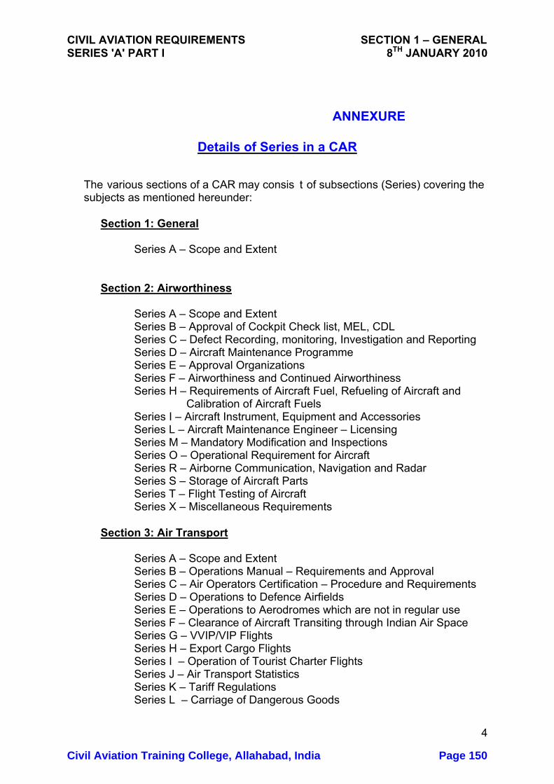
CIVIL AVIATION REQUIREMENTS SECTION 1 – GENERAL SERIES 'A' PART I 8TH JANUARY 2010
ANNEXURE
Details of Series in a CAR
The various sections of a CAR may consis t of subsections (Series) covering the subjects as mentioned hereunder:
Section 1: General
Series A – Scope and Extent Section 2: Airworthiness
Series A – Scope and Extent Series B – Approval of Cockpit Check list, MEL, CDL Series C – Defect Recording, monitoring, Investigation and Reporting Series D – Aircraft Maintenance Programme Series E – Approval Organizations Series F – Airworthiness and Continued Airworthiness
Series H – Requirements of Aircraft Fuel, Refueling of Aircraft and Calibration of Aircraft Fuels Series I – Aircraft Instrument, Equipment and Accessories Series L – Aircraft Maintenance Engineer – Licensing Series M – Mandatory Modification and Inspections Series O – Operational Requirement for Aircraft Series R – Airborne Communication, Navigation and Radar Series S – Storage of Aircraft Parts Series T – Flight Testing of Aircraft Series X – Miscellaneous Requirements
Section 3: Air Transport
Series A – Scope and Extent Series B – Operations Manual – Requirements and Approval Series C – Air Operators Certification – Procedure and Requirements Series D – Operations to Defence Airfields Series E – Operations to Aerodromes which are not in regular use Series F – Clearance of Aircraft Transiting through Indian Air Space Series G – VVIP/VIP Flights Series H – Export Cargo Flights Series I – Operation of Tourist Charter Flights Series J – Air Transport Statistics Series K – Tariff Regulations Series L – Carriage of Dangerous Goods
4
Civil Aviation Training College, Allahabad, India Page 150

CIVIL AVIATION REQUIREMENTS SECTION 1 – GENERAL SERIES 'A' PART I 8TH JANUARY 2010
Series M – Passenger Facilitation Series X – Miscellaneous Section 4: Aerodrome Standards and Licensing Series A – Scope and Extent Series B – Aerodrome Facilities Series F – Aerodrome Licensing Series X – Miscellaneous Section 5: Air Safety Series A – Scope and Extent Series B – Procedure of Reporting Accident/Incident Series C – Proceure for Accident/Incident Investigation Series D – Bird Strike incidents Series E – Airmiss & ATC incidents Series F – Prevention of Accidents/incidents Series G – Safety Audit and inspection Series X – Miscellaneous Section 6: Design Standards and Type Certification Series A – Scope and Extent Series B – Airworthiness Standards – Design Series C – Airworthiness Standards – Transport Category Aircraft
Series D – Airworthiness Standards – Normal, Utility and Aerobatic Category Aircraft
Series E – Airworthiness Standards – Rotorcraft Series F – Procedure for Type Approval of Products Parts and Materials Series G –Test Procedure Series X – Miscellaneous Section 7: Flight Crew Standards, Training and Licensing Series A – Scope and Extent Series B – Syllabus and Schedule for Examination of Subjects for issue of Licences and Ratings Series C – Medical Standards and Examination Series D – Training Organizations Series E – Flying Training Series F – Skill/Proficiency Checks Series G – Issue of Licence and Rating Series H – Renewal of Licence and Rating
Series I – Appointment/Approval of Assistant Flight instructor, Flight Instructor, Flight Instructor Incharge, Chief Flight Instructor, Check Pilot, Instructor, Examiner, Flight Inspector And Chief Flight Inspector
5
Civil Aviation Training College, Allahabad, India Page 151
CIVIL AVIATION REQUIREMENTS SECTION 1 – GENERAL SERIES 'A' PART I 8TH JANUARY 2010
Series J – Flight and Duty Time Limitations Series K – Flight Inspection Series X – Miscellaneous Section 8: Aircraft Operations Series A – Scope and Extent Series B – IAL Procedures and Approval
Series C – Aerodrome Operating Minima Series X – Miscellaneous
Section 9: Air Space and Air Traffic Management (ATM) Series A – Scope and Extent Series B – Approval of Facilities and Services Series C – Rules of the Air
Series D – Navigation, Landing and Communication Aids Series E – Air Traffic Services Series G – Aeronautical Charts
Series I – Aeronautical Information Services Series L – ATCO Licensing
Series M – Meteorology Series R – Air Routes Series S – Search and Rescue Series X – Miscellaneous
Section 10: Aviation Environment Protection Series A – Scope and Extent Series B – Emissions Series C – Noise Series X – Miscellaneous Section 11: Safe Transport of Dangerous Goods(DG) by Air Series A – Scope and Extent Series B – Carriage of Dangerous Goods Series C – Approval of Dangerous Goods Training Programme Series D – Surveillance of Dangerous Goods Programme Series X – Miscellaneous
* * *
6
Civil Aviation Training College, Allahabad, India Page 152
GOVERNMENT OF INDIA
OFFICE OF DIRECTOR GENERAL OF CIVIL AVIATION TECHNICAL CENTRE, OPP SAFDARJANG AIRPORT, NEW DELHI
CIVIL AVIATION REQUIREMENTS SECTION 9 – AIR SPACE AND AIR TRAFFIC MANAGEMENT SERIES 'D', PART I ISSUE II, 8th January 2010 EFFECTIVE: FORTHWITH
F. No. 9/38/2009-IR Subject: Requirements of Maintenanc e/ inspection of Communication,
Navigation, Landing and other equipment installed at Airports and en-route.
1. APPLICABILITY:
This part of the Civil Aviation Requirements lays down the requirements of maintenance, inspection or Comm unications, Navigation, Landing and other equipment install ed at airports and enroute and used for aircraft operations. These equipment may be owned and operated by Airports Authority of India, Meteorological Department or any other agency.
This CAR is issued under Section 5A of the Aircraft Act 1934 and Rule 133A of the Aircraft Rules 1937 for compliance by all concerned agencies.
This CAR is issued in supersession of CAR Section 4 Series X Part I, Issue I dated 4th February 1994.
2. SCOPE:
The requirements stipulated in this Civil Aviation Requirement will apply to all Communication, Navigation and landing facilities including the following:
1. Visual Landing Aids-VASI/PAPI etc., 2. Approach lighting 3. Non-Directional Beacon
1Civil Aviation Training College, Allahabad, India Page 153

CIVIL AVIATION REQUIREMENT SECTION 9 SERIES 'D' PART I 8TH JANUARY 2010
4. VHF Direction Finding System 5. Locator Beacon 6. Instrument landing System 7. Microwave landing System 8. VOR/ T-VOR Doppler VOR 9. Distance Measuring System 10. Communication Facilities like VH F and HF Radio Telephone, AFTN,
Satellite based Voice and Data Communication System, Direct Speech Circuits, VHF Data Links etc.
11. Airport Surveillance Radar 12. Air Route Surveillance Radar 13. SSR and MSSR 14. Airport Surface Detection Equipment 15. Computer based ATC - ADS etc 16. Airport Recorder and Replay System 17. Differential GPS system and connected equipment 18. RVR Measuring equipment 19. Meteorological equipment
3. MAINTENANCE: 3.1 Maintenance Schedule
The operator shall prepare maintenance schedules for periodic preventive maintenance, including testing, func tional checks and serviceability of the equipment. These maintenance sc hedules shall be prepared in accordance with the guidelines provi ded by the manufacturers of the equipment. The schedules should also indicate the level of officer who can carry out the check/ inspection and the periodicity of the schedules A copy each of these schedules should be s ubmitted to the DGCA. DGCA may introduce additional checks if required.
3.2 Test Equipment
The operator shall ensure t hat all tools/ test equipment are available for carrying out the maintenance/checks of the facility and also adequate spares to ensure continued serviceability of the facility.
3.3 Calibration of Test Equipment
The operator shall ensure that all the test equipment used for maintenance and periodical checks of the facilities are kept properly calibrated and certified by recognized standards institutions
3.4 Maintenance Records
2Civil Aviation Training College, Allahabad, India Page 154
CIVIL AVIATION REQUIREMENT SECTION 9 SERIES 'D' PART I 8TH JANUARY 2010
All records of daily and periodical ma intenance schedules (preventive as well as corrective) shall be preserv ed for a period of not less than two years. However, DGCA may direct preservation of such schedules for longer periods, if required.
3.5 Defect and Rectification Register:
The operator shall maintain a Register giving details of all the defects and rectification actions taken, duly si gned by the officer in charge of the facility.
3.6 Maintenance Personnel:
All personnel entrusted with the main tenance/checks of a facility should have undergone necessary training. T hey should undergo periodical on the-job checks at least once in a year and refresher course at least once in three years.
3.7 Responsibility of Officer in Charge.
The officer in charge of the facilit y shall be responsible for continued, maintenance and safe operation of facility.
4. STATUS OF EQUIPMENT AFTER AN ACCIDENT/INCIDENT:
In case an aircraft is involved In an a ccident while making use of a facility, the concerned unit of the facility s hall be withdrawn and flight inspected immediately. The unit shall not be declared operational till checked and tested thoroughly and its performance IS found satisfactory. The standby unit of the facility shall be utilized duri ng this period In case of an incident, DGCA may require the concerned unit of the facility to be withdrawn for checking.
4.1 In respect of a facility that is or might have been involved in an air
accident/ incident, operational status data shall be recorded for both main and standby equipment of the facility.
4.2 In order to ensure that operational data of a facility is not misinterpreted
the operator shall ensur e that the data entries are complete, clear, concise, accurate and correctly timed.
5. SELF INSPECTION:
The operator shall draw a programme for periodically inspecting and checking the functioning of the facility. The operator sha ll ensure that the functional and calibration checks of the facility required as per the ICAO
3Civil Aviation Training College, Allahabad, India Page 155
CIVIL AVIATION REQUIREMENT SECTION 9 SERIES 'D' PART I 8TH JANUARY 2010
norms are carried out and proper records of the same are maintained The operator, should ensure that the facility IS used for operations only when It is fit for operation
6. INSPECTION BY DGCA:
Any officer designated/nominated by the Director General of Civil Aviation shall be empowered to inspect at any time any facility to check. The serviceability and maintenance records and procedures
7. CERTIFICATION:
Any new equipment or system procured and installed, by the operator for providing facility as listed above, sha ll be declared operational only after it is found lit for operation on satisfac tory completion of the necessary inspection/checks and calibration fr om air and ground as required and after obtaining concurrence of the DGCA for the same.
8. LOGISTIC SUPPORT:
In order to ensure that the maintenanc e of a facility is not delayed for lack of spares. The stock of spare units , modules, PCBs and components etc. shall be maintained at the site of fa cility or at a plac e from where the required spares can be transported to the site without any avoidable delay. The storage facility shall be subject to inspection at any time by an officer designated by DGCA for this purpose,
9. MONITORING OF SERVICEABILITY STATUS:
The performance of the equipment s hould be monitored regularly. The operator shall prepare a quarterly r eport on Mean Time Between Failures (MTBF) of a facility and the same s hall be made available to DGCA. If an equipment becomes unserviceable fo r more than one week, the same should be reported to DGCA along wit h the details of the defect and proposed rectification action.
(Dr. Nasim Zaidi)
Director General of Civil Aviation
4Civil Aviation Training College, Allahabad, India Page 156
1
GOVERNMENT OF INDIA OFFICE OF DIRECTOR GENERAL OF CIVIL AVIATION TECHNICAL CENTRE, OPP SAFDARJANG AIRPORT, NEW DELHI
CIVIL AVIATION REQUIREMENTS SECTION 9 – AIR SPACE AND AIR
TRAFFIC MANAGEMENT SERIES 'D', PART II ISSUE II, 8TH JANUARY 2010 EFFECTIVE: FORTHWITH Subject : Aeronautical Telecommunications – Radio Navigation Aids
INTRODUCTION
In pursuant to Article 28 of the Convention on International Civil Aviation each contracting State undertakes to provide in its territory, air navigation facilities to facilitate air navigation and also adopt and put into operation the appropriate standard systems for communication procedures, codes, markings, signals etc., in accordance with standards which may be recommended or established from time to time, pursuant to the Convention. International Civil Aviation Organization adopts and amends from time to time, as may be necessary, international standards and recommended practices and procedures for Aeronautical Telecommunications Radio Navigation Aids in Annex 10 Volume I. This CAR is issued under the provisions of Rule 29C and Rule 133A of the Aircraft Rules, 1937 for the requirements to be followed in respect of Aeronautical Telecommunications Radio Navigation Aids. This CAR is issued in supersession of CAR Section 4 Series ‘D’ Part II dated 12th July 2006.
1. DEFINITIONS
When the following terms are used in this CAR, they have the following meanings:
Altitude: The vertical distance of a level, a point or an object considered as a point, measured from mean sea level (MSL). Effective acceptance bandwidth: The range of frequencies with respect to the assigned frequency for which reception is assured when all receiver tolerances have been taken into account.
Civil Aviation Training College, Allahabad, India Page 157
CIVIL AVIATION REQUIREMENTS SECTION 9 SERIES ‘D’ PART II 8TH JANUARY 2010
3
.
2. General Provisions For Radio Navigation Aids 2.1 Standard radio navigation aids
2.1.1 The standard radio navigation aids to precision approach and landing shall
be: a) the instrument landing system (ILS) b) the VHF Omni-directional radio range (VOR) c) the non-directional beacon (NDB) d) the distance measuring equipment (DME) e) the en-route VHF marker beacon Note1: Since radio navigation is essential for the final stages of approach
and landing, the installation of non-visual aids does not obviate the need for visual aids to approach and landing in conditions of low visibility.
2.1.2 Differences in radio navigation aids in any respect of provisions in para 3 of this CAR shall be published in an Aeronautical Information Publication (AIP).
2.1.3 Wherever there is installed a radio navigation aid that is not an ILS but which
may be used in whole or in part with aircraft equipment designed for use with the ILS, full details of parts that may be so used shall be published in an Aeronautical Information Publication (AIP). Note: This provision is to establish requirement for promulgation of
relevant information rather than to authorize such installation
2.1.4 Intentionally left blank
2.1.4.1 Intentionally left blank
2.1.4.2 Intentionally left blank
2.1.5 Intentionally left blank.
2.1.5.1 Intentionally left blank.
Civil Aviation Training College, Allahabad, India Page 158

CIVIL AVIATION REQUIREMENTS SECTION 9 SERIES ‘D’ PART II 8TH JANUARY 2010
4
.
2.2 Ground and flight-testing: 2.2.1 Radio navigation aids of the types covered by the specifications in Chapter 3 and available for use by aircraft engaged in international air navigation are subject of periodic ground and flight tests.
Note: NDB shall not be subjected to periodic flight tests. 2.3 Provision of information on the operational status of radio navigation
aids 2.3.1 Aerodrome control towers and units providing approach control service shall
be provided without delay with information on the operational status of radio navigation aids essential for approach, landing and take-off at the aerodrome(s) with which they are concerned.
2.4 Power supply for radio navigation aids and communication systems
2.4.1 Radio navigation aids and ground elements of communication systems shall
be provided with suitable power supplies and means to ensure continuity of service consist with the use of the service(s) involved.
2.5 Human Factors considerations
2.5.1 Human Factors principles should be observed in the design and certification
of radio navigation aids. Note. Guidance material on Human Factors principles can be found in the Human Factors Training Manual (Doc 9683) and Circular 249 (Human Factors Digest No. 11 Human Factors in CNS/ATM Systems).
Civil Aviation Training College, Allahabad, India Page 159
3.3 Specification for VHF Omni Directional Radio Range (VOR) 3.3.1 General
39
3.3.1.1 The VOR shall be constructed and adjusted so that similar instrumental indications in aircraft represent equal clockwise angular deviations (bearing), degree for degree from magnetic North as measured from the location of the VOR.
3.3.1.2 The VOR shall radiate a radio frequency carrier with which are associated
two separate 30 Hz modulations,. One of these modulations shall be such that its phase is independent of the azimuth of the point of observation (reference phase). The other modulation (Variable phase) shall be such that its phase at the point of observation differs from that of the reference phase by an angle equal to the bearing of the point of observation with respect to the VOR.
3.3.1.3 The reference and variable phase modulations shall be in phase along the
reference magnetic meridian through the station. Note: The reference and variable phase modulations are in phase when the
maximum value of the sum of the radio frequency carrier and the sideband energy due to the variable phase modulation occurs at the same time as the highest instantaneous frequency of the reference phase modulation
3.3.2 Radio Frequency 3.3.2.1 The VOR shall operate in the band 111.975 MHZ to 117.975 MHZ. The
channel separation shall be in increments of 50 KHZ. The frequency tolerance of the radio frequency carrier where 50 KHz channel spacing is in use shall be plus or minus 0.002 per cent. The highest assignable frequency shall be 117.950 MHz The channel separation shall be in increments of 50 KHz referred to the highest assignable frequency. In areas where 100 KHz or 200 KHz channel spacing is in general use, the frequency tolerance of the radio frequency is in general use, the frequency tolerance of the radio frequency carrier shall be plus or minus 0.005 percent.
3.3.2.2 The frequency tolerance of the radio frequency carrier of all installations in
India where 50 KHz channel spacing is in use shall be plus or minus 0.002 percent.
3.3.2.3 In areas where new VOR installations are implemented and are assigned
frequencies spaced at 50 KHz from existing VORs in the same area, priority shall be given to ensuring that the frequency tolerance of the radio frequency carrier of the existing VORs is reduced to plus or minus 0.002 percent.
3.3.3 Polarization and pattern accuracy: 3.3.3.1 The emission from the VOR shall be horizontally polarized. The vertically
polarized component of the radiation shall be as small as possible.
Civil Aviation Training College, Allahabad, India Page 160
CIVIL AVIATION REQUIREMENTS SECTION 9 SERIES ‘D’ PART II 8TH JANUARY 2010
40
3.3.3.2 The ground station contribution to the error in the bearing information conveyed by the horizontally polarized radiation from the VOR for all elevations angles between 0 to 40 degrees, measured from the center of the VOR antenna system, shall be within plus or minus 2 degrees.
3.3.4 Coverage
3.3.4.1 The VOR shall provide signals such as to permit satisfactory operation of a
typical aircraft installation at the levels and distances required for operational reasons, and up to an elevation angle of 40 degrees.
3.3.4.2 The field strength or power density in space of VOR signals required to
permit satisfactorily operation of a typical aircraft installation at the minimum service level at the maximum specified service radius should be 90 micro volt per meter or minus 107 db W/m square.
3.3.5 Modulation of navigational signals:
3.3.5.1 The radio frequency carrier as observed at any point in space shall be
amplitude modulated by two signals as described below:
a) a sub carrier of 9960 Hz of constant amplitude, frequency
modulated at 30 Hz r)
1) For the conventional VOR, the 30 Hz component of this FM sub carrier is fixed without respect to azimuth and is termed the “reference phase” and shall have a deviation ratio of 16 plus or minus 1 (i.e. 15 to 17);
2) For the Doppler VOR, the phase of the 30 Hz component varies with azimuth and is termed the “variable phase” and shall have a deviation ratio of 16 plus or minus 1 (i.e. 15 to 17) when observed at any angle of elevation up to 15 degrees, with a minimum deviation ratio of 11 when observed at any angle of elevation above 15 degrees and up to 40 degrees.
b) A 30 Hz amplitude modulation component:
1) For the conventional VOR, this component results from a
rotating field pattern, the phase of which varies with azimuth, and is termed the “variable phase”.
2) For the Doppler VOR, this component, of constant phase
with relation to azimuth and constant amplitude, is radiated omni directionally and is termed the “reference phase”.
Civil Aviation Training College, Allahabad, India Page 161
CIVIL AVIATION REQUIREMENTS SECTION 9 SERIES ‘D’ PART II 8TH JANUARY 2010
41
3.3.5.2 The nominal depth of modulation of the radio frequency carrier due to
the 30 Hz signal or sub carrier of 9960 Hz shall be within the limits of 28 percent and 32 percent.
3.3.5.3 The depth of modulation of the radio frequency carrier due to the 30
Hz, as observed at any angle of elevation up to 5 degrees, shall be within 25 to 35 percent. The depth of modulation of the radio frequency carrier due to the 9960 Hz signal, as observed at any angle of elevation up to 5 degrees, shall be within the limits of 20 to 55 per cent on facilities without voice modulation and within the limits of 20 to 35 per cent on facilities with voice modulation.
Note. When modulation is measured during flight testing under strong dynamic multipath conditions, variations in the received modulation percentages are to be expected. Short-term variations beyond these values may be acceptable. Doc 8071 contains additional information on application of airborne modulation tolerances.
3.3.5.4 The variable and reference phase modulation frequencies shall be 30 Hz within plus or minus 1 percent.
3.3.5.5 The sub carrier modulation mid-frequency shall be 9960 Hz within plus
or minus 1 percent. 3.3.5.6
a) For the conventional VOR, the percentage of amplitude modulation of the
9960 Hz sub carrier shall not exceed 5 percent. b) For the Doppler VOR, the percentage of amplitude modulation of the 9960
Hz subcarrier shall not exceed 40 percent when measured at a point at least 300 m (1000ft) from the VOR.
3.3.5.7 Where 50 KHz VOR channel spacing is implemented, the sideband
level of the harmonics of the 9960 Hz component in the radiated signal shall not exceed the following levels referred to the level of the 9960 Hz sideband:
Subcarrier Level
9960Hz 0 dB reference 2nd Harmonics - 30 dB 3rd Harmonics -50 dB 4th Harmonics & above -60 dB
3.3.6 Voice and Identification 3.3.6.1 If the VOR provides a simultaneous communication channel ground to
air, it shall be on the same radio frequency carrier as used for the
Civil Aviation Training College, Allahabad, India Page 162
CIVIL AVIATION REQUIREMENTS SECTION 9 SERIES ‘D’ PART II 8TH JANUARY 2010
42
navigational function. The radiation on this channel shall be horizontally polarized.
3.3.6.2 The peak modulation depth of the carrier on the communication
channel shall not be greater than 30 percent. 3.3.6.3 The audio frequency characteristics of the speech channel shall be
within 3dB relative to the level 1000Hz over the range 300Hz to 3000Hz.
3.3.6.4 The VOR shall provides for the simultaneous transmission of a signal
of identification on the same radio frequency carrier as that used for the navigational function .The identification signal radiation shall be horizontally polarized.
3.3.6.5 The identification signal shall employ the International Morse code and
consist of two or three letters. It shall be sent at a speed corresponding to approximately 7 words per minutes. The signal shall be repeated at least once every 30 seconds and the Modulation tone shall be 1020Hz within plus or minus 50Hz.
3.3.6.5.1 The identification signal should be transmitted at least three times
each 30 seconds, spaced equally within that time period. One of these identification signals may take the form of voice identification.
3.3.6.6 The depth to which the radio frequency carrier is modulated by the
code identification signal shall be close to, but not in excess of 10 percent except that where a communication channel is not provided, it shall be permissible to increase the modulation by the code identification signal to a value not exceeding to 20 percent.
3.3.6.6.1 If the VOR provide the simultaneous communication channel ground to
air , the modulation depth of the code identification signal should be 5 plus or minus 1 percent in order to provide a satisfactory voice quality.
3.3.6.7 The transmission of speech shall not interfere in any way with the basic
navigational function. When speech is being radiated the code identification shall not be suppressed.
3.3.6.8 The VOR receiving function shall permit positive identification of the
wanted signal under signal conditions encountered within the specified coverage limits, and with the modulation parameters specified at 2.6.5, 2.6.7 and 2.6.9 above
3.3.7 Monitoring 3.3.7.1 Suitable equipment located in the radiation field shall provide signals
for the operation of an automatic monitor. The monitor shall transmit to a control point and either remove the identification and navigational components from the carrier or cause radiation to cease if any one or a combination of the following deviations from established arises:
Civil Aviation Training College, Allahabad, India Page 163

CIVIL AVIATION REQUIREMENTS SECTION 9 SERIES ‘D’ PART II 8TH JANUARY 2010
43
a) A change in excess of 1 degree at the monitor of the bearing
information transmitted by the VOR.
b) A reduction of 15 percent in the modulation components of the radio frequency signals voltage level at the monitor of either the sub carrier, or 30 Hz amplitude modulation signals or both.
Note: Where it is not possible to provide status indication to a control point, the same shall be published in AIP.
3.3.7.2 Failure of Monitor itself shall transmit a warning to a control point and
either:
a) By removing the identification and navigations components from the carrier; or
b) Cause radiation to cease.
3.3.8 Interference Immunity Performance for VOR receiving systems 3.3.8.1 The VOR receiving system shall provide adequate immunity to
interference from two signals, third order inter-modulation products caused by VHF FM broadcast signals having levels in accordance with the following:
2N1 +N2 + 72 � 0
for VHF FM sound broadcasting signals in the range 107.7 108.0 MHz and
2N1 + N2 + 3 (24 20 log � f / 0.4) � 0
for VHF FM sound broadcasting signals below 107.7 MHz,
where the frequencies of the two VHF FM sound broadcasting signals produced, within the receiver, at two signal, third order inter-modulation product on the desired VOR frequency. N1 and N2 are the levels (dBm) of the two VHF FM sound broadcasting signals at the VOR receiver input. Neither level shall exceed the desensitization criteria set forth in 3.3.8.2 below. � f = 108.1 f1, where f1 is the frequency of N1, the VHF FM sound broadcasting signal closure to 108.1 MHz
3.3.8.2 The VOR receiving system shall not desensitized in the presence of VHF FM broadcast signals having levels in accordance with the following table.
Civil Aviation Training College, Allahabad, India Page 164

CIVIL AVIATION REQUIREMENTS SECTION 9 SERIES ‘D’ PART II 8TH JANUARY 2010
Frequency(MHz) Maximum-level-of-unwanted signal at receiver input
88 – 102 + 15 dBm 104 + 10 dBm 106 + 5 dBm 107.9 - 10 dBm Note: The relationship is linear between adjacent points designated by the above frequencies.
Civil Aviation Training College, Allahabad, India Page 165
Alrporta Authority or Indll eNS Mlnoal VoL V
Communication, Navigation & Surveillance Manual
Volume V
Lightning & surge Protection and Earthing system of eNS Installations
First Edition 2006
Airports Authority of India
AUlUst 1,2006 1 Venlon 1.0 Civil Aviation Training College, Allahabad, India Page 166

AIrports Authority or Indl. eNS MaRual Vol.V
Table of Contents
Chapter1 General OS
Cbapter2 General Requirements 07
Cbapter3 Nature and Efrec:b of Llgbtning 11
Chapter4 Elements of Lightning and Surge Protec:tion System 14
CbapterS Devices For Surgeand Transient Protec:tion . 21
Chapter6 Earthing Electrodes and Measurement of Earth Impedance 27
Cbapter 7 Maintenance Procedures of Lightning Protec:tion System 33
August 1,2006 4 Venlon 1.0 Civil Aviation Training College, Allahabad, India Page 167

eNS Manual Vol. V Airports Authority or India
Chapter - 4
Elements of Lightnine and Surge Protection System
1. Purpose of Protection
1.1 The purpose of lightning protection is to protect persons, buildings and their contents, or structures in general, from the effects of lightning, there being no evidence for believing thatany form of protection can prevent lightning strikes.
1.2 The lightning / surge protection system should provide adequate protection to:-
a) Entire Building with CNS system installed over it; b) Power supply system ofCNS facility; c) Remote telephone data andsignal lines and RF cable for eNS facility.
2. Lightning Protection
2.1 Lightning strikes the earth, on average, sixty times per minute. The tallest structures in cities across the world are regularly struck by lightning. All exposed communications towers and masts are vulnerable to a direct strike. Many of the worlds historic and heritage rated buildings are most at risk because of early construction methods and a lack of sophisticated fire protection systems.
2.2 Some suffer physical damages, with most paying the price through damage to equipment caused by induced transients on service wiring running inside or entering the structure. Engineers, designers, consultants and managers have a responsibility to provide a safe environment for employees, patrons and microelectronic computer and communication systems.
3. Protection Strategy
3.1 Thedesign principles and installation practices to be followed for lightning protection system have to ensure a co-ordinated approach for protection of personnel and critical assets. A three stage integrated strategy given below is essential. This strategy is recommended by all international lightning protection standards.
3.1.1 Direct strike protection system for the structure of the building (area lightning protection): It is designed to intercept the lightningdischarge before it strikes the building and safely conducts the energy to earth. The air terminals, down conductors and earthing system are fundamental components within a structural lightning protection system.
3.1.2 Equipotential bonding of all earthing system: Lightning is a natural phenomenon -50% of all lightning strikes involve a current flow grater than 30,000 amps. With such extreme current level, lightning need not directly strike power or data lines to cause problems. The electro-magnetic field radiated by the discharge current couples into nearby cabling, thereby inducing over-voltages (surges) along these conductors. As the current spreads into the ground, it produces extreme changes into potential at different earth points, e.g. consider the 30,000 amps of current flowing into an earthing system
August I, 2006 14 Version 1.0
Civil Aviation Training College, Allahabad, India Page 168

Airports Authority of India eNS Manual Vol. V
with a measured resistance of 5 ohms. The potential rise of the earthing system (EPR) at this point would be 150,000 volts. These differences in earth potential create damaging over voltages and resulting current flows along conductors, eventually causing a breakdown of components within sensitive equipments. This problem is particularly severe when equipment isconnected to more than one separate or remoteearth.
To minimize the influence of EPR it is essential that all local earths are equipotentially bonded to the lightning protection earthing system.
3.1.3 Transient and Surgeprotection: All incoming power, data, communications, signal and control cables from remote locations that connect to critical equipment, must have surge protection equipment fitted to clamp the damaging over voltage to a local earth point.
3.2 Without implementing all the three stages of protection strategy mentioned above, complete protection cannotbe guaranteed.
4 Elements of direct lightning protection system: In AAI following types of direct lightning protection is used:-
• Early Streamer Emission (ESE) System
• Charge TransferSystem
4.1 ESE (Early Streamer Emission) System: ESE system offers the best solutions for interception of lightning strike at the highest point. The ESE Air Terminal would be mounted on a rod / mast 2-5 meters above the highest point of the structures / building to be protected and would provide protection against direct lightning strikes over large area up to 60 meters radius around it by de- ionizing the charges developing in the clouds and offering a safe path for the electrical energy through down-conductors.
Following are the components of ESE :-
4.1.1 Air Terminals: To protect the area of building or structure, there is a need of lightning arrestors to be installed at the highest point of the structure of the building to be protected. To minimize the effect of lightning, the lightning arrestor should be able to capture the lightning and safely conduct the electrical energy to ground.
The conventional Franklin Rod technology is not sufficient to provide adequate protection to sensitive equipment, buildings, structures and safety to personnel.
4.1.2 Principle of Air Terminals working: The ESE lightning conductors Air Terminals gathers energy from the naturally offering ambient field, which builds up considerably as much as several thousand volts per meter- when a storm approaches. The lower series of energy collecting electrodes allows electrical energy to be restored within the triggering device. Just before the lightning strikes, there is a sudden and rapid increase in the electrical field around and this is detected by the Air Terminal. This information is sent to the electrical triggering device, which in turn, releases the stored energy in the form of ionization at the tip oftenninal.
August 1,2006 15 Version 1.0
Civil Aviation Training College, Allahabad, India Page 169
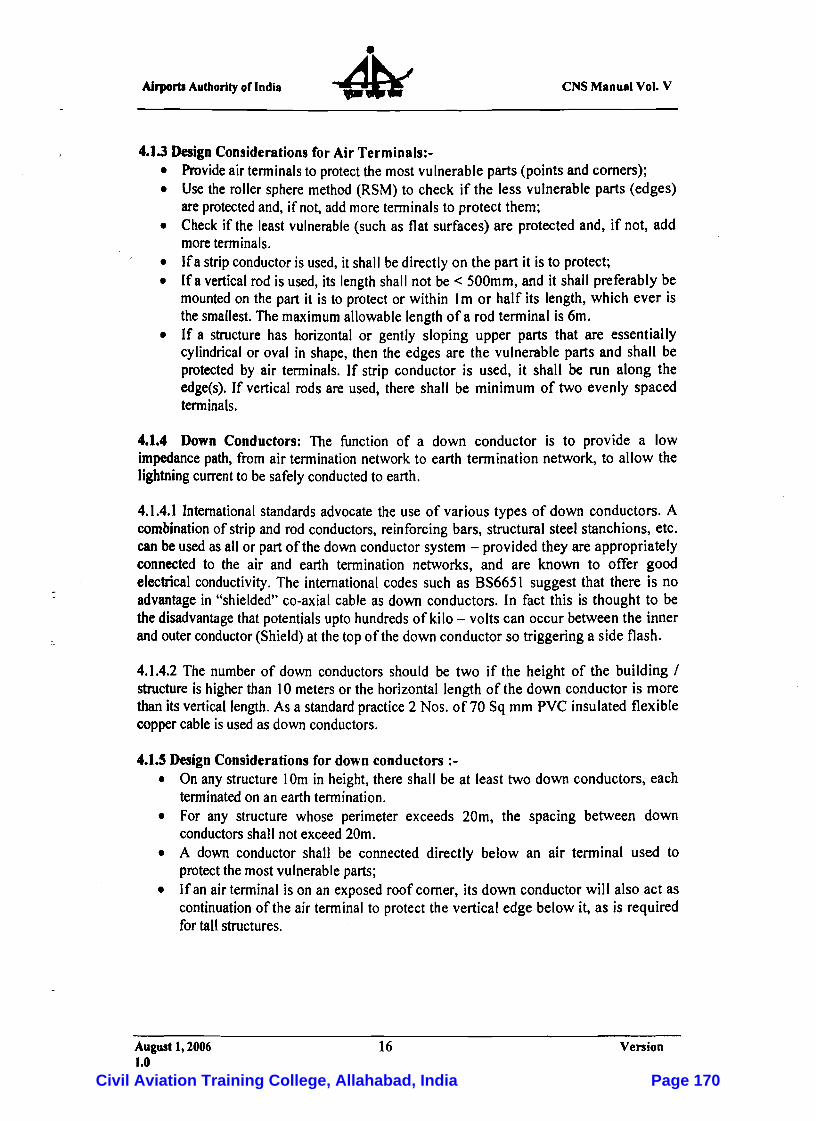
eNS Manual Vol. V Airports Authority of India
4.1.3 Design Considerations for Air Terminals:-• Provide air terminals to protect the most vulnerable parts (points and corners); • Use the roller sphere method (RSM) to check if the less vulnerable parts (edges)
are protected and, if not, add more terminals to protect them; • Check if the least vulnerable (such as flat surfaces) are protected and, if not, add
more terminals, • If a strip conductor is used, it shall be directly on the part it is to protect; • If a vertical rod is used, its length shall not be < 500mm, and it shall preferably be
mounted on the part it is to protect or within Im or half its length, which ever is the smallest. The maximum allowable length of a rod terminal is 6m.
• If a structure has horizontal or gently sloping upper parts that are essentially cylindrical or oval in shape, then the edges are the vulnerable parts and shall be protected by air terminals. If strip conductor is used, it shall be run along the edge(s). If vertical rods are used, there shall be minimum of two evenly spaced terminals,
4.1.4 Down Conductors: The function of a down conductor is to provide a low impedance path, from air termination network to earth termination network, to allow the lightning current to be safely conducted to earth.
4.1.4.1 Intemational standards advocate the use of various types of down conductors. A combination of strip and rod conductors, reinforcing bars, structural steel stanchions, etc. can be used as all or part of the down conductor system - provided they are appropriately connected to the air and earth termination networks, and are known to offer good electrical conductivity. The international codes such as BS6651 suggest that there is no advantage in "shielded" co-axial cable as down conductors. In fact this is thought to be the disadvantage that potentials upto hundreds of kilo - volts can occur between the inner and outerconductor (Shield)at the top of the down conductor so triggering a side flash.
4.1.4.2 The number of down conductors should be two if the height of the building / structure is higher than 10 meters or the horizontal length of the down conductor is more than its vertical length. As a standard practice 2 Nos. of 70 Sq mm PVC insulated flexible coppercable is used as down conductors.
4.1.5 Design Considerations for down conductors :-• On any structure 10m in height, there shall be at least two down conductors, each
terminated on an earth termination. • For any structure whose perimeter exceeds 20m, the spacing between down
conductors shall not exceed 20m. • A down conductor shall be connected directly below an air terminal used to
protect the most vulnerable parts; • Ifan airtenninal is on an exposed roof comer, its down conductor will also act as
continuation of the air terminal to protect the vertical edge below it, as is required for tall structures.
August 1,2006 16 Version 1.0
Civil Aviation Training College, Allahabad, India Page 170
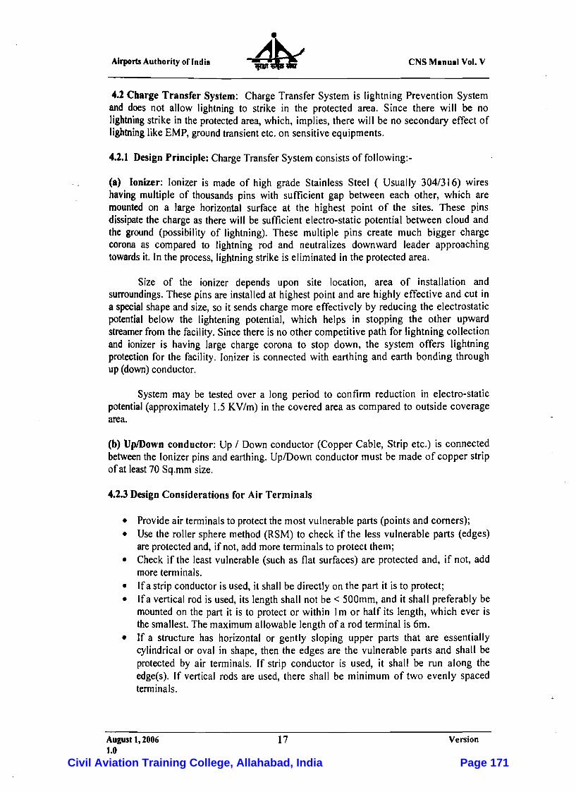
Airports Authority oflndia eNS Manual Vol. V
4.1 Cbarge Transfer System: Charge Transfer System is lightning Prevention System and does not allow lightning to strike in the protected area. Since there will be no lightning strike in the protected area, which, implies, there will be no secondary effect of lightning like EMP, ground transient etc. on sensitiveequipments.
4.1.1 Design Principle: Charge TransferSystem consists of following:-
(a) Ionizer: Ionizer is made of high grade Stainless Steel ( Usually 304/316) wires having multiple of thousands pins with sufficient gap between each other, which are mounted on a large horizontal surface at the highest point of the sites. These pins dissipate the charge as there will be sufficient electro-static potential between cloud and the ground (possibility of lightning). These multiple pins create much bigger charge corona as compared to lightning rod and neutralizes downward leader approaching towards it. In the process, lightning strike is eliminated in the protected area.
Size of the ionizer depends upon site location, area of installation and surroundings. These pins are installed at highest point and are highly effective and cut in a special shape and size, so it sends charge more effectively by reducing the electrostatic potential below the lightening potential, which helps in stopping the other upward streamer from the facility. Sincethere is no other competitive path for lightning collection and ionizer is having large charge corona to stop down, the system offers lightning protection for the facility. Ionizer is connected with earthing and earth bonding through up (down) conductor.
System may be tested over a long period to confirm reduction in electro-static potential (approximately 1.5 KV/m) in the covered area as compared to outside coverage area.
(b) UplDown conductor: Up / Down conductor (Copper Cable, Strip etc.) is connected between the Ionizer pins and earthing. Up/Down conductor must be made of copper strip of at least 70 Sq.mm size.
4.1.3 Design Considerations for Air Terminals
• Provide air terminals to protectthe most vulnerable parts (points and comers); • Use the roller sphere method (RSM) to check if the less vulnerable parts (edges)
are protected and, if not, add more terminals to protect them; • Check if the least vulnerable (such as flat surfaces) are protected and, if not, add
more terminals. • Ifa strip conductor is used, it shall be directly on the part it is to protect; • Ifa vertical rod is used, its length shall not be < 500mm, and it shall preferably be
mounted on the part it is to protect or within Im or half its length, which ever is thesmallest. The maximum allowable length of a rod terminal is 6m.
• If a structure has horizontal or gently sloping upper parts that are essentially cylindrical or oval in shape, then the edges are the vulnerable parts and shall be protected by air terminals. If strip conductor is used, it shall be run along the edge(s). If vertical rods are used, there shall be minimum of two evenly spaced terminals.
August 1,2006 17 Version 1.0
Civil Aviation Training College, Allahabad, India Page 171

AJrporu Authority of India eNS Manual Vol. V
4.1.4 Down Conductors: The function of a down conductor is to provide a low impedance path, from air termination network to earth termination network, to allow the lightning current to besafelyconducted to earth.
4.2.4.1 International standards advocate the use of various types of down conductors. A combination of strip and rod conductors, reinforcing bars, structural steel stanchions, etc. can be used as all or part of the down conductor system - provided they are appropriately connected to the air and earth termination networks, and are known to offer good electrical conductivity. The international codes such as 8S6651 suggest that there is no advantage in "shielded" co-axial cable as down conductors. In fact this is thought to be thedisadvantage that potentials upto hundreds of kilo - volts can occur between the inner andouterconductor (Shield) at the top of the down conductor so triggering a side flash.
4.1.4.1 The number of down conductors should be two if the height of the building I structure is higher than 10 meters or the horizontal length of the down conductor is more than its vertical length. As a standard practice 2 Nos. of 70 Sq mm PVC insulated flexible copper cable is used as down conductors.
4.1.5 Design Considerations for down conductors:-
• On any structure 10m in height, there shall be at least two down conductors, each terminated on an earth termination.
• For any structure whose perimeter exceeds 20m, the spacing between down conductors shall not exceed 20m.
• A down conductor shall be connected directly below an air terminal used to protect the mostvulnerable parts;
• If an air terminal is on an exposed roof comer, its down conductor will also act as continuation of the air terminal to protect the vertical edge below it, as is required for tall structures.
4.3 Earthing System: The earthing network is responsible for safely dissipating the lightning current to ground. A low impedance connection to earth is a fundamental requirement for an effective lightning protection system and the efficient operation of surge protection device. The earth resistance of an earthy pit is depending on certain criteria like soil resistivity, moisture content, temperature etc. Conventional earthing method using charcoal and salt with GI metal components are prone to corrosion and damage of earth pit in a very short span of time, hence it is recommended to use either stainless steel or copper along with chemicals earth enhancing compound which can reduce soil receptivity and absorb moisture from the surrounding soil.
August 1,2006 18 Version 1.0
Civil Aviation Training College, Allahabad, India Page 172
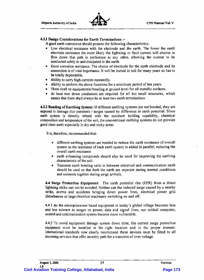
Airports Authorityof India eNS Manual Vol. V
4.3.1 Design Considerations for Earth Terminations :-A good earth connection should possess the following characteristics: • Low electrical resistance with the electrode and the earth. The lower the earth
electrode resistance the more likely the lightning or fault current will choose to flow down that path in preference to any other, allowing the current to be conducted safely to and dissipated in the earth.
• Good corrosion resistance. The choice of electrode for the earth electrode and its connection is of vital importance. It will be buried in soil for many years so has to be totallydependable.
• Ability to carry highcurrents repeatedly. • Ability to perform the above functions for a minimum period often years. • There shall be equipotential bonding at ground level for all metallic surfaces. • At least two down conductors are required for all but small structures, which
means that there shallalways be at least two earth terminations
4.3.2 Bondingof Earthing System: If different earthing systems are not bonded, they are exposed to damage due transients / surges caused by difference in earth potential. Since earth system is directly related with the moisture holding capability, chemical composition and temperature of the soil, the conventional earthing systems do not provide good clean earth especially in dry and rocky areas.
It is, therefore, recommended that:
• different earthing systems are bonded to reduce the earth resistance of overall system as the resistance of each earth system is added in parallel, reducing the overall earth resistance
• earth enhancing compounds should also be used for improving the earthing characteristic of the soil.
• Transient earth bonding units in between electrical and communication earth should be used so that both the earth are separate during normal conditions and connects togetherduring surge arrivals.
4.4 Surge Protection Equipment: The earth potential rise (EPR) from a direct lightning strike can not be avoided. Neither can the induced surge caused by a nearby strike, storms and accidents bringing down power lines, electrical power grid disturbances or large electrical machinery switching on and off.
4.4.1 As the microprocessor based equipment in today's global village becomes less and less tolerant to surges on power, data and signal lines, our critical computer, control and communication system become more vulnerable.
4.4.2 To avoid equipment damage system down time, the correct surge protection equipment must be installed in the right location and in the proper manner. International standards now clearly recommend these devices must be fitted to all incoming services that offer an entry path for a transient of over voltage.
August1, 2006 19 Version 1.0
Civil Aviation Training College, Allahabad, India Page 173

Airports Authority of India eNS Manual VoL V
4.4.3 Toachieve the above, under mentioned two stage design mustbe implemented • "Base" level production using surge diverters should be mounted at the point
ofentry to thesiteI building and • "Computer" grade protection using power filters installed at the most
important and sensitive equipment.
This design enables a maintenance person to pin point which item is sensitive to a disturbance of critical to the sites I operations and protect it with an appropriate device, whilst ignoring other more robust or less important equipment.
4.4.4 To rely on a single stage of surge diverters at the point of entry to provide adequate protection for all equipment within the building is unwise. Their performance depends heavily on the quality of the installation and lengths of leads to earth. Essential equipment may be subjected to voltages far in excess of their withstand capabilities on a regular basis.
August 1,2006 20 Venlon 1.0
Civil Aviation Training College, Allahabad, India Page 174
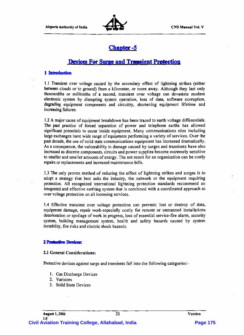
Airports Autbority of India eNS Manual Vol. V
Chapter -5
Devices For Surge and Transient Protection
1 Introduction
1.1 Transient over voltage caused by the secondary effect of lightning strikes (either between clouds or to ground) from a kilometer, or more away. Although they last only thousandths or millionths of a second, transient over voltage can devastate modem electronic system by disrupting system operation, loss of data, software corruption, degrading equipment components and circuitry, shortening equipment lifetime and increasing failures.
1.2 A major cause of equipment breakdown has been traced to earth voltage differentials. The past practice of forced separation of power and telephone earths has allowed significant potentials to occur inside equipment. Many communications sites including large exchanges have wide range of equipment performing a variety of services. Over the past decade, the use of solid statecommunications equipment has increased dramatically. As a consequence, the vulnerability to damage caused by surges and transients have also increased as discrete components, circuits and power supplies become extremely sensitive to smaller and smalleramounts of energy. The net result for an organizationcan be costly repairs or replacements and increased maintenance bills.
1.3 The only proven method of reducing the effect of lightning strikes and surges is to adopt a strategy that best suits the industry, the network or the equipment requiring protection. All recognized international lightning protection standards recommend an integrated and effective earthing system that is combined with a coordinated approach to overvoltage protection on all incoming services.
1.4 Effective transient over voltage protection can prevent: lost or destroy of data, equipment damage, repair work-especially costly for remote or unmanned installations deterioration or spoilage of work in progress, loss of essential service-fire alarm, security system, building management system, health and safety hazards caused by system instability, fire risksand electric shock hazards.
2 Protective Devices:
2.1 General Considerations:
Protective devices against surgeand transients fall into the following categories:-
I. Gas Discharge Devices 2. Varistors 3. Solid State Devices
August 1,2006 21 Version 1.0
Civil Aviation Training College, Allahabad, India Page 175

eNS Manual Vol. V Airports Authorityof India
2.2 Gas discharge devices:
These devices usually consist of glass or ceramic tubes filled with an inert gas sealed at each end with a metal electrode. They have breakdown voltages in the range 70V to 15KV with surge current ratings up to 60 KA. The strike time and firing voltage of these device is dependant on the rateof increase of voltage. Typical strike times are in the range
'.. 10ns to 500ns. Unlike most otherdevices, gas discharge devices conduct at a much lower voltage than their firing voltage. This conduction voltage is typically below 30 V.
Gas discharge devices are available in both two electrode and three electrode configurations. The latterprovide a means of clamping a pair of wires to earth regardless of which conductor was subjected to the over voltage.
2.3 Varistors:
These devices are voltage dependent resistors. The earlier forms of varistors were constructed from carbon or silicon carbide but most modem devices are made from metal oxideand are known as metal oxidevaristors (MOVs). The resistance of varistors drops significantly when the voltage exceeds a limit thus clamping the voltage near the limit. Varistor are used on circuits operating at voltages between 10Vand 1 KV. They can handle surges up to several kilo amperes and respond in tens of nanoseconds. Because the performance of MOVs deteriorates with repeated operation, it is usual to allow a high safety margin in the selection of the device rating in lightning prone areas. Alternatively, facilities should be provided to give an indication of device failure
2.4 SolidState Devices:
These devices consist of special zener diodes which exhibit voltage limiting characteristics. The breakdown voltages of such device are typically in the range 5V to 200V. They have current ratings up to several hundred amperes and response times of the order of 10 pico seconds. These devices are expensive compared to other protection devices.
3 Applications of protective devices:
3.1 Power and Signal Lines:
3.I.l With any signal or power transmission system employing two lines and a separate protection earth, two types of transients can occur. The first type appears as a difference between the two lines, independent of their potentialdifferences to earth; this is known as a differential mode transient (alsocalled transverse mode or normal mode).
3.1.2 The second type appears as a transient between each line and the earth, and is known as a common mode transient (sometimes called a longitudinal transient). This mode is that commonly experienced by twisted pair circuits as each wire is equally exposed to the transient voltage source.
August 1,2006 22 Version 1.0
Civil Aviation Training College, Allahabad, India Page 176
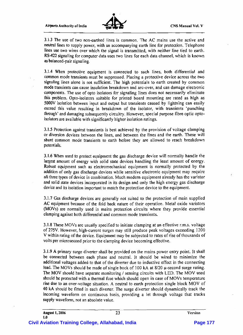
AirportsAuthority of India eNS Manual Vol. V
3.1.3 The use of two non-earthed Iines is common. The AC mains use the active and neutral lines to supply power, with an accompanying earth line for protection. Telephone lines use two wires over which the signal is transmitted, with neither line tied to earth. RS-422 signaling for computer data uses two lines for each data channel, which is known as balanced-pair signaling.
3.1.4 When protective equipment is connected to such lines, both differential and common mode transients must be suppressed. Placing a protective device across the two signaling lines alone is not sufficient. The high potentials to earth created by common mode transients can cause insulation breakdown and arc-over, and can damage electronic components. The use of opto isolators for signaling lines does not necessarily eliminate this problem. Opto-isolators suitable for printed board mounting are rated as high as 5000V isolation between input and output but transients caused by lightning can easily exceed this value resulting in breakdown of the isolator, with transients 'punching through' and damaging subsequently circuitry. However, special purpose fibre optic opto-isolators are available with significantly higher isolation ratings.
3.1.5 Protection against transients is best achieved by the provision of voltage clamping or diversion devices between the lines, and between the lines and the earth. These will shunt common mode transients to earth before they are allowed to reach breakdown potentials.
3.1.6 When used to protect equipment the gas discharge device will normally handle the largest amount of energy with solid state devices handling the least amount of energy. Robust equipment such as electromechanical equipment is normally protected by the addition of only gas discharge devices while sensitive electronic equipment may require all three types of device in combination. Much modern equipment already has the varistor and solid state devices incorporated in its design and only the high energy gas discharge device and its isolation important to match the protection device to the equipment.
3.1.7 Gas discharge devices are generally not suited to the protection of main supplied AC equipment because of the fold back nature of their operation. Metal oxide varistors (MOVs) are normally used in mains protection circuits where they provide essential clamping against both differential and common mode transients.
3.1.8These MOVs are usually specified to initiate clamping at an effective r.m.s. voltage of 275V. However, high-current surges may still produce peak voltages exceeding 1200 V within rating of the device. Equipment may be subjected to rates of rise of thousands of volts per microsecond prior to the clamping device becoming effective.
3.1.9 A primary surge diverter shall be provided on the mains power entry point. It shall be connected between each phase and neutral. It should be wired to minimize the additional voltages added to that of the diverter due to inductive effect in the connecting lead. The MOVs should be made of single bock of 100 kA at 8/20 u-second surge rating. The MOV should have separate monitoring / sensing circuits with LED. The MOV used should be protected with a thermal fuse which should open in case of MOVs temperature rise due to an over-voltage situation. A neutral to earth protection single block MOV of 40 kA should be fitted in each diverter. The surge diverter should dynamically track the incoming waveform on continuous basis, providing a let through voltage that tracks supply waveform, not an absolute value.
August 1,2006 23 Version 1.0
Civil Aviation Training College, Allahabad, India Page 177
eNS Manual Vol. V Airports Authority of India
3.I.l0 Surge diverters fitted at the point of entry can clamp the transients to a predetermined voltage level, however, high current surges may still produce peak voltages prior to clamping. Hence it is essential to install a multistage series filter to condition the residual transient and to reduce the high rate of voltage rise observed immediately prior to clamping.
3.1.11 These filters should have the following:-
a. The filter should be installed after the surge diverter and in from critical equipment power supply and should protect sensitive equipment installed in the technical building against the damaging effects of lightning power transients and RF interference.
b. The filter should have 3 stage protection, the first stage should consists of metal oxide Varistor connected between each phase and neutral to absorb transverse mode surges generated by load switching and other power system disturbances. These MOVs in conjunction with MOV between neutral and ground should absorb common mode surges caused by lightning induced disturbances or power systemearth faults.
c. The second stage of the filter should consist of inductors and capacitors. The LC section low pass filter components should further attenuate surge voltages already clamped by the first stage MOVs. In addition to this the filter should attenuate noise and power system harmonics and should be designed to attenuate both transverse and common mode noise.
d. The third stage of protection should consist of MOVs connected across the load side of the filter in a similar configuration as stage 1. These MOVs should provide further stage of protection and safeguard the filter's integrity and in addition to this, this stage should provide suppression of any surges generated by load side connected equipment.
3.1.12 It is important to note that radio frequency interference filters may not be suitable for powercircuit protection. Transient current levels may cause inductor saturation which will degrade the filter action.
4 Standards and Recommended Practices
The following standards are recommended for surge and transient protection for the equipment used in Airports Au! hority of India.
4.1Surge protection for the mains power supply: Surge protectorsof proper rating are to be installed at switchboards; distribution boards and the building powerentry point. Twostageprotections are suggested.
August 1,2006 24 Version 1.0
Civil Aviation Training College, Allahabad, India Page 178

Airports Authority of Jndi. eNS Manua' VoL V
4.1.1 FirstStageProtection is to be provided at powerentry point.
4.].].1 Rating of lightning current arrestor to be connected between phase & neutral
a) Impulse current >= 100KA, 8/20 I-lS b) Rated voltage >= 330 V c) Voltage protection level < 0.6 KV
4.1.1.2 Rating of lightning current arrestor to be connected between neutral & earth
a) Impulse current >= SO KA, 8/20 I-ls b) Rated voltage >= 270 V c) Voltage protection level < 0.6 KV
4.1.2 Second Stage Protection: This protection to be provided at UPS panel and input to the Communication or Instrumentation equipments. The protection device should be a combination of MOV, LC MOV devices. All in-circuit MOV should have associated thermal fuse to isolate the circuit in the event of failure of MOV. The MOV should also have indication system for identifying failed MOV. Following are the specs.
4.I.2.1 MOVtypeconnected between phase to neutral and neutral to earth in co-ordination with the first stage protection.
a) Nominal discharge current >= 40 KA 8/20 I-lS b) Maximum discharge current >= 40 KA c) Maximum rated operating voltage >= 320 V AC d) Voltage protection level < 0.3 KV
4.1.2.2 LC filter: The LC filter will consist of inductorand capacitor. This filtershould
a) Attenuate surge voltage to limit output peak surge to less than 300V. b) Attenuate noise and power system harmonics by 30 dB. c) Full load voltage drop due to filter should not exceed 3 Volts.
Aupst 1,2006 25 Version 1.0 Civil Aviation Training College, Allahabad, India Page 179
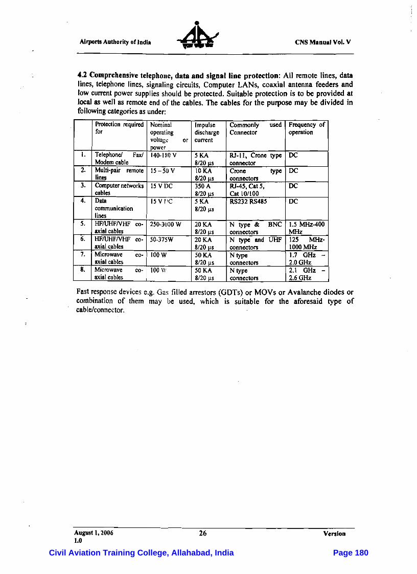
AirportsAuthority or India eNS Manual Vol. V
4.2 Comprehensive telephone, data and signal line protection: All remote lines, data lines, telephone lines, signaling circuits, Computer LANs, coaxial antenna feeders and low current power supplies should be protected. Suitable protection is to be provided at local as well as remote end of the cables. The cables for the purpose may be divided in following categories as under:
Protection required for
Telephone! Fax! Modem cable Multi-pair remote lines Computer networks cables Data communication lines HFIUHFNHF co-axial cables HFIUHFNHF co-axial cables Microwave co-axial cables Microwave co-axial cables
1.
2.
3.
4.
5.
6.
7.
8.
Nominal operating voltage or power l40-ISO V
IS- 50 V
15 VDC
IS V PC
250-3000 W
50-375W
IOOW
100W
Impulse Commonly used Frequency of discharge Connector operation current
RJ· I I, Crone type DC5KA 8/20 I.lS connector
Crone type DCIOKA 8120 us connectors
RJ-45.Cat 5. DC350A 8/20 I.lS Cat 10/100
RS232 RS485
N type & BNC
DC
1.5 MHz-400
5KA 8/20 I.lS
20KA 8/20 I.lS connectors
N type and UHF MHz 125 MHz-20KA
8/20 I.lS connectors Ntype
1000MHz 1.7 GHz -50KA
8120 us connectors Ntype
2.0GHz 2.1 GHz 50KA
8/20 I.lS connectors 2.6GHz
Fast response devices e.g. Gas filled arrestors (GDTs) or MOYs or Avalanche diodes or combination of them may be used, which is suitable for the aforesaid type of cable/connector.
August I, 2006 26 Version 1.0
Civil Aviation Training College, Allahabad, India Page 180

Airports Authority of India eNS Manual Vol. V
Chapter - 6
Earthing Electrodes and Measurement of Earth Impedance
1 General
1.1 Function of an earthing electrode:
The function ofan earthing electrode is to provide an electrical connection to thegeneral mass of earth. The characteristic primarily determining the effectiveness of an earthing electrode or group of interconnected earthing electrodes (earth termination network) is the impedance that it provides between the earth termination network and the general mass of earth.
1.2Factors influencing earth impedance:
1.2.1 The impedance of the earth termination network to lightning currents varies with time and the magnitude of the current, and is dependent on:
(a) The resistance and surge impedance of the earthing electrode and the connecting conductors;
(b) The contact resistance between the earthingelectrode and the surrounding soil;
(c) Theresistivity of the soil surrounding the earthing electrode; and
(d) The ofsoiJ ionization.
The resistance of the metallic conductors in the earth termination network can generally be neglected.
1.2.2 In addition there are often fortuitous paths to earth, e.g. via bonded electricity reticulation low voltage neutrals. These can mask the earthing electrode impedance by paralleling other routes of high surge impedance but low d.c. or low - frequency impedance to earth. It is essential to utilize measurement techniques, referred to later, to discriminate between theseconditions.
1.3 Measures for reducing earth impedance:
1.3.1 Lightning current is considered to be a high frequency phenomenon with current rise times in the order of 1010 amperes per second (10 GAls). In these circumstances, an earth termination network can best be regarded as a 'leaky' transmission line. Each conductor has resistance, inductance and capacitance to earth and leakage through non-insulated contact. An examination of earthing conductors using transmission line equations will showthat the impedance of the earth termination network is lowered by the following:
August 1,2006 27 Version 1.0
Civil Aviation Training College, Allahabad, India Page 181
Airports Authority of India eNS Manual Vol. V
(a) The use of flat strip rather than circular conductors. This increases surface area, reduces high-frequency resistance due to skin effect, increases both capacitive coupling and theearth contact area fora given cross-section of conductor.
(b) The use of a centre point feed to create the effect of two parallel connected transmission lines is also effective. This concept can be further enhanced by using several radial conductors emanating from the injection point.
(c) The use of short-length multiple conductors for example up to 30 rn, is preferred over long buried systems.
1.3.2 In areas of low to moderate soil resistivity, vertical earthing electrodes will, for an earthing electrode of given dimensions, usually be more effective in providing a low surge impedance.
1.3.3 When trench (horizontal) earthing electrodes are installed, the initial surge impedance of two or more electrically paralleled wires or strips, radiating symmetrically from a central connection point, will be < the equivalent length laid as one single unit. However, the multiplied earthing electrode will be of higher d.c. or low-frequency resistance due to electric field interaction between the individual earthing electrode segments near the central connection point. The optimum surge performance for a single horizontal earthing electrode will usually be achieved when the downconductor attaches to its midpoint.
1.3.4 The contact resistance between the earthing electrode and the soil can be up to about 10percent of the total resistance of the earth termination network. This resistance may be reduced by ionization and arc-over in the soil in contact with the earthing electrode. The
-major part of the earth resistance of an earthing electrode arises from the resistance of the earth in the immediate vicinity of the earthing electrode. The value of this resistance depends upon the shape, size, and position of the earthing electrode and the resistivity, moisture content and degree of ionization of the soil in the vicinity of the earthing electrode. The ratio of resistance at peak impulse current to resistance at low current depends on the number and arrangement of the electrodes, the peak current and soil resistivity.
1.4 Resistivity of Soil:
1.4.1 Soil resistivity is another term for the specific resistance of soil. It is usually expressed in ohms meters (symbol n.m), i.e. the resistance in ohms between opposite faces of a cube of soil having sides 1 m long.
1.4.2 The resistivity of the soil depends on its chemical and mechanical composition, moisture content and temperature. In view of this there is a very large variation in resistivity between different types of soils and with different moisture contents. This is illustrated inTables I and 2.
Note: Earthing electrodes should not be located near brick kilns or other installations where the soil can be dried out by the operating temperatures involved.
August 1,2006 28 Version 1.0
Civil Aviation Training College, Allahabad, India Page 182
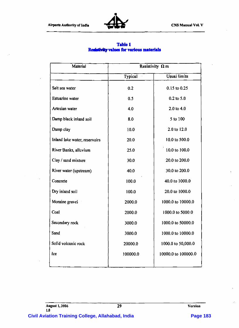
Airports Authority or Indll eNS Mlnull VoL V
Table 1 Resistivity values for various materials
Material Resistivity n m
Typical Usual limits
Salt sea water 0.2 0.15 to 0.25
Estuarine water 0.5 0.2 to 5.0
Artesian water 4.0 2.0 to 4.0
Damp black inland soil 8.0 5 to 100
Damp clay 10.0 2.0 to 12.0
Inland lakewater, reservoirs 20.0 10.0to 500.0
River Banks, alluvium 25.0 10.0to 100.0
Clay / sand mixture 30.0 20.0 to 200.0
River water (upstream) 40.0 30.0 to 200.0
Concrete 100.0 40.0 to 1000.0
Dry inland soil 100.0 20.0 to 1000.0
Moraine gravel 2000.0 1000.0 to 10000.0
Coal 2000.0 1000.0 to 5000.0
Secondary rock 3000.0 1000.0 to 50000.0
Sand 3000.0 1000.0 to 10000.0
Solid volcanic rock 20000.0 1000.0 to 50,000.0
Ice 100000.0 10000.0to 100000.0
August 1, 2006 29 Version 1.0
Civil Aviation Training College, Allahabad, India Page 183

eNS Manual Vol. V AirportsAuthority of India
Table 2
Variation of Soil resisrivity with moisture content
Moisture content Typical value of resistivity n.m .(percent by weight)
sandClay mixed with sand 0.0 10000000 -
30000002.5 1500 500005.0 430 210010.0 185
15.0 630105 20.0 29063 30.0 42 -
1.5 Artificial reduction of soil resistivity:
1.5.1 Chemical additives can be used to reduce soil resistivity. These additives generally take the form of fully ionizable salts such as sulphates, chlorides or nitrates. Such chemical additives should not be used indiscriminately as;
(a) The benefit that they provide will lessen with time due to leaching through the soil;and
(b) They may increase the rateof corrosion of the earthing electrodematerial.
Some of the chemical additives are alsoobjectionable from an environmental viewpoint.
1.5.2 A bland backfill material such as calcium or sodium bentonite clay, or montmorillonite with finely ground gypsum will reduce resistivity for a considerable period in high resistivity soils, maintain some moisture adjacent to the earth termination network, and provide a uniform and non-corrosive environment for the earthing electrodes.
August 1, 2006 30 Version 1.0
Civil Aviation Training College, Allahabad, India Page 184
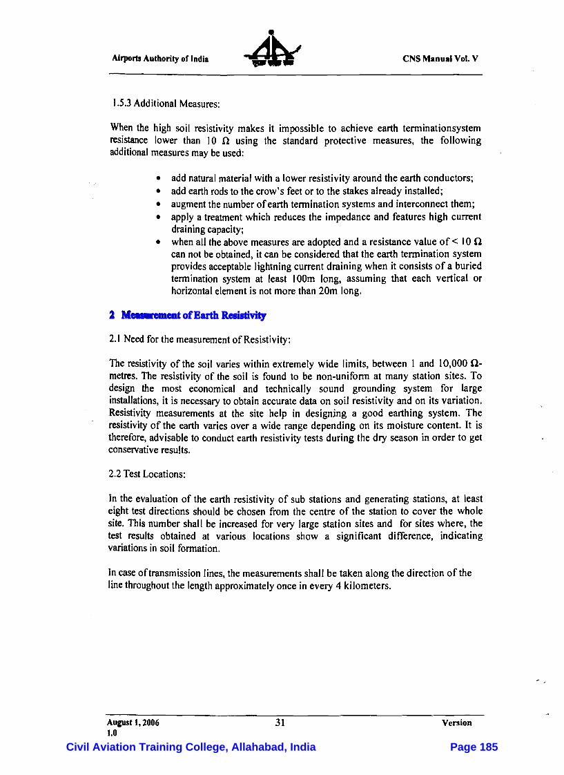
Airports Authority of India eNS Manual Vol. V
1.5.3 Additional Measures:
When the high soil resistivity makes it impossible to achieve earth tenninationsystem resistance lower than Ion using the standard protective measures, the following additional measures may beused:
• add natural material with a lower resistivity around the earth conductors; • add earth rods to the crow's feetor to the stakes already installed; • augment the number ofearth termination systems and interconnect them; • apply a treatment which reduces the impedance and features high current
draining capacity; • when all the above measures are adopted and a resistance value of < Ion
can not beobtained, it can be considered that the earth termination system provides acceptable lightning current draining when it consists of a buried termination system at least 100m long, assuming that each vertical or horizontal element is notmore than 20m long.
2 Measurement of Earth Resistivity
2.1 Need for the measurement of Resistivity:
The resistivity of the soil varies within extremely wide limits, between I and 10,000 n-metres. The resistivity of the soil is found to be non-uniform at many station sites. To design the most economical and technically sound grounding system for large installations, it is necessary to obtain accurate data on soil resistivity and on its variation. Resistivity measurements at the site help in designing a good earthing system. The resistivity of the earth varies over a wide range depending on its moisture content. It is therefore, advisable to conduct earth resistivity tests during the dry season in order to get conservative results.
2.2TestLocations:
In the evaluation of the earth resistivity of sub stations and generating stations, at least eight test directions should be chosen from the centre of the station to cover the whole site. This number shall be increased for very large station sites and for sites where, the test results obtained at various locations show a significant difference, indicating variations in soil formation.
In caseof transmission lines, the measurements shall be taken along the direction of the line throughout the length approximately once in every 4 kilometers.
August 1,2006 31 Version 1.0
Civil Aviation Training College, Allahabad, India Page 185
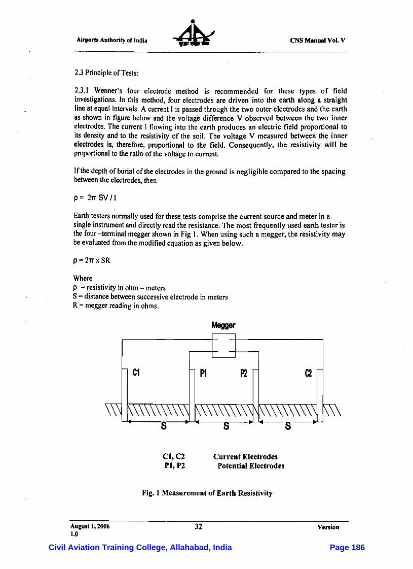
Airports Authority or India eNS Manual Vol. V
2.3 Principle of Tests:
2.3.1 Wenner's four electrode method is recommended for these types of field investigations. In this method, four electrodes are driven into the earth along a straight line at equal intervals. A current I is passed through the two outer electrodes and the earth as shown in figure below and the voltage difference V observed between the two inner electrodes. The current I flowing into the earth produces an electric field proportional to its density and to the resistivity of the soil. The voltage V measured between the inner electrodes is, therefore, proportional to the field. Consequently, the resistivity will be proportional to the ratio of the voltage to current.
If thedepth of burial of the electrodes in the ground is negligiblecompared to the spacing between theelectrodes, then
p = 2TT SV II
Earth testers nonnalJy used for these tests comprise the current source and meter in a single instrument and directly read the resistance. The most frequently used earth tester is the four -tenninal megger shown in Fig 1. When using such a megger, the resistivity may beevaluated from the modified equation as given below.
p = 2TT x SR
Where p =resistivity in ohm- meters S =distance between successive electrode in meters R =megger reading in ohms.
Megger
Cl,C2 Current Electrodes Pl,P2 Potential Electrodes
Fig. 1 Measurement of Earth Resistivity
August 1,2006 32 Version 1.0
Civil Aviation Training College, Allahabad, India Page 186
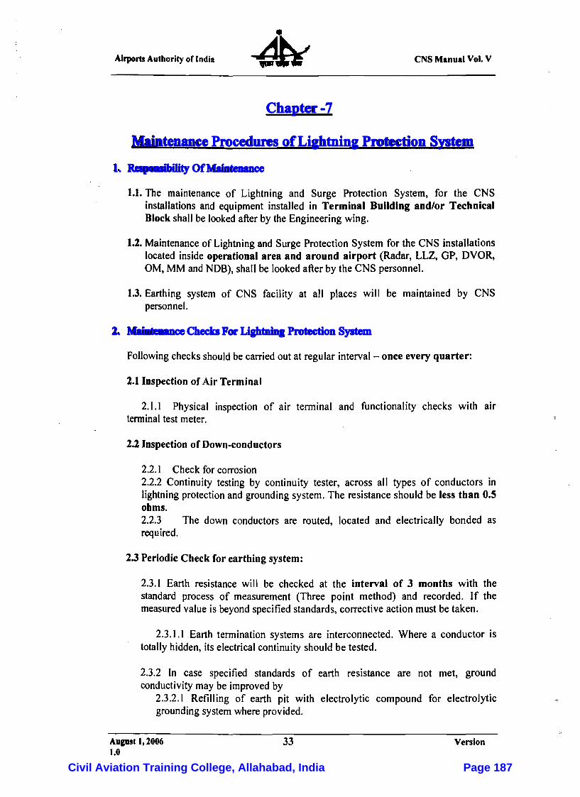
Airports Authority of India eNS Manual Vol. V
Chapter -7
Maintenance Procedures of Lightning Protection System
1. Responsibility Of Maintenance
1.1. The maintenance of Lightning and Surge Protection System, for the CNS installations and equipment installed in Terminal Building and/or Technical Blockshall be looked after by the Engineering wing.
1.2. Maintenance of Lightning and Surge Protection System for the CNS installations located inside operational area and around airport (Radar, LLZ, GP, DVOR, OM, MM and NOB), shall be looked after by the CNS personnel.
1.3. Earthing system of CNS facility at all places will be maintained by CNS personnel.
2. Maintenance Checks For Lightning Protection System
Following checksshould be carriedout at regular interval- once every quarter:
2.1 Inspection of Air Terminal
2.1.1 Physical inspection of air terminal and functionality checks with air terminal test meter.
2.2 Inspection of Down-conductors
2.2.1 Check forcorrosion 2.2.2 Continuity testing by continuity tester, across all types of conductors in lightning protection and grounding system. The resistance should be less than 0.5 ohms. 2.2.3 The down conductors are routed, located and electrically bonded as required.
2.3Periodic Check for earthing system:
2.3.1 Earth resistance will be checked at the interval of 3 months with the standard process of measurement (Three point method) and recorded. If the measured value is beyond specified standards, corrective action must be taken.
2.3.1.1 Earth termination systems are interconnected. Where a conductor is totally hidden, its electrical continuity should be tested.
2.3.2 In case specified standards of earth resistance are not met, ground conductivity may be improved by
2.3.2.1 Refilling of earth pit with electrolytic compound for electrolytic grounding system where provided.
August 1,2006 33 Version 1.0
Civil Aviation Training College, Allahabad, India Page 187
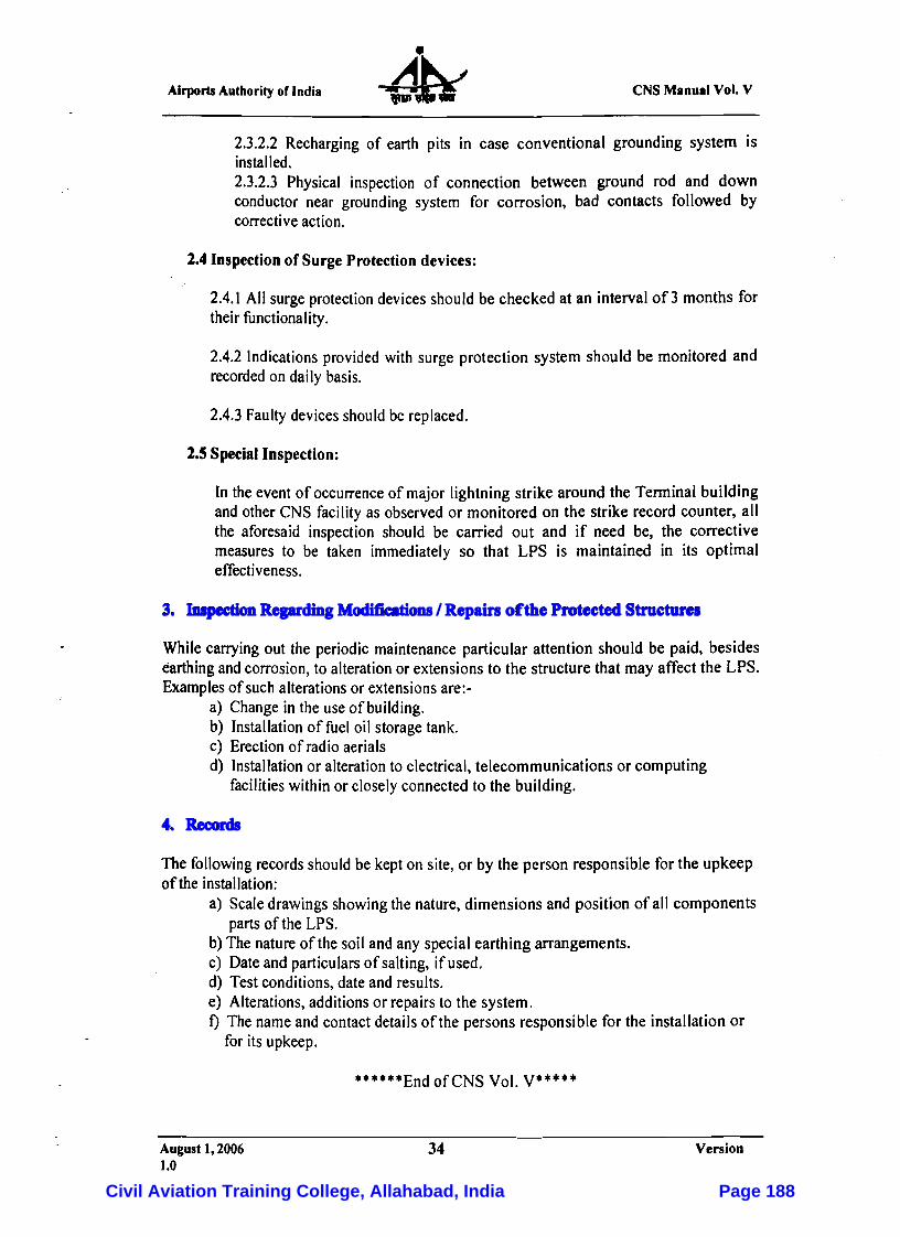
eNS Manual Vol. V Airports Authority of India
2.3.2.2 Recharging of earth pits in case conventional grounding system is installed. 2.3.2.3 Physical inspection of connection between ground rod and down conductor near grounding system for corrosion, bad contacts followed by corrective action.
2.4 Inspection of Surge Protection devices:
2.4.1 All surge protection devices should be checked at an interval of 3 months for theirfunctionality.
2.4.2 Indications provided with surge protection system should be monitored and recorded on daily basis.
2.4.3 Faulty devices should be replaced.
2.5 Special Inspection:
In the eventof occurrence of major lightning strike around the Terminal building and otherCNS facility as observed or monitored on the strike record counter, all the aforesaid inspection should be carried out and if need be, the corrective measures to be taken immediately so that LPS is maintained in its optimal effectiveness.
3. Inspection Regarding Modifications / Repairs of the Protected Structures
While carrying out the periodic maintenance particular attention should be paid, besides earthing and corrosion, to alteration or extensions to the structure that may affect the LPS. Examples of such alterations or extensions are.-
a) Change in the useof building. b) Installation of fuel oil storage tank. c) Erection of rad io aerials d) Installation or alteration to electrical, telecommunicationsor computing
facilities within or closely connected to the building.
4. Records
The following records should be kepton site, or by the person responsible for the upkeep of the installation:
a) Scale drawings showing the nature, dimensions and position of all components parts of the LPS.
b) The nature of the soil and any special earthing arrangements. c) Date and particulars of salting, ifused. d) Test conditions, date and results. e) Alterations, additions or repairs to the system. t) The name and contactdetails of the persons responsible for the installation or
for its upkeep.
.. ....EndofCNS Vol. V·····
August 1,2006 34 Version 1.0
Civil Aviation Training College, Allahabad, India Page 188
Civil Aviation Training College, Allahabad, India Page 189

Civil Aviation Training College, Allahabad, India Page 190

Civil Aviation Training College, Allahabad, India Page 191

Civil Aviation Training College, Allahabad, India Page 192
Civil Aviation Training College, Allahabad, India Page 193
Civil Aviation Training College, Allahabad, India Page 194
Civil Aviation Training College, Allahabad, India Page 195
Civil Aviation Training College, Allahabad, India Page 196
Civil Aviation Training College, Allahabad, India Page 197

Civil Aviation Training College, Allahabad, India Page 198
Civil Aviation Training College, Allahabad, India Page 199
Civil Aviation Training College, Allahabad, India Page 200
Civil Aviation Training College, Allahabad, India Page 201

Civil Aviation Training College, Allahabad, India Page 202

Civil Aviation Training College, Allahabad, India Page 203
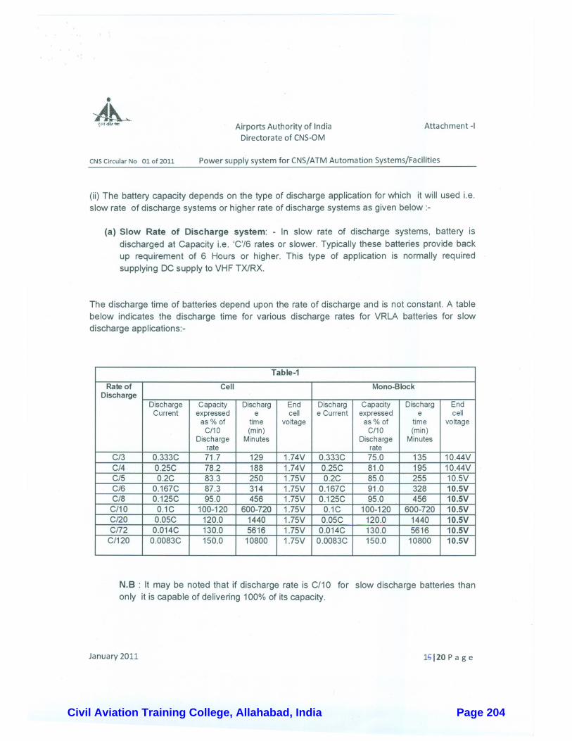
Civil Aviation Training College, Allahabad, India Page 204
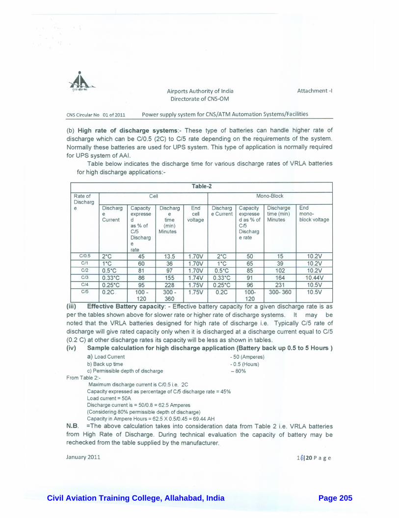
Civil Aviation Training College, Allahabad, India Page 205
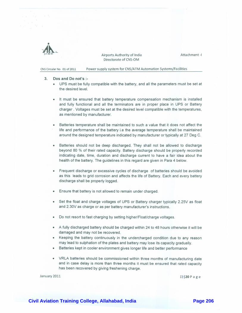
Civil Aviation Training College, Allahabad, India Page 206
Civil Aviation Training College, Allahabad, India Page 207
Civil Aviation Training College, Allahabad, India Page 208
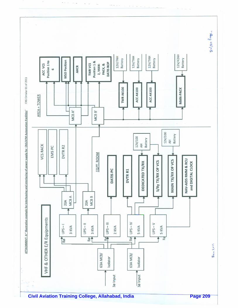
Civil Aviation Training College, Allahabad, India Page 209
sTR-trq trq]a!-d-a qTE.-firT.
*rtrr{, rEErlFGi v-q.. F"Tifdt_q
,,til:;f.i.:'{,!9.,",.
qti sr. hhn-d-qSOP for inspection/Safety Oversight Audit of
CNS/ATM Automarion facilities by DGCA
cNS C|RGULAR O2t2o12
standard operating proced u re (sop). for rnspection/safety oversi ghtAudit of cNS /ArM euLmatio; i;;ili;i": #DGcA.
i
February 2012
+il.:ii:itl
.::::+: :ijn.
,!{.i.l.ii !i.i.,i!.t!"
..iiliiiii'i';:r, .iliii-riiiit:i.
"+-t,,..,ti.i!it-'.:;:i.:iii#jo*%.r-it!l!{:\'.tr. nA: :1.,r.!.tl,,::i:Ir-.
,,f,!,.jjfl'''. _,i'I,#--,.,i,.T;.".,".jifft .,a.
'i{i{drr..r! .;ii;!,ildli !il.ii.{,!.r.'^''ti!t!,it!,i,..:'t:!il".
erTrfrq EfiTaqEa srR-fiwrAirports Authority of India
GER, l@qi6f, rrza fuf-qT--Trl;r w g;rretur Btqrtrq
Directorate of CI\S-ON,I
February Z0l2Page.l/9
Civil Aviation Training College, Allahabad, India Page 210
, nt\silq lqnlnYil=l Hllrl(f)tuIAIRPORTS AUTFIORITY. OF I NDIA
A. r
lq11 tci:-15-02-2012
+sr ii,
.+gmilqo ,'.ilrftq .ft'qiq6q wlfss"T . '
$fi*q,' frdrz SFr$ Z *q-{ z oter-o-er7 goi-arff eqr$'urqsr,
, q-6re.i8m' ($VWw-etn;, .
'.Tri-ftq ftqrqqmq mf*m-iq" P-c-frZqtc*2qfr,ff/Tfflu-n{ qtr e}tfrrdi/ gE-$,, +c-gz ofd-o.-iT/ *nta Eqd .r-q=T
\J.
frEq:-
q-SEq
) Home > Board ,MembeiMaintenace. :
> Air Navigation Services ,t eNS > Operation &'l
q-q svc\Rzvs\q {qiTdc.sily cfiq' qEftsE: gfrErrcr} d H"TdrT .i- -e=*".Tt standard operatirig Procedurd 1sbnl for tgsi:ectionlsafeiiy oveisinghi Auoit toi'crrrS^i,
' Aulomation Facitities 'by DGCA. + ?E-rE-{ 3fi ge,r-. - 1J" "r"i,".ifu
'sfr ".ffiqffi* *o ozrzotz.d A*n Afun *.**-" #fu srgnu fusT wn B fu3ifqs fu-dqretrd z+aft qtc =trd o1 s6 :o-**t't ** fr a sru-* gqra q"q"Pq ften 'frteil 6I qTFra of r ge-+t E- oft ;rroslar*ree d ffifunlirn
"irft uqtq-er t' :- "Y:'*'
Tq+q, .: F)A\{>l---'
(\q,+ ffidt>q-ilrqem' (R-o.qs frq)
Hqt-Egq]T 5-+{ or. .s-sl
rr*q Tflffii\il{ fqr$ q-ssr, qd ffi-qcooor.Safdaijung Airport, itevr Deihi .110003
$$r{N: ?8Q3?EtoPhone: 24632550
.*iq : Ec.cs.?8q,3?lBoFax i.p1-11-2463?990
l
Rajiv Gandhi BhaWan
Civil Aviation Training College, Allahabad, India Page 211

Hkkjrh; foekuiRRku Ikzkf/kdj.k SOP for inspection/Safety Oversight Audit of lapkj] fnDpkyu ,Oe fuxjkuh&iz- ,o v- funs’kky; CNS/ATM Automation facilities by DGCA
February 2012 Page 2 of 9
CNS Circular 02 of 2012
Sub: standard operating procedure (SOP) to be followed for Inspection/Safety Oversight Audit of CNS/ATM Automation Facilities by DGCA. 1. Introduction 1.1 As per Air Craft act, 1934 and its subsequent amendments, Section 4A- Safety oversight functions. The Director General of Civil Aviation (DGCA) or any other officer specially empowered in this behalf by the central government shall perform the safety oversight functions in respect of matters specified in this Act or the rules made there under. 1.2 DGCA, CIVIL AVIATION REQUIREMENT (CAR) SECTION 9 – AIR SPACE AND AIR TRAFFIC MANAGEMENT SERIES ‘D’ PART I ISSUE II dated 08th January 2010. “Requirements of Maintenance/Inspection of Communication, Navigation, Landing and other equipment installed at airports and en-route” lays down the requirements of maintenance/inspection of communications, Navigation, Landing and other equipments installed at airports/en-route stations and used for aircraft operations. 1.3 As per above CAR, in Para 6 – INSPECTION BY DGCA and Para 7- Certification, following requirement is laid down:- Quote “Para 6 – INSPECTION BY DGCA:- Any officer designated/nominated by the Director General of Civil Aviation shall be empowered to inspect at any time any facility to check the serviceability and maintenance records and procedures. Para 7 – CERTIFICATION:- Any new equipment or system procured and installed, by the operator for providing facility as listed above, shall be declared operational only after it is found fit for operation on satisfactory completion of the necessary inspection/checks and calibration from air and ground as required and after obtaining concurrence of the DGCA for the same.” Unquote 2. Inspection/Safety oversight Audit of CNS/ATM Automation Facilities by DGCA As per provisions mentioned above, inspection/Safety oversight of CNS/ATM Automation Facilities is normally carried out by DGCA for:- i. Inspection/safety oversight audit of newly installed/transinstalled CNS/ATM facility’s
before commissioning to meet the facility certification requirements. ii. Inspection/Safety oversight audit of operational CNS/ATM Facilities at field stations to meet
safety oversight function requirement. iii. Inspection/Safety oversight of Operational CNS/ATM Facilities along with such
inspection/safety oversight audit of other departments by DGCA like ATM and for requirements like Aerodrome License etc.
Civil Aviation Training College, Allahabad, India Page 212
Hkkjrh; foekuiRRku Ikzkf/kdj.k SOP for inspection/Safety Oversight Audit of lapkj] fnDpkyu ,Oe fuxjkuh&iz- ,o v- funs’kky; CNS/ATM Automation facilities by DGCA
February 2012 Page 3 of 9
iv. Inspection/Safety oversight for operationalisation of an Airport or authorizing CAT-II/CAT – III operations etc at airport.
v. Special Inspection/Safety Oversight Audit for any incident/accident investigation purposes. 3. Objective of the circular 3.1 The objective of this CNS Circular is to lay down an internal standard operating procedure (SOP) to be followed by all concerned within CNS Department so as to have uniform guidelines/response for inspection/Safety oversight Audit of CNS/ATM Automation facilities by DGCA at field stations with the purpose for:-
i. Action to be taken by all concerned in respect of preparing for inspection/Safety oversight audit of CNS/ATM automation facilities;
ii. To avoid common routine observation during inspection/Safety oversight audit of CNS/ATM automation facilities so as to have minimum adverse audit observation;
iii. Post inspection/Safety oversight Audit of facilities, procedure to be foll9owed for submitting Action taken Report/Action plan on the observations of inspection/Safety oversight Audit of CNS/ATM Automation facilities.
3.2 As mentioned above, this SOP is for internal use of CNS Department personnel to have uniform guidelines/response to DGCA Inspection/Safety Oversight audits and does not replace other orders/guidelines issued by DGCA or any other authority on the subject. 4. Definitions Following definitions will be used in conjunction with this SOP:- Corrective Action Taken Report: Action taken to eliminate the cause of a detected non-conformity or noncompliance or other undesirable situation as mentioned in the DGCA Audit observation (Note:- Corrective action does not mean the action taken to restore a non-conforming situation to a conforming situation. This is know as remedial action. If the root cause of non-conformity is not addressed then it is very likely that similar non-conformities will recur). Corrective Action Taken Plan:- An action plan submitted to DGCA by an audited/inspected station, detailing the proposed action by the station to resolve identified audit observations. Implementation of the corrective action taken plan should be always necessarily submitted with a probable date of Completion (PDC) of plan. CNS Manual: - A manual containing procedures, instructions and guidance for use by the CNS personnel in the execution of their duties for the operation and maintenance of CNS/ATM automation facilities. Checklists: Checklists are an integral part of SOPs. They depict "sets” of actions relevant to specific phases of operations that must be performed or verified. Checklists also provide a framework for verifying systems configuration for guarding against vulnerabilities in human performance
Civil Aviation Training College, Allahabad, India Page 213
Hkkjrh; foekuiRRku Ikzkf/kdj.k SOP for inspection/Safety Oversight Audit of lapkj] fnDpkyu ,Oe fuxjkuh&iz- ,o v- funs’kky; CNS/ATM Automation facilities by DGCA
February 2012 Page 4 of 9
Inspection/Safety Oversight audit Report: A standardized means of reporting the inspection findings/observations to the designated authorities. Standard Operating Procedure [SOP]:- Standard operating procedures (SOPs) specify a sequence of tasks and actions to ensure that intended task can be carried out in a safe efficient, logical and predictable manner. SOPs, should unambiguously express:-
What the task is When the task is to be conducted (time and sequence); By whom the task is to be conducted; How the task is to be done (actions); What the sequence of actions consists of; and Mitigation plan on the findings/deficiencies observed, if any, during the performance of
task. 5. Inspection/Safety Oversight Audit responsibility at CHQ Following is the general division of responsibility at CHQ for Inspection/Safety Oversight Audit of CNS/ATM facilities by DGCA:- 5.1 Matters related to Inspection/Safety Oversight Audit of operational CNS/ATM Automation facilities at field stations are handled by CNS-OM Dte. 5.2 Matters related to Inspection/ Safety Oversight Audit of newly installed/transinstalled facility(s) are handled by project executing Dte i.e. CNS-P Dte. 5.3 Inspection/Safety oversight of Operational CNS/ATM Facilities along with such inspection/Safety Oversight Audit of other departments by DGCA like ATM and for requirements like Aerodrome licensing etc. is handled by CNS-OM Dte 5.4 Matters related to Inspection/safety oversight for operationalisation of a new Airport or for authorizing CAT-II/CAT-III operations etc. at airports are handled by CNS - P Dte as part of project. 5.5 Hence all the matters i.e. submission of CAR compliance reports, Action Taken Report and other documents etc. related to Inspection/Safety Oversight Audit of facility should be accordingly suitably addressed to CHQ. In case of common issues/observations internal coordination is done by both the Dtes. 6. Dissemination of inspection/safety oversight Audit plan 6.1 Inspection/ Safety Oversight, Audit of operational CNS/ATM Automation facilities:- Advance information, normally in the brining of calendar year is received from DGCA at CHQ for their proposed plan of inspection/Safety oversight audit of operational CNS/ATM automation facilities at field stations during the calendar year. CNS-OM Dte further disseminates this information to all concerned.
Civil Aviation Training College, Allahabad, India Page 214
Hkkjrh; foekuiRRku Ikzkf/kdj.k SOP for inspection/Safety Oversight Audit of lapkj] fnDpkyu ,Oe fuxjkuh&iz- ,o v- funs’kky; CNS/ATM Automation facilities by DGCA
February 2012 Page 5 of 9
6.2 Inspection/Safety Oversight Audit of newly installed/transinstalled CNS/ATM Automation facilities, operationalisation of an Airport and authorizing CAT-II/CAT-III operations etc. at airports. 6.3 Information regarding Inspection/Safety oversight of operational CNS/ATM facilities for requirements like Aerodrome License and inspection/Safety oversight Audit of other departments like ATM by DGCA is intimated by concerned Directorate. If required at CHQ CNS-OM Dte also coordinates for such type of inspection. 7. Common avoidable observation of the audit It has been observed from previous DGCA inspection/Safety oversight audits of CNS/ATM facilities at field stations that following common observations of DGCA inspection/Audit as mentioned below are avoidable:-
i. Non submission of CAR compliance check list before start of audit to DGCA inspectors: ii. CAR compliance check list not filled up properly i.e. some of the fields left blank or use of
Use of words like sat and Adequate etc. instead of measured parameters. iii. Non-availability of relevant DGCA CAR, relevant ICAO Annex i.e. Annex 10 and DOCs
i.e. Doc 8071 etc. at stations; iv. Non-availability of required test equipments to carry out approved maintenance schedule; v. Test Equipments not being calibrated periodically;
vi. Maintenance schedules/log books and other records not maintained properly i.e. loosely bound not numbered not signed etc;
vii. Maintenance schedules not completed in time; viii. Non availability of approved maintenances schedule in respect of a facility to be
commissioned or already operational at a station; ix. Earthing resistance not being measured/recorded; x. Remote status of facility not available;
xi. Remote Control (RC) line Routing Diagram in respect of facilities not available; xii. Single Line Power Supply distribution diagram not available at the station;
xiii. Availability of redundant power supply at facility site and adequate power supply back up;
xiv. Site related issue such as proper approach road, security of site proper illumination, marking and protecting critical and sensitive areas;
xv. Non Availability of Lightning and Surge Protection Systems; xvi. Use of word like SAT and Adequate in flight inspection report/maintenance schedules
instead of measured parameters; xvii. Facility overdue for flight inspection; and
xviii. Station CNS manual not updated etc.
Civil Aviation Training College, Allahabad, India Page 215

Hkkjrh; foekuiRRku Ikzkf/kdj.k SOP for inspection/Safety Oversight Audit of lapkj] fnDpkyu ,Oe fuxjkuh&iz- ,o v- funs’kky; CNS/ATM Automation facilities by DGCA
February 2012 Page 6 of 9
8. Action to be taken by RHQ/Stations before Inspection/Safety oversight audit of CNS/ATM Facilities 8.1 Inspection/safety oversight Audit of operational CNS/ATM Automation facilities:- Following action will be initiated by concerned RHQ/Station after intimation regarding Inspection/Safety Oversight Audit of operational CNS/ATM Automation facilities is received :- (i) RHO/ GM (CNS) in charge of Metro station shall initiate action for internal performances
monitoring of the facilities at station as per the check list circulated on the subject by CHQ as soon as information is received. For the internal performance monitoring following composition of team is suggested:-
a) One or two officer from concerned RHQ/Metro depending upon the number of facility at the
station: b) One officer from CHQ CNS-OM Dept; and c) One officer from the station where the next inspection/Safety Oversight audit is planned will
also be associated. (ii) When the information regarding inspection/safety oversight audit is received from the DGCA
well in time i.e. in the beginning of calendar year, the internal performance monitoring action will be initiated two months before the planned inspection/Safety Oversight audit.
(iii) In other cases action, should be initiated as soon as information is received by RHQ/station. (iv) Two hard copies of updated station CNS Manual and DGCA CAR Compliance check list are to
be forwarded to the CHQ two months before the planned inspection/Safety Oversight, for onward submission to DGCA. A soft copy of the same is also required to be forwarded to CHQ. Soft copy may be sent by email to [email protected].
(v) While preparing the CAR Compliance check list, it must be ensured that no column is left
blank. Use of word like SAT and Adequate etc. in preparing CAR Compliance check list/performing maintenance schedules etc is to be avoided and instead measured parameters are to be indicated.
(vi) As soon as intimations of inspection/Audit is received, a review should be undertaken so as
preemptive /necessary action is initiated by all concerned so as to avoid the common observations of Inspection/Safety Oversight Audit as mentioned in Para 7 above. .
8.2 Inspection/Safety Oversight Audit of newly installed/transinstalled facility(s) for certification before commissioning:- Following action will be initiated by concerned RHO/Station after intimation regarding Inspection/ Safety Oversight Audit of CNS/ATM Automation facilities for certification before commissioning is received:-
Civil Aviation Training College, Allahabad, India Page 216
Hkkjrh; foekuiRRku Ikzkf/kdj.k SOP for inspection/Safety Oversight Audit of lapkj] fnDpkyu ,Oe fuxjkuh&iz- ,o v- funs’kky; CNS/ATM Automation facilities by DGCA
February 2012 Page 7 of 9
(i) CAR compliance as per DGCA format for the concerned facility (ILS, DVOR/DME, NDB, VHF TX/RX etc) is to be prepared and forwarded to CNS-P Dept;
(ii) While preparing the CAR Compliance check list it must be ensured that no column is left blank:
(iii) FAT Document of the facility; (iv) Approved maintenance schedule of the facility: (v) Details of the trained manpower on the facility; (vi) Copy of commissioning/recommissioning flight check in case of Nav-aids; and (vii) Necessary action is required to be initiated by all concerned so as to avoid the common
observations of Inspection/Safety Oversight Audit as mentioned in Para 7 above 8.3 Inspection/Safety oversight audit of CNS/ATM Automation facilities for Aerodrome Licensing, operationalisation of an Airport or authorizing CAT-II/CAT-III operations or any other departments like ATM etc by DGCA. Following action will be initiated by concern RHO/Station after intimation regarding Inspection/Safety oversight audit for Aerodrome Licensing, operationalisation of an Airport or authorizing CAT-II/CAT-III operations or any other departments by DGCA like ATM etc is received :-
(i) DGCA CAR Compliance checklist concerning CNS/ATM Automation facilities for Aerodrome Licensing/Operationalisation of Airport is to be prepared and forwarded to Aerodrome Licensing Dte/Operation Dte/ATM Dte as the case may be.
(ii) A copy of CAR compliance may please be forwarded to CNS-OM dte also. 9. Submission of Compliance, Action Taken Report (ATR)/Action Taken Plan(ATP) on the observations of inspection/safety oversight Audit:-
i. After the Inspection/Safety Oversight Audit at a station, DGCA forwards the observations/findings of audit to the concerned Dept at CHQ. Following are the available DGCA guidelines for submitting compliance, ATR/ATP on the findings observations of the audit:-
a) ATR Should be submitted to DGCA within 30 days. b) In case of proposed action taken plan against findings/observation, it should be
submitted with PDC. c) Internal communication within other departments of AAI is not to be reflected as
ATR or part of ATR/ATP. d) Required proof/Data i.e. measured parameters, de briefing reports, flight
inspection reports etc. is to be submitted for showing compliance to DGCA audit/observation.
e) After submitting initial ATR/ATP updated status on pending audit findings/observations is required to be submitted by 15th day of every month. Till compliance is achieved against all the findings/observations of the audit.
Civil Aviation Training College, Allahabad, India Page 217

Hkkjrh; foekuiRRku Ikzkf/kdj.k SOP for inspection/Safety Oversight Audit of lapkj] fnDpkyu ,Oe fuxjkuh&iz- ,o v- funs’kky; CNS/ATM Automation facilities by DGCA
February 2012 Page 8 of 9
ii. In view of above and to enable the CHQ to submit consolidated ATR to DGCA in time it is required that:-
a) RHQ/station should submit compliance report, TAR/ATP on audit observation findings within 15 days of receipt of same to CHQ so that it is submitted to DGCA within 30 days stipulated time as stated above.
b) Before forwarding the compliance report to CHQ, it should be reviewed by RHQ. c) RHQ is also required to review ATR/plan at their end for all such observation for
which action is required to be taken by station/RHQ and forward a consolidated compliance report, ATR/Plan to CHQ.
d) For all such observation/audit findings for which action is required to be taken by VHQ, same may please be forwarded with projections/references made earlier is any by RHQ/Station
e) Where ever action is required to be taken by other departments within AAI same may please be pursued at appropriate level and PDC obtained.
f) In some cases, station may not be able to do/complete some specific maintenance schedule due to faulty or non availability required test equipments at station. In such cases, if required test equipment is available within region at some other station same may be made available to concern station carry out required maintenance schedule till the test equipment is serviced/made available at the station.
g) Updated status report on pending audit findings/observations is required to be submitted by 05th of every month for onward submission by CHQ to DGCA by 15th of every month as stated above.
h) This updated status is required to be forwarded regularly till compliance is achieved against all the findings/observations of the audit.
10. Action Taken by CHQ for DGCA inspection/Safety oversight audit of CNS/ATM facilities Following action has been taken by CHQ to comply with various requirements of DGCA Inspection/Safety Oversight Audit of CNS/ATM automating facilities:-
i. Corporate CNS Manual has be ensured in Seven Volumes; ii. Guidelines for preparing station CNS Manuals have been circulated and Stations CNS
Manual have been prepared in respect of all the stations and approved by CHQ; iii. Approved Maintenance schedules are available in respect of all the operational CNS/ATM
Automation facilities; iv. Guidelines on some specific subjects like Updation of station CNS manual, SOP for
opening watch at station have been issued in form of CNS Circulars. v. Guidelines have been issued for the provision of ancillary systems like power supply Test
Equipment calibration and maintenances and lightning and Surge protection System etc. vi. Available DGCA CAR compliance check lists for oversight audit of CNS facilities have
been circulated and uploaded on the Infosaarthee. vii. An internal performance monitoring check list also has been prepared circulated and
uploaded on Infosaarthee so as to avoid common avoidable observations.
Civil Aviation Training College, Allahabad, India Page 218
Hkkjrh; foekuiRRku Ikzkf/kdj.k SOP for inspection/Safety Oversight Audit of lapkj] fnDpkyu ,Oe fuxjkuh&iz- ,o v- funs’kky; CNS/ATM Automation facilities by DGCA
February 2012 Page 9 of 9
9. Availability of check lists on Infosaarthee:- Soft copy following check list as motioned above has been made available at “Infosaarthee “link – “Home > Board Member> Air Navigation Services> Communications. Navigation and Surveillance (CNS) > Operation and Maintenance”
i. CAR compliance check list receiver from DGCA for safety oversight Audit of CNS facilities;
ii. Attachment V-Schedule of inspection for renewal of Aerodrome license (CNS facility check list is at S. No 7 & 9 of schedule); Extract from DGCA civil Aviation requirement, Section 4 – Aerodrome Standards & Air Traffic Services Series ’F’ Part I Dated 16th October 2006 SUBJECT REQUIREMENTS FOR ISSUE OF AN AERODROME LICENSE; and
iii. Internal performance monitoring checklist for CNS/ATM Facilities at field stations.
[Ravi Prakash] Executive Director [CNS-OM]
Civil Aviation Training College, Allahabad, India Page 219
sTR$-q trqTaErd-d gTfu-fi{oT
dqr, eqqriq-d ('-q ffi..c. (,?i 3t AhrtrqProvision of information on the
operational status of radio navigation aids
CNS CIRCULAR 03/2012
Alternate means for provision of information on the operationalstatus of Radio Navigation Aids
i
March, 2012
jil.!,( ^:.. .tr.i1 ia,it,, .:::::ti..:n!!t+ '!.:.:'it\
..::;::::::i1, .::l::::::jrrlri,..... ':i.l.llrr. ,+.
,.1-i.jjiiil .'t .ttii \Lt iti;I, " _ Jt!rr:r-.:r . . - .::+r,..ii.!f;.i4t... ,i,ilt:4.t: li::::l:;:;1. iJti.r.r.i,r.r+.
eTrdrq f{frrf,wd qrfu+-wr
Airports Authority of India
TiqR, AFfldf, ('ar ffitFilTrfr \'d $A{q1ur Ftenom
Directorate of CNS-ON,I
Page.l13 March )Ol2Civil Aviation Training College, Allahabad, India Page 220
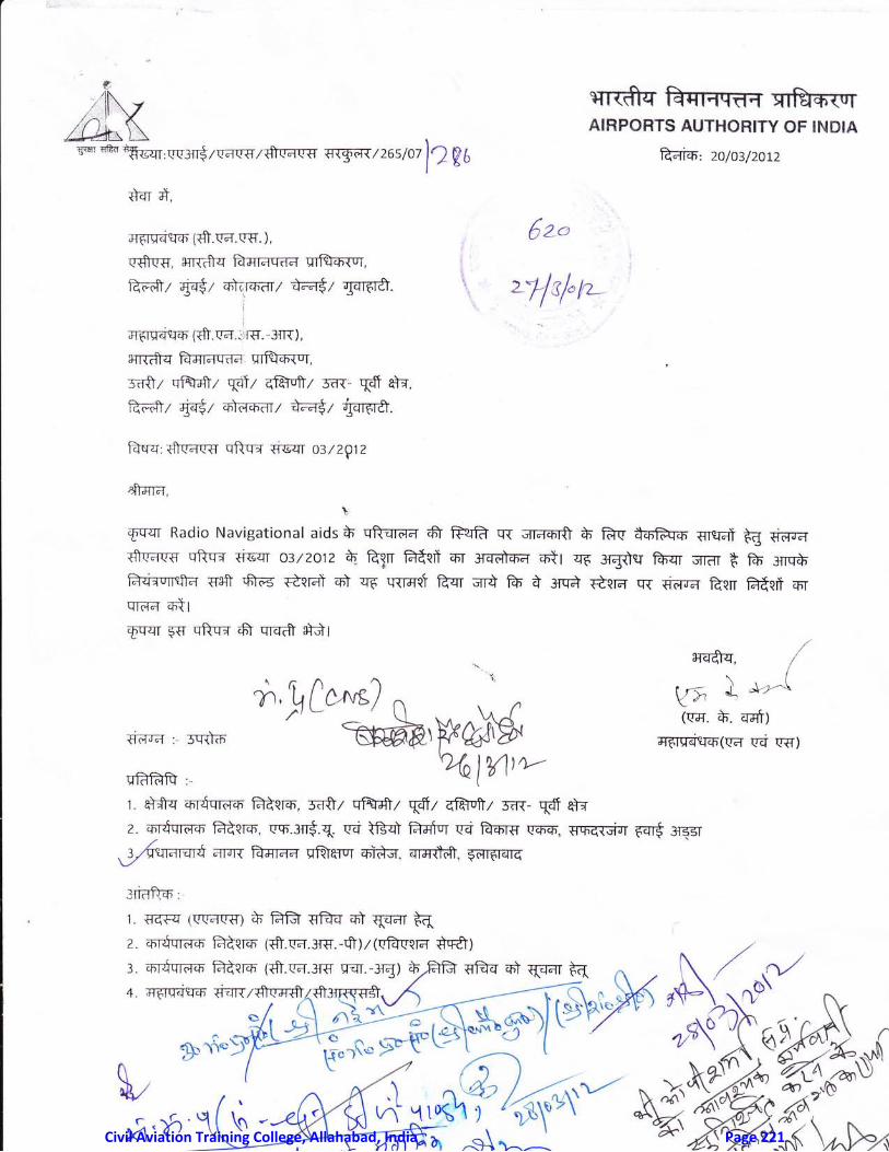
f'- /1N
,:il vIIJhL\-6"*-q"*, w;ng z vac-e z fi r'a('{T {r{gtil{ / 2 6 s m ll- V t
wrcft?T F*sil'ilftTT xr&owrAIRPORTS AUTHOHITY OF INDIA
frrTidn', 2o/03/20t2
*qT ti,
:rrflS-.Tslfr (S.r'a.r'q. ), .
!-S('{', Hrl-frq fuamq-a-a wflsfiToT,
ffiz qffiz mlcro-ar7 @t gorf*. \
I
mOq-qcrm (cff . r'a. :rrt+. -:rr ),
$TR-&q fr-alaqaa wf,fcnTrr,
t6a7 qflffi/ \d\/ qfMz E;rr. qff al*,
ffiz q-+$z entc*o-arl @r @.Fasq fr('a!-{T qftqd s.6qT o3lzplz
.*-fft;r,
I
FqqT Radio Navigational aids h qftan,a;T frr reqA q{ qrd-6l$ b fr(' ffiq-o. 1rrrl;lt E d1qraTfra-f,q{ qftq{ {i€q'o3/zotz fi Egn Rtln o.1 3rcretrffr ott q-6 rd-tE Ps-{Tr "ilff t fu:nrhh{irqrcfta osfr 6roe €cld} o} zro trrract hqr cTt fu A .*a r&na qr rin-nd frqn frfcil srrqr.q-a 6tl6-qqr {s qfrq-d fr qre?fr sidr
€A-fi"l : 5trttiF
EiFRR ,-
r4-4rq, /'../I r=; J *z'^sYo'trryr. *. eratt
flFrllqsrfr(('fr qzi ('{t
r Sfq zrrfqrFren F-tcm', mtz qlMr \frr Ef,M/ rrn- {d'qt{
6zo
,rlrl"rr_
L q)tqqtc{cn tdq<tcn {$t.(cl .Jtfi.-rltr,/t(lcl((|61 fiLlcl, ,,/:. mr-Sqrao fr{crc (fr"c-d.3r€ rqr -3r{) *FB {trIq z6} qq-dT t( n , N. / {^/+ ar6ruatro qmruzdFrn*ls"q"q"y', H^t*.$6 l$-\f"r,o'
X,do
+.,rtc"u) 'r
d,wsb'S'%olY1try--
2. qrdqrf,fr F-iqro, ('.F.3il-€'.q. qTi tcd fflq qd fufiRT l'm-m, srF-d;dirr rqr-$ :rssr/.
Wqr.lrqTt arrx P{flrda q"fa}ffiuT mi-}m. qrrrt$, Ff,rdrqrq
ldaftqt:
1. F-crq (\r(rflq-€") At FR sft-q ffit qa-dT F(z or&noro Rlsm' ($.r'a.:rg'.-fr)z(('B('cET sq&l
r*.y--
Y. u*AWCivil Aviation Training College, Allahabad, India Page 221
sTrdfqEar4qf,4qrfu*-{qr
{iqtr, tr*qrard qd}T R'rnr-fr-q.
,.i11 it, il.'i. .ttii.. .
('d $. frlsrerqProvision of information on the
operational status of radio navigation aids
CNS Circular 03 of 2012
Sub: Alternate means for provision of information on the operationat status ofradio navigation aids
INTRODUCTION
1'1 DGCA, CIVIL AVIATION REQUIREMENT (CAR) SECTION 9 - AtR ipnCr AND AtRTRAFFIC MANAGEMENT SER|ES 'D', PART il tssuE il Dated 08th Janua ry 20ro_"Aeronautical Telecommunication -Radio Navigation Aids,, lays down therequirements to be followed in respect of provision 01, AeronauticalTelecommunications - Radio Navigation Aids.
1.2 As per above CAR, Para 2.3.3- - "Provision of information on the operationalstatus of radio navigation aids" shail be made in following manner:-
"Aerodrome control towers and units providing approach control service shall beprovided without delay with information on the operational status of radionavigation aids essential for approach, landing and take-off at the aerodrome(s)with which they are concerned.,,
l-.3 Further, as per para 3.3.7 - 'voR Monitoring,, and para 3.5.4.7.2 _ DMEMonitoring " following is stated:-
"Where it is not possible to provide statr{s indication to a control point, the sameshall be published in Atp."
1'4 Accordingly, Radio Navigational aids are provided with Remote Status Units(RsUs) as part of equipment accessory. These RSU provides information on theoperational status of radio navigation aids to the ATC.
1'5 However, for some of the Navigational Aids, provision of Remote status has notbeen possible due to various limitations/constraints. Further, in some casesoperational status of Radio Navigationalaids at the intended ATc Units may not beavailable temporarily for limited duration due to faulty Remote status Unit orRemote Control Cable cutting etc.
2. Purpose of the Circular:-
The purpose of this circular is to provide guidance forstatus of radio navigation aids by alternate means dueRemote Status of the facility.
providing Operationalto non availability of
Page.2l3l\zf a'^h 1A I t
Civil Aviation Training College, Allahabad, India Page 222
$Tr$rs' F{fiTaq-da l1fftqr{q',f' -;ii;;i;''tlt'.,
T|Err, E-{qr-fd (rq F?nrdt-q qti r. Bhne-qProvision of information on the
operational status of radio navigation aids
3. Alternate means for Provision of Operational status of radio navigation aids:
Whenever remote operational status of Radio Navigational Aids could not beprovided by means of RSU, following alternate action is required to be taken by allconcerned :-
!i) Navigational aids shall be suita )ly manned by maintenance personnel duringflight operations.(ii) The maintenance personnel nranning the Nav-aid shall be provided withsuitable means of communication so as intimate any changes in opbrational statusof facility to the ATC.(iii) where it is not'possible to provide status indication to a control point,permanently in case of VOR/DME, action is also required to be taken as per CARPara 3.3.7 -r "voR fVl,onitoring" and para 3,5.4.7"1 - DME Monitoring,, asmentioned above.
5. As per the existing inltructions, the RHer shall continue to send the informationon the non availability of Remote status of Navigational Aids and Action TakenReport to restore the samg in the form NS122A to CHe.
IRavi prakash]
-. ., Executive Director ICNS-OMl
References:-
1.DGCA, CIVIL AVIATION REQUIREMENT (CAR) SECTION 9 - AIRTRAFFIC MANAGEMENT sERtEs 'D', PART il tssuE il Dated 08th"AeronauticaI Telecommunication -Radio Navigation Aids,,.
SPACE AND AIRJanuary 2010 -
Civil Aviation Training College, Allahabad, India Page 223