
Prof. Ch. SAI BABU,
67
ONLINE GATE COACHING CLASSES BY Prof. Ch. SAI BABU, Professor of Electrical & Electronics Engineering JNTUK Kakinada Lecture 3 of Electrical Machines Topic: Losses and Load Tests of DC Machine Jawaharlal Nehru Technological University, Kakinada-533003, Andhra Pradesh 1
-
Upload
khangminh22 -
Category
Documents
-
view
7 -
download
0
Transcript of Prof. Ch. SAI BABU,

ONLINE GATE COACHING CLASSES
BY
Prof. Ch. SAI BABU,
Professor of Electrical & Electronics Engineering
JNTUK Kakinada
Lecture 3 of Electrical Machines
Topic: Losses and Load Tests of DC Machine
Jawaharlal Nehru Technological University, Kakinada-533003,
Andhra Pradesh
1

Number
Syllabus
Detailed Syllabus
Lecture
III
DC Machines: Types of Losses and
Efficiency Calculations of Electric
Machines.
Various losses of DC
Machines, No Load and Load
Tests of DC Motor.
Predetermination of
Efficiency
Various losses of DC Machines
The losses that occur in a DC Machine is divided into five basic categories.
The various losses are Electrical or Copper losses (I2R losses), Core
losses or Iron losses, Brush losses, Mechanical losses, Stray load losses. These losses
are explained below in detail.
L E C T U R E 3 - L O S S E S A N D L O A D T E S T S O N D C M A C H I N E S 2 2

Contents:
Electrical or Copper losses
Magnetic Losses or Core Losses or Iron
Losses
Brush Losses
Mechanical Losses
Stray Losses
L E C T U R E 3 - L O S S E S A N D L O A D T E S T S O N D C M A C H I N E S 3 3

Electrical or Copper Losses in dc machine
These losses are also known as Winding losses as the copper loss occurs
because of the resistance of the windings.
The ohmic loss is produced by the current flowing in the windings.
Armature copper losses = Ia2Ra where Ia is armature current, and Ra is
the armature resistance. These losses are about 30 percent of the total full
load losses.
In shunt machine, the Copper loss in the shunt field is I2shRsh, where
Ish is the current in the shunt field, and Rsh is the resistance of the shunt
field windings. The shunt regulating resistance is included in Rsh.
In a series machine, the copper loss in the series windings is I2seRse,
where, Ise is the current through the series field windings, and Rse is the
resistance of the series field windings.
In a Compound machine, both the shunt and the series field losses occur.
These losses are almost 20 percent of the full load losses.
Copper losses in the interpole windings are written as Ia2Ri where Ri is
the resistance of the interpole windings.
L E C T U R E 3 - L O S S E S A N D L O A D T E S T S O N D C M A C H I N E S 4 4

Magnetic Losses or Core Losses or Iron Losses in dc machine
The core losses are the hysteresis and eddy current losses. These losses
are considered almost constant as the machines are usually operated at
constant flux density and constant speed. These losses are about 20
percent of the full load losses.
Brush Losses in dc machine
Brush losses are the losses taking place between the commutator and
the carbon brushes. It is the power loss at the brush contact point. The
brush drop depends upon the brush contact voltage drop and the
armature current Ia. It is given by the equation shown below.
The voltage drop occurring over a large range of armature currents,
across a set of brushes is approximately constant If the value of brush
voltage drop is not given than it is usually assumed to be about 2 volts.
Thus, the brush drop loss is taken as 2Ia.
L E C T U R E 3 - L O S S E S A N D L O A D T E S T S O N D C M A C H I N E S 5 5

Mechanical Losses in dc machine
The losses that take place because of the mechanical effects of the
machines are known as mechanical losses.
Mechanical losses are divided into bearing friction loss and windage
loss.
The losses occurring in the moving parts of the machine and the air
present in the machine is known as Windage losses. These losses are very
small. Stray Losses in dc machine
These losses are the miscellaneous type of losses. The following factors are
considered in stray load losses.
The distortion of flux because of armature reaction.
Short circuit currents in the coil, undergoing commutation.
These losses are very difficult to determine. Therefore, it is necessary to assign
the reasonable value of the stray loss. For most machines, stray losses are
taken by convention to be one percent of the full load output power.
L E C T U R E 3 - L O S S E S A N D L O A D T E S T S O N D C M A C H I N E S 6 6

Efficiency of DC Generator Efficiency is simply defined as the ratio of output power to the input power.
Let R = total resistance of the armature circuit (including the brush contact
resistance, at series winding resistance, inter-pole winding resistance and
compensating winding resistance). The efficiency of DC generator is explained
below in the line diagram.
If Ish is small compared with Ir, then
Ia = I
Therefore,
L E C T U R E 3 - L O S S E S A N D L O A D T E S T S O N D C M A C H I N E S 7 7

The efficiency ȠG will be a maximum
when the denominator Dr is a
minimum.
Where,
I is the output current
Ish is the current through the shunt field
Ia is the armature current = I + Ish
V is the terminal voltage.
Total copper loss in the armature circuit = Ia2Rat
Power loss in the shunt circuit = VIsh (this
includes the loss in the shunt regulating
resistance).
Mechanical losses = friction loss of bearings +
friction loss at a commutator + windage loss.
Core losses = hysteresis loss + eddy current loss
Stray loss = mechanical loss + core loss
The sum of the shunt field copper loss and stray
losses may be considered as a combined fixed
(constant) loss that does not vary with the load
current I.
Therefore, the constant losses (in shunt and
compound generators) = stray loss + shunt field
copper losses.
Dr is minimum when
L E C T U R E 3 - L O S S E S A N D L O A D T E S T S O N D C M A C H I N E S 8 8

Testing of DC Machine
When construction of DC motor or DC generator is completed. To perform its
electrical characteristics, several tests are conducted for testing of a dc machine
(Generator or Motor).
Testing of machines is used for finding Losses, Temperature rise and Efficiency.
The efficiency of a d.c. machine depends on its losses.
When losses are decrease, The efficiency is increase and it is vice-versa.
The important Tests of DC machines are classified to
Direct test method (break over test)
Swinburne Test (Indirect test Method )
Hopkinson’s-Test ( Regenerative Method )
Retardation or Running down Test
L E C T U R E 3 - L O S S E S A N D L O A D T E S T S O N D C M A C H I N E S 9 9

Direct test method (break over test)
In this method of testing the machine is put on full load and whole
developed power is wasted by applying the break. Direct test method is
used, for small machines. Because of in case of large motors, it is
difficult to dissipate the large amount of heat generated at the brake. It
is also called break over test.
Though this method is simple, but complication in the measurement of
mechanical power input in the case of generator and output in case of a
motor. If brake is to be applied to a series motor, the brake must be
tight before the motor is started, otherwise the armature may gets
damaged and winding burned.
The main draw back of this method is that the
accuracy in determining the mechanical power
output of the motor is limited. Alternately it is
difficult to provide full load for the large capacity
motor L E C T U R E 3 - L O S S E S A N D L O A D T E S T S O N D C M A C H I N E S 10
10

Swinburne Test of DC Machine This method is an indirect method of testing a
DC machine.
It is named after Sir James Swinburne.
Swinburne’s test is the most commonly used and
simplest method of testing of shunt and
compound wound DC machines which have
constant flux.
In this test the efficiency of the machine at any
load is pre-determined.
We can run the machine as a motor or as a
generator.
In this method of testing no load losses are
measured separately and eventually we can
determine the efficiency.
Calculation of Efficiency
Let, I0 is the no load current (it can be
measured by ammeter A1)
Ish is the shunt field current (it can be
measured by ammeter A2)
L E C T U R E 3 - L O S S E S A N D L O A D T E S T S O N D C M A C H I N E S 11 11

When the Machine is Motoring on Load Machine is Generating on Load
Power input = VI
Advantages of Swinburne’s Test
The main advantages of this test are:
This test is very convenient and economical as it is required very less power
from supply to perform the test.
Since constant losses are known, efficiency of Swinburne’s test can be pre-
determined at any load.
Disadvantages of Swinburne’s Test
The main disadvantages of this test are :
Iron loss is neglected though there is change in iron loss from no load to full
load due to armature reaction.
We cannot be sure about the satisfactory commutation on loaded condition
because the test is done on no-load.
We can’t measure the temperature rise when the machine is loaded. Power
losses can vary with the temperature.
In DC series motors, the Swinburne’s test cannot be done to find its efficiency
as it is a no load test. L E C T U R E 3 - L O S S E S A N D L O A D T E S T S O N D C M A C H I N E S 12 12

Hopkinson’s Test Hopkinson’s test is another useful method of testing the efficiency of a dc
machine. Hopkinson’s test is also called back-to-back test or regenerative
test.
Two identical DC shunt machines are mechanically coupled and
electrically connected in parallel across the DC supply. By adjusting the
field excitation of the machine, one is run as a motor and the other as a
generator.
The electric power from the generator and electrical power from the DC
supply are fed to the motor. The electric power given to the motor is
converted into mechanical power, the rest going to the various motor
losses. This mechanical power is given to the generator. The electrical
power of the generator is given to the motor except that which is wasted
as generator losses.
The electrical power taken from the DC supply is the sum of motor and
generator losses. this power can be measured by digital multi-meter .
Since the power input from the DC supply is equal to the power required
to supply the losses of the two machines. this test can be carried out with
a small amount of power.
By adjusting the field strengths of the machines, any load can be put on
the machines. Therefore, we can measure the total loss of the machines at
load. L E C T U R E 3 - L O S S E S A N D L O A D T E S T S O N D C M A C H I N E S 13
13

Armature copper losses in the generator = I2² rg
Armature circuit copper losses in the motor = (I1 + I2)² rm
Total power drawn by the armature circuit of the motor = V x I1 watts
Let the sum of iron losses and mechanical losses of each machine be Wc,
then
V x I1 = 2Wc + I2 ² rg + (I1 + I2)² rm
Thus, Wc = ½ [ V x I1 – I2 ² rg – (I1 + I2) ² rm ]
Efficiency of Motor
Shunt field copper losses of the motor = V x I3
Hence, total losses of the motor = Wc + (I1 + I2) ² rm + V x I3
Total power input to the motor, P1 = V x (I1 + I2 + I3)
L E C T U R E 3 - L O S S E S A N D L O A D T E S T S O N D C M A C H I N E S 14 14
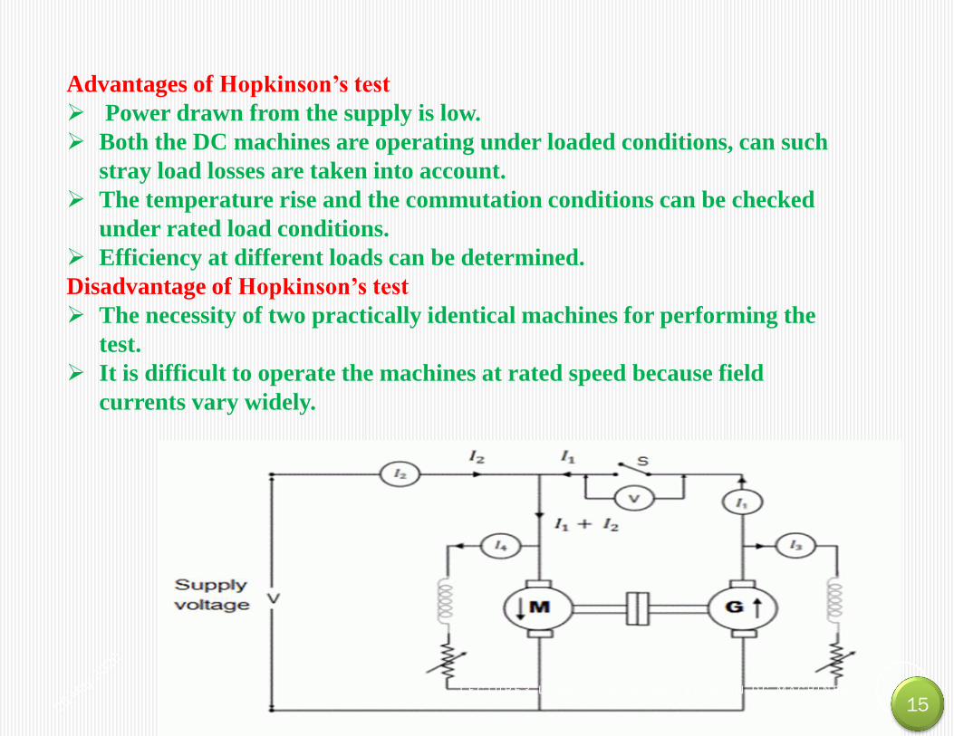
Advantages of Hopkinson’s test
Power drawn from the supply is low.
Both the DC machines are operating under loaded conditions, can such
stray load losses are taken into account.
The temperature rise and the commutation conditions can be checked
under rated load conditions.
Efficiency at different loads can be determined.
Disadvantage of Hopkinson’s test
The necessity of two practically identical machines for performing the
test.
It is difficult to operate the machines at rated speed because field
currents vary widely.
L E C T U R E 3 - L O S S E S A N D L O A D T E S T S O N D C M A C H I N E S 15 15

Retardation Test or Running Down on D.C Machines
Retardation test is also called as running down test.This is
very efficient way to find out stray losses in dc shunt motors.
In this test we get total stray losses nothing but combination of mechanical
(friction & windage) and iron losses of the machine.
The circuit diagram of retardation test on dc machines shown
below.A1,A2 are armature terminals.
L E C T U R E 3 - L O S S E S A N D L O A D T E S T S O N D C M A C H I N E S 16 16

Procedure of Retardation Test on D.C Machines
The main points in the retardation or running down test are discussed below,
1. Now start the dc machine normally,run the machine slightly above the rated
speed by adjusting resistance.
2. After achieving above the rated speed just cutoff the power supply to the
armature,but keeping field normally excited.
3. Now wait for some time to fall down of speed below rated,then using the
tachometer note down the values of speed (in rpm) and time (in sec).
4. The armature consequently slows down and the amount of kinetic energy
present in the armature is used to supply the rotational or stray losses which
includes iron, friction and winding loss.
If I is the amount of inertia of the armature ans is the angular velocity.
Kinetic energy of armature = 0.5 Iω².
Rotational losses, W = Rate of change of kinetic energy.
I=Moment of inertia of the armature.
L E C T U R E 3 - L O S S E S A N D L O A D T E S T S O N D C M A C H I N E S 17 17

I=Moment of inertia of the armature.
In retardation test of dc machines, the
rotational losses are given by
We have the formula of stray losses in retardation test of
machines, but here moment of inertia (I) of the armature is
unknown.
L E C T U R E 3 - L O S S E S A N D L O A D T E S T S O N D C M A C H I N E S 18 18

Determination of dN/dt in retardation test of dc machines
The voltmeter (V1) across the armature will give the value of
back e.m.f. of the motor.
When motor is cut off from the supply, the speed decrease in
speed is noted with the help of stop.
At any point C corresponding to normal speed, a tangent AB
is drawn. Then the value obtained from below can be
substituted in the expression for W which can give the
rotational looses.
dN/dt=OA(in rpm)/OB(in seconds)
L E C T U R E 3 - L O S S E S A N D L O A D T E S T S O N D C M A C H I N E S 19 19

Using Flywheel in retardation test
In this method we use the fly wheel whose moment of inertia is I1 to find the
I value. In first case retardation test is performed with armature alone and
dN/dt1 is determined. In next case, flywheel is employed on the shaft,
change in speed, dN/dt2 is noted.Addition of fly-wheel will not materially
affect the rotational losses.
L E C T U R E 3 - L O S S E S A N D L O A D T E S T S O N D C M A C H I N E S 20 20

(b) Without using Flywheel in retardation test
Without using flywheel, I is eliminated from the expression by an
experiment. First, retardation test is performed with armature alone.
The rotational losses are given by;
W = 0.011 IN dN/dt1
Next the motor is loaded with a known amount of power W' with a
brake.
For the same change in speed, dN/dt2 is noted. Then,
Since the values of W', t1 and t2 are known, the
value of W can be determined.
The electric loading in retardation test W' (or
extra power loss) is given by;
W' = average voltage x average current = V' I'a.
This is the simple article on retardation test on
dc machines.
L E C T U R E 3 - L O S S E S A N D L O A D T E S T S O N D C M A C H I N E S 21 21

L E C T U R E 3 - L O S S E S A N D L O A D T E S T S O N D C M A C H I N E S 22 22

L E C T U R E 3 - L O S S E S A N D L O A D T E S T S O N D C M A C H I N E S 23 23

L E C T U R E 3 - L O S S E S A N D L O A D T E S T S O N D C M A C H I N E S 24 24

L E C T U R E 3 - L O S S E S A N D L O A D T E S T S O N D C M A C H I N E S 25 25

L E C T U R E 3 - L O S S E S A N D L O A D T E S T S O N D C M A C H I N E S 26 26

1. A dc motor is connected in the short-shunt configuration, but the series
and the shunt windings get interchanged by mistake and the motor is
connected to the rated voltage,
a) neither of the windings get short-circuit
b) series winding gets overloaded
c) shunt winding gets overloaded
d) both of the winding get overloaded
View Answer
Answer: a
Explanation: In the short shunt configuration, the winding interchanging
does not change the configuration of the set up so none of the winding get
affected.
2. The main concern before doing hopkinson’s test for finding efficiency is
a) needs one motor and one generator is that it
b) ignores iron and stray losses
c) needs one motor
d) requires identical shunt machines
View Answer
Answer: d
Explanation: It is must that both the machines are identical as required by
the calculations.
L E C T U R E 3 - L O S S E S A N D L O A D T E S T S O N D C M A C H I N E S 27 27

3. Retardation test on DC shunt motor is used for finding _______
a) stray losses
b) copper losses
c) friction losses
d) iron losses
View Answer
Answer: a
Explanation: Retardation test is used for finding the stray losses.
4. The quantities needed to complete retardation test are/is
a) dw/dt and moment of inertia
b) dw/dt
c) current
d) any of the mentioned
View Answer
Answer: a
Explanation: We need the angular acceleration and the moment of inertia of
the machine.
L E C T U R E 3 - L O S S E S A N D L O A D T E S T S O N D C M A C H I N E S 28
28

5. ______ test is used for determining the efficiency of a traction motor
a) Field
b) Retardation
c) Hopkinson
d) Swineburne’s
View Answer
Answer: a
Explanation: Field test is used for finding efficiency of a traction motor.
6. If the field current and armature current are reversed, then
a) direction of rotation remains same
b) direction of rotation reverses
c) stops
d) none of the mentioned
View Answer
Answer: a
Explanation: When both field current and armature current are reversed then
the direction will not change.
L E C T U R E 3 - L O S S E S A N D L O A D T E S T S O N D C M A C H I N E S 29 29

7. Mark the possible causes of overheating of commutator in a DC machine.
a) Overload
b) Restricted ventilation
c) Shorted winding
d) Any of the mentioned
View Answer
Answer: a
Explanation: All the factors can cause the overheating of commutator.
8. In the hopkinson’s test on two DC machines. Machine A has field current of
1.4A and B has field current of 1.3A. Which machine acts as motor?
a) B
b) A
c) A,B
d) None of the mentioned
View Answer
Answer: a
Explanation: Ea/Eb = 1.4/1.3
Ea= 1.077 Eb > Eb
So, the machine will act as motor. L E C T U R E 3 - L O S S E S A N D L O A D T E S T S O N D C M A C H I N E S 30 30

9. In the Hopkinson’s test on two DC machines. Machine A has field
current of 1.4A and B has field current of 1.3A. Which machine acts as
generator?
a) B
b) A
c) A,B
d) None of the mentioned
View Answer
Answer: b
Explanation: Ea/Eb = 1.4/1.3
Ea= 1.077 Eb > Eb
So, the machine will act as generator.
10. Hopkinson’s test is also called regenerative test due to
a) energy of one machine is used to drive other
b) feedback
c) losses are least
d) extra motor is used
View Answer
Answer: a
Explanation: Regenerative phenomena utilizes the energy of the running
machine to tap the dynamically produced energy and use it to charge the
batter
L E C T U R E 3 - L O S S E S A N D L O A D T E S T S O N D C M A C H I N E S 31 31

11. The most appropriate relation to find efficiency of the generator
a) output/(output + losses)
b) (output – losses)/input
c) (output – losses)/(output + losses)
d) any of the mentioned
View Answer
Answer: a
Explanation: For a generator the output can be measured and so this
expression is used.
12. The efficiency in the swineburne’s test can be found.
a) True
b) False
View Answer
Answer: a
Explanation: Because the constant losses are known.
L E C T U R E 3 - L O S S E S A N D L O A D T E S T S O N D C M A C H I N E S 32
32

13. The possible assumption is/are made while doing swineburne’s test
(i) mechanical loss constant
(ii) Armature reaction neglected
(iii) Increases in flux
a) (i) and (ii)
b) (iii) and (i)
c) (i), (ii), and (iii)
d) (i)
View Answer
Answer: a
Explanation: There is decrease in flux due to positive temperature coefficient of
resistance in shunt machine.
14. Swineburne’s test is applicable to those machines in which flux is practically
_______
a) constant
b) linear
c) non-linear
d) none of the mentioned
View Answer
Answer: a
Explanation: Because the constant losses are known in advance of the test is
conducted L E C T U R E 3 - L O S S E S A N D L O A D T E S T S O N D C M A C H I N E S 33
33

15. Similarity between Hopkinonson’s and field’s test is that
a) both need similar mechanically coupled motor
b) both need similar electrically coupled motor
c) regenerative power
d) negligible power
View Answer
Answer: a
Explanation: The machines have to be mechanically coupled together.
16. Inspite of heavy initial investments, dc motors are used due to
a) flexibility and ease of control
b) lower losses
c) improved power factor of the system
d) all of the mentioned
View Answer
Answer: a
Explanation: The control of dc machines is very much simplified when
compared to other machines. So this makes it very useful when compared.
L E C T U R E 3 - L O S S E S A N D L O A D T E S T S O N D C M A C H I N E S 34 34

17. Separately excited dc generators are used in
a) Ward leonard system of speed control
b) Hopkinson’s testing
c) Voltage control
d) None of the mentioned
View Answer
Answer: a
Explanation: Separately excited dc generators are used in Ward leonard
system of speed control.
18. Maximum torque in dc series motor is limited by
a) commutation
b) heating
c) field control
d) all of the mentioned
View Answer
Answer: a
Explanation: Commutation is the process which reduces the induced emf and
so the torque.
L E C T U R E 3 - L O S S E S A N D L O A D T E S T S O N D C M A C H I N E S 35 35

19. Hoists, cranes and battery powered vehicles use _________ motors in
the locomotive.
a) dc series
b) dc shunt
c) induction
d) reluctance
View Answer
Answer: a
Explanation: Hoists, cranes require large starting torque which can be
provided by dc series motor.
20. There is an application which required pulsating loads, punch presses.
The most preferred machines would be
a) compound dc machine
b) series dc machine
c) shunt dc machine
d) all of the mentioned
View Answer
Answer: a
Explanation: It is compound machine whose flux can varied higher as
well as lower in order to have variable torques.
L E C T U R E 3 - L O S S E S A N D L O A D T E S T S O N D C M A C H I N E S 36 36

21. The manufacturer has mentioned a medium starting torque and 15%
speed regulation. The most appropriate motor for his requirement is
a) dc shunt motor
b) induction motor
c) differential motor
d) none of the mentioned
View Answer
Answer: a
Explanation: The dc shunt motor provides a medium values of the torque.
22. Centrifugal pumps, fans-blowers use
a) shunt as well as induction motor
b) only shunt motors
c) only induction motor
d) none of the mentioned
View Answer
Answer: a
Explanation: Centrifugal pumps, fans-blowers use shunt as well as
induction motor. L E C T U R E 3 - L O S S E S A N D L O A D T E S T S O N D C M A C H I N E S 37
37

23. Most commercial compound dc generator are normally supplied by
manufacturers as over compound machines because
a) degree of compounding can be adjusted by diverters acrosss series
field
b) they have ideally best for HVDC
c) cost effective than shunt
d) zero percent regulation
View Answer
Answer: a
Explanation: It is usually over compounded so that degree of
compounding can be adjusted by diverters across series field.
24. Which of the following are applied with differential compound
motor?
a) Hoist
b) Cranes
c) Drilling machines
d) None of the mentioned
View Answer
Answer: a
Explanation: Practically it is never used as the speed can rise very high. L E C T U R E 3 - L O S S E S A N D L O A D T E S T S O N D C M A C H I N E S 38 38

25. Most commercial compound dc generator are normally supplied by
manufacturers as ______ compounded machines.
a) over
b) under
c) level
d) none of the mentioned
View Answer
Answer: a
Explanation: Most commercial compound dc generator are normally
supplied by manufacturers as over compounded.
26. Long back ago, magnetic casette were in use, having permanent
magnet dc motors which had
a) magnets on stator and armature on rotor
b) magnet on rotor and armature on stator
c) electronic commutation
d) all of the mentioned
View Answer
Answer: a
Explanation: PMDC motors have field fixed on the stator and rotor has
coils. L E C T U R E 3 - L O S S E S A N D L O A D T E S T S O N D C M A C H I N E S 39
39

27. If a dc shunt motor is stopped by forcing starter handle back to OFF
position, then
a) dangerous sparking occurs at last stud
b) dangerous sparking occurs at all stud
c) it stops normally
d) heavy sparking
View Answer
Answer: a
Explanation: The sparking will occur at the last stud not all the studs of
the starter.
28. Interpoles are used to start the dc motor above the base speed.
a) True
b) False
View Answer
Answer: b
Explanation: Interpoles do not reduce the flux across the windings,
hence the speed does not rise above base speed.
L E C T U R E 3 - L O S S E S A N D L O A D T E S T S O N D C M A C H I N E S 40 40

29. A 200 V dc motor has external resistances of Ra and Rf in armature and
field circuits respectively. The starting current is reduced when
a) Ra is maximum and Rf minimum
b) Rf is maximum and Ra minimum
c) Ra is minimum and Rf minimum
d) Ra is maximum and Rf maximum
View Answer
Answer: a
Explanation: When Ra is maximum and Rf minimum then the current to the
armature is reduced. And hence the sparkings are reduced while starting.
30. A d.c. generator has been provided tappings on the armature winding at
intervals of 120 degrees from the side of commutator. The connection will be
a) delta connected alternator
b) star connected alternator
c) star connected induction motor
d) any of the mentioned
View Answer
Answer: a
Explanation: Dc generator if has displaced by 120 degrees physically then it
will be act as ac machine. L E C T U R E 3 - L O S S E S A N D L O A D T E S T S O N D C M A C H I N E S 41
41

31.
L E C T U R E 3 - L O S S E S A N D L O A D T E S T S O N D C M A C H I N E S 42 42

32.
L E C T U R E 3 - L O S S E S A N D L O A D T E S T S O N D C M A C H I N E S 43 43

33.
L E C T U R E 3 - L O S S E S A N D L O A D T E S T S O N D C M A C H I N E S 44 44

34.
L E C T U R E 3 - L O S S E S A N D L O A D T E S T S O N D C M A C H I N E S 45 45

35.
L E C T U R E 3 - L O S S E S A N D L O A D T E S T S O N D C M A C H I N E S 46 46

36.
L E C T U R E 3 - L O S S E S A N D L O A D T E S T S O N D C M A C H I N E S 47 47

37.
L E C T U R E 3 - L O S S E S A N D L O A D T E S T S O N D C M A C H I N E S 48 48

38.
Ans : C
L E C T U R E 3 - L O S S E S A N D L O A D T E S T S O N D C M A C H I N E S 49 49

39.
L E C T U R E 3 - L O S S E S A N D L O A D T E S T S O N D C M A C H I N E S 50 50

40.
Ans : C
L E C T U R E 3 - L O S S E S A N D L O A D T E S T S O N D C M A C H I N E S 51 51

41.
Ans : C
L E C T U R E 3 - L O S S E S A N D L O A D T E S T S O N D C M A C H I N E S 52 52

53
Few exercise Problems
What will happen when the D.C motor is connected to
A.C supply then?
1.D.C motor will run at rated speed
2.D.C motor will burn
3.D.C motor will run at slow speed
4.Both 2 & 3.
1.

54
If Ta be the armature torque and Ia be the armature
current then which of the following relation is valid for DC
series motor before saturation?
1.Ta ∝ Ia
2.Ta ∝ Ia2
3.Ta ∝ 1/Ia
4.Ta ∝ 1/Ia2
2.

55
Which DC motor is preferred for Elevator?
1.Differentially compound motor
2.Series motor
3.Shunt Motor
4.Cumulative compound motor
3.

56
In the DC machine, the fractional pitch winding
is used
1.To reduce the Harmonic in generated EMF
2.Improve Cooling
3.Increase EMF
4.To reduce the copper losses
4.

57
A 4 pole, lap wound d.c motor has 540 conductors and
230 V supply. The armature resistance is 0.8Ω. Its
speed found to be 1000 r.p.m. the flux per pole is 25
mWb. The Induced e.m.f.and Armature current will be
1.250 V, 10 A
2.300 V, 6.25 A
3.225 V, 10 A
4.225 V, 6.25 A
5.

58
A short shunt compound generator supplies a load current of 100
A at 250 V. The generator has the following winding resistances:
shunt field = 130Ω, Armature 0.1 Ω and series field = 0.1 Ω . Find
the Emf generated if the brush drop is 1 V per brush.
1.272.2 V
2.262.2 V
3.272.0 V
4.262.0 V
6.

L E C T U R E 3 - L O S S E S A N D L O A D T E S T S O N D C M A C H I N E S 60

L E C T U R E 3 - L O S S E S A N D L O A D T E S T S O N D C M A C H I N E S 61

62
Solutions for exercise Problems
What will happen when the D.C motor is connected to A.C supply then?
1.D.C motor will run at rated speed
2.D.C motor will burn
3.D.C motor will run at slow speed
4.Both 2 & 3.
Answer 4. Either 2 & 3
Explanation:
Series Connection:
•In DC machine, T = kφi
where k = number of poles and the number of turns in the winding.
Φ = flux per pole
i = current.
•If saturation of core is neglected, then Flux is proportional to field current.
•So Torque= k *field current*armature current.
•For DC series machine, Armature current = Field Current,
Therefore, Torque = k × Ia2
•If we apply AC then both, during positive as well as negative half cycle, torque is
positive from above relation. So, torque is unidirectional, but due to AC, it will be
pulsating.
Parallel connection:
•But, In the case of parallel connection, it won’t rotate at all and will start
humming and will create vibrations, as a torque produced by positive and
negative cycle will cancel out each other. D.C. motor will be heated
1.

63
If Ta be the armature torque and Ia be the armature current then which of the
following relation is valid for DC series motor before saturation?
1.Ta ∝ Ia
2.Ta ∝ Ia2
3.Ta ∝ 1/Ia
4.Ta ∝ 1/Ia2
Answer 2. Ta ∝ Ia2
Explanation:
•We know that torque is directly proportional to the product of armature
current and field flux, Ta ∝ ɸ.Ia.
•In DC series motors, field winding is connected in series with the armature, i.e.
Ia= If. Therefore, before magnetic saturation of the field, flux ɸ is directly
proportional to Ia.
•Hence, before magnetic saturation Ta ∝ Ia2.
•After magnetic saturation of the field poles, flux ɸ is independent of armature
current Ia. Therefore, the torque varies proportionally to Ia only, T ∝
Ia.Therefore, after magnetic saturation, Ta-Ia curve becomes a straight line.
2.

64
Which DC motor is preferred for Elevator?
1.Differentially compound motor
2.Series motor
3.Shunt Motor
4.Cumulative compound motor
Answer 4. Cumulative compound motor
Explanation:
•Compound motor finds application where high starting torque
or pulsating load are required.
•In the elevator, the load is always pulsating and high starting
torque is required to run the elevator.
•This high starting torque is provided by the series winding of
the compound motor and maximum speed at no load is limited
by shunt winding of the compound motor.
3.

65
In the DC machine, the fractional pitch winding is used
1.To reduce the Harmonic in generated EMF
2.Improve Cooling
3.Increase EMF
4.To reduce the copper losses
Answer 1. To reduce the Harmonic in generated EMF
Explanation:
•In full pitched coils, as one conductor of a turn in a coil cuts N pole, the other
conductor of the same turn cuts S pole resulting in the production of induced
emf(E), i.e phase angle is 180 degree
•In short-pitched coils, both conductors of the same turn in a coil don’t cut the
respective poles simultaneously. so phase angle is slightly less than 180 degree As a
result, the magnitude of induced emf gets reduced to E × Cos(nα/2)
Where E × Cos(nα/2) is called a pitch factor
For eliminating 3rd harmonic from Generated EMF,
Cos(3α/2) = 0
3α/2 = π/2
α = π/3 = 60°
4.

66
A 4 pole, lap wound d.c motor has 540 conductors and 230 V supply. The armature
resistance is 0.8Ω. Its speed found to be 1000 r.p.m. the flux per pole is 25 mWb. The
Induced e.m.f.and Armature current will be
1.250 V, 10 A
2.300 V, 6.25 A
3.225 V, 10 A
4.225 V, 6.25 A
Answer. D. 225 V, 6.25A
Explanation:-
Given Data
Number of Poles P = 4
The number of parallel Path A = 4 (In Lap wound the number of brush required by
this winding is always equal to the number of poles.)
Total number of armature conductor Z = 540
Flux per Pole Φ = 20 mWb = 25 x 10-3 Wb,
Armature current Ia =?
Back EMF Eb =?
(i) Back EMF of DC motor
= (PΦZN)/(60A) = (25 x 10 -3 x 4 x 1000 x 540)/(60 x 4) = 225 V
Eb = 225 V
(ii) Armature current
From the voltage equation the back EMF of DC motor is
Eb = V − IaRa
225 = 230 − 0.8Ia
Ia = 6.25 A
Hence the back EMF is 225 V and Armature current is 6.25 A
5.

67
A short shunt compound generator supplies a load current of 100 A at 250 V. The
generator has the following winding resistances:
shunt field = 130Ω, Armature 0.1 Ω and series field = 0.1 Ω . Find the Emf
generated if the brush drop is 1 V per brush.
1.272.2 V
2.262.2 V
3.272.0 V
4.262.0 V
Answer.1. 272.2 V
Explanation:-
Voltage = 250 V
Load current (IL) = 100 A
Shunt field (Rf) = 130Ω
Armature field (Ra) = 0.1Ω
Series field (Rse) = 0.1Ω
Brush voltage Drop = 1V
Now voltage drop in the field winding = ILRse
= 100 x 0.1 = 10 V
For short shunt compound generator, the voltage drop across series field winding
gets added with voltage drop across armature winding
Voltage drop across field winding + Voltage drop across armature winding
V1 = 250 + 10 = 260 V
Field current If = V1/Rf = 260/130 = 2 A
So armature current
Ia = IL + If = 100 + 2 = 102 A
Generated EMF
E = V1 + IaRa
= 260 + 102×0.1
E = 270.2 Volt
6.