PRODUCTIVITY IMPROVEMENT OF SHAKTI PT LABYRINTH ...
56
VISVESVARAYA TECHNOLOGICAL UNIVERSITY Jnana sangama, Belgavi, Karnataka – 590 014 Project Report on “PRODUCTIVITY IMPROVEMENT OF SHAKTI POWER TURBINE LABYRINTH CAGE” Submitted in partial fulfillment of the requirement for the award of degree of BACHELOR OF ENGINEERING IN MECHANICAL ENGINEERING SUBMITTED BY Under the guidance of Prof. SRINATH M K Asst. Professor, Department of Mechanical Engineering DEPARTMENT OF MECHANICAL ENGINEERING NEW HORIZON COLLEGE OF ENGINEERING BANGALORE-560 103 2017-18 B MOHAMMED ALTAF 1NH14ME030 ABHISHEK 1NH14ME001 ASIF ALI U BOODIHAL 1NH14ME027 MRIGANKA DEKA 1NH14ME173
-
Upload
khangminh22 -
Category
Documents
-
view
1 -
download
0
Transcript of PRODUCTIVITY IMPROVEMENT OF SHAKTI PT LABYRINTH ...

VISVESVARAYA TECHNOLOGICAL UNIVERSITY
Jnana sangama, Belgavi, Karnataka – 590 014
Project Report
on
“PRODUCTIVITY IMPROVEMENT OF SHAKTI POWER TURBINE
LABYRINTH CAGE”
Submitted in partial fulfillment of the requirement for the award of degree of
BACHELOR OF ENGINEERING
IN
MECHANICAL ENGINEERING
SUBMITTED BY
Under the guidance of
Prof. SRINATH M K
Asst. Professor,
Department of Mechanical Engineering
DEPARTMENT OF MECHANICAL ENGINEERING
NEW HORIZON COLLEGE OF ENGINEERING BANGALORE-560 103
2017-18
B MOHAMMED ALTAF 1NH14ME030
ABHISHEK 1NH14ME001
ASIF ALI U BOODIHAL 1NH14ME027
MRIGANKA DEKA 1NH14ME173

DEPARTMENT OF MECHANICAL ENGINEERING
CERTIFICATE
It is certified that the technical seminar entitled “PRODUCTIVITY
IMPROVEMENT OF SHAKTI POWER TURBINE LABYRINTH CAGE” is
work carried out by B MOHAMMED ALTAF, ABHISHEK, ASIF ALI U
BOODIHAL, MRIGANKA DEKA are bonafide students of New Horizon College
of Engineering, Bangalore in partial fulfillment for the award of degree of Bachelor
of Engineering in Mechanical Engineering of the Visvesvaraya Technological
University, Belgaum during the year 2017-18. It is further certified that all
corrections/suggestions indicated for internal assessment has been incorporated in the
report deposited in the departmental library. The Project Report has been approved as
it satisfies the academic requirements in respect of Project Work prescribed for the
said degree.
Signature of the guide Signature of the HOD Signature of the Principal Prof. Srinath M K Dr. M S GANESHA PRASAD Dr. Manjunatha Asst. Professor, Dean-Student Affairs & HOD-ME, Principal
Dept. of Mechanical Engineering. Dept. of Mechanical Engineering. NHCE
Name(s) of the student: University Seat Number(s):
BB MMOOHHAAMMMMEEDD AALLTTAAFF 11NNHH1144MMEE003300
AABBHHIISSHHEEKK 11NNHH1144MMEE000011
AASSIIFF AALLII UU BBOOOODDIIHHAALL 11NNHH1144MMEE002277
MMRRIIGGAANNKKAA DDEEKKAA 11NNHH1144MMEE117733
External Examiner(s) Signature with Date
1.
2.

ABSTRACT
“Productivity optimization through re-engineering thefixtures used for labyrinth cage
of Shakti engine”, used inadvanced light helicopter.
The objective is to improve the productivity of SHAKTI PT LABYRINTH CAGE.
Milestone chart was drawn for monitoring the activities. Structured brain storming
sessions were conducted, for data collection and analysis of the problem. The problem
was categorized under 4M’s (Man, Machine, Material and Method). Each and every
cause was discussed in depth for arriving to a root cause.
High setup and cycle time of CNC turning operation was due to use of soft jaws and
carrying out the operation. This traditional system requires machining of soft jaws
every time they are loaded, thus increasing the setup time.
Manufacturing department members with our batch discussed all the solutions and
solved this problem by developing changes in the fixture and cutting parameters to
carry out the above laid operations. There by eliminating the setup time for operation
and rejection rate is completely eliminated, also the cycle time was reduced by around
4 hours.

ACKNOWLEDGEMENT
The satisfaction that accompanies the successful completion of any work would be
incomplete without the mention of the people who made it possible and whose
constant encouragement and guidance has been a source of inspiration through the
course of completion of this technical seminar.
We express our sincere gratitude to Sri MOHAN MANGHNANI, Chairman, and
the management of New Horizon College of Engineering for providing this
endower.
We wish to express our sincere gratitude and thanks to Dr. M.S GANESHA
PRASAD, Head of Mechanical Department, New Horizon College of
Engineering, Bengaluru, as
wellasDr.MANJUNATHA,Principal,NewHorizonCollegeofEngineering,Bengalu
ru for providing facilities, friendly atmosphere and encouragement to complete the
project worksuccessfully.
WesincerelythankourguideMr.SRINATH M K,Asst.Professor,Department of
Mechanical Engineering, New Horizon College of Engineering, Bengaluru, for his
immense guidance, invaluable inspiration, words of advice and unstinted support
throughout this projectwork.
We respect and owe our deep gratitude to our external project guide Mr. C
SURYAKUMAR,SeniorManager,CNCdepartment,Engine division,
forprovidingus an opportunity to do the project work in HINDUSTAN
AERONAUTICS LIMITED. Although he had busy schedule managing the PSU
affairs, he took keen interest in our project and guided us all along till the
completion of our project work by providing all the necessary information and
support which made us complete the project duly. We are extremely thankful to
him for providing guidance and goodsupport.
We are thankful to our parents and friends for their blessings, moral support,
encouragement that has enabled me to complete this project work successfully.

INDEX
CERTIFICATE I
ACKNOWLEDGEMENT II
ABSTRACT III
CONTENTS IV
CONTENTS
CHAPTER1:INTRODUCTION 1
1.1 : CNC MACHININGPROCESS 2
1.2 : APPLICATIOMS OF CNC 4
1.3 : ADVANTAGES AND LIMITATIONS 5
1.4 : SHAKTI ENGINE 5
1.5 : TURBOSHAFTENGINE 6
1.6 : MODULES INVOLVED IN BUILT
OFSHAKTIENGINE 8
1.7 : POWER TURBINE 8
CHAPTER 2: WORKSHOP AND THE MACHINES 10
2.1: CTX GAMMA 1250 TURNMILLCENTRE 10
CHAPTER 3: LABYRINTHSEALS 13
3.1: COMPONENTS OF LABYRINTHCAGE 15
CHAPTER 4: LITERATURESURVEY 19

CHAPTER5:FIXTURES 29
5.1: GENERAL CONSIDERATIONS OFFIXTUREDESIGN 30
CHAPTER 6: MATERIALSELECTION 33
CHAPTER7: METHODOLOGY 35
CHAPTER 8: BASIC PROCESSES IN MAKINGLABYRINTHCAGE 36
CHAPTER9: CONCLUSION 49
REFERN
CES

REFERENCES
1. Thermal fatigue resistance of welded joints in stainless steel high temperature exhaust
application by Laurent & Pierie-olivier.
2. Material science and metallurgy by Phaneesh.
3. Material science and metallurgy by O P Khanna.
4. Mechanical measurements and metallurgy by Phaneesh.
5. Fundamentals of geometric dimensioning and tolerancing by Alex Krulikowski.
6. Fundamentals of geometric dimensioning and tolerancing by Gene Cogorno.
7. Thermal stresses and low cycle fatigue by Mansos S S.
8. Design of jigs fixtures and press tools by K Venkataraman.
PRODUCTIVITY IMPROVEMENT OF SHAKTI PT LABYRINTH CAGE
DEPT OF ME, NHCE Page 1
CHAPTER 1
INTRODUCTION
Productivity is a measure of output (produced from each hour of work) per unit of
input, from a certain production process.
Productivity Improvement involves analyzing the current operations processes and
determining specific, high impact areas of opportunity. Productivity improvement
strategies can then be put in place to increase efficiency as well as production output.
Benefits from productivity improvement include a decrease in overall cost combined
with an increase in revenue.
The project was done in the esteemed organization Hindustan Aeronautics Limited
(HAL).
The beginning of Hindustan Aeronautics
Limited can be traced back to the year 1940
when an eminent and foresighted
industrialist, Late Mr. Walchand Hirachand
setup the company called “HINDUSTAN
AERONAUTICS LIMITED” in association
with the Mysore Government. The
company was officially registered on
December 23, 1941 as a private company.
The collaboration was established with the
Intercontinental Aircraft Company, for the
maintenance of such aircraft as the Harlow
Trainer Curtis fighter and the Vulture
Attack Bomber.
After the flight of the Harlow trainer in 1941, HAL’s pride got a further boost due to
the successful flight of India’s first indigenously effort to ten scatter gliders designed
and built under Dr. V.M. Ghatage from the engineering department. The Second World
War saw the aircraft manufacturing efforts being abandoned in favor of repair and
overhaul services and HAL became the principle overall base for the South-East
Command of the Allied Forces. In 1945, Government of India took over the
management and activities which increased manifold after India attained freedom.

PRODUCTIVITY IMPROVEMENT OF SHAKTI PT LABYRINTH CAGE
DEPT OF ME, NHCE Page 2
After Independence, Hindustan Aeronautics Limited restructured itself for the
design, development and manufacture of a variety of aircrafts. During the 59 year
Independence era, HAL has excelled in the research and development of
indigenously designed trainers, helicopters like CHEETAH, CHETAK,
ADVANCED LIGHT HELICOPTERS(ALH) and multirole fighters such as MIG’S,
JAGUAR, MIRAGE, DORNIER, PUSHPAK, KIRAN and LIGHT COMBAT
AIRCRAFT(LCA).
The company has also expanded its domain into the Aerospace field.
Today HAL is one of the largest aerospace complexes in Asia and the fourth largest
aircraft manufacturer in the world. It plays a crucial role in the Indian ambition for
broad based industrialization with growth emphasis, to become not only self reliable
in defense production but also to become an international partner in civil aircraft
manufacture and maintenance. HAL has 4 complexes namely:
RESEARCH AND DEVELOPMENT COMPLEX
BANGALORE COMPLEX
ACCESSORY COMPLEX
MIG COMPLEX
1.1 COMPUTER NUMERICAL CONTROL (CNC) MACHINING
PROCESS CNC machining is a manufacturing process in which pre-programmed computer
software dictates the movement of factory tools and machinery. The process can be
used to control a range of complex machinery, from grinders and lathes to mills and
routers. With CNC machining, three-dimensional cutting tasks can be accomplished
in a single set of prompts.
Short for “computer numerical control,” the CNC process runs in contrast to — and
thereby supersedes — the limitations of manual control, where live operators are
needed to prompt and guide the commands of machining tools via levers, buttons and
wheels. To the onlooker, a CNC system might resemble a regular set of computer

PRODUCTIVITY IMPROVEMENT OF SHAKTI PT LABYRINTH CAGE
DEPT OF ME, NHCE Page 3
components, but the software programs and consoles employed in CNC machining
distinguish it from all other forms of computation.
When a CNC system is activated, the desired cuts are programmed into the software
and dictated to corresponding tools and machinery, which carry out the dimensional
tasks as specified, much like a robot.
In CNC programming, the code generator within the numerical system will often
assume mechanisms are flawless, despite the possibility of errors, which is greater
whenever a machine is directed to cut in more than one direction simultaneously.
The placement of a tool in a numerical control system is outlined by a series of
inputs known as the part program.

PRODUCTIVITY IMPROVEMENT OF SHAKTI PT LABYRINTH CAGE
DEPT OF ME, NHCE Page 4
With a numerical control machine, programs are inputted via punch cards. By
contrast, the programs for CNC machines are fed to computers though small
keyboards. CNC programming is retained in a computer’s memory. The code itself is
written and edited by programmers. Therefore, CNC systems offer far more
expansive computational capacity. Best of all, CNC systems are by no means static,
since newer prompts can be added to pre-existing programs through revised code.
In CNC, machines are operated via numerical control, wherein a software program is
designated to control an object. The language behind CNC machining is alternately
referred to as G-code, and it’s written to control the various behaviors of a
corresponding machine, such as the speed, feed rate and coordination.
Basically, CNC machining makes it possible to pre-program the speed and position
of machine tool functions and run them via software in repetitive, predictable cycles,
all with little involvement from human operators. Due to these capabilities, the
process has been adopted across all corners of the manufacturing sector and is
especially vital in the areas of metal and plastic production.
For starters, a 2D or 3D CAD drawing is conceived, which is then translated to
computer code for the CNC system to execute. After the program is inputted, the
operator gives it a trial run to ensure no mistakes are present in the coding.
1.2 APPLICATIONS OF CNC
The applications of CNC include both for machine tool as well as non-machine tool
areas. In the machine tool category, CNC is widely used for lathe, drill press, milling
machine, grinding unit, laser, sheet-metal press working machine, tube bending
machine etc. Highly automated machine tools such as turning center and machining
center which change the cutting tools automatically under CNC control have been
developed. In the non-machine tool category, CNC applications include welding
machines (arc and resistance), coordinate measuring machine, electronic assembly,
tape laying and filament winding machines for composites etc.

PRODUCTIVITY IMPROVEMENT OF SHAKTI PT LABYRINTH CAGE
DEPT OF ME, NHCE Page 5
1.3 ADVANTAGES AND LIMITATIONS
The benefits of CNC are:
(1) High accuracy in manufacturing
(2) Short production time
(3) Greater manufacturing flexibility
(4) Simpler fixtures
(5) Contour machining (2 to 5 –axis machining)
(6) Reduced human error.
The drawbacks include:
(1) High cost.
(2) Maintenance
(3) Requirement of skilled part programmer.
1.4 SHAKTI ENGINE
The Turbomeca Ardiden is a family of turbo shaft engines featuring simple, modular
and compact design. They are built around a gas generator with two centrifugal
compressor stages, coupled to a single-stage high-pressure turbine. The power
turbine comprises two stages. Ardiden engines satisfy the most demanding mission
requirements, while retaining full performance under high altitude and hot
temperature conditions.
Specification of Shakti engine
Oil consumption =0.2 ltr/hr
Compression ratio= 12.7:1
Air mass flow=3.75kg/sec
Power turbine speed = 20889 rpm
Gas generator speed = 39598rpm
Output shaft speed = 6000rpm
Height= 707mm
Width=571mm Length= 1279m
Weight=205 Kg
Max take off power= 1032 kW
Figure 1.1 SHAKTI ENGINE

PRODUCTIVITY IMPROVEMENT OF SHAKTI PT LABYRINTH CAGE
DEPT OF ME, NHCE Page 6
The Shakti, also known as Ardiden 1H1, is a turbo shaft engine jointly developed by
Turbomeca (France) and Hindustan Aeronautics Limited (HAL) based on the Ardiden
turbo shaft to power weaponized variants of the Dhruv Advanced Light Helicopter
(ALH). It made its maiden flight powering the Dhruv helicopter on August 16, 2007.
The first Ardiden 1H1 re-engineered Dhruv helicopter took to the skies on January 12,
2009.
The Shakti features three modules for easy maintenance: a reduction / accessory
gearbox module, a gas generator module and a power turbine module. The Time
between Overhaul (TBO) ranges from 3,000 to 6,000 hours. The Shakti engine
delivers 30 percent more power than TM333-2B2 power plant, which also powers
the Dhruv, and features 19 percent of components developed in India. The Shakti
may be the prime candidate for powering the future Light Combat Helicopter (LCH)
also being developed by HAL.
1.5 TURBOSHAFT ENGINE
Shakti Engine is a turbo shaft engine as mentioned above. A brief view about Turbo
shaft engine is given below.
A turbo shaft engine is a variant of a jet engine that has been optimized to produce
shaft power to drive machinery instead of producing thrust. Turbo shaft engines are
most commonly used in applications that require a small, but powerful, light
weight engine, inclusive of helicopters and auxiliary power units.
A turbo shaft engine uses the same principles as a turbojet to produce energy, that is,
it incorporates a compressor, combustor and turbine within the gas generator of the
engine. The primary difference between the turbo shaft and the turbojet is that an
additional power section, consisting of turbines and an output shaft, has been
incorporated into the design. In most cases, the power turbine is not mechanically
linked to the gas generator. This design, which is referred to as a "free power
turbine", allows the speed of the power turbine to be optimized for the machinery
that it will energize without the need for an additional reduction gearbox within the
engine. The power turbine extracts almost all of the energy from the exhaust stream
and transmits it via the output shaft to the machinery it is intended to drive.
A turbo shaft engine is very similar to a turboprop and many engines are available in

PRODUCTIVITY IMPROVEMENT OF SHAKTI PT LABYRINTH CAGE
DEPT OF ME, NHCE Page 7
both variants. The principal difference between the two is that the turboprop version
must be designed to support the loads of the attached propeller whereas a turbo shaft
engine need not be as robust as itnormally drives a transmission which is structurally
supported by the vehicle and not by the engine itself.

PRODUCTIVITY IMPROVEMENT OF SHAKTI PT LABYRINTH CAGE
DEPT OF ME, NHCE Page 8
1.6 MODULES INVOLVED IN BUILT OF SHAKTI
ENGINE
There are three modules in the build namely:
Reduction Gearbox.
Gas Generator.
Power Turbine.
Figure 1.2: different modules of Shakti engine
1.7 POWER TURBINE
Turbine engines are more powerful and are used in a wide variety of helicopters.
They produce a tremendous amount of power for their size but are generally more
expensive to operate. The turbine engine used in helicopters operates differently
from those used in airplane applications. In most applications, the exhaust
outlets simply release expended gases and do not contribute to the forward motion of
the helicopter. Approximately 75 percent of the incoming airflow is used to cool the
engine.
Power turbine extracts energy from the gas to drive the main power drive. It is
located at the rear of the engine. The power turbine assembly forms the module 3.

PRODUCTIVITY IMPROVEMENT OF SHAKTI PT LABYRINTH CAGE
DEPT OF ME, NHCE Page 9
Figure 1.3: power turbine module

PRODUCTIVITY IMPROVEMENT OF SHAKTI PT LABYRINTH CAGE
DEPT OF ME, NHCE Page 10
CHAPTER 2
WORKSHOP AND THE MACHINES
The workshop where the project was conducted is the SHAKTI CNC WORKSHOP.
The machines that can be found in the workshop are as follows
1. CTX Gamma 1250 Turn Mill Centre-works on Siemens 840DSL and is
capable of machining in 5 axis. It can work on a component weighing 1000kgs
having dimensions 600mm diameter and length of 1250mm and can accommodate
12 tools.
2. Hardinge Elite II- works on FANUC and is capable of machining in 2 axes the
tool holder can accommodate 12 tools and is a turn mill centre.
3. HMT SBCNC-60/1250– Works on Siemens 840DSL and is a two axis machine
centre is a CNC Disk Lathe.
4. DMC 100 U DUOBLOCK– Works on Siemens and is a two pallet machine. It
is a five axis machine. The machine has two pallets to reduce the setup time.
5. KEHREN CURVIC GRINDING MACHINE- It works on Siemens and is
a three axis machine. It has tracking teeth and is imported from Germany.
6. DMU MONOBLOCK SINGLE PALLET- It is similar to machine no.4 on
this list but the difference is that it has a single pallet.
2.1 CTX GAMMA 1250 TURN MILL CENTRE
The machine or the workstation where the major parts of the project has been
conducted is the CTX GAMMA 1250 TURN MILL CENTRE.
The CTX GAMMA 1250 is a Turning and Milling machine, which means both
turning operations and milling operations can be conducted on the same work
stations. The CTX GAMMA has a tool capacity of 12 at the same time. The CTX
gamma 1250 TC handles work pieces up to φ630 mm × 1,300 mm. The model offers
the linear specification equipped with the linear drive that achieves an acceleration of
1G and a rapid traverse rate of 60 m/min.

PRODUCTIVITY IMPROVEMENT OF SHAKTI PT LABYRINTH CAGE
DEPT OF ME, NHCE Page 11
Figure 2.1: CTX
Gamma turn mill center Few specifications are
mentioned below:
Capacity 12 tools.
Max. dia of work piece (X) 600 mm
Max. length of work piece(Z) 1250 mm
Max. spindle speed
(Turn Mill Spindle) 2000 rpm
CONTROL AND SOFTWARE ALTERNATIVES
CELOS
SIEMENS
STC 20 SLANT BED TURNING CENTRE
STC 20 SLANT BED TURNING CENTRE is a turning centre where bar stocking or
bar slicing and various other turning operations are conducted.
The STC 20 has been designed for high productivity and accuracy, with high
traverse rates and reduced non-cutting times.
Figure 2.2: STC 20 machining center

PRODUCTIVITY IMPROVEMENT OF SHAKTI PT LABYRINTH CAGE
DEPT OF ME, NHCE Page 12
Few specifications are mentioned below:
Swing over bed 420 mm
Maximum turning dia. 250 mm
Maximum turning length 600 mm
Chuck dia. 250 mm
Bar passage/Spindle bore 53 mm
Spindle power (100%) 7.5 kW
Speed range 100-4000rpm
CONTROL AND SOFTWARE ALTERNATIVES
FANUC
SIEMENS

PRODUCTIVITY IMPROVEMENT OF SHAKTI PT LABYRINTH CAGE
DEPT OF ME, NHCE Page 13
CHAPTER 3
LABYRINTH SEALS
A labyrinth seal is a type of mechanical seal that provides a tortuous path to help
prevent leakage. An example of such a seal is sometimes found within an axle's
bearing to help prevent the leakage of the oil lubricating the bearing.
A labyrinth seal may be composed of many grooves that press tightly inside another
axle, or inside a hole, so that the fluid has to pass through a long and difficult path to
escape. Sometimes screw threads exist on the outer and inner portion. These
interlock, to produce the long characteristic path which slows leakage. For labyrinth
seals on a rotating shaft, a very small clearance must exist between the tips of the
labyrinth threads and the running surface. The "teeth" of the labyrinth seal may be on
the rotating shaft or on the stator, or both, in an interlocking configuration.
Labyrinth seals on rotating shafts provide non-contact sealing action by controlling
the passage of fluid through a variety of chambers by centrifugal motion, as well as
by the formation of controlled fluid vortices. At higher speeds, centrifugal motion
forces the liquid towards the outside and therefore away from any passages.
Similarly, if the labyrinth chambers are correctly designed, any liquid that has
escaped the main chamber becomes entrapped in a labyrinth chamber, where it is
forced into a vortex-like motion. This acts to prevent its escape, and also acts to repel
any other fluid. Because these labyrinth seals are non-contact, they do not wear out.
Many gas turbine engines, having high rotational speeds, use labyrinth seals due to
their lack of friction and long life. Because liquid-filled labyrinth seals still generate
heat due to the viscosity of the seal oil, and because seal oil can contaminate the
process fluids, modern high-performance gas turbines use dry gas seals which use
spring-loaded rings with an inert gas in between the faces of the rings to provide the
seal. This creates even lower friction and provides a liquid-free seal.
A labyrinth seal is placed inside a cage which is known as labyrinth cage.

PRODUCTIVITY IMPROVEMENT OF SHAKTI PT LABYRINTH CAGE
DEPT OF ME, NHCE Page 14
FIGURE 3.1: Labyrinth cage

PRODUCTIVITY IMPROVEMENT OF SHAKTI PT LABYRINTH CAGE
DEPT OF ME, NHCE Page 15
3.1 COMPONENTS OF LABYRINTH CAGE
1) Cage body
2) Flange
3) Deflector
4) Plasma coating
5) Carbide coating
Cage body: It deflects all the gases coming from the compressor and turbine to
the exhaust vent, away from shaft.
Flange: A flange is an external or internal ridge, or rim (lip), for strength
Deflector: Purge grease through shaft seals or through a 15 mm hole (relief port)
drilled in the housing. The hole must be on the side of the bearing opposite from the
grease nipple, at the bottom of the bearing housing when in service and between the
bearing and seal.
Plasma coating:
Plasma-sprayed coatings are heated powders applied on the shaft surface at a high
temperature (3000 "F) and high speed, resulting in high adherence to the shaft. The
shaft surface hardness will be equal to the hardness of the coating being applied.
After the coating is applied, the shaft must be machined to the desired surface finish.
Because thematerials being applied are very hard and the surface finish is very rough
after application, it is necessary to grind and have the shaft to the required surface
finish.
The coating process also leaves a porous surface, which can be sealed or coated with
a lubricant. The pores can be filled with a phenolic sealer or graphite-molybdenum
disulfide dry lubricant toprotect the substrate from harmful media.
Properties of Plasma-Sprayed Coated Surfaces
Plasma-sprayed coatings provide high hardness, high abrasion resistance, excellent

PRODUCTIVITY IMPROVEMENT OF SHAKTI PT LABYRINTH CAGE
DEPT OF ME, NHCE Page 16
material uniformity, low abrasion to the seal, and good corrosion resistance when
pores are effectively sealed.
High Hardness
The hardness of a plasma-sprayed surface is determined by the coating being used. A
hardness of1300 HV (approximately 74 Rockwell C) can be obtained with chromium
oxide coatings. Lower hardness is obtained with aluminum oxide and tungsten
carbide coatings.
High Abrasion Resistance
Maxma-sprayed shafts attain excellent abrasion resistance, which makes the
materials ideal for use in abrasive environments such as steam, water, abrasive
materials, non-lubricated areas, and in high- speed or high pressure rotary
reciprocating service.
Uniformity
Plasma-sprayed coating uses metco(top coat) and amory(Bond coat). When applied
correctly, the plasma-sprayed coating has excellent matrix uniformity, as illustrated
in figure. This uniformity results in greater seal performance.
Low Abrasion to the Seal
The coatings are generally modular with rough edges, minimizing abrasion.
Corrosion Resistance
Plasma-sprayed coatings have a certain degree of porosity; however, such porosity
can easily be sealed so that plasma-sprayed shafts may be used in many aggressive
environments. After coating, a liquid phenolic sealer is applied to enhance corrosion

PRODUCTIVITY IMPROVEMENT OF SHAKTI PT LABYRINTH CAGE
DEPT OF ME, NHCE Page 17
resistance. The sealer must be compatible with the fluid media to be effective.
Thickness of Coating
The coating thickness will depend on the application, but will vary from 0.0005 to
0.0030 in(from 0.127 to 0.762 mm).

PRODUCTIVITY IMPROVEMENT OF SHAKTI PT LABYRINTH CAGE
DEPT OF ME, NHCE Page 18
HVOF Tungsten Carbide Coating
Tungsten carbide is chemical carbide containing equal parts of tungsten and carbon
atoms. It is approximately twice as strong as steel with double the density and is double
the density of steel. Tungsten Carbide’s hardness level is comparable with corundum
and can only be polished and finished with abrasives of superior hardness such as cubic
boron nitride and diamond powder, wheels, and compounds.
In its basic form, tungsten carbide is a fine gray powder, but it can be pressed and
formed into shapes for use in industrial machinery, cutting tools, abrasives, armor-
piercing rounds, other tools and instruments.
Why tungsten carbide?
It offers excellent wear for extreme conditions
It provides good surface for extremely hard coating materials
It provides rigid and dense substrate
It offers a greater degree of flexibility when needed (i.e., in applications
involving shaft flexibility)
Figure 3.3 : Tungsten carbide coating operation

PRODUCTIVITY IMPROVEMENT OF SHAKTI PT LABYRINTH CAGE
DEPT OF ME, NHCE Page 19
CHAPTER 4
LITERATURE SURVEY
THERMAL FATIGUE RESISTANCE OF WELDED JOINTS
IN STAINLESS STEEL HIGH TEMPERATUREEXHAUST
APPLICATIONS
Weld seams often constitute critical points in the thermo-mechanical fatigue design
of a stainless steel automotive exhaust manifold. Therefore, a thermal fatigue test on
V-shaped specimens was developed by ArcelorMittalIsbergues Research Centre to
simulate the thermo-mechanical loading of such a part. Two ferritic base metals
dedicated to high temperature applications, together with various filler materials
(both austenitic and ferritic grades) commonly used in the exhaust market were
tested with a 250-950°C thermal cycle. The results were compared in terms of
lifetime, cracking mechanisms and micro-structural evolution in order to point out
the best base/filler metal combinations. For austenitic weld metals, the higher
thermal expansion coefficient than ferrite weld metals (50% higher) led to a more
pronounced oxidation and a higher level of stresses generated at the interface
between melted zone and base metal. Consequently, the cracks were localized to this
interface for austenitic filler material while they appeared in the base metal and out
of the heat affected zone for ferritic filler material.
The use of stainless steel in automotive exhaust parts has been growing for the past
decades, especially in very high-temperature conditions for parts such as
manifolds.(1,2) In comparison to cast iron, stainless steel fabricated solutions enable
both a weight reduction and a higher temperature resistance.(2,3) More and more
severe emission standards will lead the car manufacturers to consider higher exhaust
gas temperature to improve catalytic conversion efficiency but with equivalent or
stronger requirements on the part lifetime. New ferritic stainless steels have been
developed for that purpose(4,5) but given that stainless steel manifolds are welded
assemblies, the resistance to thermal fatigue of welds is of great interest for exhaust
manufacturers. In this framework, the present study aimed at describing the thermal
fatigue resistance of MIG/MAG and Laser butt welds on ferritic stainless steels
sheets.

PRODUCTIVITY IMPROVEMENT OF SHAKTI PT LABYRINTH CAGE
DEPT OF ME, NHCE Page 20
® VDM Alloy 625
Nicrofer 6020 hMo
VDM® Alloy 625 is a nickel-chromium-molybdenum-niobium alloy with
excellent resistance to a variety of corrosive media. In the soft annealed
condition (grade 1; annealed at 950 to 1,050 °C (1,742 to 1,922 °F)), the alloy is
used for wet corrosion applications and is approved by TÜV for pressure vessels
in a temperature range from -196 to 450 °C (- 320 to 842
°F). For high temperature applications above 600 °C (1,112 °F), the solution
annealed variant (grade 2; annealed at 1,080 to 1,160 °C (1,976 to 2,120 °F)) is
generally used. The strength of VDM® Alloy 625 can be enhanced by heat
treatment.
VDM® Alloy 625 is also approved by ASME in both the grade 1 and grade 2
conditions for sections I, III, VIII and XII at temperatures defined in ASME
Section IID (temperature limits vary by construction code).VDM® Alloy 625 in
the soft annealed condition (grade 1) is characterized by:
Exceptional resistance to pitting, crevice corrosion, erosion and inter granular
corrosion
Immunity to chloride-induced stress corrosion cracking
Good resistance to mineral acids such as nitric, phosphoric, sulfuric and
hydrochloric acid
Good resistance to alkalis and organic acids
Good mechanical properties
VDM® Alloy 625 in the solution annealed condition (grade 2) is characterized by:
Excellent creep strength above about 600 °C (1,112 °F)
Good resistance to many types of hot gas corrosion, particularly chlorination
Designations
Mechanical properties
TEMPERATURE YIELD STRENGTH(MPa) TENSILE STRENGTH(MPa)
850 200 350
900 190 250
1000 100 120
Standard Material designation
EN 2.4856 - NiCr22Mo9Nb
ISO NC22DNb
UNS N06625
AFNOR NC22DNB

PRODUCTIVITY IMPROVEMENT OF SHAKTI PT LABYRINTH CAGE
DEPT OF ME, NHCE Page 21
Microstructure properties
VDM® Alloy 625 has a cubic face centered lattice.
Corrosion resistance
Optimum corrosion resistance can only be obtained if the material is in the
correct metallurgical condition and possesses a clean structure. Under these
circumstances
In the soft annealed condition VDM® Alloy 625 (grade 1) has excellent corrosion
resistance to a variety of corrosive media:
Excellent resistance to pitting and crevice corrosion in chloride-containing
media
Virtual immunity to chloride-induced stress corrosion cracking
High resistance to corrosion attack by mineral acids such as nitric,
phosphoric, sulfuric, and hydrochloric acid; as well as by concentrated
alkalis and organic acids, both under oxidizing as reducing conditions
Very good resistance in seawater and brackish water, even at elevated
temperatures
High resistance to intergranular corrosion after welding and heat treatment
High resistance to erosion corrosion
In the solution annealed variant VDM® Alloy 625 (grade 2) is highly resistant to
many corrosive gas atmospheres:
Good resistance to carburizing and scaling under static and cyclic conditions
Resistance to nitriding
Good resistance to gases containing halogens, and hydrogen chloride
Applications
The soft annealed version of VDM® Alloy 625 (grade 1) is used in the oil and gas
industry, the chemical process industry, marine engineering and environmental
engineering. Typical applications include:
Equipment for the production of super phosphoric acid
Plants for the treatment of radioactive waste
Production pipe systems and linings of risers in oil production
Offshore industry and seawater exposed equipment
Sea water piping in ship building
Stress corrosion cracking resistant compensators and Furnace linings

PRODUCTIVITY IMPROVEMENT OF SHAKTI PT LABYRINTH CAGE
DEPT OF ME, NHCE Page 22
The solution annealed variant of VDM® Alloy 625 (grade 2) is used for high temperature
applications up to 1,000 °C (1,832 °F), acc. to ASME Code for Pressure Vessels. Typical
applications include:
Flaring systems in refineries and offshore platforms
Recuperators and compensators for hot exhaust gases
VDM® FM 625 is used as a matching filler metal for corrosion-resistant coatings of less
resistant steels (overlay welding). Typical applications include:
Components in the oil and gas extraction
Super heater tubes in waste incineration plants
Fabrication and heat treatment
VDM® Alloy 625 can readily be hot- and cold-worked and machined. However,
machines are required for any operation that meets the high mechanical properties.
Heating
Work pieces must be clean and free of any contaminants before and during heat
treatment. Sulfur, phosphorus, lead and other low-melting-point metals can lead to
damages when heat treating VDM® Alloy 625. Sources of such contaminants include
marking and temperature-indicating paints and crayons, lubricating grease and fluids,
and fuels. Fuels should contain as little sulfur as possible.
Natural gas should contain less than 0.1 wt.-% of sulfur. Heating oil with a sulfur
content of maximum 0.5 wt.-% is also suitable. Electric furnaces are to be preferred
due to precise temperature control and freedom from contamination due to fuel. The
furnace atmosphere should be set between neutral and slightly oxidizing, and should
not change between oxidizing and reducing. Direct flame impingement needs to be
avoided.
Hot working
VDM® Alloy 625 may be hot worked in the temperature range 1,150 to 900 °C (2,100
to 1,650 °F) with subsequent rapid cooling down in water or by using air. The work
pieces should be placed in the furnace heated to hot working temperature in order to
heat up. Once the hot working temperature has been reached again, a retention time of
60 minutes for each 100 mm (4 in) of work piece thickness is recommended.
Afterwards, work pieces should be removed immediately and formed during the stated
temperature window. If the material temperature falls to 950 °C (1,742 °F), the work-
piece must be reheated.

PRODUCTIVITY IMPROVEMENT OF SHAKTI PT LABYRINTH CAGE
DEPT OF ME, NHCE Page 23
Heat treatment after hot working is recommended in order to achieve optimum
microstructure and corrosion resistance.
Cold working
Cold working should be carried out on annealed material. VDM® Alloy 625
has a higher work hardening rate than austenitic stainless steels. This must be
taken into account during design and selection of forming tools and equipment
and during the planning of the forming processes.
Intermediate annealing may be necessary at high degrees of cold working
deformation. After cold working with more than 15 % of deformation the
material should be soft annealed (grade 1) or solution annealed (grade 2).
Heat treatment
VDM® Alloy 625 is used in applications where the operating temperatures are below
600 °C (1,112
°F) in the soft annealed condition (grade 1). The soft annealing is carried out at
temperatures of 950 to 1,050 °C (1,742 to 1,922 °F); a temperature of 980 °C
(1,796 °F) is preferred.
For applications above 600 °C (1,112 °F), the solution annealed variant of VDM®
Alloy 625 (grade 2), which provides optimized creep strength, is used. The solution
heat treatment should be carried out in the temperature range between
1,080 °C and 1,160° C (1,976 and 2,120 °F), preferably at 1,120 °C (2,048 °F).
Water quenching should be carried out rapidly to achieve optimum corrosion
characteristics. Work pieces of less than 3 mm (0.12 in) thickness can be cooled
down using air nozzles. The work piece has to be put into the pre-heated furnace.
The furnace should be heated up to the maximum annealing temperature.
Descaling and pickling
Oxides of VDM® Alloy 625 and discoloration adjacent to welds are more adherent
than on stainless steels. Grinding with very fine abrasive belts or discs is
recommended. Care should be taken to prevent tarnishing. Before pickling in a
nitric/hydrofluoric acid mixture, the surface oxide layer must be broken up by
abrasive blasting or grinding or by pre- treatment in a fused salt bath. Particular
attention should be paid to the pickling time.

PRODUCTIVITY IMPROVEMENT OF SHAKTI PT LABYRINTH CAGE
DEPT OF ME, NHCE Page 24
Machining
VDM® Alloy 625 should be machined in the annealed condition. As the alloy is
prone to work- hardening, low cutting speeds and appropriate feed rates should be
used and the tool should be engaged at all times. Sufficient chip depths are important
to get below the work-hardened surface layer. The optimum dissipation of heat
through the use of large amounts of appropriate, preferably water containing cooling
lubricants is crucial for a stable machining process.
Welding
When welding nickel-base alloys and special stainless steels, the following
instructions should be adhered to:
Workplace
A separately-located workplace, which is specifically separated from areas in which
carbon steels are being processed, should be used. Maximum cleanliness is required,
and draughts should be avoided during inert gas welding.
Auxiliary equipment and clothing
Clean fine leather gloves and clean working clothes should be used.
Tools and machines
Tools used for other materials must not be used for nickel-base alloys and stainless
steels. Brushes should be made of stainless materials. Processing and machining
equipment such as shears, punches or rollers must be fitted with means (felt,
cardboard, films) in order to avoid material contamination with ferrous particles,
which can be pressed into the surface of the material and thus lead to corrosion.
Welding edge preparation
Welding edge preparation should preferably be carried out using mechanical
methods such as lathing, milling or planing. Abrasive water jet cutting or plasma
cutting is also suitable. In the latter case, however, the cut edge (seam flank) must
be cleanly re-worked. Careful grinding without overheating is acceptable.

PRODUCTIVITY IMPROVEMENT OF SHAKTI PT LABYRINTH CAGE
DEPT OF ME, NHCE Page 25
Ignition
The arc may only be struck in the weld area, e.g. along the seam flanks or outlets,
and should not be carried out on the work piece surface. Arc striking areas are
prone to corrosion.

PRODUCTIVITY IMPROVEMENT OF SHAKTI PT LABYRINTH CAGE
DEPT OF ME, NHCE Page 26
INCLUDED ANGLE
The different physical
characteristics of nickel alloys
and special stainless steels are
generally expressed through
lower thermal conductivity and
higher thermal expansion in
comparison with carbon steel.
This should be allowed for by
means of, among other things,
wider root gaps or openings (1-3
mm; 0.04-1.2 in), while larger
included angles (60-70°), as
shown in Fig. 1, should be used
for butt joints owing to the
viscous
nature of the molten weld metal
and to counter- act the pronounced
shrinkage tendency.
Cleaning
Cleaning of the base material in the seam area (both sides) and the filler material
(e.g. welding rod) should be carried out using Acetone.
Welding process
VDM® Alloy 625 can be joined by all conventional welding processes. These include
GTAW (TIG), TIG hot wire, plasma arc, GMAW (MIG/MAG) and MAG-Tandem,
submerged arc welding and SMAW (MMA). For welding, VDM® Alloy 625 should
be in the soft or solution annealed condition and be free from scale, grease and
markings. Pulsed arc welding is the preferred technique. For the MAG process the use
of a multi-component shielding gas (Ar + He + H2 + CO2) is recommended.
When welding roots, sufficient protection of the root needs to be ensured with pure argon
(Ar 4.6) so that the welding seam is free of oxides after welding. Root backing is also
recommended for the first intermediate pass following the initial root pass and in some

PRODUCTIVITY IMPROVEMENT OF SHAKTI PT LABYRINTH CAGE
DEPT OF ME, NHCE Page 27
cases even for the second pass, depending on the weld set-up.
Any discoloration/heat tint should be removed preferably by brushing with a
stainless steel wire brush while the weld metal is still hot.
Welding parameters and influences
Care should be taken that the work is performed with a deliberately chosen, low heat
input as indicated in Table 6 by way of example. The stringer bead technique is
recommended. The interpass temperature should not exceed 150 °C (302 °F). The
welding parameters should be monitored as a matter of principle.
The heat input Q can be calculated as follows:
U = arc voltage, volts
I = welding current, amps
v = welding speed, cm/min.
POST WELD TREATMENT
Brushing with a stainless steel wire brush immediately after welding, i.e. while the
metal is still hot generally results in removal of heat tint and produces the desired
surface condition without additional pickling. Pickling, if required or pre- scribed,
however, would generally be the last operation performed on the weldment. Preheating
before welding is generally not necessary.
Availability
VDM® Alloy 625 is available in the following standard semi-finished product forms
Rod and bar
Delivery conditions: forged, rolled, drawn, heat treated, oxidized, descaled resp.
pickled, machined, peeled, ground or polished
Sheet and plate
Delivery conditions: hot or cold rolled, heat treated, descaled resp. pickled

PRODUCTIVITY IMPROVEMENT OF SHAKTI PT LABYRINTH CAGE
DEPT OF ME, NHCE Page 28
Strip
Delivery conditions: cold rolled, heat treated, pickled or bright annealed
Wire
Delivery conditions: bright drawn, ¼ hard to hard, bright annealed in rings,
containers, on spools and spiders
Other shapes and dimensions such as circular blanks, rings, seamless or
longitudinal-welded tubes and pipes or forgings are subject to special enquiry.

PRODUCTIVITY IMPROVEMENT OF SHAKTI PT LABYRINTH CAGE
DEPT OF ME, NHCE Page 30
CHAPTER 5
FIXTURES
A fixture is a work-holding or support device used in the manufacturing
industry. Fixtures are used to securely locate (position in a specific location
or orientation) and support the work, ensuring that all parts produced using
the fixture will maintain conformity and interchangeability. Using a fixture
improves the economy of production by allowing smooth operation and
quick transition from part to part, reducing the requirement for skilled labor
by simplifying how work pieces are mounted, and increasing conformity
across a production run.
Types of fixtures
a) Milling fixture
b) Drilling fixture
Figure 5.1: Fixture

PRODUCTIVITY IMPROVEMENT OF SHAKTI PT LABYRINTH CAGE
DEPT OF ME, NHCE Page 31
5.1 GENERAL CONSIDERATIONS IN FIXTURE
DESIGN
LOADING AND UNLOADING OF PART
Manual lifting or hoisting
Lowering or sliding part into position
Unloading to floor
Use of magazines, conveyors, and chutes for receiving and returning part
Speed of motions
Ease of motions
Safety in manipulations
LOCATING PARTS IN FIXTURE FOR READY
Concentric to an axis
Vertical and horizontal from established surfaces
Vertical and horizontal from discrete points
Other
CLAMPING OF PART
Speed
Size of clamping forces
Direction of clamping forces
Location of clamping forces
Manual or power actuation of clamping elements
SUPPORT OF PART
Against clamping pressure
Against tool forces
Stability of part and avoidance of elastic deformation

PRODUCTIVITY IMPROVEMENT OF SHAKTI PT LABYRINTH CAGE
DEPT OF ME, NHCE Page 32
POSITIONING CUTTING TOOL RELATIVE TO LOADED
FIXTURE Rotating (“indexing’’)
Sliding
Tilting
COOLANT SUPPLY AND RETURN
CHIPS Removal of accumulated chips
Chip disposal
In order to increase the productivity, a new fixture was proposed in which material was
added, so as to bridge the new dimensions of labyrinth cage.
FIGURE 5.2: FIXTURES WITH CLAMP

PRODUCTIVITY IMPROVEMENT OF SHAKTI PT LABYRINTH CAGE
DEPT OF ME, NHCE Page 33
CHAPTER 6
MATERIAL SELECTION
1. CAGE BODY- Nimonic material (these are a family of nickel based high temperature
low creep super alloys. These materials generally consist of 50% nickel and 20%
chromium with other additives such as titanium and chromium). The material
composition of cage(NC22DNB) is as shown
C Cr Ni Co Mo Al Ti
Nb Fe Mn Si P S Cu
≤ ≤
≤0.10 20.0- 23.0
balance ≤1.00 8.0- 10.0
0.40 0.40 3.15- 4.15
5.00 0.50 0.50 0.015 0.015 0.07
2. OUTER DIA OF CAGE-Carbide coating In the continuous-combustion HVOF
(High Velocity Oxygen Fuel) thermal spray process, a fuel gas and oxygen are
combusted in a high-pressure chamber reaching temperatures up to 5,600°F (3,093°C).
The resulting hot, high-pressure gas is ejected through a small-diameter nozzle and
accelerated down a long barrel at supersonic speeds. Tungsten carbide powder (or
another powdered coating material, as your project requires) is injected into the nozzle,
where the particles mix with the speeding gases, reaching velocities up to 3,000 feet per
second.
These high speeds impart tremendous amounts of kinetic energy into the powder
particles. When these highly energetic particles strike the substrate, their velocity drops to
zero and they absorb their kinetic energy, which causes them to bond instantly to the
work piece. Subsequent particles arrive almost simultaneously, rapidly building up the
coating. This results in very dense, very adhesive and cohesive tungsten carbide coatings,
with comparatively very high bond strength, low residual stress, low porosity (typically
less than 0.5%), and high wear resistance.
3. INNER DIA OF CAGE-The Plasma Spray Process is basically the spraying
of molten or heat softened material onto a surface to provide a coating. Material in the
form of powder is injected into a very high temperature plasma flame, where it is rapidly
heated and accelerated to a high velocity. The hot material impacts on the substrate

PRODUCTIVITY IMPROVEMENT OF SHAKTI PT LABYRINTH CAGE
DEPT OF ME, NHCE Page 34
surface and rapidly cools forming a coating. This plasma spray process carried out
correctly is called a "cold process" (relative to the substrate material being coated) as the
substrate temperature can be kept low during processing avoiding damage, metallurgical
changes and distortion to the substrate material. The speed of the jet of plasma which
exits the nozzle is 150m/s and the temperature is 10000o k.
4. DIFFUSER PLATE- It is made of nickel based alloy and its composition is similar
to that of cage. This material is chosen to give the component the required strength to
withstand the high temperatures of the power turbine and it also has good machinability
and weld ability.

PRODUCTIVITY IMPROVEMENT OF SHAKTI PT LABYRINTH CAGE
DEPT OF ME, NHCE Page 35
CHAPTER 7
METHODOLOGY
OLD PROCESS NEW PROCESS
CTX

PRODUCTIVITY IMPROVEMENT OF SHAKTI PT LABYRINTH CAGE
DEPT OF ME, NHCE Page 36
CHAPTER 8
BASIC PROCESSES IN MAKING LABYRINTH CAGE
BAR STOCK SLICING: A cylindrical bar of 228 mm diameter is sliced into
sections of thickness 22mm. the cage is made up of nimonic material to withstand the
high temperatures of the engine.This process is done using standard cutter with revolving
blade
FACE TURNING: in this process the material on the biggest dimension of the
cage is done, this is to provide proper contour to the seal, the process is carried out in
lathe as well as in CNC machines.
DRILLING: Drilling is a cutting process that uses a drill bit to cut a hole of
circular cross-section in solid materials. The drill bit is usually a rotary cutting tool, often
multi-point. The bit is pressed against the work-piece and rotated at rates from hundreds
to thousands of revolutions per minute. This forces the cutting edge against the work-
piece, cutting off chips from the hole as it is drilled. All the holes drilled are through
holes few are fixing the seal at the right place with the help of screws.
SPOT AND ELECTRON BEAM WELDING: spot welding is a process
where in the metals are joined together with the help of pressure and electricity. In
operation the metals to be welded are kept between two copper electrodes and the
electrodes are pressed to apply pressure to the metal to be welded, current is applied
between two electrodes. Due to this high current the metal melts and the joint is formed
which is a permanent joint. This process follows joules law ie
Q= I2 RT
Where Q is the amount of heat generated
I is the current flowing through the conductor R is the resistance offered by the conductor
T is the time for which the pressure is applied
“Electron Beam Welding is ideal when your application requires a very precise, clean
weld with minimal heating of the material outside the primary area of the weld.
Additionally, EB Welding is excellent for joining dissimilar and hard toweldmetals.

PRODUCTIVITY IMPROVEMENT OF SHAKTI PT LABYRINTH CAGE
DEPT OF ME, NHCE Page 37
Electron beam welding is the ultimate fusion welding process. Electrons are generated
(via an electron gun) and then accelerated to very high speeds using electrical fields. This
high speed stream of electrons is then focused using magnetic fields and precisely applied
to the materials to be joined. As the electrons impact the materials their kinetic energy is
converted to heat, which causes the metals to melt and flow together. Electron beam
welding generally occurs in a vacuum as the presence of gas molecules can scatter the
beam.
Because of the high voltages involved in EB welding, and the required vacuum, the entire
process is computer controlled and heavily automated. The precise nature of the
technology often calls for specialized fixtures to secure parts for joining, and CNC tables
are commonly used to move the fixtures and work pieces within the welding chamber.
Expensive it is and must be tightly maintained, and the support required by the high
voltage and high vacuum technologies can be demanding. However, electron beam welds
are incredibly precise, strong and pure, the entire process accurately repeatable, and for
many applications and materials, electron beam welding is the best joining technology
there is.

PRODUCTIVITY IMPROVEMENT OF SHAKTI PT LABYRINTH CAGE
DEPT OF ME, NHCE Page 38
Application Advantages of Electron Beam Welding
Precise Control, Excellent Weld Depth: Weld penetration can be closely controlled —
from a minuscule 0.001 inches to a depth of up to 2 inches.
Small Heat Affected Zone: Electron beam welding has a very high depth-to- width ratio.
This allows for a deep and very narrow heat affected zone, which minimizes material
shrinkage and distortion and allows welds in close proximity to heat sensitive
components.
Strength: EB welds retain up to 95% of the strength of the base materials.
High Purity: Because electron beam welding takes place in a vacuum environment
impurities such as oxides and nitrides are eliminated, and impurities in the materials are
simply vaporized. This results in extremely clean welds perfect for joining a wide
range of metal alloys.
Versatile: Electron Beam welding is excellent for joining refractory and dissimilar metals
which are not weld able with conventional welding process.
Production Capable: Our CNC controlled welders ensure precise control and
repeatability at feed rates from 1 to 200 inches per minute.
PLASMA AND CARBIDE COATING: these processes are mentioned earlier in
the report.
STABALISATION: this process is also called as heat treatment process due to
plasma coating, carbide coating and other welding processes there is a residual stress
induced in the material which if not removed might lead to part failure due to excess
stress. This stress is due to heating and cooling of the part. In operation the part is heated
to a temperature of up to 10500 C in a vacuum furnace due to which the stresses are
relieved and the part is cooled with the help of argon gas at the rate of 200o C/min.

PRODUCTIVITY IMPROVEMENT OF SHAKTI PT LABYRINTH CAGE
DEPT OF ME, NHCE Page 39
Existing process for cage:
1. Bar stock slicing
In all machining processes, the work piece is a shape that can entirely cover the final part
shape. The objective is to cut away the excess material and obtain the final part.In bar
stock slicing, the raw material is cut into smaller work pieces according to the required
length.
2. Rough turning operations on STC20
The Rough Turning operation allows you to specify:
Longitudinal, Face and Parallel Contour roughing modes
external, internal or frontal machining according to the type of area to machine
delimitation of the area to machine
various approach and retract path types
various lead-in and lift-off options with specific feed rates
recess machining
Various contouring options with specific feed rates.
3. Turning operations on CTX gamma turn mill centre in six stages (operation
numbers 110, 140, plasma, 190, stabilizing, 240, 270 and 300).
Turning centers with rotary-tool capability are sometimes called turn-mill machines. But
at the same time, there is a specific metalworking operation performed on these machines
that rightly deserves to be called "turn-milling." This involves cutting with a rotating
milling tool while the work piece is also rotating.
4. Drilling.
Drilling is a cutting process that uses a drill bit to cut a hole of circular cross- section in
solid materials.
5. Detail part tagging/loading to next assembly as P T Labyrinth cage.
6. Spot welding of flange to cage.
7. Electron Beam welding of deflector to cage.
8. Plasma outer diameter/inner diameter final machining is done in two stages on Montfort
turn Centre.

PRODUCTIVITY IMPROVEMENT OF SHAKTI PT LABYRINTH CAGE
DEPT OF ME, NHCE Page 40
Modified process for P T labyrinth cage:
1. Bar stock slicing
2. Rough turning operations on STC20
3. Turning operations on CTX gamma turn mill centre in six stages (operation numbers 110,
140, plasma, 190, stabilizing, 240, 270 and 300).
4. Drilling on Vertical machining centre.
5. Spot welding of flange to cage.(spot welding is a process where in the material is heated
on the spot to be welded to temperature of 300 degree Celsius and a force of 3400 N
approx. is applied .The material reaches plastic state due to high temperature and is
forced to attach to the adjacent material (metal) ).
6. Electron Beam welding of deflector to cage.(Electron beam welding is a fusion welding
process were in the material to be welded is bombarded with electrons moving with very
high velocity due to which the materials weld and are fused with each other).
Through slight modification of turning fixtures used on operation numbers
270 and 300 on CTX gamma turn/mill Centre plasma outer diameter/inner diameter
finishing is completed and part was given for further operations(spot welding and
Electron Beam welding after drilling) to confirm the drawing requirements(run out
0.04mm with datum C). Stage inspection is carried out at all operations to ensure the part
geometry. Final part was thoroughly checked for its acceptance.
PRODUCTIVITY IMPROVEMENT OF SHAKTI PT LABYRINTH CAGE
DEPT OF ME, NHCE Page 41
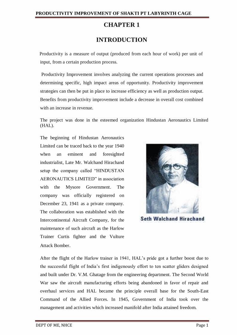
OPERATION 110

PRODUCTIVITY IMPROVEMENT OF SHAKTI PT LABYRINTH CAGE
DEPT OF ME, NHCE Page 42
OPERATION 140
PLASMA COATING

PRODUCTIVITY IMPROVEMENT OF SHAKTI PT LABYRINTH CAGE
DEPT OF ME, NHCE Page 43
OPERATION 190
STABILIZATION PROCESS

PRODUCTIVITY IMPROVEMENT OF SHAKTI PT LABYRINTH CAGE
DEPT OF ME, NHCE Page 44
OPERATION 240

PRODUCTIVITY IMPROVEMENT OF SHAKTI PT LABYRINTH CAGE
DEPT OF ME, NHCE Page 45
OPERATION 270
Old Process New Process
The differences between the old process and the new process are highlighted in the above
figures. We can see that apart from the reduction of thickness of the cage the plasma coat
on the outer dia and the inner dia are also being machined i.e. on the outer dia the
dimension 211.5+.05is being reduced to 210.975+.025. And on the inner dia there is not only
reduction on dia but also there a slight change in shape which can be noticed in the
figures. The thickness at the inner dia i.e. of 14mm which was machines to a depth of
142+0.05 after machining the 14mm thickness is divided into two parts, one at 142.92+.05
for a length of 9.5mm from the left and the rest at 143.17+.05

PRODUCTIVITY IMPROVEMENT OF SHAKTI PT LABYRINTH CAGE
DEPT OF ME, NHCE Page 46
OPERATION 300
Old Process New process
The differences between the old process and the new process are highlighted in the above
figures. Operation 300 is done on the opposite side of the seal (opposite of operation
270).even in this operation we can spot the differences in dimensions of thickness of the
cage i.e.3.6-0.1 to 2.9+_0.05. And we can also see the new contour being formed on the right
side of each process. This new contour is machined later in the old process in Montfort
lathe, where as in the new process this is accommodated in the same machine CTX
gamma turn mill center in the operation 300 thereby saving inventory cost and setup time
at Montfort lathe.

PRODUCTIVITY IMPROVEMENT OF SHAKTI PT LABYRINTH CAGE
DEPT OF ME, NHCE Page 47
FINISHED DRAWING
In the above figure we can see the drawing of completed labyrinth cage. Here holes are drilled to
fix the seal onto the fixture during operations and also spot weld the flange onto the seal.

PRODUCTIVITY IMPROVEMENT OF SHAKTI PT LABYRINTH CAGE
DEPT OF ME, NHCE Page 48
EXPECTED OUTCOME
• Elimination of final od/id machining at Montfort turn center.
• Reduction of cycle time.
• Improvement in productivity.
• Cost savings:
Setup time + unit time for
Montfort
operation=2.5hrs+1.5
hrs= 4 hrs/part
Annual requirement=83
Savings worth=83nos*4/part*hourly rate*2800
= Rs 929600/- approximately

PRODUCTIVITY IMPROVEMENT OF SHAKTI PT LABYRINTH CAGE
CHAPTER 9
CONCLUSION
Productivity improvement of Shakti power turbine labyrinth cage is carried out by change
in the existing process which was used to manufacture the labyrinth cage. The change
was done by fitting all the major processes in the CNC shop thereby reducing the
inventory costs and the setup time. Time saved is time earned. By this we are able to
manufacture the product more efficiently and also able to reduce the costs of
manufacture. Even minor changes like these can play a major role in the growth of a
company.
As we know that in the process of manufacturing a product, many problems might be
faced. A bewildering number of surface engineering techniques are available to the
modern engineer. How do you decide on the correct process for your particular
application? Essentially, an iterative process is required where the application is defined,
the properties required are established, the mechanical design of the coating is performed
and the correct materials are selected for the required properties. The substrate and
interface and surface all need to be engineered to the correct specification, and then
finally, the component is coated and the performance evaluated. If you have made the
correct choices from the correct specification the final product should be successful.
Our project work on productivity improvement of Shakti power turbine labyrinth cage,
gave us successful results.

PRODUCTIVITY IMPROVEMENT OF SHAKTI PT LABYRINTH CAGE