Product Information - MA Componentes SL
96
Hydraulic and Electronic Components Product Information
-
Upload
khangminh22 -
Category
Documents
-
view
0 -
download
0
Transcript of Product Information - MA Componentes SL

Hydraulic and Electronic Components
Product Information

2
He who knows the goal can decide;
He who decides, finds tranquillity;
He who finds tranquillity is safe;
He who is safe can consider;
He who can consider, can improve.
Anon

3
Welcome to the World of
Bucher Hydraulics...
For several decades, we have been a leading
supplier of innovative solutions in hydraulic
drive and control technology.
With our wide technical expertise, we will
smooth your way through your projects from
idea to finished product.
We can offer you the support you need at any
stage of your technically challenging projects,
whether it be in the concept phase, when set-
ting the specification or at the start of volume
production of your high quality and often
future-oriented vehicles and machines.
The product overview in the next pages should
give you an initial impression of our product
range.
Furthermore, we can offer you a variety of
possible solutions for your individual require-
ments. Our sales representatives and distribu-
tors look forward to working together with you
to find the best solutions to meet your needs.
You can find your personal contacts on our
website:
www.bucherhydraulics.com
Please note that the figures in the blue boxes are
US units.
The more intelligent solution
ECOdraulics
Farbwert GRÜN: CMYK: C20, M0, Y90, K60RGB: R111, G115, B45Pantone: 5757
ECOdraulics
ECOdraulics
“Do you speak
ECOdraulics?”
Then come to
Bucher Hydraulics:
Let’s talk about
first-class products
that support
protecting (y)our
environment.
ECOdraulics –
just for you. Further information: www.ecodraulics.com

4
Contents
Summary
Products Series Page
Pumps bar cm3/rev psi in3/rev
Internal Gear Pumps QX 320 3 - 500 4600 0.2 - 30 8
Internal Gear Pumps for Low Viscosity fluids
QXV 250 5 - 500 3600 0.3 - 30 9
Internal Gear Pumps QXP 250 3 - 500 3600 0.2 - 30 10
External Gear Pumps AP 250 0.25 - 93 3600 0.02 - 5.8 11
Motors bar cm3/rev psi in3/rev
Internal Gear Drive Units QXM 320 5 - 500 4600 0.3 - 30 14
Internal Gear Motors QXMHS 240 20 - 32 3400 1.2 - 2 15
Internal Gear Flow Dividers QXT 250 5 - 250 3600 0.3 - 15 16
External Gear Motors APM(R), APFM 280 0.5 - 26 4000 0.03 - 1.5 17
Directional Spool Valves bar l/min psi gpm
Monobloc Construction:• Manually Operated and Solenoid On/Off• Electric, Hydraulic, Manual and Combined
HDMMV
350350
80450
50005000
21119
24+2526
Manifold Mounting:• Electric, Hydraulic, Manual and Combined• Solenoid Directional Valves (CETOP)
CVW
350350
450160
50005000
11942
2728
Sectional Construction:• Manually Operated, Hydraulic, Electric, Solenoid On/Off and Solenoid Proportional• Manually Operated, Hydraulic, Solenoid On/Off, Proportional, Electrically Operated Two-stage• Hydraulic, Solenoid On/Off, Proportional, Electrically Operated Two-stage, On Board Electronic• Electric, Hydraulic, Manual and Combined• Electric, Hydraulic, Manual and Combined
HDS
L.8S
LVS
SCSVC
300
315
350
350350
150
150
260
400 600
4300
4500
5000
50005000
40
40
69
105158
30+31
32
33
35+3637
Power Units bar cm3/rev psi in3/rev
Hydraulic Power Packs UP, M-series 240 0.25 - 10 3400 0.02 - 0.6 20
Electro-hydraulic Pumps ET 250 0.25 - 10 3600 0.02 - 0.6 21

5
Product Series Page
Cartridge Valves bar l/min psi gpm
Solenoid Directional Valves W 420 350 6000 92 40
Cooler-Bypass Thermostat Valves W 50 300 700 79 41
Pressure Valves D 450 350 6400 92 42
Pressure Valves U, D 500 800 7100 211 43
Rapid Traverse Valves EGP 350 400 5000 105 44
Solenoid Pressure-Control Valves D 420 350 6000 92 45
Flow-Control Valves M 420 250 6000 66 46
Check Valves R 350 360 5000 95 47+48
Pilot Operated Check Valves ERV, DERV 600 100 8600 26 49
Stack Valves bar l/min psi gpm
Solenoid Directional Valves SW 350 300 5000 79 52
Pressure Valves SD 350 300 5000 79 53
Check Valves SR 350 300 5000 79 54
Flow-Control Valves SM 350 260 5000 69 55
Check Valves for SAE Flange Connections RVSAE 420 1200 6000 317 56
Safety Valves bar l/min psi gpm
Travel Brake Valves F, WV 420 400 6000 105 60
Load Control Valves CINDY 420 500 6000 132 61
Load Control Valves CINDY-MP 320 350 4600 92 62
Regenerative Load-Control Valves CINDY-REG 420 400 6000 105 63
Load Control Valves redundant CINDY-R 420 500 6000 132 64
Brake Valves BBV 420 50 6000 13 66
Load Control Valve REFUVA 420 300 6000 79 67
Pipe Rupture Valve for Excavators ESV, CFS 420 500 6000 132 68
Pipe Rupture Valve RS 400 400 5700 105 69
Directional Seat Valves bar l/min psi gpm
Monobloc and Sectional ValvesMonobloc Valves
SVH04WSH03
250250
2025
36003600
5.36.6
7677
Flow-Control Valves bar l/min psi gpm
Flow Dividers MTDA 420 250 6000 66 80
Flow-Control Valves:• Manually Adjustable and Fixed Adjustment• Proportional Solenoid Adjustment
MTMVRPLSA, SR
315315
80100
45004500
2126
8182
Differential Lock Valve MT..DV. 420 250 6000 66 83
Mobile Electronics: Joysticks, Controls, Amplifier and Control PCB’s 86-88
System Solutions: System Solutions (Subsystems), Fan Controls, Internal Gear Pumps for Variable Speed Drives
92-94
Ex Protected Valves bar l/min psi gpm
Valves for Potentially Explosive Areas EEx-W 315 90 4500 24 72
Proportional Directional Valves various 350 600 5000 158 73

6
Hydraulic pumps from Bucher Hydraulics are
available in both internal gear and external gear
designs, suitable for medium and high pressure
applications.
They are powerful yet compact, reliable yet cost
effective, and together with their high efficien-
cy, long service life and fine size increments,
these are key reasons for using these pumps.
Pumps

7
Internal Gear Pumps Quiet, powerful and long-lasting For low-viscosity fluids For polyurethane production
External Gear Pumps Compact and robust

8
Quiet, powerful and long-lasting
QX Internal Gear Pumps
Size 2 3 4 5 6 8
Displacement cm3/rev 3.5 – 16 10.5 – 25.5 20.5 – 65 39.5 – 127.5 80.5 – 160.5 163 – 498.5
Flow rate at 1450 r/min l/min 5 – 23 14.5 – 45.5 29.5 – 94 47 – 184 116 – 362 236 – 722
Max. speed r/min 3600 3400 3200 3000 2300 1800
Power requirement kW 2.5 – 6.2 5 – 12 10.5 – 25 20 – 49.5 40.5 – 96.5 83 – 193
Torque Nm 17 – 41 34 – 80 68 – 165 132 – 321 268 – 636 544 – 1270
Size 2 3 4 5 6 8
Displacement in3/rev 0.2 - 1.0 0.6 - 1.6 1.3 - 4.0 2.4 - 7.8 4.9 - 9.8 9.9 - 30
Flow rate at 1450 r/min gpm 1.3 - 6 4 - 12 8 - 25 12.5 - 48.5 30.5 - 95.5 62.5 -190.5
Max. speed r/min 3600 3400 3200 3000 2300 1800
Power requirement kW 2.5 – 6 5 – 12 10.5 – 25 20 – 49.5 40.5 – 96.5 83 – 193
Torque lbf ft 13 - 30 25 - 60 50 - 120 95 - 235 200 - 470 401 - 935
Fixed displacement pump
For open loop systems
Displacement: 3 – 500 cm3/rev (0.2 - 30 in3/rev)
Maximum continuous pressure: Pressure range 1 100 - 160 bar (1400 - 2300 psi) Pressure range 2 210 bar (3000 psi) Pressure range 3 320 bar (4600 psi)
Maximum intermittent pressure: Pressure range 1 125 - 210 bar (1800 - 3000 psi) Pressure range 2 250 bar (3600 psi) Pressure range 3 400 bar (5700 psi)
Very high life expectancy
Sound pressure level <57 dB(A)
Volumetric efficiency up to 98%
Trouble-free operation with fire-resistant fluid such as HFB, HFC and HFD
Suitable for use with variable speed drives
Advantages
Features
Further information: QX 100-P-000021ECOdraulics

9
For low-viscosity fluids
QXV Internal Gear Pumps
Size 2 3 4 5 6 8
Displacement cm3/rev 5 – 16 10.5 – 25.5 20.5 – 65 39.5 – 127.5 80 – 160.5 163 – 498.5
Flow rate at 1450 r/min l/min 7.5 - 23 14.5 – 45 29.5 – 94 57 - 184 116 - 362 236 - 722
Max. speed r/min 3600 3600 3600 3000 1800 1800
Size 2 3 4 5 6 8
Displacement in3/rev 0.3 - 1.0 0.6 - 1.6 1.3 - 4.0 2.4 - 7.8 4.9 - 9.8 9.9 - 30
Flow rate at 1450 r/min gpm 2 - 6 4 - 12 8 - 25 12.5 - 48.5 30.5 - 95.5 62.5 - 190.5
Max. speed r/min 3600 3600 3600 3000 1800 1800
Fixed displacement pump
For open loop systems
Displacement: 5 – 500 cm3/rev (0.3 - 30 in3/rev)
Viscosity range: 0.8 – 10 mm2/s (cSt)
Maximum continuous pressure: Pressure range 1 25 bar (350 psi) Pressure range 2 50 bar (700 psi) Pressure range 3 100 bar (1400 psi) Pressure range 4 150 bar (2100 psi) Pressure range 5 200 bar (2900 psi) Pressure range 6 250 bar (3600 psi)
High operating safety
Consistent flow rate
Trouble-free operation with kerosene, diesel fuel, brake fluid, Pentosin and HFA
Long life and low wear due to hydrodynamic bearings
Advantages
Further information: QXV 100-P-000064
Features

10
For polyurethane production
QXP Internal Gear Pumps
Size 2 3 4 5 6 8
Displacement cm3/rev 3.5 - 15 10.5 - 25.5 20.5 - 65 39.5 - 127.5 80 - 160.5 163 - 498.5
Flow rate at 1450 r/min l/min 5 - 23 14.5 - 45 29.5 - 94 57 - 184 116 - 362 236 - 722
Max. speed r/min 3600 3400 3200 3000 2300 1800
Power requirement at cont. pressure kW 2.5 - 5.5 5 - 10 10.5 - 21 20 - 41 40.5 - 81.5 83 - 162
Torque at continuous pressure Nm 17 - 41 34 - 80 68 - 165 132 - 321 268 - 636 544 - 1270
Size 2 3 4 5 6 8
Displacement in3/rev 0.2 - 1 0.6 - 1.6 1.3 - 4.0 2.4 - 7.8 4.9 - 9.8 9.9 - 30
Flow rate at 1450 r/min gpm 1.3 - 6 4 - 12 8 - 25 12.5 - 48.5 30.5 - 95.5 62.5 - 190.5
Max. speed r/min 3600 3400 3200 3000 2300 1800
Power requirement at cont. pressure kW 2.5 - 5.5 5 - 10 10.5 - 21 20 - 41 40.5 - 81.5 83 - 162
Torque at continuous pressure lbf ft 13 - 30 25 - 60 50 - 120 95 - 235 195 - 470 400 - 935
Metering pump
Displacement: 3 – 500 cm3/rev (0.2 - 30 in3/rev)
Viscosity range: 10 – 300 mm2/s (cSt) Standard 3 – 20.000 mm2/s (cSt) on request
Maximum continuous pressure: Pressure range 1 100 bar (1400 psi) Pressure range 2 210 bar (3000 psi) Pressure range 3 250 bar (3600 psi)
Highly accurate metering
Low pulsation
Variable speed operation
For use with polyol, isocyanates and additives
Extremely high operating safety
Advantages
Features
Further information: QXP 100-P-000093

11
Compact and robust
AP External Gear Pumps
Size AP05 APR05 AP100 AP/APR212AP/
APR212LNAP300
Displacement cm3 / rev 0.25 - 1.6 0.25 - 1.2 1.2 - 10 4.4 - 26.2 4.5 - 27.1 27 - 93
Max. continuous pressure bar 170 - 190 150 - 170 150 - 210 170 - 250 170 - 250 150 - 220
Max. intermittent pressure bar 180 - 210 160 - 190 180 - 250 200 - 280 200 - 280 170 - 250
Speed range r/min 550 - 7000 550 - 7000 500 - 5000 500 - 4000 500 - 4000 500 - 3500
Size AP05 APR05 AP100 AP/APR212AP/
APR212LNAP300
Displacement in3/rev 0.02 - 0.1 0.02 - 0.07 0.07 - 0.6 0.27 - 1.6 0.28 - 1.65 1.6 - 5.7
Max. continuous pressure psi 2400 - 2700 2100 - 2400 2100 - 3000 2500 - 3600 2500 - 3600 2100 - 3100
Max. intermittent pressure psi 2600 - 3000 2300 - 2700 2600 - 3600 2850 - 4000 2850 - 4000 2400 - 3600
Speed range r/min 550 - 7000 550 - 7000 500 - 5000 500 - 4000 500 - 4000 500 - 3500
Fixed displacement pump
For open and closed loop systems
Displacement:
0.25 - 93 cm3/rev (0.02 - 5.8 in3/rev)
Maximum continuous pressure: AP05 190 bar (2700 psi) APR05 170 bar (2400 psi) AP100 210 bar (3000 psi) AP/APR212 250 bar (3600 psi) AP/APR212LN 250 bar (3600 psi) AP300 220 bar (3100 psi)
Axial pressure compensated
Double pumps
Versions with integrated valves available
Advantages
Further information: AP(R) 200-P-991218, AP212 200-P-991628, AP212 200-P-991230
Features
ECOdraulics
Low Noise version (212LN) available: Pulsation -75%

12
Amongst their advantages, hydraulic motors
from Bucher Hydraulics have a low weight-to-
power ratio and are extremely compact.
The variety of types, such as internal gear, ex-
ternal gear and the roller-stator design, provide
the best solutions for vehicles and equipment
such as agricultural and forestry machinery,
construction plant, municipal vehicles, indus-
trial trucks, winches and stationary equipment.
Their suitability for energy-saving drive systems
is a particular benefit for many applications.
Motors

13
Internal Gear Drive Units All you ever wished for in a drive
Internal Gear Motors High-speed motors
Internal Gear Flow Dividers More than just a flow divider
External Gear Motors Compact and robust

14
All you ever wished for in a drive
QXM Internal Gear Drive Unit
Size 2 3 4 5 6 8
Displacement cm3/rev 5 - 16 10.5 - 25.5 20.5 - 65 39.5 - 127.5 80 - 160.5 163 - 498.5
Torque Nm 17 - 41 33.5 - 80 68 - 108 131 - 323 268 - 635 544 - 1267
Max. continuous pressure bar 100 - 320 100 - 320 100 - 320 100 - 320 100 - 320 100 - 320
Max. intermittent pressure bar 125 - 400 125 - 400 125 - 400 125 - 400 125 - 400 125 - 400
Max. speed (pump operation) r/min 4500 3900 3200 2700 2050 1500
Max. speed (motor operation) r/min 6000 5500 5000 4500 4000 3500
Size 2 3 4 5 6 8
Displacement in3/rev 0.3 - 1.0 0.6 - 1.6 1.3 - 4.0 2.4 - 7.8 4.9 - 9.8 9.9 - 30
Torque lbf ft 13 - 30 25 - 60 50 - 80 95 - 150 195 - 470 400 - 935
Max. continuous pressure psi 1400 - 4600 1400 - 4600 1400 - 4600 1400 - 4600 1400 - 4600 1400 - 4600
Max. intermittent pressure psi 1800 - 5700 1800 - 5700 1800 - 5700 1800 - 5700 1800 - 5700 1800 - 5700
Max. speed (pump operation) r/min 4500 3900 3200 2700 2050 1500
Max. speed (motor operation) r/min 6000 5500 5000 4500 4000 3500
Fixed displacement motor
For open and closed loop systems
Operates as a pump or motor with change of rotation
Reaction rate <50 ms
Sound pressure level <50 dB(A)
Reversible for one-, two- and four-quadrant operation
Suitable for use with variable speed drives
Over 70% energy saving possible
Suitable for use with fire-resistant fluids such as HFB, HFC, HFD and others
Advantages
Features
Further information: QXM 100-P-000063ECOdraulics

15
High-speed motors
QXMHS Internal Gear Drive Motor
Size 42-020 42-025 42-032
Displacement cm3/rev 20.3 25.1 32.3
Torque Nm 58 70 88
Max. continuous pressure bar 240 240 240
Max. intermittent pressure bar 280 280 280
Min. speed r/min 100 100 100
Max. intermittent speed r/min 10500 9500 8500
Size 42-020 42-025 42-032
Displacement in3/rev 1.3 1.5 2.0
Torque lbf ft 45 50 65
Max. continuous pressure psi 3400 3400 3400
Max. intermittent pressure psi 4000 4000 4000
Min. speed r/min 100 100 100
Max. intermittent speed r/min 10500 9500 8500
Fixed displacement motor
For open loop systems
External leakage connection
Three additional connections for: Saw chain lubrication, Saw chain tension, Lubrication etc.
Integrated valve functions
Viscosity range 15 – 60 mm2/s (cSt) standard up to 1,000 mm²/s at zero pressure cold start
Reaction rate <50 ms
Sound pressure level <50 dB(A)
Low operating temperature
Long service life
Advantages Withstands extremely high radial forces
Maximal power output
Further information: QXMHS 100-P-000092
Features
ECOdraulics

16
More than just a flow divider
QXT Internal Gear Flow Divider
Size 22 32 42 52 62 82
Outlet Displacement cm3/rev 5 - 8 12.5 - 15.5 25 - 32.5 50.5 - 64 101 - 125 201.5 - 249
Max. continuous pressure bar 250 250 250 250 250 250
Max. intermittent pressure bar 320 320 320 320 320 320
Max. speed r/min 6300 5000 4000 3200 2500 2000
Min. speed r/min 1250 1000 800 600 500 400
Max. flow Qin
with 2 outlet flows l/min 63 - 100 120 - 160 200 - 250 320 - 400 500 - 630 800 - 1000
Max. flow Qin
with 3 outlet flows l/min 95 - 150 180 - 240 300 - 380 480 - 600 750 - 950 1200 - 1500
Max. flow Qin
with 4 outlet flows l/min 125 - 200 240 - 320 400 - 500 640 - 800 1000 - 1260 1600 - 2000
Size 22 32 42 52 62 82
Outlet Displacement in3/rev 0.3 - 0.5 0.8 - 0.9 1.5 - 2.0 3.1 - 4.0 6.0 - 7.6 12 - 15
Max. continuous pressure psi 3600 3600 3600 3600 3600 3600
Max. intermittent pressure psi 4600 4600 4600 4600 4600 4600
Max. speed r/min 6300 5000 4000 3200 2500 2000
Min. speed r/min 1250 1000 800 600 500 400
Max. flow Qin
with 2 outlet flows gpm 17 - 26.5 31.5 - 42.5 53 - 66 84.5 - 105.5 132 - 166 211 - 265
Max. flow Qin
with 3 outlet flows gpm 25 - 39.5 47.5 - 63.5 79.5 - 100 127 - 159 198 - 251 317 - 396
Max. flow Qin
with 4 outlet flows gpm 33 - 53 63.5 - 84.5 105.5 - 132 169 - 211 265 - 333 422 - 528
Constant ratio flow divider
For open and closed loop systems
Works as a pressure intensifier
Division accuracy >98%
Sound pressure level <57 dB(A)
Flow rates up to 2000 l/min (528 gpm)
Extremely high division accuracy
Insignificant pressure pulsations
2, 3 or 4 Flow Configurations available
Exceptionally quiet operation
Suitable for use with fire-resistant fluids such as HFB, HFC, HFD and others
Advantages
Features
Further information: QXM 100-P-000059

17
Compact and robust construction
APM External Gear Motor
APMR Reversible versionModel
APMR212 APMR212LN APMR212 APMR212LN
Displacement cm3 / rev 6.4 - 26.2 6.6 - 27.1 in3/rev 0.39 - 1.6 0.4 - 1.65
Max. intermittent pressure bar 200 - 280 200 - 280 psi 2850 - 4000 2850 - 4000
Speed range r/min 500 - 4000 500 - 4000 r/min 500 - 4000 500 - 4000
Torque at max. cont. pressure Nm 24.5 - 62.5 24.5 - 62.5 lbf ft 20 - 45 20 - 45
Fixed displacement motor - unidirectional and reversible
For open and closed loop systems
Displacement: 6.4 – 26.2 cm³/rev (0.39 - 1.6 in³/rev)
Maximum continuous pressure: APM/APMR212 250 bar (3600 psi) APM/APMR212LN 250 bar (3600 psi)
Advantages
Features
APM motors specially designed for cooling system fan-drive applications
Optional external bearing attachment for extreme load applications
Low Noise version (212LN) available - Pulsation -75%
APM Standard versionModel
APM212 APM212LN APM212 APM212LN
Displacement cm3 / rev 6.4 - 26.2 6.6 - 27.1 in3/rev 0.39 - 1.6 0.4 - 1.65
Max. intermittent pressure bar 200 - 280 200 - 280 psi 2850 - 4000 2850 - 4000
Speed range r/min 500 - 4000 500 - 4000 r/min 500 - 4000 500 - 4000
Torque at max. cont. pressure Nm 24.5 - 62.5 24.5 - 62.5 lbf ft 20 - 45 20 - 45
APM Fan-drive versionModel
APM/APMR212APM/
APMR212LNAPM/APMR212
APM/APMR212LN
Displacement cm3 / rev 6.4 - 26.2 6.6 - 27.1 in3/rev 0.39 - 1.6 0.4 - 1.65
Max. intermittent pressure bar 200 - 280 200 - 280 psi 2850 - 4000 2850 - 4000
Speed range r/min 500 - 4000 500 - 4000 r/min 500 - 4000 500 - 4000
Torque at max. cont. pressure Nm 24.5 - 62.5 24.5 - 62.5 lbf ft 20 - 45 20 - 45
Pressure related axial compensation
APMR reversible motors available for 2- and 4-quadrant operation
Versions with integrated valves available
Further information: APM 200-P-991225, APMR 200-P-991225, APFM 100-P-000062, APM212 200-P 991628 ECOdraulics

18
The UP range of power units are compact
assemblies consisting of gear pump, electric
motor valve block and oil tank. The wide variety
of configurations and the simplicity of instal-
lation have made these power units highly
popular in the vehicle and handling industries.
They are predominantly used for lifting and
lowering functions.
Power Units

19
Hydraulic Power Packs Compact and powerful
Electro-hydraulic Pumps Motor–pump combination

20
Compact and powerful
Hydraulic Power Pack
Model UP50 UP100 UP110 M-series
Max. intermittent pressure bar 180 - 230 180 - 230 180 - 230 240
Displacement cm3 / rev 0.25 - 2.3 1.2 - 10 1.2 - 10 0.36 - 4.18
Tank capacity l 0.5 - 4 1.5 - 18 1.5 - 14 0.5 - 23
Viscosity range mm2/s (cSt) 20 - 120 20 - 120 20 - 120 20 - 77
Fluid temperature range °C -15 to +80 -15 to +80 -15 to +80 -30 to +55
DC motor 12...24/48 V kW 0.35 - 2.5 0.7 - 3 1.6 - 3 0.8 - 4.5
AC motor 220/240 V kW 0.12 - 0.75 0.25 - 2.2 0.25 - 2.2 0.5 - 2.2
380 V kW 0.12 - 0.75 0.25 - 4 0.25 - 4 -
Model UP50 UP100 UP110 M-series
Max. intermittent pressure psi 2600 - 3300 2600 - 3300 2600 - 3300 3400
Displacement in3/rev 0.02 - 0.14 0.07 - 0.6 0.07 - 0.6 0.02 - 0.26
Tank capacity gal 0.13 - 1.06 0.4 - 4.8 0.4 - 3.7 0.13 - 6.08
Viscosity range cSt 20 -120 20 -120 20 -120 20 - 77
Fluid temperature range °F +5 to +176 +5 to +176 +5 to +176 -22 to +130
DC motor 12...24/48 V kW 0.35 - 2.5 0.7 - 3 1.6 - 3 0.8 - 4.5
AC motor 220/240 V kW 0.12 - 0.75 0.25 - 2.2 0.25 - 2.2 0.5 - 2.2
380 V kW 0.12 - 0.75 0.25 - 4 0.25 - 4 -
Bucher Hydraulics high performance gear pumps internal development and production
Available with steel or plastic oil tank
Components such as check valves, pressure relief valves, emergency release valves, flow control valves, direct or pilot-operated directional control valves, manual valves and emergency hand pumps can be integrated
Customized systems to meet your specifications
Application-related assembly
Reduced stock level
Powerful combination
Advantages
Features
Further information: www.bucherhydraulics.com Mobile & Industrial Hydraulics Products Power units
Integrated valves
Easy installation
ECOdraulics

21
Motor–pump combination
ET Electro-hydraulic Pump
Model ET
Max. intermittent pressure bar 250
Displacement cm3 / rev 0.25 - 10
Viscosity range mm2/s (cSt) 20 - 120
Fluid temperature range °C -15 to +80
DC motor V 12, 24 and 48
Power kW 0.35 - 2.2
Special functions integrated pressure relief valve for AP100 only
Model ET
Max. intermittent pressure psi 3600
Displacement in3 / rev 0.02 - 0.6
Viscosity range cSt 20 - 120
Fluid temperature range °F +5 to +176
DC motor V 12, 24 and 48
Power kW 0.35 - 2.2
Special functions integrated pressure relief valve for AP100 only
Hydraulic connections by pipe flanges or threaded ports
Available with all external gear pumps in AP05 and AP100 ranges
Compact unit
Powerful
Advantages
Further information: ET 200-P-991029
Features

22
Directional spool valves are used in control and
safety roles in the operating and travel hydrau-
lics of mobile plant and machinery.
There are different designs and functions such
as pressure compensators, pressure limiters,
check, relief and flow valves to suit all require-
ments.
All the valve ranges employ a building block
concept, elements of which can be put together
in a valve block according to the requirements
of the application.
Directional Spool Valves
23
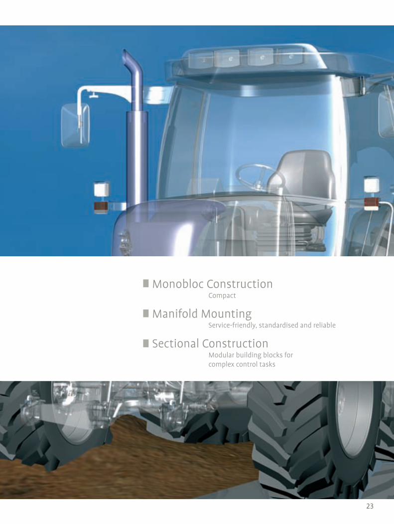
Monobloc Construction Compact
Manifold Mounting Service-friendly, standardised and reliable
Sectional Construction Modular building blocks for complex control tasks

24
Compact
HDM Monobloc DirectionalControl Valve
Size 140 11P 11S 11S/3PQ 11S/4PQ 18 15/2 19WL
Number of spools 1 2 - 6 1 - 6 3 4 1 - 4 2 - 10 3 - 10
Max. inlet pressure (P) bar 250 250 350 300 300 350 250 250
Max. work port pressure (A/B) bar 320 320 400 350 350 400 320 320
Max. return pressure bar 30 30 30 30 30 3020 (on-off)
30 (std) 10 (EHO)
30
Nominal flow rate l/min 40 45 45 50 50 70 60 80
Viscosity range 15 - 75 mm2/s (cSt), Hydraulic fluid temperature -20 to +80 °C
Actuation Hand operated, electro-hydraulic on/off or hydraulic proportional actuation
Size 140 11P 11S 11S/3PQ 11S/4PQ 18 15/2 19WL
Number of spools 1 2 - 6 1 - 6 3 4 1 - 4 2 - 10 3 - 10
Max. inlet pressure (P) psi 3600 3600 5000 4300 4300 5000 3600 3600
Max. work port pressure (A/B) psi 4600 4600 5700 5000 5000 5700 4600 4600
Max. return pressure psi 430 430 430 430 430 430290 (on-off)
430 (std) 143 (EHO)
430
Nominal flow rate gpm 11 12 12 14 14 19 15 21
Viscosity range 15 - 75 cSt, Hydraulic fluid temperature -4 to +176 °F
Actuation Hand operated, electro-hydraulic on/off or hydraulic proportional actuation
Monobloc construction
For series or parallel operation
Open centre, closed centre and carry-over circuits
Option for integrated anti-shock, anti-cavitation, pressure relief, flow control and check valves
Single lever actuation for 2 valves and remote cable controls
Fatigue-free operation
Minimal maintenance
Advantages
Features
Further information: HDM 200-P-991210, HDM15 200-P-991228, HDM11S/3PQ 200-P-991229, HDM19 200-P-991226
Compact overall dimensions
Fine metering spools

25
Wheel Loaders
HDM19WL Wheel LoadersDirectional Control Valve
Number of spools 3 - 10 3 - 10
Max. inlet pressure (P) bar 250 psi 3600
Max. work port pressure (A/B) bar 320 psi 4600
Max. return pressure bar 30 psi 430
Max. inlet flow l/min 80 gpm 21
Viscosity range mm2/s 15 - 75 cSt 15 - 75
Temperature °C -20 to +80 °F -4 to +176
Monobloc construction (three-spool)
Up to seven stackable sections
Parallel/tandem circuits
Wide range of fine-metering spools optimised for specific machine functions
Manual controls with extremely low operating forces
Wide range of controls: single and cross lever, hydraulic proportional and open loop electro-hydraulic proportional
Manual/hydraulic joystick for controlling two functions simultaneously
Regenerative circuit for fast dumping speed
Compact dimensions
Precise and stable control in each working condition
Advantages Work ports with integral flow restrictors for maximum dumping-speed setting
Optional circuit to eliminate „no-reaction time“ after fast boom lowering
Further information: HDM19 200-P-991226
Features

26
Compact
MV Proportional Directional Valve System
Size 12 18 25
Max. working pressure bar 350 350 350
Max. return pressure bar 50 50 50
Nominal flow rate l/min 100 200 450
Viscosity range mm2/s (cSt) 10 - 380 10 - 380 10 - 380
Hydraulic fluid temperature °C -20 to +80 -20 to +80 -20 to +80
Voltage V 12 or 24 DC 12 or 24 DC 12 or 24 DC
Type of actuation Electric, hydraulic, manual, Ex protection and combinations of these
Size 12 18 25
Max. working pressure psi 5000 5000 5000
Max. return pressure psi 700 700 700
Nominal flow rate gpm 26 53 119
Viscosity range cSt 10 - 380 10 - 380 10 - 380
Hydraulic fluid temperature °F -4 to +176 -4 to +176 -4 to +176
Voltage V 12 or 24 DC 12 or 24 DC 12 or 24 DC
Type of actuation Electric, hydraulic, manual, Ex protection and combinations of these
Monobloc construction
Internal load feedback
2- or 3-way pressure compensation
Individual adjustment of flow rates
All valve functions are integrated in a single compact block
Up to four proportional directional valve functions
Primary pressure relief can be
included
Sensitivity and precision of load control
Load-independent flow adjustment
Advantages Specially developed for use in mobile hydraulics
Perfectly matched to the application
Further information: MV 301-P-9050023
Features

27
Compact
MV Proportional Directional Valve System
Service-friendly and reliable
CV Proportional Directional Valve System
Compact manifold mounting design
Internal load feedback
2- or 3-way pressure compensation
Individual adjustment of flow rates
Primary pressure relief can be included
All valve functions are integrated in a single compact block
Load-independent flow adjustment
Sensitivity and precision of load control
Advantages
Further information: CV 301-P-9050025
Features
Perfect match to the application
Easy maintenance due to quick-change of individual components means minimum service interruption
Size 12 18 25
Max. working pressure bar 350 350 350
Max. return pressure bar 50 50 50
Nominal flow rate l/min 100 200 450
Viscosity range mm2/s (cSt) 10 - 380 10 - 380 10 - 380
Hydraulic fluid temperature °C -20 to +80 -20 to +80 -20 to +80
Voltage V 12 or 24 DC 12 or 24 DC 12 or 24 DC
Type of actuation Electric, hydraulic, manual, Ex protection and combinations of these
Size 12 18 25
Max. working pressure psi 5000 5000 5000
Max. return pressure psi 700 700 700
Nominal flow rate gpm 26 53 119
Viscosity range cSt 10 - 380 10 - 380 10 - 380
Hydraulic fluid temperature °F -4 to +176 -4 to +176 -4 to +176
Voltage V 12 or 24 DC 12 or 24 DC 12 or 24 DC
Type of actuation Electric, hydraulic, manual, Ex protection and combinations of these

28
Standardised and reliable
Directional Solenoid Valves, Manifold Mounting (CETOP)
Mounting pattern: ISO 4401-02-01 NG4 ISO 4401-03-02 NG6 ISO 4401-05-04 NG10 CETOP R35H 03, 05 DIN 24340 A6 DIN 24340 A10 NFPA D03, D05
Direct acting seat valve
Direct acting and two-stage spool valves
Available in explosion-protected versions
Unaffected by asymmetric flow, high viscosities or high pressure differentials
Advantages
Features
Further information: www.bucherhydraulics.com Mobile & Industrial Hydraulics Products Valves Directional spool valves Manifold mounting,
www.bucherhydraulics.com Mobile & Industrial Hydraulics Products Valves Directional seat valves Manifold mounting
Size 4 6 10
Max. working pressure bar 250 350 315
Max. flow rate l/min 25 100 160
Viscosity range mm2/s (cSt) 10 - 500 10 - 500 10 - 500
Hydraulic fluid temperature °C -25 to +80 -25 to +80 -25 to +80
Voltage V 12, 24 DC / 115, 230 AC 12, 24 DC / 115, 230 AC 12, 24 DC / 115, 230 AC
Type of actuation On/off solenoid, proportional solenoid, EEx solenoid, lever
Protection classIP65 (EN 60 529) for on/of and proportional solenoids;
IP65 / IP67 for Ex solenoids
Size 4 6 10
Max. working pressure psi 3600 5000 4500
Max. flow rate gpm 6.6 26 42
Viscosity range cSt 10 - 500 10 - 500 10 - 500
Hydraulic fluid temperature °F -13 to +176 -13 to +176 -13 to +176
Voltage V 12, 24 DC / 115, 230 AC 12, 24 DC / 115, 230 AC 12, 24 DC / 115, 230 AC
Type of actuation On/off solenoid, proportional solenoid, EEx solenoid, lever
Protection classIP65 (EN 60 529) for on/of and proportional solenoids;
IP65 / IP67 for Ex solenoids

29

30
Multi-talented versatility
HDS Sectional DirectionalControl Valve
Sectional construction
For series or parallel operation
Open centre, closed centre and carry-over circuits
Option for integrated anti-shock, anti-cavitation, pressure relief, flow control and check valves
Single lever actuation for 2 valves and remote cable controls
Different types of actuation may be combined
Minimal maintenance
Advantages
Features
Further information: HDS 200-P-991210, HDS34 200-P-991227
Customer specific control blocks for maximum flexibility
Fine metering spools
Size 07 ON-OFF 11 (11 ON-OFF) 15 (15 ON-OFF) 20 21 30 34
Number of spools 1 - 10 1 - 10 1 - 10 1 - 10 1 - 10 1 - 10 1 - 10
Max. inlet pressure (P) bar 250 250 250 250 300 250 300
Max. work port pressure (A/B) bar 320 320 320 320 350 320 350
Max. return pressure bar 20 30 (20) 30 (20) 30 30 30 30
Nominal flow rate l/min 25 45 60 80 80 120 150
Viscosity range mm2/s 15 - 75 15 - 75 (20 - 50) 15 - 75 (20 - 50) 15 - 75 15 - 75 15 - 75 15 - 75
Hydraulic fluid temperature °C -20 to +80
Actuation Hand operated, electro-hydraulic direct on/off or hydraulic proportional
Size 07 ON-OFF 11 (11 ON-OFF) 15 (15 ON-OFF) 20 21 30 34
Number of spools 1 - 10 1 - 10 1 - 10 1 - 10 1 - 10 1 - 10 1 - 10
Max. inlet pressure (P) psi 3600 3600 3600 3600 4300 3600 4300
Max. work port pressure (A/B) psi 4600 4600 4600 4600 5000 4600 5000
Max. return pressure psi 285 430 (285) 430 (285) 430 430 430 430
Nominal flow rate gpm 6.6 12 16 21 21 32 40
Viscosity range cSt 15 - 75 15 - 75 (20 - 50) 15 - 75 (20 - 50) 15 - 75 15 - 75 15 - 75 15 - 75
Hydraulic fluid temperature °F -4 to +176
Actuation Hand operated, electro-hydraulic direct on/off or hydraulic proportional
ECOdraulics

31
Forward-looking technology
HDS34 Proportional Flow Sharing Directional Control Valve
Number of spools 1 - 10 1 - 10
Max. inlet pressure (P) bar 300 psi 4300
Max. work port pressure (A/B) bar 350 psi 5000
Max. return pressure bar 30 psi 430
Max. inlet flow l/min 180 gpm 48
Max. work port flow l/min 150 gpm 40
Viscosity range mm2/s 15 - 75 cSt 15 - 75
Temperature °C -20 to +80 °F -4 to +176
Sectional design
Downstream pressure compensation
Fully interchangeable function-oriented spools
Wide range of controls: single and cross lever, hydraulic proportional, open and closed loop, electro-hydraulic proportional
Easily configurable for fixed- or variable- displacement pumps
Inlet section with priority for steering
Application-specific options for wheel loaders, telehandlers, forest equipment, backhoe loaders and excavators
Compact dimensions
Precise and stable control of simultaneous operations
Advantages Higher efficiency and reduced energy consumption
Flexibility to satisfy a wide range of applications
Further information: HDS34 200-P-991227
Features
ECOdraulics

32
Modular building blocks for complex control tasks
L.8S Proportional Directional Valve
Model L.8S L.8S
Max. working pressure bar 315 psi 4500
Nominal flow rate l/min 150 gpm 40
Max. flow rate ports A + B l/min 90 gpm 24
Max. return pressure bar 40 (210) psi 570 (3000)
Viscosity range mm2/s (cSt) 10 - 380 cSt 10 - 380
Hydraulic fluid temperature °C -20 to +80 °F -4 to +176
Voltage V 12 or 24 DC V 12 or 24 DC
Power consumption W 27 hp 0.036
Type of actuationManual, on/off and proportional solenoid with direct and pilot actuation, hydraulic actuation
Sectional design
Flexible system, specially developed for use in mobile hydraulics
Additional functions can be incorporated in the modular system: Two- and three-way pressure compensation, priority pressure compensation, individual pressure compensation, check valves, load control valves, relief valves, anti-cavitation valves, flow cut-off, flow limiters, manual override
Load-sensing capability
Suitable with all pump types and in systems with variable feeds
Advantages Load-independent flow adjustment even in parallel operation with multiple consumers
Complete solution with high functionality
Further information: L.8S 100-P-000047
Features

33
Modular building blocks for complex control tasks
L.8S Proportional Directional Valve
Forward-looking technology
LVS Proportional Directional Valve
Model LVS08 LVS12 LVS08 LVS12
Max. working pressure bar 250 350 psi 3600 5000
Nominal flow rate l/min 260 260 gpm 69 69
Max. flow rate ports A + B l/min 50 180 gpm 13 48
Max. return pressure bar 200 50 (200 optional) psi 2900 700 (2900 optional)
Viscosity range mm2/s (cSt) 10 to 380 10 to 380 cSt 10 to 380 10 to 380
Hydraulic fluid temperature °C -20 to +80 -20 to +80 °F -4 to +176 -4 to +176
Voltage V 12 or 24 DC 12 or 24 DC V 12 or 24 DC 12 or 24 DC
Power consumption W 30 18 hp 0.040 0.024
Type of actuation
On/off and proportional
solenoid with direct actuation
Manual operation, two-stage electro-
hydraulic and hydraulic actu-
ated, digital pilot head with on-
board electronics
On/off and proportional
solenoid with direct actuation
Manual operation, two-stage electro-
hydraulic and hydraulic actu-
ated, digital pilot head with on-
board electronics
Advantages
Features
Further information: LVS 100-P-000089
Sectional design
Proportional flow-control functions, downstream pressure compensation, relief valve, make-up function, seat valve, manual override, two- and three-way pressure compensation, internal and external priority functions
Flow control operation in one valve
Available with specific operations for agricultural machinery, forestry equipment, construction machines, loading cranes and many other applications
Increased handling capacity
Lasting cost savings and increased machine performance data
Fatigue-free operation
Can be configured for both fixed and variable displacement pumps
ECOdraulics

34

35
Modular building blocks for complex control tasks
SC18 Proportional Directional Valve
Compact sectional design
Load feedback
Adaptable modular system
Individual adjustment of the flow rate up to 260 l/min per actuator
Max. pump flow rate 400 l/min
Individual pressure compensator
Individual supply cut-off for each actuator port
Optional anti-shock valves, make-up valves, or a combination
Available with manual operation
Threaded ports or flanged ports
Can be used with all types of pumps and in systems with changeable supply sources
Responsive and accurate control of the load
Advantages
Features
Further information: SC18 301-P-9050085
Load-independent flow control, even with parallel operation of several actuators
Adaptable modules, specifically designed for use in mobile hydraulics
Model 18 18
Max. working pressure bar 350 psi 5000
Nominal pressure bar 420 (consumer) psi 6000 (consumer)
Max. return pressure bar 50 psi 700
Flow rate l/min 260 gpm 69
Viscosity range mm2/s 10 - 380 cSt 10 - 380
Hydraulic fluid temperature °C -20 to +80 °F -4 to +176
Power consumption V 12 or 24 DC V 12 or 24 DC
Type of actuationElectric, Hydraulic,
Manual and CombinedElectric, Hydraulic,
Manual and Combined
ECOdraulics

36
Modular building blocks for complex control tasks
SC22 Proportional Directional Valve
Compact sectional design
Load feedback
Adaptable modular system
Individual adjustment of the flow rate up to 400 l/min per actuator
Max. pump flow rate 500 l/min
Individual pressure compensator
Individual supply cut-off for each actuator port
Optional anti-shock valves, make-up valves, or a combination
Available with manual operation
Can be used with all types of pumps and in systems with changeable supply sources
Responsive and accurate control of the load
Advantages Load-independent flow control, even with parallel operation of several actuators
Adaptable modules, specifically designed for use in mobile hydraulics
Further information: SC22 301-P-9050084
Features
Model 22 22
Max. working pressure bar 350 psi 5000
Nominal pressure bar 420 (consumer) psi 6000 (consumer)
Max. return pressure bar 50 psi 700
Flow rate l/min 400 gpm 105
Viscosity range mm2/s 10 - 380 cSt 10 - 380
Hydraulic fluid temperature °C -20 to +80 °F -4 to +176
Power consumption V 12 or 24 DC V 12 or 24 DC
Type of actuationElectric, Hydraulic,
Manual and CombinedElectric, Hydraulic,
Manual and Combined

37
Modular building blocks for complex control tasks
SC22 Proportional Directional Valve
Modular building blocks for complex control tasks
SVC25 Proportional Directional Valve
Compact sectional design
Load feedback
Adaptable modular system
Individual adjustment of the flow rate up to 600 l/min per actuator
Max. pump flow rate 750 l/min
Individual pressure compensator
Individual supply cut-off for each actuator port
Optional anti-shock valves, make-up valves, or a combination
Threaded ports or flanged ports
Can be used with all types of pumps and in systems with changeable supply sources
Responsive and accurate control of the load
Advantages
Features
Further information: SVC25 301-P-9050085
Load-independent flow control, even with parallel operation of several actuators
Adaptable modules, specifically designed for use in mobile hydraulics
Model 25 25
Max. working pressure bar 350 psi 5000
Nominal pressure bar 420 (consumer) psi 6000 (consumer)
Max. return pressure bar 50 psi 700
Flow rate l/min 600 gpm 158
Viscosity range mm2/s 10 - 380 cSt 10 - 380
Hydraulic fluid temperature °C -20 to +80 °F -4 to +176
Power consumption V 12 or 24 DC V 12 or 24 DC
Type of actuationElectric, Hydraulic,
Manual and CombinedElectric, Hydraulic,
Manual and Combined

38
Our cartridge valve range includes screw-in
cartridges with UNF or metric threads as well as
plug-in and SAE standard valves.
They are characterised by their compact
design, great reliability and low maintenance.
Due to the many different possible combina-
tions these valves can be universally used for
directional, pressure, flow-control and check
purposes. Our range of seat valves offers con-
siderable advantages which ensure leakage-free
applications.
Cartridge Valves

39
Solenoid Directional Valves Screw-in and ready to go
Pressure Valves Bypass and inline functions
Solenoid Valves We can take the pressure
Flow-control Valves For regulating flow volumes
Check Valves Small and safe

40
Screw-in and ready to go
Solenoid Directional Cartridge Valve
Size 3 5 10 16
Max. operating pressure bar 420 420 350 420
Max. flow rate l/min 15 40 140 350
Viscosity range mm²/s (cSt) 10 - 500
Hydraulic fluid temperature °C -25 to +80
Voltage V 12, 24 DC / 115, 230 AC
Type of actuation SolenoidSolenoid
Ex solenoidSolenoid Solenoid
Protection classIP65 (EN 60 529) for solenoids
IP65/IP67 ( EN 60 529) for Ex solenoids
Size 3 5 10 16
Max. operating pressure psi 6000 6000 5000 6000
Max. flow rate gpm 4 11 37 92
Viscosity range cSt 10 - 500
Hydraulic fluid temperature °F -13 to +176
Voltage V 12, 24 DC / 115, 230 AC
Type of actuation SolenoidSolenoid
Ex solenoidSolenoid Solenoid
Protection classIP65 (EN 60 529) for solenoids
IP65/IP67 ( EN 60 529) for Ex solenoids
Available either with UNF or metric threads
Seat valves
Spool valves
Also available with an emergency override
Small installation size
Rotatable solenoid
Solenoid can be replaced without contact with fluids
Advantages
Features
Further information: www.bucherhydraulics.com Mobile & Industrial Hydraulics Products Valves Directional spool valves Cartridge valves,
www.bucherhydraulics.com Mobile & Industrial Hydraulics Products Valves Directional seat valves Cartridge valves

41
Robust and efficient
Cooler-Bypass Thermostat Valve
Temperature-dependent bypass control
Fast oil temperature rise (cold start phase)
Integrated pressure relief function
Various response temperatures and pressure settings
Can be fitted in a line-mounting housing
Cooling circuit rapidly reaches its optimum operating temperature
Can be installed directly into the cooler or line-mounting housing
High functional reliability and stability
Pressure safeguard to protect the cooler (peak pressures)
Great durability without the necessity for complex maintenance work
Advantages
Features
Further information: WDTUVA-10 400-P-170100, WDTUVA-16 400-P-170101
Size 10 16
Max. operating pressure bar 50 50
Max. flow rate l/min 120 300
Viscosity range mm2/s 10 - 650 10 - 650
Hydraulic fluid temperature °C -25 to +100 -25 to +80
Type of actuation Temperature-controlled
ECOdraulics
Size 10 16
Max. operating pressure psi 700 700
Max. flow rate gpm 32 79
Viscosity range cSt 10 - 650 10 - 650
Hydraulic fluid temperature °F -13 to +212 -13 to +176
Type of actuation Temperature-controlled

42
Bypass and inline applications
Pressure Valve Cartridge
Size 3 4 10 16
Max. operating pressure bar 315 420 450 420
Max. flow rate l/min 12 30 140 350
Viscosity range mm²/s (cSt) 10 - 650 10 - 650 10 - 650 10 - 650
Hydraulic fluid temperature °C -25 to +80 -25 to +80 -25 to +80 -25 to +80
Size 3 4 10 16
Max. operating pressure psi 4500 6000 6400 6000
Max. flow rate gpm 3 8 37 92
Viscosity range cSt 10 - 650 10 - 650 10 - 650 10 - 650
Hydraulic fluid temperature °F -13 to +176 -13 to +176 -13 to +176 -13 to +176
Directly and pilot controlled
Pressure relief valves
Pressure reducing valves
Pressure compensator valves
Pressure unloading valves
For bypass and inline applications
Logic valves
Small installation size
Excellent characteristics
Advantages
Further information: www.bucherhydraulics.com Mobile & Industrial Hydraulics Products Valves Pressure functions
Features

43
Bypass and inline applications
Pressure Valve Cartridge
High power density
Pressure-relief Cartridge
Model UVP DVP DDP DDP
Size 4 20 16D/E 32D/E
Max. operating pressure bar 500 450 480 480
Max. flow rate l/min 20 330 400 800
Adjustment range bar max. 500 max. 450 max. 480 max. 480
Viscosity range mm2/s 2.8 - 1500 2.8 - 1500 2.8 - 1500 2.8 - 1500
Hydraulic fluid temperature °C -20 to +80 -20 to +80 -20 to +80 -20 to +80
Protects pumps and/or actuators as well as the system against excess pressure
Various pressure ranges
Direct acting, cartridge-type seat valve
Hardened seat and poppet
Leak-free
Compact design means small space requirements
Advantages
Features
Further information: Data sheet on request
Model UVP DVP DDP DDP
Size 4 20 16D/E 32D/E
Max. operating pressure psi 7100 6400 6830 6830
Max. flow rate gpm 5.3 87 105 210
Adjustment range psi max. 7100 max. 6400 max. 6830 max. 6830
Viscosity range cSt 2.8 - 1500 2.8 - 1500 2.8 - 1500 2.8 - 1500
Hydraulic fluid temperature °F -4 to +176 -4 to +176 -4 to +176 -4 to +176

44
Compact – long-lived – practical
Rapid Traverse Valve
Model EGP
Size 20 25
Max. operating pressure bar 350 350
Flow rate l/min 250 400
Viscosity range mm2/s 2.8 - 1500
Hydraulic fluid temperature °C -20 bis +80
Compact cartridge valve for implementing regenerative circuits in one cartridge
Stable operation over the entire pressure range is ensured
No external pilot signal is required
Just one cartridge for all functions
Works automatically, does not need any external switching signal, pressure switch, etc.
Compact design means small space requirements
Advantages
Further information: Data sheet on request
Features
Model EGP
Size 20 25
Max. operating pressure psi 5000 5000
Flow rate gpm 66 105
Viscosity range cSt 2.8 - 1500
Hydraulic fluid temperature °F -4 to +176

45
Compact – long-lived – practical
Rapid Traverse Valve
Further information: Data sheet on request
We can take the pressure
Solenoid Pressure Valve Cartridge
Size 3 5 10 16
Max. operating pressure bar 420 315 315 420
Max. flow rate l/min 20 60 120 350
Viscosity range mm²/s (cSt) 10 - 500
Hydraulic fluid temperature °C -25 to +80
Type of actuation Proportional or on/off solenoid
Voltage V 12, 24 DC / 115, 230 AC
Protection class IP65 (EN 60 529)
Size 3 5 10 16
Max. operating pressure psi 6000 4500 4500 6000
Max. flow rate gpm 5.3 16 32 92
Viscosity range cSt 10 - 500
Hydraulic fluid temperature °F -13 to +176
Type of actuation Proportional or on/off solenoid
Voltage V 12, 24 DC / 115, 230 AC
Protection class IP65 (EN 60 529)
Directly and pilot controlled
Pressure relief valves
Pressure reducing valves
Pressure compensator valves
External pilot connection
2 pressure settings
Proportional or on/off solenoids
Small installation size
One valve – continuously variable pressures
2 pressure settings
Advantages
Features
Further information: www.bucherhydraulics.com Mobile & Industrial Hydraulics Products Valves Pressure functions

46
For regulating flow volumes
Flow-control Valve Cartridge
Directly and pilot controlled
Seat and spool models available
Throttle function
Flow-control function
Flow-control valve with adjustable
Proportional or manual
Space-saving
High quality
Low pressure loss
Advantages
Further information: www.bucherhydraulics.com Mobile & Industrial Hydraulics Products Valves Flow functions
Features
Size 5 6 10 16
Max. operating pressure bar 250 350 315 420
Max. flow rate l/min 30 160 160 250
Viscosity rangemm²/s
(cSt)10 - 500
Hydraulic fluid temperature °C -25 to +80
Type of actuation Proportional ManualProportional
or manualProportional
or manual
Voltage V 12, 24 DC
Protection class IP65 (EN 60 529)
Size 5 6 10 16
Max. operating pressure psi 3600 5000 4500 6000
Max. flow rate gpm 8 42 42 66
Viscosity range cSt 10 - 500
Hydraulic fluid temperature °F -13 to +176
Type of actuation Proportional ManualProportional
or manualProportional
or manual
Voltage V 12, 24 DC
Protection class IP65 (EN 60 529)

47
For regulating flow volumes
Flow-control Valve Cartridge
Small and safe
Check Valves Cartridge Design
Model RV/RK RW REP
Nominal sizes 04 - 40 / 1/8“ - 1 1/2“ 2.5 10 - 16
Max. operating pressure bar 350 315 350
Max. flow rate l/min 360 8 300
Opening pressure bar 0.1 - 2 0.16 - 6 2
Hydraulic fluid temperature °C -30 to +80 -25 to +80 -25 to +80
Model RV/RK RW REP
Nominal sizes 04 - 40 / 1/8“ - 1 1/2“ 2.5 10 - 16
Max. operating pressure psi 5000 4500 5000
Max. flow rate gpm 95 2.1 79
Opening pressure psi 1.5 - 30 2.3 - 90 30
Hydraulic fluid temperature °F -22 to +176 -22 to +176 -22 to +176
Screw-in or plug-in fitting
With the RKVC and RVC ranges the checked direction is changed by inverting the cartridge
Ball and plate valves
Simple throttle/check functions can be achieved in plate valves by means of orifices in the plate
Also available with hydraulic pilot operation
Small installation size
High sealing properties
High dynamics
Advantages
Features
Further information: www.bucherhydraulics.com Mobile & Industrial Hydraulics Products Valves Flow-preventing valves

48
We control flow rates
Counterbalance Check ValveCartridge Design
Model RVVE RVVE
Nominal sizes 04 - 40 / 1/8“ - 1 1/2“ 04 - 40 / 1/8“ - 1 1/2“
Max. operating pressure bar 350 psi 5000
Max. flow rate l/min 360 gpm 95
Opening pressure mm2/s 4 - 12 cSt 4 - 12
Hydraulic fluid temperature °C -30 bis +80 °F -22 to +176
Model provided with thread
Ball version
Can be used as a counterbalance valve
Pipe-work installation version available on request
Small installation size
High level of leak tightness
Flat characteristic curve
Advantages
Further information: RVVE 170-P-051010
Features Daten

49
We control flow rates
Counterbalance Check ValveCartridge Design
Further information: RVVE 170-P-051010
Always the right solution
ERV / DERV Pilot-operated Leak-free Check Valve
Model ERV DERV ERV DERV
Size 8 8 / 10 8 8 / 10
Max. operating pressure bar 450 (600) 350 (500) psi 6400 (8600) 5000 (7200)
Nominal flow rate l/min 60 70 (100) gpm 16 16 (26)
Viscosity range mm2/s 2.8 - 1500 2.8 - 1500 cSt 2.8 - 1500 2.8 - 1500
Hydraulic fluid temperature °C -20 bis +80 -20 bis +80 °F -4 to +176 -4 to +176
Two stage, spring-closed seat valve in cartridge design
Holds the load without leakage in the neutral position
Pressurised working circuits can be shut-off
Pilot-operated check valve and pipe-rupture valve function integrated in one unit
Suitable for retracting loaded stabiliser cylinders at two different speeds
For stabiliser cylinders on mobile vehicles and similar applications up to 600 bar (8600 psi)
Advantages
Further information: www.bucherhydraulics.com Mobile & Industrial hydraulics Products Valves Check Valves
Features

50
Our stack valve programme offers items com-
pliant with standards ISO 4401-02-01 NG4,
ISO 4401-03-02 NG6, ISO 4401-05-04 NG10,
ISO 4401-07-07 NG16, CETOP R35H 03, 05, 07,
A6 as per DIN 24340, A10 as per DIN 24340, A16
as per DIN 24340, NFPA D03, D05 and D07.
On request we can supply customised units
with innumerable operations linked in vertical
and horizontal stacks.
Stack Valves

51
Solenoid Directional Valves Directly and pilot controlled
Pressure Valves Keeping high pressures under control
Check Valves Hardened seats
Flow-control Valves For precise flow volume regulation
Check Valves Safe and dynamic

52
Direct or pilot operated
Solenoid Directional Stack Valve
Size 6 10 16
Max. operating pressure bar 350 350 350
Max. flow rate l/min 140 140 300
Viscosity range mm²/s (cSt) 10 - 500 10 - 500 10 - 500
Hydraulic fluid temperature °C -25 to +80 -25 to +80 -25 to +80
Voltage V 12, 24 DC / 115, 230 AC 12, 24 DC / 115, 230 AC 12, 24 DC / 115, 230 AC
Type of actuation Solenoid Solenoid Solenoid
Protection class IP65 (EN 60 529) IP65 (EN 60 529) IP65 (EN 60 529)
Size 6 10 16
Max. operating pressure psi 5000 5000 5000
Max. flow rate gpm 37 37 79
Viscosity range cSt 10 - 500 10 - 500 10 - 500
Hydraulic fluid temperature °F -13 to +176 -13 to +176 -13 to +176
Voltage V 12, 24 DC / 115, 230 AC 12, 24 DC / 115, 230 AC 12, 24 DC / 115, 230 AC
Type of actuation Solenoid Solenoid Solenoid
Protection class IP65 (EN 60 529) IP65 (EN 60 529) IP65 (EN 60 529)
Mounting Pattern: ISO 4401-02-01 NG4 ISO 4401-03-02 NG6 ISO 4401-05-04 NG10 ISO 4401-07-07 NG16 CETOP R35H 03, 05, 07, DIN 24340 A6 DIN 24340 A10 DIN 24340 A16 NFPA D03, D05 and D07
Direct or pilot operated
Normally open or normally closed
Bypass check valve
Operating units designed for specific applications
Standardised components
Simple installation and dismounting
Advantages
Features
Further information: www.bucherhydraulics.com Mobile & Industrial Hydraulics Products Valves Directional spool valves Stack mounting valves www.bucherhydraulics.com Mobile & Industrial Hydraulics Products Valves Directional seat valves Stack mounting valves

53
Keeping high pressures under control
Stack-mounting Pressure Valve
Size 4 6 10 16
Max. operating pressure bar 250 350 350 350
Max. flow rate l/min 25 80 140 300
Viscosity range mm²/s (cSt) 10 - 650 10 - 650 10 - 650 10 - 650
Hydraulic fluid temperature °C -25 to +80 -25 to +80 -25 to +80 -25 to +80
Voltage 12, 24 DC / 115, 230 AC
Type of actuation Manually adjustable, solenoid, proportional solenoid
Protection class IP65 (EN 60 529)
Size 4 6 10 16
Max. operating pressure psi 3600 5000 5000 5000
Max. flow rate gpm 6.6 21 37 79
Viscosity range cSt 10 - 650 10 - 650 10 - 650 10 - 650
Hydraulic fluid temperature °F -13 to +176 -13 to +176 -13 to +176 -13 to +176
Voltage 12, 24 DC / 115, 230 AC
Type of actuation Manually adjustable, solenoid, proportional solenoid
Protection class IP65 (EN 60 529)
Mounting Patterns ISO 4401-02-01 NG4 ISO 4401-03-02 NG6 ISO 4401-05-04 NG10 ISO 4401-07-07 NG16 CETOP R35H 03, 05, 07, DIN 24340 A6 DIN 24340 A10 DIN 24340 A16 NFPA D03, D05 and D07
Units with pressure relief, pressure reducing and sequence functions
Manually adjustable, on/off solenoid, Hi/Lo, proportional solenoid
A huge selection of standardised components
Adjustable and lockable in use
Advantages
Further information: www.bucherhydraulics.com Mobile & Industrial Hydraulics Products Valves Pressure functions
Features

54
Hardened seats
Stack-mounting Check Valve
Size 4 6 10 16
Max. operating pressure bar 250 350 350 350
Max. flow rate l/min 25 80 140 300
Viscosity range mm²/s (cSt) 10 - 650 10 - 650 10 - 650 10 - 650
Hydraulic fluid temperature °C -25 to +80 -25 to +80 -25 to +80 -25 to +80
Size 4 6 10 16
Max. operating pressure psi 3600 5000 5000 5000
Max. flow rate gpm 6.6 21 37 79
Viscosity range cSt 10 - 650 10 - 650 10 - 650 10 - 650
Hydraulic fluid temperature °F -13 to +176 -13 to +176 -13 to +176 -13 to +176
Mounting Patterns ISO 4401-02-01 NG4 ISO 4401-03-02 NG6 ISO 4401-05-04 NG10 ISO 4401-07-07 NG16 CETOP R35H 03, 05, 07, DIN 24340 A6 DIN 24340 A10 DIN 24340 A16 NFPA D03, D05 and D07
Check Valve
Check valve also available with hydraulic pilot operation
Direct or pilot operated
Compact design
Standardised components
Leak proof
Advantages
Features
Further information: www.bucherhydraulics.com Mobile & Industrial Hydraulics Products Valves Flow-preventing valves

55
For precise flow regulation
Stack-mounting Flow Control Valve
Size 4 6 10 16
Max. operating pressure bar 250 350 350 350
Max. flow rate l/min 25 80 160 260
Viscosity range mm²/s (cSt) 10 - 650 10 - 650 10 - 650 10 - 650
Hydraulic fluid temperature °C -25 to +80 -25 to +80 -25 to +80 -25 to +80
Size 4 6 10 16
Max. operating pressure psi 3600 5000 5000 5000
Max. flow rate gpm 6.6 21 42 69
Viscosity range cSt 10 - 650 10 - 650 10 - 650 10 - 650
Hydraulic fluid temperature °F -13 to +176 -13 to +176 -13 to +176 -13 to +176
Hole Patterns ISO 4401-02-01 NG4 ISO 4401-03-02 NG6 ISO 4401-05-04 NG10 ISO 4401-07-07 NG16 CETOP R35H 03, 05, 07, DIN 24340 A6 DIN 24340 A10 DIN 24340 A16 NFPA D03, D05 and D07
Simple throttle function
With bypass check valve
Two-way flow controller
Economical components and installation
Standardised components
All settings can be locked
Advantages
Further information: www.bucherhydraulics.com Mobile & Industrial Hydraulics Products Valves Flow functions
Features

56
Safe and dynamic
Check Valves for SAE Flange Connections
Model RVSAE RVSAE
Nominal Sizes 3/4“ - 2 1/2“ 3/4“ - 2 1/2“
Max. operating pressure bar 420 psi 6000
Nominal flow rate l/min Up to 1200 gpm Up to 317
Opening pressure bar 0.2 - 4 psi 3 - 60
Hydraulic fluid temperature °C -30 to +80 °F -22 to +176
Fit between port and flange
Checked direction can be changed by inverting the valve
Optionally available: Throttle function in checked direction
Accessories: seal plates and insert plates
Compact design
Great sealing properties
High dynamics
Same valve body for 3000 psi and 6000 psi mounting pattern
Advantages
Features
Further information: RVSAE 3/6 170-P-60000, RVSAE 3/6 DS 170-P-060100

57

58
Thanks to their extensive experience in the field
of practical applications, Bucher Hydraulics are
in a position to offer an extensive programme
of special valves for mobile and stationary uses.
Whenever heavy loads have to be moved or
held it is essential to ensure first and fore-
most that all applicable safety regulations are
adhered to.
The following pages contain just a few exam-
ples from the range of valves which meet these
exacting standards.
Safety Valves

59
Special Valves Always the right solution
Leak-free Load Control Valves Controlling loads safely
Pipe Rupture Valves No uncontrolled movement

60
Always the right solution
Travel Brake Valve
Model FBVGA WV03
Max. operating pressure bar 420 315
Nominal flow rate l/min 400 12
Viscosity range mm²/s (cSt) 10 - 380 10 - 300
Hydraulic fluid temperature °C -20 to +80 -20 to +80
Model FBVGA WV03
Max. operating pressure psi 6000 4500
Nominal flow rate gpm 105 3,1
Viscosity range cSt 10 - 380 10 - 300
Hydraulic fluid temperature °F -4 to +176 -4 to +176
FBVGA Double Travel Brake Valves
WV03 Directional Valve
Valves comply with relevant safety regulations
Designed specifically for particular applications
Greatest possible safety
Advantages
Features
Further information: Data sheet on request

61
Controlling loads safely
CINDY Leak-free Load Control Valve
SAE flange, block and cartridge designs
Block-mounted valve with integral secondary pressure relief valve
Pilot operated
Available with load pressure over-compensation
Valve locks even if the spring breaks
Load-control, check and pipe rupture valve functions all incorporated in a single valve axis
Advantages Great durability due to leak-free valve seat parts
Greatest possible protection against unintentional movement
Further information: CINDY 300-P-9050000, CINDY standard 300-P-9050012, CINDY block mount 300-P-9050013, CINDY cartridge 300-P-9050016
Features
Model CINDY SAE / CINDY manifold-mounting CINDY cartridge
Size 12 16 20 25 20 25
Max. operating pressure bar 420 420 420 420 420 420
Secondary pressure bar 460 460 460 460 460 460
Opening pressure bar Many different versions
Nominal flow rate l/min 150 250 350 500 350 500
Viscosity range mm2/s 20 - 300
Hydraulic fluid temperature °C -20 bis +80
Model CINDY SAE / CINDY manifold-mounting CINDY cartridge
Size 12 16 20 25 20 25
Max. operating pressure psi 6000 6000 6000 6000 6000 6000
Secondary pressure psi 6540 6540 6540 6540 6540 6540
Opening pressure psi Many different versions
Nominal flow rate gpm 40 66 92 132 92 132
Viscosity range cSt 20 - 300
Hydraulic fluid temperature °F -4 bis +176

62
Proven technology - compact design - economical alternative
CINDY-MP Load Control Valve
Model CINDY-MP CINDY-MP
Size 16 20 16 20
Max. operating pressure bar 320 320 psi 4600 4600
Opening pressure Many different versions Many different versions
Nominal flow rate l/min 250 350 gpm 66 92
Viscosity range mm2/s 20 - 300 cSt 20 - 300
Hydraulic fluid temperature °C -20 to +80 °F -4 to +176
Based on the tried-and-tested CINDY technology
No dynamic seals
Two-stage operation
Advantages
Features
Further information: 300-P-9050088
Valve closes even with a broken spring
Load-control valve, check valve, and pipe-rupture valve are functionally combined in one coaxial valve assembly
Long service life with leak-free seat valve components
Very high security against unintentional movements

63
Energy saving - the choice that secures the future
CINDY-REG Regenerative Safety and Load-holding Valve
Model CINDY-REG CINDY-REG
Size 20 20
Max. operating pressure bar 420 psi 6000
Max. secondary pressure bar 460 psi 6540
Opening pressure Many different versions Many different versions
Nominal flow rate l/min 400 gpm 105
Viscosity range mm2/s 20 - 300 cSt 20 - 300
Hydraulic fluid temperature °C -20 to +80 °F -4 to +176
Potential energy stored in the cylinder is returned
Based on the tried-and-tested CINDY technology
Valve in body, with integral secondary pressure-relief valve
Two-stage operation
Various control covers for ideal matching with different control signals
No separate tank line is necessary
Load-assisted closing function and high shut-off reliability
Function is unaffected by load and return-line pressures
Advantages
Further information: Data sheet on request
Features
ECOdraulics

64
Very high safety for large applications
CINDY-R Load-holding Valve with Redundancy
Based on the tried-and-tested CINDY technology
Two-stage operation
Integral thermal-expansion pressure relief function
Advantages
Features
Further information: Data sheet on request
Redundant control assemblies in the valve mean increased safety for large-scale machines
Compact design
Redundant safety for leakage
Long service life
Model CINDY-R CINDY-R
Size 25 25
Max. operating pressure bar 420 psi 6000
Max. secondary pressure bar 460 psi 6540
Opening pressure Many different versions Many different versions
Nominal flow rate l/min 500 gpm 132
Viscosity range mm2/s 20 - 300 cSt 20 - 300
Hydraulic fluid temperature °C -20 to +80 °F -4 to +176

65

66
Reliable, leak-free load holding
BBV Leak-free Brake Valve
ModelBBV 6
(C)BBV 6
(Standard)BBV 6
(C)BBV 6
(Standard)
Size 6 6 6 6
Max. operating pressure bar 420 420 psi 6000 6000
Max. secondary pressure bar 420 420 psi 6000 6000
Nominal flow rate l/min 50 50 gpm 13 13
Viscosity range mm2/s 2.8 - 1500 2.8 - 1500 cSt 2.8 - 1500 2.8 - 1500
Hydraulic fluid pressure °C -20 to +80 -20 to +80 °F -4 to +176 -4 to +176
Prevents uncontrolled cylinder movement in the event of a hose- or pipe-rupture
The integral, two-stage pressure-relief valve protects the work cylinder against excess pressure
Also available as a cartridge valve
Advantages
Features
Further information: BBV 300-P-9050020, BBVC 300-P-9050008
Leak-free load holding
Thanks to the various pilot-control versions, the valve can be tailored to the system
The control assembly is guaranteed to close, even with a broken spring
Compact design means small space requirements

67
Lifting, lowering, load control
REFUVA Load Control Valve
Size 25 25
Max. operating pressure bar 420 psi 6000
Opening pressure bar Many different versions psi Many different versions
Max. flow rate l/min 300 gpm 79
Viscosity range mm²/s (cSt) 15 - 380 cSt 15 - 380
Hydraulic fluid pressure °C -25 to +80 °F -13 to +176
For pipework installation
¾”, 1” and 1 ¼” SAE
With integrated secondary pressure limiter
Leak-free load control
Optimum Δp values during lifting and lowering operations
Suitable for retro-fitting
No adjustment to the directional valve necessary
Advantages
Further information on the REFUVA range available on request
Features

68
Fail-safe movement control
Pipe Rupture Valves for Excavators
Fulfil the requirements of ISO 8643 and EN 474-5 standards for earth-moving machinery
Direct attachment via SAE 6000 psi flange
Compact design
Pressure limiting valve independent of the return pressure
Secondary pressure limiting with no additional tank line
Insignificant lowering pressures
Greatest possible protection against unintentional movement
Adjustable flow for lock activation
Advantages
Features
No need to change any of the hydraulic adjustments already made to the equipment
Leak-free load control
Model ESV16 ESV20 ESV25 CFS16 CFS20
Max. operating pressure bar 420 420 420 420 420
Nominal flow rate l/min 250 350 500 250 350
Viscosity range mm²/s (cSt) 10 - 380 10 - 380 10 - 380 10 - 380 10 - 380
Hydraulic fluid temperature °C -30 to +90 -30 to +90 -30 to +90 -30 to +90 -30 to +90
Model ESV16 ESV20 ESV25 CFS16 CFS20
Max. operating pressure psi 6000 6000 6000 6000 6000
Nominal flow rate gpm 66 92 132 66 92
Viscosity range cSt 10 - 380 10 - 380 10 - 380 10 - 380 10 - 380
Hydraulic fluid temperature °F -22 to +194 -22 to +194 -22 to +194 -22 to +194 -22 to +194
Further information: ESV 300-P-9050075, CFS 300-P-9050076

69
No uncontrolled motion
RS Pipe Rupture Valve
Cartridge design
Screw in cartridges for pipe connection
Ball valve or plate valve
Very little space required
Flow rate easily adjusted
Adjustable flow for lock activation
Greatest possible protection against unintentional movement
Advantages
Size 8 12 16 32
Max. operating pressure bar 400 400 400 350
Nominal flow rate l/min 40 80 160 400
Viscosity range mm²/s (cSt) 20 - 380 20 - 380 20 - 380 20 - 380
Hydraulic fluid temperature °C -20 to +80 -20 to +80 -20 to +80 -20 to +80
Size 8 12 16 32
Max. operating pressure psi 5700 5700 5700 5000
Nominal flow rate gpm 11 21 42 105
Viscosity range cSt 20 - 380 20 - 380 20 - 380 20 - 380
Hydraulic fluid temperature °F -4 to +176 -4 to +176 -4 to +176 -4 to +176
Further information: RS 300-P-9050069, RSE/RSG 300-P-9050070, RSP/RSW 300-P-9050071
Features

70
On 1st July, 2003 the European Parliament
issued new directives concerning minimum
levels required to improve the health and
safety protection of workers who could be
endangered by potentially explosive atmos-
pheric conditions.
Since that date any products brought into
circulation must comply with these new
directives.
Bucher Hydraulics supplies compliant
hydraulic components.
Explosion Protected Valves

71
Valves for Potentially Explosive Areas European explosion protection legislation
Proportional Directional Valve System incorporating an Explosion Protected Design Simple, safe and precise

72
European explosion protection legislation
Valve for Potentially Explosive Areas
Examples of applications: In gaseous atmospheres, II 2 G In dust atmospheres, II 2 D
Solenoids: Ex em II T4 enhanced safety / metal casting encapsulation Ex d II C T4…T6 pressure resistant encapsulation
W- type solenoid valves in block, cartridge or pipework design
Directly and pilot controlled
Compliant with ATEX safety requirements
EC Type Approval Certification
Rugged construction
Advantages
Features
Model EEx-WED EEx-WEV EEx-W1
Nominal size 6 6 + 10 6
Max. operating pressure bar 180 315 315
Max. flow rate l/min 18 60 - 90 20
Viscosity range mm²/s (cSt) 10 - 500 10 - 500 10 - 500
Hydraulic fluid temperature °C -25 to +80 -25 to +80 -
Voltage V 24 DC / 115, 230 AC 24 DC / 115, 230 AC 24 DC / 230 AC
Protection class IP65/IP67 (EN 60 529) IP65/IP67 (EN 60 529) IP65/IP67 (EN 60 529)
Model EEx-WED EEx-WEV EEx-W1
Nominal size 6 6 + 10 6
Max. operating pressure psi 2600 4500 4500
Max. flow rate gpm 4.8 16 - 24 5.3
Viscosity range cSt 10 - 500 10 - 500 10 - 500
Hydraulic fluid temperature °F -13 to +176 -13 to +176 -
Voltage V 24 DC / 115, 230 AC 24 DC / 115, 230 AC 24 DC / 115, 230 AC
Protection class IP65/IP67 (EN 60 529) IP65/IP67 (EN 60 529) IP65/IP67 (EN 60 529)
Further information: 400-P-190110, 400-P-190210, 400-P-190310, 400-P-190410, 400-P-191110, 400-P-191210, 400-P-115210

73
Simple, safe and precise
Proportional Directional Valve Incorporating an Explosion Protected Design
Explosion protected controls (e.g. for off-shore applications)
Intrinsically safe controls for mining operations
Several ranges available (CV, MV, SV, SC, SVC)
Pilot valves with following ATEX certifications available: CE0035 I M2 Ex mb I CE0035 II 2G Ex mb II T4 CE0035 II 2D Ex mbD 21 T130°C
Electrically proportional or on/off controls in areas requiring a high level of protection
Advantage over competitors’ products: Use of precise electrical proportional controls in areas where it has previously only been possible to install manually or hydraulically operated valves
Advantages
Size 12 16 SC18 SC22 SVC25
Max. operating pressure bar 350 350 350 350 350
Max. return pressure bar 50 50 50 50 50
Nominal flow rate l/min 100 200 260 400 600
Viscosity range mm²/s (cSt) 10 - 380 10 - 380 10 - 380 10 - 380 10 - 380
Hydraulic fluid temperature °C -20 to +80 -20 to +80 -20 to +80 -20 to +80 -20 to +80
Voltage V 12 or 24 DC 12 or 24 DC 12 or 24 DC 12 or 24 DC 12 or 24 DC
Type of actuation Also in combination with manual or hydraulic actuation
Size 12 16 SC18 SC22 SVC25
Max. operating pressure psi 5000 5000 5000 5000 5000
Max. return pressure psi 700 700 700 700 700
Nominal flow rate gpm 26 53 69 105 158
Viscosity range cSt 10 - 380 10 - 380 10 - 380 10 - 380 10 - 380
Hydraulic fluid temperature °F -4 to +176 -4 to +176 -4 to +176 -4 to +176 -4 to +176
Voltage V 12 or 24 DC 12 or 24 DC 12 or 24 DC 12 or 24 DC 12 or 24 DC
Type of actuation Also in combination with manual or hydraulic actuation
Features
Further information: 400-P-190110, 400-P-190210, 400-P-190310, 400-P-190410, 400-P-191110, 400-P-191210, 400-P-115210
Further information: CV 301-P-9050025, MV 301-P-9050023, SV Info 301-P-9050026, SV 301-P-9050022 SC22 301-P-9050084, SVC25 301-P-9050085

74
These lightweight aluminium valves are suit-
able for controlling single or double acting
actuators. They are particularly suited to ap-
plications which demand a high degree of leak
tightness.
They are directly controlled 2/2 bi-directional
seat valves which are solenoid operated. Their
purpose is to control the feed and return pipes
on hydraulic equipment with virtually zero
leakage.
Directional Seat Valves

75
Seat Valves Zero leakage
Directional Seat Valves Lightweight and space-saving

76
Virtually zero leakage
SVH04 Seat Valve
Model SVH04 SVH04
Max. operating pressure bar 250 psi 3600
Nominal flow rate l/min 20 gpm 5.3
Max. flow rates ports A and B l/min 20 gpm 5.3
Viscosity range mm²/s (cSt) 10 - 300 cSt 10 - 300
Hydraulic fluid temperature °C -20 to +80 °F -4 to +176
Voltage V 12 or 24 DC V 12 or 24 DC
Power consumption W 27 hp 0.036
Type of actuation Direct solenoid operation Direct solenoid operation
Monobloc design with add-on sections
Sectional construction allows for customised valve blocks
Emergency override
Integrated pressure limiter is optionally available
Can be combined with other directional valve ranges
Leak-free sealing of feed and return pipes on hydraulic equipment
Economic alternative to conventional designs
Minimal dimensions
Advantages
Features
Further information: SVH04 100-P-00043

77
Lightweight and space-saving
WSH03 Directional Seat Valve
Monobloc design
Lightweight aluminium construction
3/2 directional spool valve followed by a 2/2 directional seat valve
Integrated manual override
Pressure limiters and flow valves also available as options
Leak-free sealing
Extremely space-saving
Lightweight
Advantages
Model WSH03 WSH03
Max. operating pressure bar 250 psi 3600
Nominal flow rate l/min 25 gpm 6.6
Max. flow rates ports A and B l/min 25 gpm 6.6
Viscosity range mm²/s (cSt) 10 - 300 cSt 10 - 300
Hydraulic fluid temperature °C -20 to +80 °F -4 to +176
Voltage V 12 or 24 DC V 12 or 24 DC
Power consumption W 27 hp 0.036
Type of actuation Direct solenoid operation Direct solenoid operation
Further information: WSH03 100-P-000023
Features

78
Flow dividers and flow control valves are
frequently used in mobile utility vehicles and
stationary plant. Depending on the require-
ments involved, there are many different
designs and additional functional features
such as pressure relief valves, bypass valves,
lock valves and shock valves.
Differential lock valves have been developed
specifically for applications in hydrostatic
drives with hydraulic motors connected in
parallel in open and closed loop systems.
Flow Valves

79
Flow Dividers for precise flow rate division
Flow Control Valves precise, safe and economical
Differential Lock Valves for locking transmissions professionally

80
For precise flow rate division
MTDA Flow Divider
Model 08 16 08 16
Max. operating pressure bar 315 / 420 315 / 420 psi 4500 / 6000 4500 / 6000
Flow range Qin
l/min 2 - 100 35 - 250 gpm 0.5 - 26 9 - 66
Control accuracy % ± 3 ± 3 % ± 3 ± 3
Viscosity range mm2/s (cSt) 10 - 300 10 - 300 cSt 10 - 300 10 - 300
Hydraulic fluid temperature °C -20 to +80 -20 to +80 °F -4 to +176 -4 to +176
Precise flow rate division and merging
No maintenance required
Advantages
Features
Further information: MTDA 100-P-000052, MTDA-H 100-P-0000101
Also available as a high-pressure flow divider up to 420 bar (6000 psi)
For installation in pipework
Various division ratios
Options:
- Final position adjustment
- Anti-cavitation valve
- Check valve
- Pressure relief valve

81
Precise, safe and economical
Flow Control Valves
For installation in pipework
Manually adjusted
Surplus flow can be pressurised (MTKA, MTCA)
Total flow protected by pressure relief valve (MTQA and MTCA)
These flow-control valves are also available in a sectional design (MTKK and MTKL)
Control flow rates economically
No maintenance required
Just one turn of the adjuster for the entire control range
Advantages
Model MTKA MTQA MTCA MTKA MTQA MTCA
Max. operating pressure
bar 315 315 315 psi 4500 4500 4500
Nominal flow rate l/min 70 70 80 gpm 19 19 21
Adjustment range, variable
l/min 0 - 65 0 - 65 0 - 65 gpm 0 - 17 0 - 17 0 - 17
Fixed adjustment range
l/min 3 - 60 3 - 60 3 - 60 gpm 0.8 - 16 0.8 - 16 0.8 - 16
Viscosity range mm2/s (cSt) 10 - 300 10 - 300 10 - 300 cSt 10 - 300 10 - 300 10 - 300
Hydraulic fluid temperature
°C -20 to +80 -20 to +80 -20 to +80 °F -4 to +176 -4 to +176 -4 to +176
Further information: MTKA, MTQA und MTCA 100-P-000046, MTKK/MTKL 100-P-000035
Features

82
Load-independent flow control
Flow Control Valves
Constant performance under vary- ing temperature and load conditions
No maintenance necessary
Sturdy, simple, safe in operation
Advantages
Features
Further information: MVRPLSA 400-P-625101, SRR 100-P-000090, SRC 100-P-000091
Configurations: - Cartridge design - Pipe-work installation type - Motor/pump assembly - Valve manifold solutions with integrated additional operations
• 2 and 3 way modes
• Residual flow is resistant to compressive stress
Easy coil change, without disturbing fluid area
Distinctive fine-adjustment range
Model MVRPLSA SRR SRC
Max. operating pressure bar 250 315 315
Nominal flow rate l/min 25 100 100
Constant flow range l/min 20 0 - 80 0 - 80
Power consumption W 19 27,6
Viscosity range mm2/s 15 - 380 10 - 300
Hydraulic fluid temperature °C -25 to +70 -20 bis +80
Voltage V 12 or 24 DC 12 oder 24 DC
Type of actuation Proportional solenoidHand-wheel, firmly adjusted,
proportional solenoid
Model MVRPLSA SRR SRC
Max. operating pressure psi 3600 4500 4500
Nominal flow rate gpm 6.6 26 26
Constant flow range gpm 5.3 0 - 21 0 - 21
Power consumption W 0.025 0.037
Viscosity range cSt 15 - 380 10 - 300
Hydraulic fluid temperature °F -13 to +158 -4 to +176
Voltage V 12 or 24 DC 12 or 24 DC
Type of actuation Proportional solenoidHand-wheel, firmly adjusted,
proportional solenoid

83
Lock transmissions professionally
MT..DV Differential Lock Valves
Robust and reliable
No maintenance required
Precise performance with no need for elaborate electronics
Advantages
Model MT..DV MT..DVD MT..DV MT..DVD
Max. operating pressure bar 420 420 psi 6000 6000
Max. flow rate Qmax l/min 100 250 gpm 26 66
Nominal flow rate l/min 25, 50, 75, 100120, 160, 200,
250gpm 6.6, 13, 20, 26 32, 42, 53, 66
Viscosity range mm2/s (cSt) 10 - 300 10 - 300 cSt 10 - 300 10 - 300
Hydraulic fluid temperature
°C -20 to +80 -20 to +80 °F -4 to +176 -4 to +176
Voltage V 12 or 24 DC 12 or 24 DC V 12 or 24 DC 12 or 24 DC
Power consumption W 30 30 hp 0.040 0.040
Type of actuationElectro-hydraulic pilot operation,
hydraulic pilot operationElectro-hydraulic pilot operation, hydraulic pilot
operation
Further information: MTDV 100-P-000002, MTDVD 100-P-000016
Features Valve manifold solutions optimized to suit installation positions
Optionally available with threaded connections or SAE flange attachments
Balancing orifices for best possible performance
Two-way and three-way lock
Pressure relief, shock and anti-cavitation valves available as options

84
We have designed mobile electronic compo-
nents specifically for applications in mobile
plant and machinery. Their reliability under
temperature fluctuations, rough mechanical
loadings and electromagnetic interference
conditions has been proven by rigorous testing
and they have stood the test of time in produc-
tion applications.
CAN-Bus and GPS compatibility, programma-
bility and customer-specific operating con-
trols ensure their communication with other
machine systems and their suitability for the
application requirements.
Mobile Electronics

85
Joysticks Everything to hand
Controls Display the operational status
Amplifier and Control PCB’s Always the right solution

86
Everything to hand
Joysticks
Suitable for finely-tuned control of driving and operating functions
Internal sensors with non-contact position sensing
Further special models available on request
Various handgrip configurations, also with hand rests
Compact design with minimal installation dimensions
Simple, fatigue-proof operation
Great reliability
Advantages
Features
Further information: Joysticks 100-P-700051
Model FGE FGE/JS4 FGE/JS3 FCE/ID FCE/J6SAE/J5SAE
Function Lever switch Prop. signal source Prop. signal source Prop. signal source Prop. signal source
Signal On / Off Prop. signal Prop. signal Prop. signal Prop. signal
Application On-off solenoid Prop. solenoid Prop. solenoid CAN Bus CAN Bus
Voltage V 9 - 30 DC 4,75 - 15 DC 9 - 30 DC 9 - 30 DC 9 - 30 DC
Protection class IP33 IP45 / IP33 IP65 IP65 IP67

87
Display the operational status
Operating Controls
Bucher Hydraulics offer a wide range of operat-ing controls with displays, pushbuttons and switches in a multitude of designs.
Either as stand-alone units or for installation in control panels
Analogue or digital controls
Also available microprocessor controlled with diagnostic capability, PC interface and GPS connection
Compact design with minimal installation dimensions
Simple, fatigue-free operation
Great reliability
Advantages
Model Proportional Amplifiers Analogue Control Units Digital Control Unit
Power outputs 1 1 - 4 1 - 4
Switched outputs 1 - 2 1 - 6 1 - 6
Application Proportional solenoids Proportional solenoids CAN-Bus
Voltage V 12 - 30 DC 12 - 30 DC 12 - 30 DC
Further information: on request
Features

88
Always the Right Solution
Amplifier And Control PCB’s
For controlling on-off and proportional solenoids
With ramp function
Command variables also as frequencies
Programmable functions
Analogue, digital signals
Implementation of control circuits
Performance data tailor made for your particular application
Perfectly tuned to hydraulics
Suitable for many different system configurations
Advantages
Features
Model Proportional Amplifiers Analogue Control Units Multi-functional Circuit Boards
Power outputs 1 - 4 1 1 - 5
Switched outputs 1 - 2 1 1 - 5
Variable Inputs 1 - 4 1 - 4 1 - 8
Application Proportional solenoids Prop. and on-off solenoids Prop. and on-off solenoids
Voltage V 12 - 30 DC 12 - 24 DC 12 - 30 DC
Further information: on request

89

90
Our professional competence and the high
performance reliability of Bucher Hydraulics’
individual components have won worldwide
recognition in the most varied of system solu-
tions. We offer our customers valve manifolds
and customized subsystems that can be used
in a multitude of different application fields.
System Solutions

91
System Solutions, Subsystems
Fan Controls
Internal Gear Units

92
Compact and energy efficient
System Solutions (Subsystems)
Valve manifolds available made of steel or aluminum
Customized systems and components
High degree of performance reliability and stability
Customer oriented system solutions
Optional with anti-corrosion treatment
Maximum performance in a minimum of space
Reduced pipe-work and assembly costs
100% performance tested
High power density
Advantages
Features
Further information: on request
Model Aluminium Steel Aluminium Steel
Valves fitted NG3 - NG16 NG3 - NG16 NG3 - NG16 NG3 - NG16
Operating pressure bar 210 420 psi 3000 6000
Max. flow rate l/min 350 350 gpm 92 92
Supply voltage V12, 24 DC / 115, 230 AC
12, 24 DC / 115, 230 AC
V12, 24 DC / 115, 230 AC
12, 24 DC / 115, 230 AC
Protection category IP65 compliant with EN 60529
Connector plug types DIN/EN, Junior Timer radial and axial, Deutsch, free cable heads
ECOdraulics
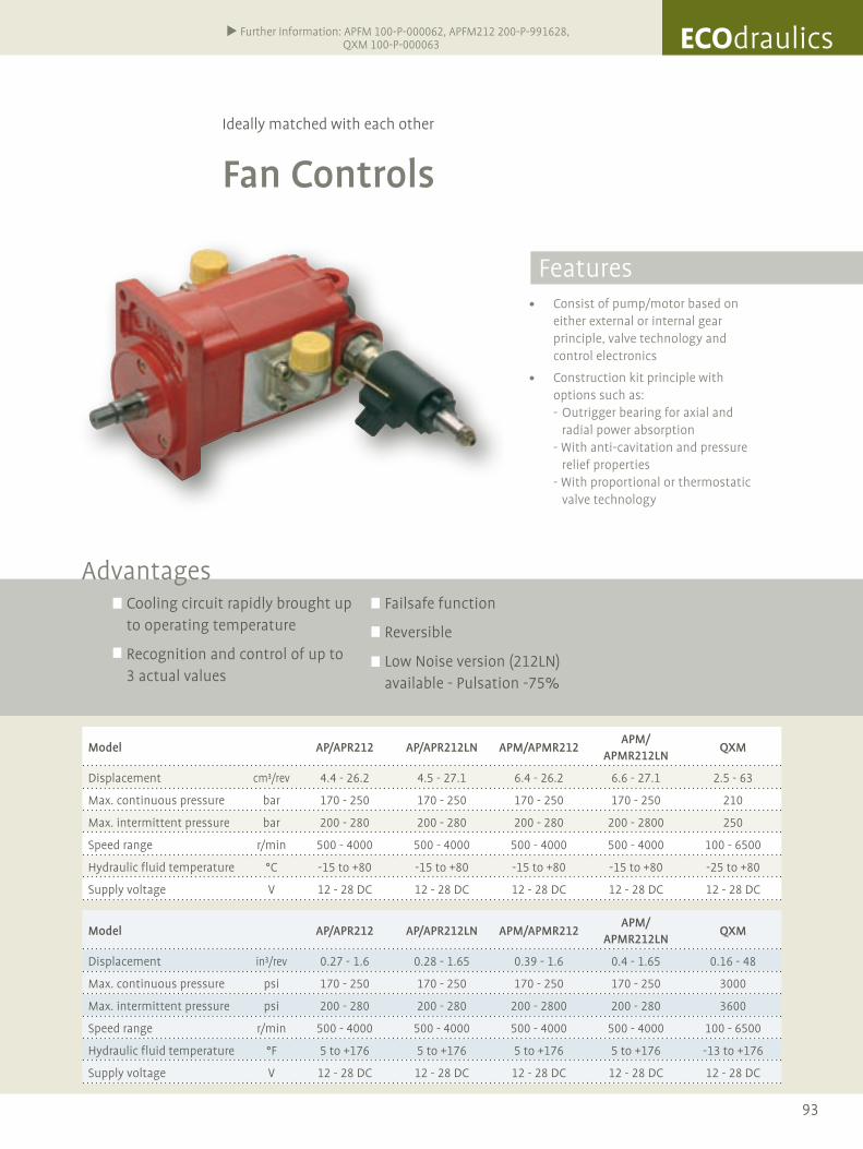
93
Ideally matched with each other
Fan Controls
Consist of pump/motor based on either external or internal gear principle, valve technology and control electronics
Construction kit principle with options such as: - Outrigger bearing for axial and radial power absorption - With anti-cavitation and pressure relief properties - With proportional or thermostatic valve technology
Cooling circuit rapidly brought up to operating temperature
Recognition and control of up to 3 actual values
Failsafe function
Reversible
Low Noise version (212LN) available - Pulsation -75%
Advantages
Further Information: APFM 100-P-000062, APFM212 200-P-991628, QXM 100-P-000063
Features
Model AP/APR212 AP/APR212LN APM/APMR212APM/
APMR212LNQXM
Displacement in³/rev 0.27 - 1.6 0.28 - 1.65 0.39 - 1.6 0.4 - 1.65 0.16 - 48
Max. continuous pressure psi 170 - 250 170 - 250 170 - 250 170 - 250 3000
Max. intermittent pressure psi 200 - 280 200 - 280 200 - 2800 200 - 280 3600
Speed range r/min 500 - 4000 500 - 4000 500 - 4000 500 - 4000 100 - 6500
Hydraulic fluid temperature °F 5 to +176 5 to +176 5 to +176 5 to +176 -13 to +176
Supply voltage V 12 - 28 DC 12 - 28 DC 12 - 28 DC 12 - 28 DC 12 - 28 DC
Model AP/APR212 AP/APR212LN APM/APMR212APM/
APMR212LNQXM
Displacement cm³/rev 4.4 - 26.2 4.5 - 27.1 6.4 - 26.2 6.6 - 27.1 2.5 - 63
Max. continuous pressure bar 170 - 250 170 - 250 170 - 250 170 - 250 210
Max. intermittent pressure bar 200 - 280 200 - 280 200 - 280 200 - 2800 250
Speed range r/min 500 - 4000 500 - 4000 500 - 4000 500 - 4000 100 - 6500
Hydraulic fluid temperature °C -15 to +80 -15 to +80 -15 to +80 -15 to +80 -25 to +80
Supply voltage V 12 - 28 DC 12 - 28 DC 12 - 28 DC 12 - 28 DC 12 - 28 DC
ECOdraulics

94
Only the flow rate that‘s needed
Internal Gear Pumps for Variable Speed Drives
Continuously variable flow rate (0% to 100%)
Dependent on the model, can be used in 1-, 2- or 4-quadrant operation
Low inertias, high dynamic response
Acceleration from 0 to 2750 rpm in 70 ms
Fast payback of the investment
Energy savings of up to 70%
Noise reduction of 10 to 20 dB(A)
Reduced oil volume
Raises productivity levels
Advantages
QXEH
Size 3 4 5 6
Displacement cm3/U 10-15,6 20,4-32,4 39,3-63,7 80,2-124,8
Max. speed min-1 3400 3200 2800 2500
Max. continuous pressure bar 250 250 250 250
Peak pressure bar 315 315 315 315
Power consumption kW 6-9,4 12,3-19,6 23,7-38,5 48,5-75,4
QXEH
Size 3 4 5 6
Displacement in3/rev 0.6-0.9 1,2-2 2.4-3.9 4.9-7.5
Max. speed min-1 3400 3200 2800 2500
Max. continuous pressure psi 3600 3600 3600 3600
Peak pressure psi 4500 4500 4500 4500
Power consumption kW 6-9,4 12,3-19,6 23,7-38,5 48,5-75,4
Features
Further Information: 100-P-000034

95
Only the flow rate that‘s needed
Internal Gear Pumps for Variable Speed Drives
Further Information: 100-P-000034
The more intelligent solution
Bucher Hydraulics is rising to the challenge to strive
towards an ecological present and future.
Like every idea, ECOdraulics starts off as a concept and
continues with everyone acting in a tangible and really
deliberate way.
Our products comply with at least one of the following
criteria:
•Reducedenergyconsumption
•Loweremissions,suchasnoiseorlostheat
•Protectionoftheenvironment
•Optimizationthroughsystemdesign
High quality standards from initial development
through to flexible series production in accordance
with ISO 9001.
EnvironmentalIssues,HealthandSafetyat
WorkinAccordancewithISO14001
A company’s excellence becomes apparent wherever
sales success is not only ostensibly a determining
factor. Bucher Hydraulics avow themselves to envi-
ronmentally conscious production methods and are
committed to complying with standard guidelines.
Amongst other things this entails reducing raw
material, operating supply item and water consump-
tion, handling hazardous substances in an ecologically
acceptable manner, using energy efficiently,
minimising emissions and wastage as well as
exercising precautionary measures taken by their
emergency management team to prevent hazards
and accidents.
ECOdraulics
Farbwert GRÜN: CMYK: C20, M0, Y90, K60RGB: R111, G115, B45Pantone: 5757
ECOdraulics
ECOdraulics
“Do you speak
ECOdraulics?”
Then come to
Bucher Hydraulics:
Let’s talk about
first-class products
that support
protecting (y)our
environment.”
ECOdraulics –
just for you.

© Bucher Hydraulics GmbH - 100-P-000068-E-04/10.2011We reserve the right to implement changes without prior notice
Bucher [email protected]
For further information visit us at:www.bucherhydraulics.com