Process Engineering Considerations - SelectedWorks - Bepress
23
Iowa State University From the SelectedWorks of Kurt A. Rosentrater August, 2004 Design Considerations for the Construction and Operation of Feed Milling Facilities. Part II: Process Engineering Considerations Kurt A. Rosentrater, United States Department of Agriculture Gregory D. Williams Available at: hps://works.bepress.com/kurt_rosentrater/44/
-
Upload
khangminh22 -
Category
Documents
-
view
0 -
download
0
Transcript of Process Engineering Considerations - SelectedWorks - Bepress

Iowa State University
From the SelectedWorks of Kurt A. Rosentrater
August, 2004
Design Considerations for the Construction andOperation of Feed Milling Facilities. Part II:Process Engineering ConsiderationsKurt A. Rosentrater, United States Department of AgricultureGregory D. Williams
Available at: https://works.bepress.com/kurt_rosentrater/44/

The authors are solely responsible for the content of this technical presentation. The technical presentation does not necessarily reflect the official position of the American Society of Agricultural Engineers (ASAE), and its printing and distribution does not constitute an endorsement of views which may be expressed. Technical presentations are not subject to the formal peer review process by ASAE editorial committees; therefore, they are not to be presented as refereed publications. Citation of this work should state that it is from an ASAE meeting paper. EXAMPLE: Author's Last Name, Initials. 2003. Title of Presentation. ASAE Meeting Paper No. 03xxxx. St. Joseph, Mich.: ASAE. For information about securing permission to reprint or reproduce a technical presentation, please contact ASAE at [email protected] or 616-429-0300 (2950 Niles Road, St. Joseph, MI 49085-9659 USA).
An ASAE/CSAE Meeting Presentation Paper Number: 044144
Design Considerations for the Construction and Operation of Feed Milling Facilities.
Part II: Process Engineering Considerations
Kurt A. Rosentrater, Ph.D., Agricultural and Bioprocess Engineer USDA, ARS, Crop and Entomology Research Unit 2923 Medary Avenue, Brookings, SD, 57006, [email protected]
Gregory D. Williams, Ph.D., P.E., S.E., Manager of Engineering FWS Design Builders Inc. 1600 E. Cliff Road, Burnsville, MN, 55337, [email protected]
Written for presentation at the 2004 ASAE/CSAE Annual International Meeting
Sponsored by ASAE/CSAE Fairmont Chateau Laurier, The Westin, Government Centre
Ottawa, Ontario, Canada 1 - 4 August 2004
Abstract. Feed milling facilities represent an important segment of our food production system, because they manufacture the majority of products used to meet the nutritional needs of livestock in our meat supply chain. Agri-industrial facilities such as feed mills have a number of unique design requirements. In an effort to summarize state of the art design procedures for feed milling facilities constructed in North America, an overview of these procedures and accepted standards has been assembled. Specifically, this paper focuses on process engineering considerations. Consequently, engineers and designers should become familiar with the distinctive design process for these facilities and develop an appropriate reference base from which to work.
Keywords. Facility Design, Feed Mills, Process Engineering

2
Introduction Agriculture is one of the most important and widespread industries both in the United States
as well as throughout the world. Agriculture and agri-industry account for nearly 13% of U.S. GDP (Williams and Bonhoff, 2004). During the year 2000, farmers in the U.S. produced 9.97 billion bushels (253.2 million Mg) of corn, 2.77 billion bushels (75.4 million Mg) of soybeans, and 2.22 billion bushels (60.4 million Mg) of wheat (AG-STATS.COM, 2002). A key component to the US agri-industrial complex is the animal feed production system. Currently, there are 1779 animal feed manufacturing facilities in the United States (U.S. Census Bureau, 2004).
Since the early 1900s, with the advent of a new slipforming method for concrete silo construction, and the ensuing grain elevator revolution, concrete feed milling facilities have often been built in conjunction with these types of grain storage structures, which is a practice that is, in fact, still used today. Not only are modern feed mill construction methodologies similar to those of the early 20th Century, but the physical layout and material handling systems do, in many respects, closely parallel each other, if not exactly match. Modern feed mills do, however, differ from their predecessors in many key respects. Today’s feed mills are much larger and have higher throughput rates than their predecessors. In addition, these facilities have greater equipment capacities, improved safety measures and dust control systems, and utilize electronic instrumentation and control systems. Even though large, concrete facilities have been constructed for many years, there exists a continual need for new facilities to service the feed industry in this country. This need exists because many older facilities have reached the end of their effective service life, and must be replaced or upgraded. Also, many local cooperatives and private companies must increase processing capacities due to increases in livestock populations and concentrations. Consequently, every year in North America several new facilities are designed and constructed. Although a number of contractors and engineers service this industry, this market segment is diminishing.
Even so, the design and operation of feed milling facilities have many unique requirements, and these demands require technically competent designers and engineers. Until Williams and Rosentrater (2004), no work has been produced to date that comprehensively discusses all of the structural engineering aspects of modern feed mill design. Process design, on the other hand, has been thoroughly addressed by AFIA (1994). Therefore, the purpose of this paper is to provide an overview of state of the art design procedures for feed milling facilities, from a process engineering perspective, in order to parallel the structural work of Williams and Rosentrater (2004). While not intended to be comprehensive, it should introduce the reader to aspects of process engineering for these facilities, and will provide standards of practice as well as sources of fundamental design and reference information for engineers and designers of these facilities, in order to improve the knowledge base of those involved in the industry.
Overview of Feed Milling Facilities Feed is produced for a number of animal types such as livestock (including poultry, swine,
and ruminants), domestic animals (such as pets), and fish (for aquaculture). Feed mills manufacture pellets or mash (e.g., mixed feed), and these products are shipped in bulk or bagged form. Feed milling facilities may be dedicated to producing feed for either single or multiple species. In the United States, feed mills tend to focus on a single species at a given mill; in other countries, such as Canada, it is more common to have multiple species feed mills. To operate a feed mill effectively, ingredient storage, conveyance, and proportioning are of utmost importance, and in larger facilities, it is not uncommon for dozens of ingredients to be used in the production of various feed blends. This ultimately leads to challenging process engineering undertakings.
Figure 1 depicts, in block flow chart format, the general systems associated with a typical feed mill. In this type of process, raw ingredients, such as whole grain, liquids, and soft stocks (i.e., minerals, salt, and other bulk non-grain materials) are delivered to the facility, typically via either rail or truck, and are then transported to appropriate storage bins via gravity flow, mechanical
3
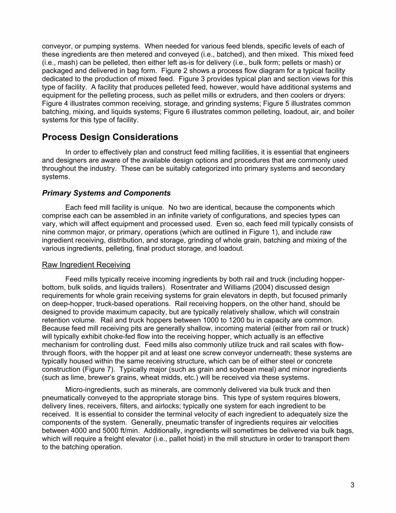
conveyor, or pumping systems. When needed for various feed blends, specific levels of each of these ingredients are then metered and conveyed (i.e., batched), and then mixed. This mixed feed (i.e., mash) can be pelleted, then either left as-is for delivery (i.e., bulk form; pellets or mash) or packaged and delivered in bag form. Figure 2 shows a process flow diagram for a typical facility dedicated to the production of mixed feed. Figure 3 provides typical plan and section views for this type of facility. A facility that produces pelleted feed, however, would have additional systems and equipment for the pelleting process, such as pellet mills or extruders, and then coolers or dryers: Figure 4 illustrates common receiving, storage, and grinding systems; Figure 5 illustrates common batching, mixing, and liquids systems; Figure 6 illustrates common pelleting, loadout, air, and boiler systems for this type of facility.
Process Design Considerations In order to effectively plan and construct feed milling facilities, it is essential that engineers
and designers are aware of the available design options and procedures that are commonly used throughout the industry. These can be suitably categorized into primary systems and secondary systems.
Primary Systems and Components
Each feed mill facility is unique. No two are identical, because the components which comprise each can be assembled in an infinite variety of configurations, and species types can vary, which will affect equipment and processed used. Even so, each feed mill typically consists of nine common major, or primary, operations (which are outlined in Figure 1), and include raw ingredient receiving, distribution, and storage, grinding of whole grain, batching and mixing of the various ingredients, pelleting, final product storage, and loadout.
Raw Ingredient Receiving
Feed mills typically receive incoming ingredients by both rail and truck (including hopper-bottom, bulk solids, and liquids trailers). Rosentrater and Williams (2004) discussed design requirements for whole grain receiving systems for grain elevators in depth, but focused primarily on deep-hopper, truck-based operations. Rail receiving hoppers, on the other hand, should be designed to provide maximum capacity, but are typically relatively shallow, which will constrain retention volume. Rail and truck hoppers between 1000 to 1200 bu in capacity are common. Because feed mill receiving pits are generally shallow, incoming material (either from rail or truck) will typically exhibit choke-fed flow into the receiving hopper, which actually is an effective mechanism for controlling dust. Feed mills also commonly utilize truck and rail scales with flow-through floors, with the hopper pit and at least one screw conveyor underneath; these systems are typically housed within the same receiving structure, which can be of either steel or concrete construction (Figure 7). Typically major (such as grain and soybean meal) and minor ingredients (such as lime, brewer’s grains, wheat midds, etc.) will be received via these systems.
Micro-ingredients, such as minerals, are commonly delivered via bulk truck and then pneumatically conveyed to the appropriate storage bins. This type of system requires blowers, delivery lines, receivers, filters, and airlocks; typically one system for each ingredient to be received. It is essential to consider the terminal velocity of each ingredient to adequately size the components of the system. Generally, pneumatic transfer of ingredients requires air velocities between 4000 and 5000 ft/min. Additionally, ingredients will sometimes be delivered via bulk bags, which will require a freight elevator (i.e., pallet hoist) in the mill structure in order to transport them to the batching operation.

4
Raw Ingredient Distribution
Ingredients can be transported within the facility via multiple pieces of equipment, including bucket elevators, distributors and gravity-flow spouting, belt conveyors, and paddle and drag chain conveyors. These types of equipment systems have been discussed in depth by Rosentrater and Williams (2004). The most common type of conveyor in feed mills, however, is the screw conveyor, because it offers the potential for not only transporting materials, but also offers the potential to accurately meter the various ingredients, which is a functionality that the other conveyor types do not offer. As with other conveyor systems, when designing screw conveyors for material transport and distribution, the throughput capacity and required power are of prime importance. The capacity of a screw conveyor can be determined as:
( )1
2s
2h
CNPDD
4Q
⋅⋅−⋅
π= (1)
where Q is the volumetric capacity (ft3/min), Dh is the diameter of the helicoidal screw flighting (in), Ds is the diameter of the screw shaft (in), P is the pitch length along the screw (in), N is the rotational speed of the screw (rev/min), and C1 is a conversion factor of 1728 (in3/ft3). The power required to drive a screw conveyor can be determined according to CEMA (1980):
omd F
000,000,1FBDLQ
000,500FNL
P ⋅
⋅⋅⋅+
⋅⋅= (2)
where P is the power required to drive the conveyor shaft (hp), which accounts for the power necessary to overcome friction as well as transport the material, L is the length of the conveyor (ft), N is the rotational speed of the screw (rev/min), Fd (-) is an empirical diameter factor that accounts for screw weight per unit length (Table 1), Q is the volumetric capacity of the conveyor (ft3/h), BD is the bulk density of the material (lb/ft3), Fm (-) is an empirical material factor related to the physical properties of the material being conveyed (Table 2), and Fo (-) is an empirical factor that accounts for sizing small conveyor motors adequately to avoid overloading, and can be determined according to CEMA (1980):
3368.0tHP9142.1Fo −⋅= (3)
where HPt is the total calculated power for the screw conveyor prior to applying the Fo motor factor (i.e., the quantity inside the brackets of Equation 2, above). If, however, the total calculated horsepower (i.e., inside the brackets) is greater than 5.2, then Fo has a value of 1.0.
Spouting is used in a feed mill facility to transfer material between various equipment components, unit operations, and storage locations. The two types of spouting that are used include unlined round spouting, often constructed from rejected well-casing, and square spouting, which is typically constructed in a “u-trough” shape. Square spouting is often lined with ceramic or urethane liners to limit wear. Round spouting is most commonly used in feed mills. When designing spouting, as mentioned in Rosentrater and Williams (2004), most designers use a material flux value between 50 and 60 bu/h/in2 for whole grain flow from receiving pits, between 70 and 80 bu/h/in2 for bin discharge of whole grain, as well as for general spouting of whole grain, and between 100 and 110 bu/h/in2 for rail loadout of whole grain. Ground grain, and other raw bulk ingredients, on the other hand, typically have a flux between 50 and 60 ft3/h/in2. In order for material to flow properly through a given spout, the primary design consideration is the angle of installation, in other words, the flow angle. It is common practice to use an angle of 9-on-12 (approximately 37o) as an absolute minimum for whole grain flow through a spout. Preferably, though, spouts should be installed at angles between 10-on-12 to 12-on-12 (approximately 40o to 45o), to ensure adequate whole grain flow. Ground grain and other mill feed ingredients require

5
flow angles between 50 o and 60o, while pellets require angles between 45o and 50o, in order to flow properly.
Raw Ingredient Storage
The two major materials of construction that are used for feed mills are concrete and steel. Concrete feed mills are typically slip formed, and are most prevalently used for large scale facilities. Steel feed mills are especially common for smaller-scale facilities, and are typically assembled from bolted bin construction, because they are sold as modular units, but they may occasionally be welded. Welded bins are usually shop fabricated due to the economics of shop techniques compared to field fabrication. Regardless of the type of construction, no two facilities are identical; the combinations for the layout of feed milling structures are vast, and are predominantly influenced by client preferences, more than any other single factor. Figure 8 illustrates several typical bin plans.
A specific design consideration for a given feed mill is the amount of space allocated to storage of bulk ingredients. Some owners require enough capacity to store at least one week’s worth of raw materials; other owners do not. Rosentrater and Williams (2004) discuss in depth design requirements for grain storage elevators, which closely parallel those of feed milling facilities. As mentioned, a material’s angle of repose will impact the effective storage capacity of a given bin. Williams and Rosentrater (2004) provide an extensive summary of angle of repose data for many commonly used feed ingredients. Moreover, compaction between the individual material particles will need to be considered when designing ingredient storage bins. This parameter is highly dependent on a material’s size, shape, and moisture content, and will also depend on the size and shape of the bin in which the material is to be stored. In practice, for grain storage it is common to use a compaction factor of 7% for bin diameters up to 39 ft, 8% for bin diameters between 40 to 59 ft, and 9% for bins with diameters greater than 60 ft. Little information is available for other (i.e., soft stock) feed materials, so it is common to use compaction factors between 5 and 10%. When sizing each bin, it is essential to consider that ingredients will probably be received before the bins are completely empty, so each bin capacity must be, at a minimum, greater than the volume of one delivery truck or rail car. A common rule of thumb is to size each bin to accommodate, at a minimum, at least 150% the delivery unit volume.
Grinding
Prior to utilization in feed formulations, whole grain must be ground to reduce particle size. Grinding systems are generally located directly under whole grain storage bins, in a separate room within the mill facility (Figure 9), or in a separate grinding building adjacent to the mill structure. This location is driven by life safety and fire codes, as discussed by Williams and Rosentrater (2004). Hammermills are the most common type of milling equipment, and can have diameters as large as 750 in, screen areas as large as 7000 in2, operating speeds up to 3600 rpm, effectively producing hammer tip speeds up to 21,000 ft/min, and require up to 600 hp. Most hammermills are typically installed with an air system, which includes air inlets (to control dust from the process) integral to the hammermill, a plenum under the grinder for airflow, and a filter, located outside of the grinder building, for dust collection. These systems typically require 1 to 2 cfm/in2 of screen area. Conveyors under the hammermill (typically a single screw conveyor) must be located at least 18 in below the hammermill discharge, to allow for an adequate air plenum size, and to prevent ground product from becoming entrained in the air stream. It is becoming common to locate the transfer conveyor even lower, and to provide a cross-sectional area of up to 10 ft2, in order to allow for optimal airflow through the plenum. Roller mills have been gaining in popularity over the last several years, primarily because of their ability to produce coarse, uniform particle sizes, with reduced noise levels, and with reduced power consumption. Owens and Heimann (1994) provide more extensive detail regarding grinding systems in feed mills.
6
Batching
In order to produce particular feed mixtures, appropriate quantities of specific ingredients must be transferred out of storage and transported to the mixer. This is the function of the batching system (Figure 10). For all major and minor ingredients, the equipment used to accomplish this includes screw feeders (e.g., screw conveyors), which provide excellent proportioning control, and are thus the conveyor of choice for this operation, and scale hoppers, which are hoppers mounted on load cells above the mixer. These hoppers range in size from one ton up to 5 tons, and must be designed with slopes greater than 60o, to prevent ingredient build-up. For ingredients that require precise quantities (e.g., minerals, antibiotics, etc.), micro-ingredient systems are used. These are very small stainless or mild steel bin clusters with small feeder screws. Bulk bag and hand dump stations are also frequently used to add ingredients to the feed mixture. All of these components must work in concert to provide the necessary quantities of various ingredients for specific feed mixtures. To avoid pressure differentials between the mixer and the scale hoppers during operation, which can prevent proper flow of material into the mixer, venting must be provided between them. Venting ductwork should be installed with a slope greater than 60o (to prevent dust build-up), and should provide an air velocity less than 500 ft/min (to prevent ingredient entrainment). Furthermore, when designing a batching operation, it is essential to provide adequate access clearance and platforms so that equipment can be serviced and repaired. These requirements are spelled out in the Code of Federal Regulations Title 29 (NARA, 2004) and enforced by OSHA. Fahrenholz (1994), Farenholz and McEllhiney (1994), McEllhiney (1994), and Moorhead (1994) provide more extensive detail regarding batching processes in feed mills.
Mixing
To produce specified feed mixtures, most modern feed mills utilize horizontal batch ribbon mixers (Figure 10), which have bottom gates that dump directly into a conveyor (typically a paddle drag) that transfers the mixed feed (e.g., mash) to a bucket elevator, where it is elevated and distributed to appropriate storage bins. Mash resides in storage until needed for pelleting, bagging, or direct bulk loadout. Ribbon mixers vary in size, but can be constructed as large as 700 ft3 in capacity. Most operate at a speed of approximately 40 rpm. Key to mixing operations is mixer cycle time, which includes time required to fill (from the batching scales), to mix, to discharge, and to wait for another batch to begin (i.e., dead time). Most mixers can achieve a cycle time between five and 10 min, depending on mixer efficiency, which thus amounts to a mixing capacity of 6 to 12 ton/h. Production capacity can quantitatively be determined according to:
demf
1
TTTTCECQ+++
⋅⋅= (4)
where Q is the volumetric throughput of the mixer (ton/h), C is the effective volume of the mixer (ton), E is the efficiency of the mixing process (%, expressed as a decimal), C1 is a conversion factor of 60 (min/h), Tf is the time required to fill the mixer from the batching scales (min), Tm is the time required to mix the ingredients (min), Te is the time required to empty the mixer, and Td is dead time between batches (min). When designing a mixing operation, it is essential to provide adequate access clearance so that equipment can be serviced, repaired, or cleaned. This ultimately means that enough clearance must be provided so that the mixer’s ribbon can be removed. Fahrenholz (1994), Farenholz and McEllhiney (1994), McEllhiney (1994), and Moorhead (1994) provide more extensive detail regarding mixing processes for feed mills.

7
Pelleting
Pelleting (Figure 11) is a process intended to densify feed ingredients, which will improve storage, handling, and shipping behavior, and to improve the feed nutritionally by increasing the palatability and feed efficiency in the livestock. Typically mixed feed (e.g., mash) is transported from the mash storage bins to a preconditioner, where it is mixed with steam so that it is more amenable to the pelleting process. Residence time in a conditioner of 20 sec is recommended, but various plants often use longer times. After conditioning the feed particles, they are then introduced into the pellet mill, where a rotating roller forces the ingredients through circular die openings, which typically have diameters smaller than ¾ in. Modern pellet mills can have die diameters up to 42 in, with effective pelleting surfaces of 1600 in2, can produce pelleted feed at a rate of up to 50 ton/h, and can consume up to 800 hp. After processing, the pellets are then cooled (horizontal or counterflow coolers are generally used), so that pellet temperature is reduced to ambient (in order to avoid spoilage problems), screened to removed fines and broken pellets, and then conveyed to storage, after which they will either be bagged or loaded out in bulk. Fairfield (1994) provides extensive detail regarding feed mill pelleting systems.
Final Product Storage
Bulk feed materials are typically stored in bins which are adjacent to, and similar to, those used for whole grain and other raw bulk ingredients, so the previous discussion regarding bulk storage is germane. Loadout bins are clustered within a loadout bay, which is typically a separate section of the mill tower. Bagged feed, on the other hand, will require warehouse storage space. Commonly located adjacent to the mill structure, a warehouse is generally constructed of either concrete (precast, tilt-up, or slipformed) or steel. When designing warehouse systems, it is important to provide adequate space, both for material storage, as well as maneuvering room for fork lift trucks. The amount of required storage will depend on many factors, including production capacity, frequency of inventory turnover, number of individual products, space required for bagged feed ingredients versus final product storage, space required for empty pallets or other materials, and, not of least importance, client preference. Pallets can range in size from 48 in by 48 in up to 60 in by 60 in. As a general rule of thumb, for each one ton of bagged product, which is the approximate capacity of one pallet, the designer should provide approximately 16 ft2 of floor space, as a minimum. Additionally, in practice, aisles are typically 8 ft wide for forklift travel only, and 12 ft wide for forklift working space (i.e., turning, stacking, etc.).
Loadout
Loadout systems for feed mills are generally different than those used in grain elevators, which were discussed by Rosentrater and Williams (2004). The two most common options for feed mills include reversible screw conveyors and weigh lorry systems. Collection screw conveyors (Figure 12, a) can have either multiple discharges, or an additional translating shuttle screw conveyor, in order to fill multiple locations in feed delivery trucks. These systems require a truck loadout scale to achieve proper truck fill. Capacities can often exceed 300 ton/h for large facilities. Weigh lorry systems (Figure 12, b), which have rail-mounted traveling scales in order to fill multiple feed truck locations, often have hopper volumes between two and six tons, and can achieve loadout capacities greater than 100 ton/h. Whichever system is implemented, however, it is essential to provide adequate clearance and access platforms so that the loadout equipment can be serviced and repaired.
Secondary Systems and Components
The six most common secondary systems used in feed mills include air, dust control, liquids, steam, pollution control, and instrumentation and controls. Because not all facilities utilize

8
these systems to the same extent, these topics will only be covered cursorily, and the reader is referred to other sources for more information.
Air
Compressed air systems are commonly used in feed milling facilities, primarily as a means of providing sources of distributed pneumatic power throughout the plant to operate air-actuated gates and other equipment. These systems typically include air filters, compressors, coolers, receivers (i.e., storage tanks), dryers, valves, and piping. The overall design of the entire system is dependent on the requirements of each individual air cylinder in the plant. Each pneumatic cylinder will require a specific volume of air to operate, which can be determined as:
1CVLCSQ ⋅⋅⋅
= (5)
where Q is volumetric flowrate required by a given air cylinder to operate (ft3/min), S is a factor to account for cylinder operation (1 for a single stroke direction [i.e., extend or return]; 2 for bidirectional operation [i.e., actuate and return]), C is the rate of cylinder cycles (strokes/h), L is the cylinder stroke length (in), V is the air consumption rate (ft3/in of stroke), and C1 is a conversion factor of 60 (min/h). The total number of cylinders will determine the total required volume for the compressed air system. In practice, air compressors are typically sized up to 200% of total calculated required air volume, in order to provide for adequate system operation. Typical operating pressure in a pipeline is between 70 and 100 psi. The maximum pipe length used will actually depend on pipe diameter, and should not have more than 0.5 psi pressure drop (due to friction losses) for a given pipe run. Pipes are typically installed with a slope of 1 in drop for every 10 ft of horizontal length (approximately a 0.5o slope) so that moisture will flow downstream. Additionally, vertical piping is typically installed with a drain trap located at the bottom end of each line to collect and remove moisture from the pipeline. Ambler (1994) provides a more detailed discussion regarding the design of compressed air systems for feed mills.
Dust Control
Most feed mills utilize some type of dust control system. In a feed mill, dust is generated at several key locations: receiving pits, grinding systems, mixing systems, conveyors, baggers, and loadout. To mitigate problems, some facilities use an oil suppression system where mineral oil is sprayed onto incoming grain. Some facilities segregate dust from the ingredient stream, using inlet hoods and ducting, and then either reintroduce the dust at a downstream location, or use cyclone or bag house filters to completely remove dust, and place it in a contained storage location for subsequent disposal or other end use. When designing systems to pneumatically transport dust, it is important to produce an airspeed that will provide adequate dust conveyance. To accomplish this, inlet hoods are typically designed to provide, at a minimum, 100 to 250 cfm of airflow for each 1 ft2 of inlet hood opening (e.g., a minimum air velocity of 100 ft/min), and the duct work is typically designed to provide an air velocity of 4000 ft/min. McDaniel (1994) provides a more detailed discussion regarding the design of dust collection and containments systems for feed mills.
Liquids
Liquid materials are commonly used as feed ingredients, so most feed mills provide systems to receive, store, and transport them for incorporation into specific feed rations. The most commonly used liquid in feed mills is liquid fat. Fat is commonly maintained between 110 and 250 oF, using heated tanks and pipelines. At these temperatures, it has a specific gravity between 0.87 and 0.90 (-). Other common liquids include choline chloride (a B vitamin; specific gravity of approximately 1.11[-]), CFCE (condensed fermented corn extractives – a byproduct of corn wet

9
milling operations; specific gravity of approximately 1.25 [-]), methionine (a nutritional supplement; specific gravity of approximately 1.19 [-]), and various others, including molasses and flavor additives. The design of piping and pumping systems is highly dependent on the physical properties of these materials, and will vary between batches. Typical equipment for liquids systems includes pumps, valves, storage tanks, flow meters, screeners, filters, pipelines, and spray nozzles. Basic design information and procedures can be found in many undergraduate fluid mechanics and dynamics texts, such as Mott (2000), Munson et al. (2002), and Potter and Wiggert (2002). Huff (1994) and Moorhead (1994) provide a more detailed discussion regarding the design of fluid handling and storage systems, and is specifically focused on feed mills.
Steam
Boilers are used in feed mills to generate steam, which is primarily used for cooking feed ingredients prior to pelleting. Common types of boilers include firetube, watertube, firebox, fluidized bed combustors, and direct-fired steam generators. Boilers typically range in capacity from 100 hp up to 2000 hp, and can generate steam up to 70,000 lb/hr. Key to an efficient boiler system is a clean water source for steam generation. This can be accomplished by chemically treating and softening water streams, in order to reduce impurities and thus to reduce boiler problems, including mineral deposits and surface corrosion. Lyon (1994), Malone (1994), Murphy (1994), and Virr (1994) provide a more detailed discussion regarding the design of boiler systems. In practice, the selection and design of steam generation and distribution systems is undertaken with the consultation of the manufacturers of the various equipment systems. Williams and Rosentrater (2004) address a number of building and safety code issues with respect to boiler and piping systems.
Pollution Control
Feed milling facilities must comply with regulations for air, water, and solid waste discharge. In the United States emission laws are based on Title 40 of the Federal Code of Regulations (NARA, 2004). Although the federal government has instituted environmental regulations, the individual states, and localities within them, may, and in fact often, adopt stricter emissions standards, so vary in terms of regulations. Prior to designing a new facility, appropriate agencies must be contacted for specific regulation information. Air emissions will originate from the handling and processing of the various feed ingredients (i.e., receiving, conveying, grinding, pelleting, cooling, and loadout are the primary operations where dust is generated). Thus, all air will need to be collected and filtered prior to discharge into the atmosphere. This includes providing filters on all equipment, as well as on the bin vents on the roof deck of the mill structure. More information regarding air emissions standards is provided in EPA (2004a). Wastewater will originate from various processes (e.g., boiler blowdown, facility cleaning and sanitizing, etc.) as well as sanitary sewage from office facilities. Plants typically treat waste water prior to discharge to a municipal system, or may utilize a septic system on site. More information regarding waste water standards is provided in EPA (2004b). Solid wastes encompass solids, liquids, and sludges that are to be discarded, and can include empty buckets, bags, containers, pallets, processing byproducts, spoiled grain, pesticides, feed additives, water treatment chemicals, lubricants, paints, solvents, etc. These are primarily remediated using a contracted waste disposal or recycling service. More information regarding waste standards is provided in EPA (2004c). Eklund (1994), Groves (1994), Kroon (1994), and Martin (1994) provide a more detailed discussion regarding pollution generation and control strategies for feed mills.
Instrumentaton and Controls
Most facilities are controlled using computer-based PLC systems, which provide real-time monitoring and control of electrical equipment in a facility. An advantage to this type of system is

10
that it provides the ability to utilize sensors and instrumentation to monitor operations, thus reducing the need for labor-intensive operations. Many sensors are available for use in a feed mill: proximity sensors and continuous flow sensors to test for plugged conditions; bin level sensors, both continuous as well as discrete, to monitor the amount of material in specific bins; motion detection sensors, bearing temperature sensors, belt alignment sensors, and chain slack sensors (to ensure proper conveyor operation). More information is provided in Rosentrater and Williams (2004). Design, implementation, and installation of these components are typically undertaken with the manufacturers of the various sensor and control systems.
Facility Sanitation
With the spread of BSE (also known as “Mad Cow Disease”), there has been an increased awareness of the need to prevent cross-contamination between same-species ingredients. For example, meat meal from bovines should not be used to produce bovine feed. This limitation of cannibalism among same species has led to a number of functional changes in the design and operation of feed milling facilities. In the last few years, items such as wash down areas for extrusion and pelleting operations are becoming more common. Self-cleaning hoppers and conveyors, isolated production lines for specific species, and more attention to general sanitation, such as dust shelves, areas of infestation, and dirt build-up are becoming more important to designers and facility owners. For further information, the reader is referred to Imholt (1999).
Process Design Methodology Although design philosophies are unique to each individual engineer, and are typically
developed over time and with experience, conducting the process design for a feed milling facility generally entails four common (i.e., major) steps. These are shown in Figure 13. Prior to initiating any design undertaking, it is vital that a facility designer compile and organize project-specific information. This includes understanding the needs, goals, constraints, and preferences of the client. Rosentrater and Williams (2004) have discussed several of these issues for grain elevator facilities. Also important in this stage to be aware of all applicable design codes and standards, several of which have been discussed by Williams and Rosentrater (2004). The next phase of process design is the most critical aspect of the entire design process: amalgamating all collected information and then translating it into a comprehensive process flow diagram for the facility. Many facility design and construction projects have encountered difficulties, sometimes to a considerable, and often expensive, extent due primarily to a faulty or inadequate process flow diagram. After this stage, but before process design can proceed, a facility layout must be developed which, in fact, will become the basis for the design of all subsequent systems in the facility. Tasks associated with this step include determining the necessary number of bins and bin sizes, including bin capacities as well as the facility roof heights, bin layouts, or plans (Figure 8), and thus the overall facility layout, which will affect building locations, traffic flow patterns, equipment locations and orientations. Finally, the actual process design must be undertaken, and all of the process engineering considerations mentioned earlier in this paper, for both primary as well as secondary systems, must be implemented, subject to the requirements supplied by the client. Throughout the entire life cycle of this design methodology, however, process engineers must work closely with structural engineers, especially during facility and equipment layout tasks. Although these are separate disciplines, the design activities of each are not mutually exclusive, but rather are closely dependent upon each other, and can either synergistically complement or impair each other. Process and equipment changes affect structural design, and vice-versa.
Conclusions and Recommendations This paper has provided an overview of common practices and procedures related to the
planning, design, construction, and operation of modern feed mills. Specifically, process

11
engineering of these facilities was considered, so designers and educators should find this paper useful. Although this paper serves as an introduction to process engineering of these facilities, it is not all-inclusive. For a more in-depth treatment of the topic, the reader is encouraged to consult the premier resource for process design of feed mills (AFIA, 1994) for further information.
References AG-STATS.COM. 2002. Statistical data for agribusiness and the study of agriculture. AG-STATS.COM.
Available online: http://www.ag-stats.com. [Accessed 27 February 2002]. Ambler, R. F. 1994. Compressed air systems. In Feed Manufacturing Technology IV, pp. 320-330.
Arlington, VA: American Feed Industry Association. AFIA. 1994. Feed Manufacturing Technology IV. Arlington, VA: American Feed Industry Association. CEMA. 1980. Screw Conveyors. Washington, D. C.: Conveyor Equipment Manufacturer’s Association. Eklund, C. W. 1994. Wastewater management. In Feed Manufacturing Technology IV, pp. 436-451.
Arlington, VA: American Feed Industry Association. EPA. 2004a. Food and Agriculture Industries, AP-42, Chapter 9. Available online:
http://www.epa.gov/ttn/chief/ap42/ch09/index.html. [Accessed 1 May 2004]. EPA. 2004b. Effluent Limitations Guidelines, Pretreatment Standards, and new Source Performance
Transportation Equipment Cleaning Point Source Category. Available online: http://www.epa.gov/agriculture/tsur.html. [Accessed 1 May 2004].
EPA. 2004c. Waste. Available online: http://www.epa.gov/agriculture/twas.html. Fairfield, D. 1994. Pelleting cost center. In Feed Manufacturing Technology IV, pp. 111-130. Arlington, VA:
American Feed Industry Association. Farenholz, C. Proportioning and mixing cost center. In Feed Manufacturing Technology IV, pp. 98-102.
Arlington, VA: American Feed Industry Association. Farenholz, C. and R. R. McEllhiney. 1994. Microingredient proportioning and mixing. In Feed
Manufacturing Technology IV, pp. 109-110. Arlington, VA: American Feed Industry Association. Groves, S. P. 1994. Environmental assessment. In Feed Manufacturing Technology IV, pp. 426-430.
Arlington, VA: American Feed Industry Association. Huff, P. L. 1994. Other liquids. In Feed Manufacturing Technology IV, pp. 194-199. Arlington, VA:
American Feed Industry Association. Imholte, T. J. and T. K. Imholte-Tauscher. 1999. Engineering for Food Safety and Sanitation. Medfield, MA:
Technical Institute of Food Safety. Kroon, S. E. 1994. Air pollution control. In Feed Manufacturing Technology IV, pp. 431-435. Arlington, VA:
American Feed Industry Association. Lyon, G. 1994. Direct-fired steam for processing. In Feed Manufacturing Technology IV, pp. 375-379.
Arlington, VA: American Feed Industry Association. Malone, R. 1994. Steam traps. In Feed Manufacturing Technology IV, pp. 366-374. Arlington, VA:
American Feed Industry Association. Martin, D. 1994. Solid and hazardous waste. In Feed Manufacturing Technology IV, pp. 457-461.
Arlington, VA: American Feed Industry Association. McDaniel, G. L. 1994. Dust collection systems. In Feed Manufacturing Technology IV, pp. 200-208.
Arlington, VA: American Feed Industry Association. McEllhiney, R. R. 1994. Batch mixing cycles. In Feed Manufacturing Technology IV, pp. 102-104.
Arlington, VA: American Feed Industry Association. Moorhead, D. F. 1994. Continuous proportioning systems. In Feed Manufacturing Technology IV, pp. 105-
108. Arlington, VA: American Feed Industry Association. Moorhead, T. G. 1994. Liquid ingredients handling. In Feed Manufacturing Technology IV, pp. 185-190.
Arlington, VA: American Feed Industry Association. Mott, R. A. 2000. Applied Fluid Mechanics. Upper Saddle River, NJ: Prentice Hall.

12
Munson, B. R., D. F. Young, and T. H. Okiishi. 2002. Fundamentals of Fluid Mechanics. New York, NY: John Wiley & Sons, Inc.
Murphy, D. T. 1994. Boiler water treatment. In Feed Manufacturing Technology IV, pp. 357-365. Arlington, VA: American Feed Industry Association.
NARA. 2004. Code of Federal Regulations, United States National Archives and Records Administration. Available online: http://www.access.gpo.gov/nara/cfr/cfr-table-search.html. [Accessed 1 May 2004].
Owens, J. M. and M. Heimann. 1994. Material processing cost center. In Feed Manufacturing Technology IV, pp. 81-97. Arlington, VA: American Feed Industry Association.
Potter, M. C. and D. C. Wiggert. 2002. Mechanics of Fluids. Pacific Grove, CA: Brooks/Cole Thompson Learning.
Rosentrater, K. A. and G. D. Williams. 2004. Design Considerations for the Construction and Operation of Grain Elevator Facilities. Part II: Process Engineering Considerations. ASAE Paper No. 044146. St. Joseph, MI: ASAE.
U.S. Census Bureau. 2004. County Business Patterns. Available online: http://censtats.census.gov/cbpnaic/cbpnaic.shtml. [Accessed 1 May 2004].
Virr, M. J. 1994. Boilers and associated equipment. In Feed Manufacturing Technology IV, pp. 351-356. Arlington, VA: American Feed Industry Association.
Williams, G. D. and D. R. Bohnhoff. 2004. An Overview of North American Agri-Industry. ASAE Paper No. 044173. St. Joseph, MI: ASAE.
Williams, G. D. and K. A. Rosentrater. 2004. Design Considerations for the Construction and Operation of Feed Milling Facilities. Part I: Planning, Structural, and Life Safety Considerations. ASAE Paper No. 044143. St. Joseph, MI: ASAE.
Table 1. Screw conveyor diameter factors (based on CEMA, 1980).
Screw Diameter (in) Diameter Factor, Fd (-)
4 12
6 18
9 31
10 37
12 55
14 78
16 106
18 135
20 165
24 235

13
Table 2. Feed ingredient material factors (based on CEMA, 1980).
Ingredient Bulk Density (lb/ft3) Material Factor, Fm (-)
Alfalfa, Meal 22 0.6 Alfalfa, Pellets 43 0.5 Bakery Byproducts 41 0.6 Barley, Meal 28 0.4 Barley, Whole 48 0.5 Blood, Dried 45 2.0 Bonemeal 60 1.7 Brewer's Grains, Dry 30 0.5 Corn, Cracked 45 0.7 Corn, Shelled 45 0.4 Cornmeal 40 0.5 Cottonseed Hulls 12 0.9 Deflourinated Phosphate 89 1.8 Dicalcium Phosphate 50 1.6 Dyna-K 70 1.7 Egg Powder 19 1.0 Feather Meal 30 1.0 Fish Meal 40 1.0 Limestone, Crushed 90 2.0 Lysine 38 1.5 Meat Scraps 40 1.5 Milo, Whole 45 0.5 Milo, Ground 41 0.6 Oat, Flour 35 0.5 Oats, Whole 26 0.4 Oyster Shells, Ground 60 2.0 Pro Pak 42 0.6 Rice, Flour 35 0.6 Rice, Grits 45 0.4 Salt 80 1.7 Soybean Meal 40 0.7 Soybeans, Whole 48 1.0 Wheat 48 0.4 Wheat Midds 35 0.5

14
Figure 1. Block flow diagram depicting major components of a typical feed mill.
Soft Stock Receiving
Grain Distribution Liquids Distribution
Soft Stock Storage
Grinding
Batching
Mixing
Incoming Soft Stocks
Bulk Loadout
Incoming Grain Incoming Liquids
Liquids Receiving Grain Receiving
Soft Stock Distribution
Liquids Storage Grain Storage
Packaging
Pelleting
Final Bulk Storage
Package Loadout
Warehouse

15
Figure 2. Process flow diagram for a typical mixed-ingredient feed mill.
Figure 3. Plan and section views for a typical mixed-ingredient feed mill.

16
Figure 4. Process flow diagram for a typical feed mill: receiving, storage, and grinding systems.
Figure 5. Process flow diagram for a typical feed mill: batching, mixing, and liquids systems.

17
Figure 6. Process flow diagram for a typical feed mill: pelleting, loadout, air, and boiler systems.
Figure 7. Typical enclosed rail and truck scale hopper receiving systems.

18
Figure 8. Common feed mill layouts (bin plans).
Figure 9. Typical grinding system housed within the mill structure.

19
Figure 10. Typical batching and mixing system.

20
Figure 11. Typical pelleting system incorporating a conditioner and counterflow cooler.

21
a
b
Figure 12. Typical shuttle conveyor (a) and weigh lorry (b) loadout systems.

22
Figure 13. General procedure for conducting feed mill process design.
Flow Diagram
Bin Layout/Arrangement Bin Sizes/Capacities
Facility Layout
Process Design
Primary Systems
Secondary Systems
Client Req. Building Codes Standards
Structural Design
Final Design