Procedure for Participating in Tender - tpnodl
234
NIT No.: TPNODL/OT/2021-2022/079 Dtd.04.10.2021 Property of TPNODL – Not to be reproduced without prior written permission of TPNODL Page | 1 Procedure for Participating in Tender Tender Enquiry No Work Description EMD (Rs.) Tender Participation Fee (Rs) Last date and time for Payment of Tender Participation Fee TPNODL/OT/2021- 2022/079 Turnkey Projects: Conversion of Existing HT Overhead Lines to underground Cables at 5 locations of Railway Crossing under CED, Balasore Rs.2,00,000 for each Work Location No. 1, 2 & 5 Rs 5000 18.10.2021 15:00 hrs Rs.50,000 for each Work Location No. 3 & 4 Please note that corresponding details mentioned in this document will supersede any other details mentioned anywhere else in the Tender Document. Procedure to Participate in Tender. Following steps to be done before “Last date and time for Payment of Tender Fee” as mentioned above: 1. Eligible and Interested Bidders to submit duly signed and stamped letter on Bidder's letter head indicating a. Tender Enquiry number b. Name of authorized person c. Contact number d. E-mail id e. Details of submission of Tender Fee f. GST Registration No 2. Non-Refundable Tender Fee, as indicated in table above, to be submitted in the form of Direct Deposit in the following bank account and submit the receipt along with a covering letter clearly indicating the Tender Reference/ Enquiry Number – Beneficiary Name – TP Northern Odisha Distribution Limited Bank Name – Union Bank of India Branch Name – Balasore Branch Account No – 500601010280332 IFSC Code – UBIN0550060 E-mail with necessary attachment to be sent to [email protected] before last date and time for payment of Tender Fee.
-
Upload
khangminh22 -
Category
Documents
-
view
3 -
download
0
Transcript of Procedure for Participating in Tender - tpnodl

NIT No.: TPNODL/OT/2021-2022/079 Dtd.04.10.2021
Property of TPNODL – Not to be reproduced without prior written permission of TPNODL
Page | 1
Procedure for Participating in Tender
Tender Enquiry No Work Description EMD
(Rs.)
Tender Participation Fee (Rs)
Last date and time for Payment of Tender Participation Fee
TPNODL/OT/2021-2022/079
Turnkey Projects: Conversion of Existing HT Overhead Lines to underground Cables at 5 locations of Railway Crossing under CED, Balasore
Rs.2,00,000 for each Work Location No. 1, 2 & 5
Rs 5000
18.10.2021 15:00 hrs
Rs.50,000 for each Work Location No. 3 & 4
Please note that corresponding details mentioned in this document will supersede any other details mentioned anywhere else in the Tender Document.
Procedure to Participate in Tender.
Following steps to be done before “Last date and time for Payment of Tender Fee” as mentioned above:
1. Eligible and Interested Bidders to submit duly signed and stamped letter on Bidder's letter head indicating
a. Tender Enquiry number b. Name of authorized person c. Contact number d. E-mail id e. Details of submission of Tender Fee f. GST Registration No
2. Non-Refundable Tender Fee, as indicated in table above, to be submitted in the form of Direct Deposit in the following bank account and submit the receipt along with a covering letter clearly indicating the Tender Reference/ Enquiry Number – Beneficiary Name – TP Northern Odisha Distribution Limited Bank Name – Union Bank of India Branch Name – Balasore Branch Account No – 500601010280332 IFSC Code – UBIN0550060
E-mail with necessary attachment to be sent to [email protected] before last date and time for payment of Tender Fee.

NIT No.: TPNODL/OT/2021-2022/079 Dtd.04.10.2021
Property of TPNODL – Not to be reproduced without prior written permission of TPNODL
Page | 2
Interested bidders to submit Tender Fee and Authorization letter before Last date and time as indicated above, after which link from TPNODL E-Tender system (Ariba) will be shared for further communication and bid submission.
Please note all future correspondence regarding the tender, bid submission, bid submission date extension, Pre-bid query etc. will happen only through TPNODL E-Tender system (Ariba). User manual to guide the bidders to submit the bid through E-Tender system (Ariba) is also enclosed.
No e-mail or verbal correspondence will be responded. All communication will be done strictly with the bidders who have done the above step to participate in the Tender.
Also, it may be strictly noted that once date of “Last date and time for Payment of Tender Participation Fee” is lapsed no Bidder will be sent link from TPNODL E-Tender System (Ariba). Without this link BA will not be able to participate in the tender. Any last moment request to participate in tender will not be entertained.
Any payment of Tender Fee / EMD by Bidder who have not done the prerequisite will not be refunded.
Also all future corrigendum to the said tender will be informed on Tender section on website www.tpnodl.com

NIT No.: TPNODL/OT/2021-2022/079 Dtd.04.10.2021
Property of TPNODL – Not to be reproduced without prior written permission of TPNODL
Page | 3
OPEN TENDER NOTIFICATION
FOR
CONVERSION OF OVERHEAD HT LINE TO UNDERGROUND CABLE AT RAILWAY CROSSING
UNDER CED , BALASORE
Tender Enquiry No.: TPNODL/OT/2021-22/079 Dtd.04.10.2021
Due Date for Bid Submission: 26.10.2021 [15.00 Hrs.]

NIT No.: TPNODL/OT/2021-2022/079 Dtd.04.10.2021
Property of TPNODL – Not to be reproduced without prior written permission of TPNODL
Page | 4
CONTENTS OF THE ENQUIRY
S. No. PARTICULARS
1. Event Information
2. Evaluation Criteria
3. Submission of Bid Documents
4. Bid Opening & Evaluation process
5. Award Decision
6. Order of Preference/Contradiction
7. Post Award Contract Administration
8. Specifications and Standards
9. General Conditions of Contract
10. Safety
Annexures
I. Annexure I – Schedule of Items
II. Annexure II – Scope of work (SOW) & Service Level Agreement (SLA)
III. Annexure III – Schedule of Deviations
IV. Annexure IV – Schedule of Commercial Specifications
V. Annexure V – Document Check List
VI. Annexure VI – Acceptance Form for Participation in Reverse Auction Event
VII. Annexure VII – General Condition of Contract

NIT No.: TPNODL/OT/2021-2022/079 Dtd.04.10.2021
Property of TPNODL – Not to be reproduced without prior written permission of TPNODL
Page | 5
1.0 Event Information
1.1 Scope of work
Open Tender is invited in e-tender bidding process from interested Bidders for turnkey projects Contract valid for a period of 06 Months as defined below:
Location No.
Work Description EMD Amount
(Rs.) Tender Fee (Rs.)
1
Conversion of Overhead 33 KV Line to U/G Cable at Railway Crossing near Bangra College , Location (KM: 237/1-3,2-4
2,00,000.00
5000.00
2
Conversion of Overhead 33 KV Basta feeder to U/G Cable at Railway Crossing near Odangi , Haldipada Location (KM): 221/33-35,34-36
2,00,000.00
3 Conversion of Overhead 33 KV Line to U/G Cable at Railway Crossing near Raisuan , Location (KM): 218/9-11,8-10
50,000.00
4
Conversion of Overhead 33 KV Line to U/G Cable at Railway Crossing near Agria , Location (KM): 211/31—212/1, 211/32—212/2
50,000.00
5
Conversion of Overhead 11 KV Line to U/G Cable at Railway Crossing near Tikirapal Halt , Location (KM): 226/17-19, 18-20
2,00,000.00
1.2 Availability of Tender Documents
Please refer “Procedure to participate in the e-tender”.
Bidders are requested to visit TPNODL website www.tpnodl.com regularly for any modification / clarification to the bid documents.
1.3 Calendar of Events
(a) Date of sale/ availability of tender documents from TPNODL Website
From 06.10.2021 onwards
(b)
Date by which interested and eligible vendors to pay tender fee and confirm participation in accordance with “Procedure for participating in tender”
18.10-2021 15:00 hrs
(c) Date & Time of Pre-Bid Meeting (If any) Not applicable due to COVID- 19. Queries to be answered through e-mail / TPNODL Tender Website.
(d) Last Date of receipt of pre-bid queries, if any 19.10.2021: 15:00 Hrs
(e) Last Date of Posting Consolidated replies to all the pre-bid queries as received
22.10.2021: 15:00 Hrs
(f) Last date and time of receipt of Bids 26.10.2021: 15:00 Hrs
(g) Date & Time of opening technical bids & EMD (Envelope-1 & 2)
26.10.2021: 15:30 Hrs

NIT No.: TPNODL/OT/2021-2022/079 Dtd.04.10.2021
Property of TPNODL – Not to be reproduced without prior written permission of TPNODL
Page | 6
(h) Date & Time of opening of Price of qualified bids
Will be notified to the successful bidders through our website / e-mail.
Note :- In the event of last date specified for submission of bids and date of opening of bids is declared as a closed holiday for TPNODL, Balasore office the last date of submission of bids and date of opening of bids will be the following working day at appointed times.
1.4 Mandatory documents required along with the Bid
1.4.1 EMD of requisite value and validity 1.4.2 Tender Fee in case the tender is downloaded from website 1.4.3 Requisite Documents for compliance to Qualification Criteria mentioned in Clause 1.7. 1.4.4 Drawing, Type Test details of items as specified at Annexure I (as applicable) 1.4.5 Duly signed and stamped ‘Schedule of Deviations’ as per Annexure III on bidder’s letter
head. 1.4.6 Duly signed and stamped ‘Schedule of Commercial Specifications’ as per Annexure IV on
bidder’s letter head. 1.4.7 Proper authorization letter / Power of Attorney to sign the tender on the behalf of bidder.
1.4.8 Copy of PAN, GST (In case any of these documents is not available with the bidder, same to be explicitly mentioned in the ‘Schedule of Deviations’).
Please note that in absence of any of the above documents, the bid submitted by a bidder shall be liable for rejection.
1.5 Deviation from Tender
Normally, the deviations to tender terms are not admissible and the bids with deviation are liable for rejection. Hence, the bidders are advised to refrain from taking any deviations on this Tender. Still in case of any deviations, all such deviations shall be set out by the Bidders, clause by clause in the ‘Annexure III - Schedule of Deviations’ and same shall be submitted as a part of the Technical Bid.
1.6 Right of Acceptance/ Rejection
Bids are liable for rejection in absence of following documents:-
1.6.1 EMD of requisite value and validity 1.6.2 Tender fee of requisite value 1.6.3 Price Bid as per the Price Schedule mentioned in Annexure-I 1.6.4 Necessary documents against compliance to Qualification Requirements mentioned at
Clause 1.7 of this Tender Document. 1.6.5 Filled in Schedule of Deviations as per Annexure III 1.6.6 Filled in Schedule of Commercial Specifications as per Annexure IV 1.6.7 Receipt of Bid within the due date and time
TPNODL reserves the right to accept / reject any or all the bids without assigning any reason thereof.
1.7 Qualification Criteria
1.7.1 The prospective Bidder(s) should be a registered Sole Proprietor Firm/ Partnership Firm/ Company, possessing valid HT Electrical License issued from ELBO (Electrical License Board of Odisha), Government of Odisha. In case bidder does not have Electrical Contractor License from said Authority, he can submit the undertaking and shall provide the valid HT license issued from the ELBO (Electrical License Board of Odisha), GoO before the award of contract The Bidder should have to submit the following valid documents.
i) EPF and ESI Registration

NIT No.: TPNODL/OT/2021-2022/079 Dtd.04.10.2021
Property of TPNODL – Not to be reproduced without prior written permission of TPNODL
Page | 7
ii) GST and PAN. Certificate
iiii). Valid Labour License ( Bidder should submit it within 20 days from the award of contract
from Local Authority)
1.7.2 Bidder must quote for the complete Scope of Work of Individual Location.
1.7.3 The Average Annual Turnover of the prospective bidder(s) during FY 17-18, FY 18-19 and FY19-20 should be at least Rs. 2.5 Crores. Copy of audited P&L Account to be submitted in this regard.
1.7.4 The bidder should have experience in field of similar work/ Construction and installation commissioning work of 33 kV / higher voltage in any power distribution utility during last 3 years. The total amount of executed work (33kV or higher rating) shall be at least Rs 2 Crs in last 3 years. Copy of work order / completion certificate to be submitted in this regard.
1.7.5 Bidder should have Performance Certificates issued from one reputed Power Distribution Utility / Companies of India in the same field as mentioned in point 4. Those bidders have executed said voltage level work earlier in NESCO/TPNODL successfully, their experience may considered. The bidder having Poor performance in execution of last work order in TPNODL/ any Distribution Utility will not be considered.
1.7.6 Bidder should not be blacklisted / debarred by any Govt. Organization or Distribution Utility. Bidder has to submit undertaking for the same.
1.8 Marketing Integrity
We have a fair and competitive marketplace. The rules for bidders are outlined in the General Condition of Contracts. Bidders must agree to these rules prior to participating. In addition to other remedies available, TPNODL reserves the right to exclude a bidder from participating in future markets due to the bidder’s violation of any of the rules or obligations contained in the General Condition of Contracts. A bidder who violates the market place rules or engages in behaviour that disrupts the fair execution of the marketplace, may result in restriction of a bidder from further participation in the marketplace for a length of time, depending upon the seriousness of the violation. Examples of violations include, but are not limited to:
Failure to honor prices submitted to the marketplace Breach of terms as published in TENDER / NIT
1.9 Supplier Confidentiality
All information contained in this tender is confidential and shall not be disclosed, published or advertised in any manner without written authorization from TPNODL. This includes all bidding information submitted to TPNODL. All tender documents remain the property of TPNODL and all suppliers are required to return these documents to TPNODL upon request. Suppliers who do not honor these confidentiality provisions will be excluded from participating in future bidding events.
2.0 Evaluation Criteria
The bids will be evaluated technically on the compliance to tender terms and conditions.
The bids of technically qualified BAs will be evaluated commercially on overall BOQ basis lowest cost of each Work Location as calculated in schedule of items [Annexure I].
The bidders have option to quote for one or all 5 work locations.

NIT No.: TPNODL/OT/2021-2022/079 Dtd.04.10.2021
Property of TPNODL – Not to be reproduced without prior written permission of TPNODL
Page | 8
Bidder has to mandatorily quote against each item of Schedule of Items Work Location Wise [Annexure I] and strictly as per the defined format. Failing to do so, the bids are liable for rejection.
NOTE: In case of a new bidder new to TPNODL, existing sites shall be visited by TPNODL officials for conforming overall performance of the bidder. However TPNODL reserves the right to carry out sites inspection and evaluation for any bidder prior to technical qualification. In case a bidder is found as Disqualified in the sites visit evaluation, their bid shall not be evaluated any further and shall be summarily rejected. The decision of TPNODL shall be final and binding on the bidder in this regard.
2.1 Price Variation Clause:
The prices shall remain firm during the entire contract period.
3.0 Submission of Bid Documents
3.1 Bid Submission
Bidders are requested to submit their offer in line with this Tender document. TPNODL shall respond to the clarification raised by various bidders and the replies will be sent to all participating bidders through e-mail.
Bids shall be submitted in 3 (Three) parts:
FIRST PART: “EMD” of Rs. 2, 00,000/- (Rupees Two Lacs only) for Work Location No.1,2 &5 and Rs. 50,000/-(Rupees Fifty Thousand only) for Work Location No. 3 & 4 shall be submitted. The EMD shall be valid for 210 days from the due date of bid submission in the form of BG / Bankers Pay Order favouring ‘’The TP Northern Odisha Distribution Limited”. The EMD has to be strictly in the format as mentioned in General Condition of Contract, failing which it shall not be accepted and the bid as submitted shall be liable for rejection. The EMD may also be submitted through NEFT / RTGS as per Bank details provided below with proper furnishing of submission details.
A separate non-refundable tender fee of stipulated amount also needs to be transferred online through NEFT / RTGS in case the tender document is downloaded from our website.
TP Northern Odisha Distribution Limited Bank Details for transferring Tender Fee and EMD is as below:
Account Name: The TP Northern Odisha Distribution Limited. Bank Name: Union Bank of India, Balasore Bank Account No. : 500601010280332 IFSC Code: UBIN0550060
In case of submission of EMD in shape of Bank Guarantee, original hard copy shall be sealed in separate envelope clearly indicating Tender Reference Number, Name of Tender and Name of Business Associate and shall be addressed to:
AGM (Elect.) (Contracts) The TP Northern Odisha Distribution Limited,
Januganj, Balasore- 756019, Odisha.
SECOND PART: “TECHNICAL BID” shall contain the following documents:
a) Documentary evidence in support of qualifying criteria b) Technical literature / GTP / Type test report etc. (if applicable) c) Qualified manpower available d) Testing facilities (if applicable)

NIT No.: TPNODL/OT/2021-2022/079 Dtd.04.10.2021
Property of TPNODL – Not to be reproduced without prior written permission of TPNODL
Page | 9
e) No Deviation Certificate as per the Annexure III – Schedule of Deviations f) Acceptance to Commercial Terms and Conditions viz Delivery schedule / period, payment terms
etc. as per the Annexure IV – Schedule of Commercial Specifications. g) Quality Assurance Plan / Inspection Test Plan for supply items (if applicable)
The technical bid shall be properly indexed and is to be submitted through TPNODL E-tender platform (Ariba) only. Hard copy of Technical Bids need not be submitted.
THIRD PART: “PRICE BID” shall contain only the price details and strictly in format as mentioned in Annexure I along with explicit break up of basic prices, Taxes & duties, Freight etc. In case any discrepancy is observed between the item description stated in Schedule of Items mentioned in the tender and the price bid submitted by the bidder, the item description as mentioned in the tender document (to the extent modified through Corrigendum issued if any) shall prevail. Price Bids have to be mandatorily submitted only through e-procurement portal of TPNODL. Bids submitted through any other form / route shall not be admissible. The interested bidders are requested to obtain user name and password for purpose of bid submission through e-procurement portal of TPNODL, Balasore.
SIGNING OF BID DOCUMENTS:
The bid must contain the name, residence and place of business of the person or persons making the bid and must be signed and sealed by the Bidder with his usual signature. The names of all persons signing should also be typed or printed below the signature.
The Bid being submitted must be signed by a person holding a Power of Attorney authorizing him to do so, certified copies of which shall be enclosed.
The Bid submitted on behalf of companies registered with the Indian Companies Act, for the time being in force, shall be signed by persons duly authorized to submit the Bid on behalf of the Company and shall be accompanied by certified true copies of the resolutions, extracts of Articles of Association, special or general Power of Attorney etc. to show clearly the title, authority and designation of persons signing the Bid on behalf of the Company. Satisfactory evidence of authority of the person signing on behalf of the Bidder shall be furnished with the bid.
A bid by a person who affixes to his signature the word ‘President’, ‘Managing Director’, ‘Secretary’, ‘Agent’ or other designation without disclosing his principal will be rejected.
The Bidder’s name stated on the Proposal shall be the exact legal name of the firm.
3.2 Contact Information
All the bidders are requested to send their pre-bid queries (if any) against this tender through e-mail within the stipulated timelines. The consolidated reply to all the queries received shall be posted on TPNODL website by the stipulated timelines as detailed in calendar of events.
Communication Details:
Name: Mr. Hrusikesh Pradhan , AGM(E)-Contracts
Contact No: 9438906036
E-Mail ID: [email protected]
Chief – Contracts & MM:
Name: Mr. Sunil Bhattar
Contact No.: 9971395265

NIT No.: TPNODL/OT/2021-2022/079 Dtd.04.10.2021
Property of TPNODL – Not to be reproduced without prior written permission of TPNODL
Page | 10
3.3 Bid Prices
Bidders shall quote for the entire Scope of Supply / work with a break up of prices for individual items and Taxes & duties. The bidder shall complete the appropriate Price Schedules included herein, stating the Unit Price for each item for both supply & erection and total price with taxes, duties & freight up to destination at various sites of TPNODL. The all-inclusive prices offered shall be inclusive of all costs as well as Duties, Taxes and Levies paid or payable during the execution of the work, breakup of price constituents.
The quantity break up shown else-where other than Price Schedule is tentative. The bidder shall ascertain himself regarding material required for completeness of the entire work. Any items not indicated in the price schedule but which are required to complete the job as per the Technical Specifications / Scope of Work / SLA mentioned in the tender, shall be deemed to be included in prices quoted.
3.4 Bid Currencies
Prices shall be quoted in Indian Rupees Only.
3.5 Period of Validity of Bids
Bids shall remain valid for 180 days from the due date of submission of the bid.
Notwithstanding clause above, the TPNODL may solicit the Bidder’s consent to an extension of the Period of Bid Validity. The request and responses thereto shall be made in writing.
3.6 Alternative Bids
Bidders shall submit Bids, which comply with the Bidding documents. Alternative bids will not be considered. The attention of Bidders is drawn to the provisions regarding the rejection of Bids in the terms and conditions, which are not substantially responsive to the requirements of the bidding documents.
3.7 Modifications and Withdrawal of Bids
The bidder is not allowed to modify or withdraw its bid after the Bid’s submission. The EMD as submitted along with the bid shall be liable for forfeiture in such event.
3.8 Earnest Money Deposit (EMD)
The bidder shall furnish, as part of its bid, an EMD amounting as specified in the tender. The EMD is required to protect the TPNODL against the risk of bidder’s conduct which would warrant forfeiture. The EMD shall be denominate in any of the following form: Online transfer of requisite amount through NEFT / RTGS. Bank Guarantee valid for 210 days after due date of submission.
The EMD shall be forfeited in case of:
a) The bidder withdraws its bid during the period of specified bid validity.
Or
b) The case of a successful bidder, if the Bidder does not i) accept the purchase order, or ii) furnish the required performance security BG
3.9 Type Tests (if applicable)

NIT No.: TPNODL/OT/2021-2022/079 Dtd.04.10.2021
Property of TPNODL – Not to be reproduced without prior written permission of TPNODL
Page | 11
The type tests report of specific items as specified in TPNODL specifications should have been carried out within five years prior to the date of opening of technical bids and test reports are to be submitted along with the bids. If type tests carried out are not within the five years prior to the date of bidding, the bidder will arrange to carry out type tests specified, at his cost. The decision to accept / reject such bids rests with TPNODL.
4.0 Bid Opening & Evaluation process
4.1 Process to be confidential
Information relating to the examination, clarification, evaluation and comparison of Bids and recommendations for the award of a contract shall not be disclosed to Bidders or any other persons not officially concerned with such process. Any effort by a Bidder to influence the TPNODL's processing of Bids or award decisions may result in the rejection of the Bidder's Bid.
4.2 Technical Bid Opening
Bids shall be opened as per the schedule mentioned in Calendar of Events. In case of limited tenders, the bids shall be opened internally by TPNODL. Owing to COVID Scenario, in case of Open Tenders also, the bids shall be opened internally by TPNODL. Technical bid must not contain any cost information whatsoever.
First the “EMD” will be checked. Bids without EMD/ cost of tender (if applicable) of required amount/ validity in prescribed format, shall be rejected.
Next, the technical bid of the bidders who have furnished the requisite EMD will be opened, one by one. The salient particulars of the techno commercial bid will be read out at the sole discretion of TPNODL.
4.3 Preliminary Examination of Bids/ Responsiveness
TPNODL will examine the Bids to determine whether they are complete, whether any computational errors have been made, whether required sureties have been furnished, whether the documents have been properly signed, and whether the Bids are generally in order. TPNODL may ask for submission of original documents in order to verify the documents submitted in support of qualification criteria.
Arithmetical errors will be rectified on the following basis: If there is a discrepancy between the unit price and the total price per item that is obtained by multiplying the unit price and quantity, the unit price shall prevail and the total price per item will be corrected. If there is a discrepancy between the Total Amount and the sum of the total price per item, the sum of the total price per item shall prevail and the Total Amount will be corrected.
Prior to the detailed evaluation, TPNODL will determine the substantial responsiveness of each Bid to the Bidding Documents including production capability and acceptable quality of the Goods offered. A substantially responsive Bid is one, which conforms to all the terms and conditions of the Bidding Documents without material deviation.
Bid determined as not substantially responsive will be rejected by the TPNODL and/or the TPNODL and may not subsequently be made responsive by the Bidder by correction of the non-conformity.
4.4 Techno Commercial Clarifications
Bidders need to ensure that the bids submitted by them are complete in all respects. To assist in the examination, evaluation and comparison of Bids, TPNODL may, at its discretion, ask the Bidder for a clarification on its Bid for any deviations with respect to the TPNODL

NIT No.: TPNODL/OT/2021-2022/079 Dtd.04.10.2021
Property of TPNODL – Not to be reproduced without prior written permission of TPNODL
Page | 12
specifications and attempt will be made to bring all bids on a common footing. All responses to requests for clarification shall be in writing and no change in the price or substance of the Bid shall be sought, offered or permitted owing to any clarifications sought by TPNODL. After all techno commercial issues are clarified, the date of price bid opening will be intimated to the technically accepted bidders and same shall also be notified at TPNODL website.
4.5 Price Bid Opening
Price bids will be opened at the stipulated date and time. The EMD of the bidder withdrawing or substantially altering his offer at any stage after the technical bid opening will be forfeited at the sole discretion of TPNODL without any further correspondence in this regard.
4.6 Reverse Auctions
TPNODL reserves the right to conduct the reverse auction (instead of public opening of price bids) for the products/ services being asked for in the tender and reserves the rights to conduct the manual negotiation with the BA who is declared L1 after Reverse Auction. The terms and conditions for such reverse auction events shall be as per the Acceptance Form attached as Annexure VI of this document. The bidders along with the tender document shall mandatorily submit a duly signed copy of the Acceptance Form attached as Annexure VI as a token of acceptance for the same.
5.0 Award Decision
TPNODL will award the contract to the successful bidder whose bid has been determined to be the lowest-evaluated responsive bid as per the Evaluation Criterion mentioned at Clause 2.0. The Cost for the said calculation shall be taken as the all-inclusive cost quoted by bidder in Annexure I (Schedule of Items) subject to any corrections required in line with Clause 4.3 above. The decision to place contract order/LOI solely depends on TPNODL on the cost competitiveness across multiple lots, quality, delivery and bidder’s capacity, in addition to other factors that TPNODL may deem relevant.
Contract order of maximum two work locations to be awarded to a successful bidder, TPNODL reserves the right to relax the clause for allotment of work order if the situations so warrant.
TPNODL reserves all the rights to award the contract to one or more bidders so as to meet the requirement or nullify the award decision without assigning any reason thereof.
In case any service provider is found unsatisfactory during the contract period, the award will be cancelled and TPNODL reserves the right to award other service provide who are found fit.
6.0 Order of Preference/Contradiction:
In case of contradiction in any part of various documents in tender, following shall prevail in order of preference:
1. Schedule of Items (Annexure I) 2. Post Award Contract Administration (Clause 7.0)/ SCC 3. Submission of Bid Documents (Clause 3.0) 4. Scope of Work and SLA (Annexure VII) 5. Technical Specifications (Annexure II) 6. Inspection Test Plan (Annexure VIII) 7. Acceptance Form for Participation in Reverse Auction (Annexure VI) 8. General Conditions of Contract (Annexure IX)
7.0 Post Award Contract Administration

NIT No.: TPNODL/OT/2021-2022/079 Dtd.04.10.2021
Property of TPNODL – Not to be reproduced without prior written permission of TPNODL
Page | 13
7.1 Scope of work:
The scope of work for execution of contracts by BA as follows:
i. Detailed survey of lines, interposing poles , DP/ 4-pole structure , underground cable rout and preparation of SLD & BOQ worked out from the dimensions of the drawings, joint inspection report etc. .
ii. To provide complete manufacture details, testing facilities & schedule of supply of materials from the approved vendors confirming standard technical specification for obtaining prior approval of TPNODL.
iii. To provide engineering drawing, data, operational manual, guaranteed technical particulars etc. wherever applicable for obtaining TPNODL‘s approval prior to execution of work.
iv. Pre-assembly, if any, erection testing and commissioning of all the equipment. v. Reliability tests and performance and guarantee tests on completion of stage wise
commissioning of involved lines and structures. vi. Loading, unloading and transportation of all materials at own risk from the manufacturer’s
facility to the site. vii. Laying of underground cable using HDPE Pipe, 33KV/ 11KV XLPE cable laying underground through
HDD method. viii. Testing, Commissioning of lines / installations in the presence of Engineer-In-Charge.
ix. Getting the lines inspected by the Electrical Inspector after completion of work including deposit of required inspection fees by own i.e. not claiming from TPNODL.
x. All expenditure towards inspection of materials at manufacturer’s site and inspection of work after completion shall be borne by you.
xi. Dismantling of existing electrical network, if any and returning the dismantled items to the TPNODL stores at your own cost.
7.2 Special Conditions of Contract
After finalization of tender, the contract shall be awarded and contract price shall remain FIRM till validity of contract and inclusive of GST and all taxes, duties, freight & insurance charges, dismantling and transportation of dismantled materials of different sizes and other levies lawfully payable on the transaction. TPNODL shall not be liable to pay anything extra above the contract price.
The completion period shall be within 03 months from the date of issue of the Work Contract.
Post award of work contract, Business Associate (BA) shall submit Performance Bank Guarantee @ 3% of the Contract value within 15 days from issue of PO/LOI . The PBG submitted, shall be released after completion of applicable guarantee period plus one month.
Any change in statutory taxes and duties shall be borne by TPNODL is supported by necessary documents, whereas any benefits arising owing to change in such statutory variation in taxes and duties shall be passed to TPNODL.
The materials to be supplied by the BA & the installation works shall be

NIT No.: TPNODL/OT/2021-2022/079 Dtd.04.10.2021
Property of TPNODL – Not to be reproduced without prior written permission of TPNODL
Page | 14
expressly guaranteed for satisfactory operation against defects in design and workmanship for a period of 24 months from the date of handing over the completed installations for commercial operation at required voltage level. But Guarantee period for supply HT Cable & accessories for 60 months from date of handing over.
BA should submit GTP & Drawing of supply items within 15days from issue of work contract for approval.
The materials and installation works will be inspected by authorized officers of TPNODL.
Any change in statutory taxes, duties and levies shall be borne by TPNODL. All other terms and conditions of TPNODL GCC shall be applicable.
7.2.1 Drawing Submission & Approval
The relevant drawings and GTPs need to be submitted as per special condition of contract mentioned in point no. 7.1.
7.2.2 Work Completion Terms
The work contract shall be completed as per special condition of contract mentioned in point 7.1.
7.2.3 Warranty Period
Guarantee/Warranty Period of the materials & work shall be as per special condition of contract mentioned in point 7.1.
7.2.4 Payment Terms
80% on account payment against actual work executed value on pro-rata basis along with taxes and duties shall be paid progressively duly certified by the Engineer-In-Charge. Documents to be provided with invoice / bill: joint measurement sheet/ materials verification/ utilization report duly certified by EIC.
Balance 20% actual work executed value shall be paid after completion of works in all respect, testing , electrical inspection & commissioning, return of dismantled materials to TPNODL Store, handing over certificate etc.
7.7 Climate Change
Significant quantities of waste are generated during the execution of project and an integrated approach for effective handling, storage, transportation and disposal of the same shall be adopted. This would ensure the minimization of environmental and social impact in order to combat the climate change.
7.8 Ethics
TPNODL is an ethical organization and as a policy TPNODL lays emphasis on ethical practices across its entire domain. Bidder should ensure that they should abide by all the ethical norms and in no form either directly or indirectly be involved in unethical practice.

NIT No.: TPNODL/OT/2021-2022/079 Dtd.04.10.2021
Property of TPNODL – Not to be reproduced without prior written permission of TPNODL
Page | 15
TPNODL work practices are governed by the Tata Code of Conduct which emphasizes on the following:
We shall select our suppliers and service providers fairly and transparently.
We seek to work with suppliers and service providers who can demonstrate that they share similar values. We expect them to adopt ethical standards comparable to our own.
Our suppliers and service providers shall represent our company only with duly authorized written permission from our company. They are expected to abide by the Code in their interactions with, and on behalf of us, including respecting the confidentiality of information shared with them.
We shall ensure that any gifts or hospitality received from, or given to, our suppliers or service providers comply with our company’s gifts and hospitality policy.
We respect our obligations on the use of third party intellectual property and data.
Bidder is advised to refer GCC attached at Annexure IX for more information.
Any ethical concerns with respect to this tender can be reported to the following e-mail ID: [email protected]
7 Specification and standards
Attached separately with tender.
8 General Condition of Contract
Any condition not mentioned above shall be applicable as per GCC for Supply attached along with this tender at Annexure IX.
9 Safety
Safety related requirements as mentioned in our safety Manual put in the Company’s website which can be accessed by:
http://www.tpnodl.com
All Associates shall strictly abide by the guidelines provided in the safety manual at all relevant stages during the contract period.

NIT No.: TPNODL/OT/2021-2022/079 Dtd.04.10.2021
Property of TPNODL – Not to be reproduced without prior written permission of TPNODL
Page | 16
ANNEXURE I Schedule for Items
Work Location No.1 – Conversion of Overhead 33 KV Line to U/G Cable at Railway Crossing near Bangra College , Nilgiri Road Station,
Location (KM): 237/1-3, 2-4 Scope of Woprk:1. 3 Ph 3W Line – 0.5 Km 2. 1C X 300 Sqmm 33KV XLPE Cable – 250 Mtr. With 2 nos. spare ducts 3. 4-pole Structure – 2 nos. 4. 33 KV 3-pole 400 Amp. Line AB Switch – 1 No. 5. Dismantling of 33 KV line- 0.2 Km
Sl no.
Particulars Unit Qty
Supply Erection Total
Amount (Rs) Rate/ unit (Rs.)
Amount (Rs.)
Rate/ unit (Rs.)
Amount (Rs.)
1 a) Supply & Construction of 3Ph 3 wire 33 KV line with 100 mm² AAA conductor & all accessories including fabrication.
Km 0.5
b) Supply & Construction of 4-Pole Structure with all accessories including fabrication.
Using Material for a & b : i) 11 mtr long, ,(150x150mm) R.S Joist (34.6 Kg/Mtr.) , Make :SAIL/TATA/JINDAL) – 18 nos. ii) 33 KV GI 'V' Cross Arm (22 Kg each) – 8 nos. iii) Back Clamp for 'V' Cross Arm (1.7 Kg each) G.I with through bolt.-8 nos. iv) 33 KV Pole Top Bracket 100X50x6 mm Channel (5.5 Kg each) G.I with clamp – 8 nos. v) 33 KV Pin Insulator with pin 10KN (Polymer type) – 42 nos vi) 33KV H/W Fitting (B&S) 90 KN, 4 Bolt -42 sets vii) Disc Insulator (B&S) 90 KN Polymer type- 42 Sets viii) GI Barbed wire for Anti-Climbing Arrangement -80 Kg ix) 100x50x6 mm , 75x40x6 mm MS Channel & 50x50x6 mm MS Angle as required x) Red Oxide Paint , Aluminium Paint & Black paint as required for painting of MS materials . xi) Earthing Coil GI- 18 Nos., xii) 6/8 SWG GI wire – 100 Kg xiii) 100 sqmm AAA conductor – 1.6 Km xiv) Nuts & Bolts GI of assorted size xv) Danger Plate -18 nos. xvi) Sundries xvii)Concreting including Couping with size (2.1mtrx0.4mtrx0.4mtr =0.336cum PCC 1:2:4) per pole
Nos 2

NIT No.: TPNODL/OT/2021-2022/079 Dtd.04.10.2021
Property of TPNODL – Not to be reproduced without prior written permission of TPNODL
Page | 17
2 Supply & Erection of 18mm HT Stay Set Complete Using: i) 18 mm HT Stay Set (GI) – 10 Sets. ii) 7/10 SWG GI Stay Wire (7 strand each of 4.06 mm dia.) – 100 Kg. iii) HT GI Stay Clamp (1.9 Kg per pair) – 10 Nos. iv) Nuts & Bolts (GI). v) HT Stay Insulator – 10 Nos. vi) Concreting per Stay (1.65mtrx0.3mtrx0.3mtr=0.1485cum - PCC 1:2:4).
Set 10
3 Supply & Installation of 33KV 3 pole 400 Amp. AB Switch (Horizontal type) with earthing , all other accessories.
No 1
4 Supply & Laying of 33 KV Underground Cable for Rly crossings with 160 mm dia HDPE pipe through HDD method (with two spare). Using : i) 1C x 300mm² 33KV XLPE Cable (Armoured), (HAVELLS / POLYCAB/KEI/ LASER/ GUPTA) or from any reputed manufacturer having type test certificate ( 5 runs with looping & raise on 4-pole str.) – 1350 Mtr. ii) Heat shrinkable termination kit for 1Cx300 mm2 33 KV XLPE Cable (outdoor type)– 10 nos.. iii) HDPE Pipe, 160 mm Dia.10 Mtr.(Spec PE80-PN8) for 33KV XLPE cable laying underground through HDD method – 1250 Mtr. iv) HDPE Pipe, 160 mm Dia,(3 Mtr. Each) 10 Mtr.(Spec PE80-PN8) for raising 33KV XLPE cable on DP/ 4P - 100 Mtr. v) 33KV Lightning Arrester, 10KA for UG Cable @ 3Nos. At each 4P-6 nos. vi) Construction of inspection Pit – 2nos. vii) 40 mm dia , 3 mtr. long earthing device with earthing Materials – 5 Nos. & Earth pit masonry work etc with 50X6mm GI Flat. Etc.
Mtr 250
4 Dismantling of HT Lines materials & other materials. Dismantling of 33KV Line materials -0.2 Km. Transportation of dismantling materials from site to TPNODL Store.
LS
5 Other items if any to be clearly specified LS LS
Total (Rs.)
GST @
Grand total quoted amount (All inclusive)
Any items not specified above but required for construction work are to be taken into account by the bidder and the bidder should quote accordingly. Total Price in words (……………………………………………………………………………………………) Bidder will be permitted to enter the item wise rates only. No other modification shall be permitted. Bidders are required to sign each and every page and enclose the same in the Price Bid in sealed Condition. Note: (i)The above rates are all inclusive with GST . (ii)Any discrepancy in unit rate and amount, unit rate stands. (iii)Any column left blank shall be treated as nil/ inclusive of.

NIT No.: TPNODL/OT/2021-2022/079 Dtd.04.10.2021
Property of TPNODL – Not to be reproduced without prior written permission of TPNODL
Page | 18
iv)The bidders are advised to quote prices strictly in the above format. Failing to do so, bids are liable for rejection. Signature of the Bidder with Seal
Work Location No.2 – Conversion of Overhead 33 KV Basta feeder to U/G Cable at Railway Crossing near Odangi , Haldipada Location (KM): 221/33-
35,34-36
Scope of Work: 1. 1C X 300 Sqmm 33KV XLPE Cable – 400 Mtr. With 2 nos. spare 2. Dismantling of 33 KV line- 0.4 Km
Sl no.
Particulars Unit Qty
Supply Erection Total
Amount (Rs) Rate/ unit (Rs.)
Amount (Rs.)
Rate/ unit (Rs.)
Amount (Rs.)
1 Supply & Laying of 33 KV Underground Cable for Rly crossings with 160 mm dia HDPE pipe through HDD method (with two spare). Using: i) 1C x 300mm² 33KV XLPE Cable (Armoured), (HAVELLS / POLYCAB/KEI/ LASER/ GUPTA) or from any reputed manufacturer having type test certificate (5 runs with looping & raise on 4-pole str.) – 2100 Mtr. ii) Heat shrinkable termination kit for 1Cx300 mm2 33 KV XLPE Cable (outdoor type)– 10 nos..
iii) HDPE Pipe, 160 mm Dia, 10 Mtr.(Spec PE80-PN8) for 33KV XLPE cable laying underground through HDD method – 2000 Mtr.
iv) HDPE Pipe, 160 mm Dia,( 3 mtr. Each) 10 Mtr.(Spec PE80-PN8) for raising 33KV XLPE cable on DP/ 4P - 100 Mtr. v) 33KV Lightning Arrester, 10KA for UG Cable @ 3Nos. At each 4P-6 nos. vi) Construction of inspection Pit – 3nos. vii) 40 mm dia , 3 mtr. long earthing device with earthing Materials – 4 Nos. & Earth pit masonry work etc with 50X6 mm GI Flat. etc. viii) 100x50x6 mm MS Channel, 50x50 x6 mm MS Angle as required. ix) 33KV H/W fitting (B&S) 90 KN, 4 Bolt- 6 Sets x) Disc insulator (B&S) 90 KN polymer type – 6 Sets xi) GI Nuts & Bolts as required xii) Danger Plate & Sundries
Mtr 400
2
Supply & Erection of 18mm HT Stay Set Complete Using: i) 18 mm HT Stay Set (GI) – 8 Sets. ii) 7/10 SWG GI Stay Wire (7 strand each of 4.06 mm dia.) – 80 Kg. iii) HT GI Stay Clamp (1.9 Kg per pair) – 8 Nos.
Set 8

NIT No.: TPNODL/OT/2021-2022/079 Dtd.04.10.2021
Property of TPNODL – Not to be reproduced without prior written permission of TPNODL
Page | 19
iv) Nuts & Bolts (GI). v) HT Stay Insulator – 8 Nos. vi) Concreting per Stay (1.65mtrx0.3mtrx0.3mtr=0.1485cum - PCC 1:2:4).
3
Dismantling of HT Lines materials & other materials. Dismantling of 33KV Line materials -0.4 Km. Transportation of dismantling materials from site to TPNODL Store.
LS
4 Other items if any to be clearly specified LS
LS
Total (Rs.)
GST @
Grand total quoted amount (All inclusive)
Any items not specified above but required for construction work are to be taken into account by the bidder and the bidder should quote accordingly. Total Price in words (……………………………………………………………………………………………) Bidder will be permitted to enter the item wise rates only. No other modification shall be permitted. Bidders are required to sign each and every page and enclose the same in the Price Bid in sealed Condition. Note: (i)The above rates are all inclusive with GST . (ii)Any discrepancy in unit rate and amount, unit rate stands. (iii)Any column left blank shall be treated as nil/ inclusive of. iv)The bidders are advised to quote prices strictly in the above format. Failing to do so, bids are liable for rejection. Signature of the Bidder with Seal

NIT No.: TPNODL/OT/2021-2022/079 Dtd.04.10.2021
Property of TPNODL – Not to be reproduced without prior written permission of TPNODL
Page | 20
Work Location No.3 – Conversion of Overhead 33 KV Line to U/G Cable at Railway Crossing near Raisuan , Rupsa , Location (KM): 218/9-11,8-10
Scope of Work: 1. 1C X 300 Sqmm 33KV XLPE Cable – 200 Mtr. with 2 nos. spare ducts 2. DP pole Structure – 1 nos. 3. 33 KV 3-pole 400 Amp. Line AB Switch – 1 No. 4. Dismantling of 33 KV line- 0.25 Km
Sl no.
Particulars Unit Qty
Supply Erection Total
Amount (Rs)
Rate/ unit (Rs.)
Amount (Rs.)
Rate/ unit (Rs.)
Amount (Rs.)
1 Supply & Laying of 33 KV Underground Cable for Rly crossings with 160 mm dia HDPE pipe through HDD method (with two spare). Using: i) 1C x 300mm² 33KV XLPE Cable (Armoured), (HAVELLS / POLYCAB/KEI/ LASER/ GUPTA) or from any reputed manufacturer having type test certificate (5 runs with looping & raise on DP str.) – 1050 Mtr. ii) Heat shrinkable termination kit for 1Cx300 mm2 33 KV XLPE Cable (outdoor type)– 10 nos..
iii) HDPE Pipe, 160 mm Dia, 10 Mtr.(Spec PE80-PN8) for 33KV XLPE cable laying underground through HDD method – 1000 Mtr.
iv) HDPE Pipe, 160 mm Dia,( 3 mtr. Each) 10 Mtr.(Spec PE80-PN8) for raising 33KV XLPE cable on both DP - 50 Mtr. v) 33KV Lightning Arrester, 10KA for UG Cable @ 3Nos. At each 4P-6 nos. vi) Construction of inspection Pit – 3nos. vii) 40 mm dia , 3 mtr. long earthing device with earthing Materials – 4 Nos. & Earth pit masonry work etc with 50X6 mm GI Flat. etc. vii) GI Nuts & Bolts as required viii) Danger Plate & Sundries
Mtr 200

NIT No.: TPNODL/OT/2021-2022/079 Dtd.04.10.2021
Property of TPNODL – Not to be reproduced without prior written permission of TPNODL
Page | 21
2 Supply & Construction of DP Structure with all accessories including fabrication.
Using : i) 11 mtr long, ,(150x150mm) R.S Joist (34.6 Kg/Mtr.) , Make :SAIL/TATA/JINDAL) – 2 nos. ii) 33 KV Pin Insulator with pin 10KN (Polymer type) – 3 nos iii) 33KV H/W Fitting (B&S) 90 KN, 4 Bolt - 6 sets iv) Disc Insulator (B&S) 90 KN Polymer type- 6 Sets v) GI Barbed wire for Anti-Climbing Arrangement -4 Kg vi) 100x50x6 mm , 75x40x6 mm MS Channel & 50x50x6 mm MS Angle as required vii) Red Oxide Paint , Aluminium Paint & Black paint as required for painting of MS materials . viii) Earthing Coil GI- 2 Nos., ix) 6/8 SWG GI wire – 30 Kg x) Nuts & Bolts GI of assorted size xv) Danger Plate -2 nos. xvi) Sundries xvii)Concreting including Couping with size (2.1mtrx0.4mtrx0.4mtr =0.336cum PCC 1:2:4) per pole
No 1
3 Supply & Erection of 18mm HT Stay Set Complete Using: i) 18 mm HT Stay Set (GI) – 2 Sets. ii) 7/10 SWG GI Stay Wire (7 strand each of 4.06 mm dia.) – 20 Kg. iii) HT GI Stay Clamp (1.9 Kg per pair) – 2 Pair. iv) Nuts & Bolts (GI) as required v) HT Stay Insulator – 2 Nos. vi) Concreting per Stay (1.65mtrx0.3mtrx0.3mtr=0.1485cum - PCC 1:2:4).
Set 2
4 Supply & Installation of 33KV 3 pole 400 Amp. AB Switch (Horizontal type) with earthing , all other accessories.
No 1
5 Dismantling of HT Lines materials & other materials. Dismantling of 33KV Line materials -0.25 Km. Transportation of dismantling materials from site to TPNODL Store.
LS
6 Other items if any to be clearly specified LS LS
Total (Rs.)
GST @
Grand total quoted amount (All inclusive)
Any items not specified above but required for construction work are to be taken into account by the bidder and the bidder should quote accordingly. Total Price in words (……………………………………………………………………………………………) Bidder will be permitted to enter the item wise rates only. No other modification shall be permitted. Bidders are required to sign each and every page and enclose the same in the Price Bid in sealed Condition. Note: (i)The above rates are all inclusive with GST . (ii)Any discrepancy in unit rate and amount, unit rate stands. (iii)Any column left blank shall be treated as nil/ inclusive of. iv)The bidders are advised to quote prices strictly in the above format. Failing to do so, bids are liable for rejection. Signature of the Bidder with Seal

NIT No.: TPNODL/OT/2021-2022/079 Dtd.04.10.2021
Property of TPNODL – Not to be reproduced without prior written permission of TPNODL
Page | 22
Work Location No.4 – Conversion of Overhead 33 KV Line to U/G Cable at Railway Crossing near Agiria , Basta , Location (KM): 211/31-212/1,
211/32-212/2 Scope of Work: 1. 1C X 300 Sqmm 33KV XLPE Cable – 200 Mtr. with 2 nos. spare ducts 2. DP pole Structure – 1 nos. 3. 33 KV 3-pole 400 Amp. Line AB Switch – 1 No. 4. Dismantling of 33 KV line- 0.25 Km
Sl no.
Particulars Unit Qty
Supply Erection Total
Amount (Rs)
Rate/ unit (Rs.)
Amount (Rs.)
Rate/ unit (Rs.)
Amount (Rs.)
1 Supply & Laying of 33 KV Underground Cable for Rly crossings with 160 mm dia HDPE pipe through HDD method (with two spare). Using: i) 1C x 300mm² 33KV XLPE Cable (Armoured), (HAVELLS / POLYCAB/KEI/ LASER/ GUPTA) or from any reputed manufacturer having type test certificate (5 runs with looping & raise on DP str.) – 1050 Mtr. ii) Heat shrinkable termination kit for 1Cx300 mm2 33 KV XLPE Cable (outdoor type)– 10 nos..
iii) HDPE Pipe, 160 mm dia 10 Mtr.(Spec PE80-PN8) for 33KV XLPE cable laying underground through HDD method – 1000 Mtr.
iv) HDPE Pipe, 160 mm Dia,( 3 mtr. Each) 10 Mtr.(Spec PE80-PN8) for raising 33KV XLPE
cable on both DP - 50 Mtr. v) 33KV Lightning Arrester, 10KA for UG Cable @ 3Nos. At each 4P-6 nos. vi) Construction of inspection Pit – 3nos. vii) 40 mm dia , 3 mtr. long earthing device with earthing Materials – 4 Nos. & Earth pit masonry work etc with 50X6 mm GI Flat. etc. vii) GI Nuts & Bolts as required viii) Danger Plate & Sundries
Mtr 200

NIT No.: TPNODL/OT/2021-2022/079 Dtd.04.10.2021
Property of TPNODL – Not to be reproduced without prior written permission of TPNODL
Page | 23
2 Supply & Construction of DP Structure with all accessories including fabrication.
Using : i) 11 mtr long, ,(150x150mm) R.S Joist (34.6 Kg/Mtr.) , Make :SAIL/TATA/JINDAL) – 2 nos. ii) 33 KV Pin Insulator with pin 10KN (Polymer type) – 3 nos iii) 33KV H/W Fitting (B&S) 90 KN, 4 Bolt - 6 sets iv) Disc Insulator (B&S) 90 KN Polymer type- 6 Sets v) GI Barbed wire for Anti-Climbing Arrangement -4 Kg vi) 100x50x6 mm , 75x40x6 mm MS Channel & 50x50x6 mm MS Angle as required vii) Red Oxide Paint , Aluminium Paint & Black paint as required for painting of MS materials . viii) Earthing Coil GI- 2 Nos., ix) 6/8 SWG GI wire – 30 Kg x) Nuts & Bolts GI of assorted size xv) Danger Plate -2 nos. xvi) Sundries xvii)Concreting including Couping with size (2.1mtrx0.4mtrx0.4mtr =0.336cum PCC 1:2:4) per pole
No 1
3 Supply & Erection of 18mm HT Stay Set Complete Using: i) 18 mm HT Stay Set (GI) – 2 Sets. ii) 7/10 SWG GI Stay Wire (7 strand each of 4.06 mm dia.) – 20 Kg. iii) HT GI Stay Clamp (1.9 Kg per pair) – 2 Pair. iv) Nuts & Bolts (GI) as required v) HT Stay Insulator – 2 Nos. vi) Concreting per Stay (1.65mtrx0.3mtrx0.3mtr=0.1485cum - PCC 1:2:4).
Set 2
4 Supply & Installation of 33KV 3 pole 400 Amp. AB Switch (Horizontal type) with earthing , all other accessories.
No 1
5 Dismantling of HT Lines materials & other materials. Dismantling of 33KV Line materials -0.25 Km. Transportation of dismantling materials from site to TPNODL Store.
LS
6 Other items if any to be clearly specified LS LS
Total (Rs.)
GST @
Grand total quoted amount (All inclusive)
Any items not specified above but required for construction work are to be taken into account by the bidder and the bidder should quote accordingly. Total Price in words (……………………………………………………………………………………………) Bidder will be permitted to enter the item wise rates only. No other modification shall be permitted. Bidders are required to sign each and every page and enclose the same in the Price Bid in sealed Condition. Note: (i)The above rates are all inclusive with GST . (ii)Any discrepancy in unit rate and amount, unit rate stands. (iii)Any column left blank shall be treated as nil/ inclusive of. iv)The bidders are advised to quote prices strictly in the above format. Failing to do so, bids are liable for rejection. Signature of the Bidder with Seal

NIT No.: TPNODL/OT/2021-2022/079 Dtd.04.10.2021
Property of TPNODL – Not to be reproduced without prior written permission of TPNODL
Page | 24
Work Location No.5 – Conversion of Overhead 11 KV Line to U/G Cable at Railway Crossing near Tikirapal Halt , Haladipada,
Location (KM): 226/17-19, 18-20 Scope of Woprk: 1. 1C X 300 Sqmm 11KV XLPE Cable – 300 Mtr. with 2 nos. spare ducts 2. 4-pole Structure – 2 nos.. 3. Dismantling of 33 KV line- 0.2 Km
Sl no.
Particulars Unit Qty
Supply Erection Total
Amount (Rs)
Rate/ unit (Rs.)
Amount (Rs.)
Rate/ unit (Rs.)
Amount (Rs.)
1 Supply & Laying of 11 KV Underground Cable for Rly crossings with 160 mm dia HDPE pipe through HDD method (with two spare). Using: i) 1C x 300mm² 11KV XLPE Cable (Armoured) A2XFY, (HAVELLS / POLYCAB/KEI/ LASER/ GUPTA) or from any reputed manufacturer having type test certificate (5 runs with looping & raise on DP str.) – 1600 Mtr. ii) Heat shrinkable termination kit for 1Cx300 mm2 11 KV XLPE Cable (outdoor type)– 10 nos.. iii) HDPE Pipe, 160 mm Dia, 10 Mtr.(Spec PE80-PN8) for 11KV XLPE cable laying underground through HDD method – 1500 Mtr. iv) HDPE Pipe, 160 mm Dia,( 3 mtr. Each) 10 Mtr.(Spec PE80-PN8) for raising 33KV XLPE cable on both DP - 100 Mtr. v) 33KV Lightning Arrester,12KV, 10KA for UG Cable @ 3Nos. At each 4P-6 nos. vi) Construction of inspection Pit – 2nos. vii) 40 mm dia , 3 mtr. long earthing device with earthing Materials – 4 Nos. & Earth pit masonry work etc with 50X6 mm GI Flat. etc. vii) GI Nuts & Bolts as required
viii) Danger Plate & Sundries
Mtr 300

NIT No.: TPNODL/OT/2021-2022/079 Dtd.04.10.2021
Property of TPNODL – Not to be reproduced without prior written permission of TPNODL
Page | 25
2 Supply & Construction of 4-Pole Structure with all accessories including fabrication.
Using Material: i) 11 mtr long, ,(150x150mm) R.S Joist (34.6 Kg/Mtr.) , Make : SAIL/TATA/JINDAL) – 8 nos. ii) 11 KV Pin Insulator with pin 5KN (Polymer type) – 6 nos iii) 11KV H/W Fitting (T&C) 45 KN-12 sets iv) Disc Insulator (T&C) 45 KN Polymer type- 12 Nos v) GI Barbed wire for Anti-Climbing Arrangement -80 Kg vi) 100x50x6 mm , 75x40x6 mm MS Channel & 50x50x6 mm MS Angle as required vii) Red Oxide Paint , Aluminium Paint & Black paint as required for painting of MS materials . viii) Earthing Coil GI- 8 Nos., ix 6/8 SWG GI wire – 50 Kg x) Nuts & Bolts GI of assorted size xi) Danger Plate –8 nos. xii) Sundries xiii)Concreting including Couping with size (2.1mtrx0.4mtrx0.4mtr =0.336cum PCC 1:2:4) per pole
Nos 2
3 Supply & Erection of 18mm HT Stay Set Complete Using: i) 18 mm HT Stay Set (GI) – 8 Sets. ii) 7/10 SWG GI Stay Wire (7 strand each of 4.06 mm dia.) – 80 Kg. iii) HT GI Stay Clamp (1.9 Kg per pair) – 8 Nos. iv) Nuts & Bolts (GI). v) HT Stay Insulator – 8 Nos. vi) Concreting per Stay (1.65mtrx0.3mtrx0.3mtr=0.1485cum - PCC 1:2:4).
Set 8
4 Dismantling of HT Lines materials & other materials. Dismantling of 33KV Line materials -0.3 Km. Transportation of dismantling materials from site to TPNODL Store.
LS
5 Other items if any to be clearly specified LS LS
Total (Rs.)
GST @
Grand total quoted amount (All inclusive)
Any items not specified above but required for construction work are to be taken into account by the bidder and the bidder should quote accordingly. Total Price in words (……………………………………………………………………………………………) Bidder will be permitted to enter the item wise rates only. No other modification shall be permitted. Bidders are required to sign each and every page and enclose the same in the Price Bid in sealed Condition. Note: (i)The above rates are all inclusive with GST . (ii)Any discrepancy in unit rate and amount, unit rate stands. (iii)Any column left blank shall be treated as nil/ inclusive of. iv)The bidders are advised to quote prices strictly in the above format. Failing to do so, bids are liable for rejection. Signature of the Bidder with Seal

NIT No.: TPNODL/OT/2021-2022/079 Dtd.04.10.2021
Property of TPNODL – Not to be reproduced without prior written permission of TPNODL
Page | 26
ANNEXUTRE II
Technical Specifications attached separately with the tender.

NIT No.: TPNODL/OT/2021-2022/079 Dtd.04.10.2021
Property of TPNODL – Not to be reproduced without prior written permission of TPNODL
Page | 27
ANNEXURE III
Schedule of Deviations Bidders are advised to refrain from taking any deviations on this TENDER. Still in case of any deviations, all such deviations from this tender document shall be set out by the Bidders, Clause by Clause in this schedule and submit the same as a part of the Technical Bid.
Unless specifically mentioned in this schedule, the tender shall be deemed to confirm the TPNODL’S specifications:
Technical Deviations:-
S. No. Clause No. Tender Clause Details Details of deviation with justifications
Commercial Deviations:-
S. No. Clause No. Tender Clause Details Details of deviation with justifications
By signing this document we hereby withdraw all the deviations whatsoever taken anywhere in this bid document and comply to all the terms and conditions, technical specifications, scope of work etc. as mentioned in the standard document except those as mentioned above.
Seal of the Bidder:
Signature:
Name:

NIT No.: TPNODL/OT/2021-2022/079 Dtd.04.10.2021
Property of TPNODL – Not to be reproduced without prior written permission of TPNODL
Page | 28
ANNEXURE IV
Schedule of Commercial Specifications (The bidders shall mandatorily fill in this schedule and enclose it with the offer Part I: Technical Bid. In the absence of all these details, the offer may not be acceptable.)
S. No. Particulars Remarks
1. Prices firm or subject to variation Firm / Variable
(If variable indicate the price variation
clause with the ceiling if applicable)
1a. If variable price variation on clause given Yes / No
1b. Ceiling --------- %
1c. Inclusive of transit insurance Yes / No
2. Completion Weeks / months
3. Guarantee clause acceptable Yes / No
4. Terms of payment acceptable Yes / No
5. Performance Bank Guarantee acceptable Yes / No
6. Liquidated damages clause acceptable Yes / No
7. Validity (180 days) Yes / No
(From the date of opening of technical bid)
8. Inspection during stage of manufacture Yes / No
9. Rebate for increased quantity Yes / No (If Yes, indicate value)
10. Change in price for reduced quantity Yes / No (If Yes, indicate value)
11. Covered under Small Scale and Ancillary Yes / No
Industrial Undertaking Act 1992 (If Yes, indicate SSI Reg’n No.)
Signature of the Bidder with Seal
NIT No.: TPNODL/OT/2021-2022/079 Dtd.04.10.2021
Property of TPNODL – Not to be reproduced without prior written permission of TPNODL
Page | 29
ANNEXURE V
Checklist of all the documents to be submitted with the Bid Bidder has to mandatorily fill in the checklist mentioned below:-
S. No. Documents attached Yes / No /
Not Applicable 1 EMD of required value
2 Tender Fee as mentioned in this RFQ
3 Company profile/organ gram
4 Signed copy of this RFQ as an unconditional acceptance
5 Duly filled schedule of commercial specifications (Annexure IV)
6 Sheet of commercial/technical deviation if any (Annexure III)
7 Balance sheet for the last completed three financial years; mandatorily enclosing Profit & loss account statement
8 Acknowledgement for Testing facilities if available (duly mentioned on bidder letter head)
9 List of Machine/tools with updated calibration certificates if applicable
10 Details of order copy (duly mentioned on bidder letter head)
11 Order copies as a proof of quantity executed
12 Details of Type Tests if applicable (duly mentioned on bidder letter head)
13 All the relevant Type test certificates as per relevant IS/IEC (CPRI/ERDA/other certified agency) if applicable
14 Project/supply Completion certificates
15 Performance certificates
16 Client Testimonial/Performance Certificates
17 Credit rating/solvency certificate
18 Undertaking regarding non blacklisting (On company letter head)
19 List of trained/untrained Manpower
Signature of the Bidder with Seal

NIT No.: TPNODL/OT/2021-2022/079 Dtd.04.10.2021
Property of TPNODL – Not to be reproduced without prior written permission of TPNODL
Page | 30
Annexure VI
Acceptance Form for Participation In Reverse Auction Event (To be signed and stamped by the bidder)
In a bid to make our entire procurement process more fair and transparent, TPNODL intends to use the reverse auctions through SAP-SRM tool as an integral part of the entire tendering process. All the bidders who are found as technically qualified based on the tender requirements shall be eligible to participate in the reverse auction event. The following terms and conditions are deemed as accepted by the bidder on participation in the bid event: 1. TPNODL shall provide the user id and password to the authorized representative of the bidder.
(Authorization Letter in lieu of the same shall be submitted along with the signed and stamped Acceptance Form).
2. TPNODL will make every effort to make the bid process transparent. However, the award decision by TPNODL would be final and binding on the supplier.
3. The bidder agrees to non-disclosure of trade information regarding the purchase, identity of TPNODL, bid process, bid technology, bid documentation and bid details.
4. The bidder is advised to understand the auto bid process to safeguard themselves against any possibility of non-participation in the auction event.
5. In case of bidding through Internet medium, bidders are further advised to ensure availability of the entire infrastructure as required at their end to participate in the auction event. Inability to bid due to telephone line glitch, internet response issues, software or hardware hangs, power failure or any other reason shall not be the responsibility of TPNODL.
6. In case of intranet medium, TPNODL shall provide the infrastructure to bidders. Further, TPNODL has sole discretion to extend or restart the auction event in case of any glitches in infrastructure observed which has restricted the bidders to submit the bids to ensure fair & transparent competitive bidding. In case of an auction event is restarted, the best bid as already available in the system shall become the start price for the new auction.
7. In case the bidder fails to participate in the auction event due any reason whatsoever, it shall be presumed that the bidder has no further discounts to offer and the initial bid as submitted by the bidder as a part of the tender shall be considered as the bidder’s final no regret offer. Any offline price bids received from a bidder in lieu of non-participation in the auction event shall be out-rightly rejected by TPNODL.
8. The bidder shall be prepared with competitive price quotes on the day of the bidding event. 9. The prices as quoted by the bidder during the auction event shall be inclusive of all the
applicable taxes, duties and levies and shall be FOR at TPNODL site. 10. The prices submitted by a bidder during the auction event shall be binding on the bidder. 11. No requests for time extension of the auction event shall be considered by TPNODL. 12. The original price bids of the bidders shall be reduced on pro-rata basis against each line item
based on the final all inclusive prices offered during conclusion of the auction event for arriving at Contract amount.
Signature & Seal of the Bidder

Technical Specification
33KV , 11 KV “V” CROSS ARM, BACK CLAMP FOR “V”CROSS ARM
AND POLE TOP BRACKET
Qualifying Criteria :- The prospective bidder may source the above items from manufacturers /suppliers
full filling the technical specification.
a) Hot Dip Galvanised Cross arms and Pole Top Brackets for both 33KV & 11KV
construction at intermediate and light angle pole shall be fabricated from grade 43A mild steel
of channel section and for heavy angle poles, end poles and section poles fabricated from
grade 43A mild steel of angle section. The grades of structural steel shall conform to IS – 226:
1975.
b) The Back Clamp for both 33KV & 11 KV ‘V’ cross arm shall be made out of 50 x 8 GI
Flat and shall be suitably designed to fit 150x150 mm RS Joist pole.
c)The Pole Top Bracket (F Clamp) shall be made out of 100x50 mm MS Channel (GI)
for 33 KV & 75x40 MS channel (GI) suitably designed to fit 150 x150xmm RS Joist pole.
Except where otherwise indicated all dimensions are subject to the following
tolerances: dimensions up to and including 50mm:+1mm: and dimensions greater than
50mm: +2%
All steel members and other parts of fabricated material as delivered shall be free of
warps, local deformation, unauthorized splices, or unauthorized bends. Bending of flat strap
shall be carried out cold. Straightening shall be carried out by pressure and not by hammering.
Straightness is of particular importance if the alignment of bolt holes along a member is
referred to its edges.
Holes and other provisions for field assembly shall be properly marked and cross referenced.
Where required, either by notations on the drawing or by the necessity of proper identification
and fittings for field assembly, the connection shall be match marked. A tolerance of not more
than 1mm shall be permitted in the distance between the center lines of bolt holes.
The holes may be either drilled or punched and, unless otherwise stated, shall be not more
than
2mm greater in diameter than the bolts. When assembling the components force may be used
to bring the bolt holes together (provided neither members nor holes are thereby distorted) but
all
force must be removed before the bolt is inserted. Otherwise strain shall be deemed to
be present and the structure may be rejected even though it may be, in all other respects, in
conformity with the specification.
The back of the inner angle irons of lap joints shall be chamfered and the ends of the members
cut where necessary and such other measures taken as will ensure that all members can
be bolted together without strain or distortion. In particular, steps shall be taken to relieve
stress in cold worked steel so as to prevent the onset of embitterment during galvanizing.
Similar parts shall be interchangeable.

Shapes and plates shall be fabricated and assembled in the shop to the greatest extent
practicable. Shearing flame cutting and chipping shall be done carefully, neatly and
accurately. Holes shall be cut, drilled or punched at right angles to the surface and shall not be
made or enlarged by burning. Holes shall be clean-cut without torn or ragged edges, and burrs
resulting from drilling or reaming operations shall be removed with the proper tool.
Shapes and plates shall be fabricated to the tolerance that will permit field erection within
tolerance, except as otherwise specified. All fabrication shall be carried out in a neat and
workmanlike manner so as to facilitate cleaning, painting, galvanizing and inspection and to
avoid areas in which water and other matter can lodge.
Contact surfaces at all connections shall be free of loose scale, dirt, burrs, oil and other foreign
materials that might prevent solid seating of the parts.
Fabrication has to be made as per drg. of „ V „ X-arm, Back clamp & „ F „ clamp.
GALVANISING All type of cross arms back clamps, F clamps & stay clamps shall be hot dip galvanized, are
as following:
All galvanizing shall be carried out by the hot dip process, in accordance with Specification
IS
2629. However, high tensile steel nuts, bolts and spring washer shall be electro galvanized to
Service Condition 4. The zinc coating (610 gms per sq.mt) shall be smooth, continuous and
uniform. It shall be free from acid spot and shall not scale, blister or be removable by
handling or packing.
There shall be no impurities in the zinc or additives to the galvanic bath which could have a
detrimental effect on the durability of the zinc coating.
Before picking, all welding, drilling, cutting, grinding and other finishing operations must be
completed and all grease, paints, varnish, oil, welding slag and other foreign matter completely
removed.
All protuberances which would affect the life of galvanizing shall also be
removed.
The weight of zinc deposited shall be in accordance with that stated in Standard IS 2629
and shall not less than 0.61kg/m² with a minimum thickness of 86 microns for items
of
thickness more than 5mm, 0.46kg/m² (64 microns) for items of thickness between
2mm and 5mm and 0.33kg/m² (47 microns) for items less than 2mm thick.
Parts shall not be galvanized if their shapes are such that the pickling solutions cannot be
removed with certainty or if galvanizing would be unsatisfactory or if their mechanical
strength would be reduced. Surfaces in contact with oil shall not be galvanized unless they are
subsequently coated with an oil resistant varnish or paint.
In the event of damage to the galvanizing the method used for repair shall be subject to the
approval of the Engineer in Charge or that of his representative.
In no case the repair of galvanisation on site will be permitted. The threads of all galvanized bolts and screwed rods shall be cleared of spelter by spinning or
brushing. A die shall not be used for cleaning the threads unless specifically approved by the
Engineer in Charge. All nuts shall be galvanized. The threads of nuts shall be cleaned with
a tap and the threads oiled.

Partial immersion of the work shall not be permitted and the galvanizing tank must therefore
be sufficiently large to permit galvanizing to be carried out by one immersion.
After galvanizing no drilling or welding shall be performed on the galvanized parts of the
equipment excepting that nuts may be threaded after galvanizing. To avoid the formation of
white rust galvanized materials shall be stacked during transport and stored in such a manner
as to permit adequate ventilation. Sodium dichromate treatment shall be provided to
avoid formation of white rust after hot dip galvanization.
The galvanized steel shall be subjected to test as per IS-
2633.
11 KV V Cross Arm (GI) :
The Cross arm is to be made out of ISMC 75x40 with 50mmx6mm flat packing on top & bottom
flange of the channel where the insulator pin is to be mounted conforming to REC construction
standard & drawing . Galvanized the V cross arm as per IS-2633/1972.(Latest Amendment) , IS
:2629/1985 (1st
. Revision).
Guaranteed Technical Particulars of 11KV 'V' Cross Arm
Sl. No.
Description
Specified
Bidders Offer Manufacturer To be specified by the
bidder
1 Type of Cross Arm ISMC 75x40
2 Channel Weight 7.14 Kg/mtr
3 Grade of Steel FY 250
4 Steel Standard IS:2062-1992
5
Fabrication Standard
IS:802 (part - 2) - 1978
6 Dimension (75x40x4.8)mm
7 Size of M S Flat welded at both
ends
50x8mm
8
Steel Tensile Strength
1500kgf/cm²
9
Working Load
200/300/350/400Kg
10
Total Weight (with tolerance per
meter + 4%)
10.2 Kg (approx.)
Signature of the bidder with Seal
33KV ‘V’ Cross arm (GI)
33 KV ‘V’ cross arm made out of 100x50x6 mm M.S Channel as per REC Standard M-1. The cross
arm shall be fabricated out of 100x50x6 mm size channel having 9.2 Kg/Mtr. After fabrication the
cross arm shall be Galvanized as per IS-2633/1972.(Latest Amendment) , IS :2629/1985 (1st
.
Revision)conforming to REC construction standard & drawing.
Guaranteed Technical Particulars of 33 KV 'V' Cross Arm

Sl.
No.
Description
Specified
Bidders Offer
Manufacturer To be specified by the
bidder
1
Type of Cross Arm
ISMC 100x50
2
Channel Weight
9.2 Kg/mtr
3
Grade of Steel
FY 250
4
Steel Standard
IS:2062-1992
5
Fabrication Standard
IS:802 (part - 2) - 1978
6
Dimension
(100x50x6)mm
7 Size of M S Flat welded at both
ends
50x8mm
8
Steel Tensile Strength
1500kgf/cm²
9
Working Load
400/ 450/ 550/600Kg
10
Total Weight
22.0 Kg (approx.)
Signature of the bidder with Seal
POLE TOP BRACKETS (F CLAMP)
GURANTEED TECHNICAL PARTICULARS
(To be submitted along with offer)
Sl.
No.
Description Unit Unit Bidder‟s offer
11 Kv 33 Kv
1 Type of crossarm
2 Grade of steel
3 Steel standard
4 Fabrication Standard
5 Dimensions Mm
6 Steel section utilized
7 Steel tensile strength N/cm²
8 Working load Kg
9 Details of galvanizing method utilized and standard/specification conforming to?
10 Weight of Top bracket Kg
11 Whether drawing has been submitted with the bid

Signature of the bidder with Seal
BACK CLAMP FOR “V” CROSS ARM
GURANTEED TECHNICAL PARTICULARS
(To be submitted along with offer)
Sl.
No.
Description Unit Unit Bidder‟s offer
11 KV 33 KV
Manufacturer ( to be specified by the bidder)
1 Type of Clamp
2 Grade of steel
3 Steel standard
4 Fabrication Standard
5 Dimensions Mm
6 Steel section utilized
7 Steel tensile strength N/cm²
8 Working load Kg
9 Details of galvanizing method utilized and standard/specification conforming to?
10 Weight of back clamp Kg
11 Whether drawing has been submitted with the bid
Signature of the bidder with Seal
Fixing of Cross Arms
After the erection of supports and providing guys, the cross-arms are to be mounted on the
support with necessary clamps, bolts and nuts. The practice of fixing the cross arms before the
pole erection should be followed.
GI Clamp for HT Stay set :
HT stay clamp GI suitable for 150x150 mm Joist pole made out of 50x8 mm GI Flat, confirming to
latest IS Specification and .
GI Clamp for LT Stay set :
LT stay clamp GI suitable for 116x100 mm Joist pole made out of 50x6 mm GI Flat, confirming to
latest IS Specification.

TECHNICAL SPECIFICATION OF INSULATORS TECHNICAL SPECIFICATION FOR 11KV AND 33KV POLYMER PIN INSULATOR
Scope : This specification cover the design, manufacturing, testing at manufacturers works,
transport to site, insurance, unloading & storage of 11 KV & 33KV Polymer Pin Insulator suitable for
use in 11 KV & 33KV Overhead Lines situated in any part of under jurisdiction of TPNODL.
General Requirements:
1. The Composite insulators will be used on lines on which the conductor will be size of conductor
u p t o 2 3 2 Sq.mm. The insulators should withstand the conductor tension, the
reversible wind load as well as the high frequency vibrations due to wind.
2. Insulator shall b e s u i t a b l e for 3 Phase, 50 Hz effectively earthed 11KV Overhead Lines and 33
KV Impedance Grounded distribution systems in a moderately/heavily polluted
atmosphere.
3. Bidder must be an indigenous manufacturer and supplier of composite
insulators of rating 11KV or above o r must have developed proven in house technology
and manufacturing process for composite insulators of above rating. The Bidder shall furnish
necessary evidence in support of the above a l o n g with the bid, which can be in the form of
certification from the utilities concerned, or any other documents to the satisfaction of the
owner.
4. Insulator shall be suitable for the long Rod Type.
5. Insulators shall have s h e d s w i t h good self-cleaning properties. Insulator shed profile, spacing,
projection etc. and selection in respect o f p o l l u t e d conditions shall be generally in
accordance with the commendation of IEC- 60815/ IS: 13134.
6. The tolerances on all dimensions e.g. diameter, length and creepage distance shall be allowed as
follows in line with-IEC 61109: ± (0.04d + 1.5) mm when d ≤ 300 mm
± (0.025d+6) mm when d > 300 mm
Where, d being the dimensions in millimeters for diameter, length or creepage distance as the case may
be. However, no negative tolerance shall be applicable to creepage distance.
7. The composite insulators including the end fitting connection shall be standard design suitable for use
with the hardware fittings of any make conforming to relevant IEC/IS standards.
8. All surfaces shall be clean, smooth, without cuts, abrasions or projections. No part shall be subjected
to excessive localized pressure. The insulator and metal parts shall be so designed and manufactured
that it shall avoid local corona formation and not generate any radio interference beyond specified
limit under the operating conditions.
Service condition : The insulators to be supplied against this specification shall be suitable for
satisfactory continuous operation under the following topical condition :
a ) Max. ambient temperature : 50 º C

b ) Min. ambient temperature : -5 º C
c ) Relative humidity : 10 % to 100 %
d ) Avarage number of rainy days : 100 / annum.
e ) Max. Anual Rainfall : 1500 mm
f ) Max. Wind Pressure : 150 Kg/ sq. Meter
g ) Max. Wind Velocity : 50 Km/ hour
h ) Max. Altitude above MSL : 1000 Meter.
i ) Seismic level : 0.3 g ( Horizontal acceleration )
j ) Avarage Thunder storm : 45 Days per annum.
k ) Climatic condition : Moderately hot and humid tropical climate,
conductive to rust and fungus groth. Polution
level is high. Some area with seashores having
saline atmosphere
System Parameters:
a ) Nominal system voltage : 11 KV & 33 KV.
b ) Highest system voltage : 12 KV & 36 KV.
c ) Power frequency : 50 Hz.
d ) Number of Phases : Three.
e ) System earthing : 11 KV Solidly earthed,
33 KV Impedence earth.
Standard : The following Indian / International Standards with latest revisions and amendments
shall be referred while accessing conformity of insulators with this specification.
Sl.
No.
Indian
Standard
Title International
Standard
1. Definition, test methods and acceptance
criteria for composite insulators for a.c.
overhead lines above 1000V
IEC : 61109
2. IS : 731 Porcelain insulators for overhead power lines
with a nominal voltage greater than 1000V
IEC : 60383
3. IS : 2071 Methods of High Voltage Testing IEC : 60060-1
4. IS : 2486 Specification for insulator fittings for
overhead power lines with a nominal voltage
greater than 1000V General Requirements and
Tests Dimensional Requirements Locking
Devices
IEC : 60120
IEC : 60372
5. Thermal Mechanical Performance test and
mechanical performance test on string
insulator units
IEC : 60575
6. IS : 13134 Guide for the selection of insulators in
respect of polluted conditions
IEC : 60815
7. Characteristics of string insulator units of the
long rod type
IEC : 60433
8. Hydrophobicity classification guide STRI guide 1.92/1
9. Radio interference characteristics of overhead
power lines and high-voltage equipment
CISPR:18-2 part2
10. IS : 8263 Methods of RI Test of HV Insulators IEC : 60437
11. Standard for insulators – Composite-
Distribution Dead-end type
ANSI C29 13-
2000

12. IS : 4759 Hot dip zinc coatings on structural steel &
other allied products
ISO : 1459
ISO : 1461
13. IS : 2629 Recommended Practice for Hot, Dip
Galvanization for iron and steel
ISO-1461 (E)
14. IS : 6745 Determination of weight of zinc coating on
zinc coated iron and steel articles
ISO : 1460
15. IS : 3203 Methods of testing of local thickness of
electroplated coatings
ISO : 2178
16. IS : 2633 Testing of Uniformity of coating of zinc
coated articles
17 Standard specification for glass fiber strands ASTMD 578-05
18 Standard test method for compositional
analysis by Thermo-gravimetric
ASTM E 1131-03
19 IS : 4699 Specification for refined secondary zinc
Technical Requirement:
1. Composite Insulators shall be designed to meet the light quality, safety and reliability and are
capable of withstanding a wide range of environmental conditions.
(a) Core : The internal insulating part
(b) Housing : The external insulating part.
(c) Metal end fittings: For attaching to hardware to support conductor.
Core: It shall be a glass-fibber reinforced epoxy resin rod of high strength (FRP rod). Glass fibbers
and resin shall be optimized in the FRP rod. Glass fibbers shall be Boron free electrically corrosion
resistant (ECR) glass fibber or Boron free E-Glass and shall exhibit both high electrical
integrity and high resistance to acid corrosion. The matrix of the FRP rod shall be Hydrolysis
resistant. The FRP shall be manufactured through Pultrusion process. The FRP rod shall be void free.
Housing (Sheath):
The FRP rod shall be covered by a seamless sheath of a silicone elastometric compound or silicone
alloy compound of a thickness of 3 mm minimum. It shall be one-piece housing using injection
Moulding Principle to cover the core. The elastomer housing shall be designed to provide the
necessary creepage distance and protection against environmental influences, external pollution and
humidity. Housing shall conform to the requirement of IEC
61109/92-93 with latest amendments.
It shall be extruded or directly moulded on core and shall have chemical bonding with the FRP
rod. The strength of the bond shall be greater than the tearing strength of the polymer. Sheath
material in the bulk as well as in the sealing / bonding area shall be free from voids.
Manufacturer should furnish a description of its quality assurance programme including fabrication;
testing and inspection for any material (i.e rubber) Components (i.e rod) or hardware (i.e. end filings).
The manufacturer has had fabricated by others should also be included. Manufacturing methods and
material composition documentation will be a part of Technical Bid to be submitted along with
offer.
WEATHERSHEDS:
The composite polymer Weathersheds made of silicone elastometric compound or silicon alloy shall
be firmly bonded to the sheath, vulcanized to the sheath or moulded as part of the sheath
and shall be free from imperfections. The weathersheds should have silicon content of minimum
30% by weight. The strength of the weathershed to sheath interface shall be greater than the tearing
strength of the polymer. The interface, if any, between sheds and sheath (housing) shall be free
from voids.
METAL END FITTINGS:
End fittings transmit the mechanical load to the core. Hardware of respective specified mechanical

load and shall be hot dip galvanized in Zinc coated with minimum 99.95 % purity of electrolytic
high grade Zinc in accordance with IS 2629. The material used in fittings
shall be corrosion resistant.
Metal end fittings shall be uniform and without sharp edges or corners and shall be free of cracks,
flakes, silvers, slag, blow-holes shrinkages defects and localized porosity.
They shall be connected to the rod by means of a controlled compression technique. As the
main duty of the end fittings is the transfer of mechanical loads to the core the fittings should be
property attached to the core by a coaxial or hexagonal compression process and should not damage
the individual fibers or crack the core.
The gap between fittings and sheath shall be sealed by flexible silicone elastometric
compound or silicone alloy compound sealant, system of attached of end fitting to the rod shall
provide superior sealing performance between housing, i.e. seamless sheath and metal connection. The
sealing must be moisture proof.
The dimensions of end fittings of insulators shall be in accordance with the standard dimensions
stated in IEC: 60120/IS:2486 Part-II/1989.
Nominal dimensions of the pin insulator shall be in accordance with the Specific Technical Particulars.
No joints in pin will be allowed. Outer portion of Pin should be Zinc coated with minimum 99.95%
purity of electrolytic high grade Zinc.
The finished surface shall be smooth and shall have a good performance. The surface shall not
crack or get chipped due to ageing effect under normal and abnormal service conditions or while
handling during transit or erection.
The design of the fittings and the insulators shall be such that there is no local corona
formation or discharges likely to cause the interference to either should or vision transmission.
Bottom end metal fitting (Shank) of Pin Insulator should be as per IS: 2486.
Length of thread on shank should be minimum 110 mm f o r 1 1 K V P i n and 130 mm for 33 KV
Pin insulator. Shank diameter is 20 mm for 11 KV Pin Insulator & 24 mm for 33 KV Pin Insulator.
Minimum Collar diameter should be 40 mm and its minimum thickness should be of 5 mm. Two
numbe r n uts as per IS 1363 (P-III) and 4 mm thick Spring Washer shall be as per IS 3063 with latest
amendments if any, Nuts and spring washer shall be hot dip galvanized.
Workmanship :
a ) All the materials shall be of latest design and conform to the best engineering practices
adopted in the high voltage filed. Bidders shall offer only such insulators as are guaranteed
by them to be satisfactory and suitable for continued good service in power transmission lines.
b ) The design, manufacturing process and material control at various stages shall be such as to give
maximum working load, highest mobility, best resistance to corrosion, good finish and elimination
of sharp edges and corners.
c ) The design of the insulators shall be such that stresses due to expansion and contraction in any
part of the insulator shall not lead to deterioration.
d ) The core shall be sound and free of cracks and voids that may adversely affect the insulators.
e ) Weather sheds shall be uniform in quality. They shall be clean, sound and smooth and shall be
free from defects and excessive flashing at parting lines.
f ) End fittings shall be free from cracks, seams, shrinks, air holes and rough edges. End fittings
should be effectively sealed to prevent moisture ingress. Effectiveness of sealing system must be
supported by test documents. All surfaces of the metal parts shall be perfectly smooth without
projecting points or irregularities, which may cause corona. All load bearing surfaces shall be
smooth and uniform so as to distribute the loading stresses uniformly.

g ) All ferrous parts shall be hot dip galvanized to give a minimum average coating of zinc equivalent
to 610 gm/sq.m. or 87µm thickness and shall be in accordance with the requirement of IS:4579.
The zinc used for galvanizing shall be of purity 99.5% as per IS : 4699. The zinc coating shall be
uniform, adherent, smooth, reasonably bright continuous and free from imperfections such as flux,
ash rust stains, bulky white deposits and blisters. The galvanized metal parts shall be guaranteed
to withstand at least four successive dips each lasting for one (1) minute duration under the
standard preece test. The galvanizing shall be carried out only after any machining.
Drawing :
The bidder shall furnish along with the bid the outline drawing of each insulator unit including a cross
sectional view of the long rod insulator unit. The drawing shall include but not be limited to the
following information :
(a) Long rod diameter with manufacturing tolerances
(b) Minimum Creepage distance with positive tolerance
(c) Protected creepage distance
(d) Eccentricity of the long rod unit
(i) Axial run out
(ii) Radial run out
(e) Unit mechanical and electrical characteristics
(f) Weight of composite long rod units

(g) Identification mark
(h) Manufacturer’s catalogue number
Marking: Each insulator shall be legibly and indelibly marked (embossing/engraved) to show
the following:
a ) Name & Trade mark of the manufacturer
b ) Month & Year of manufacturing
c ) Voltage & Type
d ) Minimum Failing Load ( in KN)
e ) “TPNODL” marking
N.B. Marking with sticker/written by Ink is not acceptable.
Type Test: The following Type Test shall have to be conducted on insulator unit,
components, and materials or complete strings;
a ) Dry Positive & Negative Lightning Impulse voltage withstand test
b ) Dry Positive & Negative Lightning Impulse Flashover voltage test
c ) Dry & Wet Power Frequency Voltage withstand test
d ) Dry & Wet Power Frequency Voltage Flashover test
e ) Mechanical Failing Load test.
f ) Radio Interference test
g ) Recovery of Hydrophobicity test
h ) Dye Penetration Test.
i ) Water Diffusion Test
j ) Chemical composition test for Silicon content
k ) Brittle facture resistance test.
Routine Test :
a ) Identification of marking
b ) Visual inspection
c ) Mechanical routine test
Acceptance Test: The following test will be carried out at manufacturer’s works during inspection of
the offered insulators before delivery :
a ) Visual examination
b ) Verification of dimension
c ) Galvanizing test
d ) Mechanical performance test
e ) Mechanical Failing Load test
Inspection:
All Acceptance tests shall be carried out at manufacturer’s works in presence of the TPNODL’s and
manufacturers representatives. In addition to above, all routine tests are also to be carried on the
insulator as per relevant IS / IEC. The entire cost of acceptance and routine test that to be carried out
as per relevant IS / IEC shall be treated as included in the quoted price of Insulator.
The manufacturer shall give at least 15(Fifteen) days advance notice intimating the actual date of
inspection and details of all tests that are to be carried out from the date when the tests will be carried
out Routine tests on all insulators shall be carried out as per IEC / IS and test reports shall be
submitted along with respective inspection offer to TPNODL.
Sampling & Rejection during inspection:
The sampling and rejection procedure for Acceptance Test shall be as per IEC 61109.
Packing :
a ) All insulators shall be packed in strong corrugated box of min. 7 ply duly palette

or wooden crates. The gross weight of the crates along with the material shall not normally
exceed 100 Kg to avoid handling problem. The crates shall be suitable for outdoor storage under
wet climate during rainy season.
b ) The packing shall be of sufficient strength to withstand rough handling during transit, storage
at site and subsequent handling in the field.
c ) Suitable cushioning, protective padding or dunn age or spacers shall be provided to prevent
damage or deformation during transit and handling.
d ) Each wooden case / crate / corrugated box shall have all the markings stenciled on it in indelible
ink.
e) The bidder shall provide instructions regarding handling and storage precautions to be taken at
site.
Guarantee :
In the event of any defect in the equipment / materials arising out of faulty design, materials,
workmanship within a period of 24 (twelve) months of commissioning or 30(eighteen) months from
the date of last despatch of any integral part of the equipment / materials whichever is earlier the
supplier shall guarantee to replace or repair the same to the satisfaction of the purchaser.
If the supplier fail to do so within a reasonable time, TPNODL reserves the right to effect repair or
replacement by any other agency and recover charges for repair or replacement from the supplier.
Quality Assurance Plan:
1. The successful bidder shall submit following information along with the bid.
2. Test certificates of the raw materials and bought out accessories.
3. Statement giving list of important raw material, their grades along with names of sub- suppliers for
raw materials, list of standards according to which the raw materials are tested. List of tests
normally carried out on raw materials in presence of bidder’s representative.
4. List of manufacturing facilities available.
5. Level of automation achieved and lists of areas where manual processing exists.
6. List of areas in manufacturing process, where stage inspections are normally carried out for quality
control and details of such tests and inspections.
7. List of testing equipments available with the bidder for final testing equipment along with valid
calibration reports.
8. The manufacturer shall submit Manufacturing Quality Assurance Plan (QAP) for approval & the same
shall be followed during manufacture and testing.
9. The successful bidder shall submit the routine test certificates of bought out raw materials/accessories
and central excise passes for raw material at the time of inspection.
10. The Owner’s representative shall at all times be entitled to have access to the works and all places of
manufacture, where insulator, and its component parts shall be manufactured and the
representatives shall have full facilities for unrestricted inspection of the Supplier’s and sub-
Supplier’s works, raw materials, manufacture of the material and for conducting necessary test as
detailed herein.
11. The material for final inspection shall be offered by the Supplier only under packed condition. The
owner shall select samples at random from the packed lot for carrying out acceptance tests. The lot
offered for inspection shall be homogeneous and shall contain insulators manufactured in 3-4
consecutive weeks.
12. The Supplier shall keep the Owner informed in advance of the time of starting and the progress of
manufacture of material i/n their various stages so that arrangements could be made for inspection.
13. No material shall be dispatched from its point of manufacture before it has been satisfactorily
inspected and tested unless the owner in writing waives off the inspection. In the later case also the
material shall be dispatched only after satisfactory testing specified herein has been completed.
14. The acceptance of any quantity of material shall in no way relieve the Supplier of his responsibility
for meeting all the requirements of the specification and shall not prevent subsequent rejection, if

such materials are later found to be defective.
ANNEXURE: A
Test on Insulator units
1. RIV Test (Dry): The insulator string along with complete hardware fittings shall have a
radio interference voltage level below 100 micro volts at one MHz when subjected to 50 Hz
voltage of 10 kV & 30 kV for 11 kV & 33 kV class insulators respectively under dry
c o n d i t i o n . The test p r o c e d u r e s h a l l b e i n a c c o r d a n c e w i t h I S : 8263/IEC:
437/CISPR 18-2.
2. Brittle Fracture Resistance Test: Brittle fracture test shall be carried out on naked rod
along with end fittings by applying “1n HNO3 acid” (63 g conc. HNO3 added to 937 g water)
to the rod. The rod should be held at 80% of SML for the duration of the test. The rod should
not fail within the 96 Hour test duration. Test arrangement should ensure continuous wetting of the
rod with Nitric acid.
3. Recovery of Hydrophobicity & Corona Test:
i) The surface of selected samples shall be cleaned with isopropyl alchohol. Allow the
surface to dry and spray with water. Record the Hydrophobicity classification in line with STRI
guide for Hydrophobicity classification (Extract enclosed at Annexure-D) Dry the sample
surface.
(ii) The sample shall b e subjected to mechanical stress by bending the Sample over a
ground electrode. Corona is continuously generated by applying 12 kV to a needle like electrode
placed 1 mm above the sample surface. Tentative arrangement shall be as shown in Annexure- E.
The test shall be done for 100 hrs.
(iii) Immediately after the corona treatment, spray the surface with Water and record the HC
classification. Dry the surface and repeat the corona treatment as at Clause-2 above. Note HC
classification. Repeat the cycle for 1000 Hrs. or until an HC of 6 or 7 is obtained. Dry the sample
surface.
(iv) Allow the sample to recover and repeat hydrophobicity Measurement at several time
intervals. Silicone rubber should recover to HC 1 – HC 2 within 24 to 48 hours, depending on the
Material and the intensity of the corona treatment.
4. Chemical composition test for Silicon content:
The content of silicon in the composite polymer shall be evaluated by EDX (Energy
Dispersion X-ray) Analysis or Thermo-gravimetric analysis. The test may be carried out at
CPRI or any other NABL accredited laboratory.

GUARANTED TECHNICAL PARTICULARS FOR 11 KV PIN INSULATOR(POLYMER
TYPE)
Sl. No. Particulars 11 KV Pin Insulator Bidders Offer
1 Type of insulator Polymeric composite
Pin Insulator
2 Reference Standard IEC 61109
3 Material of FRP Rod Borron free ECR 4 Material of sheds Silicon Rubber
5 Material of Top End Fittings SGCI /MCI/ FORGED STEEL
6 Material of Bottom End Fittings FORGED STEEL
7 Material of sealing compound RTV Silicon
8 Colour of sheds Grey
9 Rated voltage 11 KV
10 Highest voltage 12 KV
11 Dry Power Frequency Withstand
voltage
60 KV
12 Wet Power Frequency Withstand
voltage
35 KV
13 Dry Power Frequency Flashover Voltage 75 KV
14 Wet Power Frequency Flashover
Voltage
45 KV
15 Dry Lightning Impulse withstand
voltage
Positive : 75 KV
Negative : 80 KV
16 Dry Lightning Impulse Flashover
voltage
Positive : 95 KV
Negative : 100 KV
17 RIV at 1 MHz when energised at 10 KV
/ 30 KV (rms) under dry condition
< 50 microvolt
18 Creepage distance ( min ) 320 mm
19 Min Failing load 5 KN
20 Dia of FRP Rod 20 mm
21 Length of FRP Rod (min) 165 mm
22 Dia of weather sheds 100 mm
23 Thickness of housing 3 mm
24 Dry arc distance 150 mm
25 Method of fixing sheds to housing Injection moulding
26 Visible Discharge Voltage (PF) 9 KV
27 No of weather sheds (min) Three
28 Type of sheds Aerodynamic
29 Dia of bottom end fitting 20 mm
30 Thread length of bottom end fitting 110 mm (min)
31 Type of packing Wooden / Corrugated box
32 No of insulator in each pack Thirty
33 Guarantee 24 months from commissioning
or 30 months from the date of
last despatch.
Signature of the Bidder with Seal

GUARANTED TECHNICAL PARTICULARS FOR 33 KV PIN INSULATOR(POLYMER
TYPE)
Sl. No. Particulars 33 KV Pin insulator Bidders Offer
1 Type of insulator Polymeric composite
Pin Insulator
2 Reference Standard IEC 61109
3 Material of FRP Rod Borron free ECR 4 Material of sheds Silicon Rubber
5 Material of Top End Fittings SGCI /MCI/ FORGED STEEL
6 Material of Bottom End Fittings FORGED STEEL
7 Material of sealing compound RTV Silicon
8 Colour of sheds Grey
9 Rated voltage 33 KV
10 Highest voltage 36 KV
11 Dry Power Frequency Withstand
voltage
95 KV
12 Wet Power Frequency Withstand
voltage
75 KV
13 Dry Power Frequency Flashover Voltage 130 KV
14 Wet Power Frequency Flashover
Voltage 90 KV
15 Dry Lightning Impulse withstand
voltage
Positive : 170 KV
Negative : 180 KV
16 Dry Lightning Impulse Flashover
voltage
Positive : 210 KV
Negative : 230 KV
17 RIV at 1 MHz when energised at 10 KV
/ 30 KV (rms) under dry condition
< 70 microvolt
18 Creepage distance ( min ) 900 mm
19 Min Failing load 10 KN
20 Dia of FRP Rod 24 mm
21 Length of FRP Rod (min) 300 mm
22 Dia of weather sheds 110 mm
23 Thickness of housing 3 mm
24 Dry arc distance 300 mm
25 Method of fixing sheds to housing Injection moulding
26 Visible Discharge Voltage (PF) 27 KV
27 No of weather sheds (min) Eight
28 Type of sheds Aerodynamic
29 Dia of bottom end fitting 24 mm
30 Thread length of bottom end fitting 130 mm (min)
31 Type of packing Wooden / Corrugated box
32 No of insulator in each pack Twenty
33 Guarantee 24 months from commissioning
or 30 months from the date of
last despatch.
Signature of the Bidder with Seal

Technical specification of 11KV & 33 KV Composite Disc Insulators
(B&S) Polymer type
SCOPE:
This specification covers the design, manufacture, testing and supply of 11KV/33 KV
Composite Disc Insulators. The composite insulators shall be of the following type: i) Long rod insulators for conductors in tension application at angle / cut
points the insulators shall be of Ball & Socket type. ii) Line post insulators or pin insulators for straight line locations
2) SERVICE CONDITIONS: The insulators to be supplied against this specification shall be suitable for
satisfactory continuous operation under the following tropical conditions.
Maximum ambient temperature (Degree C) … 50
Minimum ambient temperature (Degree C) … 5
Relative Humidity (%) … 95
Maximum Annual Rainfall (mm) … 1450
Maximum Wind pressure (kg/m.sq.) … 260
Maximum wind velocity (km/hour) … 50
Maximum altitude above mean sea level
(meter)
… 1000
Isoceraunic level (days/year) … 50
Seismic level (Horizontal acceleration) … 0.3 g
Moderately hot and humid tropical climate
Conductive to rust and fungus growth
3) SYSTEM PARTICULARS:
a) Nominal System Voltage
11 kV
22 kV
33 kV
b) Corresponding highest system
Voltage
12 kV 24kV 36 kV
c) Frequency 50 Hz with 3% tolerance
d) Number of phase 3 3 3
e) Neutral earthing effectively grounded.
4) STANDARDS: Unless otherwise specified elsewhere in the specifications insulators shall confirm
to the latest revisions of all relevant standards available at the time of placement
of the order. The standards are listed in Annexure ‘A’.
5) GENERAL REQUIREMENTS
i) The composite insulators shall generally conform to latest Standards as listed in
Annexure ‘A

ii) The Composite Insulators will be used on lines on which the conductors will be AAA
Conductor of size up to 232 sq. mm. and AAAC of any size up to Panther (0.2 sq. inch copper equivalent). The insulators should withstand the conductor tension, the reversible wind load as well as the high frequency vibrations due to wind.
iii) Supplier must be an indigenous manufacturer and manufacturer of composite
insulators of rating 33 kV or above OR must have developed proven in house technology and manufacturing process for composite insulators of above rating OR possess technical collaboration /association with a manufacturer of composite insulators of rating 33kV or above. The Manufacturer shall furnish necessary evidence in support of the above, which can be in the form of certification from the utilities concerned, or any other documents to the satisfaction of the Employer.
iv) Insulator shall be suitable for both the suspension and strain type of load & shall be of
Ball & Socket type. The diameter of Composite Insulator shall be less than 200 mm. The center-to-center distance between B&S shall be max. 300 mm for 11 kV, 450 mm for 22 kV & 550 mm for 33 kV composite Insulator.
v) Insulators shall have sheds with good self-cleaning properties. Insulator shed profile,
spacing, projection etc. and selection in respect of polluted conditions shall be generally in accordance with the recommendation of IEC-60815/IS: 13134.
vi) The size of Composite insulator, minimum creepage distance and mechanical strength along
with hardware fittings shall be as follows:
Sr.
No.
Type of
Composite
insulators
Nomin
al
System
Voltag
e kV
(rms)
Highest
System
Voltage
kV(rms )
Visible
Discharg
e Test
Voltage
kV(rms)
Wet
Power
Frequency
Withstand
Voltage
kV(rms)
Impulse
Withstand
voltage
kV(rms)
Minimum
Creepage
Distance (mm)
(Heavily
Polluted
25mm/k
V)
Center
to
Center
Distance
Between
B&S
(mm)
Min.
Failing
load
kN
Shed
Diamet
er
(mm)
( min)
i.
Long Rod
insulator
11 12 9 35 75 320 300 45 100
22
24
18
55
125
600
450
70/90
100
33 36 27 75 170 900 550 70 100
ii. Post/Pin
Insulator
11 12 9 35 75 320 5
22 24 18 55 125 560 10
33 36 27 75 170 900 10
vii) Dimensional Tolerance of Composite Insulators
The tolerances on all dimensions e.g. diameter, length and creepage distance shall be allowed as follows in line with-IEC 61109:
(0.04d+1.5) mm when d≤300mm. (0.025d+6) mm when d>300 mm.
Where, d being the dimensions in millimeters for diameter, length or creepage distance as the case may be. However no negative tolerance shall be applicable to creepage distance.

viii) Interchange ability:
The composite insulator together with the Ball & Socket fittings shall be of standard design suitable for use with the hardware of any other indigenous make conforming to relevant standards referred above.
ix) Corona and RI Performance
All surfaces shall be clean, smooth, without cuts, abrasions or projections. No part shall be subjected to excessive localized pressure. The insulator and metal parts shall be so designed and manufactured that it shall avoid local corona formation and not generate any radio interference beyond specified limit under the operating conditions.
6) TECHNICAL DESCRIPTION OF COMPOSITE INSULATORS
Polymeric Insulators shall be designed to meet the high quality, safety and reliability and are capable of withstanding a wide range of environmental conditions.
Polymeric Insulators shall consist of THREE parts, at least two of which are insulating parts:-
(a) Core- the internal insulating part (b) Housing- the external insulating part (c) Metal end fittings.
i) CORE
It shall be a glass-fiber reinforced epoxy resin rod of high strength (FRP rod). Glass fibers and resin shall be optimized in the FRP rod. Glass fibers shall be Boron free electrically corrosion resistant (ECR) glass fiber or Boron free E-Glass and shall exhibit both high electrical integrity and high resistance to acid corrosion. The matrix of the FRP rod shall be Hydrolysis resistant. The FRP rod shall be manufactured through Pultrusion process. The FRP rod shall be void free.
ii) HOUSING:
The FRP rod shall be covered by a seamless sheath of a silicone elastometric compound or silicone alloy compound of a thickness of 3mm minimum. It shall be one-piece housing using Injection Molding Principle to cover the core. The elastomer housing shall be designed to provide the necessary creepage distance and protection against
environmental influences. Housing shall conform to the requirements of IEC61109/92-93 with latest amendments
iii) WEATHERSHEDS
The composite polymer weather sheds made of a silicone elastometric compound or silicone alloy compound shall be firmly bonded to the sheath, vulcanized to the sheath or molded as part of the sheath and shall be free from imperfections It should protect the FRP rod against environmental influences, external pollution and humidity. The weather sheds should have silicon content of minimum 30% by weight. The strength of the weather shed to sheath interface shall be greater than the tearing strength of the polymer. The interface, if any, between sheds and sheath (housing) shall be free from voids.
iv) METAL END FITTINGS:
End fitting transmit the mechanical load to the core. They shall be made of spheroidal

graphite cast iron, malleable cast iron or forged steel or aluminum alloy. They shall be connected to the rod by means of a controlled compression technique. Metal end fittings shall be suitable for Ball & Socket hard wares of respective specified mechanical load and shall be hot dip galvanized after, all fittings have been completed. The material used in fittings shall be corrosion resistant. As the main duty of the end fittings is the transfer of mechanical loads to the core the fittings should be properly attached to the core by a coaxial or hexagonal compression process & should not damage the individual fibers or crack the core. The gap between fitting and sheath shall be sealed by a flexible silicone elastomeric compound or silicone alloy compound sealant. System of attachment of end fitting to the rod shall provide superior sealing performance between housing, i.e. seamless sheath and metal connection. The sealing must be moisture proof. The dimensions of end fittings of insulators shall be in accordance with the standard dimensions stated in IEC: 60120/ IS: 2486 - Part-II /1989.
7) WORKMANSHIP
7.1 All the materials shall be of latest design and conform to the best engineering
practices adopted in the high voltage field. Manufacturers shall offer only such insulators as are guaranteed by them to be satisfactory and suitable for continued good service in power transmission lines.
7.2 The design, manufacturing process and material control at various stages shall be such as to give maximum working load, highest mobility, best resistance to corrosion, good finish and elimination of sharp edges and corners.
7.3 The design of the insulators shall be such that stresses due to expansion and
contraction in any part of the insulator shall not lead to deterioration. 7.4 The core shall be sound and free of cracks and voids that may adversely affect the
insulators. 7.5 Weather sheds shall be uniform in quality. They shall be clean, sound, smooth and shall
be free from defects and excessive flashing at parting lines. 7.6 End fittings shall be free from cracks, seams, shrinks, air holes and rough edges. End fittings
should be effectively sealed to prevent moisture ingress; effectiveness of sealing system must be supported by test documents. All surfaces of the metal parts shall be perfectly smooth with out projecting points or irregularities, which may cause corona.
All load bearing surfaces shall be sooth and uniform so as to distribute the loading stresses uniformly.
7.7 All ferrous parts shall be hot dip galvanized to give a minimum average coating of zinc
equivalent to 610 gm/sq.m. or 87 microm thickness and shall be in accordance with the requirement of IS:4759. the zinc used for galvanizing shall be of purity 99.5% as per IS:4699. The zinc coating shall be uniform, adherent, smooth, reasonably bright continuous and free from imperfections such as flux, ash rust stains, bulky white deposits and blisters. The galvanized metal parts shall be guaranteed to withstand at least four successive dips each lasting for one (1) minute duration under the standard preece test. The galvanizing shall be carried out only after any machining.
8) TESTS AND STANDARDS

Insulators offered shall be manufactured with the same configuration & raw materials as used in the insulators for which design & type test reports are submitted. The manufacturer shall submit a certificate for the same. The design & type test reports submitted shall not be more than five years old.
8.1 DESIGN TESTS :
For polymeric insulators it is essential to carry out design test as per clause 4.1 of IEC 61109 / 92-93 with latest amendments. The design tests are intended to verify the suitability of the design, materials and method of manufacture (technology). When a composite insulator is submitted to the design tests, the result shall be considered valid for the whole class of insulators, which are represented by the one tested and having the following characteristics:
• Same materials for the core, and sheds and same manufacturing method;
• Same material of the fittings, the same design, the same method of attachment;
Same or greater layer thickness of the shed material over the core (including a sheath where used );
• Same or smaller ratio of the highest system voltage to insulation length;
• Same or smaller ratio of all mechanical loads to the smallest core diameter between fittings
• Same or greater diameter of the core.
The tested composite insulators shall be identified by a drawing giving all the dimensions with the manufacturing tolerances.
Manufacturer should submit test reports for Design Tests as per IEC – 61109 (clause – 5).
Additionally following tests shall be carried out or reports for the tests shall be submitted
after award of contract: UV test: the test shall be carried out in line with clause 7.2 of ANSI C29.13.
8.2 TYPE TESTS :
The type tests are intended to verify the main characteristics of a composite insulator.
The type tests shall be applied to composite insulators, the class of which has passed the design tests.
8.2.1 Following Type test shall be conducted on a suitable number of individual insulator units,
components, materials or complete strings:
SI.
No
Description of type test Test procedure / standard
1 Dry lightning impulse withstand voltage test As per IEC 61109(Clause 6.1) 2 Wet power frequency test As per IEC 61109(Clause 6.2)
3 Mechanical load-time test As per IEC 61109(Clause 6.4) 4 Radio interference test As per IEC 61109(Clause 6.5)
Revised 5 Recovery of Hydrophobicity test Annexure – B This test may be
repeated every 3yrs by the
manufacturer

6 Chemical composition test for silicon content
Annexure – B Or any other test
method acceptable to the Employer
7 Brittle fracture resistance test Annexure – B
The Manufacturer shall submit type test reports as per IEC 61109. Additional type tests required if any shall be carried out by the manufacturer, after award of contract for which no additional charges shall be payable. In case, the tests have already been carried out, the manufacturer shall submit reports for the same.
8.3 ACCEPTANCE TESTS :
The test samples after having withstood the routine test shall be subject to the following acceptance tests in order indicated below:
(a) Verification of dimensions : Clause 7.2 IEC: 61109, (b) Verification of the locking system : Clause 7.3 IEC: 61109,
(if applicable) (c) Verification of tightness of the interface : Clause 7.4 IEC: 61109
Between end fittings & Insulator housing amendment 1of 1995 (d) Verification of the specified : Clause 7.4 IEC: 61109,
mechanical load amendment 1of 1995 (e) Galvanizing test : IS:2633/IS:6745
8.4 ROUTINE TESTS:
Sr.No. Description Standard
1 Identification of marking As per IEC: 61109 Clause 8.1
2 Visual Inspection As per IEC: 61109 Clause 8.2
3 Mechanical routine test As per IEC: 61109 Clause 8.3
Every polymeric insulator shall withstand mechanical routine test at ambient temperature tensile load at RTL corresponding to at least 50 % of the SML for at least 10 sec.
8.5 TESTS DURING MANUFACTURE:
Following tests shall also be carried out on all components as applicable
(a) Chemical analysis of zinc used for galvanizing
(b) Chemical analysis, mechanical, metallographic test and magnetic particle inspection for malleable castings.
(c) Chemical analysis, hardness tests and magnetic particle inspection for forgings. 8.6 SAMPLE BATCH FOR TYPE TESTING :
The Manufacturer shall offer material for sample selection for type testing only after getting Quality Assurance Plan approved by Employer. The sample for type testing will be manufactured strictly in accordance with the approved Quality Assurance Plan.
9) QUALITY ASSURANCE PLAN :
9.1 The Manufacturer shall submit following information:

i) Test certificates of the raw materials and bought out accessories.
ii) Statement giving list of important raw material, their grades along with names of sub-
Manufacturers for raw materials, list of standards according to which the raw materials are tested. List of tests normally carried out on raw materials in presence of Manufacturer’s representative.
iii) List of manufacturing facilities available.
iv) Level of automation achieved and lists of areas where manual processing exists.
v) List of areas in manufacturing process, where stage inspections are normally carried out
for quality control and details of such tests and inspections. vi) List of testing equipments available with the Manufacturer for final testing of
equipment along with valid calibration reports. vii) The manufacturer shall submit Manufacturing Quality Assurance Plan (QAP) for
approval & the same shall be followed during manufacture and testing.
9.2 The Manufacturer shall submit the routine test certificates of bought out raw
materials/accessories and central excise passes for raw material at the time of inspection.
9.3 The Employer’s representative shall at all times be entitled to have access to the works
and all places of manufacture, where insulator, and its component parts shall be
manufactured and the representatives shall have full facilities for unrestricted inspection
of the Manufacturer’s and sub-Manufacturer’s works, raw materials, manufacture of the
material and for conducting necessary test as detailed herein.
9.4 The material for final inspection shall be offered by the Manufacturer only under
packed condition. The Employer shall select samples at random from the packed lot for
carrying out acceptance tests. The lot offered for inspection shall be homogeneous and shall
contain insulators manufactured in 3-4 consecutive weeks. 9.5 The Manufacturer shall keep the Employer informed in advance of the time of starting and
the progress of manufacture of material in their various stages so that arrangements
could be made for inspection. 9.6 No material shall be dispatched from its point of manufacture before it has been
satisfactorily inspected and tested unless the Employer in writing waives off the
inspection. In the later case also the material shall be dispatched only after satisfactory
testing specified herein has been completed. 9.7 The acceptance of any quantity of material shall in no way relieve the Manufacturer of his
responsibility for meeting all the requirements of the specification and shall not prevent
subsequent rejection, if such material are later found to be defective
10) TEST CERTIFICATE :
The manufacturer shall furnish detailed type test reports of the offered composite Insulators as per clause 8.2 of the Technical Specifications at the NABL approved

laboratories to prove that the composite Insulators offered meet the requirements of the specification. These Type Tests should have been carried out within five years prior to the date of opening of this manufacturer.
The Employer reserves right to demand repetition of some or all the Type Test in presence of
Employer’s representative. For this purpose, the manufacturer shall quote unit rates for
carrying out each Type Test. However, such unit rates will not be considered for
evaluation of the offer. In case the unit fails in the Type Tests, the complete supply shall be
rejected.
11) TESTING FACILITIES :
The manufacturer must clearly indicate what testing facilities are available in the works
of the manufacturer and whether facilities are adequate to carry out all Routine & acceptance
Tests. These facilities should be available to Employer’s Engineers if deputed or carry out
or witness the tests in the manufacturer works. The insulators shall be tested in accordance
with the procedure detailed in IEC 61109 / 92-93 with latest amendments.
12) DRAWINGS :
(i) The Manufacturer shall furnish full description and illustration of the material offered. (ii)
The Manufacturer shall furnish the outline drawing (3 copies) of each insulator unit including a cross sectional view of the long rod insulator unit. The drawing shall include but not be limited to the following information:
Long rod diameter with manufacturing tolerances
Minimum Creepage distance with positive tolerance
Protected creepage distance
Eccentricity of the long rod unit Axial run out
Radial run out
Unit mechanical and electrical characteristics
Size and weight of ball and socket
Weight of composite long rod units
Materials Identification mark
Manufacturer’s catalogue number
(iii) After placement of award the Manufacturer shall submit fully dimensioned insulator crate
drawing for different type of insulators for approval of the Employer.
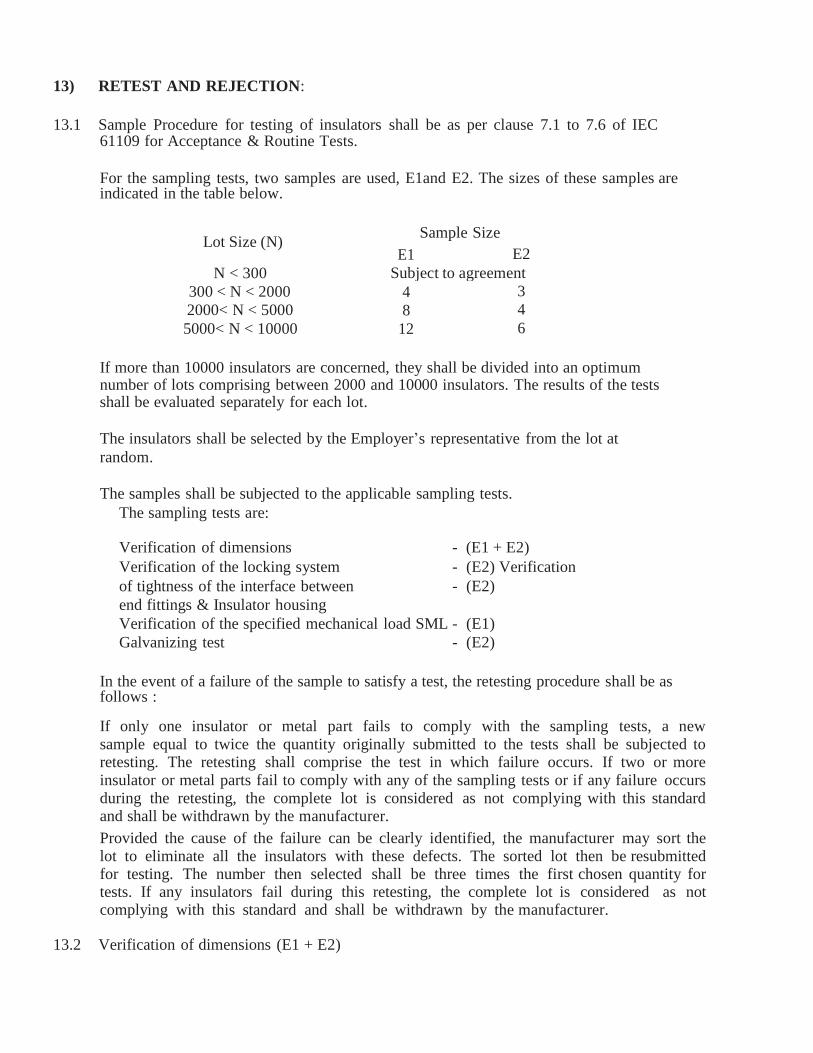
13) RETEST AND REJECTION:
13.1 Sample Procedure for testing of insulators shall be as per clause 7.1 to 7.6 of IEC
61109 for Acceptance & Routine Tests.
For the sampling tests, two samples are used, E1and E2. The sizes of these samples are indicated in the table below.
Lot Size (N) Sample Size
E1 E2
N < 300 Subject to agreement
300 < N < 2000 4 3
2000< N < 5000 8 4
5000< N < 10000 12 6
If more than 10000 insulators are concerned, they shall be divided into an optimum number of lots comprising between 2000 and 10000 insulators. The results of the tests shall be evaluated separately for each lot.
The insulators shall be selected by the Employer’s representative from the lot at
random.
The samples shall be subjected to the applicable sampling tests.
The sampling tests are:
Verification of dimensions - (E1 + E2)
Verification of the locking system - (E2) Verification
of tightness of the interface between - (E2)
end fittings & Insulator housing
Verification of the specified mechanical load SML - (E1)
Galvanizing test - (E2)
In the event of a failure of the sample to satisfy a test, the retesting procedure shall be as follows :
If only one insulator or metal part fails to comply with the sampling tests, a new sample equal to twice the quantity originally submitted to the tests shall be subjected to retesting. The retesting shall comprise the test in which failure occurs. If two or more insulator or metal parts fail to comply with any of the sampling tests or if any failure occurs during the retesting, the complete lot is considered as not complying with this standard and shall be withdrawn by the manufacturer.
Provided the cause of the failure can be clearly identified, the manufacturer may sort the lot to eliminate all the insulators with these defects. The sorted lot then be resubmitted for testing. The number then selected shall be three times the first chosen quantity for tests. If any insulators fail during this retesting, the complete lot is considered as not complying with this standard and shall be withdrawn by the manufacturer.
13.2 Verification of dimensions (E1 + E2)
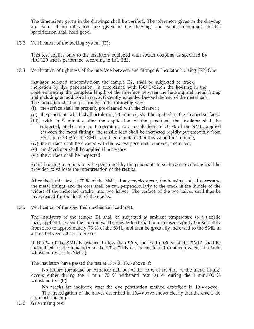
The dimensions given in the drawings shall be verified. The tolerances given in the drawing are valid. If no tolerances are given in the drawings the values mentioned in this specification shall hold good.
13.3 Verification of the locking system (E2)
This test applies only to the insulators equipped with socket coupling as specified by IEC 120 and is performed according to IEC 383.
13.4 Verification of tightness of the interface between end fittings & Insulator housing (E2) One
insulator selected randomly from the sample E2, shall be subjected to crack indication by dye penetration, in accordance with ISO 3452,on the housing in the zone embracing the complete length of the interface between the housing and metal fitting and including an additional area, sufficiently extended beyond the end of the metal part. The indication shall be performed in the following way.
(i) the surface shall be properly pre-cleaned with the cleaner ;
(ii) the penetrant, which shall act during 20 minutes, shall be applied on the cleaned surface;
(iii) with in 5 minutes after the application of the penetrant, the insulator shall be subjected, at the ambient temperature, to a tensile load of 70 % of the SML, applied between the metal fittings; the tensile load shall be increased rapidly but smoothly from zero up to 70 % of the SML, and then maintained at this value for 1 minute;
(iv) the surface shall be cleaned with the excess penetrant removed, and dried;
(v) the developer shall be applied if necessary;
(vi) the surface shall be inspected.
Some housing materials may be penetrated by the penetrant. In such cases evidence shall be provided to validate the interpretation of the results.
After the 1 min. test at 70 % of the SML, if any cracks occur, the housing and, if necessary, the metal fittings and the core shall be cut, perpendicularly to the crack in the middle of the widest of the indicated cracks, into two halves. The surface of the two halves shall then be investigated for the depth of the cracks.
13.5 Verification of the specified mechanical load SML
The insulators of the sample E1 shall be subjected at ambient temperature to a t ensile load, applied between the couplings. The tensile load shall be increased rapidly but smoothly from zero to approximately 75 % of the SML, and then be gradually increased to the SML in a time between 30 sec. to 90 sec.
If 100 % of the SML is reached in less than 90 s, the load (100 % of the SML) shall be maintained for the remainder of the 90 s. (This test is considered to be equivalent to a 1min withstand test at the SML.) The insulators have passed the test at 13.4 & 13.5 above if:
No failure (breakage or complete pull out of the core, or fracture of the metal fitting) occurs either during the 1 min. 70 % withstand test (a) or during the 1 min.100 % withstand test (b).
No cracks are indicated after the dye penetration method described in 13.4 above.
The investigation of the halves described in 13.4 above shows clearly that the cracks do not reach the core.
13.6 Galvanizing test

This test shall be performed according to IS: 2633/IS: 6745 on galvanized parts.
14) MARKINGS : 14.1 Each insulator shall be legibly and indelibly marked with the following details as per IEC-
61109:
a) Name or trademark of the manufacturer.
b) Voltage & Type
c) Month and year of manufacturing.
d) Min. failing load/guaranteed mechanical strength in kilo Newton followed by the word ‘KN’ to facilitate easy identification. e) Saubhagya ‘Employer Name’. Marking
14.2 One 10 mm thick ring or 20 mm thick spot of suitable quality of paint shall be marked on
the end fitting of each composite long rod of particular strength for easy identification. The paint shall not have any deteriorating effect on the insulator performance.
Following codes shall be used as identification mark:
For 45 KN long rod units : Blue
For 90 KN long rod units : Red
15) PACKING : 15.1 All insulators shall be packed in strong corrugated box of min. 7 ply duly paletted or wooden
crates. The gross weight of the crates along with the material shall not normally exceed 100 Kg to avoid hackling problem. The crates shall be suitable for outdoor storage under wet climate during rainy season.
15.2 The packing shall be of sufficient strength to withstand rough handling during transit, storage at site and subsequent handling in the field.
15.3 Suitable cushioning, protective padding, or Dunn age or spacers shall be provided to prevent
damage or deformation during transit and handling. 15.4 All packing cases shall be marked legibly and correctly so as to ensure safe arrival at their
destination and to avoid the possibility of goods being lost or wrongly dispatched on account of faulty packing and faulty or illegible markings. Each wooden case /crate/corrugated box shall have all the markings stenciled on it in indelible ink.
15.5 The Manufacturer shall provide instructions regarding handling and storage precautions to be taken at site.
16) GUARANTEE The Manufacturer of insulators shall guarantee overall satisfactory performance of the insulators. The manufacturer shall furnish in the form attached (Schedule ’A’) all the guaranteed technical particulars.

GUARANTED TECHNICAL PARTICULARS FOR 33 KV DISC INSULATOR
Sl. No. Particulars 33 KV Disc Spec. Bidders offer
1 Type of insulator Polymeric composite Disc Insulator
2 Reference Standard IEC 61109 3 Material of FRP Rod Boron free ECR 4 Material of sheds Silicon Rubber 5 Type of metal end fittings Ball & Socket 6 Nominal Ball Pin Diameter 16 mm 7 Material of end fittings SGCI / MCI 8 Material of sealing compound RTV Silicon 9 Colour of sheds Grey
10 Rated voltage 33 KV 11 Highest voltage 36 KV 12 Dry Power Frequency
Withstand voltage 95 KV
13 Wet Power Frequency Withstand voltage
75 KV
14 Dry Power Frequency Flashover Voltage
130 KV 15 Visible Discharge Voltage (PF) 27 KV 16 Wet Power Frequency Flashover
Voltage 90 KV
17 Dry Lightning Impulse withstand voltage
Positive : 170 KV Negative : 180 KV
18 Dry Lightning Impulse Flashover voltage
Positive : 210 KV Negative : 230 KV
19 RIV at 1 MHz when energised at 10
KV/ 30 KV (rms) under dry condition
< 70 microvolt
20 Creepage distance ( min ) 900 mm 21 Min Failing load 90 KN 22 Dia of FRP Rod 16 mm 23 Length of FRP Rod ( min ) 425 mm 24 Dia of weather sheds 110 mm 25 Thickness of housing 3 mm 26 Dry arc distance 380 mm 27 Method of fixing sheds to housing Injection moulding 28 No of weather sheds (min) Eight 29 Type of sheds Aerodynamic 30 Type of packing Wooden/Corrugated box 31 No of insulator in each pack Twenty 32 Guarantee 24 months from
commissioning or 30
months from the date of
last despatch.
Signature of the Bidder with Seal

GUARANTED TECHNICAL PARTICULARS FOR 11 KV DISC INSULATOR
11 KV Disc
Type of insulator Polymeric composite
Disc Insulator
Reference Standard IEC 61109
Material of FRP Rod Boron free ECR
Material of sheds Silicon Rubber
Type of metal end fittings Ball & Socket
Nominal Ball Pin Diameter 16 mm
Material of end fittings SGCI / MCI
Material of sealing compound RTV Silicon
Colour of sheds Grey
Rated voltage 11 KV
Highest voltage 12 KV
Dry Power Frequency
Withstand voltage
60 KV
Wet Power Frequency
Withstand voltage
35 KV
Dry Power Frequency
Flashover Voltage
75 KV
Visible Discharge Voltage (PF) 9 KV
Wet Power Frequency
Flashover Voltage
45 KV
Dry Lightning Impulse
withstand voltage
Positive : 75 KV
Negative :80 KV
Dry Lightning Impulse
Flashover voltage
Positive : 95 KV
Negative : 100 KV
RIV at 1 MHz when energised
at 10 KV / 30 KV (rms) under
dry condition
< 50 microvolt
Creepage distance ( min ) 320 mm
Min Failing load 70 KN
Dia of FRP Rod 16 mm
Length of FRP Rod ( min ) 200 mm
Dia of weather sheds 100 mm
Thickness of housing 3 mm
Dry arc distance 170 mm

Method of fixing sheds to
housing
Injection moulding
No of weather sheds (min) Three
Type of sheds Aerodynamic
Type of packing Wooden/Corrugated
box
No of insulator in each pack Thirty
Guarantee 24 months from
commissioning or 30
months from the date
of last despatch.
Signature of the Bidder with Seal
33KV & 11KV H.W fittings (B&S Type) : 33 KV & 11KV Hard Ware fittings Ball and socket type, confirming to IS: 2486 (Part-II) latest amendment and
as per drawing. B & S Hardware Fittings
The hardware fittings for B & S Strain Disc Insulator. For use in 33 KV and 11 KV Overhead power lines shall comply IS:2486 (Part-I) 1971 and 2486 (Part-II) / 1974 and IS:2486 (Part-III) 1974 IS:12048 /1987 and REC Specification 24/84 or the latest
revision thereof. All Forging and Casting shall be good finish and free from flaws and other
defects.
All ferrous fittings and parts other than those of Stainless steel shall be hot dip galvanized
as per ISS: 2633 / 1964.Small fittings like Spring washer , Nuts etc. may be Electro-galvanized as
per IS-6745 / 72.The threads of nuts and topped holes when cut after Galvanizing shall be well cited
& grassed.
(A) Ball & Socket type Hardware fittings(Conversional/ Performed ) for B & S type Strain
Insulators The hardware fittings (Ball and Socket type) 3 bol ted / 4 bol ted for 11KV/33KV shall be
suitable for fixing on 100 mmx50 mm channel cross arms and for accommodation of 100 mm² /
232 mm² Conductor.
The set shall complete with following components (i) Cross-arms straps with Bolts & Nuts, Brass split and Spring Washer. (ii) Two numbers forged cotter pins, Brass split pins, Plain washer.
(iii) One number Ball Eye of malleable cast iron
(iv) One number of socket eye complete with security clips made of Phosphor bronze

made cut of alluminium alloys-A/6.
(v) Halically formed Dead and Conductor grip having a Pre-fabricate loop to fit into the proved
contour of the thimbles on one end and for application over the conductor at the other end
for 100 mm²/232 mm² conductors.
(vi) Strain clamps shall be suitable for above ACSR / AAAC. The ultimate strength of clamp
should not be less than 4500 Kg and Slipping strength shall not be less than 90% of these
figures.
Tests : String insulator fittings shall comply with the following tests as per IS: 2486 (Part.I)
Type Tests:
a) Visual examination test
ii) Verification of dimensions
iii) Slip strength test
iv) Mechanical test
v) Electrical resistance test
vi) Heating cycle test
vii) Galvanising test.
Acceptance/ Routine Test :
i) Verification of dimensions
ii) Mechanical test iii) Galvanising test
iv) Vidual examination test
v) Routine mechanical test. Marking :
The caps and clamps shall have marked on them as trade mark & year of
manufacturing.
Packing:
All hardware fittings shall be packed in bags or boxes suitable for rough handling. Packing
shall be marked with the strength and KV rating.
Guaranteed Technical Particulars:
The bidders are required to furnish the guaranteed technical particulars duly filed in
the proforma along with the bid.
GUARANTEED TECHNICAL PARTICULARS FOR 33 KV H/W FITTINGS ( B&S )
Sl.No. Description Specified Bidders Offer
1. Manufacturer Name & Address
To be specified by Bidder
2. Standard Specification to which Hard ware Fittings
shall confirm.
IS: 2486 (Part-I,II &II)
3 Ultimate strength 9000 Kg (min.)

4. Dimensions in accordance with
IS: 2486(Part-II)
5 Material used and reference to Standard:
i) Cross arm Strap G.I as per IS:1570
ii) Ball Eye Forged Steel IS:2004
iii) Socket Eye Malleable Cast Iron IS:
2108/1962
iv) Bolted type tension clamp & its keeper
Aluminium Alloy LM-6,
IS: 617
6. Galvanised conform to IS 2633 , IS: 4759-1996 &
IS: 6747
7. Weight of Fittings not less than 2.85 Kg.
8. Tolerance in dimension if any
+ 5%
9. Manufacturer trade mark to be embossed on the sets
Specified by the Bidder
10. Specific drawing to be
enclosed.
Enclosed
NB. All ferrous fittings and the parts other than those of stainless steel , shall be galvanized.
Bidder’s Signature with Seal
GUARANTEED TECHNICAL PARTICULARS FOR 11 KV H/W FITTINGS 70KN ( B&S )
Sl.No. Description Specified Bidders Offer
1. Manufacturer Name & Address
To be specified by Bidder
2. Standard Specification to which Hard ware Fittings
shall confirm.
IS: 2486 (Part-I,II &II)
3 Ultimate strength 7000 Kg (min.)
4. Dimensions in accordance with
IS: 2486(Part-II)
5 Material used and reference to Standard:
i) Cross arm Strap G.I as per IS:1570
ii) Ball Eye Forged Steel IS:2004

iii) Socket Eye Malleable Cast Iron IS:
2108/1962
iv) Bolted type tension clamp & its keeper
Aluminium Alloy LM-6,
IS: 617
6. Galvanised conform to IS 2633 , IS: 4759-1996 &
IS: 6747
7. Weight of Fittings not less than 2.5 Kg.
8. Tolerance in dimension if
any
+ 5%
9. Manufacturer trade mark to be embossed on the sets
Specified by the Bidder
10. Specific drawing to be enclosed.
Enclosed
NB. All ferrous fittings and the parts other than those of stainless steel , shall be galvanized.
Name & Signature of Bidder with seal
GUARANTEED TECHNICAL PARTICULARS FOR HV GUY STRAIN
INSULATOR (TYPE_C)
Sl.
No.
Particulars Requirement Bidder’s offer
1 Name of Manufacturer. & Address To be specified by the bidder
2 Location of type testing To be specified by
the bidder
3 Applicable standard IS: 5300-1969 or the latest version thereof

4 Nominal System Voltage 11 KV
5 Highest System voltage 12 KV
6 Length 140 mm
7 Diameter 85mm
8 Cable hole diameter 25 ± 1.5
9 1min. power frequency withstand Voltage (Dry)
27 KV (rms)
10 1min. power frequency withstand Voltage (Wet)
13 KV
11 Minimum failing load 88 KN
12 Minimum creepage distance 57 mm
13 Drawing To be submitted
by bidder
14 Conforming standard As per IS
NB- Every insulator should bear the marking of manufacturer’s name and ISI mark
Name & Signature of Bidder with seal
GURANTEED TECHNICAL PARTICULARS OF 11KV HT STAY SETS
Sl
No.
Item
Description
Specified Parameters
Material
Bidder’s offer
Section
Tolerances
Fabrication
Tolerances
Manufacture’s Name & Address
To be specified by
the bidder
1 Anchor
Plate
8 mm thick
+2.5%-5%
450x450mm+1% GS Plate 8
mm thick
2 Anchor
Rod
18 mm dia
+5%- 3%
Length 1800mm +
0.5%
GS Round
18mm dia
Rounded Eye 40
mm inside dia +3%
Threading 40mm+
11%-5%
GS Round
18mm dia
3. Turn Buckle
Bow
18mm dia
+5%-3% 995mm+1% GS Round
18mm dia.

Length200mm +1%
GS Channel
100x50x4.7mm
4. Eye Bolt
Rod
18 mm dia
+5%-3%
Length 450mm +
1%
GS Round
18 mm dia
Threading 300mm
+1% Round Eye
40mm inside
dia+3%
5 Galvanisatio
n thickness
All galvanization shall be carried out in accordance with IS:
2629 . The weight of Zinc deposited shall be in accordance
with IS: 2629 and shall not less than 0.61 kg/m² with a
minimum thickness of 86 microns for items of thickness more
than 5 mm, 0.46kg/m²(64 microns) for items of thickness
between 2 mm & 5 mm& 0.33kg/m²(47 microns) for items
less than 2 mm thickness.
a Anchor
Plate
b Anchor
Rod
c TurnBuckle
Bow
d Eye Bolt
Rod
6 Thimble 2 nos. to be made of 1.5 mm thick G.S Sheet into a size 75x22x40 mm & shape as per standard.
7
Hexagonal Nut
One G.S Hexagonal Nut confirming to IS:1363 & 1367 with one square washer of size 50x50x6 mm (G.S) along with Anchor Rod.
8 Two G.S Hexagonal Nuts of suitable size along with Eye Bolt Rod.
Name & Signature of Agency with seal
GURANTEED TECHNICAL PARTICULARS STAY WIRE (7/10 SWG)
Sl.
No.
Description Specified Bidder’s
offer
1. Manufacturer’s name & address To be specified by
the Bidder
2 Nominal diameter of wire in mm 3.15
3 Tolerance in diameter in mm + 2.5%
4 Minimum breaking load in Kg 3697.50
5 Tensile strength Kgf/mm² 71.40
6 Overall diameter of stranded wire in mm 9.45
7 Sectional Area (in mm².) 70.16
8 Coating Test
a Type of zinc coating whether heavy or light Heavy
b Weight of coating in g/m² 476
9 a Length of wire in each coil in mtr. 193
b Tolerance + 5%
10 No. of dips the coating is able to withstand
as 18 ± 20ºC
3 dip in min.

11 Adhesion Test (Wrap Test at 1 turn per
second coiling while stress not exceeding
% nominal tensile strength)
a Min. complete turn of wrap To be specified by bidder
b Dia of mandrel on which wrapped - do -
12 Bend Test
a Angle - do -
b Dia round a format to be bent - do -
13 Freedom from defect - do -
14 Chemical composition the MS Wire used
shall not exceed
a Sulphur 0.060% - do -
b Phosphorous 0.065% - do -
15 a Weight of each coil in Kg 70 to 100
b Tolerance + 5%
16 a Weight of wire in Kg/Km 465
b Tolerance + 5%
17 Standard according to which the solid wire is manufactured
and tested
ISS: 2141/1992 &
ISS: 4826/1979
Name & Signature of Agency with seal
Guaranteed Technical Particulars for No. 6 G.I. wire
Sl.
No.
GENERAL TECHNICAL PARTICULARS
Guaranteed
Value
Bidders Offer
Manufacturer’s Name & Address
1 Nominal diameter of wire in mm 4.88 mm
2 Tolerance in diameter in mm + 2.5%
3 Sectional Area (in Sq. mm.) 18.7038
4 Tensile strength of wire in N/mm²/ MPa 550-900
5 Minimum breaking load (KN) 9
6 Variety Hard/Soft Soft
7 Type of Galvanizing Hot dip
heavy coating
8 Weight of Zinc coating (Gms/Sq. Mtr.) 290
9 No. of dips the coating is able to withstand as 18 ± 20ºC 3 dip in Min
10 Adhesion Test (Wrap Test at 1 turn per second coiling
while stress not exceeding % nominal tensile strength)
To be specified by
bidder
i) Min. complete turn of wrap do
ii) Dia of mandrel on which wrapped do
11 Bend Test do
i) Angle do

ii) Dia round a format to be bent do
12 Freedom from defect do
13 Chemical composition the MS Wire used shall not
exceed
do
i) Sulphur 0.060% do
ii) Phosphorous 0.065% do
14 Weight of wire in Kg/Km 148
15 Tolerance in wt. + 5%
16 Standard according to which the solid wire is
manufactured and tested
IS: 280/1978 ,
IS: 4826/1979 ,
IS: 7887/1975
Name & Signature of Agency with seal
Guaranteed Technical Particulars for No. 8 G.I. wire
Sl.
No.
GENERAL TECHNICAL PARTICULARS
Guaranteed
Value
Bidders Offer
Manufacturer’s Name & Address
1 Nominal diameter of wire in mm 4.06 mm
2 Tolerance in diameter in mm + 2.5%
3 Sectional Area (in Sq. mm.) 12.9462
4 Tensile strength of wire in N/mm²/ MPa 550-900
5 Minimum breaking load (KN) 8.79
6 Variety Hard/Soft Soft
7 Type of Galvanizing Hot dip
heavy coating
8 Weight of Zinc coating (Gms/Sq. Mtr.) 290
9 No. of dips the coating is able to withstand as 18 ± 20ºC 3 dip in Min
10 Adhesion Test (Wrap Test at 1 turn per second coiling
while stress not exceeding % nominal tensile strength)
To be specified by
bidder
ii) Min. complete turn of wrap do
ii) Dia of mandrel on which wrapped do
11 Bend Test do
iii) Angle do
iv) Dia round a format to be bent do
12 Freedom from defect do
13 Chemical composition the MS Wire used shall
not
exceed
do

iii) Sulphur 0.060% do
iv) Phosphorous 0.065% do
14 Weight of wire in Kg/Km 103
15 Tolerance in wt. + 5%
16 Standard according to which the solid wire is
manufactured and tested
IS: 280/1978 ,
IS: 4826/1979 ,
IS: 7887/1975
Name & Signature of Agency with seal
TECHNICAL SPECIFICATION OF 33 KV 3 POLE, 400 AMP , HORIZONTAL TYPE AB
SWITCH
1.0 SCOPE:- This specification covers manufacturing testing and supply of 3 Pole, 400 AMP, 50 Hz,
Single break, 33 KV class Air Break switches for outdoor installations to be used at 33/11 KV
Sub-stations and for incoming & outgoing Lines suitable for operation under off load conditions.
1.1 DESCRIPTION OF THE MATERIALS:-The A.B. Switch sets shall confirm to the following
parameters:-
Sl.
No.
Description Parameters of AB Switch
Parameters of AB
Switch 33 KV
i) No. of poles 3
ii) Number of Post insulator per pole 4 nos. 22/24 KV class
iii) Nominal system voltage (KV) 33
iv) Highest System Voltage (KV) 36
v) Rated frequency 50HZ
vi) System earthing Effectively earthed.
vii) Rated nominal current Amp. 400 Amp
viii) Altitude of installation Not exceeding 1000 M
The post insulators used in the A.B. Switches shall have the following ratings

Sl.
No.
Description
Parameters P.I. of AB Switches
for
33 KV
i) Power frequency withstand voltage
(dry) KV (RMS)
95
ii) Power frequency withstand voltage (wet)
KV (RMS)
75
iii)
iii
Impulse withstand voltage (dry) KV
(Peak)
170 KV (peak)
170 iv) Power frequency puncture
withstand voltage
1.3 times the actual dry flashover
voltage of the unit
1.2 STANDARDS:- The AB Switch Set shall conform to the following standards:-
i) IS-9920 (Part-I to V.)
ii) IS-2544/1973 ( for porcelain post insulators
iii) IS-2633 (for galvanization of ferrous parts.) or its latest amendments if any.
1.3 INSULATORS:-
22 KV / 24 KV class Post Insulators complete with pedestal cap duly cemented to be used in the AB
Switch Set conforming to IS-2544/1973
The bidder shall furnish the type test certificate of the post insulators from their manufacturer
for reference.
The bidder shall mention make, type of insulation materials, metal fittings, Creep age distance,
protected Creep age distance, tensile strength, compression strength, torsion strength and cantilever
strength.
1.4 CLIMATIC CONDITIONS:-
The A.B. Switch set shall be suitable for operation under the following climatic Conditions
1. Maximum ambient air temperature. 45 0
C
2. Maximum daily average air temperature 35 0
C
3. Maximum yearly average ambient air temperature 30 0
C
4. Maximum temperature attainable by a body exposed to the
sun. 50
0 C
5. Minimum ambient air temperature 0 0
C
6. Maximum relative humidity. 100%
7. Minimum number of rainy days per annum 70
8. Average number of rainy days per annum 120
9. Average annual rain fall. 150 cm.
10. Number of months of tropical monsoon conditions 4
11. Maximum wind pressure. 260 Kg./ mm2
12. Degree of exposure to atmospheric pollution. Normally polluted atmosphere.

1.5 TECHNICAL DETAILS:-
1.5.1 The 33 KV A.B. Switch Set shall be gang operated single air break outdoor type horizontal mounting
having 4 nos. 22/24 KV post insulator per phase. The operating mechanism shall be suitable for
manual operation from the ground level and shall be so designed that all the three phases shall open or
close simultaneously. The Switches shall be robust in construction, easy in operation and shall be
protected against over travel or straining that might adversely affect any of its parts. The required
base M.S. Channel, phase coupling rod, operating rod with intermediate guide braided with flexible
electrolytic copper, tail piece of required current carrying capacity and operating mechanism with
‗ON‘ & ‗OFF‘ positions shall be provided. The operating rod shall be medium gauge of 32mm
diameter nominal bore G.I. pipe single piece 6 meters. The phase coupling rod for gang operation shall
medium gauge 25mm dia nominal bore G.I. Pipe. Rotating post insulators shall be provided with
suitable bearing mounted on a base channel with 6 mm thick thrust collar and 6mm split pin made out
of stainless steel. The operating down rod shall be coupled to the spindle (minimum dia - 32mm) for
gang operation through another suitable bearing by two numbers 10mm dia through stainless steel
bolts with double nuts. The post insulators should be fixed with the base channel using Galvanized
Nuts and Bolts.
All the bearings shall be provided with grease nipple. All ferrous parts shall be galvanized and polished.
The pipes shall be galvanized in accordance with IS-4736/1968.
1.5.2 Mounting: - The A.B. Switches shall be suitable for horizontal mounting in double pole sub-station
structures. MS Galvanized base Channel & base support channel should be of min. size 100x50x5
mm.
1.5.3 Switching Blades: - It shall be made out of electrolytic copper with silver plated. The approximate
size shall be 250mm x 50 x 8mm. The switch shall have such a spring mechanism so as to ensure that
the speed of the opening of contact is independent of speed of manual operation.
1.5.4 Fixed Contacts:- The fixed jaw type female contracts (50x8x95 )mm shall be made of electrolytic
copper ( minimum 95 % copper composition) duly electroplated controlled by Phosphor bronze high
pressure spring housed in robust G.I. Cover.
It is essential that provision shall be made in fixed female contracts to take the shock arising from the
closing of moving contract blade without the same being transmitted to the post insulator. The
arrangement made in this regard shall be specifically shown in the drawing.
1.5.5 Arcing Horn:- As the switches are generally meant for isolating transmission line and distribution
transformers, suitable arcing horns shall be provided for breaking the charging current horn
shall be made of 10 mm dia G.I. Rod with spring assisted operation.
1.5.6 Terminal Connectors:- Terminal connectors shall be robust in design. The size of fixed connector
shall be ( 80 x 50 x8 mm) and size of movable connector shall be of ( 80 x50) x ( 80 x 50) x 8 mm
of copper casting with uniform machine finishing duly silver plated made out of minimum 95 %
copper composition with 2 nos. 12 mm dia holes provided with suitable brass bolts and double nuts,
flat washers & 2 nos. bimetallic solderless sockets suitable up to ACSR Panther or AAAC 232 mm2
conductor.
1.5.7 Spacing:- The minimum clearance between phase to the switch shall be 1200 mm. The operating

down rod shall be at a transverse distance of 300 mm from the outer limb of the switch. The centre
spacing between two post insulators of the same phase shall be 560 mm. In the open position of the
A.B. Switches the moving blade shall rotate through anangle of 90 0
. This shall be exhibited in the
drawing.
1.5.8 Drawing & Literatures:- Drawings of 33 KV 400 amp, 3 Pole, single break A.B. Switch shall be
furnished along with the tender.
The details of construction and materials of different parts of the A.B. Switches shall clearly be
indicated in the tender and illustrative pamphlet / literature for the same shall be submitted along with
the tender.
1.6 TESTS & TEST CERTIFICATE
1.6.1 Type Test:- Certificates for the following type tests conducted within five years proceeding to
the date of opening of tender on prototype set of A.B Switch in a Govt. Approved Testing
Laboratory preferably at CPRI, Bhopal/ Bangalore shall have to be submitted for reference and
scrutiny.
i. Impulse voltage dry test
ii. Power frequency voltage dry test
iii. Power frequency voltage wet test
iv. Temperature of resistance.
v. Measurement of resistance.
vi. Test to prove the capability of carrying the rated peak short circuit current and the rated short
time current.
vii. Mainly active load breaking capacity test.
viii. Transformer off-load breaking test.
ix. Line charging breaking capacity test.
x. Operation tests.
xi. Mechanical endurance test.
xii. Mechanical strength test for the post insulator as per IS-2544/1973.
xiii. Test for galvanization of metal (ferrous) parts as perm IS-2633/1973.
Besides, mechanical endurance test will have to be conduct on one set in the presence of our authorized
person who shall be deputed to carryout acceptance tests before delivery of the materials.
1.6.2 Routine Tests: - The following routine tests shall have to be conducted on each sets and results are to
be furnished for consideration of deputing inspecting officer for inspection and conducting testing of the
materials.
1. Power frequency voltage dry test
2. Measurement of resistance of main circuit
3. Tests to prove satisfactory operation.
4. Dimension check
5. Galvanization test.
1.7 GUARANTEED TECHNICAL PARTICULARS:-
The Bidder shall furnish the guaranteed technical particulars duly filled in the format at

Appendix-I along with the tender.
1.8 COMPLETENESS OF EQUIPMENT:-
Any fittings, accessories for apparatus which may not have been specifically mentioned in this
specification but which are usual or necessary in equipment of similar plant shall be deemed to be
included in the specification and shall be supplied by the Tender without extra charge. All plant and
equipment shall be completed in all details whether such details are mentioned in the specification or
not.
1.9 INSPECTION:-Routine and acceptance tests shall be conducted at the place of manufacturer. The bidder
are requested to furnish details of equipment which will be used for testing along with tender. The bidder of
those manufacturers who do not have adequate testing facilities for conducting routine and acceptance test are
liable for cancellation. The successful bidder has to furnish routine test certificate and guaranteed certificate for
approval prior to offer of materials for inspection for each consignment of offer.
GUARANTEED TECHNICAL PARTICULARS FOR 33KV, 400A, 50 HZ, 3 POLE, SINGLE BREAK
TYPE AB SWITCH
Sl.
No
Particulars
Desired values Bidder‘s
offer
1 2 3 4
1. Maker‘s name and country
of origin To be specified by the tenderer
2. Type of Switch Rotating type only
3. Suitable for mounting Horizontal only
4.
Number of supporting post
insulators per phase
4 nos.22 KV / 24 KV Post Insulators per
phase as per ISS-2544/1973.
5. No. of Breakers per phase Single Break
6. Post Insulator.
a) Maker‘s name and country
of origin
Techno Ceramics / Allied
Ceramic/JSI/Equivalent type test certificate to
be provided along with bid.
b) Type of cementing To be quoted for original cemented only & as
per IS-2544-1973 & relevant IEC.

c) One minute power frequency
withstand voltage Dry
95 KV RMS.
d) One minute power frequency
withstand voltage Wet
75 KV RMS.
e) Visible discharge voltage 27 KV RMS.
f) Dry Flashover Voltage To be specified by the tenderer
g) Power frequency puncture with
stand voltage
1.3 times of actual dry flash over voltage
h) Impulse withstand voltage
(switch in position) 170 KV (peak)
i) Creepage distance (mm) 450 mm minimum. (actual creepage
distance for which type test have been
conducted is to be specified by the tenderer
7.
Impulse withstand voltage for
positive and negative polarity
1.2 / 50 mircro- second wave.
a) Across the isolating distance 195 KV (peak)
b) To earth & between poles 170 KV (peak)
8. One minute power frequency
withstand voltage.
a) Across the isolating distance 80 KV (RMS)
b) To earth & between poles 70 KV (RMS)
9.a) Rated normal current and rated
frequency
400 amps. 50 Hz
b) Rated short time current. 16 KA ( RMS )
10. Rated short circuit making capacity 25 KA (RMS)
11. Rated peak withstand current 40 KA ( Peak )
12. Rated cable charging
breaking capacity
40 KA ( RMS )
13. Rated Transformer off load breaking
capacity
16 Amp (RMS)
14. Rated line charging breaking capacity 5.3 Amps ( RMS)
15. Minimum clearance between adjacent
phases
a) Switch Closed ( centre to centre) 1200 mm
b) Switch Opened ( centre to edge of
blade)
640 mm
16. Temperature rise
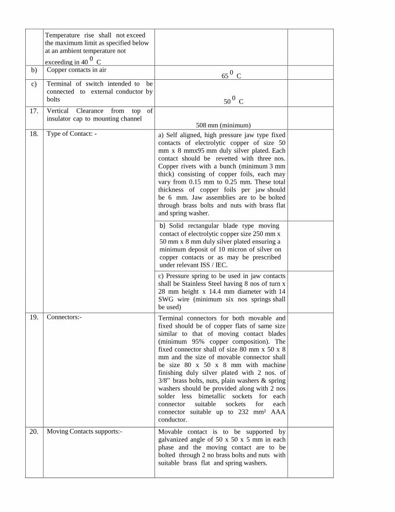
a)
Temperature rise shall not exceed
the maximum limit as specified below
at an ambient temperature not
exceeding in 40 0
C
b) Copper contacts in air 65
0 C
c) Terminal of switch intended to be
connected to external conductor by
bolts
50 0
C
17. Vertical Clearance from top of
insulator cap to mounting channel
508 mm (minimum)
18. Type of Contact: - a) Self aligned, high pressure jaw type fixed
contacts of electrolytic copper of size 50
mm x 8 mmx95 mm duly silver plated. Each
contact should be revetted with three nos.
Copper rivets with a bunch (minimum 3 mm
thick) consisting of copper foils, each may
vary from 0.15 mm to 0.25 mm. These total
thickness of copper foils per jaw should
be 6 mm. Jaw assemblies are to be bolted
through brass bolts and nuts with brass flat
and spring washer.
b) Solid rectangular blade type moving
contact of electrolytic copper size 250 mm x
50 mm x 8 mm duly silver plated ensuring a
minimum deposit of 10 micron of silver on
copper contacts or as may be prescribed
under relevant ISS / IEC.
c) Pressure spring to be used in jaw contacts
shall be Stainless Steel having 8 nos of turn x
28 mm height x 14.4 mm diameter with 14
SWG wire (minimum six nos springs shall
be used)
19. Connectors:- Terminal connectors for both movable and
fixed should be of copper flats of same size
similar to that of moving contact blades
(minimum 95% copper composition). The
fixed connector shall of size 80 mm x 50 x 8
mm and the size of movable connector shall
be size 80 x 50 x 8 mm with machine
finishing duly silver plated with 2 nos. of
3/8” brass bolts, nuts, plain washers & spring
washers should be provided along with 2 nos
solder less bimetallic sockets for each
connector suitable sockets for each
connector suitable up to 232 mm² AAA
conductor.
20. Moving Contacts supports:- Movable contact is to be supported by
galvanized angle of 50 x 50 x 5 mm in each
phase and the moving contact are to be
bolted through 2 no brass bolts and nuts with
suitable brass flat and spring washers.
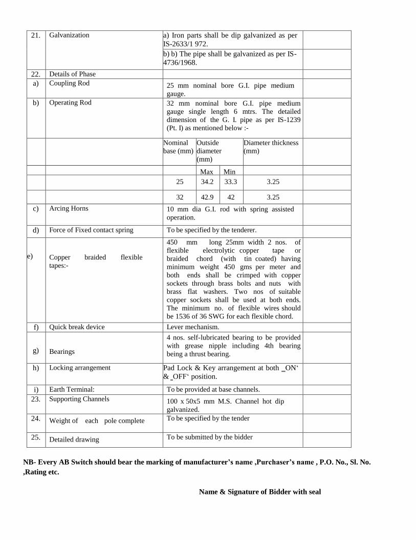
21. Galvanization a) Iron parts shall be dip galvanized as per
IS-2633/1 972.
b) b) The pipe shall be galvanized as per IS-
4736/1968.
22. Details of Phase
a) Coupling Rod 25 mm nominal bore G.I. pipe medium
gauge.
b) Operating Rod 32 mm nominal bore G.I. pipe medium
gauge single length 6 mtrs. The detailed
dimension of the G. I. pipe as per IS-1239
(Pt. I) as mentioned below :-
Nominal
base (mm)
Outside
diameter
(mm)
Diameter thickness
(mm)
Max Min
25 34.2 33.3 3.25
32 42.9 42 3.25
c) Arcing Horns 10 mm dia G.I. rod with spring assisted
operation.
d) Force of Fixed contact spring To be specified by the tenderer.
e)
Copper braided flexible
tapes:-
450 mm long 25mm width 2 nos. of
flexible electrolytic copper tape or
braided chord (with tin coated) having
minimum weight 450 gms per meter and
both ends shall be crimped with copper
sockets through brass bolts and nuts with
brass flat washers. Two nos of suitable
copper sockets shall be used at both ends.
The minimum no. of flexible wires should
be 1536 of 36 SWG for each flexible chord.
f) Quick break device Lever mechanism.
g)
Bearings
4 nos. self-lubricated bearing to be provided
with grease nipple including 4th bearing
being a thrust bearing.
h) Locking arrangement Pad Lock & Key arrangement at both ‗ON‘
& ‗OFF‘ position.
i) Earth Terminal: To be provided at base channels.
23. Supporting Channels 100 x 50x5 mm M.S. Channel hot dip
galvanized.
24. Weight of each pole complete To be specified by the tender
25. Detailed drawing To be submitted by the bidder
NB- Every AB Switch should bear the marking of manufacturer’s name ,Purchaser’s name , P.O. No., Sl. No.
,Rating etc.
Name & Signature of Bidder with seal

40mm dia GI Earthing Device: 1. Scope :-
This specification provides for design, manufacturing, testing before dispatch, supply & delivery of
Earthing Device (Heavy Duty) (for use in Sub-station earthing).
2. APPLICABLE STANDARDS :-
The Earthing Device must be made out of 40 mm nominal Bore & 3.2 mm (Medium Gauge- No
minus Tolerance allowed) wall thickness Hot Dip G.I. Pipe (as per IS ;- 1239,m Part-1, 1990 & REC construction Standard –J-2) , ISI marked of reputed Make & 3.0 mtrs length tapered finished smooth at
one end for a length of 75 mm & Clamp at the other end.
Staggered drills hole of 12 mm Dia of interval of 150mm shall be made before galvanization.
The GI Earthing Clamp/ Strip (C- Clamp Type) is to be of 50mm width, 6mm thickness & flange
length of 65 mm in each side. This should be suitable for termination of 4 nos of GI Flat earth
electrodes. The Clamp/ Strip & Earthing pipe after fabrication will be hot dip galvanized confirming to
IS: 2629/85 with latest amendments. The clamp shall have two holes in both sides suitable for 5/8 x 2”
Bolt & provided with two GI bolts& Nuts in each side of 12mm dia 50mm long half threaded with
spring washer as per IS: 3043/1982.The galvanization tests are to be conducted as per IS: 2633/72 & IS:
6745/72 & its latest amendments.
Guaranteed Technical Particulars of Earthing Device (To be submitted along with Offer)
Sl.
No.
Par
ticu
lars
Bidder’s Offer
1. Location of Factory or Place of Manufacture
2. Maker’s Name, Address & Country
3. Size of
a Pipe
b Earthing Strips
4. Length (3.0 Mtr.)
5. Thickness of Pipe
6. Galvanization Process
7. Galvanization thickness
a For Earthing device
b For Connecting Flat
8. Galavanization tests to be conducted as per ISS
9. Any other Particulars ( like details of Clamp/ G.I. Bolts)
10. Details of Drawings submitted

Name & Signature of Bidder with seal
16 mm dia. Hexagonal Bolts & Nuts and Washer (GI)
16 mm diameter GI Nuts and Bolts black hexagonal As per IS: 1387 (Part-II) Gr.-4/4.6 of following size.
Washers shall be round of thickness 1.5 mm suitable for 16 mm dia. bolts.
Specification finished products:
1. The bolts & Nuts shall be ISI Marked Mild Steel of Black Grade “B” and shall be round with
hexagonal head.
(i) The Bolts and Nuts shall be manufactured by Hot/Cold forging process neatly and cleanly finished
and shall have metric threads as per IS : 4218/1967 with its latest amendments.
(ii) The dimensions of the bolts & nuts and tolerances should conform to IS: 1363 with their latest
amendments in all respect. The eccentricity and angular errors of various elements shall be within
specified limits as per IS: 1367/1967 with its latest amendments the bolts & nuts shall be free from
forging and threading defects such as cuts, spats. burns, bulging taper eccentricity, loose fill etc. which
may affect their serviceability.
(iii) The colt heads and nuts shall be chamfered on one face only and other face shall be machined made.
(iv) Mechanical property requirement of tester shall conform to IS: 1367 (Part-III) 1979 property class 4.6 for
bolts & property class-5 for nuts as per IS: 1367 (Part VI) —1980.
(v) The bolts & nuts shall be supplied in well-cleaned conditions and suitably protected against corrosion in
individual bags of 50 Kgs.
ACCEPTANCE TESTS:
The bidder should furnish test certificate from recognized Govt. Laboratory ( NABL accredited) giving the
results of tests as per IS: 1367 (Part-Ill) —1979 & IS: 1367 (Part-VI) 1980 The test certificate shall be in
respect of the following for all sizes of both bolts & nuts as applicable given below:-
i) Dimensional particulars (Sampling Ifl accordance with IS: 2614 for both bolts & nuts
(Tolerance as per drawing).
ii) Tensile strength test on full size (for bolts minimum 400 NI Sq.mm and for Nuts Proof
Stress test Mm 610 N/Sq. mm).
iii) Power load test on full size bolts and M-12-51400 N for 15 Sec.
iv) Head soundness tests for bolts (no fracture).
v) Brinell hardness tests or Rockwell Hardness or Vickers’s Hardness tests for bolts min-
114 &max. 209 or mm. 67 & max. 95 or mm. 120 & max. 220 respectively. For nuts

Vickers’s Hardness mm. 130 & max. 302.
Markings: On the bolt head, there shall be identification marking of the manufacturer as well as property class
‘4.6”.
If possible property class “5” shall be marked on Nuts also. Further ‘ISI’ mark shall be marked on Gunny Bags
for
proper identification.
EARTHING COIL :
EARHTING COIL TECHNICAL SPECIFICATION
SCOPE :
The specification covers design, manufacture, testing and dispatch to the owner’s stores of
Earthing Coils for use in earthing of the HT & LT poles.
GENERAL REQUIREMENTS :
Earthing coils shall be fabricated from soft GI Wire Hot Dip Galvanized. The Hot Dip
galvanized wire shall have clean surface and shall be free from paint enamel or any other poor
conducting material. The coil shall be made as per REC constructions standard.
The Hot Dip galvanizing shall conform to IS: 2629/1966, 2633/1972 and 4826/1969 with latest
amendments.
TESTS :
Galvanizing Tests
Minimum Mass of Zinc
On GI Wire used 280 cm/m²
After Coiling-266 gm/m².The certificate from recognized laboratory shall be submitted towards
mas of zinc.
Dip Test
Dip test shall stand 3 dips of 1 minute and one dip of ½ minute before coiling and 4 dips of 1
minute after coiling as per IS: 4826/1979
Adhesion Test
As per ISS 4826 – 1979
DIMENSIONAL REQUIREMENT
i) Nominal dia of GI Wire -4 mm (Tolerance±2.5%)
ii) Minimum no. of turns – 115 Nos.
iii) External dia of Coil (Min) – 50 mm

iv) Length of Coil (Min) – 460 mm
v) Free length of GI Wire at one end coil (Min.) – 2500 mm
vi) The turns should be closely bound. Weight of one finished Earthing Coils (min.) – 1.850
Kg.
Guaranteed Technical Particulars of Coil Earth
Sl.
No.
GENERAL TECHNICAL
PARTICULARS Bidder’s
Offer
1 Nominal diameter of wire
2 No. of turns
3 External dia of Coil
4 Length of Coil
5 Mass of Zinc
6 Total weight of Coil
7 Whether drawing enclosed (yes)
Name & Signature of Bidder with seal
100x50x6mm MS Channel
75x40x5 mm MS Channel
50x50x6 mm Angle
Technical Specifications :
Clause
No.
TECHNICAL SPECIFICATIONS OF MILD STEEL CHANNEL & ANGLE
1.0 SCOPE
This specification covers design, manufacture, testing and dispatch to owner’s stores of M.S.
Channel & Angle for use in structures in distribution system. The channel & angle are made of
Jindal/ SAIL/ TATA

2.0 APPLICABLE STANDARD
Materials shall conform to the latest applicable Indian standards. In case bidders offer steel
section and supports conforming to any other international specifications which shall be
equivalent or better than IS, the same is also acceptable.
S.No. Standard No. Title
1 IS: 2062 Grade ‘A’Quality Specification for M.S.Angles, M.S.Channel
2 IS: 2062 Chemical and Physical composition
of material
3 IS: 1852 Rolling and Cutting Tolerances for Hot
Rolled Steel products
3.0
3.1
GENERAL REQUIREMENTS
Raw material
The Steel Sections shall be re-rolled from the BILLETS/INGOTS of tested quality as per latest
version of IS: 2830 or to any equivalent International Standard and shall be arranged by the
bidder from their own sources. The Chemical composition and Physical properties of the finished
material shall be as per the equivalent standards.

3.2
3.3
3.4
3.5
3.6
3.7
Length
The GS Flat to be supplied shall be in 5.5 meters length.
Weightment
The weighnment of GS Flat shall be witnessed by the consignee at the time of taking delivery.
The weight recorded in the material receipt certificate issued by the consignees shall be final.
i) 100x50x6 mm MS Channel - 9.56Kg/mtr.
ii) 75x40x6 mm MS Channel – 7.14Kg/mtr.
iii) 50x50x6 mm MS Angle- 4.5 Kg/ mtr.
Chemical Composition and Physical Properties of M.S. Angles, M.S. Channels, and
M.S.Flat conforming to IS: Conforming to IS:2062/84
Chemical Composition
Chemical composition For Fe 410 WA Grade
1 C - 0.23% MAX
2 Mn - 1.5% MAX
3 S - 0.050% MAX
4 P - 0.050% MAX
5 SI - 0.40% MAX
6 CE
(Carbon Equivalent)- 0.42% MAX
Mechanical Properties
1. Tensile strength Kgf/mm²⎯ - 410
2. Yield stress Min. for thickness/diameter
< 20 mm - 26 Kgf/mm² OR 250 N/ mm²
20-40 mm - 24 Kgf/mm² OR 240 N/ mm²
> 40 mm - 23 Kgf/mm² OR 230 N/ mm²
3. Elongation % - 23%
4. Bend Test (Internal Dia) - Min-3t
(t – is the thickness of the material)
Tolerance
Variation in ordered quantity for any destination and overall ordered quantity be only to the
extent of ±2%. Rolling and weight tolerances shall be as per version of IS: 1852 or to any
equivalent International Standard.

4.0
5.0
6.0
TEST
Steel Section shall be tested in IS approved Laboratory or Standard Laboratory the Bidder
country having all facilities available for conducting all the test prescribed in relevant IS or IEC
or to any equivalent International Standard or any recognized and reputable International
Laboratory or Institutions.
The bidders are required to specifically indicate that;
i) They hold valid IS (or equivalent IEC) License.
ii) Steel Section offered are bearing requisite IS certification or equivalent
marks.
The bidders are required to submit a copy of the valid IS (or equivalent IEC) License clearly
indicating size and range of product against respective ISS or any equivalent International
Standards along with their offer.
MARKING
It is desirable that the bidder should put his identification marks on the finished
material. The mark shall be in “legible English letter” given with marking dies of minimum 18
mm size.
INSPECTION AND TEST CERTIFICATES
The material to be supplied will be subject to inspection and approval by the purchaser’s
representative before dispatch and/or on arrival at the destination. Inspection before dispatch
shall not however, relieve the bidder of his responsibility to supply the Steel Sections strictly in
accordance with the specification.
Barbed Wire TECHNICAL SPECIFICATION FOR G.I. BARBED WIRE
STANDARDS:
Unless otherwise specified elsewhere in this specification, the rating as well as
performance and testing of the G.I.Barbed wire shall conform to the latest revisions
available at the time of placement of order of all the relevant standards but not
limited to as listed below.
IS:280:1978 Mild steel wire for general engineering purposes (third revision)
IS:1340:1977 Code of practice for chromate conversion coating of zinc and cadmium
coated articles and zinc base alloys (first revision)
IS:1521:1972 Method for tensile testing of steel wire (first revision)
IS:1755:1983 Method for wrapping test for metallic wire (first revision)
IS:2633:1986 Method for testing uniformity of coating of zinc coated articles(second revision)
IS:4826:1979 Hot dipped galvanized coating on round steel wires (first revision)
IS:12753:1989 Electro galvanized coatings on round steel wire – Specification

3. GENERAL TECHNICAL REQUIREMENTS:
GI Barbed wire shall be 2 PLY with a 2.5mm diameter. The barbs shall have a 2mm diameter and be 12.5mm in
length. The barbs shall have four points and shall be formed by twisting two point wires, each two turns, tightly
around both line wires making altogether four complete turns.
G.I. Barbed wire shall be of type IOWA with size and dimensions as under:-
Line wire - 2.5 mm
Point wire - 2.0 mm
Distance between two bars shall be 75 mm ( + 12 mm ).
SPECIFIC TECHNICAL PARTICULARS FOR 2.5 MM X 2.0 MM G.I.BARBED WIRE
Sl.No. Particulars Particulars Specified Bidders Offer
1 Size of wire- mm Line wire- 2.5 mm + 0.08 mm
Point wire- 2.0 mm + 0.08 mm
2 Type of Barbed Wire Iowa Type
3 Tensile strength of line
wire
390 to 590 N/mm²
4 Minimum breaking load
of completed Barbed wire
3.7 KN
5 Mass of complete
Barbed wire (minimum)
115 gms / Mtr.
6 Distance between two
Barbs
(75 + 12 ) mm
7 No. of lays between the
Barbs ( minimum )
4
8 Method of Galvanising Hot dipped according to IS:4826
/1979 with medium coating.
9 Mass of coating (minimum) Line wire- 110 gms/Mtr²
Point wire- 105 gms/Mtr²
( testing after barbing )
10 No. of dips the wire is
able to withstand without
copper coating
( testing after barbing )
A) For Line Wire 2 dip in Min
B) For Point Wire 2 dip in Min
Signature of the bidder with Seal
G.I. Flat (50 x 6 mm)
Technical Specifications
1. Scope : The specification provides for design, manufacturing, testing before dispatch for Hot dip Galvanized flats of size 50X6 mm.

2. MS flat shall conform to IS 2062 & its latest amendments for steel & Galvanization
as per IS 4759 & its Latest amendments. 3. The flat shall be coated with Zn 98 Zinc grade.
4. The minimum Zinc coating shall be 610 gm/sqm.
5. Inspection & Rejection:
a) The representative of TPNODL shall pick up samples at random from the
GI Flats offered for carrying out routine tests as per specified IS.
b) The representative shall make visual inspection on each & every GI flats.
c) The purchaser reserves the right to reject on inspection after the same is
received at destination.
Guaranteed Technical Particulars 50x6 mm GI Flat ( Bidder to be specified)
1. Location of Factory or Place of Manufacture :- 2. Maker’s Name, Address & Country:
3. Size of G.I. Flat :
4. Standard Length :
5. Galvanization Process:-
6. Galvanization thickness :-
7. Galavanization tests to be conducted
Signature of the bidder with Seal
TECHNICAL SPECIFICATION FOR 11 KV 10 KA DISTRIBUTION CLASS HEAVY DUTY SURGE
ARRESTERS (LIGHTNING ARRESTERS)
1.0 SCOPE:
1.1 This specification provides for the design, engineering, manufacture, assembly, stage testing,
inspection and testing before despatch, packing, forwarding and delivery of Metal Oxide (gapless)
Surge Arresters complete with accessories 11 KV system as specified hereunder.
1.2 It is not the intent to specify completely herein all the details of design and construction of
Surge Arresters, However, Surge Arresters shall conform in all respects to the high standard of
design and workmanship and be capable of performing in continuous commercial operation up to
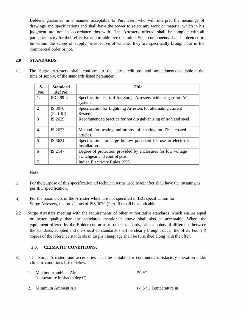
Bidder's guarantee in a manner acceptable to Purchaser, who will interpret the meanings of
drawings and specifications and shall have the power to reject any work or material which in his
judgment are not in accordance therewith. The Arresters offered shall be complete with all
parts, necessary for their effective and trouble free operation. Such components shall be deemed to
be within the scope of supply, irrespective of whether they are specifically brought out in the
commercial order or not.
2.0 STANDARDS:
2.1 The Surge Arresters shall conform to the latest editions and amendments available at the
time of supply, of the standards listed hereunder:
S.
No.
Standard
Ref No.
Title
1. IEC 99-4 Specification Part. 4 for Surge Arresters without gap for AC
system.
2 IS:3070
(Part-III)
Specification for Lightning Arresters for alternating current
System
3 IS:2629 Recommended practice for hot dip galvanising of iron and steel.
4 IS:2633 Method for testing uniformity of coating on Zinc coated
articles.
5 IS:5621 Specification for large hollow porcelain for use in electrical
installation.
6 IS:2147 Degree of protection provided by enclosures for low voltage
switchgear and control gear.
7. Indian Electricity Rules 1956.
Note:
i) For the purpose of this specification all technical terms used hereinafter shall have the meaning as
per IEC specification.
ii) For the parameters of the Arrester which are not specified in IEC specification for
Surge Arresters, the provisions of ISS 3070 (Part.III) shall be applicable.
2.2 Surge Arresters meeting with the requirements of other authoritative standards, which ensure equal
or better quality than the standards mentioned above shall also be acceptable. Where the
equipment offered by the Bidder conforms to other standards, salient points of difference between
the standards adopted and the specified standards shall be clearly brought out in the offer. Four (4)
copies of the reference standards in English language shall be furnished along with the offer.
3.0. CLIMATIC CONDITIONS:
3.1 The Surge Arresters and accessories shall be suitable for continuous satisfactory operation under
climatic conditions listed below.
1. Maximum ambient Air 50 °C
Temperature in shade (deg.C).
2. Minimum Ambient Air (-) 5 °C Temperature in

shade(deg.C).
3. Maximum daily average ambient air temperature 40°C
4. Maximum relative humidity(%) 100%
5. Height above mean sea level 1000M
6. Maximum wind pressure 260 Kg m²
7. Average No. of thunder Storm 70 days.
Days / annum.
8. Average annual rainfall (mm) 1500 mm
9. Average No. of months of 4
tropical monsoon condition p.a.
All the electrical devices shall be given tropical and fungicidal treatment to enable their satisfactory
operation in the above climatic conditions.
4.0 PRINCIPAL PARAMETERS:
The Surge Arresters offered under this specification shall conform to the parameters given
below.
S. No Particulars System parameters
for 12 KV
Distribution type
1 Nominal system voltage (kv rms) 11
2 Highest system voltage (kv rms) 12
3 1.2/50 microsecond impulse voltage with stand level
a Transformer and reactors (kvp) 75
b Other equipment and lines (kvp) 75
4 Minimum prospective symmetrical fault current for 1
second at Arrester location (KA rms)
10
5 Anticipated levels of temporary over voltage and its duration.
a Voltage(p.u.) 1.5
b Duration(Seconds) 1/10
6 System frequency(Hz) 50 + / - 1.5
7 Neutral Grounding Effectively earthed
8 Number of Phases Three
Note 1. 1 p.u. = 12 x √2KV peak /√3
5.0 GENERAL TECHNICAL REQUIREMENTS:
5.1 The Surge Arresters shall conform to the technical requirements as per Annexure-A.

5.2 The energy handling capability of each rating of Arrester offered, supported by calculations, shall
be furnished in the offer.
5.3.1 The Station Type Surge Arresters shall be fitted with pressure relief devices and arc diverting
ports and shall be tested as per the requirements of IEC specification for minimum prospective
symmetrical fault current as specified in Annexure-A.
5.3.2 The grading ring on each complete Arrester for proper stress distribution shall be provided if required
for attaining all the relevant technical parameters.
5.4 PROTECTIVE LEVELS:
The basic insulation levels and switching impulse withstand levels of the lines and equipment to be
protected have been specified in clause 4.0, "Principal Parameters".
The protective characteristics of the Arresters offered shall be clearly specified
in the schedule of guaranteed technical particulars.
5.6 GENERAL REQUIREMENTS:
5.6.1 The materials and components not specifically stated in this specification but which are
necessary for satisfactory operation of the equipment are deemed to be included in the scope of
supply unless specifically excluded.
5.6.2 Unless otherwise brought out separately by the Bidder in the schedule of deviations the Surge
Arresters offered shall conform to the specification scrupulously. All deviations from the specification
shall be brought out in the schedule of deviations. The discrepancies between the specification and the
catalogues or literature submitted as part of the offer shall not be considered as valid deviations unless
specifically brought out in the schedule of deviations.
5.6.3 Any deviation which has not been specifically brought out in the schedule of deviations of the Bid
Proposal Sheets, shall not be given effect to. The deviations brought out in the schedule shall be
supported by authentic documents, standards and other references.
5.6.4. Each individual unit of Surge Arresters shall be hermetically sealed and fully protected against ingress
of moisture. The hermetic seal shall be effective for the entire life time of the Arrester and under the
service conditions as specified. The Bidder shall furnish sectional view of the Arrester, showing details of
sealing employed.
5.6.5 The bidder shall furnish in the offer, a sectional view of pressure relief device employed in the Station
type Surge Arresters offered.
5.6.6 The Surge Arresters shall be suitable for hot line washing.
5.7 Construction:
5.7.1 All the units of Arresters of same rating shall be interchangeable without adversely affecting the
performance.
5.7.2 The Surge Arresters shall be outdoor and suitable for pedestal/ clamp type mounting.
5.7.3 All the necessary flanges, bolts, nuts, clamps etc., required for assembly of complete Arrester
with accessories and mounting on support structure to be supplied by the Purchaser shall be included
in Bidder's scope of supply.
5.7.4 The drilling details for mounting the Arrester on Purchaser's support shall be supplied by the Supplier.

5.7.5 The minimum permissible separation between the Surge Arrester and any earthed object shall be indicated
by the Bidder in his offer.
5.8. PORCELAIN / POLYMERIC HOUSING:
5.8.1 The housing may be of Porcelain or Polymeric.
5.8.2 Where the bidders are quoting for Surge Arresters with Porcelain Housing, all porcelain housings shall
be free from lamination cavities or other flaws affecting the maximum level of mechanical and
electrical strengths.
5.8.3 The porcelain shall be well vitrified and nonporous.
5.8.4 The creepage distance of the Arrester housing shall be as per Annexure-A.
5.8.5 The porcelain petticoat shall be preferably of self cleaning type (Aerofoil design).
The details of the porcelain housing such as height, angle of inclination, shape of petticoats, gap between the petticoats, diameter (ID and OD) etc., shall be indicated by the Bidder in his offer in
the form of a detailed drawing.
5.8.6 The Arrester housing shall conform to the requirements of IEC specification.
5.9. GALVANISATION, NICKEL PLATING ETC.:
5.9.1. All ferrous parts exposed to atmosphere shall be hot dip galvanized as per IS:2629 as amended from
time to time. Tinned copper / brass lugs shall be used for internal wiring. Screws used for electrical
connections shall be either made of brass or nickel plated.
5.9.2. Ground terminal pads and name plate brackets shall be hot dip galvanized.
5.9.3 The material shall be galvanised only after completing all shop operations.
5.10. ACCESSORIES AND FITTINGS:
5.10.1 All necessary accessories and earthing connection leads shall be in the Bidder's scope of supply.
5.10.2 Terminal connector conforming to IS: 5561 shall be supplied along with the arrester.
5.11. The grounding terminal shall be suitable for accommodating Purchaser's grounding connection
to steel earth mat.
5.12. Name Plate:
The arrester shall be provided with non-corrosive legible name plate indelibly marked with the
following information:
1. Purchaser’s Name : TPNODL
2. Order No.:
3. Manufacturer's name, address, trade mark and identification no. of the Arrester being
supplied.
4. Rated Voltage.
5. Maximum continuous operating voltage.
6. Type.
7. Rated Frequency.

8. Nominal discharge current.
9. Line discharge class.
10. Pressure relief current in kA rms.
11. B.I.L. of the equipment to be protected.
12. Year of manufacture.
13. Date of despatch.
14. Date of Expiry of Warranty.
6.0. TESTS:
6.1 TEST BEFORE DESPATCH:
The Surge Arrester of various rating and accessories shall be subjected at maker's works before despatch,
to the following tests as per relevant standards.
A) ROUTINE TEST ON EACH UNIT AS PER RELEVANT STANDARDS: 1. Measurement of reference voltage.
2. Residual voltage test.
3. Satisfactory absence from partial discharges and contact noises.
4. For arrester units with sealed housing leakage check shall be made on each unit.
5. Current distribution test for multi Column arrester.
6.2 TYPE TESTS:
6.2.1 The bidder shall furnish valid and authenticated type test reports from a Govt. approved / Govt.
recognized / NABL Accredited laboratory of similar rating and design of tendered material along with
detailed dimensional drawing duly signed & verified by testing agency also showing size &
numbers of blocks dimensions contained in the housing along with bid as per requirement of the Tender
Specification. Such type test certificates should not be older than 5 years as on the date of bid opening.
For this purpose date of conducting type test will be considered. The type test certificates shall be
furnished either in original or copy duly attested by notary.
The bidder should furnish documentary evidence in support of the laboratory whose type test
have been furnished, that the said laboratory is a Govt. / a Govt. approved / a Govt. recognized /
NABL accredited laboratory / ILAC accredited (in case of foreign laboratory).
The bids of only those bidders shall be considered to be meeting the type test criteria who
furnishes complete type test certificate with the bid as per above provision.
6.2.2: Following type tests shall be conducted on one unit of each rating as per relevant standard.
1. Insulation withstand test.
2. Residual voltage test.
3. Bending test on arrester housing assembly.
4. Long duration current impulse withstand test.
5. Operating duty test.
6. Pressure relief test (Only for station type)
7. Test of arrester disconnectors (For 9 KV Feeder Type)
8. Artificial pollution test on porcelain.
9. Partial discharge test.
10. Housed arresters.
a) Temperature cycle test.

b) Porosity test.
11. Galvanising test on exposed ferrous metal parts.
12. Any other type test which are not specified above but covered
as per amendment/latest edition of relevant IS/IEC.
6.3 TEST ON BOUGHT OUT ITEMS:
Tests are not required to be performed on bought out equipments/ items like, Terminal connector etc.
at the works of manufacturer. Furnishing Test Certificate of bought out items from the
original equipment manufacturers shall be deemed to be satisfactory evidence. Inspection of the
tests at Sub- contractors works will be arranged by the supplier whenever required.
6.4 ROUTINE/ACCEPTANCE TESTS:
The following tests shall be got conducted in presence of purchaser's representative, as per stipulation of
the relevant standards. Acceptance tests whenever possible shall be conducted on the complete
arrester unit. No. of samples to be selected for acceptance tests shall be nearest lower whole
number to the cube root of the number of arresters to be supplied.
1. Measurement of power frequency reference voltage on the complete arrester at the reference current
measured at the bottom of the arrester.
2. Lightning Impulse residual voltage.
3. Partial discharge test.
4. Visual inspection & verification of dimension.
5. Special thermal stability test.
6. Galvanising test on Ferrous metal parts.
7. Any other tests as per IS.
6.5 TOLERANCE ON TEST RESULTS:
As per relevant standards/specifications.
6.6. CHECKING AT STORES (TEST AT CTL):
One out of every 50 nos. Surge Arresters will be selected for checking at Store for visual, dimensional,
weight, marking etc. as per relevant ISS/GTP/approved drawing. 7.0 INSPECTION:
All the tests (as mentioned at Clause 6.4) and Inspection shall be made at the place of manufacturer
unless otherwise especially agreed upon by the bidder and purchaser at the time of purchase. The
bidder shall afford the inspection officer(s) representing the purchaser all reasonable
facilities without charges, to satisfy him that the material is being supplied in accordance with this
specification. The purchaser has the right to have the tests carried out at his own cost by an independent
agency whenever there is a dispute regarding the quality of supply.
The Inspection may be carried out by the purchaser at any stage of manufacture/before despatch as per
relevant standard.
Inspection and acceptance of any material under the specification by the purchaser, shall not relieve
the bidder of his obligation of furnishing material in accordance with the specification and shall not
prevent subsequent rejection if the material is found to be defective. The Bidder shall keep the purchaser
informed in advance, about manufacturing programe so that arrangements can be made for inspection.

The purchaser reserves the right to insist for witnessing the acceptance/routine testing of the bought out
items.
GUARANTEED TECHNICAL PARTICULARS FOR METAL OXIDE (GAPLESS)
SURGE ARRESTERS
S.
No.
Particulars Requirement of
parameters
Bidder’s offer
1 Name of Manufacturer. & Address To be specified by the bidder
2 Location of type testing To be specified by
the bidder
3 Applicable standard IS:3070 (Part-III) or the latest version thereof
4 Rated arrester voltage (KV) 11
5 Maximum continuous operating voltage
(MCOV) KV (rms)
12
6 Installation Outdoor
7 Class Distribution Class
8 Type of construction Single column,
single phase
9 Nominal discharge current corresponding to 8
/ 20 micro second wave shape (KA peak) 10
10 Type of mounting Pedestal
11 Connection (between phase to earth) /
(between phase to phase)
Phase to Earth
12 Line discharge class 2
13 Ratio of switching impulse residual
voltage to rated
voltage of arrester
As per provision
of IEC – 99 – 4 (latest
amended)
14 Minimum prospective symmetrical fault
current for pressure relief test (KA rms)
40
15
a)
Terminal connector suitable for the
conductor
Up to 100 mm² single
b) Take off For both vertical & horizontal
16 Voltage (corona extinction) (KV rms) Rated voltage of arrester
17 Partial discharge As per provision
of IEC – 99 – 4 (latest
amended)
18 Whether insulating base and discharge
counter with milli ammeter are required
No

19 Minimum creepage distance of arrester
housing
300 mm
20 Drawing To be submitted by
bidder
Name & Signature of Bidder with seal
TECHNICAL SPECIFICATION OF HEAT SHRINKABLE TERMINATION KIT OF
33KV / 11 KV CABLE.
1. Heat shrinkable termination kit for 1Cx300 mm2 33 KV XLPE Cable (outdoor type) of
make Raychem / 3M /
2. Heat shrinkable termination kit for 1Cx300 mm2 11 KV XLPE Cable (outdoor type) of
make Raychem / 3M
TECHNICAL SPECIFICATION OF HDPE PIPE
The HDPE Pipe, 160 mm Dia.(Spec PE80-PN8) to be made as per IS 4984:2016 ( any latest
version ) of reputed make i.e M/s Berlia electricals, M/s Rasi innovation, M/s Asan Engineers,
M/s Creator poly extrusions, M/s Flexiflow / Hari Plast or reputed make having type test report.
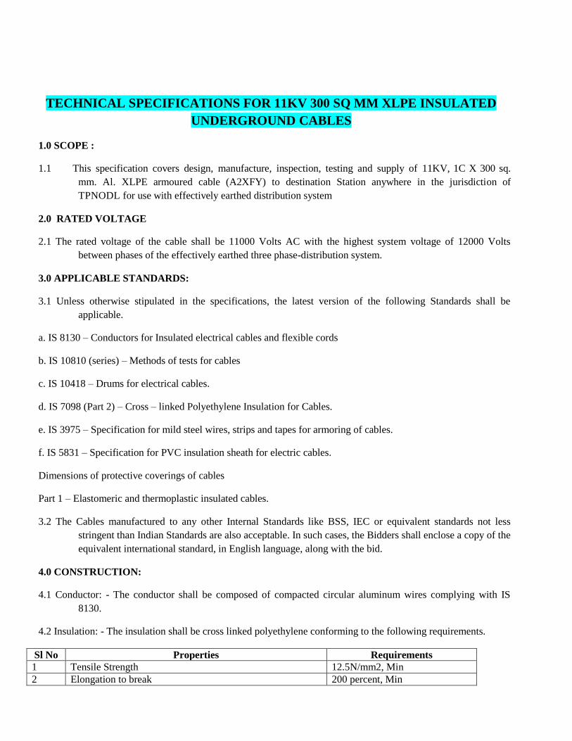
TECHNICAL SPECIFICATIONS FOR 11KV 300 SQ MM XLPE INSULATED
UNDERGROUND CABLES
1.0 SCOPE :
1.1 This specification covers design, manufacture, inspection, testing and supply of 11KV, 1C X 300 sq.
mm. Al. XLPE armoured cable (A2XFY) to destination Station anywhere in the jurisdiction of
TPNODL for use with effectively earthed distribution system
2.0 RATED VOLTAGE
2.1 The rated voltage of the cable shall be 11000 Volts AC with the highest system voltage of 12000 Volts
between phases of the effectively earthed three phase-distribution system.
3.0 APPLICABLE STANDARDS:
3.1 Unless otherwise stipulated in the specifications, the latest version of the following Standards shall be
applicable.
a. IS 8130 – Conductors for Insulated electrical cables and flexible cords
b. IS 10810 (series) – Methods of tests for cables
c. IS 10418 – Drums for electrical cables.
d. IS 7098 (Part 2) – Cross – linked Polyethylene Insulation for Cables.
e. IS 3975 – Specification for mild steel wires, strips and tapes for armoring of cables.
f. IS 5831 – Specification for PVC insulation sheath for electric cables.
Dimensions of protective coverings of cables
Part 1 – Elastomeric and thermoplastic insulated cables.
3.2 The Cables manufactured to any other Internal Standards like BSS, IEC or equivalent standards not less
stringent than Indian Standards are also acceptable. In such cases, the Bidders shall enclose a copy of the
equivalent international standard, in English language, along with the bid.
4.0 CONSTRUCTION:
4.1 Conductor: - The conductor shall be composed of compacted circular aluminum wires complying with IS
8130.
4.2 Insulation: - The insulation shall be cross linked polyethylene conforming to the following requirements.
Sl No Properties Requirements
1 Tensile Strength 12.5N/mm2, Min
2 Elongation to break 200 percent, Min

Aging in air oven
a) Treatment : Temperature
135+_30 C
7 Days
3 Duration
a) Tensile Strength variation + 25 percent, Max
b) Elongation variation + 25 percent, Max
4 Hot set
a)Treatment : Temperature
Time under load
Mechanical stress
200 + 30 C
15 min
20N/cm2
b) Elongation under load 175 percent, Max
c) Permanent elongation (set) after
cooling
15 percent, Max
5 Shrinkage
a)Treatment : Temperature
Duration
130+ 30 C
1 hour
b) Shrinkage 4 percent, Max
6 Water absorption (Gavin metric)
a)Treatment : Temperature
Duration
85+ 20 C
14 days
b) Water absorbed 1 mg / cm2, Max
7 Volume Resistivity
at 270 C
at 700 C
1 x 10¹⁴ ohm-cm, Min
1 x 10¹³ ohm-cm, Min
4.3 The screening shall consist of non-metallic semi conducting compound and copper tape, shielded cores laid up
with fillers, inner sheath of extruded PVC, Galvanized steel strip Amour and PVC ST-2 overall sheath.
4.4 The cables should be suitable for use in solidly earthed system.
4.5 The 6.35/11KV underground cables shall be manufactured to the highest quality, best workmanship with
scientific material management and quality control. The bidder shall furnish the quality plan, giving in
detail the quality control procedure / management system.
4.6 The successful Bidder shall give sufficient advance notice to the purchaser of not less than fifteen days to
arrange for stage inspection and inspection of quality assurance program during manufacture, at the
works.
5.0 SYSTEM DETAILS
General Technical particulars
General Technical particulars
Sl
No
Particulars Values
1 Nominal system voltage (rms) (U) 11KV
2 Highest system voltage (rms) (Um) 12KV
3 Phase to Earth voltage (rms) (U0) 6.35 KV
4 Number of Phase Single

5 Frequency 50Hz
6 Variation in Frequency + / - 3%
7 Type of Earthing Solidly Earthed
8 Basic impulse insulation level (1.2/50 XS wave) 75KV
9 Total relay & circuit breaker Operating time 15-20 cycles
10 One Minutes power frequency withstand voltage 28 KV rms
6.0 INSTALLATION CONDITIONS:
6.1 The cables are laid directly buried in ground. The Nominal depth of laying is up to minimum 1.2Mtr (from top
of ground to centre of cable).However, in trench less horizontal bore method, the bore can go up to a
depth of a maximum of 2 meter. Nature of soil is heterogeneous, sandy, Soil resistivity varies between
18 to 100 ohmmeter and the Thermal resistivity is around 1200 to 1500 C/ Cm/w.
7.0 CLIMATIC CONDITIONS:
7.1 The climatic conditions where these 11KV cables will be installed are as under : Climatic conditions
Sl
No
Particulars Details
1 Location TPNODL Jurisdiction
2 Max Daily average air temp 45ºC
3 Minimum ambient air temp : 10ºC
4 Ground temperature at
depth of laying assumed
350 (Max) 50 C (Min)
5 Isoceraunic level 45
6 Avg. annual rainfall 2500 mm
7 Avg. number of rainy days
per annum:
90
8 Climate Tropical moderately hot and humid.
likelihood of subsoil water at certain
location at the depth of burial of cables
9 Soil Normally dry

8.0 DESIGN CRITERIA:
8.1 The cables that are covered in these specifications are intended for use in the North Eastern belt of state of
Odisha for Power distribution purposes, under the climatic conditions and installation conditions
described in the technical specification.
8.2 Any technical features, not specifically mentioned here, but is necessary, for the good performance of the
product, shall be incorporated in the design. Such features shall be clearly brought out under Technical
deviations schedules only, in the offer made by the bidder, giving technical reasons, and justifying the
need to incorporate these features.’
8.3 For continuous operation of the cables, at specified rating, the maximum conductor temperature shall be
limited to the permissible value as per the relevant standard, generally not exceeding 900C under normal
operation and 250cC under short-circuit conditions.
8.4 The cables in service will be subject to daily load cycles, of two peaks during a day; morning peak and
evening peak, with around 50% loading during the nights.
8.5 The materials used for outer sheaths shall be resistant to oils, acids and alkalis.
8.6 The cables shall have the mechanical strength required, during handling and lying.
8.7 The cables shall be designed to withstand the thermo-mechanical forces and electrical stresses during normal
operation and transient conditions.
8.8 The cables shall be designed to have a minimum useful life span of Thirty years.
9.0 MANUFACTURE PROCESS:
9.1 Cross-linking of the insulation materials (pre compounded polyethylene) shall be conforming to IS :7098
(Part-II)
9.2 The conductor screen shall be extruded semi conducting compound. The insulation screen shall consist of the
nonmetallic part, extrude semi conducting compound with non-magnetic metallic part. The XLPE
insulation and the shield for conductor and insulation shall be extruded in one operation.
10.0 MATERIALS
10.1 Conductor: - The conductor shall be of standard construction. The material for conductor shall consist of the
plain aluminum of H2 or H4 grade as per clause – 3 of IS 8130 / 1984. 10.2 The Number of wires in the
conductor, shall be not less than the appropriate minimum number given in table – 2 of IS 8130 / 1984.
11.0 SCREENING:
11.1 The conductor screening shall be provided over the conductor by applying non-metallic semi-conducting
compound. The metallic screen shall withstand the operating temperature of the cable and shall be
compatible with the insulating material.
11.2 The insulation screen shall be applied over the insulation. The insulation screening shall consist of two parts;
namely metallic and non-metallic. The non-metallic part shall be applied directly over the insulation of
core and shall consist of a semi conducting tape and extruded semi conducting compound with a semi
conducting coating. The metallic part

of the insulation screen shall consist of either tape, or braid, or concentric serving of wires or a sheath; shall be
non-magnetic and shall be applied over the non-metallic part.
12.0 CORE IDENTIFICATION:
12.1 The core identification for Single core cables shall be provided, by suitable means, like, by application of
colored stripes, or by numerals or by printing on the cores as per clause 13 of IS : 7098 – Part 2.
12.2 For identification of different coloring of XLPE insulation, or by using colored strips, red, yellow and blue
colors respectively shall be used to identify the phase conductors.
13.0 LAYING UP OF CORES:
13.1 For multicore cables, the cores shall be laid together with a suitable right hand lay. The interstices at the
center shall be filled with a non hygroscopic material.
14.0 INNER SHEATH (COMMON COVERING)
14.1 The laid up cores shall be provided with inner sheath applied either by extrusion or bv wrapping. It shall be
ensured that the shape is as circular as possible. The inner sheath shall be so applied that it fits closely
on the laid up cores and it shall be possible to remove it without damage to the insulation.
14.2 The thickness of the inner sheath (common covering) shall be given as follows:
Calculated diameter over laid up cores in accordance With
15.3 of IS 10462 (Part 1) – (mm)
Thickness of inner
sheath
(mm)
Over Up to and including
- 25 0.3
25 35 0.4
35 45 0.5
45 55 0.6
55 - 0.7
When one or more layers of binder tapes are applied over the laid up cores, the thickness of such tapes shall
not be construed as a part of inner sheath.
14.3 For multi core cables, the interstices at the center shall be filled with a non-hygroscopic material. The
interstices around the laid up cores shall be covered with PVC compound type ST-2. This will form the
Inner sheath for multi core-single core cables.
15.0 ARMOURING:
15.1 Armoring shall be applied over the inner sheath as closely as practicable. The Amour shall be galvanized
steel strip complying with the requirements of IS 3975. A binder tape may be applied on the Amour. The
direction of the lay of the amour shall be left hand. For double armored cables, this requirement applies
to the inner layer. The outer layer shall be applied in the reverse direction to the inner layer, and there
should be a separator of the non hygroscopic material; such as plastic tape, bituminized cotton tape,
rubber tape, proofed tape between inner and outer layers of Amour.
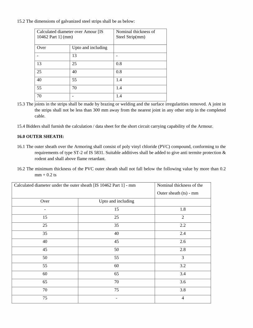
15.2 The dimensions of galvanized steel strips shall be as below:
Calculated diameter over Amour [IS
10462 Part 1] (mm)
Nominal thickness of
Steel Strip(mm)
Over Upto and including
- 13 -
13 25 0.8
25 40 0.8
40 55 1.4
55 70 1.4
70 - 1.4
15.3 The joints in the strips shall be made by brazing or welding and the surface irregularities removed. A joint in
the strips shall not be less than 300 mm away from the nearest joint in any other strip in the completed
cable.
15.4 Bidders shall furnish the calculation / data sheet for the short circuit carrying capability of the Armour.
16.0 OUTER SHEATH:
16.1 The outer sheath over the Armoring shall consist of poly vinyl chloride (PVC) compound, conforming to the
requirements of type ST-2 of IS 5831. Suitable additives shall be added to give anti termite protection &
rodent and shall above flame retardant.
16.2 The minimum thickness of the PVC outer sheath shall not fall below the following value by more than 0.2
mm + 0.2 ts
Calculated diameter under the outer sheath [IS 10462 Part 1] - mm
Nominal thickness of the
Outer sheath (ts) - mm
Over Upto and including
- 15 1.8
15 25 2
25 35 2.2
35 40 2.4
40 45 2.6
45 50 2.8
50 55 3
55 60 3.2
60 65 3.4
65 70 3.6
70 75 3.8
75 - 4

17.0 IDENTIFICATION:
17.1 The outer sheath shall have the following information embossed or indented on it; the manufacturer’s name
or trade mark, the voltage grade, the year of manufacture and the letters “TPNODL”. The identification
shall repeat every 300/350-mm along the length of the cable.
17.2 Note: The outer sheath of the cable should be embossed with “TPNODL”
18.0 INSPECTION AND QUALITY CONTROL:
18.1 The Bidder shall furnish a complete and detailed quality plan for the manufacturing process of the cable. All
raw materials shall conform to relevant applicable standards and tested for compliance to quality and
requirement. During the manufacturing process, at all stages, inspections shall be made to check the
physical and dimensional parameters, for verification to compliance to the standards. The bidder shall
arrange, for inspection by the purchaser, during manufacture, if so desired by the purchaser, to verify the
quality control process of the Bidder.
19.0 TYPE TESTS:
19.1 The offered cables with same designs shall have been type tested and Test certificates shall not be later than
5 years on the date of bid opening. Otherwise the supplier / Turnkey contractor shall arrange for type
testing at his own cost.. The supplier /Turn Key contractor shall conduct all type tests as per IS : 7098
part-II 1985, with up to date amendments or equivalent International standard, and supplies made only
after approval of test reports from the purchaser.
19.2 All type tests if required, routine acceptance test shall be conducted in the presence of the purchaser /
representative.
19.3 The supplier shall give 15 days advance notice for inspections, and witnessing of tests by the purchaser or his
representative.
19.4 The following type tests will be conducted on the cable if the type test certificates are more than 5 years old
(a) Test on conductor.
(b) Test on Amour.
(c) Test for thickness of XLPE insulation and inner and outer sheaths
(d) Physical test on XLPE insulation.
(e) Physical test for outer sheath
(f) Bleeding and blooming test for outer sheath
(g) Partial discharge test.
(h) Bending test
(i) Di-electric power factor test
i. As a function of voltage

ii. As a function of temperature
(j) Insulation resistance (volume resistivity) test
(k) Heating cycle test
(l) Impulse withstand test
(m)High voltage test
(n) Flammability test
19.5 The following test shall be performed successfully on the same test sample of completed cable, not less than
10 M in length between the test accessories:
I. Partial discharge test
II. Bending test followed by partial discharge test
III. Dielectric power factor as a function of voltage.
IV. Dielectric power factor as a function of temperature
V. Heating cycle test followed by dielectric power factor as a function of voltage and partial discharge tests.
VI. Impulse withstand test
VII. High voltage test.
20.0 ACCEPTANCE TEST:
20.1 The sampling plan for acceptance test shall be as per IS 7098 part-II, Appendix ‘A’
20.2 The following shall constitute the acceptance test.
a) Tensile test for aluminum
b) Wrapping test for aluminum
c) Conductor resistance test
d) Test for thickness of insulation
e) Test for thickness of inner and other sheath
f) Hot-set test for insulation
g) Tensile strength and elongation at break test for insulation and outer sheath.
h) Partial discharge test (on full drum length).
i) High voltage test.
j) Insulation resistance (volume resistivity test).
21.0 ROUTINE TEST:

21.1 The following shall constitute routine tests :
a) The following shall constitute routine tests:
b) Conductor resistance test
c) Partial discharge test on full drum length
d) High voltage test.
22.0 PACKING:
22.1 The cables, as per specified delivery lengths, shall be securely wound/packed in non-returnable, well
seasoned sturdy wooden drums, with strong reinforcement so as so to withstand rough handling during
transport by rail, Roads etc., The packing should withstand storage conditional in open yards. The cable
drums shall conform to IS 10418 1982 or equivalent standard.
22.2 The drawings of the cable drums with full detail shall be furnished, and got approved before dispatch.
23.0 SEALING OF CABLE ENDS ON DRUMS:
23.1 The cable ends shall be sealed properly so that Ingress of moisture is completely prevented. The individual
core endings shall be sealed effectively with water resistant compound applied over the core ad provided
with a heat shrinkable or push-on or Tapex or cold shrinkable type cap of sufficient length with adequate
cushion space so that the conductor does not puncture the cap in case of movement of the core during
unwinding or laying. Before sealing, the semi conducting layer on the cores may be removed for about 2
mm at each end, to facilitate checking the insulation resistance from one end, without removing the
sealing cap at the other end.
23.2 The single core should have an overall heat shrinkable or push-on or Tapex or cold shrinkable type cap with
adequate end clearance, and sufficient cushioning to prevent puncturing of the overall sealing cap due to
stretching of the core. The sealing cap shall have sufficient mechanical strength and shall prevent ingress
of moisture into the cable.
The ends of single core cable shall also be sealed on the same lines to prevent entry of moisture.
24.0 CABLE LENGTHS:
24.1 The cables shall be supplied in continuous lengths of 500M in case of single core cable with tolerance of + or
– 5% of drum length. It is preferable to manufacture the cable to required lengths as required by the field
conditions to have minimum joints. The turn key contractor will furnish the required drum lengths in
advance
25.0 QUANTITY TOLERANCE
A +3% tolerance shall be allowed on the ordered quantity.
26.0 MARKING:
26.1 The packed cable drum shall carry the following information, clearly painted or stenciled
a) The letters TPNODL
b) Reference to Standard and ISI mark

c) Manufacturer’s Name or trade mark.
d) Type of cable & voltage grade
e) Number of core
f) Nominal cross-sectional area of conductor.
g) Cable code
h) Length of cable on the drum
i) Direction of rotation
j) Gross weight
k) Country of Manufacture
l) Year of Manufacture
m) Purchase order and date
n) Address of consignee
27.0 GUARANTEED TECHNICAL PARTICULARS:
The b idder sha l l conf i rm fo r guarantee towards design, material, workmanship & quality of
process/ manufacturing for integrated product delivered under the contract.
In the event any defect is found by TPNODL , up to a period of at least 60 months from the date of
commissioning, bidder shall be liable to undertake to replace / rectify such defect at its own costs,
within mutually agreed time frame, and to the entire satisfaction of TPNODL, failing which
TPNODL will be at liberty to get it replaced/ rectified at Bidder’s risk and costs and recovery all such
expenses plus the TPNODL’s own charges ( @20% of expenses incurred ) , from the Bidder of from
‘Security cum Performance Deposit’ as the case may be.
28.0 DRAWING & LITERATURE
28.1 The following shall be furnished along with the tender
a) Cross sectional drawings of the cables, giving dimensional details for each size of cable.
b) An illustrated literature on the cable, giving technical information, on current ratings, cable constants,
short circuit ratings, de-rating factors, for different types of installation, packing date, weights and other
relevant information.
GURANTEED TECHNICAL PARTICULARS OF 11KV XLPE CABLE (ARMOURED) (TO BE FURNISHED BY THE BIDDER)
Sl.
No. Particulars Bidder's Offer
1 CABLES 1Cx300 mm²
a) Manufacturer
b) Trade Name
2 Type of Cable

3 Applicable specification & Standards
4 Voltage Class
5
Whether suitable for extrusion technique is employed in the manufacture
of conductor screen
6
Whether triple extrusion technique is employed in the manufacture of
conductor screen
7 Permissible voltage and frequency variation for satisfactory operation
8
Continuous Current Rating for standard conditions indicated in
specifications:
a) Air (450 C Ambient)
b) In Ground (350 C)
c) In Duct
d) In Trench
9 De-rating factors for various laying conditions
10 Conductor
a) Material
b) Shape of conductor
c) Nominal area of cross section
d) Number of strands per core
e) Diameter of Wire (before compacting and stranding)
f) Diameter and size of conductor
11 Conductor Screening
a) Type
b) Material
c) Nominal thickness
d) Continuous working temperature
e) Maximum allowable temperature at the termination of short circuit
12 Insulation
a) Material
b) Thickness of Insulation
c) Thickness of Insulation over core
d) Thickness of Insulation between core and inner sheath
e) Tolerance of thickness in insulation
f) Diameter of core over insulation
13 Specific Insulation Resistance at 900C
14 Process of curing
15 Whether XLPE Insulation filled or unfilled
16 Insulation Screening:
a) Material
b) Thickness
c) Thickness of semi conducting part
d) Thickness of metallic part

e) Size of copper tape
f) Whether overlapping provided
g) Current carrying capacity for continuous rating
h)
Current carrying capacity for short circuit rating for
1 minutes
i) Diameter of cable over screening
j) Whether insulation screen is removable without the application of heat
17 Inner Sheath
a) Material
b) Extruded
c) Minimum thickness
d) Diameter of cable over inner sheath
18 Armoring:
a) Material
b) Type of Armouring
c) Diameter of wire
d) Whether galvanized
e) Diameter of cable over Armouring
f) Current carrying capacity of Armor
19 Outer Sheath:
a) Material
b) Minimum thickness of sheath
c) Tolerance over thickness of sheath
d) Overall diameter of cable
20 Scheme for identification of cable
21
Allowable/attainable maximum conductor temperature when carrying
rated current continuously
22 Cable constants:
a) DC Resistance per core 200 C
b) AC Resistance per core at operating temperature
c) Reactance
d) Capacitance
e) Insulation Resistance at 270C
f) Loss tangent
g)
Dielectric constant – Maximum cable charging current at normal
operating voltage
23 Factory Tests (Enumerate in detail for each type of cable)
24 Is the offered cable guaranteed to safely withstand continuous conductor
temperature at 900C and also safely withstand temperature upto 1300C
for a duration of one hundred hours per year.
25 Are the offered Single core cable guaranteed to perform satisfactorily
under installation conditions specified? If ‘Yes’ furnish relevant
calculations in support including the following data:

a) Induced voltage in the Amour when a 500 mtr long cable is carrying
current
b)
Induced voltage and the circulating current in the copper tape
Name & Signature of Bidder with seal
TECHNICAL SPECIFICATION OF 100mm2 ALL ALUMINIUM
ALLOY CONDUCTOR (AAAC) 1. SCOPE
This specification covers design, Engineering, Manufacture, Testing, Inspection before dispatch,
forwarding, packing, transportation to sites, Insurance (both during transit & storage), storage,
erection, supervision testing & commissioning of all sizes of All Aluminum Alloy Conductors of
the aluminum – magnesium- silicon type for use in the distribution overhead power lines of
TPNODL of Odisha.
The equipment offered shall have been successfully type testes and the design shall have been
satisfactory operation for a period not less than f ive years on the date of bid opening.
Compliance shall be demonstrated by submitting with the bid, (i) authenticated copies of the type
test reports and (ii) performance certificates from the users.
The scope of supply includes the provision of type test, Rates of type tests shall be given in the
appropriate price schedule of the bidding document and will be considered for evaluation. The
Purchaser reserves the right to waive type tests as indicated in the section on Quality
Assurance, Inspection and Testing in the specification.
The Aluminum Alloy Conductor shall conform in all respects to highest standards of engineering,
design, workmanship, this specification and the latest revisions of relevant standards at the time
of offer and the Purchaser shall have the power to reject any work or materials, which, in his
judgment, is not in full accordance therewith.
STANDARDS
Except where modified by the specification, the Aluminum Alloy Conductor shall be designed,
manufactured and tested in accordance with latest editions of the following standards.
IEC/ISO/ Other
International Standard IS Subject
IEC :1089 Round wire concentric lay overhead electrical
standard conductors
IS 398 Aluminum Alloy Stranded Conductors
IS 9997 Aluminum Alloy redraw rods for electrical
purposes

IEC 502 : 1994 Extruded solid dielectric insulated power cables
for rated voltages 1.0 KV up to 30 KV
IEC 104 Aluminum Magnesium Silicon alloy wire for
overhead
IS 1778 line conductors Reels and drums of bare conductor.
BS : 6485-1971 PVC covered conductors for overhead power lines.
This list is not to be considered exhaustive and reference to a particular standard or
recommendation in this specification does not relieve the contractor of the necessity of
providing the goods complying with other relevant standards or recommendations.
3. GENERAL The wires shall be of heat treated aluminum, magnesium silicon alloy containing
approximately silcon-0.5 to 0.9 %. magnesium-0.6 % to 0.9%,Fe-0.5% (maximum) ,
Copper- 0.1% (max ), mn- 0.03% , Cr-0.03%, Zn-0.1%, B-0.06%, and having the mechanical
and electrical properties specified in the table and be smooth and free from all imperfections,
such as, spills, splits and scratches.
Neutral grease shall be applied between the layers of wires. The drop point temperature of the
grease shall not be less than 1200
C.
3.1 Mechanical and Electrical Characteristics of Aluminium Alloy Wires used in the
Construction of Stranded Aluminium Alloy Conductors
Nominal
Diameter
Minimum
Diameter
Max.
Diam
eter
Cross
Sectional
Area
Mass
Minimum Breaking
Load Maximum
Resistance at
200C Before
stranding
After
stranding
1 2 3 4 5 6 7 8
mm mm mm mm2 Kg/km KN KN ohms/ km
3.15 3.12 3.18 7.793 21.04 2.37 2.29 4.290
3.81 3.77 3.85 11.40 30.78 3.52 3.34 2.938
4.26 4.22 4.30 14.25 38.48 4.40 4.18 2.345
Maximum resistance values given in column 8 have been calculated from the maximum values of the
resistively as specified and the cross sectional area based on the minimum diameter.
The minimum breaking load is calculated on nominal diameter at ultimate tensile strength of 0.309
KN / mm2
for wire before stranding and 95% of the ultimate tensile strength after stranding.
4. PHYSICAL CONSTANTS FOR ALUMINIUM ALLOY WIRES
4.1 Resistively:
For the purpose of this specification, the standard value of resistively of aluminum alloy wire
which shall be used for calculation is to be taken as 0.0325 ohm mm2
/m at 200
C. the maximum
value of resistively of any single wire shall not , however, exceed 0.0328 ohm. mm2/m at 20
0 C.
4.2 Density :
At a temperature of 200
C, the density of aluminum alloy wire is to be taken as 2700 kg/m3.
4.3 Temperature Coefficient of Linear Expansion :

The temperature coefficient of linear expansion of aluminum alloy wire is to be taken as 23x10
–6
0C
4.4 Constant – Mass Temperature Coefficient
At a Temperature of 200
C, the constant – mass temperature coefficient of resistance of aluminum alloy wires, measured between two potential points rigidly fixed to the wire, is
taken as 0.00360/0
C
5. STANDARD SIZES
5.1 Nominal Sizes of Wires
The aluminum alloy wires for standard constructions covered by this specification shall have
the diameters as specified in the table and a tolerance of ±1% shall be permitted on the
nominal diameter.
5.2 Standard Conductors
The sizes, resistance and masses (excluding the mass of grease ) of stranded aluminum
alloy conductors shall be as given in table.
5.3 Mechanical and Electrical Characteristics of Aluminum Alloy Stranded
Conductors
Sl.
No.
Actual
Area
Stranding
and Wire
Dia
Approx.
Overall Dia
Approx.
Mass
Calculated Maximum Resistance
at 200
C
Approx
Calculated
Breaking
Load
1 2 3 4 5 6 7
mm2 mm mm kg/km ohms/km KN
1 55 7/3.15 9.45 149.20 0.621 16.044
2 80 7/3.81 11.43 218.26 0.425 23.41
3 100 7/4.26 12.78 272.86 0.339 29.344
4 232 19/3.94 19.70 636.67 0.1471 68.05
5.3.1 Increase in Length due to Stranding
When straightened out, each wire in any particular layer of a stranded conductor,
except the central wire, is longer than the stranded conductor by an amount
depending on the lay ratio of that layer.
5.3.2 Resistance and Mass of Conductor The resistance of any length of stranded conductor is the resistance of the same length of any
one wire multiplied by a constant as set out in the table below.
The mass of each wire in any particular layer of the stranded conductor, except the central
wire, will be greater than that of an equal length of straight wire by an amount depending on the
lay ratio of that layer. The total mass of any length of an aluminum stranded conductor is,
therefore, obtained by multiplying the mass of an equal length of straight wire by an
appropriate constant as mentioned below. In calculating the stranding constants as
mentioned in the table below, the mean lay ratio, that is the arithmetic mean of the relevant
minimum and maximum values in table for lay ratio has been assumed for each layer.

5.3.3 Calculated Breaking Load of Conductor
For a conductor containing not more than 37 wires, 95% of the sum of strength of the
individual wires calculated from the values of the minimum breaking load given in this
specification.
For a conductor containing more than 37 wires, 90% of the sum of the strengths of
the individual wire calculated from the values of the minimum breaking load given in this
specification.

5.3.4 Calculated Area and Maximum Resistance of
Conductor
The actual area of a stranded conductor has been taken as the sum of the cross- sectional
areas of the individual wires of nominal diameter. Maximum resistance values of stranded conductor have been calculated on the basis of
maximum resistivity and the cross-sectional area based on the minimum diameter of
wires.
5.3.5 Stranding Constants
Number of Wires in
Conductor
Stranding Constants
Mass Electrical Resistance
(1) (2) (3)
7 7.091 0.1447
19 19.34 0.05357
6. JOINTS IN WIRES
6.1 Conductor containing seven wires
There shall be no joint in any wire of a stranded conductor containing seven
wires, except those made in the base rod or wire before final drawing.
6.2 Conductors containing more than seven wires
In stranded conductors containing more than seven wires, joints in individual
wires are permitted in any layer except the outermost layer ( in addit ion to those
made in the base rod or wire before final drawing ) but no two such joints shall be
less than 15 m apart in the complete stranded conductor. Such joints shall be made
by cold pressure butt welding. They are not required to fulfill the
mechanical requirements for unjointed wires.
7. STRANDING
The wire used in the construction of a stranded conductor shall, before and after
stranding, satisfy all the relevant requirements of this standard. The lay ratio of the different layers shall be within the limits given in the table for
lay ratio.
In all constructions, the successive layers shall have opposite directions of lay, the
outermost layer being righ-handed. The wires in each layer shall be evenly and
closely stranded.

Unless otherwise agreed between the Employer and the Contractor, stranded
aluminum alloy conductors shall be supplied in the manufacturer’s usual
production lengths to be indicated in the bid Schedule. The Employer reserves the
right to specify particular lengths of conductor such that certain drum lengths will
be shorter than others. There will in both cases be a permitted variation of –0 +
5% in the length of any one conductor length.
8. LENGTHS AND VARIATIONS IN LENGTHS : Unless otherwise agreed
9. TESTS
9.1 Type Tests
The following tests shall be carried out as per relevant ISS once on samples of completed line conductor during each production run of up to
500 kms of the conductor from each manufacturing facility.
9.1.1 Ultimate Tensile Strength Test
This test is intended to confirm not only the breaking strength of the
finished conductor but also that the conductor has been uniformly stranded.
A conductor sample of minimum 5 m length fitted with compression dead end
clamps at either end shall be mounted in a suitable tensile test machine. Circles
perpendicular to the axis of the conductor shall be marked at two places on its
surface. Tension on the conductor sample shall be increased at a steady rate
upto 50% of the minimum UTS specified and held for one minute. The circles
drawn shall not be distorted due to relative movement of the individual strands.
Thereafter the load shall be increased at a steady rate to the specified minimum
UTS and held at that load for one minute. The conductor sample shall not fail
during this period. The applied load shall then be increased until the failing
load is reached and the value recorded.
9.1.2 D.C Resistance Test On a conductor sample of minimum 5 m length two contact
clamps shall be fitted with a pre-determined bolt torque. The resistance between the
clamps shall be measured using a Kelvin double bridge by initially placing the
clamps at zero separation and subsequently one meter apart. The test shall be
repeated at least five times and the average value recorded. The value obtained shall
be corrected to the value at 200
C, which shall conform to the requirements
of this specification.
9.2 Routine Tests
Measurement of Physical Dimensions: The samples should meet the
desired
dimensional requirements before conducting following Routine Tests as
per relevant ISS.
9.2.1 Selection of Test Samples
Samples for the tests specified in this specification shall be taken by
the manufacturer before stranding, from not less than 10% of the
individual lengths of aluminium alloy wire included in any one final
heat-treatment batch and which will be included in any one consignment

of the stranded conductors to be supplied.
Alternatively, if desired by TPNODL at the time of placing an order, that
the tests be made in the presence of his representative, samples of wire shall
be taken from length of stranded conductor.
Samples shall then be obtained by cutting 1.2 meters from the outer end
of t he finished conductor from not more than 10% of the finished reels or
drums.
Tests for electrical and mechanical properties of aluminum alloy wire
shall ordinarily be made before stranding since wires unlaid from
conductors may have different physical properties from those of the
wire prior to stranding because of the deformation brought about by
stranding and by straightening for test.
Spools offered for inspection shall be divided into equal lots, the number
of lots being equal to the number of samples to be selected, a fraction of
a lot being counted as s complete lot. One sample spool shall be selected
at random from each lot.
The following test shall be carried out once on samples of completed
line conductor during each production run of up to 500 kms of the
conductor from each manufacturing facility.
9.2.2 Breaking Load Test
The breaking load of one specimen, cut from each of the samples taken
shall be determined by means of a suitable tensile testing machine. The
load shall be applied gradually and the rate of separation of the jaws of
the testing machine shall be not less than 25 mm / min and not greater than
100mm /min.
9.2.3 Elongation Test
The elongation of one specimen cut from each of the samples taken shall
be determined as follows:
The specimen shall be straightened by hand and an original gauge length of
200 mm shall be marked on the wire. A tensile load shall be applied as
described above and the elongation shall be measured after the fractured
ends have been fitted together. If the fracture occurs outside the gauge
marks, or within 25 mm of either mark, and the required elongation is not
obtained, the test shall be disregarded and another test should be made.
When tested before and after stranding, the elongation shall not be less than 4%
on a gauge length of 200 mm.
electrical resistance test of one specimen cut from each of the samples taken shall be measured at ambient temperature. The measured resistance shall

be corrected to the value at 200
C by means of the formula :
1
R20 = RT ----------------------
-----
1 + (T-
20)
Samples taken from the alloy coils / strands shall be
chemically / spectrographically analyzed. The results
shall conform to the requirements stated in this specification. The
contractor shall make available material analyses, control documents and
certificates from each batch as and when required by the Purchaser.
Test should be conducted at the independent test house by the purchaser
in the case of absence Of facility at manufacturer. However the cost of
such testing shall be borne by the manufacturer.
9.2.4 D.C Resistance Test
The electrical resistance test of one specimen cut from each of the samples taken shall be measured at ambient temperature. The measured resistance shall be
corrected to the value at 200
C by means of the formula :
1
R20 = RT ------------------------
---
1
+
(T-20)
where ,
R20 = resistance corrected at
200
C RT
= resistance measured T0
C
= constant – mass temperature coefficient of resistance, 0.0036, and
T = ambient temperature during measurement.
The resistance corrected at 200
C shall not be more than the maximum values specified.
9.2.5 Chemical Analysis of Aluminum Alloy
Samples taken from the alloy coils / strands shall be
chemically / spectrographically analyzed. The results shall
conform to the requirements stated in this specification. The contractor shall
make available material analyses, control documents and certificates from each
batch as and when required by the Purchaser.

Test should be conducted at the independent test house by the purchaser in the
case of absence Of facility at manufacturer. However the cost of such testing
shall be borne by the manufacturer.
9.2.6 Dimensional and Lay Length Check
The individual strands of the conductors shall be dimensionally checked and the lay lengths checked to ensure that they conform to the requirements of this specification.
Ten percent drums from each lot shall be rewound in the presence of the
Purchaser or his representative to allow visual checking of the conductor for joints, scratches or other surface imperfections and to ensure that the conductor
generally conforms to the requirements this specification. The length of conductor wound on the drum shall be re-measured by means of an approved
counter / meter during the rewinding process.
9.2.7 Visual and dimensional Checks on the Conductor Drums.
The drums shall be visually and dimensionally checked to ensure that they
conform to the requirements of this specification and of IS 1778: Specification
for reels and drums of bare conductors. For wooden drums, a suitable barrel
batten strength test procedure is required. The Bidder shall state in his bid the
tests to be carried out on the drums and shall include those tests in the Quality
Assurance Programme.
9.2.8 Acceptance Tests :
All tests required to confirm enclosed Guaranteed Technical Particulars
(GTP) requirements of this specification needs to be conducted as
Acceptance Tests.
9 . 3 Test Reports.
a) Copies of type test reports shall be furnished in at least six copies along
with one original. One copy will be returned duly certified by the Owner
only after which the commercial production of the material shall start.
b) Record of routine test reports shall be maintained by the Supplier at his
works for periodic inspection by the Owner’s representative.
c) Test certificate of tests during manufacture shall be maintained by the
Contractor.
These shall be produced for verification as and when desired by the Owner.
10. Packing.
a) The conductor shall be supplied in returnable, strong, wooden drums
provided with lagging of adequate strength, constructed to protect the
conductor against any damage and displacement during transit, storage
and subsequent handling and stringing operations in the field. The
Contractor shall be responsible for any loss or damage during transportation
handling and storage due to improper packing. The drums shall generally
conform to IS: 1778-1980, except as otherwise specified hereinafter.
b) The drums shall be suitable for wheel mounting and for letting off the
conductor under a minimum controlled tension of the order of 5 KN.
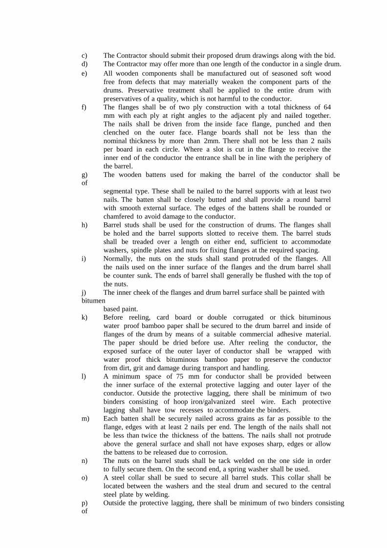
c) The Contractor should submit their proposed drum drawings along with the bid.
d) The Contractor may offer more than one length of the conductor in a single drum.
e) All wooden components shall be manufactured out of seasoned soft wood
free from defects that may materially weaken the component parts of the
drums. Preservative treatment shall be applied to the entire drum with
preservatives of a quality, which is not harmful to the conductor.
f) The flanges shall be of two ply construction with a total thickness of 64
mm with each ply at right angles to the adjacent ply and nailed together.
The nails shall be driven from the inside face flange, punched and then
clenched on the outer face. Flange boards shall not be less than the
nominal thickness by more than 2mm. There shall not be less than 2 nails
per board in each circle. Where a slot is cut in the flange to receive the
inner end of the conductor the entrance shall be in line with the periphery of
the barrel.
g) The wooden battens used for making the barrel of the conductor shall be
of
segmental type. These shall be nailed to the barrel supports with at least two
nails. The batten shall be closely butted and shall provide a round barrel
with smooth external surface. The edges of the battens shall be rounded or
chamfered to avoid damage to the conductor.
h) Barrel studs shall be used for the construction of drums. The flanges shall
be holed and the barrel supports slotted to receive them. The barrel studs
shall be treaded over a length on either end, sufficient to accommodate
washers, spindle plates and nuts for fixing flanges at the required spacing.
i) Normally, the nuts on the studs shall stand protruded of the flanges. All
the nails used on the inner surface of the flanges and the drum barrel shall
be counter sunk. The ends of barrel shall generally be flushed with the top of
the nuts.
j) The inner cheek of the flanges and drum barrel surface shall be painted with bitumen
based paint.
k) Before reeling, card board or double corrugated or thick bituminous
water proof bamboo paper shall be secured to the drum barrel and inside of
flanges of the drum by means of a suitable commercial adhesive material.
The paper should be dried before use. After reeling the conductor, the
exposed surface of the outer layer of conductor shall be wrapped with
water proof thick bituminous bamboo paper to preserve the conductor
from dirt, grit and damage during transport and handling.
l) A minimum space of 75 mm for conductor shall be provided between
the inner surface of the external protective lagging and outer layer of the
conductor. Outside the protective lagging, there shall be minimum of two
binders consisting of hoop iron/galvanized steel wire. Each protective
lagging shall have tow recesses to accommodate the binders.
m) Each batten shall be securely nailed across grains as far as possible to the
flange, edges with at least 2 nails per end. The length of the nails shall not
be less than twice the thickness of the battens. The nails shall not protrude
above the general surface and shall not have exposes sharp, edges or allow
the battens to be released due to corrosion.
n) The nuts on the barrel studs shall be tack welded on the one side in order
to fully secure them. On the second end, a spring washer shall be used.
o) A steel collar shall be sued to secure all barrel studs. This collar shall be
located between the washers and the steal drum and secured to the central
steel plate by welding.
p) Outside the protective lagging, there shall be minimum of two binders consisting of

hoop iron/ galvanized steel wire. Each protective lagging shall have two
recesses to accommodate the binders.
q) The conductor ends shall be property sealed and secured with the help of U-
nail on the side of one of the flanges to avoid loosening of the conductor
layers during transit and handling.
r) As an alternative to wooden drum Contractor may also supply the conductors
in non- returnable painted steel drums. After preparation of steel surface
according to IS:
9954, synthetic enamel paint shall be applied after application of one coat of
primer. Wooden/Steel drum will be treated at par for evaluation purpose and
accordingly the Contractor should quote in the package.
11.0 Marking. Each drum shall have the following information stenciled on it in indelible ink along
with other essential data:
(a) Contract/Award letter number
(b) Name and address of consignee.
(c) Manufacture’s name and address.
(d) Drum and lot number
(e) Size and type of conductor
(f) Length of conductor in meters
(g) Arrow marking for unwinding
(h) Position of the conductor ends
(i) Number of turns in the outer most layer.
(j) Gross weight of the drum after putting lagging.
(k) Average weight of the drum without lagging.
(l) Net weight of the conductor in the drum
(m) Month and year of manufacture of conductor
The above should be indicated in the packing list also.
12.0 Verification Conductor Length The Owner reserves the right to verify the length of conductor after unreeling at least
five (5) percent of the drums in a lot offered for inspection. For the balance drums,
length verification shall be done by the owner based on report/certification from
Manufacturer/ Contractor.
13. REJECTION AND RETESTS
13.1 Type Tests
Should the conductor fail any of the type tests specified above, the
Purchaser will not accept any conductor manufactured from the material, nor
conductor made by the manufacturing methods used for the conductor which
failed the test.
The manufacturer shall propose suitable modifications to his materials
and techniques in order that he can produce conductor which will

satisfactorily pass the type test requirements.
13.2 Routine Tests
Should any one of the test pieces first selected fail the requirements of the
tests, two further samples from the same batch shall be selected for testings,
one of which shall be from the length from which the original test sample
was taken unless that length has been withdrawn by the manufacturer.
Should the test pieces from both these additional samples satisfy
the requirements of the tests, the batch represented by these samples shall be
deemed to comply with the standard. Should the test pieces from either of the two additional samples fail, the batch represented shall be deemed not
to comply with the standard.
If checks on individual strand diameters, conductor lay lengths and conductor surface condition indicate non-compliance with the
requirements of the specification, the particular drum will be rejected.
Inspection will then be carried out on two further drums within the same batch.
If the conductor on either of the drums is non-complaint, the complete batch will be rejected.
GURANTEED TECHNICAL PARTICULARS
FOR 100 MM² ALL ALUMINIUM ALLOY CONDUCTOR
Sl.
No.
Particulars Specified Requirement Details furnished by the
bidder
1. Nominal Aluminium Alloy area of
conductor in Sq.mm : 100
2. No. of stands : 7
3.
Wire dia. in mm
a) Nominal : 4.26
b) Minimum : 4.22
c) Maximum : 4.3
4. Approximate Over all diameter of
conductor in mm : 12.78
5.
Cross sectional area in Sq.mm
i) Individual wire : 14.25
ii) Standard Conductor : 99.81
6. Minimum breaking load in KN
i) Individual wire : 4.18

ii) Standard Conductor
(U.T.S) : 29.26
7.
Approximate mass in Kg. Per KM of
Aluminium Alloy conductor
i) Individual wire : 38.48
ii) Standard Conductor : 272.86
8. Calculated maximum DC resistance at
200C in Ohm/Km
i) Individual wire : 2.345
ii) Standard Conductor : 0.339
13. Modulus of Elasticity of Aluminium
Alloy conductor Kg/Sq.mm : 0.6324 x 10⁶
16.
Co-efficient of linear expansion per
degree centigrade for
a) Individual /0C
b) Standard conductor/0C
:
:
23X106
17. Standard length (Mtr.)
: 2000 +5%
18. Lay ratio for 7 wire conductor : Min Max
To be specified by bidder
19. Direction of Lay : Right hand
20.
Standard according to which the
conductor will be manufactured and
tested
: IS : 398 (Part-4) – 1994
21. Size of the drum in mm (as per IS-
1778/80 with Amendment I /1989 :
To be offered by the
Bidder
22. Length of conductor in each drum in
Km :
To be offered by the
Bidder
Bidders Signature with Seal

TECHNICAL SPECIFICATION OF 33 KV 300 SQ.MM XLPE ARMOURED
CABLE :
1. SCOPE
This specification covers design, manufacture, inspection, testing and supply of 33KV, 300
Sq. mm. Single Core, Aluminium Conductor Cross-linked polyethylene (XLPE) insulated,
PVC sheathed, Armoured, screened Power Cables to destination Station anywhere in the
jurisdiction of TPNODL for use with effectively earthed distribution system.
2. STANDARDS 2.1 The materials shall conform in all respects to the relevant International / Indian
Standard
Specifications with latest amendments thereto.
Title Indian Standard No. International Standard
Specification for Cross linked
Polyethylene Insulated PVC Sheathed
Cable for working voltages from
3.3 kV up to and including 33 kV
IS:7098 Part II/1985 IEC : 502 (1983)
PVC insulation and sheath of
electric cables.
IS:5831/1984 IEC :502 (1983)
Conductors for insulated electric Cables and Flexible cords
IS: 8130/1984 IEC : 228 (1978)
Specification for cable drum IS : 10418/1982
Equipment conforming to other internationally accepted standards, which ensure equal or
higher quality than the standards mentioned above, would also be acceptable.
3.0 PRINCIPAL PARAMTERS:
3.1 The material shall conform to the following specific parameters.
S.I. No. Item Specification
1. Type of Installation Outdoor
2 System Voltage 33 kV (+10% - 15%)
3 System Frequency 50 Hz. + 5%
4 No. of Phases Three
5 System of earthing Solidly grounded
4.0 TECHNICAL REQUIREMENT
The cable shall be 33 kV Grade, high conductivity stranded compacted circular aluminium
conductor, tapped with semi conducting, 1 core XLPE insulated, inner PVC sheathed,
galvanized steel strip armoured with overall separate extruded PVC outer sheath, conforming
generally to IEC-60502/IS: 7098 (Part-II) - 1985 and amendment thereof suitable for 33 kV 3
phase 50 Hz earthed system.
4.1 Two distinct sheaths i.e. inner and outer shall be provided. Outer sheathing shall be designed

to afford high degree of mechanical protection and shall also be heat, oil, chemicals and
weather resistant, common acids, alkalies and saline solution shall not have adverse effect on
the material used for PVC outer sheathing.
4.2 The cable should be suitable for lying in covered trenches and/or buried direct underground.
5. CONDUCTOR The conductor shall be made from stranded very well compacted, round conductor shall be
made of aluminium wires complying the requirement as specified in Table-2 of IS: 8130
/1984 and any amendment thereof.
6 CONDUCTOR SHIELD
The conductor shall have a semi-conducting screen, which will ensure perfectly smooth profile
to avoid stress concentration. The conductor screen shall be extruded in the same
operation as the insulation.
7. INSULATION
The XLPE insulation shall be suitable for specified 33 kV system voltages. The manufacturing
process shall ensure that insulation shall be free from voids. The insulation shall
withstand mechanical and thermal stresses under steady state and transient operating
conditions. The extrusion method shall give very smooth interface between semi-conducting
screen and insulation. The insulation of the cables shall be of high standard quality and
conform to Clause-11 of IS: 7098 (Part-II)/1985 or latest amendment thereof.
8. INSULATON SHIELD
To confine electrical field to the insulation, insulation screening consisting of two parts,
namely metallic (non-magnetic) and non-metallic (semi conducting) shall be provided.
The non-metallic semi-conducting shield shall be put over the insulation of each core. The insulation shield shall be extruded in the same operation as the conductor shield and the
insulation by triple extrusion process. The insulation shield shall be bonded and Strippable, on
adequate heat treatment. Metallic shield shall be provided over non- metallic portion as per
provision of clause 12.4 of IS: 7098 (Part-II)/1985 and amendment thereof.
9. INNER SHEATH
The sheath shall be suitable to withstand the operating conditions and the desired temperature
rating of the cable. It shall be of adequate thickness, consistent quality and free from all defects.
10 ARMOUR
Galvanized steel strip armouring shall be provided. The dimensions of steel strip shall be as
per table 4 of IS: 7098 (Part-II)/1985 and its latest amendment and strip shall conform to latest
provisions of IS: 3975 - 1988 and amendment thereof.
11. OUTER SHEATH
Extruded PVC outer sheath of type ST-2 as per IS: 5831/1984 and its latest
amendment shall be applied over armouring with suitable additives to prevent attack by rodent
and termite and its thickness shall be in accordance with Clause -17.32 of IS:7098 (Part-
III)/1985 and latest amendment thereof.
12 CONSTRUCTION
12.1 The cable shall have suitable PVC fillers laid up with insulated cores to provide substantially
circular cross section before the inner sheath is applied. The fillers shall be suitable for
operating temperature of the cable and compatible with the insulating material.
12.2 All materials used in the manufacture of cable shall be new, unused and of finest
quality. All materials shall comply with the applicable provisions of the tests of the
specification, IS, Indian Electricity Rules, Indian Elect. Act and any other applicable statutory
provisions, rules and regulations.

12.3 The PVC material used in the manufacture of cable shall be of reputed make. No recycling
of the PVC is permitted. The purchaser reserves the right to ask for documentary proof of the
purchase of various materials to be used for the manufacture of cable and to check that
manufacturer is complying with quality control.
13. WORKMANSHIP AND QUALTIY ASSURANCE The workmanship shall be neat, clean and of highest grade/quality
(v) Voltage grade and size of cores.
The cable shall also be embossed (clearly visible) for the verification of its length at intervals
of 1 m say 1,2,3 up to full length on outer sheath
19.0 TEST CERTIFICATE
The tenderer shall furnish an authenticated copy of results of successful type tests. The tests as
carried out at any CPRI/ NABL accredited lab and Test certificates shall not be later than 5
years on the date of bid opening..
20. INSPECTION & TESTING
20.1 However, the purchaser reserves the right to get the cable type tested at any stage during,
pendency of contract at its own expenses in any reputed test house mentioned in Clause-19.
The transportation and arrangement of testing of sample to test laboratory shall be the
responsibility of the contractor.
20.2 Routine and Acceptance tests as laid down in IS: 7098 (Part-II) 1985 with latest amendment
thereof shall be carried out by the representative/ inspecting officers on sample selected at
random as per relevant ISS.
In addition to above, length check on one drum per inspection lot shall also be carried out by
the inspecting officer(s) for which contractor shall make all necessary arrangements and provide all necessary facilities at its own cost.
21.0 ACCEPTANCE TEST:
20.1 The sampling plan for acceptance test shall be as per IS 7098 part-II, Appendix ‘A’
20.2 The following shall constitute the acceptance test.
a) Tensile test for aluminum
b) Wrapping test for aluminum
c) Conductor resistance test
d) Test for thickness of insulation
e) Test for thickness of inner and other sheath
f) Hot-set test for insulation
g) Tensile strength and elongation at break test for insulation and outer sheath.
h) Partial discharge test (on full drum length).
i) High voltage test.

j) Insulation resistance (volume resistivity test).
22.0 ROUTINE TEST:
22.1 The following shall constitute routine tests :
a) Conductor resistance test
b) Partial discharge test on full drum length
c) High voltage test.
23. GUARANTEE:
The b idder sha l l conf i rm for guarantee towards design, material, workmanship &
quality of process/ manufacturing for integrated product delivered under the contract.
In the event any defect is found by TPNODL , up to a period of at least 60 months from
the date of commissioning, bidder shall be liable to undertake to replace / rectify such
defect at its own costs, within mutually agreed time frame, and to the entire satisfaction of
TPNODL, failing which TPNODL will be at liberty to get it replaced/ rectified at Bidder’s
risk and costs and recovery all such expenses plus the TPNODL’s own charges ( @20% of
expenses incurred ) , from the Bidder of from ‘Security cum Performance Deposit’ as the
case may be.
24.0 PACKING:
24.1 The cables, as per specified delivery lengths, shall be securely wound/packed in non-returnable,
well-seasoned sturdy wooden drums, with strong reinforcement so as so to withstand rough
handling during transport by rail, Roads etc., The packing should withstand storage
conditional in open yards. The cable drums shall conform to IS 10418 1982 or equivalent
standard.
24.2 The drawings of the cable drums with full detail shall be furnished, and got approved before
dispatch.
25.0 SEALING OF CABLE ENDS ON DRUMS:
25.1 The cable ends shall be sealed properly so that Ingress of moisture is completely prevented. The
individual core endings shall be sealed effectively with water resistant compound applied
over the core ad provided with a heat shrinkable or push-on or Tapex or cold shrinkable type
cap of sufficient length with adequate cushion space so that the conductor does not puncture
the cap in case of movement of the core during unwinding or laying. Before sealing, the semi
conducting layer on the cores may be removed for about 2 mm at each end, to facilitate
checking the insulation resistance from one end, without removing the sealing cap at the
other end.
25.2 The three cores should have an overall heat shrinkable or push-on or Tapex or cold shrinkable
type cap with adequate end clearance, and sufficient cushioning to prevent puncturing of the
overall sealing cap due to stretching of the cores. The sealing cap shall have sufficient
mechanical strength and shall prevent ingress of moisture into the cable.
The ends of single core cable shall also be sealed on the same lines to prevent entry of
moisture.

26.0 CABLE LENGTHS:
26.1 The cables shall be supplied in continuous lengths of 200M-500M in case of 3 core/ 1 Core cable
with tolerance of + or – 5% of drum length. It is preferable to manufacture the cable to
required lengths as required by the field conditions to have minimum joints. The turn key
contractor will furnish the required drum lengths in advance
27.0 MARKING:
27.1 The packed cable drum shall carry the following information, clearly painted or stencilled
a) Purchaser: TPNODL
b) Reference to Standard and ISI mark
c) Manufacturer’s Name or trade mark.
d) Type of cable & voltage grade
e) Number of cores
f) Nominal cross-sectional area of conductor.
g) Cable code
h) Length of cable on the drum
i) Direction of rotation
j) Gross weight
k) Country of Manufacture
l) Year of Manufacture
m) Purchase order and date
n) Address of consignee
28.0 GUARANTEED TECHNICAL PARTICULARS:
Guaranteed technical particulars of the cables to be furnished with the Bid as per format is
given below .
29.0 DRAWINGS & INSTRUCTION MANUAL
The tenderer shall supply the following drawings with the tender: -
i) Detailed drawing of the cable showing conductor, screening insulation,
Armouring, outer sheath etc. ii) Detailed drawing showing jointing of cable and sealing of end boxes.
Copies of instruction manuals for testing, installation jointing operation and
maintenance of cables, shall also be submitted with the offer for reference of the purchaser.
GURANTEED TECHNICAL PARTICULARS OF 33KV 300 MM² SINGLE CORE XLPE
CABLE (ARMOURED)

(TO BE FURNISHED BY THE BIDDER)
Sl.
No. Particulars Bidder's Offer
CABLE SIZE
33kv 1 core x300
mm² XLPE Cable
1 CABLES
a) Manufacturer
b) Trade Name
2 Type of Cable
3 Applicable specification & Standards
4 Voltage Class
5
Whether suitable for extrusion technique is employed in the
manufacture of conductor screen
6
Whether triple extrusion technique is employed in the manufacture of
conductor screen
7 Permissible voltage and frequency variation for satisfactory operation
8
Continuous Current Rating for standard conditions indicated in
specifications:
a) Air (450 C Ambient)
b) In Ground (350 C)
c) In Duct
d) In Trench
9 De-rating factors for various laying conditions
10 Conductor
a) Material
b) Shape of conductor
c) Nominal area of cross section
d) Number of strands per core
e) Diameter of Wire (before compacting and stranding)
f) Diameter and size of conductor
11 Conductor Screening
a) Type
b) Material
c) Nominal thickness
d) Continuous working temperature
e) Maximum allowable temperature at the termination of short circuit
12 Insulation
a) Material
b) Thickness of Insulation
c) Thickness of Insulation between cores
d) Thickness of Insulation between cores and inner sheath
e) Tolerance of thickness in insulation
f) Diameter of core over insulation

13 Specific Insulation Resistance at 900C
14 Process of curing
15 Whether XLPE Insulation filled or unfilled
16 Insulation Screening:
a) Material
b) Thickness
c) Thickness of semi conducting part
d) Thickness of metallic part
e) Size of copper tape
f) Whether overlapping provided
g) Current carrying capacity for continuous rating
h)
Current carrying capacity for short circuit rating for
1 minutes
i) Diameter of cable over screening
j)
Whether insulation screen is removable without the application of
heat
17 Inner Sheath
a) Material
b) Extruded
c) Minimum thickness
d) Diameter of cable over inner sheath
18 Armoring:
a) Material
b) Type of Armouring
c) Diameter of wire
d) Whether galvanized
e) Diameter of cable over Armouring
f) Current carrying capacity of Armor
19 Outer Sheath:
a) Material
b) Minimum thickness of sheath
c) Tolerance over thickness of sheath
d) Overall diameter of cable
20 Scheme for identification of cable
21
Allowable/attainable maximum conductor temperature when
carrying rated current continuously
22 Cable constants:
a) DC Resistance per core 200 C
b) AC Resistance per core at operating temperature
c) Reactance
d) Capacitance
e) Insulation Resistance at 270C
f) Loss tangent
g)
Dielectric constant – Maximum cable charging current at normal
operating voltage
23 Factory Tests (Enumerate in detail for each type of cable)

24 Is the offered cable guaranteed to safely withstand continuous
conductor temperature at 900C and also safely withstand temperature
upto 1300C for a duration of one hundred hours per year.
25 Are the offered Three core cable guaranteed to perform satisfactorily
under installation conditions specified? If ‘Yes’ furnish relevant
calculations in support including the following data:
a) Induced voltage in the Amour when a 500 mtr long cable is carrying
current
b)
Induced voltage and the circulating current in the copper tape
Name & Signature of Bidder with seal

TP NORTHERN ODISHA DISTRIBUTION LIMITED TECHNICAL SPECIFICATIONS
Doc. Title Technical Specification for RS Joist Pole 11 M, 14 M Doc. No: Eff. Date: 02.08.2021
Rev No: 00 Page 1 of 5 Prepared by:
Reviewed by:
Approved by:
Issued by:
Initiator
HOG (Engineering)
Property of TPNODL – Not to be reproduced without permission of TPNODL
1. Scope of Work:
This specification covers design, manufacture, testing and supply of 150x150mm RS Joist having per unit weight of 34.6kg. The bidder should enclose Performance Certificates from the above users, issued in favor of the Sub Vendor / manufacturer, as proof of successful operation in field.
2. Applicable Standards:
This specification covers the manufacturing, testing before dispatch and delivery of following R.S Joists. The poles shall be provided with zinc coting of min 120 microns.
150 x 150 mm R.S. Joist length:-14 m, 11 m (34.6kg/m)
3. Standards: The R.S Joists shall comply with the requirements of latest issue of IS – 2062 Gr – A except where specified otherwise.
4. Climatic Conditions: The climatic conditions at site under which the store shall operate satisfactory, are as follows.
i. Maximum Ambient Temperature 50°c ii. Maximum daily average ambient temperature 40°c
iii. Minimum Ambient Temperature 2°c iv. Maximum humidity 99.7% v. Minimum humidity 15%
vi. Average Annual Rainfall 1800mm vii. Average wind speed prevailing in the area 200kmph
viii. Average Thunderstorms prevailing in the area 70 days per annum ix. Average Dust storms prevailing in the area 20 days per annum x. Average number of rainy days per annum 160
xi. Maximum Altitude above sea level 1200m xii. Rainy months June to October
5. Rolled Steel Joists The Rolled Steel joist (RSJ) support structures shall be fabricated from mild steel, grade A and in lengths dictated by design parameters .The joists, may include, but shall not be limited to the sizei.e.150 X 150 mm.
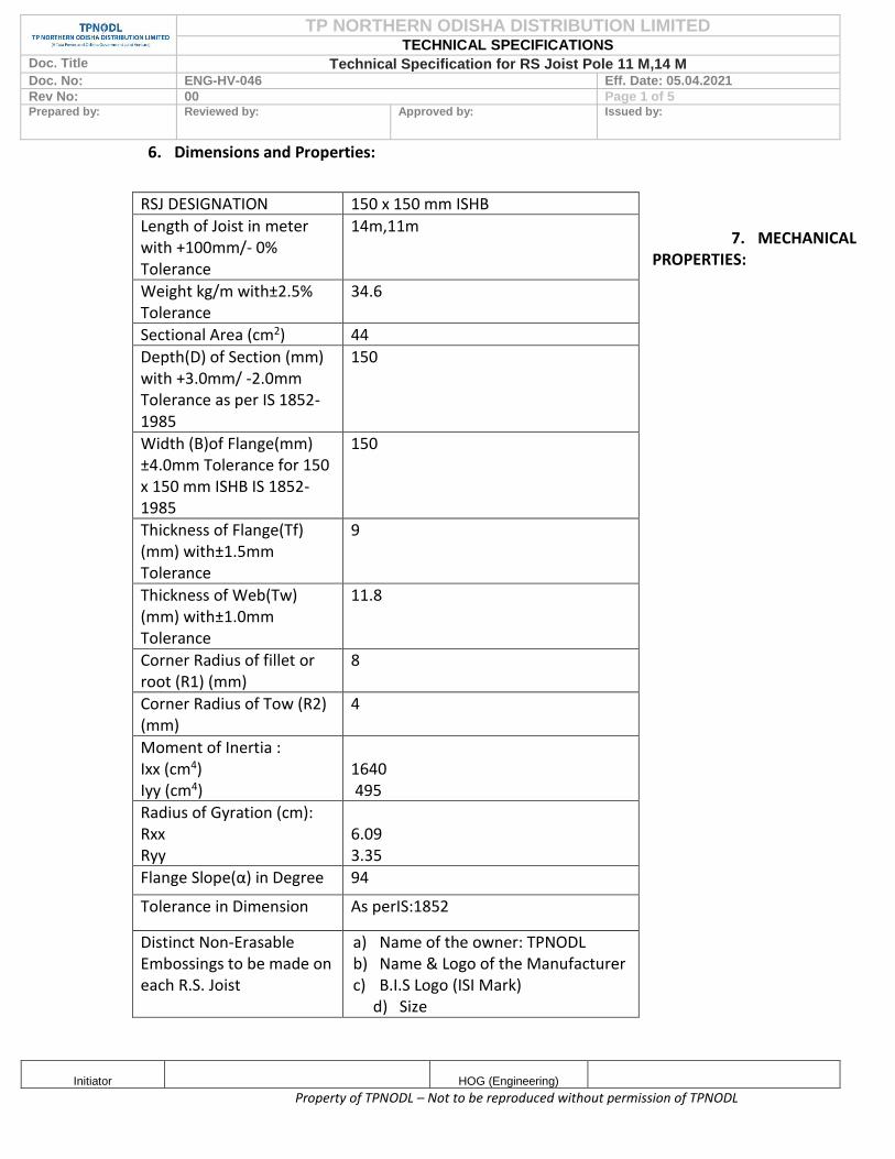
TP NORTHERN ODISHA DISTRIBUTION LIMITED TECHNICAL SPECIFICATIONS
Doc. Title Technical Specification for RS Joist Pole 11 M,14 M Doc. No: ENG-HV-046 Eff. Date: 05.04.2021
Rev No: 00 Page 1 of 5 Prepared by:
Reviewed by:
Approved by:
Issued by:
Initiator
HOG (Engineering)
Property of TPNODL – Not to be reproduced without permission of TPNODL
6. Dimensions and Properties:
7. MECHANICAL PROPERTIES:
RSJ DESIGNATION 150 x 150 mm ISHB
Length of Joist in meter with +100mm/- 0% Tolerance
14m,11m
Weight kg/m with±2.5% Tolerance
34.6
Sectional Area (cm2) 44
Depth(D) of Section (mm) with +3.0mm/ -2.0mm Tolerance as per IS 1852-1985
150
Width (B)of Flange(mm) ±4.0mm Tolerance for 150 x 150 mm ISHB IS 1852-1985
150
Thickness of Flange(Tf) (mm) with±1.5mm Tolerance
9
Thickness of Web(Tw) (mm) with±1.0mm Tolerance
11.8
Corner Radius of fillet or root (R1) (mm)
8
Corner Radius of Tow (R2) (mm)
4
Moment of Inertia : Ixx (cm4) Iyy (cm4)
1640 495
Radius of Gyration (cm): Rxx Ryy
6.09 3.35
Flange Slope(α) in Degree 94
Tolerance in Dimension As perIS:1852
Distinct Non-Erasable Embossings to be made on each R.S. Joist
a) Name of the owner: TPNODL b) Name & Logo of the Manufacturer c) B.I.S Logo (ISI Mark)
d) Size

TP NORTHERN ODISHA DISTRIBUTION LIMITED TECHNICAL SPECIFICATIONS
Doc. Title Technical Specification for RS Joist Pole 11 M,14 M Doc. No: ENG-HV-046 Eff. Date: 05.04.2021
Rev No: 00 Page 2 of 5 Prepared by:
Reviewed by:
Approved by:
Issued by:
Initiator
HOG (Engineering)
Property of TPNODL – Not to be reproduced without permission of TPNODL
Tensile Test : Requirement as per IS:2062/ 1999 Grade-A
Yield Stress(MPa) Min250
Tensile Strength(MPa) Min410
Lo=(5.65√So)Elongation% Min23
Bend Test Shall not Crack
Chemical Composition Requirement as per IS:2062/ 1999 Grade-A
Permissible variation over the Specified
Grade A -
Chemical Name Fe-410W A -
Carbon (%Max.) 0.23 0.02
Manganese (%Max.) 1.5 0.05
Sulphur (%Max.) 0.050 0.005
Phosphorous (%Max.) 0.050 0.005
Silicon (%Max.) 0.40 0.03
Carbon Equivalent (%Max.) 0.42 -
Deoxidation Mode Semi-killed or killed -
Supply condition As rolled -

TP NORTHERN ODISHA DISTRIBUTION LIMITED TECHNICAL SPECIFICATIONS
Doc. Title Technical Specification for RS Joist Pole 11 M,14 M Doc. No: ENG-HV-046 Eff. Date: 05.04.2021
Rev No: 00 Page 3 of 5 Prepared by:
Reviewed by:
Approved by:
Issued by:
Initiator
HOG (Engineering)
Property of TPNODL – Not to be reproduced without permission of TPNODL
However, In case of any discrepancy between the above data & the relevant IS Standard,
the values indicated in the IS shall prevail. The Acceptance Tests shall be carried out as
per Relevant IS standard.
RS Joists of Specific Weight 34.6 kg/m with length 13m,11m pole a with specified weight
in MT shall have to be supplied as per IS:2062;2006 Grade ”A” ,IS:808;1989/2001,
IS1608:1995 & IS:12779-1989 and their latest amendment if any complying the required
Dimension, Weight, Chemical & Mechanical properties. Confirming to the relevant IS, as
per the Tolerance given below.
8. APPLICABLE TOLLERANCES:
1. Length of each pole = + 100mm / - 0 % As per relevant IS: 12779-1989 (With
proportionate change in no of Poles)
2. Specific Weight of RS Joists = ±2.5% As per relevant IS:1852/1985
3. Weight for whole lot of supply for all categories = ±3.0% as per relevant IS: 12779-1989
for both type of RS Joists.
9. EMBOSSING ON EACH R.S JOIST: Following distinct non-erasable embossing is to be made on each R.S Joists. a) Name of the owner: TPNODL b) Name & Logo of the Manufacturer: WO No & Dt.
c) B.I.S Logo (ISI Mark) if applicable.
d) Size of the R.S Joist.

TP NORTHERN ODISHA DISTRIBUTION LIMITED TECHNICAL SPECIFICATIONS
Doc. Title Technical Specification for RS Joist Pole 11 M,14 M Doc. No: ENG-HV-046 Eff. Date: 05.04.2021
Rev No: 00 Page 4 of 5 Prepared by:
Reviewed by:
Approved by:
Issued by:
Initiator
HOG (Engineering)
Property of TPNODL – Not to be reproduced without permission of TPNODL
GUARANTEED TECHNICAL PARTICULAR (RS JOISTS sizes 150x150mm) (To be submitted along with offer)
Dimensions and Properties:
PARTICULARS Specification Specification By the Bidder
Length of Joist in meter with +100mm/-0% Tolerance
14m ,11m
Weight kg/m with±2.5% Tolerance
34.6
Sectional Area (cm2) 44
Depth(D) of Section (mm) with +3.0mm/ - 2.0mm Tolerance as per IS 1852-1985
150
Width (B)of Flange (mm) with ±2.5mm Tolerance for116 x 100 mm ISMB & ±4.0mm Tolerance for 150 x 150 mm ISHB IS 1852-1985
150
Thickness of Flange (Tf) (mm) with±1.5mm
9
Thickness of Web(Tw) (mm) with±1.0mm Tolerance
11.8
Corner Radius of fillet or root (R1) (mm)
8
Corner Radius of Tow (R2) (mm)
4
Moment of Inertia: Ixx (cm4) Iyy (cm4)
1640 495
Radius of Gyration (cm): Rxx Ryy
6.09 3.35
Modulus of Section: Zxx(cm3) Zyy(cm3)
218 63.2
Flange Slope(α) in Degree 94.0
Tolerance in Dimension As per IS: 1852
Distinct Non-Erasable embossing to be made on each R.S. Joist
a) Name of the owner: TPNODL
b) Name & Logo of the
Manufacturer: WO No
& Dt.
c) B.I.S Logo (ISI Mark) if
applicable.
d) Size of the R.S Joist.

TP NORTHERN ODISHA DISTRIBUTION LIMITED TECHNICAL SPECIFICATIONS
Doc. Title Specification for 11KV Polymeric Pin Insulator
Doc. No: Eff. Date: 02.08.2021
Rev No: Page 1 of 12
Prepared by:
Reviewed by:
Approved by:
Issued by:
Initiator
HOG (Engineering)
1. Scope
2. Applicable Standards
3. Climatic Conditions Of The Installation
4. General Constructions
5. Marking
6. Tests
7. Type Test Certificates
8. Pre-Dispatch Inspection
9. Inspection After Receipt At Stores
10. Guarantee
11. Packing
12. Tender Sample
13. Quality Control
14. Minimum Testing Facilities
15. Manufacturing Activities
16. Drawings and Documents
17. Instruction Manuals:
18. Guaranteed Technical Particulars
19. Schedule Of Deviations

TP NORTHERN ODISHA DISTRIBUTION LIMITED TECHNICAL SPECIFICATIONS
Doc. Title Specification for 11KV Polymeric Pin Insulator
Doc. No: Eff. Date: 02.08.2021
Rev No: Page 2 of 12
Prepared by:
Reviewed by:
Approved by:
Issued by:
Initiator
HOG (Engineering)
1. SCOPE OF WORK: This specification covers the technical requirements of design, manufacture, test at manufacturer's
works, packing & forwarding, supply and unloading at store/ site of 11 KV Pin polymer insulator 10 KN
used in 11 KV Overhead Transmission lines.
2. APPLICABLE STANDARDS:
Insulator shall comply with the requirements stated in the latest editions of the following standards-
a) IEC: 61109: Definition, test methods and acceptance criteria for composite insulators for
A.C. overhead lines above 1000V.
b) IEC: 61952: Insulators for overhead lines – Composite line post insulators for alternative
current.
c) IS: 2071/ IEC: 60060-1: Methods of High Voltage Testing.
d) IS: 2486/ IEC: 60120: Specification for Insulator fittings for Overhead power Lines with a
nominal voltage greater than 1000V General Requirements and Tests Dimensional
Requirements Locking Devices.
e) IEC: 60575: Thermal Mechanical Performance test and mechanical performance test on
string insulator units.
f) IS: 13134/ IEC: 60815: Guide for the selection of insulators in respect of polluted
condition.
g) STRI guide 1.92/1: Hydrophobicity Classification Guide.
h) IEC: 60437: Methods of RI Test of HV insulators.
i) IS: 4759: Hot dip zinc coatings on structural steel & other allied products.
j) IS: 2629: Recommended Practice for Hot, Dip Galvanization for iron and steel.
k) IS: 6745: Determination of Weight of Zinc Coating on Zinc coated iron and steel articles.
l) IS: 2633: Testing of Uniformity of Coating of zinc coated articles.
m) ASTM D 578-05: Standard specification for glass fiber strands.
3. CLIMATIC CONDITIONS:
The climatic conditions at site under which the store shall operate satisfactory, are as follows.
i. Maximum Ambient Temperature 50°c ii. Maximum daily average ambient temperature 40°c
iii. Minimum Ambient Temperature 2°c iv. Maximum humidity 99.7%

TP NORTHERN ODISHA DISTRIBUTION LIMITED TECHNICAL SPECIFICATIONS
Doc. Title Specification for 11KV Polymeric Pin Insulator
Doc. No: Eff. Date: 02.08.2021
Rev No: Page 3 of 12
Prepared by:
Reviewed by:
Approved by:
Issued by:
Initiator
HOG (Engineering)
v. Minimum humidity 15% vi. Average Annual Rainfall 1800mm
vii. Average wind speed prevailing in the area 200kmph viii. Average Thunderstorms prevailing in the area 70 days per annum
ix. Average Dust storms prevailing in the area 20 days per annum x. Average number of rainy days per annum 160
xi. Maximum Altitude above sea level 1200m xii. Rainy months June to October
Environmentally, some of the regions, where the work will take place includes coastal areas, subject to
high relative humidity, which can give rise to condensation. Onshore winds will frequently be salt
laden. On occasions, the combination of salt and condensation may create pollution conditions for
outdoor insulators. Some places are in heavily industrial polluted areas.
Therefore, Outdoor material and equipment shall be designed and protected for use in exposed, heavily polluted, salty, corrosive and humid coastal atmosphere
The design of equipment and accessories shall be suitable to withstand seismic forces corresponding
to an acceleration of 0.1 g.
4. GENERAL CONSTRUCTIONS:
Polymeric Insulators shall be designed to meet the high quality, safety and reliability and are capable
of withstanding a wide range of environmental conditions. Polymeric Insulators shall consist of THREE
parts, at least two of which are insulating parts:- (a) Core- the internal insulating part (b)Housing- the
external insulating part (c)Metal end fittings.
a) CORE:
Core shall be a glass-fiber reinforced epoxy resin rod of high strength (FRP rod). Glass fibers and resin
shall be optimized in the FRP rod. Glass fibers shall be Boron free electrically corrosion resistant (ECR)
glass fiber and shall exhibit both high electrical integrity and high resistance to acid corrosion. The matrix
of the FRP rod shall be Hydrolysis resistant. The FRP rod shall be manufactured through Pultrusion
process. The FRP rod shall be void free.
b) POLYMERIC HOUSING:
The FRP rod shall be covered by a seamless sheath of high voltage grade Silicone rubber housing. It
shall be one- piece housing using only Injection Moulding process to cover the core. Primer should be
used to bond the housing with FRP rod. The housing shall be designed to provide the necessary
creepage distance and protection against environmental influences. Housing shall confirm to the
requirements of IEC 60815 with latest amendments. All surfaces shall be clean, smooth, without cuts,
abrasions or projections. No part shall be subjected to excessive localized pressure. The insulator and

TP NORTHERN ODISHA DISTRIBUTION LIMITED TECHNICAL SPECIFICATIONS
Doc. Title Specification for 11KV Polymeric Pin Insulator
Doc. No: Eff. Date: 02.08.2021
Rev No: Page 4 of 12
Prepared by:
Reviewed by:
Approved by:
Issued by:
Initiator
HOG (Engineering)
metal parts shall be so designed and manufactured that it shall avoid local corona formation and not
generate any radio interference beyond specified limit under the operating conditions.
c) WEATHERSHEDS
The composite polymer weather sheds made of high voltage grade Silicone rubber polymer shall be
molded as part of the sheath and shall be free from imperfections. It should protect the FRP rod against
environmental influences, external pollution and humidity. The strength of the weather shed to sheath
interface shall be greater than the tearing strength of the polymer. The interface, if any, between
sheds and sheath (housing) shall be free from voids. Housing and weather shed material shall have
tensile strength of 3 MPa with 400% elongation minimum and tear strength of 16N/mm
d) METAL END FITTINGS: End fitting transmit the mechanical load to the core. They shall be made of spheroidal graphite cast iron, malleable cast iron or forged steel or aluminum alloy. Metal end fitting shall be suitable for pin type hardware support of respective specified mechanical load and shall be hot dip galvanized in accordance with IS 2629. They shall be connected to the rod by means of a controlled compression technique. The OD of end fittings should be machined to make the surface uniform round to ensure effective sealing when housing is molded over it. The material used in fittings shall be corrosion resistant. As the main duty of the end fittings is the transfer of mechanical loads to the core the fittings should be properly attached to the core by a coaxial or hexagonal compression process & should not damage the individual fibers or crack the core. The dimensions of end fittings of insulators shall be in accordance with the standard dimensions stated in IEC: 60120/ IS: 2486 - Part-II /1989. Outer portion of Pin should be Zinc sleeved with minimum 99.95% purity of Electrolytic high grade zinc. Bottom end metal fitting (Shank) of Pin insulator should be forged steel as per IS 2002/92. Bottom end fitting should be single unit without any joints. Nuts as per IS 1363 (P-III) and spring washer shall be as per IS 3063 with Latest amendments if any, Nuts and spring washer shall be hot dip galvanized. The design of the insulator shall be such that stresses due to expansion and contraction in any part of the insulators shall not lead to deterioration. The Pin insulator shall not engage directly with hard metal.
5. MARKING:
Each insulator shall be legibly and indelibly marked with “PO no. with date, “Property of TPNODL” along with following:
a. Manufacturer’s name b. Type designation or serial no. c. Minimum failing load in kN d. No. of relevant standard e. Month and year of manufacture f. Country of manufacture

TP NORTHERN ODISHA DISTRIBUTION LIMITED TECHNICAL SPECIFICATIONS
Doc. Title Specification for 11KV Polymeric Pin Insulator
Doc. No: Eff. Date: 02.08.2021
Rev No: Page 5 of 12
Prepared by:
Reviewed by:
Approved by:
Issued by:
Initiator
HOG (Engineering)
6. TESTS:
All routine/acceptance tests shall be witnessed by the purchaser/his authorized representative.
Following tests for 11kV Pin Polymer insulator should be done as per relevant standards:
I. Tests on Silicone Rubber:
Tensile Strength & Elongation Tear Strength Inclined Plane Tracking & Erosion Volume resistivity Dielectric Strength Dielectric Constant Density Hardness Arc Resistance Silicone content
Flammability
Resistance to weathering & UV.
Limiting oxygen index test.
Specific gravity
II. Tests on FRP Rods:
Verification of dimensions. Specific Gravity Glass Content Water Diffusion Test Hardness Dye Penetration Test. Flexural strength. Water absorption. Brittle fracture resistance test. Visible discharge test. Dry lightning impulse withstand voltage test. Wet power frequency withstand voltage test. Power Arc test. Accelerated weathering test. Tracking & erosion test.
III. Tests on End Fittings:
Thickness of Zinc Coating Uniformity of Zinc Coating Micro-structural of metal fitting.

TP NORTHERN ODISHA DISTRIBUTION LIMITED TECHNICAL SPECIFICATIONS
Doc. Title Specification for 11KV Polymeric Pin Insulator
Doc. No: Eff. Date: 02.08.2021
Rev No: Page 6 of 12
Prepared by:
Reviewed by:
Approved by:
Issued by:
Initiator
HOG (Engineering)
IV. Test of Complete polymer insulators:
Dry lightning impulse withstand voltage test. Wet power frequency test. Mechanical failing load test. Radio interference test. Mechanical performance test
U.V Resistance as per ASTM G 53: 1000 Hrs - UV Light for 8 Hours and condensation for 4 hours in a continuous cycle. Elongation to be limited to 20% (% Elongation to break before and after the test).
Salt Fog test: On insulators for 1000 hours as per IEC. Galvanization test. Visual examination. Verification of dimensions. Bending test. Verification of the locking system or the tightness of the interface between end fitting and
insulator housing. Assembled core load time test. Determination of the average failing load of the core of the assembled insulator.
V. Design Tests:
For composite insulators it is essential to carry out design test as per clause 4.1 of IEC 61109 / 92-93 with latest amendments. The design tests are intended to verify the suitability of the design, materials and method of manufacture (technology). When a composite insulator is submitted to the design tests, the result shall be considered valid for the whole class of insulators, which are represented by the one tested and having the following characteristics:
The materials for the core, and sheds and same manufacturing method; The material of the fittings, the same design, the same method of attachment; Polymer insulator should have greater layer thickness of the shed material over the core
(including a sheath where used); Polymer insulator should have smaller ratio of the highest system voltage to insulation
length; Polymer insulator should have smaller ratio of all mechanical loads to the smallest core
diameter between fittings Polymer insulator should have greater diameter of the core.
The tested composite insulators shall be identified by a drawing giving all the dimensions with the manufacturing tolerances. Manufacturer should submit test reports for Design Tests as per IEC – 61109 (clause – 5) along with the bid. Additionally following tests shall be carried out or reports for the tests shall be submitted after award of contract: UV test: the test shall be carried out in line with clause 7.2 of ANSI C29.13. In addition, chemical composition test for silicon content would also be added in the testing list.

TP NORTHERN ODISHA DISTRIBUTION LIMITED TECHNICAL SPECIFICATIONS
Doc. Title Specification for 11KV Polymeric Pin Insulator
Doc. No: Eff. Date: 02.08.2021
Rev No: Page 7 of 12
Prepared by:
Reviewed by:
Approved by:
Issued by:
Initiator
HOG (Engineering)
VI. Acceptance Tests For Composite Insulators
Verification of dimensions Visual examination Verification of the locking system or the tightness of the interface between end fitting and
insulator housing Galvanizing test Verification of the specified mechanical load Bending load test Dry power frequency withstand voltage test Analysis of material properties of housing material Analysis of material properties of core material
VII. Routine Tests
Visual Examination Mechanical load test as per IEC 61109 & IEC 62231
7. TYPE TEST CERTIFICATES:
The Bidder shall furnish the type test certificates of the 11 KV Pin polymer Insulators for the tests as
mentioned above as per the corresponding standards. All the tests shall be conducted at
CPRI/ERDA/International Laboratory/NABL as per the relevant standards. Type tests should have
been conducted in certified Test laboratories during the period not exceeding 5 years from the date
of opening the bid. In the event of any discrepancy in the test reports, i.e. any test report not
acceptable, same shall be carried out without any cost implication to TPNODL.
8. PRE DISPATCH INSPECTION:
The material shall be subject to inspection by a duly authorized representative of the TPNODL. Inspection may be made at any stage of manufacture at the discretion of the purchaser and the equipment, if found unsatisfactory as to workmanship or material, the same is liable to rejection. Bidder shall grant free access to the places of manufacture to TPNODL’s representatives at all times when the work is in progress. Inspection by the TPNODL or its authorized representatives shall not relieve the bidder of his obligation of furnishing equipment in accordance with the specifications. Material shall be dispatched after specific MDCC (Material Dispatch Clearance Certificate) is issued by TPNODL. Following documents shall be sent along with material
a) Test reports b) MDCC issued by TPNODL c) TPNODL Invoice in duplicate d) Packing list e) Drawings & catalogue f) Guarantee / Warrantee card g) Delivery Challan h) Other Documents (as applicable).

TP NORTHERN ODISHA DISTRIBUTION LIMITED TECHNICAL SPECIFICATIONS
Doc. Title Specification for 11KV Polymeric Pin Insulator
Doc. No: Eff. Date: 02.08.2021
Rev No: Page 8 of 12
Prepared by:
Reviewed by:
Approved by:
Issued by:
Initiator
HOG (Engineering)
9. INSPECTION AFTER RECEIPT A T STORES The material received at TPNODL store will be inspected for acceptance and shall be liable for rejection, if found different from the reports of the pre-dispatch inspection and one copy of the report shall be sent to Engineering & contracts department.
10. GUARANTEE: Bidder shall stand guarantee towards design, materials, workmanship & quality of process/ manufacturing of items under this contract for due and intended performance of the same, as an integrated product delivered under this contract. In the event any defect is found by the Purchaser up to a period of at least 12 months from the date of commissioning or 24 months from the date of last supplies made under the contract whichever is later, (the time scale of 12/24 months could be enhanced subject to mutual agreements). Bidder shall be liable to undertake to replace/rectify such defects at its own costs, within mutually agreed time frame, and to the entire satisfaction of the Purchaser, failing which the Purchaser will be at liberty to get it replaced/rectified at Bidder’s risks And costs and recover all such expenses plus the Purchaser’s own charges (@ 20% of expenses Incurred), from the Bidder or from the “Security cum Performance Deposit” as the case may be. Bidder shall further be responsible for ‘free replacement’ for another period of THREE years from the
end of the guarantee period for any ‘Latent Defects’ if noticed and reported by the Purchaser.
11. PACKING:
Bidder shall ensure that all the equipment covered under this specification shall be prepared for
rail/road transport in a manner so as to protect the equipment from damage in transit.
12. TENDER SAMPLE:
As and when required
13. QUALITY CONTROL
The bidder shall submit with the offer Quality assurance plan indicating the various stages of inspection, the tests and checks which will be carried out on the material of construction, components during manufacture and bought out items and fully assembled component and equipment after finishing. As part of the plan, a schedule for stage and final inspection within the parameters of the delivery schedule shall be furnished. The Purchaser's engineer or its nominated representative shall have free access to the manufacturer’s/sub-supplier’s works to carry out inspections.
14. MINIMUM TESTING FACILITIES:
The tenderer must clearly indicate what testing facilities are available in the works of the manufacturer and whether facilities are adequate to carry out all Routine & acceptance Tests. These facilities should be available to TPNODL Engineers if deputed or carry out or witness the tests in the

TP NORTHERN ODISHA DISTRIBUTION LIMITED TECHNICAL SPECIFICATIONS
Doc. Title Specification for 11KV Polymeric Pin Insulator
Doc. No: Eff. Date: 02.08.2021
Rev No: Page 9 of 12
Prepared by:
Reviewed by:
Approved by:
Issued by:
Initiator
HOG (Engineering)
manufacturer works. If any test cannot be carried out at the manufacturer's work, the reasons should be clearly stated in the tender. The insulators shall be tested in accordance with the procedure detailed in IEC 61109 / 92-93 with latest amendments.
15. MANUFACTURING ACTIVITIES:
The successful bidder will have to submit the bar chart for various manufacturing activities clearly
elaborating each stage, with quantity. This bar chart should be in line with the Quality assurance plan
submitted with the offer. This bar chart will have to be submitted within 15 days from the release
of the order.
16. DRAWINGS AND DOCUMENTS:
Following documents shall be prepared based on TPNODL specifications and statutory requirements
with complete BOM and shall be submitted with the bid:
a) Complete Drawing b) Completely filled in Technical Particulars c) General description of the equipment and all components including brochures d) Generalized drawing for Pin Insulator e) Bill of Material f) Type test Certificates g) Experience List.
After the after of the contract, four (4) copies of the drawings, drawn to scale, describing the equipment in detail shall be forwarded for approval and shall subsequently provide four (4) complete sets of final drawings, one of which shall be auto positive suitable for reproduction, before the dispatch of the equipment. Soft copy (Compact Disk CD) of all the drawing, GTP, test certificates shall be submitted after the final approval of the same to the purchaser.
Following Drawings/Documents shall be submitted after the award of the contract:
S. No Description For Approval For Review Information
Final Submission
1 Technical Parameters √ √
2 Manual/Catalogues/drawings for all components.
√
3 Technical details and test certificates of the component.
√ √
4 Installation Instructions √ √
5 Instructions for use √ √
6 Transport/shipping dimension drawing
√ √
7 QA & QC Plan √ √ √

TP NORTHERN ODISHA DISTRIBUTION LIMITED TECHNICAL SPECIFICATIONS
Doc. Title Specification for 11KV Polymeric Pin Insulator
Doc. No: Eff. Date: 02.08.2021
Rev No: Page 10 of 12
Prepared by:
Reviewed by:
Approved by:
Issued by:
Initiator
HOG (Engineering)
8 Routine, Acceptance and Type test Certificates
√ √ √
All the Documents and Drawings shall be in English Language
17. Instruction Manuals:
Bidder shall furnish two (2) soft copies (CD) and four (4) hard copies of nicely bound manual (in English
Language) covering erection and maintenance instructions and all relevant information pertaining to
the main equipment as well as auxiliary devices.
18. GUARANTEED TECHNICAL PARTICULAR Sl
No. Description Unit Requirements Bidders Offer
1
Type of Insulator
Polymeric Pin Insulator
2
Standard according to which the insulators manufactured and Tested
IEC 61952 and IEC 61109
3
Material of housing and weather sheds
High voltage grade
(a) Material of Core (FRP
rod)
ECR-Glass
BORRON FREE
(b) Material of end fittings SGI Cast/Forged Steel
(c) Sealing compound for
end fittings Silicone Sealant
4 Colour of housing Grey
5 Electrical
characteristics
(a) Type B
(b) Rated Voltage kV 12
(c) Service Voltage kV 11
(d) Rated Frequency Hz 50
(e) Visible discharge test
voltage kV 9

TP NORTHERN ODISHA DISTRIBUTION LIMITED TECHNICAL SPECIFICATIONS
Doc. Title Specification for 11KV Polymeric Pin Insulator
Doc. No: Eff. Date: 02.08.2021
Rev No: Page 11 of 12
Prepared by:
Reviewed by:
Approved by:
Issued by:
Initiator
HOG (Engineering)
(f) Dry power frequency
withstand voltage KV(rms) 60
(g)
Wet power frequency withstand voltage
kV (rms) 35
(h) Dry power Frequency
Flashover Voltage kV (rms) 75
(i)
Wet power frequency flashover voltage
kV (rms) 45
(j)
Impulse Lighting withstand voltage
kV (peak)
Positive Peak -75KV Negative
Peak -80KV
(k) Impulse Lighting
Flashover voltage KV (peak)
Positive : 95 KV
Negative : 100 KV
(l)
RIV at 1 MHz when energized at 10 KV / 30 KV (rms) under dry condition
< 50 microvolt
(m)
Creepage distance in heavily polluted atmosphere
Mm
320
(n) Minimum failing loads kN 10
(o) Diameter of FRP Rod Mm 24
Diameter of bottom end fitting Mm
20
Thread length of bottom end fitting minimum
Mm
110
(p) Length of FRP Rod Mm 165
Diameter of weather sheds
Mm 100
(q) Thickness of Housing Mm 3
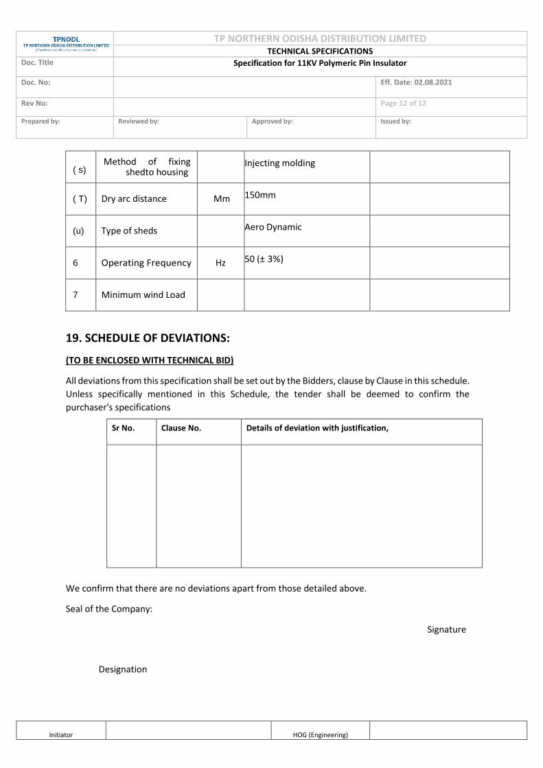
TP NORTHERN ODISHA DISTRIBUTION LIMITED TECHNICAL SPECIFICATIONS
Doc. Title Specification for 11KV Polymeric Pin Insulator
Doc. No: Eff. Date: 02.08.2021
Rev No: Page 12 of 12
Prepared by:
Reviewed by:
Approved by:
Issued by:
Initiator
HOG (Engineering)
( s) Method of fixing
shed to housing Injecting molding
( T) Dry arc distance Mm 150mm
(u) Type of sheds Aero Dynamic
6 Operating Frequency Hz 50 (± 3%)
7 Minimum wind Load
19. SCHEDULE OF DEVIATIONS:
(TO BE ENCLOSED WITH TECHNICAL BID)
All deviations from this specification shall be set out by the Bidders, clause by Clause in this schedule.
Unless specifically mentioned in this Schedule, the tender shall be deemed to confirm the
purchaser's specifications
We confirm that there are no deviations apart from those detailed above.
Seal of the Company:
Signature
Designation
Sr No. Clause No. Details of deviation with justification,

TP NORTHERN ODISHA DISTRIBUTION LIMITED
TECHNICAL SPECIFICATIONS Doc. Title SPECFICATION FOR 33kV PIN POLYMER INSULATORS Doc. No Eff. Date: 09.08.2021
Rev No. 00 Page 1 of 11 Prepared by:
Reviewed by:
Approved by:
Issued by:
Initiator
HOG (Engineering)
Property of TPNODL – Not to be reproduced without permission of TPNODL
CONTENTS
1) SCOPE
2) APPLICABLE STANDARDS
3) CLIMATIC CONDITIONS OFTHE INSTALLATION
4) GENERAL TECHNICAL REQUIREMENTS
5) GENERAL CONSTRUCTION
6) MARKING
7) TESTS
8) TYPE TEST CERTIFICATES
9) PRE-DISPATCH INSPECTION
10) INSPECTION AFTER RECEIPT AT STORES
11) GUARANTEE
12) PACKING AND TRANSPORT
13) TENDER SAMPLE
14) QUALITY CONTROL
15) TESTING FACILITIES
16) DRAWINGS AND DOCUMENTS
17) GUARANTEED TECHNICAL PARTICULARS
18) SCHEDULE OF DEVIATIONS

TP NORTHERN ODISHA DISTRIBUTION LIMITED
TECHNICAL SPECIFICATIONS Doc. Title SPECFICATION FOR 33kV PIN POLYMER INSULATORS Doc. No Eff. Date: 09.08.2021
Rev No. 00 Page 2 of 11 Prepared by:
Reviewed by:
Approved by:
Issued by:
Initiator
HOG (Engineering)
Property of TPNODL – Not to be reproduced without permission of TPNODL
1. SCOPE
This specification covers the technical requirements of design, manufacture, test at
manufacturer's works, packing & forwarding, supply and unloading at store/ site of 33 KV Pin
polymer insulator 10 KN used in 33 KV Overhead Transmission lines.
2. APPLICABLE STANDARDS: Insulator shall comply with the requirements stated in the latest editions of the following
standards
IEC: 61109: Definition, test methods and acceptance criteria for composite insulators for A.C.
overhead lines above 1000V.
IEC: 61952: Insulators for overhead lines - Composite line post insulators for alternative
current.
IS: 2071/ IEC: 60060-1: Methods of High Voltage Testing.
IS: 2486/ IEC: 60120: Specification for Insulator fittings for Overhead Power Lines with a
nominal voltage greater than 1000V General Requirements and Tests, Dimensional
Requirements Locking Devices.
IEC: 60575: Thermal Mechanical Performance test and mechanical performance test on string
insulator units.
IS: 13134/ IEC: 60815: Guide for the selection of insulators in respect of polluted condition.
STRI guide 1.92/1: Hydrophobicity Classification Guide.
IEC: 60437: Methods of RI Test of HV insulators.
IS: 4759: Hot dip zinc coatings on structural steel & other allied products.
IS: 2629: Recommended Practice for Hot, Dip Galvanization for iron and steel.
IS: 6745: Determination of Weight of Zinc Coating on Zinc coated iron and steel articles.
IS: 2633: Testing of Uniformity of Coating of zinc coated articles.
ASTM D 578-05: Standard specification for glass fiber strands.
3. CLIMATIC CONDITIONS: The climatic conditions at site under which the store shall operate satisfactory, are as follows.
i. Maximum Ambient Temperature 50°c ii. Maximum daily average ambient temperature 40°c
iii. Minimum Ambient Temperature 2°c iv. Maximum humidity 99.7% v. Minimum humidity 15%

TP NORTHERN ODISHA DISTRIBUTION LIMITED
TECHNICAL SPECIFICATIONS Doc. Title SPECFICATION FOR 33kV PIN POLYMER INSULATORS Doc. No Eff. Date: 09.08.2021
Rev No. 00 Page 3 of 11 Prepared by:
Reviewed by:
Approved by:
Issued by:
Initiator
HOG (Engineering)
Property of TPNODL – Not to be reproduced without permission of TPNODL
vi. Average Annual Rainfall 1800mm vii. Average wind speed prevailing in the area 200kmph
viii. Average Thunderstorms prevailing in the area 70 days per annum ix. Average Dust storms prevailing in the area 20 days per annum x. Average number of rainy days per annum 160
xi. Maximum Altitude above sea level 1200m xii. Rainy months June to October
Note: The atmosphere across coastal divisions of TPNODL is very saline, laden with salt,
acid and dust suspended during dry months and subjected to fog in cold months.
4. GENERAL TECHNICAL REQUIREMENTS Sl. No. Description Unit Requirements
1. Type of Insulator Polymeric Pin Insulator
2. Standard according to which the Insulators are manufactured and tested.
IEC 61952 & IEC 61109
3. Material of Housing and Weather Sheds High voltage grade rubber a. Material of Core (FRP Rod) ECR BORON FREE
b. Material of end fittings SGI Cast/Forged steel
c. Sealing compound for end fittings Silicone Sealant 4. Colour of housing Grey
5. EELECTRICAL CHARACTERISTICS
a) Nominal system voltage kV 33
b) Highest system voltage kV 36
c) Dry Power frequency withstand voltage kV 95
d) Wet Power frequency withstand voltage kV 75
e) Dry Power Frequency Flashover Voltage kV 130
f) Wet Power Frequency Flashover voltage kV 90
g) Dry Lightening Impulse withstand Voltage kV Positive: 170 KV Negative: 180 KV
h) Dry Lightening Impulse Flashover Voltage kV Positive: 210 KV Negative: 230 KV
i) RIV at 1 MHz when energized at 10 KV/ 30 KV (rms. ) under dry condition
microvolt
< 70
j) Dry arc distance mm 300
k) Visible Discharge Test Voltage kV (rms. ) 27
6. OTHER PHYSICAL & DIMENSIONAL REQUIREMENTS:
a) Creepage distance (Min.) mm 900
b) C Minimum Failing Load KN 10
c) Dia. of FRP Rod mm 24
d) L Length of FRP Rod mm 300
e) D Diameter of weather sheds mm 110
f) T Thickness of Housing mm 3
g) No. of weather sheds (min.) Nos. 8

TP NORTHERN ODISHA DISTRIBUTION LIMITED
TECHNICAL SPECIFICATIONS Doc. Title SPECFICATION FOR 33kV PIN POLYMER INSULATORS Doc. No Eff. Date: 09.08.2021
Rev No. 00 Page 4 of 11 Prepared by:
Reviewed by:
Approved by:
Issued by:
Initiator
HOG (Engineering)
Property of TPNODL – Not to be reproduced without permission of TPNODL
h) M Method of fixing sheds to housing Injection Moulding
i) t Type of Sheds Aerodynamic
j) Dia. of bottom end fitting mm 24 k) Thread Length of bottom end fitting mm 130
l) T Type of Packing Wooden / Corrugated Box m) N No. of Insulators in each box Nos. 20
5. GENRERAL CONSTRUCTION Polymeric Insulators shall be designed to meet the high quality, safety and reliability and are capable of withstanding a wide range of environmental conditions.
Polymeric Insulators shall consist of THREE parts, at least two of which are insulating parts: -
a. Core – the internal insulating part
b. Housing – the external insulating part
c. Weather Sheds
d. Metal End Fittings.
5.1 CORE It shall be a glass-fiber reinforced epoxy resin rod of high strength (FRP rod). Glass fibers and resin shall be optimized in the FRP rod. Glass fibers shall be Boron free electrically corrosion resistant (ECR) glass fiber and shall exhibit both high electrical integrity and high resistance to acid corrosion. The matrix of the FRP rod shall be Hydrolysis resistant. The FRP rod shall be manufactured through Pultrusion process. The FRP rod shall be void free. All rods must pass electric leakage current test of 170V/mm. The leakage current shall not exceed 0.05mA.
5.2 POLYMER HOUSING
The FRP rod shall be covered by a seamless sheath of high voltage grade Silicone rubber housing of
thickness 3mm minimum. It shall be one-piece housing using only Injection Molding process to cover the
core. Primer should be used to bond the housing with FRP rod. The housing shall be designed to provide
the necessary creepage distance and protection against environmental influences. Housing shall conform
to the requirements of IEC 60815 with latest amendments. The high voltage grade Silicone rubber polymer
material should be as per requirement specified in clause 8.2.2
5.3 WEATHER SHEDS
The composite polymer weather sheds made of high voltage grade Silicone rubber polymer shall be
molded as part of the sheath and shall be free from imperfections. It should protect the FRP rod against
environmental influences, external pollution and humidity. The strength of the weather shed to sheath
interface shall be greater than the tearing strength of the polymer. The interface, if any, between sheds
and sheath (housing) shall be free from voids. Housing and weather shed material shall have tensile

TP NORTHERN ODISHA DISTRIBUTION LIMITED
TECHNICAL SPECIFICATIONS Doc. Title SPECFICATION FOR 33kV PIN POLYMER INSULATORS Doc. No Eff. Date: 09.08.2021
Rev No. 00 Page 5 of 11 Prepared by:
Reviewed by:
Approved by:
Issued by:
Initiator
HOG (Engineering)
Property of TPNODL – Not to be reproduced without permission of TPNODL
strength of 3 MPa with 400% elongation minimum and tear strength of 16N/mm. The high voltage grade
Silicone rubber polymer material should be as per requirement specified in clause 8.2.2
5.4 METAL END FITTINGS
End fitting transmit the mechanical load to the core. They shall be made of spheroidal graphite cast iron,
malleable cast iron or forged steel or aluminum alloy. Metal end fitting shall be suitable for pin type
hardware support of respective specified mechanical load and shall be hot dip galvanized in
accordance with IS 2629. They shall be connected to the rod by means of a controlled compression
technique. The OD of end fittings should be machined to make the surface uniform round to ensure
effective sealing when housing is molded over it. The material used in fittings shall be corrosion
resistant. As the main duty of the end fittings is the transfer of mechanical loads to the core the
fittings should be properly attached to the core by a coaxial or hexagonal compression process &
should not damage the individual fibers or crack the core. The dimensions of end fittings of
insulators shall be in accordance with the standard dimensions stated in IEC: 60120/ IS: 2486 - Part-II
/1989. Outer portion of Pin should be Zinc sleeved with minimum 99.95% purity of Electrolytic high
grade zinc. Bottom end metal fitting (Shank) of Pin insulator should be forged steel as per IS 2002/92.
Bottom end fitting should be single unit without any joints.
Nuts as per IS 1363 (P-11I) and spring washer shall be as per IS 3063 with Latest amendments if any, Nuts and spring washer shall be hot dip galvanized.
The design of the insulator shall be such that stresses due to expansion and contraction in any part of the
insulators shall not lead to deterioration. The Pin insulator shall not engage directly with hard metal.
6. MARKING
Each insulator shall be legibly and indelibly marked as
a. Name & Trade mark of the manufacturer
b. Month and year of manufacture
c. Minimum failing load in KN
d. "TPNODL" Name should be mentioned on each insulator.
7. TESTS :
TYPE TESTS :
a) Dry lightning impulse withstand voltage test.
b) Dry/Wet power frequency test.
c) Mechanical load-time test.
d) Radio interference test.
e) Recovery of Hydrophobicity test.
f) Brittle fracture resistance test.

TP NORTHERN ODISHA DISTRIBUTION LIMITED
TECHNICAL SPECIFICATIONS Doc. Title SPECFICATION FOR 33kV PIN POLYMER INSULATORS Doc. No Eff. Date: 09.08.2021
Rev No. 00 Page 6 of 11 Prepared by:
Reviewed by:
Approved by:
Issued by:
Initiator
HOG (Engineering)
Property of TPNODL – Not to be reproduced without permission of TPNODL
g) Cantilever Load withstand test for Pin Insulators.
Tests on the high voltage grade Silicone rubber material used in manufacture of the insulator
housing and weather sheds:
The bidder shall furnish following type test reports conducted on High voltage Silicone rubber material used for Polymer housing confirming following properties along with their bid:
Sl. No. Property Requirement Standard
1. Tensile Strength (MPa) 4 MPa min ASTM D 412 – 06 a
2. Elongation (%) 300 % ASTM D 412 – 06 a
3. Tear Strength 15 N / mm min ASTMD 624
4. Inclined plane tracking & erosion resistance test
4.5 kV 360 min ASTM D 2303
5. Volume Resistivity (Ohm - cm) 1 x 10 ˆ13 ohm – cm min ASTM D 257
6. Dielectric constant 4 ASTM D 150
7. Dielectric constant 26 kV / mm min ASTM D 149
8. Density 1.5 min ASTM D 792
9. Hardness (shore A) 62 nominal ASTM D 2240
10. Arc resistance >220 seconds ASTM D 495 – 99
11. Silicone Content >40% BS: 2782 – Pt 10
12. Flammability V0 UL 94
ACCEPTANCE TEST :
a) Physical & Dimensional Verification of materials.
b) Mechanical Load Test
c) Galvanizing test.
d) Dry Power Frequency Withstand Voltage Test
ROUTINE TEST :
a) Physical & Dimensional Verification of materials.
b) Mechanical Load Test
c) Identification of Marking

TP NORTHERN ODISHA DISTRIBUTION LIMITED
TECHNICAL SPECIFICATIONS Doc. Title SPECFICATION FOR 33kV PIN POLYMER INSULATORS Doc. No Eff. Date: 09.08.2021
Rev No. 00 Page 7 of 11 Prepared by:
Reviewed by:
Approved by:
Issued by:
Initiator
HOG (Engineering)
Property of TPNODL – Not to be reproduced without permission of TPNODL
8. TYPE TEST CERTIFICATES:
The Bidder shall furnish the type test certificates of the 33 KV Pin Polymer Insulators for the tests as mentioned above as per the corresponding standards. All the tests shall be conducted at CPRI/ERDA as per the relevant standards. Type tests should have been conducted in certified Test laboratories during the period not exceeding 5 years from the date of opening the bid. In the event of any discrepancy in the test reports, i.e. any test report not acceptable, same shall be carried out without any cost implication to TPNODL.
9. PRE-DISPATCH INSPECTION:
Equipment shall be subject to inspection by a duly authorized representative of the TPCL Inspection may be
made at any stage of manufacture at the option of the purchaser and the equipment if found unsatisfactory
as to workmanship or material is liable to rejection. Supplier shall grant free access to the places of
manufacture to TPNODL's representatives at all times when the work is in progress. Inspection by the
TPNODL or its authorized representatives shall not relieve the supplier of his obligation of furnishing
equipment in accordance with the specifications. Material shall be dispatched after specific MDCC (Material
Dispatch Clearance Certificate) is issued by TPNODL.
Following documents shall be sent along with material
i. Test Reports
ii. MDCC issued by TPNODL
iii. Invoice in duplicate iv. Packing list v. Drawings & catalogue
vi. Guarantee/ Warrantee card
vii. Delivery Challan
viii. Other Documents(as applicable)
10. INSPECTION AFTER RECEIPT AT STORE: TPNODL Inspectors will inspect the material received at TPNODL Store and shall have right to reject if found different from the reports of the pre-dispatch inspection.
11. GUARANTEE: Supplier shall stand guarantee towards design, materials, workmanship & quality of process/
manufacturing of items under the contract for due and intended performance of the same, as an
integrated product delivered under this contract. In the event any defect is found by the Company up to
a period of 12 months from the date of commissioning or 24 months from the date of last supplies
made under the contract, whichever is earlier, supplier shall be liable to undertake to replace/rectify
such defects at his own costs. within mutually agreed timeframe, and to the entire satisfaction of the
Company, failing which the Company will be at liberty to get it replaced/rectified at supplier's risks
and costs and recover all such expenses plus the Company's own charges (@ 20% of expenses

TP NORTHERN ODISHA DISTRIBUTION LIMITED
TECHNICAL SPECIFICATIONS Doc. Title SPECFICATION FOR 33kV PIN POLYMER INSULATORS Doc. No Eff. Date: 09.08.2021
Rev No. 00 Page 8 of 11 Prepared by:
Reviewed by:
Approved by:
Issued by:
Initiator
HOG (Engineering)
Property of TPNODL – Not to be reproduced without permission of TPNODL
incurred), from the supplier or from the "Security cum Performance Deposit" as the case may be.
Supplier shall further be responsible for 'free replacement' for another period of THREE years from
the end of the guarantee period for any 'Latent Defects' if noticed and reported by the Company.
12. PACKING AND TRANSPORT: Supplier shall ensure that all equipment covered by this specification shall be prepared for rail/road
transport (local equipment) and be packed in such a manner as to protect it from damage in transit.
13. TENDER SAMPLE: As and when required.
14. QUALITY CONTROL:
The bidder shall submit with the offer Quality assurance plan indicating the various stages of
inspection, the tests and checks which will be carried out on the material of construction,
components during manufacture and bought out items and fully assembled component and
equipment after finishing. As part of the plan, a schedule for stage and final inspection within the
parameters of the delivery schedule shall be furnished. The Purchaser's engineer or its nominated
representative shall have free access to the manufacturer's/sub-supplier's works to carry out
inspections.
15. TESTING FACILITIES:
Supplier/ Manufacturer shall have adequate in house testing facilities for carrying out all routine
tests & acceptance tests as per relevant International/ Indian standards.
16. DRAWINGS AND DOCUMENTS: Following drawings and documents shall be prepared based on TPCL specifications and
statutory requirements and shall be submitted with the bid:
a) Completely filled in Technical Particulars
b) General description of the equipment and all components including brochures. c) Experience List
d} Type test certificates.
Drawings / documents to be submitted after the award of the contract are as under:

TP NORTHERN ODISHA DISTRIBUTION LIMITED
TECHNICAL SPECIFICATIONS Doc. Title SPECFICATION FOR 33kV PIN POLYMER INSULATORS Doc. No Eff. Date: 09.08.2021
Rev No. 00 Page 9 of 11 Prepared by:
Reviewed by:
Approved by:
Issued by:
Initiator
HOG (Engineering)
Property of TPNODL – Not to be reproduced without permission of TPNODL
Sl. No. Description For Approval For Review Information
Final Submission
1. Technical Parameters
2. General Arrangement Drawing
3. Mounting and fixing arrangement
4. Instruction for use
5. QA & QC Plan & Type Test certificates
17. GUARANTEED TECHNICAL PARTICULARS
Bidder shall submit guaranteed technical particulars in the attached format:
Sl.no Description Unit Requirements 1. Type of Insulator Polymeric Pin Insulator
To
be
fu
rnis
he
d b
y B
idd
er
2. Standard according to which the Insulators are manufactured and tested.
IEC 61952 & IEC 61109
3. Material of Housing and Weather Sheds High voltage grade rubber a. Material of Core (FRP Rod) ECR BORON FREE
b. Material of end fittings SGI Cast/Forged steel
c. Sealing compound for end fittings Silicone Sealant 4. Colour of housing Grey
5. EELECTRICAL CHARACTERISTICS
a. Nominal system voltage kV 33
b. Highest system voltage kV 36
c. Dry Power frequency withstand voltage kV 95
d. Wet Power frequency withstand voltage kV 75
e. Dry Power Frequency Flashover Voltage kV 130
f. Wet Power Frequency Flashover voltage kV 90
g. Dry Lightening Impulse withstand
Voltage
kV Positive: 170 KV Negative: 180 KV
h. Dry Lightening Impulse Flashover Voltage kV Positive: 210 KV Negative: 230 KV
i. RIV at 1 MHz when energized at 10 KV/ 30 KV
(rms. ) under dry condition
microvo
lt
< 70
j. Dry arc distance mm 300
k. Visible Discharge Test Voltage kV (rms. ) 27
6. OTHER PHYSICAL & DIMENSIONAL REQUIREMENTS:
a. Creepage distance (Min.) mm 900
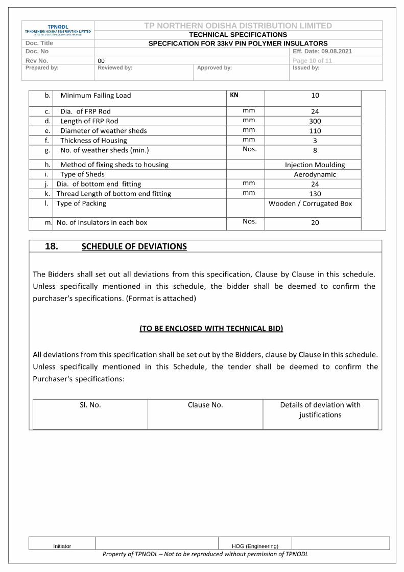
TP NORTHERN ODISHA DISTRIBUTION LIMITED
TECHNICAL SPECIFICATIONS Doc. Title SPECFICATION FOR 33kV PIN POLYMER INSULATORS Doc. No Eff. Date: 09.08.2021
Rev No. 00 Page 10 of 11 Prepared by:
Reviewed by:
Approved by:
Issued by:
Initiator
HOG (Engineering)
Property of TPNODL – Not to be reproduced without permission of TPNODL
b. Minimum Failing Load KN 10
c. Dia. of FRP Rod mm 24 d. Length of FRP Rod mm 300
e. Diameter of weather sheds mm 110
f. Thickness of Housing mm 3
g. No. of weather sheds (min.) Nos. 8
h. Method of fixing sheds to housing Injection Moulding i. Type of Sheds Aerodynamic
j. Dia. of bottom end fitting mm 24
k. Thread Length of bottom end fitting mm 130
l. Type of Packing Wooden / Corrugated Box
m. No. of Insulators in each box Nos. 20
18. SCHEDULE OF DEVIATIONS
The Bidders shall set out all deviations from this specification, Clause by Clause in this schedule.
Unless specifically mentioned in this schedule, the bidder shall be deemed to confirm the
purchaser's specifications. (Format is attached)
(TO BE ENCLOSED WITH TECHNICAL BID)
All deviations from this specification shall be set out by the Bidders, clause by Clause in this schedule.
Unless specifically mentioned in this Schedule, the tender shall be deemed to confirm the
Purchaser's specifications:
Sl. No. Clause No. Details of deviation with justifications

TP NORTHERN ODISHA DISTRIBUTION LIMITED
TECHNICAL SPECIFICATIONS Doc. Title SPECFICATION FOR 33kV PIN POLYMER INSULATORS Doc. No Eff. Date: 09.08.2021
Rev No. 00 Page 11 of 11 Prepared by:
Reviewed by:
Approved by:
Issued by:
Initiator
HOG (Engineering)
Property of TPNODL – Not to be reproduced without permission of TPNODL
We confirm that there are no deviations apart from those mentioned above. Seal of the Company Designation Signature


TP NORTHERN ODISHA DISTRIBUTION LTD
WORK INSTRUCTION /OPERATING GUIDELINES
Doc. Title GENERAL CONDITIONS OF CONTRACT FOR COMPOSITE WORK
Rev. No 0 Page 1 of 78
Prepared By Imran Ahmad/ Swetaraj Parida
Reviewed By Vipin Chauhan
Approved By Sunil Bhattar
Approved Copy of GCC (TPNODL)
CONTENTS
CLAUSE NO. DESCRIPTION
1.0 ORGANIZATIONAL VALUES
2.0 ETHICS
2.1 Tata Code of Conduct
3.0 CONTRACT PARAMETERS
3.1 Issue/ Award of Contract
3.2 Contract Commencement Date
3.3 Contract Completion Date
3.4 Contract Period/Time
3.5 Contract Execution Completion Date
3.6 Contract Execution Period/Time
3.7 Contract Price /Value
3.8 Contract Document
3.9 Contract Language
3.10 Reverse Auction
4.0 SCOPE OF WORK
4.1 Bid Evaluation- Commercial, Technical & Safety Evaluation
4.2 Indemnity
4.3 Display of notice boards at work site
4.4 Disposal of waste at site
4.5 Deployment of workforce
4.6 Damage of Properties
4.7 Issuance of material
4.8 Company's right to use works
4.9 Rights of TPNODL to vary the scope work
5.0 PRICES/RATES/TAXES
5.1 For Supply part of Contract

Doc. Title GENERAL CONDITIONS OF CONTRACT FOR COMPOSITE WORKS
Rev. No 0 Page 2 of 78
Approved copy of GCC (TPNODL)
CONTENTS
CLAUSE NO. DESCRIPTION
5.2 For Service part of Contract
5.3 Changes in statutory Tax Structure
6.0 TERMS OF PAYMENT
6.1 Pre-Requisites for Payment
6.2 Bills & Invoices
6.3 Payment & Statutory Deductions
6.4 Guidelines for Raising Running/Final Bills
6.5 Quantity Variation
6.6 Full and Final Payment
6.7 All-Risk Insurance Policy
7.0 MODE OF PAYMENT
8.0 SECURITY CUM PERFORMANCE DEPOSIT
8.1 Relationship Bank Guarantee
9.0 STATUTORY COMPLIANCE
9.1 Compliance to Various Acts
9.2 SA 8000
9.3 Affirmative Action
9.4 Compliance to Labour Laws
9.5 Compliance to C&D Waste Management Rules & Environment (Protection) Amendment Rules
9.6 MSME Development Act 2006
9.7 ISO 14001
10.0 QUALITY
10.1 Knowledge of Requirements
10.2 Material/Equipment/Works Quality
10.3 Adherence to Rules & Regulations
10.4 Specifications and Standards
11.0 SAFETY
12.0 INSPECTION/PARTICIPATION
12.1 Right to Carry Out Inspection

Doc. Title GENERAL CONDITIONS OF CONTRACT FOR COMPOSITE WORKS
Rev. No 0 Page 3 of 78
Approved copy of GCC (TPNODL)
CONTENTS
CLAUSE NO. DESCRIPTION
12.2 Facilitating Inspection
12.3 Third Party Nomination
12.4 Waiver of Inspections
12.5 Incorrect Inspection Call
13.0 MDCC & DELIVERY OF MATERIALS
13.1 Material Dispatch Clearance Certificate
13.2 Right to Rejection on Receipt
13.3 Consignee
13.4 Submission of Mandatory Documents on delivery
13.5 Dispatch and Delivery Instructions
14.0 GUARANTEE
14.1 Guarantee of Performance
14.2 Guarantee period
14.3 Failure in Guarantee period (GP)
14.4 Cost of repairs on failure in GP
14.5 Guarantee Period for Goods Outsourced
14.6 Latent Defect
14.7 Support beyond the Guarantee Period
15.0 LIQUIDATED DAMAGES
15.1 LD Waiver Request
15.2 Material Recovery
16.0 ASSIGNMENT OR SUBCONTRACTING
17.0 UNLAWFUL ACTIVITIES
18.0 CONFIDENTIALITY
18.1 Documents
18.2 Geographical Data
18.3 Associate’s Processes
18.4 Exclusions
18.5 Violation

Doc. Title GENERAL CONDITIONS OF CONTRACT FOR COMPOSITE WORKS
Rev. No 0 Page 4 of 78
Approved copy of GCC (TPNODL)
CONTENTS
CLAUSE NO. DESCRIPTION
19 INTELLECTUAL PROPERTY RIGHTS
20 INDEMNITY
21 LIABILITY & LIMITATIONS
21.1 Liability
21.2 Limitation of Liability
22.0 FORCE MAJEURE
23.0 SUSPENSION OF CONTRACT
23.1 Suspension for Convenience
23.2 Suspension for Breach of Contract Conditions
23.3 Compensation in lieu of Suspension
24.0 TERMINATION OF CONTRACTS
24.1 Termination for default/breach of contract
24.2 Termination for convenience of associate
24.3 Termination for Convenience of TPNODL
25.0 Dispute resolution and Arbitration
25.1 Governing laws and jurisdiction
26.0 ATTRIBUTES OF GCC
26.1 Cancellation
26.2 Severability
26.3 Order of Priority
27.0 INSURANCE
28.0 ERRORS AND OMISSIONS
29.0 TRANSFER OF TITLES
30.0 SUGGESTIONS & FEEDBACK
31.0 CONTACT POINTS
32.0 LIST OF ANNEXURES

Doc. Title GENERAL CONDITIONS OF CONTRACT FOR COMPOSITE WORKS
Rev. No 0 Page 5 of 78
Approved copy of GCC (TPNODL)
1.0 ORGANIZATIONAL VALUES
The Tata Group has always been a value driven organization. These values continue to
direct the Group’s growth and businesses. The Six core Tata Values underpinning the way
we do business are:
Integrity - We must conduct our business fairly, with honesty and transparency. Everything
we do must stand the test of public scrutiny.
Understanding - We must be caring, respectful, compassionate and humanitarian towards
our colleagues and customers around the world and always work for the benefit of India.
Excellence - We must constantly strive to achieve the highest possible standards in our day
to day work and in the quality of goods and services we provide.
Unity - We must work cohesively with our colleagues across the group and with our
customers and partners around the world to build strong relationships based on tolerance,
understanding and mutual co-operation.
Responsibility - We must continue to be responsible and sensitive to the countries,
communities and environments in which we work, always ensuring that what comes from the
people goes back to the people many times over.
Agility - We must work in a speedy and responsive manner and be proactive and innovative
in our approach.
2. Tata Code of Conduct
The Business Associate and TPNODL shall be bound by the provisions/ clauses mentioned
in Tata Code of Conduct (TCoC) in all their dealings with stakeholders. The Associate is
advised to go through the TCoC document available as Annexure-P.
3.0 CONTRACT PARAMETERS
3.1 Issue/Award of Contract
TPNODL awards the contract to the Associate in writing in the form of Purchase order or
Rate Contract (RC) hereafter referred as Contract, through in any or all of following modes-
physical handover / post / e-mail / web document / fax with all the attachments/enclosures
which shall be part of the contract document
On receipt of the contract, the associate shall return to TPNODL copy of the contract
document duly signed by legally authorized representative of associate, within two days of
Effective Date of Contract for contracts having contract execution time less than 30 days and
within five days for all other contracts.
Note- In case of RC though, further Release Orders (RO) shall be issued by TPNODL on RC
rates and terms & Conditions as per the requirement of TPNODL.
3.2 Contract Commencement Date
The date of issue/award of contract shall be the Effective Date of Contract or Contract
Commencement date.
3.3 Contract Completion Date

Doc. Title GENERAL CONDITIONS OF CONTRACT FOR COMPOSITE WORKS
Rev. No 0 Page 6 of 78
Approved copy of GCC (TPNODL)
The date of expiry of Guarantee Period (detailed in section 12 of this document) shall be
deemed as the Contract Completion Date.
3.4 Contract Period/Time
The period from Contract Commencement Date to Contract Completion Date shall be
deemed as the Contract Period/Time.
3.5 Contract Execution Completion Date
The stipulated date for completing the execution of all items in the schedule of quantities
(Supply, Service and or both as applicable) shall be deemed as the Contract Execution
Completion Date.
3.6 Contract Execution Period/Time
The Period from Contract Commencement Date to Contract Execution Completion Date
shall be the Contract Execution Period/Time. Timely Completion of Works/Timely Delivery of
Materials is the essence of the contract. The period from effective date of contract to the
date stipulated for completion of delivery of all items/completion of all the works/services, as
per schedule of quantities of the contract is defined as contract execution completion time.
The Delivery of Materials /The Completion of Works, as applicable, should be achieved in all
respects as per schedules of quantities and all the terms and conditions of the contract, in
the contract execution time.
Any revision/amendment in the originally stipulated contract execution time has to be
approved by authorized representative of TPNODL.
3.7 Contract Price /Value
The total all-inclusive price/value mentioned in the LOI/PO/RC of the contract document is
the Contract Price/Value and is based on the quantity, unit rates and prices quoted and
awarded and shall be subject to adjustment based on actual quantities supplied/actual
measurement of work done and accepted and certified by the authorized representative of
the company unless otherwise specified in schedule of quantities or in contract documents.
3.8 Contract Document
The Contract Document shall mean and include but not limited to the following:
NIT/Tender Enquiry, QR, Instruction to Bidders, Special Condition of Contract (SCC) of
tender, GCC, Technical & Commercial Specifications including relevant annexure and
attachments).
Bids & Proposals Received from Associate including relevant annexure/attachments.
Letter of Intent (LOI/RC/PO) with agreed deviations from the tender/bid documents.
All the Inspection and Test reports, Detailed Engineering Drawings.
Material Dispatch Clearance Certificate (MDCC).
Minutes of Meeting (MoM)
3.9 Contract Language

Doc. Title GENERAL CONDITIONS OF CONTRACT FOR COMPOSITE WORKS
Rev. No 0 Page 7 of 78
Approved copy of GCC (TPNODL)
All documents, instructions, catalogues, brochures, pamphlets, design data, norms and
calculations, drawings, operation, maintenance and safety manuals, reports, labels, on
deliveries and any other data shall be in English Language.
The Contract documents and all correspondence between the TPNODL, Third Parties
associated with the contract, and the Associate shall be in English language.
However, all signboards required indicating "Danger" and/or security at site and otherwise
statutory required shall be in English, Hindi, and local languages.
3.10 Reverse Auction
TPNODL reserves the right to conduct the reverse auction (instead of public opening of price
bids) for the products / services being asked for in the tender. The terms and conditions for
such reverse auction events shall be as per the Acceptance Form attached in Annexure J.
The bidders along with the tender document shall mandatorily submit a duly signed copy of
the Acceptance Form as mentioned in the Annexure J as a token of acceptance for the
same.
In addition to this TPNODL reserve the rights for manual negotiation even after the Reverse
Auction.
4.0 SCOPE OF WORK
All the activities that are to be undertaken by the Associate to realize the contractual
deliverables in completeness form Scope of Work. Following clauses list, but not limited to,
major requirements of the scope of work.
The associate shall satisfy himself and undertake fully the technical/commercial
requirements of items to be supplied as listed in the Schedule of Quantities together with the
tests to be performed /test reports to be furnished before dispatch, arrangement of stage and
final inspections during manufacturing as per terms and conditions of contract, technical
parameters & delivery terms and conditions including transit insurance to be met in order to
fully meet TPNODL’s requirements.
Completeness: Any supplies and services which might have not been specifically mentioned
in the Contract but are necessary for the scope mentioned in Special Terms & Conditions
and/or completeness of the works at the highest possible level, including any royalties,
license fees & compensation to be paid, whether incurred by the associates or by a third
party for the work covered in the scope, regardless of when incurred, shall be
supplied/provided by the associate without any extra cost and within the time schedule for
efficient , smooth and satisfactory operation and maintenance of the works at the highest
possible level under Indian conditions (but according to international standards for facility of
this type), unless expressly excluded from the scope of supplies and services in this
Contract.
TPNODL have the right, during the performance of the Contract, to change the scope and/or
technical character of the Project and/or of the supplies and services stipulated in the
Contract by submitting a request in writing to the Associate. The Associate shall, within
fifteen days of receipt of such request from the TPNODL, provide Purchaser with a
reasonably detailed estimate of the cost of the change outlined in the request.
In the event, TPNODL requests a change, the Contract price and time shall be adjusted
upwards or downwards, as the case may be and shall be mutually agreed to. The associate

Doc. Title GENERAL CONDITIONS OF CONTRACT FOR COMPOSITE WORKS
Rev. No 0 Page 8 of 78
Approved copy of GCC (TPNODL)
shall not be entitled to any extension of time unless such changes adversely affect the time
schedule.
The Associate shall not proceed with the changes as requested till adjustment of contract
price and time schedule where so applicable in terms of or otherwise directed by the
TPNODL.
4.1 Bid Evaluation- Commercial, Technical and Safety Evaluation
TPNODL reserves the right to evaluate the bid in the following manner on the below
parameters as per the requirement:
o Safety Evaluation: Business Associates may be required to submit a separate
Safety Bid along with their Technical & Price Bids at the time of bidding, especially in
cases where the expected contract value >= Rs. 1 Cr. and which fall in high risk
category as detailed in Annexure-N. In such cases, TPNODL shall also do a Safety
Bid Evaluation along with Technical Evaluation to declare the Qualified Bidders.
o Technical Evaluation: The bid shall be evaluated on the parameters and not limited
to Bidder Experience, Bidder Performance with other utility/company, internal
performance feedback, Technical Specification, General Technical Parameters
(GTP), Layout, Drawings etc.
TPNODL reserves the right to carry out Factory Evaluation of Manufacturer along
with the Visit to executed Sites for further evaluation to ascertain bidder's
manufacturing capability, quality procedures & Performance of executed works.
o Commercial Evaluation: The bid shall be evaluated on the basis of Qualifying
Requirement parameters and other commercial parameters as mentioned in tender.
4.2 Indemnity
Associates shall undertake to fully indemnify TPNODL (also referred to as the Company in
the GCC) against all kinds of liabilities or damages, of whatsoever nature, including
compensation arising from any accident to the person or property of those in Associate’s
employment or to any other person or properties including those of TPNODL, arising due to
reasons attributable to any, act, omission or negligence of the Associate the Associates, for
the entire period of contract including period of guarantee.
Within 7 days of award of work, the Associates shall submit Indemnity Bond in the format as
per Annexure-E to Order Issuing Authority.
Contract having value more than Rs 2 Cr per Annum, Associates shall submit Indemnity
Bond on Rs 100/- Non Judicial Stamp Paper in the format as per Annexure- E to Order
Issuing Authority.
4.3 Display of Notice Boards at Work Sites
The Associate shall put up display notice board at each project site where the works are in
progress indicating the information given below:
Name of the Project.
Estimated Cost of Project.
Date of Commencement.
Expected date of completion.

Doc. Title GENERAL CONDITIONS OF CONTRACT FOR COMPOSITE WORKS
Rev. No 0 Page 9 of 78
Approved copy of GCC (TPNODL)
Name of Associate and his telephone number.
Name of Engineer-in-Charge and his telephone number.
4.4 Disposal of Waste at Site
Significant quantities of waste are generated during the execution of project and an
integrated approach for effective handling, storage, transportation and disposal of the same
shall be adopted. This would ensure the minimization of environmental and social impact in
order to combat the climate change.
The associates shall follow the below criteria for disposal of waste at site during the
execution of project.
Associate shall ensure that the detailed project plan include the waste management,
segregation of all designated waste material (Recyclable/ Non-Recyclable), collecting,
storing, disposing and transferring the same to pre-arranged facility/destination in timely
and safe manner as per environmental legislations during the execution of project. The
project plan shall also include the innovative construction practice to eliminate or
minimize waste, protect surface/ground water, control dust and other emissions to air
and control noise during the execution of project. The copy of same shall be given to
EIC before the commencement of project.
The purchase policy of BA shall encourage the procurement of material with recycled
and minimum packaging of goods during delivery. Associate shall provide the
appropriate means for site to site transportation of materials to avoid damage and litter
generation.
Associate shall educate and inform to its project team about the requirement and
responsibilities for waste minimization and disposal in general and provide training of
practices that support this. Waste management should be treated like a safety program.
In the event that area of contaminated or biological hazard is identified, Associate shall
ensure that plant, equipment, personnel and any activity associated with the work is
carried out in consultation with EIC of TPNODL.
Associate shall ensure that the residents living near the site are kept informed about
proposed working schedule and shall informed timings and duration of any abnormal
noise full activity that is likely to happen.
Associate shall ensure the regular maintenance and monitoring of vehicles and
equipment for efficient fuel use so that emissions and noise are within acceptable limits
to avoid air pollution.
4.5 Deployment of Work Force
Associate shall deploy adequate labour, as considered necessary by TPNODL for execution
of the contract including Sundays and Holidays whenever required to do so with no extra
cost to TPNODL. However, prior permission shall be taken from the site Engineer to carry
out the work beyond normal working hours or on Sundays and Holidays. Female employees
shall not be deployed beyond normal working hours/days and no child labour shall ever be
deployed. Associate shall depute full time qualified and experienced engineers to supervise
the work at site. All such staff shall be maintained from commencement to completion of all
works to the entire satisfaction of the Engineer-in-Charge. Associate’s employees deployed
for the works under this contract will not be considered in Company’s employment at any

Doc. Title GENERAL CONDITIONS OF CONTRACT FOR COMPOSITE WORKS
Rev. No 0 Page 10 of 78
Approved copy of GCC (TPNODL)
time. Associate shall continue to be responsible for all such employees, their safety, all types
of statutory compliances related thereto and in any other manner whatsoever. The company
will stand indemnified by the Associate in respect of all the above. At the same time
Company upon noticing any breach or default on any statutory compliances, may at their
sole discretion, decide to act in a manner as deemed fit at the risks and costs of the
Associate.
TPNODL shall have the right to instruct the Associate to change the Sub- Associates or
skilled /unskilled workers in case the conduct, the workmanship or speed of the work is not
satisfactory.
Associates shall submit duly signed undertaking regarding engagement of competent staff /
employee commensurate to the nature of job to Engineer–in–charge in the format attached
as Annexure – H.
4.6 Damages to Properties
The Associates shall take necessary steps to ensure that the equipment and installations of
the Company, Third parties, including other utility services like water supply pipelines; open
drains telephone cables etc. are not damaged during execution of the works. The Associates
shall be responsible for all such damages and shall have to repair/ replace and/or
compensate for the entire claims in respect of such damages at its own cost.
4.7 Issuance of Material
The material issued to the Associate shall be in the custody of the Associates who shall be
fully responsible for the same. After completion of the works, the Associates will reconcile
the material. Any cost of material which is short or damaged/lost will be deducted from
Associate bill/ deposits.
4.8 Company’s Right To Use Works
If Taking Over Certificate is delayed for any reason, for which TPNODL’s decision shall be
final and binding upon the Associate, the Company shall be entitled to use the works or
portion thereof without affecting Associate’s responsibility and liability to complete the
balance works as per company’s directives from time to time, though Associate shall be
afforded reasonable opportunity by the company to enable Associates to complete all
balance works required for issuance of ‘Taking Over Certificate’ by the company.
4.9 Rights of TPNODL to vary the scope work
TPNODL shall have the right, during the performance of the Contract, to change the scope
and/or technical character of the Project and/or of the supplies and services stipulated in the
Contract by communicating the intent to do so in writing to the Associate. On receipt of such
communication the Associate shall, within the time frame specified in the contract shall
provide TPNODL with a reasonably detailed estimate of the cost of the change in scope
outlined in the TPNODL communication. The change in the Contract price and time shall be
revised upwards or downwards, as the case may be, and shall be mutually agreed to. The
Associate shall not be entitled to any extension of time unless such changes adversely affect
the time schedule.
The Associate shall not proceed with the changes in the scope of work till such time revision
of Contract price and time schedule are approved and communicated to the associate by
TPNODL.

Doc. Title GENERAL CONDITIONS OF CONTRACT FOR COMPOSITE WORKS
Rev. No 0 Page 11 of 78
Approved copy of GCC (TPNODL)
Any change in the Scope of Work and/or Terms & Conditions of the order shall be intimated
by TPNODL through an amendment to the contract. The amendment shall be treated valid
only if signed by the authorized signatory of the original contract.
5.0 PRICES/ RATES/ TAXES
5.1 For Supply part of Contract
Unless specified elsewhere in the contract document, the prices/rates are inclusive of cost of
finished product for which MDCC will be issued by TPNODL, packaging and forwarding
charges, freight and transit insurance charges covering loading at Associate’s works,
transportation to TPNODL store/site & unloading & delivery at TPNODL stores/TPNODL site,
cost of documentation including all the relevant test certificates and other supportive
documents to be furnished.
The Prices/Rates are inclusive of all taxes, levies, cesses and duties, particularly Goods and
Services Tax as applicable. All government levy / taxes shall be paid only when the invoice
is submitted according to the relevant act.
The prices/rates shall remain firm till actual completion of entire supply of
goods/material/equipment as per contract is achieved and shall remain valid till the
completion of the contract.
The prices shall remain unchanged irrespective of TPNODL making changes in quantum in
all or any of the schedules of items of contract.
5.2 For Service part of Contract
The Prices and Rates are inclusive of cost of materials supplied as per contract terms and
for which MDCC is issued by TPNODL and to the extent required for completion of works,
cost of service executed as per schedule of quantities, cost of testing as per contract terms,
cost of documentations including all relevant test certificates and other supportive
documents to be furnished as per contract terms. The rates shall remain firm till actual
completion of contract.
The Prices/Rates are inclusive of all taxes, levies, cesses and duties, particularly Goods and
Services Tax as applicable. All government levy / taxes shall be paid only when the invoice
is submitted according to the relevant act.
The prices shall remain unchanged irrespective of TPNODL making changes in quantum in
all or any of the schedules of items of contract.
5.3 Changes in Statutory Tax Structure
If rate of any or all of the statutory taxes and duties applicable to the contract changes, such
changes shall be incorporated by default if the changes occur within the contract execution
time and shall be applicable if the contract is executed by the Associate within the Contract
Execution Time.
For execution of contracts beyond contract execution time, where the delay is not
attributable to TPNODL no upward revision in tax /duties shall be considered irrespective of
changes in the statutory tax structure either within the contract execution time or beyond.
However, in such cases, benefits due to any downward revisions in statutory tax rates shall
be passed on to TPNODL.

Doc. Title GENERAL CONDITIONS OF CONTRACT FOR COMPOSITE WORKS
Rev. No 0 Page 12 of 78
Approved copy of GCC (TPNODL)
6.0 TERMS OF PAYMENT
A. 5% of the Release Order/ Purchase Order price shall be paid as initial interest free
advance on fulfillment of the following by the Associate:
a) Acceptance of PO/ LOI.
b) Submission of advance payment BG (APBG) of 15% of the Release Order/
Purchase Order price which shall remain valid till the advance is fully
adjusted.
c) Submission of Contract Performance Bank Guarantee (CPBG) of 5/10% of
the RC/ PO price valid till 30 days after taking over of the works.
B. 10% of the Release Order/ Purchase Order price shall be paid as interest free
advance against approval of drawings under Category-1 of major drawings, Quality
Plans, Pert Chart, Field Quality Plan, posting of Project Manager
and commencement of the first mile stone of the work mutually agreed including C-3
Form, and submission of a true copy of ‘Erection All Risk Insurance Policy’ taken for
the awarded jobs. The drawing list shall be mutually agreed at the time of award of
work.
C. 50% on account payment of the total of item wise cost of material Release Order/
Purchase Order shall be paid against receipt of material at site in good condition and
certification by TPNODL along with bills complete in all respects viz. MDCCs etc.
D. 20% on account payment of the actual executed value shall be paid against
mechanical completion of erection on prorate basis against monthly bills and 70% on
account of the actual executed value shall be paid against the service line item
including composite line item. In case this milestone is not completed beyond 120
days for reasons attributable to TPNODL, the payment corresponding to supply part
shall be released subject to submission of BG of equivalent amount by the BA valid
for a period of further 12 months. If required, it shall be extended by the BA on
request of TPNODL.
E. 15% payment of the actual executed Release Order/ Purchase Order shall be paid
after completion of acceptance test and Taking Over of the complete systems
specified in the enquiry, including clearance of Electrical Inspection, compliance of
final punch point and after reconciliation & adjustment of payments, if any, towards
Quantities of materials issued from purchaser’s stock and consumed by the
contractor for expeditious completion of the job. In case this milestone is not
completed beyond 120 days beyond schedule for reasons attributable to TPNODL,
the payment corresponding to supply part shall be released subject to submission of
BG of equivalent amount by the BA valid for a period of further 12 months. If
required, it shall be extended by the BA on request of TPNODL.
The Contractor shall submit all Operation & Maintenance manuals and “As Built
Drawings” etc. and shall also submit Equipment Warranty Bank Guarantee (EWBG)
equivalent to 5/10% of actual executed contract price before the release of this last
payment and return of CPBG. The validity of EWBG shall be for a period of 15
months from the date of taking over of the works or specified guarantee period in
drawing/tender/technical specification documents etc. whichever is later. The

Doc. Title GENERAL CONDITIONS OF CONTRACT FOR COMPOSITE WORKS
Rev. No 0 Page 13 of 78
Approved copy of GCC (TPNODL)
associate shall also submit ‘No Demand Certificate’ at the time of receipt of full and
final payment.
6.1 Pre-Requisites for Payment
Associate should have completed execution of that part of contract, for which payment is
sought, to the satisfaction of TPNODL’s Engineer-in-Charge responsible for the contract
and obtained certification for execution of the work.
Associate has undertaken joint measurement of the work executed along with TPNODL’s
Engineer-in-charge
Associate’s bills/invoices submitted have been certified by Engineer-In-Charge.
6.2 Bills & Invoices
Unless specified otherwise in the special conditions of contract, Associate shall raise not
more than one invoice/contract per month for the services rendered in the prescribed Tax
Format and the invoice shall be submitted within 15 days of the following month at TPNODL.
All Bills shall be supported by joint measurement of work done, quality test report and a copy
of wage sheet, if applicable (showing proof of having disbursed wages as per applicable
law), e-Way challan (if applicable) and a copy of statement substantiating that statutory
payments having been affected.
Bills/ invoices shall mention Associate’s GST Number, PAN number as applicable.
Final bill submission after completion of project or execution of job must be within 30 days
from the actual date of completion/execution of work awarded.
6.3 Payment & Statutory Deductions
Payment shall be released within 30 days from the submission of the bills. The associate
shall submit “No Demand Certificate” in the format as per Annexure-D at the time of receipt
of full and final payment. In case any non-compliance to contract conditions comes to
TPNODL’s notice, TPNODL will be entitled to deduct 30% of estimated wages plus 20% of
wages as TPNODL’s overheads. Associates would be obliged to provide the copy of monthly
wage sheet in any case, failing which no payment shall be made. TPNODL at their sole
discretion may deposit the PF etc. with statutory authorities. TPNODL will deduct the
amounts of TDS as per statutory requirement under the income tax act and the DVAT Act
and certificates (wherever applicable) will be issued to associate accordingly.
In case of non-submission of PAN No TDS @ 20% shall be deducted from all payable
amounts for which no TDS certificate shall be issued. TDS once deducted as above shall not
be revised in any condition.
6.3.1 Statutory Deductions
TPNODL will deduct the amounts of TDS, TCS as per statutory requirement under the
income tax act, the Goods and Services tax act, BOCW Act, or any other applicable tax act
and certificates (wherever applicable) will be issued to associate accordingly. For
consumption of TPNODL’s Water and Electricity by Associate for execution of Contract,
Associate shall pay 0.5% & 1.0% respectively of contract value and it shall be deducted from
the running bills. The Engineer-in-Charge as stated in the Order shall be responsible for

Doc. Title GENERAL CONDITIONS OF CONTRACT FOR COMPOSITE WORKS
Rev. No 0 Page 14 of 78
Approved copy of GCC (TPNODL)
certification of the work executed and the bills. Bills (including original) shall be submitted in
triplicate at Finance office, Balasore.
6.4 Guidelines for Raising Running/Final Bills
Contract Value Up to 5 Lakhs One Final Bill
Contract Value More than 5 lakhs Monthly Running Bill & One Final Bill
All Bills shall be processed only when all bank Guarantees are in place and before payments
of Final Bill Associate have to furnish NDC.
6.5 Quantity Variation
Payment will be made on the basis of actual quantity of supplies/actual measurement of
works accepted by TPNODL and not on the basis of contract quantity.
6.6 Full and Final Payment
Full & Final Payment in all contracts shall be made subject to the associate submitting “No
Demand Certificate” in the format as per Annexure-D.
6.7 Erection All –Risk Insurance Policy
Associate shall obtain an Erection All Risk (EAR) Policy as a comprehensive insurance
solution designed to cover broad spectrum of risks to which a project is exposed to - from
arrival of construction material at site till the completion of project, including but not limited to
the following, the copy of Insurance Policy shall be submitted to E-I-C/ Finance department of
TPNODL before starting the work.
a. Earthquake
b. Terrorism
c. Escalation Cost (10% of sum insured on annual basis)
d. Extended Maintenance cover for defect liability period-24 months
e. Design Defect
f. 50-50 Clause
g. 72 Hours Clause
h. Loss minimization clause
i. Offsite storage/ fabrication
j. TPL (INR 50 lac per occurrence)
k. Theft, pilferage
l. Cross liability
m. Malicious damage
n. Contractor’s plant & equipment (value 25 lakh)
o. Waiver of Subrogation clause
p. STFI- Storm, Tempest, Flood, Fire and Inundation

Doc. Title GENERAL CONDITIONS OF CONTRACT FOR COMPOSITE WORKS
Rev. No 0 Page 15 of 78
Approved copy of GCC (TPNODL)
EAR policy is mandatory document for processing the invoices. Business Associate needs to
ensure that the All- Risk Insurance Policy is obtained as per the terms of contract, failing
which:
Penalty @1% of contract value would be charged.
In case of expiry of policy before handing over the project, TPNODL Engineer-In-
Charge shall reserve the right to deduct the penalty upto a maximum of 1% of
contract value.
7.0 MODE OF PAYMENT
Payment shall be made through RTGS/ NEFT/ Online Net banking mode for which Business
Associated shall submit the details of Bank Account and other details as per annexure J.
Further, for any payments made, TPNODL is not responsible for any consequences/disputes
Associate have among the owners channel partners, sub-Associates and all such
dispute/concerns shall be settled solely by the Associate.
The quantities of items indicated are estimated and preliminary. However, payments shall be
made on the basis of actual quantity of work carried out and measured jointly by the
Company and the Associate. Associates shall be responsible to organize joint
measurements of works with TPNODL Engineer-in-Charge before raising any bill of work
done. In the event Associate fails to do so, TPNODL at their sole discretion, may take
measurements of work done and proceed as deemed fit and in such an event Associate’s
right to lodge any subsequent claim shall stand forfeited.
8.0 SECURITY CUM PERFORMANCE DEPOSIT
Associates shall submit within 15 days from the effective date of issue of PO/RC, Security
cum Performance Guarantee (SPBG) in the format as per Annexure B of this document from
banks acceptable to TPNODL for:
(a) 5% of the PO value if purchase order value is more than Rs 5 Crores.
(b) 10% of the PO value if purchase order value is less than Rs 5 Crores.
This shall remain valid till the end of the Guarantee Period of contract, plus one month.
(c) 5% of the RC value in case of Rate Contract. This shall remain valid till the Guarantee
period plus one month.
For PO/RC values less than Rs. 5 lacs, Associate may request for deduction of amount
equivalent to SPBG value from their first invoice. Such amount shall be withheld by
TPNODL while processing the invoice and shall be released after completion of
Guarantee Period plus one month.
For PO/RC values less than Rs. 3 lacs, the clause (8.0) for Security cum Performance
Bank Guarantee (SPBG) shall not be applicable.
In case of RC (Rate Contract) after the expiry of RC validity, Associate shall have to
submit SPBG. However, the Associate has the option to re-submit the SPBG as per
actual RO (Release Order) value issued against the RC, valid for Guarantee Period plus
one month. The Guarantee Period shall be considered as per the last RO issued against
the said RC. The original SPBG as submitted against the RC shall be released on
submission of the new SPBG to TPNODL. Alternatively, Associate may extend the

Doc. Title GENERAL CONDITIONS OF CONTRACT FOR COMPOSITE WORKS
Rev. No 0 Page 16 of 78
Approved copy of GCC (TPNODL)
validity of original SPBG only till the requisite period, i.e. Guarantee Period plus one
month.
9.0 STATUTORY COMPLIANCE
9.1 Compliance to Various Acts
Associate should ensure adherence to the Anti-Lobbying, Debarment, Drug-Free, Child
Labour, Factories Act and Shop and Establishment Workplace Certification, Registration
details under GST, Sales Tax and Works Contract Tax Act.
Associate shall bear the entire responsibility, liability and risk relating to coverage of its
workforce under different statutory regulations including Workman's Compensation Act, ESI
Act, Factories Act, 1948, the Contract Labour (Regulation and abolition) Act 1970, and any
other relevant regulations as the case may be. Associate shall also be solely responsible for
the payment of all benefits such as Provident Fund, ESI, Bonus, Leave compensation and
other benefits as may be applicable under applicable labour laws, etc. as per the various
statutory regulations. The Associate shall compulsorily bear the cost of medical treatment
and payment of monetary compensation to the families of the victims in case of injury or
death, while on duty during his/her engagement with the Associate and shall keep TPNODL
indemnified in this regard against any such claim and provide documentary evidences of the
same to TPNODL. TPNODL shall be entitled to, if necessary, make such payment and
recover the amount from Associate.
Associate should ensure adherence to all applicable laws, rules and regulation applicable
under this contract from time to time. In case of violation any risk, costs etc. shall be in
associates account and keep TPNODL indemnified always till completion of contracts.
9.2 SA 8000
Further being TPNODL is SA 8000 complied and expects its Associates to follow guidelines
of SA8000: 2014 on the following aspects
1. Child Labour
2. Forced or Compulsory Labour
3. Health & Safety
4. Freedom of Association & Right to Collective Bargaining
5. Discrimination
6. Disciplinary Practices
7. Working Hours
8. Remuneration
9. Management System
Business Associate is expected to ensure adherence to all statutory laws and requirements
as applicable. The Associate needs to obtain Form C-3 before commencement of work and
No Objection Certificate (NOC) on completion of work from BA-Relations Cell/ HR.
In case any non-compliance is observed, TPNODL shall reserve the right to penalize the bidder as per direction of E-I-C. The penalty shall be 1% of total all-inclusive contract value for such cases. Also, TPNODL reserves the right to reject such bidder in future tenders.

Doc. Title GENERAL CONDITIONS OF CONTRACT FOR COMPOSITE WORKS
Rev. No 0 Page 17 of 78
Approved copy of GCC (TPNODL)
9.3 Affirmative Action
TPNODL appreciate and welcome the engagement/employment of persons from SC/ST
community or any other deprived section of society by their business associates.
Relaxation in Contract Clauses under Affirmative Action for SC/ ST Business
Associates**
TPNODL believes that inclusive growth is the key to sustainable development, and to
promote the same Policy on Affirmative Action for Scheduled Caste & Scheduled Tribe
Communities has been adopted across the company.
Under the same pre-text, and to promote entrepreneurship among SC/ST community
TPNODL has taken initiative by proposing relaxations in contract clauses as per below:
S. No.
Initiative for SC/ ST BA’s Guideline Document
1 Tender Fees 100% waiver for SC/ST community All Open Tenders
2 Earnest Money Deposit
50 % relaxation of estimated EMD value
All limited and Open Tenders
3 Performance Bank Guarantee
25% relaxation in PBG for order value above 50 lacs else 50% relaxation
All limited and Open tenders
4 Turnover 25% relaxation in company turnover under qualifying requirement criteria
All Open Tenders
**Classification of BA s under SC/ST shall be governed under following guidelines:
Proprietorship/ Single Ownership Firm: Proprietor of the firm should be from SC/ST
community. Governing document shall be duly audited balance Sheet for the last FY
bearing the name of proprietor.
Partnership Firm: Only such firms shall qualify which have SC/ST partners holding equal
to or more than 50% of the total ownership pattern of the firm. Governing document shall
be Partnership Deed and audited balance sheet/ ITR for last FY.
Private limited company: Only such firms shall qualify which have SC/ST directors
holding equal to or more than 50% of the total ownership pattern of the firm. Governing
document shall be Memorandum of Understanding (MoU) and/or Article of Association
(AoA).
## Certification from SC/ST commission shall be required for deciding upon SC/ST status of
a person.
9.4 Compliance to Labor Laws
Bidder needs to ensure compliance to applicable labor laws including timely disbursement of
wages. In case wages are not disbursed as per the stipulated timelines, then TPNODL shall
pay the wages to BA employees on behalf of BA. Apart from deducting the amount of wages
paid, TPNODL shall deduct an additional service charge equivalent to 25% of the wages
paid from the payment due to BA.
9.5 Compliance to Construction and Demolition Waste Management Rules &
Environment (Protection) Amendment Rules

Doc. Title GENERAL CONDITIONS OF CONTRACT FOR COMPOSITE WORKS
Rev. No 0 Page 18 of 78
Approved copy of GCC (TPNODL)
BA is liable to follow the Construction and Demolition Waste Management Rules- 2016,
Environment (Protection) Amendment Rules- 2018 and Guidelines on dust mitigation
measures in handling construction material and C&D wastes issued by CPCB.
Following are some main points of above Rules/Guidelines for Construction work, cable
laying jobs etc.
1. Barricading to be provided at site to cover complete area. 2. Construction material and waste should be inside the closed area made by using
barricading. 3. Water sprinkling/fine spray from nozzles to be done to suppress the dust. 4. The board of Dust mitigation measures shall be displayed at site for public viewing
with required details. 5. Loose sand or soil and construction material that causes dust shall be covered. 6. Transport material that are easily wind borne need to be covered by a sheet made of
either jute, tarpaulin, plastic or any other effective material. 7. All areas for storing C&D waste/construction material to be demarcated and
preferably barricaded particularly those materials that have potential to be dust borne.
8. Grinding and cutting of building materials in open area shall be prohibited. 9. Construction material and waste should be stored only within earmarked area and
road side storage of construction material and waste shall be prohibited. 10. No uncovered vehicles carrying construction material and waste shall be permitted. 11. Construction and demolition waste processing and disposal site shall be identified
and required dust mitigation measures to be notified at the site. 9.6 Special Terms & Conditions for BAs engaged under PLPBC or Service Contracts 1. The Business Associate will abide by the rules & regulations and various process
requirements of TPNODL which may get amended from time to time based on business needs.
2. The Business Associate shall ensure submission of required information to TPNODL as
required by TPNODL or any government authorities (with a copy to TPNODL), as and when required within the stipulated time frame.
3. The business associate shall, before start of work, obtain and submit to TPNODL a copy
of
PF Code allotment letter issued to him/them by the EPF organization.
ESIC Code allotment letter issued to him/them by the ESI authorities.
valid insurance documents under Employees’ Compensation Act, for its employees not eligible for coverage under ESIC
4. The Business Associate shall, in case of his/engagement in any construction activities falling under the purview of the Building and Other Construction Workers (BOCW) Act, apply for registration under the said BOCW Act before start of work and obtain the said registration within a month of starting such work. Business Associate shall also ensure compliance to all other applicable provisions including payment of applicable cess under the Act.
5. The Business Associate shall comply with all applicable provisions under Inter State
Migrant Workmen (ISMW) Act.
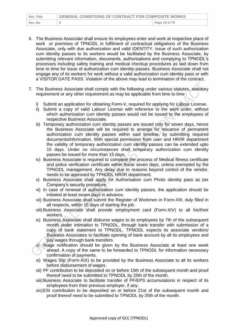
Doc. Title GENERAL CONDITIONS OF CONTRACT FOR COMPOSITE WORKS
Rev. No 0 Page 19 of 78
Approved copy of GCC (TPNODL)
6. The Business Associate shall ensure its employees enter and work at respective place of
work or premises of TPNODL in fulfilment of contractual obligations of the Business Associate, only with due authorization and valid IDENTITY. Issue of such authorization cum identity passes to its workers would be facilitated by the Business Associate, by submitting relevant information, documents, authorizations and complying to TPNODL’s processes including safety training and medical checkup procedures as laid down from time to time for issue of authorization cum identity-passes. Business Associate shall not engage any of its workers for work without a valid authorization cum identity pass or with a VISITOR GATE PASS. Violation of the above may lead to termination of the contract.
7. The Business Associate shall comply with the following under various statutes, statutory
requirement or any other requirement as may be applicable from time to time :
i) Submit an application for obtaining Form-V, required for applying for Labour License. ii) Submit a copy of valid Labour License with reference to the work order, without
which authorization cum identity passes would not be issued to the employees of respective Business Associate.
iii) Temporary authorization cum identity passes are issued only for seven days, hence the Business Associate will be required to arrange for issuance of permanent authorization cum identity passes within said timeline, by submitting required documents/information. With special permission from user and HR/IR department the validity of temporary authorization cum identity passes can be extended upto 15 days. Under no circumstances shall temporary authorization cum identity passes be issued for more than 15 days.
iv) Business Associate is required to complete the process of Medical fitness certificate and police verification certificate within these seven days, unless exempted by the TPNODL management. Any delay due to reasons beyond control of the vendor, needs to be approved by TPNODL HR/IR department.
v) Business Associate shall apply for Authorisation cum Photo identity pass as per Company’s security procedure.
vi) In case of renewal of authorization cum identity passes, the application should be initiated at least seven days in advance.
vii) Business Associate shall submit the Register of Workmen in Form-XIII, duly filled in all respects, within 15 days of starting the job.
viii) Business Associate shall provide employment card (Form-XIV) to all his/their workers.
ix) Business Associate shall disburse wages to its employees by 7th of the subsequent month under intimation to TPNODL, through bank transfer with submission of a copy of bank statement to TPNODL. TPNODL expects its associate vendors/ Business Associates to facilitate opening of bank account by all its employees and pay wages through bank transfers.
x) Wage notification should be given by the Business Associate at least one week ahead. A copy of the same to be forwarded to TPNODL for information necessary confirmation of payments.
xi) Wages Slip (Form-XIX) to be provided by the Business Associate to all its workers before disbursement of wages.
xii) PF contribution to be deposited on or before 15th of the subsequent month and proof thereof need to be submitted to TPNODL by 25th of the month.
xiii) Business Associate to facilitate transfer of PF/EPS accumulations in respect of its employees from their previous employer, if any.
xiv) ESI contribution to be deposited on or before 21st of the subsequent month and proof thereof need to be submitted to TPNODL by 25th of the month.

Doc. Title GENERAL CONDITIONS OF CONTRACT FOR COMPOSITE WORKS
Rev. No 0 Page 20 of 78
Approved copy of GCC (TPNODL)
xv) Muster roll, Wage Register, Combined Challan & ECR of PF deposition and Challan / Contribution history of ESIC to be submitted to TPNODL HR/IR Department on or before 25th of the subsequent month.
xvi) Business Associate shall be required to arrange for applicable welfare measures under applicable statutes for its employees in consultation with TPNODL order manager.
xvii) Business Associate has to submit all the relevant returns under all applicable enactments on or within the scheduled date and a copy of the same need to be submitted to TPNODL HR/IR department within seven days of the scheduled date of submission.
8. Business Associate shall not be allowed to work for TPNODL without possessing a
* Valid PO *Valid Labour License * Valid AUthorisation cum Identity Pass 9. NO BILLS OF THE VENDOR/BUSINESS ASSOCIATE SHALL BE RELEASED IN CASE
OF FAILURE TO COMPLY WITH THE ABOVE PROVISIONS. 10. Above requirement not being exhaustive, vendors/ Business Associate will be liable to
comply with the provisions of any other enactment as notified or would be applicable to them from time to time.
11. An additional overhead charge of 25% of the wage bill value will be charged to the
Business Associate in case the BA fails to pay the wages of its workers in time and TPNODL as principle employers is compelled to make the payment on their behalf. The total amount, including the overhead charge, will be recovered from the subsequent bill payable to the Business Associate.
12. Continuous default in wage payment to its employees within stipulated date as
mentioned above, for three months, will lead to termination of the contract and may also lead to blacklisting of the Business Associate/ cancel vendors’ registration.
13. After completion of work and before or at the time of submission of final bills, the
Business Associate must ensure the following and submit proof thereof to TPNODL enabling TPNODL release its final bills. In absence of the same no such bills would be released by TPNODL :
a. All wage payments are made to its workers till the last day of their work in TPNODL b. Compensation towards Leave with wages are disbursed to its employees till the last
day of their work. c. Statutory bonus is paid to its employees for the period of their work. d. Retrenchment compensation, where applicable, is paid to its employees as per
eligibility. e. Notice is given to the workers regarding retrenchment and in absence; notice pay is
given to the workers as per the enactment, where applicable. f. Along with final payments, full & final statement is issued to all its employees
engaged by them for their work in TPNODL g. No dues certificate is obtained from all its employees and copy submitted to TPNODL h. Ensure withdrawal or transfer formalities in respect of PF/EPS accumulation of all its
employees and submit proof thereof to TPNODL HR/IR dept. i. Submit Form VI-A to TPNODL and surrender Labour License, wherever issued, to
concerned labour department in case the license is no more required for work in TPNODL, and obtain clearance thereof from the Licensing Authority for submission to TPNODL.

Doc. Title GENERAL CONDITIONS OF CONTRACT FOR COMPOSITE WORKS
Rev. No 0 Page 21 of 78
Approved copy of GCC (TPNODL)
j. Ensure intimation to PF & ESI authorities regarding completion of work and closure of contract with TPNODL. Proof of such intimation need to be submitted to TPNODL.
k. Indemnify TPNODL from any future liability on account of statutory compliance or failure on part of the vendor/Business Associate for their work in TPNODL in respect of their employees or employees of their sub vendors/Business Associates, by submitting an Indemnity Bond on Rs.100/- non judicial stamp paper executed by its Director/Proprietor, authorized for the purpose, and duly notarized.
l. Return back the Authorization cum Photo Identity passes to Administration representative or HR/IR department and submit proof thereof to TPNODL HR/IR team.
14. Penalty of up to Rs.1,00,000/- per month will be applicable to Business Associates
defaulting on compliances as mentioned below, at the sole discretion of TPNODL management.
a. Any complaint received from the workmen of the Business
Associate of non-payment / less payment or payment after the due date i.e. the stipulated date for such payment as per law, will attract penalty
b. Non submission of any or all of the documents listed below (as applicable), in proof of all required statutory compliance (other than wage/payment register), within stipulated time for which it is due, will attracted penalty.
List of documents:
1. Copy of valid Labour License. 2. Registers & records under applicable enactments. 3. PF Challan & ECR File. 4. ESI Challan & Contribution History. 5. Undertaking regarding non engagement of migrant workmen at TPNODL Site. 6. Details of wage payment through Bank. 7. Compliance w.r.t. BOCW Act (if applicable) 8. Submission of Applicable returns.
Our Business Associates are our business partners who we expect to be law abiding and complying to all statutory requirements, thereby not necessitating us to invoke the penalty clause mentioned in this GCC
15. The Business Associate will be required to take an appropriate insurance coverage for
all its employees engaged by them in TPNODL against any accidental death anywhere in India, for a sum insured value of Rs.15 Lacs. In absence of having such coverage and in an unfortunate event of any accidental death of any of its workers, the BA will be required to pay such amount of Rs.15 Lacs to the victim’s family/ legal heirs. This will be payable by the BA over & above the compensation, if any, payable under the Employees’ State Insurance Act for covered employees or compensation payable by BA under the Employees’ Compensation Act.
The Business Associate will also be required to take an appropriate insurance coverage for all its employees engaged by them in TPNODL against any death due to Covid-19 irrespective of place, type & days of treatment anywhere in India, for a sum insured value of Rs.10 Lacs. In absence of having such coverage and in an unfortunate event of any death of any of its workers due to Covid-19, the BA will be required to pay such amount of Rs.10

Doc. Title GENERAL CONDITIONS OF CONTRACT FOR COMPOSITE WORKS
Rev. No 0 Page 22 of 78
Approved copy of GCC (TPNODL)
Lacs to the victim’s family/ legal heirs. The BA is free to have this coverage for their employees against Covid-19 death through a mutually agreed contributory scheme and may recover up to 50% of the average premium payable per insured, from its employees.
9.6 MSME Development ACT 2006
Provisions for Firms falling in The Micro, Small and Medium Enterprise Development Act
2006:-
Business Associate is requested to inform the TPNODL if they fall under provisions
of The Micro, Small and Medium Enterprises Development Act, 2006 legislation, and
provide necessary documents to TPNODL. The Associate also needs to mention the
relevant details on their invoice/ bill.
Business Associate shall submit the self-undertaking of registration in MSME
category at the time of bidding as well as on an annual basis to TPNODL, enabling
them to avail the consequent benefits, failing which TPNODL may take appropriate
action against such defaults.
Business Associates falling in MSME category shall submit the Tender Fee when
participating in TPNODL tenders. However, they are eligible to submit concessional
EMD at 50% of the EMD otherwise applicable.
9.6 ISO 14001
The vendor to confirm whether their organization is ISO 14001 certified. If not, the Vendor
must certify that the handling, use and disposal of their product/ by-products conform to
practices consistent with sound environment management and local statues. The Vendor
shall ensure that all the wastes are disposal in environmental friendly way with strict
compliance to applicable laws including adherence to MoEF guidelines with respect to the
disposal of batteries, lead waste, copper cables, ash, waste oil, e-waste etc. which shall be
disposed through MoEF approved parties only. The vendor shall also dispose off the e-
waste generated at the end of the product life cycle at its own costs and risk as per the
MoEF guidelines/ Orders
10.0 QUALITY
10.1 Knowledge of Requirements
The Associate shall be deemed to have carefully examined and to have knowledge of the
equipment, the general and other conditions, specifications, schedules, drawings, etc.
forming part of the Contract and also to have satisfied himself as to the nature and character
of the work to be executed and the type of the equipment and duties required including
wherever necessary of the site conditions and relevant matters and details. Any information
thus procured or otherwise obtained from TPNODL/Consultants shall not in any way relieve
the Associate from his responsibility and executing the works in accordance with the terms
of contract.
10.2 Material/Equipment/Works Quality
The items / works under the scope of the Associate shall be of the best quality and
workmanship according to the latest engineering practice and shall be manufactured from
materials of best quality considering strength and durability for their best performance and, in
any case, in accordance with the specifications set forth in this Contract. All material shall be
new. Substitution of specified material or variation from the process of

Doc. Title GENERAL CONDITIONS OF CONTRACT FOR COMPOSITE WORKS
Rev. No 0 Page 23 of 78
Approved copy of GCC (TPNODL)
fabrication/construction/manufacture may be permitted but only with the prior written
approval of the TPNODL.
10.3 Adherence to Rules & Regulations
The Associate shall procure and/or fabricate/erect all materials and equipment in
accordance with all requirements of Central and State enactment, rules and regulations
governing such work in India and at site. This shall not be construed as relieving the
Associate from complying with any requirement of TPNODL as enumerated in the Contract
which may be more rigid than and not contrary to the above mentioned rules, nor providing
such construction as may be required by the above mentioned rules and regulations. In
case of variance of the Technical Specification from the laws, ordinance, rules and
regulations governing the work, the Associate shall immediately notify the same to the
TPNODL. It is the sole responsibility of the Associate, however, to determine that such
variance exists. Wherever required by rules and regulations, the Associate shall also obtain
the statutory authorities' approval for the plant, machinery and equipment to be supplied by
the Associate.
10.4 Specifications and Standards
The Associate shall follow all codes and standards referred in the Contract Document.
Codes and standards of other may be followed by the Associate with the prior written
approval of TPNODL, provided materials, supplies and equipment according to the standard
are equal to or better than the corresponding standards specified in the Contract.
Brand names mentioned in the Contract documents are for the purpose of establishing the
type and quality of products to be used. The Associate shall not change the brand name
and qualities of the bought out items without the prior written approval of the TPNODL. All
such products and equipment shall be used or installed in strict accordance with original
manufacturer's recommendations, unless otherwise directed by the TPNODL. In any
circumstances the codes, specimen and standards prescribed by any government agency
should not be violated.
11.0 SAFETY
All Associates shall strictly abide by the guidelines provided in TPNODL’s Contractor Safety
Management System (CSMS) as applicable at all stages during the contract period.
Associate shall execute the contracts ensuring the following in and as order of priority:
Safety of Human Beings.
Safety of equipment/Assets.
Timely Completion of Contract.
Safety related requirements as mentioned in our Contractor Safety Management System is
attached as annexure K and is an integral part of this GCC.
12.0 INSPECTION/PARTICIPATION
12.1 Right to Carry Out Inspection
TPNODL reserves the right to send its representatives for inspection or participation at
various stages of contract execution listed below, applicable as per contract construction.
During basic design and detail engineering of material/ Equipment carried out by
Associate /Outsourced Agencies.

Doc. Title GENERAL CONDITIONS OF CONTRACT FOR COMPOSITE WORKS
Rev. No 0 Page 24 of 78
Approved copy of GCC (TPNODL)
During manufacturing stages of the product at Associate’s/Associate’s Outsourced
Agency’s Plant/Facility.
During Pre-dispatch Inspection and Testing of finished/manufactured product at
Associate’s/Associate’s outsourced Agency’s Plant/Facility.
During Installation & Commissioning Activities/Stages.
Prior to Clearing of the completed installation for commissioning.
Any other stage as find appropriate by TPNODL during contract execution time.
All inspections and participations shall be carried out within maximum of two weeks of
TPNODL giving written intimation to the Associate or receiving appropriate advance written
inspection call from the Associate, unless otherwise specified elsewhere in the contract
document.
MDCC request shall be submitted by BA to TPNODL at least 7 days before inspection date.
12.2 Facilitating Inspection
The Associate shall provide all opportunities and information to TPNODL’s engineers to get
acquainted with the technical know-how and the methods and practices adopted by the
Associate in basic and detail engineering. The Associate shall provide documents, drawings,
calculations etc. as may be required by TPNODL’s Engineers.
The Associate shall provide free of charge office accommodation, office facilities, secretarial
services, communication facilities, general and drawing office stationary, etc. as may be
reasonably required by the TPNODL’s engineers. Similarly, facilities shall also be provided
by Associate's outsource agencies/partners/authorized dealers (collectively termed as sub-
associates) if such basic and detail engineering activities are carried out in the design offices
of sub-Associates.
The Associate shall be responsible for the safety of employees of TPNODL/Third Party
Agency when they are at the Associate’s /Associate’s outsource agency’s plant or facility for
carrying out/witnessing inspection/testing. All statutory safety precautions as applicable shall
be followed by the Associate during Inspection Testing. If TPNODL inspectors are not
satisfied with the safety arrangements at the plant, TPNODL have the right to call off
inspection till such time corrective action is taken by the Associate.
Before raising the call for pre-dispatch final inspection and testing, the Associate shall
conduct all the tests—type tests, routine tests etc-as specified in the contract document and
submit copies of the test certificates to TPNODL along with the inspection call, for scrutiny of
TPNODL.
The Associate and TPNODL shall jointly document all the observations, comments and
action points after completion of inspection and it shall be binding on the Associate to
provide compliance on all the points requiring compliance and furnish the compliance report
to the designated authority of TPNODL for receiving clearance for dispatch of materials.
12.3 Third Party Nomination
TPNODL also may nominate a third party for the purpose of carrying out the inspection and
such an agency shall be entitled to all the rights and privileges of TPNODL as far as
conducting the inspection.

Doc. Title GENERAL CONDITIONS OF CONTRACT FOR COMPOSITE WORKS
Rev. No 0 Page 25 of 78
Approved copy of GCC (TPNODL)
12.4 Waiver of Inspections
TPNODL on its own discretion shall chose to waive off any inspection and ask the Associate
to submit all the test reports as applicable as per contract specifications, related to
inspection and testing of the goods ordered for scrutiny and clearance for dispatch.
12.5 Incorrect Inspection Call
In case it is observed that the material offered for inspection is not ready at the time of TPNODL inspection visit rendering it as futile, all costs towards such inspection shall be recovered from the BA. Taxes as applicable on such recoveries shall be borne by the BA.
13.0 MDCC & DELIVERY OF MATERIALS
13.1 Material Dispatch Clearance Certificate
Associate shall deliver material/goods/equipment against Supply Contracts or Supply Part of
Composite/Service Contracts only after receiving Material Dispatch Clearance Certificate
(hereafter termed as MDCC) issued by designated authority of TPNODL. Material delivered
at TPNODL stores or at project site without a valid MDCC issued by the designated official of
TPNODL shall be rejected. MDCC shall be issued to associate furnishing compliance report
on the action points documented during pre-dispatch inspection and testing at Associate’s/
Sub-Associate’s plant/ facility. In case Pre-dispatch inspection is waived at the discretion of
TPNODL, then, MDCC shall be issued on receiving all the test reports-routine& type-from
the Associate and finding them in order.
The associate shall include and provide for securely protecting and packing the materials so
as to avoid loss or damage during handling and transport by air, sea, rail and road or any
other means.
All such packing shall allow to the extent possible for easy removal and checking at Site.
The associate shall take special precautions to prevent rusting of steel and iron parts during
transit by sea. Gas seals or other materials shall be utilised by the associate for protection
against moisture during transit of all Plant and Equipment.
Each Equipment or parts of Equipment shall be tagged with reference to the assembly
drawings and corresponding part numbers. Each bale or package shall contain a packing
note quoting specifically the name of the associate, item description, quantity, item / package
identification.
All packing cases, containers, packing and other similar materials shall be new and supplied
free by the associate and it shall not be required to be returned to the associate.
Notwithstanding anything stated in this clause, the associate shall be entirely responsible for
loss, damage or depreciation or deterioration to the materials and supplies due to faulty
and/or insecure packing or otherwise during transportation to the Site until otherwise
provided herein.
In case of the consignments dispatched by road, the associate shall ensure that it or its sub-
contractors:
i) Identify and obtain the correct type of trucks/trailers, keeping in view the nature of
consignments to be dispatched.

Doc. Title GENERAL CONDITIONS OF CONTRACT FOR COMPOSITE WORKS
Rev. No 0 Page 26 of 78
Approved copy of GCC (TPNODL)
ii) Take such actions as may be necessary to avoid all possible chances of damages during
transit and to ensure that all packages are firmly secured.
Timelines for inspection and MDCC is as below:
S. No.
Inspection MDCC issuance time including
inspection time (max.)
1 Outside Odisha 12 days
2 Within Odisha 5 days
3 Waiver* 3 working days
* Associate is expected to raise the inspection call assuming that Inspection shall be carried
out by TPNODL. The decision for waiver of inspection shall be on sole discretion of
TPNODL.
13.2 Right to Rejection on Receipt
Goods/Material/Equipment delivered in condition physically damaged & incomplete as a
product ordered, or not packed and transported as per the terms and conditions of the
contract is liable to be rejected. Such item shall be lifted back by Associates within 15 days
from receipt of rejection note from TPNODL and have to supply back the material within next
30 days or within the timeframe mutually decided by Associate and TPNODL.
If delivery of the material is beyond the agreed time, Liquidated damage clause, mentioned
in this GCC separately shall be applicable; but the period for levy of LD shall be considered
as per the original delivery schedule and not from the agreed timelines for material
rectification.
13.3 Consignee
Unless otherwise specified in the Contract Document, Materials/Goods/Equipment shall be
consigned to “Stores-In-Charge”, TPNODL.
13.4 Submission of mandatory documents on Delivery
Following documents shall be mandatorily submitted by BA along with supply of material to
TPNODL stores/site:
S. No. Documents Requisite
1 Invoice copy in original With all consignments
2 LR copy Wherever required
3 Packing list With all consignments
4 MDCC With all consignments
5 Purchase order / Release order Signed copy
6 Test certificates With all consignments
7 Inspection/JVR report In case pre-dispatch inspection is conducted
8 Device data in CD as per template for metering items
Wherever applicable
13.5 Dispatch and Delivery Instructions

Doc. Title GENERAL CONDITIONS OF CONTRACT FOR COMPOSITE WORKS
Rev. No 0 Page 27 of 78
Approved copy of GCC (TPNODL)
S. No. Instructions
1 Purchase order/ Release order no. shall be mentioned on invoice and on material
2 TPNODL material code and material description shall be mentioned in invoice and on material.
3 “Property of TPNODL” shall be embossed on material.
4 The material shall be properly sealed and packed in standard packing as per purchase order terms & conditions.
5 The weight and quantity of material shall be mentioned wherever applicable
6 The material supplied shall be co-related with the packing list.
7
The name plate detail on equipment shall include Material code, Material description, specification detail of material [as applicable], Serial No. Year of manufacturing, PO/RO no. and date, “PROPERTY OF TPNODL, Odisha”, Guarantee period and Associate’s name.
8
In case of manual unloading, supplier / transporter shall deploy sufficient Labour for unloading the material at TPNODL central store. For heavy item(s), crane will be provided by TPNODL [unloading cost will be recovered from the associate].
9 The driver should have valid License and one helper in truck. All the documents of truck like registration papers, PUC etc should be available in Truck.
10 BA representative should accompany the material and get it unloaded / stacked in his presence wherever possible.
14.0 GUARANTEE
30.0 Guarantee of Performance
Associates shall stand guarantee that the equipment and material supplied/service or work
rendered under the contract is free from design, manufacturing, material, construction,
erection & installation and workmanship & quality defects and is capable of its due, rated
and intended quality performance, as an integrated product delivered under the contract. For
a specific period termed as Guarantee Period (as elaborated elsewhere in this clause) The
Associate should also guarantee that the equipment/material is new and unused except for
the usage required for the tests and checks required as part of quality assurance.
14.2 Guarantee Period
The Guarantee Period will be equipment/service/work specific and shall be as specified in
the Standard Specifications of TPNODL for the equipment/material/service/work and where
standard specifications are not part of contract documents or guarantee period is not
specified in the standard specifications,, the guarantee period shall be as per the Special
Terms and Conditions of the Contract. In case of no mention of the guarantee period in
standard specifications or SCC Guarantee Period will be 15 Months from the Date of
Commissioning or 24 months from the date of delivery of final lot of supplies made,
whichever is earlier.
14.3 Failure in Guarantee Period (GP)
If the equipment and material supplied/service or work rendered under the contract fails to
perform its due, rated & intended quality performance, during the Guarantee period, the
associate is liable to undertake repair/rectify/replace the equipment and material

Doc. Title GENERAL CONDITIONS OF CONTRACT FOR COMPOSITE WORKS
Rev. No 0 Page 28 of 78
Approved copy of GCC (TPNODL)
supplied/service or work rendered under the contract within time frame specified in the SCC
or elsewhere in the contract documents at associate’s cost to make the equipment and
material supplied/service or work rendered under the contract of performing its due, rated
and intended quality performance. If Associate fails to repair/rectify/replace the equipment or
material supplied/service or work rendered under the contract, failed in Guarantee Period,
TPNODL will be at liberty to get the same done at Associate’s risks and costs and recover all
such expenses plus the TPNODL’s own charges (@ 20% of expenses incurred), from the
Associate or from the “Security cum Performance Deposit” as the case may be.
If during the Warranty/ Guarantee period some parts of the supplies are replaced owing to
the defects/ damages under the Warranty, the Warranty period for such replaced parts shall
be until the expiry of twelve months from the date of such replacement or renewal or until the
end of original Guarantee period, whichever is later.
Any repairs during the Guarantee Period shall be carried out by the Associate within 30 days
of reporting the issue to Associate by TPNODL. However, if replacement of the Equipment is
required, Associate shall notify the same to TPNODL within 7 days of reporting the issue by
TPNODL. Thereafter, the total time for supply of new equipment/ material shall be equal to
the original delivery period of that equipment/ material as specified in the Contract. In case
the Associate is not able to rectify/ replace the faulty equipment/ material within the
stipulated timelines as mentioned above, penalty shall be levied as per the Liquidated
Damages clause mentioned in this document. The penalty amount shall be recovered from
the payment due to the vendor or by encashment of the SPBG as the case may be.
14.4 Cost of repairs on failure in GP
The cost of repairs/rectification /replacement, apart from the actual cost of
repairs/rectification/replacement is also inclusive of all associate costs of required
transportation, site inspection /mobilization/dismantling and re-installation costs as
applicable, to be borne by the Associate. The Associate has to ensure that the interruption in
the usage of intended purpose of the equipment is minimized to the maximum extent In lieu
of the time taken for repairs/rectification/replacement.
14.5 Guarantee period for Goods Outsourced
If the Associate outsources partly equipment/materials/services from third party as mutually
agreed upon at the pre award stage of contract, TPNODL shall have the benefit of any
additional guarantee period if provided by the third party for the part supplied/executed by
them.
14.6 Latent Defect
Hidden defects in manufacturing or design of the product supplied and which could not be
identified by the tests conducted but later manifested during operation of the equipment are
termed as latent defects. Associates shall further be responsible for ‘free replacement’ for
another period of THREE years from the end of the guarantee period for any ‘Latent Defects’
if noticed and reported by the Company.
14.7 Support beyond the Guarantee Period
The Associate shall ensure availability of spares and necessary support for a period of at
least 10 years post completion of guarantee period of equipment supplied against the
contract.

Doc. Title GENERAL CONDITIONS OF CONTRACT FOR COMPOSITE WORKS
Rev. No 0 Page 29 of 78
Approved copy of GCC (TPNODL)
15.0 LIQUIDATED DAMAGES
Liquidated damages @1% of the total executed contract value per week or part thereof, for
the period of delay in integrated completion, subject to maximum 10% of the value of the
contract shall become leviable without prejudice to other rights of the TPNODL. This amount
shall be recoverable from any amount due or becoming due to the Business Associates
under this or any other contract. In specific cases, TPNODL reserves the right to apply LD
only on the unexecuted portion of the supply and works for standalone use, provided full
quantity is executed within a maximum 30% additional time. Deduction of LD shall be on
landed cost i.e contract value inclusive of taxes and in pursuant statutory compliance GST
would be applicable at the stipulated rate and the same shall be borne by Business
Associate. In case of LD deduction, a GST invoice shall be issued by TPNODL as a proof of
deduction/ recovery.
31.0 LD Waiver Request
Any request of LD waiver shall be submitted within thirty (30) days of deducting LD. Request submitted beyond the timeline shall not be entertained.
15.2 Material Recovery
In case of any recoveries for materials or services (for material free issued by TPNODL and not reconciled by BA or for services claimed and paid in excess at the time of running bills), the total cost which shall be recovered from the BA, shall be the gross amount of material or services (i.e. including taxes) plus applicable taxes as prevailing at the time of such recoveries.
16.0 ASSIGNMENT OR SUBCONTRACTING
Associates shall not assign/subcontract/outsource the schedule of activities of contract
TPNODL enters with the associate, in part or full, without TPNODL’s prior written approval.
However outsourcing of materials/equipment/services by Associate to make the integrated
product for which TPNODL’s has placed the contract with the associate from suppliers,
makes and agencies which have been mutually agreed upon during contract pre-award
stage is permitted subject to following conditions.
In such cases where outsourcing is done by the Associate
Shall ensure that outsourced suppliers comply with the technical and financial
qualification requirements specified by TPNODL in the contract document
Shall furnish all particulars about the proposed outsourcing agencies and the details of
the goods/services/work outsourced to the Associate while seeking approval of TPNODL
for inclusion for outsourcing. The Associate shall give approval or shall refuse approval
in writing within thirty (30) days of receipt of such request. However the Associate shall
not be entitled for any additional contract execution time whatsoever in lieu of the
process for approval for outsourcing agencies, and shall be held responsible for any
delay in the project execution time.
Shall remain jointly and severally liable for any action, deficiency, and/or negligence on
the part of his outsourcing agencies. The approval extended by the Associate to
outsourcing agencies recommended by the Associate shall not discharge the later from
his Contract obligations.

Doc. Title GENERAL CONDITIONS OF CONTRACT FOR COMPOSITE WORKS
Rev. No 0 Page 30 of 78
Approved copy of GCC (TPNODL)
Shall submit to the Associate unpriced copies of purchase orders with technical
specifications included in the orders, placed on outsourcing agencies as soon as the
respective orders have been placed by the Associate.
17.0 UNLAWFUL ACTIVITIES
The Associate shall have to ensure that none of its employees are engaged in any unlawful
activities (whether covered under the scope of the present GCC or not) subversive of the
TPNODL’s interest failing which appropriate action (legal or otherwise) may be taken against
the Associate by the TPNODL, in accordance with the terms of the present GCC.
18.0 CONFIDENTIALITY
Associate and its employees or representatives thereof shall strictly maintain the
confidentiality of various information they come across while executing the contract as
detailed below.
32.0 Documents
All maps, plans, drawings, specifications, schemes and other documents or information
related to the Contract/Project and the subject matter contained therein and all other
information given to the Associate by the TPNODL in connection with the performance of the
contract shall be held confidential by the Associate and shall remain the property of the
TPNODL and shall not be used or disclosed to third parties by the Associate for any purpose
other than for which they have been supplied or prepared. The Associate may disclose to
third parties, upon execution of confidentiality agreements, such part of the drawings,
specifications or information if such disclosure is necessary for the performance of the Work
provided such third parties agree in writing to keep such information confidential to the same
extent and degree as provided herein, for the benefit of the TPNODL.
18.2 Geographical Data
Maps, layouts and photographs of the unit/plant including its surrounding regions showing
vital installation for national security of country or those of TPNODL shall not be published or
disclosed to the third parties or taken out of the country without prior written approval of the
TPNODL and upon execution of confidentiality agreements satisfactory to the TPNODL with
such third parties prior to disclosure.
18.3 Associate’s Processes
Title to secret processes if any developed by the Associate on an exclusive basis and
employed in the design of the equipment shall remain with the Associate. TPNODL shall
hold in confidence such processes and shall not disclose such processes to the third parties
without prior approval of the Associate and execution by such third parties of secrecy
agreements satisfactory to the Associate prior to disclosure. Upon completion of contract,
such processes shall become the property of the TPNODL. Title to technical specifications,
drawings, flow sheets, norms, calculations, diagrams, interpretations of test results,
schematics, layouts and such other information, which the Associate has supplied to the
TPNODL under the Contract shall be passed on to the TPNODL. The TPNODL shall have
the right to use these for construction, erection, start-up, Trial Run, operation, maintenance,
modifications and/or expansion of the works including for the manufacture of spare parts.
18.4 Exclusions

Doc. Title GENERAL CONDITIONS OF CONTRACT FOR COMPOSITE WORKS
Rev. No 0 Page 31 of 78
Approved copy of GCC (TPNODL)
The provision of Clauses 16.1 to 16.3 shall not apply to information:
Which at the time of disclosure are in the public domain which later on become part of
public domain through no fault of the party concerned, or
Which were in the possession of the party concerned prior to disclosure to him by the
other party, or
Which were received by the party concerned after the time of disclosure without
restriction on disclosure or use, from a third party who did not acquire such information
directly or indirectly from the other party or has no obligation of confidentiality for such
information.
18.5 Violation
In case of violation of this clause, the Associate is liable to pay compensation and damages
as may be determined by the competent authority of TPNODL.
19.0 INTELLECTUAL PROPERTY RIGHTS
If, in the course of performance of its functions and duties as envisaged by the scope of the
present GCC, the Associate acquires or develops, any unique knowledge or information
which would be covered, or, is likely to be covered within the definition of a trademark,
copyright, patent, business secret, geographical indication or any other form of intellectual
property right, it shall be obliged, under the terms of this present GCC, to share such
knowledge or information with the TPNODL. All rights, with respect to, or arising from such
intellectual property, as afore mentioned, shall solely vest in TPNODL.
Moreover, the Associate undertakes not to breach any intellectual property right vesting in a
third party/parties, whether by breach of statutory provision, passing off, or otherwise. In the
event of any such breach, the Associate shall be wholly liable to compensate, indemnify or
make good any loss suffered by such third party/parties, or any compensation/damages
arising from any legal proceeding/s, or otherwise. No liability of TPNODL shall arise in this
respect, and any costs, damages, expenses, compensation payable by TPNODL in this
regard to a third party/parties, arising from a legal proceeding/s or otherwise, shall be
recoverable from the Associate.
20.0 INDEMNITY
The Associate shall at all times indemnify, keep indemnified and hold harmless the TPNODL
and its officers, directors, employees, affiliates, agents, successors and assigns against all
actions, claims, demands, costs, charges and expenses arising from or incurred by reason
of any infringement of patent, trade mark, registered design, copy rights and/or industrial
property rights by manufacture, sale or use of the equipment supplied by the Associate
whether or not the TPNODL is held liable for by any court judgement. In this connection, the
TPNODL shall pass on all claims made against him to the Associate for settlement.
The Associate assumes responsibility for and shall indemnify and save harmless the
TPNODL from all liability, claims, costs, expenses, taxes and assessments including
penalties, punitive damages, attorney’s fees and court costs which are or may be required to
be paid by the TPNODL and its officers, directors, employees, affiliates, agents, successors
and assigns arising from any breach of the Associate’s obligations under the Contract or for
which the Associate has assumed responsibilities under the Contract including those
imposed under any local or national law or laws, or in respect to all salaries, wages or other

Doc. Title GENERAL CONDITIONS OF CONTRACT FOR COMPOSITE WORKS
Rev. No 0 Page 32 of 78
Approved copy of GCC (TPNODL)
compensation for all persons employed by the Associate or his Sub-Associates or suppliers
in connection with the performance of any work covered by the Contract. The Associate
shall execute, deliver and shall cause his Sub-Associate and suppliers to execute and
deliver, such other further instruments and to comply with all the requirements of such laws
and regulation as may be necessary there under to conform and effectuate the Contract and
to protect the TPNODL.
The TPNODL shall not be held responsible for any accident or damages incurred or claims
arising, due to the Associate’s error there from prior to completion of work. The Associate
shall be liable for such accidents and after completion of work for such accidents as the case
may be due to negligence on his part to carry out Work in accordance with Indian laws and
regulations and the specifications set forth herein.
21.0 LIABILITY & LIMITATIONS
21.1 Liability
Except for any specific liability which may be identified in the Contract and which may be
payable hereunder, Associate shall not be liable for any special, incidental, indirect, or
consequential Damages or any loss of business Contracts, revenues or other financial loss
(or equivalents thereof no matter how claimed, computed or characterized) arising out of or
in connection with the Performance of the Work or supply of Goods unless caused by
Associate’s negligence, willful misconduct or breach of contract.
TPNODL shall have no liability or any special, incidental, indirect or consequential Damages
for any loss of Business Contracts, revenues or other financial loss arising out of this
Contract.
21.2 Limitation of Liability
The total liability of Associate against any contract shall be limited to the Total All Inclusive
Contract Value.
22.0 FORCE MAJEURE
Force Majeure applies if the performance by either Party (“the Affected Party”) of its
obligations under Contract is materially and adversely affected.
“Force Majeure” shall mean any event or circumstance or combination of events or
circumstances referred below and their consequences that wholly or partly prevents or
unavoidably delays any Party in the performance of its obligations under this Agreement, but
only and to the extent that such events and circumstances are not within the reasonable
control, directly or indirectly, of the Affected Party and could not have been avoided even if
the Affected Party had taken reasonable care:
Act of war (whether declared or undeclared), invasion, armed conflict or act of foreign
enemy, embargo, blockade, revolution, riot, bombs, religious strife or civil commotion,
etc.
Politically motivated sabotage, or terrorism, etc.
Action or Act of Government or Governmental agency for which remedy is beyond the
control of the affected parties.
Any act of God.

Doc. Title GENERAL CONDITIONS OF CONTRACT FOR COMPOSITE WORKS
Rev. No 0 Page 33 of 78
Approved copy of GCC (TPNODL)
Note: Causes like power breakdown/ shortages/fire/strikes, accidents etc do not fall under
Force Majeure.
Time being the essence of the Contract, if either party is prevented from the performance of
its obligations in whole or in part due to an event of Force Majeure, then provided Notice of
happening of any event by the Affected Party is given to the other party within seven (7)
days from the date of occurrence of such event, which DIRECTLY has impact on works and
submitted details and quantum of resulting effect, but at the same time had made all
possible efforts to mitigate and overcome effects thereof, the Affected Party’s performance
under this Contract shall be suspended until such event ceases and the Scheduled
Completion shall be delayed accordingly.
If Force Majeure event(s) continue for a period of more than three months, the parties shall
hold consultation to discuss the further course of action.
Neither party shall be considered to be in default or in breach of its obligation under the
Contract to the extent that performance of such obligation by either party is prevented by any
circumstances of Force Majeure which arise after effective date of Contract.
Neither party can claim any compensation from the other party on account of Force Majeure.
23.0 SUSPENSION Of CONTRACT
33.0 Suspension for Convenience
TPNODL may, at any time and at its sole option, suspend execution of all or any portions of
the schedule of items of contract to be supplied/work to executed by Associate under the
contract by providing to the Associate atleast two business days written notice for contracts
having contract completion period less than sixty days and atleast seven business days’
notice for all other contracts.
Upon receipt of any such notice, the Associate shall respond as follows as applicable as per
contract construction.
Immediately discontinue further supply of material/goods specified in the suspension
notice for supply contracts
Immediately discontinue further service/work and supply of materials of those
services/materials/work specified in the suspension notice for service /composite
contract
Promptly make every reasonable effort to obtain suspension, upon terms satisfactory to
TPNODL, of all orders, outsourcing arrangements, and rental Contracts to the extent that
they relate to performance of the portion of Work suspended by the notice.
Protect and maintain the portion of the service/Work already completed, including the
portion of the Work suspended hereunder, unless otherwise specifically stated in the
notice.
Continue delivering/carrying out the supply/service/work items as per contract conditions,
which do not fall under purview of the suspension notice.
On receipt of resumption notice from TPNODL, the Associate shall resume execution of
contract as specified in the resumption notice, within the time frame specified in the
resumption notice,

Doc. Title GENERAL CONDITIONS OF CONTRACT FOR COMPOSITE WORKS
Rev. No 0 Page 34 of 78
Approved copy of GCC (TPNODL)
23.2 Suspension for Breach of Contract conditions.
TPNODL shall suspend execution of whole/or part thereof the contract till such time
Associate complies with the conditions stipulated under section clause 27 for breach/default
of contract conditions.
23.3 Compensation in lieu of Suspension
If the suspension of the contract in whole or in part is for convenience of TPNODL and not
due to any breach of contract conditions by the associate, TPNODL at its discretion shall
consider compensating all reasonable additional costs incurred by Associate in lieu of
suspension of whole or part of contract, on representation of the Associate providing justified
estimates of such additional costs and such estimates are found acceptable and approved
by competent authority of TPNODL.
If the suspension of contract in whole or part thereof is due to breach of contract conditions
(refer clause 24.3) by the Associate, Associate shall not be entitled for any compensation for
any cost incurred in lieu of suspension of whole or part of contract and also shall be liable for
compensating all the losses arising to TPNODL in lieu of suspension of contract.
Resumption notice shall be subject to the Associate taking corrective action for the breach of
contract conditions within the time frame and as per the terms specified in the suspension
notice.
24 TERMINATION OF CONTRACTS
24.1 Termination for Default/Breach of Contract
The contract / PO shall be subject to termination by TPNODL in case of breach of the
contract by the Associate which shall include but not be limited to the following:
a. Withdrawal or intimation by the Associate of its intent to withdraw or surrender the
execution / completion of the contracted work /PO or failure in ensuring adherence to
any delivery schedules, in deviation of the contract/ PO.
b. Refusal or neglect on the part of the Associate to supply material/equipment of quantity
or quality as specified by TPNODL and within the timeframe as specified in the contract
document or refusal or neglect to execute the services/work in terms of the agreed
standards of quantity or quality and/or within the timeframe specified in the contract/PO.
c. Failure in any respect to perform any portion of the Work contracted with promptness,
diligence, or in accordance with the terms of the contract.
d. Failure to furnish guarantees as specified and /or failure to comply with the terms
thereof.
e. Failure to furnish such relevant documents or information within the time specified which
may be necessary for due execution / completion of the works and documentation.
f. Liquidation, bankruptcy either voluntary or involuntary OR entering into any composition
or compromise with its creditors, or Insolvency.
g. In case any reasonable information has been received by TPNODL that Associate has
adopted/ or attempted to adopt any unethical conduct, action in award of the contract
/PO or at any time thereafter.
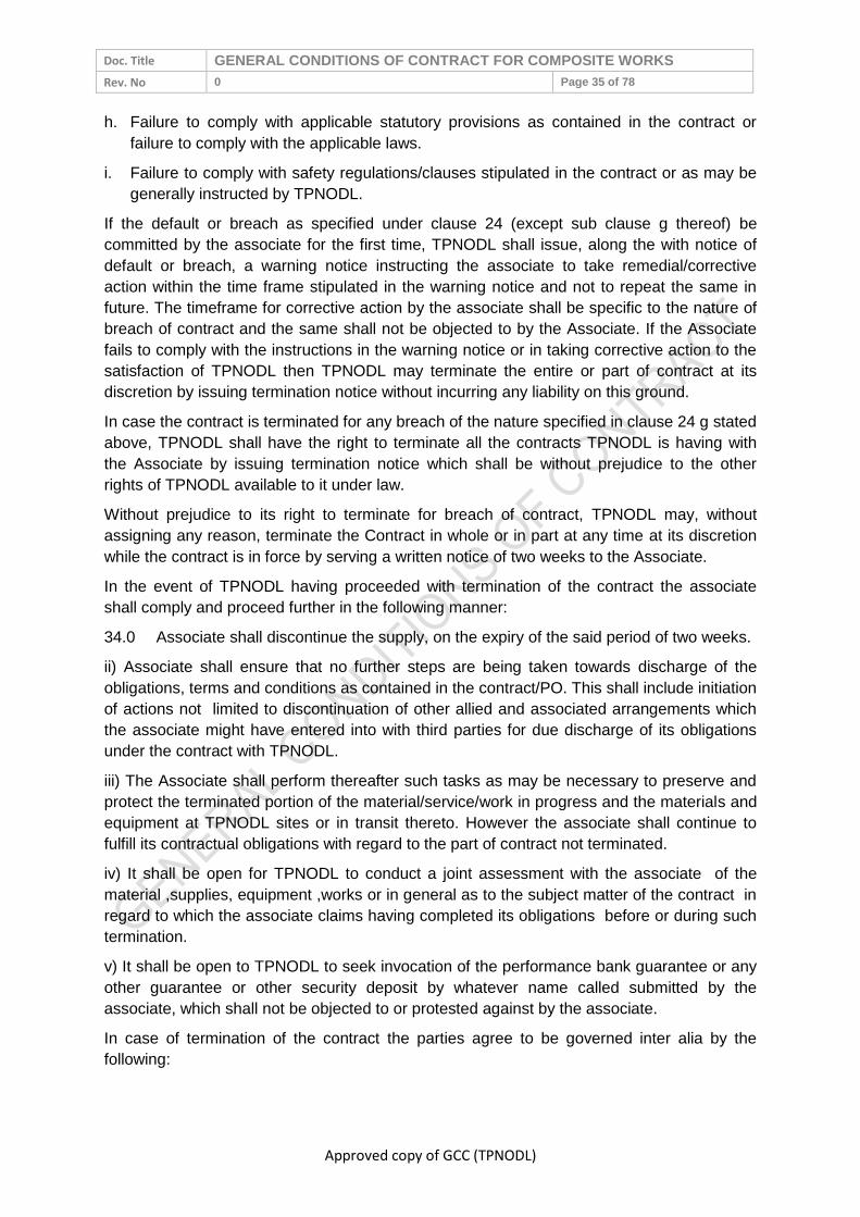
Doc. Title GENERAL CONDITIONS OF CONTRACT FOR COMPOSITE WORKS
Rev. No 0 Page 35 of 78
Approved copy of GCC (TPNODL)
h. Failure to comply with applicable statutory provisions as contained in the contract or
failure to comply with the applicable laws.
i. Failure to comply with safety regulations/clauses stipulated in the contract or as may be
generally instructed by TPNODL.
If the default or breach as specified under clause 24 (except sub clause g thereof) be
committed by the associate for the first time, TPNODL shall issue, along the with notice of
default or breach, a warning notice instructing the associate to take remedial/corrective
action within the time frame stipulated in the warning notice and not to repeat the same in
future. The timeframe for corrective action by the associate shall be specific to the nature of
breach of contract and the same shall not be objected to by the Associate. If the Associate
fails to comply with the instructions in the warning notice or in taking corrective action to the
satisfaction of TPNODL then TPNODL may terminate the entire or part of contract at its
discretion by issuing termination notice without incurring any liability on this ground.
In case the contract is terminated for any breach of the nature specified in clause 24 g stated
above, TPNODL shall have the right to terminate all the contracts TPNODL is having with
the Associate by issuing termination notice which shall be without prejudice to the other
rights of TPNODL available to it under law.
Without prejudice to its right to terminate for breach of contract, TPNODL may, without
assigning any reason, terminate the Contract in whole or in part at any time at its discretion
while the contract is in force by serving a written notice of two weeks to the Associate.
In the event of TPNODL having proceeded with termination of the contract the associate
shall comply and proceed further in the following manner:
34.0 Associate shall discontinue the supply, on the expiry of the said period of two weeks.
ii) Associate shall ensure that no further steps are being taken towards discharge of the
obligations, terms and conditions as contained in the contract/PO. This shall include initiation
of actions not limited to discontinuation of other allied and associated arrangements which
the associate might have entered into with third parties for due discharge of its obligations
under the contract with TPNODL.
iii) The Associate shall perform thereafter such tasks as may be necessary to preserve and
protect the terminated portion of the material/service/work in progress and the materials and
equipment at TPNODL sites or in transit thereto. However the associate shall continue to
fulfill its contractual obligations with regard to the part of contract not terminated.
iv) It shall be open for TPNODL to conduct a joint assessment with the associate of the
material ,supplies, equipment ,works or in general as to the subject matter of the contract in
regard to which the associate claims having completed its obligations before or during such
termination.
v) It shall be open to TPNODL to seek invocation of the performance bank guarantee or any
other guarantee or other security deposit by whatever name called submitted by the
associate, which shall not be objected to or protested against by the associate.
In case of termination of the contract the parties agree to be governed inter alia by the
following:

Doc. Title GENERAL CONDITIONS OF CONTRACT FOR COMPOSITE WORKS
Rev. No 0 Page 36 of 78
Approved copy of GCC (TPNODL)
a) In case TPNODL exercises its right of termination as stated above the associate shall not
dispute or object to the same.
b) The Associate shall be entitled to receive and claim only such payments OR sums of
money from TPNODL as may be found payable to it in regard to works executed by it under
the terms of the contract and no other claim of any nature whatsoever shall be made by the
Associate.
c) All such provisions which the parties have agreed to survive and prevail even after
termination of the contract shall remain effective despite the termination.
In the event of such termination, TPNODL may finish the Work by whatever method it may
deem expedient, including the hiring of services and /or purchase of material equipment from
such third parties as TPNODL may deem fit or may itself provide any labor or materials and
perform any part of the Work. The associate undertakes to bear the incremental costs if
any paid by TPNODL in such a case attributable to failure on the part of the associate. The
Associate in such a case shall not be entitled to receive any further payments and any sums
found payable to it may be adjusted by TPNODL against the amount recoverable from him
on this ground. The same shall be without prejudice to other rights available to TPNODL
under law against the associate.
Upon the termination of any of the contract due to occurrence of any circumstances provided
in clauses stated above and constituting repeated breach or misconduct , TPNODL shall be
entitled to bar the associates its agents , affiliates from undertaking any negotiation /
tendering, bidding, participation activities concerning TPNODL for a period of two years from
date of such termination. The same shall be without prejudice to other rights available to
TPNODL.
24.2 Termination for convenience of Associate
Associate at its convenience may request for termination of contract, clearly assigning the
reason for such request. TPNODL has full right to accept, reject or partially accept such
request. This convenience will be available to associate only after one year from the contract
effective date. For this purpose, associate will provide a notice period of 90 days to
TPNODL, Associate will have to pay TPNODL a ‘termination convenience fee’ equivalent to
5% of unexecuted contract value.
24.3 Termination for Convenience of TPNODL
TPNODL at its sole discretion may terminate the contract by giving 30 days prior notice in
writing or through email to the Associate. TPNODL shall pay the Associate for all the
supplies/ services rendered till the actual date of contract termination against submission of
invoice by the Associate to that effect.
25.0 DISPUTE RESOLUTION & ARBITRATION
In case of any dispute or difference the parties shall endeavor to resolve the same through
conciliatory and amicable measures within 15 Days failing which the matter may be referred
by either party for resolution by the sole arbitrator to be appointed mutually by both the
parties. The arbitral proceedings shall be conducted in accordance with Arbitration and
Conciliation Act 1996 and the place of arbitration shall be Bhubaneswar. The language to be
used at proceedings shall be English and the award of the arbitrator shall be final and
binding on the parties. The parties shall bear their respective costs of arbitration. The

Doc. Title GENERAL CONDITIONS OF CONTRACT FOR COMPOSITE WORKS
Rev. No 0 Page 37 of 78
Approved copy of GCC (TPNODL)
associate shall continue to discharge its obligations towards due performance of the works
as per the terms of the contract during the arbitration proceedings unless otherwise directed
in writing by TPNODL or suspended by the arbitrator. Further, TPNODL shall continue
making such payments as may be found due and payable to the associate for such works.
35.0 Governing law and jurisdiction
The parties shall be subject to the jurisdiction of the courts of law in Bhubaneswar and any
matter arising here from shall be subject to applicable law in force in India.
26.0 ATTRIBUTES OF GCC
26.1 Cancellation
The Company reserves the right to cancel, add, delete at its sole discretion, all or any terms
of this GCC or any contract, order or terms agreed between the parties in pursuance without
assigning any reasons and without any compensation to the Associates.
26.2 Severability
If any portion of this GCC is held to be void, invalid, or otherwise unenforceable, in whole or
part, the remaining portions of this GCC shall remain in effect.
26.3 Order of Priority
In case of any discrepancies between the stipulations in General Conditions of the Contract
(GCC) and Special Conditions of Contract (SCC), the GCC shall stand superseded by the
SCC to the extent stipulated hereinabove while balance portion of respective clauses of
GCC shall continue to be applicable.
36.0 INSURANCE
The Associate shall arrange accident insurance policy for his foreign
experts/specialists/personnel deputed to Site and Associate’s/his sub-Associates’
manufacturing works as well as for his Indian engineers and supervisory staff. The Associate
shall also take out for his Indian workmen, where applicable, a separate policy as required
under Workmen’s Compensation Act.
Associates shall be responsible to suitably insure their entire work-force (to the extent of at
least meeting requirements under Workmen Compensation Act) Tools, Plant, Third party
liability at the project site, All Risk comprehensive insurance for the entire works (insurance
for free issue items will be in TPNODL scope) for total contract (PO/RO) value or any other
such risks during execution of works, till the works are handed over to the company, in
consultation with TPNODL and shall submit copies of such insurances to the Engineer-in-
Charge for review / acceptance before commencing the work. Engineer-in-charge must
ensure compliance to insurance requirement by Associate before commencement of works.
TPNODL shall stand fully indemnified in this respect.
28.0 ERRORS AND OMISSIONS
The Associate shall be responsible for all discrepancies, errors and omissions in the
drawings, documents or other information submitted by him, irrespective of whether these
have been approved, reviewed or otherwise accepted by the TPNODL or not. However any
error in design/drawing arising out of any incorrect data/written information from TPNODL
will not be considered as error and omissions on part of the Associate.
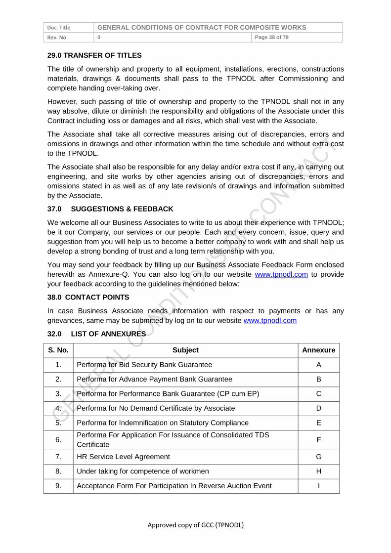
Doc. Title GENERAL CONDITIONS OF CONTRACT FOR COMPOSITE WORKS
Rev. No 0 Page 38 of 78
Approved copy of GCC (TPNODL)
29.0 TRANSFER OF TITLES
The title of ownership and property to all equipment, installations, erections, constructions
materials, drawings & documents shall pass to the TPNODL after Commissioning and
complete handing over-taking over.
However, such passing of title of ownership and property to the TPNODL shall not in any
way absolve, dilute or diminish the responsibility and obligations of the Associate under this
Contract including loss or damages and all risks, which shall vest with the Associate.
The Associate shall take all corrective measures arising out of discrepancies, errors and
omissions in drawings and other information within the time schedule and without extra cost
to the TPNODL.
The Associate shall also be responsible for any delay and/or extra cost if any, in carrying out
engineering, and site works by other agencies arising out of discrepancies, errors and
omissions stated in as well as of any late revision/s of drawings and information submitted
by the Associate.
37.0 SUGGESTIONS & FEEDBACK
We welcome all our Business Associates to write to us about their experience with TPNODL;
be it our Company, our services or our people. Each and every concern, issue, query and
suggestion from you will help us to become a better company to work with and shall help us
develop a strong bonding of trust and a long term relationship with you.
You may send your feedback by filling up our Business Associate Feedback Form enclosed
herewith as Annexure-Q. You can also log on to our website www.tpnodl.com to provide
your feedback according to the guidelines mentioned below:
38.0 CONTACT POINTS
In case Business Associate needs information with respect to payments or has any
grievances, same may be submitted by log on to our website www.tpnodl.com
32.0 LIST OF ANNEXURES
S. No. Subject Annexure
1. Performa for Bid Security Bank Guarantee A
2. Performa for Advance Payment Bank Guarantee B
3. Performa for Performance Bank Guarantee (CP cum EP) C
4. Performa for No Demand Certificate by Associate D
5. Performa for Indemnification on Statutory Compliance E
6. Performa For Application For Issuance of Consolidated TDS
Certificate F
7. HR Service Level Agreement G
8. Under taking for competence of workmen H
9. Acceptance Form For Participation In Reverse Auction Event I

Doc. Title GENERAL CONDITIONS OF CONTRACT FOR COMPOSITE WORKS
Rev. No 0 Page 39 of 78
Approved copy of GCC (TPNODL)
10. NEFT or RTGS payment request form J
11. Contractor Safety Management System K
12 Vendor Appraisal Form L
13 Manufacturers Authorization Form M
14 Safety Bid Document N
15 Tata Code of Conduct P
16 Vendor Feedback Form Q

Doc. Title GENERAL CONDITIONS OF CONTRACT FOR COMPOSITE WORKS
Rev. No 0 Page 40 of 78
Approved copy of GCC (TPNODL)
ANNEXURE-A
PROFORMA FOR BID SECURITY BANK GUARANTEE
TP Northern Odisha Distribution Ltd
Balasore
WHEREAS, (Name of the Bidder) ____________________ (hereinafter called “the
BIDDER”) has submitted his bid dated______________ for the (Tender No. & Name of
Contract) __________________________________ (hereinafter called “the BID”).
KNOW ALL men by these presents we (Name of the Bank)
_______________________________ of (Name of the Country) _______________ having
our registered office at_______________________ (hereinafter called “the BANK) are
bound unto TP Northern Odisha Distribution Ltd (TPNODL) in the sum of
______________________ for which payment well and truly to be made to the TPNODL the
Bank binds himself, his successors and assigns by these presents.
SEALED with the Common Seal of the said Bank this _______ day of _________ 20_____.
The CONDITIONS of this obligation are:
i) If the Bidder withdraws his Bid during the period of bid validity specified in the Proforma
of Bid
or
ii) If the Bidder having been notified of the acceptance of his Bid by the TPNODL during the
period of bid validity fails or refuses to furnish the Contract Performance Bank
Guarantee, in accordance with the Instructions to Bidders.
We undertake to pay the TPNODL upto the above amount upon receipt of its first written
demand, provided that in its demand the TPNODL will note that amount claimed by it is due
to it owing to the occurrence of one or both conditions, specifying the occurred condition or
conditions.
This Guarantee will remain in force upto and including the date (No of days as mentioned in
tender enquiry) days after the closing date of submission of bids as stated in the Invitation to
Bid or as extended by you at any time prior to this date, notice of which extension to the
Bank being hereby waived, and any demand in respect thereof should reach the Bank not
later than the above date.
DATE……………… SIGNATURE OF THE
BANK………………………..
WITNESS……………………………. SEAL………………………...
(Signature, Name & Address)
(At least 2 witnesses)

Doc. Title GENERAL CONDITIONS OF CONTRACT FOR COMPOSITE WORKS
Rev. No 0 Page 41 of 78
Approved copy of GCC (TPNODL)
ANNEXURE-B
PROFORMA FOR ADVANCE PAYMENT BANK GUARANTEE
(On Rs.100/- Stamp Paper)
Note:
(a) Format shall be followed in toto
(b) Claim period of six months must be kept up
(c) The guarantee to be accompanied by the covering letter from the bank confirming the
signature to the guarantee
---------------------------------------------------------------------------------------------------------------------------
---------
TP Northern Odisha Distribution Ltd
Balasore
Advance Payment B.G.No……………………
Contract No…………………dated……………
1. You have entered into a Contract
No________________________________________ with
M/s._________________________________________ (hereinafter referred to as “the
Vendor”) for the supply and delivery of ________________________________
(hereinafter referred to as" the said Equipment”) for the price and on the terms and
conditions contained in the said contract.
2. In accordance with the terms of the said contract, you have agreed to make an advance
payment of Rs._______________
(Rupees_____________________________________ only) being _______%
(________percent) of the total value of the contract on “the Vendor” furnishing you with
an irrevocable, unconditional and acceptable bank guarantee to be valid till the date of
receipt of “the said equipment” covered by your above mentioned contract. For this
purpose you have agreed to accept our guarantee.
3. In consideration thereof, we, __________________________________________
hereby irrevocably and unconditionally guarantee to pay to you on demand but in any
case before the end of five working days from the date of the claim and without demur
and without reference to “the Vendor” such amount or amounts not exceeding the sum
of Rs.___________ (Rupees ___________________________________ only) being
______% (______percent) of the total value of the contract on receipt of your intimating
that “the Vendor” has not fulfilled his contractual obligations. You shall be the sole
judge for such non-fulfillment and “the Vendor” shall have no right to question such
judgment.
4. You shall have the right to file / make your claim on us under the guarantee for a further
period of one months from the date of expiry.
5. This guarantee shall not be revoked without express consent and shall not be affected
by your granting time or any other indulgence to “the Vendor”, which shall include but

Doc. Title GENERAL CONDITIONS OF CONTRACT FOR COMPOSITE WORKS
Rev. No 0 Page 42 of 78
Approved copy of GCC (TPNODL)
not be limited to, postponement from time to time of the exercise the same in you or any
right which you may have against “the Vendor” and to exercise the same in any
covenant contained or implied in the said contract or any other course or remedy or
security available to you, and our Bank shall not be released from its obligations under
this guarantee by your exercising any of your rights with reference to matters aforesaid
or any of them or by reasons of any other act or forbearance or other acts of omission
or commission on your part or any other indulgence shown by you or by any other
matter or thing whatsoever which under the law would, but for this provision have the
effect of relieving our bank from its obligation under this guarantee.
6. We also agree that you shall be entitled at your option to enforce this guarantee against
our bank as a principal debtor, in the first instance, notwithstanding any other security or
guarantee that you may have in relation to “the Vendor’s” liabilities in respect of the
premises
7. This guarantee shall not be affected by any change in the constitution of our Bank or
“the Vendor” or for any other reason whatsoever.
8. Any claim / extension under the guarantee can be lodge-able at outstation banks or at
Mumbai branch and claim will also be payable at Mumbai Branch (to be confirmed by
Balasore Branch by a letter to that effect)
9. Notwithstanding anything herein contained, our liability under this guarantee is limited to
Rs.___________________
(Rupees___________________________________________ only) and the guarantee
will remain in force upto and including _________(Date) and shall be extended from
time to time for such period or period as may be desired by “the Vendor”.
10. Unless a demand or claim under this guarantee is received by us in writing within one
month from____________ (expiry date) i.e. on or before _____________ (claim period
end date), we shall be discharged from all liabilities under this guarantee thereafter.
Dated at ___________________this _______________ day of ___________ 200_____
Witness
Bank’s rubber stamp
1. ________________________ Banks full address
Designation of Signatory
2. ________________________ Bank official number

Doc. Title GENERAL CONDITIONS OF CONTRACT FOR COMPOSITE WORKS
Rev. No 0 Page 43 of 78
Approved copy of GCC (TPNODL)
ANNEXURE- C
PROFORMA FOR PERFORMANCE BANK GUARANTEE (CP cum EP)
(On Rs.100/- Stamp Paper)
Note:
(a) Format shall be followed in toto
(b) Claim period of one month must be kept up
(c) The guarantee to be accompanied by the covering letter from the bank confirming the
signature to the guarantee
---------------------------------------------------------------------------------------------------------------------------
--------
TP Northern Odisha Distribution Ltd
Balasore CP cum EP BG No.…………………………….
Order/Contract No…………………dated……………
1. You have entered into a Contract No _____________________________________ with M/s._____________________________________________ (hereinafter referred to as “the Vendor”) for the supply cum erection / civil work of ___________________________________ (hereinafter referred to as" the said Equipment”) for the price and on the terms and conditions contained in the said contract.
2. In accordance with the terms of the said contract, “the Vendor” agreed to furnish you with an irrevocable, unconditional and acceptable bank guarantee for 10% of the value of contract and to be valid till the end of Guarantee period plus one month towards “Contract cum Equipment performance”. For this purpose you have agreed to accept the guarantee.
3. In consideration thereof, we, ______________________________________________ hereby irrevocably and unconditionally guarantee to pay to you on demand but in any case before the end of five working days from the date of the claim and without demur and without reference to “the Vendor” such amount or amounts not exceeding the sum of Rs.___________ (Rupees _______________________________________________________ only) being _______% (_______ percent) of the total value of the contract on receipt of your intimating that “the Vendor” has not fulfilled his contractual obligations. You shall be the sole judge for such non-fulfillment and “the Vendor” shall have no right to question such judgment.
4. You shall have the right to file / make your claim on us under the guarantee for a further period of one month from the date of expiry.
5. This guarantee shall not be revoked without express consent and shall not be affected by your granting time or any other indulgence to “the Vendor”, which shall include but not be limited to, postponement from time to time of the exercise the same in you or any right which you may have against “the Vendor” and to exercise the same in any covenant contained or implied in the said contract or any other course or remedy or security available to you, and our Bank shall not be released from its obligations under this guarantee by your exercising any of your rights with reference to matters aforesaid or

Doc. Title GENERAL CONDITIONS OF CONTRACT FOR COMPOSITE WORKS
Rev. No 0 Page 44 of 78
Approved copy of GCC (TPNODL)
any of them or by reasons of any other act or forbearance or other acts of omission or commission on your part or any other indulgence shown by you or by any other matter or thing whatsoever which under the law would, but for this provision have the effect of relieving our bank from its obligation under this guarantee.
6. We also agree that you shall be entitled at your option to enforce this guarantee against our bank as a principal debtor, in the first instance, notwithstanding any other security or guarantee that you may have in relation to “the Vendor’s” liabilities in respect of the premises
7. This guarantee shall not be affected by any change in the constitution of our Bank or “the Vendor” or for any other reason whatsoever.
8. Any claim / extension under the guarantee can be lodge-able at outstation banks or at Mumbai branch and claim will also be payable at Mumbai Branch (to be confirmed by Mumbai Branch by a letter to that effect in case BG is from the branch outside Mumbai)
9. Notwithstanding anything herein contained, our liability under this guarantee is limited to Rs.___________________ (Rupees________________________________________ only and the guarantee will remain in force upto and including _________(Date) and shall be extended from time to time for such period or period as may be desired by “the Vendor”.
10. Unless a demand or claim under this guarantee is received by us in writing within one months from____________ (expiry date) i.e. on or before _____________ (claim period end date), we shall be discharged from all liabilities under this guarantee thereafter.
Dated at___________________ this_______________ day of ___________ 200__
Witness
Bank’s rubber stamp
1. ________________________ Banks full address
Designation of Signatory
2. ________________________ Bank official number

Doc. Title GENERAL CONDITIONS OF CONTRACT FOR COMPOSITE WORKS
Rev. No 0 Page 45 of 78
Approved copy of GCC (TPNODL)
ANNEXURE-D
PROFORMA FOR “NO DEMAND CERTIFICATE” BY ASSOCIATE
(On Company’s Letter head or with Company Seal)
(To be submitted by the Associate to TPNODL Accounts Department at the time of
receipt of full and final payment)
(Certificate No. CCP/002)
Name of the Project
Order/ Contract No.
Dated
Name of the Associate
Scheme No. / Job No.
We, M/s.____________________________________________ (Associate) do hereby
acknowledge and confirm that we have received the full and final payment due and payable
to us from TPNODL, in respect of our aforesaid Order No _____________
dated___________ including amendments, if any, issued by TPNODL to our entire
satisfaction and we further confirm that we have no claim whatsoever pending with TPNODL
under the said contract / W.O.
Notwithstanding any protest recorded by us in any correspondence, documents,
measurement books and / or final bills etc., we waive all our rights to lodge any claim or
protest in future under this contract.
We are issuing this “NO DEMAND CERTIFICATE” in favour of TPNODL, with full knowledge
and with our free consent without any undue influence, misrepresentation, coercion etc.
Dated Signature
Place Name
Designation
(Company Seal)

Doc. Title GENERAL CONDITIONS OF CONTRACT FOR COMPOSITE WORKS
Rev. No 0 Page 46 of 78
Approved copy of GCC (TPNODL)
ANNEXURE – E
PROFORMA FOR “INDEMNIFICATION ON STATUTORY COMPLIANCES”
(To be submitted by the successful Bidder within seven days of award of work)
(Certificate No. CCP/001)
Name of the Project
Letter of Award / Contract No.
Dated
Name of the Associate
Scheme No. / Job No.
By this confirmation we, ___________________________________________________
(Associate) are formally bound to M/s. TPNODL towards any sum which may be imposed,
levied or hereinafter recovered by the Provident Fund Organization under the provisions of
the Employees of the Provident Fund and Miscellaneous Provisions Act 1952 in respect of
employees employed by us.
We well and truly bind ourselves and our heirs executors administrators and representatives
jointly severely and respectively for the above payment only to be paid to M/s. TPNODL.
AND WHEREAS we, _______________________________________________ (Associate)
is making compliance of the Employees Provident Fund and Miscellaneous Provisions Act
1952, have entered into the above written bond for the indemnity to M/s. TPNODL against all
losses from the acts or default of the said Associate in respect of compliance of the
Provident Fund Act.
Similarly we hereby confirm that we have complied with all statutory and local laws and
nothing is outstanding with regard to Local Sales Tax, Labour Laws, Local Municipal dues,
Electricity dues etc. We have entered into the above written bond for the indemnity to M/s.
TPNODL against all losses from the acts or default of the said Associate in respect of
compliance of the Local Sales Tax Laws, Local Laws, Labour Laws, Local Municipal Dues,
Electricity dues etc.
NOW THE CONDITION, of the above written bond is as such that if the Associate during the
period of this contract commits any default or fails to make payment of Contributions in
respect of his employees to the Employees Provident Fund Organization, he shall indemnify
the Principal Employer M/s. TPNODL from all and every loss and damage caused to them
from any act, omissions or negligence of the said Associate in respect of compliances under
the Employees Provident Fund and Miscellaneous Provisions Act, 1952.
IN WITNESS to the above written bond we have here to set our hands, with our free
consent.
Dated Signature
Place Name
Designation (Company Seal)
Doc. Title GENERAL CONDITIONS OF CONTRACT FOR COMPOSITE WORKS
Rev. No 0 Page 47 of 78
Approved copy of GCC (TPNODL)
ANNEXURE-F
PROFORMA FOR APPLICATION FOR ISSUANCE OF CONSOLIDATED TDS
CERTIFICATE
To be printed on the letterhead
To,
TP Northern Odisha Distribution Ltd,
Bhubaneswar
Sub: Application for issuance of Consolidated TDS Certificate for the FY _________
Dear Sir,
I / we hereby request / authorize you to issue me / us a consolidate TDS Certificate for the
financial year _______ against tax deducted at source by you from my / our payments / bills
during the said year from time to time under Chapter XVII – B of the Income Tax Act, 1961.
For and on behalf of
Signature
Name
Address
Contact No. (Land Line)
(Mobile)
PAN #
Assessing authority
ATTACH THE COPY OF PAN CARD

Doc. Title GENERAL CONDITIONS OF CONTRACT FOR COMPOSITE WORKS
Rev. No 0 Page 48 of 78
Approved copy of GCC (TPNODL)
ANNEXURE - G
SERVICE LEVEL AGREEMENT
(To be adhered to by Business Associates (BAs) in TPNODL on Human Resource Issues)
1.0 The following shall be adhered to by the Business Associates during his / its
association with TPNODL:
Shall Abide by TPNODL Core Values:
a) Integrity – We must conduct our business fairly, with honesty and transparency. Everything
we do must stand the test of public scrutiny.
b) Understanding – We must be caring, show respect, compassion and humanity to our
colleagues and customers and always work for the benefit of the communities we serve.
c) Excellence – We must constantly strive to achieve the highest possible standards in our day
to day work and in the quality of services we provide.
d) Unity – We must work cohesively with our colleagues across the group and with our
customers and partners to build strong relationships based on tolerance, understanding and
mutual co-operation.
e) Responsibility – We must continue to be responsible and sensitive to the communities and
environments in which we work and always ensuring that what comes from the people; goes
back to the people many times over.
f) Agility- We must work in a speedy and responsive manner and be proactive and innovative
in our approach.
2.0 The Business Associate / his manager / supervisor who is responsible for managing
the project site / performance contract etc. in TPNODL would also ensure adherence
of these values by his employees / persons deployed by him in connection with his
works undertaken in TPNODL.
3.0 TPNODL is a signatory to the United Nation Global Compact as an integral part of its
Governance principles / business. The Business Associates are required to:
a) Support and respect the protection of human rights and make sure that they are not
complicit in human right abuses.
b) Respect freedom of association and effective recognition of the right to collective
bargaining.
c) Not to resort to any form of forced and compulsory labour.
d) Shall ensure abolition of child labour in his area of work.
e) There is no discrimination in respect of employment and occupation in respect of his
employees.
f) Support precautionary approach to environmental challenges.
g) Promote greater environmental responsibility by himself and his employees in his areas of
work.
h) Deploy and defuse environmental friendly technologies while carrying out the works.
i) Work against corruptions in all its form including extortion and bribery by himself and his
employees.
4.0 The Business Associates are required to adhere to all applicable Labour Laws with
special reference to the following:

Doc. Title GENERAL CONDITIONS OF CONTRACT FOR COMPOSITE WORKS
Rev. No 0 Page 49 of 78
Approved copy of GCC (TPNODL)
a) No person below the age of 18 years and no child labour will be engaged directly or
indirectly for executing the work connected with the business of TPNODL.
b) Minimum wages along with other statutory dues like PF, ESI, etc. as applicable to the
workers shall be made within the prescribed period of 7th / 10th day of the following month.
c) Deduction / deposit / record keeping and all other requirements under Employees PF Act
1952, Employees State Insurance Act 1948 and other applicable acts (if any) shall be
adhered to.
d) Only statutorily authorized deductions (if any) shall be made in accordance with the
relevant statutes.
e) All the provisions of Contract Labour (R&A) Act 1970 shall be complied with in respect of
the workers engaged for TPNODL work. The work will be commenced only after completing
necessary formalities for obtaining Labour License (if applicable).
f) Necessary registers / records, filing of returns etc. shall be maintained for verification by
Statutory / TPNODL authorities.
g) Payment of wages shall be made only in presence of and with certification of authorized
representative of TPNODL or shall be made in the form of cheque / bank transfer to the
employee.
h) During the period of contract, the Business Associate will arrange for deployment of his
supervisor / manager for total supervision and control of the work and their manpower. All
the activities related to their manpower e.g. attendance, leave, wage disbursement etc. will
be done under the supervision & control of Business Associates, While adhering to the
prescribed standard / norms of production / productivity & quality. During execution of the
work, Business Associate shall engage only such qualified / skilled manpower as may be
envisaged / required for ensuring level of production / service into the contract / work order.
i) Clearances as follows shall be obtained from IR & Welfare Group:
i. Clearance for commencement (before start of the work).
ii. No Objection Certificate (after completion / before final settlement).
iii. Copies of PF / ESI Challans shall be deposited with IR & Welfare Group every month
j) The Business Associate shall indemnify TPNODL from any liabilities under applicable
Labour Statutes.
k) The Business Associate shall ensure safety and health of his employees and shall also
maintain hygienic working environment / condition in his area of work.
l) The Business Associate and his employee shall abide by Laws of Land and shall not
violate any applicable provisions.
m) The Business Associate appreciates with and acquiesces to the right of TPNODL as
principal employer to fulfil any of his legal obligations, if he fails to do so under applicable
labour laws and deduct the same from his running bills / final payments / enchasing security
deposit / Bank Guarantee as the case may be. If there is any further shortfall TPNODL has
the right to recover the same from the Business Associate.
n) The Business Associate ensures that person employed by him adhere to the moral and
legal conduct and shall not violate any standard conduct envisaged in the premise of

Doc. Title GENERAL CONDITIONS OF CONTRACT FOR COMPOSITE WORKS
Rev. No 0 Page 50 of 78
Approved copy of GCC (TPNODL)
TPNODL by all such as, Transparency, Safety, Discipline, Integrity etc. The Business
Associate or his employees should refrain from corrupt practices, giving or taking bribe in
connection with any TPNODL business.
5.0 The ‘Statutory Compliance Enforcement System’ in TPNODL is detailed below for
adherence by all concerned. Corporate IR & Welfare Group will be the process owner
for implementation of the system with the help of concerned Engineer I/c or Officer
I/c.
a) Statutory Compliance being a professed value in TPNODL Code of Conduct, the concerned
Engineer / Officer in charges are requested to adhere to the provisions and advise
respective Business Associates in their domain to comply in letter and spirit.
b) Immediately after issuance of letter of intent, the authorized representative of the Business
Associate will report to Corporate IR & Welfare group for completion of statutory
requirements.
c) Normally, the work will be started only after ‘Clearance for Commencement of Work (CCW)
is issued by IR & W group to the Business associate. However in exceptional exigencies in
engineer I/c / Officer I/c may direct the Business Associate to start the work and inform IR &
W group about the same. Statutory requirements in this case may be completed parallely.
d) First monthly bill will be released only after producing CCW to the finance department.
Similarly closure of work and final settlement will be affected after issuance of no objection
certificate from IR & W group.
6.0 Requirements for ‘Clearance for Commencement of Work’ (CCW):
a) Submission of filled up Form ‘A’ for database (Annexure-1).
b) Copy of PF Code allocation letter.
c) Copy of ESI Code allocation letter.
d) Submission of duly filled up Form IV CL(R&A) act (In case more than or equals to 20
workers during the period of contract).
e) Submission of duly filled up Form VI A (Notice of Commencement).
f) Copy of insurance cover note under WC Act 1923 (if applicable).
g) Copy of Contract Agreement.
h) Copy of indemnity bond (if applicable).
i) Affidavit with regard to payment of wages through cheque / bank transfer only.
7.0 Requirements during execution of work:
a) Copy of receipt of application for license / license (if applicable).
b) Copy of PF Challan (latest by 26th day of every Month).
c) Copy of ESI Challan (latest by 26th day of every Month).
d) Copy of Wage disbursement sheet / Bank statement.
e) Filing / Maintenance of all statutory registers / reports / returns for inspection by Statutory/
TPNODL authorities.
f) Certification of wage disbursement by authorized representative of TPNODL.
g) Copy of ‘Labour Welfare Fund’ deposit certificate / Challan.
h) Insuring safe working practices at the work place.
8.0 Requirements for ‘No Objection Certificate’ (NOC) for closure of work:
a) Submission of duly filled up Form VI A (Notice of Completion).

Doc. Title GENERAL CONDITIONS OF CONTRACT FOR COMPOSITE WORKS
Rev. No 0 Page 51 of 78
Approved copy of GCC (TPNODL)
b) Copy of Half yearly / Annual return for ESI / PF / CL(R&A).
c) Consolidated copy of wage sheet of last month indicating full & final settlement of all dues
like retrenchment benefit, bonus, leave encashment etc. Copy of individual declaration by
employees in Form X regarding termination of employment.
d) Confirmation certificate regarding filling up of form for transfer / withdrawal of PF by the
concerned workers.
In case any of the above are deviated / not complied with the Letter of Award/Order
shall be liable to be withdrawn / cancelled.
Enclosure:
1) Form A
2) Form X
3) Form XI
4) Form VI A
5) Form XXIV

Doc. Title GENERAL CONDITIONS OF CONTRACT FOR COMPOSITE WORKS
Rev. No 0 Page 52 of 78
Approved copy of GCC (TPNODL)
FORM (A)
[To be submitted by the Business Associate to the Principal Employer within a week from LoA
issuance]
A. Details of the Agency
1. Name of Agency :
2. Nature of work :
3. Local Address with Ph.No. :
(With Father’s name) :
4. Permanent Address (Full) :
5. PF code no. & Place :
6. ESI Code no. & Place :
7. Name and address of :
Sub-contractor (if any)
B. Details of Work
8. Name of work (as specified in LOI/LOA) :
9. LOI/LOA Nos. & Dates :
10. Period of contract (Specify Dates) :
[Including Extension period, if any] :
11. Work Area [Department / Location] :
12. Name / Cell no. of Officer I/c :
13. Maximum No. of workers and staff to be engaged on any day during the year.
Supervisory Staff :
Workers :
14. Do you have any other contract in TPNODL : Yes/No
If yes, furnish details:

Doc. Title GENERAL CONDITIONS OF CONTRACT FOR COMPOSITE WORKS
Rev. No 0 Page 53 of 78
Approved copy of GCC (TPNODL)
15. Details of Workmen’s compensation Policy, if applicable
Name of Insurance Company ……………………………………………………………………………...
………………………………………Policy No ……………………………… Number of persons
covered …………… Period of coverage: From ……………………. To …………………….…..
If no, I hereby undertake the liability arising out of Workmen’s Compensation Act and Rules made there under.
C. Details of workers to be engaged
No. of Workers
S. No. Unskilled* Semi-skilled* Skilled* Clerical / Supervisory
* Number to be indicated
I/We shall fulfill all obligations arising from and under all relevant law in force from time to time. I/We
undertake to keep the TPNODL indemnified against any loss or liability arising out of failure of my /
our abiding the relevant laws.
The name of my / our representatives is …………………………………………… to enter the
TPNODL Premises on my behalf.
Date:
(Signature of the Business Associate
or his Authorized Representative)
This Business Associate is / will be engaged in TPNODL.
(Signature and seal of
Officer I/c of the Work)

Doc. Title GENERAL CONDITIONS OF CONTRACT FOR COMPOSITE WORKS
Rev. No 0 Page 54 of 78
Approved copy of GCC (TPNODL)
Form X
Undertaking
I _________________________________________________ hereby undertake that all the
dues in respect of my employment with M/s ____________________________________ for
the period of _______________________________ to __________________________have
been settled and final payments including retrenchment benefit have been made to me in full.
( )
______________________________
Date:

Doc. Title GENERAL CONDITIONS OF CONTRACT FOR COMPOSITE WORKS
Rev. No 0 Page 55 of 78
Approved copy of GCC (TPNODL)
Form XI
Undertaking
With reference to the contract job awarded by M/s TPNODL to
M/s__________________________________________________________________ vide work
order No.______________________________________________ dated__________________
I _______________________on behalf of
M/s _________________________________________________hereby undertake:
1. that the dues in respect of the workmen/ employee(s) engaged by us for the said contract,
payable as per the provisions of relevant statute pertaining to
i. wages/ salary
ii. PF & ESI, Bhubaneswar Labour Fund
iii. All other statutory obligation
has been paid /settled in full and no amount/ compliance is due/ pending.
2. That in case any dispute / claim is raised by the concerned workers i.r.o. any dues / payments,
M/s ____________________________________ will settle the same on it’s own and such
liability will be borne by M/s ____________________________________________________
3. That M/s _________________________________________ hereby indemnify M/s TPNODL
from any future liability i.r.o. any statutory obligation in respect of said contract.
Date:
________________________
( )
Authorized Signatory
For M/s _____________________

Doc. Title GENERAL CONDITIONS OF CONTRACT FOR COMPOSITE WORKS
Rev. No 0 Page 56 of 78
Approved copy of GCC (TPNODL)
FORM- VI A
Notice for Commencement /Completion of contract work
I/We, Sh. / M/s ____________________________________________________ (Name
and Address of the Contractor) hereby intimate that the contract work
_______________________________________________ (name of work) in establishment
of the ________________________________________ (name and address of the
Principal Employer) for which License
No.___________________________________________dated_____________________ha
s been issued to me/us by the Licensing Officer _______________________(name of the
Headquarters), has been commenced / completed with effect from
______________________date / on date.
Signature of Contractor
With Office Seal
The Inspector
__________________________
__________________________

Doc. Title GENERAL CONDITIONS OF CONTRACT FOR COMPOSITE WORKS
Rev. No 0 Page 57 of 78
Approved copy of GCC (TPNODL)
FORM XXIV
[See Rule 82(1)]
Return to be sent by the Contractor to the licensing Officer (in duplicate)
Half -Yearly Ending_______
1. Name and address of the Contractor
2. Name and address of the Establishment
3. Name and address of the Principal Employer
4. Duration of Contract: From _______________to _________________
5. No. of days during the half year on which
(a) the establishment of the principal employer had worked
(b) the contractor’s establishment had worked
6. Maximum No. of contract labour employed on any day during the half –year:
Men Women Children Total
7. (i) Daily hours of work and spread over
(ii) (a) whether weekly holiday observed and on what day
(b) if so, whether it was paid for
(iii) No. of man – hours of overtime worked
8. No. of man days worked by
Men Women Children Total
9. Amount of wages paid
Men Women Children Total
10. Amount of deductions from wages, if any
Men Women Children Total
Whether the following have been provided –
(i) Canteen : _____________
(ii) Rest rooms : _____________

Doc. Title GENERAL CONDITIONS OF CONTRACT FOR COMPOSITE WORKS
Rev. No 0 Page 58 of 78
Approved copy of GCC (TPNODL)
(iii) Drinking water : _____________
(iv) Crèches : _____________
(v) First Aid : _____________
Signature of contractor
Place _________________
Date __________________

Doc. Title GENERAL CONDITIONS OF CONTRACT FOR COMPOSITE WORKS
Rev. No 0 Page 59 of 78
Approved copy of GCC (TPNODL)
ANNEXURE – H
UNDERTAKING FOR COMPETENCE OF WORKMEN
Name of Associate :
Tender No. :
Item :
With reference to the tender mentioned above, I/We _______________________________,
hereby undertake that the workmen/ employee(s) engaged by M/s
__________________________ for the job against said tender shall be competent in all
respect, commensurate to the nature of job.
Date: _____________________________
( )
Authorized Signatory
For M/s
Seal

Doc. Title GENERAL CONDITIONS OF CONTRACT FOR COMPOSITE WORKS
Rev. No 0 Page 60 of 78
Approved copy of GCC (TPNODL)
ANNEXURE-I
ACCEPTANCE FORM FOR PARTICIPATION IN REVERSE AUCTION EVENT
(To be signed and stamped by the bidder prior to participation in the auction event)
In a bid to make our entire procurement process more fair and transparent, TPNODL intends to use
the reverse auctions through SAP-SRM/ ARIBA tool as an integral part of the entire tendering
process. All the bidders who are found as technically qualified based on the tender requirements shall
be eligible to participate in the reverse auction event.
The following terms and conditions are deemed as accepted by the bidder on participation in
the bid event:
1. TPNODL shall provide the user id and password to the authorized representative of the bidder.
(Authorization Letter in lieu of the same shall be submitted along with the signed and stamped
Acceptance Form).
2. TPNODL will make every effort to make the bid process transparent. However, the award
decision by TPNODL would be final and binding on the supplier.
3. The bidder agrees to non-disclosure of trade information regarding the purchase, identity of
TPNODL, bid process, bid technology, bid documentation and bid details.
4. The bidder is advised to understand the auto bid process to safeguard themselves against any
possibility of non-participation in the auction event.
5. In case of bidding through Internet medium, bidders are further advised to ensure availability of
the entire infrastructure as required at their end to participate in the auction event. Inability to bid
due to telephone line glitch, internet response issues, software or hardware hangs, power failure
or any other reason shall not be the responsibility of TPNODL.
6. In case of intranet medium, TPNODL shall provide the infrastructure to bidders. Further, TPNODL
has sole discretion to extend or restart the auction event in case of any glitches in infrastructure
observed which has restricted the bidders to submit the bids to ensure fair & transparent
competitive bidding. In case an auction event is restarted, the best bid as already available in the
system shall become the start price for the new auction.
7. In case the bidder fails to participate in the auction event due any reason whatsoever, it shall be
presumed that the bidder has no further discounts to offer and the initial bid as submitted by the
bidder as a part of the tender shall be considered as the bidder’s final no regret offer. Any offline
price bids received from a bidder in lieu of non-participation in the auction event shall be outrightly
rejected by TPNODL.
8. The bidder shall be prepared with competitive price quotes on the day of the bidding event.
9. The prices as quoted by the bidder during the auction event shall be inclusive of all the applicable
taxes, duties and levies and shall be FOR at TPNODL site.
10. The prices submitted by a bidder during the auction event shall be binding on the bidder.
11. No requests for time extension of the auction event shall be considered by TPNODL.
12. The original price bids of the bidders shall be reduced on pro-rata basis against each line item
based on the final all-inclusive prices offered during conclusion of the auction event for arriving at
Contract amount.
Signature & Seal of the Bidder

Doc. Title GENERAL CONDITIONS OF CONTRACT FOR COMPOSITE WORKS
Rev. No 0 Page 61 of 78
Approved copy of GCC (TPNODL)
ANNEXURE-J
To,
DGM (Finance) TP Northern Odisha Distribution Ltd
Balasore
Sub: e-Payments through National Electronic Fund Transfer (NEFT) OR Real Time
Gross Settlement System (RTGS)
Dear Sir,
We request and authorize you to affect e-payment through NEFT/RTGS to our Bank Account as per the details given below:-
Vendor Code :
Title of Account in the Bank :
Account Type :
(Please mention here whether account is
Savings/Current/Cash Credit)
Bank Account Number :
Name & Address of Bank
:
Bank Contact Person’s Names :
Bank Tele Numbers with STD Code :
Bank Branch MICR Code :
(Please enclose a Xerox a copy of a cheque.
This cheque should not be a payable at par
cheque)
Bank Branch IFSC Code :
(You can obtain this from branch where you
have your account)
Email Address of accounts person (to
:

Doc. Title GENERAL CONDITIONS OF CONTRACT FOR COMPOSITE WORKS
Rev. No 0 Page 62 of 78
Approved copy of GCC (TPNODL)
send payment information)
Name of the Authorized Signatory :
Contact Person’s Name
Official Correspondence Address
:
:
We confirm that we will bear the charges, if any, levied by our bank for the credit of
NEFT/RTGS amounts in our account. Any change in above furnished information shall be
informed to TPNODL well in time at our own. Further, we kept TPNODL indemnified for any
loss incurred due to wrong furnishing of above information.
Thanking you,
For ____________________
(Authorized Signatory)
(Signature with Rubber Stamp)
Certification from Bank:
We confirm that we are enabled for receiving NEFT/RTGS credits and we further confirm
that the account number (specify Bank a/c no.) of (Please mention here name of the account
holder), the signature of the authorized signatory and the MICR and IFSC Code of our
branch mentioned above are correct.
This also is certified that the above information is correct as per Bank record
(Manager’s/ Officers Signature under Bank Stamp)

Doc. Title GENERAL CONDITIONS OF CONTRACT FOR COMPOSITE WORKS
Rev. No 0 Page 63 of 78
Approved copy of GCC (TPNODL)
ANNEXURE-L
VENDOR APPRAISAL FORM
TO BE SUBMITTED BY VENDOR (To be filled as applicable)
Part A
1.0 DETAILS OF THE FIRM
1.1 NAME (IN CAPITAL LETTERS)
1.2
TYPE OF CONCERN (PROPRIETORY)
PARTNERSHIP PVT.LTD., PUBLIC LTD.
ETC.
1.3 YEAR OF ESTABLISHMENT
1.4 LOCATION OF OFFICE
POSTAL ADRESS
1.5
CONTACT DETAIL OF BA’s
REPRESENTATIVE
NAME
E-MAIL ID
CELL NO.
1.6 LOCATION OF MANUFACTURING
UNITS :
i) UNITS 1 :
ii) OTHER UNITS :
2.0 PRODUCTS / SERVICES BEING OFFERED :
3.0
TURNOVER DURING THE LAST 3 YEARS
(TO BE VERIFIED WITH THE LATEST
PROFIT & LOSS STATEMENT).
:
4.0 AVALABILITY OF STATUTORY
DOCUMENTS I.E. COPY OF PAN CARD :
5.0 AVALABILITY OF STATUTORY DOCUMENTS
I.E. COPY OF GST REGISTRATION :
6.0 APPLICABILITY UNDER MSME
CERTIFICATION :
Doc. Title GENERAL CONDITIONS OF CONTRACT FOR COMPOSITE WORKS
Rev. No 0 Page 64 of 78
Approved copy of GCC (TPNODL)
7.0 BA BELONGS TO AA COMMUNITY (SC/ST) :
8.0 DOCUMENTS VERIFYING ADDRESS PROOF
(SUPPORTED BY ANY GOVT. ISSUED
DOCUMENT)
:
9.0 TECHNICAL
9.1
NO.OF DESIGN ENGINEERS
(INDICATE NO.OF YEARS
EXPERIENCE IN RELATED FIELDS)
:
9.2 NO.OF DRAUGHTSMEN :
9.3 COLLABORATION DETAILS (IF ANY) :
9.3.1 DATE OF COLLABORATION :
9.3.2 NAME OF COLLABORATOR :
9.3.3 RBI APPROVAL DETAILS :
9.3.4 EXPERIENCE LIST OF
COLLABORATOR :
9.3.5 DURATION OF AGREEMENT :
9.4
AVAILABILITY OF STANDAR0DS /
DESIGN PROCEDURES / COLLA-
BORATOR’S / DOCUMENTS (CHECK
WHETHER THESE ARE
LATEST/CURRENT
:
9.5
TECHNICAL SUPPORT, BACK-UP
GUARANTEE, SUPERVISION, QUALITY
CONTROL BY COLLABORATOR
(WHEREVER ESSENTIAL). (THIS
CLAUSE IS RELEVANT WHEN
VENDOR’S EXPERIENCE IS
INADEQUATE)
:
9.6 QUALITY OF DRAWINGS :
10.
0 MANUFACTURE
10.
1
SHOP SPACE, LAYOUT LIGHTING,
VENTILATION, ETC. :
10.
2 POWER (KVA) :

Doc. Title GENERAL CONDITIONS OF CONTRACT FOR COMPOSITE WORKS
Rev. No 0 Page 65 of 78
Approved copy of GCC (TPNODL)
MAINS INSTALLED :
UTILISED :
STANDBY POWER SOURCE :
10.
3
MANUFACTURING FACILITIES
(ATTACH LIST OF EQUIPMENTS AS
APPLICABLE)
:
10.3.1 MATERIAL HANDLING :
10.3.2 MACHINING :
10.3.3 FABRICATION :
10.3.4 HEAT TREATMENT :
10.3.5 BALANCING FACILITY :
10.3.6 SURFACE TREATMENT PRIOR
TO PAINTING/ COATING,
POLISHING, PICKLING,
PASSIVATION, PAINTING, ETC.
:
10.
4 SUPERVISORY STAFF :
10.
5
ADEQUACY OF SKILLED LABOURS
(MACHINISTS, WELDERS, ETC.) :
10.
6 NO. OF SHIFTS :
10.
7
TYPE OF MATERIAL HANDLED (SUCH
AS CS, SS, ETC.)
10.
8 WORKMANSHIP :
10.
9 MATERIAL IN STOCK AND VALUE :
10.
10 TRANSPORT FACILITIES :
10.
11 CARE IN HANDLING :
11.
0 INSPECTION / QC / QA / TESTING

Doc. Title GENERAL CONDITIONS OF CONTRACT FOR COMPOSITE WORKS
Rev. No 0 Page 66 of 78
Approved copy of GCC (TPNODL)
11.
1
NUMBER OF PERSONNEL (INDICATE
NO.OF YEARS OF EXPERIENCE) :
11.
2 INDEPENDENCE FROM PRODUCTION :
11.
3
AVAILABILITY OF PROCEDURAL
WRITE UP/QUALITY PLAN :
11.
4
INCOMING MATERIAL CONTROL AND
DOCUMENTATION :
11.
5
RELIABILITY/REPUTATION OF
SUPPLY SOURCES :
11.
6
STAGE INSPECTION AND
DOCUMENTATION :
11.
7 SUB-ASSEMBLY & DOCUMENTATION :
11.
8
FINAL INSPECTION AND
DOCUMENTATION :
11.
9
PREPARATION OF FINAL
DOCUMENTATION PACKAGE :
11.
10 TYPE TEST FACILITIES :
11.
11 ACCEPTANCE TEST FACILITIES :
11.
12
CALIBRATION OF INSTRUMENTS AND
GAUGES (WITH TRACEABILITY TO
NATIONAL STANDARDS) (ATTACH
LIST)
:
11.
13
STATUTORY APPROVALS LIKE BIS,
IBR, ETC.(AS APPLICABLE) :
11.
14
SUB-VENDOR APPROVAL SYSTEM
AND QUALITY CONTROL :
11.
15
DETAILS OF TESTS CARRIED OUT AT
INDEPENDENT RECOGNISED
LABORATORIES
:

Doc. Title GENERAL CONDITIONS OF CONTRACT FOR COMPOSITE WORKS
Rev. No 0 Page 67 of 78
Approved copy of GCC (TPNODL)
i) FURNISH LIST OF TESTS
CARRIED OUT AND THE NAME
OF THE LABORATORY WHERE
THE TESTS WERE
CONDUCTED
:
ii) CHECK AVAILABILITY OF
CERTIFICATES AND REVIEW
THESE WHEREVER POSSIBLE
:
12.
0
EXPERIENCE (INCLUDING CONSTRUCTION
/ ERECTION / COMMISSIONING) TO BE
FURNISHED IN THE FORMAT INDICATED IN
APPENDIX)
:
13.
0
SALES, SERVICE AND SITE
ORGANISATIONAL DETAILS :
14.
0
CERTIFICATE FROM CUSTOMERS (ATTACH
COPIES OF DOCUMENTS) :
15.
0 POWER SITUATION :
16.
0 LABOUR SITUATION :
17.
0
APPLICABILITY OF SC/ST RELAXATION
(Y/N)
IF YES, SUPPORTING DOCUMENTS TO BE
ATTACHED
Part C Supporting Documents

Doc. Title GENERAL CONDITIONS OF CONTRACT FOR COMPOSITE WORKS
Rev. No 0 Page 68 of 78
Approved copy of GCC (TPNODL)
18.
0
DOCUMENTS TO BE ENCLOSED:
1. Factory License
2. ISO Certificate
3. Registration of Central Excise
4. Income Tax Clearance.
5. PF Registration
6. ESI Registration
7. Insurance for Workman Compensation
Act No.
8. Electrical Contract LIC No.
9. PAN No.
10. GST Registration
11. MSME Certification
12. WC Tax Registration
13. Organogram of Co. having organogram
of Design, safety, quality, production and
other teams.
14. Details of subscription of BIS, IEC, IEE,
ASTM or other.
15. Details of the team in Design, Quality,
Safety, Production.
16. List of manufacturing equipment as per
Part C.
17. List of calibrated equipment as per Part
C.
18. List of clients and order executed in past
two years.
19. Complaint escalation matrix.
20. Performance Certificates of same
product from Minimum two utilities.
21. e-Payment Form as per enclosed
Annexure-J
* Classification of BA s under SC/ST shall be governed under following guidelines:
Proprietorship/ Single Ownership Firm: Proprietor of the firm should be from SC/ST community. Governing document shall be Proprietorship Deed.
Partnership Firm: Only such firms shall qualify which have SC/ST partners holding equal to or more than 50% of the total ownership pattern of the firm. Governing document shall be Partnership Deed.
Private Limited Company: Only such firms shall qualify which have SC/ST directors holding equal to or more than 50% of the total ownership pattern of the firm. Governing document shall be Memorandum of Understanding (MoU) and/or Article of Association (AoA).
The relaxation available for BAs under SC / STs shall be as per GCC for Tender Fees, EMD, PBG and Turnover criteria.
Note:

Doc. Title GENERAL CONDITIONS OF CONTRACT FOR COMPOSITE WORKS
Rev. No 0 Page 69 of 78
Approved copy of GCC (TPNODL)
Certification from SC/ST Commission shall be required for deciding upon SC/ST
status of a person.
Annexure-J (e-Payment detail form) must be filled by Associate along with this form.
ANNEXURE-M
MANUFACTURER AUTHORIZATION FORM
(To be submitted on OEM’s Letter Head)
Date: …………….
Tender Enquiry No.: …………..
To,
Chief (Procurement & Stores)
TP Northern Odisha Distribution Ltd, Mumbai
Sir,
WHEREAS M/s. [name of OEM], who are official manufacturers of ………… having factories at [address of OEM] do hereby authorize M/s [name of bidder] to submit a Bid in relation to the Invitation for Bids indicated above, the purpose of which is to provide the following Goods, manufactured by us
………………………………………………………………………………………………………….
and to subsequently negotiate and sign the Contract.
We hereby extend our full guarantee and warranty in accordance with the Special Conditions of Contract or as mentioned elsewhere in the Tender Document, with respect to the Goods offered by the above firm in reply to this Invitation for Bids.
We hereby confirm that in case, the channel partner fails to provide the necessary services as per the Tender Document referred above, M/s [name of OEM] shall provide standard warranty on the materials supplied against the contract. The warranty period and inclusion / exclusion of parts in the warranty shall remain same as defined in the contract issued to their channel partner against this tender enquiry.
Yours Sincerely,
For ……………..
Authorized Signatory
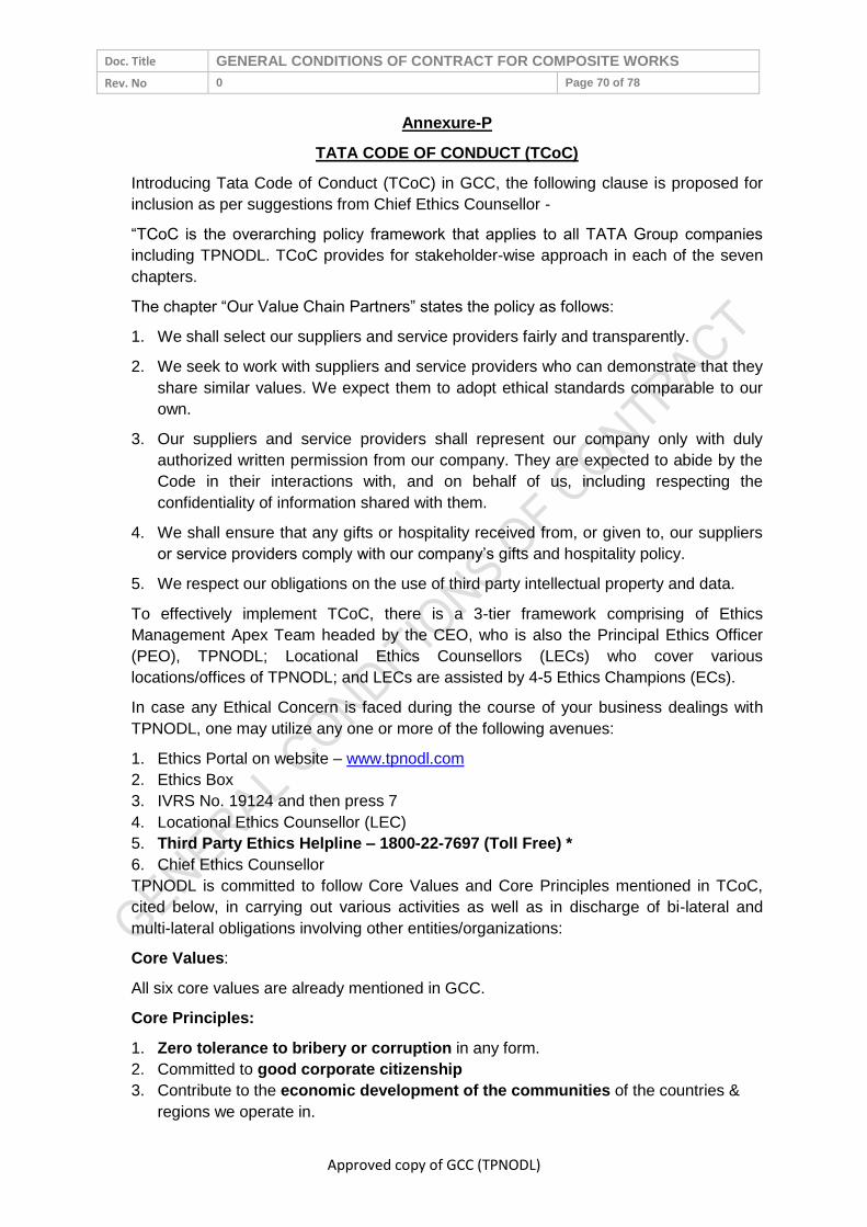
Doc. Title GENERAL CONDITIONS OF CONTRACT FOR COMPOSITE WORKS
Rev. No 0 Page 70 of 78
Approved copy of GCC (TPNODL)
Annexure-P
TATA CODE OF CONDUCT (TCoC)
Introducing Tata Code of Conduct (TCoC) in GCC, the following clause is proposed for
inclusion as per suggestions from Chief Ethics Counsellor -
“TCoC is the overarching policy framework that applies to all TATA Group companies
including TPNODL. TCoC provides for stakeholder-wise approach in each of the seven
chapters.
The chapter “Our Value Chain Partners” states the policy as follows:
1. We shall select our suppliers and service providers fairly and transparently.
2. We seek to work with suppliers and service providers who can demonstrate that they
share similar values. We expect them to adopt ethical standards comparable to our
own.
3. Our suppliers and service providers shall represent our company only with duly
authorized written permission from our company. They are expected to abide by the
Code in their interactions with, and on behalf of us, including respecting the
confidentiality of information shared with them.
4. We shall ensure that any gifts or hospitality received from, or given to, our suppliers
or service providers comply with our company’s gifts and hospitality policy.
5. We respect our obligations on the use of third party intellectual property and data.
To effectively implement TCoC, there is a 3-tier framework comprising of Ethics
Management Apex Team headed by the CEO, who is also the Principal Ethics Officer
(PEO), TPNODL; Locational Ethics Counsellors (LECs) who cover various
locations/offices of TPNODL; and LECs are assisted by 4-5 Ethics Champions (ECs).
In case any Ethical Concern is faced during the course of your business dealings with
TPNODL, one may utilize any one or more of the following avenues:
1. Ethics Portal on website – www.tpnodl.com
2. Ethics Box
3. IVRS No. 19124 and then press 7
4. Locational Ethics Counsellor (LEC)
5. Third Party Ethics Helpline – 1800-22-7697 (Toll Free) *
6. Chief Ethics Counsellor
TPNODL is committed to follow Core Values and Core Principles mentioned in TCoC,
cited below, in carrying out various activities as well as in discharge of bi-lateral and
multi-lateral obligations involving other entities/organizations:
Core Values:
All six core values are already mentioned in GCC.
Core Principles:
1. Zero tolerance to bribery or corruption in any form.
2. Committed to good corporate citizenship
3. Contribute to the economic development of the communities of the countries &
regions we operate in.

Doc. Title GENERAL CONDITIONS OF CONTRACT FOR COMPOSITE WORKS
Rev. No 0 Page 71 of 78
Approved copy of GCC (TPNODL)
4. No compromise on Safety
5. Our conduct shall be fair & transparent
6. Respect the human rights & dignity of our stakeholders
7. No unfair discrimination of any kind
8. Statements made to stakeholders shall be truthful & made in good faith
9. Not engage in any restrictive or unfair trade practice
10. Provide avenues for our stakeholders to raise concerns in good faith
11. Environment free from fear of retribution to deal with concerns that are raised
12. Expect the leaders to be role model
13. Comply with the laws of the countries in which we operate
Gift Policy:
Principles for acceptance of gifts/benefits –
A gift or benefit may be accepted only if it complies with all of the following principles:
it does not influence,
does not have the potential to influence, an employee in such a way as to
compromise or appear to compromise integrity and impartiality
does not create a conflict of interest or perception of conflict of interest;
Principles for non-acceptance of gifts/benefits -
The gift or benefit may not be accepted or given if any of the following principles apply:
causes the recipient or donor to act in partial manner in the course of duty
apprehension of the recipient becoming obligated to the donor
it is not offered openly
if is an offer of money or something readily convertible to money (e.g. Shares)
Violation –
1. Not abiding with this policy would constitute violation of “Our Employees” Stakeholder
group Clause “Gifts and Hospitality” of the Tata Code of Conduct (TCoC) 2015.
Prompt action will be taken against violations.
2. Any deviation from this policy must be supported by appropriate rationale and must
be duly approved by CEO who is also the Principal Ethics Officer. In any case, in
dealing with such deviations, the spirit of the TCoC should in no case be
compromised.
3. If it is determined that an employee / associate has violated this policy, appropriate
action including termination of the employee’s / associate’s employment or
association with TPNODL may be decided upon.
ANNEXURE-Q

Doc. Title GENERAL CONDITIONS OF CONTRACT FOR COMPOSITE WORKS
Rev. No 0 Page 72 of 78
Approved copy of GCC (TPNODL)
BUSINESS ASSOCIATE FEEDBACK FORM
With an objective to improve our internal processes and systems, and serve you better, we
solicit your valuable feedback & suggestions. It is estimated that it will take about 10 minutes
to complete this survey. We assure you that your feedback shall be kept confidential.
Please send the duly filled feedback form in the "TPNODL addressed - attached envelop"
You are associated with us as OEMs Service Contractor Material Suppliers Material & Manpower Supplier You are associated with us for Less than 1 year More than 1 year but less than 3 years More than 3 years Your office is located at Bhubaneswar Within 200 kms from Bhubaneswar More than 200 kms from Bhubaneswar Your nearly turnover with TPNODL Less than 25 Lacs 25 Lacs to 1 Crore More than 1 Cr.
Additional information
Your Name
Your Designation
Your Organization
Contact Nos.
We once again thank you for your participation in this survey. Please spare 10 minutes to
give your feedback on following pages (Section A to E)
SECTION - A
(Please √ mark in the relevant box and give your remarks / suggestions / information for our improvement.).

Doc. Title GENERAL CONDITIONS OF CONTRACT FOR COMPOSITE WORKS
Rev. No 0 Page 73 of 78
Approved copy of GCC (TPNODL)
S. No.
Parameters
1 2 3 4 5
Remarks/ Suggestion
Do
No
t A
gre
e
Slig
htl
y in
Ag
reem
en
t
In F
air
Ag
reem
en
t
Mo
stl
y in
Ag
reem
en
t
Fu
lly A
gre
e
1 You receive all relevant queries / tenders from us in timely manner.
2 We provide you enough lead time to respond to our queries / tenders.
3
We provide you adequate support (drawings, documents, clarifications, briefing etc.) to enable you meet our requirements.
4 All following elements of our contract / purchase order are rational :
4.1 Scope of Work
4.2 Delivery / Execution Schedule
4.3 Payment Terms
4.4 Liquidated Damages
4.5 Performance Guarantee
5 Our purchase orders / contracts are simple, specific & easy to understand
6
TPNODL demonstrate willingness to be flexible in administration of Contract / Purchase Order
7 We provide timely responses / clarifications to your queries
8
TPNODL representative you interact / coordinate with is adequately empowered to support you in meeting contractual obligations
9
TPNODL provide you all necessary infrastructure support for timely and quality completion of work (including AMC)
10 TPNODL Engineer-in-Charge timely certifies the jobs executed/ material supplied
11
TPNODL Engineer-in-Charge efficiently supervises the job execution for timely completion of job
12 BIRD (Bill Inward Receipt Desk) initiative has improved payment

Doc. Title GENERAL CONDITIONS OF CONTRACT FOR COMPOSITE WORKS
Rev. No 0 Page 74 of 78
Approved copy of GCC (TPNODL)
S. No.
Parameters
1 2 3 4 5
Remarks/ Suggestion
Do
No
t A
gre
e
Slig
htl
y in
Ag
reem
en
t
In F
air
Ag
reem
en
t
Mo
stl
y in
Ag
reem
en
t
Fu
lly A
gre
e
disbursement process
13 Our approach for Inspection and Quality Assurance effective to expedite project completion?
14 TPNODL never defaults on contractual terms
15 In TPNODL Contracts closure is done within set time limit
16
Our material receiving procedures are well defined and efficiently deployed to reduce mutual inconvenience
17 Bank Guarantees are released in time bound manner
18 Our processes related to payment / account settlement are effective.
19 You get payments on time
20 TPNODL Employees follow Ethical behavior

Doc. Title GENERAL CONDITIONS OF CONTRACT FOR COMPOSITE WORKS
Rev. No 0 Page 75 of 78
Approved copy of GCC (TPNODL)
SECTION - B
SECTION – B (Please rate the following parameters on a scale of 1 to 5, where 1 - Minimum; 5 - Maximum)
SN Parameters 1 2 3 4 5 Remarks/
Suggestion
1
How do you rate courtesy/ empathy/
attitude level and warmth of TPNODL
employees you interact with from
following team?
1.1 Project Engineering
1.2 District / Zones
1.3 Projects/HOG (TS &P)
1.4 Inspection & Quality Assurance
1.5 Stores
1.6 Metering & Billing
1.7 Accounts / Finance
1.8 Administration
1.9 IT & Automation
2
How would you rate TPNODL in
comparison to your other clients in
terms of fairness of treatment and
transparency with its Business
Associates?
3
How would you rate TPNODL in
comparison to your other clients in
terms of processes and systems to
manage partnership with its
Business Associates
4
How would you rate TPNODL in
comparison to your other clients in
terms of building long term &
mutually relationship with its
Business Associates

Doc. Title GENERAL CONDITIONS OF CONTRACT FOR COMPOSITE WORKS
Rev. No 0 Page 76 of 78
Approved copy of GCC (TPNODL)
SECTION – C
Please √ mark in the relevant box and give your remarks / suggestions / information for our improvement.
S. No.
Parameters
Cert
ain
ly N
O
Pro
bab
ly N
O
Pro
bab
ly Y
ES
Cert
ain
ly Y
ES
Remarks/ Suggestion
1 Based on your experience with TPNODL, would you like to continue your relationship with TPNODL?
2 If someone asks you about TPNODL, would you talk “positively” about TPNODL?
3
Would you refer TPNODL name to others in your community, fraternity and society as a professional & dynamic organization?
SECTION - D
If we ask you to rate us on a scale of 1 to 10, how will you rate TPNODL, that truly represents your overall satisfaction with us (please tick appropriate box) –
1 2 3 4 5 6 7 8 9 10

Doc. Title GENERAL CONDITIONS OF CONTRACT FOR COMPOSITE WORKS
Rev. No 0 Page 77 of 78
Approved copy of GCC (TPNODL)
SECTION – E
Please √ mark in the relevant box and give your remarks / suggestions / information for our improvement.
Please spare your thoughts for TPNODL’s improvement in particular areas of weaknesses, particularly relating to some great practices, attitudes that you have seen elsewhere in Indian and International Organizations, which you recommend TPNODL to adopt. Please give your valuable salient recommendations.
Please spare your thoughts for TPNODL’s improvement in particular areas of major concerns for you. We also welcome your suggestions to adopt any best practices, altitudes that you have observed / experienced elsewhere in Indian/ International organization.
Recommendation Please tick (√) your top 5 expectations out of the following 10 points listed below -
(Please list down improvement you
expect from TPNODL)
Timely payment
1 Flexibility in Contracts/PO
Clarity in PO,s & Contracts
2 Timely response to quarries
Timely certification of works executed
3 Clarity in Specs, drawings, other docs etc.
Adequate information provided on website for tender notification, parties qualified etc.
4 Timely receipt of material at site for execution
Performance Guarantee/EMD released in time
5 Inspection & quality assurance support for timely job completion
We thank you for your time and courtesy!!

Doc. Title GENERAL CONDITIONS OF CONTRACT FOR COMPOSITE WORKS
Rev. No 0 Page 78 of 78
Approved copy of GCC (TPNODL)