
PRIRUČNIK ZA PLOVIDBU NA SLIVU RIJEKE SAVE
216
PRIRUČNIK ZA PLOVIDBU NA SLIVU RIJEKE SAVE
-
Upload
khangminh22 -
Category
Documents
-
view
5 -
download
0
Transcript of PRIRUČNIK ZA PLOVIDBU NA SLIVU RIJEKE SAVE

PRIRUČNIK ZA PLOVIDBUNA SLIVU RIJEKE SAVE


MANUAL ON THE SAVA RIVER NAVIGATION
Publisher:The International Sava River Basin Commission Kneza Branimira 29Zagreb, CroatiaPhone: +385 1 488 69 60E-mail: [email protected] Web: www.savacommission.org
Publishing Committee:Dragan Zeljko, Želјko Milković, Duško Isaković and Goran Šukalo
Editorial Committee:Želјko Milković, Želјko Radić, Vladimir Seničić and Goran Šukalo
Translation from Serbian:Ljiljana Stević
Circulation:100 copies
Graphic design:Tijana Dinić
Printed by:

Zagreb, 2018.


As a conclusion to years of documents gathering and systematisation, it is our pleasure to present to you the Manual on the Sava River Navigation. Given the fact that no adequate and comprehensive navigation manual for the Sava River had existed before, we have made an attempt to cover as many issues related to inland navigation as possible, hence one part of the Manual deals with general topics in the field of inland navigation, while second part covers features of the waterway and navigation on the Sava River.
The Secretariat of the International Sava River Basin Commission (ISRBC) de-veloped this Manual with an aim of improving the knowledge and level of information, primarily on the Sava River navigation, but also on the universal principles of the inland navigation in general.
While developing this Manual, we used the material from all available publi-cations, and particular attention was paid to the experience and opinions of numerous experts, to whom we are profoundly thankful. We are fully aware of the fact that, perhaps, we have not entirely managed in our attempt to present all information on inland navigation adequately, and that, in foresee-able future, development of an amended edition will be required. Therefore, we would like to invite all our readers who notice any omissions or errors, to put forward their comments, remarks and suggestions that will enable us to have higher quality of future editions encompassing the latest trends in inland navigation.
We hope that this manual will provide practical assistance, both to the current participants in navigation, as well as to those who attend schools or are about to obtain crew certificates in inland navigation.
FOREWORD

FOREWORD 5
GENERAL CHARACTERISTICS OF THE SAVA RIVER 11
1.1 GENERAL AND HYDROGRAPHIC FACTS ON THE SAVA RIVER BASIN
11
1.2 HISTORY OF THE SAVA RIVER NAVIGATION 14
THE SAVA RIVER WATERWAY 21
2.1 THE WATERWAY CHARACTERISTCS 21
2.2 THE WATERWAY CLASSIFICATION 22
INFRASTRUCTURE 33
3.1 PORTS AND HARBOURS 33
3.1.1 HARBOUR AND WAREHOUSES SISAK 36
3.1.2 THE PASSENGER TERMINAL SISAK 36
3.1.3 GALDOVO BASIN 37
3.1.4 CRNAC OIL PORT 37
3.1.5 HARBOUR OF THE BROD REFINERY 38
3.1.6 PORT OF SLAVONSKI BROD 38
3.1.7 RUŠČICA OIL PORT 39
3.1.8 RTC ŠAMAC PORT 39
3.1.9 PORT OF BRČKO 40
3.1.10 PORT OF LEGET 41
3.1.11 FREE ZONE ŠABAC 42
3.1.12 PASSENGER RIVER TERMINAL BEOGRAD 42
3.2 INLAND WATERWAYS 43
3.2.1 WINTER PORTS AND WINTER SHELTERS 43
3.2.2 HYDRAULIC STRUCTURES 46
BASICS OF SHIPBUILDING AND PROPULSION 59
4.1 SHIPBUILDING BASICS 59
4.1.1 SHIP CONSTRUCTIONS 60
4.1.2 VESSEL HYDRODYNAMICS 65
4.1.3 SHIPS AND CONVOYS IN INLAND NAVIGATION 69
CONTENT6

4.2 SHIPBOARD EQUIPMENT 72
4.3 ENGINES 78
4.4 PROPULSION 80
4.4.1 PROPULSOR & RUDDER COMBINATION 81
4.4.2 STEERING PROPULSION UNIT 81
4.4.3 HYBRID PROPULSION SYSTEM 85
4.4.4 STRENGTHS AND WEAKNESSES OF PROPULSION
SYSTEMS 85
4.4.5 CAVITATION 86
4.4.6 SUMMARY 87
4.5 RUDDER 87
THE STABILITY AND LOADING OF THE SHIP 91
5.1 THE BASICS OF SHIP STABILITY 91
5.2 STATICAL STABILITY 92
5.2.1 TRANSVERSE STABILITY 93
5.2.2 LONGITUDINAL STABILITY 95
5.2.3 FORM STABILITY AND WEIGHT STABILITY 96
5.3 DINAMICAL STABILITY 96
5.4 FREE SURFACES AND THEIR EFFECTSON STABILITY
97
5.5 CARGO LOADING 99
5.5.1 CARGO DISTRIBUTION ON THE SHIP 99
5.5.2 HEAVY AND LIGHT CARGOES 100
5.5.3 LONGITUDINAL CARGO DISTRIBUTION 102
5.5.4 PREPARATIONS FOR CARGO LOADING 102
5.5.5 MONITORING OF CARGO DURING THE NAVIGATION 103
5.5.6 LOADING, STOWING AND TRANSPORT OF VARIOUS TYPES OF CARGO
104
5.5.7 THE MOST COMMON PACKAGING SYSTEMS IN MODERN WATERWAY TRANSPORT
106
7CONTENT

CONTENT8
NAVIGATION, SHIP'S MANOEUVRING AND SAILING 109
6.1 TERM AND CLASSIFICATION 109
6.2 NAVIGATION EQUIPMENT 111
6.2.1 SOUNDER 112
6.2.2 RADAR 114
6.2.3 GYROCOMPASS – GYROSCOPE 118
6.2.4 SPEED LOG 120
6.2.5 SHIP BAROMETER 120
6.2.6 BINOCULARS 121
6.2.7 RADIO TELEPHONE EQUIPMENT 122
6.3 NAVIGATIONAL MANUALS 123
6.3.1 NAVIGATIONAL CHARTS 124
6.3.2 INDICATOR OF RIVER KILOMETRES 128
6.3.3 ALBUM OF BRIDGES 129
6.3.4 NOTICES TO SKIPPERS 129
6.4 RIVER INFORMATION SERVICES – RIS 130
6.5 SHIP'S DOCUMENTS AND PAPERS 133
6.5.1 SHIP’S LOG 133
6.6 ASSEMBLING OF CONVOYS 135
6.6.1 ASSEMBLING OF TOWED CONVOYS 135
6.6.2 ASSEMBLING OF PUSHED CONVOYS 142
6.7 MOORING 146
6.8 MANOEUVRING 147
6.8.1 MANOEUVRABILITY 150
6.8.2 METEOROLOGICAL AND HYDROLOGICAL IMPACTS 151
6.9 VESSEL NAVIGATION 155
6.10 ACCIDENTS AND AVERAGES 159
6.11 PREVENTION OF POLLUTION CAUSED BY NAVIGATION 161

9CONTENT
HYDROMETEOROLOGY 165
7.1 ON HYDROMETEOROLOGY IN GENERAL 165
7.2 WATER LEVELS 168
7.2.1 HIGH WATER LEVEL 169
7.2.2 LOW WATER LEVEL 170
7.2.3 WATER LEVEL MEASUREMENT 170
7.2.4 GAUGING STATIONS 172
7.2.5 CALCULATING DEPTH USING WATER LEVEL 174
7.2.6 DETERMINATION OF THE VERTICAL CLEARANCE
UNDER THE BRIDGE 174
7.3 METEOROLOGY AND GENERAL METEOROLOGICAL PHENOMENA 177
7.4 METEOROLOGICAL AND ASTRONOMICAL OCCURENCES RELEVANT FOR INLAND NAVIGATION
184
THE SAVA RIVER FAIRWAY GUIDE 189
8.1 SECTORS AND SUB-SECTORS 189
8.1.1 SECTOR “UPPER SAVA” 189
8.1.2 SECTOR “MIDDLE SAVA 193
8.1.3 SECTOR “LOWER SAVA” 203
8.2 DIFFICULTIES IN NAVIGATION ON THE SAVA RIVER DUE TO HYDRO-METEOROLOGICAL CONDITIONS
207
LITERATURE 210


GENERAL CHARACTERISTICS OF THE SAVA RIVER 11
1.1 GENERAL AND HYDROGRAPHIC FACTS ON THE SAVA RIVER BASIN
No river ends at its banks. Each river with its basin has its own diverse habitats and species that enrich life in basin – life of people of different cultures, nations and countries. The same applies to the Sava River, which flows through four states: Slovenia, Croatia, Bosnia and Herzegovina, and Serbia. Furthermore, the Sava River also connects three capitals of these four countries: Ljubljana in Slovenia, Zagreb in Croatia, and Belgrade in Serbia. The fourth state capital – Sarajevo in Bosnia and Herzegovina, also belongs to the Sava River Basin.
The Sava River is the Danube’s third longest tributary, but the one with the highest average discharge of all. The Sava River is formed by two smaller riv-ers in Slovenia, the Sava Dolinka and Sava Bohinjka, joining near the town of Radovljica and continuing to flow through Croatia, Bosnia and Herzegovina, Serbia, until its confluence with the Danube in Serbia (Belgrade).
Until Ljublјana, the Sava is a mountainous river, but downstream towards Za-greb its channel gradient significantly flattens and it takes on the characteristics of a lowland river. From Radovlјica, the Sava River flows through Kranjska and Ljublјanska gorges, and then continues its course through 90 km of Litija karst valley. It enters the Pannonian Plain near the town of Brežice and flows along its southern flank all the way to its confluence with the Danube. The average channel gradient from the confluence with the Kupa River to its confluence with the Danube is 42 mm/km, which results in a pronounced meandering flow that is characteristic of lowland rivers.
As a consequence of such a low gradient, the Sava River cannot carry the sedi-ment brought in by its tributaries, but the sediment is deposited on its river bed
GENERAL CHARACTERISTICS OF THE SAVA RIVER

12 Manual on the Sava River Navigation
downstream from the confluences with its tributaries, thus creating numerous sand bars and shallows that during the periods of low water level complicate or sometimes even completely prevent the navigation. The Sava River water regime is typically rainy and snowy, with an average flow velocity of 3.2 m/s.
The length of the Sava River from its main source in western Slovenian mountains to its confluence with the Danube in Belgrade (Serbia) is approximately 944 km. The total basin area of 97,713 km2 covers major parts of territories of Slovenia, Croatia, Bosnia and Herzegovina, Serbia, Montenegro and minor territory of Al-bania (Table 1). With its average discharge at the confluence being about 1.700 m3/s, the Sava River represents the greatest tributary of the Danube by volume of water, contributing with almost 25% to the Danube's total discharge. This means that the sustainable development of the Sava River Basin has a significant influ-ence on the Danube River Basin.
Country Country’s share (km2) Country’s share (%)
Slovenia 11.734,8 12,0
Croatia 25.373,5 26,0
Bosnia and Herzegovina 38.349,1 39,2
Serbia 15.147,0 15,5
Montenegro 6.929,8 7,1
Albania 179,0 0,2
Total 97.713,2 100,0
Table 1 Main figures on the Sava River Basin
The Sava River is very important for the Danube River Basin due to its out-standing biological and landscape diversity. The Sava River Basin hosts the largest complex of alluvial wetlands in the Danube Basin (Posavina – central part of the Sava River Basin) and large lowland forest complexes. The Sava River is a unique example of a river basin with some of the floodplains still intact, thus supporting the flood alleviation and biodiversity.
There are seven Ramsar sites in the Sava River Basin, i.e. Cerkniško Jezero (SLO), Lonjsko Polјe, Crna Mlaka (CRO), Bardača (BiH), Zasavica, Obedska bara and Peštersko Polјe (SRB), with numerous important bird and plant habitats, as well as national level protected areas, and Natura 2000 sites.

13GENERAL CHARACTERISTICS OF THE SAVA RIVER
Main information on the Sava River’s main tributaries is provided in Table 2.
River nameTributary
(l – left; r – right)
Basin size
[km2]
River length
[km]Countries Country area
[km2]
Ljubljanica r 1,860.0 41.0 SLO
Savinja l 1,849.0 93.9 SLO
Krka r 2,247.0 94.6 SLO
Sotla/Sutla l 584.3 88.6 SLO,CRO
SLO – 450.8 km2; CRO – 133.5 km2
Krapina l 1,244.0 65.6 CRO
Kupa/Kolpa r 10,225.6 297.2 CRO,SLO
CRO – 8,412.0 km2;SLO – 1,101.0 km2;BiH – 712.6 km2
Lonja l 4,286.1 82.8 CRO
Ilova l 1,815.7 100.3 CRO
Una r 9,828.9 214.6 BiH,CRO
BiH – 8,142.9 km2;CRO – 1,686.0 km2
Vrbas r 6,273.8 249.7 BiH
Orljava l 1,615.7 99.5 CRO
Ukrina r 1,504.0 80.7 BiH
Bosna r 10,809.8 281.6 BiH
Tinja r 904.0 99.4 BiH
Drina r 20,319.9 346.0
BiH,MN,SRB,ALB
BiH – 7,118.9 km2;MN – 6,929.8 km2;SRB – 6,092.2 km2;ALB – 179.0 km2
Bosut l 2,943.1 CRO,SRB
CRO – 2,375.0 km2;SRB – 568.1 km2
Kolubara r 3,638.4 86.6 SRB
Table 2 The main tributaries of the Sava River

14 Manual on the Sava River Navigation
1.2 HISTORY OF THE SAVA RIVER NAVIGATION
First organised prehistoric human settlements appeared on the banks of rivers and lakes. It also needs to be emphasised that throughout the further devel-opment of a human society, the banks of major rivers were the places where foundations were laid for the first sciences: astronomy and geometry. Looking back at the historical development of shipbuilding, and a ship as its product, it can be observed that no human craftsmanship provides such a faithful picture of the level of human development as is the case with the ship.
The development of shipbuilding and shipping activities led to appearance of first rowing boats that only sailed down the river courses, whereas later, use of more oars meant commencement of upstream sailing in cases where the river flow velocity allowed it. Towing of vessels upstream was performed by hors-es and in some of the cases by people and horses (this method of towing was called “horseboating“).
Until the end of the 5th century CE, oars had been used as the main propulsion, while sails provided just an auxiliary propulsive force and only if the wind direc-tion was towards the ship’s stern.
In Donja Dolina, a village situated on the banks of the Sava River, a Bronze Age settlement originating from cca 4000 years BC was discovered, where, among all other findings, a 12.5 meters long and carved out of an oak tree boat was excavated. This boat with another little bit smaller than 5 m are exibited in a museum in Sarajevo.
There is no clear division line between the period dominated by ships powered by sails and the era of rowboats. It can only be approximately determined that sails started prevailing over the oars at the end of 12th and the beginning of 13th century, when appearance of the today’s sternpost made possible use of larger sails. Discovery of new sea routes and countries in the late 15th century addition-ally contributed to the development of sailing ships, shipbuilding and shipping in general, with the steadily increasing size of ships, their speed, manoeuvrabil-ity and navigational instruments.
Following factors were crucial for the rapid development of shipping and shipbuilding in the late 18th century: a general increase in Labor productivity,

15GENERAL CHARACTERISTICS OF THE SAVA RIVER
the invention of the steam engine (80’s in the 18th century), use of steel con-structions instead of wooden structures, the transition from handicraft to the industrial mode of production, the application of scientific instead of experien-tial methods in shipbuilding industry, and later invention of a propeller – in the middle of the 19th century.
First steamboats (steam-powered vessels) appeared on rivers, which is under-standable mainly for two reasons: firstly, the rivers have more suitable condi-tions for navigation (river water is calmer than sea, hence there is no danger of the waves) and, secondly, because of the river currents steamboats were more needed on rivers than at sea, where sails provided for undisturbed navigation and manoeuvring.
First steamboat was built approximately twenty years before the steam loco-motive. It is very difficult to identify the inventor of the first steamboat. It is be-lieved that it was Robert Fulton, an American painter from Pennsylvania, born in 1765, who in New York built a large and sturdy steamboat known as the ”Cler-mont“, which was equipped with a steam engine purchased in Europe (“Boul-ton & Watt“). The Clermont dimensions: Length = 40.5 m, Width = 5.48 m, Side Height = 2.74 m, deadweight = 180 tons, with power of 50 hp. The steamboat “Clermont” commenced her first successful trip on 17th of August 1807 on the Hudson River.
First steamboats in Europe were built in England and appeared in 1816 on the Seine, the Rhine and the Elbe.
Following the completion of tests, the first steamboat on the Danube had its in-augural run in 1817. The steamboat “Carolina”, built 1818 in Vienna, carrying 20 tons of loads, could make 3.5 km/h when sailing upstream, and 15 km/h when sailing downstream.
“The First Danube Steamboat Company” (Die Erste Donau Dampfschiffarts Ge-selschaft, DDSG) was founded in 1829 in Vienna.
In 1830, the ship “Franz I” made its first trip between Vienna and Budapest and it is considered the first steamboat that regularly sailed on the Danube
In 1834, the ship “Carolina”, running between Vienna and Oršava, was the first steamboat to sail through Đerdap (the Iron Gates, Djerdap gorge).

16 Manual on the Sava River Navigation
The development of the modern shipping, i.e. appearance of first steamboats, raised the need to regulate the Sava River.
In 1834, the French steamboat “Sophia“ (60 hp and 300 t capacity) commenced its trip on the Sava River in order to test the conditions for navigation. On 11th of September 1838, it arrived at Sisak. Four year later, ten steamboats of The Dan-ube Lloyd from Vienna sailed between Vienna and Sisak.
The first Croatia’s steamboat “Florisdorf” was bought in July 1844. The vessel “Florisdorf” commenced its first voyage from Vienna on 21st of August 1844, and arrived at Sisak of 8th of September 1844. Next day, the steamboat was renamed the Croatian name “Sloga” (Concord) – the name of the first Croatian steamboat ever, both on rivers and the sea (first sea steamboat “Hrvat” - The Croat - sailed only in 1879). “Sloga” run the regular passenger line every 1st and 15th of the month, sailing downstream from Sisak to Zemun, and every 6th and 21st of the month, sailing upstream from Zemun towards Sisak. However, only one year lat-er, on 14th of September 1845, the first Croatia’s steamboat “Sloga” had an acci-dent near the town of Bošnjaci and sank. Only seven days after “Sloga’s” sinking, the steamboat “Carl” of the Vienna based The Danube Lloyd’s sailed into the Sisak port, and was granted exclusive navigation rights on the Sava River. In 1846, the steamboat “Panonija” sailed into the Sava River and docked in Sisak. Regulation of the Sava River commenced in January 1856, leading to the establishment of a mixed Austrian-Turkish Commission, since the river’s right bank was under the Turkish rule.
Serious works on river engineering for commercial traffic on the upper Sava commenced in 1871 and, with minor interruptions, continue to this day.
Anyhow, even back in 1829, the city of Šabac had a fully operating ship and ferry repair workshop, where, among others, the Danube ships from Poreč and Gradište were repaired.
First Serbia’s river steamboat “Deligrad”, (Length = 58 m, Width = 7 m, dead-weight = 275 tons, and power of 50 hp) had its inaugural run on the Danube in 1862. The steamboat “Deligrad“ with its six barges that the Government of Serbia had procured in Italy, transported salt and petroleum from Romania, and passengers when needed. The “Deligrad” was armed with two cannons. This ship was sunk by its own crew on 6th of April 1941.

17GENERAL CHARACTERISTICS OF THE SAVA RIVER
First river kilometre marks were placed in 1877, from Sisak to Zemun. After the World War I, activities on regulation of the Sava River continued, and it became navigable as far as Rugvica km 652, and on the Kupa River, from its mouth as far as Pokupsko.
Back in 1870, the Steamboat Association “Šipuš and Morović” was founded in Sisak, which had two steamboats, “Hrvat” and “Slavian”. In the eighties of the 19th century, this steamboat association was taken over by the newly established “Bosnian Steamboat Company“, based in Brčko. This Company renamed the aforementioned ships “Una” and “Sarajevo”, and then built five new boats, name-ly “Vrbas” and “Bosna” for navigation on the Sava River, and “Drina”, “Zvornik” and “Lim” for navigation on the Drina River.
“The First Serbian Privileged Company” was founded in Belgrade in 1890. This Company bought out the ship “Deligrad” from Serbia, and then purchased in Ita-ly the ship “Mačva”, the barge “Beograd”, the steamboat “Stig”, as well as a number of other barges. With such a fleet size, the regular traffic was established from Belgrade to Dubravica and Šabac.
In the year 1897, Rudolf Diesel announced his invention of the internal combus-tion engine (the diesel engine) that launched a technological revolution in the shipping industry. Its utilisation in river navigation began in 1912.
In the period between two world wars, two strongest industrial plants The Shell Refinery and The Smelting Plant Caprag, were built on the bank of the Sava River, thus emphasising the economic significance of this river for the wider area of Sisak region.
After the end of World War I, in 1918, a large number of ships from Austro-Hun-garian and German shipping companies happened to be found in the newly es-tablished State of Slovenes, Croats and Serbs. According to the Paris Convention signed in 1921, majority of those ships had come into its possession, thus the acquired fleet made the new state the leader by fleet size in the Danube region.
In July 1945, in the new state of Yugoslavia the Directorate-General for the River Traffic was founded, comprising the State River Shipping, that in 1947 was re-named the Yugoslav State River Shipping. In 1952, after the restructuring and de-centralisation, it became Yugoslav River Shipping – “JRB”, which is the name that has remained to this day. Taking into consideration the technical obsolescence of the fleet at the time, in mid-1950-ies, the company started construction of

ships, tugboats (the famous "JOTA" fleet), self propelled cargo vessels, river-sea ships and barges for dry cargo and tank lighters for liquid cargo. Until then, the average age of passenger ships was 60 years, of tugs was 40 years, and of barg-es for dry and liquid cargo was 45 years. The new fleet comprised: “Džervin”, “Veternik”, “Košutnjak”, “Topčider”, “Jablanik”, “Javornje”, “Jagodnja”, “Jelašnica”, (by which “JOTA” fleet was named), “Vitorog”, “Trebević”, “Dinara”, “Komovi”, “Udarnik”, “Junak”, “Vitez”, “Kolubara”, “Mlava”, “Tamnava” and “Morava”. In 1961, the famous motor tugboat “Tara” joined the fleet. “Tara” was operating on the sector of Đer-dap, and will be remembered by its power, the navigation safety and a beautiful look.
After World War II, rivers Sava and Kupa experienced a remarkable expansion triggered by the state industrialisation plans, and as of 1952, the town of Sisak became the seat of the Danube Lloyd, one of the leading shipping companies established after decentralisation of the former state river shipping industry. At that time, a modern river port was built on the Kupa River, which, owing to its capacities, became an economic value of the city.
During the year 1955, there were several attempts to revive the frequently pro-fessionally contested upstream navigation from Galdovo, but the most famous case was that of the ship “Bačka” that managed to arrive to the Jakuševac Bridge in Zagreb. Dredger and barges were then transported from Sisak to Zagreb, and after many dramatic moments, the whole endeavour ended successfully, yield-ing the praise from general public.
In period between 1956 and 1961, a significant number of vessels were built in river and sea shipyards. During those years, strong motor tugboats such as “Bi-okovo”, “Sisak”, and “Boris Kidrič”, and motor tanker tugboats “Caprag” and “Sisak” commenced its river navigation.
The eighties of the last century saw a significant increase in towing and pushed capacities, thus the major share of the obsolete transport technology was de-commissioned. During those years, transport on the Sava River reached its peak, as well as mainly consisted of bulk cargo being reloaded in Brčko port, as well as transport of crude oil and oil derivatives for refineries in Brod and Sisak.
The war and breakup of the former Yugoslavia in the 1990-ies led to a complete termination of navigation and any significant maintenance of the waterway. It should be noted that the previous navigation regime on the Sava River was only
18 Manual on the Sava River Navigation

19GENERAL CHARACTERISTICS OF THE SAVA RIVER
of national character, whereas traffic of foreign vessels was allowed only with special permits.
Following the normalisation of relations in the region, navigation was partly re-stored, but only for ships from riparian countries, which made a sound problem for future development of this form of transport.
Signing of the Framework Agreement on the Sava River Basin and the Protocol on the Navigation Regime to the Framework Agreement on the Sava River Basin in 2002 and its entering into force in 2004 meant the declaration of the inter-national navigation regime on the Sava River. Simultaneously, significant and harmonised activities commenced on the rehabilitation of the waterway and harmonisation of the legislation on inland navigation in the Sava River Basin.


THE SAVA RIVER WATERWAY 21
2.1 THE WATERWAY CHARACTERISTCSThe international navigable waterway on the Sava River and its tributaries is de-fined by the Protocol on the Navigation Regime to the Framework Agreement on the Sava River Basin which applies to the Sava River from the rkm 0 to the rkm 594, to the Kolubara River from the rkm 0 to the rkm 5, to the Drina River from the rkm 0 to the rkm 15, to the Bosna River from the rkm 0 to the rkm 5.00, to the Vrbas River from therkm 0 to the rkm 3, to the Una River form the rkm 0 to the rkm 15, and to the Kupa River form the rkm 9 to the rkm 5 .In general, the Sava River waterway is divided into three sectors:
• Upper Sava from the rkm 594 to the rkm 467;
• Middle Sava from the rkm 467 to the rkm 139;
• Lower Sava from the rkm 139 to the rkm 0.
The Sava River is navigable for larger vessels from Sisak (conditionally, it is navi-gable from Rugvica near Zagreb to Sisak for smaller sport or pleasure crafts ) to its mouth where it empties into the Danube in Belgrade. Due to years of insuf-ficient and inadequate maintenance of the waterway, the Sava is not sufficient-ly regulated for navigation. With the exception of the part of Lower Sava, the waterway distinguishes with sharp bends with the radius of curvature of up to 200, which significantly impedes navigation, particularly for pushed convoys. It is considered that normal navigation requires a the radius of curvature of 360m, at least. In addition, shallows appear during low water levels, whereas high wa-ter levels can cause a collapse of river banks and widening of the channel, thus reducing its depth.
THE SAVA RIVER WATERWAY

Manual on the Sava River Navigation22
Furthermore, there are many artificial obstacles in the waterway that hinder navigation, such as unfavorable selection of bridge locations and sunken ves-sels. The waterway is marked in accordance with its current state, but the mark-ing system will change simultaneously with the regulation of the waterway. The development of River Information Services will significantly facilitate naviga-tion, especially at night and in bad weather conditions.
Geographically, the Sava River waterway stretches between the Mediterranean and Central Europe, it is parallel with Corridor X, and crosses Corridor Vc, which ensures its exceptionally important role in planning of transport strategies of all Sava states.
In current situation, the waterway is not sufficiently utilised, even though its geostrategic position provides for development of combined and intermodal transport that would link Central and Western Europe with the Adriatic Sea. The rehabilitation and development of waterways and the waterway infrastructure in general would significantly contribute to the competitiveness on the trans-portation services market, which is in line with all strategic documents for the transport policy of states Parties to the Framework Agreement on the Sava River basin.
2.2 WATERWAY CLASSIFICATIONWaterways are the subject of the homogenous and internationally recognised classification system established under the AGN Agreement (The European Agreement on Main Inland Waterways of International Importance). The eco-nomic significance for international water transport is linked to waterways of Class IV to VII. This classification system was created by the UNECE (the United Nations Economic Commission for Europe) and the CEMT (the European Con-ference of Ministers of transport).
The key classification criterion depends on the basic dimensions of vessels, and variables used in decision-making include length, beam and maximum draught, vessel tonnage and a bridge clearance. The competitiveness of a wa-terway greatly depends on conditions at the navigable section of the river, which determine a capacity of vessels in inland navigation, and thus the eco-nomic vitality economic vitality.

THE SAVA RIVER WATERWAY 23
In accordance with the aforementioned classification established under the AGN Agreement, the International Sava River Basin Commission adopted Decisions 21/06 and 13/09 on adoption of the Detailed Parameters for Waterway Classi-fication on the Sava River, on the basis of which Classification of the Sava River Waterway was adopted (Decisions 19/08, 14/12 and 5/17).
The Classification of the international waterway on the Sava River is a result of the current status of the waterway. In future, there will be minor corrections, as a result of the ongoing project that envisages development of the project doc-umentation and related construction works.
Classification of the Sava River Waterway is shown in the following table:
Section of the Sava River
rkm rkm Length (km) Waterway Class
0.0Sava Mouth
81.0Kamičak 81.0 Va
81.0Kamičak
176.0Rača 95.0 IV
176.0Rača
196.0Domuskela 20.0 III
196.0Šabac
313.7Slavonski Šamac /
Šamac117.7 IV
313.7Slavonski Šamac /
Šamac
338.2Oprisavci / Rit kanal
24.5 III
338.2Oprisavci / Rit kanal
371.2Slavonski Brod /
Brod33.0 IV
371.2Slavonski Brod /
Brod
594.0Sisak 222.8 III
Table 3 Classification of the Sava River Waterway

Manual on the Sava River Navigation24
Detailed Parameters for Waterway Classification on the Sava River bear gre-at importance in comprehension of key criteria used in the development of the above Classification, and these are specified and explained in the following table and its enclosures.
Annex 1: Classification enclosures
DETAILED PARAMETERS FOR INLANDaccording to Classification of European inland waterways, United Nations Economic
IMPORTANCE REGIONAL INTERNATIONAL
CLASS I II III IV
CONVOYS P.1
l (m) 118 – 132 85
b (m) 8.2 – 9.0 9.5
t (m) 1.6 – 2.0 2.5 – 2.8
W (t) 1000 – 1200 1250 – 1450
T (m) 2.3 2.2
Tv (m) + ∆ 1.3 1.3 1.6 1.6 2 3.3 3.3
B (m) 35 45 45 55 30
Bzav (m)zа min lsast 25 35 40 75 40
zа max lsast 35 45 45 75 40
Hmost (m) 3 3 4 7
minBmost (m) 35 45 45 45 30
Hkab (m)up to 110 kVup to 250 kVup to 400 kV
1515.75
17
1515.75
17
1515.75
17
1515.75
17
1515.75
17
1515.75
17
1515.75
17
1515.75
17
Hnnkab (m) 12 12 12 12 12 12 12 12
Bkab (m); Bnnkab (m) Bkab; Bnnkab = horizontal clearance or distance
Tprev (m) 1.6 2 2.25 2.5 2.5 3.0
minBprev (m) 10 10 10 10.0 – 12.5
minLprev (m) 60 60 70 – 75 90 – 190

THE SAVA RIVER WATERWAY 25
WATERWAY CLASSIFICATION – “SAVA INITIATIVE” PROGRAMMECommission for Europe – Inland Transport Committee (UN/ECE, GENEVA 1996.)
INTERNATIONAL
Va Vb VIa VIb VIc VII
P.1 P.1.2 P.2.1 P.2.2 P.3.2 P.2.3 P.3.3
95 – 110 172 – 185 95 – 110 185 – 195 195 270 – 280 285
11.4 11.4 22.8 22.8 33 22.8 33–34.2
2.5 – 4.5 2.5 – 4.5 2.5 – 4.5 2.5 – 4.5 2.5 – 4.5 2.5 – 4.5
1600 – 3000 3200 – 6000 1600 – 3000 6400 – 12000 9600 – 18000 14500 – 27000
2.4 2.4 2.4 2.4
3.4 3.4 3.4 3.4 3.4 3.4 3.7 3.7 3.6 3.6 3.8 3.8 3.8 3.8
55 35 65 40 75 100 140 120 150
85 40 95 50 100 120 150 125 170 160
90 45 100 55 120 150 180 125 200 160
7 7 9.5 10 9.5 10 9.5 10 9.5 10
55 35 65 40 75 100 140 120 150
1515.75
17
1515.75
17
1515.75
17
1515.75
17
1515.75
17
1515.75
17
1920.4021.9
1920.4021.9
1920.4021.9
1920.4021.9
1920.4021.9
1920.4021.9
1920.4021.9
1920.4021.9
12 12 12 12 12 12 16.5 16.5 16.5 16.5 16.5 16.5 16.5 16.5
from outer edges of dykes on rivers above VPV + 12.0 m
4.0 4.5 4.5 4.5 4.75 4.75 4.75
12,5 12 – 25 26 24 – 26 34 – 37 24 – 26 34 – 37
115 – 190 190 – 210 230 230 260 – 310 310 310
Manual on the Sava River Navigation26
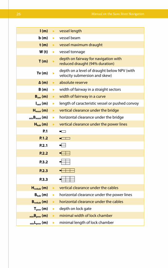
l (m) vessel length
b (m) vessel beam
t (m) vessel maximum draught
W (t) vessel tonnage
T (m) depth on fairway for navigation withreduced draught (94% duration)
Tv (m) depth on a level of draught below NPV (with velocity submersion and skew)
∆ (m) absolute reserve
B (m) width of fairway in a straight sectors
Bzav (m) width of fairrway in a curve
lsast (m) length of caracteristic vessel or pushed convoy
Hmost (m) vertical clearance under the bridge
minBmost (m) horizontal clearance under the bridge
Hkab (m) vertical clearance under the power lines
P.1
P.1.2
P.2.1
P.2.2
P.3.2
P.2.3
P.3.3
Hnnkab (m) vertical clearance under the cables
Bkab (m) horizontal clearance under the power lines
Bnnkab (m) horizontal clearance under the cables
Tprev (m) depth on lock gate
minBprev (m) minimal width of lock chamber
minLprev (m) minimal length of lock chamber

THE SAVA RIVER WATERWAY 27
Figure 1 Cross-section and plain view of river bed and fairway in a curve for the appropriate case of passing by
VPV
min Bmost
SL
BL
BZAV
BD
SDSBΔbL ΔbL ΔbD ΔbDb b
Hm
ost
NPV
Tv+Δ=t+Δt+Sz+Δ
1 22 1
Δt+Sz+Δ
SD B
D S
B B
L S
L
BZAV
β1
β2
t

Manual on the Sava River Navigation28
VPV high navigable water level
NPV low navigable water level
Bzav fairway width in a curve
BL, BD navigation lane width
SL, SB, SD additional width
∆bL1, ∆bL
2, ∆bD1, ∆bD
2 vessel side-slip
b vessel width
TV+∆ fairway depth
t maximum draught
∆t vessel skew
SZ velocity submersion
∆ absolute reserve
Hmost vertical clearance under the bridge
minBmost horizontal clearance under the bridge
β1, β2 horizontal angle of vessel side-slip
Definitions:
Low navigable water level – NPV
Low navigable water level of freeflow river at certain water gauge corre-sponds to the water level defined with the discharge duration of the 94% (Q94%). NPV = V94% [cm or m.a.s.l.] and in any point of freeflow river corre-sponds to the level of water surface with the discharge of 94% duration in a year. It is defined from statistical analysis of discharge duration taking into account 30 years of observation. Traditionally it is used to define flow profile with low water level when navigation at small rivers is performed with re-duced draught of caracteristic vessel.

THE SAVA RIVER WATERWAY 29
High navigable water level – VPV
High navigable water level of freeflow river at certain water gauge corre-sponds to the water level defined with the discharge duration of the 1% (Q1%). VPV = V1% [cm or m.a.s.l.] and in any point of freeflow river it corre-sponds to the level of water surface with the discharge of 1% duration in a year. It is defined from statistical analysis of discharge duration taking into account 30 years of observation. Traditionally it is used to define vertical clearance under the bridges or power line/cables.
Water level with 60% duration: V60%
According to AGN [Annex IIIb] for every waterway class safety navigation should be guaranteed 240 days during the year for caracteristic cargo vessel with maximum draught. This corresponds to the water level defined with the discharge duration of the 60% (Q60%). V60% [cm or m.a.s.l.] in any point of free flow river corresponds to the level of water surface with the discharge of 60% duration in a year.
Reduced draught
It is common to navigate when water level is lower than NPV. According to AGN [Annex IIIb] navigation at international E waterways (Class IV to VII) principally should be provided during whole year except ice period. This means it should be provided during the water levels lower than NPV but reduced draught of 1.2m is permitted.
∆t – trim of a vessel is the incline of a vessel to a longitudinal plane. Trim refers to the position (sitting) of a vessel in the water and is determined by the difference between the vessel’s aft (stern) and forward (bow) drafts and adopted value is 0.1m.
SZ – velocity submersion is consequence of bow or stern wave, vessel streaming velocity, size and form of vessel or convoy, immersed profile of vessel or convoy, or restrictions of waterway and adopted value is 0.2m.
∆ – absolute reserve is always free water area between hull and river bed where navigation has never been performed or never been used in some other way and adopted values are: for classes I - IV = 0.3m, for class V = 0.4m, for classes VIa and VIb = 0.5m and for classes VIc and VII = 0.6m.
Manual on the Sava River Navigation30
Small radius categories:
Rmin [m] – minimal radius of fairway axis in curve and
Rizn [m] – special radius of fairway axis in curve.
Minimal radius
Minimal radius of river bed curve is the smallest radius of fairway axis that allows undisturbed two-way navigation on low navigable water level.
Special radius
Special radius of river bed curve is 25–30% smaller that minimal. It is not defined generally but in practice it is still used at river sectors when it is not possible to apply minimal due to some terrain and urban problems. In that case bigger width of waterway than minimal one calculated for minimal ra-dius is applied.
Navigation lane
Navigation lane is a part of fairway at which navigation of vessel or convoy is performed permanently, i.e. a part of water surface that vessel or convoy can achieve during the navigation concerning its width, side-slip in curve or zigzag at straight sectors.
Fairway
Fairway is an imagined rectangle in a river cross-section in which naviga-tion is permanently performed, i.e. it is a part of a river cross-section that vessels or convoys could achieve during the navigation concerning width and depth. Horizontally it is defined by fairway lane and security widths. At one direction fairway consists of one fairway lane and security widths. Vertically it is defined by vessel draught, vessel trim and velocity submer-sion of vessel or convoy that occur during navigation.

THE SAVA RIVER WATERWAY 31
Clearance
Clearance under the bridge is free space between fairway and bridge (Figure 1). Vertically it is space between water surface and bottom edge of bridge construction and horizontally it is space between inner side of bridge pillars fundament. Clearance under the bridge is defined as imagined rectangle defined with width Bmost [m] and height minHmost [m] as minimal clearance under the bridge for every class of waterway. It contains extra space that vessel cannot achieve neither concerning the width nor height. During two-way navigation, navigation under the bridge it is reduced at one direction due to security of bridge construction but proclaimed fairway width is not reduced.


33
3.1 PORTS AND HARBOURSPorts are water areas of rivers, canals and lakes, and their directly connected land area with developed port structures that ensure efficient port activities, whereas harbours are water areas and land areas directly connected with facilities necessary for handling the ships, loading and discharging passen-gers and cargo.
In broad sense, the term “port infrastructure” includes all water areas inside the port area (river access and port basins), all bank structures (quay walls and other embankments), all facilities in port area (developed and under development) as well as a public transport infrastructure (roads, railway, bridges. etc.).
Levels of development, equipment and capacity of ports and harbours greatly determine their competitiveness, as well as the extent of demand for this type of transport on the market of transport services.
Bearing in mind and recognising the economic potential of the countries in the Sava River Basin, it can be observed that there is a considerable port and harbour network that will, along with the waterway development, prepare for the unhampered navigation on the Sava river through modernization and upgrade of technological processes.
Generally, there are two basic types of river ports, each with its specific roles, activities and particular services that they provide:
33
INFRASTRUCTURE
INFRASTRUKTURA

Manual on the Sava River Navigation34
• Conventional river ports – providing loading services, transferring cargo from ships to the shore, using mainly traditional “Lo-Lo” (Lift on/Lift off ) vertical, loading technology of different types for dry cargo, including containers (ports not specialised for any “uncon-ventional” cargo or technology);
• Specialised river ports – providing only specialised services or mainly using unconventional technologies in loading and/or other activities. They also include private ports where industrial facilities are directly located on the waterway.
Apart from the afore described basic types of ports, it is necessary to ad-ditionally elaborate on terms of “terminal” and “reloading site”, that will be frequently used in the following parts of this Chapter.
Terminal (“final station” for certain means of transport) is a part of the port or a separate unit for cargo handling/temporary warehousing, that is used for particular types of goods, such as “oil terminals”, “wheat terminals”, “con-tainer terminals” or Ro-Ro terminals. A terminal is in no case a final desti-nation for the consignment, it is only a site at which the goods change the means of transportation.
Reloading site is an appropriately equipped and positioned location di-rectly on a bank of the waterway that does not have a proper port area. Reloading sites are used by industrial companies or service operators hired by a company providing loading services for cargo transported to/from that site by river vessels.
The term “port suprastructure” includes all constructions and structures that are set up within the port infrastructure and used for the purposes of handling, warehousing and distribution of cargo, but it will not be addition-ally elaborated in the following text. The term entails loading technology (cranes), warehouses and silos, office buildings, but also the infrastructure of private transport (private railway or crane rails).
The following table provides an overview of important ports and harbours on the Sava River Basin, with general information, whereas more detailed data relevant for this Manual follow after the table.

INFRASTRUCTURE 35
Table 4 List of important ports and wharfs on the Sava
No.
Nam
eSt
ate
Rive
rrk
m/b
ank
Type
Clas
s
1.
Sisa
k
Sisa
k H
arbo
ur a
nd W
areh
ouse
sCr
oatia
Kupa
4.8/
left
gene
ral c
argo
III
2.Pa
ssen
ger T
erm
inal
Sis
akCr
oatia
Kupa
4.0/
left
pass
enge
rIII
3.G
aldo
vo B
asin
Croa
tiaSa
va59
3.7/
left
ship
ove
rhau
lIII
4.Cr
nac
Oil
Port
Croa
tiaSa
va58
7.0/
right
oil a
nd o
il de
rivat
ives
III
5.Br
odH
arbo
ur o
f the
Refi
nery
BiH
Sava
374.
5/rig
htoi
l der
ivat
ives
IV
6.Sl
avon
ski B
rod
Port
of S
lavo
nski
Bro
dCr
oatia
Sava
363.
4/le
ftge
nera
l car
goIV
7.7.
Ru
ščic
a O
il Po
rtCr
oatia
Sava
363.
0/le
ftcr
ude
oil
IV
8.Ša
mac
RTC
Šam
ac P
ort
BiH
Sava
313.
0/rig
htge
nera
lIV
9.Br
čko
Oil
Port
Brč
kо
BiH
Sava
226.
4/rig
htoi
l der
ivat
ives
IVPo
rt o
f Brč
kо22
8.4/
right
gene
ral c
argo
Pass
enge
r ter
min
al22
8.4/
right
pass
enge
r
10.
Srem
ska
Mitr
ovic
aPo
rt o
f Leg
et
Serb
iaSa
va13
5.7/
left
gene
ral c
argo
IV
11.
Šaba
cO
il te
rmin
alSe
rbia
Sava
104.
6/rig
htoi
l der
ivat
ives
IVFr
ee z
one
101.
0/rig
htge
nera
l car
go
12.
Belg
rade
Oil
term
inal
Bar
ič
Serb
iaSa
va
26.3
/rig
htoi
l der
ivat
ives
VbO
il te
rmin
al O
stru
žnic
a18
.0/r
ight
oil d
eriv
ativ
es
Oil
term
inal
Bel
grad
e El
ectr
icity
Pla
nts
5.0/
left
oil d
eriv
ativ
es
Pass
enge
r ter
min
al0.
7/rig
htpa
ssen
ger

Manual on the Sava River Navigation36
3.1.1 SISAK HARBOUR AND WAREHOUSES
Sisak Harbour and Warehouses are located on the left bank of the Kupa Riv-er, immediately behind the road bridge leading to the town of Sisak, when arriving from Zagreb direction. Until 1990-ies this was an important infra-structural facility used for handling and warehousing of cargo in the wider
territory of Sisak and Zagreb. It is well linked to all major railways and roads, and it has its own marshalling yard and a terminal for road vehicles. It also has 170 metres of vertical operational quay with capacity to moor 4 vessels.
3.1.2 THE PASSENGER TERMINAL SISAK
The passenger pontoon is located in the very centre of the town, on a regu-lated section of the left bank of Kupa, directly in front of the Port Authority building, with capacity for admission of one larger passenger ship or several smaller (tourist) vessels. The electricity supply is provided from the operational quay, which is floodlit and represents the main city promenade. The hotel, post

INFRASTRUCTURE 37
office, police station, supply centre and other facilities significant for vessel crew and passengers are all located in the immediate vicinity of the terminal.
3.1.3 GALDOVO BASIN
Galdovo Basin is located at the rkm 593.7 of the Sava River’s left bank, and basically represents a shipyard with overhaul facilities. The area of the ship-yard wharf Galdovo is regulated by the Directive on the Sisak Port, the facil-ity extending over an area of approximately 12 hectares.
3.1.4 CRNAC OIL PORT
As a handling facility of the Sisak Oil Refinery, this oil port is located at the rkm 587.0 of the Sava River’s right bank, downstream from the confluence with Kupa, and is exclusively intended as a crude oil and petroleum prod-ucts handling facility. It has two pontons for handling of crude oil and one ponton for petroleum products handling.

Manual on the Sava River Navigation38
3.1.5 HARBOUR OF THE BROD REFINERY
As a handling facility of Brod Oil Refinery, it is located at the rkm 374.5 of the Sava River’s right bank, in the immediate vicinity of the oil refinery, and is intended exclusively as a crude oil and petroleum products handling facility.
3.1.6 PORT OF SLAVONSKI BROD
Located downstream from Slavonski Brod, at the rkm 363.4 of the Sava Riv-er’s left bank, this port is organised as a modern cargo transport centre pro-viding a wide range of services. The Port is still in its development phase, and currently stretches out along the 100 metres of vertical quay.

INFRASTRUCTURE 39
3.1.7 RUŠČICA OIL PORT
This oil terminal, as a handling facility within the system of Jadran oil pipe-line (crude oil transportation company in Croatia), is located next to the Port of Slavonski Brod, several hundred meters downstream, at the rkm 363.0. It is exclusively intended as a crude oil handling facility.
3.1.8 RTC ŠAMAC PORTWith its geographic position, it is a true example of the intermodal plat-form on the waterway. With its proximity to the corridor Vc and corridor X, along with a good connection to the interior of BiH, it is recognised as very importand port for BiH and wider environment. With its gross area of 58.8
Manual on the Sava River Navigation40
hectares located at the rkm 313 of the Sava River’s right bank, at the eastern entrance to Šamac, it provides a good basis for further development of port services. It has 311 metres of a vertical quay, the basin with 150 m of unfin-ished quay wall, 30,000 m2 of open storage space, 3,600 m2 of closed ware-house, road and railway infrastructure, as well as mobile handling machinery. Anchoring and turning of vessels and convoys is possible a bit downstream from the port.
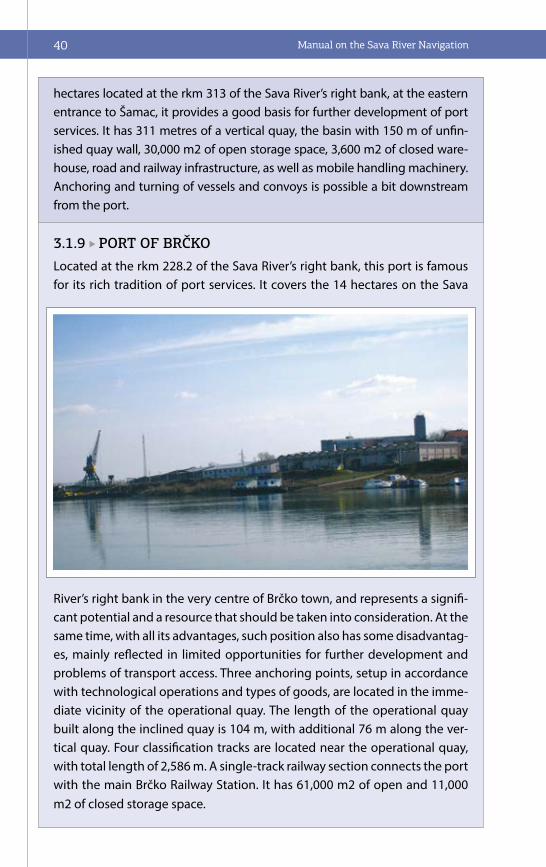
3.1.9 PORT OF BRČKOLocated at the rkm 228.2 of the Sava River’s right bank, this port is famous for its rich tradition of port services. It covers the 14 hectares on the Sava
River’s right bank in the very centre of Brčko town, and represents a signifi-cant potential and a resource that should be taken into consideration. At the same time, with all its advantages, such position also has some disadvantag-es, mainly reflected in limited opportunities for further development and problems of transport access. Three anchoring points, setup in accordance with technological operations and types of goods, are located in the imme-diate vicinity of the operational quay. The length of the operational quay built along the inclined quay is 104 m, with additional 76 m along the ver-tical quay. Four classification tracks are located near the operational quay, with total length of 2,586 m. A single-track railway section connects the port with the main Brčko Railway Station. It has 61,000 m2 of open and 11,000 m2 of closed storage space.

INFRASTRUCTURE 41
3.1.10 PORT OF LEGET
RTC Luka Leget Company is located at the 135.7 rkm of the Sava River’s left bank.
It extends over the area of 80 hectares and is positioned in the eastern in-dustrial zone of Sremska Mitrovica. It is connected to the trunkline railroad Belgrade - Zagreb via industrial railway track, and it also has the direct link to the Belgrade – Zagreb highway. RTC Luka Leget provides handling and stor-age services for all types of goods received or dispatched via river, railway or road transport means. Goods are stored in public and customs warehouses of closed and open type. Closed warehouses cover the area of 20,000 m2, whereas open storage area extends over 10 hectares of land. Port Leget has
100 m of vertical quay for mooring and handling of all types of vessels nav-igating in the Danube Basin. One portal crane with lifting capacity of 6,500 kilograms is located on the vertical quay, and it is capable of handling of all types of general and bulk cargo. Several forklifts and the car crane (with bearing capacity of 25 tons) are also available for cargo manipulation.

Manual on the Sava River Navigation42
3.1.11 FREE ZONE ŠABAC
Free Zone Šabac is located at the rkm 101.0 of the Sava River’s right bank, spreading over the area of 47 hectares within the free zone with integrated road, railway and water transport. Cargo handling in the basin is currently not possible due to the insufficient depth at the entrance. Harbour water area of 4.5 hectares with a basin has a respectable potential. It can handle 4 vessels simultaneously, and also has capacity to classify railway cars. The zone owns substantial mobile handling machinery and 10,000 m2 terminal, as well as the 10,000 m2 storage space for the containers. Besides, it compris-es a passenger terminal, 400 m of vertical quay, and 160 m of vertical quay on the front side of the basin.
Storage capacity comprises 22,000 m2 of closed and 12,000 m2 of open storage area. Additionally, it owns 5,000 m2 of storage area designated for dangerous goods. The free zone with its area of 7,000 m2 provides addi-tional services, i.e. the customs office, weighing scale and all other auxiliary services, making the entire space functional and interesting for its users.
3.1.12 PASSENGER RIVER TERMINAL BELGRADE
International passenger terminal is located at the rkm 0+750 of the Sava Riv-er’s right bank, in the immediate vicinity of its confluence with the Danube (km 1171). The exceptional position at the intersection of the river corridor VII and the corridor X makes this region an international traffic and trans-port hub, while Belgrade with lot of attractions and rich historical offer dis-tinguishes as an alluring touristic destination. International Belgrade Nikola Tesla airport is only 16.8 km away from the port.

INFRASTRUCTURE 43
3.2 INLAND WATERWAYS Inland waterways comprise all water bodies that can be used for navigation, such as rivers, lakes and canals. As a rule, these water bodies provide con-ditions for navigation within the designated fairway areas. The Sava River’s waterway has already been defined in the first part of this Manual thus will not be additionally elaborated, but focus shall be put on its basic elements: fairway width, fairway depth, river bed curve radius and river flow velocity.
Important and inevitable parts of the inland waterway infrastructure include the navigation safety facilities, such as: floating signs and bank marks – navigation marks, signal and radio stations, winter harbours and winter shelters, anchorages, river engineering structures providing fair-way parameters, locks, optical, acoustic, electrical, electronic, radar and other devices, etc.
3.2.1 WINTER HARBOURS AND WINTER SHELTERS
Winter harbour is a navigation security facility, artificially made or natu-ral water area on the waterway, setup and equipped as a safe shelter for vessels from damage inflicted by ice, high water or other bad weather conditions.
Winter shelter is a natural part of the water area on the waterway, port, and other type of harbour that serves as an emergency shelter for the protection of vessels against damages in the event of the occurence of ice, high water, or other bad weather conditions. Distance between winter shelters should not exceed 60 kilometres, i.e. one day of navigation – the daylight time.
Winter harbours and winter shelters on the waterway can be used by all vessels under equal conditions, with the exception of the vessels carrying dangerous goods that must be settled in the winter harbours specifically designated particularly for that purpose.
Maintenance of order in winter harbours and winter shelters shall be kept by the competent authority of the Party on whose territory the winter har-bour or winter shelter is located, and vessels can stay in as long as measures under extraordinary circumstances are taken.

Manual on the Sava River Navigation44
Once the measure taken under extraordinary circumstances have ceased, the boatmaster can decide to use winter harbours and winter shelters, but only in the events that are necessary for protection and saving lives, safety of vessels and persons on board, as well as navigation safety. If possible boatnasters shall notify competent authorities of their intention to use the winter harbour or winter shelter specifying the reason, location and time of stay.
The existing ports and harbours can be used as winter harbours and winter shelters.
General requirements that are necessary for definition of the winter har-bours or winter shelters are:
• Location of the winter harbour, i.e. winter shelter;
• Systematisation (designation) of a winter harbour or a winter shelter as per type of cargo;
• Categorisation of winter harbours and winter shelters in accordance with the waterway category on the sector;
• Marking of winter harbours and winter shelters.
Special requirements are defined by the competent authorities, and these refer to:
• Commanding authority at the winter harbour and winter shelter;
• Communication method from the vessels to the shore;
• Vessel mooring and anchoring method;
• Waste and other substances reception method;
• Fire protection, sanitary node with running water, electricity supply solution;
• Approach route.
INFRASTRUCTURE 45
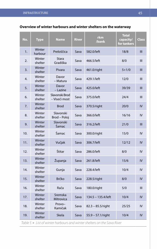
Overview of winter harbours and winter shelters on the waterway
No. Type Name River rkm/bank
Total capacity/
for tankersClass
1. Winter harbour Preloščica Sava 582.0/left 18/8 III
2. Winter shelter
Stara Gradiška Sava 466.5/left 8/0 III
3. Winter shelter Pivara Sava 461.0/right 5+1/0 III
4. Winter shelter
Davor – Matura Sava 429.1/left 12/0 III
5. Winter shelter
Davor – Lazine Sava 425.0/left 39/39 III
6. Winter shelter
Slavonski Brod– Viseći most Sava 375.0/left 24/4 III
7. Winter shelter Brod Sava 370.5/right 20/0 IV
8. Winter shelter
Slavonski Brod – Poloj Sava 366.0/left 16/16 IV
9. Winter shelter
Slavonski Šamac Sava 316.2/left 21/0 III
10. Winter shelter Šamac Sava 300.0/right 15/0 IV
11. Winter shelter Vučjak Sava 306.7/left 12/12 IV
12. Winter shelter Štitar Sava 286.0/left 8/0 IV
13. Winter shelter Županja Sava 261.8/left 15/6 IV
14. Winter shelter Gunja Sava 228.4/left 10/4 IV
15. Winter shelter Brčko Sava 228.5/right 8/0 IV
16. Winter shelter Rača Sava 180.0/right 5/0 III
17. Winter shelter
Sremska Mitrovica Sava 134.5 – 135.4/left 10/4 IV
18. Winter shelter
Provo–Kamičak Sava 82.3 – 85.5/right 25/25 IV
19. Winter shelter Skela Sava 55.9 – 57.1/right 10/4 IV
Table 5 List of winter harbours and winter shelters on the Sava River

Manual on the Sava River Navigation46
3.2.2 HYDRAULIC STRUCTURES
General characteristics of freeflowing rivers
Basic information on freeflowing rivers as seen from the standpoint of naviga-tion must be provided prior to any discussion about navigational issues.
Generally speaking, a river consists of bends with some shorter straight sec-tions in between. Contrary to seas and lakes, there is a current in the river flow, which is a force that directly affects the navigation. River flow velocity depends on the two most important factors – riverbed gradient and the flow volume of water. Since the riverbed gradient is a constant, any increase or decrease in the velocity of the river depends directly on the increase or decrease in the flow volume of water, i.e. on the water level oscillations.
The river’s velocity is not equal in all layers of its cross-section. Within the riv-er itself, the greatest velocity is on the surface and in the central river parts, but decreases along banks and near the river bottom. As a rule, the greatest velocity (main current) corresponds to the greatest depth. In addition to the longitudinal flow, there are also transverse currents and swirling waters(whirl-pools and vortices). Such flows occur in the cases of sudden changes in river’s depth or width, due to underwater obstacles, river overflows, etc. For example, at the river knee (bend in a river changing its course significantly within a short distance to a different direction) there is a an impression that the “river flows upstream”.
Some adverse effects of the water current on navigation are as follows:
• The speed of upstream navigation is reduced by the velocity of the river flow;
• Downstream navigation can be endangered if the force of the flow cur-rent is not taken into account while manoeuvring. For example, for the vessel navigating downstream to berth safely, it is necessary to make a turning manoeuvre and than to take the upstream course. For a success-ful manoeuvre it is necessary to take into account the river’s velocity and a water surface width. The manoeuvre needs to be performed so the vessel could take a favourable position with regard to the berth. Namely, with in the case of strong flow currents and weak engines, it is common that after the turning manoeuvre, vessel ends up far downstream from the berth;

INFRASTRUCTURE 47
• In the cases of a malfunction of vessel’s propulsion unit, the vessel is carried by flow currents, with a risk of an accident, as well as collision with other vessels, bank protection, bridge pillars, etc. To prevent such a threat, a back-up propulsion unit is activated (if there is one), the anchor is dropped or oars are used so as approach the bank. At the moment of the contact with the bank, the vessel should be moored.
River banks
The concave river bank is the outer bank of a curved river, followed by a greater depth and higher water flow velocity. Main current is near the concave river bank.
The convex river bank is the inside bank of the curved river with milder water currents near it, resulting in smaller depths compared to the concave bank.
Left and right river bank are determined with regard to the river’s flow direction, observing it always from the source towards the mouth, while river’s length in kilometres is calculated and marked from the mouth towards the source.
River sediment, river islands and shoals
Rivers carry huge amounts of sediment (soil, gravel, sand, silt, limestone). When the river’s tractive force is not great enough to keep the sediment particles in the flow, the sediment is deposited on the river bed.
Figure 2 River section with shoals in horizontal projection and cross-sections: A-A, in transit, and B-B, when fastest river current runs along the concave bank. 1 – high concave bank; 2 – low convex bank; 3 – the fairway axis; 4 – transverse shoals; 5 – shoals

Manual on the Sava River Navigation48
The sediment created by erosion of the river’s concave bank is carried in two directions – one towards the opposite convex bank, and the second one along the bank that it affects, being deposited on its protruding section. With water level changes during the high waters, the sediment is carried away and depos-ited somewhere else (the so called “migrating” or “moving” shoals) resulting in big depth at the places where shoals used to be before and vice versa.
If the riverbed, where the main current shifting from one bank to the other is wide, the water flow power is being significantly reduced (with velocity slowed down) so that the greatest amount of the sediment is deposited in the river’s mid-section, creating thus some cros-spread shoals that later turn into river is-lands dividing the river flow into river branches.
The sediment is also deposited on the strait section of the river along the banks, where the waters flow is calmer. Sediment deposition processes are most prom-inent at the mouth of a rivers.
Shoals may also occur when the waterborne mass in the river channel finds some obstacle, either natural or artificial, resulting in reduced flow velocity and water power, thus leading to even greater deposited of the sediment.
Rivers regulation for navigation purposes
Water action in the channel causes permanent changes, affecting both the river channel and river banks. This is primarily reflected in the failure of river banks fol-lowed by the threat to the levees. Furthermore, there is an unrestricted transfer of sand, gravel and other materials thus creating new shoals. These actions lead to shift of the fairway and changes of its main dimensions – width and depth.
The main purpose of the river engineering is the maintnace of depths, widths and bend curvature/radius within the limits that ensure safe navigation. As a rule, regulation works for navigation purposes are, generally in line with the overall river regulation, thus contributing to the flood protection, prevention of ice jam, i.e. prevention of “ice flood” and other harmful effects of the water. In other words, the goal of river regulation works is stabilisation of river banks, with adequate fairway for safe navigation.
Measures for the regulation of the natural waterways for the purposes of navi-gation are very diverse The regulation of freeflowing watercourses for the pur-poses of navigation require diverse measures that usually boil down to :
• Regulation of the river channel;
• Canalization of the river.

INFRASTRUCTURE 49
These measures can be combined as well.
River regulation for the navigation purposes is executed with the aim of achiev-ing the secure fairway of particular dimensions at low navigable level (LNL).
Regulation activities can be three-fold:
• biotechnical measures, when, for example, different types of vegetation are used for the protection against the bank failure;
• dredging works in the channel, for excavation, clearance and mainte-nance of fairway dimensions, and
• waterway regulation, with classic training works and structures.
The aforementioned regulation measures can be applied individually or in combinations.
River engineering by means of regulation structures and works is usual on in-land waters. Direct application in the regulation of natural rivers for navigation purposes have regulation structures in the channel, as well as the works on the meander cutoff. Regulation structures are used for:
• protection against the bank failure;
• construction of new banks;
• reduction of the curvature i.e. increase of the radius of river bed curve ;
• closure of branches;
• at law water levels for deepening of the narrow channels by means of the riverbed gradient, thus increasing the discharge profile;
• stabilization of the river channel.
Regulation works can be made of stone, sand, willow branches, twigs, unrein-forced and reinforced concrete, various types of wire, galvanised wire mesh, plastic foils filled with sand, etc.
Revetments (bank protection) are structures placed on concave river banks, which are prone to failure due to water current effects in river bends. Reinforce-ment of banks prevents shifting of the channel. Revetments are usually made of a gravel and crushed stone, or of concrete blocks on a bed of gravel.
Many different types of revetments are used in river engineering. They can be divided into vertical and sloping constructions.

Manual on the Sava River Navigation50
Figure 3 Vertical gravitational revetment made of gabion mattresses
Figure 4 Sloping revetment built of broken stone
Figure 5 Guide bund on the Sava River – “Rača sector”

INFRASTRUCTURE 51
Vertical structures should trasfer the horizontal load into the ground, whereas in case of sloping constructions the ground directly takes over such loads (the slope stability issue). Vertical structures can be divided into two basic groups with regard to the transfer of horizontal loads/forces. First group comprises gravitational structures where horizontal loads are transferred into the ground by means of of their own weight. There are no tensile forces in structures of this type. Second group comprises types where horizontal loads are transferred into the ground by means of their own internal forces.
Sloping revetments are generally divided according to the type of coating. Usual material is stone, in its different forms:
• Rock fill and Rip-rap;
• Hand-laid lining (rolling);
• Masonry in mortar;
• Stone blocks cemented with asphalt mastic;
• Stone filled gabions.
Due to their simple construction and competitive price, the sloping structures are the most frequent choice for bank protection. Each sloping revetment has two important constitutive elements it distinguishes with, that are used to counter the flow pressure. They are cover layer and toe.
Guide bunds are also used for the regulation of concave banks, particularly at those sections where structures should be placed in the channel, in order to reduce the river bend curvature. They can be made of stone or sand-filled bags, on a base made of crushed stone or fascine mattress (fascine - bundle of willow twigs). The body of a guide bund is connected to the bank by travers-es, thus creating inter-traverse fields. These fields reduce the velocity of water mass flowing over traverses, which increases the speed of sediment siltation and prevents the flow between the structure and the bank. This accelerates development of a new bank. Guide bunds can also be applied in regulation of straight river sections if it is necessary, to narrow the channel or to increase the depth. In such cases, these structures are simultaneously built on both left and right river bank.

Manual on the Sava River Navigation52
River groynes are the most common type of regulation works. As a rule, groynes are constructed on convex bank, but can exceptionally be construct-ed at straight river sections as well. They are constructed exclusively in groups. Their operation is two-fold: they narrow the channel, increase the riverbed gra-dient, depth and channel capacity with regard to the sediment transport and, on the other hand,cause deposition of the sediment in groyne fields. During periods of medium and high waters, water flow over groynes loses its velocity, i.e. its power for sediment transport, thus the carried material is deposited in groyne fields, resulting in development of the new bank. When river’s convex bank is protected by groynes, the opposite concave bank must be protected with revetment or guide bunds.
Figure 6 Groynes on the Sava River – “Rača sector” (top) and Skela (down)

INFRASTRUCTURE 53
Groynes and guide bunds are often mutually competitive solutions for the same purpose. Each has its own advantages and disadvantages. Hence, as com-pared to the groynes, guide bunds have the advantage of uniform flow along the structure thanks to the continuously defined regulation line, with no gen-eration of local erosion in the channel, as well as consistent sediment transport. Disadvantages of guide bunds include the following: high construction costs, difficult and costly troubleshooting/repair, difficulties during construction due to problems with foundation in deep water, slow clogging of the old channel and the need for sturdy toe of the structure. Disadvantages of groynes repre-sent advantages of guide bunds, and vice versa. Thus, advantages of groynes include easy adjustments and troubleshooting, efficient clogging of the old channel, and lower construction costs. Some of groynes’ disadvantages include occurence of transverse flow in the fairway, frequent damages during periods of high waters (overflowing) and dotted regulation line (instead of continu-ous). There have been developed special types of groynes – so-called “hocley stick” and “T-head” groynes. They are a combination of longitudinal structures and groynes, i.e. the groyne’s head completed by the part of the longitudinal structure. Such technical solutions ensure avoidance of the main groynes’ dis-advantages bound to dot-definition of the bank and transverse flow currents into the fairway.
Weir dams have a significant role in regulating the rivers that distinguish with many branches and waterway bifurcation. After the selection of the river branch that will be used for navigation, other branches are checked with weir dams, so the waters are directed only towards one river branch. All the same, weir dams are used for the closure of abandoned branchs after the construction of cutoff.
River bends cutoff is one of usual river engineering measures in waterways with sharp bends. Cutoff consists of the development of a new channel favora-ble for navigation. It shortens the river meander, and is used at sections where a natural meander should be shortened for the needs of navigation and in-creased channel capacity, or for other purposes (e.g. establishment of an inland port or winter harbour).
The cutoff is accompanied by carefully designed local training works. They in-clude revetments in the channel, downstrem and upstream of the cutoff, rock fill within the cutoff itself, a cutoff channel as a main channel and weir dams. The following figure shows the scheme of the cutoff with accompanying train-ing works.

Manual on the Sava River Navigation54
Bank protection prevents the occurrence of adverse changes in a channel, be-fore and after the cutoff. The new channle, as a main one, is constructed up to the level of the underground water, and is always routed closer to the con-vex (inside) bend. Rock fills are used to prevent the channel widening and to keep it within the design width. Weir dams are constructed both upstream and downstream from the cutoff trench, or only on the upstream part, depending on whether the abandoned channel is to be used for some other purposes (a habor) or not. They are constructed only when the new channel is entirely developed, i.e. to such an extent that water, sediment and ice may freely flow (undisturbed) (so as not to cause excessive backwater and, possibly, flooding in the area upstream from the cutoff). Weir dams accelerate the process of the final development of the cutoff, but they are usually constructed in phases (ei-ther by height or by length) so that high waters could flow through old channel before the new channel is fully developed. Cutoffs are relatively extensive in-terventions in the waterway, resulting in changes in the flow regime, sediment transport regime and changes in the geometry of the channel, not only within the location of the cutoff, but in the wider area as well.
Figure 7 Trench - Preloščica on the Sava River

INFRASTRUCTURE 55
Confluence engineering is performed on the concave bend of the main riv-er, thus providing the most efficient mixing of waters from both watercourses, followed by adequate transport of sediment and ice. So the confluence would remain permanent, it is necessary to be reinforced with appropriate training works, usually bank protection. Problems that frequently occur in confluenc-es regulation of the tributaries are of hydrologic and hydraulic nature. They in-clude the flow regime of tributaries, the flow regime of the main stem (parent river) , mutual relation of two regimes (problems of coincidence of high waters, propagation of flood wave) and torrential character of tributaries. Water level changes in the main stem cause a backwater or depression in the tributary. A backwater causes deposition of the sediment in the tributary, whereas depres-sion could lead to erosion of tributary’s channel and deposition of the sediment in the main stem, downstream from the confluence. When high waters of tribu-taries cause a backwater in the main stem, it is to expect that the sediment dep-osition will appear in the main stem, upstream from the confluence. Reduced water wave of a tributary can cause increased velocities in the main stem, with severe erosion and sediment deposition downstream from the confluence.
Figure 8 Confluence of the Drina River

Manual on the Sava River Navigation56
Figure 9 Ship lock
When, during the low water levels, regulation structures pose a threat to the safe navigation, they must be marked with bank marks and floating signs. Heights of guide bunds, traverses and groynes are determined by the altitude. Namely, their top end (“a crest”) is at the level of minimum navigable level plus 1 metre. Since all water gauges have determined minimum navigable levels, it is possible for every referent water gauge to calculate water levels at which the crests of structures or groynes emerge. These data are very important for small vessels that also navigate outside of the defined fairway. According to the afore-said, it is always possible to determine the water depth at various structures, i.e. to ascertain whether and how much those structures are above the water. Weir dams closing certain river branches are, as a rule of the same height as groynes and other river engineering structures. Nevertheless, some weir dams are higher than other training works (usually 1 metre higher), due to different hydro-technical reasons. Some weir dams have a shorter body and a lower crest, thus enabling the passage of smaller vessels during the periods of low water.

INFRASTRUCTURE 57
Canalization of the river presumes its impoundment at one or more pro-files by artificial checks – dams, which significantly changes its hydrological regime contributing to favourable navigation conditions. Inpoundment of the river creates a discontinuity of the water surface level (difference between levels of the upper and lower water) that vessels scale by use of ship locks, cranes or water slopes.


BASICS OF SHIPBUILDING AND PROPULSION 59
4.1 SHIPBUILDING BASICSShipbuilding is a branch of engineering, concerned with constructing one of the most complex products – a ship. It is a combination of science and art, hence it reflects the rate of technological advancement of a country. Scientific compo-nent of shipbuilding ensures a ship’s required features such as speed, strength, unsinkability, stability and maneuverability so that it could resist frequently dif-ficult navigation conditions. Artistic segment is important since a ship must be aesthetically striking and recognisable. Shipbuilding plays a substantial role in the security of the country during a war and in its economy, both in peace and wartime. The knowledge of shipbuilding has increased over last few decades in many fields, such as hydrodynamics and probability theory, using at the same time the experience and knowledge of many auxiliary sciences of engineering. Shipbuilding entails the construction and repairs of ships, barges, platforms and other floating vessels. Facilities for shipbuilding are called shipyards. Scrap yards are places where old ships are cut into scrap metal.
BASICS OF SHIPBUILDING AND PROPULSION
Figure 10 Tugboat Bačkaon the Kupa River, 1959

60 Manual on the Sava River Navigation
4.1.1 SHIP CONSTRUCTIONS
Ship is a watercraft operating on seas, rivers and lakes, used for the transport of goods and people (cargo and passenger ships), fishing (fishing boats), na-val military operations (warships), specialised operations on seas, rivers and lakes (cable layers, pipe layers, research vessels, etc.) and conduct of other various tasks (tugboats, icebreakers, etc.).
A ship is a large buoyant watercraft, whereas smaller vessels are called boats. Contrary to a raft, ships and boats have a cylindrical shape that provides the upthrust required for floating.
Each ship consists of many inter-related parts that make up the whole. The following figure depicts the main parts of ship:
Figure 11 Main parts of ship
4
12
3
6
7
5

BASICS OF SHIPBUILDING AND PROPULSION 61
• Bow (1) – is a forward part of a vessel, opposite of a stern;
• Anchor and anchoring gear (2) – is one of the most important systems on a ship ensuring that a ship remains in one place, and in extraordinary situations provides a quick stop. A ship can have an anchor on a stern, also called “stern anchor”. Anchoring gear comprises anchors, anchor chains/rodes, an anchor winch/windlass, a sprocket wheel, an anchor hawsepipe through which the anchor chain is fed, anchor billboard upon which the anchor is mounted and an anchor chain stopper;
• Hull (3) – is a load carrying part of a ship, and the one ensuring its un-sinkability. It consists of the bottom, sides and the deck. It does not in-clude masts, a rudder, engines, etc. More precisely, it could be said that the hull is constructed of a framing (a grid structure composed of carri-er beams and profiles, depending on the type of a vessel) and of shell (tightly fixed to the framing on the outside and on the inside). Inside of the hull is divided into decks and longitudinal partitions called bulk-heads, the role of which is to divide a ship into functional areas, increase the ship’s structural rigidity and strength, and create watertight com-partments that can contain water in the case of a hull breach or other leak, thus preventing its sinking;
• Propeller (4) – is a part of the propulsion system that converts its rota-tional motion into thrust that moves a vessel. A propeller shaft connects the propeller with the ship’s internal engine. Main characteristics of a ship propeller are: number of blades, the direction of rotation, the diam-eter and pitch of a propeller. A rudder is located behind a propeller, and it is used to steer a ship;
• Stern (5) – is the back or aft-most part of a ship. The stern lies opposite of the bow, above the propulsion machinery space of the vessel;
• Main deck (6) – is a horizontal structure placed over the ship’s hull, fully or partly covering inner space of a vessel. A space under the deck is ref-fered to as “down below”;
• Superstructure (7) – is an upward, covered and closed extension that projects above the ship’s main deck. It can extend over the entire width, from one side of the ship to the other, or be narrower than the width of a deck (a deck house). As a rule, the ship’s command bridge with its control/navigation equipment is located on the ship’s highest deck plat-form. These structures increase ships’ structural strength.

62 Manual on the Sava River Navigation
In addition to the aforementioned parts, there are some other no less im-portant elements and assemblies, such as:
• Hull equipment – all ship parts that do not contribute to the strength of a ship (interior linings, ceilings, flooring, the fitted furniture...);
• Propulsion equioment – all parts that enable a vessel to move (for example, in motor vessels: engine, shaft assembla and a propeller);
• Auxiliary devices – all devices, machines and installations used in auxiliary operations in engine rooms and on decks (emergency pow-er aggregates, various pumps, anchor gear, wheelhouse, plumbing, electrical installations, etc.);
• Mobile equipment – navigation equipment, safety equipment, machinery...
Ship’s main characteristics and dimensions
Ship’s main characteristics include:
• Ship’s own weight/light weight – expressed in tons;
• Displacement – expressed in tons or m3;
• Deadweight – expressed in tons;
• Volume capacity – expressed in m3, but also in register tons.
The ship’s own weight/light weight is the weight of the fully equipped ship when completely empty of fuel, technical and fresh water, ballast water, supplies of food, cargo and crew,s weight with their luggage. It is expressed in tons.
Displacement can be defined in two ways:
• as a volume (∇), expressed in m3;
• as a mass, i.e. weight (∆), expressed in tons.
The deadweight at any time represents the difference between the actual displacement and the ship’s own weight/light weight, given in tons. There are two types of deadweight:
• useful deadweight – the weight of cargo and passengers with their luggage, i.e. the weight that transport charges are paid for;
• total deadweight – sum of the useful deadweight and weight of fuel, supplies of food and crew,s weight with their luggage.

BASICS OF SHIPBUILDING AND PROPULSION 63
The ship’s volume capacity measures the size of the internal volume of the ship. It is expressed in m3, and also in register tons.
Register ton is a measure of the internal (enclosed) volume in a vessel, and equals 2.83 m3. This is a formula-derived measure where 1 rt = 100 ft3 = 2.83 m3.
Types of Register Tons:
• Gross Register Ton (GRT) – measure of all internal (enclosed) volume in a vessel;
• Net Register Ton (NRT) – measure of internal (enclosed) volume in a vessel space for cargo and passangers.
The main hull dimensions include:
1. Longitudinal dimensions:
LOA
Length Overall – the maximum length of the vessel in m, including all fixed installations such as parts of the steering system or power plant, mechanical or similar devices.
LPP
Length between perpendiculars – is the length between the foremost perpendicular, i.e. usually a vertical line through the stem’s intersection with the waterline, and the aftmost perpendicular which, normally, coincides with the rudder axis; the length from the forward surface of the stem, or main bow perpendicular member, to the after surface of the sternpost, or main stern perpendicular member.
LWL
Length at the water line – equals the length of the vessels hull, from centre fore to centre aft at the level of the water; the length of a ship or boat at the point where it sits in the water.
Figure 12 Longitudinal section
Bm
DEP
TH
draf
t
BWL
LOA
LWL
LPP

64 Manual on the Sava River Navigation
Also, no less important hull dimensions are:
LP
The parallel mid body length of the ship is defined as that part of the ship length for which the sectional curve is constant, i.e. horizontal around the middle of the ship.
LR
The length of run of the sectional area – defined as a length of the abaft part of the vessel’s sectional curve, moving from parallel mid body towards the stern end of the construction waterline.
LE
Length of entrance - defined as a length of the fore part of the vessel’s sectional curve, moving from parallel mid body towards the bow end of the construction waterline.
2. Cross-sectional dimensions:
BMBeam – the breadth of a vessel measured at the outside of the hull amidships, or at its greatest breadth.
BOABreadth overall – the distance across the widest part of the ship, whether it occurs on the hull below or above the water.
BWLBreadth on waterline – the hull’s largest breadth on the waterline, regardless of position.
BXBeam measured on the designed waterline at the maximum section area.
Figure 13 Cross section
Bm
DEP
TH
draf
t
BWL
LOA
LWL
LPP

BASICS OF SHIPBUILDING AND PROPULSION 65
3. Vertical dimensions:
DM (H)Depth moulded – moulded depth of a ship is measured at the middle of length L, from the top of keel to the uppermost conti-nuous deck at side
FMFreeboard – the distance measured from the waterline to the upper edge of the deck plating at side of the freeboard deck amidships.
TAThe draught aft – the vertical distance from the moulded baseline at midlength to the waterline measured at the aft perpendicular.
TF
The draught forward – the vertical distance from the moulded baseline at midlength to the waterline measured at the forward perpendicular.
TM
Mean designed draught – vertical distance from the water surface to the bottom of the underwater body of a ship, measured at half LPP, from midships to the designed waterline.
TX
The draught at the transverse section having maximum area – vertical distance from the water surface to the bottom of the underwater body of a ship, from midships to the designed waterline.
4.1.2 VESSEL HYDRODYNAMICS
The vessel hydrodynamics is a discipline studying:
• Motion of vessels through the water and phenomena occurring dur-ing such a motion;
• Vessels’ mobility issues and steering;
• Behaviour of vessels in waves.
Mobility of a vessel represents its ability to move on the water using the thrust force. The thrust force can be calculated based on a ship’s resistance and propulsor features.
Ship’s resistance is the force working against its propulsion. For a body to be able to move at a certain speed in the fluid, it is necessary to apply a certain force to overcome the resistance. The movement of vessels through fluids is opposed by hydrodynamic forces of fluids and aerodynamic forces of air. The following basic phenomena can be observed while navigating vessels through the fluid:

66 Manual on the Sava River Navigation
• Eddies are formed in the immediate vicinity of a ship’s hull due to a water friction against the hull (boundary layer);
• Large eddies develop on the ship’s stern;
• Waves following a vessel are created.
Components of resistance are:
• Resistance of the ship below the waterline (water resistance) RV;
• Resistance of the ship above the waterline (air resistance) RZ;
• Other/added resistance RO.
Additionally, water resistance consists of:
• Frictional resistance RF;
• Wave resistance RW;
• Pressure resistance RP;
• Resistance of appendages RPR.
Ship’s resistance is calculated as:
R = RV + RZ + RO = RF + RW + RP + RPR + RZ + RO
Frictional resistance represents a main component of the ship’s total resist-ance, often some 50% - 90% of the ship’s total resistance.
Frictional resistance RF is a consequence of water’s viscosity that is at the time of vessel’s motion presented as internal friction. In a thin region of fluid close to a solid body, called boundary layer, energy is transferred from the ship’s hull to the surrounding water, thus creating a frictional resistance.
V
V
VB=0
Figure 14 Ship’s friction resistance

BASICS OF SHIPBUILDING AND PROPULSION 67
The boundary layer extends from the ship’s stern towards the bow, since the in-crease in ship’s length also increases the area of water affected by friction. The frictional resistance depends on:
• The roughness of the outer shell of a ship – increase of frictional resistance due to roughness of the ship’s outer shell is on average 15 to 20%;
• The size of the hull’s wetted area – an increase in the size of the hull’s wetted area increases the frictional resistance;
• The vessel’s speed – increase in speed increases the frictional resistance;
• The vessel’s length – increase in length increases the frictional resistance.
A dimensionless parameter called Reynold’s number (Re) has an important role in expressing the condition of dynamical similarity for flow systems influenced by viscosity and inertia:
L – length (m);V – vessel’s velocity (m/s)ν – μ · ρ = coefficient of kinematic viscosity (m2/s)μ – coefficient of dynamic viscosity (N · s/m2)ρ – fluid density (kg/m3)
Depending on the Reynold’s number and the roughness of the hull, a flow within a boundary layer can be laminar or turbulent. A laminar flow is the flow of a vis-cous liquid in which layers of fluid appear to slide smoothly past/over each other, following outlines of a hull, without any major variations in speed. A turbulent flow is a flow in which there are rapid and apparently random particle fluctua-tions, caused by a constant mixing of liquid masses and very high velocity fluctu-ations at each point. Turbulent frictional resistance is significantly higher than in laminar flow. In practice, the turbulent flow is almost exclusively present, whereas the laminar flow is rapidly destabilised and disappears in the area of a ship’s bow. Therefore, it is important that ship’s hull, especially in area of the bow, is as smooth as possible. An increase in frictional resistance developing due to the increased roughness of a vessel is on average 15% to 20%, but can even exceed 40%.
Wave resistance RW appears due to the water resistance, i.e. the water resisting the change of its own status. Any increase in vessel’s velocity increases the size of waves, i.e. causes the increase in wave resistance.
The waves created by the ship can be:
• Divergent waves;
• Transverse waves.

68 Manual on the Sava River Navigation
At low speeds, transverse waves are barely visible, while divergent waves are prominent. Every increase in speed causes the increase in intensity of transverse waves, thus their crests and throughs become clearly visible along sides of a ship. A number of transverse waves appearing along the ship’s sides increases with growing speed, which at high speeds results in appearance of only one wave along the side of a ship.
Waves occur only around vessels on the water surface. If a vessel (for example, a submarine) is below the surface by length of 1 to 3 of its own radiuses, the waves disappear, i.e. there is no wave resistance either.
Wave resistance depends on:
• speed of a vessel – any increase in speed causes a progressive increase in the size of transverse waves, and thus in their resistance;
• shape of a vessel – any increase in B/T ratio causes an increase in wave resistance;
• length of a vessel – an increase in a length reduces the wave resistance (but increases the frictional resistance; optimal solution needs to be found).
Pressure (eddy) resistance RE, i.e. form resistance, appears because water streamlines at stern do not run exactly along the shape of a vessel’s hull. There-fore, the pressure at stern and the pressure at bow are not equal. This difference in pressures creates the eddy resistance.
Eddy resistance depends on a speed, and primarily on the shape of a stern, i.e. on the manner in which the hull is “sharpened” from the parallel mid body towards
V B
Figure 15 Shape favourable for wave resistance

BASICS OF SHIPBUILDING AND PROPULSION 69
the stern. The main cause for creation of eddies around vessels that have a typical form is the expansion of the boundary layer, which causes a change in the prin-cipal flow regime.
At a stern of a vessel with the full form, streamlines in the boundary layer cannot follow the form of the body, hence the boundary layer is ripped off the body sur-face, the streamlines change direction and consequently create eddies. In sharper stern forms, thickness of the boundary layer increases gradually, the rip off occurs at a point close to the stern, and consequently the wave resistance is lower.
Air resistance RZ occurs due to the motion of the ship above the waterline, rela-tive to air. To reduce the air resistance to the maximum possible extent, it is nec-essary to:
• buildthelowestpossiblesuperstructure;
• roundthesuperstructureupandmakeitinastreamlinedform;
• build thesuperstructure inagradualmanner, towards thebowandto-wards the stern.
Resistance of appendages RPR is a cumulative resistance caused by appendages such as bilge keels, struts, rudder, stabilising fins, etc. Relatively small surface of appendages causes a low frictional resistance. However, occurrence of eddies at and around appendages has greater influence on resistance, thus their shapes on the part of a ship below the waterline should be lean and without sharp edges.
4.1.3 SHIPS AND CONVOYS IN INLAND NAVIGATION
Types of vessels in inland navigation, by intended use:
• Merchant vessels – ships that carry passengers or transport cargo (20 m and longer, tugboats and pushers, regardless of length);
– Cargo ships/freighters – ships exclusively carrying various types of cargo;
– passenger ships – ships that carry more than 12 passengers (daytrip or cabin ships);
• Specialized ships – ships intended for special operations and tasks – pub-lic vessels (portmaster office, police, fire service), floating equipment (dig-gers, elevators, cranes), fishing boats, ice breakers, etc.;
• Warships – vessels primarily intended for military operations on rivers and lakes.

70 Manual on the Sava River Navigation
In addition, cargo ships/freighters can be:
• Self-propelled ships (motor ships) – vessels using its own mechanical/motor drive, apart from vessels using motors exclusively for minor trans-fers (in ports, at anchoring points) or for increasing manoeuvring capaci-ties in convoys;
– Tugs/tugboats – vessels specifically designed and equipped to propell towed convoys;
– Pushers – vessels specifically designed to propell pushed convoys;
– self-propelled vessels – motor ships equipped with their own means of propulsion, intended for transport of goods in holds.
In practice, there are also combined vessels that are designed for transport of goods in holds, but at the same time are equipped for propelling of pushed convoys:
• non-motorised vessels – vessels not using their own mechanical means of propulsion, designed and equipped for navigation in convoys propelled by motor ships;
– pushed barges/lighters – vessels specifically designed and equipped for navigation in pushed convoys, i.e. to be pushed;
– barges – vessels specifically designed and equipped for navigation in towed convoys, i.e. to be towed.
Special types of merchant cargo ships/freighters, with and without their own means of propulsion are:
Tankers – merchant vessels designed to transport various kinds of goods in liq-uid form, including:
• mineral oil and oil derivatives;
• chemical products;
• liquefied gases.
The majority of the goods mentioned above are dangerous goods, which are transported using special tanker vessel units with appropriate safety features. Eu-ropean regulations and recommendations, such as ADN, ADN–R and ADN–D, as well as national laws governing the transport of dangerous goods, are especially relevant in this context.
Modern vessels have a double hull that prevents spillage of transported goods in case of the outer hull damage. A holds is often divided into several individual compartmentstanks/, which can be split into individual areas. This means that a

BASICS OF SHIPBUILDING AND PROPULSION 71
rtankfilling system, fire suppression systems, a gas return pipe, residual gas pipes and tanks are entirely separated. All these systems are essential to prevent envi-ronmental contamination from residual toxic gases and liquids. Tanks made of stainless steel or holds with a special coating are used to prevent any reaction between dangerous goods and a tank surface. Heaters and valves are used in the transportation of cargo that can easily freeze during winter, while a deck sprin-kler system is used to protect tanks from summer heat. Transportation of liquid freights requires utilisation of the latest technology.
Container vessels are ships intended for transport of all types of containers mainly with high-tariff goods requiring a high degree of preservation. Container transportation is believed to be one of the main growing markets for transpor-tation on inland waterways. While traditional bulk cargo sector tends to be sat-urated, the container transport shows the greatest growth potential. Specifically designated ships are being developed in order to cope with increased demand. In well-developed river systems with good navigation conditions, container ship-ping tends to be more economical.
RoRo vessels are mainly designed to carry all types of road vehicles. The main ad-vantage of Ro/Ro transportation is most pronounced in less developed countries of Eastern Europe; it requires relatively small investments in port infrastructure, thus Ro/Ro services represent an emergency intermodal solution for countries that have a weakly developed port infrastructure. Main disadvantages of the Ro/Ro navigation include a nearly optimal utilisation of a ship space, as well as a use of expensive mechanisms such as trailers.
Basic types of convoys
In order to reach an optimal degree of utilisation of the Sava River’s waterway, as well as of various transportation means, especially when it comes to the trans-port of low-cost goods (construction material, timber, ores, wheat, etc.), vessels (lighters and barges) are organised into convoys. The main types of convoys are:
A pushed convoy means a rigid group of vessels, one at least of which is placed in front of the motorized vessel propelling the convoy and is known as a pusher. A convoy composed of a pusher and a pushed crafts so as to permit guided artic-ulation is also considered as rigid;
It is customary for the Sava River to attach 2, 4 or 6 lighters that are propelled by the pusher of adequate power. Standard lighters usually used on the Sava Riv-er measure 76.5 metres in length, 11.0 or 11.4 metres in width, have an average

72 Manual on the Sava River Navigation
capacity of approximately 1,650 tons and a draught of 2.5 metres. A large con-voy of 6 lighters measures up to approximately 185 m in length (one pusher and two rows of three side by side lighters). Pushed convoys are dominant on the Lower Sava, from the confluence to Slavonski Brod. The size of a pushed convoy depends on the status and dimensions of the fairway.
A towed convoy means any group consisting of one or more vessels, floating establishments or assemblies of floating material towed by one or more motor-ized vessels, the latter forming part of the convoy and being known as tugs. Even though barges towed by tugs are nowadays almost completely abandoned form of transportation on European waterways, they are still present on the Sava River.
A side by side formation means a group consisting of vessels coupled side-by-side, none of which is placed in front of the motorized vessel propelling the formation.
4.2 SHIPBOARD EQUIPMENTFor ships to be used for their intended purposes, it is necessary to be equipped with a so-called shipboard equipment, which entails ship fittings/accessories and devices. The diversity of shipboard equipment depends on the type and size of the vessel, sector of its navigation, as well as on the vessel’s intended use. Fully working condition of the equipment and its location in appropriately assigned places are essential prerequisites for equipment’s efficient use.
Vessels’ devices are mainly auxiliary machines and other gadgets, either embed-ded or attached to a deck.
Contrary to the equipment, which mainly comprises more robust, embedded or mobile objects, ship’s fittings/accessories are smaller portable objects of various general purposes. All listed devices or fittings can be used for multiple purposes.
Depending on its main purpose, vessel’s general equipment comprises:
• Anchoring gear;
• Mooring/unmooring equipment;
• Equipment designed for protection against leakage;
• Fire extinguishing equipment;
• Life-saving equipment;
• Navigational equipment;

BASICS OF SHIPBUILDING AND PROPULSION 73
• Radio communications and signalling equipment;
• Towing and pushing equipment;
• Loading/unloading and warehousing equipment;
• Propulsion machinery and installations maintenance equipment;
• Equipment and devices of general purpose;
• First aid equipment.
Anchoring gear: located on a bow and a stern, most of it is set on a ship’s main deck. The anchoring gear comprises: an anchor winch (electric, motor or man-ually operated), a main anchor, a back-up anchor (80% of the main anchor’s weight), an auxiliary anchor (20% of the main anchor’s weight), anchor chains (thick, thin), a hatch, an anchor davit, auxiliary bolard, stoppers, a chain locker, etc. As a rule, the length of the anchor chain should be one and a half of the length of the vessel. The Ship Register stipulates the standards for ship mass/anchor mass ratios, and the breaking load of the anchor chain.
In general, the following types of anchors are distinguished:
• Admiralty pattern anchor, so named after the English Admiralty that first stipulated the dimensions for this anchor type: it consists of a shank, a crown, arms, flukes, blades, a moveable stock with balls and an anchor shackle. Anchors of this type have a strong holding power, but their chains easily get entangled with a moveable stock or arms.
H
B
h
h1
c
Figure 16 Admiralty Pattern Anchor

74 Manual on the Sava River Navigation
This type of anchors is difficult to handle though, thus so-called “one-armed” mooring anchors are made, and these are used for anchoring of buoys, other fixed floating objects and navigation safety signs;
Figure 18 Danforth anchor
45 o
30 o
AA
B F
BB
C F
DD
C
E
E
Figure 17 Hall anchor

BASICS OF SHIPBUILDING AND PROPULSION 75
• Patent or stockless anchors: construction of these anchors enables a simple hauling up until they rest with the shank inside the hawsepipe. They are easy to handle and stow aboard at any time. The best per-forming patent anchors are Hall and Danforth anchors.
Mooring and coupling equipment: it is placed and symmetrically arranged on the main deck (bow, stern, sides), to enable the safest possible mooring and cou-pling of a vessel. In addition to mooring winches and capstans, lines and bollards, which comprise the basic equipment as stipulated by technical rules, the moor-ing/coupling equipment also includes: throwing line, rope coils, reinforced poles, mallet/sledge, “shorebaum”, steel pulley – reinforced, boat-hooks, pole, shovels, coupling clamps, cross bollards (single and double), cleats (“ambus”), “radla”, etc.
Mooring lines can be made of steel (steel-wire ropes) and of fiber (fiber twisted or braided ropes) . Steel-wire ropes are used in towing, pushing, mooring, coupling etc. Fiber ropes are used during mooring in ship locks and side-by-side mooring, but never during navigation – only during overnight stays.
Apart from lines, ships should have a “shorebaum” and reinforced pole – a wood-en pole with sharpened and reinforced (with steel) tip, used to moor a vessel if there is no other suitable mooring structure.
Equipment designed for protection against leakage: highly important – it in-cludes both, the equipment used for pumping the water out of a vessel (man-ually operated, electrical and mechanical pumps) and the equipment used for preventing water penetration into the vessel (impregnated cloths, wooden wedges, calcium-based mineral grease - Ca2, quick-setting cement, etc.). It should be borne in mind that due to the specifics of the inland navigation (few crew members) and the waterway infrastructure, it is very difficult to use the equipment designed to prevent water penetration, but pumps and stranding manoeuvres are mainly used.
Fire extinguishing equipment: it is compulsory for all vessels. Depending on the size and the intended purpose of a vessel, various firefighting systems are de-signed and installed – fire sprinkler systems, reservoirs with inert gas and foam, along with a number of portable fire extinguishers. Different fire extinguishing media are used for different classes of fire to be extinguished (electrical installa-tions, oil and oil derivatives, chemical products, wood, etc.).
Life-saving equipment: it must be accessible and regularly maintained. It compris-es: life buoys and life vests, lifeboats and life rafts with appropriate accessories.

76 Manual on the Sava River Navigation
Navigational and steering equipment: it is located on a deck or in a vessel’s wheelhouse and master’s cabin, i.e. in locations with high level of visibility. Main elements of this equipment are the commanding dashboard with in-struments, devices transmitting information to the engine rooms, and the rudder with transmission, a rudder blade and a rudder axis. All devices and equipment located in a wheelhouse are in more detail described in Chapter 6 of this Manual, covering the navigation issues.
Radio communications and signalling equipment: it is located on the com-manding bridge or any suitable position on a vessel’s superstructure that is easily accessible from a wheelhouse. The most important communications and signalling equipment includes: a siren/horn, a whistle, a klaxon, a trum-pet, a ship bell, a ship tannoy, radio stations, masts, signalling and naviga-tion lights, flags and pennants of the International Code of Signals, signal rockets, etc.
Towing and pushing equipment: it is arranged around the vessel’s main deck and its superstructure. A towing gear is positioned on the aft-most part of a ship, while a pushing gear is situated on its fore part. Some of the most important towing and pushing devices include:
• Towing device – towing winch – compulsory for tugboats with power over 200 KW;
• Towing device – automated towing hook with a safety latch;
• Steel wire rope – tow cable/hawser, 80 to 350 m in length, 12 to 32 mm in diametar, depending on a tug’s towing power;
• Shock cord for tow cables;
• Towing ship arch fenders;
• Auxiliary safety bollards for towing cables;
• Additional lights and daytime markings;
• Coupling winches.
Pulling and coupling winches can be manually operated, motor, electric, hy-draulic, as well as a combination of any of them.
Loading/unloading and warehousing equipment: its structure and distribution depends on the type of a vessel, as well as on the type of cargo that is trans-ported. In addition to the equipment and accessories used for manual loading

BASICS OF SHIPBUILDING AND PROPULSION 77
(rarely seen on present vessels), today’s vessels mainly use a modern electri-cal, hydraulic and pneumatic equipment that is combined in accordance with their size and intended purpose. Various types of cranes are used to manipu-late the vessel’s cargo during loading/unloading operations, along with:
• pallets, planks, boards;
• hooks and clamps (sharp and blunt);
• grippers and curbs, for bulk cargo;
• loading/unloading pipes, chutes and funnels;
• nets, baskets, chests, etc. for light and bulky goods;
• logs, magnets, levers, etc.;
• manual, electric and motor carts, forklifts, etc. used in warehouses.
Propulsion machinery and installations maintenance equipment is diverse, and is mainly related to propulsion, main and auxiliary engines, and vessels’ installations. Majority of this equipment is located in the ship’s workshop, and comprises different types of tools and instruments used to measure var-ious parameters and detect malfunctions. All vessels must have in stock a certain amount of spare parts that can be used for immediate repairs.
Equipment and devices of general purpose: include everything that is not list-ed within the above mentioned groups, but is used on a daily basis through-out vessel’s exploitation. The most significant elements of this group are:
• a boat with a chain, oars, a scoop, an anchor and a hand lamp/light;
• a gangplank – 6 m x 40 cm), rails, joints, stands, steps – a ladder;
• refrigerator, freezer, water bucket with 6 m of rope;
• radio and TV, antennas, etc.;
• an axe, pliers, cutters, a saw, screwdrivers, scrapers, snow shovel, a steel brush, etc.;
• a universal tool set, an ice-breaking set (an ice pick, an axe and a saw);
• cleaning set for the deck and its superstructure (brooms, buckets, wipers, mutton cloths, etc., and various paintings, solvents with paint-ing accessories);
• a cleaning set for common areas (a salon, a wheelhouse, corridors, cabins, etc.);
• a special kitchen and pantry cleaning and hygiene set.

78 Manual on the Sava River Navigation
It is common for certain equipment and devices mentioned above that they must be periodically checked for technical accuracy, while handling of some equipment must be regularly practised so that both the crew and the vessel are constantly prepared for events of accident or other extraordinary events.
4.3 SHIP PROPULSION MACHINERYThe propulsion machinery of a vessel is the machinery that provides the power required for a vessel’s exploitation, and consists of:
• Main propulsion engines, providing propulsion power of a vessel – main engines;
• Supporting engines, providing energy for all other operations on a vessel – auxiliary engines.
Required power of main engines depends on the size and speed of a vessel, whereas the power of auxiliary engines is mostly determined by the vessel’s intended purpose and equipment.
Main propulsion engines provide propulsion by means of internal com-bustion engines, gas or steam turbines. Two-stroke inline diesel engines are most frequently used as main propulsion engines in merchant vessels. Main characteristics of the propulsion engine are:
• Ability to change engine speed over a wide range;
• Ability of safe reversing in short time;
• Ability to work at low engine speed;
• Safe ignition in hot and cold positions;
• Reliable run during a roll i.e. pitch movements.
Steam (gas) turbines are most frequently used on warships, as well as on large merchant vessels with power of 30000 kW or higher. Their advantages are:
• High torque at low engine speed;
• Smaller engine for the same power;
• The steam produced in boilers can be used for heating the cargo as well as for washing cargo tanks;
• Steady flow and good manoeuvring properties.
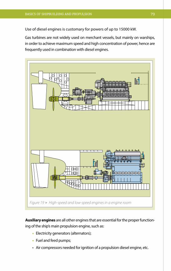
BASICS OF SHIPBUILDING AND PROPULSION 79
Use of diesel engines is customary for powers of up to 15000 kW.
Gas turbines are not widely used on merchant vessels, but mainly on warships, in order to achieve maximum speed and high concentration of power, hence are frequently used in combination with diesel engines.
Figure 19 High-speed and low-speed engines in a engine room
Auxiliary engines are all other engines that are essential for the proper function-ing of the ship’s main propulsion engine, such as:
• Electricity generators (alternators);
• Fuel and feed pumps;
• Aircompressorsneededforignitionofapropulsiondieselengine,etc.

80 Manual on the Sava River Navigation
4.4 PROPULSION
We may not be accustomed to thinking about how a sole ship’s propulsion, with-out a specified direction of its movement, makes no sense. However, it is com-mon within the field of hydrodynamics, as the most valuable and most particular (specific) theoretical tool in shipbuilding, to consider propulsion and steering separately. A set of all steering tools and devices on a vessel is called the steer-ing-propulsion system/unit (SPU).
In the field of propulsion there is an indescribable mess of terms (specialised terms in English language). An azimuth thruster - AT, colloquially known as a “Schottel”, is in English also called: azimuthing thruster, steerable thruster, fully steerable thruster, azimuthing propeller, azimuthing propulsor, swivelling thrust-er, rotatable thruster. Therefore, it is not simple for people outside the profession to master the general terminology in this field.
It is certain that, at the beginning of navigation, one device could meet both re-quirements. Our ancestors, while sitting on a fallen tree trunk with some branches in their hands, tried to sail towards their destination by rowing, in fact applied what is today known as SPU – “the steering-propulsion unit”.
Yet, we would be wrong to conclude from this that it is something completely new, since oars also represent one type of the SPU. An oar, that people made by “perfecting” a branch, was also used for steering. The ancient Greek, Roman and Viking ships were steered by oars – sometimes tied with a rope. It is therefore not surprising that the German word “das Ruder” means both a thruster and a rudder.
The oar is just one example of the SPU. They can be found on racing coxless boats, rowboats with two oars, river boats, Eskimo kayaks, Venetian gondolas, Ameri-can-Indian canoes, etc. Fast development of the steering-propulsion systems is a reason for such a non-standardized terminology. We can optionally classify them into 3 groups:
1. Propulsor & Rudder Combination;
2. Steering-Propulsion Unit;
3. Hybrid Steering-Propulsion Unit.

BASICS OF SHIPBUILDING AND PROPULSION 81
4.4.1 PROPULSOR & RUDDER COMBINATION This SPU is a combination of: a) a propulsor (that creates various extents of a forward or backward thrust, thus enabling navigation at various speeds, accel-eration and slowing down of a vessel) and b) an appropriate rudder (acting on a vessel by the shear force, thus changing the direction of its navigation). This is a classic solution for large merchant vessels.
The immediate vicinity of the propulsor and the rudder results in their positive interaction. The propulsor profits since the rudder placed in its water jet reduces the loss of the rotational kinetic energy, while the rudder placed in a propeller’s water jet develops a greater shear force, due to the increased velocity of the in-coming stream. Cavitating hub vortices and, to a somewhat lesser extent, cavitat-ing tip vortices may cause a cavitational erosion of the rudder (even serious, on fast ships). Bringing the rudder closer to the propeller has a beneficial effect on reduction of the jet rotation, hence increases a degree of utilisation of the pro-pulsion. However, if brought to close to each other, they can cause intolerable vibration of the hull.
4.4.2 STEERING PROPULSION UNITThe Steering-Propulsion Unit (SPU) is an integral device performing the tasks of a vessel’s propulsion and steering. Such devices have been in use on smaller and special vessels for a long time, but nowadays their use is being extended on ves-sels of a greater tonnage.
There are two sub-groups of the SPU: azimuthing SPU and nonazimuthing SPU. The azimuthing SPU delivers a thrust force in any direction (but not equal in all di-rections), i.e. from 0° to 360°. Nonazimuthing SPU (while sailing bow-first) delivers the thrust force only within the limited area of two stern quadrants.
Nonazimuthing SPU – NSPU sub-group includes: waterjet propulsors, semi-sub-merged/surface piercing propellers – SPP and steerable ducted propellers SDP.
Waterjet propulsors or just “jet” propulsors of various types are used in shallow aquatic areas, especially on non-regulated rivers, but even more of them are used on fast and very fast vessels, where their following advantages are particularly expressed:
simple peak resistance transition, their extreme insensitivity to cavitation, low lev-el of noise and of vibrations. Some of disadvantages include a great weight and loss in displacement at the stern.

82 Manual on the Sava River Navigation
Semi-submerged propellers (Surface piercing propellers, SPP) are propellers of diverse craftsmanship that are used on very fast vessels because they adapt well to draught changes while speed-boating, have high degrees of efficiency (no losses due to the resistance of a shaft, shaft struts and a propeller’s hub), are not affected by cavitation, simply transit over resistance peak and operate in shal-low waters.
A thruster overload protection in low-speed navigation, when transom has not cleared yet, is in practice achieved in two ways. First method is applied in hydrau-lic mechanisms that enable vertical movement of a propeller.
Figure 21 Arneson drive with partially submerged propeller on the end of the shaft movable in horizontal and vertical direction. The blackcuff protects the Cardan joint
Figure 20 Waterjet propulsor

BASICS OF SHIPBUILDING AND PROPULSION 83
Second method of reduction of the engine overload is a use of a protective U-shaped shield around the propeller, acting as an exhaust gas pipe in order to cause artificial cavitation, thus reducing the power absorption. A drawback of all SPP constructions is the fact that they stretch far behind the transom and cloud of water-dust that propulsors of a U-shaped shield produce in some regimes of operation.
Steerable ducted propellers, SDP – screw propellers in steerable duct (nozzle) – are especially used on vessels with heavily loaded propellers (fishing vessels, minesweepers, icebreakers). In addition to the fact that an increase of water flow speed through the propeler reduces the propeller load, thus contributing to the higher degree of utilisation, which is a main task of the duct, it is also beneficial for the homogenization of the incoming stream field, improves the stability of the vessel on course (simultaneously decreasing its manoeuvrability) and protects the propeller.
AziPod system (SPU–ASPU) contains four sub-groups, namely:
Vertical propulsor – contrary to all other types, this propulsor has a vertical shaft. From a circular plate that is attached to the lower end of the shaft, protrude vertical blades (VSP is also called a blade propulsor) that a special mechanism oscillatorily rotates around their axis. Resulting movement of blades comprising translational motion of the ship and their rotation around the vertical axis fol-lows the curve called a cycloid. That is why this type of propellers is also known as a cycloidal propulsor/drive. This group of propulsors includes the Voith Sch-neider Propeller – VSP and the Kirsten-Boeing propulsor. Motion of VSP blades
Figure 22 Sea Rider SPP drive with U shaped shield, acting also as rudder

84 Manual on the Sava River Navigation
(or sometimes called “wings”) moving with respect to a surrounding water exerts hydrodynamic forces: upthrust/buoyancy and drag/fluid resistance, wherein the upthrust force, as a useful force, greatly exceeds the drag force; hence the term “VSP wings”. The Kirsten-Boeing propulsor uses the drag to create the thrust, i.e. the K-B propulsor has blades.
Azimuthing or steerable or rotateable thruster – AT is a propulsor, also called a thruster, in which the power produced by the electric motor, diesel or petrol engine, is mechanically transferred onto the propeller mounted on a horizontal shaft. In addition to shafts, this requires use of conically shaped bevel gears with tooth-bearing faces. Propellers can be distinguished as pusher type propellers, tractor type propellers and tandem (twin) propellers. Pusher configuration pro-pellers often use ducts/nozzles (ducted fans). Some manufacturers of these pro-pulsors also use contra-rotating propellers.
Podded propulsor – POD is similarly shaped as the electrically driven ATE pro-pulsor, but with one significant difference – the electric motor is assembled with-in a submerged, streamlined capsule-shaped body, or “pod”, so that it does not require the vertical and horizontal shafts, nor cones, since the propeller is mount-ed directly onto the shaft of the electric motor.
Figure 23 Azimuthing thruster, electrically driven with tandem propellers – SCD
Figure 24 Azimuthing thruster, diesel driven with pushing propeller in the nozzle – SRP

BASICS OF SHIPBUILDING AND PROPULSION 85
4.4.3 HYBRID PROPULSION SYSTEM
Hybrid SPS is a combination of any typical (regular) propulsor, a propeller or FPOD, and an azimuthing SPU – most frequently it is a podded propulsor POD, but could also be an azimuthing thruster (steerable thruster) AT. Imperative for this system is that the azimuthing SPU is coaxial with the regular propulsor, located immedi-ately behind it and has contra-rotating propellers. Works on HSPS development have lately been intensified, and its wider use is expected in near future.
4.4.4 STRENGTHS AND WEAKNESSES OF PROPULSION SYSTEMS
Advantages common to all ASPU and Hybrid SPS that enabled these ship pro-pulsion and steering systems to conquer such a great field of application, are list-ed below. Some of the common qualities are:
• Excellent manoeuvrability of a vessel when sailing at very low speeds;
• Quick stop;
• Significant reduction of the ship’s turning circle at full speed;
• Absence of a rudder means a reduced resistance, avoided risks of cavita-tional erosion of the rudder, and lower costs and tonnage;
• Propeller’s location in a very uniformed speed field increases its efficiency and reduces harmful effects of cavitation (vibrations, erosion, noise);
• No resistance of appendages on multi-propeller ships;
• Reduced loss of power in transmission, since there is no stern tube;
Figure 25 Pump-jet propulsor – Schottel model SJP®
Pump-Jet propulsor is manufactured by the famous German company “The Schottel”. It is significantly different from all above mentioned propulsors, and could be briefly described as a centrifugal pump with a vertical shaft strut, lo-cated at the vessel’s bottom. Water is sucked di-rectly into the pump through the intake funnel in the bottom plate, and is expelled through the pump’s outlet nozzle, at an angle of 15° in rela-tion to the vessels bottom, to generate the de-sired thrust direction. It covers a manufactured power range from 0.05 to 3.5 MW.

86 Manual on the Sava River Navigation
• Rudder and steering device are not necessary, hence lower costs and greater deadweight;
• Simple assembly (centring of transmission shaft is not required);
• Transverse stern thruster is not required.
Weaknesses of ASPU and HSPS are generally different for different types, and do not have the common denominator, hence will not be discussed separately on this occasion and at this level.
4.4.5 CAVITATION
Cavitation is the phenomenon of water evaporation and the formation of vapour cavities in a liquid – i.e. “bubbles”. It occurs at the moment when the pressure of water becomes equal or lower than the vapour pressure of water. When the pressure of water around the propeller blades decreases to the va-pour pressure of water, the “bubbles” or “voids” are formed and are subjected to higher pressure, when they implode (turn into droplets again). Implosion around the propellers’ blades may even damage the propeller’s blades surface. First damages occur on tips of the blades, where water flows are strongest. This phenomenon is accompanied by vibrations and noise, and its first conse-quences are the lower efficiency and damage of the propeller.
Figure 26 Cavitation

BASICS OF SHIPBUILDING AND PROPULSION 87
4.4.6 SUMMARYAccording to the aforesaid, it could be noted that this field of shipbuilding is per-haps the “most propulsive” and that it has the strongest tendency of develop-ment. In structural sense (materials, constructions, displacement...) shipbuilding industry sees daily progress, but matters of propulsion and its reliability repre-sent the field that significantly determines the future and competitiveness of the shipping industry and commercial navigation in general. The propulsion systems for vessels of inland navigation develop particularly quickly and are optimised in accordance with demands set for constructors, in accordance with the develop-ment of transport and traffic technologies. Installation and use of bow propellers in newly built vessels of inland navigation, facilitate their manoeuvring and steer-ing, and contribute to their greater safety.
4.5 RUDDERA rudder is a device used to steer a ship in a desired direction, and to ensure that the given course is maintained.
The rudder is an essential element that, in addition to its primary purpose of keeping a vessel at the correct steering trajectory, can be an integral part of the vessel’s propulsion gear. Furthermore, it is also one of vessel’s mobile appendag-es. Introduction of a mechanical propulsion meant that all these attributes are shared with a propeller. The rudder, as well as all other elements of the gear, must sustain pressures, forces and resulting torques tahat arise form the rotation at a vessel’s highest speed. This should be added to superimposing forces on a rudder plate in bad weather, due to subsequent movements, i.e. yaw, pitch and roll. Mod-ern shipbuilding trends apply a number of different rudder constructions that depend on a vessel’s type, size and speed. The design and shape of the rudder may also be determined by other factors – designer’s and owner’s preferences, region of navigation, water depth, etc.
A common feature to almost all of today’s rudders, regardless of type, is their hy-drodynamic profile of the horizontal cross-section. On ships with one propeller, a rudder is positioned directly behind the propeller. This enables utilisation of the favourable effect of the propeller’s jet on the action of the rudder.
Ships with two propellers can have one or two rudders, but if a higher degree of manoeuvrability of a two-propeller ship is required, than it should be equipped with one rudder for each propeller.

88 Manual on the Sava River Navigation
Dependent upon the relationship of the position of the rudder and the centre of pressure of the rudder/axis, we can distinguish: unbalanced, semi-balanced and balanced rudders.
• Unbalanced rudders, entire area is behind the rudder’s axis of rotation;
• Semi-balanced rudders, 10% – 15% of area is in front of the rudder’s axis of rotation, and
• Balanced rudders, 20% – 25% of area is in front of the rudder’s axis of rotation.
Unbalanced
Figure 27 Rudder types, by position, with regard to axis
Semi-balanced Balanced
Simple unbalanced plate rudder Simple unbalanced double plated rudder
Figure 28 Rudder types, by shape of the cross-section

BASICS OF SHIPBUILDING AND PROPULSION 89
Rudder types, by shape of the cross-section:
• Plated rudders – cross-section of a regular, flat profile; since their resistance is greater than in double-plated rudders, they are rarely seen today, mainly on small vessels or not self-propelled vessels; and
• Double-plated rudders – cross-section of a symmetrical double-plated pro-file that significantly reduces resistance, but its hollow structure causes problems with impermeability.
Rudder types, by the method of attachment to hull:
• Simple/conventional rudders: attached to the rudder post by one or several bearings, and by the rudder stock to the vessel’s hull;
• Spade rudders: attached to the vessel’s hull only by the rudder stock; and
• Semi-spade/underhung rudders – leaning onto the rudder post or horn, and attached to the vessel’s stern.
Figure 29 Rudder types, by attachment to hull
Spade, balanced, double-plated
Simple, balanced, double-plated
Underhung, balanced, double-plated


91THE STABILITY AND LOADING OF THE SHIP
5.1 THE BASICS OF SHIP STABILITYStability is defined as the ability of a ship to regain its upright, equilibrium posi-tion, after the removal of external factors that caused the vessel to heel. The ship stability can be conceived as the ship’s resistance to heeling. External forces that can cause the vessel to heel are: wind, waves, unevenly distributed loads, centrif-ugal forces in a turn, water penetration into a vessel’s hull, a transverse position of the hawser on tugboats, lifting of heavy loads sideways, etc. The importance of ship stability calculations is indicated by the fact that a ship without stability (total stability failure) cannot operate (it would result in capsize), while a ship’s low/insufficient stability (partial stability failure) could impair normal operation of the ship and be dangerous to crew and cargo. A loss of stability is one of the most frequent occurrences which result in loss of ships. Majority of the greatest naval disasters resulted from capsizing caused by various reasons.
The ship stability is determined by two factors:
• Form stability – form of the immersed part of the hull;
• Weight stability – weight distribution
Essential parameters required in the ship stability calculations are the distance between the centre of gravity (G), which is affected by the downward pull of grav-ity (D), and the centre of buoyancy (F), which is affected by the uplifting force of buoyancy (U). The position of the centre of gravity (G) is defined by the distance measured from the after perpendicular, and by the height measured from the interior part of the bottom or keel. Archimedes’ principle states that any object, immersed in a fluid, is buoyed up by a force (U) equal to the weight of the fluid displaced by the object.
THE STABILITY AND LOADING OF THE SHIP

Manual on the Sava River Navigation92
Ship stability can be analysed in two basic groups:
• with regard to acting moments, we distinguish: statical stability (depend-ing on the ship’s form and weight distribution, it can be a form stability and a weight stability) and dynamical stability;
• with regard to direction of heeling, we distinguish: transverse stability (heeling about ship’s longitudinal axis-roll) and longitudinal stability (heel-ing about ship’s transverse/lateral axis-pitch).
5.2 STATICAL STABILITY Statical stability is stability in which external moments act statically, i.e. do not change over time, or change slowly and gradually, hence accelerations and their resulting inertial forces can be neglected. Statical stability can be defined as ship’s resistance to moments associated with a ship’s displacement from a position of equilibrium.
As external forces are applied to the vessel’s hull, the ship heels and its bottom sections previously underwater become exposed and sides of the ship previously above water are immersed. One portion of the displacement shifts from the ex-posed to the immersed side. The displacement does not change when the ship heels, since the weights remain unchanged. Moment resulting from the shifting of part of buoyancy creates a righting moment. When a vessel reaches a static equilibrium stability, i.e. the condition where the statical heeling moment (Mv) equals the static righting moment (stability moment, Mst), it will stop heeling but will remain in a heeling position. After the removal of external factors that caused the vessel to heel at an angle, the static heeling moment disappears, and the righting moment enables a ship to regain its upright, equilibrium position.
Figure 30 Parameters required for stability calculations
G
DU
VL
F

THE STABILITY AND LOADING OF THE SHIP 93
Exposure of the ship to wave conditions during navigation results in inertial forc-es that are neglected in the static condition (it is presumed that static heeling tends to last very long). The ship must be able to receive the energy transferred onto it by waves, i.e. must have dynamical stability.
5.2.1 TRANSVERSE STABILITYDistinction can be made between initial transverse stability and transverse stabil-ity at large angles of heel. The ship is said to be in initial stability condition when in fully upright or in slightly heeling position.
Value of the initial stability in upright position is measured as a distance between the metacentre and the centre of gravity, whereas on inclination to a small angle the value of the moment of initial static stability equals Mst0. In condition of initial stability, angle of heel (φ) is small, ranging from 6° to 8°.
At such angles of heel, the immersed and exposed wedges have equal volume and shape. In majority of cases it suffices to analyse the initial stability only.
The point Mo, i.e. the point where the line of buoyancy force intersects the initial line is denoted as the initial metacentre (initial transverse metacentre). The distance MoG is referred to as the initial metacentric height. The initial metacentric height MoG is a measure of the initial stability; hence it determines a vessel’s roll motion.
Figure 31 Transverse stability of a ship
G
D
MoMst
mv
HU VLφ
F Fφ
VL
φ
Moment of the external force
which cause ships inclination
Moment opposite to the inclination moment,moment of initial static stability, Mst
Moment of initialstatic stability
Mst = U • GH = U • MoG • sin φ

Manual on the Sava River Navigation94
General requirements of the stability of the ship are:
1. The weight of an immersed object (D) equals the upward force of buoyan-cy exerted by water (U), i.e. :
D = U; U = V · ρ · g
Where
V = volume of the immersed part of the hull
(m3); ρ = the density of the fluid (kg/m3);
g = the gravity/gravitational acceleration
2. Forces of buoyancy and gravity must lie on the same vertical line of action. On the contrary, resulting coupling forces will cause the ship to heel and in the worst case can result in capsize.
3. The metacentre (Mo) must at all times remain above the centre of gravity (G).
A ship is said to be in stable equilibrium if Mst (the moment of static stability) is positive. That will be the case only if MoF>FG, i.e. the centre of gravity G must be below the initial metacentre Mo, which is a general requirement for equilibrium of floating bodies. The moment of static stability acts to restore the ship’s original upright (equilibrium) position.
A ship is said to be in indifferent equilibrium if the metacentre (Mo) and the ship’s centre of gravity (G) coincide, i.e. – MoF = FG. There is no moment of stability here, thus the ship remains heeling until some force acts to change its position.
A ship is said to be in unstable equilibrium if the metacentre (Mo) is below the ship’s centre of gravity (G), i.e. MoF<FG. This results in a negative moment of sta-bility (–Mst), acting to increase the angle of heel, hence causes the ship to capsize.
Figure 32 Ratio between the buoyancy force and mass/weight of displaced fluid
GD =V• ρ•g
!
U=D
VL
F

THE STABILITY AND LOADING OF THE SHIP 95
The position of the centre of gravity (G) is of utmost importance for the analysis of ship stability. In majority of ships, the centre of gravity (G) lies above the centre of buoyancy (F). This position is conditional upon cargo stowage, as well as a vessel’s stability characteristics. However, vessels with reduced stability, such as sailboats, must have the centre of gravity (G) lying below the centre of buoyancy (F), which can be achieved with appropriate weight distribution (adding ballast).
This may lead us to conclude that a floating object is more stable if its centre of gravity G is in lower and the initial metacentre Mo in higher position, i.e. if the initial metacentric height MoG is greater.
Nevertheless, in practice, a vessel needs to meet two “opposite” criteria:
• Initial metacentric height (MoG) must be sufficient so that a ship is able to resist external moments;
• Initial metacentric height (MoG) must be moderate so that navigation can be as enjoyable as possible. Otherwise, due to great mass inertia, these ships would shift over its initial position and pitch and roll even stronger than significantly less stable ships.
5.2.2 LONGITUDINAL STABILITY
Longitudinal stability is stability that restores a ship’s upright position, should it heel about its transverse/lateral axis. Difference between transverse and longitu-dinal stability is reflected in the fact that a ship is not symmetric with respect to the midship (transverse axis) in the same manner as with respect to the bisector plane of the ship, and in longitudinal sense is very stable since it has great longi-tudinal metacentric height MLG.
Everything that applies to transverse stability also applies to longitudinal stability, but there are two important differences:
• Vessels are symmetric with respect to a bisector plane of the ship, but are rarely symmetric with respect to a midship;
• Stability moments will not be equal when a vessel heels in the fore and aft direction.
Trimming, i.e. the longitudinal heeling of the ship is of much lesser extent, and longitudinal metacentric height is considerably greater than transverse, thus a conclusion may be made that longitudinal stability is substantially greater than transverse stability.

Manual on the Sava River Navigation96
5.2.3 FORM STABILITY AND WEIGHT STABILITY
Stability of floating objects depends on hull forms and on distribution of vessel’s mass and cargo. Distribution of cargo on a vessel must be in alignment with the ability of a vessel’s form to generate a stabilising moment that will exert external forces enabling a heeling ship to regain its upright equilibrium position.
Form of a vessel affects stability in a number of ways. The most important fac-tors affecting stability are the vessel’s breadth at the waterline, and then also the fullness of the waterline. Every increase of the breadth at the same angle of heel increases the stability moment, due to the increase in volume of the immersed wedge.
At larger angles of heel, wedges are no longer even since a deck previously above water is immersed or a bilge strake previously underwater is exposed, creating a greater influence of the freeboard. The volume of the enclosed spaces above the waterline (reserve buoyancy) is immersed at large angles of heel. The greater reserve buoyancy creates greater stability, i.e. a ship retains stability even with high inclination.
The only relevant factor in changes of form stability is the breadth of a vessel.
Moment of weight stability has a negative impact on ship stability. Therefore, the position of the centre of gravity (G) must be as low as possible in order to decrease moment of weight stability, i.e. increase the total stability moment. In practice, this can be achieved by loading the cargo on the bottom of the cargo space, implementation of rules strictly prohibiting deck cargo, and, if this should not suffice, by adding so-called “ballast” in double-bottom tanks, in which man-ner the centre of gravity is artificially moved to a lower position.
5.3 DINAMICAL STABILITY Sudden changes in the extent of forces or moments affecting ships cause accel-eration of masses; thus we talk about the dynamic action of forces and dynamical stability. In dynamical stability, external forces act erratically, intermittently (in im-pulses). In such event, a vessel will incline to a certain angle of heel φ1, but after removal of the dynamic force it will not regain its equilibrium position and will, due to inertia, continue to heel to a certain angle φ2. This means that a vessel will continue to heel even after the static equilibrium is established, until mechanical effects of the external force and the buoyancy force are equal, i.e. until dynamic equilibrium is established. The ship stability can be conceived as the ship’s ability

THE STABILITY AND LOADING OF THE SHIP 97
to resist forces making it heel, and its ability to automatically regain its upright, equilibrium position, after the removal of external factors that caused the vessel to heel at an angle. A vessel without such abilities cannot navigate at all, and a vessel without sufficient stability is not safe for navigation.
5.4 FREE SURFACES AND THEIR EFFECTS ON STABILITY
In case of a ship carrying liquid or bulk cargo, its holds can be filled to the top, or certain gaps can remain to create so-called free surfaces.
When a tank is completely full (vented off air via the airline valves) it behaves as a rigid body, and as such is considered in stability control calculations. However, if tanks are not full, liquids follow the motion of the vessel. In such case, cargo changes its shape and, consequently, the position of the centre of gravity. As a re-sult, the metacentric height will be shortened, i.e. stability will be either reduced or even completely lost. Note that shortening of the metacentric height, i.e. re-duction of stability, is not determined by the amount of cargo, but only by the moment of inertia of a free surface and cargo’s specific weight. Hence, even the smallest amount of cargo at the bottom of the ship has the same negative effect as cargo filling the cargo area nearly up to the top. Moment of inertia of free sur-face of liquids is denoted as i. Calculation of their moment of inertia depends on the shape and are calculated same as the moment of inertia of the waterline.
i = l · B3/12
Where:
i – moment of inertia of free surface,
l – length of the water plane,
B – breadth of the water plane
Free surfaces are: all uncovered liquids, fuel tanks, lubricants (they must not be filled up to the top), sanitary water, water penetrating the ship, water used to ex-tinguish fire, etc. Also, grains and some other bulk cargo are considered to be free surfaces. All free surfaces significantly reduce the initial stability of the ship, but particular danger exists on ships with warehouses from one side of the ship to another, along the entire ship length, because if the water penetrates these ware-houses, there is a real threat of capsize. The situation is same with ferries – if the water floods the garage because the front doors are not properly sealed, there is a

Manual on the Sava River Navigation98
Bn=1
B
l l
bB
b
b
n=3
Figure 33 Transverse partitions/bulkheads in horizontal plane
Figure 34 Position of cargo and free surface in cargo area without
longitudinal partitions/bulkheads
Figure 35 Position of transverse and longitudinal partitions/bulkheads on a tanker
Figure 36 Position of cargo and free surfaces on a ship with
longitudinal partitions/bulkheads

THE STABILITY AND LOADING OF THE SHIP 99
risk of capsize (not so infrequent example). All precautionary measures should be applied in construction of such vessels in order to prevent these adverse events from occurring. This problem can be resolved with use of longitudinal partitions/bulkheads in all areas where free surfaces can appear.
In any case, all free surfaces reduce the metacentric height, which is something that must be considered in all stability calculations.
5.5 CARGO LOADINGCargo loading is a particularly sensitive issue that requires excellent knowledge of ship stability. Equally so, individuals responsible for cargo loading must carefully plan and implement the entire process of loading, while bearing in mind and tak-ing into account all cargo and vessel specifics. The following text deals with terms relevant for loading of the ship.
5.5.1 CARGO DISTRIBUTION ON THE SHIPCargo distribution, with respect to transverse stability of the ship: Trans-verse stability directly depends on the metacentric height, which means that the greater metacentric height will ensure the greater stability. This also indicates that position of the centre of gravity directly affects the vessel’s stability, i.e. lower position of the centre of gravity will mean the greater metacentric height and, consequently, the greater stability.
This leads to the conclusion that heavier cargo should be placed as low as possi-ble, and that account must be taken of the fact that excess metacentric height, i.e. stability, means more intense pitch and roll that is not beneficial for cargo, a vessel or its crew. Moderate or optimal metacentric height can be achieved by loading tweendeck. Loading of the upper deck requires primarily good transverse stabili-ty (filling of tanks with water or loading of the lower decks).
Cargo distribution, with respect to longitudinal stability of the ship: Trim-ming, i.e. the longitudinal heeling of the ship is not extensive, which means that external and internal moments resulting from such motion are minor and consti-tute trims by the bow and by the stern. Trim by the bow means greater resistance and reduced propeller efficiency, whereas trim by the stern increases propeller efficiency and should be planned in loading.
Cargo distribution, with respect to strength of the of the ship hull: Strength of the ship hull represents its resistance to deformations caused by the action of

Manual on the Sava River Navigation100
external forces. The strength of the ship hull consists of transverse, longitudinal and local structural elements that are ensured by strengthening of the ship’s keel, frame, bulkheads, the basis of propulsion unit and materials used during con-struction (depending on a ship’s intended use).
The following simple formula is applied in longitudinal cargo distribution and loading (based mainly on maritime navigation experience):
Where:Qs – cargo mass in a ship’s holdCs – capacity of one hold Qk – useful deadweight; total mass of commercial cargoC – total carrying capacity of all ship’s holds
A total cargo carrying capacity and a capacity of individual holds are derived from the cargo plan.
Cargo distribution, with respect to transverse stability: Symmetric loading on both, i.e. port and starboard sides, is of utmost relevance for transverse car-go distribution in order to ensure that navigation, i.e. pitch and roll of a ship will not cause movements of cargo, reduction of ship’s stability and damage to hold reinforcements.
Cargo distribution, with respect to the cargo loading/unloading rate: In prin-ciple, this refers to simultaneous loading/unloading on several locations on a ship and maintenance of its stability. The process of planning of such cargo loading/unloading operations in several ports is to be approached in an organised man-ner that takes into consideration cargo accessibility.
5.5.2 HEAVY AND LIGHT CARGOESCargo stowage: Very important factor in appropriate cargo stowage is the stow-age factor. In shipping, the stowage factor is the number that indicates how much space (capacity) mass of properly stowed cargo packaged for transport occupies in a hold of a ship. The stowage factor is expressed in cubic metres, and its cal-culation must take into account specific cargo characteristics and packaging, i.e. protective materials required for cargo stowage.

THE STABILITY AND LOADING OF THE SHIP 101
Broken stowage: Since cargoes cannot be ideally stowed, certain lost space (bro-ken stowage) appears with all types of cargo (to a greater or lesser extent). It is believed that broken stowage for cargo packed in bags is approximately 7–10%, for grains it is up to 2%, whereas for general cargo it is in range of 10–15%. Broken stowage is the loss of space caused by irregularities in the shape of ship’s hold, or the fact that some of ship’s installations are actually located in its holds (propeller shafts, pipelines, etc.).
Freight (measurement) ton and freight charge rating: When total ship capac-ity is divided by its useful deadweight for which a freight charge is paid, result is called a space per deadweight ton. If a loaded vessel carries cargoes of such a volume and weight that it fills all the vessel’s hold spaces, it would bring it down to the maximum draught line. Such a vessel is said to be loaded “full and down”.
Measurement ton is still used in transportation by sea when tariffs are charged by occupied space (40 cubic feet per one ton or 1.133 m3). For that reason, cargoes are divided into light (low density) and heavy (high density) cargoes.
Heavy (high density) cargoes occupy less than 1.133 m3 of space per one ton, and include: various ores, steel forgings and sheets, copper rods, cement, etc. When loaded with heavy cargoes, a ship will immerse to the maximum draught line, but its holds will not be full.
Light (low density) cargoes occupy more than 1.133 m3 of space per one ton, and these are mainly general types of cargo. In such cases, a ship’s total deadweight will not be utilised even though its holds are full.
Circumstances have changed lately, since modern ships have greater cargo car-rying capacity, so that a ship’s capacity and deadweight can be fully utilised with cargoes occupying 1.4 to 1.7 m3 of space per one ton. In these cases (heavy car-goes), freight charge is paid per one ton of mass. In view of the fact that a freight charge is paid per measurement ton, it is evident that cargoes must be stowed as good as possible.
Ship owners independently choose whether freight charges will be levied per freight rate or ton of mass, and this choice is called “freight charge rating”. It is com-mon that ship owners have their own tariffs with classified types of freight charg-es. For some types of cargo, the freight charge is determined per m3 or even by unit (package) – for specific cargoes.

Manual on the Sava River Navigation102
5.5.3 LONGITUDINAL CARGO DISTRIBUTION
Capacity factor: Ratio between a capacity of each separate hold and a total ca-pacity of all ship’s holds:
Where:
Cs – capacity of one hold
C – total capacity of all holds
If a ship’s useful deadweight, i.e. total mass of commercial cargo for which the freight charge is paid, is multiplied by the capacity factor of one hold, the ob-tained result will be the cargo mass per one hold:
q = Qk · fc (t)
Where:Qk – useful deadweight fc – capacity factor of one holdq – cargo mass per one hold
The sum of all factors must be one (1), and the sum of all masses (q) is equal to the useful deadweight of the ship (Qk). This is the way to ensure the integrity of calculation.
5.5.4 PREPARATIONS FOR CARGO LOADING
Preparations of a ship for cargo loading must be embarked upon extremely seri-ously. These operations to a great extent depend on the type of ship’s holds and types of cargo to be loaded. Bearing it all in mind, we can distinguish ship holds and tweendecks. Ships specifically constructed for transport of bulk cargo and ores do not have the tweendecks, as it would get in the way of grapple cranes that are used to reload such cargoes. Holds occupy the space between the ship’s double bottom and one of its decks, and across the width, from one side of the ship to the other. Ships usually have several holds that are marked from the bow to the stern. Different pipelines and installations are located in ship holds. Hold openings that enable cargo loading and unloading are called cargo hatches.
Before loading/unloading, all holds must be cleaned and dried, depending on their intended use, in appropriately prescribed manners that prevent pollution of surrounding water. Certain types of cargo also require ventilation before and after loading/unloading operations. In case that cargo is stowed on decks, the same rules apply provided that particular attention is paid to drainage channels

THE STABILITY AND LOADING OF THE SHIP 103
and grilles, and that cargo does not block the access to fire protection equipment, passages and doors.
Responsibility for preparation of a ship for cargo loading rests with the ship’s Mas-ter, and in some cases, competent inspection officers can carry out a close-up inspection of the holds. Preparatory operations and protection of cargo is very important and involves use of various types of mainly wooden dunnage (boards, planks, etc.), purpose of which is to protect installations and pipelines from po-tential damage. The dunnage also provides boundaries between cargoes and prevents displacement of cargo due to the ship’s movement.
The course of the cargo loading is managed by a crew member in charge and responsible for the cargo, who must keep continuous communication with all in-dividuals involved in this process, whether they are on the ship, ashore or operate the loading machinery. Also, it is this person’s responsibility that cargo remains preserved throughout entire loading/unloading operations.
Each member of the crew has clearly assigned tasks, both during preparations for cargo loading and during cargo unloading operations.
Preservation of cargo during transport is very important, hence all precautionary measures must be taken so that the cargo maintains its shape, quality and value. For this purpose, the cargo is generally packaged with various types of wrappings and packaging.
5.5.5 MONITORING OF CARGO DURING NAVIGATION
Constant monitoring of cargo conditions during navigation is necessary in order to prevent any potential damage, decay of sensitive items, etc. This is particularly conditional on duration of transport, climate and micro-climate circumstances prevailing at the time of navigation.
Basic measures to be undertaken for this purpose can be classified into several categories, such as:
1. Natural and artificial ventilation of holds;
2. Protection of cargo from humidity;
3. Protection of cargo from heat;
4. Protection of cargo from friction;
5. Protection of cargo from the pressure of other cargo;
6. Protection of cargo from rodents and insects;
7. Theft protection.

Manual on the Sava River Navigation104
5.5.6 LOADING, STOWING AND TRANSPORT OF VARIOUS TYPES OF CARGO
General (unspecified) cargo entails the widest variety of merchandise, such as: bags, barrels, bales, crates, boxes, bundles, cars and other vehicles, agricultural and propulsion equipment and its parts, machinery and household appliances, etc. Also, general cargo includes various types of moulded forgings, pipes, planks and other building materials. Loading/unloading of this cargo is somewhat more com-plex than loading/unloading of bulk or liquid cargo. Manipulation of general cargo requires use of ship cranes, forklifts on quay stations, trailers or other port vehicles.
Bulk cargo entails commodity cargoes that are unpackaged, but are loaded and transported in bulk, such as: coal, coke, ores, cereals, salt, sugar, sand, gravel, stone, etc. When bulk cargo is packaged, it is classified as a general cargo (salt, cereals, cement, etc.). This type of cargo is mainly transported in large quantities, and bulk cargo manipulation has lately been modernised, so that time spent in ports is now shorter than in past times.
Some major types of bulk cargo need particular attention and implementation of special care procedures. These include: cereals, coal ore, timber, sugar, rice, coffee, etc. These cargoes require application of special fire-fighting measures, protec-tion from humidity and high temperatures. Some bulk cargoes are liable to spon-taneous combustion and require special monitoring.
Equally so, cargoes packaged in bales/rolls/bags, barrels and crates requires spe-cial treatment and stowage, depending on the material they are made of. Hence, for reasons of better efficiency and utilisation of space, their storage and safe-keeping in the cargo spaces is carefully planned.
Liquid cargo is mainly transported in tanks that are specifically constructed for particular types of liquids (tankers, cisterns), and these most frequently include: petroleum and petroleum derivatives, various types of oils, water, alcohol, wine, liquefied gases, fruit juice bases, etc. Some types of liquid cargo are transported in special metal barrels. Transport of propane, butane, water, wine and fruit juice bases is carried out by special ships that apply specific monitoring measures com-pulsory for these cargoes.
Dangerous cargoes are specially treated, and due to their specific characteris-tics, their carriage is regulated by the European Agreement concerning the Inter-national Carriage of Dangerous Goods by Inland Waterways (ADN), which classi-fies dangerous goods. The classes of dangerous goods according to ADN are the following:

THE STABILITY AND LOADING OF THE SHIP 105
1. Explosive substances and articles;
2. Gases;
3. Flammable liquids;
4.1 Flammable solids, self-reactive substances and solid desensitized explosives;
4.2 Substances liable to spontaneous combustion;
4.3 Substances which, in contact with water, emit flammable gases;
5.1 Oxidizing substances;
5.2 Organic peroxides;
6.1 Toxic substances;
6.2 Infectious substances;
7. Radioactive material;
8. Corrosive substances, and
9. Miscellaneous dangerous substances and articles.
Due to importance and specific characteristics of transport of the aforemen-tioned substances, special safety measures are always applied, depending on a concrete type of dangerous good that is being transported. Measures and proce-dures regulating carriage of dangerous goods are defined by international (ADN) and national regulations.
Refrigerated cargo is transported frozen or refrigerated to a particular tempera-ture, in order to stay fresh, and can be:
1. Deep-frozen (temperature up to -40° C);
2. Frozen (temperature up to -8° C);
3. Fresh (temperature in range of -2° C to +12° C).
Deep-frozen and frozen goods are: various types of meat and fish, and fresh goods include: fruits, vegetables, eggs, milk and dairy products, lard, etc. Cool-ing equipment on modern ships is designed so that cold storages are cooled with cold air. Cooling systems can be either direct or indirect. These two systems differ in the way in which Freon gas is used to regulate the temperature in evap-orators and the way in which cooled air is directed into storage facilities (cold storage rooms).
Today we have special vessels, so-called “reefers”, which are designed to carry goods requiring temperature-controlled transport, with centralised cooling sys-tem that is automatically managed and remotely controlled.

Manual on the Sava River Navigation106
5.5.7 THE MOST COMMON PACKAGING SYSTEMS IN THE MODERN WATERWAY TRANSPORT
The most common packaging systems in the contemporary water transport are pallet and container systems which have important place in the total waterway transport due to its simple and economic handling.
Pallets typically have dimensions of 80 x 120 cm, and cargo is loaded up to 150 cm of height. They have grooves and hooks and can be loaded with forklift or derrick and crane. Cargo manipulation is safe and fast and risk from damages is reduced. The only deficiency is reduction of useful space by 10–15%.
Containers appeared by the end of fifties hence represent the most contempo-rary packaging method, and cargo manipulation is accelerated and simplified. Assembling of cargo plans is programmed and contributes to the reduction of transport costs hence increased competition of waterway transport when com-pared to other types of transport. Many types of containers have been developed ranging in construction, isolation, cooling and strength therefore the most of general cargo (except for special and bulk) can be packed. Vertical operation sys-tem was specially robotized both on the ship and terminals. Harbour operations and further cargo management time is maximally reduced. The most common type of containers is twenty-feet containers and forty-feet containers.
Figure 37 20-feet (6.1 m) ISO container equal 1 TEU
Figure 38 40-feet container on the top of two 20-feet containers

THE STABILITY AND LOADING OF THE SHIP 107
The last twenty years saw the increased construction of large cargo vessels carry-ing containers and its capacity is measured in 13.000 TEU (twenty-feet equivalent units) and which transport containers to large logistical centres where small ves-sels, up to 3000 TEU, are taking cargo further to smaller ports. Even though they are predominantly present on the sea, the containers are more and more present in the inland navigation too.
RO–RO ships, (Roll on/roll off ships or RoRo ships) are vessels designed to carry wheeled cargo, such as automobiles, trucks, semi-trailer trucks, trailers, and rail-road, that are driven on and off the ship on their own wheels or using a platform vehicle, such as a self-propelled modular transporter. This is in contrast to lift-on/lift-off (LoLo) vessels, which use a crane to load and unload cargo. This type of transport is predominantly present at sea however its use slowly finds its place in the inland waterways. RoRo vessels have built-in ramps that allow the cargo to be efficiently rolled on and off the vessel when in port.
Cargo transport with “shipborne barge”
In the maritime and river transport there is a special technology of cargo trans-port by shipborne barge (means a pushed barge designed to be carried on board seagoing vessels and to navigate on inland waterways1), which are, via inland waterways, transported to the special barge transporting ships. Barges are being carried, along with cargo, with special ships, or containers of 300 to 850 tons of capacity and usually are rectangular in shape and in most cases made of steel. Dimensions of barges are not standardized, so that they can be of different siz-es, depending on the size of the ship, technology transfer and the manner of transhipment.
Ships of this type are intended for transport of barges between countries which besides maritime routes have inland waterways. There are two main types of ves-sels differing in the way of transhipment barge: with vertical transhipment – LASH system and horizontal transhipment - SEA BEE. In the first case the lighter aboard ship (LASH) system refers to the practice of loading barges (lighters) aboard a larger vessel for transport with overhead crane and in the SEA BEE system with the large hydraulic crane which can simultaneously lift two barges. There are also two subtypes of shipborne barge: BACAT and CAPRICORN.
1 Definition pursuant to the Rules of Navigations in the Sava River Basin and European Rules of Navigation– CEVNI.


109NAVIGATION AND MANOEUVRING
6.1 TERM AND CLASSIFICATIONNavigation is the science that entails computing and calculating position and movement in space and time and managing the ship from one point to another. It is not only scientific knowledge, but also presumes the expe-rience and judgment.
There are three different types of navigation:
• Navigation on rivers and canals;
• Navigation on the coastal sea;
• Navigation on the high seas.
For the purposes of this Manual we will consider only navigation on the riv-ers and canals.
River navigation could be defined as well as the skill of vessel navigation by shortest and safest ways with the application of theoretical and practi-cal knowledge i.e.: steering ship, navigation appliances use, knowledge of navigation rules, floating and bank signs, knowledge of river characteristics, water streams, bayous, natural and artificial obstacles on the waterway, pro-cedures of departure, berthing and anchoring procedures in emergencies and similar.
Navigation on rivers, canals or other inland waterways is considered the simplest form of navigation, but also one of the most dangerous aspects of ship steering.
NAVIGATION, SHIP'S MANOEUVRING AND SAILING

110 Manual on the Sava River Navigation
The reason for simplicity is strictly marked and defined fairway; there is less need for use of electronic equipment for navigation and almost no need for optical appliances for navigation. Better information on waterways is also considered and less dependency on the weather conditions.
Pursuant to the afore-stated, the risk is reflected in poor knowledge of river flow, lack of information regarding signs and marking, the limited width of waterways, fluctuating water levels, and thus variability in depth of water in the fairway, reduced visibility at very frequent mist, etc. All this can cause poor or no manoeuvre in the fairway, a greater risk of a collision, sinking, running aground, and damage to vessels, blocking or closure of fairways.
For reliability and proper ship navigation on the rivers and canals, one must, first of all, pay attention to the signs and marking of waterways. The rules and regulations for navigation, especially if they are prescribed by the com-petent authority for a particular part of the waterway, must be taken into consideration, as well as an excellent knowledge of river flow.
Distance is not difficult to calculate. One need to follow kilometres of marked navigable waterways and can easily calculate the speed of the vessel in re-lation to the distance travelled and the remaining distance and arrival time. If the speed of water flow varies on individual sections, the calculation must include corrections to obtain a more accurate result.
It is not easy to obtain maps for navigation on the river, and if you have one, it must be as recent edition as possible because they are constantly being updated and corrected. The two main reasons for the frequent corrections and changes are passability of waterways, depending on the water level and shifting of the fairway, which in turn often requires changes in signalling and marking.
More recently, electronic navigation charts (ENCs) are produced within the River Information Services (RIS). Their development and update is prompt and simple and they can be downloaded via internet.
During the night navigation, if there is no possibility to use radar, special attention should be paid to the following:
• Make sure you have the lights for navigation on and other lights should be turned off or dimmed so as not to interfere with vision;

111NAVIGATION AND MANOEUVRING
• Regularly control the average speed and control the performance characteristics of each light buoys and lighthouses with a stop watch;
• If a buoy or beacon is closer to the right bank (your right side), it must stay on the right hand side when passing it;
• When two buoys are placed one next to each other (one closer to the right and the other closer to the left bank), one has to pass between them. That set of buoys marks the curve on the river, the fairway with sufficient depth, passing under bridges and the like;
• Pay attention to other vessels and depending on their signalling, obey traffic rules and regulations;
• Monitor regularly, using both eyes and binoculars, observing the area you are passing. Optical illusions are very common at night on the water;
• If you estimate that a further navigation is dangerous, be sure to leave the marked fairway. It is necessary to move away from the buoy, but in a way that they remain in the visual field, anchor the ship and duly mark it with signalling equipment.
6.2 NAVIGATION EQUIPMENTModern navigation equipment is the standard of every vessel and great aid in navigation and safety. Due to the high humidity and presence of impuri-ty, conditions for electronics on the vessel are hard hence requirements for producers and maintenance are strict. Properly fitted and used equipment is precondition for reliable orientation and navigation. Navigation equipment has been revolutionized which contributed towards development of so called “integrated bridge” presuming several potential combinations of link-ing navigation equipment and program packages for the adjustment of all navigation parameters hence certain integrated systems can be composed of several different components. Generally, it can be said that integrated navigation appliances interlink all potentially available navigation devices on the certain vessel into one complex. Data are being collected on the po-sition for GPS or some other available system for positioning navigation sit-uation with radar, surveillance with gyro compass, data on the depth using the sounder, and speed with speedometer.
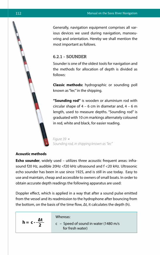
112 Manual on the Sava River Navigation
Acoustic methods
Echo sounder, widely used – utilizes three acoustic frequent areas: infra-sound f20 Hz, audible 20Hz <f20 kHz ultrasound and f <20 kHz. Ultrasonic echo sounder has been in use since 1925, and is still in use today. Easy to use and maintain, cheap and accessible to owners of small boats. In order to obtain accurate depth readings the following apparatus are used:
Doppler effect, which is applied in a way that after a sound pulse emitted from the vessel and its readmission to the hydrophone after bouncing from the bottom, on the basis of the time flow, Δt, it calculates the depth (h).
Whereas:
c – Speed of sound in water (1480 m/s for fresh water)
Generally, navigation equipment comprises all var-ious devices we used during navigation, manoeu-vring and orientation. Hereby we shall mention the most important as follows.
6.2.1 SOUNDER
Sounder is one of the oldest tools for navigation and the methods for allocation of depth is divided as follows:
Classic methods: hydrographic or sounding poll known as “lec” in the shipping.
“Sounding rod” is wooden or aluminium rod with circular shape of 4 – 6 cm in diametar and, 4 – 6 m length, used to measure depths. “Sounding rod” is graduated with 10 cm markings alternately coloured in red, white and black, for easier reading.
Figure 39 Sounding rod, in shipping known as “lec”

113NAVIGATION AND MANOEUVRING
Echo sounder resolution has the potential of distin-guishing between the two close objects at the bot-tom. We differ vertical and horizontal resolution and mistakes are reduced if modern multibeam echo sounders are used.
Figure 40 Ultrasound echo sounder
Figure 41 Advanced multipurpose Echo sunder with dual beam – (sonar)
Sonar/echo sounder (Sound navigation and Renting) is a technique using propagation of sound under water for navigation, cartography, communi-cation, detection of other ships. Its development in the nautical sector have been further advanced. Besides depth measuring below and in front of ves-sel (up to 400 m), it also has the function of detection of shoal of fish, water temperature or objects at the sea bottom.
Echo sounder has the latest generation results which were unconceivable until recently. This especially refers to the liquid crystal display, which in-creases the value of using "fish finder" even in case of middle and lower
product quality. For proper use of any in-strument, it is crucial to initially set it tak-ing into account the choice of purpose.

114 Manual on the Sava River Navigation
6.2.2 RADAR
Radar (Radio Detecting and Ranging) is a contemporary navigation sys-tem for wide application, especially in the conditions of low visibility, navi-gation of vessels through narrow and highly frequented areas, whilst avoid-ing other vessels and similar. Object-detection system uses radio waves to determine range, angle or velocity of objects. The term “radar” was used dur-ing the World War II for the first time and was used in the military purposes. Radar is an indispensable instrument nowadays with the aim of facilitating the safe navigation and the radar system is so automatized hence the man is mere controller. Man is free from tasks he had to do previously and the possibility of human error is significantly reduced.
History and development of radar is linked to 1864 when James Clark Max-well published quotations and notes on radio waves and German physicist Heinrich Hertz showed that radio waves could be reflected from solid ob-jects in 1866 and in 1904 Christian Huelsmayer used that electromagnetic waves feature for the function of collision avoidance hence constructed and patented some kind of (telemobilscope). Guglielmo Marconi invented ra-dio receiver in 1922 which used the principle of electromagnetic reflection of short waves. Development of radar greatly expanded when Watson-Watt designed aircraft detection and tracking systems and in 1939 physicist Henri Butt and biophysicist John T. Randall created magnetron. Further techno-logical development, discoveries and modifications contributed to radar entering in the wide use. Our attention will be focused on radars used in navigation.
Principles of work: radar system has transmitter that emits radio waves called radar signals in predetermined directions via antenna. Waives travel in a straight line and after reflecting from the obstacle, they partly return in the form of an echo to the sensitive radar receiver, where after amplifica-tion and processing displays, the front panel displays as a shining reflection (spot). According to the position of the spots on the screen, the azimuth (direction) is determined, as well as bow angle and distance of the observed object.
Navigation radar should meet the following criteria: discover objects at the shortest possible distance, achieve a greater range or distance detection, separate objects in azimuth and at a distance, be able to eliminate inter-ferences caused by atmospheric reflection of the water so as to make small objects clearly visible.

115NAVIGATION AND MANOEUVRING
Radar system characteris-tics: maximum and minimum radar range, accuracy in meas-uring angles and distances separating objects according to the angle and the distance. Radars can be equipped with a special computer technolo-gy and be able to solve prob-lems in collision avoidance. Such systems in Western tech-nology are indicated by CAS (Collision Avoidance System).
Radar horizon, in the navi-gation sense, represents the maximum distance from the point of emission of EM waves up to the spot where the waves hit the earth's surface. This distance, except for the geometry of the Earth, depends on: the height of antenna, the wave length of EM waves, radar pulse power and weather conditions.
Radar interference, according to its source may be: interference caused by echo from precipitatios and surface of the water, clutter caused by electric elements of radar, interference of other radars.
False echoes, depending on the origin, are:
• Indirect echo, made by reflection of one’s own vessel, bigger vessels on the shore and other vessels nearby;
• Multiple echo, is caused by nearby object with the large coefficient of reflection;
• False echoes are caused by reflection of the main lobe of the radar beam off ship's structures such as stacks and kingposts. Side-lobe ef-fects are readily recognized in that they produce a series of echoes on each side of the main lobe echo at the same range as the latter. Semicircles, or even complete circles,may be produced. Because of the low energy of the side lobes, these effects will normally occur only at the shorter ranges. The antenna with slotted waveguide has a less pronounced side lobe effects compared with parabolic antenna;
Figure 42 Contemporary river radar

116 Manual on the Sava River Navigation
• Radar interference, appears as result of sparks in the radar, and other electrical devices in the vicinity, and is most pronounced when nearby radar is working on the same wave length. They are more pronounced at higher range because time base is so fast at small ranges hence light dots stretch in barely visible tonal lines. Interference is impossi-ble to remove.
Radar shadows are dark spots on the cathode tube screen between reflec-tions even though they physically belong to the same object. They appear due to the obstacles shape, position and impossibility of EM waves to reflect geometric sheltered areas.
Blind sectors are circular clips on the screen of cathode ray tube in which there is no reception of EM waves and therefore, they cannot detect any ob-jects. They appear if there are obstacles near antennas i.e. masts, chimneys, cranes and similar.
Reflection from the water surface represents multiple spot reflections that can be variable and unstable and appear due to the reflections from the front edges of the waves and they appear at shorter distance. These interferences disappear with the reduction of reflections with button “Anticlater Sea”.
Atmospheric effects clutter refers to numerous spot reflection of irregular shape on the cathode ray tube and it fits real position of the atmospher-ic effect. Common features of this clutter (rain, low rain clouds, hail, snow, fog) are: stretched reflections without expressed edges (edge), high speed movement on the screen in comparison with real objects and reflection brightness is lower then of real objects. It can be removed with linear reduc-tion of amplification in the whole operating range. With this reduction the reflections of the real objects wil be also reduced but the clutters will disap-pear from the screen before the reflections of the real objects.The button "Anticlater Rain" shall be used.
Radar reflection differs by size, detection range, shape, fluctuation, sharp-ness and mobility.
Characteristics of land objects’ reflection: appearance on the expected places based on the ships own position, immobility, non-fluctuation, big and dense reflection whose mutual position does not change.

117NAVIGATION AND MANOEUVRING
Characteristics of vessels’ reflection are: movement, change of position when compared to other reflections, unexpected appearance, fluctuation and stability. They are narrow and appear at the medium distance with one blunt edge of reflection, whilst the edge of reflection in the direction of ves-sel movement is always sharp.
Characteristics of small vessel reflection are: occurence over short dis-tances, significant fluctuation with the temporary disappearance during the some of the EM beam rotations especialy with a wavy water surface, strong-er reflections than reflections of interferences. In the fog detection distance is less by 15-20%.
Relative motion display can be explained through two models i.e.:
• Unstabilized (Heading Upward) Display wherein: own vessel position is fixed and in the centre of display and reflections of all other fixed ob-jects move in opposite vector of vessels own speed, the heading is al-ways directed towards the null of the fixed scale (heading upward) re-gardless of the own course, where only right bow angles can be read by extra azimuth plate, and objects that are right from the bow are visible on the right hand of the display, when changing the course the head-ing remains in the same position on the display and all reflections are turning opposite from the course change. This kind of display is suitable for the preparing manoeuvre for colision avoidance;
• Stabilized (North Upward) Display, wherein: own vessel position is fixed and in the centre of display and reflections of all other fixed objects move in opposite vector of vessels own speed,the heading is direct-ed toward the real course with reading on the fixed scale, the radar image of the bank objects is oriented towards the meridian (same as the navigational charts), radar azimuth of all objects can be read with the azimuth plate, when changing the course of the own vessel the positions of the reflections remain the same while heading are rotat-ing in the new course direction. This kind of display is suitable while manouvering for the colision avoidance.
True Motion Display shows real movement within limited space and in order to achieve it, it is necessary to dissemble movement into the components in the direction of N–S and E–W, for which it is necessary to continuously pro-vide data on the course and speed as well as data from the gyrocompass and speedometer.

118 Manual on the Sava River Navigation
This means that the position of the one’s own ship is in the starting point from which the moving of time base starts and the start is shifted proportionally with the movement of own ship. The characteristics of these display modes are:
• All fixed objects are stationary reflections on the display;
• All movable objects including the own vessel are moving in relation to the immovable objects in real courses and speeds;
• Whole picture is orientated as well as navigation map according to the meridian which requires additional scale for angle measurement because the fixed scale on the rim of the display cannot be used. Az-imuths are measured electronically with a straight line which appear on the display from the point of time base development and the value is read on a separate digital display.
6.2.3 GYROCOMPASS – GYROSCOPE
Gyroscope is an instrument which uses certain physical characteristics of massive rotating body (spinning wheel, gyroscope) for identification of meridian. It appeared in the first decade of the twentieth century for the first time for the purpose of polar expeditions. Gyroscope is a dynamic tool which rotates freely with great speed. It is usually designed as symmetric rotor with great peripheral speed, which is mounted in the gimbal rings.
Axis of spinning wheel rotation is the main or primary axis, while the axes in which the gimbal rings are fastened are horizontal and vertical equatori-al axis. On spinning wheel with three degrees of rotation freedom all axes intersect in one point hence such wheel is balanced. Spinning wheel shows two main characteristics: inertia and precession.
Inertia is a characteristic of gyroscope that rotation axis keep the same di-rection in the space, depending on direction of platform on which the wheel is attached. In doing so, wheel retains that direction regardless of any move-ment, including the movement of the Earth, which means that the axis of ro-tation keeps direction in space independently of the movement of the Earth.
Precession is the charachteristic of the spinning wheel that the rotation axis will be shifted for 90 ° from the direction of the force acting on that axis. These two properties are used to operate gyrocompass. By limiting the free rotation of spinning wheel, the axis of rotation is set in the direction of meridian. For the positioning of the rotation axis in the horizontal position,

119NAVIGATION AND MANOEUVRING
gravity acts on the rotation axis, and for positioning into the meridian direc-tion, inertia in the direction of the Earth rotation acts on the rotation axis.
Gyrocompass error (deviation) is total deflection of the main axis (spin axis) from the real meridian. It is positive if the gyrocompass axis is deflected towards east and negative if the same is deflected towards the west. The following errors can affect deflection of the spin axis: error of the ship move-ment, latitude error, ballistic error, quadrant deviation and installation error.
Gyroscope use in the inland navigation – Autopilot is the automatic steering device. It is from one side connected to the gyrocompass, and on the other to an electric or hydraulic steering gear. If the ship veers off the course, the steering gear which returns it to the course is triggered. The compass repeater has contact that establishes connection with the left or right ring connectors, depending on the ship turn. When the rudder starts to turn, connecting rings are activated over return link, and they terminate link with rudder engine. Alternately turn on and off can maintain the course with oscillations of ±0.5°. Sensitivity of autopilot is manually established. When navigating during bad weather, sensitivity of auto pilot should be re-duced. Automatic steering reduces losses and increases median ship speed.
Figure 43 Gyrocompass – gyroscope
Vertical axiss
Platform
Spin axis
W
M
J
Horizontal axiss Precession
Ω

120 Manual on the Sava River Navigation
6.2.4 SPEED LOGSpeed log is an instrument measuring vessel speed and there are three types:
• Patent log, measuring speed by rotating its own propellers. Transfer to indicator is mechanical one, and the navigation speed is determined by speed of propeller in the time unit. This type of speedometer are impractical, out-dated and not in use;
• Electro-mechanical log, which measures speed of navigation with pro-peller attached to the vessel bottom. Propeller rotation also measures speed of navigation with the help of propeller attached to the ship bottom. The spinning propeller instigates small dynamo that sends display (voltmeter gauged in knots or kilometres) electrical value in the form of electrical impulses;
• Pitometer log, measures speed of navigation by “Pitot tube”, and it measures difference between static and dynamic pressure which is shown on the indicator in knots or kilometres in the time unit.
Navigation speed shown on the log shows speed through water instead of speed in relation to the bottom or riverbank. Therefore in order to get real movement speed in relation to the riverbank in the upstream navigation (along the river), navigation speed should be reduced for the water velocity flow and vice versa, add water velocity if navigating downstream.
Speed of navigation on the rivers and channels can be measured by read-ing the kilometre mark for determining the distance travelled per unit of time. For example, from rkm 255 to rkm 262 on the Sava River it takes one hour, which means that the navigation speed in relation to the riverbank amounts to 7 km/h. For more precise measuring, when testing newly built ships, testing kilometres or miles are used, that are specially allocated for that purpose.
6.2.5 SHIP BAROMETER Barometer is the measurement instrument for measuring atmosphere pres-sure hence air pressure constituting atmosphere.
The first barometer was so called water barometer (called Goethe barome-ter since Goethe popularized it) which worked on the principle of container with air submerged in the water, and the column of water rised up when the atmospheric pressure dropped (the column of air goes down). The most

121NAVIGATION AND MANOEUVRING
Figure 44 Мodern metal aneroid barometers
common is mercury barometer (column of mercury that will increase or de-crease depending on changes in air pressure). It was discovered by Evange-lista Torricelli. There is also dry (aneroid) barometer.
Barometer is an indispensable instrument in the meteorology. It is also use-ful in the so-called folk meteorology because it is commonly believed that the increase in air pressure is followed by sunnier weather, and with the fall, cloudier weather will follow. Barometer announces the arrival of rain, clear weather, and a tendency to pressure changes due to flow of air masses (wind). Whether the change is positive or negative pressure, wind and storm will be greater if the large pressure changes in a short period of time.
6.2.6 BINOCULARSBinoculars are one of the most common aids in navigation. It is the type of optical instrument consisted of two small oculars attached in the way so (when looking through with both eyes) they form one picture. The advan-tage of binoculars over telescope is that it naturally increases the ability of human sight and both eyes are used.
Increasing x the diameter of the lens: the numbers that characterize each of binoculars and are usually printed on the body of binoculars next to the eyepiece.
They are shown in the form of numbers i.e. 7 x 30, 7 x 50, 11 x 80 etc. The first number shows degree of the binocular magnification and the second is the diameter of the lens in millimetres. We can say that the magnification is actually making objects virtually closer to the eye for the specified value.

122 Manual on the Sava River Navigation
Binoculars with magnifying rate of eight will show the object 8 time larger, while the angle of object view shall be eight times bigger than seen with the naked eye.
Other number (30, 50, 80 etc.) is the lens diameter in millimetres. The larger the diameter the more light enters the binoculars and objects with less light are better viewed. The value of “light grasp” depends on the lens diameter. Hence binoculars with lens diameter of 50 mm shall grasp 2.8 times more light than with the lens of 30 mm diameter. Binocular lenses of medium size are suitable for navigation.
6.2.7 RADIOTELEPHONE EQUIPMENT
Radiotelephone equipment is considered an aid to vessel navigation via which they receive hydro meteorological reports and weather forecast which are reported by the shore radio stations on the daily basis. The river and maritime transport uses as follows:
Shortwave radiotelephone device (HF) which uses frequency of 1.6 to 3.8 MHz (calling frequency is 2.12 MHz). Standard type has big range. This HF radiotelephone device was used more in the past for professional shipping, in shipping companies with long distance vessels.
VHF radiotelephone device (VHF) uses frequency of 156 to 162 MHz. Calling frequency is of 156,8 MHz – channel 16 (safe navigation channel).
Figure 45 Binoculars/ Great Britain, 20th century, steel, glass, brass

123NAVIGATION AND MANOEUVRING
Standard VHF radiotelephone devices have 55 channels for communica-tion and they are intended for radio communication for short distances, communication vessel-vessel or vessel-shore (harbour master, company, marina, harbour etc.). The range of the transmitter is 50 km while the power consumption is small and may be carried by any ship's battery.Mo-tor vessels (except small crafts and ferries) and floating equipment may sail on the Sava River only if they are equipped with a radiotelephone installation in proper working order.
Work with VHF device is specified in the “Manual for the Radiotelephone Service in the Sava River Basin” which Sava commission issued in accord-ance with the Manual which is issued for the all network of inland water-ways in European by the Rhine, Danube and Mosel Commissions.
6.3 NAVIGATION MANUALSNavigation manuals are of great importance for each boatmaster regardless whether they are masters on the commercial ships or recreational skippers. Main purpose is to provide necessary nautical information both in prepara-tion and execution of navigation. Special attention is paid to the timeliness and accuracy of all manuals to secure maximal possible safety for vessel, crew and other participant in navigation. Navigation manuals include also navigational publications which published data important for navigation safety and which cannot be shown in the navigational charts and such
Figure 46 VHF device
124 Manual on the Sava River Navigation
publications are used together with the navigational charts. Besides naviga-tion manual, there are other publications useful for inland navigation.
6.3.1 NAVIGATIONAL CHARTS
To this day the navigational chart is the backbone and the main navigational guide, so much attention was given to their detail, update and durability in nav-igation conditions. As a rule, it is issued by the authorized state bodies, respon-sible for the accuracy of the information provided. Basic division is as follows:
Paper chart: Up until the late nineties of the last century, paper chart was the only chart used, whilst in the last couple of years it has been used pre-dominantly as an additional navigation manual. The only real navigational chart which has been designed for vessel orientation and guidance only is “Pilot Chart for the Danube River” issued by the Danube Commission from Budapest. The chart is in 1:10000 map scale, which enabled high level of details. Besides the presentation of the waterway itself, this map contains numerous information for orientation and guidance of vessel i.e. type of riverbank, position of regulation structures, fairway axis, depth on the fair-way axis, position of the shallows, rocks, the direction of the river, kilometre marking, floating navigational lighted and unlighted marks, riverbed on high and low navigation level (HNL and LNL) and and navigational signs and marks. The navigational charts for Sava River have not been developed yet, however hydro technical maps are used but these charts are with lower level of details and far more unreliable for navigation.
Electronic Navigational Chart – ENC represents data base standardized in content, structure and format and issued for use with the Electronic chart display and information system (ECDIS). It was based on the standards of International Maritime Organization (IMO) and it is adjusted with standards S-57 and S-52 of International Hydro graphic Organization (IHO).
For the inland navigation the– Inland ENC (Inland Electronic Navigation-al Chart) were developed along with Inland ECDIS. Inland ENC is adjusted to IHO standards S-57 and S-52 hence improved with additions and expla-nations of this standard for Inland ECDIS. Inland ENC contains all necessary cartography information hence may contain all additional information that can be considered useful for navigation.

125NAVIGATION AND MANOEUVRING
Inland ECDIS is electronic chart display and information system for inland navigation. Its purpose is to contribute to safety and efficiency of inland navigation hence contributes to environmental protection. It was based on the European project findings - Indris (Inland Navigation Demon-strator for River Information Services) and German Project ARGO 2001. when Danube and Rhine Commissions adopted Inland ECDIS for Electrical navigation charts for inland navigation - Inland ENC for Rhine and Danube. UN Economic Commission for Europe (UNECE) has adopted Inland ECDIS in 2001. as a recommendation for European inland waterways network. Up un-til November 2013, navigational charts for inland navigation pursuant to the Inland ECDIS Standard was developed, covering almost 10.000 kilometres of European waterways including Mosel, Rhine, Elbe, Sava and Drava in Germany, Holland, France, Belgium, Switzerland, Austria, Slovakia, Hungary, Croatia, Serbia, Bulgaria, Romania and Ukraine.
Unlike paper charts that are limited to only four colours in data display, elec-tronic navigational charts can use navigation data in many colours and it is possible to display only those data as chosen by the user. When using Inland ECDIS, minimum data should be displayed as prescribed by IMO and Inter-national Hydrographic Organization (IHO).
The Inland ECDIS system enables the onscreen display of useful informa-tion together with the navigation situation i.e. position, speed, course of its own vessel and situation with vessels in vicinity (vessel distribution, course, speed) and other important data. There are two types of display, relative one and the real one.
The position of its own vessel vessel in the relative display is, as well as with radar, placed in the middle of the screen, bank line (electronic chart) shall move in the same direction with the speed equal to the speed of vessel. Such display requires great capacity of computer memory considering that large data quantity needs to be moved on the display.
The real display, which uses North Up orientation, electronic chart is fixed and the display shows vessel movement. Every time the vessel approaches the edge of display, the picture is reprogrammed hence it expands area in the direction of navigation and narrows the area opposite to the direction of movement and the position of the vessel is placed near the opposite screen

126 Manual on the Sava River Navigation
edge. Special display or frame on the ECDIS display is aimed to show data on course, speed, depth or position in alfanumerical digital shape. Selected displays may also be used, for vessels or views of the area where vessels are navigated or areas where vessels are directed to, whilst simultaneously on the main screen it shows general navigation situation. Also, electronic nav-igational charts can overlap with a radar image, i.e. can be simultaneously shown on the display.
Generally speaking, electronic navigational charts should meet the follow-ing criteria:
• ENC must be compatible with the inland ECDIS standard;
• Information on the ENC must be current;
• They must contain so called minimal data set, necessary for efficient and reliable use of electronic navigational charts.
Along with the aforementioned mandatory conditions, it is desirable for ENC to contain information on depth in the critical parts of waterway. Inland ECDIS represents standard view of electronic navigational charts in the inland navi-gation accepted by the Central Commission for the Navigation of Rhine, Inter-national Sava River Basin Commission and Danube Commission and Europe-an Commission in the Directive No. 414/2007.
Figure 47 ENC and radar

127NAVIGATION AND MANOEUVRING
The primary functions are as follows:
• Inland ECDIS contributes to the safety and efficiency of inland water-way transport and environmental protection;
• Inland ECDIS reduces the amount of work compared to traditional methods of navigation and information system;
• Inland ECDIS is a reliable and accessible source of information for all subjects involved in inland navigation;
• Inland ECDIS provides a simple and reliable updating of the electronic navigational charts;
• Inland ECDIS can be used in navigation and information mode. Nav-igation Mode means that the Inland ECDIS used in conjunction with traffic information obtained by radar and / or AIS. Information Mode means the use of Inland ECDIS without traffic information.
Electronic navigational charts of the Sava River are made according to the required standards and are of good quality and higher level of details shall be covered in the new updated issues.
Figure 48 Example of an ENC

128 Manual on the Sava River Navigation
6.3.2 INDICATOR OF RIVER KILOMETRESIndicator, together with a navigational chart, is the most important source of information for orientation and vessel navigation. It encompasses kilo-metre signs, towns, bridges, islands, dangerous places, esturies, shipyards, etc. Indicator bounds with numerous useful details and it is an indispensa-ble manual for both experienced navigators and those with less experience and knowledge.
Base/Land Receiver
Mobile Receiver
Echosounder
Base and Mobile
Receiver Radio
Connection
Power Source
Data Synchronization
Transmitter
Figure 49 Integrated Navigation System

129NAVIGATION AND MANOEUVRING
Figure 50 Indicator of RK for the Sava River and its navigable tributaries
Figure 51 Album of bridges on the Sava River and its navigable tributaries
6.3.3 ALBUM OF BRIDGES
6.3.4 NOTICES TO SKIPPERS
They are issued by harbour master officies hence they have all information about changes on the waterways, river engineering works and endanger-ment and bans on navigation for certain sectors. In the RIS system we rec-ognize them as “notices to skippers/NtS”.

130 Manual on the Sava River Navigation
6.4 RIVER INFORMATION SERVICE – RIS
River information service- RIS represents several services based on the con-temporary technologies shaping and directing exchange of information among participants in the inland navigation. Exchange of information is conducted based on the haromonized information and communication sys-tems hence these information are used in various applications and systems for transport development.
This concept encompasses the following:
• Inland AIS (Automatic Identification System – AIS);
• Inland ECDIS (Electronic Chart Display and Information System);
• ERI – Electronic Reporting International;
• NtS – Notices to Skippers;
• Electronic Navigational Charts;
• Hull Database;
• Lock Management Systems.
The first association with RIS is usually the vessels location and monitoring system which is based on the Inland AIS transponders and services based on it. AIS base stations network has been installed along the river and enables exchange of information with vessels equipped with AIS transponders. Two-way communication between base stations and vessel devices enables view of traffic situation from the shore and distanced locations (through transfer of the data on the vessel position, its speed, course, size, type of cargo, num-ber of the crew members, destination, etc.), but also delivery of information to the ship masters i.e. notice to skippers, GPS corrections, short messages.
Mutual communication of transponders installed on the vessels is equally important. Thus vessel transponders collect and process data on the vessels positions in the nearby surrounding, its size, speed, course, type of cargo etc. and thus provide to master better view of traffic situation and situation with other vessels in the vicinity which is improvement in the process of making tactical decisions.

131NAVIGATION AND MANOEUVRING
AIS transponder in ship-ship communication has unique ability to unequiv-ocally identify targets (other vessels equipped with AIS devices) which are several kilometres distanced without need for optical visibility and in very bad meteorological conditions i.e. fog or heavy rain).
Figure 52 Information exchange on AIS system
Shore station
Repeater
Repeater
Ship to Ship(collision prevention)
Ship to Shore(VTS, ship message)
Shore to Ship
Mountains
RIScentre
Shore station
Repeater
Repeater
Ship to Ship(collision prevention)
Ship to Shore(VTS, ship message)
Shore to Ship
Mountains
RIScentre
Information from AIS transponder and from the location and monitoring system of vessels are represented with one very significant AIS subsystem – Inland ECDIS. ECDIS shows data on vessels in the electronic navigational chart, in real time in both information mode and navigation mode.
Inland ECDIS in information mode represents Electronic Atlas and serves so as to insure information on fairway and it is not planned to be used for steer-ing. In the information regime, Inland ECDIS can be linked to the position sensor so as to automatically move chart image and to link parts of the chart suited to the current surrounding with the vessel position fixed in the centre of the screen.

132 Manual on the Sava River Navigation
Navigation regime assumes the use of Inland EDCIS for vessel steering with the use of radar. Vessel position is derived from the system for the continued positioning whose precision is in accordance with the require-ments of safe navigation. Besides basic purpose and that is display of traf-fic image, ECDIS subsystems often have links with other RIS subsystems i.e. system for electronic reporting, system for electronic NtS, and in the navigation mode it is enabled to overlap radar image with electronic nav-igational chart and AIS data.
ERI – (Electronic Reporting International) enables ship master to report in advance its voayage to the competent authorities, even in the case of the navigation through several countries. Thus, he submits the report about the details of the voayage in the form of a standardized language-independent and machine-readable message (port of origin, destination, details of the cargo, the size and composition of the convoy, persons on board, places of load-unload etc.).
System for electronic NtS – Notices to Skippers enables competent authori-ties to distribute notices by electronic means, in a standardized language-in-dependent and machine-readable form hence such notices are shown on the ECDIS display in the ship wheelhouse.
Electronic navigational charts are in the centre of RIS and are directly used in the navigation process. They are listed in the service group “Fairway Infor-mation Services” – FIS.
Binding element of the RIS subsystems is so called Hull Database which in the standardized format contains all data from the ship register of every country. Those data are used by other sub systems of RIS and mutual data exchange is possible.
System for navigation locks managemnet enables lock operator to optimize lock operation based on the information on the ships position from the ship location and monitoring system and based on the information from the ERI system and Hull Database.
The above mentioned subsystems are only part of those that are currently being implemented on the European rivers aimed at:

133NAVIGATION AND MANOEUVRING
• Increasing the safety of navigation on inland waterways and in ports;
• The contribution to additional measures - ensuring local and regional traffic information for safe monitoring on the tactical and the strategic level;
• Increasing the efficiency of inland navigation - optimization of resource management in the transport chain, allowing the exchange of informa-tion between vessels, locks, bridges, terminals and ports;
• Better use of inland waterways - to provide information on the status of the waterway;
• Protecting the environment by providing the transport and traffic information for an effective process of reducing navigation accidents.
The Sava River Waterway is covered with basic RIS services from 2016. Uti-lization of harmonized systems and application of international standards which make RIS interoperable, makes the Sava River integral part of Euro-pean waterways network when it comes to the application of information technologies aiming to provide support to navigation.
6.5 SHIP’S DOCUMENTS AND PAPERS
6.5.1 SHIP’S LOG Ship’s Log is one of documents which are kept on the vessels (except small crafts) for inland navigation. The content and method of keeping Log is pre-scribed by certain rules/regulations. It is kept on the daily basis and based on the etered data one may monitor all activities on the vessel and if needed re-construct certain events. This is important when determining facts and analy-ses of accidents or other extraordinary events, and data from the ship’s diary is applicable in court.
Logbook contains: vessel information (name or emblem, the type of vessel, port of entry, the total engine power), official number, date and place of is-sue, name of the competent authority which issued it, stamp and signature of the authorized person, information on previously issued and compleated log (number, date and place of issuance and the name of the competent authority that issued it).

134 Manual on the Sava River Navigation
Log contains the following data:
• Hydrometeorological data relating to: weather conditions, air temper-ature and water level and relevant gauging station;
• data on the movement and operation of the vessel, with information on departure, arrival and stoppages of navigation;
• composition and form of a convoy, the amount of cargo and draught of vessels;
• Information on taking and leaving the vessel from convoy;
• data on qulified crew on duty in the wheelhouse and engine room;
• data on putting in service and lay-up of vessel;
• important information during the navigation, which among other things include:
– The measured depth of the fairway, changes to the marking system and changes in the fairway;
– Accidents and damages of vessels;
– Major repairs and work performed during the voayage, changes in number and the composition of the crew;
– Outbreak of severe illness of crew and passengers;
– Information on the work of the engines and its maintenance.
Besides the log, ships should have on board crew list, used oil log, ships cer-tificate and other documents and books as prescribed by the national and international regulations.
Log is kept during navigation and in ports or harbours, every day from 0 to 24 hours. The log is not kept whilst vessel is laid-up. Vessels lay-up and put-ting in service is considered as extraordinary events. During navigation, log is kept by the master or his deputy. Once logbook is kept by other person then master, master certifies imported data on the daily basis.
135NAVIGATION AND MANOEUVRING
6.6 FORMING OF CONVOYSConvoy forming can be done in several ways, taking into account ship power, water level, depth and obstacles in the waterway we have to navigate through.
Whilst forming convoy we hereby use binding/fastening and tying.
Binding/fastening: when two or more vessels are linked with one to another, side by side. It is used for upstream and downstream navigation. We may link two, three, four or more vessels.
Tying: Linking of vessels for each other (one in front of other) is called tying. Tying a vessel for each other we are forming the longitudinal row of vessels.
6.6.1 FORMING OF TOWED CONVOYS
Upstream convoys shall be formed in longitudinsl row because of the lesser water resistance. The longitudinal row is formed in a way that barges are linked one behind the other. This procedure reduces the resistance, because only the first barge in the wake of a motor ship is exposed to a greater wa-ter resistance, while others go one after another in the created longitudinal row. The first barge which receives the towing line from the tug typically needs to have the best manoeuvrability and the deapest draught.
Shipping practice has shown that the best position for towing is when the barge is tied at the point on the 1/6 of its length, starting from the bow. In order to reduce the resistance of the convoy, the length of the towing lines should be as long as possible and their length depends on the conditions of the waterway. Today it is common to give towing lines with the length of 50 to 100 meters.
Two towing lines can be tied in two ways: straight and cross (figure right). In the upstream navigation towing lines is given in the straight way when the convoy is formed in more then one longitudinal row so as to be able to dismantle it in the sector with favourable navigation conditions, in order to reduce water resistance. In practice, depending on the type of convoy (com-position), the master decides in which way the towing lines will be tied.
In the downstream navigation, the towing lines of 3 to 5 m long, are always tied in the cross way for easier steering of the towed vessels by the tugboat.

136 Manual on the Sava River Navigation
Tying of the towed vessels (one in front of other) is done by set of secondary towlines. The way of tying depends on the caracteristics of the fairway sector.
Depending on the discharhe (current), weight and size of the convoy, num-ber of secondary towlines amounts from one to three. We mainly distinguish three types of tying: long, medium and short.
Long tying is applied on the river sectors with the high current velocity hence each vessel can be separately towed through curves and straights
and other potential obstacles. Until recently it was used on the upper Danube. With long tying, the distance between vessels, from the stern of the first vessel to the bow of the vessel behind amounts to three meters. Long tying requires three secondary towlines i.e.: the first rope comes from the vessel behind from the front bollard (see Figure 54). If tying between barges is on the right-hand side, than towline starts from the vessel behind and from the left front bollard to the opposite side between the second and third bollard and from there to the vessel in front. On the vessel in front this first towline goes halfaround right bollard in the midship to the left bollard on the midship where the loop is placed. The second rope is also comes from the vessel behind to the vessel in front where the loop is placed on the second right bow bollard. When tying, the rope is placed around the right front bollard in the midship, where it makes one
Figure 53 Straight and crosswise tied towing lines

137NAVIGATION AND MANOEUVRING
round, and from there to the bow bollards of the vessel behind where it is tied with several eights rounds between second and third bollard. The third rope comes from the vessel in front, it is pulled under the eights rounds and loop is placed on the vessel behind, on the free right bow bollard.
Part of the rope on the vessel in front makes round over the front bollard in the midship, and several eights rounds over the right bow bollards.
Prior to manoeuvre of long tying, one auxiliary rope is handed from free bollards of the second vessel with aim to temporarily hold vessels together, whilst finishing tying. Once the all towlines are tyed, their length must be equalized in order to be equally loaded.
3m
Figure 54 Long tying

138 Manual on the Sava River Navigation
Middle tying, is used for the navigation in shallow water and the same as in the case of long tying it is done in a way that the vessel in front is providing one towline and the next one is providing two towlines (see figure). The first towline starts from the vessel behind from the port bow bollards to the starboard side, between the second and third bow bollards, and from there to the vessel in front where it should go around the last bollard on midship on the starboard side and across to the port side where loop is placed on the last bollard on midship.
The second towline starts from the same vessel placing the towline around the second and third bow bollards on the starboard side, and the towline goes on the vessel in front around the last bollard in midship and loop is placed on the front bollard on midship, starboard side.
Figure 55 Middle tying
3m

139NAVIGATION AND MANOEUVRING
The third rope starts from the vessel in front, the towline goes around stern bol-lards on the starboard side and then goes half-around last starboard bollard on midship of the same vessel, from where goes on the vessel behind half-around second bow bollard on the starboard side and loop is placed on the first bow bollard on the starboard side.
When using long and middle tying, distance between the vessels amounts to three meters.
Short tying is used on the fairway sectors with steady water flow i.e. middle and lower Danube, Sava and Tisa.
As to this type of tying two towlines starts from the vessel behind and one from the vessel in front. The first towline starts from the vessel behind from the port bow bollards to the starboard side, between the second and third bow bol-lards, and from there to the vessel in front where it should go between the stern
Figure 56 Short tying
8 m

140 Manual on the Sava River Navigation
bollards and around the last bollard on midship on the starboard side and across to the port side where loop is placed on the last bollard on midship. The second towline starts from the same vessel placing the towline around the second and third bow bollards on the starboard side, and the towline goes on the vessel in front where it should go between the stern bollards and around the last bollard in midship and loop is placed on the front bollard on midship, starboard side.
The third rope starts from the vessel in front, the towline goes around stern bollards on the starboard side from where goes on the vessel behind half-around second bow bollard on the starboard side and loop is placed on the first bow bollard on the starboard side.
Other activities are the same as described with long and middle tying.
Short tying distance between vessels amounts to eight meters.
Short cross tying is mainly used on the upper Sava, Drava and canals. It is done in different ways but distance between vessels should be between two to three meters. Details are explained in the Figure 57 “Short cross tying”.
Figure 57 Short cross-tying
1,5−
3 m

141NAVIGATION AND MANOEUVRING
Figure 59 Firm binding
Figure 58 Ordinary binding
Binding of towed convoys
In the upstream navigation, longitudinal rowes of vessels can be both bind and unbind. For the bind rowes not to unbind, we need to bind them together. The whole convoy must be firmly bind together and also with vessels which are tied with the tugboat with towlines.
Other vessels in the convoy shall be bind to them.
In practice, we have ordinary, firm and firm/com-pact way of binding.
Ordinary binding (left figure) are used on vessels which are on the receiving end of the towlines from tugboat and secondary towlines from other vessels in tow hence it is not necessary to use longitudinall, but only transversal and crosswise binding.
Firm binding is used with longer longitudinal row, when the same is formed of more then two trans-versal rowes and only with light or empty vessels.

142 Manual on the Sava River Navigation
Firm compact binding is used on rivers with high current velocity and also for loaded vessels.
Figure 60 Firm compact binding
6.6.2 FORMING PUSHED CONVOYS
Pusher and pushed barges in the pushed convoys, regardless of their number, size, whether they are loaded or empty, they must be firmly binded so as to practicaly form one unit – “ship”, which they are in terms of pushing.
In order to accomplish that, we use binding and tying by tensioning. This type of binding and tying is mainly used during formation of pushed convoys with the aid of the coupling devices (winches for tensioning the ropes). Since our shipping industry has not been familiarized with this type of bid-ing we shall use standard names:

143NAVIGATION AND MANOEUVRING
Figure 61 Stern-to-stern
Figure 62 Bow-to-bow
Figure 63 Barge on the pusher shoulder
Figure 64 Binding of pushed barges(side by side)
Long Combined Short
“Stern-to-stern coupling”, means tying two integral barges with the rear part (stern) next to each other.
“Head-to-head coupling” means tying two symmetrical barges head-to-head principle.
“Placing on shoulders" means tying pusher with the convoy of barges.
Equally so, pushed barges can be bound side by side in a three different ways:

144 Manual on the Sava River Navigation
The following figures show examples of coupling of the pushed convoys with scheme of ropes.
Figure 65 Downstream pushed convoy

145NAVIGATION AND MANOEUVRING
Figure 66 Upstream pushed convoy

146 Manual on the Sava River Navigation
6.7 MOORINGMooring means an operation aimed at making fast along the riverbank. It is also used for safe cargo handling, discharge of passengers, in cases of the failure of the engine etc.
The lower figure shows ropes used for mooring of vessels to the river bank:
Figure 67 Mooring the vessel on the riverbank
1. head line
2. forward breast line
3. forward spring
4. forward side line
5. aft side line
6. aft spring
7. aft breast line
8. second stern line
9. stern line
728
91
5 63 4
• Head line: dos not allow that forward part of the vessel lean on the pier or riverbank;
• Forward breast line: keep the forward part of the vessel close to the pier or riverbank;
• Forward spring: prevent from advancing;
• Forward side line: as well as the head line, it is a supporting line. The entire weight of the vessel rests on the head and forward side line;

147NAVIGATION AND MANOEUVRING
• Aft side line: has the same effect as a forward spring;
• Aft springs: has the same effect as a forward side line and head line;
• Aft breast line: keep stern close to the pier or riverbank;
• Second stern line: it is used mostly during the manoeuvre of departure when the width of the fairway is limited to remove vessel from the pier or riverbank;
• Stern line: prevents upstream vessel movements.
During longer periods of mooring, besides the above-mentioned lines, “shorebaum” may be placed both on the bow and stern of the vessel. Usually in the practice all the stated lines are not used at the same time. The image shows all lines because of their easier recognition and explanation of the functions.
Loops of the lines given from the vessel, on the riverbank or pier are placed on the bollards. The lines are tossed to the bank with the help of the heaving line. The lines specified above should be gradually tensioned and in any case not more than it is permitted since there is a danger of line breaking which can cause serious harm to people handling the lines.
On waterways with high current velocity, loaded vessels especially require additional lines. This type of lines is called “double line” or “kec”.
6.8 MANOEUVRINGManoeuvring is the skill of commanding a ship during: sailing out, sailing in, anchoring, mooring, pushing, towing, salvage operations, unfavourable weath-er condition, etc. It is based on the knowledge of the principle of manoeu-vring and proper application of those principles in practice and knowledge of manoeuvring characteristics of vessels. Each master during navigation or ma-noeuvring must know characteristics of vessel-convoy he is in charge of: type of vessel (tug, pusher, selfpropeled cargo vessel, etc.) convoy size, convoy draught, and manoeuvring abilities of convoy. When steering one needs to know what to expect in the course of navigation. First of all the elements of fairway i.e. width, depth, the radius of river bends and current velocity. Knowing everything stat-ed above, the master also needs to be maximaly concentrated (discipline and precautions when steering and manoeuvring).

148 Manual on the Sava River Navigation
The most important manoeuvring characteristics of the vessel are:
• The stopping ability or “head reach” is the distance the vessel travels before stopping from the moment when the command “stop” and “full astern” is issued. Head reach is determined for all engine operation modes, and duration time is notified. It is determined by using bank landmarks. Free “head reach” is the distance vessel makes from the moment the com-mand “stop” is issued until it stops on its own (without help of engines);
• The time of engine transfer from the mode “ahead” to the mode “astern” is determined for all operating modes and is notified along with the “head reach” time. It is different depending on the type of propulsion and type of propeller. Modern vessels have “pitch” propeller with the rotating blades decreasing the time and not requiring reversible engine;
• The turning capacity is the size of the turning circle which vessel makes with constant speed and certain angle of the rudder, and is determined for all operatiom modes and rudder angles (10, 20, 30 and for the maxi-mum angle). At the same time turning time is recorded as well;
• Turning capacity in fixed point, the modern time brought some novelties such as bow thruster , thus contributing significantly to the manoeuvring capabilities.
In addition to maneuvering characteristic, understanding of maneuvering devic-es is also required, such as:
• Anchoring device enabling manoeuvring and making it safer. In the event of the engine blackout, at the crucial moments, only anchor can protect the vessel against the damage;
• Winches and coupling devices – the ship master and crew must be famil-iar with it and use it properly;
• Emergency steering gear-it is necessary to activate it periodicaly and per-form regular drills with crew which must be entered in the ship's log;
• Internal communication system on the vessel used during manoeuvring (bridge-bow-stern; bridge-engine-emergency steering station and alike). This is of great importance on the large vessels because visual communi-cation is not possible between bridge and all parts of the vessel with all participants in the manoeuvreing.Wireless internal ship communications is used nowadays.

149NAVIGATION AND MANOEUVRING
Steering with the vessel in manoeuvring means enabling its precise move-ments in relation to the riverbank, another vessels etc. In inland navigation process of steering the vessel consists of practically continuous manoeuvre, which includes turns, passing (overtaking and meeting), approaching the riverbank or harbour, entering and leaving locks.
Taking into account that the vessel is always with its one part in the water, it is affected by the current, waves, vicinity of river bottom or bank and wind. Moreover, the vessel is affected by internal forces, propulsion, force of the mooring lines and anchors. Therefore it is necessary to know influence of all forces, in order to use it during manoeuvring and reduce its adverse effects or prevent them as much as possible. Manoeuvring skills cannot be learnt or understood only by theoretical learning, even though the same could be used as the basis. Only practical work and practice can help.
The inertia of the vessel is reflected in an insufficiently firm connection with the environment – water, which results in the slow halting and passing cer-tain stopping distance depending on the direction of the water current and direction and wind force. The stopping distance can be reduced by change of engine operating modes (used during manoeuvring) and dosing the en-gine power in accordance with the current conditions of the fairway.
Figure 68 Operating mode from the ahead to astern; from the stop mode in the still water;from the stop mode in the upstream navigation

150 Manual on the Sava River Navigation
6.8.1 MANOEUVRING FEATURES
Manoeuvring abilities of the vessel are the certain characteristics of vessel which enable it to change the course and the speed under the influence of propulsion and steering system. Besides the professional skill of a person performing the manoeuvre, speed and safety of manoeuvre directly de-pend on the manoeuvring abilities of the vessel. Manoeuvring ability of the vessel depends mostly on the ship construction properties: length, shape, size of the body, type of propulsion and steering system. Besides these, ma-noeuvring abilities also depend on the external factors i.e. strong crosswind.
Manoeuvring abilities of vessel mainly depends on the type and number of propulsors and steering gear. For example the vessel with two propellers and auxiliary steering system has significantly better manoeuvring ability. Newer vessels have additional propulsors for lateral manoeuvres, earlier mentioned “bow“ and “stern thrusters“, which make lateral movements safe and simple. They are built in at bow and stern of the vessel.
Mobility means a vessel’s speed which is provided by propulsors.
Drifting begins when the vessel stops, though it exists in sailing, and compensates by changing the course. Drifting mostly de-pends on current and the wind, and is directly connected with the form of the hull (submerged part and superstructure). Ships with shallow draught and large superstructure (powerboat form) under the strong impact of wind will drift significantly (especial-ly bow section - lighter and less submerged part) whilst vessels with deeper draught (displace-ment form) will drift less due to the resistance to the wind from the submerged part of hull.
Figure 69 Drifting of a vessel under the impact of wind
1
2
3
4

151NAVIGATION AND MANOEUVRING
Steering ability of the vessel is its ability to keep or change the course by using steering gear. Characteristics of steering ability of vessel are ability to change the course and stability in course. Ability to change the course is the ability of vessel to change the course according to the boatmaster`s wish un-der the impact of steering gear. Stability on the course means vessel’s ability in keeping the determined course under the impact of the external forces. Stability on the course also means that the vessel requires 4 to 6 movements of the rudder per minute, at an angle of 2° to 3°, to keep the vessel on the determined course, whilst deviation of the vessel from the course should at an angle of 2° to 3°. The main reasons for the departure of vessels from the determined course are: the heeling, limited depth and width of the fairway, wind, current and waves.
6.8.2 МЕТЕОROLOGICAL AND HYDROLOGICAL IMPACTSWind impact The wind can affect the freeboard and part of the high freeboard thus complicating or disabling the performance of the simplest manoeuvre. The wind has special impact on the river vessels when compared to the sea vessels since they have smaller draught.
The names of winds are defined depending on the wind direction towards the vessel: the wind blowing directly at the bow is called the "bow", the one that blows astern is called "stern", and side blows is "side" wind. If the wind is blow-ing from the bow and side it is called "at the bow" or "at the stern" if blowing is between the stern and the ship's side.
Wind affects the vessel during navigation and it causes drifting except when it acts directly on the bow thus decreasing the speed of navigation or if it blows towards the stern thus increasing the speed. The wind which acts in transverse direction, affects the vessel, which is in the still position, and is moved to the “traversing” position. However when the vessel is heading straight forward, it will be hard to move the bow from the side position towards the wind since the wind will not allow bow to turn. When the vessel sails astern, it will be easy to move it towards the wind direction, since the wind is pressing the vessel to leeward. Therefore if sailing astern with the side wind, the wind will turn stern windward and the bow will turn rearward.
The wind is one of the most important factors when planning manoeuvring. If we set sailing with the side wind blowing from the shore, and the vessel has small fore draught, its impact is often stronger then when sailing astern. If we

152 Manual on the Sava River Navigation
wish to decrease the impact of wind to the manoeuvre, all activities must be performed vigorously and fast. As long as the manoeuvre is slow and indeci-sive, the vessel shall be exposed to the wind action.
Figure 71 Drifting curve with calm weather and during strong wind during constant drive
Figure 70 Wind directions and its effects on the freeboard and superstructure of the vessel
2
2
3
5
5
4 4
1
with windwithout wind

153NAVIGATION AND MANOEUVRING
The most unfavourable impact to the sailing safety is “Kosava” wind which blows on the lower part of the Sava River up to Sremska Mitrovica. It blows from the south east and reaches the speed up to 100 km/h. When he enters the windy sector, the boatmaster should be familiar with the characteristics of his vessel i.e. stability, manoeuvring abilities, effective power of engine, height of the hip and freeboard which is exposed to the wind, and second-ly, the sailing conditions in the sector in which inputs (wind force and wave height). Given those information and experience, he will decide whether he will enter the sector or he will wait until weather conditions get better. In case of a small vessel, skipper needs to make a decision on available information whether to continue the navigation or move the vessel into the shelter untill the wind calms down. Navigation and manoeuvres in those cases must be performed so as to avoid head on wind and waves and berthing should be done windward, if situation allows that.
Summer time is often followed by sudden change of weather followed by strong wind, sometimes of storm strength. Severe weather cannot be abso-lutely surprising since it is preceded by some weather conditions at least fif-teen minutes earlier. Air pressure drops suddenly, the sky gets dark and the air is heavy. In such cases, if the vessel is underway, it is recommended to hide under slope at the shore or some other leeward place. After that, deck equip-ment that is not fixed should be secured. The same shall apply to the vessel and during night on the open river since storm during the night can surprise even the most experienced. Besides that, waves made by passing vessels can also surprise especially if the vessel is moored or berthed near fairway. The waves on the rivers cannot be great as on the sea hence do not create im-portant obstacle for navigation except in the zones upstream from the dams and on the lakes. However waves made from the passenger vessels of great strength and size, for the small vessel may prove to be unpleasant.
Impact of the river current: Manoeuvring abilities of the vessel in the stream do not change hence its sensitivity in the monotonous stream does not change too. However it should be known that water is moving along the ves-sel. For example, if the vessel sailed in the calm water with the speed of 10 km/h than it would sail the same speed in relation to the bank hence its speed through water and in relation to the bottom would amount 10 km/h In case of navigation against the stream with the speed of 4 km/h, the vessel would sail with 10 km/h, but in relation to the bank it would amount only 6 km/h.

154 Manual on the Sava River Navigation
Downstream navigation speed would be added hence the speed in relation to the bank (speed over the bottom) would amount 14 km/h. Turning circle through water and over the bottom is also different. The first one is in the uniform flow exactly the same as in the calm waters, because stream carries vessel as well as water droplets around it. If the turning circle is lasting longer, stream is drifting vessel. Ship turning upstream and downstream is different. Upstream turn is enabling stretched movement circle when compared to the downstream movement. Turn curve length depends on the speed of the wa-ter velocity and the time required for the turn.
Vessel Turning Is one of the most important manoeuvres which requires skills, knowledge and experience narrow channels. Manoeuvring is skill which is perfected by hard work, hence successful manoeuvring requires experi-ence. Still skills and good sense of space and movement can be insufficient if captain does not have necessary knowledge hence in the narrow waterway wrong positioning of turning point or necessary space he would require for full circle.
It is required to know how much the diameter of the circle in the shal-low water can double hence it can be deviated and prolonged under the impact of wind (per-pendicular to wind) or under impact of the cur-rent (in the direction of stream). Good boatmas-ter has to know at every moment to properly estimate the position of the turning point. Many collisions and grounding happened because of ig-norance or neglecting of the position of the u turn point while manoeuvring in the restricted space.
Figure 72 Vessel path in the river and still waters
2
2
1
In the riverIn the still waters

155NAVIGATION AND MANOEUVRING
Shipping industry uses the word “rondeau”, instead of “turning”, which re-mained as foreign word along with other expressions and words. During si-multaneous action of wind and flow, in order to keep vessel on the course, it is necessary to stick to the principles of steering the vessel along the line of the resultant effects of these forces. Resultant is approximately determined visually and success of manoeuvring in those conditions depends on the knowledge and skills of boatmasters.
The influence of shallow water is reflected in increase in the draft because when in shallow water, there is an occurrence of vessel skew and veloci-ty submersion. In case the distance between the vessel’s bottom and river bottom is lower and speed higher, the submersion is also bigger. Continu-ation of movement in shallow water and high, total water resistance is to increase, and navigation speed will decrease, which will create stern wave “vessel pulls water” and submersion will reach its maximum. So as to annul negative phenomenon, it is necessary to decrease speed of navigation in the shallow parts of the fairway.
6.9 VESSEL NAVIGATIONVessel navigation requires combination of acquired theoretical knowledge, practical skills and procedures, as well as special preparation for each ven-ture and with additional years of practice, this will make mature and experi-enced boatmaster. There are three phases of the process, i.e.:
• Determining current position in relation to the fairway and banks;
• Selection of course and speed;
• Steering the vessel on the selected course.
Depending on the waterway, there are different kinds of navigation i.e.: river, canal, lake, navigation on the reservoir upstream from the dam as well as on some parts of the river directly before the confluence into the sea. From the me-teorological point of view, navigation can be performed under the conditions of good and limited visibility (fog, precipitation), i.e. in calm or windy weather. There are generally two types of vessel steering: instrumental and visual, sepa-rate or in combination.
Visual method is mostly applied in navigation on rivers, canals and reservoirs lakes and is characterized by clear visibility of banks and navigation marks, and boatmaster visually determines position by orientating itself towards

156 Manual on the Sava River Navigation
marks and characteristic points on the bank that are compared with the navigational chart.
Instrumental method in the inland navigation is applied on the wide waterways (big rivers and lakes), without visual contact with banks and mainly presumes integrated use of radar, echo sounder and speedometer. It is also applied during night and under conditions of reduced visibility (fog, rain etc.) With the imple-mentation of RIS instrumental method will be applied more than today on the inland waterways.
Limited navigation is performed near the place of vessels permanet mooring, for short daytrips, usually with user`s experience, with visual recognition of the characteristic places on the bank and waterway as well as dangerous places on the waterway. This kind of navigation requires information about water level and weather forecast and vessel shall be equipped with the minimum equip-ment i.e.: binoculars, lenses, hook, bailer, life jackets, spare equipment and tools for the engine etc. This way is applied by almost all owners of smaller vessels and small crafts.
Steering vessel in the coastal navigation is the skill of steering vessel on the longer sections where the boatmaster in not very familiar with the fairway. Therefore prior to navigation, it is necessary to perform certain preparations in terms of familiarizing with waterway and its marking system. Information about the waterway and navigation conditions can be found in navigational and hydro technical charts, indicator of river kilometers and other manuals for navigation. Boatmaster shall also use his notes from previous seilings as well as notes and experiences from other boatmasters with greater experience for certain section.
In the downstream navigation when there are no other vessels, boatmaster may navigate in the middle of the fairway, near the main current hence when observing the other vessels or formations, he should make manoeuvre and place the vessel on the side of the fairway or even outside the fairway choos-ing sections with the weakest current. In case of need, smaller vessels may pass from the other (“wrong”) side of the floating sign still bearing in mind that those signs are placed where the depth is 2.5 m.
Acquiring experience and full knowledge of navigation sector, smaller vessels will in upstream navigation sail off the fairway or in its vicinity near the convex bank, down by the sandbars and shoals and regulation constructions and above them when the waterlevel allows it, as well as on all part of the fairway where

157NAVIGATION AND MANOEUVRING
Figure 73 Unsafe navigation with one orientation point-high possibility of stranding
Figure 74 Navigation with two orientation points (covered direction)-safe navigation
the current is the weakest. Such navigation manner is also called “pajsovanje”, and smaller vessels and vessels with smaller draught are applying it much easier.
When determining the position it is necessary to take two orientation points - bank or floating sign, caracteristic tree or object on the bank and usually one in front and second astern. Otherwise, only one orientation point can lead vessel outside the trajectory – course i.e. between two sandbars or groynes.
Navigation in the calm waters (navigation without effect of the river cur-rent) is performed in canals (with weak, neglectable water current) on the river parts with reservoirs made by dams, upstream from the dam where the navigation is simpler and easier. However there are certain orientation prob-lems on these waterways. Namely, one of the parameters for orientation is the river channel and if the navigator is not familiar with bank or river island and there is no navigation map, navigator may be easily disorientated, es-pecially when they suddenly come to a halt. Navigator may lose orientation in the running waters too, when under the conditions of heavy fog, parts of the both banks are not visible.

158 Manual on the Sava River Navigation
The course of the vessel represents the direction of movement in relation to the bank, waterway or other objects that are sailing or are moored / an-chored. The choice of a safe course consists of determining the most favour-able direction of movement, taking into account: the characteristics of the sector, the position of river islands, shoals, obstructions in the fairway, a cur-rent of water, eddies, volume and frequency of traffic.
When during the navigation, vessel veers off the given course, the reason can be as follows: subjective - error in steering, or objective - the effect of wind, waves and water current, eddies or deliberate diversion due to the arrival of the convoy and the like. The course is corrected with the corre-sponding manoeuvring using engines and rudder, and if possible with new orientation points.
Man Overboard Manoeuvre will be discussed in this chapter due to the specific character of maneuvering. It is practiced whenever weather condi-tions are favourable. Lifting a man from water is very complicated manoeu-vre, especially during navigation and night regardless of the fact that person has life jacket or not. Regardless of the reasons for the man to be in the water, everyone who observe person in water must throw life jacket as soon as possible and mark his/her position. Depending on the conditions vessel manoeuvre, after observing man in water shall be as follows:
• Direct vessel turn is used by vessel that can make full turn of smaller diameter and when the vessel can be stopped at relatively short dis-tance. Direct turn is performed in such way that, immediately upon observation of man in water, rudder is turned towards the side where the man was observed;
• Williamson turn is performed when person in the water is observed from the bigger vessel. The vessel shall be turned in the opposite di-rection and is often used when boatmaster is later informed on the person’s fall in the water;
• Scharnow turn is performed under the similar circumstances as in case of Williamson turn. Prior to performing this turn it is necessary to inform engine mate (on vessels with central command mate on the bridge can reduce speed on his own), that manoeuvre follows and prior to placing rudder on a side, it is necessary to reduce the speed. This specially applies to the vessels which sail with higher speed.

159NAVIGATION AND MANOEUVRING
Figure 75 Man Overboard Manoeuvre
12
Note: on the river one need to carefully approach to the man in water, against the current and wind so as not to “trample” man. The vessel is positioned, if possible, in a way that the man is in the lee (calmer water). Manoeuvre at night is a lot more complex, requires more experience and skills of the crew, and contemporary life jackets equipped with self-igniting torch, whistle, etc.
6.10 ACCIDENTS AND AVERAGESNavigation accident is an extraordinary event on the inland waterways where death, injury or some material damage occurred.
Traffic safety condition, as a whole, is usually expressed in the number of ex-traordinary events-averages, and the death toll and material damage result-ing in them. Overall, the safety of navigation is regulated by regulatory acts of the competent authorities (law on navigation, navigation rules, technical regulations, etc.), aimed at improving safety, and reducing the number of accidents /averages and damages caused by them.

160 Manual on the Sava River Navigation
Averages can be classified according to various criteria, but generally there are three types that are accepted, as follows:
• General average;
• Particular average;
• Mixed average.
The act of general average is any deliberate and reasonable outstanding loss and every deliberate and reasonable damage made/caused by the boatmaster or his deputy, if undertook reasonably with aim to save prop-erty of all participants in the same voayage against the real and common threatening danger. Preconditions necessary for the act to be pronounced as deliberate are: that it is performed consciously-in order to save lives or property, with common sense-the cost must be justified and salvage and benefit must come out of it.
Particular average is every accident that does not fulfil preconditions i.e. el-ements of the general average.
Mixed averages are those in which, from one initial cause, occur several av-erages, some with elements of general average and some with elements of particular average.
Port Master Officies, in most countries, in cases of average have the task of conducting the investigation of average, and must issue a proper documen-tation about it.
Boatmaster as well as persons who witnessed average are obliged to report to the nearest Port Master Office or police station and inform about location, time and severity of average.
In case of average, boatmaster shall prepare the following documents to be presented to the Port Master Office and navigation safety inspection:
• Statement with separate statements of crew members who worked the shift during average;
• Extract from the ship log;
• Sketch of accident;
• Ship documents.
Following the insight in the presented documentation and determination of facts during the inspection on the site of average, Port Master Office makes report and suggests further procedure.

161NAVIGATION AND MANOEUVRING
6.11 PREVENTION OF POLLUTION CAUSED BY NAVIGATION
Navigation and all activities related to the navigation and waterway in-frastructure increase the risk of water pollution in the Sava River Basin. Therefore, and for the purpose of this manual we shall specify the most basic obligations of boatmaster and the crew as well as measures and procedures to mitigate consequences of potential pollution made dur-ing navigation.
Boatmaster and crew must undertake all necessary measures so as to prevent water pollution caused by navigation and it is necessary to take all measures and trainings for suitable actions in case of pollution.
It is not permitted to discharge or spill substances, including oils, that can cause water pollution and boatmaster, crew members and other per-sons on board vessel must make all possible efforts in order to prevent water pollution. Further on it is necessary to reduce waste quantity to the least possible measure and prevent as much as possible mixing of different types of waste.
In case of discharge or spill of substances that may cause water pollu-tion, boatmaster has obligation to report it, without delay, to the near-est authorities and precisely indicate the position, quantity and type of spilled substances. Each vessel that caused or noticed the pollution of water shell report it, by every possible means, to competent authorities , as well as to vessels that may found themselves near the site of pollution.
Waste occurring on board should also be collected and delivered, pursu-ant to the national regulations, to reception facilities at ports (if there are any) or some other places designated for waste reception. Boatmaster is responsible for keeping and updating “used-oil log” and has to secure its availability in case it is required by the competent inspection body.
It should be kept on mind that it is forbidden to discharge oily and greasy waste in the water, and bilge water should be delivered to the reception facilities.

162 Manual on the Sava River Navigation
Discharge into the waterway of water from a separation plant for the bilge water on the vessels, whose operation is certified by the compe-tent authorities, shall be exempt from the prohibition specified above if the maximum content of oil residues after separation is consistently and without prior dilution in accordance with national requirements, but in any case less then 5 mg/l.
It is forbidden to dispose or discharge parts of cargo or cargo-related waste from vessels into the waterway but this prohibition shall not apply to swilling-out water with cargo residues from substances, which are ex-plicitly allowed to be discharged into the waterway in accordance with national regulations.
All household refuse generated on a vessel shall be collected and, when possible, after sorting to paper, glass, other recyclable materials and oth-er refuse, delivered to the reception facilities. It is generally forbidden to burn household refuse, sludge, slops and special waste on board.
Passenger vessels, which do not have a certified waste water treatment plant must not discharge household waste water into the waterway. Boatmasters of those vessels must kp and regularly update “Sanitary Water Log” and they shall present it to the competent authorities upon request..
The boatmaster of a vessel transporting hazardous substances shall no-tify the competent authorities of the State involved. The State in ques-tion may organize an escort for the vessel on the territory under its jurisdiction.

163NAVIGATION AND MANOEUVRING


HYDROMETEOROLOGY 165
7.1 ON HYDROMETEOROLOGY IN GENERAL
Hydrometeorology is the science about the water in the atmosphere. It links hydrological and meteorological issues within the hydrological cycle, i.e. in the cyclic movements of water in nature.
Potamology is a branch of hydrology which studies surface water flows and their regimes. It includes hydrodynamics and elements of erosion and sedimentation in watercourses. Of particular importance in potamology are hydrography, which describes the surface watercourses, and hydrometry, which is a technique of measuring surface and subsurface watercourses.
is the study of lakes and stillwater. Studying stillwaters includes hydrological phenomena with a special emphasis on the environmental influence.
Cryology studies water in its solid states, e.g. ice, hail, snow and ice pellets.
Groundwater Hydrology is a branch of hydrology studying groundwaters, their appearances and movement under different conditions in the litho-sphere. This interdisciplinary science mainly consists of hydrology and ge-ology and studies the behaviour of water in the ground. Common names are also hydrogeology, geohydrology or groundwater study. The term used depends on the aspect which is being emphasised. The most common term in our language is hydrogeology.
HYDROMETEOROLOGY

166 Manual on the Sava River Navigation
Therefore, hydrology is a science involved in analysing and studying the nu-merous influences of water, with regards to its movements and influences on living and non-living nature. It studies the water in the atmosphere, on the earth surface and below it, regardless of its state. It includes monitoring and measuring different quantities in nature and the analysis of the collec-ted data. Based on the data, conclusions are made regarding the available quantities of water and their distribution in time and space.
Precipitation on the ground
Precipitationon the ocean
Evaporation from the ocean
Surface inflow
Surfaceflow
Impermeable layers
Humidity in the ground
Infiltration
Surface drainage
Underground inflowGroundwater flow
Groundwaterlevel
Evaporation andevapotranspiration
Evaporation from the ground
Humidity in the air
Figure 76 Water regimes in the atmosphere, on the surface and below the surface
The main difference between hydrology and other technical disciplines is that the natural phenomena studied by hydrology can not be subjected to such strict analysis such are common in engineering mechanics. The scope of deliberation in hydrology is very broad, hydrological analyses use diffe-rent methods and it is often that the only credibility of the results of hydro-logical calculations are being evaluated.

167HYDROMETEOROLOGY
Hydrological Cycle occurs in the Earth system: atmosphere, hydrosphere (on the surface) and in the lithosphere (solid component of the Earth, below the hydrosphere). Water permeates the ground up to the depth of 1 km (in karst even up to 2–3 km) and the atmosphere up to 15 km height. The whole process has the amplitude of approximately 16 km.
1
23
4
5
6
7
9
8
10
11
1. Solar radiation 2. Atmospheric water 3. Snow and ice 4. Precipitation 5. Surface flow 6. Infiltration
7. Ground flow 8. Evaporation 9. Plant absorption 10. Transpiration 11. Condensation
Figure 77 Hydrological cycle

168 Manual on the Sava River Navigation
7.2 WATER LEVELSOne of the fundamental parameters for the navigation safety is the water level in the river. It determines the dimensions of the waterway, width and depth, current velocity, etc. The water level changes continuously and de-pends directly on the discharge, size of the river basin, atmospheric pressu-re, the snow melting and water runoff-runoff velocity.
The water level is the level of the water surface at a given time, with respect to a particular reference height -zero reference point at the given gauging station.
Staff gauge is a fixed ruler with metric graduation. It is referenced to a zero reference point, so it can have positive and negative readings. As a rule, the zero reference point is determined using the long term average of the low water levels for the monitoring location. It is fixed at a chosen elevation above the sea level. In order to avoid negative readings, new gauge stati-ons have the zero reference point marked below the lowest recorded water levels. Depending on how they are installed, water gauges can be vertical, angled, step-shaped or modern: automatic (limnigraph), clock gauges etc.
Water level information is provided by relevant government authorities and agencies and is published in the government public services and on web pages of hydrometeorological agencies. Traditionally, port master offices inform boatmasters about the water levels, and port master offices occasio-nally issue their notices to that regard.
Water gauges are installed at gauging stations which are established on the whole network of inland water courses. In order to monitor the water level fluctuation, water gauges are established at distances between 50 km and 100 km.
Following the acquired data on water level and its fluctuations, rising and falling trends, as well as equipped with basic theoretical and practical knowledge, a boatmaster will have the information such as:
• Navigation conditions, in terms of the flow velocity, coverage of river islands and sandbars with water etc.;
• Water depth above river groynes and other river engineering structures;

169HYDROMETEOROLOGY
• Water depth at entrances to river inlets;
• Possible unpleasant surprises (in the nautical sense), like getting stranded during the night break ie. beching;
• Possibility of staying in a river branch without the danger of being entrapped due to water level fall (water depth is usually lowest at the entrance).
For their own use, boatmasters can make an makeshift waterstaff so they could monitor water level rise and fall, as well as trends in the water stage fluctuations. Such a water gauge consist of one rod or a bar which is stuck in the river bed near the ship and the shore, and it should be protected against the waves for the better precision.
It is recommended to boatmasters who keep ship logs, to record water levels for the sector they are navigating if they do not keep water level recordings in a separate log. This is important so they could correlate their own obser-vations and information obtained from other users related to the reference water level. For instance, the determined depth in certain river branch has to be referenced to the water level recorded at a particular gauging station.
From the nautical point of view, we distinguish three basic water levels: low, medium and high. Exusiting regulations also distinguish low and high navi-gable levels, which will be explained later in the text.
7.2.1 HIGH WATER LEVELWater level fluctuations in the Sava River can measure up to 11 metres diffe-rence between the highest and the lowest level, which can significantly affect the condition in the river. The adverse effects are manifested as:
• Significantly larger water mass (higher flow velocity). This is more pro-nounced in the upper course and diminishes closer to the mouth;
• Disorientation of the vessel due to occurrence of a large water surfa-ces caused by the floods;
• Danger to small vessels and high speed vessels posed by the objects dislodged from floded river banks.

170 Manual on the Sava River Navigation
7.2.2 LOW WATER LEVEL
Low water level limits the dimensions of the waterway (width and depth) which has detrimental effects on the navigation safety. Vessels must naviga-te with reduced draughts and in convoys with reduced dimensions. Passing other vessels in bottlenecks can also become dangerous etc.
However, at low water level the river shows all of its beauty and abundance, numerous shoals. Flow velocity is minimal, and the access to the banks and islands is easy while all river engineering structures are visible. This period is ideal for getting to know the waterway.
Low water level does not affect the navigation safety of small crafts, pro-vided all precautions are taken. This especially applies to small crafts with large dimensions (close to maximum) and with draught exceeding 0.5 m.
7.2.3 WATER LEVEL MEASUREMENT
Water levels in rivers, lakes and artificial lakes can be used directly for the fo-recast of the inflow, designation of flood affected zones as well as for design of structures in the river or in its vicinity.
Water levels or water stages are a changes in the level of water surfaces in watercourses, lakes or other water bodies and are expressed with respect to a chosen reference point, which can be absolute or relative. Water stage is usually measured with a precision of 1cm. For special purposes the precision can be higher.
In hydrometry, several types of devices are used to measure water levels/stages:
• Devices without automatic logging;
• Measuring devices with automatic logging (limnigraphs).
Devices without automatic logging are graduated staffs with graduation at 2 cm interval. Staff gauges are usually made of iron, enamelled tin, plastic, aluminium etc. The most commonly used ones are:
• Vertical graduated staff gauge;
• Step-shaped gauge;
• Angled water gauge.

171HYDROMETEOROLOGY
A large number of different types of limnigraphs are used today. They can be classified according to the start-up mode and according to redording mode. The usual configuration consists of a vertical tube fixed above the watercourse and the access bridge (island type), or fixed on the bank and connected to the watercourse with a horizontal pipe (well type). The verti-cal tube contains a float and a counterweight connected to the axle of the limnigraph by a thin steel wire. The plotter is connected to the axle via gears and it continuously records the water stage at desired time intervals onto a paper tape driven by a clock mechanism.
Different types of limnigraphs, with gas-purge system (pressure base limni-graph) can also be found in general use. They work on the principle that hydrostatic pressure at a given point in the watercourse is directly propor-tional to the height of the water column above that point. Many devices of this type use Nitrogen as a medium for pressure transfer. Small quantities of air or gas (Nitrogen) are allowed to escape to the watercourse through a pipe, or trough a special fitting at the outlet. The pressure of the gas esca-ping into the water is measured by converting the pressure to angular mo-vement of the limnigraph axle, allowing mechanical recording of the water level.
The main advantage of the pressure based limnigraph is that it does not require a vertical tube and is not sensitive to small amounts of deposited sediment.
Figure 78 Limnigraph
Figure 79 IA plotter recording thewater stage on a paper tape - limnigram

172 Manual on the Sava River Navigation
Both types of limnigraphs are analogue mechanical devices with graphical recording of water level. Recording can be converted from analogue to digital form. Lately, automatic electronic limnigraphs have been used more often – these have the ability to store data in the digital form. Time intervals for recor-ding can be set in advance. Collected data are transferred to a portable com-puter via special connector or a contactless infrared sensor. By means of radio waves or telemetry, the data can be transferred to desired storage locations.
All types of limnigraphs require the set up of a water gauge, which is used as a referential indicator of the water level during the limnigraph’s operation.
7.2.4 GAUGING STATIONS
The purpose of gauging stations is the systematic monitoring and recording of water levels at a given point on the watercourse.
When choosing a location for a gauging station the following criteria have to be satisfied:
• The watercourse needs to be straight at the distance of 100 m up-stream and downstream of the station;
• Complete flow of the watercourse is concentrated in the channel at all water levels and there are no bypass flows;
• The riverbed is not prone to erosion or sediment deposition, and the-re are no water vegetation;
• The banks are stable, high enough in case of a flood wave, and are not covered in bushes;
• Invariable natural control object such as rapid or stable rocky riverbed for low waters or cascades, which remains unflooded at all water le-vels. If such an object does not exist, construction of an artificial one should be considered.
• Location for the gauging station should be set immediately upstream of the control object;
• Gauging station has to be established far enough upstream of the mouth of the other watercourse in order to avoid the influence of back waters;
• Aside from the above conditions, selection of the location needs to facilitate establishment of the station as well as its future operation.

173HYDROMETEOROLOGY
In many cases it will be impossible to satisfy all the criteria, and then it will be necessary to determine the relatively optimal location for the gauging station.
Red. br. Vrsta Naziv Rijeka Stacionaža
(rkm) Obala Kota „0“ (mnm)
1. staff, limnigraph Crnac Sava 588.2 right 91.34
2. staff Gušće Sava 572.0 left 89.04
3. staff, limnigraph Jasenovac Sava 516.2 left 86.82
4. staff, limnigraph
Stara Gradiška Sava 467.0 left 85.39
5. staff, limnigraph Mačkovac Sava 451.3 left 83.64
6. staff, limnigraph Davor Sava 423.8 left 82.78
7. staff, limnigraph
Slavonski Brod Sava 371.3 left 81.80
8. staff, limnigraph
Slavonski Šamac Sava 314.3 left 80.70
9. staff, limnigraph Županja Sava 267.5 left 76.28
10. limnigraph Brčko Sava 228.8 left 76.62
11. staff/digital Jamena Sava 204.8 left 72.44
12.staff/
limnigraph/digital
Sremska Mitrovica Sava 139.24 left 72.22
13. staff/limnigraph Šabac Sava 106.28 right 72.61
14. staff Beljin Sava 67.53 right 69.99
15.staff/
limnigraph/digital
Beograd Sava 0.82 right 62.28
Table 6 Major gauging stations

174 Manual on the Sava River Navigation
7.2.5 CALCULATING DEPTH BY USE OF WATER LEVEL
If the depth at the given sector is known for the zero reference point, and if we know the current water level at the gauging station for that sector, we have all required parameters to calculate the depth.
Example: At “0” reference point at the cross section Slavonski Šamac there is the depth of 240 cm on shallow sections of the fairway on this sector.
Example 1:
Water level Šamac is +50, what is the depth in the shallow sections? Water level + 50At “0” + 240 –––––TOTAL : + 290The shallow sections depth in this example is 290 cm.
Example 2:
Water level - 100At “0” +240 –––––TOTAL: +140The shallow sections depth in this example is 140 cm.
7.2.6 DETERMINATION OF THE VERTICAL CLEARANCE UNDER THE BRIDGE
For a safe vessels passage under a bridge or highlines stretched over the river (ferry, power cables etc.) it is necessary to know their height above the water surface for the zero reference point of the referential gauging station and the height of the highest fixed point on the vessel. High lines and brid-ge heights are given in the Indicator of river kilometers, and the distance between the keel and the highest fixed point on the vessel provided in the ship certificate. Therefore the vessel height depends on its draught.
Height of the vessel’s superstructure can be obstacle to the passage under the bridge, the most characteristic of which are:
1. the height of mast;
2. the height of the radar antenna;
3. the height of the highest fixed point (of ship’s equipment or super-structure) with lowered mast. This point can be movable, i.e. can be removed, for example – the wheelhouse can be dismantled, steering wheel can be lowered in some vessels, etc.;

175HYDROMETEOROLOGY
4. “over all height” (OAH)/extreme height/height of the highest fixed point (“fikspunt”). This point is integral part of the vessel’s constructi-on and cannot be removed, such as a radar antenna stand.
If the height of a bridge construction (at “0” reference point of the particular water gauge) is subtracted by the actual water level at the moment of a vessel’s passage, resulting value is the vertical bridge clearance. Vertical cle-arance is used in deciding whether a vessel can pass under the bridge and what needs to be removed for the safe passage.
For a better understanding of the above mentioned, we will deal with a concrete example:
Vessel “Učka” should pass under the bridge in Belgrade, the height of which is 12.62 m above zero reference point. Water level on the Belgrade water ga-uging station is +550 cm. OAH/height of the highest fixed point measured from the hull bottom is 7.06 m. Draught of the loaded vessel is 150 cm.
Clearance at the “0” level of referent WGS
Water level on Belgrade WGS
Clearance under the bridge
OAH/highest fixed point (Hm)
Draught (T)
OAH height at the moment of passage
Clearance under the bridge
OAH height at the moment of passage
Free space
12.62-5.50
–––––––7.12
7.06-1.50
–––––––5.56
7.12-5.56
–––––––1.56 m
Last number indicates the height between the OAH and the bottom edge of the bridge structure, which means that a vessel can pass under this bridge, since there is still 1.56 m of free space.
Passing under bridges requires extreme attention. Changes in draught and water level values should be taken with some caution, since these data cannot always be calculated with full precision. Draught readings could be wrong due to waves or ship motions, while water levels can change betwe-en readings due to great water inflows. In addition, data on height of some bridges are not fully reliable.

176 Manual on the Sava River Navigation
0 1 2 3 4 5 6 7 8 9 10 11 12 13 14 15 16 17 18
18 17 16 15 14 13 12 11 10 9 8 7 6 5 4 3 2 1 0
0 1 2 3 4 5 6 7 8 9 10 11 12 13 14 15 16 17 18
18 17 16 15 14 13 12 11 10 9 8 7 6 5 4 3 2 1 0
0 1 2 3 4 5 6 7 8 9 10 11 12 13 14 15
15 14 13 12 11 10 9 8 7 6 5 4 3 2 1 0
XI
XII
21
92.0
8 m
.a.s
.l.92
.08
m.a
.s.l.
HN
L 84
.35
m.a
.s.l.
117.
80 m
131.
49 m
94.4
6 m
.a.s
.l.
“0”
= E
N =
76.
20 m
.a.s
.l.
2.30 m
3.30 m74
.61
m.a
.s.l.
Figure 80 Album of bridges – Navigation span calculation

177HYDROMETEOROLOGY
If for any reason passage under the bridge is not certain, a check can be conducted on the spot. It is done from the bridge or through observation of the vessel. If access to the bridge is clear, a bridge height to the water level is measured by means of a rope with a attached weight. This measure is usually taken when a vessel is stationary near the bridge, so that in case of a negative result preparations for a vessel’s passage can be avoided.
Check on a vessel is conducted in a following manner: when navigating upstream, a vessel approaches the bridge with reduced speed, stops and remains stationary in its vicinity with use of ships main engines.
Clearance can be determined by pointing across the highest fixed point and one ship’s protruding point of the same height, to the bottom edge of the bridge structure. Other safer method entails a use of a vertical lath (depth sounder or pole-hook) – height is then measured from the front part of the ship located under the bridge.
In downstream navigation, a vessel should first turn upstream just before the bridge, and then, carried by the water stream, should be positioned at a distance required for measurement. If the water stream is to strong, first the ship should be anchored upstream from the bridge, and then brought to the distance required for measurement by use of anchor cables and engi-nes. Understandably, this manoeuvre is conducted without towage. In case of a vessel arriving with convoy, it is compulsory that convoy is detached and anchored by the bank.
If a ship’s fixed point is higher than the free space by few centimetres, a vessel could be loaded with ballast (heavy objects or water in the hull) in order to incre-ase the vessel’s draught to the point that allow its passage under the bridge.
7.3 METEOROLOGY AND GENERAL METEOROLOGICAL PHENOMENA
Air temperature: is a measure of how hot or cold the air is and it is mea-sured by thermometers with mercury or alcohol confined in a tube, placed in a dark space 2 m above the surface. The Celsius 100 degree scale is used here for common temperature measurements, with its zero point 0°C being defined as the melting point of ice, and +100°C being defined as the boiling point of water at normal atmospheric pressure.

178 Manual on the Sava River Navigation
Horizontal distribution of temperature depends on the insolation and a composition of the Earth surface. Temperature distribution is significantly affected by land and sea, i.e. while the sea reduces the extent of periodic temperature fluctuations, the land increases them.
The air temperature decreases with altitude up the troposphere, and then changes become insignificant. Sometimes, in some layers, temperature rises with altitude (inversion) or remains constant (isothermia). The variation of temperature with change in altitude is called the vertical gradient, mean value of which is 0.65°C for each 100 meters.
Atmospheric pressure: is the pressure exerted on a unit of horizontal sur-face area, equal to the weight of air column above the ground, up to the upper edge of the atmosphere. Atmospheric pressure measurements are most frequently taken with mercury barometers in which the height of mer-cury column is balanced with the weight of the air column, and are expre-ssed in millimetres of mercury (mm) or millibars (mb), which is today’s main expression of atmospheric pressure.
The standard (normal, reference) pressure, which is also called a physical atmosphere, is provisionally equivalent to weight of column of Hg with height of 760 mm and 1 cm2 in cross-section, at temperature of 0°C and 45°N latitude, where sea-level gravitational acceleration equals 980.655 cm2/s, corresponding to 1013.27 mb. Due to air compressibility, the atmos-pheric pressure decreases as altitude increases, that change being faster closer to the ground, and slower at higher altitudes. The vertical distance within which atmospheric pressure changes by 1 mb is called a barometric step. It depends on the pressure and on the temperature. It decreases with increasing pressure and decreasing temperature, and increases with incre-asing temperature and decreasing pressures. Up to the 3000 m altitude, ba-rometric step is approximately 10 m.
Atmospheric pressure has a horizontal variation as well. Value which defines this change is a horizontal pressure gradient and it is vertical on isobar in direction of pressure decrease. It is measured in millimetres or millibars on distance of 100 km.
Air density: is the mass per unit volume of air. Air density can be calculated as a function of pressure and temperature. Air pressure increases with de-creasing temperature and increasing pressure, and vice versa.

179HYDROMETEOROLOGY
The International Standard Atmosphere (ISA) – is a provisional distribution of mean values of basic physical parameters defined as under mean sea le-vel and latitude that is 45°, temperature = 1°C, the pressure = 760 mm, and specific weight = 1.125 kg/m3. In ISA, temperature decrease equals 0.65°C per each 100 m until height of 11000m. From 11000 m to 25000 m, tempe-rature is constant, i.e. -56.5 °C.
Atmospheric/Weather front: is a boundary zone between two air masses containing distinctly different physical characteristics. In synoptic charts, weather fronts are plotted at points of section of weather front and Earth surface. Weather fronts are marked with lines of designated colour that are called weather front lines. There are two main types of weather fronts:
Cold front: appears when the cold air moves into an area of warm air, forc-ing this warm air to give ground and to get overtaken by cold air. This front brings cold weather conditions.
Warm front: appears when the warm air moves into an area of cold air, forc-ing this cold air to get overtaken by warm air. This front brings warmer weather conditions.
There are also so-called complex fronts or occluded fronts that are formed when the warm and cold fronts meet (the line or plane occurring where the cold front of a depression has overtaken the warm front, raising the warm sector from ground level). A cold occlusion occurs when the air behind the occluded front is colder than the air ahead of it. A warm occlusion occurs when the cold air behind the occluded front is warmer than the air ahead of it. Meteorological conditions on these fronts can be very complex during their formation phase, whereas during the further rising of the warm air occluded fronts disperse.
With regard to geographic distribution of air masses, weather fronts are clas-sified as: the Arctic front that separates Arctic from Polar air masses; the Polar front that separates Polar from Tropical air masses; and the Tropical front that separates Tropical from Equatorial air masses.
Cirrus-type, cirrostratus and altostratus, and finally nimbostratus clouds oc-cur along the warm front, at some 800–1000 km before the line of the front. Cirrus and cirrostratus clouds range in thickness from 1 to 2 km, an average thickness of altostratus clouds is 2–4 km, while nimbostratus clouds have considerable vertical extent. Moderate to strong freezing occurs in nimbo-stratus-type clouds, especially those containing a high concentration of liq-uid water and at low temperatures.

180 Manual on the Sava River Navigation
A precipitation zone persists along the weather front line, over an area of 200–300 km during summers, and up to 400 km during winters. Fog is so-metimes formed ahead of the approaching front, ranging in width of up to 200 km.
Cyclone and anticyclone: uneven distribution of the atmospheric pressure contribute to the development of pressure systems (formations). Two main types of pressure systems are: a cyclone, or an area of low pressure, and an anticyclone or area of high pressure.
The air pressure in cyclones is lowest in a cyclone’s centre, but gradually rises towards its periphery. It is characterized by inward spiralling air that rotates counter-clockwise in the Northern Hemisphere. The air pressure in anticyclones is highest in a centre, with outward spiralling air that rotates clockwise direction.
In addition to main types of pressure systems, there are also:
• a depression; elongated segment from the centre of the cyclone, loca-ted between two areas of high pressure;
• a ridge; elongated segment from the centre of the anticyclone, loca-ted between two areas of low pressure;
• a saddle; pressure area between two cross-arranged cyclones and anticyclones.
The air pressure constantly changes in time and in space, thus causing the pressure systems to alter, relocate and change their intensity.
Cyclones and anticyclones move at average speed of 30–40 km/h, and last 1–2, or most up to 7 days. Atmospheric fronts form in a cyclone, meaning that weather in a cyclone is mainly determined by frontal cloudy systems and precipitation.
Humidity: can be analysed as absolute and relative.
Absolute humidity: is the water content of air expressed in gram per 1 m3.
Relative humidity: the amount of water vapor in the air, expressed as a percentage of the maximum amount that the air could hold at the given temperature.

181HYDROMETEOROLOGY
In dry air it is 0%, and in saturated (moist) it is 100%. Relative humidity is a measure of air satiation with water vapour.
The air temperature at which a real content of water vapour saturates the air and turns into liquid is called the dew point or dew point temperature. The most important characteristic of water vapour is the transition from one to another aggregate state, i.e.
• transition to the liquid state or condensation, and
• transition to the solid state or sublimation.
The main cause of these phenomena is cooling of the air saturated with water vapour.
Wind is the movement of air in an approximately horizontal direction, charac-terised by the direction and the speed. The wind direction is determined in terms of the cardinal direction from which it originates, expressed in degrees. For example, 360° wind direction means that wind originates from north. Wind speed is expressed in metres per second (m/s) or kilometres per hour (km/h). The ground wind speed is measured with anemometers and electronic wind vanes and on higher altitudes with weather balloons and radiosonde. Due to the actions of deviation forces, friction, gravity and centrifugal force, the gro-und winds blow at a certain angle in relation to isobars, turning toward areas of low atmospheric pressure.
One of the main characteristics of wind its high temporal variations (“reful-nost”). Especially in a layer of friction, winds blows erratically (intermittently), with speeds varying up to 50% to one or another side of the mean value in 1–2 seconds. A whirlwind-type of air movement is called the turbulent movement.
Clouds are divided by international classification into 10 types, i.e.: Cirus (Ci), Cirrocumulus (Cc), Cirrostratus (Cs), Altocumulus (Ac), Altostratus (As), Nimbostra-tus (Ns), Stratocumulus (Sc), Stratus (St), Cumulus (Cu) and Cumulonimbus (Cb).
Clouds are vertically divided into three étages/levels: high, mid- and low level clouds:
• High level clouds: Cirrus, Cirrocumulus and Cirrostratus;
• Mid-level clouds: Altostratus and Altocumulus;
• Low level clouds: Stratocumulus, Stratus, Cumulus and Cumulonimbus.

182 Manual on the Sava River Navigation
Cloudiness or the amount of the sky that is covered by clouds is expressed in eights. For example, 8/8 means that the sky is fully covered by clouds, 4/8 means that the sky is covered 50%, etc. Low heights of clouds (50–200 m) are observed on atmospheric fronts and in precipitation zones. Areas between clouds are very different and exposed to frequent changes.
Precipitation is basically water falling from clouds to the ground, and can be:
• long-term, if falling out of nimbostratus and altostratus clouds;
• drizzling, if falling from stratocumulus and stratus clouds, and
• showering, if falling from cumulonimbus, and frequently followed by storms.
Atmospheric precipitation that fall from clouds caused by weather fronts are called frontal precipitation, and those that fall from clouds formed wit-hin single-type air masses are convectional precipitation.
Precipitation are divided into solid, liquid and combined, and are most frequently seen as:
• long-term moderate rain, with middle-sized droplets;
• rain shower with large droplets, intense, starts and stops suddenly;
• drizzling rain with very small droplets, falling very slowly;
• long-term snow in the form of flakes of moderate intensity;
• snow shower in the form of large flakes, very intense, starts and stops suddenly;
• wet snow in the form of mixed rain and snow (sleet);
• frozen rain in the form of transparent ice drops, 1–3 mm in diameter;
• snow pellets falling in the form of white grains, 2–5 mm in diameter; and
• hail in the form of ice balls or irregular lumps of ice different in size.
Fog is a visible mass consisting of tiniest water droplets or ice crystals sus-pended in the air at or near the Earth’s surface, reducing horizontal visibility to less than 1 km. If visibility is in 1–10 km range, then such condition is called haze or mist. Fogs form when the ground air cools down to the dew point temperature, which causes condensation.

183HYDROMETEOROLOGY
The thickness of a fog layer varies from several meters to several tens of me-ters. Most frequently it occurs after midnight or in early morning hours, and breaks up before noon.
Air masses are huge volumes of air covering vast areas in which meteoro-logical elements uniformly change in the horizontal direction. According to their origin/source region, they are classified as continental and maritime. By general characteristics, they are classified as: cold, warm and local air masses.
By geographic classification, air masses can be: arctic, moderate, tropical and equatorial. Each of them can be maritime or continental, depending on their source region.
• cold air masses are those moving towards warmer areas and bringing cooler weather conditions;
• warm air masses are those moving towards colder areas and bringing warmer weather conditions, and
• local air masses are those that remain at their source region, but in movement can become either warm or cold.
Thunderstorm and strong winds are atmospheric phenomena associated with cumulonimbus clouds, accompanied by electrical discharge in the form of lightning, with strong acoustic effect of thunder and showery precipitation.
Thunderstorms result from:
• pri nejednakom zagrijavanju donjeg sloja zraka;
• pri brzom dizanju toplog zraka, a pri nastupanju hladnog u atmosfer-skoj fronti i
• pri dizanju zraka duž planinskog grebena.
Lightening is an electric discharge between electrically charged regions of reverse polarity, produced by cumulonimbus clouds when the charge of electric field reaches the value of 10000 V per 1 cm. Actual discharge can occur between different clouds and their parts, or between a cloud and the ground. Electrical discharge can be in the form of a line or ball lightning.
Thunder (bang/crack) occurs when the air in an electrical discharge canal expands quickly due to a rapid warming. Thunder bang can be heard up to 35 km, or sometimes even up to 50 km away.

184 Manual on the Sava River Navigation
7.4 METEOROLOGICAL AND ASTRONOMICAL OCCURENCES RELEVANT FOR INLAND NAVIGATION
Wind is by all means one of the factors adversely affecting navigation. De-pending on the wind’s strength and direction (with exception of sailing under certain circumstances), navigation with small vessels can become uncomfortable both for the crew and for the passengers, especially in con-ditions of strong rolling. During the extremely strong winds, stability and navigability of small vessels can be seriously jeopardized.
The most frequent winds (on the lower part of Sava) are “košava” – eastern and southeastern wind, and “sjeverac” – a northern wind. Winds are less pro-nounced on the upper course, but cyclone storms with hurricane strength do occur occasionally during extreme conditions in summer months.
Information on winds and their intensity can be obtained from the hydro-meteorological services, shipping companies, navigating vessels and Port Masters offices.
Limited visibility: fogs, blizzards, haze, showers and other reasons create condi-tions of limited visibility. The most difficult of them is fog, which can reduce vis-ibility to the extent that a vessel’s bow becomes invisible from its wheelhouse.
Experience has proven the necessity, and the navigation rules require man-datory use of radar during the fog, while convoys navigating downstream are forbidden to continue navigation in case of fog. Before the radars ap-peared, navigators used to say “Fog descends – the ship at a standstill”.
Regardless of all the modern equipment, navigation during fog requires implementation of extra precaution measures. Navigation of small crafts is not recommended if visibility is reduced to less than 10 meters. In such weather conditions, the sense of orientation can be lost, i.e. sometimes it is impossible to determine if a vessel is moving upstream, downstream or to-wards a bank, meaning that smaller vessels can hit the hydro-constructions, navigating or stationary convoys, bridge pillars, etc.
In conditions of limited visibility, especially during fogs, skippers of small crafts must not underestimate the unfavourable navigation conditions and must take up appropriate precautionary measures. When making a decision
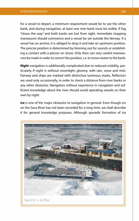
185HYDROMETEOROLOGY
for a vessel to depart, a minimum requirement would be to see the other bank, and during navigation, at least one river bank must be visible. If fog “closes the way” and both banks are lost from sight, immediate stopping manoeuvre should commence and a vessel be set outside the fairway. If a vessel has an anchor, it is obliged to drop it and take an upstream position. The precise position is determined by listening out for sounds or establish-ing a contact with a person on shore. Only then can very careful manoeu-vres be made in order to correct the position, i.e. to move nearer to the bank.
Night navigation is additionally complicated due to reduced visibility, par-ticularly if night is without moonlight, gloomy, with rain, snow and mist. Fairway and ships are marked with distinctive luminous marks. Reflectors are used only occasionally, in order to check a distance from river banks or any other obstacles. Navigators without experience in navigation and suf-ficient knowledge about the river should avoid operating vessels on their own by night.
Ice is one of the major obstacles to navigation in general. Even though ice on the Sava River has not been recorded for a long time, we shall describe it for general knowledge purposes. Although sporadic formation of ice
Figure 81 Ice flow

186 Manual on the Sava River Navigation
(10–15%) in motion, does not pose danger for larger vessels and convoys, the same does not apply to vessels with weaker constructions, boat houses, boat restaurants, landing stages, smaller ships and small crafts.
Before each upcoming winter, preparations must be carried out for vessels to be moved in winter harbours or winter shelters (river inlets with calm water, without direct inflow of river water).
Just before the immediate formation of ice in motion, the river marking system (floating signs) should be removed so as to protect it from destruc-tion. Hence, navigation becomes more complicated and vessels navigate only with the aid of luminous and non-luminous signals set on river banks.
Depending on its form, strength, shape and other characteristics, following forms of ice can be distinguished:
Clear ice or “vedrac” is the first ice formed on calm waters, canals, closed ports, winter harbours and bank areas where currents, as a rule, are weaker. This ice is characterised by purity, hardness, smooth surface and transpa-rency. In the course of exceptionally long and strong winters, its thickness can exceed 50 centimetres, thus must be constantly “crushed” in winter shel-ters and around vessels. Ice crushing around vessels creates air vents which prevent damage that expanding ice could inflict to a vessel’s hull or other vital parts (propulsors, stern, sensors, etc.).
Frozen snow ice or “snježanik” appears when water temperature on river sur-face approaches zero simultaneously with long lasting snowfall, hence the river surface becomes covered with grey wreaths with white edges. That is a first signal that ice is about to form. Experienced navigators used to say that a “cream was created”. In contact with a river bank, the “slush” made of snow, ice and water captures rocks and soil, which at low temperatures turns into frozen boulders very hazardous for navigation.
Ground ice or “podnac” (ice locked to the riverbed) is formed of frozen water particles carried by the river currents onto the riverbed, locking it to sedi-ment and thus creating ice shoals that are very hazardous for navigation.
Icebergs are formed by coupling of moving ice masses, resulting in creation of large ice forms. Enlargement of icebergs combined with effects of water

currents results in a force that is dangerous for vessels, transversal and pa-rallel waterway constructions, river dams, bridges, etc.
When flowing ice carried by the water current arrives to a narrowing on the waterway, a curve, shallows, underwater forms, bridge pillars or other ob-stacles, it halts. Arrival of other icebergs creates a huge pressure that causes piling up and creates an ice barrier that can be several meters high. This situation leads to differences in water levels, i.e. to a rapid decrease of water levels downstream, and increase of water levels upstream from the barrier. As a rule, this is followed by a dyke break and flooding of upstream areas. This is also called a “white flood”.
In order to prevent this, special vessels – icebreakers, are on call on critical points, to prevent formation of the ice barrier, or, if it is already formed, to break it as soon as possible. Once the barrier is broken and freed ice masses are on move again, resulting force destroys everything in its way.
HYDROMETEOROLOGY 187


189THE SAVA RIVER FAIRWAY GUIDE
8.1 SECTORS AND SUB-SECTORSFrom the navigational point of view, and with reference to the characteri-stics of the fairway, dimensions of convoys and other navigational require-ments, the Sava River can be divided into 3 sectors with their sub-sectors:
• Upper Sava: Sisak – Gradiška (Sava rkm 594 + Kupa rkm 5 – Sava rkm 467);
• Middle Sava: Gradiška (rkm 467) – Sremska Mitrovica (rkm 139) with following sub-sectors:
– Gradiška (rkm 467) – Slavonski Brod (rkm 371);
– Slavonski Brod (rkm 371) – Brčko (rkm 228);
– Brčko (rkm 228) – Sremska Mitrovica (rkm 139);
• Lower Sava: Sremska Mitrovica (rkm 139) – Belgrade (rkm 0).
8.1.1 SECTOR “UPPER SAVA” (rkm 594 – rkm 467)
At the confluence with the Kupa River, average water discharge of the Sava River is 680 m3/s. Total length of this sector, including the Kupa River, is 132 rkm, and for the major part of the year, it has unfavourable navigational con-ditions. This sector is characterised by numerous sharp curves (with small ra-dius of river bed axis in curve), relatively narrow width of the fairway (due to numerous shallows, especially during periods of low water levels, i.e. Crnac +/- “0” and lower), and insufficient depths of the fairway that appear during the periods of low water levels. All these factors together adversely affect the navigational safety and call for cautious navigation that must take into consideration vessels’ draught and the size of convoys.
THE SAVA RIVER FAIRWAY GUIDE

190 Manual on the Sava River Navigation
The Sava River tributaries on this sector are: right - Kupa (rkm 591) and Una (rkm 515), and left – Lonja (rkm 554), Trebež (rkm 547), Veliki Strug (rkm 475) and Mali Strug (rkm 470). The Sava River receives an average water intake of 298 m3/s from Kupa, and 250 m3/s from Una. These two rivers contribute significant amounts of water to the Sava River. Water gauge stations referent for planning, calculations and navigation management in this sector are: Cr-nac (“0” mark on the water gauge is at a height of 91.34 ASL) and Jasenovac (“0” mark of the water gauge is at a height of 86.82 ASL).
The most favourable water levels in this sector are: Crnac +100 and above, and Jasenovac +250 and above; at these water levels, the depth of the fa-irway would be approximately 4 m and more.
The river current is very strong during periods of high water levels, which increases the dangers for navigation, especially for convoys navigating downstream in river curves/bends and possibility of their stranding on a concave river bank.
Main dangers emerging during periods of lower water levels, i.e. Crnac “0” mark or lower, are insufficient depth and width of the fairway.
Shallows are places in a fairway where the depth of a river is significantly redu-ced, and consequently the fairway width becomes significantly narrower. A cer-tain number of shallows have been well maintained for years, but some of them are prone to siltation and require occasional clearing. Due to a rapid backfilling process, some of these locations must be cleared more frequently, while some must be regulated by various hydro-constructions in order to ensure the navi-gability. This sector of the fairway has many shallows that need to be carefully studied for navigational purposes, while results of such analysis should be appli-ed during navigation in conditions of low water levels. This experience is valua-ble and should be shared with everyone navigating on this very difficult sector.
Depths on the fairway greatly depend on the difference in water levels between the water gauge stations in Crnac and Jasenovac, which, in normal conditions, is 120 cm higher in Jasenovac, i.e. the water level at Crnac station + 120 cm. This should be noted since there is a possibility of greater inflow of water from the Una River into Sava, which increases the water level in Ja-senovac, whereas the water level in Crnac remains unchanged – this results in greater depths of shallows upstream from Jasenovac, and even in Lonja, which is presently the most problematic shallow in the entire upper sector.

191THE SAVA RIVER FAIRWAY GUIDE
Shallow - Name Rkm Shallow - Name Rkm
Goričica 590–589 Lonja 554–552
Blinjski Kut 584–581 Puska 542–540
Lukavac 579–578 Kraplje 534–531
Gušće 573–570 Višnjica 524
Bistrać 564–562 Jasenovac 517–516
Bobovac 560,3 Mlinarice 504–503
Donji Bobovac 558 Javička Greda 501
Strmen 556–555
Table 7 Shallows in the Upper Sava sector
Curves are the main feature of the upper sector of the Sava River. Some of them are very sharp with small radius of river bed axis in curve. The main attribute of these curves is the fact that they are practically connected to each other, i.e. vessels exiting one curve immediately enter the next one. For that reason, navi-gators often call the navigation on the upper sector of the Sava River “a slalom run”. This manner of navigation requires a constant vigilance and manoeuvring in both directions, while passing or overtaking is practically impossible.
Curve – name Rkm Curve – name Rkm
Goričica 590–589 Žabarski Bok 543
Čigoč 568–567 Cvijetni Vir 538
Gornji Bobovac 561 Brest 536
Donji Bobovac 558 Kraplje 533
Strmen 556 Bumbekovača 529
Ivanjski Bok 551–550 Mlaka 492
Savički Dol 549 Strmac 487–486
Trebež 547
Table 8 Curves dangerous for navigation

192 Manual on the Sava River Navigation
revetments on concave banks and poor visibility conditions. In addition, and as a rule, the fairway in curves becomes narrower, which is especially case du-ring periods of low water levels, which calls for the extreme vigilance, frequent manoeuvring, waiting for vessels and convoys navigating downstream, etc.
Bridges, in navigational sense, always represent an obstacle on the fairway; hence, navigation under bridges requires particular attention. Since bridges have already been addressed in the Chapter 6 of this Manual, this section will only give a brief overview of bridges on this sector of the Sava River.
There are three bridges on the Kupa River, on 5 kilometres of the fairway:
River (rkm) Bridge name
Width of navigation
bridge span (m)
Height of navigation bridge span (m) Referent
WGS“0” (m.a.s.l)At mark
“0”At HNL
Kupa (4.68)
Road bridge – new bridge
Sisak34.25 15.51 8,60 Crnac
(91.34)
Kupa (3.40)
Road bridge – old bridge
Sisak37.0 5.48–13.98 7,02 Crnac
(91.34)
Kupa (2.10)
Railway bridge Sisak 21.50 14.11 7,32 Crnac
(91.34)
There are five more bridges in this sector of the Sava River:
River (rkm) Bridge name
Width of navigation
bridge span (m)
Height of navigation bridge span (m) Referent
WGS“0” (m.a.s.l)At mark
“0”At HNL
Sava(593.7)
Road bridge Galdovo 49.0 12.7 5.77 Crnac
(91.34)
Sava (587.7)
Road bridge Crnac 67.80 13.58–14.51 6.65–7.58 Crnac
(91.34)
Sava (517.2)
Railway bridge
Jasenovac41.0 14.35 6.16 Jasenovac
(86.82)
Sava (515.6)
Road bridge Jasenovac 110.0 13.59–15.44 5.39–7.24 Jasenovac
(86.82)
Sava (466.8)
Road bridge Gradiška 89.0 17.03–17.39 7.86–8.22 Mačkovac
(83.64)
Turning and anchoring points: Depending on the water levels, turning and anchoring points in this sector of the Sava River are: Crnac on rkm 586.5, Jasenovac on rkm 514, Košutarica on rkm 511 and Stara Gradiška

193THE SAVA RIVER FAIRWAY GUIDE
on rkm 468. In addition to the aforementioned official turning and anchor-ing points, turning of some convoys and tugs is also possible in the case of pressing need and in circumstances of favourable hydrological conditions in following locations: Lukavec on rkm 579, Gušće on rkm 570, Bistrać on rkm 563, Lonja on rkm 553, Trebež on rkm 547 and rkm 546, Puska on rkm 541, 539, Kraplјe on rkm 534 and rkm 532, Drenov Bok on rkm 526; when water level recorded in Jasenovac is above +100 cm - in Javička greda on rkm 499, Strmac on rkm 486, Jablanac on rkm 485, Dugi Put on rkm 481, Gaštica on rkm 480 and Veliki Strug and Mali Strug on rkm 475 and 470 respectively.
The dimensions and forms of the convoys on this sector are specified by Naviga-tion Rules on the Sava River Basin, in Chapter XI “Additional local requirements”.
8.1.2 SECTOR “MIDDLE SAVA” (rkm 467 – rkm 139)
The “Middle Sava” is the longest sector of the Sava River and stretches from Gradiš-ka to Sremska Mitrovica, in total length of 328 rkm. According to navigational and seiling conditions, this sector is divided into three earlier mentioned sub-sectors:
This categorisation is a result of navigational possibilities conditional on its right tributaries, the most important of which are:
• Vrbas – it empties into the Sava River on rkm 427 as its right tributary. With its length of 253 km, it extends over a drainage basin area of 5,570 km2;
• Ukrina – 128.7 km long, it empties into the Sava River on rkm 381.5 as its right tributary;
• Bosna – it empties into the Sava River on rkm 314.5 and is a very important tributary with a length of 306 km, drainage basin area of 10,460 km2 and annual water inflow of 5.5 billion m3;
• Drina is the largest tributary of the Sava River, joining it on rkm 178, with approximate annual water inflow of 12 billion m3. Apart from wa-ter, Drina carries great amounts of sediment, negatively affecting the navigational conditions on this sector and limiting the size and form of towed and pushed convoys;
• The Bosut River, emptying into the Sava River on rkm 162.5 on its left bank, also affects the navigational conditions on this sub-sector. From the perspective of navigation, this section is important for vessels mo-ving upstream, for which speed and complexity of navigation trough this section provide the elements for estimation of conditions needed to pass through Rača section without disassembling of convoys.

194 Manual on the Sava River Navigation
Relative to the amount of sediment and water carried into the Sava River, ri-vers Vrbas, Bosna and Drina have the greatest influence on deformation of the riverbed gradient of the Sava River, velocity of its water current, meandering, etc. which all negatively affect navigational conditions, the size and form of convoys, as well as their draught. Based on these characteristics, this sector was divided into three sub-sectors.
Sub-sector “Gradiška – Slavonski Brod” (rkm 467 to rkm 370)
This sub-sector, with a length of 97 km, is in overall better condition than both the preceding sector and the following/downstream sub-sector. The referent water gauge station for this sub-sector is in Slavonski Brod. At water level: Sl. Brod “0” cm, depth of shallows in this sector is around 160 cm, whe-reas average width of its fairway is in range from 40 to 50 m.
The best known shallows on this sub-sector are:
Shallow - Name Rkm Shallow - Name Rkm
Gradiška 466–464 Kobaš 402–401
Mačkovac 453–452 Osavica 398–397
Dolina 450–448 Grlić 395–394
Gornje polje 431–430 Dubočac 390–387
Davor–Toka 427–425 Zbjeg–Ukrina 385–383
Radinje 420,5 Sijekovac–Migalovci 378–377
Kaoci 416–415 Rafinerija Brod 375–374,5
Table 9 Overview of shallows on sub-sector Gradiška – Slavonski Brod
Curves on this sub-sector have proper radiuses, their values being around 400 m, which enables passing of bigger towed and pushed convoys in both directions of navigation. Overview of major curves on this sub-sector is giv-en in the following table.
Curve – Name Rkm Curve – Name Rkm
Pivare 462–461 Krst 442
Trnava 457 Gaj 434
Kopanik 454 Hercegov Dol 420
Mačkovac 452 Motaica 412
Table 10 Overview of curves on sub-sector Gradiška – Slavonski Brodd

195THE SAVA RIVER FAIRWAY GUIDE
The major navigational problems are the curve of Hercegov Dol, because of its Radinje shoal that appears directly below the “nook”, and the Motaica curve, due to whirlpools (limans) appearing along both river banks after the curve. Passing in these curves should be avoided because there is a high probability that one of convoy’s segments will enter the liman and almost certainly will cau-se the tow line to break. Due to poor visibility conditions in curves, navigation in them requires compulsory use of all available navigational tools and radio communication devices.
Turning and anchoring on this sub-sector is possible in specifically assigned locations: Davor on rkm 428.5, Kobaš on rkm 400, Slavonski Brod on rkm 370.1.
Upstream-downstream towed and pushed convoys
Conditional on the water levels and the power of tugs, this sub-sector allows the convoys towed upstream to be composed of six barges set in three transversal rows with two ve-ssels in each of them. Towing lines connecting the vessels in convoy should be set crosswise.
If water levels allow, convoys towed in downstream direction can be composed of six barges set in two transversal rows.
At favourable water levels, convoys pushed in upstream direction can be composed of four pushed bar-ges set in two rows (two pushed barges in each row), and ordinary convoys pushed in downstream direction are composed of three pushed barges set in one row.
Figure 82 Upstream and downstream towed convoys – Middle Sava to Slavonski Brod
2519
0
33

196 Manual on the Sava River Navigation
Particular attention in navigation on this sector should be paid to passage un-der the bridge in Brod, because of its opening which is improperly set relative to the fairway, especially during downstream navigation when the fairway shifts from the right to the left river bank just before the entrance (approximately 300 m), where the navigational opening of the bridge is located.
Sub-sector “Slavonski Brod – Brčko” (rkm 370 to rkm 228)
With exception of some minor sections, this sub-sector of the middle Sava is very difficult for navigation, especially during periods of low water levels. The length of this sub-sector is 142 rkm, and its referent water gauge stations are Slavon-ski Brod, Šamac and Brčko. This sub-sector encompasses the 33 km long section between Novi Grad and Domalјevac, or so-called “Šamac section”, which is the most difficult for navigation on the Sava River. Water gauge station referent for navigation on this section of the fairway is in Šamac.
First major obstacle to navigation downstream from Slavonski Brod is the curve and shallow Vijuš (km 367), which creates problems at low water levels, mainly because of the shallow on the concave bank, but also because of its quite a sharp curve (note that two-rows towed convoys are permitted in this sub-sector).
Shallow Oprisavci is located on km 337, and it also represents an obstacle to na-vigation due to its very narrow passage during periods of low water levels.
Apart from these shallows, significant curves dangerous for meeting of vessels are: Vijuš km 367, Moclek km 358 and Uglјara km 343.
Section “Novi Grad–Domalјevac” (rkm 333 to rkm 297)
Very big shallow extends from rkm 329 to rkm 322 – Novi Grad. Canals of different widths had to be dredged in order to enable navigation on this section. However, these canals are not parallel with river banks, thus make the orientation very hard. This section could be called a beginning of the Šamac sector. Lower part of this sector, on rkm 321, is called “Jaruge”, where, according to the preliminary design, the entrance/exit of the multipurpose Dunav–Sava canal should be located.
Figure 83 Upstream pushed convoys
Figure 84 Downstream pushed convoys

197THE SAVA RIVER FAIRWAY GUIDE
The Bosna River empties into the Sava River on rkm 314 of the right bank, brin-ging in huge amounts of sediment and depositing it directly below the conflu-ence, forming a so-called “Šamac sector” on this longitudinal river profile. From the navigational point of view, the most unfavourable parts of this section, from Jaruge on rkm 321 to Domalјevac on rkm 297, are shallows listed in the following table:
Name Rkm Name Rkm
Šamac ispod Klanice 313–312 Klenić 305–304
Savulja 311 Nevjerica 303–302
Vrbanja 309 Dubočica 301
Vučjak 308 Domaljevac 297
Table 11 Overview of shallows on Šamac sector
For guidance purposes only, at “0” mark of water level on gauge station Slavon-ski Šamac, depth of water is 240 cm.
Disassembling and towing or pushing of smaller parts of bigger convoys trough “Šamac Sector” is necessary and requires full engagement of all crew members. Disassembling is neccessary from Jabuke turning point on rkm 316 (at lower water levels and with two-row convoy, it is better to turn on rkm 320, becau-se of the shallow located on rkm 317, which is too narrow for navigation) to Domalјevac on rkm 297. When water level on Slavonski Šamac gauge station is “0” and lower, disassembling is necessary from Svilaj on rkm 333.At favourable water levels, downstream navigation in a way described in previous text secti-on are usually performed from Jabuke to Klenić, and at low water levels, from Jabuke to Domalјevac. If water levels are extremely low, it is recommended all the way to Tolisa, i.e. Županja.
Towed convoys: Downstream nsvigation of towed convoys is allowed with maximum three barges in a tow, of which only two can be loaded and the one on right side shall be empty, because of the Savulјa shallow and tendency of “falling” of the tow to the right side, in which case if the far right side barge is loaded it is at high risk of being stranded.
Upstream navigation: – one barge at time, depending on a draught.

198 Manual on the Sava River Navigation
At the entrance of the Savulјa shallow, which is the most critical point by reason of its funnel-shape and falls, tow lines can lose manoeuvring qualities, and if not prepared for this situation, there is a risk of stranding or, with sudden increase of forward power of the tug even of rupture of the tow lines. Tow lines should be as short as possible, both in downstream and upstream navigation. In anvigation, it is best to sail slow and be able to increase the speed at a proper moment in order to straighten the barges in tow.
Pushed convoys: As regards the downstream and upstream navigation of pus-hed convoys, it is possible to sail with two pushed barges of maximum length and width of convoy not exceeding 110 m X 23 m at water level of “0” mark and higher on Šamac gauge station. At lower water levels, dimensions should be 110m x 12 m. At water levels of + 150 on Šamac gauge station, navigation is possible with three pushed barges with dimensions of convoy not exceeding 110m x 35 m. Parameters of these convoys, both towed and pushed, depend on water levels, vessel’s draught and propelling power of the tug or pusher. All these standards and limits are for orientation purposes only, and Port Master Office in Slavonski Brod should be consulted before every arrival to the sector.
Apart from shallows on Šamac sector, other main obstacles to navigation are sharp curves with insufficient radiuses: Vučjak on rkm 307, Dubočica from rkm 301 to rkm 300, and Domalјevac on rkm 295. This sub-sector of the Middle Sava, from Slavonski Brod to Brčko, is rightfully categorised as the most demanding on the entire fairway of the Sava River.
Name Rkm Name Rkm
Vijuš 367 Niškovo Polje 295–292
Oprisavci 337 Rastovica 286
Novi Grad – Jaruge 329–321 Štitar 284
Gornja Jabuka 317 Suvo Polje 282–278
Jabuka 315–314 Tolisa 277–274
Klanica 313 Repovac 272
Savulja 311 Orašje 263–262
Nevjerica 303 Vučilovac 246–244
Dubočica 302–301 Rajevo Selo 235
Domaljevac 297–296 Brčko 230–229
Table 12 Overview of shallows on sub-sector Slavonski Brod – Brčko

199THE SAVA RIVER FAIRWAY GUIDE
Due to poor visibility conditions, possibility of meeting other vessels and insufficient radius in curve, particular attention must be paid, not only to shallows, but also to all curves given in the following table:
Curve – name Rkm Curve – name Rkm
Vijuš 367 Domaljevac 295
Moclek 358 Štitar 285
Ugljara 343 Tolisa 277
Vučjak 307 Vidovica 255
Dubočica 300 Rajevo Selo 235
Table 13 Overview of curves on sub-sector Slavonski Brod – Brčko
Turning and anchoring points Depending on water levels on this part of the Sava River, turning and anchoring points are: Ruščica on rkm 364 and rkm 362.2, Jaruge on rkm 319, Šamac on rkm 312.5, Domalјevac on rkm 299, Županja on rkm 268.7 and Brčko on rkm 228.
Bridges
There are 6 bridges on this sub-sector:
River (rkm) Bridge
Width of navigation
bridge span(m)
Height of navigation bridge span (m) Referent
WGS“0” (m.a.s.l)At mark
“0” At HNL
Sava (374.8)
Product line of Brod
Refinery 104.30 19.06–22.23 16.53–17.93
Slavonski Brod
(81.80)
Sava (371.5)
Road bridge Brod 66.30 15.03 7.65
Slavonski Brod
(81.80)
Sava (311.8)
Road and railway bridge Šamac
65.30 14.65 8.14Slavonski
Šamac (80.70)
Sava (261.6)
Road bridge Županja 117.80 15.88–18.26 7.73–10.11 Županja
(76.28)
Sava (228.8)
Road bridge Gunja – Brčko 47.50 14.12 7.60 Brčko
(76.62)
Sava (226.8)
Railway Gunja
– Brčko120.00 16.06–16.13 9.64–9.71 Brčko
(76.62)

200 Manual on the Sava River Navigation
Bridges that can represent obstacles for navigation are:
• Slavonski Brod/Brod – road bridge on rkm 371.5 linking two cities of Brod; at favourable water levels it is not an obstacle to navigation, but at lower water levels represents an obstacle that must be taken into account because of its pillars which are irregularly set in relation to the fairway;
• Šamac – road/railway bridge on rkm 311.8 has suitable dimen-sions, but in some situations the pillar of the old bridge can be an obstacle to navigation in both directions. Owing to irregular kind of the entering into the bridge opening and sudden turning of con-voys on short distance from right to the left bank, vessels navigating downstream are exposed to danger to hit the pillar of the demol-ished bridge located in the immediate vicinity of the opening of the new bridge;
• Gunja – Brčko road bridge on rkm 228.8 is very unsuitable for navi-gation at low water levels. Owing to its irregular kind of the entering, navigation is difficult especially for vessels navigating downstream, hence larger convoys must be disassembled and propelled in small-er parts. Entering into this bridge is difficult because of shallows causing sudden turning of convoys navigating downstream from right to the left bank in the immediate vicinity of the bridge.
Forms and a composition of towed convoys navigating upstream and down-stream primarily depend on water levels and the power of tugboats. Down-stream towing is possible for convoys formed of two transversal rows with compulsory disassembling on “Šamac sector” regardless of water levels.
Depending on the power of tugboats, convoys towed in upstream direction can be formed in one or two lines, with appropriately set tow lines.
Pushed convoys navigating downstream can be composed of two tran-sversal rows. All necessary precautionary measures applying to towed convoys must also be taken with pushed convoys, along with compulsory disassembling.
Pushed convoys navigating upstream can also be composed of several vesse-ls, depending on the power of pushers and water levels. Convoys navigating upstream can comprise six vessels forming two or three transversal rows.

201THE SAVA RIVER FAIRWAY GUIDE
Contrary to towed convoys that can follow the line of curves, rigid pushed convoys must manoeuvre much more when passing through curves in or-der to avoid ramming into the concave bank. Similar manoeuvring tech-niques should be applied when navigating trough the narrow sections of the fairway, especially when correcting the trajectory in order to ensure safe passage under bridges.
Sub-sector “Brčko – Sremska Mitrovica” (rkm 228 to rkm 139)
Length of this sub-sector of the Middle Sava is 89 km. Two major tributaries empty into the Sava River on this part of its course – Drina from the right and Bosut from the left side.
Main feature of this sub-sector is the diversity of navigational conditions, ranging from very favourable to very limiting. During periods of low water levels this stretch of the fairway sees a number of shallows that must be ta-ken into account when navigating in both directions. Their overview is given in the following table.
Place – name Rkm Place – name Rkm
Gunja 223–221 Visoča 191–189
Brezovo Polje 220–217 Bela Crkva 185–184
Devojačka–Nakić Kula 213–210 Sremska Rača 178.5–177.5
Jamena 205–203
Table 14 Overview of shallows on Brčko – Rača section
Section from rkm 179.5 to rkm 172.6, better known as “Rača sector”, stretches over approximately seven kilometres. Its regulation began back in 1892. Major regulation works had never been carried out in a profession-al and planned manner, which reflected negatively on dimensions of the fairway.
After the World War II, regulation and sand exploitation works successfully managed to restrain the restless and rapid waters of this sector, thus en-suring sufficient depths of the fairway. Old hydro-constructions had been repaired, and new additionally narrowed the river bed which contributed to stabilisation of depths in this navigationally demanding section of the river.

202 Manual on the Sava River Navigation
The most difficult section to navigate through is on rkm 177, where the fairway width is very narrow during periods of low water levels, due to the longitudi-nal regulation facility built on the right river bank, and groynes – transversal regulation facilities built on the left river bank. The longitudinal regulation con-struction appears at a water level of approximately +230 cm, and transversal groynes at +330 cm on water gauge station Sremska Mitrovica. Downstream from the transversal regulation constructions, the river created a shoal, which is the narrowest and the most critical point to navigate on this section.
Convoys navigating downstream and upstream are must be disassemblied, if necessary, from Rača on rkm 179.5 all the way to just before Poloj on rkm 172.6, although it is not rare case with large convoys to be disassemblied all the way to just before the Bosut curve on rkm 162. Convoys navigating downstream at low water levels can be formed of maximum three vessels in one transversal row, whereas passing of convoys navigating upstream depends on the power of tugboats/pushers. If these convoys manage to pass this curve without major difficulties, then it will be also possible on Rača section. However, if passing through this curve is slow, disassembling should be a chosen option.
This sub-sector of the Sava River is characterised by curves, which can be obstacles to navigation for convoys of maximum dimensions. In past, Rača section had three, and then only two signalling stations, making sure that only one convoy can proceed through the sector. Signalling stations were first located in Rača, at the confluence with Drina and near Poloj, and later only in Rača and Poloj, but entailed compulsory use of “loco-pilots”. Nowa-days, with expansion of all modern communication devices, use of signalling stations and pilots is abandoned.
Curves on this sector are big and sharp, thus representing obstacles to unin-terrupted navigation. Their overview is given in the following table:
Curve – name Rkm Curve – name Rkm
Rača 179–177 Ravnje 155.5
Bosut 163–162 Menđeloš 153
Table 15 Curves on the “Rača sector“
With the exception of “Rača sector”, where the dimensions of convoys are li-mited, convoys of maximum dimensions can navigate through other curves and obstacles in both directions.

203THE SAVA RIVER FAIRWAY GUIDE
Turning and anchoring points on this sector are important, and their over-view is given in the following table:
Name Rkm Name Rkm
Brezovo Polje 216 Bosut 161
Bela Crkva 184.5 Ravnje 156
Rača 180 Laćarak 143.5
Poloj 171 Sremska Mitrovica 139
Table 16 Overview of locations suitable for turning and anchoring on “Rača sector”
Bridges on this sector are:
River (rkm) Name
Width of navigation
bridge span (m)
Height of navigation bridge span (m) Referent
WGS“0” (m.a.s.l)At mark
“0”At HNL
Sava (183.31)
Road and railway
bridge Rača140.00 17.23 --- Jamena
(72.44)
Sava (139.24)
New pedestrian
bridge Sremska Mitrovica
100.00 14.59–16.52 8.37–10.30Sremska Mitrovica
(72.22)
As already said, towed and pushed convoys navigating upstream and down-stream may be formed of several vessels, with limitations in Rača sector, whe-re convoys navigation upstream depend on the power of tugboats/pushers, and convoys navigating downstream can have only one transversal row.
8.1.3 SECTOR “LOWER SAVA” (rkm 139 to rkm 0)
This sector has all characteristics of a lowland river. The river course is more tranquil and with mild curves, while the riverbed is wide and with greater depths. It also features many river islands and river inlets with different navi-gational characteristics. The greatest depth on this sector is 25 m, near village of Hrtkovci on rkm 121. The river width near Šabac and Ostružnica is approxi-mately 600 m. The major river islands are: Mišarska, Vitojevačka, Velika Grabo-vačka, Miloševa, Skelska, Kolubarska (Barička), Međica and Ciganlija.

204 Manual on the Sava River Navigation
Major tributaries emptying into the Sava River on this sector are: Vukodraž on rkm 62.0, Kolubara on rkm 27.6, Barička reka on rkm 26.5 and Topčider-ska reka on rkm 4. These are all right tributaries that have no major influence on discharge and the magnitude of the total water amount. Kolubara has a pluvio-nival water regime, with expressed oscillations throughout the year. In addition to its minor discharge, it carries great amount of sediment into the Sava River, especially at high water levels, which negatively affects the dimensions of the fairway during periods of law waters.
Regulation interventions on the sector of Lower Sava did not achieve desi-red results. Dredging of certain sectors of the waterway extended the width and depth of its riverbed, while building of longitudinal and transversal re-gulation facilities resulted in gathering of water from the wide transversal river profile. However, despite all taken measures, low water levels bring to this sector poor navigation conditions, which is particularly evident on sec-tion from rkm 111.7 to rkm 82.3, or so-called “Šabac sector”, and its stretch from rkm 89.0 to rkm 82.3 (known as “Kamičak”).
Section rkm 111.7 – rkm 82.3 (known as “Šabac sector”) extends from for-mer Drenovačka Ada to Vrbica, in total length of approximately 30 km. It is characterised by absence of sufficient depths and widths of the fairway, which are consequences of a great dispersion of water in a wide riverbed. Back in period from 1924 to 1935, major dredging works had been carried out on this section, namely from Vitojevačka ada on rkm 95.3 in length of 18 km in downstream direction, entailing digging of canals between 50 and 80 meters wide.
Regulation of the waterway on the stretch downstream from Mišarska ada was carried out with combined use of longitudinal and transversal regula-ting hydro-constructions, and in 1994, a partition was built on the top of Podgorička ada on rkm 86.8 along the right river bank, closing the former fairway and shifting the navigation to the left river bank.
During periods of extremely low water levels, convoys are disassmblied from rkm 113 to Vrbica on rkm 80. Convoys are navigating downstream in only one row, while number of pushed barges depends on their draught. If convoy dimensions allow passage through the major part of this sector, disassembling is conducted only from Široke njive on rkm 90.0 to Vrbice on rkm 80. Due to limited fairway width and depth on this section, towed and

205THE SAVA RIVER FAIRWAY GUIDE
pushed convoys must navigate with extreme caution, complying with all navigation norms. Any deviation from experiential and relevant standards may cause dangerous stranding, closure of the fairway and accidents with grave consequences. Navigation on this section must also be careful if visi-bility conditions are limited, when water levels change, and especially when marking system is either removed or incomplete for some reason (during winter period).
Locations suitable for turning on this sector are: Jarak on rkm 124, Hrtkov-ci on rkm 121, former Drenovačka ada on rkm 113, Šabac on rkm 105, Široke njive on rkm 90, Ada Vrbica on rkm 80. Referent water gauge stations for this sector are in Sremska Mitrovica, Šabac and Belgrade. Status on the gauge station Šabac is very important for navigation, both at low water levels in sense of overview of fairway depths, and at high water levels because of the limited clearance of the navigation bridge span of the old railway bridge in Šabac. Status on the water gauge station Belgrade is important reference for the clearance of navigation bridge span below the old railway bridge in Belgrade. “0” mark on the water gauge station Sremska Mitrovica is on 72.22, on the water gauge station Šabac at 72.61, and on the water gauge station Belgrade at 68.28 m.a.s.l. Navigation on section from Barička ada on rkm 27 to rkm 25 is regulated as one-way, going around the river island. Vessels navigating downstream use the old fairway along the right river bank, while vessels navigating upstream go between the left banks of the river and the island.
Name Rkm Name Rkm
Šabački – before bridge 113–107 Široke Njive 92–89
Šabački – after bridge 107–104 Kamičak 89–82
Mišarski 103–101 Orljača 76–72
Mrđenovac 98–95 Kolubara 27.5–26.5
Table 17 Shallows on Lower Sava
Bridges on this sector are a huge obstacle to navigation during periods of high water levels; hence all changes in water levels must be closely moni-tored. The bridges on this sector are:

206 Manual on the Sava River Navigation
River (rkm) Bridge name
Width of navigation
bridge span (m)
Height of navigation bridge span (m) Referent
WGS“0” (m.a.s.l)At mark
“0”At HNL
Sava (136.6)
Road bridge Sremska Mitrovica
150.0 15.44–17.32 9.30–11.18Sremska Mitrovica
(72.22)
Sava (106.96)
Railway bridge Šabac 75.0 11.26–11.48 6.46–6.68 Šabac
(72.61)
Sava (104.53)
Road bridge Šabac 80.0 14.13 9.42 Šabac
(72.61)
Sava (42.53)
Road-heat pipe bridge Obrenovac
80.0/120.0 17.84–17.97 11.01–11.14 Beograd (68.28)
Sava (15.43)
Railway bridge
Ostružnica2 x 75.0 14.44–14.52 8.41–8.49 Beograd
(68.28)
Sava (15.0)
Road bridge Ostružnica 150.0 16.58–18.22 10.56–12.2 Beograd
(68.28)
Sava (3.8)
Road bridge Belgrade
– Ada Ciganlija
150.0 21.02–21.62 15.33–15.93 Beograd (68.28)
Sava (3.0)
New railway bridge
Belgrade120.0 21.72 16.06 Beograd
(68.28)
Sava (2.73)
Oldrailway bridge
Belgrade
90.0 12.62 6.96 Beograd (68.28)
Sava (2.52)
Road bridge “Gazela” Belgrade
200.0 16.52–21.06 10.87–15.41 Beograd (68.28)
Sava (1.43)
Road/tram-way bridge
Belgrade90.0 15.89–16.48 10.27–10.86 Beograd
(68.28)
Sava (1.0)
Road bridge (Brankov) Belgrade
100.0 15.55–16.36 9.94–10.75 Beograd (68.28)

207THE SAVA RIVER FAIRWAY GUIDE
Forms and types of convoys
• Towed-pushed convoys navigating upstream, at favourable water levels and depending on the power of tugboats, may be formed of several vessels of various forms and purposes;
• In locations with limiting conditions (Šabac sector), at low water lev-els, these convoys must adjust to the prevailing conditions of the fair-way on this sector;
• Towed-pushed convoys navigating downstream can also be formed of several vessels, but fully respecting limitations of Šabac sector and formations not exceeding two transversal rows.
Exceptions are the dimensions of convoys navigating on the sector “Mouth of the Sava River” (“Ušće Save”) from rkm 0 to rkm 11, and these are specified by Navigation Rules on the Sava River Basin, in Chapter XI “Additional local requirements”.
8.2 DIFFICULTIES IN NAVIGATION ON THE SAVA RIVER DUE TO HYDRO-METEOROLOGICAL CONDITIONS
These difficulties in navigation on the Sava River occur as consequences of hydrological, hydrographic and weather conditions characteristic for a varia-ble humid continental climate. Their incidence over years and in the course of a single year differs, is variable and depends on weather conditions. Some years are dry, some are rainy, with mild or harsh winters, with more or less windy days. Also different are frequencies and duration of foggy periods and periods with low temperatures and ice.
According to significance, duration and frequency of hydrometeorological conditions on the Sava River fairway, the most distinctive and harmful from the nautical point of view are:
High and extremely high and low and extremely low water levels
Low and high water levels adversely affect navigational conditions, and in both cases can cause suspension of navigation. If, however, vessels continue under way, there is a risk of huge material damage and endangering of hu-man lives. In addition to loss of visual contact with shore, high water levels negatively affect navigational conditions since increased velocity of water

208 Manual on the Sava River Navigation
current that carries a large number of tree trunks and other floating objects can damage and put out of function the steering device and propulsion system, which altogether means exposure to water torrents with unforeseea-ble severe consequences.
Negative effects of high water levels are reflected in the fact that navigation is sometimes temporarily impossible due to the heights of artificial obstacles in the fairway (Šabac Bridge, old railway bridge in Belgrade and other). Low water levels can reduce the commercial effects, have a negative effect on utilisation of the cargo area capacity, towing power, and the size of convoys, frequently require disassembling of convoys, etc. It is not rare case that navigation is pro-hibited due to low water levels. Cargo capacity is reduced and damages to the vessels are greater, especially on Šamac, Rača, Šabac and some other sectors.
Rapids
Rapids are a regular feature on riverbeds that have a steep gradient and come about during low water levels. Rapids occur in places where natural or artificial objects are entrenched in the riverbed, or result from sudden narrowing of the riverbed with high banks. Rapids can significantly affect the manoeuvring abilities and navigation, hence must be taken into consi-deration when entering zones where they are a common occurrence.
Number of days with low temperatures and ice
Most frequently, fog forms on the Sava River in spring and in autumn. As a rule, fog begins to form at the same time when water levels become good for na-vigation. Plains along the banks of rivers, ponds and inlets are good places for the formation of fog. On the Upper Sava sector, fog is particularly pronounced around the mouths of Mali and Veliki Strug, on the Middle Sava in zones of Ša-mac sector, Županja, Brod and Rača sector, while the Lower Sava sector is parti-cularly affected by fog around Sremska Mitrovica, Šabac, Ušće and Ostružnica.
Number of days with low temperatures and ice
Of all the rivers in the region, the Sava River is the last one to freeze. The reasons for this are manifold:
• High concentration of saltpetre (KNO3) in water;
• Chemical composition of mineral substances dissolved in water of the Sava River and its tributaries;

• Severe pollution with wastewater from industry concentrated on the river banks;
• Pollution of coastal farmland with pesticides and other water-born substances that end up in the Sava River, etc.;
• Hot water from the nuclear power plant “Krško” and Thermal Power Plant “Nikola Tesla”.
The Sava River can freeze when several days of low temperatures, -14 °C and below, coincide with very low water levels.
Number of windy days and their incidence
As already stated, a number of windy days and their incidence in the Sava River Basin are of secondary importance. Košava (a cold, squally southea-stern wind) does not significantly affect the navigation in the Sava Basin, with the exception of some sections on the Lower Sava, where suspensions of navigation occur rarely. Occurrence of windstorms originating from the slopes of Bosnian mountains is the best signal for suspension of navigation and for vessels to remain leeward until the storm weakens. Consequences of windstorms could be catastrophic for convoys and their cargo, as well as for human lives. These phenomena are short in duration, thus timely and brief suspensions of navigation have no greater impact on the organisation of navigation, fulfilment of obligations and the very navigational endeavour.
THE SAVA RIVER FAIRWAY GUIDE 209
LITERATUREIlija Ika Petrović, Stojan StošićOsnovi plovidbe rekama i morima, 2002.
Centar za razvoj unutarnje plovidbe d.o.o.Priručnik za unutarnju plovidbu u Republici HrvatskojZagreb, December 2006.
Miroslav Sambolek,Od vesla do Queen Mary IIBrodarski Institute, Zagreb
Prof. dr. Neven Kuspilić, dipl. inž. građ.Hidrotehničke građevine – 2. dioUniversity of Zagreb, Faculty of Civil Engineering, 2008.
Milan Milovanović LankaRiječna navigacija 1, 2, 3, i 4
Milan GruborPlovidba potiskivanih brodskih sastavaBelgrade, 1983.
Slobodan ŽivanićRečna navigacija za II, III, i IV razred usmerenog obrazovanja saobraćajne strukeBelgrade/Novi Sad, 1988.
Vladeta Čolić, Vladimir ŠkilјaicaStabilitet i krcanje broda – udžbenik za III i IV razred saobraćajne školeBelgrade, 1997.
Dr Joško Dvornik, v. prof. i Srđan Dvornik, dipl. inž.Konstrukcija, otpor i propulzija jahtiFaculty of Maritime Studies, Split, 2013.
The available and recognised literature used in naval high schools and colleges spe-cialised for water transportation was utilised in development of this Manual. Besides the Editorial Committee, which provided unquestionable contribution to this pu-blication, particularly important was the role of the ISRBC Permanent Expert Group for Navigation (PEG NAV), which defined the structure of this Manual. Also, use was made of all information available on the Internet, not published but in accordance with modern trends and indicating directions for development of new technologies in this form of transport. In addition to the listed sources, invaluable were interviews with captains and other navigators whose experience of navigation and life on the Sava River were the source of information not available in literature.
Significant contribution to this publication has been provided by the competent autho-rities from Member States to the International Sava River Basin Commission competent for inland waterways, and especially by “The Agency for Inland Waterways” from Vukovar and “The Directorate for Inland Waterways” Belgrade, representatives of which are the members of the aforementioned Editorial Committee that has prepared this publication.
210

Notes and comments

Notes and comments

Notes and comments

Notes and comments

PRIRUČNIK ZA PLOVIDBUNA SLIVU RIJEKE SAVE