
ZÁBOJNÍK JOSEF - Sociální sítě na internetu v kontextu arabské revoluce - BP 2012
Upload
khangminh22Category
view
1download
0

ČESKÉ VYSOKÉ UČENÍ TECHNICKÉ V PRAZE
Fakulta elektrotechnická
Katedra telekomunikační techniky
Přenos polohové informace
prostřednictvím datové sítě
květen 2016 Bakalant: Anastasiya Shkalikava
Vedoucí práce: Ing. Pavel Puričer

Čestné prohlášení
Prohlašuji, že jsem zadanou bakalářskou práci zpracoval sám s přispěním vedoucího práce akonzultanta a používal jsem pouze literaturu v práci uvedenou. Dále prohlašuji, že nemámnámitek proti půjčování nebo zveřejňování mé bakalářské práce nebo její části se souhlasemkatedry.
Datum: 27.5.2016
podpis bakalanta


Acknowledgements:
First of all I would like to thank my supervisor Ing. Pavel Puričer for his tolerance and
support in every problem that occurred during the writing of this thesis. Furthermore, I would
like to thank him for providing the hardware and the literature used in this work.
I would also like to extend a special thanks to my close friend Vadim for many valuable
pieces of advice and his endless support throughout the writing of the thesis.
Finally, my thanks goes to my family for their continuous support in every difficult moment
that I had.
Anotace:
Tato bakalářská práce je rozdělena do dvou částí. První část práce se zabývá teoretickým
popisem GNSS standardů vytvořených pro různé účely, rozborem typů chyb, které vznikají při
přenášení signálu z družice ke konečnému uživateli a zahrnuje metody zpřesňování polohy GPS
přijímače. Druhá část práce se zabývá praktickým měřením polohy bez a s použitím různých
druhů korekcí, konkretně SBAS a korekcí přenášených Ntrip protokolem. V této části je také
popsán software použitý na určení polohy.
Klíčová slova: GPS, RINEX, RTCM SC-104, Ntrip, NMEA, chyby GPS, DGPS, real-time,
postprocessing, EUREF, BNC, u-center.
Summary:
This bachelor project is divided into two parts. The first one, which is theoretical, describes the
most commonly used GNSS standards for different purposes, types of errors which appear while
the signal from satellite is transmitted to rover users and correction methods which are used to
get rid of these errors and get accurate position. The second, practical, part represents measured
results, where are opposed plain GPS positioning and GPS positioning using SBAS corrections
and corrections transmitted over Ntrip protocol.
Key words: GPS, RINEX, RTCM SC-104, Ntrip, NMEA, errors in GPS, DGPS, real-time,
postprocessing, EUREF, BNC, u-center.
Contents
I. THEORETICAL PART...............................................................................................................8 1. GNSS standard formats..............................................................................................................8
1.1 RINEX standard...................................................................................................................8 1.1.1 General information and message types.......................................................................8 1.1.2 Contents and example of an RTCM observation type message...................................8
1.2 RTCM SC-104 standards...................................................................................................11 1.2.1 General information....................................................................................................11 1.2.2 RTCM special committees.........................................................................................11 1.2.3 RTCM SC-104 standards for GNSS services.............................................................12 1.2.4 Structure of RTCM message type 1...........................................................................14
1.3 NTRIP protocol..................................................................................................................16 1.3.1 Introduction................................................................................................................16 1.3.2. General information..................................................................................................16 1.3.3. NtripSource...............................................................................................................17 1.3.4. NtripServer................................................................................................................17 1.3.5. NtripServer on Windows...........................................................................................17 1.3.6. NtripCaster................................................................................................................19 1.3.7. NtripClient.................................................................................................................19
1.4. NMEA protocol.................................................................................................................20 1.4.1. General information..................................................................................................20 1.4.2. NMEA message structure..........................................................................................20 1.4.3. NMEA message types...............................................................................................20 1.4.4. Examples of NMEA messages..................................................................................21
2. Types of errors in GPS..............................................................................................................24 2.1 Ephemeris data errors.........................................................................................................24 2.2 Satellite clock errors...........................................................................................................25 2.3 Atmospheric errors.............................................................................................................25 2.4 Multipath errors..................................................................................................................26 2.5 Receiver errors...................................................................................................................26 2.6 Satellite geometry..............................................................................................................27 2.7. DGPS correction of individual kinds of errors.................................................................27
3. Correction methods distinguished by evaluation speed............................................................28 3.1 Real-time and postprocessing methods..............................................................................28 3.2 Example in detail...............................................................................................................28
4. Correction transfer methods......................................................................................................30 4.1 SBAS..................................................................................................................................30
4.1.1 OmniSTAR.................................................................................................................31 4.2 GBAS.................................................................................................................................31
4.2.1 EUREF Permanent Network (EPN)...........................................................................31 II. PRACTICAL PART.................................................................................................................34 5. Software used............................................................................................................................34
5.1 Open source Ntrip software...............................................................................................34 5.2 BKG Ntrip Client (BNC): A detailed review.....................................................................35 5.3 Mountpoint description examples......................................................................................43 5.4 U-center..............................................................................................................................44
6. Measurements............................................................................................................................46Conclusion.....................................................................................................................................50References......................................................................................................................................51Appendix........................................................................................................................................53
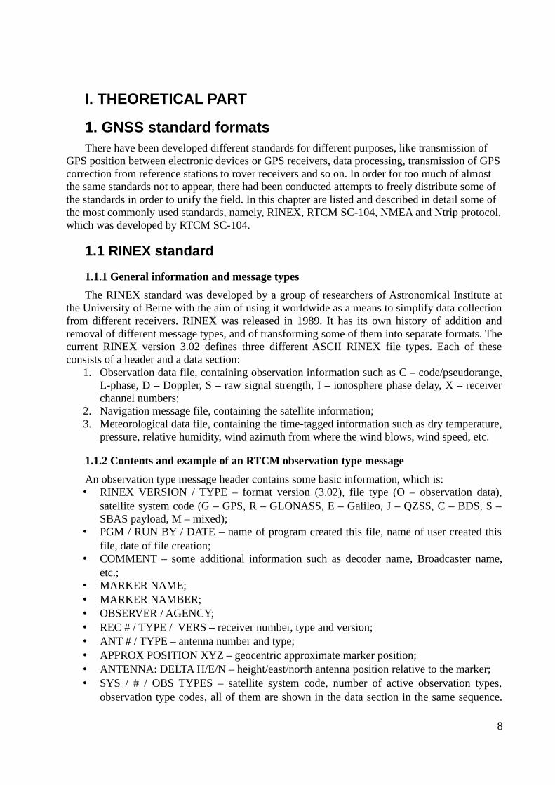
I. THEORETICAL PART
1. GNSS standard formatsThere have been developed different standards for different purposes, like transmission of
GPS position between electronic devices or GPS receivers, data processing, transmission of GPScorrection from reference stations to rover receivers and so on. In order for too much of almost the same standards not to appear, there had been conducted attempts to freely distribute some of the standards in order to unify the field. In this chapter are listed and described in detail some of the most commonly used standards, namely, RINEX, RTCM SC-104, NMEA and Ntrip protocol,which was developed by RTCM SC-104.
1.1 RINEX standard
1.1.1 General information and message types
The RINEX standard was developed by a group of researchers of Astronomical Institute atthe University of Berne with the aim of using it worldwide as a means to simplify data collectionfrom different receivers. RINEX was released in 1989. It has its own history of addition andremoval of different message types, and of transforming some of them into separate formats. Thecurrent RINEX version 3.02 defines three different ASCII RINEX file types. Each of theseconsists of a header and a data section:
1. Observation data file, containing observation information such as C – code/pseudorange,L-phase, D – Doppler, S – raw signal strength, I – ionosphere phase delay, X – receiverchannel numbers;
2. Navigation message file, containing the satellite information;3. Meteorological data file, containing the time-tagged information such as dry temperature,
pressure, relative humidity, wind azimuth from where the wind blows, wind speed, etc.
1.1.2 Contents and example of an RTCM observation type message
An observation type message header contains some basic information, which is: • RINEX VERSION / TYPE – format version (3.02), file type (O – observation data),
satellite system code (G – GPS, R – GLONASS, E – Galileo, J – QZSS, C – BDS, S –SBAS payload, M – mixed);
• PGM / RUN BY / DATE – name of program created this file, name of user created thisfile, date of file creation;
• COMMENT – some additional information such as decoder name, Broadcaster name,etc.;
• MARKER NAME;• MARKER NAMBER;• OBSERVER / AGENCY;• REC # / TYPE / VERS – receiver number, type and version;• ANT # / TYPE – antenna number and type;• APPROX POSITION XYZ – geocentric approximate marker position;• ANTENNA: DELTA H/E/N – height/east/north antenna position relative to the marker; • SYS / # / OBS TYPES – satellite system code, number of active observation types,
observation type codes, all of them are shown in the data section in the same sequence.
8
Each observation type code consists of a type (C – Code/ Pseudorange, L – Phase, D –Doppler, S – Raw signal strength (carrier to noise ratio), I – ionosphere phase delay, X –receiver channel numbers), a band (1/2/5/6/7/8/0, for example for GPS “1” means L1,“2” means L2, “5” means L5-frequency respectively) and an attribute (P/C/Y/M forrespective code-based signals, D for semi-codeless signals, N for “codeless”,A/B/C/I/Q/S/L for respective channels, X/Z for channel combinations, W – based on Z-tracking)
• TIME OF FIRST OBS;• END OF HEADER.
9
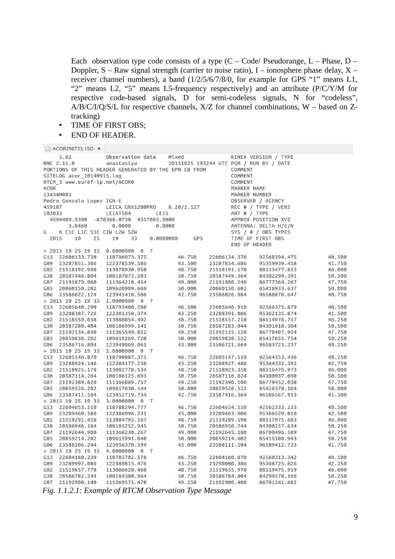
Fig. 1.1.2.1: Example of RTCM Observation Type Message
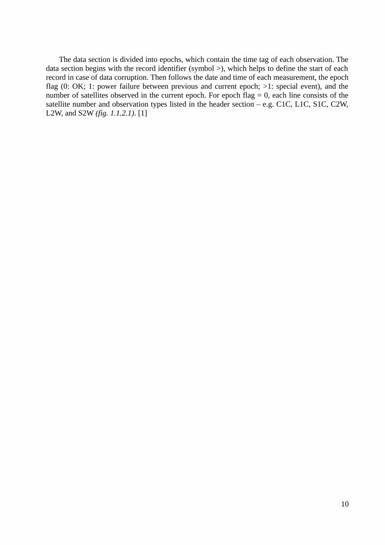
The data section is divided into epochs, which contain the time tag of each observation. Thedata section begins with the record identifier (symbol >), which helps to define the start of eachrecord in case of data corruption. Then follows the date and time of each measurement, the epochflag (0: OK; 1: power failure between previous and current epoch; >1: special event), and thenumber of satellites observed in the current epoch. For epoch flag = 0, each line consists of thesatellite number and observation types listed in the header section – e.g. C1C, L1C, S1C, C2W,L2W, and S2W (fig. 1.1.2.1). [1]
10

1.2 RTCM SC-104 standards
1.2.1 General information
The Radio Technical Commission for Maritime Services (RTCM) was established in 1947 asa US government advisory committee to investigate issues related to maritimetelecommunications. It is now an international non-profit scientific, professional, and educationalorganization, supported by its members all over the world. The RTCM is involved in maritimeradio navigation and radio communication policy issues, regulatory changes, and technicalstandards development for marine electronics – such as Emergency Position Indicating RadioBeacons (EPIRBs), Personal Locator Beacons (PLBs) and Satellite Emergency NotificationDevices (SENDs), Digital Selective Calling (DSC) equipment, Global Navigation SatelliteSystems and various VHF requirements, among other things. The RTCM has more than 130member organizations, both government and non-government, including:
• Manufacturers of radionavigation and radiocommunication systems,
• Government agencies concerned with standards for maritime radionavigation andradiocommunication systems,
• Government agencies and commercial entities involved in operation of maritimeradionavigation and radiocommunication systems,
• Associations with an interest in maritime radionavigation and radiocommunicationsystems and related public policy,
• Ship owners and operators,
• Educational institutions,
• Sales and service providers. [2]
1.2.2 RTCM special committees
The special committees are groups of government and non-government members that worktogether on different tasks specific for each committee. Their goal is to develop technicalstandards and consensus recommendations with regard to issues related to telecommunications. The Special Committees are:
• Special Committee (SC) 101 on Digital Selective Calling (DSC) • Special Committee (SC) 104 on Differential Global Navigation Satellite Systems
(DGNSS) • Special Committee (SC) 109 on Electronic Charting Technology • Special Committee (SC) 110 on Emergency Beacons (EPIRBs and PLBs) • Special Committee (SC) 112 on Ship Radar • Special Committee (SC) 117 on Maritime VHF Interference • Special Committee (SC) 119 on Maritime Survivor Locator Devices • Special Committee (SC) 121 on Automatic Identification Systems (AIS) and Digital
Messaging • Special Committee (SC) 123 on Digital Message Services over Maritime Frequencies • Special Committee (SC) 127 on Enhanced Loran (eLoran) • Special Committee (SC) 128 on Satellite Emergency Notification Devices (SEND)
11
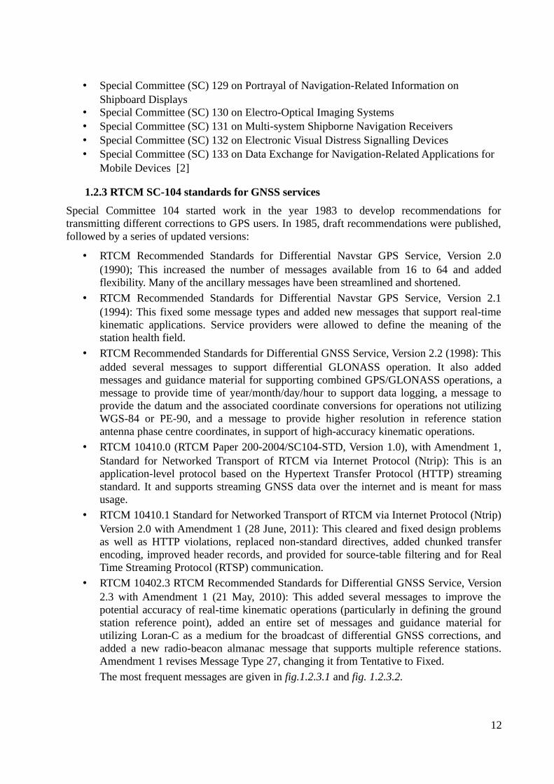
• Special Committee (SC) 129 on Portrayal of Navigation-Related Information on Shipboard Displays
• Special Committee (SC) 130 on Electro-Optical Imaging Systems • Special Committee (SC) 131 on Multi-system Shipborne Navigation Receivers • Special Committee (SC) 132 on Electronic Visual Distress Signalling Devices • Special Committee (SC) 133 on Data Exchange for Navigation-Related Applications for
Mobile Devices [2]
1.2.3 RTCM SC-104 standards for GNSS services
Special Committee 104 started work in the year 1983 to develop recommendations fortransmitting different corrections to GPS users. In 1985, draft recommendations were published,followed by a series of updated versions:
• RTCM Recommended Standards for Differential Navstar GPS Service, Version 2.0(1990); This increased the number of messages available from 16 to 64 and addedflexibility. Many of the ancillary messages have been streamlined and shortened.
• RTCM Recommended Standards for Differential Navstar GPS Service, Version 2.1(1994): This fixed some message types and added new messages that support real-timekinematic applications. Service providers were allowed to define the meaning of thestation health field.
• RTCM Recommended Standards for Differential GNSS Service, Version 2.2 (1998): Thisadded several messages to support differential GLONASS operation. It also addedmessages and guidance material for supporting combined GPS/GLONASS operations, amessage to provide time of year/month/day/hour to support data logging, a message toprovide the datum and the associated coordinate conversions for operations not utilizingWGS-84 or PE-90, and a message to provide higher resolution in reference stationantenna phase centre coordinates, in support of high-accuracy kinematic operations.
• RTCM 10410.0 (RTCM Paper 200-2004/SC104-STD, Version 1.0), with Amendment 1,Standard for Networked Transport of RTCM via Internet Protocol (Ntrip): This is anapplication-level protocol based on the Hypertext Transfer Protocol (HTTP) streamingstandard. It and supports streaming GNSS data over the internet and is meant for massusage.
• RTCM 10410.1 Standard for Networked Transport of RTCM via Internet Protocol (Ntrip)Version 2.0 with Amendment 1 (28 June, 2011): This cleared and fixed design problemsas well as HTTP violations, replaced non-standard directives, added chunked transferencoding, improved header records, and provided for source-table filtering and for RealTime Streaming Protocol (RTSP) communication.
• RTCM 10402.3 RTCM Recommended Standards for Differential GNSS Service, Version2.3 with Amendment 1 (21 May, 2010): This added several messages to improve thepotential accuracy of real-time kinematic operations (particularly in defining the groundstation reference point), added an entire set of messages and guidance material forutilizing Loran-C as a medium for the broadcast of differential GNSS corrections, andadded a new radio-beacon almanac message that supports multiple reference stations.Amendment 1 revises Message Type 27, changing it from Tentative to Fixed.
The most frequent messages are given in fig.1.2.3.1 and fig. 1.2.3.2.
12
• RTCM 10403.2, Differential GNSS (Global Navigation Satellite Systems) Services -Version 3 (1 February, 2013): The main changes are that the parity scheme now usesbandwidth more efficiently, parity is now independent from word to word, the newintegrity of the message is higher, new messages were developed and are still beingdeveloped, and Multiple Signal Messages (MSM) was added, including five amendmentsthat were made in Version 3.1. [2]
13
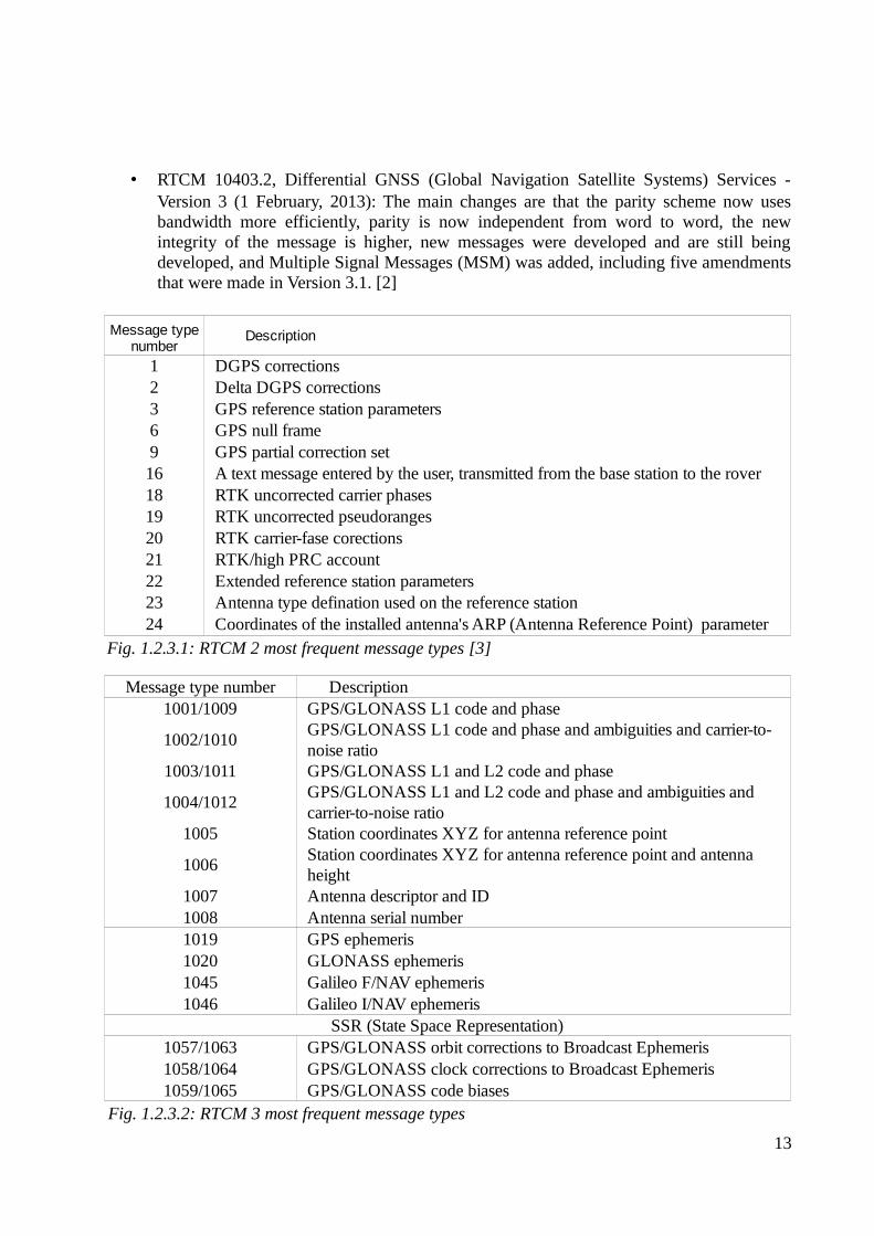
Fig. 1.2.3.1: RTCM 2 most frequent message types [3]
Description
1 DGPS corrections2 Delta DGPS corrections3 GPS reference station parameters6 GPS null frame9 GPS partial correction set16 A text message entered by the user, transmitted from the base station to the rover18 RTK uncorrected carrier phases19 RTK uncorrected pseudoranges20 RTK carrier-fase corections21 RTK/high PRC account22 Extended reference station parameters23 Antenna type defination used on the reference station24 Coordinates of the installed antenna's ARP (Antenna Reference Point) parameter
Message type number
Fig. 1.2.3.2: RTCM 3 most frequent message types
Message type number Description1001/1009 GPS/GLONASS L1 code and phase
1002/1010
1003/1011 GPS/GLONASS L1 and L2 code and phase
1004/1012
1005 Station coordinates XYZ for antenna reference point
1006
1007 Antenna descriptor and ID1008 Antenna serial number 1019 GPS ephemeris1020 GLONASS ephemeris1045 Galileo F/NAV ephemeris1046 Galileo I/NAV ephemeris
SSR (State Space Representation)1057/1063 GPS/GLONASS orbit corrections to Broadcast Ephemeris1058/1064 GPS/GLONASS clock corrections to Broadcast Ephemeris1059/1065 GPS/GLONASS code biases
GPS/GLONASS L1 code and phase and ambiguities and carrier-to-noise ratio
GPS/GLONASS L1 and L2 code and phase and ambiguities and carrier-to-noise ratio
Station coordinates XYZ for antenna reference point and antenna height
1.2.4 Structure of RTCM message type 1
The message type 1 frame length is 30 bits, while the frame height depends on the number ofsatellites visible at the reference station – e.g. if the number of satellites is four, the frame heightis nine words; if the number of satellites is five, then the frame height is 11 words. Every wordends with a 6-bit parity, which is used to check for errors. The sequence of 1 – 24 bits of the first
14
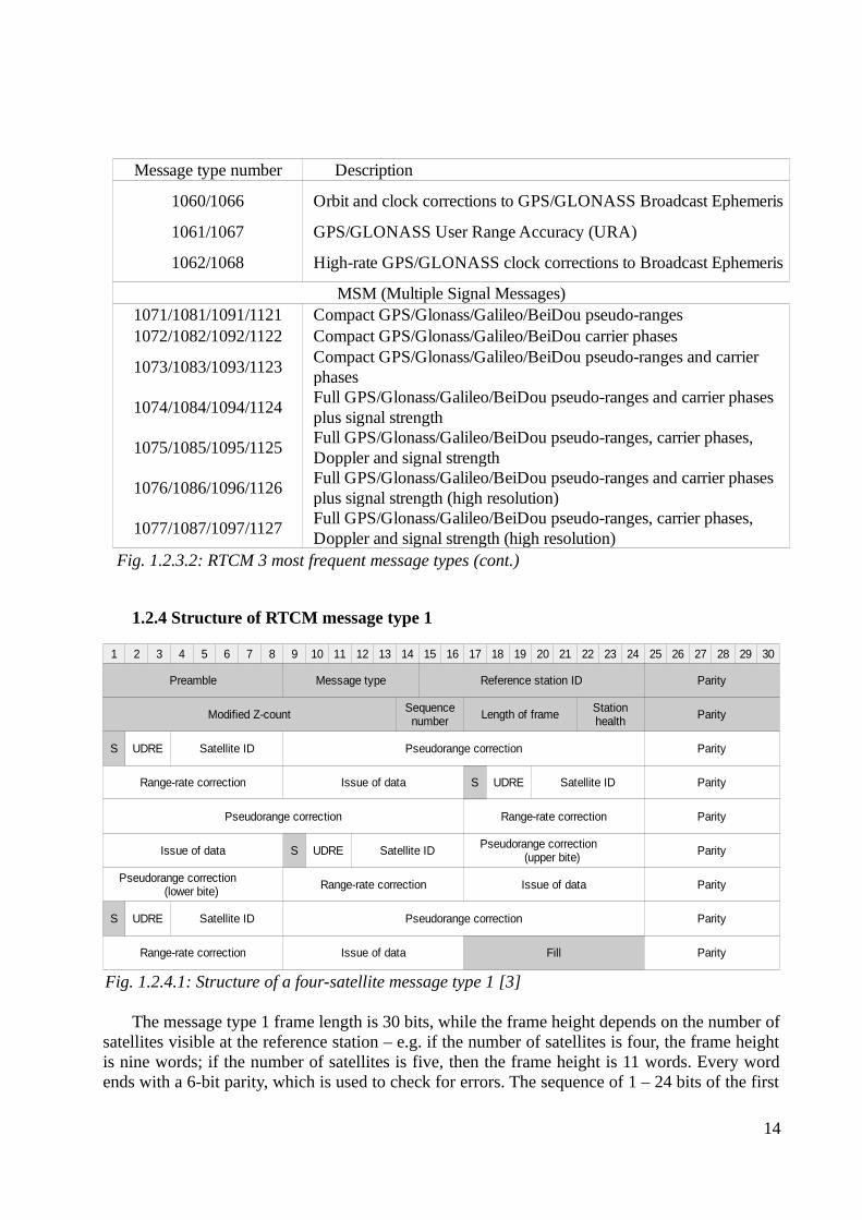
Fig. 1.2.3.2: RTCM 3 most frequent message types (cont.)
Message type number Description
1060/1066 Orbit and clock corrections to GPS/GLONASS Broadcast Ephemeris
1061/1067 GPS/GLONASS User Range Accuracy (URA)
1062/1068 High-rate GPS/GLONASS clock corrections to Broadcast Ephemeris
MSM (Multiple Signal Messages)1071/1081/1091/1121 Compact GPS/Glonass/Galileo/BeiDou pseudo-ranges1072/1082/1092/1122 Compact GPS/Glonass/Galileo/BeiDou carrier phases
1073/1083/1093/1123
1074/1084/1094/1124
1075/1085/1095/1125
1076/1086/1096/1126
1077/1087/1097/1127
Compact GPS/Glonass/Galileo/BeiDou pseudo-ranges and carrier phasesFull GPS/Glonass/Galileo/BeiDou pseudo-ranges and carrier phases plus signal strengthFull GPS/Glonass/Galileo/BeiDou pseudo-ranges, carrier phases, Doppler and signal strengthFull GPS/Glonass/Galileo/BeiDou pseudo-ranges and carrier phases plus signal strength (high resolution)Full GPS/Glonass/Galileo/BeiDou pseudo-ranges, carrier phases, Doppler and signal strength (high resolution)
Fig. 1.2.4.1: Structure of a four-satellite message type 1 [3]
1 2 3 4 5 6 7 8 9 10 11 12 13 14 15 16 17 18 19 20 21 22 23 24 25 26 27 28 29 30
Preamble Message type Reference station ID Parity
Modified Z-count Length of frame Parity
S UDRE Satellite ID Pseudorange correction Parity
Range-rate correction Issue of data S UDRE Satellite ID Parity
Pseudorange correction Range-rate correction Parity
Issue of data S UDRE Satellite ID Parity
Range-rate correction Issue of data Parity
S UDRE Satellite ID Pseudorange correction Parity
Range-rate correction Issue of data Fill Parity
Sequence number
Station health
Pseudorange correction (upper bite)
Pseudorange correction (lower bite)
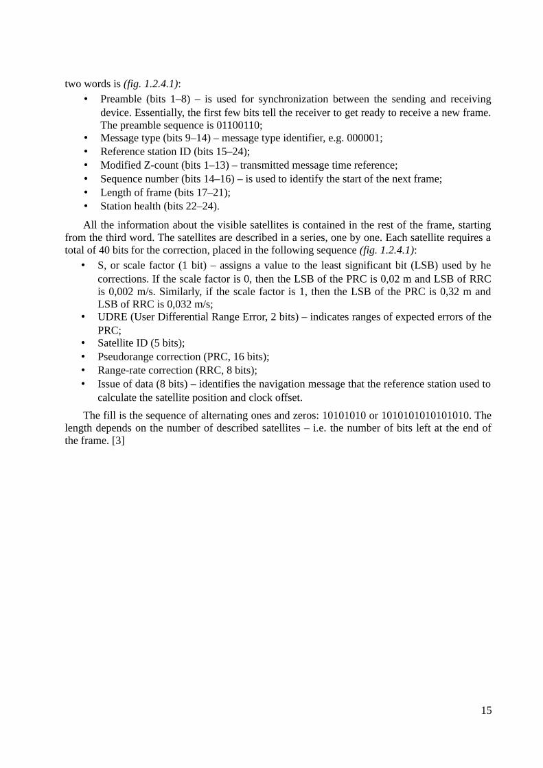
two words is (fig. 1.2.4.1):
• Preamble (bits 1–8) – is used for synchronization between the sending and receivingdevice. Essentially, the first few bits tell the receiver to get ready to receive a new frame.The preamble sequence is 01100110;
• Message type (bits 9–14) – message type identifier, e.g. 000001;• Reference station ID (bits 15–24);• Modified Z-count (bits 1–13) – transmitted message time reference;• Sequence number (bits 14–16) – is used to identify the start of the next frame;• Length of frame (bits 17–21);• Station health (bits 22–24).
All the information about the visible satellites is contained in the rest of the frame, startingfrom the third word. The satellites are described in a series, one by one. Each satellite requires atotal of 40 bits for the correction, placed in the following sequence (fig. 1.2.4.1):
• S, or scale factor (1 bit) – assigns a value to the least significant bit (LSB) used by hecorrections. If the scale factor is 0, then the LSB of the PRC is 0,02 m and LSB of RRCis 0,002 m/s. Similarly, if the scale factor is 1, then the LSB of the PRC is 0,32 m andLSB of RRC is 0,032 m/s;
• UDRE (User Differential Range Error, 2 bits) – indicates ranges of expected errors of thePRC;
• Satellite ID (5 bits);• Pseudorange correction (PRC, 16 bits);• Range-rate correction (RRC, 8 bits);• Issue of data (8 bits) – identifies the navigation message that the reference station used to
calculate the satellite position and clock offset.
The fill is the sequence of alternating ones and zeros: 10101010 or 1010101010101010. Thelength depends on the number of described satellites – i.e. the number of bits left at the end ofthe frame. [3]
15
1.3 NTRIP protocol
1.3.1 Introduction
Nowadays standalone GPS receivers typically detect positions with an error of 10–15metres, which may be a very low accuracy for some applications. In such situations, whenaccuracy of no more than an error of one meter is required, a Differential Global NavigationSatellite System (DGNSS) is used. A DGNSS reaches this high accuracy by providing correctiondata from one or more (if the distance between a user and reference station is large enough)reference stations.
There are about 15 current technical standards developed by the RTCM Special Committees(SC). The RTCM-104 DGNSS standard is used around the world for differential satellitenavigation systems, both maritime and terrestrial, and it accepts differential correction messagesand RTK messages. The messages under the RTCM-104 DGNSS standard are transmitted overcommunication links – e.g. via radio transmission, or via a mobile communication network. TheNtrip protocol (Network Transport of RTCM via Internet Protocol) is based on HTTP and itsmessages are broadcast to stationary or mobile receivers over the Internet. [4]
1.3.2. General information
The Ntrip System is based on the HTTP streaming standard. HTTP was originally designedfor bulk traffic, but it is also used for IP streaming applications, like the RTCM application. Themajor purpose of the Ntrip System is making the RTCM corrections (or other types of GNSSstreaming data) available in real-time for mobile users.
Ntrip is meant to be an open non-proprietary protocol. Here are some major characteristicsof the Ntrip System:
• Ntrip is an application-level protocol that supports streaming any kind of GNSS data over
16
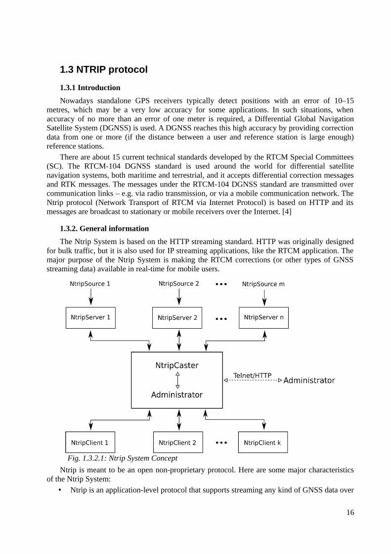
Fig. 1.3.2.1: Ntrip System Concept
the internet;• It is based on the HTTP streaming standard;• Ntrip supports wireless internet access through any mobile IP networks (like GSM,
GPRS, EDGE, or UMTS) because it uses TCP/IP;• The system is meant for mass usage;• Regarding security needs, stream providers and users are not necessarily in direct contact,
and streams are usually not blocked by firewalls or proxy servers protecting local areanetworks;
• The Ntrip software components are NtripSources, which provide data streams,NtripServers, which transfer the data streams from an NtripSource to the NtripCaster,NtripCaster, which is the administrator, the major system component, and NtripClients,which receive the data streams of the desired NtripSources (fig. 1.3.2.1). [4]
1.3.3. NtripSource
NtripSources are devices that generate GNSS streaming data at specific locations. This datais then sent by NtripServers to the NtripCaster, which is the main system component.NtripServers define an NtripSource ID called 'mountpoint', which must be unique for everysingle NtripSource. It is recommended to use a four-character ID, followed by an integer value(e.g. BUCU0 for Bucharest), as a mountpoint name. According to the data provided by theNtripSource, a source-table is created, which includes information about the mountpoint ID, theformat in use (e.g. RTCM 2.3, RTCM 3.2, CMR, RAW), the recognized navigation system (e.g.GPS, GPS+GLONASS), location coordinates (country, latitude, longitude), and other details. [5]
1.3.4. NtripServer
The NtripServer is designed to be a server for a single NtripSource. It is used to transfer theGNSS data of an NtripSource (the NtripServer grabs a serial GNSS byte stream via a COM-port)to the NtripCaster, using the TCP/IP connection.
1.3.5. NtripServer on Windows
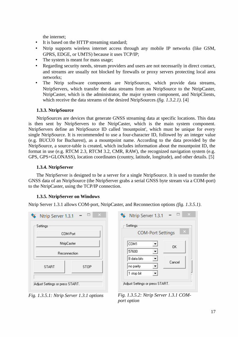
Ntrip Server 1.3.1 allows COM-port, NtripCaster, and Reconnection options (fig. 1.3.5.1).
17
Fig. 1.3.5.2: Ntrip Server 1.3.1 COM-port option
Fig. 1.3.5.1: Ntrip Server 1.3.1 options
When configuring the COM-port (fig. 1.3.5.2), you will have to choose the port name, abaud rate (using a high baud rate is recommended – e.g. 57600), the number of data bits forserial input (usually 8), parity, and the number of stop bits for serial input (usually 1).
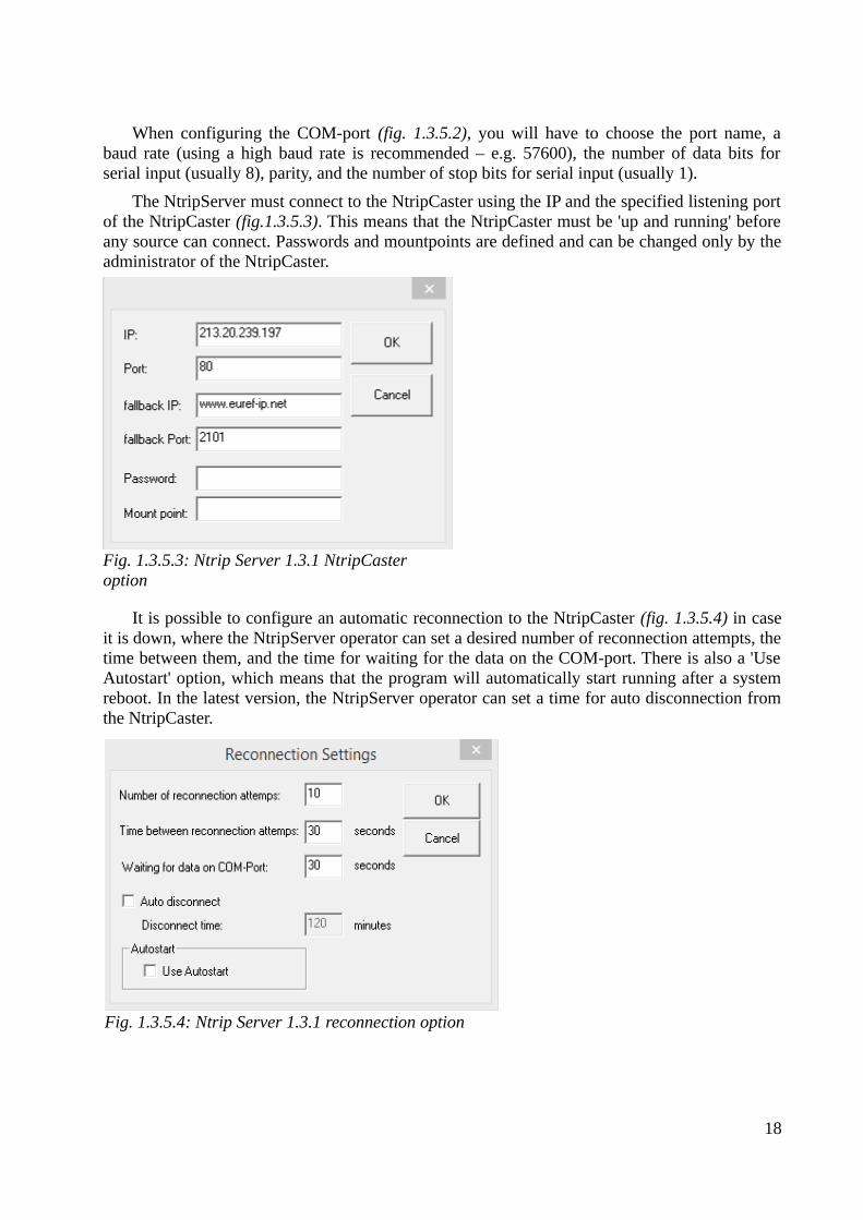
The NtripServer must connect to the NtripCaster using the IP and the specified listening portof the NtripCaster (fig.1.3.5.3). This means that the NtripCaster must be 'up and running' beforeany source can connect. Passwords and mountpoints are defined and can be changed only by theadministrator of the NtripCaster.
It is possible to configure an automatic reconnection to the NtripCaster (fig. 1.3.5.4) in caseit is down, where the NtripServer operator can set a desired number of reconnection attempts, thetime between them, and the time for waiting for the data on the COM-port. There is also a 'UseAutostart' option, which means that the program will automatically start running after a systemreboot. In the latest version, the NtripServer operator can set a time for auto disconnection fromthe NtripCaster.
18
Fig. 1.3.5.3: Ntrip Server 1.3.1 NtripCaster option
Fig. 1.3.5.4: Ntrip Server 1.3.1 reconnection option
1.3.6. NtripCaster
The NtripCaster, as the main system component, works as a server accepting requestmessages on a single port from both the NtripServer and the NtripClient, and deciding whetherto receive or send the incoming information. The NtripCaster administrator is responsible forhandling mountpoints for NtripSources, passwords, NtripClient access rights, billing, statistics,and so on.
The NtripCaster is based on the Icecast software, which is a streaming media serverdeveloped under GNU GPL (General Public License). Its purpose is to duplicate the incomingdata for a large number of clients accessing the desired mountpoints. The Icecast server iscapable of streaming audio content as Opus or Vorbis over standard HTTP, video as WebM orTheora over HTTP, MP3 over the communications protocol used by SHOUTcast, and AAC(Advanced Audio Coding) and NSV (Nullsoft Streaming Video) over the SHOUTcast protocol(Theora, AAC, and NSV are only supported in version 2.2.0 and newer). The NtripCaster (withabout 0.5 to 10 Kbit/s transmission rate) is a re-designed Icecast, which, unlike the Icecast,supports the GNSS data streams like:
• RTCM corrections, DGNSS, • RTCM corrections, RTK, • RTCA corrections, EGNOS & WAAS, • RAW data, • SP3 ultra-rapid orbits, • RINEX observations.
There are two different NtripCaster versions – a standard and a professional version – bothof which use the same principle. The professional version, unlike the standard version,guarantees a larger amount of simultaneous connections and is meant for mass usage. [5]
1.3.7. NtripClient
To start the session the NtripClient software must send the correct request message. Thatmeans the NtripClient operator needs to choose the desired Caster host, Caster port, and NTRIPversion, then enter username and password, and download the source-table, where he will selectthe desired mountpoints. It is possible for several NtripClients to access the data of a desiredNtripSource at the same time. [5]
19
1.4. NMEA protocol
1.4.1. General information
The NMEA protocol was developed by the National Marine Electronics Association. Itdefines the interface shared by various pieces of marine electronic equipment. This NMEAprotocol describes not only the data taken from GPS receivers, but also metering taken fromsonars, radars, electronic compasses, barometers and other marine navigation equipment. Themajority of navigation programs representing data in real time understand and support theNMEA protocol. This data includes the complete PVT: position, velocity, and time. [6]
1.4.2. NMEA message structure
Each NMEA message is complete and doesn't depend on other messages. It begins with '$'and ends with '\n' (next sentence), and can be no longer than 80 symbols. The data there isdivided by commas. The message includes the headline, the body, and the checksum field. The headline consists of five symbols. The first two letters define the device that uses thatsentence type (for all GPS NMEA messages the prefix is GP), while the last three letters definethe sentence name. The messages not described in the NMEA specification, but realized in GPSreceivers according to general rules have the prefix P, followed by the company's three uniquesymbols (NMEA Garmin message has the prefix PGRM, Magellan has PMGL).
The body contains information that is written in ASCII code and it does not need anydecryption. If there is not enough place for the whole data, then it will be divided into severalmessages.
The checksum field is at the end of every NMEA message, separated from the data by ' ',followed by a two-digit hexadecimal number. The checksum is the bitwise XOR of ASCII codesof all characters between the '$' and ' '. This field is required on some sentences forcompleteness control. [6]
1.4.3. NMEA message types
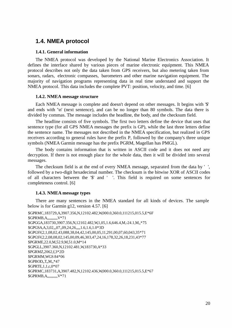
There are many sentences in the NMEA standard for all kinds of devices. The samplebelow is for Garmin g12, version 4.57. [6]
20
$GPRMC,183729,A,3907.356,N,12102.482,W,000.0,360.0,111215,015.5,E*6F$GPRMB,A,,,,,,,,,,,,V*71$GPGGA,183730,3907.356,N,12102.482,W,1,05,1.6,646.4,M,-24.1,M,,*75$GPGSA,A,3,02,,,07,,09,24,26,,,,,1.6,1.6,1.0*3D$GPGSV,2,1,08,02,43,088,38,04,42,145,00,05,11,291,00,07,60,043,35*71$GPGSV,2,2,08,08,02,145,00,09,46,303,47,24,16,178,32,26,18,231,43*77$PGRME,22.0,M,52.9,M,51.0,M*14$GPGLL,3907.360,N,12102.481,W,183730,A*33$PGRMZ,2062,f,3*2D$PGRMM,WGS 84*06$GPBOD,,T,,M,,*47$GPRTE,1,1,c,0*07$GPRMC,183731,A,3907.482,N,12102.436,W,000.0,360.0,111215,015.5,E*67$GPRMB,A,,,,,,,,,,,,V*71
The messages here are updated every two seconds. If we change the bit rate from 4800 kbit/s to9600 kbit/s, the messages will be updated every second.
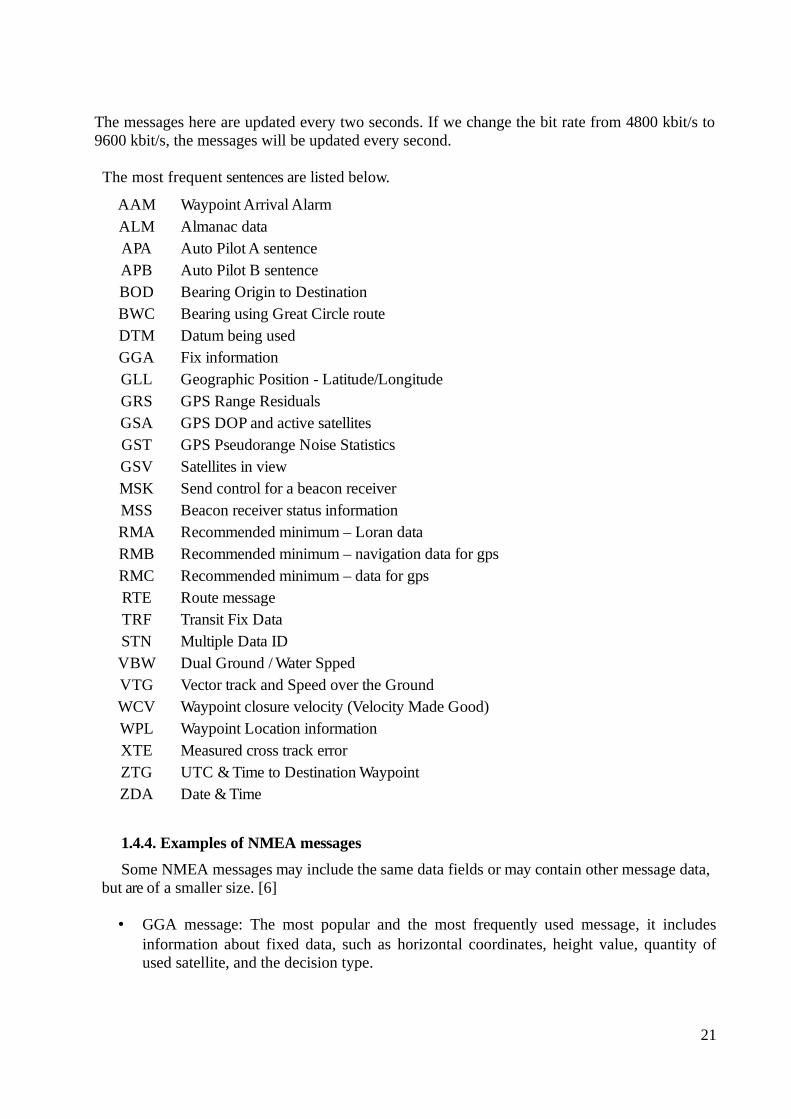
The most frequent sentences are listed below.
1.4.4. Examples of NMEA messages
Some NMEA messages may include the same data fields or may contain other message data,but are of a smaller size. [6]
• GGA message: The most popular and the most frequently used message, it includesinformation about fixed data, such as horizontal coordinates, height value, quantity ofused satellite, and the decision type.
21
AAM Waypoint Arrival AlarmALM Almanac dataAPA Auto Pilot A sentenceAPB Auto Pilot B sentenceBOD Bearing Origin to DestinationBWC Bearing using Great Circle routeDTM Datum being usedGGA Fix informationGLL Geographic Position - Latitude/LongitudeGRS GPS Range ResidualsGSA GPS DOP and active satellitesGST GPS Pseudorange Noise StatisticsGSV Satellites in viewMSK Send control for a beacon receiverMSS Beacon receiver status informationRMA Recommended minimum – Loran dataRMB Recommended minimum – navigation data for gpsRMC Recommended minimum – data for gpsRTE Route messageTRF Transit Fix Data STN Multiple Data IDVBW Dual Ground / Water SppedVTG Vector track and Speed over the GroundWCV Waypoint closure velocity (Velocity Made Good)WPL Waypoint Location information XTE Measured cross track error ZTG UTC & Time to Destination WaypointZDA Date & Time
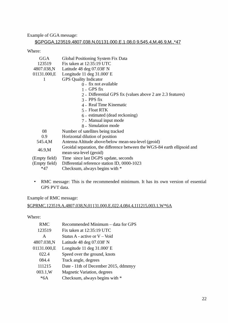
Example of GGA message:
$GPGGA,123519,4807.038,N,01131.000,E,1,08,0.9,545.4,M,46.9,M,,*47
Where:
• RMC message: This is the recommended minimum. It has its own version of essentialGPS PVT data.
Example of RMC message:
$GPRMC,123519,A,4807.038,N,01131.000,E,022.4,084.4,111215,003.1,W *6A
Where:
22
GGA Global Positioning System Fix Data123519 Fix taken at 12:35:19 UTC
4807.038,N Latitude 48 deg 07.038' N01131.000,E Longitude 11 deg 31.000' E
1 GPS Quality Indicator0 - fix not available1 - GPS fix2 - Differential GPS fix (values above 2 are 2.3 features)3 - PPS fix 4 - Real Time Kinematic 5 - Float RTK 6 - estimated (dead reckoning) 7 - Manual input mode 8 - Simulation mode
08 Number of satellites being tracked0.9 Horizontal dilution of position
545.4,M Antenna Altitude above/below mean-sea-level (geoid)
46.9,M
(Empty field) Time since last DGPS update, seconds(Empty field) Differential reference station ID, 0000-1023
*47 Checksum, always begins with *
Geoidal separation, the difference between the WGS-84 earth ellipsoid and mean-sea-level (geoid)
RMC Recommended Minimum – data for GPS123519 Fix taken at 12:35:19 UTC
A Status A - active or V – Void4807.038,N Latitude 48 deg 07.038' N01131.000,E Longitude 11 deg 31.000' E
022.4 Speed over the ground, knots084.4 Track angle, degrees
111215 Date - 11th of December 2015, ddmmyy003.1,W Magnetic Variation, degrees
*6A Checksum, always begins with *
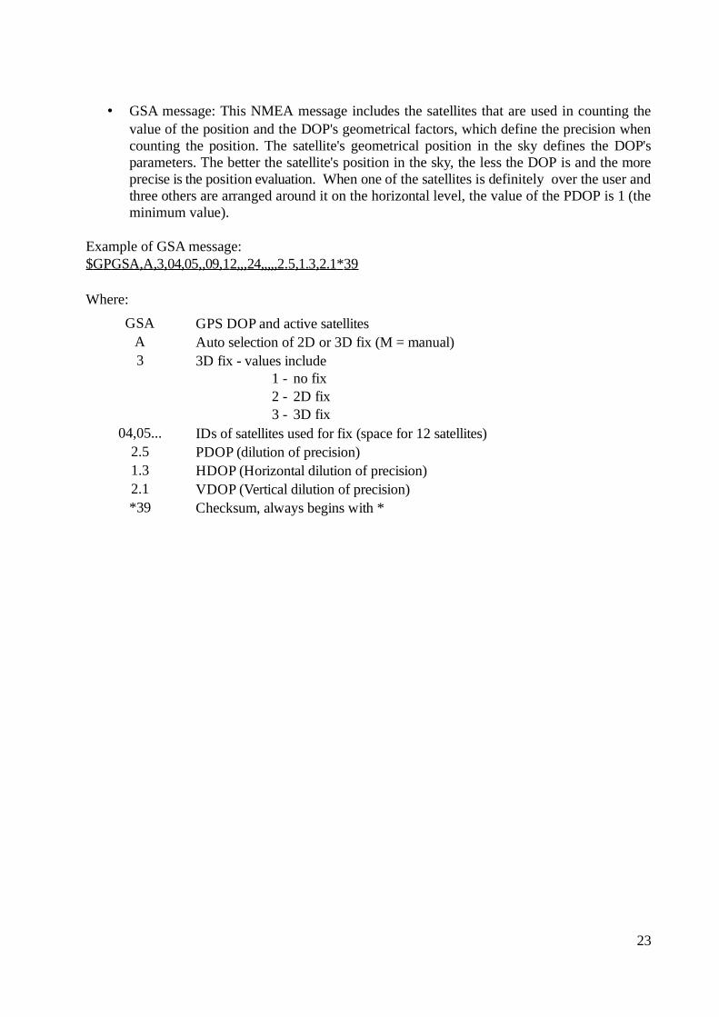
• GSA message: This NMEA message includes the satellites that are used in counting thevalue of the position and the DOP's geometrical factors, which define the precision whencounting the position. The satellite's geometrical position in the sky defines the DOP'sparameters. The better the satellite's position in the sky, the less the DOP is and the moreprecise is the position evaluation. When one of the satellites is definitely over the user andthree others are arranged around it on the horizontal level, the value of the PDOP is 1 (theminimum value).
Example of GSA message:$GPGSA,A,3,04,05,,09,12,,,24,,,,,2.5,1.3,2.1*39
Where:
23
GSA GPS DOP and active satellitesA Auto selection of 2D or 3D fix (M = manual) 3 3D fix - values include
1 - no fix2 - 2D fix3 - 3D fix
04,05... IDs of satellites used for fix (space for 12 satellites)2.5 PDOP (dilution of precision)1.3 HDOP (Horizontal dilution of precision) 2.1 VDOP (Vertical dilution of precision)*39 Checksum, always begins with *
2. Types of errors in GPS
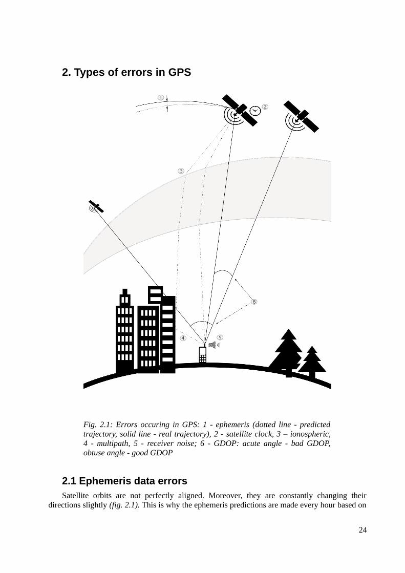
2.1 Ephemeris data errorsSatellite orbits are not perfectly aligned. Moreover, they are constantly changing their
directions slightly (fig. 2.1). This is why the ephemeris predictions are made every hour based on
24
Fig. 2.1: Errors occuring in GPS: 1 - ephemeris (dotted line - predictedtrajectory, solid line - real trajectory), 2 - satellite clock, 3 – ionospheric,4 - multipath, 5 - receiver noise; 6 - GDOP: acute angle - bad GDOP,obtuse angle - good GDOP

actual observed positions from the past four-hour period given by Jet Propulsion Laboratory,USA. The reasons for such constantly changing orbits are a very complicated gravitationalmodel, and the effect of such forces as solar radiation pressure and atmospheric drag. Althoughthe ephemeris error for a particular satellite is the same for any GPS user using it, the error has adifferent impact on positioning errors depending on an actual receiver position due to differentview angles.
2.2 Satellite clock errorsEvery satellite has a very precise atomic clock installed but it cannot be perfectly precise,
which is an essential parameter for accurate GPS positioning. Errors can appear even in this kindof clock and every microsecond of this error can lead to a positioning error of 300 metres. Theequation below shows how it is calculated:
lec=εc∗c [m; s, m/s]
where lec is the pseudorange calculation error depending on satellite clock error only, εc is thesatellite clock error, and c the velocity of light 3*108 m/s.
Satellite system time will almost never be exactly the same as GPS system time. Thismistiming is predicted to a limited extent using the calculated parameters a0, a1, a2, which aretransmitted as part of a navigation file to help a receiver reduce the error. After automaticcorrection is completed, the positioning is made using the TGPS parameter:
TGPS=t s−εc [s; s, s]
where TGPS is the corrected GPS time of transmission, ts the satellite time of transmission, and εc
the satellite clock error.
The parts of the equation above are calculated in the following way:
t s=t rr−lc
[s; s, m, m/s]
where ts is the satellite time of transmission, trr the signal reception time at receiver, l thepseudorange, and c the velocity of light 3*108 m/s;
εc=a0+a1∗dt+a2∗dt 2 [s; s, s/s, s, s/(s*s), s]
where εc is the satellite clock error, a0 the clock bias, a1 the clock drift, a2 the frequency drift, anddt the satellite clock offset;
dt=t s−t sr [s; s, s]
where dt is the satellite clock offset, ts the satellite time of transmission, and tsr the time ofsatellite receiving request. [7]
2.3 Atmospheric errorsThe signal from a satellite does not only travel through vacuum but also through the
atmosphere, which can be divided into two layers – the ionosphere and the troposphere.
The ionosphere represents the layer consisting of rarefied gas that, due to interactions withultraviolet and X-ray radiations coming from the sun, is becoming ionized – i.e. electrons areseparated from atoms, leaving free negatively charged electrons and positively charged atomcores. Since this electron separation needs energy, the said energy is taken from solar radiation,gradually weakening it; therefore, different ionosphere sub-layers can be distinguished.
This kind of environment has a different refraction coefficient than that of vacuum. So, thesignal trajectory inside the ionosphere layer can have slight random instabilities but the error it
25
gives is negligibly small. Besides, its trajectory is refracted into a slightly different angle over theborder between two environments (fig. 2.1), but it only makes a notable difference, whereas asatellite is lower than five degrees over horizon. The greatest impact on signal passage throughthe ionosphere is due to change in the velocity of light. The total ionospheric delay is highlydependent on a number of free electrons along the signal's path, which is called the total electroncontent (TEC). TEC is affected by a variety of parameters, such as time of day, time of year,point in 11-year solar cycle, and geographic location. TEC has its maximum at the poles andaround the equator, at midday or during increased solar activity with peak ionospheric delay over150 metres, whereas under normal conditions it is in the order of 10 metres.
Since the ionosphere delay depends on carrier frequency, different ways to combine the L1and L2 carriers can be used to eliminate or at least reduce it. Users with single-frequencyreceivers – in the absence of the ability to make their own dual-frequency corrections – can useany one of the empirical ionospheric models, such as the Klobuchar model, coefficients of whichcan be found in the navigation message, or they can receive pre-calculated corrections from theclosest reference station.
Unlike the ionosphere, the troposphere is a non-dispersive medium for frequencies used inGPS. This means that the signal velocity will be the same for every code or carrier frequency. Asa result, it is impossible to compensate for troposphere delay by combining the L1 and L2observations. Meanwhile, a delay depends on temperature and pressure – together called thedelay's dry component – and humidity – i.e. the wet component. About 90 per cent of thetropospheric delay consists of the dry component, which can be accurately predicted usingmathematical models. The remaining 10 per cent – the wet component – is not easy to predict.The delay also greatly depends on the satellite's elevation angle, from about two metres at thezenith to 20–30 metres at five degrees over the horizon. [3]
2.4 Multipath errorsMultipath error is an error caused by the fact that the signal from the satellite not only travels
straight to the antenna but also can be reflected off some surfaces, such as water or buildings(fig. 2.1). In this case, the reflected signal takes more time to be caught by the antenna than thedirect signal. Therefore, they overlap with each other, making it harder to distinguish actualpseudorange or carrier-phase. The easiest and most obvious way to get rid of this error is to use aplace without any reflective objects around. If this is not an option, then a user may use somespecial antennas, such as a chock ring antenna (a ground plane that has several concentric metalhoops to attenuate the reflected signals) or an antenna with the same polarization as the GPSsignal (the GPS signal has right-handed circular polarization while reflected signals have left-handed polarization). But it will not work in case the signal reflects twice or an even number oftimes because the polarization will again become right-handed.
2.5 Receiver errorsAny GPS receiver would have some level of internal noise (fig. 2.1). Obviously, the lower
the noise is, the better the positioning accuracy is. In order to evaluate the noise level for specificreceiver, two tests can be performed: zero baseline and short baseline test. Zero baseline testconsists of position measure through one antenna and two or more GPS receivers. As oneantenna is used, any difference between receivers' positioning is only created by receiver noise,which is inconvenient in the way, that the antenna noise would not be measured. In order to alsomeasure antenna noise, short baseline test is performed. It means the position measure over twoconsecutive days with antenna being moved for a couple of metres for the second day. After this
26
much time almost every error would cancel out, leaving only the system noise and multipatherror, which can be eliminated by differencing the first and second day's measures. [3]
2.6 Satellite geometryThe positioning accuracy is not only decreased by errors affecting the signal, but also by
possible bad satellite geometry (fig. 2.1). A bad satellite geometry means, that the satellites areplaced on a narrow viewing angle so that the uncertainty region is elongated and occupying arelatively large area instead of being square with smaller area. The named uncertainty regionrepresents the area closed between major and minor radii corresponding to the estimateddistance. In general, the best GDOP occurs while the satellites used are 90° apart as seen fromreceiver. Geometric dilution of precision (GDOP) is divided into several components, which aretime dilution of precision (TDOP) and position dilution of precision (PDOP), which in its turn iddivided into horizontal dilution of precision (HDOP) and vertical dilution of precision (VDOP).The smaller GDOP is, the better accuracy is obtained: an excellent level of GDOP coefficient isup to 2, a good level is up to 5 and is not recommended when it is more than 5. [3]
2.7. DGPS correction of individual kinds of errorsSince satellite errors are fully common for reference stations and rover receivers, they can be
completely corrected by DGPS. Ionospheric errors depend on receiver's location, so in case thatthe reference station used is placed within a distance of cca. a hundred kilometres, it can also beassumed, that the errors are corrected completely but it is not true in case of reference stationlocated significantly further. However, multipath errors and receiver noise are unique to everyspecific receive, so DGPS can not compensate for these effects. This is why in order to acquirethe most accurate position possible, a user not only has to use DGPS corrections, but also to picka place that would not create much of signal reflection and to use more precise hardware.
27
3. Correction methods distinguished by evaluation speedThe GPS signal from a satellite goes through numerous interferences that cause different
errors, such as ephemeris data errors, satellite clock errors, ionosphere and troposphere errors,multipath errors, and receiver errors, as discussed in Chapter 2. It is important to take theseerrors into account because any of them can lead to an enormous mistake of a couple kilometresaway from an actual point. To bring these errors down to more reasonable levels or to avoid themcompletely, correction methods are used. This works much more efficiently if the user is close tothe reference station. Then the corrections needed for them both are not too different and the usercan receive them almost immediately.
3.1 Real-time and postprocessing methods Two basic ways of realizing correction methods are identified: a real-time method when datais corrected in real time and a method of better accuracy, which is called postprocessing DGPSwhen data is corrected afterwards. The main difference is that real-time corrections only consistof predicted data calculated using corrections from a few seconds before, while postprocessingmeasurements are also collected at a later time to achieve the best accuracy. This difference willbe explained in detail in the picture below.
Real-time DGPS is used when the speed of obtaining the results is important – e.g. when arover receiver is moving. This is why corrections must not have latency in them. To meet thiscondition, corrections are sent by the reference station some seconds before they are measured soas to compensate the time used to send, and then receive and calculate the corrections on theother side. This means they are only predictions based on the last measured corrections.
Postprocessing is a more complex process than the real-time differential correction method.It is based on sending raw GPS rover data to the central server with operational postprocessingsoftware where the sent data is corrected using raw GPS base data and its known position.Postprocessing techniques are used in case a user does not need to know his positionimmediately but is able to wait for the server to collect base data taken after the rover positioningtime, to calculate the corrections and send them back. The algorithm used in this postprocessingsoftware is expected to be very precise, and, therefore, relatively complex and powerful, which isthe second reason for better postprocessing accuracy.
3.2 Example in detailFig. 3.2.1 shows a simplified example of the working order of real-time and postprocessing
methods. Please note that the example does not represent exactly how these systems work but isjust a schematic illustration of the difference between their main principles of operation.
The reference station (8;2) receives its own GPS position every two seconds (fig. 3.2.1 -marks 0s, 2s, and 4s, placed at (2;1), (3;6), and (10;7) respectively). A vector from the referencestation to a mark is an error vector – i.e. the difference between the received and the real GPSposition – while the reverse vector is the correction vector. The rover receiver obtains its GPSposition at the moment of 3s and, at the same time, requests for a correction.
As mentioned earlier, the real-time method is based on correction predictions, or the datacalculated by the reference station using the last acquired real marks. In the example, only twomarks are obtained (0s, 2s) before the moment of 3s. So, the correction trajectory from 2s to 4s(4;11) is predicted based on marks 0s and 2s, and then is sent to the rover receiver where therequired point on this trajectory is calculated. In the figure, the prediction trajectory and the
28
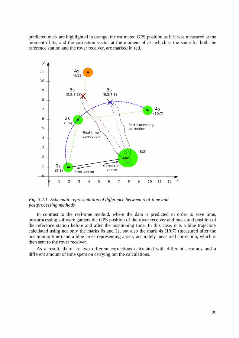
predicted mark are highlighted in orange; the estimated GPS position as if it was measured at themoment of 3s, and the correction vector at the moment of 3s, which is the same for both thereference station and the rover receiver, are marked in red.
In contrast to the real-time method, where the data is predicted in order to save time,postprocessing software gathers the GPS position of the rover receiver and measured position ofthe reference station before and after the positioning time. In this case, it is a blue trajectorycalculated using not only the marks 0s and 2s, but also the mark 4s (10;7) (measured after thepositioning time) and a blue cross representing a very accurately measured correction, which isthen sent to the rover receiver.
As a result, there are two different corrections calculated with different accuracy and adifferent amount of time spent on carrying out the calculations.
29
Fig. 3.2.1: Schematic representation of difference between real-time and postprocessing methods
0s (2;1)
2s (3;6)
4s (4;11)
3s (3,5;8,5)
3s (6,2;7,8)
4s (10;7)
Error vector
Correction vector
Postprocessing correction
Real-time correction
1 2 3 4 5 6 7 8 9 10 11 120
0
1
2
3
4
5
6
7
8
9
10
11
x
y
(8;2)
4. Correction transfer methodsThere have been developed two main augmentation systems for positioning accuracy
improvement: the satellite based augmentation system (SBAS) and the ground basedaugmentation system (GBAS). Both of them calculate corrections by means of reference stationsand their precisely known positions. Reference stations analyze the condition of satellites andionosphere and then transfer calculated corrections to the receivers. The main difference betweenthese two systems is that SBAS system transfer their corrections through geostationary satelliteswhile GBAS system - straight to the rover receivers using radio- or mobile-networks.
4.1 SBASSBAS comprises a number of services, the first of which, Wide Area Augmentation System
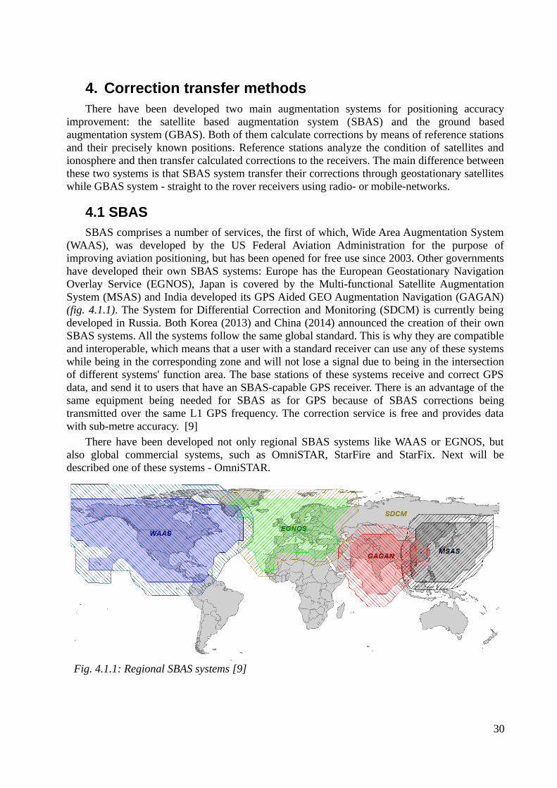
(WAAS), was developed by the US Federal Aviation Administration for the purpose ofimproving aviation positioning, but has been opened for free use since 2003. Other governmentshave developed their own SBAS systems: Europe has the European Geostationary NavigationOverlay Service (EGNOS), Japan is covered by the Multi-functional Satellite AugmentationSystem (MSAS) and India developed its GPS Aided GEO Augmentation Navigation (GAGAN)(fig. 4.1.1). The System for Differential Correction and Monitoring (SDCM) is currently beingdeveloped in Russia. Both Korea (2013) and China (2014) announced the creation of their ownSBAS systems. All the systems follow the same global standard. This is why they are compatibleand interoperable, which means that a user with a standard receiver can use any of these systemswhile being in the corresponding zone and will not lose a signal due to being in the intersectionof different systems' function area. The base stations of these systems receive and correct GPSdata, and send it to users that have an SBAS-capable GPS receiver. There is an advantage of thesame equipment being needed for SBAS as for GPS because of SBAS corrections beingtransmitted over the same L1 GPS frequency. The correction service is free and provides datawith sub-metre accuracy. [9]
There have been developed not only regional SBAS systems like WAAS or EGNOS, butalso global commercial systems, such as OmniSTAR, StarFire and StarFix. Next will bedescribed one of these systems - OmniSTAR.
30
Fig. 4.1.1: Regional SBAS systems [9]
4.1.1 OmniSTAR
OmniSTAR is a commercial SBAS system that is available wirelessly through satellite andmobile phone technologies. It offers real-time DGPS services of different kinds, depending onspecific region, time of correction acquisition, and desired accuracy. The level of desiredaccuracy can range from a radius of a sub-metre to a few metres when a quick start-up time isdesired or even to 5 cm accuracy, with full accuracy available within 45 minutes. The systemimproves and facilitates railway and aviation operations by providing appropriate companieswith the software needed to monitor the accurate position of railway trains and aircraftsrespectively. In agriculture, position corrections provided by OmniSTAR can be of help inapplications like farm mapping and farm machinery movement, especially in case of automatedsystems when planting, seeding, spraying, harvesting, and so on. In mining, it can be used in datacollection for tenement pegging, drilling boreholes, identification surveys, and soil sampling. Inmapping and GIS, it helps with the acquisition of data needed to make any kind of map,including boundary, irrigation, landscape, and agriculture and forestry condition surveys, mapsof resources, utilities, cables, pipelines, and so on.
OmniSTAR has reference stations all over the world. It has offices in USA Texas 77063 forNorth, Central, and South America and the Caribbean, in Australia WA 6021 for a zonestretching from India and China to Australia, the Netherlands Leidschendam 2266 KA forEurope, Middle East, Russia, and CIS, and in South Africa 7925 Cape Town for Africa.OmniSTAR reference stations send a corrected GPS position to a stationary OmniSTAR satellitewhich then sends those signals on both single-frequency (L1 only) code phase pseudo-rangesolutions and dual-frequency (L1/L2) carrier phase solutions to roving GPS receivers. [10]
4.2 GBASGBAS system contains three operational segments: the Space Segment, the Ground Segment
and the Aircraft (or User) Segment. The most distinctive is the Ground Segment, which in itsturn contains at least 4 reference GNSS receivers, reference stations subsystem, used to gatherGNSS signals and monitor their quality, processor subsystem responsible for calculatingcorrections and data broadcast subsystem. There are regional networks of reference stations, thatmay be of help to rover users. They contain different number of stations, work with differentnavigation systems (usually GPS and GLONASS) and different format versions, they may alsobe free of charge or not. Examples of these networks are EUREF (EU), IGS (EU), CZEPOS(CZE), SAPOS (DEU) and so on. Next is described a huge GBAS network - EUREF.
4.2.1 EUREF Permanent Network (EPN)
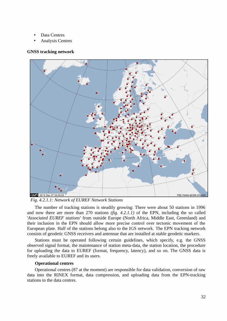
EPN is a voluntary federation of more than 100 self-funding European agencies, universitiesand research institutions in more than 30 European countries. Its activities are coordinated byEUREF. EPN is a network of more than 270 continuously operating GPS, GLONASS andGalileo reference stations organized mainly for European Coordinate System ETRS89 (EuropeanTerrestrial Reference System 1989). The purpose of EPN is not only the maintenance of theETRS89 geodetic system, but also usage for different scientific applications such as themonitoring of ground deformations, sea level, ionospheric analysis, space weather and numericalweather prediction. [11]
EPN components [11]: • GNSS Tracking Network• Operational Centres
31
• Data Centres• Analysis Centres
GNSS tracking network
The number of tracking stations is steadily growing: There were about 50 stations in 1996and now there are more than 270 stations (fig. 4.2.1.1) of the EPN, including the so called'Associated EUREF stations' from outside Europe (North Africa, Middle East, Greenland) andtheir inclusion in the EPN should allow more precise control over tectonic movement of theEuropean plate. Half of the stations belong also to the IGS network. The EPN tracking networkconsists of geodetic GNSS receivers and antennae that are installed at stable geodetic markers.
Stations must be operated following certain guidelines, which specify, e.g. the GNSSobserved signal format, the maintenance of station meta-data, the station location, the procedurefor uploading the data to EUREF (format, frequency, latency), and so on. The GNSS data isfreely available to EUREF and its users.
Operational centres
Operational centres (87 at the moment) are responsible for data validation, conversion of rawdata into the RINEX format, data compression, and uploading data from the EPN-trackingstations to the data centres.
32
Fig. 4.2.1.1: Network of EUREF Network Stations
Data centres
Local data centres (LDCs) collect the data from the stations of a local network, and make itavailable for local and EUREF users. The data is then sent to the regional data centres (RDCs),which make the data available for local, regional, and IGS users. RDCs then collect the datafrom all the EPN stations. If there is no LDC for a particular station, then the data will be sentfrom the OC directly to the RDC. The EPN data is available in daily, hourly, and 15-min RINEXfiles, and for many stations as a real-time data stream in RTCM format via NTRIP.
Analysis centres (18 at the moment) Local analysis centres (LACs) process the data from a particular subnetwork of EPN stations
and are responsible for quality control. The LACs products are weekly network solutions of theirlocal subnetwork, which must be delivered within one month to the regional analysis centre(RAC). RACs combine the weekly subnetwork solutions into one official European solution.
The terminology 'local analysis centre' does not mean 'local' in a geographical sense, but in ahierarchical one: LACs process a subnetwork, that can geographically cover different countriesinvolved in the EPN.
33
II. PRACTICAL PART
5. Software used
5.1 Open source Ntrip softwareIn order to start testing data streams using Ntrip transport protocol, you should download
Ntrip Client software from the official page http://igs.bkg.bund.de/ntrip/download. You can alsodownload Ntrip Server software or Multi-Function software.
Ntrip Client Software: Ntrip Version 2.0 Command Line Client, reading from Ntrip Version 1.0 or 2.0 Caster – for PosixWindows.
Ntrip Server Software:Windows Server, reading from Serial Port for Windows 98/2000/NT/XP, Command Line Server;reading from TCP/IP Port for Windows 98/2000/NT/XP, Ntrip Version 2.0 Command LineServer; reading from SISNeT Server, TCP/UDP IP Port, Serial port, or NtripCaster to support anNtrip Version 1.0 or 2.0 Caster – for Posix Windows.
Multi-Function Ntrip Software and Assisting Tools:
for different operating systems:BKG Ntrip Client (BNC), Decoder, Converter and Monitor reading RTCM 2.x and RTCM 3.xformats, supporting Real-time PPP, High-rate RINEX Data Centers, Real-time GNSS Enginesand Real-time Combination Centers; for Windows Systems:GNSS Surfer, Ntrip Client and Server, RTCM 2.x and 3.x Encoder & Decoder, Topcon/JavadRaw Decoder, RINEX Generator, Web-Monitoring, Backup-System;RTKLIB, Open Source Program Package for RTK-GPS;RTCM 2.x Decoder, reading from local IP Port;Ntrip built-in RTCM version3, decodes to RINEX, GPS + GLONASS observations, antennainformation, Decode Message Type 1001 ~ 1012;
for Linux Systems:Ntrip Client, converts RTCM 3.x to RINEX;Ntrip Client, GPS Service/Monitor Daemon;Professional Ntrip v2 Broadcaster;
for Unix/Linux, Distributions: SUSE, Fedora, Mandriva:NtripClient, NtripServer, and NtripCaster Repositories, search for 'ntrip'.
34
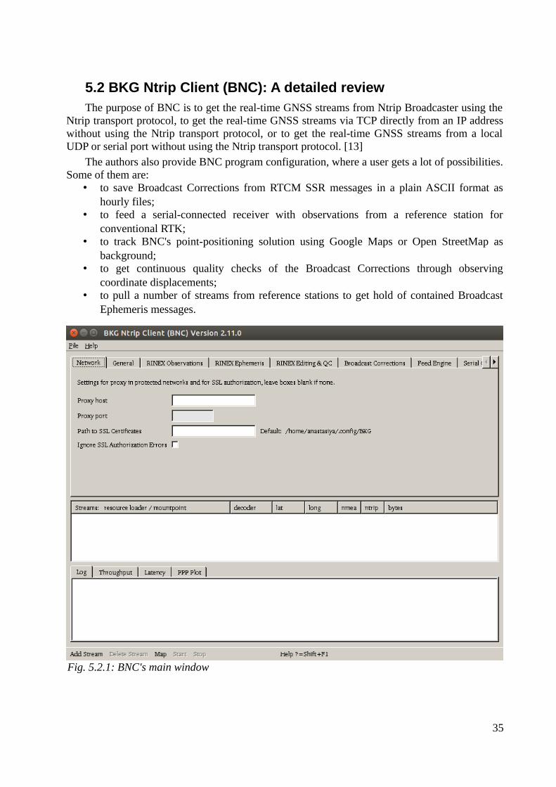
5.2 BKG Ntrip Client (BNC): A detailed reviewThe purpose of BNC is to get the real-time GNSS streams from Ntrip Broadcaster using the
Ntrip transport protocol, to get the real-time GNSS streams via TCP directly from an IP addresswithout using the Ntrip transport protocol, or to get the real-time GNSS streams from a localUDP or serial port without using the Ntrip transport protocol. [13]
The authors also provide BNC program configuration, where a user gets a lot of possibilities.Some of them are:
• to save Broadcast Corrections from RTCM SSR messages in a plain ASCII format ashourly files;
• to feed a serial-connected receiver with observations from a reference station forconventional RTK;
• to track BNC's point-positioning solution using Google Maps or Open StreetMap asbackground;
• to get continuous quality checks of the Broadcast Corrections through observingcoordinate displacements;
• to pull a number of streams from reference stations to get hold of contained BroadcastEphemeris messages.
35
Fig. 5.2.1: BNC's main window
Most of the data streams are available free of charge. It is necessary to apply for freeregistration at http://register.rtcm-ntrip.org, so as to get access to EUREF and IGS Broadcasters,and test the data streams.
The top menu bar (fig. 5.2.1) allows the selection of an appropriate font, savingconfigurations, and quitting the program. It also provides the program documentation.
The bottom menu bar (fig. 5.2.1) allows adding or deleting the streams you want to workwith and to start or stop the program. After clicking on the 'Add Stream' button, you have tochoose one of several communication links, which are Ntrip Broadcaster, TCP/IP port, UDP port,and Serial port, as shown below.
Add stream
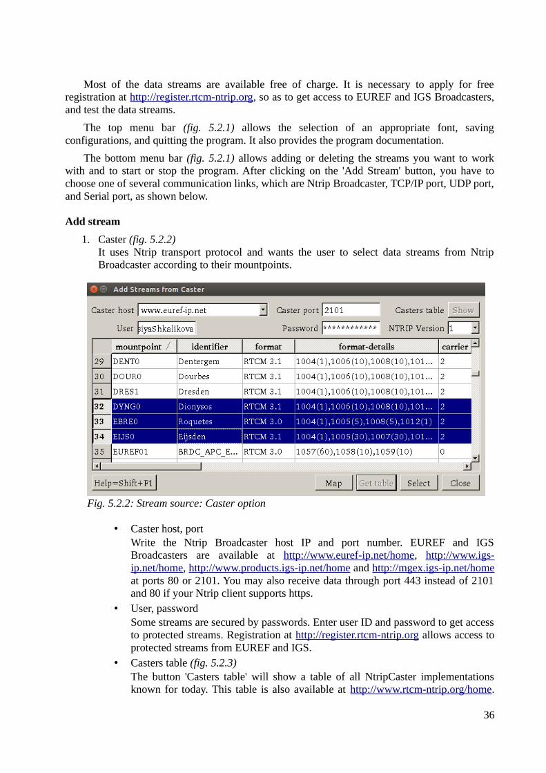
1. Caster (fig. 5.2.2)It uses Ntrip transport protocol and wants the user to select data streams from NtripBroadcaster according to their mountpoints.
• Caster host, portWrite the Ntrip Broadcaster host IP and port number. EUREF and IGSBroadcasters are available at http://www.euref-ip.net/home, http://www.igs-ip.net/home, http://www.products.igs-ip.net/home and http://mgex.igs-ip.net/homeat ports 80 or 2101. You may also receive data through port 443 instead of 2101and 80 if your Ntrip client supports https.
• User, passwordSome streams are secured by passwords. Enter user ID and password to get accessto protected streams. Registration at http://register.rtcm-ntrip.org allows access toprotected streams from EUREF and IGS.
• Casters table (fig. 5.2.3)The button 'Casters table' will show a table of all NtripCaster implementationsknown for today. This table is also available at http://www.rtcm-ntrip.org/home.
36
Fig. 5.2.2: Stream source: Caster option
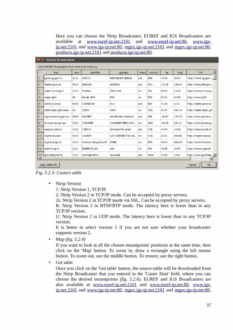
Here you can choose the Ntrip Broadcaster. EUREF and IGS Broadcasters areavailable at www.euref-ip.net :2101 and www.euref-ip.net :80, www.igs-ip.net:2101 and www.igs-ip.net :80, mgex.igs-ip.net:2101 and mgex.igs-ip.net:80,products.igs-ip.net:2101 and products.igs-ip.net:80.
• Ntrip Version1: Ntrip Version 1, TCP/IP.2: Ntrip Version 2 in TCP/IP mode. Can be accepted by proxy servers.2s: Ntrip Version 2 in TCP/IP mode via SSL. Can be accepted by proxy servers.R: Ntrip Version 2 in RTSP/RTP mode. The latency here is lower than in anyTCP/IP version.U: Ntrip Version 2 in UDP mode. The latency here is lower than in any TCP/IPversion.It is better to select version 1 if you are not sure whether your broadcastersupports version 2.
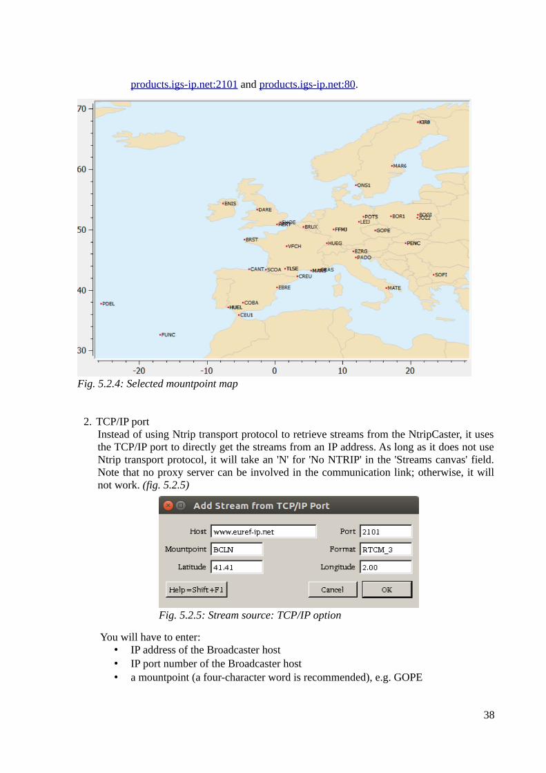
• Map (fig. 5.2.4)If you want to look at all the chosen mountpoints' positions at the same time, thenclick on the 'Map' button. To zoom in, draw a rectangle using the left mousebutton. To zoom out, use the middle button. To restore, use the right button.
• Get tableOnce you click on the 'Get table' button, the source-table will be downloaded fromthe Ntrip Broadcaster that you entered in the 'Caster Host' field, where you canchoose the desired mountpoints (fig. 5.2.6). EUREF and IGS Broadcasters arealso available at www.euref-ip.net :2101 and www.euref-ip.net :80, www.igs-ip.net:2101 and www.igs-ip.net :80, mgex.igs-ip.net:2101 and mgex.igs-ip.net:80,
37
Fig. 5.2.3: Casters table
products.igs- ip.net:2101 and products.igs-ip.net:80.
2. TCP/IP port Instead of using Ntrip transport protocol to retrieve streams from the NtripCaster, it usesthe TCP/IP port to directly get the streams from an IP address. As long as it does not useNtrip transport protocol, it will take an 'N' for 'No NTRIP' in the 'Streams canvas' field.Note that no proxy server can be involved in the communication link; otherwise, it willnot work. (fig. 5.2.5)
You will have to enter:• IP address of the Broadcaster host• IP port number of the Broadcaster host• a mountpoint (a four-character word is recommended), e.g. GOPE
38
Fig. 5.2.4: Selected mountpoint map
Fig. 5.2.5: Stream source: TCP/IP option
• the stream format, e.g. RTCM_2, RTCM_3, RTNET, ZERO• the latitude of the mountpoint – e.g. 49.91• the longitude of the mountpoint – e.g. 14.79
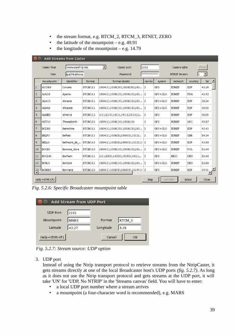
3. UDP portInstead of using the Ntrip transport protocol to retrieve streams from the NtripCaster, itgets streams directly at one of the local Broadcaster host's UDP ports (fig. 5.2.7). As longas it does not use the Ntrip transport protocol and gets streams at the UDP port, it willtake 'UN' for 'UDP, No NTRIP' in the 'Streams canvas' field. You will have to enter:
• a local UDP port number where a stream arrives• a mountpoint (a four-character word is recommended), e.g. MARS
39
Fig. 5.2.7: Stream source: UDP option
Fig. 5.2.6: Specific Broadcaster mountpoint table
• the stream format, e.g. RTCM_2, RTCM_3, RTNET, ZERO• the latitude of the mountpoint – e.g. 43.27• the longitude of the mountpoint – e.g. 5.35
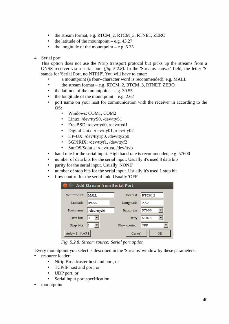
4. Serial portThis option does not use the Ntrip transport protocol but picks up the streams from aGNSS receiver via a serial port (fig. 5.2.8). In the 'Streams canvas' field, the letter 'S'stands for 'Serial Port, no NTRIP'. You will have to enter:
• a mountpoint (a four--character word is recommended), e.g. MALL• the stream format – e.g. RTCM_2, RTCM_3, RTNET, ZERO• the latitude of the mountpoint – e.g. 39.55• the longitude of the mountpoint – e.g. 2.62• port name on your host for communication with the receiver in according to the
OS:• Windows: COM1, COM2• Linux: /dev/ttyS0, /dev/ttyS1• FreeBSD: /dev/ttyd0, /dev/ttyd1• Digital Unix: /dev/tty01, /dev/tty02• HP-UX: /dev/tty1p0, /dev/tty2p0• SGI/IRIX: /dev/ttyf1, /dev/ttyf2• SunOS/Solaris: /dev/ttya, /dev/ttyb
• baud rate for the serial input. High baud rate is recommended, e.g. 57600• number of data bits for the serial input. Usually it's used 8 data bits• parity for the serial input. Usually 'NONE'• number of stop bits for the serial input. Usually it's used 1 stop bit• flow control for the serial link. Usually 'OFF'
Every mountpoint you select is described in the 'Streams' window by these parameters:• resource loader:
• Ntrip Broadcaster host and port, or• TCP/IP host and port, or• UDP port, or• Serial input port specification
• mountpoint
40
Fig. 5.2.8: Stream source: Serial port option
• decoder: name of decoder used to handle the incoming stream content according to itsformat; to get the raw data, specify the decoder as 'ZERO'
• lat: latitude of reference station in degrees• long: longitude of reference station in degrees• nmea: if there is a need to send NMEA-GGA message with position coordinates inside in
order to initiate the streaming, then 'yes', otherwise 'no'• ntrip:
• Ntrip protocol version (1, 2, 2s, R or U), or• 'N', which means 'No Ntrip' - for TCP/IP streams, or• 'UN', which means 'UDP, No Ntrip' - for UDP streams, or• 'S', which means 'Serial, No Ntrip' - for serial input streams
• bytes: number of bytes received
The logging window provides information about BNC's activities, which are:
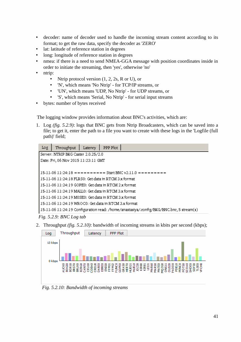
1. Log (fig. 5.2.9): logs that BNC gets from Ntrip Broadcasters, which can be saved into afile; to get it, enter the path to a file you want to create with these logs in the 'Logfile (fullpath)' field;
2. Throughput (fig. 5.2.10): bandwidth of incoming streams in kbits per second (kbps);
41
Fig. 5.2.9: BNC Log tab
Fig. 5.2.10: Bandwidth of incoming streams
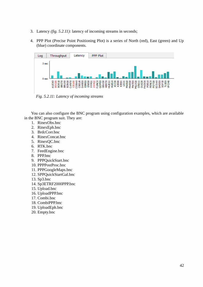
3. Latency (fig. 5.2.11): latency of incoming streams in seconds;
4. PPP Plot (Precise Point Positioning Plot) is a series of North (red), East (green) and Up(blue) coordinate components.
You can also configure the BNC program using configuration examples, which are availablein the BNC program suit. They are:
1. RinexObs.bnc2. RinexEph.bnc3. BrdcCorr.bnc4. RinexConcat.bnc5. RinexQC.bnc6. RTK.bnc7. FeedEngine.bnc8. PPP.bnc9. PPPQuickStart.bnc10. PPPPostProc.bnc11. PPPGoogleMaps.bnc12. SPPQuickStartGal.bnc13. Sp3.bnc14. Sp3ETRF2000PPP.bnc15. Upload.bnc16. UploadPPP.bnc17. Combi.bnc18. CombiPPP.bnc19. UploadEph.bnc20. Empty.bnc
42
Fig. 5.2.11: Latency of incoming streams
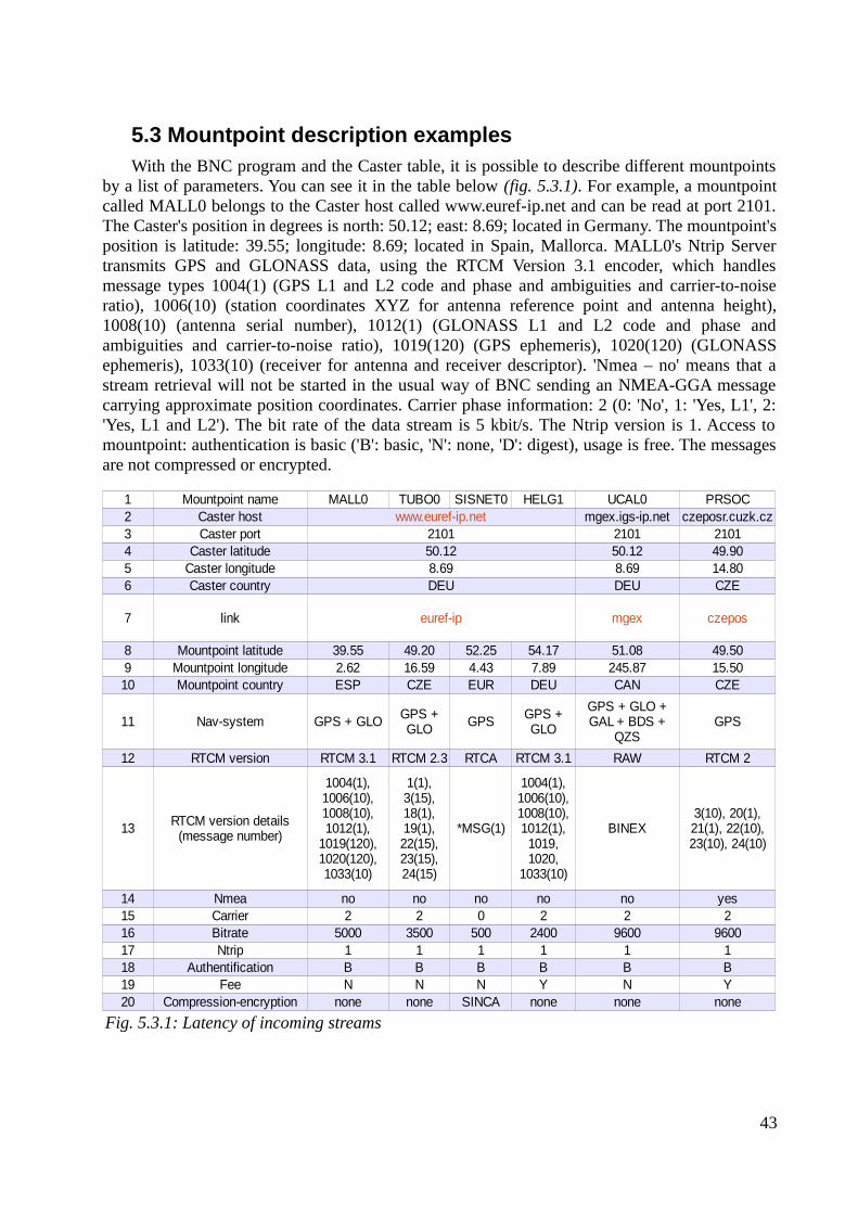
5.3 Mountpoint description examplesWith the BNC program and the Caster table, it is possible to describe different mountpoints
by a list of parameters. You can see it in the table below (fig. 5.3.1). For example, a mountpointcalled MALL0 belongs to the Caster host called www.euref-ip.net and can be read at port 2101.The Caster's position in degrees is north: 50.12; east: 8.69; located in Germany. The mountpoint'sposition is latitude: 39.55; longitude: 8.69; located in Spain, Mallorca. MALL0's Ntrip Servertransmits GPS and GLONASS data, using the RTCM Version 3.1 encoder, which handlesmessage types 1004(1) (GPS L1 and L2 code and phase and ambiguities and carrier-to-noiseratio), 1006(10) (station coordinates XYZ for antenna reference point and antenna height),1008(10) (antenna serial number), 1012(1) (GLONASS L1 and L2 code and phase andambiguities and carrier-to-noise ratio), 1019(120) (GPS ephemeris), 1020(120) (GLONASSephemeris), 1033(10) (receiver for antenna and receiver descriptor). 'Nmea – no' means that astream retrieval will not be started in the usual way of BNC sending an NMEA-GGA messagecarrying approximate position coordinates. Carrier phase information: 2 (0: 'No', 1: 'Yes, L1', 2:'Yes, L1 and L2'). The bit rate of the data stream is 5 kbit/s. The Ntrip version is 1. Access tomountpoint: authentication is basic ('B': basic, 'N': none, 'D': digest), usage is free. The messagesare not compressed or encrypted.
43
Fig. 5.3.1: Latency of incoming streams
1 Mountpoint name MALL0 TUBO0 SISNET0 HELG1 UCAL0 PRSOC2 Caster host mgex.igs-ip.net czeposr.cuzk.cz3 Caster port 2101 2101 21014 Caster latitude 50.12 50.12 49.905 Caster longitude 8.69 8.69 14.806 Caster country DEU DEU CZE
7 link
8 Mountpoint latitude 39.55 49.20 52.25 54.17 51.08 49.509 Mountpoint longitude 2.62 16.59 4.43 7.89 245.87 15.5010 Mountpoint country ESP CZE EUR DEU CAN CZE
11 Nav-system GPS + GLO GPS GPS
12 RTCM version RTCM 3.1 RTCM 2.3 RTCA RTCM 3.1 RAW RTCM 2
13 *MSG(1) BINEX
14 Nmea no no no no no yes15 Carrier 2 2 0 2 2 216 Bitrate 5000 3500 500 2400 9600 960017 Ntrip 1 1 1 1 1 118 Authentification B B B B B B19 Fee N N N Y N Y20 Compression-encryption none none SINCA none none none
www.euref-ip.net
euref-ip mgex czepos
GPS + GLO
GPS + GLO
GPS + GLO + GAL + BDS +
QZS
RTCM version details (message number)
1004(1), 1006(10), 1008(10), 1012(1),
1019(120), 1020(120), 1033(10)
1(1), 3(15), 18(1), 19(1), 22(15), 23(15), 24(15)
1004(1), 1006(10), 1008(10), 1012(1),
1019, 1020,
1033(10)
3(10), 20(1), 21(1), 22(10), 23(10), 24(10)
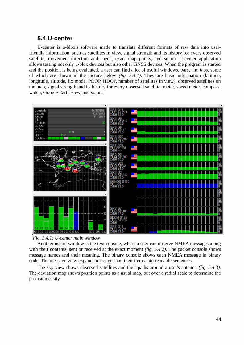
5.4 U-centerU-center is u-blox's software made to translate different formats of raw data into user-
friendly information, such as satellites in view, signal strength and its history for every observedsatellite, movement direction and speed, exact map points, and so on. U-center applicationallows testing not only u-blox devices but also other GNSS devices. When the program is startedand the position is being evaluated, a user can find a lot of useful windows, bars, and tabs, someof which are shown in the picture below (fig. 5.4.1). They are basic information (latitude,longitude, altitude, fix mode, PDOP, HDOP, number of satellites in view), observed satellites onthe map, signal strength and its history for every observed satellite, meter, speed meter, compass,watch, Google Earth view, and so on.
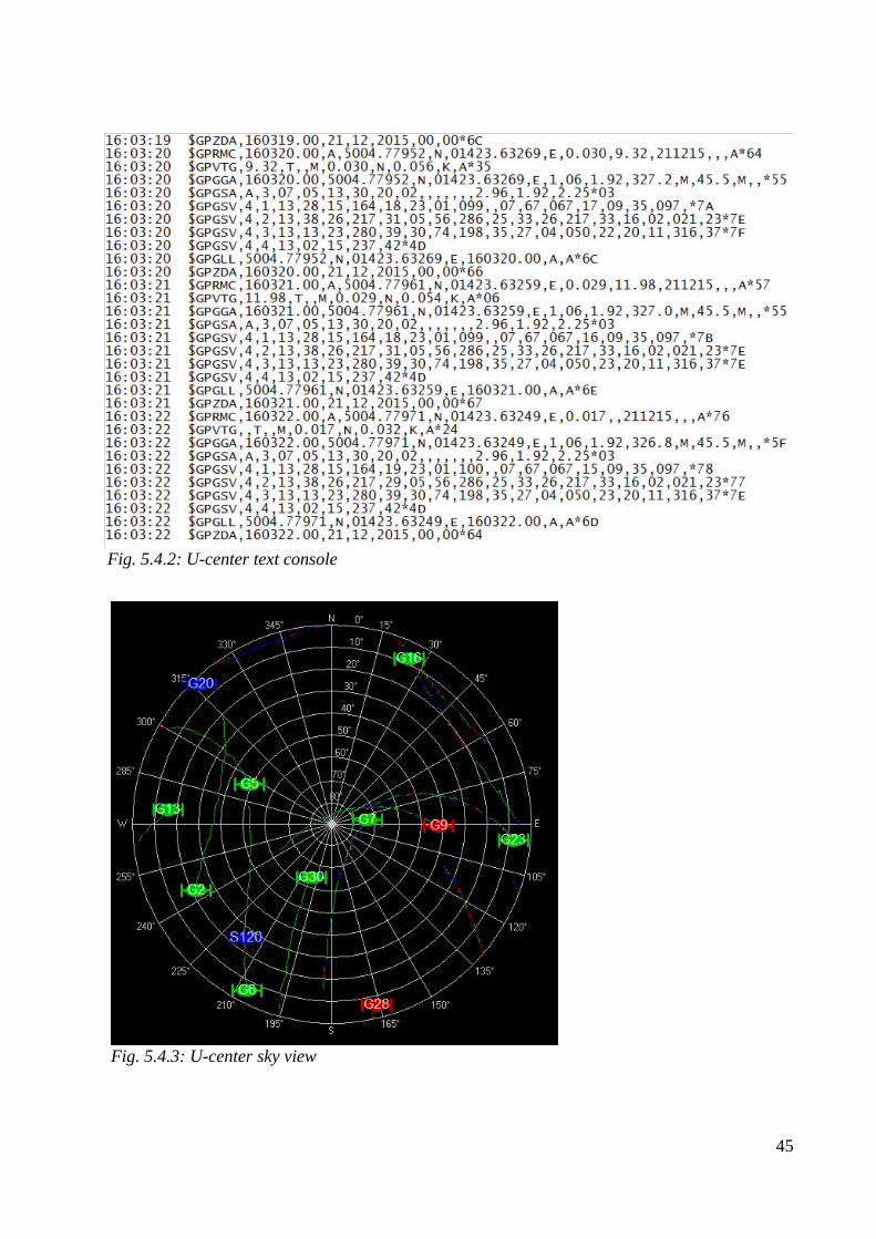
Another useful window is the text console, where a user can observe NMEA messages alongwith their contents, sent or received at the exact moment (fig. 5.4.2). The packet console showsmessage names and their meaning. The binary console shows each NMEA message in binarycode. The message view expands messages and their items into readable sentences.
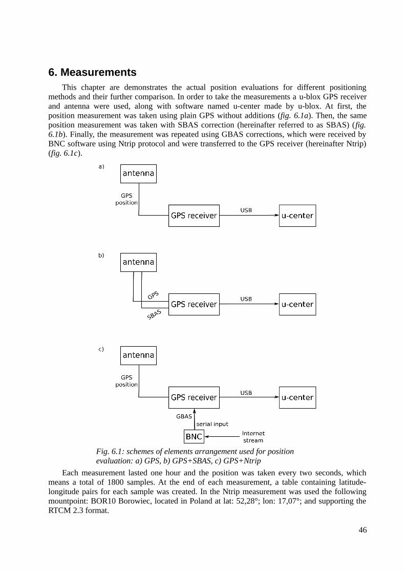
The sky view shows observed satellites and their paths around a user's antenna (fig. 5.4.3).The deviation map shows position points as a usual map, but over a radial scale to determine theprecision easily.
44
Fig. 5.4.1: U-center main window
45
Fig. 5.4.2: U-center text console
Fig. 5.4.3: U-center sky view
6. MeasurementsThis chapter are demonstrates the actual position evaluations for different positioning
methods and their further comparison. In order to take the measurements a u-blox GPS receiverand antenna were used, along with software named u-center made by u-blox. At first, theposition measurement was taken using plain GPS without additions (fig. 6.1a). Then, the sameposition measurement was taken with SBAS correction (hereinafter referred to as SBAS) (fig.6.1b). Finally, the measurement was repeated using GBAS corrections, which were received byBNC software using Ntrip protocol and were transferred to the GPS receiver (hereinafter Ntrip)(fig. 6.1c).
Each measurement lasted one hour and the position was taken every two seconds, whichmeans a total of 1800 samples. At the end of each measurement, a table containing latitude-longitude pairs for each sample was created. In the Ntrip measurement was used the followingmountpoint: BOR10 Borowiec, located in Poland at lat: 52,28°; lon: 17,07°; and supporting theRTCM 2.3 format.
46
Fig. 6.1: schemes of elements arrangement used for position evaluation: a) GPS, b) GPS+SBAS, c) GPS+Ntrip
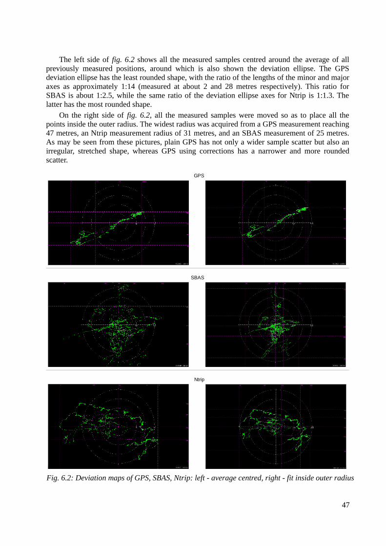
The left side of fig. 6.2 shows all the measured samples centred around the average of allpreviously measured positions, around which is also shown the deviation ellipse. The GPSdeviation ellipse has the least rounded shape, with the ratio of the lengths of the minor and majoraxes as approximately 1:14 (measured at about 2 and 28 metres respectively). This ratio forSBAS is about 1:2.5, while the same ratio of the deviation ellipse axes for Ntrip is 1:1.3. Thelatter has the most rounded shape.
On the right side of fig. 6.2, all the measured samples were moved so as to place all thepoints inside the outer radius. The widest radius was acquired from a GPS measurement reaching47 metres, an Ntrip measurement radius of 31 metres, and an SBAS measurement of 25 metres.As may be seen from these pictures, plain GPS has not only a wider sample scatter but also anirregular, stretched shape, whereas GPS using corrections has a narrower and more roundedscatter.
47
Fig. 6.2: Deviation maps of GPS, SBAS, Ntrip: left - average centred, right - fit inside outer radius
GPS
SBAS
Ntrip
To ensure a more precise comparison of the different positioning methods, the average radiuswas chosen as the main comparison parameter. This was calculated using tables of latitude-longitude pairs in the following way:
1. The average point was calculated using the arithmetic mean in degrees
x0=
∑i=1
n
xi
n[°; °, –]
y0=
∑i=1
n
y i
n[°; °, –]
where (x0, y0) – average point coordinates (latitude, longitude), (xi, yi ) – coordinate for aspecific sample, n – count of samples.Average points:
(x0GPS, y0GPS) = (50.07958, 14.39372)
(x0SBAS, y0SBAS) = (50.07965, 14.39313)
(x0NTRIP, y0NTRIP) = (50.07948, 14.39300)
2. For each latitude-longitude pair, a radius was calculated relative to the average point andconverted to metres by multiplying degree distances by numbers corresponding to thelatitude in question
ri=√((x i−x0)∗111230.31)2+(( y i− y 0)∗71577.31)2 [m; °, °, °, °]
where ri – distance between the average point and the specific sample, (x0, y0) – averagepoint coordinates (latitude, longitude), (xi, yi ) – coordinate for a specific sample.
3. The average radius was calculated using all the radii
rav=1n √∑i=1
n
r i2 [m; –, m]
where rav – the average radius, n – count of samples, r i – distance between the averagepoint and specific sample.The average radii:
r0GPS = 0.6895 m
r0SBAS = 0.3448 m
r0NTRIP = 0.2507 mAs may be seen from these results, corrections heavily improve the positioning accuracy in
our case: SBAS sees a 50% improvement and Ntrip a 63.6% improvement. Ntrip has betteraccuracy mostly because GBAS systems have more reference stations than SBAS systems. Sinceionospheric errors vary from place to place, the greatest impact on the error correction resultsfrom the ground station located at the position closest to the measured position. Hence, thedenser the station grid is the more chance there is to have a signal from the least distance and,therefore, to locate the position with better accuracy.
Fig. 6.3 indicates the count of samples located in between specific radii around the averagepoint, with these radii located five metres apart from each other. All three methods are compared.The first thing worthy of attention is the maximum radius: SBAS is less than 30 metres, Ntrip is
48
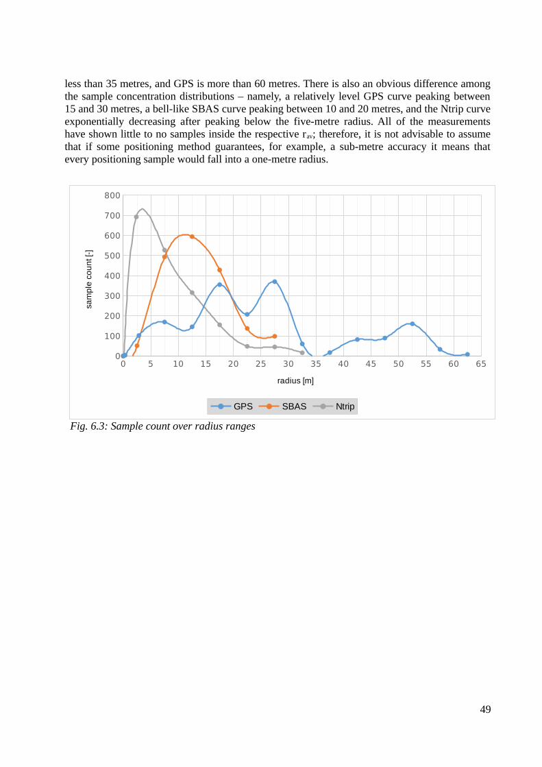
less than 35 metres, and GPS is more than 60 metres. There is also an obvious difference amongthe sample concentration distributions – namely, a relatively level GPS curve peaking between15 and 30 metres, a bell-like SBAS curve peaking between 10 and 20 metres, and the Ntrip curveexponentially decreasing after peaking below the five-metre radius. All of the measurementshave shown little to no samples inside the respective rav; therefore, it is not advisable to assumethat if some positioning method guarantees, for example, a sub-metre accuracy it means thatevery positioning sample would fall into a one-metre radius.
49
Fig. 6.3: Sample count over radius ranges
0 5 10 15 20 25 30 35 40 45 50 55 60 650
100
200
300
400
500
600
700
800
GPS SBAS Ntrip
radius [m]
sam
ple
co
un
t [-]
ConclusionThe main goal of this bachelor thesis is to demonstrate the position evaluation using plain
GPS and differential GPS (DGPS) and then to compare them. DGPS was developed to improveGPS positioning. DGPS can be divided into satellite based augmentation system (SBAS) andground based augmentation system (GBAS). Each system has their own definite standards andformats, which are described in the Chapter 1.
In the Chapter 6 'Measurements' were compared different methods of position evaluation,namely, plain GPS, GPS+SBAS and GPS+GBAS (using Ntrip protocol to get a broadcaster'sstream from the Internet). As it was expected, the measurements using correction methods turnedout to be more accurate: SBAS sees a 50% improvement and Ntrip a 63,6% improvement. Thereis a difference between SBAS- and GBAS correction improvement of more than 13% mostlybecause of station grid density: in case of GBAS there is a bigger chance to use the best suitingreference station by possibility to choose them, while SBAS positioning only informs the userwhich station it uses. The average radii (r0 or rav) are: r0GPS = 0.6895 metres, r0SBAS = 0.3448metres, and r0NTRIP = 0.2507 metres. The most noticeable difference among these methods may beseen in fig. 6.3, which is the maximum radius of each method: plain GPS has max. radius atabout 60 – 65 metres, Ntrip at about 30 – 35 metres, and SBAS at about 25 – 30 metres.
50

References[1] RINEX: The Receiver Independent Exchange Format, Version 3.02. In: IGS (InternationalGNSS Service) [online]. International GNSS Service (IGS), RINEX Working Group and RadioTechnical Commission for Maritime Services Special Committee 104 (RTCM-SC104), 2013.[cit. 26.05.2016]. Available from: ftp://igs.org/pub/data/format/ rinex 302.pdf
[2] RTCM (The Radio Technical Commission for Maritime Services) [online]. RTCM. [cit.26.05.2016]. Available from:http://www.rtcm.org/default.php
[3] EL-RABBANY, Ahmed. Introduction to GPS: The Global Positioning System. Norwood,MA 02062: ARTECH HOUSE, INC., 2002. ISBN 1-58053-183-0.
[4] Networked Transport of RTCM via Internet Protocol (Ntrip) , Version 1.0. In: GDC (GNSSData Center) [online]. Bundesamt für Kartographie und Geodäsie (BKG), 2004. [cit.26.05.2016]. Available from:http://igs.bkg.bund.de/root_ftp/NTRIP/documentation/NtripDocumentation.pdf/
[5] Denise DETTMERING, Christian WAESE and Georg WEBER. Networked Transport ofRTCM via Internet Protocol, Ntrip, Version 1.0, Example Implementation. In: GDC (GNSS DataCenter) [online]. Bundesamt für Kartographie und Geodäsie (BKG), 2006. [cit. 26.05.2016].Available from:http://igs.bkg.bund.de/root_ftp/NTRIP/documentation/NtripImplementation.pdf/
[6] Dale DePriest. NMEA data. In: GPS information [online]. [cit. 26.05.2016]. Available from:http://www.gpsinformation.org/dale/nmea.htm/
[7] Bharati Bidikar, Gottapu Sasibhushana Rao, Laveti Ganesh, MNVS Santosh Kumar. SatelliteClock Error and Orbital Solution Error Estimation for Precise Navigation Applications. In:Scientific Research: An Academic Publisher [online]. 2014. [cit. 26.05.2016]. Available from:file.scirp.org/pdf/POS_2014021316044905.pdf/
[8] Why postprocess GPS data? Esri [online]. Esri, 2004. [cit. 26.05.2016]. Available from: http://www.esri.com/~/media/files/pdfs/partners/hardware/why-postprocess.pdf
[9] SBAS Made Easy. In: SX Blue Series [online]. GENEQ Inc. [cit. 26.05.2016]. Availablefrom: http://www.sxbluegps.com/technology/sbas-made-easy/
[10] OmniSTAR [online]. OmniSTAR. [cit. 26.05.2016]. Available from: http://www.omnistar.com/Home.aspx
[11] EUREF Permanent Network [online]. EPN Central Bureau, 2014. [cit. 26.05.2016].Available from: http://www.epncb.oma.be/_organisation/components.php
51

[12] EUREF Permanent Network [online]. Wikipedia. [cit. 26.05.2016]. Available from: https://en.wikipedia.org/wiki/EUREF_Permanent_Network
[13] BKG Ntrip Client (BNC) Version 2.9. In: Open Source Software development for Ntrip[online]. Trac Open Source Project, 2013. [cit. 26.05.2016]. Available from: software.rtcm-ntrip.org/svn/trunk/BNC/src/bnchelp.html
52

AppendixAttached CD contains the following data:
• this bachelor thesis in .pdf format• the software used in this work (BNC, u-center)• the data obtained during the measurements • all the images and graphs used in this thesis
53
Copyright © 2022 FDOKUMEN