Prediction of added resistance of ships in waves
10
Prediction of added resistance of ships in waves Shukui Liu, Apostolos Papanikolaou n , George Zaraphonitis Ship Design Laboratory, National Technical University of Athens, Greece article info Article history: Received 23 November 2009 Accepted 7 December 2010 Editor-in-Chief: A.I. Incecik Available online 3 January 2011 Keywords: Added resistance Drift forces Far-field method Near-field method 3D panel method Kochin function abstract The prediction of the added resistance of ships in waves is a demanding, quasi-second-order seakeeping problem of high practical interest. In the present paper, a well established frequency domain 3D panel method and a new hybrid time domain Rankine source-Green function method of NTUA-SDL are used to solve the basic seakeeping problem and to calculate first order velocity potentials and the Kochin functions, as necessary for the calculation of the added resistance by Maruo’s far-field method. A wide range of case studies for different hull forms (slender and bulky) was used to validate the applicability and accuracy of the implemented methods in practice and important conclusions regarding the efficiency of the investigated methods are drawn. & 2010 Elsevier Ltd. All rights reserved. 1. Introduction When sailing in a seaway, the calm water resistance and powering of a ship is increased and this is accounted for in traditional ship design by some rough proportional increase of calm water resistance by about 20–40%. However, the accurate prediction of ship’s resistance in waves is nowadays of increased importance, both for the designer and the shipowner/operator, since it greatly affects the selection of ship’s engine/propulsion system and ship’s perfor- mance in terms of sustainable service speed and fuel consumption in realistic sea conditions. Also, accurate and efficient predictions of the added resistance in natural seaways are necessary for the imple- mentation of modern onboard ship routing systems. The added resistance is a steady force of second-order with respect to the incident wave’s amplitude and acting opposite to ship’s forward speed in longitudinal direction. When the ship has zero forward speed, then the added resistance is trivially identical to the longitudinal drift force (Papanikolaou and Zaraphonitis, 1987). There are several alternative approaches to the added resistance problem; they can be generally classified into two main categories, namely far-field and near-field methods. The far-field methods are based on considerations of the diffracted and radiated wave energy and momentum flux at infinity, leading to the steady added resistance force by the total rate of momentum change. The near- field method, on the other side, leads to the added resistance as the steady second-order force obtained by direct integration of the hydrodynamic, steady second-order pressure acting on the wetted ship surface. The latter can be calculated exactly from first order potential functions, and their derivatives. It is evident that though both above methods should lead to the same numerical results for the added resistance, this is not so in practice, because both methods request equally accurate solutions of the basic potential, seakeeping theory problem in the near and far field, which cannot be ensured in practice. This is a well-known observation in the similarly posed drift force problem. Thus, even if the same potential theory and related numerical methods are used for the solution of the linear seakeeping problem and the calculation of the governing potential function (and its derivatives and of related hydrodynamic quantities, including ship motions, as necessary) in the near- and far-field, the numerical results by the near- and far-field method for the added resistance are in general different, thus a basic question arises, namely which method is more efficient for practical applications. In this respect, several theoretical approaches of varying com- plexity and accuracy have been introduced in the past and numerically implemented/verified. The first far-field approach was introduced by Maruo (1957) in the late 50s; it was further elaborated in the following years by Maruo (1960, 1963) and Joosen (1966). In the early 70s, the first near field, direct pressure integration methods appeared; however, the considered hydro- dynamic pressure distribution was highly simplified (e.g. Boese, 1970). At about the same time, the radiated energy approach of Gerritsma and Beukelman (1972) was introduced, which is basi- cally following the far-field approach of Maruo. Strøm-Tejsen et al. (1973) did a thorough evaluation of all the above approaches to find large discrepancies between the numerical results form different theoretical approaches and relevant model experimental data. Later on, Salvesen (1974) investigated the added resistance problem by applying Gerritsma and Beukelman’s method, but using Contents lists available at ScienceDirect journal homepage: www.elsevier.com/locate/oceaneng Ocean Engineering 0029-8018/$ - see front matter & 2010 Elsevier Ltd. All rights reserved. doi:10.1016/j.oceaneng.2010.12.007 n Corresponding author. E-mail address: [email protected] (A. Papanikolaou). Ocean Engineering 38 (2011) 641–650
Transcript of Prediction of added resistance of ships in waves

Ocean Engineering 38 (2011) 641–650
Contents lists available at ScienceDirect
Ocean Engineering
0029-80
doi:10.1
n Corr
E-m
journal homepage: www.elsevier.com/locate/oceaneng
Prediction of added resistance of ships in waves
Shukui Liu, Apostolos Papanikolaou n, George Zaraphonitis
Ship Design Laboratory, National Technical University of Athens, Greece
a r t i c l e i n f o
Article history:
Received 23 November 2009
Accepted 7 December 2010
Editor-in-Chief: A.I. Incecikmethod and a new hybrid time domain Rankine source-Green function method of NTUA-SDL are used to
solve the basic seakeeping problem and to calculate first order velocity potentials and the Kochin
Available online 3 January 2011Keywords:
Added resistance
Drift forces
Far-field method
Near-field method
3D panel method
Kochin function
18/$ - see front matter & 2010 Elsevier Ltd. A
016/j.oceaneng.2010.12.007
esponding author.
ail address: [email protected] (A. Papaniko
a b s t r a c t
The prediction of the added resistance of ships in waves is a demanding, quasi-second-order seakeeping
problem of high practical interest. In the present paper, a well established frequency domain 3D panel
functions, as necessary for the calculation of the added resistance by Maruo’s far-field method. A wide
range of case studies for different hull forms (slender and bulky) was used to validate the applicability and
accuracy of the implemented methods in practice and important conclusions regarding the efficiency of
the investigated methods are drawn.
& 2010 Elsevier Ltd. All rights reserved.
1. Introduction
When sailing in a seaway, the calm water resistance andpowering of a ship is increased and this is accounted for in traditionalship design by some rough proportional increase of calm waterresistance by about 20–40%. However, the accurate prediction ofship’s resistance in waves is nowadays of increased importance, bothfor the designer and the shipowner/operator, since it greatly affectsthe selection of ship’s engine/propulsion system and ship’s perfor-mance in terms of sustainable service speed and fuel consumption inrealistic sea conditions. Also, accurate and efficient predictions of theadded resistance in natural seaways are necessary for the imple-mentation of modern onboard ship routing systems.
The added resistance is a steady force of second-order withrespect to the incident wave’s amplitude and acting opposite toship’s forward speed in longitudinal direction. When the ship haszero forward speed, then the added resistance is trivially identical tothe longitudinal drift force (Papanikolaou and Zaraphonitis, 1987).There are several alternative approaches to the added resistanceproblem; they can be generally classified into two main categories,namely far-field and near-field methods. The far-field methods arebased on considerations of the diffracted and radiated wave energyand momentum flux at infinity, leading to the steady addedresistance force by the total rate of momentum change. The near-field method, on the other side, leads to the added resistance as thesteady second-order force obtained by direct integration of thehydrodynamic, steady second-order pressure acting on the wetted
ll rights reserved.
laou).
ship surface. The latter can be calculated exactly from first orderpotential functions, and their derivatives. It is evident that thoughboth above methods should lead to the same numerical results forthe added resistance, this is not so in practice, because both methodsrequest equally accurate solutions of the basic potential, seakeepingtheory problem in the near and far field, which cannot be ensured inpractice. This is a well-known observation in the similarly posed driftforce problem. Thus, even if the same potential theory and relatednumerical methods are used for the solution of the linear seakeepingproblem and the calculation of the governing potential function (andits derivatives and of related hydrodynamic quantities, includingship motions, as necessary) in the near- and far-field, the numericalresults by the near- and far-field method for the added resistance arein general different, thus a basic question arises, namely whichmethod is more efficient for practical applications.
In this respect, several theoretical approaches of varying com-plexity and accuracy have been introduced in the past andnumerically implemented/verified. The first far-field approachwas introduced by Maruo (1957) in the late 50s; it was furtherelaborated in the following years by Maruo (1960, 1963) and Joosen(1966). In the early 70s, the first near field, direct pressureintegration methods appeared; however, the considered hydro-dynamic pressure distribution was highly simplified (e.g. Boese,1970). At about the same time, the radiated energy approach ofGerritsma and Beukelman (1972) was introduced, which is basi-cally following the far-field approach of Maruo. Strøm-Tejsen et al.(1973) did a thorough evaluation of all the above approaches to findlarge discrepancies between the numerical results form differenttheoretical approaches and relevant model experimental data.Later on, Salvesen (1974) investigated the added resistanceproblem by applying Gerritsma and Beukelman’s method, but using

Fig. 1. Coordinate system.
S. Liu et al. / Ocean Engineering 38 (2011) 641–650642
basic results of the STF seakeeping strip theory (Salvesen et al.1970) and found quite satisfactory results for the investigated shiphull forms. This was not surprising, considering the superiority ofthe STF strip theory method for the prediction of ship motions overother methods at that time. Also, the significance of accurate shipmotions predictions for a reliable estimation of the added resis-tance was acknowledged and one may have concluded that if amore accurate calculation of the ship motions could be used(or even ship motions from model experiments), all above alternativeapproaches to the added resistance may have led to better results.An exact in the sense of potential theory near-field, direct pressureintegration approach to the added resistance problem was intro-duced by Faltinsen et al. (1980), with good validation results. Theobserved deficiency of the approach in short waves was addressedby the introduction of a simplified added resistance estimationformula, which models remarkably well the complicate interactionbetween the diffraction of waves and the steady flow around theship. The same problem appears in exaggerated form with lowspeed, full hull forms with blunt bows (bulkcarriers and tankers),for which Ohkusu (1985) proposed an improved approach. Thismethod was further elaborated by Iwashita and Ohkusu (1992),who applied Maruo’s (1963) improved far-field formulation andthe concept of Kochin functions, to obtain very good results for theadded resistance of a fully submerged spheroid by use of a 3Dpulsating and traveling source, Green function method. In his mostrecent state of the art review, Naito (2008) concluded thaty ‘‘goodagreement can be obtained by applying this (latter) calculationmethod to all types of ship. However this method has not beenwidely utilized due to the complicated calculation technique andlarge computing time required’’. More recently, using an enhancedunified theory, Kashiwagi (2009) calculated the added resistanceby a modified version of Maruo’s approach, obtaining also quitesatisfactory results.
In the present study, the well established frequency domain 3Dpanel method and computer code NEWDRIFT (Papanikolaou–Zaraphonitis, 1987, Papanikolaou–Schellin, 1992 and Papanikolaouet al. 2000), a new time domain Green function method (Liu et al.2007) and a hybrid time domain the Rankine source-Greenfunction method (Liu and Papanikolaou, 2009, 2010) of NTUA-SDLare used to solve the basic seakeeping problem and to calculate thefirst order potential and the linear ship responses, as necessary forthe added resistance calculations; then Maruo’s far-field theoryand the Kochin functions approach is adopted for the calculation ofthe added resistance. For comparison, the near-field, directpressure integration method has been also partly investigated. Finally,for the short waves range, the asymptotic method of Faltinsen et al.(1980) and an improved derivative of it introduced recently byKuroda et al. (2008) and Tsujimoto et al. (2008) are employed.A wide range of case studies of different hull forms (slender andbulky) was used to validate the applicability and the accuracy of thedeveloped and implemented methods in practice.
2. Basic formulation
A coordinate system is introduced, as shown in Fig. 1. The x–y
plane coincides with the calm water free surface with the x-axispointing towards the bow and the z-axis pointing upwards.
The incident wave potential is given by
F0 ¼ Re igza
o ekz�ikðx coswþy sinwÞeioet
� �¼ Re ðf0cþf0sÞe
ioeth i
ð1Þ
where w is the incident wave heading (w¼p corresponds to headwaves),oe ¼o�kVcosw is the encounter frequency, k¼o2/g¼2p/lis the wave number, V is ship’s advance velocity and f0c, f0s are
the symmetric and anti-symmetric parts of the wave potential,respectively,
f0c ¼ igza
o ekz�ikx coswcosðkysinwÞ ð2Þ
f0s ¼gza
o ekz�ikx coswsinðkysinwÞ ð3Þ
The diffraction potential may be also decomposed as follows:
F7 ¼ Re½f7eioet� ¼ Re½ðf7cþf7sÞeioet� ð4Þ
with:
@f7c
@n¼�
@f0c
@n,@f7s
@n¼�
@f0s
@nð5Þ
The diffraction potentials f7c and f7s share the same symmetrychrematistics with the symmetric and anti-symmetric parts of theincident wave potential, respectively. The complex function H(kj,y),known as Kochin function, describing the elementary wavesradiated from the ships is given by
Hðkj,yÞ ¼ZZ
Sf@
@n�@f@n
� �GjðyÞds ð6Þ
where:
GjðyÞ ¼ exp½kjðyÞzþ ikjðyÞðxcosyþysinyÞ� ð7Þ
and kj(y), j¼1, 2 are the unsteady wave numbers
kjðyÞ ¼K0
2
1�2Ocosy7ffiffiffiffiffiffiffiffiffiffiffiffiffiffiffiffiffiffiffiffiffiffiffiffi1�4Ocosyp
cos2yþ:j¼ 1
�:j¼ 2
!ð8Þ
In the above equations, y is the angle of elementary wavesgenerated by the body, O¼oeV/g is the Hanaoka parameter, andK0¼g/V2 is the steady wave number. From Eq. (8) after somealgebraic manipulation the following expressions may be derivedfor k1(y) and k2(y):
k1ðyÞ ¼ K0 sec2y17
ffiffiffiffiffiffiffiffiffiffiffiffiffiffiffiffiffiffiffiffiffiffiffiffi1�4Ocosyp
4
!2
ð9Þ
k2ðyÞ ¼ k2
1þffiffiffiffiffiffiffiffiffiffiffiffiffiffiffiffiffiffiffiffiffiffiffiffi1�4Ocosyp
� �2
ð10Þ
Following Maruo (1963), the added resistance may be expressedby the above Kochin function as
RAW ¼r
8p
Z �a0
�p=2þ
Z p=2
a0
�
Z 3p=2
p=2
( )9Hðk1,yÞ92 k1½k1 cosy�kcosw�ffiffiffiffiffiffiffiffiffiffiffiffiffiffiffiffiffiffiffiffiffiffiffiffi
1�4Ocosyp dy
þr
8p
Z 2p�a0
a0
9Hðk2,yÞ92 k2½k2 cosy�kcosw�ffiffiffiffiffiffiffiffiffiffiffiffiffiffiffiffiffiffiffiffiffiffiffiffi1�4Ocosyp dy ð11Þ

S. Liu et al. / Ocean Engineering 38 (2011) 641–650 643
where r is the density of sea water and a0 is the critical angle(a0¼arcos(1/(4O)) for O41/4 and a0¼0 for Or1/4). When V¼0then O¼0, k1(y)-N and k2(y)¼k. Thus the wave systems arereduced to the ring wave only. For the zero speed case, the driftforce may be expressed as follows (Maruo, 1960):
RAW ¼rk2
8p
Z 2p
0HðyÞ92
ðcosy�coswÞdy ð12Þ
where:
HðyÞ ¼ZZ
Sexp½kzþ ikðxcosyþysinyÞ� fkðnzþ icosynxþ isinynyÞ�
@f@n
� �ds
ð13Þ
For the short waves range, Faltinsen et al. (1980) derived thefollowing asymptotic formula for the added resistance, assumingthat the incident waves are perfectly reflected from the non-shadedpart of the ship surface that is exposed to the waves
F1 ¼
ZL
Fnsinjdl ð14Þ
where
Fn ¼1
2rgz2
a sin2ðj�wÞþ 2o0V
g1þcosjcosðj�wÞ� �� �
ð15Þ
The integration in Eq. (14) is performed over the non-shadedpart (A-F-B) of the waterline (Fig. 2).
This expression yields good results for relatively full bodies;however, some poor results were obtained for fine hull forms likethose of containerships. In order to improve this drawback, Kurodaet al. (2008) further investigated Fujii and Takahashi’s (1975) semi-empirical original method and proposed an improved expressionfor the added resistance in short waves, which takes the followingform:
RAW ¼1
2rgz2
aadð1þaUÞBBf ðwÞ ð16Þ
where
Bf ðwÞ ¼1
B
ZI
sin2ðj�wÞsinjdlþ
ZII
sin2ðjþwÞsinjdl
� �ð17Þ
ad ¼p2I2
1ðkedÞ
p2I21ðkedÞþK2
1 ðkedÞð18Þ
1þaU ¼ 1þCUFn ð19Þ
ke ¼ kð1þOcoswÞ2 ð20Þ
CU ¼max½10:0,�310Bf ðwÞþ68� ð21Þ
B and d are the beam and draught of the ship, Bf is the bluntnesscoefficient, ad accounts for the effect of draught and frequency and
Fig. 2. Coordinate system for the short waves range added resistance calculation
methods.
1+au for the effect of forward speed. The two integrals in Eq. (17)are calculated over the A–F section (integral I) and B–F (integral II)section of the non-shaded part of the waterline (see Fig. 2). I1 is thefirst order modified Bessel function of the first kind and K1 is thefirst order modified Bessel function of the second kind. Note that inthe original proposal, the determination of CU was more compli-cated and required the use of experimental data.
2.1. Computation of Kochin function
The expression for the calculation of the Kochin functionsinvolves the fluid velocity on the body surface. The latter may becalculated via the body boundary condition. For the symmetricpotentials f1, f3, f5 and the symmetric part of the diffractionpotential f7c, the Kochin function takes the following form:
Hmðkj,yÞ ¼ 2
ZZS=2
ekjðyÞzþ ikjðyÞx cosycosðkjðyÞysinyÞ
� kjðyÞðfmcnz�fms cosynxÞ�@fmc
@n
�
þ ikjðyÞðfmsnzþfmcnx cosyÞ�i@fms
@n
�ds
�2
ZZS=2
ekjðyÞzþ ikjðyÞx cosysinðkjðyÞysinyÞ
�ðfmcþ ifmsÞkjðyÞsinynyds ð22Þ
where, m¼1, 3, 5, 7c. For the anti-symmetric potentials, i.e. f2, f4,f6 and f7s, the Kochin function takes the following form:
Hmðkj,yÞ ¼ 2i
ZZS=2
ekjzþ ikjx cosysinðkjðyÞysinyÞ
� kjðyÞðfmcnz�fms cosynxÞ�@fmc
@n
�
þ ikjðyÞðfmsnzþfmcnx cosyÞ�i@fms
@n
�ds
þ2
ZZS=2
ekjðyÞzþ ikjðyÞx cosycosðkjðyÞysinyÞ
�ðfmcþ ifmsÞkjðyÞisinynyds ð23Þ
where, m¼2, 4, 6, 7s.
2.2. Behavior of the wave systems
In the following, we investigate the behavior of the wavesystems for the case of a submerged spheroid with a length tobreadth ratio L/B¼5 and draught to breadth ratio d/B¼0.75 wherethe draught d is measured from the free surface to the body centerwith Fn¼0.2, k¼2.5 m�1, oeE7.14 s�1 in head waves. The corre-sponding values of the Hanaoka parameter, the steady wavenumber and the critical angle are: OE0.64, K0E12.7 m�1,a0E671. The unsteady wave numbers of the two wave systemsare plotted in Fig. 3. From this graph it may be observed that thewave number k1 approaches infinite when y-p/2, while the wavenumber k2 grows larger (although still remains bounded) as thewave direction approaches the critical angle. It has been generallyfound that the wave number k1 is much larger than k2, indicatingthat the k1 waves are very small and can be neglected in thecalculation of added resistance in head waves. Fig. 4 shows theweighting functions in the added resistance formulation. Since thek1 wave system is neglected, only the weighting functions for the k2
wave system have been shown. The weighting functions aredefined by the following expressions:
WF2ð1Þ ¼k2ðyÞ2 cosyffiffiffiffiffiffiffiffiffiffiffiffiffiffiffiffiffiffiffiffiffiffiffiffi1�4Ocosyp ð24Þ

Fig. 4. Weighting function of the k2 wave system.
Fig. 5. Kochin amplitude function of a submerged spheroid.
Fig. 6. Integrand in Maruo’s formula for a submerged spheroid.
Fig. 3. Unsteady wave numbers of the two wave systems.
S. Liu et al. / Ocean Engineering 38 (2011) 641–650644
WF2ð2Þ ¼�k2ðyÞkcoswffiffiffiffiffiffiffiffiffiffiffiffiffiffiffiffiffiffiffiffiffiffiffiffi
1�4Ocosyp ð25Þ
Fig. 5 shows the non-dimensional Kochin function amplitude fora spheroid in the range a0oyop and Fig. 6 shows the integrand ofthe second term in expression (11). A more detailed analysis can befound in Naito et al. (1988).
3. Numerical validations and discussion
The far-field method for the calculation of the added resistance,presented in Section 2, has been numerically implemented in acomputer code, using velocity potential and other seakeeping dataresulting from application of three different seakeeping assess-ment codes of NTUA-SDL, namely
1.
The 3D frequency domain panel code NEWDRIFT (Papanikolaou–Schellin, 1992); relevant results are denoted in the graphs by ND.2.
The 3D time domain Green function code (Liu et al, 2007);relevant results denoted by LIU.3.
The 3D time domain hybrid Rankine source (near field)/Greenfunction (far field) code HYBRID (Liu and Papanikolaou, 2010);relevant results denoted by HYBRID.Generated data are validated in a series of test cases incomparison to numerical results of other authors, partly numericalresults of a near-field, direct pressure integration method(Papanikolaou and Zaraphonitis, 1987) and experimental data, tothe extent available. Typical results from these validation studiesare presented and discussed in the following.
3.1. Submerged spheroid
Iwashita and Ohkusu (1992) studied a shallowly submergedspheroid with a length to breadth ratio L/B¼5 and draught tobreadth ratio d/B¼0.75, where the draught d is measured from thefree surface to the body center. This study case has been addressedwith two different approaches: The first one is using a hybrid timedomain Green function method presented by Liu et al. (2007) for thecalculation of the first-order potential. The second approach is basedon a frequency domain 3D panel (i.e. NEWDRIFT, Papanikolaou andZaraphonitis, 1987) for the solution of the first order problem andthe calculation of the potential and the body motions. The deducedfirst-order results either from the time-domain or the frequencydomain approach are introduced in Eqs. (22) and (23) for the

Fig. 9. Added resistance on a submerged spheroid, Fn¼0.3, d¼0.75B.
S. Liu et al. / Ocean Engineering 38 (2011) 641–650 645
calculation of the Kochin functions, from which the added resistanceis calculated according to Eq. (11). In addition to the above, the driftforces and added resistance are calculated also applying the near-field, direct pressure integration approach, implemented in theNEWDRIFT code (denoted as NDnear in the graphs).
Results from the first approach (denoted as LIUfar in the graphs)for the drift force at zero speed, and for the added resistance whenthe body is moving at forward speed in incident head waves withsuppressed responses (fixed body case) are presented in Figs. 7–9.Good agreement may be observed between the present results andthe results of Iwashita and Ohkusu (1992), denoted as IWASHITA inthe graphs, both for the zero speed and nonzero speed calculations(Figs. 7–9).
The same spheroid has been also tested at a deeper submer-gence of d/B¼1.25. Comparisons have been herein made onlybetween the two NTUA codes, namely the time- and frequencydomain potential solvers (LIU and NEWDRIFT) at zero and at aforward speed corresponding to Fn¼0.2. Good agreement betweenboth solvers was obtained using the far-field method in the zerospeed case. For the forward speed case, though the trend andmaximum values are in general in good agreement, the hereinpredicted peak value is actually slightly shifted, which mightbe credited to the fact that the employed 3D panel methodcorresponding to the NEWDRIFT code is essentially based on a
Fig. 7. Horizontal drift force on a submerged spheroid at Fn¼0, d¼0.75B.
Fig. 8. Added resistance on a submerged spheroid, Fn¼0.2, d¼0.75B.
Fig. 10. Horizontal drift force on a submerged spheroid at Fn¼0, d¼1.25B.
zero speed Green function and forward speed effects are taken intoaccount in an approximate way by exploiting slender body theoryassumptions. These results are shown in Figs. 10 and 11.
3.2. Floating spheroid
The added resistance of a half-immersed (floating) spheroidwith a length to beam ratio L/B¼5 has been studied by Kashiwagi(1997). Fig. 12 shows the drift force (zero speed) results for thefreely moving spheroid, computed by NEWDRIFT (NDnear) and bythe far field method (NDfar) using the first-order potentials fromNEWDRIFT. A very good agreement between the near field and farfield methods may be observed, along with a reasonable agreementwith Kashiwagi’s enhanced unified theory results. Fig. 13 shows theadded resistance of the half-immersed spheroid with suppressedmotions at a forward speed corresponding to Fn¼0.2. The resultsdenoted by LIN are reproduced from Lin et al. (1993). Threedifferent panelizations have been tested with NEWDRIFT, namely360, 728 and 960 panels on half body. It may be observed that insome cases 360 panels are not enough for the accurate calculationof the added resistance, while with 728 panels, convergence hasbeen generally achieved. Considering that 200 panels would lead ingeneral to good motion results for such a simple body by the samecode, we may conclude that added resistance is much more

Fig. 11. Added resistance on a submerged spheroid, Fn¼0.2, d¼1.25B.
Fig. 12. Drift force on a freely moving spheroid at Fn¼0.
Fig. 13. Added resistance on a fixed half-immersed spheroid at Fn¼0.2.
S. Liu et al. / Ocean Engineering 38 (2011) 641–650646
sensitive to the size of panelization, than results of first order.A similar observation was made by Kashiwagi (2009). Nevertheless,a significant deviation between a variety of numerical results andexperimental values is observed for this case, which is theoreticallyand practically a difficult benchmark case, because of the compli-cated above still water level wetting of the half-immersed spher-oid. Kashiwagi presented good results for this case with hisenhanced unified slender body theory, when using correct n1 termwhich better accounts for the wave diffraction near the bow.
3.3. Wigley hull
A series of Wigley hulls were tested and reported by Journee(1992). In this section the validation of Wigley-III is presented. Thehull surface is defined by the following expression:
y
b¼ 1�
x
L=2
� �2 !
1�z
D
2� �
1þ0:2x
L=2
� �2 !
ð26Þ
where 2b/L¼0.1 and D/L¼0.0625. The hull surface was discretizedby 800 panels (port side only). For the body at zero speed, the driftforce for the fixed body case and the free floating case are predictedby both the near field and the far field method, as shown in Fig. 14.A very good agreement between the near field and far field driftforce results may be observed.
Calculations have been performed with non-zero forward speedas well. Fig. 15 presents results for the added resistance by thefar-field method. Despite some scatter in the experimental data,clearly the numerical values NDfar are over predicting the addedresistance and lead to a slight shift of the peak values towardssmaller wavelengths. This tendency is partly attributed to inac-curacies in the consideration of forward speed effects by NEW-DRIFT, but mainly attributed to a common shortcoming of linearseakeeping methods, which are based on potential theory, namelythe under-estimation of damping coefficients, leading to predic-tions of increased first-order motions in the vicinity of theresonance. Another reason for the numerically predicted increasedmotion amplitudes in the resonance region (thus also of addedresistance) are nonlinear effects due to the above still water levelhull form, which is not considered in linear frequency domainmethods; these effects become very significant when the motionsare of large amplitude; Papanikolaou et al. (2000) tried to overcomethis problem by including additional viscous damping to thepotential theory terms, derived with the help of ‘‘empirical’’ viscouslift and cross-flow drag coefficients. The introduction of cross-flowviscous damping in the first-order calculations for the Wigley hull
Fig. 14. Drift force on a Wigley-hull in head seas at Fn¼0.0.

Fig. 15. Added resistance on a Wigley-hull in head seas at Fn¼0.3.
Fig. 16. Drift force on a S60 hull in head seas at Fn¼0.0. Fig. 17. Added resistance on a Series 60 hull at Fn¼0.266.
Fig. 18. Added resistance on a Series 60 hull at Fn¼0.283.
S. Liu et al. / Ocean Engineering 38 (2011) 641–650 647
resulted in a reduction of the peak values for the added resistance(denoted as NDfarCD), much closer to the experimental measure-ments, as shown in Fig. 15. In this calculation, the cross-flowviscous damping coefficient is Cd¼0.1, whereas the incident waveamplitude is assumed as za/L¼1/60.
3.4. Series 60 hull with Cb¼0.6
Calculations were made for a Series 60 hull with block coeffi-cient of 0.60, which has been studied extensively by manyresearchers (e.g. Strøm-Tejsen et al. (1973)). The hull surfacewas discretized by 809 panels (port side). Calculations wereperformed at first for the zero speed case. Fig. 16 presents thedrift force result. For the fixed body case, there is a very goodagreement between the near field and far field results. For the free-floating case however, a small discrepancy may be observed,although calculations with both methods were based on the samefirst-order potential and motion data.
Calculations have been also carried out by the far field methodfor two forward speeds, for which experimental data were
available. The obtained results for Fn¼0.266 and 0.283 are pre-sented in Figs. 17 and 18, respectively. Once again, as in the Wigleyhull case, Fig. 15, numerical results without any viscous correctionstrongly over-predict the experimental measurements. The intro-duction of cross-flow viscous damping in the first-order calcula-tions (Cd¼0.1, za/L¼1/50) resulted in a considerable reduction ofthe peak values of the added resistance (and motion amplitudes),much closer to the experimental measurements. Note here the verygood prediction by the new HYBRID time domain method ofNTUA-SDL (Liu and Papanikolaou, 2010), which, compared toNEWDRIFT, takes accurately into account forward speed effectsand in addition accounts for the above water hull form nonlinea-rities. The calculation by HYBRID method has been herein doneonly for the range of l/L¼0.8–1.6, where the resonance takes placeand the nonlinearity plays a significant role. In the short wavesrange, added resistance calculations according to the asymptoticformulae of Faltinsen et al. (1980) and also of Kuroda et al. (2008),denoted as SW1 and SW2, respectively, are also presented.
3.5. S-175 container ship
Calculations were performed also for the S175 Container ship,a hull form that has been thoroughly investigated by many

Fig. 21. Added resistance on the S-175 container ship at Fn¼0.30.
S. Liu et al. / Ocean Engineering 38 (2011) 641–650648
researchers (15th ITTC, 1978). A panelization with 885 panels wasused in the calculations. Added resistance results are presented inFigs. 19–21. A quite satisfactory agreement between the numericalpredictions and the experimental results (reproduced fromTakahashi, 1988 and Seakeeping Committee report of ITTC 1984)is observed. Pure potential flow calculations by the panel codeNEWDRDIFT resulted again in a small over-prediction of the addedresistance at the peak, which is eliminated when the cross-flow dragviscous correction is introduced (Cd¼0.1, za/L¼1/55). The results ofthe new HYBRID method of NTUA-SDL are in good agreement withthe experimental data. In the short waves range, added resistancecalculations using the asymptotic formulae of Faltinsen et al. andalso of Kuroda and Tsujimoto are presented for this hull also,denoted as SW1 and SW2, respectively. In the short waves range, theagreement of added resistance calculations according to Kuroda andTsujimoto with the experiments is very satisfactory.
3.6. Bulk-carrier
Finally, results of drift force and added resistance calculations fora Bulk-Carrier, also studied by Kadomatsu (1988), are presented.
Fig. 19. Added resistance on the S-175 container ship at Fn¼0.25.
Fig. 20. Added resistance on the S-175 container ship at Fn¼0.275.
Fig. 22. Drift Force on a Bulk-Carrier in head seas at Fn¼0.0.
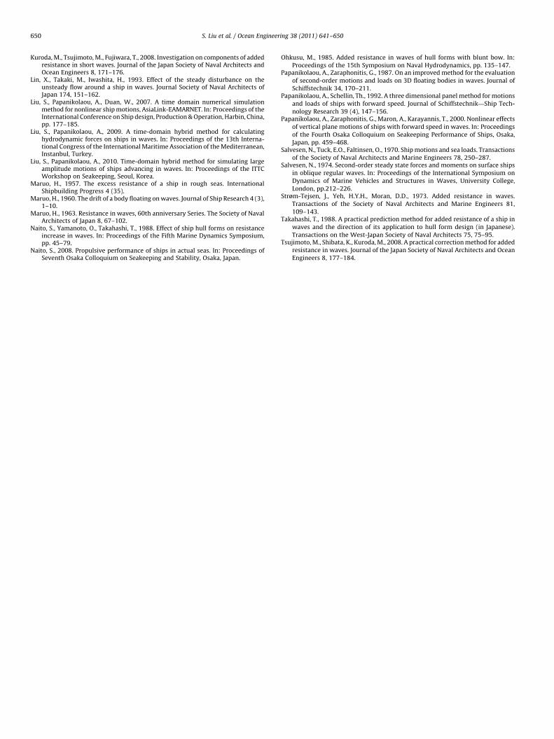
This is a quite full hull form, with Lpp¼285 m, B¼50.0 m, D¼18.5 m,Cb¼0.829 and LCB¼3.83% Lpp forward of the midship section.A panelization consisting of 819 panels on the half body was usedfor the calculations. The drift force and added resistance results areshown in Figs. 22–25, compared against experimental data. Thenumerical results agree well with the experiments, with theexception of the short waves range at the higher speeds corre-sponding to Fn¼0.10 and 0.15, where the added resistance isunder-predicted. However, in this range of wavelengths, calcula-tions based on the asymptotic formulae of Faltinsen et al. and alsoof Kuroda and Tsujimoto resulted in a very good agreement withthe experimental data. Note that in this case of full bodies at lowspeed, no viscous correction for motion damping proves necessary,because of the resulting small amplitude motion responses and ofrelated nonlinearities, along with limited forward speed effects.
4. Summary and conclusions
The added resistance problem of ships in waves has been solvedfollowing Maruo’s far-field theory and numerically implemented
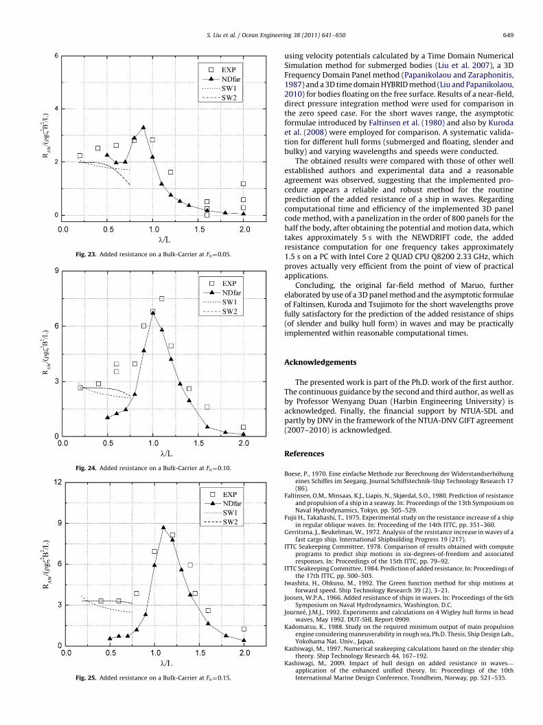
Fig. 23. Added resistance on a Bulk-Carrier at Fn¼0.05.
Fig. 24. Added resistance on a Bulk-Carrier at Fn¼0.10.
Fig. 25. Added resistance on a Bulk-Carrier at Fn¼0.15.
S. Liu et al. / Ocean Engineering 38 (2011) 641–650 649
using velocity potentials calculated by a Time Domain NumericalSimulation method for submerged bodies (Liu et al. 2007), a 3DFrequency Domain Panel method (Papanikolaou and Zaraphonitis,1987) and a 3D time domain HYBRID method (Liu and Papanikolaou,2010) for bodies floating on the free surface. Results of a near-field,direct pressure integration method were used for comparison inthe zero speed case. For the short waves range, the asymptoticformulae introduced by Faltinsen et al. (1980) and also by Kurodaet al. (2008) were employed for comparison. A systematic valida-tion for different hull forms (submerged and floating, slender andbulky) and varying wavelengths and speeds were conducted.
The obtained results were compared with those of other wellestablished authors and experimental data and a reasonableagreement was observed, suggesting that the implemented pro-cedure appears a reliable and robust method for the routineprediction of the added resistance of a ship in waves. Regardingcomputational time and efficiency of the implemented 3D panelcode method, with a panelization in the order of 800 panels for thehalf the body, after obtaining the potential and motion data, whichtakes approximately 5 s with the NEWDRIFT code, the addedresistance computation for one frequency takes approximately1.5 s on a PC with Intel Core 2 QUAD CPU Q8200 2.33 GHz, whichproves actually very efficient from the point of view of practicalapplications.
Concluding, the original far-field method of Maruo, furtherelaborated by use of a 3D panel method and the asymptotic formulaeof Faltinsen, Kuroda and Tsujimoto for the short wavelengths provefully satisfactory for the prediction of the added resistance of ships(of slender and bulky hull form) in waves and may be practicallyimplemented within reasonable computational times.
Acknowledgements
The presented work is part of the Ph.D. work of the first author.The continuous guidance by the second and third author, as well asby Professor Wenyang Duan (Harbin Engineering University) isacknowledged. Finally, the financial support by NTUA-SDL andpartly by DNV in the framework of the NTUA-DNV GIFT agreement(2007–2010) is acknowledged.
References
Boese, P., 1970. Eine einfache Methode zur Berechnung der Widerstandserhohungeines Schiffes im Seegang. Journal Schiffstechnik-Ship Technology Research 17(86).
Faltinsen, O.M., Minsaas, K.J., Liapis, N., Skjørdal, S.O., 1980. Prediction of resistanceand propulsion of a ship in a seaway. In: Proceedings of the 13th Symposium onNaval Hydrodynamics, Tokyo, pp. 505–529.
Fujii H., Takahashi, T., 1975. Experimental study on the resistance increase of a shipin regular oblique waves. In: Proceeding of the 14th ITTC, pp. 351–360.
Gerritsma, J., Beukelman, W., 1972. Analysis of the resistance increase in waves of afast cargo ship. International Shipbuilding Progress 19 (217).
ITTC Seakeeping Committee, 1978. Comparison of results obtained with computeprograms to predict ship motions in six-degrees-of-freedom and associatedresponses. In: Proceedings of the 15th ITTC, pp. 79–92.
ITTC Seakeeping Committee, 1984. Prediction of added resistance. In: Proceedings ofthe 17th ITTC, pp. 500–503.
Iwashita, H., Ohkusu, M., 1992. The Green function method for ship motions atforward speed. Ship Technology Research 39 (2), 3–21.
Joosen, W.P.A., 1966. Added resistance of ships in waves. In: Proceedings of the 6thSymposium on Naval Hydrodynamics, Washington, D.C.
Journee, J.M.J., 1992. Experiments and calculations on 4 Wigley hull forms in headwaves, May 1992. DUT-SHL Report 0909.
Kadomatsu, K., 1988. Study on the required minimum output of main propulsionengine considering maneuverability in rough sea, Ph.D. Thesis, Ship Design Lab.,Yokohama Nat. Univ., Japan.
Kashiwagi, M., 1997. Numerical seakeeping calculations based on the slender shiptheory. Ship Technology Research 44, 167–192.
Kashiwagi, M., 2009. Impact of hull design on added resistance in waves—
application of the enhanced unified theory. In: Proceedings of the 10thInternational Marine Design Conference, Trondheim, Norway, pp. 521–535.
S. Liu et al. / Ocean Engineering 38 (2011) 641–650650
Kuroda, M., Tsujimoto, M., Fujiwara, T., 2008. Investigation on components of addedresistance in short waves. Journal of the Japan Society of Naval Architects andOcean Engineers 8, 171–176.
Lin, X., Takaki, M., Iwashita, H., 1993. Effect of the steady disturbance on theunsteady flow around a ship in waves. Journal Society of Naval Architects ofJapan 174, 151–162.
Liu, S., Papanikolaou, A., Duan, W., 2007. A time domain numerical simulationmethod for nonlinear ship motions, AsiaLink-EAMARNET. In: Proceedings of theInternational Conference on Ship design, Production & Operation, Harbin, China,pp. 177–185.
Liu, S., Papanikolaou, A., 2009. A time-domain hybrid method for calculatinghydrodynamic forces on ships in waves. In: Proceedings of the 13th Interna-tional Congress of the International Maritime Association of the Mediterranean,Instanbul, Turkey.
Liu, S., Papanikolaou, A., 2010. Time-domain hybrid method for simulating largeamplitude motions of ships advancing in waves. In: Proceedings of the ITTCWorkshop on Seakeeping, Seoul, Korea.
Maruo, H., 1957. The excess resistance of a ship in rough seas. InternationalShipbuilding Progress 4 (35).
Maruo, H., 1960. The drift of a body floating on waves. Journal of Ship Research 4 (3),1–10.
Maruo, H., 1963. Resistance in waves, 60th anniversary Series. The Society of NavalArchitects of Japan 8, 67–102.
Naito, S., Yamanoto, O., Takahashi, T., 1988. Effect of ship hull forms on resistanceincrease in waves. In: Proceedings of the Fifth Marine Dynamics Symposium,pp. 45–79.
Naito, S., 2008. Propulsive performance of ships in actual seas. In: Proceedings ofSeventh Osaka Colloquium on Seakeeping and Stability, Osaka, Japan.
Ohkusu, M., 1985. Added resistance in waves of hull forms with blunt bow. In:Proceedings of the 15th Symposium on Naval Hydrodynamics, pp. 135–147.
Papanikolaou, A., Zaraphonitis, G., 1987. On an improved method for the evaluationof second-order motions and loads on 3D floating bodies in waves. Journal ofSchiffstechnik 34, 170–211.
Papanikolaou, A., Schellin, Th., 1992. A three dimensional panel method for motionsand loads of ships with forward speed. Journal of Schiffstechnik—Ship Tech-nology Research 39 (4), 147–156.
Papanikolaou, A., Zaraphonitis, G., Maron, A., Karayannis, T., 2000. Nonlinear effectsof vertical plane motions of ships with forward speed in waves. In: Proceedingsof the Fourth Osaka Colloquium on Seakeeping Performance of Ships, Osaka,Japan, pp. 459–468.
Salvesen, N., Tuck, E.O., Faltinsen, O., 1970. Ship motions and sea loads. Transactionsof the Society of Naval Architects and Marine Engineers 78, 250–287.
Salvesen, N., 1974. Second-order steady state forces and moments on surface shipsin oblique regular waves. In: Proceedings of the International Symposium onDynamics of Marine Vehicles and Structures in Waves, University College,London, pp.212–226.
Strøm-Tejsen, J., Yeh, H.Y.H., Moran, D.D., 1973. Added resistance in waves.Transactions of the Society of Naval Architects and Marine Engineers 81,109–143.
Takahashi, T., 1988. A practical prediction method for added resistance of a ship inwaves and the direction of its application to hull form design (in Japanese).Transactions on the West-Japan Society of Naval Architects 75, 75–95.
Tsujimoto, M., Shibata, K., Kuroda, M., 2008. A practical correction method for addedresistance in waves. Journal of the Japan Society of Naval Architects and OceanEngineers 8, 177–184.