Post Production
320
Post Production Unit - 1 Post-production is part of the process of filmmaking , video production , and photography . Post- production includes all stages of production occurring after shooting or recording individual program segments. Post-production is the third and final major phase of the production process . It is often referred to simply as post, e.g. "We can sort that out in post". There are many things which can happen in post-production. Common tasks include: Editing video footage Editing the soundtrack, adding sound effects, music, etc. Adding titles and graphics Colour and exposure correction Adding special effects Re-shooting certain scenes if required ("pick-up" shots) In some cases post-production is relatively straightforward, consisting of choosing and arranging footage in the correct sequence. In most cases however, post-production is a time-consuming job taking longer than the actual production phase. Currently we’re in the middle of post-production for VGHS, which probably causes some of you out there to wonder what exactly “post-production” for a feature-length webseries entails. I figure I might outline the various steps and tasks that post production entails so you can have a bit more context in the coming weeks. “Post Production” for any sort of film or video project is a generally linear process, assuming you mostly did your job right in the pre-production and production phases (more information on those aspects in another post). As the term suggests, “Post” happens after the principal photography is finished. Broadly, it encompasses: Picture editing Sound effects editing Music composition Visual effects
-
Upload
khangminh22 -
Category
Documents
-
view
0 -
download
0
Transcript of Post Production

Post Production
Unit - 1
Post-production is part of the process of filmmaking, video production, and photography. Post-production includes all stages of production occurring after shooting or recording individual program segments. Post-production is the third and final major phase of the production process. It is often referred to simply as post, e.g. "We can sort that out in post".
There are many things which can happen in post-production. Common tasks include:
Editing video footage Editing the soundtrack, adding sound effects, music, etc. Adding titles and graphics Colour and exposure correction Adding special effects Re-shooting certain scenes if required ("pick-up" shots)
In some cases post-production is relatively straightforward, consisting of choosing and arrangingfootage in the correct sequence. In most cases however, post-production is a time-consuming job taking longer than the actual production phase.
Currently we’re in the middle of post-production for VGHS, which probably causes some of you out there to wonder what exactly “post-production” for a feature-length webseries entails. I figure I might outline the various steps and tasks that post production entails so you can have a bit more context in the coming weeks.
“Post Production” for any sort of film or video project is a generally linear process, assuming youmostly did your job right in the pre-production and production phases (more information on those aspects in another post). As the term suggests, “Post” happens after the principal photography is finished. Broadly, it encompasses:
Picture editing
Sound effects editing
Music composition
Visual effects

Sound mixing
Color correction
That’s also (roughly) the order things happen, although there’s the occasional round tripping between steps.
Breaking each step down further:
Post-production is many different processes grouped under one name. These typically include:
Video editing the picture of a television program using an edit decision list (EDL)
Writing, (re)recording, and editing the soundtrack.
Adding visual special effects - mainly computer-generated imagery (CGI) and digital copy from which release prints will be made (although this may be made obsolete by digital-cinema technologies).
Sound design, sound effects, ADR, foley, and music, culminating in a process known as sound re-recording or mixing with professional audio equipment.
Transfer of colour motion picture film to video or DPX with a telecine and color grading (correction) in a color suite.
The post-production phase of creating a film usually takes longer than the actual shooting of thefilm and can take several months to complete because it includes the complete editing, colour correction, and the addition of music and sound. The process of editing a movie is also seen as the second directing because through post-production it is possible to change the intention of the movie. Furthermore, through the use of color grading tools and the addition of music and sound, the atmosphere of the movie can be heavily influenced. For instance, a blue-tinted movie is associated with a cold atmosphere and the choice of music and sound increases the effect of the shown scenes to the audience.
Post-production was named a "dying industry" by Phil Izzo. The once exclusive service offered by high-end post-production facilities have been eroded away by video editing software that operates on a non-linear editing system (NLE). As such, traditional (analogue) post-production services are being surpassed by digital, leading to sales of over $6 billion annually.
Television
In television, the phases of post-production include: editing, video editing, sound editing, animation and visual effects insertions, viewing and the start of the airing process. It is imperative that post-production executes and oversees the preparation until the final product iscompletely ready.

Photography
Professional post-producers usually apply a certain range of image editing operations to the rawimage format provided by a photographer or an image-bank. There is a range of proprietary andfree and open-source software, running on a range of operating systems available to do this work.
The first stage of post-production usually requires loading the raw images into the post-production software. If there is more than one image, and they belong to a set, ideally post-producers try to equalize the images before loading them. After that, if necessary, the next step would be to cut the objects in the images with the Pen Tool for a perfect and clean cut. The nextstage would be cleaning the image using tools such as the healing tool, clone tool, and patch tool.
The next stages depend on what the client ordered. If it's a photo-montage, the post-producers would usually start assembling the different images into the final document, and start to integrate the images with the background.
In advertising, it usually requires assembling several images together in a photo-composition.
Types of work usually done:
Advertising that requires one background (as one or more images to assemble) and one or more models. (Usually, the most time consuming as a lot of times these are image bank images which don't have much quality, and they all have different light and color as they were not controlled by only one photographer in one set location)
Product-photography that usually requires several images of the same object with different lights, and assembled together, to control light and unwanted reflections, or to assemble parts that would be difficult to get in one shot, such as a beer glass for a beer advertising. (Sometimes to composite one image of a beer glass it requires 4 or 5 images: one for the base, one for the beer, one for the label, one for the foam, and one or more for splashing beer if that is desired)
Fashion photography that usually requires a really heavy post-production for editorial or advertising.
Music
Techniques used in music post-production include comping (compiling the best portions of multiple takes into one superior take), timing and pitch correction (perhaps through beat quantization), and adding effects. This process is typically referred to as mixing and can also involve equalization and adjusting the levels of each individual track to provide an optimal sound experience.[3] Contrary to the name, post-production may occur at any point during recording and production process and is non-linear and nonveridic.

PICTURE EDITING
Generally, the first step is to have an assistant editor come in and organize the project file and footage in a clear and clean fashion. The footage is brought into the editing program, each clip’s metadata is manually entered (shot, take number, type of shot, notes on the action within the shot, etc.)
Assistant Editor is pretty much the Worst Job on a Film, second to Animal Waste Manager. It’s like getting all the Legos out and having to sort them by color and piece into separate bins so your big brother (the editor) can come in and build something totally rad and awesome out of it(also you’re not invited to the Lego party afterwards). But if you’re going the usual Hollywood apprenticeship route and you wish to become an editor, you gotta cut your teeth on moving virtual files around inside a computer for a while.
Additionally, nowadays, the assistant editor’s job also includes transcoding footage (re-encodingthe video file to something that works better with the editing program), handling incoming visual effects files, and maybe even mocking up visual effects. So it’s a job that pretty much sucks more now than it used to when you were handling film, which could burn you to death at possibly any moment.
After the project file is hot to trot, the editor shoves the assistant gently aside and starts cutting together the picture. Usually the first step is to complete an assembly, which is basically laying out the scenes in broad strokes according to the script. After that, the cut is refined and improved in successive iterations until you arrive at a product that generally pisses the editor offthe least.
During the editing process, the editor will loudly verbally direct a healthy amount of vitriol at actors, extras, the cinematographer, the camera operator, the assistant camera people, the sound people, and basically everyone except the caterers. If you were to just go off of what the editor is screaming at his computer, you’d assume that the editor is a knight in diamond encrusted armor perched atop a hill heroically swooping in to singlehandedly save this trainwreck of a project.
That would be incorrect. The editor is actually a knight in diamond encrusted armor riding a flaming dragon whose wingbeats stir the air in such a way that hard surfaces vibrate the Freebird solo continuously who has come to save your project.
Of course, the truth is the editor is only taking pieces that everyone else got for him to create the final product. It’d be like building a Lego spaceship and concluding that the entire country ofDenmark is worthless. But don’t tell him or her that because, well, you need them for now.
While editing in this phase, it’s important to lay in as many sound effects and as much temp music as you can, because that stuff greatly affects the perceived pace and smoothness of the sequence.

The time this portion takes can vary greatly depending on the nature of the project and how theproject was shot. A movie like Hitchcock’s Rope, which is comprised of nothing but long single takes strung together to look like one continous shot, would probably take a few hours to edit. Amuch more complex project with loads of visual effects and parallel storylines (like, I dunno, VGHS) takes comparatively longer.
During this time, shots you wish you had (or in most cases, shots you really desparately need) become immediately obvious. You’ll make a list of these and then go out, round up the actors again, and have a day or two of reshoots. Maybe you want to change how a scene starts off or maybe you really need a line to clarify something that makes no sense – once the project is edited, these things become extremely obvious.
Once the editor has pounded at the keyboard for a while, he or she is so sick of working on it that they’ll refuse to change another frame. At that point, the movie is “picture locked.” Back in the days of film, that meant there were no more changes to the edit from that point onward. With the wonders and horrors of digital technology, picture lock isn’t as locked down as it used to be. There will often be going back to the picture to readjust things all the way up till the end.
But if you’re a true editing badass, a locked picture should be locked like Fort Knox.
SOUND EFFECTS EDITINGAt this point, the sound department steps in and handles two very important things:
1. Make everything anybody says sound good and clear
2. Make everything that’s supposed to make a sound make that sound
When you’re shooting there’s unlimited choice in terms of camera angles and how you shoot it. When you edit, you can only work with what got recorded to the cameras. When you edit sound, you only have the locked edit to go off of.
When editing the dialogue, dialogue editors may go back through other takes to find different line readings, or replace words that are overlapped by sounds that occurred on set. They’ll also make note of lines that need re-recording for whatever reason. That process is known as ADR. Ifyou ever see a movie and characters are talking and a helicopter is landing or taking off next to them, odds are the dialogue you hear was rerecorded later in a studio with the actors watching themselves and trying to match what they were shouting at each other on set.
MUSIC COMPOSITIONAfter picture lock, the director will sit down the project’s composer, who could be anybody from“somebody legitimate” to “my neighbor because he has a cool band.” They’ll go over the edit and discuss points where music is appropriate, and what that music feels like.

The tendancy is often to just lay down music everywhere, but next time you go to a movie, make a note as to how often you’re hearing any sort of score underneath a scene. American films tend to have a lot more music than foreign films, but a lot less music than student films, which 94% of the time end up being music videos without cutaways of a band playing (probably because the band would be a dude playing a clarinet and a dude playing a piano. Also the clarinet is out of tune).
After the composer and director agree on wall-to-wall wailing electric guitar solos for the score, the composer straps on his electric guitar and starts wailing power chords while the director throws up the horns and headbangs until it’s all finished.
VISUAL EFFECTSVisual effects can generally be broken down into two types:
1. Visual effects that nobody ever notices
2. Visual effects that are so cool nobody remembers anything else about your movie
Type 1 Visual Effects encompasses everything from painting out cables, rig removal, digital replacing signage, blending two takes together, and generally anything that, if done properly, is completely invisible, yet fairly important. Obviously these visual effects kinda suck to do. If you can’t find anybody who will take these on, try your Assistant Editor. He’s probably jobless and you know he has no self-esteem.
Type 2 Visual Effects is basically all the cool stuff. Transforming robots, asteroids barrelling towards earth, transforming robots barrelling towards earth, etc. It’s what’s in the trailers, and what Michael Bay has made a career out of creating. Type 2 Visual Effects are acknowledged by everyone, especially females, as being Cool As Hell and you probably could do with more of them in your movie.
Visual effects often requires some coordination with the sound guys, because effects will bring with them sound elements that need to be synced up.
SOUND MIXINGOnce the sound has been edited, the dialogue nice and intelligable, and the music emotionally and spiritually uplifting, it’s up to the sound mixer to bring all these sound elements into harmony with each other.
Sound mixers often have long hair, which is to hide the fact they’re wearing earplugs. They also wear those earplugs to live events like concerts, and occasionally movies because they rely on their razor sharp hearing to make a living. Most people might think earplugs at a concert is lame

but guess what it’s actually super cool because once you lose your hearing you never get it back. So while you stumble around and struggle to hear your grandchildren tell you they love you because you listened to too much dubstep in your younger years, sound mixers and I will belaughing. All the way to the bank. Which you’ll also be unable to hear.
Sound mixing can get pretty complex nowadays – back in the day, you’d only mix for one track – mono. Now, you might be doing a 7.1 theatrical mix (that’s seven speakers and a subwoofer), and providing isolated elements to foreign countries so they can bring in local actors and redub all your actors.
Funny story – when I was doing direct-to-DVD feature films, our sales agent once complained about being unable to sell a movie to a foreign country because of the acting. “What do they care?” he said, “They’ll just dub it in Spanish anyway!”
Dynamic range, or the difference between the quietest parts and the loudest parts, is another issue in the mix. Theatrical mixes often have huge dynamic range because they can depend on avery controlled listening environment (i.e. a movie theater). Once you start doing mixes for TVs or online, the range has to be a lot less. You ever have that problem while watching a movie where you have to turn up the volume on all the dialogue parts, and turn it down when the explosions happen? That’s probably because you were dealing with the dynamic range of a theatrical mix. A ton of home audio systems actually have built-in hardware that’ll flatten out the dynamic range of a theatrical mix but it’s buried in the menus and let’s be honest nobody knows how to program those things.
Once the sound is mixed, the sound part of a movie is completely done. That just leaves…
COLOR CORRECTION
It’s not racist, despite the fact that you’ll hear phrases tossed around like “crush the blacks” and “bring up the whites.” Color correction is the last step for the visual side of a movie.The boring part of color correction involves matching the white balance and levels between shots, adjusting portions of the frame to be darker or lighter, and generally tweaking the image to make it look better.The cool part of color correction is applying a sweet “look” to the image that has the potential to greatly influence how a movie is perceived. The look could be everything from the sickly green of The Matrix, to the bleach bypassed desaturated look of Saving Private Ryan, to the super boring and pretty much black-and-white look of half of the freaking Harry Potter movies.
Most high falutin’ color correction dudes will tell you that you need a super expensive monitor to properly judge the color and the looks, similar to how audio guys will tell you that you need studio reference monitors to properly do the mix. Usually, we don’t have those things, so what we do is color correct it and then watch it on as many TVs and monitors as we can and then use that information to tweak things (that’s what we did, for example, for our Battlefield 3 commercial).

Once that’s done, you combine the final sound mix and the final color correction and you got yourself a finished movie!
The Production ProcessThe production process refers to the stages (phases) required to complete a media product, from the idea to the final master copy. The process can apply to any type of media production including film, video, television and audio recording. The stages in each medium vary; for example, there is obviously no storyboard in an audio recording. However the same general concepts work for any medium.
The three main stages of production are:
1. Pre-production: Planning, scripting & storyboarding, etc.2. Production: The actual shooting/recording.3. Post-production: Everything between production and creating the final master copy.
Pre-Production
Pre-production is a fairly loose term which refers to the tasks undertaken before production begins. Exactly what is included in this stage depends on the medium and situation.
For a small video company, pre-production may refer to everything that happens before shooting begins, for example, meeting with the client, research, storyboarding, location planning, etc.
For feature films, pre-production is more specific and only begins when other milestones have been met such as financing, screenplay, casting and major staffing. In this case pre-production includes:
Location scouting Prop and wardrobe identification and preparation Special effects identification and preparation Production schedule Set construction Script-locking (semi-finalisation of the script) Script read-through with cast, director and other interested parties
Production
In film and video, production refers to the part of the process in which footage is recorded. This is what most people imagine when they think of a film being made — actors on sets, cameras rolling, etc. The production phase is also known as principal photography.
In large feature films the beginning of the production phase marks the "point of no return", i.e. the point at which it is no longer financially viable to cancel the project. At this point it is almost always cheaper to continue until the project is finished than to deal with the financial fall-out of canceling.
The goal of principal photography is obviously to record all required shots, however it is fairly common to shoot "pick-up" shots in post-production. Pick-up shots may be required when a mistake is noticed, a script change is made (this is unusual), or even if a performance is deemed to be unsatisfactory.
In music, production usually refers to the creative direction of a project. Unlike a film producer who is more of a manager, a music producer has a very hands-on role in the creative development.
Film Production Pipeline

At last, we get to the end of the film pipeline. Postproduction is everything that comes after shooting has finished (except for pick-up shots, which are just more production, and won't be covered except to say that if you're doing any something went wrong and hopefully you left room in your budget for reshooting. If not, a great postproduction crew (especially a great Editor) may be able to save your film anyway. Maybe even make it just as good, if not better, than it would have been had you spent money reshooting and skimped on post. Here is a visual guide to postproduction, followed by a summary of the process:
Acquisition Before any postproduction happens, your footage must be taken into the system. If you're shooting film and cutting the negative you shot, then you're all set -- and you're probably also time-shifted back about 20 years or so. Even if you are cutting film, you'll want to make a dupe neg, cut that, and then conform the original negative. More likely, however, you're going to scanyour film digitally, or deliver your digital footage into the digital system (and then ultimately either do a negative conform to the digital edit decision list to create the dupe neg -- or just make your dupe negatives using a film printer). Both film and digital delivery into post may require conversion (not all digital formats are the same). Either you've set aside money in your budget for this or, and only a no-budget shooter would even contemplate this, you're going to spend a ton of time mastering the conversion system and acquiring footage yourself. No, simply opening up Final Cut doing the default acquire for your device isn't going to give you the best possible results.

Visual Effects and Effects
Editing Visual Effects are optical or (nowadays, generally) digital techniques used to create imagery that isn't in the photographed footage. (Special Effects are practical techniques for creating effects in the photographed image, generally 0n-set and with the actors in the shot with the effect -- though not always.) The images generated can range from fantastical fantasy

and sci-fi creatures, buildings, and vehicles, to dangerous things like explosions, fires, tornadoes, and tidal waves, to "mundane" things like normal buildings and scenery (and these backgrounds may be traditional matte paintings, or sophisticated digital 3D set extensions). Effects artists work from the storyboards and photographed footage to create these new elements, compositors layer the effets work into the original plates, and effects editors cut the results back into the film based on the Editor's overall pacing and tone decisions balanced against the special requirements of the effect. VFX is an extremely technically complex aspect of filmmaking, and it since most Indie Auteurs won't be dealing with VFX much, if at all, it's a topic best left to a future post -- but only after the release of the Handbook for which I am writing chapters about pipeline.
Editing, Sound (Editing, Design, Foley, Dialog Editing and A.D.R.)and Music (Scoring)
Editing is the third and final major revision of your film. First the script (and boards, if you made any) were revised and revised. Then the film was shot, with all sorts of on-set decisions being made that changed the shape of the film. The editing room is where the last big changes are made before the film is released. The basics of editing are simple: look at the shooting script, breakdown, shot logs, and footage, and create from the footage what is in the breakdown. However, a skilled Editor has as his or her job helping the Director make the best possible film, including going off script and picking different takes than the circle take, changing shot order and length, and pretty much anything else than can feasibly be done given the footage in the can. Collaboration with a great editor always results in a much better film. Since editing is assembly of the final film, this is where the pacing and tone is established. Pacing is allabout timing. When do we see what, and for how long? What comes before and after? Tone is in part dictated by pacing and what is left in and what is taken out of the material. It is also in part dictated by the acting -- but it is also the result of choices made about sound design, music, and color palette. During the Edit phase of postproduction, generally the longest phase (unless it is a VFX heavy film, in which case the craft-intensive VFX work may take longer than everything else involved in making the film combined), pacing and tone are the order of the day, and that is what everyone is working on: trying to use picture and sound to get the proper emotional impact out of every moment in the film.
Here are some of the specific jobs involved in doing so:
Editor:

While the editor generally does the actual work of cutting the picture his or her self, they are also the person responsible for the overall editing of the film. Other than the Director, the Editor has the most influence over the pacing and tone of the film because all other editorial decisions are made based on what is happening in the picture edit.Assistant Editors: Handle acquisition, logging, data management (of footage and sound, but also script, breakdown, and shot log info in a database) for the editor. May also do rough assemblies of sequences for the editor (sticking closely to the breakdown, log and shooting script specifications).Sound Editor: The person responsible for editing sound on the film, which may mean all the sound, or it may mean all the sound except for the music, or it may mean just the sound effects and foley (the term comes from the latter, but in the cases of very talented major sound editorsand/or low budget features with small crews, the sound editor may do all the sound). Without the effects and foley, a film sounds quite flat and lifeless -- this is a very important job that is often underappreciated.
Dialog Editor:
In the traditional case where Sound Editor is responsible for effects and foley editing, the DialogEditor is responsible for the potentially very complex task of dialog editing. This means cutting in and syncing-up the best possible dialog choices that correspond to the picture editing choices. This may mean trimming, cleanup, and sync of dialog from the same take, or clever manipulation and syncing of dialog from one or more other takes. When the dialog is spotty foreither technical or performance reasons, the Editor may be doing a lot of tricky cuts that in turnmean tricky cutting and syncing for the Dialog Editor.Sound Designer: Sometimes a Sound Editor does all their own effects selection and/or performance, and sometimes they work with a full-time Sound Designer whose job is to create new sound effects.
Foley Artist:
A Foley Artist is basically a performance sound designer whose job is to create, in real-time as they watch running footage, sound effects that match the image. Foley Artists are the ones who clap blocks together for running horses and punch slabs of meat and break bambook for

fistfights. Digital sound design and editing is making Foley less common, which is a shame as it's a lot of fun.
A.D.R. Editor:
Additional/alternate Dialog Recording, or Dubbing, is the process of replacing the voices in a film with alternate performances. Dubbing foreign language films is one use, but the one we care about here is using A.D.R. to salvage footage that has good picture but bad sound (either for technical or performance reasons), or to add or change dialog because something isn't working in the text. The A.D.R. Editor works with the Director to guide the Actor through this process, in which they watch the shots being altered, and attempt to deliver the new performance in a manner that fits the footage as closely as is possible.
Composer and Orchestrator:
The Composer and Orchestrator create the score to match the film. Sometimes this is done well before postproduction begins, though that is suboptimal. It is much more successful for a Composer and Orchestrator to score based on early edits of the film, refine until the film is nearfinal picture, and then let the orchestra, band or synthesist perform the score while watching something close to the final edit.
Music Editor:
A Music Editor may edit the score into the film in the case where the Sound Editor is only a sound effects and Foley editor. In the common case where things change after the Composer and Orchestrator have already wrapped off the film, the Music Editor is responsible for recutting the existing musical performances in a way that best fits the changed picture and sound edit.In order to nail down the pacing and tone, Editing is often done in close collaboration with sound editing, dialog editing, sound design, and scoring. The timing of shots influences the length of pieces in the score, and where the highs and lows are placed in the music, and vice-versa. The same goes for sound design and editing. Each new cut of the picture influences the Sound Mix.

Sound Mix
All that editing results in an assemblage in which the timing may be perfect, but the sound and picture levels most likely are not. Sound mixing is the process of getting all those levels right forthe sound, and balancing the dialog, effects/Foley, and music in a manner that allows the audience to always hear the text, and brings forward the music and backgrounds for effect at appropriate moments.
The dialog and effects/Foley are generally mixed separately from the music, which is mixed by a professional music producer/mixer in the manner music is mixed for an album release (i.e. the levels are mixed relative to the rest of the music to create tonal and emotional dynamics). Only then is a final sound mix done where the three elements are brought together and the overall levels are balanced out so that the text is comprehensible while also giving you the layers of background and music that make it feel like a film to an audience.
How the three elements of sound are first edited, and then mixed, heavily influences the tone of the film. If you've got the same war footage, adding bombastic music and keeping the sound effects frequent, loud and clear (Michael Bay, etc.) is a much different tone than adding brooding music and/or occasionally bringing in a cacophony of sounds atop a baseline of muted backgrounds or outright siglence (Saving Private Ryan Beachhead Scene, etc.).
On very low budget films, the Sound Editor may very well also be the Sound Mixer (and maybe even the Music Mixer), and all the cleanup and mixing may happen on an ongoing basis alongside the editing.
Color Grading / Timing and "D.I."
Color Grading is the process of digitally adjusting the imagery to get the final visual tone, similarto how sound mixing creates the final aural tone. If a lot of manipulation is done to the image, sometimes the term "Telecine" or "Digital Intermediate" is used instead of Color Grading (even though no matter how little you do to the image, any process that takes film, digitizes it, digitally alters the image, and then films out for release is a digital intermediate process). Color Timing is a holdover term from optical filmmaking wherein the final color was balanced by timing how long each color of light was shining on each frame during exposure of the dupe negative.

All this terminology just means: we took the original image, possibly converted it to a different format, and then did something to it to modify the appearance of the image in frame.
What is done can be subtle or extreme. Traditional grading consists simply of adjusting the color and value of the image (optically or digitally) so that adjoining shots that are supposed to appear to the audience as being in the same time and place look as much like they were shot under the same lighting conditions as possible.
But a lot of the tone of a film comes from this process. When Directors and DPs have ideas about the thematic, emotional, or philosophical aspects of a film being coded by a look -- warm vs cool, high contrast vs low, and so on -- they traditionally did as much of that as they can with on-set lighting. But rarely is that perfect, and shots must be corrected relative to each other.
This correction technology evolved to today's digital technology, which is causing more people to shoot a neutral palette put off the final decisions about tone until post. (Why taking that attitude too far can easily lead to acting performances that don't match your tone may seem obvious, but if it were so obvious it wouldn't happen so often and thus it still will wind up the topic for a future post).
Extreme lighting effects (deep blue lighting, extremely high contrast, etc.) which when done on-set could pose a high risk to the footage being usable at all are now more often being shot with a more subtle on-set treatment and "punched up" in post -- or whole new looks are created in post, using digital tools (if you've never seen a big grading system like a Lustre, think Magic Bullet Colorista or Apple Color (or the built in FCP color grading) or the keying, rotoing and colormanipulation parts of After Effects or Shake on steriods, and if you've never seen any of those things -- think Photoshop optimized for moving images, and then some).
Print It!
Once you've done all this, there's nothing left to do but print the film and release it. (Which involves mastering and printing, distribution deals, the logistics of the distribution process, marketing and advertising, merchandising, publicity, and other things that will be covered in future articles.)
There is a saying in the business that projects are never finished, they're abandoned. Eventually you run out of budget, or energy, or inspiration -- or a Studio Executive arrives to inform you

that either your film arrives at the duplication house tomorrow, or you'll never work in this townagain. Then you're done.
If all has gone well, you've done every thing in all four pipeline posts at least twice (meaning you've iterated on every step a couple times, done at least a couple takes of every shot, and generally given yourself and your crew the opportunity to make changes for the better at every step along the way).
Production Pipe line of 2D film
The animation production process, as with any other projects is divided into three parts, namelythe pre-production, production, and post-production process.
Under the pre-production process for animation is the script, storyboarding, audio recording,animatic, character, prop and location design, color styling, and color model sheet. The pre-production sets the tone for the animation production process, if it is not well conceived anddone, there will be a lot of retakes and corrections to be done in the production process and itwill be very costly in terms of time, effort and money.
In our case, we just did the production without really thinking through the concept of theanimation, so there were some corrections and realignments in the latter stages of theproduction. But because of the delays in the production process, we were able to fix ourproblems without over hauling the story and designs. We kind of just added, changed and fixedup just a few things to improve the animation. But for major changes, such as redesigning thecharacter models completely; we were not able to do so, as it would be too costly and time-consuming.
Under the production process is the background layout and posting, animation, line test,digital background, clean-up-inbetween, scanning, ink and paint, compositing and exportrendering. If the artists are not good, there will be a lot of retakes in the clean-up in-betweeningstage, as experienced in our case. Compositing also takes a long time, as errors are found outand corrected before the final rendering.
Under the post-production process are the musical scoring, sound effects, editing and outputto media.

Traditional Workflow Chart
Pre-Production
The Script
Every project starts with a script or synopsis. The script is the written version of the project. Itis the source of all the upcoming steps. The script usually contains the storyline, locationdescriptions, actions, dialogue, description of sound effects, etc. It contains all the informationnecessary for the artists to illustrate and animate the series or movie. The script is needed inorder to transform the project into a storyboard. The same script is used as a dialogue for the

audio recording. Finally, characters, props, and locations will be designed from all of thedescriptions contained in the script.
In the case of Jobert and the Crop Circle Warriors, the scriptwriter is also an artist but not ananimator, and he told each episode’s story like a rough comic book for Season 1 based on thecomic book series Jobert at Iba Pang Super Pinoys. Our challenge was these stories were tooshort for a 20-minute episode and lacked dynamic camera angles, pans, and tilts. So we had toexpand the story without straying off too much from the material. For Season 2, the samescriptwriter found it easier just to do the script in all words from the dialogues to the characterdescriptions, backgrounds etc. He says its less time consuming but we have no plans to convertit storyboard yet, as it depends if Season 1 will be shown and Season 2 will get any green lightfor production.
Sample of Script for the Project

Some Season 1 Dialogue Script
The Storyboard
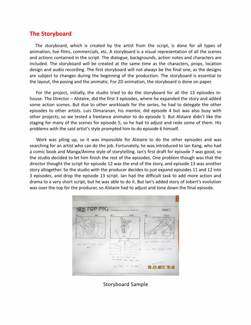
The storyboard, which is created by the artist from the script, is done for all types ofanimation, live films, commercials, etc. A storyboard is a visual representation of all the scenesand actions contained in the script. The dialogue, backgrounds, action notes and characters areincluded. The storyboard will be created at the same time as the characters, props, locationdesign and audio recording. The first storyboard will not always be the final one, as the designsare subject to changes during the beginning of the production. The storyboard is essential tothe layout, the posing and the animatic. For 2D animation, the storyboard is done on paper.
For the project, initially, the studio tried to do the storyboard for all the 13 episodes in-house. The Director – Alstaire, did the first 3 episodes, where he expanded the story and addedsome action scenes. But due to other workloads for the series, he had to delegate the otherepisodes to other artists. Luis Dimaranan, his mentor, did episode 4 but was also busy withother projects; so we tested a freelance animator to do episode 5. But Alstaire didn’t like thestaging for many of the scenes for episode 5, so he had to adjust and redo some of them. Hisproblems with the said artist’s style prompted him to do episode 6 himself.
Work was piling up, so it was impossible for Alstaire to do the other episodes and wassearching for an artist who can do the job. Fortunately, he was introduced to Ian Kang, who hada comic book and Manga/Anime style of storytelling. Ian’s first draft for episode 7 was good, sothe studio decided to let him finish the rest of the episodes. One problem though was that thedirector thought the script for episode 12 was the end of the story, and episode 13 was anotherstory altogether. So the studio with the producer decides to just expand episodes 11 and 12 into3 episodes, and drop the episode 13 script. Ian had the difficult task to add more action anddrama to a very short script, but he was able to do it. But Ian’s added story of Jobert’s evolutionwas over the top for the producer, so Alstaire had to adjust and tone down the final episode.
Storyboard Sample

Audio Recording
The audio recording is also called voice recording. the script is needed for dialogue and extrasound effects. The voice actors will read the lines from the script and record the dialogue. Thesevoices will be used later on for the animatic, the animation, and the final productioncompositing.
Due to the high price of professional voice actors, we had to audition people who had naturalvoices that would fit each character. It was a tedious process but with the help of a smallrecording studio of Chet Tiongson, we were able to get a good batch of voice talents. We had asmall group that did multiple voices in each series, even Alstaire decided to do some voices ofminor characters. We were only able to record when the storyboards were finished, whichmeant the voices were not recorded in a succession of a few days for all the episodes. Theepisodes had to be recorded a few months apart. The voice talents also had to be free fromtheir jobs, so usually, the recording starts at 8 pm due to various locations of the talents fromtheir work. The recordings would also finish about 12 midnight to 1 AM. But for the first timevoice talents, it was a fun experience.
Some problems for the recording were casting voices for the younger versions of thecharacters and we had to use multiple talents for these, and many did not make the cut. After afew years due to production delays, we found out that we were missing some dialogues, due tosome talents not being present on some recording nights. we also needed to change somedialogue to better fit the story. So we had to recall the voice talents, this time to a newrecording studio. The problem was a key voice talent, the one who voiced Jessalaine alreadysettled in Germany, so we had to find someone who had almost the same voice.
After the compositing of the final episodes, the producer decided to change the voices of 3characters to make it clearer and understandable.
Voice Recording at the Studio

The Animatic
The animatic, also known as the Leica reel, comes directly from the storyboard. The animaticis the first movie of a project and is used to help the animators and compositors. The storyboardis scanned in and mounted with sounds and dialogue. There is no animation yet. It is simply thestoryboard frames changing panel by panel with dialogues and some sound effects to helpevaluate the rhythm and the look of the show. This will help avoid mistakes that would havebeen found only at the end of the show. This step is unnecessary if you are absolutely sure ofyour storyboard and timing, but an animatic is always recommended. Generally, an externalsoftware is used to do the storyboard editing to create the animatic.
As a budding director at the start for Jobert, Alstaire wasn’t aware of the purpose ofanimatics, he figured out that we did not need it at that time. So not all the episodes for Joberthad animatics. Now, Alstaire realized that it would have helped the producer see the story andpinpoint revisions before we even started production. Instead of an animatic, what we did waswe had Luis do the sound cut for Jobert, this is the process of placing the audio in its properplace and timing based on the storyboard. Essentially, it is the animatic for in-house purposes.Since Luis was the one doing this, we were confident that the timing was good. Although after afew episodes, we had to outsource this to other experienced animators.
One mistake that Alstaire learned much from was to make sure the one doing the animaticsis experienced. In our case, the exposure sheet writer volunteered to do some episodes. WhenAlstaire checked these episodes, some were lacking in dialogue, and the person involved usedother dialogues that weren’t supposed to be there. These mistakes caused a lot of setbacks inproduction. Alstaire had to look for the missing dialogue, those that weren’t found had to berecorded again.
Design
Once the script is completed, the designer can start work. Before any animation, backgroundor coloration can be done, the design needs to be addressed. The artist has to decide on theproduction style, the character’s look, the location’ complexity, etc. Once these designs aredone and approved, the “Model Pack” is produced, containing all of the models for all theaspects. The final designs and models will be used by the color stylist and layout artist, andfinally by the animator.
The design for the series was taken directly from the comic book, which is from the JapaneseAnime look. Alstaire just did some minimal changes in the design and look of the characters tomake it better for animation. Some characters were also designed based on the storyboards of
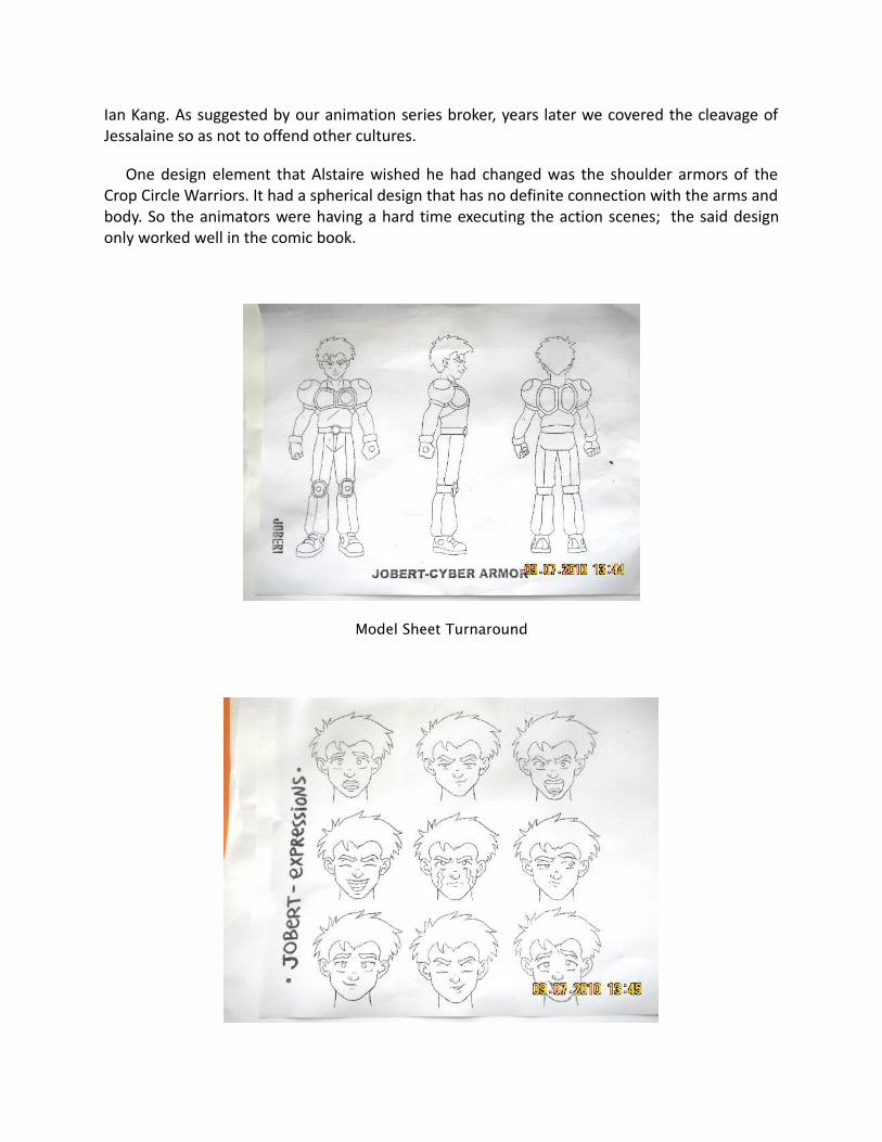
Ian Kang. As suggested by our animation series broker, years later we covered the cleavage ofJessalaine so as not to offend other cultures.
One design element that Alstaire wished he had changed was the shoulder armors of theCrop Circle Warriors. It had a spherical design that has no definite connection with the arms andbody. So the animators were having a hard time executing the action scenes; the said designonly worked well in the comic book.
Model Sheet Turnaround

Model Sheet Facial Expressions and Mouth Movement
Color Styling
Once the black and white designs are done, they are sent to color styling. The color stylist willchoose the colors and ambiance for the production and will balance the characters, props, andeffects with the locations’ palettes. The color combinations create moods for the show. Whenthe colors are approved, color models are produced and backgrounds are painted. Color modelswill often be added to the Model Pack. The color models will be used by the color artists andthe colored background will be sent to the compositing.
In the project, we took the colors from the comic book cover itself, and just enhanced somecolors and added some design elements. Shown in the last 3 pictures, the character models forJobert and Frogee Mercury were altered a bit to improve the look in the series.
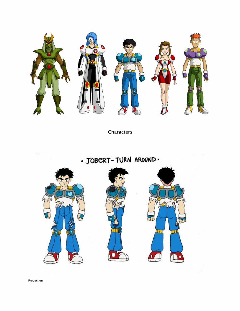
Characters
Production

Layout
The layout and posing process link the storyboard artist and the animator. The layout artistuses the storyboard and prepares an organized folder for an animator. This folder contains afield guide that shows the proper camera move and the right size of the scene. It also includesthe character’s main poses from the storyboard following the official design, the effects,backgrounds and all the other information necessary to the animator. The backgrounds aredone directly out of the storyboard and the location design. The background artist refers to thestoryboard and draws the background for each scene.
Alstaire was the only artist who had experience in layout but was already loaded with work.The studio decided to hire layout artists, but because of the low budget, we paid the artists perepisode instead of per scene as the standard practice. The first layout artist really did a badwork, so Alstaire had to redo those that were done for episodes 1 and 2. Succeeding layoutartists only finished some episodes partially because they were also doing some other jobs forother studios.
Luis agreed to layout episode 4 and Ricky Liwanag did a good job on episodes 5 to 7, but hepassed away after doing his job. With the storyboards for the remaining episodes having gooddrawings, the studio decided on just enlarging the storyboard panels to animatable size and hadthe backgrounds done by some animators. Some of the backgrounds were still poor because ofthe artists involved lacked the skill in background drawing, but Alstaire was able to fix them andother backgrounds were just adjusted during coloring.

The Layout-Pose 1 and 2 are done by the Layout Artist based on the storyboard. This will be given asguides for the animators
Background Painting
Once the background layouts are completed, they are ready to be painted. The backgroundpainter will take the final layout and paint them using the palettes created by the color stylists.Once the backgrounds are painted, they will be sent to the Scene Setup team or theCompositing team.
Joel Orcena was the one who did the backgrounds for the trailer and the first 2 episodes ofthe series. The line art done by the layout artist was sub-par, the background artist had to try toenhance them. Joel did the best he could and was able to fix the first episodes, but his familyasked him to take over his father’s business, so he had to go back to Bicol.
We needed two new background artists to continue with the series when 3 students appliedfor the job namely: Socrates Gucor, Bryan Lumantas, and Opel Maglana. Each student hadtraditional painting backgrounds and they were interested in trying digital painting. Episodes 4to 8 were their initial projects, and each episode’s background improved through time. Socrateswas the artist who seriously wanted to improve his craft and he was the one who remained till

the final episodes. So his work has vastly improved, especially in the final episodes. Bryan andOpel subsequently went back to Davao after finishing their projects. We also had some sceneswere we used 3D graphics for the background.
Samples

Animation
Once we have the Model Pack, Storyboard, Layout, and Backgrounds approved we can nowproceed to Animation. The animators create scenes by acting out the situations that thecharacter in the scene requires, they based their timing and noted it down using the ExposureSheet (X-Sheet)
Scanning
After all the hand drawings are done, those are now scanned into the computer. In largestudios, they use a large scanner with an auto feeder. These type of scanners, together with theright software, can read paper holes. So even if the paper was misaligned, the softwareautomatically puts all the pages in the right position.
Small Scanner
The large scanner with the auto feeder is too expensive for a small studio. We just used asmall home scanner and placed a peg bar, so all the paper would be centered. The problem wasthe small scanners were much slower than the large scanners, and it took up the time for theDigital Ink and Paint Artists before they can even paint; so we hired On-the-Job-Trainees,messengers or administration staff to do the scanning on their free time. This method allowedthe painters more time to paint and finish their work faster.
Today, there is a much more efficient way of production, which people in the animationindustry call Tradigital Animation…this is combining the traditional method of animation withdigital technology.
Instead of animating on paper, the animator draws directly to the computer by a digitizingtablet. The regular Wacom Tablet (Bamboo Pen) cost about P6,000, but there are less expensivebrands but those are not durable.
Compositing
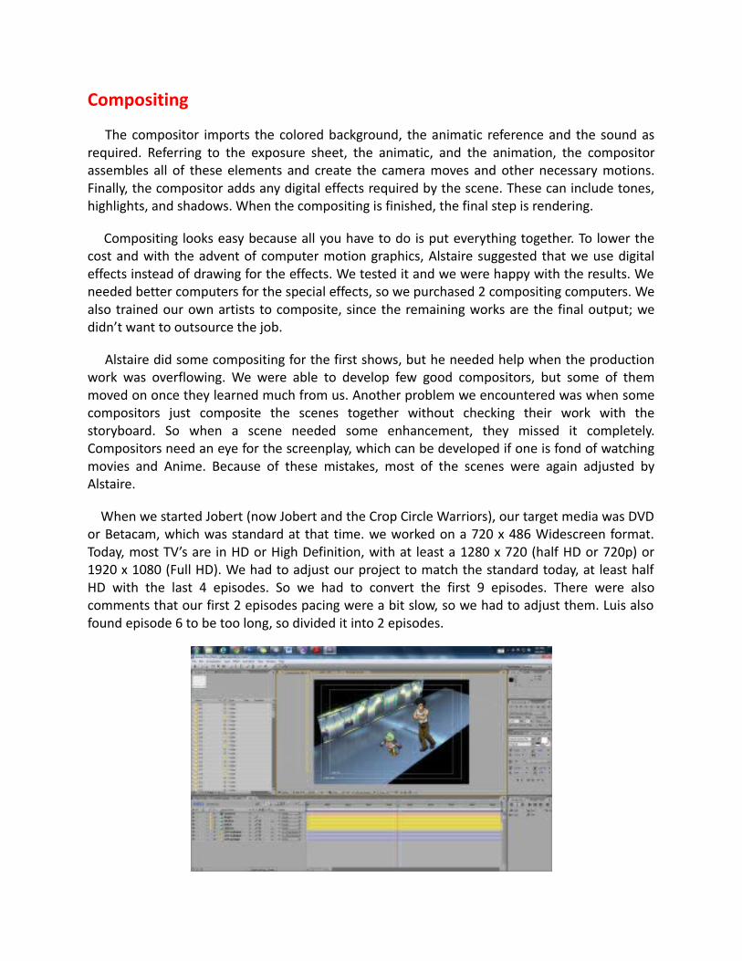
The compositor imports the colored background, the animatic reference and the sound asrequired. Referring to the exposure sheet, the animatic, and the animation, the compositorassembles all of these elements and create the camera moves and other necessary motions.Finally, the compositor adds any digital effects required by the scene. These can include tones,highlights, and shadows. When the compositing is finished, the final step is rendering.
Compositing looks easy because all you have to do is put everything together. To lower thecost and with the advent of computer motion graphics, Alstaire suggested that we use digitaleffects instead of drawing for the effects. We tested it and we were happy with the results. Weneeded better computers for the special effects, so we purchased 2 compositing computers. Wealso trained our own artists to composite, since the remaining works are the final output; wedidn’t want to outsource the job.
Alstaire did some compositing for the first shows, but he needed help when the productionwork was overflowing. We were able to develop few good compositors, but some of themmoved on once they learned much from us. Another problem we encountered was when somecompositors just composite the scenes together without checking their work with thestoryboard. So when a scene needed some enhancement, they missed it completely.Compositors need an eye for the screenplay, which can be developed if one is fond of watchingmovies and Anime. Because of these mistakes, most of the scenes were again adjusted byAlstaire.
When we started Jobert (now Jobert and the Crop Circle Warriors), our target media was DVDor Betacam, which was standard at that time. we worked on a 720 x 486 Widescreen format.Today, most TV’s are in HD or High Definition, with at least a 1280 x 720 (half HD or 720p) or1920 x 1080 (Full HD). We had to adjust our project to match the standard today, at least halfHD with the last 4 episodes. So we had to convert the first 9 episodes. There were alsocomments that our first 2 episodes pacing were a bit slow, so we had to adjust them. Luis alsofound episode 6 to be too long, so divided it into 2 episodes.

The first picture is the composited scene with Jobert and Frogee Mercury talking andwalking in a hallway. The problem was the background artist only did the hallway the length ofthe screen, the background should be moving while the 2 characters are walking. In the secondpicture, the compositor converted the floor and walls into 3D planes, and mirrored the edges,effects were added to create an illusion of a long hallway.
Export
Once the compositing is completed, the final step is to render the scene as a movie or animage sequence. Generally, the compositor will be the same person to do the rendering.
Even with 2 powerful computers, rendering is time-consuming. It would take about 15 hoursto render one episode in Standard Definition. We have not yet rendered one full episode in HDyet, so we are not sure how many hours it will take to render.
Post-Production
Musical Score and Sound Effects
A musical score is an original music written specifically to accompany a film. The score formspart of the film’s soundtrack, which also usually includes dialogue and sound effects, andcomprises a number of orchestral, instrumental or choral pieces called cues which are timed tobegin and end at specific points during the film in order to enhance the dramatic narrative andthe emotional impact of the scene in question.
Sound effects or audio effects are artificially created or enhanced sounds, or sound processesused to emphasize artistic or other content or films, television shows, live performance,animation, video games, music, or other media.
When we did our first teaser trailer for Jobert, we found a small recording studio with ChetTiongson as our Scorer. He did a great job with the teaser trailer. When he did the first episodethough, Alstaire found it inferior from the scoring of the teaser. Maybe because an episode waslonger, and it was harder to do multiple musics for different scenes. Chet was also limited in hissound effects, we were expecting him to build the sound effects because he had a sound booth.Anyway, we told Chet about this, and he fixed it a bit. But we still weren’t satisfied with what hedelivered.
We then found another Scorer based in Davao, Charles Fournier, he did episode 2 and 8, thescore was better but he also lacked sound effects. Alstaire suggested some sites where he couldget better effects and Charles tried to add more, but we all felt it was still lacking. When thefinal edit was done, Alstaire just added the extra sounds needed to make it better. Alstaire evenadded a music loop in one transformation scene and it really added drama to the scene.
For our third episode, Diwa de Leon added good music, but the sound effects are a bit lacking.So we downloaded more sound effects as production went on, so we can fill in the missingsound effects in Post Production.
Editing
Editing is choosing segments of the animation production footage, sound effects, and soundrecordings in the post-production process that will be in the final output.
After rendering an episode into an image sequence in compositing, we then edit it with thesound and music so it will render much faster to the chosen media. We had to shorten, cut andspeed up some scenes to have better pacing for an episode. We also put cuts for commercialbreaks and add the intro and credits.
Problems Encountered During Compositing and Editing
In our case, due to our low budget, there is a lack of workforce; our director is also the onehandling the compositing and editing. So all the problems mentioned below are also hisresponsibility to fix-up. Hence, even in the last stages of production we still experienced delays.In our case, we prefer to complete all the episodes and the other collaterals before sending it tothe broker/s for review by the distributors.
1) New Compositors and Editors
The new compositors and editors (newbies) lack knowledge and feel of the story are proneto mistakes in their job, so the director had to redo some scenes, especially those that neededeffects.

2) Special Effects Missing or Does Not Match with Earlier Finished Episodes
The latter episodes employed new and better special effects because of the newersoftware and technology. So we had to fix-up the special effects from the earlier finishedepisodes to catch-up with the newer episodes. The newbies also lacked the experience and skillin compositing and special effects, so what they did was somewhat lacking, so those had to beredone too. As seen below, the software wherein the gun was fired automatically created theshadows in the background and the hand.
Episode 1 – Special Effects Original
Episode 1 – Special Effects Correction
3) Color Grading
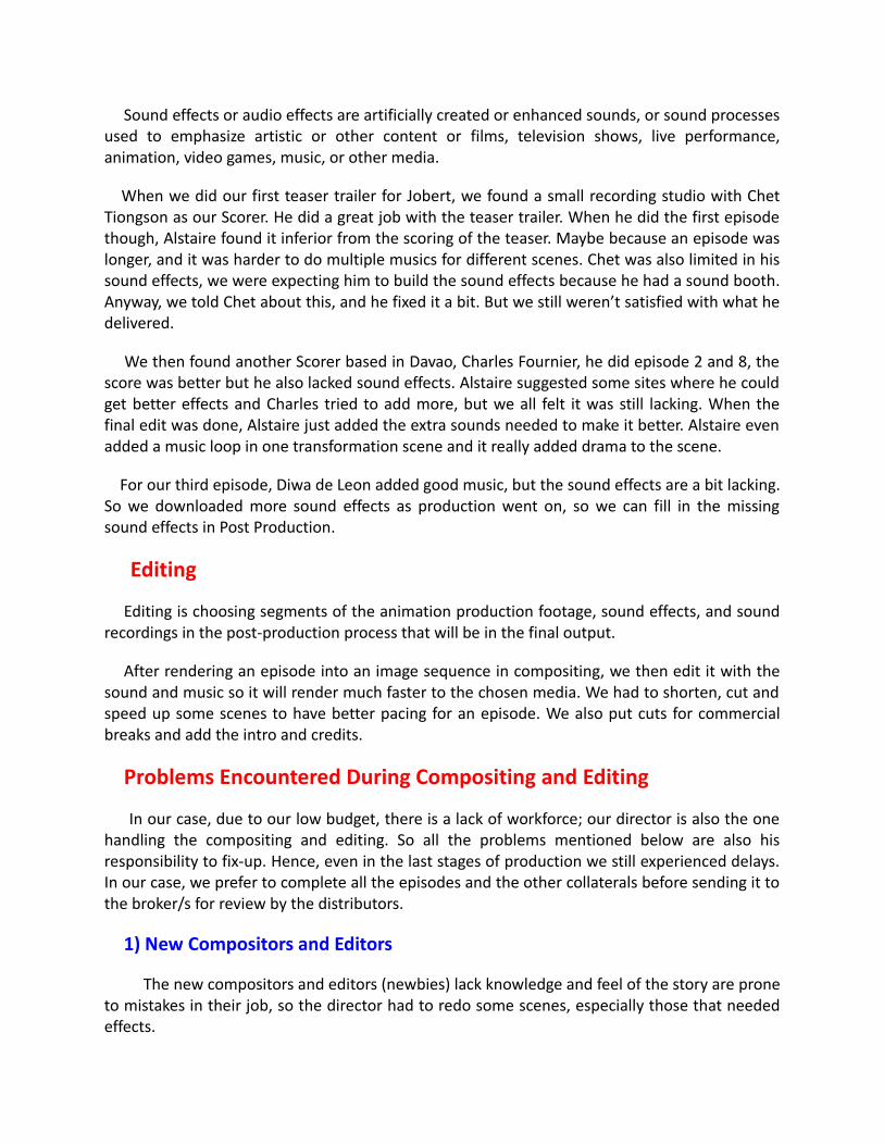
The director noticed the color correction and grading being done with the current Animeshows, it had a very nice stylized look. So he applied it to the later episodes and it looked great;so he had to apply the same grading to the earlier finished episodes. The color correction addsthe needed atmosphere to the scene. For samples episode 3 and 7 (the original ones), eventhough the character/s are in a room it still a bit bright but with the color correction and fx therooms are a bit darker. Color and FX additions are also added to break the monotony of similarflat colors in the next scenes. At episode 4, the director added more yellows to create theatmosphere of a hot and sunny day. Adding colors such as blue for shade, red for fire, and greenfor an alien environment are subtle effects but it makes the animation a whole lot better.
Ep.3 – Original HD
Ep.3 – HD with Color Correction and FX
Ep. 4 – Standard Definition

Ep. 4 – HD with Color Correction
Ep.7 – Standard Definition
Ep.7 – HD with Color Correction and FX
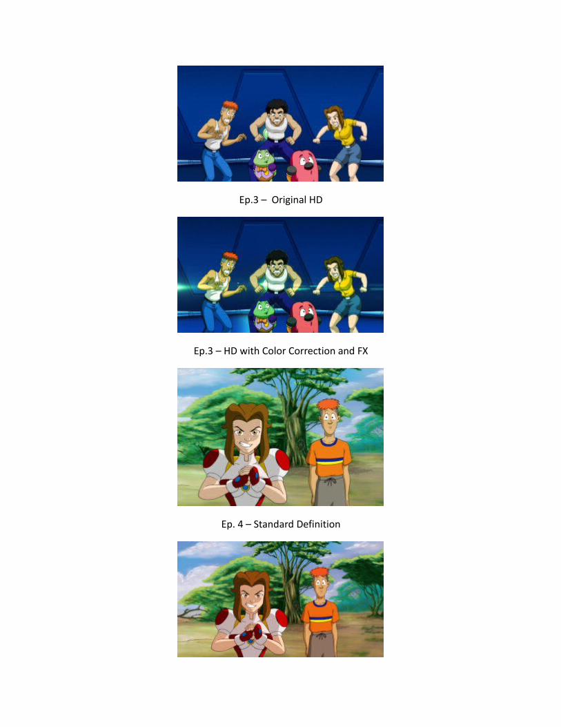
4) Wrong or Mismatched Colors from Digital Ink and Paint
We discovered mistakes in Digital Paint usually only in a single frame out of a scene. Thosewere usually overlooked in checking, and since we had some changes with the production staff,a few errors came up during the final episodes. Usually, it was a wrong color used or colorbleeding into where it shouldn’t be. The director usually corrects this inside the compositingsoftware, but for the new compositors, they do it the long way. They go back into the digitalpaint software and edit it, which could have gone faster had they asked help or advice from asenior artist. Below are samples of mistakes in Digital Ink and Paint, which are not noticeable incompositing at first glance.
Inner Mouth Should Be Darker
Inner Mouth Should be Darker/Eyes Should Be Yellow
The character’s inner mouth is lightly colored (pink) by the Digital Ink and Paint (DIP)artist, not noticeable in itself, but if put against the character’s body shadows (darker) themouth will look like its lighted from the inside.
Correct Color

Color Bleeding on Face
The color of the character’s armor bled into his face, due to a gap in the cleanup line.This was only for one frame, and when you play the scene, it isn’t noticeable to some artists,but there will be a flash of color when seen on television. These mistakes have to be fixed backat the Digital Ink and Paint before we can bring it back to Compositing.
5) Wrong Registration of Body Parts
We also discovered wrong registration of arms and mouths to the body of some semi-finished animations. In animation, parts that are moving are separated to lessen the work of theassistant animators. The problem comes from scanning when the paper holes on the animationpaper get torn a bit; since we use a peg bar on the scanner to hold the paper in place, itsometimes gets misaligned when scanning. The artists in the Digital Ink and Paint usuallycorrects this but some artists forget to do this. Some compositors also miss this error, becausethey are focused more on the special effects (FX) and staging of the scene. For this problem, wehave to go back to Digital Paint to correct the scenes.
Robot Head not Registered to the Body

Close-Up Robot Head
The robot head is a sample of wrong registration. In the scene, the head is not alignedwith the body. Maybe this is due to a mistake in scanning. The X-sheet artist should have movedthe head to properly connect to the body. These kinds of mistakes go back again to the DigitalInk and Paint artists who do the X-sheets.
Missing Mouth
The missing mouth is only one frame which is not noticeable during playback, but thedirector felt that there was something wrong when he saw a kind of FLASH and played it slowly.
6) Missing Backgrounds
We had some freelance layout artists who did a poor job on the backgrounds. Some artistseven submitted the incomplete set of backgrounds, so we had to redo some or reusebackgrounds that were close to the storyboard. The director instructed the compositors to usebackgrounds from different episodes since we don’t have a resident background artist anymore.

Some compositors made poor choices or were just lazy in finding the background that fits thescene; so the director had to correct these in editing.
7) Low Resolution from Digital Ink and Paint
There were a few scenes that were rendered from Digital Paint with very low resolutionand were very pixelated when we were trying to convert the earlier episodes to high-definition(HD) for the television screen. We had to re-render these scenes using a higher resolution. Theprocess of converting the standard definition (SD) to high definition (HD) takes up the mosttime in compositing as there will be many adjustments in sizing, mirroring, lighting etc.
Standard Definition
High Definition (Not yet edited or adjusted)
Size Difference Between SD and HD

Pixel Difference
The Standard Definition (SD), is used by Standard Box-type televisions, and the HighDefinition (HD) is used by the new LCD, LED and Plasma televisions. At first glance, it looks likethat the only difference is the SD is like a square screen which is tighter and the HD is arectangular screen. There is more to it than just that, the first thing that differs is the screensize, if we place the SD and HD pictures together, you can see a sizeable difference in size. This isto accommodate the bigger screens available in the LCD and LED televisions. If we use thestandard definition (SD) video in a high definition (HD) television, the pictures will look darkerand the edges will look pixelated, as shown in the Pixel Difference picture.
Ratio Difference
Stretched Image to Screen
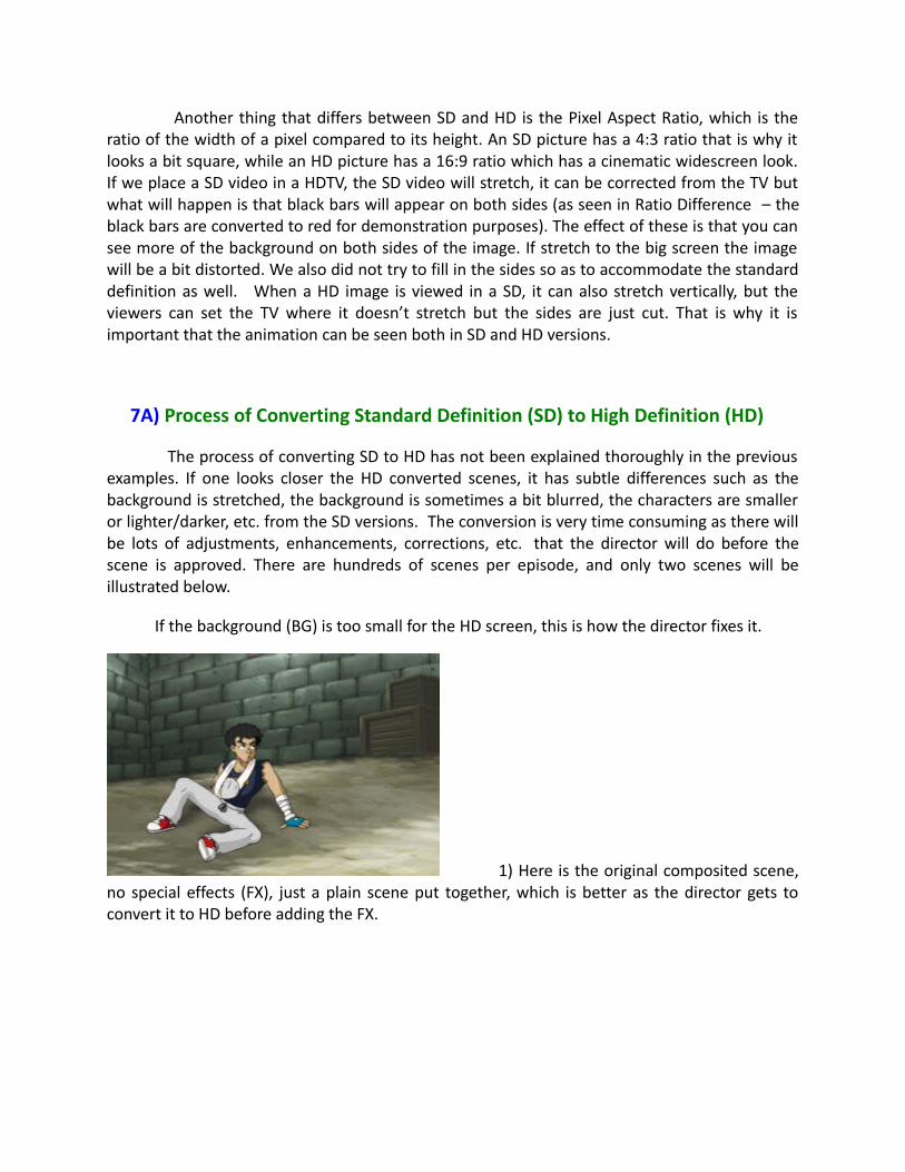
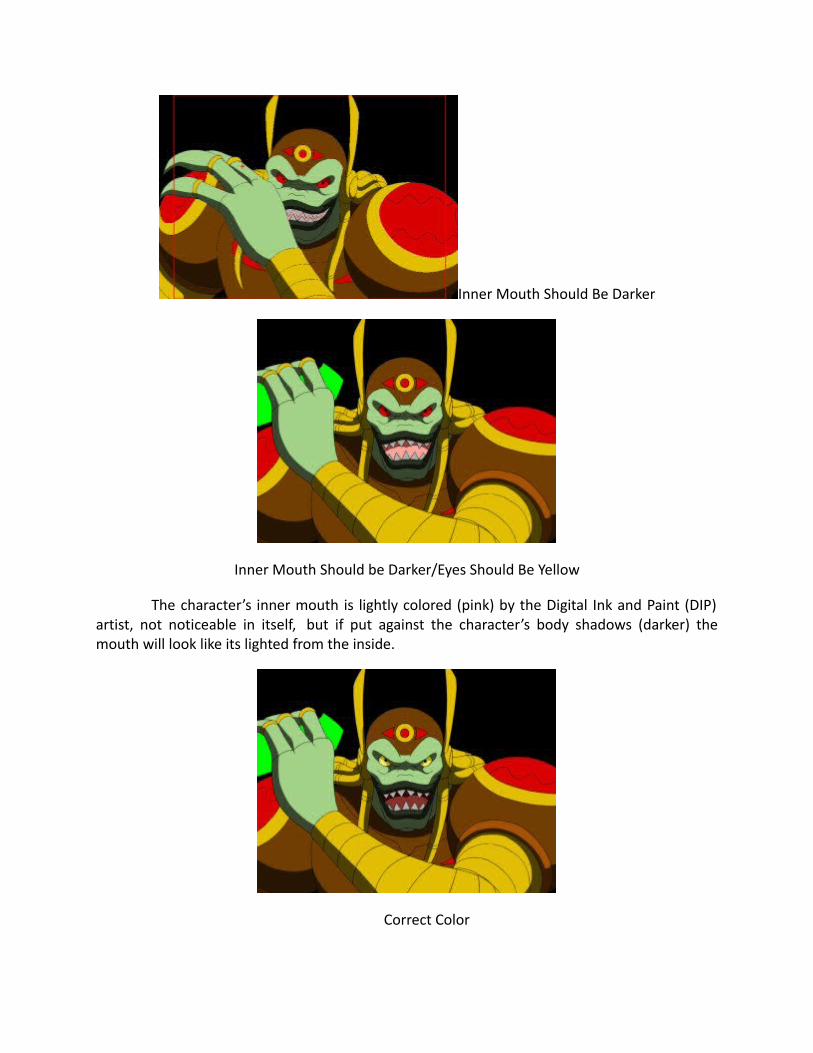
Another thing that differs between SD and HD is the Pixel Aspect Ratio, which is theratio of the width of a pixel compared to its height. An SD picture has a 4:3 ratio that is why itlooks a bit square, while an HD picture has a 16:9 ratio which has a cinematic widescreen look.If we place a SD video in a HDTV, the SD video will stretch, it can be corrected from the TV butwhat will happen is that black bars will appear on both sides (as seen in Ratio Difference – theblack bars are converted to red for demonstration purposes). The effect of these is that you cansee more of the background on both sides of the image. If stretch to the big screen the imagewill be a bit distorted. We also did not try to fill in the sides so as to accommodate the standarddefinition as well. When a HD image is viewed in a SD, it can also stretch vertically, but theviewers can set the TV where it doesn’t stretch but the sides are just cut. That is why it isimportant that the animation can be seen both in SD and HD versions.
7A) Process of Converting Standard Definition (SD) to High Definition (HD)
The process of converting SD to HD has not been explained thoroughly in the previousexamples. If one looks closer the HD converted scenes, it has subtle differences such as thebackground is stretched, the background is sometimes a bit blurred, the characters are smalleror lighter/darker, etc. from the SD versions. The conversion is very time consuming as there willbe lots of adjustments, enhancements, corrections, etc. that the director will do before thescene is approved. There are hundreds of scenes per episode, and only two scenes will beillustrated below.
If the background (BG) is too small for the HD screen, this is how the director fixes it.
1) Here is the original composited scene,no special effects (FX), just a plain scene put together, which is better as the director gets toconvert it to HD before adding the FX.

2) The director converts the scene to HD and resizes the elements (render a new DigitalInk and Paint (DIP) to have a better image), as you can see the BG is now shorter horizontally.
3) The director applies a mirror effect on the BG to lengthen the edges, but it distorts theedges quite noticeably.
4) The director enlarges it a bit to hide the awkward areas, but it can’t cover all of it…inthis case the crates on the right.

5) The director then duplicates the BG and cut the crate using a mask, flip it and darken ita bit. He will use this to cover the awkward image of conjoined crates.
6) He will put it in place and extend the mask to show some bricks which is also a mirrorof the wall.
7) He now adjusts the BG a bit more to see which will best cover the adjustments he made.He also adds some color correction to make it look that Jobert is inside the abandonedwarehouse.

8) He now adds some light effects to match the light glows on the ground which was doneby the BG artist. This is now the completed scene converted to HD.
In another scene, the sequence in applying the FX to a finished scene plus conversion toHD is illustrated below.
1)The original composited work of artists, no fx, just the BG and animation placedtogether at standard definition.
2) The director added a blur to the background and also to Balhalya in the foreground, tobetter focus on Jobert and to create more depth in the scene.

3) He added a light to simulate a dark interior, it also adds focus to Jobert and creates asuspenseful atmosphere.
4) He added Color Correction here, increasing the blues and decreasing the reds but veryslightly; to stimulate the reflection of the color of the walls to the characters.
5) He added some Lens Flare FX to make the lights at the back look a bit real, and tomake the shot seem like it was taken by a movie camera. This was how he fixed the scenes forJobert for the past episodes, now aside from this, he converted them to HD, but for newerepisodes, he was able to have the compositors start at the HD size.

6) This is the sequence in converting the SD scenes into HD…first he converts the projectfrom SD which has a screen size of 720 x 480 to HD which has a screen size of 1920 x 1080. Asyou can see the screen is way bigger than the elements from the original scene.
7) You will also notice that the elements have stretched slightly. This is because the pixelaspect ratio of SD is 0.9, which means that each pixel is a rectangle, while the HD pixel aspectratio is 1.0 or a square pixel. He has to adjust or interpret the elements so that it matches thescreen ratio.
8) He increases the size of the BG and Animation to its maximum size at 100%, he hadthe BG artists and the DIP artists render at a high resolution…usually DIP renders at 1024 x 768and BGs at 2500 x 2000…this is so when the director resizes them to a smaller size, the lines willlook darker. As you can see here, the BG has almost covered the screen but the animation is stillsmall, but he still needs to adjust both to match the original composition.

9) He first resizes the BG slightly to fill up the gaps.
10) Then he makes the DIP artist render the animation at a higher resolution, from 1024 x768 and double it to 2048 x 1536. When done, the director just replaces the original animationwith a new render. As you can see here, the animation is now bigger. It is darker because thelight FX is now too weak for the bigger file.
11) He now resizes the animation to match the wider screen. The original body ofBalhalya was cut since it was for SD screen only.

12) To fix this, he resizes Balhalya a bit and moves him to the left. But still matching thefeel of the scene.
13) He then increases the amount of the lighting FX to closely match the original effect.
14) He also moved the BG to match the original composition.

15) And finally, he moved the Lens Flare FX to its correct position which is right on top ofthe lights in the BG. This is the completed HD scene.
8) Missing 3D Animation and Effects
There were some scenes that used old 3D models of some ships and droids, that havesince been updated. Examples were the Manta ship and the Battle Droids. The director wasn’table to inform these updates to the new compositors who still used the old models. Thedirector already corrected these in checking, but due to the number of scenes, he missed one ortwo and he gets surprised when he encounters these errors again in editing.
9) Corrupted Files
Some 3D files were corrupted when the director checked the compositing of someepisodes. Usually, this happens when copying files from one computer to another. It is usuallythe 3D effects and characters that are affected. Examples are the Frogee ship, the new BattleDroids and Krystel’s wings. The director had to fix some of these in compositing or re-rendermost of it using the original 3D software the original artists used. It is a good thing, that thedirector can still contact some of the original artists, who have since moved to other jobs orcountries.
10) High-Definition Conversion Needs Better Computers/HardwareMalfunction
With better effects and high-definition, one needs better computers to apply them. Wehave two high-end computers that can handle the job, although these are also out-datedalready. Other compositors have had a hard time opening scenes with the newer special effects,so compositing gets done at a slower pace.
11) Voice-Over Does Not Synch with Animation
In sound editing, when placing the sound dialogue with the composited scenes, therewere animation parts that did not sync with the voice. Usually, the problem comes from the X-sheet. The mouths were not rendered with the animation. The director had to go back and re-render these animations and replace them back in compositing.

12) Lack of Sound Effects
Adding subtle sound effects is one of the most difficult tasks in editing our project. Wealready have gone through 3 different sound editing people, and they usually have the majorsound and music effects but lacks some of the small detail effects such as a phone ring, stepsand punching sounds. The director has already collected sounds from the Internet through theyears and have given these to the sound guys to use if they need it, but they hardly use them.So the director is already adding some of these subtle sounds in editing before we send theepisodes for scoring to the sound people.
Final Output
This will be the final format of the video, whether DVD, Blu-ray or maybe just Video File. Wewill just prepare the file and render it according to the needs of the distributor. For viewingpurposes, we have rendered it in Standard Definition.
Timeline for Production
Note: The timeline for production explained and illustrated here is with the assumption thatthe Pre-Production (storyboard, model sheets, voice over and X-sheets) is already completed, isbased on the traditional method of animation and according to the right budget.
How do we compute the Timeline for our Animation Production?
We start with the given details…we will be doing 13-episodes with a running time of22 minutes per episode. Since we can’t make each episode exactly 22 minutes, we will just pegthat time as the maximum time limit.
Since animation is computed in footages and frames, we will first convert the minutesinto the said units (feet and frames). Note: Animators compute their scenes by feet and frameswhile Clean-Up and In-betweeners (CU/IB) artists, Digital Ink and Paint (DIP) artists computetheir work by each frame done. The formulas are: 1 minute is equal to 60 seconds, 1 second isequal to 24 frames or drawings or it could be less than this number ( example for limitedmovement of animation shows), 1 foot is equal to 16 frames. So based on the formulas 22minutes is 1,980 feet (22 minutes x 60 seconds x 24 frames divided by 16 (frames/foot) or31,680 frames but since the animation for television is done with each frame held for 2 frames (since its not a movie, wherein the audience can see on the big screen – if the movements arefluid or not) , we divide the total frames in half, so for the total frames to be Cleaned-Up andIn-Betweened and Painted is 15,840 frames or drawings.
In animation, frames are translated to drawings. And one frame of animation can be anumber of drawings for a scene. For example a scene of a character talking; that is one drawingof the character per frame. Another example of a scene: 5 characters are riding bicycles acrosstown, here you will be drawing 5 characters on bicycles plus the crowd around the town in oneframe. If the characters on their bicycles are moving, the crowd can just be still drawing, but ifthe characters on their bicycles are standing (stationary); you will have to add movement to thecrowd to stimulate life. All the people in the scene will look like statues if you don’t addmovement. So a single frame of animation can be one drawing or a number of drawings, sobudgeting animation with numerous scenes and characters will be difficult.
In television, animation cost is lowered by adding holds or pauses in a scene. A holdor pause is shooting a frame for more than 4 frames, this will come out as the characterpausing; when you hold a character for more than 24 frames, the character will look like arobot. There can be a few seconds in a scene when the drawing is held for 24 frames, which canlower the cost a bit. Combine all of these scenes with few seconds pauses in an episode; thetotal cost can be lowered some more.
Japanese animation or anime has used this technique (long pauses) considerably andconsistently that it is associated with anime. In Japanese animation, some scenes have little orno movement at all. To balance this lack of motion, their drawings are much more detailed thanthe Western style of animation. Shadows and highlights have numerous layers, and thecharacter costumes and eyes are much more detailed. they also apply camera movements,dynamic camera shots, special effects and great cinematography. Our director has even seen ascene where the character’s back was shown for 5 seconds with the camera panning. That is 5seconds without any animation at all. For more technical details about the timing, pausing andframing just research the Internet, one good site is McAnim8.
Based on our director’s 18 years experience in the industry, an averageAnimator canfinish about 40 feet of Animation per week. And Clean-Up and In-between Artists can finish100 frames of animation a week. Also, a 22-minute Animation usually has about 300 scenes asan average, which also means 300 backgrounds per episode (although the director usually triesto lessen the backgrounds to 2/3 of the average required backgrounds). Given the formulas andaverages, this will be used to compute the average output of Layout and Background Artists.Layout Artists can finish about 20 scenes per week and Background Artists can finish 10backgrounds per week. A good Compositor can finish 20 scenes a week.

Now that we know the average work to be done, we can now make our timeline.
Weekly Allotted Artists
Averages Time Total Needed
Layout 20 scenes 2 weeks 40 scenes 7.5
Animation 40 feet 3 weeks 120 feet 16.5
CU/IB 100 pieces 4 weeks 400 pieces 39.6
Backgrounds 10 pieces 3 weeks 30 pieces 10
DIP 500 pieces 3 weeks 1,500 pieces 10.56
Compositing 40 scenes 2 weeks 80 scenes 3.75
If we will estimate that 1 episode is to be done in a month, with overlapping works …We need about 8 Layout Artists, 17 Animators, 40 CU/IB Artists, 10 Background Artists, 11Digital Ink and Paint Artists and 4 Compositors to finish 1 episode in 5 to 6 weeks. We haven’teven included Editing and Retakes which can take about 2 weeks each. We can safely say thatwe can finish 13 episodes in 13 months if all the artists are present. Our main problem was thestudio cannot accommodate that many artists and we are below the normal budget. So wedepended on freelance artists to do the work, but we competed with other studios for the goodartists. And not all artists are Average, there are few who are Above Average – who coulddouble the output but are usually busy in other studios and there are a Lot of Below AverageArtists that can only do half the output of Average Artists. So the quality of the artists is a bigfactor on how the timeline will be planned.
Based on the timelines charts, we only have a difference of 2 weeks, because it ishard to quantify other aspects of production that were removed from the Traditional to theTradigital production. The two methods will be compared in the production process ofAnimation, Clean-Up and In-between (CU/IB) and Digital Ink and Paint (DIP).

Animation
Traditional
Animators animate using pencil and paper. A 3-second scene at 24 frames persecond has 72 frames of animation which can be lessened to 36 frames if each frame is hottwice. An animator has to test his scene by shooting each drawing with a camera connected to acomputer ( a line test), after this he can sequence it correctly and play to see if the action iswhat he intended it to be. If he is not satisfied, he can redraw some parts or all of it, and linetest it again until he gets the effect he wants. The animator then hands his animation to theproduction coordinator who then submits it to the director for checking. The director watchesthe line test and approves the scene, which the production coordinator then gives it to theClean-Up and In-between.
Tradigital
Animators animate directly into a computer using a tablet. He uses the samenumber of frames as in the Traditional method. An animator, after finishing his scene in thecomputer, he can automatically playback his scene without transferring to another machine. Hecan make adjustments and play it back while seating on his chair. The time to transfer to a linetest machine and shooting each drawing with a camera has been eliminated. The animator cannow send this file to the production coordinator instantaneously via the network. The directorcan now play the scene sent via the network and approves it which is sent to the Clean-Up andIn-Between Department. There is a notable difference in time from standing and waiting in linefor other animators doing the line testing (shoot his drawings per page, adjust exposure sheetand play it) In our case, we only have 2 line test machines, we did not include the time saved inthe timelines as it is hard to quantify the time saved. There will be a lot of savings in the paper,erasers, and pencils as this will no longer be used in the Tradigital method.
Clean-Up and In-Between
Traditional
Clean-Up Artists trace the work of the animators using pencil and paper. Using acopier, they make copies of the model sheets as guides. The In-between Artists draws the in-between drawings between the cleaned up drawing using pencil and paper. They have toduplicate the line quality of the clean-up artists so it is consistent. Both clean-up and in-between artists should be careful to lessen erasures so that when the drawings are scanned,there will be less dirt and smudges seen. Finished drawings are then scanned into the computerfor digital ink and paint.

Tradigital
Clean-up Artists trace the work of animators directly in a computer using a tablet.They bring out the models digitally to use as guides save a lot of time as opposed to using amodel guidebook, photocopying it and lining up to photocopy it. In-between artists draw the in-between drawings between the cleaned-up drawings using a tablet. The artists can pick a linethickness in the software they are using so that all drawings are consistent. They don’t need toerase or redo any drawing on paper, as everything is edited on the computer. Finished files arenow sent directly to digital ink and paint (No need for scanning).
Digital Ink and Paint (DIP)
Traditional
DIP artists clean (erase) the scanned images of smudges, erasures, and dirt thescanner picked up in the computer. The drawings are converted to Raster image by a DIPsoftware. (When you zoom up a Raster or Bitmap image, you will see that the image is made upof small squares or pixels.) Placing a color is just a point and click with the mouse; the line coloris basically the pencil color when scanned.
Tradigital
When the Clean-up and In-between Artists trace the animations, the drawings arealready in Vector, and it can be colored directly on the same software. (A Vector image is madeup of lines that even when you zoom up, it is still a smooth line) These images retain itsappearance regardless of size if one zooms in, while in the Raster image, once zoomed theimages becomes more pixelated. The Vector images can close up on an eye then zooms out to afull shot of the person in front of his house, which would be very difficult to do for a Rasterimage.

Production process of 3D movie
Pre-Production
The first process in the animation pipeline, and also one of the most important, is pre-production. It begins with the main concepts which are initially turned into a full story, and then, once the story has been finalized, other things such as the script, shot sequence and camera angles are worked on.
Some major components of pre production are Story Boarding, Layouts, Model Sheets and Animatics.
...they also provide a visual reminder of the original plan; something that can be referred back to throughout the production.
Story Boarding
The Storyboard helps to finalize the development of the storyline, and is an essential stage of the animation process. It is made up of drawings in the form of a comic strip, and is used to both help visualise the animation and to communicate ideas clearly. It details the scene and changes in the animation, often accompanied by text notes describing things occurring within the scene itself, such as camera movements.
Not only can storyboards be especially useful when working in group environments (something quite common in the animation industry,) but they also provide a visual reminder of the original plan; something that can be referred back to throughout the production.

Layouts
Once the storyboards have been approved, they are sent to the layout department which then works closely with the director to design the locations and costumes. With this done they begin to stage the scenes, showing the various characters' positions throughout the course of each shot.
Model Sheets
Model sheets are precisely drawn groups of pictures that show all of the possible expressions that a character can make, and all of the many different poses that they could adopt. These sheets are created in order to both accurately maintain character detail and to keep the designs of the characters uniform whilst different animators are working on them across several shots.
During this stage the character designs are finalized so that when production starts their blueprints can be sent to the modeling department who are responsible for creating the final character models.
Animatics
In order to give a better idea of the motion and timing of complex animation sequences and VFX-heavy scenes, the pre-visualization department within the VFX studio creates simplified mock-ups called “Animatics” shortly after the storyboarding process.
These help the Director plan how they will go about staging the above sequences, as well as how visual effects will be integrated into the final shot.

Production
Now that the storyboard has been approved the project enters the production phase. It's here that the actual work can start, based on the guidelines established during preproduction. Some major parts are layout, modeling, texturing, lighting, rigging and animation.
[layout artists] produce the 3D version of what storyboard artists had previously drawn on paper.
Layout
Using lo-res models or blocks of geometry in the place of the final set and characters, the Layout Artist is responsible for composing the shot and delivering rough animation to the animators as a guide. What they produce is the 3D version of what the storyboard artists had previously drawn on paper.
During this stage the Director approves camera moves, depth of field and the composition of the modelsmaking up the set and set dressing. It is then the responsibility of the Modeling department to deliver these approved set, prop and character models in the final layout stages.
Modelling
Modelers are usually split into two or more departments. Whilst organic modelers tend to have a sculpture background and specialise in building the characters and other freeform surfaces, hard-surfacemodelers often have a more industrial design or architectural background, and as such they model the vehicles, weapons, props and buildings.
Working closely with the Art Directors, Visual Effects Supervisors and Animation Supervisors, modelers turn the 2D concept art and traditionally sculpted maquettes into high detail, topologically sound 3D models. They then assist the Technical Animator and Enveloper as the model has a skeleton put in place and the skin is developed. Following this, the model may be handed back to the Modeler, who will proceed to sculpt facial expressions and any specific muscle tension/jiggle shapes that may be required.

Once the model is approved, it will be made available to the rigging and texture paint departments, who complete the final stages in preparing the model for animation and rendering. With luck, the model will move through the production pipeline without coming back for modeling fixes, although some amount of fixes are inevitable - problems with models sometimes don't appear until the rendering stage, in which case the lighter will send the model back to be fixed.
Texturing
Whether creating a texture from scratch or through editing an existing image, Texturing Artists are responsible for writing shaders and painting textures as per the scene requirements.
Working hand-in-hand with the surfacing and shading departments, textures are painted to match the approved concept art and designs which were delivered by the art department. These textures are created in the form of maps which are then assigned to the model.
...lighting TDs combine the latest version of the animation, the effects, the camera moves, the shaders and textures, and render out an updated version every day.
Lighting
Not only does a Lighting Artist have to think lighting the individual scenes, they also have to consider how to bring together all of the elements that have been created by the other departments. In most companies, lighting TDs combine the latest version of the animation, the effects, the camera moves, the shaders and textures into the final scenes, and render out an updated version every day.
Lighters have a broad range of responsibilities, including placing lights, defining light properties, defining how light interacts with different types of materials, the qualities and complexities of the realistic textures involved, how the position and intensity of lights affect mood and believability, as well as color theory and harmony. They are required to establish direct and reflected lighting and shadows for each assigned shot, ensuring that each shot fits within the continuity of a sequence, all the while aiming to fulfill the vision of the Directors, Production Designers, Art Directors and VFX Supervisors.
Rigging
Rigging is the process of adding bones to a character or defining the movement of a mechanical object, and it's central to the animation process. A character TD will make test animations showing how a creature or character appears when deformed into different poses, and based on the results corrective adjustments are often made.
The rigging department is also involved in developing cloth simulation – so as well as making a character able to clench their fist or rotate their arm, the rigging and cloth department is responsible for making their costume move in a believable manner.
...planning a character's performance frame by frame uses the same basic principles first developed for 2D animation.

Animation
In modern production companies, the practice of meticulously planning a character's performance frameby frame is applied in 3D graphics using the same basic principles and aesthetic judgments that were first developed for 2D and stop-motion animation. If motion capture is used at the studio to digitize the motion of real actors, then a great deal of an animator's time will also be spent cleaning up the motion captured performance and completing the portions of the motion (such as the eyes and hands) that maynot have been digitized during the process.
The effects team also produce elements such as smoke, dust, water and explosions, although development on these aspects does not start until the final animation/lighting has been approved as they are integral to the final shot and often computationally heavy.
Post-Production
Post-production is the third and final step in film creation, and it refers to the tasks that must be completed or executed after the filming or shooting ends. These include the editing of raw footage to cutscenes together, inserting transitional effects, working with voice and sound actors and dubbing to namejust a few of the many post-production tasks.

Overall, however, the three main phases of post-production are compositing, sound editing and video editing.
Compositing
The compositing department brings together all of the 3D elements produced by the previous departments in the pipeline, to create the final rendered image ready for film! Compositors takerendered images from lighters and sometimes also start with compositing scripts that TDs develope in order to initially comp together their dailies (working versions of the shot.)
General compositing tasks include rendering the different passes delivered by a lighting
department to form the final shot, paint fixes and rotoscoping (although compositors sometimes rely on mattes created by a dedicated rotoscoping department), as well as the compositing of fx elements and general color grading.

Sound Editing
This department is responsible for selecting and assembling the sound recordings in preparationfor the final sound mix, ensuring lip sync and adding all of the sound effects required for the final film.
Video Editing
Video editing is the process of manipulating and rearranging shots to create a seamless final product, and it is at this stage that any unwanted footage and scenes are removed. Editing is a crucial step in making sure the video flows in a way which achieves the initial goal. Other tasks include titling and adding any effects to the final video and text.
Conclusion
The production pipeline detailed above is broadly common in most studios, however each studio is likely to have a custom pipeline determined by the type of project they are currently undertaking. A 2D production pipeline starts with workbook and goes all the way through final checking, composting and film output, whilst the 3D CGI production process emphasizes the design, modeling and rigging and animation stages. Moreover, animation production is a very coordinated process where different teams of artists work together while utilizing optimum resources and achieving the initial goal in the time available.
SOFTWARE USED IN ANIMATION, WEB & GRAPHICSDESIGN, VFX & GAMING –
Autodesk 3dsmax
Autodesk 3dsmaxTM is used for 3D modeling & animation. It is widely used inTV,movies, architecture studios & game development. Autodesk 3ds Max is usedin designing popular games like World of Warcraft, Need for Speed, Call of Dutyetc. Examples of 3ds Max in movies include 2012, Avatar, Iron Man, Lara Croft:Tomb Raider, Transformers, X-men etc.

Autodesk Maya
Autodesk® Maya® is used to create animation with the help of various tools formodeling, simulation, visual effects, match moving, compositing & rendering. Itfinds application in films, TV, architecture & automotive design. Maya has beenbehind the stunning visuals seen in Harry Potter and the Half-Blood Prince, KungFu Panda, Transformers, etc. It has also been used in games like FIFA 09, Prince ofPersia, etc.
ZBrush
ZBrush is used for digital sculpting too used for modeling, texturing & painting.Sculpting software allows users to manipulate digital objects (painting, givingshape & texture etc) and create realistic animation. Zbrush has been used inpopular movies like The Lord of the rings, Pirates of the Caribbean, Transformersetc & games like Half life 2, Prince of Persia, World of Warcraft etc.
Motion Builder
It is a popular 3D character animation software. It is preferred by professionalsworld wide for motion capture & keyframe animation due to features like realtimedisplay tools, inverse kinematics, facial & skeletal animation, etc.
Stop Motion ProStop motion animation technique is used to show physical objects in animationfilm 'moving on their own'. Stop Motion Pro is a simple, easy-to-use software thathelps you edit frames into movies & add sound and other effects.
V-Ray
V-Ray is a popular rendering engine software used in graphics & animation.Rendering is the process of getting 2D image or animation output from a 3Dmodel. V-Ray can be effectively used with 3D software like 3ds Max, Maya,Sketchup, Softimage, etc. V-Ray is used for creating quality animation in movies,video games & architecture etc.
Adobe After EffectsAdobe After Effects is a popular post-production software used to add specialeffects to animation films, TV shows, commercials, etc. We see various examplesof After Effects in movies such as the opening sequence for an sci-fi film, or HarryPotter's magic spells.
Adobe PhotoshopThe word 'Photoshop' is so popular that it has become a verb now! It is used for'editing' images, photographs, scanned art etc. Photoshop is widely applied in TV,movies, media & advertising, training, web development etc.
Final Cut ProApple Final Cut Pro is an industry level non-linear editing software. Its userfriendlyinterface makes it the preferred choice for creating quality animation,motion graphics & sound inputs. Final Cut Pro is used in television, films, &advertising. Examples of Final Cut Pro at work in films include The Cold Mountain,The Curious Case of Benjamin Button, etc.
Adobe PremiereAdobe Premiere is used for editing (adding titles, visual effects, etc) 3D animation& graphics. It is used in many popular TV shows & movies.
Eyeon Fusion

Eyeon Fusion is a powerful node-based compositing software. It is used widely inmovies, television, advertising, medicine, architecture etc. Eyeon Fusion ispreferred in 3D animation & VFX applications for its features like rotoscoping,paint tools, advanced look-up tables, etc. Examples of Fusion used in movies -Terminator Salvation, Snakes on a Plane, 300, etc.
NukeNuke is used for node-based compositing, used mainly in post-production work inTV, advertising, & movies. Nuke has been used in the production of high qualityvisual effects in films like Tron: Legacy, Black Swan, Avatar etc.
GameBryoGameBryo is one of the industry's most preferred game engine used to createquality video games. Its features like a comprehensive toolset, flexible workflow,and prototyping abilities make it a popular choice for game designers.Matchmove,Rotoscoping,Modeling,Animation,Lighting/Rendering, Compositingare some of the steps involved while adding VFX. One need not know each andevery step completely but can rather have a specialization for and one or two ofthese.
Planning for a VFX Shoot
Live action shooting techniques for VFX
Creating 3D sets, assets & characters for a Visual effect (VFX) shot
Painting realistic & Semi-legalistic textures in Photoshop
Animation (CG Camera and Character Animation)
3D Lighting
3D Rendering (rendering Passes using mental ray)
Compositing (2D & 3D)
Matte panting
Develop motion graphic for televisions & live action films.
Roto (Tips & Tricks)
2d & 3d Match Moving
3D-stereoscopic (Depth /2D /3D)
Create live action short film projects using visual effects (Digital/SpecialEffect) & animation techniques.
Unit – 2
The 6 stages of editing as a film director
1. LoggingThe dailies or rushes are sorted and labelled in ‘bins’. Each take can contain extra notes from thedirector or the cinematographer. This is the first time the editor sees the film, and since it is shot out of sequence, it is out of context of the story. A good editor views the rushes and looks for fluidity of movement and nuances that will later be incorporated into the film.
2. First AssemblyThe editor considers all the visual and audio material collected on the shoot for each scene and then re-orders it in the way to tell the story best.In the scene above, the editor may decide to open with an aerial shot of Central London and then track in to Buckingham Palace. The next shot might be a closeup of the hands followed by a dissolve shot to the hands of the hobo playing the banjo. There are dozens of possible combinations the editor can chose for this one simple sequence, each of which create a different mood and tell a different story.Editing on a large budget feature usually commences as soon as the film starts shooting. An editor will work on the rushes and assemble scenes for the director and producer to view. Oftenat this point the editor and director will decide that additional footage of key moments is necessary in order to make more editing choices available during the edit.Hint: First assembly is like a sketch of the finished scene.It is a good idea to save these sketches for reference later,should the editor get stuck.
3. Rough Cut and VariationsThe rough cut can take up to three months to complete. Each editor works differently. Sometimes the editor works alone and shows the day or weeks work to the director and producer, Sometimes the editor and director work together, discussing every nuance.In the rough cut, the scenes are placed in order and checked for continuity. This all-important step in the editing process allows for revisions and new ideas to be tried and tested.Hint: Make the edit points between the scenes very obvious in order to emphasise the ‘roughness’. Failure to do so may result in the editor committing to an edit before it is ready.
4. First CutThe first cut is the rough cut that is accepted by the editor, the director and the producer. Selection and sequence are basically fixed, although changes can still be made. The later film is visible. Detailed fine cut starts out from its proportions, structures, rhythms and emphasises them.Hint: Never be afraid to let the first cut ‘rest’ for a few days so everyone involved can see it with fresh eyes.

5. Fine CutThe fine cut no longer focuses on the entire film, but on the details of each and every cut. The fine cut emphasises and strengthens the rhythms and structures identified in the first cut.
6. Final CutWhen a fine cut has been agreed with the editor, director and producer, the sound designer, music composer and title designer join the editor. Sound effects and music are created and added to the final cut. When everyone has agreed with the final cut, the Edit Decision List is sent to the lab where a negative cutter ‘conforms’ the negative to the EDL in order to create a negative that is an exact copy of the final cut.
Sound design
Sound design is the art and practice of creating sound tracks for a variety of needs. It involves specifying, acquiring or creating auditory elements using audio production techniques and tools. It is employed in a variety of disciplines including filmmaking, television production, videogame development, theatre, sound recording and reproduction, live performance, sound art, post-production, radio and musical instrument development. Sound design commonly involves performing (see e.g. foley) and editing of previously composed or recorded audio, such as sound effects and dialogue for the purposes of the medium. A sound designer is one who practices sound design.
Sound is widely used in a variety of human-computer interfaces, in computer games and video games. Sound production for computer applications adds few extra concerns and requirements to the sound. Some of them are: non-repetitiveness, interactivity/dynamicity and low memory and CPU use. For example, the most computational resources are usually devoted to graphics, which in turn means that the sound playback is often limited to some upper memory consumption as well as CPU use limits. These have to be added to the concerns of audio production, since it is often not enough to merely "create good sound", but the sound also has to fit to the given computational limits, while still sounding good, which may require e.g. the use of audio compression or voice allocating systems. However, sound for computer applications also adds some new creative aspects to music and sound, because computer sound (especially in games) often involves the sound having or desired to be interactive. Adding interactivity can involve using a variety of playback systems or logic, using tools that allow the production of interactive sound (e.g. Max/MSP, Wwise) and it also deviates from being just an art form to also requiring software or electrical engineering, since implementing interactivity of sound also requires engineering of the systems that play the

sound or e.g. process user input. Therefore, in interactive applications, a sound designer often collaborates with an engineer (e.g. a sound programmer) who's concerned with designing the playback systems and their efficiency.
What is Sound Design –
Sound design is the process of recording, acquiring, manipulating or generating audio elements.It is employed in a variety of disciplines including filmmaking, television production, theatre, sound recording and reproduction, live performance, sound art, post-production and video game software development. Sound design most commonly involves the manipulation of previously composed or recorded audio, such as music and sound effects. In some instances it may also involve the composition or recording of audio to create a desired effect or mood.

Sound Designing Studio
Examples of Sound design- The eerie scream of an Alien, or the sound of the weapons going offin a video game. A sound designer is one who creates all the stunning sound SFX. Sound design requires both technological and artistic skills. A sound designer needs to develop excellent knowledge and techniques in recording, mixing, and special effects in order to create unique and interesting sounds. There are a host of modern Software and hardware synths which are used to create new and unheard SFX and sounds.
The Designer’s Work
Sound designers and composers begin their work by studying the script, gathering as much information as they can about any sound or music it calls for. As in all other aspects of design, an early meeting with the director and the design team is essential to get a clear understanding of the production concept.Some directors will already have very clear ideas about what the sound effects and/or music should sound like, while others may request that the sound designer/composer sit in on rehearsals to assist with developing effects and music to fit the specific contexts in which they will be used.
The Sound Designer works closely with the Director and a range of other staff to create the aural world for the audience, involving:
• The Sound Designer may create sound effects, atmospheres, sonic textures and filmic ambiences that will create naturalistic and abstract worlds for the story, as well as aid the
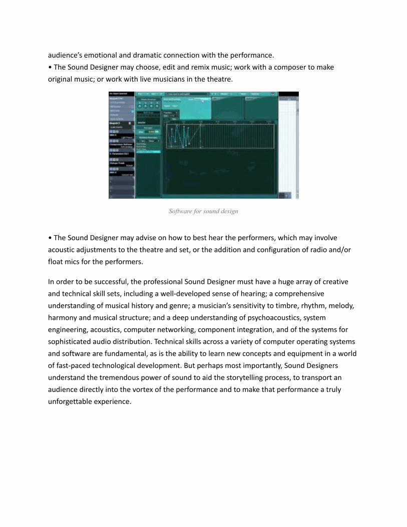
audience’s emotional and dramatic connection with the performance.• The Sound Designer may choose, edit and remix music; work with a composer to make original music; or work with live musicians in the theatre.
Software for sound design
• The Sound Designer may advise on how to best hear the performers, which may involve acoustic adjustments to the theatre and set, or the addition and configuration of radio and/or float mics for the performers.
In order to be successful, the professional Sound Designer must have a huge array of creative and technical skill sets, including a well-developed sense of hearing; a comprehensive understanding of musical history and genre; a musician’s sensitivity to timbre, rhythm, melody, harmony and musical structure; and a deep understanding of psychoacoustics, system engineering, acoustics, computer networking, component integration, and of the systems for sophisticated audio distribution. Technical skills across a variety of computer operating systems and software are fundamental, as is the ability to learn new concepts and equipment in a world of fast-paced technological development. But perhaps most importantly, Sound Designers understand the tremendous power of sound to aid the storytelling process, to transport an audience directly into the vortex of the performance and to make that performance a truly unforgettable experience.
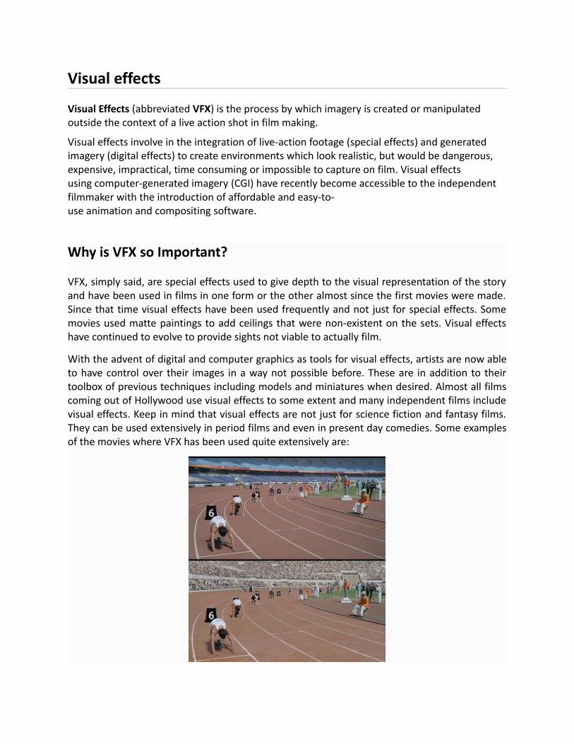
Visual effects
Visual Effects (abbreviated VFX) is the process by which imagery is created or manipulated outside the context of a live action shot in film making.
Visual effects involve in the integration of live-action footage (special effects) and generated imagery (digital effects) to create environments which look realistic, but would be dangerous, expensive, impractical, time consuming or impossible to capture on film. Visual effects using computer-generated imagery (CGI) have recently become accessible to the independent filmmaker with the introduction of affordable and easy-to-use animation and compositing software.
Why is VFX so Important?
VFX, simply said, are special effects used to give depth to the visual representation of the storyand have been used in films in one form or the other almost since the first movies were made.Since that time visual effects have been used frequently and not just for special effects. Somemovies used matte paintings to add ceilings that were non-existent on the sets. Visual effectshave continued to evolve to provide sights not viable to actually film.
With the advent of digital and computer graphics as tools for visual effects, artists are now ableto have control over their images in a way not possible before. These are in addition to theirtoolbox of previous techniques including models and miniatures when desired. Almost all filmscoming out of Hollywood use visual effects to some extent and many independent films includevisual effects. Keep in mind that visual effects are not just for science fiction and fantasy films.They can be used extensively in period films and even in present day comedies. Some examplesof the movies where VFX has been used quite extensively are:

Bhaag Milkha Bhaag
Kick

Pirates of the Caribbean“Seeing is believing”, and making things believable is no easy task. Making seamless and photorealistic renders is the most sought after objective for VFX artists.
How are VFX made?Adding Visual Effects is not a one man job. It requires quite a lot of smaller milestones that needto be achieved first. Treating a video is a procedure. Different companies have variedprocedures depending on the size and number of shots to be completed and also the number ofpeople involved.
Matchmove, Rotoscoping, Modeling, Animation, Lighting/Rendering, Compositing are some ofthe steps involved while adding VFX. One need not know each and every step completely butcan rather have a specialization for and one or two of these.
Where can I study VFX?

SeamEdu School of Pro-Expressionism offers Bachelors of Fine Arts (Visual Effects & Animationfor Film & TV) degree for those who have completed their 12th grade from any stream. SeamEduhas set its mark as one of the top animation institutes in India. Toolbox, which is an in-houseanimation studio, is regarded as the best in Pune. The course duration is 4 years and includesbut is not limited to the following:
Planning for a VFX Shoot
Live action shooting techniques for VFX
Creating 3D sets, assets & characters for a Visual effect (VFX) shot
Painting realistic & Semi-legalistic textures in Photoshop
Animation (CG Camera and Character Animation)
3D Lighting
3D Rendering (rendering Passes using mental ray)
Compositing (2D & 3D)
Matte panting
Develop motion graphic for televisions & live action films.
Roto (Tips & Tricks)
2d & 3d Match Moving
3D-stereoscopic (Depth /2D /3D)
Create live action short film projects using visual effects (Digital/Special Effect) &animation techniques.
Career Options after Studying VFX and Animation:On completion of the course the student can select from the following course options:
Pre-production Artist: Storyboard Artist, Character Designer, Concept Artist, LayoutArtist
Post-Production Artist: Compositing Artist, Rotomation Artist, Motion Graphic Artist,Mach Moving Artist, 3D Animator, Effects Artist, Roto Artist, 2D Paint Artist, 3D Modeler &Texturing Artist, 3D Lighting & Rendering Artist, Matte Painting Artist
Color grading
Color grading is the process of altering and enhancing the color of a motion picture, video image, or still image electronically, photo-chemically or digitally. Color grading encompasses

both color correction and the generation of artistic color effects. Whether for theatrical film, video distribution, or print, color grading is generally now performed digitally in a color suite. The earlier photo-chemical film process, known as color timing, was performed at a photographic laboratory.
Fixing exposure problems
Fixing white balance problems
Repairing excessive noise from aggressive ISO settings
Expanding contrast from LOG- or Flat- recorded images
“Developing” the image from RAW recordings
Setting the initial black-, white- and gamma points
Almost every shot needs one of these corrective actions applied to it.
When I teach, I call color correction the “first pass” in a color grading workflow. These are the first things a colorist needs to look at before doing anything else while color grading. Another term often used for this stage of a color grade is “Primary color correction.”
What else is color grading?
After correcting the initial image problems, colorists move into the realm of the color grade. Some examples include:
Shot matching: Ensuring the editor”s “invisible edit” isn’t revealed by shots that look different as the timeline plays down
Removing distractions: Isolating and manipulating annoying elements that prevent shotsfrom matching each other
Controlling the viewer’s eye: Using shape masks (or other techniques), attracting the eyeto the focal point of interest
Creating looks: Stylizing an image to indicate a flashback, dream sequence, or re-creation—or simply to give the entire project a unique feel

There are two main types of color manipulation, and their names are often (mistakenly) used interchangeably. Color correction and color grading are similar in their process, but different in how and when they are used.
Color Correction
Color correction is a singular process that involves making adjustments to an image to “correct” any deviations from its standard appearance.
These corrections include:
Exposure
White Balance
ISO Noise
Contrast
Color correction can be used to cover mistakes made with camera settings as well as to pull more information from flat-profiles. You should color correct your footage whenever possible, as it creates cohesion between shots.
Color GradingColor Grading is a multi-process that can change the visual tone of an entire film. Once your footage is corrected, you can work to change the thematics and aesthetics. Grading is used more as a brush to paint a picture with purpose. These include:
Shot Matching
Removing Objects

Shape Masks
Cinematic Looks (day-to-night, underwater, flashbacks, etc…)
Color grading is considered a more “high-end” process than color correction and it’s not used quite as often for most videos. If you are looking to create more detailed color profiles, be prepared for more labor intensive editing and longer render times.
Film editing
Film editing is a technical part of the post-production process of filmmaking. The term is derivedfrom the traditional process of working with film which increasingly involves the use of digital technology.
The film editor works with the raw footage, selecting shots and combines them into sequences which create a finished motion picture. Film editing is described as an art or skill, the only art that is unique to cinema, separating filmmaking from other art forms that preceded it, although there are close parallels to the editing process in other art forms such as poetry and novel writing. Film editing is often referred to as the "invisible art"[1] because when itis well-practiced, the viewer can become so engaged that he or she is not aware of the editor's work.
On its most fundamental level, film editing is the art, technique and practice of assembling shots into a coherent sequence. The job of an editor is not simply to mechanically put pieces of a film together, cut off film slates or edit dialogue scenes. A film editor must creatively work with the layers of images, story, dialogue, music, pacing, as well as the actors' performances to effectively "re-imagine" and even rewrite the film to craft a cohesive whole. Editors usually play a dynamic role in the making of a film. Sometimes, auteurist film directors edit their own films, for example, Akira Kurosawa, Bahram Beyzai and the Coen Brothers.
With the advent of digital editing, film editors and their assistants have become responsible for many areas of filmmaking that used to be the responsibility of others. For instance, in past years, picture editors dealt only with just that—picture. Sound, music and (more recently) visualeffects editors dealt with the practicalities of other aspects of the editing process, usually under the direction of the picture editor and director. However, digital systems have increasingly put these responsibilities on the picture editor. It is common, especially on lower budget films, for the editor to sometimes cut in makeshift music, mock up visual effects and add temporary sound effects or other sound replacements. These temporary elements are usually replaced with more refined final elements produced by the sound, music and visual effects teams hired to complete the picture.

Post-productionPost-production editing may be summarized by three distinct phases commonly referred to as the editor's cut, the director's cut, and the final cut.
There are several editing stages and the editor's cut is the first. An editor's cut (sometimes referred to as the "Assembly edit" or "Rough cut") is normally the first pass of what the final film will be when it reaches picture lock. The film editor usually starts working while principal photography starts. Likely, prior to cutting, the editor and director will have seen and discussed "dailies" (raw footage shot each day) as shooting progresses. Screening dailies gives the editor ageneral idea of the director's intentions. Because it is the first pass, the editor's cut might be longer than the final film. The editor continues to refine the cut while shooting continues, and often the entire editing process goes on for many months and sometimes more than a year, depending on the film.
When shooting is finished, the director can then turn his or her full attention to collaborating with the editor and further refining the cut of the film. This is the time that is set aside where the film editor's first cut is molded to fit the director's vision. In the United States, under the rules of the Directors Guild of America, directors receive a minimum of ten weeks after completion of principal photography to prepare their first cut. While collaborating on what is referred to as the "director's cut", the director and the editor go over the entire movie in great detail; scenes and shots are re-ordered, removed, shortened and otherwise tweaked. Often it is discovered that there are plot holes, missing shots or even missing segments which might require that new scenes be filmed. Because of this time working closely and collaborating – a period that is normally far longer and more intricately detailed than the entire preceding film production – many directors and editors form a unique artistic bond.
There’s a reason film editing is often called “the invisible art”: The goalof most editors is to create a seamless finished product, with no trace of their tampering. In reality, their fingerprints are all over the final film, and they are often among the most important figures in the entire process. Although the actors and the cinematographers play the primary roles in producing the footage available, it is up to the editor to splice this footage together to create a story.
Film editing is part of post-production, or everything that goes on after the actual shooting of the film stops. Other aspects of post-production include sound editing and mixing, computer generated effects, and soundtrack creation. The film editor’s job is to join together the various shots into scenes, and the scenes into a finished movie. They usually work closely with the director to realize his or her vision for the film and to make the efforts of everyone else involvedshine.

Before the advent of digital editing, the film editor would literally cut up the film and piece it back together. An editor would take long strips of film, cut them precisely, and stick them to other strips with tape and glue, creating rolls of film. Nowadays, all this work is done on a computer and is much more accessible to amateurs.
In case you’re still doubting the importance of the film editor, consider the famous Kuleshov Effect. Lev Kuleshov, a Soviet filmmaker, spliced together shots of a man’s face—showing no obvious emotion—with shots of some food, a young girl in a coffin, and a beautiful woman. Audiences believed that the actor expressed a different emotion each time: first hunger, then sadness, then desire. However, each shot of the actor was identical. Instead, it was the context, given to the audience by the editing, that created the illusion of emotion.
It is often difficult to judge the quality of editing in a film. Sometimes editors go for a stylized look, packing many energetic cuts into a short span of time. Often, however, the sure sign of great editing is just how invisible it is. The Oscar-winning editor WalterMurch, known for “Apocalypse Now” and “The Conversation,” once said that “Every film is a puzzle really, from an editorial point of view.” Once the job is done, and done well, it’s hard to even notice the separate pieces.
Video Editing Terminology
Capture Device: A hardware or firmware device used to convert analogue video into digital video.
Compressors & Codecs: Software or firmware used to compress and decompress digital video. Compression makes the file size smaller.
Editing: The process of rearranging, adding and/or removing sections of video clips. Also, creating transitions between clips. Editing is part of post-production.
Encoding: The process of converting digital video into a particular format, for example, saving a video project in MGEG-2 format for DVD distribution.
Layering: Adding multiple layers of superimposed video.
Linear Editing: Also known as tape to tape editing. A method of editing in which footage is copied from one tape to another in the required order (more info).
Non Linear Editing: An editing method which uses computer software to edit the footage (moreinfo).
Transition: The way one shot changes to the next (more info).

Post Production: Everything that happens to the video and audio after production, i.e. after the footage has been shot. Post production includes video editing, audio editing, titling, colour correction, effects, etc.
Types of editingOnce the province of expensive machines called video editors, video editing software is now available for personal computers and workstations. Video editing includes cutting segments (trimming), re-sequencing clips, and adding transitions and other Special Effects.[1]
Linear video editing, using video tape and is edited in a very linear way. Several videoclips from different tapes are recorded to one single tape in the order that they will appear.
Non-linear editing system (NLE), This is edited on computers with specialised software. These are non destructive to the video being edited and use programs such as Adobe Premiere Pro, Final Cut Pro and Avid.
Offline editing is the process in which raw footage is copied from an original source, without affecting the original film stock or video tape. Once the editing has been completelyedited, the original media is then re-assembled in the online editing stage.
Online editing is the process of reassembling the edit to full resolution video after an offline edit has been performed and is done in the final stage of a video production.
Vision mixing, when working within live television and video production environments. A vision mixer is used to cut live feed coming from several cameras in real time.
Linear video editing

High-end linear editing suite
Linear video editing is a video editing post-production process of selecting, arranging and modifying images and sound in a predetermined, ordered sequence.[1]Regardless of whether it was captured by a video camera, tapeless camcorder, or recorded in a television studio on a video tape recorder (VTR) the content must be accessed sequentially.[2] For the most part video editing software has replaced linear editing. In the past film editing was done in linear fashion, where film reels were literally cut into long strips divided by takes and scenes, and then glued or taped back together to create a logical sequence of film. Linear video editing is more time consuming and highly specialised and tedious work. Still, it is relevant today because of some reasons:
Inexpensive – Linear editing is simple and inexpensive method of editing.
Mandatory for some jobs – Linear editing is mandatory for some jobs. For example if they want to join only two sections of video clips together in sequence that it is a lot quickerand easiest way.
Increases their knowledge and versatility – If they learn linear editing skills it increases their knowledge as well as versatility. According to many professional editors who learn linear editing skills they first tend to become overall best round editor.

Current usage
While computer based video editing software has been adopted throughout most of the commercial, film, industrial and consumer video industries, linear video tape editing is still commonplace in television station newsrooms for the production of television news, and medium-sized production facilities which haven’t made the capital investment in newer technologies. News departments often still use linear editing because they can start editing tape and feeds from the field as soon as received since no additional time is spent capturing material as is necessary in non-linear editing systems and systems that are able to digitally record and edit simultaneously have only recently become affordable for small operations.
Non-linear editing system
Example of a non-linear video editing studio
Non-destructive editing is a form of audio, video or image editing where the original content is not modified in the course of editing, instead the edits are specified and modified by specialized software. A pointer-based playlist, effectively an edit decision list (EDL), for video or a directed acyclic graph for still images is used to keep track of edits. Each time the edited audio, video, or image is rendered, played back, or accessed, it is reconstructed from the original source and the specified editing steps. Although this process is more computationally intensive than directly modifying the original content, changing the edits themselves can be almost instantaneous, and it prevents further generation loss as the audio, video, or image is edited.
A non-linear editing system (NLE) is a video (NLVE) or audio editing (NLAE) digital audio workstation (DAW) system that performs non-destructive editing on source material. The name is in contrast to 20th century methods of linear video editing and film editing.
Basic techniques
A non-linear editing approach may be used when all assets are available as files on video servers or hard disks, rather than recordings on reels or tapes—while linear editing is tied to theneed to sequentially view film or hear tape. Non-linear editing enables direct access to any video frame in a digital video clip, without needing to play or scrub/shuttle through adjacent footage to reach it, as is necessary with video tape linear editing systems.
When ingesting audio or video feeds, metadata are attached to the clip. Those metadata can be attached automatically (timecode, localization, take number, name of the clip) or manually

(players names, characters, in sports: red card, goal...). It is then possible to access any frame byentering directly the timecode or the descriptive metadata. An editor can, for example at the end of the day in the Olympic Games, easily retrieve all the clips related to the players who received a gold medal.
The non-linear editing method is similar in concept to the cut and paste techniques used in IT. However, with the use of non-linear editing systems, the destructive act of cutting of film negatives is eliminated. It can also be viewed as the audio/video equivalent of word processing, which is why it is called desktop video editing in the consumer space.
Quality
At one time, a primary concern with non-linear editing had been picture and sound quality. Storage limitations at the time required that all material undergo lossy compression techniques to reduce the amount of memory occupied.
Improvements in compression techniques and disk storage capacity have mitigated these concerns, and the migration to High Definition video and audio has virtually removed this concern completely. Most professional NLEs are also able to edit uncompressed video with the appropriate hardware.
Offline editingOffline editing is part of the post-production process of filmmaking and television production in which raw footage is copied and the copy only is then edited, thereby not affecting the camera original film stockor video tape. Once the project has been completely offline edited, the original media will be assembled in the online editing stage.
The term offline originated in the computing and telecommunications industries, meaning "not under the direct control of another device" (automation).
Modern offline video editing is conducted in a non-linear editing (NLE) suite. The digital revolution has made the offline editing workflow process immeasurably quicker, as practitionersmoved from time-consuming (video tape to tape) linear video editing online editing suites, to computer hardware and video editing software such as Adobe Premiere, Final Cut Pro, Avid, Sony Vegas, Lightworks and VideoPad. Typically, all the original footage (often tens or hundreds of hours) is digitized into the suite at a low resolution. The editor and director are then free to work with all the options to create the final cut.

Online editingOnline editing is a post-production linear video editing process that is performed in the final stage of a video production. It occurs after offline editing. For the most part, online editing has been replaced by video editing software that operate on non-linear editing systems (NLE). High-end postproduction companies still use the Offline-Online Editing workflow with NLEs.
The term online originated in the telecommunication industry, meaning "Under the direct control of another device" (automation). Online editors such as the Sony BVE-9000 edit control unit used the RS-422remote control 9-Pin Protocol to allow the computer-interface of edit controllers to control video tape recorders (VTR) via a series of commands. The protocol supports a variety of devices including one-inch reel-to-reel type C videotape as well as videocassette recorders (VCR) to Fast-Forward, Rewind and Play and Record based on SMPTE timecode. The controllers have the ability to interface with professional audio equipment like audio mixers with console automation.
The video quality first introduced with Avid's Media Composer in 1989 was incapable of producing broadcast quality images due to computer processing limitations. The term 'Online' changed from its original meaning to where the pictures are re-assembled at full or 'online' resolution. An edit decision list (EDL) or equivalent is used to carry over the cuts and dissolves created during the offline edit. This conform is checked against a video copy of the offline edit to verify that the edits are correct and frame-accurate. This workprint (cutting copy in the UK) also provides a reference for any digital video effects that need to be added.
After conforming the project, the online editor will add visual effects, lower third titles, and apply color correction. This process is typically supervised by the client(s). The editor will also ensure that the program meets the technical delivery broadcast safe specs of the broadcaster, ensuring proper video levels, aspect ratio, and blanking width.
Sometimes the online editor will package the show, putting together each version. Each version may have different requirements for the formatting (i.e. closed blacks), bumper music, use of a commercial bumper, different closing credits, etc.
Projects may be re-captured at the lowest level of video compression possible - ideally with no compression at all.
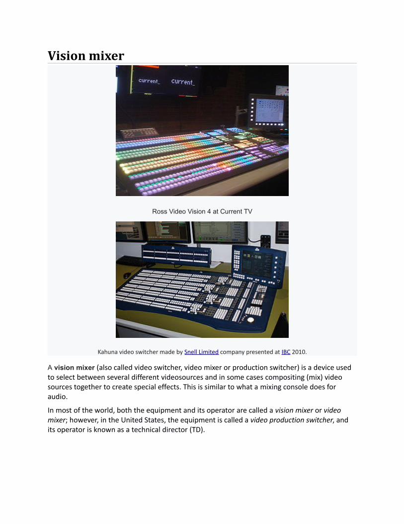
Vision mixer
Ross Video Vision 4 at Current TV
Kahuna video switcher made by Snell Limited company presented at IBC 2010.
A vision mixer (also called video switcher, video mixer or production switcher) is a device used to select between several different videosources and in some cases compositing (mix) video sources together to create special effects. This is similar to what a mixing console does for audio.
In most of the world, both the equipment and its operator are called a vision mixer or video mixer; however, in the United States, the equipment is called a video production switcher, and its operator is known as a technical director (TD).

Rendering (computer graphics)
A variety of rendering techniques applied to a single 3D scene

An image created by using POV-Ray 3.6
Rendering or image synthesis is the automatic process of generating a photorealistic or non-photorealistic image from a 2D or 3D model (or models in what collectively could be called a scene file) by means of computer programs. Also, the results of displaying such a model can becalled a render. A scene file contains objects in a strictly defined language or data structure; it would contain geometry, viewpoint, texture, lighting, and shading information as a description of the virtual scene. The data contained in the scene file is then passed to a rendering program to be processed and output to a digital image or raster graphics image file. The term "rendering" may be by analogy with an "artist's rendering" of a scene.
Though the technical details of rendering methods vary, the general challenges to overcome in producing a 2D image from a 3D representation stored in a scene file are outlined as the graphics pipeline along a rendering device, such as a GPU. A GPU is a purpose-built device able to assist a CPU in performing complex rendering calculations. If a scene is to look relatively realistic and predictable under virtual lighting, the rendering software should solve the rendering equation. The rendering equation doesn't account for all lighting phenomena, butis a general lighting model for computer-generated imagery. 'Rendering' is also used to describe the process of calculating effects in a video editing program to produce final video output.
Rendering is one of the major sub-topics of 3D computer graphics, and in practice is always connected to the others. In the graphics pipeline, it is the last major step, giving the final appearance to the models and animation. With the increasing sophistication of computer graphics since the 1970s, it has become a more distinct subject.
Rendering has uses in architecture, video games, simulators, movie or TV visual effects, and design visualization, each employing a different balance of features and techniques. As a product, a wide variety of renderers are available. Some are integrated into larger modeling andanimation packages, some are stand-alone, some are free open-source projects. On the inside, a renderer is a carefully engineered program, based on a selective mixture of disciplines related to: light physics, visual perception, mathematics, and software development.
In the case of 3D graphics, rendering may be done slowly, as in pre-rendering, or in realtime. Pre-rendering is a computationally intensive process that is typically used for movie creation, while real-time rendering is often done for 3D video games which rely on the use of graphics cards with 3D hardware accelerators.

Features
A rendered image can be understood in terms of a number of visible features. Rendering research and development has been largely motivated by finding ways to simulate these efficiently. Some relate directly to particular algorithms and techniques, while others are produced together.
Shading – how the color and brightness of a surface varies with lighting
Texture-mapping – a method of applying detail to surfaces
Bump-mapping – a method of simulating small-scale bumpiness on surfaces
Fogging/participating medium – how light dims when passing through non-clear atmosphere or air
Shadows – the effect of obstructing light
Soft shadows – varying darkness caused by partially obscured light sources
Reflection – mirror-like or highly glossy reflection
Transparency (optics), transparency (graphic) or opacity – sharp transmission of light through solid objects
Translucency – highly scattered transmission of light through solid objects
Refraction – bending of light associated with transparency
Diffraction – bending, spreading, and interference of light passing by an object or aperture that disrupts the ray
Indirect illumination – surfaces illuminated by light reflected off other surfaces, rather than directly from a light source (also known as global illumination)
Caustics (a form of indirect illumination) – reflection of light off a shiny object, orfocusing of light through a transparent object, to produce bright highlights on another object
Depth of field – objects appear blurry or out of focus when too far in front of or behind the object in focus

Motion blur – objects appear blurry due to high-speed motion, or the motion of the camera
Non-photorealistic rendering – rendering of scenes in an artistic style, intended to look like a painting or drawing
Techniques
Many rendering algorithms have been researched, and software used for rendering may employa number of different techniques to obtain a final image.
Tracing every particle of light in a scene is nearly always completely impractical and would take a stupendous amount of time. Even tracing a portion large enough to produce an image takes an inordinate amount of time if the sampling is not intelligently restricted.
Therefore, a few loose families of more-efficient light transport modelling techniques have emerged:
rasterization, including scanline rendering, geometrically projects objects in the scene to an image plane, without advanced optical effects;
ray casting considers the scene as observed from a specific point of view, calculating the observed image based only on geometry and very basic optical laws of reflection intensity, and perhaps using Monte Carlo techniques to reduce artifacts;
ray tracing is similar to ray casting, but employs more advanced optical simulation, and usually uses Monte Carlo techniques to obtain more realistic results at a speed that is often orders of magnitude faster.
The fourth type of light transport technique, radiosity is not usually implemented as a renderingtechnique, but instead calculates the passage of light as it leaves the light source and illuminates surfaces. These surfaces are usually rendered to the display using one of the other three techniques.
Most advanced software combines two or more of the techniques to obtain good-enough results at reasonable cost.
Another distinction is between image order algorithms, which iterate over pixels of the image plane, and object order algorithms, which iterate over objects in the scene. Generally object order is more efficient, as there are usually fewer objects in a scene than pixels.
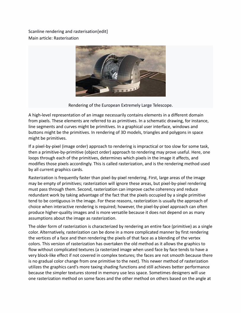
Scanline rendering and rasterisation[edit]Main article: Rasterisation
Rendering of the European Extremely Large Telescope.
A high-level representation of an image necessarily contains elements in a different domain from pixels. These elements are referred to as primitives. In a schematic drawing, for instance, line segments and curves might be primitives. In a graphical user interface, windows and buttons might be the primitives. In rendering of 3D models, triangles and polygons in space might be primitives.
If a pixel-by-pixel (image order) approach to rendering is impractical or too slow for some task, then a primitive-by-primitive (object order) approach to rendering may prove useful. Here, one loops through each of the primitives, determines which pixels in the image it affects, and modifies those pixels accordingly. This is called rasterization, and is the rendering method used by all current graphics cards.
Rasterization is frequently faster than pixel-by-pixel rendering. First, large areas of the image may be empty of primitives; rasterization will ignore these areas, but pixel-by-pixel rendering must pass through them. Second, rasterization can improve cache coherency and reduce redundant work by taking advantage of the fact that the pixels occupied by a single primitive tend to be contiguous in the image. For these reasons, rasterization is usually the approach of choice when interactive rendering is required; however, the pixel-by-pixel approach can often produce higher-quality images and is more versatile because it does not depend on as many assumptions about the image as rasterization.
The older form of rasterization is characterized by rendering an entire face (primitive) as a singlecolor. Alternatively, rasterization can be done in a more complicated manner by first rendering the vertices of a face and then rendering the pixels of that face as a blending of the vertex colors. This version of rasterization has overtaken the old method as it allows the graphics to flow without complicated textures (a rasterized image when used face by face tends to have a very block-like effect if not covered in complex textures; the faces are not smooth because thereis no gradual color change from one primitive to the next). This newer method of rasterization utilizes the graphics card's more taxing shading functions and still achieves better performance because the simpler textures stored in memory use less space. Sometimes designers will use one rasterization method on some faces and the other method on others based on the angle at
which that face meets other joined faces, thus increasing speed and not hurting the overall effect.
Ray casting
In ray casting the geometry which has been modeled is parsed pixel by pixel, line by line, from the point of view outward, as if casting rays out from the point of view. Where an object is intersected, the color value at the point may be evaluated using several methods. In the simplest, the color value of the object at the point of intersection becomes the value of that pixel. The color may be determined from a texture-map. A more sophisticated method is to modify the colour value by an illumination factor, but without calculating the relationship to a simulated light source. To reduce artifacts, a number of rays in slightly different directions may be averaged.
Rough simulations of optical properties may be additionally employed: a simple calculation of the ray from the object to the point of view is made. Another calculation is made of the angle ofincidence of light rays from the light source(s), and from these as well as the specified intensities of the light sources, the value of the pixel is calculated. Another simulation uses illumination plotted from a radiosity algorithm, or a combination of these two.
Raycasting is primarily used for realtime simulations, such as those used in 3D computer games and cartoon animations, where detail is not important, or where it is more efficient to manually fake the details in order to obtain better performance in the computational stage. This is usuallythe case when a large number of frames need to be animated. The resulting surfaces have a characteristic 'flat' appearance when no additional tricks are used, as if objects in the scene were all painted with matte finish.
Ray tracing

Spiral Sphere and Julia, Detail, a computer-generated image created by visual artist Robert W. McGregor using only POV-Ray 3.6 and its built-in scene description language.
Main article: Ray tracing (graphics)
Ray tracing aims to simulate the natural flow of light, interpreted as particles. Often, ray tracing methods are utilized to approximate the solution to the rendering equation by applying Monte Carlo methods to it. Some of the most used methods are path tracing, bidirectional path tracing, or Metropolis light transport, but also semi realistic methods are in use, like Whitted Style Ray Tracing, or hybrids. While most implementations let light propagate on straight lines, applications exist to simulate relativistic spacetime effects.[1]
In a final, production quality rendering of a ray traced work, multiple rays are generally shot for each pixel, and traced not just to the first object of intersection, but rather, through a number ofsequential 'bounces', using the known laws of optics such as "angle of incidence equals angle of reflection" and more advanced laws that deal with refraction and surface roughness.
Once the ray either encounters a light source, or more probably once a set limiting number of bounces has been evaluated, then the surface illumination at that final point is evaluated using techniques described above, and the changes along the way through the various bounces evaluated to estimate a value observed at the point of view. This is all repeated for each sample,for each pixel.
In distribution ray tracing, at each point of intersection, multiple rays may be spawned. In path tracing, however, only a single ray or none is fired at each intersection, utilizing the statistical nature of Monte Carlo experiments.
As a brute-force method, ray tracing has been too slow to consider for real-time, and until recently too slow even to consider for short films of any degree of quality, although it has been used for special effects sequences, and in advertising, where a short portion of high quality (perhaps even photorealistic) footage is required.

However, efforts at optimizing to reduce the number of calculations needed in portions of a work where detail is not high or does not depend on ray tracing features have led to a realistic possibility of wider use of ray tracing. There is now some hardware accelerated ray tracing equipment, at least in prototype phase, and some game demos which show use of real-time software or hardware ray tracing.
Layer and Node based Compositing –
LayersA layer is a singular level inside a layer based software. This singular level can be anything from a video layer to an image. Each effect is also represented individually as a layer. Layers can be combined into bins, directories and groups. In some layer based applications like After Effects (AE), you can nest entire compositions, consisting of layers and groups, into other compositions. Additionally, effects like blur and color correction can be applied to each individual layer. However, if you want blur and color correction on all layers, you will either have to duplicate the effect multiple times or nest it into a new composition. As a direct result of the need for nesting, projects can become quite large, difficult to navigate and unruly.
Layers in AdobeIt is no real secret that the reason layers are talked about in the visual effects world is the ubiquity of AE and Photoshop. In fact, most node based software companies assume you have used either Photoshop or AE before ever touching their software. The real question is, why switch from layers if it is so prevalent? The biggest point of contention is the lack of built-in 3D compositing in AE. AE is really a 2.5D environment. Additionally, as mentioned before, the bigger your project gets, the harder it is to deal with in AE.
NodesA node is a singular level inside a node based software. This singular level can be anything from a video to an image to a solid. Nodes in groups are called networks. Nodes can contain their own networks. Effects like blur and color correction are their own nodes. All you have to do is connect the blur node to the node of whatever you want to blur. If you want something else to have the same blur, just connect the blur to that as well. One change to the blur will affect both nodes if they are both connected. Unlike layers, you don’t have to change the blur for each layer. This is important for big visual effects shots where you can have anywhere from ten to

one hundred nodes or layers. If you decide you don’t like the blur on one node, just delete the connection to that node. The blur will still continue to affect all other nodes.
Nodes in FusionCurrently, Fusion 7 is a free software download from Blackmagic Design, so it provides the perfect opportunity to learn about nodes. The grid in Fusion’s node layout makes it very easy to organize your nodes, even for beginners.
Take a look at our example. Does a node-based composite in Fusion look scary? It might, but once you understand how it works, it’s so simple, you will be shocked to find that creating graphics takes longer than actually compositing.
If you look at the images we’ve created, out of the 45 active nodes, only 16 of them are used forthe composite. If you look at Image A, you will notice those sixteen nodes clearly displayed. In the upper left of Image A, you will notice the original green screen. The image to the right in Image A is the finished initial composite.

In Image B, we once again see the finished initial composite as well as the final shot. You will also notice that all 47 nodes are displayed to give an idea of the scope of the node network for the shot. The green nodes are files — an image, footage, or even an image sequence. The tan nodes are all roto or matte layers. The gray nodes are adjustments like transform, blur, color correction, etc. Blue are 3D nodes. Fusion, like most node based compositors is in a 3D environment. The pink nodes are particles. The gold nodes are light for the 3D. The nodes in a line at the bottom are all merge tools leading up to the saver node, which is pretty much an exporter or render node.
Nodes in NukeNuke is probably the most frequently used software for high-end visual effects for feature film, TV, commercials and music videos. It’s reliable, stable, and has the most plugins of any of the node based softwares. What sets Nuke further apart are its unparalleled keying tools. If you’ve ever purchased a plugin from the Foundry for AE such as Keylight, you will find it works the same way in Nuke. Of course, Nuke comes with a high price tag, which is why Nuke is used almost exclusively by visual effects professionals. The Foundry has a free 15-day unrestricted trial version of Nuke. They also offer a personal learning edition (PLE) of Nuke with limited features for free, if you want to try it out for an extended period of time.
Nodes or Layers: Which is better?To be honest, there is no right or wrong answer. They both can achieve the same effects. Software preference will factor greatly into your decision. The more that you use one software type, the more you will become accustomed to that system. Just remember that layers are not great for huge projects with many items and effects; likewise, projects with little footage and few effects are sometimes not the most efficient for nodes. What it really boils down to is

personal preference. A great rule of thumb is go big and go nodes or keep it small and stick withlayers.
Unit – 3

39
Pre
parin
g P
roje
cts
and
Imag
es
Cha
pter
– 2
Preparing Projects and Images
OverviewThis chapter is about preparing a project and adding clips to the Flow Node Editor. Fusion can read single frames, image sequences or movie files at various resolutions and bit depths. Knowing which files you can load in, how to set up a project to handle them, and finally, reading those files in are the first steps in beginning your composition.
Setting up a ProjectSource media can come in a variety of formats, including NTSC, PAL, HD, and 4K or larger. Often you will have different formats within a single comp. Each format has different properties, from resolution to color depth and gamma curve. Fusion can mix and match material of different formats together in a single composite, but it is important to note how Fusion configures and combines materials of different formats when loading and merging them together.
The first thing you do when starting on a new project is to set the preferences to match the intended final output format. The preferences are organized into separate groups: one for global preferences and one for the preferences of the currently opened compositions.
The Frame Format preferences are used to determine the default resolution used for new Creator tools (i.e., text, background, fractals, etc.), pixel aspect for display and rotation, as well as the frame rate used for playback.
Frame Format preference for images generated in Fusion
If the same frame format is used day after day, the global Frame Format preferences should match the most commonly used footage. For example, on a project where the majority of the source content will be 1080p high definition, it makes sense to set up the global preferences to match the frame format of the HD source content you typically use.

40
Pre
parin
g P
roje
cts
and
Imag
es
Cha
pter
– 2
To set up the default Frame Format for new compositions do the following:
1 Choose File > Preferences.
2 Click the Global and new Comp disclosure triangle in the sidebar to open the Globals group.
3 Select the Frame Format category to display its options.
When you set options in the Global Frame Format category, they determine the default frame format for any new compositions you create. They do not affect any existing compositions. If you want to make changes to existing compositions, you must open the comp. You can then select the Frame Format controls listed under the comp’s name in the sidebar.
The preferences are described in greater detail in Chapter 16.
Loading ImagesOnce the Frame Format preferences are set, you typically begin to composite by importing, or more accurately, reading in source media. When Fusion reads in media, it doesn’t convert or move the original files. It just reads the files in place, so the concept of importing source media into a Library or some kind of media vault is not applicable in Fusion. You are always dealing with the original source files in their original location.
Source media is read into a comp using a Loader tool. Although there are other tools within Fusion you can use to generate images like gradients, fractals or text, each still image, image sequence or movie file must be added to your comp using a Loader tool.
To add media to your comp do one of the following:
� Choose Tools > I/O > Loader.
� Right click over the Flow Node editor, then choose Add Tool > I/O > Loader.
� Drag a file from a Windows Explorer file browser or Mac OS X Finder window into the Flow Node Editor.
To add only one frame of an image sequence to your comp:
� Hold Shift while you drag a single frame from an image sequence into the Flow Node Editor.
When you drag from the operating system, a Loader is automatically added to the Flow Node Editor and the media file is directly added to the comp. If multiple files are dragged into the Flow Node Editor, a separate Loader is added for each file. This comes in handy when you want to read in photographs from a digital camera that are numbered sequentially.
Color Bit DepthsThe term Bit Depth describes how many colors are available in the color palette that is used to make up an image. The higher the bit depth, the greater the precision of color is in the image, and therefore, the greater the reproduction of color. The higher precision is most obvious in gradients with subtle changes. Lower bit depth gradients have noticeable banding artifacts, where higher bit depth images can reproduce more colors, so fewer, if any, banding artifacts are seen. You can set Fusion to process images with 8-bit integer, 16-bit integer, 16-bit float and 32-bit float bits per channel.
Generally, 8-bit integer color processing is the lowest bit depth you’ll come across for video formats. 8-bit images come from older or consumer grade video equipment. If you try to perform any significant gamma or color correction on 8-bit images, you can often see more visible banding.

53
Flow
Nod
e Ed
itor
Cha
pter
– 3
Flow Node Editor Overview
The Flow Node Editor with connected tools

54
Flow
Nod
e Ed
itor
Cha
pter
– 3
What is Node Based Compositing?The Flow Node Editor is the heart of Fusion’s compositing interface. It uses a schematic or flow chart structure to build a composition instead of layers in a layer list. Each image and effect that you add to your composition is called a Tool, which is represented as a tile in the Flow Node Editor. You draw connections between tools to arrange the order that image processing operations are applied. Just by viewing the connections between tools, you can get a clear overview of the process each image goes through to be composited.
Using a Schematic view, sometimes called a Tree view, has tremendous flexibility for compositing, including the ability to branch a tool’s output into separate branches and eliminate the need to precompose or nest layers.
This flow shows a Loader to read the image, connected to a Resize tool, connected to a Saver to render the image to disk
This chapter discusses how to work in the Flow Node Editor, add and connect tools together, and other basic operations you can perform on tools in the Flow Node Editor.

55
Flow
Nod
e Ed
itor
Cha
pter
– 3
Navigating the Flow Node EditorThe Flow Node Editor is one of the default panels whenever you create a new composition or when an existing comp is opened. The Work Panel that contains the Flow Node Editor can be switched to display the Spline Editor, Timeline Editor and Console, as needed. In order for you to work effectively in the Flow Node Editor, you need to be able to pan and zoom in on areas of a composition.
To display the flow when it is not currently visible, do one of the following:
� Select the Flow tab from the top right corner of the work area.
� Press the F5 key on the keyboard.
The tabs in the Work Panel
To zoom in and out on an area of a flow, do the following:
� Hold the left and middle mouse buttons, then drag to zoom in and out.
To pan in the Flow Node Editor, do the following:
� Hold the middle mouse button, then drag to pan.
� Drag the scrollbars at the right and left sides of the Flow Node Editor panel.
� Press Command-Shift (Mac OS X) or Ctrl-Shift (Windows), then drag to pan.
If a tool that is not visible in the Flow Node Editor becomes selected, either by performing a Find or selecting the header in the Control Panel, the Flow Node Editor will automatically pan to display the tool’s tile in the visible area.
The Flow NavigatorAnother useful way to pan around the Flow Node Editor is to use the Flow Navigator. The Flow Navigator is a small rectangular overview in the upper right corner of the Flow Node Editor. It gives a bird’s eye view of the entire composition, with an inner outline that indicates the portion of the composition that is visible in the panel. You can use the Flow Navigator when you are zoomed in on a flow and want to pan around a composition.
The Flow Navigator

56
Flow
Nod
e Ed
itor
Cha
pter
– 3
To display or hide the Flow Navigator, do one of the following:
� Right click in an empty area of the Flow Node Editor, then choose Options > Show Navigator.
� Press the V key.
To have the Flow Navigator display automatically when needed:
� Right click in an empty area of the Flow Node Editor, then choose Options > Auto Navigator.
To change the size of Flow Navigator, do the following:
� Drag the lower left corner of the Navigator to resize it.
Drag the corner to resize the Navigator
To return to the default Flow Navigator size, do the following:
� Right click in the Flow Navigator, then choose Reset Size.
To pan the flow using the Flow Navigator, do the following:
� Drag in the Flow Navigator to change what portion of the flow is visible.

57
Flow
Nod
e Ed
itor
Cha
pter
– 3
Flow Node Editor Tool TilesWhen you want to load images from disk, save images to disk, merge multiple images together, and apply effects like blurs, glows or color corrections, you must add a tool to the Flow Node Editor.
Once a tool is added to the Flow Node Editor it is represented by a Tool tile.
A Tool tile in the Flow Node Editor
The tiles can be displayed as a small rectangle or as a larger square. The rectangular form displays the tool’s name in the center of the tile, while the square form shows either the tool’s icon or a thumbnail of the image it is outputting. You can get detailed information about the tool and the data it is processing by hovering your cursor over it in the Flow Node Editor.

58
Flow
Nod
e Ed
itor
Cha
pter
– 3
Adding Tools to the Flow Node EditorYou can add tools to the Flow Node Editor in a number of different ways depending on what is the easiest place for you to access them and the type of tool you are adding. The most obvious way to add a tool is to use the Tools menu in the menu bar since it contains every tool in Fusion, organized into general categories. When you select a tool from any submenu in the Tools menu it is immediately added to the Flow Node Editor. If another tool is selected in the flow, the selected tool’s output is automatically connected to the new tool’s input. If no tool is selected in the flow, the new tool is added, unconnected to any other tool. The Tools menu is the most obvious way, but not necessarily the fastest or most productive way, to add a tool to the flow. There are a number of other ways that, once you learn them, may better fit your workflow.
The Tools menu

59
Flow
Nod
e Ed
itor
Cha
pter
– 3
Adding Tools from the ToolbarIf you find yourself constantly using the same tools over and over in different comps, you can use the Toolbar, located above the Viewers, to display tools of your choice for easy access. The tools are displayed as buttons. Clicking on a button adds that tool to the composition exactly as if the tool had been selected from the Tools menu. You can also drag the button into the flow to position the tool manually. Dropping the dragged tool over the connection between tools will automatically insert the tool into the connection.
The Toolbar
The buttons use an abbreviated form of each tool’s name (e.g., BC for Brightness/Contrast), but if you can’t remember what some of the abbreviations stand for, you can position the cursor over any toolbar button and a tooltip will display the full name of that tool.
Toolbar buttons can also be dragged into the Viewers, causing them to be added to the flow immediately after the currently viewed tool, regardless of the currently active tool.
In some cases you may want to add a tool from the Toolbar in order to replace an existing tool in the flow. For instance, if you have a Brightness/Contrast tool already connected in the Flow Node Editor, but you want to use the Color Curves instead, you can remove the Brightness Contrast and replace it with the Color Curves in one step.
To replace a tool in the flow with a tool from the Toolbar, do the following:
1 Drag a tool from the Toolbar directly over the tool in the Flow Node Editor that you want replaced.
2 When the mouse button is released, click OK in the dialog to confirm the replacement.
Dragging a tool from the Toolbar to replace an existing tool.
When you replace one tool with another, the settings that are identical between the two tools are carried over. For example, replacing a Transform tool with a Merge will copy the existing center and angle values from the Transform to the Merge.
For details on customizing the toolbars, refer to the Toolbar chapter later in this manual.

60
Flow
Nod
e Ed
itor
Cha
pter
– 3
Adding Tools from the Contextual MenuThere are different submenus you can use to add tools to a flow when you right click over a tool, over an empty area of the Flow Node Editor, or over a connection line also called a pipe. This can be a very convenient way to add a tool since your cursor is often in the Flow Node Editor selecting, moving and connecting tools.
Adding tools from the contextual menu
To Add a tool, do the following:
1 Right click in an empty area of the Flow Node Editor.
2 Choose a tool from the Add Tool submenu.
Selecting a tool from the Add Tool submenu will add the tool at the position of the cursor. If the cursor is positioned over a connection between two tools, the new tool is inserted between the existing tools.
When you right click over a tool in the Flow Node Editor, you have a choice to either Insert a Tool or Replace a Tool.
To Insert a Tool, do the following:
1 Right click over a tool in the Flow Node Editor.
2 Choose a tool from the Insert submenu.
Selecting a tool from the Insert submenu will insert the new tool after the selected tool.

61
Flow
Nod
e Ed
itor
Cha
pter
– 3
To Replace a Tool, do the following:
1 Right click over a tool in the Flow Node Editor.
2 Choose a tool from the Replace submenu.
Replacing tools from the contextual menu
Selecting a tool from the Replace menu will replace the selected tool with a new one.
If the new tool has controls with the same name as the tool you are replacing, those settings will be retained. For example, replacing a Transform tool with a DVE will preserve the values of the center, angle and size controls.
Adding Tools from the BinsThe Bins are an extremely useful tool in Fusion that we cover in more detail in the Bins chapter of this manual. However, in terms of adding tools, it is as simple as drag and drop.
You open a bin by choosing File > Bins or pressing Command-B (Mac OS X) or Ctrl-B (Windows).
The bin contains different categories of items you can add to a flow. By selecting the Tools category you can drag and drop a tool directly into the flow.

62
Flow
Nod
e Ed
itor
Cha
pter
– 3
Tools in a bin
Adding Tools from a File BrowserIf you drag a clip or image sequence from an Mac OS X or Windows file browser into the Flow Node Editor, it automatically adds a Loader and reads in the file. If multiple clips or image sequences are dragged into the flow, a separate loader is added for each file and they are merged together.
Dragging from a file browser
You can choose to drag in any file from an image sequence and the entire sequence will be read in as a single clip. However, to read in a single frame from an image sequence, hold Shift and drag the frame you want into the Flow Node Editor. That frame will be read in as a still. This can be useful when loading a number of images taken with a digital still camera.
Tool settings (.settings) files can also be dragged from the file browser into the Flow Node Editor. Dragging a settings file will add the tool saved in that file and configured it according to the saved settings.
Deleting ToolsIf you want to delete a tool from the Flow Node Editor, select the tool, then press Delete (Mac OS X) or Backspace (Windows) on the keyboard. The tool is removed from the Flow Node Editor. As an alternative, you can right click on a tool and then select Delete from the context menu.
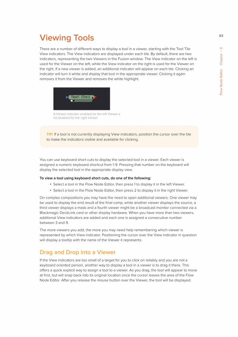
63
Flow
Nod
e Ed
itor
Cha
pter
– 3
Viewing ToolsThere are a number of different ways to display a tool in a viewer, starting with the Tool Tile View indicators. The View indicators are displayed under each tile. By default, there are two indicators, representing the two Viewers in the Fusion window. The View indicator on the left is used for the Viewer on the left, while the View indicator on the right is used for the Viewer on the right. If a new viewer is added, an additional indicator will appear on each tile. Clicking an indicator will turn it white and display that tool in the appropriate viewer. Clicking it again removes it from the Viewer and removes the white highlight.
A Viewer indicator enabled for the left Viewer a nd disabled for the right Viewer
You can use keyboard short cuts to display the selected tool in a viewer. Each viewer is assigned a numeric keyboard shortcut from 1-9. Pressing that number on the keyboard will display the selected tool in the appropriate display view.
To view a tool using keyboard short cuts, do one of the following:
� Select a tool in the Flow Node Editor, then press 1 to display it in the left Viewer.
� Select a tool in the Flow Node Editor, then press 2 to display it in the right Viewer.
On complex compositions you may have the need to open additional viewers. One viewer may be used to display the end result of the final comp, while another viewer displays the source, a third viewer displays a mask and a fourth viewer might be a broadcast monitor connected via a Blackmagic DeckLink card or other display hardware. When you have more than two viewers, additional View indicators are added and each one is assigned a consecutive number between 3 and 9.
The more viewers you add, the more you may need help remembering which viewer is represented by which View indicator. Positioning the cursor over the View indicator in question will display a tooltip with the name of the Viewer it represents.
Drag and Drop into a ViewerIf the View indicators are too small of a target for you to click on reliably and you are not a keyboard oriented person, another way to display a tool in a viewer is to drag it there. This offers a quick explicit way to assign a tool to a viewer. As you drag, the tool will appear to move at first, but will snap back into its original location once the cursor leaves the area of the Flow Node Editor. After you release the mouse button over the Viewer, the tool will be displayed.
TIP: If a tool is not currently displaying View indicators, position the cursor over the tile to make the indicators visible and available for clicking.

64
Flow
Nod
e Ed
itor
Cha
pter
– 3
Dragging a tool into a viewer
The last way you can view a tool in a viewer is to use the tool’s contextual menu.
To view a tool using the tool’s contextual menu, do one of the following:
� Right click over a tool in the Flow Node Editor, then choose View On > Left to display the tool on the left Viewer.
� Right click over a tool in the Flow Node Editor, then choose View On > Right to display the tool on the right Viewer.
Choosing a viewer from the contextual menu
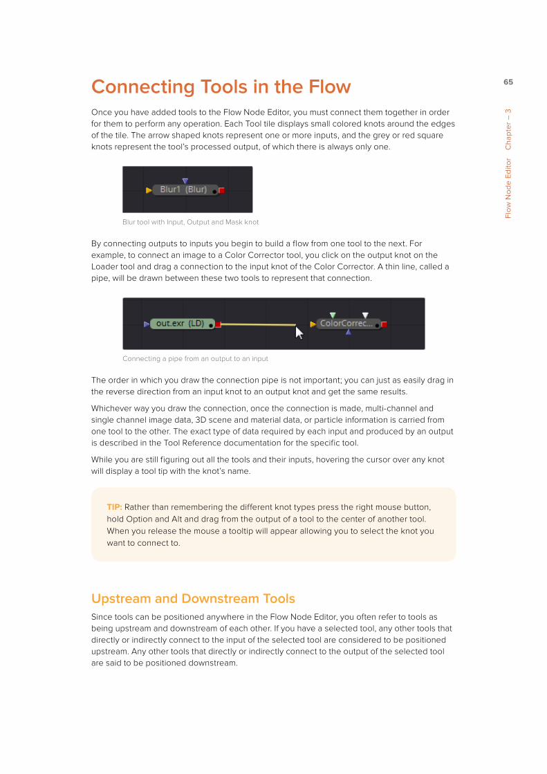
65
Flow
Nod
e Ed
itor
Cha
pter
– 3
Connecting Tools in the FlowOnce you have added tools to the Flow Node Editor, you must connect them together in order for them to perform any operation. Each Tool tile displays small colored knots around the edges of the tile. The arrow shaped knots represent one or more inputs, and the grey or red square knots represent the tool’s processed output, of which there is always only one.
Blur tool with Input, Output and Mask knot
By connecting outputs to inputs you begin to build a flow from one tool to the next. For example, to connect an image to a Color Corrector tool, you click on the output knot on the Loader tool and drag a connection to the input knot of the Color Corrector. A thin line, called a pipe, will be drawn between these two tools to represent that connection.
Connecting a pipe from an output to an input
The order in which you draw the connection pipe is not important; you can just as easily drag in the reverse direction from an input knot to an output knot and get the same results.
Whichever way you draw the connection, once the connection is made, multi-channel and single channel image data, 3D scene and material data, or particle information is carried from one tool to the other. The exact type of data required by each input and produced by an output is described in the Tool Reference documentation for the specific tool.
While you are still figuring out all the tools and their inputs, hovering the cursor over any knot will display a tool tip with the knot’s name.
Upstream and Downstream Tools Since tools can be positioned anywhere in the Flow Node Editor, you often refer to tools as being upstream and downstream of each other. If you have a selected tool, any other tools that directly or indirectly connect to the input of the selected tool are considered to be positioned upstream. Any other tools that directly or indirectly connect to the output of the selected tool are said to be positioned downstream.
TIP: Rather than remembering the different knot types press the right mouse button, hold Option and Alt and drag from the output of a tool to the center of another tool. When you release the mouse a tooltip will appear allowing you to select the knot you want to connect to.

66
Flow
Nod
e Ed
itor
Cha
pter
– 3
This is an important distinction to make because, unlike layer based systems, the visual positioning of the file or effect in the Flow Node Editor has no bearing on the composite’s outcome. Only whether tools are upstream or downstream of each other impacts the composite.
Tools upstream and downstream of the selected Merge tool
Disconnecting ToolsAs often as you connect tools, you need to be able to disconnect them as well. This allows you to rearrange the order of tools in a flow. The pipe that connects two tools is divided into two halves: the output half and the input half.
To disconnect the input or output of a tool, do one of the following:
Click on the input half of the connection between two tools.
Click on the input arrow, then drag to pull the connection away from the tool.
Click the pipe nearest to the input to disconnect it
To disconnect both the input and output of a tool, do the following:
� Hold Shift and drag the tool away from the connections.
You don’t have to disconnect an input only to replace it with the output from another tool.
If you drag a connection to an input that already has a connection, you will simultaneously disconnect the tool and reconnect it with the output you are dragging.
Tracing Pipes Through the Flow Several visual cues exist to help you follow the pipes through the flow.
The cursor positioned over a tool, highlights the connected pipes
Positioning the cursor over a specific tool will cause the pipes connected to that tool to become highlighted.

67
Flow
Nod
e Ed
itor
Cha
pter
– 3
BranchingA tool’s input can only have one connection from one output, but a tool’s output can be connected to inputs on multiple tools. Splitting the output of a tool so it connects to inputs on multiple tools is called Branching. This allows you to have one image that is processed in different ways and then combined back together later on in the flow.
A Loader tool branched to three output
Connection Types You can change the flexibly of the pipes used to connect tools together. The default uses linear lines that are drawn straight between two knots. This can cause pipes to overlap tiles, which some people may feel interferes with the view of the flow.
The default linear pipes style
You can switch the linear connection style with one that allows you to used right angles to avoid overlapping tiles.
To use connection pipes with right angles, do the following:
1 Right click in an empty area of the Flow Node Editor
2 From the contextual menu choose Options > Orthogonal Pipes

68
Flow
Nod
e Ed
itor
Cha
pter
– 3
The Orthogonal pipes style
The connections now use right angles to connect one tool to the next. You can even add your own routers to a default straight pipe or orthogonal pipe to force a right angle and route it however you like.
To add a router to an Orthogonal connection pipe, do the following:
� Option-click (Mac OS X) or Alt-Click (Windows) on a connection pipe where you want to add a router.
A router added to a pipe
To return to Linear connection pipes, do the following:
1 Right click in an empty area of the Flow Node Editor.
2 From the contextual menu choose Options > Direct Pipes.
Any routers you’ve added will remain on those connections.
To remove a router, do one of the following:
� Select the router you want to delete, then press Command-Delete (Mac OS X) or Delete (Windows) on the keyboard.
� Right click over the router you want to delete, then choose Delete from the contextual menu.
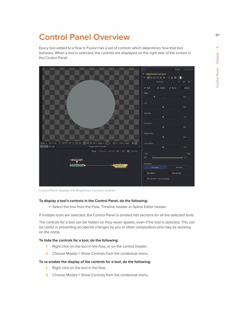
97
Con
trol
Pan
el
Cha
pter
– 4
Control Panel OverviewEvery tool added to a flow in Fusion has a set of controls which determines how that tool behaves. When a tool is selected, the controls are displayed on the right side of the screen in the Control Panel.
Control Panel displays the Brightness Contrast controls
To display a tool’s controls in the Control Panel, do the following:
� Select the tool from the Flow, Timeline header or Spline Editor header.
If multiple tools are selected, the Control Panel is divided into sections for all the selected tools.
The controls for a tool can be hidden so they never appear, even if the tool is selected. This can be useful in preventing accidental changes by you or other compositors who may be working on the comp.
To hide the controls for a tool, do the following:
1 Right click on the tool in the flow, or on the control header.
2 Choose Modes > Show Controls from the contextual menu.
To re-enable the display of the controls for a tool, do the following:
1 Right click on the tool in the flow.
2 Choose Modes > Show Controls from the contextual menu.

98
Con
trol
Pan
el
Cha
pter
– 4
The Control Panel InterfaceThe Control Panel includes a small title bar at the top called the Control Header, which displays the tool’s name and a button to close or open the controls.
The Control Header with the Close/Open button on the left side
More than one tool can be selected at a time and their controls are displayed in the Control Panel divided by a header for each selected tool.
Two tools in the Control Panel
Maximizing the Control PanelA small downward arrow height button can be found at the top left of the Control Panel. This button is used to toggle the Control Panel between maximized height and half height, depending on how much room you want to provide to the Viewers.
The Maximize button on the left side of the Control Panel
In maximized height mode, the Control Panel is aligned with the top of the window, taking up the entire right side of the Fusion window for the display of controls.

99
Con
trol
Pan
el
Cha
pter
– 4
The Maximize mode
In half height mode, the top of the Control Panel is aligned with the top of the Flow Node Editor, expanding the horizontal space for the Viewers.
The Regular mode

100
Con
trol
Pan
el
Cha
pter
– 4
Scaling and Panning the Control WindowYou can drag the vertical splitter between the Control Panel and the Work Panel or Viewers to increase the overall width of the panel. Most controls will resize together with the panel. This allows for greater precision with sliders, angles and other tools.
Drag the divider to increase or decrease the Control Panel width
The controls have a minimum width of approximately 280 pixels. They will begin to be cropped rather than be resized if you decrease the panel size beyond that point.
The Control Panel can be panned up or down to reveal portions that have scrolled out of the visible portion of the screen.
To pan the Control Panel up or down, do one of the following:
� On the right side of the Control Panel, drag the scrollbar up or down.
� Press the middle mouse button and drag up or down inside the Control Panel.

101
Con
trol
Pan
el
Cha
pter
– 4
Control Panel Display PreferencesBy default you only see selected tools in the Control Panel and only the active tool is expanded to show controls. You can, however, choose to change this behavior by choosing Fusion > Preferences (Mac OS X) or File > Preferences (Windows) and opening the User Interface preferences. In the User Interface preferences are two checkboxes that manage the display of controls.
Control preferences in the General category.
Auto Control HideWhen the Auto Control Hide option is enabled, the only controls visible are for the currently selected tool. All other controls are removed from the Control Panel to reduce clutter. This is enabled by default. When this checkbox is disabled once a tool is selected its controls always remain in the Control Panel.
Auto Control Close ToolsWhen the Auto Control Close checkbox is enabled, the Control Panel for the active selected tool is the only expanded controls. The controls for every other selected tool are automatically collapsed in the Control Panel. This checkbox defaults to enabled.

102
Con
trol
Pan
el
Cha
pter
– 4
Selecting and Viewing with the Control HeaderSelecting with the Control HeaderWhen you have multiple tools selected, you can make a tool the active tool by clicking its control header in the Control Panel. As the actively selected tool, the control header changes to a yellow color, the other tools are removed from the Control panel and any viewer displaying that tool’s output will then show the tool’s onscreen controls.
Viewing a Tool with the Control HeaderYou can view a tool by dragging the control header into one of the Viewers. To make a preview in one of the Viewers, hold Option (Mac OS X) or Alt (Windows) and drag the control header into the Viewer.
Viewing a Tool’s Splines with the Control HeaderIf you want to view the animated curves for a tool in the Spline Editor, you can add them by dragging the control header from the Control Panel into the Spline Editor. The animated splines attached to the tool will automatically be displayed for editing.
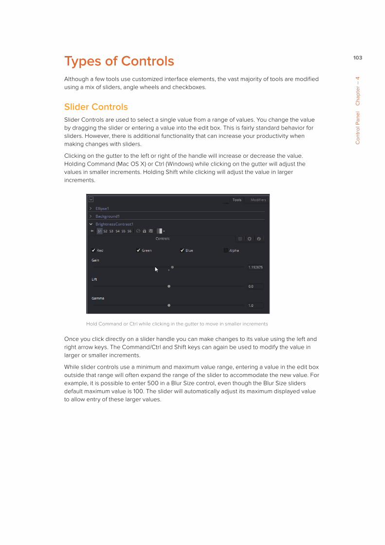
103
Con
trol
Pan
el
Cha
pter
– 4
Types of ControlsAlthough a few tools use customized interface elements, the vast majority of tools are modified using a mix of sliders, angle wheels and checkboxes.
Slider ControlsSlider Controls are used to select a single value from a range of values. You change the value by dragging the slider or entering a value into the edit box. This is fairly standard behavior for sliders. However, there is additional functionality that can increase your productivity when making changes with sliders.
Clicking on the gutter to the left or right of the handle will increase or decrease the value. Holding Command (Mac OS X) or Ctrl (Windows) while clicking on the gutter will adjust the values in smaller increments. Holding Shift while clicking will adjust the value in larger increments.
Hold Command or Ctrl while clicking in the gutter to move in smaller increments
Once you click directly on a slider handle you can make changes to its value using the left and right arrow keys. The Command/Ctrl and Shift keys can again be used to modify the value in larger or smaller increments.
While slider controls use a minimum and maximum value range, entering a value in the edit box outside that range will often expand the range of the slider to accommodate the new value. For example, it is possible to enter 500 in a Blur Size control, even though the Blur Size sliders default maximum value is 100. The slider will automatically adjust its maximum displayed value to allow entry of these larger values.
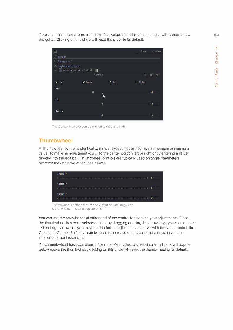
104
Con
trol
Pan
el
Cha
pter
– 4
If the slider has been altered from its default value, a small circular indicator will appear below the gutter. Clicking on this circle will reset the slider to its default.
The Default indicator can be clicked to reset the slider
ThumbwheelA Thumbwheel control is identical to a slider except it does not have a maximum or minimum value. To make an adjustment you drag the center portion left or right or by entering a value directly into the edit box. Thumbwheel controls are typically used on angle parameters, although they do have other uses as well.
Thumbwheel controls for X,Y and Z rotation with arrows on either end for fine tune adjustments
You can use the arrowheads at either end of the control to fine tune your adjustments. Once the thumbwheel has been selected either by dragging or using the arrow keys, you can use the left and right arrows on your keyboard to further adjust the values. As with the slider control, the Command/Ctrl and Shift keys can be used to increase or decrease the change in value in smaller or larger increments.
If the thumbwheel has been altered from its default value, a small circular indicator will appear below above the thumbwheel. Clicking on this circle will reset the thumbwheel to its default.

105
Con
trol
Pan
el
Cha
pter
– 4
Range ControlsThe Range Controls are actually two separate controls, one for setting the Low Range value and one for the High Range value. To adjust the values, you drag the handles on either end of the Range bar. To slide the high and low values of the range simultaneously, drag from the center of the Range bar. You can also expand or contract the range symmetrically by holding Command (Mac OS X) or Ctrl (Windows) and dragging either end of the Range bar. You find Range controls on parameters that require a high and low threshold, like the Matte Control, Chroma Keyer and Ultra Keyer tools.
A Matte Threshold Range control
CheckboxesCheckboxes are controls that have either an On or Off value. Clicking on the Checkbox control will toggle the state between selected and not selected. Checkboxes can be animated, with a value of 0 for Off and a value of 1.0 or greater for On.
Checkboxes used to select color channels
Drop down ListsDrop down lists are used to select one option from a menu. Once the menu is open, choosing one of the items will select that entry. When the menu is closed the selection is displayed in the Control Panel.
Drop down list of fonts in the Text tool
Drop down menu selections can be animated, with a value of 0 representing the first item in the list, 1 representing the second, and so forth.
TIP: You can enter floating point values in the Range controls by typing the values in using the Low and High numeric entry boxes.

106
Con
trol
Pan
el
Cha
pter
– 4
Button ArraysButton Arrays are groups of buttons that allow you to select from a range of options. They are almost identical in function to drop down menu controls, except that in the case of a button array it is possible to see all of the available options at a glance.
The Color Depth button array
Color Wheel and PickerThe Color Picker is displayed wherever a parameter requires a color as its value, such as the Fill or Outline color in the Text+ tool. The selected color is shown in a swatch below the Pick button. The swatch has two halves; the left half shows the color and the right half shows the color overlaid on a checkerboard background to preview transparency.
The color swatch with transparency preview
The color picker is extremely flexible and has four different techniques for selecting and displaying colors.
TIP: Color an be represented by 0-1, 0.255, or 0 - 65000 by setting the range you want in the Preferences > General panel
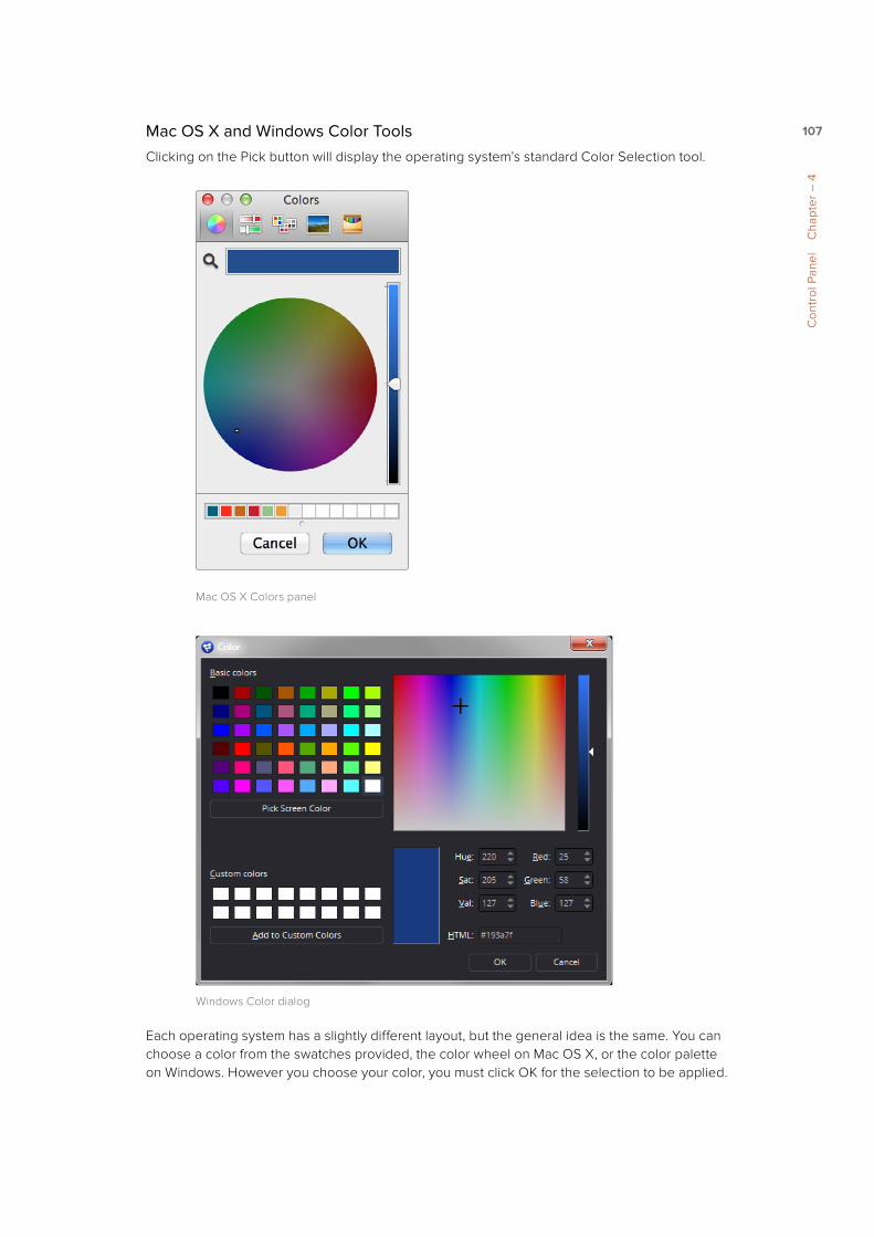
107
Con
trol
Pan
el
Cha
pter
– 4
Mac OS X and Windows Color ToolsClicking on the Pick button will display the operating system’s standard Color Selection tool.
Mac OS X Colors panel
Windows Color dialog
Each operating system has a slightly different layout, but the general idea is the same. You can choose a color from the swatches provided, the color wheel on Mac OS X, or the color palette on Windows. However you choose your color, you must click OK for the selection to be applied.

108
Con
trol
Pan
el
Cha
pter
– 4
The Color WheelYou also have access to the built in Color Wheel by clicking the small disclosure arrow above the Pick button. The built in color wheel includes a luminance bar for Grayscale values as well as edit boxes for Hue, Saturation and Luminance values.
The Color Wheel in the Text+ tool
Picking Colors from an ImageIf you are trying to match the color from an image in the Viewer, you can press the cursor down over the Pick button, then drag the cursor into the Viewer. The cursor will change to an eye dropper and a popup swatch will appear above the cursor with the color you are hovering over and its values. When you are over the color you want, release the mouse button to set the color.
The eye dropper with color swatch
The color picker normally selects from a single pixel in the image, but you can adjust the size of the selection by dragging into the Viewer with the eye dropper, then holding Command (Mac OS X) or Ctrl (Windows) and dragging out a rectangle for the sample side you want. The size change applies to all color pickers until the size is changed again.
GradientsThe Gradient Control bar is used to create a gradual blend between colors. The gradient bar displays a preview of the colors used from start to end. By default there are two triangular color stops, one on the left that determines the start color and one on the right that determines the end color.

109
Con
trol
Pan
el
Cha
pter
– 4
The default Gradient controls
Gradient TypeThe Gradient Type button array is used to select the form used to draw the gradient. Linear draws the gradient along a straight line from the starting color stop to the ending color stop.
Linear Gradient
Reflect draws the gradient by mirroring the linear gradient on either side of the starting point.
Reflect Gradient
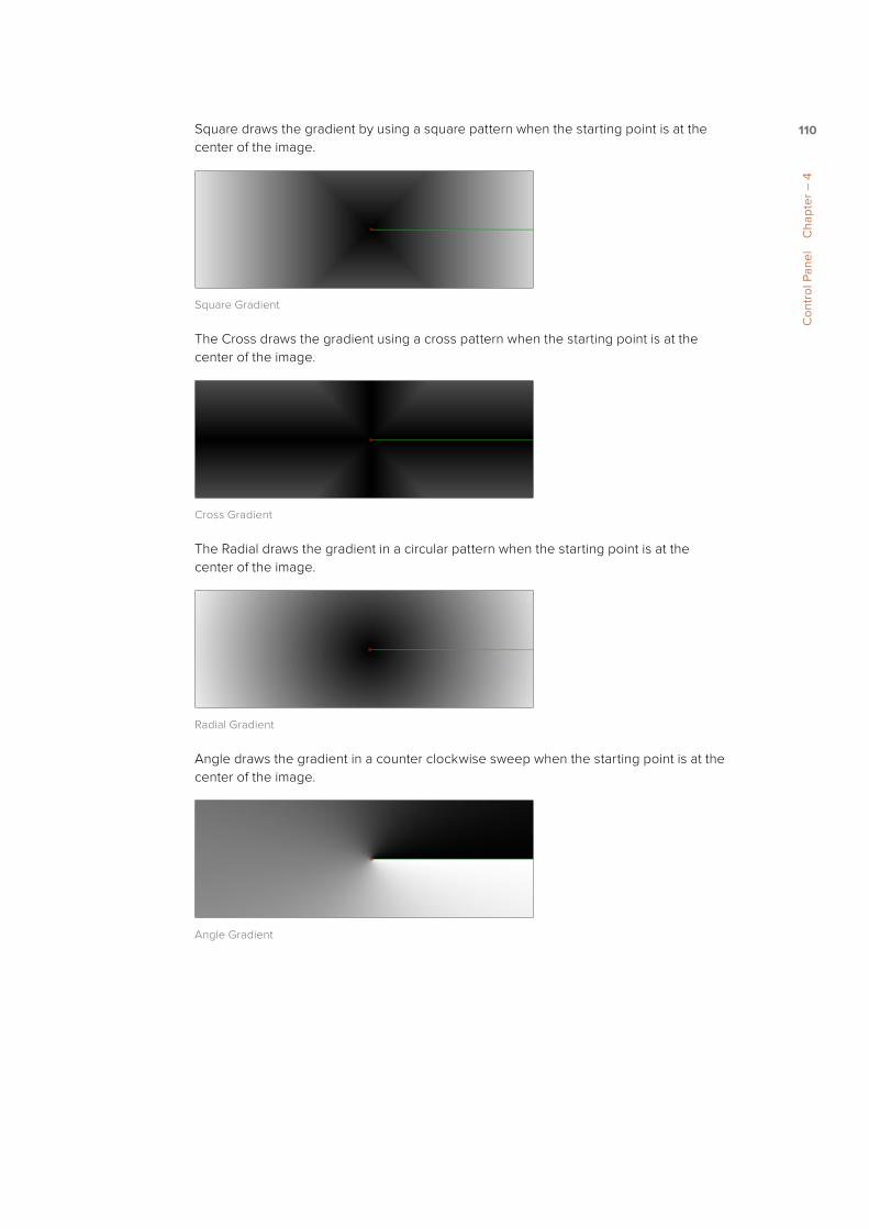
110
Con
trol
Pan
el
Cha
pter
– 4
Square draws the gradient by using a square pattern when the starting point is at the center of the image.
Square Gradient
The Cross draws the gradient using a cross pattern when the starting point is at the center of the image.
Cross Gradient
The Radial draws the gradient in a circular pattern when the starting point is at the center of the image.
Radial Gradient
Angle draws the gradient in a counter clockwise sweep when the starting point is at the center of the image.
Angle Gradient

111
Con
trol
Pan
el
Cha
pter
– 4
Start and End PositionThe Start and End Position controls have a set of X and Y edit boxes which are useful for fine tuning the start and end position of the gradient. The position settings are also represented by two crosshair on screen controls in the Viewer, which may be more practical for initial positioning.
Gradient Colors BarThe Gradient Colors bar is used to select the blending colors for the gradient. The default two color stops set the start and end colors. You can change the colors used in the gradient by selecting the color stop, then using the eye dropper or color wheel to set the new color.
You can add, move, copy and delete colors from the gradient using the colors bar.
To add a color stop to the gradient colors bar, do the following:
1 Click anywhere along the bottom of the gradient colors bar.
2 Use the eye dropper or color wheel to set the color for the color stop.
To move a color stop on the colors bar, do the following:
� Drag a color stop left or right along the gradient color bar.
To copy a color stop on the colors bar, do the following:
� Hold Command (Mac OS X) or Ctrl (Windows) while you drag a color stop.
To delete a color stop from the colors bar, do one of the following:
� Drag the color stop up past the gradient bar.
� Select the color stop, then click the red X button to delete it.
Gradient Interpolation Method
The Gradient Interpolation Method button array lets you select what color space is used to calculate the colors between color stops.
The Gradient Interpolation Method button array
OffsetWhen you adjust the Offset control, the position of the gradient is moved relative to the start and end markers. This control is most useful when used in conjunction with the repeat and ping-pong modes described below.
Once/Repeat/Ping-PongThese three buttons are used to set the behavior of the gradient when the Offset control scrolls the gradient past its start and end positions.The Once button is the default behavior, which keeps the color continuous for offset. Repeat loops around to the start color when the offset goes beyond the end color. Ping pong repeats the color pattern in reverse.

112
Con
trol
Pan
el
Cha
pter
– 4
1x1, 2x2, 3x3, 4x4, 5x5These buttons control the amount of sub-pixel precision used when the edges of the gradient become visible in Repeat mode, or when the gradient is animated. Higher settings will take significantly longer to render but be more precise.
Gradient Contextual menuGradients have their own context menu that you can bring up by right clicking on the gradient bar. In the Gradient contextual menu are options for animating, publishing and connecting one gradient to another. There is also a gradient specific modifier that builds a custom gradient by sampling colors from the output of a tool in the flow. To learn more about Modifiers, read Chapter 14 Introduction to Controls and Customization later in this manual.
ModifiersModifiers are expressions, calculations, trackers, paths and other mathematical components that you attach to a parameter to extend its functionality. When a modifier is attached to a parameter, its controls will appear separately in the Control Panel Modifiers tab.
To attach a Modifier, do the following:
1 Right click over the parameter to which you want to attach a Modifier.
2 Make a selection from the Modifier submenu in the contextual menu.
To learn more about Modifiers, read Chapter 14 Introduction to Controls and Customization later in this manual.
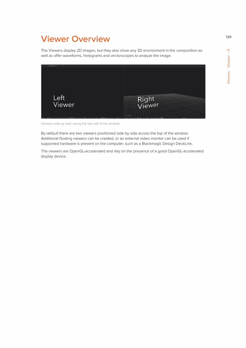
126
Vie
wer
s C
hapt
er –
5
Viewer OverviewThe Viewers display 2D images, but they also show any 3D environment in the composition as well as offer waveforms, histograms and vectorscopes to analyze the image.
Viewers side by side, along the top half of the window
By default there are two viewers positioned side by side across the top of the window. Additional floating viewers can be created, or an external video monitor can be used if supported hardware is present on the computer, such as a Blackmagic Design DeckLink.
The viewers are OpenGL-accelerated and rely on the presence of a good OpenGL-accelerated display device.

127
Vie
wer
s C
hapt
er –
5
Types of ViewersAlthough the primary viewers are the Left and Right Viewers that are always available above the Flow Node Editor, these viewers are not the only viewers available to you. You can open additional viewers as well as HD, UltraHD and DCI 4K monitors to evaluate your comps.
Floating Viewers You can open an unlimited number of Floating Viewers which are ideal for dual monitor configurations. Floating viewers can be set to full screen mode to make the best use of screen real estate. To open a new floating viewer, choose Window > New Image View from the menu bar. If this is an option you want to use regularly, you can save the position and configuration of the new viewer using the layout preferences.
Floating Viewer

128
Vie
wer
s C
hapt
er –
5
HD, Ultra HD and DCI 4K MonitorsIf video hardware, like the Blackmagic Design DeckLink 4K Extreme, is present in the computer, you can display images on external SD, HD, UltraHD or full frame DCI 4K monitors. You can configure your Blackmagic Design DeckLink hardware by going to Fusion > Preferences (Mac OS X) or File > Preferences (Windows) and selecting the Video Monitoring preferences.
The Blackmagic DeckLink card preferences
The monitors cannot be used to manipulate preview controls like center cross hairs or masks, but they are extremely valuable for evaluating the images in the same format in which they will be output, and for determining color fidelity and accuracy with a properly calibrated monitor.

129
Vie
wer
s C
hapt
er –
5
Displaying a Tool in the ViewerThere are a number of different ways to display a tool in the Viewer, starting with the Tool Tile View Indicators. The View indicators are displayed under each tile. By default, there are two indicators, representing the two Viewers in the Fusion window. The View indicator on the left is used for the Viewer on the left, while the View indicator on the right is used for the Viewer on the right. If a new viewer is added, an additional indicator will appear on each tile. Clicking an indicator will turn it white and display that tool in the appropriate viewer. Clicking it again removes it from the viewer and removes the white highlight.
A View indicator enabled for the left Viewer and disabled for the right Viewer
The name of the currently viewed tool is displayed on the horizontal toolbar at the bottom of the Viewer.
The name of the tool currently displayed is located at the bottom of the Viewer
You can use keyboard shortcuts to display the selected tool in a viewer. Each viewer is assigned a numeric keyboard shortcut from 1-9. Pressing that number on the keyboard will display the selected tool in the appropriate Viewer.
To view a tool using keyboard shortcuts, do one of the following:
� Selected a tool in the Flow Node Editor, then press 1 to display it in the left Viewer.
� Selected a tool in the Flow Node Editor, then press 2 to display it in the right Viewer.
You can also drag the tool from the Flow Node Editor into a viewer. The tool will appear to move at first but will snap back into its original location once the cursor leaves the area of the Flow Node Editor.
To view a tool by dragging, do the following:
1 Drag the tool into the Viewer.
2 Release the mouse button over the Viewer.
Tip: If a tool is not currently displaying View indicators, position the cursor over the tile to make the indicators visible and available for clicking.

130
Vie
wer
s C
hapt
er –
5
To view a tool using the Control Panel, do the following:
� Drag the tool’s control header from the Control Panel into a viewer.
If you have an image that is stored on your computer’s hard drive, you can use the viewers for quick previews before adding it to a flow.
To view an image stored in a file browser, do one of the following:
� Drag the image from the operating system’s file browser into a viewer.
� Right click over a viewer, then choose Load Preview.
This contextual menu will load the clip as a preview with transport controls at the bottom of the Control Panel to play, review, and loop the sequence.
The transport controls at the bottom of the Control Panel
When you drag an image into a viewer, whether it be from the Control Panel, the Flow Node Editor or the file browser, holding Option (Mac OS X) or Alt (Windows) while dragging will create a Flipbook Preview in that viewer. The Render Settings dialog will be displayed, and upon accepting the settings, the tool will be rendered and the resulting frames stored in RAM for fast playback on that viewer. This is similar to selecting Create Preview On from the tool’s contextual menu. You can also hold Shift-Option (Mac OS X) or Shift-Alt (Windows) to skip the dialog and immediately start rendering the preview with the last used settings.
Tools can also be loaded into a viewer using the different contextual menus.
To load a tool into a viewer using the tool’s contextual menu, do the following:
1 Right click on a tool’s tile in the Flow Node Editor.
2 Choose View On, then in the submenu choose the viewer to use.
The Tool contextual menu

131
Vie
wer
s C
hapt
er –
5
To load a tool into a viewer using the Control header contextual menu, do the following:
1 Right click on the tool’s Control header in the Control Panel.
2 Choose View On, then in the submenu choose the viewer to use.
The Control header’s contextual menu
To load a tool into a viewer using the Timeline header contextual menu, do the following:
1 Right click on the tool’s name in the Timeline header area to the left of the Timeline.
2 From the contextual menu choose View On, then from the submenu choose the viewer.
Removing Images from the ViewerTo clear an image from a viewer, click in the Viewer to make it active; a light purple outline is displayed around the active panel. With the Viewer active, press the Tilde (~) key. This key is usually found to the left of the 1 key on U.S. keyboards. The fastest way to remove all the images from all the viewers is to make sure none of the viewers is the active panel, then press the Tilde key.

132
Vie
wer
s C
hapt
er –
5
Position and LayoutWhen you resize and change the layout of viewers in the comp, that configuration is always saved with the comp. So each time you open the comp, the size and layout is remembered. You can prevent this behavior by disabling the Recall Layout checkbox in the Global Layout preferences.
If you want all new compositions to open with a certain Viewer layout, you can configure the layout of the two primary viewers then use the Grab Document Layout button in the Global Layout preferences to remember the layout for any new compositions. To save the position and size of floating viewers, you use the Grab Program Layout button. Finally, if you want to have the floating viewers opened automatically when you open Fusion, enable the Create Floating Views checkbox.
Layout ToolbarThe Layout Toolbar at the top of the Fusion window can be used to configure the Viewers and panels using four preset layouts.
The Layout Toolbar
First Button Use this option to maximize a single viewer (Viewer 1), aligning the Control Panel with the top of the screen.
Second ButtonUse this option for dual viewers, aligning the Control Panel with the top of the screen. This is the default layout.
Third ButtonUse this option to maximize a single viewer (Viewer 1), aligning the Control Panel with the top of the Flow Node Editor.
Fourth ButtonUse this option for dual viewers, aligning the Control Panel with the top of the Flow Node Editor.

133
Vie
wer
s C
hapt
er –
5
Splitter BarsYou can change the relative sizes of the left and right viewers using the horizontal splitter bar that runs between them.
Drag the splitter to increase or decrease the amount of space used by one viewer. The adjacent viewer will adjust to accommodate the new layout.
The amount of vertical space available for both viewers can be adjusted by dragging the horizontal scroll bar between the Viewers and the Work area below them.
The Viewer Splitter bar
Fullscreen ViewersFloating viewers are not affected by the buttons in the Layout toolbar. You adjust the size of a floating viewer by dragging any corner of the Viewer window, or by double clicking on the Viewer’s titlebar. Additionally, a floating viewer can be scaled to fullscreen by right clicking in the Viewer and choosing Global Options > Full Screen from the contextual menu.
You can maximize one of the fixed viewers to full screen by placing the cursor over the Viewer and pressing the F4 key. To restore a full screen viewer to its original layout position, press F4 again. This shortcut can also be used to maximize the Work area below the Viewers.
TIP: You can use the height button above the Control Panel to shrink the Control Panel to half height, giving the Viewers additional horizontal space. To learn more about the Control Panel, read Chapter 4.
TIP: The Full screen option is only available in Fusion Studio

134
Vie
wer
s C
hapt
er –
5
Panning in the ViewerThe image in the Viewer can be panned so you can focus your work a specific area of the frame. To pan, position the cursor in the Viewer, hold the middle mouse button, then drag the mouse in the direction you want to pan. If your mouse does not include a middle mouse button, hold Command-Shift (Mac OS X) or Ctrl-Shift (Windows) while dragging.
When viewing a 3D scene, panning changes the point of view and thus the center point for scaling and rotation, too. A combination of panning and rotation will allow you to move the point of view anywhere in the scene.
TIP: While viewing a 3D scene, zooming in will decrease the sensitivity of panning, to allow finer control when navigating around small images and scenes. Correspondingly, pan sensitivity will increase when zooming out. If you need to move the point of view faster, zoom out first or reset the scale with Command-1 (Mac OS X) or Ctrl-1 (Windows).

135
Vie
wer
s C
hapt
er –
5
Scaling in the ViewerThere are a number of ways to scale an image or 3D scene once it is displayed in a viewer.
You can use the mouse, the keyboard, the contextual menu or the Viewer toolbar.
Using the MouseTo scale the image in the Viewer by dragging the mouse, do the following:
1 Place the cursor over the Viewer.
2 Hold the middle and left mouse buttons.
3 Drag the mouse to the left or right.
The image smoothly scales, centered on the starting position of the cursor. Dragging to the right zooms in, while dragging to the left zooms out.
To scale the image in the Viewer by clicking on the mouse, do the following:
1 Place the cursor over the Viewer.
2 Hold the middle mouse button.
3 Click once using the left mouse button to zoom in or the right button to zoom out.
The scaling uses a fixed amount, centered on the position of the cursor.
To scale the image in the Viewer by rolling the mouse wheel, do the following:
1 Place the cursor over the Viewer.
2 Press Command (Mac OS X) or Ctrl (Windows) and roll the mouse wheel up or down.
Each step on the wheel increases or decreases the scale by a fixed amount, centered on the cursor.
Using the KeyboardUsing the keyboard, you can change the scale in a viewer by a fixed value. The + or - keys on the numeric keypad can be used on the active viewer to zoom in and out. Pressing Command-1 (Mac OS X) or Ctrl-1 (Windows) will set the image or scene back to its default of 100% scale, and will recenter it as well. If the image is larger than the Viewer, which in most cases it is, pressing Command-F (Mac OS X) or Ctrl-F (Windows) will fit the image or scene in the Viewer’s frame.
TIP: There is a lower limit to the scale of a 3D scene. Continuing to zoom in past this limit will instead move (“dolly“) the point of view forwards. The mouse wheel will move forward slowly, and the keyboard will move more quickly.

136
Vie
wer
s C
hapt
er –
5
Using the Contextual MenuThe benefit of using the Viewer’s contextual menu for scaling is the number of preset scale settings that can be selected to scale the Viewer by a specific amount. You can also quickly scale the image to fit in the Viewer’s frame.
The Scale submenu in the Viewer’s contextual menu
Using the Viewer ToolbarThe Viewer Toolbar contains a Scale menu similar to the one found in the contextual menu. Click on the Scale menu to bring up a list of several preset scales to choose from, or click on the Fit button beside it to fit the image or scene to the Viewer window.
The Scale menu and Fit button in the Viewer toolbar

137
Vie
wer
s C
hapt
er –
5
Making PreviewsIn addition to displaying the output of a tool, the viewers are also used to display flipbook previews and do file playback of image sequences and AVI or MOV movie files straight from disk.
RAM Flipbook PreviewsTo watch a clip or the output of a tool play back in the Viewer, you can use the RAM flipbook. RAM Flipbook Previews are preview renders that exist entirely within RAM and allow you to watch a tool’s output at playback speed. Flipbook previews are created by holding Option (Mac OS X) or Alt (Windows) while dragging a tool into the Viewer, or by selecting Create/Play Preview from the tool’s contextual menu.
Either way you invoke the flipbook preview, a Preview Render dialog will open where you can change the quality, resolution and motion blur settings of the flipbook preview.
The Flipbook Preview Render dialog
If you want to bypass the dialog and use the default setting or the settings that were chosen last, hold Shift-Option (Mac OS X) or Shift-Alt (windows) while you drag the tool into the Viewer. The settings dialog will not show up and rendering the preview will start right away.
SettingsThe Settings section of the Preview Render dialog include three buttons that determine the overall quality and appearance of your flipbook preview. These buttons also have a significant impact on render times.
The Settings buttons in the Flipbook Preview Render dialog

138
Vie
wer
s C
hapt
er –
5
HiQ When enabled, this settings renders the preview in full image quality. If you need to see what the final output of a tool would look like, then you would enable the HiQ setting. If you are producing a rough preview to test animation, you can save yourself time by disabling this setting.
MB The MB in this setting stands for Motion Blur. When enabled, this setting renders with motion blur applied if any tool is set to produce motion blur. If you are generating a rough preview and you aren’t concerned with the motion blur for animated elements, then you can save yourself time by disabling this setting.
Some When Some is enabled, only the tools specifically needed to produce the image of the tool you’re previewing are rendered.
SizeSince RAM flipbook previews use RAM, it is incredibly helpful to know how many frames you can render into RAM before you run out of memory. The Flipbook Preview dialog calculates the currently available memory and displays how many frames will fit into RAM. If you have a small amount of RAM in your computer and you cannot render the entire range of frames you want, you can choose to lower the resolution to a setting that delivers the best quality/duration ratio for your preview.
The Size settings with the number of frames that will fit into RAM
NetworkFusion Studio can use the network rendering nodes to distribute the process of rendering the preview. Chapter 18 describes network rendering setup.
The Network Groups pane displays additional computers available for rendering

139
Vie
wer
s C
hapt
er –
5
Shoot OnSometimes you may not want to render every single frame, but every second, third or fourth to save render time and get faster feedback. You can use the Step parameter to determine the interval at which frames are rendered.
The Shoot On parameters are used for skipping frames during render
Frame RangeThis field uses the current Render In/Out Range set in the Time Ruler to determine the start and end frames for rendering. You can modify the range to render more or fewer frames.
The Frame Range determines the starting and ending frames for the flipbook preview
ConfigurationsOnce you’re done setting your personal preview configuration, it can be saved permanently for later use by clicking Add and then typing in a new name for your personal settings.
The Configurations area can be used to save your settings for future flipbook previews
Playing Back the PreviewOnce the preview is done rendering, the flipbook is loaded into the Viewer. A frame counter appears in the corner of the Viewer, and a Play/Pause button is added to the right of the Viewer’s bottom toolbar. A more complete set of playback controls appear in the bottom right corner of the Fusion window beneath the Control Panel.

140
Vie
wer
s C
hapt
er –
5
The flipbook preview with a Play/Pause button in the Viewer’s toolbar.
Once you’ve watched the flipbook, you can remove it from the Viewer and free up your RAM by right clicking in the Viewer and choosing Remove Preview from the contextual menu.
The Flipbook Preview options in the Viewer’s contextual menu
With the flipbook preview still loaded in the Viewer, there are other options in the Viewer’s contextual menu to enable looped or ping-pong playback, as well as enter Fullscreen mode, which allows you to focus on the clip without the rest of Fusion’s interface. After you’ve viewed the clip, to exit Fullscreen mode you deselect Fullscreen from the contextual menu, or press the Esc key.
It is also possible to “trim“ the flipbook in order to skip playback of the first or last few frames. This can be done using the scrub bar in the transport controls that appear at the bottom right of Fusion‘s window. Hold Command (Mac OS X) or Ctrl (Windows) and drag the the start or end of the scrub bar to set or change the frames to be played. Right clicking on the scrub bar will bring up a contextual menu where you can reset the In and Out points.
The transport controls can be used to trim frames from the start and end of the flipbook

141
Vie
wer
s C
hapt
er –
5
Updating a PreviewAn option that is designed for the interactive frame by frame work of rotocoping and paint is to set a Preview to Update from its contextual menu. When active, any frames that are modified on the previewed tool are automatically updated in the preview’s playback. This lets you reserve the RAM to do playback. You can keep it playing on a loop or ping-pong while you work in another viewer.
Mouse and Keyboard ShortcutsWhile the flipbook preview is loaded into a viewer you can play or scrub through it using only the mouse or the keyboard.
To play back a flipbook using the mouse, do the following:
� Double click in the Viewer to start playback.
To scrub through a flipbook using the mouse, do the following:
� Hold the right mouse button and drag the mouse left or right to scrub through frames.
To play back a flipbook using the keyboard, do one of the following:
� Press spacebar to start or stop playback.
� Hold Shift and press spacebar to play in reverse.
To scrub through a flipbook frame by frame using the keyboard, do one of the following:
� Press the left or right arrow keys to move to the previous or next frame.
� Hold Shift and press the left or right arrow keys to jump back or forward 10 frames.
� Press Command (Mac OS X) or Ctrl (Windows) left arrow key to jump to the first frame.
� Press Command (Mac OS X) or Ctrl (Windows) right arrow key to jump to the last frame.
File Sequence PreviewsIf you want to play the file sequence or movie file read in by a Loader tool you don’t have to create a flipbook preview, you can use the transport controls that appear in the bottom of the Control Panel.
After pressing the Play button, the images are displayed as quickly as possible in the Viewer. By default, the left Viewer is used, but that default can be changed using the Preview preferences. By changing these preferences you can also play the file sequence to installed video hardware, but this may decrease playback performance.
As with flipbooks, you can trim the In and Out points for image sequence previews, using the scrub bar in the transport controls. By default, trimming done in the scrub bar while a Loader tool is selected will be mirrored in the Loader’s Trim In/Out controls. This can be disabled using the scrub bar’s contextual menu.
While the file sequence preview is enabled, normal viewing of tools to that viewer is disabled. When you are ready to return to displaying tools in the Viewer, select another tool or empty area of the Flow Node Editor.
TIP: The mouse and keyboard shortcuts work in Fullscreen mode as well.

142
Vie
wer
s C
hapt
er –
5
Preview ControlsWhen it comes to adjusting images, the Control Panel provides very precise numerical values, but sometimes visually positioning an element using on screen controls can get you where you want to go with less tweaking. The Viewers show preview controls for manipulating the parameters of the currently selected tool. Common preview controls include crosshairs, angle indicators, polylines and paint strokes. Each of these controls can be manipulated directly in the Viewer using the mouse or keyboard.
The Angle preview control
The controls shown are determined only by the tools that are selected, not by the tool displayed in the Viewer. For example, a downstream blur is easily viewed while manipulating the controls for a selected polygon mask or merge. If multiple tools are selected, the controls for all of those tools are shown.
Enabling/Disabling Preview ControlsThe preview controls for a viewer can be disabled so they do not interfere with viewing the image.
The Show Controls button in the Viewer toolbar is used to show and hide preview controls
To disable the preview controls, do one of the following:
� Click the Show Controls button in the View toolbar.
� Right click in the Viewer and choose Show Controls in the Options submenu.
� Press Command (Mac OS X) or Ctrl (Windows) -K on the keyboard.
TIP: Some tools, like Masks, allow disabling of their preview controls on a per-tool basis because you often use multiple polygon tools to organize and animate masks.

143
Vie
wer
s C
hapt
er –
5
You can disable some tools, like the Polygon tool, on a per tool basis.
Making Fine Adjustments to ControlsIf you want the visual guidance of preview controls with the precision of the Control Panel, you can use a few keyboard shortcuts.
The arrow keys can be used to adjust the position of the preview control along the vertical or horizontal axis by small steps.
Holding Command (Mac OS X) or Ctrl (Windows) while using the arrow keys reduces the scale of each step by a factor of ten. Holding Shift increases the scale of each step by a factor of ten.

144
Vie
wer
s C
hapt
er –
5
ToolbarsThere are two toolbars in the Viewer: a horizontal toolbar called the View Toolbar, and a vertical toolbar called the Tool Toolbar. Both are used for showing buttons that are specific to the selected control.
Viewer ToolbarThe Viewer Toolbar runs across the bottom of the Viewer, providing access to many of the most commonly used Viewer related settings. Most of the buttons found on this toolbar are described in detail throughout this chapter.
The Viewer toolbar located at the bottom of the Viewer
This toolbar is dynamic, meaning the buttons that are displayed may change depending on the type of viewer. A 3D Viewer shows a set of buttons for controlling the display of lights and shadows, for example, but these buttons are not needed in a 2D viewer since there are no lights or shadows in 2D. A tooltip can be displayed by hovering the cursor over any button.
Tool Specific ToolbarsIn addition to the Viewer toolbar, a vertical Tool toolbar is displayed along the side of the Viewer, depending on the selected tool. Text, masks, paths, paint strokes and the 3D environment are some of the tools that make use of this toolbar.
The Tool Toolbar for masks
You can customize the size and type of buttons displayed in this toolbar by right clicking on the toolbar to bring up the contextual menu.

145
Vie
wer
s C
hapt
er –
5
Customizing the ToolbarsIf you want to change the size of the buttons and icons in the toolbars, these settings are available in the context menu.
The contextual menu for the Tool toolbar
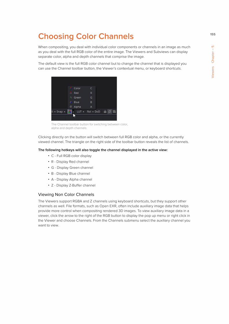
155
Vie
wer
s C
hapt
er –
5
Choosing Color ChannelsWhen compositing, you deal with individual color components or channels in an image as much as you deal with the full RGB color of the entire image. The Viewers and Subviews can display separate color, alpha and depth channels that comprise the image.
The default view is the full RGB color channel but to change the channel that is displayed you can use the Channel toolbar button, the Viewer’s contextual menu, or keyboard shortcuts.
The Channel toolbar button for switching between color, alpha and depth channels
Clicking directly on the button will switch between full RGB color and alpha, or the currently viewed channel. The triangle on the right side of the toolbar button reveals the list of channels.
The following hotkeys will also toggle the channel displayed in the active view:
� C - Full RGB color display
� R - Display Red channel
� G - Display Green channel
� B - Display Blue channel
� A - Display Alpha channel
� Z - Display Z-Buffer channel
Viewing Non Color ChannelsThe Viewers support RGBA and Z channels using keyboard shortcuts, but they support other channels as well. File formats, such as Open EXR, often include auxiliary image data that helps provide more control when compositing rendered 3D images. To view auxiliary image data in a viewer, click the arrow to the right of the RGB button to display the pop up menu or right click in the Viewer and choose Channels. From the Channels submenu select the auxiliary channel you want to view.

166
Vie
wer
s C
hapt
er –
5
As with all offsets in Fusion, this is a resolution independent number where 1 is the width of the full image and 0.5 is half the width of the image. Guide 2’s text box is used to set the aspect ratio of the projection area.
The Frame Format Guides settings
Guide Frame AspectTo find out how the current image compares to a specified frame format, you can choose from a list of frame aspect ratios in the Guides submenu of the Viewer’s contextual menu. The frame aspect is usually set to Default. This forces the frame aspect to the same resolution as the image displayed in the view.
The Guide > Frame Aspect submenu in the Viewer’s contextual menu.
When the frame aspect is set using the Guides > Frame Aspect context menu, the guides will represent the exact boundaries of the specified format and any image area outside of that will be dark gray.
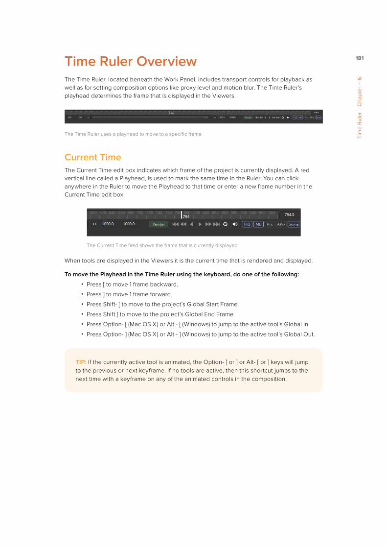
181
Tim
e R
uler
C
hapt
er –
6
Time Ruler OverviewThe Time Ruler, located beneath the Work Panel, includes transport controls for playback as well as for setting composition options like proxy level and motion blur. The Time Ruler’s playhead determines the frame that is displayed in the Viewers.
The Time Ruler uses a playhead to move to a specific frame
Current TimeThe Current Time edit box indicates which frame of the project is currently displayed. A red vertical line called a Playhead, is used to mark the same time in the Ruler. You can click anywhere in the Ruler to move the Playhead to that time or enter a new frame number in the Current Time edit box.
The Current Time field shows the frame that is currently displayed
When tools are displayed in the Viewers it is the current time that is rendered and displayed.
To move the Playhead in the Time Ruler using the keyboard, do one of the following:
� Press [ to move 1 frame backward.
� Press ] to move 1 frame forward.
� Press Shift- [ to move to the project’s Global Start Frame.
� Press Shift ] to move to the project’s Global End Frame.
� Press Option- [ (Mac OS X) or Alt - [ (Windows) to jump to the active tool’s Global In.
� Press Option- ] (Mac OS X) or Alt - ] (Windows) to jump to the active tool’s Global Out.
TIP: If the currently active tool is animated, the Option- [ or ] or Alt- [ or ] keys will jump to the previous or next keyframe. If no tools are active, then this shortcut jumps to the next time with a keyframe on any of the animated controls in the composition.

182
Tim
e R
uler
C
hapt
er –
6
Keyframe TicksWhen animated tools are selected, green vertical ticks on the Time Ruler will indicate the keyframe positions.
The Time Ruler with keyframe tick marks.
Cache IndicatorWhen assembling a flow, images are rendered for display in the Viewers. These images are stored in a RAM Cache so they can be displayed instantly at a later time without having to re-render them. You do not have to do anything since caching happens automatically. When the size of the cache reaches the limits of available memory, lower priority frames are eliminated to make space for new images.
The frames cached for a tool are indicated by a green line under that frame in the Time Ruler. The indicator only displays the cache regions for the actively selected tool in the flow.
The green line indicates frames that have been cached for playback
When you change the comp quality or proxy scale, the cache is not discarded; it is marked with a red line instead. This lets you know that if you return to the prior quality setting or proxy scale, the cache is kept. However, if you render those frames using the new quality or proxy scale, then the old cache will be overwritten.
In some cases, changing the Quality setting will not cause the Cache Indicator to turn red. When the cached frames are at the HiQ setting and you turn HiQ off, the green frames won’t turn red. The HiQ cached frames will be used even though the HiQ setting has been disabled.
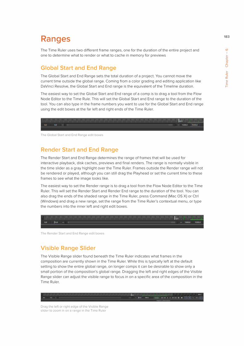
183
Tim
e R
uler
C
hapt
er –
6
RangesThe Time Ruler uses two different frame ranges, one for the duration of the entire project and one to determine what to render or what to cache in memory for previews
Global Start and End RangeThe Global Start and End Range sets the total duration of a project. You cannot move the current time outside the global range. Coming from a color grading and editing application like DaVinci Resolve, the Global Start and End range is the equivalent of the Timeline duration.
The easiest way to set the Global Start and End range of a comp is to drag a tool from the Flow Node Editor to the Time Rule. This will set the Global Start and End range to the duration of the tool. You can also type in the frame numbers you want to use for the Global Start and End range using the edit boxes at the far left and right ends of the Time Ruler.
The Global Start and End Range edit boxes
Render Start and End RangeThe Render Start and End Range determines the range of frames that will be used for interactive playback, disk caches, previews and final renders. The range is normally visible in the time slider as a gray highlight over the Time Ruler. Frames outside the Render range will not be rendered or played, although you can still drag the Playhead or set the current time to these frames to see what the image looks like.
The easiest way to set the Render range is to drag a tool from the Flow Node Editor to the Time Ruler. This will set the Render Start and Render End range to the duration of the tool. You can also drag the ends of the shaded range in the Time Ruler, press Command (Mac OS X) or Ctrl (Windows) and drag a new range, set the range from the Time Ruler’s contextual menu, or type the numbers into the inner left and right edit boxes.
The Render Start and End Range edit boxes
Visible Range SliderThe Visible Range slider found beneath the Time Ruler indicates what frames in the composition are currently shown in the Time Ruler. While this is typically left at the default setting to show the entire global range, on longer comps it can be desirable to show only a small portion of the composition’s global range. Dragging the left and right edges of the Visible Range slider can adjust the visible range to focus in on a specific area of the composition in the Time Ruler.
Drag the left or right edge of the Visible Range slider to zoom in on a range in the Time Ruler

184
Tim
e R
uler
C
hapt
er –
6
Render ButtonThe Render Button opens the composition’s Render Settings dialog, where you can confirm the render options and start rendering the composition to disk. Holding Shift while clicking the Render button will skip the dialog and use the default values for the rendering with full resolution, high quality and motion blur enabled.
The Render Settings dialog brought up by clicking the Render button
Transport ControlsThe Transport Controls in the Time Ruler can be used to play the composition forward or in reverse, to advance current time to the next or previous frame, or to jump current time to the start and end of the Render range. In this context, playback means the flow at the current frame will render into the Viewer, then advance the current time to the next frame (or previous frame) and repeat. There is no guarantee of real time playback at the project’s full frame rate, unless the frames are already cached in memory.
The transport controls
TIP: Holding the middle mouse button and dragging in the Time Ruler will pan the visible range. This can be handy when you’re zoomed in and need to move ahead to the next groups of frames.

185
Tim
e R
uler
C
hapt
er –
6
Right clicking on either the frame advance or previous frame button will display a contextual menu that can be used to set a frame increment for that button. This frame increment setting will be used when you click the frame advance buttons or use the keyboard shortcuts. This is often useful for rotoscoping on fixed increments, or inspecting a frame one field at a time.
Right click to change the frame advance increment
The loop button is a tri-state button that determines whether playback will stop when the playhead reaches the render start or end, loop back and start again, ping pong back and forth or stop completely.
Audio MuteThe Audio button is a toggle that turns on and off audio playback. Additionally, if you right click on this button, a contextual menu will allow you to select a .wav file that will play along with the composition. The same menu allows you to assign an offset to the audio playback so you can adjust when it begins.
Right click the Audio button to select an audio file to play with the composition
TIP: Changing the frame increments on any transport button changes it for all transport buttons, including playback.

186
Tim
e R
uler
C
hapt
er –
6
Composition Quality OptionsThe Composition Quality options consist of two buttons. The High Quality button and the Motion Blur button.
The Composition Quality options in the Time Ruler
High QualityWhen working interactively to create a flow, the quality of the images in the displays is often less important than the speed with which they are shown. As a result, you have the option to render images for better interactivity or at final render quality. When you disable the High Quality (HiQ) setting, more complex and time consuming operations such as area sampling, anti aliasing and interpolation are skipped to produce results more rapidly. Enabling HiQ mode will force a full quality render identical to that produced during a final render.
Motion BlurWhen the Motion Blur button in the toolbar is toggled off, the motion blur options enabled on any of the tools in the composition will be ignored. This can result in significantly quicker renders and previews, since the sub frames required to produce motion blur will no longer be calculated.
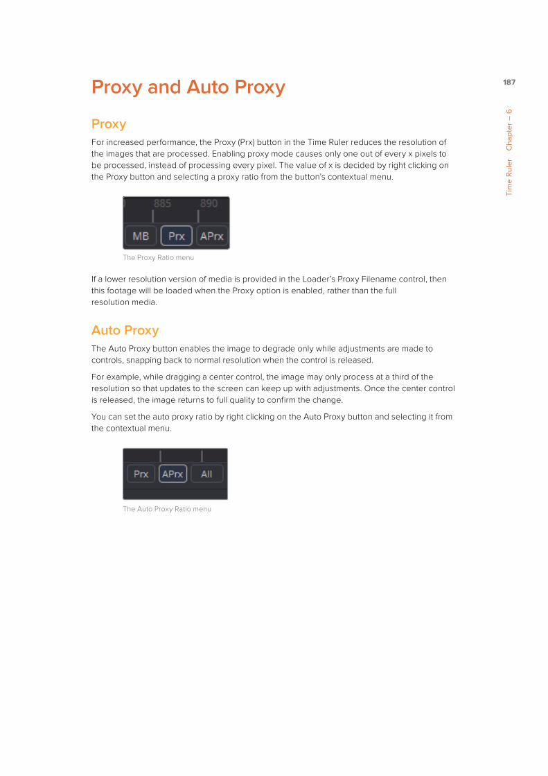
187
Tim
e R
uler
C
hapt
er –
6
Proxy and Auto Proxy
ProxyFor increased performance, the Proxy (Prx) button in the Time Ruler reduces the resolution of the images that are processed. Enabling proxy mode causes only one out of every x pixels to be processed, instead of processing every pixel. The value of x is decided by right clicking on the Proxy button and selecting a proxy ratio from the button’s contextual menu.
The Proxy Ratio menu
If a lower resolution version of media is provided in the Loader’s Proxy Filename control, then this footage will be loaded when the Proxy option is enabled, rather than the full resolution media.
Auto ProxyThe Auto Proxy button enables the image to degrade only while adjustments are made to controls, snapping back to normal resolution when the control is released.
For example, while dragging a center control, the image may only process at a third of the resolution so that updates to the screen can keep up with adjustments. Once the center control is released, the image returns to full quality to confirm the change.
You can set the auto proxy ratio by right clicking on the Auto Proxy button and selecting it from the contextual menu.
The Auto Proxy Ratio menu

188
Tim
e R
uler
C
hapt
er –
6
Selective UpdatesFusion normally renders only the tools that are needed to display the images in the views. The Selective Update button in the Time Ruler opens the Render Settings dialog to select the mode used during final and network renders.
There are three modes of selective update that are cycled through by clicking the Selective Update button in the Time Ruler.
The Selective Update button set to Some by default
SomeDuring final renders, the Some setting causes only tools that directly contribute to the output to be rendered. This is the default mode of selective update called Some, because only some of the tools in the flow are rendered.
NoneThe None setting will prevent rendering of all tools in the flow, which can be handy for making a large number of changes to a slow composition. When the Selective Update button is set to None, the Flow Node Editor, Timeline Editor and the Spline Editor will be highlighted with a red border to indicate that the Tools are not being updated to reflect changes taking place in the composition.
AllThe All setting forces all of the tools in the flow to render. This is primarily used when you want to update all of the thumbnails in the flow.
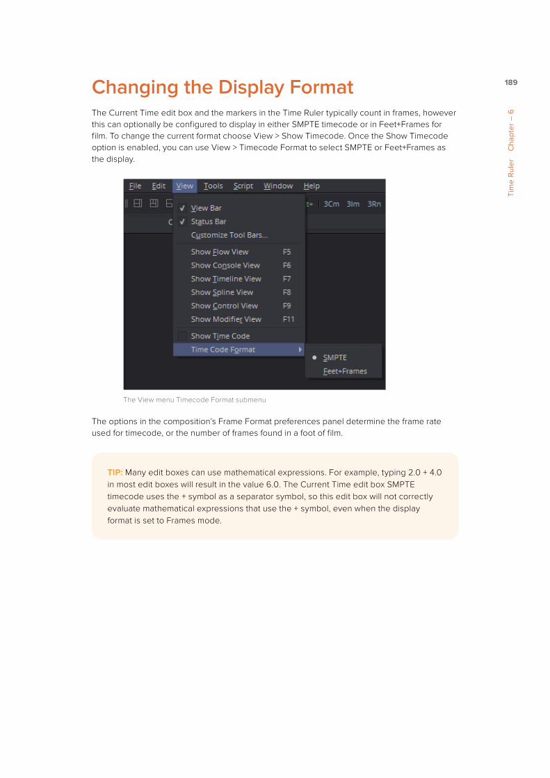
189
Tim
e R
uler
C
hapt
er –
6
Changing the Display FormatThe Current Time edit box and the markers in the Time Ruler typically count in frames, however this can optionally be configured to display in either SMPTE timecode or in Feet+Frames for film. To change the current format choose View > Show Timecode. Once the Show Timecode option is enabled, you can use View > Timecode Format to select SMPTE or Feet+Frames as the display.
The View menu Timecode Format submenu
The options in the composition’s Frame Format preferences panel determine the frame rate used for timecode, or the number of frames found in a foot of film.
TIP: Many edit boxes can use mathematical expressions. For example, typing 2.0 + 4.0 in most edit boxes will result in the value 6.0. The Current Time edit box SMPTE timecode uses the + symbol as a separator symbol, so this edit box will not correctly evaluate mathematical expressions that use the + symbol, even when the display format is set to Frames mode.

190
Tim
e R
uler
C
hapt
er –
6
Entering Frame NumbersWhen setting ranges and entering frame numbers to move to a specific frame, numbers can be entered in subframe increments. You can set a range to be -145.6 to 451.75 or set the Playhead to 115.22. This can be very helpful to set keyframes where they actually need to occur, rather than on a frame boundary, so you get more natural animation. Having subframe time lets you use time remapping tools or just scale keyframes in the Spline view and maintain precision.

191
Tim
elin
e Ed
itor
Cha
pter
– 7
Chapter 7
Timeline Editor
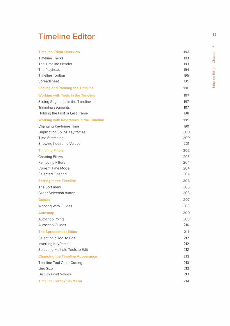
192
Tim
elin
e Ed
itor
Cha
pter
– 7
Timeline Editor
Timeline Editor Overview 193
Timeline Tracks 193
The Timeline Header 193
The Playhead 194
Timeline Toolbar 195
Spreadsheet 195
Scaling and Panning the Timeline 196
Working with Tools in the Timeline 197
Sliding Segments in the Timeline 197
Trimming segments 197
Holding the First or Last Frame 198
Working with Keyframes in the Timeline 199
Changing Keyframe Time 199
Duplicating Spline Keyframes 200
Time Stretching 200
Showing Keyframe Values 201
Timeline Filters 202
Creating Filters 203
Removing Filters 204
Current Time Mode 204
Selected Filtering 204
Sorting in the Timeline 205
The Sort menu 205
Order Selection button 206
Guides 207
Working With Guides 208
Autosnap 209
Autosnap Points 209
Autosnap Guides 210
The Spreadsheet Editor 211
Selecting a Tool to Edit 212
Inserting Keyframes 212
Selecting Multiple Tools to Edit 212
Changing the Timeline Appearance 213
Timeline Tool Color Coding 213
Line Size 213
Display Point Values 213
Timeline Contextual Menu 214

193
Tim
elin
e Ed
itor
Cha
pter
– 7
Timeline Editor Overview The Timeline Editor is used to adjust the timing of elements in a project. You can trim and extend clips, adjust the timing of an animation spline, or trim the duration of a tool. You can freely rearrange the order of tools in the Timeline without affecting the layering order of your comp. All compositing operations are handled in the Flow Node Editor, while the Timeline Editor manages the timing of your composition.
The Timeline Editor
To show the Timeline Editor, do one of the following:
� Click the Timeline tab located at the top of the Work area.
� Press F7 on the keyboard.
Timeline TracksThe Timeline tracks are the main part of the Timeline interface. The horizontal axis represents the duration or time for each tool and it is usually labeled with frame numbers. The segments that run along the horizontal axis represent the time range of each tool and use the same color properties as the Tool tiles in the flow.
The Timeline tracks
The Timeline HeaderThe Timeline header area on the left side of the Timeline is a hierarchical list of the tools in the flow. Each tool is displayed by name and can be opened further, revealing a track for each keyframe animation, modifier and mask attached to that tool. The Timeline header acts as a label and selection tool for the segments in the Timeline.
The Brightness/Contrast tool in the Timeline Header area

194
Tim
elin
e Ed
itor
Cha
pter
– 7
Collapse/Open AllA quick way to open all the tracks and keyframe splines is to use the Collapse/Open All button. Located above the Timeline header, the button is labeled with a + or a - symbol, depending on the current state of the tracks.
The Collapse/Open All button set to Open All
Clicking this button when the label is a minus (-) sign will collapse the list of tools in the header. When the label is a plus (+) symbol, all tool categories and specific tools in the header will be opened revealing any splines created from animation.
The PlayheadThe Playhead is a vertical bar that runs through the Timeline view to indicate the position of the current frame or time.
The Playhead
Dragging the playhead left or right can change the current frame of the project and ultimately what is displayed in the Viewer. As current time is changed, the frame number is displayed in the Time Ruler to assist with precise positioning.
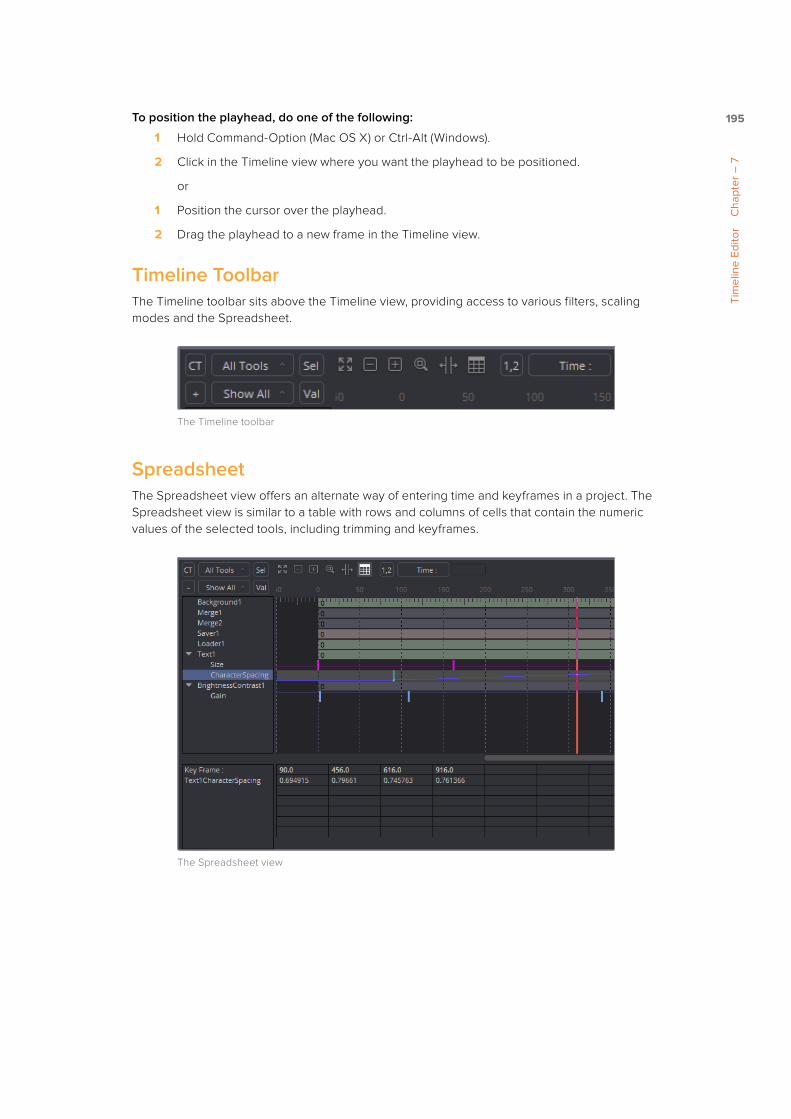
195
Tim
elin
e Ed
itor
Cha
pter
– 7
To position the playhead, do one of the following:
1 Hold Command-Option (Mac OS X) or Ctrl-Alt (Windows).
2 Click in the Timeline view where you want the playhead to be positioned.
or
1 Position the cursor over the playhead.
2 Drag the playhead to a new frame in the Timeline view.
Timeline ToolbarThe Timeline toolbar sits above the Timeline view, providing access to various filters, scaling modes and the Spreadsheet.
The Timeline toolbar
SpreadsheetThe Spreadsheet view offers an alternate way of entering time and keyframes in a project. The Spreadsheet view is similar to a table with rows and columns of cells that contain the numeric values of the selected tools, including trimming and keyframes.
The Spreadsheet view

196
Tim
elin
e Ed
itor
Cha
pter
– 7
Scaling and Panning the TimelineSimilar to the Flow Node Editor, learning to scale and pan in the Timeline will allow you to make adjustments more efficiently.
To pan the Timeline view, do one of the following:
� Hold the middle mouse button and drag to pan in all four directions.
� Drag the scrollbars at the bottom or along the sides of the Timeline.
The scrollbars at the bottom and sides of the Timeline can be used to pan.
To scale the Timeline view from the toolbar, do one of the following:
� Click the the Zoom Out and Zoom In icon in the toolbar to scale the Timeline in or out.
� Click the Zoom to Rectangle button, then drag a rectangle in the Timeline.
� Click the Fit button so that all currently visible tools are scaled to fit within the view.
The Fit, Zoom Out, Zoom In and Zoom to Rectangle buttons in the toolbar
To scale the Timeline view using the mouse, do the following:
1 Position the cursor over the Timeline view.
2 Hold the middle mouse button.
3 Click the left mouse button to zoom in or the right button to zoom out.
To scale the Timeline view using the keyboard, do one of the following:
� Press the + and - keys on the numeric keypad to scale in and out.
� Press Command-R (Mac OS X) or Ctrl-R (Windows) to enable scale to rectangle mode.
To scale the Timeline view using the Axis labels, do the following:
1 Position the cursor over the frame labels of the horizontal axis.
2 Drag right to zoom in and left to zoom out.
Dragging in the Axis label area will zoom in and out of the Timeline
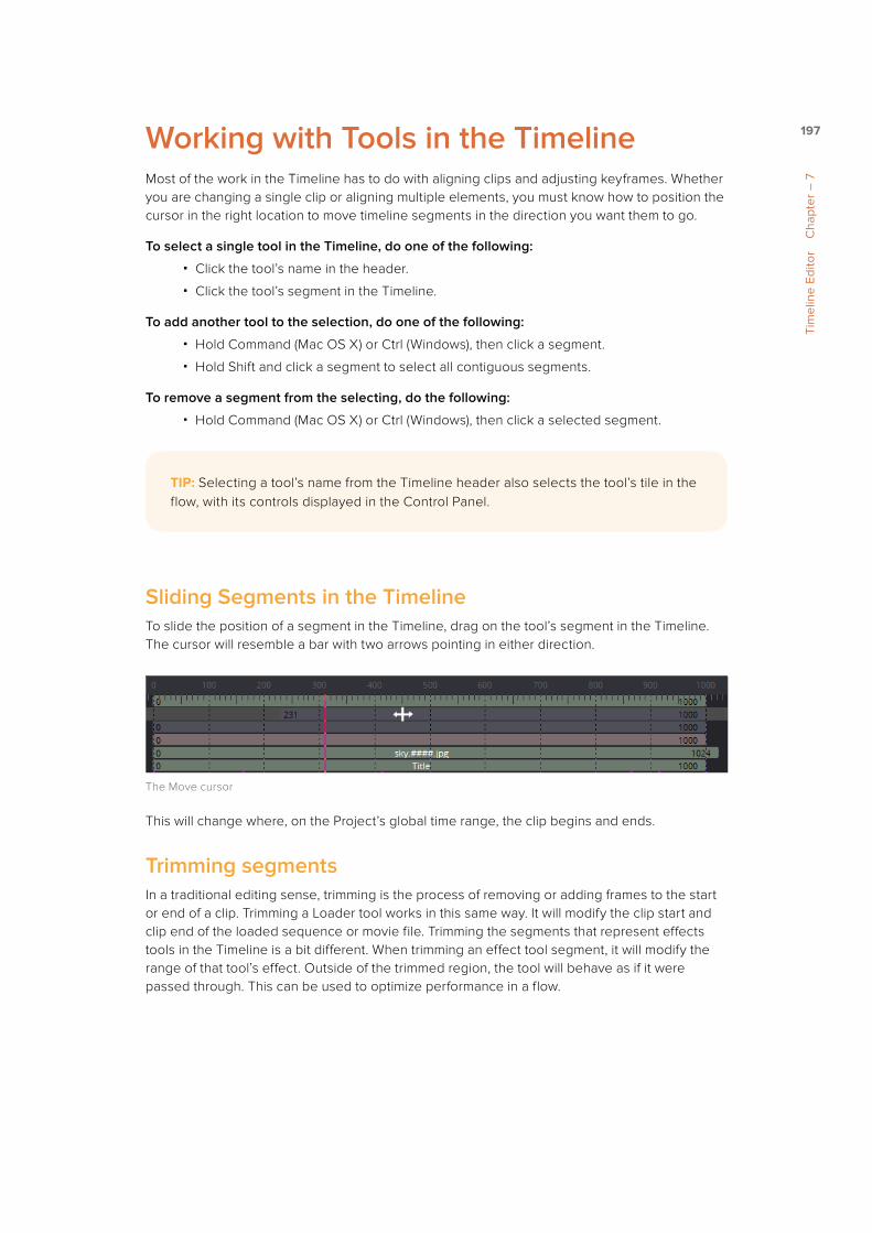
197
Tim
elin
e Ed
itor
Cha
pter
– 7
Working with Tools in the TimelineMost of the work in the Timeline has to do with aligning clips and adjusting keyframes. Whether you are changing a single clip or aligning multiple elements, you must know how to position the cursor in the right location to move timeline segments in the direction you want them to go.
To select a single tool in the Timeline, do one of the following:
� Click the tool’s name in the header.
� Click the tool’s segment in the Timeline.
To add another tool to the selection, do one of the following:
� Hold Command (Mac OS X) or Ctrl (Windows), then click a segment.
� Hold Shift and click a segment to select all contiguous segments.
To remove a segment from the selecting, do the following:
� Hold Command (Mac OS X) or Ctrl (Windows), then click a selected segment.
Sliding Segments in the TimelineTo slide the position of a segment in the Timeline, drag on the tool’s segment in the Timeline. The cursor will resemble a bar with two arrows pointing in either direction.
The Move cursor
This will change where, on the Project’s global time range, the clip begins and ends.
Trimming segmentsIn a traditional editing sense, trimming is the process of removing or adding frames to the start or end of a clip. Trimming a Loader tool works in this same way. It will modify the clip start and clip end of the loaded sequence or movie file. Trimming the segments that represent effects tools in the Timeline is a bit different. When trimming an effect tool segment, it will modify the range of that tool’s effect. Outside of the trimmed region, the tool will behave as if it were passed through. This can be used to optimize performance in a flow.
TIP: Selecting a tool’s name from the Timeline header also selects the tool’s tile in the flow, with its controls displayed in the Control Panel.

198
Tim
elin
e Ed
itor
Cha
pter
– 7
Imagine a clip, for example, that is 100 frames long and is connected to a tool that animates a defocus from frames 80 -100. There is little to no point in processing the defocus tool between frames 0 - 79. Trimming the defocus segment to start at frame 80 in the Timeline will effectively prevent it from rendering and consuming memory or processor time until needed.
To trim a segment in the Timeline, do the following:
� Drag on either end of the tool’s segment in the Timeline.
The cursor will change to a vertical bar with a single arrow when the cursor is in the right location to trim.
The Trim cursor
Holding the First or Last FrameIf you want to hold a Loader’s First or Last frame of a clip for a certain number of frames, also called a freeze frame, you can hold Command (Mac OS X) or Ctrl (Windows) while you drag beyond the first or last of the segment in the Timeline.
A Loader with freeze frames created at the first and last of the clip
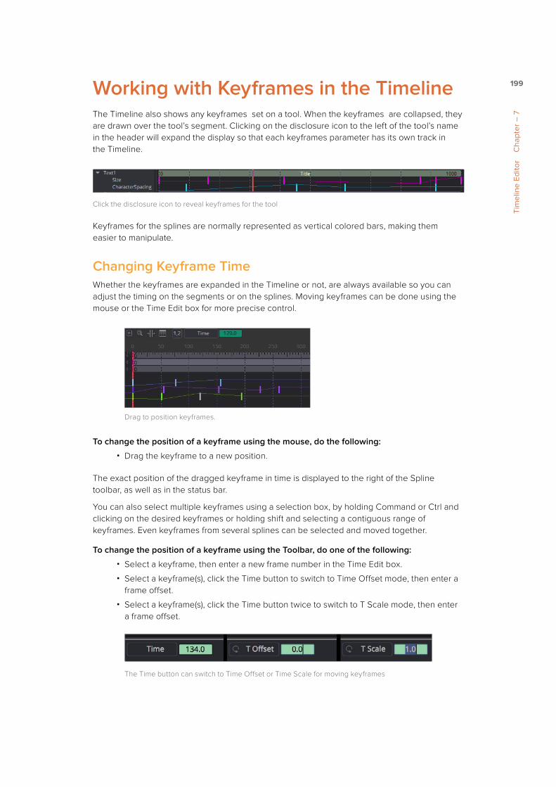
199
Tim
elin
e Ed
itor
Cha
pter
– 7
Working with Keyframes in the TimelineThe Timeline also shows any keyframes set on a tool. When the keyframes are collapsed, they are drawn over the tool’s segment. Clicking on the disclosure icon to the left of the tool’s name in the header will expand the display so that each keyframes parameter has its own track in the Timeline.
Click the disclosure icon to reveal keyframes for the tool
Keyframes for the splines are normally represented as vertical colored bars, making them easier to manipulate.
Changing Keyframe TimeWhether the keyframes are expanded in the Timeline or not, are always available so you can adjust the timing on the segments or on the splines. Moving keyframes can be done using the mouse or the Time Edit box for more precise control.
Drag to position keyframes.
To change the position of a keyframe using the mouse, do the following:
� Drag the keyframe to a new position.
The exact position of the dragged keyframe in time is displayed to the right of the Spline toolbar, as well as in the status bar.
You can also select multiple keyframes using a selection box, by holding Command or Ctrl and clicking on the desired keyframes or holding shift and selecting a contiguous range of keyframes. Even keyframes from several splines can be selected and moved together.
To change the position of a keyframe using the Toolbar, do one of the following:
� Select a keyframe, then enter a new frame number in the Time Edit box.
� Select a keyframe(s), click the Time button to switch to Time Offset mode, then enter a frame offset.
� Select a keyframe(s), click the Time button twice to switch to T Scale mode, then enter a frame offset.
The Time button can switch to Time Offset or Time Scale for moving keyframes
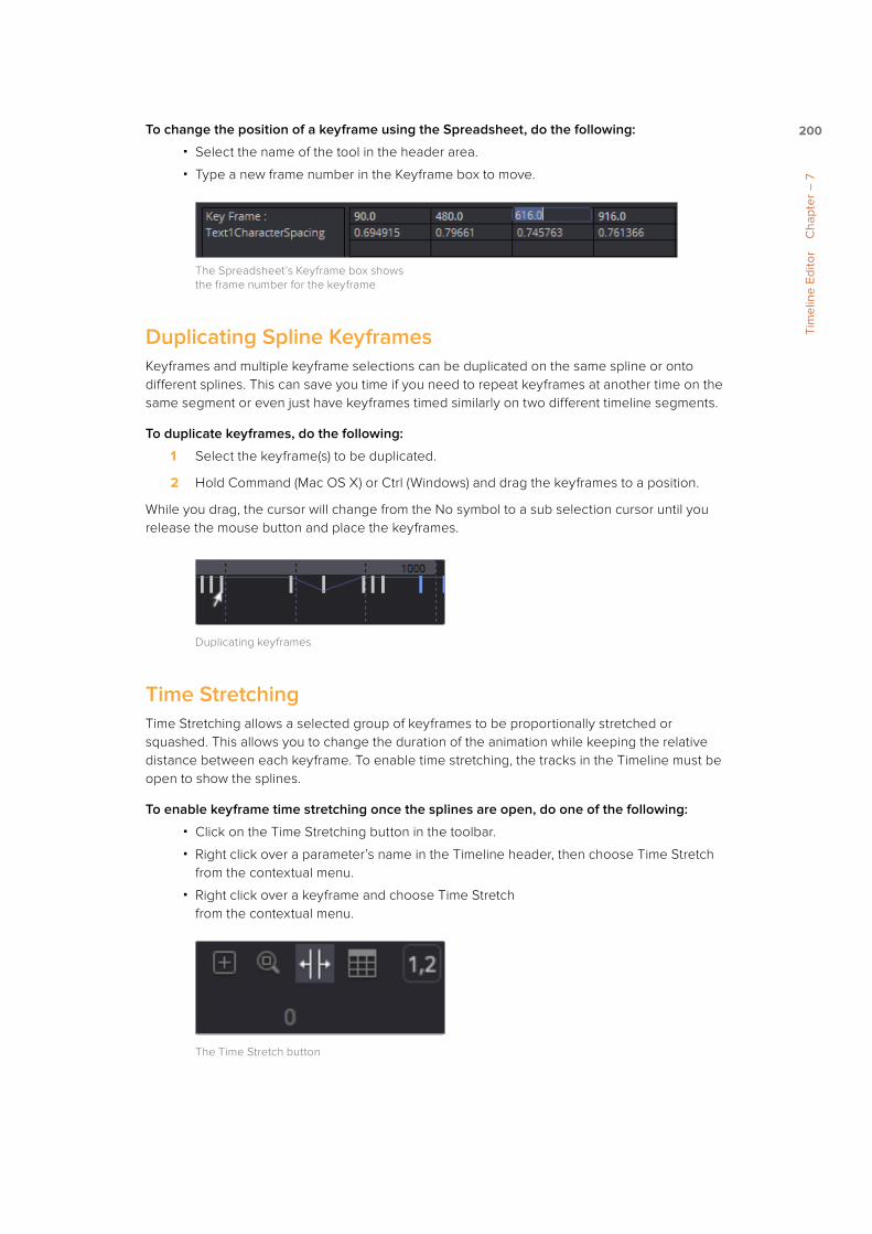
200
Tim
elin
e Ed
itor
Cha
pter
– 7
To change the position of a keyframe using the Spreadsheet, do the following:
� Select the name of the tool in the header area.
� Type a new frame number in the Keyframe box to move.
The Spreadsheet’s Keyframe box shows the frame number for the keyframe
Duplicating Spline KeyframesKeyframes and multiple keyframe selections can be duplicated on the same spline or onto different splines. This can save you time if you need to repeat keyframes at another time on the same segment or even just have keyframes timed similarly on two different timeline segments.
To duplicate keyframes, do the following:
1 Select the keyframe(s) to be duplicated.
2 Hold Command (Mac OS X) or Ctrl (Windows) and drag the keyframes to a position.
While you drag, the cursor will change from the No symbol to a sub selection cursor until you release the mouse button and place the keyframes.
Duplicating keyframes
Time StretchingTime Stretching allows a selected group of keyframes to be proportionally stretched or squashed. This allows you to change the duration of the animation while keeping the relative distance between each keyframe. To enable time stretching, the tracks in the Timeline must be open to show the splines.
To enable keyframe time stretching once the splines are open, do one of the following:
� Click on the Time Stretching button in the toolbar.
� Right click over a parameter’s name in the Timeline header, then choose Time Stretch from the contextual menu.
� Right click over a keyframe and choose Time Stretch from the contextual menu.
The Time Stretch button

201
Tim
elin
e Ed
itor
Cha
pter
– 7
If more than one keyframe is selected on the spline, the keyframes will be surrounded by a purple rectangle to identify which keyframes will be stretched or squashed. If no keyframes are selected, you can drag a rectangle to set the boundaries of the bars. The time stretcher can affect more than one spline at a time.
The Time Stretch selection rectangle
Once the selection is made, you can drag on the left or right edge of the purple rectangle to stretch or shrink the timing of the spline segments within the rectangle.
To disable time stretching, click on the toolbar button again or re-select Time Stretch from the contextual menu.
Showing Keyframe ValuesIf parameters are animated on a tool, colored tick marks in the tool’s timeline segment indicate where keyframes are placed. If the tracks and splines are open on a parameter, the Val button above the header area will reveal text boxes beneath each keyframe on the spline. The boxes show the keyframe’s current value and allow you to edit the value by typing in a new number.
Keyframes with value displayed in the Timeline
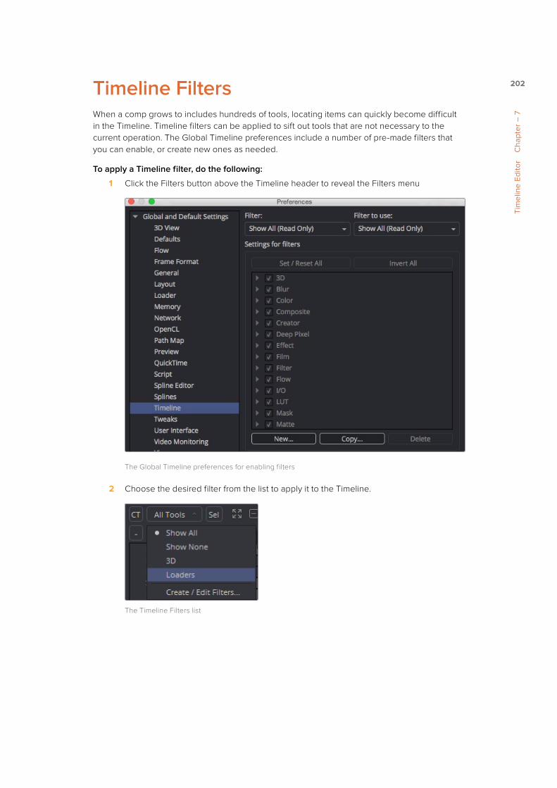
202
Tim
elin
e Ed
itor
Cha
pter
– 7
Timeline FiltersWhen a comp grows to includes hundreds of tools, locating items can quickly become difficult in the Timeline. Timeline filters can be applied to sift out tools that are not necessary to the current operation. The Global Timeline preferences include a number of pre-made filters that you can enable, or create new ones as needed.
To apply a Timeline filter, do the following:
1 Click the Filters button above the Timeline header to reveal the Filters menu
The Global Timeline preferences for enabling filters
2 Choose the desired filter from the list to apply it to the Timeline.
The Timeline Filters list

203
Tim
elin
e Ed
itor
Cha
pter
– 7
Creating FiltersYou create new Timeline filters in the Timeline Preferences dialog by choosing Fusion > Preferences (Mac OS X) or File > Preferences (Windows) and then selecting Global > Timeline in the sidebar. You can also open the Timeline preferences by clicking the Filter button above the Timeline header and choosing Create/Edit Filters.
Once in the Timeline Preferences dialog, clicking the New button will allow you to name and create a new filter with the default set to all the tools being enabled.
Add and Remove Tools from FiltersThe Timeline Preferences dialog includes a list of all the tools you can choose to include in your custom filter. Clicking the disclosure button next to a Tool category opens it to reveal the specific Tool types. If you enable the checkbox next to a tool, that tool will not be filtered out when you select the custom filter from the Filter list in the Timeline.
Enable each tool you want to keep in the Timeline when the filter is selected
The Invert All button and Set/Reset All button can apply global changes to all of the checkboxes, toggling the selected states as described.
When you are done configuring the custom filter, click the Save button to close the preferences dialog and save the filter.

204
Tim
elin
e Ed
itor
Cha
pter
– 7
Removing FiltersTo disable the currently applied filter, choose Show All from the Filter pop up menu in the Timeline. You can permanently remove a filter from the list by returning to the Timeline preferences, choose the filter from list at the top of the dialog, then clicking the Delete button.
Clicking Delete permanently removes the custom filter from the Filter list
Current Time ModeWhile not part of the Filter menu, the CT (Current Time) button can filter the Timeline. When you are working on a complex composite with many elements that come and go throughout the comp, clicking the CT button can filter the Timeline to only display the segments that are under the PlayHead.
The CT button will filter the Timeline to show only tools that are at the Playhead position
Selected FilteringAnother button located in the toolbar that can help clear the Timeline of segments that maybe temporarily in the way is the Select or Sel button. Located to the right of the CT button, the Sel button will filter out all the segments from the Timeline except the segment of the selected tools in the Timeline header. Clicking the Sel button again will return to displaying all the tools.
The Sel button filters the Timeline to display only the tool you select in the Timeline header
TIP: When the Sel button is enabled, you can select tools in the Flow Node Editor or Control Editor and they will be the only tools displayed in the Timeline.

217
Spl
ine
Edito
r C
hapt
er –
8
Spline Editor OverviewThe Spline Editor is the main area where animation is manipulated and refined. It is primarily used to show the changing values of parameters over time in the form of splines. Whereas Keyframes explicitly set the value of a parameter on a given frame, Splines are lines or curves that interpolate the values between keyframes. Once a keyframe is set on a parameter, a spline is created and can be displayed in the Spline Editor so you can make further refinements to the animation. However, the Spline Editor is more advanced than a standard curve editor since it can also display functions, which may not be splines, like changing characters within a text string or mathematical expressions that drive your animations.
On the left side of the Spline Editor, the Spline header shows a list of tools and their parameters that are keyframed. The majority of the panel is taken up by a graph area that displays the splines for those keyframed parameters. The horizontal axis of the graph area represents time while the vertical axis represents the parameter’s value. By manipulating the keyframes and splines using different interpolation methods, you can dramatically change the style of animation.
The Spline Editor

218
Spl
ine
Edito
r C
hapt
er –
8
Spline Editor InterfaceThe Spline Editor Interface has three main working areas: the Graph, the Header and the Toolbar. All three of these areas as described below in detail.
Spline GraphThe Spline graph is the largest area of the interface. It is here that the actual animation spline is displayed for editing. There are two axes in the graph. The horizontal axis represents time and the vertical axis represents the spline’s value. A thin bar, called the Playhead, runs vertically through the graph to represent the current time as it does in the Timeline Editor. You can drag the playhead to change the current time and the frame that is displayed in the Viewers.
The Spline graph
Spline HeaderThe Spline header displays a list of each tool with animated parameters in the project. Each tool has a disclosure arrow that can be used to reveal its animated parameters. Clicking the checkbox next to a parameter’s name displays the parameter’s spline in the Spline graph.
The Spline header
ToolbarThe Toolbar across the top of the Spline Editor represents the most common operations applied to a spline, or splines, in the Graph. Although you can access many of them from the Graph’s contextual menu, the buttons provide a shortcut.
The operation of each button is described later in this chapter.
The Spline toolbar

219
Spl
ine
Edito
r C
hapt
er –
8
Viewing, Scaling and Panning the Spline EditorIt is sometimes necessary to adjust the view of the Graph within the Spline Editor, just as it is in the Timeline Editor and Flow Node Editor. You often need to scale and pan around to focus on an area of animation that needs work. Below are a number of different ways this can be accomplished.
To view the Spline Editor, do one of the following:
� Click the Spline Editor tab located at the top of the Work Panel.
� Press F8 to switch to the Spline Editor.
� Right click on a tool within the Flow Node or Timeline Editor or a parameter in the Control Panel and select Edit Splines from the contextual menu.
The Spline Editor tab
To scale the Spline Graph using the Toolbar buttons, do one of the following:
� Click the Scale buttons located in the top left corner of the Graph.
� Click the Zoom to Fit button to fit all the currently active splines within the Graph view.
� Click the Zoom rectangle button, then draw a rectangle in the Graph to define the area you want to fill the view.
Toolbar Scale buttons
To scale the Spline Graph using the axis labels, do the following:
� Place the cursor over the horizontal or vertical axis label and drag to resize the Graph view on the corresponding axis.
Dragging in the horizontal axis label will scale the graph horizontally

220
Spl
ine
Edito
r C
hapt
er –
8
To scale the Spline Graph using the mouse, do the following:
� Place the cursor over the Graph, hold the middle mouse button, then click once on the left mouse button to zoom in and once on the right button to zoom out.
To scale the Spline Graph using the keyboard, do one of the following:
� Press the + and - keys on the numeric keypad.
� Press Command-R (Mac OS X) or Ctrl-R (Windows) to enable scale to rectangle mode, then drag of a rectangle around the area of the Graph you want to fill the view.
To pan the Spline Editor, do one of the following:
� Hold the middle mouse button and drag up, down, left or right.
� Drag the scrollbars on the right or bottom of the Graph.
Dragging in the horizontal scroll bar will pan the graph horizontally
In general, scaling and panning the Spline Editor works the same as it does in all navigable parts of the Fusion interface. See Chapter 1, Getting Started, for more information.

221
Spl
ine
Edito
r C
hapt
er –
8
Creating Animation SplinesWhen you add keyframes to a parameter, an animation spline is created in the Spline Editor. The default animation spline uses the standard Bezier spline found in most drawing and graphics software, but you have other spline interpolation options as well.
To create and view a default spline animation, do the following:
1 In the Control Panel, right click over the parameter to be animated.
2 Choose Animate from the contextual menu.
3 Right click over the parameter again and choose Edit from the contextual menu.
Selecting Animate from the context menu will animate the parameter using the default Bezier spline type. Instead of choosing Animate in the Control Panel contextual menu, other spline types can be used from the Modify With contextual submenu.
The Modify With contextual submenu

222
Spl
ine
Edito
r C
hapt
er –
8
You can change the default spline type by changing the Default Animate option in the Globals > Defaults panel of the Preferences.
Modify with > Bezier SplineChoosing Bezier Spline from the Modify With contextual submenu is the same as choosing Animate, unless you have changed the default spline type in your preferences. Bezier splines use three points for each keyframe on the spline to determine the smoothness of the curve. The first point is the actual keyframe or control point, representing the value at a given time. The other two points are direction handles that determine how smoothly the curve for the segments leading in and out of the keyframe are drawn. Bezier splines are powerful because they allow you to create combinations of curves and straight lines.
Modify with > B-SplineB-splines are simpler and easier to control than Bezier splines because they use a single control point that pulls the spline in its direction, producing a smooth curve when you set the interpolation to smooth. The spline is shaped by the control point but it doesn’t necessarily go through it. Unlike Bezier splines, B-splines do not have direction handles, so the control point determines the keyframe value as well as the smoothness of the curve.
Modify with > Natural Cubic SplineNatural Cubic Splines are very similar to Bezier splines, especially when the interpolation between points is linear. When the interpolation is smooth, the handles for Cubic splines are locked and invisible, and always set to make the smoothest possible curve.
Other choices in this menu allow you to use Expressions and Modifiers for animation. You can learn more about Modifiers in the Tool Reference Manual. You can learn more about Expressions in Chapter 14, Introduction to Controls and Customization.
Displaying Splines for EditingThe Spline header on the left of the Spline Editor is a hierarchical list. The names of any tools in the flow that have an animated control are displayed. Clicking the disclosure arrow on a tool reveals all of the names of the animated parameters on that tool. Clicking directly on the parameter name in the Spline header will activate that spline for display and editing.
The Spline header with Brightness Contrast tool and its animated Gain parameter

223
Spl
ine
Edito
r C
hapt
er –
8
Tool Status CheckboxTo the left of each parameter’s name in the header is a checkbox that indicates the spline’s status. When you select a parameter name, the checkbox becomes Active. Selecting a different parameter disables the first parameter when the other becomes Active. There are three selection modes for each checkbox: Active, Viewed and Disabled.
ActiveWhen the checkbox is enabled with a check mark, that spline is displayed in the Graph and is Active. This spline can then be edited.
ViewedWhen the checkbox is enabled but filled with a gray box, the spline is visible in the Graph but is Read only. It cannot be edited.
DisabledWhen the checkbox is empty, the spline is not visible in the Graph and cannot be edited.
Three parameters for Brightness Contrast in three different modes: Active, Viewed and Disabled
You can click on a checkbox to change its mode even if the parameter name is not selected. This allows you to make multiple parameters Active, Viewed or Disabled. Changing the state of the checkbox at the Tool level will set the mode for all splines attached to that tool.
Selection StatesThere are three Selection States that determine how the list of parameters in the header behave when a checkbox or parameter name is selected to activate a spline. These buttons are located in the Spline toolbar, just above the header. They are labeled All, None and One. Additional options control what tools are displayed in the header. These are controlled by the Sel button and the Show All control checkbox.
AllClicking on this button activates all splines for editing.
NoneAll spline checkboxes will be set to Disabled.

224
Spl
ine
Edito
r C
hapt
er –
8
OneWhen the One button is selected, only one spline in the header is active and visible at a time. Clicking another spline’s checkbox will set it to Active and all other splines will be disabled.
The Selection State buttons used to activate and deactivate splines in the graph
Show Selected OnlyAnother button located above the Spline header that can help clear the Graph of splines that maybe temporarily in the way is the Select or Sel button. The Sel button will filter out all the splines from the Spline Editor except the spline of the selected tools in the header. Clicking the Sel button again will return to displaying all the tools.
The Selection State buttons used to activate and deactivate splines in the graph
The Sel button filters the Spline Editor to display only the tool you select in the header
Show All ControlBy default, only animated parameters are displayed in the header. Enabling this checkbox will display all tools and parameters that are in the flow. Activating one of the controls will automatically add an animation spline to it.
TIP: When the SEL button is enabled, you can select tools in the Flow Node Editor or Control Panel and they will be the only tools displayed in the Spline Editor.

225
Spl
ine
Edito
r C
hapt
er –
8
With a large number of tools displayed, which themselves might have a large number of parameters, you may end up with a cluttered header that’s slow to work with. You can more efficiently use the Show All control option when the Sel option is enabled to limit the number of tools and parameters displayed.
Options to show only selected parameters or all tools and parameters that are in the flow
Removing and Deleting Animation SplinesTo remove an animation spline from a parameter, right click on the parameter in the Control Panel and choose Remove [tool parameter’s name] from the contextual menu. Removing a spline from a control will only delete the spline if no other tools in the composition are connected to the same spline at that time.
The Remove menu for a Brightness Contrast Gain animation
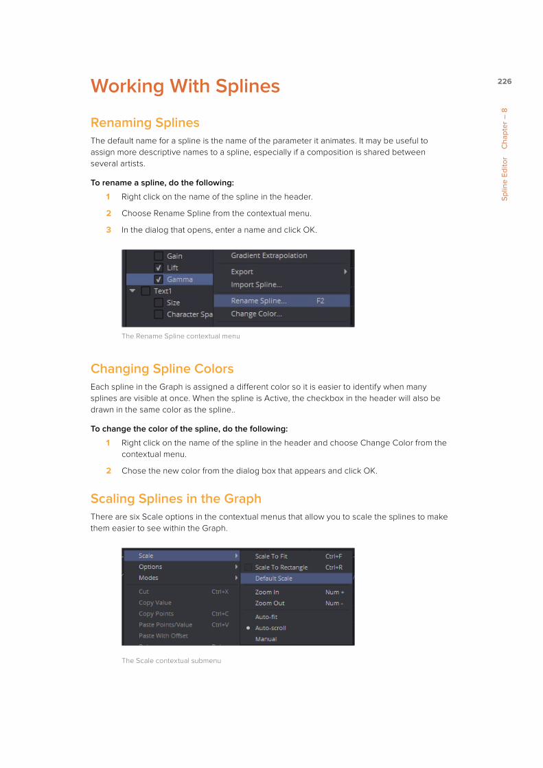
226
Spl
ine
Edito
r C
hapt
er –
8
Working With Splines
Renaming SplinesThe default name for a spline is the name of the parameter it animates. It may be useful to assign more descriptive names to a spline, especially if a composition is shared between several artists.
To rename a spline, do the following:
1 Right click on the name of the spline in the header.
2 Choose Rename Spline from the contextual menu.
3 In the dialog that opens, enter a name and click OK.
The Rename Spline contextual menu
Changing Spline ColorsEach spline in the Graph is assigned a different color so it is easier to identify when many splines are visible at once. When the spline is Active, the checkbox in the header will also be drawn in the same color as the spline..
To change the color of the spline, do the following:
1 Right click on the name of the spline in the header and choose Change Color from the contextual menu.
2 Chose the new color from the dialog box that appears and click OK.
Scaling Splines in the GraphThere are six Scale options in the contextual menus that allow you to scale the splines to make them easier to see within the Graph.
The Scale contextual submenu

227
Spl
ine
Edito
r C
hapt
er –
8
To scale Splines in the Graph using the Scale contextual, do one of the following:
� Choose Scale to Fit to fit splines into the view.
� Choose Scale to Rectangle to zoom the view in on the contents of a drawn rectangle.
� Choose Default Scale to reset the scaling to the default values.
� Choose Zoom In/Zoom Out to incrementally scale or shrink the content of the Graph.
� Choose Auto Fit to dynamically perform a Scale to Fit when new splines get selected or added.
� Choose Auto Scroll to fit the view in X direction.
Spline OptionsThere are three options in the contextual menus that ensure the splines stay within the visible Graph area as you work.
The Options contextual submenu
Fit TimesWhen enabled, the Graph automatically scales to fit the X-axis when a spline is selected. All visible splines are taken into account, not just the newly selected spline. With this option off, activating a new spline will not change the horizontal scale.
Fit ValuesWhen enabled, the Graph automatically scales to fit the Y-axis when a spline is selected. All visible splines are taken into account, not just the newly selected spline. With this option off, activating a new spline will not change the vertical scale.
Follow ActiveThis option causes all splines connected to the currently active tool to be made visible and ready for editing whenever a tool is selected.
Show All InputsThe Show All Inputs option shows all the parameters on all tools in the Spline header, regardless of whether they are animated or not. This mode is handy when animating a bunch of parameters quickly, but it can be cumbersome with large compositions.

228
Spl
ine
Edito
r C
hapt
er –
8
Selection GroupsIt is possible to save the current selection state of the splines in the header, making Selection groups that can easily be reapplied when needed.
To create a Selection group, do the following:
1 Right click over a parameter in the header or in the Graph.
2 From the contextual menu, choose Save Current Selection.
3 Name the Selection group in the dialog, then click OK.
The Save Current Selection menu
To reapply the selection group, right click over any parameter in the header and choose the Selection group by name from the Set Selection submenu. Other contextual menu options will allow Selection groups to be renamed or deleted.

229
Spl
ine
Edito
r C
hapt
er –
8
Working With KeyframesOnce a spline is displayed in the Graph and enabled for editing, the spline’s keyframes can be manipulated in a variety of ways. No matter how you want to manipulate a keyframe, you have to be able to select it first.
To select keyframes on a visible spline, do one of the following:
� Click directly on the keyframe.
� Drag a rectangle around multiple keyframes.
Dragging a rectangle allows you to select all the keyframes within an area
To add a keyframe to the current selection, do the following:
� Hold Command (Mac OS X) or Ctrl (Windows), then click on the point to add. This will add the keyframe to the selection.
To select all keyframes from the active splines, do one of the following:
� Click in an empty area of the Graph, then press Command-A (Mac OS X) or Ctrl-A (Windows).
� Right click over the Graph and choose Select Point > All from the Spline Editor’s contextual menu.
Moving KeyframesKeyframes can be moved with the cursor, keyboard or using the Time and Value Edit controls in the toolbar.
TIP: Although extremely flexible, keyframes on the same spline cannot be made to overlap. If a key exists at frame 2 and frame 5, the key at frame 5 cannot be moved to frame 1.

230
Spl
ine
Edito
r C
hapt
er –
8
To move a keyframe with the cursor, do one of the following:
� Drag the selected keyframe to its new position in the spline. If more than one point is selected, all selected points will be moved with the one selected.
� Hold Option (Mac OS X) or Alt (Windows) and drag the point to constrain its motion to the first axis you drag.
To move a keyframe with the keyboard, do one of the following:
� Select a keyframe, then use the arrow keys to move the keyframe left, right, up or down.
� Select a keyframe, then hold Shift and press the arrows keys to move the keyframe in larger increments.
TIP: When using the arrow keys to move a keyframe, the scale of the Graph determines the amount of movement applied to each keypress. The closer the zoom in, the finer the adjustment.
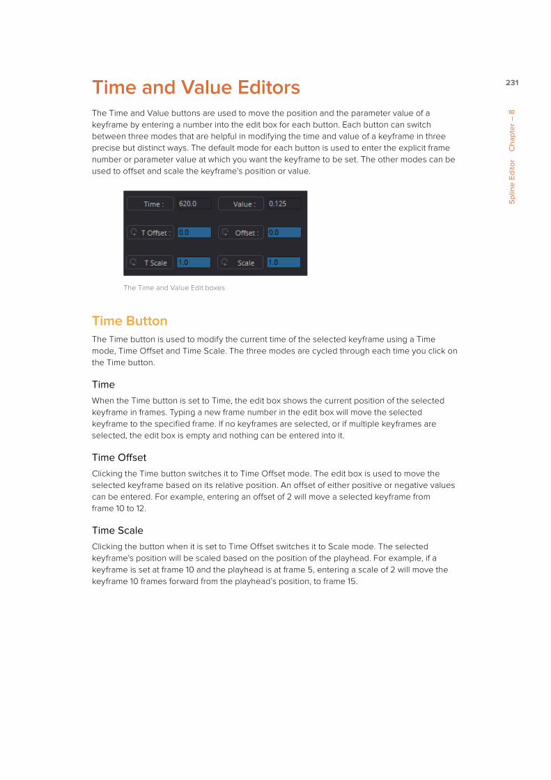
231
Spl
ine
Edito
r C
hapt
er –
8
Time and Value EditorsThe Time and Value buttons are used to move the position and the parameter value of a keyframe by entering a number into the edit box for each button. Each button can switch between three modes that are helpful in modifying the time and value of a keyframe in three precise but distinct ways. The default mode for each button is used to enter the explicit frame number or parameter value at which you want the keyframe to be set. The other modes can be used to offset and scale the keyframe’s position or value.
The Time and Value Edit boxes
Time ButtonThe Time button is used to modify the current time of the selected keyframe using a Time mode, Time Offset and Time Scale. The three modes are cycled through each time you click on the Time button.
TimeWhen the Time button is set to Time, the edit box shows the current position of the selected keyframe in frames. Typing a new frame number in the edit box will move the selected keyframe to the specified frame. If no keyframes are selected, or if multiple keyframes are selected, the edit box is empty and nothing can be entered into it.
Time OffsetClicking the Time button switches it to Time Offset mode. The edit box is used to move the selected keyframe based on its relative position. An offset of either positive or negative values can be entered. For example, entering an offset of 2 will move a selected keyframe from frame 10 to 12.
Time ScaleClicking the button when it is set to Time Offset switches it to Scale mode. The selected keyframe’s position will be scaled based on the position of the playhead. For example, if a keyframe is set at frame 10 and the playhead is at frame 5, entering a scale of 2 will move the keyframe 10 frames forward from the playhead’s position, to frame 15.
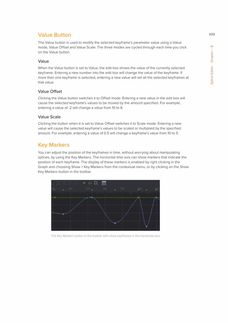
232
Spl
ine
Edito
r C
hapt
er –
8
Value ButtonThe Value button is used to modify the selected keyframe’s parameter value using a Value mode, Value Offset and Value Scale. The three modes are cycled through each time you click on the Value button.
ValueWhen the Value button is set to Value, the edit box shows the value of the currently selected keyframe. Entering a new number into the edit box will change the value of the keyframe. If more than one keyframe is selected, entering a new value will set all the selected keyframes at that value.
Value OffsetClicking the Value button switches it to Offset mode. Entering a new value in the edit box will cause the selected keyframe’s values to be moved by the amount specified. For example, entering a value of -2 will change a value from 10 to 8.
Value ScaleClicking the button when it is set to Value Offset switches it to Scale mode. Entering a new value will cause the selected keyframe’s values to be scaled or multiplied by the specified amount. For example, entering a value of 0.5 will change a keyframe’s value from 10 to 5.
Key MarkersYou can adjust the position of the keyframes in time, without worrying about manipulating splines, by using the Key Markers. The horizontal time axis can show markers that indicate the position of each keyframe. The display of these markers is enabled by right clicking in the Graph and choosing Show > Key Markers from the contextual menu, or by clicking on the Show Key Markers button in the toolbar.
The Key Markers button in the toolbar with show keyframes in the horizontal axis

233
Spl
ine
Edito
r C
hapt
er –
8
Adding New KeyframesOnce one keyframe is added to a parameter, additional keyframes are automatically added whenever you make a change to the parameter’s value. For example, if the strength of an animated glow is changed at frame 15, a keyframe with the new value will be set at frame 15.
The easiest ways to explicitly add keyframes to a spline is either by clicking directly on the spline or using Shift-K to add it at the current playhead position. For special situations, the Spline Editor contextual menu includes a number of other ways to set keyframes.
Set KeySelecting Set Key from the contextual menu adds a new keyframe along the active spline wherever the position of the cursor is when the contextual menu is displayed.
The Set Key menu
Set Key Equal toThis option allows a new keyframe to be added with a value equal to the next or the previous keyframe. Easily add linear sections in your spline with no value change.
Deleting KeyframesTo delete a keyframe or keyframes, simply select the keyframes and press Command-Delete (Mac OS X) or Delete (Windows). This will only remove the keyframes. It will not remove the spline, even if all of the keyframes are deleted.
Copying and Pasting KeyframesThe Keyframe values from one spline can be copied to a different area on the same spline or from one spline to another.
To copy Keyframe values, do one of the following:
� Select the desired keyframes, then press Command-C (Mac OS X) or Ctrl-C (Windows).
� Select the desired keyframes, then choose Copy Value from the Graph’s contextual menu.
� Hold Command (Mac OS X) or Ctrl (Windows) and drag the points where you want them.
To paste Keyframes points, do one of the following:
� Place the cursor where you want the points pasted, then choose Paste from the Graph’s contextual menu.
� Place the cursor where you want the points pasted, then press Command-V (Mac OS X) or Ctrl-V (Windows).

234
Spl
ine
Edito
r C
hapt
er –
8
Reshaping SplinesThe shape of a spline impacts an animation by changing the interpolation between keyframe values. A Bezier spline is incredibly flexible for making the adjustments to a spline’s shape because it uses a pair of direction handles to shape the spline as it passes through the keyframe or control point. These handles can only be seen when the keyframe is selected. Dragging on direction handles will adjust the slope of the segments passing through the spline.
A Bezier Control point and direction handles
By default, the two direction handles on a control point are locked together so that if one moves, the one on the other side moves with it. This maintains a constant tension through the keyframe. There are situations, however, when it is desirable to modify these direction handles separately for a more pronounced curve or effect.
To move a direction handle independently of the other, do the following:
1 Select the control point to be modified.
2 Hold Command (Mac OS X) or Ctrl (Windows), then drag on the direction handle.
Holding Command or Ctrl allows you to move a handle independently.
To make the Spline Editor treat all Bezier handles as independent, right click in the Graph and choose Independent Handles from the Options contextual submenu.
Although manipulating the handles on a Bezier spline gives you a lot of flexibility, you can take a few short cuts to place the direction handles in commonly used handle positions. These options can be found in the Graph’s contextual menu as well as in the Spline Editor’s toolbar.

235
Spl
ine
Edito
r C
hapt
er –
8
LinearA Linear segment will effectively take the shortest route, which is a straight line between two keyframes. The rate of change stays the same throughout the animation so it produces a fairly rigid, mechanical style. To make the selected keyframe(s) linear, press the L key or click the Linear button in the toolbar.
The Linear button in the toolbar
SmoothA smoothed segment will provide a gentle keyframe transition in and out of the keyframe, by slightly extending the direction handles on the curve. It slows down the animation as you pass through the keyframe. To smooth the selected keyframe(s), press the S key or click the toolbar’s Smooth button
The Smooth button in the toolbar
Step In/OutOn occasion, it is not desirable to have any interpolation between two keyframes. Instead, the value of one keyframe may need to be held until another keyframe is set. For these cases, use Step In or Step Out mode.
Setting Step In on a keyframe will hold the value of the keyframe steady, then switch values when it reaches the next keyframe. Step Out immediately switches to the value of the upcoming keyframe.

236
Spl
ine
Edito
r C
hapt
er –
8
To set Step In or Step Out, do one of the following:
� Select at least two keyframes, then click the Step In or Step Out buttons on the toolbar.
� Select at least two keyframes, then right click and choosing the appropriate option from the contextual menu.
� Select at least two keyframes, then press I or O on the keyboard.
The Step In/Out buttons in the toolbar
Looping SplinesIt is often useful to repeat a given section of an animation, either infinitely or for a specified number of times, such as is required to create a strobing light, or a spinning wheel. There are a number of ways to repeat a selected segment in the Spline Editor, accessible in the Graph’s contextual menu and in the toolbar.
The various Loop buttons in the toolbar
Set LoopIf you want to repeat or loop a selected spline segment, you first select the two or more keyframes that define the section you want looped. You can then either select Set Loop from the Graph’s contextual menu or click on the Set Loop button in the toolbar. The selected section of the spline will appear as a dotted line and it will repeated until the end of the global range, or until another keyframe ends the repeating segment.
A looped section in the Graph

237
Spl
ine
Edito
r C
hapt
er –
8
Changing and Removing the LoopYou can change the looped segment by modifying any of the keyframes or control points that were originally used to create the loop. Simply select one of the originating key points, make any necessary modifications and the looped segment will update. To remove the loop, select the keyframes you used to create the loop, then click the Loop button in the toolbar.
Relative LoopThe Relative Loop mode repeats the segment as with Loop, where each repetition adds upon the last point of the previous loop so that the values increase steadily over time.
A Relative Loop section in the Graph
Ping-PongThe Ping-Pong Loop mode repeats the selected segment, where each successive loop is reversed so that the segment plays through, reverses itself and repeats. Ping-Pong is often used for pendulum like animations where an object has to swing back and forth in a repetitive seamless motion.
A Ping-Pong section in the Graph
Set Pre-loopThe Set Pre-loop option contains the same options for looping as the Loop option, except that the selected segment is repeated backward in time rather than forward. The Pre-loop option is found in the Graph’s contextual menu.
Duplicate Repeating SplinesRepeated splines are like looped splines, except that the selected segment is only repeated a specified number of times and each repetition is a copy rather than an instance. Adjustments to the original segment do not alter the shape of its repetitions.
The Repeat modes are available through the Repeat submenu in the Graph contextual menu. Selecting any of the modes in the submenu will open a dialog where the number of times the segment is to be copied can be entered.

238
Spl
ine
Edito
r C
hapt
er –
8
The Repeat contextual submenu
Reversing SplinesReverse can be used to invert a segment of an animation spline. To apply reverse, choose a group of points in a spline and select Reverse from the contextual menu or use the V hotkey. The keyframes are reversed in the Graph and points immediately surrounding the reversed selection adjust of needed.
The Reverse button in the toolbar
Time StretchingTime Stretching allows for a selected group or keyframes to be proportionally stretched or squashed. This allows you to change the duration of the animation while keeping the relative distance between each keyframe. To enable spline stretching, select the group of keyframes that you want to time stretch, then choose Modes > Time Stretching from the Graph’s contextual menu or click on the Time Stretch button in the toolbar.
The Time Stretch button in the toolbar
When you have more than one keyframe selected on the spline, enabling Time Stretch will surround the outer keyframes with two vertical purple bars. Click drag on the purple vertical bars to stretch or shrink the timing of the spline segments within the bars. Drag these bars back and forth to stretch or squash the spline segment.
The Time Stretch bars in the Graph

239
Spl
ine
Edito
r C
hapt
er –
8
To disable the Time Stretching mode, click on the Time Stretch button in the toolbar again or reselect Modes > Time Stretching from the contextual menu.
Shape BoxThe Shape Box transform mode is similar to Time Stretching, however, it can adjust the vertical scaling of keyframe values as well as time.
To enable the Shape Box, do one of the following:
� Select a group of keyframes, then choose Modes > Shape Box from the contextual menu.
� Select a group of keyframes, then click the Shape Box button in the toolbar.
� Select a group of keyframes, then press Shift-B to enable and disable the Shape Box mode.
The Shape Box button in the toolbar
A purple rectangle will be drawn around any points selected when the mode is enabled. To scale, skew or stretch the spline, drag on any of the control points located around the box. Dragging on the box edges will move the keyframes.
The Shape Box in the Graph
TIP: If no keyframes are selected when you enable Time Stretch, drag a rectangle to set the boundaries of the Time Stretch.
TIP: If no points are selected, or if you want to select a new group of keyframes, you can drag out a new rectangle at any time.

240
Spl
ine
Edito
r C
hapt
er –
8
Ease In/OutFor a more precise way to adjust the length of Bezier direction handles attached to selected keyframes, you can use the Spline Ease dialog. The dialog can be accessed by selecting a keyframe in the Graph, then choosing Edit > Ease In/Out from the Graph’s contextual menu or by pressing T on the keyboard.
The appearance of the toolbar changes to present you the Ease In/Out controls. You can use the sliders to adjust the length of the direction handles or enter a value in the edit boxes.
The Ease In/Out controls in the toolbar
Clicking the Lock In/Out button will collapse the two sliders into one, so any adjustments apply to both direction handles.
Reducing PointsWhen there are too many control points, too close together on a spline, you can Reduce Points to decrease the number of them, making it easier to modify the points remaining. The overall shape of the spline is maintained as closely a possible, while eliminating redundant points from the path.
To reduce the number of points on a spline, do the following:
1 Select the range of keyframes you want to thin out.
2 Select Reduce Points from the contextual menu
3 In the Reduce Points dialog, drag the slider to a lower value.
You can set the slider value as low as possible as long as the spline still closely resembles the shape of your original spline.
TIP: When the value is 100, no points will be removed from the spline. Use smaller values to eliminate more points.

273
Poly
lines
, Mas
ks a
nd M
otio
n Pa
ths
Cha
pter
– 1
0
Polyline ToolbarsWhenever a tool that contains one or more polylines is selected, the polyline is shown on all Viewers and the Polyline Toolbar is displayed along the side of each Viewer. The toolbar contains several buttons that make switching polyline modes and options easy to access.
The polyline toolbar
If you hover the cursor over any of the Polyline Toolbar buttons, a tooltip that describes the button’s function appears. Clicking on a button will affect the currently active polyline or the selected polyline points, depending on the button.
You can change the size of the toolbar icons, add labels to the buttons, or make other adjustments to the toolbar’s appearance in order to make polylines easier to use. All the options can by found by right clicking on the toolbar and selecting from the options displayed in the contextual menu.
Selecting a PolylineIt is possible to have several polylines in the Viewer at once, so it is important to be able to switch between polylines easily.
To make a polyline active, do one of the following:
� Click one of the polyline’s control points or segments.
� Press Tab and Shift-Tab to cycle between available polylines.
� Right click in the Viewer and choose the desired polyline by name from the Controls > Select menu.
� To the right of the Viewer toolbar, click on the disclosure arrow to display a list of all polylines to choose from.

274
Poly
lines
, Mas
ks a
nd M
otio
n Pa
ths
Cha
pter
– 1
0
Click the Arrow icon to display a list of polylines and Control previews
Polyline Creation ModesThere are several different modes available from the toolbar for creating and modifying polylines. The specific mode used when a polyline is first added will depend on whether it is used as a path or a mask.
Each of the modes is described in more detail below.
Click AppendThis mode is the default mode for mask creation. It’s used to quickly define the rough shape of the mask, after which you switch to Insert and Modify mode to refine the mask further.
The Click Append toolbar button (Shift-C)
To create a mask using the Click Append mode, do the following:
1 Select Click Append from the toolbar or press Shift-C.
2 Click the cursor where you want to start the shape.
3 Move and click the cursor to append a point to the last one.
4 To close the shape, place the mouse pointer over the first point created and click when the cursor changes shape.
When a shape is closed, the polyline is automatically switched to Insert and Modify mode.
Although the Click Append mode is rarely used with paths, it can be helpful when you know the overall shape of a motion path but you don’t know the timing yet.
TIP: Holding Shift while you draw a mask constrains subsequent points to 45 degree angles relative to the previous point. This can be very helpful when drawing regular geometry.

275
Poly
lines
, Mas
ks a
nd M
otio
n Pa
ths
Cha
pter
– 1
0
Insert and ModifyMasks, which are created in Click Append mode, automatically switch to Insert and Modify mode when the mask shape is closed. You can also manually switch to this mode by clicking the Insert and Modify button in the toolbar or using the Shift-I keyboard short cut. This mode makes it easier to add additional points and refine the shape of the mask. Dragging the control points or direction handles modifies existing points on the polyline.
The Insert Modify toolbar button (Shift-I)
Insert and Modify mode is also the default mode for creating motion paths. A new control point is automatically added to the end of the polyline, extending or refining the path, any time a parameter that is animated with a motion path is moved.
Draw AppendThe Draw Append mode creates a freehand polyline shape directly on the Viewer, like drawing with a pencil or a paintbrush. This mode is ideal to use in conjunction with a tablet and for the creation of garbage mattes and effect masks around complex shapes.
The Draw Append toolbar button (Shift-D)
Protection ModesIn addition to the modes used to create a polyline, two other modes are used to protect the points from further changes after they have been created.

276
Poly
lines
, Mas
ks a
nd M
otio
n Pa
ths
Cha
pter
– 1
0
Modify OnlyModify Only mode allows existing points on the polyline to be modified, but new points may not be added to the shape.
The Modify Only toolbar button (Shift-M)
DoneThe Done mode prohibits the creation of any new points, as well as further modification of any existing points on the polyline.
The Done toolbar button (Shift-N)
TIP: Even with Modify Only selected, it is still possible to delete points from a polyline.

277
Poly
lines
, Mas
ks a
nd M
otio
n Pa
ths
Cha
pter
– 1
0
Closing PolylinesThere are several ways to close a polyline, which will connect the last point to the first.
To close a polyline, do one of the following:
� Hover the cursor over the first point created, then click on the point.
� Press Shift-O on the keyboard.
� Click the Close button on the polyline toolbar.
� Choose Closed from the polyline’s contextual menu.
The Close toolbar button (Shift-O)
All of these options are toggles that can also be used to open a closed polygon.

310
Trac
king
C
hapt
er –
11
Tracking OverviewTracking is one of the most powerful automation tools available to a compositor. A tracker can follow a pattern of pixels in an image over time, generating a motion path from the pattern’s movement. This information is then used to perform a variety of tasks, including image stabilization, matching the movement of one image to another and driving the positions of points on a mask.
Image with tracking patterns
Detailed reference for each of the controls in the tracker can be found in the Tool Reference Manual. This chapter provides more general information on how to use a tracker.

311
Trac
king
C
hapt
er –
11
Basic WorkflowThe basic approach to tracking has two steps. A pattern is selected and tracked, then the results are applied to one of several operations using the tracking data. The layout of the Tracker tool’s tabs in the Control Panel reflects the workflow. The Tracker tab is where you select the patterns and perform the track. The Operations tab is where you decide how the tracking data is used.
The Tracker Control Panel

312
Trac
king
C
hapt
er –
11
Tracking UsesThere are four primary applications for the data that results from tracking.
StabilizingYou can use one or more trackers to remove all of the motion from the sequence or to smooth out vibration and shakiness. When you use a single tracker pattern to stabilize, you only stabilize the X and Y position. Using multiple patterns together, you are able to stabilize position, rotation and scaling.
Match MovingThe reverse of stabilizing is Match Moving, which detects position, rotation and scaling in an image sequence using one or more patterns. Instead of removing that motion, it is applied to another image that matches the movement so that the two images can be composited together.
Corner PositioningCorner Positioning tracks four patterns which are then used to map the four corners of a new foreground into the background. This technique is generally used for sign or TV screen replacement.
Perspective PositioningPerspective Positioning again tracks four patterns to identify the four corners of a rectangle. Each corner is then mapped to a corner of the image, rescaling and warping the image to remove all apparent perspective.
Connecting Parameters to a TrackerThe position of a tracker pattern can also be used to drive the position of a center or axis control. For example, once you track the face of a suspect on a surveillance tape, you then connect the center of a mask on a Blur tool to the result in order to obscure the features.
As an example, to connect a Mask tool’s Center parameters to a tracker, do the following:
1 In the Control panel, right click over the Mask’s Center Parameter label.
2 From the contextual menu, choose Connect To > Tracker 1: Offset Position.
The Connect To submenu for connecting a track to a parameter
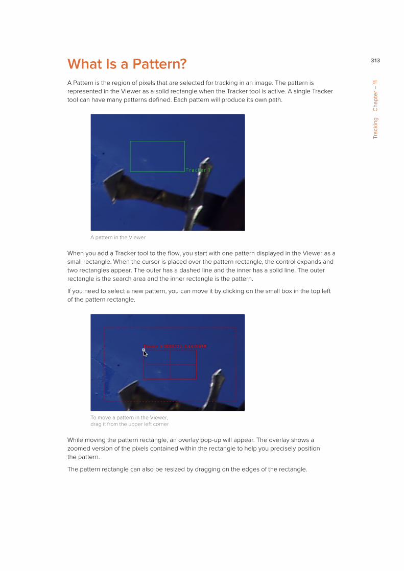
313
Trac
king
C
hapt
er –
11
What Is a Pattern?A Pattern is the region of pixels that are selected for tracking in an image. The pattern is represented in the Viewer as a solid rectangle when the Tracker tool is active. A single Tracker tool can have many patterns defined. Each pattern will produce its own path.
A pattern in the Viewer
When you add a Tracker tool to the flow, you start with one pattern displayed in the Viewer as a small rectangle. When the cursor is placed over the pattern rectangle, the control expands and two rectangles appear. The outer has a dashed line and the inner has a solid line. The outer rectangle is the search area and the inner rectangle is the pattern.
If you need to select a new pattern, you can move it by clicking on the small box in the top left of the pattern rectangle.
To move a pattern in the Viewer, drag it from the upper left corner
While moving the pattern rectangle, an overlay pop-up will appear. The overlay shows a zoomed version of the pixels contained within the rectangle to help you precisely position the pattern.
The pattern rectangle can also be resized by dragging on the edges of the rectangle.

314
Trac
king
C
hapt
er –
11
Search AreaWhen the cursor is over the onscreen control for a pattern, a second rectangle with a dotted border will appear surrounding the pattern. This outer rectangle represents the search area.
When moving from one frame to another while tracking, the tracker will search a region surrounding the last known tracker position in an attempt to relocate the pattern. The larger the search area, the better chance you have of successfully tracking fast moving objects but the longer it will take to track. However, there are some ways to optimize tracking for specific content.
For example, tracking a pattern that is moving quickly across the screen from left to right requires a wide search area but does not require a very tall one, since all movement is horizontal. If the search area is smaller than the movement of the pattern from one frame to the next, the tracker will likely fail and start tracking the wrong pixels. It is important to take the speed and direction of the motion into consideration when setting the search area.
Resize the search area by dragging on the edges of the dotted outline
Adding and Removing PatternsAlthough each Tracker tool starts with only a one pattern, a single tool is capable of tracking multiple patterns. Additional patterns can be added by clicking on the Add button immediately above the Tracker List control.
To add an additional tracker, click the Add button in the Control Panel
TIP: The size of the search area can be animated over time. This is useful for times when the track pattern accelerates or decelerates rapidly part of the way through the scene.

315
Trac
king
C
hapt
er –
11
Multiple patterns are useful when stabilizing and corner or perspective positioning. They also help to keep the flow from becoming cluttered by collecting into a single tool what would otherwise require several tools.
If you need to delete a pattern, select the pattern in the Tracker list and click the Delete button.
Enabling/Suspending/Disabling PatternsTo the left of each pattern’s name in the Tracker list is a checkbox that can be used to set the pattern into one of three states. The checkbox is a three way toggle that switches between Enabled, Suspended and Disabled.
EnabledAn Enabled tracker will re-track its pattern every time the track is performed. Its path data is available for use by other tools and the data is available for stabilization and corner positioning.
An Enabled checkbox
SuspendedWhen the checkbox appears gray, it is Suspended. In this state it does not re-track its pattern when the track is performed. The data is locked to prevent additional changes, but the data from the path is still available for other tools. The data is also available for advanced tracking modes like stabilization and corner positioning.
A Suspended checkbox
DisabledA Disabled tracker does not create a path when tracking is performed. Its data is not available to other tools or for advanced tracking operations like stabilization and corner positioning.
A Disabled checkbox

316
Trac
king
C
hapt
er –
11
Pattern SelectionThe Tracker works by searching each frame for the pixels contained in the pattern. In order for a track to be successful, a fairly high contrast and unique region of the image must be located in the footage. This process is known as Pattern Selection.
The first step in pattern selection is to review the footage to be tracked several times. Watch for candidate patterns that are visible through the entire range of frames, where the contrast is high and the shape of the pattern does not change over time. The more unique the pattern, the more likely the track is to be successful.
In addition to locating high contrast, defined patterns, watch for the frames where the pattern moves the most. Identifying the maximum range of a pattern’s motion will help to determine the correct size for the pattern search area.
It is not uncommon to have a scene that requires the use of several different patterns to generate a single path. This most often occurs because the pattern moves out of frame or is temporarily obscured by another scene element. Combining patterns into a single pattern is described later in the chapter.
Selecting the Pattern’s Image ChannelsWhen a pattern of pixels is selected, the Tracker automatically selects the color channel used for tracking the pattern based on an analysis of each channel for contrast, clarity and reliability. The channels selected are highlighted in the bars to the right of the Pattern display window in the tool controls.
Channel bars indicate which channel is selected for tracking
You can override the automatic channel selection by clicking the buttons beneath the bars for each channel to determine the channel used for tracking.
You can choose any one of the color channels, the luminance channels or the alpha channel to track a pattern.
When choosing a channel, the goal is to choose the cleanest, highest contrast channel for use in the track. Channels that contain large amounts of grain or noise should be avoided. Bright objects against dark backgrounds often track best using the luminance channel.

317
Trac
king
C
hapt
er –
11
Selecting Patterns for StabilizationSelecting patterns for stabilization can be a tricky business. The location of the pattern, when it is selected, is used to determine precisely how the image will be stabilized. At least two patterns are required to correct for rotation; using three patterns will correct for scaling and more will usually improve the quality of the solution.
Try not to select just any potentially valid pattern in the sequence, as some patterns will make the solution worse rather than better. To help with your selection, use the following guidelines when selecting patterns for stabilization.
� Locate patterns at the same relative depth in the image. Objects further in the background will move in greater amounts compared to objects in the foreground due to perspective distortion. This can confuse the stabilization calculations, which do not compensate for depth.
� Locate patterns that are fixed in position relative to each other. Patterns should not be capable of moving with reference to each other. The four corners of a sign would be excellent candidates, while the faces of two different people in the scene would be extremely poor choices for patterns.

318
Trac
king
C
hapt
er –
11
Tracking the PatternOnce the patterns are selected, you can begin tracking to create paths that represent their position for each frame. Each pattern enabled in the Track list will produce its own path.
Before initiating the Tracker, you’ll need to set a render range that is usually a range of frames during which the pattern is visible in the frame. This maybe the entire clip of a small portion.
To learn how to set the Render Range, read Chapter 6, The Time Ruler.
Once the render range is set, you can use on any of the Tracking Transport buttons at the top of the Control Panel to start tracking. Once tracking has started you cannot work in the flow until it has completed.
The Tracking Transport buttons
To begin tracking, do one of the following:
� Click the Track Reverse button to track from the end of the render range.
� Click Track Backward from Current Frame, to track backward from the current playhead position.
� Click the Track Forward button to track from the start of the render range.
� Click Track Forward from Current Frame, to track forward from the current playhead position.
Pattern tracking will stop automatically when it reaches the end of the render range (or the start when tracking backward), but you can also interrupt it and stop tracking at anytime.
To stop tracking, do one of the following: � Click the Stop Tracking button in the Tracker transports.
� Click Stop Render at the bottom of the Fusion window.
� Press the Escape key.
When tracking is complete, the path will be connected to the pattern. The path from that pattern can now be connected to another tool or used for more advanced operations like stabilization and corner positioning.

319
Trac
king
C
hapt
er –
11
Using The Pattern FlipbooksEach pattern has a pair of thumbnail windows shown in the Control Panel. The left window shows the pattern that is selected.
The Tracker Pattern Selection and Flipbook thumbnails
The right window is updated during the track to show the actual pattern acquired on each frame. Each pattern adds these images to a Flipbook and once the render is complete you can play back the Thumbnail Pattern flipbook to evaluate the accuracy of the tracked path.

320
Trac
king
C
hapt
er –
11
Adaptive Pattern TrackingEven the most ideal pattern will usually undergo shifts in profile, lighting conditions and other variables. These can adversely affect pattern recognition to the point that a pattern becomes unusable. The Tracker offers three modes of pattern acquisition during tracking that can help to correct these conditions. The modes can be set using the Adaptive Mode buttons in the Control Panel.
The Adaptive Mode buttons
NoneWhen the Adaptive mode is set to None, the pattern within the rectangle is acquired when the pattern is selected, and that becomes the only pattern used during the track.
Every FrameWhen Every Frame is chosen, the pattern within the rectangle is acquired when the pattern is selected, then re-acquired at each frame. The pattern found at frame 1 is used in the search on frame 2, the pattern found on frame 2 is used to search frame 3, and so on. This method helps the Tracker adapt to changing conditions in the pattern.
Every Frame tracking is slower and can be prone to drifting from sub-pixel shifts in the pattern from frame to frame. Its use is therefore not recommended unless other methods fail.
Best Match TrackingBest Match tracking works in much the same way as Every Frame tracking, however, it will not re-acquire the pattern if the difference between the original pattern and the new one is too great. This helps to prevent cases where transient changes in the image cause the Tracker to become confused.
As a comparison between the two Adaptive modes, if a shadow passes over the tracker point, the Every Frame tracking mode may start tracking the shadow instead of the desired pattern. The Best Match mode would detect that the change from the previous frame’s pattern was too extreme and would not grab a new pattern from that frame.
The Adaptive mode is applied to all active patterns while tracking. If you only want some patterns to use the Adaptive mode, disable all other patterns in the list before tracking.

321
Trac
king
C
hapt
er –
11
Dealing With Obscured PatternsOften, an otherwise ideal pattern can be temporarily obscured or blocked from tracking; for example, when tracking a car that passes behind a telephone pole.
In these situations, you divide the render range up into two ranges, the range before the pattern is obscured and the range after the pattern becomes visible again. After tracking the two ranges individually, the Tracker will automatically interpolate between the end of the first range and the start of the second. You can then set the track path to Insert and Modify mode and insert points in the non-tracked range to compensate for any non-linear motion in the tracked pattern.
The Insert and Modify button can be used to insert new points on the path
Dealing With Patterns That Leave the FrameThere are two options when a tracker leaves the frame. If the pattern re-enters the frame, you can treat it like an obscured pattern. If the pattern does not re-enter the frame, or it is undesirable to hand track portions of the movement, you can use the Track Center (Append) mode to select a new pattern.
The Track Center Append mode button
The Track Center (Append) mode selects a new pattern that will continue to add keyframes to the existing path. The offset between the old pattern and the new pattern is automatically calculated to create one continuous path.
To use the Track Center (Append) mode, do the following:
1 When the pattern has become untrackable for some reason, change the playhead to the last frame that tracked successfully.
2 Click the Track Center (Append) button in the Control Panel.
3 Reposition the Pattern selector to the new pattern.
4 Restart tracking from the current frame.
When selecting a pattern to use in appending to an existing path, a pattern that is close to the old pattern and at the same apparent depth in the frame generates the best results. The further away the new pattern is, the more likely it is that perspective and axial rotation will disturb the accuracy of the tracked result.

322
Trac
king
C
hapt
er –
11
Tracker OffsetsOften, the pattern selected for tracking is not exactly the same as the pattern required for the track. For example, the pattern to be tracked is a button on an actor’s sleeve but the effect requires the person’s hand to be glowing. To cause the glow’s effect mask to be centered on the actor’s hand, it would be necessary to make use of the Tracker Offset control.
The Tracker Offset controls in the Control Panel
The tracker offset allows for constant or animated positional offsets to be created relative to the actual tracker’s pattern center. You can position an offset from the pattern’s tracked position using the X Offset and Y Offset controls in the Tracker’s Pattern controls.
The position of the offset in the Viewer will be shown by a dashed line running from the pattern center to the offset position. You can also adjust the offset in the Viewer using the Tracker Offset button. Clicking the button enabled you to reposition the path while keeping the tracker pattern in place.
The Tracker Offset button
Once an offset for a pattern is set, you can connect other positional controls to the Tracker’s Offset menu using the Connect To > Tracker: Offset Position option in the control’s contextual menu. The path created during the track remains fixed to the center of the pattern.
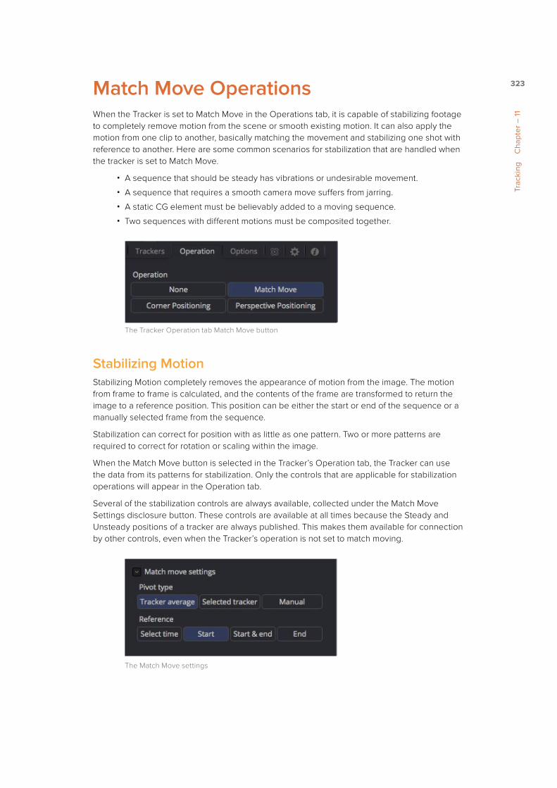
323
Trac
king
C
hapt
er –
11
Match Move OperationsWhen the Tracker is set to Match Move in the Operations tab, it is capable of stabilizing footage to completely remove motion from the scene or smooth existing motion. It can also apply the motion from one clip to another, basically matching the movement and stabilizing one shot with reference to another. Here are some common scenarios for stabilization that are handled when the tracker is set to Match Move.
� A sequence that should be steady has vibrations or undesirable movement.
� A sequence that requires a smooth camera move suffers from jarring.
� A static CG element must be believably added to a moving sequence.
� Two sequences with different motions must be composited together.
The Tracker Operation tab Match Move button
Stabilizing MotionStabilizing Motion completely removes the appearance of motion from the image. The motion from frame to frame is calculated, and the contents of the frame are transformed to return the image to a reference position. This position can be either the start or end of the sequence or a manually selected frame from the sequence.
Stabilization can correct for position with as little as one pattern. Two or more patterns are required to correct for rotation or scaling within the image.
When the Match Move button is selected in the Tracker’s Operation tab, the Tracker can use the data from its patterns for stabilization. Only the controls that are applicable for stabilization operations will appear in the Operation tab.
Several of the stabilization controls are always available, collected under the Match Move Settings disclosure button. These controls are available at all times because the Steady and Unsteady positions of a tracker are always published. This makes them available for connection by other controls, even when the Tracker’s operation is not set to match moving.
The Match Move settings

324
Trac
king
C
hapt
er –
11
MergeThe Merge buttons determine to what input knot on the Tracker tool the stabilization data is applied. When stabilizing an image to remove all motion, or smooth the motion, the Merge button should be set to BG Only.
EdgesThe Edges buttons determine whether the edges of an image that leave the visible frame are cropped, duplicated or wrapped when the stabilization is applied. Wrapping edges is often desirable for some methods of match moving, although rarely when stabilizing the image for any other purpose. These controls are described in greater detail in the Tool References for the Tracker later in this manual.
Position/Rotation/ScalingUse the Position, Rotation and Scaling checkboxes to select what aspects of the motion are corrected.
Pivot TypeThe Pivot Type for the stabilization is used to calculate the axis of rotation and scaling calculations. This is usually the average of the combined pattern centers but may be changed to the position of a single tracker or a manually selected position.
ReferenceThe Reference controls establish whether the image is stabilized to the first frame in the sequence, the last frame or to a manually selected frame. Any deviation from this reference by the tracked patterns is transformed back to this ideal frame.
As a general rule, when tracking to remove all motion from a clip, set the Merge mode to BG Only, the Pivot type to Tracker Average or Selected Tracker and the Reference control to Start, End or Select Time.
Smoothing MotionWhen confronted with an image sequence with erratic or jerky camera motion, instead of trying to remove all movement from the shot, you often need to preserve the original camera movement while losing the erratic motion.
The Start & End reference option is designed for this technique. Instead of stabilizing to a reference frame, the tracked path is simplified. The position of each pattern is evaluated from the start of the path and the end of the path along with intervening points. The result is smooth motion that replaces the existing unsteady move.
The Reference Intermediate Points slider is displayed when Start & End is selected

325
Trac
king
C
hapt
er –
11
To preserve some of the curvature of the original camera motion, you can increase the value of the Reference Intermediate Points slider that appears when the Start & End reference mode is selected.
When tracking to create smooth camera motion, ensure that the Start & End reference mode is enabled and set the Merge mode to BG Only. It is recommended to leave the Pivot type control set to Tracker Average.
Matching Movement in ClipsSome clips may need to be stabilized so that an element from another source can be added to the shot. After the element or effect has been composited, the stabilization should be removed to make the shot look natural again.
Match moving essentially applies the movement from the tracked clip to another clip.
There are two ways to perform match moving. One method involves connecting other tools, such as transform or merge, to a tracker’s outputs. The other method is to stabilize an image by trying to remove all motion but instead of setting the Merge buttons to BG Only, set it to FG Over BG, FG Only, or in rare occasions, BG Over FG.
Set the Merge buttons to BG Only, FG Over BG or BG Over FG
When using this Merge buttons, you connect a foreground image to the Tracker tool’s Input knot in the flow.
Connect a foreground image to the Tracker’s foreground input
Enabling the FG Only mode will apply the motion from the background to the foreground, and the Tracker will only output the modified FG image. This result can later be merged over the original, allowing further modifications of the foreground to be applied using other tools before merging the result over the background clip.
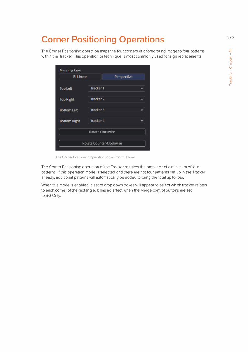
326
Trac
king
C
hapt
er –
11
Corner Positioning OperationsThe Corner Positioning operation maps the four corners of a foreground image to four patterns within the Tracker. This operation or technique is most commonly used for sign replacements.
The Corner Positioning operation in the Control Panel
The Corner Positioning operation of the Tracker requires the presence of a minimum of four patterns. If this operation mode is selected and there are not four patterns set up in the Tracker already, additional patterns will automatically be added to bring the total up to four.
When this mode is enabled, a set of drop down boxes will appear to select which tracker relates to each corner of the rectangle. It has no effect when the Merge control buttons are set to BG Only.
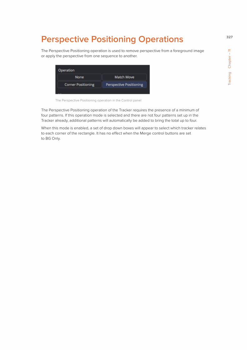
327
Trac
king
C
hapt
er –
11
Perspective Positioning OperationsThe Perspective Positioning operation is used to remove perspective from a foreground image or apply the perspective from one sequence to another.
The Perspective Positioning operation in the Control panel
The Perspective Positioning operation of the Tracker requires the presence of a minimum of four patterns. If this operation mode is selected and there are not four patterns set up in the Tracker already, additional patterns will automatically be added to bring the total up to four.
When this mode is enabled, a set of drop down boxes will appear to select which tracker relates to each corner of the rectangle. It has no effect when the Merge control buttons are set to BG Only.

414
Intr
oduc
tion
to C
ontr
ols
and
Cus
tom
izat
ion
Cha
pter
– 1
4
The ConsoleThe Console view provides a place to get log and error messages, read FusionScript outputs, or input FusionScripts directly. It can be accessed with the F6 hotkey or clicking the Console tab. The Console tab will display an icon when new content is produced. The icon will identify if it is an error, log, or script output.
The Console
At the top of the Console is a Toolbar. The button on the far left is Clear Screen and wipes the Console contents away. The next four buttons toggle the visibility of Error messages, Log messages, Script messages, and Input echoing. Showing only a specific type of message can help you find what you are looking for in the Console. The next three buttons let you choose the input script language. Lua 5.1 is the default and is installed with Fusion. Python 2.7 and Python 3.3 require that you have the appropriate Python environment already installed on your computer. Since scripts in the Console are executed immediately, you can switch between input languages at any time.
At the bottom of the Console is the Entry Field. You can type your scripts here and execute them in the current comp context. Scripts are entered one line at a time and are executed immediately.
Useful shortcuts are available for input in the Console. A single equals sign = is the same as print(). Two equals signs == is the same as dump(), printing out the contents of a table provided.
Pressing the up arrow will walk through previous input entries. The history of these inputs is saved in the .comp file.
Some examples of Lua scripts you can input:=tan(pi/3)̂ 2
The Console is a convenient place to do calculations.
comp:GetAttrs()
The Console uses the composition context, so we can refer to the current comp as “comp.” The current instance of Fusion can be referred to as “fu.”
Help(composition)
The Console is an easy way to get help with FusionScript.
comp.CurrentTime=comp:GetNextKeyTime(comp.CurrentTime)
The Console is also useful for testing out FusionScript snippets, making sure that it works as expected. This particular line will skip to the next keyframe or range start/stop for any tool in the comp. This doesn’t make much sense to use in the Console, but you could bind it to a hotkey, perhaps Shft+Ctrl+]. Now you can rapidly skip through your keyframes.

415
Intr
oduc
tion
to C
ontr
ols
and
Cus
tom
izat
ion
Cha
pter
– 1
4
To jog backwards, bind:comp.CurrentTime=comp:GetNextPrevTime(comp.CurrentTime) to Shft+Ctrl+[.
for i,v in ipairs(fu:GetRegSummary(CT_Tool)) do if v.REGS_OpIconString
then print(v.REGS_OpIconString..” = “..v.REGS_Name) end end
Because scripts are executed immediately after you hit return, typical loop formatting won’t work. Doing the loop in one line, however, does.
= composition:AskUser(“Motion Blur Quality For Selected Tools”,
{{“Quality:”, “Slider”, Min = 0, Default = 10 ,Integer = true}}) for
i,tool in pairs(comp:GetToolList(true)) do tool.Quality =
ask[“Quality:”] end
Even though scripts are executed one line at a time, you can still input them one at a time. If there is an error in your script, you will get a message immediately following the input in the Console.
When you create a new comp or open an existing one, a Fusion tip will be placed in the Console. Typing “tip” into the Entry Field will display another tip.
TIP: The font used in the Console can be scaled using Command-Mousewheel or Ctrl-Mousewheel.

425
Fina
l and
Pre
view
Ren
ders
C
hapt
er –
15
Rendering OverviewSince most composites happen over time, it is very important to be able to view a project or a selected clip at the intended frame rate, not just a single frame at a time. Although this can often be done by rendering the final output to disk, Fusion allows you to create previews using full resolution, floating point playback at your full frame rate.
When the intention is to evaluate an effect before your final output, Fusion offers several different ways to create and playback previews.
RAM Cache PreviewersWhen working with a composite, the frames rendered for interactive display are cached into memory, up to a preset memory limit. Priority is given to maintaining caches for tools that are currently displayed in a Viewer. Other tools may also cache their result, depending on available memory and the time cost of the tool, among other factors.
Pressing the Play Forward or Play Backward buttons in the Time Ruler will attempt to play back the frames in the current render range at the rate configured in the comp’s frame format preferences. For example, if the frame format is set to HDTV 720, the frame rate attempted will be 60.
Transport controls in the Time Ruler
The composition will, by default, render only the tools that are required to produce the image from the tools that are currently displayed in the Viewer.
If a cache already exists for the tools currently being played, the composition will generally play at the full frame rate. The actual frame rate achieved during playback will be displayed in the status bar during playback. Frames without a cache will need to render first, but as they render they will add themselves to the cache, and the next time they play through it will be at the full frame rate.
The green line in the Time Ruler shows regions of cached frames
You can read more about RAM Flipbook Previews in Chapter 5, Viewers.

426
Fina
l and
Pre
view
Ren
ders
C
hapt
er –
15
File Sequence PreviewsFile Sequence and Disk Previews are previews of file sequences on disk, as in the files used by a tool that has been cached to disk. A File Sequence preview plays a series of files from disk as quickly as they can be loaded from disk and formatted for use in the Viewer.
Both Loaders and Savers, which are tools that refer to files stored on disk, are able to read and write these types of previews. From the Loader or Saver you can create Flipbooks or .fb files, which are optimized for fast playback, or create .raw files, which are slower but contain more information.
When a Loader or Saver is the selected tool in the flow, transport controls appear beneath the tool controls. Tools that have a pre-rendered or populated disk cache will also reveal transport controls when they are selected.
Transport controls under the Control Panel for a Loader
Clicking on any of the transport buttons will begin the file sequence playback. The left Viewer is normally used to display these previews, although the target display can be changed using the Preview preferences.

427
Fina
l and
Pre
view
Ren
ders
C
hapt
er –
15
The target frame rate is chosen from the Frame Format preferences, but it can be changed using the RATE (FPS) control in the transports. The faster the drives are able to provide footage, the faster frames are displayed.
While the file sequence playback is active, the Viewer cannot be used for normal image viewing.
To create a file sequence preview for a Loader or Saver, do the following:
1 Right click on the header of a Loader or Saver tool in the Control Panel, then choose Create Preview on > File Sequence from the contextual menu.
2 In the dialog, click Start Render to create the file sequence preview.
3 Use the transport control under the Control Panel to play the clip back.
To disable the playback of the file sequence preview, do the following:
De-select the tool that has enabled the file sequence preview to turn the display of the preview off.
TIP: Frames played through file sequence playback are not spooled into the interactive cache.
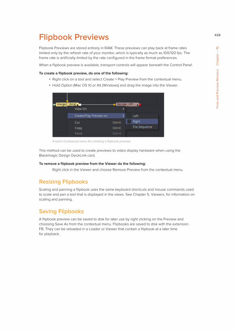
428
Fina
l and
Pre
view
Ren
ders
C
hapt
er –
15
Flipbook PreviewsFlipbook Previews are stored entirely in RAM. These previews can play back at frame rates limited only by the refresh rate of your monitor, which is typically as much as 100/120 fps. The frame rate is artificially limited by the rate configured in the frame format preferences.
When a flipbook preview is available, transport controls will appear beneath the Control Panel.
To create a flipbook preview, do one of the following:
� Right click on a tool and select Create > Play Preview from the contextual menu.
� Hold Option (Mac OS X) or Alt (Windows) and drag the image into the Viewer.
A tool’s Contextual menu for creating a flipbook preview
This method can be used to create previews to video display hardware when using the Blackmagic Design DeckLink card.
To remove a flipbook preview from the Viewer do the following:
Right click in the Viewer and choose Remove Preview from the contextual menu.
Resizing FlipbooksScaling and panning a flipbook uses the same keyboard shortcuts and mouse commands used to scale and pan a tool that is displayed in the views. See Chapter 5, Viewers, for information on scaling and panning.
Saving FlipbooksA flipbook preview can be saved to disk for later use by right clicking on the Preview and choosing Save As from the contextual menu. Flipbooks are saved to disk with the extension .FB. They can be reloaded in a Loader or Viewer that contain a flipbook at a later time for playback.

429
Fina
l and
Pre
view
Ren
ders
C
hapt
er –
15
Memory UsageSince flipbooks are stored in memory, they consume available memory used for image processing and tool caches. The amount of available memory determines the number of frames that can play back smoothly.
When creating a file preview, the Render Settings dialog will display the number of estimated frames that will fit within working memory. Rendering more than this number of frames will likely exceed available memory and cause the system to use the swap file.
Render Setting dialog

430
Fina
l and
Pre
view
Ren
ders
C
hapt
er –
15
Final RendersWhen all is said and done, the composite has to be rendered to disk. This is accomplished by adding a Saver tool to the flow and pointing it to a directory on disk or over the network.
Any number of Savers can be present at any point in a flow, making it easy to save intermediate composites, as well as final results in any resolution or format with a single pass.
Multiple Savers used in a composition
Any tool that has a valid high quality, full resolution frame in the memory or disk cache will not need to be rendered. The cached result will be used instead.
Starting a Final RenderYou can click the green Render button in the Time Ruler, choose Start Render from the File menu or press F12 to start a render. When a render is started, the Render Settings dialog will appear.
Click the Render button to begin a final render
This dialog is used to configure the rendering options. Clicking on the Start Render button on the dialog will begin the actual render.
Fusion can continue to be used while rendering, although performance will be affected by the ongoing render. You can open new compositions and work on them, but any attempt to change controls or settings in the rendering composition will display a dialog asking if you would like to abort the current render.
TIP: To bypass the Render Settings dialog when starting a render, hold Shift down while clicking on the Start Render button.
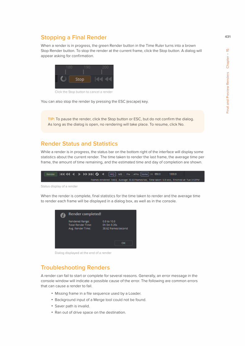
431
Fina
l and
Pre
view
Ren
ders
C
hapt
er –
15
Stopping a Final RenderWhen a render is in progress, the green Render button in the Time Ruler turns into a brown Stop Render button. To stop the render at the current frame, click the Stop button. A dialog will appear asking for confirmation.
Click the Stop button to cancel a render
You can also stop the render by pressing the ESC (escape) key.
Render Status and StatisticsWhile a render is in progress, the status bar on the bottom right of the interface will display some statistics about the current render. The time taken to render the last frame, the average time per frame, the amount of time remaining, and the estimated time and day of completion are shown.
Status display of a render
When the render is complete, final statistics for the time taken to render and the average time to render each frame will be displayed in a dialog box, as well as in the console.
Dialog displayed at the end of a render
Troubleshooting RendersA render can fail to start or complete for several reasons. Generally, an error message in the console window will indicate a possible cause of the error. The following are common errors that can cause a render to fail.
� Missing frame in a file sequence used by a Loader.
� Background input of a Merge tool could not be found.
� Saver path is invalid.
� Ran out of drive space on the destination.
TIP: To pause the render, click the Stop button or ESC, but do not confirm the dialog. As long as the dialog is open, no rendering will take place. To resume, click No.

443
Pre
fere
nces
C
hapt
er –
16
Categories of PreferencesThe first entry in the Preferences sidebar is assigned to the Global preferences. Clicking the disclosure arrows for the Global preferences reveals the following sections.
3D ViewThe 3D View preference offers control over various parameters of the 3D Viewers including grids, default ambient light set up and Stereoscopic views.
DefaultThe Default preference is used to select default behavior for a variety of options, such as animation, global range, timecode display, and automatic tool merging.
FlowYou use the Flow preference to set many of the same options found in the Flow contextual menu, like settings for Tile picture, the Navigator and pipe style.
Frame FormatThe Frame Format preference is used to create new frame formats as well as select the default image height and width when adding new creator tools like Background and Text+. You also set the frame rate for playback.
GeneralGeneral preference contains options for the general operation, such as auto save, and gamma settings for color controls.
LayoutYou can use the Layout preference to save the exact layout of Fusion’s windows.
LoaderUsing the Loader preference, you can set options for the Default Loader’s depth and aspect ratio as well as define the local and network LoaderCache settings.
MemoryMemory management for multi frame and simultaneous branch rendering is configured in the Memory preference.
NetworkOnly available in Fusion Studio, the Network rendering preference is used to configure options, such as selecting a render master, email notification and whether the machine can be used as a render slave.
OpenCLThe Open CL preference contains options for selecting OpenCL devices, enabling caching, and debugging OpenCL devices and tools.
Path MapPath Map preference is used to configure virtual file path names used by Loaders and Savers as well as the folders used by Fusion to locate comps, macros, scripts, tool settings, disk caches and more.
444
Pre
fere
nces
C
hapt
er –
16
PreviewThe Preview preference is where you configure the Preview creation and playback options.
QuickTimeThis section lets you configure QuickTime codecs.
ScriptThe preference for Scripting includes a field for passwords used to execute scripts externally, programs to use for editing scripts, and the default Python version to use.
Spline EditorThe Spline Editor preference allows you to set various spline options for Autosnap behavior, handles, markers and more.
SplinesOptions for the handling and smoothing of animation splines, Tracker path defaults, onion-skinning, roto assist and more are found in the Splines preference.
TimelineThe Timeline preference is where you create and edit Timeline/Spline filters, and set default options for the Timeline Editor.
TweaksTweaks preference handles miscellaneous settings for modifying the behavior when loading frames over the network and queue/network rendering.
User InterfaceThese Preferences set the appearance of the user interface window and how the Control panel is displayed.
Video MonitoringThe Video Monitoring preference is where you can configure your Blackmagic video display hardware for monitoring on an HD, Ultra HD or DCI 4K display.
ViewThe View preference is used to manage settings for Viewers, including default control colors Z-depth channel viewing ranges, default LUTs, padding for fit zoom, and more.
VR HeadsetsThe VR Headsets preference allows configuration of any connected Virtual Reality headsets, including how stereo and 3D scenes are viewed.
BinsThere are three panels as part of the Bins preference: a Security panel where you set users and passwords for serving the local bins; a Servers panel used to select which remote Bin servers are connected; and a Settings panel for stamp rendering. These are only available in Fusion Studio.
ImportThe Import settings contains options for EDL Import that affect how flows are built using the data from an EDL.

26
2 Using the Interface
This chapter is designed to help you understand Nuke’s workflow, learn how to use the interface, and customise the interface to suit your preferences.
Understanding the WorkflowNuke utilizes a node-based work flow, where you connect a series of nodes to read, process, and manipulate images. Each node in the project—an image keyer, a colour-correction, or a blur filter, for example—performs an operation and contributes to the output.
Saved projects are called script files. You can open a Nuke project file in a text editor, and you will see a series of sequential commands which are interpreted and executed when you render the output.
In Figure 2-2, you see an example of a very simple Nuke script. Two Read nodes reference image sequences on disk. Effect nodes extract a matte and blur an image. A merge node (named over) composites the foreground image over the background. Finally, a Write node renders and outputs the completed composite to disk. You’ll also see a Viewer node, which displays theoutput of any node in the script.
Figure 2-1: A Nuke project consists of a network of linked operators called nodes.
Figure 2-2: A simple Nuke script.
Viewer node
Output nodeeffect nodes
Read nodes

NUKEUSING THE INTERFACE
27
The Nuke Window
Panes and PanelsNuke’s main window is divided into three panes: the Node Graph/Curve Editor pane, the Prop-erties/Script Editor pane, and the Viewer pane.
Onto these panes, you can add the following panels:
• Toolbars for selecting nodes
• Node Graphs (also known as DAGs) for building node trees
• Curve Editors for editing animation curves
• Properties Bins for adjusting the nodes’ controls
• Viewers for previewing the output
• Script Editors for executing Python commands.
By default, there is a Node Graph panel in the lower left corner, a Viewer panel in the top left corner, and a Properties Bin on the right, as shown in Figure 2-5.
Figure 2-3: Empty main window.
Viewer pane
Properties/Script Editor pane
Node Graph/Curve Editor pane

NUKEUSING THE INTERFACE
28
The Node Graph is where you add nodes and build your node tree. When you add a node to the panel, its properties panel appears in the Properties Bin on the right. This is where you can adjust the node to produce the effect you’re after. To check the result, you can view the out-put in a Viewer.
You can open more panels using the content menus described in Toolbar, Menu Bar and Con-tent Menus below. You can add several panels on the same pane and switch between them by using the tabbed pages on top of the pane.
Tabbed PanelsPanes are divided into tabbed panels on the top of the pane. To go to a different tab, simply click on the tab name.
Toolbar, Menu Bar and Content MenusThe toolbar is located on the left-hand side of the Nuke window. By default, it consists of twelve icons. The different nodes are grouped under these icons based on their functions. You use the toolbar to add nodes to the Node Graph.
Figure 2-4: Main window with a Node Graph, Viewer, and Properties Bin.
Figure 2-5: Moving from the Properties tab to the Script Editor tab.
Viewer
Properties Bin with properties panels
Node Graph with a node tree

NUKEUSING THE INTERFACE
29
The menu bar is located on top of the Nuke window. Its menus, such as the File or Edit menu, let you perform more general actions related to the whole script, the viewers, or editing, rather than certain individual nodes.
In addition to the toolbar and the menu bar, you should also familiarise yourself with the con-tent menus. They are the gray checkered boxes in the top left corner of each pane. If you click on the box, a pop-up menu opens. You can use the options in the pop-up menu to customise the window layout.
Figure 2-6: The toolbar and the menu bar.
menu bar
toolbar

NUKEUSING THE INTERFACE
30
Finally, to work faster, you can right-click on the different panels to display a pop-up menu with options related to that particular panel.
Using the ToolbarNuke’s toolbar includes the following icons:
Figure 2-7: Using the content menus.
Figure 2-8: A right-click menu in the Node Graph.
Icon Functions
Image Image read and write nodes, built-in Nuke elements, and Viewer nodes.
Draw Roto shapes, paint tools, film grain, fills, lens flares, sparkles, other vector-based
image tools.

NUKEUSING THE INTERFACE
31
To display a tool tip that explains the icon’s function, move your mouse pointer over the icon.
Time Retiming image sequences.
Channel Channel management.
Color Applying colour correction effects.
Filter Applying convolve filters, such as blur, sharpen, edge detect, and erode.
Keyer Extracting procedural mattes.
Merge Layering background and foreground elements.
Transform Translating, scaling, tracking, and stabilizing elements.
3D 3D compositing nodes and tools.
Views Nodes for working with views and stereoscopic or multi-view material.
Any plug-ins, if installed.
Other Additional operators for script and viewer management.
Icon Functions

NUKEUSING THE INTERFACE
32
To make selections from the toolbar, click on an icon and select an option from the menu that appears.
To quickly browse through the menus in the toolbar, click and drag over the icons. Nuke opens and closes the menus as you drag over them, making it easy to search for a particular node or find out what the available menus contain.
Using the Menu BarThe Nuke menu bar includes these functions:
To quickly browse through the available menus and see what they contain, click on a menu and move the mouse pointer over other menus. Nuke opens and closes the menus as you go.
Figure 2-9: Selecting a node from the toolbar.
Tip
You can press the middle mouse button on a menu icon to repeat the last item used from that menu. For example, if you first select a Blur node from the Filter menu, you can then add another Blur node by simply pressing the middle mouse button on the Filter icon.
Menu Functions
File Commands for disk operations, including loading, saving, and importing scripts.
Edit Editing functions, preferences, and project settings.
Layout Restoring and saving layouts.
Viewer Adding and connecting viewers.
Render Rendering the output.
Help Accessing a list of hot keys, user documentation, training resources, tutorial files,
and Nuke-related e-mail lists.

NUKEUSING THE INTERFACE
33
Working with NodesNodes are the basic building blocks of any composite. To create a new compositing script, you insert and connect nodes to form a network of the operations you want to perform to layer and manipulate your images.
Adding NodesYou add nodes using the toolbar. When you add a node, Nuke automatically connects it to the last selected node.
To add a node:
1. To select the existing node that you want the new node to follow, click on the node once.
2. Click an icon on the toolbar and select a node from the menu that appears. For example, if you want to add a Blur node, click the Filter icon and select Blur.
Selecting NodesNuke offers a number of options for selecting nodes. Selected nodes display in a highlight col-our defined in your preferences. The default highlight colour is light yellow.
To select a single node:Click once on the node.
To select multiple nodes:Press Shift while clicking on each node you want to select.ORDrag on the workspace to draw a marquee. Nuke selects all nodes inscribed by the marquee.
Tip
You can also add nodes by pressing the Tab key on the Node Graph and starting to type the name of the node. This opens a prompt displaying a list of matches. Select the node you want to add from the list either by clicking on it or scrolling to it with the Up and Down arrows and pressing Enter. To add the last node you created using this method, simply press Tab and then Enter.
Alternatively, you can add nodes using the right-click menu on the Node Graph or keyboard short-cuts (most menus in the toolbar include a note of the relevant hot key next to the item in question).
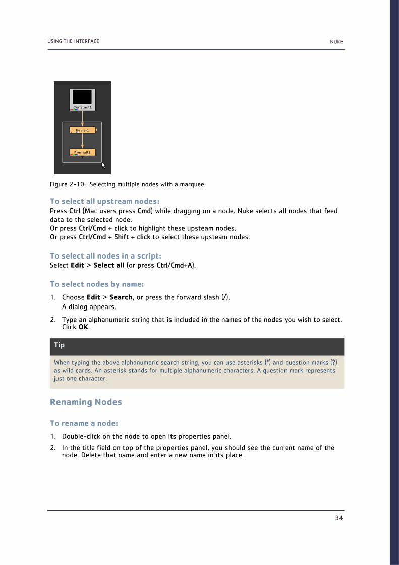
NUKEUSING THE INTERFACE
34
To select all upstream nodes:Press Ctrl (Mac users press Cmd) while dragging on a node. Nuke selects all nodes that feed data to the selected node. Or press Ctrl/Cmd + click to highlight these upsteam nodes.Or press Ctrl/Cmd + Shift + click to select these upsteam nodes.
To select all nodes in a script:Select Edit > Select all (or press Ctrl/Cmd+A).
To select nodes by name:
1. Choose Edit > Search, or press the forward slash (/).
A dialog appears.
2. Type an alphanumeric string that is included in the names of the nodes you wish to select. Click OK.
Renaming Nodes
To rename a node:
1. Double-click on the node to open its properties panel.
2. In the title field on top of the properties panel, you should see the current name of the node. Delete that name and enter a new name in its place.
Figure 2-10: Selecting multiple nodes with a marquee.
Tip
When typing the above alphanumeric search string, you can use asterisks (*) and question marks (?) as wild cards. An asterisk stands for multiple alphanumeric characters. A question mark represents just one character.
NUKEUSING THE INTERFACE
35
OR
1. Click on the node in the Node Graph to select it.
2. Press N.
3. Enter a new name for the node in the rename field that appears on top of the node.
Editing NodesTo copy, paste, and perform other editing functions in the compositing tree, you can use the standard editing keys (for example, Ctrl/Cmd+C to copy, and Ctrl/Cmd+V to paste). You can copy nodes to files or memory. Copied nodes inherit the values of their parent, but these val-ues, unlike those in cloned nodes (see below), are not actively linked—that is, you can assign different values to the original and the copy.
When you paste nodes, Nuke automatically connects them to the node that is selected before the paste operation. If you don’t want to connect anything, click on a blank area of the work-space to deselect any selected nodes before pasting.
To copy nodes to memory:
1. Select the node or nodes you want to copy.
2. Choose Edit > Copy (or press Ctrl/Cmd+C).
To copy nodes to files:
1. Select the node or nodes you want to copy.
2. Choose File > Export nodes as script.
3. Navigate to the directory where you want to store the node as a file.
4. Type a name for the node(s) at the end of the pathway, followed by the extension .nk.
To cut nodes:
1. Select the node or nodes you want to cut.
2. Choose Edit > Cut (or press Ctrl/Cmd+X).
Nuke removes the node(s) from the script and writes the node(s) to memory.
To paste nodes from memory:
1. Select the node that you want the pasted node to follow.
2. Choose Edit > Paste (or press Ctrl/Cmd+V).

NUKEUSING THE INTERFACE
36
Nuke adds the nodes to the script, connecting them to the node you selected in step 1.
To paste nodes from files:
1. Select the node that you want the pasted node to follow.
2. Choose File > Import script.
3. Navigate to the directory that stores the node file.
4. Select the node file, and click Import.
Nuke adds the nodes described by the file to the node you selected in step 1.
Cloning NodesYou can clone nodes in preparation for pasting them elsewhere in a script. Cloned nodes inherit the values of their parent, but unlike copied nodes, they also maintain an active link with their parents’ values. If you alter the values of one, the other automatically inherits these changes.
Clones are helpful for maintaining consistent setups across multiple elements. For example, you might use clones to apply an identical film grain setup to a series of elements shot on the same stock. Should you need later to make changes to the setup, these changes would auto-matically ripple throughout the script.
To clone nodes:
1. Select the node or nodes you want to clone.
2. Choose Edit > Clone or (press Alt+K).
Nuke clones the node(s), whilst maintaining an active link to the parental node(s). The clone status is indicated with an orange line that connects the clone to its parent node. The nodes also share the same name.
To declone nodes:
1. Select the node or nodes you want to declone.
2. Choose Edit > Declone (or press Alt+Shift+K).
Nuke removes the clone status of the selected nodes.
Disabling and Deleting Nodes
To disable nodes:
1. Select the node or nodes you want to disable.
2. Select Edit > Node > Disable\Enable (or press D).
Nuke cancels the node(s)’s effect on the data stream.
To re-enable nodes:
1. Select the node or nodes you want to re-enable.
2. Select Edit > Node > Disable\Enable (or press D).

NUKEUSING THE INTERFACE
37
To delete nodes:
1. Select the node or nodes you want to delete.
2. Select Edit > Erase (or press Delete).
Nuke removes the node(s) from the script.
Connecting NodesAs discussed, when you add or paste nodes into to a script, Nuke automatically generates pipes between the currently selected node and the new nodes. As you build up a script, you’ll need to move these pipes, or run new pipes between nodes. In Nuke, you make such modifica-tions by dragging on the back end of the pipe (the end without the arrowhead).
To disconnect a node:Drag the head or tail of the connecting arrow to an empty area of the workspace.ORSelect the lower node in the tree and press Ctrl+D (Mac users press Cmd+D).
To reconnect a node:Drag on the head or tail of the connecting arrow and drop it over the centre of the node to which you want to connect.
Figure 2-11: Disconnecting a pipe.
Figure 2-12: Reconnecting a pipe.

NUKEUSING THE INTERFACE
38
To duplicate a connecting arrow:Shift+drag the connecting arrow on top of the node you want to create a connection to. Nuke duplicates the connecting arrow, leaving the original connection untouched.
To add a node between two connected nodes:Drag the node into the space between the already connected nodes. As you do so you will see the link between these two nodes become active. When that happens, simply release the node you are dragging and it will automatically wire itself into the network between the two nodes.
To bend connecting arrows:
1. Select the node before the connector you want to bend.
2. From the toolbar, select Other > Dot. A dot appears after the selected node, causing a bend in the connector.
3. Drag the dot as necessary to reposition the bend.
Note
Nuke distinguishes the dual inputs that may run into a merge node with the labels A and B. A refers to the foreground element, and B to the background element. Nuke always copies from the A input to the B. This means that if you later decide to disable the node associated with an A input, the data stream will keep flowing, because it will, by default, use the B input.
Tip
You can also add a dot to an existing connection by pressing Ctrl (Cmd on a Mac) and clicking on the yellow dot that appears on the connecting arrow.
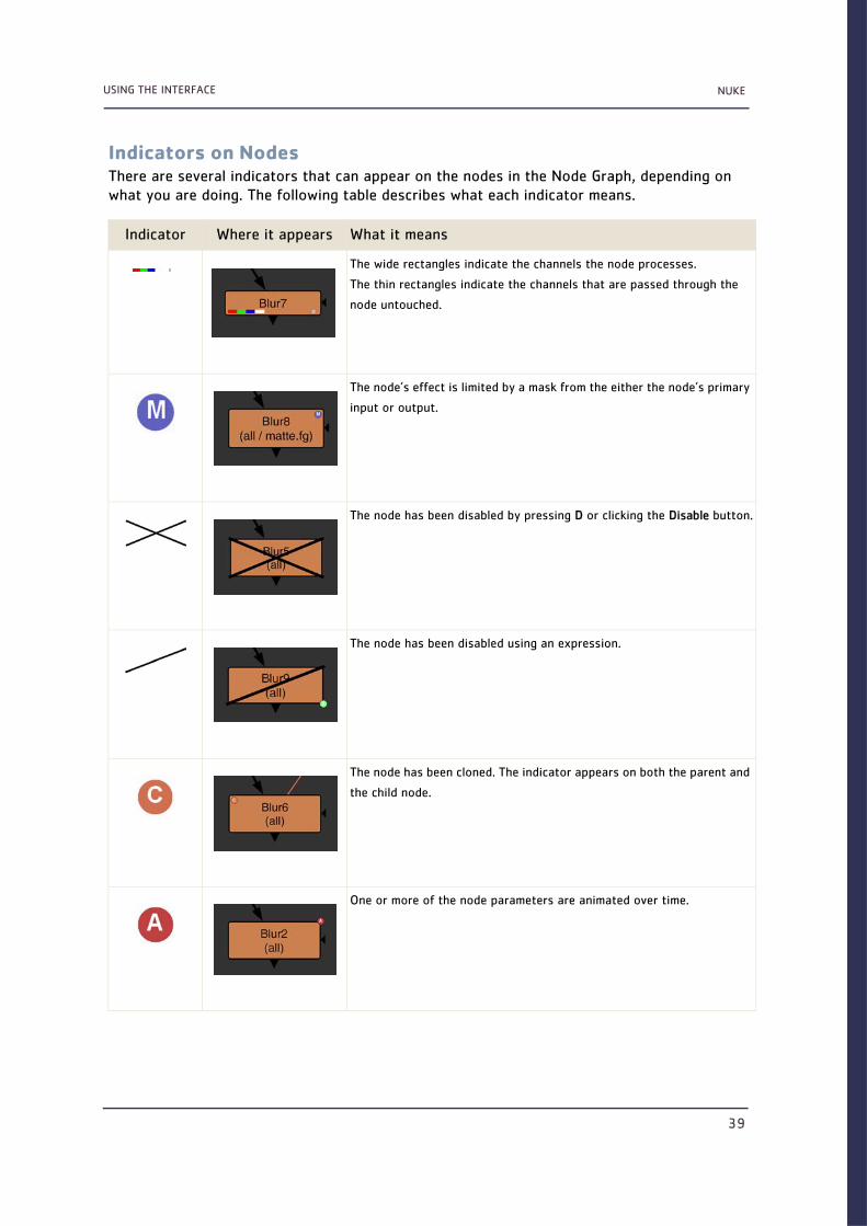
NUKEUSING THE INTERFACE
39
Indicators on NodesThere are several indicators that can appear on the nodes in the Node Graph, depending on what you are doing. The following table describes what each indicator means.
Indicator Where it appears What it means
The wide rectangles indicate the channels the node processes.
The thin rectangles indicate the channels that are passed through the
node untouched.
The node’s effect is limited by a mask from the either the node’s primary
input or output.
The node has been disabled by pressing D or clicking the Disable button.
The node has been disabled using an expression.
The node has been cloned. The indicator appears on both the parent and
the child node.
One or more of the node parameters are animated over time.

NUKEUSING THE INTERFACE
40
Searching for NodesNuke’s Search feature allows you to search for nodes in your script and select any matches found. As a search string, you can enter all or part of a node name. For example, you can search for all Blur nodes in your script by entering bl as the search string.
Using regular expressions, you can also do more complex searches, such as searching for all the Read and Write nodes in a script.
To search for nodes:
1. Select Edit > Search (or press /) to bring up the search dialog.
2. In the search field, enter the string you want to search for.
If you want to search for all nodes in the script, enter * (an asterisk).
If you want to search for all Read nodes in the script, enter Read.
If you want to search for all the Read and Write nodes, enter the following expression:
(*Read*|*Write*)
3. Click OK.
One or more of the node parameters are being driven by an expression.
You are working with a multiview project and have split off one or more
views in the node’s controls.
The full effect of the node is not in use, because you have adjusted the
mix slider in the node’s controls.
Indicator Where it appears What it means

NUKEUSING THE INTERFACE
41
Nuke searches for the nodes in the script and selects any matches it finds.
Viewing Information on NodesYou can obtain more detailed information from any node by selecting that node and thenpressing the ’i’ key. This will display an information window associated with that node,particularly useful when troubleshooting.
Customising the Node DisplayYou can modify the colour, name, and notes that a particular node displays. Doing so can make it easier for other artists to decipher the intent of your script. For example, you might colour all nodes green that relate to keying.
To modify a node’s display characteristics:
1. Double-click on the node to display its properties panel.
2. Click the Node tab at the top of the dialog. Its attributes appear.
3. Do any of the following:
• Enter a new name for the node on top of the old name.
• Click on the left colour button to change the colour of the node. To copy a colour of one node to another, drag and drop the colour button from the node whose colour you want to copy on top of the colour button in the node whose colour you want to change.
• Type any comments regarding the node in the label field. These will appear on the surface of the node.
• From the font pulldown menu, select the font type for any text on the node.
Note
When you enter expressions in the search dialog, remember that the search field only takes regular expressions. Any characters that have specific meanings in regular expressions, such as [ and ], need to be preceded by the \ character.
Figure 2-13: Nodes can be colour-coded according to function.

NUKEUSING THE INTERFACE
42
• Use the buttons on the right to bold or emphasize the text.
• Enter the font size in the font size field.
• Click color to choose a new font colour.
• The Select color dialog appears, allowing you to select the desired colour.
• Check hide input to conceal the node’s incoming pipe. This can enhance the readability of large scripts.
• Check postage stamp to display a thumbnail render of the node’s output on its surface.
Grouping Nodes in the Node GraphYou can group nodes in the Node Graph using the Backdrop node or the Group node. The Backdrop node adds a background box behind the nodes, separating the nodes visually from the rest of the node tree. A Group node, instead, combines a set of nodes into a single node, acting as a nesting container for those nodes.
Grouping Nodes with the Backdrop NodeYou can use the Backdrop node to visually group nodes in the Node Graph. Inserting a Back-drop node creates a box behind the nodes. When you move the box, all the nodes that overlap the box are moved, too. By inserting several backdrop nodes, you can group the nodes in your node tree onto boxes of different colours and titles. This makes it easier to find a particular node in a large node tree, for example.
Tip
You can also have Nuke automatically colour-code nodes for you based on their function. Select Edit > Preferences (or press Shift+S) to open the Preferences dialog. Click on the Node Colors tab, and check the autocolor option.
Thereafter, every time you add a node to a script, the node will take on the colour appropriate to its function. You can edit these colours as necessary on the Node Colors tab of the Preferences dialog.

NUKEUSING THE INTERFACE
43
To group nodes with a Backdrop node:
1. Select Other > Backdrop. A BackdropNode box appears in the Node Graph.
2. Drag the triangle in the lower right corner of the box to resize the box as necessary.
3. Click on the box title bar and drag it to move the box behind the nodes you want to group together. If there are any nodes on the box, they move together with the box.
Figure 2-14: Nodes grouped in the Node Graph with Backdrop nodes.

NUKEUSING THE INTERFACE
44
4. To change the colour of the box, open the Backdrop node’s controls by double-clicking on the title bar, then click the left colour button and pick a new colour with the colour picker that appears.
5. To change the title of the box, enter a new name for the Backdrop node in the node’s controls.
6. If you later want to remove the box, click on the triangle in the lower right corner to select the box and press Delete. Clicking on the title bar and pressing Delete removes both the box and the nodes on it.
Grouping Nodes with the Group NodeYou can use the Group node to nest multiple nodes inside a single node.
To group nodes with a Group node:
1. Select all the nodes you want to nest inside the Group node.
2. Select Other > Group (or press Ctrl/Cmd+G on the Node Graph).
All the selected nodes are collapsed into a group. The original nodes are still in the layout and can be deleted if you like. The internal structure of the Group node is shown on a separate tab that opens.
To view the nodes nested inside a Group node:
In the Group node’s controls, click the S button (short for Show) in the top right corner.
A new tab that contains the nested nodes opens.
To ungroup nodes:
1. In the Group node’s controls, click the S button in the top right corner.
Drag here to move the box and the nodes inside it.
Drag here to resize the box.

NUKEUSING THE INTERFACE
45
A new tab that contains the nested nodes opens.
2. Copy the nodes from the new tab into your script. If you want to lock the connections between the grouped nodes so that they cannot be accidentally disconnected during the copy-paste operation, check lock all connections in the Group node’s controls.
3. Delete the unnecessary Group node from your script.
Adding Notes to the Node GraphUsing the StickyNote node, you can add notes to the Node Graph. The notes can be any text. Usually, they are made as annotations to the elements in the node tree.
To add a note to the Node Graph:
1. Click on the part of the Node Graph where you want to add a note.
2. Select Other > StickyNote. A note box appears in the Node Graph.
3. In the StickyNote controls, enter your note in the label field.
Navigating Inside the Node Graph
PanningAs scripts grow in complexity, you need to be able to pan to a particular cluster of nodes quickly. The Node Graph offers a couple of methods for doing so.

NUKEUSING THE INTERFACE
46
Panning with the MouseTo pan with the mouse, press Alt and drag the mouse pointer over the workspace. The script moves with your pointer.
Panning with the MapIf your script spills over the edges of the workspace, a navigator map automaticallyappears in the bottom-right corner.
The map shows you a miniature view of the entire script and the pink rectangle shows the portion of the script that you see within the workspace borders.
To pan with the map, drag the pink rectangle to pan to a different view of the script.
When you pan or resize the window, the map automatically appears when the workspace does not show the entire script. When the whole script is contained within the window border, then the map automatically disappears.
Note
On Linux, Alt+drag may not work as expected. This is due to the default window functionality on Gnome. To get around it, you can use the Windows key instead of Alt when panning.
Alternatively, you can change your window preferences on Gnome to fix the problem:
1. Select Applications > Preferences > Windows to open the Window Preferences dialog.
2. Under Movement Key, select Super (“or Windows logo”).
You should now be able to pan with Alt+drag.
Figure 2-15: Panning with the map.
Tip
The navigation map is resizeable. Drag on its upper left corner to make it as large or small as you like.

NUKEUSING THE INTERFACE
47
ZoomingYou can zoom in on or out from the script in a couple of ways.
To zoom in:Move your mouse pointer over the area you want to zoom in on, and press the plus key (+) repeatedly until the workspace displays the script at the desired scale.ORPress Alt and drag right while holding down the middle mouse button.
To zoom out:Move your mouse pointer over the area you want to zoom out from, and press the minus key (-) repeatedly until the workspace displays the script at the desired scale.ORPress Alt and drag left while holding down the middle mouse button.
Fitting Selected Nodes in the Node GraphTo fit selected nodes in the Node Graph, press F.
Fitting the Node Tree in the Node GraphTo fit the entire the node tree in the Node Graph, click on the Node Graph to make sure no nodes are selected and press F.
Properties panelsWhen you insert a node, its properties panel appears in the Properties Bin with options to define the node’s output. You can also open the properties panel later by double-clicking on the node in the Node Graph (or selecting the node and pressing Return).
Note
On Linux, Alt+middle drag may zoom the entire Nuke window instead of the Node Graph. This is default functionality on Gnome. To get around it, you can use the Windows key instead of Alt when zooming.
Alternatively, you can change your window preferences on Gnome to fix the problem:
1. Select Applications > Preferences > Windows to open the Window Preferences dialog.
2. Under Movement Key, select Super (“or Windows logo”).
You should now be able to zoom in and out of the Node Graph with Alt+middle drag.
Tip
To open a properties panel in a floating window, Ctrl+double-click (Mac users Cmd+double-click) on the node.

NUKEUSING THE INTERFACE
48
Managing the Properties BinYou can limit the number of properties panels that can be open in the Properties Bin. To do so, enter the maximum number of properties panels in the field on the Properties Bin.
To lock the Properties Bin and have all new properties panels appear in floating windows, click the lock button on the Properties Bin.
To empty the Properties Bin and close all the properties panels in it, click the remove all pan-els button.
Controls That Appear on All Properties PanelsThese are the standard controls of every properties panel:
Figure 2-16: The Read node and its properties panel.
Control Function
Hide or show the node’s tabbed pages.
Centres the node in the Node Graph.
Centres one of the node’s inputs in the Node Graph. Select the input from the pull-
down menu that appears.
name field
(for example, Blur1)
You can enter a new name for the node here.
Controls that appear on all nodes

NUKEUSING THE INTERFACE
49
Floating control panels also include the following buttons:
Many properties panels also contain several tabbed pages.
(left) Changes the colour of the node. You can drag and drop this button on top of
another colour button to copy the colour. To revert to the default colour defined in
your Preferences, right-click on the button and select Set colour to default.
An X on the button indicates the colour is unset, and the colour defined in the Pref-
erences is used.
(right) Changes the colour used for the node’s controls in the viewer. You can drag and
drop this button on top of another colour button to copy the colour. To revert to
the default colour defined in your Preferences, right-click on the button and select
Set colour to default.
An X on the button indicates the colour is unset, and the colour defined in the Pref-
erences is used.
Undoes the last change made to the node.
Redoes the last change undone.
Reverts any changes made after the properties panel was opened.
Displays a pop-up help related to the node and its controls.
Floats the properties panel. Clicking this button again docks the properties panel
back in the Properties Bin if the Bin exists.
Closes the properties panel.
Control Function
Reverts any changes made after the properties panel was opened.
Reverts any changes made after the properties panel was opened and closes the
properties panel.
Closes the properties panel.
Control Function

NUKEUSING THE INTERFACE
50
On the Node tab, you can usually adjust the following controls:
Displaying Parameters
To display a node’s parameters:Double-click the node. It’s properties panel appears.
Figure 2-21 shows the controls available for editing parameters. Note that the presence of each control will vary according to the parameter’s function.
Figure 2-17: The Read node’s properties panel and the Node tab.
Control Function
label Lets you add comments to the node. The comments are displayed on the node’s sur-
face.
font Lets you change the font for any text displayed on the node.
Bolds any text displayed on the node.
Emphasizes any text displayed on the node.
Lets you change the font size of any text displayed on the node.
Lets you change the colour of any text displayed on the node.
hide input Check this to hide the node’s incoming pipe. This control does not appear on all
nodes.
cached Check this to keep the data upstream from the node in memory, so that it can be
read quickly.
postage stamp Check this to display a thumbnail render of the node’s output on its surface.
disable Check this to disable the node. Uncheck to re-enable. (You can also disable or re-
enable a node by selecting it in the Node Graph and pressing D.)
tabbed pages

NUKEUSING THE INTERFACE
51
Using Input FieldsYou can key values directly into a field, or use the arrow keys to increment and decrement val-ues.
To key in field values:
1. Click in the field to select the value you wish to replace:
• Double-click to the left of the value to select only the whole number digits.
• Double-click the right of the value to select only decimal digits.
• Press Return or double-click on the decimal itself to select all digits.
2. Type the value you want to replace the selection.
You can increment or decrement field values by hundreds, tens, tenths, hundreths, and so on. The magnitude of change depends on the initial position of your cursor. For example if you wanted to increment the initial value of 20.51 by ones, you would insert your cursor before the 0.
To increment and decrement a field value:
1. Click to insert the cursor just prior to the digit you want to increment or decrement.
Figure 2-18: Parameter controls.
Tip
You can also enter expressions (programmatic instructions for generating values) into fields. You always start an expression by typing =. See Chapter 16, Expressions, on page 345 for information about how to format expressions.
Tip
Nuke also allows you to enter formulas into fields, making it easy to do quick calculations. For exam-ple, if you wanted to halve a value of 378, you could simply type 378/2 into a field and press Enter to get 189.
switch between slider and channel values
animation buttonsample colour from Viewer
colour picker
input fieldslider

NUKEUSING THE INTERFACE
52
2. Press the up arrow to increment by unit, or the down arrow to decrement by one unit.
Using Sliders
To set a value with a slider:Drag the knob to the desired value.ORClick the desired value on the graduated scale beneath the slider.
To reset a slider to its default value:Ctrl+click (Mac users Cmd+click) on the slider.
Separating ChannelsBy default, many parameters in Nuke automatically gang channels for you. For example, if you drag on the Gain slider in the ColorCorrect node, you simultaneously affect the R, G, and B channels (assuming you’re processing the RGB channel set). You can, however, use the a parameter’s channel chooser button to reveal and edit the values assigned to individual chan-nels.
To edit an individual channel’s value:
1. Click the parameter’s channel chooser button. The number on its surface lets you know how many channels are available for editing. A series of input fields—one for each individ-ual channel—appears.
2. Edit the values in any of the revealed input fields as necessary.
You can also use a colour slider for editing individual channels. See Using Colour Sliders and Colour Wheel on page 53.
Using the Colour Picker and Colour ControlsNuke offers a colour picker for inputting values. Colour pickers are especially useful for set-ting white or black points, or for colour matching tasks, such as sampling values in a back-ground plate to colour-correct a foreground image.
To use the colour picker and colour controls:
• Click the colour picker button to display and make colour selections. The colour picker window opens.
Tip
You can also increment and decrement values using the mouse wheel (if available) or by pressing Alt while dragging on the value. The latter method is particularly useful for tablet users.

NUKEUSING THE INTERFACE
53
• To activate the eye dropper and sample colours from the Viewer (see below), click the colour swatch button.To copy a colour from one colour swatch to another, drag and drop the colour swatch with the desired colour on top of the swatch whose colour you want to change.
• To toggle between using the slider and manually entering values for each of the chan-nels, click the channel chooser button (which displays the number of available chan-nels).
To sample a colour from the Viewer:
1. In the parameters, click the colour swatch to activate the eye dropper.
2. Move your mouse pointer over the viewer from which you wish to copy colour values.
3. Zoom and pan as necessary until the region from which you want to sample is clearly visible.
4. Ctrl/Cmd+click to sample a colour value from the Viewer, or Ctrl/Cmd+Alt+click to sample a colour from the node’s input while viewing its output. To sample a region rather than a single pixel’s colour value, also press Shift. The input fields associated with the colour picker update to reflect the colour values of the sampled pixels. In the case of a sampled region, Nuke inserts the average colour values of all inlying pixels.
5. If you didn’t manage to sample just the right pixel or quite the right region, Ctrl/Cmd+click, Ctrl+Alt+click, Ctrl/Cmd+Shift+click, or Ctrl/Cmd+Alt+Shift+click again. A new overlay appears and the old one disappears.
6. When you’ve captured the right values, click the colour picker button again. The colour swatch reappears displaying the colour or colour average you sampled.
Using Colour Sliders and Colour WheelSome parameters offer colour sliders and a colour wheel for inputting values. These offer an intuitive and precise means for assigning just the right colour value to a parameter.
To display the colour sliders and colour wheel:Click the parameter’s colour picker button. The colour sliders and wheel appear.
Figure 2-19: Options for colour selection.
3-channel
colour swatch
colour picker

NUKEUSING THE INTERFACE
54
To customise the colour sliders and wheel window:
• From the TMI, HSV, and RGB buttons, select which slider set you want to display. The available slider sets are described below.
• To make the sliders horizontal rather than vertical, resize the colour sliders window. When the window is wide enough, the sliders become horizontal.
• If you want the background of the sliders show what the value of the colour would be if the sliders were set to the current position, click the Dyn button.
• Click the colour wheel button to cycle through three states: the colour wheel, the col-our square, and hide colour wheel/square.
• To hide or show the colour swatches, toggle the colour swatches button.
the available slider sets
currently selected colour
last selected colour
original colour
Drag here to adjust saturation.
Drag here to adjust the hue.
show/hide the colour wheel
use dynamic colours for slider backgrounds
Left/right-click the slider label to nudge the value by 0.01.
show/hide the colour swatches

NUKEUSING THE INTERFACE
55
To use the colour wheel:
• To adjust the hue, drag the marker on the edge of the colour wheel/on the circle.
• To adjust the saturation, drag the marker inside the wheel/square.
• To zoom in and out of the colour wheel, press Alt and drag right or left with the middle mouse button.
• To pan in the colour wheel, press Alt and drag the mouse pointer over the colour wheel.
• To reset the zoom and/or pan, middle-click on the colour wheel.
To use the colour sliders:To increment the value by 0.01, right-click on the slider label (e.g. R or A). To decrement the value by 0.01, left-click on the label. Use Shift+click for 0.1, and Alt+click for 0.001.
You can also click and drag right or left on a label to scrub the value up or down. Use Shift+drag to scrub faster, and Alt+drag to scrub slower.
These are the functions of the TMI sliders:
• The temperature slider (T) lets you control apparent colour temperature by inversely affecting red and green values (assuming your are processing the RGBA channel set).To cool (that is, increase the blue channel’s value, while decreasing the red channel’s), drag up. To heat (increase the red channel’s value, while decreasing the blue channel’s), drag down.
• The magenta/green slider (M) lets you control the mix of green and magenta hues.To add more magenta (increase the red and blue channel’s values, while decreasing the green channel’s), drag up. To add more green (increase the green channel’s value while decreasing the red and blue channels’), drag down.
Tip
You can also Ctrl/Cmd+click on the colour wheel to only affect the hue of the selected colour, and Shift+click to only affect the saturation.

NUKEUSING THE INTERFACE
56
• The intensity slider (I) lets you simultaneously control the red, green, and blue channel val-ues.To increase the value of all channels by the same amount, drag up. To decrease the value of all channels by the same amount, drag down.
To increase the channel’s value, drag up. To decrease it, drag down.
These are the functions of the HSV sliders:
• The hue slider (H) lets you control the colour’s location on the traditional colour wheel (for example, whether the colour is red, yellow, or violet).
• The saturation slider (S) lets you control the intensity or purity of the colour.
• The value slider (V) lets you control the brightness of the colour (the maximum of red, green, and blue values).
These are the functions of the RGB sliders:
• The red slider (R) lets you control the red channel’s value (or the first channel in a channel set if you are processing another set besides RBGA).To increase the channel’s value, drag up. To decrease it, drag down.
• The green slider (G) lets you control the green channel’s value (or the second channel in a channel set if you are processing another set besides RBGA).To increase the channel’s value, drag up. To decrease it, drag down.
• The blue slider (B) lets you control the blue channel’s value (or the third channel in a chan-nel set if you are processing another set besides RBGA).To increase the channel’s value, drag up. To decrease it, drag down.
The alpha slider is included in all three slider sets:
• The alpha slider (A) lets you control the alpha channel’s value (or the fourth channel in a channel set if you are processing another set besides RBGA).To increase the channel’s value, drag up. To decrease it, drag down.
To use the colour swatches:When you have found a good colour, you may want to save it in one of the colour swatches for further use. To do so, adjust the colour wheel or sliders until you are happy with the colour, and right-click on the colour swatch where you want to save it. You can also drag and drop a colour into a colour swatch from any other colour button or swatch.
To open another colour picker window:To open another colour picker window while keeping the first window open, Ctrl/Cmd+click on another parameter’s colour picker button.
To switch between the current and previous or original colour:The rectangle above the sliders shows the original colour (on the right) next to the currently selected colour (on the left). When you drag the markers to adjust the colour, the last selected colour is shown in between these. To switch between the currently selected colour and the original colour, click on the rectangle.

NUKEUSING THE INTERFACE
57
Animating ParametersAnimating a parameter refers to changing its value over time. You do so by setting keyframes (frames at which you explicitly define a value) and allowing Nuke to interpolate the values in between. You can animate most of Nuke’s parameters in this manner.
Working with Animated ParametersThe Animation menu lets you set keyframes, delete keys, and perform other editing operations on the curves for animated parameters.
To set keyframes:
1. Use a viewer to cue to a frame where you want to place a key.
2. Click the animation button next to the parameter you want to animate.
3. Select Set key from the drop down menu. The parameter’s input field turns turquoise, indicating that a keyframe has been inserted. Nuke enters the autokey mode: when you change the parameters value at another frame, it will automatically create a keyframe for you.
You can also set a key for all the controls in a node. To do so, select Set key on all knobs from the properties panel right-click menu.
4. Cue to the next frame where you want to place a key.
5. Edit the parameter’s value using the input field, regular slider, or colour slider. The moment you change the value, Nuke creates a keyframe.
6. Continue adding keyframes as necessary.
7. Use the viewer’s scrubber to preview the result.
Figure 2-20: The animation menu.

NUKEUSING THE INTERFACE
58
To delete a single keyframe:
1. Use the viewer’s next keyframe and previous keyframe buttons to cue to the keyframe that you want to remove. Notice that the scrub bar indicates key-frames with a green mark.
2. Click the animation button.
3. Select Delete key from the drop down menu.
Nuke removes the keyframe.
To delete all keyframes from a parameter:
1. Click the animation button.
2. Select No animation from the drop down menu. A confirmation dialog appears. Select Yes.
Nuke removes all keyframes from the parameter, and sets the static value to match that of the current frame.
Animated Parameters and the Curve EditorAs you add keyframes to a parameter, Nuke automatically plots a curve on its Curve Editor panel, where each value (the y axis) is plotted as it changes over time (the x axis). You can add keyframes, delete keyframes, and even adjust the interpolation between keyframes without ever looking at this curve. However, as the animation grows more complex, you may find it easier to edit the animation by manipulating this curve directly. For more information on how to do so, see Using the Curve Editor below.
Using the Curve Editor
Displaying Curves
To reveal an animation curve:
1. Click the animation button next to the parameter whose curve you wish to view.
2. Select Curve editor. The Curve Editor panel appears with a focus on the selected parameter’s curve.
The vertical, or y axis, denotes the value of the parameter.

NUKEUSING THE INTERFACE
59
The horizontal, or x axis, denotes time (in frame units).
To display curves in the Editor:
1. In the parameter tree on the left, click the + and - signs to expand and collapse the hierar-chy as necessary.
2. Click a parameter’s name to make its curve the focus of the editor. To focus on multiple curves at the same time, Shift+click on the names in the parameter tree.
3. To display separate curves for each channel, separate the channels for the relevant control in the node’s properties panel.
The parameter tree on the left lets you focus on any curve in the script.
To remove a curve from the Editor:
1. In the parameter tree on the left, click the + and - signs to expand and collapse the hierar-chy as necessary.
2. Select a curve in the parameter tree, and press Delete.
To zoom in or out in the Editor:
1. Click on the area you want to zoom in on or out of.
2. Press the + button to zoom in, or the - button to zoom out.
OR
Scroll up with the mouse wheel to zoom in, or down to zoom out.
Figure 2-21: Nuke’s Curve Editor panel.
Tip
To zoom to a custom area in the Curve Editor, middle-click on the Editor and drag to select an area with a marquee. When you release the mouse button, the Editor will zoom to fit the selected area in the Editor.
parameter tree
expression field
current frame indicator
selected keyframe
keyframes
selected curve

NUKEUSING THE INTERFACE
60
To pan in the Editor:Alt+drag over the editor.
To reset zoom and panning:
1. Right-click on the Curve Editor.
2. From the menu that opens, select View > Frame All (or press A on the Editor).
Nuke centres the curve in the Editor, resetting the zoom.
To centre a portion of the curve in the editor:
1. Select the points you want to centre in the editor.
2. Right-click on the Editor, and select View > Frame Selected (or press F on the Editor).
Nuke centres the selected portion of the curve in the editor. If no points are selected, Nuke centres the selected curve, or all curves.
Editing CurvesYou edit curves by moving the points on the curve to new locations. If necessary, you can add more points to the curve. You can also sketch curves freely, use the usual editing functions such as copy and paste, smooth curves with filtering, interpolate curves, loop, reverse or negate curves, and use expressions to modify curves.
To add points to a curve:
1. Click on the curve you want to edit. The curve turns yellow to indicate it’s selected.
2. Ctrl+Alt+click (Mac users Cmd+Alt+click) on the part of the curve editor you want to add a point to. You can add points both on the curve and outside the curve.
OR
1. Right-click on the Editor and select Edit > Generate. The Generate keys dialog opens.
2. In the Start at field, enter the first frame you want to use as a keyframe.
3. In the End at field, enter the last frame you want to use as a keyframe.
4. In the Increment field, enter the frame increment you want to use between the first and the last keyframe. For example, if you want every tenth frame to be a keyframe, enter 10.
5. In the last field, enter the value you want to use for y. If you do not enter a value here, the keyframes are added to the current curve without modifying the curve shape.
6. Click OK.
To select points on a curve:
• To select individual points, click on the point you want to select.
• To select multiple points, Shift+click on the points, or drag a marquee around them.A box is drawn around the points, and the points turn white to indicate they have been selected.
• To select all points, press Ctrl+A (Mac users press Cmd+A).A box is drawn around the points, and the points turn white to indicate they have been selected.

NUKEUSING THE INTERFACE
61
To move points on a curve:
• To move a point along either the x or y axis only, drag the point to a new location.
• To move a point in any direction, Ctrl+drag (Mac users Cmd+drag) the point to a new loca-tion.
• To adjust the values of a point numerically, select the point and click on the x or y value that appears next to it.
• To move several points at the same time, select them and drag the selection box to a new location.
To add or remove points to or from the selection box, Shift+click on the points.
To resize and scale the selection box, drag its edges. If the selection box is very narrow, you can press Ctrl/Cmd when resizing it. This allows you to resize the box in one dimension only. For example, if you have a box that’s wide on the x axis but flat on the y axis, you can resize it in this way along the x axis.
To avoid accidentally moving a point inside the selection box, press Ctrl/Cmd+Shift when dragging the box to hide the points inside the box.
To adjust the slope around the points:
1. Select a point on the curve. Red tangent handles appear on both sides of the point.
2. Drag the tangent handles to a new location. The curve follows the handles.

NUKEUSING THE INTERFACE
62
To sketch a curve freely:Press Alt+Ctrl+Shift (Mac users press Alt+Cmd+Shift) while drawing a curve on the editor. Nuke sketches a curve that follows your mouse movements.
To cut, copy, and paste selected points, expressions, or curves:
1. Right-click on the Curve Editor.
2. From the menu that opens, select Edit and the editing function you want to use on the entire curve, for example:
• Edit > Copy > Copy Selected Keys to only copy the points you have currently selected.
• Edit > Copy > Copy Curves to copy an entire curve.
• Edit > Copy > Copy Expressions to copy the expression that creates the curve.
• Edit > Copy > Copy Links to copy a curve and keep its values linked to the original curve, so that if you change the original, your changes also affect the copied curve.
To move selected points on the curve by a fixed value:
1. Select all the points you want to move.
2. Right-click on the editor and select Edit > Move. The Move Animation Keys dialog opens.
3. In the x and y fields, define how you want to move the points along the x and y axes. For example, to shift the selected points to the right by a value of 10, enter x+10 in the x field.
4. In the slope and left slope fields, define how you want to move the points’ tangent handles.
To smooth the curve with filtering:
1. Select the portion of the curve that needs smoothing.
2. Right-click on the editor and select Edit > Filter. The Filter Multiple dialog opens.
Alt+Ctrl/Cmd+Shift

NUKEUSING THE INTERFACE
63
3. In the No. of times to filter field, specify how many times you want to filter the curve. Filtering sets new values on each point based on the average values of their neighbouring points. The more filtering, the smoother the curve.
To interpolate parts of a curve:
1. Select the point(s) between or around which you want to interpolate the curve.
2. Right-click on the Editor. Select Interpolation and the type of interpolation you want to use. Select
• Constant to force a constant value after each selected point.
• Linear to use linear interpolation. This produces sharp changes at keyframes and straight lines between them.
• Smooth to set the tangents’ slopes equal to the slope between the keyframe to the left and the keyframe to the right if the selected point is between these two keyframes along the y axis. If the selected point is not between these keyframes and has a larger or smaller value than both keyframes, the tangents’ slopes are made horizontal. This ensures the resulting curve never exceeds the keyframe values.
before filtering after filtering

NUKEUSING THE INTERFACE
64
• Catmull-Rom to set the tangents’ slope equal to the slope between the keyframe to the left and the keyframe to the right regardless of where the selected point is located. The resulting curve can exceed the keyframe values.
• Cubic to set the slope so that the second derivative is continuous. This smoothens the curve.
• Horizontal to make the tangents horizontal, setting the slope around the selected points to zero.
• Break to adjust the two tangents of a selected point independent of each other.
between the previous and next keyframe on y
not between the previous and next keyframe on y
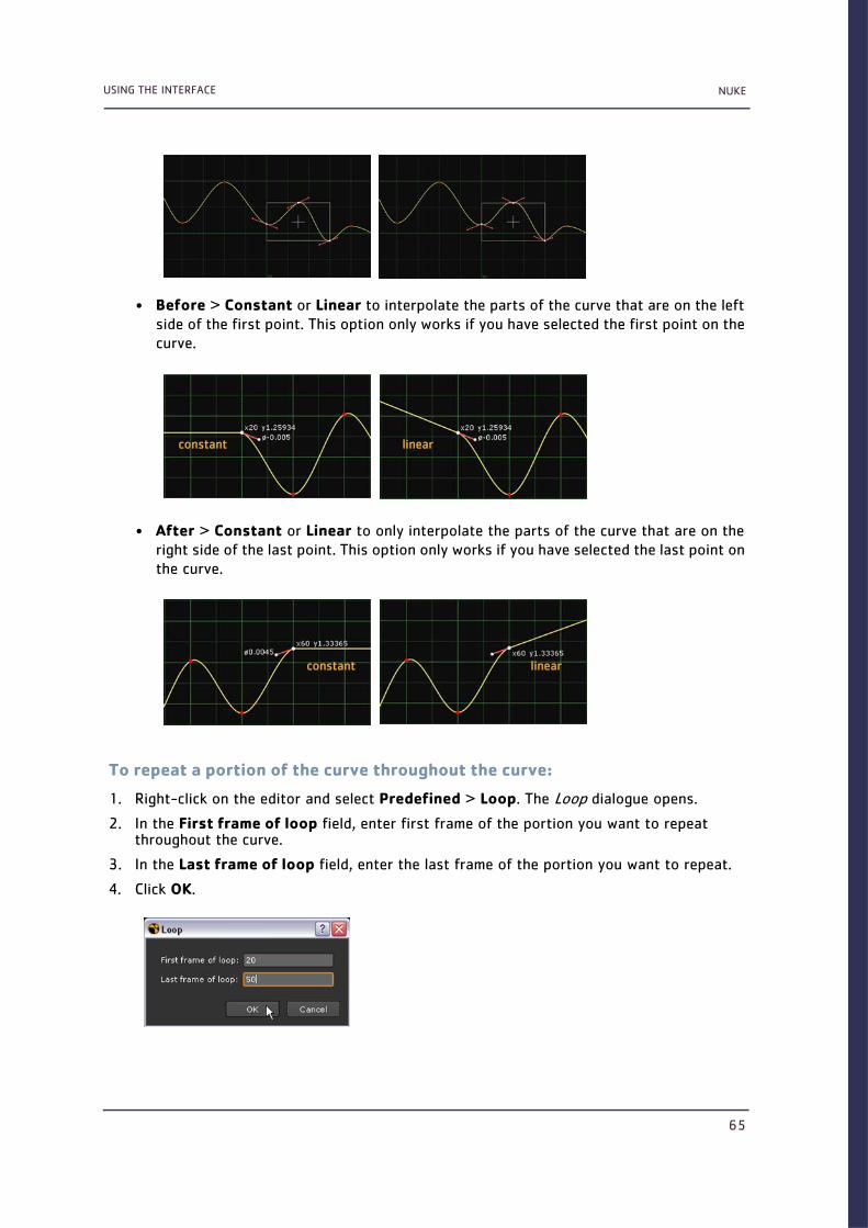
NUKEUSING THE INTERFACE
65
• Before > Constant or Linear to interpolate the parts of the curve that are on the left side of the first point. This option only works if you have selected the first point on the curve.
• After > Constant or Linear to only interpolate the parts of the curve that are on the right side of the last point. This option only works if you have selected the last point on the curve.
To repeat a portion of the curve throughout the curve:
1. Right-click on the editor and select Predefined > Loop. The Loop dialogue opens.
2. In the First frame of loop field, enter first frame of the portion you want to repeat throughout the curve.
3. In the Last frame of loop field, enter the last frame of the portion you want to repeat.
4. Click OK.
constant linear
constant linear

NUKEUSING THE INTERFACE
66
The shape of the curve between these frames is repeated throughout the rest of the curve. The solid line represents the actual curve, and the dotted line the original curve with the keyframes.
To reverse a curve:Right-click on the editor and select Predefined > Reverse. This makes the curve go backward in time. Both the new curve and the original curve are dis-played. The solid line represents the actual curve, and the dotted line contains the keyframes that you can modify.
To negate a curve:Right-click on the editor and select Predefined > Negate. The curve becomes the negative of the keyframes. For example, a value of 5 turns into -5. Both the new curve and the original curve are displayed. The solid line represents the actual curve, and the dotted line contains the keyframes that you can modify.
To use an expression to modify a curve:Enter the expression in the expression field at the bottom of the Curve Editor.
the portion to loop
before reverse after reverse
before negate after negate

NUKEUSING THE INTERFACE
67
OR
1. Right-click on the Editor, and select Edit > Edit expression.
2. In the dialog that opens, type the expression you want to use for the curve, for example, sin(x)/x.
3. Click OK.
ViewersViewer nodes, unlike process nodes, don’t alter data in any way; rather, they act as windows on it. Each viewer node displays the render output of any connected process nodes in the viewer panel. Viewer nodes are essential for quickly assigning the right values to parameters because they allow you to edit in context—that is, edit a given node’s parameters upstream in a script while viewing the effect of those changes downstream.
You can place as many viewer nodes in a script as you wish, which allows you to simultane-ously view multiple outputs. You can also pipe the output from up to ten process nodes into single viewer node, and then cycle through the various displays. This allows you to easily com-pare an image before and after processing by a given effect.
Adding Viewer NodesViewers have corresponding nodes that appear in the Node Graph. These nodes do not pro-duce output for rendering; they generate display data only. You can connect viewer nodes as described in Working with Nodes on page 33. In practice, you’ll work faster by using the viewer hotkeys described below.
To add a viewer node:
1. Select the node whose output you wish to view.
2. Do one of the following:
• Using the menu bar, choose Viewer > Create New Viewer.
• Using the toolbar, choose Image > Viewer.
• Using a keyboard shortcut, press Ctrl+I (Mac users press Cmd+I).
Nuke connects a viewer node to the node you selected in step 1, and displays the output of the node in the viewer panel. You can also insert a Viewer node and set up its first connection by simply pressing 1 over the Node Graph.
Connecting Viewer NodesOnce you add a viewer node to the script, you can quickly pipe any process node’s output to it simply by selecting the process node then pressing any number key. Doing so pipes the output to one of the ten input ports available on every viewer node (the 0 key represents the tenth slot).

NUKEUSING THE INTERFACE
68
.
Toggling ViewsIf a Viewer node has multiple inputs, like the one depicted above, you can press the up or down arrow keys to quickly cycle through the views (your cursor needs to be in the viewer window). To view a particular node press the number key (1, 2, 3... 0) corresponding to the pipe number whose contents you wish to view.
Panning and Zooming the Viewer Window
To pan the frame:Hold the Alt key and drag on the display. The frame follows the mouse pointer.
To recentre the frame:Press F.
Figure 2-22: A Viewer node with multiple inputs.
Note
On Linux, Alt+drag may not work as expected. This is due to the default window functionality on Gnome. To get around it, you can use the Windows key instead of Alt when panning.
Alternatively, you can change your window preferences on Gnome to fix the problem:
1. Select Applications > Preferences > Windows to open the Window Preferences dialog.
2. Under Movement Key, select Super (“or Windows logo”).
You should now be able to pan with Alt+drag.

NUKEUSING THE INTERFACE
69
To zoom in on the frame:
1. Move your pointer over the area of the display on which you want to zoom.
2. Press the plus button (+) repeatedly until the frame attains the desired scale.
OR
Select zoom in from the zoom pulldown menu in the top right corner.
To zoom out from the frame:
1. Move your pointer over the area of the display from which you want to zoom.
2. Press the minus button (-) repeatedly until the frame displays at the desired scale.
OR
Select zoom out from the zoom pulldown menu in the top right corner.
To restore the zoom to 100%:Press Ctrl+1 (Mac users press Cmd+1).
Hiding Floating Viewers
To hide a floating viewer:Press ‘ (the accent key).
To show a hidden floating viewer:Press ‘ (the accent key) again.
Using the Viewer ControlsA Viewer’s onscreen controls let you navigate the timeline, display channels, zoom, choose cameras (3D mode), and create display wipes and composites.
Figure 2-23: Viewer controls.
zoom menu
region of interest
channel set/channel display wipe/display composite controlscamera(s)
timeline controls
downscale menu
2D/3D

NUKEUSING THE INTERFACE
70
Timeline ControlsDrag the orange marker along the timeline to quickly cue to a specific frame. The number of the current frame appears in the Current field above the timeline. You can also cue to a frame by typing its number directly into this field.
By default, Nuke automatically adjusts the timeline of every Viewer window to show the frame range defined in your Project Settings. If no frame range is defined, the frame range of the first image you read in is used as the global frame range.
Viewer timeline controls also have a frame range source pulldown menu that you can use to define where the timeline gets its frame range from. You can set this menu to Global, Input, or Custom. Global is the default setting described above.
To have the viewer adjust the timeline to show the “in” and “out” frames of the current input clip, select Input from the frame range source menu. The number of the first frame in the clip is shown in the left end of the timeline and the number of the last frame in the right end. If you change the input of the viewer, the frame range on the timeline is adjusted accordingly.To manually adjust the frame range for the current viewer window, pan and zoom on the time-line until you see the desired frame range and Custom becomes selected in the frame range source menu. Alt+drag to pan, and MMB+drag to zoom in. You can also zoom in on or out of the timeline using the mouse wheel. To reset the zoom, press the middle mouse button over the timeline.
To adjust the playback range for the current viewer window, Ctrl+drag (Mac users Cmd+drag) the red playback range marker on the timeline to a new “in” and “out” frames as shown in Figure 2-31, or enter a new playback range in the playback range field.
The fps field (frames-per-second) initially displays the project’s playback speed. Nuke will attempt to maintain this speed throughout playback, although this adjusts depending on the resolution of the imagery and your hardware configuration.
The Frame Increment field lets you specify the number of frames by which the Previous increment/Next increment buttons cue the sequence.
Figure 2-24: Timeline controls.
Figure 2-25: Adjusting the frame range for the current Viewer.
current frame playback buttonsframe increment fps field
time markerframe range source playback range field

NUKEUSING THE INTERFACE
71
The following table lists the functions of the playback buttons:
The Playback Mode button lets you control how many times and in what direction the viewer plays back the sequence. Click the button to toggle between the following modes:
Jumping to a Specific FrameYou can move quickly to a specific frame on the timeline by choosing File > Go to frame (or by pressing Alt+G), entering a frame number in the dialog that appears, and clicking OK.
Buttons Functions
The First frame and Last frame buttons cue the sequence to the first and last
frame.
The Previous keyframe and Next keyframe buttons cue the sequence to the
script’s previous or next keyframe.
The Play backward and Play forward buttons play the sequence backward or for-
ward at the script’s frame rate.
The Back 1 Frame and Forward 1 Frame buttons cue the sequence to the previous
or next frame.
The Stop button halts playback.
The Previous increment and Next increment buttons cue forward or back by 10
frames by default. These are useful for heavy keyframing tasks. You can adjust
the increment value as necessary.
Button Function
Repeatedly play the sequence (loop).
Play the sequence once from the current frame to the head or tail (stop).
Repeatedly play the image back and forth from head to tail.

NUKEUSING THE INTERFACE
72
Synchronising Viewer PlaybackThe Lock/Unlock button lets you toggle synchronized playback of viewer windows. By default, all viewers are locked—that is, if you cue to a frame in one viewer, all other viewers follow suit.
When the lock icon changes from a closed lock to an open lock, that viewer’s playback becomes independent of other viewers, and not cued to the other viewers.
Pausing the DisplayThe Pause button stops the viewer from updating and holds the last frame rendered. To reac-tivate display rendering for all frames, press the button again.
You can click the render update button next to Pause (or press U) to manually update the dis-play while keeping Pause active.
Displaying a Single ChannelYou can press the R, G, B, and A keys on your keyboard to display the red, green, blue, and alpha channels respectively. Or, you can also select a channel from the RGB pulldown menu in the top left corner.
Press one of the channel keys again to toggle back and display all channels.
Figure 2-26: Synchronizing viewers.
Figure 2-27: Pausing the display update of a viewer.
Figure 2-28: Displaying a single channel.
Click to
Click to manually update when Pause is active.

NUKEUSING THE INTERFACE
73
Channel Set and Channel Display ListsThe channel set list lets you choose a set of colour channels to display in the viewer. By default, this is set to display the rgba set, but you can choose any channel set in the data stream.
The Channel list controls which channel appears when you view the “alpha” channel. The default setting actually does display the alpha channel when you press the A key; however, you can change this by selecting any channel in the data stream.
Image Format LabelsThe Pixel Value indicator displays information about the pixel underlying the pointer or about a sampled pixel or region of pixels. (You can sample a single pixel from the Viewer by pressing Ctrl/Cmd while clicking, a region from the Viewer by pressing Ctrl/Cmd+Shift while dragging, a single pixel from the node’s input by pressing Ctrl/Cmd+Alt while clicking, and a region from the node’s input by pressing Ctrl/Cmd+Alt+Shift while dragging.) From left to right, the indica-tor displays the following about the current pixel or sample: its x and y position; its Red, Green, Blue, and Alpha values; and other values depending on the colour type you have selected from the colour type menu on the right.
Figure 2-29: Selecting a channel set
Figure 2-30: Selecting the channel to display when A is pressed.
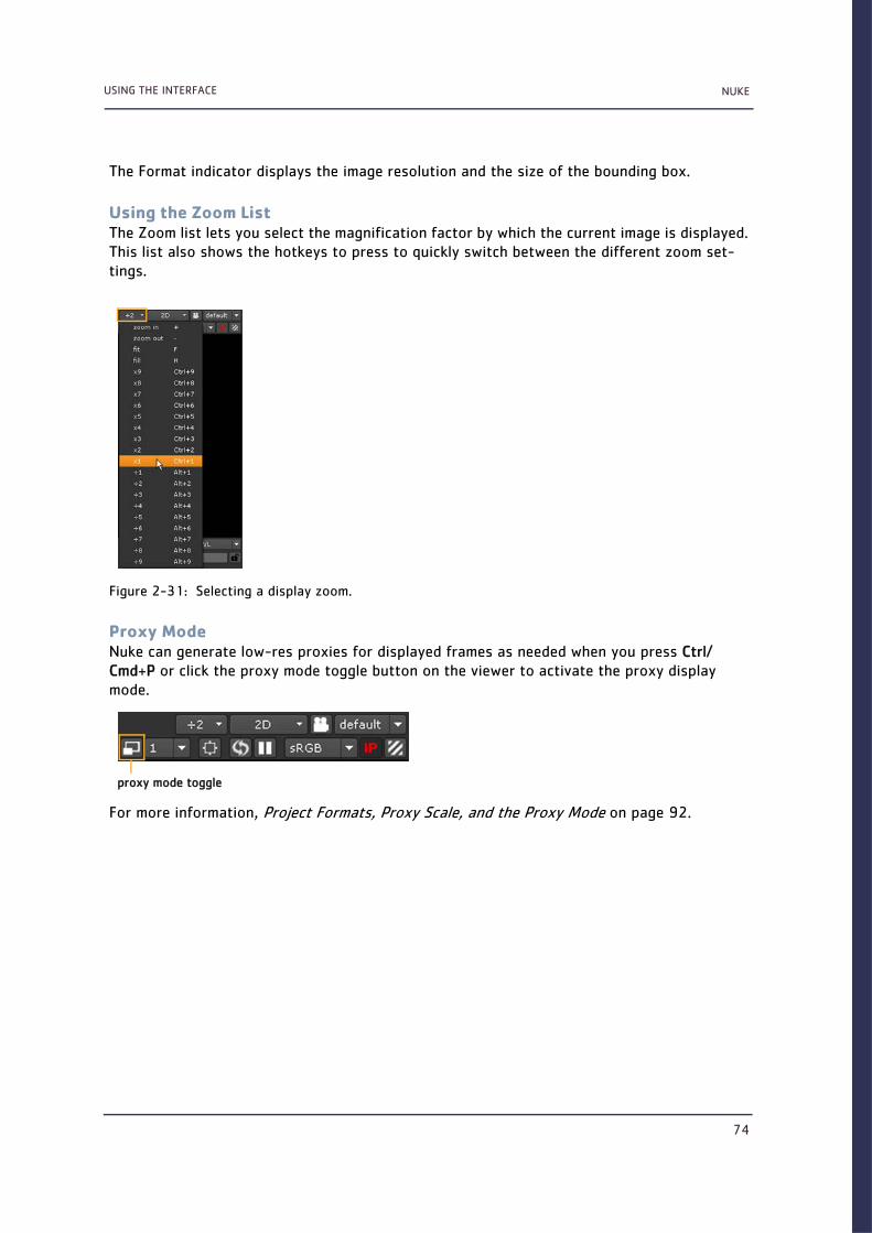
NUKEUSING THE INTERFACE
74
The Format indicator displays the image resolution and the size of the bounding box.
Using the Zoom ListThe Zoom list lets you select the magnification factor by which the current image is displayed. This list also shows the hotkeys to press to quickly switch between the different zoom set-tings.
Proxy ModeNuke can generate low-res proxies for displayed frames as needed when you press Ctrl/Cmd+P or click the proxy mode toggle button on the viewer to activate the proxy display mode.
For more information, Project Formats, Proxy Scale, and the Proxy Mode on page 92.
Figure 2-31: Selecting a display zoom.
proxy mode toggle

NUKEUSING THE INTERFACE
75
Figure 2-32: High-res display and proxy display.
Full resolution
Proxy

NUKEUSING THE INTERFACE
76
The global proxy resolution and/or scale are determined by the project settings, which you can open by selecting Edit > Project settings (or pressing S).
Rendered proxies, specified in the Read nodes’ controls, will override the proxy format speci-fied in the project settings—except when you use Reformat nodes (click the Transform icon and select Reformat) to change the image format after you’ve read it into the script.
Lowering the Display Resolution of Individual ViewersViewers also have a pulldown menu that allows you to easily switch to lower display resolu-tions, regardless of whether you have activated proxy mode or not. Using this multiplier set-ting, you can, for example, change the display resolution of an individual viewer to 50% of the current (be it full size or proxy) resolution. This is useful if you want to have Nuke display your images more quickly without having to touch the project settings. It also comes in handy if you have just a few very large plates in your script, as you can choose to use lower resolutions when viewing just these plates.
Figure 2-33: Proxy display resolution defined on the project settings properties panel.
Figure 2-34: Reading in proxy versions of images.

NUKEUSING THE INTERFACE
77
To lower the display resolution of individual viewers:
From the viewer’s down-rez menu, choose the factor by which you want to lower the display resolution. Select:
• 1 to display 1/1 of the currently active resolution.
• 2 to display 1/2 of the currently active resolution.
• 4 to display 1/4 of the currently active resolution.
• 8 to display 1/8 of the currently active resolution.
• 16 to display 1/16 of the currently active resolution.
• 32 to display 1/32 of the currently active resolution.
For example, if you have a 4K plate and are using a proxy scale of 0.5, your plate will still be 2K even in the proxy mode. Setting the down-rez factor to 2 in the viewer will scale the plate down further to 50% of the proxy resolution, that is to 1K. This gives you much faster (but less accurate) feedback.
Pixel Aspect RatioThe pixel aspect ratio determines whether your images are displayed using square or rectan-gular pixels. By default, the viewer uses the pixel aspect ratio defined in your project settings. To see the current setting, select Edit > Project settings (or press S).
For example, a pixel aspect ratio of 2 accurately displays anamorphic footage the way it will be projected, like this:
Figure 2-35: The viewer uses the pixel aspect ratio defined for the script.

NUKEUSING THE INTERFACE
78
If you want to ignore the pixel aspect ratio, you can toggle it by pressing Ctrl/Cmd+Shift+P over the viewer window.
Region of Interest (ROI)The ROI button lets you enable rendering only through a region of interest—a portion of the image you explicitly select. This is useful for quickly viewing render results in a process-heavy script.
After you’ve set a region of interest, you can clear it by pressing Shift+W over the viewer. Then, drag a new marquee to define a new region of interest. Click the ROI button again to turn off the feature and update the whole viewer with the recent changes.
Adjust Display Gain and GammaThe gain and gamma sliders let you adjust the displayed image, without affecting your final output. These controls are useful for tasks like spotting holes in mattes. You can boost or reduce gain by entering a multiplier (exposure value), dragging on the slider, or using the F-Stop arrows. Boost or reduce gamma by entering a gamma multiplier or dragging the gamma slider.
Figure 2-36: Press Ctrl/Cmd+Shift+P over the viewer window to ignore the pixel aspect ratio.
Figure 2-37: Region of interest controls.

NUKEUSING THE INTERFACE
79
The gain and gamma toggle buttons let you switch between the default values of 1 (normal) and the last gain and gamma adjustments you made in the viewer.
The Zebra Stripe button, when pressed, applies stripes to all out of gamut pixels.
Viewer Input Toggle / LUT ToggleA Nuke script may include a special node—sometimes called a viewer LUT or lookup table—that adjusts the viewer display to show how rendered output will look after transferred to film, video, or other devices or media.
Usually, the viewer LUT is a custom script that you create and import as a node. This must be named VIEWER_INPUT to have an effect on the viewers. Any image you view is passed through it when the IP button is activated.
Figure 2-38: Display gain and gamma controls
Figure 2-39: Toggling the use of the VIEWER_INPUT node.
Tip
Normally, the viewer will send the image it is going to display through the VIEWER_INPUT process node, then apply gain/gamma and LUT effects to the result prior to display. However, depending on what the input process node is doing, this may not be the correct order. Therefore, if your VIEWER_INPUT process node has float controls named "gain" and/or "gamma", then the Viewer will drive them from the corresponding viewer controls and not do that image processing itself. This allows you to implement the gain and gamma in your VIEWER_INPUT process gizmo/group node using whatever nodes and order you want. If your input process node does not have gain/gamma controls, then the Viewer will apply the effects in its normal way after running the image through the VIEWER_INPUT process node.
gain toggle display gain slider gamma toggle display gamma slider
zebra stripe button
Click here to activate / deactivate the effect of VIEWER_INPUT.

NUKEUSING THE INTERFACE
80
2D / 3D Toggle and Camera ControlsThe 2D / 3D list lets you toggle between 2D and 3D display modes in the current viewer. This list also lets you choose between different orthographic (non-perspective) views when work-ing in the 3D mode.
The camera list on the right lets you choose which camera to look through when multiple cam-eras exist in your 3D scene. For more information on these controls, see Chapter 13, 3D Com-positing, on page 267.
Using the Viewer Composite Display ModesThe wipe control provides an option for displaying a split-screen of two images, which can help you compare before and after versions for colour correction, filtering, and other image manipulation. This control also includes display compositing options to overlay different images.
To display a comparison wipe:
1. Select a node in your script and press 1 to display its output in the Viewer.
2. Select the node you want to compare and press 2.
The 2 keystroke connects the image to the viewer (assigning the next available connection, number 2).
3. From the A and B lists on top of the Viewer, select the images you want to compare. The lists include the last four nodes connected to the Viewer.
4. From the viewer composite list in the middle, select wipe.
Figure 2-40: The 2D / 3D views and camera controls.

NUKEUSING THE INTERFACE
81
The two images are displayed split-screen in the Viewer.
5. Drag the handles of the crosshair to adjust the wipe:
• Drag the crosshair centre to change its position.
• Drag the long handle (on the right) to rotate the wipe.
• Drag the “arc” handle to cross-dissolve the second image.
6. When finished with the split-screen, select none (-) from the viewer composite list.
The display composite options—over, under, and minus—can also be selected to overlay two images. When the two images are 2D, this allows you to create a quick comp.
When one image is 2D and the other is a 3D node, you can use under to line up the wireframe preview with the 2D reference, and see how the 3D matches prior to a full render.
One example of this is when you want to preview a wireframe 3D scene with a background plate that you are trying to match, as shown below.
Drag this handle to cross-dissolve.
Drag this handle to rotate the split.
Drag the crosshair to position the split line.

NUKEUSING THE INTERFACE
82
For more information, see Chapter 13, 3D Compositing, on page 267.
Using the File BrowserWhenever you load or save files in Nuke, you’ll see a browser similar to the one shown in Figure 2-42. The directory navigation buttons let you create or access the directory from which you wish to read or write data.
The navigation controls let you move through the directory structure, bookmark favourite directories, and create new directory folders.
Figure 2-41:
Figure 2-42: Nuke’s file browser.
3D node input“under” selected background plate
navigation controls
pathname field filter menu

NUKEUSING THE INTERFACE
83
To use the navigation controls:
• Click the Create New Directory button to create a new directory at your current position in the file hierarchy.
• Click Up one directory to ascend one directory level closer to the root.
• Click Home to access the directory defined as your local working directory.
• Click Root to ascend to the very top of your local drive or server’s file hierarchy.
• Click Work to access the directory you (or your system administrator) defined as your net-work working directory.
• Click the + button to add a directory bookmark.
• Click the edit button to edit the name or pathname to a bookmark.
• Click the - button to remove a directory bookmark.
To limit the file list to specific file types, use the filter pulldown menu and Sequences check-box.
To use the filter pulldown menu and Sequences checkbox:
• Select *.nk to display only Nuke script files.
• Select * to display all files (except hidden files), regardless of whether they’re associated with Nuke.
• Select .* * to display all files, including hidden files.
• Select */ to display directory names, but not their contents.
• Check Sequences to display image sequences as single titles, as in fgelement.%04d.cin 1-50 rather than fgelement.0001.cin, fgelement.0002.cin, fgelement. 0003.cin, and so on.
Pathname FieldThe pathname field displays the current directory path, lets you navigate to a new path, andalso enter a filename for scripts and rendered images.
To use the pathname field:
1. To navigate to a directory, type the pathname in the field and press Tab.
2. To enter a script name, browse to a directory path and enter the file name after the displayed path.
To preview files in the file browser:
1. Click the black arrow in the top right corner of the file browser.
Figure 2-43: Pathname field.
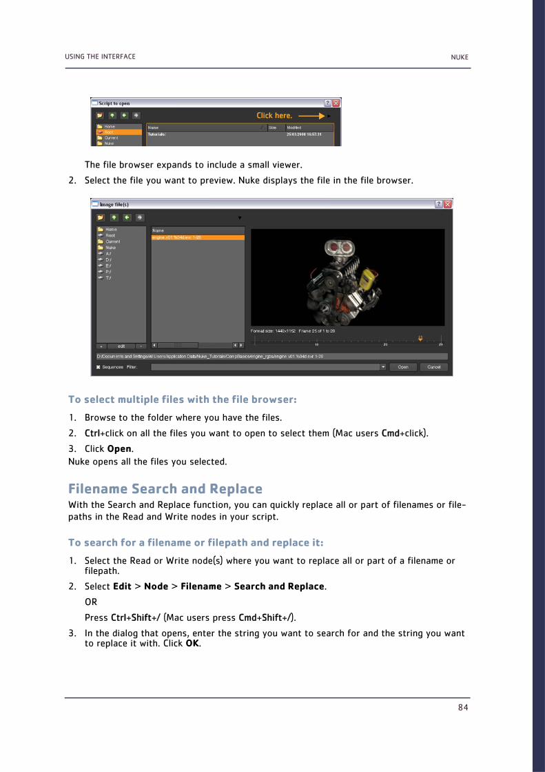
NUKEUSING THE INTERFACE
84
The file browser expands to include a small viewer.
2. Select the file you want to preview. Nuke displays the file in the file browser.
To select multiple files with the file browser:
1. Browse to the folder where you have the files.
2. Ctrl+click on all the files you want to open to select them (Mac users Cmd+click).
3. Click Open.
Nuke opens all the files you selected.
Filename Search and ReplaceWith the Search and Replace function, you can quickly replace all or part of filenames or file-paths in the Read and Write nodes in your script.
To search for a filename or filepath and replace it:
1. Select the Read or Write node(s) where you want to replace all or part of a filename or filepath.
2. Select Edit > Node > Filename > Search and Replace.
OR
Press Ctrl+Shift+/ (Mac users press Cmd+Shift+/).
3. In the dialog that opens, enter the string you want to search for and the string you want to replace it with. Click OK.
Click here.
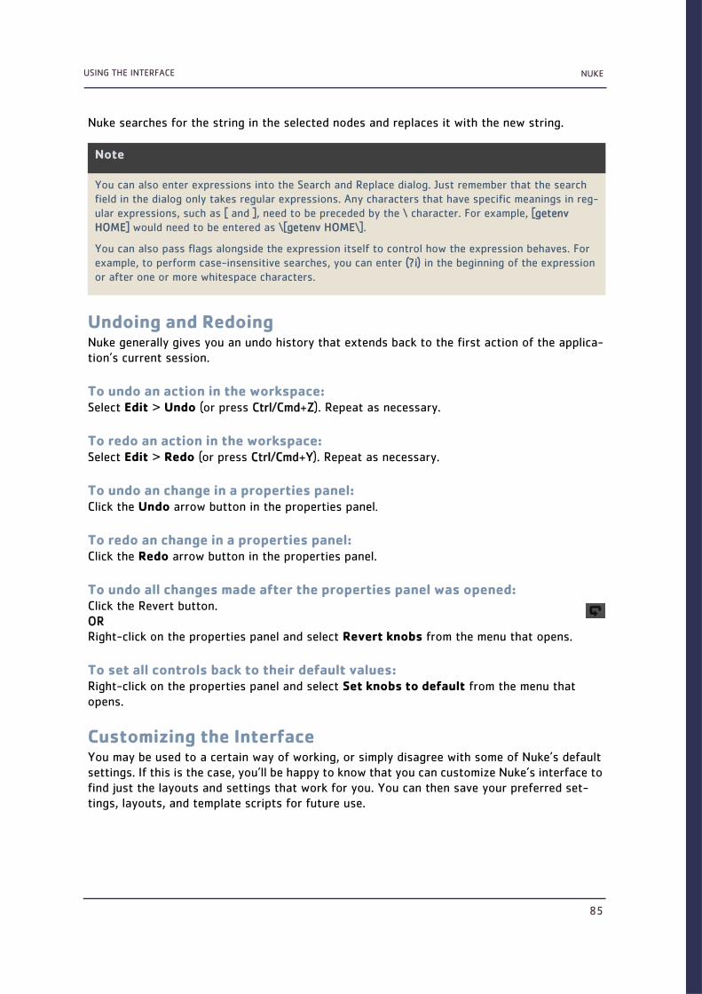
NUKEUSING THE INTERFACE
85
Nuke searches for the string in the selected nodes and replaces it with the new string.
Undoing and RedoingNuke generally gives you an undo history that extends back to the first action of the applica-tion’s current session.
To undo an action in the workspace:Select Edit > Undo (or press Ctrl/Cmd+Z). Repeat as necessary.
To redo an action in the workspace:Select Edit > Redo (or press Ctrl/Cmd+Y). Repeat as necessary.
To undo an change in a properties panel:Click the Undo arrow button in the properties panel.
To redo an change in a properties panel:Click the Redo arrow button in the properties panel.
To undo all changes made after the properties panel was opened:Click the Revert button.ORRight-click on the properties panel and select Revert knobs from the menu that opens.
To set all controls back to their default values:Right-click on the properties panel and select Set knobs to default from the menu that opens.
Customizing the InterfaceYou may be used to a certain way of working, or simply disagree with some of Nuke’s default settings. If this is the case, you’ll be happy to know that you can customize Nuke’s interface to find just the layouts and settings that work for you. You can then save your preferred set-tings, layouts, and template scripts for future use.
Note
You can also enter expressions into the Search and Replace dialog. Just remember that the search field in the dialog only takes regular expressions. Any characters that have specific meanings in reg-ular expressions, such as [ and ], need to be preceded by the \ character. For example, [getenv HOME] would need to be entered as \[getenv HOME\].
You can also pass flags alongside the expression itself to control how the expression behaves. For example, to perform case-insensitive searches, you can enter (?i) in the beginning of the expression or after one or more whitespace characters.

NUKEUSING THE INTERFACE
86
Interface LayoutsWhen your scripts grow, you may not be able to fit all the different elements on your display at the same time. Luckily, you can customize the windows and panes, so that accessing the elements you often need becomes as quick and easy as possible.
Customizing PanesYou can resize and split panes to make more room for different elements on the screen.
To resize a pane:
Drag the divider line of the pane into a new location.
To split a pane:
1. Click on the content menu button in the top left corner of the pane.
2. Select Split Vertical or Split Horizontal from the menu that opens.
Moving the ToolbarYou can move the toolbar into a new position by adding a new panel for it, hiding the panel name and controls, and resizing the panel. For more information on how to do this, see Adding Tabbed Panels and Hiding Tab Names and Controls below.
Adding Tabbed PanelsWhen you can’t fit more elements to your display, you can use tabs to save space. You can also use tabs to move the toolbar into a new location.
To add tabs:
1. Click on the content menu button in the top left corner of the pane.
2. Select the type of tab you want to add, for example, Node Toolbar, Node Graph, New Viewer, or Script Editor.
The new tab is added on top of the existing tabs.
To move tabs:
Click on the name of the tab and drag the tab to a new position inside the same pane or in another pane.
Figure 2-44: Resizing a pane.

NUKEUSING THE INTERFACE
87
To close tabs:
1. Make sure you are viewing the tab you want to close.
2. Click the “x” button in the top right corner of the current tab.
Tabs and Floating WindowsYou can turn tabs and panes into floating windows and vice versa.
To turn a tab or pane into a floating window:
1. Make sure you are viewing the tab or pane you want to float.
2. From the content menu, select Float Tab or Float Pane.
Alternatively, in the case of tabs, you can also do one of the following:
• Click the float button in the top right corner of the current tab.
OR
• Ctrl+click on the tab name (Mac users Cmd+click).
OR
• Right-click on the tab name and select Float Tab.
To turn a floating window into a tab or pane:
Click on the tab name or pane in the floating window and drag it to where you want it to dock.
To close floating windows:
Click the “x” button in the top right corner of the tab or pane.
Customizing Windows
To make a pane expand to the size of the window:
1. With your cursor in the pane.
2. Press spacebar quickly. (Pressing and holding the spacebar brings up a context senstive menu for that pane.)
To make a window fullscreen:
1. Make sure the window you want to make fullscreen is active. This could be the main appli-cation window or a floating viewer. Making it fullscreen removes the window borders.
2. Press Alt+S.

NUKEUSING THE INTERFACE
88
Hiding Tab Names and ControlsYou can hide the names and control buttons of tabs, as you may not need them with all pan-els, such as the Toolbar panel.
To hide the names and controls on tabs:
From the content menu, disable Show Tabs.
To show the names and controls on tabs:
1. Move your mouse pointer over the very top of the pane area until the top edge of the pane brightens up.
2. Right-click to open the content menu.
3. From the content menu, enable Show Tabs.
Saving LayoutsYou can save up to six favourite layouts and retrieve them as necessary. You can also use these features to setup the Nuke interface for dual monitors.
To save a layout:
1. Open and arrange the Nuke panes, panels, and tabs as desired.
2. Select Layout > Save layout 1 (startup default) (or press Ctrl/Cmd+F1) to save the default layout. Select Yes in the confirmation dialog that appears.
This step shows F1 as the keystroke, but it can be any key between F1 and F6.
To retrieve a layout:
Select Layout > Restore layout 1(startup default) (or press Shift+F1) to retrieve the default layout.
F1 is used here, but if you saved a layout to a different function key—any key between F1 and F6—then you can press Shift followed by the key to retrieve the layout.
To use window layout 1 as the default when loading scripts:
1. Select Edit > Preferences to open the preferences dialog.
2. Go to the Windows tab.
3. Check use window layout 1 when loading scripts. This is usually checked by default.

NUKEUSING THE INTERFACE
89

Last updated on 5/1/2015 2
COURSE OUTLINE
PART I: Introduction to FCPX
1. What is Final Cut Pro X o FCPX Folder Structure o Nondestructive Editing
2. Exploring the Interface PART II: Video Editing with FCPX
1. Import Media
2. Organize Media
3. Create a Project
4. Edit Media 4.1 Rough Cut
4.1.1 Drag and Drop Edit 4.1.2 Using Different Type of Editing Tools 4.1.3 Adding Clips Using Video-‐only or Audio-‐only mode 4.1.4 Removing Clips from Your Project
4.2 Refining the Edit 4.2.1 Straight Cut with Blade Tool 4.2.2 Ripple Edit 4.2.3 Precision Editor 4.2.4 Roll Edit
4.3 Audio Edit 4.3.1 Adjust Audio Level 4.3.2 Fade Audio In or Out 4.3.3 Record Voiceover
5. Add Transitions and Titles
6. Share a Project

Last updated on 5/1/2015 3
PART I: Introduction to FCPX 1. What is Final Cut Pro X (FCPX) Final Cut Pro X is a revolutionary application for creating, editing, and producing the highest-‐quality video. FCPX combines high-‐performance digital editing and native support for virtually any video format with easy-‐to-‐use and time-‐saving features that let you focus on storytelling. The latest version of FCPX is 10.1.3 as of 10/1/2014. This new version provides you with more flexibility and control over media management, and streamlined organizing tools. 2. FCPX File Structure In Final Cut Pro 10.1 or later, you organize your work in libraries. A library contains multiple events and projects in the same location. Basically, you media and projects live in your events, and your events reside in your libraries. The library tracks all your media files, your editing decisions, and the associated metadata.
Therefore, it is very important that you create a new library and define library location BEFORE you start any FCPX project. At the DMC, if you want to save your FCPX file to DMC computers, it is required to save your FCPX library to SAVEWORKHERE drive. Otherwise, you can save your library to your external drive. To do so, go to File > New > Library…, and choose SAVEWORHERE drive or your external drive if it is connected, click SAVE. Now all events and projects you create under this library will be saved on SAVEWORKHERE drive (or your external drive)>your library.

Last updated on 5/1/2015 4
NOTE: If you are not sure about where you saved your FCPX library or files, you can simply right click on the clip either from Browser window or from Timeline window, from the dropdown menu, select Reveal in Finder. Once you locate your library, you can drag the library to your desired location. 3. FCXP Interface
• Organize media in the Libraries list and the Browser Your imported media is available in events in your library. (An event is like a folder that contains clips and projects.). When you select an event in a library, its clips and projects appear in the Browser.
• Play back clips and projects in the Viewer The Viewer is where you play back your video, including clips and projects with up to 1920 x 1080, or even 4K resolution. You can also use onscreen controls, superimposed over the video in the Viewer, to adjust settings for a wide array of effects and transitions.
• Edit your project in the Magnetic Timeline The bottom portion of the Final Cut Pro window contains the Timeline, where you create your movie by adding and arranging clips and making all your edits. The Timeline in Final Cut Pro “magnetically” adjusts clips to fit around clips that you drag into place. If you drag clips out of place, the surrounding clips close up to fill the space. A Final Cut Pro project holds all of the information for your final movie, including your editing decisions and links to all the source clips and events.

Last updated on 5/1/2015 5
• Toolbar located right above the Project Timeline is where you access to different editing tools, text and transition generators, and your iPhoto/iTune libraries. You can also view timecode, audio level, and file render status on the toolbar.
PART II: VIDEO EDITING WITH FCPX Final Cut Pro workflow: Import Media è Organize Your library è Create a Project è Edit Your movie èAdd Titles and Transitions èShare Your Movie 1. Import Media
• Import from a file-‐based (tapeless) camera or device • Import from iMovie, iTune, iPhoto • Import from a hard disk • Record Audio
* Note: Before you import any media into FCPX, be sure to create a new library for your events and projects and save to DMC SAVEWORHERE drive or your own external drive, as the imported media has to reside in a library. Please refer to FCPX File Structure on page 3 for detailed instruction on how to create a library. 1.1 Import from a file-‐based camcorder, camera, or device
1) Connect your camcorder, camera, or device to your computer, using the cable that
came with the device, and turn it on. 2) Switch to Preview Mode 3) To open the Media Import window, do one of the following:
Choose File > Import > Media (or press Command-‐I). Click the Import Media button on the left end of the toolbar.
4) If necessary, select your camcorder, camera, or device from the CAMERAS section on the left. The Media Import window displays all the media on your device. In this window you can preview the media by either playing it using the playback controls or skimming it by moving the pointer forward or backward over a filmstrip.
5) To import all clips: Click Import All. To import only some of the clips: Select each clip you want to import by Command-‐clicking each clip, and click Import Selected (the Import button changes its name).
Tip: To select several clips located together, you can drag around the clips to enclose

Last updated on 5/1/2015 6
them with the selection rectangle.
6) To import portions of clips: Drag inside the filmstrip to select the range that you want, and click Import Selected. You can also select multiple ranges in each clip. Tip: You can also select a clip, press the Space bar to play the clip, and press either I to set a start point or O to set an end point.
7) In the window that appears, choose how you want to organize the imported media
in the Event Library: To add the imported clips to an existing event: Select “Add to existing event,” and choose the event from the pop-‐up menu. To create a new event: Select “Create new Event” and type a name in the text field; then choose the library from the pop-‐up menu.
If you want to create optimized or proxy media, analyze the video or the audio, select the relevant checkboxes. Keep in mind that if you want FPCX run any of the above analyzing tasks, it takes longer time for FCP to import and your file size may be enlarged. Unless your recording has serious video or audio issues, it is highly recommended that you simply check Copy to library (This option duplicates the media files and places the copies in the current library storage locations.) and Keywords From folders. Keywords From Folders creates a keyword for each folder name and applies the keyword to all the files in the folder during import. Additionally, a Keyword Collection is created for each keyword.
If you don’t set Final Cut Pro to analyze your media during the import process, you can analyze it later (if necessary) in the Event Browser.
8) Click Import. By default, the Media Import window closes when you click Import. You can begin working with your clips in the Event Browser immediately. Final Cut Pro imports your media in the background.

Last updated on 5/1/2015 7
9) When background tasks are completed, disconnect the camcorder, camera, or
device.
1.2 Import from iMovie: When you send a movie to Final Cut Pro X, the project file and the media used in the project are copied to your Final Cut Pro X library. Only a movie project can be sent to Final Cut Pro X. If you want to send a trailer, you must first convert it to a movie.
Note that you can only send your movie’s project and media files to Final Cut Pro X from WITHIN iMovie.
1) In iMovie, do one of the following: a. Select the project in the browser, or double-‐click the project to open it. b. With the project open, click anywhere in the timeline.
Note: If you can’t find the project you’re looking for, verify that the correct library is selected.
2) Choose File > Send Movie To Final Cut Pro.
Final Cut Pro X opens. A new library appears in Final Cut Pro X with the name of your iMovie library, and a new event within that library contains the movie project you sent.
1.3 Import from iPhoto: Choose Window > Media Browser > Photos OR
Click the Photos button in the toolbar . 1.4 Import from iTune: Choose Window > Media Browser > Music and Sound OR
Click the Music and Sound button in the toolbar . 1.5 Import from a hard disk:
o Choose File > Import > Media or click on import button on the toolbar . o Locate the file and click on Import Selected…

Last updated on 5/1/2015 8
o In the following window, choose either add the file to the existing event or create a new event.
o Check Copy to library and From Folders. o Leave all other options unchecked, unless you want FCPX to perform any of
these analyzing or fixing tasks for you. Note that if you check any of these options, it takes longer time for FCPX to import your file.
2. Organize media
1) Organize library: A library contains multiple events and projects in the same location. When you import video, audio, and still images, the source media files (your raw footage) appear as clips in one or more events in the library. As your library grows, you can rename, copy, move, and delete your clips, events, and projects as necessary. Or you can import your source medial files into a new library.
• To create a new library, go to File>New>Library… • To rename a library, click on the name once and type in a new name • To close a library, right-‐click your mouse and choose Close Library “your
library name” • To open a library, go to File>Open Libraries • To delete a library, right-‐click your mouse and choose Move to Trash. • To move/copy media between libraries, simply click on the library, select and
drag the media from the Browser to another library event. • To move/copy a whole event to a different library, just select and drag the name
of the event to a different library. Notice that a library must contain at least one event, if there is only one event in the library, you must create a new blank event before you can delete the event you want.
2) Organize footage with keywords and ratings
Part of the power of FCP X comes from its use of metadata to help organize media.

Last updated on 5/1/2015 9
Metadata is information that is attached or embedded in media, such as time and date, video format, frame rate, codec etc. This metadata is recorded by the camera while shooting. In FCP X we can add additional information to the metadata of a clip, which will then help refine the organization of our media. The metadata that we will add is called 'Keywords'. Keywords enable us to further sort our clips; and Keyword Collections are created to hold our keywords.
When you import file into FCPX, be sure to organize your files in different folders outside of FCPX, and bring them in as Keyword Collections. This way, you can easily locate/access/retrieve your files within FCPX event browser window. Keyword collections are the main way to label your shots. They are more like tags than folders, because you can label a clip with as many different keywords as you like. So in this sense, shots can exist in multiple locations, making it easier for you to find what you need. To add Keyword to a clip, select the clip or lasso select part of the clip in the Event
Browser window, then click on Keyword Editor button on the toolbar to open up Keyword Editor window. You can add up to 10 keywords to this clip. Press return to create keyword collection folder that can be accessed from Event Library window. To add more clips into this keyword collection folder, simply select them all at once in Even Browser window and drag to the keyword collection folder in the event library. You can also rate your clips by marking it as Favorite or Rejected, say if the clips are bad shots – blurry, shaky, and perhaps you will never use them, you can mark them as Rejected. For good shots, you can mark them as Favorite.
Just click on Hide Rejected drop down menu next to the search field in the Browser window, and choose as you like.
3. Create a Project Once you have collected all the media files and organized them by using FCPX Keyword Editor and Rating, then you are ready to create your project and get your feet wet in editing. To create a project, go to File > New Project. Be aware of the event and the library you would like your project to reside in. Use the default setting, click on OK. New blank project is opened in the Magnetic Timeline area where you can begin editing.
4. Edit Media Now you are ready to select and add clips to the timeline to make a rough cut and form a sequence. There are several ways to add clips to the timeline:
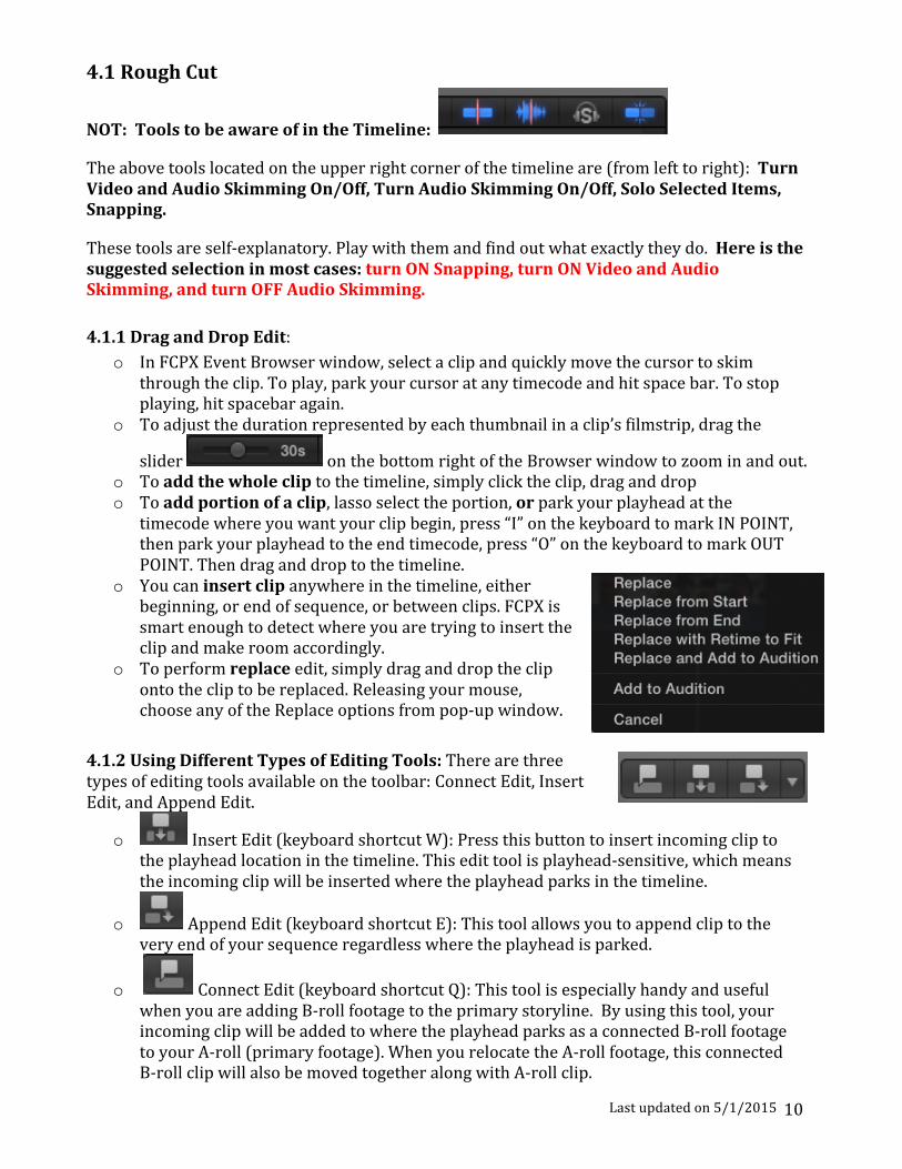
Last updated on 5/1/2015 10
4.1 Rough Cut
NOT: Tools to be aware of in the Timeline:
The above tools located on the upper right corner of the timeline are (from left to right): Turn Video and Audio Skimming On/Off, Turn Audio Skimming On/Off, Solo Selected Items, Snapping.
These tools are self-‐explanatory. Play with them and find out what exactly they do. Here is the suggested selection in most cases: turn ON Snapping, turn ON Video and Audio Skimming, and turn OFF Audio Skimming. 4.1.1 Drag and Drop Edit:
o In FCPX Event Browser window, select a clip and quickly move the cursor to skim through the clip. To play, park your cursor at any timecode and hit space bar. To stop playing, hit spacebar again.
o To adjust the duration represented by each thumbnail in a clip’s filmstrip, drag the
slider on the bottom right of the Browser window to zoom in and out. o To add the whole clip to the timeline, simply click the clip, drag and drop o To add portion of a clip, lasso select the portion, or park your playhead at the
timecode where you want your clip begin, press “I” on the keyboard to mark IN POINT, then park your playhead to the end timecode, press “O” on the keyboard to mark OUT POINT. Then drag and drop to the timeline.
o You can insert clip anywhere in the timeline, either beginning, or end of sequence, or between clips. FCPX is smart enough to detect where you are trying to insert the clip and make room accordingly.
o To perform replace edit, simply drag and drop the clip onto the clip to be replaced. Releasing your mouse, choose any of the Replace options from pop-‐up window.
4.1.2 Using Different Types of Editing Tools: There are three types of editing tools available on the toolbar: Connect Edit, Insert Edit, and Append Edit.
o Insert Edit (keyboard shortcut W): Press this button to insert incoming clip to the playhead location in the timeline. This edit tool is playhead-‐sensitive, which means the incoming clip will be inserted where the playhead parks in the timeline.
o Append Edit (keyboard shortcut E): This tool allows you to append clip to the very end of your sequence regardless where the playhead is parked.
o Connect Edit (keyboard shortcut Q): This tool is especially handy and useful when you are adding B-‐roll footage to the primary storyline. By using this tool, your incoming clip will be added to where the playhead parks as a connected B-‐roll footage to your A-‐roll (primary footage). When you relocate the A-‐roll footage, this connected B-‐roll clip will also be moved together along with A-‐roll clip.

Last updated on 5/1/2015 11
4.1.3 Adding clips using video-‐only or audio-‐only mode: By default, whenever you add clips from an event to the Timeline, all of the video and audio components of the event clip are included in the edit. However, you can also add just the video portion or just the audio portion of event clips to the Timeline, even if the event clips contain both video and audio.
1) To add just the video from your selection to the Timeline: Choose Video Only from the Edit pop-‐up menu in the toolbar (or press Shift-‐2).
2) To add just the audio from your selection to
the Timeline: Choose Audio Only from the Edit pop-‐up menu in the toolbar (or press Shift-‐3).
3) The edit buttons in the toolbar change their appearance to indicate the mode you
selected.
4) After the above selection is made, you can refer to 4.1.2 Using Different Types of Editing Tools to add your clips to the timeline.
4.1.4 Removing clips from your project When you remove clips from a project in the Timeline, the source media in events, the Final Cut Pro media browsers, and the Finder is not affected. Delete clips or ranges from the Timeline
o In the Timeline, to delete an entire clip, select the clip; to delete a portion of a clip, you can either choose Range Selection tool from Selection tool drop-‐down menu, or press I on your keyboard to mark IN point, press O to mark OUT point, the selected portion is surround by a yellow outline.
o Ripple Delete: Choose Edit > Delete (or press the Delete key). This will affect the total duration of your sequence.
o Life Delete: If you want to keep the duration of the sequence when deleting, then choose Edit>Replace with Gap.

Last updated on 5/1/2015 12
4.2 Refining the Edit After you bring in all the clips and form a rough sequence, you can fine-‐tune your edit further to make it more precise. The real art of editing comes from trimming process, which sets great editors apart from others. This is also the most time consuming process. FCPX provides different ways to make trimming easy and intuitive. By default, you should always use the selection tool unless you intentionally want to use any of other editing tools. The trimming tools can be accessed from the drop down menu of the selection tool on the toolbar. We will learn how to Ripple Trim, Roll Trim, and use the Precision Editor. Before we refine our edit, check the FCPX preference setting and make sure the following options (shown in below screenshot) are checked under Editing tab.
4.2.1 Straight Cut with Blade Tool: From drop down menu of the selection tool, choose Blade. Each time you cut a clip in your project, it is split into two clips and creates a new edit point. This is especially useful if you want to insert some media in between a clip. You would need to use Blade to split the clip first and then insert.
4.2.2 Ripple Edit: The default selection tool is the ripple tool. Park the select tool over an edit point, and you’ll notice how the

Last updated on 5/1/2015 13
selection tool changes into a trimming tool. Also, notice the small filmstrip icon that indicates which side you’ll be trimming.
To extend a clip, grab onto the edge of the clip and extend the clip forward. By doing so, the viewer window will show you both sides of the edit point so you can compare the outgoing shot with the incoming shot.
This type of trim is called a ripple trim, meaning your project will become shorter or longer based on the number of frames that you subtract or add. Be aware that once the media for a clip runs out, you won’t be able to extend the clip any further. A red line will appear at the end of the edit point if you try to exceed the amount of media available for a clip.
4.2.3 Precision Editor: To avoid the issue of running out the media without knowing, you can see how much media is available ahead of time by double clicking on an edit point and opening up the Precision Editor.
This grey area here represents areas of the outgoing and incoming portions of media that are available for trimming.
In this mode, to extend a clip, you can simply skim to the area of where you want the clip to begin or end and then press the mouse button. Now the edit is complete.
To close the precision editor, just double click on the edit point.
4.2.4 Roll Edit: A roll edit adjusts the start point and the end point of two adjacent clips simultaneously. If you like where two clips are placed in the Timeline, but you want to change when the cut point happens, you can use the Trim tool to roll the edit point between the two clips. No clips move in the Timeline as a result; only the edit point between the two clips moves. No other clips in the project are affected. When you perform a roll edit, the overall duration of the project stays the same, but both clips change duration. One gets longer while the other gets shorter to compensate.
1) Choose the Trim tool from the Tools pop-‐up menu in the toolbar 2) In the Timeline, click the center of the edit point you want to roll so
that both sides of the edit point are selected. 3) Drag the edit point left or right. The edit point is rolled to the new
location. The combined duration of the two clips stays the same. 4) If you can’t roll the edit point any farther and one side of the edit
point appears red, you’ve reached the end of the media for one of the two clips. Likely, you can also use Precision Editor to see the extra media of a clip. For more information on using Precision Editor, refer to 4.2.3 Precision Editor.
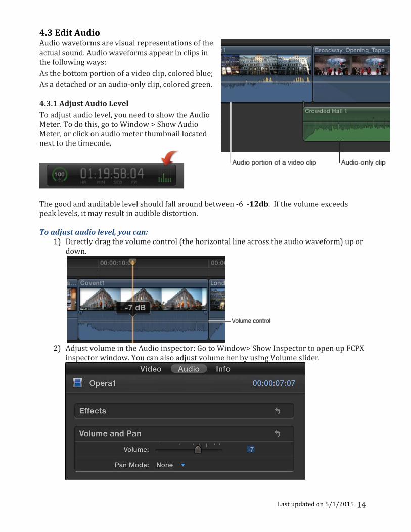
Last updated on 5/1/2015 14
4.3 Edit Audio Audio waveforms are visual representations of the actual sound. Audio waveforms appear in clips in the following ways: As the bottom portion of a video clip, colored blue; As a detached or an audio-‐only clip, colored green. 4.3.1 Adjust Audio Level To adjust audio level, you need to show the Audio Meter. To do this, go to Window > Show Audio Meter, or click on audio meter thumbnail located next to the timecode.
The good and auditable level should fall around between -‐6 -‐12db. If the volume exceeds peak levels, it may result in audible distortion. To adjust audio level, you can:
1) Directly drag the volume control (the horizontal line across the audio waveform) up or down.
2) Adjust volume in the Audio inspector: Go to Window> Show Inspector to open up FCPX
inspector window. You can also adjust volume her by using Volume slider.

Last updated on 5/1/2015 15
4.3.2 Fade audio in or out You can quickly create fade-‐ins and fade-‐outs to the audio portion of clips in the Timeline by using fade handles, which appear when you place the pointer over the top-‐left or top-‐right corner of the audio waveform. Drag the fade handle to the point in the clip where you want the fade to begin or end. Fade handles from the beginning of a clip create a fade-‐in, while fade handles at the end of a clip create a fade-‐out.
4.3.3 Record Voiceover You can record audio directly in Final Cut Pro from input sources such as built-‐in and external microphones. The recorded audio file appears both in the Event Browser and as a connected clip in the Timeline. This function is particularly useful for recording voiceover narration. To Record live audio
1). Position the playhead where you want to start recording in the Timeline. 2). Choose Window > Record Voiceover.
Tip: To start recording immediately without adjusting settings, press Option-‐Shift-‐A and go to step 7). Click the Record button to start or stop recording.
3). To adjust the input level of the microphone, do one of the following: Drag the Input Gain slider right to increase the input level, or left to decrease it. Type a dB value in the Input Gain field.
Use the Audio meter to make sure the volume doesn’t exceed peak levels (colored red), which may result in audible distortion. Note: If the Input Gain slider is dimmed for a selected input device, try adjusting the gain on the device itself or its software utility (if available).
4). To name your voiceover clip, click the Name field and type a new name.
5). To specify other voiceover settings, click on the Advanced disclosure triangle and do any of the following:
• To change the input device or the number of

Last updated on 5/1/2015 16
input channels (mono or stereo): Choose an option from the Input pop-‐up menu. The default choice of System Setting uses the first channel of the input device currently selected in OS X Sound preferences.
Tip: If you always want to record with a particular device or a particular channel on a multichannel audio device, choose that device/channel pair from the Input pop-‐up menu instead of System Setting. Final Cut Pro remembers the setting and indicates in the Input pop-‐up menu whether the device is available.
• To listen to your microphone input as you record: Set Monitor to On. The
microphone audio plays from the output device currently selected in OS X Sound preferences. There is no input signal when monitoring is off. Tip: To listen to a live mix of both microphone and project audio, set Monitor to On and deselect the “Mute project while recording” checkbox below.
• To adjust the monitoring level: Drag the Gain slider right to increase the monitoring level, or left to decrease it (or type a dB value in the Gain field).
Note: If the built-‐in microphone is selected, the Gain slider automatically resets to zero to prevent feedback from the built-‐in speakers when monitoring is turned on. To avoid feedback, use headphones or external speakers placed away from the microphone.
• To turn off the automatic countdown before recording: Deselect the “Countdown to record” checkbox
• To unmute project audio while recording: Deselect the “Mute project while recording” checkbox
• To turn off automatic grouping of multiple voiceover takes into auditions: Deselect the “Create Audition from takes” checkbox.
• To change where the recording is saved: Choose an event in the current library from the Event pop-‐up menu.
6). To start recording, click the Record button (or press Option-‐Shift-‐A). 7). To stop recording, click the Record button (or press the Space bar or Option-‐Shift-‐A).
5. Add transitions and titles You can easily add special effects to video, audio, and photos in your projects:
o Transitions: Add an effect between clips to control how they change from one to the next
o Titles: Use to add text at any point in your project (title, scrolling credit, lower third, etc)
o Effects: Use to do a wide variety of things to your video and audio clips, such as resize,
move, rotate, trim, skew, crop, or apply the Ken Burns zooming effect to a video clip. 5.1 Transitions You can add cross dissolves and other transition effects between cuts to make your program

Last updated on 5/1/2015 17
more interesting. Transitions replace one shot with another over a specified period of time; when one shot ends, another one replaces it. Two very common video transitions occur over time: fades and cross dissolves. To add transitions:
1) Click the Transitions button in the toolbar.
2) Select a transition:
a. Move the pointer over the transition thumbnails to see an example of what the transition looks like.
b. Additionally, you can type text in the search field to filter the list of transitions that appear. Cross Dissolve is the most commonly used transition and is highly recommended.
3) To apply the transition to an edit point: simply Drag the transition to it. 4) To further adjust the transition, you can double click on the transition to open up the
inspector window and change the parameters.
5) To change the duration of a transition, right click on the transition, choose Change
Duration… from drop-‐down menu, then type your desired duration in the timecode area.
6) To delete a transition, simply click on it and hit delete key on the keyboard.

Last updated on 5/1/2015 18
5.2 Titles Titles play a critical role in movies, providing important bookends (such as opening titles and closing credits) and conveying time and dates within the movie. Titles, especially in the lower third of the screen, are also used in documentaries and informational videos to convey details about subjects or products onscreen. Add a title to a project clip
1) Drag the playhead in the Timeline to the point where you want to add the title. 2) Click the Titles button in the toolbar to open Title Browser.
3) Mouse over each transition thumbnail and see how it looks like in the viewer window. 4) You can double click on the selected transition, or drag and drop. 5) To adjust the text, double click on it. You can either directly type text in the viewer
window, change its position, or go to text inspector window to have more controls over the text.
6) To delete a title, click on it and hit delete key on
your keyboard.
6. Share your project Final Cut Pro provides a variety of destinations, or preconfigured export settings, that you can use to output your project or clip. For example, you can export a project or clip as a QuickTime movie, export it for viewing on

Last updated on 5/1/2015 19
Apple devices such as iPhone and iPad, publish it to websites such as Facebook and YouTube, or burn it to a disc. Each of these options uses a different destination. When you first open Final Cut Pro, a default set of destinations appears in the Share submenu of the File menu and in the Share pop-‐up menu.
Share projects, clips, and ranges You can share an entire project, an entire clip, or a portion of a project or clip (indicated with a range selection. 1). Do one of the following:
o Select a project in the Project Library. o Select a clip in the Event Browser. o Select a range in a project in the Timeline or in a clip in the Event Browser.
2). Do one of the following:
o Choose File > Share, and choose a destination from the submenu.
o Click the Share button in the toolbar, and choose a destination from the pop-‐up menu.

Last updated on 5/1/2015 20
3). In the Share window that appears, do any of the following:
o Move the pointer over the image to skim the video. o In the Info pane on the right, view and modify project or clip
attributes, such as the title and description. • Important: By default, the title field lists the project
or clip name. Changing the title does not change the project or clip name, which is the name used for the exported file.
• All of the attributes associated with the project or clip will be included in the output file.
o At the bottom of the window, view information about the file that will be exported, including frame size and frame rate, audio channels and sample rate, duration, output file type, and file size.
o For some destinations like Apple Devices, you can also view a list of devices that will play the exported file. To view the compatible devices, move the pointer over the Compatibility icon in the lower-‐right corner (see screenshot to the right).
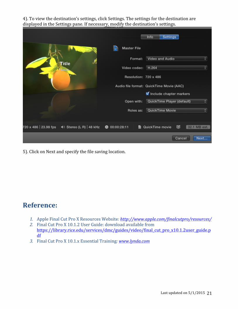
Last updated on 5/1/2015 21
4). To view the destination’s settings, click Settings. The settings for the destination are displayed in the Settings pane. If necessary, modify the destination’s settings.
5). Click on Next and specify the file saving location. Reference:
1. Apple Final Cut Pro X Resources Website: http://www.apple.com/finalcutpro/resources/ 2. Final Cut Pro X 10.1.2 User Guide: download available from
https://library.rice.edu/services/dmc/guides/video/final_cut_pro_x10.1.2user_guide.pdf
3. Final Cut Pro X 10.1.x Essential Training: www.lynda.com