Polycyclic Aromatic Hydrocarbon Chemistry in a Spirit of ...
264
Polycyclic Aromatic Hydrocarbon Chemistry in a Spirit of Graphene Engineering Dissertation zur Erlangung des Grades “Doktor der Naturwissenschaften” am Fachbereich Chemie, Pharmazie und Geowissenschaften der Johannes Gutenberg-Universität Mainz und in Kooperation mit dem Max-Plank-Institut für Polymerforschung Mainz (Ian) Cheng-Yi Hou / 侯正一 geb. in München, Deutschland Mainz, 2020
-
Upload
khangminh22 -
Category
Documents
-
view
0 -
download
0
Transcript of Polycyclic Aromatic Hydrocarbon Chemistry in a Spirit of ...

Polycyclic Aromatic Hydrocarbon Chemistry
in a Spirit of
Graphene Engineering
Dissertation
zur Erlangung des Grades
“Doktor der Naturwissenschaften”
am Fachbereich Chemie, Pharmazie und Geowissenschaften
der Johannes Gutenberg-Universität Mainz
und in Kooperation mit
dem Max-Plank-Institut für Polymerforschung Mainz
(Ian) Cheng-Yi Hou / 侯正一
geb. in München, Deutschland
Mainz, 2020

1. Betrichterstatter:
2. Betrichterstatter:
Tag der mündlichen Prüfung: 02.09.2020

Die vorliegende Arbeit wurde in der Zeit von Juli 2015 bis März 2020 im Max-
Planck-Institut für Polymerforschung in Mainz unter der Betreuung von Prof.
Dr. Klaus Müllen durchgeführt.
Ich danke Prof. Dr. Klaus Müllen für seine wissenschaftliche und persönliche
Unterstützung sowie für seine ständige Diskussionsbereitschaft.


To my wife
To Hong Kong and Taiwan
To Freedom


1
Table of Contents
Abbreviations ................................................................................................................................................. 4
CHAPTER 1. INTRODUCTION ........................................................................................... 7
1.1 From an sp2-carbon to graphene .............................................................................................................. 7 1.1.1 Polycyclic aromatic hydrocarbons ......................................................................................................... 8 1.1.2 Graphene ................................................................................................................................................ 10
1.2 Quantization of graphene ....................................................................................................................... 14 1.2.1 Top-down graphene quantization ........................................................................................................ 14 1.2.2 Bottom-up synthesis of nanographenes on monocrystalline surface ................................................ 16 1.2.3 Organic synthetic strategy for large nanographenes ......................................................................... 17 1.2.4 Organic synthesis of large monodispersed graphene quantum dots ................................................. 23 1.2.5 Organic synthesis of wide graphene nanoribbons .............................................................................. 25
1.3 Defects in graphene and their model compounds .................................................................................. 31 1.3.1 Types of defects in graphene ................................................................................................................ 31 1.3.2 Relationship between organic compounds and graphene defects ..................................................... 35 1.3.3 Molecular models representing point defects in graphene ................................................................ 37 1.3.4 Molecular models related to topological non-trivial defects in graphene ......................................... 41
1.4 Controlling assemblies of nanographenes .............................................................................................. 47 1.4.1 Controlling 3D supramolecular assemblies of nanographenes .......................................................... 47 1.4.2 Controlling supramolecular assemblies of nanographenes at interfaces .......................................... 50
1.5 Motivation ............................................................................................................................................... 54 1.5.1 Synthesis of polyphenylenes as potential precursors for nanographenes approaching length scale
of 5 nm ............................................................................................................................................................. 54 1.5.2 Bottom-up approach for nanostructures related to graphene grain boundaries ............................. 56 1.5.3 Exploring self-assemblies of hexa-peri-hexabenzocoronene derivatives ........................................... 58
1.6 References ............................................................................................................................................... 60
CHAPTER 2. SYNTHESIS OF DENDRITIC POLYPHENYLENES POSSESSING 366
AND 546 CARBONS AS POTENTIAL PRECURSORS FOR GIANT D6H-
SYMMETRIC NANOGRAPHENES................................................................................... 72
2.1 Main text ................................................................................................................................................. 72
2.2 Supporting information .......................................................................................................................... 80
2.3 References ............................................................................................................................................... 97
CHAPTER 3. STEPWISE LATERAL EXTENSION OF PHENYL SUBSTITUTED
LINEAR POLYPHENYLENES ........................................................................................... 99
3.1 Abstract .................................................................................................................................................. 99
3.2 Introduction .......................................................................................................................................... 101

2
3.3 Result and Discussion ........................................................................................................................... 104
3.4 Conclusion ............................................................................................................................................ 113
3.5 Experimental Section ............................................................................................................................ 114
3.6 Supporting information ........................................................................................................................ 123
3.7 References ............................................................................................................................................. 138
CHAPTER 4. ON-SURFACE SYNTHESIS OF POLYAZULENE WITH 2,6-
CONNECTIVITY ................................................................................................................ 140
4.1 Abstract ................................................................................................................................................ 140
4.2 Main text ............................................................................................................................................... 141
4.3 Supporting information ........................................................................................................................ 148
4.4 References ............................................................................................................................................. 152
CHAPTER 5. ON-SURFACE SYNTHESIS OF SP2-CARBON-NANOSTRUCTURE
WITH A SKELETON OF REGULARLY FUSED ALTERNATING PENTAGONS
AND HEPTAGONS ............................................................................................................. 154
5.1 Main text ............................................................................................................................................... 154
5.2 Supporting information ........................................................................................................................ 159
5.3 References ............................................................................................................................................. 164
CHAPTER 6. PHOTO-MODULATION OF 2D-SELF-ASSEMBLY OF
AZOBENZENE-HEXA-PERI-HEXABENZOCORONENE-AZOBENZENE TRIADS
................................................................................................................................................ 167
6.1 Abstract ................................................................................................................................................ 167
6.2 Introduction .......................................................................................................................................... 169
6.3 Result and discussion ............................................................................................................................ 171
6.4 Conclusion ............................................................................................................................................ 177
6.5 Experimental methods .......................................................................................................................... 178
6.6 Supporting information ........................................................................................................................ 181
6.7 References ............................................................................................................................................. 191
CHAPTER 7. HEXA-PERI-HEXABENZOCORONENE WITH DIFFERENT
ACCEPTOR UNITS FOR TUNING OPTOELECTRONIC PROPERTIES ................ 194

3
7.1 Abstract ................................................................................................................................................ 194
7.2 Main text ............................................................................................................................................... 195
7.3 Supporting information ........................................................................................................................ 203
7.4 References ............................................................................................................................................. 223
CHAPTER 8. CHEMISORPTION OF ATOMICALLY PRECISE 42-CARBON
GRAPHENE QUANTUM DOTS ON METAL OXIDE FILMS GREATLY
ACCELERATES INTERFACIAL ELECTRON TRANSFER ...................................... 226
8.1 Abstract ................................................................................................................................................ 226
8.2 Main Text .............................................................................................................................................. 228
8.3 Supporting information ........................................................................................................................ 236
8.4 References ............................................................................................................................................. 246
CHAPTER 9. SUMMARY AND OUTLOOK .................................................................. 249
9.1 Synthesis of large-sized Polyphenylenes ............................................................................................... 250
9.2 Synthesis of Sp2-carbon-nanostructures with multiple heptagon-pentagon-pairs .............................. 252
9.3 Stimuli responsive self-assembly of nanographenes ............................................................................. 254
9.4 References ............................................................................................................................................. 256
ACKNOWLEDGEMENT ................................................................................................... 257
4
Abbreviations
2D WAXS 2D wide-angle X-ray scattering
nc-AFM Non-contact atomic force microscopy
AGNR Armchair graphene nanoribbon
AR Aspect ratio
APT Attached proton test
AQ 9,10-Anthraquinone
ATR Attenuated total reflection
BE Binding energy
CB Conduction band
CNTs Carbon nanotubes
CP Tetraphenylcyclopenta-2,4-dien-1-one
CT Charge transfer
CV Cyclic voltammetry
CVD Chemical vapor deposition
D-A Diels-Alder
DCM Dichloromethane
DCB 1,2-Dichlorobenzene
DCTB Trans-2-[3-(4-tert-Butylphenyl)-2-methyl-2-propenylidene]malononitrile
DFT Density functional theory
DLC Discotic liquid crystalline
DMSO Dimethylsulfoxide
DMF N,N-dimethylformaldehyde
DOSY 1H NMR diffusion ordered spectroscopy
DS Drude-Smith
DSC Differential scanning calorimetry
DV Double vacancies
Eads Adsorption energy
EBL Electron-beam lithography
ET Electron transfer
FET Field-effect transistor
GB Grain boundaries
GPC Gel permeation chromatography
GO Graphene oxide
5
rGO Reduced graphene oxide
GNR Graphene nanoribbon
GQD Graphene quantum dot
HBC Hexa-peri-hexabenzocoronene
HOMO Highest occupied molecular orbitals
HOPG Highly oriented pyrolytic graphite
HPB Hexaphenylbenzene
HRMS High-resolution mass spectra
Ion/Ioff On/off electric current ratio
LDOS Local density of states
LUMO Lowest unoccupied molecular orbitals
Mn Number-average molecular weight
Mw Weight-average molecular weight
MALDI Matrix-assisted laser desorption ionization
MM/MD Molecular mechanics/molecular dynamics
NG Nanographene
NMI Naphthalene monoimide
NVT Constant numbers of particles, volume and temperature
i-NW Inorganic nanowires
OFET Organic field-effect transistors
OLED Organic light emitting diodes
OLCD Organic liquid crystal display
OLET Organic light-emitting transistor
OPV Organic photovoltaic cells
OPTP Optical pump-terahertz probe
PAH Polycyclic aromatic hydrocarbon
PBAH All-benzenoid polycyclic aromatic hydrocarbon
PBC Periodic boundary condition
PDI Polydispersity index
PMI perylene monoimide
PP Polyphenylene
PPP Poly(p-phenylene)
PSS Photostationary state
RH Hydrodynamic radius

6
RFID Radio-frequency identification
STM Scanning tunneling microscopy
STS Scanning tunneling spectroscopy
SI Supporting information
SV Single vacancy
SW Stone-Wales
TBAF Tetrabutylammonium fluoride
TBAOH Tetrabutylammonium hydroxide
TCB 1,2,4-Trichlorobenzene
TCNQ 7,7,8,8-Tetracyanoquinodimethane
TEM Transmission electron microscopy
TEA Triethylamine
TGA Thermogravimetry analysis
THF Tetrahydrofuran
TIPS Triisopropylsilyl
TLC Thin layer chromatography
TMS Trimethylsilyl
UHV Ultra-high vacuum
UPS Ultraviolet photoelectron spectroscopy
VB Valence band
VBXPS Valence band X-ray photoelectron spectroscopy

7
Chapter 1. Introduction
1.1 From an sp2-carbon to graphene
Carbon is the 15th most abundant element on earth and the 4th in the observable universe by
mass. Magnificently, carbon is the basis of lives in our world. It is involved in a large
diversity of substances that are stable at the earth’s ambient temperature. Furthermore, in
(nano)technology, carbon in different forms, such as carbon dots, graphite, (nano)graphene,
(nano)diamond, carbon nanotubes (CNTs), fullerenes, and constituent for unlimited numbers
of organic compounds, offer applications in electronics, sensing, medicine, and quantum
computing, making carbon “the king of all elements”.1
Figure 1.1 Schematic representation of electronic structure of simple sp2-carbon systems.
Carbon belongs to group 14, with a ground state electron configuration of 1s22s22p2, where
the four outer electrons are valence electrons. This provides carbon with a high degree of
freedom for covalent bonding. Theoretically, carbon has three kinds of orbital hybridizations
in a covalent bond—sp, sp2 and sp3, leading to linear, trigonal, and tetrahedral geometry. In
reality, the orbital hybridization and bond angle depend on substitutions. In the sp2-
hybridization, the three hybridized atomic orbitals stay in the same plane, leaving an intact
orthogonal p-orbital. In molecules, the sp2-hybridized orbitals form σ-bonding framework,
while the orthogonal p-orbitals build up additional π-bondings, leading to a planar geometry,
such as the simple example ethene. Furthermore, larger systems arise from connecting more
carbon atoms in a similar way. These systems are further stabilized by additional bonding
interactions between neighboring π-bonds. In a special case, when 4 n + 2 sp2-carbons are
linked in a cyclic, planar manner, the system becomes especially stable, and the π-electrons
are fully delocalized. The most representative example is benzene, in which every C-C bond
possess the same bond length, indicating the same bond-order in all the six bonds. These
systems are described as possessing aromaticity.

1.1 From an sp2-carbon to graphene
8
1.1.1 Polycyclic aromatic hydrocarbons
Large -system composed of multiple fused aromatic rings are called polycyclic aromatic
hydrocarbons (PAH). They are a step forward from benzene, but exist in an unlimited
diversity. PAH-research has its self-evident importance, since PAHs occur in our
environment. Specifically, small PAHs are formed through biosynthesis, and larger ones
during combustion of fossil fuels.2 The latter has been proven as the major source of PAHs
identified in sediments in Massachusetts, USA.3 Besides, as a family of sp2-carbon
conjugated system, PAHs have their historical importance in the development of molecular
orbital theory.4 In addition, NASA suggested in 2014 that more than 20% of carbon by mass
in our observable universe may be in form of PAH, and had been already existed in a young
universe after the Big Bang.5 This implies that PAHs would be components in abiogenesis for
formation of carbon-based life in our world. Nevertheless, medium-sized PAHs, such as
benzo[a]pyrene, are verified as carcinogens. Metabolites of these PAHs can insert between
DNA base pairs, which could then alter DNA sequence, and cause mutation during DNA
transcription.6 In fact, PAH with more than four rings appear to be absent from biosynthesis.7
For this reason, a few decades of PAH-research has focused on their carcinogenic,
toxicological, and environmental analysis.
Organic synthetic approaches toward PAHs were pioneered as early as 1910 by Scholl et al.8
and later on by Clar et al.9 in the 1950s. It was however not until the 90s that organic
synthesis of PAHs ushered in an explosive development,10 partially related to the thriving
growth of organic electronics, including organic light emitting diodes (OLED), organic liquid
crystal displays (OLCD), organic field-effect transistors (OFET), organic light-emitting
transistors (OLET), organic photovoltaic cells (OPV), organic radio-frequency identification
tags (RFID), and organic conductors.11 Organic electronics utilize the high-lying π-orbitals of
organic molecules as charge conducting channels. PAHs, with their large π-systems
perpendicular to its σ-bonding framework, are suitable for this transport mechanism.
Organic synthesis provides an arsenal of tools that can fine-tune the core structure and
substituents of PAHs. Core structure and substituents are closely related to crystal packing,
energy level, and energy gap of PAHs, which are especially important for electronic
applications. In fact, pentacene, a representative example of the acene family, has been
developed as a prototype to investigate device fabrication, architecture, aging, and structure-
property relationships in different fields of organic electronics.12,13

Chapter 1. Introduction
9
The synthesis of PAHs often includes a two-steps protocol. First, a molecular precursor with
mainly sp2-carbons is synthesized, typically featuring a nonplanar overall structure. Then, the
precursor is planarized (graphitized) into PAHs. Here, a widely used precursor is
polyphenylene (PP), for its high accessibility. For example, hexaphenylbenzene (HPB) can be
planarized into hexa-peri-hexabenzocoronene (HBC) (Scheme 1.1). PAHs synthesized from a
framework of benzene, such as HBC, are called all-benzenoid polycyclic aromatic
hydrocarbons (PBAH). More precisely, PBAH is defined as PAHs that can be represented by
a resonance form that contains only Clar’s aromatic sextets (electronic structure of benzene)
with no independent double bond or radical.14 Since this resonance form is energetically
favored over the others, it has a higher weight in the ground state electronic configuration of
PBAHs. More details about PBAHs will be discussed in section 1.2.
Scheme 1.1 Synthesis of PAH from nonplanar molecular precursor.
Of course, many PAHs cannot be classified as PBAHs. These PAHs can possess more
olefinic or open-shell radical characters, and their π-electrons are usually more delocalized
than in PBAH. Taking tetracene as an example, in all the close-shell resonance forms of
tetracene, there are always twelve π-electrons that are not included in a Clar’s sextet. As a
result, tetracene is prone to reactions such as hydrogenation, bromination, oxidation, and
Diels-Alder (D-A) reaction. In comparison, its isomer triphenylene, which is a PBAH, is an
especially chemically inert molecule (Figure 1.2a).15 In addition, the energy gap between
highest occupied molecular orbitals (HOMO) and lowest unoccupied molecular orbitals
(LUMO) of tetracene is also much smaller than that of triphenylene.
Most of PAHs, such as those mentioned above, are composed of mainly hexagons. This is
naturally related to the fact that PAHs derived from organic synthesis usually have PP
precursors. Moreover, the three sp2-hybridized orbitals of carbon have a 120° angle between
their symmetry axes, leading to a 120° bond angle between two adjacent sp2-sp2 σ-bonds.
Thus, there is no ring strain in a hexagon composed of sp2-carbons. Nevertheless, PAHs can

1.1 From an sp2-carbon to graphene
10
also possess non-hexagons in its skeleton, as long as it is still aromatic and polycyclic.
Azulene is the simplest example of a PAH with no hexagon in its skeleton, but a fused
pentagon-heptagon-pair. Notably, azulene is an isomer of naphthalene, which is composed of
two fused benzene rings (Figure 1.2b). Although both azulene and naphthalene are ten-π-
electron aromatic systems, they portray fundamentally different characters. First, azulene is
blue in color while naphthalene is white. Second, the five-membered ring of azulene has
higher electron density than its seven-membered ring, leading to an intrinsic dipole moment
of 1.04 Debye, while naphthalene is non-polar. Besides, azulene is very basic as a
hydrocarbon, while the basicity of naphthalene is rarely considered.
Figure 1.2 Two pairs of isomers that belong to different classes of PAHs. (a) Triphenylene, a
PBAH; and tetracene, a non-PBAH (an acene). (b) Naphthalene, an alternant PAH; and
azulene, a non-alternant PAH.
Similar to azulene, PAHs having odd-membered rings in their skeleton belong to non-
alternant hydrocarbons, while those only holding even-membered rings, such as naphthalene,
are called alternant hydrocarbons. The former ones normally have uneven electron density
distribution in their ground state electronic configurations. More non-alternant hydrocarbons
will be discussed in section 1.3.
1.1.2 Graphene
Research on PAHs is embracing its second explosive growth in these two decades.10 This
shall be in close relationship with the first isolation of graphene, which can be considered as
an infinitely large PAH with only hexagons in its skeleton (Figure 1.3), by Geim and
Novoselov in 2004.16 The isolation of graphene opened a new carbon era and quickly earned
Geim and Novoselov a Nobel Prize in 2010. Notably, graphene is the basis for other carbon
allotropes in different dimensions, such as stacking up to 3D graphite, rolling up to 1D CNTs,
or enfolding into 0D fullerenes (Figure 1.3).17,18 However, although Wallace had already
defined a suitable crystal lattice for graphene, and successfully predicted its unique band
structure in as early as 1947,19 for a long time, graphene itself was regarded as unrealistic,

Chapter 1. Introduction
11
since its long-range 2D order is theoretically easily destroyed by thermal fluctuation.20 In fact,
evidence on isolation of CNTs and fullerene apperaed much earlier in 1952 and 1985,
respectively,21,22 while in the 70s and 80s researches related to graphene were focused on
adjusting electronic properties of graphite, especially its conductivity, by synthesizing
graphite intercalation compounds.23
Figure 1.3 Relationship between graphene and other carbon allotropes in different
dimensions. Reprinted with permission from Ref. 17; copyright: 2007, Springer Nature.
The ground breaking isolation of single layer graphene by Geim and Novoselov in 2004
immediately revealed some of its exotic properties,16 such as optical transparency, zero band
gap, high charge carrier mobility above 10000 cm2V−1s−1, as well as an abnormal ambipolar
field-effect carrier concentration change, which does not exist for metallic conductors.
Thanks to improved sample preparation, a charge carrier mobility24 as high as 200000
cm2V−1s−1 (100 times higher than that of silicon transistors) and a thermal conductivity25
exceeding 5300 Wm−1K−1 (10 times higher than that of copper) have been measured. Besides,

1.1 From an sp2-carbon to graphene
12
graphene is extremely robust and stiff, with the largest ever-measured Young’s modulus
around 1 TPa.26 The outstanding mechanical strength partially explains why a graphene flake
with up to 0.01 mm2 size can exist as suspended free-standing membranes without scrolling
or folding.27
Uncovering the marvelous nature of graphene requires proper fabrication methods, which has
been a never-ending pursue, especially in a view of the balance between product quality and
high-throughput production.28 Fabrication principle of graphene can be roughly categorized
as “top-down” and “bottom-up”, where the former involves exfoliation of graphite and the
latter stems from atomic or molecular precursors. Geim and Novoselov originally
micromechanically exfoliated highly oriented pyrolytic graphite using adhesive tape.16 This
method can produce graphene with extremely good quality, but is also extremely inefficient,
limiting it to only fundamental studies. Besides, other physical exfoliation methods, such as
employing shear-force, fulfil requirements for industrial production,29–31 but cause more
damage to the graphene products, resulting in a drop of mobility to around 100 cm2V−1s−1.28
Recently, electrochemical exfoliation has appeared as a promising high-throughput
physical/chemical exfoliation method, which is able to produce graphene with hole mobility
up to 400 cm2V−1s−1.32–34 Alternatively, chemical exfoliation of graphite by oxidizing them
into graphene oxide (GO), followed by back-reduction, can produce reduced graphene oxide
(rGO) in high efficiency.35 Nevertheless, rGO is normally heavily damaged graphene,
exhibiting mobility only at around 1 cm2V−1s−1. Notably, some recent reports have employed
milder chemical conditions, reaching rGO with mobility higher than 1000 cm2V−1s−1,
suggesting that chemical exfoliation of graphite is worth a revisit.36–39
Different from a feature of mass production in most of the top-down graphene fabrication
techniques, the advantage of bottom-up approaches lies in achieving graphene with high
quality and large area, by avoiding possible damage and breaking during graphite exfoliation.
This is particularly important for high-performance electronic and optical device applications.
Specifically, a graphene sheet with exceptionally good quality can be epitaxially grown on
monocrystalline surface of SiC. Typically, C-terminated face of SiC is heated above 1000 °C
to produce graphenes with remarkably high charge carrier mobility of 10000–30000
cm2V−1s−1. In parallel, chemical vapor deposition (CVD) of small molecular carbon sources
on monocrystalline surfaces, typically a metal surface, is able to fabricate large area (23-cm-
wide and 100-m-long40) and high field-effect transistor (FET) mobility > 4000 cm2V−1s−1
polycrystalline graphene sheets. Besides, monocrystalline graphene is achieved with large

Chapter 1. Introduction
13
domain size (diameter > 1 cm2) and high FET mobility of 15000–30000 cm2V−1s−1,41 making
CVD the most promising protocol for growing large-area high-quality graphene.
Graphene, as a transparent, flexible, tough, and super good conductor, holds great potential
especially as next generation electronic applications in solar cells, light-emitting diodes,
touch panels, smart and wearable devices.42 Besides, graphene exhibits outstandingly high
surface area, with theoretical and experimental values of > 2500 and 400–700 m2g−1,
respectively.43,44 Since the π-electrons of graphene are exposed on its surface, they are easily
affected by external stimulus. Thus, graphene is also suitable for applications in
supercapacitors, sensors, and systems for DNA sequencing.45–47 However, the zero band gap
semiconducting nature of graphene limits its digital and logic applications. Although
transistors using graphene as conducting channel can reach incredible transistor frequencies
higher than 100 GHz,48 the on/off electric current ratio (Ion/Ioff) is generally below 5. There
are four ways that could potentially solve this problem—quantization, defect engineering,
functionalization, as well as using bilayer graphene.49,50 Moreover, these modifications could
also adjust the other properties of graphene, and add new stimuli-responsiveness.
14
1.2 Quantization of graphene
Similar to other metallic and semiconducting materials, when the domain of graphene shrinks
from bulk material to a smaller size, quantum confinement can play a role on its electronic
properties. When the confinement occurs in both dimensions of graphene, graphene quantum
dots (GQDs) are obtained. GQDs can also be considered as large-sized PAHs that contain
almost only hexagons. Besides, graphene nanoribbons (GNRs) are characterized by a one-
dimensional confinement. Notably, quantum confinement effects dominate electronic
transport in FETs based on GQDs with diameters smaller than 100 nm.51 In parallel, the
conductivity of GNRs also exhibits a major drop at a width below 100 nm.52 Thus,
nanographenes (NG), which include GQDs and GNRs, can be specified as nano-cut-outs of
graphene with confinement in at least one of its dimensions in a range of 1–100 nm.28
The synthesis of NGs can be categorized into two strategies, similar to the fabrication of
graphene—“top-down” and “bottom-up” methods. The former involves ripping graphene and
other higher-dimensional carbon allotropes into lower-dimensional nano-objects, while the
latter stems from combining quasi-zero dimensional molecular or atomic building blocks.
1.2.1 Top-down graphene quantization
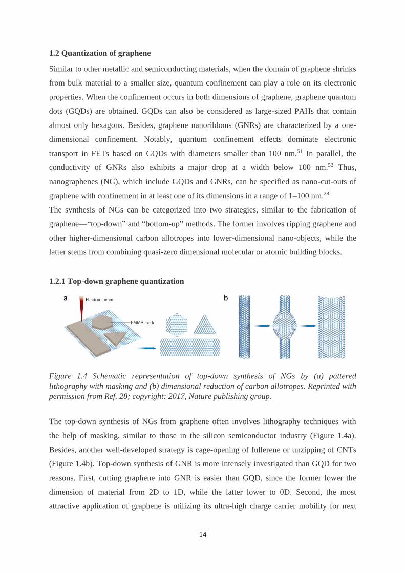
Figure 1.4 Schematic representation of top-down synthesis of NGs by (a) pattered
lithography with masking and (b) dimensional reduction of carbon allotropes. Reprinted with
permission from Ref. 28; copyright: 2017, Nature publishing group.
The top-down synthesis of NGs from graphene often involves lithography techniques with
the help of masking, similar to those in the silicon semiconductor industry (Figure 1.4a).
Besides, another well-developed strategy is cage-opening of fullerene or unzipping of CNTs
(Figure 1.4b). Top-down synthesis of GNR is more intensely investigated than GQD for two
reasons. First, cutting graphene into GNR is easier than GQD, since the former lower the
dimension of material from 2D to 1D, while the latter lower to 0D. Second, the most
attractive application of graphene is utilizing its ultra-high charge carrier mobility for next

Chapter 1. Introduction
15
generation semiconductors, and GNRs have advantages in device fabrication, channel
alignment, and consistency of performance (when aspect ratio (AR) is high). Nevertheless,
GQD has its advantage in other applications such as OLED, OPV, bioimaging, and
biosensing.53
Figure 1.5 (a) Reciprocal value of band gap (Eg) as a function of GNR width (W). Reprinted
with permission from Ref. 52; copyright: 2007, American Physical Society. (b) Correlation
between Ion/Ioff and GNR width of GNR-based FETs. Reprinted with permission from Ref. 54;
copyright: 2009, American Chemical Society.
Band gap opening already occurs in relatively wide GNRs (Figure 1.5a).52 However, for
applying GNR in a transistor, an insufficiently large band gap results in very low Ion/Ioff,
leading to a device that cannot be reasonably switched off. Importantly, it is shown that an
Ion/Ioff larger than ten can be achieved in FETs using GNR narrower than 10 nm (Figure
1.5b).54 As a trade-off, narrowing GNRs causes a drop of charge carrier mobility, due to
increase of effective charge carrier masses.55,56 Thus, a technique that fabricates GNR with a
width of 5–10 nm is immensely desired, where a balance between Ion/Ioff and mobility in a
FET is plausible.
Electron-beam lithography (EBL) is widely applied for graphene nanopatterning, because of
its high resolution.51,52 Employing EBL, FET devices fabricated from 10-nm-wide GNR
achieve high mobility of 800–1000 cm2V−1s−1 and Ion/Ioff > 106 at 4 K.57 Furthermore,
lithography resolution can be enhanced by using heavier particle beams, such as Helium55
and Argon58 ions, leading to sub-5-nm GNRs. However, EBL is a time- and energy-
consuming process, requiring strict operating conditions, making it impractical for industrial
manufacturing. To improve this, more productive lithography processes, such as reactive-ion
and plasma etching, have been combined with efficient nano-masking protocols, e.g., water
adsorption at step-edge of substrate,59 inorganic nanowires (i-NW),54 printed organic

1.2 Quantization of graphene
16
nanowires,60 and self-assembled block copolymers,61 for potential large-scale production of
sub-10-nm GNRs from high quality graphene sheets. Notably, Yu and Duan fabricated
bilayer-GNR FET by lithography of i-NW masked bilayer graphene. The FET device gave a
high room temperature Ion/Ioff ~ 3000 with an off-state under external electric field, which
came from the behavior of bilayer graphene.62
Besides, solution chemical/physical methods provide another approach for mass-production
of GNRs. Remarkably, Dai’s group reported on a synthesis of GNRs, with a distribution of
width from 50 nm down to sub-10-nm, as byproduct during exfoliation of graphite in 1,2-
dichloroethane by sonication.63 FETs based on the sub-10-nm GNRs exhibited mobility up to
200 cm2V−1s−1 and the highest Ion/Ioff up to 107 ever achieved for GNR-based FETs. The same
group also reported on unzipping oxidized multi-wall CNTs by sonication to fabricate 10–30-
nm-wide GNRs with FET mobility up to 1500 cm2V−1s−1.64
The solution-based wet chemical/physical top-down syntheses of GNRs are usually under
milder conditions than the lithography methods. This can often lead to GNRs with smoother
edge structure and roughness. Moreover, solution-based methods are more promising for
high-throughput GNR production. However, for applications as transistor, especially in an
integrated circuit, material processing and device fabrication using the resulting GNRs
become a cumbersome task. Conversely, lithography processes gain advantage for patterning
densely aligned transistor channels, along with direct circuit design. Notably, Dai’s group
attempted on combining the advantages by slow chemical etching of wide GNR (20 nm)
prepared from EBL.65 The protocol succeeded in narrowing down the GNRs to sub-5-nm,
and rendered a high Ion/Ioff > 104 for their FET. Such trials of balancing the quality of GNRs,
their production rate, and ease of patterning on, especially, insulator or semiconductor surface,
is the core-concern of current GNR researches.
1.2.2 Bottom-up synthesis of nanographenes on monocrystalline surface
Bottom-up synthesis is another strategy to achieve NGs with a much better structural control.
Specifically, the bottom-up protocols can be categorized into two classes. First, primarily
based on CVD methods, NGs are grown on confined templates or starting from a nano-sized
seed. Second, NGs with atomically precise structure are derived from organic synthesis with
or without surface-assisted reaction steps.
CVD growth of graphene often employs metals as template. Indeed, bottom-up fabrication of
NGs on a nano-sized metal substrate is possible. Kato and Hatakeyama patterned a dumbbell-
shape Ni.66 When current passed through this nanostructure, the narrower part heated up

Chapter 1. Introduction
17
more quickly, and became more reactive. Consequently, graphene could be selectively grown
on the narrower part. Using this method, 23-nm-wide multi-layer GNR was fabricated with a
direct Ni electrode connection, and transistor based on the nano-connection reached Ion/Ioff up
to 104. Nevertheless, using EBL for Ni nano-patterning was inevitable. Alternatively, GNRs
with width down to 20 nm could be grown at edge of a Ni thin film, sandwiched between
insulators, avoiding EBL etching.67
Besides, direct CVD growth of GNRs on specific facets of SiC or Ge is reported. De Heer’s
group reconstructed a deep abrupt step on SiC (001) at 1200–1300 °C to form a SiC (110)
nano-facet.68 Next, GNR selectively grew on the (110) nano-facet at 1450 °C, because of a
lower stability of SiC (110) than SiC (001). Remarkably, a 40-nm-wide GNR could then be
in-situ fabricated, and a transistor based on such GNR reached Ion/Ioff ratio ~ 10 and charge
carrier mobility as high as 2700 cm2V-1s-1. In another approach, applying a very slow CVD
growing rate (< 5 nm h-1), Arnold et al. demonstrated growth of GNRs with width < 10 nm
and uniform crystallography and smooth edge on a Ge (001) facet.69 These methods are
highly valuable for allowing direct growth of GNRs on an insulating substrate. Thus, they
avoid transfer of GNRs from otherwise a metal surface, often used in CVD processes. Such a
feature largely facilitates device fabrication. For example, large-scale integrated transistors
were produced on SiC substrates with a channel density of up to 40000 cm-2.68
It is important to stress that, although the NGs synthesized by the above-mentioned methods
are frequently described as “smooth” and “straight”, there exists a common drawback—the
nano-structure of products, in an atomic aspect, are extremely ill-controlled, especially at the
peripheries of NGs.28 This uncertainty leads to NGs with varied property, especially for
small-sized ones, where the size is already comparable with the error-scale. For example, a
width variation of GNRs provided by block-copolymer-masked lithography resulted in losing
synchrony in multichannel transistor, and led to a poor Ion/Ioff.61,70
1.2.3 Organic synthetic strategy for large nanographenes
Organic synthesis is a bottom-up method with atomically precise control. With such power,
syntheses of monodispersed GQDs or width-unified GNRs are possible, which is drastically
different from the above-mentioned methods. In section 1.1.1, development history of PAH
has been introduced. When the size of PAH (with mainly hexagons as skeleton) becomes
larger than 1 nm, it can be considered as NGs. Accordingly, HBC (Scheme 1.1), with its size
just exceeding 1 nm, serves as a milestone indicating PAHs entering the field of NGs. Yet, to
be relevant at a molecular scale larger than 1 nm, organic synthesis faces obstacles in
1.2 Quantization of graphene
18
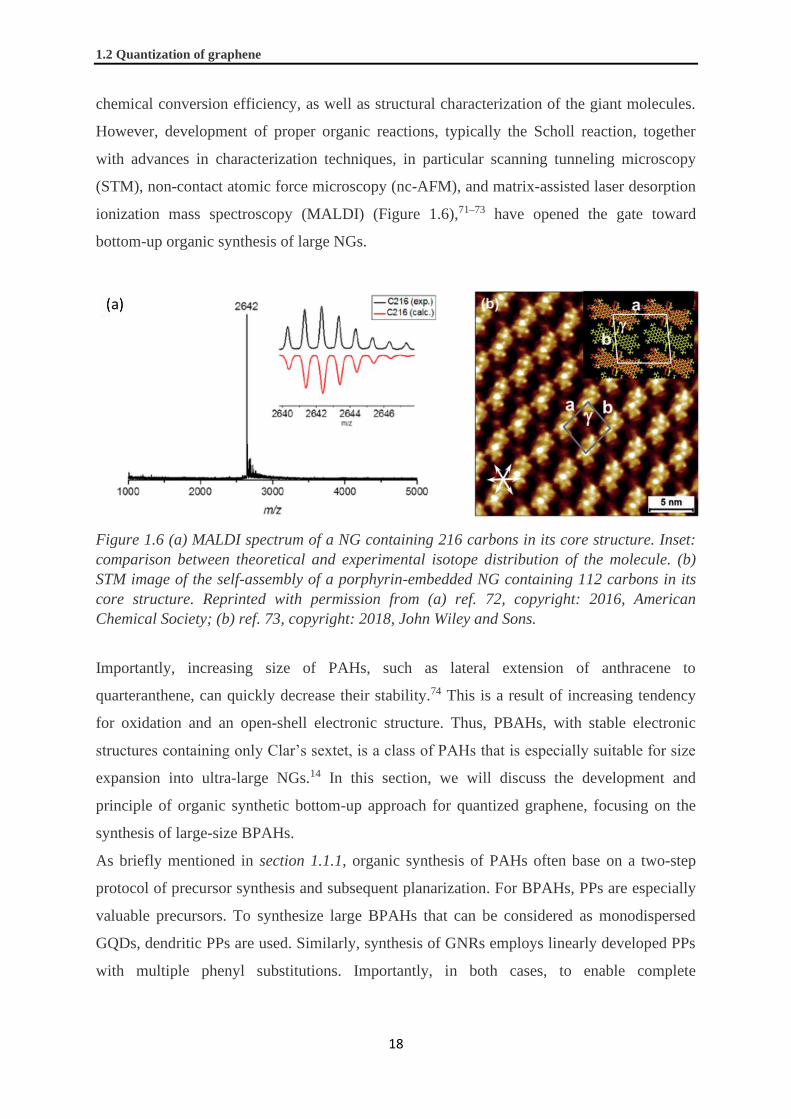
chemical conversion efficiency, as well as structural characterization of the giant molecules.
However, development of proper organic reactions, typically the Scholl reaction, together
with advances in characterization techniques, in particular scanning tunneling microscopy
(STM), non-contact atomic force microscopy (nc-AFM), and matrix-assisted laser desorption
ionization mass spectroscopy (MALDI) (Figure 1.6),71–73 have opened the gate toward
bottom-up organic synthesis of large NGs.
Figure 1.6 (a) MALDI spectrum of a NG containing 216 carbons in its core structure. Inset:
comparison between theoretical and experimental isotope distribution of the molecule. (b)
STM image of the self-assembly of a porphyrin-embedded NG containing 112 carbons in its
core structure. Reprinted with permission from (a) ref. 72, copyright: 2016, American
Chemical Society; (b) ref. 73, copyright: 2018, John Wiley and Sons.
Importantly, increasing size of PAHs, such as lateral extension of anthracene to
quarteranthene, can quickly decrease their stability.74 This is a result of increasing tendency
for oxidation and an open-shell electronic structure. Thus, PBAHs, with stable electronic
structures containing only Clar’s sextet, is a class of PAHs that is especially suitable for size
expansion into ultra-large NGs.14 In this section, we will discuss the development and
principle of organic synthetic bottom-up approach for quantized graphene, focusing on the
synthesis of large-size BPAHs.
As briefly mentioned in section 1.1.1, organic synthesis of PAHs often base on a two-step
protocol of precursor synthesis and subsequent planarization. For BPAHs, PPs are especially
valuable precursors. To synthesize large BPAHs that can be considered as monodispersed
GQDs, dendritic PPs are used. Similarly, synthesis of GNRs employs linearly developed PPs
with multiple phenyl substitutions. Importantly, in both cases, to enable complete

Chapter 1. Introduction
19
planarization of PP precursors, their structures must be carefully designed to allow a 2D
projection without overlapping benzene rings in a graphene-related lattice.
HBC is a good example for understanding both precursor synthesis and the subsequent
planarization reaction in PBAH chemistry. Although early approaches used partially
planarized precursors,75 contemporary synthetic methods are often based on pure PP
structures because of their facile synthesis. Particularly, Hyatt developed a Co2(CO)8-
catalyzed cyclotrimerization of tolanes that efficiently produces C6-symmetric HPB skeletons
(Scheme 1.2).76 Furthermore, C3-symmetric HPB could also be produced in this way, but
tolanes with two substituents that are different in polarity shall be applied, to facilitate
product separation.77 Besides, synthesis of HPB with other substitution patterns, particularly
“para” and “ortho”, employed a D-A reaction between tetraphenylcyclopenta-2,4-dien-1-one
(CP) and tolane, which is directly followed by extrusion of carbon monoxide (Scheme 1.2).
In addition, metal-catalyzed cross coupling reactions, such as Suzuki-coupling, were also
efficient enough for synthesizing HPBs.78 From a strategic point of view, the
cyclotrimerization works as a convergent method to combine three building blocks, whereas
the D-A method can be considered as a divergent method to equip a structural core with
multiple phenyl substitutions.
Scheme 1.2 Synthesis of HPB by cyclotrimerization or D-A reaction.
To convert HPB into HBC, six additional C-C bonds are formed, together with loss of twelve
hydrogen atoms. This cyclodehydrogenation reaction was attempted in early years by
conventional Scholl reaction, namely, coupling aromatic rings in the presence of Lewis acids,
though poor yields were encountered (Scheme 1.3, condition (a)).79 In contrast, addition of
oxidants or using oxidative Lewis acids, such as FeCl3,80 MoCl5,
81 or Cu(II)/AlCl3,82
significantly improved the conversion (Scheme 1.3, conditions (b)–(d)). Rempala, Kroulík,
and King conducted a systematic comparison and suggested that, for the Scholl reaction of
pristine HPB, a use of MoCl5 achieved the highest yield of HBC (Scheme 1.3, condition

1.2 Quantization of graphene
20
(b)).81 Nevertheless, chlorination or chopping off of substituents were observed as side
reactions for Scholl reactions using MoCl5 or Cu(II)/AlCl3 (FeCl3 also led to some
chlorination). Notably, an effective reagent system developed by Zhai, Shukla, and Rathore
has risen recently.83 This reagent system employed an organic oxidant 2,3-dichloro-5,6-
dicyanobenzoquinone (DDQ), combined with strong acid, typically methanesulfonic acid or
triflic acid (Scheme 1.3, condition (f)), and has been proven especially valuable for many
cyclodehydrogenation reactions that ill-performed using conventional reagents.
Scheme 1.3 Converting pristine HPB into HBC by the Scholl reaction. Conditions: (a) 18 eq.
AlCl3/NaCl, 120–130 °C, 3%. (b) 12 eq. MoCl5, dichloromethane (DCM), rt, 99%. (c) 12 eq.
CuCl2/AlCl3, CS2, rt, 60%. (d) FeCl3, DCM, rt, 118% (with inseparable iron residue). (e) 9
eq. PhI(O2CCF3)2/BF3⋅Et2O, DCM, -40 °C, 78%. (f) 6 eq. DDQ, MeSO3H, DCM, 0 °C, 99%
(HPB with alkyl substituent). Data extracted from: (a) ref. 79, (b)–(e) ref. 81, and (f) ref. 83.
The Scholl reaction of HPB is a magnificent chemical conversion, forming multiple C-C
bonds in one pot. The successful procedure suggests a high efficiency in each single bond-
formation step. Notably, the original Scholl reaction used non-oxidative Lewis acid, such as
AlCl3.84 Thus, it was believed to proceed via an arenium cation intermediate, followed by
deprotonation and dehydrogenation upon heating (Scheme 1.4, path I). However, the last step
was controversial, since quantitative generation of H2 gas was not observed.85 Notably,
abundant O2 gas, which often existed in the experimental environment, could also serve as
oxidant to transform easily oxidizable species, such as dihydro intermediate 6a’’ (Scheme
1.4), without H2 extrusion.
Importantly, most of the Lewis acids currently used for Scholl reaction are also oxidants,
including FeCl3 and MoCl5. Thus, the Scholl reaction can occur via another plausible
mechanism using these reagents, that is, the radical cation pathway (Scheme 1.4, path II). In
the work of Rempala, Kroulík, and King, deriving from computational and experimental
evidences, it was suggested that the arenium cation mechanism (Scheme 1.4, path I) was the

Chapter 1. Introduction
21
thermodynamically favored pathway.81 However, in reality, the reaction could be much more
complicated, involving various intercrossing steps. Notably, for the Scholl reaction using
DDQ/acid, the transformation did not proceed in case of precursors with high oxidation
potential. Thus, the reaction under this condition more likely proceeded through a radical
cation pathway.86
Scheme 1.4 Schematic representation of the mechanism of the Scholl reaction. Path I:
arenium cation pathway. Path II: radical cation pathway. Path III: skeleton rearrangement
as side reaction.
Notably, rearrangements can occur as side reactions during Scholl reactions (Scheme 1.4,
path III). In an extreme example, heating o-terphenylene (6) at 140 °C in the presence of
strong acid led to formation of m-terphenylene and p-terphenylene as a final mixture in a
ratio of 65:35.87 The reaction proceeded via a 1,2-phenyl shift, driven by the higher stability
of m-terphenylene arenium cation (Scheme 1.4, path III). Although contemporary Scholl
reactions were performed at much lower temperature, similar side reactions could still occur.
For example, our group revealed that, during the Scholl reaction of an extended HPB 9, a
significant amount of the o-terphenylene side arms isomerized into m-terphenylene (Scheme
1.5a).88 On the bright side, in some cases rearrangement could also “correct” kinks in PP
precursors, such as a successful complete planarization of PP 11 through a possible
equilibrium between isomers with different connectivity of phenylenes (Scheme 1.5b).89

1.2 Quantization of graphene
22
Nevertheless, to ensure a desired NG product structure, PP precursors shall be designed to
avoid rearrangement during Scholl reaction.90
Scheme 1.5 Skeletal rearrangement during Scholl reaction of PP 9 and 11.
Because of lacking solubility, solution-synthesized large NGs are often challenging for
conventional characterization, such as NMR, single crystal X-ray diffraction, and mass
spectrometry. To overcome this obstacle, our group and Roman Fasel’s group developed a
protocol in 2010 to combine advantages of organic synthesis with surface-assisted
chemistry.91,92 This technique depended on sublimation of molecular precursor, synthesized
in solution, onto a monocrystalline metal surface under ultra-high vacuum (UHV) conditions.
Upon further heating, the metal surface promoted a homolytic cleavage of, e.g. C-H bond,
forming radical species. Then, the radical species further reacted intra- or intermolecularly,
followed by dehydrogenation into 2D graphitic structures.93
The power of this method lies in two points. First, the flat monocrystalline metal surface
facilitates a perfect planarization of precursors. Second, NG products can be in-situ
characterized by scanning microscopy, especially STM and nc-AFM, under UHV conditions,
to extract structural and electronic information with atomic resolution. For the first
demonstration, the cyclohexaphenylene 13 was used, leading to a triangular-shaped
monodispersed GQD 14 (Scheme 1.6a).92 Although a requirement of sublimable precursors

Chapter 1. Introduction
23
limited the size of obtainable monodispersed GQDs, for synthesis of GNRs this was not so
much a problem. For example, monomeric precursor 15 with halogen substituents was
sublimed onto Au(111). Upon heating, 15 underwent C-X cleavage, and the generated radical
intermediates polymerized into polymeric precursor 16. Upon further enhancing the
temperature to 670 K, surface-assisted cyclodehydrogenation occurred, and 16 planarized
into GNR 17 (Scheme 1.6b).94 The solution synthesis combined with a surface-assisted
reaction is now widely applied, especially for fundamental studies, to systematically
investigate different NGs on surfaces.
Scheme 1.6 The First demonstration of on-surface synthesis of (a) a GQD and (b) a GNR,
and their STM images taken in-situ. Reprinted with permission from (a) ref. 92, copyright:
2011, Nature Publishing group; (b) ref. 94, copyright: 2010, Nature Publishing group.
1.2.4 Organic synthesis of large monodispersed graphene quantum dots
Either applying the divergent or convergent synthetic strategy of HPB mentioned in section
1.2.3, PPs rapidly expend into dendritic structures that could be planarized into
monodispersed GQDs. Synthesis of PP 21, serving as potential precursor for GQD with a Z-
shape C2h-symmetry, was a representative example (Scheme 1.7a).95 This divergent synthesis
relied on two-layer-extension of 3,3’,5,5’-tetraethenyl-1,1’-biphenyl (18) by repetitive D-A
reactions with CPs (Scheme 1.7a). Notably, 2D projections of 20 or 21 in a graphene-related
lattice (like in Scheme 1.7a) exhibit no spatial overlap benzene ring. This enabled the
conversion of 20a into a square-shape D2h-symmetric GQD with 132-carbon aromatic
core.96,97 The exact mass of this GQD was observed by MALDI-TOF mass analysis. Despite
the successfulness of 20a, a graphitization of 21 was not reported.

1.2 Quantization of graphene
24
Our group also reported a highly efficient Scholl reaction of an even larger dendritic PP
precursor 24. The reaction led to GQD 25 with a D6h-symmetric 222-carbon π-core (Scheme
1.7b).98 This is a perfect demonstration of convergent synthesis of dendritic PP precursors for
bottom-up approach of GQDs. Remarkably, 25, with a diameter close to 3 nm, is the largest
GQD ever reported with a relatively clean MALDI-TOF spectrum showing desired product
as the dominating peaks. Notably, PP precursors, as well as partially planarized intermediates,
exhibit much stronger signals in MALDI-TOF analysis than the fully planarized GQD
targets.99 Accordingly, observing dominating peak of GQD over the others suggests a high
content of fully-converted GQD in the product mixture.
The extension of BPAHs into GQDs gradually lower their HOMO-LUMO gap, roughly
proportional to reciprocal of the number of carbon atoms in their -core.96 The 222-carbon 25
possesses a HOMO-LUMO gap approaching 1.4 eV. However, these large PAHs are often
insoluble, hindering a thorough investigation of their photophysical properties.
Scheme 1.7 (a) Divergent and (b) convergent synthesis of dendritic PPs that can serve as
precursors for large monodispersed GQDs.
The extension of BPAHs into GQDs gradually lower their HOMO-LUMO gap, roughly
proportional to reciprocal of the number of carbon atoms in their π-core.96 The 222-carbon 25

Chapter 1. Introduction
25
possesses an HOMO-LUMO gap approaching 1.4 eV. However, these large PAHs are often
insoluble, hindering a thorough investigation of their photophysical properties.
Our group also synthesized highly extended dendritic PPs 26 and 27, aiming at fabricating
monodispersed GQDs with a diameter exceeding 5 nm (Figure 1.7). Both PP precursors were
achieved through divergent two-layer-extension by D-A reactions, similar to 21 (Scheme
1.7a). The triangular-shape PP 26 was ideally a precursor for a monodispersed GQD with D3h
symmetry and a 474-carbon π-core. However, its full planarization was especially
challenging. Interestingly, MALDI-TOF analysis of products after the Scholl reaction
compared with model compounds suggested that partial graphitization occurred within each
three arms, and a propeller structure likely formed.100 On the other hand, PP 27 was extended
from a HBC core.101 Notably, 2D projection of 27 shows overlap of benzene rings (Figure
1.7). Considering that the rearrangement or extrusion of phenyl groups could occur during the
Scholl reaction (section 1.2.3), 27 could be ideally planarized into D6h-symmetric
monodispersed GQD with a 546-carbon π-core after losing six phenyl groups. However,
Scholl reaction of 27 was complicated and could not be fully clarified.
Figure 1.7 Extended dendritic PPs as potential precursors for monodispersed GQDs
approaching 5 nm.
1.2.5 Organic synthesis of wide graphene nanoribbons
Organic synthesis provides opportunities for not only atomically precise bottom-up
fabrication of GNRs but also their systematic investigation by series of oligomers.
Representatively, two series of monodispersed GQDs derived from 1D-extended HBC were
synthesized by our group (Figure 1.8). The “armchair” series (28–30) extended HBC toward

1.2 Quantization of graphene
26
the “angle” direction,96,97 whereas the “superacene” series (28, 31, 32) on “sides”.102,103 These
monodispersed GQDs could be considered as GNRs with a width close to 1 nm and a very
small AR. Importantly, long alkyl chains were equipped to enhance solubility of the large
GQDs, enabling energy gap estimation in solution by UV-Vis absorption spectroscopy
(Figure 1.8). Similar to some other conjugated materials, gradual decrease of energy gap
along increment of repeating units was observed, and band gap of 1.1 eV and 1.7 eV is
predicted for the “armchair” and the “superacene” GNRs, respectively, with infinite repeating
units and large ARs.
Figure 1.8 Two series of 1D-extended HBCs and their estimated energy gap (EG). Predicted
EG for corresponding GNRs are shown in the parentheses.
To synthesize GNRs based on the “armchair” series shown in Figure 1.8, our group pioneered
on an A2B2-type Suzuki polymerization between HPB boronic ester 33 and
diiodotetraphenylbenzene (Scheme 1.8a).104 However, because of a high steric hindrance, the
efficiency of the Suzuki reaction was low.105 Nevertheless, the PP precursor 34 was isolated
with number average molecular weight (Mn) of up to 14 kDa and a polydispersity index (PDI)
as small as 1.2.104 However, the Scholl reaction of 34 using FeCl3 as oxidant only gave GNR
35 with a band gap at around 2.2 eV. This indicated that the effective conjugated length of 35
would be even smaller than 29 (Figure 1.8 and Scheme 1.8). Excitingly, an improved
synthesis has been developed recently by Zhu and Dong (Scheme 1.8b).106 This approach

Chapter 1. Introduction
27
utilized AB-type Suzuki-polymerization of 4-bromo-2,3-diphenylboronic ester 36.
Remarkably, Mn of the resulting polymer 37 reached a higher value up to 31 kDa. Moreover,
it was found out that DDQ/triflic acid is more efficient over FeCl3 for converting 37 into
GNR 38. Consequently, GNR 38 possessed a band gap close to 1.1 eV, which agreed with
what predicted from oligomers (Figure 1.8). Our group have also utilized similar monomeric
structure for on-surface synthesis of pristine GNR 38 without alkyl substituents.107
Scheme 1.8 Laterally extended GNRs belonging to BPAHs made by various synthetic
strategies and monomer design.

1.2 Quantization of graphene
28
GNRs 35 and 38 can be considered as laterally fused poly(p-phenylene) (PPP) chains
(Scheme 1.8). In fact, lateral fusion of PPP chains occurred on an Au(111) surface at 650 K.
Nevertheless, fusion of more than two chains was challenging.108 In contrast, syntheses of
GNRs that corresponds to lateral fusion of four (GNR 41), five (GNR 44), and six (GNR 47)
PPP chains were demonstrated by solution-based organic synthesis with various synthetic
methods (Scheme 1.8).
Rubin’s group has reported a novel approach toward GNR 41 utilizing topochemical
polymerization.109 Specifically, by screening substituents of potential monomers, monomer
39 with methoxymethoxyl groups was revealed as possessing proper intermolecular
orientation that enabled its polymerization upon heating or UV-light irradiation in
monocrystalline state. Further heating the polymer product 40 in solid state resulted in its
graphitization into GNR 41 (Scheme 1.8c). For the synthesis of wider GNR 44, Amsharov’s
group employed polymerization of dibromo-p-pentaphenyl monomer 42 on-surface.110 STM
analysis confirmed the formation of GNR, although relatively dense structural defects were
observed (Scheme 1.8d). Besides, our group synthesized an even wider GNR 47 by Scholl
reaction of a PP precursor 46, which was obtained from Yamamoto polymerization of
diphenyldichloro-HPB monomer 45 (Scheme 1.8e).111
GNRs 38, 41, 44, and 47 represent a family of similar structure that belongs to BPAHs, with
gradually increased width exceeding 2 nm. Theoretically, their band gap shall be inversely
proportional to their width.112 However, as shown in Scheme 1.8, the band gaps increase with
the width, portraying the narrowest GNR 38 with the smallest band gap. This could stem
from several reasons: (1) The four GNRs were produced from completly different synthetic
methods. Some polymer precursors could lead to incomplete cyclodehydrogenation reactions.
(2) As already observed by comparing GNR 35 and 38, AR of GNRs casts a decisive
influence on their band gap. Particularly, estimated from Mn of PP precursor 46, the AR of
GNR 47 could be as low as two. Thus, GNR 47 shall be considered as oligomer with an
energy gap far from convergence. (3) GNRs often exhibit a strong tendency toward
aggregation and intermolecular electronic interaction could influence their band gaps.
On the other hand, our group have recently developed a protocol to synthesize GNRs based
on the “superacene” series (Figure 1.10 and Scheme 1.9a). This synthesis utilized AB-type D-
A polymerization of monomer 48 featuring a CP and an ethynyl functional group.103,113
Moreover, by using monomers 51 and 54 with more phenyl substituents at proper positions,
laterally extended PPs 52 and 55 were achieved. Their Scholl reactions led to GNRs 53 and
56 with width approaching 2 nm (Scheme 1.9b,c).114,115

Chapter 1. Introduction
29
Scheme 1.9 Lateral extension of GNRs by D-A polymerization of extended CP monomers.
Since GNR 50, 53, and 56 were synthesized applying the same protocol, their properties can
be reasonably compared. Especially, the GNRs exhibited lowering of band gap from 1.9, to
1.4, and to 1.2 eV, while their width increased from 0.66, to 1.1, and to 1.5 nm, respectively
(Scheme 1.9). The values agreed with prediction provided by density functional theory (DFT)
calculation, which gave band gaps of 2.0, 1.5, and 1.2 eV,116 respectively. Notably, there
were several other remarkable features for this D-A-polymerization-based GNR synthesis.
First, the D-A polymerization was highly efficient, producing PP precursors with
exceptionally large Mn. Consequently, extremely high AR, for example, over 500 for GNR 50,
was developed (Scheme 1.9a). This is way more superior than the GNRs described in Scheme
1.8, and should be one of the reasons for the consistence between the theoretically calculated
and experimentally estimated band gaps. Second, according to light scattering analysis results,
the PP precursors had an extreme backbone rigidity influenced by enormous substituents on

1.2 Quantization of graphene
30
the polymer backbones. This helped them maintaining a semirigid conformation in
solution.103,117 Consequently, exceptionally long linear GNRs with no kink were formed after
the Scholl reaction. For example, a straight chain of GNR 50 longer than 500 nm was
revealed by AFM analysis.118 Third, since the D-A reaction was a metal-free chemical
conversion, it tolerated substituents such as halogens, allowing further functionalization of
the GNRs with, for example, optically119 or magnetically120 active moieties.
Current bottom-up organic synthesis demonstrates fabrication of structurally precise GNRs
with a uniform width exceeding 2 nm. This ensures identical intrinsic properties between
individual GNR strands, which is drastically different from top-down synthesis. In addition,
recent studies have also demonstrated control of the length distribution of bottom-up
synthesized GNRs, applying polymer precursors derived from living-polymerizations.121,122
Indeed, it is highly intriguing to investigate electronic applications based on solution-
synthesized GNRs, especially as transistors. However, FET motilities for solution-
synthesized GNRs are often low, in a range of 10-3–10-5 cm2V-1s-1.123 Our group, in
collaboration with Bonn’s group, have estimated the intrinsic mobility of GNR 50 to be as
high as 150–15000 cm2V-1s-1 by non-contact terahertz conductivity measurment,103 despite its
transistors only exhibited an Ion/Ioff lower than 2.118,124 Above all, one foresees that device
fabrication using solution-synthesized GNRs are facing more complicated challenges than
top-down synthesized ones. A plethora of other substances can obstruct the device
performance, such as the dispersing solvent, solubilizing side-chains and additives, and
impurities coming from synthesis. Moreover, GNRs strongly aggregate in solution, which can
alter their band gaps.118 Development of processing technique and device fabrication for
solution-based GNRs are thus equally important as their synthesis.

Chapter 1. Introduction
31
1.3 Defects in graphene and their model compounds
As a bulk material, graphene inevitably possesses various kinds of defects in its crystal lattice,
because of thermodynamics and unideal synthetic conditions. Notably, some similar defects
were studied in other carbon allotropes, e.g., CNTs, fullerenes, and graphite, prior to the
graphene era.125 However, as a flat atomic monolayer, graphene provides more suitable
objects for defect analysis, especially after the development of high-resolution transmission
electron microscopy (TEM).
Defects in graphene can be in principle understood similarly as those in 3D materials,
although the 2D nature of graphene in a sense simplifies the situation by lowering dimension.
Besides, 2D nature of graphene alters energetic profile between various types of defects
compared to their counterparts in 3D materials. Moreover, sp2-hydridized carbons can form
various non-hexagon rings, leading to topological defects, which locally or globally affect the
graphene crystal lattice. Such scenario distinguishes graphene from the most of other
materials.
1.3.1 Types of defects in graphene
The simplest defect in graphene is a single vacancy (SV) of lattice atom, a point defect
similar to Schottky defect in 3D crystals. Importantly, migration energy barrier of SV is
lower than its formation energy.126 Thus, at an elevated temperature, SVs coalesce into other
more stable defects, typically a double vacancies (DV). Then, DV undergoes spontaneous
reconstruction, forming two bonds between the four dangling bonds, leading to a pentagon-
octagon-pentagon topological defect (Figure 1.9a).127 Further reconstruction of the pentagon-
octagon-pentagon defect into more complicated topological defects can occur at high
temperature, driven by release of local strain.
Another representative topological point defect is the Stone-Wales (SW) defect (Figure 1.9b),
which was proposed as early as 1986, almost 20 years before the isolation of graphene.128 SW
defect is formed by rotation of a pair of carbon atoms for 90°, creating a pentagon-heptagon-
heptagon-pentagon topology and no lattice vacancy. Practically, at elevated temperature (>
1000 °C) or under bombard of high-energy particles, typically during TEM analysis, SW
defect can form and be kinetically trapped. Besides, the high-energy electrons used during
TEM measurement could also ballistically knock out carbon atoms, forming SVs.129 If the
carbon atom leaving graphene lattice remained on graphene surface, an adatom-vacancy pair
could be formed, which is similar to a Frenkel defect in 3D crystals, although it is

1.3 Defects in graphene and their model compounds
32
conceptually different since the adatom prefers to stay at the third dimension, namely being
excluded from graphene lattice. Furthermore, when carbon adatoms migrating on graphene
surface meet, they combine into a pair and insert into graphene crystal lattice (Figure 1.9c).
Such topological defect is called inverse SW defect, for a similar heptagon-pentagon-
pentagon-heptagon topology but different arrangement compared to SW defect.130 Notably,
inverse SW defect violates the “isolated pentagon rule”,131 thus causing severe local buckling
on graphene.
Figure 1.9 Topological trivial point defects observed in graphene. (a) A reconstructed DV.
Arrows indicate bonds formed during reconstruction. (b) A SW defect. Circled atoms are
rotated in the graphene lattice. (c) Inverse SW defect. Circled atoms are inserted adatoms.
Reprinted with permission from Ref. 125; copyright: 2011, American Chemical Society.
Unlike those in a 3D crystal, point defects in 2D graphene lattice are “half-naked”, lacking
stabilization from the third dimension. As a result, the energy of formation of these defects in
graphene starting from a perfect crystal lattice is much higher than those of similar defects in
3D materials. For example, energy of formation of SV defect in most metals is smaller than 3
eV, while in graphene it is above 7.5 eV.126,132 Likewise, the same energy of (inverse) SW
defects are high (> 5 eV).130,133 Thus, point defect concentration in graphene flake is
negligibly low in those synthesized in a thermal equilibrium condition, such as CVD. This is
also the reason why CVD can produce high-quality graphene sheet.
As mentioned in section 1.1.2, CVD is currently the leading fabrication technique for the
synthesis of large-area graphene wafer. At the beginning of CVD graphene growing process,
graphene crystalizes from multiple nucleation cites. Then, developed graphene domains
eventually merge into a large-area graphene sheet.134 However, because of crystal lattice
mismatch between different domains, the large-area graphene sheets are always
polycrystalline. Thus, in reality, defects that strongly influence graphene properties would be
line defects, which define graphene grain boundaries (GB).135 It is revealed by TEM imaging

Chapter 1. Introduction
33
that fused pentagon/heptagon arrays generally dominate the nanostructure of GBs.136 To
understand this, the nature of topological defects in graphene shall be explained more.
The point defects mentioned above are “topologically trivial”, since the overall symmetry of
the surrounding graphene lattice is preserved. In contrast, some “non-trivial” topological
defects cast long-range influence on the graphene lattice. Here, disclination and dislocation
line defects in 3D materials can be adopted, though as 2D projection, to describe most of
“non-trivial” topological defects in graphene lattice. Typically, a pentagon or a heptagon,
considered as disclination defect in graphene, cause rotation of graphene crystal lattice
surrounding the defect point (Figure 1.10a). Alternatively, the influence of pentagon or
heptagon defects can be understood as removing or adding a 60° wedge into graphene lattice,
respectively (Figure 1.10a).137 These single pentagon/heptagon defects inevitably result in
nonplanar local topology, and they have not been experimentally observed in graphene.
Figure 1.10 Topological non-trivial defects in graphene. (a) Disclinations, s = degree of
wedge that is added (negative) or removed (positive). (b) Dislocations, b = Burgers vector. (c)
GBs, = misorientation angle between two grains. Reprinted with permission from Ref. 135;
copyright: 2014, Nature Publishing group.
Importantly, when a pentagon and a heptagon are close in space, they compromise each
other’s effect, namely rotation of graphene crystal lattice, on local environment. In other
words, two disclination defects join as a dislocation defect (Figure 1.10b). A dislocation
defect semi-infinitely expands graphene crystal lattice along a translation vector, which is

1.3 Defects in graphene and their model compounds
34
described by adapted Burgers vector. For example, Figure 1.10b portrays a (1,0) and a (1,1)
dislocation defect. Notably, in comparison with a disclination defect, a dislocation defect
furnishes only minor perturbation on the crystal lattice (Figure 1.10a,b). As a result, the local
area surrounding dislocation defects can be more or less planar,137 and the calculated
formation energy of dislocation defects in graphene is close to that of SW and SV defects.133
Also, dislocation defects are experimentally observed by microscopies in graphene lattice.138
Notably, to maintain a continuous lattice across two graphene grains with different crystal
orientation, the crystal lattice requires regular expansion at the GB, namely, periodic
alignment of dislocation defects can be the element of graphene GB. The larger is the
misorientation angle, the denser are the dislocation defects. For example, Figure 1.10c
portrays theoretical nanostructures at two linear GBs between 21.8° and 32.3° misoriented
graphene lattices. These two GBs possess particularly low calculated formation energy.137
Figure 1.11 Microscopic images of graphene GB nanostructures. (a) TEM image of a
boundary of 27° misoriented graphene lattices. (b) STM image of a GB loop. (c) STM image
of a GB composed of pentagons and octagons. Reprinted with permission from (a) ref. 136,
copyright: 2011, Nature Publishing group; (b) ref. 139, copyright: 2011, American Physical
Society; (c) ref. 140, copyright: 2010, Nature Publishing group.
Experimentally observed nanostructures at graphene GBs are more chaotic than ideal cases
(Figure 1.11a).136 This is understandable because graphene grains can have various
misorientation angles, which is normally not ideal for simple GB nanostructures shown in
Figure 1.10c. Moreover, the group of Yakobson recently has suggested that sinuous GBs are
even energetically favored over linear ones.141 Nevertheless, the fused pentagon-heptagon-
pairs, namely (1,0) dislocation, or the structure of azulene, still dominate the nanostructure of
GBs. Interestingly, a flower-like GB loop is widely observed (Figure 1.11b),139 where a very
small graphene domain with 30° lattice misorientation is isolated from the bulk graphene
lattice. Such a “graphene flower” could be a local minimum in the energy profile of graphene

Chapter 1. Introduction
35
point defect reconstruction. Besides, GBs can also exist between graphene domains without
lattice misorientation. For example, a pentagon/octagon nanoline, or an array of fused
reconstructed DV defects, is observed in graphene grown on Ni(111) (Figure 1.11c).140
Influence on electronic transport properties is one of the most important concerns for
graphene GBs. It is generally observed that GBs reduce the conductance of graphene.142
However, interesting phenomena, such as low temperature magnetoresistance, can be induced,
probably due to presence of some local states. Inspiringly, Yazyev and Louie proposed that a
through-GB electron transport barrier could be created by controlling the periodicity of GB
and crystal lattice misorientation between graphene domains, as a result of electron
momentum mismatch.143 Thus, it is theoretically possible for a polycrystalline graphene-
based transistor with a high Ion/Ioff without opening an intrinsic band gap. Remarkably, the
group of Zettl demonstrated intentional creation of an over-7-nm-long line defect with the
same structure shown in Figure 1.11c, starting from a hole in graphene, aiming at a potential
application in electrostatically gated “valley valve” device.144 Moreover, taking advantage of
the higher reactivity of GBs, Raghavan’s group has recently realized reversible passivation of
GBs by hydrogenation for regulating conductivity of polycrystalline graphene.145
GBs also affect other intrinsic properties of graphene. Particularly, presence of GBs reduces
mechanical strength of graphene.146 However, it is also pointed out from theoretical side that
such a scenario is strongly related to misorientation angles between grains, and regularity of
nanostructure of GB. Especially, the mechanical strength of GB can be close to that of
pristine graphene when the tilt angle is large.147,148 Besides, although theoretical studies are
debating on the thermal transport over GBs,149,150 Cheng and Ren et al. have recently
experimentally demonstrated a higher grain-size-sensitivity of thermal conductivity over
electronic conductivity in polycrystalline graphene, suggesting their potential for
thermoelectric material.151 Nevertheless, although interesting phenomena have been predicted
or observed in the above-mentioned defect engineering, fabrication techniques still lack
precise control on nanostructure at GBs.
1.3.2 Relationship between organic compounds and graphene defects
Pentagons and heptagons exist in various synthetic and natural organic molecules. For
example, the simple structure of cyclopentadiene (57) and cycloheptatriene (61) (Figure 1.12).
The polyene structure of 57 and 61 can be easily converted to fully sp2-hybridized
cyclopentadienide anion 58 and tropylium cation 62, which are extraordinarily stable for ions
of hydrocarbons. Besides, crystal structure analysis suggests no C-C bond length alternation

1.3 Defects in graphene and their model compounds
36
in both 58 and 62.152 Notably, 58 and 62 both contain six π-electrons. Thus, they are aromatic
and isoelectronic to benzene, which explains their high stability.
Figure 1.12 Representative structures of single-ring molecules with pentagon or heptagon,
and bicyclic azulene.
Aside from the ionic species 58 and 62, radialenes 59 and 63, and fulvenes 60 and 64, are
simple examples of neutral monocyclic sp2-hydrocarbons with pentagonal or heptagonal
skeletons, although they are much less stable. Production of [5]radialene 59 has been reported
recently by Paddon-Row and Sherburn from low temperature decomposition of an iron
complex, though 59 easily oligomerized after formation.153 From the diene-rich structure of
59, it would be expected that D-A reaction could be the reason for the low stability of 59.
However, calculations suggested a biradical intermediate.153 Besides, with an increased
reactivity, isolation or proof of formation of [7]radialene 63 is not reported yet. On the other
hand, pentafulvene 60 and heptafulvene 64 are more stable than radialenes, although they are
still sensitive to heat, light, and oxygen.154 The methylene groups of 60 and 64 are reactive
toward nucleophilic and electrophilic attack, respectively.155 This tendency is rationalized by
the ability of forming an aromatic cyclopentadienide anion or tropylium cation. Moreover,
azulene 65, serving as a fused pentafulvene and heptafulvene, is the most stable non-hexagon
hydrocarbon among 59–65, as a result of an aromatic ten-π-electron system. In fact,
cyclopentadiene and fulvene derivatives are often used as precursors for azulene synthesis.156
These simple monocyclic sp2-hydrocarbons shown in Figure 1.12 can be considered as
“naked” defects of graphene, namely, without the surrounding graphene lattice. Depending
on the local electronic structures, defects in graphene could inherit the chemical and physical
properties of these small sub-nano architectures. Organic synthesis provides a bottom-up

Chapter 1. Introduction
37
approach for model compounds related to defects in graphene. The following sections will
introduce such PAHs and NGs.
1.3.3 Molecular models representing point defects in graphene
The SV and DV point defects contain dangling bonds, which prefer reconstruction and
migration within the graphene lattice. Indeed, they shall be considered as intermediates in an
organic reaction point of view, for their high reactivity. Thus, isolation of small molecular
models for SV and DV defect is impractical. However, sp2-macrocycles, such as annulenes
and cycloarenes, can be regarded as model compounds for vacancies in graphene lattice,
where all the dangling bonds are passivated with hydrogen atoms (Figure 1.13).
The cis-trans alternating isomer of [12]annulene (66), with nine outer- and three inner-
protons, in its planar conformation, represents the hydrogen-passivated “naked” SV defect of
graphene (Figure 1.13). However, the inner-protons cast significant steric hindrance. Thus,
[12]annulene 66 is nonplanar. Moreover, it was shown that [12]annulene 66 undergo facile
isomerization via a Mobius aromatic transition state through heavy atom tunnelling,157 which
was followed by a six-electron-electrocyclization into a dihydrobenzo[8]annulene.158
Figure 1.13 Representative molecular model compounds for SV and DV defects in graphene.
In contrary, steric hindrance is smaller in the larger and more stable [14]annulene 67, which
serves as a good model compound for passivated “naked” DV defect in graphene (Figure
1.13). In a single crystal analysis, [14]annulene 67 displayed roughly planar structure, with
closely identical bond lengths for every C-C bonds. This suggested a 14-π-electron aromatic
system.159 Interestingly, it appeared that [14]annulene 67 adopted a less symmetric

1.3 Defects in graphene and their model compounds
38
conformation in solution, and the inner protons experienced a weaker diamagnetic shielding
effect than what was expected from an aromatic ring current. The result suggested that
[14]annulene 67 could enhance its aromaticity when it was transformed from solution to the
solid state, as an interplay between intermolecular interaction, steric hindrance, aromatic
stabilization, and C-C double bond strength.160 Besides, 2,7-di-tert-
butyldicyclopenta[a,e]cyclooctene (68), structurally related to 67, was achieved by Hafner,
Thiele, and Mink (Figure 1.13), although the synthesis did not involve derivatives of 67, but
started from a bis-cyclopentadiene.161 Importantly, the pentagon-octagon-pentagon
architecture of 68 is one of the major topological defects formed after reconstruction of a DV
defect, and thus it is more crucial than SV and DV defects for understanding graphene at
ambient conditions.127 Notably, from single crystal analysis, the perfectly planar structure of
68 was revealed. Moreover, the bond length of the bridging C-C bonds was close to a single
bond, and the rest were nearly identical. Similar structural features were also observed in
azulene 65, indicating a high overall aromaticity.161
As a further step from molecular models for “naked” SV and DV defects in graphene, it is
important to π-extend 66–68 to a nano-environment more similar to the graphene lattice.
However, the synthesis encounters severe obstacles. For cycloarene analogues 69–71 (Figure
1.13), only 70 was synthesized through a long 18-step route.162 Notably, a mass signal
corresponding to 71 was observed in the product mixture of cyclodehydrogenation reaction
toward 70. This could suggest an organic chemical version of DV defects reconstruction.162
Unfortunately, no follow-up investigation was reported. Indeed, π-extension induced a more
severe steric penalty on the inner protons, especially in 69, which could be the main factor for
their challenging synthesis.163 Nevertheless, cycloarene 70 already gave a useful insight into
electronic structure of passivated DV defect. Particularly, from its 1H-NMR analysis, it was
suggested that macrocyclic diamagnetism, which existed in 67, disappeared in 70, indicating
a more localized electronic structure.162
Recently, our group has synthesized a NG similar to 25 (Scheme 1.7b), the NG containing
222 sp2-carbons, but with a six-carbon hole in its center.72 This NG could be considered as
model compound for a passivated sextuple vacancy defect of graphene. Although such
defects should have little chance to exist in graphene flakes, it gave insight into novel
graphene-related nanostructures provided by bottom-up synthesis. Remarkably, our group
and Fasel’s group demonstrated on-surface synthesis of a framework of 1,3,5-benzenetriyl,
which could be regarded as graphene with regular sub-nano pores.164 Such a structure was
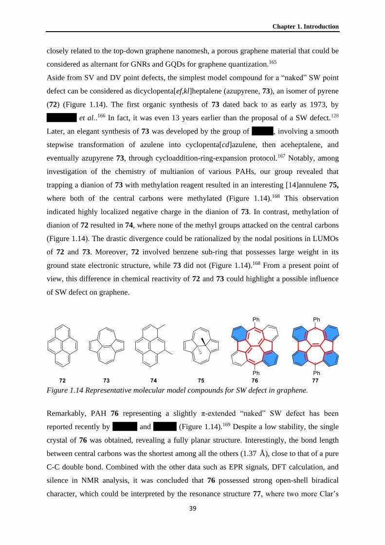
Chapter 1. Introduction
39
closely related to the top-down graphene nanomesh, a porous graphene material that could be
considered as alternant for GNRs and GQDs for graphene quantization.165
Aside from SV and DV point defects, the simplest model compound for a “naked” SW point
defect can be considered as dicyclopenta[ef,kl]heptalene (azupyrene, 73), an isomer of pyrene
(72) (Figure 1.14). The first organic synthesis of 73 dated back to as early as 1973, by
Anderson et al..166 In fact, it was even 13 years earlier than the proposal of a SW defect.128
Later, an elegant synthesis of 73 was developed by the group of Hafner, involving a smooth
stepwise transformation of azulene into cyclopenta[cd]azulene, then aceheptalene, and
eventually azupyrene 73, through cycloaddition-ring-expansion protocol.167 Notably, among
investigation of the chemistry of multianion of various PAHs, our group revealed that
trapping a dianion of 73 with methylation reagent resulted in an interesting [14]annulene 75,
where both of the central carbons were methylated (Figure 1.14).168 This observation
indicated highly localized negative charge in the dianion of 73. In contrast, methylation of
dianion of 72 resulted in 74, where none of the methyl groups attacked on the central carbons
(Figure 1.14). The drastic divergence could be rationalized by the nodal positions in LUMOs
of 72 and 73. Moreover, 72 involved benzene sub-ring that possesses large weight in its
ground state electronic structure, while 73 did not (Figure 1.14).168 From a present point of
view, this difference in chemical reactivity of 72 and 73 could highlight a possible influence
of SW defect on graphene.
Figure 1.14 Representative molecular model compounds for SW defect in graphene.
Remarkably, PAH 76 representing a slightly π-extended “naked” SW defect has been
reported recently by Konishi and Yasuda (Figure 1.14).169 Despite a low stability, the single
crystal of 76 was obtained, revealing a fully planar structure. Interestingly, the bond length
between central carbons was the shortest among all the others (1.37 Å), close to that of a pure
C-C double bond. Combined with the other data such as EPR signals, DFT calculation, and
silence in NMR analysis, it was concluded that 76 possessed strong open-shell biradical
character, which could be interpreted by the resonance structure 77, where two more Clar’s

1.3 Defects in graphene and their model compounds
40
sextets are drawn (Figure 1.14). The electronic difference between 73 and 76 indicates the
strong dependence of chemical and physical properties of a SW defect on the surrounding
nanostructure.
Dicyclohepta[cd,gk]pentalene (82), another isomer of pyrene, was also synthesized earlier
than the graphene era in 1972 by Reel and Vogel, one year before azupyrene 73 (Scheme
1.10).170 The initial synthesis involved intermediate 79. Later, improved syntheses employing
intermediates 80 and 81 were developed (Scheme 1.10).171,172 Indeed, pyrene isomer 82 can
be considered as molecular model for “naked” inverse SW defect, the twin of SW defect in
graphene. Remarkably, these syntheses involving intermediate 79–81 can be regarded as
organic chemical version of the formation of inverse SW defect in graphene. Creation of an
inverse SW defect in graphene is believed proceeding through adatoms insertion into crystal
lattice during high-energy particle bombard.130 Here, reactions take place with much lower
energy barrier by a series of chemical conversion, that eventually also lead to insertion of two
sp2-carbons into a sub-nano graphene, the anthracene 78 (Scheme 1.10).
Scheme 1.10 Organic synthesis of an isomer of pyrene representing inverse SW defect.
According to the crystal structures of 67, 68, and 82 (Figure 1.13 and Scheme 1.10), standard
deviations of bond lengths between their peripheral carbons were 1.9, 0.7, and 1.8 pm,
respectively. Moreover, the C15-C16 bond length in 82 was only 1.35 Å (typical C=C bond
length is 1.34 Å). These data suggested that the electronic structure of 82 could be interpreted
as a C=C segment surrounded by a 14-π-electron system with aromaticity in between 67 and
68.171 Indeed, the influence of ring strain, especially in the case of 67 and 82, should also be
considered. Notably, the single crystal of 82 indicated an almost planar structure, which may
contradict the fact that an inverse SW defect causes local buckling in graphene lattice.

Chapter 1. Introduction
41
However, the C7-C14 atomic distance in 82 was obviously larger than C2-C5. Thus, one could
imagine that there will be local curvature in a highly π-extended 82.
1.3.4 Molecular models related to topological non-trivial defects in graphene
The effect of disclination topological defect on graphene lattice (rotation of crystal lattice)
can be modeled by radial π-extension of skeletons of radialenes shown in Figure 1.12 with
hexagons. Remarkably, the organic synthesis of corannulene (83), where a pentagon was
embedded in five hexagons, was achieved in as early as 1966 by Lawton and Barth (Figure
1.15).173 An interesting interpretation of the electronic structure of 83 lay in its polarized
resonance structure 84, where an aromatic anion of [5]annulene was surrounded by an
aromatic cation of [15]annulene (Figure 1.15). In fact, this interpretation gave 83 the name
“corannulene”, for “annulene-in-annulene”. However, from single crystal analysis,
corannulene exhibited an obvious bond length alternation, indicating localized double bond
characteristics similar to the electronic structure of [5]radialene. Thus, the resonance form 83
describes corannulene more properly. Importantly, corannulene 83 is a nonplanar PAH
displaying a cone shape, with a cone depth of 0.87 Å.174 Such observations surely described
how disclination defect should induce local buckling in graphene lattice. Notably, a further
radially π-extended corannulene 85 has been recently reported by Shoyama and Würthner
(Figure 1.15).175 The crystal structure of 85 showed a deepened graphitic cone structure, with
a cone depth of 4.3 Å, portraying the long-range topological influence of a disclination defect
on an NG.
Figure 1.15 Molecular models representing disclination defects in graphene.
Inspired by the synthesis of corannulene 83, its analogue [7]circulene 86 was achieved 17
years later in 1983 by Yamamoto, Harada, and Nakazaki (Figure 1.15).176 It was shown that
[7]circulene 86 adopted a saddle-like molecular structure, due to a crowded heptagon center.

1.3 Defects in graphene and their model compounds
42
Moreover, detailed analysis revealed that bond types a–d shown in Figure 1.15 exhibited
average bond length of 1.46, 1.43, 1.41, and 1.34 Å, respectively, where bond length of type
b, representing the double bond in a [7]radialene electronic system, was abnormally large.176
So far, for 86, there is no report on a similar radial π-extension like 85. However, several
NGs containing two embedded heptagons were reported.177,178 These NGs, with extended
saddle-architecture, served as potential precursors for the synthesis of nanobelt representing
inner part of a torus shape CNT.
Figure 1.16 Simple organic molecules representing “naked” dislocation defect in graphene.
It can be easily recognized that the two dislocation defects of a pentagon-heptagon-pair in a
graphene lattice shown in Figure 1.10b, namely the (1,1) and (1,0) dislocation, correlate to
the molecular skeleton of pentaheptafulvalene (87) and azulene (65), respectively (Figure
1.16). Pentaheptafulvalene 87 was initially considered as highly polar compound, represented
by the resonance structure 88, which consists of an aromatic cyclopentadienide anion and
tropylium cation (Figure 1.16). However, from theoretical calculations and a 1H NMR
analysis, a dominantly olefinic character was identified.179 This is closely related to the high
reactivity of pristine 87, especially toward D-A reactions. Nevertheless, the polarized
resonance structure still contributed to the ground state electronic configuration of 87, and
one of its tetrabenzo derivatives has a dipole moment of 0.83 D, comparable with that of
azulene 65.179
When pentaheptafulvalene 87 was slightly π-extended into acepleiadylene 89, another isomer
of pyrene, its nature fundamentally changed (Figure 1.16). With the presence of a highly
aromatic naphthalene sub-ring, the electronic structure of 89 was better described by a
naphthalene with an ethene-1,2-diyl and a 1,3-butadiene-1,4-diyl functional groups,
according to a crystal structure of acepleiadylene 89 and s-trinitrobenzene complex.180
Consequently, 89 was much more stable than pentheptafulvalene 87.
Further π-extension of the “naked” dislocation defects can have a drastic influence on their
chemical/physical properties as well as molecular geometry. There are several remarkable

Chapter 1. Introduction
43
examples of π-extended (1,0) (azulene, Figure 1.17) as well as (1,1) (pentaheptafulvalene,
Figure 1.18) dislocation defects. Notably, reports on syntheses of NGs with only one
embedded dislocation defect are rare. This is probably due to the fact that both (1,0) and (1,1)
dislocation defects are C2v-symetric, while incorporation of more dislocation defects in a
single NG can lift the molecular symmetry to C2h or higher.
Figure 1.17 NGs with embedded (1,0) dislocation defects (structure of azulene).
Feng, Fasel, and our group together have recently reported on the synthesis and
characterization of PAH 90 with two embedded (1,0) dislocation defects (Figure 1.17).181
Interestingly, similar to 76, the peri-fused benzo groups delivered 90 a biradical ground state
and an optical energy gap as low as 1.13 eV. Moreover, scanning tunneling spectroscopy
(STS) confirmed localized states on the apical positions of the heptagons for derivatives of 90
with less substituents.181,182 Besides, Pena and Pascual have recently achieved NG 91, a
cyclic trimer of a smaller NG possessing the same double embedded (1,0) dislocation defect
structure as 90, by on-surface synthesis (Figure 1.17).183 The synthesis involved a tandem
cyclodehydrogenation of a “conjoined cove” region, forming the pentagon and the heptagon
in the last steps. More recently, Yang, Rominger, and Mastalerz have realized 92 by a similar
tandem cyclodehydrogenation reaction, but using solution synthetic protocols (Figure
1.17).184 Remarkably, derivatives of NG 90 and 91, which were synthesized on-surface,
retained a rather flat conformation.181–183 Furthermore, from single crystal analysis of 92, its
local curvature was much smaller than that of corannulene 83 and [7]circulene 86 (Figure
1.15).183 These geometric features highlight the counter effect of combining pentagon and
heptagon, the two disclination defects with opposite influence, into a dislocation defect.
Itami and Scott reported a facile synthesis of NG 93 starting from corannulene 83 (Figure
1.18).185 The pentagon in 93 was surrounded by five heptagons, which profoundly cancelled
the topological effect of the pentagon on 93. As a result, the central corannulene adopted a

1.3 Defects in graphene and their model compounds
44
shallow bowl-shape with a bowl depth of only 0.37 Å, drastically different from pristine
corannulene (0.87 Å). In addition, the five heptagons caused warped helical structures on the
periphery of 93, which hindered intermolecular interactions, and rendered its derivative a
high solubility even in hexane.
Figure 1.18 NGs with embedded (1,1) dislocation defects (structure of pentaheptafulvalene).
NG 93 can be considered as a model compound for a cluster of (1,1) dislocation defects,
where every defect radially points outward. Indeed, this nonplanar warped molecule is of
particular interest for nanoscience.186 However, the existence of such “artificial” defects in
graphene flakes is unlikely. Cheung, Xu, and Miao reported on the synthesis of NG 94 with
two embedded (1,1) dislocation defects pointing in opposite directions. The synthesis of 94
involved π-extension of an HBC analogue 95 with two heptagons in its skeleton (Figure
1.18).187 In comparison to NG 93, NG 94 could better represent the local environment of a
(1,1) dislocation defect in the graphene lattice. Interestingly, both NG 94 and 95 adopt saddle
shapes, with the hexagon in the structural center being the saddle point. Recently, another NG
96 has been achieved by the group of Martín (Figure 1.18).188 Its synthesis employed a π-
extension from monofunctionalized corannulene. NG 96 was correlated to the structure of 93,
but with only one embedded (1,1) dislocation defect.
Similar to the (1,0) dislocation defects, the (1,1) dislocation defects also help with the
relaxation of local curvature induced by the two disclination defects. This effect could be
proven by single crystal analysis of NG 94 and 96 (Figure 1.18). Specifically, The C-C
distance of the apical carbons in the heptagons in NG 94 was 7.64 Å, while in its precursor 95
it was 7.22 Å (Figure 1.18). Moreover, it remained basically flat around the pentagons in NG
94.187 On the other hand, the bowl depth of the corannulene sub-structure in NG 96 was 0.84
Å, in between 93 and the pristine corannulene 83.188
It appears that NGs 90–92 with embedded (1,0) dislocation defects are flatter than NGs 93–
96 containing (1,1) dislocation defects (Figure 1.17 and 1.18). This relates to the fact that a

Chapter 1. Introduction
45
(1,1) dislocation defect expand graphene lattice to a higher extent than (1,0) dislocation
defect.135 To this end, it is important to stress that none of the dislocation defect in NGs 90–
96 is “fully” embedded in hexagons. That is, these dislocation defects are more or less on the
periphery of the NGs. Indeed, NG with fully embedded dislocation defect is essential for a
first approximation to the force field induced by dislocation defect in the graphene lattice.
Thus, the structural correlation of NGs 90–96 to the real situation in graphene lattice shall be
address with extra care.
Unidirectionally aligned dislocation defects, or pentagon-hepatgon-pairs, can construct a
graphene GB (Figure 1.10c).143 Several NGs mentioned above provide views on possible
structures at graphene GB. For example, the symmetry axis of the two (1,1) dislocation
defects in NG 94 are collinear (Figure 1.18), although they point toward opposite directions,
making them distinct from graphene GB. Besides, the two (1,0) dislocation defects in NG 91
can be seen as a GB loop that isolate a sub-nano grain A with a size of a benzene from the
surrounding larger grain B (Figure 1.17), similar to a “graphene flower” that is often
observed in the graphene lattice (Figure 1.10b). Notably, different tilting angles between
grain A and grain B are clearly observed in their STM images.183
Figure 1.19 PAHs and oligoarenes relate to nanostructures at graphene GBs.
Evidenced by scanning probe microscopies, arrays of cata-fused alternant pentagons and
heptagons dominate the nanostructure at graphene GBs (Figure 1.11).135 However, restricted
by synthetic availability, bottom-up synthesis can only offer limited insight into the chemical
and physical behavior of these nanostructures. For a vivid example, only 97 and 99 out of the
four isomers of cata-fused azulenoazulenes 97–100, which contain alternant
pentagon/heptagon skeletons, have been successfully synthesized and isolated to date (Figure
1.19).189,190 From spectral analysis it appeared that both 97 and 99 were photophysically and
chemically similar to azulene, and the contribution of a [18]annulene resonance form was low
1.3 Defects in graphene and their model compounds
46
in their ground state electronic configurations. Besides, a further polarization of electrons to
the terminal pentagon in 97 has been suggested.189
Finally, it is worth mentioning that the group of Katagiri synthesized a series of different
terazulene linked on 2,6-position of azulene, including 101, in which azulenes are head-to-tail
aligned (Figure 1.19).191,192 It was revealed that the ordered connection in terazulene 101
rendered it an evenly distributed LUMO over the whole molecule, which enabled a good n-
type OFET performance.191 Moreover, DFT calculations suggested a dipole moment of 5.3 D
for 101, more than three times larger than that of azulene (1.04 D), suggesting a further
polarized electronic structure. Besides, the group of Luh synthesized poly[2(6)-aminoazulene]
102, where all the azulenylene moieties in the polymer chain were head-to-tail aligned.193
Interestingly, unlike polyaniline, poly[2(6)-aminoazulene] 102 processed a small band gap, as
a result of a more effective conjugation. Nevertheless, a synthesis of head-to-tail connected
poly(2,6-azulenylene) has not been reported yet. Although such a structure was not observed
at graphene GB for entropy reason,135 it was suggested that it could construct a graphene GB
nanostructure between specifically 21.8° misoriented graphene grains (Figure 1.10c).
Moreover, such GB was calculated to exhibit one of the smallest formation energy and
induce very little local buckling in surrounding graphene lattice.137

Chapter 1. Introduction
47
1.4 Controlling assemblies of nanographenes
So far, graphene sheet has not been found in nature. In nature, graphene sheets pile up into
graphite, where layers are bonded by London dispersion force, which is around 44 meV per
carbon (~ 1 kcal/mol), estimated by thermal desorption of PAHs on graphite surface.194,195
This is not a strong force, at least in comparison with C-C bond energy within graphene layer
(C-C bond energy in benzene ~ 135 kcal/mol). The anisotropic bonding in graphite is the
reason why graphene can be exfoliated from it.
Graphite exists in two forms, alpha graphite and beta graphite, where the graphene layers
stack in AB-type or ABC-type, respectively, to avoid carbon atoms directly staying on top of
each other. This is a result of reducing electron repulsion between graphene layers. In fact,
intermolecular/interlayer interactions in NGs and graphite are a balance between quadrupole-
quadrupole repulsion and London dispersion force, and for small π-systems such as benzene
and naphthalene, it is even arguable whether there is a favorable π-π interaction over the other
London dispersion forces.196 Nevertheless, it is known that total London dispersion force that
could be induced between molecules is related to the polarizability and topology of molecules.
Therefore, larger π-systems with increasingly polarizable π-electrons and a planar topology
favor parallel-displaced intermolecular interactions. This reflects in a positive correlation
between π-core size of NGs and their adhesion energy per carbon atom on graphite.194,195,197
The scenario is described as “π-π stacking”, which often dominates intermolecular interaction
between NG molecules.
1.4.1 Controlling 3D supramolecular assemblies of nanographenes
With an diameter just exceeding 1 nm, HBC derivatives have been employed as model
compounds to gain an insight into the physical and chemical behavior of NGs.14,96,198 When
HBC is substituted with multiple long alkyl chains, it not only enhances its solubility in
organic solvents but also fundamentally alters its thermal physical behavior as bulk materials.
Particularly, our group has systematically investigated the influence of various alkyl side
chains with different length and structure, and revealed that mesophase behavior can be
introduced to HBC with a controllable phase transition temperature and a wide phase
width.199,200 Remarkably, although pristine HBC displays a melting point over 700 °C, by
substitution of branched alkyl chains, a mesophase transition can occur lower than a room
temperature.201 Furthermore, alkyl chain substituted GQDs with π-core larger than HBC can
keep a mesophase even higher than 550 °C.202
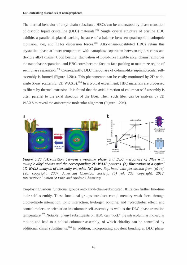
1.4 Controlling assemblies of nanographenes
48
The thermal behavior of alkyl-chain-substituted HBCs can be understood by phase transition
of discotic liquid crystalline (DLC) materials.204 Single crystal structure of pristine HBC
exhibits a parallel-displaced packing because of a balance between quadrupole-quadrupole
repulsion, π-π, and CH-π dispersion forces.205 Alky-chain-substituted HBCs retain this
crystalline phase at lower temperature with nanophase separation between rigid π-cores and
flexible alkyl chains. Upon heating, fluctuation of liquid-like flexible alkyl chains reinforces
the nanophase separation, and HBC cores become face-to-face packing to maximize region of
such phase separation.206 Consequently, DLC mesophase of column-like supramolecular self-
assembly is formed (Figure 1.20a). This phenomenon can be easily monitored by 2D wide-
angle X-ray scattering (2D WAXS).200 In a typical experiment, HBC materials are processed
as fibers by thermal extrusion. It is found that the axial direction of columnar self-assembly is
often parallel to the axial direction of the fiber. Then, such fiber can be analysis by 2D
WAXS to reveal the anisotropic molecular alignment (Figure 1.20b).
Figure 1.20 (a)Transition between crystalline phase and DLC mesophase of NGs with
multiple alkyl chains and the corresponding 2D WAXS patterns. (b) Illustration of a typical
2D WAXS analysis of thermally extruded NG fiber. Reprinted with permission from (a) ref.
198, copyright: 2007, American Chemical Society; (b) ref. 203, copyright: 2012,
International Union of Pure and Applied Chemistry.
Employing various functional groups onto alkyl-chain-substituted HBCs can further fine-tune
their self-assembly. These functional groups introduce complementary weak force through
dipole-dipole interaction, ionic interaction, hydrogen bonding, and hydrophobic effect, and
control molecular orientation in columnar self-assembly as well as the DLC phase transition
temperature.207 Notably, phenyl substituents on HBC can “lock” the intracolumnar molecular
motion and lead to a helical columnar assembly, of which chirality can be controlled by
additional chiral substituents.208 In addition, incorporating covalent bonding at DLC phase,

Chapter 1. Introduction
49
such as triggering polymerization of acrylate groups of HBC 103 at its DLC phase, can fix
molecules into a network and avoid back-transition into crystalline phase (Figure 1.21).209
Figure 1.21 HBC derivatives with different kinds of functional group that control their 3D
supramolecular assemblies.
Substitution patterns and positions also play an important role on intercolumnar organization
and intracolumnar molecular orientation of the 3D assembly of HBC derivatives.210 Notably,
combing these above-mentioned concepts, the group of Aida synthesized HBC derivative 104,
which assembled into a hollow nanotube with a diameter of 20 nm in solution (Figure
1.21).211 Besides, larger π-functional groups, such as perylene monoimide (PMI) in HBC
derivative 105, can further regulate the nanomorphology by additional π-π interactions
(Figure 1.21). Our group and the group of Samorì revealed that intercolumnar nanophase
segregation between electron donor (HBC) and acceptor (PMI) occurred for 105 as bulk
material.212,213 The nanophase separation led to double-channeled charge transfer (CT)
pathway and ambipolar FET performance of device based on 106.
Despite thermal responsive DLC behaviors of alkyl-substituted NGs, it will be intriguing for
controlling self-assemblies of NGs by other stimuli. Yet, the use of other external stimuli has
only been occasionally considered. Among different external stimuli, light is particularly
attractive for a possible remote application with high spatial and temporal resolution. Notably,
molecular photoswitches can isomerize between (quasi)stable states by light irradiation. Such
isomerization could change the local physical/chemical environment and have an impact on
molecular interaction.214 Especially, azobenzene, exhibiting a drastic change on their
geometry and polarity upon isomerization between its trans- and cis-forms, is the most
widely applied moiety for photoregulated supramoleculer behaviors.215
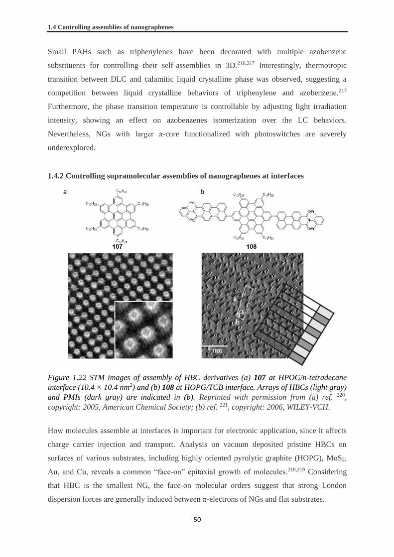
1.4 Controlling assemblies of nanographenes
50
Small PAHs such as triphenylenes have been decorated with multiple azobenzene
substituents for controlling their self-assemblies in 3D.216,217 Interestingly, thermotropic
transition between DLC and calamitic liquid crystalline phase was observed, suggesting a
competition between liquid crystalline behaviors of triphenylene and azobenzene.217
Furthermore, the phase transition temperature is controllable by adjusting light irradiation
intensity, showing an effect on azobenzenes isomerization over the LC behaviors.
Nevertheless, NGs with larger π-core functionalized with photoswitches are severely
underexplored.
1.4.2 Controlling supramolecular assemblies of nanographenes at interfaces
Figure 1.22 STM images of assembly of HBC derivatives (a) 107 at HPOG/n-tetradecane
interface (10.4 × 10.4 nm2) and (b) 108 at HOPG/TCB interface. Arrays of HBCs (light gray)
and PMIs (dark gray) are indicated in (b). Reprinted with permission from (a) ref. 220,
copyright: 2005, American Chemical Society; (b) ref. 221, copyright: 2006, WILEY-VCH.
How molecules assemble at interfaces is important for electronic application, since it affects
charge carrier injection and transport. Analysis on vacuum deposited pristine HBCs on
surfaces of various substrates, including highly oriented pyrolytic graphite (HOPG), MoS2,
Au, and Cu, reveals a common “face-on” epitaxial growth of molecules.218,219 Considering
that HBC is the smallest NG, the face-on molecular orders suggest that strong London
dispersion forces are generally induced between π-electrons of NGs and flat substrates.

Chapter 1. Introduction
51
STM provides opportunity for molecularly or atomically precise and a quasi-time-resolved
imaging. For this reason, STM is particularly useful for monitoring molecular assembly of
NGs at interfaces.198 For example, STM reveals that hexadodecyl-HBC 107 assembles into
2D crystal with a square unit cell at HOPG/n-tetradecane interface (Figure 1.22a).220 The
HBC core can be differentiated from alkyl chains for a different contrast in the image.
From STM analysis of a considerable number of HBC derivatives, it has been shown that
their assemblies on HOPG are highly controllable by equipping different functional groups as
well as altering substitution patterns.222 For example, in collaboration with Rabe and Samorì,
we investigated self-assemblies of PMI-HBC dyad 106 and PMI-HBC-PMI triad 108 at
HOPG/TCB interfaces (Figure 1.21 and 1.22b).221 Interestingly, unlike the behavior of its
structural analog 105 in 3D, assembly of PMI-HBC dyad 106 on HOPG surface displayed
rather isolated molecular organization with no intermolecular interaction between π-cores. In
contrast, PMI-HBC-PMI triad 108 exhibited a nanophase segregation between electron donor
(HBC) and acceptor (PMI), where PMIs packed in an “edge-on” fashion (Figure 1.22b). The
edge-on packing of PMIs led to a more compact assembly of triad 108 and a surprisingly
smaller occupied-area-per-molecule on HOPG in comparison with that of dyad 106.
Scheme 1.11 Photoisomerization between trans- and cis-forms of azobenzene-containing (a)
isophthalic acid 109 and (b) HBC 110.
After demonstrating the tunable assemblies of NGs at HOPG/liquid interface by
functionalization, the next concern is whether it is possibly for remote controlling such

1.4 Controlling assemblies of nanographenes
52
assemblies.223 In collaboration with the group of De Schryver, we had pioneered on
investigating 2D self-assembly of azobenzene derivatives at HOPG/liquid interface.224
Azobenzene-containing isophthalic acid derivative 109 was found to form stable 2D crystals
for both of its trans- and cis-isomers at HOPG/1-undecanol interface. These self-assemblies
were stabilized by London dispersion force between long alkyl chains, and hydrogen bonds
between molecules as well as 1-undecanol cocrystalizing on surface. Furthermore, in
collaboration with the group of Rabe, we studied photoisomerization of azobenzene-
containing HBC 110 and its self-assembly on HOPG (Scheme 1.11b).225 Unfortunately,
although the trans-form of 110 constituted a 2D pattern at HOPG/TCB interface, no change
was observed after light irradiation.
Figure 1.23 Various monodispersed GQDs with carboxyl groups.
In a device application point of view, it is essential to develop protocols that can control
assembly of NGs on substrates surface beyond that of HOPG. Particularly, assembly on
surface of dielectric materials, such as metal/semimetal oxide, is important for applications in
OFET and OPV. In collaboration with Bjørnholm’s group, we investigated films of carboxyl-

Chapter 1. Introduction
53
group-functionalized amphiphilic HBC 111 on mica (Figure 1.23).226 From X-ray diffraction
analysis, it was revealed that HBC 111 assembled in an edge-on fashion. Besides, the group
of Li synthesized a larger carboxyl-group-equipped monodispersed GQD 112 (Figure
1.23).227 Low surface-coverage film of GQD 112 on mica can be prepared by either
Langmuir-Blodgett technique at water/air interface or submerging the substrate in a toluene
solution of GQD 112. From AFM film-thickness-analysis, they concluded that GQD 112
assembled as an edge-on monolayer for the chemical affinity of carboxyl group to mica
surface. Interestingly, thin film of the other two monodispersed GQDs 113 and 114 with no
carboxyl group or one more carboxyl group, respectively, exhibited face-on arrangement on
mica (Figure 1.23). The same group also discovered that dye-sensitized solar cell using
monodispersed GQD 113 and TiO2 gave a low current density, which is attributed to a low
affinity of 113 onto TiO2 surface induced by only physisorption. It was suggested that a
chemisorption could improve the performance.228

54
1.5 Motivation
In the previous sections we have witnessed that the relationship between PAHs, NGs, and
graphene is a matter of length scale. Indeed, the most attractive application of graphene is
next generation electronics, for its supreme carrier mobility. However, because of the very
nature of graphene as zero band gap material, several applications, especially as logic device,
are severely hindered. To solve this, it is necessary to resort to nanoscience.
This thesis aims for bottom-up synthesis that provides new possibilities on ultra large and
non-hexagon-containing PAHs and NGs, under a frame of graphene quantization and defect
engineering, respectively. Furthermore, anchoring on HBC, we also explore, by chemical
functionalization, aspects related to assembly of NGs at interface as well as in bulk.
1.5.1 Synthesis of polyphenylenes as potential precursors for nanographenes
approaching length scale of 5 nm
We have seen in section 1.2 that employing both top-down and bottom-up methods can
provide NGs.70 There, we highlight that carrier mobility and band gap of NGs primarily relate
to their size,56 and a balance between a reasonable band gap and high carrier mobility could
be reached at a spatial scale of 5–10 nm.52,54 Thus, proper fabrication technique is highly
desired for producing NGs as well as their precursors confined at this scale.
We have introduced in section 1.2.4 and 1.2.5 that GQDs and GNRs can be achieved
currently with a diameter or a width up to 3 nm or 2 nm, respectively. This is still far below
the desired 5–10 nm spatial scale. Thus, in Chapter 2 and Chapter 3, we will engage in new
synthetic approaches for dendritic and linear PPs that could potentially serve as precursors for
larger GQDs and GNRs, respectively.
We have described in section 1.2.4 our earlier attempts on synthesizing dendritic PP 26 and
27 as precursors for larger GQDs (Figure 1.7).100,101 However, their complete graphitization
are hindered by a lower symmetry and overlap between benzene ring in 2D projection,
respectively. In Chapter 2, we will synthesize another two dendritic PPs having 366 and 546
carbons, respectively, by divergent synthesis employing D-A reactions (Figure 1.24). Their
structure will be characterized in detail by NMR and MALDI. After achieving the dendritic
PPs, their graphitization reactions will be investigated by both solution-based reactions as
well as surface-assisted thermal cyclodehydrogenation. An ideal complete planarization of
these two PP precursors, featuring no overlap in 2D projection, could lead to D6h-symmetric
monodispersed GQDs with diameters approaching 4 nm and 5 nm, respectively.

Chapter 1. Introduction
55
Figure 1.24 Dendritic PPs suitable as precursors for monodispersed GQDs with diameters
approaching 5 nm.
Figure 1.25 New universal synthetic protocol for synthesis of PP precursors for GNRs with
customized width.
In section 1.2.5, we have highlighted synthesis of linear PPs that are suitable for bottom-up
synthesis of wide GNRs. Especially, our previous approaches using AB-type D-A
polymerization provide a series of PP as precursors for GNRs with increased width up to 2

1.5 Motivation
56
nm.113 Based on these, in Chapter 3, we will develop another approach for lateral extension
of PPs, applying two different kinds of D-A reactions (Figure 1.25). Firstly, a linear PP
backbone bearing ethynyl functional groups that could react in a second D-A reaction step is
synthesized by D-A polymerization. Secondly, CPs with trimethylsilyl (TMS)-protected
ethynyl groups can stepwise extend the PP backbone through a sequence of D–A reactions
and deprotections. This approach avoids complicated monomer design that is required for our
former synthetic protocol. Furthermore, the structures of the PPs are carefully designed to
exclude any benzene overlap in a 2D projection, and thus they are suitable precursors for
GNRs with tailored width. Cyclodehydrogenations of the resulted PPs will also be studied.
1.5.2 Bottom-up approach for nanostructures related to graphene grain boundaries
Defect engineering can tailor properties of graphene. In particular, understanding and perhaps
controlling GB is especially important, since large graphene flakes are always
polycrystalline.135 Nevertheless, unleashing the potential of GB requires synthetic methods
that could precisely control its nanostructure as well as tilt angles between graphene grains.
In section 1.3, we have described how bottom-up synthesis is employed for constructing
various model compounds related to defect structures in graphene. However, it is obvious
that reports are extremely rare on model structures that can be correlated to GB in graphene,
despite it is in fact more important for understanding graphene.
One can envisage that model structures for graphene GB require an oligomeric or polymeric
approach. Thus, solubility issues could complicate their structural characterization. Moreover,
some molecular model compounds of defects in graphene already exhibit low stability.169,181
It is expected that the stability of nanostructures representing GB in graphene can be even
lower, since a cluster of point defects coexists. Fortunately, on-surface synthesis at UHV
condition provides a “super clean” environment and opportunities for in-situ structural
characterization at an atomic level by scanning probe microscopies (section 1.2.3).93 Taking
full advantage of this method, in collaboration with Fasel’s group, we will explore in Chapter
4 and Chapter 5 the synthesis of polyazulenes that give an insight on graphene GB.
In Chapter 4, we will synthesize 2,6-diiodoazulene in solution, and study its further
polymerization under UHV condition on Au (111) surface (Figure 1.26, path I). The non-
negligible intrinsic dipole moment of azulene could play a guiding role during polymerization,
forming 2,6-polyazulene with a possible controlled head-to-tail connection. Electronic
properties of the resulted polymer will be further characterized by STS. The 2,6-polyazulene,
although not experimentally observed at graphene GB, is a theoretical local minimum in an

Chapter 1. Introduction
57
energy profile of different GB nanostructures.137 Besides, the polyazulene is also interesting
on its own as a highly polarized nanowire.
Figure 1.26 Bottom-up approach for nanostructure closely related to graphene GB.
It has been shown in section 1.3.1 that experimentally observed graphene GB are often
composed of fused pentagons-heptagon-pairs (Figure 1.11).136 Accordingly, in Chapter 5, we
will employ 3,3’-dibromo-1,1’-biazulene and polymerize it under UHV condition at Au(111)
surface (Figure 1.26, path II). The target product 1,3-polyazulene structurally allows a further
cyclodehydrogenation into planar sp2-carbon-nanostructure. Notably, azulene is known for
isomerizing into naphthalene or indene derivatives, especially when involving radical
intermediates.229 Thus, cyclodehydrogenation of 1,3-polyazulene is expected to be companied
by skeleton rearrangement, and could possibly lead to cata-fused azulenes.

1.5 Motivation
58
1.5.3 Exploring self-assemblies of hexa-peri-hexabenzocoronene derivatives
We have described in section 1.4 the self-assembly behaviors of NGs in bulk as well as at
interface. Especially, serving as the simplest NG, HBC has been widely employed as model
compound for understanding supramoleculer organization of NGs and exploring their
applications. In Chapter 6–8, we will examine some aspects of assembly of chemically
functionalized HBCs and their photophysical and photochemical properties.
Alkylated HBCs can have DLC behavior and specific 2D assembly patterns at HOPG/liquid
interface. Such supramolecular behaviors are often thermally responsive. However,
controlling the assembly of HBC derivatives by other stimuli has remained relatively
unexplored. In section 1.4.2, we have mentioned that HBC derivative 110 with one
azobenzene functional group does not change its 2D-assembly pattern at HOPG/liquid
interface after light irradiation. In Chapter 6, we will synthesize two more symmetric HBCs
decorated with one more azobenzene moiety (Figure 1.27a). We will then investigate their
photoisomerization by UV-Vis absorption and NMR spectral change upon UV-irradiation.
Furthermore, their 2D assemblies at HOPG/liquid interface will be examined by STM
analysis coupled with in-situ light irradiation. The additional azobenzene could induce a
pronounced local environmental change upon isomerization and enable an observable
alteration on assembly patterns.
Figure 1.27 HBC functionalized with different moieties for investigation of their assemblies.
We have seen in section 1.4 that electron withdrawing PMI groups can have a drastic effect
on assemblies of HBCs in bulk as well as at interface. Accordingly, in Chapter 7, in
Chapter 1. Introduction
59
collaboration with Keerthi, we will systematically investigate the 3D assemblies and thermal
behavior of HBCs with various electron accepting functional groups (Figure 1.27b).
Furthermore, since NGs have an electron-rich nature, functionalizing them with electron
accepting moieties could strongly affect their electronic properties. However, there were only
limited number of related works in the literatures.230 Thus, the UV-Vis absorption spectra of
the corresponding HBCs will be compared. Also, two different synthetic strategies, namely
“pre-functionalization” and “post-functionalization”, will be evaluated. This synthetic studies
can pilot further functionalization attempts for larger NGs.119
We have described in section 1.4.2 that carboxyl groups can induce edge-on chemisorption of
GQDs on mica. Attempts on applying them in dye-sensitized solar cell suggest that
chemisorption would enhance the performance over physisorption. Considering that there is
no systematic proof for this claim, in Chapter 8, we will synthesize HBC derivatives with or
without carboxyl group (Figure 1.27c). In collaboration with the group of Bonn, we will
adsorb them onto metal oxide surface and compare their photoinduced CT with metal oxide
by Optical pump-terahertz probe (OPTP).

60
1.6 References
(1) Demming, A. King of the Elements? Nanotechnology 2010, 21 (30), 300201.
(2) Sims, R. C.; Overcash, M. R. Fate of Polynuclear Aromatic Compounds (PNAs) in Soil-Plant Systems. In Residue
Reviews; Springer New York: New York, NY, 1983; Vol. 88, pp 1–68.
(3) Hites, R. A.; Laflamme, R. E.; Farrington, J. W. Sedimentary Polycyclic Aromatic Hydrocarbons: The Historical
Record. Science 1977, 198 (4319), 829–831.
(4) Fleming, I. Molecular Orbitals and Organic Chemical Reactions; John Wiley & Sons Ltd: Chichester, 2009.
(5) Bauschlicher, C. W.; Boersma, C.; Bauschlicher, C. W.; Ricca, A.; Mattioda, A. L.; Cami, J.; Peeters, E.; De Armas,
F. S.; Saborido, G. P.; Hudgins, D. M.; et al. The NASA Ames PAH IR Spectroscopic Database Version 2.00:
Content, Web Site, and on(off)Line Tools. Astrophys. Journal, Suppl. Ser. 2014, 211 (1), 8.
(6) Xue, W.; Warshawsky, D. Metabolic Activation of Polycyclic and Heterocyclic Aromatic Hydrocarbons and DNA
Damage: A Review. Toxicol. Appl. Pharmacol. 2005, 206 (1), 73–93.
(7) Grimmer, G.; Düvel, D. Endogenous Formation of Polycyclic Hydrocarbons in Higher Plants. 8. Carcinogenic
Hydrocarbons in the Human Environment. Z. Naturforsch. B. 1970, 25 (10), 1171–1175.
(8) Scholl, R.; Seer, C.; Weitzenböck, R. Perylen, Ein Hoch Kondensierter Aromatischer Kohlenwasserstoff C20H12.
Berichte der Dtsch. Chem. Gesellschaft 1910, 43 (2), 2202–2209.
(9) Clar, E.; Stewart, D. G. Aromatic Hydrocarbons. LXV. Triangulene Derivatives 1. J. Am. Chem. Soc. 1953, 75 (11),
2667–2672.
(10) Wang, X.-Y.; Yao, X.; Müllen, K. Polycyclic Aromatic Hydrocarbons in the Graphene Era. Sci. China Chem. 2019,
62 (9), 1099–1144.
(11) Horowitz, G. Organic Transistors. In Organic Electronics; Wiley-VCH Verlag GmbH & Co. KGaA: Weinheim,
FRG, 2006; pp 1–32.
(12) Anthony, J. E. Engineered Pentacenes. In Organic Electronics; Wiley-VCH Verlag GmbH & Co. KGaA: Weinheim,
FRG, 2006; pp 58–74.
(13) Kelley, T. High-Performance Pentacene Transistors. In Organic Electronics; Wiley-VCH Verlag GmbH & Co.
KGaA: Weinheim, FRG, 2006; pp 33–57.
(14) Wu, J.; Müllen, K. All-Benzenoid Polycyclic Aromatic Hydrocarbons: Synthesis, Self-Assembly and Applications
in Organic Electronics. In Carbon-Rich Compounds; Wiley-VCH Verlag GmbH & Co. KGaA: Weinheim, FRG,
2006; pp 90–139.
(15) Bresó-Femenia, E.; Chaudret, B.; Castillón, S. Selective Catalytic Hydrogenation of Polycyclic Aromatic
Hydrocarbons Promoted by Ruthenium Nanoparticles. Catal. Sci. Technol. 2015, 5 (5), 2741–2751.
(16) Novoselov, K. S.; Geim, A. K.; Morozov, S. V.; Jiang, D.; Zhang, Y.; Dubonos, S. V.; Grigorieva, I. V.; Firsov, A.
A. Electric Field in Atomically Thin Carbon Films. Science 2004, 306 (5696), 666–669.
(17) Geim, A. K.; Novoselov, K. S. The Rise of Graphene. Nat. Mater. 2007, 6 (3), 183–191.
(18) Novoselov, K. S.; Fal’Ko, V. I.; Colombo, L.; Gellert, P. R.; Schwab, M. G.; Kim, K. A Roadmap for Graphene.
Nature 2012, 490 (7419), 192–200.
(19) Wallace, P. R. The Band Theory of Graphite. Phys. Rev. 1947, 71 (9), 622–634.
(20) Lifshitz, E. M.; Pitaevskii, L. P. Fluctuations. In Course of Theoretical Physics, Vol. 5, Statistical Physics, Part 1;
Landau, L. D., Lifshitz, E. M., Eds.; Pergamon Press Ltd.: Oxford, 1980; pp 333–400.
(21) Радушкевич, Л. В. О Структуре Углерода, Образующегося При Термическом Разложении Окиси Углерода
На Железном Контакте. Журнал Физической Химии 1952, 26, 88–95.
(22) Kroto, H. W.; Heath, J. R.; O’Brien, S. C.; Curl, R. F.; Smalley, R. E. C60: Buckminsterfullerene. Nature 1985, 318
(6042), 162–163.
(23) Dresselhaus, M. S.; Dresselhaus, G. Intercalation Compounds of Graphite. Adv. Phys. 1981, 30 (2), 139–326.

Chapter 1. Introduction
61
(24) Morozov, S. V.; Novoselov, K. S.; Katsnelson, M. I.; Schedin, F.; Elias, D. C.; Jaszczak, J. A.; Geim, A. K. Giant
Intrinsic Carrier Mobilities in Graphene and Its Bilayer. Phys. Rev. Lett. 2008, 100 (1), 016602.
(25) Balandin, A. A.; Ghosh, S.; Bao, W.; Calizo, I.; Teweldebrhan, D.; Miao, F.; Lau, C. N. Superior Thermal
Conductivity of Single-Layer Graphene. Nano Lett. 2008, 8 (3), 902–907.
(26) Lee, C.; Wei, X.; Kysar, J. W.; Hone, J. Measurement of the Elastic Properties and Intrinsic Strength of Monolayer
Graphene. Science 2008, 321 (5887), 385–388.
(27) Booth, T. J.; Blake, P.; Nair, R. R.; Jiang, D.; Hill, E. W.; Bangert, U.; Bleloch, A.; Gass, M.; Novoselov, K. S.;
Katsnelson, M. I.; et al. Macroscopic Graphene Membranes and Their Extraordinary Stiffness. Nano Lett. 2008, 8
(8), 2442–2446.
(28) Wang, X.-Y.; Narita, A.; Müllen, K. Precision Synthesis versus Bulk-Scale Fabrication of Graphenes. Nat. Rev.
Chem. 2017, 2 (1), 0100.
(29) Paton, K. R.; Varrla, E.; Backes, C.; Smith, R. J.; Khan, U.; O’Neill, A.; Boland, C.; Lotya, M.; Istrate, O. M.; King,
P.; et al. Scalable Production of Large Quantities of Defect-Free Few-Layer Graphene by Shear Exfoliation in
Liquids. Nat. Mater. 2014, 13 (6), 624–630.
(30) Hernandez, Y.; Nicolosi, V.; Lotya, M.; Blighe, F. M.; Sun, Z.; De, S.; McGovern, I. T.; Holland, B.; Byrne, M.;
Gun’ko, Y. K.; et al. High-Yield Production of Graphene by Liquid-Phase Exfoliation of Graphite. Nat.
Nanotechnol. 2008, 3 (9), 563–568.
(31) Ren, W.; Cheng, H. M. The Global Growth of Graphene. Nat. Nanotechnol. 2014, 9 (10), 726–730.
(32) Yang, S.; Ricciardulli, A. G.; Liu, S.; Dong, R.; Lohe, M. R.; Becker, A.; Squillaci, M. A.; Samorì, P.; Müllen, K.;
Feng, X. Ultrafast Delamination of Graphite into High-Quality Graphene Using Alternating Currents. Angew. Chem.
Int. Ed. 2017, 56 (23), 6669–6675.
(33) Yang, S.; Brüller, S.; Wu, Z. S.; Liu, Z.; Parvez, K.; Dong, R.; Richard, F.; Samorì, P.; Feng, X.; Müllen, K.
Organic Radical-Assisted Electrochemical Exfoliation for the Scalable Production of High-Quality Graphene. J. Am.
Chem. Soc. 2015, 137 (43), 13927–13932.
(34) Yang, S.; Lohe, M. R.; Müllen, K.; Feng, X. New-Generation Graphene from Electrochemical Approaches:
Production and Applications. Adv. Mater. 2016, 28 (29), 6213–6221.
(35) Chua, C. K.; Pumera, M. Chemical Reduction of Graphene Oxide: A Synthetic Chemistry Viewpoint. Chem. Soc.
Rev. 2014, 43 (1), 291–312.
(36) Eigler, S.; Enzelberger-Heim, M.; Grimm, S.; Hofmann, P.; Kroener, W.; Geworski, A.; Dotzer, C.; Röckert, M.;
Xiao, J.; Papp, C.; et al. Wet Chemical Synthesis of Graphene. Adv. Mater. 2013, 25 (26), 3583–3587.
(37) Butz, B.; Dolle, C.; Halbig, C. E.; Spiecker, E.; Eigler, S. Highly Intact and Pure Oxo-Functionalized Graphene:
Synthesis and Electron-Beam-Induced Reduction. Angew. Chem. Int. Ed. 2016, 55 (51), 15771–15774.
(38) Matsumoto, M.; Saito, Y.; Park, C.; Fukushima, T.; Aida, T. Ultrahigh-Throughput Exfoliation of Graphite into
Pristine “single-Layer” Graphene Using Microwaves and Molecularly Engineered Ionic Liquids. Nat. Chem. 2015,
7 (9), 730–736.
(39) Voiry, D.; Fullon, R.; Lee, C.; Jeong, H. Y.; Shin, H. S.; Chhowalla, M. High-Quality Graphene via Microwave
Reduction of Solution-Exfoliated Graphene Oxide. Science 2016, 353 (6306), 1430–1433.
(40) Kobayashi, T.; Bando, M.; Kimura, N.; Shimizu, K.; Kadono, K.; Umezu, N.; Miyahara, K.; Hayazaki, S.; Nagai, S.;
Mizuguchi, Y.; et al. Production of a 100-m-Long High-Quality Graphene Transparent Conductive Film by Roll-to-
Roll Chemical Vapor Deposition and Transfer Process. Appl. Phys. Lett. 2013, 102 (2), 023112.
(41) Hao, Y.; Bharathi, M. S.; Wang, L.; Liu, Y.; Chen, H.; Nie, S.; Wang, X.; Chou, H.; Tan, C.; Fallahazad, B.; et al.
The Role of Surface Oxygen in the Growth of Large Single-Crystal Graphene on Copper. Science 2013, 342 (6159),
720–723.
(42) Jang, H.; Park, Y. J.; Chen, X.; Das, T.; Kim, M. S.; Ahn, J. H. Graphene-Based Flexible and Stretchable
Electronics. Adv. Mater. 2016, 28 (22), 4184–4202.

1.6 References
62
(43) Chang, C. W.; Liao, Y. C. Accelerated Sedimentation Velocity Assessment for Nanowires Stabilized in a Non-
Newtonian Fluid. Langmuir 2016, 32 (51), 13620–13626.
(44) Chae, H. K.; Siberio-Pérez, D. Y.; Kim, J.; Go, Y.; Eddaoudi, M.; Matzger, A. J.; O’Keeffe, M.; Yaghi, O. M. A
Route to High Surface Area, Porosity and Inclusion of Large Molecules in Crystals. Nature 2004, 427 (6974), 523–
527.
(45) Stoller, M. D.; Park, S.; Yanwu, Z.; An, J.; Ruoff, R. S. Graphene-Based Ultracapacitors. Nano Lett. 2008, 8 (10),
3498–3502.
(46) Garaj, S.; Hubbard, W.; Reina, A.; Kong, J.; Branton, D.; Golovchenko, J. A. Graphene as a Subnanometre Trans-
Electrode Membrane. Nature 2010, 467 (7312), 190–193.
(47) Schedin, F.; Geim, A. K.; Morozov, S. V.; Hill, E. W.; Blake, P.; Katsnelson, M. I.; Novoselov, K. S. Detection of
Individual Gas Molecules Adsorbed on Graphene. Nat. Mater. 2007, 6 (9), 652–655.
(48) Lin, Y.-M.; Dimitrakopoulos, C.; Jenkins, K. A.; Farmer, D. B.; Chiu, H.-Y.; Grill, A.; Avouris, P. 100-GHz
Transistors from Wafer-Scale Epitaxial Graphene. Science 2010, 327 (5966), 662–662.
(49) Xia, F.; Farmer, D. B.; Lin, Y. M.; Avouris, P. Graphene Field-Effect Transistors with High on/off Current Ratio
and Large Transport Band Gap at Room Temperature. Nano Lett. 2010, 10 (2), 715–718.
(50) Schwierz, F. Graphene Transistors. Nat. Nanotechnol. 2010, 5 (7), 487–496.
(51) Ponomarenko, L. A.; Schedin, F.; Katsnelson, M. I.; Yang, R.; Hill, E. W.; Novoselov, K. S.; Geim, A. K. Chaotic
Dirac Billiard in Graphene Quantum Dots. Science 2008, 320 (5874), 356–358.
(52) Han, M. Y.; Özyilmaz, B.; Zhang, Y.; Kim, P. Energy Band-Gap Engineering of Graphene Nanoribbons. Phys. Rev.
Lett. 2007, 98 (20), 206805.
(53) Shen, J.; Zhu, Y.; Yang, X.; Li, C. Graphene Quantum Dots: Emergent Nanolights for Bioimaging, Sensors,
Catalysis and Photovoltaic Devices. Chem. Commun. 2012, 48 (31), 3686–3699.
(54) Bai, J.; Duan, X.; Huang, Y. Rational Fabrication of Graphene Nanoribbons Using a Nanowire Etch Mask. Nano
Lett. 2009, 9 (5), 2083–2087.
(55) Abbas, A. N.; Liu, G.; Liu, B.; Zhang, L.; Liu, H.; Ohlberg, D.; Wu, W.; Zhou, C. Patterning, Characterization, and
Chemical Sensing Applications of Graphene Nanoribbon Arrays Down to 5 Nm Using Helium Ion Beam
Lithography. ACS Nano 2014, 8 (2), 1538–1546.
(56) Fischer, M. M.; de Sousa, L. E.; Luiz e Castro, L.; Ribeiro, L. A.; de Sousa, R. T.; Magela e Silva, G.; de Oliveira
Neto, P. H. Effective Mass of Quasiparticles in Armchair Graphene Nanoribbons. Sci. Rep. 2019, 9 (1), 17990.
(57) Hwang, W. S.; Tahy, K.; Li, X.; Xing, H. (Grace); Seabaugh, A. C.; Sung, C. Y.; Jena, D. Transport Properties of
Graphene Nanoribbon Transistors on Chemical-Vapor-Deposition Grown Wafer-Scale Graphene. Appl. Phys. Lett.
2012, 100 (20), 203107.
(58) Wei, D.; Xie, L.; Lee, K. K.; Hu, Z.; Tan, S.; Chen, W.; Sow, C. H.; Chen, K.; Liu, Y.; Wee, A. T. S. Controllable
Unzipping for Intramolecular Junctions of Graphene Nanoribbons and Single-Walled Carbon Nanotubes. Nat.
Commun. 2013, 4 (1), 1374.
(59) Abramova, V.; Slesarev, A. S.; Tour, J. M. Meniscus-Mask Lithography for Narrow Graphene Nanoribbons. ACS
Nano 2013, 7 (8), 6894–6898.
(60) Min, S. Y.; Kim, T. S.; Kim, B. J.; Cho, H.; Noh, Y. Y.; Yang, H.; Cho, J. H.; Lee, T. W. Large-Scale Organic
Nanowire Lithography and Electronics. Nat. Commun. 2013, 4 (1), 1773.
(61) Son, J. G.; Son, M.; Moon, K. J.; Lee, B. H.; Myoung, J. M.; Strano, M. S.; Ham, M. H.; Ross, C. A. Sub-10 Nm
Graphene Nanoribbon Array Field-Effect Transistors Fabricated by Block Copolymer Lithography. Adv. Mater.
2013, 25 (34), 4723–4728.
(62) Yu, W. J.; Duan, X. Tunable Transport Gap in Narrow Bilayer Graphene Nanoribbons. Sci. Rep. 2013, 3 (1), 1248.
(63) Li, X.; Wang, X.; Zhang, L.; Lee, S.; Dai, H. Chemically Derived, Ultrasmooth Graphene Nanoribbon
Semiconductors. Science 2008, 319 (5867), 1229–1232.
Chapter 1. Introduction
63
(64) Jiao, L.; Wang, X.; Diankov, G.; Wang, H.; Dai, H. Facile Synthesis of High-Quality Graphene Nanoribbons. Nat.
Nanotechnol. 2010, 5 (5), 321–325.
(65) Wang, X.; Dai, H. Etching and Narrowing of Graphene from the Edges. Nat. Chem. 2010, 2 (8), 661–665.
(66) Kato, T.; Hatakeyama, R. Site- and Alignment-Controlled Growth of Graphene Nanoribbons from Nickel Nanobars.
Nat. Nanotechnol. 2012, 7 (10), 651–656.
(67) Martin-Fernandez, I.; Wang, D.; Zhang, Y. Direct Growth of Graphene Nanoribbons for Large-Scale Device
Fabrication. Nano Lett. 2012, 12 (12), 6175–6179.
(68) Sprinkle, M.; Ruan, M.; Hu, Y.; Hankinson, J.; Rubio-Roy, M.; Zhang, B.; Wu, X.; Berger, C.; de Heer, W. A.
Scalable Templated Growth of Graphene Nanoribbons on SiC. Nat. Nanotechnol. 2010, 5 (10), 727–731.
(69) Jacobberger, R. M.; Kiraly, B.; Fortin-Deschenes, M.; Levesque, P. L.; McElhinny, K. M.; Brady, G. J.; Rojas
Delgado, R.; Singha Roy, S.; Mannix, A.; Lagally, M. G.; et al. Direct Oriented Growth of Armchair Graphene
Nanoribbons on Germanium. Nat. Commun. 2015, 6 (1), 8006.
(70) Xu, W.; Lee, T. W. Recent Progress in Fabrication Techniques of Graphene Nanoribbons. Mater. Horizons 2016, 3
(3), 186–207.
(71) Samor, P.; Severin, N.; Simpson, C. D.; Müllen, K.; Rabe, J. P. Epitaxial Composite Layers of Electron Donors and
Acceptors from Very Large Polycyclic Aromatic Hydrocarbons. J. Am. Chem. Soc. 2002, 124 (32), 9454–9457.
(72) Beser, U.; Kastler, M.; Maghsoumi, A.; Wagner, M.; Castiglioni, C.; Tommasini, M.; Narita, A.; Feng, X.; Müllen,
K. A C216-Nanographene Molecule with Defined Cavity as Extended Coronoid. J. Am. Chem. Soc. 2016, 138 (13),
4322–4325.
(73) Chen, Q.; Brambilla, L.; Daukiya, L.; Mali, K. S.; De Feyter, S.; Tommasini, M.; Müllen, K.; Narita, A. Synthesis
of Triply Fused Porphyrin-Nanographene Conjugates. Angew. Chem. Int. Ed. 2018, 57 (35), 11233–11237.
(74) Konishi, A.; Hirao, Y.; Matsumoto, K.; Kurata, H.; Kishi, R.; Shigeta, Y.; Nakano, M.; Tokunaga, K.; Kamada, K.;
Kubo, T. Synthesis and Characterization of Quarteranthene: Elucidating the Characteristics of the Edge State of
Graphene Nanoribbons at the Molecular Level. J. Am. Chem. Soc. 2013, 135 (4), 1430–1437.
(75) Clar, E.; Ironside, C. T. Hexabenzocoronene. Proc. Chem. Soc. 1958, 150.
(76) Hyatt, J. A. Synthesis of a Hexaalkynylhexaphenylbenzene. Org. Prep. Proced. Int. 1991, 23 (4), 460–463.
(77) Feng, X.; Pisula, W.; Kudernac, T.; Wu, D.; Zhi, L.; De Feyter, S.; Müllen, K. Controlled Self-Assembly of C3-
Symmetric Hexa-Peri- Hexabenzocoronenes with Alternating Hydrophilic and Hydrophobic Substituents in
Solution, in the Bulk, and on a Surface. J. Am. Chem. Soc. 2009, 131 (12), 4439–4448.
(78) Yang, X.; Dou, X.; Müllen, K. Efficient Synthesis of Symmetrically and Unsymmetrically Substituted
Hexaphenylbenzene Analogues by Suzuki-Miyaura Coupling Reactions. Chem. - An Asian J. 2008, 3 (4), 759–766.
(79) Feng, X.; Pisula, W.; Müllen, K. Large Polycyclic Aromatic Hydrocarbons: Synthesis and Discotic Organization.
Pure Appl. Chem. 2009, 81 (12), 2203–2224.
(80) Müller, M.; Kübel, C.; Müllen, K. Giant Polycyclic Aromatic Hydrocarbons. Chem. - A Eur. J. 1998, 4 (11), 2099–
2109.
(81) Rempala, P.; Kroulik, J.; King, B. T. Investigation of the Mechanism of the Intramolecular Scholl Reaction of
Contiguous Phenylbenzenes. J. Org. Chem. 2006, 71 (14), 5067–5081.
(82) Stabel, A.; Herwig, P.; Müllen, K.; Rabe, J. P. Diodelike Current–Voltage Curves for a Single Molecule–Tunneling
Spectroscopy with Submolecular Resolution of an Alkylated,Peri-Condensed Hexabenzocoronene. Angew. Chem.
Int. Ed. 1995, 34 (15), 1609–1611.
(83) Zhai, L.; Shukla, R.; Rathore, R. Oxidative C−C Bond Formation (Scholl Reaction) with DDQ as an Efficient and
Easily Recyclable Oxidant. Org. Lett. 2009, 11 (15), 3474–3477.
(84) Scholl, R.; Mansfeld, J. Meso-Benzdianthron (Helianthron),Meso-Naphthodianthron, Und Ein Neuer Weg Zum
Flavanthren. Berichte der Dtsch. Chem. Gesellschaft 1910, 43 (2), 1734–1746.
(85) Grzybowski, M.; Skonieczny, K.; Butenschön, H.; Gryko, D. T. Comparison of Oxidative Aromatic Coupling and
1.6 References
64
the Scholl Reaction. Angew. Chem. Int. Ed. 2013, 52 (38), 9900–9930.
(86) Zhai, L.; Shukla, R.; Wadumethrige, S. H.; Rathore, R. Probing the Arenium-Ion (ProtonTransfer) versus the
Cation-Radical (Electron Transfer) Mechanism of Scholl Reaction Using DDQ as Oxidant. J. Org. Chem. 2010, 75
(14), 4748–4760.
(87) Ajaz, A.; McLaughlin, E. C.; Skraba, S. L.; Thamatam, R.; Johnson, R. P. Phenyl Shifts in Substituted Arenes via
Ipso Arenium Ions. J. Org. Chem. 2012, 77 (21), 9487–9495.
(88) Dötz, F.; Brand, J. D.; Ito, S.; Gherghel, L.; Müllen, K. Synthesis of Large Polycyclic Aromatic Hydrocarbons:
Variation of Size and Periphery. J. Am. Chem. Soc. 2000, 122 (32), 7707–7717.
(89) Müller, M.; Iyer, V. S.; Kübel, C.; Enkelmann, V.; Müllen, K. Polycyclic Aromatic Hydrocarbons by
Cyclodehydrogenation and Skeletal Rearrangement of Oligophenylenes. Angew. Chem. Int. Ed. 1997, 36 (15),
1607–1610.
(90) Feng, X.; Wu, J.; Enkelmann, V.; Müllen, K. Hexa-Peri-Hexabenzocoronenes by Efficient Oxidative
Cyclodehydrogenation: The Role of the Oligophenylene Precursors. Org. Lett. 2006, 8 (6), 1145–1148.
(91) Cai, J.; Ruffieux, P.; Jaafar, R.; Bieri, M.; Braun, T.; Blankenburg, S.; Muoth, M.; Seitsonen, A. P.; Saleh, M.; Feng,
X.; et al. Atomically Precise Bottom-up Fabrication of Graphene Nanoribbons. Nature 2010, 466 (7305), 470–473.
(92) Treier, M.; Pignedoli, C. A.; Laino, T.; Rieger, R.; Müllen, K.; Passerone, D.; Fasel, R. Surface-Assisted
Cyclodehydrogenation Provides a Synthetic Route towards Easily Processable and Chemically Tailored
Nanographenes. Nat. Chem. 2011, 3 (1), 61–67.
(93) Sun, Q.; Zhang, R.; Qiu, J.; Liu, R.; Xu, W. On-Surface Synthesis of Carbon Nanostructures. Adv. Mater. 2018, 30
(17), 1705630.
(94) Cai, J.; Ruffieux, P.; Jaafar, R.; Bieri, M.; Braun, T.; Blankenburg, S.; Muoth, M.; Seitsonen, A. P.; Saleh, M.; Feng,
X.; et al. Atomically Precise Bottom-up Fabrication of Graphene Nanoribbons. Nature 2010, 466 (7305), 470–473.
(95) Iyer, V. S.; Wehmeier, M.; Brand, J. D.; Keegstra, M. A.; Müllen, K. From Hexa-Peri-Hexabenzocoronene to
“Superacenes.” Angew. Chem. Int. Ed. 1997, 36 (15), 1604–1607.
(96) Watson, M. D.; Fechtenkotter, A.; Müllen, K. Big Is Beautiful−“Aromaticity” Revisited from the Viewpoint of
Macromolecular and Supramolecular Benzene Chemistry. Chem. Rev. 2001, 101 (5), 1267–1300.
(97) Simpson, C. Nanoscale Polycyclic Aromatic Hydrocarbons - Synthesis and Charachterization, Johannes Gutenberg-
Universität, Mainz, 2003.
(98) Simpson, C. D.; Brand, J. D.; Berresheim, A. J.; Przybilla, L.; Räder, H. J.; Müllen, K. Synthesis of a Giant 222
Carbon Graphite Sheet. Chem. - A Eur. J. 2002, 8 (6), 1424–1429.
(99) Przybilla, L.; Brand, J.-D.; Yoshimura, K.; Räder, H. J.; Müllen, K. MALDI-TOF Mass Spectrometry of Insoluble
Giant Polycyclic Aromatic Hydrocarbons by a New Method of Sample Preparation. Anal. Chem. 2000, 72 (19),
4591–4597.
(100) Simpson, C. D.; Mattersteig, G.; Martin, K.; Gherghel, L.; Bauer, R. E.; Räder, H. J.; Müllen, K. Nanosized
Molecular Propellers by Cyclodehydrogenation of Polyphenylene Dendrimers. J. Am. Chem. Soc. 2004, 126 (10),
3139–3147.
(101) Dössel, L. Nanographene Als Funktionale Materialien Und Synthetische Herausforderung, Johannes Gutenberg-
Universität, Mainz, 2011.
(102) Wasserfallen, D. Synthetical Engineering of Supramolecular Properties of Large Polycyclic Aromatic
Hydrocarbons, Johannes Gutenberg-Universität, Mainz, 2006.
(103) Narita, A.; Feng, X.; Hernandez, Y.; Jensen, S. A.; Bonn, M.; Yang, H.; Verzhbitskiy, I. A.; Casiraghi, C.; Hansen,
M. R.; Koch, A. H. R.; et al. Synthesis of Structurally Well-Defined and Liquid-Phase-Processable Graphene
Nanoribbons. Nat. Chem. 2014, 6 (2), 126–132.
(104) Yang, X.; Dou, X.; Rouhanipour, A.; Zhi, L.; Räder, H. J.; Müllen, K. Two-Dimensional Graphene Nanoribbons. J.
Am. Chem. Soc. 2008, 130 (13), 4216–4217.

Chapter 1. Introduction
65
(105) Wu, J.; Gherghel, L.; Watson, M. D.; Li, J.; Wang, Z.; Simpson, C. D.; Kolb, U.; Müllen, K. From Branched
Polyphenylenes to Graphite Ribbons. Macromolecules 2003, 36 (19), 7082–7089.
(106) Li, G.; Yoon, K.-Y.; Zhong, X.; Zhu, X.; Dong, G. Efficient Bottom-Up Preparation of Graphene Nanoribbons by
Mild Suzuki-Miyaura Polymerization of Simple Triaryl Monomers. Chem. - A Eur. J. 2016, 22 (27), 9116–9120.
(107) Talirz, L.; Söde, H.; Dumslaff, T.; Wang, S.; Sanchez-Valencia, J. R.; Liu, J.; Shinde, P.; Pignedoli, C. A.; Liang, L.;
Meunier, V.; et al. On-Surface Synthesis and Characterization of 9-Atom Wide Armchair Graphene Nanoribbons.
ACS Nano 2017, 11 (2), 1380–1388.
(108) Basagni, A.; Sedona, F.; Pignedoli, C. A.; Cattelan, M.; Nicolas, L.; Casarin, M.; Sambi, M. Molecules–Oligomers–
Nanowires–Graphene Nanoribbons: A Bottom-Up Stepwise On-Surface Covalent Synthesis Preserving Long-
Range Order. J. Am. Chem. Soc. 2015, 137 (5), 1802–1808.
(109) Jordan, R. S.; Wang, Y.; McCurdy, R. D.; Yeung, M. T.; Marsh, K. L.; Khan, S. I.; Kaner, R. B.; Rubin, Y.
Synthesis of Graphene Nanoribbons via the Topochemical Polymerization and Subsequent Aromatization of a
Diacetylene Precursor. Chem 2016, 1 (1), 78–90.
(110) Abdurakhmanova, N.; Amsharov, N.; Stepanow, S.; Jansen, M.; Kern, K.; Amsharov, K. Synthesis of Wide
Atomically Precise Graphene Nanoribbons from Para-Oligophenylene Based Molecular Precursor. Carbon 2014, 77,
1187–1190.
(111) El Gemayel, M.; Narita, A.; Dössel, L. F.; Sundaram, R. S.; Kiersnowski, A.; Pisula, W.; Hansen, M. R.; Ferrari, A.
C.; Orgiu, E.; Feng, X.; et al. Graphene Nanoribbon Blends with P3HT for Organic Electronics. Nanoscale 2014, 6
(12), 6301–6314.
(112) Yazyev, O. V. A Guide to the Design of Electronic Properties of Graphene Nanoribbons. Acc. Chem. Res. 2013, 46
(10), 2319–2328.
(113) Hou, I. C. Y.; Hu, Y.; Narita, A.; Müllen, K. Diels-Alder Polymerization: A Versatile Synthetic Method toward
Functional Polyphenylenes, Ladder Polymers and Graphene Nanoribbons. Polym. J. 2018, 50 (1), 3–20.
(114) Narita, A.; Verzhbitskiy, I. A.; Frederickx, W.; Mali, K. S.; Jensen, S. A.; Hansen, M. R.; Bonn, M.; De Feyter, S.;
Casiraghi, C.; Feng, X.; et al. Bottom-up Synthesis of Liquid-Phase-Processable Graphene Nanoribbons with near-
Infrared Absorption. ACS Nano 2014, 8 (11), 11622–11630.
(115) Hu, Y.; Xie, P.; De Corato, M.; Ruini, A.; Zhao, S.; Meggendorfer, F.; Straasø, L. A.; Rondin, L.; Simon, P.; Li, J.;
et al. Bandgap Engineering of Graphene Nanoribbons by Control over Structural Distortion. J. Am. Chem. Soc.
2018, 140 (25), 7803–7809.
(116) Osella, S.; Narita, A.; Schwab, M. G.; Hernandez, Y.; Feng, X.; Müllen, K.; Beljonne, D. Graphene Nanoribbons as
Low Band Gap Donor Materials for Organic Photovoltaics: Quantum Chemical Aided Design. ACS Nano 2012, 6
(6), 5539–5548.
(117) Forero-Martinez, N. C.; Baumeier, B.; Kremer, K. Backbone Chemical Composition and Monomer Sequence
Effects on Phenylene Polymer Persistence Lengths. Macromolecules 2019, 52 (14), 5307–5316.
(118) Abbas, A. N.; Liu, G.; Narita, A.; Orosco, M.; Feng, X.; Müllen, K.; Zhou, C. Deposition, Characterization, and
Thin-Film-Based Chemical Sensing of Ultra-Long Chemically Synthesized Graphene Nanoribbons. J. Am. Chem.
Soc. 2014, 136 (21), 7555–7558.
(119) Keerthi, A.; Radha, B.; Rizzo, D.; Lu, H.; Diez Cabanes, V.; Hou, I. C. Y.; Beljonne, D.; Cornil, J.; Casiraghi, C.;
Baumgarten, M.; et al. Edge Functionalization of Structurally Defined Graphene Nanoribbons for Modulating the
Self-Assembled Structures. J. Am. Chem. Soc. 2017, 139 (46), 16454–16457.
(120) Slota, M.; Keerthi, A.; Myers, W. K.; Tretyakov, E.; Baumgarten, M.; Ardavan, A.; Sadeghi, H.; Lambert, C. J.;
Narita, A.; Müllen, K.; et al. Magnetic Edge States and Coherent Manipulation of Graphene Nanoribbons. Nature
2018, 557 (7707), 691–695.
(121) Yano, Y.; Mitoma, N.; Matsushima, K.; Wang, F.; Matsui, K.; Takakura, A.; Miyauchi, Y.; Ito, H.; Itami, K. Living
Annulative π-Extension Polymerization for Graphene Nanoribbon Synthesis. Nature 2019, 571 (7765), 387–392.

1.6 References
66
(122) von Kugelgen, S.; Piskun, I.; Griffin, J. H.; Eckdahl, C. T.; Jarenwattananon, N. N.; Fischer, F. R. Templated
Synthesis of End-Functionalized Graphene Nanoribbons through Living Ring-Opening Alkyne Metathesis
Polymerization. J. Am. Chem. Soc. 2019, 141 (28), 11050–11058.
(123) Yoon, K. Y.; Dong, G. Liquid-Phase Bottom-up Synthesis of Graphene Nanoribbons. Mater. Chem. Front. 2020, 4
(1), 29–45.
(124) Zschieschang, U.; Klauk, H.; Müller, I. B.; Strudwick, A. J.; Hintermann, T.; Schwab, M. G.; Narita, A.; Feng, X.;
Müllen, K.; Weitz, R. T. Electrical Characteristics of Field-Effect Transistors Based on Chemically Synthesized
Graphene Nanoribbons. Adv. Electron. Mater. 2015, 1 (3), 1400010.
(125) Banhart, F.; Kotakoski, J.; Krasheninnikov, A. V. Structural Defects in Graphene. ACS Nano 2011, 5 (1), 26–41.
(126) Krasheninnikov, A. V.; Lehtinen, P. O.; Foster, A. S.; Nieminen, R. M. Bending the Rules: Contrasting Vacancy
Energetics and Migration in Graphite and Carbon Nanotubes. Chem. Phys. Lett. 2006, 418 (1–3), 132–136.
(127) Kotakoski, J.; Krasheninnikov, A. V.; Kaiser, U.; Meyer, J. C. From Point Defects in Graphene to Two-
Dimensional Amorphous Carbon. Phys. Rev. Lett. 2011, 106 (10), 105505.
(128) Wales, D. J.; Stone, A. J. Theoretical Studies Of Icosahedral C60 And Some Related Species. Chem. Phys. Lett.
1986, 128 (5), 501–503.
(129) Meyer, J. C.; Kisielowski, C.; Erni, R.; Rossell, M. D.; Crommie, M. F.; Zettl, A. Direct Imaging of Lattice Atoms
and Topological Defects in Graphene Membranes. Nano Lett. 2008, 8 (11), 3582–3586.
(130) Lusk, M. T.; Carr, L. D. Nanoengineering Defect Structures on Graphene. Phys. Rev. Lett. 2008, 100 (17), 175503.
(131) Schmalz, T. G.; Seitz, W. A.; Klein, D. J.; Hite, G. E. Elemental Carbon Cages. J. Am. Chem. Soc. 1988, 110 (4),
1113–1127.
(132) Maier, K.; Peo, M.; Saile, B.; Schaefer, H. E.; Seeger, A. High–Temperature Positron Annihilation and Vacancy
Formation in Refractory Metals. Philos. Mag. A 1979, 40 (5), 701–728.
(133) Li, L.; Reich, S.; Robertson, J. Defect Energies of Graphite: Density-Functional Calculations. Phys. Rev. B 2005, 72
(18), 184109.
(134) Li, X.; Cai, W.; An, J.; Kim, S.; Nah, J.; Yang, D.; Piner, R.; Velamakanni, A.; Jung, I.; Tutuc, E.; et al. Large-Area
Synthesis of High-Quality and Uniform Graphene Films on Copper Foils. Science 2009, 324 (5932), 1312–1314.
(135) Yazyev, O. V.; Chen, Y. P. Polycrystalline Graphene and Other Two-Dimensional Materials. Nat. Nanotechnol.
2014, 9 (10), 755–767.
(136) Huang, P. Y.; Ruiz-Vargas, C. S.; Van Der Zande, A. M.; Whitney, W. S.; Levendorf, M. P.; Kevek, J. W.; Garg, S.;
Alden, J. S.; Hustedt, C. J.; Zhu, Y.; et al. Grains and Grain Boundaries in Single-Layer Graphene Atomic
Patchwork Quilts. Nature 2011, 469 (7330), 389–392.
(137) Yazyev, O. V.; Louie, S. G. Topological Defects in Graphene: Dislocations and Grain Boundaries. Phys. Rev. B
2010, 81 (19), 195420.
(138) Lehtinen, O.; Kurasch, S.; Krasheninnikov, A. V.; Kaiser, U. Atomic Scale Study of the Life Cycle of a Dislocation
in Graphene from Birth to Annihilation. Nat. Commun. 2013, 4 (1), 2098.
(139) Cockayne, E.; Rutter, G. M.; Guisinger, N. P.; Crain, J. N.; First, P. N.; Stroscio, J. A. Grain Boundary Loops in
Graphene. Phys. Rev. B 2011, 83 (19), 195425.
(140) Lahiri, J.; Lin, Y.; Bozkurt, P.; Oleynik, I. I.; Batzill, M. An Extended Defect in Graphene as a Metallic Wire. Nat.
Nanotechnol. 2010, 5 (5), 326–329.
(141) Zhang, Z.; Yang, Y.; Xu, F.; Wang, L.; Yakobson, B. I. Unraveling the Sinuous Grain Boundaries in Graphene. Adv.
Funct. Mater. 2015, 25 (3), 367–373.
(142) Yu, Q.; Jauregui, L. A.; Wu, W.; Colby, R.; Tian, J.; Su, Z.; Cao, H.; Liu, Z.; Pandey, D.; Wei, D.; et al. Control
and Characterization of Individual Grains and Grain Boundaries in Graphene Grown by Chemical Vapour
Deposition. Nat. Mater. 2011, 10 (6), 443–449.
(143) Yazyev, O. V.; Louie, S. G. Electronic Transport in Polycrystalline Graphene. Nat. Mater. 2010, 9 (10), 806–809.

Chapter 1. Introduction
67
(144) Chen, J.-H.; Autès, G.; Alem, N.; Gargiulo, F.; Gautam, A.; Linck, M.; Kisielowski, C.; Yazyev, O. V.; Louie, S. G.;
Zettl, A. Controlled Growth of a Line Defect in Graphene and Implications for Gate-Tunable Valley Filtering. Phys.
Rev. B 2014, 89 (12), 121407.
(145) Balasubramanian, K.; Biswas, T.; Ghosh, P.; Suran, S.; Mishra, A.; Mishra, R.; Sachan, R.; Jain, M.; Varma, M.;
Pratap, R.; et al. Reversible Defect Engineering in Graphene Grain Boundaries. Nat. Commun. 2019, 10 (1), 1090.
(146) Lee, G. H.; Cooper, R. C.; An, S. J.; Lee, S.; Van Der Zande, A.; Petrone, N.; Hammerberg, A. G.; Lee, C.;
Crawford, B.; Oliver, W.; et al. High-Strength Chemical-Vapor-Deposited Graphene and Grain Boundaries. Science
2013, 340 (6136), 1074–1076.
(147) Grantab, R.; Shenoy, V. B.; Ruoff, R. S. Anomalous Strength Characteristics of Tilt Grain Boundaries in Graphene.
Science 2010, 330 (6006), 946–948.
(148) Wei, Y.; Wu, J.; Yin, H.; Shi, X.; Yang, R.; Dresselhaus, M. The Nature of Strength Enhancement and Weakening
by Pentagong-Heptagon Defects in Graphene. Nat. Mater. 2012, 11 (9), 759–763.
(149) Lu, Y.; Guo, J. Thermal Transport in Grain Boundary of Graphene by Non-Equilibrium Green’s Function Approach.
Appl. Phys. Lett. 2012, 101 (4), 043112.
(150) Serov, A. Y.; Ong, Z.-Y.; Pop, E. Effect of Grain Boundaries on Thermal Transport in Graphene. Appl. Phys. Lett.
2013, 102 (3), 033104.
(151) Ma, T.; Liu, Z.; Wen, J.; Gao, Y.; Ren, X.; Chen, H.; Jin, C.; Ma, X.-L.; Xu, N.; Cheng, H.-M.; et al. Tailoring the
Thermal and Electrical Transport Properties of Graphene Films by Grain Size Engineering. Nat. Commun. 2017, 8
(1), 14486.
(152) Kitaigorodskii, A. I.; Struchkov, Y. T.; Khotsyanova, T. L.; Vol’pin, M. E.; Kursanov, D. N. Crystal Structures of
Tropylium Perchlorate and Iodide. Bull. Acad. Sci. USSR Div. Chem. Sci. 1960, 9 (1), 32–36.
(153) Mackay, E. G.; Newton, C. G.; Toombs-Ruane, H.; Lindeboom, E. J.; Fallon, T.; Willis, A. C.; Paddon-Row, M. N.;
Sherburn, M. S. [5]Radialene. J. Am. Chem. Soc. 2015, 137 (46), 14653–14659.
(154) Swan, E.; Platts, K.; Blencowe, A. An Overview of the Cycloaddition Chemistry of Fulvenes and Emerging
Applications. Beilstein J. Org. Chem. 2019, 15, 2113–2132.
(155) Neuenschwander, M. Low-Temperature Olefin Syntheses in View of Parent Fulvenes and Fulvalenes. Helv. Chim.
Acta 2015, 98 (6), 731–762.
(156) Xin, H.; Gao, X. Application of Azulene in Constructing Organic Optoelectronic Materials: New Tricks for an Old
Dog. ChemPlusChem 2017, 82 (7), 945–956.
(157) Arbitman, J. K.; Michel, C. S.; Castro, C.; Karney, W. L. Calculations Predict That Heavy-Atom Tunneling
Dominates Möbius Bond Shifting in [12]- and [16]Annulene. Org. Lett. 2019, 21 (21), 8587–8591.
(158) Oth, J. F. M.; Röttele, H.; Schröder, G. [12]Annulene. Tetrahedron Lett. 1970, 11 (1), 61–66.
(159) Chiang, C. C.; Paul, I. C. Crystal and Molecular Structure of [14]Annulene. J. Am. Chem. Soc. 1972, 94 (13), 4741–
4743.
(160) Wannere, C. S.; Sattelmeyer, K. W.; Schaefer, H. F.; Schleyer, P. V. R. Aromaticity: The the Alternating C-C Bond
Length Structures of [14]-, [18]- and [22]Annulene. Angew. Chem. Int. Ed. 2004, 43 (32), 4200–4206.
(161) Hafner, K.; Thiele, G. F.; Mink, C. Synthesis and Structure of 2,7‐Di‐tert‐butyldicyclopenta[a,e]Cyclooctene.
Angew. Chem. Int. Ed. 1988, 27 (9), 1191–1192.
(162) Funhoff, D. J. H.; Staab, H. A. Cyclo[d.e.d.e.e.d.e.d.e.e.]Decakisbenzene, a New Cycloarene. Angew. Chem. Int. Ed.
1986, 25 (8), 742–744.
(163) Staab, H. A.; Sauer, M. Cycloarene, Eine Neue Klasse Aromatischer Verbindungen, IV. Versuche Zur Synthese
Des Cyclo[d.e.e.d.e.e.d.e.e]Nonakisbenzens Und Des Cyclo[d.e.d.e.d.e.d.e.d.e]Decakisbenzens. Liebigs Ann. der
Chemie 1984, 1984 (4), 742–760.
(164) Bieri, M.; Treier, M.; Cai, J.; Aït-Mansour, K.; Ruffieux, P.; Gröning, O.; Gröning, P.; Kastler, M.; Rieger, R.; Feng,
X.; et al. Porous Graphenes: Two-Dimensional Polymer Synthesis with Atomic Precision. Chem. Commun. 2009,
1.6 References
68
No. 45, 6919–6921.
(165) Bai, J.; Zhong, X.; Jiang, S.; Huang, Y.; Duan, X. Graphene Nanomesh. Nat. Nanotechnol. 2010, 5 (3), 190–194.
(166) Anderson, A. G.; Montana, A. F.; MacDonald, A.; Masada, G. M. Synthesis of Dicyclopenta[ef,kl]Heptalene
(Azupyrene). II. Routes from 1,6,7,8,9,9a-Hexahydro-2H-Benzo[c,d]Azulen-6-One and 5-Phenylpentanoic Acid. J.
Org. Chem. 1973, 38 (8), 1445–1450.
(167) Hafner, K.; Diehl, H.; Richarz, W. Cycloadditions of Aceheptylene—A Facile Synthesis of
Dicyclopenta[ef,kl]Heptalenes. Angew. Chem. Int. Ed. 1976, 15 (2), 108–109.
(168) Müllen, K. New Reductive Transformations of Unsaturated Cyclic Hydrocarbons [New Synthetic Methods (66)].
Angew. Chem. Int. Ed. 1987, 26 (3), 204–217.
(169) Konishi, A.; Horii, K.; Shiomi, D.; Sato, K.; Takui, T.; Yasuda, M. Open-Shell and Antiaromatic Character Induced
by the Highly Symmetric Geometry of the Planar Heptalene Structure: Synthesis and Characterization of a
Nonalternant Isomer of Bisanthene. J. Am. Chem. Soc. 2019, 141 (26), 10165–10170.
(170) Reel, H.; Vogel, E. Dicyclohepta[cd,gh]Pentalene—A New Pyrene Isomer. Angew. Chem. Int. Ed. 1972, 11 (11),
1013–1014.
(171) Vogel, E.; Wieland, H.; Schmalstieg, L.; Lex, J. Novel Synthesis and Molecular Structure of the Pyrene Isomer
Dicyclohepta[cd,gh]Pentalene (Azuleno[2,1,8-ija]Azulene). Angew. Chem. Int. Ed. 1984, 23 (9), 717–719.
(172) Vogel, E.; Markowitz, G.; Schmalstieg, L.; Itô, S.; Breuckmann, R.; Roth, W. R. Thermal Deoxygenation of
Syn‐15,16‐Dioxo‐1,6:8,13‐bismethano[14]Annulene to the Pyrene Isomer Dicyclohepta[cd,gh]Pentalene
(Azuleno[2,1,8‐ija]Azulene). Angew. Chem. Int. Ed. 1984, 23 (9), 719–720.
(173) Barth, W. E.; Lawton, R. G. Dibenzo[ghi,mno]Fluoranthene. J. Am. Chem. Soc. 1966, 88 (2), 380–381.
(174) Hanson, J. C.; Nordman, C. E. The Crystal and Molecular Structure of Corannulene, C20H10. Acta Cryst. 1976, 32
(4), 1147–1153.
(175) Shoyama, K.; Würthner, F. Synthesis of a Carbon Nanocone by Cascade Annulation. J. Am. Chem. Soc. 2019, 141
(33), 13008–13012.
(176) Yamamoto, K.; Harada, T.; Nakazaki, M.; Naka, T.; Kai, Y.; Harada, S.; Kasai, N. Synthesis and Characterization
of [7]Circulene. J. Am. Chem. Soc. 1983, 105 (24), 7171–7172.
(177) Cheung, K. Y.; Miao, Q. A Ketone-Functionalized Aromatic Saddle as a Potential Building Block for Negatively
Curved Carbon Nanobelts. Chinese Chem. Lett. 2019, 30 (8), 1506–1508.
(178) Pun, S. H.; Chan, C. K.; Luo, J.; Liu, Z.; Miao, Q. A Dipleiadiene-Embedded Aromatic Saddle Consisting of 86
Carbon Atoms. Angew. Chem. Int. Ed. 2018, 57 (6), 1581–1586.
(179) Halton, B. The Fulvalenes. Eur. J. Org. Chem. 2005, No. 16, 3391–3414.
(180) Hanson, A. W. The Crystal Structure of the Acepleiadylene, s -Trinitrobenzene Complex. Acta Crystallogr. 1966,
21 (1), 97–102.
(181) Liu, J.; Mishra, S.; Pignedoli, C. A.; Passerone, D.; Urgel, J. I.; Fabrizio, A.; Lohr, T. G.; Ma, J.; Komber, H.;
Baumgarten, M.; et al. Open-Shell Nonbenzenoid Nanographenes Containing Two Pairs of Pentagonal and
Heptagonal Rings. J. Am. Chem. Soc. 2019, 141 (30), 12011–12020.
(182) Mishra, S.; Lohr, T. G.; Pignedoli, C. A.; Liu, J.; Berger, R.; Urgel, J. I.; Müllen, K.; Feng, X.; Ruffieux, P.; Fasel,
R. Tailoring Bond Topologies in Open-Shell Graphene Nanostructures. ACS Nano 2018, 12 (12), 11917–11927.
(183) Hieulle, J.; Carbonell-Sanromà, E.; Vilas-Varela, M.; Garcia-Lekue, A.; Guitián, E.; Peña, D.; Pascual, J. I. On-
Surface Route for Producing Planar Nanographenes with Azulene Moieties. Nano Lett. 2018, 18 (1), 418–423.
(184) Mastalerz, M.; Yang, X.; Rominger, F. Contorted Polycyclic Aromatic Hydrocarbons with Two Embedded Azulene
Units. Angew. Chem. Int. Ed. 2019.
(185) Kawasumi, K.; Zhang, Q.; Segawa, Y.; Scott, L. T.; Itami, K. A Grossly Warped Nanographene and the
Consequences of Multiple Odd-Membered-Ring Defects. Nat. Chem. 2013, 5 (9), 739–744.
(186) Lin, H. A.; Sato, Y.; Segawa, Y.; Nishihara, T.; Sugimoto, N.; Scott, L. T.; Higashiyama, T.; Itami, K. A Water-

Chapter 1. Introduction
69
Soluble Warped Nanographene: Synthesis and Applications for Photoinduced Cell Death. Angew. Chem. Int. Ed.
2018, 57 (11), 2874–2878.
(187) Cheung, K. Y.; Xu, X.; Miao, Q. Aromatic Saddles Containing Two Heptagons. J. Am. Chem. Soc. 2015, 137 (11),
3910–3914.
(188) Fernández-García, J. M.; Evans, P. J.; Medina Rivero, S.; Fernández, I.; García-Fresnadillo, D.; Perles, J.; Casado,
J.; Martín, N. π-Extended Corannulene-Based Nanographenes: Selective Formation of Negative Curvature. J. Am.
Chem. Soc. 2018, 140 (49), 17188–17196.
(189) Yoshida, Z. ichi; Shibata, M.; Ogino, E.; Sugimoto, T. A New Cata-Condensed Nonalternant Tetracyclic
Hydrocarbon Azuleno[2,1-e]Azulene. Tetrahedron Lett. 1984, 25 (31), 3343–3346.
(190) Takayasu, T.; Nitta, M. On the Reaction of Azulen-2-Ylmethylene(Triphenyl)Phosphorane. Convenient Preparation
of Azuleno[1,2-f ]- and Azuleno[1,2-a]-Azulenes and Their Properties. J. Chem. Soc., Perkin Trans. 1 1997, 23,
3537–3542.
(191) Yamaguchi, Y.; Ogawa, K.; Nakayama, K. I.; Ohba, Y.; Katagiri, H. Terazulene: A High-Performance n-Type
Organic Field-Effect Transistor Based on Molecular Orbital Distribution Control. J. Am. Chem. Soc. 2013, 135 (51),
19095–19098.
(192) Yamaguchi, Y.; Takubo, M.; Ogawa, K.; Nakayama, K. I.; Koganezawa, T.; Katagiri, H. Terazulene Isomers:
Polarity Change of OFETs through Molecular Orbital Distribution Contrast. J. Am. Chem. Soc. 2016, 138 (35),
11335–11343.
(193) Hou, I. C.-Y.; Shetti, V.; Huang, S.-L.; Liu, K.-L.; Chao, C.-Y.; Lin, S.-C.; Lin, Y.-J.; Chen, L.-Y.; Luh, T.-Y.
Poly[2(6)-Aminoazulene]: Synthesis, Photophysical Properties, and Proton Conductivity. Org. Chem. Front. 2017,
4 (5), 773–778.
(194) Zacharia, R.; Ulbricht, H.; Hertel, T. Interlayer Cohesive Energy of Graphite from Thermal Desorption of
Polyaromatic Hydrocarbons. Phys. Rev. B 2004, 69 (15), 155406.
(195) Weippert, J.; Hauns, J.; Bachmann, J.; Böttcher, A.; Yao, X.; Yang, B.; Narita, A.; Müllen, K.; Kappes, M. M. A
TPD-Based Determination of the Graphite Interlayer Cohesion Energy. J. Chem. Phys. 2018, 149 (19), 194701.
(196) Rashkin, M. J.; Waters, M. L. Unexpected Substituent Effects in Offset π-π Stacked Interactions in Water. J. Am.
Chem. Soc. 2002, 124 (9), 1860–1861.
(197) Silva, N. J.; Machado, F. B. C.; Lischka, H.; Aquino, A. J. A. π–π Stacking between Polyaromatic Hydrocarbon
Sheets beyond Dispersion Interactions. Phys. Chem. Chem. Phys. 2016, 18 (32), 22300–22310.
(198) Wu, J.; Pisula, W.; Müllen, K. Graphenes as Potential Material for Electronics. Chem. Rev. 2007, 107 (3), 718–747.
(199) Yeh, M. Y.; Liao, Y.; Wuu, D.; Huang, C. Columnar Mesophases of Alkylated Hexa-Peri-Hexabenzocoronenes
Wirh Remarkably Large Phase Widths. Adv. Mater. 1996, 8 (6), 510–513.
(200) Pisula, W.; Tomović, Ž.; Simpson, C.; Kastler, M.; Pakula, T.; Müllen, K. Relationship between Core Size, Side
Chain Length, and the Supramolecular Organization of Polycyclic Aromatic Hydrocarbons. Chem. Mater. 2005, 17
(17), 4296–4303.
(201) Liu, C. yang; Fechtenkötter, A.; Watson, M. D.; Müllen, K.; Bard, A. J. Room Temperature Discotic Liquid
Crystalline Thin Films of Hexa-Peri-Hexabenzocoronene: Synthesis and Optoelectronic Properties. Chem. Mater.
2003, 15 (1), 124–130.
(202) Tomović, Ž.; Watson, M. D.; Müllen, K. Superphenalene-Based Columnar Liquid Crystals. Angew. Chem. Int. Ed.
2004, 43 (6), 755–758.
(203) Seyler, H.; Purushothaman, B.; Jones, D. J.; Holmes, A. B.; Wong, W. W. H. Hexa-Peri-Hexabenzocoronene in
Organic Electronics. Pure Appl. Chem. 2012, 84 (4), 1047–1067.
(204) Fleischmann, E. K.; Zentel, R. Liquid-Crystalline Ordering as a Concept in Materials Science: From
Semiconductors to Stimuli-Responsive Devices. Angew. Chem. Int. Ed. 2013, 52 (34), 8810–8827.
(205) Goddard, R.; Haenel, M. W.; Krüger, C.; Herndon, W. C.; Zander, M. Crystallization of Large Planar Polycyclic

1.6 References
70
Aromatic Hydrocarbons: The Molecular and Crystal Structures of Hexabenzo[bc,ef,hi,kl,no,qr]Coronene and
Benzo[1,2,3-bc:4,5,6-b‘c’]Dicoronene. J. Am. Chem. Soc. 1995, 117 (1), 30–41.
(206) Demus, D.; Goodby, J.; Gray, G. W.; Spiess, H. ‐W.; Vill, V. Handbook of Liquid Crystals; Wiley, 1998.
(207) Pisula, W.; Feng, X.; Müllen, K. Tuning the Columnar Organization of Discotic Polycyclic Aromatic Hydrocarbons.
Adv. Mater. 2010, 22 (33), 3634–3649.
(208) Pisuia, W.; Tomović, Ž.; Watson, M. D.; Müllen, K.; Kussmann, J.; Ochsenfeld, C.; Metzroth, T.; Gauss, J. Helical
Packing of Discotic Hexaphenyl Hexa-Peri-Hexabenzocoronenes: Theory and Experiment. J. Phys. Chem. B 2007,
111 (26), 7481–7487.
(209) Kastler, M.; Pisula, W.; Davies, R. J.; Gorelik, T.; Kolb, U.; Müllen, K. Nanostructuring with a Crosslinkable
Discotic Material. Small 2007, 3 (8), 1438–1444.
(210) Wang, Z.; Watson, M. D.; Wu, J.; Müllen, K. Partially Stripped Insulated Nanowires: A Lightly Substituted Hexa-
Peri-Hexabenzocoronene-Based Columnar Liquid Crystal. Chem. Commun. 2004, 4 (3), 336–337.
(211) Hill, J. P.; Jin, W.; Kosaka, A.; Fukushima, T.; Ichihara, H.; Shimomura, T.; Ito, K.; Hashizume, T.; Ishii, N.; Aida,
T. Self-Assembled Hexa-Peri-Hexabenzocoronene Graphitic Nanotube. Science 2004, 304 (5676), 1481–1483.
(212) Mativetsky, J. M.; Kastler, M.; Savage, R. C.; Gentilini, D.; Palma, M.; Pisula, W.; Müllen, K.; Samorì, P. Self-
Assembly of a Donor-Acceptor Dyad across Multiple Length Scales: Functional Architectures for Organic
Electronics. Adv. Funct. Mater. 2009, 19 (15), 2486–2494.
(213) Dössel, L. F.; Kamm, V.; Howard, I. A.; Laquai, F.; Pisula, W.; Feng, X.; Li, C.; Takase, M.; Kudernac, T.; De
Feyter, S.; et al. Synthesis and Controlled Self-Assembly of Covalently Linked Hexa- Peri -
Hexabenzocoronene/Perylene Diimide Dyads as Models to Study Fundamental Energy and Electron Transfer
Processes. J. Am. Chem. Soc. 2012, 134 (13), 5876–5886.
(214) Frath, D.; Yokoyama, S.; Hirose, T.; Matsuda, K. Photoresponsive Supramolecular Self-Assemblies at the
Liquid/Solid Interface. J. Photochem. Photobiol. C 2018, 34, 29–40.
(215) Feringa, B. L.; Browne, W. R. Molecular Switches, Second Edition; Feringa, B. L., Browne, W. R., Eds.; Wiley-
VCH Verlag GmbH & Co. KGaA: Weinheim, Germany, 2011; Vol. 1.
(216) Rahman, M. L.; Tschierske, C.; Yusoff, M.; Silong, S. Synthesis and Liquid Crystalline Properties of a Disc-Shaped
Molecule with Azobenzene at the Periphery. Tetrahedron Lett. 2005, 46 (13), 2303–2306.
(217) Tanaka, D.; Ishiguro, H.; Shimizu, Y.; Uchida, K. Thermal and Photoinduced Liquid Crystalline Phase Transitions
with a Rod-Disc Alternative Change in the Molecular Shape. J. Mater. Chem. 2012, 22 (48), 25065–25071.
(218) Keil, M.; Samorí, P.; Dos Santos, D. A.; Kugler, T.; Stafström, S.; Brand, J. D.; Müllen, K.; Brédas, J. L.; Rabe, J.
P.; Salaneck, W. R. Influence of the Morphology on the Electronic Structure of Hexa-Peri-Hexabenzocoronene
Thin Films. J. Phys. Chem. B 2000, 104 (16), 3967–3975.
(219) Ruffieux, P.; Gröning, O.; Bielmann, M.; Simpson, C.; Müllen, K.; Schlapbach, L.; Gröning, P. Supramolecular
Columns of Hexabenzocoronenes on Copper and Gold (111) Surfaces. Phys. Rev. B 2002, 66 (7), 073409.
(220) Piot, L.; Marchenko, A.; Wu, J.; Müllen, K.; Fichou, D. Structural Evolution of Hexa-Peri-Hexabenzocoronene
Adlayers in Heteroepitaxy on n-Pentacontane Template Monolayers. J. Am. Chem. Soc. 2005, 127 (46), 16245–
16250.
(221) Samorì, P.; Fechtenkötter, A.; Reuther, E.; Watson, M. D.; Severin, N.; Müllen, K.; Rabe, J. P. Self-Assembly of
Perylene Monoimide Substituted Hexa-Peri- Hexabenzocoronenes: Dyads and Triads at Surfaces. Adv. Mater. 2006,
18 (10), 1317–1321.
(222) Ito, S.; Wehmeier, M.; Brand, J. D.; Kübel, C.; Epsch, R.; Rabe, J. P.; Müllen, K. Synthesis and Self-Assembly of
Functionalized Hexa-Peri-Hexabenzocoronenes. Chem. - A Eur. J. 2000, 6 (23), 4327–4342.
(223) Mali, K. S.; Pearce, N.; De Feyter, S.; Champness, N. R. Frontiers of Supramolecular Chemistry at Solid Surfaces.
Chem. Soc. Rev. 2017, 46 (9), 2520–2542.
(224) Vanoppen, P.; Grim, P. C. M.; Rücker, M.; De Feyter, S.; Moessner, G.; Valiyaveettil, S.; Müllen, K.; De Schryver,

Chapter 1. Introduction
71
F. C. Solvent Codeposition and Cis-Trans Isomerization of Isophthalic Acid Derivatives Studied by STM. J. Phys.
Chem. 1996, 100 (50), 19636–19641.
(225) Ai, M.; Groeper, S.; Zhuang, W.; Dou, X.; Feng, X.; Müllen, K.; Rabe, J. P. Optical Switching Studies of an
Azobenzene Rigidly Linked to a Hexa-Peri-Hexabenzocoronene Derivative in Solution and at a Solid-Liquid
Interface. Appl. Phys. A 2008, 93 (2), 277–283.
(226) Reitzel, N.; Hassenkam, T.; Balashev, K.; Jensen, T. R.; Howes, P. B.; Kjaer, K.; Fechtenkötter, A.; Tchebotareva,
N.; Ito, S.; Müllen, K.; et al. Langmuir and Langmuir-Blodgett Films of Amphiphilic Hexa-Peri-
Hexabenzocoronene: New Phase Transitions and Electronic Properties Controlled by Pressure. Chem. - A Eur. J.
2001, 7 (22), 4894–4901.
(227) Hamilton, I. P.; Li, B.; Yan, X.; Li, L. S. Alignment of Colloidal Graphene Quantum Dots on Polar Surfaces. Nano
Lett. 2011, 11 (4), 1524–1529.
(228) Yan, X.; Cui, X.; Li, B.; Li, L. S. Large, Solution-Processable Graphene Quantum Dots as Light Absorbers for
Photovoltaics. Nano Lett. 2010, 10 (5), 1869–1873.
(229) Alder, R. W.; East, S. P.; Harvey, J. N.; Oakley, M. T. The Azulene-to-Naphthalene Rearrangement Revisited: A
DFT Study of Intramolecular and Radical-Promoted Mechanisms. J. Am. Chem. Soc. 2003, 125 (18), 5375–5387.
(230) Hinkel, F.; Cho, D.; Pisula, W.; Baumgarten, M.; Müllen, K. Alternating Donor-Acceptor Arrays from Hexa-
Perihexabenzocoronene and Benzothiadiazole: Synthesis, Optical Properties, and Self-Assembly. Chem. - A Eur. J.
2015, 21 (1), 86–90.

72
Chapter 2. Synthesis of Dendritic Polyphenylenes Possessing 366
and 546 Carbons as Potential Precursors for Giant D6h-
Symmetric Nanographenes
Ian Cheng-Yi Hou,1 Antoine Hinaut,2 Sebastian Scherb,2 Ernst Meyer,2 Akimitsu Narita1,3,*
and Klaus Müllen1,4,*
1Max Planck Institute for Polymer Research, Ackermannweg 10, D-55128 Mainz, Germany 2Department of Physics, University of Basel, Klingelbergstrasse 82, 4056 Basel, Switzerland 3Organic and Carbon Nanomaterials Unit, Okinawa Institute of Science and Technology Graduate University, 1919-1
Tancha, Onna-son, Kunigami, Okinawa 904-0495, Japan 4Institute of Physical Chemistry, Johannes Gutenberg-University Mainz, Duesbergweg 10-14, D-55128 Mainz, Germany
Published in: Unpublished manuscript.
Contribution: Organic synthesis and characterization. First draft preparation and correction.
DOSY NMR analysis.
2.1 Main text
Dendritic polyphenylene (PP) is a class of hyper-branched macromolecules that are
composed of substituted benzenes as their scaffold. Semi-rigid quasi-spherical nanostructures,
high intramolecular free volume, and supreme thermal stability of dendritic PPs render them
wide applications in the fields of imaging, sensing, and biomedicine.1,2 Moreover, carefully
designed dendritic PPs, which can be represented by 2D-projection without overlapping of
benzene rings, serve as potential precursors for nanographenes (NG), nano-sized graphene
fragments.3–5
More than two decades ago, an efficient organic synthesis of hexa-peri-hexabenzocoronene,
the smallest NG, was achieved through oxidative cyclodehydrogenation of
hexaphenylbenzene (HPB) 2 (Figure 1).6 Since then, properly designed dendritic PPs give
birth to various NGs with tailored shapes, such as hexagon,7 triangle,8 dumbbell,9 star,10
donut,11 and ribbon12. These NGs offer an opportunity for systematic investigating their size-
dependent energy gaps.13,14 Notably, NGs with a size of 5–10 nm display a proper balance
between charge carrier mobility and band gap, thus are of great interest for application in
logic devices.15,16 We have recently developed a method to synthesize PP serving as potential
precursor for the synthesis of graphene nanoribbon with a width wider than 3 nm.17 However,
so far, organic bottom-up synthesis can only provide NG flakes with a size up to 3 nm,
employing dendritic PP 3 as the precursor (Figure 1).7 The synthesis of NG flakes with a
diameter larger than 3 nm are partially hindered by availability of proper PP precursors, as
well as difficulties in a complete graphitization.18,19 To this end, we synthesized PPs 4 and 5,

Chapter 2. Synthesis of Dendritic Polyphenylenes Possessing 366 and 546 Carbons
as Potential Precursors for Giant D6h-Symmetric Nanographenes
73
which consist of 366 and 546 sp2-carbons, respectively, as potential precursors for
unprecedentedly large D6h-symmetric NGs with size approaching 5 nm (Figure 1). Structure
of 4 and 5 were characterized by 1H NMR, 13C NMR, and matrix-assisted laser
desorption/ionization (MALDI) mass spectra. Their van der Waal radius are estimated by 1H
NMR diffusion ordered spectroscopy (DOSY) and compared with smaller PPs 2 and 3. We
also describe our initial attempts on oxidative cyclodehydrogenation of PPs 4 and 5 in
solution, as well as surface-assist thermal cyclodehydrogenation under ultra-high vacuum
(UHV) conditions.
Figure 1. Dendritic PPs correlated to D6h-symmetric “super benzenes”.
Synthesis of dendritic PP 4 was achieved by first constructing a star-shape skeleton 10, that
contains six internal alkynes, followed by its six-fold Diels-Alder (D-A) reaction with
tetraphenylcyclpenta-2,4-dien-1-one (CP) (Scheme 1). First, the trimethylsilyl protecting
group of 1-(trimethylsilylethynyl)-3,5-diphenylbenzene (6)20 was removed by reacting with
tetrabutylammonium fluoride. Then, the ethynyl group was allowed to selectively react with
the iodo group of p-bromoiodobenzene through a Sonogashira reaction at room temperature
to give 1-(4-bromophenylethynyl)-3,5-diphenylbenzene (7). Next, the bromo group of 7 was
lithiated and converted to boronic acid functional group by reacting with B(OMe)3.
Subsequently, a six-fold Suzuki reaction between 8 and HPB core 921 converted them to 10 in
45% yield, under standard Suzuki reaction condition using Pd(PPh3)4 as catalyst and K2CO3
as base. Notably, although 8 and 9 can be isolated as pure substances, 8, 9, and 10, especially
the latest, exhibited poor solubility in common organic solvents, which hindered a thorough
purification of 10. Thus, a crude product of the star-shape core 10 was directly subjected to
the six-fold D-A reaction with CP in a suspension in Ph2O. During the reaction, the

2.1 Main text
74
suspension became a transparent solution, indicating conversion of 10 into more soluble D-A
adducts. Finally, the adduct mixture was purified by recycling gel permeation
chromatography (GPC) to afford PP 4 in 66% yield (83% yield before GPC).
Scheme 1. Synthesis of dendritic PP 4. TBAF: tetrabutylammonium fluoride. THF:
tetrahydrofuran. TEA: triethylamine.
Synthesis of PP 5 was accomplished based on the previous synthesis of PP 3 (Scheme 2).
Namely, HPB core 1321 with six ethynyl functional groups was step-wise extended by D-A
reaction with two different functionalized CPs 3-m-(triisopropylsilylethynyl)phenyl-2,4,5-
triphenylcyclopenta-2,4-dien-1-one (12) and 2,5-bis(3,4-diphenyl)phenyl-3,4-
diphenylcyclopenta-2,4-dien-1-one (18). Synthesis of 12 was achieved by Knoevenagel
condensation between 3-(triisopropylsilylethynyl)benzyl (11)22 and 1,3-diphenylacetone in
95% yield. Synthesis of 18 was conducted by introducing two additional phenyl groups to
1,3-di[(4-bromo-3-phenyl)phenyl]acetone (16)23 with a double Suzuki reaction, followed by
Knoevenagel condensation with benzil. Notably, these two functionalized CPs share same
core structures as monomers we previously used for synthesis of lateral extended graphene
nanoribbons.23,24 After both 12 and 18 were isolated, hexaethynyl-HPB core 1321 was firstly
reacted with 12 through a six-fold D-A reaction, followed by deprotection, to afford dendritic
PP 15 as an ethynyl-group-functionalized PP 3. Dendritic PP 15 was then further extended by

Chapter 2. Synthesis of Dendritic Polyphenylenes Possessing 366 and 546 Carbons
as Potential Precursors for Giant D6h-Symmetric Nanographenes
75
a six-fold D-A reaction with 18 in Ph2O at 260 °C toward dendritic PP 5 in 75% yield. Crude
mixture of PP 5 was purified by GPC to remove smaller molecular weight impurities. It is
important to note that both 4 and 5 can be projected into a 2D graphene-related structure
without any cavity nor overlapping of a single benzene rings (Scheme 1 and 2).
Scheme 2. Synthesis of dendritic PP 5. TBAOH: tetrabutylammonium hydroxide. DCB: 1,2-
dichlorobenzene.
PP 4 possesses several protons under different environment. Unfortunately, their signals
severely overlap in the 1H NMR spectrum of 4. As a result, the spectrum cannot be fully
assigned (Figure S4). With the same reason but also a problem of existence of various
possible isomers (Figure S1), peaks in the 1H NMR spectrum of 5 are broad (Figure S5),
hindering an unambiguous structural characterizations based on NMR. Nonetheless, MALDI-
TOF spectra of 4 and 5 show peaks at m/z = 4639.9246 and 6920.8087, respectively, in
agreement with their theoretical exact mass m/z = 4639.9250 and 6920.8640 (Figure 2).
Moreover, the isotope distribution for both 4 and 5 match well with theoretical patterns
(Figure 2, insets). Furthermore, we estimated molecular size of PPs 2–5 in solution, by their
DOSY spectra (Figure 3a). Their self-diffusion constants in CD2Cl2 were determined as 8.47,
4.04, 3.33 and 2.79 × 10⁻⁶ cm2/s, respectively. These values correspond to hydrodynamic
radiuses (RH) of around 0.618, 1.19, 1.57 and 1.88 nm. RH of these PP molecules exhibit a
linear relationship with cubic root of numbers of benzene rings in each structure (Figure 3b).
Although 5 possesses different molecular shape from 2–4, where the backbone of the later

2.1 Main text
76
four are composed of only rigid p-phenylenes, while 5 contains more flexible m-phenylenes,
their RH are in good agreement with their increasing mass, suggesting a similar molecular
shape in solution.
Figure 2. MALDI-TOF spectra of 4 and 5. Insets: comparison of isotopes distribution and the
corresponding theoretical pattern for the formula.
Figure 3. (a) DOSY NMR signal of 2–5 in CD2Cl2 at 25 °C and (b) correlation of their RH (r)
derived from (a) with their cubic root of numbers of benzene rings.

Chapter 2. Synthesis of Dendritic Polyphenylenes Possessing 366 and 546 Carbons
as Potential Precursors for Giant D6h-Symmetric Nanographenes
77
Figure 4. Black lines: MALDI-TOF spectra of 4 after cyclodehydrogenation. Condition:
DDQ, TfOH, CH2Cl2, 12 h. Red, blue and green lines correspond to theoretical isotope
pattern of reactant 4, partially and fully cyclodehydrogenated products, respectively, with
structures shown in the same color.
After confirming the structure of 4 and 5, we investigated their cyclodehydrogenation
reaction in solution. We employed common conditions for solution cyclodehydrogenation
reactions, such as Cu(CF3SO3)2/AlCl3/CS2, FeCl3/CH2Cl2/MeNO2, or 2,3-dichloro-5,6-
dicyano-p-quinone(DDQ)/CF3SO3H/CH2Cl2. In addition, unconventional conditions were
also examined, such as NaPF6/(CF3SO3)2O/CF3SO3H/SO2Cl2, Cu(CF3SO3)2/AlCl3/h, or
using silica as template (Table S1 and S2). Unfortunately, these trials often lead to
unresolvable product mixture. In general, long reaction time (> 24h) resulted in powder with
no detectable signal in MALDI-TOF analysis. Notably, in the cases of 5, when using
Cu(CF3SO3)2/AlCl3/CS2 or DDQ/CF3SO3H/CH2Cl2 as reagent system and a shorter reaction
time, very broad undefined band were observed by MALDI-TOF with an onset close to 6700
(110 bonds formed) and 6660 (130 bonds formed) m/z, respectively (Table S2). Besides, in
the case of 4, signals close to 4531 m/z, which is the exact mass of partial
cyclodehydrogenation of the HPB core and the six HPB side arms, were observed after
cyclodehydrogenations using Cu(CF3SO3)2/AlCl3/CS2 or DDQ/CF3SO3H/CH2Cl2 and a 12 h
reaction time (Figure 4 and Table S1). However, their isotope distribution is much wider than
theoretical prediction, indicating existence of multiple structural defects. Importantly, we
have observed in our previous work that a complete cyclodehydrogenation reaction of large

2.1 Main text
78
PP was extremely difficult, and cyclodehydrogenation reaction of a dendritic PP with 474
carbons led to a propeller nanostructure.19 These results indicate that partial graphitization
into NG fragments would hinder a complete planarization of dendritic PPs. In addition, for
complete planarization of 4 and 5, the reactions require formation of 96 and 150 new bonds,
respectively. To reach a 50% reaction yield of complete planarized products of 4 and 5, they
demand higher than 99.2% and 99.5% yield, respectively, for each single C-C bond
formation step. Indeed, these scenarios are challenging for any kind of chemical
transformation.
Despite the intrinsic difficulty of cyclodehydrogenation of dendritic PP 4 and 5 in solution,
formation of poorly soluble intermediate could lead to incomplete conversion or side
reactions. In contrary, on-surface thermal cyclodehydrogenation are not limited by solubility
of reactant nor product in organic solvent. Furthermore, on-surface synthesis offers an
opportunity for in-situ characterization of reaction products at an atomic level by scanning
probe microscopies.25,26
Figure 5. nc-AFM images of dendritic PP 5 on Au(111) surface under UHV condition (a)(b)
before and (c)(d) after annealing at 300 °C. Parameters: (a,b) f2 = 1.02 MHz, A2 = 400 pm,
∆f = -25 Hz; (c) f1 = 170 kHz, A1 = 4 nm, ∆f = -10 Hz; (d) f2 = 1.01 MHz, A2 = 400 pm, ∆f
= -30 Hz. Scale bar: (a,c) 50 nm; (b,d) 2nm.
On-surface synthesis of NGs often employs sublimation of PP precursors onto single
crystalline metal surfaces, followed by their surface-assisted thermal
cyclodehydrogenation.26,27 However, both dendritic PP 4 and 5 are too large for sublimation

Chapter 2. Synthesis of Dendritic Polyphenylenes Possessing 366 and 546 Carbons
as Potential Precursors for Giant D6h-Symmetric Nanographenes
79
at a temperature before decomposition. Thus, we resorted to electrospray deposition, which
has been utilized for depositing high molecular weight oligomeric or polymeric materials
onto single crystalline substrates under UHV conditions.28–31 Figure 5a exhibits a room
temperature non-contact atomic force microscopy (nc-AFM) image of dendritic PP 5
deposited on Au(111) surface by electrospray deposition without any further surface
treatment. Notably, molecules prefer stacking at stepedges (indicated by red arrow), while
isolated single molecule is also observed on terrace (indicated by white arrow). An
enlargement of a single molecule reveals a disc-like structural feature (Figure 5b). Such
topology agrees with our previous investigation on other large PP dendrimers on surface.32
Next, to induce possible surface-assisted cyclodehydrogenation of dendritic PP 5, we
annealed the sample at 300 °C for 20 min. Notably, according to the nc-AFM image taken
after the annealing, molecules became relatively evenly distributed (Figure 5c). Furthermore,
in an enlarged image of a single molecule, a hexagonal topology is revealed, which is
drastically different from those observed before annealing (Figure 5d). Similar structural
feature is also observed for dendritic PP 4 after annealing (Figure S2). Estimated from the nc-
AFM images, these hexagonal structures exhibit a diameter of 5 and 6.5 nm for annealed
dendritic PP 4 and 5, respectively. Although obvious structural defects exist (Figure 5d,
indicated in blue arrow), the size and symmetry of the molecules observed are in reasonable
agreement with the D6h-symmetric NGs that could be derived from cyclodehydrogenation of
dendritic PP 4 and 5 (Figure S3). Our experimental results suggest that surface-assisted
cyclodehydrogenation possess great potential for achieving unprecedentedly large NG flakes
from large dendritic PPs.
In conclusion, we synthesized two dendritic PPs with 366 and 546 carbons in their skeleton.
These dendritic PPs can be represented by 2D projections without cavity nor overlapping of
phenyl rings, thus are suitable as precursors for synthesis of super large NGs with D6h
symmetry. The DOSY spectra of these two large dendritic PP revealed 1.57 and 1.88 nm van
der Waals radiuses in CD2Cl2. Although the complete in-solution cyclodehydrogenation of
these two PPs into NGs was difficult, formation of an intermediate with propeller structure
was suggested during the reaction. Furthermore, on surface thermal cyclodehydrogenation of
both dendritic PPs resulted in nanostructure with hexagonal topologies.
Cyclodehydrogenation conditions and on surface microscopic characterization are currently
optimized in our lab.

80
2.2 Supporting information
1. General Information
Unless otherwise noted, materials were purchased from Fluka, Aldrich, Acros, abcr, Merck,
and other commercial suppliers, and were used as received unless otherwise specified. Au
substrates were purchased from Mateck GmbH. Compounds 6, 9, 11, 13, and 16 were
synthesized according to ref20, ref21, ref22, ref21, and ref23, respectively. All reactions working
with air- or moisture-sensitive compounds were carried out under argon atmosphere using
standard Schlenk line techniques. Thin layer chromatography (TLC) was performed on silica
gel-coated aluminum sheets with F254 indicator. Preparative column chromatography was
performed on silica gel from Merck with a grain size of 0.063–0.200 mm (silica gel) or 0.04–
0.063 mm (flash silica gel, Geduran Si 60). Melting points were determined on a Büchi hot
stage apparatus without correction. Membrane filtration was performed on polyvinylidene
fluoride membranes with a pore size of 0.45 m (Merck). NMR spectra were recorded in
deuterated solvents using Bruker AVANCE III 300 and Bruker AVANCE III 700 MHz NMR
spectrometers. Chemical shifts (δ) were expressed in ppm relative to the residual of solvent
(CD2Cl2 @ 5.32 ppm for 1H NMR, 53.84 ppm for 13C NMR; dimethylsulfoxide-d6 (DMSO-
d6) @ 2.50 ppm for 1H NMR, 39.52 ppm for 13C NMR). Coupling constants (J) were
recorded in Hertz (Hz) with multiplicities explained by the following abbreviations: s =
singlet, d = doublet, t = triplet, q =quartet, dd = doublet of doublets, dt = doublet of triplets, m
= multiplet, br = broad. The 13C NMR spectra of compound 4 and 5 were recorded with spin-
echo attached-proton test sequence with CH, CH3 showing negative signal and C, CH2
showing positive signal. High-resolution mass spectra (HRMS) were recorded by matrix-
assisted laser decomposition/ionization (MALDI) using 7,7,8,8-tetracyanoquinodimethane
(TCNQ) or trans-2-[3-(4-tert-Butylphenyl)-2-methyl-2-propenylidene]malononitrile (DCTB)
as matrix with a Bruker Reflex II-TOF spectrometer (MALDI-TOF HRMS). Non-contact
atomic force microscopy (nc-AFM) measurements were performed with a home-built
microscope with Nanonis RC5 electronics. PPP-NCL cantilevers (Nanosensors) were used as
sensors (typical resonance frequencies of f1 = 160 kHz and f2 = 1 MHz).

Chapter 2. Synthesis of Dendritic Polyphenylenes Possessing 366 and 546 Carbons
as Potential Precursors for Giant D6h-Symmetric Nanographenes
81
2. Summary of cyclodehydrogenation reaction of dendritic PP 4 and 5 in solution
Table S1. Cyclodehydrogenation of dendritic PP 4 under different conditions monitored by
MALDI-TOF analysis.
entry conditions1 intermediate mass2,3 final mass2,4
1 Cu(OTf)2, AlCl3, CS2, 40 °C ~4532 ~4532
2
NaPF6, (OTf)2O, TfOH,
SO2Cl2, air very broad -
3 FeCl3, CH2Cl2/MeNO2, rt very broad and weak -
4 Cu(OTf)2, AlCl3, hν similar as entry 3 -
5
FeCl3, CH2Cl2/MeNO2, silica,
rt similar as entry 3 -
6 DDQ, TfOH, CH2Cl2, rt ~45325 similar as entry 3
1Tf = trifluoromethanesulfonyl group. 2Onset of signal band of interest in MALDI-TOF
analysis. 3Analyzed after 12 h reaction. 4Analyzed after 24 h reaction. 5Signal band is
narrower than entry 1.
Table S2. Cyclodehydrogenation of dendritic PP 5 under different conditions monitored by
MALDI-TOF analysis.
entry conditions1
intermediate
mass3,4 final mass3,5
1 Cu(OTf)2, AlCl3, CS2, 40 °C2 ~6699, broad ~6699, broad
2
Cu(OTf)2, AlCl3, CS2, o-chloranil,
30 °C very broad no signal
3 FeCl3, CH2Cl2/MeNO2, rt similar as entry 2 no signal
4 DDQ, TfOH, CH2Cl2 ~6660, broad6 ~6660, broad, weak4
1Tf = trifluoromethanesulfonyl group. 2No signal when equivalent of reagent was doubled. 3Onset of signal band of interest in MALDI-TOF analysis. 4Analyzed after 12 h reaction. 5Analyzed after 24 h reaction. 6Analyzed after 4 h reaction.

2.2 Supporting information
82
3. Experimental details
Isomers of dendritic PP 5
The D-A reaction of CP and ethynyl group is not regioselective.24 This leads to two different
connection of the side arms in dendritic PP 5 (Figure S1). Thus, there can be six types of
isomer A6, A5B, A4B2 (three regioisomers), A3B3 (three regioisomers), A2B4 (three
regioisomers), AB5, and B6. If every isomer exist, then the dendritic PP we synthesized is a
mixture of total 13 different regioisomers. This scenario can also complicate their
cyclodehydrogenation reactions.
Figure S1. The two kinds of connection of the six arms of dendritic PP 5.
DOSY NMR analysis
Van der Waals radius was estimated using the Stokes-Einstein equation:
where k is Boltzmann constant (1.380 × 10⁻²³ J/K), T is temperature in Kelvin, η is viscosity
of solution (CD2Cl2, 4.17 × 10⁻⁴ Pa⋅s at 25 °C) and D is the self-diffusion constants extracted
from DOSY spectra (m2/s). The diffusion constants were calibrated by CH2Cl2 in CD2Cl2
solvent (D = 3.03 × 10⁻⁵ cm2/s) as internal standard.
Dendritic PP 4 and 5 on Au(111) surface under ultra-high vacuum (UHV) conditions
Au(111) single crystal substrates were prepared in UHV conditions by several cycles of Ar+
sputtering and annealing at 550°C. After the treatment, atomically flat surfaces were obtained
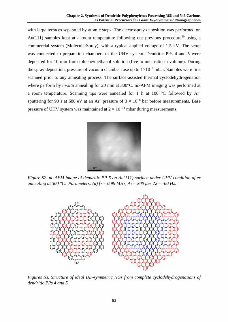
Chapter 2. Synthesis of Dendritic Polyphenylenes Possessing 366 and 546 Carbons
as Potential Precursors for Giant D6h-Symmetric Nanographenes
83
with large terraces separated by atomic steps. The electrospray deposition was performed on
Au(111) samples kept at a room temperature following our previous procedure30 using a
commercial system (MolecularSpray), with a typical applied voltage of 1.5 kV. The setup
was connected to preparation chambers of the UHV system. Dendritic PPs 4 and 5 were
deposited for 10 min from toluene/methanol solution (five to one, ratio in volume). During
the spray deposition, pressure of vacuum chamber rose up to 1×10⁻⁶ mbar. Samples were first
scanned prior to any annealing process. The surface-assisted thermal cyclodehydrogenation
where perform by in-situ annealing for 20 min at 300°C. nc-AFM imaging was performed at
a room temperature. Scanning tips were annealed for 1 h at 100 °C followed by Ar+
sputtering for 90 s at 680 eV at an Ar+ pressure of 3 × 10⁻⁶ bar before measurements. Base
pressure of UHV system was maintained at 2 × 10⁻¹¹ mbar during measurements.
Figure S2. nc-AFM image of dendritic PP 5 on Au(111) surface under UHV condition after
annealing at 300 °C. Parameters: (d) f2 = 0.99 MHz, A2 = 800 pm, ∆f = -60 Hz.
Figures S3. Structure of ideal D6h-symmetric NGs from complete cyclodehydrogenations of
dendritic PPs 4 and 5.

2.2 Supporting information
84
Synthetic procedure and characterization data for unreported compounds
Synthesis of dendritic PP 4: A mixture of star-shape skeleton 10 (30 mg, 0.012 mmol),
2,3,4,5-tetraphenyl-cyclopenta-2,4-dien-1-one (46 mg, 0.12 mmol) and diphenyl ether (0.5
mL) was degassed by freeze-pump-thaw technique for three cycles. This mixture was heated
at 260 °C overnight, during which it became a clear solution, and the purple color lightened.
After cooling to a room temperature, methanol was added to the solution. A white precipitate
(47 mg, 0.010 mmol, 83%) was collected. This precipitate was further purified by recycling
gel permeation chromatography to yield 4 as a white solid (37 mg, 0.079 mmol, 66%): mp >
410 °C; 1H NMR (700 MHz, CD2Cl2): δ 7.22 (s, 6H), 7.17–7.12 (m, 36H), 7.08– 7.02 (m,
24H), 6.99–6.93 (m, 36H), 6.93–6.86 (m, 84H), 6.86–6.79 (m, 48H), 6.70 (d, J = 8 Hz, 12H);
13C NMR (176 MHz, CD2Cl2) δ 141.49, 141.34, 141.21, 141.18, 141.07, 140.90, 140.84,
140.41, 140.39, 140.33, 140.24, 140.04, 139.91, 137.98, 137.57, 132.46, 132.17, 132.13,
131.88, 131.84, 131.81, 130.38, 128.83, 127.35, 127.19, 127.05, 126.98, 126.94, 125.85,
125.70 125.63, 125.49, 125.26, 123.36; HRMS (MALDI-TOF) m/z: [M]+ calcd for C366H246
4639.9250; Found 4639.9246.
Synthesis of dendritic PP 5: A solution of dendritic PP 14 (55 mg, 0.014 mmol) in
tetrahydrofuran (3 mL) was degassed by freeze-pump-thaw technique for 3 cycles. To this
solution was injected a tetrahydrofuran solution of tetrabutylammonium fluoride (0.1 mL,
0.09 mmol, 1 M). The solution was allowed to react for 1 h, and poured into methanol (30
mL) to induce precipitation of product. The precipitate was collected by filtration with a
membrane filter, and washed with methanol to give dendritic PP 15 as a white powder (38
mg, 0.013 mmol, 93%), which was directly used in the next step without further purification.
A solution of 15 (35 mg, 0.012 mmol) and 2,5-di([1,1':2',1''-terphenyl]-4'-yl)-3,4-
diphenylcyclopenta-2,4-dien-1-one (18) (73 mg, 0.11 mmol) in diphenyl ether (1 mL) was
degassed by freeze-pump-thaw technique for 3 cycles. This mixture was heated at 260 °C
overnight. After cooling to a room temperature, methanol (10 mL) was added to the solution
to induce precipitation of product. The precipitate was collected by filtration with a
membrane filter, and washed with methanol to give crude 5 as a white powder (62 mg,
0.0090 mmol, 75%). The crude 5 was further purified by recycling gel permeation
chromatography to yield 5 as a white solid (44 mg, 0.0064 mmol, 53%): mp > 410 °C; 1H
NMR (700 MHz, CD2Cl2): δ 7.56–7.36 (br, 6H), 7.33–6.48 (m, 348H), 6.48–6.29 (m, 12H);
13C NMR (176 MHz, CD2Cl2): δ 142.36, 142.30, 142.25, 142.11, 141.96, 141.90, 141.80,

Chapter 2. Synthesis of Dendritic Polyphenylenes Possessing 366 and 546 Carbons
as Potential Precursors for Giant D6h-Symmetric Nanographenes
85
141.65, 141.02, 140.97, 140.84, 140.70, 140.60, 140.49, 140.44, 140.39, 140.29, 140.23,
140.04, 139.49, 139.45, 139.32, 138.95, 138.79, 138.01, 134.58, 133.64, 132.93, 132.31,
132.18, 132.12, 132.05, 132.02, 131.78, 131.72, 131.58, 131.54, 130.25, 130.24, 130.17,
129.62, 129.43, 128.73, 128.19, 128.11, 128.06, 127.91, 127.52, 127.23, 126.97, 126.77,
126.59, 126.14, 125.93, 125.84; HRMS (MALDI-TOF) m/z: [M]+ calcd for C546H366
6920.8640; Found 6920.8087.
Synthesis of 1-(4-bromophenylethynyl)-3,5-diphenylbenzene (7): To a solution of 1-
(trimethylsilylethynyl)-3,5-diphenylbenzene (6)20 (5.07 g, 15.5 mmol) in THF (50 mL) was
injected a THF solution of TBAF (23 mL, 1 M, 23 mmol). The solution was stirred at a room
temperature for 1 h, and then passed through a short pad of silica gel with THF as eluent.
Solvent was then removed in vacuo to afford 1-ethynyl-3,5-diphenylbenzene as a white solid
(3.92 g, 15.4 mmol, 99% crude yield), which was directly used in the next step without
further purification. A mixture of 1-ethynyl-3,5-diphenylbenzene (3.92 g, 15.4 mmol),
PdCl2(PPh3)2 (0.22 g, 0.31 mmol), CuI (0.059 g, 0.31 mmol), tetrahydrofurane (20 mL) and
triethylamine (10 mL) was degassed by Argon bubbling under vigorous stirring for 15 min.
To this mixture was then added p-bromoiodobenzene (4.81 g, 17.0 mmol) at 0 °C, portion by
portion. The mixture was gradually warmed up to a room temperature and stirred overnight.
Diethyl ether and ice was added into the mixture and the organic layer was washed with HCl
(aq., 2 M), water, and brine, and dried over MgSO4. The solution was concentrated in vacuo
and the residue was purified by recrystallization from ethanol to afford 7 as a pale yellow
crystal (3.21 g, 7.86 mmol, 51%, over two steps): mp 121.9–123.2 °C; 1H NMR (300 MHz,
CD2Cl2): δ 7.83 (d, J = 1.7 Hz, 1H), 7.77 (d, J = 1.7 Hz, 2H), 7.69 (d, J = 7.3 Hz, 4H), 7.54 (d,
J = 8.4 Hz, 2H), 7.50 (t, J = 7.3 Hz, 4H), 7.46 (d, J = 8.4 Hz, 2H), 7.41 (t, J = 7.3 Hz, 2H);
13C NMR (75 MHz, CD2Cl2): δ 142.62, 140.72, 133.67, 132.28, 129.57, 129.48, 128.41,
127.71, 126.88, 124.38, 123.16, 122.71, 90.92, 88.94; HRMS (MALDI-TOF) m/z: [M]+ calcd
for C26H17Br 408.0514; Found 408.0548.
Synthesis of (4-([1,1':3',1''-terphenyl]-5'-ylethynyl)phenyl)boronic acid (8): To a solution of
1-(4-bromophenylethynyl)-3,5-diphenylbenzene (7) (3.11 g, 7.62 mmol) in tetrahydrofuran
(25 mL) was injected a hexane solution of nBuLi (5.3 mL, 8.4 mmol) at -78 °C. The mixture
was allowed to react for 30 min, and then B(OMe)3 (1.7 mL, 15 mmol) was syringed. The
solution was then gradually warmed up to a room temperature, and further stirred for 3 h. A
water solution of HCl (20 mL, 2 M) was added at 0 °C to quench the reaction. The mixture
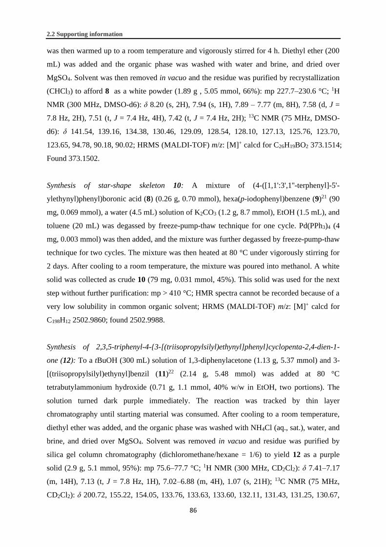
2.2 Supporting information
86
was then warmed up to a room temperature and vigorously stirred for 4 h. Diethyl ether (200
mL) was added and the organic phase was washed with water and brine, and dried over
MgSO4. Solvent was then removed in vacuo and the residue was purified by recrystallization
(CHCl3) to afford 8 as a white powder (1.89 g , 5.05 mmol, 66%): mp 227.7–230.6 °C; 1H
NMR (300 MHz, DMSO-d6): δ 8.20 (s, 2H), 7.94 (s, 1H), 7.89 – 7.77 (m, 8H), 7.58 (d, J =
7.8 Hz, 2H), 7.51 (t, J = 7.4 Hz, 4H), 7.42 (t, J = 7.4 Hz, 2H); 13C NMR (75 MHz, DMSO-
d6): δ 141.54, 139.16, 134.38, 130.46, 129.09, 128.54, 128.10, 127.13, 125.76, 123.70,
123.65, 94.78, 90.18, 90.02; HRMS (MALDI-TOF) m/z: [M]+ calcd for C26H19BO2 373.1514;
Found 373.1502.
Synthesis of star-shape skeleton 10: A mixture of (4-([1,1':3',1''-terphenyl]-5'-
ylethynyl)phenyl)boronic acid (8) (0.26 g, 0.70 mmol), hexa(p-iodophenyl)benzene (9)21 (90
mg, 0.069 mmol), a water (4.5 mL) solution of K2CO3 (1.2 g, 8.7 mmol), EtOH (1.5 mL), and
toluene (20 mL) was degassed by freeze-pump-thaw technique for one cycle. Pd(PPh3)4 (4
mg, 0.003 mmol) was then added, and the mixture was further degassed by freeze-pump-thaw
technique for two cycles. The mixture was then heated at 80 °C under vigorously stirring for
2 days. After cooling to a room temperature, the mixture was poured into methanol. A white
solid was collected as crude 10 (79 mg, 0.031 mmol, 45%). This solid was used for the next
step without further purification: mp > 410 °C; HMR spectra cannot be recorded because of a
very low solubility in common organic solvent; HRMS (MALDI-TOF) m/z: [M]+ calcd for
C198H12 2502.9860; found 2502.9988.
Synthesis of 2,3,5-triphenyl-4-{3-[(triisopropylsilyl)ethynyl]phenyl}cyclopenta-2,4-dien-1-
one (12): To a tBuOH (300 mL) solution of 1,3-diphenylacetone (1.13 g, 5.37 mmol) and 3-
[(triisopropylsilyl)ethynyl]benzil (11)22 (2.14 g, 5.48 mmol) was added at 80 °C
tetrabutylammonium hydroxide (0.71 g, 1.1 mmol, 40% w/w in EtOH, two portions). The
solution turned dark purple immediately. The reaction was tracked by thin layer
chromatography until starting material was consumed. After cooling to a room temperature,
diethyl ether was added, and the organic phase was washed with NH4Cl (aq., sat.), water, and
brine, and dried over MgSO4. Solvent was removed in vacuo and residue was purified by
silica gel column chromatography (dichloromethane/hexane = 1/6) to yield 12 as a purple
solid (2.9 g, 5.1 mmol, 95%): mp 75.6–77.7 °C; 1H NMR (300 MHz, CD2Cl2): δ 7.41–7.17
(m, 14H), 7.13 (t, J = 7.8 Hz, 1H), 7.02–6.88 (m, 4H), 1.07 (s, 21H); 13C NMR (75 MHz,
CD2Cl2): δ 200.72, 155.22, 154.05, 133.76, 133.63, 133.60, 132.11, 131.43, 131.25, 130.67,

Chapter 2. Synthesis of Dendritic Polyphenylenes Possessing 366 and 546 Carbons
as Potential Precursors for Giant D6h-Symmetric Nanographenes
87
129.89, 129.75, 129.20, 128.61, 128.61, 128.53, 128.25, 128.06, 126.41, 125.98, 123.72,
118.74, 106.86, 91.86, 18.94, 11.81; HRMS (MALDI-TOF) m/z: [M]+ calcd for C40H40OSi
564.2848; found 564.2789.
Synthesis of dendritic PP 14: A mixture of hexa(4-ethynylphenyl)benzene (13)21 (30 mg,
0.044 mmol), 2,3,5-triphenyl-4-{3-[(triisopropylsilyl)ethynyl]phenyl}cyclopenta-2,4-dien-1-
one (12) (226 mg, 0.398 mmol), and o-xylene (0.6 mL) was degassed by freeze-pump-thaw
technique for three cycles. This mixture was heated at 125 °C for 3 days. After cooling to a
room temperature methanol (3 mL) was added to induce precipitation of product. The
precipitate was collected by filtration with a membrane filter and washed with methanol to
give 13 as a white powder (61 mg, 0.015 mmol, 37%): mp > 410 °C; 1H NMR (300 MHz,
CD2Cl2): δ 7.45–7.37 (br, 6H), 7.26–7.08 (m, 30H), 7.06–6.68 (m, 84H), 6.68–6.57 (br, 12H),
6.43–6.30 (m, 12H), 1.08 (s, 126H); 13C NMR (75 MHz, CD2Cl2): δ 142.16, 142.11, 141.97,
141.20, 141.03, 140.74, 140.64, 140.38, 140.20, 139.51, 139.38, 138.97, 138.54, 135.98,
131.99, 131.59, 130.31, 128.68, 128.02, 127.91, 127.74, 127.28, 127.16, 127.01, 126.74,
126.14, 125.88, 122.38, 122.08, 107.58, 107.51, 90.34, 90.22, 18.83, 18.81, 11.70; HRMS
(MALDI-TOF) m/z: [M]+ calcd for C288H270Si6 3895.9743; Found 3895.9639.
Synthesis of 1,3-di([1,1':2',1''-terphenyl]-4'-yl)propan-2-one (17): The procedure was
modified from our previous work describing synthesis of a similar structure.23 A mixture of
1,3-bis(3-phenyl-4-bromophenyl)acetone (16)23 (113 mg, 0.218 mmol), phenyl boronic acid
(80 mg, 0.65 mmol), a water (3 mL) solution of K2CO3 (180 mg, 1.3 mmol), EtOH (3 mL),
and toluene (12 mL) was degassed by freeze-pump-thaw technique for one cycle. Pd(PPh3)4
(25 mg, 0.022 mmol) was then added, and the mixture was further degassed by freeze-pump-
thaw technique for two cycles. The mixture was then heated at reflux under vigorously
stirring for 4 h. After cooling to a room temperature, the mixture was diluted with diethyl
ether and washed with NaOH (aq., 2 M), water, and brine, and dried over MgSO4. Solvent
was then removed in vacuo, and the residue was purified by silica gel column
chromatography (dichloromethane/hexane = 2/3) to yield 17 as a white solid (99 mg, 0.19
mmol, 88%): mp 138.8–140.2 °C; 1H NMR (300 MHz, CD2Cl2): δ 7.39 (d, J = 7.8 Hz, 2H),
7.34–7.17 (m, 16 H), 7.17–7.06 (m, 8 H), 3.91 (s, 4 H); 13C NMR (75 MHz, CD2Cl2): δ
205.74, 141.88, 141.78, 141.34, 139.86, 134.05, 132.39, 131.41, 130.42, 130.39, 129.27,
128.39, 127.10, 127.02, 118.73, 49.44; HRMS (MALDI-TOF) m/z: [M]+ calcd for C40H40OSi
514.2297; found 514.2258.

2.2 Supporting information
88
Synthesis of 2,5-di([1,1':2',1''-terphenyl]-4'-yl)-3,4-diphenylcyclopenta-2,4-dien-1-one (18):
To a tBuOH (150 mL) solution of 1,3-di([1,1':2',1''-terphenyl]-4'-yl)propan-2-one (17) (1.01
g, 1.96 mmol) and benzil (412 mg, 1.96 mmol) was added at 80 °C tetrabutylammonium
hydroxide (0.19 mg, 0.29 mmol, 40% w/w in EtOH). The solution turned dark purple
immediately. The reaction was tracked by thin layer chromatography until consumption of
starting material. After cooling to a room temperature, diethyl ether was added, and the
organic phase was washed with NH4Cl (aq., sat.), water, and brine, and dried over MgSO4.
Solvent was removed in vacuo, and the residue was purified by silica gel column
chromatography (dichloromethane/hexane = 1/6) to yield 18 as a purple solid (0.88 g, 1.2
mmol, 63%): mp 143.8–145.0 °C; 1H NMR (300 MHz, CD2Cl2): δ 7.50–7.25 (m, 12H),
7.25–7.18 (m, 6H), 7.18–7.06 (m, 14H), 7.01–6.90 (m, 4H); 13C NMR (75 MHz, CD2Cl2): δ
200.91, 155.76, 141.83, 141.73, 140.62, 140.17, 133.96, 133.01, 130.91, 130.60, 130.34,
129.86, 129.61, 129.13, 128.76, 128.39, 128.29, 127.10, 126.99, 125.44; HRMS (MALDI-
TOF) m/z: [M]+ calcd for C53H36O 688.2766; found 688.2763.
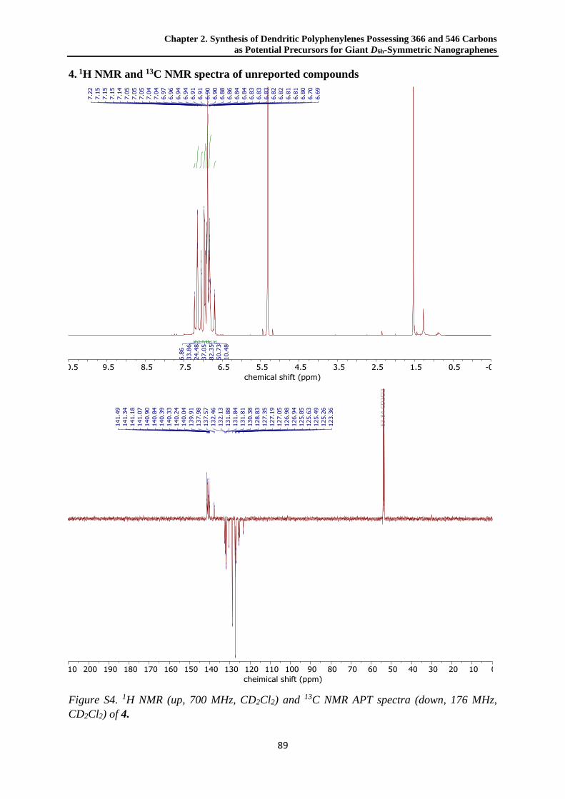
Chapter 2. Synthesis of Dendritic Polyphenylenes Possessing 366 and 546 Carbons
as Potential Precursors for Giant D6h-Symmetric Nanographenes
89
4. 1H NMR and 13C NMR spectra of unreported compounds
Figure S4. 1H NMR (up, 700 MHz, CD2Cl2) and 13C NMR APT spectra (down, 176 MHz,
CD2Cl2) of 4.

2.2 Supporting information
90
Figure S5. 1H NMR (up, 700 MHz, CD2Cl2) and 13C NMR APT spectra (down, 176 MHz,
CD2Cl2) of 5.

Chapter 2. Synthesis of Dendritic Polyphenylenes Possessing 366 and 546 Carbons
as Potential Precursors for Giant D6h-Symmetric Nanographenes
91
Figure S6. 1H NMR (up, 300 MHz, CD2Cl2) and 13C NMR spectra (down, 75 MHz, CD2Cl2)
of 7.

2.2 Supporting information
92
Figure S7. 1H NMR (up, 300 MHz, DMSO-d6) and 13C NMR spectra (down, 75 MHz, DMSO-
d6) of 8.

Chapter 2. Synthesis of Dendritic Polyphenylenes Possessing 366 and 546 Carbons
as Potential Precursors for Giant D6h-Symmetric Nanographenes
93
Figure S8. 1H NMR (up, 300 MHz, CD2Cl2) and 13C NMR spectra (down, 75 MHz, CD2Cl2)
of 12.

2.2 Supporting information
94
Figure S9. 1H NMR (up, 300 MHz, CD2Cl2) and 13C NMR spectra (down, 75 MHz, CD2Cl2)
of 14.
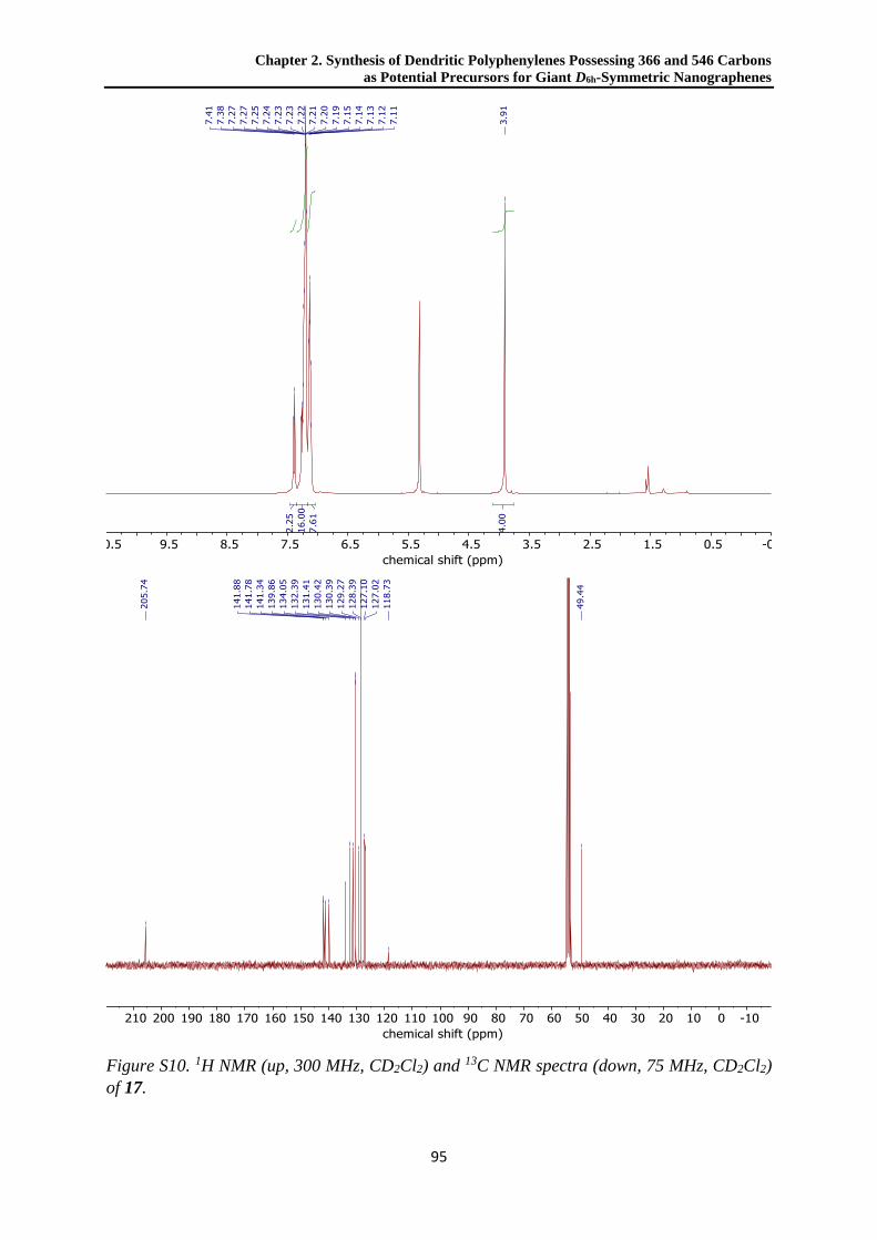
Chapter 2. Synthesis of Dendritic Polyphenylenes Possessing 366 and 546 Carbons
as Potential Precursors for Giant D6h-Symmetric Nanographenes
95
Figure S10. 1H NMR (up, 300 MHz, CD2Cl2) and 13C NMR spectra (down, 75 MHz, CD2Cl2)
of 17.

2.2 Supporting information
96
Figure S11. 1H NMR (up, 300 MHz, CD2Cl2) and 13C NMR spectra (down, 75 MHz, CD2Cl2)
of 18.

Chapter 2. Synthesis of Dendritic Polyphenylenes Possessing 366 and 546 Carbons
as Potential Precursors for Giant D6h-Symmetric Nanographenes
97
2.3 References
(1) Hammer, B. A. G.; Müllen, K. Expanding the Limits of Synthetic Macromolecular Chemistry through
Polyphenylene Dendrimers. J. Nanoparticle Res. 2018, 20 (10), 262.
(2) Hammer, B. A. G.; Müllen, K. Dimensional Evolution of Polyphenylenes: Expanding in All Directions. Chem. Rev.
2016, 116 (4), 2103–2140.
(3) Wang, X.-Y.; Yao, X.; Müllen, K. Polycyclic Aromatic Hydrocarbons in the Graphene Era. Sci. China Chem. 2019,
62 (9), 1099–1144.
(4) Narita, A.; Wang, X. Y.; Feng, X.; Müllen, K. New Advances in Nanographene Chemistry. Chem. Soc. Rev. 2015,
44 (18), 6616–6643.
(5) Güçlü, A. D.; Potasz, P.; Korkusinski, M.; Hawrylak, P. Graphene Quantum Dots; NanoScience and Technology;
Springer Berlin Heidelberg: Berlin, Heidelberg, 2014.
(6) Wu, J.; Pisula, W.; Müllen, K. Graphenes as Potential Material for Electronics. Chem. Rev. 2007, 107 (3), 718–747.
(7) Simpson, C. D.; Brand, J. D.; Berresheim, A. J.; Przybilla, L.; Räder, H. J.; Müllen, K. Synthesis of a Giant 222
Carbon Graphite Sheet. Chem. - A Eur. J. 2002, 8 (6), 1424–1429.
(8) Feng, X.; Wu, J.; Ai, M.; Pisula, W.; Zhi, L.; Rabe, J. P.; Müllen, K. Triangle-Shaped Polycyclic Aromatic
Hydrocarbons. Angew. Chem. Int. Ed. 2007, 46 (17), 3033–3036.
(9) Müller, M.; Iyer, V. S.; Kübel, C.; Enkelmann, V.; Müllen, K. Polycyclic Aromatic Hydrocarbons by
Cyclodehydrogenation and Skeletal Rearrangement of Oligophenylenes. Angew. Chem. Int. Ed. 1997, 36 (15),
1607–1610.
(10) Tomović, Ž.; Watson, M. D.; Müllen, K. Superphenalene-Based Columnar Liquid Crystals. Angew. Chem. Int. Ed.
2004, 43 (6), 755–758.
(11) Beser, U.; Kastler, M.; Maghsoumi, A.; Wagner, M.; Castiglioni, C.; Tommasini, M.; Narita, A.; Feng, X.; Müllen,
K. A C216-Nanographene Molecule with Defined Cavity as Extended Coronoid. J. Am. Chem. Soc. 2016, 138 (13),
4322–4325.
(12) Yang, X.; Dou, X.; Rouhanipour, A.; Zhi, L.; Räder, H. J.; Müllen, K. Two-Dimensional Graphene Nanoribbons. J.
Am. Chem. Soc. 2008, 130 (13), 4216–4217.
(13) Tan, Y. Z.; Yang, B.; Parvez, K.; Narita, A.; Osella, S.; Beljonne, D.; Feng, X.; Müllen, K. Atomically Precise Edge
Chlorination of Nanographenes and Its Application in Graphene Nanoribbons. Nat. Commun. 2013, 4 (May), 1–7.
(14) Watson, M. D.; Fechtenkotter, A.; Müllen, K. Big Is Beautiful−“Aromaticity” Revisited from the Viewpoint of
Macromolecular and Supramolecular Benzene Chemistry. Chem. Rev. 2001, 101 (5), 1267–1300.
(15) Han, M. Y.; Özyilmaz, B.; Zhang, Y.; Kim, P. Energy Band-Gap Engineering of Graphene Nanoribbons. Phys. Rev.
Lett. 2007, 98 (20), 206805.
(16) Bai, J.; Duan, X.; Huang, Y. Rational Fabrication of Graphene Nanoribbons Using a Nanowire Etch Mask. Nano
Lett. 2009, 9 (5), 2083–2087.
(17) Hou, I. C. Y.; Narita, A.; Müllen, K. Stepwise Lateral Extension of Phenyl-Substituted Linear Polyphenylenes.
Macromol. Chem. Phys. 2020, 221 (1), 1900374.
(18) Dössel, L. Nanographene Als Funktionale Materialien Und Synthetische Herausforderung, Johannes Gutenberg-
Universität, Mainz, 2011.
(19) Simpson, C. D.; Mattersteig, G.; Martin, K.; Gherghel, L.; Bauer, R. E.; Räder, H. J.; Müllen, K. Nanosized
Molecular Propellers by Cyclodehydrogenation of Polyphenylene Dendrimers. J. Am. Chem. Soc. 2004, 126 (10),
3139–3147.
(20) Zhao, W.; Huang, L.; Guan, Y.; Wulff, W. D. Three-Component Asymmetric Catalytic Ugi Reaction - Concinnity
from Diversity by Substrate-Mediated Catalyst Assembly. Angew. Chem. Int. Ed. 2014, 53 (13), 3436–3441.
(21) Shen, X.; Ho, D. M.; Pascal, R. A. Synthesis of Polyphenylene Dendrimers Related to “Cubic Graphite.” J. Am.

2.3 References
98
Chem. Soc. 2004, 126 (18), 5798–5805.
(22) Hu, Y.; Xie, P.; De Corato, M.; Ruini, A.; Zhao, S.; Meggendorfer, F.; Straasø, L. A.; Rondin, L.; Simon, P.; Li, J.;
et al. Bandgap Engineering of Graphene Nanoribbons by Control over Structural Distortion. J. Am. Chem. Soc.
2018, 140 (25), 7803–7809.
(23) Narita, A.; Verzhbitskiy, I. A.; Frederickx, W.; Mali, K. S.; Jensen, S. A.; Hansen, M. R.; Bonn, M.; De Feyter, S.;
Casiraghi, C.; Feng, X.; et al. Bottom-up Synthesis of Liquid-Phase-Processable Graphene Nanoribbons with near-
Infrared Absorption. ACS Nano 2014, 8 (11), 11622–11630.
(24) Narita, A.; Feng, X.; Hernandez, Y.; Jensen, S. A.; Bonn, M.; Yang, H.; Verzhbitskiy, I. A.; Casiraghi, C.; Hansen,
M. R.; Koch, A. H. R.; et al. Synthesis of Structurally Well-Defined and Liquid-Phase-Processable Graphene
Nanoribbons. Nat. Chem. 2014, 6 (2), 126–132.
(25) Treier, M.; Pignedoli, C. A.; Laino, T.; Rieger, R.; Müllen, K.; Passerone, D.; Fasel, R. Surface-Assisted
Cyclodehydrogenation Provides a Synthetic Route towards Easily Processable and Chemically Tailored
Nanographenes. Nat. Chem. 2011, 3 (1), 61–67.
(26) Sun, Q.; Zhang, R.; Qiu, J.; Liu, R.; Xu, W. On-Surface Synthesis of Carbon Nanostructures. Adv. Mater. 2018, 30
(17), 1705630.
(27) Zhong, Q.; Hu, Y.; Niu, K.; Zhang, H.; Yang, B.; Ebeling, D.; Tschakert, J.; Cheng, T.; Schirmeisen, A.; Narita, A.;
et al. Benzo-Fused Periacenes or Double Helicenes? Different Cyclodehydrogenation Pathways on Surface and in
Solution. J. Am. Chem. Soc. 2019, 141 (18), 7399–7406.
(28) Saywell, A.; Sprafke, J. K.; Esdaile, L. J.; Britton, A. J.; Rienzo, A.; Anderson, H. L.; O’Shea, J. N.; Beton, P. H.
Conformation and Packing of Porphyrin Polymer Chains Deposited Using Electrospray on a Gold Surface. Angew.
Chem. Int. Ed. 2010, 49 (48), 9136–9139.
(29) Kondratuk, D. V.; Perdigão, L. M. A.; Esmail, A. M. S.; O’Shea, J. N.; Beton, P. H.; Anderson, H. L.
Supramolecular Nesting of Cyclic Polymers. Nat. Chem. 2015, 7 (4), 317–322.
(30) Hinaut, A.; Pawlak, R.; Meyer, E.; Glatzel, T. Electrospray Deposition of Organic Molecules on Bulk Insulator
Surfaces. Beilstein J. Nanotechnol. 2015, 6 (1), 1927–1934.
(31) Hinaut, A.; Meier, T.; Pawlak, R.; Feund, S.; Jöhr, R.; Kawai, S.; Glatzel, T.; Decurtins, S.; Müllen, K.; Narita, A.;
et al. Electrospray Deposition of Structurally Complex Molecules Revealed by Atomic Force Microscopy.
Nanoscale 2018, 10 (3), 1337–1344.
(32) Nguyen, T. T. T.; Baumgarten, M.; Rouhanipour, A.; Räder, H. J.; Lieberwirth, I.; Müllen, K. Extending the Limits
of Precision Polymer Synthesis: Giant Polyphenylene Dendrimers in the Megadalton Mass Range Approaching
Structural Perfection. J. Am. Chem. Soc. 2013, 135 (11), 4183–4186.
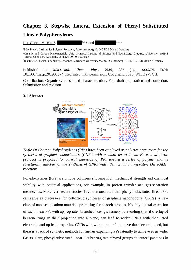
99
Chapter 3. Stepwise Lateral Extension of Phenyl Substituted
Linear Polyphenylenes
Ian Cheng-Yi Hou1, Akimitsu Narita1,2,* and Klaus Müllen1,3,*
1Max Planck Institute for Polymer Research, Ackermannweg 10, D-55128 Mainz, Germany 2Organic and Carbon Nanomaterials Unit, Okinawa Institute of Science and Technology Graduate University, 1919-1
Tancha, Onna-son, Kunigami, Okinawa 904-0495, Japan 3Institute of Physical Chemistry, Johannes Gutenberg-University Mainz, Duesbergweg 10-14, D-55128 Mainz, Germany
Published in: Macromol. Chem. Phys. 2020, 221 (1), 1900374. DOI:
10.1002/macp.201900374. Reprinted with permission. Copyright: 2020, WILEY-VCH.
Contribution: Organic synthesis and characterization. First draft preparation and correction.
Submission and revision.
3.1 Abstract
Table Of Content. Polyphenylenes (PPs) have been employed as polymer precursors for the
synthesis of graphene nanoribbons (GNRs) with a width up to 2 nm. Here, a synthetic
protocol is proposed for lateral extension of PPs toward a series of polymer that is
structurally suitable for the synthesis of GNRs wider than 2 nm via repetitive Diels-Alder
reactions.
Polyphenylenes (PPs) are unique polymers showing high mechanical strength and chemical
stability with potential applications, for example, in proton transfer and gas-separation
membranes. Moreover, recent studies have demonstrated that phenyl substituted linear PPs
can serve as precursors for bottom-up syntheses of graphene nanoribbons (GNRs), a new
class of nanoscale carbon materials promising for nanoelectronics. Notably, lateral extension
of such linear PPs with appropriate “branched” design, namely by avoiding spatial overlap of
benzene rings in their projection into a plane, can lead to wider GNRs with modulated
electronic and optical properties. GNRs with width up to ~2 nm have thus been obtained, but
there is a lack of synthetic methods for further expanding PPs laterally to achieve even wider
GNRs. Here, phenyl substituted linear PPs bearing two ethynyl groups at “outer” positions in

3.1 Abstract
100
each repeating unit together with 3,4-diphenylcyclopentadienones bearing a
trimethylsilyl(TMS)-protected ethynyl group are used for stepwise lateral extension of the
PPs based on a sequence of Diels-Alder cycloadditions and deprotections. Each successive
reaction step could be corroborated by 1H NMR and IR spectroscopy as well as gel
permeation chromatography, providing a new pathway towards linear PPs that could
potentially serve as precursors of wider GNRs with tunable electronic bandgap.

Chapter 3. Stepwise Lateral Extension of Phenyl Substituted Linear Polyphenylenes
101
3.2 Introduction
Polyphenylenes (PPs) are polymers with exceptional properties1,2 including outstanding
mechanical strength as well as thermal and chemical stability. This qualifies PPs for
applications under harsh conditions such as proton-transfer3–7, electrodialysis8 and gas
separation9,10 membranes. Linear PPs with phenyl substituents can also serve as precursors
for graphene nanoribbons (GNRs), nanometer-wide strips of graphene. The underlying
concept is to appropriately design branched PP structures that can be fully planarized by C-C
bond formation between the benzene rings, typically through oxidative
cyclodehydrogenation.1,2,11–13 GNRs synthesized by such bottom-up methods have not only
contributed to fundamental studies in condensed matter physics, but also exhibited potential
for future applications in nanoelectronics, photonics, and quantum computing.14–16
One of the most efficient methods to synthesize PPs is through the use of Diels-Alder
cycloadditions between cyclopentadienone (CP) derivatives, usually a 2,3,4,5-
tetraarylcyclopentadienone, and alkynes leading to, both, linear and dendritic PPs.1,2 In
comparison with other polymerization methods typically though transition-metal
catalyzed/mediated reactions, Diels-Alder reaction, which underdoes without metal catalyst
or other reagents, has advantages also with high efficiency.12,17 An A2B2-type Diels-Alder
polymerization between an A2 monomer having two CP moieties and a bisalkyne serving as a
B2 monomer has been known for more than 70 years18,19 and provided numerous linear PPs
with a backbone of poly[(p-phenylene)-ran-(m-phenylene)].2 On the other hand, CP
derivatives carrying an alkyne functional group can serve as bifunctional monomers which
undergo AB-type Diels-Alder polymerization to yield linear PPs with surprisingly high
persistence length.17,20 Moreover, PPs synthesized by this procedure exhibit higher degrees of
polymerizations (DP) than that of those made by A2B2-type polymerization.17,21,22
In 2014, we have reported an AB-type Diels-Alder polymerization of tetraphenyl-CP 1a
leading to linear PP-Ia with the poly[(p-phenylene)-ran-(m-phenylene)] backbone (Figure
1a). The weight-average molecular weight (Mw) of PP-Ia exceeded 600,000 g/mol, which
was much larger than the values obtained with previous PPs prepared by the A2B2-type Diels-
Alder polymerization. The structure of PP-Ia can be projected into a plane without spatial
overlap of benzene rings. “Planarization” of PP-Ia through oxidative cyclodehydrogenation
could, thus, provide structurally defined GNRs.17
Moreover, we have demonstrated the synthesis of laterally extended linear PP-Ib by using
CP-based monomer 1b having four extra phenyl rings in addition to the structure of 1a

3.2 Introduction
102
(Figure 1a).21 PP-Ib was planarized by cyclodehydrogenation furnishing an even wider GNR
with a width of ca. 2 nm. Remarkably, this quasi one-dimensional GNR exhibited a smaller
electronic bandgap compared to that of the narrower GNRs obtained from PP-Ia.21 However,
synthesis of linear PPs broader than PP-Ib has remained elusive, although it would lead to
even wider GNRs with tunable bandgaps essential for the development of GNR-based
nanoelectronics.
Figure 1. (a) Diels-Alder polymerization of tetraphenyl-CPs 1a–c to PP-Ia–c, respectively.
(b) Proposed strategy for the lateral extension of PP-Ic by a sequence of deprotections and
Diels-Alder reactions with diphenyl-CPs 2b,c to form PPs with architectures that are suitable
for planarization into wider GNRs.
Considering synthetic complexity expected for further extension of monomer 1b with more
phenyl rings, as well as the importance of making PPs with different degrees of lateral
extension, we have conceived a universal approach to “broaden” linear PPs in a stepwise
manner. To this end, we employ linear PPs bearing two ethynyl groups at the “outer”
positions in each repeating unit which can be subjected to Diels-Alder reactions for “growth”
in the lateral direction. We choose CPs that have trimethylsilyl (TMS)-protected ethynyl

Chapter 3. Stepwise Lateral Extension of Phenyl Substituted Linear Polyphenylenes
103
groups which allows for the lateral expansion of PPs step by step through a sequence of
Diels-Alder reaction and deprotection. Such a synthetic strategy based on sequential Diels-
Alder reactions has been used for the divergent construction of dendritic PPs, but not
previously considered for linear PPs (Figure 1b).1,23,24
Here, we synthesized CP-based monomer 1c bearing two triisopropylsilyl(TIPS)-protected
ethynyl groups on the peripheral phenyl rings. Polymerization of 1c provided PP-Ic which
was subjected to deprotection to PP-Id having ethynyl groups for the further lateral growth
(Figure 1a). As to the diene counterpart, 3,4-diphenyl-CP 2b with TMS-protected ethynyl
groups was utilized instead of the typical tetraphenyl-CP. It is this “trick” which avoids the
spatial overlap of benzene rings in the 2D projection of the resulting PPs (Figure 1b). After
reaching the desired degree of lateral extension by repeating the sequence of the Diels-Alder
cycloaddition with 2b and deprotection, a reaction with 3,4-diphenyl-CP 2c carrying
solubilizing long alkyl chains can serve as an end-capping. The 2,5-positions of the CP cores
of 2b,c were substituted with TMS moieties as protecting groups, because non-substituted
3,4-diphenyl-CP can undergo irreversible Diels-Alder dimerization even at a room
temperature.25 Diels-Alder cycloadditions of PP-Id with 2b, deprotection and subsequent
Diels-Alder reaction with 2c were corroborated by gel permeation chromatography (GPC),
NMR, and FTIR spectroscopy. Our preliminary attempts to planarize the resulting PPs
through oxidative cyclodehydrogenation failed to give wider GNRs without defects, based on
an analysis by UV-vis absorption spectrum. Nevertheless, our strategy for the step-by-step
lateral extension of PPs can be applicable to syntheses of different linear PPs with various
degree of lateral expansion, including those that potentially serve as precursors of GNRs with
distinct structures.

104
3.3 Result and Discussion
3.3.1. Synthesis of Tetraphenyl- and Diphenyl-substituted CP Building Blocks
3.3.1.1 Synthesis of Tetraphenyl-CP 1c
Scheme 1. Synthesis of (a) tetraphenyl-CP 1c and (b) diphenyl-CP 2a–c. THF:
tetrahydrofuran. TEA: triethylamine. TBAOH: tetra-n-butylammonium hydroxide. Cp2ZrCl2:
zirconocene dichloride.
For the synthesis of 3-(m-ethynylphenyl)-4-phenyl-2,5-bis{m-
[(triisopropyl)silylethynyl]phenyl}cyclopenta-2,4-dien-1-one (1c) as the CP-based monomer
for the polymerization to PP-Ic, 1,3-bis(3-bromophenyl)acetone26 (3) was initially reacted

Chapter 3. Stepwise Lateral Extension of Phenyl Substituted Linear Polyphenylenes
105
with TIPS-acetylene under Sonogashira conditions to give bis(TMS-ethynylphenyl)acetone 4.
In parallel, 3-bromobenzil17 (5) was functionalized with TMS-ethynyl group and then
deprotected with tetra-n-butylammonium fluoride (TBAF) to provide 3-ethynylbenzil (7).
Subsequently, a Knoevenagel condensation between 4 and 6 afforded monomer 1c in 59%
yield (Scheme 1a).
3.3.1.2 Synthesis of Diphenyl-CP 2a–c
To synthesize 3,4-diphenyl-CPs 2a and 2c, we first carried out a zirconocene-mediated
dimerization of aryl TMS-acetylene derivatives 8a and 8c27, forming Zr-metallacycle
intermediates 9a and 9c, respectively (Scheme 1b).28 Attempts at direct iodination of 9a with
I2 failed.28 However, after converting 9a,c into organo-copper species in situ by reaction with
CuCl, iodination of the copper species smoothly produced (1Z,3Z)-1,4-diiodo-2,3-
diphenylbutadiene derivatives 10a,c with high regio- and stereoselectivity, but moderate
yields of 30% for both (Scheme 1b).28–30 10b was synthesized similarly but starting from a
mixture of 8a and 8b. Because of formation of a large amount of homocoupled products,
which rendered a purification process tedious, 10b was isolated in a much lower yield of 12%.
We have also tried, but failed, to synthesize 10b in a controlled manner through a tandem
addition of 8a,b, following literature-known conditions for the coupling of other TMS-
alkynes.28,31,32 Next, iodo groups of 10a–c were lithiated by treatment with tBuLi and
converted again into the organo-copper reagents by reacting with CuCl (Scheme 1b). We
then tried to react the resulting organo-copper intermediates with different carbonyl sources
for the formation of the corresponding CPs 2a–c. After failures with carbon dioxide gas33 and
oxalyl chloride34 we found that the reaction proceeded with carbon monoxide gas
successfully yielding 3,4-diphenyl-CPs 2a–c after oxidation in 22–48% yield (Scheme 1b).35
It was not possible to perform a one-pot synthesis of CP derivatives 2a–c directly from 8a–c,
respectively, without isolation of the diiodo species 9a–c.34
After obtaining diphenyl-CPs 2a–c, we first tested their stability and reactivity under
conditions commonly used for a Diels-Alder reaction between tetraphenyl-CPs and aromatic
compounds bearing ethynyl groups. 2a was heated in a concentration of 0.2 M at 130 °C in o-
xylene for three days with no observable reaction, but could be recovered in more than 95%
yield demonstrating a largely increased stability of the CP core with the TMS-substituents.33
This condition was later-on used in the Diels-Alder reactions for the lateral extension of PPs
(vide infra). Next, 2a was heated with 1.1 eq. of phenylacetylene at 120 °C in chlorobenzene
for three days until it was fully consumed. 1,4-Bis(trimethylsilyl)-2,3,6-triphenylbenzene (11)
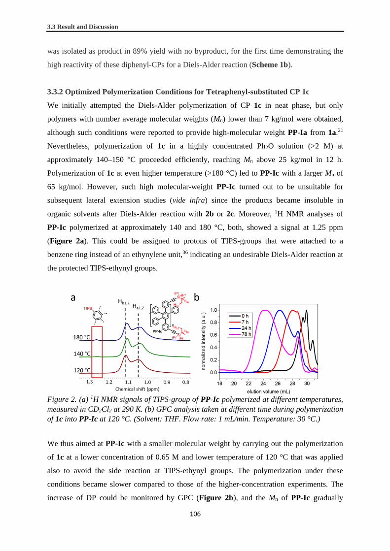
3.3 Result and Discussion
106
was isolated as product in 89% yield with no byproduct, for the first time demonstrating the
high reactivity of these diphenyl-CPs for a Diels-Alder reaction (Scheme 1b).
3.3.2 Optimized Polymerization Conditions for Tetraphenyl-substituted CP 1c
We initially attempted the Diels-Alder polymerization of CP 1c in neat phase, but only
polymers with number average molecular weights (Mn) lower than 7 kg/mol were obtained,
although such conditions were reported to provide high-molecular weight PP-Ia from 1a.21
Nevertheless, polymerization of 1c in a highly concentrated Ph2O solution (>2 M) at
approximately 140–150 °C proceeded efficiently, reaching Mn above 25 kg/mol in 12 h.
Polymerization of 1c at even higher temperature (>180 °C) led to PP-Ic with a larger Mn of
65 kg/mol. However, such high molecular-weight PP-Ic turned out to be unsuitable for
subsequent lateral extension studies (vide infra) since the products became insoluble in
organic solvents after Diels-Alder reaction with 2b or 2c. Moreover, 1H NMR analyses of
PP-Ic polymerized at approximately 140 and 180 °C, both, showed a signal at 1.25 ppm
(Figure 2a). This could be assigned to protons of TIPS-groups that were attached to a
benzene ring instead of an ethynylene unit,36 indicating an undesirable Diels-Alder reaction at
the protected TIPS-ethynyl groups.
Figure 2. (a) 1H NMR signals of TIPS-group of PP-Ic polymerized at different temperatures,
measured in CD2Cl2 at 290 K. (b) GPC analysis taken at different time during polymerization
of 1c into PP-Ic at 120 °C. (Solvent: THF. Flow rate: 1 mL/min. Temperature: 30 °C.)
We thus aimed at PP-Ic with a smaller molecular weight by carrying out the polymerization
of 1c at a lower concentration of 0.65 M and lower temperature of 120 °C that was applied
also to avoid the side reaction at TIPS-ethynyl groups. The polymerization under these
conditions became slower compared to those of the higher-concentration experiments. The
increase of DP could be monitored by GPC (Figure 2b), and the Mn of PP-Ic gradually

Chapter 3. Stepwise Lateral Extension of Phenyl Substituted Linear Polyphenylenes
107
developed to around 13 kg/mol after 78 h together with disappearance of oligomers. The
obtained PP-Ic still gave a pale purple color in solution indicating the presence of a
tetraphenyl-CP moiety at a chain-end, which could interfere with the Diels-Alder reaction in
the next step for the lateral extension (vide infra). PP-Ic was thus end-capped by reaction
with phenylacetylene at 160 °C overnight. After the reaction, the purple color disappeared,
suggesting the absence of CP groups in the polymer chain. To our delight, 1c exclusively
reacted at the terminal alkyne moieties under these polymerization conditions at 120 °C
without showing a signal at 1.25 ppm (Figure 2a). Interestingly, the proton signals of TIPS-
ethynyl groups split into two broad bands peaking at 1.11 and 1.05 ppm. This can be
attributed to m-(TIPS-ethynyl)phenyl groups that are present in different environments where
those with two ortho phenyl groups (Ha1 and Ha2) are more shielded (Figure 2a). Moreover,
matrix-assisted laser desorption-ionization time-of-flight mass spectrometric (MALDI-TOF)
analysis of the treated PP-Ic revealed peaks at m/z corresponding to the mass of tetramer to
decamer. There, all TIPS-protecting-groups remain intact while a phenyl group is attached
through the end-capping, although an ethynyl group at the other end is presumably oxidized
(Figure S1).
3.3.3 Lateral Extension of PP-Ic
2.3.1 Extension of PP-Ic toward PP-II and PP-IIIa
PP-Ic with a Mn around 13 kg/mol was next subjected to a sequence of deprotection and
Diels-Alder cycloaddition with the diphenyl-CPs 2b and/or 2c for lateral growth (Scheme 2).
Firstly, a diluted solution of PP-Ic in THF was reacted with TBAF to remove TIPS-
protecting groups, furnishing PP-Id with multiple peripheral ethynyl functional groups as
evidenced by 1H NMR. The split signals of TIPS functional groups (vide supra) of PP-Ic at
0.9–1.2 ppm completely disappeared in the 1H NMR spectrum of PP-Id, with simultaneous
appearance of signals of ethynyl groups centered at 3.0 ppm, suggesting complete
deprotection (Figure 3). The ethynyl signals of PP-Id were also present as two bands
induced by different environments surrounding m-ethynylphenyl moieties (vide supra).
PP-Id retained good solubility in THF and other common organic solvents which allowed the
further Diels-Alder reactions of the terminal alkynes. PP-Id was thus reacted either with
diphenyl-CP 2c to afford PP-II decorated with alkyl chains, or 2b to give PP-IIIa possessing
TMS-ethynyl groups ready for further expansion. The reaction of PP-Id with 2c in o-
dichlorobenzene (ODCB) at 150 °C produced PP-II in 48% yield. The reaction of PP-Id
with 2b in o-xylene at 120 °C, where the lower reaction temperature allowed one to avoid

3.3 Result and Discussion
108
reaction of TMS-protected internal alkynes (vide supra), produced PP-IIIa in 65% yield
(Scheme 2). During the conversions, gel formation was commonly observed. This fact could
explain the relatively low yields, especially for PP-II. The 1H NMR spectrum of PP-IIIa
demonstrates complete conversion of all the ethynyl groups since their signals at 3.0 ppm
vanish (Figure 3). On the other hand, TMS signals at -1.0–0.5 ppm emerge, which can be
assigned to three different TMS groups introduced by the addition of diphenyl-CP 2b. The
signals of TMS groups on benzene rings at -1.0–0.0 ppm are also split into two bands for
similar reasons as in PP-Ic and PP-Id. The TMS-groups on ethynylene moieties are less
shielded, and their signals appear at lower field of about 0.0–0.5 ppm (Figure 3). Similar
spectral features can also be observed in the 1H NMR spectrum of PP-II (Figure S23).
Scheme 2. Lateral extension reactions of PP-Ic.

Chapter 3. Stepwise Lateral Extension of Phenyl Substituted Linear Polyphenylenes
109
Figure 3. 1H NMR spectra of PP-Ic, PP-Id, PP-IIIa, PP-IIIb and PP-IV, measured in
CD2Cl2 at 290 K. Regions in red circle show the characteristic signals of different functional
groups.
2.3.2 Extension of PP-IIIa toward PP-IV
The TMS protecting groups of PP-IIIa can be removed regenerating Diels-Alder reactive
ethynyl groups for further reactions. To prevent the possible removal of TMS-groups on
phenylenes, the deprotection reaction was conducted under a milder condition by reacting
with K2CO3 in THF/MeOH (2/1) as cosolvents. To our delight, the polymer retained good
solubility even in such a polar solvent combination during deprotection, resulting in fully
deprotected PP-IIIb in high yield (Scheme 2). In the 1H NMR spectrum of PP-IIIb the
signals of TMS-ethynyl groups are completely gone, while those attached to benzene rings
remain, confirming good selectivity and efficiency of the deprotection reaction (Figure 3).
Unlike those for PP-Id, the signals of the ethynyl groups on PP-IIIb exhibit a single broad
band centered at 3.0 ppm as a result of similar local environments for every m-ethynylphenyl
moieties.
Finally, to prove that PP-IIIb can still grow further, it was allowed to react with the end-
capping diphenyl-CP 2c in ODCB at 150 °C to give PP-IV in 35% yield (Scheme 2). The
low yield was again a result of the gel forming tendency of the polymer product. Signals of
the long alkyl chains arise at 0.75–1.5 ppm together with disappearance of the signals of

3.3 Result and Discussion
110
ethynyl groups at 3.0 ppm in the 1H NMR spectrum of PP-IV. A broad signal at 2.0–3.0 ppm
is attributed to protons on -positions of the alkyl chains. The relative signal intensities
agreed with theoretical values for PP-Ic, PP-Id, PP-II, PP-IIIa, PP-IIIb and PP-IV in their
1H NMR spectra, corroborating their chemical structures (Figure S21–27). It is important to
note that, since both PP-IIIa and PP-IIIb still retain good solubility in common organic
solvents, PP-IIIb can also react repeatedly with diphenyl-CP 2b using the same procedure
toward a series of wider and wider linear PPs.
2.3.3 Attempts of Planarization of PP-II into GNR
Having these expanded PPs in hand, we made preliminary attempts at their planarization into
GNRs. It is reported that TMS-groups can be removed during oxidative
cyclodehydrogenation reactions.37 Thus, we first tried the cyclodehydrogenation of PP-II
under the standard conditions used for syntheses of GNRs17 using FeCl3 (15 eq. per C-C bond
to be formed) in a mixture of dichloromethane and nitromethane at room temperature for
three days. However, the resulting product exhibited a broad absorption extending up to ~800
nm with a shoulder at around 400–550 nm in the UV-Vis spectrum measured for a
suspension in 1,2,4-trichlorobenzene (Figure S2). In comparison to the previously reported
GNR derived from PP-Ib, showing a defined absorption band with a maximum at 660 nm
and an onset at ~1000 nm, the blue-shifted and rather featureless absorption of the product
indicated incomplete planarization of PP-II. We then removed the TMS-groups by treatment
of PP-II with HBr under microwave conditions (see Supporting Information for details)
considering that the TMS-groups might have hampered the efficient planarization. The UV-
vis absorption spectrum of the resulting product after the cyclodehydrogenation was similar
to the one obtained without removal of TMS-substituents. The incomplete
cyclodehydrogenation of PP-II might be due to the formation of isomers through C-C bond
closure at undesired positions. This would, of course, prohibit further planarization (Figure
S3). Optimization of the cyclodehydrogenation conditions as well as the design of the PP for
the fabrication of wider GNRs are planned in our laboratory.
3.3.4 IR and GPC Analysis of PPs
2.4.1 IR Analyses of PPs
To gain further insight into the structures of the obtained PPs, powders of PP-Ic, PP-II, PP-
IIIa and PP-IV were analyzed by IR spectroscopy (Figure 4). All four PPs show IR bands at
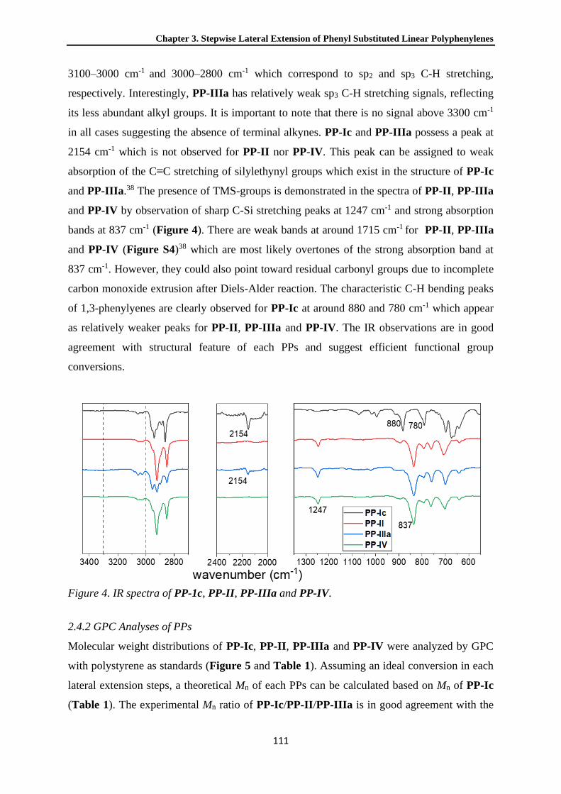
Chapter 3. Stepwise Lateral Extension of Phenyl Substituted Linear Polyphenylenes
111
3100–3000 cm-1 and 3000–2800 cm-1 which correspond to sp2 and sp3 C-H stretching,
respectively. Interestingly, PP-IIIa has relatively weak sp3 C-H stretching signals, reflecting
its less abundant alkyl groups. It is important to note that there is no signal above 3300 cm-1
in all cases suggesting the absence of terminal alkynes. PP-Ic and PP-IIIa possess a peak at
2154 cm-1 which is not observed for PP-II nor PP-IV. This peak can be assigned to weak
absorption of the C≡C stretching of silylethynyl groups which exist in the structure of PP-Ic
and PP-IIIa.38 The presence of TMS-groups is demonstrated in the spectra of PP-II, PP-IIIa
and PP-IV by observation of sharp C-Si stretching peaks at 1247 cm-1 and strong absorption
bands at 837 cm-1 (Figure 4). There are weak bands at around 1715 cm-1 for PP-II, PP-IIIa
and PP-IV (Figure S4)38 which are most likely overtones of the strong absorption band at
837 cm-1. However, they could also point toward residual carbonyl groups due to incomplete
carbon monoxide extrusion after Diels-Alder reaction. The characteristic C-H bending peaks
of 1,3-phenylyenes are clearly observed for PP-Ic at around 880 and 780 cm-1 which appear
as relatively weaker peaks for PP-II, PP-IIIa and PP-IV. The IR observations are in good
agreement with structural feature of each PPs and suggest efficient functional group
conversions.
Figure 4. IR spectra of PP-1c, PP-II, PP-IIIa and PP-IV.
2.4.2 GPC Analyses of PPs
Molecular weight distributions of PP-Ic, PP-II, PP-IIIa and PP-IV were analyzed by GPC
with polystyrene as standards (Figure 5 and Table 1). Assuming an ideal conversion in each
lateral extension steps, a theoretical Mn of each PPs can be calculated based on Mn of PP-Ic
(Table 1). The experimental Mn ratio of PP-Ic/PP-II/PP-IIIa is in good agreement with the
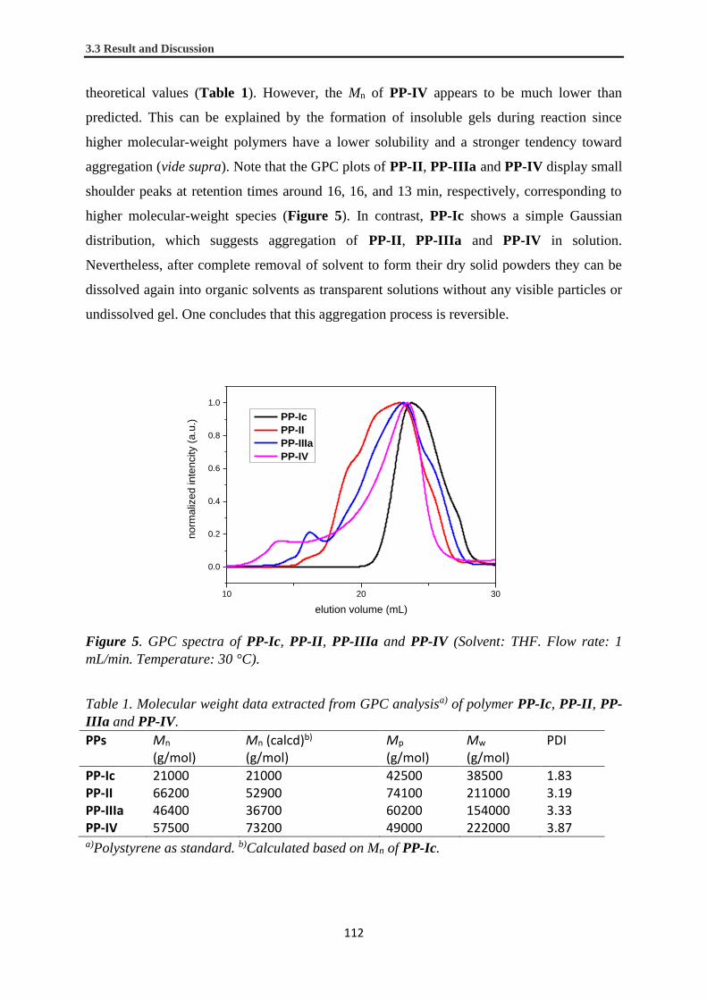
3.3 Result and Discussion
112
theoretical values (Table 1). However, the Mn of PP-IV appears to be much lower than
predicted. This can be explained by the formation of insoluble gels during reaction since
higher molecular-weight polymers have a lower solubility and a stronger tendency toward
aggregation (vide supra). Note that the GPC plots of PP-II, PP-IIIa and PP-IV display small
shoulder peaks at retention times around 16, 16, and 13 min, respectively, corresponding to
higher molecular-weight species (Figure 5). In contrast, PP-Ic shows a simple Gaussian
distribution, which suggests aggregation of PP-II, PP-IIIa and PP-IV in solution.
Nevertheless, after complete removal of solvent to form their dry solid powders they can be
dissolved again into organic solvents as transparent solutions without any visible particles or
undissolved gel. One concludes that this aggregation process is reversible.
10 20 30
0.0
0.2
0.4
0.6
0.8
1.0
norm
aliz
ed inte
ncity (
a.u
.)
elution volume (mL)
PP-Ic
PP-II
PP-IIIa
PP-IV
Figure 5. GPC spectra of PP-Ic, PP-II, PP-IIIa and PP-IV (Solvent: THF. Flow rate: 1
mL/min. Temperature: 30 °C).
Table 1. Molecular weight data extracted from GPC analysisa) of polymer PP-Ic, PP-II, PP-
IIIa and PP-IV.
PPs Mn (g/mol)
Mn (calcd)b) (g/mol)
Mp
(g/mol)
Mw
(g/mol) PDI
PP-Ic 21000 21000 42500 38500 1.83 PP-II 66200 52900 74100 211000 3.19 PP-IIIa 46400 36700 60200 154000 3.33 PP-IV 57500 73200 49000 222000 3.87 a)Polystyrene as standard. b)Calculated based on Mn of PP-Ic.

Chapter 3. Stepwise Lateral Extension of Phenyl Substituted Linear Polyphenylenes
113
3.4 Conclusion
We have developed an elegant way for lateral expansion of a linear PP by reaction with
diphenyl-CP derivatives using a stepwise Diels-Alder cycloaddition/deprotection protocol.
This route is commonly used in the field of dendritic PPs, but has so far not been applied
within the synthesis of linear PPs. Each individual step of the extension procedure was
monitored by recording 1H NMR and IR spectra, showing successful functional group
transformations. The resulting extended PPs were analyzed by GPC revealing the step-wise
evolution of the molecular weight. Preliminary attempts at cyclodehydrogenation of these
PPs were not successful. However, our synthetic protocol opens up further opportunities for
the synthesis of wider GNRs and their band-gap engineering. Moreover, such laterally
expanded PPs can also be regarded as a new class of polymers that have implications for the
field of macromolecular chemistry and physics.20,39 For example, light scattering studies are
desired to elucidate the effect of such lateral expansion on their persistence lengths, although
the issue of the aggregations needs to be addressed first by devising the chemical structures.
Further, substitution of their peripheral positions with different functional groups might lead
to formation of unique self-assembled nanostructures.39

114
3.5 Experimental Section
General Information: Unless otherwise noted, materials were purchased from Fluka, Aldrich,
Acros, abcr, Merck and other commercial suppliers and used as received unless otherwise
specified. Compound 3, 5, 8c and 10a were synthesized according to ref 26, ref 17, ref 27 and
ref 30, respectively. All reactions working with air- or moisture-sensitive compounds were
carried out under argon atmosphere using standard Schlenk line techniques. Thin layer
chromatography (TLC) was performed on silica gel coated aluminum sheets with F254
indicator. Preparative column chromatography was performed on silica gel from Merck with
a grain size of 0.063–0.200 mm (silica gel) or 0.04–0.063 mm (flash silica gel, Geduran Si
60). Melting points were determined on a Büchi hot stage apparatus without correction.
Membrane filtration was performed on polyvinylidene fluoride membrane with a pore size of
0.45 m (Merck). NMR spectra were recorded in deuterated solvents using Bruker AVANCE
III 250 and Bruker AVANCE III 300 MHz NMR spectrometers. Chemical shifts (δ) were
expressed in ppm relative to the residual of solvent (CD2Cl2 @ 5.32 ppm for 1H NMR, 53.84
ppm for 13C NMR; CDCl3 @ 7.26 ppm for 1H NMR, 77.16 ppm for 13C NMR). Coupling
constants (J) were recorded in Hertz (Hz) with multiplicities explained by the following
abbreviations: s = singlet, d = doublet, t = triplet, q =quartet, dd = doublet of doublets, dt =
doublet of triplets, m = multiplet, br = broad. IR was measured on a Nicolet 730 FT-IR
spectrometer equipped with an attenuated total reflection (ATR) setup. The samples were
deposited as pristine material on the diamond crystal and pressed on it with a stamp.
Analytical GPC was performed using a PSS SECcurity Agilent 1260 Infinity Setup (Polymer
Standards Service GmbH (PSS)). A column combination from PSS (SDV 106, 104, 500 Å,
300x8 mm) was connected and maintained at 30 °C. THF was used as eluent with a flow rate
of 1 mL/min. The relative molecular weights were calculated based on a universal
polystyrene calibration using the signal recorded by a PSS SECcurity UV detector (254 nm).
High-resolution mass spectra (HRMS) were recorded by matrix-assisted laser
decomposition/ionization (MALDI) using 7,7,8,8-tetracyanoquinodimethane (TCNQ) or
trans-2-[3-(4-tert-Butylphenyl)-2-methyl-2-propenylidene]malononitrile (DCTB) as matrix
with a Bruker Reflex II-TOF spectrometer (MALDI-TOF HRMS).
Synthesis of 3-(3-ethynylphenyl)-4-phenyl-2,5-bis[3-(triisopropylsilylethynyl)phenyl]
cyclopenta-2,4-dien-1-one (1c): To a solution of 1-phenyl-2-[3-
(trimethylsilylethynyl)phenyl]ethane-1,2-dione (6) (1.00 g, 3.28 mmol) in THF (20 mL) was

Chapter 3. Stepwise Lateral Extension of Phenyl Substituted Linear Polyphenylenes
115
injected a THF solution of TBAF (4.5 mL 1 M, 4.5 mmol). The solution was stirred at a room
temperature for 1 h, and then passed through a short pad of silica gel with THF as eluent.
Solvent was then removed in vacuo to afford 1-phenyl-2-(3-ethynylphenyl)ethane-1,2-dione
(7) as a yellow solid (770 mg, 3.27 mmol, 99% crude yield), which was directly used in the
next step without further purification. To a solution of 1,3-bis[3-
(triisopropylsilylethynyl)phenyl]propan-2-one (4) (1.62 g, 3.11 mmol) and 7 (770 mg, 3.27
mmol) in tBuOH (180 mL) was added at 80 °C a solution of tri-n-butylammonium hydroxide
(0.2 g, 0.3 mmol, 40% w/w) in EtOH under vigorous stirring. The reaction was tracked by
TLC until consumption of starting materials (ca. 30 min). During the time the solution
gradually turned into dark purple. The solution was then allowed to cool down to a room
temperature, and diluted with ether and water. The aqueous phase was extracted three times
and the combined organic phases were washed with water, brine and dried over MgSO4. The
solvent was then removed in vacuo and the residue was purified by triethylamine-neutralized
silica gel column chromatography (eluent: dichloromethane/hexane = 1/3) to afford 1c as a
purple solid (1.40 g, 59%, over 2 steps from 6): mp 130.1–131.9 °C; 1H NMR (300 MHz,
CD2Cl2, δ): 7.49 – 7.28 (m, 5H), 7.30 – 7.12 (m, 7H), 7.08 (s, 1H), 7.03 – 6.91 (m, 4H), 3.05
(s, 1H), 1.09 (s, 42H); 13C NMR (75 MHz, CD2Cl2, δ): 199.93, 155.80, 154.68, 134.23,
133.83, 133.05, 132.95, 132.88, 131.47, 131.44, 131.34, 131.16, 130.59, 130.56, 130.13,
129.63, 129.48, 128.83, 128.74, 128.66, 128.59, 125.69, 125.14, 123.92, 123.84, 122.72,
107.27, 107.21, 91.44, 91.32, 83.19, 78.22, 18.98, 11.86; MS (MALDI-TOF) m/z: [M]+ calcd
for C53H60OSi2, 768.4 (100%), 769.4 (68%), 770.4 (29%), 771.4 (7.6%); Found 768.4 (95%),
769.4 (100%), 770.4 (43%), 771.4 (22%).
Synthesis of 3,4-diphenyl-2,5-bis(trimethylsilyl)cyclopenta-2,4-dien-1-one (2a): Synthesis of
2a was carried out following a reported procedure.35 To a solution of [(1Z,3Z)-1,4-diiodo-
2,3-diphenylbuta-1,3-diene-1,4-diyl]bis(trimethylsilane) (10a)30 (301 mg, 0.500 mmol) in
diethyl ether (5 mL) was injected a hexane solution of tBuLi (1.18 mL, 1.7 M, 2.0 mmol) at –
78 °C. After stirring at –78 °C for 1 h, CuCl (1.4 mg, 1.05 mmol) was added into the reaction
mixture. The mixture was further stirred at –78 °C for 30 min. CO (g.) was then bubbled
through the mixture under vigorous stirring for 10 min. Di-tert-butyl peroxide (0.19 mL, 1.1
mmol) was then injected into the mixture, which was allowed to warm up to 0 °C and stirred
at this temperature for 1 h. Water was then added to quench the reaction and the organic
phase was diluted with diethyl ether. The organic layer was washed with Na2S2O3 (aq., 5%),
water, brine and dried over MgSO4. The solvent was then removed in vacuo and the residue

3.5 Experimental Section
116
was purified by triethylamine-neutralized silica gel column chromatography (eluent:
dichloromethane/hexane = 1/8) to afford 2a as a yellow solid (40.6 mg, 22%): 1H NMR (300
MHz, CD2Cl2, δ): 7.25–7.14 (m, 6H), 7.00–6.88 (m, 4H), -0.03 (s, 18H). The NMR data
agreed with a previously reported one in a literature.40
Synthesis of 3-phenyl-2,5-bis(trimethylsilyl)-4-[3-(trimethylsilylethynyl)phenyl]cyclopenta-
2,4-dien-1-one (2b): Synthesis of 2b was carried out following a reported procedure.35 To a
solution of {(1Z,3Z)-1,4-diiodo-2-phenyl-3-[3-(trimethylsilylethynyl)phenyl]buta-1,3-diene-
1,4-diyl}bis(trimethylsilane) (10b) (4.3 g, 6.2 mmol) in diethyl ether (60 mL) was injected a
hexane solution of tBuLi (15 mL, 1.7 M, 26 mmol) at –78 °C. After stirring at –78 °C for 1 h,
CuCl (1.3 g, 13 mmol) was added into the reaction mixture. The mixture was further stirred
at –78 °C for 30 min. CO (g.) was then bubbled through the mixture under vigorous stirring
for 10 min. Di-tert-butyl peroxide (2.4 mL, 13 mmol) was then injected into the mixture,
which was allowed to warm up to 0 °C and stirred at this temperature for 1 h. Water was then
added to quench the reaction and the organic phase was diluted with diethyl ether. The
organic layer was washed with Na2S2O3 (aq., 5%), water, brine and dried over MgSO4. The
solvent was then removed in vacuo and the residue was purified by triethylamine-neutralized
silica gel column chromatography (eluent: dichloromethane/hexane = 1/10) to afford 2b as a
yellow solid (1.2 g, 40%): mp 120.7–123.0 °C; 1H NMR (300 MHz, CD2Cl2, δ): 7.30 (d, J =
7.7 Hz, 1H), 7.26–7.17 (m, 3H), 7.12 (t, J = 7.7 Hz, 1H), 7.09 (s, 1H), 6.99 – 6.90 (m, 2H),
6.85 (d, J = 7.7 Hz, 1H), 0.22 (s, 9H), -0.01 (s, 9H), -0.02 (s, 9H); 13C NMR (75 MHz,
CD2Cl2, δ): 210.22, 171.48, 170.54, 136.66, 136.08, 132.02, 131.89, 131.78, 131.06, 128.86,
128.78, 128.68, 128.11, 123.15, 104.84, 95.21, 0.10, 0.04; MS (MALDI-TOF) m/z: [M]+
calcd for C28H36OSi3 472.2 (100%), 473.2 (46%), 474.2 (19%); Found 472.2 (100%), 473.2
(73%), 474.2 (30%).
Synthesis of 3,4-bis(3-tetradecylphenyl)-2,5-bis(trimethylsilyl)cyclopenta-2,4-dien-1-one
(2c): Synthesis of 2c were accomplished following a previously reported procedure.35 To a
solution of [(1Z,3Z)-1,4-diiodo-2,3-bis(3-tetradecylphenyl)buta-1,3-diene-1,4-
diyl]bis(trimethylsilane) (10c) (1.77 g, 1.78 mmol) in diethyl ether (20 mL) was injected at -
78 °C a hexane solution of tBuLi (4.30 mL, 1.7 M, 7.30 mmol). The solution was allowed to
react for 1 h, and CuCl (0.370 g, 3.74 mmol) was added into the solution. The mixture was
further stirred at -78 °C for 30 min. CO (g.) was then bubbled through the mixture under
vigorous stirring for 10 min. Di-tert-butyl peroxide (0.684 mL, 3.74 mmol) was then injected

Chapter 3. Stepwise Lateral Extension of Phenyl Substituted Linear Polyphenylenes
117
into the solution, which was then warmed up to 0 °C and allowed to react for 1 h. Water was
added to quench the reaction and the organic phase was diluted with diethyl ether. The
organic layer was washed with Na2S2O3 (aq., 5%), water, brine and dried over MgSO4. The
ether was then removed in vacuo and the residue was purified by triethylamine-neutralized
silica gel column chromatography (dichloromethane/hexane = 1/25) to afford 2c as a yellow
solid (0.659 g, 48%): mp 37.2–38.7 °C; 1H NMR (300 MHz, CD2Cl2, δ): 7.08 (t, J = 7.4 Hz,
2H), 7.01 (d, J = 7.6 Hz, 2H), 6.74 (d, J = 7.2 Hz, 2H), 6.72 (s, 2H), 2.45 (t, J = 7.6 Hz, 4H),
1.40 (quin, J = 8.2, 7.3 Hz, 4H), 1.34 – 1.07 (br, 44H), 0.88 (t, J = 6.4 Hz, 6H), -0.02 (s,
18H); 13C NMR (75 MHz, CD2Cl2, δ): 210.68, 172.32, 142.70, 136.23, 130.46, 128.93,
128.72, 127.77, 126.12, 36.26, 32.52, 31.97, 30.29, 30.25, 30.17, 30.08, 29.95, 29.69, 23.28,
14.46, 0.14; HRMS (MALDI-TOF) m/z: [M]+ calcd for C51H84OSi2 768.6061; Found
768.6130.
Synthesis of 1,3-bis[3-(triisopropylsilylethynyl)phenyl]propan-2-one (4): A mixture of 1,3-
bis(3-bromophenyl)acetone (3)26 (5.0 g, 14 mmol), (triisopropylsilyl)acetylene (7.6 mL, 34
mmol), PdCl2(PPh3)2 (0.48 g, 0.68 mmol), CuI (0.26 g, 1.4 mmol), PPh3 (0.36 g, 1.4 mL) and
piperidine (50 mL) was degassed by argon bubbling under vigorous stirring for 15 min. The
mixture was then stirred at 100 °C overnight. After cooling down to a room temperature,
ether and ice was added into the mixture and the organic layer was washed with HCl (aq., 2
M), water and brine and dried over MgSO4. Ether were removed in vacuo and the residue was
purified by silica gel column chromatography (eluent: ethyl acetate/hexane = 1/6) to afford 4
as a pale yellow oil (7.7 g, 99%): 1H NMR (300 MHz, CD2Cl2, δ): 7.39 (d, J = 7.5 Hz, 2H),
7.34–7.22 (s, 2H, with an embedded t, J = 7.4 Hz, 2H), 7.12 (d, J = 7.3 Hz, 2H), 3.74 (s, 4H),
1.14 (s, 42H); 13C NMR (75 MHz, CD2Cl2, δ): 205.10, 134.85, 133.57, 131.17, 130.29,
129.09, 124.38, 107.27, 91.40, 49.37, 19.02, 11.91; HRMS (MALDI-TOF) m/z: [M + H]+
calcd for C37H55 OSi2 571.3791; Found 571.3765.
Synthesis of 1-phenyl-2-[3-(trimethylsilylethynyl)phenyl]ethane-1,2-dione (6): A mixture of
3-bromobenzil (5)17 (2.1 g, 7.3 mmol), (trimethylsilyl)acetylene (3.0 mL, 22 mmol),
Pd(PPh3)4 (0.26 g, 0.22 mmol), CuI (0.046 g, 0.22 mmol), THF (10 mL) and trimethylamine
(10 mL) was degassed by argon bubbling under vigorous stirring for 15 min. The mixture
was then stirred at 100 °C overnight. After cooling down to a room temperature, ether and ice
was added into the mixture and the organic layer was washed with HCl (aq., 2 M), water and
brine and dried over MgSO4. The solvents were removed in vacuo and the residue was

3.5 Experimental Section
118
purified by silica gel column chromatography (eluenet: ethyl acetate/hexane = 1/10) to afford
6 as a pale yellow solid (2.1 g, 94%): mp 50.2–51.3 °C; 1H NMR (300 MHz, CD2Cl2, δ): 8.04
(s, 1H), 7.96 (d, J = 8.0 Hz, 2H), 7.92 (d, J = 7.5 Hz, 1H), 7.72 (d, J = 7.8 Hz, 1H), 7.66 (t, J
= 7.3 Hz, 1H), 7.51 (t, J = 7.7 Hz, 2H), 7.45 (t, J = 7.7 Hz, 1H), 0.25 (s, 9H); 13C NMR (75
MHz, CD2Cl2, δ): 194.05, 193.75, 137.95, 135.15, 133.38, 133.15, 132.91, 130.08, 129.52,
129.18, 129.14, 124.53, 103.29, 96.57, -0.07; MS (MALDI-TOF) m/z: [M − H]+ calcd for
C19H17O2Si 305.1 (100%), 306.1 (26%), 306.1 (5.1%); Found 305.1 (100%), 306.1 (15%),
306.1 (3.6%).
Synthesis of {(1Z,3Z)-1,4-diiodo-2-phenyl-3-[3-(trimethylsilylethynyl)phenyl]buta-1,3-diene-
1,4-diyl}bis(trimethylsilane) (10b): The synthetic procedure was modified from literature
reports.28,29 To a suspension of zirconocene dichloride (18 g, 63 mmol) in THF (200 mL) was
added a hexane solution of nBuLi (83 mL, 1.6 M, 0.13 mol) at –78 °C. The solution turned
pale yellow upon the addition. The mixture was stirred at –78 °C for 1 h to generate an active
zirconocene species. Trimethyl(phenylethynyl)silane (8a) (11 g, 63 mmol) and 1,3-
bis[(trimethylsilyl)ethynyl]benzene (8b) (17 g, 63 mmol) were then simultaneously added to
the mixture under argon flow. The mixture was stirred for 3 h while it was allowed to
gradually warm up to a room temperature. The mixture turned into a dark brown solution
during the process. The mixture was then cooled down to 0 °C, and CuCl (7.5 g, 75 mmol)
was added in one portion, followed by addition of I2 (38 g, 0.15 mmol) in 5 portions. The
mixture was allowed to gradually warm up to a room temperature and stirred overnight. The
reaction was then quenched with water and diluted with ether. The organic layer was washed
with Na2S2O3 (aq., 5%), water, brine and dried over MgSO4. The solvents were then removed
in vacuo and the residue was purified by triethylamine-neutralized silica gel column
chromatography (eluent: cyclohexane) to afford 10b as a pale-yellow solid (5.2 g, 12%, first
band): mp 136.2–137.3 °C; 1H NMR (300 MHz, CD2Cl2, δ): 7.40 (d, J = 7.4 Hz, 1H), 7.37 –
7.26 (m, 3H), 7.24 (m, 2H), 7.20 (d, J = 8.0 Hz, 2H), 7.15 (t, J = 5.5 Hz, 1H), 0.26 (s, 9H),
0.01 (s, 9H), 0.00 (s, 9H); 13C NMR (75 MHz, CD2Cl2, δ): 163.31, 162.60, 139.93, 139.66,
132.77, 132.13, 129.86, 129.70, 128.77, 128.25, 123.17, 114.06, 113.69, 104.76, 99.93, 95.01,
0.94, 0.85, -0.04; MS (MALDI-TOF) m/z: [M − I]+ calcd for C27H36ISi3 571.1 (100%), 572.1
(45%), 573.1 (19%); found 571.3 (100%), 572.3 (44%), 573.3 (20%).
Synthesis of [(1Z,3Z)-1,4-diiodo-2,3-bis(3-tetradecylphenyl)buta-1,3-diene-1,4-
diyl]bis(trimethylsilane) (10c): The synthetic procedure was modified from reported

Chapter 3. Stepwise Lateral Extension of Phenyl Substituted Linear Polyphenylenes
119
procedures.28,29 A hexane solution of nBuLi (8.1 mL, 1.6 M, 13 mmol) was injected into a
suspension of zirconocene dichloride (1.8 g, 6.2 mmol) in THF (6 mL) at –78 °C. The
solution turned into pale yellow upon the injection. The mixture was allowed to react at -
78 °C for 1 h to generate an active zirconocene species. Trimethyl[(3-n-
tetradecylphenyl)ethynyl]silane (8c)27 (3.28 g, 12.3 mmol) was then injected into the mixture
in one portion. The mixture was stirred for 3 h while it was allowed to gradually warm up to a
room temperature. The mixture turned into a dark brown solution during the process. The
mixture was then cooled down to 0 °C, and CuCl (0.73 g, 7.4 mmol) was added in one
portion, followed by addition of I2 (3.76 g, 14.8 mmol) in 5 portions. The mixture was then
gradually warmed up to a room temperature and allowed to react under stirring overnight.
The reaction was then quenched with water and diluted with ether. The organic layer was
washed with Na2S2O3 (aq., 5%), water, brine and dried over MgSO4. The ether was then
removed in vacuo and the residue was purified by triethylamine-neutralized silica gel column
chromatography (eluent: cyclohexane) to afforded 10c as pale-yellow oil (1.85 g, 30%): 1H
NMR (300 MHz, CD2Cl2, δ): 7.19 – 7.10 (br, 4H), 7.10 – 7.01 (br, 2H), 7.01 – 6.88 (br, 2H),
2.53 (t, J = 7.5 Hz, 4H), 1.53 (quin, J = 7.5 Hz, 4H), 1.44 – 1.16 (br, 44H), 0.92 (t, J = 6.5 Hz,
6H), 0.00 (s, 18H); 13C NMR (75 MHz, CD2Cl2, δ): 164.21, 143.01, 139.98, 130.27, 128.99,
128.17, 127.08, 112.44, 36.28, 32.60, 31.98, 30.39, 30.37, 30.33, 30.27, 30.16, 30.04, 29.76,
23.36, 14.57, 1.22; MS (MALDI-TOF) m/z: [M – C2(TMS)2I2]+ calcd for C42H66 570.5
(100%), 571.5 (45%), 572.5 (10%); found 571.1 (100%), 572.1 (42%), 573.1 (18%).
Synthesis of 1,4-bis(trimethylsilyl)-2,3,5-triphenylbenzene (11): A solution of 3,4-diphenyl-
2,5-bis(trimethylsilyl)cyclopenta-2,4-dien-1-one (2a) (33 mg, 0.089 mmol) and
phenylacetylene (14 mg, 0.13 mmol) in ODCB (0.5 mL) was degassed by freeze-pump-thaw
technique for three cycles. The solution was then stirred at 120 °C for 3 days. The solvent
was removed in vacuo and the residue was purified by silica gel column chromatography
(eluent: dichloromethane/hexane = 1/20) to afford 11 as a white solid (36 mg, 89%): mp
160.4–162.0 °C; 1H NMR (300 MHz, CD2Cl2, δ): 7.56 – 7.33 (m, 6H), 7.18 – 7.01 (m, 8H),
7.01 – 6.93 (m, 2H), -0.08 (s, 9H), -0.47 (s, 9H); 13C NMR (75 MHz, CD2Cl2, δ): 149.40,
148.95, 146.60, 146.41, 143.56, 143.17, 140.07, 138.80, 135.77, 132.63, 131.87, 130.43,
128.48, 127.60, 127.34, 127.25, 126.74, 126.63, 3.08, 0.66; MS (MALDI-TOF) m/z: [M]+
calcd for C30H34Si2 450.2 (100%), 451.2 (43%), 452.2 (15%); Found 450.2 (100%), 451.2
(41%), 452.2 (12%).

3.5 Experimental Section
120
Synthesis of PP-Ic: A solution of 1c (0.50 g, 0.65 mmol of repeating unit) in Ph2O (1 mL)
was degassed by freeze-pump-thaw technique for three cycles. The solution was then stirred
at 120 °C for 78 h. During the reaction, small amounts of solution were taken from the
mixture by syringes and the molecular weight was monitored by GPC analysis with PS
standards (see Results and discussion for details). Phenylacetylene (0.13 g, 1.3 mmol) was
then added and the solution was stirred at 160 °C overnight, during which purple color of the
solution completely disappeared. After cooling down to a room temperature, MeOH (10 mL)
was added to induce precipitation of polymeric products. A white precipitate was collected by
filtration with a membrane filter and washed with methanol to afford PP-Ic (465 mg, 91%):
1H NMR (250 MHz, CD2Cl2, δ): 7.53 – 6.02 (br, 18H), 1.23 – 1.08 (br, 21H), 1.08 – 0.73 (br,
21H); IR: ν = 3059 (w), 2941 (m), 2864 (w), 2154 (m), 1597 (w), 1463 (m), 1383 (w), 1244
(w), 1170 (w), 1072 (w), 995 (m), 882 (s), 791 (m), 674(s), 553 (m), 499 (m), 462 (m).
Synthesis of PP-Id: A solution of PP-Ic (0.23 g, 0.31 mmol of repeating unit) in THF (10
mL) was degassed by freeze-pump-thaw technique for three cycles. To this solution was
injected a THF solution of TBAF (1 M, 3 mL). After the injection the mixture was degassed
by freeze-pump-thaw technique for another three cycles. The solution was then allowed to
react at a room temperature for one day before pouring into methanol (100 mL). White
precipitates were collected by filtration with a membrane filter and washed with methanol to
afford as PP-Id (105 mg, 79%): 1H NMR (250 MHz, CD2Cl2, δ): 7.64 – 5.95 (br, 18H), 3.26
– 3.07 (br, 1H), 3.07 – 2.82 (br, 1H).
Synthesis of PP-II: A solution of PP-Id (51 mg, 0.12 mmol of repeating unit) and 2c (0.27 g,
0.36 mmol) in ODCB (1 mL) was degassed by freeze-pump-thaw technique for three cycles.
This solution was stirred at 160 °C for seven days. After cooling to a room temperature, the
solution was poured into methanol (20 mL) to induce precipitation of polymer products. The
precipitates were collected by filtration with a membrane filter and washed with methanol to
afford crude product of PP-II (0.15 g, 67%), which was further purified by recycling GPC to
yield PP-II as a white powder (0.13 g, 58%): 1H NMR (250 MHz, CD2Cl2, δ): 8.84 – 5.48 (br,
36H), 3.08 – 1.93 (br, 8H), 1.93 – 0.95 (br, 96H), 0.95 – 0.44 (br, 12H), 0.37 – -0.36 (br,
18H), -0.36 – -1.31 (br, 18H); IR: ν = 3054 (w), 2923 (m), 2853 (m), 1713.13065 (w),
1600.16127 (w), 1463 (w), 1400 (w), 1247 (m), 1174 (w), 1087 (w), 1054 (w), 837 (s), 762
(m), 708 (m), 641 (w), 556 (w), 446 (w).

Chapter 3. Stepwise Lateral Extension of Phenyl Substituted Linear Polyphenylenes
121
Synthesis of PP-IIIa: A solution of PP-Id (54 mg, 0.13 mmol of repeating unit) and 2b (0.17
g, 0.36 mmol) in chlorobenzene (1 mL) was degassed by freeze-pump-thaw technique for
three cycles. This solution was stirred at 125 °C for five days. After cooling to a room
temperature, the solution was poured into methanol (20 mL) to induce precipitation of
polymer products. The polymer precipitates were collected by filtration with a membrane
filter and washed with methanol to give a crude product of PP-IIIa (white powder, 0.11 g,
68%). The yellow filtrate was concentrated in vacuo and the residue was purified by silica gel
column chromatography (eluent: dichloromethane/hexane = 1/6) to recover unreacted 2b as a
yellow solid (49 mg, 0.11 mmol). The crude product was further purified by recycling GPC
to yield PP-IIIa as a white powder (0.10 g, 62%): 1H NMR (250 MHz, CD2Cl2, δ): 8.02 –
5.72 (br, 38H), 0.44 – 0.04 (br, 18H), 0.44 – -0.34 (br, 18H), -0.34 – -1.00 (br, 18H); IR: ν =
3057 (w), 2923 (w), 2853 (w), 2154 (w), 1719 (w), 1597 (w), 1479 (w), 1409 (w), 1341 (w),
1248 (m), 1185 (w), 1125 (w), 1072 (w), 1021 (w), 837 (s), 759 (m), 701 (m), 642 (m), 566
(w), 450 (w).
Synthesis of PP-IIIb: A solution of PP-IIIa (15 mg, 0.012 mmol of repeating unit) in THF (2
mL) and methanol (1 mL) was degassed by freeze-pump-thaw technique for three cycles. To
this solution was added K2CO3 (3.3 mg, 0.024 mmol) under a flow of argon. The mixture was
vigorously stirred overnight at a room temperature and poured into methanol (20 mL) to
induce precipitation of polymer product. The precipitates were collected by filtration with a
membrane filter and washed with methanol to afford a white powder of PP-IIIb (12 mg,
83%): 1H NMR (250 MHz, CD2Cl2, δ): 8.11 – 5.79 (br, 38H), 3.22 – 2.77 (br, 2H) 0.44 –
0.04 (br, 18H), 0.37 – -0.36 (br, 18H), -0.36 – -1.13 (br, 18H).
Synthesis of PP-IV, Procedure A: A mixture of PP-IIIb (14 mg, 0.012 mmol of repeating
unit) and 2c (36 mg, 0.047 mmol) in ODCB (0.2 mL) was degassed by freeze-pump-thaw
technique for three cycles. This mixture was stirred at 160 °C for four days, during which a
gel was formed. After cooling to a room temperature, THF (5 mL) was added to the mixture.
The mixture was sonicated for 15 min and filtrated. The solution was poured into methanol
(20 mL) to induce precipitation of polymer product. The precipitates were collected by
filtration with a membrane filter and washed with methanol to afford a white powder of PP-
IV (6.0 mg, 20%).
Procedure B: A solution of PP-IIIa (10 mg, 0.0077 mmol of repeating unit) in THF (2 mL)
and methanol (1 mL) was degassed by freeze-pump-thaw technique for three cycles. To this

3.5 Experimental Section
122
solution was added K2CO3 (2.1 mg, 0.015 mmol) under a flow of argon. The mixture was
vigorously stirred overnight and then dichloromethane (20 mL) was added. The organic
phase was washed with water and brine and dried over Na2SO4. 2c (24 mg, 0.031 mmol) and
ODCB (0.2 mL) were added into the solution and the mixture was concentrated in vacuo to
remove dichloromethane. After degassing by freeze-pump-thaw technique for three cycles,
the residual solution was stirred at 160 °C for four days. After cooling to a room temperature,
the solution was poured into methanol (20 mL) to induce precipitation of polymer product.
The precipitates were collected by filtration with a membrane filter and washed with
methanol to afford a white powder of PP-IV (6.7 mg, 34% over two steps): 1H NMR (250
MHz, CD2Cl2, δ): 8.26 – 5.76 (br, 56H), 2.95 – 2.05 (br, 8H), 1.85 – 0.96 (br, 96H), 0.96 –
0.62 (br, 12H), 0.34 – -0.37 (br, 36H), -0.37 – -1.28 (br, 36H); IR: ν = 3054 (w), 2924 (m),
2853 (w), 1717 (w), 1600 (w), 1463 (w), 1404 (w), 1343 (w), 1247 (m), 1087 (w), 1021 (w),
837 (s), 762 (m), 702 (m), 641 (w), 429 (w).

Chapter 3. Stepwise Lateral Extension of Phenyl Substituted Linear Polyphenylenes
123
3.6 Supporting information
General
Microwave-assisted reactions were performed using a CEM microwave reactor Discover-S-
Class. Solution UV–vis absorption spectra were recorded at a room temperature on a Perkin-
Elmer Lambda 900 spectrophotometer. The baseline was corrected by subtracting a
measurement of the cuvette filled with pure solvent used for the measurement.
Removal of trimethylsilyl groups from PP-II
We have tried several different reagents to remove trimethylsilyl (TMS) groups from PP-II.
We first used the most common reagent tetra-n-butylammonium fluoride (TBAF). It is
interesting to note that, PP-II was initially insoluble in N,N-dimethylformaldehyde (DMF).
However, after adding TBAF to a mixture of PP-II and DMF, it turned into a clear solution,
presumably forming Si-F ionic adduct. However, a reaction at a room temperature overnight
only showed very little desilylation, based on 1H NMR spectrum. Elevation of the reaction
temperature had minor effect on the reaction and insoluble product was eventually formed at
a reaction temperature of 80 °C. Refluxing a solution of PP-II in tetrahydrofuran (THF) and
concentrated HCl (aq.) resulted in no reaction. On the other hand, there was also no reaction
in a solution of PP-II in THF and HBF4 (aq.) at a room temperature, while heating to 85 °C
led to again formation of insoluble products. Eventually, we found out that heating of PP-II
in a solution of THF and concentrated HBr (aq.) at 100 °C allowed smooth removal of the
silyl groups. The efficiency of the reaction was further improved under microwave irradiation,
leading to complete removal of the TMS groups.
Desilylation of PP-II: A solution of PP-II (32.6 mg, 0.0171 mmol of repeating units) in THF
(25 mL) in a microwave reaction tube was degassed by argon bubbling for 5 min. To this
solution was added 1 mL of concentrated aqueous solution of HBr (48 w/w %). The solution
was subjected to microwave irradiation in a microwave reactor at 110 °C with max power of
300 W with activated cooling, for 2 days. After cooling to a room temperature, the solution
was poured into methanol (100 mL) to induce precipitation of polymeric product. The
precipitate was collected as a light brownish flake through filtration with a membrane filter
(26 mg, 94%). The product was hardly soluble in dichloromethane, but soluble after adding a
small amount of HBr (aq.) or using THF as solvent. 1H NMR suggested a complete removal
of all TMS groups (Figure S24). 1H NMR (250 MHz, CD2Cl2, δ): 8.2–6.0 (br, 40H), 2.7–2.0
(br, 8H), 1.5–0.9 (br, 96H), 0.9–0.7 (br, 12H).

3.6 Supporting information
124
Figure S1. Matrix assist laser desorption ionization time of flight mass spectrum of PP-1c
recorded in linear mode (matrix: trans-2-[3-(4-tert-Butylphenyl)-2-methyl-2-
propenylidene]malononitrile). Inset: enlargement of the hexamer signal.
400 500 600 700 800
0.0
0.2
0.4
0.6
0.8
abso
rban
ce
wavelength (nm)
GNR PP-II
Figure S2. UV-Vis absorption spectrum of product after the oxidative cyclodehydrogenation
of PP-II, recorded in 1,2,4-trichlorobenzene.

Chapter 3. Stepwise Lateral Extension of Phenyl Substituted Linear Polyphenylenes
125
Figure S3. Possible cyclodehydrogenation of PP-II at undesired position.
3500 3150 2800 2450 2100 1750 1400 1050 700
Wavenumber (cm-1)
PP-Ic
PP-II
PP-IIIa
PP-IV
Figure S4. FT-IR spectra of PP-Ic, PP-II, PP-IIIa and PP-IV at the full spectral region of
3500–600 cm-1.

3.6 Supporting information
126
Figure S5. 1H NMR spectrum of 1c. (300 MHz, CD2Cl2)
Figure S6. 13C NMR spectrum of 1c. (75 MHz, CD2Cl2)

Chapter 3. Stepwise Lateral Extension of Phenyl Substituted Linear Polyphenylenes
127
Figure S7. 1H NMR spectrum of 2b. (300 MHz, CD2Cl2)
Figure S8. 13C NMR spectrum of 2b. (75 MHz, CD2Cl2)

3.6 Supporting information
128
Figure S9. 1H NMR spectrum of 2c. (300 MHz, CD2Cl2)
Figure S10. 13C NMR spectrum of 2c. (75 MHz, CD2Cl2)

Chapter 3. Stepwise Lateral Extension of Phenyl Substituted Linear Polyphenylenes
129
Figure S11. 1H NMR spectrum of 4. (300 MHz, CD2Cl2)
Figure S12. 13C NMR spectrum of 4. (75 MHz, CD2Cl2)

3.6 Supporting information
130
Figure S13. 1H NMR spectrum of 6. (300 MHz, CDCl3)
Figure S14. 13C NMR spectrum of 6. (75 MHz, CDCl3)

Chapter 3. Stepwise Lateral Extension of Phenyl Substituted Linear Polyphenylenes
131
Figure S15. 1H NMR spectrum of 10b. (300 MHz, CD2Cl2)
Figure S16. 13C NMR spectrum of 10b. (75 MHz, CD2Cl2)

3.6 Supporting information
132
Figure S17. 1H NMR spectrum of 10c. (300 MHz, CD2Cl2)
Figure S18. 13C NMR spectrum of 10c. (75 MHz, CD2Cl2)

Chapter 3. Stepwise Lateral Extension of Phenyl Substituted Linear Polyphenylenes
133
Figure S19. 1H NMR spectrum of 11. (300 MHz, CD2Cl2)
Figure S20. 13C NMR spectrum of 11. (75 MHz, CD2Cl2)

3.6 Supporting information
134
Figure S21. 1H NMR spectrum of PP-Ic. (250 MHz, CD2Cl2)
Figure S22. 1H NMR spectrum of PP-Id. (250 MHz, CD2Cl2)

Chapter 3. Stepwise Lateral Extension of Phenyl Substituted Linear Polyphenylenes
135
Figure S23. 1H NMR spectrum of PP-II. (250 MHz, CD2Cl2)
Figure S24. 1H NMR spectrum of PP-II after desilylation. (250 MHz, CD2Cl2)

3.6 Supporting information
136
Figure S25. 1H NMR spectrum of PP-IIIa. (250 MHz, CD2Cl2)
Figure S26. 1H NMR spectrum of PP-IIIb. (250 MHz, CD2Cl2)

Chapter 3. Stepwise Lateral Extension of Phenyl Substituted Linear Polyphenylenes
137
Figure S27. 1H NMR spectrum of PP-IV. (250 MHz, CD2Cl2)

138
3.7 References
(1) Hammer, B. A. G.; Müllen, K. Dimensional Evolution of Polyphenylenes: Expanding in All Directions. Chem. Rev. 2016,
116 (4), 2103–2140.
(2) Hou, I. C. Y.; Hu, Y.; Narita, A.; Müllen, K. Diels-Alder Polymerization: A Versatile Synthetic Method toward Functional
Polyphenylenes, Ladder Polymers and Graphene Nanoribbons. Polym. J. 2018, 50 (1), 3–20.
(3) Si, K.; Wycisk, R.; Dong, D.; Cooper, K.; Rodgers, M.; Brooker, P.; Slattery, D.; Litt, M. Rigid-Rod
Poly(Phenylenesulfonic Acid) Proton Exchange Membranes with Cross-Linkable Biphenyl Groups for Fuel Cell
Applications. Macromolecules 2013, 46 (2), 422–433.
(4) Adamski, M.; Skalski, T. J. G.; Britton, B.; Peckham, T. J.; Metzler, L.; Holdcroft, S. Highly Stable, Low Gas Crossover,
Proton-Conducting Phenylated Polyphenylenes. Angew. Chem. Int. Ed. 2017, 56 (31), 9058–9061.
(5) Holmes, T.; Skalski, T. J. G.; Adamski, M.; Holdcroft, S. Stability of Hydrocarbon Fuel Cell Membranes: Reaction of
Hydroxyl Radicals with Sulfonated Phenylated Polyphenylenes. Chem. Mater. 2019, 31 (4), 1441–1449.
(6) Shiino, K.; Miyake, J.; Miyatake, K. Highly Stable Polyphenylene Ionomer Membranes from Dichlorobiphenyls. Chem.
Commun. 2019, 55 (49), 7073–7076.
(7) Motealleh, B.; Huang, F.; Largier, T. D.; Khan, W.; Cornelius, C. J. Solution-Blended Sulfonated Polyphenylene and
Branched Poly(Arylene Ether Sulfone): Synthesis, State of Water, Surface Energy, Proton Transport, and Fuel Cell
Performance. Polymer (Guildf). 2019, 160, 148–161.
(8) Largier, T. D.; Wang, D.; Mueller, J.; Cornelius, C. J. Improving Electrodialysis Based Water Desalination Using a
Sulfonated Diels-Alder Poly(Phenylene). J. Memb. Sci. 2017, 531, 103–110.
(9) Largier, T.; Huang, F.; Cornelius, C. J. Homopolymer and Multi-Block Diels-Alder Polyphenylenes: Synthesis, Physical
Properties, X-Ray Diffraction, and Gas Transport. Eur. Polym. J. 2017, 89, 301–310.
(10) Largier, T.; Huang, F.; Kahn, W.; Cornelius, C. J. Poly(Phenylene) Synthesized Using Diels-Alder Chemistry and Its
Sulfonation: Sulfonate Group Complexation with Metal Counter-Ions, Physical Properties, and Gas Transport. J. Memb.
Sci. 2019, 572, 320–331.
(11) Wang, X.-Y.; Yao, X.; Müllen, K. Polycyclic Aromatic Hydrocarbons in the Graphene Era. Sci. China Chem. 2019, 62 (9),
1099–1144.
(12) Narita, A.; Wang, X. Y.; Feng, X.; Müllen, K. New Advances in Nanographene Chemistry. Chem. Soc. Rev. 2015, 44 (18),
6616–6643.
(13) Narita, A.; Chen, Z.; Chen, Q.; Müllen, K. Solution and On-Surface Synthesis of Structurally Defined Graphene
Nanoribbons as a New Family of Semiconductors. Chem. Sci. 2019, 10 (4), 964–975.
(14) Gröning, O.; Wang, S.; Yao, X.; Pignedoli, C. A.; Borin Barin, G.; Daniels, C.; Cupo, A.; Meunier, V.; Feng, X.; Narita,
A.; et al. Engineering of Robust Topological Quantum Phases in Graphene Nanoribbons. Nature 2018, 560 (7717), 209–
213.
(15) Rizzo, D. J.; Veber, G.; Cao, T.; Bronner, C.; Chen, T.; Zhao, F.; Rodriguez, H.; Louie, S. G.; Crommie, M. F.; Fischer, F.
R. Topological Band Engineering of Graphene Nanoribbons. Nature 2018, 560 (7717), 204–208.
(16) Slota, M.; Keerthi, A.; Myers, W. K.; Tretyakov, E.; Baumgarten, M.; Ardavan, A.; Sadeghi, H.; Lambert, C. J.; Narita,
A.; Müllen, K.; et al. Magnetic Edge States and Coherent Manipulation of Graphene Nanoribbons. Nature 2018, 557
(7707), 691–695.
(17) Narita, A.; Feng, X.; Hernandez, Y.; Jensen, S. A.; Bonn, M.; Yang, H.; Verzhbitskiy, I. A.; Casiraghi, C.; Hansen, M. R.;
Koch, A. H. R.; et al. Synthesis of Structurally Well-Defined and Liquid-Phase-Processable Graphene Nanoribbons. Nat.
Chem. 2014, 6 (2), 126–132.
(18) Ried, W.; Freitag, D. Synthese von Polyphenyl-Poly-Phenylen. Naturwissenschaften 1966, 53 (12), 306.
(19) Stille, J. K.; Harris, F. W.; Rakutis, R. O.; Mukamal, H. Diels-Alder Polymerizations: Polymers Containing Controlled
Aromatic Segments. J. Polym. Sci. Part B Polym. Lett. 1966, 4 (10), 791–793.
(20) Forero-Martinez, N. C.; Baumeier, B.; Kremer, K. Backbone Chemical Composition and Monomer Sequence Effects on
Phenylene Polymer Persistence Lengths. Macromolecules 2019, 52 (14), 5307–5316.
(21) Narita, A.; Verzhbitskiy, I. A.; Frederickx, W.; Mali, K. S.; Jensen, S. A.; Hansen, M. R.; Bonn, M.; De Feyter, S.;

Chapter 3. Stepwise Lateral Extension of Phenyl Substituted Linear Polyphenylenes
139
Casiraghi, C.; Feng, X.; et al. Bottom-up Synthesis of Liquid-Phase-Processable Graphene Nanoribbons with near-Infrared
Absorption. ACS Nano 2014, 8 (11), 11622–11630.
(22) Hu, Y.; Xie, P.; De Corato, M.; Ruini, A.; Zhao, S.; Meggendorfer, F.; Straasø, L. A.; Rondin, L.; Simon, P.; Li, J.; et al.
Bandgap Engineering of Graphene Nanoribbons by Control over Structural Distortion. J. Am. Chem. Soc. 2018, 140 (25),
7803–7809.
(23) Hammer, B. A. G.; Müllen, K. Expanding the Limits of Synthetic Macromolecular Chemistry through Polyphenylene
Dendrimers. J. Nanoparticle Res. 2018, 20 (10), 262.
(24) Nguyen, T. T. T.; Baumgarten, M.; Rouhanipour, A.; Räder, H. J.; Lieberwirth, I.; Müllen, K. Extending the Limits of
Precision Polymer Synthesis: Giant Polyphenylene Dendrimers in the Megadalton Mass Range Approaching Structural
Perfection. J. Am. Chem. Soc. 2013, 135 (11), 4183–4186.
(25) Fuchs, B.; Pasternak, M.; Pazhenchevsky, B. Chemical and Photochemical Behavior of Nondissociating
Cyclopentadienone Dimers. J. Org. Chem. 1981, 46 (10), 2017–2020.
(26) Sauriat-Dorizon, H.; Maris, T.; Wuest, J. D.; Enright, G. D. Molecular Tectonics. Construction of Porous Hydrogen-
Bonded Networks from Bisketals of Pentaerythritol. J. Org. Chem. 2003, 68 (2), 240–246.
(27) Chen, X. C.; Nishinaga, S.; Okuda, Y.; Zhao, J. J.; Xu, J.; Mori, H.; Nishihara, Y. A Divergent Synthesis of 3,10-
Dialkylpicenes. Org. Chem. Front. 2015, 2 (5), 536–541.
(28) Negishi, E. ichi; Holmes, S. J.; Tour, J. M.; Miller, J. A.; Cederbaum, F. E.; Swanson, D. R.; Takahashi, T. Novel
Bicyclization of Enynes and Diynes Promoted by Zirconocene Derivatives and Conversion of Zirconabicycles into
Bicyclic Enones via Carbonylation. J. Am. Chem. Soc. 1989, 111 (9), 3336–3346.
(29) Xi, C.; Hou, S.; Afifi, T. H.; Hara, R.; Takahashi, T. Remarkable Effect of Copper Chloride on Diiodination of
Zirconacyclopentadienes. Tetrahedron Lett. 1997, 38 (23), 4099–4102.
(30) Xi, Z.; Song, Z.; Liu, G.; Liu, X.; Takahashi, T. Preparation of Partially Substituted 1-Halo- and 1,4-Dihalo-1,3-Dienes via
Reagent-Controlled Desilylation of Halogenated 1,3-Dienes. J. Org. Chem. 2006, 71 (8), 3154–3158.
(31) Xi, Z.; Hara, R.; Takahashi, T. Highly Selective and Practical Alkyne-Alkyne Cross-Coupling Using Cp2ZrBu2 and
Ethylene. J. Org. Chem. 1995, 60 (14), 4444–4448.
(32) Buchwald, S. L.; Nielsen, R. B. Selective, Zirconium-Mediated Cross-Coupling of Alkynes: Synthesis of Isomerically
Pure 1,3-Dienes and 1,4-Diiodo 1,3-Dienes. J. Am. Chem. Soc. 1989, 111 (8), 2870–2874.
(33) Xi, Z.; Song, Q. Efficient Synthesis of Cyclopentadienone Derivatives by the Reaction of Carbon Dioxide with 1,4-
Dilithio-1,3-Dienes. J. Org. Chem. 2000, 65 (26), 9157–9159.
(34) Chen, C.; Xi, C.; Jiang, Y.; Hong, X. 1,1-Cycloaddition of Oxalyl Dichloride with Dialkenylmetal Compounds: Formation
of Cyclopentadienone Derivatives by the Reaction of 1,4,-Dilithio-1,3-Dienes or Zirconacyclopentadienes with Oxalyl
Chloride in the Presence of CuCl. J. Am. Chem. Soc. 2005, 127 (22), 8024–8025.
(35) Luo, Q.; Wang, C.; Zhang, W.-X.; Xi, Z. CuCl-Mediated Tandem CO Insertion and Annulation of 1,4-Dilithio-1,3-Dienes:
Formation of Multiply Substituted Cyclopentadienones and/or Their Head-to-Head Dimers. Chem. Commun. 2008, No. 13,
1593.
(36) Hilt, G.; Janikowski, J. Regiocontrolled Cobalt-Catalyzed Diels-Alder Reactions of Silicon-Functionalized, Terminal, and
Internal Alkynes. Org. Lett. 2009, 11 (3), 773–776.
(37) Pradhan, A.; Dechambenoit, P.; Bock, H.; Durola, F. Twisted Polycyclic Arenes by Intramolecular Scholl Reactions of
C3-Symmetric Precursors. J. Org. Chem. 2013, 78 (6), 2266–2274.
(38) Launer, P. J. Infrared Analysis of Organosilicon Compounds: Spectra-Structure Correlations. In Silicone Compounds
Register and Review; Arkles, B., Larson, G. L., Eds.; Gelest, Inc.: Morrisville, 1987; pp 100–103.
(39) Huang, Y.; Mai, Y.; Yang, X.; Beser, U.; Liu, J.; Zhang, F.; Yan, D.; Müllen, K.; Feng, X. Temperature-Dependent
Multidimensional Self-Assembly of Polyphenylene-Based “Rod-Coil” Graft Polymers. J. Am. Chem. Soc. 2015, 137 (36),
11602–11605.
(40) Liu, L.; Wei, J.; Chi, Y.; Zhang, W. X.; Xi, Z. Structure and Reaction Chemistry of Magnesium Organocuprates Derived
from Magnesiacyclopentadienes and Copper(I) Salts. Angew. Chem. Int. Ed. 2016, 55 (47), 14762–14765.

140
Chapter 4. On-surface Synthesis of Polyazulene with 2,6-
Connectivity
Qiang Sun1†, Ian Cheng-Yi Hou2†, Kristjan Eimre1, Carlo A. Pignedoli1, Pascal Ruffieux1,
Akimitsu Narita2,3,*, Roman Fasel1,4*
1Empa, Swiss Federal Laboratories for Materials Science and Technology, Überlandstrasse 129, CH-8600 Dübendorf, 2Max Planck Institute for Polymer Research, 55128 Mainz, Germany. 3Organic and Carbon Nanomaterials Unit, Okinawa Institute of Science and Technology Graduate University, 1919-1
Tancha, Onna-son, Kunigami, Okinawa 904-0495, Japan. 4Department of Chemistry and Biochemistry, University of Bern, Freiestrasse 3, CH-3012 Bern, Switzerland.
†These authors contributed equally to this work
Published in: Chem. Commun. 2019, 55 (89), 13466–13469. DOI: 10.1039/c9cc07168g.
Reprinted with permission. Copyright: 2019, the Royal Society of Chemistry.
Contribution: Organic synthesis and characterization. Preparing first draft with the co-first
author. Manuscript revision.
4.1 Abstract
ToC Figure. We report the on-surface synthesis and characterization of the homopolymer of
azulene connected exclusively at 2,6-positions.
Azulene, the smallest neutral nonalternant aromatic hydrocarbon, serves as not only a
prototype for fundamental studies but also a versatile building block for functional materials
because of its unique opto(electronic) properties. Here, we report the on-surface synthesis and
characterization of the homopolymer of azulene connected exclusively at the 2,6-positions
using 2,6-diiodoazulene as the monomer precursor. As an intermediate to the formation of
polyazulene, a gold-(2,6-azulenylene) chain is observed.

Chapter 4. On-surface Synthesis of Polyazulene with 2,6-Connectivity
141
4.2 Main text
Properties of carbon-based aromatic systems are sensitively determined by their bond
topologies.1,2 So far, much attention has been paid to the design and synthesis of aromatic
materials like conjugated polymers and nanographenes constituted by alternant hydrocarbons,
which do not possess odd-membered rings. In contrast, incorporation of non-alternant
hydrocarbons has only rarely been explored. Electronic and optical properties of alternant and
non-alternant hydrocarbons differ profoundly. Azulene (Scheme 1), for example, an aromatic
hydrocarbon containing 10 π-electrons, has several characteristics that differ from its isomer
naphthalene.3,4 Azulene has an intrinsic dipole moment of 1.08 D,5 while naphthalene is non-
polar. The dipole moment of azulene arises from an unequal distribution of electron density
between its electron-deficient 7-membered ring and electron-rich 5-membered ring due to an
aromatic stabilization according to Hückel’s rule. In addition, azulene exhibits an
“anomalous” fluorescence from its second excited singlet state in violation of Kasha’s rule,6
which makes it a promising candidate in optoelectronics.7,8
12
3
45
6
7
8 I
In
on Au(111)
290 °C
a b
Scheme 1. (a) The chemical structure of azulene with carbon atom numbering. (b) On-
surface synthetic route toward the 2,6-polyazulene.
Because of its unique electronic and optical properties, azulene has been employed as core
structure of functional materials for different applications such as stimuli-responsive
materials,9 organic field-effect transistors,10,11 solar cells12 and others.13,14 The connectivity of
azulenylene units (Scheme 1a) in the derived structures has a substantial influence on their
optical and electronic properties.15 One remarkable example is that the lowest unoccupied
molecular orbital (LUMO) of 2,6’:2’,6”-terazulene is fully delocalized over the whole
molecule, showing strong bonding between the azulene moieties, resulting in a good n-type
semiconductor performance.10,16 This motivates the study of 2,6-polyazulene. However,
despite a number of theoretical studies on 2,6-polyazulenes, reports on the synthesis of
azulene-based polymers predominantly focus on the incorporation of 1,3-azulenylenes.17,18
Recent studies showed that integration of 2,6-azulenylenes into copolymers had great
potential for field-effect transistors and proton-conducting materials.11,19 Nevertheless, the
synthesis of azulene homopolymers with 2,6-connectivity remained elusive.

4.2 Main text
142
On-surface synthesis has recently developed as a complementary strategy for chemical
synthesis. A significant number of structures/materials which are challenging by conventional
solution chemistry have been achieved by this method.20–22 Due to its potentially interesting
properties, 2,6-polyazulene is starting to gain attention from the community of on-surface
synthesis.23 Here, we report the on-surface synthesis of polyazulene with exclusive 2,6-
connectivity using 2,6-diiodoazulene as the molecular precursor (Scheme 1b). The electronic
property of the synthesized polyazulene is investigated by scanning tunneling spectroscopy
(STS) and density functional theory (DFT) calculations. The electronic gap of the
polyazulene is determined to be 1.8 eV on Au(111), which is further supported by differential
conductance dI/dV mapping. This work demonstrates not only the synthesis but also the first
detailed electronic characterization of azulene homopolymers with pure 2,6-connectivity.
The 2,6-diiodoazulene was synthesized following a previous work.24 To access the pristine
2,6-diiodoazulene molecules, we first deposit the molecule under ultrahigh vacuum condition
onto an Au(111) surface maintained at 160 K to avoid possible deiodination that would occur
at room temperature.25 As shown in the scanning tunneling microscopy (STM) images (Fig.
1a and 1b), 2,6-diiodoazulene forms porous structures on Au(111). A zoom-in image reveals
the monomers appearing as rod structures with brighter iodine protrusions at both ends
according to the chemical model overlaid in Fig. 1b. Note that it is not possible to
differentiate the 7- and 5-membered rings and the exact orientation of azulenes solely based
on the STM images. After annealing the sample to 350 K, a chain structure is observed on the
surface (Fig. 1c and 1d). The molecular chains are composed of two alternating subunits (Fig.
1d), assigned to 2,6-azulenylene moieties and to gold adatoms, respectively. We superimpose
an equally scaled chemical structure of a chain segment onto a small-scale STM image in Fig.
1d, which shows a good match. It is not surprising that gold atoms are involved in
nanostructures obtained upon dehalogenation of molecules on Au substrates, and there are
many reports of organo-metallic species on Au(111).26–28 The detached iodine atoms are
detected as round protrusions staying aside the organo-metallic chains (indicated by a blue
arrow in Fig. 1d), forming some honeycomb-type structure at the left part of Fig. 1c. This is
consistent with the fact that iodine desorption from Au(111) starts only at around 540 K.25
Closer inspection of the structures formed at 350 K reveals that a few 2,6-connected
oligoazulenes without the involvement of Au atoms have already been formed (one of them is
indicated by a green arrow in Fig. 1d). The one-dimensional organometallic chains are
straight due to the formation of the C-Au-C organo-metallic motifs as aryl radicals on
Au(111).26–28 Further annealing the sample to 580 K triggers the release of all Au atoms from

Chapter 4. On-surface Synthesis of Polyazulene with 2,6-Connectivity
143
the organo-metallic chains and the formation of the carbon-carbon bonded polymer, as well
as partial desorption of iodines (Fig. 1e and 1f). A high-resolution STM image of the polymer
reveals that the azulene units are connected along their long axis, implying the formation of
2,6-connected polyazulene.
Figure 1. (a,b) STM images after deposition of 2,6-diiodoazulene on Au(111) held at 160 K.
Chemical structures of four molecules are overlaid on the corresponding STM image in (b).
(c,d) STM images of the sample after annealing to 350 K. An inset in (d) highlights the
organo-metallic chain. The blue arrow indicates a detached iodine atom. The green arrow
indicates oligomeric 2,6-connected azulene segments. (e,f) STM images after annealing the
sample to 580 K. A scaled chemical model of a 2,6-oligoazulene is overlaid on a chain in (f).
Scanning parameters: (a) Vs = -1 V, It = 0.09 nA; (b) Vs = -0.02 V, It = 0.25 nA; (c) Vs = -1
V, It = 0.06 nA; (d) Vs = -0.005 V, It = 0.1 nA; (e) Vs = -1 V, It = 0.08 nA; (f) Vs = -0.01 V, It
= 1 nA.

4.2 Main text
144
To further support the formation of polyazulene and determine the connectivity between
azulene units, we resort to bond-resolved non-contact atomic force microscopy (nc-AFM).29
As shown in Fig. 2a, the structure of the polymer can be clearly resolved, with the 5- and 7-
membered rings being imaged with different sizes. Typical defects in the straight 2,6-
connected polyazulene are kinks (cf. Fig. S1) arising from 1,6-connected azulene units, which
are attributed to a small amount of impurity from the precursor24 or to a 2,1-sigmatropic
rearrangement. Within a 2,6-polyazulene chain, neighboring 2,6-azulenylenes can be
connected in three different ways, namely pentagon vs. heptagon (p-h), pentagon vs. pentagon
(p-p), or heptagon vs. heptagon (h-h), which correspond to 2,6-, 2,2- and 6,6-connectivity,
respectively (see the arrows in Fig. 2a). The h-h-connectivity is the most easily recognized,
since it results in a non-zero dihedral angle between neighboring azulenylene units due to the
steric hindrance between the hydrogen atoms at 5,7-positions of azulenylene, which is clearly
reflected in the nc-AFM images. High resolution images however also allow identification of
p-h- and p-p-connectivity. An interesting aspect about the reaction between azulenylenes is
whether there is any preference for the p-h-connectivity, since azulene has an intrinsic dipole
moment of 1.08 D which might direct the polymerization process via dipole-dipole
interactions. To this end, we have performed a statistical analysis of the linkages between
neighboring azulenylenes. It turns out that the ratio between p-h-, p-p- and h-h-linkages is 2 :
1 : 1 (Fig. 2b), which indicates a non-selective, random connection between the 5- and 7-
membered rings (see discussion in Fig. S2). Thus, the intrinsic dipole moment of pristine
azulene does not play a role in orienting the azulenylenes during on-surface polymerization.
We attribute this to the screening effect of the electrons of the metal which produces an
image dipole, with the resulting dipolar interaction being inconsequentially small for
molecular dipoles oriented parallel to the surface.30 A possible way to align the azulenylenes
and to obtain p-h linkages only may thus be the use of an insulating substrate.
To study the electronic properties of 2,6-polyazulene, we first carry out DFT calculations of
an azulene molecule and polyazulene. Fig. 3a shows the frontier orbitals from HOMO-2 to
LUMO+1 of azulene, while Fig. 3b gives the band structure of the 2,6-polyazulene
originating from these orbitals. The bands originating from the highest occupied molecular
orbital (HOMO), HOMO-2 and LUMO+1 are relatively flat due to the orbitals having low
amplitudes at the 2,6-positions where azulene units are connected. In contrast, the bands
originating from HOMO-1 and LUMO show significant dispersion due to considerable
orbital overlap between the neighboring azulenylenes. To further investigate how the random
distribution of p-h-, p-p- and h-h-linkages affects the electronic structure, we performed band

Chapter 4. On-surface Synthesis of Polyazulene with 2,6-Connectivity
145
structure calculations for three different structures consisting of a supercell with four azulene
units. The first structure with only the p-h-linkage between all the azulenylenes reproduces
the band structure of 2,6-polyazulene (Fig. 3c), but folded to a four times smaller Brillouin
zone. The second structure (star) in Fig. 3c has alternating p-p- and h-h-linkages, and the
third structure (diamond) has every third unit flipped compared to the others. Besides a
splitting of the bands due to lifting of degeneracy near k-vectors corresponding to the
modified periodicity, the band structures near the valence band (VB) and conduction band
(CB) onsets do not differ much from each other. All of the three structures have an electronic
band gap of 0.94 ± 0.03 eV, and their frontier bands display similar dispersions. This is in
line with the fact that the molecular orbitals of azulene possess no weight at 2,6-positions for
HOMO-2 and HOMO but considerable weight for HOMO-1 and LUMO (Fig. 3a). Although
three different linkages are randomly distributed within our experimentally obtained
polymers, the electronic properties of the synthesized polyazulene shall remain very similar
to the ones of the perfectly regular poly(2,6-azulenylene).
Figure 3. Electronic structure of azulene and polyazulenes with 2,6-connectivity. (a) The
shape of frontier orbitals of an azulene molecule. (b) Band structure of 2,6-polyazulene and
the orbital shapes of the frontier bands which evolve from the corresponding molecular
orbital of azulene shown in (a). (c) Band structures of three polyazulenes with different
connectivity patterns in a supercell containing four 2,6-azulenylenes with all units oriented in
the same way (triangle); first and third unit flipped (star); and only third unit flipped
(rhombus). The green arrows show two examples of degeneracy liftings caused by the flipped
units. In all band structure plots, top of the valence band is taken as zero energy, orange lines
are occupied bands while blue lines correspond to unoccupied bands. In all orbital plots
wavefunction isosurfaces at ±0.03 Å-3/2 are shown. a is the length of one azulene unit within
the homopolymer.

4.2 Main text
146
Figure 4. (a) STM image of a polyazulene segment (Vs = -1.5 V, It = 0.9 nA) and (b) its
differential conductance dI/dV spectra. The spectra were taken at the locations marked by
crosses with corresponding colors in (a). The grey spectrum has been acquired on a clean
Au(111) area nearby. Spectra are vertically offset for clarity. (c) Constant-current dI/dV
maps of the HOMO and LUMO, and the corresponding DFT-calculated LDOS maps. The h-
h-linkage which shows a higher contrast is highlighted by dashed rectangles in both dI/dV
and LDOS maps.
We have used dI/dV spectroscopy to experimentally characterize the electronic properties.
The point spectra of the polymer reveal two peaks at around -1.25 V and 0.6 V, which
correspond to its VB and CB onsets, respectively (Fig. 4a and 4b). To verify the assignment
of the molecular orbitals, we have performed dI/dV mapping at two corresponding bias
voltages (Fig. 4c). The dI/dV maps show clear patterns confirming their origin from
molecular orbitals. Moreover, the position of the h-h-linkage has a higher contrast in dI/dV
mapping of the CB onset, which is highlighted by the white rectangle in Fig. 4. This feature
could also be seen in the constant-current STM imaging at a bias voltage of 0.6 V (Fig. S3),
and is consistent with the fact that the LUMO of an azulene monomer is mainly located at the
7-membered ring (see also Fig. 3a).17 To further support our experimental findings, we
determine the electronic properties of the experimentally observed polyazulene segment
shown in Fig. 4a by DFT calculations (Fig. S4). The DFT calculated local density of states
(LDOS) maps at the VB and CB onsets (i.e. HOMO and LUMO) are in good agreement with
the experimental dI/dV maps at both negative and positive biases (Fig. 4c), and thus confirm
the peaks at -1.25 V and 0.6 V in Fig. 4b originating from the VB and CB onsets. Note that
the energy positions of the DFT computed LDOS are determined from the calculated DOS
Chapter 4. On-surface Synthesis of Polyazulene with 2,6-Connectivity
147
shown in Fig. S4. Notably, the h-h-linkage displays characteristic contrast in both DFT
calculated maps, and appears particularly bright in the experimental map (highlighted by
dashed rectangles).
The frontier states (i.e. the first occupied and unoccupied states) of the polymer are
positioned symmetrically with respect to a negative bias voltage of around -0.3 V (Fig. 4b).
In contrast, the frontier states of most carbon nanowires/ribbons composed of alternant
(poly)benzenoids are positioned symmetrically to positive bias voltages on Au(111).31 This is
due to the systems having different valence and conduction band alignments with respect to
the vacuum level, which determines the corresponding positioning with respect to the Au
Fermi level upon adsorption for weakly interacting systems. This is reflected in our DFT
calculations, which demonstrate that for polyazulene the VB and CB onsets are respectively
at -5.0 eV and -4.1 eV with respect to the vacuum level. In contrast, the band onsets for
armchair graphene nanoribbons of width 7 (7AGNR) are found at -4.7 eV and -3.2 eV (Fig.
S5).
In conclusion, the homopolymer of azulene with exclusive 2,6-connectivity has been
synthesized by dehalogenative coupling of 2,6-diiodoazulene on Au(111). Although azulene
has an intrinsic dipole moment, dipole-dipole interactions do not yield a preferential
pentagon-heptagon-linkage along the polymer. However, the electronic properties of 2,6-
polyazulene do not significantly depend on the ratio of the p-p, p-h and h-h linkages. STS
yields an electronic gap of 1.8 eV for polyazulene on Au(111), confirmed by STS mapping
and DFT-based LDOS simulations. The study route may enable future applications of
azulene-based functional materials.
148
4.3 Supporting information
Methods
STM/STS/nc-AFM. A commercial low-temperature STM/nc-AFM (Scienta Omicron)
system was used for sample preparation and in situ characterization under ultra-high vacuum
conditions (base pressure below 1×10⁻¹⁰ mbar). The Au(111) single crystal was cleaned by
argon sputtering (p = 6 × 10⁻⁶ mbar) and annealing cycles to 750 K for 15 minutes.
Deposition of the molecular precursors was done by thermal evaporation from a 6-fold
organic evaporator (Mantis GmbH). STM images were recorded in constant-current mode,
and the dI/dV spectra were recorded using the lock-in technique (URMS = 20 mV). nc-AFM
images were recorded with a CO-functionalized tip attached to a quartz tuning fork sensor
(resonance frequency 23.5 kHz, peak-to-peak oscillation amplitude below 100 pm).
Density functional theory calculations. DFT orbitals of the isolated azulene and the band
structures were calculated with the Quantum Espresso software package using the PBE
exchange correlation functional. A plane wave basis with an energy cutoff of 400 Ry for the
charge density was used together with PAW pseudopotentials (SSSP)32. For the band
structure of the primitive (super) cell calculations a Monkhorst k-mesh of 40 x 1 x 1 (10 x 1 x
1) was used. The models of the gap-phase calculated polyazulenes were constructed in flat
geometries. The cell and atomic geometries were relaxed until forces were smaller than 1 e-4
a.u. To perform these calculations we used the AiiDA platform.33
The equilibrium geometry of the polyazulene polymer on the Au(111) substrate was obtained
with the CP2K code.34 The gold slab consisted of 4 atomic layers of Au along the [111]
direction and a layer of hydrogen to suppress one of the two Au(111) surface states. 40 Å of
vacuum were included in the cell to decouple the system from its periodic replicas in the
direction perpendicular to the surface. We used the TZV2P Gaussian basis set35 for C and H
and the DZVP basis set for Au together with a cutoff of 600 Ry for the plane wave basis set.
We used norm conserving Goedecker-Teter-Hutter36 pseudopotentials, the PBE37
parametrization for the exchange correlation functional and the Grimme's DFT-D3 dispersion
corrections38. To obtain the equilibrium geometries we kept the atomic positions of the
bottom two layers of the slab and hydrogen layer fixed to the ideal bulk positions, all other
atoms were relaxed until forces were lower than 0.005 eV/Å.

Chapter 4. On-surface Synthesis of Polyazulene with 2,6-Connectivity
149
Figure S1. (a) STM image of a kinked polymer. (b) nc-AFM image of the area which is
highlighted by a dashed rectangle in (a). (c) The same nc-AFM image as (b) with the
chemical structure of the polymer overlaid, where we clearly see that the kink is due to a 1,6-
connected azulenylene unit. The protrusions beside the polymer in the STM image are the
detached iodine atoms, which are not seen in the nc-AFM image.
Figure S2. The possible linkages between the 2,6-azulenylene units in non-biased situations.
If we take the middle azulenylene as the starting point, it can connect to a second azulenylene
in four different ways, that is, 6’,6, 2,6’, 2’,6, and 2,2’, where 2,6’ and 2’,6 lead to the same
connectivity (2,6-connectivity) in the polymer chain. Thus, a non-biased statistic ratio of 2,6
(p-h), 2,2 (p-p) and 6,6 (h-h) linkages in the polymer chain would be 2 : 1 : 1.

4.3 Supporting information
150
Figure S3. A typical STM image of polyazulene product on Au(111) at a bias voltage of 0.6 V.
The h-h-linkage is clearly seen as a bump in the chains, three of them being indicated by red
arrows.
Figure S4. (a) Top and side views of a DFT optimized structure of a finite polyazulene chain
on Au(111). (b) Gray filled area shows the DFT calculated density of states (DOS) of the
polymer on the surface scaled by a factor of 0.1. Projections of the HOMO-1, HOMO,
LUMO and LUMO+1 orbitals from the gas-phase polymer onto the orbitals of the
molecule/substrate system are shown in colored lines. The energy positions used for the
LDOS map simulations are indicated by red arrows.

Chapter 4. On-surface Synthesis of Polyazulene with 2,6-Connectivity
151
Figure S5. A schematic illustration of the energy level alignment of polyazulene, 7AGNR and
the metal substrate. The band structures of polyazulene and 7AGNR are shown with energies
taken with respect to the vacuum level. We use blue(green) dashed lines to indicate the onsets
of their VB(CB). A metal surface is schematically shown on the right, whose Fermi level
position is determined by the work function ϕ and an arbitraty value is chosen here.

152
4.4 References
(1) Klein, B. P.; van der Heijden, N. J.; Kachel, S. R.; Franke, M.; Krug, C. K.; Greulich, K. K.; Ruppenthal, L.; Müller, P.;
Rosenow, P.; Parhizkar, S.; et al. Molecular Topology and the Surface Chemical Bond: Alternant Versus Nonalternant
Aromatic Systems as Functional Structural Elements. Phys. Rev. X 2019, 9 (1), 011030.
(2) Mishra, S.; Lohr, T. G.; Pignedoli, C. A.; Liu, J.; Berger, R.; Urgel, J. I.; Müllen, K.; Feng, X.; Ruffieux, P.; Fasel, R.
Tailoring Bond Topologies in Open-Shell Graphene Nanostructures. ACS Nano 2018, 12 (12), 11917–11927.
(3) Sidman, J. W.; McClure, D. S. Electronic and Vibrational States of Azulene. J. Chem. Phys. 1956, 24 (4), 757–763.
(4) Michl, J.; Thulstrup, E. W. Why Is Azulene Blue and Anthracene White? A Simple Mo Picture. Tetrahedron 1976, 32 (2),
205–209.
(5) Anderson, A. G.; Steckler, B. M. Azulene. VIII. A Study of the Visible Absorption Spectra and Dipole Moments of Some
1- and 1,3-Substituted Azulenes 1,2. J. Am. Chem. Soc. 1959, 81 (18), 4941–4946.
(6) Zhou, Y.; Baryshnikov, G.; Li, X.; Zhu, M.; Ågren, H.; Zhu, L. Anti-Kasha’s Rule Emissive Switching Induced by
Intermolecular H-Bonding. Chem. Mater. 2018, 30 (21), 8008–8016.
(7) Tétreault, N.; Muthyala, R. S.; Liu, R. S. H.; Steer, R. P. Control of the Photophysical Properties of Polyatomic Molecules
by Substitution and Solvation: The Second Excited Singlet State of Azulene. J. Phys. Chem. A 1999, 103 (15), 2524–2531.
(8) Mitchell, D. R.; Gillispie, G. D. The S2 .Rarw. S1 Absorbance Spectrum of Azulene Determined by Two-Color Two-
Photon Fluorescence Excitation. J. Phys. Chem. 1989, 93 (11), 4390–4393.
(9) Murai, M.; Amir, E.; Amir, R. J.; Hawker, C. J. Azulene-Based Conjugated Polymers: Unique Seven-Membered Ring
Connectivity Leading to Stimuli-Responsiveness. Chem. Sci. 2012, 3 (9), 2721.
(10) Yamaguchi, Y.; Ogawa, K.; Nakayama, K.; Ohba, Y.; Katagiri, H. Terazulene: A High-Performance n-Type Organic
Field-Effect Transistor Based on Molecular Orbital Distribution Control. J. Am. Chem. Soc. 2013, 135 (51), 19095–19098.
(11) Xin, H.; Ge, C.; Jiao, X.; Yang, X.; Rundel, K.; McNeill, C. R.; Gao, X. Incorporation of 2,6-Connected Azulene Units
into the Backbone of Conjugated Polymers: Towards High-Performance Organic Optoelectronic Materials. Angew.
Chemie 2018, 130 (5), 1336–1340.
(12) Nishimura, H.; Ishida, N.; Shimazaki, A.; Wakamiya, A.; Saeki, A.; Scott, L. T.; Murata, Y. Hole-Transporting Materials
with a Two-Dimensionally Expanded π-System around an Azulene Core for Efficient Perovskite Solar Cells. J. Am. Chem.
Soc. 2015, 137 (50), 15656–15659.
(13) Dong, J.-X.; Zhang, H.-L. Azulene-Based Organic Functional Molecules for Optoelectronics. Chinese Chem. Lett. 2016,
27 (8), 1097–1104.
(14) Xin, H.; Gao, X. Application of Azulene in Constructing Organic Optoelectronic Materials: New Tricks for an Old Dog.
ChemPlusChem 2017, 82 (7), 945–956.
(15) Amir, E.; Murai, M.; Amir, R. J.; Cowart, J. S.; Chabinyc, M. L.; Hawker, C. J. Conjugated Oligomers Incorporating
Azulene Building Blocks – Seven- vs. Five-Membered Ring Connectivity. Chem. Sci. 2014, 5 (11), 4483–4489.
(16) Yamaguchi, Y.; Takubo, M.; Ogawa, K.; Nakayama, K.; Koganezawa, T.; Katagiri, H. Terazulene Isomers: Polarity
Change of OFETs through Molecular Orbital Distribution Contrast. J. Am. Chem. Soc. 2016, 138 (35), 11335–11343.
(17) Nöll, G.; Lambert, C.; Lynch, M.; Porsch, M.; Daub, J. Electronic Structure and Properties of Poly- and Oligoazulenes. J.
Phys. Chem. C 2008, 112 (6), 2156–2164.
(18) Steer, R. P. Photophysics of Molecules Containing Multiples of the Azulene Carbon Framework. J. Photochem. Photobiol.
C 2019, 40, 68–80.
(19) Hou, I. C.-Y.; Shetti, V.; Huang, S.-L.; Liu, K.-L.; Chao, C.-Y.; Lin, S.-C.; Lin, Y.-J.; Chen, L.-Y.; Luh, T.-Y. Poly[2(6)-
Aminoazulene]: Synthesis, Photophysical Properties, and Proton Conductivity. Org. Chem. Front. 2017, 4 (5), 773–778.
(20) Björk, J.; Hanke, F. Towards Design Rules for Covalent Nanostructures on Metal Surfaces. Chem. - A Eur. J. 2014, 20 (4),
928–934.
(21) Held, P. A.; Fuchs, H.; Studer, A. Covalent-Bond Formation via On-Surface Chemistry. Chem. - A Eur. J. 2017, 23 (25),
5874–5892.
(22) Sun, Q.; Zhang, R.; Qiu, J.; Liu, R.; Xu, W. On-Surface Synthesis of Carbon Nanostructures. Adv. Mater. 2018, 30 (17),
1705630.
Chapter 4. On-surface Synthesis of Polyazulene with 2,6-Connectivity
153
(23) Fan, Q.; Martin-Jimenez, D.; Ebeling, D.; Krug, C. K.; Brechmann, L.; Kohlmeyer, C.; Hilt, G.; Hieringer, W.;
Schirmeisen, A.; Gottfried, J. M. Nanoribbons with Nonalternant Topology from Fusion of Polyazulene: Carbon
Allotropes beyond Graphene. J. Am. Chem. Soc. 2019, 141 (44), 17713–17720.
(24) Narita, M.; Murafuji, T.; Yamashita, S.; Fujinaga, M.; Hiyama, K.; Oka, Y.; Tani, F.; Kamijo, S.; Ishiguro, K. Synthesis of
2-Iodoazulenes by the Iododeboronation of Azulen-2-Ylboronic Acid Pinacol Esters with Copper(I) Iodide. J. Org. Chem.
2018, 83 (3), 1298–1303.
(25) Di Giovannantonio, M.; Deniz, O.; Urgel, J. I.; Widmer, R.; Dienel, T.; Stolz, S.; Sánchez-Sánchez, C.; Muntwiler, M.;
Dumslaff, T.; Berger, R.; et al. On-Surface Growth Dynamics of Graphene Nanoribbons: The Role of Halogen
Functionalization. ACS Nano 2018, 12 (1), 74–81.
(26) Urgel, J. I.; Hayashi, H.; Di Giovannantonio, M.; Pignedoli, C. A.; Mishra, S.; Deniz, O.; Yamashita, M.; Dienel, T.;
Ruffieux, P.; Yamada, H.; et al. On-Surface Synthesis of Heptacene Organometallic Complexes. J. Am. Chem. Soc. 2017,
139 (34), 11658–11661.
(27) Sun, Q.; Cai, L.; Ma, H.; Yuan, C.; Xu, W. Dehalogenative Homocoupling of Terminal Alkynyl Bromides on Au(111):
Incorporation of Acetylenic Scaffolding into Surface Nanostructures. ACS Nano 2016, 10 (7), 7023–7030.
(28) Zhang, H.; Lin, H.; Sun, K.; Chen, L.; Zagranyarski, Y.; Aghdassi, N.; Duhm, S.; Li, Q.; Zhong, D.; Li, Y.; et al. On-
Surface Synthesis of Rylene-Type Graphene Nanoribbons. J. Am. Chem. Soc. 2015, 137 (12), 4022–4025.
(29) Gross, L.; Mohn, F.; Moll, N.; Liljeroth, P.; Meyer, G. The Chemical Structure of a Molecule Resolved by Atomic Force
Microscopy. Science 2009, 325 (5944), 1110–1114.
(30) Kunkel, D. A.; Hooper, J.; Simpson, S.; Miller, D. P.; Routaboul, L.; Braunstein, P.; Doudin, B.; Beniwal, S.; Dowben, P.;
Skomski, R.; et al. Self-Assembly of Strongly Dipolar Molecules on Metal Surfaces. J. Chem. Phys. 2015, 142 (10),
101921.
(31) Ruffieux, P.; Cai, J.; Plumb, N. C.; Patthey, L.; Prezzi, D.; Ferretti, A.; Molinari, E.; Feng, X.; Müllen, K.; Pignedoli, C. A.;
et al. Electronic Structure of Atomically Precise Graphene Nanoribbons. ACS Nano 2012, 6 (8), 6930–6935.
(32) Lejaeghere, K.; Bihlmayer, G.; Bjorkman, T.; Blaha, P.; Blugel, S.; Blum, V.; Caliste, D.; Castelli, I. E.; Clark, S. J.; Dal
Corso, A.; et al. Reproducibility in Density Functional Theory Calculations of Solids. Science 2016, 351 (6280), aad3000–
aad3000.
(33) Pizzi, G.; Cepellotti, A.; Sabatini, R.; Marzari, N.; Kozinsky, B. AiiDA: Automated Interactive Infrastructure and
Database for Computational Science. Comput. Mater. Sci. 2016, 111, 218–230.
(34) Hutter, J.; Iannuzzi, M.; Schiffmann, F.; Vandevondele, J. Cp2k: Atomistic Simulations of Condensed Matter Systems.
Wiley Interdiscip. Rev. Comput. Mol. Sci. 2014, 4 (1), 15–25.
(35) Vandevondele, J.; Krack, M.; Mohamed, F.; Parrinello, M.; Chassaing, T.; Hutter, J. Quickstep: Fast and Accurate Density
Functional Calculations Using a Mixed Gaussian and Plane Waves Approach. Comput. Phys. Commun. 2005, 167 (2),
103–128.
(36) Goedecker, S.; Teter, M.; Hutter, J. Separable Dual-Space Gaussian Pseudopotentials. Phys. Rev. B 1996, 54 (3), 1703–
1710.
(37) Perdew, J. P.; Burke, K.; Ernzerhof, M. Generalized Gradient Approximation Made Simple. Phys. Rev. Lett. 1996, 77 (18),
3865–3868.
(38) Grimme, S.; Antony, J.; Ehrlich, S.; Krieg, H. A Consistent and Accurate Ab Initio Parametrization of Density Functional
Dispersion Correction (DFT-D) for the 94 Elements H-Pu. J. Chem. Phys. 2010, 132 (15), 154104.
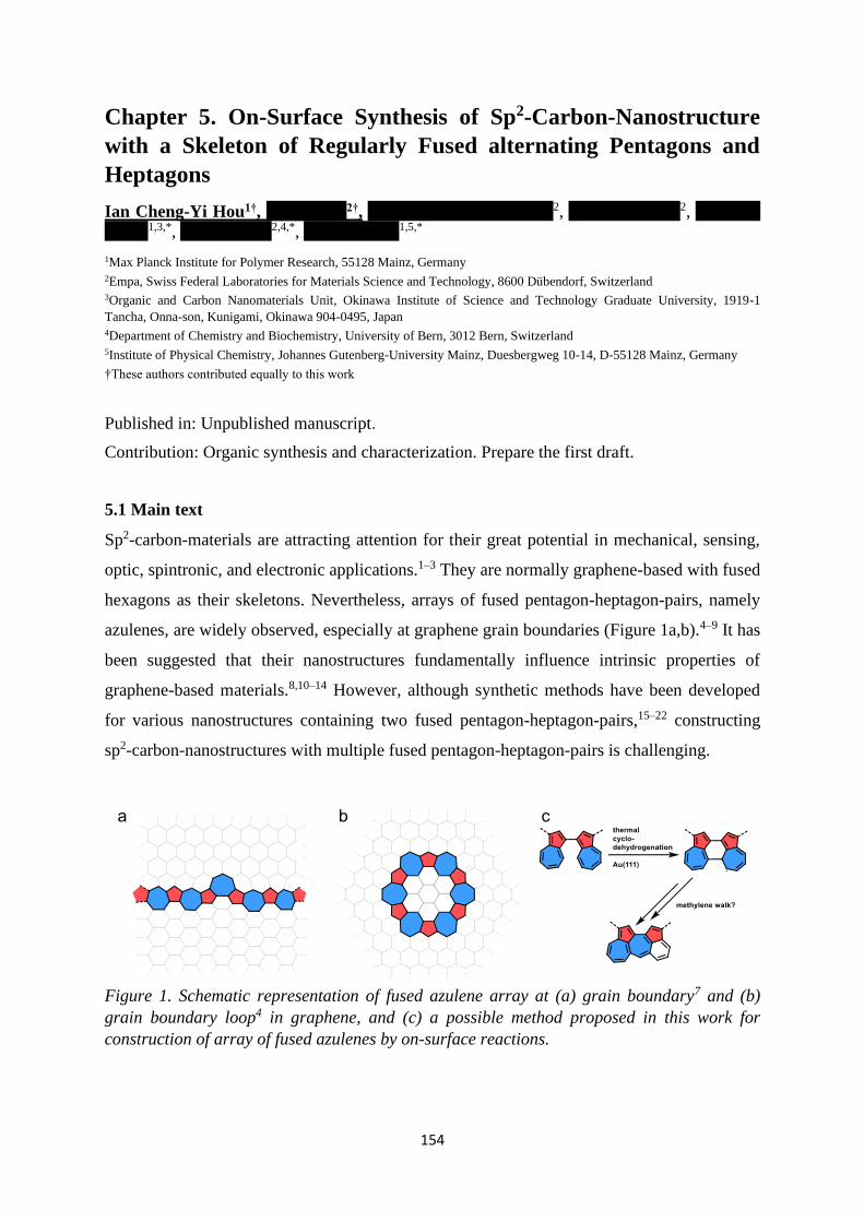
154
Chapter 5. On-Surface Synthesis of Sp2-Carbon-Nanostructure
with a Skeleton of Regularly Fused alternating Pentagons and
Heptagons
Ian Cheng-Yi Hou1†, Qiang Sun2†, Marco Di Giovannantonio2, Pascal Ruffieux2, Akimitsu
Narita1,3,*, Roman Fasel2,4,*, Klaus Müllen1,5,*
1Max Planck Institute for Polymer Research, 55128 Mainz, Germany 2Empa, Swiss Federal Laboratories for Materials Science and Technology, 8600 Dübendorf, Switzerland
3Organic and Carbon Nanomaterials Unit, Okinawa Institute of Science and Technology Graduate University, 1919-1
Tancha, Onna-son, Kunigami, Okinawa 904-0495, Japan 4Department of Chemistry and Biochemistry, University of Bern, 3012 Bern, Switzerland 5Institute of Physical Chemistry, Johannes Gutenberg-University Mainz, Duesbergweg 10-14, D-55128 Mainz, Germany
†These authors contributed equally to this work
Published in: Unpublished manuscript.
Contribution: Organic synthesis and characterization. Prepare the first draft.
5.1 Main text
Sp2-carbon-materials are attracting attention for their great potential in mechanical, sensing,
optic, spintronic, and electronic applications.1–3 They are normally graphene-based with fused
hexagons as their skeletons. Nevertheless, arrays of fused pentagon-heptagon-pairs, namely
azulenes, are widely observed, especially at graphene grain boundaries (Figure 1a,b).4–9 It has
been suggested that their nanostructures fundamentally influence intrinsic properties of
graphene-based materials.8,10–14 However, although synthetic methods have been developed
for various nanostructures containing two fused pentagon-heptagon-pairs,15–22 constructing
sp2-carbon-nanostructures with multiple fused pentagon-heptagon-pairs is challenging.
Figure 1. Schematic representation of fused azulene array at (a) grain boundary7 and (b)
grain boundary loop4 in graphene, and (c) a possible method proposed in this work for
construction of array of fused azulenes by on-surface reactions.

Chapter 5. On-Surface Synthesis of Sp2-Carbon-Nanostructure
with a Skeleton of Regularly Fused alternating Pentagons and Heptagons
155
On-surface synthesis has recently achieved great success in fabrication of novel sp2-carbon-
nanostructures.23–27 This method is conducted by sublimation of molecular precursors under
ultra-high vacuum (UHV) on monocrystalline metal surfaces, followed by surface-assisted
reactions at an elevated temperature.23 Especially, surface-assisted cyclodehydrogenations
can convert partially planarized polycyclic aromatic hydrocarbons (PAH) into larger π-
systems. Such reaction often proceeds between hexagons of PAHs through formation of
radical-adduct intermediates.28 Importantly, it is known that radical-adducts of azulene could
undergo skeletal rearrangement at elevated temperature.29,30 However, although
cyclodehydrogenation of PAHs on surface could lead to formation of azulene skeleton,31,32
and on-surface reactions of azulene derivatives have been studied,33–36 surface-assisted
cyclodehydrogenation between azulenes remains unexplored. We envisage that
intramolecular cyclodehydrogenation of oligoazulenes can convert the isolated hexagon-
pentagon-pairs into a nanostructure of fused pentagons and heptagons via skeletal
rearrangements (Figure 1c). To this end, we polymerized 1,1'-dibromo-3,3'-biazulene (2) on
Au(111) surface via dehalogenation coupling, and triggered surface-assisted
cyclodehydrogenation of the polymeric product by heating until 250 °C.
Cyclodehydrogenated product with rearranged azulene skeleton was unambiguously
characterized by high-resolution scanning tunneling microscopy (STM) and non-contact
atomic force microscopy (nc-AFM). For the first time, sp2-carbon-nanostructures were
synthesized with a skeleton of regularly fused pentagon-heptagon-pairs.
Scheme 1. Synthesis of 2 in solution and its polymerization and graphitization on Au(111)
surface.
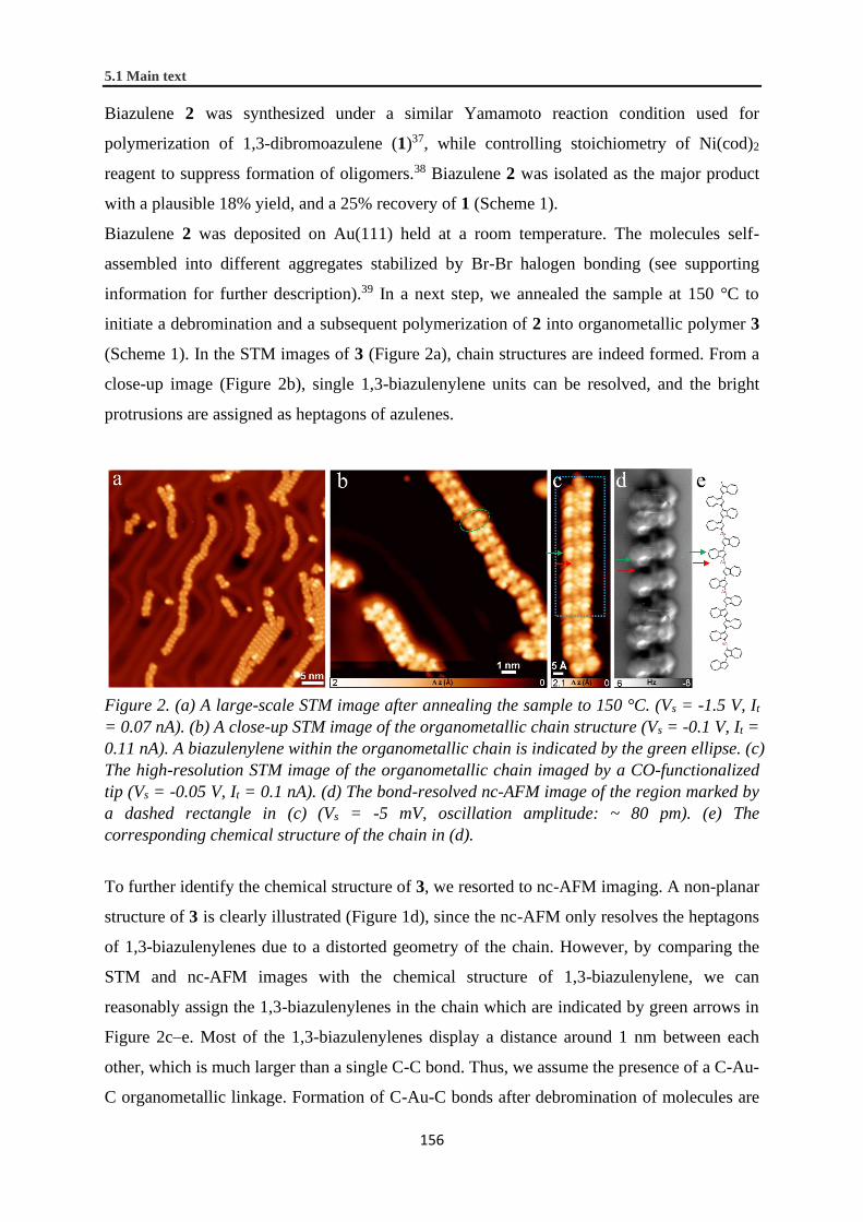
5.1 Main text
156
Biazulene 2 was synthesized under a similar Yamamoto reaction condition used for
polymerization of 1,3-dibromoazulene (1)37, while controlling stoichiometry of Ni(cod)2
reagent to suppress formation of oligomers.38 Biazulene 2 was isolated as the major product
with a plausible 18% yield, and a 25% recovery of 1 (Scheme 1).
Biazulene 2 was deposited on Au(111) held at a room temperature. The molecules self-
assembled into different aggregates stabilized by Br-Br halogen bonding (see supporting
information for further description).39 In a next step, we annealed the sample at 150 °C to
initiate a debromination and a subsequent polymerization of 2 into organometallic polymer 3
(Scheme 1). In the STM images of 3 (Figure 2a), chain structures are indeed formed. From a
close-up image (Figure 2b), single 1,3-biazulenylene units can be resolved, and the bright
protrusions are assigned as heptagons of azulenes.
Figure 2. (a) A large-scale STM image after annealing the sample to 150 °C. (Vs = -1.5 V, It
= 0.07 nA). (b) A close-up STM image of the organometallic chain structure (Vs = -0.1 V, It =
0.11 nA). A biazulenylene within the organometallic chain is indicated by the green ellipse. (c)
The high-resolution STM image of the organometallic chain imaged by a CO-functionalized
tip (Vs = -0.05 V, It = 0.1 nA). (d) The bond-resolved nc-AFM image of the region marked by
a dashed rectangle in (c) (Vs = -5 mV, oscillation amplitude: ~ 80 pm). (e) The
corresponding chemical structure of the chain in (d).
To further identify the chemical structure of 3, we resorted to nc-AFM imaging. A non-planar
structure of 3 is clearly illustrated (Figure 1d), since the nc-AFM only resolves the heptagons
of 1,3-biazulenylenes due to a distorted geometry of the chain. However, by comparing the
STM and nc-AFM images with the chemical structure of 1,3-biazulenylene, we can
reasonably assign the 1,3-biazulenylenes in the chain which are indicated by green arrows in
Figure 2c–e. Most of the 1,3-biazulenylenes display a distance around 1 nm between each
other, which is much larger than a single C-C bond. Thus, we assume the presence of a C-Au-
C organometallic linkage. Formation of C-Au-C bonds after debromination of molecules are

Chapter 5. On-Surface Synthesis of Sp2-Carbon-Nanostructure
with a Skeleton of Regularly Fused alternating Pentagons and Heptagons
157
often observed on the more reactive Copper surfaces40,41 or between terminal alkynyl
bromides42. However, the C-Au-C bonds could also be formed when the steric hindrance
between the debrominated species hampers the direct C-C bond formation.43 In this work, the
direct C-C bond formation between two biazulenylene units also faces a substantial steric
hindrance, which would favor the formation of the C-Au-C organometallic bonds. This also
reflects in the observation of protrusions of Au atoms in the STM image (indicated by a red
arrow in Fig. 2c). Despite a majority of C-Au-C linkage in 3, interestingly, there also exists
some higher 1,3-oligoazulenylenes in the polymer chain, as a result of C-C bond formation
between 1,3-biazulenylenes (Figure 2c–e).
Figure 3. (a) A large-scale STM image after further annealing 3 to 250 °C. (Vs = -1 V, It =
0.1 nA). (b) A close-up STM image of a small segment (Vs = -0.02 V, It = 0.1 nA) and its
corresponding (c) bond-resolved nc-AFM image (Vs = -5 mV, oscillation amplitude: ~80 pm)
and (d) chemical structure with numbers indicating ring size. (e) A close-up STM image of a
large object (Vs = -0.02 V, It = 0.1 nA) and its corresponding (f) bond-resolved nc-AFM
image (Vs = -5 mV, oscillation amplitude: ~80 pm) and (g) an illustrative chemical structure.
White and blue circles in (a) corresponds to structures in (b,c) and (e,f), respectively.
After confirming the formation of 3 on surface, we annealed the sample to 250 °C. In the
STM images of the resulted materials (Figure 3a,b,e), curved nanostructures that are
distinctly different from those in Figure 2 are observed. In an nc-AFM image of a short
segment with 23 polygons, a skeleton of multiple fused pentagon-heptagon-pairs is clearly
identified (Figure 3c,d). This nanostructure is likely a product of 1,3-octaazulene, which is
formed by extrusion of all Au atoms in 3 (Scheme S1 and Figure 2c–e). Importantly, a simple
cyclodedydrogenation of 1,3-oligoazulene shall lead to oligo(peri-azulene) (Scheme S1),

5.1 Main text
158
while formation of the structure shown in Figure 3c must involve rearrangement of the
azulene skeleton. Interestingly, except the end-groups, all the pentagons are in the inner ring,
while hexagons stay in the outer ring, and heptagons in the middle (Figure 3c,d). Such
arrangement suggests a chain-reaction mechanism (vide infra). Besides, shorter segments of
cyclodehydrogenated 1,3-hexaazulene was also detected with the same structural feature
(Figure S2). Unfortunately, no nanoring (Figure S3), which could be the possible
cyclodehydrogenated product of 1,3-decaazulene, was observed. However, there existed
several nanostructures of longer segments that stemmed from polymeric precursors (Figure
3a). In an enlarged image of one of these structures, it is revealed as cyclodehydrogenated
products of oligoazulenylenes linked by C-C single bonds (Figure 3e–g). Notably, a complete
cyclodehydrogenation of poly(1,3-azulenylene)s shall lead to helical architectures and
structural overlap that are not favored on surface. Thus, planarization into oligomer of short
fragments occurred. Nevertheless, the nanostructure still represents the feature of a regularly
rearranged skeleton (Figure 3f,g).
The ordered rearrangement can be explained by “methylene-walk” of radical adduct of
azulenes.29,30 Although previous studies showed that azulene in a polymer chain hardly
rearranges on surface below 400 °C,33–35 radical-adduct of azulene can have a much lower
reaction barrier for rearrangements. First, we assume that surface-assisted C-H bond cleavage
occurred at azulenyl end-groups since they have higher degree of freedom, which facilitates
interactions with Au surface (Scheme S1). Then, the formed radical species attacked on the
neighboring azulenylene, which triggered a chain-reaction through repetitive steps of
cyclopropylcarbinyl-homoallyl-rearrangement/1,2-hydrogen-shift/inter-azulene-radical-attack
(Scheme S1), and eventually led to the structure what we observed. Detailed mechanistic
study is progressing in our group.
In conclusion, to study surface-assisted cyclodehydrogenation between heptagons of PAHs,
we synthesized 1,3-biazulenylene-Au organometallic polymers on Au(111) from 1,1’-
dibromo-3,3’-biazulene. After annealing at 250 °C, novel sp2-carbon-nanostrcutures were
identified with skeletons of multiple regularly fused pentagon-heptagon-pairs. Formation of
such nanostructures involved rearrangement of azulene skeletons in a controlled manner. The
results demonstrate the great potential using azulene as precursor for on-surface synthesis of
unconventional sp2-carbon-nanostructures. This shall benefit the understanding of defects in
graphene-related materials9 as well as development of novel sp2-carbon-2D/3D materials44,45.

Chapter 5. On-Surface Synthesis of Sp2-Carbon-Nanostructure
with a Skeleton of Regularly Fused alternating Pentagons and Heptagons
159
5.2 Supporting information
General Information
Unless otherwise noted, materials were purchased from Fluka, Aldrich, Acros, abcr, Merck,
and other commercial suppliers, and were used as received unless otherwise specified. 1,3-
Dibromoazulene (1) was synthesized following ref37. All reactions working with air- or
moisture-sensitive compounds were carried out under argon atmosphere using standard
Schlenk line techniques. Preparative column chromatography was performed on silica gel
from Merck with a grain size of 0.04–0.063 mm (flash silica gel, Geduran Si 60). NMR
spectra were recorded in deuterated solvents using Bruker AVANCE III 300 spectrometers.
Chemical shifts (δ) were expressed in ppm relative to the residual of solvent (CD2Cl2 @ 5.32
ppm for 1H NMR, 53.84 ppm for 13C NMR). Coupling constants (J) were recorded in Hertz
(Hz) with multiplicities explained by the following abbreviations: s = singlet, d = doublet, t =
triplet, q =quartet, dd = doublet of doublets, dt = doublet of triplets, m = multiplet, br = broad.
The 13C NMR spectrum was recorded with spin-echo attached-proton test sequence with CH,
CH3 showing negative signal and C, CH2 showing positive signal. High-resolution mass
spectra (HRMS) were recorded by matrix-assisted laser decomposition/ionization (MALDI)
using trans-2-[3-(4-tert-Butylphenyl)-2-methyl-2-propenylidene]malononitrile (DCTB) as
matrix with a Bruker Reflex II-TOF spectrometer (MALDI-TOF HRMS).
Synthetic procedure of 1,1’-dibromo-3,3’-biazulene (2)
To a schlenk tube containing 1,3-dibromoazulene37 (792 mg, 2.77 mmol) was added bis(1,5-
cyclooctadiene)nickel (457 mg, 1.66 mmol), 1,5-cyclooctadiene (180 mg, 1.66 mmol), 4,4’-
bipyridine (290 mg, 1.85 mmol) and dimethylformaldehyde (20 mL) in a glove box. The
color of the mixture immediately turned into dark purple. The mixture was then heated at 70
°C under vigorous stirring for 1h. After reaching a room temperature, diethyl ether (200 mL)
was added and the solution was washed with water, 1M HCl (aq.), brine and dried over
Mg2SO4. Solvent was then removed in vacuo and the residue was purified by silica gel
column chromatography (DCM/hexane = 1/20). First band from the column was unreacted
1,3-dibromoazulene (220 mg, 25%) and the second was 2 (201 mg, 18%) and the rest was
higher 1,3-oligoazulenes (170 mg). 2 was collected as a green powder and recrystallized
seven times (hexane) before next step: 1H NMR (300 MHz, CD2Cl2): δ 8.40 (d, J = 9.7 Hz,
2H), 8.27 (d, J = 9.7 Hz, 2H), 8.01 (s, 2H), 7.66 (t, J = 9.9 Hz, 2H), 7.27 (t, J = 9.8 Hz, 2H),
7.14 (t, J = 9.8 Hz, 2H); 13C NMR (75 MHz, CD2Cl2): δ 140.20, 138.99, 137.45, 137.05,

5.2 Supporting information
160
136.90, 136.63, 124.65, 124.51, 124.05, 104.25; HRMS (MALDI-TOF) m/z: [M]+ calcd for
C20H12Br2 409.9306; Found [M]+ 409.9294.
STM/nc-AFM analysis
A commercial low-temperature STM/nc-AFM (Scienta Omicron) system was used for
sample preparation and in situ characterization under ultra-high vacuum conditions (base
pressure below 1×10⁻¹⁰ mbar). The Au(111) single crystal was cleaned by cycles of argon
sputtering (p = 6 × 10⁻⁶ mbar) and annealing at 750 K for 15 minutes. Deposition of 2 on
Au(111) was conducted by thermal evaporation from a six-fold organic evaporator (Mantis
GmbH). STM images were recorded in constant-current mode, and the dI/dV spectra were
recorded using the lock-in technique (URMS = 20 mV). nc-AFM images were recorded with a
CO-functionalized tip attached to a quartz tuning fork sensor (resonance frequency 23.5 kHz,
peak-to-peak oscillation amplitude below 100 pm).
Self-assembly of 2 on Au (III)
Figure S1. (a) A large-scale STM image after deposition of 2 on Au(111) at a room
temperature (Vs = -1.5 V, It = 0.06 nA). (b) A high-resolution STM image of a typical self-
assembled structure of 2 (Vs = -0.02 V, It = 0.1 nA). The corresponding chemical models of
three 2 molecules are overlaid on the STM image.
Biazulenyl 2 was deposited on Au(111) held at a room temperature. The molecules tend to
stay at the fcc regions between the herringbone reconstruction of the Au(111) and self-
assembled into different aggregates, implying a weak intermolecular interaction (Figure S1a).
Due to a nonplanar geometry of 2, the heptagons exhibited higher contrast. In addition, the
bromine atoms also show higher contrasts in the STM image. After overlapping the

Chapter 5. On-Surface Synthesis of Sp2-Carbon-Nanostructure
with a Skeleton of Regularly Fused alternating Pentagons and Heptagons
161
corresponding chemical structures of 2 onto a high resolution STM image, it can be seen that
the self-assembled structures are stabilized by Br-Br halogen bonding (Figure S1b).39
Complementary figures and scheme
Figure S2. (a) A close-up STM image of a cyclodehydrogenated product of 1,3-
hexaazulenylene on Au(111) and (b) its corresponding bond-resolved nc-AFM image.
Parameters: (a) Vs = −0.02 V, It = 0.1 nA; (b) Vs = −5 mV, oscillation amplitude ~ 80 pm.
Figure S3. A nanoring structure (not observed) that could be formed from
cyclodehydrogenation of 1,3-decaazulene.

5.2 Supporting information
162
Scheme S1. Proposed reaction mechanism from 1,3-azulenylene-Au polymer to the fused
pentagon-heptagon-pairs.29,30

Chapter 5. On-Surface Synthesis of Sp2-Carbon-Nanostructure
with a Skeleton of Regularly Fused alternating Pentagons and Heptagons
163
Figure S4. 1H NMR spectrum (300 MHz) of 2 in CD2Cl2.
Figure S5. Spin-echo 13C NMR (75 MHz) spectrum of 2 in CD2Cl2.

164
5.3 References
(1) Fukuzumi, S. Chemical Science of π-Electron Systems; Akasaka, T., Osuka, A., Fukuzumi, S., Kandori, H., Aso, Y.,
Eds.; Springer Japan: Tokyo, 2015.
(2) Matsumoto, K. Frontiers of Graphene and Carbon Nanotubes: Devices and Applications; Matsumoto, K., Ed.;
Springer Japan: Tokyo, 2015.
(3) Müllen, K.; Feng, X. From Polyphenylenes to Nanographenes and Graphene Nanoribbons; Müllen, K., Feng, X.,
Eds.; Advances in Polymer Science; Springer International Publishing: Cham, 2017.
(4) Cockayne, E.; Rutter, G. M.; Guisinger, N. P.; Crain, J. N.; First, P. N.; Stroscio, J. A. Grain Boundary Loops in
Graphene. Phys. Rev. B 2011, 83 (19), 195425.
(5) Huang, P. Y.; Ruiz-Vargas, C. S.; Van Der Zande, A. M.; Whitney, W. S.; Levendorf, M. P.; Kevek, J. W.; Garg, S.;
Alden, J. S.; Hustedt, C. J.; Zhu, Y.; et al. Grains and Grain Boundaries in Single-Layer Graphene Atomic
Patchwork Quilts. Nature 2011, 469 (7330), 389–392.
(6) Rasool, H. I.; Ophus, C.; Klug, W. S.; Zettl, A.; Gimzewski, J. K. Measurement of the Intrinsic Strength of
Crystalline and Polycrystalline Graphene. Nat. Commun. 2013, 4 (1), 2811.
(7) Yazyev, O. V.; Chen, Y. P. Polycrystalline Graphene and Other Two-Dimensional Materials. Nat. Nanotechnol.
2014, 9 (10), 755–767.
(8) Balasubramanian, K.; Biswas, T.; Ghosh, P.; Suran, S.; Mishra, A.; Mishra, R.; Sachan, R.; Jain, M.; Varma, M.;
Pratap, R.; et al. Reversible Defect Engineering in Graphene Grain Boundaries. Nat. Commun. 2019, 10 (1), 1090.
(9) Banhart, F.; Kotakoski, J.; Krasheninnikov, A. V. Structural Defects in Graphene. ACS Nano 2011, 5 (1), 26–41.
(10) Ma, T.; Liu, Z.; Wen, J.; Gao, Y.; Ren, X.; Chen, H.; Jin, C.; Ma, X.-L.; Xu, N.; Cheng, H.-M.; et al. Tailoring the
Thermal and Electrical Transport Properties of Graphene Films by Grain Size Engineering. Nat. Commun. 2017, 8
(1), 14486.
(11) Zhang, Z.; Yang, Y.; Xu, F.; Wang, L.; Yakobson, B. I. Unraveling the Sinuous Grain Boundaries in Graphene. Adv.
Funct. Mater. 2015, 25 (3), 367–373.
(12) Serov, A. Y.; Ong, Z.-Y.; Pop, E. Effect of Grain Boundaries on Thermal Transport in Graphene. Appl. Phys. Lett.
2013, 102 (3), 033104.
(13) Chen, J.-H.; Autès, G.; Alem, N.; Gargiulo, F.; Gautam, A.; Linck, M.; Kisielowski, C.; Yazyev, O. V.; Louie, S. G.;
Zettl, A. Controlled Growth of a Line Defect in Graphene and Implications for Gate-Tunable Valley Filtering. Phys.
Rev. B 2014, 89 (12), 121407.
(14) Yazyev, O. V.; Louie, S. G. Electronic Transport in Polycrystalline Graphene. Nat. Mater. 2010, 9 (10), 806–809.
(15) Yoshida, Z. ichi; Shibata, M.; Ogino, E.; Sugimoto, T. A New Cata-Condensed Nonalternant Tetracyclic
Hydrocarbon Azuleno[2,1-e]Azulene. Tetrahedron Lett. 1984, 25 (31), 3343–3346.
(16) Takayasu, T.; Nitta, M. On the Reaction of Azulen-2-ylmethylene(Triphenyl)Phosphorane. Convenient Preparation
of Azuleno[1,2-f]- and Azuleno[1,2-a]-Azulenes and Their Properties. J. Chem. Soc., Perkin Trans. 1 1997, 23,
3537–3542.
(17) Anderson, A. G.; Montana, A. F.; MacDonald, A.; Masada, G. M. Synthesis of Dicyclopenta[ef,kl]Heptalene
(Azupyrene). II. Routes from 1,6,7,8,9,9a-Hexahydro-2H-Benzo[c,d]Azulen-6-One and 5-Phenylpentanoic Acid. J.
Org. Chem. 1973, 38 (8), 1445–1450.
(18) Hafner, K.; Diehl, H.; Richarz, W. Cycloadditions of Aceheptylene—A Facile Synthesis of
Dicyclopenta[ef,kl]Heptalenes. Angew. Chem. Int. Ed. 1976, 15 (2), 108–109.
(19) Konishi, A.; Horii, K.; Shiomi, D.; Sato, K.; Takui, T.; Yasuda, M. Open-Shell and Antiaromatic Character Induced
by the Highly Symmetric Geometry of the Planar Heptalene Structure: Synthesis and Characterization of a
Nonalternant Isomer of Bisanthene. J. Am. Chem. Soc. 2019, 141 (26), 10165–10170.
(20) Reel, H.; Vogel, E. Dicyclohepta[cd,gh]Pentalene—A New Pyrene Isomer. Angew. Chem. Int. Ed. 1972, 11 (11),

Chapter 5. On-Surface Synthesis of Sp2-Carbon-Nanostructure
with a Skeleton of Regularly Fused alternating Pentagons and Heptagons
165
1013–1014.
(21) Vogel, E.; Wieland, H.; Schmalstieg, L.; Lex, J. Novel Synthesis and Molecular Structure of the Pyrene Isomer
Dicyclohepta[cd,gh]Pentalene (Azuleno[2,1,8-ija]Azulene). Angew. Chem. Int. Ed. 1984, 23 (9), 717–719.
(22) Vogel, E.; Markowitz, G.; Schmalstieg, L.; Itô, S.; Breuckmann, R.; Roth, W. R. Thermal Deoxygenation of
Syn‐15,16‐Dioxo‐1,6 :8,13‐bismethano[14]Annulene to the Pyrene Isomer Dicyclohepta[cd,gh]Pentalene
(Azuleno[2,1,8‐ija]Azulene). Angew. Chem. Int. Ed. 1984, 23 (9), 719–720.
(23) Sun, Q.; Zhang, R.; Qiu, J.; Liu, R.; Xu, W. On-Surface Synthesis of Carbon Nanostructures. Adv. Mater. 2018, 30
(17), 1705630.
(24) Gröning, O.; Wang, S.; Yao, X.; Pignedoli, C. A.; Borin Barin, G.; Daniels, C.; Cupo, A.; Meunier, V.; Feng, X.;
Narita, A.; et al. Engineering of Robust Topological Quantum Phases in Graphene Nanoribbons. Nature 2018, 560
(7717), 209–213.
(25) Rizzo, D. J.; Veber, G.; Cao, T.; Bronner, C.; Chen, T.; Zhao, F.; Rodriguez, H.; Louie, S. G.; Crommie, M. F.;
Fischer, F. R. Topological Band Engineering of Graphene Nanoribbons. Nature 2018, 560 (7717), 204–208.
(26) Di Giovannantonio, M.; Urgel, J. I.; Beser, U.; Yakutovich, A. V.; Wilhelm, J.; Pignedoli, C. A.; Ruffieux, P.;
Narita, A.; Müllen, K.; Fasel, R. On-Surface Synthesis of Indenofluorene Polymers by Oxidative Five-Membered
Ring Formation. J. Am. Chem. Soc. 2018, 140 (10), 3532–3536.
(27) Mishra, S.; Beyer, D.; Eimre, K.; Kezilebieke, S.; Berger, R.; Gröning, O.; Pignedoli, C. A.; Müllen, K.; Liljeroth,
P.; Ruffieux, P.; et al. Topological Frustration Induces Unconventional Magnetism in a Nanographene. Nat.
Nanotechnol. 2020, 15 (1), 22–28.
(28) Treier, M.; Pignedoli, C. A.; Laino, T.; Rieger, R.; Müllen, K.; Passerone, D.; Fasel, R. Surface-Assisted
Cyclodehydrogenation Provides a Synthetic Route towards Easily Processable and Chemically Tailored
Nanographenes. Nat. Chem. 2011, 3 (1), 61–67.
(29) Alder, R. W.; East, S. P.; Harvey, J. N.; Oakley, M. T. The Azulene-to-Naphthalene Rearrangement Revisited: A
DFT Study of Intramolecular and Radical-Promoted Mechanisms. J. Am. Chem. Soc. 2003, 125 (18), 5375–5387.
(30) Stirling, A.; Iannuzzi, M.; Laio, A.; Parrinello, M. Azulene-to-Naphthalene Rearrangement: The Car-Parrinello
Metadynamics Method Explores Various Reaction Mechanisms. ChemPhysChem 2004, 5 (10), 1558–1568.
(31) Hieulle, J.; Carbonell-Sanromà, E.; Vilas-Varela, M.; Garcia-Lekue, A.; Guitián, E.; Peña, D.; Pascual, J. I. On-
Surface Route for Producing Planar Nanographenes with Azulene Moieties. Nano Lett. 2018, 18 (1), 418–423.
(32) Mishra, S.; Lohr, T. G.; Pignedoli, C. A.; Liu, J.; Berger, R.; Urgel, J. I.; Müllen, K.; Feng, X.; Ruffieux, P.; Fasel,
R. Tailoring Bond Topologies in Open-Shell Graphene Nanostructures. ACS Nano 2018, 12 (12), 11917–11927.
(33) Shiotari, A.; Nakae, T.; Iwata, K.; Mori, S.; Okujima, T.; Uno, H.; Sakaguchi, H.; Sugimoto, Y. Strain-Induced
Skeletal Rearrangement of a Polycyclic Aromatic Hydrocarbon on a Copper Surface. Nat. Commun. 2017, 8 (1),
16089.
(34) Sun, Q.; Hou, I. C. Y.; Eimre, K.; Pignedoli, C. A.; Ruffieux, P.; Narita, A.; Fasel, R. On-Surface Synthesis of
Polyazulene with 2,6-Connectivity. Chem. Commun. 2019, 55 (89), 13466–13469.
(35) Fan, Q.; Martin-Jimenez, D.; Ebeling, D.; Krug, C. K.; Brechmann, L.; Kohlmeyer, C.; Hilt, G.; Hieringer, W.;
Schirmeisen, A.; Gottfried, J. M. Nanoribbons with Nonalternant Topology from Fusion of Polyazulene: Carbon
Allotropes beyond Graphene. J. Am. Chem. Soc. 2019, 141 (44), 17713–17720.
(36) Klein, B. P.; Van Der Heijden, N. J.; Kachel, S. R.; Franke, M.; Krug, C. K.; Greulich, K. K.; Ruppenthal, L.;
Müller, P.; Rosenow, P.; Parhizkar, S.; et al. Molecular Topology and the Surface Chemical Bond: Alternant Versus
Nonalternant Aromatic Systems as Functional Structural Elements. Phys. Rev. X 2019, 9 (1), 011030.
(37) Dubovik, J.; Bredihhin, A. A Convenient Synthesis of Functionalized Azulenes via Negishi Cross-Coupling. Synth.
2015, 47 (4), 538–548.
(38) Wang, F.; Lai, Y. H.; Kocherginsky, N. M.; Kosteski, Y. Y. The First Fully Characterized 1,3-Polyazulene: High
Electrical Conductivity Resulting from Cation Radicals and Polycations Generated upon Protonation. Org. Lett.

5.3 References
166
2003, 5 (7), 995–998.
(39) Shang, J.; Wang, Y.; Chen, M.; Dai, J.; Zhou, X.; Kuttner, J.; Hilt, G.; Shao, X.; Gottfried, J. M.; Wu, K.
Assembling Molecular Sierpiński Triangle Fractals. Nat. Chem. 2015, 7 (5), 389–393.
(40) Wang, W.; Shi, X.; Wang, S.; Van Hove, M. A.; Lin, N. Single-Molecule Resolution of an Organometallic
Intermediate in a Surface-Supported Ullmann Coupling Reaction. J. Am. Chem. Soc. 2011, 133 (34), 13264–13267.
(41) Di Giovannantonio, M.; Tomellini, M.; Lipton-Duffin, J.; Galeotti, G.; Ebrahimi, M.; Cossaro, A.; Verdini, A.;
Kharche, N.; Meunier, V.; Vasseur, G.; et al. Mechanistic Picture and Kinetic Analysis of Surface-Confined
Ullmann Polymerization. J. Am. Chem. Soc. 2016, 138 (51), 16696–16702.
(42) Sun, Q.; Cai, L.; Ma, H.; Yuan, C.; Xu, W. Dehalogenative Homocoupling of Terminal Alkynyl Bromides on
Au(111): Incorporation of Acetylenic Scaffolding into Surface Nanostructures. ACS Nano 2016, 10 (7), 7023–7030.
(43) Urgel, J. I.; Hayashi, H.; Di Giovannantonio, M.; Pignedoli, C. A.; Mishra, S.; Deniz, O.; Yamashita, M.; Dienel, T.;
Ruffieux, P.; Yamada, H.; et al. On-Surface Synthesis of Heptacene Organometallic Complexes. J. Am. Chem. Soc.
2017, 139 (34), 11658–11661.
(44) Rickhaus, M.; Mayor, M.; Juríček, M. Chirality in Curved Polyaromatic Systems. Chem. Soc. Rev. 2017, 46 (6),
1643–1660.
(45) Ni, B.; Zhang, T.; Li, J.; Li, X.; Gao, H. Topological Design of Graphene. In Handbook of Graphene; Wiley, 2019;
pp 1–44.

167
Chapter 6. Photo-modulation of 2D-Self-assembly of Azobenzene-
Hexa-peri-hexabenzocoronene-Azobenzene Triads
Ian Cheng-Yi Hou,1 Valentin Diez-Cabanes,2 Agostino Galanti,3 Michal Valášek,4 Marcel
Mayor,4,5 Jérôme Cornil,2 Akimitsu Narita,1,6,* Paolo Samorì3,* and Klaus Müllen1,7,*
1Max Planck Institute for Polymer Research, Ackermannweg 10, D-55128 Mainz, Germany 2Laboratory for Chemistry of Novel Materials, University of Mons, Place du Parc 20, B-7000 Mons, Belgium
3Université de Strasbourg, CNRS, ISIS UMR 7006, 8 allée Gaspard Monge, 67000 Strasbourg, France 4Karlsruhe Institute of Technology KIT, Institute of Nanotechnology, P.O. Box 3640, 76021 Karlsruhe, Germany 5Department of Chemistry, University of Basel, St. Johannsring 19, 4056 Basel, Switzerland 6Organic and Carbon Nanomaterials Unit, Okinawa Institute of Science and Technology Graduate University
1919-1 Tancha, Onna-son, Kunigami, Okinawa 904-0495, Japan 7Institute of Physical Chemistry, Johannes Gutenberg-University Mainz, Duesbergweg 10-14, D-55128 Mainz, Germany
Published in: Chem. Mater. 2019, 31 (17), 6979–6985. DOI:
10.1021/acs.chemmater.9b01535. Reprinted with permission. Copyright: 2019, American
Chemical Society.
Contribution: Organic synthesis and characterization (excluding azobenzene building blocks).
Photoswitching analysis in solution. STM analysis. Prepare and correcting the first draft.
Submission and revision the manuscript.
6.1 Abstract
ToC Figure.
Achieving exquisite control over self-assembly of functional polycyclic aromatic
hydrocarbons (PAH) and nanographene (NG) is essential for their exploitation as active
elements in (nano)technological applications. In the framework of our effort to leverage their
functional complexity, we designed and synthesized two hexa-peri-hexabenzocoronene
(HBC) triads, pAHA and oAHA, decorated with two light-responsive azobenzene moieties at
the pseudo-para and ortho positions, respectively. Their photoisomerization in solution is
demonstrated by UV-Vis absorption. 1H NMR measurements of oAHA suggested 23% of Z-
form can be obtained at a photostationary state with UV irradiation (366 nm). Scanning

6.1 Abstract
168
tunneling microscopy imaging revealed that the self-assembly of pAHA and oAHA at the
solid-liquid interface between highly oriented pyrolytic graphite (HOPG) and their solution in
1,2,4-trichlorobenzene can be modulated upon light irradiation. This is in contrast to our
previous work using HBC bearing a single azobenzene moiety, which did not show such
photomodulation of the self-assembled structure. Upon E-Z isomerization both pAHA and
oAHA displayed an increased packing density on the surface of graphite. Moreover, pAHA
revealed a change of self-assembled pattern from an oblique unit cell to a dimer row
rectangular crystal lattice whereas the assembly of oAHA retained a dimer row structure
before and after light irradiation, yet with a modification of the inter-row molecular
orientation. Molecular mechanics/molecular dynamics simulations validated the self-
assembly patterns of pAHA and oAHA, comprising azobenzenes in their Z-forms. These
results pave the way toward use of suitably functionalized large PAHs, as well as NGs, to
develop photo-switchable devices.

Chapter 6. Photo-modulation of 2D-Self-assembly of
Azobenzene-Hexa-peri-hexabenzocoronene-Azobenzene Triads
169
6.2 Introduction
Hexa-peri-hexabenzocoronene (HBC), a molecule containing 42 sp2 carbons and possessing
a D6h symmetry, is one of the most representative and well-studied polycyclic aromatic
hydrocarbons (PAHs). With a diameter slightly exceeding 1 nm, it is considered one of the
smallest possible nanographene (NG), i.e. molecularly defined subunits of the graphene
lattice which is confined in at least one of its lateral dimensions.1–3 For this reason, HBC is
frequently used as a model system to gain insight into the behavior of NG-based materials.4–8
The large π-conjugated core of HBC gives rise to strong, non-covalent interactions among
adjacent molecules, as well as between molecules and the basal plane of graphite.
Understanding the resulting self-assembly processes is essential for advances in HBC-based
(nano)technologies.5,6,9 Self-assembly of HBC derivatives has been studied in various
environments, namely in solution and in bulk, where 3D columnar supramolecular structures
are formed,6,10–17 and on surfaces, enabling programmed 2D nano-patterning.14,18,19
Substituents at peripheral positions play a key role in controlling self-assembly behavior of
HBC. For example, HBCs with appropriate alkyl substituents show thermal phase transitions
between crystalline and liquid-crystalline phases, where the phase-transition temperature can
be tuned by the length of the side chains.6,11,20,21 Self-assembly of HBCs can thus be
controlled by heat, yet the use of other external stimuli as remote controls to regulate self-
assembly of HBC-based materials has only been occasionally considered.19,22
Among external stimuli, light is particularly attractive, as photons may be remotely applied
with high spatial and temporal resolution. A plausible way of imparting photo-switchable
characteristics to HBCs is to functionalize their peripheries with photochromic moieties.23–26
In particular, azobenzene exhibits a pronounced geometric change between its E/Z-isomers,
which has been applied to light-controllable, self-assembled materials and photo-mechanical
devices.27–31 Photoresponsive self-assembly of azobenzene-containing materials has been
intensively investigated, especially at solid-air32–36 and solid-liquid19,37–42 interfaces. Surface
confinement restricts assembly in 2D and provides an opportunity for detailed examination of
structures and dynamics of these molecules in real space by scanning probe microscopy
techniques. In this context, it is extremely interesting to combine carbon-based
nanostructures with photochromic molecules like azobenzene to develop optically responsive
systems and materials.26 HBC bearing one azobenzene unit was prevously reported, but self-
assembly of its Z-form could not be observed on a graphite surface by scanning tunneling
microscopy (STM).19 Here we synthesized azobenzene-HBC-azobenzene triads, pAHA and
oAHA (Scheme 1), featuring an HBC core and two peripheral azobenzene moieties in the
6.2 Introduction
170
pseudo-para and pseudo-ortho positions, respectively. Geometries of pAHA and oAHA are
employed to explore intermolecular interactions that affect their self-assembly.
Photoisomerization of the azobenzene moieties in solution is confirmed by UV-Vis
absorption, combined with 1H NMR spectroscopy. Self-assembly of these two HBCs at the
solid-liquid interface before and after UV light irradiation was monitored by STM, and
corroborated with molecular mechanics/molecular dynamics (MM/MD) simulations.
Formation of stable self-assemblies for both pAHA and oAHA after isomerization of their
azobenzene moieties reveals the potential of using large PAHs, as well as NGs, for photo-
responsive devices and smart surfaces.

Chapter 6. Photo-modulation of 2D-Self-assembly of
Azobenzene-Hexa-peri-hexabenzocoronene-Azobenzene Triads
171
6.3 Result and discussion
Synthesis of azobenzene-HBC-azobenzene triads. pAHA and oAHA were synthesized
from the corresponding HBCs 1 and 2 bearing two bromo groups at desired positions, in
addition to four n-dodecyl chains43, which guarantee the molecule’s good solubility in
organic solvents and high affinity to graphite surfaces (Scheme 1). The azobenzene moieties
were introduced by a two-fold Suzuki coupling reaction between 1 or 2 with azobenzene
boronic ester 3.44 pAHA and oAHA were isolated in 69% and 73% yields, respectively.
Scheme 1. Synthesis of azobenzene-HBC-azobenzene pAHA and oAHA.
Photoisomerization in solution. Reversible photoisomerization of both pAHA and oAHA
could be observed in solution upon alternating irradiation at 366 and 436 nm (Figures S1–S3).
The spectral changes upon photoisomerization were relatively small, and could be attributed
to overlapping absorption features of the azobenzene units and the HBC core. HBC has a
higher extinction coefficient,15,45 which could overshadow spectral variation of the
azobenzene units. Nevertheless, oAHA showed sufficient solubility to enable 1H NMR
spectroscopic analysis at room temperature, which demonstrated that approximately 23% of
Z-form was obtained in a photostationary state (PSS) after irradiation at 366 nm (Figure S4).
STM investigation of 2D self-assembly. The UV-Vis absorption and 1H NMR results,
indicating the efficient photoisomerization of pAHA and oAHA in solution, motivated us to
investigate the influence of isomerization on their self-assembly at the solid-liquid interface
between graphite and their supernatant solutions. 2D self-assembly patterns of pAHA and
oAHA were monitored by STM at the interface between 1,2,4-trichlorobenzene (TCB)
solutions and highly oriented pyrolytic graphite (HOPG) before and after in-situ UV light
irradiation (Figure 1, 2; Table 1). In all cases, brighter areas with a diameter of ~1 nm can be

6.3 Result and discussion
172
assigned to HBC cores as a result of more favorable resonant tunneling between the Fermi
level of HOPG and the frontier orbitals of the large aromatic core. Non-irradiated pAHA
exhibits an oblique unit cell containing one molecule and an area of 6.8 ± 0.6 nm2 per
molecule (Figure 1a and Table 1), while oAHA forms a dimer-row structure with two
molecules per unit cell and an area of 5.9 ± 0.3 nm2 per molecule (Figure 2a and Table 1). A
different assembly was also observed for oAHA (Figure S5; Table S1). These crystal
packings are all assigned to assemblies of E,E-isomers, which have both azobenzenes in E-
form (Figure 1a, 2a and S5).
Figure 1. STM images recorded at the interface between HOPG and a 0.1 mM solution of
pAHA in TCB and their 2D crystal packing models derived from MM/MD simulations. (a) An
STM image taken without irradiation (pAHA ori in Table 1) and (c) a corresponding packing
model of E,E-isomers. (b) An image recorded after irradiation at 366 nm (pAHA irr in Table
1) and (d) a corresponding packing model of E,Z-isomers. Inset in (a,b): images of the same
crystal packing taken for a larger area of 50 nm × 50 nm. The newly formed dimer row
crystal packing coexists with the oblique packing of E,E-isomers with a clear border, as can
be seen in the inset of (b). Tunneling parameters: (a) bias voltage tunneling (VT) = –300 mV,
average tunneling current (IT) = 20 pA; (c) VT = –300 mV, IT = 20 pA. Atom color coding:
(c,d) carbon (gray), nitrogen (blue), hydrogen (white).

Chapter 6. Photo-modulation of 2D-Self-assembly of
Azobenzene-Hexa-peri-hexabenzocoronene-Azobenzene Triads
173
It is interesting to note that, although pAHA and oAHA are a pair of isomers themselves,
their assemblies show significantly different density where that of oAHA is much more
compact. Different packing motifs between pAHA and oAHA demonstrate that connectivity
of the azobenzene-HBC-azobenzene triads strongly affects molecular self-assembly at the
solid-liquid interface. The same supramolecular packing is extended over a larger area (50
nm × 50 nm) (Figure 1a and 2a, insets). Analysis of pAHA over even larger areas
demonstrated that the crystalline domains end when terraces in the HOPG surface were
encountered. These domains remained intact for hours without transforming into other self-
assembled structures, thus confirming high stability of the crystal packing.
Table 1. Experimental lattice constants of pAHA and oAHA self-assembly at the HOPG/TCB
interface. a (nm) b (nm) γ (°) χ (nm)b δ (°)b Areac
(nm2)
Eadsd
(kcal/mol)
BEe
(kcal/mol)
pAHA ori 3.0 ± 0.2 2.5 ± 0.1 65 ± 5 - - 6.8 ± 0.6 -210.89f -23.35f
pAHA irra 4.2 ± 0.1 2.52 ± 0.05 88 ± 1 1.6 ± 0.1 11 ± 3 5.3 ± 0.2 -204.57g -13.83g
oAHA ori 4.4 ± 0.1 2.7 ± 0.1 81 ± 3 2.0 ± 0.2 25 ± 4 5.9 ± 0.3 -211.58f -17.27f
oAHA irra 5.2 ± 0.2 1.77 ± 0.09 83 ± 5 2.4 ± 0.3 -4 ± 4 4.6 ± 0.3 -205.72g -19.50g
aOnly formed after irradiation at 366 nm. bInter-row distance and angle, specified in STM
Figures. cArea per molecule. dAdsorption energy between molecule and the HOPG surface.
Derived from MM/MD simulation. eIntermolecular binding energy. Derived from MM/MD
simulation. fCalculated for the E,E-form. gCalculated for the E,Z-form.
STM investigation after light irradiation. After the 2D-self-assembly patterns of pAHA
and oAHA were illustrated, their solution on the HOPG substrate was irradiated in situ with
UV light (λirr = 366 nm) to examine effect of photoisomerization of the azobenzene moieties
on the 2D crystalline assemblies. After 3 minutes of irradiation at a power density of 2
mW/cm2, new domains with radically different lattice parameters were observed for both
pAHA and oAHA, along with the simultaneous presence of the aforementioned domains
formed by their E,E-isomers (Figure 1b and 2b, respectively). Molecules in the photo-
modified domains assemble in dimer rows with a rectangular crystal lattice for both pAHA
and oAHA showing an area of 5.3 ± 0.2 nm2 and 4.6 ± 0.3 nm2 per molecule, respectively
(Figure 1b, 2b and Table 1). Additionally, another dimer row structured self-assembly pattern
with δ close to 0° and a parallelogram unit cell was observed for pAHA (Figure S6 and Table
S1). HBC cores in the photo-modified domains appear darker, compared with those in intact
domains of the E,E-isomers, coexisting on the same STM image (inset of Figures 1b and 2b).

6.3 Result and discussion
174
This could indicate a larger HOPG/HBC distance46 possibly induced by nonplanar Z-form
azobenzene arms. Moreover, the photo-modified domains exhibit denser packing than those
in the original domains of the E,E-isomers, as evidenced by their smaller average area per
molecule (Table 1). These observations support an assumption that the photo-modified
domains consist of molecules containing nonplanar Z-form isomers, with azobenzene arms
presumably back-folded in the supernatant solution, reducing the molecular footprint
visualized by STM. However, although rarely observed on HOPG for HBC species,10,47,48
occurrence of a change in a 2D-assembly pattern for the E,E-isomers themselves cannot be
completely excluded.
Figure 2. STM images recorded at the interface of HOPG and a 0.1 mM TCB solution of
oAHA and their 2D crystal packing models derived from MM/MD simulations. (a) An STM
image taken without irradiation (oAHA ori in Table 1) and (c) a corresponding packing
model of E,E-isomers. (b) An image taken after irradiation at 366 nm (oAHA irr in Table 1)
and (d) a corresponding packing model of E,Z-isomers. Inset in (a, b): images of the same
crystal packing taken over a larger area 50 nm × 50 nm. The newly formed rectangular
dimer row crystal packing coexists with the domain of E,E-isomers with a clear border, as
can be seen in the inset of (b). Tunneling parameters (a) VT = –550 mV, IT = 20 pA; (c) VT
= –700 mV, IT = 20 pA. Atom color coding: (c,d) carbon (gray), nitrogen (blue), hydrogen
(white).

Chapter 6. Photo-modulation of 2D-Self-assembly of
Azobenzene-Hexa-peri-hexabenzocoronene-Azobenzene Triads
175
Simulation of the assembly patterns. MM/MD calculations were performed to further
support the assumed formation of self-assembled domains consisting of isomers with Z-form
azobenzenes, as well as to gain a greater understanding of how the azobenzene moieties
govern the self-assembly of pAHA and oAHA by unraveling the packing at the atomistic
level. Although lattice constants extracted from simulated results are generally larger than
those experimentally determined, there is a reasonable agreement between experiment and
simulation, allowing for a detailed interpretation of the STM images (Figure S7 and Table
S2). Considering the relatively low Z/E-ratio at the PSS suggested by 1H NMR measurements
for oAHA (Figure S4) and assuming similar behavior for pAHA, we infer that the assembly
patterns arising after irradiation in both cases are composed of E,Z-isomers, but not Z,Z-
isomers. The best matching simulated patterns of E,Z-isomers are displayed in Figure 1c, d
and 2c, d. Interestingly, nanophase separations between flexible alkyl chains and rigid
azobenzenes is suggested for the packing of E,E-isomers of both pAHA and oAHA (Figure
1c and 2c, respectively). The nanophase separation disappears in the self-assembly of the
E,Z-isomer of pAHA (Figure 1d). In the case of oAHA, azobenzenes intercalate in a zig-zag
fashion. Spatial demand of azobenzenes on the surface determines the length b of the short
lattice axis (Figure 2c): when one of the azobenzenes is switched into the Z-form, molecular
size is reduced and the packing becomes tighter (Figure 2d). In contrast to pAHA, the
nanophase separation in oAHA is retained in the self-assembly of both E,Z- an Z,Z-isomers
(Figure S7). The incremental increase of binding energy with the number of Z-units in the
oAHA molecule indicates that interaction between Z-azobenzenes benefits retention of the
nanophase separation patterns (Table S2).
It is important to stress that observation of stable self-assemblies of molecules containing Z-
isomers of azobenzene-based photoswitches at the solid-liquid interface by STM represents a
challenging task.37,40 This is a result of the non-planarity of the Z-isomers and lone-pair
electrons of nitrogens interacting with the graphite surfaces, thereby causing molecular
desorption. Formation of stable assemblies for different photoactive states without
desorption/readsorption of molecules is essential for development of responsive surfaces and
devices.45,49,50 In our case, the packing density increased upon irradiation with UV light and
we did not monitor the presence of regions with fuzzy contrast between domains of different
assembly. It is therefore likely that the physisorbed molecules undergo a process that involves
the subsequential desorption, isomerization in solution and re-adsorption onto the surface
where void space is created by the shrinking of the assemblies. On the same time, some other
molecules may undergo isomerization directly on the surface. Moreover, large PAHs such as

6.3 Result and discussion
176
HBC, namely NGs, exhibit very high adsorption energy toward HOPG surfaces.51 In this
regard, desorption of molecules from the surface might not occur while molecules may move
on the surface during irradiation and rearrange to form the new domains. However, the
absence of a monitoring of the switch on the time scale of the event does not allow us to
provide a conclusive mechanism for this process. Note also from the MM/MD calculation
that absolute values of adsorption energies for the different isomers of pAHA and oAHA are
similar (<9% energy difference from the most to the least stable isomers, see Table S2). Such
a scenario is consistent with our observation of self-assembly of the Z-azobenzene-containing
isomers for both pAHA and oAHA.

Chapter 6. Photo-modulation of 2D-Self-assembly of
Azobenzene-Hexa-peri-hexabenzocoronene-Azobenzene Triads
177
6.4 Conclusion
In summary, we have synthesized two model compounds, pAHA and oAHA, to cast light
onto the photo-responsive behavior of large PAHs, as well as NGs, decorated with
azobenzenes. UV-Vis absorption and 1H NMR measurements demonstrated their
photoisomerization in solution. STM images and MM/MD simulation of pAHA and oAHA
revealed the photo-modulation of self-assembled structures into more compact packings,
formed by Z-azobenzene-containing isomers at TCB/HOPG interface. The MM/MD
simulation suggests similar nanophase separation between alkyl chains and azobenzenes in
all three isomers of oAHA while it disappears in E,Z-isomer of pAHA. The markedly
different packings of the different isomers of pAHA and oAHA on the graphite surface
provide clear evidence for the potential of using large PAHs, as well as NGs, for the design
of new photo-responsive materials that are suitable for the development of switchable
surfaces and devices. We are actively working towards gaining a complete understanding on
the mechanism of this photo-modulated self-assembly and exploring HBC derivatives
possessing more azobenzene substituents and higher symmetry.

178
6.5 Experimental methods
General. All reactions working with air- or moisture-sensitive compounds were carried out
under argon atmosphere using standard Schlenk line techniques. Thin layer chromatography
(TLC) was performed on silica gel coated aluminum sheets with F254 indicator. Silica gel
column chromatography separation was performed with 0.063–0.200 mm particle size. NMR
spectra were recorded in deuterated solvents using Bruker AVANCE III 500 and Bruker
AVANCE III 700 MHz NMR spectrometers. The 13C NMR spectra were recorded with spin-
echo attached-proton test (APT) sequence with CH, CH3 showing negative signal and C, CH2
showing positive signal. Chemical shifts (δ) were expressed in ppm relative to the residual of
solvent (C2D2Cl4 @ 6.00 ppm for 1H NMR, 73.78 ppm for 13C NMR). Coupling constants (J)
were recorded in Hertz (Hz) with multiplicities explained by the following abbreviations: s =
singlet, d = doublet, t = triplet, q =quartet, dd = doublet of doublets, dt = doublet of triplets, m
= multiplet, br = broad. The UV–Vis absorption spectra were measured with a Perkin-Elmer
Lambda 900 spectrophotometer in a quartz cuvette (Hellma) with a light path of 1 cm at room
temperature. High-resolution mass spectra (HRMS) were recorded by matrix-assisted laser
decomposition/ionization (MALDI) using 7,7,8,8-tetracyanoquinodimethane (TCNQ) as
matrix with a Bruker Reflex II-TOF spectrometer (MALDI-TOF HRMS).
Materials. Unless otherwise noted, all starting materials and reagents were purchased from
commercial sources (Alfa Aesar, Sigma-Aldrich, Acros and TCI) and used without further
purification. HBCs 1 and 2 containing two bromo functional groups43 and the azobenzene
boronic ester 344 were synthesized according to the previously published literature procedures.
Synthesis of pAHA. To a suspension of dibromo-HBC 1 (40 mg, 0.030 mmol), SPhos (4.4
mg, 0.011 mmol), and azobenzene boronic ester 3 (26 mg, 0.084 mmol) in toluene (8 mL)
was added a solution of K2CO3 (1.4 g, 10 mmol) in water (1.5 mL) and ethanol (1.5 mL).
This mixture was degassed by freeze-pump-thaw technique (1 cycle). Pd(PPh3)4 (8.0 mg,
0.0069 mmol) was then added to the mixture, which was further degassed by freeze-pump-
thaw technique for another 2 cycles. The mixture was then heated at 40 °C under vigorous
stirring for 16 h. After cooling to a room temperature, the mixture was poured into methanol.
The yellow precipitates was collected by vacuum filtration and washed with methanol and
then purified by silica gel column chromatography (two times, eluent: hot toluene) to afford
the title compound as a bright yellow solid (32 mg, 69%). 1H NMR (500 MHz, C2D2Cl4, 373
K): δ 8.60–8.40 (br, 4H), 8.35–8.20 (m, 4H), 8.20–8.05 (m, 8H), 8.05–7.95 (m, 8H), 7.75–
Chapter 6. Photo-modulation of 2D-Self-assembly of
Azobenzene-Hexa-peri-hexabenzocoronene-Azobenzene Triads
179
7.55 (m, 6H), 3.15–2.85 (br, 8H), 2.15–1.90 (br, 8H), 1.85–1.60 (br, 16H), 1.60–1.20 (m,
56H), 1.10–0.85 (br, 12H). 13C NMR (126 MHz, C2D2Cl4, 373 K): δ 153.11, 151.95, 144.02,
139.17, 135.56, 130.54, 129.28, 128.86, 128.59, 127.72, 123.47, 122.90, 122.08, 121.99,
120.70, 120.66, 120.39, 118.67, 118.50, 118.42, 36.83, 31.70, 31.58, 29.99, 29.78, 29.71,
29.67, 29.62, 29.49, 29.12, 22.39, 13.74. HRMS (MALDI-TOF) Mass. calcd. for C114H130N4
[M]+ 1555.0296. Found [M]+ 1555.0505.
Synthesis of oAHA. To a suspension of dibromo-HBC 2 (45 mg, 0.034 mmol), SPhos (5.4
mg, 0.014 mmol), and azobenzene boronic ester 3 (41 mg, 0.13 mmol) in toluene (6 mL) was
added a solution of K2CO3 (0.7 g, 5 mmol) in water (1 mL) and ethanol (1 mL). This mixture
was degassed by freeze-pump-thaw technique (1 cycle). Pd(PPh3)4 (7.6 mg, 0.0066 mmol)
was then added to the mixture, which was further degassed by freeze-pump-thaw technique
for another 2 cycles. The mixture was then heated at 40 °C under vigorous stirring for 16 h.
After cooling to a room temperature, the mixture was poured into methanol. The yellow
precipitates were collected by vacuum filtration and washed with methanol and then purified
by silica gel column chromatography (two times, eluent: hot toluene) to afford the title
compound as a brownish solid (38 mg, 73%). 1H NMR (500 MHz, C2D2Cl4, 373 K): δ 8.20–
8.05 (m, 8H), 8.00–7.87 (br, 2H), 7.85–7.80 (br, 2H), 7.80–7.76 (br, 2H), 7.76–7.71 (br, 2H),
7.71–7.60 (m, 12H), 7.58–7.50 (br, 2H), 3.00–2.80 (br, 4H), 2.80 –2.65 (br, 4H), 2.05–1.93
(br, 4H), 1.93–1.78 (br, 4H), 1.78–1.20 (m, 72H), 1.10–0.90 (m, 12H). 13C NMR (126 MHz,
C2D2Cl4, 373 K): δ 153.15, 151.72, 143.32, 138.73, 138.51, 134.22, 130.48, 128.85, 128.61,
128.55, 128.27, 128.20, 128.01, 127.91, 127.19, 123.24, 122.90, 122.65, 121.68, 121.48,
120.27, 120.20, 119.85, 118.09, 118.00, 117.80, 117.62, 117.10, 36.89, 36.66, 31.74, 31.63,
31.35, 30.11, 30.09, 29.84, 29.74, 29.70, 29.68, 29.61, 29.54, 29.42, 29.17, 22.43, 13.78.
HRMS (MALDI-TOF) Mass. calcd. for C114H130N4 [M]+ 1555.0296. Found [M]+ 1555.0420.
Photoswitching in solution. The photoswitching in solution was conducted by direct
irradiation of a THF solution of pAHA or oAHA in a quartz cuvette used for UV-Vis
absorption spectral measurement. The absorption spectra were directly recorded using a UV-
Vis spectrophotometer after irradiation. The light source used for switching was a Mercury
arc lamp (HBO 200W/2, OSRAM). The irradiation wavelength was controlled by using
optical filters (Schott Glaswerke). More details of experimets can be found in the supportion
information.

6.5 Experimental methods
180
STM Investigation. The STM imaging was conducted at ambient pressure and room
temperature at constant current mode with a Veeco Multimode III (Bruker) connected with a
STM head (tip: mechanically cut Pt/Ir wire, 4:1, φ = 0.25 mm, Goodfellow) and a 1 μm
piezoelectric scanner (A-Piezo, Veeco). The substrates (HOPG, Momentive Performance)
were glued on (silver conductive paint, Aldrich) a metal disk (Ted Pella) that magnetically
attached to the STM base. In our instrumental configuration, the sample is grounded. The
experiments were performed at the solid/liquid interface between the HOPG and a drop (4 μL)
of TCB solution of the molecule under investigation. The photo-controlled assembly was
achieved by in situ irradiation of the solution on the HOPG substrate with optical fiber-
coupled LED light source (ThorLabs, 365 nm, Pd = 2 mW cm-2) by placing the collimator
lens at a distance of 5 cm for 3 minutes. The raw STM data were processed by SPIP (Image
Metrology). Drift of every image was calibrated by the images of the HOPG crystal lattice in
situ (VT = 60 mV, IT = 20 pA). The unit cell constants were estimated from the average of
multiple images (pAHA ori: 75, pAHA irr: 18, pAHA irr2: 6, oAHA ori: 13, oAHA ori2:
20, oAHA irr: 26).
MM/MD Simulations. The methodology employed in the MM/MD simulation is the same as
the one used in our previous work for multi-azobenzene compounds.37 The details about the
description of the modifed Dreiding force field52 used to reproduce the geometries of the
multi-azobenzene groups adsorbed on graphite are given in the previously mentioned work.
All the MM/MD simulations were performed using Materials Studio 7.0 package.53 Details of
the simulation methods and description can be found in the supporting information.
Chapter 6. Photo-modulation of 2D-Self-assembly of
Azobenzene-Hexa-peri-hexabenzocoronene-Azobenzene Triads
181
6.6 Supporting information
Experimental details
Photoswitching in solution. Solution used were heated at 80 °C overnight prior to
investigation to ensure that all molecules were in E-form. The 365 nm light irradiation was
achieved by using a 3 mm GG320 combined with a UG11 filter to eliminate the high energy
UV peaks and the visible light peaks of the light source to reveal only the 366 nm peak (Pd =
70 mW cm-2). The 436 nm light irradiation was achieved by using 3 mm GG395 filter to
block the UV light from the light source (Pd = 310 mW cm-2). Lower energy peaks of the
light source were not blocked. The experiments were conducted at room temperature. If not
specified, the irradiation interval was 10 s. The light source used for the photoisomerization
in THF-d8 for tracking the reaction by 1H NMR spectra is the same for UV-Vis measurement.
Because the solution is 100-times more concentrated than that for UV-Vis experiments, as
well as the partial absorption of 366 nm light by the NMR tube (glass), the irradiation time
was longer.
STM investigation. The surface of the HOPG substrate was peeled off (Scotch tape) several
times until visually flat before use. Solution used were heated at 80 °C overnight before
investigation to ensure all materials were in E-form. At the concentration used for
investigation, the materials will eventually slowly precipitate out from the solution because of
strong intermolecular π-π-stacking. Nevertheless, the molecule-substrate interaction still
overcome the intermolecular stacking and the 2D supramolecular self-assembly pattern was
observed.
MM/MD simulations. Following the reported methodologies37,52, an orthorombic unit cell of
dimensions a= 487Å, b= 324Å and c= 50Å coupled to Periodic Boundary Conditions (PBC)
was used to reproduce structural packing of the graphene substrate. This graphene layer has
been considered as an infinite rigid body to reduce the computational cost. In this unit cell, a
self-assembly group of 144 molecules (12 rows and columns) was placed on the graphene
substrate, whereas the big dimensions of the unit cell ensure a large lateral vacuum distance
(>40Å) between the replicated group of molecules. The simulation have been carried out in
vacuum following the NVT ensemble (constant number of particles, volume and temperature)
with a temperature of T=100K. The thermostat used to monitor the temperature was Velocity
Scale. The atomic charges were calculated following the Gasteiger method,54 while a cut-off
distance of 12.5Å was used in the non-bonded interactions. Firstly, the unit cell was
6.6 Supporting information
182
optimized at MM level. The resulting optimized unit cell was used as starting point for the
quenched simulation (MM/MD). The run simulation time used was 25 ps, whereas the time
step was 1 fs. The geometries of the MM/MD run were extracted every 500 steps, thus
resulting in a total of 50 geometries per run. The geometry with lower energy was used as
starting point for a new quenched simulation. All this process has been repeated till the
energy difference between the starting and the most stable geometry is very low.
Some of the assumptions used in our model are: (i) the 2D self-assembly is formed by one
single layer of HBC monomers, all of them made of a single isomer (E,E; E,Z or Z,Z); (ii) all
alkyl chains of the HBC compounds are adsorbed on the graphite layer, implying that all
atoms of the alkyl chains are in the same plane as the HBC core; and (iii) only the best fitting
models which ended up in clear self-assembled pattern from several starting models have
been shown here; our models thus represent one of the possible suitable patterns with similar
structural parameters as the STM images.
In order to obtain a more complete interpretation of the experimental findings, we casted
down the different energies driving the 2D self-assembly of the two HBC compounds on
graphite. For this purpose, we have computed two parameters: adsorption energy (Eads) and
binding energy (BE), giving us a hint on the relative strength of the molecule-substrate and
molecule-molecule interactions. The adsorption energy (Eads) has been computed as the
average adsorption energy of an individual HBC molecule on the graphite surface, following
eq. 1:
With Etot the total energy of the system, EGr the energy of the graphite layer, EHBC the energy
of the monolayer of HBC molecules and n the number of HBC molecules that form the
assembly. In our case we have taken n = 64. The binding energy (BE) has been defined as the
average interaction energy between HBC molecules in the assembly following eq. 2:
(1)
(2)

Chapter 6. Photo-modulation of 2D-Self-assembly of
Azobenzene-Hexa-peri-hexabenzocoronene-Azobenzene Triads
183
With Ei the energy of the individual molecules that form the monolayer. As in the last case
we considered a representative assembly made of 64 molecules. These energies are also
collected in Table S2.
UV-Vis absorption spectra Figure S1, S2, S3 and 1H NMR spectra Figure S4
Figure S1. UV-Vis absorption spectra of the THF solutions of (a) pAHA (9.1 × 10⁻⁶ M) and
(b) oAHA (1.3 × 10⁻⁵ M) without light irradiation (black line) and at the PSS of 366 nm
irradiation (red line) . Arrows show the trend of the spectral change at different spectral
region.
Figure S2. Absorbance variation of (a) pAHA (4.5 × 10⁻⁷ M) and (b) oAHA (1.3 × 10⁻⁶ M) in
THF monitored at 368 nm starting from PSS366 upon alternated irradiation with 436 and 366
nm light.

6.6 Supporting information
184
Figure S3. UV-Vis absorption spectra of (a) pAHA (4.5 × 10⁻⁷ M) and (b) oAHA (1.3 × 10⁻⁶
M) in THF after the first cycle and the seventh cycle of photoswitching.
Figure S4. Aromatic region of the 1H NMR spectra of oAHA in THF-d8 recorded after
different time of direct irradiation of the solution in NMR tube with 366 nm light until the
PSS was reached. The broad peak at around 6.95–7.10 ppm is assigned to the signals of the
protons of Z-azobenzene labeled in red. The integration of this peak is compared with the
integration of the protons on HBC and E-azobenzene (7.15–7.45 ppm) to estimate the
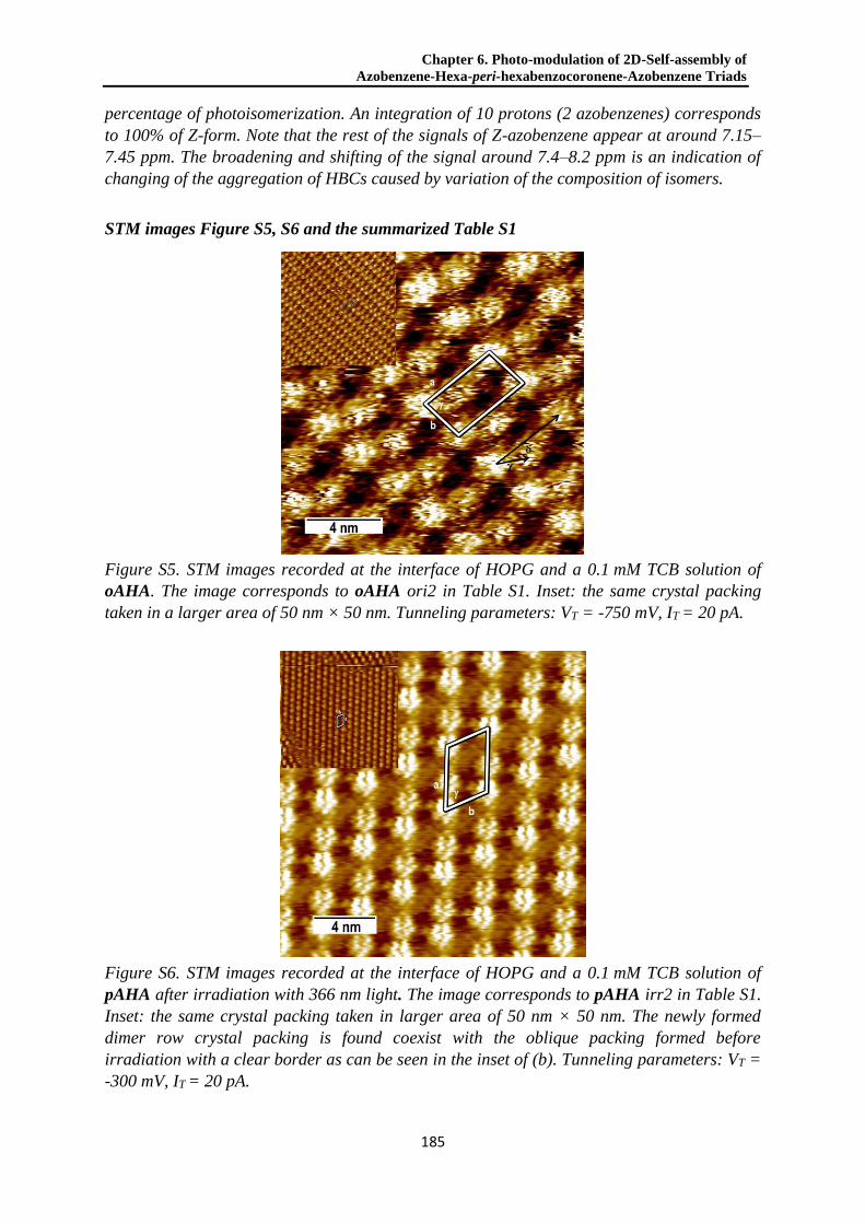
Chapter 6. Photo-modulation of 2D-Self-assembly of
Azobenzene-Hexa-peri-hexabenzocoronene-Azobenzene Triads
185
percentage of photoisomerization. An integration of 10 protons (2 azobenzenes) corresponds
to 100% of Z-form. Note that the rest of the signals of Z-azobenzene appear at around 7.15–
7.45 ppm. The broadening and shifting of the signal around 7.4–8.2 ppm is an indication of
changing of the aggregation of HBCs caused by variation of the composition of isomers.
STM images Figure S5, S6 and the summarized Table S1
Figure S5. STM images recorded at the interface of HOPG and a 0.1 mM TCB solution of
oAHA. The image corresponds to oAHA ori2 in Table S1. Inset: the same crystal packing
taken in a larger area of 50 nm × 50 nm. Tunneling parameters: VT = -750 mV, IT = 20 pA.
Figure S6. STM images recorded at the interface of HOPG and a 0.1 mM TCB solution of
pAHA after irradiation with 366 nm light. The image corresponds to pAHA irr2 in Table S1.
Inset: the same crystal packing taken in larger area of 50 nm × 50 nm. The newly formed
dimer row crystal packing is found coexist with the oblique packing formed before
irradiation with a clear border as can be seen in the inset of (b). Tunneling parameters: VT =
-300 mV, IT = 20 pA.

6.6 Supporting information
186
Table S1. Lattice constants of the additional experimental 2D crystal packing of pAHA and
oAHA.
a (nm) b (nm) γ (°) (nm)b (°)c Area per molecule (nm2)
pAHA irr2a 4.3 ± 0.2 3.00 ± 0.04 63 ± 2 1.74 ± 0.05 -0.1 ± 0.9 5.7 ± 0.3
oAHA ori2 4.3 ± 0.3 2.65 ± 0.08 80 ± 4 2.4 ± 0.2 17 4 5.6 ± 0.4
aOnly formed after 366 nm light irradiation. bThe inter-row distance, specified in the STM
Figures. cThe inter-row angle, specified in the STM Figures.
MM/MD simulations results Figure S7 and Table S2
The adsorption energies Eads of both E,Z and Z,Z present lower energy values respect to the
E,E isomer (~5 kcal/mol for E,Z and ~15 kcal/mol for Z,Z) due to the lower π-π interactions
caused by the non-planar configuration of the Z-form. However, due to the large aromaticity
of the HBC, the magnitude of Eads is one order of magnitude higher than BE. As a
consequence, this factor is dominating the assembly process, thus explaining the highly
packed patterns observed in the STM images.
In the case of the binding energy BE, comparing first this energy among the two structural
models of pAHA for the E,E form, it is found that model II presents an energy twice higher
than model I, thus demonstrating the importance of alkyl chains interdigitation in the
intermolecular stabilization. Nevertheless, in most of the cases BE increases with the number
of Z units, thus showing that the intermolecular interactions help to stabilize the Z-forms
within the assembly.

Chapter 6. Photo-modulation of 2D-Self-assembly of
Azobenzene-Hexa-peri-hexabenzocoronene-Azobenzene Triads
187
Figure S7. Summary of the STM images of ordered domains of pAHA found (a) before and
(b)(c) after the 366 nm irradiation; and oAHA found (d) before and (e) after the 366 nm
irradiation. Right side: corresponding supramolecular packing models of various isomers
obtained by MM/MD simulations for each STM pattern on the left sides.

6.6 Supporting information
188
Table S2. Experimental (ori- for original and irr- for irradiated) and theoretical unit cell
parameters (lateral dimensions a and b, corresponding angle γ, area occupied per molecule
A, center to center distance χ between non-equivalent molecules in the unit cell and angle δ
formed by the vector connecting the non-equivalent molecules and the b lateral vector) and
calculated thermodynamic quantities (adsorption (Eads) and binding (BE) energies). The
highlighted rows are used to help making a direct comparison between the experimental
(numbers in parentheses) and the best fitting theoretical models. Only the first model is
formed by one molecule in the unit cell while the rest of the models are composed by two
molecules in the unit cell.
HBC Model a (nm) b (nm) γ (°) A (nm²) χ(nm) δ(°) Eads (kcal/mol) BE (kcal/mol)
pAHA
ori (3.0) (2.5) (65) (6.8) - - - -
EE-I 3.0 2.5 64 6.8 - - -212.71 -11.09
EE-II 3.2 2.5 62 6.9 - - -210.89 -23.35
irr (4.2) (2.52) (88) (5.3) (1.6) (11) - -
EZ-a 5.0 2.66 83 6.6 2.3 9.4 -204.57 -13.83
ZZ-a 4.3 2.80 89 6.0 2.0 17 -195.99 -17.15
irr2 (4.3) (3.00) (63) (5.7) (1.74) (-0.1) - -
EZ-b 4.6 3.10 62 6.3 1.80 22 -204.96 -17.13
ZZ-b 4.1 3.18 62 5.7 2.04 0.1 -194.96 -24.36
oAHA
ori (4.4) (2.7) (81) (5.9) (2.0) (25) - -
EE-a 4.9 2.8 79 6.7 2.4 24 -211.58 -17.27
ori2 (4.3) (2.65) (80) (5.6) (2.4) (17) - -
EE-b 4.6 2.93 84 6.7 2.1 16 -208.47 -13.51
irr (5.2) (1.77) (83) (4.6) (2.4) (-4) - -
EZ 5.4 2.28 80 6.1 2.6 11 -205.72 -19.50
ZZ 5.1 2.27 79 5.7 2.4 16 -192.53 -25.70
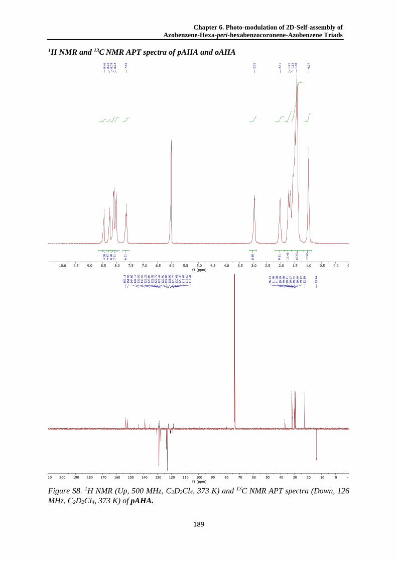
Chapter 6. Photo-modulation of 2D-Self-assembly of
Azobenzene-Hexa-peri-hexabenzocoronene-Azobenzene Triads
189
1H NMR and 13C NMR APT spectra of pAHA and oAHA
Figure S8. 1H NMR (Up, 500 MHz, C2D2Cl4, 373 K) and 13C NMR APT spectra (Down, 126
MHz, C2D2Cl4, 373 K) of pAHA.

6.6 Supporting information
190
Figure S9. 1H NMR (Up, 500 MHz, C2D2Cl4, 373 K) and 13C NMR APT spectra (Down, 126
MHz, C2D2Cl4, 373 K) of oAHA.
Chapter 6. Photo-modulation of 2D-Self-assembly of
Azobenzene-Hexa-peri-hexabenzocoronene-Azobenzene Triads
191
6.7 References
(1) Narita, A.; Wang, X. Y.; Feng, X.; Müllen, K. New Advances in Nanographene Chemistry. Chem. Soc. Rev. 2015,
44 (18), 6616–6643.
(2) Wang, X.-Y.; Narita, A.; Müllen, K. Precision Synthesis versus Bulk-Scale Fabrication of Graphenes. Nat. Rev.
Chem. 2017, 2 (1), 0100.
(3) Narita, A.; Chen, Z.; Chen, Q.; Müllen, K. Solution and On-Surface Synthesis of Structurally Defined Graphene
Nanoribbons as a New Family of Semiconductors. Chem. Sci. 2019, 10 (4), 964–975.
(4) Chen, Q.; Brambilla, L.; Daukiya, L.; Mali, K. S.; De Feyter, S.; Tommasini, M.; Müllen, K.; Narita, A. Synthesis
of Triply Fused Porphyrin-Nanographene Conjugates. Angew. Chem. Int. Ed. 2018, 57 (35), 11233–11237.
(5) Yen, H. J.; Tsai, H.; Zhou, M.; Holby, E. F.; Choudhury, S.; Chen, A.; Adamska, L.; Tretiak, S.; Sanchez, T.; Iyer,
S.; et al. Structurally Defined 3D Nanographene Assemblies via Bottom-Up Chemical Synthesis for Highly
Efficient Lithium Storage. Adv. Mater. 2016, 28 (46), 10250–10256.
(6) Wu, J.; Pisula, W.; Müllen, K. Graphenes as Potential Material for Electronics. Chem. Rev. 2007, 107 (3), 718–747.
(7) Wang, Y.; Yin, Z.; Zhu, Y.; Gu, J.; Li, Y.; Wang, J. Hexapole [9]Helicene. Angew. Chem. Int. Ed. 2019, 58 (2),
587–591.
(8) Evans, P. J.; Ouyang, J.; Favereau, L.; Crassous, J.; Fernández, I.; Perles, J.; Martín, N. Synthesis of a Helical
Bilayer Nanographene. Angew. Chem. Int. Ed. 2018, 57 (23), 6774–6779.
(9) Ziogos, O. G.; Konstantinopoulos, S.; Tsetseris, L.; Theodorou, D. N. Computational Studies of Nanographene
Systems: Extended Discotics, Covalently Linked “Supermolecules,” and Functionalized Supramolecular
Assemblies. J. Phys. Chem. C 2018, 122 (32), 18715–18731.
(10) Feng, X.; Pisula, W.; Kudernac, T.; Wu, D.; Zhi, L.; De Feyter, S.; Müllen, K. Controlled Self-Assembly of C3-
Symmetric Hexa-Peri- Hexabenzocoronenes with Alternating Hydrophilic and Hydrophobic Substituents in
Solution, in the Bulk, and on a Surface. J. Am. Chem. Soc. 2009, 131 (12), 4439–4448.
(11) Zhou, Y.; Zhang, M. Y.; Gu, K. H.; Zhu, Y. F.; Fan, X. H.; Shen, Z. Facile Synthesis and Phase Behaviors of
Monofunctionalized Hexa-Peri-Hexabenzocoronenes. Asian J. Org. Chem. 2015, 4 (8), 746–755.
(12) Wong, W. W. H.; Birendra Singh, T.; Vak, D.; Pisula, W.; Yan, C.; Feng, X.; Williams, E. L.; Chan, K. L.; Mao, Q.;
Jones, D. J.; et al. Solution Processable Fluorenyl Hexa-Peri-Hexabenzocoronenes in Organic Field-Effect
Transistors and Solar Cells. Adv. Funct. Mater. 2010, 20 (6), 927–928.
(13) Gu, K.; Zhang, M.; Zhou, Y.; Han, M.; Zhang, W.; Shen, Z.; Fan, X. Hierarchical Self-Assembly of Disc-Rod
Shape Amphiphiles Having Hexa-Peri-Hexabenzocoronene and a Relatively Long Rod. Langmuir 2017, 33 (13),
3311–3316.
(14) Hu, Y.; Dössel, L. F.; Wang, X.-Y.; Mahesh, S.; Pisula, W.; De Feyter, S.; Feng, X.; Müllen, K.; Narita, A.
Synthesis, Photophysical Characterization, and Self-Assembly of Hexa- Peri -
Hexabenzocoronene/Benzothiadiazole Donor-Acceptor Structure. ChemPlusChem 2017, 82 (7), 1030–1033.
(15) Keerthi, A.; Hou, I. C. Y.; Marszalek, T.; Pisula, W.; Baumgarten, M.; Narita, A. Hexa-Peri-Hexabenzocoronene
with Different Acceptor Units for Tuning Optoelectronic Properties. Chem. - An Asian J. 2016, 11 (19), 2710–2714.
(16) Hinkel, F.; Cho, D.; Pisula, W.; Baumgarten, M.; Müllen, K. Alternating Donor-Acceptor Arrays from Hexa-
Perihexabenzocoronene and Benzothiadiazole: Synthesis, Optical Properties, and Self-Assembly. Chem. - A Eur. J.
2015, 21 (1), 86–90.
(17) Wu, S. H.; Chen, H. H. Self-Assembling Behavior of Binary Mixture of Hexa-Peri-Hexabenzocoronene Derivatives
with Different Molecular Symmetry. Tetrahedron 2018, 75 (2), 220–229.
(18) Dumslaff, T.; Yang, B.; Maghsoumi, A.; Velpula, G.; Mali, K. S.; Castiglioni, C.; De Feyter, S.; Tommasini, M.;
Narita, A.; Feng, X.; et al. Adding Four Extra K-Regions to Hexa-Peri-Hexabenzocoronene. J. Am. Chem. Soc.
2016, 138 (14), 4726–4729.

6.7 References
192
(19) Ai, M.; Groeper, S.; Zhuang, W.; Dou, X.; Feng, X.; Müllen, K.; Rabe, J. P. Optical Switching Studies of an
Azobenzene Rigidly Linked to a Hexa-Peri-Hexabenzocoronene Derivative in Solution and at a Solid-Liquid
Interface. Appl. Phys. A 2008, 93 (2), 277–283.
(20) Pisula, W.; Zorn, M.; Chang, J. Y.; Müllen, K.; Zentel, R. Liquid Crystalline Ordering and Charge Transport In
Semiconducting Materials. Macromol. Rapid Commun. 2009, 30 (14), 1179–1202.
(21) Fleischmann, E. K.; Zentel, R. Liquid-Crystalline Ordering as a Concept in Materials Science: From
Semiconductors to Stimuli-Responsive Devices. Angew. Chem. Int. Ed. 2013, 52 (34), 8810–8827.
(22) Oda, K.; Hiroto, S.; Shinokubo, H. NIR Mechanochromic Behaviours of a Tetracyanoethylene-Bridged Hexa-: Peri-
Hexabenzocoronene Dimer and Trimer through Dissociation of C-C Bonds. J. Mater. Chem. C 2017, 5 (22), 5310–
5315.
(23) Feringa, B. L.; Browne, W. R. Molecular Switches, Second Edition; Feringa, B. L., Browne, W. R., Eds.; Wiley-
VCH Verlag GmbH & Co. KGaA: Weinheim, Germany, 2011; Vol. 1.
(24) Lubbe, A. S.; Szymanski, W.; Feringa, B. L. Recent Developments in Reversible Photoregulation of
Oligonucleotide Structure and Function. Chem. Soc. Rev. 2017, 46 (4), 1052–1079.
(25) Balzani, V.; Credi, A.; Venturi, M. Molecular Devices and Machines: Concepts and Perspectives for the
Nanoworld: Second Edition; Wiley-VCH Verlag GmbH & Co. KGaA: Weinheim, Germany, 2008; Vol. 2.
(26) Zhang, X.; Hou, L.; Samorì, P. Coupling Carbon Nanomaterials with Photochromic Molecules for the Generation of
Optically Responsive Materials. Nat. Commun. 2016, 7 (1), 11118.
(27) Barrett, C. J.; Mamiya, J. I.; Yager, K. G.; Ikeda, T. Photo-Mechanical Effects in Azobenzene-Containing Soft
Materials. Soft Matter 2007, 3 (10), 1249–1261.
(28) Naumov, P.; Chizhik, S.; Panda, M. K.; Nath, N. K.; Boldyreva, E. Mechanically Responsive Molecular Crystals.
Chem. Rev. 2015, 115 (22), 12440–12490.
(29) Bisoyi, H. K.; Li, Q. Light-Driven Liquid Crystalline Materials: From Photo-Induced Phase Transitions and
Property Modulations to Applications. Chem. Rev. 2016, 116 (24), 15089–15166.
(30) Yagai, S.; Kitamura, A. Recent Advances in Photoresponsive Supramolecular Self-Assemblies. Chem. Soc. Rev.
2008, 37 (8), 1520–1529.
(31) Orgiu, E.; Samorì, P. 25th Anniversary Article: Organic Electronics Marries Photochromism: Generation of
Multifunctional Interfaces, Materials, and Devices. Adv. Mater. 2014, 26 (12), 1827–1844.
(32) Scheil, K.; Gopakumar, T. G.; Bahrenburg, J.; Temps, F.; Maurer, R. J.; Reuter, K.; Berndt, R. Switching of an
Azobenzene-Tripod Molecule on Ag(111). J. Phys. Chem. Lett. 2016, 7 (11), 2080–2084.
(33) Jaekel, S.; Richter, A.; Lindner, R.; Bechstein, R.; Nacci, C.; Hecht, S.; Kühnle, A.; Grill, L. Reversible and
Efficient Light-Induced Molecular Switching on an Insulator Surface. ACS Nano 2018, 12 (2), 1821–1828.
(34) Mielke, J.; Selvanathan, S.; Peters, M.; Schwarz, J.; Hecht, S.; Grill, L. Molecules with Multiple Switching Units on
a Au(111) Surface: Self-Organization and Single-Molecule Manipulation. J. Phys. Condens. Matter 2012, 24 (39),
394013.
(35) Tegeder, P. Optically and Thermally Induced Molecular Switching Processes at Metal Surfaces. J. Phys. Condens.
Matter 2012, 24 (39), 394001.
(36) Nacci, C.; Baroncini, M.; Credi, A.; Grill, L. Reversible Photoswitching and Isomer-Dependent Diffusion of Single
Azobenzene Tetramers on a Metal Surface. Angew. Chem. Int. Ed. 2018, 57 (46), 15034–15039.
(37) Galanti, A.; Diez-Cabanes, V.; Santoro, J.; Valášek, M.; Minoia, A.; Mayor, M.; Cornil, J.; Samorì, P. Electronic
Decoupling in C3-Symmetrical Light-Responsive Tris(Azobenzene) Scaffolds: Self-Assembly and
Multiphotochromism. J. Am. Chem. Soc. 2018, 140 (47), 16062–16070.
(38) Frath, D.; Yokoyama, S.; Hirose, T.; Matsuda, K. Photoresponsive Supramolecular Self-Assemblies at the
Liquid/Solid Interface. J. Photochem. Photobiol. C 2018, 34, 29–40.
(39) Garah, M. El; Borré, E.; Ciesielski, A.; Dianat, A.; Gutierrez, R.; Cuniberti, G.; Bellemin-Laponnaz, S.; Mauro, M.;

Chapter 6. Photo-modulation of 2D-Self-assembly of
Azobenzene-Hexa-peri-hexabenzocoronene-Azobenzene Triads
193
Samorì, P. Light-Induced Contraction/Expansion of 1D Photoswitchable Metallopolymer Monitored at the Solid–
Liquid Interface. Small 2017, 13 (40), 1701790.
(40) Zeitouny, J.; Aurisicchio, C.; Bonifazi, D.; De Zorzi, R.; Geremia, S.; Bonini, M.; Palma, C. A.; Samorì, P.; Listorti,
A.; Belbakra, A.; et al. Photoinduced Structural Modifications in Multicomponent Architectures Containing
Azobenzene Moieties as Photoswitchable Core. J. Mater. Chem. 2009, 19 (27), 4715–4724.
(41) Liu, Y.; Mu, L.; Liu, B.; Kong, J. Controlled Switchable Surface. Chem. - A Eur. J. 2005, 11 (9), 2622–2631.
(42) Tahara, K.; Inukai, K.; Adisoejoso, J.; Yamaga, H.; Balandina, T.; Blunt, M. O.; De Feyter, S.; Tobe, Y. Tailoring
Surface-Confined Nanopores with Photoresponsive Groups. Angew. Chem. Int. Ed. 2013, 52 (32), 8373–8376.
(43) Ito, S.; Wehmeier, M.; Brand, J. D.; Kübel, C.; Epsch, R.; Rabe, J. P.; Müllen, K. Synthesis and Self-Assembly of
Functionalized Hexa-Peri-Hexabenzocoronenes. Chem. - A Eur. J. 2000, 6 (23), 4327–4342.
(44) Harvey, J. H.; Butler, B. K.; Trauner, D. Functionalized Azobenzenes through Cross-Coupling with
Organotrifluoroborates. Tetrahedron Lett. 2007, 48 (9), 1661–1664.
(45) Bléger, D.; Ciesielski, A.; Samorì, P.; Hecht, S. Photoswitching Vertically Oriented Azobenzene Self-Assembled
Monolayers at the Solid-Liquid Interface. Chem. - A Eur. J. 2010, 16 (48), 14256–14260.
(46) Samorí, P.; Fechtenkötter, A.; Jäckel, F.; Böhme, T.; Müllen, K.; Rabe, J. P. Supramolecular Staircase via Self-
Assembly of Disklike Molecules at the Solid−Liquid Interface. J. Am. Chem. Soc. 2001, 123 (46), 11462–11467.
(47) Piot, L.; Marchenko, A.; Wu, J.; Müllen, K.; Fichou, D. Structural Evolution of Hexa-Peri-Hexabenzocoronene
Adlayers in Heteroepitaxy on n-Pentacontane Template Monolayers. J. Am. Chem. Soc. 2005, 127 (46), 16245–
16250.
(48) Müllen, K.; Fichou, D.; Silly, F.; Marie, C.; Tortech, L. Tuning the Packing Density of 2D Supramolecular Self-
Assemblies at the Solid−Liquid Interface Using Variable Temperature. ACS Nano 2010, 4 (3), 1288–1292.
(49) Cojal González, J. D.; Iyoda, M.; Rabe, J. P. Reversible Photoisomerization of Monolayers of π-Expanded
Oligothiophene Macrocycles at Solid-Liquid Interfaces. Angew. Chem. Int. Ed. 2018, 57 (52), 17038–17042.
(50) Tahara, K.; Inukai, K.; Adisoejoso, J.; Yamaga, H.; Balandina, T.; Blunt, M. O.; De Feyter, S.; Tobe, Y. Tailoring
Surface-Confined Nanopores with Photoresponsive Groups. Angew. Chem. Int. Ed. 2013, 52 (32), 8373–8376.
(51) Weippert, J.; Hauns, J.; Bachmann, J.; Böttcher, A.; Yao, X.; Yang, B.; Narita, A.; Müllen, K.; Kappes, M. M. A
TPD-Based Determination of the Graphite Interlayer Cohesion Energy. J. Chem. Phys. 2018, 149 (19), 194701.
(52) Mayo, S. L.; Olafson, B. D.; Goddard, W. A. DREIDING: A Generic Force Field for Molecular Simulations. J.
Phys. Chem. 1990, 94 (26), 8897–8909.
(53) MS Modeling, V7. Accelrys Software Inc.: San Diego, CA 2015.
(54) Gasteiger, J.; Marsili, M. A New Model for Calculating Atomic Charges in Molecules. Tetrahedron Lett. 1978, 19
(34), 3181–3184.

194
Chapter 7. Hexa-peri-hexabenzocoronene with Different Acceptor
Units for Tuning Optoelectronic Properties
Ashok Keerthi,1 Ian Cheng-Yi Hou,1 Tomasz Marszalek,1 Wojciech Pisula,1,2 Martin
Baumgarten,1 and Akimitsu Narita1,*
1Max Planck Institute for Polymer Research, Ackermannweg 10, D-55128 Mainz, Germany 2Department of Molecular Physics, Faculty of Chemistry, Lodz University of Technology, Zeromskiego 116, 90-924 Lodz,
Poland
Published in: Chem. - An Asian J. 2016, 11 (19), 2710–2714. DOI: 10.1002/asia.201600638.
Reprinted with permission. Copyright: 2016, WILEY-VCH.
Contribution: Organic synthesis and characterization (excluding acceptor building blocks).
UV-Vis, CV measurements.
7.1 Abstract
ToC Figure. Hexa-peri-hexabenzocoronene (HBC)-based donor-acceptor dyads were
synthesized with three different acceptor units, 9,10-anthraquinone (AQ), naphthalene-1,8-
dicarboximide (NMI), and perylene-3,4-dicarboximide (PMI). The three HBC-acceptor
dyads demonstrated varying degrees of intramolecular charge-transfer interactions, allowing
tuning of their photophysical and optoelectronic properties.
Hexa-peri-hexabenzocoronene (HBC)-based donor-acceptor dyads were synthesized with
three different acceptor units, through two pathways: 1) “pre-functionalization” of
monobromo-substituted hexaphenylbenzene prior to the cyclodehydrogenation; and 2) “post-
functionalization” of monobromo-substituted HBC after the cyclodehydrogenation. The
HBC-acceptor dyads demonstrated varying degrees of intramolecular charge-transfer
interactions, depending on the attached acceptor units, which allowed tuning of their
photophysical and optoelectronic properties, including the energy gaps. The two synthetic
pathways described here can be complementary and potentially be applied for the synthesis
of nanographene-acceptor dyads with larger aromatic cores, including one-dimensionally
extended graphene nanoribbons.

Chapter 7. Hexa-peri-hexabenzocoronene with Different
Acceptor Units for Tuning Optoelectronic Properties
195
7.2 Main text
Large polycyclic aromatic hydrocarbons (PAHs), as represented by hexa-peri-
hexabenzocoronene (HBC), have been attracting a renewed attention as nanographene
molecules, having defined nanoscale graphene structures with distinct optical and electronic
properties. 1-3 Such nanographene molecules bear high potential not only for applications in
electronic and optoelectronic devices as organic semiconductors or structurally defined
graphene quantum dots,1, 4-9 but also as models for studying chemical functionalization and
structural modification of graphene and graphene nanoribbons (GNRs).1-3 A series of
nanographene molecules with different structures, e.g., size and edge configuration, as well
as heteroatom doping, have thus far been synthesized, demonstrating the possibility of fine-
tuning their photophysical and optoelectronic properties through the structural modulation.1, 4,
10-15 Nevertheless, the peripheral functionalization of such nanographene molecules with
different functional groups has been relatively underdeveloped, despite the vast opportunities
of bestowing new functions on them as well as modulating their properties without changing
the aromatic core structures.16-24 In particular, nanographene molecules coupled with acceptor
units are of great interest for lowering their energy gaps through charge-transfer interactions,
although only a few such examples are known in the literature.25-29
Figure 1. Chemical structures of HBC-AQ, -NMI, and -PMI.
To this end we have selected HBC as a model system for exploring the functionalization of
nanographene molecules with different acceptor units. HBC derivatives have gained great
interest as organic functional materials with phase-forming behavior, serving as donor
materials in organic photovoltaics (OPV)29-31 as well as p-type semiconductors in organic
field-effect transistors (OFETs).32-34 Herein we report syntheses of three HBC-acceptor dyads

7.2 Main text
196
(HBC-A) bearing different acceptor units, i.e., 9,10-anthraquinone (AQ),35 naphthalene-1,8-
dicarboximide (NMI),36 and perylene-3,4-dicarboximide (PMI)37 (Figure 1). The three HBC-
acceptor dyads demonstrate varied photophysical and optoelectronic properties and,
depending on the acceptor unit, allowed for a fine control of their optical properties and
energy gaps.
The synthesis of HBC-acceptor dyads started from monobromo-substituted
hexaphenylbenzene derivative HPB-Br24 and two synthetic routes were investigated in
comparison: 1) “pre-functionalization” of HPB-Br with an acceptor unit (A) through a
Suzuki coupling to obtain HPB-A, followed by oxidative cyclodehydrogenation to afford
HBC-A (Route I, Scheme 1); 2) cyclodehydrogenation of HPB-Br to monobromo-
substituted HBC derivative HBC-Br,24 followed by “post-functionalization” to provide
HBC-A (Route II, Scheme 1). The pre-functionalization protocol enables facile and complete
purification of the soluble, functionalized precursor HPB-A, although the acceptor unit might
compromise the efficiency of the cyclodehydrogenation, and/or be unstable under the
reaction conditions. On the other hand, the post-functionalization protocol can ensure the
completion of the cyclodehydrogenation, i.e., from HPB-Br to HBC-Br, and is more
straightforward for preparing various HBC-A with different acceptor units, whereas the
separation of the resulting HBC-A from debrominated byproducts could be difficult,
depending on their solubility. Thus, these two protocols can be complementary to each other
and are worthwhile studying in comparison.
First, the synthesis was carried out through the pre-functionalization route: HPB-Br was
coupled with boronic esters of the acceptor units, namely, 2-(4,4,5,5-tetramethyl-1,3,2-
dioxaborolan-2-yl)anthracene-9,10-dione (AQ-boro), N-(2-ethylhexyl)-4-(4,4,5,5-
tetramethyl-1,3,2-dioxaborolan-2-yl)naphthalene-1,8-dicarboximide (NMI-boro), and
N - ( 2 , 6 - d i i s o p r o p y l p h e n y l ) - 9 - ( 4 , 4 , 5 , 5 - t e t r a m e t h y l - 1 , 3 , 2 - d i o x a b o r o l a n - 2 - y l ) p e r y l e n e - 3 , 4 -
dicarboximide (PMI-boro)38 via the Suzuki coupling to obtain HPB-AQ, -NMI, and -PMI,
respectively (Scheme 1). Subsequently, the oxidative cyclodehydrogenation of these
precursors was carried out using FeCl3 in dichloromethane and nitromethane at room
temperature, providing HBC-AQ, -NMI, and -PMI, respectively. The products were highly
soluble in common organic solvents such as dichloromethane (DCM), toluene,
tetrahydrofuran (THF), and ethyl acetate, which allowed for purification by silica gel column
chromatography and comprehensive characterizations in solution. Structural proof was thus
obtained by 1H and 13C NMR as well as matrix-assisted laser desorption/ionization time-of-
flight (MALDI-TOF) mass spectrometry (MS) analyses (see SI), indicating that all three

Chapter 7. Hexa-peri-hexabenzocoronene with Different
Acceptor Units for Tuning Optoelectronic Properties
197
acceptor units did not hinder the complete cyclodehydrogenation. Nevertheless, MALDI-
TOF MS analysis displayed relatively intense peaks of chlorinated byproducts for HBC-NMI
and -PMI, in comparison to HBC-AQ, which could not be removed by the silica gel column
chromatography (see Figures S17–S19). These characterizations also confirmed that no extra
C-C bond was formed between the HBC core and the acceptor units during the
cyclodehydrogenation, which would make a five-membered ring particularly in the cases of
HBC-NMI and -PMI (Figure S1).
Route II
Route I
Scheme 1. Scheme Caption Synthetic routes towards HBC-acceptor dyads; a)
toluene/ethanol/2 M K2CO3, 90 °C, 16 h; pre-functionalization: HPB-AQ: 74%; HPB-NMI:
90%; HPB-PMI: 54%; post-functionalization: HBC-AQ: 79%; HBC-NMI: 94%; HBC-
PMI: 81% b) FeCl3, nitromethane, dichloromethane, rt, 1 h; post-functionalization: HBC-Br:
83%; pre-functionalization: HBC-AQ: 46%; HBC-NMI: 91%; HBC-PMI: 32%.
Next, the second, post-functionalization route was applied for the syntheses of HBC-AQ, -
NMI, and -PMI, which was expected to suppress the undesired chlorinated byproducts.
HPB-Br was first subjected to the cyclodehydrogenation to obtain HBC-Br,24 and then to
Suzuki coupling with AQ-boro, NMI-boro, and PMI-boro to afford HBC-AQ, -NMI, and -
PMI, respectively (Scheme 1). The MALDI-TOF MS analyses of thus obtained HBC-NMI
and -PMI samples showed significantly smaller signals from the chlorinated byproducts.
Although the relative intensities in the MALDI-TOF MS analysis do not correspond to the
actual ratios between different chemical species, the obvious suppression of the byproduct
signals under the same measurement condition indicated the superiority of the post-

7.2 Main text
198
functionalization route for the preparation of soluble HBC-acceptor dyads. On the other hand,
the pre-functionalization route can be useful for HBC derivatives with limited solubility,
which cannot be separated from debrominated byproducts through column chromatography
although the cyclodehydrogenation conditions need to be carefully optimized to suppress the
chlorination. It should be noted that the UV-Vis absorption and emission spectra of the HBC-
acceptor dyads prepared by the pre- and post-functionalization methods were almost identical
(Figures S8–10), showing that the chlorinated byproducts detected by MALDI-TOF MS had
negligible influences on the optical properties of HBC-AQ, -NMI, and -PMI. These results
indicated that both pre- and post-functionalization routes can be complementarily employed
for the synthesis of different HBC-acceptor dyads, and eventually also applied for coupling
larger nanographene molecules and GNRs with acceptor units.
The optical and electrochemical properties of the three HBC-acceptor dyads were
investigated in comparison. UV-Vis absorption spectra of HBC-AQ, -NMI, and -PMI all
showed the ß-band of the HBC core at ~ 360 nm along with the p-band at ~390 nm (Figure
2A).39 A broad red-shifted band observed for HBC-AQ at 400–520 nm and for HBC-NMI at
400–460 nm could presumably be assigned to the intramolecular charge-transfer (CT)
interactions between donor and acceptor units, although it was difficult to confirm its
dependence on the polarity of the solvent25 due to the small absorbance (Figure S6). It should
be noted that these broad bands also overlap with the α-band of the HBC core, which
nevertheless does not extend over 425 nm (Figure 2A).39 On the other hand, no red-shifted
absorption band was visible in the absorption spectrum of HBC-PMI, compared to the
absorption of the PMI unit itself,37 suggesting the absence of the ground-state CT.
(A) (B)
500 600 700 800
0.0
0.2
0.4
0.6
0.8
1.0 HBC
HBC-AQ
HBC-NMI
HBC-PMI
No
rma
lized
Em
issio
n (
a.u
.)
Wavelength (nm)350 400 450 500 550 600
0.0
0.5
1.0
1.5
2.0
e
x1
05 L
mo
l-1cm
-1
Wavelength (nm)
HBC
HBC-AQ
HBC-NMI
HBC-PMI
Figure 2. (A) Absorption and (B) emission spectra of the HBC-acceptor dyads in comparison
with pristine HBC bearing six dodecyl chains, recorded in toluene solutions at a
concentration of 10–5 mol/L. Excitation wavelength in the photoluminescence spectroscopy
measurements was 400 nm.

Chapter 7. Hexa-peri-hexabenzocoronene with Different
Acceptor Units for Tuning Optoelectronic Properties
199
In the emission spectra, HBC-NMI revealed peaks at ~480 and ~500 nm in toluene, which
were red-shifted to ~550 nm in THF, due to the intramolecular CT (Figures 2B and S7).40
Interestingly, HBC-AQ showed the emission maxima (λem) at ~560 nm in toluene with large
Stokes shift of approximately 110 nm, based on the absorption maxima of the CT band at
~450 nm. The emission maxima of HBC-AQ further red-shifted to 680 nm when the solvent
was changed to THF, corroborating the strong intramolecular donor-acceptor interactions in
HBC-AQ (Figures 2B and S7). Additionally, HBC-AQ exhibited dual fluorescence in THF
with an emission peak at 492 nm from local excitation of the HBC moiety, in addition to the
CT peak. This observation might be due to stabilization of different conformations of the
molecule, depending on the solvent.41 HBC-PMI displayed a small red-shift of emission
peak (λem: 571 nm) from that of pristine PMI at ~550 nm (Figure 2B).26 The red-shift of the
emission peak, comparing the spectra in toluene and THF, was also very limited (10 nm)
(Figures S7), which provided further evidence for the weak intramolecular CT interactions
between the HBC and PMI units. Among the three systems, HBC-PMI gave the highest
quantum yield of 45% whereas HBC-AQ and -NMI exhibited that of around 8–9%. The
optical energy gaps were estimated from the absorption onset in toluene to be 2.41 eV (HBC-
AQ), 2.70 eV (HBC-NMI), and 2.16 eV (HBC-PMI), which demonstrated the possibility of
fine-tuning the optical properties by changing the acceptor units.
Table 1. Photophysical and electrochemical properties of the HBC-acceptor dyads
[a] Absorption peaks (λabs), emission maxima (λem), and fluorescence quantum yields (ΦF)
were recorded in toluene. [b] HOMO level (EHOMO) was calculated by EHOMO = ELUMO,CV –
Eg,opt. [c] LUMO level (ELUMO,CV) was determined by CV. [d] Optical energy gaps (Eg,opt)
were estimated from the onset of the absorption spectra in toluene.
Cyclic voltammetry (CV) analyses of the HBC-acceptor dyads were performed in THF with
0.1 M Bu4N+PF6
- electrolyte, an Ag reference electrode, and a platinum counter electrode,
giving reversible reduction (Table 1 and Figure S5). The lowest unoccupied molecular
orbitals (LUMO) energy levels were estimated from the onset of reduction and found to be
Compound abs (nm)[a] em (nm)[a] ΦF (%)[a] EHOMO (eV)[b] ELUMO,CV (eV)[c]
Eg,opt (eV)[d]
HBC-AQ 364; 392; 448 558 8.2 –5.83 –3.42 2.41
HBC-NMI 361; 394; 410; 450 482; 502 8.8 –6.01 –3.31 2.70
HBC-PMI 363; 392; 498; 523 571 45 –5.67 –3.51 2.16
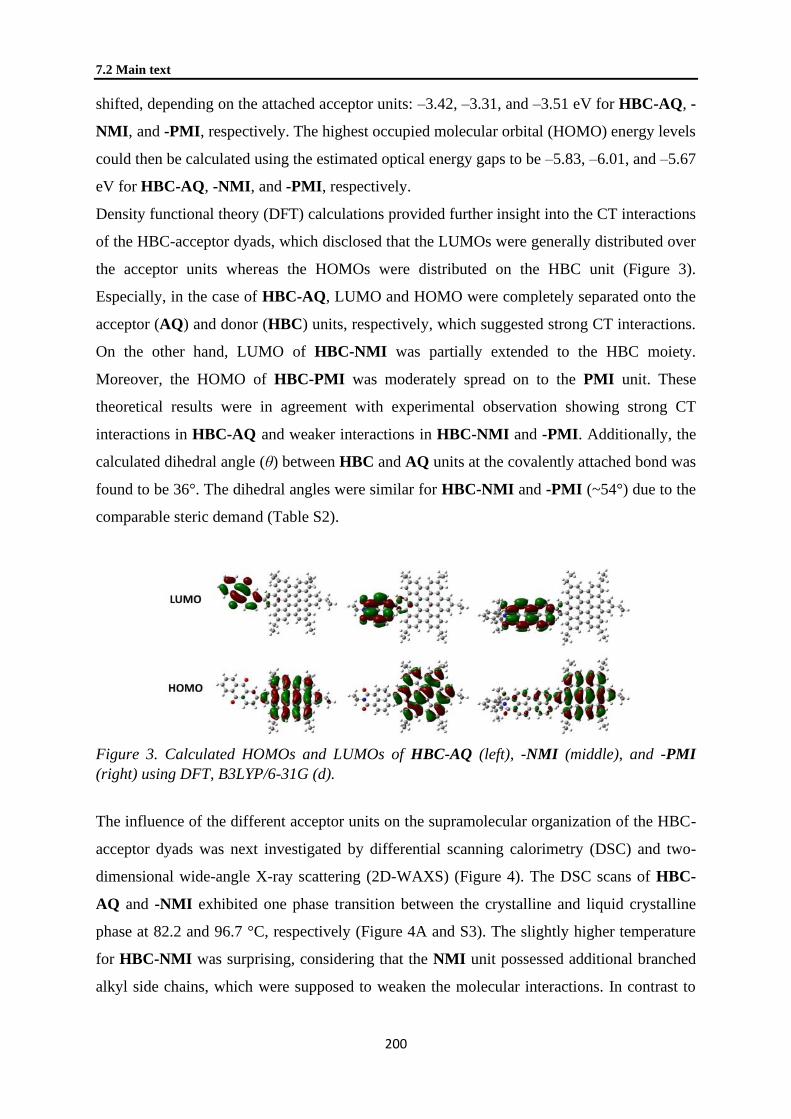
7.2 Main text
200
shifted, depending on the attached acceptor units: –3.42, –3.31, and –3.51 eV for HBC-AQ, -
NMI, and -PMI, respectively. The highest occupied molecular orbital (HOMO) energy levels
could then be calculated using the estimated optical energy gaps to be –5.83, –6.01, and –5.67
eV for HBC-AQ, -NMI, and -PMI, respectively.
Density functional theory (DFT) calculations provided further insight into the CT interactions
of the HBC-acceptor dyads, which disclosed that the LUMOs were generally distributed over
the acceptor units whereas the HOMOs were distributed on the HBC unit (Figure 3).
Especially, in the case of HBC-AQ, LUMO and HOMO were completely separated onto the
acceptor (AQ) and donor (HBC) units, respectively, which suggested strong CT interactions.
On the other hand, LUMO of HBC-NMI was partially extended to the HBC moiety.
Moreover, the HOMO of HBC-PMI was moderately spread on to the PMI unit. These
theoretical results were in agreement with experimental observation showing strong CT
interactions in HBC-AQ and weaker interactions in HBC-NMI and -PMI. Additionally, the
calculated dihedral angle (θ) between HBC and AQ units at the covalently attached bond was
found to be 36°. The dihedral angles were similar for HBC-NMI and -PMI (~54°) due to the
comparable steric demand (Table S2).
Figure 3. Calculated HOMOs and LUMOs of HBC-AQ (left), -NMI (middle), and -PMI
(right) using DFT, B3LYP/6-31G (d).
The influence of the different acceptor units on the supramolecular organization of the HBC-
acceptor dyads was next investigated by differential scanning calorimetry (DSC) and two-
dimensional wide-angle X-ray scattering (2D-WAXS) (Figure 4). The DSC scans of HBC-
AQ and -NMI exhibited one phase transition between the crystalline and liquid crystalline
phase at 82.2 and 96.7 °C, respectively (Figure 4A and S3). The slightly higher temperature
for HBC-NMI was surprising, considering that the NMI unit possessed additional branched
alkyl side chains, which were supposed to weaken the molecular interactions. In contrast to

Chapter 7. Hexa-peri-hexabenzocoronene with Different
Acceptor Units for Tuning Optoelectronic Properties
201
the observation of phase transitions for HBC-AQ and -NMI, HBC-PMI did not reveal any
peak in the DSC measurement.
Figure 4. (A) DSC curves of HBC derivatives recorded at 10 °C/min under N2 atm. (B–D)
2D-WAXS of HBC-NMI recorded at (B) 120 °C and (C) 30 °C and (D) HBC-PMI at 30 °C.
The fiber samples were placed vertically in front of the detector.
Based on the DSC results, the supramolecular organization in bulk was investigated by using
X-ray scattering. For these measurements, macroscopically aligned fiber samples were
obtained through extrusion.42-43 The scattering was collected by an area detector in the wide-
angle range. As shown in Figure 4B and C, two typical 2D-WAXS patterns of HBC-NMI
recorded at 120 and 30 °C, respectively, indicated its discotic LC columnar organization. In
the LC phase, the disc-shaped molecules were packed on top of each other forming columnar
structures (Figure 4B). The intracolumnar π-stacking distance of 0.35 nm was derived from
meridional reflections, while the equatorial ones were attributed to the intercolumnar
arrangement with stacks being oriented along the fiber axis. From the position of these
scattering intensities a hexagonal unit cell with a parameter of ahex = 2.94 nm was determined.
Interestingly, HBC-AQ assembled in an identical hexagonal fashion, as the observation for
HBC-NMI, in the LC phase (ahex = 2.88 nm) (Figure 4). In the crystalline phase, HBC-AQ
and -NMI organized also in similar supramolecular structures (Figure 4C and S4), where the
columnar hexagonal organization was maintained with a slightly smaller ahex parameter of
2.40 nm. In the stacks, the molecules displayed a herringbone tilting towards the columnar
axis. In contrast to HBC-AQ and -NMI, HBC-PMI revealed solely a LC phase over the

7.2 Main text
202
investigated temperature range without becoming crystalline (Figure 4D). The packing
parameter was ahex = 2.92 nm for the hexagonal unit cell and 0.35 nm for the π-stacking
distance.
In summary, three HBC-acceptor dyads, bearing 9,10-anthraquinone, naphthalene-1,8-
dicarboximide, and perylene-3,4-dicarboximide units, were prepared through two synthetic
routes, namely via the coupling of the acceptor unit before and after the
cyclodehydrogenation of the HBC core. Photophysical, electrochemical, and liquid-
crystalline properties of the HBC-acceptor dyads were studied, which demonstrated different
degrees of intramolecular CT interactions and modulation of the energy gaps, depending on
the acceptor units. These results marked the possibility of sensitively controlling the
optoelectronic properties of such nanographene molecules through coupling with different
acceptor units. Furthermore, the reported synthetic protocols can now be applied to larger
nanographene molecules and graphene nanoribbons, paving the way towards new generation
of nanographene-acceptor systems.

Chapter 7. Hexa-peri-hexabenzocoronene with Different
Acceptor Units for Tuning Optoelectronic Properties
203
7.3 Supporting information
General
All reagents were purchased from commercial sources and used without further purification
unless otherwise stated. Thin layer chromatography was carried out using pre-coated
aluminum sheets with silica gel 60 F254 (Merck). Column chromatography was performed
using Merck silica gel 60, 40-63 μm (230-400 mesh). 1H NMR and 13C NMR spectra were
recorded in the listed deuterated solvents on a Bruker AVANCE 250, 300, and 500 MHz
spectrometers. Mass spectra were obtained using Field desorption mass spectra were obtained
on a VG Instruments ZAB 2-SE-FPD spectrometer. Matrix-assisted laser desorption time-of-
flight mass spectrometer (MALDI-TOF) mass spectra were taken on a Bruker Reflex II
MALDI-TOF mass spectrometer with dithranol as matrix and calibrated against a mixture of
C60/C70. The UV-vis spectra were recorded at 298 K on a Perking-Elmer Lambda 900
spectrophotometer.
CV measurements were carried out on a computer-controlled GSTAT12 in a three-electrode
cell in a THF solution of Bu4NPF6 (0.1 M) with a scan rate of 100 mV/s at room temperature,
with using glassy carbon electrode as the working electrode, Pt wire as the counter electrode,
Ag electrode as the reference electrode. HOMO and LUMO energy levels were calculated
from the onsets of the first oxidation and reduction peak by empirical formulas EHOMO = –
(Eonsetox1 + 4.8) eV, ELUMO = –(Eonset
red1 + 4.8) eV while the potentials were determined using
ferrocene (Fc) as standard. Density functional theory (DFT) calculations were carried out at
the B3LYP/6-31G (d) level using Gaussian 0944 and molecular structures were generated
using GaussView 5.0.945. The side chains were set to CH2CH3 (ethyl) to simplify the
calculation. Thermogravimetry analysis (TGA) was carried out on a Mettler 500
Thermogravimetry Analyzer with heating rates of 10 K/min. Differential scanning
calorimetry (DSC) were measured on a Mettler DSC 30 with heating and cooling rates of 10
K/min.
Synthesis
Unless otherwise noted, materials were purchased from Aldrich, Acros, TCI, and other
commercial suppliers and used as received unless otherwise specified. The monobromo-
substituted HPB and HBC derivatives, 4-bromo-4''-dodecyl-3',4',5',6'-tetrakis(4-
dodecylphenyl)-1,1':2',1''-terphenyl (HPB-Br) and 2-bromo-5,8,11,14,17-pentadodecylhexa-
peri-hexabenzocoronene (HBC-Br), respectively,24 4-bromo-N-(2-ethylhexyl)-1,8-
naphthalimide,46 and boronic acids N-(2,6-diisopropylphenyl)-9-(4,4,5,5-tetramethyl-1,3,2-
7.3 Supporting information
204
dioxaborolan-2-yl)perylene-3,4-dicarboximide (PMI-boro)38 and 2-(4,4,5,5-tetramethyl-
1,3,2-dioxaborolan-2-yl)anthracene-9,10-dione (AQ-boro)47 were prepared following the
reported procedures.
N-(2-ethylhexyl)-4-(4,4,5,5-tetramethyl-1,3,2-dioxaborolan-2-yl)naphthalene-1,8-
dicarboximide (NMI-boro): Pd(dppf)Cl2 (300 mg, 0.41 mmol) was added to a well-
degassed solution of 4-Bromo-N-(2-ethylhexyl)-1,8-naphthalimide (3.88 g, 10.0 mmol),
bis(pinacolato)diboron (2.54 g, 10.0 mmol), and KOAc (2.00 g, 20.4 mmol) in anhydrous
1,4-dioxane (100 mL). The resulting mixture was stirred at 70 °C for 16 h under
argon atmosphere. After cooling, the mixture was evaporated to dryness and taken up
with dichloromethane (DCM). The organic layer was washed with water, dried over MgSO4,
filtered, and evaporated to dryness. Purification by column chromatography (SiO2, 1:4
DCM/hexane) afforded NMI-boro in 85% yield (3.70 g). 1H NMR (250 MHz, CDCl3) δ =
9.12 (d, J = 7.5 Hz, 1H), 8.61 (d, J = 7.5 Hz, 1H), 8.57 (d, J = 7.5 Hz, 1H), 8.30 (d, J = 7.5
Hz, 1H), 7.78 (t, J1 = J2 = 7.5 Hz, 1H), 4.16–4.08 (m, 2H), 1.98–1.93 (m, 1H), 1.45 (s, 12H),
1.40–1.31 (m, 8H), 0.96–0.84 (m, 6H). 13C NMR (75 MHz, CDCl3) δ = 164.71, 164.70,
135.77, 135.25, 134.84, 130.88, 129.79, 127.91, 127.07, 124.78, 122.66, 84.55, 44.18, 37.90,
30.77, 28.73, 24.97, 24.10, 23.06, 14.08, 10.66. MS (FD): calcd. for C26H34BNO4 [M]+ 435.4
(100.0%, m/z) found 435.3.
Suzuki coupling reaction procedure: To a solution of HPB-Br or HBC-Br (1 eq.) and
corresponding aryl boronic ester (2 eq.) in toluene (2 mL) was added a solution of K2CO3 (4
eq.) in water and EtOH (1:1, 2 mL). The reaction mixture was degassed and the catalyst
(Pd(PPh3)4, 0.1 eq) along with ligand (SPhos, 0.2 eq) were added under the argon flow. The
reaction mixture was stirred at 90 °C for 16 hours under argon atmosphere. After cooling
down to room temperature, methanol was added followed by extraction with chloroform. The
combined organic layers were washed with water and dried over Na2SO4. The solvents were
removed in vacuo and the crude was further purified by column chromatography on silica gel
to afford the desire products.
Synthesis of HPB-AQ: Following the Suzuki coupling procedure, reaction between HPB-Br
(50 mg, 0.034 mmol) and AQ-boro (28.7 mg, 0.086 mmol) afforded HPB-AQ after flash
column chromatography (3 % ethyl acetate in hexane) as yellow powder (40 mg, 74%). 1H

Chapter 7. Hexa-peri-hexabenzocoronene with Different
Acceptor Units for Tuning Optoelectronic Properties
205
NMR (250 MHz, CD2Cl2) δ = 8.36–8.35 (1H, AN), 8.29–8.22 (m, 3H, AN), 7.87–7.78 (m,
3H, AN), 7.28 (d, J = 12 Hz, 2H), 6.99 (d, J = 12 Hz, 2H), 6.78–6.66 (m, 20H), 2.39–2.34 (m,
10H), 1.55–1.11 (m, 100H), 0.88–0.83 (m, 15H). 13C NMR (63 MHz, CD2Cl2) δ = 183.48,
183.12, 146.90, 142.89, 141.32, 141.06, 140.76, 140.25, 140.07, 138.72, 138.65, 138.56,
135.58, 134.50, 134.29, 134.19, 134.13, 132.86, 132.35, 132.33, 131.79, 128.21, 127.56,
127.49, 127.24, 127.04, 125.75, 125.37, 35.85, 35.73, 32.51, 32.48, 31.89, 31.76, 30.33,
30.32, 30.27, 30.16, 30.11, 29.97, 29.91, 29.47, 29.25, 23.27, 23.24, 14.46. MS (FD): calcd.
for C116H156O2 [M]+ 1583 (100.0%, m/z) found 1582.
Synthesis of HPB-NMI: Following the Suzuki coupling procedure, reaction between HPB-
Br (50 mg, 0.034 mmol) and 1,8-naphthalene monoimide boronic ester (NMI-boro, 29.4 mg,
0.068 mmol) afforded HPB-NMI after flash column chromatography (20% DCM in hexane)
as colorless oil (52 mg, 90%). 1H NMR (300 MHz, CD2Cl2) δ = 8.56 (d, J = 6.3 Hz, 1H),
8.51 (d, J = 7.5 Hz, 1H), 7.85 (d, J = 7.5 Hz, 1H), 7.63 (t, J = 7.5 Hz, 1H), 7.50 (d, J = 7.5 Hz,
1H), 6.99 (s, 2H), 6.98 (s, 2H), 6.82–6.67 (m, 20H), 4.09 (m, 2H), 2.43–2.35 (m, 10H), 1.95–
1.91 (m, 1H), 1.41–1.10 (m, 109H), 0.92–0.85 (m, 22H). 13C NMR (75 MHz, CD2Cl2) δ =
165.03, 164.81, 147.44, 142.35, 141.44, 141.05, 140.82, 140.38, 140.34, 140.18, 140.14,
138.74, 138.70, 135.96, 133.00, 132.28, 131.99, 131.87, 131.33, 129.16, 128.50, 127.94,
127.24, 127.13, 123.48, 122.20, 44.47, 38.51, 35.94, 35.89, 32.55, 32.52, 31.95, 31.93, 31.91,
31.33, 30.37, 30.35, 30.30, 30.26, 30.23, 30.19, 30.14, 30.07, 30.00, 29.95, 29.50, 29.46,
29.29, 24.61, 23.67, 23.30, 23.28, 14.48, 14.46, 11.01. MS (MALDI-TOF, positive) m/z (%)
calcd. for C122H171NO2 [M]+ 1683.3 (27), 1684.3 (36), 1685.3 (24), 1686.3 (11), 1687.4 (4),
found 1683.6 (29), 1684.6 (36), 1685.6 (21), 1686.6 (11), 1687.7 (3).
Synthesis of HPB-PMI: The Suzuki coupling reaction of HPB-Br (40 mg, 0.028 mmol ) and
PMI-boro (41.8 mg, 0.069 mmol) was performed at 105 °C subsequent purification by flash
column chromatography using hot toluene as eluent afforded HPB-PMI as red oil (28 mg,
54%). 1H NMR (250 MHz, CD2Cl2) δ = 8.62 (d, J = 7.5 Hz, 2H), 8.52, 8.49–8.45 (m, 4H),
7.75–7.41 (m, 8H), 7.37–7.34 (d, J = 7.5 Hz, 2H), 6.85–6.66 (m, 20H), 2.81–2.70 (m, 2H),
2.45–2.35 (m, 10H), 1.44–1.08 (m, 100H), 0.88–0.78 (m, 27H). 13C NMR (176 MHz, CD2Cl2)
δ = 164.62, 146.71, 144.31, 141.88, 141.39, 141.02, 140.86, 140.58, 140.30, 140.18, 140.13,
138.81, 138.74, 138.45, 138.32, 136.87, 133.35, 132.77, 132.71, 132.41, 132.22, 132.01,
131.89, 131.19, 130.17, 129.80, 129.69, 129.10, 129.03, 128.80, 128.66, 128.59, 128.44,
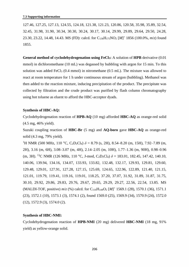
7.3 Supporting information
206
127.46, 127.25, 127.13, 124.55, 124.18, 121.38, 121.23, 120.86, 120.58, 35.98, 35.89, 32.54,
32.45, 31.98, 31.90, 30.34, 30.30, 30.24, 30.17, 30.14, 29.99, 29.89, 29.64, 29.50, 24.28,
23.30, 23.22, 14.48, 14.43. MS (FD): calcd. for C136H175NO2 [M]+ 1856 (100.0%, m/z) found
1855.
General method of cyclodehydrogenation using FeCl3: A solution of HPB derivative (0.01
mmol) in dichloromethane (10 mL) was degassed by bubbling with argon for 15 min. To this
solution was added FeCl3 (0.4 mmol) in nitromethane (0.5 mL). The mixture was allowed to
react at room temperature for 1 h under continuous stream of argon (bubbling). Methanol was
then added to the reaction mixture, inducing precipitation of the product. The precipitate was
collected by filtration and the crude product was purified by flash column chromatography
using hot toluene as eluent to afford the HBC-acceptor dyads.
Synthesis of HBC-AQ:
Cyclodehydrogenation reaction of HPB-AQ (10 mg) afforded HBC-AQ as orange-red solid
(4.5 mg, 46% yield).
Suzuki coupling reaction of HBC-Br (5 mg) and AQ-boro gave HBC-AQ as orange-red
solid (4.3 mg, 79% yield).
1H NMR (500 MHz, 110 °C, C2D2Cl4) δ = 8.79 (s, 2H), 8.54–8.20 (m, 15H), 7.92–7.89 (m,
2H), 3.16 (m, 6H), 3.08–3.07 (m, 4H), 2.14–2.05 (m, 10H), 1.77–1.36 (m, 90H), 0.98–0.96
(m, 3H). 13C NMR (126 MHz, 110 °C, J-mod, C2D2Cl4) δ = 183.01, 182.45, 147.42, 140.10,
140.06, 139.94, 134.16, 134.07, 133.93, 133.82, 132.48, 132.17, 129.93, 129.81, 129.60,
129.48, 129.01, 127.91, 127.28, 127.15, 125.69, 124.65, 122.96, 122.89, 121.40, 121.15,
121.01, 119.79, 119.41, 119.16, 119.01, 118.25, 37.20, 37.07, 31.92, 31.89, 31.87, 31.75,
30.10, 29.92, 29.86, 29.83, 29.76, 29.67, 29.65, 29.29, 29.27, 22.56, 22.54, 13.85. MS
(MALDI-TOF, positive) m/z (%) calcd. for C116H144O2 [M]+ 1569.1 (28), 1570.1 (36), 1571.1
(23), 1572.1 (10), 1573.1 (3), 1574.1 (2), found 1569.0 (25), 1569.9 (34), 1570.9 (24), 1572.0
(12), 1572.9 (3), 1574.0 (2).
Synthesis of HBC-NMI:
Cyclodehydrogenation reaction of HPB-NMI (20 mg) delivered HBC-NMI (18 mg, 91%
yield) as yellow-orange solid.
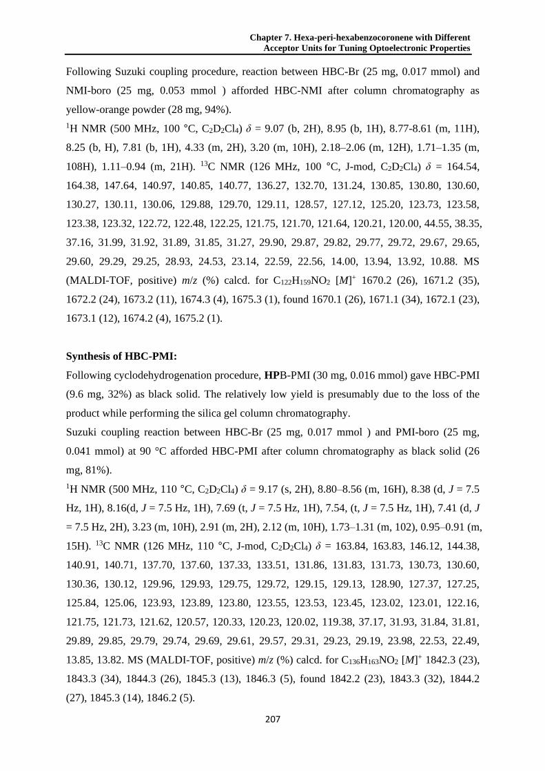
Chapter 7. Hexa-peri-hexabenzocoronene with Different
Acceptor Units for Tuning Optoelectronic Properties
207
Following Suzuki coupling procedure, reaction between HBC-Br (25 mg, 0.017 mmol) and
NMI-boro (25 mg, 0.053 mmol ) afforded HBC-NMI after column chromatography as
yellow-orange powder (28 mg, 94%).
1H NMR (500 MHz, 100 °C, C2D2Cl4) δ = 9.07 (b, 2H), 8.95 (b, 1H), 8.77-8.61 (m, 11H),
8.25 (b, H), 7.81 (b, 1H), 4.33 (m, 2H), 3.20 (m, 10H), 2.18–2.06 (m, 12H), 1.71–1.35 (m,
108H), 1.11–0.94 (m, 21H). 13C NMR (126 MHz, 100 °C, J-mod, C2D2Cl4) δ = 164.54,
164.38, 147.64, 140.97, 140.85, 140.77, 136.27, 132.70, 131.24, 130.85, 130.80, 130.60,
130.27, 130.11, 130.06, 129.88, 129.70, 129.11, 128.57, 127.12, 125.20, 123.73, 123.58,
123.38, 123.32, 122.72, 122.48, 122.25, 121.75, 121.70, 121.64, 120.21, 120.00, 44.55, 38.35,
37.16, 31.99, 31.92, 31.89, 31.85, 31.27, 29.90, 29.87, 29.82, 29.77, 29.72, 29.67, 29.65,
29.60, 29.29, 29.25, 28.93, 24.53, 23.14, 22.59, 22.56, 14.00, 13.94, 13.92, 10.88. MS
(MALDI-TOF, positive) m/z (%) calcd. for C122H159NO2 [M]+ 1670.2 (26), 1671.2 (35),
1672.2 (24), 1673.2 (11), 1674.3 (4), 1675.3 (1), found 1670.1 (26), 1671.1 (34), 1672.1 (23),
1673.1 (12), 1674.2 (4), 1675.2 (1).
Synthesis of HBC-PMI:
Following cyclodehydrogenation procedure, HPB-PMI (30 mg, 0.016 mmol) gave HBC-PMI
(9.6 mg, 32%) as black solid. The relatively low yield is presumably due to the loss of the
product while performing the silica gel column chromatography.
Suzuki coupling reaction between HBC-Br (25 mg, 0.017 mmol ) and PMI-boro (25 mg,
0.041 mmol) at 90 °C afforded HBC-PMI after column chromatography as black solid (26
mg, 81%).
1H NMR (500 MHz, 110 °C, C2D2Cl4) δ = 9.17 (s, 2H), 8.80–8.56 (m, 16H), 8.38 (d, J = 7.5
Hz, 1H), 8.16(d, J = 7.5 Hz, 1H), 7.69 (t, J = 7.5 Hz, 1H), 7.54, (t, J = 7.5 Hz, 1H), 7.41 (d, J
= 7.5 Hz, 2H), 3.23 (m, 10H), 2.91 (m, 2H), 2.12 (m, 10H), 1.73–1.31 (m, 102), 0.95–0.91 (m,
15H). 13C NMR (126 MHz, 110 °C, J-mod, C2D2Cl4) δ = 163.84, 163.83, 146.12, 144.38,
140.91, 140.71, 137.70, 137.60, 137.33, 133.51, 131.86, 131.83, 131.73, 130.73, 130.60,
130.36, 130.12, 129.96, 129.93, 129.75, 129.72, 129.15, 129.13, 128.90, 127.37, 127.25,
125.84, 125.06, 123.93, 123.89, 123.80, 123.55, 123.53, 123.45, 123.02, 123.01, 122.16,
121.75, 121.73, 121.62, 120.57, 120.33, 120.23, 120.02, 119.38, 37.17, 31.93, 31.84, 31.81,
29.89, 29.85, 29.79, 29.74, 29.69, 29.61, 29.57, 29.31, 29.23, 29.19, 23.98, 22.53, 22.49,
13.85, 13.82. MS (MALDI-TOF, positive) m/z (%) calcd. for C136H163NO2 [M]+ 1842.3 (23),
1843.3 (34), 1844.3 (26), 1845.3 (13), 1846.3 (5), found 1842.2 (23), 1843.3 (32), 1844.2
(27), 1845.3 (14), 1846.2 (5).

7.3 Supporting information
208
Figure S1: Possible five-membered-ring formation during the cyclodehydrogenation reaction
of HPB-PMI and HPB-NMI using FeCl3 as reagent.
Thermal properties
Figure S2. TGA curves of the HBC-acceptor dyads measured under a nitrogen atmosphere at
a heating rate of 10 ºC/min.
Figure S3. DSC heating and cooling curves of the HBC-acceptor dyads measured under a
nitrogen atmosphere at a heating and cooling rate of 10 ºC/min.

Chapter 7. Hexa-peri-hexabenzocoronene with Different
Acceptor Units for Tuning Optoelectronic Properties
209
Two-dimensional wide-angle X-ray scattering (2D-WAXS)
2D-WAXS measurements were performed using a custom setup consisting of the Siemens
Kristalloflex X-ray source (copper anode X-ray tube, operated at 35 kV/20 mA), Osmic
confocal MaxFlux optics, two collimating pinholes (1.0 and 0.5 mm Owis, Germany) and an
antiscattering pinhole (0.7 mm–Owis, Germany). The patterns were recorded on a MAR345
image plate detector (Marresearch, Germany). The samples were prepared by filament
extrusion using a home-built mini-extruder.
Figure S4. 2DWAXS of HBC-AQ recorded at a) 120 °C and b) 30 °C. The fiber sample was
placed vertically in front of the detector.
Cyclic voltammetry
-2.5 -2.0 -1.5 -1.0 -0.5
-2.5 -2.0 -1.5 -1.0 -0.5
Voltage (V) vs Fc/Fc+
HBC-AQ
Cu
rren
t (A
) HBC-NMI
HBC-PMI
Figure S5. Cyclic voltammograms of HBC-acceptor dyads in THF with 0.1 M Bu4N+PF6
–
electrolyte, an Ag reference electrode, a platinum counter electrode, and ferrocene as an
external standard.

7.3 Supporting information
210
UV-vis absorption and photoluminescence spectra in different solvents
Figure S6. Normalized UV-vis absorption spectra of HBC-acceptor dyads in THF and
toluene solvents at room temperature.
Figure S7. Normalized photoluminescence spectra of HBC-acceptor dyads in THF and
toluene solvents at room temperature.
Table S1.
Compound abs (nm) em (nm) ΦF (%)
THF Toluene THF Toluene
HBC-AQ 361; 391; ~450 364; 392; 448 492; 680 561 8.2
HBC-NMI 359; 392; 450 361; 394; 410; 450 545 482; 502 8.8
HBC-PMI 362; 390; 496; 519 363; 392; 498; 523 581 571 45
Figure S8.Normalized absorption and emission spectra of pre- and post-functionalized HBC-
AQ, recorded in THF solutions at a concentration of 10–5 mol/L. Excitation wavelength in the
photoluminescence spectroscopy measurements was 400 nm.

Chapter 7. Hexa-peri-hexabenzocoronene with Different
Acceptor Units for Tuning Optoelectronic Properties
211
Figure S9.Normalized absorption and emission spectra of pre- and post-functionalized HBC-
NMI, recorded in THF solutions at a concentration of 10–5 mol/L. Excitation wavelength in
the photoluminescence spectroscopy measurements was 400 nm.
Figure S10.Normalized absorption and emission spectra of pre- and post-functionalized
HBC-PMI, recorded in THF solutions at a concentration of 10–5 mol/L. Excitation
wavelength in the photoluminescence spectroscopy measurements was 400 nm.

7.3 Supporting information
212
Theoretical calculations
Figure S11. Geometry optimized structures of HBC derivatives.
Figure S12. Calculated UV-vis absorption spectra of the HBC-acceptor dyads (TD-SCF,
B3LYP/6-31G(d)).
Table S2. Calculated HOMO and LUMO levels, energy gap, absorption maxima, and
dihedral angles (θ) of functionalized HBC dyads using DFT, B3LYP/6-31G (d).
COMPOU
ND
EHOMO,
CALC (EV)
ELUMO,C
ALC (EV)
EG,C
ALC (EV)
ABS,CALC
(NM)
Θ (°)
HBC-AQ –5.16 –2.76 2.40 388; 585 35.8
HBC-NMI –5.23 –2.35 2.88 368; 471 53.5
HBC-PMI –5.19 –2.77 2.42 503 54.3
HBC-Alk –5.01 –1.48 3.53 363 —

Chapter 7. Hexa-peri-hexabenzocoronene with Different
Acceptor Units for Tuning Optoelectronic Properties
213
1H and 13C NMR spectra
Figure S13. 1H (above) and 13C NMR (below) spectra of NMI-boro in CDCl3.

7.3 Supporting information
214
Figure S14. 1H (above) and 13C NMR (below) spectra of HPB-AQ in CD2Cl2.

Chapter 7. Hexa-peri-hexabenzocoronene with Different
Acceptor Units for Tuning Optoelectronic Properties
215
Figure S15. 1H (above) and 13C NMR (below) spectra of HBC-AQ in C2D2Cl4.

7.3 Supporting information
216
-100102030405060708090100110120130140150160170f1 (ppm)
11.0
114
.46
14.4
823
.28
23.3
023
.67
29.4
629
.50
29.9
530
.00
30.0
730
.14
30.1
930
.23
30.2
630
.30
30.3
530
.37
31.9
131
.93
31.9
532
.52
32.5
535
.89
35.9
4
44.4
7
53.2
853
.64
54.0
054
.36
54.7
2
122.
2012
3.48
127.
1312
7.24
127.
9412
8.50
129.
1613
0.76
131.
0113
1.33
131.
8713
1.99
132.
2813
3.00
135.
9613
8.70
138.
7413
9.78
140.
1414
0.18
140.
3414
0.38
140.
8214
1.05
141.
4414
2.35
147.
44
164.
8116
5.03
Figure S16. 1H (above) and 13C NMR (below) spectra of HPB-NMI in CD2Cl2.

Chapter 7. Hexa-peri-hexabenzocoronene with Different
Acceptor Units for Tuning Optoelectronic Properties
217
-100102030405060708090100110120130140150160170180190200210f1 (ppm)
13.9
213
.94
22.5
622
.59
29.2
529
.29
29.6
029
.65
29.6
729
.72
29.7
729
.82
29.8
729
.90
31.8
531
.89
31.9
231
.99
37.1
638
.35
44.5
5
73.7
874
.00
74.2
211
9.16
120.
0012
0.21
121.
6412
1.70
121.
7512
2.25
122.
4812
2.72
123.
3212
3.38
123.
5812
3.73
125.
2012
7.12
128.
5712
9.11
129.
7012
9.88
130.
0613
0.11
130.
2713
0.60
130.
8013
0.85
131.
2413
2.70
136.
2714
0.77
140.
8514
0.97
147.
64
164.
3816
4.54
Figure S17. 1H (above) and 13C NMR (below) spectra of HBC-NMI in C2D2Cl4.
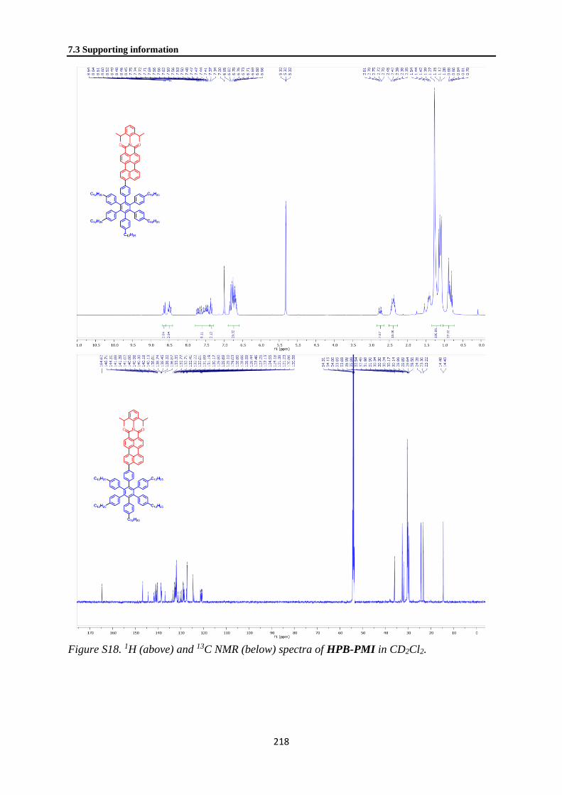
7.3 Supporting information
218
Figure S18. 1H (above) and 13C NMR (below) spectra of HPB-PMI in CD2Cl2.

Chapter 7. Hexa-peri-hexabenzocoronene with Different
Acceptor Units for Tuning Optoelectronic Properties
219
Figure S19. 1H (above) and 13C NMR (below) spectra of HBC-PMI in C2D2Cl4.

7.3 Supporting information
220
MALDI TOF MS spectra of HBC-acceptor dyads
1569.9
1569.0 1570.9
1572.0
1572.9
1569.9
1569.3
1568.3 1570.3
1571.3
1572.3
1569.3
Figure S20. MALDI-TOF spectra of HBC-AQ prepared through the pre-functionalization
(top) and the post-functionalization (bottom) protocols.

Chapter 7. Hexa-peri-hexabenzocoronene with Different
Acceptor Units for Tuning Optoelectronic Properties
221
1671.0 1671.0
1670.01672.0
1673.0
1674.0
+Cl
+2Cl
1671.11671.1
1670.11672.1
1673.1
1674.2
Figure S21. MALDI-TOF spectra of HBC-NMI prepared through the pre-functionalization
(top) and the post-functionalization (bottom) protocols.

7.3 Supporting information
222
1843.3 1843.3
1842.2 1844.2
1845.3
1846.2
+Cl
+2Cl
1843.3 1843.3
1842.2
1844.2
1845.3
1846.2
Figure S22. MALDI-TOF spectra of HBC-PMI prepared through the pre-functionalization
(top) and the post-functionalization (bottom) protocols.

223
7.4 References
(1) Narita, A.; Wang, X.-Y.; Feng, X.; Müllen, K., New advances in nanographene chemistry. Chem. Soc. Rev. 2015,
44 (18), 6616-6643.
(2) Narita, A.; Feng, X.; Hernandez, Y.; Jensen, S. A.; Bonn, M.; Yang, H.; Verzhbitskiy, I. A.; Casiraghi, C.; Hansen,
M. R.; Koch, A. H. R.; Fytas, G.; Ivasenko, O.; Li, B.; Mali, K. S.; Balandina, T.; Mahesh, S.; De Feyter, S.;
Müllen, K., Structurally Well-Defined and Liquid-Phase-Processable Graphene Nanoribbons. Nature Chem. 2014,
6, 126-132.
(3) Vo, T. H.; Shekhirev, M.; Kunkel, D. A.; Morton, M. D.; Berglund, E.; Kong, L.; Wilson, P. M.; Dowben, P. A.;
Enders, A.; Sinitskii, A., Large-scale solution synthesis of narrow graphene nanoribbons. Nat. Commun. 2014, 5,
3189.
(4) Wu, J.; Pisula, W.; Müllen, K., Graphenes as Potential Material for Electronics. Chem. Rev. 2007, 107 (3), 718-
747.
(5) Li, X.; Rui, M.; Song, J.; Shen, Z.; Zeng, H., Carbon and Graphene Quantum Dots for Optoelectronic and Energy
Devices: A Review. Adv. Funct. Mater. 2015, 25 (31), 4929-4947.
(6) Loh, K. P.; Tong, S. W.; Wu, J., Graphene and Graphene-like Molecules: Prospects in Solar Cells. J. Am. Chem.
Soc. 2016, 138 (4), 1095-1102.
(7) Soldano, C.; Mahmood, A.; Dujardin, E., Production, properties and potential of graphene. Carbon 2010, 48 (8),
2127-2150.
(8) Yan, X.; Li, B.; Li, L.-S., Colloidal Graphene Quantum Dots with Well-Defined Structures. Acc. Chem. Res. 2013,
46 (10), 2254-2262.
(9) Segawa, Y.; Ito, H.; Itami, K., Structurally uniform and atomically precise carbon nanostructures. Nat. Rev. Mater.
2016, 1, 15002.
(10) Berger, R.; Giannakopoulos, A.; Ravat, P.; Wagner, M.; Beljonne, D.; Feng, X.; Müllen, K., Synthesis of Nitrogen-
Doped ZigZag-Edge Peripheries: Dibenzo-9a-azaphenalene as Repeating Unit. Angew. Chem. Int. Ed. 2014, 53
(39), 10520-10524.
(11) Wang, X.-Y.; Wang, J.-Y.; Pei, J., BN Heterosuperbenzenes: Synthesis and Properties. Chem.—Eur. J. 2015, 21 (9),
3528-3539.
(12) Jiang, W.; Li, Y.; Wang, Z., Heteroarenes as high performance organic semiconductors. Chem. Soc. Rev. 2013, 42
(14), 6113-6127.
(13) Segura, J. L.; Juarez, R.; Ramos, M.; Seoane, C., Hexaazatriphenylene (HAT) derivatives: from synthesis to
molecular design, self-organization and device applications. Chem. Soc. Rev. 2015, 44 (19), 6850-6885.
(14) Ball, M.; Zhong, Y.; Wu, Y.; Schenck, C.; Ng, F.; Steigerwald, M.; Xiao, S.; Nuckolls, C., Contorted Polycyclic
Aromatics. Acc. Chem. Res. 2015, 48 (2), 267-276.
(15) Dou, C.; Saito, S.; Matsuo, K.; Hisaki, I.; Yamaguchi, S., A Boron-Containing PAH as a Substructure of Boron-
Doped Graphene. Angew. Chem. Int. Ed. 2012, 51 (49), 12206-12210.
(16) Tan, Y.-Z.; Osella, S.; Liu, Y.; Yang, B.; Beljonne, D.; Feng, X.; Müllen, K., Sulfur-Annulated Hexa-peri-
hexabenzocoronene Decorated with Phenylthio Groups at the Periphery. Angew. Chem. Int. Ed. 2015, 54 (10),
2927-2931.
(17) Yamaguchi, R.; Ito, S.; Lee, B. S.; Hiroto, S.; Kim, D.; Shinokubo, H., Functionalization of Hexa-peri-
hexabenzocoronenes: Investigation of the Substituent Effects on a Superbenzene. Chem. Asian J. 2013, 8 (1), 178-
190.
(18) Yamaguchi, R.; Hiroto, S.; Shinokubo, H., Synthesis of Oxygen-Substituted Hexa-peri-hexabenzocoronenes
through Ir-Catalyzed Direct Borylation. Org. Lett. 2012, 14 (10), 2472-2475.

7.4 References
224
(19) Tan, Y.-Z.; Osella, S.; Liu, Y.; Yang, B.; Beljonne, D.; Feng, X.; Müllen, K., Sulfur-Annulated Hexa-peri-
hexabenzocoronene Decorated with Phenylthio Groups at the Periphery. Angew. Chem. Int. Ed. 2015, 54 (10),
2927-2931.
(20) Wong, W. W. H.; Subbiah, J.; Puniredd, S. R.; Purushothaman, B.; Pisula, W.; Kirby, N.; Müllen, K.; Jones, D. J.;
Holmes, A. B., Liquid crystalline hexa-peri-hexabenzocoronene-diketopyrrolopyrrole organic dyes for photovoltaic
applications. J. Mater. Chem. 2012, 22 (39), 21131-21137.
(21) Lungerich, D.; Hitzenberger, J. F.; Marcia, M.; Hampel, F.; Drewello, T.; Jux, N., Superbenzene–Porphyrin
Conjugates. Angew. Chem. Int. Ed. 2014, 53 (45), 12231-12235.
(22) Hill, J. P.; Jin, W.; Kosaka, A.; Fukushima, T.; Ichihara, H.; Shimomura, T.; Ito, K.; Hashizume, T.; Ishii, N.; Aida,
T., Self-Assembled Hexa-peri-hexabenzocoronene Graphitic Nanotube. Science 2004, 304 (5676), 1481-1483.
(23) Ravat, P.; Marszalek, T.; Pisula, W.; Müllen, K.; Baumgarten, M., Positive Magneto-LC Effect in Conjugated Spin-
Bearing Hexabenzocoronene. J. Am. Chem. Soc. 2014, 136 (37), 12860-12863.
(24) Ito, S.; Wehmeier, M.; Brand, J. D.; Kübel, C.; Epsch, R.; Rabe, J. P.; Müllen, K., Synthesis and Self-Assembly of
Functionalized Hexa-peri-hexabenzocoronenes. Chem.–Eur. J. 2000, 6 (23), 4327-4342.
(25) Hinkel, F.; Cho, D.; Pisula, W.; Baumgarten, M.; Müllen, K., Alternating Donor–Acceptor Arrays from Hexa-peri-
hexabenzocoronene and Benzothiadiazole: Synthesis, Optical Properties, and Self-Assembly. Chem. Eur. J. 2015,
21 (1), 86-90.
(26) Dössel, L. F.; Kamm, V.; Howard, I. A.; Laquai, F.; Pisula, W.; Feng, X.; Li, C.; Takase, M.; Kudernac, T.; De
Feyter, S.; Müllen, K., Synthesis and Controlled Self-Assembly of Covalently Linked Hexa-peri-
hexabenzocoronene/Perylene Diimide Dyads as Models To Study Fundamental Energy and Electron Transfer
Processes. J. Am. Chem. Soc. 2012, 134 (13), 5876-5886.
(27) Samorì, P.; Fechtenkötter, A.; Reuther, E.; Watson, M. D.; Severin, N.; Müllen, K.; Rabe, J. P., Self-Assembly of
Perylene Monoimide Substituted Hexa-peri-hexabenzocoronenes: Dyads and Triads at Surfaces. Adv. Mater. 2006,
18 (10), 1317-1321.
(28) Wong, W. W. H.; Subbiah, J.; Puniredd, S. R.; Purushothaman, B.; Pisula, W.; Kirby, N.; Mullen, K.; Jones, D. J.;
Holmes, A. B., Liquid crystalline hexa-peri-hexabenzocoronene-diketopyrrolopyrrole organic dyes for photovoltaic
applications. J. Mater. Chem. 2012, 22 (39), 21131-21137.
(29) Ren, S.; Yan, C.; Vak, D.; Jones, D. J.; Holmes, A. B.; Wong, W. W. H., Solution Processable Monosubstituted
Hexa-Peri-Hexabenzocoronene Self-Assembling Dyes. Adv. Funct. Mater. 2012, 22 (10), 2015-2026.
(30) Li, J. L.; Kastler, M.; Pisula, W.; Robertson, J. W. F.; Wasserfallen, D.; Grimsdale, A. C.; Wu, J. S.; Müllen, K.,
Organic Bulk-Heterojunction Photovoltaics Based on Alkyl Substituted Discotics. Adv. Funct. Mater. 2007, 17 (14),
2528-2533.
(31) Haßheider, T.; Benning, S. A.; Lauhof, M. W.; Kitzerow, H. S.; Bock, H.; Watson, M. D.; Müllen, K., ORGANIC
HETEROJUNCTION PHOTOVOLTAIC CELLS MADE OF DISCOTIC, MESOGENIC MATERIALS.
Molecular Crystals and Liquid Crystals 2004, 413 (1), 461-472.
(32) Mativetsky, J. M.; Kastler, M.; Savage, R. C.; Gentilini, D.; Palma, M.; Pisula, W.; Müllen, K.; Samorì, P., Self-
Assembly of a Donor-Acceptor Dyad Across Multiple Length Scales: Functional Architectures for Organic
Electronics. Adv. Funct. Mater. 2009, 19 (15), 2486-2494.
(33) Yamamoto, Y.; Jin, W.; Fukushima, T.; Minari, T.; Tsukagoshi, K.; Saeki, A.; Seki, S.; Tagawa, S.; Aida, T.,
Charge Transport Properties of Hexabenzocoronene Nanotubes by Field Effect: Influence of the Oligoether Side
Chains on the Mobility. Chem. Lett. 2009, 38 (9), 888-889.
(34) Craats, A. M. v. d.; Warman, J. M.; Fechtenkötter, A.; Brand, J. D.; Harbison, M. A.; Müllen, K., Record Charge
Carrier Mobility in a Room-Temperature Discotic Liquid-Crystalline Derivative of Hexabenzocoronene. Avd.
Mater. 1999, 11 (17), 1469-1472.

Chapter 7. Hexa-peri-hexabenzocoronene with Different
Acceptor Units for Tuning Optoelectronic Properties
225
(35) Samorì, P.; Yin, X.; Tchebotareva, N.; Wang, Z.; Pakula, T.; Jäckel, F.; Watson, M. D.; Venturini, A.; Müllen, K.;
Rabe, J. P., Self-Assembly of Electron Donor−Acceptor Dyads into Ordered Architectures in Two and Three
Dimensions: Surface Patterning and Columnar “Double Cables”. J. Am. Chem. Soc. 2004, 126 (11), 3567-3575.
(36) Bullock, J. E.; Vagnini, M. T.; Ramanan, C.; Co, D. T.; Wilson, T. M.; Dicke, J. W.; Marks, T. J.; Wasielewski, M.
R., Photophysics and Redox Properties of Rylene Imide and Diimide Dyes Alkylated Ortho to the Imide Groups. J.
Phys. Chem. B 2010, 114 (5), 1794-1802.
(37) Keerthi, A.; Liu, Y.; Wang, Q.; Valiyaveettil, S., Synthesis of Perylene Dyes with Multiple Triphenylamine
Substituents. Chem. Eur. J. 2012, 18 (37), 11669-11676.
(38) Stappert, S.; Li, C.; Müllen, K.; Basché, T., Synthesis of an Acceptor–Donor–Acceptor Multichromophore
Consisting of Terrylene and Perylene Diimides for Multistep Energy Transfer Studies. Chem. Mater. 2016, 28 (3),
906-914.
(39) Rieger, R.; Müllen, K., Forever young: polycyclic aromatic hydrocarbons as model cases for structural and optical
studies. J. Phys. Org. Chem. 2010, 23, 315-325.
(40) Zhao, G.-J.; Chen, R.-K.; Sun, M.-T.; Liu, J.-Y.; Li, G.-Y.; Gao, Y.-L.; Han, K.-L.; Yang, X.-C.; Sun, L.,
Photoinduced Intramolecular Charge Transfer and S2 Fluorescence in Thiophene-π-Conjugated Donor–Acceptor
Systems: Experimental and TDDFT Studies. Chem. Eur. J. 2008, 14 (23), 6935-6947.
(41) Thiagarajan, V.; Selvaraju, C.; Malar, E. J. P.; Ramamurthy, P., A Novel Fluorophore with Dual Fluorescence:
Local Excited State and Photoinduced Electron-Transfer-Promoted Charge-Transfer State. ChemPhysChem 2004, 5
(8), 1200-1209.
(42) Pisula, W.; Tomović, Ž.; Watson, M. D.; Müllen, K.; Kussmann, J.; Ochsenfeld, C.; Metzroth, T.; Gauss, J., Helical
Packing of Discotic Hexaphenyl Hexa-peri-hexabenzocoronenes: Theory and Experiment. J. Phys. Chem. B 2007,
111 (26), 7481-7487.
(43) Hansen, M. R.; Schnitzler, T.; Pisula, W.; Graf, R.; Müllen, K.; Spiess, H. W., Cooperative Molecular Motion
within a Self-Assembled Liquid-Crystalline Molecular Wire: The Case of a TEG-Substituted Perylenediimide Disc.
Angew. Chem. Int. Ed. 2009, 48 (25), 4621-4624.
(44) Frisch, M. J.; Trucks, G. W.; Schlegel, H. B.; Scuseria, G. E.; Robb, M. A.; Cheeseman, J. R.; Scalmani, G.;
Barone, V.; Mennucci, B.; Petersson, G. A.; Nakatsuji, H.; Caricato, M.; Li, X.; Hratchian, H. P.; Izmaylov, A. F.;
Bloino, J.; Zheng, G.; Sonnenberg, J. L.; Hada, M.; Ehara, M.; Toyota, K.; Fukuda, R.; Hasegawa, J.; Ishida, M.;
Nakajima, T.; Honda, Y.; Kitao, O.; Nakai, H.; Vreven, T.; Montgomery Jr., J. A.; Peralta, J. E.; Ogliaro, F.;
Bearpark, M. J.; Heyd, J.; Brothers, E. N.; Kudin, K. N.; Staroverov, V. N.; Kobayashi, R.; Normand, J.;
Raghavachari, K.; Rendell, A. P.; Burant, J. C.; Iyengar, S. S.; Tomasi, J.; Cossi, M.; Rega, N.; Millam, N. J.;
Klene, M.; Knox, J. E.; Cross, J. B.; Bakken, V.; Adamo, C.; Jaramillo, J.; Gomperts, R.; Stratmann, R. E.; Yazyev,
O.; Austin, A. J.; Cammi, R.; Pomelli, C.; Ochterski, J. W.; Martin, R. L.; Morokuma, K.; Zakrzewski, V. G.; Voth,
G. A.; Salvador, P.; Dannenberg, J. J.; Dapprich, S.; Daniels, A. D.; Farkas, Ö.; Foresman, J. B.; Ortiz, J. V.;
Cioslowski, J.; Fox, D. J. Gaussian 09, Gaussian, Inc.: Wallingford, CT, USA, 2009.
(45) Roy Dennington, T. K., John Millam GaussView, 5; Semichem Inc.: 2009.
(46) Gudeika, D.; Lygaitis, R.; Mimaitė, V.; Grazulevicius, J. V.; Jankauskas, V.; Lapkowski, M.; Data, P., Hydrazones
containing electron-accepting and electron-donating moieties. Dyes Pigm. 2011, 91 (1), 13-19.
(47) Hankache, J.; Wenger, O. S., Microsecond charge recombination in a linear triarylamine-Ru(bpy)32+-
anthraquinone triad. Chem. Commun. 2011, 47 (36), 10145-10147.

226
Chapter 8. Chemisorption of Atomically Precise 42-Carbon
Graphene Quantum Dots on Metal Oxide Films Greatly
Accelerates Interfacial Electron Transfer
Peng Han1, Ian Cheng-Yi Hou1, Hao Lu1, Xiao-Ye Wang1, Klaus Müllen1,2, Mischa Bonn1,
Akimitsu Narita1,3, Enrique Cánovas1,4,*
1Max Planck Institute for Polymer Research, Ackermannweg 10, 55128 Mainz, Germany. 2Institute of Physical Chemistry, Johannes Gutenberg University Mainz, Duesbergweg 10-14, 55128 Mainz, Germany. 3Organic and Carbon Nanomaterials Unit, Okinawa Institute of Science and Technology Graduate University, Okinawa 904-
0495, Japan. 4Instituto Madrileño de Estudios Avanzados en Nanociencia (IMDEA Nanociencia), Faraday 9, 28049 Madrid, Spain.
Published in: J. Phys. Chem. Lett. 2019, 10 (7), 1431–1436. DOI:
10.1021/acs.jpclett.9b00399. Reprinted with permission. Copyright: 2019, American
Chemical Society.
Contribution: Organic synthesis and characterization. Measuring UV-Vis spectra. Assist on
surface adsorption experiments. Assist on ToC Figure and the organic synthetic parts in main
text and SI.
8.1 Abstract
ToC Figure.
Graphene quantum dots (GQDs) are emerging as environmentally friendly, low-cost and
highly tunable building blocks in solar energy conversion architectures, such as solar (fuel)
cells. Specifically, GQDs constitute a promising alternative for organometallic dyes in
sensitized oxide systems. Current sensitized solar cells employing atomically precise GQDs
are based on physisorbed sensitizers, with typically limited efficiencies. Chemisorption has
been pointed out as a solution to boost pothoconversion efficiencies, by allowing improved
control over sensitizer surface coverage and sensitizer-oxide coupling strength. Here,
employing time-resolved THz spectroscopy, we demonstrate that chemisorption of atomically
precise C42-GQDs (hexa-peri-hexabenzocoronene derivatives consisting of 42 sp2 carbon

Chapter 8. Chemisorption of Atomically Precise 42-Carbon Graphene Quantum
Dots on Metal Oxide Films Greatly Accelerates Interfacial Electron Transfer
227
atoms) onto mesoporous metal oxides, enabled by their functionalization with a carboxyl
group, enhances electron transfer (ET) rates by almost two orders of magnitude when
compared with physisorbed sensitizers. Density functional theory (DFT) calculations,
absorption spectroscopy and valence band X-ray photoelectron spectroscopy reveal that the
enhanced ET rates can be traced to stronger donor-acceptor coupling strength enabled by
chemisorption.

8.2 Main Text
228
8.2 Main Text
Graphene quantum dots (GQDs) are nano-sized graphene fragments, which have non-zero,
size-dependent bandgaps due to quantum confinement effects.1–3 Moreover, GQDs are metal-
free and hence potentially low-cost and environment-friendly. These features have motivated
researchers to apply GQDs in solar energy conversion schemes (e.g. solar cells4–7 and
photocatalytic devices8,9). GQDs are typically prepared by hydrothermal treatment of
graphene or small molecules1–3; although certain control of GQD size has been achieved
following this synthesis protocol2, samples are generally defined by broad absorption features
induced by inhomogeneous broadening (i.e. samples does not consist on a narrow
distribution of chemical structures), an aspect that is detrimental for optoelectronic
applications.
Alternatively, large polycyclic aromatic hydrocarbons (PAHs) have been synthesized in the
field of organic chemistry over the last decades, being hexa-peri-hexabenzocoronene (HBC),
consisting of 42 sp2 carbon atoms, a representative example10,11. Recently, Yan et al. reported
the synthesis of large PAHs consisting of 132, 168, and 170 sp2 carbon atoms and referred to
them as colloidal GQDs.12,13 Such PAHs, sometimes also called nanographenes, can indeed
serve as atomically precise zero dimensional GQDs, owing to their well-defined size- and
shape-dependent optoelectronic properties as predicted by theoretical predictions14–16. Yan et
al. also reported the use of such well-defined GQDs as absorbers in a sensitized solar cell
geometry.17 However, these initial solar cell devices revealed low photo-conversion
efficiencies, mainly linked with low short-circuit currents. The poor photocurrent produced in
the cells was tentatively correlated with the low affinity of the employed GQDs sensitizers,
which were physisorbed onto the mesoporous oxide surface. In a follow up report from the
same group, functionalization of the colloidal GQDs by carboxyl groups was reported to
allow better control on the interfacial bonding geometry on polar surfaces (specifically on
mica) by chemisorption.18 Furthermore, theoretical studies have shown that chemisorption –
instead of physisorption - of sensitizers should favor donor-acceptor coupling and hence
boost electron transfer at GQD/oxide interfaces19,20. Although all these works have suggested
that chemisorption of GQDs onto metal oxides might improve photoconversion efficiencies
in sensitized systems, there is at present no experimental evidence to support that claim. Here,
we quantify interfacial electron transfer (ET) rates for atomically precise GQDC42 (HBC with
42 sp2 carbon atoms) chemisorbed and physisorbed on mesoporous SnO2 by optical pump-
terahertz probe (OPTP) spectroscopy. We demonstrate that sensitizer chemisorption onto the
oxide electrode substantially improves ET rates induced by strong overlap (hybridization)
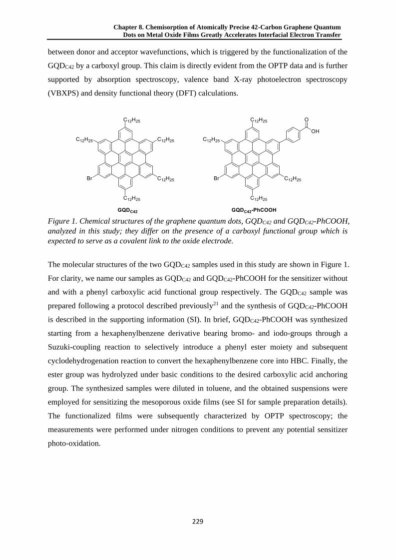
Chapter 8. Chemisorption of Atomically Precise 42-Carbon Graphene Quantum
Dots on Metal Oxide Films Greatly Accelerates Interfacial Electron Transfer
229
between donor and acceptor wavefunctions, which is triggered by the functionalization of the
GQDC42 by a carboxyl group. This claim is directly evident from the OPTP data and is further
supported by absorption spectroscopy, valence band X-ray photoelectron spectroscopy
(VBXPS) and density functional theory (DFT) calculations.
Figure 1. Chemical structures of the graphene quantum dots, GQDC42 and GQDC42-PhCOOH,
analyzed in this study; they differ on the presence of a carboxyl functional group which is
expected to serve as a covalent link to the oxide electrode.
The molecular structures of the two GQDC42 samples used in this study are shown in Figure 1.
For clarity, we name our samples as GQDC42 and GQDC42-PhCOOH for the sensitizer without
and with a phenyl carboxylic acid functional group respectively. The GQDC42 sample was
prepared following a protocol described previously21 and the synthesis of GQDC42-PhCOOH
is described in the supporting information (SI). In brief, GQDC42-PhCOOH was synthesized
starting from a hexaphenylbenzene derivative bearing bromo- and iodo-groups through a
Suzuki-coupling reaction to selectively introduce a phenyl ester moiety and subsequent
cyclodehydrogenation reaction to convert the hexaphenylbenzene core into HBC. Finally, the
ester group was hydrolyzed under basic conditions to the desired carboxylic acid anchoring
group. The synthesized samples were diluted in toluene, and the obtained suspensions were
employed for sensitizing the mesoporous oxide films (see SI for sample preparation details).
The functionalized films were subsequently characterized by OPTP spectroscopy; the
measurements were performed under nitrogen conditions to prevent any potential sensitizer
photo-oxidation.
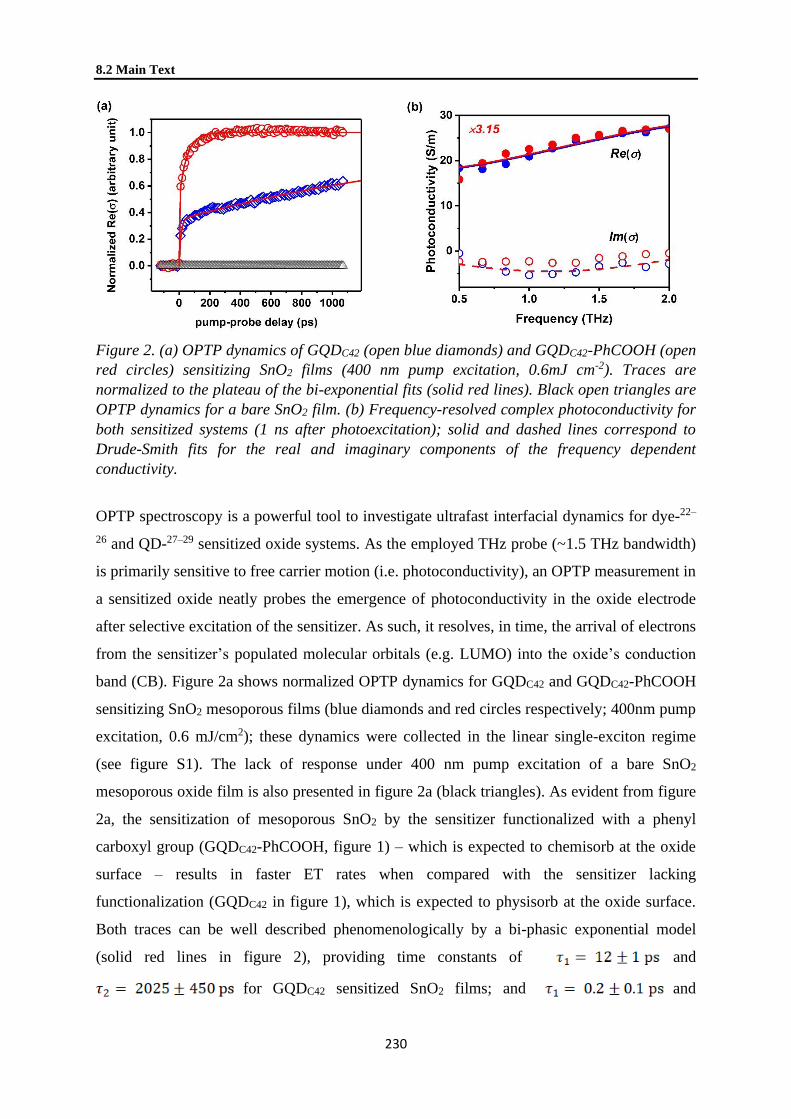
8.2 Main Text
230
Figure 2. (a) OPTP dynamics of GQDC42 (open blue diamonds) and GQDC42-PhCOOH (open
red circles) sensitizing SnO2 films (400 nm pump excitation, 0.6mJ cm-2). Traces are
normalized to the plateau of the bi-exponential fits (solid red lines). Black open triangles are
OPTP dynamics for a bare SnO2 film. (b) Frequency-resolved complex photoconductivity for
both sensitized systems (1 ns after photoexcitation); solid and dashed lines correspond to
Drude-Smith fits for the real and imaginary components of the frequency dependent
conductivity.
OPTP spectroscopy is a powerful tool to investigate ultrafast interfacial dynamics for dye-22–
26 and QD-27–29 sensitized oxide systems. As the employed THz probe (~1.5 THz bandwidth)
is primarily sensitive to free carrier motion (i.e. photoconductivity), an OPTP measurement in
a sensitized oxide neatly probes the emergence of photoconductivity in the oxide electrode
after selective excitation of the sensitizer. As such, it resolves, in time, the arrival of electrons
from the sensitizer’s populated molecular orbitals (e.g. LUMO) into the oxide’s conduction
band (CB). Figure 2a shows normalized OPTP dynamics for GQDC42 and GQDC42-PhCOOH
sensitizing SnO2 mesoporous films (blue diamonds and red circles respectively; 400nm pump
excitation, 0.6 mJ/cm2); these dynamics were collected in the linear single-exciton regime
(see figure S1). The lack of response under 400 nm pump excitation of a bare SnO2
mesoporous oxide film is also presented in figure 2a (black triangles). As evident from figure
2a, the sensitization of mesoporous SnO2 by the sensitizer functionalized with a phenyl
carboxyl group (GQDC42-PhCOOH, figure 1) – which is expected to chemisorb at the oxide
surface – results in faster ET rates when compared with the sensitizer lacking
functionalization (GQDC42 in figure 1), which is expected to physisorb at the oxide surface.
Both traces can be well described phenomenologically by a bi-phasic exponential model
(solid red lines in figure 2), providing time constants of and
for GQDC42 sensitized SnO2 films; and and

Chapter 8. Chemisorption of Atomically Precise 42-Carbon Graphene Quantum
Dots on Metal Oxide Films Greatly Accelerates Interfacial Electron Transfer
231
for GQDC42-PhCOOH sensitized SnO2 films. Biphasic ET dynamics are a
common observable for dye- and QD- sensitized oxide systems that have been generally
explained in terms of two distinct transfer channels towards the oxide electrode. They might
be linked with “hot” and “cold” ET channels30,31, or, alternatively, to “cold” ET channels
induced by two donor-acceptor interfacial conformations (i.e., providing distinct donor-
acceptor energetics)32. Biphasic dynamics have been also rationalized by considering effects
induced by molecules loosely attached (physisorbed) to the surface or those present in form
of the aggregates 29,33,34. Even though it is difficult to rule out any of these scenarios from the
current data, the fact that both ET components become faster when QDs are chemisorbed
onto the oxide matrix support the view that two ET channels define our interfacial dynamics.
A deeper analysis of the nature of the bi-phasic signals is underway and will be reported
elsewhere.
To validate the conclusion of faster ET rates for the chemisorbed sensitizers inferred from the
OPTP data, we analyze the frequency-resolved complex photoconductivity in the samples.
This approach can tell whether OPTP dynamics indeed refer uniquely to electrons populating
the oxide conduction band. Figure 2b presents the real and imaginary (closed and open
symbols) components of the complex conductivity for GQDC42 (blue), and GQDC42-PhCOOH
(red) sensitized oxide films (1ns after excitation, 1.5 THz bandwidth). As evident from figure
2b, the complex photoconductivity spectra for chemisorbed and physisorbed dots onto the
oxide overlap quite well, indicating that the nature of the monitored photoconductivity for
both samples is identical, as expected for electrons in SnO2. The resolved complex spectra
can be well described by the phenomenological Drude-Smith (DS) model35:
(Eq. 1)
where , , and refers to the plasma frequency, vacuum permittivity, scattering time
and localization factor respectively. Within the DS model, the measurable frequency resolved
photoconductivity can be attributed to free carriers experiencing preferential backscattering at
the boundaries of the nanocrystalline mesoporous oxide electrode22,36. The strength of the
localization is parametrized by c, which ranges between 0 (free carrier-Drude reponse) and -1
(representing full localization of charges). Best fit to the data using equation 1 for both
samples provide the same fitting parameters within error; a scattering rate of
and localization factor of . These results are in good agreement with

8.2 Main Text
232
previous values inferred for nanostructured SnO2 films37–39, and hence demonstrate that the
monitored signal in figure 2a refers uniquely to electrons populating the oxide conduction
band. These results support our conclusion that the changes in the monitored interfacial ET
rates can be traced uniquely to the presence of the phenyl carboxyl group functionalizing the
GQDC42-PhCOOH, allowing for chemisorption. Furthermore, these results reveal that
electron transport within the analyzed SnO2 electrode is unaffected by the type of
functionalization (chemisorption or physisorption).
To check the generality of our observation that ET is accelerated for chemisorbed sensitizers,
we also measured interfacial ET dynamics for both sensitizers onto mesoporous ZnO and
TiO2 films (figure S3). For ZnO samples we observed as well faster ET rates for the
chemisorbed sensitizers, analogous to the case of SnO2 based samples (figure 2). For titania,
ET occurs faster than our experimental sub-ps time resolution for both sensitizers, so we are
unable to determine changes in ET rates for this set of samples. The overall slower ET rates
observed for ZnO and SnO2 electrodes when compared to titania – generally explained in
terms of larger density of states for the latter improving donor-acceptor coupling strength—
agree qualitatively with those reported for organo-metallic dye sensitizers onto the same
electrodes40. Overall, the results support the view that the presence of a phenyl carboxyl
group facilitates ET transfer towards the electrode independently of its nature.
To rationalize our finding of faster ET for chemisorbed GQDC42, we investigate the nature of
the interaction between sensitizer donor and oxide acceptor. Figure 3 presents the relative
energy level alignments. For the SnO2 electrode, the energy positions are obtained from
ultraviolet photoelectron spectroscopy (UPS, see figure S5) and absorbance. For the two
molecules, the highest occupied molecular orbital (HOMO) and lowest unoccupied molecular
orbital (LUMO) were obtained from gas-phase DFT calculations. When the interaction of the
metal oxide with the molecules is not taken into account, upon sensitization, the slightly
larger ∆G (the energy difference between the LUMO of the sensitizer and the CB of the
electron-accepting oxide, see figure 3) for the GQDC42 lacking a carboxyl group should lead
to faster ET for the physisorbed sensitizers29. From the OPTP data shown in figure 2a, it is
clear that this is not the case, which shows that the chemical interaction between chemisorbed
GQDC42-PhCOOH and the oxide electrode affects donor-acceptor energetics (and hence
coupling strength). The frontier orbitals obtained from DFT calculations offer some insight
on this aspect. As shown in figure 3, the sensitizer expected to chemisorb to the oxide surface
(GQDC42-PhCOOH) reveals a substantial LUMO distribution on carboxyl group, which is
expected to deprotonate and bond to the oxide surface. The localization of the LUMO nearer

Chapter 8. Chemisorption of Atomically Precise 42-Carbon Graphene Quantum
Dots on Metal Oxide Films Greatly Accelerates Interfacial Electron Transfer
233
the oxide surface will provide enhanced donor-acceptor coupling strength (donor-acceptor
wavefunction overlap) when compared with the physisorbed case, in line with the OPTP data
shown in figure 2a. Faster ET rates as a function of shorter donor-acceptor orbital distances
between sensitizers and metal oxides have been demonstrated in quantum dot-oxide41 and
dye-oxide40 systems.
Figure 3. Interfacial donor-acceptor energetics derived from gas-phase DFT calculations for
GQDC42 and GQDC42-PhCOOH sensitizers and from UPS for tin oxide. Frontier orbital
distributions of HOMO and LUMO for both sensitizers are also presented. The Fermi level
for the tin oxide sample is within the oxide CB, indicating strong n-type character.
To reveal a stronger interaction between chemisorbed GQDC42 orbitals and the oxide
conduction band, we analyzed the samples by optical absorption and valence band X-ray
photoelectron spectroscopy. In figure 4a we present the UV-VIS absorbance spectrum of both
sensitized systems (solid red and blue lines for chemisorbed and physisorbed GQDC42
respectively) along with the bare oxide film (black line). Figure 4a also provides the spectra
of the toluene solution of both sensitizers (dashed red and blue lines for chemisorbed and
physisorbed GQDC42 respectively); the absorption profiles peak at 3.45 eV and 3.39 eV for
GQDC42 and GQDC42-PhCOOHs respectively. Whereas the peak absorbance for GQDC42
remains essentially identical upon sensitization, a clear blue shift is resolved for the peak
absorbance of the GQDC42-PhCOOH sensitizers after binding to the oxide electrode (dotted
and solid red lines in figure 4a). A similar blue shift in the absorbance after sensitization has
been previously reported for dye-sensitized films and explained in terms of the strong
coupling induced by deprotonation of the dyes42–45 induced by chemisorption; in good
agreement with our expectations.

8.2 Main Text
234
Figure 4. (a) UV-VIS absorbance spectrum of GQDC42 (blue) and GQDC42-PhCOOH (red)
sensitized SnO2 films and for sensitizers dispersed in solution (dashed lines). The spectrum of
bare SnO2 film is also shown (solid black line). (b) Valence band X-ray spectra of GQDC42
(blue) and GQDC42-PhCOOH (red) sensitized and bare (black) SnO2 electrodes. The dashed
lines are linear fits enabling binding energy estimates for the analyzed systems.
In figure 4b we present VBXPS data for a bare SnO2 mesoporous film (solid black line) and
oxide electrodes functionalized by GQDC42-PhCOOH and GQDC42 sensitizers (red and blue
line respectively). As evident from the plot, the physisorbed GQDC42 sensitized and the bare
tin oxide electrodes reveal identical electron binding energies. However, the electron binding
energy is reduced by approximately 2 eV upon chemisorption of GQDC42-PhCOOHs,
indicating significant/efficient modification/decoration of the surface of the oxide, which was
absent upon the physisorption (the results were reproducible within ~50 meV for samples
produced in three different batches). The observed change in electron binding energy can be
explained by chemical modification at the oxide interface (e.g. deprotonation of COOH
groups able to modify the Fermi energy at the oxide) and/or by dipolar effects (modifying
vacuum levels induced by the presence of a surface electric field induced by sensitization)46.
In any case, it reveals a strong donor-acceptor interaction for the chemisorbed GQDC42, in
qualitative agreement with absorbance spectra shown in figure 4a and the expected closer
proximity of frontier orbitals inferred by DFT calculation (figure 3). All these results support
qualitatively the experimentally resolved effect on interfacial OPTP dynamics, i.e. the main
conclusion of this work: chemisorption of GQDC42, enabled by their functionalization with a
carboxyl group, substantially enhances ET rates.
In summary, we investigated the rates of electron transfer from physisorbed and chemisorbed
GQD sensitizers to metal oxides, using HBC derivatives as atomically precise GQDs. An
increase of ET rates as large as two orders of magnitude is observed for chemisorbed

Chapter 8. Chemisorption of Atomically Precise 42-Carbon Graphene Quantum
Dots on Metal Oxide Films Greatly Accelerates Interfacial Electron Transfer
235
sensitizers when compared with physisorbed ones. Accelerated electron transfer is correlated
with enhanced donor-acceptor coupling (i.e., wavefunction hybridization). These results
demonstrate that functionalization of GQDs with anchoring head groups represents a
potential path for improved photoconversion efficiencies in carbon-based sensitizer/oxide
electrodes employed in solar energy conversion schemes.

236
8.3 Supporting information
Materials and methods
General methods. All reactions working with air- or moisture-sensitive compounds were
carried out under argon atmosphere using standard Schlenk line techniques. Unless otherwise
noted, all starting materials and reagents were purchased from commercial sources (such as
Alfa Aesar, Sigma-Aldrich, Acros and TCI) and used without further purification. Thin layer
chromatography (TLC) was performed on silica gel coated aluminum sheets with F254
indicator and silica gel column chromatography separation was performed with the 0.063–
0.200 mm particle size. NMR spectra were recorded in deuterated solvents using Bruker
AVANCE III 500 and Bruker AVANCE III 700 MHz NMR spectrometers. Chemical shifts
(δ) were expressed in ppm relative to the residual of solvent (CD2Cl2 @ 5.32 ppm for 1H
NMR, 54.00 ppm for 13C NMR, C2D2Cl4 @ 6.00 ppm for 1H NMR, 73.78 ppm for 13C
NMR). Coupling constants (J) were recorded in Hertz (Hz) with multiplicities explained by
the following abbreviations: s = singlet, d = doublet, t = triplet, q =quartet, dd = double of
doublets, dt = doublet of triplets, m = multiplet, br = broad. The micro-FT-IR spectra were
recorded through a diamond anvil cell (transmission mode) with a Nicolet Nexus FT-IR
spectrometer coupled with a Thermo Electron Continuμm IR microscope. The wavenumber
(ν) is expressed in cm-1. UV–vis absorption spectra were measured on a Perkin-Elmer
Lambda 900 spectrophotometer at room temperature. High-resolution mass spectra (HRMS)
were recorded by matrix-assisted laser decomposition/ionization (MALDI) using 7,7,8,8-
tetracyanoquinodimethane (TCNQ) as matrix on a Bruker Reflex II-TOF spectrometer
(MALDI-TOF HRMS).
Synthesis of ethyl 5'-(4-bromophenyl)-4-dodecyl-3',4',6'-tris(4-dodecylphenyl)-
[1,1':2',1'':4'',1'''-quaterphenyl]-4'''-carboxylic acid (2 in scheme S1). To a suspension of
4-bromo-4''-dodecyl-3',5',6'-tris(4-dodecylphenyl)-4'-(4-iodophenyl)-1,1':2',1''-terphenyl21
(0.18 g, 0.12 mmol) and 4-ethoxycarbonylphenylboronic acid (77 mg, 0.40 mmol) in toluene
(5 mL) was added a solution of K2CO3 (0.9 g, 7 mmol) in water (1 mL) and ethanol (1 mL).
This mixture was degassed by freeze-pump-thaw technique (1 cycle). Pd(PPh3)4 (15 mg,
0.013 mmol) was then added to the mixture, which was further degassed by freeze-pump-
thaw technique for another 2 cycles. The mixture was then heated at 70 °C under vigorous
stirring and monitored by TLC until the starting material was consumed (about 1 h). After
cooling to a room temperature, the mixture was diluted with diethyl ether and washed with
water and brine. The organic layer was then dried over MgSO4 and the solvent was removed
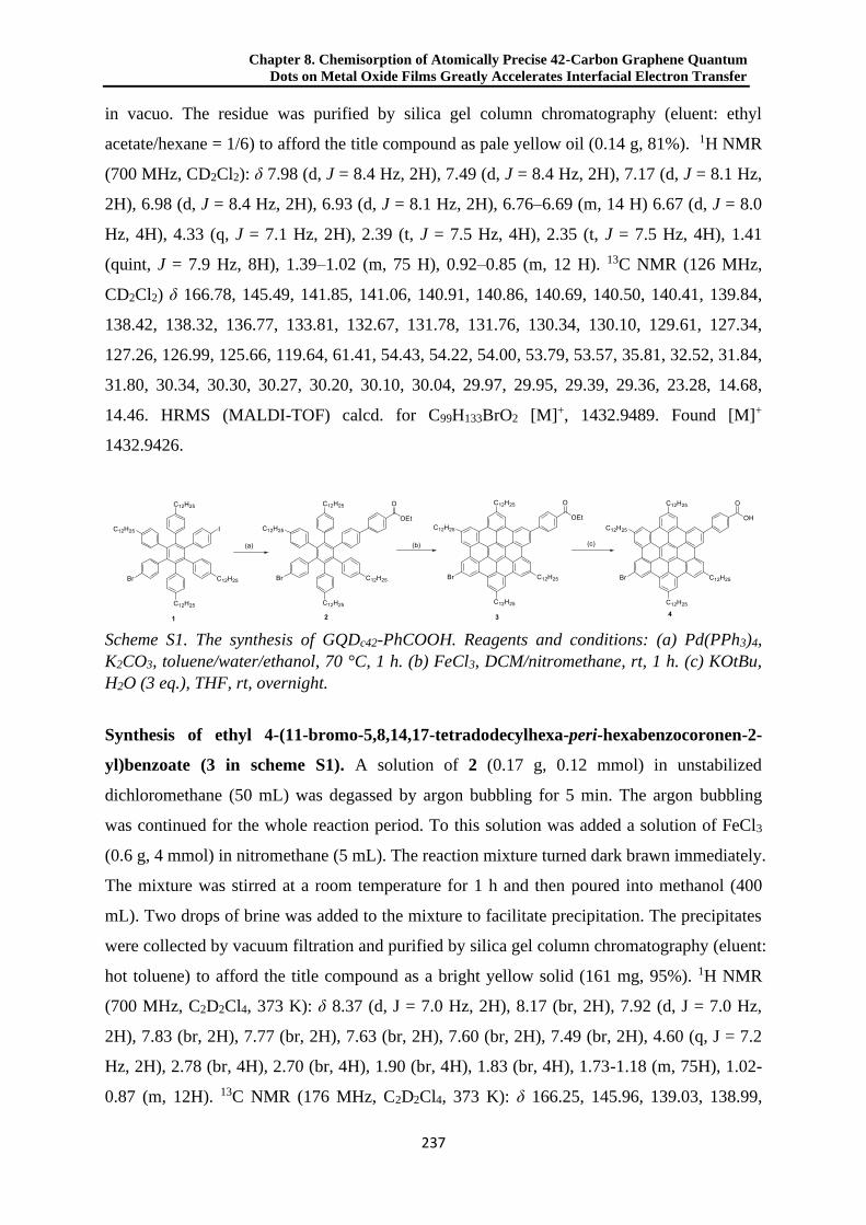
Chapter 8. Chemisorption of Atomically Precise 42-Carbon Graphene Quantum
Dots on Metal Oxide Films Greatly Accelerates Interfacial Electron Transfer
237
in vacuo. The residue was purified by silica gel column chromatography (eluent: ethyl
acetate/hexane = 1/6) to afford the title compound as pale yellow oil (0.14 g, 81%). 1H NMR
(700 MHz, CD2Cl2): δ 7.98 (d, J = 8.4 Hz, 2H), 7.49 (d, J = 8.4 Hz, 2H), 7.17 (d, J = 8.1 Hz,
2H), 6.98 (d, J = 8.4 Hz, 2H), 6.93 (d, J = 8.1 Hz, 2H), 6.76–6.69 (m, 14 H) 6.67 (d, J = 8.0
Hz, 4H), 4.33 (q, J = 7.1 Hz, 2H), 2.39 (t, J = 7.5 Hz, 4H), 2.35 (t, J = 7.5 Hz, 4H), 1.41
(quint, J = 7.9 Hz, 8H), 1.39–1.02 (m, 75 H), 0.92–0.85 (m, 12 H). 13C NMR (126 MHz,
CD2Cl2) δ 166.78, 145.49, 141.85, 141.06, 140.91, 140.86, 140.69, 140.50, 140.41, 139.84,
138.42, 138.32, 136.77, 133.81, 132.67, 131.78, 131.76, 130.34, 130.10, 129.61, 127.34,
127.26, 126.99, 125.66, 119.64, 61.41, 54.43, 54.22, 54.00, 53.79, 53.57, 35.81, 32.52, 31.84,
31.80, 30.34, 30.30, 30.27, 30.20, 30.10, 30.04, 29.97, 29.95, 29.39, 29.36, 23.28, 14.68,
14.46. HRMS (MALDI-TOF) calcd. for C99H133BrO2 [M]+, 1432.9489. Found [M]+
1432.9426.
Scheme S1. The synthesis of GQDc42-PhCOOH. Reagents and conditions: (a) Pd(PPh3)4,
K2CO3, toluene/water/ethanol, 70 °C, 1 h. (b) FeCl3, DCM/nitromethane, rt, 1 h. (c) KOtBu,
H2O (3 eq.), THF, rt, overnight.
Synthesis of ethyl 4-(11-bromo-5,8,14,17-tetradodecylhexa-peri-hexabenzocoronen-2-
yl)benzoate (3 in scheme S1). A solution of 2 (0.17 g, 0.12 mmol) in unstabilized
dichloromethane (50 mL) was degassed by argon bubbling for 5 min. The argon bubbling
was continued for the whole reaction period. To this solution was added a solution of FeCl3
(0.6 g, 4 mmol) in nitromethane (5 mL). The reaction mixture turned dark brawn immediately.
The mixture was stirred at a room temperature for 1 h and then poured into methanol (400
mL). Two drops of brine was added to the mixture to facilitate precipitation. The precipitates
were collected by vacuum filtration and purified by silica gel column chromatography (eluent:
hot toluene) to afford the title compound as a bright yellow solid (161 mg, 95%). 1H NMR
(700 MHz, C2D2Cl4, 373 K): δ 8.37 (d, J = 7.0 Hz, 2H), 8.17 (br, 2H), 7.92 (d, J = 7.0 Hz,
2H), 7.83 (br, 2H), 7.77 (br, 2H), 7.63 (br, 2H), 7.60 (br, 2H), 7.49 (br, 2H), 4.60 (q, J = 7.2
Hz, 2H), 2.78 (br, 4H), 2.70 (br, 4H), 1.90 (br, 4H), 1.83 (br, 4H), 1.73-1.18 (m, 75H), 1.02-
0.87 (m, 12H). 13C NMR (176 MHz, C2D2Cl4, 373 K): δ 166.25, 145.96, 139.03, 138.99,

8.3 Supporting information
238
135.37, 135.25, 135.21, 130.25, 130.10, 129.46, 128.97, 128.19, 128.15, 127.03, 123.01,
122.58, 121.72, 121.70, 121.53, 121.47, 120.86, 120.52, 120.25, 120.04, 118.62, 118.00,
117.60, 117.48, 117.28, 60.79, 36.77, 36.67, 31.72, 31.56, 31.46, 29.95, 29.77, 29.74, 29.66,
29.63, 29.52, 29.14, 22.41, 14.33, 13.74. IR: ν = 3063, 2952, 2917, 2849, 1719, 1609, 1576,
1466, 1271, 1104, 1021, 861, 849, 771, 721, 705. HRMS (MALDI-TOF) calcd. for
C99H121BrO2 [M]+, 1420.8550. Found [M]+ 1420.8501.
Synthesis of 4-(11-bromo-5,8,14,17- tetradodecylhexa-peri-hexabenzocoronen -2-
yl)benzoic acid (4 in scheme S1). To a solution of 3 (30 mg, 21 mol) and water (1.1 mg, 62
mol) in tetrahydrofuran (7 mL) was added a tetrahydrofuran solution of KOtBu (0.19 mL, 1
M, 190 mol) at a room temperature. The mixture was stirred overnight and poured into
methanol (50 mL). The precipitates were collected by vacuum filtration and washed with
water, methanol and acetone to afford the title compound as a brownish orange solid (29 mg,
99%). HRMS (MALDI-TOF) calcd. for C97H117BrO2 [M]+, 1392.8237. Found [M]+
1392.8180. IR: ν = 3062, 2952, 2919, 2849, 1687, 1609, 1576, 1464, 1414, 1367, 1181, 861,
849, 774, 719, 613, 553, 492. Because of the strong aggregation of 3 in solution, NMR
spectra could not be resolved.
Preparation of GQDs sensitized metal oxide films. Mesoporous metal oxide films (SnO2,
ZnO, TiO2) were prepared by doctor-blading method. After sintering at 450 °C for 2h, they
were left to cool down to 80 °C. After this, we immersed the mesoporous films in an
anhydrous toluene solution containing the GQDs (1 mg/5 mL). To allow the sensitization, the
samples remained in a N2 purged glovebox overnight. The obtained sensitized films were
rinsed in Toluene and dried under N2 environment without applying any thermal treatment
during the process.
OPTP Spectroscopy. The detailed working principle of OPTP spectroscopy has been
introduced elsewhere47. A Ti:sapphire amplified laser system (Spitfire ACE by Spectra-
Physics) producing ultra-short laser pulses of ~40 fs duration at 800 nm at 1 kHz repetition
rate was used to drive our OPTP set-up. About ~ 900 mW energy is used to run the optical
pump-THz probe spectrometer setup. For the THz generation and detection, 10% of the
incoming laser beam is used (90 mW). THz radiation is generated in a phase-matched manner
by optical rectification in a ZnTe crystal (<110> orientation, 10×10×1 mm thickness,
purchased from MaTeck). The ZnTe generation crystal is pumped with a slightly focused
Chapter 8. Chemisorption of Atomically Precise 42-Carbon Graphene Quantum
Dots on Metal Oxide Films Greatly Accelerates Interfacial Electron Transfer
239
beam (~ 3 mm diameter) of 800 nm light (80 mW power, 50 fs FWHM). The THz light exits
the ZnTe generation crystal slightly divergent and is first collimated and subsequently
focused on the sample using a pair of off-axis parabolic mirrors. The transmitted THz pulses
are recollimated and focused on a second ZnTe detection crystal by another pair of parabolic
mirrors, where the instantaneous THz field strength is detected through electro-optical
sampling. In our experiment, graphene quantum dots were selectively excited by a 400nm
optical pulse which was generated by frequency doubling of the fundamental 800 nm in a
BBO crystal. Assuming thin film approximation applies and fixing the arriving time of
sampling beam at the THz peak, the magnitude of the real part of photoconductivity as a
function of pump-probe time delay (up to 1 ns for our setup) was provided. This
measurement gives information about the product of the photo-induced charge carrier density
and their average mobility. To deconvolute these two factors and interrogate the nature of
interfacial ET frequency-resolved photoconductivity needs to be measured. In this
measurement, the recorded photo-induced change in amplitude and phase of the propagating
THz pulses yield information on, respectively, the real and imaginary parts of the complex-
valued photoconductivity of the sample under study.
UPS, VBXPS, and XPS. UPS and VBXPS measurements were conducted on a Kratos Axis
UltraDLD spectrometer (Kratos, Manchester, England). In these measurements, the samples
were transported from an inert-atmosphere glovebox (<1 ppm of O2) to the vacuum system
(2×10⁻⁷ mbar) immediately after they were prepared. In UPS measurement, electrical contact
was always applied. The sample was held at a bias of –9 V with respect to the spectrometer.
Illumination at 21.2 eV is provided by the He(I) emission line from a helium discharge lamp,
and the chamber pressure increases from ~10-10 to ~10-7 mbar. Photoelectron emission was
collected at 0° from the surface normal of the samples. The spectra were taken in three
different spots to confirm the spectra reproducibility and irradiation exposure time was kept
under one minute. VBXPS spectra were collected using an Al Kα excitation source with a
photon energy of 1487 eV. Spectra were acquired in hybrid mode of the analyzer lens, using
a 0° take-off angle, which is defined as the angle between the surface normal and the axis of
the analyzer lens.
First-Principles Calculations. DFT calculations were performed using the Gaussian 09
software package.48 The geometry and energies were calculated at the B3LYP/6-311+G(d,p)
level. All alkyl chains were replaced with methyl groups for computational simplicity.

8.3 Supporting information
240
Supplementary figures
OPTP dynamics of GQDs Sensitized SnO2 in Linear Single-Exciton Regime
Figure S1. OPTP dynamics of (a) GQDs sensitized SnO2 and (b) GQDs-PhCOOH sensitized
SnO2 as a function of 400 nm pump excitation fluence. The data demonstrate that excitation
in the linear regime (i.e., the signals scale linearly with fluence, hence no change of oxide
mobility in the oxide is resolved).
Oscillations in frequency-resolved photoconductivity spectra
Figure S2. (Top figures) THz probe line shapes in the time domain for both samples. A series
of oscillations appear at time delays above 6 ps that we tentatively correlate with multiple
reflections of the pump excitation for our sample/substrate geometry (QD-oxide film/fused
silica). Fourier transformation of bare data reveals oscillations in the complex conductivity
line shape in the frequency domain (bottom panels). The oscillations can be filtered out by
shorting the time spam (from 0 to 6ps) prior Fourier transformation. Fits to the Drude-Smith
model for bare and filtered data in the frequency domain (solid and dashed lines in bottom
panel) demonstrate that the filtering protocol is barely affecting the inferred photophysical
response of the analyzed systems.

Chapter 8. Chemisorption of Atomically Precise 42-Carbon Graphene Quantum
Dots on Metal Oxide Films Greatly Accelerates Interfacial Electron Transfer
241
OPTP dynamics of GQDs Sensitized ZnO/TiO2
Figure S3. Normalized OPTP dynamics of GQDs sensitized ZnO films (a) and TiO2 films (b)
excited under the same conditions employed for sensitized SnO2 films for fig 2a in the
manuscript. Dynamics in bare ZnO and TiO2 films are also shown (black open circles).
Biphasic fits for the ZnO case provide ET time constant τ1 = 3 ps, τ2 = 42 ps for physisorbed
case and τ1 = 0.3 ps, τ2 = 13 ps for chemisorbed case respectively. The ET components for
TiO2 are faster than our setup resolution (sub 100fs).
Frequency-Resolved Photoconductivity of GQDs Sensitized ZnO/TiO2
Figure S4. Frequency-resolved complex photoconductivity (solid and open dots for the real
and imaginary components) for (a) sensitized ZnO systems and (b) TiO2 system (1ns after
excitation). Solid and dashed lines are best fits to the DS model. Best fit in mesoporous ZnO
films provides a scattering rate and localization parameter of τs = 33.6 fs and c = -0.97,
which agrees well with previous reports.49 For titania, we obtain from the DS fits τs = 64.5 fs
and c = -0.84, also in agreement with literature.50

8.3 Supporting information
242
UPS data of Mesoporous SnO2 Film
Figure S5. Ultraviolet photoelectron spectroscopy (UPS) data of three spots on the same
SnO2 film (solid lines). Two cutoffs were resolved for each spectrum: the one close to the
Fermi level representing valence band edge (VBE) of SnO2; the one far from the Fermi level
representing vacuum level in each spot. From these cutoffs, we can obtain the workfunction
of the system.
Absorption Spectrum of Mesoporous SnO2 Film
Figure S6. Absorption spectrum of bare SnO2 film. A bandgap of 3.86 eV can be inferred by
linear extrapolation.

Chapter 8. Chemisorption of Atomically Precise 42-Carbon Graphene Quantum
Dots on Metal Oxide Films Greatly Accelerates Interfacial Electron Transfer
243
NMR spectra of unreported compounds
Figure S7. 1H NMR spectrum of 2 in CD2Cl2 (700 MHz).
Figure S8. 13C NMR spectrum of 2 in CD2Cl2 (126 MHz).

8.3 Supporting information
244
Figure S9. 1H NMR spectrum of 3 in C2D2Cl4 (700 MHz, 373 K).
Figure S10. 13C NMR spectrum of 3 in C2D2Cl4 (176 MHz, 373 K).

Chapter 8. Chemisorption of Atomically Precise 42-Carbon Graphene Quantum
Dots on Metal Oxide Films Greatly Accelerates Interfacial Electron Transfer
245
3500 3000 2500 2000 1500 1000 500
1.0
0.8
0.6
0.4
0.2
0.0
inte
nsity (
a.u
.)
wavenumbers (cm-1)
3
4
1719 1687
1104
1271
Figure S11. Infrared absorption spectra of 3 and 4. The complete transformation of ester
functional group into carboxyl group is clearly demonstrated by the infrared absorption
spectral change of carbonyl functional groups, which shifts from 1719 cm-1 (benzoic ester) to
1687 cm-1 (benzoic acid).
Figure S12. HRMS (MALDI-TOF) spectrum of 4 (matrix: TCNQ).

246
8.4 References
(1) Zheng, P.; Wu, N. Fluorescence and Sensing Applications of Graphene Oxide and Graphene Quantum Dots: A
Review. Chem. - An Asian J. 2017, 12 (18), 2343–2353.
(2) Li, X.; Rui, M.; Song, J.; Shen, Z.; Zeng, H. Carbon and Graphene Quantum Dots for Optoelectronic and Energy
Devices: A Review. Adv. Funct. Mater. 2015, 25 (31), 4929–4947.
(3) Li, L.; Wu, G.; Yang, G.; Peng, J.; Zhao, J.; Zhu, J. J. Focusing on Luminescent Graphene Quantum Dots: Current
Status and Future Perspectives. Nanoscale 2013, 5 (10), 4015–4039.
(4) Zamiri, G.; Bagheri, S. Fabrication of Green Dye-Sensitized Solar Cell Based on ZnO Nanoparticles as a
Photoanode and Graphene Quantum Dots as a Photo-Sensitizer. J. Colloid Interf. Sci. 2018, 511, 318–324.
(5) Chen, L.; Guo, C. X.; Zhang, Q.; Lei, Y.; Xie, J.; Ee, S.; Guai, G.; Song, Q.; Li, C. M. Graphene Quantum-Dot-
Doped Polypyrrole Counter Electrode for High-Performance Dye-Sensitized Solar Cells. ACS Appl. Mater.
Interfaces 2013, 5 (6), 2047–2052.
(6) Dinari, M.; Momeni, M. M.; Goudarzirad, M. Dye-Sensitized Solar Cells Based on Nanocomposite of
Polyaniline/Graphene Quantum Dots. J. Mater. Sci. 2016, 51 (6), 2964–2971.
(7) Mihalache, I.; Radoi, A.; Mihaila, M.; Munteanu, C.; Marin, A.; Danila, M.; Kusko, M.; Kusko, C. Charge and
Energy Transfer Interplay in Hybrid Sensitized Solar Cells Mediated by Graphene Quantum Dots. Electrochim.
Acta 2015, 153, 306–315.
(8) Bayat, A.; Saievar-Iranizad, E. Graphene Quantum Dots Decorated Rutile TiO2 Nanoflowers for Water Splitting
Application. J. Energy Chem. 2018, 27 (1), 306–310.
(9) Rajender, G.; Kumar, J.; Giri, P. K. Interfacial Charge Transfer in Oxygen Deficient TiO2-Graphene Quantum Dot
Hybrid and Its Influence on the Enhanced Visible Light Photocatalysis. Appl. Catal. B Environ. 2018, 224, 960–972.
(10) Narita, A.; Wang, X. Y.; Feng, X.; Müllen, K. New Advances in Nanographene Chemistry. Chem. Soc. Rev. 2015,
44 (18), 6616–6643.
(11) Wu, J.; Pisula, W.; Müllen, K. Graphenes as Potential Material for Electronics. Chem. Rev. 2007, 107 (3), 718–747.
(12) Yan, X.; Li, B.; Li, L. S. Colloidal Graphene Quantum Dots with Well-Defined Structures. Acc. Chem. Res. 2013,
46 (10), 2254–2262.
(13) Yan, X.; Cui, X.; Li, L. S. Synthesis of Large, Stable Colloidal Graphene Quantum Dots with Tunable Size. J. Am.
Chem. Soc. 2010, 132 (17), 5944–5945.
(14) Rieger, R.; Müllen, K. Forever Young: Polycyclic Aromatic Hydrocarbons as Model Cases for Structural and
Optical Studies. J. Phys. Org. Chem. 2010, 23 (4), 315–325.
(15) Tan, Y. Z.; Yang, B.; Parvez, K.; Narita, A.; Osella, S.; Beljonne, D.; Feng, X.; Müllen, K. Atomically Precise Edge
Chlorination of Nanographenes and Its Application in Graphene Nanoribbons. Nat. Commun. 2013, 4 (1), 2646.
(16) Wang, X.-Y.; Narita, A.; Müllen, K. Precision Synthesis versus Bulk-Scale Fabrication of Graphenes. Nat. Rev.
Chem. 2017, 2 (1), 0100.
(17) Yan, X.; Cui, X.; Li, B.; Li, L.-S. Large, Solution-Processable Graphene Quantum Dots as Light Absorbers for
Photovoltaics. Nano Lett. 2010, 10 (5), 1869–1873.
(18) Hamilton, I. P.; Li, B.; Yan, X.; Li, L. S. Alignment of Colloidal Graphene Quantum Dots on Polar Surfaces. Nano
Lett. 2011, 11 (4), 1524–1529.
(19) Seyed-Talebi, S. M.; Beheshtian, J.; Neek-Amal, M. Doping Effect on the Adsorption of NH3 Molecule onto
Graphene Quantum Dot: From the Physisorption to the Chemisorption. J. Appl. Phys. 2013, 114 (12), 124307.
(20) Long, R. Understanding the Electronic Structures of Graphene Quantum Dot Physisorption and Chemisorption onto
the TiO2 (110) Surface: A First-Principles Calculation. ChemPhysChem 2013, 14 (3), 579–582.
(21) Ito, S.; Wehmeier, M.; Brand, J. D.; Kübel, C.; Epsch, R.; Rabe, J. P.; Müllen, K. Synthesis and Self-Assembly of
Functionalized Hexa-Peri-Hexabenzocoronenes. Chem. - A Eur. J. 2000, 6 (23), 4327–4342.
Chapter 8. Chemisorption of Atomically Precise 42-Carbon Graphene Quantum
Dots on Metal Oxide Films Greatly Accelerates Interfacial Electron Transfer
247
(22) Turner, G. M.; Beard, M. C.; Schmuttenmaer, C. A. Carrier Localization and Cooling in Dye-Sensitized
Nanocrystalline Titanium Dioxide. J. Phys. Chem. B 2002, 106 (45), 11716–11719.
(23) Tiwana, P.; Docampo, P.; Johnston, M. B.; Snaith, H. J.; Herz, L. M. Electron Mobility and Injection Dynamics in
Mesoporous ZnO, SnO 2, and TiO2 Films Used in Dye-Sensitized Solar Cells. ACS Nano 2011, 5 (6), 5158–5166.
(24) Karakus, M.; Zhang, W.; Räder, H. J.; Bonn, M.; Cánovas, E. Electron Transfer from Bi-Isonicotinic Acid Emerges
upon Photodegradation of N3-Sensitized TiO2 Electrodes. ACS Appl. Mater. Interfaces 2017, 9 (40), 35376–35382.
(25) Tiwana, P.; Parkinson, P.; Johnston, M. B.; Snaith, H. J.; Herz, L. M. Ultrafast Terahertz Conductivity Dynamics in
Mesoporous TiO2: Influence of Dye Sensitization and Surface Treatment in Solid-State Dye-Sensitized Solar Cells.
J. Phys. Chem. C 2010, 114 (2), 1365–1371.
(26) Brauer, J. C.; Moser, J.-E. Transient Photoconductivity of Dye-Sensitized TiO2 Nanocrystalline Films Probed by
Optical Pump-THz Probe Spectroscopy. Ultrafast Phenom. 2011, 358–360.
(27) Wang, H.; Barceló, I.; Lana-Villarreal, T.; Gómez, R.; Bonn, M.; Cánovas, E. Interplay between Structure,
Stoichiometry, and Electron Transfer Dynamics in SILAR-Based Quantum Dot-Sensitized Oxides. Nano Lett. 2014,
14 (10), 5780–5786.
(28) Zhao, K.; Pan, Z.; Mora-Seró, I.; Cánovas, E.; Wang, H.; Song, Y.; Gong, X.; Wang, J.; Bonn, M.; Bisquert, J.; et al.
Boosting Power Conversion Efficiencies of Quantum-Dot-Sensitized Solar Cells beyond 8% by Recombination
Control. J. Am. Chem. Soc. 2015, 137 (16), 5602–5609.
(29) Cánovas, E.; Moll, P.; Jensen, S. A.; Gao, Y.; Houtepen, A. J.; Siebbeles, L. D. A.; Kinge, S.; Bonn, M. Size-
Dependent Electron Transfer from PbSe Quantum Dots to SnO 2 Monitored by Picosecond Terahertz Spectroscopy.
Nano Lett. 2011, 11 (12), 5234–5239.
(30) Wang, H. I.; Infante, I.; Brinck, S. Ten; Cánovas, E.; Bonn, M. Efficient Hot Electron Transfer in Quantum Dot-
Sensitized Mesoporous Oxides at Room Temperature. Nano Lett. 2018, 18 (8), 5111–5115.
(31) Benkö, G.; Kallioinen, J.; Korppi-Tommola, J. E. I.; Yartsev, A. P.; Sundström, V. Photoinduced Ultrafast Dye-to-
Semiconductor Electron Injection from Nonthermalized and Thermalized Donor States. J. Am. Chem. Soc. 2002,
124 (3), 489–493.
(32) Furube, A.; Katoh, R.; Yoshihara, T.; Hara, K.; Murata, S.; Arakawa, H.; Tachiya, M. Ultrafast Direct and Indirect
Electron-Injection Processes in a Photoexcited Dye-Sensitized Nanocrystalline Zinc Oxide Film: The Importance of
Exciplex Intermediates at the Surface. J. Phys. Chem. B 2004, 108 (33), 12583–12592.
(33) Wenger, B.; Grätzel, M.; Moser, J. E. Rationale for Kinetic Heterogeneity of Ultrafast Light-Induced Electron
Transfer from Ru(II) Complex Sensitizers to Nanocrystalline TiO2. J. Am. Chem. Soc. 2005, 127 (35), 12150–
12151.
(34) Cánovas, E.; Wang, H.; Karakus, M.; Bonn, M. Hot Electron Transfer from PbSe Quantum Dots Molecularly
Bridged to Mesoporous Tin and Titanium Oxide Films. Chem. Phys. 2016, 471, 54–58.
(35) Smith, N. V. Classical Generalization of the Drude Formula for the Optical Conductivity. Phys. Rev. B - Condens.
Matter Mater. Phys. 2001, 64 (15), 155106.
(36) Ulbricht, R.; Hendry, E.; Shan, J.; Heinz, T. F.; Bonn, M. Carrier Dynamics in Semiconductors Studied with Time-
Resolved Terahertz Spectroscopy. Rev. Mod. Phys. 2011, 83 (2), 543–586.
(37) Tsokkou, D.; Othonos, A.; Zervos, M. Carrier Dynamics and Conductivity of SnO 2 Nanowires Investigated by
Time-Resolved Terahertz Spectroscopy. Appl. Phys. Lett. 2012, 100 (13), 133101.
(38) Regan, K. P.; Swierk, J. R.; Neu, J.; Schmuttenmaer, C. A. Frequency-Dependent Terahertz Transient
Photoconductivity of Mesoporous SnO2 Films. J. Phys. Chem. C 2017, 121 (29), 15949–15956.
(39) Zou, X.; Luo, J.; Lee, D.; Cheng, C.; Springer, D.; Nair, S. K.; Cheong, S. A.; Fan, H. J.; Chia, E. E. M.
Temperature-Dependent Terahertz Conductivity of Tin Oxide Nanowire Films. J. Phys. D. Appl. Phys. 2012, 45
(46), 465101.
(40) Asbury, J. B.; Hao, E.; Wang, Y.; Ghosh, H. N.; Lian, T. Ultrafast Electron Transfer Dynamics from Molecular

8.4 References
248
Adsorbates to Semiconductor Nanocrystalline Thin Films. J. Phys. Chem. B 2001, 105 (20), 4545–4557.
(41) Wang, H.; McNellis, E. R.; Kinge, S.; Bonn, M.; Cánovas, E. Tuning Electron Transfer Rates through Molecular
Bridges in Quantum Dot Sensitized Oxides. Nano Lett. 2013, 13 (11), 5311–5315.
(42) Hagberg, D. P.; Edvinsson, T.; Marinado, T.; Boschloo, G.; Hagfeldt, A.; Sun, L. A Novel Organic Chromophore
for Dye-Sensitized Nanostructured Solar Cells. Chem. Commun. 2006, No. 21, 2245–2247.
(43) Wang, Z. S.; Sugihara, H. N3-Sensitized TiO2 Films: In Situ Proton Exchange toward Open-Circuit Photovoltage
Enhancement. Langmuir 2006, 22 (23), 9718–9722.
(44) Lin, L. Y.; Tsai, C. H.; Wong, K. T.; Huang, T. W.; Hsieh, L.; Liu, S. H.; Lin, H. W.; Wu, C. C.; Chou, S. H.; Chen,
S. H.; et al. Organic Dyes Containing Coplanar Diphenyl-Substituted Dithienosilole Core for Efficient Dye-
Sensitized Solar Cells. J. Org. Chem. 2010, 75 (14), 4778–4785.
(45) Nazeeruddin, M. K.; Humphry-Baker, R.; Liska, P.; Grätzel, M. Investigation of Sensitizer Adsorption and the
Influence of Protons on Current and Voltage of a Dye-Sensitized Nanocrystalline TiO2 Solar Cell. J. Phys. Chem. B
2003, 107 (34), 8981–8987.
(46) Cahen, D.; Kahn, A. Electron Energetics at Surfaces and Interfaces: Concepts and Experiments. Adv. Mater. 2003,
15 (4), 271–277.
(47) Wang, H. I.; Lu, H.; Nagata, Y.; Bonn, M.; Cánovas, E. Dipolar Molecular Capping in Quantum Dot-Sensitized
Oxides: Fermi Level Pinning Precludes Tuning Donor-Acceptor Energetics. ACS Nano 2017, 11 (5), 4760–4767.
(48) Frisch, M. J.; Trucks, G. W.; Schlegel, H. B.; Scuseria, G. E.; Robb, M. A.; Cheeseman, J. R.; Scalmani, G.; Barone,
V.; Mennucci, B.; Petersson, G. A.; et al. Gaussian 09, Revision D.01. Gaussian, Inc.: Wallingford CT 2013.
(49) Baxter, J. B.; Schmuttenmaer, C. A. Conductivity of ZnO Nanowires, Nanoparticles, and Thin Films Using Time-
Resolved Terahertz Spectroscopy. J. Phys. Chem. B 2006, 110 (50), 25229–25239.
(50) Turner, G. M.; Beard, M. C.; Schmuttenmaer, C. A. Carrier Localization and Cooling in Dye-Sensitized
Nanocrystalline Titanium Dioxide. J. Phys. Chem. B 2002, 106 (45), 11716–11719.

249
Chapter 9. Summary and Outlook
This thesis deals with synthesis of precursors and model nanostructures that are related to
graphene quantization and defects at GBs. It is especially intriguing for synthetic approach of
NGs and its precursor at a length scale of 5–10 nm. Thus, in Chapter 2 and Chapter 3, we
have developed synthetic protocols for PP nanostructures that expend until 5 nm length scale
in both quasi-1D and quasi-2D. Besides, constructing carbon-nanostructures with multiple
pentagon-heptagon-pair is challenging, although such nanostructures are essential for
understanding and even tailoring nanostructure at graphene GB. Therefore, in Chapter 4 and
Chapter 5, we have employed azulene in solution-based chemistry combined with on-surface
synthesis for building sp2-carbon-nanostrures that correlate to both theoretical and
experimental graphene GBs. Furthermore, nano-sized graphene behaves like molecule.
Controlling their assembly can be leveraged against several difficulties in various disciplines
of material applications. In Chapter 6–8, we attempt to control assembly of HBC in 2D as
well as 3D.
Figure 1. Schematic summary of achievements in this thesis.

250
9.1 Synthesis of large-sized Polyphenylenes
In Chapter 2, we constructed large-sized dendritic PP utilizing divergent synthetic strategies.
Such strategies relied on first synthesizing skeletons with multiple ethynyl or ethynylene
functional groups, followed by their D-A reactions with CP to introduce enormous benzene
rings. Dendritic PPs was achieved containing up to 546 carbon atoms. In parallel, in Chapter
3 we developed a stepwise D-A reaction protocol based on two different types of cyclopenta-
2,4-dien-1-one derivatives. In principle, applying this protocol, linear PPs with tailored width
can be achieved. PPs synthesized in Chapter 2 and Chapter 3 were characterized by NMR,
IR spectroscopy as well as MALDI MS and GPC, confirming the power of employing D-A
reaction between CP and ethynyl/ethynylene functional group for large-sized PPs synthesis.1
Despite the successfulness, the complete cyclodehydrogenations of large-sized PPs in
solution encountered enormous difficulties. Cyclodehydrogenations of large-sized dendritic
PPs stopped at partially planarized intermediates. Similarly, cyclodehydrogenated product of
wide linear PPs resulted in graphitic materials with large band gap. This indicated that we
would be standing at the limited-size that current in-solution synthesis could achieve.
Nevertheless, with the help of electrospray deposition, we were able to visualize dendritic
PPs on surface and monitor their thermal reaction products. Further investigation such as low
temperature nc-AFM shall be applied for unraveling the detail of the resulted nanostructures.2
In addition, modifying the syntheses could provide other precursors that would perform better
in cylcodehydrogenation reactions. Notably, dendritic PPs can be more easily purified in a
“polymeric reaction” than those for linear PPs, which have wide molecular weight
distribution. Accordingly, as shown in Scheme 1, using a stepwise synthetic strategy similar
as what we used in Chapter 4, dendritic PP with various size can derive from a HPB core and
two other building blocks, employing an additional Suzuki reaction step. Notably, these
dendritic PPs do not possess HPB sub-structures. Consequently, cease of reaction at some
partial planarized structures containing small-sized NGs would be avoided. In parallel, for the
extension of linear PPs, it would be wiser now coming back to monomer extension approach,
for an ease of purification. It has been shown that cyclodehydrogenation of poly[p-
phenylene-alt-(2,3-diphenyl-p-phenylene)] leads to 6AGNR with high quality.3 Accordingly,
a plausible two-building-blocks-synthesis shown in Scheme 2 can produce a series of CP
monomer that is suitable for polymerization into linear PP. Such PPs shall serve as attractive
precursors for lateral extended high quality GNRs.

Chapter 9. Summary and Outlook
251
Scheme 1. A “stepwise” synthesis of extended dendritic PPs.
Scheme 2. An approach for lateral extended CP monomer by stepwise synthesis of oligo[p-
phenylene-alt-(2,3-diphenyl-p-phenylene)].

252
9.2 Synthesis of Sp2-carbon-nanostructures with multiple heptagon-pentagon-pairs
In Chapter 4 we have synthesized poly(2,6-azulenylene) on Au(111) surface. Although a
dipole-moment-guided polymerization did not occur, and 2,6-azulenylenes randomly linked
on-surface, the lower-lying-energy of the CB and VB bands of the poly(2,6-azulenylene)
marked it as a unique sp2-carbon materials, in comparison with GNRs synthesized on-surface.
Despite to serve as a possible GB structure in graphene 2,6-azulenylene shall align in a head-
to-tail manner,4 it would be still interesting to grow graphene flakes starting from the
poly(2,6-azulenylene) on-surface to see whether tilt angle between resulted graphene grains
could be controlled (Scheme 3a). In addition, using azulene dimer with higher symmetry can
avoid the uncontrolled connection during on-surface polymerization, and result in a more
ordered polymer that would serve as candidate for not only constructing GB in graphene but
also lateral fusion into graphene allotropes such as Haeckelites (Scheme 3b).5 Besides,
solution-synthesis could provide orderly linked poly(2,6-azulenylene) by differentiating
functional groups on 2,6-positions, such as applying Suzuki polymerization (Scheme 3c).
Orderly linked poly(2,6-azulenylene) is interesting as a rigid nanorod with aligned dipole
moments.6
Scheme 3. Possible further works based on on-surface synthesis of poly(2,6-azulenylene).

Chapter 9. Summary and Outlook
253
In Chapter 5, we have succeeded on applying cyclodehydrogenation of poly(1,3-azulenylene)
on-surface, which was accompanied by a “methylene walk” rearrangement of azulene
skeleton that led to a unique nanostructure of fused multiple heptagon-pentagon-pairs. Such
nanostructure is highly related to those experimentally observed at graphene GB. Importantly,
so far similar nanostructure cannot be constructed using other synthetic protocols. Future
works can be focused on applying this azulene on-surface reaction for the synthesis of
ribbon-like structure, especially for analogs of 5AGNRs, with high content of heptagons and
pentagons. Notably, on-surface synthesis of 5AGNR is still challenging acquiring long
nanoribbons due to a lack of proper monomeric precursor that could polymerize into long
polymer.7 Inspired by the fact that we can achieve poly(1,3-azulenylene) on-surface with high
DP, 4,4’-dihalo-1,1’-binaphthalenyl, an isomer of 3,3’-dihalo-1,1’biazulenyl used in our
present work, can be a good candidate to polymerize on-surface into long poly(1,4-
naphthalenylene) (Scheme 4a). If the cyclodehydrogenation of poly(1,4-naphthalene) into
5AGNR worked well, several different monomers of combinations of 1,3-azulenylene and
1,4-naphthalenylene could fertilize synthesis of novel 5AGNR analogues (Scheme 4b,c).
Scheme 3. Possible further works based-on on-surface cyclodehydrogenation of 1,3-
azulenylene.

254
9.3 Stimuli responsive self-assembly of nanographenes
In Chapter 6, monitored by STM, we have demonstrated photomodulation of 2D self-
assembly patterns of two azobenzene-HBC-azobenzene triads at liquid/HOPG interface. This
is a huge step forward from our earlier work of a HBC-azobenzene dyad that did not show
such stimuli-responsive behavior.8 Besides, in Chapter 7, we have seen that both the
electronic properties as well as 3D self-assembly behavior of HBC can be fine-tuned by
conjugation with electron-withdrawing π-systems (NMI, PMI, and anthraquinone). This work
piloted our recent work on functionalization of GNR with electron withdrawing groups.9
Furthermore, in Chapter 8, employing VBXPS, we demonstrated that HBCs can physisorb or
chemisorb on mesoporous TiO2 and SnO2, where the chemisorption was enabled by a
carboxyl functional group. Applying OPTP, the much faster photoinduced ET from HBC to
metal oxide was revealed for chemisorption over physisorption.
The achievements in Chapter 6 is one of the rare demonstration of photoswitching of NGs
functionalized with photoswitches. However, the UV-Vis absorption of azobenzene is
overshadowed by that of HBC. Thus, employing azobenzene derivatives that can be switched
by longer wavelength irradiation, such as 2,2’,6,6’-tetramethoxyazobenzene, would be
necessary for future works.10 Furthermore, it can be helpful for photophysical decouple of
HBC with azobenzene to avoid through bond energy transfer or interruption of the two π-
systems. Also, employing branched or multiple alkyl side chains could lower the DLC phase
transition temperature.11 With a carful screening of different substitutions, a HBC-
azobenzene material that is photoswitchable between crystalline and DLC phase at a room
temperature could be realized (Scheme 4).
Scheme 4. Improved design of a HBC functionalized with multiple azobenzenes.

Chapter 9. Summary and Outlook
255
Organic synthesis and graphene science are seemingly unrelated fields. However,
establishing on nanoscience, the two fields can benefit on each other and even create new
research directions. Especially, organic synthesis provide model compounds for
understanding defects in graphene. Currently, synthesis of fully embedded defect structure in
sub-nano graphene lattice is still highly underdeveloped. In particular, circumazulene,
circumpentaheptafulvalene, and related structures, although not reported yet, possess
nanoenvironment that is required for a first approximation of force field surrounding
dislocation defects in graphene.12 Their synthesis shall offer a fundamental understanding of
line defects and GB in graphene. It is expected that organic synthesis in a spirit of graphene
science will continually rise and shine in the near future.

256
9.4 References
(1) Hou, I. C. Y.; Hu, Y.; Narita, A.; Müllen, K. Diels-Alder Polymerization: A Versatile Synthetic Method toward
Functional Polyphenylenes, Ladder Polymers and Graphene Nanoribbons. Polym. J. 2018, 50 (1), 3–20.
(2) Hinaut, A.; Meier, T.; Pawlak, R.; Feund, S.; Jöhr, R.; Kawai, S.; Glatzel, T.; Decurtins, S.; Müllen, K.; Narita, A.;
et al. Electrospray Deposition of Structurally Complex Molecules Revealed by Atomic Force Microscopy.
Nanoscale 2018, 10 (3), 1337–1344.
(3) Li, G.; Yoon, K.-Y.; Zhong, X.; Wang, J.; Zhang, R.; Guest, J. R.; Wen, J.; Zhu, X.-Y.; Dong, G. A Modular
Synthetic Approach for Band-Gap Engineering of Armchair Graphene Nanoribbons. Nat. Commun. 2018, 9 (1),
1687.
(4) Yazyev, O. V.; Louie, S. G. Topological Defects in Graphene: Dislocations and Grain Boundaries. Phys. Rev. B
2010, 81 (19), 195420.
(5) Fan, Q.; Martin-Jimenez, D.; Ebeling, D.; Krug, C. K.; Brechmann, L.; Kohlmeyer, C.; Hilt, G.; Hieringer, W.;
Schirmeisen, A.; Gottfried, J. M. Nanoribbons with Nonalternant Topology from Fusion of Polyazulene: Carbon
Allotropes beyond Graphene. J. Am. Chem. Soc. 2019, 141 (44), 17713–17720.
(6) Steer, R. P. Photophysics of Molecules Containing Multiples of the Azulene Carbon Framework. J. Photochem.
Photobiol. C 2019, 40, 68–80.
(7) Zhang, H.; Lin, H.; Sun, K.; Chen, L.; Zagranyarski, Y.; Aghdassi, N.; Duhm, S.; Li, Q.; Zhong, D.; Li, Y.; et al.
On-Surface Synthesis of Rylene-Type Graphene Nanoribbons. J. Am. Chem. Soc. 2015, 137 (12), 4022–4025.
(8) Ai, M.; Groeper, S.; Zhuang, W.; Dou, X.; Feng, X.; Müllen, K.; Rabe, J. P. Optical Switching Studies of an
Azobenzene Rigidly Linked to a Hexa-Peri-Hexabenzocoronene Derivative in Solution and at a Solid-Liquid
Interface. Appl. Phys. A 2008, 93 (2), 277–283.
(9) Keerthi, A.; Radha, B.; Rizzo, D.; Lu, H.; Diez Cabanes, V.; Hou, I. C. Y.; Beljonne, D.; Cornil, J.; Casiraghi, C.;
Baumgarten, M.; et al. Edge Functionalization of Structurally Defined Graphene Nanoribbons for Modulating the
Self-Assembled Structures. J. Am. Chem. Soc. 2017, 139 (46), 16454–16457.
(10) Bléger, D.; Hecht, S. Visible-Light-Activated Molecular Switches. Angew. Chem. Int. Ed. 2015, 54 (39), 11338–
11349.
(11) Pisula, W.; Feng, X.; Müllen, K. Tuning the Columnar Organization of Discotic Polycyclic Aromatic Hydrocarbons.
Adv. Mater. 2010, 22 (33), 3634–3649.
(12) Yazyev, O. V.; Chen, Y. P. Polycrystalline Graphene and Other Two-Dimensional Materials. Nat. Nanotechnol.
2014, 9 (10), 755–767.

257
Acknowledgement
Time flies. The almost-five-year PhD of mine looks so long. But in the end, it feels like
everything stops suddenly. Frankly speaking, I was not so well prepared when I first came to
Mainz. Looking back, I would say I had dived into my PhD without planning. It is followed
up with heavy work-loading and little time left for thinking. Thinking, along the time of my
thesis writing, is what I realize so important and would like to do better if I could start all-
over again. My immaturity made other people’s life more difficult. Yet I still could be
standing here at the last stage of my PhD. That is why I must acknowledge so many people
who work together with me during my PhD study. Without them, I think I would have spent
much more time.
Most importantly, I would like express my gratitude to my supervisor Prof. Klaus Müllen.
Although I could not occupy much of his precious time (and I should not), every chance we
communicate through quarterly reports or face-to-face inspire and challenge me for a higher
place. His high working efficiency and enormous knowledge is what I would like to learn
from. He also demonstrates how to be an organic chemist who is not just doing synthesis for
others, but has his own insight into material development. Working with Prof. Müllen has
really sharpened my mind and remolded me.
As importantly, I shall thank to my project leader Prof. Akimitsu Narita. Prof. Narita is
always the first person to correct my unrealistic and shabby manuscripts. We have discussed
among many research subjects and it has been always inspiring. Prof. Narita also trained me
to work in a precise and scientific way for the good of my carrier. Massive time he spent and
friendship he offered is beyond description.
I would also like to thank Prof. Xinliang Feng who recruited me at the very beginning.
Because of Prof. Feng, I can have the chance involving in “iSwitch” project, which gave me
so many advantages considering salary, training opportunities, collaborations etc. I do not
know whether I deserve them or not but could only work even harder. Also, Prof. Feng was
the landlord of my apartment. This helps me so much in a city where foreigner hardly get a
two-person apartment with a decent rent.
Furthermore, I am thankful for the company and assistance provided by AK Müllen people,
with you guys we can always have some fun along the daily hardworking. Especially,
The people who shared lab space with me. I am lucky for staying in lots of labs during my
PhD. Firstly, special thanks to Prof. Yunbin Hu, Dr. Qiang Chen, and Dr. Ulianna Beser for

258
helping me and showing me around at the beginning when I first came to Mainz; as well as
Dr. Martin Pfeffermann, Prof. Xiao-ye Wang, and Dr. Tim Dumslaff who are good
neighbours in my first lab. Secondly, thanks to Dr. Sebastian Stappert and Dr. Ruomeng
Duan who helped us moving in their lab, which is our second one. Thirdly, thanks Dr. Xuelin
Yao, Dr. Jasmin Santoro and Alicia Götz who joined us in our third lab; Dr. Enquan Jin,
Anna Baun, Dr. Zijie Qiu and Marcel Dillenburger in our fourth lab; and Dr. Xiushang Xu
and Sebastian Seitel in our fifth lab in the University. The abovementioned people established
a nice working place in the five labs and together we made great times.
I would also like to address my gratefulness to people who share office with me. Prof.
Akimitzu Narita, Dr. Bastian Dumslaff, Dr. Martin Pfeffermann, Anna baun, Dr. Enquan Jin,
Dr. Tim Dumslaff, and Dr. Qiang Chen, in the office MPIP; and Dr. Daniel Uersfeld in the
office University. We had so many great times. Also, Paniz Soltani, who passed away in an
airplane crash just one month before finishing of this thesis. I only hope you could have seen
me reaching the final stage.
In addition, I need to address my gratefulness to AK Sönnichsen in JGU. Especially Prof.
Carsten Sönnichsen, Eva Wächtersbach, Karl Wandner, Qian Du, Prof. Weixiang Ye, and
Katja Krüger, who embrace me with a nice and warm place to stay and fun things to do for
my last PhD year.
Also, I am thankful for involving in Marie Skłodowska-Curie ITN “iSwitch” that gave me a
chance to meet and learn with many talented young researchers. Thanks the coordinator Prof.
Paolo Samorì and project manager Dr. Nicolas Weibel for their dedicated works. Especially,
thanks Prof. Paolo Samorì and Dr. Agostino Galanti for providing me a nice, comfortable and
fruitful secondment at Strasbourg. Thanks Prof. Stefan Hecht, Dr. Dennis Chung-Yang
Huang, and Dr. Sebastian Fredrich for their hospitality during my secondment in Berlin. Also
thanks to all the collaborators within iSwitch projects.
Also, thanks all the people from NMR, thermal analysis, Mass analysis, and polymer analysis
departments, as well as cafeteria in MPIP. Thank you for making daily life easier. Thanks Dr.
Manfred Wagner for organizing every week football game. Thanks all the collaborators in
and out MPIP for realizing our fruitful results. Also thanks to everyone I have encountered
during this almost five years staying in Mainz.
In the end, I would like to thank my lovely wife Li-Wen Wang, the mi-gi-ga. You delight my
life with so many joys (also pains). We are so different but that is why we are interested by
each other. I wish you a happy-everyday life, and I will work the very best for that.