Industrial Automation & Motion PLCs, HMIs, Drives, Servo ...
Upload
khangminh22Category
view
0download
0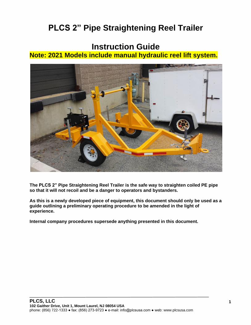
PLCS, LLC 102 Gaither Drive, Unit 1, Mount Laurel, NJ 08054 USA phone: (856) 722-1333 ● fax: (856) 273-9723 ● e-mail: [email protected] ● web: www.plcsusa.com
1
PLCS 2” Pipe Straightening Reel Trailer
Instruction Guide Note: 2021 Models include manual hydraulic reel lift system.
The PLCS 2” Pipe Straightening Reel Trailer is the safe way to straighten coiled PE pipe so that it will not recoil and be a danger to operators and bystanders. As this is a newly developed piece of equipment, this document should only be used as a guide outlining a preliminary operating procedure to be amended in the light of experience. Internal company procedures supersede anything presented in this document.
PLCS, LLC 102 Gaither Drive, Unit 1, Mount Laurel, NJ 08054 USA phone: (856) 722-1333 ● fax: (856) 273-9723 ● e-mail: [email protected] ● web: www.plcsusa.com
2
The PLCS 2” Reel Pipe Straightening Reel Trailer Transports 120” diameter reels of 2” PE pipe to the job site, then straightens and dispenses the pipe through the integrated Straightener System for easy pipe handling. An onboard clamp holds the pipe securely during the cutting operation to prevent the cut end from whipping up and harming the operator. The following equipment is supplied with each trailer:
• 2 x Rubber Wheel Chocks
• 1 x 9/16” Ratchet Combination Wrench
• 1 x 15/16” Ratchet Combination Wrench
• 1 x T-Handle Hex Wrench
Note: A PLCS Pipe and Duct Puller is recommended for the operation. Safety – Please Take Careful Note
• Reels of diameter pipe can weigh up to 1 ½ tons.
• The stored energy in coiled pipe is very high and should be handled with extreme caution.
• Reels of pipe should only be lifted by equipment with an adequate load rating and reach.
• Crew leaders must inspect all slings, straps, etc. before each use.
• The reel should be raised to the minimum height necessary for the loading process.
• Never stand underneath a raised reel.
• Survey the loading area and make sure there are no possible overhead obstructions, particularly electrical lines in the vicinity.
• Moving parts in this machine can cause severe bodily harm. All personnel must keep hands and body away from moving parts of machine. Failure to do could result in serious injury or death. Never reach into the reel area or the Straightener unit during any stage of the reel loading or pipe dispensing operation. All personnel must be made aware of the requirement to enter this area at the time.
• Wear a hard hat, safety shoes, safety glasses, and other applicable personal protective equipment. Remove jewelry and rings, and do not wear loose fitting clothing or long hair that could catch on controls or moving machinery.
• Always follow company procedures.
Cold Weather Conditions
Operation below 32° F is not recommended. There are practical limits to pulling pipe in cold weather. The pipe is very stiff and it takes much more energy to impart a back bend into it so that it can be straightened sufficiently. Please follow the pipe manufacturer guidelines for working in cold weather conditions.
PLCS, LLC 102 Gaither Drive, Unit 1, Mount Laurel, NJ 08054 USA phone: (856) 722-1333 ● fax: (856) 273-9723 ● e-mail: [email protected] ● web: www.plcsusa.com
3
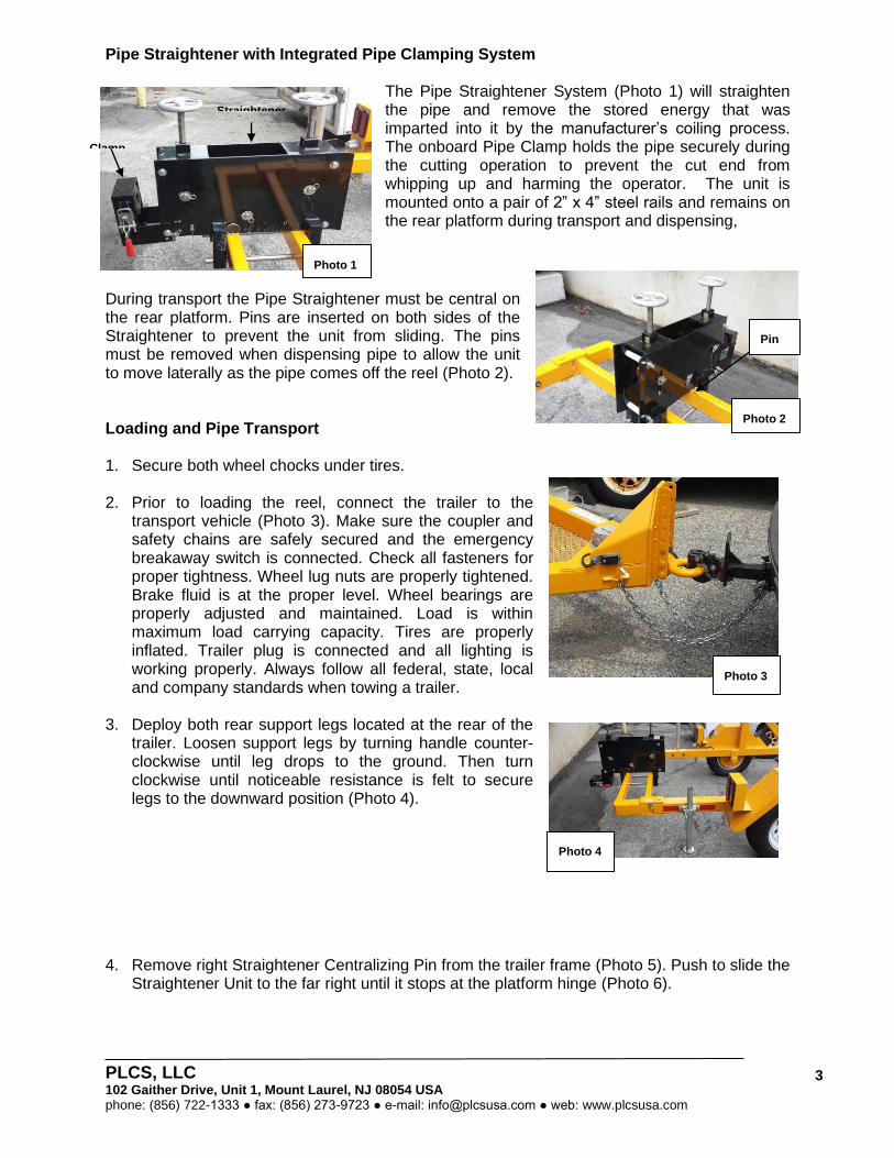
Pipe Straightener with Integrated Pipe Clamping System
The Pipe Straightener System (Photo 1) will straighten the pipe and remove the stored energy that was imparted into it by the manufacturer’s coiling process. The onboard Pipe Clamp holds the pipe securely during the cutting operation to prevent the cut end from whipping up and harming the operator. The unit is mounted onto a pair of 2” x 4” steel rails and remains on the rear platform during transport and dispensing,
During transport the Pipe Straightener must be central on the rear platform. Pins are inserted on both sides of the Straightener to prevent the unit from sliding. The pins must be removed when dispensing pipe to allow the unit to move laterally as the pipe comes off the reel (Photo 2). Loading and Pipe Transport 1. Secure both wheel chocks under tires.
2. Prior to loading the reel, connect the trailer to the
transport vehicle (Photo 3). Make sure the coupler and safety chains are safely secured and the emergency breakaway switch is connected. Check all fasteners for proper tightness. Wheel lug nuts are properly tightened. Brake fluid is at the proper level. Wheel bearings are properly adjusted and maintained. Load is within maximum load carrying capacity. Tires are properly inflated. Trailer plug is connected and all lighting is working properly. Always follow all federal, state, local and company standards when towing a trailer.
3. Deploy both rear support legs located at the rear of the trailer. Loosen support legs by turning handle counter-clockwise until leg drops to the ground. Then turn clockwise until noticeable resistance is felt to secure legs to the downward position (Photo 4).
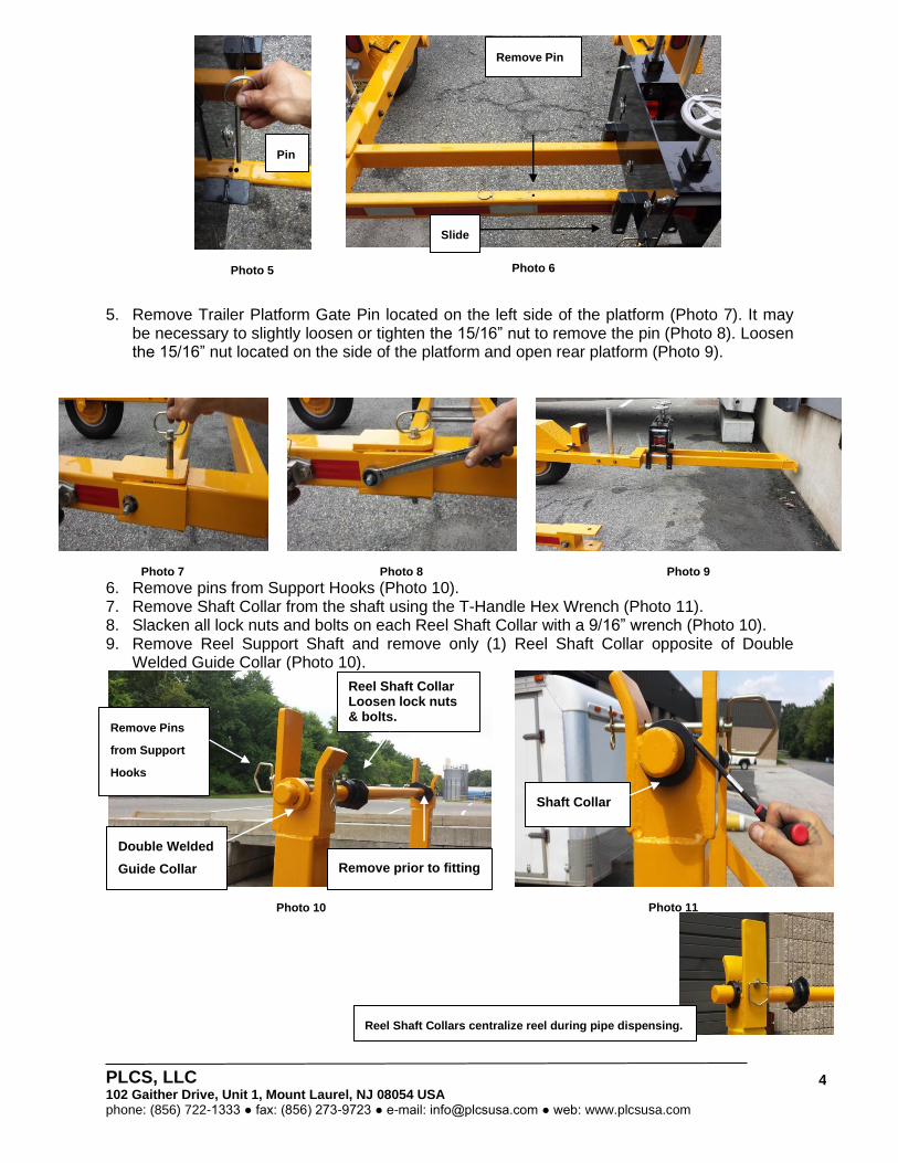
4. Remove right Straightener Centralizing Pin from the trailer frame (Photo 5). Push to slide the Straightener Unit to the far right until it stops at the platform hinge (Photo 6).
Photo 1
Photo 2
Pin
Clamp
Straightener
Photo 3
Photo 4
PLCS, LLC 102 Gaither Drive, Unit 1, Mount Laurel, NJ 08054 USA phone: (856) 722-1333 ● fax: (856) 273-9723 ● e-mail: [email protected] ● web: www.plcsusa.com
4
5. Remove Trailer Platform Gate Pin located on the left side of the platform (Photo 7). It may be necessary to slightly loosen or tighten the 15/16” nut to remove the pin (Photo 8). Loosen the 15/16” nut located on the side of the platform and open rear platform (Photo 9).
Photo 7
Photo 8
Photo 9 6. Remove pins from Support Hooks (Photo 10). 7. Remove Shaft Collar from the shaft using the T-Handle Hex Wrench (Photo 11). 8. Slacken all lock nuts and bolts on each Reel Shaft Collar with a 9/16” wrench (Photo 10). 9. Remove Reel Support Shaft and remove only (1) Reel Shaft Collar opposite of Double
Welded Guide Collar (Photo 10).
Photo 10
Photo 11
Photo 5
Photo 6
Remove Pins
from Support
Hooks
Double Welded
Guide Collar
Reel Shaft Collar Loosen lock nuts & bolts.
Remove prior to fitting
shaft onto reel.
Shaft Collar
Pin
Slide
Reel Shaft Collars centralize reel during pipe dispensing.
Remove Pin
PLCS, LLC 102 Gaither Drive, Unit 1, Mount Laurel, NJ 08054 USA phone: (856) 722-1333 ● fax: (856) 273-9723 ● e-mail: [email protected] ● web: www.plcsusa.com
5
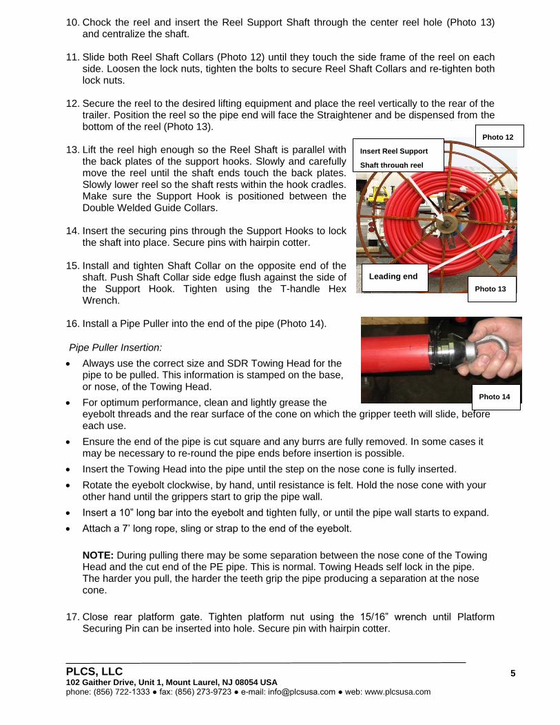
10. Chock the reel and insert the Reel Support Shaft through the center reel hole (Photo 13) and centralize the shaft.
11. Slide both Reel Shaft Collars (Photo 12) until they touch the side frame of the reel on each side. Loosen the lock nuts, tighten the bolts to secure Reel Shaft Collars and re-tighten both lock nuts.
12. Secure the reel to the desired lifting equipment and place the reel vertically to the rear of the trailer. Position the reel so the pipe end will face the Straightener and be dispensed from the bottom of the reel (Photo 13).
13. Lift the reel high enough so the Reel Shaft is parallel with the back plates of the support hooks. Slowly and carefully move the reel until the shaft ends touch the back plates. Slowly lower reel so the shaft rests within the hook cradles. Make sure the Support Hook is positioned between the Double Welded Guide Collars.
14. Insert the securing pins through the Support Hooks to lock the shaft into place. Secure pins with hairpin cotter.
15. Install and tighten Shaft Collar on the opposite end of the shaft. Push Shaft Collar side edge flush against the side of the Support Hook. Tighten using the T-handle Hex Wrench.
16. Install a Pipe Puller into the end of the pipe (Photo 14). Pipe Puller Insertion:
• Always use the correct size and SDR Towing Head for the pipe to be pulled. This information is stamped on the base, or nose, of the Towing Head.
• For optimum performance, clean and lightly grease the eyebolt threads and the rear surface of the cone on which the gripper teeth will slide, before each use.
• Ensure the end of the pipe is cut square and any burrs are fully removed. In some cases it may be necessary to re-round the pipe ends before insertion is possible.
• Insert the Towing Head into the pipe until the step on the nose cone is fully inserted.
• Rotate the eyebolt clockwise, by hand, until resistance is felt. Hold the nose cone with your other hand until the grippers start to grip the pipe wall.
• Insert a 10” long bar into the eyebolt and tighten fully, or until the pipe wall starts to expand.
• Attach a 7’ long rope, sling or strap to the end of the eyebolt.
NOTE: During pulling there may be some separation between the nose cone of the Towing Head and the cut end of the PE pipe. This is normal. Towing Heads self lock in the pipe. The harder you pull, the harder the teeth grip the pipe producing a separation at the nose cone.
17. Close rear platform gate. Tighten platform nut using the 15/16” wrench until Platform
Securing Pin can be inserted into hole. Secure pin with hairpin cotter.
Leading end
Photo 12
Insert Reel Support
Shaft through reel
hole.
Photo 13
Photo 14
PLCS, LLC 102 Gaither Drive, Unit 1, Mount Laurel, NJ 08054 USA phone: (856) 722-1333 ● fax: (856) 273-9723 ● e-mail: [email protected] ● web: www.plcsusa.com
6
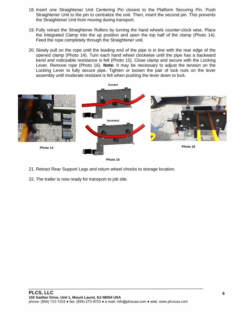
18. Insert one Straightener Unit Centering Pin closest to the Platform Securing Pin. Push Straightener Unit to the pin to centralize the unit. Then, insert the second pin. This prevents the Straightener Unit from moving during transport.
19. Fully retract the Straightener Rollers by turning the hand wheels counter-clock wise. Place the Integrated Clamp into the up position and open the top half of the clamp (Photo 14). Feed the rope completely through the Straightener unit.
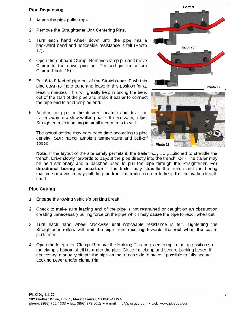
20. Slowly pull on the rope until the leading end of the pipe is in line with the rear edge of the opened clamp (Photo 14). Turn each hand wheel clockwise until the pipe has a backward bend and noticeable resistance is felt (Photo 15). Close clamp and secure with the Locking Lever. Remove rope (Photo 16). Note: It may be necessary to adjust the tension on the Locking Lever to fully secure pipe. Tighten or loosen the pair of lock nuts on the lever assembly until moderate resistant is felt when pushing the lever down to lock.
Photo 14
Photo 15
Photo 16
21. Retract Rear Support Legs and return wheel chocks to storage location.
22. The trailer is now ready for transport to job site.
Locking Lever
PLCS, LLC 102 Gaither Drive, Unit 1, Mount Laurel, NJ 08054 USA phone: (856) 722-1333 ● fax: (856) 273-9723 ● e-mail: [email protected] ● web: www.plcsusa.com
7
Pipe Dispensing 1. Attach the pipe puller rope.
2. Remove the Straightener Unit Centering Pins.
3. Turn each hand wheel down until the pipe has a
backward bend and noticeable resistance is felt (Photo 17).
4. Open the onboard Clamp. Remove clamp pin and move Clamp to the down position. Reinsert pin to secure Clamp (Photo 18).
5. Pull 6 to 8 feet of pipe out of the Straightener. Push this pipe down to the ground and leave in this position for at
least 5 minutes. This will greatly help in taking the bend out of the start of the pipe and make it easier to connect the pipe end to another pipe end.
6. Anchor the pipe to the desired location and drive the trailer away at a slow walking pace. If necessary, adjust Straightener Unit setting in small increments to suit. The actual setting may vary each time according to pipe density, SDR rating, ambient temperature and pull-off speed. Note: If the layout of the site safely permits it, the trailer may be positioned to straddle the trench. Drive slowly forwards to payout the pipe directly into the trench. Or - The trailer may be held stationary and a backhoe used to pull the pipe through the Straightener. For directional boring or insertion - The trailer may straddle the trench and the boring machine or a winch may pull the pipe from the trailer in order to keep the excavation length short.
Pipe Cutting
1. Engage the towing vehicle’s parking break.
2. Check to make sure leading end of the pipe is not restrained or caught on an obstruction creating unnecessary pulling force on the pipe which may cause the pipe to recoil when cut.
3. Turn each hand wheel clockwise until noticeable resistance is felt. Tightening the Straightener rollers will limit the pipe from recoiling towards the reel when the cut is performed.
4. Open the Integrated Clamp. Remove the Holding Pin and place camp in the up position so the clamp’s bottom shell fits under the pipe. Close the clamp and secure Locking Lever. If necessary, manually situate the pipe on the trench side to make it possible to fully secure Locking Lever and/or clamp Pin.
Photo 17
Photo 18

PLCS, LLC 102 Gaither Drive, Unit 1, Mount Laurel, NJ 08054 USA phone: (856) 722-1333 ● fax: (856) 273-9723 ● e-mail: [email protected] ● web: www.plcsusa.com
8
5. Cut the pipe in the center between the inside edge of the onboard Clamp and the edge of the Straightener (Photo 19).
6. To remove the pipe from onboard Clamp, have one operator hold the pipe with two hands near the outside the Integrated Clamp prior and the other operator release the Clamp Locking Lever.
7. Remove Pipe Puller from the leading end of the pipe by turning the eyebolt counter-clockwise until it is loose. Do not continue to loosen or the inner end could separate and drop back into the pipe. Apply a sharp tap with a soft hammer to the end of the eyebolt. This will release the gripper teeth. Remove the Pipe Puller from the pipe. Expansion of the Pipe Puller’s gripper rings set within the pipe may cause minimal scoring. This may be removed at the discretion of the utility by cutting off a few inches from the end of the pipe.
8. Reinstall Pipe Puller onto recently cut end.
9. Slightly slacken rollers. Pull pipe leading end to onboard Clamp. Close and secure clamp. Retighten rollers.
10. Centralize Straightener Unit and insert Centralizing Pins. The trailer is now ready for transport to another location. NOTE: If the trailer will be transported without pipe, fit a small length of pipe into the Integrated Clamp and secure Locking Lever. This will help prevent the Locking Lever from possibly loosening avoiding accidental damage during transport.
Photo 19
Holding Pin Locking Lever
PLCS, LLC 102 Gaither Drive, Unit 1, Mount Laurel, NJ 08054 USA phone: (856) 722-1333 ● fax: (856) 273-9723 ● e-mail: [email protected] ● web: www.plcsusa.com
9
Pipe End Control The PLCS Straightener removes most of the energy stored in a coiled length of pipe. It is still important to carefully follow these remaining steps to ensure gradual, controlled release of any residual stored energy as the end of the coiled reel is run out.
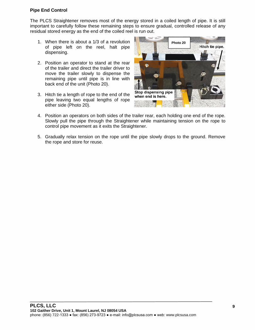
1. When there is about a 1/3 of a revolution of pipe left on the reel, halt pipe dispensing.
2. Position an operator to stand at the rear of the trailer and direct the trailer driver to move the trailer slowly to dispense the remaining pipe until pipe is in line with back end of the unit (Photo 20).
3. Hitch tie a length of rope to the end of the
pipe leaving two equal lengths of rope either side (Photo 20).
4. Position an operators on both sides of the trailer rear, each holding one end of the rope. Slowly pull the pipe through the Straightener while maintaining tension on the rope to control pipe movement as it exits the Straightener.
5. Gradually relax tension on the rope until the pipe slowly drops to the ground. Remove the rope and store for reuse.
Photo 20

PLCS, LLC 102 Gaither Drive, Unit 1, Mount Laurel, NJ 08054 USA phone: (856) 722-1333 ● fax: (856) 273-9723 ● e-mail: [email protected] ● web: www.plcsusa.com
10
2” Reel PE Conduit Pipe Trailer Specifications
Model/ Part# 73-315001
Gross Axle
Weight Rating (GAWR)
8,000 lbs.
Overall Length 156”
Overall Width 102”
Reel Capacity 120” x 60”
Empty Weight 1,700 lbs.
Tongue Weight 200 lbs.
Hitch 3” Pintle Adjustable 12,0000 lbs.
Straightener 2” HDPE / MDPE with Integrated Pipe Holding Clamp
Straightener Weight 135 lbs.
Running Gear
Axle 8,000 lbs.
Suspension Slipper Sprung Axles
Tires ST215/75R17.5 Load Range (H)
Wheels 17.5 x 6.75 8 Bolt White mod
Brakes Electric
Parking Brake 2” x 12” Backing Plate
Frame
Main Frame 4” x 6” Rectangular Tube
Reel Rack Shell 4 x 4 in. Square tube
Reel Rack Lift Support 3 1/2 x 3 1/2 in. Square tube
Reel Rack Lift 3/4 in x 5 1/2 in. flat
Spindle Bar 2 1/2” Steel
Light Boxes 4” x 6” Rectangular Tube
Fenders 12” Channel
Electrical
Plug 7 RV Molded Plug
Wiring Enclosed in conduit / junction boxes. Soldered & shrink wrapped.
Lights Standard LED DOT package
Safety
Chains Rated to match
Breakaway Battery, battery box, and switch
Decals Warning decals & reflective tape
Accessories
Wheel Chocks Rubber
Jack
One front and Two rear single 12K spring loaded drop leg jacks
Two support jacks mounted on rear frame to prevent trailer from
squatting during HDD or loading.
Paint
PPG Industrial Urethane White, Yellow
Hydraulic Lift System
Cylinders 2” x 20”
Pump Dual Manual Lever Pump—95 cu. In.
Fluid Dexron III / Mercon A.T.F.
PLCS, LLC 102 Gaither Drive, Unit 1, Mount Laurel, NJ 08054 USA phone: (856) 722-1333 ● fax: (856) 273-9723 ● e-mail: [email protected] ● web: www.plcsusa.com
11
Warranty (Valid for a period of 12 months from date of delivery)
1. PLCS Inc. warrants that the PLCS 2” Reel Trailer is manufactured entirely from new components and is free from defects in materials and workmanship.
2. The warranty covers use of the vehicle, when properly maintained and when used under
normal conditions and within its stated design capabilities, which means when loading, unloading and transporting pipe that is packaged on a standard reel that are consistent with the specifications of the vehicle.
3. The sole and exclusive remedy of the purchaser under this warranty shall be the repair
or replacement, at the option of PLCS Inc., of any part, which was furnished and installed and has failed as a result of a defect in materials or workmanship.
4. The warranty does not apply to:
a. Tires b. Parts and accessories or other items manufactured by others except for
whatever warranty is supplied by the manufacturer of those parts and accessories, which will be passed on to the purchaser by PLCS Inc.
c. Items which, while not defective, are subject to fair wear and tear.
5. Purchaser agrees by accepting delivery of the PLCS 2” Reel Trailer that PLCS Inc. has no liability for any loss of usage or consequential or incidental damaged alleged to have been caused by any defect in the trailer.
Terms
The manufacturer reserves the right to amend these specifications at any time. PLCS products are sold subject to the terms of sale of PLCS Inc. No employee of PLCS is authorized to make any change in the conditions of sale of any Company product. Any questions regarding the suitability of these products for a particular purpose should be addressed to PLCS Inc., 102 Gaither Drive, Unit 1, Mt Laurel, NJ 08054 phone 856-722-1333. Except as provided by law, no liability is accepted for any loss, damage or consequential loss arising directly or indirectly from the use of the Company's products, or from information given in its publications. No warranty is given or implied that the use of any information or any product of the Company does not infringe the proprietary rights of a third party. Prospective users shall be solely responsible for any use made of the products and/or information and should therefore satisfy themselves by appropriate trials, that the product to be used is suitable for the intended purpose and that such use will not infringe any proprietary right of a third party.
Copyright © 2022 FDOKUMEN