Planning Commission Study Session - Town of Gilbert
23
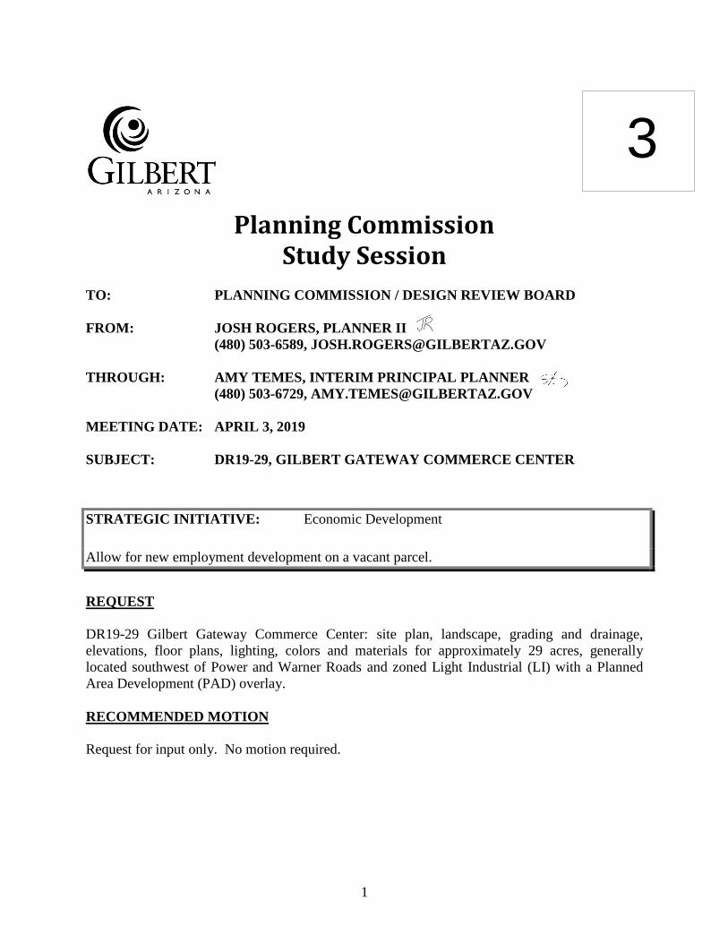
1 Planning Commission Study Session TO: PLANNING COMMISSION / DESIGN REVIEW BOARD FROM: JOSH ROGERS, PLANNER II (480) 503-6589, [email protected] THROUGH: AMY TEMES, INTERIM PRINCIPAL PLANNER (480) 503-6729, [email protected] MEETING DATE: APRIL 3, 2019 SUBJECT: DR19-29, GILBERT GATEWAY COMMERCE CENTER STRATEGIC INITIATIVE: Economic Development Allow for new employment development on a vacant parcel. REQUEST DR19-29 Gilbert Gateway Commerce Center: site plan, landscape, grading and drainage, elevations, floor plans, lighting, colors and materials for approximately 29 acres, generally located southwest of Power and Warner Roads and zoned Light Industrial (LI) with a Planned Area Development (PAD) overlay. RECOMMENDED MOTION Request for input only. No motion required. 3
-
Upload
khangminh22 -
Category
Documents
-
view
3 -
download
0
Transcript of Planning Commission Study Session - Town of Gilbert
1
Planning Commission Study Session
TO: PLANNING COMMISSION / DESIGN REVIEW BOARD
FROM: JOSH ROGERS, PLANNER II
(480) 503-6589, [email protected]
THROUGH: AMY TEMES, INTERIM PRINCIPAL PLANNER
(480) 503-6729, [email protected]
MEETING DATE: APRIL 3, 2019
SUBJECT: DR19-29, GILBERT GATEWAY COMMERCE CENTER
STRATEGIC INITIATIVE: Economic Development
Allow for new employment development on a vacant parcel.
REQUEST
DR19-29 Gilbert Gateway Commerce Center: site plan, landscape, grading and drainage,
elevations, floor plans, lighting, colors and materials for approximately 29 acres, generally
located southwest of Power and Warner Roads and zoned Light Industrial (LI) with a Planned
Area Development (PAD) overlay.
RECOMMENDED MOTION
Request for input only. No motion required.
3

2
APPLICANT/OWNER Company: Ware Malcomb Company: TC/P Gilbert Gateway LLC
Name: Eric Zitny Name: Ryan Norris
Address: 2777 E. Camelback Rd., Suite 325 Address: 2231 E. Camelback Rd., Suite 102
Phoenix, AZ 85016 Phoenix, AZ 85016
Phone: 480-800-5291 Phone: 602-285-3140
Email: [email protected] Email: [email protected]
BACKGROUND/DISCUSSION
History
Date Description
December 20, 2005 Town Council approves annexation of approx. 102 acres (Ord. No.
1872) into the Town of Gilbert.
March 6, 2007 Town Council approves the Cooley Station at Santan and Power
PAD (Z06-61, Ord. No. 1899) rezoning 74 acres of Maricopa
County R-43 (Rural Residential) to 43 acres of Town of Gilbert
Light Industrial (LI) and 31 acres of Regional Commercial (RC)
with a PAD.
March 12, 2013 Town Council approves removal and replacement of the Cooley
Station at Santan and Power PAD with the American Furniture
Warehouse PAD (Z12-27, Ord. No. 2419). Approved ordinance
changes 10 acres of existing Light Industrial (LI) to Regional
Commercial (RC) and modifies development standards for the RC
zoning district.
Overview
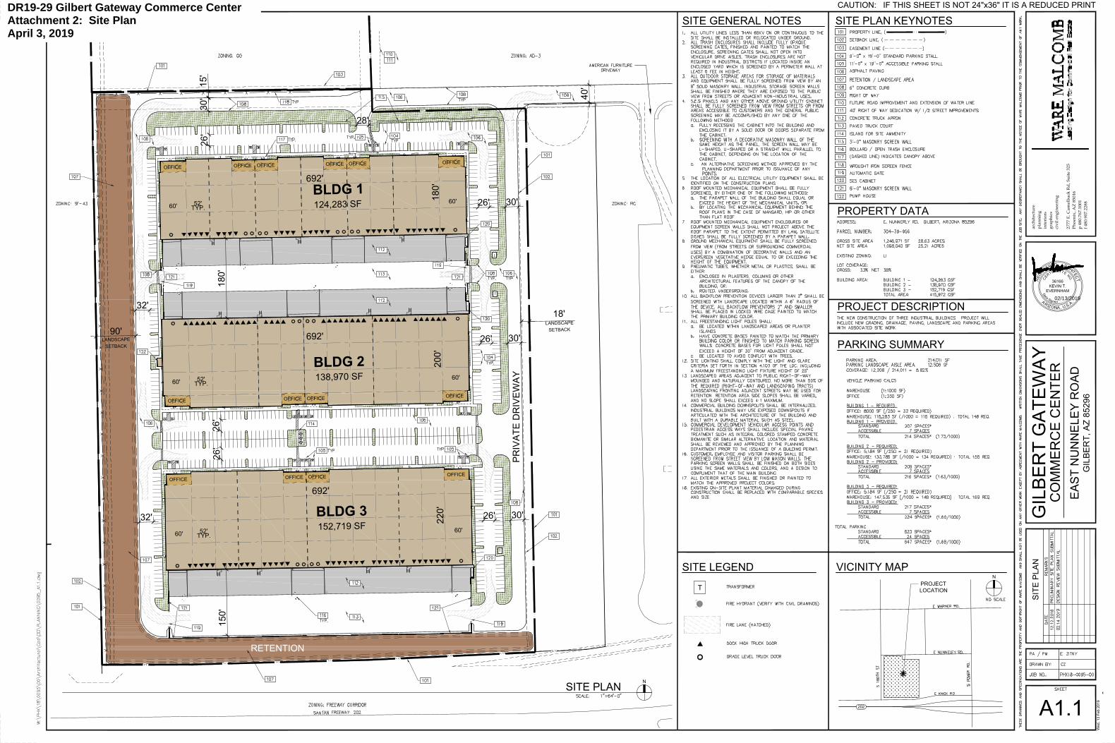
The applicant proposes to develop 3 industrial/ office buildings totaling approximately 416,000
sq. ft. for light manufacturing and warehousing uses on the approximately 29 acre site. The
subject site is located directly west of the existing American Furniture Warehouse and just north
of the Santan Freeway. The site was annexed into the Town in 2005 and was subsequently
rezoned from Maricopa County Residential to Town of Gilbert Light Industrial (LI) and
Regional Commercial (RC). The site has remained undeveloped since. The 29 acre site is
located within the Gateway Character Area.
Surrounding Land Use & Zoning Designations:
Existing Land Use
Classification
Existing Zoning Existing Use
North General Office and
Airport District III (County
Airport Light Industrial)
General Office (GO) and
Airport District III (County
Airport Light Industrial)
Undeveloped
South Public
Facility/Institutional
Public Facility
/Institutional (PF/I)
Santan Freeway
East Regional Commercial Regional Commercial
(RC) PAD
American Furniture
Warehouse

3
West Residential >0-1
DU/Acre
Single Family-43 (SF-43) Non-subdivided
residential community
Site Light Industrial Light Industrial (LI) PAD Undeveloped
Project Data Table
Site Development Regulations
Required per LDC Provided
Maximum Building Height
(ft.)/(Stories)
55’/3 47’3”/1
Minimum Building Setback (ft.)
Front 25’ 100’ – 150’
Side (Residential, West) 75’ 150’
Side (Non-residential, East) 15’ 135’
Rear (Non-residential) 15’ 210’
Separation Between Buildings
(ft.)
15’ 140’
Minimum Required Perimeter
Landscape Area (ft.)
Front 20’ 33’
Side (Residential, West) 25’ 90’
Side (Non-residential, East) 15’ 18’
Rear (Non-residential) 15’ 50’-60’
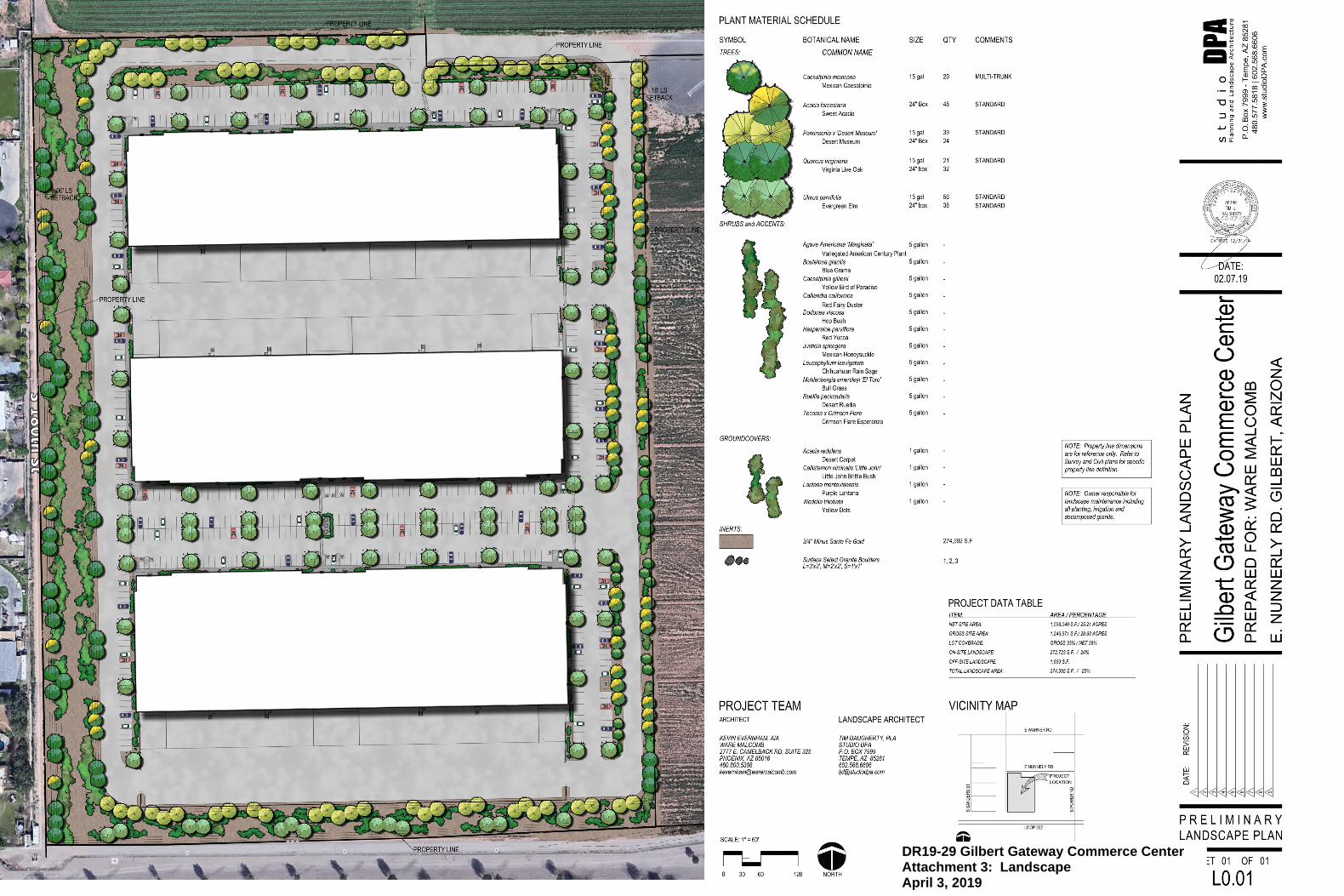
Landscaping (% of net lot area) -- 25%
Off-Street Parking and Loading 472 647 spaces
DISCUSSION
A neighborhood meeting was held in September of 2018 for a potential rezoning of the property
directly north of the subject site. During the meeting the attendees brought up concerns about
industrial development along the entire eastern boundary of their residential neighborhood
(including the subject site for this Design Review). Staff would like the Planning Commission to
be aware of the concerns the neighbors raised as it is likely they will attend the upcoming public
hearing for this case.
Neighborhood Concerns:
Noise generated by an industrial uses;
Industrial lighting illuminating;
The massing of large industrial buildings;
Loss of access to an irrigation valve;
Concerns about Nunneley Dr. extending west of Swan Dr. and connecting to their
neighborhood.
The applicant for this project was made aware of these concerns early on and took them into
account when designing the subject site.

4
The project is currently in first review and therefore additional comments, beyond what are
included in this report, may be brought forward for discussion during the study session meeting.
Site
The site development is comprised of 3 large rectangular industrial office / warehouse buildings,
oriented north/south. Vehicular access (auto and truck) is established off of Nunneley to the
north and off of a private drive to the east. Truck courts/loading docks are located between
Buildings 1 and 2 and the south of Building 3, adjacent to the freeway. The private drive on the
east side of the site will help pull the larger truck traffic away from the residential homes to the
west and relieve the ingress/egress point on Nunneley Drive.
All 3 buildings have been oriented in such a way to ensure that truck courts are either back to
back or concealed from the main avenues of approach. Truck courts will be screened from view
via an 8’ high masonry end-screen wall. Building 1 will support up to 6 tenant entries whilst
Buildings 2 and 3 will currently support up to 4 tenant entries. Trash enclosures will be within
the screened truck court areas. Trash enclosures are optional within fully screened truck
courts/loading docks.
Staff would like the Planning Commission’s input on raising the height of the truck court screen
wall as an option to eliminate trash enclosures. Staff appreciates any additional comments that
the Planning Commission would like to offer regarding the site plan.
Landscape
The proposed landscape plan includes significant on-site and off-site perimeter landscaping as
well as adequate foundation landscaping on the front and sides of all three (3) of the proposed
industrial buildings. Parking islands are located throughout the customer parking areas on the
front and side elevations. The residential area to the west side of the site will have 8’ high
masonry screen walls, in addition to ninety (90) ft. wide of landscape buffer with non-deciduous
trees and shrubs oriented in a natural, undulating pattern as well as a wrought iron decorative
fence. The total on-site landscape area (25%) exceeds with the minimum amount (15%)
required.
Staff does not have any specific request for input on the landscaping; however, any input the
Commission would like to offer would be greatly appreciated.
5
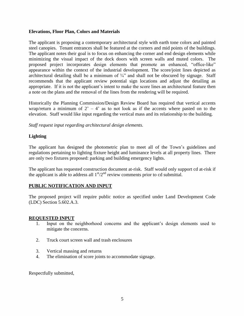
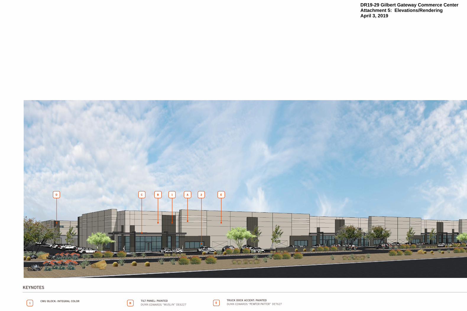
Elevations, Floor Plan, Colors and Materials
The applicant is proposing a contemporary architectural style with earth tone colors and painted
steel canopies. Tenant entrances shall be featured at the corners and mid points of the buildings.
The applicant notes their goal is to focus on enhancing the corner and end design elements while
minimizing the visual impact of the dock doors with screen walls and muted colors. The
proposed project incorporates design elements that promote an enhanced, “office-like”
appearance within the context of the industrial development. The score/joint lines depicted as
architectural detailing shall be a minimum of ¾” and shall not be obscured by signage. Staff
recommends that the applicant review potential sign locations and adjust the detailing as
appropriate. If it is not the applicant’s intent to make the score lines an architectural feature then
a note on the plans and the removal of the lines from the rendering will be required.
Historically the Planning Commission/Design Review Board has required that vertical accents
wrap/return a minimum of 2’ – 4’ as to not look as if the accents where pasted on to the
elevation. Staff would like input regarding the vertical mass and its relationship to the building.
Staff request input regarding architectural design elements.
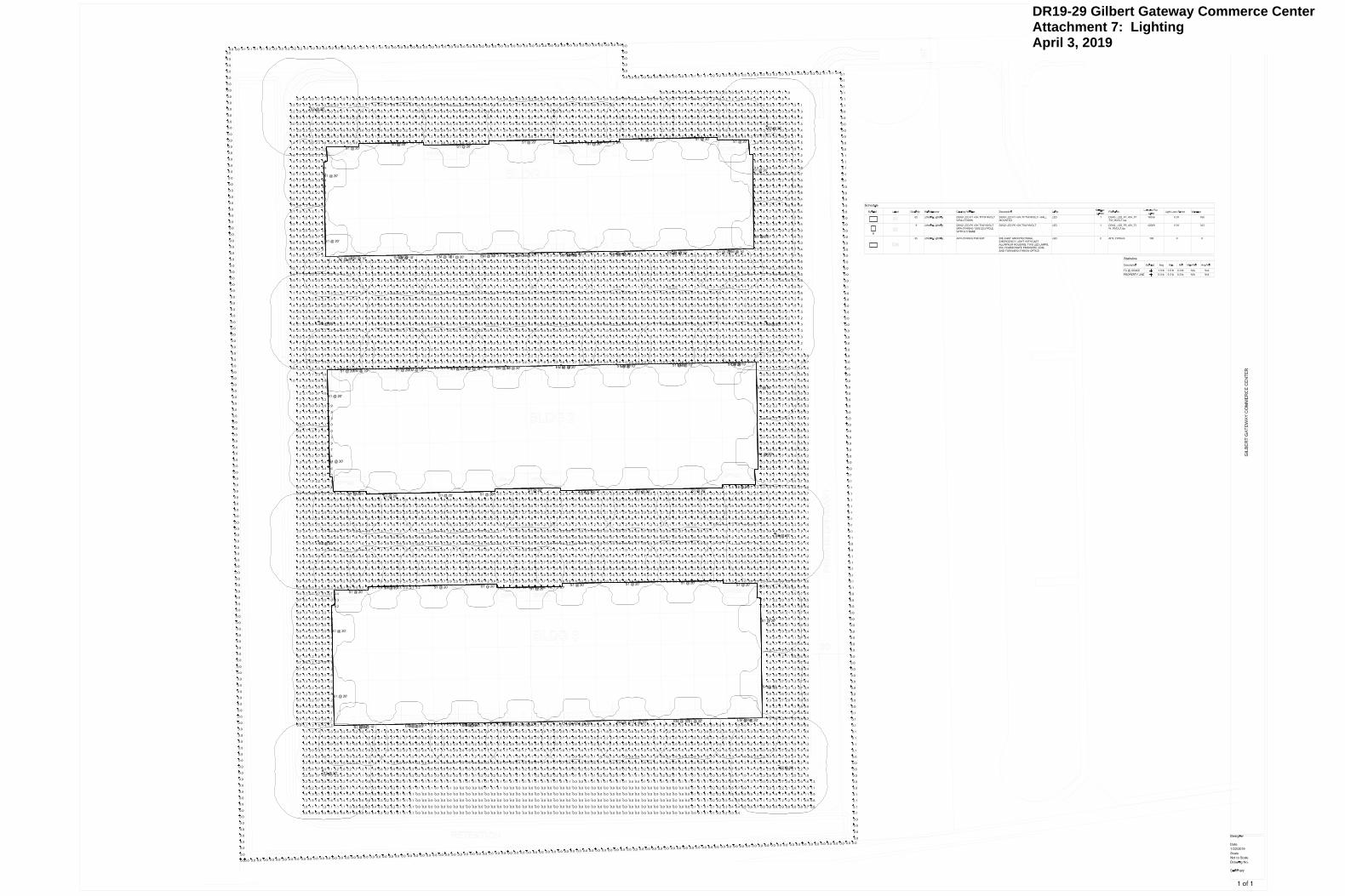
Lighting
The applicant has designed the photometric plan to meet all of the Town’s guidelines and
regulations pertaining to lighting fixture height and luminance levels at all property lines. There
are only two fixtures proposed: parking and building emergency lights.
The applicant has requested construction document at-risk. Staff would only support cd at-risk if
the applicant is able to address all 1st/2
nd review comments prior to cd submittal.
PUBLIC NOTIFICATION AND INPUT
The proposed project will require public notice as specified under Land Development Code
(LDC) Section 5.602.A.3.
REQUESTED INPUT
1. Input on the neighborhood concerns and the applicant’s design elements used to
mitigate the concerns.
2. Truck court screen wall and trash enclosures
3. Vertical massing and returns
4. The elimination of score joints to accommodate signage.
Respectfully submitted,

6
Josh Rogers
Planner II
Attachments and Enclosures:
1) Vicinity Map
2) Site Plan
3) Landscape
4) Colors and Materials
5) Elevations/Rendering
6) Floor Plans
7) Lighting

Maricopa County GIO, Maricopa County Assessor's Office
O
1/17/2019 3:59:30 PM
MapDR19-29 Gilbert Gateway Commerce CenterAttachment 1: Vicinity MapApril 3, 2019
RETENTION
PR
IV
AT
E D
RIV
EW
AY
BLDG 3
152,719 SF
BLDG 2
138,970 SF
BLDG 1
124,283 SF
OFFICE
T
OFFICEOFFICE
OFFICEOFFICE
OFFICE
OFFICE
OFFICE OFFICE
OFFICE
OFFICE
OFFICE
OFFICE
OFFICE
S.E
.S
.
S.E
.S
.
S.E
.S
.
T
T
692'
692'
692'
30
'15'
180'
26'
26'
32'
26'
30'26'
26' 30'
32'
40'
150'
26'30'
220'
180'
52'
TYP.
60'
60'
52'
TYP.
60'
60'
52'
TYP.
60'
60'
18'
LANDSCAPE
SETBACK
200'
28'
90'
LANDSCAPE
SETBACK
SIT
E P
LA
N
A1.1
SITE PLAN
N
SITE LEGEND
PROPERTY DATA
PROJECT DESCRIPTION
SITE PLAN KEYNOTESSITE GENERAL NOTES
PARKING SUMMARY
VICINITY MAP
N
202
PROJECT
LOCATION
EA
ST
N
UN
NE
LE
Y R
OA
D
GILB
ER
T, A
Z 85296
Ph
oen
ix
, A
Z 850
16
2777
E
. C
am
elb
ack
R
d, S
uite 325
grap
hics
pla
nn
in
g
arch
itectu
re
in
terio
rs
p 48
0.767
.1
00
1
f 4
80.90
7.228
8
civ
il en
gin
eerin
g
CAUTION: IF THIS SHEET IS NOT 24"x36" IT IS A REDUCED PRINT
Wed, 13 F
eb 2019
-
GILB
ER
T G
AT
EW
AY
CO
MM
ER
CE
C
EN
TE
R
T
02/13/2019
DR19-29 Gilbert Gateway Commerce CenterAttachment 2: Site PlanApril 3, 2019

UNAUTHORIZED VEHICLES PARKED
IN DESIGNATED ACCESSIBLE
SPACES NOT DISPLAYING
DISTINGUISHING PLACARDS OR
SPECIAL LICENSE PLATES ISSUED
FOR PERSONS WITH DISABILITIES
WILL BE TOWED AWAY
AT THE OWNER'S EXPENSE
TOWED VEHICLES
MAY BE RECLAIMED AT
(Insert Address)
OR BY TELEPHONING
(Insert Telephone Number)
ALL LETTERING SHALL BE A
MINIMUM OF 1" INCH
HEIGHT TYPICAL WITH 0.5"
SPACING
COLORS:
BORDER & LEGEND - BLACK
BACKGROUND - WHITE (RETROREFLECTIVE)
APPROPRIATE
INFORMATION SHALL BE
ADDED TO SIGN
2'-0"
2'-0"
80" A
T W
ALK
IN
G
SU
RF
AC
ES
60" A
T LA
ND
SC
AP
E
AR
EA
NOTE:
ARROW TO POINT IN
DIRECTION OF ACCESSIBLE
ENTRANCE BASED ON
LOCATION OF SIGN.
ACCESSIBLE
ENTRANCE
1'-0"
352
ACCESSIBLE
ENTRANCE
353
1'-6"
80
" A
T W
AL
KIN
G
SU
RF
AC
ES
60
" A
T L
AN
DS
CA
PE
AR
EA
COLOR:
BORDER AND LEGEND - WHITE (RETROREFLECTIVE)
BACKGROUND - BLUE (RETROREFLECTIVE)
RESERVED
HANDICAP
PARKING
PLATE OR PERMIT
ONLY
A.R.S. SEC. 28-884
1'-0"
1'-6
"
1/2" RADIUS, TYP.
TEXT SHALL READ: "RESERVED
PARKING". TEXT SHALL BE GREEN
LETTERING ON WHITE REFLECTIVE
BACKGROUND, NO SMALLER THAN
2" IN HEIGHT.
INTERNATIONAL SYMBOL OF
ACCESSIBILITY SHOWN WHITE ON
6"x6" BLUE FIELD WITH 1/2"
RADIUS CORNERS.
TEXT SHALL READ: "HANDICAP
PLATE OR PERMIT ONLY". TEXT
SHALL BE GREEN LETTERING ON
WHITE REFLECTIVE BACKGROUND,
NO SMALLER THAN 1" IN HEIGHT.
TEXT SHALL READ: "A.R.S. SEC.
28-884". TEXT SHALL BE GREEN
LETTERING ON WHITE REFLECTIVE
BACKGROUND, NO SMALLER THAN
1/2" IN HEIGHT.
3/8" WIDE GREEN COLOR BAND
APPROVED PHOENIX FIRE DEPARTMENT
FIRE ACCESS ROAD SIGNS
(FIRE LANE SIGNS)
FIRE
LANE
NO
PARKING
BY ORDER OF THE
FIRE MARSHAL
Phoenix Fire Code
12
1. THE SIGN PLATE SHALL BE A MINIMUM OF 12" X 18" WITH A THICKNESS OF .080 ALUMINUM
CONSTRUCTION.
2. THE SIGN FACE SHALL HAVE A WHITE REFLECTIVE BACKGROUND WITH A RED LEGEND. USE THE
STANDARD 3M SCOTCHLITE SIGN FACE NUMBER R7-32 OR EQUIVALENT, WITH RED SCREEN PRINTED
LETTERING AS SHOWN ABOVE.
12
18
Phoenix Fire Code
FIRE LANE
STANDARD
FIRE LANE SIGN DETAIL
UNIVERSAL SYMBOL
FIRE LANE SIGN DETAIL
8 1/2" DIA.
WHITE
BLACK
RED
2"
3/4"
2"
1 1/2"
3/4"
3/4"
RESERVED
HANDICAP
PARKING
PLATE OR PERMIT
ONLY
A.R.S. SEC. 28-884
ACCESSIBLE
VAN
1'-0"
6"
1'-8
"4
"
2'-6
"7
'-0
".
1'-6
"
1'-0"
12" X 18"ACCESIBLE PARKING
SIGN.
VAN ACCESIBLE SIGN WITH
GREEN COLOR TEXT ON
WHITE REFLECTIVE
BACKGROUND. WHERE
OCCURS.
2" X 3" X 3/16" GALV.
STEEL TUBE AND PAINTED,
CAP TUBE END.
FINISH GRADE / PAVEMENT
CONCRETE FOOTING
1/2"
TYP.
8" CMU WALL
PAINTED FINISH "C" TO MATCH BUILDING
FINISH SURFACE
SEE CIVIL DRAWINGS
CONCRETE FOOTING
SEE STRUCTURAL DRAWINGS
CONCRETE CAP
8'-0
" H
EIG
HT
S
CR
EE
N W
AL
L
3'-0
" H
EIG
HT
P
AR
KIN
G S
CR
EE
N W
AL
L
18" HIGH x 2" THICK NUMBERS
SIGN FOAM CUT TO DEPTH WITH
PLEXIGLASS FACE ATTACHED
PAINTED BLACK
AVENIR 95 BLACK
SIZE:
MATERIAL:
COLOR:
FONT:
TOP OF PARAPET
2'-0
".
APPROVED STREET ADDRESSES, INCLUDING BUILDING/SUITE NUMBERS, SHALL BE PLACED ON ALL NEW
AND EXISTING BUILDINGS IN SUCH A POSITION AS TO BE PLAINLY VISIBLE AND ELIGIBLE FROM THE STREET
OR ROAD FRONTING THE PROPERTY. SAID NUMBERS SHALL CONTRAST WITH THEIR BACKGROUND.
NOTE: NO STREET ADDRESS OR BUILDING NUMBER SHAB E POST UNDER A GABLE OR OBSTRUCTED BY
ANY FEATURE OR FOLIAGE.
ADDRESS NUMBER:
SHOULD BE NO LOWER THAN THE FIRST STORY OR ON A SIGN AT EACH ENTRANCE FACING THE
DESIGNATED PROPERTY ADDRESS.
NUMBERS SHALL BE A MINIMUM 12" HIGH WITH A 2" STROKE.
CONDUIT OR CONDENSATE LINE
GALVANIZED METAL CLAMPSECURED TO GALVANIZEDCHANNEL
UV RESISTANT RUBBER BASE,INSTALL PER MANUFACTURER'SSPECIFICATIONSDURA-BLOK OR EQUAL
ROOF SURFACE
2'-0"
12
A6.0
GATE
STATIONARY FENCE
HEAVY DUTY STEEL "V" GROOVE
WHEELS, TYP. @ EA. END AND
MIDDLE OF GATE
SLOPE CONC. MIN. 1/4" PER
FOOT TO DRIVE AISLE
INTERIOR EXTERIOR
CONC. CURB/FTG.
6" 1'-0" 8"
GUIDE WHEEL
& BRACKET
PE
R C
IV
IL
6"
6'-0
"2
'-0
".
GATES MEET IN THE
MIDDLE OF THE ROADWAY
5
GATE TRACK
CONC. FOOTING
FOR TRACK
CONC. TROUGH
PROVIDE FIRE LANE ENTRY
SIGNAGE, SEE DETAIL 4/ A6.0
6" BOLLARD
ROLLING GATE
12
A6.0
A6.0
MAX 4" OPENING IN
FENCING PERMITTED AT
ANY JUNCTION, TYPICAL
6" BOLLARD10" 10"
CONC. CURB
DE
TA
ILS
A6.0
SCALE: 1" = 1'-0"
1
UNAUTHORIZED VEHICLE SIGNAGE
SCALE: 1 1/2" = 1'-0"
2
ACCESSIBLE DIRECTION SIGN
SCALE: 1 1/2" = 1'-0"
3
ACCESSIBLE SIGNS
SCALE: 1 1/2" = 1'-0"
4
FIRELANE ENTRY SIGNAGE
SCALE: 3/4" = 1'-0"
6
VAN ACCESSIBLE SIGNAGE
SCALE: 3/16" = 1'-0"
8
DOUBLE WIDE BIN ENCLOSURE
SCALE: 3/4" = 1'-0"
5
SLIDING GATE - TRACK
SCALE: 1" = 1'-0"
11
MASONRY SCREEN WALL
SCALE: 1" = 1'-0"
9
MASONRY TRASH WALL
SCALE: 1/8" = 1'-0"
7
BUILDING ADDRESS NUMBERS
SCALE:1" = 1'-0"
12
SLIDING GATE - SECTION
SCALE:1" = 1'-0"
10
SLIDING GATE - PLAN
EA
ST
N
UN
NE
LE
Y R
OA
D
GILB
ER
T, A
Z 85296
Ph
oen
ix
, A
Z 850
16
2777
E
. C
am
elb
ack
R
d, S
uite 325
grap
hics
pla
nn
in
g
arch
itectu
re
in
terio
rs
p 48
0.767
.1
00
1
f 4
80.90
7.228
8
civ
il en
gin
eerin
g
CAUTION: IF THIS SHEET IS NOT 24"x36" IT IS A REDUCED PRINT
Wed, 13 F
eb 2019
-
GILB
ER
T G
AT
EW
AY
CO
MM
ER
CE
C
EN
TE
R
NOT USED
NOT USED
02/13/2019
DR19-29 Gilbert Gateway Commerce CenterAttachment 3: LandscapeApril 3, 2019

DR19-29 Gilbert Gateway Commerce CenterAttachment 4: Colors and MaterialsApril 3, 2019
1CMU BLOCK: INTEGRAL COLOR
2CLEAR ANODIZED MULLIONS WITH HIGH PERFORMANCE GLAZINGPPG
ATILT PANEL: PAINTEDDUNN “MINER’S DUST” DEC786
BTILT PANEL: PAINTEDDUNN “MUSLIN” DE6227
CSTEEL TUBE CANOPY: PAINTEDDUNN EDWARDS “ESPRESSO MACCHIATO” DET638
TRUCK DOCK ACCENT: PAINTEDDUNN EDWARDS “METAL FRINGE” DET626
KEYNOTES
D
EB 1 2C AD
PAGE
30 2 . 1 3 . 2 0 1 9GILBERT GATEWAY COMMERCE CENTER
GILBERT, ARIZONA - PHX18-0095-00
CONCEPTUAL VIEWThis conceptual design is based upon a preliminary review of entitlement requirements and on unverified and possibly incomplete site and/or building information, and is intended merely to assist in exploring how the project might be developed. Signage shown is for illustrative purposes only and does not necessarily reflect municipal code compliance.
02/13/2019
TRUCK DOCK ACCENT: PAINTEDDUNN EDWARDS E PEWTER PATTER “ E” DET6227 EDWARDS
EDWARDS
DR19-29 Gilbert Gateway Commerce CenterAttachment 5: Elevations/RenderingApril 3, 2019

TOP OF PARAPET
TOP OF PARAPET
TOP OF PARAPET
TOP OF PARAPET
NORTH ELEVATION
SOUTH ELEVATION
EAST ELEVATION
WEST ELEVATION
PAGE0 2 . 1 1 . 2 0 1 9GILBERT GATEWAY COMMERCE CENTER
GILBERT, ARIZONA - PHX18-0095-00
BUILDING 1This conceptual design is based upon a preliminary review of entitlement requirements and on unverified and possibly incomplete site and/or building information, and is intended merely to assist in exploring how the project might be developed. Signage shown is for illustrative purposes only and does not necessarily reflect municipal code compliance.
41'-3"
43'-5"
43'-5"
41'-3"
3
0 20 40 80 200
1" =40'02/13/2019
DASHED LINE INDICATES FUTURE FULLYSCREENED ROOF EQUIPMENT BEHINDPARAPET, TYP.
DASHED LINE INDICATES ROOFLINE BEYOND
CONCRETE TILT PANEL, PAINTEDCLEAR ANODIZED ALUM.STOREFRONT WITH PPGGLAZING, TINTED GREY
STEEL CANOPY, PAINTED
STOREFRONT DOORSTOREFRONT DOOR STOREFRONT DOORSTOREFRONT DOORSTOREFRONT DOOR STOREFRONT DOOR
DOCK DOOR9' W x 10' H
DOCK DOOR9' W x 10' H
DOCK DOOR9' W x 10' H
GRADE DOOR12' W x 14' H
GRADE DOOR12' W x 14' H
TOP OF WALL8'-0"
INSULATED HOLLOWMETAL MAN DOOR
INSULATED HOLLOWMETAL MAN DOOR
INSULATED HOLLOWMETAL MAN DOOR
INSULATED HOLLOWMETAL MAN DOOR
INSULATED HOLLOWMETAL MAN DOOR
INSULATED HOLLOWMETAL MAN DOOR
TOP OF CANOPY20'-0"
GRADE DOOR22' W x 14' H
GRADE DOOR22' W x 14' H
INSULATED HOLLOWMETAL MAN DOOR, TYP.
CLERESTORY GLAZING, TYP.
TOP OF PARAPET41'-3"
TOP OF CANOPY20'-0"
TOP OF PARAPET43'-5"
TOP OF PARAPET43'-5"
TOP OF CANOPY20'-0"
TOP OF PARAPET41'-3"
INTEGRAL COLOR CMU BLOCK
DASHED LINE INDICATES FUTURE FULLYSCREENED ROOF EQUIPMENT BEHINDPARAPET, TYP.
DASHED LINE INDICATES ROOFLINE BEYONDCONCRETE TILT PANEL, PAINTED
DASHED LINE INDICATES FUTUREFULLY SCREENED ROOF EQUIPMENTBEHIND PARAPET, TYP.
DASHED LINE INDICATES FUTUREFULLY SCREENED ROOF EQUIPMENTBEHIND PARAPET, TYP.
DASHED LINE INDICATES ROOFLINE BEYOND
CONCRETE TILT PANEL, PAINTED
DASHED LINE INDICATES ROOFLINE BEYOND
CONCRETE TILT PANEL, PAINTED
CLEAR ANODIZED ALUM. STOREFRONTWITH PPG GLAZING, TINTED GREY
INTEGRAL COLOR CMU BLOCK
CLEAR ANODIZED ALUM. STOREFRONTWITH PPG GLAZING, TINTED GREY
INTEGRAL COLOR CMU BLOCK
STEEL CANOPY, PAINTED
STEEL CANOPY, PAINTED
CONCRETE ACCENT TILT PANEL,PAINTED
CONCRETE ACCENT TILT PANEL,PAINTED
CONCRETE ACCENT TILT PANEL,PAINTED

TOP OF PARAPET
TOP OF PARAPET
TOP OF PARAPET
TOP OF PARAPET
SOUTH ELEVATION
WEST ELEVATION
EAST ELEVATION
PAGE0 2 . 1 1 . 2 0 1 9GILBERT GATEWAY COMMERCE CENTER
GILBERT, ARIZONA - PHX18-0095-00
BUILDING 2This conceptual design is based upon a preliminary review of entitlement requirements and on unverified and possibly incomplete site and/or building information, and is intended merely to assist in exploring how the project might be developed. Signage shown is for illustrative purposes only and does not necessarily reflect municipal code compliance.
45'-3"
45'-3"
47'-5"
47'-5"
4
0 20 40 80 200
1" =40'
02/13/2019
DASHED LINE INDICATES FUTURE FULLYSCREENED ROOF EQUIPMENT BEHINDPARAPET, TYP.
DASHED LINE INDICATES ROOFLINE BEYOND
CONCRETE TILT PANEL, PAINTEDCLEAR ANODIZED ALUM.STOREFRONT WITH PPGGLAZING, TINTED GREY
STOREFRONT DOORSTOREFRONT DOORSTOREFRONT DOOR STOREFRONT DOOR
DOCK DOOR9' W x 10' H
DOCK DOOR9' W x 10' H
DOCK DOOR9' W x 10' H
GRADE DOOR12' W x 14' H
TOP OF CANOPY20'-0"
TOP OF WALL8'-0"
INSULATED HOLLOWMETAL MAN DOOR
INSULATED HOLLOWMETAL MAN DOOR
INSULATED HOLLOWMETAL MAN DOOR
INSULATED HOLLOWMETAL MAN DOOR
INSULATED HOLLOWMETAL MAN DOOR
INSULATED HOLLOWMETAL MAN DOOR
GRADE DOOR22' W x 14' H
GRADE DOOR22' W x 14' H
STEEL CANOPY, PAINTED
NORTH ELEVATIONINSULATED HOLLOWMETAL MAN DOOR, TYP.
CLERESTORY GLAZING, TYP.DASHED LINE INDICATES FUTURE FULLYSCREENED ROOF EQUIPMENT BEHINDPARAPET, TYP.
DASHED LINE INDICATES ROOFLINE BEYONDCONCRETE TILT PANEL, PAINTED
DASHED LINE INDICATES FUTURE FULLYSCREENED ROOF EQUIPMENT BEHINDPARAPET, TYP.
DASHED LINE INDICATES ROOFLINE BEYOND
CONCRETE TILT PANEL, PAINTED
CLEAR ANODIZED ALUM. STOREFRONTWITH PPG GLAZING, TINTED GREY
STEEL CANOPY, PAINTED
DASHED LINE INDICATES FUTUREFULLY SCREENED ROOF EQUIPMENTBEHIND PARAPET, TYP.
DASHED LINE INDICATES ROOFLINE BEYOND
CONCRETE TILT PANEL, PAINTED
CLEAR ANODIZED ALUM. STOREFRONTWITH PPG GLAZING, TINTED GREY
INTEGRAL COLOR CMU BLOCK
STEEL CANOPY, PAINTED
TOP OF PARAPET43'-5"
TOP OF CANOPY20'-0"
TOP OF PARAPET41'-3"
TOP OF CANOPY20'-0"
TOP OF PARAPET41'-3"
TOP OF PARAPET43'-5"
CONCRETE ACCENT TILT PANEL,PAINTED
CONCRETE ACCENT TILT PANEL,PAINTED
CONCRETE ACCENT TILT PANEL,PAINTED

TOP OF PARAPET
TOP OF PARAPET
TOP OF PARAPET
TOP OF PARAPET
NORTH ELEVATION
SOUTH ELEVATION
EAST ELEVATION
WEST ELEVATION
PAGE0 2 . 1 1 . 2 0 1 9GILBERT GATEWAY COMMERCE CENTER
GILBERT, ARIZONA - PHX18-0095-00
BUILDING 3This conceptual design is based upon a preliminary review of entitlement requirements and on unverified and possibly incomplete site and/or building information, and is intended merely to assist in exploring how the project might be developed. Signage shown is for illustrative purposes only and does not necessarily reflect municipal code compliance.
45'-1"
47'-3"
47'-3"
45'-1"
5
0 20 40 80 200
1" =40'
02/13/2019
DASHED LINE INDICATES FUTURE FULLYSCREENED ROOF EQUIPMENT BEHINDPARAPET, TYP.
DASHED LINE INDICATES ROOFLINE BEYOND
CONCRETE TILT PANEL, PAINTED CLEAR ANODIZED ALUM.STOREFRONT WITH PPGGLAZING, TINTED GREY
STOREFRONT DOORSTOREFRONT DOORSTOREFRONT DOOR STOREFRONT DOOR
DOCK DOOR9' W x 10' H
DOCK DOOR9' W x 10' H
DOCK DOOR9' W x 10' H
GRADE DOOR12' W x 14' H
TOP OF CANOPY20'-0"
TOP OF WALL8'-0"
INSULATED HOLLOWMETAL MAN DOOR
INSULATED HOLLOWMETAL MAN DOOR
INSULATED HOLLOWMETAL MAN DOOR
INSULATED HOLLOWMETAL MAN DOOR
INSULATED HOLLOWMETAL MAN DOOR
INSULATED HOLLOWMETAL MAN DOOR
TOP OF CANOPY20'-0"
GRADE DOOR22' W x 14' H
GRADE DOOR22' W x 14' H
STEEL CANOPY, PAINTED
INSULATED HOLLOWMETAL MAN DOOR, TYP.
CLERESTORY GLAZING, TYP.
DASHED LINE INDICATES FUTUREFULLY SCREENED ROOF EQUIPMENTBEHIND PARAPET, TYP.
DASHED LINE INDICATES ROOFLINE BEYOND
CONCRETE TILT PANEL, PAINTED
CLEAR ANODIZED ALUM. STOREFRONTWITH PPG GLAZING, TINTED GREY
STEEL CANOPY, PAINTED
DASHED LINE INDICATES FUTUREFULLY SCREENED ROOF EQUIPMENTBEHIND PARAPET, TYP.
DASHED LINE INDICATES ROOFLINE BEYOND
CONCRETE TILT PANEL, PAINTED
CLEAR ANODIZED ALUM. STOREFRONTWITH PPG GLAZING, TINTED GREY
INTEGRAL COLOR CMU BLOCK
STEEL CANOPY, PAINTED
TOP OF PARAPET43'-5"
TOP OF CANOPY20'-0"
TOP OF PARAPET41'-3"
INTEGRAL COLOR CMU BLOCK
DASHED LINE INDICATES FUTUREFULLY SCREENED ROOF EQUIPMENTBEHIND PARAPET, TYP.
DASHED LINE INDICATES ROOFLINE BEYONDCONCRETE TILT PANEL, PAINTED
CONCRETE ACCENT TILT PANEL,PAINTED
CONCRETE ACCENT TILT PANEL,PAINTED
CONCRETE ACCENT TILT PANEL,PAINTED

S.E
.S
.
1 2 3 4 5 6 7 8 9 10 11 12 13 14
A
B
C
D
A
B
C
D
1 2 3 4 5 6 7 8 9 10 11 12 13 14
FLO
OR
P
LA
N
A2.1
BUILDING 1: FLOOR PLAN
N
FLOOR PLAN NOTES WALL LEGENDDOOR TYPES
T
SECTIONAL O.H. DOOR
HOLLOW METAL
DOOR NOTES
ALUMINUM STOREFRONT
(PAIR)
EA
ST
N
UN
NE
LE
Y R
OA
D
GILB
ER
T, A
Z 85296
Ph
oen
ix
, A
Z 850
16
2777
E
. C
am
elb
ack
R
d, S
uite 325
grap
hics
pla
nn
in
g
arch
itectu
re
in
terio
rs
p 48
0.767
.1
00
1
f 4
80.90
7.228
8
civ
il en
gin
eerin
g
CAUTION: IF THIS SHEET IS NOT 24"x36" IT IS A REDUCED PRINT
Wed, 13 F
eb 2019
-
GILB
ER
T G
AT
EW
AY
CO
MM
ER
CE
C
EN
TE
R
0 16'' 32'' 64'' 128''
1/32"=1'-0"
AREA
02/13/2019
DR19-29 Gilbert Gateway Commerce CenterAttachment 6: Floor PlansApril 3, 2019

S.E
.S
.
1 2 3 4 5 6 7 8 9 10 11 12 13 14
1 2 3 4 5 6 7 8 9 10 11 12 13 14
A
B
C
D
E
A
B
C
D
E
FLO
OR
P
LA
N
A2.2
BUILDING 2: FLOOR PLAN
N
FLOOR PLAN NOTES WALL LEGENDDOOR TYPES
T
SECTIONAL O.H. DOOR
HOLLOW METAL
DOOR NOTES
ALUMINUM STOREFRONT
(PAIR)
0 16'' 32'' 64'' 128''
1/32"=1'-0"
EA
ST
N
UN
NE
LE
Y R
OA
D
GILB
ER
T, A
Z 85296
Ph
oen
ix
, A
Z 850
16
2777
E
. C
am
elb
ack
R
d, S
uite 325
grap
hics
pla
nn
in
g
arch
itectu
re
in
terio
rs
p 48
0.767
.1
00
1
f 4
80.90
7.228
8
civ
il en
gin
eerin
g
CAUTION: IF THIS SHEET IS NOT 24"x36" IT IS A REDUCED PRINT
Wed, 13 F
eb 2019
-
GILB
ER
T G
AT
EW
AY
CO
MM
ER
CE
C
EN
TE
R
AREA
02/13/2019

S
.
E
.
S
.
1 2 3 4 5 6 7 8 9 10 11 12 13 14
A
B
C
D
E
A
B
C
D
E
1 2 3 4 5 6 7 8 9 10 11 12 13 14
SIT
E Z
ON
IN
G
A2.3
BUILDING 3: FLOOR PLAN
N
0 16'' 32'' 64'' 128''
1/32"=1'-0"
EA
ST
N
UN
NE
LE
Y R
OA
D
GILB
ER
T, A
Z 85296
Ph
oen
ix
, A
Z 850
16
2777
E
. C
am
elb
ack
R
d, S
uite 325
grap
hics
pla
nn
in
g
arch
itectu
re
in
terio
rs
p 48
0.767
.1
00
1
f 4
80.90
7.228
8
civ
il en
gin
eerin
g
CAUTION: IF THIS SHEET IS NOT 24"x36" IT IS A REDUCED PRINT
Wed, 13 F
eb 2019
-
GILB
ER
T G
AT
EW
AY
CO
MM
ER
CE
C
EN
TE
R
FLOOR PLAN NOTES WALL LEGENDDOOR TYPES
T
SECTIONAL O.H. DOOR
HOLLOW METAL
DOOR NOTES
ALUMINUM STOREFRONT
(PAIR)
AREA
02/13/2019
DR19-29 Gilbert Gateway Commerce CenterAttachment 7: LightingApril 3, 2019

EMERGENCY AFN
Catalog Number
Notes
Type
AFN
Series Finish Options
AFN AFFINITY Series die-cast architectural emergency lighting
W WhiteB BlackBN Brushed nickelDB Dark bronze
(blank) Features lead calcium batteryPREM Features ni-cad battery, self-diagnostics and damp location 32°F to 122°F (0° C to 50°C)EXT Features high-temperature ni-cad battery listed from 0°F to 122°F (-18°C to 50°C), self-diagnostics,
time delay; listed for cold weather, damp and wet locationFWD Forward throw optics with LED light source, 10.8WWL Wet location with time delay listed from 32°F to 122°F (0°C to 50°C) 1
ORDERING INFORMATIONF
For shortest lead times, configure product using bolded options. Example: AFN W EXT
FEATURES & SPECIFICATIONSINTENDED USE — Provides a minimum of 90 minutes illumination for the rated wattage upon loss of AC power. Ideal for applications requiring low-profile, attractive emergency lighting.CONSTRUCTION — Compact, low-profile, architectural design with die-cast aluminum housing. Avail-able finishes are texturized polyester powder coat paint in brushed nickel, white, black and dark bronze. All finishes can be painted in the field to match the wall color of choice. U.S. Patent No. D468,046.OPTICS — Standard optics provided with two 6W wedge-base xenon lamps offer 55 percent more light output than standard incandescent lamps. Patent-pending reflector/refractor design features superior vac-metalized, die-casted reflectors; and multi-faceted, highly transmissive refractor that significantly improve photometrics. Forward throw (FWD) option optics provided with two high-brightness white LEDs (10.8W total), projecting an NFPA-101 compliant path 3' wide and 28' forward, when mounted 8-1/2' AFF. The typical life of the LED lamp is 10 years.All light sources meet requirements for NEC 700.16.Low-profile, integrated test switch/pilot light located below the lens.Easily visible green status indicator.ELECTRICAL — Dual-voltage input capability (120/277V). Current-limiting charger maximizes battery life and minimizes energy consumption. Provides low operating costs.Edge connectors on printed circuit board ensure long-term durability.Short-circuit protection — current-limiting charger circuitry protects printed circuit board from shorts.Thermal protection senses circuitry temperature and adjusts charge current to prevent overheating and charger failure.Thermal compensation adjusts charger output to provide optimum charge voltage relative to ambient temperature.Regulated charge voltage maintains constant-charge voltage over a wide range of line voltages. Prevents over/undercharging that shortens battery life and reduces capacity.Filtered charger input minimizes charge voltage ripple and extends battery life.AC/LVD reset allows battery connection before AC power is applied and prevents battery damage from deep discharge.Battery: Sealed, maintenance-free lead-calcium battery provides 12W rated capacity. Nickel-cadmium battery with Premium and Exterior option packages. Automatic 48-hour recharge after a 90-minute discharge.Low-voltage disconnect prevents excessively deep discharge that can permanently damage the battery. Single-circuit battery connection.Brownout protection is automatically switched to emergency mode when supply voltage drops below 80 percent of nominal. EXT option package includes 20-minute time delay for supplemental lighting during HID startup.Self-diagnostics (PREM and EXT option packages)Patented Electronics - U.S. Patent No. D468,046 and 6,502,044.Single multi-chromatic LED indicator to display two-state charging, test activation and three-state diagnostic status.
Die-Cast Architectural Emergency Light
AFN
Accessories: Order as separate catalog number. 2
ELA AFNR DB Remote fixture (less batteries and electronics) to be powered by 6V battery equipment as part of an emergency lighting system (listed from -40°F to 122°F; -40°C to 50°C), BN, W, B finishes available.
Test switch provides manual activation of 30-second diagnostic testing for on-demand visual inspection.Self-diagnostic testing for five minutes every 30 days and 30 minutes every six months.Diagnostic evaluation of lamp, AC to DC transfer, charging and battery condition. Continuously monitors AC functionality.Postpone automatic test initiates eight hour delay of an automatic test by activating the manual test switch.INSTALLATION — Universal J-box mounting pattern. Rigid conduit entry provision on top of the unit.LISTINGS — UL Listed. Wet locations and cold temperature (EXT) listed. Damp location (PREM) listed. Wet location (WL) option available with PREM package. Meets UL 924, NFPA 101, NFPA 70-NEC and OSHA illumination standards. UL labeled.WARRANTY — 3-year limited warranty (Battery is prorated). FWD (LED light source) 5-year limited warranty (Battery is prorated). Complete warranty terms located at: www.acuitybrands.com/CustomerResources/Terms_and_conditions.aspxNote: Actual performance may differ as a result of end-user environment and application.Specifications subject to change without notice.
®
Notes
1 WL only available with PREM option package.
2 See spec sheet ELA-OMC-ELA-AFNR.
White
Brushed Nickel

AFN Affinity® Die-Cast Architectural Emergency Light
SPECIFICATIONS
FIXTURE PERFORMANCE
1 FC average
26 ft.
3 ft.
0.1 FC min.
Center-to-Center Spacing on a 3-foot Path of Egress
6 ft.
0.1 FC min.
1 FC average
21 ft.
AFFINITY FWD®
28'
20'
8.5'
6'3'
0.1 FC min.
1 FC average
Center-to-Center Spacing on a 6-foot Path of Egress
Path of Egress3'-wide
XenonLamp
26'Center-to-Center Spacing
Path of Egress6'-wide
21'
NOTE: Meets Life Safety Code standard minimum illuminance of 0.1 FC and average illuminance of 1.0 FC. Assumes open space with no obstructions, mounting height: 8.5', ceiling height: 9', and reflectances: 80/50/20.
SPACING GUIDE
MOUNTINGAll dimensions are inches (centimeters).Shipping weight: 3.5 lbs. (1.59 kgs.)
2-3/4(6.9)
9-1/2(24.1)
9-1/2(24.1)
9-1/2(24.1)
6-1/2(16.5)
6-1/2(16.5)
4-3/8(18.6)
4-3/8(18.6)
Test switch status indicator
ELECTRICAL: Primary Circuit
AC Input Outputvolts
Watts outputType Volts Amps Watts 1-1/2 hrs.
AFN 120 .11 1.1 6 12277 .12 1.3
AFN PREM 120 .15 1.4 6 12277 .14 1.4
AFN EXT 120 .23 211
6 12277 .25 351
BATTERY: Sealed Lead-Calcium
VoltageTypical
shelf life2
Typicallife2 Maintenance3
Temperaturerange4
6 12 months 3 - 5 years none60°– 90°F
(16°– 32°C)
Notes
1 EXT provided with battery heater.
2 At 77°F (25°C).
3 All life safety equipment, including emergency lighting for path of egress must be maintained, serviced, and tested in accordance with all National Fire Protection Association (NFPA) and local codes. Failure to perform the required maintenance, service, or testing could jeopardize the safety of occupants and will void all warranties.
4 Optimum ambient temperature range where unit will provide capacity for 90 minutes. Higher and lower temperatures affect life and capacity. See option packages for expanded temperature ranges.
BATTERY: Nickel-Cadmium
VoltageTypical
shelf life2
Typicallife2 Maintenance3
Temperaturerange4
6 3 years 7 - 9 years none32°– 122°F(0°– 50°C)
AFN
EMERGENCY: One Lithonia Way, Conyers, GA 30012 Phone: 800-334-8694 www.lithonia.com [email protected] © 2003-2018 Acuity Brands Lighting, Inc. All rights reserved. Rev. 07/09/18
One Lithonia Way • Conyers, Georgia 30012 • Phone: 800.279.8041 • www.lithonia.com© 2011-2018 Acuity Brands Lighting, Inc. All rights reserved.
DSX0-LEDRev. 03/21/18
Page 1 of 7
D-SeriesSize 0LED Area Luminaire
Specifications
Catalog Number
Notes
Type
EPA: 0.95 ft2
(.09 m2)
Length: 26”(66.0 cm)
Width: 13”(33.0 cm)
Height: 7”(17.8 cm)
Weight (max):
16 lbs(7.25 kg)
Hit the Tab key or mouse over the page to see all interactive elements.
L
H
W
Ordering Information EXAMPLE: DSX0 LED P6 40K T3M MVOLT SPA DDBXD
DSX0 LED
Series LEDs Color temperature Distribution Voltage Mounting
DSX0 LED Forward opticsP1 P4 P7P2 P5P3 P6Rotated opticsP101 P121
P111 P131
30K 3000 K40K 4000 K50K 5000 K AMBPC Amber phosphor
converted2
T1S Type I shortT2S Type II shortT2M Type II mediumT3S Type III shortT3M Type III mediumT4M Type IV mediumTFTM Forward throw
mediumT5VS Type V very short
T5S Type V shortT5M Type V mediumT5W Type V wideBLC Backlight control2,3
LCCO Left corner cutoff2,3
RCCO Right corner cutoff2,3
MVOLT 4,5
120 6
208 5,6
240 5,6
277 6
347 5,6,7
480 5,6,7
Shipped includedSPA Square pole mountingRPA Round pole mountingWBA Wall bracket SPUMBA Square pole universal mounting adaptor 8
RPUMBA Round pole universal mounting adaptor 8
Shipped separatelyKMA8 DDBXD U Mast arm mounting bracket adaptor
(specify finish)9
Control options Other options Finish (required)
Shipped installedNLTAIR2 nLight AIR generation 2 enabled10
PER NEMA twist-lock receptacle only (control ordered separate) 11
PER5 Five-wire receptacle only (control ordered separate) 11,12
PER7 Seven-wire receptacle only (control ordered separate) 11,12
DMG 0-10V dimming extend out back of housing for external control (control ordered separate)PIR Bi-level, motion/ambient sensor, 8-15’ mounting height, ambient sensor enabled at 5fc 5,13,14
PIRH Bi-level, motion/ambient sensor, 15-30’ mounting height, ambient sensor enabled at 5fc 5,13,14
PIRHN Network, Bi-Level motion/ambient sensor15
PIR1FC3V Bi-level, motion/ambient sensor, 8-15’ mounting height, ambient sensor enabled at 1fc 5,13,14
PIRH1FC3V Bi-level, motion/ambient sensor, 15-30’ mounting height, ambient sensor enabled at 1fc 5,13,14
BL30 Bi-level switched dimming, 30% 5,16,17
BL50 Bi-level switched dimming, 50% 5,16,17
PNMTDD3 Part night, dim till dawn 5,18
PNMT5D3 Part night, dim 5 hrs 5,18
PNMT6D3 Part night, dim 6 hrs 5,18
PNMT7D3 Part night, dim 7 hrs 5,18
FAO Field adjustable output19
Shipped installedHS House-side shield 20
SF Single fuse (120, 277, 347V) 6
DF Double fuse (208, 240, 480V) 6
L90 Left rotated optics 1
R90 Right rotated optics 1
DDL Diffused drop lens 20
Shipped separately BS Bird spikes21
EGS External glare shield21
DDBXD Dark bronzeDBLXD BlackDNAXD Natural aluminumDWHXD WhiteDDBTXD Textured dark bronzeDBLBXD Textured blackDNATXD Textured natural
aluminumDWHGXD Textured white
Capable LuminaireThis item is an A+ capable luminaire, which has been designed and tested to provide consistent color appearance and system-level interoperability.
• All configurations of this luminaire meet the Acuity Brands’ specification for chromatic consistency
• This luminaire is A+ Certified when ordered with DTL® controls marked by a shaded background. DTL DLL equipped luminaires meet the A+ specification for luminaire to photocontrol interoperability1
• This luminaire is part of an A+ Certified solution for ROAM® or XPoint™ Wireless control networks, providing out-of-the-box control compatibility with simple commissioning, when ordered with drivers and control options marked by a shaded background1
To learn more about A+, visit www.acuitybrands.com/aplus.
1. See ordering tree for details.
2. A+ Certified Solutions for ROAM require the order of one ROAM node per luminaire. Sold Separately: Link to Roam; Link to DTL DLL
A+ Capable options indicated by this color background.

One Lithonia Way • Conyers, Georgia 30012 • Phone: 800.279.8041 • www.lithonia.com© 2011-2018 Acuity Brands Lighting, Inc. All rights reserved.
DSX0-LEDRev. 03/21/18
Page 2 of 7
Tenon O.D. Single Unit 2 at 180° 2 at 90° 3 at 120° 3 at 90° 4 at 90°2-3/8” AST20-190 AST20-280 AST20-290 AST20-320 AST20-390 AST20-4902-7/8” AST25-190 AST25-280 AST25-290 AST25-320 AST25-390 AST25-490
4” AST35-190 AST35-280 AST35-290 AST35-320 AST35-390 AST35-490
Tenon Mounting Slipfitter **
Drilling
Top of Pole
0.563”
2.650”
1.325”0.400”(2 PLCS)
Template #8
To see complete photometric reports or download .ies files for this product, visit Lithonia Lighting’s D-Series Area Size 0 homepage. Photometric DiagramsIsofootcandle plots for the DSX0 LED 40C 1000 40K. Distances are in units of mounting height (20’).
Test
No
. LTL
2345
1P25
tes
ted
in a
cco
rdan
ce
with
IESN
A L
M-7
9-08
.
4
3
2
1
0
-4
-3
-2
-1
4 3 2 1 0 4321
T1M
Test
No
. LTL
2345
6P25
tes
ted
in a
cco
rdan
ce
with
IESN
A L
M-7
9-08
.
4
3
2
1
0
-4
-3
-2
-1
4 3 2 1 0 4321
T3M
Test
No
. LTL
2345
7P25
tes
ted
in a
cco
rdan
ce
with
IESN
A L
M-7
9-08
.
4
3
2
1
0
-4
-3
-2
-1
4 3 2 1 0 4321
T4M
Test
No
. LTL
2342
2P25
tes
ted
in a
cco
rdan
ce
with
IESN
A L
M-7
9-08
.
4
3
2
1
0
-4
-3
-2
-1
4 3 2 1 0 4321
T5M
LEGEND
0.1 fc
0.5 fc
1.0 fc
Ordering Information
NOTES1 P10, P11, P12 and P13 and rotated options (L90 or R90) only available together.2 AMBPC is not available with BLC, LCCO, RCCO, P4, P7 or P13.3 Not available with HS or DDL.4 MVOLT driver operates on any line voltage from 120-277V (50/60 Hz).5 Any PIRx with BL30, BL50 or PNMT, is not available with 208V, 240V, 347V, 480V or MVOLT. It is only available in 120V or 277V specified. 6 Single fuse (SF) requires 120V, 277V or 347V. Double fuse (DF) requires 208V, 240V or 480V.7 Not available in P4, P7 or P13. Not available with BL30, BL50 or PNMT options.8 Existing drilled pole only. Available as a separate combination accessory; for retrofit use only: PUMBA (finish) U; 1.5 G vibration load rating per ANCI C136.31.9 Must order fixture with SPA mounting. Must be ordered as a separate accessory; see Accessories information. For use with 2-3/8” mast arm (not included).10 Must be ordered with PIRHN.11 Photocell ordered and shipped as a separate line item from Acuity Brands Controls. See accessories. Shorting Cap included.12 If ROAM® node required, it must be ordered and shipped as a separate line item from Acuity Brands Controls. Shorting Cap included.13 Reference Motion Sensor table on page 3.14 Reference PER Table on page 3 to see functionality.15 Must be ordered with NLTAIR2. For more information on nLight Air 2 visit this link.16 Requires (2) separately switched circuits.17 Not available with 347V, 480V or PNMT. For PER5 or PER7 see PER Table on page 3. Requires isolated neutral.18 Not available with 347V, 480V, BL30 and BL50. For PER5 or PER7 see PER Table on page 3. Separate Dusk to Dawn required.19 Not available with other dimming controls options.20 Not available with BLC, LCCO and RCCO distribution. Also available as a separate accessory; see Accessories information.21 Must be ordered with fixture for factory pre-drilling. 22 Requires luminaire to be specified with PER, PER5 or PER7 option. See PER Table on page 3.23 For retrofit use only.
AccessoriesOrdered and shipped separately.
DLL127F 1.5 JU Photocell - SSL twist-lock (120-277V) 22
DLL347F 1.5 CUL JU Photocell - SSL twist-lock (347V) 22
DLL480F 1.5 CUL JU Photocell - SSL twist-lock (480V) 22
DSHORT SBK U Shorting cap 22
DSX0HS 20C U House-side shield for 20 LED unit 20
DSX0HS 30C U House-side shield for 30 LED unit 20
DSX0HS 40C U House-side shield for 40 LED unit 20
DSX0DDL U Diffused drop lens (polycarbonate) 20
PUMBA DDBXD U* Square and round pole universal mount-ing bracket adaptor (specify finish) 23
KMA8 DDBXD U Mast arm mounting bracket adaptor (specify finish) 8
For more control options, visit DTL and ROAM online.
26.06
5.96 TYP.
7.3018.76
.45 TYP.
6.53 TYP.
.32
R.09
.19.13
3.30
.13
.14 THRU
12.43
4.31
6.53.50
78°
59°
.38 12.05.30
SEE DETAIL A4 PLCS.
SCALE 2:1ADETAIL
C
90.0090.00
90.0090.00
External Glare Shield
.50
73˚
12.05 12.476
HANDHOLE ORIENTATION
AHandhole
B
C
DPole drilling nomenclature: # of heads at degree from handhole (default side A)
DM19AS DM28AS DM29AS DM32AS DM39AS DM49AS
1 @ 90° 2 @ 280° 2 @ 90° 3 @ 120° 3 @ 90° 4 @ 90°
Side B Side B & D Side B & C Round pole only Side B, C, & D Sides A, B, C, D
Note: Review luminaire spec sheet for specific nomenclature
Pole top or tenon O.D. 4.5" @ 90° 4" @ 90° 3.5" @ 90° 3" @ 90° 4.5" @ 120° 4" @ 120° 3.5" @ 120° 3" @ 120°
DSX SPA Y Y Y N - - - -DSX RPA Y Y N N Y Y Y YDSX SPUMBA Y N N N - - - -DSX RPUMBA N N N N Y Y Y N
*3 fixtures @120 require round pole top/tenon.

![10 11 Session HR Session Seri Management[1]](https://static.fdokumen.com/doc/165x107/6314ba61fc260b71020fb0ee/10-11-session-hr-session-seri-management1.jpg)