
PICTURETEL LIVE50 LIVE100 - DEKOM
196
PICTURET EL LIVE50 LIVE100 Installation Guide
-
Upload
khangminh22 -
Category
Documents
-
view
1 -
download
0
Transcript of PICTURETEL LIVE50 LIVE100 - DEKOM

PICTURETELLIVE50
LIVE100Installation Guide

The information contained in this document is subject to change without notice. PictureTel assumes no responsibility for technical or editorial errors or omissions that may appear in this document or for the use of this material. Nor does PictureTel make any commitment to update the information contained in this document. This document contains proprietary information which is protected by copyright. All rights reserved. No part of this document may be photocopied or reproduced in any form without the prior written consent of PictureTel Corporation.Live50 and Live100, Release 1.6
Copyright © 1996: PictureTel Corporation—Printed in U.S.A.PictureTel Corporation,100 Minuteman Road, Andover, MA 01810
Telephone number: 508-292-5000Edition: 800-0599-01 Rev. B
The PictureTel logo and PictureTel are registered trademarks and LiveTalk and LiveShare Plus are trademarks of PictureTel Corporation. All other product names are the trademarks of their respective owners.

FCC Notices
Class B Part 15 Information
This device complies with Part 15 of the FCC Rules. Operation is subject to the following two conditions: (1) this device may not cause harmful interference, and (2) this device must accept any interference received, including interference that may cause undesired operation.
This equipment has been tested and found to comply with the limits for a Class B digital device, pursuant to Part 15 of the FCC Rules. These limits are designed to provide reasonable protection against harmful interference in a residential installation. This equipment generates, uses, and can radiate radio frequency energy and, if not installed and used in accordance with the instruction manual, may cause harmful interference to radio communications. However, there is no guarantee that interference will not occur in a particular installation. If this equipment does cause harmful interference to radio or television reception, which can be determined by turning the equipment off and on, the user is encouraged to try to correct the interference by one or more of the following measures:
❑ Reorient or relocate the receiving antenna.
❑ Increase the separation between the equipment and the receiver.
❑ Connect the equipment into an outlet on a circuit different from that to which the receiver is connected.
❑ Consult the dealer or an experienced radio/TV technician for help.
Changes or modifications to this equipment not expressly approved by the party responsible for compliance could void the user’s authority to operate the equipment.
Switched-56 Connection Information
This equipment complies with Part 68 of the FCC Rules. An internal cover on the Switched-56-1 network interface board has a label that contains, among other information, the FCC Registration Number and Ringer Equivalence Number (REN) for this equipment. Upon request you must provide this information to your telephone company.
The REN is useful to determine the quantity of devices you may connect to your telephone line and still have all of those devices ring when your telephone number is called. In most but not all areas, the sum of the RENs of all devices connected to one line should not exceed five (5.0). To be certain of the number of devices you may connect to your line, as determined by the REN, you should contact your local telephone company to determine the maximum REN for your calling area.
If your telephone equipment causes harm to the telephone network, the telephone company may discontinue your service temporarily. If possible, they will notify you in advance. But if advance notice isn’t practical, you will be notified as soon as possible. You will be informed of your right to file a complaint with the FCC.

Your telephone company may make changes in its facilities, equipment, operations, or procedures that could affect the proper functioning of your equipment. If they do, you will be notified in advance to give you an opportunity to maintain uninterrupted telephone service.
If you need more information on this subject please call 1-800-874-2835. The telephone company may ask that you disconnect this equipment from the network until the problem has been corrected or until you are sure that the equipment is not malfunctioning.
Installation
This device is equipped with a USOC RJ11C connector.
Warning: Changes or modifications to this unit not expressly approved by the party responsible for compliance could void the user’s authority to operate the equipment.
Notice to Canadian Users
This digital apparatus does not exceed the Class B limits for radio noise emissions from digital apparatus set out in the Radio Interference Regulations of the Canadian Department of Communications.
Le present appareil numberique n’emet pas de bruits radioelectriques depassant les limites applicables aux appareils numberiques de la classe B prescrites dens le Reglement sur le brouillage radioelectrique edicte par le ministere des Communications du Canada.
Notice: The Canadian Department of Communcations label identifies certified equipment. This certification means that the equipment meets certain telecommunications network protective, operational, and safety requirements. The Department does not guarantee the equipment will operate to the user’s satisfaction.
Before installing this equipment, users should ensure that it is permissible to be connected to the facilities of the local telecommunications company. The equipment must also be installed using an acceptable method of connection. In some cases, the company’s inside wiring associated with a single line individual service may be extended by means of a certified connector assembly (telephone extension cord). The customer should be aware that compliances with the above conditions may not prevent degradation of service in some situations.
Repairs to certified equipment should be made by an authorized Canadian maintenance facility designated by the supplier. Any repairs or alterations made by the user to this equipment, or equipment malfunctions, may give the telecommunications company cause to request the user to disconnect the equipment.
Users should ensure, for their own protection, that the electrical ground connections of the power utility, telephone lines, and internal metallic water pipe system, if present, are connected together. This precaution may be particularly important in rural areas.

Caution: Users should not attempt to make such connections themselves, but should contact the appropriate electric inspection authority, or electirician, as appropriate.
Bescheinigung des Herstellers/Importeurs
Hiermit wird bescheinigt, dass PictureTel LIVE PCS 50 in Übereinstimmung mit den Bestimmungen der BMPT-AmtsblVfg 243/1991 funkentstört ist. Der vorschriftsmässige Betrieb mancher Geräte (z.B. Messsender) kann allerdings gewissen Einschränkungen unterliegen. Beachten Sie deshalb die HinWeise in der Bedienungsanleitung.
Dem Zentralamt fuer Zulassungen im Femmeldewesen wurde das Inverkehrbringen dieses Gerätes angezeigt und die Berechtigung zur Überprüfung der Serie auf die Einhaltung der Bestimmungen eingeräumt.
PictureTel GmbH, Büropark Oktavian, Münchner Strasse 14, D-8043 München-Unterföhring, Germany

International Approvals
Live50
The PictureTel Live50 complies with EEC Directives 89/336EEC, 91/263/EEC, 93/68/EEC and European Standards EN 55022B, EN50082-1, I-CTR3 and EN60950. The PictureTel Live50 includes a Euro-ISDN Basic Access Port. The Euro-ISDN Basic Access Port has been approved for connection to the Public Telecommunications Network by the British Approvals Board for Telecommunications (BABT). Consequently, BABT has granted PictureTel the following Approval Marking:
The PictureTel Live50 ISDN Basic Access Port has been approved in France by DGPT. The following Approval number has been assigned to the Chipshot ISDN port:
95050B.
The PictureTel Live50 ISDN Basic Access Port has been approved in Germany by BZT. The following Approval number (Zulassungsnummer) has been assigned to the Chipshot ISDN Port:
BZ T A116384E
The PictureTel Live50 (PCS50 Chipshot) has been approved in Hong Kong by Hong Kong Telecom and has been granted Permission to Connect (PTC) to Dataline BRI service. The following PTC Approval number has been assigned:
PTC 205/94/SDWL
The PictureTel Live50 (PCS50 Chipshot) ISDN Port has been approved in Japan by JATE. The following Approval number has been assigned to the CHIPSHOT ISDN Port:
T95-5037-2
The PictureTel Live50 (PCS50 Chipshot ) has been approved in Singapore by TAS and has been assigned the following Approval number:
TAC No : ISDN1-ISTE-AC-0150-95
The PictureTel Live50 ISDN Basic Access Port has been approved in Switzerland by BAKOM. The following Approval number has been assigned to the CHIPSHOT ISDN Port:
95.00.96.I.N
CC168 X

Live100
The PictureTel Live100 complies with EEC Directives 89/336EEC, 91/263/EEC, 93/68/EEC and European Standards EN 55022B, EN50082-1, I-CTR3 and EN60950. The PictureTel Live100 includes a Euro-ISDN Basic Access Port. The Euro-ISDN Basic Access Port has been approved for connection to the Public Telecommunications Network by the British Approvals Board for Telecommunications (BABT). Consequently, BABT has granted PictureTel the following Approval Marking:
The PictureTel Live100 (ESCAB) ISDN Basic Access Port has been approved in Australia by AUSTEL. The following Approval number has been assigned to the ESCAB ISDN:
A94/38B/0389.
The PictureTel Live100 (ESCAB) ISDN Basic Access Port has been approved in France by DGPT. The following Approval number has been assigned to the ESCAB ISDN:
94149B.
The PictureTel Live100 (ESCAB) ISDN Basic Access Port has been approved in Germany by BZT. The following Approval number (Zulassungsnummer) has been assigned to the ESCAB ISDN:
A108535E
The PictureTel Live100 (ESCAB) ISDN Basic Access Port has been approved in New Zealand by Telecom New Zealand. The following Telepermit number has been assigned to the ESCAB ISDN:
PTC 23/94/021
The PictureTel Live100 (ESCAB) ISDN Basic Access Module has been approved in Switzerland by BAKOM. The following Approval number has been assigned to the ESCAB ISDN:
94.06.11.I.N
CC168 X

Notice to Users of Public DATAPHONE Digital ServiceThe following instructions are provided to ensure that you comply with FCC Rules, Part 68.
1. All direct connections to DDS lines must be made through standard plugs and jacks furnished by the telephone company. No connections can be made to party lines or coin lines. Before connecting your unit, you must do the following:
a. Tell your local telephone company that you have an FCC registered device and that you wish to connect to the company’s line. Provide them with the 14-digit FCC registration number listed on the device’s label. They will also need to know the facility interface code and service code to connect the necessary service. For your unit, the facility interface code is 04DU5-56 for 56 kbps service. The service code is 6.0Y.
b. Inform the local telephone company of the jack arrangement you want to use, which is RJ-48S.
c. Connect the channel service unit (CSU) with the appropriate cable after the telephone company has installed the requested jack.
2. If the unit appears to be malfunctioning, it should be disconnected from the telephone line until you learn if your equipment or the telephone line is the source of the trouble. If your equipment needs repair, it should not be reconnected until it is repaired.
3. The CSU is designed to prevent harm to the DDS network. If the telephone company finds that the equipment exceeds tolerance parameters, the telephone company can temporarily disconnect service, although they will attempt to give you advance notice if possible.
4. Under FCC Rules, no customer is authorized to repair this equipment. This restriction applies regardless of whether the equipment is in or out of warranty.
5. If the telephone company alters their equipment or operations in a manner that will affect use of this device, they must give you advance warning so as to give you the opportunity for uninterrupted service. You will be advised of your right to file a complaint with the FCC.
6. In the event of equipment malfunction, all repairs should be performed by PictureTel Corporation or an authorized agent. It is the responsibility of the users requiring service to report the need for service to our company or to one of our authorized agents.

ix
Contents
About This Guide
Upgrading..........................................................................................................................................xv
Windows 3.1 vs Windows 95..........................................................................................................xv
Chapter 1Getting Started
Overview ..........................................................................................................................................1-1
In this Chapter ........................................................................................................................ 1-1
System Requirements...................................................................................................................... 1-2
Live50 Package Contents................................................................................................................ 1-2
The Live50 Video Cameras ................................................................................................... 1-3
Live100 Package Contents.............................................................................................................. 1-4
The Live100 FlipCam Camera.............................................................................................. 1-4
Speakerphone Unit ................................................................................................................ 1-5
PictureTel Live Software ................................................................................................................ 1-6
Before Installing PictureTel Live ................................................................................................... 1-7
Consider Your Networking Environment.......................................................................... 1-7
Installing PictureTel Live for the First Time ...................................................................... 1-7
Installing Over a Previous Version ..................................................................................... 1-8
About the 384 Kbps Option .................................................................................................. 1-8
Your Installation .............................................................................................................................. 1-9
For Specific Information ...............................................................................................................1-10

x
Chapter 2Installing PictureTel Live50 Hardware
Overview...........................................................................................................................................2-1
In this Chapter ........................................................................................................................2-1
Checking Your PC Settings ............................................................................................................2-3
Opening Your PC.............................................................................................................................2-4
Replacing Your VGA Board ...........................................................................................................2-4
Installing the Live50 Board ............................................................................................................2-5
Inserting the Live50 Board....................................................................................................2-5
Connecting the Live50 Board to the VGA Board...............................................................2-7
Installing Optional Network Interface Boards ............................................................................2-8
Labeling the Live50 Board..............................................................................................................2-9
Closing Your PC...............................................................................................................................2-9
Connecting the Cameras...............................................................................................................2-10
Connecting the Live50 Desktop Camera ..........................................................................2-10
Mounting the Live50 Desktop Camera........................................................................2-12
Connecting the Live50 FlipCam Camera..........................................................................2-13
Mounting and Positioning the FlipCam ......................................................................2-15
Connecting the Earpiece ...............................................................................................................2-16
Connecting the Speakerphone Unit ............................................................................................2-17
Connecting Optional Equipment to the Speakerphone ...........................................................2-19
Connecting Other Audio Devices ...............................................................................................2-20
Connecting to the Network..........................................................................................................2-21
From the Live50 Board ........................................................................................................2-21
From a Network Interface board .......................................................................................2-21
Restarting Your PC........................................................................................................................2-21

xi
Chapter 3Installing PictureTel Live100 Hardware
Overview ..........................................................................................................................................3-1
In this Chapter ........................................................................................................................ 3-1
Checking Your PC Settings ............................................................................................................ 3-3
Opening Your PC ............................................................................................................................ 3-4
Installing the VGA Video Board ................................................................................................... 3-5
Installing the Audio Communications Board ............................................................................. 3-6
Connecting the Live100 Boards Together .................................................................................... 3-7
Installing Optional Network Interface Boards............................................................................ 3-8
Attaching Labels .............................................................................................................................. 3-8
Closing Your PC .............................................................................................................................. 3-9
Reconnecting Cables ....................................................................................................................... 3-9
Connecting the FlipCam Camera................................................................................................ 3-10
Connecting the FlipCam to the PC.................................................................................... 3-10
Mounting and Positioning the FlipCam ...........................................................................3-11
Connecting the Speakerphone Unit ............................................................................................3-12
Connecting Optional Equipment to the Speakerphone...........................................................3-14
Connecting the Headset ...................................................................................................... 3-14
Connecting the Power Supply ........................................................................................... 3-15
Connecting to the Network..........................................................................................................3-15
From the Live100 Audio Communcations Board ...........................................................3-15
From a Network Interface board .......................................................................................3-15
Optional Devices ...........................................................................................................................3-16
Connecting a Second FlipCam Camera ............................................................................3-17
Connecting a VCR or Other Video Source .......................................................................3-17
Restarting Your PC........................................................................................................................3-18

xii
Chapter 4Installing PictureTel Live Software
Overview...........................................................................................................................................4-1
In this Chapter ........................................................................................................................4-1
General Considerations ..................................................................................................................4-2
Installing from a LAN .....................................................................................................................4-3
Installation Steps..............................................................................................................................4-4
Installing the VGA Driver ..............................................................................................................4-5
Windows 3.1x PictureTel VGA Driver Installation...........................................................4-5
Windows 95 Driver Selection ...............................................................................................4-7
Windows 3.1x Non-PictureTel VGA Driver Installation..................................................4-8
Windows 95 Matrox Driver Installation .............................................................................4-8
Step 1: Installing the Microsoft MGA Driver ................................................................4-8
Step2: Upgrading to the PowerDesk Driver .................................................................4-9
Step 3: Adjusting Desktop Area and Display Area......................................................4-9
Starting the Setup Wizard ............................................................................................................4-10
Installing LiveShare Plus ..............................................................................................................4-11
Installing LiveShare Plus On Windows 3.1x and Windows 95 .....................................4-12
Installing the PictureTel Live Application .................................................................................4-13
ISDN Protocol..................................................................................................................4-15
Reconfiguring Memory (optional step) ............................................................................4-18
Verifying Your Installation .................................................................................................4-19
Locating PictureTel Live Files......................................................................................................4-20
What To Do Next ...........................................................................................................................4-21
Chapter 5Troubleshooting
Overview...........................................................................................................................................5-1
In this Chapter ........................................................................................................................5-1
Problems Bringing Up DOS and Windows .................................................................................5-2
Problems Starting Up PictureTel Live ..........................................................................................5-4

xiii
Appendix AChecking Your
PC Settings....................................................................................................................................A-1
Appendix BChanging Settings on the Live100 Boards ............................................................................. B-1
Appendix CInstalling Network Interface Boards ....................................................................................... C-1
Appendix DInstalling the 384 Kbps Option ..................................................................................................D-1
Appendix EHow to Order ISDN in the United States .............................................................................. E-1
Appendix FDeinstalling PictureTel Live ........................................................................................................F-1
Appendix GChanging the Video Mode Setting ...........................................................................................G-1
Appendix HInstallation Requirements Outside of the United States .................................................H-1
Appendix IPerformance Tips ..............................................................................................................................I-1
Appendix JLaptop Docking Station Configuration ....................................................................................J-1
Appendix KOrdering and Returning Components ....................................................................................K-1


xv
About This Guide
This guide tells you how to install the PictureTel Live50 and Live100 (formerly PCS 50 and PCS 100) desktop videoconferencing systems on your personal computer.
This guide covers both hardware and software installation. It assumes that you’re familiar with installing PC add-on boards, installing and using Microsoft Windows applications, and connecting PCs to peripheral equipment.
Anyone performing the procedures in this guide should have prior experience installing computer equipment.
Upgrading If you are upgrading your PictureTel Live software from a previous version, you can turn directly to Chapter 4, Installing PictureTel Live Software. The procedure for installing the upgrade is the same as for installing the original software.
For support or service, please contact your PictureTel service provider or call Customer Service at 508-292-5999. If you are located in the United States, you may call 800-874-2835 during your local business hours.
Windows 3.1 vs Windows 95
PictureTel Live, version 1.6, is a Windows 3.1x application that can be installed and used in a Windows 95 operating environment.
Window and dialog displays in this manual are based on the Windows 3.1x graphical user interface. If you are a Windows 95 user, the graphical interface and the associated window controls for expanding, contracting, and scrolling will be different than what is presented in this manual.


1-1
1Getting Started
Overview The PictureTel Live50 and Live100 are PC desktop videoconferencing products that give you full-color, full-motion, live video and audio with information-sharing capabilities.
For a complete description about using these products, see the PictureTel Live User’s Guide.
In this ChapterThis chapter covers the following major topics:
Topic Page
System Requirements 2
Live50 Package Contents 2
Live100 Package Contents 4
Before Installing PictureTel Live 7
Your Installation 9
For Specific Information 10
GETTING STARTED
1-2
System Requirements
To install and operate PictureTel Live50 or Live100, your PC must meet the following requirements:
❑ 80386 (or better) CPU
❑ 8MB of memory, with at least 20MB of virtual memory
❑ 20MB of available hard disk space
❑ Microsoft Windows 3.1x or Windows 95
❑ VGA or SVGA monitor
❑ For the Live50 - ISA (AT) or EISA bus with two expansion slots (one slot must accommodate a full-length PC board).
❑ For the Live100 - ISA (AT) or EISA bus with two full-length expansion slots available.
If the slots are not adjacent to each other, use the eight-inch PictureTel cable #510-0210-01 to connect the two PictureTel Live boards. Refer to Appendix K for information about ordering components from PictureTel.
Live50 Package Contents
The PictureTel Live50 package includes the following:
❑ Live50 board
❑ VGA board with a VESA (Video Electronics Standards Association) Advanced Feature Connector
❑ Live 50 Desktop video camera or optional FlipCam camera.
❑ Earpiece or optional Speakerphone unit with handset
❑ Cables
❑ PictureTel Live and LiveShare Plus Software

Live50 Package Contents
1-3
The Live50 Video CamerasThe Live50 product is equipped with one of two different camera types, a desktop video camera, or a FlipCam camera.
The basic Live50 camera is a color video camera for the desktop environment that can be placed on top of your PC monitor for capturing your image during a videoconferencing session. It has a fixed focus and a tilt base for positioning.
The FlipCam video camera is also a color video camera for your desktop that can be adjusted to a wide range of subjects and lighting conditions and provides manual zoom, focus, and brightness (iris) controls, as well as a privacy shutter that you can use when you don’t want to be on camera.
Live50Desktop Camera
PictureTel
.
Sliding shutter
Lens
FocusZoom
Brightness (Iris)
Tilt Base
Live50FlipCam Camera

GETTING STARTED
1-4
Live100 Package Contents
The PictureTel Live100 package includes the following items:
❑ VGA Video board
❑ Audio Communications board with ISDN BRI network inteface
❑ FlipCam video camera (an optional FlipCam stand is available)
❑ Speakerphone unit with handset
❑ Cables
❑ PictureTel Live and LiveShare Plus Software
The Live100 FlipCam CameraThe FlipCam is a color video camera for the desktop environment that can be placed on top of your PC monitor for capturing your image during a videoconferencing session.
The FlipCam can be adjusted to a wide range of subjects and lighting conditions and provides manual zoom, focus, and brightness (iris) controls, as well as a privacy shutter that you can use when you don’t want to be on camera.
PictureTel
.
Sliding shutter
Lens
FocusZoom
Brightness (Iris)
Tilt Base
Live100FlipCam Camera

Live100 Package Contents
1-5
Speakerphone UnitThe speakerphone is a free-standing unit that includes a handset, microphone, and speaker. The color of the Live100 speakerphone is black, the color of the optional Live50 speakerphone is white.
You can also plug in an optional headset for more private conversations. The buttons on the front of the unit let you control the volume, mute the audio, and select the speaker or optional headset.
PICTURETEL
Handset
Mute buttonHeadset button
Speaker button
Microphone
Volume up buttonVolume down button
Speaker

GETTING STARTED
1-6
PictureTel Live Software
PictureTel Live software for release 1.6 is distributed on the following disks:
The PictureTel Live software includes:
❑ The PictureTel Live application that lets you conduct videoconferences from your Windows desktop. The PictureTel Live application is delivered on 3.5” diskettes and can be installed on either Windows 3.1x or Windows 95 operating systems
❑ The PictureTel LiveShare Plus (LSP) software that lets you share online information with videoconferencing participants. The LSP application is delivered in two different versions:
• One version (3.5” diskettes) for installation in a Windows 3.1x operating system
• One version (3.5”diskettes) for installation in a Windows 95 operating system
You only need to install one set of LSP diskettes. If you are currently working in a Windows 3.1x environment, you need to install the LSP 2.2 diskettes. If you are working in a Windows 95 environment, you need to install the LSP 3.0 diskettes.
❑ The PictureTel Live VGA drivers with accelerated graphics that let you display both graphics and live, full-motion video on your PC monitor. The drivers are contained on a separate 3.5 “
and
Ver 2.2 Ver 3.0
LiveShare PlusVersion 2.2for Windows 3.1x
Liveshare PlusVersion 3.0for Windows 95
Live50 or Live100Version 1.6
PictureTel VGA DriversVGA
Ver 1.6
(for Live100 applications only)
Note: VGA drivers for Live50 are supplied with the VGAcard shipped with the Live50 product.

Before Installing PictureTel Live
1-7
diskette and distributed with Live100 applications only. Live50 applications use the VGA drivers that come with the supplied video board.
❑ The software release notes (the README.TXT file)
Before Installing PictureTel Live
Installing the PictureTel Live system is a multiple step process that includes hardware and software installation.
The following paragraphs describe considerations and decisions you need to make before installing the PictureTel Live product.
Consider Your Networking EnvironmentYou need to determine what type of network connection you need to establish your videoconferencing connections.
Does your facility use direct ISDN connections?
Does your facility use Switched-56 connections?
Consult with your systems administrator or your Information Systems department to determine the type of connection you need for your PC connection to allow you to videoconference.
If you are setting up videoconferencing for the first time, you need to contact your telephone company for ISDN service. Refer to the Appendix E, How to Order ISDN Services , in the back of this manual.
Installing PictureTel Live for the First TimeInstalling PictureTel Live50 or Live100 for the first time involves installing hardware and software. The installation consists of the following steps:
1. Installing the VGA Video drivers and Video board.
2. Installing the Live50 Board or the Live100 Audio Communications board.
3. Connecting the boards together.
4. Attaching labels to the backplates of the new boards.
5. Installing the correct LiveShare Plus software for Windows 3.1 or Windows 95.

GETTING STARTED
1-8
6. Installing the PictureTel Live50 or Live100 software.
7. Testing the system.
If you are installing an optional Network Interface boardIf you are installing an optional network interface board that allows you to make the appropriate connections to your videoconferencing network, refer to Appendix C for specific installation instructions.
Installing Over a Previous VersionIf you are installing the 1.6 version of Live over an existing version of a PictureTel PCS Live product, you need to know the following information to complete the new installation:
❑ IRQ setting and I/O port address of PCS 50 or PCS 100 Audio Communications board [PICTEL00]
❑ IRQ setting and I/O port address of any Network Interface boards [PICTEL02, 03, ...]
❑ Your Service Provider Identification (SPID) numbers
❑ Your Multiple Subscriber Numbers (MSN), for switches outside the USA and Canada that allow multiple terminals on a single line
Run your current PictureTel Live Configure program to obtain this information.
We also recommend that you backup your phone book (consisting of both .pbk and .mdx files in the PCS directory) to preserve the addresses you want to maintain from your previous version of Live.
About the 384 Kbps OptionIf you are currently using the enhanced 384 Kbps option for increasing the bandwidth beyond 128Kbps, no action is required since this option remains in effect after upgrading to version 1.6.
If you are adding the 384 Kbps option that allows you to place a call using a bandwidth speed beyond the normal 128 Kbps, there is an extra installation step required to load the 384 software. The 384 Kbps option allows you to select a bandwidth speed between 128 and 384 Kbps.

Your Installation
1-9
Your Installation The number of steps in your installation process is going to vary for any of the following reasons:
❑ You are using Windows 3.1x or upgrading to Windows 95
❑ You are installing PictureTel Live for the first time or you are upgrading from a previous version of PictureTel Live
❑ Your network connection type is ISDN, or SW-56, V.35 or RS-449
❑ You are adding the 384 Kbps software option
The information below presents a very brief description of your customized PictureTel Live installation.
If you are installing PictureTel Live and you are... Your installation steps are:
A new PictureTel Live customer using Windows 3.1x
1. VGA Video Drivers and Board2. Live50 or Live100 Audio
Communications Board3. LiveShare Plus 2.24. Live 1.6
A new PictureTel Live customer using Windows 95
1. VGA Video Drivers and Board2. Live50 or Live100 Audio
Communications Board3. LiveShare Plus 3.04. Live 1.6
A current PictureTel Live user upgrading from a previous version of Live to release 1.6 running under Windows 3.1x
1. LiveShare Plus 2.22. Live 1.6
A current PictureTel Live user upgrading from Windows 3.1x to Windows 95, and upgrading from a previous version of Live to 1.6
1. Windows 952. Reinstall VGA Drivers3. LiveShare Plus 3.04. Live 1.6

GETTING STARTED
1-10
For Specific Information
Please refer to the following table for more specific information about installing PictureTel Live:
A new PictureTel Live customer using Windows 3.1x and installing the 384 option
1. VGA Video Drivers and Board2. Live50 or Live100 Audio
Communications Board3. LiveShare Plus 2.24. Live 1.65. 384 software
A new PictureTel Live customer using Windows 95 and installing the 384 option
1. VGA Video Drivers and Board2. Live50 or Live100 Audio
Communications Board3. LiveShare Plus 3.04. Live 1.65. 384 software
If you are installing PictureTel Live and you are... Your installation steps are:
For information about... Refer to...
Installing PictureTel Live50 Hardware Chapter 2
Installing PictureTel Live100 Hardware Chapter 3
Installing PictureTel Live Software Chapter 4
Troubleshooting Chapter 5
Checking Your PC Settings Appendix A
Changing Settings On Live100 Boards Appendix B
Installing Network Interface Boards Appendix C
Installing the 384 Kbps Option Appendix D
How to Order ISDN Services in the United States
Appendix E

For Specific Information
1-11
Deinstalling PictureTel Live Appendix F
Changing The Video Mode Setting Appendix G
Installation Requirements Outside of the United States
Appendix H
Performance Tips Appendix I
Laptop Docking Station Configuration Appendix J
Ordering And Returning Components Appendix K
For information about... Refer to...


2-1
2Installing
PictureTel Live50Hardware
Overview This chapter tells you how to install the PictureTel Live50 hardware. If you are not familiar with installing PC boards and peripherals, you should have an experienced person install the hardware for you.
Note: If you are installing the Live100 product, refer to Chapter 3, Installing PictureTel Live100 Hardware
In this ChapterThis chapter covers the following required ( )and optional ( ) hardware installation steps:
Step Topic Page
1 Checking Your PC Settings 3
2 Opening Your PC 4
3 Replacing Your VGA Board 4
4 Installing the Live50 Board 5
5 Installing Optional Network Interface Boards
8
6 Labeling the Live50 Board 9
7 Closing Your PC 9

INSTALLING PICTURETEL LIVE50 HARDWARE
2-2
8 Connecting the Cameras 10
9 Connecting the Earpiece 16
10 Connecting the Speakerphone Unit 17
11 Connecting Optional Equipment to the Speakerphone
19
12 Connecting Other Audio Devices 20
13 Connecting to the Network 21
14 Restarting Your PC 21
Step Topic Page

Checking Your PC Settings
2-3
Checking Your PC Settings
Before installing the Live50 hardware, you must confirm which IRQ, I/O port address, and shared memory settings are available for the Live50 board to use.
1. Begin by checking your PC documentation, then check the manufacturer’s documentation for settings used by any devices you have added to your PC, such as:❑ SCSI devices
❑ LAN cards
❑ Modems
❑ Scanners
❑ Sound cards
2. As you check the manufacturer’s default settings, check to see if you changed any of their default settings.
3. If your PC has an ISA bus, you can then run the Microsoft Diagnostics program, as described in Appendix A, to check your PC settings.
Note: Keep in mind that the Microsoft Diagnostics program may not always report every setting that is in use. The most accurate way to determine the settings that are in use, is to check the manufacturer’s documentation.
4. Write down the settings that are already in use.
5. Compare your list of settings that are in use with the default settings for the Live50.The default PC settings for the Live50 are:
• IRQ 11
• I/O port address = 0280
• Shared memory space D000-D3FF
If you are installing optional network interface boards, refer to Appendix C, Installing Network Interface Boards for additional IRQ and I/0 port address default settings.
6. If there is a conflict, change the settings in your Live50, as described in Appendix B.

INSTALLING PICTURETEL LIVE50 HARDWARE
2-4
Opening Your PC To open your PC and prepare it for the Live50 board, follow these steps:
1. Power off your PC.Leave your PC connected to the power source to provide a ground connection.
Caution
Do not connect or disconnect hardware components when your PC is on. Doing so may damage the hardware.
2. Disconnect your monitor cable, and other cables if necessary, from the PC chassis.
3. Remove the chassis cover.Refer to your PC documentation for instructions.
Replacing Your VGA Board
The first step of the PictureTel Live50 hardware installation is to replace your current VGA board with the VGA board shipped with the Live50:
1. Remove your current VGA board (or follow the instructions in your PC documentation for disabling the VGA from the motherboard).
2. Insert the VGA board shipped with your Live50 system.For detailed instructions, see the documentation shipped with the VGA board.
Note: The VGA drivers for your VGA board need to be installed after you have finished with the Live50 hardware installation. Refer to Chapter 4, Installing PictureTel Live Software for installation instructions.
When you’re done, keep your PC chassis cover off, because you’ll be installing the Live50 board next.

Installing the Live50 Board
2-5
Installing the Live50 Board
This section tells you how to install the Live50 board.
Note: For BABT (British Approvals Board for Telecommunications - United Kingdom) and AUSTEL (Australia) requirements for installing the Live50 board, refer to Appendix H.
Inserting the Live50 BoardTo insert the Live50 board:
1. Power off your PC.For instructions, see your PC documentation.
Caution
Do not connect or disconnect Live50 components when your PC is on. Doing so may damage the Live50 hardware.
2. Locate an available ISA or EISA expansion slot next to the VGA board, or locate the next available slot.
3. Remove the back plate of the expansion slot and save the screw.
4. Remove the Live50 board from its plastic antistatic package.
Caution
The Live50 board can be damaged by static discharge.To equalize static charge, ground yourself by touching the metal back panel of your PC.

INSTALLING PICTURETEL LIVE50 HARDWARE
2-6
5. Check Switch 1 on the board to make sure it is set as shown below.The first switch should be down (off), and the next three should be up (on). This switch sets the I/O address.
6. Insert the board into the expansion slot next to the VGA board, or into the next available slot.Make sure the board is securely seated in its slot.
7. Secure the board by replacing the screw that holds the back plate.
Switch 1

Installing the Live50 Board
2-7
Connecting the Live50 Board to the VGA BoardTo connect the Live50 board to the VGA board:
1. Connect one end of the VAFC cable to the VESA Advanced Feature Connector on the top of the Live50 board.
2. Connect the other end of the VAFC cable to the VESA Advanced Feature Connector on the VGA board.The VESA Advanced Feature Connector on your VGA board might be different from the connector shown in the following illustration. With some VGA boards, you might have to twist the VAFC cable to connect it.
VGA board
Live50 board
VAFC cable
TabVESA Advanced Feature Connector

INSTALLING PICTURETEL LIVE50 HARDWARE
2-8
Installing Optional Network Interface Boards
If you are not using an ISDN connection, you have several network connection options that require installing one or more network interface boards. The following table identifies the appropriate network interface board for each type of network connection. Refer to Appendix C, Installing Network Interface Boards for a complete description of the installation process.
Note: For V.35 and RS-449 connections, CSU/DSUs (Channel Service Unit/Data Service Units) may be required between the PC and the telephone company’s digital network connection. Your installation may already have these devices in place. Consult your telephone company representative.
If you need this connection type:
The required hardware boards are listed here:
ISDN (BRI) No optional network interface boards are required.
(Consult your telephone provider to determine if a network termination device (NT1) is required.)
Integrated 4-Wire SW56 Switched-56 Network Interface
V.35 (or RS-449) dialed/nondialed
DDM/Network Interface

Labeling the Live50 Board
2-9
Labeling the Live50 Board
To attach the Live50 board label to your PC:
1. Peel off the label.
2. Attach the label to your PC chassis to the left of the Live50 board, with the triangles pointing toward the board.
Closing Your PC After you install and connect the Live50 board and attach the label, replace the chassis cover on your PC. If you have disconnected any cables, reconnect them.
ISDN
Speakerphone
Camera
Microphone
Speaker

INSTALLING PICTURETEL LIVE50 HARDWARE
2-10
Connecting the Cameras
This section tells you how to connect and mount both the Live50 desktop camera and the FlipCam camera.
Caution
Do not connect or disconnect Live50 components when your PC is on. Doing so may damage the Live50 hardware.
Connecting the Live50 Desktop CameraCamera connections are located in the rear of the unit. To connect the camera:
1. Plug one end of the video cable into the socket labeled on the camera.
2. Plug the other end of the video cable into the socket labeled on the Live50 board.
3. Plug the AC power adapter cable into the socket labeled on the camera.
VIDEO
6V

Connecting the Cameras
2-11
4. Do one of the following:❑ If you have a camera with an AC power adapter like the one
labeled in the illustration, plug the AC power adapter into a power outlet.
❑ If you have a camera with an AC power adapter like the one labeled , plug the AC power adapter into the extension cable supplied by your distributor, and then plug the extension cable into a power outlet.
A
B
Live50 boardsocket labeled
Live50 boardsocket labeled
Camera
Camera
AC power adapter
AC power adapterExtension cable
B
A

INSTALLING PICTURETEL LIVE50 HARDWARE
2-12
Mounting the Live50 Desktop CameraYou can mount the camera either on top of your PC monitor as shown below, or on an overhead shelf.

Connecting the Cameras
2-13
Connecting the Live50 FlipCam CameraTo connect the FlipCam camera to the Live50 board, follow these steps:
1. Tilt the camera body up and away from its circular base, as shown in the illustration below.
2. Locate the 8-pin FlipCam cable, with plugs labeled .The cable has a ferrite bead ( ) near one end.
PICTURETEL
8A
8A
7
7
7
To Live50 Camera Socket
Socket
FerriteBead
To Live50Speakerphone
SpeakerphoneCable
FlipCamCable
Live50 FlipCamAdapter Cable
7
P/N 510-0244-01
8A

INSTALLING PICTURETEL LIVE50 HARDWARE
2-14
Caution
The cables for the speakerphone unit and the FlipCam are similar, but they are not interchangeable. The end plugs on the FlipCam cable are labeled , and the plugs on the Speakerphone cable are labeled . If you connect the wrong cable, you might damage the Live50 components.
Be careful when you connect or disconnect the cable. When connecting the cable, be sure the flat side of the plug lines up with the flat side of the socket, as shown by the socket label. When disconnecting the cable, be sure to release the collar lock by pulling on the plug’s collar, not on the cable.
3. Plug the end of the cable without the ferrite bead into the socket at the back of the camera near the hinge.Both the plug and the socket are labeled . Push the plug securely into the socket.
4. Press the cable into the guide on the camera base.
5. Connect the Live50 FlipCam Adapter cable to the FlipCam cable.Both plugs are labled .
6. Be sure your PC is turned off.
7. Plug the yellow connector at end of the FlipCam Adapter cable into the camera socket labeled on the Live50 board.
8. Plug the male end of the parallel section of cable on the FlipCam Adapter into the female socket labeled on the Live50 board .Both the plug and the socket are labeled .
The other end of this portion of cable is left open for connecting the Speakerphone cable. The plugs on this cable and the Speakerphone cable are both labeled .
If you are using the earpiece instead of the Speakerphone, this section of cable must still be connected to the Live50 board to supply power to the FlipCam.
8A7
3
3A
7
ISDN
7A
3A
8A
8A
77
7

Connecting the Cameras
2-15
Mounting and Positioning the FlipCamThe FlipCam camera is designed with flexibility in mind. You can mount it in several ways, and you can quickly switch from one mounting option to another.
Camera Mounting OptionsYou have two options for mounting the camera:
❑ You can set the camera on any flat, surface.
If you’re using this camera as your main camera, place it on top of your video monitor. For other uses, you can place it on a shelf or tabletop.
The camera base has a rubber surface to keep it from slipping.
❑ You can mount the camera on a standard camera tripod.
The camera base has a standard-size threaded hole for tripod mounting. You attach it to the tripod as you would any other camera.

INSTALLING PICTURETEL LIVE50 HARDWARE
2-16
Connecting the Earpiece
The PictureTel Live50 includes either an earpiece or an optional speakerphone unit as its audio device.
Caution
Do not connect or disconnect Live50 components when your PC is on. Doing so may damage the Live50 hardware.
To connect the earpiece to the Live50 board:
1. Plug the black connector with the speaker icon into the socket labeled on the Live50 board.
2. Plug the red connector with the microphone icon into the socket labeled on the Live50 board.
Speaker socket
Microphone socket

Connecting the Speakerphone Unit
2-17
Connecting the Speakerphone Unit
The PictureTel Live50 includes either an earpiece or an optional speakerphone unit as its audio device.
To connect the speakerphone unit:
Caution
Do not connect or disconnect Live50 components when your PC is on. Doing so may damage the Live50 hardware.
Plug one end of the speakerphone cable into the socket labeled on the Live50 board as shown below, aligning the plug
carefully.
Note: If you are using the optional FlipCam camera, you connect the plug labeled into the FlipCam Adapter cable plug that is also labeled . Refer to the FlipCam Adapter illustration on page 2-13.
7
Socket labeled 7
Socket labeled
Socket labeled
7
77

INSTALLING PICTURETEL LIVE50 HARDWARE
2-18
Caution
Be careful when you connect or disconnect the cable. When connecting it, be sure the flat side of the plug lines up with the flat side of the socket, as shown by the socket label. When disconnecting it, first release the collar lock by sliding the cable collar back toward you; then gently remove the cable from its socket.
3. Plug the other end of the speakerphone cable into the socket labeled on the speakerphone unit, aligning the plug carefully.
4. Plug one end of the handset cable into the socket labeled on the speakerphone unit.
5. Plug the other end of the handset cable into the handset.
3
3A
7
ISDN
7A
3A
7

Connecting Optional Equipment to the Speakerphone
2-19
Connecting Optional Equipment to the Speakerphone
You can connect two optional pieces of equipment (available through your PictureTel distributor) to the speakerphone unit:
❑ A headset, to allow free use of your hands during a videoconference while retaining privacy
❑ A power supply, for extra volume from the speakerphone
12V+
Power PCConnector
OptionalHeadset
Headset

INSTALLING PICTURETEL LIVE50 HARDWARE
2-20
Connecting Other Audio Devices
In place of the earpiece or speakerphone, you can connect other audio input and output devices to the Live50 board, such as a multimedia microphone and amplified speakers. You plug the microphone and speakers into the same sockets you use to connect the earpiece.
To connect a multimedia microphone and amplified speakers:
1. Plug the stereo connector from the amplified speakers into the socket labeled on the Live50 board.
Warning
When you connect amplified speakers, use only a stereo connector that has tip, ring, and sleeve segments, as shown below. If you use a mono connector that has only tip and sleeve segments, you might damage the Live50 board.
2. Plug the connector from the microphone into the socket labeled on the Live50 board.
Tip
Ring
Sleeve
Speaker socket
Microphone socket
Tip
RingSleeve

Connecting to the Network
2-21
Connecting to the Network
The Live50 connection to the network is made from a socket in the network interface board to a network service jack. To connect your PC to the network, follow the procedure below for the network interface board you have installed.
From the Live50 BoardTo connect to an ISDN BRI network:
1. Plug one end of the 8-pin modular network cable into the RJ-45 socket labeled ISDN on the Live50 board.
2. Plug the other end of the cable into the network service jack.
From a Network Interface boardIf you are connecting to a network using an optional network interface board, refer to Appendix C for specific information about your connection.
Restarting Your PC
After you connect all of the Live50 components and connect your system to the network, power on your PC.
You’re now ready to install the PictureTel Live software. Refer to Chapter 4 for software installation instructions.


3-1
3Installing
PictureTel Live100Hardware
Overview This chapter explains how to install the PictureTel Live100 required and optional hardware. If you are not familiar with configuring and installing PC boards, arrange for an experienced person to do the installation for you.
Note: If you are installing the Live50 product, refer to Chapter 2, Installing PictureTel Live50 Hardware
In this ChapterThis chapter covers the following required ( )and optional ( ) hardware installation steps:
Step Topic Page
1 Checking Your PC Settings 3
2 Opening Your PC 4
3 Installing the VGA Video Board 5
4 Installing the Audio Communications Board
6
5 Connecting the Live100 Boards Together 7
6 Installing Optional Network Interface Boards
8
7 Attaching Labels 8

INSTALLING PICTURETEL LIVE100 HARDWARE
3-2
8 Closing Your PC 9
9 Reconnecting Cables 9
10 Connecting the FlipCam Camera 10
11 Connecting the Speakerphone Unit 12
12 Connecting Optional Equipment to the Speakerphone
14
13 Connecting to the Network 15
14 Optional Devices 16
15 Restarting Your PC 18
Step Topic Page

Checking Your PC Settings
3-3
Checking Your PC Settings
Before installing the PictureTel Live100 hardware, you must confirm which IRQ, I/O port address, and shared memory settings are available for the Live100 boards to use.
1. Begin by checking your PC documentation, then check the manufacturer’s documentation for settings used by any devices you have added to your PC, such as:❑ SCSI devices
❑ LAN cards
❑ Modems
❑ Scanners
❑ Sound cards
2. As you check the manufacturer’s default settings, check to see if you changed any of their default settings.
3. If your PC has an ISA bus, you can then run the Microsoft Diagnostics program, as described in Appendix A, to check your PC settings.
Note: Keep in mind that the Microsoft Diagnostics program may not always report every setting that is in use. The most accurate way to determine the settings that are in use, is to check the manufacturer’s documentation.
4. Write down the settings that are already in use.
5. Compare your list of settings that are in use with the default settings for the Live100.The default PC settings for the Live100 are:
• IRQ 11 (audio card)
• I/O port address
– 0280 (audio card)
– 27CA-27CE (VGA video board)
• Shared memory space D000-D3FF
If you are installing optional network interface boards, refer to Appendix C, Installing Network Interface Boards for additional IRQ and I/0 port address default settings.

INSTALLING PICTURETEL LIVE100 HARDWARE
3-4
6. If there is a conflict, change the corresponding switch settings in your Live100 boards, as described in Appendix B.
Opening Your PC To open your PC and prepare it for the Live100 boards, follow these steps:
Note: For BABT (British Approvals Board for Telecommunications - United Kingdom) and AUSTEL (Australia) requirements for installing the Live100 board, refer to Appendix H.
1. Power off your PC.Leave your PC connected to the power source to provide a ground connection.
2. Disconnect your monitor cable, and other cables if necessary, from the PC chassis.
3. Remove the chassis cover.Refer to your PC documentation for instructions.
4. Remove your VGA board if it is a separate board, or disable VGA on the motherboard.Refer to your PC documentation for instructions on how to disable VGA on the motherboard.
5. Locate two adjacent full-size expansion slots.One of these can be the expansion slot from which you removed your VGA board.
Note: If you are installing additional Live100 network interface boards, locate slots for them as well. The additional boards must not be more than one slot away from the Live100 Audio Communications board.
6. Remove the back plates of your selected expansion slots and save the screws.

Installing the VGA Video Board
3-5
Installing the VGA Video Board
To install the VGA Video board, follow these steps:
1. Remove the VGA Video board from its plastic antistatic package.
Caution
The VGA Video board can be damaged by static discharge. To equalize static charge, ground yourself by touching the metal back panel of your PC.
You can identify the VGA Video board by the 15-pin VGA connector on the back plate.
2. Insert the board into the selected expansion slot.Make sure the board is securely seated in its slot.
3. Secure the board by replacing the screw that holds the back plate.
Note: The VGA drivers for your video board need to be installed after you have finished with the Live100 hardware installation. Refer to Chapter 4, Installing PictureTel Live Software for installation instructions.
Insert into thePC’s expansion slot
Back plateInterboard connector
VGAconnector

INSTALLING PICTURETEL LIVE100 HARDWARE
3-6
Installing the Audio Communications Board
To install the Audio Communications board, follow these steps:
1. Remove the Audio Communications board from its plastic antistatic package.
Note: The default switch settings are explained in Appendix B, Changing Settings on the Live100 Boards.
Caution
The Audio Communications board can be damaged by static discharge. To equalize static charge, ground yourself by touching the metal back panel of your PC.
You can identify the Audio Communcations board by the MVIP connector on the top edge.
2. Insert the board into the expansion slot adjacent to the VGA Video board.Make sure the board is securely seated in its slot.
3. Secure the board by replacing the screw that holds the back plate.
Insert into thePC’s expansion slot
Back plateInterboard MVIP connectorconnector for optional boards

Connecting the Live100 Boards Together
3-7
Connecting the Live100 Boards Together
To connect the two Live100 boards together, use the supplied ribbon cable, and follow the directions below.
To connect the boards together, follow these steps:
1. Grasp the connector on one end of the ribbon cable so that you can squeeze the tabs along the sides.
2. Line up the key on this connector with the interboard connector on top of one of the Live100 boards.
Caution
The ribbon cable has 100-pin connectors. When you connect the cable to the Live100 boards, be careful not to damage the pins.
3. Slide the key into the interboard connector while squeezing the tabs, keeping the top of the connector parallel with the top of the board.
4. Click the tabs into the locks on the sides of the interboard connector.
Ribbon cable Interboard connector
Audio Communicationsboard
VGA Videoboard

INSTALLING PICTURETEL LIVE100 HARDWARE
3-8
5. Repeat these steps to connect the other end of the ribbon cable to the other board.
Installing Optional Network Interface Boards
If you are not using an ISDN connection, you have several network connection options that require installing one or more network interface boards. The following table identifies the appropriate network interface board for each type of network connection. Refer to Appendix C, Installing Network Interface Boards for a complete description of the installation process.
Note: For V.35 and RS-449 connections, CSU/DSUs (Channel Service Unit/Data Service Units) may be required between the PC and the telephone company’s digital network connection. Your installation may already have these devices in place. Consult your telephone company representative.
Attaching Labels After you have installed the Live100 boards, attach labels to your PC by following these steps:
1. Locate the sheet of labels for the Live100 boards.
2. Peel off the label that includes the “VGA” marking.
3. Attach this label to your PC chassis to the left of the VGA Video board, with the triangle at the top and pointing toward the board.
If you need this conneciton type:
The required hardware boards are listed here:
ISDN (BRI) No optional network interface boards are required.
(Consult your telephone provider to determine if a network termination device (NT1) is required.)
Integrated 4-Wire SW56 Switched-56 Network Interface
V.35 (or RS-449) dialed/nondialed
DDM/Network Interface

Closing Your PC
3-9
4. Peel off the label that includes the “ISDN” marking.
5. Attach this label to your PC chassis to the left of the Audio Communications board, with the triangle at the top and pointing toward the board.
Closing Your PC After you install the Live100 boards and attach the labels, replace the chassis cover on your PC. Refer to your PC documentation for instructions.
Reconnecting Cables
Reconnect the cables you disconnected earlier from your PC:
1. Connect your monitor cable to the 15-pin connector labeled VGA on the VGA Video board.
2. Reconnect any other PC cables you disconnected earlier.
VGA Video AudioCommunicationsboardboard
To the monitor(connector labeled VGA)
ISDN
VCR/Audio
Speakerphone
Aux. Speaker& Mic.
Main FlipCamVCR or other aux. video device
Second FlipCam
7
8A(connects to VCR’s video out)

INSTALLING PICTURETEL LIVE100 HARDWARE
3-10
Connecting the FlipCam Camera
This section tells you how to:
❑ Connect the FlipCam camera to your PC
❑ Mount and position the camera
Caution
Do not connect or disconnect Live100 components when your PC is on. Doing so may damage the Live100 hardware.
Connecting the FlipCam to the PCTo connect the FlipCam to the VGA Video board in your PC, follow these steps:
1. Tilt the camera body up and away from its circular base, as shown below.
2. Locate the 8-pin FlipCam cable, with plugs labeled .The cable has a ferrite bead near one end.
8A socketCable guide
VGA Video board
Ferrite Bead
8A

Connecting the FlipCam Camera
3-11
Caution
The cables for the speakerphone unit and the FlipCam are similar, but they are not interchangeable. The end plugs on the FlipCam cable are labeled , and the plugs on the Speakerphone cable are labeled . If you connect the wrong cable, you might damage the Live100 components.
Be careful when you connect or disconnect the cable. When connecting it, be sure the flat side of the plug lines up with the flat side of the socket, as shown by the socket label. When disconnecting it, be sure to release the collar lock by pulling on the plug’s collar, not on the cable.
3. Plug the end of the cable without the ferrite bead into the socket at the back of the camera near the hinge.Both the plug and the socket are labeled . Push the plug securely into the socket.
4. Press the cable into the guide on the camera base.
5. Be sure your PC is turned off.
6. Plug the end of the cable with the ferrite bead into the socket nearest the VGA connector on the VGA Video board.Both the plug and the socket are labeled . (The socket farthest from the VGA connector is also labeled ; that socket is for a second camera.)
Push the plug securely into the socket.
Mounting and Positioning the FlipCamThe FlipCam camera is designed with flexibility in mind. You can mount it in several ways, and you can quickly switch from one mounting option to another.
8A7
3
3A
7
ISDN
7A
3A
8A
8A8A

INSTALLING PICTURETEL LIVE100 HARDWARE
3-12
You have two options for mounting the camera:
❑ You can mount the camera on a standard camera tripod.
The camera base has a standard-size threaded hole for tripod mounting. You attach it to the tripod as you would any other camera.
❑ You can set the camera on any flat, secure surface.
If you’re using this camera as your main camera, place it on top of your video monitor. For other uses, you can place it on a secure shelf or tabletop.
The camera base has a rubber surface to keep it from slipping.
In addition, PictureTel offers an optional document stand that allows the FlipCam to switch to a downward focus to view documents on a flat desktop. Refer to Appendix I for ordering this optional camera stand.
Connecting the Speakerphone Unit
To connect the speakerphone unit:
1. Be sure your PC is turned off.
Caution
Do not connect or disconnect Live100 components when your PC is on. Doing so may damage the Live100 hardware.
2. Locate the 7-pin speakerphone unit cable, with plugs labeled .7

Connecting the Speakerphone Unit
3-13
Caution
The cables for the speakerphone unit and the FlipCam are similar, but they are not interchangeable. The end plugs on the FlipCam cable are labeled , and the plugs on the Speakerphone cable are labeled . If you connect the wrong cable, you might damage the Live100 components.
Be careful when you connect or disconnect the cable. When connecting the cable, be sure the flat side of the plug lines up with the flat side of the socket, as shown by the socket label. When disconnecting the cable, be sure to release the collar lock by pulling on the plug’s collar, not on the cable.
3. Plug one end of the speakerphone cable into the socket labeled on the speakerphone unit, aligning the plug carefully.
The drawing below shows the location of the socket.
4. Plug the other end of the speakerphone cable into the socket labeled on the Audio Communications board, aligning it carefully.
8A73
3A
7
ISDN
7A
3A
7
AudioCommunicationsboard
7

INSTALLING PICTURETEL LIVE100 HARDWARE
3-14
5. Plug one end of the handset cable into the socket farthest to the right on the back of the speakerphone unit, labeled .
6. Plug the other end of the handset cable into the handset.
Connecting Optional Equipment to the Speakerphone
You can connect two optional pieces of equipment (available through your PictureTel distributor) to the speakerphone unit:
❑ A headset, to allow free use of your hands during a videoconference while retaining privacy
❑ A power supply, for extra volume from the speakerphone
The figure below shows the sockets for optional equipment on the back of the speakerphone unit.
Connecting the HeadsetTo connect the optional headset to the speakerphone unit, plug the headset cable into the speakerphone unit socket labeled with the headset icon .
Power InHeadset
Connecting to the Network
3-15
Connecting the Power SupplyIf you plan to use the speakerphone in a large room or if your PC is not providing sufficient power for quality audio, you may choose to use the optional power supply.
To connect the optional power supply, follow these steps:
1. Plug the power supply cable into the power socket labeled on the back of the speakerphone unit.
2. Plug one end of the power cord into the power supply.
3. Plug the other end of the power cord into a wall outlet.
Connecting to the Network
The Live100 connection to the network is made from a socket in the network interface board to a network service jack. To connect your PC to the network, follow the procedure below for the network interface board you have previously installed.
From the Live100 Audio Communcations BoardIf you are connecting directly into an ISDN BRI network, using the Live100 audio communications board, follow these steps:
1. Plug one end of the 8-pin modular network cable into the RJ-45 socket labeled ISDN on the Audio Communications board.
2. Plug the other end of the cable into the network service jack.
From a Network Interface boardIf you are connecting to a network using an optional network interface board , refer to Appendix C for specific information about your connection.
+12V
INSTALLING PICTURETEL LIVE100 HARDWARE
3-16
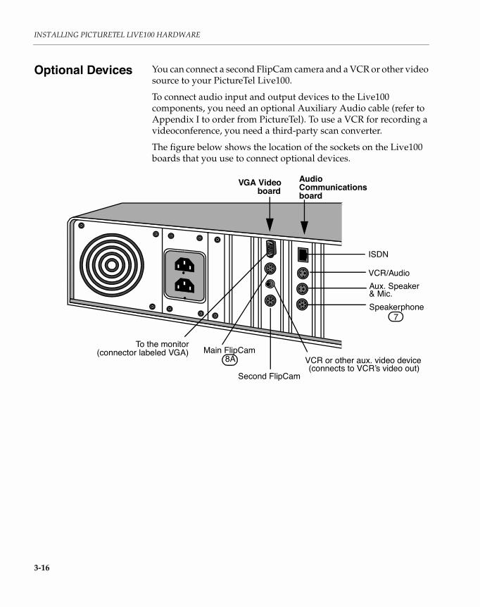
Optional Devices You can connect a second FlipCam camera and a VCR or other video source to your PictureTel Live100.
To connect audio input and output devices to the Live100 components, you need an optional Auxiliary Audio cable (refer to Appendix I to order from PictureTel). To use a VCR for recording a videoconference, you need a third-party scan converter.
The figure below shows the location of the sockets on the Live100 boards that you use to connect optional devices.
VGA Video AudioCommunicationsboardboard
To the monitor(connector labeled VGA)
ISDN
VCR/Audio
Speakerphone
Aux. Speaker& Mic.
Main FlipCamVCR or other aux. video device
Second FlipCam
7
8A(connects to VCR’s video out)

Optional Devices
3-17
Connecting a Second FlipCam CameraTo connect a second FlipCam camera to your PictureTel Live100, follow these steps:
1. Be sure your PC is turned off.
Caution
Do not connect or disconnect Live100 components when your PC is on. Doing so may damage the Live100 hardware.
2. Plug the camera cable into the socket labeled that is farthest from the 15-pin VGA connector for your PC monitor.
3. To enable the camera, power on your PC, bring up the PictureTel Live application, and from the Tools menu choose Preferences. Choose the Cameras category and assign a name to the second FlipCam camera and select OK.
Connecting a VCR or Other Video SourceTo connect a VCR or other composite video source (such as a camcorder) to the Live100 boards, follow these steps:
1. Be sure your PC is turned off.
Caution
Do not connect or disconnect Live100 components when your PC is on. Doing so may damage the Live100 hardware.
2. Plug the VCR video-out cable into the yellow video-in socket labeled on the VGA Video board.Use a cable with an RCA connector.
3. Plug the Auxiliary Audio cable into the socket labeled or on the Audio Communications board.
4. Plug the VCR audio-out cable into the audio-in socket on the Auxiliary Audio cable.
8A
3 3A

INSTALLING PICTURETEL LIVE100 HARDWARE
3-18
5. Plug the VCR audio-in cable into the audio-out socket on the Auxiliary Audio cable.
Restarting Your PC
After you connect all of the Live100 components, power on your PC. You’re now ready to install the PictureTel Live software.

4-1
4Installing PictureTel
Live Software
Overview The PictureTel Live software can be installed after you have completed your PictureTel Live hardware installation. If you are not familiar with installing software in a Windows environment you should have an experienced person install the software for you.
In this ChapterThis chapter covers the following major topics:
Topic Page
General Considerations 2
Installing from a LAN 3
Installation Steps 4
Installing the VGA Driver 5
Starting the Setup Wizard 10
Installing LiveShare Plus 11
Installing the PictureTel Live Application 13
Locating PictureTel Live Files 20
What To Do Next 21

INSTALLING PICTURETEL LIVE SOFTWARE
4-2
General Considerations
During the installation, the PictureTel Live setup program creates a directory (C:\PICTEL\PCS), by default, for the PictureTel Live and LiveShare Plus software and copies the files into that directory.
During setup, you’ll enter information about the PictureTel Live 50 or Live100 board configurations and your videoconferencing network interface.
If you are using ISDN BRI (basic rate interface), make sure you have the following information from your network provider (telephone company or telecom group) before you run the PictureTel Live setup program:
❑ The ISDN signaling protocol (referred to as switch type)❑ Your Service Provider Identification (SPID) numbers ❑ Your Multiple Subscriber Numbers (MSN), for switches outside
the USA and Canada, that allow multiple terminals on a single line
❑ Your Local Directory Numbers (LDN), for switches inside the USA and Canada, that allow multiple terminals on a single line

Installing from a LAN
4-3
Installing from a LAN
If you are installing PictureTel Live software in several Live systems connected to a LAN, you can install the software from the LAN rather than from disks. Just follow these steps:
1. Create installation directories on a convenient hard disk.On a hard disk accessible to all the Live, create the directory structure illustrated below.
2. Copy the installation disks to the new directories.Copy all the files from the first installation disk to the 1 directory, from the second disk to the 2 directory, and so on.
3. Use these directories in place of the installation disks.As you follow the instructions in the rest of this chapter, use the directories in place of the installation disks.
For example, when you are ready to run the Setup program, instead of using a pathname like
a:\setupuse one like
e:\live\1\setup
LivePlus123
Live123
or
Liveshare Plus LiveShare Plus
VGAE:\
Live 50 or 100
VGA Video Drivers
for Win3.1x for Win 95

INSTALLING PICTURETEL LIVE SOFTWARE
4-4
Installation Steps To install the complete Live application the following installation order is recommended.
1. The correct VGA Video Drivers for your PictureTel Live hardware need to be selected and installed.
2. Insert the Live Disk 1 and run a:\setup to initiate the Setup Wizard.
or
LiveShare Plus LiveShare Plus
Live
VGA Video Drivers
Step 3.)
Step 1.)
Step 4.)
Step 2.)
for Win3.1x for Win 95
Running the PictureTel Live Setup Wizard

Installing the VGA Driver
4-5
3. Install the Windows 3.1 or the Windows 95 version of LiveShare Plus. (After this install, Windows will be restarted.)
4. Install the PictureTel Live application. (After this install, Windows will be restarted.)
Installing the VGA Driver
The VGA driver you need to install depends on which Live system you are installing and which Windows operating system you are running. There are four different VGA driver installation/selection procedures described below that should address your specific installation requirements. Choose one of the following procedures to install your VGA drivers:
❑ If you are running Windows 3.1x, and you have installed the PictureTel Live100 system, or the Live50 system with a PictureTel VGA board for an ISA bus, refer to the Windows 3.1x PictureTel VGA Driver Installation procedure described below.
❑ If you are running Windows 95, and you have installed the PictureTel Live100 system, or the Live50 system with a PictureTel VGA board for an ISA bus, refer to the Windows 95 Driver Selection procedure described below.
❑ If you are running Windows 3.1x, and you have installed the PictureTel Live50 system with a Matrox or Compaq QVision VGA board for a PCI bus, refer to the Windows 3.1x Non-PictureTel VGA Driver Installation procedure described below.
❑ If you are running Windows 95, and you have installed the PictureTel Live50 system with a Matrox VGA video board, refer to the Windows 95 Matrox Driver Installation procedure described below.
Note: When you install the VGA drivers, set the screen resolution to 1024 x 768 (no higher) at 60 Hz and select 256 or more colors.
Windows 3.1x PictureTel VGA Driver InstallationPictureTel provides the VGA drivers necessary for Live100 systems and Live50 systems using the PictureTel VGA board for an ISA bus, running in a Windows 3.1x operating system. For Windows 95 systems, do not install the drivers provided on the VGA disk,

INSTALLING PICTURETEL LIVE SOFTWARE
4-6
instead, perform the Windows 95 Driver Selection procedure described below.
To install the appropriate driver from the Windows 3.1x desktop, follow these steps.
1. Open the Main program group and select (double-click) Windows SetupWindows displays the Windows Setup window.
2. From the Options menu, select Change System Settings...Windows displays the Change System Settings window.
3. Click on the Display bar or on the down arrow next to the Display bar.A scrollable list of display drivers appears.
4. Press the down arrow until you highlight Other display (Requires disk from OEM)..., and press Enter.
5. Insert the disk labeled VGA Driver into the diskette drive.
6. Enter the appropriate drive at the prompt and press Enter.
7. Highlight the VGA driver you want to use and press Enter.The VGA driver you select must match the resolution of your PC monitor. If you don’t know the resolution of your monitor, refer to your PC documentation.
When you select a VGA driver and press Enter, a confirmation screen appears displaying your selected driver.
8. Press Enter to accept your selected VGA driver.
9. Close the windows and return to the desktop
10. Remove the VGA disk from the diskette drive.
11. Open a Windows application to verify that the VGA board is working properly.
If your selected setting causes your video display to appear distorted, you need to run the setup program again and try a lower resolution. This happens when the video display chip on your VGA board is incompatible with your selected setting.

Installing the VGA Driver
4-7
After you verify that the VGA board is working properly, follow the instructions in the next section for using the SetupWizard.
Windows 95 Driver Selection For Live100 systems, or Live50 systems using the PictureTel VGA board for an ISA bus, running in a Windows 95 operating system, perform the following Windows 95 Driver Selection procedure:
1. Click on the Start button, point to Settings, and click on Control Panel.
2. Double click on the Display icon.
3. Click on the Settings tab page.
4. Click on the Change Display type button.
5. Click on the Change button in the Adapter Type area.
6. Make sure the Show all devices setting is selected.
7. Select Tseng Labs from the Manufacturers area and the Tseng Labs ET4000 /W32 driver from the Models area of the window.
8. Click OK to apply the change.
You are prompted to restart your computer to apply the changes to the display settings.
9. Open a Windows application to verify that the VGA board is working properly.
If your selected setting causes your video display to appear distorted, you need to run the setup program again and try a lower resolution. This happens when the video display chip on your VGA board is incompatible with your selected setting.
After you verify that the VGA board is working properly, follow the instructions in the next section for using the Setup Wizard.

INSTALLING PICTURETEL LIVE SOFTWARE
4-8
Windows 3.1x Non-PictureTel VGA Driver Installation If you are installing a Live50 system with a Matrox or Compaq QVision VGA board for a PCI bus and you are running Windows 3.1x, then you need to follow the installation instructions provided specifically for that VGA video board.
1. Run the Setup program provided by the video board manufacturer.
2. After you have completed the installation, remove the VGA installation disk from the diskette drive.
3. Open a Windows application to verify that the VGA board is working properly.
If your selected setting causes your video display to appear distorted, you need to run the setup program again and try a lower resolution. This happens when the video display chip on your VGA board is incompatible with your selected setting.
After you verify that the VGA board is working properly, follow the instructions in the next section for using the Setup Wizard
Windows 95 Matrox Driver InstallationIf you are installing a Live50 system with a Matrox VGA board for a PCI bus and you are running Windows 95, then you need to follow this installation procedure. This procedure consists of three main steps:
1. Installing the Microsoft MGA Driver 1.0 (available as part of Windows 95)
2. Installing the MGA PowerDesk upgrade (disk supplied with PictureTel Live50, Version 1.6)
3. Adjusting the “Desktop Area” and “Display Area.”
Step 1: Installing the Microsoft MGA Driver You may have installed a new Matrox VGA board as part of the Live50 hardware installation, or your Matrox board may have been installed from a previous version of Live50 (formerly PCS 50). In either case when Windows 95 is first started with the Matrox board installed, Windows 95 acknowledges the Matrox VGA board and automatically installs the Microsoft MGA 1.0 driver.
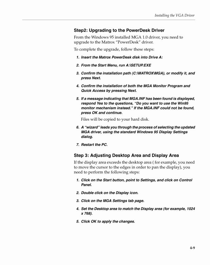
Installing the VGA Driver
4-9
Step2: Upgrading to the PowerDesk DriverFrom the Windows 95 installed MGA 1.0 driver, you need to upgrade to the Matrox “PowerDesk” driver.
To complete the upgrade, follow these steps:
1. Insert the Matrox PowerDesk disk into Drive A:
2. From the Start Menu, run A:\SETUP.EXE
3. Confirm the installation path (C:\MATROX\MGA), or modify it, and press Next.
4. Confirm the installation of both the MGA Monitor Program and Quick Access by pressing Next.
5. If a message indicating that MGA.INF has been found is displayed, respond Yes to the questions, “Do you want to use the Win95 monitor mechanism instead.” If the MGA.INF could not be found, press OK and continue.Files will be copied to your hard disk.
6. A “wizard” leads you through the process of selecting the updated MGA driver, using the standard Windows 95 Display Settings dialog.
7. Restart the PC.
Step 3: Adjusting Desktop Area and Display AreaIf the display area exceeds the desktop area ( for example, you need to move the cursor to the edges in order to pan the display), you need to perform the following steps:
1. Click on the Start button, point to Settings, and click on Control Panel.
2. Double click on the Display icon.
3. Click on the MGA Settings tab page.
4. Set the Desktop area to match the Display area (for example, 1024 x 768).
5. Click OK to apply the changes.

INSTALLING PICTURETEL LIVE SOFTWARE
4-10
After you verify that the VGA board is working properly, follow the instructions in the next section for using the Setup Wizard.
Starting the Setup Wizard
The Installation of PictureTel Live software is guided by a Windows wizard. The wizard identifies any component that has been installed (such as the VGA Video Drivers) and directs you to install the remaining components that make up the complete installation:
❑ LiveShare Plus application
❑ Live application
When running, the wizard displays a message area to inform you of the status of each installation component and the necessary actions to complete each part of the installation.
Before you begin the installation, your PC must be displaying the Windows 3.1x or Windows 95 desktop.
To initiate the PictureTel Live Setup Wizard, run the setup program that initiates the Setup Wizard by following these steps:
1. From either the Windows 3.1x Program Manager or the Windows 95 Start Menu, select the Run ... program.Windows displays either the 3.1x Run dialog box

Installing LiveShare Plus
4-11
or the Windows 95 Run dialog box.
2. Insert Disk1 :SETUP of the Live 50 or 100 installation disks, and enter a:\setup in the Run dialog box.Windows initiates the Live Setup Wizard.
Installing LiveShare Plus
The LiveShare Plus application comes in two different versions, one for Windows 3.1x, and one for Windows 95. Make sure you follow the installation instructions for the version that matches your operating environment.

INSTALLING PICTURETEL LIVE SOFTWARE
4-12
Install LiveShare Plus locally on each PC; do not install it on network drives.
Installing LiveShare Plus On Windows 3.1x and Windows 95To install LiveShare Plus from the Setup Wizard:
1. Insert LiveShare Plus diskette 1 into the diskette drive (a: or b:).
2. Set the Install Path to read from the correct diskette drive.
3. Select (double-click) LiveShare Plus from the Wizard’s display box.LiveShare Plus setup begins.
4. Follow the instructions that appear on the screen.
5. When the Choose Destination Location box appears, you can enter a custom installation location or click the Continue button to accept the default location. Only install LiveShare Plus on your local hard disk. Do not install it on a network drive or on a removable disk drive.
When the installation is complete, the setup program displays a finished message and initiates the Do you want to restart the computer dialog.
6. Before you restart the computer, remove the diskettes from the drive.
7. When installation is complete, store your LiveShare Plus diskettes in a safe place.

Installing the PictureTel Live Application
4-13
Installing the PictureTel Live Application
To install the PictureTel Live application from the Setup Wizard, perform the following steps:
1. Insert DISK 1: SETUP of the Live50 or Live 100 Installation disks in drive a: or b: and enter a:\setup or b:\setup in the Run dialog box to run the Setup Wizard.
2. Select (double-click) PictureTel Live (double-click) from the wizard’s display box.
3. Fill in your name, your company, and the serial number of your PictureTel Live unit and press enter.You can find the serial number on the product registration card, which is shipped with the PictureTel Live documentation.
The setup program displays a confirmation window.
4. If the information is correct, press enter (or click the Yes button). If the information is incorrect, click the No button and make the corrections.Setup displays the Installation Path window.
The default drive and directory are C:\PICTEL\PCS. You can accept the default or change this information by typing a different name.

INSTALLING PICTURETEL LIVE SOFTWARE
4-14
5. Press enter (continue) to keep the default drive and directory or change them to be compatible with your standards.The Setup program creates the directory for the PictureTel Live application and will later copy all but two files into this directory. (See Locating PictureTel Live Files on page 4-20.)
If an existing version of Live is currently installed and this directory already exists, the setup program allows you to override it and continue the upgrade installation, choose a different directory, or cancel this setup program.
After the directory path is confirmed, setup begins a dialog that allows you to enter network interface informaton.
6. Setup displays the following window with the network interface choices your PC will use for videoconferencing.
If you enabled ISDN, the dialog will ask you for the information described in the following paragraphs.
If you enabled Switched 56, V.35, or RS-449, you will be asked for the IRQ and I/O Port Address settings of the network interface board you have previously installed. Then you can go to Step 10.

Installing the PictureTel Live Application
4-15
ISDN ProtocolThere are different ISDN protocols in use throughout the world, and your Live system must be configured to operate with the specific protocol that your network uses.
The protocol depends on the country where you are using the Live, and whether you are connected to a public or a private network.
The Setup program displays a list of countries; if only a single switch type is supported in the public network in a country, then only the name of the country appears in the list. If multiple switch types are supported in a country, then each switch type for that country is listed.
Selecting an ISDN protocolIf you are connected to a public network, and your country appears on the list only once, select that list item.
If you are connected to a public network in one of the following countries, you should select Europe: Euro-ISDN:
❑ Austria❑ Denmark❑ Finland❑ Greece❑ Hong Kong❑ Ireland❑ Italy❑ Luxembourg❑ Netherlands❑ Portugal❑ Spain❑ Sweden❑ United Kingdom
If you are connected to a public network in France and you have installed the Live100 system, you have the following choices:
❑ Euro-ISDN❑ VN3
Live50 users in France must select Euro-ISDN.

INSTALLING PICTURETEL LIVE SOFTWARE
4-16
If you are connected to a public network in Germany and you have installed either the Live50 or Live100 system, you have the following choices:
❑ Euro-ISDN❑ ITR6
Note: If you are connected to a private network, or if your country appears on the list more than once, or if your country does not appear in the list displayed by the Setup program, and is not in the list of countries that use Europe: Euro-ISDN, you must contact your network service provider to determine which protocol you should select during installation.
7. Enter the Service Provider IDs (SPIDs) for the B channels (in the United States and Canada only)On fully-initializing switches (this includes 5ESS CUSTOM Multipoint, DMS CUSTOM Multipoint, and National ISDN (NI-1)) in the United States and Canada, you must enter the SPIDs assigned to you by your network provider. Unless these items are entered correctly, you will not be able to make or receive calls.
8. If you are connecting your Live system to an ISDN network outside of North America, you may need to specify the "Number Type" and "Number Plan" used by that network.This is done when you specify the ISDN protocol. The pull-down menus which allow you to specify the Number Type and Number Plan appear only if needed.
If you do not know the proper settings, you can attempt to proceed with the installation using the default values. If you then have difficulty originating or receiving calls, contact your service provider to determine the proper Number Type and Number Plan, and run the PictureTel Live Configuration program to configure your system accordingly.
9. You need to specify the Multiple Subscriber Numbers (MSNs) for those switches outside the United States and Canada that permit multiple terminals, each with a unique set of ISDN phone numbers, to be connected to a single line. For such switches inside the United States and Canada, you need to specify the equivalent

Installing the PictureTel Live Application
4-17
Local Directory Numbers in these boxes. If you do not specify the Local Directory Numbers for calls inside the United States and Canada, you will not be able to receive calls.In order to allow your Live system to respond only to those incoming calls which are intended for it, you must specify the MSNs or LDNs which will differentiate your Live from all other terminals on the line.
10. In the next window you must specify the PC settings for the Live board. The default settings are:
Refer to Appendix A to check that these default settings do not conflict with other settings already used in your PC.
Note: If you have trouble bringing up DOS and Windows or starting up PictureTel Live after you install the software, refer to Chapter 5, Troubleshooting, and then run the Setup program again to manually change the settings.
Write down the settings here for future reference:
IRQ: ______I/O port address: __________________Shared memory space address: __________________The Setup program automatically selects the video input format based on the country ISDN switch, either : PAL (Phase Alternate Line) for Europe or NTSC (National Television Standards Committee) for North America and Japan.
You can override the selection if the setup program selects the wrong format.
Setting Default
IRQ 11
I/O port address 280
memory space address D000 through D3FF

INSTALLING PICTURETEL LIVE SOFTWARE
4-18
11. Specify a node name that identifies you and your PictureTel Live system to the other party during videoconferencesThe name can contain up to 32 characters and can include spaces. You can use your own name or any other name to identify yourself and your PC.
12. If you are installing the Live50 software, the setup program performs an additional step and verifies your video board.
Note: This step is for the Live50 software installation only.
You have the option of accepting the video card Setup has detected (Yes), or selecting another card by responding No and initiating the board selection box dialog. We recommend you accept the video card Setup has detected. If a problem occurs you can choose another selection.
At this point, the basic installation is over and setup responds by transferring the files from the installation disks to your hard drive and giving you the option of modifying your config.sys file to prevent an extended memory manager from using specific address space reserved for Live operations.
Reconfiguring Memory (optional step)If you are using an extended memory manager, such as EMM386 (which is shipped with Microsoft DOS or Windows) or a third party manager, you need to configure the extended memory manager to exclude the memory region that is used by your PictureTel Live software.
The PictureTel Live Setup program allows you to edit the line in your CONFIG.SYS file, which configures the extended memory manager, by displaying an edit window in which you can make the appropriate changes.
Note: If you are sure that you do not have an extended memory manager installed in your PC, or if you are not upgrading from a previous version of PictureTel Live and have not changed the memory address, you do not need to make the following change.
Be sure to refer to the documentation for the memory manager installed in your PC for the exact syntax of the exclude statement
Installing the PictureTel Live Application
4-19
before modifying your CONFIG.SYS file. For example, if your extended memory manager is EMM386, refer to your DOS manual for the statement format.
The memory region which must be excluded begins at the address you entered earlier in the installation. If you accepted the default value, then the memory region begins at D000.
The address at which the memory region ends is the starting address plus 3FF. If you accepted the default value, then the memory region ends at D3FF.
For example, if you are using the EMM386 extended memory manager, you must edit the line in your CONFIG.SYS file in which EMM386 is configured to include the statement:
x=D000-D3FF1. Edit your CONFIG.SYS file to add an exclude statement to the line
defining your extended memory manager.2. Allow the Setup program to reboot your PC.
The Setup program automatically reboots your PC and restarts Windows.
3. Once Windows has restarted, you may need to re-optimize your system, using your extended memory manager’s optimization program.For example, if you use EMM386, you now need to run the MS-DOS 6.0 Memmaker program.If Windows fails to restart correctly, you probably need to select a different combination of IRQ, I/O, and memory address settings. Refer to Chapter 5, Troubleshooting.
Verifying Your InstallationAfter installing PictureTel Live, you can run a simple test to confirm that it is working properly.
1. Start PictureTel Live.If you can’t start PictureTel Live, follow these steps:
a. Exit Windows.
b. Turn your PC off, and then on.
c. Start Windows.

INSTALLING PICTURETEL LIVE SOFTWARE
4-20
d. Attempt to start PictureTel Live.
If the Live application is still not working properly, then refer to Chapter 5, Troubleshooting.
2. Check your Local Video window to make sure that you can see the video image captured by your local video camera.
3. Choose Diagnostics from the Tools menu.
4. Click the Loopback button.After a delay of several seconds the Loopback test begins.
Once the test begins, you should observe a delay of about one second between moving and seeing the motion in your video image, and between speaking and hearing your speech.
You can adjust the volume of the speaker using the scroll tool to the left of the test mode video image.
5. Click the hangup (or end test) button.If the Loopback test is unsuccessful, a message may be displayed at the bottom of the remote video window.
6. Verify your Network connection. You should see the Ready message displayed at the bottom of the remote video window.If you see the “Network Down” message, then there is a problem with the network. Refer to Chapter 5, Troubleshooting.
Locating PictureTel Live Files
The PictureTel Live Setup program installs all but two PictureTel Live files in the directory that you specified. For example, if you accept the default directory, the Setup program installs the PictureTel Live software in C:\PICTEL\PCS.
The Setup program installs these files in the C:\WINDOWS directory:
❑ PCS100.INI
❑ VCSWIN.INI

What To Do Next
4-21
In addition, the Setup program saves the following files before modifying them:
What To Do Next You’re now ready to refer to the PictureTel Live User’s Guide to learn how to use the system.
This File: Is Saved Before Modification As:
C:\WINDOWS\SYSTEM.INI C:\WINDOWS\SYSTEM.PCS
C:\WINDOWS\WIN.INI C:\WINDOWS\WIN.PCS


5-1
5Troubleshooting
Overview This chapter helps you troubleshoot problems that can occur during installation.
Note: If you have problems during normal operation of PictureTel Live, refer to the troubleshooting chapter of the PictureTel Live User’s Guide.
In this ChapterThis chapter covers the following major topics:
Topic Page
Problems Bringing Up DOS and Windows 2
Problems Starting Up PictureTel Live 4

TROUBLESHOOTING
5-2
Problems Bringing Up DOS and Windows
If Windows fails to start after you have installed PictureTel Live, you probably need to select a different combination of IRQ, I/O and memory addresses for the PictureTel Live system. Refer to Appendix A “Checking Your PC Settings” for information on choosing an appropriate combination.
PictureTel Live Setup modifies the SYSTEM.INI and WIN.INI files in your Windows system directory. In order to restart Windows, you will need to replace these files with their original versions. Do this to restore the original versions which were saved by PictureTel Live Setup:
1. Change to the directory containing your Windows system files.Typically, this is:C:\WINDOWS
2. Replace the new versions of the system files with the original versions of the files, by entering the following commands:COPY /Y SYSTEM.PCS SYSTEM.INICOPY /Y WIN.PCS WIN.INI
3. Reboot your PC.If you still encounter problems bringing up DOS and Windows, refer to the instructions in Table 5-1 on page 5-3.
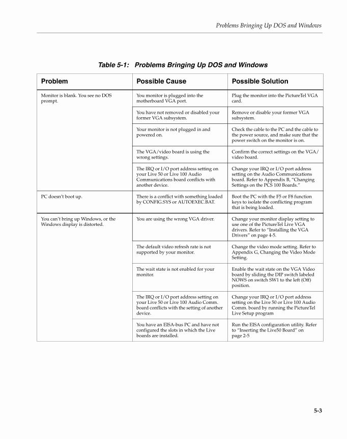
Problems Bringing Up DOS and Windows
5-3
Table 5-1: Problems Bringing Up DOS and Windows
Problem Possible Cause Possible Solution
Monitor is blank. You see no DOS prompt.
You monitor is plugged into the motherboard VGA port.
Plug the monitor into the PictureTel VGA card.
You have not removed or disabled your former VGA subsystem.
Remove or disable your former VGA subsystem.
Your monitor is not plugged in and powered on.
Check the cable to the PC and the cable to the power source, and make sure that the power switch on the monitor is on.
The VGA/video board is using the wrong settings.
Confirm the correct settings on the VGA/video board.
The IRQ or I/O port address setting on your Live 50 or Live 100 Audio Communications board conflicts with another device.
Change your IRQ or I/O port address setting on the Audio Communications board. Refer to Appendix B, “Changing Settings on the PCS 100 Boards.”
PC doesn’t boot up. There is a conflict with something loaded by CONFIG.SYS or AUTOEXEC.BAT.
Boot the PC with the F5 or F8 function keys to isolate the conflicting program that is being loaded.
You can’t bring up Windows, or the Windows display is distorted.
You are using the wrong VGA driver. Change your monitor display setting to use one of the PictureTel Live VGA drivers. Refer to “Installing the VGA Drivers” on page 4-5.
The default video refresh rate is not supported by your monitor.
Change the video mode setting. Refer to Appendix G, Changing the Video Mode Setting.
The wait state is not enabled for your monitor.
Enable the wait state on the VGA Video board by sliding the DIP switch labeled NOWS on switch SW1 to the left (Off) position.
The IRQ or I/O port address setting on your Live 50 or Live 100 Audio Comm. board conflicts with the setting of another device.
Change your IRQ or I/O port address setting on the Live 50 or Live 100 Audio Comm. board by running the PictureTel Live Setup program
You have an EISA-bus PC and have not configured the slots in which the Live boards are installed.
Run the EISA configuration utility. Refer to “Inserting the Live50 Board” on page 2-5
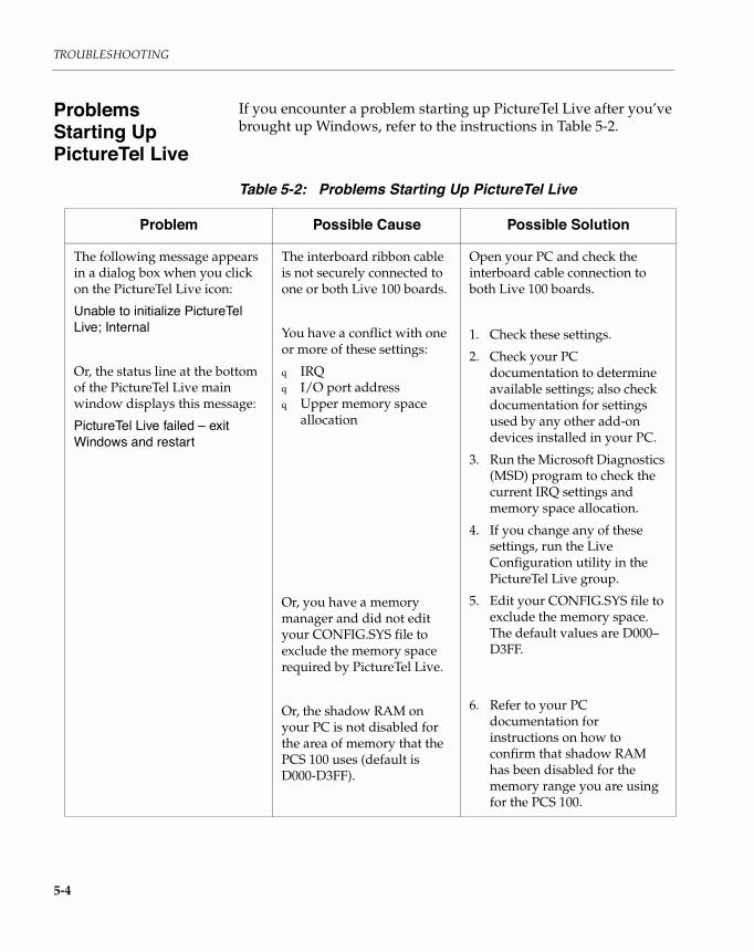
TROUBLESHOOTING
5-4
Problems Starting Up PictureTel Live
If you encounter a problem starting up PictureTel Live after you’ve brought up Windows, refer to the instructions in Table 5-2.
Table 5-2: Problems Starting Up PictureTel Live
Problem Possible Cause Possible Solution
The following message appears in a dialog box when you click on the PictureTel Live icon:
Unable to initialize PictureTel Live; Internal
Or, the status line at the bottom of the PictureTel Live main window displays this message:
PictureTel Live failed – exit Windows and restart
The interboard ribbon cable is not securely connected to one or both Live 100 boards.
You have a conflict with one or more of these settings:
q IRQq I/O port addressq Upper memory space
allocation
Or, you have a memory manager and did not edit your CONFIG.SYS file to exclude the memory space required by PictureTel Live.
Or, the shadow RAM on your PC is not disabled for the area of memory that the PCS 100 uses (default is D000-D3FF).
Open your PC and check the interboard cable connection to both Live 100 boards.
1. Check these settings.
2. Check your PC documentation to determine available settings; also check documentation for settings used by any other add-on devices installed in your PC.
3. Run the Microsoft Diagnostics (MSD) program to check the current IRQ settings and memory space allocation.
4. If you change any of these settings, run the Live Configuration utility in the PictureTel Live group.
5. Edit your CONFIG.SYS file to exclude the memory space. The default values are D000–D3FF.
6. Refer to your PC documentation for instructions on how to confirm that shadow RAM has been disabled for the memory range you are using for the PCS 100.

Problems Starting Up PictureTel Live
5-5
You see no video in the Local Video window when you start up PictureTel Live.
Your camera is not plugged in or powered on.
Check the cable to the PC and the cable to the power source and check that the power switch on the camera is on.
The VAFC cable is not securely connected to the Live 50 board and the VGA board. (Live 50 only)
Open your PC and check the VAFC cable connection to both boards.
You have specified the wrong graphics card. (Live 50 only)
Use the Live configure program and select the correct graphics card.
The VGA driver that you have selected may not work with your monitor.
Select a VGA driver with a different monitor resolution.
The following message appears:
Network downThe network cable is not plugged in.
Check the cable connection to the network.
Either the Live system or the network is failing.
Choose Diagnostics from the PictureTel Live Tools menu, and run the Loopback test. For instructions, see the PictureTel Live PCS 50/100 User’s Guide.
If any of this test fails, call your authorized PictureTel service provider. If the test passes, call your network service provider.
Table 5-2: Problems Starting Up PictureTel Live
Problem Possible Cause Possible Solution


A-1
AChecking Your
PC Settings
Overview If you start up the PictureTel Live application and see hardware failure messages, it might mean that one or more default settings conflict with your PC settings. To search for conflicts, follow the steps under Checking an ISA-Bus PC orChecking and Configuring an EISA-Bus PC. If you find a conflict, run the PictureTel Live Setup program again and change the settings.
If you aren’t sure whether you have an ISA-bus or EISA-bus PC, refer to the documentation that came with your PC.
Using Auto Detect
The PictureTel Live Setup program can automatically detect available settings for IRQs, I/O port addresses, and shared memory space on the Live 50 board and the Live100 Audio Communications board. However, with some PCs, the Setup program may not be able to detect one or more of these settings. If this happens, we recommend you choose the default settings. These settings work for most PC configurations.
Under Windows 95On one of the windows of the Setup program there is an “Auto detect” button that is only active if you are installing PictureTel Live in a Windows 95 environment. This button causes the Setup program to review the other devices installed under Windows 95 and selects IRQ, I/O port addresses and shared memory values which should not conflict with any of these devices.
However, you should be aware that values selected using the Auto detect feature can still present conflicts under some circumstances.

CHECKING YOUR PC SETTINGS
A-2
Checking anISA-Bus PC
If your PC has an ISA bus, check the current IRQ settings, I/O port address settings, and shared memory space allocations by following these steps:
1. Start Windows and select MS-DOS prompt from the Main program group.Windows displays an MS-DOS box.
1. From the Windows DOS prompt, type this command:msd
A warning message may appear; ignore the warning, since in this case it is beneficial to keep Windows running while you execute the Microsoft Diagnostics program.
The Microsoft Diagnostics program Main Menu appears.
2. Type q to select IRQ Status.The IRQ Status screen appears.
3. Locate IRQ 11 and check if it is available.The Live 50 board and the Live 100 Audio Communications board use IRQ 11 as its default IRQ setting. If the Description column displays (Reserved) and if the Detected column is blank, IRQ 11 is possibly available for the Audio Communications board.
If a device is using IRQ 11, locate an available IRQ setting and write it down:
Available IRQ: ______
You’ll need to change the setting on the Audio Communications board, as described in “Changing Settings on the Audio Communications Board” on page B-3.
4. Press Enter to return to the Diagnostics program Main Menu.
5. Type m to select Memory.The Memory screen appears.

Checking an ISA-Bus PC
A-3
6. Check if the memory address you set in the PictureTel Live Setup program is available.If you find that a device is using this shared memory space, locate an available 16 KB memory range on the Memory screen and write down its starting address:
Available shared memory space address: __________________
Note: If no 16 KB range in extended memory is available, you must make it available. If you use the standard Windows memory manager, this range will be automatically excluded during installation. If you use a third-party memory manager, you must add the appropriate EXCLUDE statement yourself.
7. Press Enter to return to the Diagnostics program Main Menu.
8. Press F3 to exit the Microsoft Diagnostics program.
9. Review your PC documentation for conflicts with theI/O port address you set in the PictureTel Live Setup program.❑ Address 0280 (the default I/O port address for the Audio
Communications board)
❑ Address 27CA-27CE (the default I/O port address for the VGA Video board)
If you have any other add-on boards installed in your PC, also review the add-on board documentation.
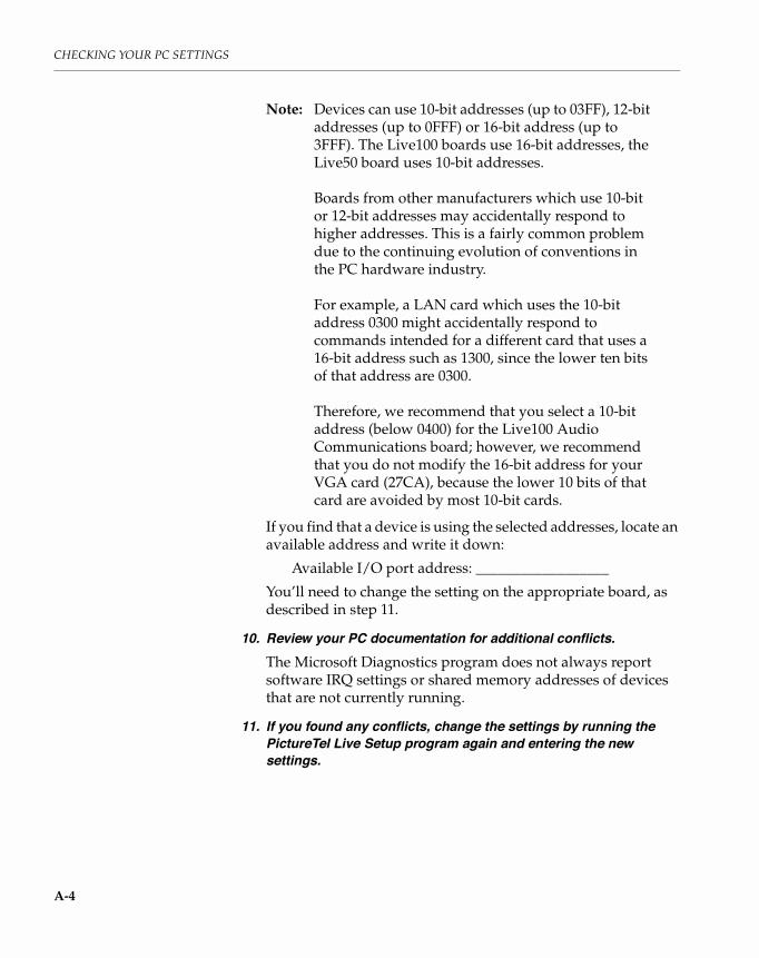
CHECKING YOUR PC SETTINGS
A-4
Note: Devices can use 10-bit addresses (up to 03FF), 12-bit addresses (up to 0FFF) or 16-bit address (up to 3FFF). The Live100 boards use 16-bit addresses, the Live50 board uses 10-bit addresses.
Boards from other manufacturers which use 10-bit or 12-bit addresses may accidentally respond to higher addresses. This is a fairly common problem due to the continuing evolution of conventions in the PC hardware industry.
For example, a LAN card which uses the 10-bit address 0300 might accidentally respond to commands intended for a different card that uses a 16-bit address such as 1300, since the lower ten bits of that address are 0300.
Therefore, we recommend that you select a 10-bit address (below 0400) for the Live100 Audio Communications board; however, we recommend that you do not modify the 16-bit address for your VGA card (27CA), because the lower 10 bits of that card are avoided by most 10-bit cards.
If you find that a device is using the selected addresses, locate an available address and write it down:
Available I/O port address: __________________
You’ll need to change the setting on the appropriate board, as described in step 11.
10. Review your PC documentation for additional conflicts.The Microsoft Diagnostics program does not always report software IRQ settings or shared memory addresses of devices that are not currently running.
11. If you found any conflicts, change the settings by running the PictureTel Live Setup program again and entering the new settings.

Checking and Configuring an EISA-Bus PC
A-5
Checking and Configuring an EISA-Bus PC
If your PC has an EISA bus, use the EISA configuration utility supplied by the PC manufacturer to do the following:
1. Check your current PC settings for conflicts with the settings for IRQ, I/O port addresses, and shared memory space you set in the PictureTel Live Setup program.If you find any conflicts, locate and write down the available settings here:
Available IRQ: ______
Available I/O port address: __________________
Available shared memory space address: __________________
2. If you found any conflicts, change the settings by running the PictureTel Live Setup program again and entering the new settings.
3. Configure your PC for the Live50 and Live100 Audio Communications board.Run your EISA configuration utility to configure your PC for the Audio Communications board, using these options:
❑ Manually configure an ISA board
❑ Add a board without a .CFG file
For instructions, refer to your PC documentation.
If you’re installing optional PictureTel Live network interface boards, refer Appendix C or to the documentation provided with those boards.


B-1
BChanging
Settings on theLive100 Boards
Overview This appendix tells you how to change the IRQ setting and theI/O port address settings on the Live100 boards. If you find conflicts with any of the default settings on these boards when you check your PC environment (as explained in Chapter 3), follow the instructions in this appendix.
Changing Settings on the VGA Video Board
To change the I/O port address setting on the VGA Video board, follow these steps:
1. Remove the board from its plastic antistatic package.
Caution
This board can be damaged by static discharge. To equalize static charge, ground yourself by touching the metal back panel of your PC.

CHANGING SETTINGS ON THE LIVE100 BOARDS
B-2
Figure B-1 shows the VGA Video board, which you can identify by the 15-pin VGA connector on the back plate.
Figure B-1: VGA Video Board
2. Place the board on a level surface so that its component side faces up and the back plate (with the connectors) is to your right.
3. If the default I/O port address setting of 27CA–27CE conflicts with the I/O port address of another device in your PC, change the setting for this board to 029A–029E by doing the following:
a. Refer to Figure B-1 and locate switch SW1 on the board.b. Use a ballpoint pen to slide the DIP switch labeled ADR2 on
SW1 to the right. This changes the I/O port address for this board from 27CA–27CE to 029A–029E.
Caution
Do not use a pencil. The graphite can damage the switch.
ADR2IRQ9NOWSRSVD
SW1
OFF ON
Back plate
VGAconnector
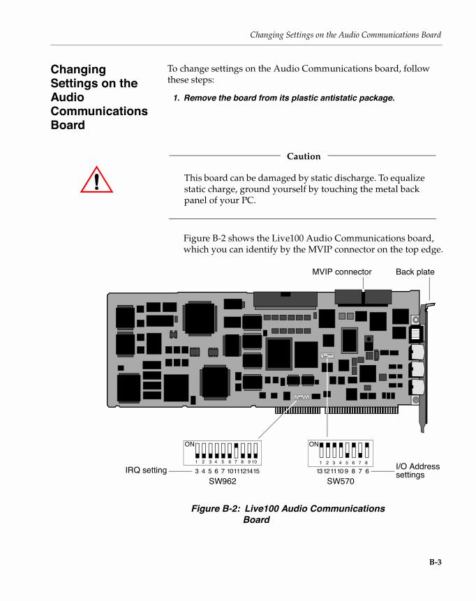
Changing Settings on the Audio Communications Board
B-3
Changing Settings on the Audio Communications Board
To change settings on the Audio Communications board, follow these steps:
1. Remove the board from its plastic antistatic package.
Caution
This board can be damaged by static discharge. To equalize static charge, ground yourself by touching the metal back panel of your PC.
Figure B-2 shows the Live100 Audio Communications board, which you can identify by the MVIP connector on the top edge.
Figure B-2: Live100 Audio Communications Board
SW9623 4 5 6 7 1011121415
SW570
ON
9 8 67101112131 2 3 4 5 6 7 8 9 10
IRQ setting
ON
1 2 3 4 5 6 7 8 I/O Address
Back plate
settings
MVIP connector

CHANGING SETTINGS ON THE LIVE100 BOARDS
B-4
2. Place the board on a level surface so that its component side faces up and the back plate (with the connectors) is to your right.
3. If the default IRQ setting (IRQ 11) conflicts with the IRQ of another device in your PC, change the IRQ setting for this board by doing the following:
a. Refer to Figure B-2 and locate switch SW962 on the board.This switch has 10 sliding DIP switches. A DIP switch in the up position is ON and in the down position is OFF.
b. Use a ballpoint pen to slide the DIP switch labeled 7, which is IRQ 11, down to the OFF position.
Caution
Do not use a pencil. The graphite can damage the switch.
c. Make sure all switches are down in the OFF position before proceeding to the next step.
d. Slide the DIP switch for your selected IRQ setting up to the ON position.
Note: Only one DIP switch can be in the ON position.
You’ll need to specify this IRQ setting during software installation, as explained in Chapter 4.

Changing Settings on the Audio Communications Board
B-5
4. If the default I/O port address setting (0280) conflicts with the I/O port address of another device in your PC, change the setting for this board by doing the following:
a. Refer to Figure B-2 and locate switch SW570 on the Audio Communications board.This switch has eight sliding DIP switches. A switch in the up position is a logical 0, and a switch in the down position is a logical 1. Figure B-2 illustrates the position of the DIP switches for the default I/O port setting, which is hexadecimal 0280.
I/O port addresses are expressed in hexadecimal and can be assigned 0000 to 3FC0 in increments of 64 (40 hexadecimal).
The I/O port address takes the form
xyz0
where
x is designated with switches 13 and 12 and can be hexadecimal digits 0, 1, 2, or 3
y is designated with switches 11 through 8 and can be hexadecimal digits 0 through F
z is designated with switches 7 and 6 can be hexadecimal digits 0, 4, 8, or C
0 is preset and is not defined by a switch
Table B-1 on the next page provides the switch settings for each hexadecimal digit. The leftmost column lists the 16 hexadecimal digits. The remaining columns show you how to set each switch for that digit.

CHANGING SETTINGS ON THE LIVE100 BOARDS
B-6
Table B-1: Switch Settings for Hexadecimal Digits
Digit
Switch Number
x Position y Position z Position
13 12 11 10 9 8 7 6
0
1
2
3
4
5
6
7
8
9
A
B
C
D
E
F
Note: The shading indicates that the digit is not allowed in this position.

Changing Settings on the Audio Communications Board
B-7
b. Use a ballpoint pen to slide the following DIP switches:
For the digit in position x, set switches 13 and 12 accordingly. This digit can be 0, 1, 2, or 3 only.
For the digit in position y, set switches 11 through 8 accordingly. This digit can be 0 through F.
For the digit in position z, set switches 7 and 6 accordingly. This digit can be 0, 4, 8, or C only.
Remember, the last 0 in the address is preset; you do not have to set any switches.
Caution
Do not use a pencil. The graphite can damage the switches.
For example, to set the address to 0200, set the switches like this:
Or, to set the address to 16C0, set the switches like this:
You’ll need to specify the new I/O port address setting during software installation, as explained in Chapter 4.
ON
1 2 3 4 5 6 7 8
2 0
Logical 0
Logical 1
0 0
13 12 11 10 9 8 7 6
ON
1 2 3 4 5 6 7 8
6 C
Logical 0
Logical 1
1 0
13 12 11 10 9 8 7 6


C-1
CInstalling
Network InterfaceBoards
Overview This appendix contains installation instructions for the available Network Interfaces for the Live50 and Live100 videoconferencing systems. It also includes information on cable connections to the Inverse Multiplexer (IMUX) devices, which provide a variety of network solutions for videoconferencing applications.
The installation procedures differ slightly, depending on whether you are installing the Switched-56 or the V.35/RS-449 Data-Dialer Module/Network Interface board. The procedures for each type of installation are summarized below:
To install the Switched-56 Network Interface board:
1. Install the Live50/Live100 hardware using Chapter 2, Installing PictureTel Live50 Hardware or Chapter 3, Installing PictureTel Live100 Hardware for instructions.
2. Install the Switched-56 Network Interface board.
3. Install the PictureTel Live application software using Chapter 4, Installing PictureTel Live Software, for instructions.
To install the V.35/RS-449 Data-Dialer Module (DDM)/Network Interface board:
1. Install the Live50/Live100 hardware using Chapter 2, Installing PictureTel Live50 Hardware or Chapter 3, Installing PictureTel Live100 Hardware for instructions.
2. Install the DDM/Network Interface board.

INSTALLING NETWORK INTERFACE BOARDS
C-2
3. Install the PictureTel Live application software using Chapter 4, Installing PictureTel Live Software, for instructions.
Note: On the Network Interface Settings window, be sure to select ISDN BRI only (and no additional networks) to test your Live50/Live100 installation.
If do not have ISDN service, you should still perform this step, selecting “AT&T 5ESS custom point-to-point” as the ISDN protocol.
4. When the installation is complete, select Tools > Diagnostics > Loopback to test the audio and video and verify the Live50/Live100 installation integrity.
5. Install the DDM/Network Interface board software as described later in this document.
6. When the installation is complete, select Tools > Diagnostics > Loopback to test the integrity of your DDM/Network Interface board installation.

Overview
C-3
In this AppendixThis appendix covers the following major topics:
Topic Page
Connection Types 5
Installing the Switched-56 Network Interface Board
6
Installing the Data-Dialer Module/Network Interface Board
15
Installing the Data-Dialer Module/Network Interface Board Software
27
Cable Pinouts 40
Maximum Cable Length 45

INSTALLING NETWORK INTERFACE BOARDS
C-4
Before You Begin Make sure your product kit contains all of the appropriate items (listed below).
Switched-56 Kit
DDM V.35 Kit
Component Quantity Part Number
Switched-56 Network Interface board 1
Live50 CHI to MVIP cable (1) 1 180-0293-01
Live100 MVIP cable (1) 1 510-0167-01
Switched-56 chassis label (1) 1
Loopback test cables (2) 2
Switched-56 network cables 2
PictureTel Live50/Live100 Network Interface Installation Guide
1 800-0610-02
Component Quantity Part Number
DDM/Network Interface board 1
Live50 CHI to MVIP cable 1 180-0293-01
Live100 MVIP cable 1 510-0167-01
V.35/RS-366 4-leg cable 1 180-0313-01
DDM/Network Interface board installation diskettes
2
PictureTel Live50/Live100 Network Interface Installation Guide
1 800-0610-02

Connection Types
C-5
DDM RS-449 Kit
Connection Types
The following table identifies the appropriate Network Interface board for each type of network connection.
Note: For V.35/RS-449 connections, CSU/DSUs (Channel Service Unit/Data Service Units) may be required between the PC and the telephone company’s digital network connection. Your installation may already have these devices in place. Consult your telephone company representative.
Component Quantity Part Number
DDM/Network Interface board 1
Live50 CHI to MVIP cable 1 180-0293-01
Live100 MVIP cable 1 510-0167-01
RS-449/RS-366 4-leg cable 1 180-0312-01
DDM/Network Interface board installation diskettes
2
PictureTel Live50/Live100 Network Interface Installation Guide
1 800-0610-02
If you need this connection type: You need this type of board:
Integrated 4-Wire SW56 Switched-56 Network Interface
V.35 (or RS-449) dialed/ nondialed
DDM/Network Interface

INSTALLING NETWORK INTERFACE BOARDS
C-6
Installing the Switched-56 Network Interface Board
The Switched-56 Network Interface board allows you to connect your PictureTel Live videoconferencing system to a digital data network using a Switched-56 interface.
These components are included with your Network Interface board:
Your Switched-56 Network Interface board uses 01C0 (hexadecimal) as its default I/O port address, which is set using a DIP switch. It also uses IRQ 15 as its default IRQ setting, which is set using a jumper. The next section explains how to change these settings if necessary.
Caution
Before you install the Network Interface board, you should check and configure the environment on your ISA-bus or EISA-bus PC. Refer to Appendix A, Checking Your PC Settings for instructions.
Component Quantity Part Number
Switched-56 Network Interface board 1
Live50 CHI to MVIP cable (1) 1 180-0293-01
Live100 MVIP cable (1) 1 510-0167-01
Switched-56 chassis label (1) 1
Loopback test cables (2) 2
Switched-56 network cables 2
PictureTel Live50/Live100 Network Interface Installation Guide
1 800-0610-02

Installing the Switched-56 Network Interface Board
C-7
Unpacking the Switched-56 Network Interface BoardTo unpack the Switched-56 Network Interface board:
1. Remove the board from the plastic antistatic package.
Caution
This board can be damaged by static discharge. To equalize static charge, ground yourself by touching the metal back panel of your PC.
2. Place the board on a level surface so that its component side faces up and the back plate (with the connectors) is to your right.
Changing the IRQ Setting on the Switched-56 Network Interface Board
Note: If the default IRQ setting (IRQ 15) does not conflict with the IRQ setting of another device in your PC, you can skip this section.
To change the board’s IRQ setting, follow these steps:
1. Find the jumper block on the board.The jumper block is just above the edge connector at the bottom of the board. It has 12 pairs of unlabeled pins, with a jumper bridging one of the pairs. Each jumper position represents a different IRQ setting, as shown here:
2. Choose a setting other than 15 and identify the pair of pins that matches your chosen setting.
15 14 12 11 10 9 7 6 5 4 3 — IRQ Setting
(Unused)
Board Orientation:Backplate on the rightISA gold fingers down
Jumper

INSTALLING NETWORK INTERFACE BOARDS
C-8
3. Move the jumper to the new position.Remove the jumper shunt from the jumper block by lifting it straight up. Then align it over the correct pair of pins, and push it straight down.
Record your IRQ setting. You must specify it during software installation.
Changing the I/O Port Address on the Switched-56 Network Interface Board
Note: If the default I/O port address setting (01C0) does not conflict with the I/O port address of another device in your PC, you can skip this section.
The board’s I/O port address is set with a switch located at the top center of the board. The switch has six sliding DIP switches. A switch in the up position is a logical 0 (off), and a switch in the down position is a logical 1 (on).
The illustration below shows the switch positions for the default I/O port address setting, which is hexadecimal 01C0:
1 2 3 4 5 6
C 1
Logical 0
Logical 10 0
RightLeft
01C0 =

Installing the Switched-56 Network Interface Board
C-9
The I/O port address takes the form:
0xy0
where:
0 is preset and is not defined by a switch.
x is designated with switches 5 and 6 and can be digits 0, 1, 2, or 3.
y is designated with switches 1 through 4 and can be digits 0 through F.
0 is preset and is not defined by a switch.
I/O port addresses are expressed in hexadecimal and can be assigned a value from 0000 to 03F0 in increments of 16 (10 hexadecimal).
Note: These switch settings do not follow the same scheme as the settings on the Live100 Audio Communications board.
To set the I/O port address on your Switched-56 Network Interface board:
1. Make sure that the back plate (with the connectors) is facing toward your right.
2. For the digit in position x, set switches 5 and 6 accordingly.Use a thin, blunt instrument, such as a ballpoint pen.
Caution
Do not use a pencil; the graphite can damage the switches.

INSTALLING NETWORK INTERFACE BOARDS
C-10
This digit can be a 0, 1, 2, or 3 only.
Digit Values Switch 5 Switch 6
0
1
2
3
1 2 3 4 5 6
y x
Logical 0
Logical 10 0
RightLeft
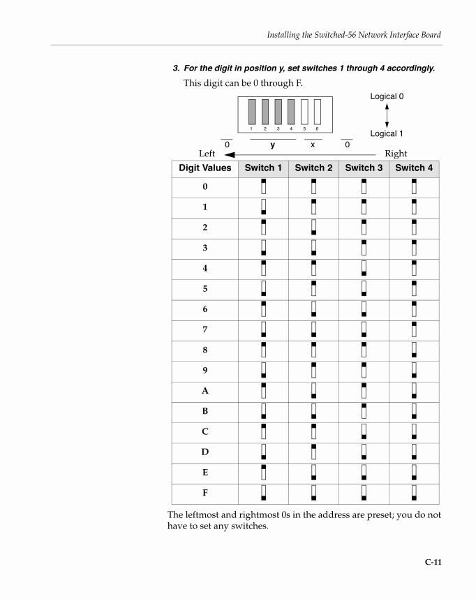
Installing the Switched-56 Network Interface Board
C-11
3. For the digit in position y, set switches 1 through 4 accordingly.This digit can be 0 through F.
The leftmost and rightmost 0s in the address are preset; you do not have to set any switches.
Digit Values Switch 1 Switch 2 Switch 3 Switch 4
0
1
2
3
4
5
6
7
8
9
A
B
C
D
E
F
1 2 3 4 5 6
y x
Logical 0
Logical 10 0
RightLeft
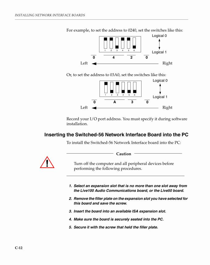
INSTALLING NETWORK INTERFACE BOARDS
C-12
For example, to set the address to 0240, set the switches like this:
Or, to set the address to 03A0, set the switches like this:
Record your I/O port address. You must specify it during software installation.
Inserting the Switched-56 Network Interface Board into the PCTo install the Switched-56 Network Interface board into the PC:
Caution
Turn off the computer and all peripheral devices before performing the following procedures.
1. Select an expansion slot that is no more than one slot away from the Live100 Audio Communications board, or the Live50 board.
2. Remove the filler plate on the expansion slot you have selected for this board and save the screw.
3. Insert the board into an available ISA expansion slot.
4. Make sure the board is securely seated into the PC.
5. Secure it with the screw that held the filler plate.
1 2 3 4 5 6
4 2
Logical 0
Logical 10 0
RightLeft
1 2 3 4 5 6
A 3
Logical 0
Logical 10 0
RightLeft

Installing the Switched-56 Network Interface Board
C-13
Connecting the Switched-56 Network Interface BoardThe Network Interface board needs to be connected to either the Live100 Audio Communications board or the Live50 board using the supplied MVIP cable. The MVIP cable for the Live100 product can be identified by the 40-pin connectors on each end. The CHI to MVIP cable for the Live50 product uses a 40-pin connector for attaching the Network Interface card and an 8-pin Molex connector for attaching to the Live50 board.
Connecting the Live100 MVIP CableFor the Live100 product, connect the Switched-56 Network Interface board to the Audio Communications board by using the supplied ribbon cable with a 40-pin connector on each end.
Caution
Use care when connecting the MVIP cable to the board so as not to damage the pins.
Live100 MVIP Cable(Part #510-0167-01)
Live50 CHI to MVIP Cable(Part #180-0293-01)

INSTALLING NETWORK INTERFACE BOARDS
C-14
To connect the two boards using the MVIP cable, follow these steps:
1. Grasp the connector on one end of the ribbon cable.
2. Line up the key on this connector with the slot on the expansion connector attached to the front of the Live100 Audio Communications board.
3. Slide the key into the expansion connector slot.
4. Repeat these steps to connect the other end of the ribbon cable to the Network Interface board.
Connecting the Live50 CHI to MVIP Cable For the Live50 product, connect the Switched-56 Network Interface board to the Live50 board by using the supplied CHI to MVIP cable with a 40-pin connector on one end and an 8-pin connector on the opposite end.
Caution
Use care when connecting the CHI to MVIP cable to the board so as not to damage the pins.
To connect the two boards using the CHI to MVIP cable, follow these steps:
1. Grasp the 40-pin connector on one end of the cable.
2. Line up the key on this connector with the slot on the expansion connector attached to the Network Interface board.
3. Slide the key into the expansion connector slot.
4. Connect the 8-pin connector to the Live50 board.
Note: Be sure to position the 8-pin connector so that the white wire is closest to the back plate on the Network Interface board.
Now you need to install the Live50 or Live100 application software, as instructed in Chapter 4, Installing PictureTel Live Software.

Installing the DDM/Network Interface Board
C-15
Installing the DDM/Network Interface Board
The DDM/Network Interface board allows you to connect your PictureTel Live videoconferencing system to a high-speed data network using a V.35 or an RS-449 interface.
These components are included with your Network Interface board:
DDM V.35 Kit
Component Quantity Part Number
DDM/Network Interface board 1
Live50 CHI to MVIP cable 1 180-0293-01
Live100 MVIP cable 1 510-0167-01
V.35/RS-366 4-leg cable 1 180-0313-01
DDM/Network Interface board installation diskettes
2
PictureTel Live50/Live100 Network Interface Installation Guide
1 800-0610-02

INSTALLING NETWORK INTERFACE BOARDS
C-16
DDM RS-449 Kit
The V.35/RS-449 Network Interface boards use 3CC0 (hexadecimal) as the default I/O port address, which is set using a DIP switch. For more information, refer to Changing the I/O Port Address on the DDM/Network Interface Board (below).
Caution
Before you install the Network Interface board, you should check and configure the environment on your ISA-bus or EISA-bus PC. Refer to Appendix A, Checking Your PC Settings for instructions on these procedures.
Unpacking the DDM/Network Interface BoardTo unpack the DDM/Network Interface board, remove the board from its protective box and then from the plastic antistatic package.
Component Quantity Part Number
DDM/Network Interface board 1
Live50 CHI to MVIP cable 1 180-0293-01
Live100 MVIP cable 1 510-0167-01
RS-449/RS-366 4-leg cable 1 180-0312-01
DDM/Network Interface board installation diskettes
2
PictureTel Live50/Live100 Network Interface Installation Guide
1 800-0610-02

Installing the DDM/Network Interface Board
C-17
Caution
This board can be damaged by static discharge. To equalize static charge, ground yourself by touching the metal back panel of your PC.
Place the board on a level surface so that the component side faces up and the back plate (with the connectors) is to your right, as shown in the following illustration.
DDM/Network Interface Board

INSTALLING NETWORK INTERFACE BOARDS
C-18
Changing the I/O Port Address on the DDM/Network Interface Board
Note: If the default I/O port address setting (3CC0) does not conflict with the I/O port address of another device in your PC, you can skip this section.
The board’s I/O port address is set with a switch located at the top right of the board (near the back plate). The switch has eight sliding DIP switches. A switch in the up position is a logical 0 (off), and a switch in the down position is a logical 1 (on).
The I/O port address takes the form:
xyz0
where:
x is designated with switches 7 and 8 and can be digits 0, 1, 2, or 3.
y is designated with switches 3 through 6 and can be digits 0 through F.
z is designated with switches 1 and 2 and can be digits 00, 40, 80, or C0.
0 (the last digit) is constant and has no associated switches.
I/O port addresses are expressed in hexadecimal and can be assigned a value from 0000 to 3FC0 in increments of 16 (10 hexadecimal).
The default I/O port address setting (3CC0) is illustrated below:
1 2 3 4 5 6
y x
Logical 0
Logical 1z
7 8
RightLeft0

Installing the DDM/Network Interface Board
C-19
To change the I/O port address on your DDM/Network Interface board:
1. Make sure that the back plate (with the connectors) is facing toward your right.
2. For the digit in position x, set switches 7 and 8 accordingly.Use a thin, blunt instrument, such as a ballpoint pen.
Caution
Do not use a pencil; the graphite can damage the switches.
This digit can be a 0, 1, 2, or 3 only.
Digit Values Switch 7 Switch 8
0
1
2
3
1 2 3 4 5 6
y x
Logical 0
Logical 1z
7 8
RightLeft
0

INSTALLING NETWORK INTERFACE BOARDS
C-20
3. For the digit in position y, set switches 3 through 6 accordingly.This digit can be 0 through F.
Digit Values Switch 3 Switch 4 Switch 5 Switch 6
0
1
2
3
4
5
6
7
8
9
A
B
C
D
E
F
1 2 3 4 5 6
y x
Logical 0
Logical 1z
7 8
RightLeft0
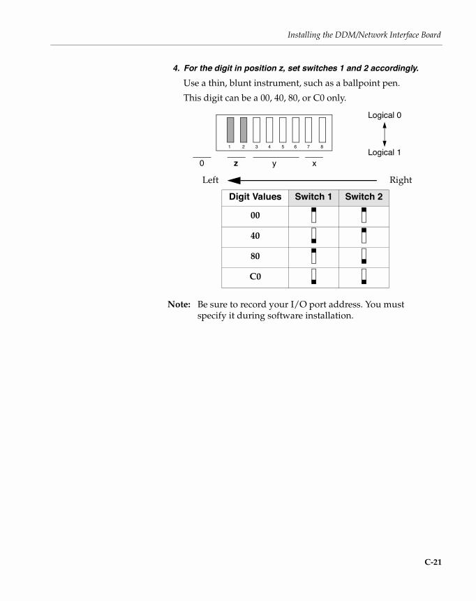
Installing the DDM/Network Interface Board
C-21
4. For the digit in position z, set switches 1 and 2 accordingly.Use a thin, blunt instrument, such as a ballpoint pen.
This digit can be a 00, 40, 80, or C0 only.
Note: Be sure to record your I/O port address. You must specify it during software installation.
Digit Values Switch 1 Switch 2
00
40
80
C0
1 2 3 4 5 6
y x
Logical 0
Logical 1z
7 8
RightLeft
0

INSTALLING NETWORK INTERFACE BOARDS
C-22
Examples of I/O port address settings are provided below:
1 2 3 4 5 6
y xz
7 8
RightLeft
0
1 2 3 4 5 6
y xz
7 8
0
0100
1 2 3 4 5 6
y xz
7 8
0
1 2 3 4 5 6
y x
Logical 0
Logical 1
z
7 8
0
37C0
2480
1240Logical 0
Logical 1
Logical 0
Logical 1
Logical 0
Logical 1

Installing the DDM/Network Interface Board
C-23
1 2 3 4 5 6
y xz
7 8
RightLeft
0
1 2 3 4 5 6
y xz
7 8
0
0940
1 2 3 4 5 6
y xz
7 8
0
1 2 3 4 5 6
y xz
7 8
0
2F00
3DC0
2A80
Logical 0
Logical 1
Logical 0
Logical 1
Logical 0
Logical 1
Logical 0
Logical 1

INSTALLING NETWORK INTERFACE BOARDS
C-24
Inserting the DDM/Network Interface Board into the PCTo install the DDM/Network Interface board into the PC:
Caution
Turn off the computer and all peripheral devices before performing the following procedures.
1. Select an expansion slot that is no more than one slot away from the Live100 Audio Communications board, or the Live50 board.
2. Remove the filler plate on the expansion slot you have selected for this board and save the screw.
3. Insert the board into an available ISA expansion slot.
4. Make sure the board is securely seated into the PC.
5. Secure it with the screw that held the filler plate.
Connecting the DDM/Network Interface BoardThe DDM/Network Interface board needs to be connected to either the Live100 Audio Communications board or the Live50 board using the supplied MVIP cable. The MVIP cable for the Live100 product can be identified by the 40-pin connectors on each end. The CHI to MVIP cable for the Live50 product uses a 40-pin connector for attaching to the Network Interface card and an 8-pin Molex connector for attaching to the Live50 board.

Installing the DDM/Network Interface Board
C-25
Connecting the Live100 MVIP CableFor the Live100 product, connect the DDM/Network Interface board to the Audio Communications board by using the supplied ribbon cable with a 40-pin connector on each end.
Caution
Use care when connecting the MVIP cable to the board so as not to damage the pins.
To connect the two boards using the MVIP cable, follow these steps:
1. Grasp the connector on one end of the ribbon cable.
2. Line up the key on this connector with the slot on the expansion connector attached to the front of the Live100 Audio Communications board.
3. Slide the key into the expansion connector s Repeat these steps to connect the other end of the ribbon cable to the Network Interface board.
Live100 MVIP Cable
Live50 CHI to MVIP Cable
(Part #510-0167-01)
(Part # 180-0293-01)

INSTALLING NETWORK INTERFACE BOARDS
C-26
Connecting the Live50 CHI to MVIP Cable For the Live50 product, connect the DDM/Network Interface board to the Live50 board by using the supplied CHI to MVIP cable with a 40-pin connector on one end and an 8-pin Molex connector on the other end.
Caution
Use care when connecting the CHI to MVIP cable to the board so as not to damage the pins.
To connect the two boards using the CHI to MVIP cable, follow these steps:
1. Grasp the 40-pin connector on one end of the cable.
2. Line up the key on this connector with the slot on the expansion connector attached to the Network Interface board.
3. Slide the key into the expansion connector slot.
4. Connect the 8-pin connector to the Live50 board.
Note: Be sure to position the 8-pin connector so that the white wire is closest to the back plate on the Network Interface board.
Now you need to install the Data-Dialer Module/Network Interface Board software.

Installing the Data-Dialer Module/Network Interface Board Software
C-27
Installing the Data-Dialer Module/Network Interface Board Software
To install the software for the Data-Dialer Module/Network Interface Board, perform the following procedures:
1. Install the Live50/Live100 application software, as instructed in Chapter 4, Installing PictureTel Live Software.
Note: If you have already installed the Live50/Live100 application software, verify that your Live50/Live100 hardware is working properly. For instructions, refer toVerifying Your Installation in Chapter 4.Insert the DDM/Network Interface Board Installation Software Disk 1 of 2 into drive A: or B:.
2. Fromthe Windows 3.1x Program Manager, Select File...Run. From the Windows 95 Start Menu, select Run... Program.
3. Type A:SETUP or B:SETUP. Press Enter, and follow the on-screen instructions to install your software.
4. When the software installation is complete, select PictureTel Live50/Live100 Configure from the PictureTel Program Manager group.
5. The Registration Confirmation window is displayed.Click Continue.

INSTALLING NETWORK INTERFACE BOARDS
C-28
6. .The Network Interface Settings window is displayed. If the V.35/RS-449 will be your only Network Interface, toggle off the ISDN BRI check box, and select the appropriate Network Interface type, as shown below.
When you have selected the appropriate Network Interface settings, click Continue.
7. The Hardware Settings window is displayed.In the Hardware Type field, select Integrated data-dialer module. Then click Continue.

Installing the Data-Dialer Module/Network Interface Board Software
C-29
8. The DDM Base I/O Address and DDM IRQ fields appear on the Hardware Settings window.
This window illustrates the default DDM base I/O address setting. If your DDM base I/O address setting differs from the default, the correct setting is detected and displayed.
If no changes are required, click Continue.
9. The Node Name Selection window is displayed. If no changes are required, click Continue.
10. The Modify CONFIG.SYS file window is displayed. If no changes are required, click No Change.
11. The Installation Complete window in displayed.Click OK to reboot and restart your system.
12. Start the Live50/Live100 application, and select Tools > Preferences.

INSTALLING NETWORK INTERFACE BOARDS
C-30
13. The Preferences window is displayed.Select Network from the Category scroll bar, and select V.35/RS-449, in the Network field.
When you have made the appropriate selections on the Preferences window, click OK.
14. To verify the integrity of your installation, choose Tools > Diagnostics > Loopback.
Note: To make the Diagnostics window active during Loopback testing, press Alt-Tab.

Installing the Data-Dialer Module/Network Interface Board Software
C-31
15. From the Diagnostics window, choose View > Current Call Information.
On the Current Call Information screen, verify that:
• The correct network type has been selected. For example, if you selected V.35/RS-449, it should be displayed on the first line.
• Both channels are connected.
• The Data Receive and Data Transmit rates are the same.
16. When you have verified the integrity of your installation, click End Test to finish the Loopback testI

INSTALLING NETWORK INTERFACE BOARDS
C-32
IMUX Cabling Configurations
IMUXs are a family of devices that provide switched digital access for PictureTel videoconferencing and multipoint bridge products. The following information presents cabling information for connecting the Live50 and Live100 products, with V.35/RS-449 Network Interface boards, to many of the IMUX products in use today.
Figure 1 represents the connection of an RS-449/RS-366-equipped PictureTel Live50/Live100 system with an IMX-1BN, IMX-1BA, or IMX-1BE.
Figure 1. Connecting an RS-449/RS-366-equipped Live system with an IMX-1BN, -1BA, or -1BE
If operation at data rates above 128 Kbps (up to and including 384 Kbps) is required, then the option 384-UPG is also required.
RS-449 Data Cables
RS-366 Dialing Cables
80-pin SCSI M Connector
D37M
D25M
IMUX
IMX1B to RS-366 adapter cable180-0101-01
180-0312-01
SYSTEM
D25F D26M

IMUX Cabling Configurations
C-33
Figure 2 represents the connection of an RS-449/RS-366-equipped Live50/Live100 system with an IMX-1 (or Promptus Oasis 200T-RS-449)
Figure 2. Connecting an RS-449/RS-366-equipped Live system with an IMX-1 or Promptus Oasis 200T-RS-449
If operation at data rates above 128 Kbps (up to and including 384 Kbps) is required, then the option 384-UPG is also required.
IMUX
RS-366 Dialing Cables
RS-449 Data Cables
IMUXSYSTEM
80-pin SCSI M Connector
D25M
D37M
180-0312-01

INSTALLING NETWORK INTERFACE BOARDS
C-34
Figure 3 represents the connection of a V.35/RS-366-equipped Live50/Live100 system with a Teleos Model 20 Videohub.
Figure 3. Connecting a V.35/RS-366-equipped Live system to a Teleos Model 20 Videohub
If operation at data rates above 128 Kbps (up to and including 384 Kbps) is required, then the option 384-UPG is also required.
V.35 Data Cables
RS-366 Dialing Cables
80-pin SCSI M Connector
M34M
D25M
IMUX
220-0093-0004180-0313-01
SYSTEM
D25F D15M
M34F D25M220-0089-0004
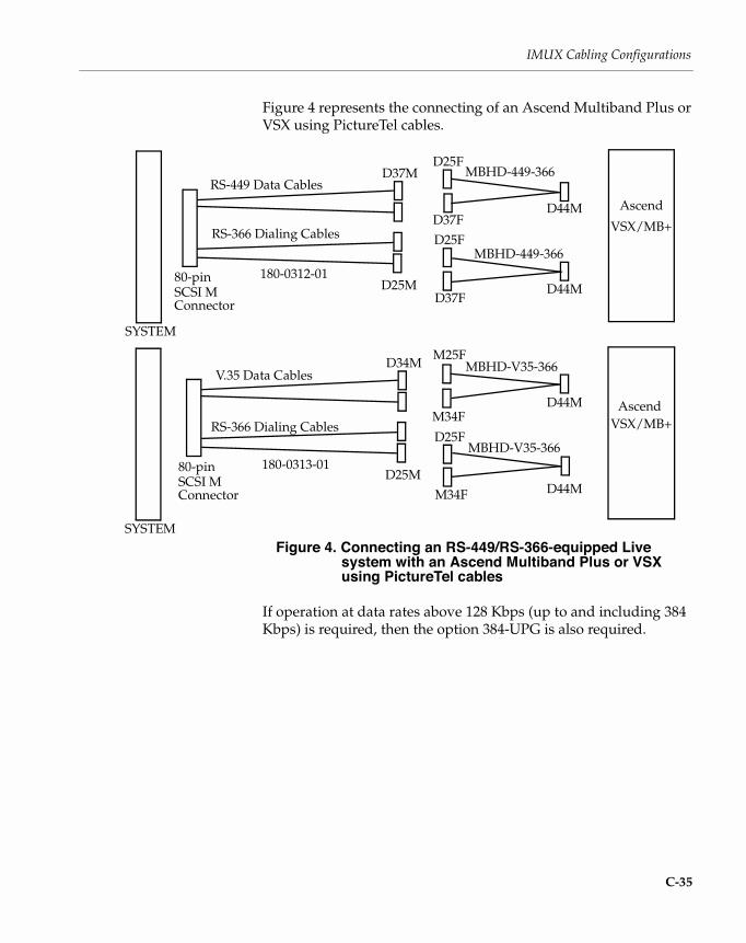
IMUX Cabling Configurations
C-35
Figure 4 represents the connecting of an Ascend Multiband Plus or VSX using PictureTel cables.
Figure 4. Connecting an RS-449/RS-366-equipped Live system with an Ascend Multiband Plus or VSX using PictureTel cables
If operation at data rates above 128 Kbps (up to and including 384 Kbps) is required, then the option 384-UPG is also required.
Ascend
SYSTEM
VSX/MB+
D25F
D37FD44M
D25F
D37FD44M
Ascend
SYSTEM
VSX/MB+
M25F
M34FD44M
D25F
M34F D44M
MBHD-V35-366
MBHD-V35-366
MBHD-449-366
MBHD-449-366
RS-366 Dialing Cables
RS-449 Data Cables
80-pin SCSI M Connector
D37M
D25M180-0312-01
V.35 Data Cables
RS-366 Dialing Cables
80-pin SCSI M Connector
D34M
D25M180-0313-01

INSTALLING NETWORK INTERFACE BOARDS
C-36
Figure 5 represents the connection of an ASCEND MAX with a Live50 or Live100 that uses the V.35/RS-449 Interface for data and the RS-366 for dialing.
Figure 5. Connecting an RS-449/RS-366-equipped Live system with an Ascend MAX
If operation at data rates above 128 Kbps (up to and including 384 Kbps) is required, then the option 384-UPG is also required.
Note: A better cable solution for the above system is shown in Figure 6.
SYSTEM
D25F
D37FD44M
D25F
D37FD44M
SYSTEM
D25F
M34FD44M
D25F
M34FD44M
MBHD-V35-366
MBHD-V35-366
MBHD-449-366
MBHD-449-366D44F
D44F
D44F
SCSI-80
D44F
D44F
D44F
SCSI-80
RS-449 Data Cables
RS-366 Dialing Cables
80-pin SCSI M Connector
D37M
D25M180-0312-01
V.35 Data Cables
RS-366 Dialing Cables
80-pin SCSI M Connector
M34M
D25M180-0313-01
RS-449
V.35
MAX
MAX

IMUX Cabling Configurations
C-37
Figure 6 represents the connection of a V.35/RS-449 & RS-366-equipped Live50 or Live100 to an Ascend MAX using an Ascend MBHD-PT1000 Cable.
Figure 6. Connecting an RS-449/RS-366-equipped Live system with an Ascend MAX using an Ascend MBHD-PT1000 cable
If operation at data rates above 128 Kbps (up to and including 384 Kbps) is required, then the option 384-UPG is also required.
SCSI-80
MAX
Ascend2510-0113-001
SYSTEM
Ascend MBHD-PT1000
D25FV.35/RS-449 Data
D44MD25F
RS-366 Dialing
MBVHD-3MBHD
D44F
D44M
D37F
D37F
RS-449 Data Cables
RS-366 Dialing Cables
80-pin SCSI M
D37M
D25M180-0312-01 Ascend MBHD-449-366
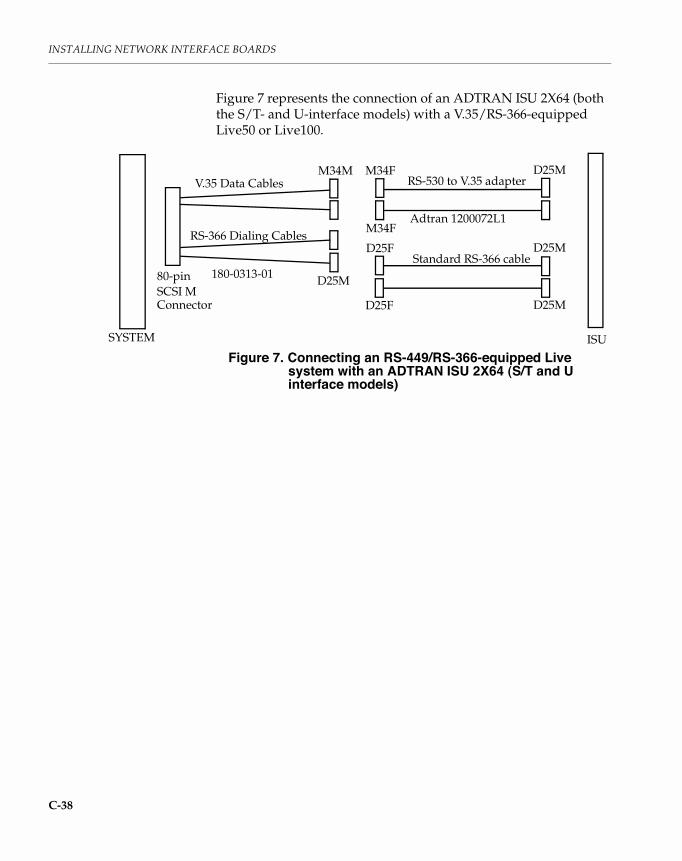
INSTALLING NETWORK INTERFACE BOARDS
C-38
Figure 7 represents the connection of an ADTRAN ISU 2X64 (both the S/T- and U-interface models) with a V.35/RS-366-equipped Live50 or Live100.
Figure 7. Connecting an RS-449/RS-366-equipped Live system with an ADTRAN ISU 2X64 (S/T and U interface models)
D25M
ISU
RS-530 to V.35 adapterM34F
SYSTEM
M34FAdtran 1200072L1
V.35 Data Cables
RS-366 Dialing Cables
80-pin SCSI M Connector
M34M
D25M180-0313-01
D25MStandard RS-366 cable
D25F
D25F D25M

IMUX Cabling Configurations
C-39
Figure 8 represents the connection of an ADTRAN ISU 512 IMUX with a V.35/RS-366-equipped Live50 or Live100.
Figure 8. Connecting an RS-449/RS-366-equipped Live system with an ADTRAN ISU 512 IMUX
IMUX
RS-530 to V.35 adapterM34F
SYSTEM
Adtran 1200072L1
D25FD25M
1200120L1
Adtran RS-366 “Y” cable
V.35 Data Cables
RS366 Dialing Cables
80-pin SCSI M Connector
M34M
D25M180-0313-01
direct connect
ISU 512
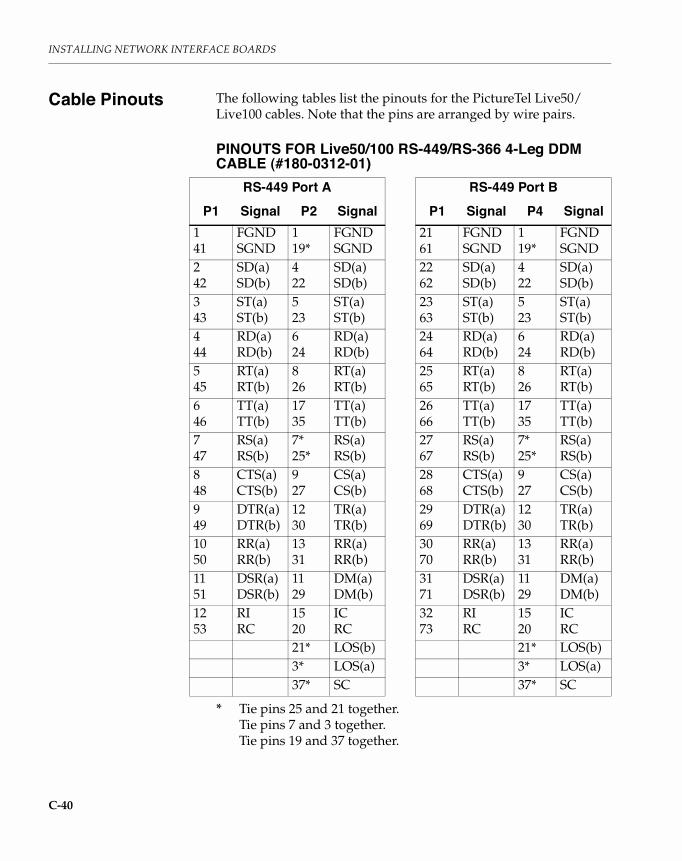
INSTALLING NETWORK INTERFACE BOARDS
C-40
Cable Pinouts The following tables list the pinouts for the PictureTel Live50/Live100 cables. Note that the pins are arranged by wire pairs.
PINOUTS FOR Live50/100 RS-449/RS-366 4-Leg DDM CABLE (#180-0312-01)
* Tie pins 25 and 21 together.Tie pins 7 and 3 together.Tie pins 19 and 37 together.
RS-449 Port A RS-449 Port BP1 Signal P2 Signal P1 Signal P4 Signal
141
FGNDSGND
119*
FGNDSGND
2161
FGNDSGND
119*
FGNDSGND
242
SD(a)SD(b)
422
SD(a)SD(b)
2262
SD(a)SD(b)
422
SD(a)SD(b)
343
ST(a)ST(b)
523
ST(a)ST(b)
2363
ST(a)ST(b)
523
ST(a)ST(b)
444
RD(a)RD(b)
624
RD(a)RD(b)
2464
RD(a)RD(b)
624
RD(a)RD(b)
545
RT(a)RT(b)
826
RT(a)RT(b)
2565
RT(a)RT(b)
826
RT(a)RT(b)
646
TT(a)TT(b)
1735
TT(a)TT(b)
2666
TT(a)TT(b)
1735
TT(a)TT(b)
747
RS(a)RS(b)
7*25*
RS(a)RS(b)
2767
RS(a)RS(b)
7*25*
RS(a)RS(b)
848
CTS(a)CTS(b)
927
CS(a)CS(b)
2868
CTS(a)CTS(b)
927
CS(a)CS(b)
949
DTR(a)DTR(b)
1230
TR(a)TR(b)
2969
DTR(a)DTR(b)
1230
TR(a)TR(b)
1050
RR(a)RR(b)
1331
RR(a)RR(b)
3070
RR(a)RR(b)
1331
RR(a)RR(b)
1151
DSR(a)DSR(b)
1129
DM(a)DM(b)
3171
DSR(a)DSR(b)
1129
DM(a)DM(b)
1253
RIRC
1520
ICRC
3273
RIRC
1520
ICRC
21* LOS(b) 21* LOS(b)3* LOS(a) 3* LOS(a)37* SC 37* SC

Cable Pinouts
C-41
PINOUTS FOR Live50/100 RS-449/RS-366 4-Leg DDM CABLE (#180-0312-01) (continued)
RS-366 Port A RS-366 Port BP1 Signal P3 Signal P1 Signal P5 Signal
5413
SGNDFGND
71
SGNDFGND
7433
SGNDFGND
71
SGNDFGND
1415
NB1NB2
1415
NB1NB2
3435
NB1NB2
1415
NB1NB2
1617
NB4NB8
1617
NB4NB8
3637
NB4NB8
1617
NB4NB8
5556
DPRACR
23
DPRACR
7576
DPRACR
23
DPRACR
5758
CRQPND
45
CRQPND
7778
CRQPND
45
CRQPND
1819
RCSC
1819
RCSC
3839
RCSC
1819
RCSC
5960
PWIDSC
613
PWIDSC
7980
PWIDSC
613
PWIDSC
20 DLO 22 DLO 40 DLO 22 DLO

INSTALLING NETWORK INTERFACE BOARDS
C-42
Figure 9 represents the Live50/Live100 DDM cable (#180-0312-01).
Figure 9. RS-449/RS-366 4-Leg DDM Cable (#180-0312-01)
P1
P1
P41P1

Cable Pinouts
C-43
PINOUTS FOR Live50/100 V.35/RS-366 4-Leg DDM CABLE (#180-0313-01)
V.35 Data Port A V.35 Data Port BP1 Signal P2 Signal P1 Signal P4 Signal
141
FGNDSGND
AB
FGNDSGND
2161
FGNDSGND
AB
FGNDSGND
242
SD(a)SD(b)
PS
SD(a)SD(b)
2262
SD(a)SD(b)
PS
SD(a)SD(b)
343
ST(a)ST(b)
YAA
SCT(a)SCT(b)
2363
ST(a)ST(b)
YAA
SCT(a)SCT(b)
444
RD(a)RD(b)
RT
RD(a)RD(b)
2464
RD(a)RD(b)
RT
RD(a)RD(b)
545
RT(a)RT(b)
VX
SCR(a)SCR(b)
2565
RT(a)RT(b)
VX
SCR(a)SCR(b)
646
TT(a)TT(b)
UW
SCTE(a)SCTE(b)
2666
TT(a)TT(b)
UW
SCTE(a)SCTE(b)
7 RS C RTS 27 RS C RTS848
CTSCTS
DB
CTSSGND
2868
CTSCTS
DB
CTSSGND
9 DTR H DTR 29 DTR H DTR1050
RRRR
FB
RLSDSGND
3070
RRRR
FB
RLSDSGND
1151
DSRDSR
EB
DSRSGND
3171
DSRDSR
EB
DSRSGND
1253
RIRC
JB
RISGND
3273
RIRC
JB
RISGND

INSTALLING NETWORK INTERFACE BOARDS
C-44
PINOUTS FOR Live50/100 V.35/RS-366 4-Leg DDM CABLE (#180-0313-01) (continued)
RS-366 Dialer Port A RS-366 Dialer Port BP1 Signal P3 Signal P1 Signal P5 Signal
5413
SGNDFGND
71
SGNDFGND
7433
SGNDFGND
71
SGNDFGND
1415
NB1NB2
1415
NB1NB2
3435
NB1NB2
1415
NB1NB2
1617
NB4NB8
1617
NB4NB8
3637
NB4NB8
1617
NB4NB8
5556
DPRACR
23
DPRACR
7576
DPRACR
23
DPRACR
5758
CRQPND
45
CRQPND
7778
CRQPND
45
CRQPND
1819
RCSC
1819
RCSC
3839
RCSC
1819
RCSC
5960
PWIDSC
613
PWIDSC
7980
PWIDSC
613
PWIDSC
20 DLO 22 DLO 40 DLO 22 DLO

Maximum Cable Length
C-45
Figure 10 represents the Live50/Live100 DDM cable (#180-0313-01).
Figure 10. V.35/RS-366 4-Leg DDM Cable (#180-0313-01)
Maximum Cable Length
The following table lists the relationships between RS-449 data rates and cable lengths.
RS-449 Cable Lengths
*For reference only. The Live50 and Live100 support data rates up to and including 384Kbps.
V.35 Cable LengthsThe maximum V.35 cable length is 100 feet (30 meters).
P1
P41P1
Data Rate (in Kbps) Cable Length56 or 64 4000 feet (1200 meters)
384 1476 feet (450 meters)
768* 575 feet (175 meters)


C-1
CInstalling the
384 Kbps Option
This appendix tells you how to install the 384 Kbps option that allows the PictureTel Live application to transmit at any adjustable rate from 128 to 384 Kbps. The transmit rate is established outside of the Live application by either an IMUX or other communcation device in a network configuration.
The 384 Kbps option should be installed after installing the hardware and software for the Live application. The 384 software is provided as a separately purchased option and comes on a single diskette.
To install the 384 Kbps option:
1. From either the Windows 3.1x Program Manager or the Windows 95 Start Menu, select the Run ... program.Windows displays the 3.1x Run dialog box.
2. Insert the 384 disk and enter a:\setup in the Run dialog box.
The setup program installs the software and your Live application can now operate at rates higher than 128 Kbps.


D-1
DHow to Order
ISDN in theUnited States
You need to order an ISDN BRI line to operate the PictureTel Live PCS application. An ISDN BRI line can take several weeks to install from the time you order. We recommend you plan ahead. Also, check with your provider on whether you need a Network Termination Device (NT1).
This appendix provides you with the following information:
❑ What to ask your telephone company.
❑ What information you need to give your telephone company.
❑ A list of telephone numbers for regional and long distance ISDN providers.
❑ A list of companies that manufacture or distribute Network Termination Devices ,or NT1s.

HOW TO ORDER ISDN IN THE UNITED STATES
D-2
What to Ask You need to ask for following information from your telephone company:
❑ What type of ISDN switch will connect your ISDN line?
The most common ISDN switch types are AT&T 5ESS, Northern Telecom DMS-100, and Siemens EWSD NI1 (as detailed in the following tables).
❑ What type of ISDN service will I be receiving?
Two of the most common types are Custom or National (as detailed in the following tables). If Custom service is available, find out if it is a point-to-point or a multi-point connection.
❑ What is your dialing number?
❑ What are your Service Provider Identification Numbers (SPIDs)?
What You Need to Provide
On the next few pages of this appendix are 5 tables that can help you expedite the ISDN installation process.
The following 3 tables list the line provisioning required for the PictureTel Live PCS application:
❑ AT&T 5ESS Switch Information
❑ Northern Telecom DMS-100 Switch Line Information
❑ Seimens EWSD NI-1 Switch Settings
The following 2 tables provide phone numbers for ordering ISDN service and NT1 devices.
❑ ISDN Ordering Phone Number Listing
❑ Network Termination Device (NT1) Sources
You can fax or mail this information to your telephone company.
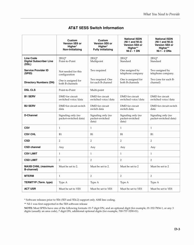
What You Need to Provide
D-3
AT&T 5ESS Switch Information
CustomVersion 5E6 or
Higher*Non-Initializing
CustomVersion 5E6 or
Higher*Fully initializing
National ISDN(NI-1 and NI-2)Version 5E8 or
Higher**NI-2 - 1 DN
National ISDN(NI-1 and NI-2)Version 5E8 or
Higher**NI-1 - 2 DNs
Line CodeDigital Subscriber Line (DSL)
Service Provider ID (SPID)
Directory Numbers (DN)
2B1Q*Point-to-Point
Not needed for this configuration
One is assigned for both B-channels
2B1Q*Multipoint
Two required
Two required. One for each B-channel
2B1Q*Standard
One assigned by telephone company
One is assigned for both B-channels
2B1Q*Standard
Two assigned by telephone company.
Two (one for each B-channel)
DSL CLS Point-to-Point Multi-point
B1 SERV DMD for circuit switched voice/data
DMD for circuit switched voice/data
DMD for circuit switched voice/data
DMD for circuit switched voice/data
B2 SERV DMD for circuit switch data
DMD for circuit switch data
DMD for circuit switch data
DMD for circuit switch data
D-Channel Signaling only (no packet-switched data)
Signaling only (no packet-switched data)
Signaling only (no packet-switched data)
Signaling only (no packet-switched data)
CSV 1 1 1 1
CSV CHL B1 B1 B1 B1
CSD 2 2 2 2
CSD channel Any Any Any Any
CSV LIMIT 1 1 1 1
CSD LIMIT 2 2 2 2
MAXB CHNL (maximum B-channel)
Must be set to 2. Must be set to 2. Must be set to 2 Must be set to 2
MTERM 1 2 2 2
TERMTYP (Term. type) Type A Type A Type A Type A
ACT USR Must be set to YES Must be set to YES Must be set to YES Must be set to YES
* Software releases prior to 5E6 (5E5 and 5E4.2) support only AMI line coding.** NI-1 was first supported in the 5E8 software releaseNOTE: Most SPIDs have one of the following formats: 01-7 digit DN, and an optional digit (for example, 01-332-7834-1, or any 3 digits (usually an area code), 7 digit DN, additional optional digits (for example, 700-737-3290-01).

HOW TO ORDER ISDN IN THE UNITED STATES
D-4
Northern Telecom DMS-100 Switch Line Information
CustomLoad BCS-33
(PVC-1)
NationalISDN-1 (NI-1)Load BCS-35
Line CodeDigital Subscriber Line (DSL)
Service Provider ID (SPID)
Directory Numbers (DN)
2B1Q
Two
Two
2B1Q*
Two
Two(one for each B-channel)
Provisioning Parameters B1 B1
Set circuit switch toYes Set circuit switch toYes
Set Bearer Restriction to NOPMD (No Packet Data)
Set Bearer Restriction to NOPMD Must be set to 2
Functional Terminal Adapter Functional Terminal Adapter
Set TEI to Dynamic Set TEI to Dynamic
Set Ring to Yes Set Ring to Yes
Set EKTS to No Set EKTS to No
Set data option: PROVLLC CMDATA (lower layer compatibility)
Provisioning Parameters B2 B2
Set circuit switch toYes Set circuit switch toYes
Set BearerRestriction to NOPMD Must be set to 2
Set BearerRestriction to NOPMD Must be set to 2
Functional Terminal Adapter Functional Terminal Adapter
Set TEI to Dynamic Set TEI to Dynamic
Set Ring to Yes Set Ring to Yes
Set EKTS to No Set EKTS to No
Set data option: PROVLLC CMDATA (lower layer compatiibility)

What You Need to Provide
D-5
Siemens EWSD NI-1 Switch Settings
Information Category Specific Options
Line CodeDigital Subscriber Line (DSL)
2B1QNational*
Provisioning Parameters BCHDNs = 2 (directory numbers assigned by telephone company)
BCDN = C56
BCDN = C64 (if supported by interexchange carrier to local central office)
CT = CMD (circuit mode data)
TSPIDs assigned by telephone company: Two
BRI should be provisioned as follows:
Subscriber
- Set B1 CT = CMD (for circuit switched data/voice)
- Set B2 CT = CMD (for circuit switched data)
- BCHCT = 2
- IBCHCT = 2
- OBCHCT = 2
- COS = NICND (class of service; no ISDN calling # delivery)
- PIC = XXX-C56 (where XXX is the interexchange carrier’s code)
- PIC = XXX-C64 (where XXX is the interexchange carrier’s code)
Terminal Service Profile Data: - USID = 1 (user ID) - TSPID = 7085551234001 (for illustration purposes)
- TERMLIM = 1 (maximum number of terminals that can share this SPID)
- CT = CMD
- FKMPINUM = 0 (feature key management profile index number)
Access Data: - BCHEQN = 2 (number of B-channels assigned)
- BEQN = SP & AU3 & C56 & C64 (bearer capabilities on BRI)
- COE = CLASS1 (class of equipment)
- LINKOPT = DYNNOPL (dynamic link, no packet links)
- CPDDN = 7085551234-CMD - The directory numbers assigned bt the telephone company must match the bearer capabilities requested. In this example, the single number listed is for circuit mode data. For this application, two DN’s are requested.
- CPVDN2 = 7085551235
* NI-1 was first supported in the APS 11 software release.
NOTE: Some fields might vary from one switch to another. Voice DN might be different from CMD DN.

HOW TO ORDER ISDN IN THE UNITED STATES
D-6
ISDN Ordering Phone Number Listing
The following numbers should be helpful in contacting telephone provides for ISDN services. The first table provides the numbers for regional telephone providers, and the second table lists the long distance carriers that offer ISDN lines and services.
ISDN Regional Provider Telephone Number(s)
Ameritech 1-8-432-ISDN
Bell Atlantic 1-800-570-ISDN (all except New Jersey Bell)
1-800-843-2255x4736 (N J Bell customers)
Pacific Bell 1-800-4PB-ISDN (ISDN Service Center)
1-800-995-0346 (ISDN Hotline)
1-800-662-0735 (ISDN Telemarketing)
1-800-995-0346 (24 Hour Hotline)
Bell South 1-800-428-ISDN (Technical Support)
1-800-858-9413 (Sales)
Cincinnati Bell 513-566-DATA (ISDN information )
GTE Call locally for ordering information
Nevada Bell Call locally for ordering information
NYNEX 1-800-650-4736
Southwestern Bell 214-268-1403 (Dallas/Ft. Worth)
713-567-4300 (Houston)
512-351-8050 (San Antonio)
1-800-SWB-ISDN (Austin)
US West 1-800-728-4949 ( FAX-Back)
1-800-246-5226 (small business).
ISDN Long Distance Carriers Telephone Number(s)
AT&T 1-800-222-7956 (Commercial)
1-800-820-6464 (Residential)
MCI 1-800-624-4736
Sprint 703-689-5743
Bell South 1-800-428-ISDN

NT1 Sources
D-7
NT1 Sources The following numbers should be helpful in contacting companies that manufacture or market Network Termination Devices (NT1).
Company Address and Telephone Number(s)
Adtran, Inc. 901 Explorer BoulevardHuntsville, AL 35806-2807205-971-80001-800-788-5408 Sales
Bell Atlantic Teleproducts
West Building, Suite 15050 E. Swedesford RoadFrazer, PA 193551-800-221-0845
Motorola UDS 5000 Bradford DriveHuntsville, AL 35805-19931-800-566-3266, ask for ISDN Lifeguard
PictureTel 100 Minuteman RoadAndover, MA 018101-800-716-6000
Tone Commander Systems
4379 150th Avenue NEP.O. Box 97039Redmond, WA 98073-97391-800-524-0024FAX: 206-881-7179


E-1
EDeinstalling
PictureTel Live
This appendix tells you how to remove the PictureTel Live software from your PC if you should ever need to do so.
These instructions assume that you installed the PictureTel Live 1.6 software in the directory C:\PICTEL\PCS (or C:\PCS for verison 1.5), and that Microsoft Windows is installed in directory C:\WINDOWS. If this is not the case, you should substitute the correct directory names.
Deinstalling PictureTel Live Version 1.6 (or 1.5) and LiveShare Plus Software
To deinstall PictureTel Live version 1.6 (or 1.5) and PictureTel LiveShare Plus software, follow these steps:
1. Preserve any phone books you want to save.Phone books are files with the .PBK extension and the .MDX extension in the directory C:\PICTEL\PCS (or C:\PCS for version 1.5). Copy or move these files to another directory.
2. Remove the PCS-related memory exclusion, if any, from the CONFIG.SYS file.
3. To remove the PictureTel LiveShare Plus software, select Run from the Windows Program Manager File menu, and enter the full path name of DEINSTAL.EXEThe typical path name is:
C:\PICTEL\LIVEPLUS\DEINSTAL.EXE

DEINSTALLING PICTURETEL LIVE
E-2
4. Delete these files:C:\WINDOWS\PCS100.INIC:\WINDOWS\VCSWIN.INIC:\WINDOWS\*.PCS
5. Remove the PictureTel Live changes from the SYSTEM.INI file.Use an editor to remove the changes from SYSTEM.INI, following these steps:
a. In the [BOOT] section, change the lineCOMM.DRV=C:\PCS\TDCOMM.DRV
by replacing C:\PCS\TDCOMM.DRV with the original driver name. You will find this name in the [PICTEL01] section, on the line that begins StdCommDriver=.
For example, if you find this line in the [PICTEL01] sectionStdCommDriver=COMM.DRV
then change the line in the [BOOT] section toCOMM.DRV=COMM.DRV
Or, if you find this line in the [PICTEL01] sectionStdCommDriver=JANCOMM.DRV
then change the line in the [BOOT] section toCOMM.DRV=JANCOMM.DRV
b. In the [386ENH] section, remove the lineDEVICE=C:\PCS\PICTEL00.386
and similar lines, where 00 may be replaced with 01, 02, and so on.
c. In the [386ENH] section, remove the EMM EXCLUDE statement that corresponds to the PictureTel Live memory address range:
EMMExclude
d. Entirely remove the section[PICTEL00]
and similar sections, where 00 may be replaced with 01, 02, and so on.

Deinstalling PictureTel Live Version 1.6 (or 1.5) and LiveShare Plus Software
E-3
6. Delete the directory where the software was installed, typically:C:\PCS
7. Run Windows Setup, and select a non-PictureTel VGA driver.
8. In Program Manager, delete the PictureTel Live PCS icon group.
If you plan to reinstall the PictureTel Live software:
1. Turn your PC off.
2. Turn your PC on again.
If you do not plan to reinstall the PictureTel Live software:
1. Turn off your PC.
2. Remove the PCS 50 or 100 hardware.
3. Enable or restore your original VGA hardware.
DEINSTALLING PICTURETEL LIVE
E-4
Deinstalling PictureTel Live Versions Earlier than 1.5
To deinstall any PictureTel Live and LiveShare Plus software earlier than version 1.5, follow these instructions:
1. To remove the earlier version of PictureTel Live Share software, select Run from the Windows Program Manager File menu, and enter the full path name of REMOVE.EXE. The typical path name is:
C:\PCS\LiveSHAR\REMOVE.EXE
2. Preserve any PictureTel Live phone books that you want to save.Phone books are files with the .PBK extension and the .MDX extension, typically found in the directory:
C:\PCS
Copy or move these files to another directory.
3. Remove the PCS -related memory exclusion from the CONFIG.SYS file.
4. Remove the PictureTel Live changes from the WIN.INI file.Use an editor to remove the section:
[P2P/W]
5. Remove the PictureTel Live changes from the SYSTEM.INI file. Use an editor to remove the changes from the SYSTEM.INI file, following these steps:
a. In the [BOOT] section, change the line:
COMM.DRV=C:\PCS\TDCOMM.DRVby replacing C:\PCS\TDCOMM.DRV with the original driver name. You can find the original driver name in the [PICTEL01] section, on the line that begins:
StdCommDriver=For example, if you find this line in the [PICTEL01] section:
StdCommDriver=JANCOMM.DRVthen change the line in the [BOOT] section to:
COMM.DRV=JANCOMM.DRV

Deinstalling PictureTel Live Versions Earlier than 1.5
E-5
b. In the [BOOT] section, restore the line:
user.exe=C:\PCS\LiveSHAR\user.exeto:
user.exe=user.exec. In the [BOOT] section, restore the line
gdi.exe=C:\PCS\LiveSHAR\gdi.exeto:
gdi.exe=gdi.exed. In the [386ENH] section, remove the line:
DEVICE=C:\PCS\PICTEL00.386and similar lines, where 00 may be replaced with 01, 02, and so on.
e. In the [386] section, remove the EMM.EXCLUDE statement that corresponds to the PictureTel Live memory address range:
EMMExcludef. Write down the system settings in the [PICTEL00] section,
so that you can use the same settings when you install the 1.5 version of the PictureTel Live software. These settings are similar to the following lines:
PICTEL_IO=nnnnPICTEL_IRQ=nnPICTEL_MEM=nnnn
g. Entirely remove the section:
[PICTEL00]and similar sections, where 00 may be replaced with 01, 02, and so on.
h. Entirely remove the section:
[Live Share]
6. Delete these files:C:\WINDOWS\PCS100.INIC:\WINDOWS\VCSWIN.INIC:\WINDOWS\*.PCS

DEINSTALLING PICTURETEL LIVE
E-6
7. Delete the directory where the software was installed, typically:C:\PCS
8. In Program Manager, delete the PictureTel Live PCS 100 icon group.
9. Turn your PC off.
10. Turn your PC on again.

F-1
FChanging the
Video ModeSetting
The video mode setting allows you to modify the video refresh rate, which is a characteristic of your PC monitor.
Monitors support one or more video refresh rates. If your monitor doesn’t support the PictureTel Live default video refresh rate, your monitor display will appear distorted, and you’ll need to change the video mode setting.
To change the video mode setting, follow these steps:
1. Exit Windows.
2. Edit your AUTOEXEC.BAT file by adding the following line:install-directory\VGA\VMODE vmode
For the variable install-directory, substitute the name of the drive and directory where you installed the PictureTel Live applications (for example, C:\PCS).
For the variable vmode, substitute a setting from Table F-1 on the next page. The column titled “then use this video mode setting” lists all the possible settings. All but one of these settings are for non-interlaced monitors.
Note: You can add one video mode line to your AUTOEXEC.BAT file for each monitor resolution. If you use the Windows Setup program to change the display setting to a different VGA driver for a different resolution, PictureTel Live automatically sets the monitor characteristics based on that video mode setting.
3. Reboot your system.

CHANGING THE VIDEO MODE SETTING
F-2
Table F-1: Video Mode Settings
If you’re using this monitor resolution...
and your monitorhas these characteristics...
then use thisvideo mode
setting: NotesHorizontal Frequency
Vertical Frequency
640 x 480 31.50 kHz 60.00 Hz 60HZ Default setting for this resolution
640 x 480 37.86 kHz 72.81 Hz 72HZ
800 x 600 35.50 kHz 56.00 Hz 35K
800 x 600 38.00 kHz 60.00 Hz 38K
800 x 600 48.40 kHz 72.70 Hz 48K Default setting for this resolution
1024 x 768 49.00 kHz 60.00 Hz 65M Default setting for this resolution
1024 x 768 56.48 kHz 70.07 Hz 72M
1024 x 768 35.50 kHz 87.00 Hz 45M Interlaced monitor

G-1
GInstallation
RequirementsOutside of theUnited States
Overview This appendix contains the following information:
❑ BABT (British Approvals Board for Telecommunications) requirements for installing the Live50 and Live100 (formerly PCS 50 and PCS 100) boards in countries for which the pan European approval applies.
❑ AUSTEL requirements for installing the Live50 and Live100 (formerly PCS 50 and PCS 100) boards in Australia.
The following sections describe the BABT and AUSTEL requirements that must be met for the approval to be valid.
Installation Information
The following statement describes the installation requirements for BABT approval in the United Kingdom (not required for pan European approval):
❑ The PictureTel Live50 and Live100 boards are approved for installation in a host, and with host attachments which are either type approved for such apparatus, or, if supplied after March 1, 1989, are marked with or supplied with a statement that the host is supplied under General Approval Number NS/G/1234/J/100003. (United Kingdom only.)
The following statements describe the installation requirements for AUSTEL approval:
❑ The PictureTel Live50 and Live100 boards shall only be installed in a Personal Computer (PC) that complies with the AUSTEL criteria of “Data Terminal Equipment” as defined by the Telecommunications Act of 1991, Notice Under Section 267 (No. 1 of 1993).

INSTALLATION REQUIREMENTS OUTSIDE OF THE UNITED STATES
G-2
❑ The PictureTel Live50 and Live100 boards shall only be installed in a PC that requires the use of a tool before access can be gained to internal parts.
❑ The telecommunications line connection must be disconnected from the PC before removing any external covers and shall be reconnected only after all external covers are replaced.
❑ The PictureTel Live50 and Live100 boards shall only be installed if the clearance and creepage distances between adjacent cards are equal to or greater than 4mm and 5mm respectively.
❑ A warning label is provided with the PictureTel Live50 and Live100 boards and shall be attached to the PC in a visible position. The label shall contain the following wording:
Telecommunications network voltages exist inside the PC. The line connection must be disconnected before removing covers and reconnected only after covers are replaced.
Safety Information
The following statements describe the safety requirements for BABT and AUSTEL approval.
The Live50 and Live100 boards are designed for use with an IBM compatible PC. The network interface for the Live50 and Live100 boards is a TNV (Telecommunications Network Voltage) port working within the limits of SELV (Safe Extra Low Voltage). The connection to the PC bus is a SELV port.

Safety Information
G-3
The Live50 board has the following ports for connection to the network and other apparatus:
The Live100 board has the following ports for connection to the network and other apparatus:
Table G-1: Live50 Board Port Connections
Type of Circuit Port Location Port Description
SELV J1 CHI to MVIP Connection
TNV J2 ISDN Basic Rate Interface
SELV J3 Speakerphone
SELV J5 Speaker Output
SELV J6 Microphone Input
SELV J7 Video Input
SELV P1 VAFC Bus
SELV P2 ISA PC Bus
7
Table G-2: Live100 Board Port Connections
Type of Circuit Port Location Port Description
SELV J082 MVIP Connection
TNV J397 ISDN Basic Rate Interface
SELV J898 Speakerphone
SELV J698 Aux Audio In/Out
SELV J598 Aux Audio In/Out
SELV J973 ISA PC Bus
SELV J157 Interboard connector

INSTALLATION REQUIREMENTS OUTSIDE OF THE UNITED STATES
G-4
Power Requirements
The following statements describe the power requirements for BABT and AUSTEL approval.
The Live50 and Live100 boards are powered from the host chassis and have the following power requirements per board:
The power drawn from the host chassis together with that required for any other expansion boards and accessories must be within the power rating of the host chassis.
The Live50 and Live100 boards must be installed in such a way that the integrity of the network protection from hazardous voltages used or generated internally by the host chassis is not impaired.
The clearance and creepage distances shown as X and Y in Figure G-1 and as listed in Table G-4 must be maintained between the Live50 or Live100 boards and:
❑ The host chassis in which it is installed
❑ Any adjacent expansion boards installed in the host chassis
Table G-3: Power Requirements
Voltage Current (max.)
+5V (+/-.25V) 3.25A
+12V (+/-.5V) .5A

Power Requirements
G-5
The exception to this requirement is the edge connector, which is located in the host chassis power and data bus slots, where no minimum distance applies.
Note: For a host or other expansion card fitted in the host, using or generating voltages greater than 300V (rms or dc), advice from a competent telecommunications safety engineer must be obtained before installation of the relevant equipment.
The creepage distances shown apply in a normal office environment. Where the local environment within the host chassis is subject to conductive pollution or dry nonconductive pollution which could become conductive due to condensation, the creepage distances shown in parentheses will apply. The clearance and creepage between adjacent points should be checked as follows (refer to Figure G-1):
❑ The clearance distance (X) is the shortest distance measured between two points through the air.
❑ The creepage distance (Y) is the shortest distance between two points measured across a surface.
The user should obtain advice from a competent telecommunications safety engineer if in doubt.
Table G-4: Clearance and Creepage
Clearance Xmm Creepage YmmVoltage used or
generated by other parts of the host or
expansion bus
2.0 2.4 (3.8) up to 50Vrms or Vdc
2.6 3.0 (4.8) up to 125Vrms or Vdc
4.0 5.0 (8.0) up to 250Vrms or Vdc
4.0 6.4 (10.0) up to 300Vrms or Vdc
*See Note *See Note Above 300Vrms or Vdc

INSTALLATION REQUIREMENTS OUTSIDE OF THE UNITED STATES
G-6
Figure G-1: PictureTel Live50 and Live100 Boards Clearance and Creepage
Power supply unitor other source ofexcessive voltage X
Y
X
Y
Live50/Live100 board Adjacent board

H-1
HPerformance Tips
Overview The following technical tips will help you get the best results with PictureTel Live and LiveShare Plus, especially on systems that have slower processors and use many device drivers.
Configuration Tips
The following tips related to statements in your CONFIG.SYS, SYSTEM.INI, and AUTOEXEC.BAT files:
❑ Make sure your CONFIG.SYS file contains the following lines: device=c:\dos\himem.sys device=c:\dos\emm386.exe noems x=d000-d3FF BUFFERS=30 FILES=40 dos=high,UMB
This assumes that you are using memory addresses D000-D3FF. The number of buffers should be at least 30, and the number of files at least 40.
❑ Confirm that your SYSTEM.INI file also excludes the correct memory areas. For example, if you are using addresses D000-D3FF, it should contain these lines:
Device=D:\PCS\PICTEL01.386 EMMExclude=D000-D3FF
If there are additional exclusions for other devices, they must also be excluded from the memory manager line of your CONFIG.SYS file.
❑ Make sure your AUTOEXEC.BAT and CONFIG.SYS files load as many drivers into high memory as possible, in order to free

PERFORMANCE TIPS
H-2
up lower memory. These are examples from a CONFIG.SYS file:
DEVICEHIGH=C:\SCSI\MA13B.SYS DEVICEHIGH=C:\SCSI\NECCDR.SYS /d:NECCD
Experiment with the loading order of the drivers to force the most efficient use of memory. You can check current memory allocation using this DOS command:
mem /c
Note: Please refer to your Windows documentation for more information about the CONFIG.SYS and SYSTEM.INI files.
Memory Tips The following tips relate to swap files and memory usage:
❑ In order to improve overall Windows performance when you run other programs along with PictureTel LIVE, you should configure your system with a Swap File, preferably a permanent one.
To configure your Swap File, open the Control Panel, choose 386 Enhanced, and then choose Virtual Memory. You can use the type and size of Swap File the system recommends as the default.
❑ If you are experiencing Windows’ messages relating to insufficient memory, try launching PictureTel Live before your other Windows applications.

I-1
ILaptop Docking
StationConfiguration
Overview If you install PictureTel Live on a laptop docking station, you need to make special provisions for using your laptop both in and out of the docking station. This involves creating a batch file that lets you choose between docked and mobile configurations when starting up your laptop.
Choosing a Docked or Mobile Configuration
After installing the PictureTel Live software, follow these steps to create a batch file that allows you to choose between a docked or mobile configuration during start-up. Perform these 5 steps with the laptop connected to the docking station:
1. Copy SYSTEM.INI to SYSTEM.DOC.
2. Run the Windows setup program and change your video driver to VGA.
3. Try undocking the laptop and running Windows. If everything works properly, copy SYSTEM.INI to SYSTEM.LAP.
4. Create an AUTOEXEC.BAT file that will prompt you for either the docked or mobile configuration when you start up. Here is one you can use or modify:
@ECHO OFFPROMPT $p$gPATH C:\;C:\WINDOWS;C:\DOS;C:\NECUTILSSET TEMP=C:\TEMPIF NOT EXIST VERSION. GOTO SETUPCLS

LAPTOP DOCKING STATION CONFIGURATION
I-2
TYPE VERSION:SETUPLH /L:0;1,16400 /S C:\WINDOWS\SMARTDRV.EXErem ============= PCMCIA2 Device Drivers ===============rem == If PCMCIA cards are not used in your system, these rem == drivers can be remarked to save system memory area.rem ================================================LOADHIGH C:\PCMCIA2\CS_APM.EXErem ====================MENU=======================rem ==The following statement will get values from CONFIG.SYSrem == for mobile or docked configurations.rem =================================================goto %CONFIG%:DOCKEDrem =================================================rem == Add to this section any drivers, etc., that are unique rem == to the docked configuration.rem =================================================\necutils\BACKLITE FULLrem ==The following statement changes the video mode for anrem ==alternative video source.\necutils\videomod crem ==The following statement copies the docking station's rem ==SYSTEM.DOK to the required SYSTEM.INI name. Note that rem ==if you make any changes to SYSTEM.INI, you must copy rem ==them to SYSTEM.DOK in order for this to continue to workrem ==correctly.copy==\windows\system.dok \windows\system.inirem==echo .goto END:MOBILErem =================================================rem ==Add to this section any drivers, etc., that are unique rem ==to the mobile configuration.rem =================================================rem ==The following statement changes the video mode to the rem ==LCD display\necutils\videomod lrem ==The following statement copies the laptop's

Choosing a Docked or Mobile Configuration
I-3
rem ==SYSTEM.LAP to the required SYSTEM.INI name. Note that rem ==if you make any changes to SYSTEM.INI, you must copy rem ==them to SYSTEM.LAP in order for this to continue to workrem ==correctly.copy \windows\system.lap \windows\system.ini:END
5. Add an appropriate section to your CONFIG.SYS file to go along with the AUTOEXEC.BAT file, such as this one:
[MENU]rem ==========================================rem ==The following is a menu which will allow you to chooserem ==separate configurations for Mobile or Docked.rem ==========================================MENUITEM=MOBILE, Mobile ConfigurationMENUITEM=DOCKED, Docked Configurationrem ==========================================rem ==Change the following timer value for the most rem ==appropriate setting. For example, change the 10 to 5 rem ==or a 5-second delay.rem ==========================================MENUDEFAULT=MOBILE,10MENUCOLOR=1,3[DOCKED]rem ==========================================rem ==Add to this section any drivers, etc., that are unique rem ==to the docked configuration.rem ==========================================[MOBILE]rem ==========================================rem ==Add to this section any drivers, etc., that are unique rem ==to the mobile configuration.rem ==========================================rem DEVICEHIGH=C:\DOS\POWER.EXE


J-1
JOrdering
and ReturningComponents
This appendix tells you how to order and return PictureTel Live 50 and 100 components.
Ordering Components
To order replacement components:
1. Locate the appropriate part number using the tables in this appendix.
2. Call PictureTel Customer Services at 800-874-2835 or508-292-5999, or call your local PictureTel distributor.

ORDERING AND RETURNING COMPONENTS
J-2
Live 50 Part Numbers
The following table lists part numbers for the PictureTel Live 50 product components.
Component Part Number
Live 50 board 500-0145-02
VGA board with VESA Advanced Feature Connector (ISA bus)
520-0508-01or520-0508-02
VGA board with VESA Advanced Feature Connector (PCI bus)
370-0258-01
VAFC cable 510-0206-01
Camera (NTSC) 370-0242-01
Camera (PAL) 370-0243-01
Earpiece 370-0260-01
Speakerphone unit 520-0490-02
Speakerphone handset 370-0262-01
Speakerphone handset cord 180-0204-01
Speakerphone cable 510-0165-01
Speakerphone power supply (optional) 300-0013-01
ISDN BRI cable 180-0005-01
Network Interface MVIP cable 180-0293-01
FlipCam Adapter cable 510-0244-01
FlipCam Camera (NTSC) 520-0615-01
FlipCam Camera (PAL) 520-0616-01

Live 100 Part Numbers
J-3
Live 100 Part Numbers
The following table lists part numbers for the PictureTel Live 100 product components.
Component Part Number
VGA Video board 500-0109-04
Audio Communications board 500-0089-04
Interboard ribbon cable 510-0172-01
FlipCam camera (NTSC) 520-0250-03
FlipCam camera (PAL) 520-0251-03
Camera stand 520-0252-01
Camera cable 510-0164-01
Speakerphone 520-0253-02
Speakerphone handset 370-0169-01
Speakerphone handset cord 180-0133-01
Speakerphone cable 510-0165-01
Speakerphone power supply (optional) 300-0013-01
FlipCam camera 10-meter cable (optional) 510-0183-01
Auxiliary Audio cable (optional) 510-0162-01
ISDN BRI cable 180-0005-01

ORDERING AND RETURNING COMPONENTS
J-4
Returning Components
When you return a part to PictureTel, ship only the part that requires repair. For example, if a board needs repair, separate all cables from the board, and send the board without the cables.
To return PictureTel Live components:
1. Request a return material authorization (RMA) number.You can request an RMA in two ways:
❑ Call PictureTel Customer Services at 800-874-2835or 508-292-5999.
❑ Send a FAX to PictureTel Customer Services at 508-292-3333.
2. Wrap the component in an antistatic bag, if necessary.
3. Pack the component in a shipping container, using bubble wrap as needed.
4. Mark the outside of the shipping container with the RMA number.
5. Send the container to your local PictureTel distributor or to this address:Customer Services LogisticsPictureTel CorporationOne Centennial DrivePeabody, MA 01960–9970U.S.A.

Index-1
Index
AAC power adapter 2-11
amplified speakers, connecting 2-20
Audio Communications boardchanging switch settings B-3installing 3-6
BBABT (British Approvals Board for
Telecommunications) requirements H-1
boardschanging switch settings B-1connecting together 3-7
boards, connecting 2-7
Ccable
IMX-1BA C-32IMX-1BE C-32IMX-1BN C-32Live100 MVIP C-13, C-25Live50 MVIP C-14, C-26
camcorder, connecting 3-17
camera
auxiliary 3-17connecting 2-10connecting to PC 3-10mounting 2-12, 2-15, 3-12problems with 5-5
changing the I/O port address on a Switched-56 network interface board C-8
changing the I/O Port Address on the DDM Network Interface Board C-18
changing the IRQ setting on a Switched-56 network interface board C-7
componentsdescription of 1-2, 1-4ordering replacements K-1returning K-4
configuringPictureTel LIVE 4-13, C-27
connectingamplified speakers 2-20boards 2-7camera 2-10earpiece 2-16headset to speakerphone 2-19multimedia microphone 2-20optional devices to PC 2-20power supply to speakerphone 2-19speakerphone 2-17

Index-2
to ISDN BRI 2-21to network interface 2-21
connecting boards together 3-7
connecting the DDM network interface board C-24
connecting the Live100 MVIP cableto a DDM network interface board C-25to a Switched-56 network interface board
C-13
connecting the Live50 MVIP cableto a DDM network interface board C-26to a Switched-56 network interface board
C-14
connecting the Switched-56 Network Interface Board C-13
connection typesDDM network interface C-5Switched-56 network interface C-5
CSU/DSU C-5
DDDM network interface board
connecting C-24connection type C-5installing C-15unpacking C-16
default drive and directory 4-13
default settingsconflict with A-1list of 4-17
deinstalling software F-1
DIP switch settings, changing on boards B-1
display, problems with 5-3, G-1
DOS, problems with 5-2
Eearpiece, connecting 2-16
EISA-bus PC A-5
EXCLUDE statement A-3, F-2
extended memory manager 4-18
Ffiles, locating 4-20
FlipCam cameraconnecting to PC 3-10description of 1-4mounting 2-15, 3-12
Ggrounding yourself 2-5, 3-5
Hhardware failure messages A-1
hardware installation 2-1
headset 3-14
headset, connecting to speakerphone 2-19
II/O port address
changing on a Switched-56 network interface board C-8
I/O port address settingschecking A-1default 4-17detected by Setup program 4-17
I/O port addressesswitch settings B-6

Index-3
IMUX Cabling Configurations C-31
IMX-1BA cable C-32
IMX-1BE cable C-32
IMX-1BN cable C-32
installingamplified speakers 2-20camera 2-10multimedia microphone 2-20optional audio devices 2-20over a LAN 4-3PCS 50 board 2-5, 2-7software 4-10speakerphone 2-17VGA board 2-4
installing the DDM network interface board C-15, C-24
installing the Switched-56 network interface board C-6, C-12
IRQ settings 4-17changing on a Switched-56 network
interface board C-7checking A-2default A-1, A-2
ISA-bus PC A-2
ISDN BRI, connecting to 2-21, 3-15
LLAN installation 4-3
Local Channel Loopback test 5-5
MMemmaker 4-19
memory manager, using 4-18
Microsoft Diagnostics (MSD) program A-2
monitor, problems with G-1
MS-DOS 6.0 Memmaker 4-19
multimedia microphone, connecting 2-20
MVIP cable C-13, C-24
Nnetwork
connecting to 3-15
network interface, connecting to 2-21, 3-15
node name 4-18
NTSC 4-17
Oopening PC 2-4, 3-4
optional audio devices, connecting to PC 2-20
optional devices, connecting to PC 3-16
optional equipment, connecting to speakerphone 2-19
PPAL 4-17
parts, returning K-4
PC requirements 1-2
PC settings, checking A-2
PCS 50 board, installing 2-5, 2-7
phone books F-1
PictureTel LIVE softwaredeinstalling F-1
PictureTel LIVE, problems with 5-4

Index-4
pinouts for Live50/100 cablesRS-449/RS-366 C-40, C-41V.35/RS-366 C-43, C-44
power supply 3-15
power supply, connecting to speakerphone 2-19
problemsaccessing PictureTel LIVE 5-4with display 5-3
Rremoving software F-1
requirements for the PC 1-2
ribbon cable 3-7
RS-449 cable lengths C-45
Sserial number 4-13
Service Provider IDs (SPIDs) 4-16
service, telephone number xv
setup program 4-10
shared memory space settingschecking A-2default 4-17, A-3detected by Setup program 4-17
signaling protocol 4-14, C-29
softwaredeinstalling F-1description of 1-6
speakerphone unitconnecting to PC 3-12
speakerphone, installing 2-17
SPIDs (Service Provider IDs) 4-16
stereo connector requirements 2-20
switch settings, changing on boards B-1
Switched-56 network interface boardchanging I/O port address C-8changing IRQ C-7connecting C-13connection type C-5installing C-6unpacking C-7
SYSTEM.INI file 4-21
Ttroubleshooting
camera problems 5-5DOS problems 5-2video 5-5Windows problems 5-2
types of connectionsDDM network interface C-5Switched-56 network interface C-5
Uunpacking
DDM network interface board C-16Switched-56 network interface board C-7
VVCR, connecting 3-17
VGA board, installing 2-4
VGA driver, installing 4-6
VGA driversinstalling 4-5setting screen resolution 4-5

Index-5
VGA Video boardchanging switch settings B-1installing 3-5
video, problems with 5-5, G-1
WWindows, problems with 5-2


