
PIC 10.0 Installation Guide - Oracle Help Center
220
Oracle® Communications Performance Intelligence Center Installation Guide Release 10.1 E53508 Revision 3 January 2015
-
Upload
khangminh22 -
Category
Documents
-
view
2 -
download
0
Transcript of PIC 10.0 Installation Guide - Oracle Help Center
Oracle® Communications Performance Intelligence Center
Installation Guide
Release 10.1
E53508 Revision 3
January 2015

2 E53508
Oracle Communications Performance Intelligence Center Installation Guide, Release 10.1
Copyright © 2003, 2015, Oracle and/or its affiliates. All rights reserved.
This software and related documentation are provided under a license agreement containing restrictions on use and disclosure and are protected by intellectual property laws. Except as expressly permitted in your license agreement or allowed by law, you may not use, copy, reproduce, translate, broadcast, modify, license, transmit, distribute, exhibit, perform, publish, or display any part, in any form, or by any means. Reverse engineering, disassembly, or decompilation of this software, unless required by law for interoperability, is prohibited.
The information contained herein is subject to change without notice and is not warranted to be error-free. If you find any errors, please report them to us in writing.
If this is software or related documentation that is delivered to the U.S. Government or anyone licensing it on behalf of the U.S. Government, the following notice is applicable:
U.S. GOVERNMENT RIGHTS Programs, software, databases, and related documentation and technical data delivered to U.S. Government customers are "commercial computer software" or "commercial technical data" pursuant to the applicable Federal Acquisition Regulation and agency-specific supplemental regulations. As such, the use, duplication, disclosure, modification, and adaptation shall be subject to the restrictions and license terms set forth in the applicable Government contract, and, to the extent applicable by the terms of the Government contract, the additional rights set forth in FAR 52.227-19, Commercial Computer Software License (December 2007). Oracle America, Inc., 500 Oracle Parkway, Redwood City, CA 94065.
This software or hardware is developed for general use in a variety of information management applications. It is not developed or intended for use in any inherently dangerous applications, including applications that may create a risk of personal injury. If you use this software or hardware in dangerous applications, then you shall be responsible to take all appropriate fail-safe, backup, redundancy, and other measures to ensure its safe use. Oracle Corporation and its affiliates disclaim any liability for any damages caused by use of this software or hardware in dangerous applications.
Oracle and Java are registered trademarks of Oracle and/or its affiliates. Other names may be trademarks of their respective owners.
Intel and Intel Xeon are trademarks or registered trademarks of Intel Corporation. All SPARC trademarks are used under license and are trademarks or registered trademarks of SPARC International, Inc. AMD, Opteron, the AMD logo, and the AMD Opteron logo are trademarks or registered trademarks of Advanced Micro Devices. UNIX is a registered trademark of The Open Group.
This software or hardware and documentation may provide access to or information on content, products, and services from third parties. Oracle Corporation and its affiliates are not responsible for and expressly disclaim all warranties of any kind with respect to third-party content, products, and services. Oracle Corporation and its affiliates will not be responsible for any loss, costs, or damages incurred due to your access to or use of third-party content, products, or services.
My Oracle Support (MOS) (https://support.oracle.com) is your initial point of contact for all product support and training needs. A representative at Customer Access Support (CAS) can assist you with MOS registration.
Call the CAS main number at 1-800-223-1711 (toll-free in the US), or call the Oracle Support hotline for your local country from the list at http://www.oracle.com/us/support/contact/index.html.
See more information on MOS in the Appendix section.

E53508 3
TABLE OF CONTENTS
TABLE OF CONTENTS ............................................................................................................. 3
LIST OF FIGURES ..................................................................................................................... 7
LIST OF TABLES ....................................................................................................................... 7
1 INTRODUCTION ................................................................................................................... 8 1.1 Document Admonishments.............................................................................................. 8 1.2 Reference Documents ..................................................................................................... 8 1.3 Related Publications ........................................................................................................ 8 1.4 Documentation Availability, Packaging and Updates ....................................................... 8 1.5 Scope And Audience ....................................................................................................... 9 1.6 Requirements and Prerequisites ..................................................................................... 9
1.6.1 Hardware Requirements ..................................................................................................... 9 1.6.2 Software Requirements .................................................................................................... 10 1.6.3 Licence Requirements ...................................................................................................... 10
2 INSTALLATION OVERVIEW .............................................................................................. 11 2.1 Flowchart Description .................................................................................................... 11 2.2 PIC High Level Manufacturing ....................................................................................... 12 2.3 NSP DL360/BL460c Gen8 OneBox ............................................................................... 13 2.4 IMF DL360 Gen8 SubSystem ........................................................................................ 14 2.5 IMF E5-APP-B SubSystem ............................................................................................ 15 2.6 PMF DL360 Gen8 ......................................................................................................... 16 2.7 DWS DL360/BL460 Gen8 ............................................................................................. 17 2.8 IXP DL360/BL460c Gen8 .............................................................................................. 18
3 SYSTEM CONFIGURATION .............................................................................................. 20 3.1 Operating system installation on HP Gen8 rackmount ................................................... 20 3.2 Operating system installation on HP Gen8 blade ........................................................... 20 3.3 Blade SAN storage configuration ................................................................................... 20 3.4 Resize /var/TKLC partition ............................................................................................. 20
4 NSP APPLICATION INSTALLATION PROCEDURES ....................................................... 21 4.1 NSP Pre-Install Configuration (onebox) ......................................................................... 21
4.1.1 Verify system health .......................................................................................................... 21 4.1.2 Create the bulkconfig file .................................................................................................. 21 4.1.3 Configure the server hostname......................................................................................... 21 4.1.4 Configure SNMP ............................................................................................................... 22 4.1.5 Temporary customer IP assignement ............................................................................... 22 4.1.6 Copy Weblogic and Oracle product files ........................................................................... 22
4.2 WebLogic and Oracle product installation...................................................................... 22 4.2.1 Mount NSP media ............................................................................................................. 23 4.2.2 Install WebLogic Product .................................................................................................. 23 4.2.3 Install Oracle database Product ........................................................................................ 23
4.3 NSP application installation ........................................................................................... 23 4.3.1 Mount NSP media ............................................................................................................. 23 4.3.2 Install NSP ........................................................................................................................ 23

4 E53508
4.4 NSP Post Installation Configuration ............................................................................... 24 4.4.1 Configure NodeA (onebox) ................................................................................................ 24 4.4.2 Change Customer Icon (Optional) .................................................................................... 25 4.4.3 Install Optional Applications .............................................................................................. 25 4.4.4 Configure Purchased Tokens(Onebox and Fourbox) ....................................................... 26 4.4.5 Configure Apache HTTPS Certificate (Optional) .............................................................. 26 4.4.6 Configure Mail Server (Optional) ...................................................................................... 27 4.4.7 Configure Authenticated Mail Server (Optional) ............................................................... 27 4.4.8 Configure SNMP Management Server (Optional) ............................................................ 28 4.4.9 Modify WebLogic Administration Password (Optional) ..................................................... 28 4.4.10 Configure Session Timeout (Optional) .............................................................................. 29 4.4.11 Control Access of NSP to HTTPS (Optional) .................................................................... 29 4.4.12 Configure External LDAP (Optional) ................................................................................. 29 4.4.13 Control Cisco PMP (Optional) ........................................................................................... 30 4.4.14 Configure the default settings for the new users (Optional) ............................................. 30 4.4.15 Configure CSV streaming feed feature (Optional) ............................................................ 30 4.4.16 Configure FSE automated update (Optional) ................................................................... 31 4.4.17 Configure NSP FTP or SFTP Server ................................................................................ 31 4.4.18 EPI and Plugin Configuration for Tracing ......................................................................... 32
4.5 NSP Post Install Health Check ...................................................................................... 32
5 XMF APPLICATION INSTALLATION PROCEDURES ....................................................... 33 5.1 xMF Pre-Install Configuration ........................................................................................ 33
5.1.1 Temporary customer IP assignment ................................................................................. 33 5.1.2 Copy ISO ........................................................................................................................... 33 5.1.3 Configure server ............................................................................................................... 33
5.2 xMF Pre-Install Healthcheck .......................................................................................... 34 5.3 Install xMF ..................................................................................................................... 34 5.4 Configure Site and Subsystem for xMF ......................................................................... 35 5.5 xMF Healthcheck post customer integration .................................................................. 35
6 DWS INSTALLATION PROCEDURES ............................................................................... 38 6.1 DWS Pre-Install Configuration ....................................................................................... 38 6.2 Install Oracle Product ................................................................................................... 40 6.3 Install IXP ...................................................................................................................... 41 6.4 DWS Post-Install Healthcheck ....................................................................................... 42 6.5 Integrate Customer Network .......................................................................................... 43 6.6 Configure Oracle ........................................................................................................... 44 6.7 Add DWS to CCM ......................................................................................................... 45 6.8 DWS Post-Integration Configuration (Optional) ............................................................. 46
6.8.1 Activate Session Compression ......................................................................................... 46 6.8.2 Change Default Passwords of Oracle Accounts ............................................................... 47
7 IXP APPLICATION INSTALLATION PROCEDURES ........................................................ 48 7.1 IXP Pre-Install Configuration ......................................................................................... 48
7.1.1 Verify each server healthcheck. ......................................................................................... 48 7.1.2 Create the bulkconfig file ................................................................................................... 49 7.1.3 Configure the server hostname .......................................................................................... 50
7.2 Install IXP ...................................................................................................................... 50 7.2.1 Temporary customer IP assignment ................................................................................. 50 7.2.2 Copy ISO ........................................................................................................................... 50 7.2.3 Install the application ........................................................................................................ 50

E53508 5
7.2.4 Analyze the installation log ............................................................................................... 51 7.3 IXP Post-Install Healthcheck ......................................................................................... 51 7.4 Integrate Customer Network .......................................................................................... 52 7.5 Add IXP Subsystem to CCM.......................................................................................... 53 7.6 Install xDR Builders ....................................................................................................... 54 7.7 Capacity Management KPIs installation ........................................................................ 55
7.7.1 Installation Procedures for Capacity Management standard KPIs ................................... 56 7.8 IXP Subsystem Healthcheck ......................................................................................... 56 7.9 IXP Post-Integration Configuration (Optional) ................................................................ 57
7.9.1 DataBroker and CSV streaming feeds .............................................................................. 57 7.9.2 Delivery Network Failure and Recovery (DataBroker) ..................................................... 59
8 APPENDIX: ADDITIONAL CONFIGURATION ON BLADE SERVER ................................ 60 8.1 Adding ISO Images to the PM&C Image Repository ...................................................... 60 8.2 Configure SAN Storage Using PM&C Application .......................................................... 60
9 APPENDIX: RACKMOUNT BIOS SETTINGS AND SERVER IPM ..................................... 63
10 APPENDIX: MOUNT TPD ISO VIA ILO ON GEN8 ............................................................. 70
11 APPENDIX: BLADE SERVER IPM ..................................................................................... 72 11.1 PM&C 5.0 to 5.5 upgrade ........................................................................................... 72 11.2 Configure the blade server iLO password for Administrator account ........................... 72 11.3 Upgrade the blade server firmware ............................................................................. 72 11.4 Confirm/Upgrade the blade server BIOS settings ........................................................ 72 11.5 IPM Servers Using PM&C Application ......................................................................... 72 11.6 Additional configuration step after IPM ........................................................................ 72 11.7 Configure Syscheck Default Route Ping Test .............................................................. 72 11.8 Set the IP on the fibre channel disk controllers ............................................................ 73 11.9 Configuring Fibre Channel Disk Controllers ................................................................ 73 11.10 Configuring Advanced Settings on P2000 Fibre Channel Disk Controllers ............. 73 11.11 Upgrade the firmware on the MSA P2000 disk controllers ..................................... 73
12 APPENDIX: INTEGRATED LIGHTS OUT CONFIGURATION ........................................... 74
13 APPENDIX: MANUAL CONFIGURATION OF ETHERNET INTERFACES ....................... 83
14 APPENDIX: PIC BULKCONFIG FILE DESCRIPTION ....................................................... 97 14.1 NSP Bulkconfig File Description .................................................................................. 97 14.2 IXP Bulkconfig File Description ................................................................................. 100 14.3 DWS Bulkconfig File Description ............................................................................... 104 14.4 xMF Bulkconfig File Description ................................................................................ 108
15 APPENDIX: SWITCHES CONFIGURATION .................................................................... 113 15.1 Cisco basic knowledge .............................................................................................. 113
15.1.1 Configure and access the serial console on TPD ........................................................... 113 15.1.2 Configure and access the serial console on TVOE ........................................................ 114 15.1.3 4948&4948EF Reset to factory defaults ......................................................................... 114 15.1.4 Assign an IP address on a 3020 ..................................................................................... 115 15.1.5 2950 & 3020 Reset to factory defaults ............................................................................ 115 15.1.6 Configure telnet access on a 3020 ................................................................................. 116

6 E53508
15.1.7 Configure SSH access .................................................................................................... 118 15.1.8 Recover a switch from rommon prompt .......................................................................... 118 15.1.9 Upgrade IOS software .................................................................................................... 119 15.1.10 Backup the switch config on a server ........................................................................ 120 15.1.11 Configure Cisco 4948/4948E/4948E-F switch .......................................................... 120 15.1.12 Configure Cisco 3020 switch ..................................................................................... 122 15.1.13 Flush ARP table ........................................................................................................ 122
15.2 RM mediation ............................................................................................................ 124 15.2.1 Switch port allocation ...................................................................................................... 124 15.2.2 Control Frame Switch ..................................................................................................... 124 15.2.3 Extension Frame Switch ................................................................................................. 127
15.3 Blade mediation ........................................................................................................ 131 15.3.1 Switch port allocation ...................................................................................................... 132 15.3.2 Aggregation Switch ......................................................................................................... 133 15.3.3 Enclosure Switch ............................................................................................................ 139 15.3.4 G6 MSA cabling diagram ................................................................................................ 142
15.4 IMF ........................................................................................................................... 151 15.4.1 default config ................................................................................................................... 151 15.4.2 alternate config ............................................................................................................... 153 15.4.3 Switch port allocation ...................................................................................................... 154 15.4.4 Yellow-sw1-1 Switch (Layer 3)........................................................................................ 155 15.4.5 Blue-sw1-1 Switch (Layer 3) ........................................................................................... 160 15.4.6 Yellow-sw2-1 Switch (Layer 3)........................................................................................ 164 15.4.7 Blue-sw2-1 Switch (Layer 3) ........................................................................................... 167 15.4.8 Yellow-sw3-1 Switch (Layer 3)........................................................................................ 170 15.4.9 Blue-sw3-1 Switch (Layer 3) ........................................................................................... 172 15.4.10 Single Switch yellow-blue-sw1-1 ............................................................................... 175 15.4.11 HP Layer 2 switch configurations (PIC 9.x and earlier) ............................................ 177 15.4.12 IMF on E5-AppB ........................................................................................................ 195 15.4.13 IMF MTU Configurations ........................................................................................... 206
16 APPENDIX: CAPACITY MANAGEMENT PROTRAQ CONFIGURATIONS ..................... 208
17 APPENDIX: HOW TO CONFIGURE NTP ......................................................................... 213 17.1 NTP architecture ....................................................................................................... 213 17.2 Check the NTP precision........................................................................................... 213
18 APPENDIX: NETWORK PORTS BETWEEN PIC COMPONENTS .................................. 214
19 APPENDIX: MY ORACLE SUPPORT (MOS) ................................................................... 219
20 APPENDIX: LOCATE PRODUCT DOCUMENTATION ON THE ORACLE TECHNOLOGY NETWORK SITE .......................................................................................... 220

E53508 7
List of Figures
Figure 1. Flowchart conventions ................................................................................................................ 11 Figure 2. High level installation ................................................................................................................. 12 Figure 3. NSP installation .......................................................................................................................... 13 Figure 4. IMF Gen8 SubSystem installation .............................................................................................. 14 Figure 5. IMF E5-APP-B SubSystem installation ..................................................................................... 15 Figure 6. PMF installation ......................................................................................................................... 16 Figure 7. DWS installation ........................................................................................................................ 17 Figure 8. IXP subsystem installation ......................................................................................................... 19
List of Tables
Table 1. Admonishments ............................................................................................................................. 8

8 E53508
1 INTRODUCTION
1.1 Document Admonishments
Admonishments are icons and text throughout this manual that alert the reader to assure personal safety, to minimize possible service interruptions, and to warn of the potential for equipment damage.
Table 1. Admonishments
DANGER:
(This icon and text indicate the possibility of personal injury.)
WARNING:
(This icon and text indicate the possibility of equipment damage.)
CAUTION:
(This icon and text indicate the possibility of service interruption.)
1.2 Reference Documents
Platform 6.5 Configuration Procedure Reference 909-2249-001 Revision A, December 2013
TPD Initial Product Manufacture 909-2130-001 Revision D, December 2013
HP Solutions Firmware Upgrade Pack 2.2.6, E54547 and E54546 Teklec Default Passwords ,TR006061
EAGLE SW Compatibility Matrix SS005887 v19
PIC 10 Planning Guide
PIC 10 Feature Guide
1.3 Related Publications
For information about additional publications that are related to this document, refer to the Release Notice document. The Release Notice document is published as a part of the Release Documentation and is also published as a separate document on the Oracle Technology Network Site.
1.4 Documentation Availability, Packaging and Updates
Oracle provides documentation with each system and in accordance with contractual agreements. For General Availability (GA) releases, Oracle publishes a complete PIC 10 documentation set.. Documentation Bulletins announce a new or updated release.
The Oracle PIC 10 documentation set is released on NSP iso.
Note: Customers may print a reasonable number of each manual for their own use.
Documentation is updated when significant changes are made that affect system operation. Updates resulting from Severity 1 and 2 Problem Reports (PRs) are made to existing manuals. Other changes are included in the documentation for the next scheduled release. Updates are made by re-issuing an electronic file to the customer support site. Occasionally, changes are communicated first with a Documentation Bulletin to provide customers with an advanced notice of the issue until officially released in the documentation. Documentation Bulletins are posted on the Customer Support site and can be viewed per product and release.

E53508 9
1.5 Scope And Audience
This document describes the procedures to install a PIC system at Release 10.
This document is intended for use by trained engineers in software installation on both rackmount and c-class blades
system. A working-level understanding of Linux and command line interface is expected to successfully use this
document.
It is strongly recommended that prior to performing an installation of the operating system and applications
software, on either a rackmount or c-class blades system, the user read through this document.
Note: The procedures in this document are not necessarily in a sequential order. There are flow diagrams in the
Installation Overview chapter that provide the sequence of the procedures for each component of this PIC system.
Each procedure describes a discrete action. It is expected that the individuals responsible for installing the PIC
system should reference these flow diagrams during this installation process.
1.6 Requirements and Prerequisites
1.6.1 Hardware Requirements
PIC release 10 supports the following hardware for the Manufacturing Installation:
POWER PRODUCT CABINET P/N
TECHNICAL REFERENCE
(T.R)
SYSTEM INTERCONNECT
(S.I) G8&D2700 PRODUCT
AC CTRL CABINET (NSP IXP) RM 870-3115-03&04 821-0042-02 892-0098-03
AC Extension CABINET (IXP) RM 870-3115-01&02 821-0043-02 892-0099-02
AC PMF CABINET RM 870-3115-06&07 821-0045-02 892-0101-02
AC BASE STORAGE C-Class 870-3115-10
821-0049-02
892-0103-11
AC EXTENSION STORAGE C-Class 870-3115-09 892-0103-12
AC COMPUTE C-Class 870-3115-11 892-0103-13
AC NETWORK C-Class 870-3115-12 892-0103-14
DC IMF DC ENTREPRISE 44U RM NEBS 870-3115-08 821-0054-02 892-0105-02
DC IMF DC ENTREPRISE 42U RM 870-3115-05 821-0048-02 G6&D2700 PRODUCT
AC CTRL CABINET (NSP IXP) RM on HP G6 870-3021-XX 821-0042-01 892-0098-XX
AC Extension CABINET (IXP) RM on HP G6 870-3022-XX 821-0043-01 892-0099-01
AC PMF CABINET RM on HP G6 870-3023-XX 821-0045-01 892-0101-01
AC BASE STORAGE C-Class on HP G6 (P2000 & D2700) 870-3042-01
821-0049-01
892-0103-01
AC EXTENSION STORAGE C-Class on HP G6 (P2000 & D2700) 870-3042-02 892-0103-02
AC COMPUTE C-Class on HP G6 (P2000 & D2700) 870-3042-03 892-0103-03
AC NETWORK C-Class on HP G6 (P2000 & D2700) 870-3042-04 892-0103-04
AC LAB TRIAL C-Class on HP G6 (P2000 & D2700) 870-3042-05 892-0103-05
DC IMF DC ENTREPRISE 36U RM on HP G6 870-3039-01 821-0046-01 892-0102-01
DC IMF DC ENTREPRISE 42U RM on HP G6 870-3031-01 821-0048-01 892-0105-01
AC IMF AC ENTREPRISE 42U RM on HP G6 870-3063-XX 821-0050-01 892-0107-01

10 E53508
1.6.2 Software Requirements
The following software is required for the PIC 10 installation.
Oracle Communication GBU deliverables:
• NSP
• IXP
• XDR Builder
• XMF
• TADAPT
• TPD
• TVOE
• PM&C
All the software must be downloaded from Oracle Software Delivery Cloud (OSDC).
https://edelivery.oracle.com/
Other required Oracle GA deliverables can be downloaded from Oracle web site:
• WebLogic 10.3.5.0 for 64bits JVM support product
o wls1035_generic.jar
http://www.oracle.com/technetwork/middleware/weblogic/downloads/wls-main-097127.html
o jrockit-jdk1.6.0_45-R28.2.7-4.1.0-linux-x64.bin
http://www.oracle.com/technetwork/java/javase/downloads/java-archive-downloads-jrockit-2192437.html
Other required Oracle database patchset 13390677 deliverables can be downloaded from Oracle support site:
• Oracle Database 11.2.0.4 64bits product patchset
o p13390677_112040_Linux-x86-64_1of7.zip
o p13390677_112040_Linux-x86-64_2of7.zip
o p13390677_112040_Linux-x86-64_3of7.zip
https://updates.oracle.com/Orion/PatchDetails/process_form?patch_num=13390677&aru=16716375&release=80112040&plat_lang=226P&patch_num_id=1730815&
1.6.3 Licence Requirements
Licenses required for software installation of PIC 10 are embedded licenses and do not require an explicit license key be applied.
• Set of script to enable optional feature, included in NSP ISO.

E53508 11
2 INSTALLATION OVERVIEW This section provides installation overview information for the PIC 10 system by using flowcharts that depict the sequence of procedures for each subsystem and their associated servers.
2.1 Flowchart Description
The flowcharts within each section depict the sequence of procedures that need to be executed to install the specified subsystem.
Each flowchart contains the equipment associated with each subsystem, and the required tasks that need to be executed on each piece of equipment. Within each task, there is a reference to a specific procedure within this manual that contains the detailed information for that procedure.
Figure 1. Flowchart conventions
Operation 1
See: 1
"See: x" navigates you to the reference list below the flowchart. Execute the section specified by
the "Refer to Topic title" on ALL server types thix box covers.
Operation 2
See: 2
Execute the operation on ONE of the servers this box
covers. Server specification will be included in
referred section itself.
Server type X Server type Y Server type Z
Operation 4
See: n
Operation 4 depends on successful execution of
operation 2 and can be executed in parallel to
operation 3.
Operation 3
See: 3
Operation 3 depends on opera-
tion 2 and can be run in paral-
lel with operation 4.
Operation 5
See: n
Execute only after operation 3 and operation 4 have finished successfully.
Operation 6
See: n
Dashed border of this box denotes the OPTIONAL operation. Follow the section and consider
the operation execution.
Denotes an operation
on a single server
with no affect to
others.
Denotes an operation
on all servers and
can be executed
sequentially or in
parallel.
Denotes an operation
on a single server but
affecting the rest.
Dependency arrow. Start the succeeding operation only after the preceding
operation has finished successfully on ALL required servers.
The bold bar denotes the concurrent operations. Operations in between the
bold bars have no mutual dependency.
The bold bar denotes the synchronization point of concurrent operations. Execute the successive operation(s) only
after all preceding concurrent operations have finished successfully.

12 E53508
2.2 PIC High Level Manufacturing
This flowchart describes PIC high-level manufacturing installation overview.
IXP/NSP/DWS/xMFcomponents can be installed in parallel. Referring to graphic below, the HW type applicable to each component is identified and for each HW type, the applicable flowchart is identified by section of this document where it is located.
Figure 2. High level installation
Firmware upgrade
follow E54547 and E54546
NSP
2.3. NSP DL360/BL460c Gen8 OneBox
xMF 1
2.4. IMF DL360 Gen8
SubSystemor
2.6. PMF DL360 Gen8
xMF 2 2.4. IMF DL360 Gen8
SubSystemor
2.6. PMF DL360 Gen8
xMF n 2.4. IMF DL360 Gen8
SubSystemor
2.6. PMF DL360 Gen8
IXP 1
2.8. IXP
DL360/BL460c Gen8
IXP 2
2.8. IXP
DL360/BL460c Gen8
IXP n
2.8. IXP
DL360/BL460c Gen8
DWS 1
2.7. DWS
DL360/BL460 Gen8
DWS 2
2.7. DWS
DL360/BL460 Gen8
DWS n
2.7. DWS
DL360/BL460 Gen8
Switch configuration
15. APPENDIX: Switches Configuration

E53508 13
2.3 NSP DL360/BL460c Gen8 OneBox
This flowchart depicts the sequence of procedures that must be executed to install the NSP One-boxsetup.
Figure 3. NSP installation
9 APPENDIX: Rackmount BIOS
Settings and Server IPM
estimation : 30mn
4.1 NSP Pre-Install
Configuration (onebox)
estimation : 5mn
4.2 WebLogic and Oracle
product installation
estimation : 30mn
4.3 NSP application
installation
estimation : 40mn
4.4 NSP Post Installation
Configuration
estimation : 40mn
4.5 NSP Post Install Health
Check
estimation : 5mn
11 APPENDIX: Blade server IPM
estimation : 30mn
8.2 Configure SAN Storage Using
PM&C Application
estimation : 30mn
3.4 Resize /var/TKLC
partition
estimation : XXmn

14 E53508
2.4 IMF DL360 Gen8 SubSystem
This flowchart depicts the sequence of procedures that must be executed to install the IMF DL360 Gen8 subsystem and associated servers.
Figure 4. IMF Gen8 SubSystem installation
9 APPENDIX: Rackmount BIOS
Settings and Server IPM
estimation : 30mn
5.1 xMF Pre-Install
Configuration
estimation : 10mn
5.2 xMF Pre-Install
Healthcheck
estimation : 5mn
5.3 Install xMF
estimation : 30mn
9 APPENDIX: Rackmount BIOS
Settings and Server IPM
estimation : 30mn
5.1 xMF Pre-Install
Configuration
estimation : 10mn
5.2 xMF Pre-Install
Healthcheck
estimation : 5mn
9 APPENDIX: Rackmount BIOS
Settings and Server IPM
estimation : 30mn
5.1 xMF Pre-Install
Configuration
estimation : 10mn
5.2 xMF Pre-Install
Healthcheck
estimation : 5mn
5.3 Install xMF
estimation : 30mn
5.3 Install xMF
estimation : 30mn
IMF 1A IMF 1B IMF 1C/...
5.4 Configure Site and Subsystem for xMF
estimation:10mn
5.5 xMF Healthcheck post customer integration
estimation :10-15 mn

E53508 15
2.5 IMF E5-APP-B SubSystem
This flowchart depicts the sequence of procedures that must be executed to install the IMF E5-APP-B subsystem and associated servers.
E5-APP-B feature will be available from PIC 10.1 release. IPM sequence is not required as E5-APP-B card is provided with TPD already installed.
Figure 5. IMF E5-APP-B SubSystem installation
5.1 xMF Pre-Install
Configuration
estimation : 10mn
5.2 xMF Pre-Install
Healthcheck
estimation : 5mn
5.3 Install xMF
estimation : 30mn
5.1 xMF Pre-Install
Configuration
estimation : 10mn
5.2 xMF Pre-Install
Healthcheck
estimation : 5mn
5.1 xMF Pre-Install
Configuration
estimation : 10mn
5.2 xMF Pre-Install
Healthcheck
estimation : 5mn
5.3 Install xMF
estimation : 30mn
5.3 Install xMF
estimation : 30mn
IMF 1A IMF 1B IMF 1C/...
5.4 Configure Site and Subsystem for xMF
estimation:10mn
5.5 xMF Healthcheck post customer integration
estimation :10-15 mn

16 E53508
2.6 PMF DL360 Gen8
This flowchart depicts the sequence of procedures that must be executed to install the PMF DL360 Gen8 server.
Figure 6. PMF installation
9 APPENDIX: Rackmount BIOS
Settings and Server IPM
estimation : 30mn
5.1 xMF Pre-Install
Configuration
estimation : 10mn
5.2 xMF Pre-Install
Healthcheck
estimation : 5mn
5.3 Install xMF
estimation : 30mn
PMF 0A
5.4 Configure Site and
Subsystem for xMF
estimation:10 mn
5.5 xMF Healthcheck post
customer integration
estimation:10-15mn

E53508 17
2.7 DWS DL360/BL460 Gen8
This flowchart depicts the sequence of procedures that must be executed to install the DWS.
Note: DWS must be installed as an independent subsystem (use different bulkconfig from the IXP)
Figure 7. DWS installation
6.7 Add DWS to CCM
estimation : 5mn
DWS
9 APPENDIX: Rackmount BIOS
Settings and Server IPM
estimation : 30mn
6.1 DWS Pre-Install Configuration
estimation : 5mn
6.2 Install Oracle Product
estimation : 20mn
6.3 Install IXP
estimation : 60mn
6.8 DWS Post-Integration
Configuration (Optional)
estimation : 10mn
NSP
6.4 DWS Post-Install Healthcheck
estimation : 5mn
6.5 Integrate Customer Network
estimation : 10mn
6.6 Configure Oracle
estimation : 60mn
3.4 Resize /var/TKLC partition
estimation : 5mn
11 APPENDIX: Blade server
IPM
estimation : 30mn
8.2 Configure SAN Storage Using
PM&C Application
estimation : 30mn

18 E53508
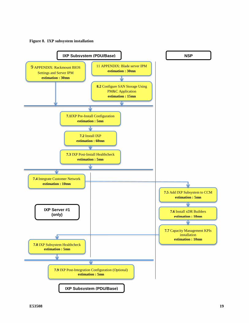
2.8 IXP DL360/BL460c Gen8
This flowchart depicts the sequence of procedures that must be executed to install the IXP subsystem and associated server functions.
The IXP subsystem consists of the following types of servers:
• IXP PDU storage server
• IXP Base server
Note: the servers making the IXP subsystem have to be installed at the same time; mainly, as depicted in the following flowchart, Operating System and IXP have to be installed on each server of the subsystem; then, some steps to declare the subsystem in NSP, are to be executed on one single server; finally, some optional steps are to be executed on each server of the subsystem.
E53508 19
Figure 8. IXP subsystem installation
9 APPENDIX: Rackmount BIOS
Settings and Server IPM
estimation : 30mn
7.1IXP Pre-Install Configuration
estimation : 5mn
7.2 Install IXP
estimation : 60mn
7.3 IXP Post-Install Healthcheck
estimation : 5mn
7.4 Integrate Customer Network
estimation : 10mn
7.5 Add IXP Subsystem to CCM
estimation : 5mn
7.6 Install xDR Builders
estimation : 10mn
IXP Server #1
(only)
IXP Subsystem (PDU/Base)
11 APPENDIX: Blade server IPM
estimation : 30mn
7.8 IXP Subsystem Healthcheck
estimation : 5mn
7.9 IXP Post-Integration Configuration (Optional)
estimation : 5mn
NSP
8.2 Configure SAN Storage Using
PM&C Application
estimation : 15mn
IXP Subsystem (PDU/Base)
7.7 Capacity Management KPIs
installation
estimation : 10mn
20 E53508
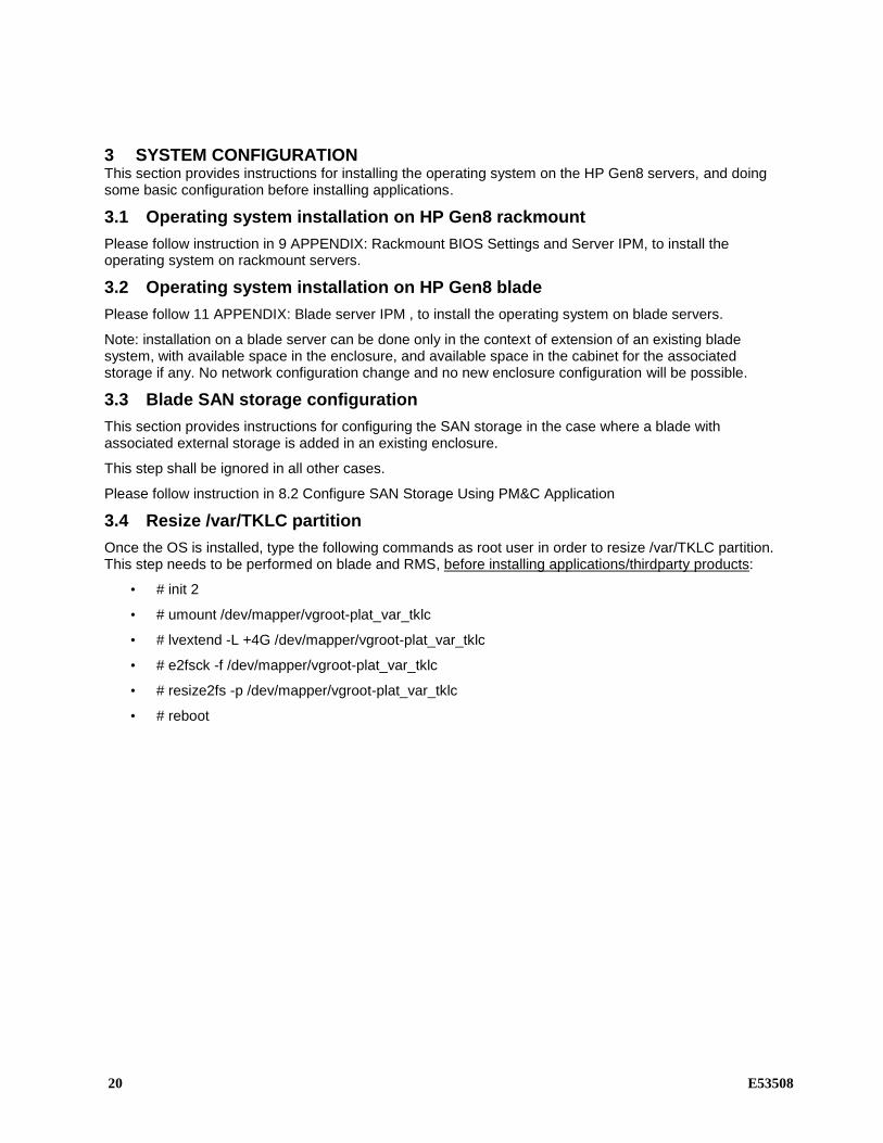
3 SYSTEM CONFIGURATION This section provides instructions for installing the operating system on the HP Gen8 servers, and doing some basic configuration before installing applications.
3.1 Operating system installation on HP Gen8 rackmount
Please follow instruction in 9 APPENDIX: Rackmount BIOS Settings and Server IPM, to install the operating system on rackmount servers.
3.2 Operating system installation on HP Gen8 blade
Please follow 11 APPENDIX: Blade server IPM , to install the operating system on blade servers.
Note: installation on a blade server can be done only in the context of extension of an existing blade system, with available space in the enclosure, and available space in the cabinet for the associated storage if any. No network configuration change and no new enclosure configuration will be possible.
3.3 Blade SAN storage configuration
This section provides instructions for configuring the SAN storage in the case where a blade with associated external storage is added in an existing enclosure.
This step shall be ignored in all other cases.
Please follow instruction in 8.2 Configure SAN Storage Using PM&C Application
3.4 Resize /var/TKLC partition
Once the OS is installed, type the following commands as root user in order to resize /var/TKLC partition. This step needs to be performed on blade and RMS, before installing applications/thirdparty products:
• # init 2
• # umount /dev/mapper/vgroot-plat_var_tklc
• # lvextend -L +4G /dev/mapper/vgroot-plat_var_tklc
• # e2fsck -f /dev/mapper/vgroot-plat_var_tklc
• # resize2fs -p /dev/mapper/vgroot-plat_var_tklc
• # reboot

E53508 21
4 NSP APPLICATION INSTALLATION PROCEDURES This section provides the procedures for installing the Network Software Platform (NSP) application.
Note: only onebox NSP configuration is supported for fresh installation.
4.1 NSP Pre-Install Configuration (onebox)
Box: Onebox
This procedure describes how to configure the NSP servers, which is required prior to installing NSP application.
This procedure consists of several actions that are needed to configure the NSP servers:
• Create the NSP bulkconfig file.
• Configure the NSP server hostname.
• Configure SNMP.
Before you perform this procedure, make sure you have read and are familiar with APPENDIX: PIC bulkconfig file description
4.1.1 Verify system health
Log in as root on the server where you want to install the application, and run:
# syscheck
Review the fail_log file (/var/TKLC/log/syscheck/fail_log) for any errors .
Example ouput for a healthy system:
Running modules in class disk...
OK
Running modules in class proc...
OK
Running modules in class system...
OK
Running modules in class hardware...
OK
LOG LOCATION: /var/TKLC/log/syscheck/fail_log
Note: Errors of NTP in syscheck can be ignored at this time, as NTP server is not configured
4.1.2 Create the bulkconfig file
As root user create the /root/bulkconfig file as described in Appendix NSP Bulkconfig File Description .
4.1.3 Configure the server hostname
a) As root, run: # su - platcfg
b) Select Server Configuration ➤ Hostname
c) Click Edit.
d) Type the NSP server hostname and click OK.
e) Return to the main platcfg menu.

22 E53508
4.1.4 Configure SNMP
a) From the main platcfg menu, select Network Configuration➤SNMP Configuration➤NMS
b) Configuration and select Edit > Add A New NMS Server.
c) Enter
Hostname or IP: 127.0.0.1
Port: 162
SNMP Community String: TEKELEC
and then click OK and then EXIT
d) Click YES to restart alarm server and then press any Key to continue.
e) Exit the platcfg menu.
4.1.5 Temporary customer IP assignement
To configure network manually please refer APPENDIX: Manual configuration of ethernet interfaces.
This step is mandatory for RMS installation in order to proceed to the file transfer in the next step.
For the Blade systems you can skip this step and use the control network IPs for the file transfer from the PM&C.
4.1.6 Copy Weblogic and Oracle product files
a) Download the following files from Oracle Download center and copy them to /var/TKLC/upgrade folder:
o WebLogic 10.3.5.0 for 64bits JVM support product
wls1035_generic.jar
jrockit-jdk1.6.0_45-R28.2.7-4.1.0-linux-x64.bin
o Oracle Database 11.2.0.4 64bits product
p13390677_112040_Linux-x86-64_1of7.zip
p13390677_112040_Linux-x86-64_2of7.zip
b) Copy NSP and xMF iso to /var/TKLC/upgrade folder.
c) On the c-class blade server download the ISO from the PM&C ISO repository. ISOs are available on the PM&C server under the /var/TKLC/smac/image directory. Store the ISO file to /var/TKLC/upgrade directory. If the ISO is not present in PM&C ISO repository add the ISO file using the procedure Adding ISO Images to the PM&C Image Repository
4.2 WebLogic and Oracle product installation
This procedure describes how to install the other software required like WebLogic and Oracle Product with the files copied.
Note: Run this procedure from iLO console !

E53508 23
4.2.1 Mount NSP media
As root, run:
# mount –o loop iso_path /mnt/upgrade
where iso_path is the absolute path of the NSP ISO image, which includes the name of the image (starting with /var/TKLC/upgrade).
4.2.2 Install WebLogic Product
As root, run:
# /mnt/upgrade/install_weblogic.sh
Wait until the installation process is complete.
Analyze the installation log
Verify that WebLogic installed successfully.
In the WebLogic Software Installation log (/var/TKLC/log/upgrade/weblogic.log), the
Weblogic product is installed successfully message appears at the end of the file.
If this message does not appear in the log file, contact the Oracle Customer Care Center.
4.2.3 Install Oracle database Product
As root, run:
# /mnt/upgrade/install_oracle.sh
Wait until the installation process is complete.
Note: the system will reboot at the end of Oracle database product installation
Analyze the installation log:
Verify that Oracle installed successfully.
In the Oracle product Installation log (/var/TKLC/log/upgrade/oracle.log), the
Oracle product is installed successfully message appears at the end of the file.
If this message does not appear in the log file, contact the Oracle Customer Care Center.
4.3 NSP application installation
This procedure describes how to install the NSP Product from the NSP ISO.
Note: Run this procedure from iLO console !
4.3.1 Mount NSP media
As root, run:
# mount –o loop iso_path /mnt/upgrade
where iso_path is the absolute path of the NSP ISO image, which includes the name of the image (starting with /var/TKLC/upgrade).
4.3.2 Install NSP
As root, run:
# /mnt/upgrade/install_nsp.sh
24 E53508
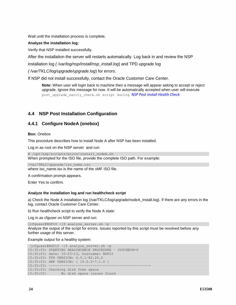
Wait until the installation process is complete.
Analyze the installation log:
Verify that NSP installed successfully.
After the installation the server will restarts automatically. Log back in and review the NSP
installation log ( /var/log/nsp/install/nsp_install.log) and TPD upgrade log
( /var/TKLC/log/upgrade/upgrade.log) for errors.
If NSP did not install successfully, contact the Oracle Customer Care Center.
Note: When user will login back to machine then a message will appear asking to accept or reject upgrade. Ignore this message for now. It will be automatically accepted when user will execute
post_upgrade_sanity_check.sh script during NSP Post Install Health Check
4.4 NSP Post Installation Configuration
4.4.1 Configure NodeA (onebox)
Box: Onebox
This procedure describes how to install Node A after NSP has been installed.
Log in as root on the NSP server and run:
# /opt/nsp/scripts/procs/install_nodeA.sh
When prompted for the ISO file, provide the complete ISO path. For example:
/var/TKLC/upgrade/iso_name.iso
where iso_name.iso is the name of the xMF ISO file.
A confirmation prompt appears.
Enter Yes to confirm.
Analyze the installation log and run healthcheck script
a) Check the Node A installation log (/var/TKLC/log/upgrade/nodeA_install.log). If there are any errors in the log, contact Oracle Customer Care Center.
b) Run healthcheck script to verify the Node A state:
Log in as cfguser on NSP server and run:
[cfguser@NSP10 ~]$ analyze_server.sh -p
Analyze the output of the script for errors. Issues reported by this script must be resolved before any further usage of this server.
Example output for a healthy system:
[cfguser@NSP10 ~]$ analyze_server.sh -p
15:35:03: STARTING HEALTHCHECK PROCEDURE - SYSCHECK=0
15:35:03: date: 10-23-13, hostname: NSP10
15:35:03: TPD VERSION: 6.5.1-82.26.0
15:35:03: XMF VERSION: [ 10.0.0-7.1.0 ]
15:35:03: -------------------------------------------------
15:35:03: Checking disk free space
15:35:03: No disk space issues found

E53508 25
15:35:03: Checking syscheck - this can take a while
15:35:11: No errors in syscheck modules
15:35:11: Checking statefiles
15:35:11: Statefiles do not exist
15:35:11: Checking runlevel
15:35:11: Runlevel is OK (N 4)
15:35:11: Checking upgrade log
15:35:11: Install logs are free of errors
15:35:11: Analyzing IDB state
15:35:11: IDB in START state
15:35:11: Checking IDB database
15:35:11: iaudit has not found any errors
15:35:11: Analyzing processes
15:35:12: Processes analysis done
15:35:12: All tests passed. Good job!
15:35:12: ENDING HEALTHCHECK PROCEDURE WITH CODE 0
Example output for a system with errors:
08:18:31: >>> Error: Syscheck analyzes contains alarms
One or more module in class "hardware" FAILED
08:18:32: >>> Suggestion: Check /var/TKLC/log/syscheck/fail_log at 1297084711
for more information
...
909-2122-001 Revision 1, April 22, 2011 133
xMF Application Installation Procedures08:18:35: >>> Error: 1 test(s) failed!
08:18:35: ENDING HEALTHCHECK PROCEDURE WITH CODE 2
4.4.2 Change Customer Icon (Optional)
This procedure describes how to change the customer icon (for example, replace the standard Tekelec logo with a customer logo). This procedure is optional.
1. Open a terminal window and log in as tekelec on the NSP server (One-box).
2. Copy the customer icon file (customer_icon.jpg) to the /opt/www/resources directory.
3. Verify the customer icon properties:
The file name must be customer_icon.jpg.
The file must belong to user tekelec in group tekelec.
The compression format must be Jpeg.
Optimum width/height ratio is 1.25.
Any image can be used; the suggested minimum width/height is 150 pixels.
4.4.3 Install Optional Applications
This procedure describes how to install optional applications.
4.4.3.1 Applications list
L99465 PIC Mediation DataFeed
L99467 PIC Multiprotocol Troubleshooting Application
L99468 PIC Network and Service Alarm Applications
L99469 PIC Network and Service Dashboard
L99470 PIC SS7 Network Surveillance Applications

26 E53508
L99471 On Demand User Plane Capture Application
Session Point Code
4.4.3.2 Applications installation
1. Open a terminal window and log in as tekelec on the NSP server (One-box).
2. Change dir to /opt/nsp/nsp-
package/framework/install/dist/install/optional/exec folder
3. Change the permission of the executables by executing the below command:
# chmod a+x *
Below should be the updated permission:
-rwxr-xr-x 1 tekelec tekelec 13456 Jul 4 15:44 L99465_PIC_Mediation_DataFeed
4. Install the required optional application by running the corresponding executable for that application.
For example : To install optional application “PIC Network and Service Dashboard “ type the name of executable “L99469_PIC_Network_and_Service_Dashboard” and hit enter command
5. The install logs are available at /var/log/nsp/install/activate_optional.log.
4.4.4 Configure Purchased Tokens(Onebox and Fourbox)
This procedure describes how to increase purchased token after NSP is installed
1. Open a terminal window and log in as tekelec on the NSP server (One-box).
2. Change dir to /opt/nsp/nsp-
package/framework/install/dist/install/optional/exec folder
3. Change the permission of the executables by executing the below command:
# chmod a+x L99466_PIC_Management_Application
Below should be the updated permission:
-rwxr-xr-x 1 tekelec tekelec 13720 Jul 4 15:44
L99466_PIC_Management_Application
4. Run the L99466_PIC_Management_Application executable provided. It will prompt for no of concurrent user you want to set. Enter the value. Note: User can not decrease the number of tokens. Value can be increased only.Maximum value can be 50 only.
5. After the value provided it will successfully increase the token.
4.4.5 Configure Apache HTTPS Certificate (Optional)
This procedure describes how to configure the Apache HTTPS certificate.
This procedure is optional; however, it is required when operating in a secured network environment and is available only on the NPS One-box.
1. Open a terminal window and log in as root on the NSP One-box.
2. Enter the platcfg menu. As root, run:
E53508 27
3. su - platcfg
4. Copy the files server.crt and server.key that are provided by the customer to /root.
5. Select NSP Configuration ► Configure Apache HTTPS Certificate.
6. Press Enter.
7. Select Yes to confirm the action.
8. Exit the platcfg menu.
In order to revert Apache configuration, execute the following as root:
rcstool use /etc/httpd/conf.d/ssl.conf 1.1
service httpd restart
4.4.6 Configure Mail Server (Optional)
This procedure describes how to configure the SMTP mail server.
This procedure is optional; however, this option is required for Security (password initialization set to AUTOMATIC) and Forwarding (forwarding by mail filter defined) and is available only on the
NPS server (One-box).
1. Open a terminal window and log in as root on the NSP server (One-box)
2. Enter the platcfg menu. As root, run: # su - platcfg
3. Select NSP Configuration ► SMTP Configuration.
4. Select Edit.
5. Type the IP address of the SMTP server and click OK.
6. The host file for the alias used in the WebLogic Mail service is updated.
7. Exit the platcfg menu.
4.4.7 Configure Authenticated Mail Server (Optional)
This procedure describes how to authenticate the mail server. This procedure is optional.
Note: This procedure is performed after the SMTP has been configured (refer to the In order to revert Apache configuration, execute the following as root:
rcstool use /etc/httpd/conf.d/ssl.conf 1.1
service httpd restart
Configure Mail Server (Optional) procedure).
When a mail server requires authentication, additional parameters must be defined in the WebLogic console.
1. Connect to the NSP application interface.
2. Log in as weblogic on the WebLogic Console.
3. Select Services ► Mail Sessions ► NspMailSession.
4. Click Lock&Edit and modify the JavaMail properties as needed. For example:
mail.transport.protocol=smtp, mail.smtp.host=mail.server, mail.smtp.from= [email protected], mail.smtp.timeout=5 00, mail.smtp.connectiontimeout=500
28 E53508
5. Add the following parameters:
mail.smtp.auth=true mail.smtp.port=465 mail.smtp.quitwait=false user=my_account password=my_password
where my_account and my_password change according to the customer SMTP server.
6. If the SMTP over SSL is used, then add the following parameters:
mail.smtp.socketFactory.port=4 6 5 mail.smtp.socketFactory.class=javax.net.ssl.SSLSocketFactory mail.smtp.socketFactory.fallback=false
7. Click Save.
8. Click Activate Configuration.
9. Log in as root on the NSP server and run:
# service nspservice restart
4.4.8 Configure SNMP Management Server (Optional)
This procedure describes how to configure the SNMP management server.
This procedure is optional; however, this option is required for Forwarding (forwarding by SNMP filter defined) and is available only on the NPS One-box
1. Open a terminal window and log in as root on the NSP One-box.
2. Copy the files server.crt and server.key that are provided by the customer to /root.
3. Enter the platcfg menu. As root, run:
su - platcfg
4. Select NSP Configuration ► SNMP Agent Configuration.
A window appears which allows you to enter the IP address of the SNMP management platform and version of SNMP agent and traps.
5. Select Edit.
6. Type the appropriate values and click OK.
The SNMP agent configuration is updated and the SNMP Management server is automatically restarted.
7. Exit the platcfg menu.
4.4.9 Modify WebLogic Administration Password (Optional)
This procedure describes how to modify the WebLogic administration password.
This procedure is optional; however, this option is required for security and is available only on the NPS One-box
1. Open a terminal window and log in as root on the NSP One-box .
2. Enter the platcfg menu. As root, run:

E53508 29
su - platcfg
3. Select NSP Configuration ► NSP Password C onfiguration ► Weblogic Password Configuration (for startup and deploy).
A window appears which allows you to enter the password. The password must contain at least 1 non-alphabetical character.
4. Select Edit.
5. Type a valid password and click OK.
Note: Make sure the new password contains at least one numeric or special character.
The configuration files are updated and NSP is restarted automatically.
6. Exit the platcfg menu.
4.4.10 Configure Session Timeout (Optional)
This procedure describes how to configure the session timeout, the amount of time (in minutes) that a session can remain inactive before it is invalidated and token released.
1. Log in as TklcSrv on the NSP application interface.
2. Select the Security application.
3. Select Action ► Manage Tokens.
The Tokens window appears.
4. Type the appropriate value (in minutes; must be from 15 to 480, e.g., 3 0) in the Session timeout field and click Apply.
4.4.11 Control Access of NSP to HTTPS (Optional)
This procedure describes how to control the access (enable or disable) of the NSP frontend to HTTPS. This procedure is optional.
1. Open a terminal window and log in as root on the NSP server (One-box).
2. Enter the platcfg menu. As root, run:
# su platcfg
3. Select NSP Configuration ► Enable HTTP Port ► Edit.
4. Select the appropriate option to either enable or disable the access and click OK.
Select Yes to enable access to HTTP.
Select No to disable access to HTTP.
5. Exit the platcfg menu.
4.4.12 Configure External LDAP (Optional)
This procedure describes how to use a customer-provided authentication based on the Lightweight Directory Access Protocol (LDAP). This procedure is optional.
1. Open a terminal window and log in as root on the NSP server (One-box).

30 E53508
2. Configure the NSP database. As root, run:
# cd /opt/nsp/scripts/procs
# sh nsp_update_procs.sh externalLDAP true
3. From a web brower, connect to the NSP application interface. Use the following URL:
http://192.168.1.1/console
where 192.168.1.1 is the IP address of the NSP server.
4. Log in to the WebLogic Console as weblogic.
5. Select Security Realm ► myrealm ► Providers ► Authentication.
6. Click Lock&Edit and add a new LDAP Authenticator.
Provide the necessary parameters that correspond to the customer LDAP tree configuration (refer to the WebLogic documentation for more information about this process).
7. Set the control flag for all of the Authentication Providers to SUFFICIENT.
8. Click Save.
9. Click Activate Configuration.
4.4.13 Control Cisco PMP (Optional)
This procedure describes how to enable or disable the Cisco PMP. This procedure is optional.
1. Open a terminal window and log in as tekelec on the NSP server or the NSP Oracle server.
2. Run the appropriate commands:
• To enable the Cisco PMP, run:
# cd /opt/nsp/nsp-package/framework/db/dist/utils/cmd
# sh PmpOption.sh -e
• To enable the Cisco PMP, run:
# cd /opt/nsp/nsp-package/framework/db/dist/utils/cmd
# sh PmpOption.sh -e
4.4.14 Configure the default settings for the new users (Optional)
This procedure describes how configure the default settings for the new users. This procedure is optional.
1. Login on the NSP as user Tekelec
2. Modify the user preferences according the customer requirement and especially the Time Zone.
3. Validate the settings using the button “Save as default” for each panel you modified.
4.4.15 Configure CSV streaming feed feature (Optional)
This procedure describes how to enable or disable the CSV streaming feed feature: this feature is subject to subscription and it is disabled after installation.
1. Open a terminal window and log in as tekelec on the NSP server (1 box)
2. Run the appropriate commands:
o To enable CSV streaming feed, run:
# cd /opt/nsp/nsp-package/framework/core

E53508 31
# ant enable.csv.license
o To disable CSV streaming feed, run:
# cd /opt/nsp/nsp-package/framework/core
# ant disable.csv.license
4.4.16 Configure FSE automated update (Optional)
This procedure describes how to enable or disable the automatic update of enrichment configuration file defined or to be defined in NSP system.
NSP scan regurlarly defined folder and its subfolder (every 30 mn) to find files with same name as the those declared. In this case it loads file to replace exsiting FSE and reapply it automatically to selected session.
1. Log in as tekelec on the NSP application interface.
2. Select the Centralized Configuration application.
3. Select Mediation ► Enrichment Files.
The Enrichment Files List screen opens
4. Click on automated update button in list toolbar .
The FSE Auto Update Configuration screen opens.
5. Enter SFTP location where system can find Enrichment FSE file.
URL should be like sftp://<USER>:<PASSWORD>@<HOSTNAME_OR_IP>/<PATH> where
<USER> is username of SFTP server
<PASSWORD> is password of SFTP user
<HOSTNAME_OR_IP> is address of SFTP server
<PATH> is relative path under user home folder in SFTP server
Note: Empty string turns off automated update
6. Click OK to validate changes.
4.4.17 Configure NSP FTP or SFTP Server
This procedure describes how to configure NSP to allow xDR export from ProTrace application to customer's
external FTP or SFTP server.
Note: For an NSP Four-box, this procedure needs to be run on both the Primary server and the Secondary
server.
1. Copy the FTP security file from the NSP server
a) Open a terminal window and log in as root on the NSP server (One-box), Primary/Secondary server
(Four-box).
b) As root, run:

32 E53508
# cd /opt/nsp/bea/user_projects/domains/tekelec/nsp
c) Copy the contents of file sftp_security.pub.
2. Update the FTP or SFTP server
a) Log in on the FTP or SFTP server.
b) In the file $HOME/.ssh/authorized_keys, add the contents of file sftp_security.pub that you copied
in the previous step.
c) Make sure that the FTP or SFTP server is properly configured to allow file transfer.
Don’t use root user to transfer files. tekelec and other users should be use. By default files will be uploaded to user home. E.g- /opt/nsp for tekelec
4.4.18 EPI and Plugin Configuration for Tracing
Refer to Section 7.6, PIC 10 Maintenance Guide (E53511-01)
4.5 NSP Post Install Health Check
Box: Onebox
1. Open a terminal window and log in as root on the NSP One-box.
2. As root, run:
# /opt/nsp/scripts/procs/post_upgrade_sanity_check.sh
Note: When user will execute this script it will automatically accept the upgrade
3. Review the NSP installation logs ( /var/log/nsp/install/nsp_install.log).
Verify the following:
• Port 80 connectivity is OK
• Oracle server health is OK
• WebLogic health for ports 5556, 7001, 8001 is OK
• Oracle em console connectivity is OK
• The disk partition includes the following lines, depending on whether rackmount or blades setup:
• If rackmount, the output contains the following lines:
/dev/sdc1 275G 4.2G 271G 2% /usr/TKLC/oracle/ctrl1
/dev/sdb1 825G 8.6G 817G 2% /usr/TKLC/oracle/oradata
/dev/sdd1 275G 192M 275G 1% /usr/TKLC/oracle/backup
Note: the lines must begin with the /dev/sd*1 designations; values may differ.
• If blades, output contains following lines:
/dev/mapper/nsp_redo_vol 69G 4.2G 61G 7% /usr/TKLC/oracle/ctrl1
/dev/mapper/nsp_data_vol 413G 76G 316G 20% /usr/TKLC/oracle/oradata
/dev/mapper/nsp_backup_vol 138G 9.2G 121G 8% /usr/TKLC/oracle/backup
Note: values may differ.

E53508 33
5 XMF APPLICATION INSTALLATION PROCEDURES This section provides the procedures for installing the xMF application.
Note: This step should be executed for all the servers in sub-system.
5.1 xMF Pre-Install Configuration
This section provides procedures to configure the xMF servers that must be performed before installing the xMF application.
5.1.1 Temporary customer IP assignment
This procedure provides instructions to temporary customer IP assigment to transfer the Application
ISO on server during installation.
Note: This procedure is only to be used to transfer the Application ISO during installation.
Configure Vlan tagging and assign ip address in case of IMF
a) Login via ILO, MRV, OOBM or RMM to server as root
b) Execute following commands (1st line for E5-APP-B only):
# ifconfig eth01 up
# modprobe 8021q
# vconfig add eth01 200 # ifconfig eth01.200 <CUST IP ADDRESS> netmask <MASK> # route add default gw <DEFAULT ROUTE IP ADDRESS>
Assign ip address in case of PMF: see APPENDIX: Manual configuration of ethernet interfaces
5.1.2 Copy ISO
a) Transfer xMF ISO on the server to /var/TKLC/upgrade directory
b) Verify that ISO file is transferred completely on the xMF server.
5.1.3 Configure server
This procedure describes how to configure the xMF servers prior to installing the xMF application.
Note: This procedure must be executed on all of the IMF and PMF servers.
1. Change the current hostname, designation and function
Note: The designation and function are case sensitive and must be capitalized; otherwise, the software functionality will not work properly and will result in the need to reinstall the application.
a) Enter the platcfg menu, as root run: # su – platcfg
b) Select Server Configuration->Hostname c) Select Edit d) Set the hostname e) Select Server Configuration -> Designation/Function. f) Select Edit. g) Change the designation and function.

34 E53508
• For a IMF subsystem:
In the Designation field, enter the designation in the following format: 1A for the first server, 1B for the second, and so on. In the Function field, enter IMF.
• For a standalone PMF:
In the Designation field, enter the 0A for the server. In the Function field, enter PMF.
h) Select Exit.
2. Install the bulkconfig file
Note: Before you perform this procedure, make sure you have read and are familiar with the xMF Bulkconfig File Description 14.4
5.2 xMF Pre-Install Healthcheck
This procedure describes how to run the syscheck and analyze the output to determine the state of the xMF server before installing the xMF application.
Log in as root on the xMF server that you want to install the xMF application.
Run:
# syscheck Review the fail_log file (/var/TKLC/log/syscheck/fail_log) for any errors.
Example ouput for a healthy system: Running modules in class disk... OK Running modules in class proc... OK Running modules in class system... OK Running modules in class hardware... OK LOG LOCATION: /var/TKLC/log/syscheck/fail_log
5.3 Install xMF
This procedure describes how to install the xMF application on a server that has the operating system installed.
Note: Run this procedure from iLO console !
1. Log in as root user
2. Enter the platcfg menu, as root run:
# su – platcfg
3. Select Maintenance ➤ Upgrade ➤ Initiate Upgrade.
4. Select the xMF application media and press Enter.
Informational messages appear on the terminal screen as the upgrade proceeds. When installation is complete, the server reboots and displays the login prompt.
You can check the TPD upgrade log file (/var/TKLC/log/upgrade/upgrade.log) for any error; but the status of the server will be checked when you run the healthcheck script after you configure the switches.
E53508 35
Note: In case of TPD 5.5, the early checks may fail if the upgrade is not attempted from the non disconnectable media, so before attempting the next upgrade remove the “UNKNOWN” entry from “/usr/TKLC/plat/etc/platform_revision” file
5.4 Configure Site and Subsystem for xMF
This procedure describes how to create a site on NSP and set a subsystem in this new site.
The subsystem is treated by PIC as a cluster, accessible by NSP through this IP address.
A dedicated IP address, called Virtual IP (VIP), is needed for the subsystem. This address must be
a real address in the subsystem subnet that is not physically used by any other server or
equipment. The current Active Master server in the subsystem is the server representing the VIP.
For a standalone PMF, the VIP is the IP address of the PMF server. For a single-server IMF, it is
possible to assign the server IP address as VIP; however, when additional servers are added, the
VIP address must be changed to a dedicated IP address to work properly. It is recommended that a
dedicated IP address be used from the beginning, to avoid changing the VIP when more servers are
added.
Note: There is only one xMF subsystem supported per site. If a standalone PMF is in a
site/subsystem, no other IMF or PMF subsystem or standalone PMF can be added. They need to be
added to different logical site in Centralized Configuration. All of the configuration is performed
through the NSP application interface.
1. Log in to the NSP application
a) Log in as tekelec to the NSP application interface using the NSP apache or one
box server IP address.
b) Click Centralized configuration. The NSP application launches.
2. Create a site on NSP
a) Select Equipment Registry ► Sites ► Add.
b) Type the desired site name and click Add.
3. Create xMF sub-system and Add the server(s) on NSP
Note: Skip this step if the Site already exists.
a) Select Equipment Registry ► Sites ► New site name created ► XMF ► Add
b) Type the server IP address(es) for the xMF subsystem and click Add.
c) Click Create.
5.5 xMF Healthcheck post customer integration
This procedure describes how to run the healthcheck script on xMF servers.
The script gathers the healthcheck information from each server in the xMF subsystem or from
standalone server. The script should be run from only on one server of the XMF subsystem ( the 1A
server is preferred) or on stand-alone. The output consists of a list of checks and results, and, if
applicable, suggested solutions.
1. Open a terminal window and log in as cfguser on any server in the xMF subsystem or
standalone server.

36 E53508
2. Run the automatic healthcheck script.
$ analyze_subsystem.sh
3. Analyze the output of the script for errors. Issues reported by this script must be resolved before
any further usage of this server. Verify no errors are present.
If the error occurs, contact the Tekelec Customer Care Center.
Note: For a standalone, there will be only one server in the output.
Example output for a healthy subsystem:
ANALYSIS OF SERVER IMF0502-1A STARTED 11:28:59: STARTING HEALTHCHECK PROCEDURE - SYSCHECK=0 11:28:59: date: 02-07-11, hostname: IMF0502-1A TPD VERSION: 3.3.8- 11:28:59: 63.25.0 XMF VERSION: [ 60.6.7-2.1.0 ] 11:28:59: Checking disk free space 11:28:59: No disk space issues found 11:28:59: Checking whether ssh keys are exchanged among machines in frame this 11:28:59: can take a while 11:29:08: 11:29:08: 3 mates found: yellow-1B yellow-1C yellow-1D 11:29:26: Connection to all mates without password was successful 11:29:26: Checking A-Node server 11:29:29: Connection to A-Node 10.240.9.4 was successful 11:29:29: A-Node version is: 60.6.7-2.1.0 11:29:29: Checking version of the nsp 11:29:32: Connection to nsp 10.240.9.3 was successful 11:29:32: nsp version is: 6.6.4-7.1.0 11:29:32: nsp was installed on: 2011-01-13 05:09:26 (25 days 6 hours ago) 11:29:32: All tests passed. Good job! 11:29:32: ENDING HEALTHCHECK PROCEDURE WITH CODE 0 END OF ANALYSIS OF SERVER IMF0502-1A ANALYSIS OF SERVER IMF0502-1B STARTED 11:30:04: ENDING HEALTHCHECK PROCEDURE WITH CODE 0 END OF ANALYSIS OF SERVER IMF0502-1B ANALYSIS OF SERVER IMF0502-1C STARTED 11:30:36: ENDING HEALTHCHECK PROCEDURE WITH CODE 0 END OF ANALYSIS OF SERVER IMF0502-1C IMF0502-1A TPD: 3.3.8-63.25.0 XMF: 60.6.7-2.1.0 0 test(s) failed IMF0502-1B TPD: 3.3.8-63.25.0 XMF: 60.6.7-2.1.0 0 test(s) failed IMF0502-1C TPD: 3.3.8-63.25.0 XMF: 60.6.7-2.1.0 0 test(s) failed

E53508 37
Example output for a subsystem with errors:
END OF ANALYSIS OF SERVER IMF0502-1D
IMF0502-1A TPD: 3.3.8-63.25.0 XMF: 60.6.7-2.1.0 1 test(s) failed
IMF0502-1B TPD: 3.3.8-63.24.0 XMF: 60.6.7-1.0.0 3 test(s) failed
server on interface yellow-1c is not accessible (ping)
IMF0502-1D TPD: 3.3.8-63.25.0 XMF: 60.6.7-2.1.0 0 test(s) failed
Differences between tpd platform versions found!
Differences between message feeder application versions found!

38 E53508
6 DWS INSTALLATION PROCEDURES This section provides the procedures for installing the Data warehouse storage (DWS).
6.1 DWS Pre-Install Configuration
This procedure describes how to configure DWS prior to installing the application.
Before you perform this procedure, make sure you have read and are familiar with the DWS Bulkconfig File Description.
Note: manufacturing must contact Project Manager or Professional Engineer in charge of the project in order to define the server hostnames in case of an extension project as this can’t be changed without a complete re-installation of the soft.
Note: You must create a new bulkconfig file, with one single host entry with the IXP-XDR function. Do not copy and reuse the bulkconfig file that was created for the servers of an IXP subsystem.
1. Verify each server healthcheck.
a) Run syscheck. Log in as root on the server that you want to install the application. As root
run: # syscheck
Review the /var/TKLC/log/syscheck/fail_log file for any errors. Example output of healthy server:
Running modules in class disk...
OK
Running modules in class proc...
OK
Running modules in class system...
OK
Running modules in class hardware...
OK
LOG LOCATION: /var/TKLC/log/syscheck/fail_log
Resolve each error before you continue with the procedure.
Note: Errors of NTP in syscheck can be ignored at this time, as NTP server is not configured
b) If the server has an external disk storage attached verify the disks state.
Check to which slot an external storage is connected. As root run:
# hpacucli ctrl all show
Example output:
[root@ixp0301-1a ~]# hpacucli ctrl all show
Smart Array 6400 in Slot 2 (sn: P5782AT9SX5017)
Smart Array P400i in Slot 0 (Embedded) (sn: PH95MP6416 )
Now show a detailed report for each disk. As root run:
# hpacucli ctrl slot=slot_number pd all show

E53508 39
where slot_number is the number of the slot received in previous step. All disks must be in OK state. Example output:
[root@ixp0301-1a ~]# hpacucli ctrl slot=2 pd all show
Smart Array 6400 in Slot 2
array A
physicaldrive 1:0 (port 1:id 0 , Parallel SCSI, 300 GB, OK)
physicaldrive 1:1 (port 1:id 1 , Parallel SCSI, 300 GB, OK)
physicaldrive 1:2 (port 1:id 2 , Parallel SCSI, 300 GB, OK)
physicaldrive 1:3 (port 1:id 3 , Parallel SCSI, 300 GB, OK)
physicaldrive 1:4 (port 1:id 4 , Parallel SCSI, 300 GB, OK)
physicaldrive 1:5 (port 1:id 5 , Parallel SCSI, 300 GB, OK)
physicaldrive 1:8 (port 1:id 8 , Parallel SCSI, 300 GB, OK)
array B
physicaldrive 2:0 (port 2:id 0 , Parallel SCSI, 300 GB, OK)
physicaldrive 2:1 (port 2:id 1 , Parallel SCSI, 300 GB, OK)
physicaldrive 2:2 (port 2:id 2 , Parallel SCSI, 300 GB, OK)
physicaldrive 2:3 (port 2:id 3 , Parallel SCSI, 300 GB, OK)
physicaldrive 2:4 (port 2:id 4 , Parallel SCSI, 300 GB, OK)
physicaldrive 2:5 (port 2:id 5 , Parallel SCSI, 300 GB, OK)
physicaldrive 2:8 (port 2:id 8 , Parallel SCSI, 300 GB, OK)
c) If the server has a SAN disk storage verify the vdisks are attached to the server.
Check to which vdisk are connected. As root run:
# multipath -ll
Example output:
0_oracle_data (3600c0ff000d825e6c7508d4f01000000) dm-8 HP,MSA2012fc
[size=1.4T][features=1 queue_if_no_path][hwhandler=0][rw]
\_ round-robin 0 [prio=2][active]
\_ 0:0:0:1 sda 8:0 [active][ready]
\_ 1:0:0:1 sdc 8:32 [active][ready]
0_oracle_index (3600c0ff000d82539cc6a8d4f01000000) dm-9 HP,MSA2012fc
[size=1.4T][features=1 queue_if_no_path][hwhandler=0][rw]
\_ round-robin 0 [prio=2][active]
\_ 0:0:1:2 sdb 8:16 [active][ready]
\_ 1:0:1:2 sdd 8:48 [active][ready]
Make sure the LUN number are the one expected per the engineering. The LUN is the number highlited in yellow in the example
2. Create the bulkconfig file
a) As a root user.
b) Create the /root/bulkconfig file as explained in annex DWS Bulkconfig File Description.
Note: Be sure to have one only host entry in the bulkconfig file with the hostname formatted
as ixpNNNN-MA, with:
o the same NNNN designation (4 digits) as for the related IXP subsystem
o the same M designation (1 digit, excluding “0”) as for the related IXP subsystem
o as its A designation (a small letter), “z” for the first DWS used by this IXP subsystem,
“y” for the second DWS, and so on…
40 E53508
3. Configure the server hostname
a) Enter the platcfg menu.
As root, run:
# su - platcfg
b) Select Server Configuration -> Hostname.
c) Click Edit.
d) Enter the server hostname in the standard format: ixpNNNN-MA (see step 2 for naming
details).
e) Exit the platcfg menu.
4. Temporary customer IP assignment
This procedure provides instructions to temporary customer IP assignment to transfer the Application ISO on server during installation.
Note: This procedure is only to be used to transfer the Application ISO during installation. For the Blade systems you can skip this step and use the control network IPs for the file transfer from the PM&C.
Refer to APPENDIX: Manual configuration of ethernet interfaces
6.2 Install Oracle Product
This procedure describes how to install the Oracle Product on a server with the operating system installed (TPD).
Before you perform this procedure:
Make sure that you have the IXP ISO file available.
Verify the /root/bulkconfig file needed for this installation has been created on the server
accordingly to specific application directions as a result of pre-install configuration step.
In case of c-class blades SAN Configuration must be done properly before starting Oracle Installation
This procedure must be run via iLO.
1. Copy ISO and Oracle product
a) Download the following files from Oracle Download center and copy them to
/var/TKLC/upgrade folder. For Oracle Database 11.2.0.4 product:
o p13390677_112040_Linux-x86-64_1of7.zip
o p13390677_112040_Linux-x86-64_2of7.zip
o p13390677_112040_Linux-x86-64_3of7.zip
b) Copy IXP iso to /var/TKLC/upgrade folder.
c) On the c-class blade server download the ISO from the PM&C ISO repository. ISOs are available on the PM&C server under the /var/TKLC/smac/image directory. Store the ISO file to /var/TKLC/upgrade directory. If the ISO is not present in PM&C ISO repository add the ISO file using the procedure Adding ISO Images to the PM&C Image Repository

E53508 41
2. Mount the media
# mount -o loop /var/TKLC/upgrade/iso_file /mnt/upgrade
where iso_file is the IXP iso filename.
Note: IXP iso must be mounted to /mnt/upgrade
3. Install Oracle
As root, run:
# /mnt/upgrade/install_oracle.sh
Note: When installing Oracle 11g you will be prompted by the following:
You are about to install Oracle 11G and ASM. Are you sure you want to
continue
(yes/no)
Type yes to confirm. Press <enter> to continue.
When the installation process is complete the server will automatically reboot.
4. Analyze the installation log
Review the installation log ( /var/TKLC/log/upgrade/oracle.log) for any errors. Oracle
must be installed successfully.
If there are any errors, contact the Oracle PIC Design Support Team
Note: The script /opt/oracle11/oracle/product/11.2.0/db_1/root.sh is already executed by the installation.
6.3 Install IXP
This procedure describes how to install the IXP application on the TPD platform.
Note: Run this procedure via iLO.
1. Copy ISO
a) Copy IXP iso to /var/TKLC/upgrade folder.
b) On the c-class blade server download the ISO from the PM&C ISO repository. ISOs are
available on the PM&C server under the /var/TKLC/smac/image directory. Store the ISO file
to /var/TKLC/upgrade directory. If the ISO is not present in PM&C ISO repository add the ISO
file using the procedure Adding ISO Images to the PM&C Image Repository
2. Log in and Validate the installation media
a) Enter the platcfg menu.

42 E53508
As root, run:
# su - platcfg
b) Select Maintenance -> Upgrade -> Validate Media.
c) Select the desired upgrade media and press Enter.
The validation process must complete without errors. You should receive the following message:
CDROM is Valid
If any errors are reported during this validation process, then DO NOT USE this media to install the application.
3. Install the application
a) From platcfg menu select Maintenance -> Upgrade -> Initiate Upgrade.
When the installation process is complete, the server restarts automatically.
Note: after the server has restarted, at login, a message asking to accept or reject the upgrade is displayed: the message can be safely ignored until the Integrate Customer Network step has been executed.
b) If the ISO file was copied to the server, then remove this file to save disk space.
As root, run:
# rm -f /var/TKLC/upgrade/iso_file
where iso_file is the absolute path of the ISO image, which includes the name of the image.
Information note: At this step, for BL460 G6 servers, the default gateway is not set, thus, remote access is only possible though the iLO (the gateway will be set during Customer integration).
4. Analyze the installation log
Review the installation log ( /var/TKLC/log/upgrade/upgrade.log) for any errors.
If there are any errors, contact the Oracle PIC Design Support Team
6.4 DWS Post-Install Healthcheck
This procedure describes how to run the server health check after the application has been installed on the server.
1. Log in on the server that you want to analyze.
2. As cfguser, run:
$ analyze_server.sh –p
The script gathers the health check information from the server. A list of checks and associated results is generated. There might be steps that contain a suggested solution. Analyze the output of the script for any errors. Issues reported by this script must be resolved before any further use of this server.
The following examples show the structure of the output, with various checks, values, suggestions, and errors.

E53508 43
Example of overall output:
$ analyze_server.sh
12:40:30: STARTING HEALTHCHECK PROCEDURE - SYSCHECK=0
12:40:30: date: 08-22-11, hostname: ixp8888-1a
12:40:30: TPD VERSION: 4.2.4-70.90.0
12:40:30: IXP VERSION: [ 10.0.0-64.2.0 ]
12:40:30: XDR BUILDERS VERSION: [ 10.0.0-37.1.0 ]
12:40:30: -------------------------------------------------
12:40:31: Analyzing server record in /etc/hosts
12:40:31: Server ixp8888-1a properly reflected in /etc/hosts file
12:40:31: Analyzing IDB state
12:40:31: IDB in START state
12:40:31: Analyzing shared memory settings
12:40:31: Shared memory set properly
.....
12:43:02: All tests passed!
12:43:02: ENDING HEALTHCHECK PROCEDURE WITH CODE 2
Example of a successful test:
12:40:31: Analyzing server record in /etc/hosts
12:40:31: Server ixp8888-1a properly reflected in /etc/hosts file
Example of a failed test:
12:21:48: Analyzing IDB state
12:21:48: >>> Error: IDB is not in started state (current state X)
12:21:48: >>> Suggestion: Verify system stability and use 'prod.start'
to start
the product
Note: if the following error shows up during server analysis, it can be simply ignored, as the alarm will be cleared after Integrate Customer Network step (see below) will have been executed.
12:21:48: >>> Error: Alarm raised for tpdServerUpgradePendingAccept...
12:21:48: >>> Suggestion: Check /var/TKLC/log/syscheck/fail_log...
In any other cases, after attempting the suggested resolution, if the test fails again, then contact Oracle Customer Care Center.
6.5 Integrate Customer Network
This procedure describes how to integrate the DWS post-manufacturing customer network.
This procedure uses the /root/bulkconfig file as an input for the customer network integration. Before you perform this procedure, make sure you have read and are familiar with the DWS Bulkconfig File Description.
This procedure is run from the iLO.
1. Update the bulkconfig file

44 E53508
a) Log in on the iLO of DWS that you want to reconfigure.
b) Update the /root/bulkconfig file with the customer IP addresses and timezone.
2. Run the customer network integration
a) Run the IXP subsystem customer network integration script. As root, run: # bc_customer_integration.sh
b) Confirm this operation. Enter yes.
A prompt for the root password appears.
c) Provide the root password. The servers reboot.
3. Run the post-integration settings
Note: The DWS has new IP address. The previous addresses are no longer accessible.
a) Run post-integration settings. As root, run: # bc_customer_integration.sh --post
Note: The key exchange operation is part of this script.
A prompt for the root and cfguser passwords appears.
b) Provide the appropriate passwords.
c) When the script is complete, check the terminal output for any errors.
If error occured, contact the Tekelec Customer Care Center.
Note: the error message “SSH Connection to… failed” can show up at the very end of the execution of that script (bug 19169230): the error can simply be ignored (there is no impact on the installation process).
4. Finalize the DWS conversion
Note: At this step, the formerly existing IXP xDR server is turned into a DWS (avoiding it to be recognized from the NSP as an IXP xDR server).
Run conversion command. As cfguser, run:
$ makeDWH.sh
A prompt for the root password will appear: type in the root password (input is not visible).
A prompt for the NSP Primary IP address may appear: enter the correct IP address (not a host name) of the NSP Primary (in case of a 4 box NSP) or of the NSP server (in case of a 1 box NSP).
6.6 Configure Oracle
This procedure describes how to run the automatic Oracle post-install script. This procedure allocates necessary data and index files and runs various Oracle post-install settings and tunings.
This procedure is applicable to DWS servers only and can take a very long time (up to 5 hours with 25 disk of 600Gb)
Note: Run this procedure via iLO.

E53508 45
1. Log in on the DWS Server.
2. As root, run:
# cd_oracle_utils
# ./oracle-postinstall.pl --auto | tee -a
/var/TKLC/log/ixp/postinstall-oracle.log
3. When the script finishes, check the log file /var/TKLC/log/ixp/postinstall-oracle.log for any errors.
If there are any errors, contact the Oracle PIC Design Support Team
Example output:
--CUT--
inf | --- Calculated new sizing in space usage:
inf | part | existing | requested | target
inf | Temp size | 12884901888 | 17179869184 | as requested
inf | DATA_CDR size |137438953472 |1272487125741 | 1271310319616
inf | DATA_IND size | 34359738368 |1040365377590 | 1030792151040
inf |oraindex DATA_CDR size | 0 | 289237746768 | 274877906944
inf | --- Calculated new sizing in number of files:
inf | part | exists |requested| create | cdr:ind %
inf | Temp files | 6 | 8 | 2 | na
inf | DATA_CDR data | 8 | 74 | 66 | 48.879
inf | DATA_IND data | 2 | 60 | 58 | 39.632
inf |oraindex DATA_CDR data | 0 | 16 | 16 | 10.569
war | Will create 2 temp files.
war | Will create 66 DATA_CDR data files.
war | Will create 58 DATA_IND data files.
war | Will create 16 DATA_CDR data files at oraindex.
inf | File: 0/142 at 1GB avg 0.00s, ETA 0.00s
inf | File: 1/142 at 1GB avg 0.00s, ETA 0.00s
inf | File: 2/142 at 1GB avg 0.00s, ETA 0.00s
inf | File: 3/142 at 1GB avg 3.69s, ETA 8201.00s
inf | File: 4/142 at 1GB avg 3.69s, ETA 8145.94s
inf | File: 5/142 at 1GB avg 3.70s, ETA 8111.01s
inf | File: 6/142 at 1GB avg 3.70s, ETA 8057.48s
inf | File: 7/142 at 1GB avg 3.71s, ETA 8014.10s
inf | File: 8/142 at 1GB avg 3.72s, ETA 7969.14s
--CUT--
6.7 Add DWS to CCM
This procedure describes how to add the DWS to the CCM on NSP. This procedure is performed through the NSP application interface.
1. Log in to the NSP and open Centralized Configuration (CCM)
a) Log in to the NSP application interface as tekelec using the NSP Primary server IP address.
b) Open the Centralized Configuration application.
c) Select Equipment Registry.
2. Configure the new site

46 E53508
a) Right-click the Sites list and select Add to enter new site configuration.
b) Type the Site name and Description and click Add.
3. Add the DWS to the site
a) Navigate to Sites.
b) Right-click DWH and select Add to enter the DWS configuration:
o Fill the DWS server hostname into the Storage Name field. o Fill the Login user Id (IXP by default) o Fill the Password (Refer to TR006061 for the default value) o Fill the Service Name (IXP by default) o Fill in the IP address of the DWS.
c) Click Add.
6.8 DWS Post-Integration Configuration (Optional)
6.8.1 Activate Session Compression
This procedure describes how to activate/deactivate compression for a particular Oracle session.
Before performing this procedure be aware of the following facts:
Activated compression will have negative influence on storage speed rate.
Activated compression will have negative influence on ProTrace queries speed rate.
Activated compression will have positive influence on storage size.
All current benchmark tests have been tested with deactivated compression.
Note: Execute this procedure on all DWS servers in the Storage Pool where the session is located.
1. Login to the DWS server
a) Open a terminal window and log in to the DWS server as cfguser.
b) Navigate to /opt/TKLCixp/prod/db/tuning/cmd directory. As cfguser run: $ cd /opt/TKLCixp/prod/db/tuning/cmd
2. How to activate the compression
To activate compression for particular session as cfguser run: $ ./TuningPackage.sh ixp/ixp@localhost/ixp -c session
where session is the name of particular session.
3. How to deactivate the compression
To deactivate compression for particular session as cfguser run: $ ./TuningPackage.sh ixp/ixp@localhost/ixp -x session
where session is the name of particular session.
4. Verify the settings

E53508 47
Verify the session list where the session compression is activated. As cfguser run: $ ./TuningPackage.sh ixp/ixp@localhost/ixp -l
All session with activated compression will be listed in the command output.
6.8.2 Change Default Passwords of Oracle Accounts
This procedure describes how to modify the default passwords of the Oracle account. This procedure is applicable to any DWS server in the subsystem.
1. Connect as database administrator
a) Log in on the DWS server.
b) Connect to Oracle as the database administrator. As the oracle user, run: $ sqlplus / as sysdba
2. Set passwords
a) Set the password for DBSNMP. Run: SQL> alter user DBSNMP identified by password;
where password is actual password.
b) Set the password for OUTLN. Run: SQL> alter user OUTLN identified by password;
where password is actual password.
c) Set the password for SYSMAN. Run: SQL> alter user SYSMAN identified by password;
where password is the actual password.
3. Close the Oracle session
Exit the Oracle session. Run: SQL> exit;

PIC 10.0 Installation Guide
48 E53508
7 IXP APPLICATION INSTALLATION PROCEDURES
This section provides the procedures for installing the Integrated xDR Platform (IXP) application.
7.1 IXP Pre-Install Configuration
This procedure describes how to configure IXP prior to installing the application.
Before you perform this procedure, make sure you have read and are familiar with the IXP Bulkconfig File Description.
Note: manufacturing must contact Project Manager or Professional Engineer in charge of the project in order to define the server hostnames in case of an extension project as this can’t be changed without a complete re-installation of the soft.
Note: When creating a bulkconfig file on a server in the IXP subsystem, if such a file has already been created on a different server, then reuse that bulkconfig file. The content of the bulkconfig file is the same for all servers in the IXP subsystem.
7.1.1 Verify each server healthcheck.
1. Run syscheck. Log in as root on the server that you want to install the application. As root run:
# syscheck
Review the /var/TKLC/log/syscheck/fail_log file for any errors.
Example output of healthy server:
Running modules in class disk...
OK
Running modules in class proc...
OK
Running modules in class system...
OK
Running modules in class hardware...
OK
LOG LOCATION: /var/TKLC/log/syscheck/fail_log
Resolve each error before you continue with the procedure.
Note: Errors of NTP in syscheck can be ignored at this time, as NTP server is not configured
Note: Step b and c has to be executed if error occur in this step.
2. If the server has an external disk storage attached verify the disks state.
Check to which slot an external storage is connected. As root run:
# hpacucli ctrl all show
Example output:
[root@ixp0301-1a ~]# hpacucli ctrl all show
Smart Array 6400 in Slot 2 (sn: P5782AT9SX5017)
Smart Array P400i in Slot 0 (Embedded) (sn: PH95MP6416 )

PIC 10.0 Installation Guide
E53508 49
Now show a detailed report for each disk. As root run:
# hpacucli ctrl slot=slot_number pd all show
where slot_number is the number of the slot received in previous step. All disks must be in OK state. Example output:
[root@ixp0301-1a ~]# hpacucli ctrl slot=2 pd all show
Smart Array 6400 in Slot 2
array A
physicaldrive 1:0 (port 1:id 0 , Parallel SCSI, 300 GB, OK)
physicaldrive 1:1 (port 1:id 1 , Parallel SCSI, 300 GB, OK)
physicaldrive 1:2 (port 1:id 2 , Parallel SCSI, 300 GB, OK)
physicaldrive 1:3 (port 1:id 3 , Parallel SCSI, 300 GB, OK)
physicaldrive 1:4 (port 1:id 4 , Parallel SCSI, 300 GB, OK)
physicaldrive 1:5 (port 1:id 5 , Parallel SCSI, 300 GB, OK)
physicaldrive 1:8 (port 1:id 8 , Parallel SCSI, 300 GB, OK)
array B
physicaldrive 2:0 (port 2:id 0 , Parallel SCSI, 300 GB, OK)
physicaldrive 2:1 (port 2:id 1 , Parallel SCSI, 300 GB, OK)
physicaldrive 2:2 (port 2:id 2 , Parallel SCSI, 300 GB, OK)
physicaldrive 2:3 (port 2:id 3 , Parallel SCSI, 300 GB, OK)
physicaldrive 2:4 (port 2:id 4 , Parallel SCSI, 300 GB, OK)
physicaldrive 2:5 (port 2:id 5 , Parallel SCSI, 300 GB, OK)
physicaldrive 2:8 (port 2:id 8 , Parallel SCSI, 300 GB, OK)
3. If the server has a SAN disk storage verify the vdisks are attached to the server.
Check to which vdisk are connected. As root run:
# multipath -ll
Example output:
0_oracle_data (3600c0ff000d825e6c7508d4f01000000) dm-8 HP,MSA2012fc
[size=1.4T][features=1 queue_if_no_path][hwhandler=0][rw]
\_ round-robin 0 [prio=2][active]
\_ 0:0:0:1 sda 8:0 [active][ready]
\_ 1:0:0:1 sdc 8:32 [active][ready]
0_oracle_index (3600c0ff000d82539cc6a8d4f01000000) dm-9 HP,MSA2012fc
[size=1.4T][features=1 queue_if_no_path][hwhandler=0][rw]
\_ round-robin 0 [prio=2][active]
\_ 0:0:1:2 sdb 8:16 [active][ready]
\_ 1:0:1:2 sdd 8:48 [active][ready]
Make sure the LUN number are the one expected per the engineering. The LUN is the number highlited in yellow in the example
7.1.2 Create the bulkconfig file
1. As a root user.
2. Create the /root/bulkconfig file as explained in annex IXP Bulkconfig File Description.
Note: Be sure to have one host entry per IXP server in the bulkconfig file. Enter the hostname
as ixpNNNN-MA, with:
o the same NNNN designation (4 digits) for all the servers of the IXP subsystem and the
same as for the related DWS

PIC 10.0 Installation Guide
50 E53508
o the same M designation (1 digit, excluding “0”) for all the servers for the IXP subsystem
and the same as for the related DWS
o as its A designation (a small letter), “a” for the first server in this IXP subsystem, “b” for
the second server, and so on…
7.1.3 Configure the server hostname
1. Enter the platcfg menu.
As root, run:
# su - platcfg
2. Select Server Configuration -> Hostname
3. Click Edit.
4. Enter the server hostname in the standard format: ixpNNNN-MA (see section 7.1.2 for naming details).
5. Exit the platcfg menu.
7.2 Install IXP
This procedure describes how to install the IXP application on the TPD platform.
Before you perform this procedure, make sure that you have the appropriate IXP ISO file available.
Verify the /root/bulkconfig file needed for this installation has been created on the server accordingly to specific application directions as a result of pre-install configuration step.
Note: Run this procedure via iLO.
7.2.1 Temporary customer IP assignment
This procedure provides instructions to temporary customer IP assignment to transfer the Application ISO on server during installation.
Note: This procedure is only to be used to transfer the Application ISO during installation. For the Blade systems you can skip this step and use the control network IPs for the file transfer from the PM&C.
Refer to APPENDIX: Manual configuration of ethernet interfaces
7.2.2 Copy ISO
1. Copy IXP iso to /var/TKLC/upgrade folder.
2. On the c-class blade server download the ISO from the PM&C ISO repository. ISOs are available on the PM&C server under the /var/TKLC/smac/image directory. Store the ISO file to /var/TKLC/upgrade directory. If the ISO is not present in PM&C ISO repository add the ISO file
using the procedure Adding ISO Images to the PM&C Image Repository
7.2.3 Install the application
1. From platcfg menu select Maintenance -> Upgrade -> Initiate Upgrade.
When the installation process is complete, the server restarts automatically.

PIC 10.0 Installation Guide
E53508 51
Note: after the server has restarted, at login, a message asking to accept or reject the upgrade is displayed: the message can be safely ignored until the Integrate Customer Network step has been executed.
2. If the ISO file was copied to the server, then remove this file to save disk space.
As root, run:
# rm -f /var/TKLC/upgrade/iso_file
where iso_file is the absolute path of the ISO image, which includes the name of the image.
Information note: At this step, for BL460 G6 servers, the default gateway is not set, thus, remote access is only possible though the iLO (the gateway will be set during Customer integration).
7.2.4 Analyze the installation log
Review the installation log ( /var/TKLC/log/upgrade/upgrade.log) for any errors.
If there are any errors, contact the Oracle PIC Design Support Team
7.3 IXP Post-Install Healthcheck
This procedure describes how to run the server health check after the application has been installed on the server.
1. Log in on the server that you want to analyze.
2. As cfguser, run:
$ analyze_server.sh –p
The script gathers the health check information from the server. A list of checks and associated results is generated. There might be steps that contain a suggested solution. Analyze the output of the script for any errors. Issues reported by this script must be resolved before any further use of this server.
The following examples show the structure of the output, with various checks, values, suggestions, and errors.
Example of overall output:
[cfguser@ixp8888-1a ~]$ analyze_server.sh
12:40:30: STARTING HEALTHCHECK PROCEDURE - SYSCHECK=0
12:40:30: date: 08-22-11, hostname: ixp8888-1a
12:40:30: TPD VERSION: 4.2.4-70.90.0
12:40:30: IXP VERSION: [ 10.0.0-64.2.0 ]
12:40:30: XDR BUILDERS VERSION: [ 10.0.0-37.1.0 ]
12:40:30: -------------------------------------------------
12:40:31: Analyzing server record in /etc/hosts
12:40:31: Server ixp8888-1a properly reflected in /etc/hosts file
12:40:31: Analyzing IDB state
12:40:31: IDB in START state
12:40:31: Analyzing shared memory settings
12:40:31: Shared memory set properly
.....
12:43:02: All tests passed!
12:43:02: ENDING HEALTHCHECK PROCEDURE WITH CODE 2

PIC 10.0 Installation Guide
52 E53508
Example of a successful test:
12:40:31: Analyzing server record in /etc/hosts
12:40:31: Server ixp8888-1a properly reflected in /etc/hosts file
Example of a failed test:
12:21:48: Analyzing IDB state
12:21:48: >>> Error: IDB is not in started state (current state X)
12:21:48: >>> Suggestion: Verify system stability and use 'prod.start'
to start
the product
Note: if the following error shows up during server analysis, it can be simply ignored, as the alarm will be cleared after Integrate Customer Network step (see below) will have been executed.
12:21:48: >>> Error: Alarm raised for tpdServerUpgradePendingAccept...
12:21:48: >>> Suggestion: Check /var/TKLC/log/syscheck/fail_log...
In any other cases, after attempting the suggested resolution, if the test fails again, then contact Oracle Customer Care Center.
7.4 Integrate Customer Network
This procedure describes how to integrate the IXP subsystem post-manufacturing customer network.
This procedure uses the /root/bulkconfig file as an input for the customer network integration. Before you perform this procedure, make sure you have read and are familiar with the IXP Bulkconfig File Description.
This procedure is run from the iLO.
1. Update the bulkconfig file
a) Log in on the iLO of any IXP server in the IXP subsystem that you want to reconfigure.
b) Update the /root/bulkconfig file with the customer IP addresses and timezone.
2. Run the customer network integration
a) Run the IXP subsystem customer network integration script. As root, run: # bc_customer_integration.sh
b) Confirm this operation.
Enter yes.
A prompt for the root password appears.
c) Provide the root password.
The servers reboot.
3. Run the post-integration settings
Note: The IXP server has new IP address. The previous addresses are no longer accessible.
a) Run post-integration settings. As root, run: # bc_customer_integration.sh --post

PIC 10.0 Installation Guide
E53508 53
A prompt for the root and cfguser passwords appears.
Note: The key exchange operation is part of this script.
Note: the error message “SSH Connection to… failed” can show up at the very end of the execution of that script (bug 19169230): the error can simply be ignored (there is no impact on the installation process).
b) Provide the appropriate passwords.
c) When the script is complete, check the terminal output for any errors. If the error occurs,
contact the Tekelec Customer Care Center.
7.5 Add IXP Subsystem to CCM
This procedure describes how to add the IXP subsystem to the CCM on NSP. This procedure is performed through the NSP application interface.
For an estimated time for this procedure, refer to the IXP overview flowchart.
Note: a pool of DWS (it can be one single DWS) must already have been declared in CCM. A pool of DWS cannot be the primary xDR storage of several IXP subsystems (the primary xDR storage is the DWS pool that is selected when the IXP subsystem is declared in CCM).
1. Log in to the NSP and open Centralized Configuration (CCM)
a) Log in to the NSP application interface as tekelec using the NSP Apache/Onebox server IP
address.
b) Open the Centralized Configuration application.
c) Select Equipment Registry.
2. Configure the new site
a) Right-click the Sites list and select Add to enter new site configuration.
b) Type the Site name and Description and click Add.
3. Add the IXP subsystem to the site
a) Navigate to Sites.
b) Right-click IXP and select Add to enter the IXP subsystem configuration.
c) Type values for the following fields:
• IXP subsystem name in Subsystem Name
• Dedicated IP address for the IXP subsystem in VIP Address.
Note: The Virtual IP (VIP) Address is an actual IP address in the same subsystem subnet
that is not physically used by any other server or equipment. The subsystem is treated by
NSP as a cluster accessible from NSP through this IP address.
• IP address of the IXP server
d) Click Add.
e) Repeat steps 3.b.-3.d for each server in the IXP subsystem.
f) Verify that all of the added servers are listed in the Locations list.
g) Select the DWS pool to use as primary xDR storage.
h) Click Create.
Information is synchronized from the IXP servers to the NSP.

PIC 10.0 Installation Guide
54 E53508
4. Apply the configuration changes
a) Navigate to Mediation tab.
b) In the left-hand menu, open Sites, open the site on which the IXP subsystem has been
created, open IXP and right-click the IXP subsystem name.
c) Select Apply changes… and click Next, Next, Apply changes
d) Confirm by clicking OK
e) Click Done when the changes have been applied
7.6 Install xDR Builders
This procedure describes how to trigger the xDR Builders installation on the IXP subsystem from the CCM.
1. Log in on the NSP Primary server and insert the xDR DVD/CD or copy the ISO file
a) Open a terminal window and log in on the NSP Primary Weblogic server.
b) Insert the xDR Builders DVD/CD or copy the xDR Builder ISO file to the NSP Primary
Weblogic server.
2. Run the install script
a) As root, run: # cd /opt/nsp/scripts/oracle/cmd
# ./install_builder.sh
The following prompt appears:
Please enter path to Builder CDROM or ISO [/media/cdrom]
b) Enter the appropriate response based on the media used:
• For a DVD/CD, press Enter.
• For an ISO file, enter the exact path including the ISO file name.
c) Wait until the installation is complete.
3. Verify the ISO installation on NSP
a) Open a web browser and log in as TklcSrv on the NSP application interface.
b) Open the Upgrade Utility.
c) Click Manage Builder Rpm in the left tree.
A list of xDR Builder RPMs appears. The ISO file installed in the previous step is on this list,
with a state Not Uploaded.
4. Upload Builders RPM
a) Select the desired xDR Builder RPM with the Not Uploaded state and click Upload. A
confirmation window appears.
b) Click Continue to continue the RPM upload.
If the upload is successful, then the RPM state changes to Uploaded. If the upload fail
contact the Tekelec Customer Care Center.
5. Associate the xDR Builders RPM with the IXP subsystem

PIC 10.0 Installation Guide
E53508 55
a) Click View Builder RPM Status in the left tree. A list of the IXP subsystems appears.
b) Select one or more IXP subsystems and click Associate RPM Package. A list of Builder
RPMs that are uploaded in NSP appears.
c) Select the appropriate xDR Builder RPM and click Associate.
If the association is successful, then the list of the subsystems is updated. The RPM Name
column contains the new RPM package name and Association Status is marked as OK. If
the association fails contact the Tekelec Customer Care Center.
6. Apply the configuration to the IXP subsystem
a) Return to the main page of the NSP application interface.
b) Open the Centralized Configuration application.
c) Navigate to Mediation.
d) Open Sites and open the site; then, open IXP.
a) Right-click the subsystem and select Apply changes....
b) Click Next.
c) Click Apply Changes.
d) When change is complete, verify there are no errors on the result page.
7. Install the xDR Builders RPM on IXP
a) Return to the main page of the NSP application interface.
b) Open the Upgrade Utility.
c) Click View Builder RPM Status in the left tree.
The available IXP subsystem with their respective RPM Associate Status and Install Status
appears.
d) Before initiating the builder installation, make sure the Builder RPM that you want to install
on the IXP subsystem is associated with the IXP subsystem as indicated by RPM Name column
and Association Status marked as OK. Also, Install Status should contain either - or No
Started.
e) Select one or more IXP subsystems and click Install RPM Package. If the installation is
successful, the Install status changes to OK. If the installation fails contact the Tekelec
Customer Care Center.
7.7 Capacity Management KPIs installation
Capacity Management is a statistical session is generated with a dedicated xDR builder.
It provides very detailed self-surveillance data which can be better analyzed after selection and
aggregation.
Derived statistical data are produced in real time (periodicity at the minute, quarter of hour and hour).
These statistical results are stored as regular xDR, which allows to manage this with standard PIC tools
(such as ProTrace or ProPerf).
They globally provide system activity information in real time and an historical, traffic volume and verify
the accuracy according to licenses.
Standard KPI configurations are provided and need mandatory installation steps. In addition optional
customized KPI configurations could be added for more perspectives.

PIC 10.0 Installation Guide
56 E53508
7.7.1 Installation Procedures for Capacity Management standard KPIs
This procedure describes how to deploy all needed elements for PIC system monitoring. This procedure is
essential for license controls and this deployment is NOT optional.
1. CapacityManagement statistical session deployment
a) All elements such as dedicated streams and DataFlows for this statistical session are automatically
created as part of system deployment.
Naming convention makes that needed elements will contain CapacityManagement in the name
(generally as suffix).
b) Each time a new equipment such as IXP or xMF will be added to the system, it will be taken into
account by CCM to create all new needed CapacityManagement elements. This mechanism will be
done by a check at each configuration changes.
c) You must check whether these elements have been correctly deployed or not (by using CCM and
verifying presence or not of dedicated streams and DFP).
If not, please contact Support team in order to have the needed elements deployed for further usage of
Capacity Management.
2. ProTraq templates deployment
a) A set of ProTraq templates is provided. 3 configurations must be deployed (no automatic feature for this
operation):
- PIC_UsageStat_Mn: applied on CapacityManagement; provides consolidation / conversion of input Mbps for
probed acquisition (PMF), integrated acquisition (IMF) and mediation (IXP) over 1 mn. To apply on the basic
statistical session CapacityManagement which is part of the standard deployment. Refer to APPENDIX:
Capacity Management ProTraq configurations
- PIC_UsageStat: applied on PIC_UsageStat_Mn result stat session; Agregation of PIC_UsageStat_Mn results
over 15 minutes. Provides average, minimum, maximum throughput. To apply on the PIC_UsageStats_Mn
statistical session (generated from the ProTraq configuration template PIC_UsageStat_Mn). Refer to
APPENDIX: Capacity Management ProTraq configurations
- PIC_ActivityStat: applied on CapacityManagement; Aggregation of key output data flows over 15 minutes, per
destination for xMF and per final XB for IXP in Kbps and efficiency. To apply on the basic statistical session
CapacityManagement which is part of the standard deployment. Refer to Capacity management good
practices(Doc ID 1683859.2) on My Oracle Support
The ProTraq configurations will have to be saved as text files before being imported into ProTraq
application, on NSP. Refer to ProTraq user guide to learn how to import ProTraq configurations and
apply them to sessions.
b) Activate the configurations
c) Check the results: the statistical sessions must be created and should contain results. After one minute
for PIC_UsageStats and after end of next quarter for the 2 others.
For deeper usages of Capacity Management please refer to the dedicated document (e.g. IXP and xMF
troubleshooting guides).
7.8 IXP Subsystem Healthcheck
This procedure describes how to run the automatic healthcheck of the IXP subsystem.

PIC 10.0 Installation Guide
E53508 57
1. Open a terminal window and log in on any IXP server in the IXP subsystem you want to analyze.
2. As cfguser, run:
$ analyze_subsystem.sh
The script gathers the healthcheck information from all the configured servers in the subsystem.
A list of checks and associated results is generated. There might be steps that contain a
suggested solution. Analyze the output of the script for any errors. Issues reported by this script
must be resolved before any further use of this server.
The following examples show the structure of the output, with various checks, values,
suggestions, and errors.
Example of overall output: $ analyze_subsystem.sh
ANALYSIS OF SERVER ixp2222-1a STARTED
10:16:05: STARTING HEALTHCHECK PROCEDURE - SYSCHECK=0
10:16:05: date: 05-20-11, hostname: ixp2222-1a
10:16:05: TPD VERSION: 4.2.3-70.86.0 10:16:05: IXP VERSION: [7.1.0-
54.1.0]
10:16:05: XDR BUILDERS VERSION: [7.1.0-36.1.0]
10:16:05:
10:16:05: Analyzing server record in /etc/hosts
10:16:05: Server ixp2222-1b properly reflected in /etc/hosts file
10:16:05: Analyzing IDB state
10:16:05: IDB in START state
12:21:48: Analyzing disk usage
10:24:09: ENDING HEALTHCHECK PROCEDURE WITH CODE 0
END OF ANALYSIS OF SERVER ixp2222-1b
ixp2222-1a TPD:[ 4.2.3-70.86.0 ] IXP:[ 7.1.0-54.1.0 ] XB:[ 7.1.0-36.1.0 ] 0
test(s) failed
ixp2222-1b TPD:[ 4.2.3-70.86.0 ] IXP:[ 7.1.0-54.1.0 ] XB:[ 7.1.0-36.1.0 ] 0
test(s) failed
Example of a successful test: 10:24:08: Analyzing DaqServer table in IDB
10:24:08: Server ixp2222-1b reflected in DaqServer table
Example of a failed test: 12:21:48: Analyzing IDB state
12:21:48: >>> Error: IDB is not in started state (current state X) 12:21:48:
>>> Suggestion: Verify system stability and use 'prod.start' to start the
product
7.9 IXP Post-Integration Configuration (Optional)
This section contains various optional post-integration configuration procedures.
7.9.1 DataBroker and CSV streaming feeds
This procedure describes how to integrate a DataBroker server into an IXP subsystem. Data Broker streaming feeds write files on customer servers providing NFS shared directories.
That same procedure is to be followed to integrate a CSV server into an IXP subsystem; such a server is used by the CSV streaming feed feature to store CSV files on a server that is not part of an IXP subsystem.

PIC 10.0 Installation Guide
58 E53508
Note: For the CSV streaming feed feature, instead of using a dedicated server provided by the customer, it is possible to use a PDU server which is part of the current IXP subsystem or which is part of another IXP subsystem (as long as all the servers are in the same LAN).
Note: The following procedures describe how to setup shared directories using the NFS v3 protocol; it may be possible to use NFS v4, but the commands to execute are not described here (you should refer to linux and NFS documentation to learn how to use NFS v4 protocol).
1. Configure the shared directory on the sharing server
a) Select an existing directory or already mounted local file system in which the exported files
will be stored.
Note: Be sure the shared directory has read/write/execute access rights for IXP’s cfguser
user. If the user cfguser also exists on the sharing server, with the same UID as on the IXP
servers, create the shared directory as cfguser (or mount the local file system in a directory
owned by cfguser); in any other case, set RWX access rights on the shared directory for
everybody.
b) Update the exports file. As root, execute:
If the server uses a versioning system like rcstool, first check out the file:
# rcstool co /etc/exports
Edit /etc/exports and add this line (<path_to_share> is the directory or path to file system to share,
<ip_ixp_export> is the IP address of an IXP server); add as many lines as IXP servers that will
remotely access this shared directory
<path_to_share> <ip ixp export>(rw,sync,anonuid=-1)
If needed, check in the file:
# rcstool ci /etc/exports
c) Restart the NFS services. As root execute:
# chkconfig --levels 345 nfs on
# service rpcbind restart
# service nfs restart
2. Mount the shared directory on IXP side
Note: These steps are to be executed on each IXP server that will remotely access the shared directory of
the sharing server.
a) Create the mount point. As root, execute: # mkdir /var/TKLC/ixp/StoreExport
# chown cfguser:cfg /var/TKLC/ixp/StoreExport
b) Update the fstab file. As root, execute: # rcstool co /etc/fstab
Edit /etc/fstab and add this line (<ip_server_nfs> is the IP address of the sharing server)
<ip server nfs>:<path_to_share> /var/TKLC/ixp/StoreExport nfs
rw,rsize=32768,wsize=32768,soft 0 0
# rcstool ci /etc/fstab
# mount --all
c) Restart the NFS services. As root execute:
# chkconfig --levels 345 nfs on
# service rpcbind restart
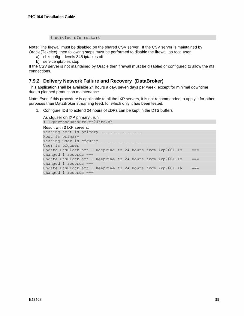
PIC 10.0 Installation Guide
E53508 59
# service nfs restart
Note: The firewall must be disabled on the shared CSV server. If the CSV server is maintained by
Oracle(Tekelec) then following steps must be performed to disable the firewall as root user
a) chkconfig --levels 345 iptables off
b) service iptables stop
If the CSV server is not maintained by Oracle then firewall must be disabled or configured to allow the nfs
connections.
7.9.2 Delivery Network Failure and Recovery (DataBroker)
This application shall be available 24 hours a day, seven days per week, except for minimal downtime due to planned production maintenance.
Note: Even if this procedure is applicable to all the IXP servers, it is not recommended to apply it for other purposes than DataBroker streaming feed, for which only it has been tested.
1. Configure IDB to extend 24 hours of xDRs can be kept in the DTS buffers
As cfguser on IXP primary , run: # IxpExtendDataBroker24hrs.sh
Result with 3 IXP servers: Testing host is primary .................
Host is primary
Testing user is cfguser .................
User is cfguser
Update DtsBlockPart - KeepTime to 24 hours from ixp7601-1b ===
changed 1 records ===
Update DtsBlockPart - KeepTime to 24 hours from ixp7601-1c ===
changed 1 records ===
Update DtsBlockPart - KeepTime to 24 hours from ixp7601-1a ===
changed 1 records ===

PIC 10.0 Installation Guide
60 E53508
8 APPENDIX: ADDITIONAL CONFIGURATION ON BLADE SERVER
This section provides instructions for Configuring SAN Storage using PM&C Application.
8.1 Adding ISO Images to the PM&C Image Repository
Follow 909-2249-001 Platform 6.5 Configuration Procedure Reference, section 3.7.9 Add the following DVD/CD/ISOs to the PM&C ISO images repository when performing this procedure:
• IXP • xDR Builders • xMF • NSP • WebLogic • Oracle
Due to the limited partition size on the PM&C, you might not be able to load all iso at once.
8.2 Configure SAN Storage Using PM&C Application
Follow 909-2249-001 Platform 6.5 Configuration Procedure Reference, section 3.8.1
Warning: This step is mandatory; if SAN volumes already existed (because the servers have
been used for another purpose or simply because the servers are being reinstalled), they have
to be removed before going on with the creation of the new SAN volumes. To remove existing
SAN volumes, follow 909-2249-001 Platform 6.5 Configuration Procedure Reference, section
3.8.2.
Warning: To avoid performance issues on C-class blade setup fulfill the following rules. A
single storage group exists of a single P2000 and up to 3 D2700 JBODs. Do not allow more than 1
DWS server per fibre channel controller and 2 DWS servers per storage group. When there are 2
DWS servers configured on a single storage group then both needs to be on a different sides of
the controller. The first must be configured on A and the second one on B. You will face a
performance issues when 2 DWS servers will be connected to the same side of the controller,
either A or B.
Example: You need to deploy 3 DWS servers and 1 PDU server, each of all in a different
subsystem. The configuration would need to be 2 P2000s and 2 D2700 JBODs accross 2
storage groups. Each storage group consisting of 1 P2000 and 1 D2700 JBOD.
Storage Group 1
• 1. slot: P2000 with DWS Server
• 2. slot: D2700 with DWS Server (now rule for 2 DWS servers per storage group exceeded)
• 3. slot: empty (extension could only add D2700 with PDU server since DWS are exceeded)
• 4. slot: empty (extension could only add D2700 with PDU server since DWS are
exceeded)
Storage Group 2
• 1. slot: P2000 with DWS Server
• 2. slot: D2700 with PDU Server
• 3. slot: empty (extension could add D2700 with DWS for a maximum of 2 per storage
group, or PDU)
• 4. slot: empty (extension could add D2700 with DWS for a maximum of 2 per storage
group, or PDU)
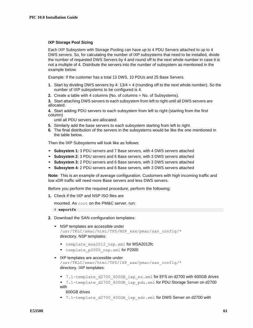
PIC 10.0 Installation Guide
E53508 61
IXP Storage Pool Sizing
Each IXP Subsystem with Storage Pooling can have up to 4 PDU Servers attached to up to 4
DWS servers. So, for calculating the number of IXP subsystems that need to be installed, divide
the number of requested DWS Servers by 4 and round off to the next whole number in case it is
not a multiple of 4. Distribute the servers into the number of subsystem as mentioned in the
example below.
Example: If the customer has a total 13 DWS, 10 PDUs and 25 Base Servers.
1. Start by dividing DWS servers by 4: 13/4 = 4 (rounding off to the next whole number). So the number of IXP subsystems to be configured is 4.
2. Create a table with 4 columns (No. of columns = No. of Subsystems).
3. Start attaching DWS servers to each subsystem from left to right until all DWS servers are allocated.
4. Start adding PDU servers to each subsystem from left to right (starting from the first column)
until all PDU servers are allocated.
5. Similarly add the base servers to each subsystem starting from left to right. 6. The final distribution of the servers in the subsystems would be like the one mentioned in
the table below.
Then the IXP Subsystems will look like as follows:
• Subsystem 1: 3 PDU servers and 7 Base servers, with 4 DWS servers attached
• Subsystem 2: 3 PDU servers and 6 Base servers, with 3 DWS servers attached
• Subsystem 3: 2 PDU servers and 6 Base servers, with 3 DWS servers attached
• Subssytem 4: 2 PDU servers and 6 Base servers, with 3 DWS servers attached
Note: This is an example of average configuration. Customers with high incoming traffic and
low xDR traffic will need more Base servers and less DWS servers.
Before you perform the required procedure, perform the following:
1. Check if the IXP and NSP ISO files are
mounted. As root on the PM&C server, run:
# exportfs
2. Download the SAN configuration templates:
• NSP templates are accessible under /usr/TKLC/smac/html/TPD/NSP_xxx/pmac/san_config/*
directory. NSP templates:
• template_msa2012_nsp.xml for MSA2012fc
• template_p2000_nsp.xml for P2000
• IXP templates are accessible under /usr/TKLC/smac/html/TPD/IXP_xxx/pmac/san_config/*
directory. IXP templates:
• 7.1-template_d2700_600GB_ixp_es.xml for EFS on d2700 with 600GB drives
• 7.1-template_d2700_600GB_ixp_pdu.xml for PDU Storage Server on d2700 with
600GB drives
• 7.1-template_d2700_600GB_ixp_xdr.xml for DWS Server on d2700 with

PIC 10.0 Installation Guide
62 E53508
600GB drives
• 7.1-template_d2700_ixp_es.xml for EFS on d2700
• 7.1-template_d2700_ixp_pdu.xml for PDU Storage Server on d2700 • 7.1-template_d2700_ixp_xdr.xml for DWS Server on d2700
• 7.1-template_msa2012_ixp_es.xml for EFS on MSA2012fc
• 7.1-template_msa2012_ixp_pdu.xml for PDU Storage Server on MSA2012fc
• 7.1-template_msa2012_ixp_xdr.xml for DWS Server on MSA2012fc
drives
• 7.1-template_p2000_600GB_ixp_es.xml for EFS on P2000 with 600GB drives
• 7.1-template_p2000_600GB_ixp_pdu.xml for PDU Storage Server on P2000 with 600GB drives
• 7.1-template_p2000_600GB_ixp_xdr.xml for DWS Server on P2000 with
600GB drives
• 7.1-template_p2000_ixp_es.xml for EFS on P2000 with 300GB drives
• 7.1-template_p2000_ixp_pdu.xml for PDU Storage Server on P2000 with 300GB
drives
• 7.1-template_p2000_ixp_xdr.xml for DWS Server on P2000 with 300GB
drives
• template_msa2012_ASM_ixp_xdr.xml for DWS Server on MSA2012fc with 12 drives
3. Get the bond0 IP addresses of the blade servers. (These IPs are needed to update the SAN
configuration files that were downloaded.)
To locate the bond0 IPs, access the PM&C application interface and log in as pmacadmin.
Then select Main Menu Software Software Inventory OS Only. A table with a
list of all the servers with OS installed appears. The IP Address column contains the bond0
IP address.
4. Update the SAN config files to accommodate the customer's specific network settings. Follow the information inside the template files on how to update them.
If there is a failed SAN procedure, contact the Oracle Customer Care Center.
When preparing a DWS or the PDU storage pool of an IXP subsystem, the template for each
server needs to be updated separately. Prepare as many files as you plan to configure for
DWS, IXP PDU servers and EFS.
5. Copy all of the templates into the /usr/TKLC/smac/etc/storage directory.
6. After copying the respective template, user can now perform the SAN configuration on the system. User needs to log in as pmacadmin and then select Main Menu Storage
Configure SAN Storage. User then needs to select the respective template from the drop down and click Configure Storage button on the GUI.
When you define the LUN for the disk start with the value 01 and do not use the value 00 Use the command multipath –ll to check the LUN used on the blade servers
Note: If you are adding SAN to an extanding SAN on an existing system take care to modify the
existing zones on the Brocades switch before in order to allow the communication with the new port used. Refer the point 10 in the next section.

PIC 10.0 Installation Guide
E53508 63
9 APPENDIX: RACKMOUNT BIOS SETTINGS AND SERVER IPM
STEP # In this procedure you will configure BIOS settings and IPM each HP Gen8 server equipped in the cabinet.
Prerequisites:
- System power-up is complete - TPD Initial Product Manufacture media 872-xxxx-xxx
- KVM connection to the server via KVM/RKM equipped or external
1 Insert TPD Media into the server
Open the CD/DVD media drive in the server to be tested. Insert the appropriate 64-bit TPD media into the optical drive. The KVM should be connected and the screen for the server to be tested ready.
2
Access the Server BIOS
Reboot the server. This can be achieved by pressing and holding the power button until the server turns off, then after approximately 5-10 seconds press the power button to enable power.
As soon as you see F9=Setup in the lower left corner of the screen, press [F9] to access the BIOS setup screen. You may be required to press [F9] 2-3 times. The F9=Setup will change to F9 Pressed once it is accepted. See example below.
Expected Result:
ROM-Based Setup Utility is accessed and the ROM-Based Setup Utility menu will be displayed.

PIC 10.0 Installation Guide
64 E53508
3 Set Server CMOS Clock
Scroll to Date and Time and press [ENTER]
Set the date and time and press [ENTER].
Note: Whatever the time zone the server is installed you must configure here the GMT time. Local time would be configured in the OS using the time zone configuration. In case this is not respected you will face some RCS error during the software installation.
Expected Result:
Correct Time & Date is set.
4 Configure iLO serial port settings
The serial ports on HP Gen8 rack mount servers need to be configured so the serial port used by the BIOS and TPD are connected to the “VSP” on the iLO. This will allow the remote administration of the servers without the need for external terminal servers. If this configuration has not been completed correctly and the server rebooted, the syscheck “syscheck -v hardware serial” test will fail.
Select System Options and press [ENTER].
Select Serial Port Options
and press [ENTER ].
Change Embedded Serial Port to COM2 and press [ENTER ].
Change Virtual Serial Port to COM1 and press [ENTER ].
Press <ESC> two times

PIC 10.0 Installation Guide
E53508 65
5 Disable Hyperthreading –PMF servers only
Hyperthreading is to be disabled only on PMF servers. Proceed to the next step if configuring the BIOS of an IMF server.
Select System Options and press [ENTER].
Select Processor Options and press [ENTER ].
Select Intel ® Hyperthreading Options and press [ENTER ].
Select Disable and press [ENTER ].
Press <ESC> three times
6 Save Configuration and Exit
Press [F10] to save the configuration and exit. The server will reboot
Expected Result:
Settings are saved and server reboots.
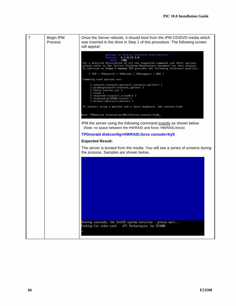
PIC 10.0 Installation Guide
66 E53508
7 Begin IPM Process
Once the Server reboots, it should boot from the IPM CD/DVD media which was inserted in the drive in Step 1 of this procedure. The following screen will appear:
IPM the server using the following command exactly as shown below (Note: no space between the HWRAID and force: HWRAID,force):
TPDnoraid diskconfig=HWRAID,force console=tty0
Expected Result:
The server is booted from the media. You will see a series of screens during the process. Samples are shown below.

PIC 10.0 Installation Guide
E53508 67
8

PIC 10.0 Installation Guide
68 E53508
9 IPM Complete – remove media and reboot the server.
The IPM process takes approximately 15-20 minutes; you will see several messages and screens in the process.
Once the IPM is complete, you will be prompted to reboot as shown below. Press Enter to reboot the server and then remove the CD/DVD media from the drive if it does not eject on it’s own (so the server does not boot from the TPD disk again)
10 Server Reboot Once the server reboots, you should see a login prompt.
Note: During the first system boot, swap files may be initialized and activated. Each swap file will take about 2 minutes.
Login as root and refer to TR006061 for the default “TPD root” password
Expected Result:
Login prompt is displayed and you are logged in as root.

PIC 10.0 Installation Guide
E53508 69
11 Perform syscheck test
Login as root and perform syscheck test on the server.
Enter: syscheck at the prompt and press [ENTER]
Verify syscheck test passes. You may see a failure related to NTP. This is acceptable since we do not have an NTP server setup yet.
Expected Result:
The syscheck test passes.
12 Check alarms Perform alarm check test on the server.
At the prompt, enter (exactly as shown): alarmMgr -alarmStatus
Expected Result:
Nothing. No alarms should be displayed (with the exception of NTP related since we are not yet connected to an NTP server).
13 Repeat this process for all HP servers equipped in the cabinet
Repeat steps 1-13 for each HP server equipped in the cabinet.
Expected Result:
Each server is loaded with TPD and syscheck passes with no alarms other than the exceptions noted.

PIC 10.0 Installation Guide
70 E53508
10 APPENDIX: MOUNT TPD ISO VIA ILO ON GEN8
On iLO Web GUI: Launch the Java Integrated Remote Console applet.
On the menu to the left navigate to the Remote Console page. Click on the Java Integrated Remote
Console to open it.
On iLO3 - Java Security Prompt: Acknowledge Security Warning.
If a dialog similar to the one below is presented, click Yes to acknowledge the issue and proceed.
If other warning dialogs are presented you may also acknowledge them as well to proceed to the
Java Integrated Remote Console applet.
On iLO Remote Console: Create Virtual Drive Connection
Click on the Virtual Drives drop down menu. Goto CD/DVD then click on Virtual Image.
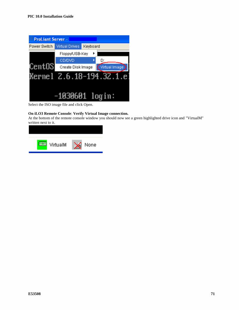
PIC 10.0 Installation Guide
E53508 71
Select the ISO image file and click Open.
On iLO3 Remote Console: Verify Virtual Image connection.
At the bottom of the remote console window you should now see a green highlighted drive icon and "VirtualM"
written next to it.

PIC 10.0 Installation Guide
72 E53508
11 APPENDIX: BLADE SERVER IPM
Note: in the context of PIC 10 fresh installation, only addition of blade in existing enclosure is possible. So this document covers only this part.
11.1 PM&C 5.0 to 5.5 upgrade
Follow document 909-2281-001 PM&C 5.5 Incremental Upgrade for PM&C upgrade procedure.
11.2 Configure the blade server iLO password for Administrator account
Follow 909-2249-001 Platform 6.5 Configuration Procedure Reference, section 3.4.3 Take care to the copy and paste from the document. For the password use the default value defined in TR006061 for “iLO Administrator”.
11.3 Upgrade the blade server firmware
Follow 909-2249-001 Platform 6.5 Configuration Procedure Reference, section 3.4.1 Step 1 must be executed as root and not pmacadmin It is really recommended to have a console open and make sure the firmware upgrade really take place and not only have a server reboot without nothing happening. In case of problem to mount the iso or if you are not on site and can’t plug a USB flash on the iLO, it is possible to proceed this way like on RM servers by connecting each iLO and then use the Virtual Media to mount the iso. Take care in case of remote upgrade this will require a reliable and fast IP connection.
11.4 Confirm/Upgrade the blade server BIOS settings
Follow 909-2249-001 Platform 6.5 Configuration Procedure Reference, section 3.4.2
11.5 IPM Servers Using PM&C Application
Use the appropriate 64-bit TPD media.. Follow 909-2249-001 Platform 6.5 Configuration Procedure Reference, section 3.7.10
11.6 Additional configuration step after IPM
This step is mandatory on all blades server after IPM.
Some parameters must be commented out in file /etc/sysctl.conf
1. Connect as root user on the blade
2. Run
# rcstool co /etc/sysctl.conf
3. edit file /etc/sysctl.conf (with e.g.)
comment out (with "#" sign in first character of line) the 3 lignes starting with "net.bridge"
4. Run
# rcstool ci /etc/sysctl.conf
11.7 Configure Syscheck Default Route Ping Test
Follow 909-2249-001 Platform 6.5 Configuration Procedure Reference, section 3.4.5

PIC 10.0 Installation Guide
E53508 73
11.8 Set the IP on the fibre channel disk controllers
Follow 909-2249-001 Platform 6.5 Configuration Procedure Reference, section 3.3.1 You might add a minicom from the PM&C to the controller.
11.9 Configuring Fibre Channel Disk Controllers
Follow 909-2249-001 Platform 6.5 Configuration Procedure Reference, section 3.3.2 In the step 11 the trap must be sent to NSP WL1 server.
11.10 Configuring Advanced Settings on P2000 Fibre Channel Disk Controllers
Follow 909-2249-001 Platform 6.5 Configuration Procedure Reference, section 3.3.4. In case of MSA2012fc follow section 3.4.3
11.11 Upgrade the firmware on the MSA P2000 disk controllers
Follow 909-2249-001 Platform 6.5 Configuration Procedure Reference, section 3.3.6. In case of MSA2012fc follow section 3.4.5

PIC 10.0 Installation Guide
74 E53508
12 APPENDIX: INTEGRATED LIGHTS OUT CONFIGURATION
STEP #
In this section you will configure the Integrated Lights Out (iLO). You will be configuring the IP address, Netmask, Gateway and adding the tekelec user and password. If the final customer network and IP address information is not available at the time of this configuration, a default IP address for each server based on U mounting location in the cabinet is provided in Appendix E should be used instead for testing purposes. Prerequisites: The HP ProLiant servers will need to be connected to a KVM for access.

PIC 10.0 Installation Guide
E53508 75
1 Enter the Integrated Lights Out configuration menu
Reboot the server:
At the prompt, enter: reboot and press [ENTER] and the server will reboot.
Press any key when you see the notice. To view Option ROM messages, then press F8 for the Integrated Lights Out 2 Advanced menu access.
Expected result:
The iLO setup menu is accessed after pressing [F8] when the Integrated Lights Out prompt appears on the screen.
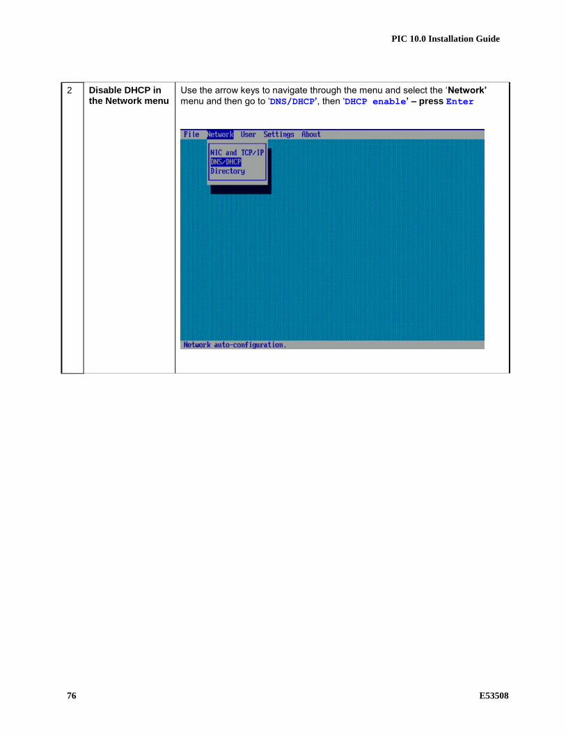
PIC 10.0 Installation Guide
76 E53508
2 Disable DHCP in the Network menu
Use the arrow keys to navigate through the menu and select the ‘Network’
menu and then go to ‘DNS/DHCP’, then ‘DHCP enable’ – press Enter

PIC 10.0 Installation Guide
E53508 77
3 Disable DHCP in the Network menu
Use the space bar to disable DHCP. (the space bar toggles the DHCP option ‘ON’ and ‘OFF’)
Save the settings by pressing the [F10] key
Expected result:
DHCP is disabled and settings are saved.

PIC 10.0 Installation Guide
78 E53508
4 Configure the IP Address, Subnet Mask and Default Gateway
Use the arrow keys to navigate through the menu and select the ‘Network’ menu and then go to ‘NIC and TCP/IP’

PIC 10.0 Installation Guide
E53508 79
5 Configure the IP Address, Subnet Mask and Default Gateway
Fill in the following IP Address information using the final customer IP address if available, otherwise use defaults for test:
IP Address: 192.168.100.xxx
(where xxx = IP address for the server see Appendix E)
Subnet Mask: 255.255.255.0
Default Gateway: 192.168.100.1
(screenshot is for reference only and may not represent correct values)
Save the settings by pressing the [F10] key
Expected result:
Network settings (IP address, default gateway and subnet mask) are configured and saved.
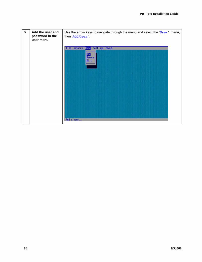
PIC 10.0 Installation Guide
80 E53508
6 Add the user and password in the user menu
Use the arrow keys to navigate through the menu and select the ‘User’ menu,
then ‘Add User’.
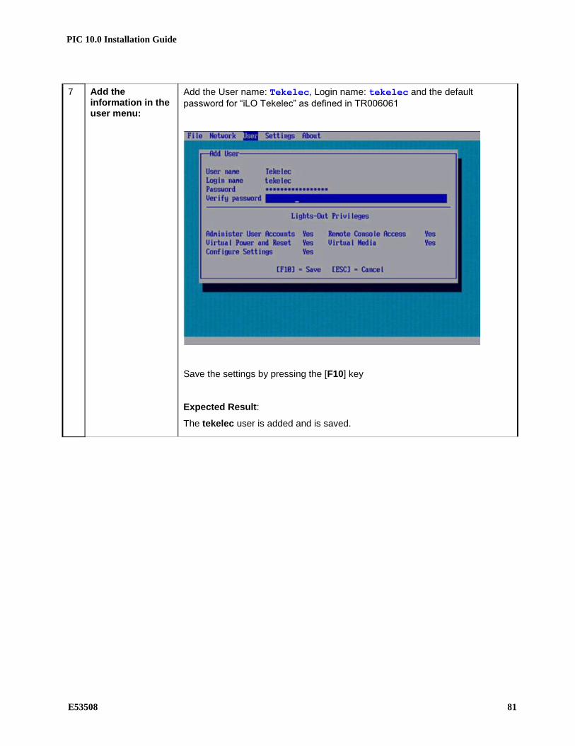
PIC 10.0 Installation Guide
E53508 81
7 Add the information in the user menu:
Add the User name: Tekelec, Login name: tekelec and the default
password for “iLO Tekelec” as defined in TR006061
Save the settings by pressing the [F10] key
Expected Result:
The tekelec user is added and is saved.

PIC 10.0 Installation Guide
82 E53508
8 Exit the iLO configuration menu and save changes.
Use the arrow keys to navigate through the menu and select the ‘File menu,
then ‘Exit’.
9 Press ENTER to confirm
10 Repeat for each server equipped.
Repeat steps 1 through 9 for each HP DL360 ProLiant server equipped in the cabinet
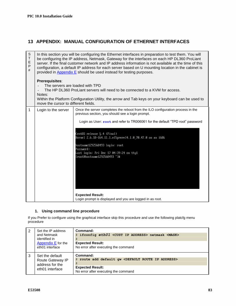
PIC 10.0 Installation Guide
E53508 83
13 APPENDIX: MANUAL CONFIGURATION OF ETHERNET INTERFACES
S T E P #
In this section you will be configuring the Ethernet interfaces in preparation to test them. You will be configuring the IP address, Netmask, Gateway for the interfaces on each HP DL360 ProLiant server. If the final customer network and IP address information is not available at the time of this configuration, a default IP address for each server based on U mounting location in the cabinet is provided in Appendix E should be used instead for testing purposes. Prerequisites:
- The servers are loaded with TPD - The HP DL360 ProLiant servers will need to be connected to a KVM for access. Notes: Within the Platform Configuration Utility, the arrow and Tab keys on your keyboard can be used to move the cursor to different fields.
1 Login to the server Once the server completes the reboot from the ILO configuration process in the previous section, you should see a login prompt.
Login as User: root and refer to TR006061 for the default “TPD root” password
Expected Result:
Login prompt is displayed and you are logged in as root.
1. Using command line procedure
If you Prefer to configure using the graphical interface skip this procedure and use the following platcfg menu procedure
2 Set the IP address and Netmask identified in
Appendix E for the
eth01 interface
Command: # ifconfig eth01 <CUST IP ADDRESS> netmask <MASK>
#
Expected Result:
No error after executing the command
3 Set the default Route Gateway IP address for the eth01 interface
Command: # route add default gw <DEFAULT ROUTE IP ADDRESS>
#
Expected Result:
No error after executing the command

PIC 10.0 Installation Guide
84 E53508
4 Configure remaining servers in frame
Repeat Steps 1 through 3 for each equipped HP DL360 server.
2. Using platcfg menu procedure
If you configures IP using the command line following the previous procedure, you can skip this procedure is alredy completed
2 Enter the Platform Configuration Utility
To enter the Platform Configuration Utility menu enter: su – platcfg
3 Enter the Platform Configuration Utility
Expected Result:
Main Menu of Platform Configuration Utility is displayed

PIC 10.0 Installation Guide
E53508 85
4 Enter the Network Configuration menu of the Platform Configuration Utility
Main Menu of Platform Configuration Utility is displayed. Use the arrow keys on the keyboard to select Network Configuration and press [ENTER] to select it.
Expected Result:
The Network Configuration menu is displayed
5 Enter the Network Interfaces menu
Use the arrow keys on the keyboard to select Network Interfaces and press [ENTER] to select it.
Expected Result:
The Network Interfaces menu is displayed

PIC 10.0 Installation Guide
86 E53508
6 Enter the Edit an Interface menu
Use the arrow keys on the keyboard to select Edit an Interface and press [ENTER]
to select it.
Expected Result:
The Network Interfaces menu is displayed with interface choices eth01 and eth02

PIC 10.0 Installation Guide
E53508 87
7 Edit the eth01 interface properties
Use the arrow keys on the keyboard to select eth01 and press [ENTER] to select it.
Expected Result: The eth01 interface is selected and you are presented with eth01 Interface Statistics.
Press the [ENTER] key to Edit the properties of eth01. Expected Result:
The eth01 interface is selected and you are presented with eth01 Interface Statistics. You have selected ‘Edit’ and are presented with properties to change.

PIC 10.0 Installation Guide
88 E53508
8 Configure MTU, GRO, and boot protocol
Press [TAB] to move to off for GRO, then press the [SPACEBAR] key to select it.
An asterisk will appear once selected. Press [TAB] to move to OK, then press the [ENTER] key to continue.
Expected Result:
GRO is set to off and you now see the menu which allows you to edit the IP address.
9 Configure IP Press [TAB] to move to Yes, then press the [ENTER] key to continue.
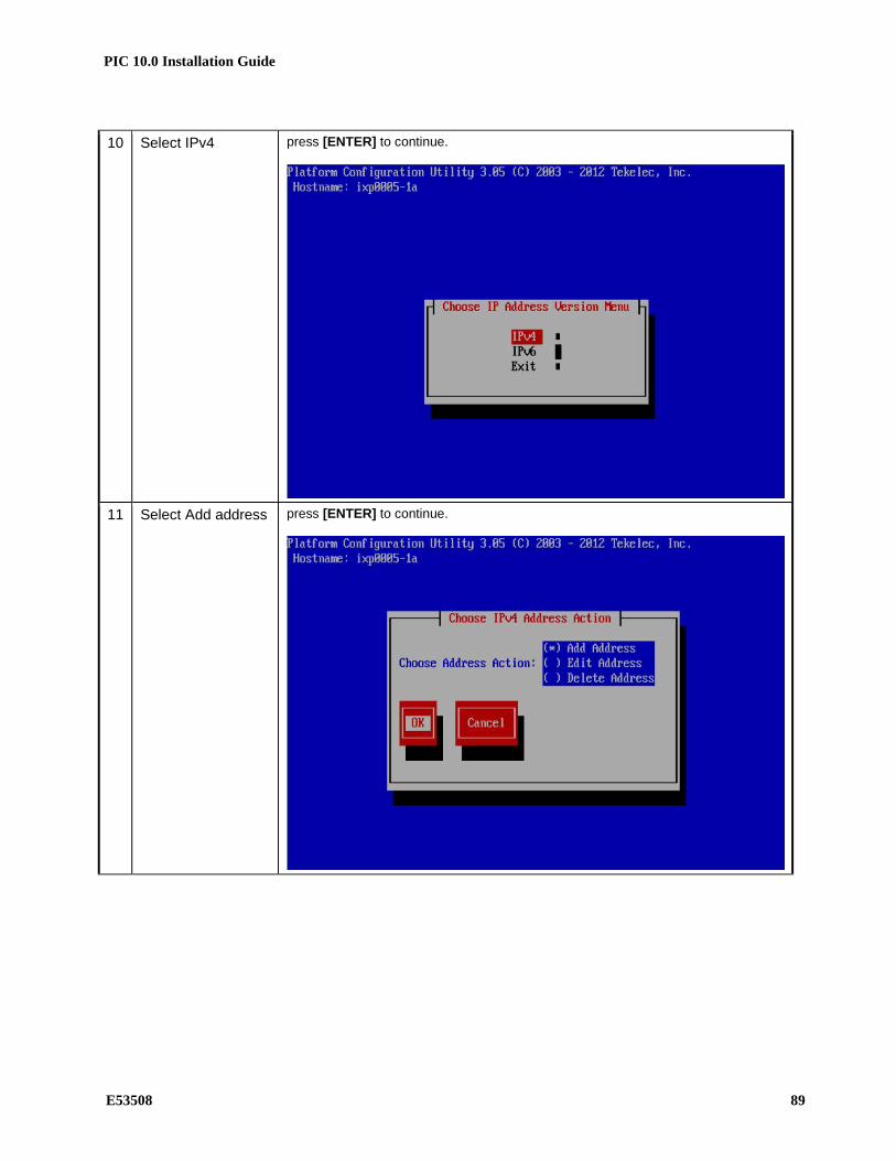
PIC 10.0 Installation Guide
E53508 89
10 Select IPv4 press [ENTER] to continue.
11 Select Add address press [ENTER] to continue.

PIC 10.0 Installation Guide
90 E53508
12 Set the IP address and Netmask identified in
Appendix E for the
eth01 interface
Use the [TAB] and arrow keys on the keyboard to add IP address. Enter the IP address of the server then press [TAB] to select NETMASK. Press [TAB] to select
( ) yes and press [SPACEBAR] to select then [TAB] and press [ENTER] to
continue.
13 You will see the following screen:
Expected Result:
IP address and Netmask is set to the correct IP address for the server. Wait for it to complete.

PIC 10.0 Installation Guide
E53508 91
14 Verify the settings and exit
Once the screen comes back, verify the IP address and Netmask. Use the [TAB] key on the keyboard to select Exit and press [ENTER] to continue.
Use the [TAB] key on the keyboard to select Exit and press [ENTER] to continue
Expected Result:
IP address and Netmask is set to the correct IP address for the server and you exit the Network Interfaces menu.

PIC 10.0 Installation Guide
92 E53508
15 Set the Gateway address for the eth01 interface
Use the arrow keys on the keyboard to select Routing and press [ENTER] to
continue.
Select IPv4 and press [ENTER] to continue.
Select Edit and press [ENTER] to add the default gateway.
Expected Result:
Routing menu is opened and Edit is selected
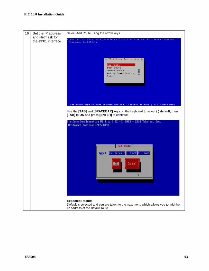
PIC 10.0 Installation Guide
E53508 93
16 Set the IP address and Netmask for the eth01 interface
Select Add Route using the arrow keys.
Use the [TAB] and [SPACEBAR] keys on the keyboard to select ( ) default, then [TAB] to OK and press [ENTER] to continue.
Expected Result:
Default is selected and you are taken to the next menu which allows you to add the IP address of the default route.
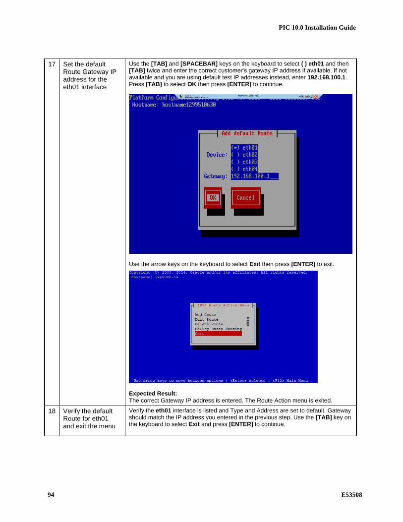
PIC 10.0 Installation Guide
94 E53508
17 Set the default Route Gateway IP address for the eth01 interface
Use the [TAB] and [SPACEBAR] keys on the keyboard to select ( ) eth01 and then [TAB] twice and enter the correct customer’s gateway IP address if available. If not available and you are using default test IP addresses instead, enter 192.168.100.1. Press [TAB] to select OK then press [ENTER] to continue.
Use the arrow keys on the keyboard to select Exit then press [ENTER] to exit.
Expected Result:
The correct Gateway IP address is entered. The Route Action menu is exited.
18 Verify the default Route for eth01 and exit the menu
Verify the eth01 interface is listed and Type and Address are set to default. Gateway should match the IP address you entered in the previous step. Use the [TAB] key on the keyboard to select Exit and press [ENTER] to continue.

PIC 10.0 Installation Guide
E53508 95
Select Exit and press [ENTER] to leave the Routing Configuration menu
Select Exit and press [ENTER] to leave the Network Configuration menu
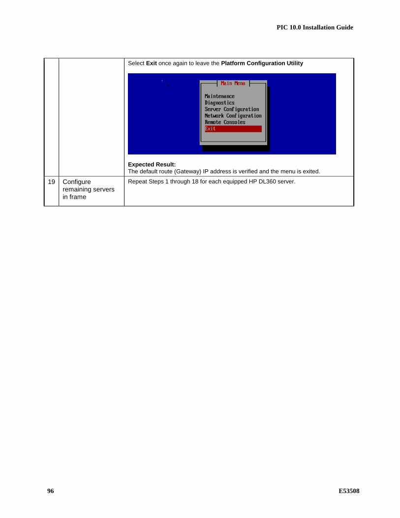
PIC 10.0 Installation Guide
96 E53508
Select Exit once again to leave the Platform Configuration Utility
Expected Result:
The default route (Gateway) IP address is verified and the menu is exited.
19 Configure remaining servers in frame
Repeat Steps 1 through 18 for each equipped HP DL360 server.

PIC 10.0 Installation Guide
E53508 97
14 APPENDIX: PIC BULKCONFIG FILE DESCRIPTION
14.1 NSP Bulkconfig File Description
The NSP subsystem bulkconfig file contains the overall NSP pre-installation configuration information, most importantly the hostname and SNMP configuration. During the installation process, various scripts use this file to configure NSP. The bulkconfig file is a text file and as such can be created or updated with any available text editor, e.g. vi or vim. The bulkconfig file templates can be found on the NSP iso in the / directory. For NSP One-Box you can use the /bulkconfig.nsp-onebox template together with the /bulkconfig.example.nsp-onebox example showing an updated bulkconfig template. Do not use this reference example to configure the NSP system. For NSP Four-Box you can use the /bulkconfig.nsp-fourbox template together with the /bulkconfig.example.nsp-fourbox example. Note: When you install PIC, you are asked to create this bulkconfig file and update this file. DO NOT remove the NSP bulkconfig file from the server. This topic provides a description of each keyword and parameter used in the bulkconfig file. It is important to read and understand the contents of this file. bulkconfig file location and rights File name: bulkconfig File absolute path: /root/bulkconfig Mount the NSP iso file. As root run : # mount –o loop /var/TKLC/upgrade/iso_file.iso /mnt/upgrade Copy the good bulkconfig file template: For one Box # cp /mnt/upgrade/bulkconfig.nsp-onebox /root/bulkconfig For four Box # cp /mnt/upgrade/bulkconfig.nsp-fourbox /root/bulkconfig Change the permission on the bulkconfig # chmod 644 /root/bulkconfig Unmount the NSP iso file. As root run : # umount /mnt/upgrade bulkconfig file: template The bulkconfig file is written in the CSV format. Each line begins with a keyword that describes the type of information that the line contains. The keyword is mandatory. Each line must begin with the keyword, and then contains various values for this keyword. The keyword and its associated values are separated by a comma. There are no empty spaces in the lines.

PIC 10.0 Installation Guide
98 E53508
host,hostname_of_server,IP_address,function,interface_name,network_mask,network_gateway ntpserver1,IP_address ntpserver2,IP_address timezone,time_zone Refer to the following descriptions of each keyword and its associated values. host Description host,hostname_of_server,IP_address,function,interface_name,network_mask,network_gateway ...
The host keyword has the following associated values: hostname_of_server A valid hostname , it should match the hostname set on server.
The IP address of the server. For blade systems, the internal IP address of
the server.
IP_address The IP address of the server. For blade systems, the internal IP address of the server. function The function of the server. Use one of the following entries:
• NSP_ONEBOX for the NSP One-box Server
• NSP_APACHE for the NSP Apache Server
• NSP_ORACLE for the NSP Oracle Server
• NSP_SECONDARY for the NSP Secondary Server
• NSP_PRIMARY for the NSP Primary Server
interface_name Name of the interface where the network settings are applied.
• Use eth01 (backend) for a rackmount system and eth02 (frontend)for the
second interface on Apache and One-box servers.
• Use bond0.3 for the blade systems and bond0.4 for the second
interface on Apache and One-box servers.
network_mask The network mask.
network_gateway The default gateway
On Apache and One-box servers the gateway must be the one from frontend
(eth02) for all interfaces including the backend interface (eth01) on apache
server (frontend gateway must be put on bot lines)
In the case some IXP/DWS/xMF servers are not on the same subnetwork as NSP
backend, routes to thoses subnetworks must be manually added in NSP,
specifying as gateway the interface matching the physical customer network
topoly (backend or frontend). Use platcfg tool to add those routes.
ntpserver Description Refer to Appendix 17 to know how to configure NTP. ntpserver1,IP_address ntpserver2,IP_address
• ntpserver1 is the first NTP server • ntpserver2 is the second NTP server
The ntpserver keyword has the following associated value: IP_address The IP address of the NTP server
timezone Description timezone,time_zone

PIC 10.0 Installation Guide
E53508 99
The timezone keyword has the following associated value: time_zone The timezone string. For a list of available timezones that you can
use, refer to the /usr/share/zoneinfo/zone.tab file TZ column. For example: [root@nsp ~]# cat /usr/share/zoneinfo/zone.tab time_zone --CUT-- #code coordinates TZ comments AD +4230+00131 Europe/Andorra AE +2518+05518 Asia/Dubai AF +3431+06912 Asia/Kabul AG +1703-06148 America/Antigua CZ +5005+01426 Europe/Prague ---CUT—
NSP One-box bulkconfig Template
host,hostname_of_server,IP_address,function,interface_name,network_mask,network_gateway host,hostname_of_server,IP_address,function,interface_name,network_mask,network_gateway ntpserver1,IP_address ntpserver2,IP_address timezone,time_zone
Example: A bulkconfig file needs to be created for the NSP One-box: • Server hostname: nsp-onebox • Because it is a one-box server, two interfaces are needed • Because it is a rackmount system, use eth01 and eth02 for these interfaces Note: If you are configuring C-class blades, replace eth01 with bond0.3 and eth02 with bond0.4 when you create this file. • IP addresses:
• First interface (eth01): 10.236.2.141
• Second interface (eth02): 10.236.1.141
• Subnet mask: 255.255.255.254
• Gateway addresses:
• First interface (eth01): 10.236.2.129
• Second interface (eth02): 10.236.1.129
• NTP server IP address: 10.236.129.11
• Server timezone: Europe/Paris
The corresponding bulkconfig file you create should appear as follows: Note: There is no new line character in the middle of the host configuration. [root@nsp-onebox ~]# cat /root/bulkconfig
host,nsp-onebox,10.236.2.141,NSP_ONEBOX,eth01,255.255.255.224,10.236.1.129 host,nsp-onebox,10.236.1.142,NSP_ONEBOX,eth02,255.255.255.224,10.236.1.129 ntpserver1,10.236.129.11 ntpserver2, timezone,Europe/Paris

PIC 10.0 Installation Guide
100 E53508
Note: in case there is no network connectivity from backend gateway to frontend IP, the frontend line must be removed from bulkconfig file, and interface must be configured manually using platcfg tool.
14.2 IXP Bulkconfig File Description
The IXP subsystem bulkconfig file contains the overall IXP pre-installation configuration information. Note: there is one bulkconfig file for each IXP subsystem. During the installation process, various scripts use this file to configure IXP. The bulkconfig file is a case sensitive text file and as such can be created or updated with any available text editor, e.g. vi or vim. The IXP bulkconfig file template is located on the IXP iso on the /upgrade/IXP_bulkconfig_template path. The file is unique for the IXP subsystem and is present on each server in this subsystem. Note: When you install PIC, you are asked to create this bulkconfig file and update this file. DO NOT remove the IXP bulkconfig file from the server. The IXP subsystem bulkconfig file is used during these processes: • Manufacturing installation • Customer network integration • Change IP • Disaster recovery procedure This topic provides a description of each keyword and parameter used in the bulkconfig file. It is important to read and understand the contents of this file. bulkconfig file location and rights File name: bulkconfig File absolute path: /root/bulkconfig Mount the ixp iso file. As root run : # mount –o loop /var/TKLC/upgrade/iso_file.iso /mnt/upgrade Copy the good bulkconfig file template: # cp /mnt/upgrade/upgarde/IXP_bulkconfig_template /root/bulkconfig Change the permission on the bulkconfig # chmod 644 /root/bulkconfig Unmount the IXP iso file. As root run : # umount /mnt/upgrade bulkconfig file: template The bulkconfig file is written in the CSV format.

PIC 10.0 Installation Guide
E53508 101
Each line begins with a keyword that describes the type of information that the line contains. The keyword is mandatory. Each line must begin with the keyword, and then contains various values for this keyword. The keyword and its associated values are separated by a comma. There are no empty spaces in the lines. host,hostname_of_1st_server,IP_address,function,interface_name,network_mask,network_gateway host,hostname_of_2nd_server,IP_address,function,interface_name,network_mask,network_gateway host,hostname_of_nth_server,IP_address,function,interface_name,network_mask,network_gateway ntpserver1,IP_address ntpserver2,IP_address ntpserver3,IP_address ntppeerA, ntppeerB, nspprimary,IP_address_of_primary_weblogic_or_onebox_nsp_backend nspsecondary,IP_address_of_secondary_weblogic nsporacle,IP_address_of_oracle_server timezone,time_zone Refer to the following descriptions of each keyword and its associated values. host Description host,hostname_of_1st_server,IP_address,function,interface_name,network_mask,network_gateway host,hostname_of_2nd_server,IP_address,function,interface_name,network_mask,network_gateway host,hostname_of_nth_server,IP_address,function,interface_name,network_mask,network_gateway ... Example (installation): host,ixp1981-1a,10.236.2.141,IXP-PDU,eth01,255.255.255.224,10.236.2.129 host,ixp1981-1b,10.236.2.142,IXP-BASE,eth01,255.255.255.224,10.236.2.129 host,ixp1981-1c,10.236.2.143,IXP-BASE,eth01,255.255.255.224,10.236.2.129 The count of the host lines equals to the count of the servers in the subsystem. There is a single host line per server in the subsystem. Example (disaster recovery of ixp1981-1b server): host,ixp1981-1a,10.236.2.141,IXP-PDU,eth01,255.255.255.224,10.236.2.129 host,ixp1981-1b,10.236.2.142,DR-BASE,eth01,255.255.255.224,10.236.2.129 host,ixp1981-1c,10.236.2.143,IXP-BASE,eth01,255.255.255.224,10.236.2.129 The count of the host lines equals to the count of the servers in the subsystem. There is a single host line per server in the subsystem.

PIC 10.0 Installation Guide
102 E53508
The host keyword has the following associated values: hostname_of_nth_server The server hostname in the standard IXP format: ixpNNNN-MA where: • N is numeric 0-9 • M is numeric 1-9 • A is alphabetical a-z IP_address The IP address of the server. For blade systems, the backend (VLAN 3) IP address of the server. function The function of the server. Use one of the following entries for installation:
• IXP-PDU for the PDU Storage Server • IXP-BASE for the IXP Base Server Function for the disaster recovery procedure for the particular server is different. Use one of the following entries for disaster recovery: • DR-PDU for the PDU Storage Server • DR-BASE for the IXP Base Server
interface_name Name of the interface where the network settings are applied. • eth01 for the rackmount systems • bond0.3 for the blade systems
network_mask The network mask. network_gateway The default gateway. ntpserver Description Refer to Appendix 17 to know how to configure NTP. ntpserver1,IP_address ntpserver2,IP_address ntpserver3,IP_address ntppeerA, ntppeerB, • ntpserver1 is the first NTP server • ntpserver2 is the second NTP server • ntpserver3 is the third NTP server • ntppeerA not applicable; leave empty • ntppeerB not applicable; leave empty Example: ntpserver1,10.236.129.11 ntpserver2, ntpserver3, ntppeerA, ntppeerB, The ntpserver keyword has the following associated value: IP_address The IP address of the NTP server. NSP Description nspprimary,IP_address_of_primary_weblogic_or_onebox_nsp_backend nspsecondary,IP_address_of_secondary_weblogic nsporacle,IP_address_of_oracle_server

PIC 10.0 Installation Guide
E53508 103
• nspprimary is the NSP Primary WebLogic server or the One-box NSP server • nspsecondary is the NSP Secondary WebLogic server • nsporacle is the NSP Oracle server Example (for a One-box NSP): nspprimary,10.10.10.10 nspsecondary, nsporacle, The NSP keyword has the following associated values: IP_address_of_primary_weblogic_or_onebox_nsp_backend The IP address of the NSP server:
• One-box: backend IP address of the One-box NSP server IP_address_of_secondary_weblogic The IP address of the NSP server:
• One-box: not applicable; leave empty IP_address_of_oracle_server The IP address of the NSP Oracle server:
• One-box: not applicable; leave empty timezone Description timezone,time_zone Example: timezone,Europe/Paris The timezone keyword has the following associated value: time_zone
The timezone string. For a list of available timezones that you can use, refer to the /usr/share/zoneinfo/zone.tab file TZ column. For example:
[root@nsp ~]# cat /usr/share/zoneinfo/zone.tab --CUT-- #code coordinates TZ comments AD +4230+00131 Europe/Andorra 909-2122-001 Revision 1.11, February 02, 2012 DRAFT 210 PIC Bulkconfig File Description AE +2518+05518 Asia/Dubai AF +3431+06912 Asia/Kabul AG +1703-06148 America/Antigua CZ +5005+01426 Europe/Paris ---CUT— bulkconfig file: installation example A bulkconfig file needs to be created for the following IXP subsystem: • Subsystem hostname: ixp1981 • 1a server is the PDU Storage Server with the IP address: 10.236.2.141 • 1b server is the Base Server with the IP address: 10.236.2.142

PIC 10.0 Installation Guide
104 E53508
• 1c server is the Base Server with the IP address: 10.236.2.143 • Network interface: eth01 • Network mask: 255.255.255.254 • Default gateway: 10.236.2.129 • NTP server IP address: 10.236.129.11 • NSP One-box IP address: 10.10.10.10 • Server timezone: Europe/Paris The corresponding bulkconfig file you create should appear as follows: Note: There is no new line character in the middle of the host configuration. [root@ixp1981-1a ~]# cat /root/bulkconfig host,ixp1981-1a,10.236.2.141,IXP-PDU,eth01,255.255.255.224,10.236.2.129 host,ixp1981-1b,10.236.2.142,IXP-BASE,eth01,255.255.255.224,10.236.2.129 host,ixp1981-1c,10.236.2.143,IXP-BASE,eth01,255.255.255.224,10.236.2.129 ntpserver1,10.236.129.11 ntpserver2, ntpserver3, ntppeerA, ntppeerB, nspprimary,10.10.10.10 nspsecondary, nsporacle, timezone,Europe/Paris Automated records in /etc/bulkconfig file During the automated integration of IXP subsystem with EFS server(s) the following line is added to the /etc/bulkconfig file (one per integrated EFS server): efs,hostname_of_EFS,IP_address_of_EFS where • hostname_of_EFS is the hostname of EFS that local DataFeeds hosts uses as an export target • IP_address_of_EFS is the IP address of such EFS Example: efs,ixp7777-1e,10.236.0.33
14.3 DWS Bulkconfig File Description
The DWS bulkconfig file contains the overall DWS pre-installation configuration information. During the installation process, various scripts use this file to configure the DWS. The bulkconfig file is a case sensitive text file and as such can be created or updated with any available text editor, e.g. vi or vim. The DWS bulkconfig file template is located on the IXP iso on the /upgrade/IXP_bulkconfig_template path. The file is unique for each DWS.

PIC 10.0 Installation Guide
E53508 105
Note: When you install PIC, you are asked to create this bulkconfig file and update this file. DO NOT remove the DWS bulkconfig file from the server. The DWS bulkconfig file is used during these processes: • Manufacturing installation • Customer network integration • Change IP • Disaster recovery procedure This topic provides a description of each keyword and parameter used in the bulkconfig file. It is important to read and understand the contents of this file. bulkconfig file location and rights File name: bulkconfig File absolute path: /root/bulkconfig Mount the IXP iso file. As root run : # mount –o loop /var/TKLC/upgrade/iso_file.iso /mnt/upgrade Copy the good bulkconfig file template: # cp /mnt/upgrade/upgrade/IXP_bulkconfig_template /root/bulkconfig Change the permission on the bulkconfig # chmod 644 /root/bulkconfig Unmount the IXP iso file. As root run : # umount /mnt/upgrade bulkconfig file: template The bulkconfig file is written in the CSV format. Each line begins with a keyword that describes the type of information that the line contains. The keyword is mandatory. Each line must begin with the keyword, and then contains various values for this keyword. The keyword and its associated values are separated by a comma. There are no empty spaces in the lines. host,hostname_of_server,IP_address,function,interface_name,network_mask,network_gateway ntpserver1,IP_address ntpserver2,IP_address ntpserver3,IP_address ntppeerA, ntppeerB, nspprimary,IP_address_of_primary_weblogic_or_onebox_nsp_backend nspsecondary,IP_address_of_secondary_weblogic nsporacle,IP_address_of_oracle_server timezone,time_zone

PIC 10.0 Installation Guide
106 E53508
Refer to the following descriptions of each keyword and its associated values. host Description host,hostname_of_server,IP_address,function,interface_name,network_mask,network_gateway ... Example (installation): host,ixp1981-1a,10.236.2.141,IXP-XDR,eth01,255.255.255.224,10.236.2.129 There is one single host line per DWS. Example of disaster recovery: host,ixp1981-1a,10.236.2.141,DR-XDR,eth01,255.255.255.224,10.236.2.129 There is one single host line per DWS. The host keyword has the following associated values: hostname_of_server The server hostname in the standard IXP format: ixpNNNN-MA where: • N is numeric 0-9 • M is numeric 1-9 • A is alphabetical a-z IP_address The IP address of the server. For blade systems, the backend (VLAN 3) IP address of the server. function The function of the server. For installation:
• IXP-XDR For disaster recovery: • DR-XDR
interface_name Name of the interface where the network settings are applied. • eth01 for the rackmount systems • bond0.3 for the blade systems
network_mask The network mask. network_gateway The default gateway. ntpserver Description Refer to Appendix 17 to know how to configure NTP. ntpserver1,IP_address ntpserver2,IP_address ntpserver3,IP_address ntppeerA, ntppeerB, • ntpserver1 is the first NTP server • ntpserver2 is the second NTP server • ntpserver3 is the third NTP server • ntppeerA not applicable; leave empty • ntppeerB not applicable; leave empty Example:

PIC 10.0 Installation Guide
E53508 107
ntpserver1,10.236.129.11 ntpserver2, ntpserver3, ntppeerA, ntppeerB, The ntpserver keyword has the following associated value: IP_address The IP address of the NTP server. NSP Description nspprimary,IP_address_of_primary_weblogic_or_onebox_nsp_backend nspsecondary,IP_address_of_secondary_weblogic nsporacle,IP_address_of_oracle_server • nspprimary is the NSP Primary WebLogic server or the One-box NSP server • nspsecondary is the NSP Secondary WebLogic server • nsporacle is the NSP Oracle server Example (for a One-box NSP): nspprimary,10.10.10.10 nspsecondary, nsporacle, The NSP keyword has the following associated values: IP_address_of_primary_weblogic_or_onebox_nsp_backend The IP address of the NSP server:
• One-box: backend IP address of the One-box NSP server IP_address_of_secondary_weblogic The IP address of the NSP server:
• One-box: not applicable; leave empty IP_address_of_oracle_server The IP address of the NSP Oracle server:
• One-box: not applicable; leave empty timezone Description timezone,time_zone Example: timezone,Europe/Paris The timezone keyword has the following associated value: time_zone
The timezone string. For a list of available timezones that you can use, refer to the /usr/share/zoneinfo/zone.tab file TZ column. For example:
[root@nsp ~]# cat /usr/share/zoneinfo/zone.tab --CUT-- #code coordinates TZ comments AD +4230+00131 Europe/Andorra 909-2122-001 Revision 1.11, February 02, 2012 DRAFT 210
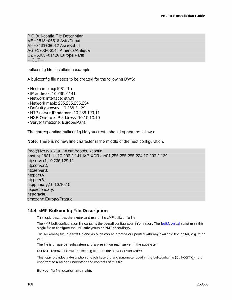
PIC 10.0 Installation Guide
108 E53508
PIC Bulkconfig File Description AE +2518+05518 Asia/Dubai AF +3431+06912 Asia/Kabul AG +1703-06148 America/Antigua CZ +5005+01426 Europe/Paris ---CUT— bulkconfig file: installation example A bulkconfig file needs to be created for the following DWS: • Hostname: ixp1981_1a • IP address: 10.236.2.141 • Network interface: eth01 • Network mask: 255.255.255.254 • Default gateway: 10.236.2.129 • NTP server IP address: 10.236.129.11 • NSP One-box IP address: 10.10.10.10 • Server timezone: Europe/Paris The corresponding bulkconfig file you create should appear as follows: Note: There is no new line character in the middle of the host configuration. [root@ixp1981-1a ~]# cat /root/bulkconfig host,ixp1981-1a,10.236.2.141,IXP-XDR,eth01,255.255.255.224,10.236.2.129 ntpserver1,10.236.129.11 ntpserver2, ntpserver3, ntppeerA, ntppeerB, nspprimary,10.10.10.10 nspsecondary, nsporacle, timezone,Europe/Prague
14.4 xMF Bulkconfig File Description
This topic describes the syntax and use of the xMF bulkconfig file.
The xMF bulk configuration file contains the overall configuration information. The bulkConf.pl script uses this
single file to configure the IMF subsystem or PMF accordingly.
The bulkconfig file is a text file and as such can be created or updated with any available text editor, e.g. vi or
vim.
The file is unique per subsystem and is present on each server in the subsystem.
DO NOT remove the xMF bulkconfig file from the server or subsystem.
This topic provides a description of each keyword and parameter used in the bulkconfig file (bulkconfig). It is
important to read and understand the contents of this file.
Bulkconfig file location and rights

PIC 10.0 Installation Guide
E53508 109
File name: bulkconfig
File path:/root/bulkconfig
Mount the XMF iso file. As root run : # mount –o loop /var/TKLC/upgrade/iso_file.iso /mnt/upgrade
Copy the good bulkconfig file template: # cp /mnt/upgrade/upgrade/XMF_bulkconfig_template /root/bulkconfig
Change the permission on the bulkconfig # chmod 644 /root/bulkconfig
Unmount the XMF iso file. As root run : # umount /mnt/upgrade
Bulkconfig file: template
The bulkconfig file is written in the CSV format.
Each line begins with a keyword that describes the type of information that the line contains. The keyword is
mandatory. Each line must begin with the keyword and then contains various values for this keyword. The
keyword and its associated values are separated by a comma. There are no empty spaces in the lines.
host,hostname_of_1st_server,IP_address,function,interface_name,network_mask,network_gateway,designation host,hostname_of_2nd_server,IP_address,function,interface_name,network_mask,network_gateway,designation host,hostname_of_nth_server,IP_address,function,interface_name,network_mask,network_gateway,designation ntpserver1,IP_address ntpserver2,IP_address ntpserver3,IP_address ntppeerA,IP_address ntppeerB,IP_address nspprimary,IP_address_of_primary_nsp nspsecondary,IP_address_of_secondary_nsp
timezone,time_zoneRefer to the following descriptions of each keyword and its associated values. host
Description
host,hostname_of_1st_server,IP_address,function,interface_name,network_mask,network_gateway,designation host,hostname_of_2nd_server,IP_address,function,interface_name,network_mask,network_gateway,designation host,hostname_of_nth_server,IP_address,function,interface_name,network_mask,network_gateway,designation…
Example for IMF setup:
host,imf-1a,192.168.253.5,IMF,bond0.200,255.255.255.224,192.168.253.1,1A
host,imf-1b,192.168.253.6,IMF,bond0.200,255.255.255.224,192.168.253.1,1B
host,imf-1c,192.168.253.7,IMF,bond0.200,255.255.255.224,192.168.253.1,1C
Example for PMF standalone:
host,pmf-0a,192.168.2.106,PMF,eth01,255.255.255.0,192.168.2.1,0A
The count of the host lines equals to the count of the servers in the subsystem. There is a single host line per
server in the subsystem.
The host keyword has the following associated values:
hostname_of_nth_server The server hostname.

PIC 10.0 Installation Guide
110 E53508
Note: It is recommended that the hostname ends with the designation of the
server (for example, malibu-1a).
function The function of the server. Use one of the following entries:
•he function
designation The designation of the server is a combination of frame number and position
of the server in the frame. Use the following rule:
• IMF subsystem: 1A for the first server, 1B for the second server, etc. •F subsystem: 1A for
interface name The name of customer network interface (typically: bond0.200 for IMF and
eth01 for PMF)
IP_address The IP address of the server. For blade systems, the internal IP address of
the server
network_mask The network mask
network_gateway The default gateway

PIC 10.0 Installation Guide
E53508 111
ntpserver Description
Refer to Appendix 17 to know how to configure NTP.
ntpserver1,IP_address
ntpserver2,IP_address
ntpserver3,IP_addres
ntppeerA,IP_address
ntppeerB,IP_address
• ntpserver1 is the first NTP server
• ntpserver2 is the second NTP server
• ntpserver3 is the third NTP server
• ntppeerA not applicable; leave empty
• ntppeerB not applicable; leave empty
Example:
ntpserver1,10.236.129.11
The ntpserver keyword has the following associated value:
IP_address The IP address of the NTP server.
nsp Description
nspprimary,IP_address_of_primary_nsp nspsecondary,IP_address_of_secondary_nsp_appserver
• nspprimary is the NSP Primary server
• nspsecondary is the NSP Secondary WebLogic server
Example (for a One-box NSP):
nspprimary,10.10.10.10
The nsp keyword has the following associated values:
IP_address_of_primary_nsp The IP address of the NSP Primary server:
• One-box: backend IP address of the One-box NSP server
IP_address_of_secondary_nsp The IP address of the NSP Secondary server:
• One-box: not applicable; leave empty
timezone Description
timezone,time_zone
Example:
timezone,Europe/Paris
The timezone keyword has the following associated value:
time_zone The timezone string. For a list of available timezones that you can use, refer to the
/usr/share/zoneinfo/zone.tab file TZ column. For example:
[root@nsp ~]# cat /usr/share/zoneinfo/zone.tab
--CUT--
#code coordinates TZ comments
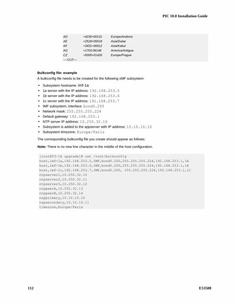
PIC 10.0 Installation Guide
112 E53508
AD +4230+00131 Europe/Andorra
AE +2518+05518 Asia/Dubai
AF +3431+06912 Asia/Kabul
AG +1703-06148 America/Antigua
CZ +5005+01426 Europe/Prague
----CUT—
Bulkconfig file: example
A bulkconfig file needs to be created for the following xMF subsystem:
• Subsystem hostname: imf-1a
• 1a server with the IP address: 192.168.253.5
• 1b server with the IP address: 192.168.253.6
• 1c server with the IP address: 191.168.253.7
• IMF subsystem, interface: bond0.200
• Network mask: 255.255.255.224
• Default gateway: 192.168.253.1
• NTP server IP address: 10.250.32.10
• Subsystem is added to the appserver with IP address: 10.10.10.10
• Subsystem timezone: Europe/Paris
The corresponding bulkconfig file you create should appear as follows:
Note: There is no new line character in the middle of the host configuration.
[root@T3-1A upgrade]# cat /root/bulkconfig
host,imf-1a,192.168.253.5,IMF,bond0.200,255.255.255.224,192.168.253.1,1A
host,imf-1b,192.168.253.6,IMF,bond0.200,255.255.255.224,192.168.253.1,1B
host,imf-1c,192.168.253.7,IMF,bond0.200, 255.255.255.224,192.168.253.1,1C
ntpserver1,10.250.32.10
ntpserver2,10.250.32.11
ntpserver3,10.250.32.12
ntppeerA,10.250.32.13
ntppeerB,10.250.32.14
nspprimary,10.10.10.10
nspsecondary,10.10.10.11
timezone,Europe/Paris

PIC 10.0 Installation Guide
E53508 113
15 APPENDIX: SWITCHES CONFIGURATION Topics:
15.1 Cisco basic knowledge
enable to move from user mode to priviledge mode
disable to move from priviledge mode to user mode
show running-config to display the current configuration in RAM
show startup-config to display the saved configuration in NVRAM
configure terminal to move from priviledge mode to config mode
interface gi1/1 to move from config mode to an interface config
copy running-config startup-config save the current configuration
show interfaces display the interfaces status
reload to reboot the switch
show version to display the ROM and IOS information
show tech-support to display a full switch status report. It should be caoptured in a file because it is long and
takes a few minutes
15.1.1 Configure and access the serial console on TPD
Setup minicom access for 4948/4948E switches. This procedure is generic and can be used on any PIC server running TPD and connected to a switch console through a serial cable. Determine whether needed minicom files are already available by issuing the following command: # ls /etc/minirc.*
The minicom configuration name is: “minirc.<name_of_configuration>”. If the minicom configuration file is not already present, proceed with the rest of this step, otherwise skip to the next step: Setup the serial connections for a switch by issuing the following command: # remoteConsole --add --name=<name_of_configuration> --bps=9600 --parity=N --
databits=8
--handshake=none --port=<switch_serial_port>
Note:
- The default switch_serial_port should be /dev/ttyS1 - The name_of_configuration depends on the user’s choice (ex: switch, yellow-sw1-1, blue-
sw1-1…) Connect serially to switch by issuing the following command as root on the management server: # minicom <name_of_configuration>
Press RETURN to get started.
Press Enter
If the “autoinstall” line below does not appear, the switch may not be in factory default condition, continue with the step, disregarding this line: Would you like to terminate autoinstall? [yes]:Enter
Switch> enable
Switch#
If “enable” command above prompts for a password, the switch is not in factory default configuration. This may be due to a previous configuration attempt. This procedure is for initial install. To exit from the console, enter <ctrl-a><q> and you will be returned to the server prompt.

PIC 10.0 Installation Guide
114 E53508
15.1.2 Configure and access the serial console on TVOE
From TVOE server: Setup conserver serial access a switch and open the firewall to allow for future tftp use in this procedure. From management server, configure the conserver service to enable serial access to the switches: # conserverAdm --addConsole --name=switch_console --device=/dev/ttyS4
Open the conserver port on the firewall of the TVOE management server: # iptables -I INPUT -s <pmac_mgmtVLAN_ip_address>/255.255.255.255 -p all -j ACCEPT
# service iptables save
Note: The default devices should be /dev/ttyS4 and /dev/ttyS5 for PM&C Connect serially to switch by issuing the following command from the PM&C server or any other servers you open the port on the firewall. # console -M <TVOE_server_mgmtVLAN_ip_address> -l platcfg switch_console
Enter platcfg@pmac5000101's password: <platcfg_password>
[Enter `^Ec?' for help]
Press Enter
Switch>
Depending on the switch config you might have to provide also the appropriate password to access the switch console after having provided the platcfg password. To exit from the console, enter <ctrl-E><c><.> and you will be returned to the server prompt.
15.1.3 4948&4948EF Reset to factory defaults
Using this procedure you might loose the network connectirty.
It is advice to not do it with a remote connection
In priviledge mode type Switch#write erase
Erasing the nvram filesystem will remove all configuration files! Continue? [confirm]
[OK]
Erase of nvram: complete
*May 23 07:28:47.754: %SYS-7-NV_BLOCK_INIT: Initialized the geometry of nvram
Switch#erase cat4000_flash:
Erasing the cat4000_flash filesystem will remove all files! Continue? [confirm]
[OK]
Erase of cat4000_flash: complete
Switch#reload
System configuration has been modified. Save? [yes/no]: <- if the question is asked
the answer to this question is no
Proceed with reload? [confirm]
Once the switch rebooted you might receive the following question before to get the prompt Press RETURN to get started!
00:00:01: %C4K_IOSSYS-3-BLANKSTARTUPCONFIG: Blank or invalid startup-config, bo
s00:00:17: %SPANTREE-5-EXTENDED_SYSID: Extended SysId enabled for type vlan
00:00:18: %C4K_IOSMODPORTMAN-6-MODULEONLINE: Module 1 (WS-C4948 S/N: FOX11450NC
e00:00:37: %SYS-5-RESTART: System restarted --
Cisco IOS Software, Catalyst 4500 L3 Switch Software (cat4500-IPBASEK9-M), Vers
)Technical Support: http://www.cisco.com/techsupport
Copyright (c) 1986-2008 by Cisco Systems, Inc.
Compiled Tue 29-Jul-08 12:15 by tinhuang
Would you like to terminate autoinstall? [yes]: <- if the question is asked the
answer to this question is yes
Configure the switch to boot properly by verifying that the bootvar is showing the correct configuration,
from 0-IPBASEK9-M), V# dir bootflash:
determine from the output the latest image (check the version at cisco website if necessary)

PIC 10.0 Installation Guide
E53508 115
if the width of the screen does not permit to see the complete output, use the following (the question mark
Number”, and if it # show file info bootflash:? # show bootvar
if how b variablebootflash:?oes not permit to /or config register is not 0x2102: basically follow: # config terminal
(config)# boot system flash bootflash:<name of image with latest version>
(config)# config-register 0x2102
(config)# end
# write memory
# show bootvar
15.1.4 Assign an IP address on a 3020
Refer to 909-2249-001 section 3.5.2 Configure initial OA settings via configuration wizard step 8 OA GUI: EBIPA settings
15.1.5 2950 & 3020 Reset to factory defaults
Using this procedure you might loose the network connectivity.
It is advice to not do it with a remote connection
In priviledge mode type Switch#write erase
Erasing the nvram filesystem will remove all configuration files! Continue? [confirm]
[OK]
Erase of nvram: complete
*May 23 07:28:47.754: %SYS-7-NV_BLOCK_INIT: Initialized the geometry of nvram
Switch#delete flash:vlan.dat
Delete filename [vlan.dat]?
Delete flash:vlan.dat? [confirm]
Switch#reload
System configuration has been modified. Save? [yes/no]: <- if the question is asked
the answer to this question is no
Proceed with reload? [confirm]

PIC 10.0 Installation Guide
116 E53508
15.1.6 Configure telnet access on a 3020
Connect on the OA from the enclosure, and Navigate to the Interconnect Bays. Open the management URL. Take care if you reseted the switch the password is back to the default value. If it is the first access the web interface will open directly on the express setup, otherway you can access it from the configure menu.
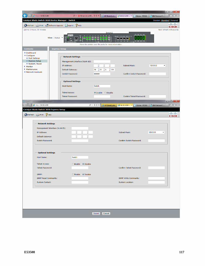
PIC 10.0 Installation Guide
E53508 117
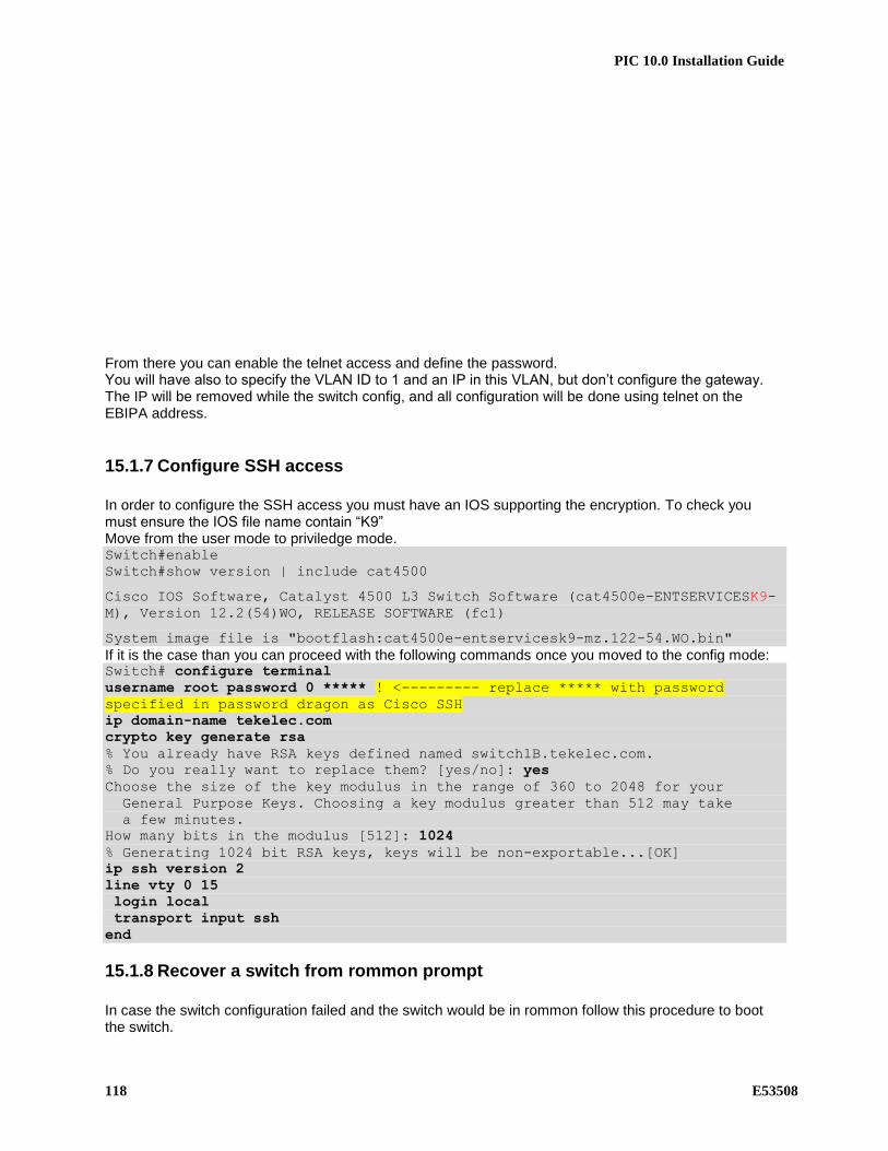
PIC 10.0 Installation Guide
118 E53508
From there you can enable the telnet access and define the password. You will have also to specify the VLAN ID to 1 and an IP in this VLAN, but don’t configure the gateway. The IP will be removed while the switch config, and all configuration will be done using telnet on the EBIPA address.
15.1.7 Configure SSH access
In order to configure the SSH access you must have an IOS supporting the encryption. To check you must ensure the IOS file name contain “K9” Move from the user mode to priviledge mode. Switch#enable
Switch#show version | include cat4500
Cisco IOS Software, Catalyst 4500 L3 Switch Software (cat4500e-ENTSERVICESK9-
M), Version 12.2(54)WO, RELEASE SOFTWARE (fc1)
System image file is "bootflash:cat4500e-entservicesk9-mz.122-54.WO.bin"
If it is the case than you can proceed with the following commands once you moved to the config mode: Switch# configure terminal
username root password 0 ***** ! <--------- replace ***** with password
specified in password dragon as Cisco SSH
ip domain-name tekelec.com
crypto key generate rsa
% You already have RSA keys defined named switch1B.tekelec.com.
% Do you really want to replace them? [yes/no]: yes
Choose the size of the key modulus in the range of 360 to 2048 for your
General Purpose Keys. Choosing a key modulus greater than 512 may take
a few minutes.
How many bits in the modulus [512]: 1024
% Generating 1024 bit RSA keys, keys will be non-exportable...[OK]
ip ssh version 2
line vty 0 15
login local
transport input ssh
end
15.1.8 Recover a switch from rommon prompt
In case the switch configuration failed and the switch would be in rommon follow this procedure to boot the switch.

PIC 10.0 Installation Guide
E53508 119
Note: This is a generic procedure and the ios file name might be different depending on version running on your switch. rommon 6 >dir bootflash:
File size Checksum File name
--------------------------------------------------
12632100 bytes (0xc0c024) 0x8136853a cat4500-ipbasek9-mz.122-31.SGA8.bin
456060 bytes (0x6f57c) 0x66d8b2a7 cat4500-ios-promupgrade-122_31r_SGA1
Total space = 60817408 bytes, Available = 47728992 bytes
rommon 8 >confreg
Configuration Summary :
=> console baud: 9600
=> autoboot from: commands specified in 'BOOT' environment variable
do you wish to change the configuration? y/n [n]: y
enable "diagnostic mode"? y/n [n]: n
enable "use net in IP bcast address"? y/n [n]:
enable "load rom after netboot fails"? y/n [n]:
enable "use all zero broadcast"? y/n [n]:
enable "break/abort has effect"? y/n [n]: y
enable "ignore system config info"? y/n [n]:
change console baud rate? y/n [n]:
change the boot characteristics? y/n [n]: y
enter to boot:
0 = disable autoboot
1 = the first file from internal flash device
2 = commands specified in 'BOOT' environment variable
[2]:
Configuration Summary :
=> break/abort has effect
=> console baud: 9600
=> autoboot from: commands specified in 'BOOT' environment variable
do you wish to save this configuration? y/n [n]: y
You must reset or power cycle for new configuration to take effect
rommon 10 >boot bootflash:cat4500-ipbasek9-mz.122-31.SGA8.bin
Rommon reg: 0xE2004180
###########
k2diags version 5.2_c
Switch> enable
Switch# config t
Switch(config)# config-reg 0x2102
Switch(config)# boot system flash bootflash:cat4500-ipbasek9-mz.122-31.SGA8.bin
Switch(config)# end
Switch# copy running-config startup-config
Switch# reload
Configuration has been modified, save? No
<reboots>
The following links provide additional info if needed. http://www.cisco.com/en/US/products/hw/switches/ps663/products_configuration_example09186a0080094ecf.shtml
15.1.9 Upgrade IOS software
Copy the new IOS file on the server you will use as tftp server in the directory /tftpboot. In the following example 10.10.10.10 is the IXP used as tftp server and 10.10.10.11 is the switch to load the new software. The tftp server must have an IP connectivity to the switch. [root@ixp0000-1a tftpboot]# ping 10.10.10.11
PING 10.10.10.11 (10.10.10.11) 56(84) bytes of data.
64 bytes from 10.10.10.11: icmp_seq=1 ttl=255 time=0.659 ms
64 bytes from 10.10.10.11: icmp_seq=2 ttl=255 time=1.47 ms
64 bytes from 10.10.10.11: icmp_seq=3 ttl=255 time=1.38 ms
If the switch have no IP configured, from the priviledge mode Switch#configure terminal

PIC 10.0 Installation Guide
120 E53508
Switch(config)#interface vlan 1
Switch(config-if)#ip address 10.10.10.11 255.255.255.0
Start the tftp service on the server [root@ixp0000-1a tftpboot]# service xinetd start
Starting xinetd:
[root@ixp0000-1a tftpboot]# /usr/TKLC/plat/sbin/tftpctl --start
RCS_VERSION=1.3
Stopping xinetd: [ OK ]
Starting xinetd: [ OK ]
Copy the new software to the switch Switch#copy tftp: bootflash:
Address or name of remote host []? 10.10.10.10
Source filename []? cat4500-ipbasek9-mz.122-53.SG2.bin
Destination filename [cat4500-ipbasek9-mz.122-53.SG2.bin]?
Accessing tftp://10.10.10.10/cat4500-ipbasek9-mz.122-53.SG2.bin...
Loading cat4500-ipbasek9-mz.122-53.SG2.bin from 10.10.10.10 (via Vlan1):
!!!!!!!!!!!!!!!!!!!!!!!!!!!!!!!!!!!!!!!!!!!!!!!!!!!!!!!!!!!!!!!!
[OK - 16332568 bytes]
CCCCCCCCCCCCCCCCCCCCCCCCCCCCCCCCCCCCCCCCCCCCCCCCCCCCCCCCCCCCCCCCCCCCCCCCCCCCCCCCCCCCCC
CCCCCCCCCCCCCCCCCCCCCCCCCCCCCCCCCCCCCCCCCCCCCCCCCCCCCCCCCCCCCCCCCCCCCCCCCC
16332568 bytes copied in 73.440 secs (222393 bytes/sec)
Switch#dir bootflash:
Directory of bootflash:/
1 -rwx 14569696 May 23 2009 11:53:09 +00:00 cat4500-ipbase-mz.122-46.SG.bin
2 -rwx 16332568 Aug 14 2013 05:29:21 +00:00 cat4500-ipbasek9-mz.122-53.SG2.bin
60817408 bytes total (775240 bytes free)
Modify the configuration to boot using the new software and no more the previous one. Switch#configure terminal
Enter configuration commands, one per line. End with CNTL/Z.
Switch(config)#boot system flash bootflash:cat4500-ipbasek9-mz.122-53.SG2.bin
Switch(config)#no boot system flash bootflash:cat4500-ipbase-mz.122-46.SG.bin
Switch(config)#config-register 0x2102
Switch(config)#exit
Switch #copy running-config startup-config
Switch #reload
After reloading, verify that the switch is booting to the expected version: Switch# #show version | include bootflash System image file is "bootflash:cat4500-ipbasek9-mz.122-53.SG2.bin"
15.1.10 Backup the switch config on a server
Use the following command to backup a switch configuration on a server. blue-sw1-1#copy running-config scp:
Address or name of remote host []? 172.22.49.10
Destination username [root]?
Destination filename [blue-sw1-1-confg]?
Writing blue-sw1-1-confg
Password:
!!
9314 bytes copied in 14.292 secs (652 bytes/sec)
blue-sw1-1#
15.1.11 Configure Cisco 4948/4948E/4948E-F switch
This procedure describes how to configure the Cisco switches.

PIC 10.0 Installation Guide
E53508 121
Configure the switches from the applicable server as follows: Note: Not all the switches listed may be applicable for your particular configuration.
• Yellow-sw1-1 from IMF-1A server • Blue-sw1-1 from IMF-1B server • Yellow-sw2-1 from IMF-1C server • Blue-sw2-1 from IMF-1D server • Yellow-sw3-1 from IMF-1E server • Blue-sw3-2 from IMF-1F server
In case there are more switches required than IMF servers, the console port of the additional switch will have to be moved on one of the servers or configured using a laptop. For an estimated time for this procedure, refer to the IMF flowcharts in Installation Overview. Mediation switch are connected to the first IXP server from the cabinet. Refer to section 1.6.1 to for detailed cabling of the switch console to the servers.
Note: In case in the procedure would failed, refer to E53511-01 PIC 10 Maintenance guide in order to recover the switch from rommon prompt.
A. Configure and access the serial console from the server (PM&C, IMF or IXP) on the switches
a. Refer to section 15.1.1 or 15.1.2 B. Reset the switch to factory default
a. If you are reconfiguring a switch backup the current config in a file using the command Switch# show running-config
b. Refer to section 15.1.3 to reset the switch C. Configure the switch using the appropriate template
a. Refer to following sections to select the appropriate configuration template and adapt it to the customer IP network.
i. Section 15.2 for RMS mediation ii. Section 15.3 for Blades
iii. Section 15.4 for IMFs b. As there is no log file for the following steps it is recomanded to enable the log feature from
your terminal in case something would not work as expected and assistance is required. c. Move from the user mode to priviledge mode and then to config mode
Switch# enable
Switch# configure terminal
Note : if you reset the switch to factory default no password should be requested to connect on it and move to enable mode. d. Adapt the template configuration to your network. The lines you need to customize are
higlited with Yellow comments. Paste the command in block and not necessary one by one but don’t do it with too much commands at a time in order to take care if an error message would appear.
e. Once the config is in place you can check it is matching your expectation using the command Switch# show running-config
f. If the configuration is fine then you can save it in the flash in order to have it automatically reloaded if the switch reboot
Switch# copy running-config startup-config
g. If there is an issue in your config you can can reboot the switch without saving and then restart the config from the step a
Switch# reload
h. Finally to configure the SSH access to the switch refer to section 15.1.7

PIC 10.0 Installation Guide
122 E53508
i. Once the config is in place you can check it is matching your expectation using the command Switch# show running-config
j. If the configuration is fine then you can save it in the flash in order to have it automatically reloaded if the switch reboot
Switch# copy running-config startup-config
k. If there is an issue in your config you can can reboot the switch without saving and then restart the config from the step h
Switch# reload
15.1.12 Configure Cisco 3020 switch
A. Assign IP addesses to the switches
a. Refer to 909-2249-001 section 3.5.2 Configure initial OA settings via configuration wizard step 8 OA GUI: EBIPA settings if this was not done earlier
B. Reset the switch to factory default a. If you are reconfiguring a switch backup the current config in a file using the command
Switch# show running-config
b. Refer to section 15.1.5 to reset the switch. Take care to only erase the vlan.dat and not the whole content of the flash.
C. Reconfigure the telnet access a. Refer to section 15.1.6.
D. Configure the switch using the appropriate template a. Refer to the following section 15.3.3. b. As there is no log file for the following steps it is recomanded to enable the log feature from
your terminal in case something would not work as expected and assistance is required. c. Open a telnet session on the switch and then move from the user mode to priviledge mode
and then to config mode Switch# enable
Switch# configure terminal
Note : if you reset the switch to factory default no password should be requested to connect on it and move to enable mode. d. Paste all the commands from the template config you have adated to you network. The lines
you need to customize are higlited with Yellow comments. You can paste the command in block and not necessary one by one but don’t do it with too much commands at a time in order to take care if an error message would appear.
e. Once the config is in place you can check it is matching your expectation using the command Switch# show running-config
f. If the configuration is fine then you can save it in the flash in order to have it automatically reloaded if the switch reboot
Switch# copy running-config startup-config
g. If there is an issue in your config you can can reboot the switch without saving and then restart the config from the step a
Switch# reload
15.1.13 Flush ARP table
A. Check VIP addess mapping on the Switch (in enable mode) Switch #show arp
Protocol Address Age (min) Hardware Addr Type Interface
Internet 172.21.49.10 1 0010.1326.a103 ARPA Vlan100
Internet 172.21.49.11 0 001e.6700.c9a4 ARPA Vlan100

PIC 10.0 Installation Guide
E53508 123
Use the ifconfig command on the Master IMF server to get the MAC address of its interfaces: bond0.200 Link encap:Ethernet HWaddr 00:10:13:26:A1:03
inet addr:10.31.2.101 Bcast:10.31.2.255 Mask:255.255.255.0
inet6 addr: fe80::210:13ff:fe26:a103/64 Scope:Link
Compare the Hardware Addr with the HWaddr (be careful in this exemple 0010.1326.a103 is equal to 00:10:13:26:A1:03) . If the values are equal or if no entry matches the VIP address, then it is not necessary to flush ARP table of the Cisco switch. If the VIP address is associated to a wrong MAC address, then continue the procedure.
B. Flush the ARP table on the Switch (in enable mode) Switch# clear arp-cache

PIC 10.0 Installation Guide
124 E53508
15.2 RM mediation
The VLAN values must be customized according customer requirement
15.2.1 Switch port allocation
15.2.2 Control Frame Switch
Note : The command “spanning-tree portfast trunk” will return the following warning, you can
ignore:
%Warning: portfast should only be enabled on ports connected to a single
host. Connecting hubs, concentrators, switches, bridges, etc... to this
interface when portfast is enabled, can cause temporary bridging loops.
Use with CAUTION
Note : the commands “switchport trunk encapsulation dot1q” and “media-type rj45“ will fail on the
4948EF switch but it is kept this config for compatibility with the previous 4948
!
no service pad
service timestamps debug uptime
service timestamps log uptime
service password-encryption
service compress-config
!
hostname Switch
!
enable secret ***** ! <--------- replace ***** with password specified in
password dragon as Cisco enable
!
no aaa new-model
ip subnet-zero
no ip source-route
no ip domain-lookup
!
vtp mode transparent
!
!
!
Port 42
NSP
Frontend
vlan 100
iLO
vlan 300
Frontend
vlan 200
CUST
All or no
vlan
Port 11
ServerF
iLO
Port 13
ServerG
iLO
Port 15
ServerH
iLO
Port 17
ServerI
iLO
Port 19
ServerJ
iLO
Port 21
ServerK
iLO
Port 23
ServerL
iLO
Port 25
Next
Frame
Port 27
Next
Frame
Port 29
Next
Frame
Port 31
Next
Frame
Port 33
Next
Frame
Port 35
Next
Frame
Port 37
Next
Frame
Port 39
Next
Frame
Port 45
Free Port 48
Cust Net
SW B
Ctrl Frame RM
Port 7
ServerD
iLO
Port 41
Cust Net
iLO
Port 5
ServerC
iLO
Port 1
ServerA
iLO
Port 3
ServerB
iLO
Port 9
Free
Port 47
Cust Net
SW A Port 46
Free
Port 14
ServerG
eth1
Port 16
ServerH
eth1
Port 18
ServerI
eth1
Port 20
ServerJ
eth1
Port 22
ServerK
eth1
Port 24
ServerL
eth1
Port 26
Next
Frame
Port 28
Next
Frame
Port 30
Next
Frame
Port 32
Next
Frame
Port 34
Next
Frame
Port 36
Next
Frame
Port 38
Next
Frame
Port 40
Next
Frame
Port 2
ServerA
eth1
Port 4
ServerB
eth1
Port 6
ServerC
eth1
Port 8
ServerD
eth1
Port 10
ServerE
eth1
Port 12
ServerF
eth1
Port 43
Free Port 44
Free
Port 11
ServerF
iLO
Port 13
ServerG
iLO
Port 15
ServerH
iLO
Port 17
ServerI
iLO
Port 19
ServerJ
iLO
Port 21
ServerK
iLO
Port 23
ServerL
iLO
Port 45
Free
Port 7
ServerD
iLO
Port 5
ServerC
iLO
Port 9
ServerE
iLO
Port 3
ServerB
iLO
Port 1
Free
Port 46
Free
Port 14
ServerG
eth1
Port 16
ServerH
eth1
Port 18
ServerI
eth1
Port 20
ServerJ
eth1
Port 22
ServerK
eth1
Port 24
ServerL
eth1
Port 2
ServerA
eth1
Port 4
ServerB
eth1
Port 6
ServerC
eth1
Port 8
ServerD
eth1
Port 10
ServerE
eth1
Port 12
ServerF
eth1
Port 43
Free Port 44
Free
Ext Frame RM
7.1 and higher
Port 27
Free Port 28
Free
Port 25
Free Port 26
Free
Port 31
Free Port 32
Free
Port 29
Free Port 30
Free
Port 35
Free Port 36
Free
Port 33
Free Port 34
Free
Port 39
Free Port 40
Free
Port 37
Free Port 38
Free
Port 41
Free Port 42
Free
Port 47
iLO Ctrl
FramePort 48
Eth Ctrl
Frame
Port 21
ServerF
iLO
Port 23
ServerG
iLO
Port 25
ServerH
iLO
Port 27
ServerI
iLO
Port 29
ServerJ
iLO
Port 31
ServerK
iLO
Port 33
ServerL
iLO
Port 45
Free
Port 7
ServerD
iLO
Port 5
ServerC
iLO
Port 9
ServerE
iLO
Port 3
ServerB
iLO
Port 1
Free
Port 46
Free
Port 24
ServerG
eth1
Port 26
ServerH
eth1
Port 28
ServerI
eth1
Port 30
ServerJ
eth1
Port 32
ServerK
eth1
Port 34
ServerL
eth1
Port 2
ServerA
eth1
Port 4
ServerB
eth1
Port 6
ServerC
eth1
Port 8
ServerD
eth1
Port 10
ServerE
eth1
Port 22
ServerF
eth1
Port 43
Free Port 44
Free
Ext Frame RM
7.0 and lower
Port 13
Free Port 14
Free
Port 11
Free Port 12
Free
Port 17
Free Port 18
Free
Port 15
Free Port 16
Free
Port 35
Free Port 36
Free
Port 19
Free Port 20
Free
Port 39
Free Port 40
Free
Port 37
Free Port 38
Free
Port 41
Free Port 42
Free
Port 47
iLO Ctrl
FramePort 48
Eth Ctrl
Frame
The first IXP Server iLO are directly connected
to customer network. Server E in th control
frame and server A in teh extension frames

PIC 10.0 Installation Guide
E53508 125
power redundancy-mode redundant
no file verify auto
!
spanning-tree mode rapid-pvst
no spanning-tree optimize bpdu transmission
spanning-tree extend system-id
!
vlan internal allocation policy ascending
!
!
vlan 100 ! <--------- replace VLAN with customer value
name iLO
!
vlan 200 ! <--------- replace VLAN with customer value
name CUST
!
vlan 300 ! <--------- replace VLAN with customer value
name NSP_Front
!
Interface range Gi1/1 ,Gi1/3 ,Gi1/5 ,Gi1/7 ,Gi1/9
description Server iLO Access
switchport access vlan 100 ! <--------- replace VLAN with customer value
switchport mode access
spanning-tree portfast
!
Interface range Gi1/11 ,Gi1/13 ,Gi1/15 ,Gi1/17 ,Gi1/19
description Server iLO Access
switchport access vlan 100 ! <--------- replace VLAN with customer value
switchport mode access
spanning-tree portfast
!
Interface range Gi1/21 ,Gi1/23 ,Gi1/25 ,Gi1/27 ,Gi1/29
description Server iLO Access
switchport access vlan 100 ! <--------- replace VLAN with customer value
switchport mode access
spanning-tree portfast
!
Interface range Gi1/31 ,Gi1/33 ,Gi1/35 ,Gi1/37 ,Gi1/39
description Server iLO Access
switchport access vlan 100 ! <--------- replace VLAN with customer value
switchport mode access
spanning-tree portfast
!
Interface range Gi1/41
description Server iLO Access
switchport access vlan 100 ! <--------- replace VLAN with customer value
switchport mode access
spanning-tree portfast
!
interface range Gi1/2 ,Gi1/4 ,Gi1/6 ,Gi1/8 ,Gi1/10
description Server CUST Access
switchport access vlan 200 ! <--------- replace VLAN with customer value
switchport mode access
spanning-tree portfast
!
interface range Gi1/12 ,Gi1/14 ,Gi1/16 ,Gi1/18 ,Gi1/20

PIC 10.0 Installation Guide
126 E53508
description Server CUST Access
switchport access vlan 200 ! <--------- replace VLAN with customer value
switchport mode access
spanning-tree portfast
!
interface range Gi1/22 ,Gi1/24 ,Gi1/26 ,Gi1/28 ,Gi1/30
description Server CUST Access
switchport access vlan 200 ! <--------- replace VLAN with customer value
switchport mode access
spanning-tree portfast
!
interface range Gi1/32 ,Gi1/34 ,Gi1/36 ,Gi1/38 ,Gi1/40
description Server CUST Access
switchport access vlan 200 ! <--------- replace VLAN with customer value
switchport mode access
spanning-tree portfast
!
interface GigabitEthernet1/42
description NSP NIC2 CUST Ethernet Access
switchport access vlan 300 ! <--------- replace VLAN with customer value
switchport mode access
spanning-tree portfast
!
interface range GigabitEthernet1/43 - 46
description UNUSED
shutdown
!
interface GigabitEthernet1/47
description 802.1Q trunk link to backbone SWA
switchport trunk encapsulation dot1q
switchport mode trunk
media-type rj45
!
interface GigabitEthernet1/48
description 802.1Q trunk link to backbone SWB
switchport trunk encapsulation dot1q
switchport mode trunk
media-type rj45
spanning-tree cost 20
!
interface Vlan1
no ip address
shutdown
!
interface Vlan100 ! <--------- replace VLAN with customer value
description Optional Switch Virtual Interface (SVI) for iLO Subnet - switch
management
no ip address
shutdown
!
interface Vlan200 ! <--------- replace VLAN with customer value
description Optional Switch Virtual Interface (SVI) for CUST Subnet - switch
management
no ip address
shutdown
!

PIC 10.0 Installation Guide
E53508 127
no ip http server
!
!
!
no cdp run
!
control-plane
!
!
line con 0
password ***** ! <--------- replace ***** with password specified in
password dragon as Cisco telnet
exec-timeout 30 0
logging synchronous
stopbits 1
!
end
15.2.3 Extension Frame Switch
Note : The command “spanning-tree portfast trunk” will return the following warning, you can
ignore:
%Warning: portfast should only be enabled on ports connected to a single
host. Connecting hubs, concentrators, switches, bridges, etc... to this
interface when portfast is enabled, can cause temporary bridging loops.
Use with CAUTION
Note : the commands “switchport trunk encapsulation dot1q” and “media-type rj45“ will fail on the
4948EF switch but it is kept this config for compatibility with the previous 4948
!
no service pad
service timestamps debug uptime
service timestamps log uptime
service password-encryption
service compress-config
!
hostname Switch
!
enable secret ***** ! <--------- replace ***** with password specified in
password dragon as Cisco enable
!
no aaa new-model
ip subnet-zero
no ip source-route
no ip domain-lookup
!
vtp mode transparent
!
!
!
power redundancy-mode redundant
no file verify auto
!

PIC 10.0 Installation Guide
128 E53508
spanning-tree mode rapid-pvst
no spanning-tree optimize bpdu transmission
spanning-tree extend system-id
!
vlan internal allocation policy ascending
!
!
vlan 100 ! <--------- replace VLAN with customer value
name iLO
!
vlan 200 ! <--------- replace VLAN with customer value
name CUST
!
Interface range Gi1/1 ,Gi1/3 ,Gi1/5 ,Gi1/7 ,Gi1/9
description Server iLO Access
switchport access vlan 100 ! <--------- replace VLAN with customer value
switchport mode access
spanning-tree portfast
!
Interface range Gi1/11 ,Gi1/13 ,Gi1/15 ,Gi1/17 ,Gi1/19
description Server iLO Access
switchport access vlan 100 ! <--------- replace VLAN with customer value
switchport mode access
spanning-tree portfast
!
Interface range Gi1/21 ,Gi1/23 ,Gi1/25 ,Gi1/27 ,Gi1/29
description Server iLO Access
switchport access vlan 100 ! <--------- replace VLAN with customer value
switchport mode access
spanning-tree portfast
!
Interface range Gi1/31 ,Gi1/33 ,Gi1/35 ,Gi1/37 ,Gi1/39
description Server iLO Access
switchport access vlan 100 ! <--------- replace VLAN with customer value
switchport mode access
spanning-tree portfast
!
Interface range Gi1/41 ,Gi1/43 ,Gi1/45
description Server iLO Access
switchport access vlan 100 ! <--------- replace VLAN with customer value
switchport mode access
spanning-tree portfast
!
interface range Gi1/2 ,Gi1/4 ,Gi1/6 ,Gi1/8 ,Gi1/10
description Server CUST Access
switchport access vlan 200 ! <--------- replace VLAN with customer value
switchport mode access
spanning-tree portfast
!
interface range Gi1/12 ,Gi1/14 ,Gi1/16 ,Gi1/18 ,Gi1/20
description Server CUST Access
switchport access vlan 200 ! <--------- replace VLAN with customer value
switchport mode access
spanning-tree portfast
!
interface range Gi1/22 ,Gi1/24 ,Gi1/26 ,Gi1/28 ,Gi1/30

PIC 10.0 Installation Guide
E53508 129
description Server CUST Access
switchport access vlan 200 ! <--------- replace VLAN with customer value
switchport mode access
spanning-tree portfast
!
interface range Gi1/32 ,Gi1/34 ,Gi1/36 ,Gi1/38 ,Gi1/40
description Server CUST Access
switchport access vlan 200 ! <--------- replace VLAN with customer value
switchport mode access
spanning-tree portfast
!
interface range Gi1/42 ,Gi1/44 ,Gi1/46
description Server CUST Access
switchport access vlan 200 ! <--------- replace VLAN with customer value
switchport mode access
spanning-tree portfast
!
interface GigabitEthernet1/47
description Connection to Control Frame Switch on iLO VLAN
switchport access vlan 100 ! <--------- replace VLAN with customer value
switchport mode access
spanning-tree portfast
!
interface GigabitEthernet1/48
description Connection to Control Frame Switch on CUST VLAN
switchport access vlan 200 ! <--------- replace VLAN with customer value
switchport mode access
spanning-tree portfast
!
!
interface Vlan1
no ip address
shutdown
!
interface Vlan100 ! <--------- replace VLAN with customer value
description Optional Switch Virtual Interface (SVI) for iLO Subnet - switch
management
no ip address
shutdown
!
interface Vlan200 ! <--------- replace VLAN with customer value
description Optional Switch Virtual Interface (SVI) for CUST Subnet - switch
management
no ip address
shutdown
!
no ip http server
!
!
!
no cdp run
!
control-plane
!
!
line con 0

PIC 10.0 Installation Guide
130 E53508
password ***** ! <--------- replace ***** with password specified in
password dragon as Cisco telnet
exec-timeout 30 0
logging synchronous
stopbits 1
!
end

PIC 10.0 Installation Guide
E53508 131
15.3 Blade mediation
C-Class Enclosure 1
Customer Network
Tekelec Product
Backend VLAN 3
ISL
Frontend VLAN 4
Customer Router A
Demarcation
172.20.97.2/29
Customer Router B
Demarcation
172.20.97.3/29
Customer
Switch A
Customer
Switch B
Aggregation SwitchA
Cisco 4948 Layer 3
Aggregation SwitchB
Cisco 4948 Layer 3
Tekelec Demarcation VIP: 172.20.97.4/29
Management VIP: 172.20.98.1/24
Backend VIP: 172.20.96.1/24
Frontend VIP: 172.20.97.17/28
Customer Demarcation VIP: 172.20.97.1/29
VRRP Communication
C-Class Enclosure (x)
Management VLAN 2
Enclosure Switchs
Cisco 3020 Layer 2
Enclosure Switchs
Cisco 3020 Layer 2
Demarcation VLAN
defined by customer
Switch IPs
Management 172.20.98.2/24
Backend 172.20.96.2/24
Frontend 172.20.97.18/28
Demarcation 172.20.97.5/29
Switch IPs
Management 172.20.98.3/24
Backend 172.20.96.3/24
Frontend 172.20.97.19/28
Demarcation 172.20.97.6/29

PIC 10.0 Installation Guide
132 E53508
15.3.1 Switch port allocation
All the following information assume the cabling has been done according the System Interconnect diagrams 893-0103-XX to be used for G6 &G8 servers with P2000 storage arrays
Port 1
Agg
SW B
P1 Port 2
Agg
SW B
P2
Port 3
Agg
SW B
P3Port 4
Agg
SW B
P4
Port 5
Enc1
SW1
P17 Port 6
Enc1
SW1
P18
Port 7
Enc1
SW1
P19Port 8
Enc1
SW1
P20
Port 42
Free
Port 43
Free
Port 44
Free
Port 45
For
Laptop
Port 46
For
Laptop
Port 48
Cust
Net
eth
vlan 1-4vlan X
customerVlan 2-3
vlan 2
managementno vlan
Aggregation SwitchA
Encosure 1
Switch1
Encosure 7
Switch1
Aggregation SwitchB
Encosure 1
Switch2
Encosure 7
Switch2
PM&C iLO is directly connected
to customer network
Port 47
Free
Port 9
Enc2
SW1
P17 Port 10
Enc2
SW1
P18
Port 11
Enc2
SW1
P19Port 12
Enc2
SW1
P20
Port 13
Enc3
SW1
P17 Port 14
Enc3
SW1
P18
Port 15
Enc3
SW1
P19Port 16
Enc3
SW1
P20
Port 17
Enc4
SW1
P17 Port 18
Enc4
SW1
P18
Port 19
Enc4
SW1
P19Port 20
Enc4
SW1
P20
Port 21
Enc5
SW1
P17 Port 22
Enc5
SW1
P18
Port 23
Enc5
SW1
P19Port 24
Enc5
SW1
P20
Port 25
Enc6
SW1
P17 Port 26
Enc6
SW1
P18
Port 27
Enc6
SW1
P19Port 28
Enc6
SW1
P20
Port 29
Enc7
SW1
P17 Port 30
Enc7
SW1
P18
Port 31
Enc7
SW1
P19Port 32
Enc7
SW1
P20
Port 33
Enc1
OA1
Port 34
Enc2
OA1
Port 35
Enc3
OA1
Port 37
Enc5
OA1
Port 39
Enc7
OA1
Port 36
Enc4
OA1
Port 38
Enc6
OA1
Port 40
PM&C
Eth1
Port 1
Agg
SW A
P1 Port 2
Agg
SW A
P2
Port 3
Agg
SW A
P3Port 4
Agg
SW A
P4
Port 5
Enc1
SW2
P17 Port 6
Enc1
SW2
P18
Port 7
Enc1
SW2
P19Port 8
Enc1
SW2
P20
Port 42
Free
Port 43
Free
Port 44
Free
Port 48
Cust
Net
eth
Port 47
Free
Port 9
Enc2
SW2
P17 Port 10
Enc2
SW2
P18
Port 11
Enc2
SW2
P19Port 12
Enc2
SW2
P20
Port 13
Enc3
SW2
P17 Port 14
Enc3
SW2
P18
Port 15
Enc3
SW2
P19Port 16
Enc3
SW2
P20
Port 17
Enc4
SW2
P17 Port 18
Enc4
SW2
P18
Port 19
Enc4
SW2
P19Port 20
Enc4
SW2
P20
Port 21
Enc5
SW2
P17 Port 22
Enc5
SW2
P18
Port 23
Enc5
SW2
P19Port 24
Enc5
SW2
P20
Port 25
Enc6
SW2
P17 Port 26
Enc6
SW2
P18
Port 27
Enc6
SW2
P19Port 28
Enc6
SW2
P20
Port 29
Enc7
SW2
P17 Port 30
Enc7
SW2
P18
Port 31
Enc7
SW2
P19Port 32
Enc7
SW2
P20
Port 33
Enc1
OA2
Port 34
Enc2
OA2
Port 35
Enc3
OA2
Port 37
Enc5
OA2
Port 39
Enc7
OA2
Port 36
Enc4
OA2
Port 38
Enc6
OA2
Port 40
PM&C
Eth2
Port 41
Free
Port 2
Server2
eth2
Port 3
Server3
eth2Port 4
Server4
eth2
Port 5
Server5
eth2Port 6
Server6
eth2
Port 1
Server1
eth2Port 8
Server8
eth2
Port 9
Server9
eth2Port 10
Server10
eth2
Port 11
Server11
eth2Port 12
Server12
eth2
Port 7
Server7
eth2
Port 13
Server13
eth2Port 14
Server14
eth2
Port 15
Server15
eth2Port 16
Server16
eth2
Port 17
Agg
SW B
P5 Port 18
Agg
SW B
P6
Port 19
Agg
SW B
P7Port 20
Agg
SW B
P8
Port 21
SAN
contr1Port 22
SAN
contr2
Port 23
SAN
contr3Port 24
SAN
contr4
Vlan 1-2
Port 2
Server2
eth2
Port 3
Server3
eth2Port 4
Server4
eth2
Port 5
Server5
eth2Port 6
Server6
eth2
Port 1
Server1
eth2Port 8
Server8
eth2
Port 9
Server9
eth2Port 10
Server10
eth2
Port 11
Server11
eth2Port 12
Server12
eth2
Port 7
Server7
eth2
Port 13
Server13
eth2Port 14
Server14
eth2
Port 15
Server15
eth2Port 16
Server16
eth2
Port 17
Agg
SW B
P29 Port 18
Agg
SW B
P30
Port 19
Agg
SW B
P31Port 20
Agg
SW B
P32
Port 21
SAN
contr1Port 22
SAN
contr2
Port 23
SAN
contr3Port 24
SAN
contr4
Port 2
Server2
eth2
Port 3
Server3
eth2Port 4
Server4
eth2
Port 5
Server5
eth2Port 6
Server6
eth2
Port 1
Server1
eth2Port 8
Server8
eth2
Port 9
Server9
eth2Port 10
Server10
eth2
Port 11
Server11
eth2Port 12
Server12
eth2
Port 7
Server7
eth2
Port 13
Server13
eth2Port 14
Server14
eth2
Port 15
Server15
eth2Port 16
Server16
eth2
Port 17
Agg
SW A
P29Port 18
Agg
SW A
P30
Port 19
Agg
SW A
P31Port 20
Agg
SW A
P32
Port 21
SAN
contr1Port 22
SAN
contr2
Port 23
SAN
contr3Port 24
SAN
contr4
Port 2
Server2
eth2
Port 3
Server3
eth2Port 4
Server4
eth2
Port 5
Server5
eth2Port 6
Server6
eth2
Port 1
Server1
eth2Port 8
Server8
eth2
Port 9
Server9
eth2Port 10
Server10
eth2
Port 11
Server11
eth2Port 12
Server12
eth2
Port 7
Server7
eth2
Port 13
Server13
eth2Port 14
Server14
eth2
Port 15
Server15
eth2Port 16
Server16
eth2
Port 17
Agg
SW A
P5 Port 18
Agg
SW A
P6
Port 19
Agg
SW A
P7Port 20
Agg
SW A
P8
Port 21
SAN
contr1Port 22
SAN
contr2
Port 23
SAN
contr3Port 24
SAN
contr4
Port 45
For
Laptop
Port 46
For
Laptop
Port 41
Free

PIC 10.0 Installation Guide
E53508 133
15.3.2 Aggregation Switch
Note : The command “spanning-tree portfast trunk” will return the following warning, you can
ignore:
%Warning: portfast should only be enabled on ports connected to a single
host. Connecting hubs, concentrators, switches, bridges, etc... to this
interface when portfast is enabled, can cause temporary bridging loops.
Use with CAUTION
Note : the commands “switchport trunk encapsulation dot1q” and “media-type rj45“ will fail on the
4948EF switch but it is kept this config for compatibility with the previous 4948
!
!
! Aggregation Switch configuration
! MASTER VRRP switch
!
!
hostname switchA ! <------ replace the hostname to identify the switch
!
!
spanning-tree mode rapid-pvst
no spanning-tree optimize bpdu transmission
spanning-tree extend system-id
!
enable secret ***** ! <--------- replace ***** with password specified in
password dragon as Cisco enable
service password-encryption
no service pad
service timestamps debug datetime
service timestamps log datetime
no logging console
no aaa new-model
track 1 interface GigabitEthernet1/48 line-protocol
ip subnet-zero
vtp mode transparent
!
power redundancy-mode redundant
!
!
! VLAN CONFIGURATION (internal)
!
!
vlan internal allocation policy ascending
!
vlan 2
name management
!
vlan 3
name backend
!
vlan 4
name frontend
!

PIC 10.0 Installation Guide
134 E53508
vlan 110 ! <------ Enter customer value for demarcation VLAN
name customer
!
!
! INTER switch1A to other switch ETHERCHANNEL (internal)
!
!
interface Port-channel1
description Trunk_between_switch1A_and_Enc1SW1
switchport
switchport trunk encapsulation dot1q
switchport trunk allowed vlan 1-4
switchport mode trunk
!
interface Port-channel2
description Trunk_between_switch1A_and_Enc2SW1
switchport
switchport trunk encapsulation dot1q
switchport trunk allowed vlan 1-4
switchport mode trunk
!
interface Port-channel3
description Trunk_between_switch1A_and_Enc3SW1
switchport
switchport trunk encapsulation dot1q
switchport trunk allowed vlan 1-4
switchport mode trunk
!
interface Port-channel4
description Trunk_between_switch1A_and_Enc4SW1
switchport
switchport trunk encapsulation dot1q
switchport trunk allowed vlan 1-4
switchport mode trunk
!
interface Port-channel5
description Trunk_between_switch1A_and_Enc5SW1
switchport
switchport trunk encapsulation dot1q
switchport trunk allowed vlan 1-4
switchport mode trunk
!
interface Port-channel6
description Trunk_between_switch1A_and_Enc6SW1
switchport
switchport trunk encapsulation dot1q
switchport trunk allowed vlan 1-4
switchport mode trunk
!
interface Port-channel7
description Trunk_between_switch1A_and_Enc7SW1
switchport
switchport trunk encapsulation dot1q
switchport trunk allowed vlan 1-4
switchport mode trunk

PIC 10.0 Installation Guide
E53508 135
!
interface Port-channel8
description Trunk_between_switch1A_and_switch1B
switchport
switchport trunk encapsulation dot1q
switchport trunk allowed vlan 1-4
switchport mode trunk
switchport nonegotiate
!
!
! INTER switch1A to other switch PORTS (internal)
!
!
interface range GigabitEthernet1/1-4
description Trunk_between_switch1A_and_switch1B
switchport trunk encapsulation dot1q
switchport trunk allowed vlan 1-4
switchport mode trunk
switchport nonegotiate
channel-group 8 mode active
!
interface range GigabitEthernet1/5-8
description Trunk_between_cxeny(en1)-sw1
switchport trunk encapsulation dot1q
switchport trunk allowed vlan 1-4
switchport mode trunk
channel-group 1 mode active
spanning-tree portfast trunk
!
interface range GigabitEthernet1/9-12
description ISL_to_cxeny(en2)-sw1
switchport trunk encapsulation dot1q
switchport trunk allowed vlan 1-4
switchport mode trunk
channel-group 2 mode active
spanning-tree portfast trunk
!
interface range GigabitEthernet1/13-16
description ISL_to_cxeny(en3)-sw1
switchport trunk encapsulation dot1q
switchport trunk allowed vlan 1-4
switchport mode trunk
channel-group 3 mode active
spanning-tree portfast trunk
!
interface range GigabitEthernet1/17-20
description ISL_to_cxeny(en4)-sw1
switchport trunk encapsulation dot1q
switchport trunk allowed vlan 1-4
switchport mode trunk
channel-group 4 mode active
spanning-tree portfast trunk
!
interface range GigabitEthernet1/21-24
description ISL_to_cxeny(en5)-sw1
switchport trunk encapsulation dot1q

PIC 10.0 Installation Guide
136 E53508
switchport trunk allowed vlan 1-4
switchport mode trunk
channel-group 5 mode active
spanning-tree portfast trunk
!
interface range GigabitEthernet1/25-28
description ISL_to_cxeny(en6)-sw1
switchport trunk encapsulation dot1q
switchport trunk allowed vlan 1-4
switchport mode trunk
channel-group 6 mode active
spanning-tree portfast trunk
!
interface range GigabitEthernet1/29-32
description ISL_to_cxeny(en7)-sw1
switchport trunk encapsulation dot1q
switchport trunk allowed vlan 1-4
switchport mode trunk
channel-group 7 mode active
spanning-tree portfast trunk
!
!
! OA PORTS
!
!
interface range GigabitEthernet1/33-39
description cxeny(enX)-OA
switchport access vlan 2
switchport mode access
spanning-tree portfast
!
!
! PM&C PORTS
!
!
interface GigabitEthernet1/40
description c1ms1-nic
switchport trunk encapsulation dot1q
switchport trunk allowed vlan 1-3
switchport mode trunk
spanning-tree portfast trunk
!
interface GigabitEthernet1/41
description c1ms1-iLO for compatibilty with G6 & G5, it is recommanded to
connect directly on customer network
switchport access vlan 2
switchport mode access
spanning-tree portfast
!
!
! UNSUSED PORTS
!
!
interface range GigabitEthernet1/42-44
description Unused
shutdown

PIC 10.0 Installation Guide
E53508 137
!
interface GigabitEthernet1/47
description Unused
shutdown
!
!
! Laptop PORTS
!
!
interface range GigabitEthernet1/45-46
description for Laptop connection
switchport access vlan 2
switchport mode access
spanning-tree portfast
no shutdown
!
!
! Customer uplink PORTS
!
!
interface GigabitEthernet1/48
description Customer_Uplink
switchport access vlan 110
switchport mode access
media-type rj45
no shutdown
!
!
! VLAN INTERFACE CONFIGURATION
!
!
interface Vlan1
ip address dhcp
no shutdown
!
interface Vlan2
description IP address, netmask, and gateway for this switch in the
management VLAN
ip address 172.20.98.2 255.255.255.0 ! <------ Enter IP and netmask FOR
management VLAN
vrrp 2 ip 172.20.98.1 ! <------ replace IP with gateway for
management VLAN
vrrp 2 track 1
no shutdown
!
interface Vlan3
description IP address, netmask, and gateway for this switch in the backend
VLAN
ip address 172.20.96.2 255.255.255.128 ! <------ Enter IP and netmask FOR
backend VLAN
vrrp 3 ip 172.20.96.1 ! <------ replace IP with gateway for
backend VLAN
vrrp 3 track 1
no shutdown
!
interface Vlan4

PIC 10.0 Installation Guide
138 E53508
description IP address, netmask, and gateway for this switch in the frontend
VLAN
ip address 172.20.97.18 255.255.255.240 ! <------ Enter IP and netmask for
frontend VLAN
vrrp 4 ip 172.20.97.17 ! <------ replace IP with gateway for
frontend VLAN
vrrp 4 track 1
no shutdown
!
description VLAN ID, IP address, netmask, and gateway for this switch in the
demarcation VLAN
interface Vlan110 ! <------ Enter customer value for demarcation VLAN
ip address 172.20.97.5 255.255.255.248 ! <------ Enter IP and netmask for
demarcation VLAN
vrrp 5 ip 172.20.97.4 ! <------ replace IP with gateway for
demarcation VLAN
vrrp 5 track 1
no shutdown
!
ip route 0.0.0.0 0.0.0.0 172.20.97.1 ! <--------- replace IP with
customer default gateway
ip route 0.0.0.0 0.0.0.0 172.20.96.3 200 ! <--------- replace IP with other
aggregation switch IP address in backend vlan
no ip http server
!
!
logging 172.20.96.4 ! <--------- replace IP with PM&C address
no cdp run
!
snmp-server user cfguser cfguser v1
snmp-server user cfguser cfguser v2c
snmp-server community cfguser RO
snmp-server enable traps snmp authentication linkdown linkup coldstart
warmstart
snmp-server enable traps tty
snmp-server enable traps fru-ctrl
snmp-server enable traps entity
snmp-server enable traps cpu threshold
snmp-server enable traps vlancreate
snmp-server enable traps vlandelete
snmp-server enable traps envmon fan shutdown supply temperature status
snmp-server enable traps config
snmp-server enable traps ipmulticast
snmp-server enable traps bridge newroot topologychange
snmp-server enable traps syslog
snmp-server enable traps vlan-membership
snmp-server host 172.20.96.132 version 2c tekelec ! <--------- replace IP
with WL1 address
!
control-plane
!
!
line con 0
password ***** ! <--------- replace ***** with password specified in
password dragon as Cisco telnet
login

PIC 10.0 Installation Guide
E53508 139
stopbits 1
!
ntp clock-period 17179480
ntp server 10.27.8.4 ! <--------- replace IP with NTP server address
end
15.3.3 Enclosure Switch
!
!
! Enclosure Switch configuration
!
!
hostname C3020A_IOBAY
!
no service config
no service pad
service timestamps debug datetime
service timestamps log datetime
enable secret ***** ! <--------- replace ***** with password specified in
password dragon as Cisco enable
service password-encryption
!
link state track 1
ip subnet-zero
no ip domain-lookup
!
spanning-tree mode rapid-pvst
no spanning-tree optimize bpdu transmission
spanning-tree etherchannel guard misconfig
spanning-tree extend system-id
spanning-tree vlan 1-1024 priority 53248
!
!
! VLAN CONFIGURATION (internal)
!
!
vlan internal allocation policy ascending
!
vlan 2
name management
!
vlan 3
name backend
!
vlan 4
name frontend
!
interface Port-channel1
description ISL_between_4948_and_3020
switchport trunk allowed vlan 1-4
switchport mode trunk
link state group 1 upstream
!

PIC 10.0 Installation Guide
140 E53508
interface range GigabitEthernet0/17-20
description ISL_between_4948_and_3020
switchport trunk allowed vlan 1-4
switchport mode trunk
channel-group 1 mode active
spanning-tree portfast trunk
!
interface FastEthernet0
description IP address configured in the OA interface
! ip address dhcp ! <--------- remove the comment only in case the
interface would not be already configured in dhcp
!
interface range GigabitEthernet0/1-16
description bay.ethx
switchport mode trunk
link state group 1 downstream
spanning-tree portfast trunk
!
interface range GigabitEthernet0/21-24
description P2000 SAN controller
switchport access vlan 2
switchport mode access
spanning-tree portfast
!
interface Vlan1
no ip address
shutdown
!
ip classless
ip http server
ip http secure-server
!
logging 172.20.96.4 ! <--------- replace IP with PM&C management address
no cdp run
snmp-server community tekelec RO
snmp-server enable traps snmp authentication linkdown linkup coldstart
warmstart
snmp-server enable traps tty
snmp-server enable traps entity
snmp-server enable traps cpu threshold
snmp-server enable traps vlancreate
snmp-server enable traps vlandelete
snmp-server enable traps envmon fan shutdown supply temperature status
snmp-server enable traps config
snmp-server enable traps bridge newroot topologychange
snmp-server enable traps syslog
snmp-server enable traps vlan-membership
snmp-server host 172.20.96.132 version 2c tekelec ! <--------- replace IP
with WL1 backend address
!
control-plane
!
!
line con 0
password ***** ! <--------- replace ***** with password specified in
password dragon as Cisco telnet

PIC 10.0 Installation Guide
E53508 141
login
line vty 0 15
password ***** ! <--------- replace ***** with password specified in
password dragon as Cisco telnet
login
!
ntp clock-period 36028892
ntp server 10.31.3.132 ! <--------- replace IP with NTP server address
end

PIC 10.0 Installation Guide
142 E53508
15.3.4 G6 MSA cabling diagram
All the following information assume the cabling has been done according the System Interconnect diagrams 892-0093-01, 892-0094-01, 892-0095-01, and 892-0094-02 to be used for G6 servers with MSA storage arrays
A.1.1.1 Aggregation Switch 4948
!
! No configuration change since last restart
! NVRAM config last updated at 15:38:22 gmt-5 Thu Apr 16 2009
!
version 12.2
no service pad
service timestamps debug datetime
service timestamps log datetime
service password-encryption
service compress-config
!
hostname switch1A
!
no logging console
Port 1
Agg
SW B
P1 Port 2
Agg
SW B
P2
Port 3
Agg
SW B
P3Port 4
Agg
SW B
P4
Port 5
Enc1
SW1
P17 Port 6
Enc1
SW1
P18
Port 7
Enc1
SW1
P19Port 8
Enc1
SW1
P20
Port 48
Cust
Net
eth
vlan 1-4vlan X
customerVlan 2-3
vlan 2
managementno vlan
Aggregation SwitchA
Encosure 1
Switch1
Encosure 9
Switch1
Aggregation SwitchB
Encosure 1
Switch2
Encosure 9
Switch2
Port 47
Free
Port 9
Enc2
SW1
P17 Port 10
Enc2
SW1
P18
Port 11
Enc2
SW1
P19Port 12
Enc2
SW1
P20
Port 13
Enc3
SW1
P17 Port 14
Enc3
SW1
P18
Port 15
Enc3
SW1
P19Port 16
Enc3
SW1
P20
Port 17
Enc4
SW1
P17 Port 18
Enc4
SW1
P18
Port 19
Enc4
SW1
P19Port 20
Enc4
SW1
P20
Port 21
Enc5
SW1
P17 Port 22
Enc5
SW1
P18
Port 23
Enc5
SW1
P19Port 24
Enc5
SW1
P20
Port 25
Enc6
SW1
P17 Port 26
Enc6
SW1
P18
Port 27
Enc6
SW1
P19Port 28
Enc6
SW1
P20
Port 29
Enc7
SW1
P17 Port 30
Enc7
SW1
P18
Port 31
Enc7
SW1
P19Port 32
Enc7
SW1
P20
Port 41
Enc1
OA1
Port 41
Enc2
OA1
Port 42
Enc3
OA1
Port 43
Enc5
OA1
Port 44
Enc7
OA1
Port 42
Enc4
OA1
Port 43
Enc6
OA1
Port 46
PM&C
Eth1
Port 1
Agg
SW A
P1 Port 2
Agg
SW A
P2
Port 3
Agg
SW A
P3Port 4
Agg
SW A
P4
Port 5
Enc1
SW2
P17 Port 6
Enc1
SW2
P18
Port 7
Enc1
SW2
P19Port 8
Enc1
SW2
P20
Port 48
Cust
Net
eth
Port 47
Free
Port 9
Enc2
SW2
P17 Port 10
Enc2
SW2
P18
Port 11
Enc2
SW2
P19Port 12
Enc2
SW2
P20
Port 13
Enc3
SW2
P17 Port 14
Enc3
SW2
P18
Port 15
Enc3
SW2
P19Port 16
Enc3
SW2
P20
Port 17
Enc4
SW2
P17 Port 18
Enc4
SW2
P18
Port 19
Enc4
SW2
P19Port 20
Enc4
SW2
P20
Port 21
Enc5
SW2
P17 Port 22
Enc5
SW2
P18
Port 23
Enc5
SW2
P19Port 24
Enc5
SW2
P20
Port 25
Enc6
SW2
P17 Port 26
Enc6
SW2
P18
Port 27
Enc6
SW2
P19Port 28
Enc6
SW2
P20
Port 29
Enc7
SW2
P17 Port 30
Enc7
SW2
P18
Port 31
Enc7
SW2
P19Port 32
Enc7
SW2
P20
Port 40
PM&C
Eth2
Port 2
Server2
eth2
Port 3
Server3
eth2Port 4
Server4
eth2
Port 5
Server5
eth2Port 6
Server6
eth2
Port 1
Server1
eth2Port 8
Server8
eth2
Port 9
Server9
eth2Port 10
Server10
eth2
Port 11
Server11
eth2Port 12
Server12
eth2
Port 7
Server7
eth2
Port 13
Server13
eth2Port 14
Server14
eth2
Port 15
Server15
eth2Port 16
Server16
eth2
Port 17
Agg
SW B
P5 Port 18
Agg
SW B
P6
Port 19
Agg
SW B
P7Port 20
Agg
SW B
P8
Port 21
SAN
contr1Port 22
SAN
contr2
Port 23
SAN
contr3Port 24
SAN
contr4
Vlan 1-2
Port 2
Server2
eth2
Port 3
Server3
eth2Port 4
Server4
eth2
Port 5
Server5
eth2Port 6
Server6
eth2
Port 1
Server1
eth2Port 8
Server8
eth2
Port 9
Server9
eth2Port 10
Server10
eth2
Port 11
Server11
eth2Port 12
Server12
eth2
Port 7
Server7
eth2
Port 13
Server13
eth2Port 14
Server14
eth2
Port 15
Server15
eth2Port 16
Server16
eth2
Port 17
Agg
SW B
P29 Port 18
Agg
SW B
P30
Port 19
Agg
SW B
P31Port 20
Agg
SW B
P32
Port 21
SAN
contr1Port 22
SAN
contr2
Port 23
SAN
contr3Port 24
SAN
contr4
Port 2
Server2
eth2
Port 3
Server3
eth2Port 4
Server4
eth2
Port 5
Server5
eth2Port 6
Server6
eth2
Port 1
Server1
eth2Port 8
Server8
eth2
Port 9
Server9
eth2Port 10
Server10
eth2
Port 11
Server11
eth2Port 12
Server12
eth2
Port 7
Server7
eth2
Port 13
Server13
eth2Port 14
Server14
eth2
Port 15
Server15
eth2Port 16
Server16
eth2
Port 17
Agg
SW A
P5 Port 18
Agg
SW A
P6
Port 19
Agg
SW A
P7Port 20
Agg
SW A
P8
Port 21
SAN
contr1Port 22
SAN
contr2
Port 23
SAN
contr3Port 24
SAN
contr4
Port 2
Server2
eth2
Port 3
Server3
eth2Port 4
Server4
eth2
Port 5
Server5
eth2Port 6
Server6
eth2
Port 1
Server1
eth2Port 8
Server8
eth2
Port 9
Server9
eth2Port 10
Server10
eth2
Port 11
Server11
eth2Port 12
Server12
eth2
Port 7
Server7
eth2
Port 13
Server13
eth2Port 14
Server14
eth2
Port 15
Server15
eth2Port 16
Server16
eth2
Port 17
Agg
SW A
P29 Port 18
Agg
SW A
P30
Port 19
Agg
SW A
P31Port 20
Agg
SW A
P32
Port 21
SAN
contr1Port 22
SAN
contr2
Port 23
SAN
contr3Port 24
SAN
contr4
Port 45
Enc9
OA1
Port 44
Enc8
OA1
Port 33
Enc8
SW1
P17 Port 34
Enc8
SW1
P18
Port 35
Enc8
SW1
P19Port 36
Enc8
SW1
P20
Port 37
Enc9
SW1
P17 Port 38
Enc9
SW1
P18
Port 39
Enc9
SW1
P19Port 40
Enc9
SW1
P20
Port 33
Enc8
SW2
P17 Port 34
Enc8
SW2
P18
Port 35
Enc8
SW2
P19Port 36
Enc8
SW2
P20
Port 37
Enc9
SW2
P17 Port 38
Enc9
SW2
P18
Port 39
Enc9
SW2
P19Port 40
Enc9
SW2
P20
Port 45
PM&C
iLO

PIC 10.0 Installation Guide
E53508 143
enable secret ***** ! <--------- replace ***** with password specified in
password dragon as Cisco enable
!
no aaa new-model
!
track 1 interface GigabitEthernet1/48 line-protocol
ip subnet-zero
!
vtp mode transparent
!
!
!
!
!
power redundancy-mode redundant
no file verify auto
!
spanning-tree mode rapid-pvst
no spanning-tree optimize bpdu transmission
spanning-tree extend system-id
spanning-tree vlan 1-1024 priority 45056
!
vlan internal allocation policy ascending
!
vlan 2
name management
!
vlan 3
name backend
!
vlan 4
name frontend
!
vlan 10 ! <--------- replace VLAN with customer value
name cust
!
interface Port-channel1
description ISL_between_c1as1_and_c1en1-sw1
switchport
switchport trunk encapsulation dot1q
switchport trunk allowed vlan 1-4
switchport mode trunk
spanning-tree portfast trunk
!
interface Port-channel2
description ISL_between_c1as1_and_cxeny(en2)-sw1
switchport
switchport trunk encapsulation dot1q
switchport trunk allowed vlan 1-4
switchport mode trunk
spanning-tree portfast trunk
!
interface Port-channel3
description ISL_between_c1as1_and_cxeny(en3)-sw1
switchport
switchport trunk encapsulation dot1q

PIC 10.0 Installation Guide
144 E53508
switchport trunk allowed vlan 1-4
switchport mode trunk
spanning-tree portfast trunk
!
interface Port-channel4
description ISL_between_c1as1_and_cxeny(en4)-sw1
switchport
switchport trunk encapsulation dot1q
switchport trunk allowed vlan 1-4
switchport mode trunk
spanning-tree portfast trunk
!
interface Port-channel5
description ISL_between_c1as1_and_cxeny(en5)-sw1
switchport
switchport trunk encapsulation dot1q
switchport trunk allowed vlan 1-4
switchport mode trunk
spanning-tree portfast trunk
!
interface Port-channel6
description ISL_between_c1as1_and_cxeny(en6)-sw1
switchport
switchport trunk encapsulation dot1q
switchport trunk allowed vlan 1-4
switchport mode trunk
spanning-tree portfast trunk
!
interface Port-channel7
description ISL_between_c1as1_and_cxeny(en7)-sw1
switchport
switchport trunk encapsulation dot1q
switchport trunk allowed vlan 1-4
switchport mode trunk
spanning-tree portfast trunk
!
interface Port-channel8
description ISL_between_c1as1_and_cxeny(en8)-sw1
switchport
switchport trunk encapsulation dot1q
switchport trunk allowed vlan 1-4
switchport mode trunk
spanning-tree portfast trunk
!
interface Port-channel9
description ISL_between_c1as1_and_cxeny(en9)-sw1
switchport
switchport trunk encapsulation dot1q
switchport trunk allowed vlan 1-4
switchport mode trunk
spanning-tree portfast trunk
!
interface Port-channel10
description ISL_between_c1as1_and_c1as2
switchport
switchport trunk encapsulation dot1q

PIC 10.0 Installation Guide
E53508 145
switchport trunk allowed vlan 1-4
switchport mode trunk
spanning-tree portfast trunk
!
interface range GigabitEthernet1/1-4
description switch1B.gi1/1-4
switchport trunk encapsulation dot1q
switchport trunk allowed vlan 1-4
switchport mode trunk
channel-group 10 mode active
spanning-tree portfast trunk
!
interface range GigabitEthernet1/5-8
description ISL_to_c1en1(en1)-sw1
switchport trunk encapsulation dot1q
switchport trunk allowed vlan 1-4
switchport mode trunk
channel-group 1 mode active
spanning-tree portfast trunk
!
interface range GigabitEthernet1/9-12
description ISL_to_cxeny(en2)-sw1
switchport trunk encapsulation dot1q
switchport trunk allowed vlan 1-4
switchport mode trunk
channel-group 2 mode active
spanning-tree portfast trunk
!
interface range GigabitEthernet1/13-16
description ISL_to_cxeny(en3)-sw1
switchport trunk encapsulation dot1q
switchport trunk allowed vlan 1-4
switchport mode trunk
channel-group 3 mode active
spanning-tree portfast trunk
!
interface range GigabitEthernet1/17-20
description ISL_to_cxeny(en4)-sw1
switchport trunk encapsulation dot1q
switchport trunk allowed vlan 1-4
switchport mode trunk
channel-group 4 mode active
spanning-tree portfast trunk
!
interface GigabitEthernet1/21-24
description ISL_to_cxeny(en5)-sw1
switchport trunk encapsulation dot1q
switchport trunk allowed vlan 1-4
switchport mode trunk
channel-group 5 mode active
spanning-tree portfast trunk
!
interface range GigabitEthernet1/25-28
description ISL_to_cxeny(en6)-sw1
switchport trunk encapsulation dot1q
switchport trunk allowed vlan 1-4

PIC 10.0 Installation Guide
146 E53508
switchport mode trunk
channel-group 6 mode active
spanning-tree portfast trunk
!
interface range GigabitEthernet1/29-32
description ISL_to_cxeny(en7)-sw1
switchport trunk encapsulation dot1q
switchport trunk allowed vlan 1-4
switchport mode trunk
channel-group 7 mode active
spanning-tree portfast trunk
!
interface range GigabitEthernet1/33-36
description ISL_to_cxeny(en8)-sw1
switchport trunk encapsulation dot1q
switchport trunk allowed vlan 1-4
switchport mode trunk
channel-group 8 mode active
spanning-tree portfast trunk
!
interface range GigabitEthernet1/37-40
description ISL_to_cxeny(en9)-sw1
switchport trunk encapsulation dot1q
switchport trunk allowed vlan 1-4
switchport mode trunk
channel-group 9 mode active
spanning-tree portfast trunk
!
interface range GigabitEthernet1/41-45
description oa1&iLO
switchport access vlan 2
switchport mode access
spanning-tree portfast
!
interface GigabitEthernet1/46
description c1ms1-nic1
switchport trunk encapsulation dot1q
switchport trunk allowed vlan 1-3
switchport mode trunk
media-type rj45
spanning-tree portfast trunk
!
interface GigabitEthernet1/47
description unused
switchport trunk encapsulation dot1q
switchport mode trunk
shutdown
media-type rj45
spanning-tree portfast trunk
!
interface GigabitEthernet1/48
description Customer_Uplink
switchport access vlan 10 ! <--------- replace VLAN with customer value
switchport mode access
media-type rj45
spanning-tree portfast

PIC 10.0 Installation Guide
E53508 147
!
interface Vlan1
no ip address
!
interface Vlan2
description IP address, netmask, and gateway for this switch in the
management VLAN
ip address 10.240.8.2 255.255.255.0 ! <------ replace IP and netmask
for management VLAN
vrrp 2 ip 10.240.8.1 ! <------ replace IP with gateway for
management VLAN
vrrp 2 track 1
no shutdown
!
interface Vlan3
description IP address, netmask, and gateway for this switch in the backend
VLAN
ip address 10.240.9.2 255.255.255.0 ! <------ Enter IP and netmask for
backend VLAN
vrrp 3 ip 10.240.9.1 ! <------ replace IP with gateway for
backend VLAN
vrrp 3 track 1
no shutdown
!
interface Vlan4
description IP address, netmask, and gateway for this switch in the frontend
VLAN
ip address 10.240.10.2 255.255.255.0 ! <------ Enter IP and netmask for
frontend VLAN
vrrp 4 ip 10.240.10.1 ! <------ replace IP with gateway for
frontend VLAN
vrrp 4 track 1
no shutdown
!
interface Vlan10 ! <--------- replace VLAN with customer value
description VLAN ID, IP address, netmask, and gateway for this switch in the
demarcation VLAN
ip address 10.250.54.24 255.255.255.0 ! <------ Enter IP and netmask for
demarcation VLAN
vrrp 10 ip 10.250.54.26 ! <------ replace IP with Oracle
gateway for demarcation VLAN
no shutdown
!
ip route 0.0.0.0 0.0.0.0 10.250.54.1 ! <--------- replace IP with
customer default gateway
no ip http server
no ip http secure-server
!
!
logging 10.27.8.0 ! <--------- replace IP with PM&C address
no cdp run
!
snmp-server community cfguser RO
snmp-server enable traps snmp authentication linkdown linkup coldstart
warmstart
snmp-server enable traps flash insertion removal

PIC 10.0 Installation Guide
148 E53508
snmp-server enable traps cpu threshold
snmp-server enable traps envmon fan shutdown supply temperature status
snmp-server enable traps port-security
snmp-server enable traps storm-control trap-rate 5
snmp-server enable traps config
snmp-server enable traps hsrp
snmp-server enable traps mac-notification change move threshold
snmp-server enable traps bridge newroot topologychange
snmp-server enable traps vlan-membership
snmp-server host 10.31.5.211 version 2c cfguser ! <--------- replace IP
with WL1 address
!
control-plane
!
!
line con 0
password ***** ! <--------- replace ***** with password specified in
password dragon as Cisco telnet
login
stopbits 1
!
ntp clock-period 17179453
ntp server 10.240.8.4 ! <--------- replace IP with NTP server address
end
A.1.1.2 Encosure Switch 3020
version 12.2
no service pad
service timestamps debug uptime
service timestamps log uptime
service password-encryption
!
hostname c1en1p1
!
no logging console
enable secret ***** ! <--------- replace ***** with password specified in
password dragon as Cisco enable
!
no aaa new-model
clock timezone gmt+1 1
system mtu routing 1500
vtp mode transparent
ip subnet-zero
!
!
spanning-tree mode rapid-pvst
no spanning-tree optimize bpdu transmission
spanning-tree etherchannel guard misconfig
spanning-tree extend system-id
spanning-tree vlan 1-1024 priority 53248
!
vlan internal allocation policy ascending
!
vlan 2

PIC 10.0 Installation Guide
E53508 149
name management
!
vlan 3
name backend
!
vlan 4
name frontend
!
!
!
interface Port-channel1
description ISL_between_4948_and_3020
switchport trunk allowed vlan 1-4
switchport mode trunk
spanning-tree portfast trunk
!
interface FastEthernet0
ip address dhcp
!
interface range GigabitEthernet0/1-16
description bay.ethx
switchport mode trunk
spanning-tree portfast trunk
!
interface range GigabitEthernet0/17-20
description ISL_between_4948_and_3020
switchport trunk allowed vlan 1-4
switchport mode trunk
channel-group 1 mode active
spanning-tree portfast trunk
!
interface range GigabitEthernet0/21-24
description cxsan-fc-port-mngt
switchport trunk native vlan 2
switchport trunk allowed vlan 2,3
switchport mode trunk
spanning-tree portfast trunk
!
interface Vlan1
no ip address
shutdown
!
ip classless
ip route 0.0.0.0 0.0.0.0 10.31.5.129 254 ! <--------- replace IP with
customer default gateway
ip http server
ip http secure-server
!
logging 10.27.8.0 ! <--------- replace IP with PM&C address
no cdp run
snmp-server community cfguser RO
snmp-server enable traps snmp authentication linkdown linkup coldstart
warmstart
snmp-server enable traps cpu threshold
snmp-server enable traps flash insertion removal
snmp-server enable traps port-security

PIC 10.0 Installation Guide
150 E53508
snmp-server enable traps envmon fan shutdown supply temperature status
snmp-server enable traps storm-control trap-rate 5
snmp-server enable traps config
snmp-server enable traps hsrp
snmp-server enable traps bridge newroot topologychange
snmp-server enable traps mac-notification change move threshold
snmp-server enable traps vlan-membership
snmp-server host 10.31.5.211 version 2c cfguser ! <--------- replace IP
with WL1 address
!
control-plane
!
!
line con 0
exec-timeout 0 0
password ***** ! <--------- replace ***** with password specified in
password dragon as Cisco telnet
login
line vty 0 4
password ***** ! <--------- replace ***** with password specified in
password dragon as Cisco telnet
login
line vty 5 15
password ***** ! <--------- replace ***** with password specified in
password dragon as Cisco telnet
login
!
ntp clock-period 36029033
ntp server 10.31.5.132 ! <--------- replace IP with NTP server address
end
PIC 10.0 Installation Guide
E53508 151
15.4 IMF
For new sytems installed using HPGen8 it is recomanded to use the following configuration described in chapter 3.4
and assuming the system is installed in accordance with the hardware requirements defined in section 1.7 and
summarized in section 3.4.3 describing the switch port allocation.
If requirested by customer an alternate config can be used and is described in section 3.4.2 and in this case you have
to configure the switch as for the default and than add the few lines described in this section.
The Layer 3 configuration described in section 3.4.4 to 3.4.9 are deigned for the CISCO 49448EF switch but is
keeping also some commands in order to remain compatible with the previous CISCO 4948.
In case of switch installed to extend existing systems it is is recommended the same Layer 2 config used in the
previous PIC releases and remembered in section:
3.4.11 for HP cabinets
3.4.12 for E5-AppB
If customers don’t want to use Layer 3 configuration for a new system installation, those Layer 2 configuration can
still be used even if you have 4948EF instead of 4948 switches.
CAUTION:
In case of switch reconfiguration, the communication to IMF server may be lost.
It is recommended, to avoid any communication lost during switch reconfiguration, to
change interface status to down state on all IMF sub-system servers before starting
switch reconfiguration:
- For yellow switch reconfiguration, use “ifdown eth01”
- For blue switch reconfiguration, use “ifdown eth03”
After switch reconfiguration, don’t forget to restart the interface using ifdup
command.
Use this procedure only if you really need to avoid any communication lost.
15.4.1 default config
The interface to customer switch are configured in natif mode.If customer use vlans they must be configured on his
switch (transparent for Tekelec) :
Vlan 100 172.21.49.0 255.255.255.0
vlan can’t be changed and is transaparent to the customer
IP can’t be changed and shall not be used for servers communicating with IMF (NSP&IXP&VPN)
Vlan 101 172.22.49.0 255.255.255.0
vlan can’t be changed and is transaparent to the customer
IP can’t be changed and shall not be used for servers communicating with IMF (NSP&IXP&VPN)
Vlan 200 192.168.0.0 255.255.255.224 internal network minimum size for largets config
IP must be changed according values customer provided
vlan can’t be changed and is transaparent to the customer
in the following config 192.168.0.1 is reserved and shall be used as default route for the IMF servers. 192.168.0.2 &
192.168.0.3 are reserved for switch IP
Vlan 300 192.168.10.0 255.255.255.224 iLO network

PIC 10.0 Installation Guide
152 E53508
IP must be changed according values customer provided
Vlan 400 192.168.20.0 255.255.255.240 external network (demarcation)
IP must be changed according values customer provided
Note : the commands “switchport trunk encapsulation dot1q” and “media-type rj45“ will fail on the
4948EF switch but it is kept this config for compatibility with the previous 4948
Note: While the configuration you may receive warnings like the one bellow, but this is expected. %Warning: portfast should only be enabled on ports connected to a single
Warning: portfast should only be enabled on ports connected to a singleb
Warning: portfast should only be enabled on ports connecy bridging loops.
Warning: portfast should only be enabled on ports connecy bridging loops.t this is
expected. 4948vers. 192.168.0.2 & 192.168.0.3 are reserved for switch IPwhen portfast
is
Bonding
IMF Blue1 Switch
Customer switch A
Customer Switch B
ILO for other servers
192.168.10.2
ILO for server B
ILO for server A
VLAN 400
VLAN 400
VLAN 400
Virtual router 3
192.168.20.6
Virtual router 2
192.168.20.1
192.168.20.4
192.168.20.5
VLAN 300
192.168.20.2192.168.0.2
VLAN 200Virtual router 1
192.168.0.1
192.168.20.3
VLAN 300
192.168.10.3
VLAN 300
VLAN 300
192.168.0.3
IMF Yellow1 Switch

PIC 10.0 Installation Guide
E53508 153
15.4.2 alternate config
If the customer want to configure on Tekelec switches, we can use the alternate config bellow just by adding the few
lines bellow to the default config.
This configuration can be dangerous, because customer must guarantee the is no link
between the two switch access, other way it would make a loop and his network may crash.
interface Port-channel1
switchport trunk allowed vlan 100,101,200,300,400
interface GigabitEthernet 1/1
switchport trunk allowed vlan 100,101,200,300,400
interface GigabitEthernet 1/2
switchport trunk allowed vlan 100,101,200,300,400
no track 1 int gigabitEthernet 1/47 line-protocol
track 1 interface port-channel 1 line-protocol
Bonding
IMF Blue1 Switch
Customer switch A
Customer Switch B
ILO for other servers
192.168.10.2
ILO for server B
ILO for server A
VLAN 400
VLAN 400
Virtual router 3
192.168.20.6Virtual router 2
192.168.20.1
192.168.20.4
192.168.20.5
VLAN 300
192.168.20.2
192.168.0.2
VLAN 200Virtual router 1
192.168.0.1
192.168.20.3
VLAN 300
192.168.10.3
VLAN 300
VLAN 300
192.168.0.3
IMF Yellow1 Switch
VLAN 400

PIC 10.0 Installation Guide
154 E53508
15.4.3 Switch port allocation
Port 1
Blue1
SW P1 Port 2
Blue1
SW P2
Port 3
ServerA
eth01Port 4
ServerB
eth01
Port 5
ServerC
eth01Port 6
ServerC
iLO
Port 7
ServerD
eth01Port 8
ServerE
eth01
Port 9
ServerE
iLOPort 10
ServerF
eth01
Port 11
Eagle
LinksPort 12
Eagle
Links
Port 13
Eagle
LinksPort 14
Eagle
Links
Port 15
Eagle
LinksPort 16
Eagle
Links
Port 17
Eagle
LinksPort 18
Eagle
Links
Port 19
Eagle
LinksPort 20
Eagle
Links
Port 21
Eagle
LinksPort 22
Eagle
Links
Port 23
Eagle
LinksPort 24
Eagle
Links
Port 25
Eagle
LinksPort 26
Eagle
Links
Port 27
Eagle
LinksPort 28
Eagle
Links
Port 29
Eagle
LinksPort 30
Eagle
Links
Port 31
Eagle
LinksPort 32
Eagle
Links
Port 33
Eagle
LinksPort 34
Eagle
Links
Port 35
Eagle
LinksPort 36
Eagle
Links
Port 37
Eagle
LinksPort 38
Eagle
Links
Port 39
Eagle
LinksPort 40
Eagle
Links
Port 41
Yellow3
SW P1Port 42
Yellow3
SW P2
Port 43
Yellow2
SW P1Port 44
Yellow2
SW P2
Port 45
For
LaptopPort 46
For
Laptop
Port 47
Cust Net
ethPort 48
Cust Net
iLO
vlan 100
yellow
vlan 400
backend
vlan 101
blue
vlan 300
oobm
or iLO
All or no
vlan
Port 1
Yellow1
SW P43 Port 2
Yellow1
SW P44
Port 3
ServerG
eth01Port 6
ServerI
eth01
Port 5
ServerH
eth01
Port 7
ServerI
iLO
Port 9
ServerK
eth01Port 8
ServerJ
eth01
Port 10
ServerK
iLO
Port 11
ServerL
eth01Port 12
Eagle
Links
Port 13
Eagle
LinksPort 14
Eagle
Links
Port 15
Eagle
LinksPort 16
Eagle
Links
Port 17
Eagle
LinksPort 18
Eagle
Links
Port 19
Eagle
LinksPort 20
Eagle
Links
Port 21
Eagle
LinksPort 22
Eagle
Links
Port 23
Eagle
LinksPort 24
Eagle
Links
Port 25
Eagle
LinksPort 26
Eagle
Links
Port 27
Eagle
LinksPort 28
Eagle
Links
Port 29
Eagle
LinksPort 30
Eagle
Links
Port 31
Eagle
LinksPort 32
Eagle
Links
Port 33
Eagle
LinksPort 34
Eagle
Links
Port 35
Eagle
LinksPort 36
Eagle
Links
Port 37
Eagle
LinksPort 38
Eagle
Links
Port 39
Eagle
LinksPort 40
Eagle
Links
Port 1
Yellow1
SW P41 Port 2
Yellow1
SW P42
Port 11
Eagle
LinksPort 12
Eagle
Links
Port 13
Eagle
LinksPort 14
Eagle
Links
Port 15
Eagle
LinksPort 16
Eagle
Links
Port 17
Eagle
LinksPort 18
Eagle
Links
Port 19
Eagle
LinksPort 20
Eagle
Links
Port 21
Eagle
LinksPort 22
Eagle
Links
Port 23
Eagle
LinksPort 24
Eagle
Links
Port 25
Eagle
LinksPort 26
Eagle
Links
Port 27
Eagle
LinksPort 28
Eagle
Links
Port 29
Eagle
LinksPort 30
Eagle
Links
Port 31
Eagle
LinksPort 32
Eagle
Links
Port 33
Eagle
LinksPort 34
Eagle
Links
Port 35
Eagle
LinksPort 36
Eagle
Links
Port 37
Eagle
LinksPort 38
Eagle
Links
Port 39
Eagle
LinksPort 40
Eagle
Links
Port 1
Yellow1
SW P1 Port 2
Yellow1
SW P2
Port 3
ServerA
eth03Port 4
ServerB
eth03
Port 5
ServerC
eth03
Port 7
ServerD
iLOPort 6
ServerD
eth03
Port 8
ServerE
eth03
Port 10
ServerF
iLO
Port 9
ServerF
eth03
Port 11
Eagle
LinksPort 12
Eagle
Links
Port 13
Eagle
LinksPort 14
Eagle
Links
Port 15
Eagle
LinksPort 16
Eagle
Links
Port 17
Eagle
LinksPort 18
Eagle
Links
Port 19
Eagle
LinksPort 20
Eagle
Links
Port 21
Eagle
LinksPort 22
Eagle
Links
Port 23
Eagle
LinksPort 24
Eagle
Links
Port 25
Eagle
LinksPort 26
Eagle
Links
Port 27
Eagle
LinksPort 28
Eagle
Links
Port 29
Eagle
LinksPort 30
Eagle
Links
Port 31
Eagle
LinksPort 32
Eagle
Links
Port 33
Eagle
LinksPort 34
Eagle
Links
Port 35
Eagle
LinksPort 36
Eagle
Links
Port 37
Eagle
LinksPort 38
Eagle
Links
Port 39
Eagle
LinksPort 40
Eagle
Links
Port 41
Blue3
SW P1Port 42
Blue3
SW P2
Port 43
Blue2
SW P1Port 44
Blue2
SW P2
Port 45
For
LaptopPort 46
For
Laptop
Port 47
Cust Net
ethPort 48
Cust Net
iLO
Port 1
Blue1
SW P43 Port 2
Blue1
SW P44
Port 3
ServerG
eth03Port 4
ServerH
eth03
Port 6
ServerI
eth03
Port 5
ServerH
iLO
Port 7
ServerJ
eth03
Port 9
ServerK
eth03Port 8
ServerJ
iLO
Port 10
ServerL
eth03
Port 12
Eagle
Links
Port 13
Eagle
LinksPort 14
Eagle
Links
Port 15
Eagle
LinksPort 16
Eagle
Links
Port 17
Eagle
LinksPort 18
Eagle
Links
Port 19
Eagle
LinksPort 20
Eagle
Links
Port 21
Eagle
LinksPort 22
Eagle
Links
Port 23
Eagle
LinksPort 24
Eagle
Links
Port 25
Eagle
LinksPort 26
Eagle
Links
Port 27
Eagle
LinksPort 28
Eagle
Links
Port 29
Eagle
LinksPort 30
Eagle
Links
Port 31
Eagle
LinksPort 32
Eagle
Links
Port 33
Eagle
LinksPort 34
Eagle
Links
Port 35
Eagle
LinksPort 36
Eagle
Links
Port 37
Eagle
LinksPort 38
Eagle
Links
Port 39
Eagle
LinksPort 40
Eagle
Links
Port 1
Blue1
SW P41 Port 2
Blue1
SW P42
Port 11
Eagle
LinksPort 12
Eagle
Links
Port 13
Eagle
LinksPort 14
Eagle
Links
Port 15
Eagle
LinksPort 16
Eagle
Links
Port 17
Eagle
LinksPort 18
Eagle
Links
Port 19
Eagle
LinksPort 20
Eagle
Links
Port 21
Eagle
LinksPort 22
Eagle
Links
Port 23
Eagle
LinksPort 24
Eagle
Links
Port 25
Eagle
LinksPort 26
Eagle
Links
Port 27
Eagle
LinksPort 28
Eagle
Links
Port 29
Eagle
LinksPort 30
Eagle
Links
Port 31
Eagle
LinksPort 32
Eagle
Links
Port 33
Eagle
LinksPort 34
Eagle
Links
Port 35
Eagle
LinksPort 36
Eagle
Links
Port 37
Eagle
LinksPort 38
Eagle
Links
Port 39
Eagle
LinksPort 40
Eagle
Links
Yellow SW1
Yellow SW2
Yellow SW3
Blue SW1
Blue SW2
Blue SW3
Port 4
ServerG
iLO
Port 41
Eagle
LinksPort 42
Eagle
Links
Port 43
Eagle
LinksPort 44
Eagle
Links
Port 45
Eagle
LinksPort 46
Eagle
Links
Port 41
Eagle
LinksPort 42
Eagle
Links
Port 43
Eagle
LinksPort 44
Eagle
Links
Port 45
Eagle
LinksPort 46
Eagle
Links
Port 9
Eagle
LinksPort 10
Eagle
Links
Server A and B iLO are directly
connected to customer network
Port 47
Eagle
LinksPort 48
Eagle
Links
Port 47
Eagle
LinksPort 48
Eagle
Links
Port 5
Eagle
LinksPort 6
Eagle
Links
Port 7
Eagle
LinksPort 8
Eagle
Links
Port 3
Eagle
LinksPort 4
Eagle
Links
Port 41
Eagle
LinksPort 42
Eagle
Links
Port 43
Eagle
LinksPort 44
Eagle
Links
Port 45
Eagle
LinksPort 46
Eagle
Links
Port 47
Eagle
LinksPort 48
Eagle
Links
Port 41
Eagle
LinksPort 42
Eagle
Links
Port 43
Eagle
LinksPort 44
Eagle
Links
Port 45
Eagle
LinksPort 46
Eagle
Links
Port 47
Eagle
LinksPort 48
Eagle
Links
Port 3
Eagle
LinksPort 4
Eagle
Links
Port 5
Eagle
LinksPort 6
Eagle
Links
Port 7
Eagle
LinksPort 8
Eagle
Links
Port 9
Eagle
LinksPort 10
Eagle
Links
Port 11
ServerL
iLO

PIC 10.0 Installation Guide
E53508 155
15.4.4 Yellow-sw1-1 Switch (Layer 3)
! IMF YELLOW1 SWITCH configuration
!
!
hostname yellow-sw1-1
!
no spanning-tree vlan 1-4094
no spanning-tree optimize bpdu transmission
!
enable secret ***** ! <--------- replace ***** with password specified in
password dragon as Cisco enable
service password-encryption
no service pad
service timestamps debug datetime
service timestamps log datetime
no logging console
no aaa new-model
track 1 interface GigabitEthernet1/47 line-protocol
ip subnet-zero
!
ip multicast-routing
!
power redundancy-mode redundant
!
!
! VLAN CONFIGURATION (internal)
!
!
vlan 100
name internal_yellow
!
vlan 101
name internal_blue
!
vlan 200
name IMF2IXP_internal_(backend)
!
vlan 300
name oobm_or_iLO
!
vlan 400
name IMF2IXP_external_(frontend)
!
!
! INTER YELLOW SW1 TO BLUE SW1 ETHERCHANNEL (internal)
!
!
interface Port-channel1
description Trunk_between_yellow_sw1_and_blue_sw1
switchport
switchport trunk encapsulation dot1q
switchport trunk allowed vlan 100,101,200,300
mtu 9198
no shutdown
!
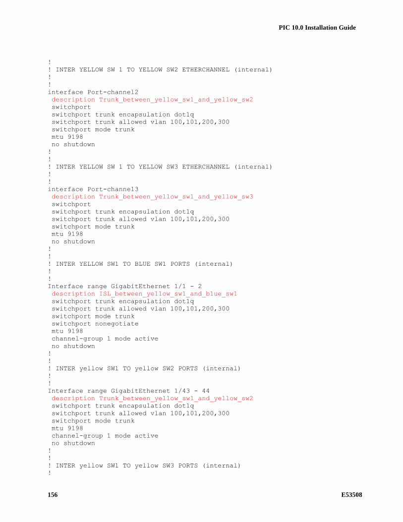
PIC 10.0 Installation Guide
156 E53508
!
! INTER YELLOW SW 1 TO YELLOW SW2 ETHERCHANNEL (internal)
!
!
interface Port-channel2
description Trunk_between_yellow_sw1_and_yellow_sw2
switchport
switchport trunk encapsulation dot1q
switchport trunk allowed vlan 100,101,200,300
switchport mode trunk
mtu 9198
no shutdown
!
!
! INTER YELLOW SW 1 TO YELLOW SW3 ETHERCHANNEL (internal)
!
!
interface Port-channel3
description Trunk_between_yellow_sw1_and_yellow_sw3
switchport
switchport trunk encapsulation dot1q
switchport trunk allowed vlan 100,101,200,300
switchport mode trunk
mtu 9198
no shutdown
!
!
! INTER YELLOW SW1 TO BLUE SW1 PORTS (internal)
!
!
Interface range GigabitEthernet 1/1 - 2
description ISL_between_yellow_sw1_and_blue_sw1
switchport trunk encapsulation dot1q
switchport trunk allowed vlan 100,101,200,300
switchport mode trunk
switchport nonegotiate
mtu 9198
channel-group 1 mode active
no shutdown
!
!
! INTER yellow SW1 TO yellow SW2 PORTS (internal)
!
!
Interface range GigabitEthernet 1/43 - 44
description Trunk_between_yellow_sw1_and_yellow_sw2
switchport trunk encapsulation dot1q
switchport trunk allowed vlan 100,101,200,300
switchport mode trunk
mtu 9198
channel-group 1 mode active
no shutdown
!
!
! INTER yellow SW1 TO yellow SW3 PORTS (internal)
!

PIC 10.0 Installation Guide
E53508 157
!
Interface range GigabitEthernet 1/41 - 42
description Trunk_between_yellow_sw1_and_yellow_sw3
switchport trunk encapsulation dot1q
switchport trunk allowed vlan 100,101,200,300
switchport mode trunk
mtu 9198
channel-group 1 mode active
no shutdown
!
!
! IMF Servers PORTS
!
!
interface range GigabitEthernet 1/3 - 5
description IMF servers ports
switchport trunk encapsulation dot1q
switchport mode trunk
mtu 9198
no shutdown
!
interface range GigabitEthernet 1/7 - 8
description IMF servers ports
switchport trunk encapsulation dot1q
switchport mode trunk
mtu 9198
no shutdown
!
interface range GigabitEthernet 1/10
description IMF servers ports
switchport trunk encapsulation dot1q
switchport mode trunk
mtu 9198
no shutdown
!
!
! iLO PORTS
!
!
interface GigabitEthernet 1/6
description IMF iLO ports
switchport access vlan 300
switchport mode access
no shutdown
!
interface GigabitEthernet 1/9
description IMF iLO ports
switchport access vlan 300
switchport mode access
no shutdown
!
!
! EAGLE PORTS
!
!
interface range GigabitEthernet 1/11 - 40

PIC 10.0 Installation Guide
158 E53508
description Eagle FC or STC ports
switchport access vlan 100
switchport mode access
mtu 9198
no shutdown
!
!
! PORT TO CUSTOMER SWITCH A
!
!
interface GigabitEthernet 1/47
description to customer switch A
switchport access vlan 400
switchport mode access
media-type rj45
no shutdown
!
interface GigabitEthernet 1/48
description reserved for optional direct access to ILO in case of disaster
switchport access vlan 300
switchport mode access
media-type rj45
no shutdown
!
!
! Laptop PORTS
!
!
interface range GigabitEthernet 1/45 - 46
description for Laptop
switchport access vlan 200
switchport mode access
media-type rj45
no shutdown
!
!
! VLAN INTERFACE CONFIGURATION
!
!
interface Vlan1
no ip address
!
!
interface VLAN 100
ip address 172.21.49.1 255.255.254.0
ip pim dense-mode
no shutdown
!
!
track 1 int gigabitEthernet 1/47 line-protocol
interface Vlan200
description internal VRRP for IMF to IXP traffic. Both IP addresses and
netmask must be configured according customer network.
ip address 192.168.0.2 255.255.255.224 ! <--------- replace IP with the
value provided by the customer
vrrp 1 ip 192.168.0.1 ! <--------- replace IP with default gateway

PIC 10.0 Installation Guide
E53508 159
vrrp 1 priority 100
vrrp 1 track 1
vrrp 1 preempt
no shutdown
!
!
interface Vlan300
description oobm or iLO optional IP. IP address and netmask must be
configured according customer network.
ip address 192.168.10.2 255.255.255.240 ! <--------- replace IP with the
value provided by the customer
no shutdown
!
!
interface Vlan 400
description external VRRP for IMF to IXP traffic to Customer switches. Both
IP addresses and netmask must be configured according customer network.
ip address 192.168.20.2 255.255.255.248 ! <--------- replace IP with the
value provided by the customer
vrrp 2 ip 192.168.20.1 ! <--------- replace IP with default gateway
vrrp 2 priority 100
vrrp 2 preempt
no shutdown
!
!
no ip http server
no ip http secure-server
!
ip route 0.0.0.0 0.0.0.0 192.168.20.6 1 ! <--------- replace IP with
customer default gateway
!
!
line con 0
password ***** ! <--------- replace ***** with password specified in
password dragon as Cisco telnet
login
!
logging 172.21.49.10
!
no cdp run
!
end

PIC 10.0 Installation Guide
160 E53508
15.4.5 Blue-sw1-1 Switch (Layer 3)
! IMF BLUE1 SWITCH configuration
!
!
hostname blue-sw1-1
!
no spanning-tree vlan 1-4094
no spanning-tree optimize bpdu transmission
!
enable secret ***** ! <--------- replace ***** with password specified in
password dragon as Cisco enable
service password-encryption
no service pad
service timestamps debug datetime
service timestamps log datetime
no logging console
no aaa new-model
track 1 interface GigabitEthernet1/47 line-protocol
ip subnet-zero
!
ip multicast-routing
!
power redundancy-mode redundant
!
!
! VLAN CONFIGURATION (internal)
!
!
vlan 100
name internal_yellow
!
vlan 101
name internal_blue
!
vlan 200
name IMF2IXP_internal_(backend)
!
vlan 300
name oobm_or_iLO
!
vlan 400
name IMF2IXP_external_(frontend)
!
!
! INTER YELLOW SW1 TO BLUE SW1 ETHERCHANNEL (internal)
!
!
interface Port-channel1
description Trunk_between_yellow_sw1_and_blue_sw1
switchport
switchport trunk encapsulation dot1q
switchport trunk allowed vlan 100,101,200,300
mtu 9198
no shutdown
!

PIC 10.0 Installation Guide
E53508 161
!
! INTER BLUE SW 1 TO BLUE SW2 ETHERCHANNEL (internal)
!
!
interface Port-channel2
description Trunk_between_ blue_sw1_and_ blue_sw2
switchport
switchport trunk encapsulation dot1q
switchport trunk allowed vlan 100,101,200,300
switchport mode trunk
mtu 9198
no shutdown
!
!
! INTER BLUE SW 1 TO BLUE SW3 ETHERCHANNEL (internal)
!
!
interface Port-channel3
description Trunk_between_ blue_sw1_and_blue_sw3
switchport
switchport trunk encapsulation dot1q
switchport trunk allowed vlan 100,101,200,300
switchport mode trunk
mtu 9198
no shutdown
!
!
! INTER BLUE SW1 TO yellow SW1 PORTS (internal)
!
!
Interface range GigabitEthernet 1/1 - 2
description ISL_between_blue_sw1_and_yellow_sw1
switchport trunk encapsulation dot1q
switchport trunk allowed vlan 100,101,200,300
switchport mode trunk
switchport nonegotiate
mtu 9198
channel-group 1 mode active
no shutdown
!
!
! INTER BLUE SW1 TO BLUE SW2 PORTS (internal)
!
!
Interface range GigabitEthernet 1/43 - 44
description Trunk_between_blue_sw1_and_blue_sw2
switchport trunk encapsulation dot1q
switchport trunk allowed vlan 100,101,200,300
switchport mode trunk
mtu 9198
channel-group 1 mode active
no shutdown
!
!
! INTER BLUE SW1 TO BLUE SW3 PORTS (internal)
!

PIC 10.0 Installation Guide
162 E53508
!
Interface range GigabitEthernet 1/41 - 42
description Trunk_between_blue_sw1_and_blue_sw3
switchport trunk encapsulation dot1q
switchport trunk allowed vlan 100,101,200,300
switchport mode trunk
mtu 9198
channel-group 1 mode active
no shutdown
!
!
! IMF Servers PORTS
!
!
interface range GigabitEthernet 1/3 - 6
description IMF servers ports
switchport trunk encapsulation dot1q
switchport mode trunk
mtu 9198
no shutdown
!
interface range GigabitEthernet 1/8 - 9
description IMF servers ports
switchport trunk encapsulation dot1q
switchport mode trunk
mtu 9198
no shutdown
!
!
! iLO PORTS
!
!
interface GigabitEthernet 1/7
description IMF iLO ports
switchport access vlan 300
switchport mode access
no shutdown
!
interface GigabitEthernet 1/10
description IMF iLO ports
switchport access vlan 300
switchport mode access
no shutdown
!
!
! EAGLE PORTS
!
!
interface range GigabitEthernet 1/11 - 40
description Eagle FC or STC ports
switchport access vlan 101
switchport mode access
mtu 9198
no shutdown
!
!

PIC 10.0 Installation Guide
E53508 163
! PORT TO CUSTOMER SWITCH B
!
!
interface GigabitEthernet 1/47
description to customer switch B
switchport access vlan 400
switchport mode access
media-type rj45
no shutdown
!
!
interface GigabitEthernet 1/48
description not used to avoid loop risk on iLO VLAN.
switchport access vlan 300
switchport mode access
media-type rj45
shutdown
!
!
! Laptop PORTS
!
!
interface range GigabitEthernet 1/45 - 46
description for Laptop
switchport access vlan 200
switchport mode access
media-type rj45
no shutdown
!
!
! VLAN INTERFACE CONFIGURATION
!
!
interface Vlan1
no ip address
!
!
interface VLAN 101
ip address 172.22.49.1 255.255.254.0
ip pim dense-mode
no shutdown
!
!
track 1 int gigabitEthernet 1/47 line-protocol
interface Vlan200
description internal VRRP for IMF to IXP traffic. Both IP addresses and
netmask must be configured according customer network.
ip address 192.168.0.3 255.255.255.224 ! <--------- replace IP with the
value provided by the customer
vrrp 1 ip 192.168.0.1 ! <--------- replace IP with default gateway
vrrp 1 priority 99
vrrp 1 track 1
vrrp 1 preempt
no shutdown
!
!

PIC 10.0 Installation Guide
164 E53508
interface Vlan 400
description external VRRP for IMF to IXP traffic to Customer switches. Both
IP addresses and netmask must be configured according customer network.
ip address 192.168.20.3 255.255.255.248 ! <--------- replace IP with the
value provided by the customer
vrrp 2 ip 192.168.20.1 ! <--------- replace IP with default gateway
vrrp 2 priority 99
vrrp 2 preempt
no shutdown
!
!
no ip http server
no ip http secure-server
!
ip route 0.0.0.0 0.0.0.0 192.168.20.6 1 ! <--------- replace IP with
customer default gateway
!
!
line con 0
password ***** ! <--------- replace ***** with password specified in
password dragon as Cisco telnet
login
!
logging 172.22.49.10
!
no cdp run
!
end
15.4.6 Yellow-sw2-1 Switch (Layer 3)
! IMF YELLOW2 SWITCH configuration
!
!
hostname yellow-sw2-1
!
no spanning-tree vlan 1-4094
no spanning-tree optimize bpdu transmission
!
enable secret ***** ! <--------- replace ***** with password specified in
password dragon as Cisco enable
service password-encryption
no service pad
service timestamps debug datetime
service timestamps log datetime
no logging console
no aaa new-model
track 1 interface GigabitEthernet1/47 line-protocol
ip subnet-zero
!
ip multicast-routing
!
power redundancy-mode redundant
!
!
! VLAN CONFIGURATION (internal)

PIC 10.0 Installation Guide
E53508 165
!
!
vlan 100
name internal_yellow
!
vlan 101
name internal_blue
!
vlan 200
name IMF2IXP_internal_(backend)
!
vlan 300
name oobm_or_iLO
!
vlan 400
name IMF2IXP_external_(frontend)
!
!
! INTER YELLOW SW 2 TO YELLOW SW 1 ETHERCHANNEL (internal)
!
!
interface Port-channel2
description Trunk_between_yellow_sw2_and_yellow_sw1
switchport
switchport trunk encapsulation dot1q
switchport trunk allowed vlan 100,101,200,300
switchport mode trunk
mtu 9198
no shutdown
!
!
! INTER yellow SW2 TO yellow SW1 PORTS (internal)
!
!
Interface range GigabitEthernet 1/1 - 2
description Trunk_between_yellow_sw2_and_yellow_sw1
switchport trunk encapsulation dot1q
switchport trunk allowed vlan 100,101,200,300
switchport mode trunk
mtu 9198
channel-group 1 mode active
no shutdown
!
!
! IMF Servers PORTS
!
!
interface GigabitEthernet 1/3
description IMF servers ports
switchport trunk encapsulation dot1q
switchport mode trunk
mtu 9198
no shutdown
!
interface range GigabitEthernet 1/5 - 6
description IMF servers ports

PIC 10.0 Installation Guide
166 E53508
switchport trunk encapsulation dot1q
switchport mode trunk
mtu 9198
no shutdown
!
interface range GigabitEthernet 1/8 - 9
description IMF servers ports
switchport trunk encapsulation dot1q
switchport mode trunk
mtu 9198
no shutdown
!
interface range GigabitEthernet 1/11
description IMF servers ports
switchport trunk encapsulation dot1q
switchport mode trunk
mtu 9198
no shutdown
!
!
! iLO PORTS
!
!
interface GigabitEthernet 1/4
description IMF iLO ports
switchport access vlan 300
switchport mode access
no shutdown
!
interface GigabitEthernet 1/7
description IMF iLO ports
switchport access vlan 300
switchport mode access
no shutdown
!
interface GigabitEthernet 1/10
description IMF iLO ports
switchport access vlan 300
switchport mode access
no shutdown
!
!
! EAGLE PORTS
!
!
interface range GigabitEthernet 1/12 - 48
description Eagle FC or STC ports
switchport access vlan 100
switchport mode access
mtu 9198
no shutdown
!
!
! VLAN INTERFACE CONFIGURATION
!
!

PIC 10.0 Installation Guide
E53508 167
interface Vlan1
no ip address
!
!
interface VLAN 100
ip address 172.21.49.2 255.255.254.0
ip pim dense-mode
no shutdown!
!
interface Vlan200
description for remote access though telnet
ip address 192.168.0.4 255.255.255.224 ! <--------- replace IP with
the value provided by the customer
no shutdown
!
!
no ip http server
no ip http secure-server
!
ip route 0.0.0.0 0.0.0.0 192.168.0.1 1 ! <--------- replace IP with VLAN
200 vrrp IP
!
!
line con 0
password ***** ! <--------- replace ***** with password specified in
password dragon as Cisco telnet
login
!
logging 172.21.49.10
!
no cdp run
!
end
15.4.7 Blue-sw2-1 Switch (Layer 3)
! IMF BLUE2 SWITCH configuration
!
!
hostname blue-sw2-1
!
no spanning-tree vlan 1-4094
no spanning-tree optimize bpdu transmission
!
enable secret ***** ! <--------- replace ***** with password specified in
password dragon as Cisco enable
service password-encryption
no service pad
service timestamps debug datetime
service timestamps log datetime
no logging console
no aaa new-model
track 1 interface GigabitEthernet1/47 line-protocol
ip subnet-zero
!

PIC 10.0 Installation Guide
168 E53508
ip multicast-routing
!
power redundancy-mode redundant
!
!
! VLAN CONFIGURATION (internal)
!
!
vlan 100
name internal_yellow
!
vlan 101
name internal_blue
!
vlan 200
name IMF2IXP_internal_(backend)
!
vlan 300
name oobm_or_iLO
!
vlan 400
name IMF2IXP_external_(frontend)
!
!
! INTER BLUE SW 2 TO BLUE SW 1 ETHERCHANNEL (internal)
!
!
interface Port-channel2
description Trunk_between_ blue_sw2_and_ blue_sw1
switchport
switchport trunk encapsulation dot1q
switchport trunk allowed vlan 100,101,200,300
switchport mode trunk
mtu 9198
no shutdown
!
!
! INTER BLUE SW2 TO BLUE SW1 PORTS (internal)
!
!
Interface range GigabitEthernet 1/1 - 2
description Trunk_between_blue_sw2_and_blue_sw1
switchport trunk encapsulation dot1q
switchport trunk allowed vlan 100,101,200,300
switchport mode trunk
mtu 9198
channel-group 1 mode active
no shutdown
!
!
! IMF Servers PORTS
!
!
interface range GigabitEthernet 1/3 - 4
description IMF servers ports
switchport trunk encapsulation dot1q

PIC 10.0 Installation Guide
E53508 169
switchport mode trunk
mtu 9198
no shutdown
!
interface range GigabitEthernet 1/6 - 7
description IMF servers ports
switchport trunk encapsulation dot1q
switchport mode trunk
mtu 9198
no shutdown
!
interface range GigabitEthernet 1/9 - 10
description IMF servers ports
switchport trunk encapsulation dot1q
switchport mode trunk
mtu 9198
no shutdown
!
!
! iLO PORTS
!
!
interface GigabitEthernet 1/5
description IMF iLO ports
switchport access vlan 300
switchport mode access
no shutdown
!
interface GigabitEthernet 1/8
description IMF iLO ports
switchport access vlan 300
switchport mode access
no shutdown
!
interface GigabitEthernet 1/11
description IMF iLO ports
switchport access vlan 300
switchport mode access
no shutdown
!
!
! EAGLE PORTS
!
!
interface range GigabitEthernet 1/12 - 48
description Eagle FC or STC ports
switchport access vlan 101
switchport mode access
mtu 9198
no shutdown
!
!
! VLAN INTERFACE CONFIGURATION
!
!
interface Vlan1

PIC 10.0 Installation Guide
170 E53508
no ip address
!
!
interface VLAN 101
ip address 172.22.49.2 255.255.254.0
ip pim dense-mode
no shutdown
!
!
interface Vlan200
description for remote access though telnet
ip address 192.168.0.5 255.255.255.224 ! <--------- replace IP with
the value provided by the customer
no shutdown
!
!
no ip http server
no ip http secure-server
!
ip route 0.0.0.0 0.0.0.0 192.168.0.1 1 ! <--------- replace IP with VLAN
200 vrrp IP
!
!
line con 0
password ***** ! <--------- replace ***** with password specified in
password dragon as Cisco telnet
login
!
logging 172.22.49.10
!
no cdp run
!
end
15.4.8 Yellow-sw3-1 Switch (Layer 3)
! IMF YELLOW3 SWITCH configuration
!
!
hostname yellow-sw3-1
!
no spanning-tree vlan 1-4094
no spanning-tree optimize bpdu transmission
!
enable secret ***** ! <--------- replace ***** with password specified in
password dragon as Cisco enable
service password-encryption
no service pad
service timestamps debug datetime
service timestamps log datetime
no logging console
no aaa new-model
track 1 interface GigabitEthernet1/47 line-protocol
ip subnet-zero
!

PIC 10.0 Installation Guide
E53508 171
ip multicast-routing
!
power redundancy-mode redundant
!
!
! VLAN CONFIGURATION (internal)
!
!
vlan 100
name internal_yellow
!
vlan 101
name internal_blue
!
vlan 200
name IMF2IXP_internal_(backend)
!
vlan 300
name oobm_or_iLO
!
vlan 400
name IMF2IXP_external_(frontend)
!
!
! INTER YELLOW SW 3 TO YELLOW SW 1 ETHERCHANNEL (internal)
!
!
interface Port-channel3
description Trunk_between_yellow_sw3_and_yellow_sw1
switchport
switchport trunk encapsulation dot1q
switchport trunk allowed vlan 100,101,200,300
switchport mode trunk
mtu 9198
no shutdown
!
!
! INTER yellow SW3 TO yellow SW1 PORTS (internal)
!
!
Interface range GigabitEthernet 1/1 - 2
description Trunk_between_yellow_sw3_and_yellow_sw1
switchport trunk encapsulation dot1q
switchport trunk allowed vlan 100,101,200,300
switchport mode trunk
mtu 9198
channel-group 1 mode active
no shutdown
!
!
! EAGLE PORTS
!
!
interface range GigabitEthernet 1/3 - 48
description Eagle FC or STC ports
switchport access vlan 100

PIC 10.0 Installation Guide
172 E53508
switchport mode access
mtu 9198
no shutdown
!
!
! VLAN INTERFACE CONFIGURATION
!
!
interface Vlan1
no ip address
!
!
interface VLAN 100
ip address 172.21.49.3 255.255.254.0
ip pim dense-mode
no shutdown
!
!
interface Vlan200
description for remote access though telnet
ip address 192.168.0.6 255.255.255.224 ! <--------- replace IP with
the value provided by the customer
no shutdown
!
!
no ip http server
no ip http secure-server
!
ip route 0.0.0.0 0.0.0.0 192.168.0.1 1 ! <--------- replace IP with yellow
VLAN 200 vrrp IP
!
!
line con 0
password ***** ! <--------- replace ***** with password specified in
password dragon as Cisco telnet
login
!
logging 172.21.49.10
!
no cdp run
!
end
15.4.9 Blue-sw3-1 Switch (Layer 3)
! IMF BLUE3 SWITCH configuration
!
!
hostname blue-sw3-1
!
no spanning-tree vlan 1-4094
no spanning-tree optimize bpdu transmission
!
enable secret ***** ! <--------- replace ***** with password specified in
password dragon as Cisco enable

PIC 10.0 Installation Guide
E53508 173
service password-encryption
no service pad
service timestamps debug datetime
service timestamps log datetime
no logging console
no aaa new-model
track 1 interface GigabitEthernet1/47 line-protocol
ip subnet-zero
!
ip multicast-routing
!
power redundancy-mode redundant
!
!
! VLAN CONFIGURATION (internal)
!
!
vlan 100
name internal_yellow
!
vlan 101
name internal_blue
!
vlan 200
name IMF2IXP_internal_(backend)
!
vlan 300
name oobm_or_iLO
!
vlan 400
name IMF2IXP_external_(frontend)
!
!
! INTER BLUE SW 3 TO BLUE SW 1 ETHERCHANNEL (internal)
!
!
interface Port-channel3
description Trunk_between_ blue_sw3_and_ blue_sw1
switchport
switchport trunk encapsulation dot1q
switchport trunk allowed vlan 100,101,200,300
switchport mode trunk
mtu 9198
no shutdown
!
!
! INTER BLUE SW3 TO BLUE SW1 PORTS (internal)
!
!
Interface range GigabitEthernet 1/1 - 2
description Trunk_between_blue_sw3_and_blue_sw1
switchport trunk encapsulation dot1q
switchport trunk allowed vlan 100,101,200,300
switchport mode trunk
mtu 9198
channel-group 1 mode active

PIC 10.0 Installation Guide
174 E53508
no shutdown
!
!
! EAGLE PORTS
!
!
interface range GigabitEthernet 1/3 - 48
description Eagle FC or STC ports
switchport access vlan 101
switchport mode access
mtu 9198
no shutdown
!
!
! VLAN INTERFACE CONFIGURATION
!
!
interface Vlan1
no ip address
!
!
interface VLAN 101
ip address 172.22.49.3 255.255.254.0
ip pim dense-mode
no shutdown!
!
interface Vlan200
description for remote access though telnet
ip address 192.168.0.7 255.255.255.224 ! <--------- replace IP with
the value provided by the customer
no shutdown
!
!
no ip http server
no ip http secure-server
!
ip route 0.0.0.0 0.0.0.0 192.168.0.1 1 ! <--------- replace IP with yellow
VLAN 200 vrrp IP
!
!
line con 0
password ***** ! <--------- replace ***** with password specified in
password dragon as Cisco telnet
login
!
logging 172.22.49.10
!
no cdp run
!
end
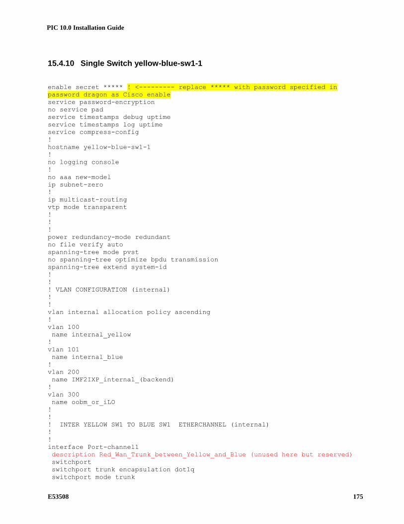
PIC 10.0 Installation Guide
E53508 175
15.4.10 Single Switch yellow-blue-sw1-1
enable secret ***** ! <--------- replace ***** with password specified in
password dragon as Cisco enable
service password-encryption
no service pad
service timestamps debug uptime
service timestamps log uptime
service compress-config
!
hostname yellow-blue-sw1-1
!
no logging console
!
no aaa new-model
ip subnet-zero
!
ip multicast-routing
vtp mode transparent
!
!
!
power redundancy-mode redundant
no file verify auto
spanning-tree mode pvst
no spanning-tree optimize bpdu transmission
spanning-tree extend system-id
!
!
! VLAN CONFIGURATION (internal)
!
!
vlan internal allocation policy ascending
!
vlan 100
name internal_yellow
!
vlan 101
name internal_blue
!
vlan 200
name IMF2IXP_internal_(backend)
!
vlan 300
name oobm_or_iLO
!
!
! INTER YELLOW SW1 TO BLUE SW1 ETHERCHANNEL (internal)
!
!
interface Port-channel1
description Red_Wan_Trunk_between_Yellow_and_Blue (unused here but reserved)
switchport
switchport trunk encapsulation dot1q
switchport mode trunk

PIC 10.0 Installation Guide
176 E53508
mtu 9198
!
!
! INTER YELLOW SW1 TO BLUE SW1 PORTS (internal)
!
!
Interface range GigabitEthernet 1/1 - 2
description Red_Wan_Trunk_between_Yellow_and_Blue (unused here but reserved)
switchport trunk encapsulation dot1q
switchport mode trunk
mtu 9198
channel-group 1 mode active
!
!
! IMF Servers PORTS
!
!
interface range GigabitEthernet1/3 - 4
description for IMF 1A external + internal networks port
switchport trunk encapsulation dot1q
switchport trunk allowed vlan 1,100,101,200,300
switchport mode trunk
mtu 9198
spanning-tree portfast trunk
!
!
! EAGLE PORTS
!
!
interface range GigabitEthernet1/5 - 24
description yellow network port for Eagle connectivity
switchport access vlan 100
switchport mode access
mtu 9198
spanning-tree portfast
!
!
interface range GigabitEthernet1/25-44
description blue network port for Eagle connectivity
switchport access vlan 101
switchport mode access
mtu 9198
spanning-tree portfast
!
interface range GigabitEthernet1/45-46
description unused
shutdown
!
!
! PORT TO CUSTOMER SWITCH A
!
!
interface GigabitEthernet1/47
description port where customer is connected to IMF
switchport access vlan 200
switchport mode access
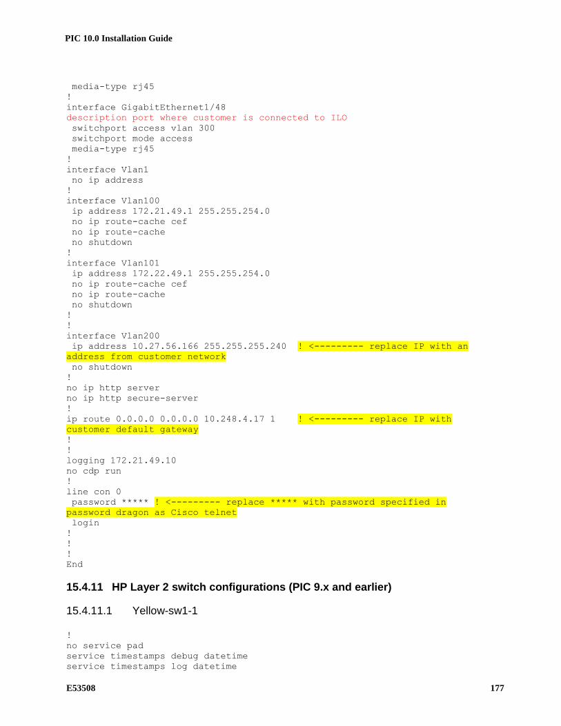
PIC 10.0 Installation Guide
E53508 177
media-type rj45
!
interface GigabitEthernet1/48
description port where customer is connected to ILO
switchport access vlan 300
switchport mode access
media-type rj45
!
interface Vlan1
no ip address
!
interface Vlan100
ip address 172.21.49.1 255.255.254.0
no ip route-cache cef
no ip route-cache
no shutdown
!
interface Vlan101
ip address 172.22.49.1 255.255.254.0
no ip route-cache cef
no ip route-cache
no shutdown
!
!
interface Vlan200
ip address 10.27.56.166 255.255.255.240 ! <--------- replace IP with an
address from customer network
no shutdown
!
no ip http server
no ip http secure-server
!
ip route 0.0.0.0 0.0.0.0 10.248.4.17 1 ! <--------- replace IP with
customer default gateway
!
!
logging 172.21.49.10
no cdp run
!
line con 0
password ***** ! <--------- replace ***** with password specified in
password dragon as Cisco telnet
login
!
!
!
End
15.4.11 HP Layer 2 switch configurations (PIC 9.x and earlier)
15.4.11.1 Yellow-sw1-1
!
no service pad
service timestamps debug datetime
service timestamps log datetime
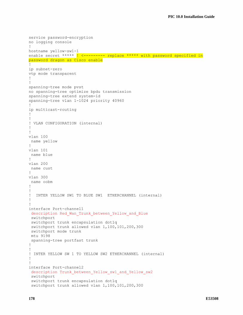
PIC 10.0 Installation Guide
178 E53508
service password-encryption
no logging console
!
hostname yellow-sw1-1
enable secret ***** ! <--------- replace ***** with password specified in
password dragon as Cisco enable
!
ip subnet-zero
vtp mode transparent
!
!
spanning-tree mode pvst
no spanning-tree optimize bpdu transmission
spanning-tree extend system-id
spanning-tree vlan 1-1024 priority 40960
!
ip multicast-routing
!
!
! VLAN CONFIGURATION (internal)
!
!
vlan 100
name yellow
!
vlan 101
name blue
!
vlan 200
name cust
!
vlan 300
name oobm
!
!
! INTER YELLOW SW1 TO BLUE SW1 ETHERCHANNEL (internal)
!
!
interface Port-channel1
description Red_Wan_Trunk_between_Yellow_and_Blue
switchport
switchport trunk encapsulation dot1q
switchport trunk allowed vlan 1,100,101,200,300
switchport mode trunk
mtu 9198
spanning-tree portfast trunk
!
!
! INTER YELLOW SW 1 TO YELLOW SW2 ETHERCHANNEL (internal)
!
!
interface Port-channel2
description Trunk_between_Yellow_sw1_and_Yellow_sw2
switchport
switchport trunk encapsulation dot1q
switchport trunk allowed vlan 1,100,101,200,300

PIC 10.0 Installation Guide
E53508 179
switchport mode trunk
mtu 9198
spanning-tree portfast trunk
!
!
! INTER YELLOW SW 1 TO YELLOW SW3 ETHERCHANNEL (internal)
!
!
interface Port-channel3
description Trunk_between_Yellow_sw1_and_Yellow_sw3
switchport
switchport trunk encapsulation dot1q
switchport trunk allowed vlan 1,100,101,200,300
switchport mode trunk
mtu 9198
spanning-tree portfast trunk
!
!
! INTER YELLOW SW1 TO BLUE SW1 PORTS (internal)
!
!
interface range gigabitEthernet 1/1 - 2
description ISL_between_yellow_sw1_and_blue_sw1
switchport trunk encapsulation dot1q
switchport trunk allowed vlan 1,100,101,200,300
switchport mode trunk
mtu 9198
channel-group 1 mode active
spanning-tree portfast trunk
no shutdown
!
!
! INTER yellow SW1 TO yellow SW3 PORTS (internal)
!
!
interface range gigabitEthernet 1/41 - 42
description Trunk_between_yellow_sw1_and_yellow_sw3
switchport trunk encapsulation dot1q
switchport trunk allowed vlan 1,100,101,200,300
switchport mode trunk
mtu 9198
channel-group 3 mode active
spanning-tree portfast trunk
no shutdown
!
!
! INTER yellow SW1 TO yellow SW2 PORTS (internal)
!
!
interface range gigabitEthernet 1/43 - 44
description Trunk_between_yellow_sw1_and_yellow_sw2
switchport trunk encapsulation dot1q
switchport trunk allowed vlan 1,100,101,200,300
switchport mode trunk
mtu 9198
channel-group 2 mode active

PIC 10.0 Installation Guide
180 E53508
spanning-tree portfast trunk
no shutdown
!
!
! IMF Servers PORTS
!
!
interface range gigabitEthernet 1/3 - 5
description IMF servers ports
switchport trunk encapsulation dot1q
switchport mode trunk
mtu 9198
spanning-tree portfast trunk
no shutdown
!
interface range gigabitEthernet 1/7 - 8
description IMF servers ports
switchport trunk encapsulation dot1q
switchport mode trunk
mtu 9198
spanning-tree portfast trunk
no shutdown
!
interface gigabitEthernet 1/10
description IMF servers ports
switchport trunk encapsulation dot1q
switchport mode trunk
mtu 9198
spanning-tree portfast trunk
no shutdown
!
!
! iLO PORTS
!
!
interface gigabitEthernet 1/6
description IMF iLO ports
switchport mode access
switchport access vlan 300
spanning-tree portfast
no shutdown
!
interface gigabitEthernet 1/9
description IMF iLO ports
switchport mode access
switchport access vlan 300
spanning-tree portfast
no shutdown
!
!
! EAGLE PORTS
!
!
interface range gigabitEthernet 1/11 - 40
description Eagle FC or STC ports
switchport mode access

PIC 10.0 Installation Guide
E53508 181
switchport access vlan 100
mtu 9198
spanning-tree portfast
no shutdown
!
!
! Laptop PORTS
!
!
interface range GigabitEthernet 1/45 - 46
description for Laptop
switchport access vlan 200
switchport mode access
media-type rj45
no shutdown
!
!
! PORT TO CUSTOMER SWITCH A
!
!
interface gigabitEthernet 1/47
description to customer switch A
switchport mode access
switchport access vlan 200
media-type rj45
no shutdown
!
interface gigabitEthernet 1/48
description to customer switch A (iLO)
switchport mode access
switchport access vlan 300
media-type rj45
no shutdown
!
interface VLAN 100
ip address 172.21.49.1 255.255.254.0
ip pim dense-mode
no shutdown
!
no ip route-cache
!
no ip http server
!
no cdp run
!
line con 0
password ***** ! <--------- replace ***** with password specified in
password dragon as Cisco telnet
login
!
logging 172.21.49.10
!
end

PIC 10.0 Installation Guide
182 E53508
15.4.11.2 Blue-sw1-1
!
no service pad
service timestamps debug datetime
service timestamps log datetime
service password-encryption
no logging console
!
hostname blue-sw1-1
enable secret ***** ! <--------- replace ***** with password specified in
password dragon as Cisco enable
!
ip subnet-zero
vtp mode transparent
!
!
spanning-tree mode pvst
no spanning-tree optimize bpdu transmission
spanning-tree extend system-id
spanning-tree vlan 1-1024 priority 40960
!
ip multicast-routing
!
!
! VLAN CONFIGURATION (internal)
!
!
vlan 100
name yellow
!
vlan 101
name blue
!
vlan 200
name cust
!
vlan 300
name oobm
!
!
! INTER YELLOW SW1 TO BLUE SW1 ETHERCHANNEL (internal)
!
!
interface Port-channel1
description Red_Wan_Trunk_between_Yellow_and_Blue
switchport
switchport trunk encapsulation dot1q
switchport trunk allowed vlan 1,100,101,200,300
switchport mode trunk
mtu 9198
spanning-tree portfast trunk
!
!
! INTER BLUE SW 1 TO BLUE SW2 ETHERCHANNEL (internal)
!

PIC 10.0 Installation Guide
E53508 183
!
interface Port-channel2
description Trunk_between_Blue_sw1_and_Blue_sw2
switchport
switchport trunk encapsulation dot1q
switchport trunk allowed vlan 1,100,101,200,300
switchport mode trunk
mtu 9198
spanning-tree portfast trunk
!
!
! INTER BLUE SW 1 TO BLUE SW3 ETHERCHANNEL (internal)
!
!
interface Port-channel3
description Trunk_between_Blue_sw1_and_Blue_sw3
switchport
switchport trunk encapsulation dot1q
switchport trunk allowed vlan 1,100,101,200,300
switchport mode trunk
spanning-tree portfast trunk
!
!
! INTER BLUE SW1 TO yellow SW1 PORTS (internal)
!
!
interface range gigabitEthernet 1/1 - 2
description ISL_between_blue_sw1_and_yellow_sw1
switchport trunk encapsulation dot1q
switchport trunk allowed vlan 1,100,101,200,300
switchport mode trunk
mtu 9198
channel-group 1 mode active
spanning-tree portfast trunk
no shutdown
!
!
! INTER BLUE SW1 TO BLUE SW3 PORTS (internal)
!
!
interface range gigabitEthernet 1/41 - 42
description Trunk_between_blue_sw1_and_blue_sw3
switchport trunk encapsulation dot1q
switchport trunk allowed vlan 1,100,101,200,300
switchport mode trunk
channel-group 3 mode active
mtu 9198
spanning-tree portfast trunk
no shutdown
!
!
! INTER BLUE SW1 TO BLUE SW2 PORTS (internal)
!
!
interface range gigabitEthernet 1/43 - 44
description Trunk_between_blue_sw1_and_blue_sw2

PIC 10.0 Installation Guide
184 E53508
switchport trunk encapsulation dot1q
switchport trunk allowed vlan 1,100,101,200,300
switchport mode trunk
channel-group 2 mode active
mtu 9198
spanning-tree portfast trunk
no shutdown
!
!
! IMF Servers PORTS
!
!
interface range gigabitEthernet 1/3 - 6
description IMF servers ports
switchport trunk encapsulation dot1q
switchport mode trunk
mtu 9198
spanning-tree portfast trunk
no shutdown
!
interface range gigabitEthernet 1/8 - 9
description IMF servers ports
switchport trunk encapsulation dot1q
switchport mode trunk
mtu 9198
spanning-tree portfast trunk
no shutdown
!
!
! iLO PORTS
!
!
interface gigabitEthernet 1/7
description IMF iLO ports
switchport mode access
switchport access vlan 300
spanning-tree portfast
no shutdown
!
interface gigabitEthernet 1/10
description IMF iLO ports
switchport mode access
switchport access vlan 300
spanning-tree portfast
no shutdown
!
!
! EAGLE PORTS
!
!
interface range gigabitEthernet 1/11 - 40
description Eagle FC or STC ports
switchport mode access
switchport access vlan 101
mtu 9198
spanning-tree portfast

PIC 10.0 Installation Guide
E53508 185
no shutdown
!
!
! Laptop PORTS
!
!
interface range GigabitEthernet 1/45 - 46
description for Laptop
switchport access vlan 200
switchport mode access
media-type rj45
no shutdown
!
!
! PORT TO CUSTOMER SWITCH B
!
!
interface gigabitEthernet 1/47
description to customer switch B
switchport mode access
switchport access vlan 200
media-type rj45
no shutdown
!
interface gigabitEthernet 1/48
description to customer switch B (iLO)
switchport mode access
switchport access vlan 300
media-type rj45
no shutdown
!
interface VLAN 101
ip address 172.22.49.1 255.255.254.0
ip pim dense-mode
no shutdown
!
no ip route-cache
!
no ip http server
!
no cdp run
!
line con 0
password ***** ! <--------- replace ***** with password specified in
password dragon as Cisco telnet
login
!
logging 172.22.49.10
!
end
15.4.11.3 Yellow-sw2-1
!

PIC 10.0 Installation Guide
186 E53508
no service pad
service timestamps debug datetime
service timestamps log datetime
service password-encryption
no logging console
!
hostname yellow-sw2-1
enable secret ***** ! <--------- replace ***** with password specified in
password dragon as Cisco enable
!
ip subnet-zero
vtp mode transparent
!
boot-start-marker
boot system flash bootflash:cat4500-ipbasek9-mz.122-53.SG2.bin
boot-end-marker
!
!
spanning-tree mode pvst
no spanning-tree optimize bpdu transmission
spanning-tree extend system-id
spanning-tree vlan 1-1024 priority 53248
!
ip multicast-routing
!
!
! VLAN CONFIGURATION (internal)
!
!
vlan 100
name yellow
!
vlan 101
name blue
!
vlan 200
name cust
!
vlan 300
name oobm
!
!
! INTER YELLOW SW 2 TO YELLOW SW 1 ETHERCHANNEL (internal)
!
!
interface Port-channel1
description Trunk_between_Yellow_sw2_and_Yellow_sw1
switchport
switchport trunk encapsulation dot1q
switchport trunk allowed vlan 1,100,101,200,300
switchport mode trunk
mtu 9198
spanning-tree portfast trunk
!
!
! INTER yellow SW2 TO yellow SW1 PORTS (internal)

PIC 10.0 Installation Guide
E53508 187
!
!
interface range gigabitEthernet 1/1 - 2
description Trunk_between_yellow_sw2_and_yellow_sw1
switchport trunk encapsulation dot1q
switchport trunk allowed vlan 1,100,101,200,300
switchport mode trunk
mtu 9198
channel-group 1 mode active
spanning-tree portfast trunk
no shutdown
!
!
! IMF Servers PORTS
!
!
interface gigabitEthernet 1/3
description IMF servers ports
switchport trunk encapsulation dot1q
switchport mode trunk
mtu 9198
spanning-tree portfast trunk
no shutdown
!
interface range gigabitEthernet 1/5 - 6
description IMF servers ports
switchport trunk encapsulation dot1q
switchport mode trunk
mtu 9198
spanning-tree portfast trunk
no shutdown
!
interface range gigabitEthernet 1/8 - 9
description IMF servers ports
switchport trunk encapsulation dot1q
switchport mode trunk
mtu 9198
spanning-tree portfast trunk
no shutdown
!
interface gigabitEthernet 1/11
description IMF servers ports
switchport trunk encapsulation dot1q
switchport mode trunk
mtu 9198
spanning-tree portfast trunk
no shutdown
!
!
! iLO PORTS
!
!
interface gigabitEthernet 1/4
description IMF iLO ports
switchport mode access
switchport access vlan 300

PIC 10.0 Installation Guide
188 E53508
spanning-tree portfast
no shutdown
!
interface gigabitEthernet 1/7
description IMF iLO ports
switchport mode access
switchport access vlan 300
spanning-tree portfast
no shutdown
!
interface gigabitEthernet 1/10
description IMF iLO ports
switchport mode access
switchport access vlan 300
spanning-tree portfast
no shutdown
!
!
! EAGLE PORTS
!
!
interface range gigabitEthernet 1/12 - 48
description Eagle FC or STC ports
switchport mode access
switchport access vlan 100
mtu 9198
spanning-tree portfast
no shutdown
!
interface VLAN 100
ip address 172.21.49.2 255.255.254.0
ip pim dense-mode
no shutdown
!
no ip route-cache
!
no ip http server
!
no cdp run
!
line con 0
password ***** ! <--------- replace ***** with password specified in
password dragon as Cisco telnet
login
!
logging 172.21.49.10
!
end
15.4.11.4 Blue-sw2-1
!
no service pad
service timestamps debug datetime
service timestamps log datetime

PIC 10.0 Installation Guide
E53508 189
service password-encryption
no logging console
!
hostname blue-sw2-1
enable secret ***** ! <--------- replace ***** with password specified in
password dragon as Cisco enable
!
ip subnet-zero
vtp mode transparent
!
!
spanning-tree mode pvst
no spanning-tree optimize bpdu transmission
spanning-tree extend system-id
spanning-tree vlan 1-1024 priority 53248
!
ip multicast-routing
!
!
! VLAN CONFIGURATION (internal)
!
!
vlan 100
name yellow
!
vlan 101
name blue
!
vlan 200
name cust
!
vlan 300
name oobm
!
!
! INTER BLUE SW 2 TO BLUE SW 1 ETHERCHANNEL (internal)
!
!
interface Port-channel1
description Trunk_between_Blue_sw2_and_Blue_sw1
switchport
switchport trunk encapsulation dot1q
switchport trunk allowed vlan 1,100,101,200,300
switchport mode trunk
mtu 9198
spanning-tree portfast trunk
!
!
! INTER BLUE SW2 TO BLUE SW1 PORTS (internal)
!
!
interface range gigabitEthernet 1/1 - 2
description Trunk_between_blue_sw2_and_blue_sw1
switchport trunk encapsulation dot1q
switchport trunk allowed vlan 1,100,101,200,300
switchport mode trunk

PIC 10.0 Installation Guide
190 E53508
mtu 9198
channel-group 1 mode active
spanning-tree portfast trunk
no shutdown
!
!
! IMF Servers PORTS
!
!
interface range gigabitEthernet 1/3 - 4
description IMF servers ports
switchport trunk encapsulation dot1q
switchport mode trunk
mtu 9198
spanning-tree portfast trunk
no shutdown
!
interface range gigabitEthernet 1/6 - 7
description IMF servers ports
switchport trunk encapsulation dot1q
switchport mode trunk
mtu 9198
spanning-tree portfast trunk
no shutdown
!
interface range gigabitEthernet 1/9 - 10
description IMF servers ports
switchport trunk encapsulation dot1q
switchport mode trunk
mtu 9198
spanning-tree portfast trunk
no shutdown
!
!
! iLO PORTS
!
!
interface gigabitEthernet 1/5
description IMF iLO ports
switchport mode access
switchport access vlan 300
spanning-tree portfast
no shutdown
!
interface gigabitEthernet 1/8
description IMF iLO ports
switchport mode access
switchport access vlan 300
spanning-tree portfast
no shutdown
!
interface gigabitEthernet 1/11
description IMF iLO ports
switchport mode access
switchport access vlan 300
spanning-tree portfast

PIC 10.0 Installation Guide
E53508 191
no shutdown
!
!
! EAGLE PORTS
!
!
interface range gigabitEthernet 1/12 - 48
description Eagle FC or STC ports
switchport mode access
switchport access vlan 101
mtu 9198
spanning-tree portfast
no shutdown
!
interface VLAN 101
ip address 172.22.49.2 255.255.254.0
ip pim dense-mode
no shutdown
!
no ip route-cache
!
no ip http server
!
no cdp run
!
line con 0
password ***** ! <--------- replace ***** with password specified in
password dragon as Cisco telnet
login
!
logging 172.22.49.10
!
end
15.4.11.5 Yellow-sw3-1
!
no service pad
service timestamps debug datetime
service timestamps log datetime
service password-encryption
no logging console
!
hostname yellow-sw3-1
enable secret ***** ! <--------- replace ***** with password specified in
password dragon as Cisco enable
!
ip subnet-zero
vtp mode transparent
!
!
spanning-tree mode pvst
no spanning-tree optimize bpdu transmission
spanning-tree extend system-id
spanning-tree vlan 1-1024 priority 53248

PIC 10.0 Installation Guide
192 E53508
!
ip multicast-routing
!
!
! VLAN CONFIGURATION (internal)
!
!
vlan 100
name yellow
!
vlan 101
name blue
!
vlan 200
name cust
!
vlan 300
name oobm
!
!
! INTER YELLOW SW 3 TO YELLOW SW 1 ETHERCHANNEL (internal)
!
!
interface Port-channel1
description Trunk_between_Yellow_sw3_and_Yellow_sw1
switchport
switchport trunk encapsulation dot1q
switchport trunk allowed vlan 1,100,101,200,300
switchport mode trunk
mtu 9198
spanning-tree portfast trunk
!
!
! INTER yellow SW3 TO yellow SW1 PORTS (internal)
!
!
interface range gigabitEthernet 1/1 - 2
description Trunk_between_yellow_sw3_and_yellow_sw1
switchport trunk encapsulation dot1q
switchport trunk allowed vlan 1,100,101,200,300
switchport mode trunk
mtu 9198
channel-group 1 mode active
spanning-tree portfast trunk
no shutdown
!
!
! EAGLE PORTS
!
!
interface range gigabitEthernet 1/3 - 48
description Eagle FC or STC ports
switchport mode access
switchport access vlan 100
mtu 9198
spanning-tree portfast

PIC 10.0 Installation Guide
E53508 193
no shutdown
!
interface VLAN 100
ip address 172.21.49.3 255.255.254.0
ip pim dense-mode
no shutdown
!
no ip route-cache
!
no ip http server
!
no cdp run
!
line con 0
password ***** ! <--------- replace ***** with password specified in
password dragon as Cisco telnet
login
!
logging 172.21.49.10
!
end
15.4.11.6 Blue-sw3-1
!
no service pad
service timestamps debug datetime
service timestamps log datetime
service password-encryption
no logging console
!
hostname blue-sw3-1
enable secret ***** ! <--------- replace ***** with password specified in
password dragon as Cisco enable
!
ip subnet-zero
vtp mode transparent
!
!
spanning-tree mode pvst
no spanning-tree optimize bpdu transmission
spanning-tree extend system-id
spanning-tree vlan 1-1024 priority 53248
!
ip multicast-routing
!
!
! VLAN CONFIGURATION (internal)
!
!
vlan 100
name yellow
!
vlan 101
name blue

PIC 10.0 Installation Guide
194 E53508
!
vlan 200
name cust
!
vlan 300
name oobm
!
!
! INTER BLUE SW 3 TO BLUE SW 1 ETHERCHANNEL (internal)
!
!
interface Port-channel1
description Trunk_between_Blue_sw3_and_Blue_sw1
switchport
switchport trunk encapsulation dot1q
switchport trunk allowed vlan 1,100,101,200,300
switchport mode trunk
mtu 9198
spanning-tree portfast trunk
!
!
! INTER BLUE SW3 TO BLUE SW1 PORTS (internal)
!
!
interface range gigabitEthernet 1/1 - 2
description Trunk_between_blue_sw3_and_blue_sw1
switchport trunk encapsulation dot1q
switchport trunk allowed vlan 1,100,101,200,300
switchport mode trunk
mtu 9198
channel-group 1 mode active
spanning-tree portfast trunk
no shutdown
!
!
! EAGLE PORTS
!
!
interface range gigabitEthernet 1/3 - 48
description Eagle FC or STC ports
switchport mode access
switchport access vlan 101
mtu 9198
spanning-tree portfast
no shutdown
!
interface VLAN 101
ip address 172.22.49.3 255.255.254.0
ip pim dense-mode
no shutdown
!
no ip route-cache
!
no ip http server
!
no cdp run

PIC 10.0 Installation Guide
E53508 195
!
line con 0
password ***** ! <--------- replace ***** with password specified in
password dragon as Cisco telnet
login
!
logging 172.22.49.10
!
end
15.4.12 IMF on E5-AppB

PIC 10.0 Installation Guide
196 E53508
15.4.12.1 Switch port allocation
15.4.12.2 Yellow-sw1-1 Switch (Layer 3)
! IMF YELLOW SWITCH configuration
!
!
hostname yellow-sw1-1
!
no spanning-tree vlan 1-4094
no spanning-tree optimize bpdu transmission
!
enable secret ***** ! <--------- replace ***** with password specified in
password dragon as Cisco enable
service password-encryption
no service pad
service timestamps debug datetime
service timestamps log datetime
no logging console
no aaa new-model
track 1 interface GigabitEthernet1/47 line-protocol
ip subnet-zero
!
ip multicast-routing
!
power redundancy-mode redundant
!
!
! VLAN CONFIGURATION (internal)
!
!
vlan 100
name internal_yellow
!
vlan 101
name internal_blue
!
vlan 200
name IMF2IXP_internal_(backend)
Port 1
Blue
SW P1 Port 2
Blue
SW P2
Port 3
ServerA
eth01Port 4
ServerB
eth01
Port 5
ServerC
eth01
Port 7
ServerE
eth01Port 6
ServerD
eth01
Port 8
ServerF
eth01
Port 11
Eagle
LinksPort 12
Eagle
Links
Port 13
Eagle
LinksPort 14
Eagle
Links
Port 15
Eagle
LinksPort 16
Eagle
Links
Port 17
Eagle
LinksPort 18
Eagle
Links
Port 19
Eagle
LinksPort 20
Eagle
Links
Port 21
Eagle
LinksPort 22
Eagle
Links
Port 23
Eagle
LinksPort 24
Eagle
Links
Port 25
Eagle
LinksPort 26
Eagle
Links
Port 27
Eagle
LinksPort 28
Eagle
Links
Port 29
Eagle
LinksPort 30
Eagle
Links
Port 31
Eagle
LinksPort 32
Eagle
Links
Port 33
Eagle
LinksPort 34
Eagle
Links
Port 35
Eagle
LinksPort 36
Eagle
Links
Port 37
Eagle
LinksPort 38
Eagle
Links
Port 39
Eagle
LinksPort 40
Eagle
Links
Port 48
For
Laptop
Port 47
Cust Net
eth
vlan 100
yellow
vlan 400
backend
vlan 101
blue
All or no
vlan
Port 1
Yellow
SW P1 Port 2
Yellow
SW P2
Port 3
ServerA
eth03Port 4
ServerB
eth03
Port 5
ServerC
eth03Port 6
ServerD
eth03
Port 8
ServerF
eth03
Port 7
ServerE
eth03
Port 11
Eagle
LinksPort 12
Eagle
Links
Port 13
Eagle
LinksPort 14
Eagle
Links
Port 15
Eagle
LinksPort 16
Eagle
Links
Port 17
Eagle
LinksPort 18
Eagle
Links
Port 19
Eagle
LinksPort 20
Eagle
Links
Port 21
Eagle
LinksPort 22
Eagle
Links
Port 23
Eagle
LinksPort 24
Eagle
Links
Port 25
Eagle
LinksPort 26
Eagle
Links
Port 27
Eagle
LinksPort 28
Eagle
Links
Port 29
Eagle
LinksPort 30
Eagle
Links
Port 31
Eagle
LinksPort 32
Eagle
Links
Port 33
Eagle
LinksPort 34
Eagle
Links
Port 35
Eagle
LinksPort 36
Eagle
Links
Port 37
Eagle
LinksPort 38
Eagle
Links
Port 39
Eagle
LinksPort 40
Eagle
Links
Port 48
For
Laptop
Port 47
Cust Net
eth
Yellow SW
Blue SW
Terminal server server is directly
connected to customer network
Port 9
Eagle
LinksPort 10
Eagle
Links
Port 9
Eagle
LinksPort 10
Eagle
Links
Port 41
Eagle
LinksPort 42
Eagle
Links
Port 43
Eagle
LinksPort 44
Eagle
Links
Port 41
Eagle
LinksPort 42
Eagle
Links
Port 43
Eagle
LinksPort 44
Eagle
Links
Port 45
Eagle
LinksPort 46
Eagle
Links
Port 45
Eagle
LinksPort 46
Eagle
Links
Port 3
ServerB
eth01
Port 5
ServerC
eth01
Port 7
ServerD
eth01
Port 47
Cust Net
eth
Port 4
ServerB
eth03
Port 6
ServerC
eth03
Port 8
ServerD
eth03
Port 48
For
Laptop
Single SW
Port 1
ServerA
eth01
Port 2
ServerA
eth03
Port 11
Eagle
LinksPort 12
Eagle
Links
Port 13
Eagle
LinksPort 14
Eagle
Links
Port 15
Eagle
LinksPort 16
Eagle
Links
Port 17
Eagle
LinksPort 18
Eagle
Links
Port 19
Eagle
LinksPort 20
Eagle
Links
Port 21
Eagle
LinksPort 22
Eagle
Links
Port 23
Eagle
LinksPort 24
Eagle
Links
Port 25
Eagle
LinksPort 26
Eagle
Links
Port 9
Eagle
LinksPort 10
Eagle
Links
Port 28
Eagle
Links
Port 29
Eagle
LinksPort 30
Eagle
Links
Port 31
Eagle
LinksPort 32
Eagle
Links
Port 33
Eagle
LinksPort 34
Eagle
Links
Port 35
Eagle
LinksPort 36
Eagle
Links
Port 37
Eagle
LinksPort 38
Eagle
Links
Port 39
Eagle
LinksPort 40
Eagle
Links
Port 41
Eagle
LinksPort 42
Eagle
Links
Port 43
Eagle
LinksPort 44
Eagle
Links
Port 45
Eagle
LinksPort 46
Eagle
Links
Port 27
Eagle
Links

PIC 10.0 Installation Guide
E53508 197
!
vlan 400
name IMF2IXP_external_(frontend)
!
!
! INTER YELLOW SW1 TO BLUE SW1 ETHERCHANNEL (internal)
!
!
interface Port-channel1
description Trunk_between_yellow_sw1_and_blue_sw1
switchport
switchport trunk encapsulation dot1q
switchport trunk allowed vlan 100,101,200,300
mtu 9198
no shutdown
!
!
! INTER YELLOW SW1 TO BLUE SW1 PORTS (internal)
!
!
Interface range GigabitEthernet 1/1 - 2
description ISL_between_yellow_sw1_and_blue_sw1
switchport trunk encapsulation dot1q
switchport trunk allowed vlan 100,101,200,300
switchport mode trunk
switchport nonegotiate
mtu 9198
channel-group 1 mode active
no shutdown
!
!
! IMF Servers PORTS
!
!
interface range GigabitEthernet 1/3 - 8
description IMF servers ports
switchport trunk encapsulation dot1q
switchport mode trunk
mtu 9198
no shutdown
!
!
! EAGLE PORTS
!
!
interface range GigabitEthernet 1/9 - 46
description Eagle FC or STC ports
switchport access vlan 100
switchport mode access
mtu 9198
no shutdown
!
!
! PORT TO CUSTOMER SWITCH A
!
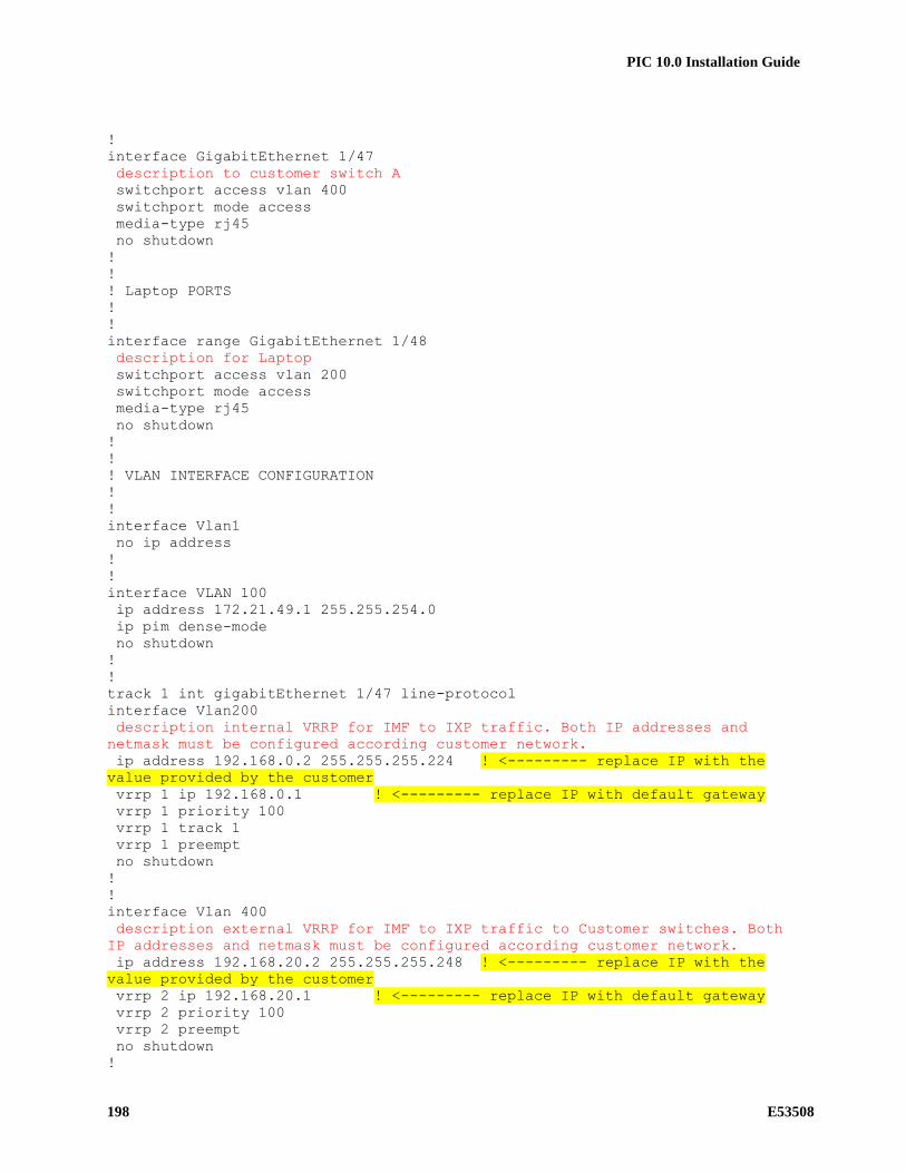
PIC 10.0 Installation Guide
198 E53508
!
interface GigabitEthernet 1/47
description to customer switch A
switchport access vlan 400
switchport mode access
media-type rj45
no shutdown
!
!
! Laptop PORTS
!
!
interface range GigabitEthernet 1/48
description for Laptop
switchport access vlan 200
switchport mode access
media-type rj45
no shutdown
!
!
! VLAN INTERFACE CONFIGURATION
!
!
interface Vlan1
no ip address
!
!
interface VLAN 100
ip address 172.21.49.1 255.255.254.0
ip pim dense-mode
no shutdown
!
!
track 1 int gigabitEthernet 1/47 line-protocol
interface Vlan200
description internal VRRP for IMF to IXP traffic. Both IP addresses and
netmask must be configured according customer network.
ip address 192.168.0.2 255.255.255.224 ! <--------- replace IP with the
value provided by the customer
vrrp 1 ip 192.168.0.1 ! <--------- replace IP with default gateway
vrrp 1 priority 100
vrrp 1 track 1
vrrp 1 preempt
no shutdown
!
!
interface Vlan 400
description external VRRP for IMF to IXP traffic to Customer switches. Both
IP addresses and netmask must be configured according customer network.
ip address 192.168.20.2 255.255.255.248 ! <--------- replace IP with the
value provided by the customer
vrrp 2 ip 192.168.20.1 ! <--------- replace IP with default gateway
vrrp 2 priority 100
vrrp 2 preempt
no shutdown
!

PIC 10.0 Installation Guide
E53508 199
!
no ip http server
no ip http secure-server
!
ip route 0.0.0.0 0.0.0.0 192.168.20.6 1 ! <--------- replace IP with
customer default gateway
!
!
line con 0
password ***** ! <--------- replace ***** with password specified in
password dragon as Cisco telnet
login
!
logging 172.21.49.10
!
no cdp run
!
end
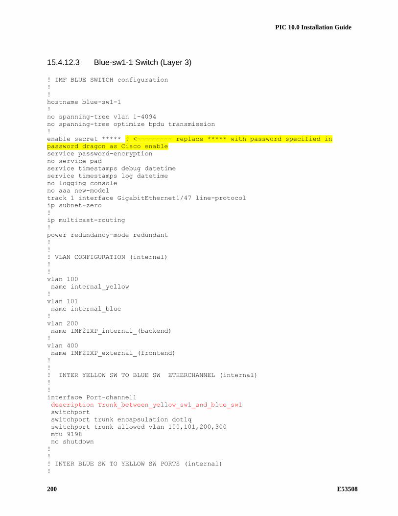
PIC 10.0 Installation Guide
200 E53508
15.4.12.3 Blue-sw1-1 Switch (Layer 3)
! IMF BLUE SWITCH configuration
!
!
hostname blue-sw1-1
!
no spanning-tree vlan 1-4094
no spanning-tree optimize bpdu transmission
!
enable secret ***** ! <--------- replace ***** with password specified in
password dragon as Cisco enable
service password-encryption
no service pad
service timestamps debug datetime
service timestamps log datetime
no logging console
no aaa new-model
track 1 interface GigabitEthernet1/47 line-protocol
ip subnet-zero
!
ip multicast-routing
!
power redundancy-mode redundant
!
!
! VLAN CONFIGURATION (internal)
!
!
vlan 100
name internal_yellow
!
vlan 101
name internal_blue
!
vlan 200
name IMF2IXP_internal_(backend)
!
vlan 400
name IMF2IXP_external_(frontend)
!
!
! INTER YELLOW SW TO BLUE SW ETHERCHANNEL (internal)
!
!
interface Port-channel1
description Trunk_between_yellow_sw1_and_blue_sw1
switchport
switchport trunk encapsulation dot1q
switchport trunk allowed vlan 100,101,200,300
mtu 9198
no shutdown
!
!
! INTER BLUE SW TO YELLOW SW PORTS (internal)
!

PIC 10.0 Installation Guide
E53508 201
!
Interface range GigabitEthernet 1/1 - 2
description ISL_between_blue_sw1_and_yellow_sw1
switchport trunk encapsulation dot1q
switchport trunk allowed vlan 100,101,200,300
switchport mode trunk
switchport nonegotiate
mtu 9198
channel-group 1 mode active
no shutdown
!
!
! IMF Servers PORTS
!
!
interface range GigabitEthernet 1/3 - 8
description IMF servers ports
switchport trunk encapsulation dot1q
switchport mode trunk
mtu 9198
no shutdown
!
!
! EAGLE PORTS
!
!
interface range GigabitEthernet 1/9 - 46
description Eagle FC or STC ports
switchport access vlan 101
switchport mode access
mtu 9198
no shutdown
!
!
! PORT TO CUSTOMER SWITCH B
!
!
interface GigabitEthernet 1/47
description to customer switch B
switchport access vlan 400
switchport mode access
media-type rj45
no shutdown
!
!
! Laptop PORTS
!
!
interface range GigabitEthernet 1/48
description for Laptop
switchport access vlan 200
switchport mode access
media-type rj45
no shutdown
!
!

PIC 10.0 Installation Guide
202 E53508
! VLAN INTERFACE CONFIGURATION
!
!
interface Vlan1
no ip address
!
!
interface VLAN 101
ip address 172.22.49.1 255.255.254.0
ip pim dense-mode
no shutdown
!
!
track 1 int gigabitEthernet 1/47 line-protocol
interface Vlan200
description internal VRRP for IMF to IXP traffic. Both IP addresses and
netmask must be configured according customer network.
ip address 192.168.0.3 255.255.255.224 ! <--------- replace IP with the
value provided by the customer
vrrp 1 ip 192.168.0.1 ! <--------- replace IP with default gateway
vrrp 1 priority 99
vrrp 1 track 1
vrrp 1 preempt
no shutdown
!
!
interface Vlan 400
description external VRRP for IMF to IXP traffic to Customer switches. Both
IP addresses and netmask must be configured according customer network.
ip address 192.168.20.3 255.255.255.248 ! <--------- replace IP with the
value provided by the customer
vrrp 2 ip 192.168.20.1 ! <--------- replace IP with default gateway
vrrp 2 priority 99
vrrp 2 preempt
no shutdown
!
!
no ip http server
no ip http secure-server
!
ip route 0.0.0.0 0.0.0.0 192.168.20.6 1 ! <--------- replace IP with
customer default gateway
!
!
line con 0
password ***** ! <--------- replace ***** with password specified in
password dragon as Cisco telnet
login
!
logging 172.22.49.10
!
no cdp run
!
end

PIC 10.0 Installation Guide
E53508 203
15.4.12.4 Single Switch yellow-blue-sw1-1 (Layer 2)
enable secret ***** ! <--------- replace ***** with password specified in
password dragon as Cisco enable
service password-encryption
no service pad
service timestamps debug uptime
service timestamps log uptime
service compress-config
!
hostname yellow-blue-sw1-1
!
no logging console
!
no aaa new-model
ip subnet-zero
!
ip multicast-routing
vtp mode transparent
!
!
!
power redundancy-mode redundant
no file verify auto
spanning-tree mode pvst
no spanning-tree optimize bpdu transmission
spanning-tree extend system-id
!
!
! VLAN CONFIGURATION (internal)
!
!
vlan internal allocation policy ascending
!
vlan 100
name internal_yellow
!
vlan 101
name internal_blue
!
vlan 200
name IMF2IXP_internal_(backend)
!
!
! IMF Servers PORTS
!
!
interface range GigabitEthernet1/1 - 8
description for IMF 1A external + internal networks port
switchport trunk encapsulation dot1q
switchport trunk allowed vlan 1,100,101,200
switchport mode trunk
mtu 9198
spanning-tree portfast trunk
!

PIC 10.0 Installation Guide
204 E53508
!
! EAGLE PORTS
!
!
interface range GigabitEthernet1/9 - 27
description yellow network port for Eagle connectivity
switchport access vlan 100
switchport mode access
mtu 9198
spanning-tree portfast
!
!
interface range GigabitEthernet1/28 - 46
description blue network port for Eagle connectivity
switchport access vlan 101
switchport mode access
mtu 9198
spanning-tree portfast
!
!
! PORT TO CUSTOMER SWITCH A
!
!
interface GigabitEthernet1/47
description port where customer is connected to IMF
switchport access vlan 200
switchport mode access
media-type rj45
!
!
! Laptop PORTS
!
!
interface range GigabitEthernet 1/48
description for Laptop
switchport access vlan 200
switchport mode access
media-type rj45
no shutdown
!
!
! VLAN INTERFACE CONFIGURATION
!
!
interface Vlan1
no ip address
!
interface Vlan100
ip address 172.21.49.1 255.255.254.0
no ip route-cache cef
no ip route-cache
no shutdown
!
interface Vlan101
ip address 172.22.49.1 255.255.254.0
no ip route-cache cef

PIC 10.0 Installation Guide
E53508 205
no ip route-cache
no shutdown
!
!
interface Vlan200
ip address 10.27.56.166 255.255.255.240 ! <--------- replace IP with an
address from customer network
no shutdown
!
no ip http server
no ip http secure-server
!
ip route 0.0.0.0 0.0.0.0 10.248.4.17 1 ! <--------- replace IP with
customer default gateway
!
!
logging 172.21.49.10
no cdp run
!
line con 0
password ***** ! <--------- replace ***** with password specified in
password dragon as Cisco telnet
login
!
!
!
End

PIC 10.0 Installation Guide
206 E53508
15.4.13 IMF MTU Configurations
On IMF in order to support Fast Copy, the MTU of the bond0, bond0.100 and bond0.101 interfaces is configured to
2000, however Cisco switch 2950 doesnitch IPopulate a column called , can cause temporary bridging loops.. In the
s configured globably for the switch unlike Cisco 4948 switch, where MTU can be configured per interface. Usually
the Cisco switches are not used to monitor the Fast Copy traffic and they may be configured with default MTU of
1500, however the MTU can be configured to different value as per the switch configuration. Following table can be
taken as reference for MTU.
Cisco Switch XMF Mode MTU
4948 All 2000
4948EF All 2000

PIC 10.0 Installation Guide
E53508 207
15.4.13.1 Procedure to configure the MTU
S
T
E
P
#
Steps to be completed.
This procedure outlines the steps for configuring MTU on
Cisco 2950 Switches and IMFs T1100
1 Take note of existing Switch Connections.
Take note of all existing Yellow and Blue Switch connections.
2 Copy blue-sw1-1 running config to startup config
bue-sw1-1# copy run start
3 Copy yellow-sw1-1 running config to startup
config
yellow-sw1-1# copy run start
4 Set blue-sw1-1 switch MTU setting
blue-sw1-1(config)#system mtu 1530
5 Set yellow-sw1-1 switch MTU setting
yellow-sw1-1(config)#system mtu 1530
6 Set Stand-by IMF eth91 MTU to 1530
1. Add MTU="1530" to ifcfg-eth91 file under /etc/sysconfig/network-scripts Initiate service network restart
7 Set Stand-by IMF bond0 MTU to 1530
1. Add MTU="1530" to ifcfg-bond0 file under /etc/sysconfig/network-scripts
2. Initiate service network restart
8 Set Stand-by IMF bond0.100 MTU to 1530
1. Add MTU="1530" to ifcfg-bond0.100 file under /etc/sysconfig/network-scripts
2. Initiate service network restart
9 Set Stand-by IMF bond0.101 MTU to 1530
1. Add MTU="1530" to ifcfg-bond0.101 file under /etc/sysconfig/network-scripts
2. Initiate service network restart
10 Save Cisco 2950 yellow-sw1-1 running config to
startup config
2. yellow-sw1-1# copy run start
11 Save Cisco 2950 blue-sw1-1 running config to
startup config
3. blue-sw1-1# copy run start

PIC 10.0 Installation Guide
208 E53508
16 APPENDIX: CAPACITY MANAGEMENT PROTRAQ CONFIGURATIONS

PIC 10.0 Installation Guide
E53508 209
Pic_UsageStat_Mn.fse
SECTION:MAIN
# ProTraq
# Copyright (c) 2003, 2014, Oracle and/or its affiliates. All rights reserved.
# PIC_UsageStat_Mn, generated Tue Aug 05 08:07:48 EDT 2014
# PIC input bandwidth per server and per minute v1.0
VERSION:600
DLL:FSEQOS
MODE:AFTER
DESTINATION::PIC_UsageStats_Mn
ALARMPERIOD:60
ALARMSERVER::0
STATPERIOD:60:1814400
COMMENT:PIC input bandwidth per server and per minute v1.0
POINTCODEFORMAT:0:0:8:8:8:0
INSTANCE:
INSTANCEOID:
SECTION:CORNER:QUERY
NAME:PDU
EXPR:A
COND:A:Unit:=:1
SECTION:COLUMN:0:FIELD:Hostname of server (if applicable)
NAME:Server
STRING:Hostname:Hostname:Hostname:Host name of the server processing this flow.
SIZE:128:DATA:MANDATORY::128
ORACLE:VARCHAR2
SECTION:COLUMN:1:CUMULATIVE:Average Mbps per server to be compared to license RTU per server
NAME:LicensedMbps
FIELD:KbpsTotal
SCALE:1000
FILTER:0
SECTION:LINE:0:TOP:30:0:2
NAME:perServer
CRITERIA:Hostname:999:9999
ORDER:1:0
FILTER:1
EXPR:( C AND F AND G ) OR D
COND:C:CollectionPoint:=:ETH
COND:D:CollectionPoint:=:XBFINAL
COND:F:Direction:=:1
COND:G:DataFlow:<>:eth0*
SECTION:LINE:1:QUERY:30:0:6:EXCLUSIVE
NAME:Mediation Protocol 2
EXPR:( A OR B ) AND C AND ( E OR F OR G OR H OR I OR J OR K OR L )
COND:A:Role:=:4
COND:B:Role:=:5
COND:C:CollectionPoint:=:XBFINAL
COND:E:DataFlow:=:*LTE--DIAMETER-GY-rec
COND:F:DataFlow:=:*LTE--DIAMETER-S9-rec
COND:G:DataFlow:=:*LTE--RAN-EMM-reconst
COND:H:DataFlow:=:*LTE--GTP-v2-Mobility
COND:I:DataFlow:=:*LTE--RAN-ESM-reconst
COND:J:DataFlow:=:*RAN--CC2
COND:K:DataFlow:=:*SS7--SIGTRAN-TRANSPO
COND:L:DataFlow:=:*SS7--EISUP-reconstit
SECTION:LINE:2:QUERY:30:0:7:EXCLUSIVE
NAME:Mediation Protocol
EXPR:( A OR B ) AND C
COND:A:Role:=:4
COND:B:Role:=:5
COND:C:CollectionPoint:=:XBFINAL
SECTION:LINE:3:QUERY:30:0:4:EXCLUSIVE

PIC 10.0 Installation Guide
210 E53508
NAME:Probed Acquisition
EXPR:A AND B AND C AND D
COND:A:Role:=:2
COND:B:CollectionPoint:=:ETH
COND:C:Direction:=:1
COND:D:DataFlow:<>:eth0*
SECTION:LINE:4:QUERY:30:0:5:EXCLUSIVE
NAME:Integrated Acquisition
EXPR:A AND B AND C
COND:A:Role:=:1
COND:B:CollectionPoint:=:LINK
COND:C:Direction:=:1

PIC 10.0 Installation Guide
E53508 211
PIC_UsageStat.fse
SECTION:MAIN
# ProTraq
# Copyright (c) 2003, 2014, Oracle and/or its affiliates. All rights reserved.
# PIC_UsageStat, generated Tue Aug 05 05:49:21 EDT 2014
# Licensed Mbps average, min and max over 1 hour v1.0
VERSION:600
DLL:FSEQOS
MODE:AFTER
DESTINATION::PIC_UsageStats
ALARMPERIOD:1800
ALARMSERVER::0
STATPERIOD:3600:6048000
COMMENT:Licensed Mbps average, min and max over 1 hour v1.0
POINTCODEFORMAT:0:0:8:8:8:0
INSTANCE:
INSTANCEOID:
SECTION:COLUMN:0:FIELD:Hostname
NAME:Server
STRING:Server:Server:Server:Hostname of server (if applicable)
SIZE:128:DATA:MANDATORY::128
ORACLE:VARCHAR2
SECTION:COLUMN:1:CUMULATIVE:Average throughput
NAME:LicensedMbps
FIELD:LicensedMbps
SCALE:30
FILTER:0
SECTION:COLUMN:2:CUMULATIVE:Highest average in a minute
NAME:MaxMbps
FIELD:LicensedMbps
SCALE:1
RESULT:MAX
FILTER:0
SECTION:COLUMN:3:CUMULATIVE:Lowest average over one minute
NAME:MinMbps
FIELD:LicensedMbps
SCALE:1
RESULT:MIN
FILTER:0
SECTION:LINE:0:TOP:30:0:1:EXCLUSIVE
NAME:perServer
CRITERIA:Server:200:200
ORDER:1:0
FILTER:1
EXPR:A
COND:A:Line:=:perServer*
SECTION:LINE:1:QUERY:30:0:5:EXCLUSIVE
NAME:Mediation Protocol 2
EXPR:A
COND:A:Line:=:Mediation Protocol 2
SECTION:LINE:2:QUERY:30:0:6:EXCLUSIVE
NAME:Mediation Protocol
EXPR:A
COND:A:Line:=:Mediation Protocol
SECTION:LINE:3:QUERY:30:0:3:EXCLUSIVE
NAME:Probed Acquisition
EXPR:A
COND:A:Line:=:Probed Acquisition
SECTION:LINE:4:QUERY:30:0:4:EXCLUSIVE
NAME:Integrated Acquisition

PIC 10.0 Installation Guide
212 E53508
EXPR:A
COND:A:Line:=:Integrated Acquisition

PIC 10.0 Installation Guide
E53508 213
17 APPENDIX: HOW TO CONFIGURE NTP
The goal of this MOP is to reach the targeted NTP precision on the DS Wiki
http://cqweb/wiki/index.php/How_to_check_the_NTP_synchronization
Delay: Should be bellow 10 ms.
Offset: Should be bellow 1 ms.
17.1 NTP architecture
Configure two Tekelec servers as Tekelec NTP taking in account the preference described below.
On these servers NTP configure one or more customer NTP and the second Tekelec NTP as a peer. (see platcfg
screenshot below). Make sure each Tekelec NTP are connected to “independent” NTP and don’t share the customer
NTP servers.
On all other servers use these Tekelec NTP as ntpserver1 and ntpserver2. (see platcfg screenshot below)
Don’t configure the customer NTP as backup of the Tekelec NTP you selected!
If there are remote site(s) with poor NTP synchronization use some local servers as Tekelec NTP. This is especially
the case when you have xMF or IXP installed on site in different regions from a big country and using a single NSP.
17.2 Check the NTP precision
Wait sometime after the configuration and check the NTP using the command ntpq –p on each server [cfguser@ixp0051-1z ~]$ ntpq -p
remote refid st t when poll reach delay offset jitter
==============================================================================
*ntpserver1 10.16.0.2 3 u 1 16 377 0.180 1.013 0.023
+ntpserver2 192.5.41.41 2 u 1 16 377 0.292 9.233 0.044
+ntpserver3 192.5.41.41 2 u 2 16 377 0.264 1.108 0.064
Customer
NTP 1
Customer
NTP 2
Tekelec
NTP 1
xMF 1 xMF n IXP 1-1a IXP n
Peer
Prefer
ntpserver1
Backup
ntpserver2
Remote site
Tekelec
NTP 1
Remote site
xMF nRemote site
IXP 1-1a
Remote site
IXP n
Tekelec
NTP 2Remote site
Tekelec
NTP 2
Peer
Prefered Tekelec NTP:
* PM&C
* NSP Apache or OneBox
* NSP WL2
* NSP WL1
* NSP Oracle
* IXP 1a
* IXP 1b
* xMF 1a
* xMF 1b
Remote site
xMF 1
Remote
Customer
NTP 3
Remote
Customer
NTP 2
Remote
Customer
NTP 1

PIC 10.0 Installation Guide
214 E53508
18 APPENDIX: NETWORK PORTS BETWEEN PIC COMPONENTS

PIC 10.0 Installation Guide
E53508 215
Client Source IP Server Destination IP Port Transport Protocol Description by port VLAN by port
Optional
NSP_PRIMARY Weblogic server xMF IMF and PMF servers 7 TCP/UDP echo Linux echo test protocol Admin N
NSP_SECONDARY Weblogic server xMF IMF and PMF servers 7 TCP/UDP echo Linux echo test protocol Admin N
xMF IMF and PMF servers NSP_PRIMARY Weblogic server 7 TCP/UDP echo Linux echo test protocol Admin N
xMF IMF and PMF servers NSP_SECONDARY Weblogic server 7 TCP/UDP echo Linux echo test protocol Admin N
Tekelec_Admin Admin remote or jumpoff or VPN Customer_DWH Non IXP Oracle server 22 TCP ssh Linux Secured Shell including sftp Admin N
NSP_PRIMARY Weblogic server Customer_source SFTP source for automatic FSE updates
22 TCP ssh Linux Secured Shell including sftp Admin N
Tekelec_Admin Admin remote or jumpoff or VPN ILO ILO range 22 TCP ssh Linux Secured Shell including sftp Admin N
PM&C DL360 PMAC NSP_APACHE_BACK NSP backend side (application) 22 TCP ssh Linux Secured Shell including sftp Admin N
Tekelec_Admin Admin remote or jumpoff or VPN NSP_APACHE_BACK NSP backend side (application) 22 TCP ssh Linux Secured Shell including sftp Admin N
PM&C DL360 PMAC NSP_ORACLE Central configuration 22 TCP ssh Linux Secured Shell including sftp Admin N
Tekelec_Admin Admin remote or jumpoff or VPN NSP_ORACLE Central configuration 22 TCP ssh Linux Secured Shell including sftp Admin N
PM&C DL360 PMAC NSP_PRIMARY Weblogic server 22 TCP ssh Linux Secured Shell including sftp Admin N
Tekelec_Admin Admin remote or jumpoff or VPN NSP_PRIMARY Weblogic server 22 TCP ssh Linux Secured Shell including sftp Admin N
PM&C DL360 PMAC NSP_SECONDARY Weblogic server 22 TCP ssh Linux Secured Shell including sftp Admin N
Tekelec_Admin Admin remote or jumpoff or VPN NSP_SECONDARY Weblogic server 22 TCP ssh Linux Secured Shell including sftp Admin N
PM&C DL360 PMAC OA Blade on-board administrator 22 TCP ssh Linux Secured Shell including sftp Admin N
Tekelec_Admin Admin remote or jumpoff or VPN PM&C DL360 PMAC 22 TCP ssh Linux Secured Shell including sftp Admin N
PM&C DL360 PMAC SAN_Controller P2000 or MSA2012 controllers 22 TCP ssh Linux Secured Shell including sftp Admin N
Tekelec_Admin Admin remote or jumpoff or VPN SAN_Controller P2000 or MSA2012 controllers 22 TCP ssh Linux Secured Shell including sftp Admin N
PM&C DL360 PMAC SAN_SWITCH Brocade switch 22 TCP ssh Linux Secured Shell including sftp Admin N
Tekelec_Admin Admin remote or jumpoff or VPN SAN_SWITCH Brocade switch 22 TCP ssh Linux Secured Shell including sftp Admin N
NSP_PRIMARY Weblogic server xMF IMF and PMF servers 22 TCP ssh Linux Secured Shell including sftp Admin N
NSP_SECONDARY Weblogic server xMF IMF and PMF servers 22 TCP ssh Linux Secured Shell including sftp Admin N
PM&C DL360 PMAC xMF IMF and PMF servers 22 TCP ssh Linux Secured Shell including sftp Admin N
Tekelec_Admin Admin remote or jumpoff or VPN xMF IMF and PMF servers 22 TCP ssh Linux Secured Shell including sftp Admin N
PM&C DL360 PMAC SWITCH Cisco managed switches 23 TCP telnet Telnet protocol Admin N
NSP_PRIMARY Weblogic server Customer_MAIL Mail server to forward alarms 25 TCP smtp Simple Mail Transfer Protocol Admin Y
NSP_SECONDARY Weblogic server Customer_MAIL Mail server to forward alarms 25 TCP smtp Simple Mail Transfer Protocol Admin Y
NSP_APACHE_BACK NSP backend side (application) PM&C DL360 PMAC 69 UDP tftp Trivial File Transfer Protocol Admin LAN
NSP_ORACLE Central configuration PM&C DL360 PMAC 69 UDP tftp Trivial File Transfer Protocol Admin LAN
NSP_PRIMARY Weblogic server PM&C DL360 PMAC 69 UDP tftp Trivial File Transfer Protocol Admin LAN
NSP_SECONDARY Weblogic server PM&C DL360 PMAC 69 UDP tftp Trivial File Transfer Protocol Admin LAN
SWITCH Cisco managed switches PM&C DL360 PMAC 69 UDP tftp Trivial File Transfer Protocol Admin LAN
Tekelec_Admin Admin remote or jumpoff or VPN Customer_DWH Non IXP Oracle server 80 TCP http Hyper Text Transfer Protocol (web) Admin/Data OR HTTPS
Tekelec_Admin Admin remote or jumpoff or VPN ILO ILO range 80 TCP http Hyper Text Transfer Protocol (web) Admin/Data OR HTTPS
Customer_Workstation End user LAN NSP_APACHE_FRONT NSP frontend side (web clients) 80 TCP http Hyper Text Transfer Protocol (web) Admin/Data OR HTTPS
Tekelec_Admin Admin remote or jumpoff or VPN NSP_APACHE_FRONT NSP frontend side (web clients) 80 TCP http Hyper Text Transfer Protocol (web) Admin/Data OR HTTPS

PIC 10.0 Installation Guide
216 E53508
OA Blade on-board administrator PM&C DL360 PMAC 80 TCP http Hyper Text Transfer Protocol (web) Admin/Data OR HTTPS
MSW Legacy Message Switch NTP_Server Customer NTP and/or NSP Apache Back End
123 UDP ntp Network Time Protocol (sync) Admin N
NSP_APACHE_BACK NSP backend side (application) NTP_Server Customer NTP and/or NSP Apache Back End
123 UDP ntp Network Time Protocol (sync) Admin N
NSP_ORACLE Central configuration NTP_Server Customer NTP and/or NSP Apache Back End
123 UDP ntp Network Time Protocol (sync) Admin N
NSP_PRIMARY Weblogic server NTP_Server Customer NTP and/or NSP Apache Back End
123 UDP ntp Network Time Protocol (sync) Admin N
NSP_SECONDARY Weblogic server NTP_Server Customer NTP and/or NSP Apache Back End
123 UDP ntp Network Time Protocol (sync) Admin N
OA Blade on-board administrator NTP_Server Customer NTP and/or NSP Apache Back End
123 UDP ntp Network Time Protocol (sync) Admin N
PM&C DL360 PMAC NTP_Server Customer NTP and/or NSP Apache Back End
123 UDP ntp Network Time Protocol (sync) Admin N
SAN_Controller P2000 or MSA2012 controllers NTP_Server Customer NTP and/or NSP Apache Back End
123 UDP ntp Network Time Protocol (sync) Admin N
SAN_Switch Brocade switch NTP_Server Customer NTP and/or NSP Apache Back End
123 UDP ntp Network Time Protocol (sync) Admin N
SWITCH Cisco managed switches NTP_Server Customer NTP and/or NSP Apache Back End
123 UDP ntp Network Time Protocol (sync) Admin N
Tekelec_Admin Admin remote or jumpoff or VPN NTP_Server Customer NTP and/or NSP Apache Back End
123 UDP ntp Network Time Protocol (sync) Admin N
xMF IMF and PMF servers NTP_Server Customer NTP and/or NSP Apache Back End
123 UDP ntp Network Time Protocol (sync) Admin N
NSP_SECONDARY Weblogic server Customer_SNMP Alarm forwarding destination 161 UDP snmp.a Simple Network Management Protocol (MIB query)
Admin N
Customer_SNMP Alarm forwarding destination NSP_PRIMARY Weblogic server 161 UDP snmp.a Simple Network Management Protocol (MIB query)
Admin N
NSP_PRIMARY Weblogic server Customer_SNMP Alarm forwarding destination 162 UDP snmp.b Simple Network Management Protocol (traps)
Admin Y
OA Blade on-board administrator NSP_PRIMARY Weblogic server 162 UDP snmp.b Simple Network Management Protocol (traps)
Admin Y
SAN_Controller P2000 or MSA2012 controllers NSP_PRIMARY Weblogic server 162 UDP snmp.b Simple Network Management Protocol (traps)
Admin Y
SAN_SWITCH Brocade switch NSP_PRIMARY Weblogic server 162 UDP snmp.b Simple Network Management Protocol (traps)
Admin Y
Tekelec_Admin Admin remote or jumpoff or VPN Customer_DWH Non IXP Oracle server 443 TCP/UDP https Hyper Text Transfer Protocol Secure (web) Data N
Tekelec_Admin Admin remote or jumpoff or VPN ILO ILO range 443 TCP/UDP https Hyper Text Transfer Protocol Secure (web) Data N
Customer_Workstation End user LAN NSP_APACHE_FRONT NSP frontend side (web clients) 443 TCP/UDP https Hyper Text Transfer Protocol Secure (web) Data N
Tekelec_Admin Admin remote or jumpoff or VPN NSP_APACHE_FRONT NSP frontend side (web clients) 443 TCP/UDP https Hyper Text Transfer Protocol Secure (web) Data N
Tekelec_Admin Admin remote or jumpoff or VPN OA Blade on-board administrator 443 TCP/UDP https Hyper Text Transfer Protocol Secure (web) Data N
Tekelec_Admin Admin remote or jumpoff or VPN PM&C DL360 PMAC 443 TCP/UDP https Hyper Text Transfer Protocol Secure (web) Data N
Tekelec_Admin Admin remote or jumpoff or VPN SAN_Controller P2000 or MSA2012 controllers 443 TCP/UDP https Hyper Text Transfer Protocol Secure (web) Data N
Tekelec_Admin Admin remote or jumpoff or VPN SAN_SWITCH Brocade switch 443 TCP/UDP https Hyper Text Transfer Protocol Secure (web) Data N
Tekelec_Admin Admin remote or jumpoff or VPN SWITCH Cisco managed switches 443 TCP/UDP https Hyper Text Transfer Protocol Secure (web) Data N
MSW Legacy Message Switch MSW Legacy Message Switch 1099 TCP RMI RMI Registry Java Remote Procedure Invokation
Admin N
NSP_PRIMARY Weblogic server xMF IMF and PMF servers 1099 TCP RMI RMI Registry Java Remote Procedure Invokation
Admin N
NSP_SECONDARY Weblogic server xMF IMF and PMF servers 1099 TCP RMI RMI Registry Java Remote Procedure Invokation
Admin N

PIC 10.0 Installation Guide
E53508 217
Tekelec_Admin Admin remote or jumpoff or VPN IXP_XDR Pool xDR storage 1158 TCP OracleEM.a Oracle Database remote console Admin N
Tekelec_Admin Admin remote or jumpoff or VPN NSP_ORACLE Central configuration 1158 TCP OracleEM.a Oracle Database remote console Admin N
NSP_PRIMARY Weblogic server Customer_DWH Non IXP Oracle server 1521 TCP OracleNet8 Database queries and insertion Data N
NSP_SECONDARY Weblogic server Customer_DWH Non IXP Oracle server 1521 TCP OracleNet8 Database queries and insertion Data N
Tekelec_Admin Admin remote or jumpoff or VPN Customer_DWH Non IXP Oracle server 1521 TCP OracleNet8 Database queries and insertion Data N
NSP_PRIMARY Weblogic server IXP_XDR Pool xDR storage 1521 TCP OracleNet8 Database queries and insertion Data N
NSP_SECONDARY Weblogic server IXP_XDR Pool xDR storage 1521 TCP OracleNet8 Database queries and insertion Data N
Tekelec_Admin Admin remote or jumpoff or VPN IXP_XDR Pool xDR storage 1521 TCP OracleNet8 Database queries and insertion Data N
Tekelec_Admin Admin remote or jumpoff or VPN NSP_ORACLE Central configuration 1521 TCP OracleNet8 Database queries and insertion Data N
xMF IMF and PMF servers NSP_ORACLE Central configuration 1521 TCP OracleNet8 Database queries and insertion Data N
NSP_PRIMARY Weblogic server XMF IMF and PMF servers 3306 TCP MySql My SQL database queries (config DB) Admin N
NSP_PRIMARY Weblogic server MSW Legacy Message Switch 3333 TCP RMI (JMX) Java Management Extension Remote Invokation
Data N
Tekelec_Admin Admin remote or jumpoff or VPN IXP_XDR Pool xDR storage 5520 TCP OracleEM.b Oracle database remote console Admin N
Tekelec_Admin Admin remote or jumpoff or VPN NSP_ORACLE Central configuration 5520 TCP OracleEM.b Oracle database remote console Admin N
Tekelec_Admin Admin remote or jumpoff or VPN MSW Legacy Message Switch 5631 TCP PCanyw.a PC Anywhere data Admin Y
Tekelec_Admin Admin remote or jumpoff or VPN MSW Legacy Message Switch 5632 UDP PCanyw.b PC Anywhere status Admin Y
Tekelec_Admin Admin remote or jumpoff or VPN MSW Legacy Message Switch 5900 TCP VNC Windows Remote Console Admin Y
Tekelec_Admin Admin remote or jumpoff or VPN MSW Legacy Message Switch 6969 TCP JMX(http) Java management eXtension, admin console
Admin OBSOLETE
Tekelec_Admin Admin remote or jumpoff or VPN NSP_PRIMARY Weblogic server 8001 TCP nsp.admin.ldap NSP Weblogic administration, LDAP, console, sync
Admin N
Tekelec_Admin Admin remote or jumpoff or VPN MSW Legacy Message Switch 8080 TCP http(SM) Hypertext Transfer Protocol for System Mgmt
Admin N
xMF IMF and PMF servers Customer_TADAPT Customer 3rd party application 9090 TCP MFP.a Proprietary Message Flow Protocol, PDU Data TADAPT
Tekelec_Admin Admin remote or jumpoff or VPN Customer_DWH Non IXP Oracle server 9300 TCP iLO.a HP Integrated Lights Out, shared remote console
Management N
Tekelec_Admin Admin remote or jumpoff or VPN ILO ILO range 9300 TCP iLO.a HP Integrated Lights Out, shared remote console
Management N
NSP_PRIMARY Weblogic server xMF IMF and PMF servers 15616 TCP JDBC Java DataBase Connectivity (config DB) Admin N
NSP_SECONDARY Weblogic server xMF IMF and PMF servers 15616 TCP JDBC Java DataBase Connectivity (config DB) Admin N
xMF IMF and PMF servers NSP_PRIMARY Weblogic server 16810 TCP inetsync COMCOL internetwork synchronization Admin N
NSP_PRIMARY Weblogic server xMF IMF and PMF servers 16810 TCP inetsync COMCOL internetwork synchronization Admin N
xMF IMF and PMF servers xMF IMF and PMF servers 16810 TCP inetsync COMCOL internetwork synchronization Admin N
xMF IMF and PMF servers NSP_PRIMARY Weblogic server 16878 TCP inetmerge COMCOL internetwork merge Admin N
NSP_PRIMARY Weblogic server XMF IMF and PMF servers 16878 TCP inetmerge COMCOL internetwork merge Admin N
xMF IMF and PMF servers XMF IMF and PMF servers 16878 TCP inetmerge COMCOL internetwork merge Admin N
Tekelec_Admin Admin remote or jumpoff or VPN Customer_DWH Non IXP Oracle server 17988 TCP iLO.b HP Integrated Lights Out, virtual media (CD)
Management N
Tekelec_Admin Admin remote or jumpoff or VPN ILO ILO range 17988 TCP iLO.b HP Integrated Lights Out, virtual media (CD)
Management N
Tekelec_Admin Admin remote or jumpoff or VPN Customer_DWH Non IXP Oracle server 17990 TCP iLO.c HP Integrated Lights Out, Console relay Management N
Tekelec_Admin Admin remote or jumpoff or VPN ILO ILO range 17990 TCP iLO.c HP Integrated Lights Out, Console relay Management N
NSP_PRIMARY Weblogic server xMF IMF and PMF servers 41000 TCP RMI-JMX-sec Remote Method Invokation for JMX, secured
Admin N

PIC 10.0 Installation Guide
218 E53508
NSP_SECONDARY Weblogic server xMF IMF and PMF servers 41000 TCP RMI-JMX-sec Remote Method Invokation for JMX, secured
Admin N
Tekelec_Admin Admin remote or jumpoff or VPN NSP_APACHE_BACK NSP backend side (application) 49696 TCP JMX(https) Java management eXtension, admin console secure
Admin N
Tekelec_Admin Admin remote or jumpoff or VPN NSP_ORACLE Central configuration 49696 TCP JMX(https) Java management eXtension, admin console secure
Admin N
Tekelec_Admin Admin remote or jumpoff or VPN NSP_PRIMARY Weblogic server 49696 TCP JMX(https) Java management eXtension, admin console secure
Admin N
Tekelec_Admin Admin remote or jumpoff or VPN NSP_SECONDARY Weblogic server 49696 TCP JMX(https) Java management eXtension, admin console secure
Admin N
Tekelec_Admin Admin remote or jumpoff or VPN xMF IMF and PMF servers 49696 TCP JMX(https) Java management eXtension, admin console secure
Admin N
Tekelec_Admin Admin remote or jumpoff or VPN NSP_PRIMARY Weblogic server 7001;7003
TCP jms,t3 NSP Weblogic, users, alarms and administration
Admin N
xMF IMF and PMF servers NSP_PRIMARY Weblogic server 7001;7003
TCP jms,t3 NSP Weblogic, users, alarms and administration
Admin N
Tekelec_Admin Admin remote or jumpoff or VPN NSP_SECONDARY Weblogic server 7001;7003
TCP jms,t3 NSP Weblogic, users, alarms and administration
Admin N
xMF IMF and PMF servers NSP_SECONDARY Weblogic server 7001;7003
TCP jms,t3 NSP Weblogic, users, alarms and administration
Admin N
xMF IMF and PMF servers NSP_PRIMARY Weblogic server na ICMP ICMP Ping connectivity tests Admin TEMPORARY
NSP_ORACLE Central configuration xMF IMF and PMF servers na ICMP ICMP Ping connectivity tests Admin TEMPORARY
NSP_PRIMARY Weblogic server NEPTUNE External probe Astellia neptune 80 TCP http Hyper Text Transfer Protocol (web) Admin/Data OR HTTPS
Tekelec_Admin Admin remote or jumpoff or VPN NEPTUNE External probe Astellia neptune 22222 TCP Neptune.https Astellia probe configuration Admin Y
NEPTUNE External probe Astellia neptune NSP_PRIMARY Weblogic server 162 UDP snmp.b Simple Network Management Protocol (traps)
Admin Y
Tekelec_Admin Admin remote or jumpoff or VPN TAP Splitter 80 TCP http Hyper Text Transfer Protocol (web) Admin/Data OR HTTPS
Tekelec_Admin Admin remote or jumpoff or VPN TELENA_FALCO TDM-SIGTRAN Converter 22 TCP ssh Linux Secured Shell including sftp Admin N
TELENA_FALCO TDM-SIGTRAN Converter NSP_PRIMARY Weblogic server 162 UDP snmp.b Simple Network Management Protocol (traps)
Admin Y
PIC 10.0 Installation Guide
E53508 219
19 APPENDIX: MY ORACLE SUPPORT (MOS)
MOS (https://support.oracle.com) is your initial point of contact for all product support and training needs. A
representative at Customer Access Support (CAS) can assist you with MOS registration.
Call the CAS main number at 1-800-223-1711 (toll-free in the US), or call the Oracle Support hotline for your local
country from the list at http://www.oracle.com/us/support/contact/index.html. When calling, make the selections in
the sequence shown below on the Support telephone menu:
1. Select 2 for New Service Request
2. Select 3 for Hardware, Networking and Solaris Operating System Support
3. Select 2 for Non-technical issue
You will be connected to a live agent who can assist you with MOS registration and provide Support Identifiers.
Simply mention you are a Tekelec Customer new to MOS.
MOS is available 24 hours a day, 7 days a week, 365 days a year.

PIC 10.0 Installation Guide
220 E53508
20 APPENDIX: LOCATE PRODUCT DOCUMENTATION ON THE ORACLE TECHNOLOGY NETWORK SITE
Oracle customer documentation is available on the web at the Oracle Technology Network (OTN) site,
http://docs.oracle.com. You do not have to register to access these documents. Viewing these files requires Adobe
Acrobat Reader, which can be downloaded at www.adobe.com.
1. Log into the Oracle Technology Network site at http://docs.oracle.com.
2. Under Applications, click the link for Communications.
The Oracle Communications Documentation window opens with Tekelec shown near the top.
3. Click Oracle Communications Documentation for Tekelec Products.
4. Navigate to your Product and then the Release Number, and click the View link (the Download link will retrieve
the entire documentation set).
5. To download a file to your location, right-click the PDF link and select Save Target As.