Phobos-BT-A---Instruction-manual.pdf - BFT Automation
12
D812868 00100_01 15-07-16 ISTRUZIONI DI INSTALLAZIONE INSTALLATION MANUAL INSTRUCTIONS D’INSTALLATION MONTAGEANLEITUNG INSTRUCCIONES DE INSTALACION INSTALLATIEVOORSCHRIFTEN AUTOMAZIONI A PISTONE PER CANCELLI A BATTENTE PISTON AUTOMATIONS FOR SWING GATES AUTOMATIONS A PISTON POUR PORTAILS BATTANTS ELEKTROMECHANISCHER DREHTORANTRIEB AUTOMATIZACIONES A PISTON PARA PORTONES CON BATIENTE AUTOMATISERINGSSYSTEMEN MET ZUIGER VOOR VLEUGELPOORTEN Attenzione! Leggere attentamente le “Avvertenze” all’interno! Caution! Read “Warnings” inside carefully! Attention! Veuillez lire attentivement les Avertissements qui se trouvent à l’intérieur! Achtung! Bitte lesen Sie aufmerksam die „Hinweise“ im Inneren! ¡Atención¡ Leer atentamente las “Advertencias” en el interior! Let op! Lees de “Waarschuwingen”tigre aan de binnenkant zorgvuldig! PHOBOS BT A25 PHOBOS BT A40
-
Upload
khangminh22 -
Category
Documents
-
view
5 -
download
0
Transcript of Phobos-BT-A---Instruction-manual.pdf - BFT Automation

D81
2868
001
00_0
1 15
-07-
16
ISTR
UZI
ON
I DI I
NST
ALL
AZI
ON
EIN
STA
LLAT
ION
MA
NU
AL
INST
RUC
TIO
NS
D’IN
STA
LLAT
ION
MO
NTA
GEA
NLE
ITU
NG
INST
RUCC
ION
ES D
E IN
STA
LACI
ON
INST
ALL
ATIE
VOO
RSCH
RIFT
EN
AUTOMAZIONI A PISTONE PER CANCELLI A BATTENTEPISTON AUTOMATIONS FOR SWING GATESAUTOMATIONS A PISTON POUR PORTAILS BATTANTSELEKTROMECHANISCHER DREHTORANTRIEBAUTOMATIZACIONES A PISTON PARA PORTONES CON BATIENTEAUTOMATISERINGSSYSTEMEN MET ZUIGER VOOR VLEUGELPOORTEN
Attenzione! Leggere attentamente le “Avvertenze” all’interno! Caution! Read “Warnings” inside carefully! Attention! Veuillez lire attentivement les Avertissements qui se trouvent à l’intérieur! Achtung! Bitte lesen Sie aufmerksam die „Hinweise“ im Inneren! ¡Atención¡ Leer atentamente las “Advertencias” en el interior! Let op! Lees de “Waarschuwingen”tigre aan de binnenkant zorgvuldig!
PHO
BOS
BT A
25PH
OBO
S BT
A40

AVVERTENZE PER L’INSTALLATORE
Tutto quello che non è espressamente previsto nel manuale d’installa-zione, non è permesso. ll buon funzionamento dell’operatore è garantito solo se vengono rispettati i dati riportati. La ditta non risponde dei danni causati dall’inosservanza delle indicazioni riportate in questo manuale.Lasciando inalterate le caratteristiche essenziali del prodotto, la Ditta si riserva di apportare in qualunque momento le modifiche che essa ritiene convenienti per migliorare tecnicamente, costruttivamente e commercialmente il prodotto, senza impegnarsi ad aggiornare la presente pubblicazione.
ATTENZIONE! Importanti istruzioni di sicurezza. Leggere e seguire atten-tamente tutte le avvertenze e le istruzioni che accompagnano il prodotto poiché un’installazione errata può causare danni a persone, animali o cose. Le avvertenze e le istruzioni forniscono importanti indicazioni riguardanti la sicurezza, l’installazione, l’uso e la manutenzione. Conservare le istruzioni per allegarle al fascicolo tecnico e per consultazioni future.SICUREZZA GENERALEQuesto prodotto è stato progettato e costruito esclusivamente per l’utilizzo indicato in questa documentazione. Usi diversi da quanto indicato potrebbero essere causa di danni al prodotto e di pericolo.- Gli elementi costruttivi della macchina e l’installazione devono essere in accordo con le seguenti Direttive Europee, ove applicabili: 2004/108/CE, 2006/95/CE, 2006/42/CE, 89/106/CE, 99/05/CE e loro modifiche successive. Per tutti i Paesi extra CEE, oltre alle norme nazionali vigenti, per un buon livello di sicurezza è opportuno rispettare anche le norme citate.
- La Ditta costruttrice di questo prodotto (di seguito “Ditta”) declina qualsiasi responsabilità derivante da un uso improprio o diverso da quello per cui è destinato e indicato nella presente documentazione nonché dall’inosservanza della Buona Tecnica nella costruzione delle chiusure (porte, cancelli, ecc.) e dalle deformazioni che potrebbero verificarsi durante l’uso.
- L’installazione deve essere eseguita da personale qualificato (installatore profes-sionale, secondo EN12635), nell’osservanza della Buona Tecnica e delle norme vigenti.
- Prima di installare il prodotto apportare tutte le modifiche strutturali relative alle realizzazione dei franchi di sicurezza a alla protezione o segregazione di tutte le zone di schiacciamento, cesoiamento, convogliamento e di pericolo in genere, secondo quanto previsto dalle norme EN 12604 ed 12453 o eventuali norme locali di installazione. Verificare che la struttura esistente abbia i necessari requisiti di robustezza e stabilità.
- Prima di iniziare l’installazione verificare l’integrità del prodotto.- La Ditta non è responsabile della inosservanza della Buona Tecnica nella costru-zione e manutenzione degli infissi da motorizzare, nonché delle deformazioni che dovessero intervenire nell’utilizzo.
- Verificare che l’intervallo di temperatura dichiarato sia compatibile con il luogo destinato all’installazione dell’automazione.
- Non installare questo prodotto in atmosfera esplosiva: la presenza di gas o fumi infiammabili costituisce un grave pericolo per la sicurezza.
- Togliere l’alimentazione elettrica, prima di qualsiasi intervento sull’impianto. Scollegare anche eventuali batterie tampone se presenti.
- Prima di collegare l’alimentazione elettrica, accertarsi che i dati di targa corrispon-dano ai quelli della rete di distribuzione elettrica e che a monte dell’impianto elettrico vi siano un interruttore differenziale e una protezione da sovracorrente adeguati. Prevedere sulla rete di alimentazione dell’automazione, un interruttore o un magnetotermico onnipolare che consenta la disconnessione completa nelle condizioni della categoria di sovratensione III.
- Verificare che a monte della rete di alimentazione, vi sia un interruttore differen-ziale con soglia non superiore a 0.03A e a quanto previsto dalle norme vigenti.
- Verificare che l’impianto di terra sia realizzato correttamente: collegare a terra tutte le parti metalliche della chiusura (porte, cancelli, ecc.) e tutti i componenti dell’impianto provvisti di morsetto di terra.
- L’installazione deve essere fatta utilizzando dispositivi di sicurezza e di comandi conformi alla EN 12978 e EN12453.
- Le forze di impatto possono essere ridotte mediante l’utilizzo di bordi deformabili.- Nel caso in cui le forze di impatto superino i valori previsti dalle norme, applicare dispositivi elettrosensibili o sensibili alla pressione.
- Applicare tutti i dispositivi di sicurezza (fotocellule, coste sensibili, ecc.) necessari a proteggere l’area da pericoli di impatto, schiacciamento, convogliamento, cesoiamento. Tenere in considerazione le normative e le direttive in vigore, i criteri della Buona Tecnica, l’utilizzo, l’ambiente di installazione, la logica di funzionamento del sistema e le forze sviluppate dall’automazione.
- Applicare i segnali previsti dalle normative vigenti per individuare le zone pericolose (i rischi residui). Ogni installazione deve essere identificata in modo visibile secondo quanto prescritto dalla EN13241-1.
- Successivamente al completamento dell’installazione, applicare una targa identificativa della porta/cancello
- Questo prodotto non può essere installato su ante che incorporano delle porte (a meno che il motore sia azionabile esclusivamente a porta chiusa).
- Se l’automazione è installata ad una altezza inferiore a 2,5 m o se è accessibile, è necessario garantire un adeguato grado di protezione delle parti elettriche e meccaniche.
- Solo per automazioni per serrande 1) Le parti in movimento del motore devono essere installate ad una altezza superiore a 2,5m al di sopra del pavimento o al di sopra di un altro livello che possa consentirne l’accesso.
2) Il motoriduttore deve essere installato in uno spazio segregato e provvisto di protezione in modo che sia accessibile solo con uso di utensili.
- Installare qualsiasi comando fisso in posizione tale da non causare pericoli e lontano da parti mobili. In particolare i comandi a uomo presente devono essere posizionati in vista diretta della parte guidata, e, a meno che non siano a chiave, devono essere installati a una altezza minima di 1,5 m e in modo tale da non essere accessibili al pubblico.
- Applicare almeno un dispositivo di segnalazione luminosa (lampeggiante) in posizione visibile, fissare inoltre alla struttura un cartello di Attenzione.
- Fissare in modo permanente una etichetta relativa al funzionamento dello sblocco manuale dell’automazione e apporla vicino all’organo di manovra.
- Assicurarsi che durante la manovra siano evitati o protetti i rischi meccanici ed in particolare l’impatto, lo schiacciamento, il convogliamento, il cesoiamento tra parte guidata e parti circostanti.
- Dopo aver eseguito l’installazione, assicurarsi che il settaggio dell’automazione motore sia correttamente impostato e che i sistemi di protezione e di sblocco funzionino correttamente.
- Usare esclusivamente parti originali per qualsiasi manutenzione o riparazione. La Ditta declina ogni responsabilità ai fini della sicurezza e del buon funziona-mento dell’automazione se vengono impiegati componenti di altri produttori.
- Non eseguire alcuna modifica ai componenti dell’automazione se non espres-samente autorizzata dalla Ditta.
- Istruire l’utilizzatore dell’impianto per quanto riguarda gli eventuali rischi residui, i sistemi di comando applicati e l’esecuzione della manovra apertura manuale in caso di emergenza: consegnare il manuale d’uso all’utilizzatore finale.
- Smaltire i materiali di imballo (plastica, cartone, polistirolo, ecc.) secondo quanto previsto dalle norme vigenti. Non lasciare buste di nylon e polistirolo alla portata dei bambini.
COLLEGAMENTIATTENZIONE! Per il collegamento alla rete utilizzare: cavo multipolare di sezione minima 5x1,5mm2 o 4x1,5mm2 per alimentazioni trifase oppure 3x1,5mm2 per alimentazioni monofase (a titolo di esempio, il cavo può essere del tipo H05RN-F con sezione 4x1.5mm2). Per il collegamento degli ausiliari utilizzare conduttori con sezione minima di 0,5 mm2.- Utilizzare esclusivamente pulsanti con portata non inferiore a 10A-250V.- I conduttori devono essere vincolati da un fissaggio supplementare in prossi-mità dei morsetti (per esempio mediante fascette) al fine di tenere nettamente separate le parti in tensione dalle parti in bassissima tensione di sicurezza.
- Il cavo di alimentazione, durante l’installazione, deve essere sguainato in modo da permettere il collegamento del conduttore di terra all’appropriato morsetto lasciando però i conduttori attivi il più corti possibile. Il conduttore di terra deve essere l’ultimo a tendersi in caso di allentamento del dispositivo di fissaggio del cavo.
ATTENZIONE! i conduttori a bassissima tensione di sicurezza devono essere fisicamente separati dai conduttori a bassa tensione.L’accessibilità alle parti in tensione deve essere possibile esclusivamente per il personale qualificato (installatore professionale)VERIFICA DELL’AUTOMAZIONE E MANUTENZIONEPrima di rendere definitivamente operativa l’automazione, e durante gli interventi di manutenzione, controllare scrupolosamente quanto segue:- Verificare che tutti i componenti siano fissati saldamente;- Verificare l’operazione di avvio e fermata nel caso di comando manuale.- Verificare la logica di funzionamento normale o personalizzata.- Solo per cancelli scorrevoli: verificare il corretto ingranamento cremagliera - pignone con un gioco di 2 mm lungo tutta la cremagliera; tenere la rotaia di scorrimento sempre pulita e libera da detriti.
-Solo per cancelli e porte scorrevoli: verificare che il binario di scorrimento del cancello sia lineare, orizzontale e le ruote siano idonee a sopportare il peso del cancello.
-Solo per cancelli scorrevoli sospesi (Cantilever): verificare che non ci sia abbas-samento o oscillazione durante la manovra.
-Solo per cancelli a battente: verificare che l’asse di rotazione delle ante sia perfettamente verticale.
- Solo per barriere: prima di aprire la portina la molla deve essere scarica (asta verticale). - Controllare il corretto funzionamento di tutti i dispositivi di sicurezza (fotocellule, coste sensibili, ecc) e la corretta regolazione della sicurezza antischiacciamento verificando che il valore della forza d’impatto misurato nei punti previsti dalla norma EN 12445, sia inferiore a quanto indicato nella norma EN 12453.
- Le forze di impatto possono essere ridotte mediante l’utilizzo di bordi deformabili.- Verificare la funzionalità della manovra di emergenza ove presente.- Verificare l’operazione di apertura e chiusura con i dispositivi di comando applicati.- Verificare l’integrità delle connessioni elettriche e dei cablaggi, in particolare lo stato delle guaine isolanti e dei pressa cavi.
- Durante la manutenzione eseguire la pulizia delle ottiche delle fotocellule.- Per il periodo di fuori servizio dell’automazione, attivare lo sblocco di emergenza (vedi paragrafo “MANOVRA DI EMERGENZA”) in modo da rendere folle la parte guidata e permettere così l’ apertura e la chiusura manuale del cancello.
- Se il cavo di alimentazione è danneggiato, esso deve essere sostituito dal co-struttore o dal suo servizio di assistenza tecnica o comunque da una persona con qualifica similare, in modo da prevenire ogni rischio.
- Se si si installano dispositivi di tipo “D” (come definiti dalla EN12453), collegati in modalità non verificata, prescrivere una manutenzione obbligatoria con frequenza almeno semestrale.
- La manutenzione come sopra descritta deve essere ripetuta con frequenza almeno annuale o ad intervalli di tempo minori qualora le caratteristiche del sito o dell’installazione lo richiedessero.
ATTENZIONE! Ricordarsi che la motorizzazione è una facilitazione dell’uso del cancello/porta e non risolve problemi a difetti e deficienze di installazione o di mancata manutenzione.
DEMOLIZIONE L’eliminazione dei materiali va fatta rispettando le norme vigenti. Non
gettate il vostro apparecchio scartato, le pile o le batterie usate nei rifiuti domestici. Avete la responsabilità di restituire tutti i vostri rifiuti da apparecchiature elettriche o elettroniche lasciandoli in un punto di raccolta dedicato al loro riciclo.
SMANTELLAMENTONel caso l’automazione venga smontata per essere poi rimontata in altro sito bisogna:- Togliere l’alimentazione e scollegare tutto l’impianto elettrico.- Togliere l’attuatore dalla base di fissaggio.- Smontare tutti i componenti dell’installazione.- Nel caso alcuni componenti non possano essere rimossi o risultino danneggiati, provvedere alla loro sostituzione.
LE DICHIARAZIONI DI CONFORMITÀ SONO CONSULTABILI NEL SITO WEB: http://www.bft-automation.com/CELE ISTRUZIONI DI MONTAGGIO ED USO SONO CONSULTABILI NELLA SEZIONE DOWNLOAD.
D811766_15
INSTALLER WARNINGS
Anything that is not explicitly provided for in the installation ma-nual is not allowed. The operator’s proper operation can only be guaranteed if the information given is complied with. The Firm shall not be answerable for damage caused by failure to comply with the instructions featured herein.While we will not alter the product’s essential features, the Firm reserves the right, at any time, to make those changes deemed opportune to improve the product from a technical, design or commercial point of view, and will not be required to update this publication accordingly.
WARNING! Important safety instructions. Carefully read and comply with all the warnings and instructions that come with the product as incorrect installation can cause injury to people and animals and damage to property. The warnings and instructions give important information regarding safety, installation, use and maintenance. Keep hold of instructions so that you can attach them to the technical file and keep them handy for future reference.GENERAL SAFETYThis product has been designed and built solely for the purpose indicated herein. Uses other than those indicated herein might cause damage to the product and create a hazard.- The units making up the machine and its installation must meet the requirements of the following European Directives, where applicable: 2004/108/EC, 2006/95/EC, 2006/42/EC, 89/106/EC, 99/05/EC and later amendments. For all countries outside the EEC, it is advisable to comply with the standards mentioned, in ad-dition to any national standards in force, to achieve a good level of safety.
- The Manufacturer of this product (hereinafter referred to as the “Firm”) disclaims all responsibility resulting from improper use or any use other than that for which the product has been designed, as indicated herein, as well as for failure to apply Good Practice in the construction of entry systems (doors, gates, etc.) and for deformation that could occur during use.
- Installation must be carried out by qualified personnel (professional installer, according to EN 12635), in compliance with Good Practice and current code.
- Before installing the product, make all structural changes required to produce safety gaps and to provide protection from or isolate all crushing, shearing and dragging hazard areas and danger zones in general in accordance with the provisions of standards EN 12604 and 12453 or any local installation standards. Check that the existing structure meets the necessary strength and stability requirements.
- Before commencing installation, check the product for damage.- The Firm is not responsible for failure to apply Good Practice in the construction and maintenance of the doors, gates, etc. to be motorized, or for deformation that might occur during use.
- Make sure the stated temperature range is compatible with the site in which the automated system is due to be installed.
- Do not install this product in an explosive atmosphere: the presence of flammable fumes or gas constitutes a serious safety hazard.
- Disconnect the electricity supply before performing any work on the system. Also disconnect buffer batteries, if any are connected.
- Before connecting the power supply, make sure the product’s ratings match the mains ratings and that a suitable residual current circuit breaker and overcurrent protection device have been installed upline from the electrical system. Have the automated system’s mains power supply fitted with a switch or omnipolar thermal-magnetic circuit breaker with a contact separation that provide full disconnection under overvoltage category III conditions.
- Make sure that upline from the mains power supply there is a residual current circuit breaker that trips at no more than 0.03A as well as any other equipment required by code.
- Make sure the earth system has been installed correctly: earth all the metal parts belonging to the entry system (doors, gates, etc.) and all parts of the system featuring an earth terminal.
- Installation must be carried out using safety devices and controls that meet standards EN 12978 and EN 12453.
- Impact forces can be reduced by using deformable edges.- In the event impact forces exceed the values laid down by the relevant standards, apply electro-sensitive or pressure-sensitive devices.
- Apply all safety devices (photocells, safety edges, etc.) required to keep the area free of impact, crushing, dragging and shearing hazards. Bear in mind the standards and directives in force, Good Practice criteria, intended use, the instal-lation environment, the operating logic of the system and forces generated by the automated system.
- Apply all signs required by current code to identify hazardous areas (residual risks). All installations must be visibly identified in compliance with the provisions of standard EN 13241-1.
- Once installation is complete, apply a nameplate featuring the door/gate’s data.- This product cannot be installed on leaves incorporating doors (unless the motor can be activated only when the door is closed).
- If the automated system is installed at a height of less than 2.5 m or is accessible, the electrical and mechanical parts must be suitably protected.
- For roller shutter automation only 1) The motor’s moving parts must be installed at a height greater than 2.5 m above the floor or other surface from which they may be reached.
2) The gearmotor must be installed in a segregated and suitably protected space so that it cannot be reached without the aid of tools.
- Install any fixed controls in a position where they will not cause a hazard, away from moving parts. More specifically, hold-to-run controls must be positioned within direct sight of the part being controlled and, unless they are key operated, must be installed at a height of at least 1.5 m and in a place where they cannot be reached by the public.
- Apply at least one warning light (flashing light) in a visible position, and also attach a Warning sign to the structure.
- Attach a label near the operating device, in a permanent fashion, with informa-tion on how to operate the automated system’s manual release.
- Make sure that, during operation, mechanical risks are avoided or relevant protective measures taken and, more specifically, that nothing can be banged, crushed, caught or cut between the part being operated and surrounding parts.
- Once installation is complete, make sure the motor automation settings are correct and that the safety and release systems are working properly.
- Only use original spare parts for any maintenance or repair work. The Firm dis-claims all responsibility for the correct operation and safety of the automated system if parts from other manufacturers are used.
- Do not make any modifications to the automated system’s components unless explicitly authorized by the Firm.
- Instruct the system’s user on what residual risks may be encountered, on the control systems that have been applied and on how to open the system manu-ally in an emergency. give the user guide to the end user.
- Dispose of packaging materials (plastic, cardboard, polystyrene, etc.) in accord-ance with the provisions of the laws in force. Keep nylon bags and polystyrene out of reach of children.
WIRINGWARNING! For connection to the mains power supply, use: a multicore cable with a cross-sectional area of at least 5x1.5mm2 or 4x1.5mm2 when dealing with three-phase power supplies or 3x1.5mm2 for single-phase supplies (by way of example, type H05RN-F cable can be used with a cross-sectional area of 4x1.5mm2). To con-nect auxiliary equipment, use wires with a cross-sectional area of at least 0.5 mm2.- Only use pushbuttons with a capacity of 10A-250V or more.- Wires must be secured with additional fastening near the terminals (for example,
using cable clamps) in order to keep live parts well separated from safety extra low voltage parts.
- During installation, the power cable must be stripped to allow the earth wire to be connected to the relevant terminal, while leaving the live wires as short as possible. The earth wire must be the last to be pulled taut in the event the cable’s fastening device comes loose.
WARNING! safety extra low voltage wires must be kept physically separate from low voltage wires.Only qualified personnel (professional installer) should be allowed to access live parts.CHECKING THE AUTOMATED SYSTEM AND MAINTENANCEBefore the automated system is finally put into operation, and during maintenance work, perform the following checks meticulously:- Make sure all components are fastened securely.- Check starting and stopping operations in the case of manual control.- Check the logic for normal or personalized operation.- For sliding gates only: check that the rack and pinion mesh correctly with 2 mm of play along the full length of the rack; keep the track the gate slides on clean and free of debris at all times.
- For sliding gates and doors only: make sure the gate’s running track is straight and horizontal and that the wheels are strong enough to take the weight of the gate.
- For cantilever sliding gates only: make sure there is no dipping or swinging during operation.
- For swing gates only: make sure the leaves’ axis of rotation is perfectly vertical.-For barriers only: before opening the door, the spring must be decompressed (vertical boom).
- Check that all safety devices (photocells, safety edges, etc.) are working properly and that the anti-crush safety device is set correctly, making sure that the force of impact measured at the points provided for by standard EN 12445 is lower than the value laid down by standard EN 12453.
- Impact forces can be reduced by using deformable edges.- Make sure that the emergency operation works, where this feature is provided.- Check opening and closing operations with the control devices applied.- Check that electrical connections and cabling are intact, making extra sure that insulating sheaths and cable glands are undamaged.
- While performing maintenance, clean the photocells’ optics.- When the automated system is out of service for any length of time, activate the emergency release (see “EMERGENCY OPERATION” section) so that the operated part is made idle, thus allowing the gate to be opened and closed manually.
- If the power cord is damaged, it must be replaced by the manufacturer or their technical assistance department or other such qualified person to avoid any risk .
- If “D” type devices are installed (as defined by EN12453), connect in unverified mode, foresee mandatory maintenance at least every six months
- The maintenance described above must be repeated at least once yearly or at shorter intervals where site or installation conditions make this necessary.
WARNING! Remember that the drive is designed to make the gate/door easier to use and will not solve problems as a result of defective or poorly performed installation or lack of maintenance
SCRAPPING Materials must be disposed of in accordance with the regulations in
force. Do not throw away your discarded equipment or used batteries with household waste. You are responsible for taking all your waste electrical and electronic equipment to a suitable recycling centre.
DISMANTLINGIf the automated system is being dismantled in order to be reassembled at another site, you are required to:- Cut off the power and disconnect the whole electrical system.- Remove the actuator from the base it is mounted on.- Remove all the installation’s components.- See to the replacement of any components that cannot be removed or happen to be damaged.
DECLARATIONS OF CONFORMITY CAN BE FOUND AT http://www.bft-automation.com/CE INSTRUCTIONS FOR USE AND ASSEMBLY CAN BE FOUND IN THE DOWN-LOAD SECTION.
D811766_15 PHOBOS BT A25 - PHOBOS BT A40 - 3
D81
2868
001
00_0
1

FIG. Y
6
ON
OFF
ON
1 2 3
5
9
6
11
7
4
8
10
MANUALE D’USO: MANOVRA DI EMERGENZA / USER GUIDE:EMERGENCY OPERATION- MANUEL D’UTILISATION: DE LA MANŒUVRE D’URGENCE / BEDIENUNGSHANDBUCH: NOTFALLMANÖVER-
MANUAL DE USO: MANIOBRA DE EMERGENCIA / GEBRUIKERSHANDLEIDING: NOODMANOEUVRE
Con Elettroserratura, With electric lock, Avec serrure électrique, Mit Elektroschloß, Con electrocerradura, Met elektrische sluiting.
8 - PHOBOS BT A25 - PHOBOS BT A40
D81
2868
001
00_0
1

FIG. Y
6
ON
OFF
ON
1 2
4
8
5
10
6
3
7 9
Senza Elettroserratura, Without electric lock, Sans serrure électrique, Ohne Elektroschloß, Sin electrocerradura, Zonder elektrische sluiting.
PHOBOS BT A25 - PHOBOS BT A40 - 9
D81
2868
001
00_0
1

AVVERTENZE PER L’UTILIZZATORE ( I )ATTENZIONE: per la vostra sicurezza dopo l’attivazione dello sblocco ribloccare l’anta nella posizione totalmente aperta o totalmente chiusa, verificare tale posizione dell’anta prima di qual-siasi attivazione dell’automatismo. ATTENZIONE! Importanti istruzioni di sicurezza. Leggere e seguire attentamente le Avvertenze e le Istruzioni che accompagnano il prodotto poi-ché un uso improprio può causare danni a per-sone, animali o cose. Conservare le istruzioni per consultazioni future e trasmetterle ad eventuali subentranti nell’uso dell’impianto.Questo prodotto dovrà essere destinato solo all’uso per il quale è stato espressamente insta-llato. Ogni altro uso è da considerarsi improprio e quindi pericoloso. Il costruttore non può essere considerato responsabile per eventuali danni causati da usi impropri, erronei e irragionevoli.SICUREZZA GENERALENel ringraziarVi per la preferenza accordata a questo prodotto, la Ditta è certa che da esso otterrete le prestazioni necessarie al Vostro uso.Questo prodotto risponde alle norme riconosciute della tecnica e della disposizioni relative alla sicurezza se correttamente installato da personale qualificato ed esperto (installatore professionale).L’automazione, se installata ed utilizzata correttamen-te, soddisfa gli standard di sicurezza nell’uso. Tuttavia è opportuno osservare alcune regole di comporta-mento per evitare inconvenienti accidentali:- Tenere bambini, persone e cose fuori dal raggio
d’azione dell’automazione, in particolare durante il movimento.
- Non permettere a bambini di giocare o sostare nel raggio di azione dell’automazione.
- L’apparecchio può essere utilizzato da bambini di età non inferiore a 8 anni e da persone con ridotte capacità fisiche, sensoriali o mentali, o prive di esperienza o della necessaria conoscenza, purché sotto sorveglianza oppure dopo che le stesse abbiano ricevuto istruzioni relative all’uso sicuro dell’apparecchio e alla comprensione dei pericoli ad esso inerenti. I bambini non devono giocare con l’apparecchio. La pulizia e la manutenzione destinata ad essere effettuata dall’utilizzatore non deve essere effettuata da bambini senza sorveglianza.
- I bambini devono essere sorvegliati per sincerarsi che non giochino con l’apparecchio. Non permettere ai bambini di giocare con i controlli fissi. Tenere i telecomandi lontani dai bambini.
- Evitare di operare in prossimità delle cerniere o organi meccanici in movimento.
- Non contrastare il movimento dell’anta e non tentare di aprire manualmente la porta se non è stato sbloc-cato l’attuatore con l’apposita manopola di sblocco.
- Non entrare nel raggio di azione della porta o can-cello motorizzati durante il loro movimento.
- Non lasciare radiocomandi o altri dispositivi di comando alla portata dei bambini onde evitare azionamenti involontari.
- L’attivazione dello sblocco manuale potrebbe causa-re movimenti incontrollati della porta se in presenza di guasti meccanici o di condizioni di squilibrio.
- In caso di apritapparelle: sorvegliare la tapparella in movimento e tenere lontano le persone finché non è completamente chiusa. Porre cura quando si aziona lo sblocco se presente, poiché una tapparella aperta potrebbe cadere rapidamente in presenza di usura o rotture.
- La rottura o l’usura di organi meccanici della porta (parte guidata), quali ad esempio cavi, molle, sup-porti, cardini, guide.. potrebbe generare pericoli. Far controllare periodicamente l’impianto da personale qualificato ed esperto (installatore professionale) secondo quanto indicato dall’installatore o dal costruttore della porta.
- Per ogni operazione di pulizia esterna, togliere l’alimentazione di rete.
- Tenere pulite le ottiche delle fotocellule ed i dispo-sitivi di segnalazione luminosa. Controllare che rami ed arbusti non disturbino i dispositivi di sicurezza.
- Non utilizzare l’automatismo se necessita di inter-venti di riparazione. In caso di guasto o di malfunzio-namento dell’automazione, togliere l’alimentazione di rete sull’automazione, astenersi da qualsiasi ten-tativo di riparazione o intervento diretto e rivolgersi solo a personale qualificato ed esperto (installatore professionale) per la necessaria riparazione o manu-tenzione. Per consentire l’accesso, attivare lo sblocco di emergenza (se presente).
- Per qualsiasi intervento diretto sull’automazione o sull’impianto non previsto dal presente manuale, avvalersi di personale qualificato ed esperto (ins-tallatore professionale).
- Con frequenza almeno annuale far verificare l’integrità e il corretto funzionamento dell’automazione da personale qualificato ed esperto (installatore professionale), in particolare di tutti i dispositivi di sicurezza.
- Gli interventi d’installazione, manutenzione e ripara-zione devono essere documentati e la relativa docu-mentazione tenuta a disposizione dell’utilizzatore.
- Il mancato rispetto di quanto sopra può creare situazioni di pericolo.
DEMOLIZIONE L’eliminazione dei materiali va fatta rispettando
le norme vigenti. Non gettate il vostro appa-recchio scartato, le pile o le batterie usate nei rifiuti domestici. Avete la responsabilità di restituire tutti i vostri rifiuti da apparecchia-ture elettriche o elettroniche lasciandoli in un punto di raccolta dedicato al loro riciclo.
Tutto quello che non è espressamente previsto nel manuale d’uso, non è permesso. ll buon fun-zionamento dell’operatore è garantito solo se vengono rispettate le prescrizioni riportate in questo manuale. La Ditta non risponde dei danni causati dall’inosservanza delle indicazioni ripor-tate in questo manuale.Lasciando inalterate le caratteristiche essenziali del prodotto, la Ditta si riserva di apportare in qualunque momento le modifiche che essa ri-tiene convenienti per migliorare tecnicamente, costruttivamente e commercialmente il prodotto, senza impegnarsi ad aggiornare la presente pub-blicazione.
USER WARNINGS (GB)WARNING: for your safety, after unlocking the leaf, relock it in the fully open or closed position and check that the leaf is in said position before activating the device. WARNING! Important safety instructions. Care-fully read and comply with the Warnings and Ins-tructions that come with the product as improper use can cause injury to people and animals and damage to property. Keep the instructions for fu-ture reference and hand them on to any new users.This product is meant to be used only for the pur-
D812832 00200_0210 - PHOBOS BT A25 - PHOBOS BT A40
D81
2868
001
00_0
1

pose for which it was explicitly installed. Any other use constitutes improper use and, consequently, is hazardous. The manufacturer cannot be held liable for any damage as a result of improper, incorrect or unreasonable use.GENERAL SAFETYThank you for choosing this product. The Firm is confident that its performance will meet your ope-rating needs.This product meets recognized technical standards and complies with safety provisions when installed correctly by qualified, expert personnel (professional installer).If installed and used correctly, the automated system will meet operating safety standards. Nonetheless, it is advisable to observe certain rules of behaviour so that accidental problems can be avoided:- Keep adults, children and property out of range of
the automated system, especially while it is moving.- Do not allow children to play or stand within range
of the automated system.- The unit can be used by children over 8 years old
and by people with reduced physical, sensory or mental capabilities or with no experience or neces-sary knowledge on condition they are supervised or trained about the safe use of the equipment and understand the risks involved. Children must not play with the unit. Cleaning and maintenance must not be performed by unsupervised children.
- Children must be supervised to ensure they do not play with the device. Do not allow children to play with the fixed controls. Keep remote controls out of reach of children.
- Do not work near hinges or moving mechanical parts.- Do not hinder the leaf’s movement and do not at-
tempt to open the door manually unless the actuator has been released with the relevant release knob.
- Keep out of range of the motorized door or gate while they are moving.
- Keep remote controls or other control devices out of reach of children in order to avoid the automated system being operated inadvertently.
- The manual release’s activation could result in un-controlled door movements if there are mechanical faults or loss of balance.
- When using roller shutter openers: keep an eye on the roller shutter while it is moving and keep people away until it has closed completely. Exercise care when activating the release, if such a device is fitted, as an open shutter could drop quickly in the event of wear or breakage.
- The breakage or wear of any mechanical parts of the door (operated part), such as cables, springs, supports, hinges, guides…, may generate a hazard. Have the system checked by qualified, expert per-sonnel (professional installer) at regular intervals according to the instructions issued by the installer or manufacturer of the door.
- When cleaning the outside, always cut off mains power.- Keep the photocells’ optics and illuminating indica-
tor devices clean. Check that no branches or shrubs interfere with the safety devices.
- Do not use the automated system if it is in need of repair. In the event the automated system breaks down or malfunctions, cut off mains power to the system; do not attempt to repair or perform any other work to rectify the fault yourself and instead call in qualified, expert personnel (professional installer) to perform the necessary repairs or maintenance. To allow access, activate the emergency release (where fitted).
- If any part of the automated system requires direct work of any kind that is not contemplated herein, employ the services of qualified, expert personnel (professional installer).
- At least once a year, have the automated system, and especially all safety devices, checked by qualified, expert personnel (professional installer) to make sure that it is undamaged and working properly.
- A record must be made of any installation, mainte-nance and repair work and the relevant documenta-tion kept and made available to the user on request.
- Failure to comply with the above may result in ha-zardous situations.
SCRAPPING Materials must be disposed of in accordance
with the regulations in force. Do not throw away your discarded equipment or used bat-teries with household waste. You are respon-sible for taking all your waste electrical and electronic equipment to a suitable recycling centre.
Anything that is not explicitly provided for in the user guide is not allowed. The operator’s proper operation can only be guaranteed if the instruc-tions given herein are complied with. The Firm shall not be answerable for damage caused by failure to comply with the instructions featured herein.While we will not alter the product’s essential features, the Firm reserves the right, at any time, to make those changes deemed opportune to improve the product from a technical, design or commercial point of view, and will not be required to update this publication accordingly.
AVERTISSEMENTS POUR L’UTILISATEUR (F)ATTENTION : pour votre sécurité, après l’activation du déverrouillage, re-verrouillez le vantail en position complètement ouvert ou complètement fermé, vérifiez cette position du vantail avant de procéder à une quelconque activation de l’automatisation. ATTENTION ! Instructions de sécurité importantes. Veuillez lire et suivre attentivement tous les aver-tissements et toutes les instructions fournis avec le produit sachant qu’un usage incorrect peut provo-quer des préjudices aux personnes, aux animaux ou aux biens. Veuillez conserver les instructions pour d’ultérieures consultations et pour les transmettre aux propriétaires futurs éventuels. Cet appareil ne peut être destiné qu’à l’usage pour lequel il a été expressément installé. Tout autre usage sera considéré comme impropre et donc dangereux. Le fabricant ne sera en aucun cas considéré comme responsable des préjudices dus à un usage impropre, erroné ou déraisonné.SECURITE GÉNÉRALENous vous remercions d’avoir choisi ce produit qui, nous n’en doutons pas, saura vous garantir les per-formances attendues.Ce produit, correctement installé par du personnel qualifié et expérimenté (monteur professionnel) est conforme aux normes reconnues de la technique et des prescriptions de sécurité.Si l’automatisation est montée et utilisée correcte-ment, elle garantit la sécurité d’utilisation prescrite. Il est cependant nécessaire de respecter certaines règles de comportement pour éviter tout inconvé-nient accidentel.- Tenir les enfants, les personnes et les objets à l’écart
du rayon d’action de l’automatisation, en particulier D812832 00200_02 PHOBOS BT A25 - PHOBOS BT A40 - 11
D81
2868
001
00_0
1

INSTALLAZIONE VELOCE-QUICK INSTALLATION-INSTALLATION RAPIDESCHNELLINSTALLATION-INSTALACIÓN RÁPIDA - SNELLE INSTALLATIE
B
A
RQ
3x1 mm2
2x1,5 mm2
3x1,5 mm2
RG582x0,75 mm
23x1,5 mm
2
3x1,5 mm2
5x0,75 mm2
5x0,75 mm2
2x1,5 mm2
2x0,75 mm2
3x1 mm2
kgC=710 mm (PHOBOS BT A25)aP
D
2S
F
b
x
Z=b-
x >6
0mm
S
PHOBOS BT A25 PHOBOS BT A40
C=820 mm (PHOBOS BT A40)
2 3
1
b a 100 110 120 130 140 150 160 170100 114 116 108 102 97110 112 108 103 98 95120 111 105 99 95130 107 105 100 95 92140 105 100 95 92150 105 100 95 92160 101 95 92 89170 101 93 91 89180 92 90 88190 90 87200 87
b a 100 110 120 130 140 150 160 170 180 190 200 210 220 230130 100 104 107 110 113 116 119 121 124 123 114 109 104 101140 100 103 106 109 112 115 118 120 122 116 110 107 102 98150 99 102 105 108 111 114 117 119 120 112 106 102 98 95160 98 101 105 107 110 113 115 116 114 109 103 99 96170 97 100 104 107 109 112 114 113 109 105 100 96 93180 97 100 103 106 108 111 113 109 105 100 97 93190 97 100 102 105 107 109 112 106 101 96 93200 97 99 101 104 106 106 106 100 97 93210 96 98 101 103 106 104 103 97 92220 96 98 101 103 105 101 97 93230 96 98 101 103 105 97 93240 95 97 99 99 96 92250 95 97 97 95 91260 95 97 95 91
S (mm)
PHOBOS BT A25 PHOBOS BT A40
125 kg (~ 1250 N) 250 kg (~ 2500 N) 125 kg (~ 1250 N) 250 kg (~ 2500 N)
b (mm) b (mm)20 100 ÷ 120 130 ÷ 210 130 ÷ 160 170 ÷ 26030 100 ÷ 130 140 ÷ 210 130 ÷ 170 180 ÷ 26040 100 ÷ 140 150 ÷ 210 130 ÷ 180 190 ÷ 26050 100 ÷ 150 160 ÷ 210 130 ÷ 190 200 ÷ 260
PREDISPOSIZIONE TUBI, TUBE ARRANGEMENT, PRÉDISPOSITION DES TUYAUX,VORBEREITUNG DER LEITUNGEN, DISPOSICIÓN DE TUBOS,
VOORBEREIDING LEIDINGEN.
SCHEMA D’INSTALLAZIONE. INSTALLATION DIAGRAM. SCHÉMA D’INSTALLATION.INSTALLATIONSSCHEMA. ESQUEMA DE INSTALACIÓN. INSTALLATIESCHEMA.
16 - PHOBOS BT A25 - PHOBOS BT A40
D81
2868
001
00_0
1
ITALIA
NO
ENG
LISHFRA
NÇA
ISESPA
ÑO
LNEDERLANDS
DEU
TSCH
* *
*
D
*
E
F+ 30 mm
- 30 mm
C
3 x 1,5 mm2
Ø=7.1÷9.6
40 mm
1
2
V14
3
12
3 MOT -MOT +FC
9,5
3,5
V1
V1
1 2
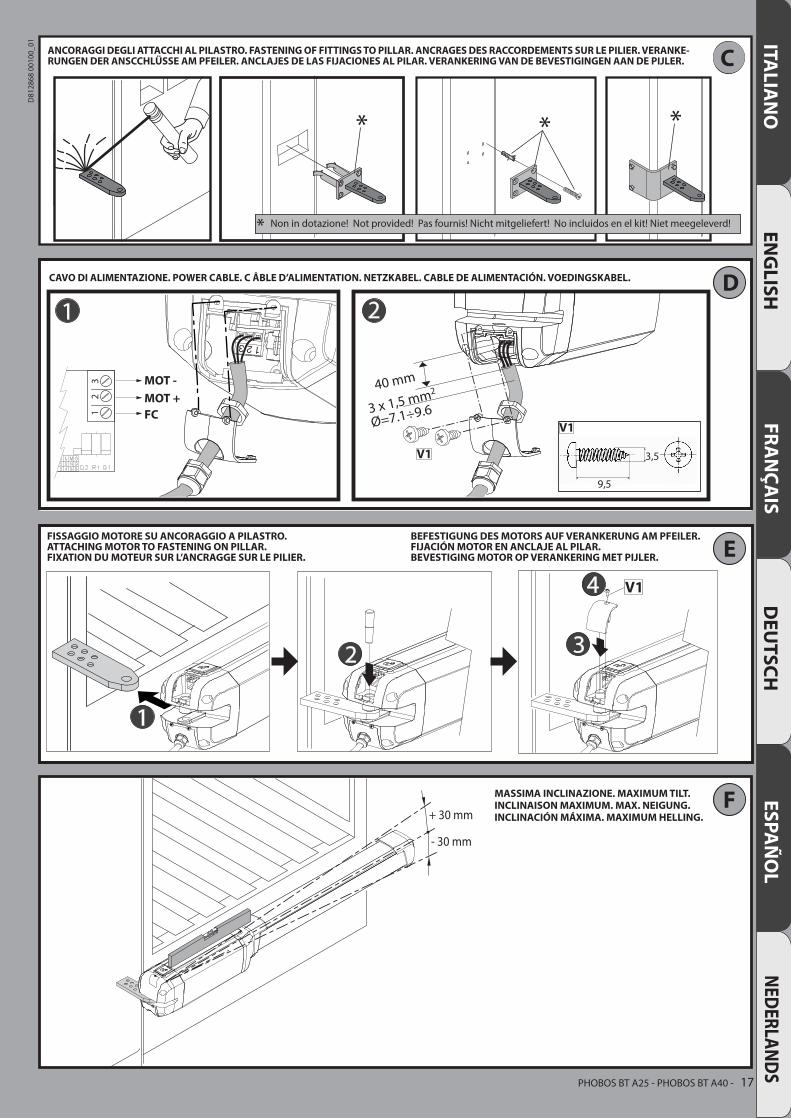
ANCORAGGI DEGLI ATTACCHI AL PILASTRO. FASTENING OF FITTINGS TO PILLAR. ANCRAGES DES RACCORDEMENTS SUR LE PILIER. VERANKE-RUNGEN DER ANSCCHLÜSSE AM PFEILER. ANCLAJES DE LAS FIJACIONES AL PILAR. VERANKERING VAN DE BEVESTIGINGEN AAN DE PIJLER.
CAVO DI ALIMENTAZIONE. POWER CABLE. C ÂBLE D’ALIMENTATION. NETZKABEL. CABLE DE ALIMENTACIÓN. VOEDINGSKABEL.
Non in dotazione! Not provided! Pas fournis! Nicht mitgeliefert! No incluidos en el kit! Niet meegeleverd!
FISSAGGIO MOTORE SU ANCORAGGIO A PILASTRO.ATTACHING MOTOR TO FASTENING ON PILLAR.FIXATION DU MOTEUR SUR L’ANCRAGGE SUR LE PILIER.
MASSIMA INCLINAZIONE. MAXIMUM TILT.INCLINAISON MAXIMUM. MAX. NEIGUNG.INCLINACIÓN MÁXIMA. MAXIMUM HELLING.
BEFESTIGUNG DES MOTORS AUF VERANKERUNG AM PFEILER.FIJACIÓN MOTOR EN ANCLAJE AL PILAR.BEVESTIGING MOTOR OP VERANKERING MET PIJLER.
PHOBOS BT A25 - PHOBOS BT A40 - 17
D81
2868
001
00_0
1
G
H
100 mm
1,5m
m2m
m 135mm
2mm
1,5m
m
PHOBOS BT A25 PHOBOS BT A40
1
I J
K2 3
1
J
3
A
B
FC1 (OPEN)
*
~5 mm
1 2
A
FC2 (CLOSE)
~5 mm
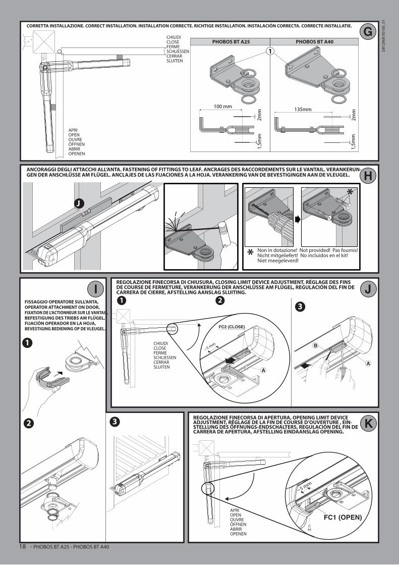
CORRETTA INSTALLAZIONE. CORRECT INSTALLATION. INSTALLATION CORRECTE. RICHTIGE INSTALLATION. INSTALACIÓN CORRECTA. CORRECTE INSTALLATIE.
ANCORAGGI DEGLI ATTACCHI ALL’ANTA. FASTENING OF FITTINGS TO LEAF. ANCRAGES DES RACCORDEMENTS SUR LE VANTAIL. VERANKERUN-GEN DER ANSCHLÜSSE AM FLÜGEL. ANCLAJES DE LAS FIJACIONES A LA HOJA. VERANKERING VAN DE BEVESTIGINGEN AAN DE VLEUGEL.
CHIUDICLOSEFERMESCHLIESSENCERRARSLUITEN
CHIUDICLOSEFERMESCHLIESSENCERRARSLUITEN
APRIOPENOUVREÖFFNENABRIROPENEN
Non in dotazione! Not provided! Pas fournis! Nicht mitgeliefert! No incluidos en el kit!Niet meegeleverd!
FISSAGGIO OPERATORE SULL’ANTA,OPERATOR ATTACHMENT ON DOOR,FIXATION DE L’ACTIONNEUR SUR LE VANTAIL, BEFESTIGUNG DES TRIEBS AM FLÜGEL, FIJACIÓN OPERADOR EN LA HOJA, BEVESTIGING BEDIENING OP DE VLEUGEL.
REGOLAZIONE FINECORSA DI CHIUSURA, CLOSING LIMIT DEVICE ADJUSTMENT, RÉGLAGE DES FINS DE COURSE DE FERMETURE, VERANKERUNG DER ANSCHLÜSSE AM FLÜGEL, REGULACIÓN DEL FIN DE CARRERA DE CIERRE, AFSTELLING AANSLAG SLUITING.
REGOLAZIONE FINECORSA DI APERTURA, OPENING LIMIT DEVICE ADJUSTMENT, RÉGLAGE DE LA FIN DE COURSE D’OUVERTURE , EIN-STELLUNG DES ÖFFNUNGS-ENDSCHALTERS, REGULACIÓN DEL FIN DE CARRERA DE APERTURA, AFSTELLING EINDAANSLAG OPENING.
APRIOPENOUVREÖFFNENABRIROPENEN
18 - PHOBOS BT A25 - PHOBOS BT A40
D81
2868
001
00_0
1

Sinistra/Left/GaucheLinks/IzquierdaEsquerda
Destra/Right/DroiteRechts/Derecha
Direita
L
M
O P
N
b
b
72,5 mm PHOBOS BT A25108 mm PHOBOS BT A40
Cu MAX 290 mm PHOBOS BT A25Cu MAX 400 mm Phobos BT A40
b80
a
b85
0 P
HO
BO
S B
T A
2596
0 P
HO
BO
S B
T A
40
1005
PH
OB
OS
BT
A25
1115
PH
OB
OS
BT
A40
1
11
120
110
80
850 PHOBOS BT A25960 PHOBOS BT A40
110
PHOBOS BT A25 - PHOBOS BT A40 - 19
D81
2868
001
00_0
1
ITALIA
NO
ENG
LISHINSTALLATION MANUAL
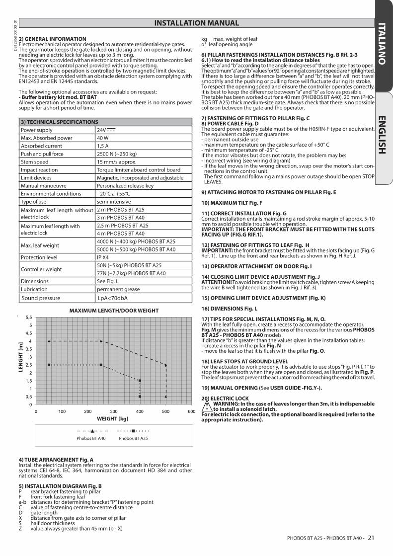
2) GENERAL INFORMATIONElectromechanical operator designed to automate residential-type gates. The gearmotor keeps the gate locked on closing and on opening, without needing an electric lock for leaves up to 3 m long. The operator is provided with an electronic torque limiter. It must be controlled by an electronic control panel provided with torque setting. The end-of-stroke operation is controlled by two magnetic limit devices. The operator is provided with an obstacle detection system complying with EN12453 and EN 12445 standards.
The following optional accessories are available on request:- Buffer battery kit mod. BT BATAllows operation of the automation even when there is no mains power supply for a short period of time.
3) TECHNICAL SPECIFICATIONSPower supply 24V Max. Absorbed power 40 WAbsorbed current 1,5 APush and pull force 2500 N (~250 kg)Stem speed 15 mm/s approx.Impact reaction Torque limiter aboard control boardLimit devices Magnetic, incorporated and adjustableManual manoeuvre Personalized release keyEnvironmental conditions - 20°C a +55°CType of use semi-intensive
Maximum leaf length without electric lock
2 m PHOBOS BT A253 m PHOBOS BT A40
Maximum leaf length with electric lock
2,5 m PHOBOS BT A254 m PHOBOS BT A40
Max. leaf weight4000 N (~400 kg) PHOBOS BT A255000 N (~500 kg) PHOBOS BT A40
Protection level IP X4
Controller weight50N (~5kg) PHOBOS BT A2577N (~7,7kg) PHOBOS BT A40
Dimensions See Fig. LLubrication permanent grease
Sound pressure LpA<70dbA
4) TUBE ARRANGEMENT Fig. A Install the electrical system referring to the standards in force for electrical systems CEI 64-8, IEC 364, harmonization document HD 384 and other national standards.
5) INSTALLATION DIAGRAM Fig. BP rear bracket fastening to pillarF front fork fastening leafa-b distances for determining bracket “P” fastening pointC value of fastening centre-to-centre distanceD gate lengthX distance from gate axis to corner of pillarS half door thicknessZ value always greater than 45 mm (b - X)
kg max. weight of leafα° leaf opening angle
6) PILLAR FASTENINGS INSTALLATION DISTANCES Fig. B Rif. 2-36.1) How to read the installation distance tables Select “a” and “b” according to the angle in degrees α° that the gate has to open. The optimum “a” and “b” values for 92° opening at constant speed are highlighted.If there is too large a difference between “a” and “b”, the leaf will not travel smoothly and the pushing or pulling force will fluctuate during its stroke.To respect the opening speed and ensure the controller operates correctly, it is best to keep the difference between “a” and “b” as low as possible.The table has been worked out for a 40 mm (PHOBOS BT A40), 20 mm (PHO-BOS BT A25) thick medium-size gate. Always check that there is no possible collision between the gate and the operator.
7) FASTENING OF FITTINGS TO PILLAR Fig. C8) POWER CABLE Fig. DThe board power supply cable must be of the H05RN-F type or equivalent. The equivalent cable must guarantee:- permanent outside use- maximum temperature on the cable surface of +50° C- minimum temperature of -25° CIf the motor vibrates but does not rotate, the problem may be:- Incorrect wiring (see wiring diagram)- If the leaf moves in the wrong direction, swap over the motor’s start con-
nections in the control unit. The first command following a mains power outage should be open STOP
LEAVES.
9) ATTACHING MOTOR TO FASTENING ON PILLAR Fig. E
10) MAXIMUM TILT Fig. F
11) CORRECT INSTALLATION Fig. GCorrect installation entails maintaining a rod stroke margin of approx. 5-10 mm to avoid possible trouble with operation.IMPORTANT: THE FRONT BRACKET MUST BE FITTED WITH THE SLOTS FACING UP (FIG.G RIF.1).
12) FASTENING OF FITTINGS TO LEAF Fig. HIMPORTANT: the front bracket must be fitted with the slots facing up (Fig. G Ref. 1). Line up the front and rear brackets as shown in Fig. H Ref. J.
13) OPERATOR ATTACHMENT ON DOOR Fig. I
14) CLOSING LIMIT DEVICE ADJUSTMENT Fig. JATTENTION! To avoid braking the limit switch cable, tighten screw A keeping the wire B well tightened (as shown in Fig. J Rif. 3).
15) OPENING LIMIT DEVICE ADJUSTMENT (Fig. K)
16) DIMENSIONS Fig. L
17) TIPS FOR SPECIAL INSTALLATIONS Fig. M, N, O.With the leaf fully open, create a recess to accommodate the operator. Fig. M gives the minimum dimensions of the recess for the various PHOBOS BT A25 - PHOBOS BT A40 models. If distance “b” is greater than the values given in the installation tables:- create a recess in the pillar Fig. N- move the leaf so that it is flush with the pillar Fig. O.
18) LEAF STOPS AT GROUND LEVELFor the actuator to work properly, it is advisable to use stops “Fig. P Rif. 1” to stop the leaves both when they are open and closed, as illustrated in Fig. P. The leaf stops must prevent the actuator rod from reaching the end of its travel.
19) MANUAL OPENING (See USER GUIDE -FIG.Y-).
20) ELECTRIC LOCK
WARNING: In the case of leaves longer than 3m, it is indispensable to install a solenoid latch.
For electric lock connection, the optional board is required (refer to the appropriate instruction).
MAXIMUM LENGTH/DOOR WEIGHT
Phobos BT A25Phobos BT A40
LEN
GH
T [m
]
WEIGHT [kg]
PHOBOS BT A25 - PHOBOS BT A40 - 21
D81
2868
001
00_0
1

ITALY