Phaser 6125/6130 Service Manual - Laser Pros International
454
Service Manual Phaser ® 6125/6130 701P47834 Color Laser Printer
-
Upload
khangminh22 -
Category
Documents
-
view
0 -
download
0
Transcript of Phaser 6125/6130 Service Manual - Laser Pros International
Service Manual
Phaser® 6125/6130
701P47834
Color Laser Printer


Service Manual701P47834
Phaser® 6125/6130Color Laser Printer
WarningThe following servicing instructions are for use by qualified service personnel only. To avoid personal injury, do not perform any servicing other than that contained in the operating instructions, unless you are qualified to do so.
First Printing: December 2007

ii Phaser 6125/6130 Color Laser Printer Service Manual
Prepared By:
Xerox CorporationXOG Worldwide Product Training and Information26600 SW ParkwayWilsonville, OR 97070
© 2007 by Xerox Corporation. All rights reserved.
Unpublished rights reserved under the copyright laws of the United States. Contents of this publication may not be reproduced in any form without permission of Xerox Corporation.
Copyright protection claimed includes all forms and matters of copyrightable materials and information now allowed by statutory or judicial law or hereinafter granted, including without limitation, material generated from the software programs which are displayed on the screen such as styles, templates, icons, screen displays, looks, etc.
Xerox technical training materials and service manuals are intended for use by authorized Xerox service technicians and service partners only and are not for resale. These materials may not be distributed, copied, or otherwise reproduced without prior written consent from Xerox Corporation.
XEROX®, CentreWare®, Phaser®, PrintingScout™, TekColor™, and Walk-Up® are trademarks of Xerox Corporation in the United States and/or other countries.
Adobe Reader®, Adobe Type Manager®, ATM™, and PostScript® are trademarks of Adobe Systems Incorporated in the United States and/or other countries.
Apple®, AppleTalk®, Bonjour®, EtherTalk®, LaserWriter®, LocalTalk®, Macintosh®, Mac OS®, and TrueType® are trademarks of Apple Computer, Inc. in the United States and/or other countries.
HP-GL®, HP-UX®, and PCL® are trademarks of Hewlett-Packard Corporation in the United States and/or other countries.
Windows®, Vista™, and Windows Server™ are trademarks of Microsoft Corporation in the United States and/or other countries.
Novell®, NetWare®, NDPS®, NDS®, Novell Directory Services®, IPX™, and Novell Distributed Print Services™ are trademarks of Novell, Incorporated in the United States and/or other countries.
SunSM, Sun Microsystems™, and Solaris™ are trademarks of Sun Microsystems, Incorporated in the United States and/or other countries.
SWOP® is a trademark of SWOP, Inc.
UNIX® is a registered trademark in the US and other countries, licensed exclusively through X/Open Company Limited.
As an Energy Star® partner, Xerox Corporation has determined that this product meets the Energy Star guidelines for energy efficiency. The Energy Star name and logo are registered U.S. marks.
PANTONE® Colors generated may not match PANTONE-identified standards. Consult current PANTONE Publications for accurate color. PANTONE® and other Pantone, Inc. trademarks are the property of Pantone, Inc. © Pantone, Inc., 2000.

Phaser 6125/6130 Color Laser Printer Service Manual iii
Service Terms
Manual Terms
Various terms are used throughout this manual to either provide additional information on a specific topic or to warn of possible danger present during a procedure or action. Be aware of all symbols and terms when they are used, and always read Note, Caution, and Warning statements.
NoteA note indicates an operating or maintenance procedure, practice or condition that is necessary to efficiently accomplish a task. A note can provide additional information related to a specific subject or add a comment on the results achieved through a previous action.
CautionA caution indicates an operating or maintenance procedure, practice or condition that, if not strictly observed, results in damage to, or destruction of, equipment.
WarningA warning indicates an operating or maintenance procedure, practice or condition that, if not strictly observed, results in injury or loss of life.
Product Terms
Caution: A personal injury hazard exists that may not be apparent. For example, a panel may cover the hazardous area.
Danger: A personal injury hazard exists in the area where you see the sign.
iv Phaser 6125/6130 Color Laser Printer Service Manual
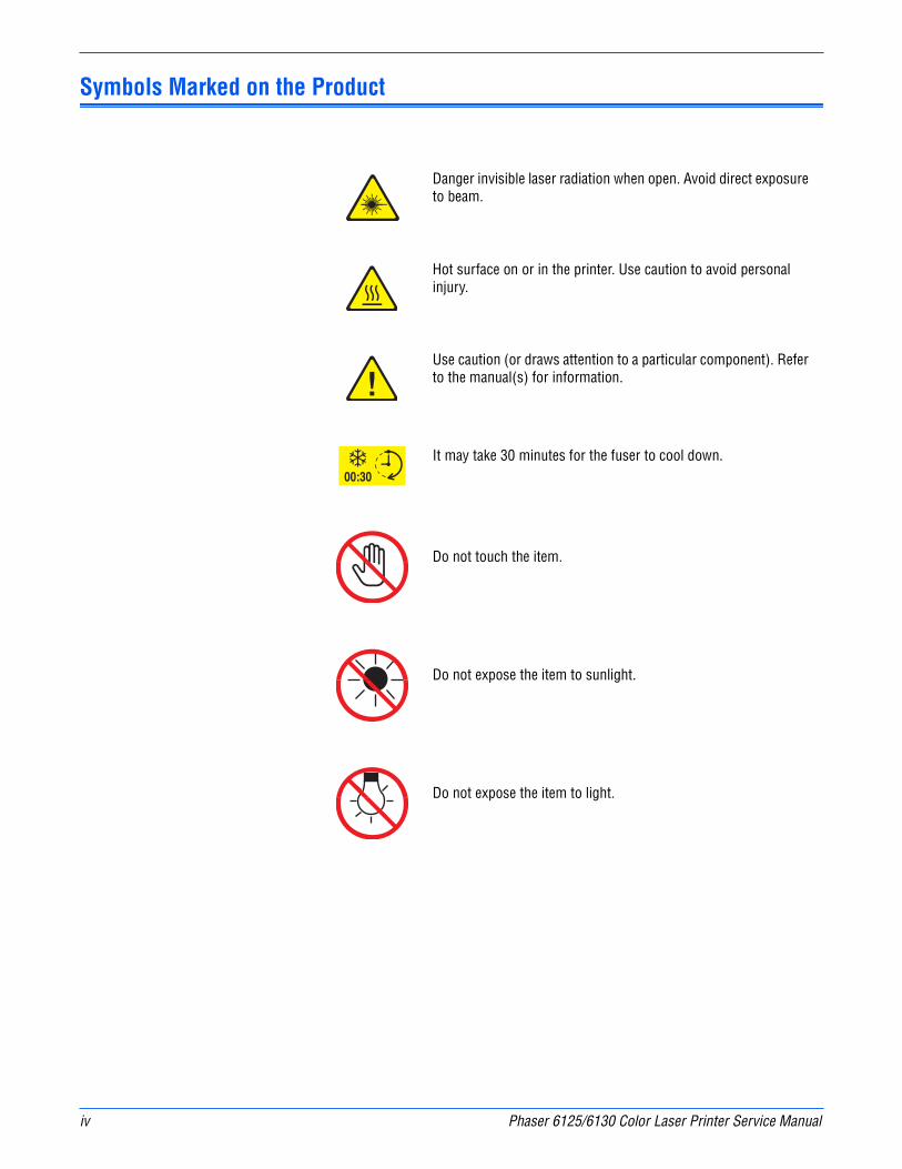
Symbols Marked on the Product
Danger invisible laser radiation when open. Avoid direct exposure to beam.
Hot surface on or in the printer. Use caution to avoid personal injury.
Use caution (or draws attention to a particular component). Refer to the manual(s) for information.
It may take 30 minutes for the fuser to cool down.
Do not touch the item.
Do not expose the item to sunlight.
Do not expose the item to light.
Phaser 6125/6130 Color Laser Printer Service Manual v
Power Safety Precautions
Power Source
For 115 VAC printers, do not apply more than 127 volts RMS between the supply conductors or between either supply conductor and ground. For 230 VAC printers, do not apply more than 254 volts RMS between the supply conductors or between either supply conductor and ground. Use only the specified power cord and connector. This manual assumes that the reader is a qualified service technician.
Plug the three-wire power cord (with grounding prong) into a grounded AC outlet only. If necessary, contact a licensed electrician to install a properly grounded outlet. If the product loses its ground connection, contact with conductive parts may cause an electrical shock. A protective ground connection by way of the grounding conductor in the power cord is essential for safe operation.
Disconnecting Power
WarningTurning the power Off using the power switch does not completely de-energize the printer. You must also disconnect the power cord from the printer’s Alternating Current (AC) inlet. Disconnect the power cord by pulling the plug, not the cord.
Disconnect the power cord in the following cases:
■ if the power cord or plug is frayed or otherwise damaged,
■ if any liquid or foreign material is spilled into the product,
■ if the printer is exposed to any excess moisture,
■ if the printer is dropped or damaged,
■ if you suspect that the product needs servicing or repair,
■ whenever you clean the product.

vi Phaser 6125/6130 Color Laser Printer Service Manual
Electrostatic Discharge (ESD) Precautions
Some semiconductor components, and the respective sub-assemblies that contain them, are vulnerable to damage by Electrostatic Discharge (ESD). These components include Integrated Circuits (ICs), Large-Scale Integrated circuits (LSIs), field-effect transistors, and other semiconductor chip components. The following techniques will reduce the occurrence of component damage caused by static electricity.
Be sure the power is Off to the chassis or circuit board, and observe all other safety precautions.
■ Immediately before handling any semiconductor components assemblies, drain the electrostatic charge from your body. This can be accomplished by touching an earth ground source or by wearing a wrist strap device connected to an earth ground source. Wearing a wrist strap will also prevent accumulation of additional bodily static charges. Be sure to remove the wrist strap before applying power to the unit under test to avoid potential shock.
■ After removing a static sensitive assembly from its anti-static bag, place it on a grounded conductive surface. If the anti-static bag is conductive, you may ground the bag and use it as a conductive surface.
■ Do not use freon-propelled chemicals. These can generate electrical charges sufficient to damage some devices.
■ Do not remove a replacement component or electrical sub-assembly from its protective package until you are ready to install it.
■ Immediately before removing the protective material from the leads of a replacement device, touch the protective material to the chassis or circuit assembly into which the device will be installed.
■ Minimize body motions when handling unpacked replacement devices. Motion such as your clothes brushing together, or lifting a foot from a carpeted floor can generate enough static electricity to damage an electro-statically sensitive device.
■ Handle ICs and Erasable Programmable Read-Only Memories (EPROM’s) carefully to avoid bending pins.
■ Pay attention to the direction of parts when mounting or inserting them on Printed Circuit Boards (PCB’s).

Phaser 6125/6130 Color Laser Printer Service Manual vii
Service Safety Summary
General Guidelines
For qualified service personnel only: Refer also to the preceding “Power Safety Precautions” on page 1-v.
Avoid servicing alone: Do not perform internal service or adjustment of this product unless another person capable of rendering first aid or resuscitation is present.
Use care when servicing with power: Dangerous voltages may exist at several points in this product. To avoid personal injury, do not touch exposed connections and components while power is On. Disconnect power before removing the power supply shield or replacing components.
Do not wear jewelry: Remove jewelry prior to servicing. Rings, necklaces and other metallic objects could come into contact with dangerous voltages and currents.
Warning Labels
Read and obey all posted warning labels. Throughout the printer, warning labels are displayed on potentially dangerous components. As you service the printer, check to make certain that all warning labels remain in place.
Safety Interlocks
Make sure all covers are in place and all Interlock Switches are functioning correctly after you have completed a printer service call. If you bypass an Interlock Switch during a service call, use extreme caution when working on or around the printer.
Class 1 Laser Product
The Phaser 6125/6130 Color Laser PrinterPhaser 6125/6130 Color Laser Printer is certified to comply with Laser Product Performance Standards set by the U.S. Department of Health and Human Services as a Class 1 Laser Product. This means that this product does not emit hazardous laser radiation; which is possible only because the laser beam is totally enclosed during all modes of customer operation. When servicing the printer or laser unit, follow the procedures specified in this manual and there will be no hazards from the laser.
viii Phaser 6125/6130 Color Laser Printer Service Manual
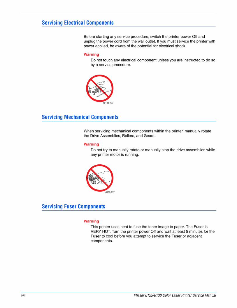
Servicing Electrical Components
Before starting any service procedure, switch the printer power Off and unplug the power cord from the wall outlet. If you must service the printer with power applied, be aware of the potential for electrical shock.
WarningDo not touch any electrical component unless you are instructed to do so by a service procedure.
Servicing Mechanical Components
When servicing mechanical components within the printer, manually rotate the Drive Assemblies, Rollers, and Gears.
WarningDo not try to manually rotate or manually stop the drive assemblies while any printer motor is running.
Servicing Fuser Components
WarningThis printer uses heat to fuse the toner image to paper. The Fuser is VERY HOT. Turn the printer power Off and wait at least 5 minutes for the Fuser to cool before you attempt to service the Fuser or adjacent components.
s6180-256
s6180-257

Phaser 6125/6130 Color Laser Printer Service Manual ix
Regulatory Specifications
Xerox has tested this product to electromagnetic emission and immunity standards. These standards are designed to mitigate interference caused or received by this product in a typical office environment.
United States (FCC Regulations)
This equipment has been tested and found to comply with the limits for a Class B digital device, pursuant to Part 15 of the Federal Communications Commission (FCC) Rules. These limits are designed to provide reasonable protection against harmful interference in a residential installation. This equipment generates, uses, and can radiate radio frequency energy. If it is not installed and used in accordance with these instructions, it may cause harmful interference to radio communications. However, there is no guarantee that interference will not occur in a particular installation. If this equipment does cause harmful interference to radio or television reception, which can be determined by turning the equipment Off and On, the user is encouraged to try to correct the interference by one or more of the following measures:
■ Reorient or relocate the receiver (device being interfered with).
■ Increase the separation between the printer and the receiver.
■ Connect the equipment into an outlet on a circuit different from that which the receiver is connected.
■ Consult the dealer or an experienced radio/television technician for help.
Any changes or modifications not expressly approved by Xerox could void the user's authority to operate the equipment. To ensure compliance with Part 15 of the FCC rules, use shielded interface cables.
Canada (Regulations)
This Class B digital apparatus complies with Canadian ICES-003.
Cet appareil numérique de la classe B est conforme à la norme NMB-003 du Canada.

x Phaser 6125/6130 Color Laser Printer Service Manual
European Union
The CE mark applied to this product symbolizes Xerox’s declaration of conformity with the following applicable Directives of the European Union as of the dates indicated:
This product, if used properly in accordance with the user's instructions, is neither dangerous for the consumer nor for the environment.
To ensure compliance with European Union regulations, use shielded interface cables.
A signed copy of the Declaration of Conformity for this product can be obtained from Xerox.
January 1, 1995: Low Voltage Directive 73/23/EEC as amended by 93/68/EEC
January 1, 1996: Electromagnetic Compatibility Directive 89/336/EEC

Phaser 6125/6130 Color Laser Printer Service Manual xi
Manual Organization
The Phaser 6125/6130 Color Laser Printer Service Manual is the primary document used for repairing, maintaining, and troubleshooting the printer. Use this manual as your primary resource for understanding the operational characteristics of the printer and all available options. This manual describes specifications, theory, and the diagnosis and repair of problems occurring in the print engine and attached options. Also included are detailed replacement procedures, parts lists, and wiring diagrams.
The Phaser 6125/6130 Color Laser Printer Service Manual contains these sections:
Introductory, Safety, and Regulatory Information: This section contains important safety information and regulatory requirements.
Section 1 - General Information: This section contains an overview of the printer’s operation, configuration, specifications, and consumables.
Section 2 - Theory of Operation: This section contains detailed functional information on the print engine components.
Section 3 - Error Codes and Messages: This section provides detailed troubleshooting procedures for error messages and codes generated by resident diagnostics.
Section 4 - General Troubleshooting: Troubleshooting discussions cover the operation of Power On Self Test (POST), Service Diagnostics, In addition, this section includes troubleshooting methods for situations where error indicator is not available.
Section 5 - Print-Quality Troubleshooting: This section focuses on techniques to correct image quality problems associated with the printer output.
Section 6 - Adjustments and Calibrations: This section provides procedures for the adjustment of print engine components.
Section 7 - Cleaning and Maintenance: This section provides periodic cleaning procedures for the printer.
Section 8 - Service Parts Disassembly: This section contains removal procedures for spare parts listed in the Parts List. A replacement procedure is included when necessary.
Section 9 - Parts List: This section contains exploded views of the print engine and optional Field Replaceable Units (FRUs), as well as part numbers for orderable parts.
Section 10 - Plug/Jack and Wiring Diagrams: This section contains the plug/jack locations and the wiring diagrams for the printer.
Appendix A - Reference: This section provides an illustration of the printer’s menu structure, printer firmware update instructions, and a list of acronyms and abbreviations.

xii Phaser 6125/6130 Color Laser Printer Service Manual
Phaser 6130 Color Laser Printer Service Manual xiii
Contents
Contents
Service Terms . . . . . . . . . . . . . . . . . . . . . . . . . . . . . . . . . . . . . . . . . . . . . . . . . . . . . . . . . . . . . . . . . . . . . . . . . . . . . . . . iiiSymbols Marked on the Product . . . . . . . . . . . . . . . . . . . . . . . . . . . . . . . . . . . . . . . . . . . . . . . . . . . . . . . . . . . . . . . . . . ivPower Safety Precautions . . . . . . . . . . . . . . . . . . . . . . . . . . . . . . . . . . . . . . . . . . . . . . . . . . . . . . . . . . . . . . . . . . . . . . . . vElectrostatic Discharge (ESD) Precautions . . . . . . . . . . . . . . . . . . . . . . . . . . . . . . . . . . . . . . . . . . . . . . . . . . . . . . . . . . viService Safety Summary . . . . . . . . . . . . . . . . . . . . . . . . . . . . . . . . . . . . . . . . . . . . . . . . . . . . . . . . . . . . . . . . . . . . . . . . viiRegulatory Specifications . . . . . . . . . . . . . . . . . . . . . . . . . . . . . . . . . . . . . . . . . . . . . . . . . . . . . . . . . . . . . . . . . . . . . . . ixManual Organization . . . . . . . . . . . . . . . . . . . . . . . . . . . . . . . . . . . . . . . . . . . . . . . . . . . . . . . . . . . . . . . . . . . . . . . . . . . xi
1 General InformationPrinter Introduction and Overview . . . . . . . . . . . . . . . . . . . . . . . . . . . . . . . . . . . . . . . . . . . . . . . . . . . . . . . . . . . . . . . . 1-2
Technical Support Information . . . . . . . . . . . . . . . . . . . . . . . . . . . . . . . . . . . . . . . . . . . . . . . . . . . . . . . . . . . 1-2Printer Configurations . . . . . . . . . . . . . . . . . . . . . . . . . . . . . . . . . . . . . . . . . . . . . . . . . . . . . . . . . . . . . . . . . . . . . . . . . 1-3Parts of the Printer. . . . . . . . . . . . . . . . . . . . . . . . . . . . . . . . . . . . . . . . . . . . . . . . . . . . . . . . . . . . . . . . . . . . . . . . . . . . 1-4
Front and Side Views. . . . . . . . . . . . . . . . . . . . . . . . . . . . . . . . . . . . . . . . . . . . . . . . . . . . . . . . . . . . . . . . . . . 1-4Rear View . . . . . . . . . . . . . . . . . . . . . . . . . . . . . . . . . . . . . . . . . . . . . . . . . . . . . . . . . . . . . . . . . . . . . . . . . . . 1-5Control Panel . . . . . . . . . . . . . . . . . . . . . . . . . . . . . . . . . . . . . . . . . . . . . . . . . . . . . . . . . . . . . . . . . . . . . . . . . 1-6
Printer Options. . . . . . . . . . . . . . . . . . . . . . . . . . . . . . . . . . . . . . . . . . . . . . . . . . . . . . . . . . . . . . . . . . . . . . . . . . . . . . . 1-8Additional Memory . . . . . . . . . . . . . . . . . . . . . . . . . . . . . . . . . . . . . . . . . . . . . . . . . . . . . . . . . . . . . . . . . . . . 1-8Multi-Protocol Network Card . . . . . . . . . . . . . . . . . . . . . . . . . . . . . . . . . . . . . . . . . . . . . . . . . . . . . . . . . . . . . 1-8
Maintenance Items. . . . . . . . . . . . . . . . . . . . . . . . . . . . . . . . . . . . . . . . . . . . . . . . . . . . . . . . . . . . . . . . . . . . . . . . . . . . 1-9Consumables . . . . . . . . . . . . . . . . . . . . . . . . . . . . . . . . . . . . . . . . . . . . . . . . . . . . . . . . . . . . . . . . . . . . . . . . . . . . . . . 1-10Printer Specifications. . . . . . . . . . . . . . . . . . . . . . . . . . . . . . . . . . . . . . . . . . . . . . . . . . . . . . . . . . . . . . . . . . . . . . . . . 1-11
Memory Specifications . . . . . . . . . . . . . . . . . . . . . . . . . . . . . . . . . . . . . . . . . . . . . . . . . . . . . . . . . . . . . . . . 1-12Electrical Specifications. . . . . . . . . . . . . . . . . . . . . . . . . . . . . . . . . . . . . . . . . . . . . . . . . . . . . . . . . . . . . . . . 1-12Print Speed . . . . . . . . . . . . . . . . . . . . . . . . . . . . . . . . . . . . . . . . . . . . . . . . . . . . . . . . . . . . . . . . . . . . . . . . . 1-13Environmental Specifications . . . . . . . . . . . . . . . . . . . . . . . . . . . . . . . . . . . . . . . . . . . . . . . . . . . . . . . . . . . 1-13Operating Mode. . . . . . . . . . . . . . . . . . . . . . . . . . . . . . . . . . . . . . . . . . . . . . . . . . . . . . . . . . . . . . . . . . . . . . 1-14First Print Output Time (FPOT) . . . . . . . . . . . . . . . . . . . . . . . . . . . . . . . . . . . . . . . . . . . . . . . . . . . . . . . . . . 1-15Image Specifications . . . . . . . . . . . . . . . . . . . . . . . . . . . . . . . . . . . . . . . . . . . . . . . . . . . . . . . . . . . . . . . . . . 1-16Physical Dimensions and Clearances . . . . . . . . . . . . . . . . . . . . . . . . . . . . . . . . . . . . . . . . . . . . . . . . . . . . . 1-17Mounting Surface Specifications . . . . . . . . . . . . . . . . . . . . . . . . . . . . . . . . . . . . . . . . . . . . . . . . . . . . . . . . . 1-18Media and Tray Specifications. . . . . . . . . . . . . . . . . . . . . . . . . . . . . . . . . . . . . . . . . . . . . . . . . . . . . . . . . . . 1-19
Controller Functions. . . . . . . . . . . . . . . . . . . . . . . . . . . . . . . . . . . . . . . . . . . . . . . . . . . . . . . . . . . . . . . . . . . . . . . . . . 1-20Job Control . . . . . . . . . . . . . . . . . . . . . . . . . . . . . . . . . . . . . . . . . . . . . . . . . . . . . . . . . . . . . . . . . . . . . . . . . 1-20Non-Genuine Mode . . . . . . . . . . . . . . . . . . . . . . . . . . . . . . . . . . . . . . . . . . . . . . . . . . . . . . . . . . . . . . . . . . . 1-22Toner Remaining Amount . . . . . . . . . . . . . . . . . . . . . . . . . . . . . . . . . . . . . . . . . . . . . . . . . . . . . . . . . . . . . . 1-23Maintenance Function . . . . . . . . . . . . . . . . . . . . . . . . . . . . . . . . . . . . . . . . . . . . . . . . . . . . . . . . . . . . . . . . . 1-23Diagnostics . . . . . . . . . . . . . . . . . . . . . . . . . . . . . . . . . . . . . . . . . . . . . . . . . . . . . . . . . . . . . . . . . . . . . . . . . 1-24Information Pages . . . . . . . . . . . . . . . . . . . . . . . . . . . . . . . . . . . . . . . . . . . . . . . . . . . . . . . . . . . . . . . . . . . . 1-24
xiv Phaser 6130 Color Laser Printer Service Manual
Contents
2 Theory of OperationPhaser 6125/6130 Operational Overview . . . . . . . . . . . . . . . . . . . . . . . . . . . . . . . . . . . . . . . . . . . . . . . . . . . . . . . . . . . 2-2
Print Process Block Diagram. . . . . . . . . . . . . . . . . . . . . . . . . . . . . . . . . . . . . . . . . . . . . . . . . . . . . . . . . . . . . 2-2Printing Process . . . . . . . . . . . . . . . . . . . . . . . . . . . . . . . . . . . . . . . . . . . . . . . . . . . . . . . . . . . . . . . . . . . . . . . . . . . . . 2-3
Charging . . . . . . . . . . . . . . . . . . . . . . . . . . . . . . . . . . . . . . . . . . . . . . . . . . . . . . . . . . . . . . . . . . . . . . . . . . . . 2-4Exposure . . . . . . . . . . . . . . . . . . . . . . . . . . . . . . . . . . . . . . . . . . . . . . . . . . . . . . . . . . . . . . . . . . . . . . . . . . . . 2-5Development . . . . . . . . . . . . . . . . . . . . . . . . . . . . . . . . . . . . . . . . . . . . . . . . . . . . . . . . . . . . . . . . . . . . . . . . . 2-7Transfer (Drum ---> Paper) . . . . . . . . . . . . . . . . . . . . . . . . . . . . . . . . . . . . . . . . . . . . . . . . . . . . . . . . . . . . . . 2-9Cleaning (Imaging Unit). . . . . . . . . . . . . . . . . . . . . . . . . . . . . . . . . . . . . . . . . . . . . . . . . . . . . . . . . . . . . . . . 2-10Excess Toner Collection. . . . . . . . . . . . . . . . . . . . . . . . . . . . . . . . . . . . . . . . . . . . . . . . . . . . . . . . . . . . . . . . 2-11Fusing . . . . . . . . . . . . . . . . . . . . . . . . . . . . . . . . . . . . . . . . . . . . . . . . . . . . . . . . . . . . . . . . . . . . . . . . . . . . . 2-12
Paper Path of the Printer . . . . . . . . . . . . . . . . . . . . . . . . . . . . . . . . . . . . . . . . . . . . . . . . . . . . . . . . . . . . . . . . . . . . . . 2-13Paper Path Route. . . . . . . . . . . . . . . . . . . . . . . . . . . . . . . . . . . . . . . . . . . . . . . . . . . . . . . . . . . . . . . . . . . . . 2-13Paper Path Components . . . . . . . . . . . . . . . . . . . . . . . . . . . . . . . . . . . . . . . . . . . . . . . . . . . . . . . . . . . . . . . 2-14
Major Assemblies and Functions . . . . . . . . . . . . . . . . . . . . . . . . . . . . . . . . . . . . . . . . . . . . . . . . . . . . . . . . . . . . . . . . 2-15Paper Tray . . . . . . . . . . . . . . . . . . . . . . . . . . . . . . . . . . . . . . . . . . . . . . . . . . . . . . . . . . . . . . . . . . . . . . . . . 2-15Paper Feeder . . . . . . . . . . . . . . . . . . . . . . . . . . . . . . . . . . . . . . . . . . . . . . . . . . . . . . . . . . . . . . . . . . . . . . . . 2-17Manual Feed & Registration . . . . . . . . . . . . . . . . . . . . . . . . . . . . . . . . . . . . . . . . . . . . . . . . . . . . . . . . . . . . 2-19Transfer Unit and Fuser . . . . . . . . . . . . . . . . . . . . . . . . . . . . . . . . . . . . . . . . . . . . . . . . . . . . . . . . . . . . . . . . 2-23Laser Unit . . . . . . . . . . . . . . . . . . . . . . . . . . . . . . . . . . . . . . . . . . . . . . . . . . . . . . . . . . . . . . . . . . . . . . . . . . 2-24Toner Cartridge & Dispenser . . . . . . . . . . . . . . . . . . . . . . . . . . . . . . . . . . . . . . . . . . . . . . . . . . . . . . . . . . . . 2-26Imaging Unit . . . . . . . . . . . . . . . . . . . . . . . . . . . . . . . . . . . . . . . . . . . . . . . . . . . . . . . . . . . . . . . . . . . . . . . . 2-27Drive Assembly . . . . . . . . . . . . . . . . . . . . . . . . . . . . . . . . . . . . . . . . . . . . . . . . . . . . . . . . . . . . . . . . . . . . . . 2-28Electrical . . . . . . . . . . . . . . . . . . . . . . . . . . . . . . . . . . . . . . . . . . . . . . . . . . . . . . . . . . . . . . . . . . . . . . . . . . . 2-30
Printer Modes . . . . . . . . . . . . . . . . . . . . . . . . . . . . . . . . . . . . . . . . . . . . . . . . . . . . . . . . . . . . . . . . . . . . . . . . . . . . . . 2-34Operational Modes . . . . . . . . . . . . . . . . . . . . . . . . . . . . . . . . . . . . . . . . . . . . . . . . . . . . . . . . . . . . . . . . . . . 2-34
Printer Control . . . . . . . . . . . . . . . . . . . . . . . . . . . . . . . . . . . . . . . . . . . . . . . . . . . . . . . . . . . . . . . . . . . . . . . . . . . . . . 2-34Paper Size Detection . . . . . . . . . . . . . . . . . . . . . . . . . . . . . . . . . . . . . . . . . . . . . . . . . . . . . . . . . . . . . . . . . . 2-34Laser Unit Light Quantity Control . . . . . . . . . . . . . . . . . . . . . . . . . . . . . . . . . . . . . . . . . . . . . . . . . . . . . . . . 2-34Process Control . . . . . . . . . . . . . . . . . . . . . . . . . . . . . . . . . . . . . . . . . . . . . . . . . . . . . . . . . . . . . . . . . . . . . . 2-35Color Registration Control . . . . . . . . . . . . . . . . . . . . . . . . . . . . . . . . . . . . . . . . . . . . . . . . . . . . . . . . . . . . . . 2-36Fuser Control . . . . . . . . . . . . . . . . . . . . . . . . . . . . . . . . . . . . . . . . . . . . . . . . . . . . . . . . . . . . . . . . . . . . . . . . 2-37
Drive Transmission . . . . . . . . . . . . . . . . . . . . . . . . . . . . . . . . . . . . . . . . . . . . . . . . . . . . . . . . . . . . . . . . . . . . . . . . . . 2-38Main Drive . . . . . . . . . . . . . . . . . . . . . . . . . . . . . . . . . . . . . . . . . . . . . . . . . . . . . . . . . . . . . . . . . . . . . . . . . . 2-38Sub Drive Assemblies . . . . . . . . . . . . . . . . . . . . . . . . . . . . . . . . . . . . . . . . . . . . . . . . . . . . . . . . . . . . . . . . . 2-40
3 Error Messages and CodesIntroduction . . . . . . . . . . . . . . . . . . . . . . . . . . . . . . . . . . . . . . . . . . . . . . . . . . . . . . . . . . . . . . . . . . . . . . . . . . . . . . . . . 3-2
Accessing Error History Report . . . . . . . . . . . . . . . . . . . . . . . . . . . . . . . . . . . . . . . . . . . . . . . . . . . . . . . . . . . 3-2Error History Report . . . . . . . . . . . . . . . . . . . . . . . . . . . . . . . . . . . . . . . . . . . . . . . . . . . . . . . . . . . . . . . . . . . 3-2
Servicing Instructions . . . . . . . . . . . . . . . . . . . . . . . . . . . . . . . . . . . . . . . . . . . . . . . . . . . . . . . . . . . . . . . . . . . . . . . . . 3-4Messages, Chain Link Codes, and Procedures. . . . . . . . . . . . . . . . . . . . . . . . . . . . . . . . . . . . . . . . . . . . . . . . . . . . . . . 3-5
Error Messages Abbreviations. . . . . . . . . . . . . . . . . . . . . . . . . . . . . . . . . . . . . . . . . . . . . . . . . . . . . . . . . . . . 3-5Error Message and Chain Link Code Summary . . . . . . . . . . . . . . . . . . . . . . . . . . . . . . . . . . . . . . . . . . . . . . . 3-6
Image Processor Board Errors. . . . . . . . . . . . . . . . . . . . . . . . . . . . . . . . . . . . . . . . . . . . . . . . . . . . . . . . . . . . . . . . . . 3-21Flash Memory Errors . . . . . . . . . . . . . . . . . . . . . . . . . . . . . . . . . . . . . . . . . . . . . . . . . . . . . . . . . . . . . . . . . . 3-21Out of Memory . . . . . . . . . . . . . . . . . . . . . . . . . . . . . . . . . . . . . . . . . . . . . . . . . . . . . . . . . . . . . . . . . . . . . . 3-22PDL Error . . . . . . . . . . . . . . . . . . . . . . . . . . . . . . . . . . . . . . . . . . . . . . . . . . . . . . . . . . . . . . . . . . . . . . . . . . 3-23Network/FontROM/MACaddress/RAM/Controller/NVRAM/ASIC Error. . . . . . . . . . . . . . . . . . . . . . . . . . . . . 3-24PAGEC Time Error . . . . . . . . . . . . . . . . . . . . . . . . . . . . . . . . . . . . . . . . . . . . . . . . . . . . . . . . . . . . . . . . . . . . 3-25RAM Error . . . . . . . . . . . . . . . . . . . . . . . . . . . . . . . . . . . . . . . . . . . . . . . . . . . . . . . . . . . . . . . . . . . . . . . . . . 3-26

Phaser 6130 Color Laser Printer Service Manual xv
Contents
Toner Cartridge Errors . . . . . . . . . . . . . . . . . . . . . . . . . . . . . . . . . . . . . . . . . . . . . . . . . . . . . . . . . . . . . . . . . . . . . . . . 3-27Insert Yellow/Cyan/Magenta/Black Cartridge . . . . . . . . . . . . . . . . . . . . . . . . . . . . . . . . . . . . . . . . . . . . . . . . 3-27Non-Xerox Toner, Invalid Yellow/Magenta/Cyan/Black . . . . . . . . . . . . . . . . . . . . . . . . . . . . . . . . . . . . . . . . 3-27Replace Yellow/Magenta/Cyan/Black . . . . . . . . . . . . . . . . . . . . . . . . . . . . . . . . . . . . . . . . . . . . . . . . . . . . . . 3-27Yellow/Magenta/Cyan/Black Low. . . . . . . . . . . . . . . . . . . . . . . . . . . . . . . . . . . . . . . . . . . . . . . . . . . . . . . . . 3-27Waste Full, Yellow/Magenta/Cyan/Black Cartridge. . . . . . . . . . . . . . . . . . . . . . . . . . . . . . . . . . . . . . . . . . . . 3-28
Jam Errors . . . . . . . . . . . . . . . . . . . . . . . . . . . . . . . . . . . . . . . . . . . . . . . . . . . . . . . . . . . . . . . . . . . . . . . . . . . . . . . . . 3-29Jam at Tray . . . . . . . . . . . . . . . . . . . . . . . . . . . . . . . . . . . . . . . . . . . . . . . . . . . . . . . . . . . . . . . . . . . . . . . . . 3-29Jam at Front Cover . . . . . . . . . . . . . . . . . . . . . . . . . . . . . . . . . . . . . . . . . . . . . . . . . . . . . . . . . . . . . . . . . . . 3-34Jam at Manual Feed Slot . . . . . . . . . . . . . . . . . . . . . . . . . . . . . . . . . . . . . . . . . . . . . . . . . . . . . . . . . . . . . . . 3-37Jam at Front Cover . . . . . . . . . . . . . . . . . . . . . . . . . . . . . . . . . . . . . . . . . . . . . . . . . . . . . . . . . . . . . . . . . . . 3-42Jam at Exit. . . . . . . . . . . . . . . . . . . . . . . . . . . . . . . . . . . . . . . . . . . . . . . . . . . . . . . . . . . . . . . . . . . . . . . . . . 3-44Jam at Registration Roll . . . . . . . . . . . . . . . . . . . . . . . . . . . . . . . . . . . . . . . . . . . . . . . . . . . . . . . . . . . . . . . 3-46
MPC Errors . . . . . . . . . . . . . . . . . . . . . . . . . . . . . . . . . . . . . . . . . . . . . . . . . . . . . . . . . . . . . . . . . . . . . . . . . . . . . . . . 3-50MPC Error . . . . . . . . . . . . . . . . . . . . . . . . . . . . . . . . . . . . . . . . . . . . . . . . . . . . . . . . . . . . . . . . . . . . . . . . . . 3-50
Transfer Unit Errors . . . . . . . . . . . . . . . . . . . . . . . . . . . . . . . . . . . . . . . . . . . . . . . . . . . . . . . . . . . . . . . . . . . . . . . . . . 3-51CTD Sensor Error/CTD Sensor/Check Unit . . . . . . . . . . . . . . . . . . . . . . . . . . . . . . . . . . . . . . . . . . . . . . . . . 3-51DTB Life Over/Transfer Life . . . . . . . . . . . . . . . . . . . . . . . . . . . . . . . . . . . . . . . . . . . . . . . . . . . . . . . . . . . . . 3-52Insert Imaging Unit . . . . . . . . . . . . . . . . . . . . . . . . . . . . . . . . . . . . . . . . . . . . . . . . . . . . . . . . . . . . . . . . . . . 3-53Low Density Yellow/Magenta/Cyan/Black Cartridge. . . . . . . . . . . . . . . . . . . . . . . . . . . . . . . . . . . . . . . . . . . 3-54
Paper Setting Errors . . . . . . . . . . . . . . . . . . . . . . . . . . . . . . . . . . . . . . . . . . . . . . . . . . . . . . . . . . . . . . . . . . . . . . . . . 3-56Insert Output to Tray/Manual Feed . . . . . . . . . . . . . . . . . . . . . . . . . . . . . . . . . . . . . . . . . . . . . . . . . . . . . . . 3-56Load Manual Feed . . . . . . . . . . . . . . . . . . . . . . . . . . . . . . . . . . . . . . . . . . . . . . . . . . . . . . . . . . . . . . . . . . . . 3-56Load Manual Feed . . . . . . . . . . . . . . . . . . . . . . . . . . . . . . . . . . . . . . . . . . . . . . . . . . . . . . . . . . . . . . . . . . . . 3-57Load Tray . . . . . . . . . . . . . . . . . . . . . . . . . . . . . . . . . . . . . . . . . . . . . . . . . . . . . . . . . . . . . . . . . . . . . . . . . . 3-59Load Tray/Tray Empty . . . . . . . . . . . . . . . . . . . . . . . . . . . . . . . . . . . . . . . . . . . . . . . . . . . . . . . . . . . . . . . . . 3-60
Fuser Errors . . . . . . . . . . . . . . . . . . . . . . . . . . . . . . . . . . . . . . . . . . . . . . . . . . . . . . . . . . . . . . . . . . . . . . . . . . . . . . . . 3-62Insert Fuser . . . . . . . . . . . . . . . . . . . . . . . . . . . . . . . . . . . . . . . . . . . . . . . . . . . . . . . . . . . . . . . . . . . . . . . . 3-62Replace Fuser / Fuser Life . . . . . . . . . . . . . . . . . . . . . . . . . . . . . . . . . . . . . . . . . . . . . . . . . . . . . . . . . . . . . . 3-63Fuser Error . . . . . . . . . . . . . . . . . . . . . . . . . . . . . . . . . . . . . . . . . . . . . . . . . . . . . . . . . . . . . . . . . . . . . . . . . 3-64
Motor Errors . . . . . . . . . . . . . . . . . . . . . . . . . . . . . . . . . . . . . . . . . . . . . . . . . . . . . . . . . . . . . . . . . . . . . . . . . . . . . . . 3-66Fan Motor Error . . . . . . . . . . . . . . . . . . . . . . . . . . . . . . . . . . . . . . . . . . . . . . . . . . . . . . . . . . . . . . . . . . . . . . 3-66Motor Error . . . . . . . . . . . . . . . . . . . . . . . . . . . . . . . . . . . . . . . . . . . . . . . . . . . . . . . . . . . . . . . . . . . . . . . . . 3-67Sub Motor Error . . . . . . . . . . . . . . . . . . . . . . . . . . . . . . . . . . . . . . . . . . . . . . . . . . . . . . . . . . . . . . . . . . . . . 3-69
Imaging Unit Errors . . . . . . . . . . . . . . . . . . . . . . . . . . . . . . . . . . . . . . . . . . . . . . . . . . . . . . . . . . . . . . . . . . . . . . . . . . 3-71Replace Imaging Unit/PHD CRUM Error . . . . . . . . . . . . . . . . . . . . . . . . . . . . . . . . . . . . . . . . . . . . . . . . . . . 3-71
Cover Open Errors . . . . . . . . . . . . . . . . . . . . . . . . . . . . . . . . . . . . . . . . . . . . . . . . . . . . . . . . . . . . . . . . . . . . . . . . . . . 3-72Front Cover Open. . . . . . . . . . . . . . . . . . . . . . . . . . . . . . . . . . . . . . . . . . . . . . . . . . . . . . . . . . . . . . . . . . . . . 3-72Side Door Open . . . . . . . . . . . . . . . . . . . . . . . . . . . . . . . . . . . . . . . . . . . . . . . . . . . . . . . . . . . . . . . . . . . . . . 3-73
MCU Errors . . . . . . . . . . . . . . . . . . . . . . . . . . . . . . . . . . . . . . . . . . . . . . . . . . . . . . . . . . . . . . . . . . . . . . . . . . . . . . . . 3-74MCU Firmware Error . . . . . . . . . . . . . . . . . . . . . . . . . . . . . . . . . . . . . . . . . . . . . . . . . . . . . . . . . . . . . . . . . . 3-74MCU NVRAM Error . . . . . . . . . . . . . . . . . . . . . . . . . . . . . . . . . . . . . . . . . . . . . . . . . . . . . . . . . . . . . . . . . . . 3-75
Laser Unit Errors . . . . . . . . . . . . . . . . . . . . . . . . . . . . . . . . . . . . . . . . . . . . . . . . . . . . . . . . . . . . . . . . . . . . . . . . . . . . 3-76Laser Error . . . . . . . . . . . . . . . . . . . . . . . . . . . . . . . . . . . . . . . . . . . . . . . . . . . . . . . . . . . . . . . . . . . . . . . . . 3-76
System Error . . . . . . . . . . . . . . . . . . . . . . . . . . . . . . . . . . . . . . . . . . . . . . . . . . . . . . . . . . . . . . . . . . . . . . . . . . . . . . . 3-77MCU Communication Error . . . . . . . . . . . . . . . . . . . . . . . . . . . . . . . . . . . . . . . . . . . . . . . . . . . . . . . . . . . . . 3-77
Other Errors . . . . . . . . . . . . . . . . . . . . . . . . . . . . . . . . . . . . . . . . . . . . . . . . . . . . . . . . . . . . . . . . . . . . . . . . . . . . . . . . 3-78Invalid Job. . . . . . . . . . . . . . . . . . . . . . . . . . . . . . . . . . . . . . . . . . . . . . . . . . . . . . . . . . . . . . . . . . . . . . . . . . 3-78Download Mode . . . . . . . . . . . . . . . . . . . . . . . . . . . . . . . . . . . . . . . . . . . . . . . . . . . . . . . . . . . . . . . . . . . . . 3-79K Mode Sol Error. . . . . . . . . . . . . . . . . . . . . . . . . . . . . . . . . . . . . . . . . . . . . . . . . . . . . . . . . . . . . . . . . . . . . 3-80Env Sensor Error . . . . . . . . . . . . . . . . . . . . . . . . . . . . . . . . . . . . . . . . . . . . . . . . . . . . . . . . . . . . . . . . . . . . . 3-82

xvi Phaser 6130 Color Laser Printer Service Manual
Contents
4 General TroubleshootingIntroduction . . . . . . . . . . . . . . . . . . . . . . . . . . . . . . . . . . . . . . . . . . . . . . . . . . . . . . . . . . . . . . . . . . . . . . . . . . . . . . . . . 4-2System Startup . . . . . . . . . . . . . . . . . . . . . . . . . . . . . . . . . . . . . . . . . . . . . . . . . . . . . . . . . . . . . . . . . . . . . . . . . . . . . . 4-2Power On Self Test (POST) . . . . . . . . . . . . . . . . . . . . . . . . . . . . . . . . . . . . . . . . . . . . . . . . . . . . . . . . . . . . . . . . . . . . . 4-3Service Diagnostics . . . . . . . . . . . . . . . . . . . . . . . . . . . . . . . . . . . . . . . . . . . . . . . . . . . . . . . . . . . . . . . . . . . . . . . . . . . 4-5
Entering Service Mode. . . . . . . . . . . . . . . . . . . . . . . . . . . . . . . . . . . . . . . . . . . . . . . . . . . . . . . . . . . . . . . . . . 4-5Using Service Diagnostics . . . . . . . . . . . . . . . . . . . . . . . . . . . . . . . . . . . . . . . . . . . . . . . . . . . . . . . . . . . . . . . 4-5Service Mode Control Panel Button Descriptions . . . . . . . . . . . . . . . . . . . . . . . . . . . . . . . . . . . . . . . . . . . . . 4-5
Service Mode Menu Map . . . . . . . . . . . . . . . . . . . . . . . . . . . . . . . . . . . . . . . . . . . . . . . . . . . . . . . . . . . . . . . . . . . . . . . 4-6Menu Map - Page 1 . . . . . . . . . . . . . . . . . . . . . . . . . . . . . . . . . . . . . . . . . . . . . . . . . . . . . . . . . . . . . . . . . . . . 4-6Menu Map - Page 2 . . . . . . . . . . . . . . . . . . . . . . . . . . . . . . . . . . . . . . . . . . . . . . . . . . . . . . . . . . . . . . . . . . . . 4-7
Printer Components. . . . . . . . . . . . . . . . . . . . . . . . . . . . . . . . . . . . . . . . . . . . . . . . . . . . . . . . . . . . . . . . . . . . . . . . . . . 4-8Motors, Clutches, Solenoids, Lamps . . . . . . . . . . . . . . . . . . . . . . . . . . . . . . . . . . . . . . . . . . . . . . . . . . . . . . . 4-8Sensors . . . . . . . . . . . . . . . . . . . . . . . . . . . . . . . . . . . . . . . . . . . . . . . . . . . . . . . . . . . . . . . . . . . . . . . . . . . . . 4-8
Service Mode Diagnostic Tests . . . . . . . . . . . . . . . . . . . . . . . . . . . . . . . . . . . . . . . . . . . . . . . . . . . . . . . . . . . . . . . . . . 4-9Diagnostic Tests and Utilities . . . . . . . . . . . . . . . . . . . . . . . . . . . . . . . . . . . . . . . . . . . . . . . . . . . . . . . . . . . . 4-9Sensor Tests . . . . . . . . . . . . . . . . . . . . . . . . . . . . . . . . . . . . . . . . . . . . . . . . . . . . . . . . . . . . . . . . . . . . . . . . 4-20Motor Tests . . . . . . . . . . . . . . . . . . . . . . . . . . . . . . . . . . . . . . . . . . . . . . . . . . . . . . . . . . . . . . . . . . . . . . . . . 4-27Tray Feed Solenoid (Half/Init) . . . . . . . . . . . . . . . . . . . . . . . . . . . . . . . . . . . . . . . . . . . . . . . . . . . . . . . . . . . 4-30
Control Panel Troubleshooting . . . . . . . . . . . . . . . . . . . . . . . . . . . . . . . . . . . . . . . . . . . . . . . . . . . . . . . . . . . . . . . . . 4-37Printer Does Not Come to a “Ready” State . . . . . . . . . . . . . . . . . . . . . . . . . . . . . . . . . . . . . . . . . . . . . . . . . 4-37Control Panel LED is On, Control Panel Display is Blank . . . . . . . . . . . . . . . . . . . . . . . . . . . . . . . . . . . . . . . 4-37
Engine Test Print . . . . . . . . . . . . . . . . . . . . . . . . . . . . . . . . . . . . . . . . . . . . . . . . . . . . . . . . . . . . . . . . . . . . . . . . . . . . 4-38Inoperable Printer Troubleshooting . . . . . . . . . . . . . . . . . . . . . . . . . . . . . . . . . . . . . . . . . . . . . . . . . . . . . . . . . . . . . . 4-39
Engine Power-Up Sequence . . . . . . . . . . . . . . . . . . . . . . . . . . . . . . . . . . . . . . . . . . . . . . . . . . . . . . . . . . . . 4-39Printer Continually Displays Warming Up . . . . . . . . . . . . . . . . . . . . . . . . . . . . . . . . . . . . . . . . . . . . . . . . . . 4-39
AC Power Supply Troubleshooting . . . . . . . . . . . . . . . . . . . . . . . . . . . . . . . . . . . . . . . . . . . . . . . . . . . . . . . . . . . . . . 4-40DC Power Supply Troubleshooting . . . . . . . . . . . . . . . . . . . . . . . . . . . . . . . . . . . . . . . . . . . . . . . . . . . . . . . . . . . . . . 4-41
LVPS Overcurrent Protection Circuit . . . . . . . . . . . . . . . . . . . . . . . . . . . . . . . . . . . . . . . . . . . . . . . . . . . . . . 4-41LVPS Overvoltage Protection Circuit . . . . . . . . . . . . . . . . . . . . . . . . . . . . . . . . . . . . . . . . . . . . . . . . . . . . . . 4-41LVPS . . . . . . . . . . . . . . . . . . . . . . . . . . . . . . . . . . . . . . . . . . . . . . . . . . . . . . . . . . . . . . . . . . . . . . . . . . . . . . 4-41
+24 VDC Interlock Switch . . . . . . . . . . . . . . . . . . . . . . . . . . . . . . . . . . . . . . . . . . . . . . . . . . . . . . . . . . . . . . . . . . . . . 4-43Abnormal Noise and Electrical Problems . . . . . . . . . . . . . . . . . . . . . . . . . . . . . . . . . . . . . . . . . . . . . . . . . . . . . . . . . . 4-44
Abnormal Noise When Power is Turned On. . . . . . . . . . . . . . . . . . . . . . . . . . . . . . . . . . . . . . . . . . . . . . . . . 4-44Abnormal Noise During Standby . . . . . . . . . . . . . . . . . . . . . . . . . . . . . . . . . . . . . . . . . . . . . . . . . . . . . . . . . 4-45Abnormal Noise During Printing . . . . . . . . . . . . . . . . . . . . . . . . . . . . . . . . . . . . . . . . . . . . . . . . . . . . . . . . . 4-46Electrical Noise . . . . . . . . . . . . . . . . . . . . . . . . . . . . . . . . . . . . . . . . . . . . . . . . . . . . . . . . . . . . . . . . . . . . . . 4-49AC Supply Problems . . . . . . . . . . . . . . . . . . . . . . . . . . . . . . . . . . . . . . . . . . . . . . . . . . . . . . . . . . . . . . . . . . 4-50DC Short . . . . . . . . . . . . . . . . . . . . . . . . . . . . . . . . . . . . . . . . . . . . . . . . . . . . . . . . . . . . . . . . . . . . . . . . . . . 4-51
Operating System and Application Problems. . . . . . . . . . . . . . . . . . . . . . . . . . . . . . . . . . . . . . . . . . . . . . . . . . . . . . . 4-52Windows 2000, Windows XP, Windows Server Troubleshooting . . . . . . . . . . . . . . . . . . . . . . . . . . . . . . . . 4-52Verify Settings . . . . . . . . . . . . . . . . . . . . . . . . . . . . . . . . . . . . . . . . . . . . . . . . . . . . . . . . . . . . . . . . . . . . . . . 4-52Verify Driver Installation . . . . . . . . . . . . . . . . . . . . . . . . . . . . . . . . . . . . . . . . . . . . . . . . . . . . . . . . . . . . . . . 4-52Macintosh Troubleshooting (Mac OS 10.2 and Higher). . . . . . . . . . . . . . . . . . . . . . . . . . . . . . . . . . . . . . . . 4-53UNIX / Linux . . . . . . . . . . . . . . . . . . . . . . . . . . . . . . . . . . . . . . . . . . . . . . . . . . . . . . . . . . . . . . . . . . . . . . . . 4-54
5 Print-Quality TroubleshootingPrint-Quality Problems Overview . . . . . . . . . . . . . . . . . . . . . . . . . . . . . . . . . . . . . . . . . . . . . . . . . . . . . . . . . . . . . . . . . 5-2
Defects Associated with Specific Printer Components . . . . . . . . . . . . . . . . . . . . . . . . . . . . . . . . . . . . . . . . . 5-2Checklist Before Troubleshooting Print-Quality . . . . . . . . . . . . . . . . . . . . . . . . . . . . . . . . . . . . . . . . . . . . . . . . . . . . . . 5-4
Checking the Printer Condition . . . . . . . . . . . . . . . . . . . . . . . . . . . . . . . . . . . . . . . . . . . . . . . . . . . . . . . . . . . 5-4Checklist . . . . . . . . . . . . . . . . . . . . . . . . . . . . . . . . . . . . . . . . . . . . . . . . . . . . . . . . . . . . . . . . . . . . . . . . . . . . 5-5
Phaser 6130 Color Laser Printer Service Manual xvii
Contents
Test Prints . . . . . . . . . . . . . . . . . . . . . . . . . . . . . . . . . . . . . . . . . . . . . . . . . . . . . . . . . . . . . . . . . . . . . . . . . . . . . . . . . . 5-8No Image IOT . . . . . . . . . . . . . . . . . . . . . . . . . . . . . . . . . . . . . . . . . . . . . . . . . . . . . . . . . . . . . . . . . . . . . . . . 5-8Pattern IOT . . . . . . . . . . . . . . . . . . . . . . . . . . . . . . . . . . . . . . . . . . . . . . . . . . . . . . . . . . . . . . . . . . . . . . . . . . 5-9Grid 2 ESS . . . . . . . . . . . . . . . . . . . . . . . . . . . . . . . . . . . . . . . . . . . . . . . . . . . . . . . . . . . . . . . . . . . . . . . . . . . 5-9Cyan 20% ESS. . . . . . . . . . . . . . . . . . . . . . . . . . . . . . . . . . . . . . . . . . . . . . . . . . . . . . . . . . . . . . . . . . . . . . . 5-10Magenta 20% ESS. . . . . . . . . . . . . . . . . . . . . . . . . . . . . . . . . . . . . . . . . . . . . . . . . . . . . . . . . . . . . . . . . . . . 5-10Yellow 20% ESS . . . . . . . . . . . . . . . . . . . . . . . . . . . . . . . . . . . . . . . . . . . . . . . . . . . . . . . . . . . . . . . . . . . . . 5-11Black 20% ESS . . . . . . . . . . . . . . . . . . . . . . . . . . . . . . . . . . . . . . . . . . . . . . . . . . . . . . . . . . . . . . . . . . . . . . 5-11CMY 20% ESS. . . . . . . . . . . . . . . . . . . . . . . . . . . . . . . . . . . . . . . . . . . . . . . . . . . . . . . . . . . . . . . . . . . . . . . 5-12Gradation ESS . . . . . . . . . . . . . . . . . . . . . . . . . . . . . . . . . . . . . . . . . . . . . . . . . . . . . . . . . . . . . . . . . . . . . . . 5-12Toner Pallet Check. . . . . . . . . . . . . . . . . . . . . . . . . . . . . . . . . . . . . . . . . . . . . . . . . . . . . . . . . . . . . . . . . . . . 5-13Contamination Check. . . . . . . . . . . . . . . . . . . . . . . . . . . . . . . . . . . . . . . . . . . . . . . . . . . . . . . . . . . . . . . . . . 5-14
Print-Quality Specifications . . . . . . . . . . . . . . . . . . . . . . . . . . . . . . . . . . . . . . . . . . . . . . . . . . . . . . . . . . . . . . . . . . . . 5-15Environmental Condition . . . . . . . . . . . . . . . . . . . . . . . . . . . . . . . . . . . . . . . . . . . . . . . . . . . . . . . . . . . . . . . 5-15Quality Paper . . . . . . . . . . . . . . . . . . . . . . . . . . . . . . . . . . . . . . . . . . . . . . . . . . . . . . . . . . . . . . . . . . . . . . . . 5-15Paper Condition. . . . . . . . . . . . . . . . . . . . . . . . . . . . . . . . . . . . . . . . . . . . . . . . . . . . . . . . . . . . . . . . . . . . . . 5-15Printer Condition . . . . . . . . . . . . . . . . . . . . . . . . . . . . . . . . . . . . . . . . . . . . . . . . . . . . . . . . . . . . . . . . . . . . . 5-15Specifications . . . . . . . . . . . . . . . . . . . . . . . . . . . . . . . . . . . . . . . . . . . . . . . . . . . . . . . . . . . . . . . . . . . . . . . 5-16
Print-Quality Troubleshooting . . . . . . . . . . . . . . . . . . . . . . . . . . . . . . . . . . . . . . . . . . . . . . . . . . . . . . . . . . . . . . . . . . 5-20Print-Quality Defect Definitions . . . . . . . . . . . . . . . . . . . . . . . . . . . . . . . . . . . . . . . . . . . . . . . . . . . . . . . . . . 5-20Repeating Defect Measurement. . . . . . . . . . . . . . . . . . . . . . . . . . . . . . . . . . . . . . . . . . . . . . . . . . . . . . . . . . 5-21Light or Undertone Print . . . . . . . . . . . . . . . . . . . . . . . . . . . . . . . . . . . . . . . . . . . . . . . . . . . . . . . . . . . . . . . 5-22Blank Print (No Print) . . . . . . . . . . . . . . . . . . . . . . . . . . . . . . . . . . . . . . . . . . . . . . . . . . . . . . . . . . . . . . . . . 5-25Black Print . . . . . . . . . . . . . . . . . . . . . . . . . . . . . . . . . . . . . . . . . . . . . . . . . . . . . . . . . . . . . . . . . . . . . . . . . . 5-28Vertical Blank Lines . . . . . . . . . . . . . . . . . . . . . . . . . . . . . . . . . . . . . . . . . . . . . . . . . . . . . . . . . . . . . . . . . . . 5-30Horizontal Band, Voids, or Streaks . . . . . . . . . . . . . . . . . . . . . . . . . . . . . . . . . . . . . . . . . . . . . . . . . . . . . . . 5-32Vertical Stripes . . . . . . . . . . . . . . . . . . . . . . . . . . . . . . . . . . . . . . . . . . . . . . . . . . . . . . . . . . . . . . . . . . . . . . 5-35Horizontal Stripes . . . . . . . . . . . . . . . . . . . . . . . . . . . . . . . . . . . . . . . . . . . . . . . . . . . . . . . . . . . . . . . . . . . . 5-37Partial Band . . . . . . . . . . . . . . . . . . . . . . . . . . . . . . . . . . . . . . . . . . . . . . . . . . . . . . . . . . . . . . . . . . . . . . . . . 5-39Random Spots. . . . . . . . . . . . . . . . . . . . . . . . . . . . . . . . . . . . . . . . . . . . . . . . . . . . . . . . . . . . . . . . . . . . . . . 5-42Repeating Bands, Lines, Marks, or Spots . . . . . . . . . . . . . . . . . . . . . . . . . . . . . . . . . . . . . . . . . . . . . . . . . . 5-45Residual Image or Ghosting . . . . . . . . . . . . . . . . . . . . . . . . . . . . . . . . . . . . . . . . . . . . . . . . . . . . . . . . . . . . 5-46Background Contamination . . . . . . . . . . . . . . . . . . . . . . . . . . . . . . . . . . . . . . . . . . . . . . . . . . . . . . . . . . . . . 5-48Skew . . . . . . . . . . . . . . . . . . . . . . . . . . . . . . . . . . . . . . . . . . . . . . . . . . . . . . . . . . . . . . . . . . . . . . . . . . . . . . 5-51Damaged Paper . . . . . . . . . . . . . . . . . . . . . . . . . . . . . . . . . . . . . . . . . . . . . . . . . . . . . . . . . . . . . . . . . . . . . . 5-54Unfused Image . . . . . . . . . . . . . . . . . . . . . . . . . . . . . . . . . . . . . . . . . . . . . . . . . . . . . . . . . . . . . . . . . . . . . . 5-57Color Registration . . . . . . . . . . . . . . . . . . . . . . . . . . . . . . . . . . . . . . . . . . . . . . . . . . . . . . . . . . . . . . . . . . . . 5-59
6 Adjustments and CalibrationsAdjustments. . . . . . . . . . . . . . . . . . . . . . . . . . . . . . . . . . . . . . . . . . . . . . . . . . . . . . . . . . . . . . . . . . . . . . . . . . . . . . . . . 6-2
Color Registration . . . . . . . . . . . . . . . . . . . . . . . . . . . . . . . . . . . . . . . . . . . . . . . . . . . . . . . . . . . . . . . . . . . . . 6-2Printing the Color Registration Correction Chart . . . . . . . . . . . . . . . . . . . . . . . . . . . . . . . . . . . . . . . . . . . . . . 6-2Enabling/Disabling Automatic Color Registration . . . . . . . . . . . . . . . . . . . . . . . . . . . . . . . . . . . . . . . . . . . . . 6-3Adjusting Color Registration . . . . . . . . . . . . . . . . . . . . . . . . . . . . . . . . . . . . . . . . . . . . . . . . . . . . . . . . . . . . . 6-3Resetting the Fuser . . . . . . . . . . . . . . . . . . . . . . . . . . . . . . . . . . . . . . . . . . . . . . . . . . . . . . . . . . . . . . . . . . . . 6-5
Calibrations . . . . . . . . . . . . . . . . . . . . . . . . . . . . . . . . . . . . . . . . . . . . . . . . . . . . . . . . . . . . . . . . . . . . . . . . . . . . . . . . . 6-6Initializing Print Meter . . . . . . . . . . . . . . . . . . . . . . . . . . . . . . . . . . . . . . . . . . . . . . . . . . . . . . . . . . . . . . . . . . 6-6Initializing NVM (NVRAM) . . . . . . . . . . . . . . . . . . . . . . . . . . . . . . . . . . . . . . . . . . . . . . . . . . . . . . . . . . . . . . . 6-6
Parameter Setting . . . . . . . . . . . . . . . . . . . . . . . . . . . . . . . . . . . . . . . . . . . . . . . . . . . . . . . . . . . . . . . . . . . . . . . . . . . . 6-7

xviii Phaser 6130 Color Laser Printer Service Manual
Contents
7 Cleaning and MaintenanceService Maintenance Procedure. . . . . . . . . . . . . . . . . . . . . . . . . . . . . . . . . . . . . . . . . . . . . . . . . . . . . . . . . . . . . . . . . . 7-2
Recommended Tools. . . . . . . . . . . . . . . . . . . . . . . . . . . . . . . . . . . . . . . . . . . . . . . . . . . . . . . . . . . . . . . . . . . 7-2Cleaning . . . . . . . . . . . . . . . . . . . . . . . . . . . . . . . . . . . . . . . . . . . . . . . . . . . . . . . . . . . . . . . . . . . . . . . . . . . . . . . . . . . . 7-2Maintenance . . . . . . . . . . . . . . . . . . . . . . . . . . . . . . . . . . . . . . . . . . . . . . . . . . . . . . . . . . . . . . . . . . . . . . . . . . . . . . . . 7-3
RIP (Repair, Inspect, and Prevent) Procedure. . . . . . . . . . . . . . . . . . . . . . . . . . . . . . . . . . . . . . . . . . . . . . . . 7-3
8 Service Parts DisassemblyOverview . . . . . . . . . . . . . . . . . . . . . . . . . . . . . . . . . . . . . . . . . . . . . . . . . . . . . . . . . . . . . . . . . . . . . . . . . . . . . . . . . . . 8-2
Standard Orientation of the Printer . . . . . . . . . . . . . . . . . . . . . . . . . . . . . . . . . . . . . . . . . . . . . . . . . . . . . . . . 8-3Preparation . . . . . . . . . . . . . . . . . . . . . . . . . . . . . . . . . . . . . . . . . . . . . . . . . . . . . . . . . . . . . . . . . . . . . . . . . . 8-4Notations in the Disassembly Text. . . . . . . . . . . . . . . . . . . . . . . . . . . . . . . . . . . . . . . . . . . . . . . . . . . . . . . . . 8-5Fastener Types . . . . . . . . . . . . . . . . . . . . . . . . . . . . . . . . . . . . . . . . . . . . . . . . . . . . . . . . . . . . . . . . . . . . . . . 8-6
Maintenance Items and Consumables . . . . . . . . . . . . . . . . . . . . . . . . . . . . . . . . . . . . . . . . . . . . . . . . . . . . . . . . . . . . . 8-7Separator Roller . . . . . . . . . . . . . . . . . . . . . . . . . . . . . . . . . . . . . . . . . . . . . . . . . . . . . . . . . . . . . . . . . . . . . . 8-7Imaging Unit . . . . . . . . . . . . . . . . . . . . . . . . . . . . . . . . . . . . . . . . . . . . . . . . . . . . . . . . . . . . . . . . . . . . . . . . . 8-8Fuser . . . . . . . . . . . . . . . . . . . . . . . . . . . . . . . . . . . . . . . . . . . . . . . . . . . . . . . . . . . . . . . . . . . . . . . . . . . . . . . 8-9Toner Cartridges (C, M, Y, K) . . . . . . . . . . . . . . . . . . . . . . . . . . . . . . . . . . . . . . . . . . . . . . . . . . . . . . . . . . . 8-10
Covers . . . . . . . . . . . . . . . . . . . . . . . . . . . . . . . . . . . . . . . . . . . . . . . . . . . . . . . . . . . . . . . . . . . . . . . . . . . . . . . . . . . . 8-11Toner Access Door . . . . . . . . . . . . . . . . . . . . . . . . . . . . . . . . . . . . . . . . . . . . . . . . . . . . . . . . . . . . . . . . . . . 8-11Rear Tray Cover. . . . . . . . . . . . . . . . . . . . . . . . . . . . . . . . . . . . . . . . . . . . . . . . . . . . . . . . . . . . . . . . . . . . . . 8-12Cassette Stopper . . . . . . . . . . . . . . . . . . . . . . . . . . . . . . . . . . . . . . . . . . . . . . . . . . . . . . . . . . . . . . . . . . . . . 8-12Control Panel . . . . . . . . . . . . . . . . . . . . . . . . . . . . . . . . . . . . . . . . . . . . . . . . . . . . . . . . . . . . . . . . . . . . . . . . 8-13Top Cover . . . . . . . . . . . . . . . . . . . . . . . . . . . . . . . . . . . . . . . . . . . . . . . . . . . . . . . . . . . . . . . . . . . . . . . . . . 8-14Output Tray Extension . . . . . . . . . . . . . . . . . . . . . . . . . . . . . . . . . . . . . . . . . . . . . . . . . . . . . . . . . . . . . . . . . 8-15Right Side Cover . . . . . . . . . . . . . . . . . . . . . . . . . . . . . . . . . . . . . . . . . . . . . . . . . . . . . . . . . . . . . . . . . . . . . 8-16Left Side Cover . . . . . . . . . . . . . . . . . . . . . . . . . . . . . . . . . . . . . . . . . . . . . . . . . . . . . . . . . . . . . . . . . . . . . . 8-17Rear Cover. . . . . . . . . . . . . . . . . . . . . . . . . . . . . . . . . . . . . . . . . . . . . . . . . . . . . . . . . . . . . . . . . . . . . . . . . . 8-18Front Cover . . . . . . . . . . . . . . . . . . . . . . . . . . . . . . . . . . . . . . . . . . . . . . . . . . . . . . . . . . . . . . . . . . . . . . . . . 8-19
Paper Feeder . . . . . . . . . . . . . . . . . . . . . . . . . . . . . . . . . . . . . . . . . . . . . . . . . . . . . . . . . . . . . . . . . . . . . . . . . . . . . . . 8-21Drive Clutch Kit . . . . . . . . . . . . . . . . . . . . . . . . . . . . . . . . . . . . . . . . . . . . . . . . . . . . . . . . . . . . . . . . . . . . . . 8-21Feed Drive Assembly . . . . . . . . . . . . . . . . . . . . . . . . . . . . . . . . . . . . . . . . . . . . . . . . . . . . . . . . . . . . . . . . . . 8-22Feed Solenoid . . . . . . . . . . . . . . . . . . . . . . . . . . . . . . . . . . . . . . . . . . . . . . . . . . . . . . . . . . . . . . . . . . . . . . . 8-24Feeder Assembly . . . . . . . . . . . . . . . . . . . . . . . . . . . . . . . . . . . . . . . . . . . . . . . . . . . . . . . . . . . . . . . . . . . . . 8-25Left Harness Assembly . . . . . . . . . . . . . . . . . . . . . . . . . . . . . . . . . . . . . . . . . . . . . . . . . . . . . . . . . . . . . . . . 8-26Manual Feed No Paper Sensor. . . . . . . . . . . . . . . . . . . . . . . . . . . . . . . . . . . . . . . . . . . . . . . . . . . . . . . . . . . 8-28Feed Roller . . . . . . . . . . . . . . . . . . . . . . . . . . . . . . . . . . . . . . . . . . . . . . . . . . . . . . . . . . . . . . . . . . . . . . . . . 8-30
Xerographics . . . . . . . . . . . . . . . . . . . . . . . . . . . . . . . . . . . . . . . . . . . . . . . . . . . . . . . . . . . . . . . . . . . . . . . . . . . . . . . 8-31Laser Unit . . . . . . . . . . . . . . . . . . . . . . . . . . . . . . . . . . . . . . . . . . . . . . . . . . . . . . . . . . . . . . . . . . . . . . . . . . 8-31Dispenser Assembly . . . . . . . . . . . . . . . . . . . . . . . . . . . . . . . . . . . . . . . . . . . . . . . . . . . . . . . . . . . . . . . . . . 8-34Erase LED Assembly . . . . . . . . . . . . . . . . . . . . . . . . . . . . . . . . . . . . . . . . . . . . . . . . . . . . . . . . . . . . . . . . . . 8-37Right Imaging Unit Restraint Block . . . . . . . . . . . . . . . . . . . . . . . . . . . . . . . . . . . . . . . . . . . . . . . . . . . . . . . 8-38Left Imaging Unit Restraint Block . . . . . . . . . . . . . . . . . . . . . . . . . . . . . . . . . . . . . . . . . . . . . . . . . . . . . . . . 8-39Toner Cartridge Holder (K), (C), (M), (Y). . . . . . . . . . . . . . . . . . . . . . . . . . . . . . . . . . . . . . . . . . . . . . . . . . . 8-40Transfer Unit . . . . . . . . . . . . . . . . . . . . . . . . . . . . . . . . . . . . . . . . . . . . . . . . . . . . . . . . . . . . . . . . . . . . . . . . 8-41HVPS Board. . . . . . . . . . . . . . . . . . . . . . . . . . . . . . . . . . . . . . . . . . . . . . . . . . . . . . . . . . . . . . . . . . . . . . . . . 8-43
Frame. . . . . . . . . . . . . . . . . . . . . . . . . . . . . . . . . . . . . . . . . . . . . . . . . . . . . . . . . . . . . . . . . . . . . . . . . . . . . . . . . . . . . 8-44I/P Board Cage. . . . . . . . . . . . . . . . . . . . . . . . . . . . . . . . . . . . . . . . . . . . . . . . . . . . . . . . . . . . . . . . . . . . . . . 8-44Transfer Unit Pivot Kit . . . . . . . . . . . . . . . . . . . . . . . . . . . . . . . . . . . . . . . . . . . . . . . . . . . . . . . . . . . . . . . . . 8-45Separate Upper and Lower Assemblies . . . . . . . . . . . . . . . . . . . . . . . . . . . . . . . . . . . . . . . . . . . . . . . . . . . . 8-47
Drive . . . . . . . . . . . . . . . . . . . . . . . . . . . . . . . . . . . . . . . . . . . . . . . . . . . . . . . . . . . . . . . . . . . . . . . . . . . . . . . . . . . . . 8-52Main Drive Assembly. . . . . . . . . . . . . . . . . . . . . . . . . . . . . . . . . . . . . . . . . . . . . . . . . . . . . . . . . . . . . . . . . . 8-52Sub-Drive . . . . . . . . . . . . . . . . . . . . . . . . . . . . . . . . . . . . . . . . . . . . . . . . . . . . . . . . . . . . . . . . . . . . . . . . . . 8-53
Phaser 6130 Color Laser Printer Service Manual xix
Contents
Electrical . . . . . . . . . . . . . . . . . . . . . . . . . . . . . . . . . . . . . . . . . . . . . . . . . . . . . . . . . . . . . . . . . . . . . . . . . . . . . . . . . . 8-54Control Panel Harness . . . . . . . . . . . . . . . . . . . . . . . . . . . . . . . . . . . . . . . . . . . . . . . . . . . . . . . . . . . . . . . . . 8-54Interlock Harness . . . . . . . . . . . . . . . . . . . . . . . . . . . . . . . . . . . . . . . . . . . . . . . . . . . . . . . . . . . . . . . . . . . . 8-54LVPS . . . . . . . . . . . . . . . . . . . . . . . . . . . . . . . . . . . . . . . . . . . . . . . . . . . . . . . . . . . . . . . . . . . . . . . . . . . . . . 8-55Fan. . . . . . . . . . . . . . . . . . . . . . . . . . . . . . . . . . . . . . . . . . . . . . . . . . . . . . . . . . . . . . . . . . . . . . . . . . . . . . . . 8-56GFI Breaker . . . . . . . . . . . . . . . . . . . . . . . . . . . . . . . . . . . . . . . . . . . . . . . . . . . . . . . . . . . . . . . . . . . . . . . . . 8-57Humidity Sensor . . . . . . . . . . . . . . . . . . . . . . . . . . . . . . . . . . . . . . . . . . . . . . . . . . . . . . . . . . . . . . . . . . . . . 8-58MCU Board . . . . . . . . . . . . . . . . . . . . . . . . . . . . . . . . . . . . . . . . . . . . . . . . . . . . . . . . . . . . . . . . . . . . . . . . . 8-59Image Processor Board . . . . . . . . . . . . . . . . . . . . . . . . . . . . . . . . . . . . . . . . . . . . . . . . . . . . . . . . . . . . . . . . 8-60Toner Access Door Switch . . . . . . . . . . . . . . . . . . . . . . . . . . . . . . . . . . . . . . . . . . . . . . . . . . . . . . . . . . . . . 8-63
9 Parts ListSerial Number Format . . . . . . . . . . . . . . . . . . . . . . . . . . . . . . . . . . . . . . . . . . . . . . . . . . . . . . . . . . . . . . . . . . . . . . . . . 9-2Using the Parts List . . . . . . . . . . . . . . . . . . . . . . . . . . . . . . . . . . . . . . . . . . . . . . . . . . . . . . . . . . . . . . . . . . . . . . . . . . . 9-3Print Engine Parts . . . . . . . . . . . . . . . . . . . . . . . . . . . . . . . . . . . . . . . . . . . . . . . . . . . . . . . . . . . . . . . . . . . . . . . . . . . . 9-4
Parts List 1.1 Covers . . . . . . . . . . . . . . . . . . . . . . . . . . . . . . . . . . . . . . . . . . . . . . . . . . . . . . . . . . . . . . . . . . . 9-4Parts List 2.1 Paper Tray . . . . . . . . . . . . . . . . . . . . . . . . . . . . . . . . . . . . . . . . . . . . . . . . . . . . . . . . . . . . . . . . 9-6Parts List 3.1 Paper Feeder (1 of 2). . . . . . . . . . . . . . . . . . . . . . . . . . . . . . . . . . . . . . . . . . . . . . . . . . . . . . . . 9-8Parts List 3.2 Paper Feeder (2 of 2). . . . . . . . . . . . . . . . . . . . . . . . . . . . . . . . . . . . . . . . . . . . . . . . . . . . . . . 9-10Parts List 4.1 Xerographics . . . . . . . . . . . . . . . . . . . . . . . . . . . . . . . . . . . . . . . . . . . . . . . . . . . . . . . . . . . . . 9-12Parts List 5.1 Dispenser . . . . . . . . . . . . . . . . . . . . . . . . . . . . . . . . . . . . . . . . . . . . . . . . . . . . . . . . . . . . . . . 9-14Parts List 6.1 Transfer & Fuser . . . . . . . . . . . . . . . . . . . . . . . . . . . . . . . . . . . . . . . . . . . . . . . . . . . . . . . . . . 9-16Parts List 7.1 Drive . . . . . . . . . . . . . . . . . . . . . . . . . . . . . . . . . . . . . . . . . . . . . . . . . . . . . . . . . . . . . . . . . . . 9-18Parts List 8.1 Electrical (1/2) . . . . . . . . . . . . . . . . . . . . . . . . . . . . . . . . . . . . . . . . . . . . . . . . . . . . . . . . . . . . 9-19Parts List 8.2 Electrical (2/2) . . . . . . . . . . . . . . . . . . . . . . . . . . . . . . . . . . . . . . . . . . . . . . . . . . . . . . . . . . . . 9-21Parts List 9.1 Wiring Harness . . . . . . . . . . . . . . . . . . . . . . . . . . . . . . . . . . . . . . . . . . . . . . . . . . . . . . . . . . . 9-23
Xerox Supplies and Accessories . . . . . . . . . . . . . . . . . . . . . . . . . . . . . . . . . . . . . . . . . . . . . . . . . . . . . . . . . . . . . . . . 9-25Service Kits . . . . . . . . . . . . . . . . . . . . . . . . . . . . . . . . . . . . . . . . . . . . . . . . . . . . . . . . . . . . . . . . . . . . . . . . . 9-26
10 Plug/Jack and Wiring DiagramsPlug/Jack Diagrams and Designators . . . . . . . . . . . . . . . . . . . . . . . . . . . . . . . . . . . . . . . . . . . . . . . . . . . . . . . . . . . . 10-2
Print Engine Plug/Jack Designators. . . . . . . . . . . . . . . . . . . . . . . . . . . . . . . . . . . . . . . . . . . . . . . . . . . . . . . 10-2Plug/Jack Locators . . . . . . . . . . . . . . . . . . . . . . . . . . . . . . . . . . . . . . . . . . . . . . . . . . . . . . . . . . . . . . . . . . . . . . . . . . 10-6
General Diagram - Plug/Jack Locations. . . . . . . . . . . . . . . . . . . . . . . . . . . . . . . . . . . . . . . . . . . . . . . . . . . . 10-6Map 1 - Transfer Unit, Control Panel, Imaging Unit, Dispenser, Fuser . . . . . . . . . . . . . . . . . . . . . . . . . . . . 10-8Map 2 - Laser Unit, Feeder Assembly . . . . . . . . . . . . . . . . . . . . . . . . . . . . . . . . . . . . . . . . . . . . . . . . . . . . . 10-9Map 3 - LVPS, Drive Motors, I/P Board, AC Power . . . . . . . . . . . . . . . . . . . . . . . . . . . . . . . . . . . . . . . . . . 10-10Map 4 - Toner Dispenser Motors, HVPS, MCU . . . . . . . . . . . . . . . . . . . . . . . . . . . . . . . . . . . . . . . . . . . . . 10-11
Notations Used in the Wiring Diagrams . . . . . . . . . . . . . . . . . . . . . . . . . . . . . . . . . . . . . . . . . . . . . . . . . . . . . . . . . . 10-12Print Engine Wiring Diagrams . . . . . . . . . . . . . . . . . . . . . . . . . . . . . . . . . . . . . . . . . . . . . . . . . . . . . . . . . . . . . . . . . 10-15
Wiring Diagrams Configurations . . . . . . . . . . . . . . . . . . . . . . . . . . . . . . . . . . . . . . . . . . . . . . . . . . . . . . . . 10-15DC Power Supply. . . . . . . . . . . . . . . . . . . . . . . . . . . . . . . . . . . . . . . . . . . . . . . . . . . . . . . . . . . . . . . . . . . . 10-17Feeder, Manual Feed, & Registration . . . . . . . . . . . . . . . . . . . . . . . . . . . . . . . . . . . . . . . . . . . . . . . . . . . . . 10-19Drive . . . . . . . . . . . . . . . . . . . . . . . . . . . . . . . . . . . . . . . . . . . . . . . . . . . . . . . . . . . . . . . . . . . . . . . . . . . . . 10-20Laser Unit . . . . . . . . . . . . . . . . . . . . . . . . . . . . . . . . . . . . . . . . . . . . . . . . . . . . . . . . . . . . . . . . . . . . . . . . . 10-22Xerographic . . . . . . . . . . . . . . . . . . . . . . . . . . . . . . . . . . . . . . . . . . . . . . . . . . . . . . . . . . . . . . . . . . . . . . . . 10-24High Voltage Power Supply . . . . . . . . . . . . . . . . . . . . . . . . . . . . . . . . . . . . . . . . . . . . . . . . . . . . . . . . . . . . 10-26Developer . . . . . . . . . . . . . . . . . . . . . . . . . . . . . . . . . . . . . . . . . . . . . . . . . . . . . . . . . . . . . . . . . . . . . . . . . 10-27Fuser . . . . . . . . . . . . . . . . . . . . . . . . . . . . . . . . . . . . . . . . . . . . . . . . . . . . . . . . . . . . . . . . . . . . . . . . . . . . . 10-29Controller. . . . . . . . . . . . . . . . . . . . . . . . . . . . . . . . . . . . . . . . . . . . . . . . . . . . . . . . . . . . . . . . . . . . . . . . . . 10-31

xx Phaser 6130 Color Laser Printer Service Manual
Contents
ReferencePhaser 6130 Menu Map. . . . . . . . . . . . . . . . . . . . . . . . . . . . . . . . . . . . . . . . . . . . . . . . . . . . . . . . . . . . . . . . . . . . . . . . A-2Firmware Update . . . . . . . . . . . . . . . . . . . . . . . . . . . . . . . . . . . . . . . . . . . . . . . . . . . . . . . . . . . . . . . . . . . . . . . . . . . . . A-3
Boot Controller Update . . . . . . . . . . . . . . . . . . . . . . . . . . . . . . . . . . . . . . . . . . . . . . . . . . . . . . . . . . . . . . . . . A-3Firmware Controller Update. . . . . . . . . . . . . . . . . . . . . . . . . . . . . . . . . . . . . . . . . . . . . . . . . . . . . . . . . . . . . . A-4Firmware MPC Update. . . . . . . . . . . . . . . . . . . . . . . . . . . . . . . . . . . . . . . . . . . . . . . . . . . . . . . . . . . . . . . . . . A-5
Acronyms and Abbreviations . . . . . . . . . . . . . . . . . . . . . . . . . . . . . . . . . . . . . . . . . . . . . . . . . . . . . . . . . . . . . . . . . . . . A-6
Index

1Chapter
General InformationIn this chapter...■ Printer Introduction and Overview
■ Printer Configurations
■ Parts of the Printer
■ Printer Options
■ Maintenance Items
■ Consumables
■ Printer Specifications
■ Controller Functions

1-2 Phaser 6125/6130 Color Laser Printer Service Manual
General Information
Printer Introduction and Overview
The Phaser 6125/6130 Color Laser Printer has a single-pass color laser-design architecture, which offers color and mono print speed at 12/16-ppm, and resolutions up to 600 x 600 dots-per-inch (dpi). The printer supports Adobe PostScript 3 and PCL6, USB 2.0, and 10/100 Base-TX Ethernet.
The Phaser 6125/6130 printer provides a standard 250-Sheet Paper Tray, and a single-sheet Manual Feed Slot. Both the Paper Tray and the Manual Feed Slot support specialty media, card stock, and envelopes. The Output Tray holds 150 sheets facedown.
The printer options add memory and functionality. Memory upgrades for the Phaser 6130 are available from Xerox to increase the standard RAM from 128 up to the 1152 MB maximum. The Phaser 6125 does not accept additional memory. The Multi-Protocol Network Card expands the supported network protocols.
Technical Support Information
The Xerox Phaser 6125/6130 Color Laser Printer Service Manual is the primary document used for repairing, maintaining, and troubleshooting the printer.
To ensure complete understanding of this product, participation in Xerox Phaser 6125/6130 Service Training is strongly recommended. To service this product, Xerox certification for this product is required.
For updates to the Service Manual, Service Bulletins, knowledge base, etc., go to:
■ Xerox Global Service Net - https://www.xrxgsn.com/secure/main.pl
■ Service Partners: http://www.office.xerox.com/partners
For further technical support, contact your assigned Xerox Technical Support for this product.

Phaser 6125/6130 Color Laser Printer Service Manual 1-3
General Information
Printer Configurations
The printer is available in these configurations.
Printer Configurations
FeaturesPrinter Configuration
6130N (PDL) 6125N (GDI)
Processor and Clock Speed 400 MHz 400 MHz
Memory Configurationa
a. The Phaser 6125/6130 has one memory slot supporting 256 MB/ 512 MB/ 1 GB DDR2 DIMMs, to a maximum of 1152 MB. Standard memories are soldered on board. The Phaser 6125 does not accept additional memory.
128 MB 64 MB
Print Speed (Color/Mono) 12/16 12/16
Resolutions (dpi)
Standard 600 x 600 x 1 bit 600 x 600 x 1 bit
Enhanced 600 x 600 x 4 bit 600 x 600 x 4 bit
Adobe PostScript 3 Fonts Standard Standard
PCL6 Fonts Standard Standard
Job Pipelining Standard Standard
USB 2.0 Hi-Speed Support Standard Standard
Ethernet Interface 10/100 Base-TX 10/100 Base-TX
Manual Feed Slot (Single sheet) Standard Standard
Standard Tray (250 Sheet) Standard Standard
Wireless LAN Optional Optional
Warranty 1 year onsite 1 year onsite

1-4 Phaser 6125/6130 Color Laser Printer Service Manual
General Information
Parts of the Printer
Front and Side Views
1. Front Cover
2. Control Panel
3. Output Tray (and Top Cover)
4. Output Tray Extender
5. Front Cover Release Button
6. Toner Access Door
7. Paper Tray
8. Manual Feed SlotTop Cover
s6130-179
1
2
34
5
6
78
Phaser 6125/6130 Color Laser Printer Service Manual 1-5
General Information
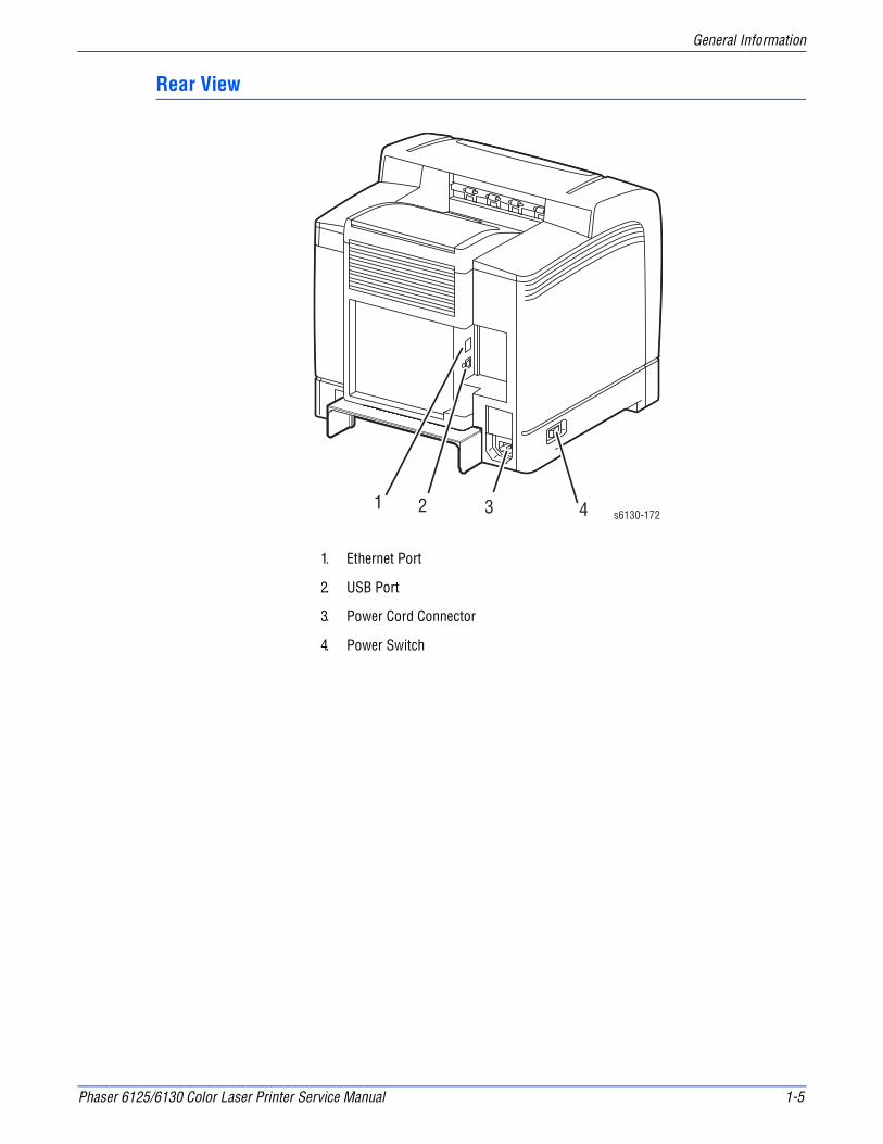
Rear View
1. Ethernet Port
2. USB Port
3. Power Cord Connector
4. Power Switch
1 2 3 4 s6130-172

1-6 Phaser 6125/6130 Color Laser Printer Service Manual
General Information
Control Panel
The Control Panel consists of two LEDs, one display window, and eight functional buttons. These buttons are used to navigate the menu system, perform functions, and select modes of operation for the printer.
Control Panel Button Descriptions
1. Ready LED (Power/Status) LED On - Ready or processing print job.LED blinking - Receiving data.LED Off - An error has occurred and the printer is offline.
2. Error LED Light On - Error with print job.(blinking = not user fixable)(On solid = user fixable)
3. Display Displays printer settings, status, and messages.
4. Menu Button Toggles display between Menu mode and Print mode.
5. 4 Way Cursor Buttons Menu navigation.
Up and Down arrows Switches between Menus or Items on the same level.
Right and Left arrows Switches between the Menu levels.
6. Cancel Button Cancels the current print job.
7. OK Button Move to the next level, confirm setting, and print report.
8. Wake Up LED/Button LED comes On when the printer is in Power Saver Mode. Press this button to exit Power Saver Mode.
Ready
C M Y K
3
s6130-1731 2 6
3 4 5 7 8

Phaser 6125/6130 Color Laser Printer Service Manual 1-7
General Information
LED Indicators
Control Panel Shortcuts
LED State Printer State
Green Ready to Print or in Power Saver mode
Flashing Green Processing print job
Red Error occurs, can be fixed by user
Flashing Red Error occurs, cannot be fixed by user
Mode Buttons Pressed at Power On
Service Diagnostics Up + Down arrow buttons
Reset Password to 0000(used when the Control Panel menus are locked)
Menu
Boot Download for Controller Up + Down + Menu buttons

1-8 Phaser 6125/6130 Color Laser Printer Service Manual
General Information
Printer Options
Printer options, available for the Phaser 6130 ,include:
■ Additional Memory (256 MB/ 512 MB)
■ Multi-Protocol Network Card
Additional Memory
The Phaser 6125/6130 printer features one slot that accepts 256, 512, or 1024 MB of DDR2 DIMMs. Memory modules must meet the following characteristics:
■ 200 Pin DDR2 SO-DIMM (8 chip type)
■ Unbuffered, Non-parity
The printer Configuration page lists the amount of RAM installed in the printer.
NoteOptional memory is not available for the 6125 model.
Multi-Protocol Network Card
The optional Multi-Protocol Network Card (MPC card) provides additional protocols and security features including IPP, SMB, SSL/HTTPs, WINS, DDNS, and Netware.
s6130-174
s6130-175

Phaser 6125/6130 Color Laser Printer Service Manual 1-9
General Information
Maintenance Items
Routine maintenance items are parts or assemblies that require periodic replacement. These items are typically customer replaceable (CRU).
The listed items have limited life and require periodic replacement.
NotePrint life is based on “typical” office printing and 5% coverage per color on 24 lb. paper. Print life figures are not guaranteed and varies depending on usage habits. Imaging Unit print life is based on 3-page jobs using letter-size paper.
Maintenance Items
Item Print Life
Imaging Unit Approximately 30,000 pages
Fuser Up to 50,000 pages
Separator Roller Up to 100,000 pages
Imaging Unit
Paper Tray
Separator Roller
s6130-176
1-10 Phaser 6125/6130 Color Laser Printer Service Manual
General Information
Consumables
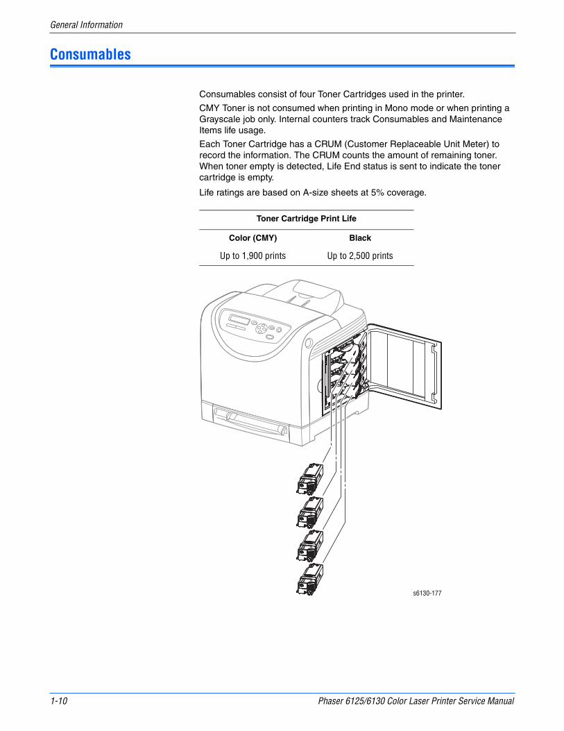
Consumables consist of four Toner Cartridges used in the printer.
CMY Toner is not consumed when printing in Mono mode or when printing a Grayscale job only. Internal counters track Consumables and Maintenance Items life usage.
Each Toner Cartridge has a CRUM (Customer Replaceable Unit Meter) to record the information. The CRUM counts the amount of remaining toner. When toner empty is detected, Life End status is sent to indicate the toner cartridge is empty.
Life ratings are based on A-size sheets at 5% coverage.
Toner Cartridge Print Life
Color (CMY) Black
Up to 1,900 prints Up to 2,500 prints
s6130-177
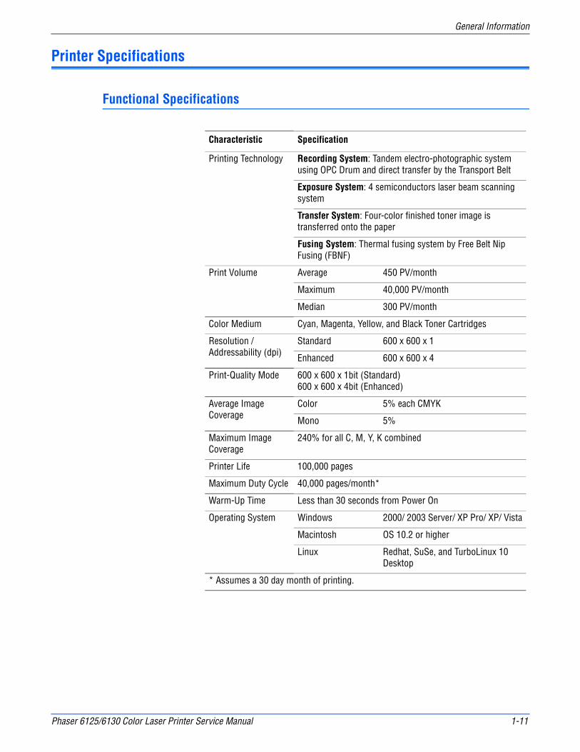
Phaser 6125/6130 Color Laser Printer Service Manual 1-11
General Information
Printer Specifications
Functional Specifications
Characteristic Specification
Printing Technology Recording System: Tandem electro-photographic system using OPC Drum and direct transfer by the Transport Belt
Exposure System: 4 semiconductors laser beam scanning system
Transfer System: Four-color finished toner image is transferred onto the paper
Fusing System: Thermal fusing system by Free Belt Nip Fusing (FBNF)
Print Volume Average 450 PV/month
Maximum 40,000 PV/month
Median 300 PV/month
Color Medium Cyan, Magenta, Yellow, and Black Toner Cartridges
Resolution / Addressability (dpi)
Standard 600 x 600 x 1
Enhanced 600 x 600 x 4
Print-Quality Mode 600 x 600 x 1bit (Standard)600 x 600 x 4bit (Enhanced)
Average Image Coverage
Color 5% each CMYK
Mono 5%
Maximum Image Coverage
240% for all C, M, Y, K combined
Printer Life 100,000 pages
Maximum Duty Cycle 40,000 pages/month*
Warm-Up Time Less than 30 seconds from Power On
Operating System Windows 2000/ 2003 Server/ XP Pro/ XP/ Vista
Macintosh OS 10.2 or higher
Linux Redhat, SuSe, and TurboLinux 10 Desktop
* Assumes a 30 day month of printing.
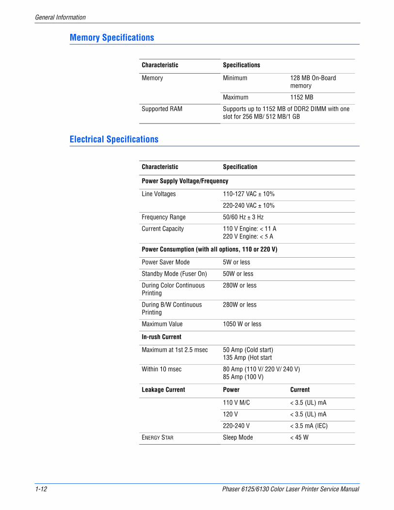
1-12 Phaser 6125/6130 Color Laser Printer Service Manual
General Information
Memory Specifications
Electrical Specifications
Characteristic Specifications
Memory Minimum 128 MB On-Board memory
Maximum 1152 MB
Supported RAM Supports up to 1152 MB of DDR2 DIMM with one slot for 256 MB/ 512 MB/1 GB
Characteristic Specification
Power Supply Voltage/Frequency
Line Voltages 110-127 VAC ± 10%
220-240 VAC ± 10%
Frequency Range 50/60 Hz ± 3 Hz
Current Capacity 110 V Engine: < 11 A220 V Engine: < 5 A
Power Consumption (with all options, 110 or 220 V)
Power Saver Mode 5W or less
Standby Mode (Fuser On) 50W or less
During Color Continuous Printing
280W or less
During B/W Continuous Printing
280W or less
Maximum Value 1050 W or less
In-rush Current
Maximum at 1st 2.5 msec 50 Amp (Cold start)135 Amp (Hot start
Within 10 msec 80 Amp (110 V/ 220 V/ 240 V)85 Amp (100 V)
Leakage Current Power Current
110 V M/C < 3.5 (UL) mA
120 V < 3.5 (UL) mA
220-240 V < 3.5 mA (IEC)
ENERGY STAR Sleep Mode < 45 W

Phaser 6125/6130 Color Laser Printer Service Manual 1-13
General Information
Print Speed
Environmental Specifications
ResolutionColorA/A4
MonoA/A4
600 Standard 12/12 16/16
600 Enhanced 12/12 16/16
Paper Type (65 - 220 gsm)
Letter 12 26
A4 12 25
A5 18 26
Legal 15 26
Transparency 6 6
Characteristic Specification
Temperature
Operating 5 to 32° C (41 to 90° F)
Standby -20 to 40° C (-4 to 104° F)
Humidity (% RH)
Operating 15 to 85% RH
Standby 5 to 85% RH
Altitude
Operating 0 to 3,100 meters (10,171 feet)
Acoustic Noise LWA(B) Sound Power Level (B) Sound Pressure (dBA)
Printing 6.16 51.6
Standby 4.3 25.7

1-14 Phaser 6125/6130 Color Laser Printer Service Manual
General Information
Operating Mode
Mode Condition Description
Running Mode The printer is under operating condition such as running or recording.
Fusing Maintained at operating temperature.
Exposure The Laser Unit Motor runs at the operating speed.
Recording The system is operating.
Cooling Fan The fan operates at high speed.
Control Panel Operation
LCD - Backlight: OnLED - Ready LED is turned On.
Ready Mode The printer is in standby status, ready to run.
Fusing The system keeps the standby temperature.
Exposure The system is at Pause.
Recording The system is at Pause.
Cooling Fan The fan operates at low speed.
Control Panel Operation
LCD - Backlight: OnLED: If printer is online, Ready LED is turned On.
Power Saver Mode (Deep Sleep)
The printer enters into the Power Saver mode to reduce power consumption when it has not received print data for the specified time.
Fusing The system is Off.
Exposure The system is at Pause.
Recording The system is at Pause.
Cooling Fan The system is Off.
Control Panel Operation
LCD: Off, LCD Backlight: OffLED: Power Saver LED is turned On.
Note: When the printer receives a print job or the Wake Up button is pressed, the printer exits the Power Saver mode and enters the Ready mode.
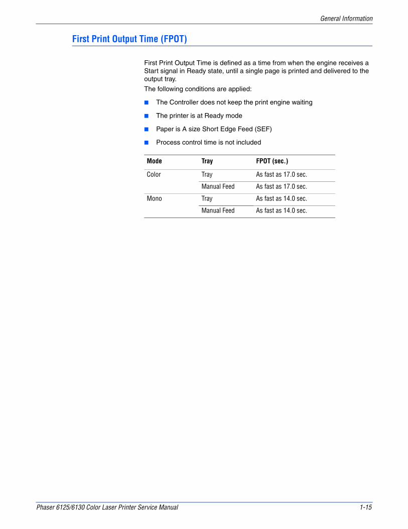
Phaser 6125/6130 Color Laser Printer Service Manual 1-15
General Information
First Print Output Time (FPOT)
First Print Output Time is defined as a time from when the engine receives a Start signal in Ready state, until a single page is printed and delivered to the output tray.
The following conditions are applied:
■ The Controller does not keep the print engine waiting
■ The printer is at Ready mode
■ Paper is A size Short Edge Feed (SEF)
■ Process control time is not included
Mode Tray FPOT (sec.)
Color Tray As fast as 17.0 sec.
Manual Feed As fast as 17.0 sec.
Mono Tray As fast as 14.0 sec.
Manual Feed As fast as 14.0 sec.

1-16 Phaser 6125/6130 Color Laser Printer Service Manual
General Information
Image Specifications
NoteThe printer has 4 mm margins on all sides.
■ Refer to “Print-Quality Troubleshooting” on page 5-1 for detailed specifications.
Characteristic Specification
Maximum Print Area 210.9 mm (8.2 inches) x 351.6 mm (13.8 inches)
Guaranteed Print Area 207.9 mm (8.2 inches) x 347.6 mm (13.7 inches)
Skew 190 mm ± 1.2 mm
Perpendicularity 114.5 mm ± 0.8 mm
Parallelism
Horizontal 180 mm ± 1.2 mm
Vertical 234 mm ± 1.2 mm
Linearity
Horizontal 190 mm ± 0.5 mm
Vertical 234 mm ± 0.5 mm
Slant 269 mm ± 1.2 mm
Magnification Error
Horizontal Simplex 234 mm ± 0.5 mm
Horizontal Duplex 234 mm ± 0.8 mm
Vertical Simplex 190 mm ± 0.5 mm
Vertical Duplex 190 mm ± 0.8 mm
Registration
Leading Edge 10.0 mm ± 2.0 mm
Side Edge 8.5 mm ± 2.5 mm
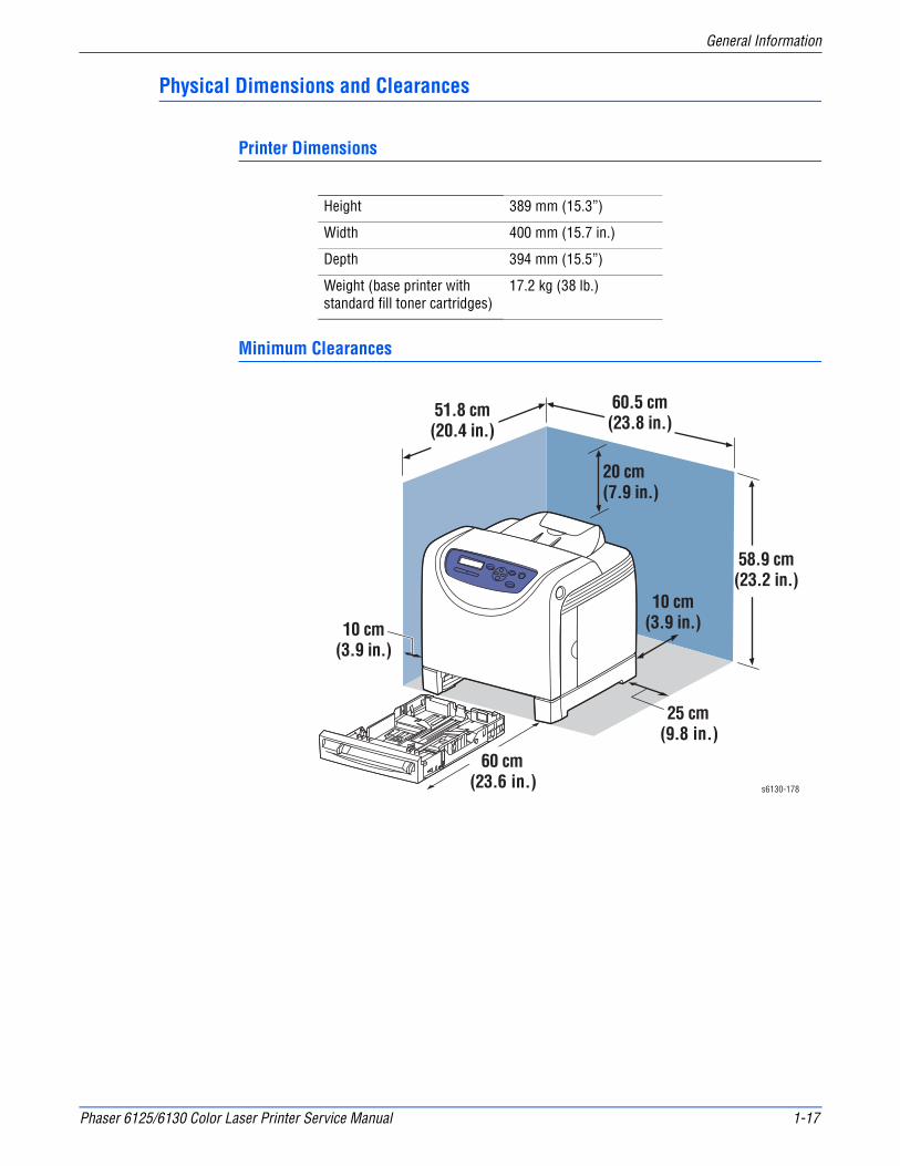
Phaser 6125/6130 Color Laser Printer Service Manual 1-17
General Information
Physical Dimensions and Clearances
Printer Dimensions
Minimum Clearances
Height 389 mm (15.3”)
Width 400 mm (15.7 in.)
Depth 394 mm (15.5”)
Weight (base printer with standard fill toner cartridges)
17.2 kg (38 lb.)
58.9 cm(23.2 in.)
20 cm(7.9 in.)
10 cm(3.9 in.)
25 cm (9.8 in.)
60.5 cm(23.8 in.)
10 cm(3.9 in.)
51.8 cm(20.4 in.)
60 cm (23.6 in.) s6130-178

1-18 Phaser 6125/6130 Color Laser Printer Service Manual
General Information
Mounting Surface Specifications
These specifications apply to any printer used as a table-top printer.
1. Mounting surface flatness must be within the specified range.
2. The printer must not be tipped or tilted more than 7 mm.
Failure to adhere to the specified mounting specifications will void all guarantees of print-quality and/or performance. Known problems that can occur as a result of exceeding the mounting surface specifications are:
■ Color-to-Color mis-registration, primarily in the horizontal (laser scan) direction.
■ A smear or line of toner approximately 40 mm from the trailing edge of the print.
Right Hand Side
s6180-263
5mm Max
s6180-262
10° or 7 mm
10° or 7 mm
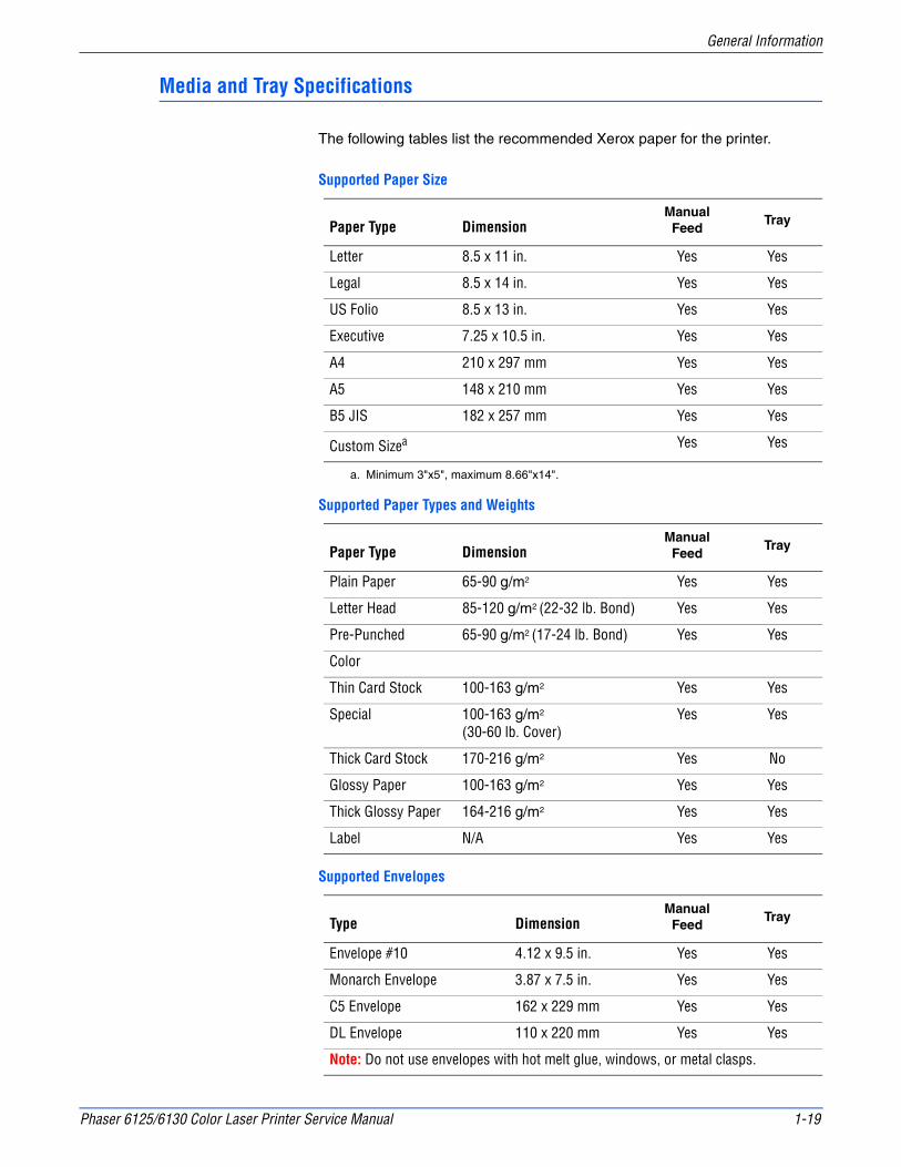
Phaser 6125/6130 Color Laser Printer Service Manual 1-19
General Information
Media and Tray Specifications
The following tables list the recommended Xerox paper for the printer.
Supported Paper Size
Paper Type DimensionManual
FeedTray
Letter 8.5 x 11 in. Yes Yes
Legal 8.5 x 14 in. Yes Yes
US Folio 8.5 x 13 in. Yes Yes
Executive 7.25 x 10.5 in. Yes Yes
A4 210 x 297 mm Yes Yes
A5 148 x 210 mm Yes Yes
B5 JIS 182 x 257 mm Yes Yes
Custom Sizea
a. Minimum 3"x5", maximum 8.66"x14".
Yes Yes
Supported Paper Types and Weights
Paper Type DimensionManual
FeedTray
Plain Paper 65-90 g/m2 Yes Yes
Letter Head 85-120 g/m2 (22-32 lb. Bond) Yes Yes
Pre-Punched 65-90 g/m2 (17-24 lb. Bond) Yes Yes
Color
Thin Card Stock 100-163 g/m2 Yes Yes
Special 100-163 g/m2
(30-60 lb. Cover)Yes Yes
Thick Card Stock 170-216 g/m2 Yes No
Glossy Paper 100-163 g/m2 Yes Yes
Thick Glossy Paper 164-216 g/m2 Yes Yes
Label N/A Yes Yes
Supported Envelopes
Type DimensionManual
FeedTray
Envelope #10 4.12 x 9.5 in. Yes Yes
Monarch Envelope 3.87 x 7.5 in. Yes Yes
C5 Envelope 162 x 229 mm Yes Yes
DL Envelope 110 x 220 mm Yes Yes
Note: Do not use envelopes with hot melt glue, windows, or metal clasps.
1-20 Phaser 6125/6130 Color Laser Printer Service Manual
General Information
Controller Functions
Job Control
Cancel Print
User can cancel a print job while printing is in progress using the Cancel button on the Control Panel. Job cancellation is not immediate. Depending on the job size, it may take a while to completely cancel.
Forced Output
This function forces the printer to print the received data when the printer is waiting for the remaining data during job processing.
IP Filter
User can accept or reject print jobs up to five specified IP addresses. IP filter is available only to LPD and Port9100.
Job Recovery
When a print job fails due to a paper jam, the printer automatically restarts the job after the jammed paper is removed. User does not have to reprint the entire job.
Job Timeout
When job transmission is interrupted for a certain period of time, the print data is deleted as an error. The timeout setting can be changed using the menu on the printer’s Control Panel.
Print Volume Management
Print Volume (PV) Management manages print volume per user and can manage up to 50 users.
RAM Disk
RAM Disk functions when memory is expanded, enabling Collation, Secure Print, Proof Print, Form Overlay, and Font Download. 256 MB is needed to enable RAM Disk and all related functions.

Phaser 6125/6130 Color Laser Printer Service Manual 21
General Information
Collation
The job is stored in the memory and multiple copies are printed. When the entire job does not fit in the memory, the printer prints one copy up to the stored pages, and the remaining are discarded.
An error message will appear on the Control Panel: “Error xxxx Press set key.”
Two options are available to ensure Job Collation will process effectively:
■ Break large print job into multiple small print jobs
■ Increase memory for the printer
Secure Print
When memory is expanded to 256 MB or more, the printer holds print data, including a User Password (11 digits), User Name, and Document Name in the memory.
■ User ID – consists of a variable length from 1 to 24 byte characters (20H-FFH). The driver requests the User ID from the user when the Secure Print option is selected. A user ID cannot be blanked with only space characters.
■ User Password – consists of a variable length from 0 to 11 digits. The password is an optional input and hidden from the user interface by displaying “*” for each digit. If a password is not specified, the driver will accept it as a zero-length string so that a password will not be required when requesting job output from the printer.
■ Document Name – consists of a variable length from 0 to 24 characters (20H-FFH) that specifies the document name.
The data will not be printed until the same password, user name, and document name are provided via the printer menu on the Control Panel. User can remove or keep the data after printing the document. The data remains in the printer memory as long as it is not cleared and will be cleared when the printer is turned off. User can omit entering a password (this is called Store Print - not available for MAC OS 10.2.).
Proof Print
Proof Print can be selected only when multiple sets of prints are specified in the printer driver. Proof Print requires at least 256 MB of memory. The printer prints only the first set of the print data including a user name and document name specified in the printer driver. User can keep or remove the data using the printer menu on the Control Panel. The data remains in the printer memory as long as it is not cleared and will be cleared when the printer is turned Off. This function is not available for MAC OS 10.2 and Linux operating systems.
Form Overlay
The function for writing PCL6 forms are downloaded into RAM Disk.
22 Phaser 6125/6130 Color Laser Printer Service Manual
General Information
Font Download
PCL6 fonts can be downloaded into RAM Disk.
Billing Meters
The Billing Print counter provides the number of pages printed properly (simplex print is counted as 1 and duplex print is counted as 2 - including N up).
If an error has occurred after the one side printed properly during duplex printing, it is counted as 1.
NoteSame data is stored in two or more addresses in one IC. When the Controller is replaced, IC can be transferred.
ID Print
User can position and print the User Name on the upper right, upper left, lower right, and lower left (only for PCL6) of the page.
Non-Genuine Mode
When the Toner Cartridge life has ended, the printer stops accepting print request (life of the Toner Cartridge is counted by the counter in the CRUM). This mode can be changed so the printer will not stop at the end of the Toner Cartridge rated life; however, the printer will display an end of life message on the Control Panel.
Counter Description
Color Print Counter Counts the number of pages printed in color (7 digits).
Mono Print Counter Counts the number of pages printed in mono (7 digits).
Total Print Counter Count the total number of pages printed in color and mono (7 digits).

Phaser 6125/6130 Color Laser Printer Service Manual 23
General Information
Toner Remaining Amount
The CentreWare Internet Services (IS) and PrintingScout (SimpleMonitor) allow the printer to display toner remaining amount.
Maintenance Function
Firmware Update
The Image Processor Board and Multi-Protocol Network Card firmware can be updated by customers and service technicians using a Windows PC or Macintosh with dedicated utilities. Firmware updates are available at www.xerox.com/office/support.
Detailed procedures are available in “Firmware Update” on page A-3.
Note
Boot Code can be updated via USB port only.
Toner Cartridge Control Panel Display
Toner Cartridge Control Panel Display Functionality
Normal Status
Life Warning Error
End of Life Error
Xerox Xerox (TM) Toner Cartridge
Replace Soon
Replace Toner Cartridge
Prints with full functionality.
Xerox (refill Toner Cartridge)
Xerox (TM) Toner Cartridge
Replace Soon
Empty Prints with full functionality up to 40% of the Toner Cartridge life.
Other OEM (non-Xerox printer manufacturer)
Non-Xerox Toner Cartridge
Printer displays error and will not print.
Non-Xerox Toner Cartridge Manufacturer
Non-Xerox Toner Cartridge
No Life Tracking
Replace Toner Cartridge
Prints with full functionality.
Updated Firmware Windows
Via USB/IEEE1284 Via Network (port 9100)
Image Processor Board Available Available
Multi Protocol Network Card Available Available
MCU Boarda
a. MCU Board cannot be updated when ROM starts to be used for MCU Board.
Available Available
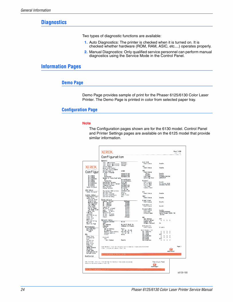
24 Phaser 6125/6130 Color Laser Printer Service Manual
General Information
Diagnostics
Two types of diagnostic functions are available:
1. Auto Diagnostics: The printer is checked when it is turned on. It is checked whether hardware (ROM, RAM, ASIC, etc....) operates properly.
2. Manual Diagnostics: Only qualified service personnel can perform manual diagnostics using the Service Mode in the Control Panel.
Information Pages
Demo Page
Demo Page provides sample of print for the Phaser 6125/6130 Color Laser Printer. The Demo Page is printed in color from selected paper tray.
Configuration Page
NoteThe Configuration pages shown are for the 6130 model. Control Panel and Printer Settings pages are available on the 6125 model that provide similar information.
s6130-180

Phaser 6125/6130 Color Laser Printer Service Manual 25
General Information
User can print the Configuration Page from the Control Panel > Menu > Information Pages > Configuration. The Configuration Page is printed in from the default tray and includes the following information.
PCL Fonts List
User can print the PCL Fonts List default in color on A size paper from default tray. The PCL Font List contains:
■ No., Fonts, Escape Sequence, Font ID, Sample
PCL Macro List
User can print the PCL Macro List default on A paper size from default tray.
Configuration Page Information
General Description Detail Description
Title Prints Title of the document
Product Name (Logo) Prints organization’s logo
General Total Impressions, Total Color Impressions, Total Black Impressions, Memory Capacity, Printer Language, Number of Fonts Available, PostScript Version, PostScript Serial Number, Firmware Version, Boot Version, Engine Version, PostScript CRD Version, Default Paper, Default Language, Current Temperature, Current Humidity
Printer Options Multi-Protocol Card (when installed)Duplex Unit: (00.00.00)Paper Tray: Tray 1 (MPT), Tray 2-3
Print Volume Print Volume for each paper size
Network Setup Firmware Version, MAC Address, Ethernet, TCP/IP, Protocol, Host Access List, Adobe Protocol
Parallel Setup ECP, Adobe Protocol
USB Setup Adobe Protocol
System Setup PowerSaver Time, Audio Tones, Time-Out, Language, Auto Log Print, Print ID, Print Text, Banner Sheet, RAM Disk, Tray Switching, mm/inch, Start Up Page
Maintenance Auto Reg Adj., Non-Xerox Toner
PCL Paper Tray, Paper Size, Orientation, 2-Sided, Font, Symbol Set, Font Size, Font Pitch, Form Line, Quantity, Image Enhance, Hex Dump, Draft Mode, Line Termination, Default Color
PostScript PS Error Report, PS Job Time-Out, Paper Select Mode
Control Panel Panel Lock
Tray Settings MPT Mode, Tray 2
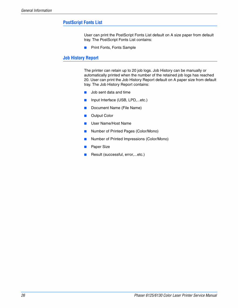
26 Phaser 6125/6130 Color Laser Printer Service Manual
General Information
PostScript Fonts List
User can print the PostScript Fonts List default on A size paper from default tray. The PostScript Fonts List contains:
■ Print Fonts, Fonts Sample
Job History Report
The printer can retain up to 20 job logs. Job History can be manually or automatically printed when the number of the retained job logs has reached 20. User can print the Job History Report default on A paper size from default tray. The Job History Report contains:
■ Job sent data and time
■ Input Interface (USB, LPD,...etc.)
■ Document Name (File Name)
■ Output Color
■ User Name/Host Name
■ Number of Printed Pages (Color/Mono)
■ Number of Printed Impressions (Color/Mono)
■ Paper Size
■ Result (successful, error,...etc.)

Phaser 6125/6130 Color Laser Printer Service Manual 27
General Information
Error History Report
The printer can retain up to 42 jam errors and up to 42 fatal errors. User can print the Error History Report default on A paper size from default tray using the printer menu in the Control Panel.
Jam Error log includes the following information:
■ Item No., Total Print Count, Paper Jam Type
Fatal Error log includes the following information:
■ Item No., Total Print Count, Chain-Link Code
Print Meter (Print Volume Report)
User can print the Print Meter page default on A paper size from default tray. The Print Meter page contains:
■ Date of Initialization, Job Accounting User Name, Pages, Sheets, Date/Time
s6130-181

28 Phaser 6125/6130 Color Laser Printer Service Manual
General Information

2Chapter
Theory of OperationIn this chapter...■ Phaser 6125/6130 Operational Overview
■ Printing Process
■ Paper Path of the Printer
■ Major Assemblies and Functions
■ Printer Modes
■ Printer Control
■ Drive Transmission

2-2 Phaser 6125/6130 Color Laser Printer Service Manual
Theory of Operation
Phaser 6125/6130 Operational Overview
The Phaser 6125/6130 Color Laser Printer is a full-color laser printer that uses Raster Output Scanner (ROS) lasers with an electrophotographic four-color CMYK process. The tandem system consists of four color drums (C, M, Y, and K) which creates the toner image.
The following block diagram provides the sequence of events for the xerographic process (dashed lines) and the paper flow (solid lines) into and out of the printer.
Print Process Block Diagram
s6xxx-001
Imaging Unit
(1) Charge
(2) Exposure
(3) Development
(5) Cleaning (7) Cleaning (6) Fusing
(4) Transfer (Drum to Paper)
Transfer Belt Paper
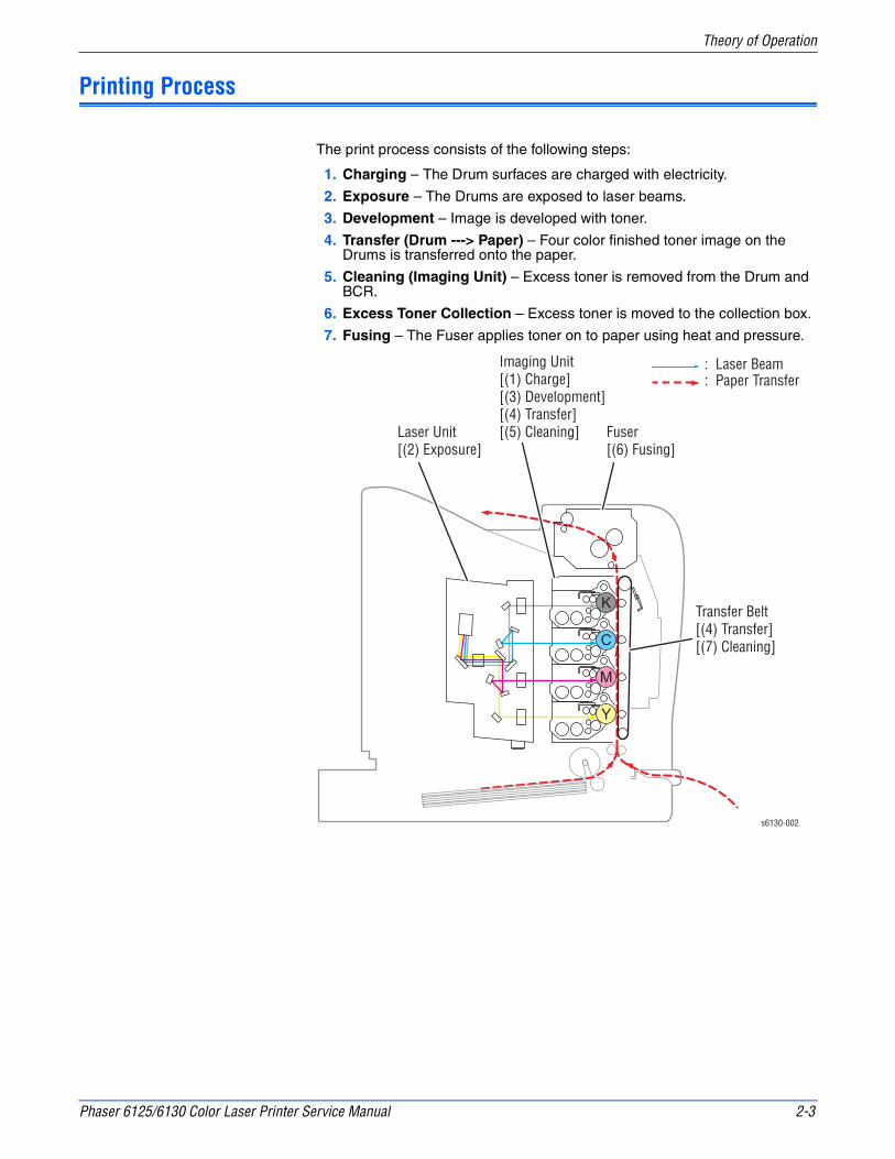
Phaser 6125/6130 Color Laser Printer Service Manual 2-3
Theory of Operation
Printing Process
The print process consists of the following steps:
1. Charging – The Drum surfaces are charged with electricity.
2. Exposure – The Drums are exposed to laser beams.
3. Development – Image is developed with toner.
4. Transfer (Drum ---> Paper) – Four color finished toner image on the Drums is transferred onto the paper.
5. Cleaning (Imaging Unit) – Excess toner is removed from the Drum and BCR.
6. Excess Toner Collection – Excess toner is moved to the collection box.
7. Fusing – The Fuser applies toner on to paper using heat and pressure.
s6130-002
Transfer Belt[(4) Transfer][(7) Cleaning]
Imaging Unit[(1) Charge][(3) Development][(4) Transfer][(5) Cleaning] Fuser
[(6) Fusing]
: Laser Beam: Paper Transfer
Laser Unit[(2) Exposure]
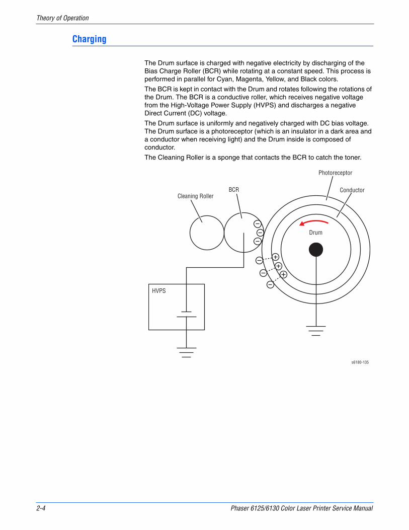
2-4 Phaser 6125/6130 Color Laser Printer Service Manual
Theory of Operation
Charging
The Drum surface is charged with negative electricity by discharging of the Bias Charge Roller (BCR) while rotating at a constant speed. This process is performed in parallel for Cyan, Magenta, Yellow, and Black colors.
The BCR is kept in contact with the Drum and rotates following the rotations of the Drum. The BCR is a conductive roller, which receives negative voltage from the High-Voltage Power Supply (HVPS) and discharges a negative Direct Current (DC) voltage.
The Drum surface is uniformly and negatively charged with DC bias voltage. The Drum surface is a photoreceptor (which is an insulator in a dark area and a conductor when receiving light) and the Drum inside is composed of conductor.
The Cleaning Roller is a sponge that contacts the BCR to catch the toner.
s6180-135
Cleaning RollerBCR
Photoreceptor
Conductor
Drum
HVPS

Phaser 6125/6130 Color Laser Printer Service Manual 2-5
Theory of Operation
Exposure
Four laser diodes (one for each color) in the Laser Unit emit laser beams. The beams are directed by mirrors to the rotating polygon mirror attached to the scanner motor. As the polygon mirror rotates, the beams are directed through a series of lenses and mirrors to each of the drums, which are scanned by the beams from end to end in the axial direction.
: Laser beams (Y): Laser beams (M): Laser beams (C): Laser beams (K)
s6xxx-003
Front
Drum (K)
Drum (C)
Drum (M)
Drum (Y)
Polygon Mirror
Mirror
Mirror
Lens
Mirror
Mirror
Mirror
Lens
Mirror
Lens
Mirror
Lens
Mirror
Mirror
Lens
Laser Diode Board
Polygon MirrorScanner
SOS Board
Lens
Lens
Mirror
Mirror
Mirror
Mirror
Rear View
SOS Sensor
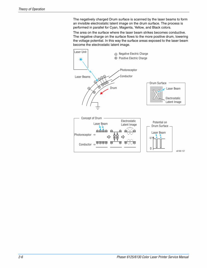
2-6 Phaser 6125/6130 Color Laser Printer Service Manual
Theory of Operation
The negatively charged Drum surface is scanned by the laser beams to form an invisible electrostatic latent image on the drum surface. The process is performed in parallel for Cyan, Magenta, Yellow, and Black colors.
The area on the surface where the laser beam strikes becomes conductive. The negative charge on the surface flows to the more positive drum, lowering the voltage potential. In this way the surface areas exposed to the laser beam become the electrostatic latent image.
Laser Unit
Laser Beams
Laser Beam
Laser Beam
Laser Beam
Negative Electric ChargePositive Electric Charge
Photoreceptor
Photoreceptor
Conductor
Conductor
Drum
Electrostatic Latent Image
Electrostatic Latent Image
Potential onDrum Surface
-V
0
Drum Surface
Concept of Drum
s6180-137

Phaser 6125/6130 Color Laser Printer Service Manual 2-7
Theory of Operation
Development
Toner is electrically attached to the invisible electrostatic latent image on the drum surface to form the visible toner image on the Drum.
The toner in the Toner Cartridge is agitated by the built-in Agitator and fed into the Developer. The Augers are driven by the Toner Motor and the Developer Motor in the Main Drive. The toner to be consumed according to the print count is calculated and fed into the Developer. This process, called Toner Dispensation, is controlled by two processes: Pixel Count Dispense Control (PCDC) and Automatic Density Control (ADC).
The toner fed into the Developer and the carrier in the Developer are agitated by the Auger, and supplied to the Magnet Roller arranged in the drum surface area. The toner and carrier are charged by friction due to agitation (toner in negative, carrier in positive), and they are attracted electrically. A uniform layer is formed by the Trimmer Bar as the carrier magnetic substance is attracted to the Magnetic Roller.
HVPS
s6xxx-004
: Negative Electric Charge: Positive Electric Charge: Toner: Carrier
Trimmer RodPaddle
Toner Cartridge
Auger
AugerMagnet Roller
Agitator
Drum
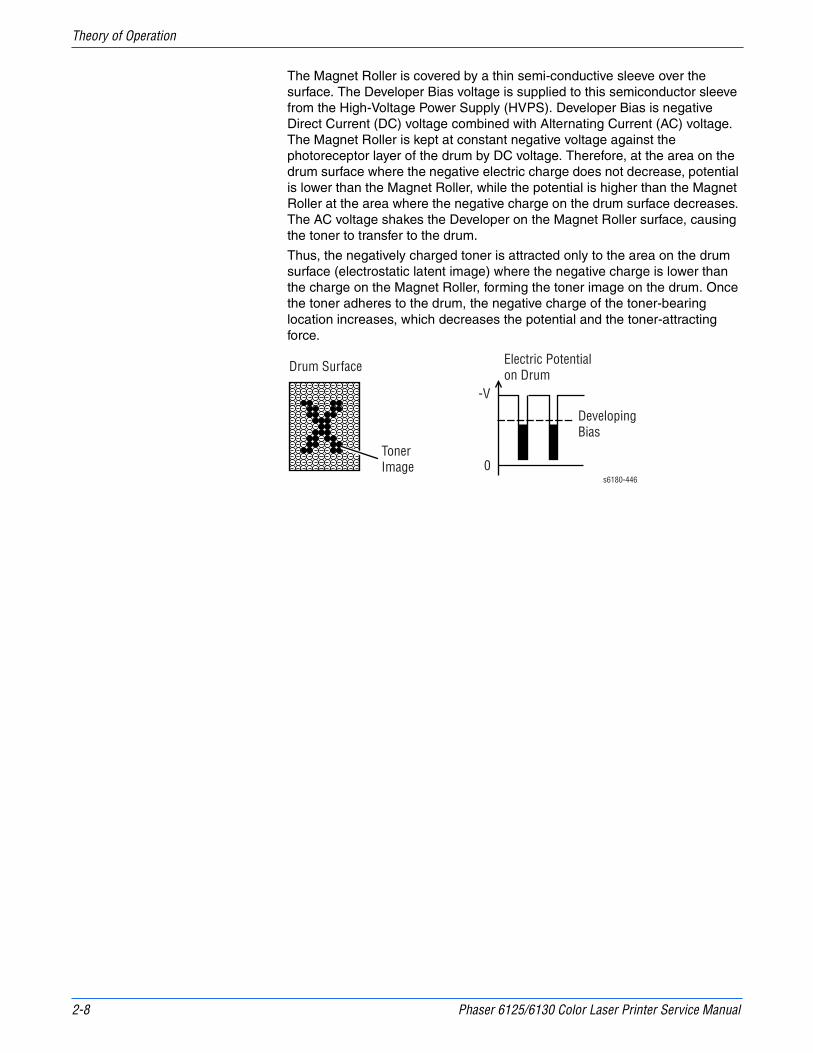
2-8 Phaser 6125/6130 Color Laser Printer Service Manual
Theory of Operation
The Magnet Roller is covered by a thin semi-conductive sleeve over the surface. The Developer Bias voltage is supplied to this semiconductor sleeve from the High-Voltage Power Supply (HVPS). Developer Bias is negative Direct Current (DC) voltage combined with Alternating Current (AC) voltage. The Magnet Roller is kept at constant negative voltage against the photoreceptor layer of the drum by DC voltage. Therefore, at the area on the drum surface where the negative electric charge does not decrease, potential is lower than the Magnet Roller, while the potential is higher than the Magnet Roller at the area where the negative charge on the drum surface decreases. The AC voltage shakes the Developer on the Magnet Roller surface, causing the toner to transfer to the drum.
Thus, the negatively charged toner is attracted only to the area on the drum surface (electrostatic latent image) where the negative charge is lower than the charge on the Magnet Roller, forming the toner image on the drum. Once the toner adheres to the drum, the negative charge of the toner-bearing location increases, which decreases the potential and the toner-attracting force.
Drum Surface
TonerImage
Electric Potentialon Drum
Developing Bias
-V
0s6180-446
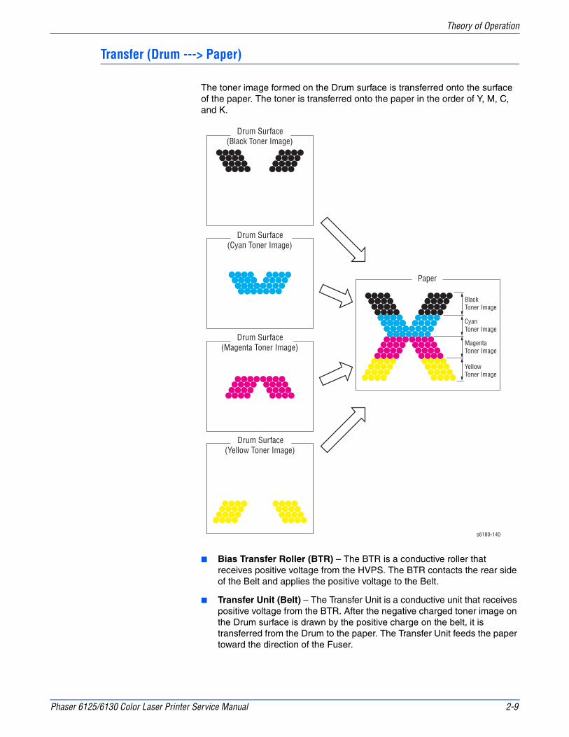
Phaser 6125/6130 Color Laser Printer Service Manual 2-9
Theory of Operation
Transfer (Drum ---> Paper)
The toner image formed on the Drum surface is transferred onto the surface of the paper. The toner is transferred onto the paper in the order of Y, M, C, and K.
■ Bias Transfer Roller (BTR) – The BTR is a conductive roller that receives positive voltage from the HVPS. The BTR contacts the rear side of the Belt and applies the positive voltage to the Belt.
■ Transfer Unit (Belt) – The Transfer Unit is a conductive unit that receives positive voltage from the BTR. After the negative charged toner image on the Drum surface is drawn by the positive charge on the belt, it is transferred from the Drum to the paper. The Transfer Unit feeds the paper toward the direction of the Fuser.
s6180-140
Drum Surface(Black Toner Image)
Drum Surface(Cyan Toner Image)
Drum Surface(Magenta Toner Image)
Drum Surface(Yellow Toner Image)
Paper
Black Toner Image
Cyan Toner Image
Magenta Toner Image
Yellow Toner Image
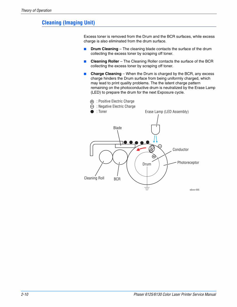
2-10 Phaser 6125/6130 Color Laser Printer Service Manual
Theory of Operation
Cleaning (Imaging Unit)
Excess toner is removed from the Drum and the BCR surfaces, while excess charge is also eliminated from the drum surface.
■ Drum Cleaning – The cleaning blade contacts the surface of the drum collecting the excess toner by scraping off toner.
■ Cleaning Roller – The Cleaning Roller contacts the surface of the BCR collecting the excess toner by scraping off toner.
■ Charge Cleaning – When the Drum is charged by the BCR, any excess charge hinders the Drum surface from being uniformly charged, which may lead to print quality problems. The the latent charge pattern remaining on the photoconductive drum is neutralized by the Erase Lamp (LED) to prepare the drum for the next Exposure cycle.
s6xxx-005
: Positive Electric Charge: Negative Electric Charge: Toner Erase Lamp (LED Assembly)
Blade
Cleaning Roll BCR
Drum
Conductor
Photoreceptor
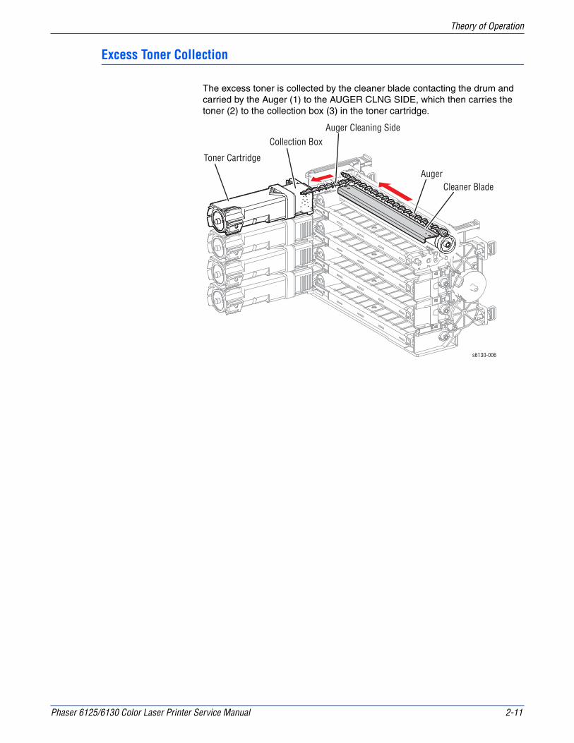
Phaser 6125/6130 Color Laser Printer Service Manual 2-11
Theory of Operation
Excess Toner Collection
The excess toner is collected by the cleaner blade contacting the drum and carried by the Auger (1) to the AUGER CLNG SIDE, which then carries the toner (2) to the collection box (3) in the toner cartridge.
s6130-006
Toner Cartridge
Collection BoxAuger Cleaning Side
AugerCleaner Blade

2-12 Phaser 6125/6130 Color Laser Printer Service Manual
Theory of Operation
Fusing
Toner is applied by the BTR and the Developers. The toner image is bonded to the paper with the Fuser (Fusing Unit) by the Free Belt Nip Fusing (FBNF) thermal fusing system. The Heat Roller with the Heater Lamp melts the toner particles. Toner is fused onto the paper by the combination of heat and pressure.
Warm-Up Stand By Printing
Main Heater Lamp On On/Off On
s6130-007
PaperNip Spring
Felt
Belt
Nip Head
Belt Frame
SheetUnfixed Toner
Heater LampHeat Roller
Fixed Toner
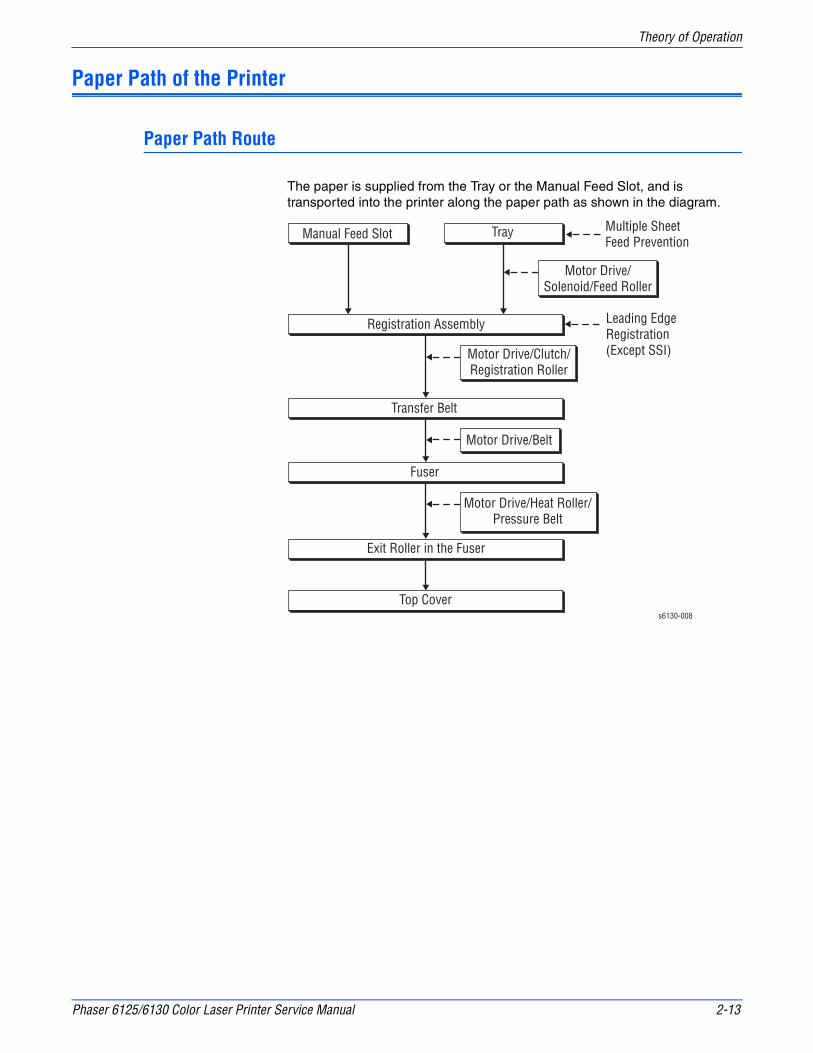
Phaser 6125/6130 Color Laser Printer Service Manual 2-13
Theory of Operation
Paper Path of the Printer
Paper Path Route
The paper is supplied from the Tray or the Manual Feed Slot, and is transported into the printer along the paper path as shown in the diagram.
s6130-008
Manual Feed Slot Tray Multiple Sheet Feed Prevention
Motor Drive/Solenoid/Feed Roller
Leading Edge Registration (Except SSI)
Registration Assembly
Transfer Belt
Fuser
Exit Roller in the Fuser
Top Cover
Motor Drive/Clutch/Registration Roller
Motor Drive/Belt
Motor Drive/Heat Roller/Pressure Belt

2-14 Phaser 6125/6130 Color Laser Printer Service Manual
Theory of Operation
Paper Path Components
Paper path components for the printer are shown in the following figure.
s6130-009
: Laser Beam: Paper Transfer: Paper Sensors
Exit Roller
Heat Roller
Pressure Belt
Belt
Rubber Registration RollerMetal Registration Roller
Exit Sensor
Manual Feed No Paper Sensor
Registration Sensor
Separator RollerFeed Roller
Tray No Paper Sensor

Phaser 6125/6130 Color Laser Printer Service Manual 2-15
Theory of Operation
Major Assemblies and Functions
Major functional components for the printer are classified into the following categories based on the printer configuration.
■ Paper Tray
■ Paper Feeder
■ Manual Feed & Registration
■ Transfer Unit and Fuser
■ Laser Unit
■ Toner Cartridge & Dispenser
■ Imaging Unit
■ Drive Assembly
■ Electrical
Paper Tray
■ Left/Right Side Guide
The Side Guides move at a right angle to the paper transfer direction to align the paper width.
■ Separator Roller
The Separator Roller and Feed Roller pinch the paper to prevent multiple sheets of paper from feeding.
s6130-010
Bottom Plate
Side Guide (L)
Side Guide (R)
End Guide
Separator Roller

2-16 Phaser 6125/6130 Color Laser Printer Service Manual
Theory of Operation
■ Paper Tray End Guide
The End Guide moves in toward the paper transfer direction to determine the paper size.
■ Bottom Plate
The bottom plate is locked to the tray bottom when the tray is pulled out of the paper feeder, and unlocked when the tray is installed in the paper feeder. When unlocked, the bottom plate lifts the paper, pushing it against the feed roller using spring tension.
Multiple Sheet Feed Prevention
The sheets loaded into the Paper Tray are occasionally stuck together along the edges, which can cause a multiple feed or a jam. The sheets are fed by the Feed Roller to a position between the Feed Roller and the Separator Roller. Normally, when only one sheet is fed, both the Feed Roller and Separator Roller rotate to allow the sheet to pass.
However, when two sheets are fed concurrently, only the Feed Roller rotates. The Separator Roller is locked, allowing the upper sheet to pass, separated from the lower sheet that is stopped by the friction with the Separator Roller at rest.
The Separator Roller is pushed toward the Feed Roller by spring pressure, and controlled by the Friction Clutch with which it is coupled.
s6130-011
Feed Roller
Separator Roller
Separator Roller
Friction Clutch

Phaser 6125/6130 Color Laser Printer Service Manual 2-17
Theory of Operation
Paper Feeder
■ Tray No Paper Sensor (Photo Sensor)
Detects the presence/absence of paper in the Paper Tray based on the position of No Paper Actuator. (No paper: Sensor beam is intercepted)
■ Feed Solenoid
The Feed Solenoid transmits drive energy from the Main Drive Assembly to the Feed Roller.
s6130-
Feed Roller
Feed Solenoid
Tray No Paper Sensor
s6130-013
Tray No Paper Sensor
No Paper Actuator(No Paper Position)
Tray No Paper Sensor
Paper
No Paper Actuator
Bottom Plate
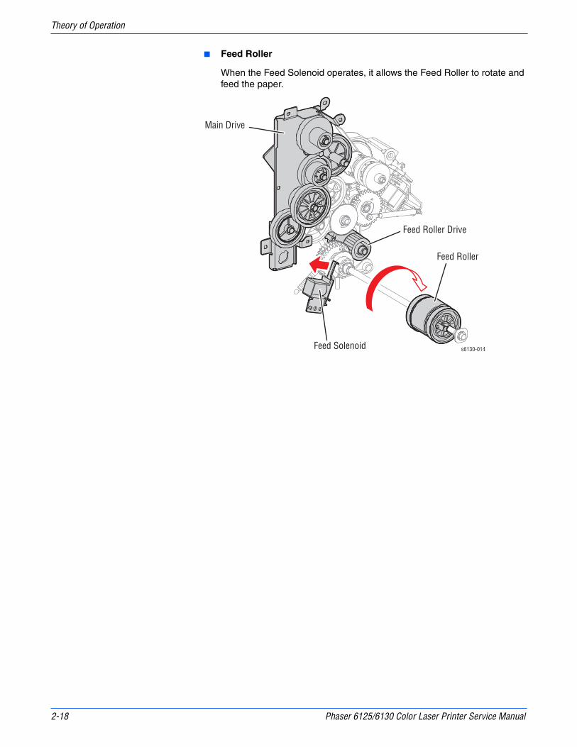
2-18 Phaser 6125/6130 Color Laser Printer Service Manual
Theory of Operation
■ Feed Roller
When the Feed Solenoid operates, it allows the Feed Roller to rotate and feed the paper.
s6130-014
Feed Roller
Feed Solenoid
Main Drive
Feed Roller Drive

Phaser 6125/6130 Color Laser Printer Service Manual 2-19
Theory of Operation
Manual Feed & Registration
■ Manual Feed No Paper Sensor (Photo Sensor)
Detects presence/absence of paper in the Manual Feed Slot by the change in actuator position.
Upon detecting the sheet, the Regi Roller rotates for a predetermined duration to feed the sheet. The sheet is caught between the Rollers so that it may not fall from the Manual Feed Slot.
The Rollers stop immediately when the Registration Sensor detects the presence of paper.
■ Registration Sensor (Photo Sensor)
The Registration Sensor detects paper when the paper leading edge reaches the Registration Chute. When paper is fed from the Manual Feed Slot, the Registration Sensor measures the paper length. The On time of the Registration Sensor is converted into the paper length.
NoteOn: The paper activates the Actuator.
s6130-
Manual Sheet Feed No Paper Sensor
Manual Sheet Feed No Paper Sensor
Paper
Manual Sheet Feed Actuator(No Paper Position)
Manual Sheet Feed Actuator
RegistrationRollers
RegistrationRollers
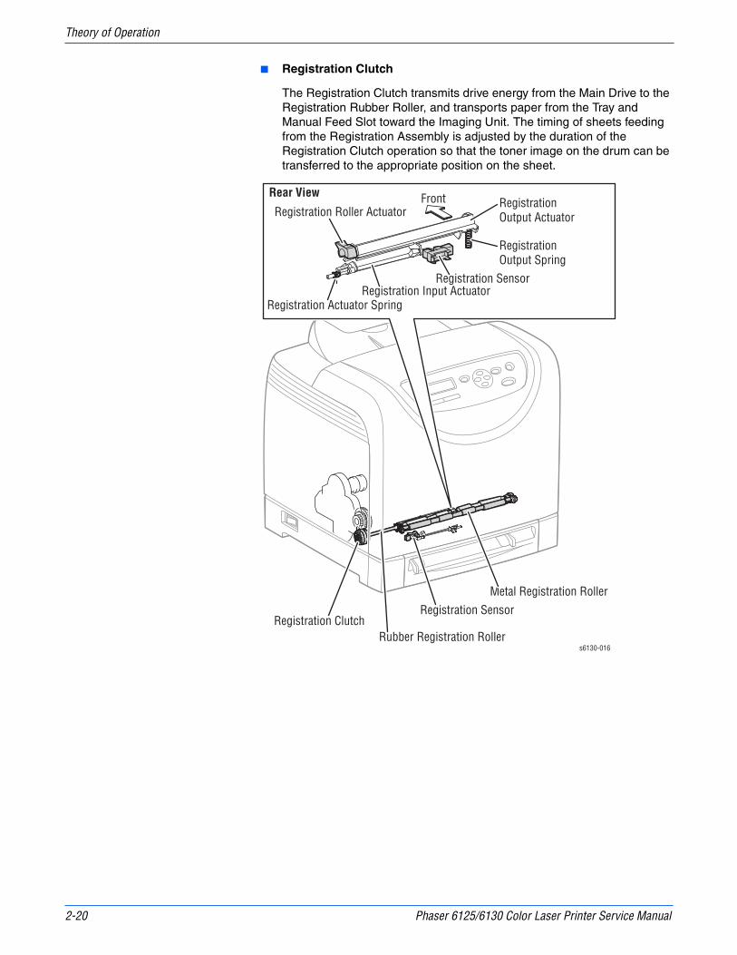
2-20 Phaser 6125/6130 Color Laser Printer Service Manual
Theory of Operation
■ Registration Clutch
The Registration Clutch transmits drive energy from the Main Drive to the Registration Rubber Roller, and transports paper from the Tray and Manual Feed Slot toward the Imaging Unit. The timing of sheets feeding from the Registration Assembly is adjusted by the duration of the Registration Clutch operation so that the toner image on the drum can be transferred to the appropriate position on the sheet.
s6130-016
Registration Sensor
Rubber Registration Roller
Metal Registration Roller
Registration Clutch
Registration Output Spring
Registration Actuator Spring
Registration Output Actuator
Registration Input Actuator
Registration Roller Actuator
Registration Sensor
Rear View Front
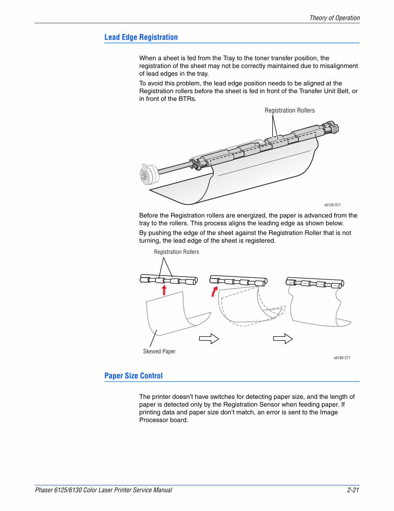
Phaser 6125/6130 Color Laser Printer Service Manual 2-21
Theory of Operation
Lead Edge Registration
When a sheet is fed from the Tray to the toner transfer position, the registration of the sheet may not be correctly maintained due to misalignment of lead edges in the tray.
To avoid this problem, the lead edge position needs to be aligned at the Registration rollers before the sheet is fed in front of the Transfer Unit Belt, or in front of the BTRs.
Before the Registration rollers are energized, the paper is advanced from the tray to the rollers. This process aligns the leading edge as shown below.
By pushing the edge of the sheet against the Registration Roller that is not turning, the lead edge of the sheet is registered.
Paper Size Control
The printer doesn’t have switches for detecting paper size, and the length of paper is detected only by the Registration Sensor when feeding paper. If printing data and paper size don’t match, an error is sent to the Image Processor board.
Registration Rollers
s6130-017
s6180-271
Registration Rollers
Skewed Paper

2-22 Phaser 6125/6130 Color Laser Printer Service Manual
Theory of Operation
Paper Detection
Since the paper path from Manual Feed Slot to the Registration Sensor is different than from the Paper Tray to the Registration Sensor, the Registration Sensor is provided with the Registration In Actuator and the Registration Roller Actuator.
■ The Registration Roller Actuator detects the sheet from the Manual Feed Slot and detects the tail edge of the paper from the paper tray.
■ The Registration In Actuator detects the lead edge of the paper from the paper tray.
The movement of the Registration In Actuator does not affect the Registration Roller Actuator.
Front
s6130-018
Registration Output Spring
Registration Actuator Spring
Registration Output Actuator
Registration Input Actuator
Registration Input Actuator
Registration Input Actuator
Registration Input Actuator
Registration Input Actuator
Registration Roller Actuator
Registration Roller Actuator
Normal Position
Paper Detection: Trailing Edge
From Paper Tray
From Manual Sheet FeedPaper
Paper
Paper
Registration Sensor
Registration Sensor
RegistrationSensor
Registration Sensor
Registration Sensor
Rear View
Registration Sensor
Registration Roller Actuator
Registration Roller Actuator
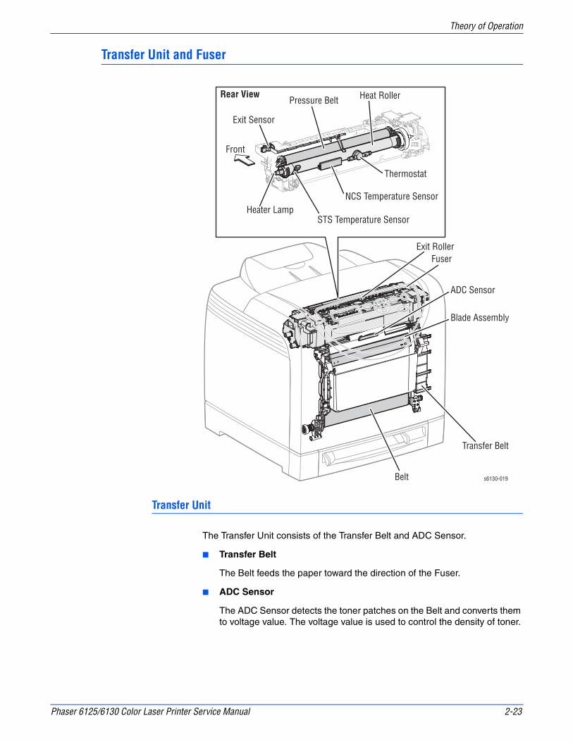
Phaser 6125/6130 Color Laser Printer Service Manual 2-23
Theory of Operation
Transfer Unit and Fuser
Transfer Unit
The Transfer Unit consists of the Transfer Belt and ADC Sensor.
■ Transfer Belt
The Belt feeds the paper toward the direction of the Fuser.
■ ADC Sensor
The ADC Sensor detects the toner patches on the Belt and converts them to voltage value. The voltage value is used to control the density of toner.
Exit Roller
Transfer Belt
Belt
ADC Sensor
Blade Assembly
Fuser
s6130-019
Heat Roller
Heater Lamp
Thermostat
STS Temperature Sensor
NCS Temperature Sensor
Pressure BeltRear View
Exit Sensor
Front

2-24 Phaser 6125/6130 Color Laser Printer Service Manual
Theory of Operation
Fuser
The Fuser fixes transferred toner onto the paper using heat and pressure and feeds the paper before and after toner is fixed. The Fuser consists of the following components: Heat Roller, Heater Lamp, Thermostat, Temperature Sensor, Pressure Belt, Exit Roller, and Exit Sensor.
■ Exit Sensor
The Exit Sensor detects passage of printed pages after fusing on the Actuator’s position changes.
Laser Unit
The Laser Unit is an exposure unit that generates laser beams to form an electrostatic latent image on the drum surface. The Laser Unit consists of the following components: Laser Diode (LD) Board, Scanner Assembly, Start of Scan (SOS) Board, Lenses, Mirrors, and Windows.
Windows
Laser Unit
s6130-020
Front
Laser Diode Board
Polygon MirrorScanner
SOS Board
Lens
Lens
Mirror
Mirror
Mirror
Mirror
Rear View
SOS Sensor

Phaser 6125/6130 Color Laser Printer Service Manual 2-25
Theory of Operation
■ Laser Diode Board
The Laser Diode Board consists of four laser diodes (LDs) corresponding to C, M, Y, and K. Each LD converts the electric signals of incoming image data into laser waves. In order to stabilize the laser light quantity during formation of an electrostatic latent image, the LD Board monitors the intensity of the laser beam to adjust it to the appropriate level. This process is called Auto Power Control (APC).
■ Scanner
The Scanner consists of a Scanner Motor that rotates at a constant speed and a Polygon Mirror that is mounted on the Motor Shaft. The laser light output from the LD is directed onto the Polygon Mirror by the Mirror. The Polygon Mirror, provided with six reflecting mirror faces, changes the reflection angle of the laser light as it rotates, thereby allowing the laser light to scan the drum along its axial direction. Scanning is performed using one reflecting mirror face for each line.
■ Start of Scan (SOS) Board
The SOS Sensor on the SOS Board converts incoming laser beam, upon detection, to an electric signal as reference for starting scanning, and transmits this signal to the MCU Board. The SOS sensor signals are used to synchronize the starting point of the laser beam scanning with the starting point of the image writing.
■ Lenses
The laser light reflected from the Polygon Mirror reaches the drum surface via the Lenses, Mirror, and Window. The Lenses correct aberration.
■ Mirror
The Mirror directs the laser beam and secures an optical path.
■ Window
The window prevents debris from entering the Laser Unit.

2-26 Phaser 6125/6130 Color Laser Printer Service Manual
Theory of Operation
Toner Cartridge & Dispenser
The Toner Cartridge is a customer replaceable item that includes the following components:
■ Customer Replaceable Unit Memory (CRUM) Connector
The CRUM Connector reads and writes the CRUM data. Printer specific information is stored in the CRUM.
■ Dispenser Motor (C/M/Y/K)
The Dispenser Motor provides the drive for the Agitator and Auger in the Toner Cartridge, and supplies toner to the Developer.
Dispenser Motor (K)
Dispenser Motor (C)
Dispenser Motor (M)
Dispenser Motor (Y)
Toner Cartridge (K)
Toner Cartridge (C)
Toner Cartridge (M)
Toner Cartridge (Y)CRUM Connector (Y)
CRUM Connector (M)
CRUM Connector (C)
CRUM Connector (K)
s6130-021
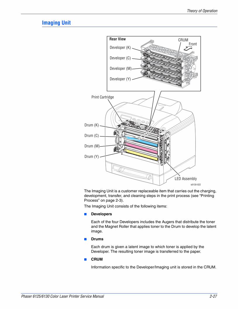
Phaser 6125/6130 Color Laser Printer Service Manual 2-27
Theory of Operation
Imaging Unit
The Imaging Unit is a customer replaceable item that carries out the charging, development, transfer, and cleaning steps in the print process (see “Printing Process” on page 2-3).
The Imaging Unit consists of the following items:
■ Developers
Each of the four Developers includes the Augers that distribute the toner and the Magnet Roller that applies toner to the Drum to develop the latent image.
■ Drums
Each drum is given a latent image to which toner is applied by the Developer. The resulting toner image is transferred to the paper.
■ CRUM
Information specific to the Developer/Imaging unit is stored in the CRUM.
Print Cartridge
Drum (K)
LED Assembly
Drum (C)
Drum (M)
Drum (Y)
s6130-022
Developer (K)
Developer (C)
Developer (M)
CRUM
Developer (Y)
Rear ViewFront

2-28 Phaser 6125/6130 Color Laser Printer Service Manual
Theory of Operation
■ Erase Lamp (LED)
The light of the LED passes through the lens of the Developer, illuminates the drum, and eliminates the charge on the drum.
Drive Assembly
The Drive Assembly consists of three major sections:
■ Main Drive Assembly
Supplies drive to the Drums (C, M, Y, K), Transfer Belt, Registration Rollers, and Feeder Assembly.
■ Sub Drive Assembly
Supplies drive to the Fuser and Developers (C, M, Y, K).
■ Feed Drive Assembly
The Feed Drive Assy transmits the driving force from the Sub Drive Assembly to relevant parts.
Imaging Unit Erase LampErase Lens
LED AssemblyDrums6130-023
s6130-024
Sub Drive
Main Drive
Feed Drive
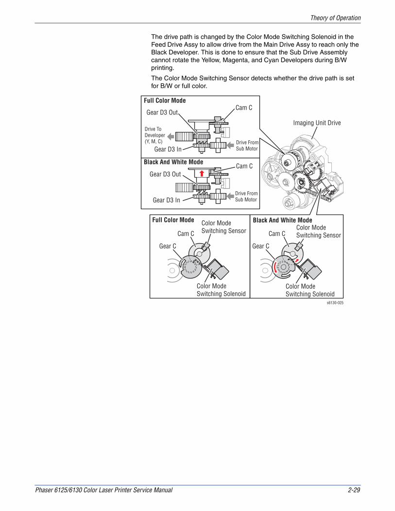
Phaser 6125/6130 Color Laser Printer Service Manual 2-29
Theory of Operation
The drive path is changed by the Color Mode Switching Solenoid in the Feed Drive Assy to allow drive from the Main Drive Assy to reach only the Black Developer. This is done to ensure that the Sub Drive Assembly cannot rotate the Yellow, Magenta, and Cyan Developers during B/W printing.
The Color Mode Switching Sensor detects whether the drive path is set for B/W or full color.
Black And White Mode
Black And White Mode
s6130-025
Full Color Mode
Full Color Mode
Drive FromSub MotorGear D3 In
Color ModeSwitching Sensor
Color ModeSwitching Solenoid
Gear D3 OutCam C
Cam C
Gear C
Color ModeSwitching Sensor
Color ModeSwitching Solenoid
Cam C
Gear C
Imaging Unit Drive
Drive FromSub Motor
Drive ToDeveloper (Y, M, C)
Gear D3 In
Gear D3 OutCam C

2-30 Phaser 6125/6130 Color Laser Printer Service Manual
Theory of Operation
Electrical
Fan
The Fan removes heat from the printer to prevent overheating.
Power Switch
The Power Switch turns the printer AC Power Supply On/Off.
Low-Voltage Power Supply (LVPS)
Two types of LVPS are available: 100/120V and 230V. The LVPS supplies AC power from the power source to the Fuser Heater; the LVPS also generates and supplies stable low-voltage DC power used for the logic circuits. The LVPS contains a control circuit for the Fuser heater, in addition to the power circuit.
s6130-026
Fan
Power Switch
EEPROM
Humidity Sensor
LVPS
Control Panel
Interlock Switch Side Cover Switch
MultiProtocolNetworkCard (MPC)
HVPSIP Board
MCU Board
GFI Breaker

Phaser 6125/6130 Color Laser Printer Service Manual 2-31
Theory of Operation
Machine Control Unit Board
The Machine Control Unit (MCU) Board controls the printing process based on the communication with the printer Image Processor Board and information from the Sensors or Switches. Major functions include:
1. Communicates with the Image Processor Board.
2. Receives information from the Sensors or Switches.
3. Controls the Motors in the Main Drive and Drive Assembly.
4. Distributes low-voltage DC power generated from the LVPS to each component.
5. Controls the Laser Unit.
NoteWhen replacing an MCU Board, be sure to transfer the NVRAM from the old MCU Board to the new MCU Board.
High-Voltage Power Supply (HVPS)
The HVPS provides high-voltage power to the components in the Transfer Belt and Imaging Unit to perform charging, development, and primary transfer of the print process to the BCR, BTR, and Developer.
Electrically Erasable Programmable Read-Only Memory (EEPROM) Board
The EEPROM Board stores the printer unique information.
Control Panel
The Control Panel displays the printer status and operates the printer.
Ready
C M Y K
3
s6130-068

2-32 Phaser 6125/6130 Color Laser Printer Service Manual
Theory of Operation
Image Processor Board
The Image Processor (I/P) Board is connected to the MCU Board, which controls the printer, including Diagnostic, Interface, and Image Processing. The I/P Board is one of the major elements of the Phaser 6130 printer.
The primary function of the I/P Board is to receive host data through one of the following available ports (USB, or Ethernet). The received host data is buffered, stored, and sent to the print engine in a rasterized format.
1.Standard Memory (128 MB on-board RAM)
2.Optional Memory DIMM (should be swapped)
3.Multi-Protocol Network Card Connection
4.NVRAM
5.Ethernet Connection
6.USB Connection
When installing a new I/P Board in the printer, you must transfer the following parts from the old board to the new board:
■ Memory DIMM (if installed)
■ NVRAM
■ Multi-Protocol Network Card (if installed)
Humidity /Temperature Sensor
The Humidity/Temperature Sensor reads the humidity and temperature within the printer.
Interlock Switch
The Interlock Switch is a switch that interrupts the supply of +24 VDC power to the HVPS or Motor upon the opening of the Front Cover.
s6130-070
2
1
1
13
45
6

Phaser 6125/6130 Color Laser Printer Service Manual 2-33
Theory of Operation
Toner Access Door Switch
A switch that detects when the Toner Access Door is open.
GFI Breaker
Opens to shut off the AC power if it detects any voltage or current or leakage current that exceeds the rating of the AC power supply.
Multi-Protocol Network Card (MPC)
An option that allows the use of multiple network protocols.
Data Flow
The electrical signal flow for the print data from the printer I/P Board is shown in the following diagram.
Host (Electric Signal)
Electronic Sub-system Control Board (Electric Signal)
Machine Control Unit (Electric Signal)
Laser Unit (Laser Beams)
Electrostatic Latent On Drum (Invisible Image)
Toner Image On Drum
Toner Image On Paper
Print Image On Paper
s6130-069
Computer
I/P Board
MCU Board
Laser Unit
Imaging Unit
Imaging Unit
Transfer Belt
Fuser

2-34 Phaser 6125/6130 Color Laser Printer Service Manual
Theory of Operation
Printer Modes
Operational Modes
The Phaser 6130 printer includes the following modes:
■ Ready Mode
The printer is ready for printing.
■ Printing Mode
Printing is in progress.
■ Sleep Mode (Energy Star)
The printer has entered a power saving state.
■ Deep Sleep Mode
The printer has entered a power saving state.
Printer Control
Paper Size Detection
The printer has no switches for detecting paper size; only the length of the paper is detected by the Regi Sensor as the paper is feeding. If the detected size does not match the size sent in the print data, an error is reported to the Image Processor.
Laser Unit Light Quantity Control
Image data is sent to the Laser Unit as an electric signal (data are expressed with high and low voltage values), and the laser diodes convert the image data from electric signals to optical signals (data are expressed with blinking laser beams).
Variations in light quantity of laser beams or variations in the optical system (such as lenses) or drum sensitivity cannot attain a proper electrostatic image. Therefore, the laser beam light quantity is monitored and controlled by the laser diodes.
The Laser Unit has four laser diodes for Yellow, Magenta, Cyan, and Black respectively and the beam intensity is automatically adjusted for each color.

Phaser 6125/6130 Color Laser Printer Service Manual 2-35
Theory of Operation
Process Control
For stable printing, the parameters related to the image development must be corrected as necessary. The process control is performed in two methods after every 25 cumulative prints, upon termination of a print run, or during a continuous run.
■ Potential Control
■ Toner Density Control
The following controls supplement the above controls:
■ High Area Coverage Mode
■ Admix Mode
Potential Control
To attain stable printing image density, the drum charging voltage, the developing DC voltage, and the Laser Unit beam intensity are adjusted according to the developing capability of each color carrier that varies momentarily. The adjusted drum charging voltage, the developing DC voltage, and the Laser Unit beam intensity are fed back to keep the printing image density constant.
The outline of controls is as follows:
1. The Humidity/Temperature Sensor detects humidity and temperature.
2. The patches of respective colors (Yellow, Magenta, Cyan, and Black) for the potential control are generated and transferred on the Transfer Belt.
3. The ADC Sensor (Density Sensor) detects the density of the patch on the Belt.
4. The drum charging voltage, developing DC voltage, and the Laser Unit beam intensity are adjusted for each color according to the detected patch density.
Toner Density Control
Toner density must be kept constant to attain stable printing. The control system for this purpose is called toner density control.
1. PCDC (Pixel Count Dispense Control)
The amount of toner to be consumed in the developing process is calculated by counting the video signals entered to the Laser Unit. The amount of the toner to be consumed is calculated by the toner dispensing time. The toner motor is driven for the calculated toner dispensing time when supplying the toner to the Developer.
2. ADC (Auto Density Control)
The patches of respective colors (Yellow, Magenta, Cyan, and Black) for the toner density control are generated under a specified potential condition, and transferred on the Belt. The ADC Sensor measures this density, and the measured value is compared with reference value. If the toner density is low, the toner dispense quantity is increased at the next printing, or if the toner density is higher, the toner dispense quantity is reduced at the next printing. The toner dispense quantity is calculated by the toner dispense time. This calculation is made for each color.

2-36 Phaser 6125/6130 Color Laser Printer Service Manual
Theory of Operation
High Area Coverage Mode
A continuous printing of any image of area coverage exceeding the toner dispense capability causes the toner density in the Developer to be lowered.
The High Area Coverage Mode postpones the next page feed and dispenses extra toner during this time, if the toner dispense time reaches the specified value during a continuous printing.
Admix Mode
The Admix Mode dispenses toner immediately to prevent the reduction of toner density, whenever the value of the toner density control patch measured by the ADC Sensor falls far below the standard value, by dispensing extra toner. If the toner density level cannot be recovered after this operation, it is determined that toner has run out.
ADC Sensor Control Function
The ADC Sensor is a reflection type sensor that radiates light from its LED onto the target and detects the reflected light at its photoreceptor and outputs electric signals responsive to the amount of the detected light.
To ensure an accurate patch density measurement, the surface of the ADC sensor is cleaned to remove soil due to toner, etc., and the light amount adjustment is made so that the reflected light amount satisfies the prescribed value, when creating the patch for potential control and toner density control.
Color Registration Control
The printer uses a tandem electro-photographic system with Organic Photo Conductor (OPC) Drums and direct transfer by the Transfer Belt. Because the images are formed on the individual Drums of the respective colors and then overlapped to form one image, a color shift may occur. The color registration control calculates how much the registration is shifted, and adjusts the Laser Unit write timing.
The scan control adjusts all four colors in the process direction.
The color registration control is made from a change in inside temperature and the print count at the execution of the process control. This control is outlined as follows:
1. With no toner on the Transfer Belt, the output value of the ADC Sensor is measured to determine the threshold value.
2. The patches for color registration control are generated on the Belt. These patches are composed of 10 mm lines of K, C, K, M, K, and Y in this order by the amount of four dispense counts, led by a black trigger.

Phaser 6125/6130 Color Laser Printer Service Manual 2-37
Theory of Operation
3. The ADC Sensor reads the patch density.
4. The amount of registration shift is calculated from the threshold value determined in step 1 and the patch density measured in step 3.
5. The Laser Unit write timing is changed according to the amount of registration shift.
Fuser Control
Fuser Temperature Control
After the target temperature is set, the Heat Roller surface temperature is controlled by turning the Heater Lamp On/Off.
Temperature of individual area of the Heat Roller is detected by the Fuser Non-Contact Sensor (NCS) in the middle of the Heat Roller and the Temp Sensor at the edge of it.
The target temperature set up varies depending on the time of Warm-up, Printing, or Process Control. The target set temperature is changed based on the printer’s interior temperature detected by the Humidity Sensor.
Cool Down
As printing continues, the distribution of temperature in the Heat Roller becomes uneven in both the paper feed and non-paper feed areas. Cooling Down suspends paper feeling for a certain period of time so that the Heat Roller temperature distribution can be uniform.
When the temperature of the Heat Roller edge is high, cooling down is performed to lower the temperature to the target value.
Fuser NCS Sensor Warm-Up
The Fuser Non-Contact Sensor at the center of the Heat Roller loses its accuracy when the temperature of the sensor itself is below -5° C. Therefore, the sensor is warmed up when the temperature is below -5° C.
10 mm
About One Half Turn Of Belt
s6180-290
KKCKMKY
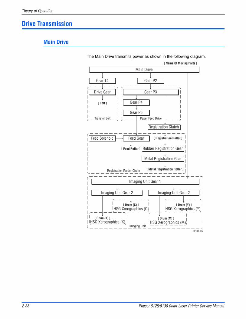
2-38 Phaser 6125/6130 Color Laser Printer Service Manual
Theory of Operation
Drive Transmission
Main Drive
The Main Drive transmits power as shown in the following diagram.
Main Drive
[ Belt ]
Transfer Belt
[ Name Of Moving Parts ]
Gear P3
Paper Feed Drive
Registration Feeder Chute
Registration Clutch
Rubber Registration Gear
Metal Registration Gear
Gear P2Gear T4
Gear P4
Gear P5
[ Registration Roller ]
[ Metal Registration Roller ]
Feed GearFeed Solenoid
Drive Gear
[ Feed Roller ]
HSG Xerographics (K)[ Drum (K) ]
HSG Xerographics (C)[ Drum (C) ]
Imaging Unit Gear 2
HSG Xerographics (M)[ Drum (M) ]
HSG Xerographics (Y)[ Drum (Y) ]
Imaging Unit Gear 2
Imaging Unit Gear 1
Imaging Units6130-027

Phaser 6125/6130 Color Laser Printer Service Manual 2-39
Theory of Operation
s6130-028
Paper Feed Drive
Imaging Unit
Main Drive
Gear P2
Gear P3Gear P4
Gear P5
Feed Gear[ Feed Roller ]
Registration Feeder Chute
Registration Clutch[ Registration Roller ]
Rubber Registration GearMetal Registration Gear[ Metal Registration Roller ]
Feed Solenoid
Imaging UnitGear 2[ Drum (M) ][ Drum (Y) ]
Imaging UnitGear 1
Imaging UnitGear 2[ Drum (K) ][ Drum (C) ]
Transfer Belt
Gear T4 Drive Gear[ Belt ]
[ Name Of Moving Parts ]
: Indicates The Engagement Of Gears
Front
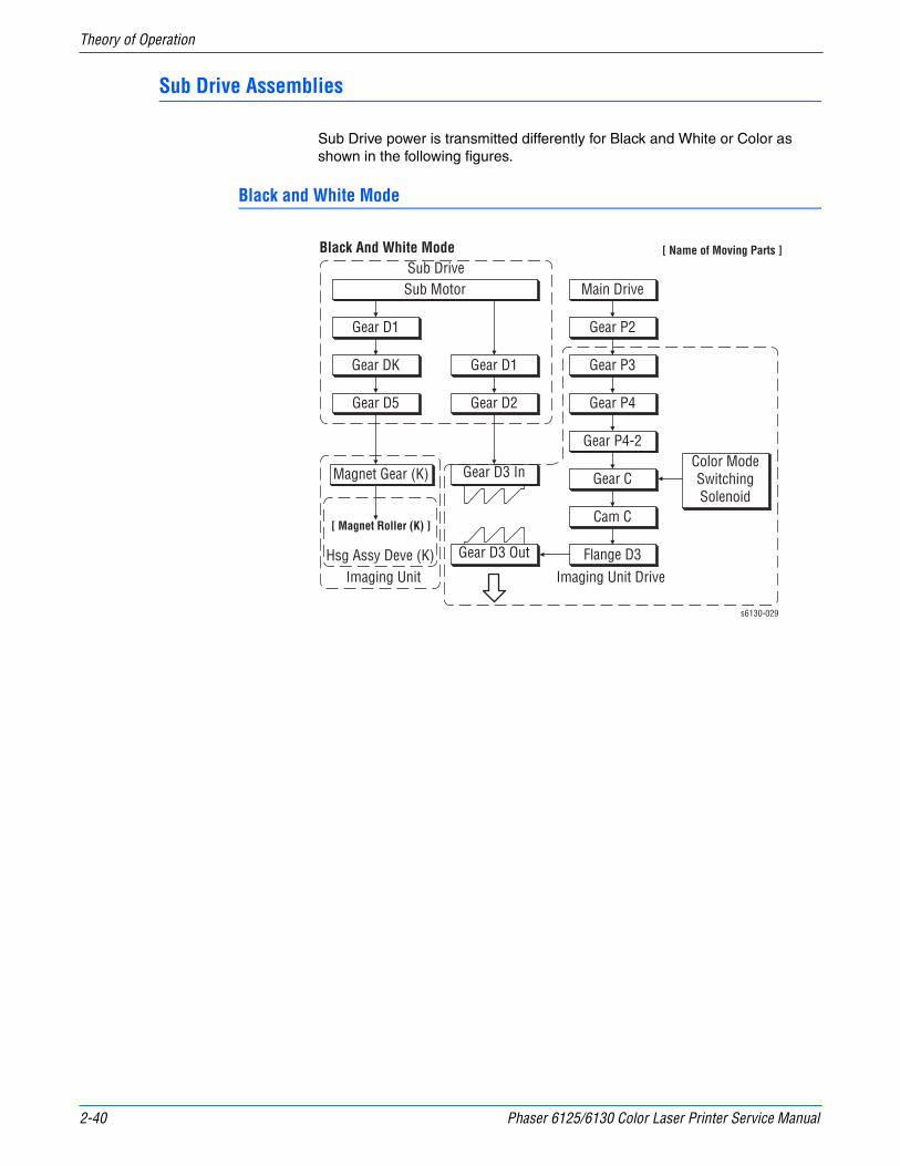
2-40 Phaser 6125/6130 Color Laser Printer Service Manual
Theory of Operation
Sub Drive Assemblies
Sub Drive power is transmitted differently for Black and White or Color as shown in the following figures.
Black and White Mode
Gear D1
Gear D2
Gear DK
Gear D1 Gear P2
Main DriveSub Motor
Gear D5
Magnet Gear (K) Gear D3 In
Sub Drive
Gear D3 Out Flange D3
Cam C
Gear C
Gear P4-2
Gear P4
Gear P3
Color ModeSwitchingSolenoid
Imaging Unit DriveHsg Assy Deve (K)
[ Magnet Roller (K) ]
[ Name of Moving Parts ]
Imaging Unit
s6130-029
Black And White Mode

Phaser 6125/6130 Color Laser Printer Service Manual 2-41
Theory of Operation
s6130-143
Gear DK
Gear D1
Sub Motor
Gear D1
Gear D2
Gear D5
Magnet Gear (K)[ Magnet Roll (K) ]
Sub Drive
Print CartridgeDrive
HSG Developer (K)
Gear D3 InGear D3 Out
Gear P2
Gear P3Color ModeSwitching Solenoid
Gear P4Gear C
Cam CFlange D3
Gear P4-2
Imaging Unit
Main Drive
Cam C Flange D3
Gear D2
Gear D4Gear D3 In
Gear D3 Out
: Indicates The Engagement Of Gears.[ Name Of Moving Parts ][ Black And White Mode ]
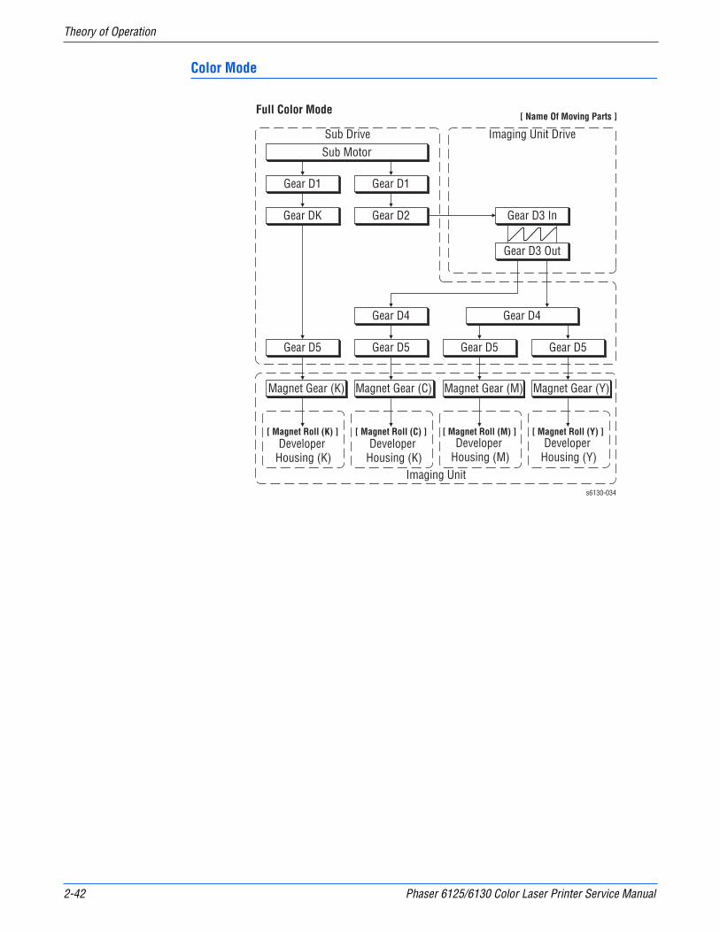
2-42 Phaser 6125/6130 Color Laser Printer Service Manual
Theory of Operation
Color Mode
Gear D1
Gear D2Gear DK
Gear D1
Sub Motor
Gear D5
Magnet Gear (K)
Sub Drive Imaging Unit Drive
Gear D3 In
Gear D3 Out
Developer Housing (K)
[ Magnet Roll (K) ]
Magnet Gear (C)
[ Magnet Roll (C) ]
Magnet Gear (M)
Developer Housing (M)
[ Magnet Roll (M) ]
Magnet Gear (Y)
Gear D5 Gear D5 Gear D5
Gear D4 Gear D4
Developer Housing (Y)
[ Magnet Roll (Y) ]
Imaging Units6130-034
[ Name Of Moving Parts ]Full Color Mode
Developer Housing (K)

Phaser 6125/6130 Color Laser Printer Service Manual 2-43
Theory of Operation
s6130-035
Gear DK
Gear D1
Sub Motor
Gear D1
Gear D2
Gear D5Magnet Gear (K)[ Magnet Roller (K) ]
Sub Drive
Imaging Unit Drive
Developer (K)
Gear D4
Magnet Gear (C)[ Magnet Roller (C) ]
Developer (C)
Magnet Gear (M)[ Magnet Roller (M) ]
Magnet Gear (Y)[ Magnet Roller (Y) ]
Developer (Y)
Developer (M)
Gear D5
Gear D5Gear D4
Gear D5
Imaging Unit
Gear D2
Gear D4Gear D3 In
Gear D3 Out
[ Name Of Moving Parts ]Full Color Mode
: Indicates The Engagement Of Gears
Front
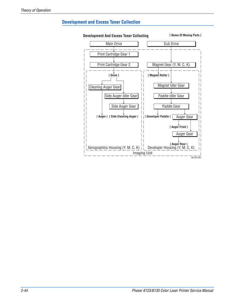
2-44 Phaser 6125/6130 Color Laser Printer Service Manual
Theory of Operation
Development and Excess Toner Collection
Main Drive Sub Drive
Print Cartridge Gear 1
Xerographics Housing (Y, M, C, K)
[ Drum ]
Print Cartridge Gear 2
Cleaning Auger Gear Magnet Idler Gear
Paddle Idler Gear
Paddle Gear
Auger Gear
Auger Gear
Side Auger Idler Gear
Side Auger Gear
[ Side Cleaning Auger ] [ Developer Paddle ]
[ Auger Front ]
[ Auger Rear ]
[ Auger ]
Developer Housing (Y, M, C, K)
[ Magnet Roller ]
Magnet Gear (Y, M, C, K)
[ Name Of Moving Parts ]Development And Excess Toner Collecting
Imaging Units6130-030
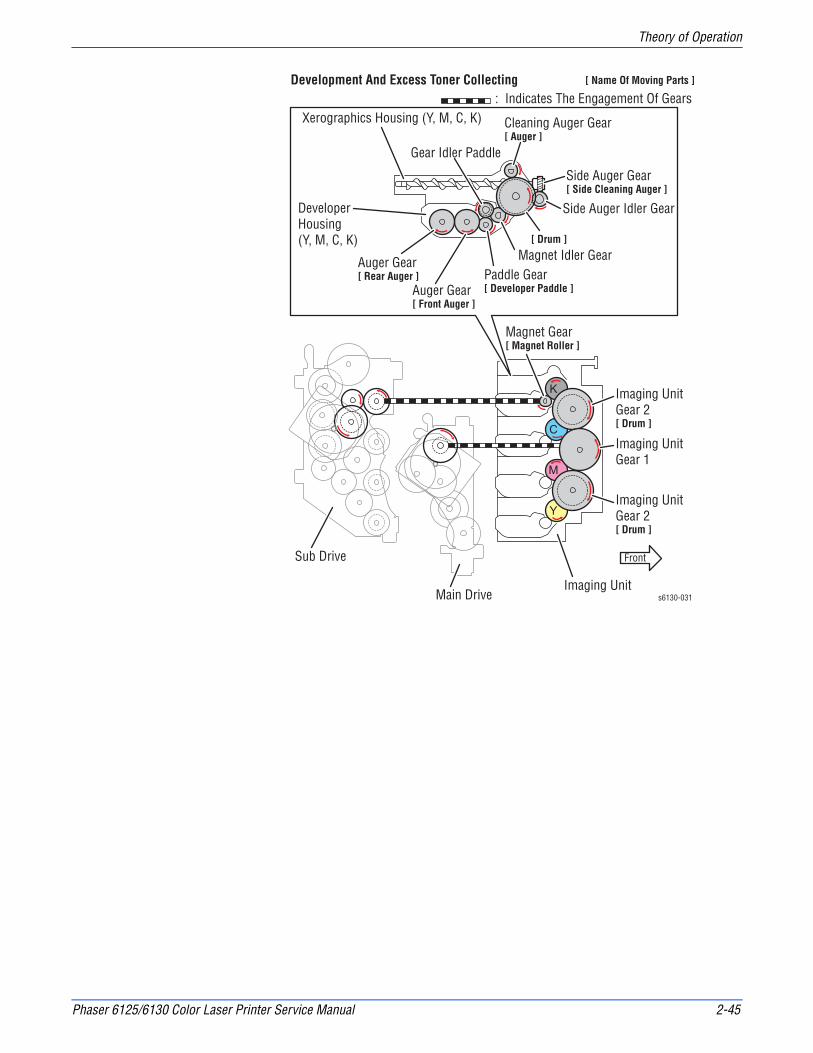
Phaser 6125/6130 Color Laser Printer Service Manual 2-45
Theory of Operation
s6130-031
Front
Main Drive
Sub Drive
Magnet Gear[ Magnet Roller ]
Imaging Unit
Imaging UnitGear 1
Imaging UnitGear 2[ Drum ]
Imaging UnitGear 2[ Drum ]
Xerographics Housing (Y, M, C, K)
[ Drum ]
Cleaning Auger Gear[ Auger ]
Magnet Idler Gear
Gear Idler Paddle
Paddle Gear[ Developer Paddle ]Auger Gear
[ Front Auger ]
Auger Gear[ Rear Auger ]
Side Auger Idler Gear
Side Auger Gear[ Side Cleaning Auger ]
DeveloperHousing (Y, M, C, K)
Development And Excess Toner Collecting: Indicates The Engagement Of Gears
[ Name Of Moving Parts ]
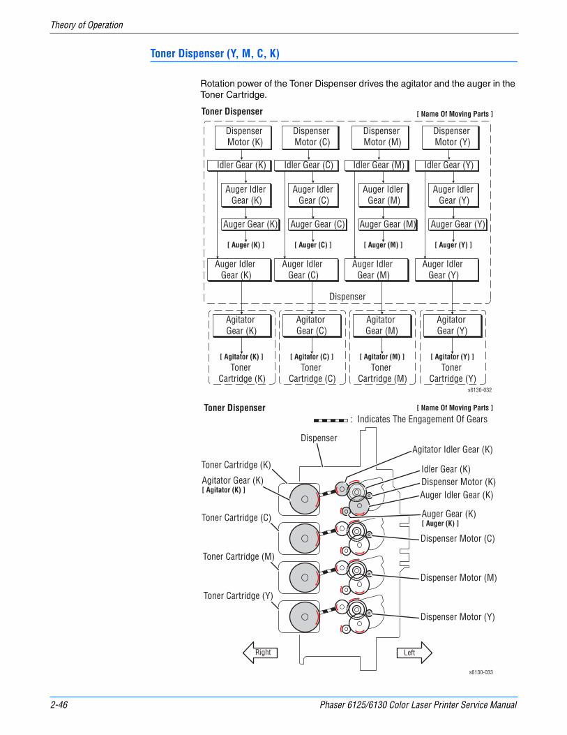
2-46 Phaser 6125/6130 Color Laser Printer Service Manual
Theory of Operation
Toner Dispenser (Y, M, C, K)
Rotation power of the Toner Dispenser drives the agitator and the auger in the Toner Cartridge.
[ Name Of Moving Parts ]
Dispenser
Toner Cartridge (K)
Idler Gear (K)
Dispenser Motor (K)
Agitator Gear (K)
Toner Dispenser
[ Auger (K) ]
Auger Idler Gear (K)
Auger Idler Gear (K)
[ Agitator (K) ]
Agitator Gear (C)
Agitator Gear (M)
Agitator Gear (Y)
Toner Cartridge (C)
[ Agitator (C) ]Toner
Cartridge (M)
[ Agitator (M) ]Toner
Cartridge (Y)
[ Agitator (Y) ]
Auger Gear (K)
Idler Gear (C)
Dispenser Motor (C)
[ Auger (C) ]
Auger Idler Gear (C)
Auger Idler Gear (C)
Auger Gear (C)
Idler Gear (M)
Dispenser Motor (M)
[ Auger (M) ]
Auger Idler Gear (M)
Auger Idler Gear (M)
Auger Gear (M)
Idler Gear (Y)
Dispenser Motor (Y)
[ Auger (Y) ]
Auger Idler Gear (Y)
Auger Idler Gear (Y)
Auger Gear (Y)
s6130-032
s6130-033
Right Left
Dispenser
Toner Cartridge (K) Idler Gear (K)Dispenser Motor (K)Agitator Gear (K)
[ Agitator (K) ]
Agitator Idler Gear (K)
Auger Idler Gear (K)
Auger Gear (K)[ Auger (K) ]
Toner Cartridge (C)
Toner Cartridge (M)
Toner Cartridge (Y)
Dispenser Motor (C)
Dispenser Motor (M)
Dispenser Motor (Y)
[ Name Of Moving Parts ]
: Indicates The Engagement Of GearsToner Dispenser
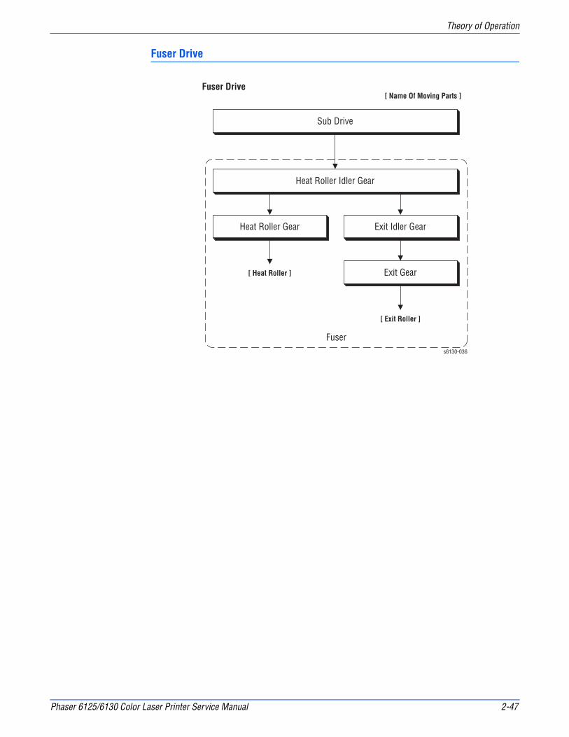
Phaser 6125/6130 Color Laser Printer Service Manual 2-47
Theory of Operation
Fuser Drive
Sub Drive
[ Name Of Moving Parts ]
Heat Roller Idler Gear
Fuser
Heat Roller Gear Exit Idler Gear
Exit Gear
Fuser Drive
[ Exit Roller ]
[ Heat Roller ]
s6130-036

2-48 Phaser 6125/6130 Color Laser Printer Service Manual
Theory of Operation
s6130-037
Front
Sub Drive
Fuser
Heat Roller Idler Gear
Heat Roller Gear[ Heat Roller ]
Exit Idler Gear
Exit Gear[ Exit Roller ]
Fuser Drive: Indicates The Engagement Of Gears
[ Name Of Moving Parts ]

3Chapter
Error Messages and Codes
In this chapter...■ Introduction
■ Servicing Instructions
■ Messages, Chain Link Codes, and Procedures
■ Image Processor Board Errors
■ Toner Cartridge Errors
■ Jam Errors
■ MPC Errors
■ Transfer Unit Errors
■ Paper Setting Errors
■ Fuser Errors
■ Motor Errors
■ Imaging Unit Errors
■ Cover Open Errors
■ MCU Errors
■ Laser Unit Errors

3-2 Phaser 6125/6130 Color Laser Printer Service Manual
Error Messages and Codes
Introduction
This chapter describes error messages and numeric codes displayed on the Control Panel or listed on the Error History page. These error indications serve as the entry point into the troubleshooting process.
Troubleshooting of problems not directly indicated by or associated with an error message or Chain Link code is covered in “General Troubleshooting” on page 4-1. Print quality problems are covered in “Print-Quality Troubleshooting” on page 5-1.
The printer tracks and reports errors in a number of ways. The two types of error reporting discussed in this section include:
■ Error messages and Chain Link codes display on the Control Panel
■ Engine (fatal) and Jam Error logs display on the Control Panel or listed on the Error History Report
Accessing Error History Report
1. From the Control Panel, press the Menu button.
2. Information Pgs is displayed. Press the OK button.
3. Press the Up or Down arrow button to find Error History. Press the OK button.
4. The Error History Report is printed. When printing is finished, the menu is displayed.
Error History Report
The Error History Report provides a list of error messages and Chain Link codes relating to Jam errors and System (fatal) errors. The printer can retain up to 42 Jam errors and 42 System Fail errors.
For Chain Link codes, Chain number (0 to 999) and Link number (0 to 999) are assigned. Chain numbers are assigned for each component. The component number that detects the Fault is entered in the Chain code, and the Fault type is defined by the Link code.
Examples of Error message and Chain Link code:
■ System Fail History
■ Chain Link: 018-310
■ Paper Jam History
■ Paper Jam Type: IOT Remain Registration Jam

Phaser 6125/6130 Color Laser Printer Service Manual 3-3
Error Messages and Codes
The Error History page contains two types of history information.
System Fail History
System Fail History contains: Item Number, Total Print Count, and Chain-Link code.
Paper Jam History
Paper Jam History contains: Item No., Total Print Count, and Paper Jam Type information.
s6130-181
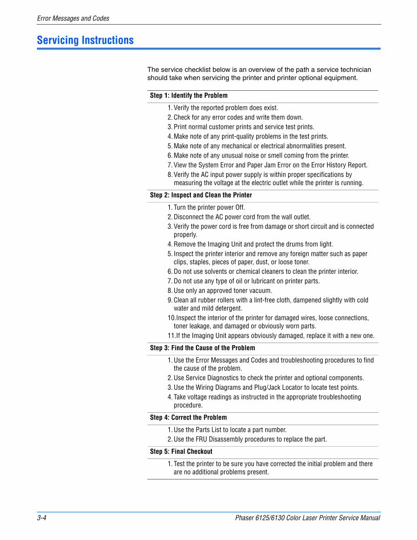
3-4 Phaser 6125/6130 Color Laser Printer Service Manual
Error Messages and Codes
Servicing Instructions
The service checklist below is an overview of the path a service technician should take when servicing the printer and printer optional equipment.
Step 1: Identify the Problem
1. Verify the reported problem does exist.2. Check for any error codes and write them down.3. Print normal customer prints and service test prints.4. Make note of any print-quality problems in the test prints.5. Make note of any mechanical or electrical abnormalities present.6. Make note of any unusual noise or smell coming from the printer.7. View the System Error and Paper Jam Error on the Error History Report.8. Verify the AC input power supply is within proper specifications by
measuring the voltage at the electric outlet while the printer is running.
Step 2: Inspect and Clean the Printer
1. Turn the printer power Off.2. Disconnect the AC power cord from the wall outlet.3. Verify the power cord is free from damage or short circuit and is connected
properly.4. Remove the Imaging Unit and protect the drums from light.5. Inspect the printer interior and remove any foreign matter such as paper
clips, staples, pieces of paper, dust, or loose toner.6. Do not use solvents or chemical cleaners to clean the printer interior.7. Do not use any type of oil or lubricant on printer parts.8. Use only an approved toner vacuum.9. Clean all rubber rollers with a lint-free cloth, dampened slightly with cold
water and mild detergent.10.Inspect the interior of the printer for damaged wires, loose connections,
toner leakage, and damaged or obviously worn parts.11.If the Imaging Unit appears obviously damaged, replace it with a new one.
Step 3: Find the Cause of the Problem
1. Use the Error Messages and Codes and troubleshooting procedures to find the cause of the problem.
2. Use Service Diagnostics to check the printer and optional components.3. Use the Wiring Diagrams and Plug/Jack Locator to locate test points.4. Take voltage readings as instructed in the appropriate troubleshooting
procedure.
Step 4: Correct the Problem
1. Use the Parts List to locate a part number.2. Use the FRU Disassembly procedures to replace the part.
Step 5: Final Checkout
1. Test the printer to be sure you have corrected the initial problem and there are no additional problems present.

Phaser 6125/6130 Color Laser Printer Service Manual 3-5
Error Messages and Codes
Messages, Chain Link Codes, and Procedures
The error messages and chain link codes generated by the printer’s operating system are the lead-in to the troubleshooting procedures that follow in subsequent pages. This section correlates the output of the printer’s diagnostic aids and provides the troubleshooting procedures to locate and correct the reported errors.
Error Messages Abbreviations
Due to limited display space, some error messages include abbreviations. The most common abbreviations used throughout this chapter are listed here.
Term Definition
ADC Automatic Density Control
ASIC Application-Specific Integrated Circuit
BLK Black
COMM Communication
CTD Toner Density Sensor (ADC)
CRT Cartridge
CRUM Customer Replaceable Unit
DTB Transfer Unit (Direct Transfer Belt)
ER/ERR Error
ENV Environment
FUNC Function
MACaddress Media Access Control Address
MCU Machine Control Unit
MPC Multi-Protocol Network Card
NVM Non-Volatile Memory. Used instead of NVRAM.
NV RAM Non-Volatile Random Access Memory
PCL Printer Control Language
PDL Page Description Language
PHD Imaging Unit
RAM Random Access Memory
REG Registration
ROM Read Only Memory
SSI Manual Feed Slot (Single Sheet Input)
TRAN Transfer Unit

3-6 Phaser 6125/6130 Color Laser Printer Service Manual
Error Messages and Codes
Error Message and Chain Link Code Summary
The Error Message Summary table lists possible errors, along with the corresponding code, and page reference for the corrective procedure.
■ The Control Panel Message column shows the message as it appears on the printer’s display.
■ The Chain Link column lists codes listed on the printer Error History Report and the Control Panel.
■ The Go to Page column references the procedure related to the error.
Use this table to identify the proper procedure to correct the reported error.
Error Message and Chain Link Code Display
Chain Link Code
Control Panel Message Error Contents
Go to Page
Image Processor Board Errors
016-500 Erase Flash ErrRestart Printer
Error 016-500Restart Printer
<DOWNLOAD DELETE ERROR>The flash memory error is detected.
page 3-21
016-501 Write Flash ErrRestart Printer
Error 016-501Restart Printer
<DOWNLOAD WRITE ERROR>The flash memory error is detected.
page 3-21
016-502 Verify Flash ErrRestart Printer
Error 016-502Restart Printer
<DOWNLOAD VERIFY ERROR>The flash memory error is detected.
page 3-21
016-718 Out of MemoryPress Ok Button
Error 016-718Press Ok Button
<Memory Overflow>Exceeds the memory capacity.
page 3-22
016-720 PDL ErrorPress Ok Button
Error 016-720Press Ok Button
<PDL Error>PDL error occurs.
page 3-23
Scroll
Scroll
Scroll
Scroll
Scroll

Phaser 6125/6130 Color Laser Printer Service Manual 3-7
Error Messages and Codes
016-737 Format ErrorPress Ok Button
Error 016-737Press Ok Button
<DOWNLOAD FORMAT ERROR>The download file is broken, or communication error is detected.
page 3-21
016-742 Invalid IDPress Ok Button
Error 016-742Press Ok Button
<DOWNLOAD ID ERROR>The ID of the downloaded file is invalid.
page 3-21
016-743 Range Chk ErrorPress Ok Button
Error 016-743Press Ok Button
<DOWNLOAD RANGE ERROR>The wrong address is detected.
page 3-21
016-744 Check Sum ErrorPress Ok Button
Error 016-744Press Ok Button
<DOWNLOAD CHECKSUM ERROR>The checksum is invalid.
page 3-21
016-745 Header ErrorPress Ok Button
Error 016-745Press Ok Button
<DOWNLOAD HEADER ERROR>The header information is invalid.
page 3-21
018-319 Network ErrorRestart Printer
Error 018-319Restart Printer
<On Board Network OS Error>The error is detected by On Board Network OS.
page 3-24
018-320 Network ErrorRestart Printer
Error 018-320Restart Printer
<On Board Network VxWorks Error>The error is detected by On Board VxWORKS.
page 3-24
024-362 PAGEC Time ErrorRestart Printer
Error 024-362Restart Printer
<PAGEC Timeout Error>The PAGEC timeout error is detected.
page 3-25
Error Message and Chain Link Code Display (continued)
Chain Link Code
Control Panel Message Error Contents
Go to Page
Scroll
Scroll
Scroll
Scroll
Scroll
Scroll
Scroll
Scroll
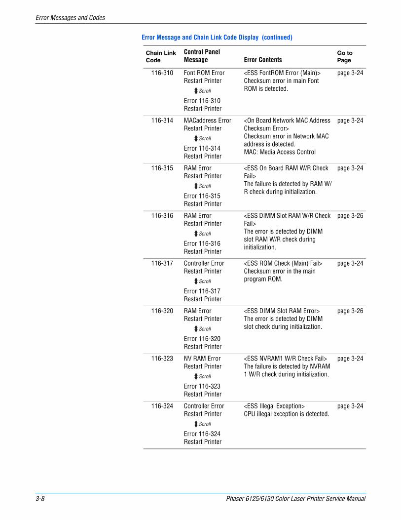
3-8 Phaser 6125/6130 Color Laser Printer Service Manual
Error Messages and Codes
116-310 Font ROM ErrorRestart Printer
Error 116-310Restart Printer
<ESS FontROM Error (Main)>Checksum error in main Font ROM is detected.
page 3-24
116-314 MACaddress ErrorRestart Printer
Error 116-314Restart Printer
<On Board Network MAC Address Checksum Error>Checksum error in Network MAC address is detected.MAC: Media Access Control
page 3-24
116-315 RAM ErrorRestart Printer
Error 116-315Restart Printer
<ESS On Board RAM W/R Check Fail>The failure is detected by RAM W/R check during initialization.
page 3-24
116-316 RAM ErrorRestart Printer
Error 116-316Restart Printer
<ESS DIMM Slot RAM W/R Check Fail>The error is detected by DIMM slot RAM W/R check during initialization.
page 3-26
116-317 Controller ErrorRestart Printer
Error 116-317Restart Printer
<ESS ROM Check (Main) Fail>Checksum error in the main program ROM.
page 3-24
116-320 RAM ErrorRestart Printer
Error 116-320Restart Printer
<ESS DIMM Slot RAM Error>The error is detected by DIMM slot check during initialization.
page 3-26
116-323 NV RAM ErrorRestart Printer
Error 116-323Restart Printer
<ESS NVRAM1 W/R Check Fail>The failure is detected by NVRAM 1 W/R check during initialization.
page 3-24
116-324 Controller ErrorRestart Printer
Error 116-324Restart Printer
<ESS Illegal Exception>CPU illegal exception is detected.
page 3-24
Error Message and Chain Link Code Display (continued)
Chain Link Code
Control Panel Message Error Contents
Go to Page
Scroll
Scroll
Scroll
Scroll
Scroll
Scroll
Scroll
Scroll
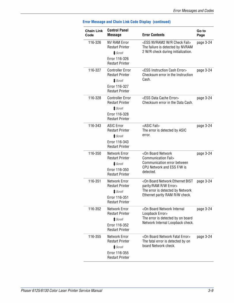
Phaser 6125/6130 Color Laser Printer Service Manual 3-9
Error Messages and Codes
116-326 NV RAM ErrorRestart Printer
Error 116-326Restart Printer
<ESS NVRAM2 W/R Check Fail>The failure is detected by NVRAM 2 W/R check during initialization.
page 3-24
116-327 Controller ErrorRestart Printer
Error 116-327Restart Printer
<ESS Instruction Cash Error>Checksum error in the Instruction Cash.
page 3-24
116-328 Controller ErrorRestart Printer
Error 116-328Restart Printer
<ESS Data Cache Error>Checksum error in the Data Cash.
page 3-24
116-343 ASIC ErrorRestart Printer
Error 116-343Restart Printer
<ASIC Fail>The error is detected by ASIC error.
page 3-24
116-350 Network ErrorRestart Printer
Error 116-350Restart Printer
<On Board Network Communication Fail>Communication error between CPU Network and ESS F/W is detected.
page 3-24
116-351 Network ErrorRestart Printer
Error 116-351Restart Printer
<On Board Network Ethernet BIST parity/RAM R/W Error>The error is detected by Network Ethernet parity RAM R/W check.
page 3-24
116-352 Network ErrorRestart Printer
Error 116-352Restart Printer
<On Board Network Internal Loopback Error>The error is detected by on board Network Internal Loopback check.
page 3-24
116-355 Network ErrorRestart Printer
Error 116-355Restart Printer
<On Board Network Fatal Error>The fatal error is detected by on board Network check.
page 3-24
Error Message and Chain Link Code Display (continued)
Chain Link Code
Control Panel Message Error Contents
Go to Page
Scroll
Scroll
Scroll
Scroll
Scroll
Scroll
Scroll
Scroll

3-10 Phaser 6125/6130 Color Laser Printer Service Manual
Error Messages and Codes
116-390 NV RAM ErrorRestart Printer
Error 116-390Restart Printer
<ESS NVRAM1 SIZE And ID Check Fail>The error is detected by consistency check between NVRAM size required by the system and its actual size, and by consistency check of ID recorded when turning ON the power.
page 3-24
Toner Cartridge Errors
InsertYellow Cartridge
<IOT Y CRU Detached>Yellow Cartridge detached is detected.
page 3-27
InsertMagenta Cartridge
<IOT M CRU Detached>Magenta Cartridge detached is detected.
page 3-27
InsertCyan Cartridge
<IOT C CRU Detached>Cyan Cartridge detached is detected.
page 3-27
InsertBlack Cartridge
<IOT K CRU Detached>Black Cartridge detached is detected.
page 3-27
Non-Xerox TonerInvalid Yellow
<IOT CRUM ID Error>CRUM ID error of Yellow Cartridge is detected.
page 3-27
Non-Xerox TonerInvalid Magenta
<IOT CRUM ID Error>CRUM ID error of Magenta Cartridge is detected.
page 3-27
Non-Xerox TonerInvalid Cyan
<IOT CRUM ID Error>CRUM ID error of Cyan Cartridge is detected.
page 3-27
Non-Xerox TonerInvalid Black
<IOT CRUM ID Error>CRUM ID error of Black Cartridge is detected.
page 3-27
%s Replace Yellowand
ReplaceYellow Cartridge
<IOT Y CRU Life Over>Yellow Cartridge has reached end-of-life.
page 3-27
%s Replace Magentaand
ReplaceMagenta Cartridge
<IOT M CRU Life Over>Magenta Cartridge has reached end-of-life.
page 3-27
%s Replace Cyanand
ReplaceCyan Cartridge
<IOT C CRU Life Over>Cyan Cartridge has reached end-of-life.
page 3-27
Error Message and Chain Link Code Display (continued)
Chain Link Code
Control Panel Message Error Contents
Go to Page
Scroll
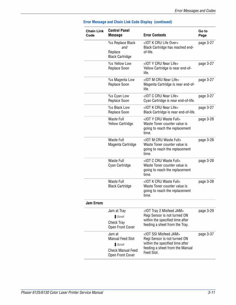
Phaser 6125/6130 Color Laser Printer Service Manual 3-11
Error Messages and Codes
%s Replace Blackand
ReplaceBlack Cartridge
<IOT K CRU Life Over>Black Cartridge has reached end-of-life.
page 3-27
%s Yellow LowReplace Soon
<IOT Y CRU Near Life>Yellow Cartridge is near end-of-life.
page 3-27
%s Magenta LowReplace Soon
<IOT M CRU Near Life>Magenta Cartridge is near end-of-life.
page 3-27
%s Cyan LowReplace Soon
<IOT C CRU Near Life>Cyan Cartridge is near end-of-life.
page 3-27
%s Black LowReplace Soon
<IOT K CRU Near Life>Black Cartridge is near end-of-life.
page 3-27
Waste FullYellow Cartridge
<IOT Y CRU Waste Full>Waste Toner counter value is going to reach the replacement time.
page 3-28
Waste FullMagenta Cartridge
<IOT M CRU Waste Full>Waste Toner counter value is going to reach the replacement time.
page 3-28
Waste FullCyan Cartridge
<IOT C CRU Waste Full>Waste Toner counter value is going to reach the replacement time.
page 3-28
Waste FullBlack Cartridge
<IOT K CRU Waste Full>Waste Toner counter value is going to reach the replacement time.
page 3-28
Jam Errors
Jam at Tray
Check TrayOpen Front Cover
<IOT Tray 2 Misfeed JAM>Regi Sensor is not turned ON within the specified time after feeding a sheet from the Tray.
page 3-29
Jam at Manual Feed Slot
Check Manual FeedOpen Front Cover
<IOT SSI Misfeed JAM>Regi Sensor is not turned ON within the specified time after feeding a sheet from the Manual Feed Slot.
page 3-37
Error Message and Chain Link Code Display (continued)
Chain Link Code
Control Panel Message Error Contents
Go to Page
Scroll
Scroll
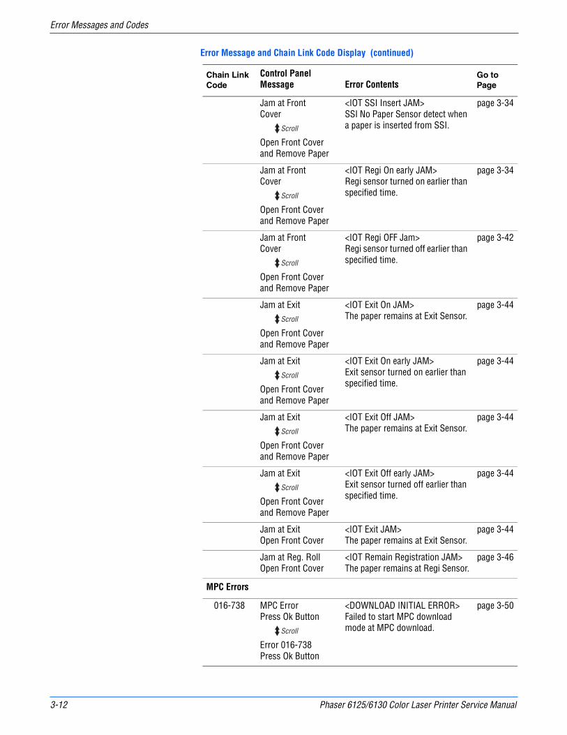
3-12 Phaser 6125/6130 Color Laser Printer Service Manual
Error Messages and Codes
Jam at Front Cover
Open Front Coverand Remove Paper
<IOT SSI Insert JAM>SSI No Paper Sensor detect when a paper is inserted from SSI.
page 3-34
Jam at FrontCover
Open Front Coverand Remove Paper
<IOT Regi On early JAM>Regi sensor turned on earlier than specified time.
page 3-34
Jam at FrontCover
Open Front Coverand Remove Paper
<IOT Regi OFF Jam>Regi sensor turned off earlier than specified time.
page 3-42
Jam at Exit
Open Front Coverand Remove Paper
<IOT Exit On JAM>The paper remains at Exit Sensor.
page 3-44
Jam at Exit
Open Front Coverand Remove Paper
<IOT Exit On early JAM>Exit sensor turned on earlier than specified time.
page 3-44
Jam at Exit
Open Front Coverand Remove Paper
<IOT Exit Off JAM>The paper remains at Exit Sensor.
page 3-44
Jam at Exit
Open Front Coverand Remove Paper
<IOT Exit Off early JAM>Exit sensor turned off earlier than specified time.
page 3-44
Jam at ExitOpen Front Cover
<IOT Exit JAM>The paper remains at Exit Sensor.
page 3-44
Jam at Reg. RollOpen Front Cover
<IOT Remain Registration JAM>The paper remains at Regi Sensor.
page 3-46
MPC Errors
016-738 MPC ErrorPress Ok Button
Error 016-738Press Ok Button
<DOWNLOAD INITIAL ERROR>Failed to start MPC download mode at MPC download.
page 3-50
Error Message and Chain Link Code Display (continued)
Chain Link Code
Control Panel Message Error Contents
Go to Page
Scroll
Scroll
Scroll
Scroll
Scroll
Scroll
Scroll
Scroll
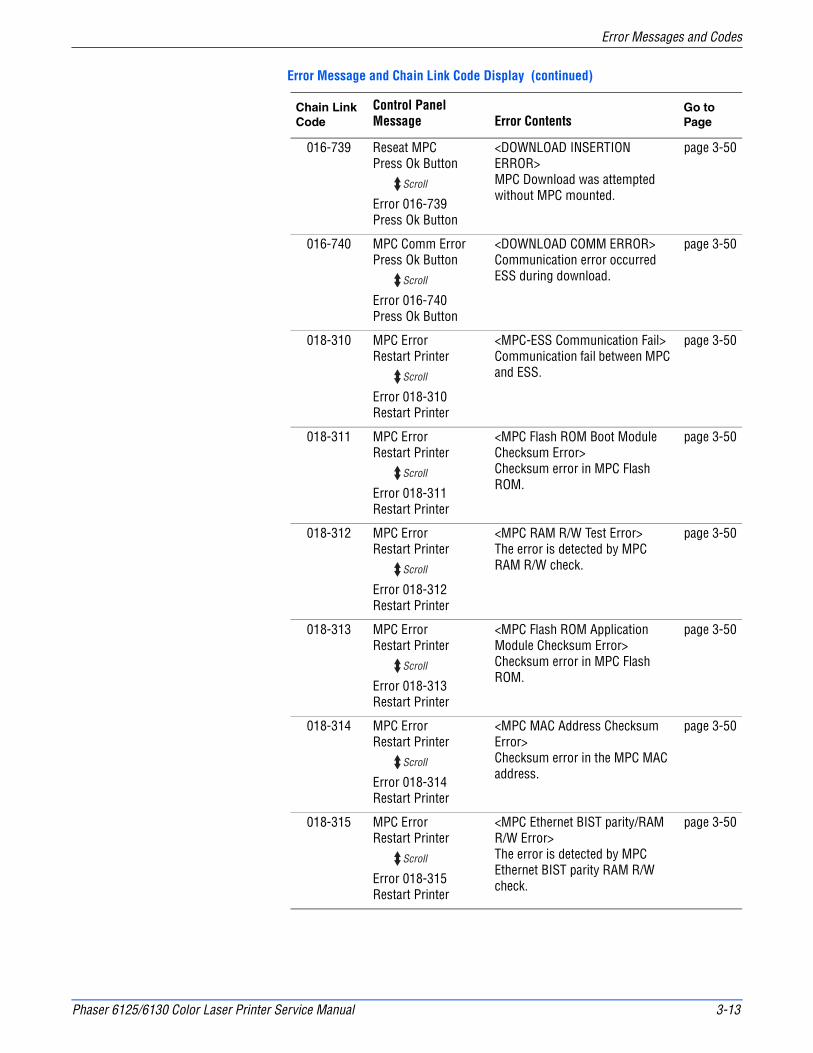
Phaser 6125/6130 Color Laser Printer Service Manual 3-13
Error Messages and Codes
016-739 Reseat MPCPress Ok Button
Error 016-739Press Ok Button
<DOWNLOAD INSERTION ERROR>MPC Download was attempted without MPC mounted.
page 3-50
016-740 MPC Comm ErrorPress Ok Button
Error 016-740Press Ok Button
<DOWNLOAD COMM ERROR>Communication error occurred ESS during download.
page 3-50
018-310 MPC ErrorRestart Printer
Error 018-310Restart Printer
<MPC-ESS Communication Fail>Communication fail between MPC and ESS.
page 3-50
018-311 MPC ErrorRestart Printer
Error 018-311Restart Printer
<MPC Flash ROM Boot Module Checksum Error>Checksum error in MPC Flash ROM.
page 3-50
018-312 MPC ErrorRestart Printer
Error 018-312Restart Printer
<MPC RAM R/W Test Error>The error is detected by MPC RAM R/W check.
page 3-50
018-313 MPC ErrorRestart Printer
Error 018-313Restart Printer
<MPC Flash ROM Application Module Checksum Error>Checksum error in MPC Flash ROM.
page 3-50
018-314 MPC ErrorRestart Printer
Error 018-314Restart Printer
<MPC MAC Address Checksum Error>Checksum error in the MPC MAC address.
page 3-50
018-315 MPC ErrorRestart Printer
Error 018-315Restart Printer
<MPC Ethernet BIST parity/RAM R/W Error>The error is detected by MPC Ethernet BIST parity RAM R/W check.
page 3-50
Error Message and Chain Link Code Display (continued)
Chain Link Code
Control Panel Message Error Contents
Go to Page
Scroll
Scroll
Scroll
Scroll
Scroll
Scroll
Scroll
Scroll

3-14 Phaser 6125/6130 Color Laser Printer Service Manual
Error Messages and Codes
018-316 MPC ErrorRestart Printer
Error 018-316Restart Printer
<MPC Internal Loopback Error>The error is detected by Loopback test.
page 3-50
018-317 MPC ErrorRestart Printer
Error 018-317Restart Printer
<MPC Fatal Error>The error is detected by MPC check.
page 3-50
116-333 MPC errorRestart Printer
Error 116-333Restart Printer
<PCI Option#0 Fail>Detection error of PCI option 0.
page 3-50
Transfer Unit Errors
092-310 CTD Sensor ErrorRestart Printer
Error 092-310Restart Printer
092-310Code: XXXX
<IOT CTD (ADC) Sensor Error>
Shows detail of error code when pressing three keys Down arrow, Up arrow, and OK.092-310
Code: 0801:fail 1/0802: Fail 2
page 3-51
094-330 DTB Life OverRestart Printer
Error 094-330Restart Printer
<IOT DTB Life Over>Imaging Unit reached the replacement time.
page 3-52
Check UnitCTD Sensor
<IOT CTD (ADC) Sensor Contamination>Contamination of the ADC Sensor is detected.
page 3-51
CTD Sensor <IOT CTD (ADC) Sensor Contamination>Contamination of the ADC Sensor is detected.
page 3-51
InsertImaging Unit
<IOT PHD Detached>Imaging Unit detached is detected.
page 3-53
Low DensityYellow Cartridge
<IOT Y Toner Low Density>Detects low density of yellow.
page 3-54
Error Message and Chain Link Code Display (continued)
Chain Link Code
Control Panel Message Error Contents
Go to Page
Scroll
Scroll
Scroll
Scroll
Scroll
Scroll

Phaser 6125/6130 Color Laser Printer Service Manual 3-15
Error Messages and Codes
Low DensityMagenta Cartridge
<IOT M Toner Low Density>Detects low density of magenta.
page 3-54
Low DensityCyan Cartridge
<IOT C Toner Low Density>Detects low density of cyan.
page 3-54
Low DensityBlack Cartridge
<IOT K Toner Low Density>Detects low density of black.
page 3-54
ReplaceImaging Unit
<IOT CRUM ID Error>CRUM ID error of Imaging Unit is detected.
page 3-71
Transfer LifeReplace Soon
<IOT DTB Life Pre Warning>The Imaging Unit is going to reach the replacement time.
page 3-52
Paper Setting Errors
Insert Outputto Manual Feed
< Paper Empty at Manual Duplex>Waiting for side 2 to be set for manual duplex print (Manual Feed).
page 3-56
Insert Outputto Tray
< Paper Empty at Manual Duplex>Waiting for side 2 to be set for manual duplex print.
page 3-56
Load Manual FeedXX (Paper size)
Load Manual FeedYY (paper type)
<IOT Paper Size Mismatch>Paper size mismatch detected in Manual Feed Slot.
page 3-56
Load Manual FeedXX (Paper size)
Load Manual FeedYY (paper type)
<No suitable paper>Paper empty is detected in Manual Feed Slot.
page 3-57
Load TrayXX (Paper size)
Load TrayYY (paper type)
<IOT Paper Size Mismatch>Paper size mismatch detected in Tray.
page 3-59
Load TrayXX (Paper size)
Load TrayYY (paper type)
<No suitable paper>Paper empty is detected in Tray.
page 3-60
Tray Empty <No paper in Ready>The paper empty is detected.
page 3-60
Error Message and Chain Link Code Display (continued)
Chain Link Code
Control Panel Message Error Contents
Go to Page
Scroll
Scroll
Scroll
Scroll

3-16 Phaser 6125/6130 Color Laser Printer Service Manual
Error Messages and Codes
Fuser Errors
010-317 Insert Fuser010-317
Insert FuserRestart Printer
<IOT Fuser Detached>Detached Fuser is detected.
page 3-62
010-351 Replace Fuser010-351
Replace FuserRestart Printer
<IOT Fuser Life Over>Fuser has reached replacement time.
page 3-63
010-397 Fuser ErrorRestart Printer
Error 010-397Restart Printer
010-397Code: XX
<IOT Fuser Failure>Fuser Failure is detected.Shows detail of error code when pressing three keys “Down arrow”, “Upper arrow”, and “OK”010-397Code: XX
01: NC circuit fail/02: NC Detect disconnection/03: NC Detect fail/04: NC Comp disconnection/05: NC Comp fail/06: NC Temp Over/07: STS Temp Over/08: NC Comp Table Fail/09: NC Overheat/0A: STS disconnection/0B: STS Overheat/0C: STS Lowtemp/0D: NC Lowtemp/0E: Cool Timeover/0F: Fuser Ready Time over ERR1/10: NC Warm up Time over ERR2/11: Fuser Ready Time over ERR2/12: Relay Off STS H/13: Relay Off NC H/14: Relay Other/15: Fuser Machine Code ERR/16: Fuser Ready Time over ERR3
page 3-64
Fuser LifeReplace Soon
<IOT Fuser Life Pre Warning>Fuser is going to reach replacement time.
page 3-63
Error Message and Chain Link Code Display (continued)
Chain Link Code
Control Panel Message Error Contents
Go to Page
Scroll
Scroll
Scroll
Scroll

Phaser 6125/6130 Color Laser Printer Service Manual 3-17
Error Messages and Codes
Motor Errors
042-313 Fan Motor ErrorRestart Printer
Error 042-313Restart Printer
<IOT Fan Motor Failure>Rear Fan Motor error is detected
page 3-66
042-325 Motor ErrorRestart Printer
Error 042-325Restart Printer
<IOT Motor Failure>Main Motor failure is detected.
page 3-67
042-326 Motor ErrorRestart Printer
Error 042-326Restart Printer
<IOT Motor Failure>Sub Motor failure is detected.
page 3-67
Imaging Unit Errors
091-916 PHD CRUM ErrorRestart Printer
Error 091-916Restart Printer
<IOT CRUM ID Error>CRUM ID error of Imaging Unit is detected.
page 3-71
Cover Open Errors
Front Cover OpenClose Front Cover
<IOT Cover Front Open>Front cover is open.
page 3-72
Side Door OpenClose Side Door
<IOT Side Cover Open>Side cover is open.
page 3-73
Error Message and Chain Link Code Display (continued)
Chain Link Code
Control Panel Message Error Contents
Go to Page
Scroll
Scroll
Scroll
Scroll

3-18 Phaser 6125/6130 Color Laser Printer Service Manual
Error Messages and Codes
MCU Errors
024-340 MCU Firmware ErrRestart Printer
Error 024-340Restart Printer
024-340Code: XX
<IOT Firmware Error>Firmware error occurs.
Shows detail of error code when pressing three keys “Down arrow”, “Up arrow”, and “OK”.024-340Code: XX
01: Task Over/02: Time Over/03: NV Write Retry/04: NV Write Queue Over/05: LEISUS Send Over/06: CRUM Data/07: Pursuit Comp/08: Pursuit SUM/09: Fuser NV/0A: Dispense/0B: FSR SBY Mode/0C: Media ERR2/0D: Hanpa/0E: FSR SBY Mode/0F: FSR Print Mode/10: Continuous Heater/11: PPM Group ERR/12: CMODE ERR/13: Send CMD ERR
page 3-74
041-340 MCU NVRAM ErrorRestart Printer
Error 041-340Restart Printer
ADDR: XXXXData: XX
<IOT NVRAM Error>IOT NVM Error occurs.
Shows detail of error code and address when pressing three keys “Down arrow”, “Upper arrow”, and “OK”.ADDR: XXXXData: XX1000 to 17FF: MCU PWBA/3000 to 30FF: Transfer Belt/3100 to 31FF: Yellow Toner Cartridge/3200 to 32FF: Magenta Toner Cartridge/3300 to 33FF: Cyan Toner Cartridge/3400 to 34FF: Black Toner Cartridge
page 3-75
Error Message and Chain Link Code Display (continued)
Chain Link Code
Control Panel Message Error Contents
Go to Page
Scroll
Scroll
Scroll
Scroll
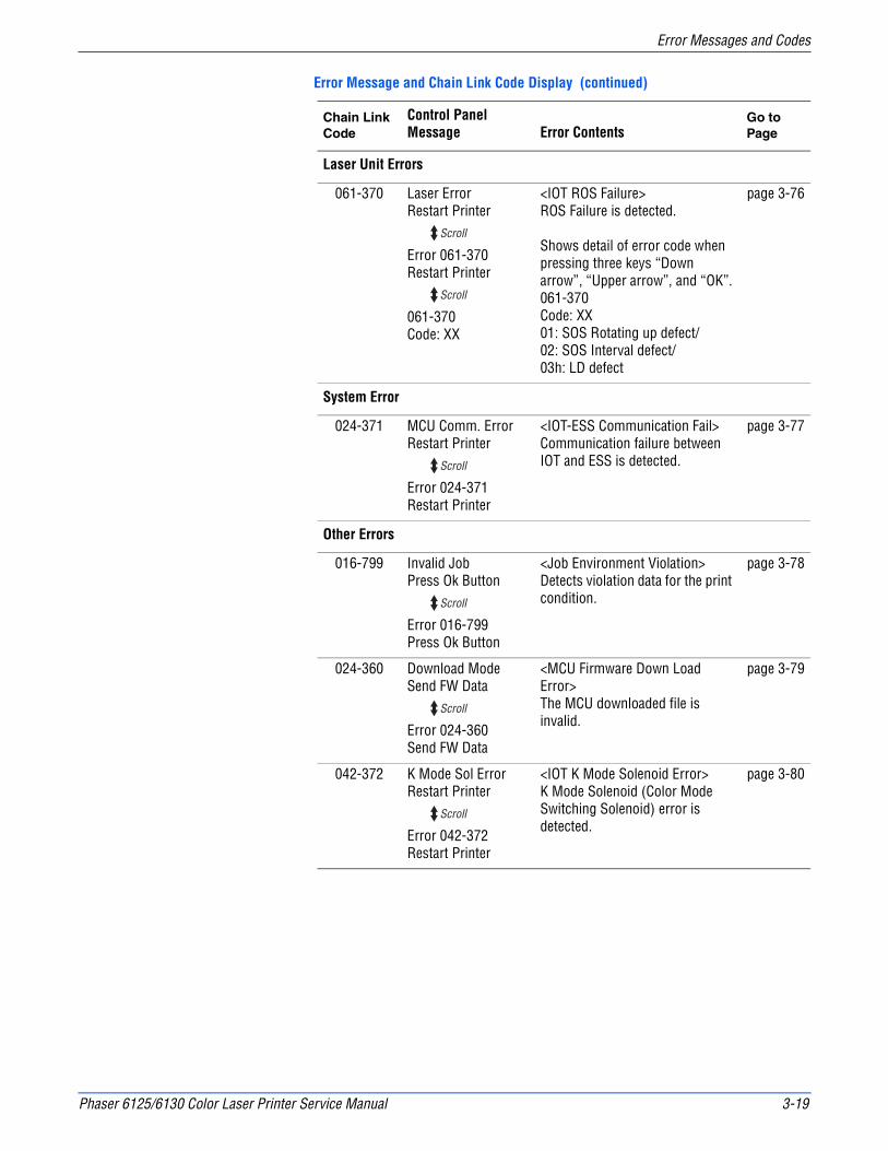
Phaser 6125/6130 Color Laser Printer Service Manual 3-19
Error Messages and Codes
Laser Unit Errors
061-370 Laser ErrorRestart Printer
Error 061-370Restart Printer
061-370Code: XX
<IOT ROS Failure>ROS Failure is detected.
Shows detail of error code when pressing three keys “Down arrow”, “Upper arrow”, and “OK”.061-370Code: XX01: SOS Rotating up defect/02: SOS Interval defect/03h: LD defect
page 3-76
System Error
024-371 MCU Comm. ErrorRestart Printer
Error 024-371Restart Printer
<IOT-ESS Communication Fail>Communication failure between IOT and ESS is detected.
page 3-77
Other Errors
016-799 Invalid JobPress Ok Button
Error 016-799Press Ok Button
<Job Environment Violation>Detects violation data for the print condition.
page 3-78
024-360 Download ModeSend FW Data
Error 024-360Send FW Data
<MCU Firmware Down Load Error>The MCU downloaded file is invalid.
page 3-79
042-372 K Mode Sol ErrorRestart Printer
Error 042-372Restart Printer
<IOT K Mode Solenoid Error>K Mode Solenoid (Color Mode Switching Solenoid) error is detected.
page 3-80
Error Message and Chain Link Code Display (continued)
Chain Link Code
Control Panel Message Error Contents
Go to Page
Scroll
Scroll
Scroll
Scroll
Scroll
Scroll
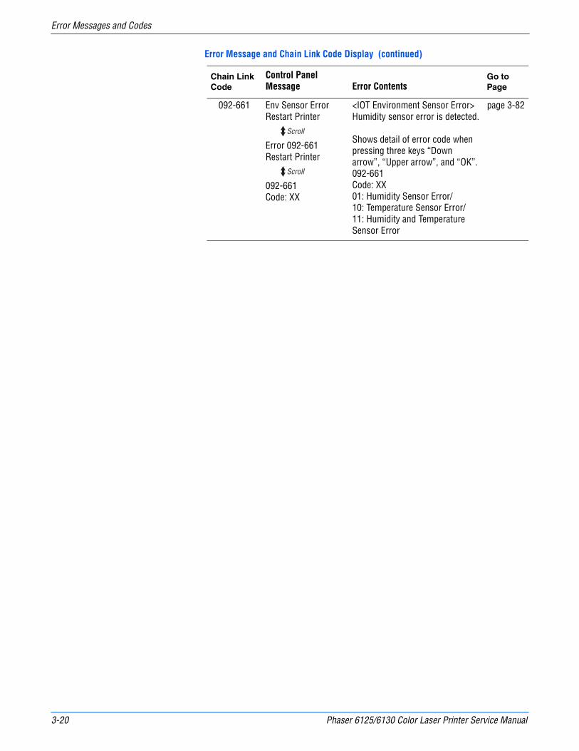
3-20 Phaser 6125/6130 Color Laser Printer Service Manual
Error Messages and Codes
092-661 Env Sensor ErrorRestart Printer
Error 092-661Restart Printer
092-661Code: XX
<IOT Environment Sensor Error>Humidity sensor error is detected.
Shows detail of error code when pressing three keys “Down arrow”, “Upper arrow”, and “OK”.092-661Code: XX01: Humidity Sensor Error/10: Temperature Sensor Error/11: Humidity and Temperature Sensor Error
page 3-82
Error Message and Chain Link Code Display (continued)
Chain Link Code
Control Panel Message Error Contents
Go to Page
Scroll
Scroll
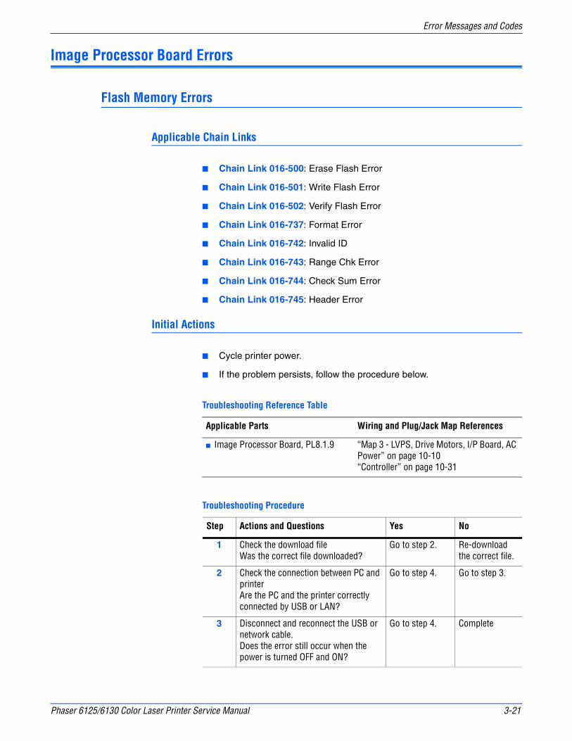
Phaser 6125/6130 Color Laser Printer Service Manual 3-21
Error Messages and Codes
Image Processor Board Errors
Flash Memory Errors
Applicable Chain Links
■ Chain Link 016-500: Erase Flash Error
■ Chain Link 016-501: Write Flash Error
■ Chain Link 016-502: Verify Flash Error
■ Chain Link 016-737: Format Error
■ Chain Link 016-742: Invalid ID
■ Chain Link 016-743: Range Chk Error
■ Chain Link 016-744: Check Sum Error
■ Chain Link 016-745: Header Error
Initial Actions
■ Cycle printer power.
■ If the problem persists, follow the procedure below.
Troubleshooting Reference Table
Applicable Parts Wiring and Plug/Jack Map References
■ Image Processor Board, PL8.1.9 “Map 3 - LVPS, Drive Motors, I/P Board, AC Power” on page 10-10“Controller” on page 10-31
Troubleshooting Procedure
Step Actions and Questions Yes No
1 Check the download fileWas the correct file downloaded?
Go to step 2. Re-download the correct file.
2 Check the connection between PC and printer Are the PC and the printer correctly connected by USB or LAN?
Go to step 4. Go to step 3.
3 Disconnect and reconnect the USB or network cable.Does the error still occur when the power is turned OFF and ON?
Go to step 4. Complete

3-22 Phaser 6125/6130 Color Laser Printer Service Manual
Error Messages and Codes
Out of Memory
The printer memory is full and cannot continue to print. Print job requires additional memory.
Applicable Chain Link
■ Chain Link 016-718: Out of memory
Initial Actions
■ Cycle printer power.
■ If the problem persists, follow the procedure below.
4 Reseat plugs and jacks on the Image Processor Board (refer to the procedure on page 8-60). Does the error still occur when the power is turned OFF and ON?
Go to step 4. Complete
5 Re-download the correct file from the Xerox web site.Does the error still occur when the power is turned OFF and ON?
Replace the Image Processor Board (page 8-60).
Complete
Troubleshooting Reference Table
Applicable Parts Wiring and Plug/Jack Map References
■ Image Processor Board, PL8.1.9■ Memory Card (Option)
“Map 3 - LVPS, Drive Motors, I/P Board, AC Power” on page 10-10“Controller” on page 10-31
Troubleshooting Procedure Table
Step Actions and Questions Yes No
1 1. Check the required memory for the print job.
2. Print a small size file (like a Windows test print).
3. Does the error still occur?
Go to step 2. Add memory card or separate the print job.
2 Reseat the memory card. Does the error still occur?
Go to step 3. Complete.
Troubleshooting Procedure (continued)
Step Actions and Questions Yes No

Phaser 6125/6130 Color Laser Printer Service Manual 3-23
Error Messages and Codes
PDL Error
Error relating to Printer Command Language (PCL) has occurred.
Applicable Chain Link
■ Chain Link 016-720: PDL Error
Initial Actions
■ Cycle printer power.
■ If the problem persists, follow the procedure below.
3 Check the memory card capacity. Print the printer Configuration Page: Menu > Information Pgs > Configuration.Is the memory capacity correct, including the optional memory?
Go to step 4. Replace the Image Processor Board (page 8-60).
4 Replace the memory card. Does the error still occur?
Replace the Image Processor Board (page 8-60).
Complete.
Troubleshooting Reference Table
Applicable Parts Wiring and Plug/Jack Map References
■ Image Processor Board, PL8.1.9 “Map 3 - LVPS, Drive Motors, I/P Board, AC Power” on page 10-10“Controller” on page 10-31
Troubleshooting Procedure Table
Step Actions and Questions Yes No
1 Check the print job.1. Print a small print job (like a
Windows test print).2. Does the error still occur?
Go to step 2. Complete.
2 Reseat plugs and jacks on the Image Processor Board. Does the error still occur?
Replace the Image Processor Board (page 8-60).
Complete.
Troubleshooting Procedure Table (continued)
Step Actions and Questions Yes No
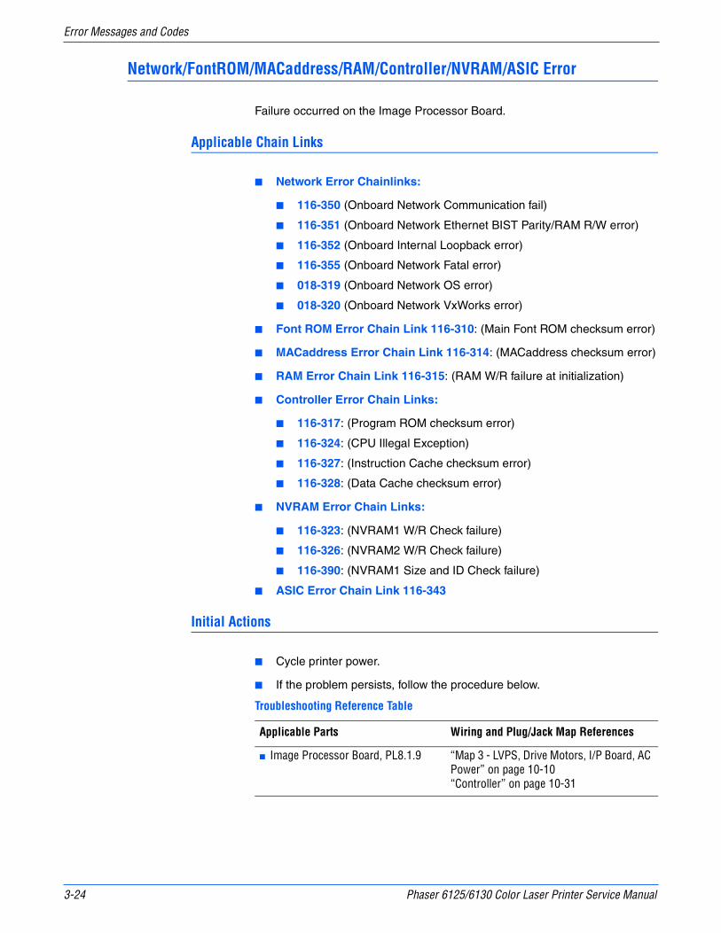
3-24 Phaser 6125/6130 Color Laser Printer Service Manual
Error Messages and Codes
Network/FontROM/MACaddress/RAM/Controller/NVRAM/ASIC Error
Failure occurred on the Image Processor Board.
Applicable Chain Links
■ Network Error Chainlinks:
■ 116-350 (Onboard Network Communication fail)
■ 116-351 (Onboard Network Ethernet BIST Parity/RAM R/W error)
■ 116-352 (Onboard Internal Loopback error)
■ 116-355 (Onboard Network Fatal error)
■ 018-319 (Onboard Network OS error)
■ 018-320 (Onboard Network VxWorks error)
■ Font ROM Error Chain Link 116-310: (Main Font ROM checksum error)
■ MACaddress Error Chain Link 116-314: (MACaddress checksum error)
■ RAM Error Chain Link 116-315: (RAM W/R failure at initialization)
■ Controller Error Chain Links:
■ 116-317: (Program ROM checksum error)
■ 116-324: (CPU Illegal Exception)
■ 116-327: (Instruction Cache checksum error)
■ 116-328: (Data Cache checksum error)
■ NVRAM Error Chain Links:
■ 116-323: (NVRAM1 W/R Check failure)
■ 116-326: (NVRAM2 W/R Check failure)
■ 116-390: (NVRAM1 Size and ID Check failure)
■ ASIC Error Chain Link 116-343
Initial Actions
■ Cycle printer power.
■ If the problem persists, follow the procedure below.
Troubleshooting Reference Table
Applicable Parts Wiring and Plug/Jack Map References
■ Image Processor Board, PL8.1.9 “Map 3 - LVPS, Drive Motors, I/P Board, AC Power” on page 10-10“Controller” on page 10-31
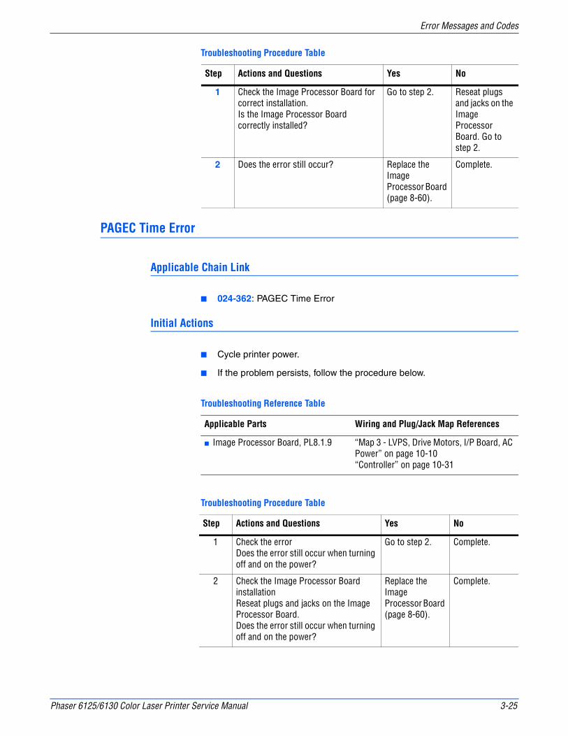
Phaser 6125/6130 Color Laser Printer Service Manual 3-25
Error Messages and Codes
PAGEC Time Error
Applicable Chain Link
■ 024-362: PAGEC Time Error
Initial Actions
■ Cycle printer power.
■ If the problem persists, follow the procedure below.
Troubleshooting Procedure Table
Step Actions and Questions Yes No
1 Check the Image Processor Board for correct installation. Is the Image Processor Board correctly installed?
Go to step 2. Reseat plugs and jacks on the Image Processor Board. Go to step 2.
2 Does the error still occur? Replace the Image Processor Board (page 8-60).
Complete.
Troubleshooting Reference Table
Applicable Parts Wiring and Plug/Jack Map References
■ Image Processor Board, PL8.1.9 “Map 3 - LVPS, Drive Motors, I/P Board, AC Power” on page 10-10“Controller” on page 10-31
Troubleshooting Procedure Table
Step Actions and Questions Yes No
1 Check the errorDoes the error still occur when turning off and on the power?
Go to step 2. Complete.
2 Check the Image Processor Board installationReseat plugs and jacks on the Image Processor Board.Does the error still occur when turning off and on the power?
Replace the Image Processor Board (page 8-60).
Complete.

3-26 Phaser 6125/6130 Color Laser Printer Service Manual
Error Messages and Codes
RAM Error
The printer controller has detected a DIMM slot RAM error.
Applicable Chain Link
■ 116-316: RAM Error (DIMM Slot RAM W/R Check Fail)
■ 116-320: RAM Error (DIMM Slot RAM Error)
Initial Actions
■ Cycle printer power.
■ If the problem persists, follow the procedure below.
Troubleshooting Reference Table
Applicable Parts Wiring and Plug/Jack Map References
■ Image Processor Board, PL8.1.9■ Memory Card (Option)
“Map 3 - LVPS, Drive Motors, I/P Board, AC Power” on page 10-10“Controller” on page 10-31
Troubleshooting Procedure Table
Step Actions and Questions Yes No
1 Verify RAM is compatible with the printer. If RAM was recently installed, it may not be compatible. Is RAM compatible?
Go to step 2. Replace the Memory Card.
2 Check the Memory Card for correct installation. Is the Memory Card correctly installed?
Go to step 3. Complete.
3 Replace the Memory Card.Does the error still occur?
Replace the Image Processor Board (page 8-60).
Complete.

Phaser 6125/6130 Color Laser Printer Service Manual 3-27
Error Messages and Codes
Toner Cartridge Errors
Insert Yellow/Cyan/Magenta/Black Cartridge
The printer does not detect the Toner Cartridge.
Non-Xerox Toner, Invalid Yellow/Magenta/Cyan/Black
The Toner Cartridge CRUM ID error indicates that a non-Xerox Toner Cartridge is installed.
Replace Yellow/Magenta/Cyan/Black
The Toner Cartridge (Yellow/Magenta,/Cyan/Black) has reached its end of life.
Yellow/Magenta/Cyan/Black Low
The Toner Cartridge (Yellow/Magenta,/Cyan/Black) is near its end of life.
Initial Actions
■ Check the Toner Cartridge life using CentreWare IS.
■ Cycle printer power.
■ If problem persists, follow the procedure below.
Troubleshooting Reference Table
Applicable Parts Wiring and Plug/Jack Map References
■ Toner Cartridge (Y/M/C/K),PL5.1.21-24■ MCU Board, PL8.2.13
■ “Map 1 - Transfer Unit, Control Panel, Imaging Unit, Dispenser, Fuser” on page 10-8■ “Map 4 - Toner Dispenser Motors, HVPS, MCU” on page 10-11■ “Developer” on page 10-27
Troubleshooting Procedure Table
Step Actions and Questions Yes No
1 Check the Toner Cartridge for correct installation. Is the Toner Cartridge correctly installed?
Go to step 3. Go to step 2.
2 Reseat the Toner Cartridge. Make sure the lock key is in the lock position.Does the error still occur?
Go to step 3. Complete.

3-28 Phaser 6125/6130 Color Laser Printer Service Manual
Error Messages and Codes
Waste Full, Yellow/Magenta/Cyan/Black Cartridge
Initial Actions
■ Check the Toner Cartridge life using CentreWare IS.
■ Cycle printer power.
■ If problem persists, follow the procedure below.
3 Replace the Toner Cartridge (page 8-10). Does the error still occur?
Go to step 4. Complete.
4 Check the Toner CRUM Harness for continuity1. Disconnect J31 from the MCU
Board.2. Disconnect J311 (Y), J312 (M),
J313 (C) or J314 (K) from the connector CRUM.
Is each cable of J31 <=> J311, J312, J313 or J314 continuous?
Go to step 5. Replace the Dispenser Assembly (page 8-34)
5 Reseat plugs and jacks on the MCU Board.Does the error still occur when the power is turned OFF and ON?
Go to step 6. Complete.
6 Measure the voltage at P31-3 <=> Ground.Is the voltage approximately +3.3VDC?
Replace the Dispenser Assembly (page 8-34)
Replace the MCU Board (page 8-59).
Troubleshooting Reference Table
Applicable Parts Wiring and Plug/Jack Map References
■ Toner Cartridge (Y/M/C/K),PL5.1.21-24■ MCU Board, PL8.2.13
■ “Map 1 - Transfer Unit, Control Panel, Imaging Unit, Dispenser, Fuser” on page 10-8■ “Map 4 - Toner Dispenser Motors, HVPS, MCU” on page 10-11“Developer” on page 10-27
Troubleshooting Procedure Table
Step Actions and Questions Yes No
1 Replace the TONER CARTRIDGE.Does the error still occur when turning of and on the power?
Replace the MCU Board. (page 8-59)
Complete.
Troubleshooting Procedure Table (continued)
Step Actions and Questions Yes No
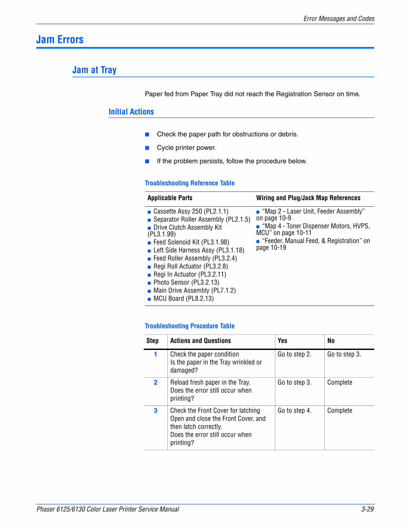
Phaser 6125/6130 Color Laser Printer Service Manual 3-29
Error Messages and Codes
Jam Errors
Jam at Tray
Paper fed from Paper Tray did not reach the Registration Sensor on time.
Initial Actions
■ Check the paper path for obstructions or debris.
■ Cycle printer power.
■ If the problem persists, follow the procedure below.
Troubleshooting Reference Table
Applicable Parts Wiring and Plug/Jack Map References
■ Cassette Assy 250 (PL2.1.1)■ Separator Roller Assembly (PL2.1.5)■ Drive Clutch Assembly Kit (PL3.1.99)■ Feed Solenoid Kit (PL3.1.98)■ Left Side Harness Assy (PL3.1.18)■ Feed Roller Assembly (PL3.2.4)■ Regi Roll Actuator (PL3.2.8)■ Regi In Actuator (PL3.2.11)■ Photo Sensor (PL3.2.13)■ Main Drive Assembly (PL7.1.2)■ MCU Board (PL8.2.13)
■ “Map 2 - Laser Unit, Feeder Assembly” on page 10-9■ “Map 4 - Toner Dispenser Motors, HVPS, MCU” on page 10-11■ “Feeder, Manual Feed, & Registration” on page 10-19
Troubleshooting Procedure Table
Step Actions and Questions Yes No
1 Check the paper conditionIs the paper in the Tray wrinkled or damaged?
Go to step 2. Go to step 3.
2 Reload fresh paper in the Tray.Does the error still occur when printing?
Go to step 3. Complete
3 Check the Front Cover for latchingOpen and close the Front Cover, and then latch correctly.Does the error still occur when printing?
Go to step 4. Complete

3-30 Phaser 6125/6130 Color Laser Printer Service Manual
Error Messages and Codes
4 Check the Main Motor (Main Drive Assembly) for operationPerform the Main Motor (FULL2) test (page 4-27): Service Mode > Engine Diag > Motor Test > Main Motor (FULL2). During this check, defeat the Front Cover interlock switch.Does the Main Motor (Main Drive Assembly) operate properly?
Go to step 5. Go to step 16.
5 Check the Feed Drive Assembly for operationPerform the Regi Clutch test (page 4-33): Service Mode > Engine Diag > Motor Test > Regi Clutch. During this check, defeat the Front Cover interlock switch.Do the Registration and Metal Registration Rollers rotate properly?
Go to step 6. Go to step 26.
6 Check the paper feeding positionIs the paper not fed from the Tray?
Go to step 7. Go to step 11.
7 Check after resetting the Side Guides and End Guide on the Tray.Reset the Side Guides and End Guide, and reseat the Tray in the printer correctly.Does the error still occur when printing?
Go to step 8. Complete
8 Check the Separator Roller Assembly on the Tray for shape and rotationPull the Tray out from the printer.Is the Separator Roller Assembly not contaminated and/or damaged, and rotated smoothly?
Go to step 9. Replace the Separator Roller Assembly (page 8-7).
9 Check the Feed Roller Assembly for shape and rotationPull the Tray out of the printer.Is the Feed Roller Assembly free of contamination and/or undamaged, and does it rotate smoothly?
Go to step 10. Replace the Feed Roller Assembly (page 8-30).
10 Check the Feed Solenoid for operationPerform the Tray Feed Solenoid (Auto) test (page 4-34): Service Mode > Engine Diag > Motor Test > Tray Feed Solenoid (Auto). During this check, defeat the Front Cover interlock switch.Does the Feed Solenoid operate properly?
Replace the Paper Tray (CASSETTE ASSY 250).
Go to step 18.
Troubleshooting Procedure Table (continued)
Step Actions and Questions Yes No
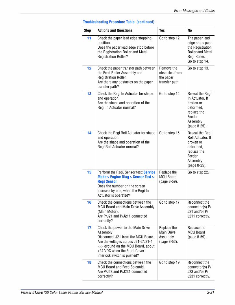
Phaser 6125/6130 Color Laser Printer Service Manual 3-31
Error Messages and Codes
11 Check the paper lead edge stopping positionDoes the paper lead edge stop before the Registration Roller and Metal Registration Roller?
Go to step 12. The paper lead edge stops past the Registration Roller and Metal Regi Roller. Go to step 14.
12 Check the paper transfer path between the Feed Roller Assembly and Registration Roller.Are there any obstacles on the paper transfer path?
Remove the obstacles from the paper transfer path.
Go to step 13.
13 Check the Regi In Actuator for shape and operation.Are the shape and operation of the Regi In Actuator normal?
Go to step 14. Reseat the Regi In Actuator. If broken or deformed, replace the Feeder Assembly (page 8-25).
14 Check the Regi Roll Actuator for shape and operation. Are the shape and operation of the Regi Roll Actuator normal?
Go to step 15. Reseat the Regi Roll Actuator. If broken or deformed, replace the Feeder Assembly (page 8-25).
15 Perform the Regi. Sensor test: Service Mode > Engine Diag > Sensor Test > Regi Sensor.Does the number on the screen increase by one, when the Regi In Actuator is operated?
Replace the MCU Board (page 8-59).
Go to step 22.
16 Check the connections between the MCU Board and Main Drive Assembly (Main Motor).Are P/J21 and P/J211 connected correctly?
Go to step 17. Reconnect the connector(s) P/J21 and/or P/J211 correctly.
17 Check the power to the Main Drive AssemblyDisconnect J21 from the MCU Board.Are the voltages across J21-2/J21-4 <=> ground on the MCU Board, about +24 VDC when the Front Cover interlock switch is pushed?
Replace the Main Drive Assembly (page 8-52).
Replace the MCU Board (page 8-59).
18 Check the connections between the MCU Board and Feed Solenoid.Are P/J23 and P/J231 connected correctly?
Go to step 19. Reconnect the connector(s) P/J23 and/or P/J231 correctly.
Troubleshooting Procedure Table (continued)
Step Actions and Questions Yes No
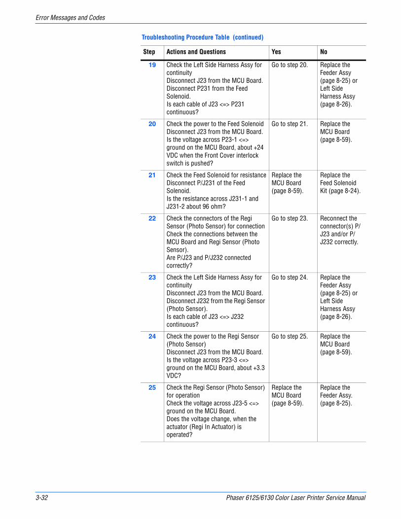
3-32 Phaser 6125/6130 Color Laser Printer Service Manual
Error Messages and Codes
19 Check the Left Side Harness Assy for continuityDisconnect J23 from the MCU Board.Disconnect P231 from the Feed Solenoid.Is each cable of J23 <=> P231 continuous?
Go to step 20. Replace the Feeder Assy (page 8-25) or Left Side Harness Assy (page 8-26).
20 Check the power to the Feed SolenoidDisconnect J23 from the MCU Board.Is the voltage across P23-1 <=> ground on the MCU Board, about +24 VDC when the Front Cover interlock switch is pushed?
Go to step 21. Replace the MCU Board (page 8-59).
21 Check the Feed Solenoid for resistanceDisconnect P/J231 of the Feed Solenoid.Is the resistance across J231-1 and J231-2 about 96 ohm?
Replace the MCU Board (page 8-59).
Replace the Feed Solenoid Kit (page 8-24).
22 Check the connectors of the Regi Sensor (Photo Sensor) for connectionCheck the connections between the MCU Board and Regi Sensor (Photo Sensor).Are P/J23 and P/J232 connected correctly?
Go to step 23. Reconnect the connector(s) P/J23 and/or P/J232 correctly.
23 Check the Left Side Harness Assy for continuityDisconnect J23 from the MCU Board.Disconnect J232 from the Regi Sensor (Photo Sensor).Is each cable of J23 <=> J232 continuous?
Go to step 24. Replace the Feeder Assy (page 8-25) or Left Side Harness Assy (page 8-26).
24 Check the power to the Regi Sensor (Photo Sensor)Disconnect J23 from the MCU Board.Is the voltage across P23-3 <=> ground on the MCU Board, about +3.3 VDC?
Go to step 25. Replace the MCU Board (page 8-59).
25 Check the Regi Sensor (Photo Sensor) for operationCheck the voltage across J23-5 <=> ground on the MCU Board.Does the voltage change, when the actuator (Regi In Actuator) is operated?
Replace the MCU Board (page 8-59).
Replace the Feeder Assy. (page 8-25).
Troubleshooting Procedure Table (continued)
Step Actions and Questions Yes No
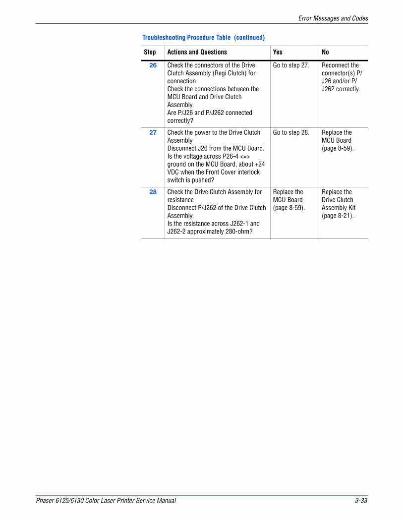
Phaser 6125/6130 Color Laser Printer Service Manual 3-33
Error Messages and Codes
26 Check the connectors of the Drive Clutch Assembly (Regi Clutch) for connectionCheck the connections between the MCU Board and Drive Clutch Assembly.Are P/J26 and P/J262 connected correctly?
Go to step 27. Reconnect the connector(s) P/J26 and/or P/J262 correctly.
27 Check the power to the Drive Clutch AssemblyDisconnect J26 from the MCU Board.Is the voltage across P26-4 <=> ground on the MCU Board, about +24 VDC when the Front Cover interlock switch is pushed?
Go to step 28. Replace the MCU Board (page 8-59).
28 Check the Drive Clutch Assembly for resistanceDisconnect P/J262 of the Drive Clutch Assembly.Is the resistance across J262-1 and J262-2 approximately 280-ohm?
Replace the MCU Board (page 8-59).
Replace the Drive Clutch Assembly Kit (page 8-21).
Troubleshooting Procedure Table (continued)
Step Actions and Questions Yes No
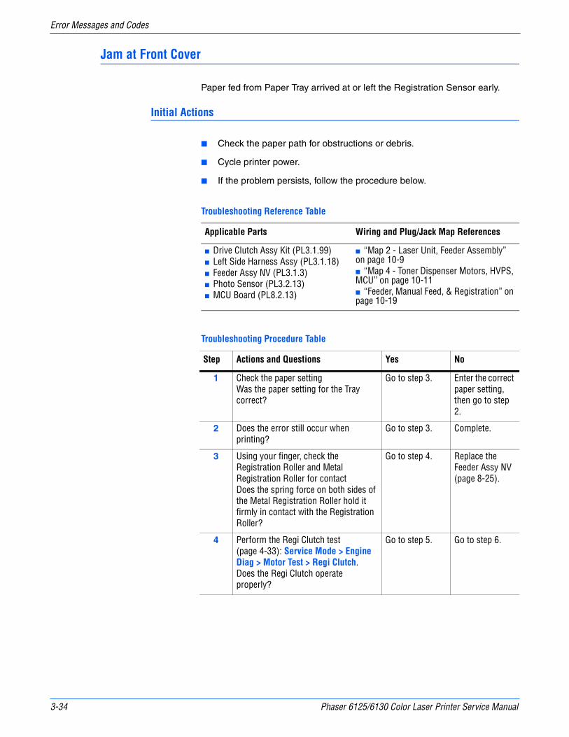
3-34 Phaser 6125/6130 Color Laser Printer Service Manual
Error Messages and Codes
Jam at Front Cover
Paper fed from Paper Tray arrived at or left the Registration Sensor early.
Initial Actions
■ Check the paper path for obstructions or debris.
■ Cycle printer power.
■ If the problem persists, follow the procedure below.
Troubleshooting Reference Table
Applicable Parts Wiring and Plug/Jack Map References
■ Drive Clutch Assy Kit (PL3.1.99)■ Left Side Harness Assy (PL3.1.18)■ Feeder Assy NV (PL3.1.3)■ Photo Sensor (PL3.2.13)■ MCU Board (PL8.2.13)
■ “Map 2 - Laser Unit, Feeder Assembly” on page 10-9■ “Map 4 - Toner Dispenser Motors, HVPS, MCU” on page 10-11■ “Feeder, Manual Feed, & Registration” on page 10-19
Troubleshooting Procedure Table
Step Actions and Questions Yes No
1 Check the paper settingWas the paper setting for the Tray correct?
Go to step 3. Enter the correct paper setting, then go to step 2.
2 Does the error still occur when printing?
Go to step 3. Complete.
3 Using your finger, check the Registration Roller and Metal Registration Roller for contactDoes the spring force on both sides of the Metal Registration Roller hold it firmly in contact with the Registration Roller?
Go to step 4. Replace the Feeder Assy NV (page 8-25).
4 Perform the Regi Clutch test (page 4-33): Service Mode > Engine Diag > Motor Test > Regi Clutch.Does the Regi Clutch operate properly?
Go to step 5. Go to step 6.

Phaser 6125/6130 Color Laser Printer Service Manual 3-35
Error Messages and Codes
5 Check the Regi Sensor (Photo Sensor) for operation. Perform the Regi Sensor test (page 4-21): Service Mode > Engine Diag > Sensor Test > Regi Sensor.Does the number on the screen increase by one, when the actuator (Regi In Actuator) is operated?
Replace the MCU Board (page 8-59).
Go to step 9.
6 Check the connections between the MCU Board andDrive Clutch Assembly (Regi Clutch).Are P/J26 and P/J262 connected correctly?
Go to step 7. Reconnect the connector(s) P/J26 and/or P/J262 correctly.
7 Check the power to the Drive Clutch AssemblyDisconnect J26 from the MCU Board.Is the voltage across P26-4 <=> ground on the MCU Board, about +24 VDC when the Front Cover interlock switch is pushed?
Go to step 8. Replace the MCU Board (page 8-59).
8 Check the Drive Clutch Assembly for resistanceDisconnect P/J262 of the Drive Clutch Assembly.Is the resistance across J262-1 and J262-2 approximately 280-ohm?
Replace the MCU Board (page 8-59).
Replace the Drive Clutch Assembly Kit (page 8-21).
9 Check the connectors of the Regi Sensor (Photo Sensor) for connectionCheck the connections between the MCU Board and Regi Sensor (Photo Sensor).Are P/J23 and P/J232 connected correctly?
Go to step 10. Reconnect the connector(s) P/J23 and/or P/J232 correctly.
10 Check the Left Side Harness Assy for continuityDisconnect J23 from the MCU Board.Disconnect J232 from the Regi Sensor.Is each cable of J23 <=> J232 continuous?
Go to step 11. Replace the Feeder Assy (page 8-25) or Left Side Harness Assy (page 8-26).
11 Check the power to the Regi SensorDisconnect J23 from the MCU Board.Is the voltage across P23-3 <=> ground on the MCU Board, about +3.3 VDC?
Go to step 12. Replace the MCU Board (page 8-59).
Troubleshooting Procedure Table (continued)
Step Actions and Questions Yes No
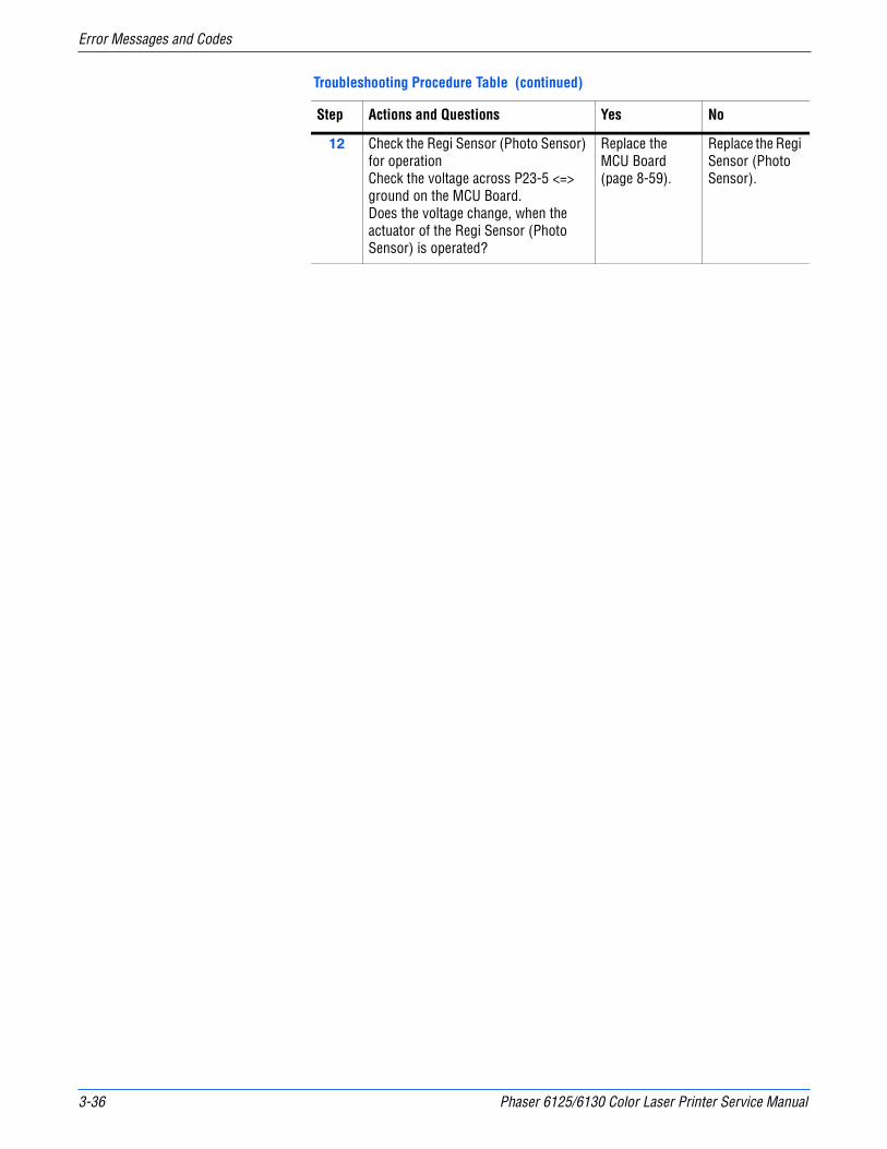
3-36 Phaser 6125/6130 Color Laser Printer Service Manual
Error Messages and Codes
12 Check the Regi Sensor (Photo Sensor) for operationCheck the voltage across P23-5 <=> ground on the MCU Board.Does the voltage change, when the actuator of the Regi Sensor (Photo Sensor) is operated?
Replace the MCU Board (page 8-59).
Replace the Regi Sensor (Photo Sensor).
Troubleshooting Procedure Table (continued)
Step Actions and Questions Yes No

Phaser 6125/6130 Color Laser Printer Service Manual 3-37
Error Messages and Codes
Jam at Manual Feed Slot
Paper fed from the Manual Feed Slot did not reach the Registration Sensor on time.
Initial Actions
■ Try picking paper from the tray.
■ Check the paper path for obstructions or debris.
■ Cycle printer power.
■ If the problem persists, follow the procedure below.
Troubleshooting Reference Table
Applicable Parts Wiring and Plug/Jack Map Reference
■ Drive Clutch Assy Kit, PL3.1.99■ Left Side Harness Assy, PL3.1.18■ Photo Sensor, PL3.2.13■ Actuator SSI, PL3.2.14■ Main Drive Assy, PL7.1.2■ MCU Board, PL8.2.13
■ “Map 2 - Laser Unit, Feeder Assembly” on page 10-9■ “Map 4 - Toner Dispenser Motors, HVPS, MCU” on page 10-11■ “Feeder, Manual Feed, & Registration” on page 10-19
Troubleshooting Procedure Table
Step Actions and Questions Yes No
1 Check the paper sizeDoes the paper size meet the specification?
Go to step 3. Use the paper that meets the specifications, then go to step 2.
2 Does the error still occur when printing?
Go to step 3. Complete
3 Check the paper conditionIs the paper in the Manual Feed Slot wrinkled or damaged?
Replace with a new and dry sheet, then go to step 4.
Go to step 5.
4 Does the error still occur when printing?
Go to step 6. Complete
5 Insert a fresh sheet of paper in the Manual Feed Slot.Does the error still occur when printing?
Go to step 6. Complete
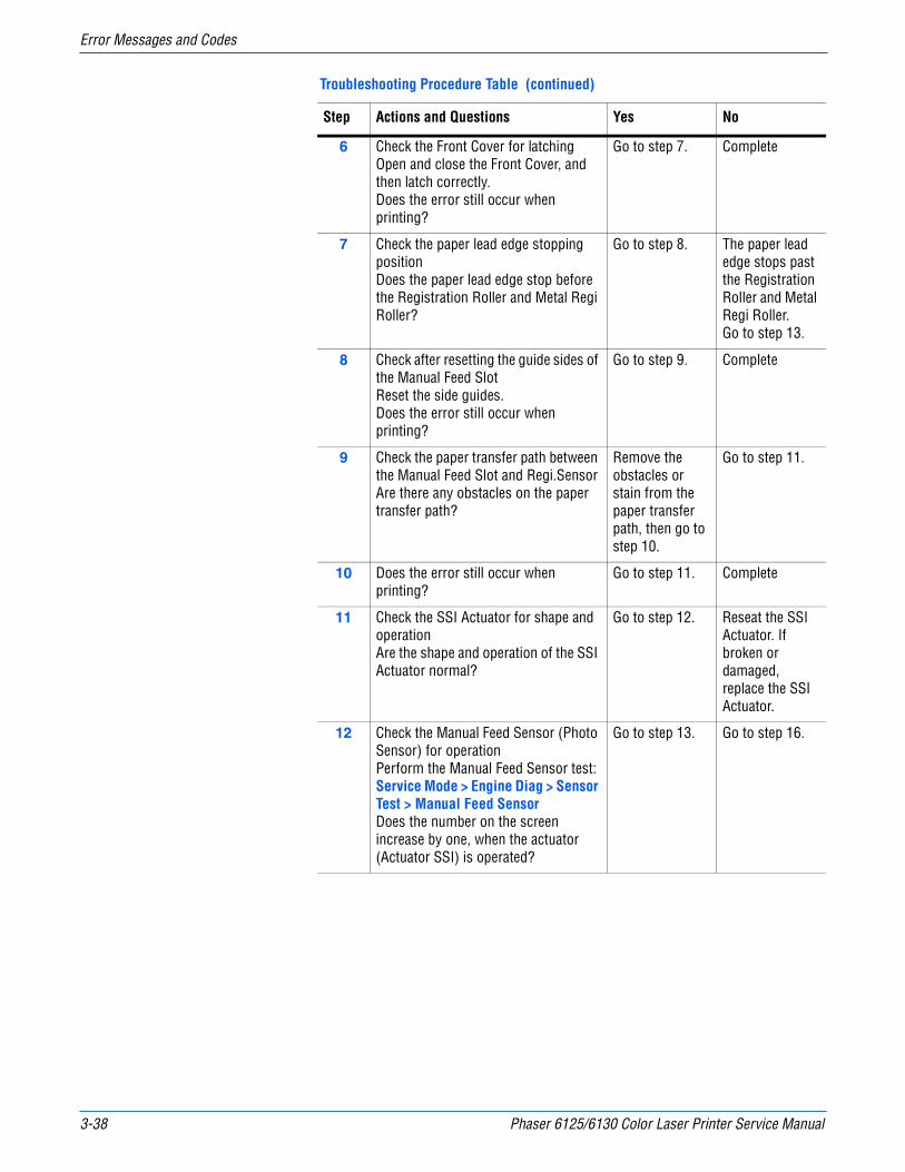
3-38 Phaser 6125/6130 Color Laser Printer Service Manual
Error Messages and Codes
6 Check the Front Cover for latchingOpen and close the Front Cover, and then latch correctly.Does the error still occur when printing?
Go to step 7. Complete
7 Check the paper lead edge stopping positionDoes the paper lead edge stop before the Registration Roller and Metal Regi Roller?
Go to step 8. The paper lead edge stops past the Registration Roller and Metal Regi Roller. Go to step 13.
8 Check after resetting the guide sides of the Manual Feed SlotReset the side guides.Does the error still occur when printing?
Go to step 9. Complete
9 Check the paper transfer path between the Manual Feed Slot and Regi.SensorAre there any obstacles on the paper transfer path?
Remove the obstacles or stain from the paper transfer path, then go to step 10.
Go to step 11.
10 Does the error still occur when printing?
Go to step 11. Complete
11 Check the SSI Actuator for shape and operationAre the shape and operation of the SSI Actuator normal?
Go to step 12. Reseat the SSI Actuator. If broken or damaged, replace the SSI Actuator.
12 Check the Manual Feed Sensor (Photo Sensor) for operationPerform the Manual Feed Sensor test: Service Mode > Engine Diag > Sensor Test > Manual Feed SensorDoes the number on the screen increase by one, when the actuator (Actuator SSI) is operated?
Go to step 13. Go to step 16.
Troubleshooting Procedure Table (continued)
Step Actions and Questions Yes No
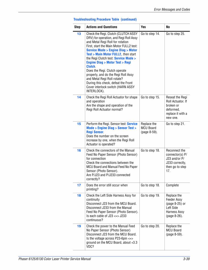
Phaser 6125/6130 Color Laser Printer Service Manual 3-39
Error Messages and Codes
13 Check the Regi. Clutch (CLUTCH ASSY DRV) for operation, and Regi Roll Assy and Metal Regi Roll for rotationFirst, start the Main Motor FULL2 test: Service Mode > Engine Diag > Motor Test > Main Motor FULL2, then start the Regi Clutch test: Service Mode > Engine Diag > Motor Test > Regi Clutch.Does the Regi. Clutch operate properly, and do the Regi Roll Assy and Metal Regi Roll rotate?During this check, defeat the Front Cover interlock switch (HARN ASSY INTERLOCK).
Go to step 14. Go to step 25.
14 Check the Regi Roll Actuator for shape and operationAre the shape and operation of the Regi Roll Actuator normal?
Go to step 15. Reseat the Regi Roll Actuator. If broken or deformed, replace it with a new one.
15 Perform the Regi. Sensor test: Service Mode > Engine Diag > Sensor Test > Regi Sensor.Does the number on the screen increase by one, when the Regi Roll Actuator is operated?
Replace the MCU Board (page 8-59).
Go to step 21.
16 Check the connectors of the Manual Feed No Paper Sensor (Photo Sensor) for connectionCheck the connections between the MCU Board and Manual Feed No Paper Sensor (Photo Sensor).Are P/J23 and P/J233 connected correctly?
Go to step 18. Reconnect the connector(s) P/J23 and/or P/J233 correctly, then go to step 17.
17 Does the error still occur when printing?
Go to step 18. Complete
18 Check the Left Side Harness Assy for continuityDisconnect J23 from the MCU Board.Disconnect J233 from the Manual Feed No Paper Sensor (Photo Sensor).Is each cable of J23 <=> J233 continuous?
Go to step 19. Replace the Feeder Assy (page 8-25) or Left Side Harness Assy (page 8-26).
19 Check the power to the Manual Feed No Paper Sensor (Photo Sensor)Disconnect J23 from the MCU Board.Is the voltage across P23-6pin <=> ground on the MCU Board, about +3.3 VDC?
Go to step 20. Replace the MCU Board (page 8-59).
Troubleshooting Procedure Table (continued)
Step Actions and Questions Yes No

3-40 Phaser 6125/6130 Color Laser Printer Service Manual
Error Messages and Codes
20 Check the Manual Feed No Paper Sensor (Photo Sensor) for operationCheck the voltage across J23-8pin <=> ground on the MCU Board.Does the voltage change, when the SSI Actuator is operated?
Replace the MCU Board (page 8-59).
Replace the Feeder Assembly (page 8-25).
21 Check the connectors of the Regi Sensor (Photo Sensor) for connectionCheck the connections between the MCU Board and Regi Sensor (Photo Sensor).Are P/J23 and P/J232 connected correctly?
Go to step 22. Reconnect the connector(s) P/J23 and/or P/J232 correctly.
22 Check the Left Side Harness Assy for continuityDisconnect J23 from the MCU Board.Disconnect J232 from the Regi Sensor (Photo Sensor).Is each cable of J23 <=> J232 continuous?
Go to step 23. Replace the Feeder Assy (page 8-25) or Left Side Harness Assy (page 8-26).
23 Check the power to the Regi Sensor (Photo Sensor)Disconnect J23 from the MCU Board.Is the voltage across P23-3pin <=> ground on the MCU Board about +3.3 VDC?
Go to step 24. Replace the MCU Board (page 8-59).
24 Check the Regi Sensor (Photo Sensor) for operationCheck the voltage across J23-5pin <=> ground on the MCU Board.Does the voltage change, when the Regi Roll Actuator is operated?
Replace the MCU Board (page 8-59).
Replace the Feeder Assembly page 8-25.
25 Check the connectors of the Drive Clutch Assy (Regi Clutch) for connectionCheck the connections between the MCU Board and Drive Clutch Assy.Are P/J26 and P/J262 connected correctly?
Go to step 26. Reconnect the connector(s) P/J26 and/or P/J262 correctly.
26 Check the HARN ASSY KSNR REGCL for continuityDisconnect J26 from the MCU Board.Disconnect P262 from the Drive Clutch Assy (Regi Clutch).Is each cable of J26 <=> P262 continuous?
Go to step 27. Replace the HARN ASSY KSNR REGCL.
Troubleshooting Procedure Table (continued)
Step Actions and Questions Yes No

Phaser 6125/6130 Color Laser Printer Service Manual 3-41
Error Messages and Codes
27 Check the power to the Drive Clutch AssyDisconnect J26 from the MCU Board.Is the voltage across P26-4pin <=> ground on the MCU Board, about +24 VDC when the Interlock Switch (HARN ASSY INTERLOCK) is pushed?
Go to step 28. Replace the MCU Board (page 8-59).
28 Check the Drive Clutch Assy for resistanceDisconnect P/J262 of the Drive Clutch Assy.Is the resistance across J262-1 and J262-2 approximately 280-ohm?
Replace the MCU Board (page 8-59).
Replace the Drive Clutch Kit. (page 8-21)
Troubleshooting Procedure Table (continued)
Step Actions and Questions Yes No

3-42 Phaser 6125/6130 Color Laser Printer Service Manual
Error Messages and Codes
Jam at Front Cover
No Paper condition detected at the Manual Feed.
Initial Actions
■ Check the paper path for obstructions or debris.
■ Cycle printer power.
■ If the problem persists, follow the procedure below.
Troubleshooting Reference Table
Applicable Parts Wiring and Plug/Jack Map References
■ Left Side Harness Assy (PL3.1.18)■ Photo Sensor (PL3.2.13)■ MCU Board (PL8.2.13)
■ “Map 2 - Laser Unit, Feeder Assembly” on page 10-9■ “Map 4 - Toner Dispenser Motors, HVPS, MCU” on page 10-11■ “Feeder, Manual Feed, & Registration” on page 10-19
Troubleshooting Procedure Table
Step Actions and Questions Yes No
1 Check the customer operationDid the customer insert the paper to the Manual Feed Slot during print?
After print completion, insert the paper to the SSI.
Go to step 2.
2 Check the Manual Feed No Paper Sensor (Photo Sensor) for operationPerform the Manual Feed Sensor test (page 4-25): Service Mode > Engine Diag > Sensor Test > Manual Feed Sensor.Does the number on the screen increase by one, when the actuator (SSI Actuator) is operated by paper.
Go to step 3. Go to step 4.
3 Check the errorDoes the error still occur when printing?
Replace the MCU Board (page 8-59).
Complete
4 Check the connections between the MCU Board and Manual Feed No Paper Sensor (Photo Sensor).Are P/J23 and P/J233 connected correctly?
Go to step 6. Reconnect the connector(s) P/J23 and/or P/J233 correctly, then go to step 5.
5 Does the error still occur when printing?
Go to step 6. Complete

Phaser 6125/6130 Color Laser Printer Service Manual 3-43
Error Messages and Codes
6 Check the Left Side Harness Assy for continuityDisconnect J23 from the MCU Board.Disconnect J233 from the Manual Feed No Paper Sensor (Photo Sensor).Is each cable of J23 <=> J233 continuous?
Go to step 7. Replace the Feeder Assy (page 8-25) or Left Side Harness Assy (page 8-26).
7 Check the power to the Manual Feed No Paper SensorDisconnect J23 from the MCU Board.Is the voltage across P23-6pin <=> ground on the MCU Board, about +3.3 VDC?
Go to step 8. Replace the MCU Board (page 8-59).
8 Check the Manual Feed No Paper Sensor for operationCheck the voltage across J23-8pin <=> ground on the MCU Board.Does the voltage change when the SSI Actuator is operated?
Replace the MCU Board (page 8-59).
Replace the Feeder Assembly (page 8-25).
Troubleshooting Procedure Table (continued)
Step Actions and Questions Yes No
3-44 Phaser 6125/6130 Color Laser Printer Service Manual
Error Messages and Codes
Jam at Exit
The Registration Sensor indicates that paper did not reach the sensor on time or that paper remains in the Registration Chute.
WarningThe Fuser may be hot. Turn the printer power Off and allow at least 5 minutes for the Fuser to cool before removing the Fuser.
Initial Actions
■ Ask the customer about the paper types being used. If not on the recommended list, determine if this is contributing to the problem. Recycled, multi-purpose or copier paper tends to contaminate the paper path. Constant use of special papers such labels or business cards can also contribute to jamming.
■ Ensure the correct tray loading and setup procedures are followed (securing the guides, selecting the correct paper type, fanning the paper, etc.)
■ Make sure the printer is plugged directly into an electrical outlet. Using extension cords or a power strip is not recommended.
■ Make every attempt to establish a jam rate prior to starting any work. If possible print an Error History Report and note the page count between jams.
■ Determine if jamming is occurring in the tray but not the manual feed slot or vice-versa. This helps to identify any dirty or defective parts.
■ Clear the paper path of any jams and paper debris. Start at the Turn Chute and work up to the Registration Chute Assembly.
■ Clean the paper Feed and Separator Rollers in the paper tray and tray slot using a slightly damp (water only) lint free cloth.
■ Cycle printer power.
■ If the problem persists, follow the procedure below.
Troubleshooting References Table
Applicable Parts Wiring and Plug/Jack Map References
■ Fuser Harness, PL6.1.2■ Fuser, PL6.1.1■ MCU Board, PL8.2.13
■ “Map 1 - Transfer Unit, Control Panel, Imaging Unit, Dispenser, Fuser” on page 10-8■ “Map 4 - Toner Dispenser Motors, HVPS, MCU” on page 10-11■ “Fuser” on page 10-29
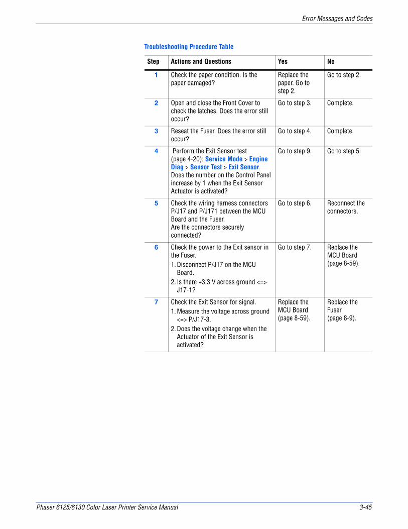
Phaser 6125/6130 Color Laser Printer Service Manual 3-45
Error Messages and Codes
Troubleshooting Procedure Table
Step Actions and Questions Yes No
1 Check the paper condition. Is the paper damaged?
Replace the paper. Go to step 2.
Go to step 2.
2 Open and close the Front Cover to check the latches. Does the error still occur?
Go to step 3. Complete.
3 Reseat the Fuser. Does the error still occur?
Go to step 4. Complete.
4 Perform the Exit Sensor test (page 4-20): Service Mode > Engine Diag > Sensor Test > Exit Sensor.Does the number on the Control Panel increase by 1 when the Exit Sensor Actuator is activated?
Go to step 9. Go to step 5.
5 Check the wiring harness connectors P/J17 and P/J171 between the MCU Board and the Fuser. Are the connectors securely connected?
Go to step 6. Reconnect the connectors.
6 Check the power to the Exit sensor in the Fuser.1. Disconnect P/J17 on the MCU
Board.2. Is there +3.3 V across ground <=>
J17-1?
Go to step 7. Replace the MCU Board (page 8-59).
7 Check the Exit Sensor for signal.1. Measure the voltage across ground
<=> P/J17-3.2. Does the voltage change when the
Actuator of the Exit Sensor is activated?
Replace the MCU Board (page 8-59).
Replace the Fuser (page 8-9).

3-46 Phaser 6125/6130 Color Laser Printer Service Manual
Error Messages and Codes
Jam at Registration Roll
The Registration Sensor indicates that paper did not reach the sensor on time or that paper remains in the Registration Chute.
WarningThe Fuser may be hot. Turn the printer power Off and allow at least 5 minutes for the Fuser to cool before removing the Fuser.
Initial Actions
■ Ask the customer about the paper types being used. If not on the recommended list, determine if this is contributing to the problem. Recycled, multi-purpose or copier paper tends to contaminate the paper path. Constant use of special papers such labels or business cards can also contribute to jamming.
■ Ensure the correct tray loading and setup procedures are followed (securing the guides, selecting the correct paper type, fanning the paper, etc.)
■ Make sure the printer is plugged directly into an electrical outlet. Using extension cords or a power strip is not recommended.
■ Make every attempt to establish a jam rate prior to starting any work. If possible print an Error History Report and note the page count between jams.
■ Determine if jamming is occurring in the tray but not the manual feed slot or vice-versa. This helps to identify any dirty or defective parts.
■ Clear the paper path of any jams and paper debris. Start at the Turn Chute and work up to the Registration Chute Assembly.
■ Clean the paper Feed and Separator Rollers in the paper tray and tray slot using a slightly damp (water only) lint free cloth.
■ Cycle printer power.
■ If the problem persists, follow the procedure below.
Troubleshooting References Table
Applicable Parts Wiring and Plug/Jack Map References
■ Drive Clutch Assembly Kit (PL3.1.99)■ Left Side Harness Assembly (PL3.1.18)■ Feeder Assembly (PL3.1.3)■ Photo Sensor (PL3.2.13)■ Transfer Unit (PL6.1.7)■ Main Drive Assembly (PL7.1.2)■ MCU Board (PL8.2.13)
■ “Map 1 - Transfer Unit, Control Panel, Imaging Unit, Dispenser, Fuser” on page 10-8■ “Map 2 - Laser Unit, Feeder Assembly” on page 10-9■ “Map 3 - LVPS, Drive Motors, I/P Board, AC Power” on page 10-10■ “Map 4 - Toner Dispenser Motors, HVPS, MCU” on page 10-11■ “Drive” on page 10-20■ “Feeder, Manual Feed, & Registration” on page 10-19■ “Fuser” on page 10-29

Phaser 6125/6130 Color Laser Printer Service Manual 3-47
Error Messages and Codes
Troubleshooting Procedure Table
Step Actions and Questions Yes No
1 Check the paper conditionIs the paper wrinkled or damaged?
Replace the paper. Go to step 2.
Go to step 3.
2 Does the error still occur when printing?
Go to step 3. Complete
3 Check the Front Cover for latchingOpen and close the Front Cover, and then latch correctly.Does the error still occur when printing?
Go to step 4. Complete
4 Check around the Regi SensorIs there any remaining paper and/or foreign substance around the Regi Sensor?
Remove the paper and/or substance, then go to step 5.
Go to step 6.
5 Does the error still occur when printing?
Go to step 6. Complete
6 Check the Transfer UnitIs there any remaining paper and/or damage on the belt of the Transfer Unit?
Remove the remaining paper. If the belt is damaged, replace the Transfer Unit (page 8-41).
Go to step 7.
7 1. Remove the Imaging Unit.2. Rotate the Registration and Metal
Registration Rollers with your finger.
Are the Registration and Metal Registration Rollers seated correctly?Are they undamaged and free of contamination, and do they rotate smoothly?
Go to step 8. Clean the rollers if possible, or replace the Feeder Assembly (page 8-25).
8 Check the Regi In and Regi Roll Actuators for shape and operation.Are the shape and operation of the Regi In and Regi Roll Actuators normal?
Go to step 9. Reseat the Regi In Actuator and/or Regi Roll Actuator. If broken or deformed, replace the Feeder Assembly (page 8-25).
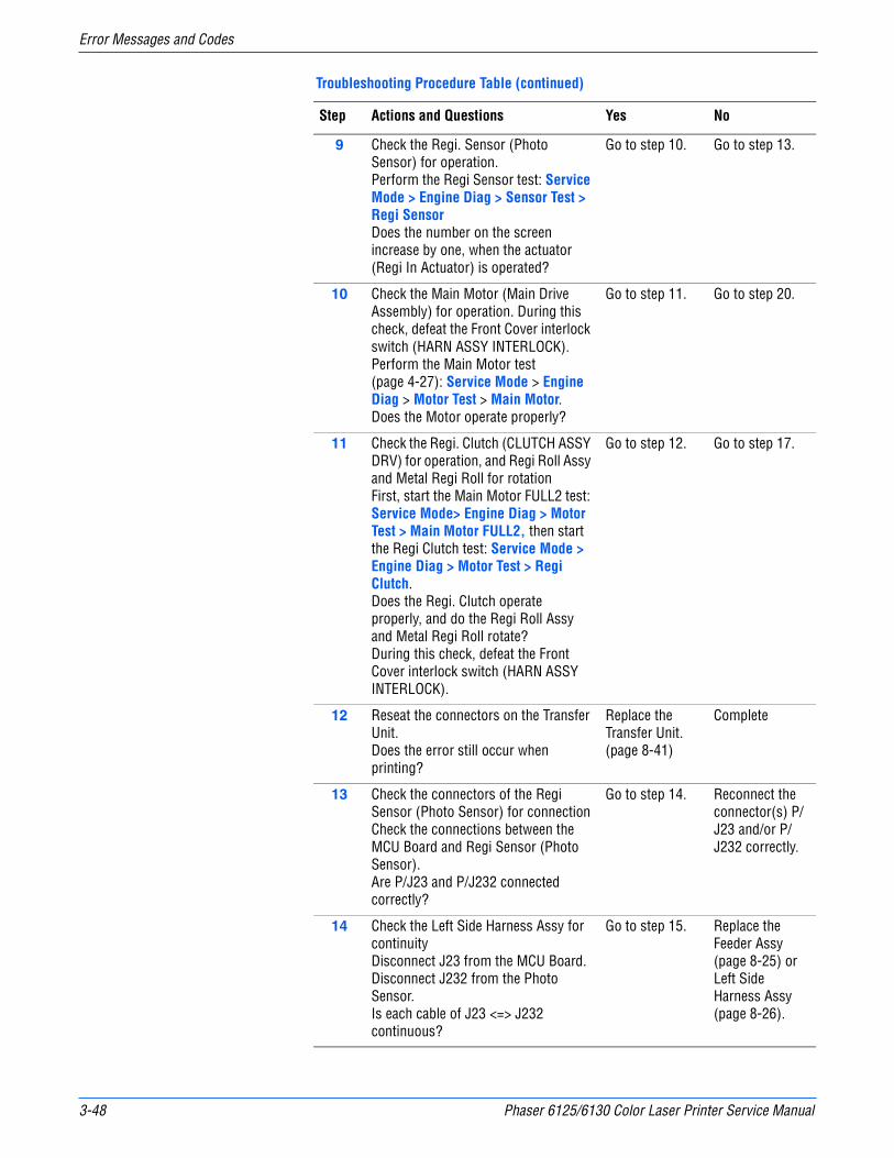
3-48 Phaser 6125/6130 Color Laser Printer Service Manual
Error Messages and Codes
9 Check the Regi. Sensor (Photo Sensor) for operation. Perform the Regi Sensor test: Service Mode > Engine Diag > Sensor Test > Regi SensorDoes the number on the screen increase by one, when the actuator (Regi In Actuator) is operated?
Go to step 10. Go to step 13.
10 Check the Main Motor (Main Drive Assembly) for operation. During this check, defeat the Front Cover interlock switch (HARN ASSY INTERLOCK).Perform the Main Motor test (page 4-27): Service Mode > Engine Diag > Motor Test > Main Motor.Does the Motor operate properly?
Go to step 11. Go to step 20.
11 Check the Regi. Clutch (CLUTCH ASSY DRV) for operation, and Regi Roll Assy and Metal Regi Roll for rotationFirst, start the Main Motor FULL2 test: Service Mode> Engine Diag > Motor Test > Main Motor FULL2, then start the Regi Clutch test: Service Mode > Engine Diag > Motor Test > Regi Clutch.Does the Regi. Clutch operate properly, and do the Regi Roll Assy and Metal Regi Roll rotate?During this check, defeat the Front Cover interlock switch (HARN ASSY INTERLOCK).
Go to step 12. Go to step 17.
12 Reseat the connectors on the Transfer Unit.Does the error still occur when printing?
Replace the Transfer Unit. (page 8-41)
Complete
13 Check the connectors of the Regi Sensor (Photo Sensor) for connectionCheck the connections between the MCU Board and Regi Sensor (Photo Sensor).Are P/J23 and P/J232 connected correctly?
Go to step 14. Reconnect the connector(s) P/J23 and/or P/J232 correctly.
14 Check the Left Side Harness Assy for continuityDisconnect J23 from the MCU Board.Disconnect J232 from the Photo Sensor.Is each cable of J23 <=> J232 continuous?
Go to step 15. Replace the Feeder Assy (page 8-25) or Left Side Harness Assy (page 8-26).
Troubleshooting Procedure Table (continued)
Step Actions and Questions Yes No

Phaser 6125/6130 Color Laser Printer Service Manual 3-49
Error Messages and Codes
15 Check the power to the Photo SensorDisconnect J23 from the MCU Board.Is the voltage across P23-3pin <=> ground on the MCU Board, about +3.3 VDC?
Go to step 16. Replace the MCU Board (page 8-59).
16 Check the Photo Sensor for operationCheck the voltage across J23-5 <=> ground on the MCU Board.Does the voltage change, when the Regi Roll Actuator is operated?
Replace the MCU Board (page 8-59).
Replace the Feeder Assembly (page 8-25).
17 Check the connectors of the Drive Clutch Assy (Regi Clutch) for connectionCheck the connections between the MCU Board and Drive Clutch Assy.Are P/J26 and P/J262 connected correctly?
Go to step 18. Reconnect the connector(s) P/J26 and/or P/J262 correctly.
18 Check the power to the Drive Clutch Assy (Regi Clutch)Disconnect J26 from the MCU Board.Is the voltage across P26-4pin <=> ground on the MCU Board, about +24 VDC when the Front Cover Interlock Switch is pushed?
Go to step 19. Replace the MCU Board (page 8-59).
19 Check the Drive Clutch Assy for resistanceDisconnect P/J262 of the Drive Clutch Assy.Is the resistance across J262-1 and J262-2 approximately 280-ohm?
Replace the MCU Board (page 8-59).
Replace the Drive Clutch Kit (page 8-21).
20 Check the connections between the MCU Board and Main Drive Assembly (Main Motor).Are P/J21 and P/J211 connected securely?
Go to step 21. Reconnect the connector(s) P/J21 and/or P/J211 securely.
21 Check the power to the Main Drive AssemblyDisconnect J21 from the MCU Board.Are the voltages across J21-2/J21-4 <=> ground on the MCU Board, about +24 VDC when the Front Cover Interlock Switch is pushed?
Replace the Main Drive Assembly (page 8-52)
Replace the MCU Board (page 8-59).
Troubleshooting Procedure Table (continued)
Step Actions and Questions Yes No

3-50 Phaser 6125/6130 Color Laser Printer Service Manual
Error Messages and Codes
MPC Errors
MPC Error
Multi-Protocol Network Card error occurs.
Applicable Chain Link
■ 016-738: MPC Error (Download Initial Error)
■ 016-739: MPC Error (Reseat MPC)
■ 016-740: MPC Communication Error
■ 018-310: MPC Error (NIC Controller Communication)
■ 018-311: MPC Error (NIC Flash ROM Boot Module Checksum Error)
■ 018-312: MPC Error (......)
■ 018-313: MPC Error (NIC Flash ROM Application Module Checksum Error)
■ 018-314: MPC Error (NIC MAC Address Checksum Error)
■ 018-315: MPC Error (NIC Ethernet BIST Parity/RAM R/W Error)
■ 018-316: MPC Error (NIC Internal Loopback Error)
■ 018-317: MPC Error (NIC Fatal Error)
■ 116-333: MPC Error (PCI Option #0 Failure)
Initial Actions
■ Cycle printer power.
■ If the problem persists, follow the procedure below.
Troubleshooting Reference Table
Applicable Parts Wiring and Plug/Jack Map References
■ Multi-Protocol Network Card (Option), PL8.1.11■ Image Processor Board, PL8.1.9
Troubleshooting Procedure Table
Step Actions and Questions Yes No
1 Check the Multi-Protocol Network Card (MPC) for correct installation. Is the MPC correctly installed?
Go to step 2. Reseat the MPC. Go to step 2.
2 Does the error still occur? Go to step 3. Complete.
3 Replace the Multi-Protocol Network Card (page 8-63).
Replace the Image Processor Board (page 8-60).
Complete.
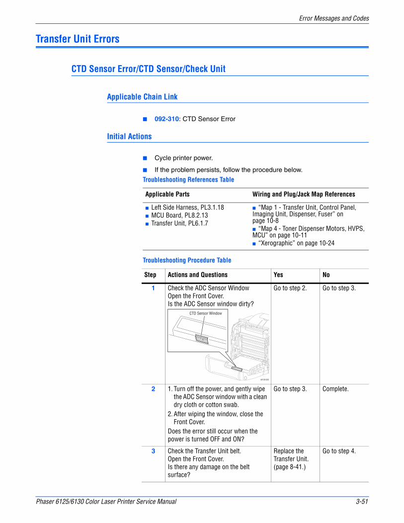
Phaser 6125/6130 Color Laser Printer Service Manual 3-51
Error Messages and Codes
Transfer Unit Errors
CTD Sensor Error/CTD Sensor/Check Unit
Applicable Chain Link
■ 092-310: CTD Sensor Error
Initial Actions
■ Cycle printer power.
■ If the problem persists, follow the procedure below.
Troubleshooting References Table
Applicable Parts Wiring and Plug/Jack Map References
■ Left Side Harness, PL3.1.18■ MCU Board, PL8.2.13■ Transfer Unit, PL6.1.7
■ “Map 1 - Transfer Unit, Control Panel, Imaging Unit, Dispenser, Fuser” on page 10-8■ “Map 4 - Toner Dispenser Motors, HVPS, MCU” on page 10-11■ “Xerographic” on page 10-24
Troubleshooting Procedure Table
Step Actions and Questions Yes No
1 Check the ADC Sensor WindowOpen the Front Cover.Is the ADC Sensor window dirty?
Go to step 2. Go to step 3.
2 1. Turn off the power, and gently wipe the ADC Sensor window with a clean dry cloth or cotton swab.
2. After wiping the window, close the Front Cover.
Does the error still occur when the power is turned OFF and ON?
Go to step 3. Complete.
3 Check the Transfer Unit belt.Open the Front Cover.Is there any damage on the belt surface?
Replace the Transfer Unit. (page 8-41.)
Go to step 4.
s6130-203
CTD Sensor Window
3-52 Phaser 6125/6130 Color Laser Printer Service Manual
Error Messages and Codes
DTB Life Over/Transfer Life
Applicable Chain Link
■ 094-330: Transfer Unit is at end of life.
Initial Actions
■ Ensure the Transfer Unit is installed correctly.
■ Cycle printer power.
■ If problem persists, follow the procedure below.
4 Check the connections between the MCU Board and Transfer Unit.Are both P/J28 and P/J281 connected correctly?
Go to step 6. Reconnect P/J28 and/or P/J281 correctly, then go to step 5.
5 Does the error still occur when the power is turned OFF and ON?
Go to step 6. Complete
6 Check the Left Side Harness for continuity1. Disconnect J281 from the Transfer
Unit.2. Disconnect J28 from the MCU
Board.Is each cable of J281 <=> J28 continuous?
Go to step 7. Replace the Feeder Assy (page 8-25) or Left Side Harness Assy (page 8-26).
7 Check the power to the ADC Sensor1. Disconnect J28 from the MCU
Board.2. Measure the voltage between P28-1
and ground.Does the voltage measure about +5 VDC?
Replace the Transfer Unit (page 8-41.)
Replace the MCU Board (page 8-59.)
Troubleshooting Reference Table
Applicable Parts Wiring and Plug/Jack Map References
■ MCU Board, PL8.2.13■ Transfer Unit, PL6.1.7
■ “Map 1 - Transfer Unit, Control Panel, Imaging Unit, Dispenser, Fuser” on page 10-8■ “Map 4 - Toner Dispenser Motors, HVPS, MCU” on page 10-11■ “Xerographic” on page 10-24
Troubleshooting Procedure Table (continued)
Step Actions and Questions Yes No

Phaser 6125/6130 Color Laser Printer Service Manual 3-53
Error Messages and Codes
Insert Imaging Unit
Initial Actions
■ Cycle printer power.
■ Ensure the Imaging Unit is installed correctly.
■ If problem persists, follow the procedure below.
Troubleshooting Procedure Table
Step Actions and Questions Yes No
1 Check the life counter value of the Transfer Belt: Service Mode > Parameter > Life DTB Waste. Is the life count value near the maximum?
Replace the Transfer Unit (page 8-41).
Replace the MCU Board (page 8-59).
Troubleshooting Reference Table
Applicable Parts Wiring and Plug/Jack Map References
■ MCU Board, PL8.2.13■ Imaging Unit, PL4.1.21
■ “Map 1 - Transfer Unit, Control Panel, Imaging Unit, Dispenser, Fuser” on page 10-8■ “Map 4 - Toner Dispenser Motors, HVPS, MCU” on page 10-11■ “Xerographic” on page 10-24
Troubleshooting Procedure Table
Step Actions and Questions Yes No
1 Check the connectors between the MCU Board and Imaging Unit.Are P/J42 and P/J422 connected securely?
Replace the Imaging Unit (page 8-8), then go to step 3.
Securely reconnect P/J42 and/or P/J422, then go to step 2.
2 Does the error still occur when the power is turned OFF and ON?
Go to step 3. Complete
3 Does the error still occur when the power is turned OFF and ON?
Replace the MCU Board (page 8-59).
Complete
3-54 Phaser 6125/6130 Color Laser Printer Service Manual
Error Messages and Codes
Low Density Yellow/Magenta/Cyan/Black Cartridge
Initial Actions
■ Cycle printer power.
■ Remove the toner cartridge and shake it gently side-to-side, then reinstall.
■ Check that all sealing tapes are removed from the Imaging Unit.
■ If problem persists, follow the procedure below.
Troubleshooting Reference Table
Applicable Parts Wiring and Plug/Jack Map References
■ Dispenser Assy, PL5.1.1■ Toner Cartridge (Y,M,C,K), PL5.1.(21,22,23,24)■ Transfer Unit Assy, PL6.1.7■ MCU Board, PL8.2.13■ Imaging Unit, PL4.1.21
■ “Map 1 - Transfer Unit, Control Panel, Imaging Unit, Dispenser, Fuser” on page 10-8■ “Map 4 - Toner Dispenser Motors, HVPS, MCU” on page 10-11■ “Xerographic” on page 10-24
Troubleshooting Procedure Table
Step Actions and Questions Yes No
1 Use CWIS to determine the amount of toner remaining.Does CWIS report very little toner remaining?
Replace the Toner Cartridge, then go to step 2.
Go to step 3.
2 Does the error still occur when the power is turned OFF and ON?
Go to step 3. Complete
3 Check the Y, M, C, or K Toner Motor: Service Mode > Engine Diag > Motor Test > (Yellow, Magenta, Cyan, Black) Toner Motor.Does the Toner Motor function normally? During this check, defeat the Front Cover interlock switch.
Go to step 4. Go to step 5.
4 Check the Dispenser Assy gears for shape and operation.Are the shape and operation of the gears of the DISPENSER ASSY normal?
Go to step 9. Replace the Dispenser Assembly (page 8-34).
5 Check the connectors between the MCU Board and Dispenser Motor Assembly.Are P/J18 and P/J181 connected correctly?
Go to step 7. Reconnect connector(s) P/J18 and/or P/J181 securely, then go to step 6.

Phaser 6125/6130 Color Laser Printer Service Manual 3-55
Error Messages and Codes
6 Does the error still occur when the power is turned OFF and ON?
Go to step 7. Complete
7 Check the Toner Motor Harness Assembly for continuityDisconnect J18 from the MCU Board for the Y or M Toner Motors, or J19 for the C or K Toner Motors.Disconnect J181 from the Y Motor, or J182 from the M Motor; or disconnect J191 for the C Motor, or J192 for the K MotorIs each cable of J18 <=> J181/J182 or J19 <=> J191/J192 continuous?
Go to step 8. Replace the Dispenser Assembly (page 8-34).
8 Check the power to the Toner MotorsDisconnect J18 and/or J19 from the MCU Board.On the MCU Board, is the voltage across P18-3, P18-8, P19-4 or P19-9 <= > ground about +24 VDC when the interlock switch (HARN ASSY INTERLOCK) is pushed.
Replace the Dispenser Assembly (page 8-34).
Replace the MCU Board (page 8-59).
9 Replace the Toner Cartridge (Y, M, C, or K), and check that the lock key is in the lock position.Does the error still occur when the power is turned OFF and ON?
Go to step 10. Complete
10 Replace the Imaging Unit.Does the error still occur when the power is turned OFF and ON?
Replace the Transfer Unit (page 8-41).
Complete
Troubleshooting Procedure Table (continued)
Step Actions and Questions Yes No
3-56 Phaser 6125/6130 Color Laser Printer Service Manual
Error Messages and Codes
Paper Setting Errors
Insert Output to Tray/Manual Feed
Waiting for side 2 to be set for manual duplex print.
Load Manual Feed
Size mismatch detected at Manual Feed Slot.
Troubleshooting Procedure Table
Step Actions and Questions Yes No
1 Check the customer operationDid the customer load the paper to the tray?
Go to step 2. Load the paper.
2 Check the customer operationDid the customer load the paper to the tray too late?
Try print again. Go to step 3.
3 Check the customer operationDid the customer load the paper to specified tray?
Go to Load Manual Feed (page 3-57)
Try printing again.
Troubleshooting Reference Table
Applicable Parts Wiring and Plug/Jack Map References
Image Processor Board (PL8.1.9)MCU Board (PL8.2.13)
■ “Map 1 - Transfer Unit, Control Panel, Imaging Unit, Dispenser, Fuser” on page 10-8■ “Map 4 - Toner Dispenser Motors, HVPS, MCU” on page 10-11■ “Xerographic” on page 10-24
Troubleshooting Procedure Table
Step Actions and Questions Yes No
1 Check the paper sizeDoes the paper size being used meet the specification?
Go to step 3. Use paper that meets the specifications, then go to step 2.
2 Does the error still occur when printing?
Go to step 3. Complete
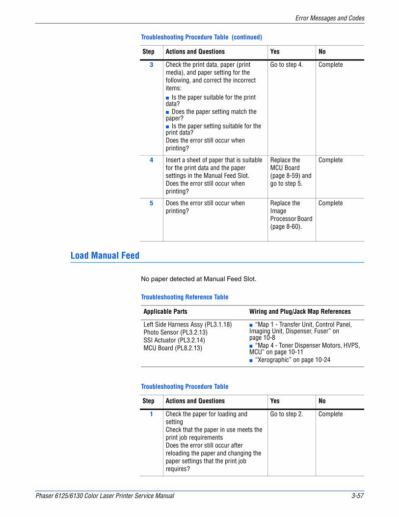
Phaser 6125/6130 Color Laser Printer Service Manual 3-57
Error Messages and Codes
Load Manual Feed
No paper detected at Manual Feed Slot.
3 Check the print data, paper (print media), and paper setting for the following, and correct the incorrect items:■ Is the paper suitable for the print data?■ Does the paper setting match the paper?■ Is the paper setting suitable for the print data?Does the error still occur when printing?
Go to step 4. Complete
4 Insert a sheet of paper that is suitable for the print data and the paper settings in the Manual Feed Slot.Does the error still occur when printing?
Replace the MCU Board (page 8-59) and go to step 5.
Complete
5 Does the error still occur when printing?
Replace the Image Processor Board (page 8-60).
Complete
Troubleshooting Reference Table
Applicable Parts Wiring and Plug/Jack Map References
Left Side Harness Assy (PL3.1.18)Photo Sensor (PL3.2.13)SSI Actuator (PL3.2.14)MCU Board (PL8.2.13)
■ “Map 1 - Transfer Unit, Control Panel, Imaging Unit, Dispenser, Fuser” on page 10-8■ “Map 4 - Toner Dispenser Motors, HVPS, MCU” on page 10-11■ “Xerographic” on page 10-24
Troubleshooting Procedure Table
Step Actions and Questions Yes No
1 Check the paper for loading and settingCheck that the paper in use meets the print job requirementsDoes the error still occur after reloading the paper and changing the paper settings that the print job requires?
Go to step 2. Complete
Troubleshooting Procedure Table (continued)
Step Actions and Questions Yes No
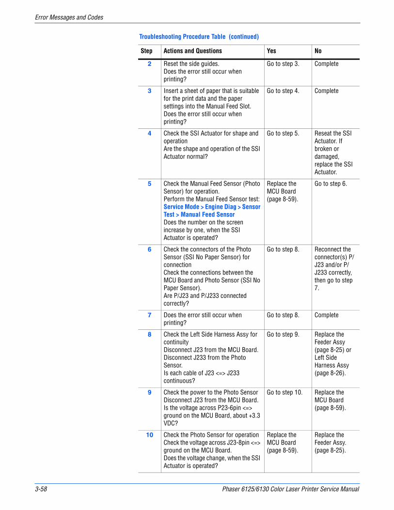
3-58 Phaser 6125/6130 Color Laser Printer Service Manual
Error Messages and Codes
2 Reset the side guides.Does the error still occur when printing?
Go to step 3. Complete
3 Insert a sheet of paper that is suitable for the print data and the paper settings into the Manual Feed Slot.Does the error still occur when printing?
Go to step 4. Complete
4 Check the SSI Actuator for shape and operationAre the shape and operation of the SSI Actuator normal?
Go to step 5. Reseat the SSI Actuator. If broken or damaged, replace the SSI Actuator.
5 Check the Manual Feed Sensor (Photo Sensor) for operation. Perform the Manual Feed Sensor test: Service Mode > Engine Diag > Sensor Test > Manual Feed SensorDoes the number on the screen increase by one, when the SSI Actuator is operated?
Replace the MCU Board (page 8-59).
Go to step 6.
6 Check the connectors of the Photo Sensor (SSI No Paper Sensor) for connectionCheck the connections between the MCU Board and Photo Sensor (SSI No Paper Sensor).Are P/J23 and P/J233 connected correctly?
Go to step 8. Reconnect the connector(s) P/J23 and/or P/J233 correctly, then go to step 7.
7 Does the error still occur when printing?
Go to step 8. Complete
8 Check the Left Side Harness Assy for continuityDisconnect J23 from the MCU Board.Disconnect J233 from the Photo Sensor.Is each cable of J23 <=> J233 continuous?
Go to step 9. Replace the Feeder Assy (page 8-25) or Left Side Harness Assy (page 8-26).
9 Check the power to the Photo SensorDisconnect J23 from the MCU Board.Is the voltage across P23-6pin <=> ground on the MCU Board, about +3.3 VDC?
Go to step 10. Replace the MCU Board (page 8-59).
10 Check the Photo Sensor for operationCheck the voltage across J23-8pin <=> ground on the MCU Board.Does the voltage change, when the SSI Actuator is operated?
Replace the MCU Board (page 8-59).
Replace the Feeder Assy. (page 8-25).
Troubleshooting Procedure Table (continued)
Step Actions and Questions Yes No
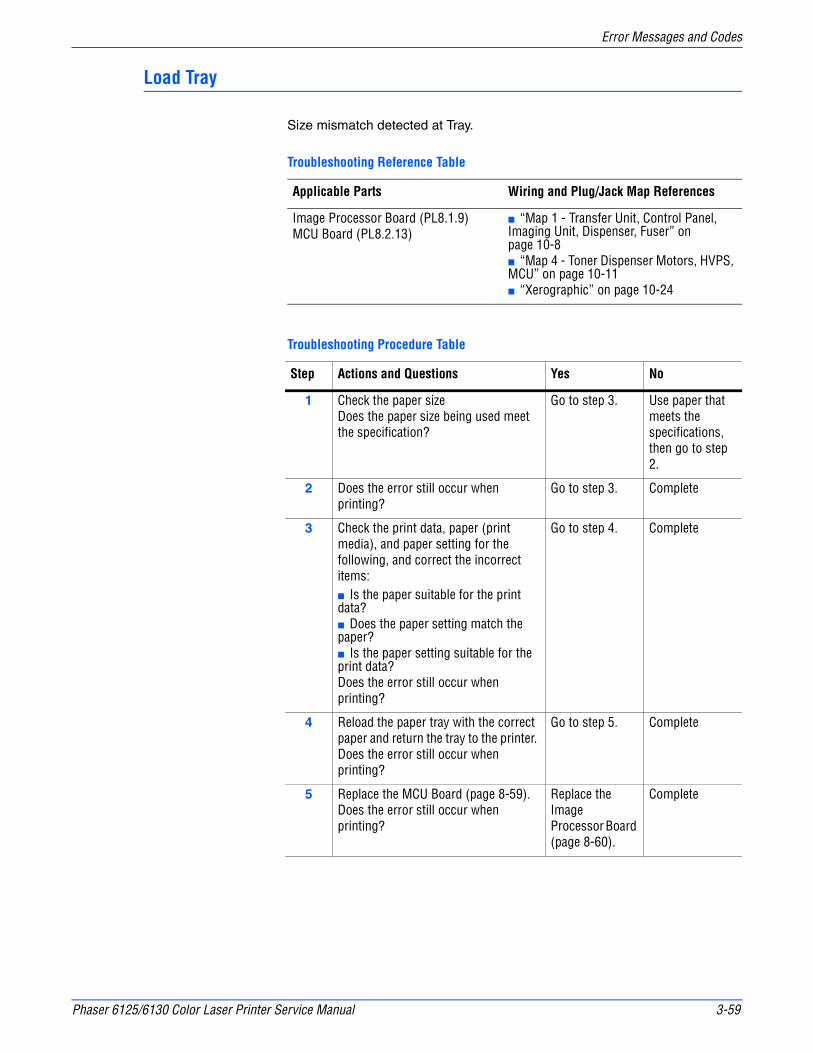
Phaser 6125/6130 Color Laser Printer Service Manual 3-59
Error Messages and Codes
Load Tray
Size mismatch detected at Tray.
Troubleshooting Reference Table
Applicable Parts Wiring and Plug/Jack Map References
Image Processor Board (PL8.1.9)MCU Board (PL8.2.13)
■ “Map 1 - Transfer Unit, Control Panel, Imaging Unit, Dispenser, Fuser” on page 10-8■ “Map 4 - Toner Dispenser Motors, HVPS, MCU” on page 10-11■ “Xerographic” on page 10-24
Troubleshooting Procedure Table
Step Actions and Questions Yes No
1 Check the paper sizeDoes the paper size being used meet the specification?
Go to step 3. Use paper that meets the specifications, then go to step 2.
2 Does the error still occur when printing?
Go to step 3. Complete
3 Check the print data, paper (print media), and paper setting for the following, and correct the incorrect items:■ Is the paper suitable for the print data?■ Does the paper setting match the paper?■ Is the paper setting suitable for the print data?Does the error still occur when printing?
Go to step 4. Complete
4 Reload the paper tray with the correct paper and return the tray to the printer. Does the error still occur when printing?
Go to step 5. Complete
5 Replace the MCU Board (page 8-59). Does the error still occur when printing?
Replace the Image Processor Board (page 8-60).
Complete
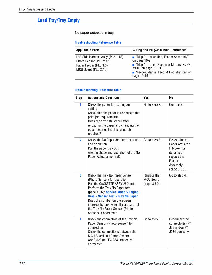
3-60 Phaser 6125/6130 Color Laser Printer Service Manual
Error Messages and Codes
Load Tray/Tray Empty
No paper detected in tray.
Troubleshooting Reference Table
Applicable Parts Wiring and Plug/Jack Map References
Left Side Harness Assy (PL3.1.18)Photo Sensor (PL3.2.13)Paper Feeder (PL3.1.3)MCU Board (PL8.2.13)
■ “Map 2 - Laser Unit, Feeder Assembly” on page 10-9■ “Map 4 - Toner Dispenser Motors, HVPS, MCU” on page 10-11■ “Feeder, Manual Feed, & Registration” on page 10-19
Troubleshooting Procedure Table
Step Actions and Questions Yes No
1 Check the paper for loading and settingCheck that the paper in use meets the print job requirementsDoes the error still occur after reloading the paper and changing the paper settings that the print job requires?
Go to step 2. Complete
2 Check the No Paper Actuator for shape and operationPull the paper tray out.Are the shape and operation of the No Paper Actuator normal?
Go to step 3. Reseat the No Paper Actuator. If broken or deformed, replace the Feeder Assembly (page 8-25).
3 Check the Tray No Paper Sensor (Photo Sensor) for operationPull the CASSETTE ASSY 250 out.Perform the Tray No Paper test (page 4-26): Service Mode > Engine Diag > Sensor Test > Tray No PaperDoes the number on the screen increase by one, when the actuator of the Tray No Paper Sensor (Photo Sensor) is operated?
Replace the MCU Board (page 8-59).
Go to step 4.
4 Check the connectors of the Tray No Paper Sensor (Photo Sensor) for connectionCheck the connections between the MCU Board and Photo Sensor.Are P/J23 and P/J234 connected correctly?
Go to step 5. Reconnect the connector(s) P/J23 and/or P/J234 correctly.
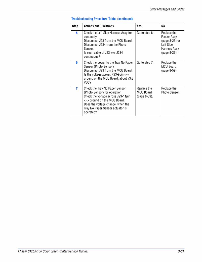
Phaser 6125/6130 Color Laser Printer Service Manual 3-61
Error Messages and Codes
5 Check the Left Side Harness Assy for continuityDisconnect J23 from the MCU Board.Disconnect J234 from the Photo Sensor.Is each cable of J23 <=> J234 continuous?
Go to step 6. Replace the Feeder Assy (page 8-25) or Left Side Harness Assy (page 8-26).
6 Check the power to the Tray No Paper Sensor (Photo Sensor) Disconnect J23 from the MCU Board.Is the voltage across P23-9pin <=> ground on the MCU Board, about +3.3 VDC?
Go to step 7. Replace the MCU Board (page 8-59).
7 Check the Tray No Paper Sensor (Photo Sensor) for operationCheck the voltage across J23-11pin <=> ground on the MCU Board.Does the voltage change, when the Tray No Paper Sensor actuator is operated?
Replace the MCU Board (page 8-59).
Replace the Photo Sensor.
Troubleshooting Procedure Table (continued)
Step Actions and Questions Yes No

3-62 Phaser 6125/6130 Color Laser Printer Service Manual
Error Messages and Codes
Fuser Errors
Insert Fuser
The printer detects that the Fuser is not installed.
Applicable Chain Link
■ 010-317: Fuser not detected
Troubleshooting Reference Table
Applicable Parts Wiring and Plug/Jack Map References
Fuser (PL6.1.1) Fuser Harness Assy (PL6.1.2)MCU Board (PL8.2.13)
■ “Map 2 - Laser Unit, Feeder Assembly” on page 10-9■ “Map 4 - Toner Dispenser Motors, HVPS, MCU” on page 10-11■ “Feeder, Manual Feed, & Registration” on page 10-19
Troubleshooting Procedure Table
Step Actions and Questions Yes No
1 Reseat the Fuser.Warning: Start the operation after the Fuser has cooled down.Does the error still occur when the power is turned OFF and ON?
Go to step 2. Complete
2 Check the connectors for connectionRemove the Fuser.Warning: Start the operation after the Fuser has cooled down.Check the connections between the MCU Board and Fuser.Are P/J17 and P/J171 connected correctly?
Go to step 4. Reconnect the connector(s) P/J17 and/or P/J171 correctly, then go to step 3.
3 Does the error still occur when the power is turned OFF and ON?
Go to step 4. Complete
4 Check the Fuser Harness Assy for continuityRemove the Fuser.Warning: Start the operation after the Fuser has cooled down.Disconnect J17 from the MCU Board.Is each cable of J17 <=> P171 continuous? NOTE: P171 is attached to the frame.
Go to step 5. Replace the Fuser Harness Assy.
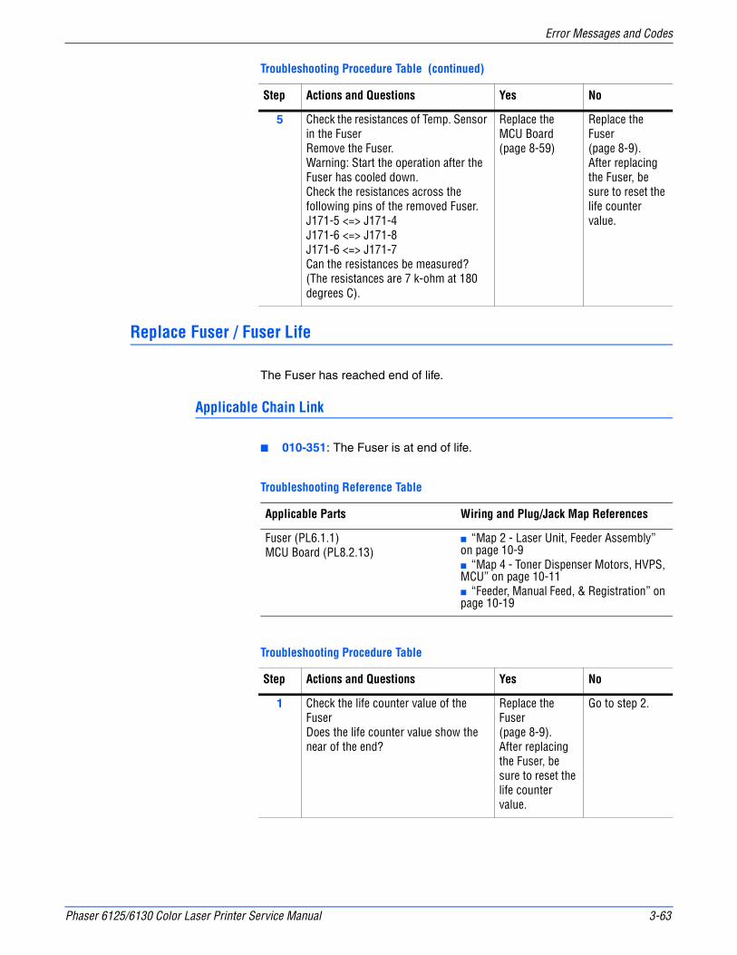
Phaser 6125/6130 Color Laser Printer Service Manual 3-63
Error Messages and Codes
Replace Fuser / Fuser Life
The Fuser has reached end of life.
Applicable Chain Link
■ 010-351: The Fuser is at end of life.
5 Check the resistances of Temp. Sensor in the FuserRemove the Fuser.Warning: Start the operation after the Fuser has cooled down.Check the resistances across the following pins of the removed Fuser.J171-5 <=> J171-4J171-6 <=> J171-8J171-6 <=> J171-7Can the resistances be measured? (The resistances are 7 k-ohm at 180 degrees C).
Replace the MCU Board (page 8-59)
Replace the Fuser (page 8-9).After replacing the Fuser, be sure to reset the life counter value.
Troubleshooting Reference Table
Applicable Parts Wiring and Plug/Jack Map References
Fuser (PL6.1.1) MCU Board (PL8.2.13)
■ “Map 2 - Laser Unit, Feeder Assembly” on page 10-9■ “Map 4 - Toner Dispenser Motors, HVPS, MCU” on page 10-11■ “Feeder, Manual Feed, & Registration” on page 10-19
Troubleshooting Procedure Table
Step Actions and Questions Yes No
1 Check the life counter value of the FuserDoes the life counter value show the near of the end?
Replace the Fuser (page 8-9).After replacing the Fuser, be sure to reset the life counter value.
Go to step 2.
Troubleshooting Procedure Table (continued)
Step Actions and Questions Yes No
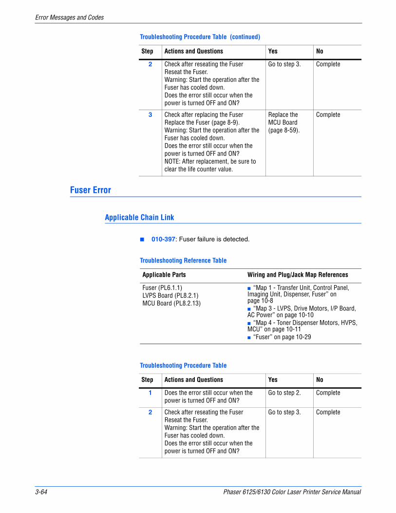
3-64 Phaser 6125/6130 Color Laser Printer Service Manual
Error Messages and Codes
Fuser Error
Applicable Chain Link
■ 010-397: Fuser failure is detected.
2 Check after reseating the FuserReseat the Fuser.Warning: Start the operation after the Fuser has cooled down.Does the error still occur when the power is turned OFF and ON?
Go to step 3. Complete
3 Check after replacing the FuserReplace the Fuser (page 8-9).Warning: Start the operation after the Fuser has cooled down.Does the error still occur when the power is turned OFF and ON?NOTE: After replacement, be sure to clear the life counter value.
Replace the MCU Board (page 8-59).
Complete
Troubleshooting Reference Table
Applicable Parts Wiring and Plug/Jack Map References
Fuser (PL6.1.1)LVPS Board (PL8.2.1)MCU Board (PL8.2.13)
■ “Map 1 - Transfer Unit, Control Panel, Imaging Unit, Dispenser, Fuser” on page 10-8■ “Map 3 - LVPS, Drive Motors, I/P Board, AC Power” on page 10-10■ “Map 4 - Toner Dispenser Motors, HVPS, MCU” on page 10-11■ “Fuser” on page 10-29
Troubleshooting Procedure Table
Step Actions and Questions Yes No
1 Does the error still occur when the power is turned OFF and ON?
Go to step 2. Complete
2 Check after reseating the FuserReseat the Fuser.Warning: Start the operation after the Fuser has cooled down.Does the error still occur when the power is turned OFF and ON?
Go to step 3. Complete
Troubleshooting Procedure Table (continued)
Step Actions and Questions Yes No
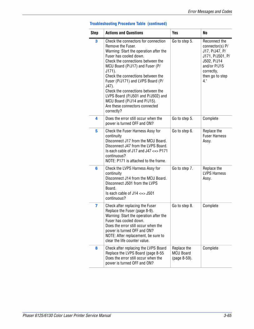
Phaser 6125/6130 Color Laser Printer Service Manual 3-65
Error Messages and Codes
3 Check the connectors for connectionRemove the Fuser.Warning: Start the operation after the Fuser has cooled down.Check the connections between the MCU Board (P/J17) and Fuser (P/J171).Check the connections between the Fuser (P/J171) and LVPS Board (P/J47).Check the connections between the LVPS Board (P/J501 and P/J502) and MCU Board (P/J14 and P/J15).Are these connectors connected correctly?
Go to step 5. Reconnect the connector(s) P/J17, P/J47, P/J171, P/J501, P/J502, P/J14 and/or P/J15 correctly,then go to step 4."
4 Does the error still occur when the power is turned OFF and ON?
Go to step 5. Complete
5 Check the Fuser Harness Assy for continuityDisconnect J17 from the MCU Board.Disconnect J47 from the LVPS Board.Is each cable of J17 and J47 <=> P171 continuous? NOTE: P171 is attached to the frame.
Go to step 6. Replace the Fuser Harness Assy.
6 Check the LVPS Harness Assy for continuityDisconnect J14 from the MCU Board.Disconnect J501 from the LVPS Board.Is each cable of J14 <=> J501 continuous?
Go to step 7. Replace the LVPS Harness Assy.
7 Check after replacing the FuserReplace the Fuser (page 8-9).Warning: Start the operation after the Fuser has cooled down.Does the error still occur when the power is turned OFF and ON?NOTE: After replacement, be sure to clear the life counter value.
Go to step 8. Complete
8 Check after replacing the LVPS BoardReplace the LVPS Board (page 8-55Does the error still occur when the power is turned OFF and ON?
Replace the MCU Board (page 8-59).
Complete
Troubleshooting Procedure Table (continued)
Step Actions and Questions Yes No
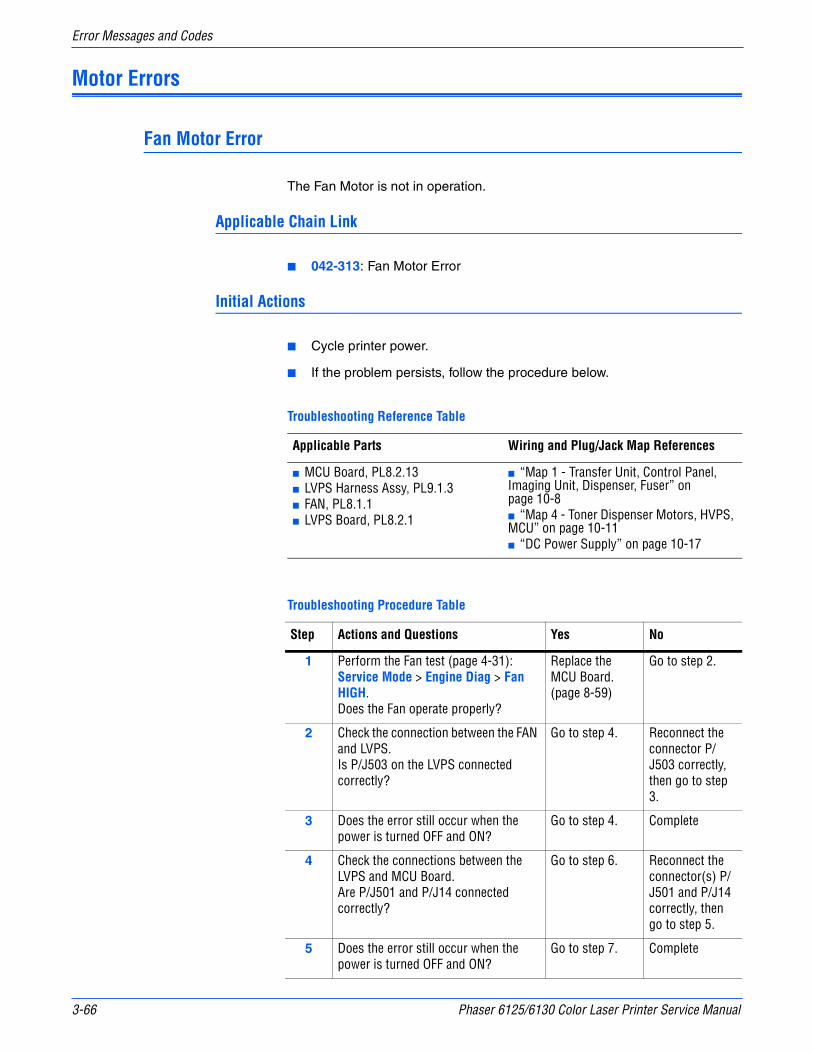
3-66 Phaser 6125/6130 Color Laser Printer Service Manual
Error Messages and Codes
Motor Errors
Fan Motor Error
The Fan Motor is not in operation.
Applicable Chain Link
■ 042-313: Fan Motor Error
Initial Actions
■ Cycle printer power.
■ If the problem persists, follow the procedure below.
Troubleshooting Reference Table
Applicable Parts Wiring and Plug/Jack Map References
■ MCU Board, PL8.2.13■ LVPS Harness Assy, PL9.1.3■ FAN, PL8.1.1■ LVPS Board, PL8.2.1
■ “Map 1 - Transfer Unit, Control Panel, Imaging Unit, Dispenser, Fuser” on page 10-8■ “Map 4 - Toner Dispenser Motors, HVPS, MCU” on page 10-11■ “DC Power Supply” on page 10-17
Troubleshooting Procedure Table
Step Actions and Questions Yes No
1 Perform the Fan test (page 4-31): Service Mode > Engine Diag > Fan HIGH.Does the Fan operate properly?
Replace the MCU Board. (page 8-59)
Go to step 2.
2 Check the connection between the FAN and LVPS.Is P/J503 on the LVPS connected correctly?
Go to step 4. Reconnect the connector P/J503 correctly, then go to step 3.
3 Does the error still occur when the power is turned OFF and ON?
Go to step 4. Complete
4 Check the connections between the LVPS and MCU Board.Are P/J501 and P/J14 connected correctly?
Go to step 6. Reconnect the connector(s) P/J501 and P/J14 correctly, then go to step 5.
5 Does the error still occur when the power is turned OFF and ON?
Go to step 7. Complete
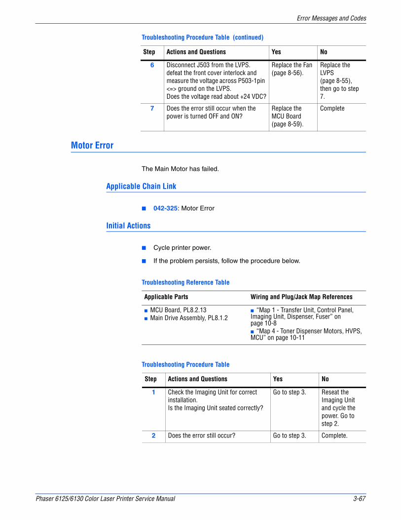
Phaser 6125/6130 Color Laser Printer Service Manual 3-67
Error Messages and Codes
Motor Error
The Main Motor has failed.
Applicable Chain Link
■ 042-325: Motor Error
Initial Actions
■ Cycle printer power.
■ If the problem persists, follow the procedure below.
6 Disconnect J503 from the LVPS.defeat the front cover interlock and measure the voltage across P503-1pin <=> ground on the LVPS.Does the voltage read about +24 VDC?
Replace the Fan (page 8-56).
Replace the LVPS (page 8-55), then go to step 7.
7 Does the error still occur when the power is turned OFF and ON?
Replace the MCU Board (page 8-59).
Complete
Troubleshooting Reference Table
Applicable Parts Wiring and Plug/Jack Map References
■ MCU Board, PL8.2.13■ Main Drive Assembly, PL8.1.2
■ “Map 1 - Transfer Unit, Control Panel, Imaging Unit, Dispenser, Fuser” on page 10-8■ “Map 4 - Toner Dispenser Motors, HVPS, MCU” on page 10-11
Troubleshooting Procedure Table
Step Actions and Questions Yes No
1 Check the Imaging Unit for correct installation.Is the Imaging Unit seated correctly?
Go to step 3. Reseat the Imaging Unit and cycle the power. Go to step 2.
2 Does the error still occur? Go to step 3. Complete.
Troubleshooting Procedure Table (continued)
Step Actions and Questions Yes No
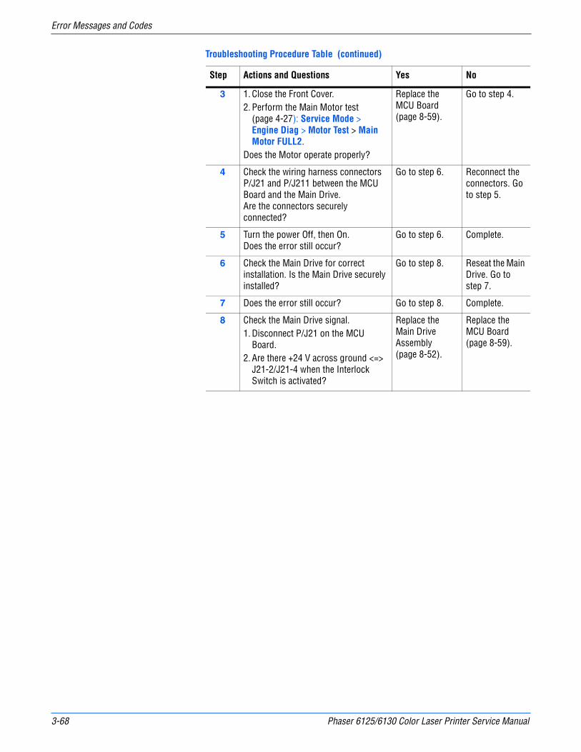
3-68 Phaser 6125/6130 Color Laser Printer Service Manual
Error Messages and Codes
3 1. Close the Front Cover.2. Perform the Main Motor test
(page 4-27): Service Mode > Engine Diag > Motor Test > Main Motor FULL2.
Does the Motor operate properly?
Replace the MCU Board (page 8-59).
Go to step 4.
4 Check the wiring harness connectors P/J21 and P/J211 between the MCU Board and the Main Drive. Are the connectors securely connected?
Go to step 6. Reconnect the connectors. Go to step 5.
5 Turn the power Off, then On.Does the error still occur?
Go to step 6. Complete.
6 Check the Main Drive for correct installation. Is the Main Drive securely installed?
Go to step 8. Reseat the Main Drive. Go to step 7.
7 Does the error still occur? Go to step 8. Complete.
8 Check the Main Drive signal.1. Disconnect P/J21 on the MCU
Board.2. Are there +24 V across ground <=>
J21-2/J21-4 when the Interlock Switch is activated?
Replace the Main Drive Assembly (page 8-52).
Replace the MCU Board (page 8-59).
Troubleshooting Procedure Table (continued)
Step Actions and Questions Yes No

Phaser 6125/6130 Color Laser Printer Service Manual 3-69
Error Messages and Codes
Sub Motor Error
The Sub Motor has failed.
Applicable Chain Link
■ Chain Link 042-326: Sub Motor Error
Initial Actions
■ Cycle printer power.
■ If the problem persists, follow the procedure below.
Troubleshooting Reference Table
Applicable Parts Wiring and Plug/Jack Map References
■ MCU Board, PL8.2.13■ Sub Drive Assembly, PL7.1.1
■ “Map 1 - Transfer Unit, Control Panel, Imaging Unit, Dispenser, Fuser” on page 10-8■ “Map 3 - LVPS, Drive Motors, I/P Board, AC Power” on page 10-10
Troubleshooting Procedure Table
Step Actions and Questions Yes No
1 Check the Imaging Unit and Fuser for correct installation. Are the Imaging Unit and Fuser correctly installed?
Go to step 3. Reseat the Imaging Unit and Fuser. Go to step 2.
2 Does the error still occur? Go to step 3. Complete.
3 1. Close the Front Cover.2. Perform the Sub Motor test
(page 4-28): Service Mode > Engine Diag > Motor Test > Sub Motor FULL2.
Does the Sub Motor operate properly?
Replace the MCU Board (page 8-59).
Go to step 4.
4 Check the wiring harness connectors P/J22 and P/J221 between the MCU Board and the Sub Drive Assembly. Are the connectors securely connected?
Go to step 6. Reconnect the connectors. Go to step 5.
5 Does the error still occur? Go to step 6. Complete.
6 Check the Sub Drive Assembly for correct installation. Is it correctly installed?
Go to step 8. Reseat the Main Drive. Go to step 7.
7 Does the error still occur? Go to step 8. Complete.
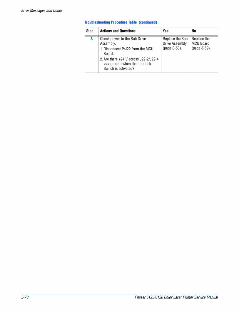
3-70 Phaser 6125/6130 Color Laser Printer Service Manual
Error Messages and Codes
8 Check power to the Sub Drive Assembly.1. Disconnect P/J22 from the MCU
Board.2. Are there +24 V across J22-2/J22-4
<=> ground when the Interlock Switch is activated?
Replace the Sub Drive Assembly (page 8-53).
Replace the MCU Board (page 8-59).
Troubleshooting Procedure Table (continued)
Step Actions and Questions Yes No

Phaser 6125/6130 Color Laser Printer Service Manual 3-71
Error Messages and Codes
Imaging Unit Errors
Replace Imaging Unit/PHD CRUM Error
Applicable Chain Link
■ 091-916: Imaging Unit CRUM Error
Initial Actions
■ Cycle printer power.
■ If the problem persists, follow the procedure below.
Troubleshooting Reference Table
Applicable Parts Wiring and Plug/Jack Map References
■ MCU Board, PL8.2.13■ Imaging Unit, PL4.1.21
■ “Map 1 - Transfer Unit, Control Panel, Imaging Unit, Dispenser, Fuser” on page 10-8■ “Map 3 - LVPS, Drive Motors, I/P Board, AC Power” on page 10-10
Troubleshooting Procedure Table
Step Actions and Questions Yes No
1 Check the Imaging Unit typeIs the correct Imaging Unit installed?
Go to step 3. Replace with the correct Imaging Unit, then go to step 2.
2 Does the error still occur when the power is turned OFF and ON?
Go to step 3. Complete
3 Reseat the Imaging Unit.Does the error still occur when the power is turned OFF and ON?
Go to step 4. Complete
4 Check the connectors to the MCU Board and Imaging Unit.Are P/J42 and P/J422 connected correctly?
Go to step 6. Reconnect the connector(s) P/J42 and/or P/J422 securely, then go to step 5.
5 Does the error still occur when the power is turned OFF and ON?
Go to step 6. Complete
6 Replace the Imaging Unit (page 8-8).Does the error still occur when the power is turned OFF and ON?
Replace the MCU Board. (page 8-59)
Complete
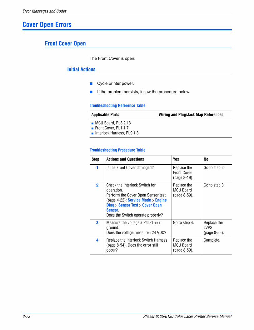
3-72 Phaser 6125/6130 Color Laser Printer Service Manual
Error Messages and Codes
Cover Open Errors
Front Cover Open
The Front Cover is open.
Initial Actions
■ Cycle printer power.
■ If the problem persists, follow the procedure below.
Troubleshooting Reference Table
Applicable Parts Wiring and Plug/Jack Map References
■ MCU Board, PL8.2.13■ Front Cover, PL1.1.7■ Interlock Harness, PL9.1.3
Troubleshooting Procedure Table
Step Actions and Questions Yes No
1 Is the Front Cover damaged? Replace the Front Cover (page 8-19).
Go to step 2.
2 Check the Interlock Switch for operation.Perform the Cover Open Sensor test (page 4-22): Service Mode > Engine Diag > Sensor Test > Cover Open Sensor.Does the Switch operate properly?
Replace the MCU Board (page 8-59).
Go to step 3.
3 Measure the voltage a P44-1 <=> ground.Does the voltage measure +24 VDC?
Go to step 4. Replace the LVPS (page 8-55).
4 Replace the Interlock Switch Harness (page 8-54). Does the error still occur?
Replace the MCU Board (page 8-59).
Complete.
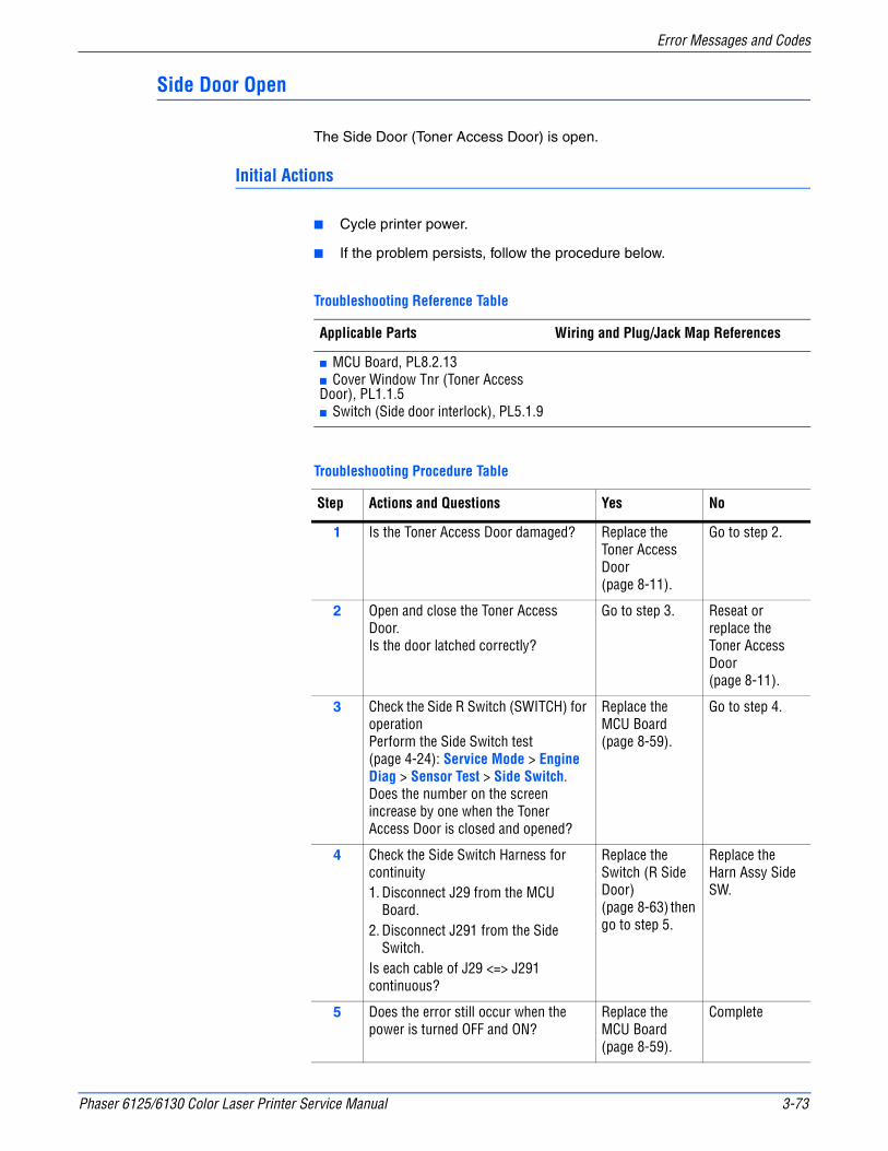
Phaser 6125/6130 Color Laser Printer Service Manual 3-73
Error Messages and Codes
Side Door Open
The Side Door (Toner Access Door) is open.
Initial Actions
■ Cycle printer power.
■ If the problem persists, follow the procedure below.
Troubleshooting Reference Table
Applicable Parts Wiring and Plug/Jack Map References
■ MCU Board, PL8.2.13■ Cover Window Tnr (Toner Access Door), PL1.1.5■ Switch (Side door interlock), PL5.1.9
Troubleshooting Procedure Table
Step Actions and Questions Yes No
1 Is the Toner Access Door damaged? Replace the Toner Access Door (page 8-11).
Go to step 2.
2 Open and close the Toner Access Door.Is the door latched correctly?
Go to step 3. Reseat or replace the Toner Access Door (page 8-11).
3 Check the Side R Switch (SWITCH) for operationPerform the Side Switch test (page 4-24): Service Mode > Engine Diag > Sensor Test > Side Switch.Does the number on the screen increase by one when the Toner Access Door is closed and opened?
Replace the MCU Board (page 8-59).
Go to step 4.
4 Check the Side Switch Harness for continuity1. Disconnect J29 from the MCU
Board.2. Disconnect J291 from the Side
Switch.Is each cable of J29 <=> J291 continuous?
Replace the Switch (R Side Door) (page 8-63) then go to step 5.
Replace the Harn Assy Side SW.
5 Does the error still occur when the power is turned OFF and ON?
Replace the MCU Board (page 8-59).
Complete
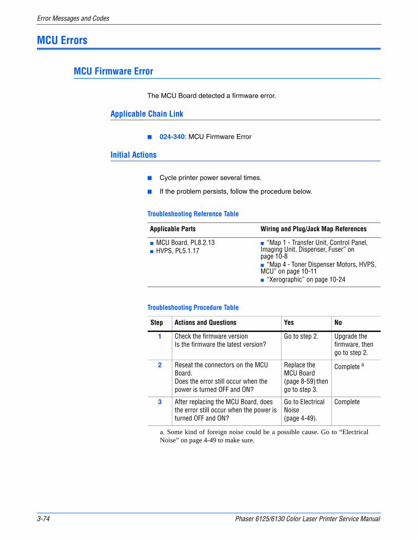
3-74 Phaser 6125/6130 Color Laser Printer Service Manual
Error Messages and Codes
MCU Errors
MCU Firmware Error
The MCU Board detected a firmware error.
Applicable Chain Link
■ 024-340: MCU Firmware Error
Initial Actions
■ Cycle printer power several times.
■ If the problem persists, follow the procedure below.
Troubleshooting Reference Table
Applicable Parts Wiring and Plug/Jack Map References
■ MCU Board, PL8.2.13■ HVPS, PL5.1.17
■ “Map 1 - Transfer Unit, Control Panel, Imaging Unit, Dispenser, Fuser” on page 10-8■ “Map 4 - Toner Dispenser Motors, HVPS, MCU” on page 10-11■ “Xerographic” on page 10-24
Troubleshooting Procedure Table
Step Actions and Questions Yes No
1 Check the firmware versionIs the firmware the latest version?
Go to step 2. Upgrade the firmware, then go to step 2.
2 Reseat the connectors on the MCU Board.Does the error still occur when the power is turned OFF and ON?
Replace the MCU Board (page 8-59) then go to step 3.
Complete a
a. Some kind of foreign noise could be a possible cause. Go to “ElectricalNoise” on page 4-49 to make sure.
3 After replacing the MCU Board, does the error still occur when the power is turned OFF and ON?
Go to Electrical Noise (page 4-49).
Complete

Phaser 6125/6130 Color Laser Printer Service Manual 3-75
Error Messages and Codes
MCU NVRAM Error
Engine NVRAM is corrupted.
Applicable Chain Link
■ 041-340: MCU NVRAM Error
Initial Actions
■ Cycle printer power.
■ If the problem persists, follow the procedure below.
NotePress the Down Arrow, Up Arrow, and OK buttons simultaneously to display error code detail called for in this procedure.
Troubleshooting Reference Table
Applicable Parts Wiring and Plug/Jack Map References
■ Toner Cartridge, PL5.1.21/5.1.22/5.1.23/5.1.24■ Transfer Unit, PL6.1.7■ MCU Board, PL8.2.13
■ “Map 1 - Transfer Unit, Control Panel, Imaging Unit, Dispenser, Fuser” on page 10-8■ “Map 4 - Toner Dispenser Motors, HVPS, MCU” on page 10-11■ “Xerographic” on page 10-24
Troubleshooting Procedure Table
Step Actions and Questions Yes No
1 Check the errorDoes the error still occur when turning off and on the power?
Go to step 2. Complete
2 Check the failure partsIs the “ADDR: 1***” displayed?
Replace the MCU Board (page 8-59).
Go to step 3.
3 Check the failure partsIs the “ADDR: 30**” displayed?
Replace the Transfer Unit (page 8-41).
Go to step 4.
4 Check the failure partsIs the “ADDR: 31**” displayed?
Replace the Yellow Toner Cartridge.
Go to step 5.
5 Check the failure partsIs the “ADDR: 32**” displayed?
Replace the Magenta Toner Cartridge.
Go to step 6.
6 Check the failure partsIs the “ADDR: 33**” displayed?
Replace the Cyan Toner Cartridge.
Replace the Black Toner Cartridge.

3-76 Phaser 6125/6130 Color Laser Printer Service Manual
Error Messages and Codes
Laser Unit Errors
Laser Error
An error was detected in the Laser Unit.
Applicable Chain Link
■ Chain Link 061-370: Laser Error (ROS Failure)
Initial Actions
■ Cycle printer power.
■ If the problem persists, follow the procedure below.
Troubleshooting Reference Table
Applicable Parts Wiring and Plug/Jack Map References
■ ROS (Laser Unit) Kit, PL4.1.99■ MCU Board, PL8.2.13
■ “Map 2 - Laser Unit, Feeder Assembly” on page 10-9■ “Map 4 - Toner Dispenser Motors, HVPS, MCU” on page 10-11■ “Laser Unit” on page 10-22
Troubleshooting Procedure Table
Step Actions and Questions Yes No
1 Check the Laser Unit for correct installation. Is the Laser Unit correctly installed?
Go to step 3. Reinstall the Laser Unit. Go to step 2.
2 Cycle the power.Does the error still occur?
Go to step 3. Complete.
3 Check the wiring harness connectors P/J40, P/J41, P/J411, and P/J412 between the MCU Board and the Laser Unit. Are the connectors securely connected?
Go to step 5 Reconnect the connectors. Go to step 4.
4 Cycle the power.Does the error still occur?
Go to step 5. Complete.
5 Replace the Laser Unit (page 8-31). Does the error still occur?
Replace the MCU Board (page 8-59).
Complete.

Phaser 6125/6130 Color Laser Printer Service Manual 3-77
Error Messages and Codes
System Error
MCU Communication Error
The MCU Board detected a communication error.
Applicable Chain Link
■ 024-371: MCU Comm Error
Initial Actions
■ Cycle printer power.
■ If the problem persists, follow the procedure below.
Troubleshooting Reference Table
Applicable Parts Wiring and Plug/Jack Map References
■ MCU Board, PL8.2.13■ Image Processor Board, PL8.1.9
■ “Map 3 - LVPS, Drive Motors, I/P Board, AC Power” on page 10-10■ “Map 4 - Toner Dispenser Motors, HVPS, MCU” on page 10-11■ “Controller” on page 10-31
Troubleshooting Procedure Table
Step Actions and Questions Yes No
1 Check connectors P/J10 on the MCU Board and P/J101 on the Image Processor Board.Are the connectors securely connected?
Go to step 3. Reconnect the connector(s) P/J10 and/or P/J101 correctly, then go to step 2.
2 Cycle the power.Does the error still occur?
Go to step 3 Complete.
3 Replace the Image Processor Board (page 8-60). Does the error still occur?
Replace the MCU Board (page 8-59).
Complete.
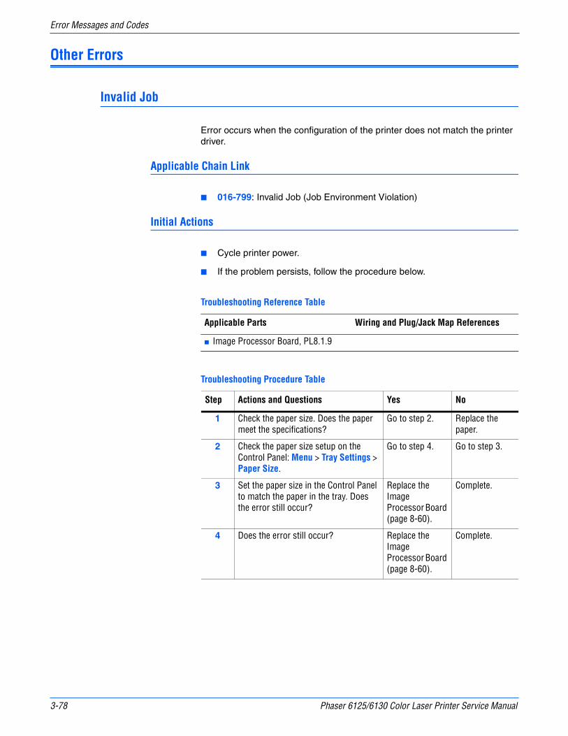
3-78 Phaser 6125/6130 Color Laser Printer Service Manual
Error Messages and Codes
Other Errors
Invalid Job
Error occurs when the configuration of the printer does not match the printer driver.
Applicable Chain Link
■ 016-799: Invalid Job (Job Environment Violation)
Initial Actions
■ Cycle printer power.
■ If the problem persists, follow the procedure below.
Troubleshooting Reference Table
Applicable Parts Wiring and Plug/Jack Map References
■ Image Processor Board, PL8.1.9
Troubleshooting Procedure Table
Step Actions and Questions Yes No
1 Check the paper size. Does the paper meet the specifications?
Go to step 2. Replace the paper.
2 Check the paper size setup on the Control Panel: Menu > Tray Settings > Paper Size.
Go to step 4. Go to step 3.
3 Set the paper size in the Control Panel to match the paper in the tray. Does the error still occur?
Replace the Image Processor Board (page 8-60).
Complete.
4 Does the error still occur? Replace the Image Processor Board (page 8-60).
Complete.

Phaser 6125/6130 Color Laser Printer Service Manual 3-79
Error Messages and Codes
Download Mode
The MCU downloaded file is invalid.
Applicable Chain Link
■ 024-360: MCU Firmware Download Error
Troubleshooting Reference Table
Applicable Parts Wiring and Plug/Jack Map References
■ Image Processor Board, PL8.1.9
Troubleshooting Procedure Table
Step Actions and Questions Yes No
1 Check the download firmwareIs the correct firmware downloaded?
Go to step 2. Download the correct firmware.
2 Check the Image Processor Board installationReseat all connectors on the Image Processor Board.Does the error still occur when downloading the firmware?
Replace the Image Processor Board (page 8-60).
Complete
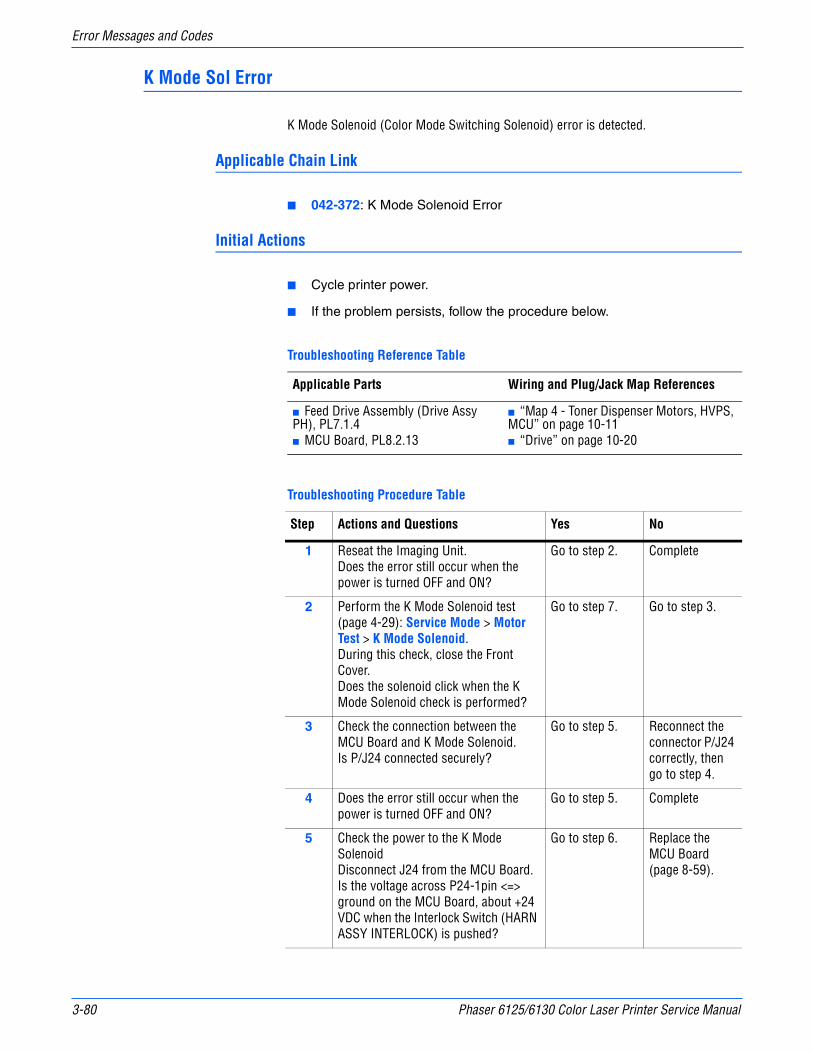
3-80 Phaser 6125/6130 Color Laser Printer Service Manual
Error Messages and Codes
K Mode Sol Error
K Mode Solenoid (Color Mode Switching Solenoid) error is detected.
Applicable Chain Link
■ 042-372: K Mode Solenoid Error
Initial Actions
■ Cycle printer power.
■ If the problem persists, follow the procedure below.
Troubleshooting Reference Table
Applicable Parts Wiring and Plug/Jack Map References
■ Feed Drive Assembly (Drive Assy PH), PL7.1.4■ MCU Board, PL8.2.13
■ “Map 4 - Toner Dispenser Motors, HVPS, MCU” on page 10-11■ “Drive” on page 10-20
Troubleshooting Procedure Table
Step Actions and Questions Yes No
1 Reseat the Imaging Unit.Does the error still occur when the power is turned OFF and ON?
Go to step 2. Complete
2 Perform the K Mode Solenoid test (page 4-29): Service Mode > Motor Test > K Mode Solenoid.During this check, close the Front Cover.Does the solenoid click when the K Mode Solenoid check is performed?
Go to step 7. Go to step 3.
3 Check the connection between the MCU Board and K Mode Solenoid.Is P/J24 connected securely?
Go to step 5. Reconnect the connector P/J24 correctly, then go to step 4.
4 Does the error still occur when the power is turned OFF and ON?
Go to step 5. Complete
5 Check the power to the K Mode SolenoidDisconnect J24 from the MCU Board.Is the voltage across P24-1pin <=> ground on the MCU Board, about +24 VDC when the Interlock Switch (HARN ASSY INTERLOCK) is pushed?
Go to step 6. Replace the MCU Board (page 8-59).
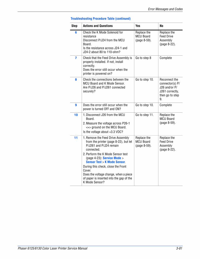
Phaser 6125/6130 Color Laser Printer Service Manual 3-81
Error Messages and Codes
6 Check the K Mode Solenoid for resistanceDisconnect P/J24 from the MCU Board.Is the resistance across J24-1 and J24-2 about 80 to 110-ohm?
Replace the MCU Board (page 8-59).
Replace the Feed Drive Assembly (page 8-22).
7 Check that the Feed Drive Assembly is properly installed. If not, install correctly. Does the error still occur when the printer is powered on?
Go to step 8 Complete
8 Check the connections between the MCU Board and K Mode Sensor.Are P/J26 and P/J261 connected securely?
Go to step 10. Reconnect the connector(s) P/J26 and/or P/J261 correctly, then go to step 9.
9 Does the error still occur when the power is turned OFF and ON?
Go to step 10. Complete
10 1. Disconnect J26 from the MCU Board.
2. Measure the voltage across P26-1 <=> ground on the MCU Board.
Is the voltage about +3.3 VDC?
Go to step 11. Replace the MCU Board (page 8-59).
11 1. Remove the Feed Drive Assembly from the printer (page 8-22), but let P/J261 and P/J24 remain connected.
2. Perform the K Mode Sensor test (page 4-23): Service Mode > Sensor Test > K Mode Sensor.
During this check, close the Front Cover.Does the voltage change, when a piece of paper is inserted into the gap of the K Mode Sensor?
Replace the MCU Board (page 8-59).
Replace the Feed Drive Assembly (page 8-22).
Troubleshooting Procedure Table (continued)
Step Actions and Questions Yes No
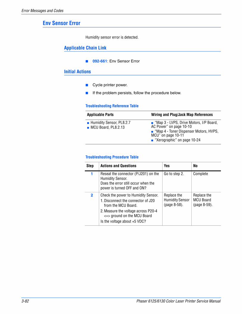
3-82 Phaser 6125/6130 Color Laser Printer Service Manual
Error Messages and Codes
Env Sensor Error
Humidity sensor error is detected.
Applicable Chain Link
■ 092-661: Env Sensor Error
Initial Actions
■ Cycle printer power.
■ If the problem persists, follow the procedure below.
Troubleshooting Procedure Table
Troubleshooting Reference Table
Applicable Parts Wiring and Plug/Jack Map References
■ Humidity Sensor, PL8.2.7■ MCU Board, PL8.2.13
■ “Map 3 - LVPS, Drive Motors, I/P Board, AC Power” on page 10-10■ “Map 4 - Toner Dispenser Motors, HVPS, MCU” on page 10-11■ “Xerographic” on page 10-24
Step Actions and Questions Yes No
1 Reseat the connector (P/J201) on the Humidity Sensor.Does the error still occur when the power is turned OFF and ON?
Go to step 2. Complete
2 Check the power to Humidity Sensor.1. Disconnect the connector of J20
from the MCU Board.2. Measure the voltage across P20-4
<=> ground on the MCU BoardIs the voltage about +5 VDC?
Replace the Humidity Sensor (page 8-58).
Replace the MCU Board (page 8-59).

4Chapter
General TroubleshootingIn this chapter... ■ Introduction
■ System Startup
■ Power On Self Test (POST)
■ Service Diagnostics
■ Service Mode Menu Map
■ Printer Components
■ Service Mode Diagnostic Tests
■ Control Panel Troubleshooting
■ Inoperable Printer Troubleshooting
■ AC Power Supply Troubleshooting
■ DC Power Supply Troubleshooting
■ +24 VDC Interlock Switch
■ Abnormal Noise and Electrical Problems

4-2 Phaser 6125/6130 Color Laser Printer Service Manual
General Troubleshooting
Introduction
This chapter covers the System Startup, Power On Self Test (POST), Service Diagnostics, and troubleshooting problems that are not associated with a Chain Link code or Control Panel error message.
For troubleshooting problems associated with a Chain Link code or Control Panel error message, refer to “Error Messages and Codes” on page 3-1. Print-quality problems are covered in “Print-Quality Troubleshooting” on page 5-1.
System Startup
Listed here is a typical startup routine from a cold start. The printer requires approximately 20 seconds to complete this sequence.
1. When the power switch is turned On, the “Health” LED on the Image Processor Board turns On immediately.
2. The Boot Loader checks for RAM present and functional. If an error is detected, RAM ERROR is displayed and the Health LEDs alternately blink at 1/2 second intervals.
3. The Boot Loader then loads and runs POST diagnostics.
4. POST turns Off the Health LED.
5. POST checks the Control Panel.
6. The Control Panel LED cycles: Green and Red simultaneously, and Green.
7. The Control Panel LED turns Green and Red and Diagnosing... message is displayed.
8. The Control Panel message changes to Ready Calibrating and then Xerox (TM) Toner Cartridge.
9. The Control Panel LED turns Green and the Ready message is displayed.

Phaser 6125/6130 Color Laser Printer Service Manual 4-3
General Troubleshooting
Power On Self Test (POST)
POST Diagnostics provide a quick mean of isolating a defective subsystem associated with the Image Processor Board and SDRAM. POST returns control to the boot loader and the operating system is loaded.
The following tests are performed when the printer is powered On.
1. Checks and initializes CRU Register.
2. Initializes ASIC.
3. Checks RAM.
4. Initializes the Control Panel driver.
5. Processes the ROM Sum Check.
6. Initializes Memory Manager.
7. Initializes EEPROM driver.
8. Initializes IOT Controller.
9. Starts the Operating System process.
10. Printer is Ready.
POST Test Description
Test Chain Link Description
CodeROM 116-317 This test calculates the ROM checksum chip by chip and compares it with the value stored in the CodeROM itself.Checksum error is in the main program ROM.
FontROM This test calculates the FontROM checksum chip by chip and compares it with the value stored in the FontROM itself.
116-310 Checksum error is in the built-in FontROM.
116-317 Checksum error is in the main program ROM.
EEPROM This test writes/reads/verifies on the diagnostic area of the EEPROM.
116-323 Error is detected in EEPROM0 during initialization.
116-326 Error is detected in EEPROM1 during initialization.
DRAM This test checks OPEN/SHORT of the address line of the DRAM. This test also writes/reads/verifies on the entire DRAM.
116-315 Error is detected if included RAM is different.
116-316 Error is detected if extended RAM is different.
116-320 Error is detected if extended RAM is not supported.
MAC+PHY Test 116-352 This test performs PHY internal loopback.
ASIC 116-343 Performs register test.

4-4 Phaser 6125/6130 Color Laser Printer Service Manual
General Troubleshooting
PANEL This test checks input and output of the Control Panel buttons.
IOT 024-371 This test performs communication test with the Engine.This test also checks for Communication failure between the Engine and Controller.
POST Test Description (continued)
Test Chain Link Description
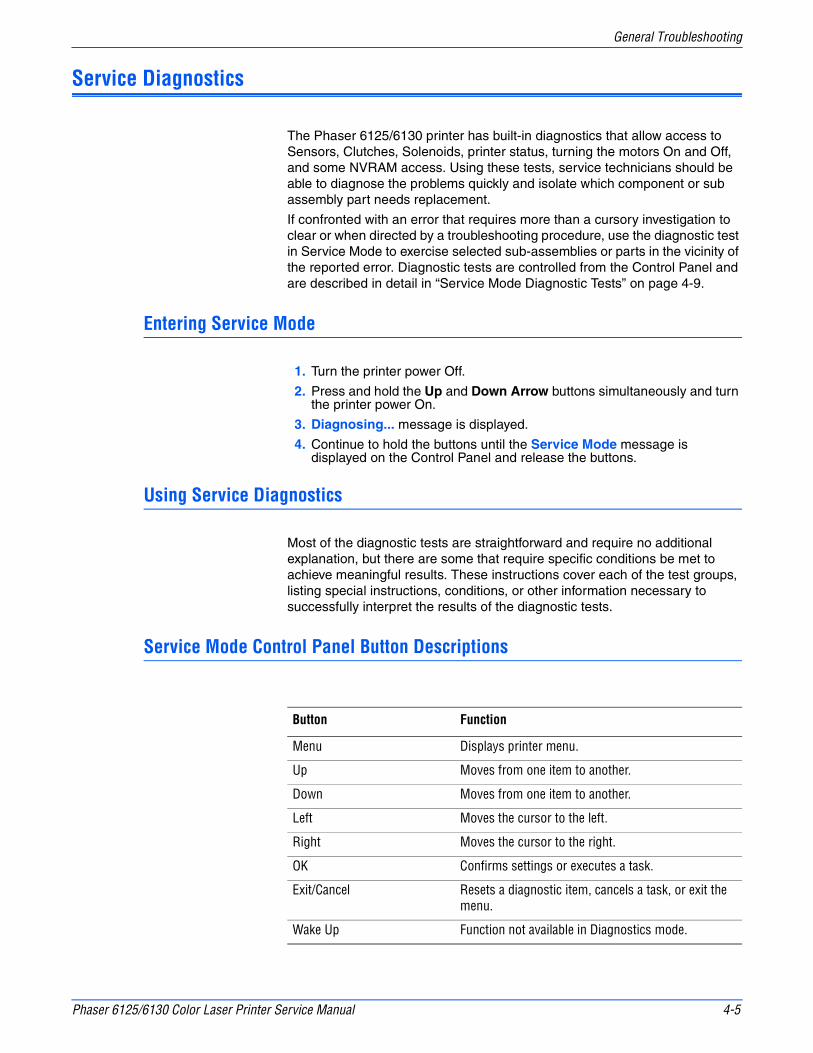
Phaser 6125/6130 Color Laser Printer Service Manual 4-5
General Troubleshooting
Service Diagnostics
The Phaser 6125/6130 printer has built-in diagnostics that allow access to Sensors, Clutches, Solenoids, printer status, turning the motors On and Off, and some NVRAM access. Using these tests, service technicians should be able to diagnose the problems quickly and isolate which component or sub assembly part needs replacement.
If confronted with an error that requires more than a cursory investigation to clear or when directed by a troubleshooting procedure, use the diagnostic test in Service Mode to exercise selected sub-assemblies or parts in the vicinity of the reported error. Diagnostic tests are controlled from the Control Panel and are described in detail in “Service Mode Diagnostic Tests” on page 4-9.
Entering Service Mode
1. Turn the printer power Off.
2. Press and hold the Up and Down Arrow buttons simultaneously and turn the printer power On.
3. Diagnosing... message is displayed.
4. Continue to hold the buttons until the Service Mode message is displayed on the Control Panel and release the buttons.
Using Service Diagnostics
Most of the diagnostic tests are straightforward and require no additional explanation, but there are some that require specific conditions be met to achieve meaningful results. These instructions cover each of the test groups, listing special instructions, conditions, or other information necessary to successfully interpret the results of the diagnostic tests.
Service Mode Control Panel Button Descriptions
Button Function
Menu Displays printer menu.
Up Moves from one item to another.
Down Moves from one item to another.
Left Moves the cursor to the left.
Right Moves the cursor to the right.
OK Confirms settings or executes a task.
Exit/Cancel Resets a diagnostic item, cancels a task, or exit the menu.
Wake Up Function not available in Diagnostics mode.

4-6 Phaser 6125/6130 Color Laser Printer Service Manual
General Troubleshooting
Service Mode Menu Map
6130 Menu Map - Page 1
Engine Diag
Print Info
ESS Diag
Power SaverOn/Off
OK
Exit
Service ModeAll Test
CodeROM Test
FontROM Test
EEPROM Test
DRAM Test
MAC+PHY Test
ASIC Test
PANEL Test
Engine Test
Info Page
Print Settings
Installation
SerialNo.
Tone Correction
Display Counter*
HexDump
Pixel Counter
Configuration*
Counter Type*
Print Counter
CopyCounter MtoB
CopyCounter BtoM
Clear All NVM
Clear JobHistory
Clear AuditronPV*
Sensor Test
Motor Test
NVM Settings
Color PrintB/W PrintTotal PrintColor BackupB/W BackupTotal BackupColor ErrorB/W Error
Edit NVMSave NVM to ESSLoad NVM from ESSInitialize SlavePrint NVM Info
Main Motor FULL2Main Motor FULL1Main Motor HALFSub Motor FULL2Sub Motor FULL1Sub Motor HALFK Mode SolenoidTray Feed Solenoid (Half)Tray Feed Solenoid (Init)Fan HIGHFan LOWYellow Toner MotorMagenta Toner MotorCyan Toner MotorBlack Toner MotorRegi ClutchTray Feed Solenoid (Auto)Drum Erase Lamp KDrum Erase Lamp YMC
s6130-201
To access Service Mode, press Up and Down Arrows at power ON.
Manual Feed SensorTray No PaperRegi SensorExit SensorK Mode SensorSide SwitchCover Open Sensor
*Not used in this printer
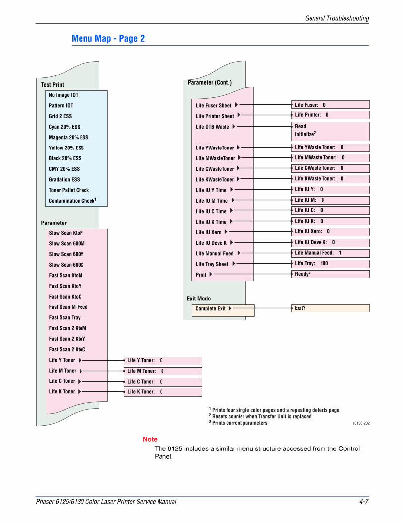
Phaser 6125/6130 Color Laser Printer Service Manual 4-7
General Troubleshooting
Menu Map - Page 2
NoteThe 6125 includes a similar menu structure accessed from the Control Panel.
Test Print
Parameter
Parameter (Cont.)
No Image IOT
Pattern IOT
Grid 2 ESS
Cyan 20% ESS
Magenta 20% ESS
Yellow 20% ESS
Black 20% ESS
CMY 20% ESS
Gradation ESS
Toner Pallet Check
Contamination Check1
Exit Mode
Complete Exit
Slow Scan KtoP
Slow Scan 600M
Slow Scan 600Y
Slow Scan 600C
Fast Scan KtoM
Fast Scan KtoY
Fast Scan KtoC
Fast Scan M-Feed
Fast Scan Tray
Fast Scan 2 KtoM
Fast Scan 2 KtoY
Fast Scan 2 KtoC
Life Y Toner
Life M Toner
Life C Toner
Life K Toner
Life Fuser Sheet
Life Printer Sheet
Life DTB Waste
Life YWasteToner
Life MWasteToner
Life CWasteToner
Life KWasteToner
Life IU Y Time
Life IU M Time
Life IU C Time
Life IU K Time
Life IU Xero
Life IU Deve K
Life Manual Feed
Life Tray Sheet
Life Y Toner: 0
Life YWaste Toner: 0
Life MWaste Toner: 0
Life CWaste Toner: 0
Life KWaste Toner: 0
Life IU Y: 0
Life IU M: 0
Life IU C: 0
Life IU K: 0
Life IU Xero: 0
Life IU Deve K: 0
Life Manual Feed: 1
Life Tray: 100
Ready3
Exit?
Life M Toner: 0
Life C Toner: 0
Life K Toner: 0
Life Fuser: 0
Life Printer: 0
ReadInitialize2
s6130-202
1 Prints four single color pages and a repeating defects page2 Resets counter when Transfer Unit is replaced3 Prints current parameters
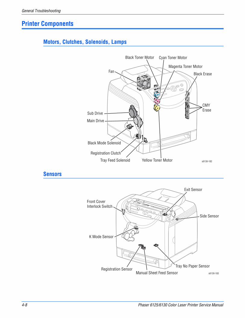
4-8 Phaser 6125/6130 Color Laser Printer Service Manual
General Troubleshooting
Printer Components
Motors, Clutches, Solenoids, Lamps
Sensors
Sub Drive
Main Drive
Black Mode Solenoid
Registration Clutch
Tray Feed Solenoid
Fan
Black Toner Motor Cyan Toner Motor
Magenta Toner Motor
Yellow Toner Motor s6130-182
Black Erase
CMY Erase
s6130-183
Side Sensor
K Mode Sensor
Tray No Paper Sensor
Manual Sheet Feed SensorRegistration Sensor
Exit Sensor
Front Cover Interlock Switch
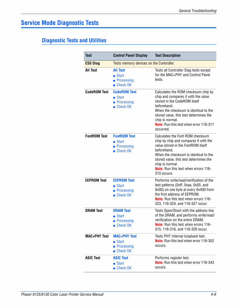
Phaser 6125/6130 Color Laser Printer Service Manual 4-9
General Troubleshooting
Service Mode Diagnostic Tests
Diagnostic Tests and Utilities
Test Control Panel Display Test Description
ESS Diag Tests memory devices on the Controller.
All Test All Test■ Start■ Processing■ Check OK
Tests all Controller Diag tests except for the MAC+PHY and Control Panel tests.
CodeROM Test CodeROM Test■ Start■ Processing■ Check OK
Calculates the ROM checksum chip by chip and compares it with the value stored in the CodeROM itself beforehand.When the checksum is identical to the stored value, this test determines the chip is normal.Note: Run this test when error 116-317 occurred.
FontROM Test FontROM Test■ Start■ Processing■ Check OK
Calculates the Font ROM checksum chip by chip and compares it with the value stored in the FontROM itself beforehand. When the checksum is identical to the stored value, this test determines the chip is normal.Note: Run this test when errors 116-310 occurs.
EEPROM Test EEPROM Test■ Start■ Processing■ Check OK
Performs write/read/verification of the test patterns (0xff, 0xaa, 0x55, and 0x00) on one byte at every 0x400 from the first address of EEPROM.Note: Run this test when errors 116-323, 116-324, and 116-327 occur.
DRAM Test DRAM Test■ Start■ Processing■ Check OK
Tests Open/Short with the address line of the DRAM, and performs write/read/verification on the entire DRAM.Note: Run this test when errors 116-315, 116-316, and 116-320 occur.
MAC+PHY Test MAC+PHY Test■ Start■ Processing■ Check OK
Tests PHY Internal loopback test.Note: Run this test when error 116-352 occurs.
ASIC Test ASIC Test■ Start■ Check OK
Performs register test.Note: Run this test when error 116-343 occurs.
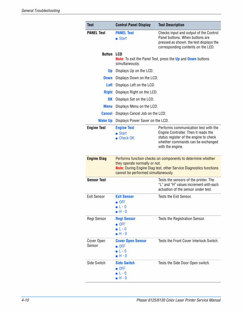
4-10 Phaser 6125/6130 Color Laser Printer Service Manual
General Troubleshooting
PANEL Test PANEL Test■ Start
Checks input and output of the Control Panel buttons. When buttons are pressed as shown, the test displays the corresponding contents on the LED.
Button LCDNote: To exit the Panel Test, press the Up and Down buttons simultaneously.
Up Displays Up on the LCD.
Down Displays Down on the LCD.
Left Displays Left on the LCD.
Right Displays Right on the LCD.
OK Displays Set on the LCD.
Menu Displays Menu on the LCD.
Cancel Displays Cancel Job on the LCD.
Wake Up Displays Power Saver on the LCD.
Engine Test Engine Test■ Start■ Check OK
Performs communication test with the Engine Controller. Then it reads the status register of the engine to check whether commands can be exchanged with the engine.
Engine Diag Performs function checks on components to determine whether they operate normally or not.Note: During Engine Diag test, other Service Diagnostics functions cannot be performed simultaneously.
Sensor Test Tests the sensors of the printer. The “L” and “H” values increment with each actuation of the sensor under test.
Exit Sensor Exit Sensor■ OFF■ L - 0■ H - 0
Tests the Exit Sensor.
Regi Sensor Regi Sensor■ OFF■ L - 0■ H - 0
Tests the Registration Sensor.
Cover Open Sensor
Cover Open Sensor■ OFF■ L - 0■ H - 0
Tests the Front Cover Interlock Switch.
Side Switch Side Switch■ OFF■ L - 0■ H - 0
Tests the Side Door Open switch.
Test Control Panel Display Test Description
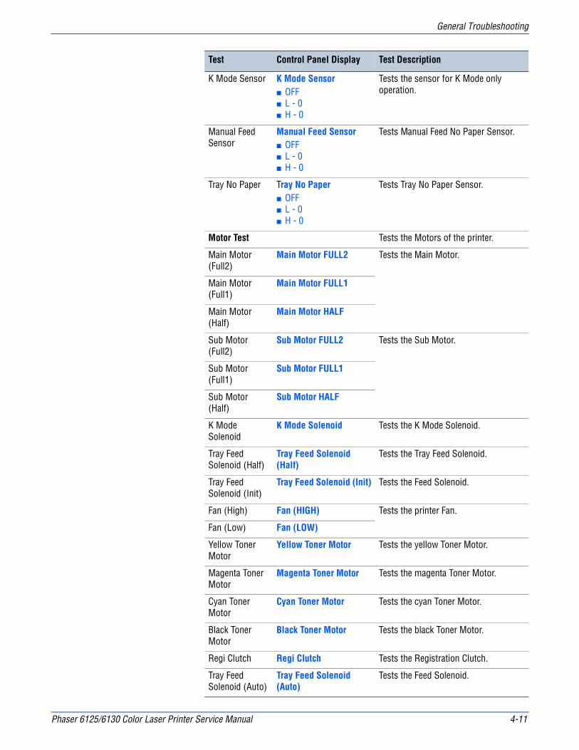
Phaser 6125/6130 Color Laser Printer Service Manual 4-11
General Troubleshooting
K Mode Sensor K Mode Sensor ■ OFF■ L - 0■ H - 0
Tests the sensor for K Mode only operation.
Manual Feed Sensor
Manual Feed Sensor■ OFF■ L - 0■ H - 0
Tests Manual Feed No Paper Sensor.
Tray No Paper Tray No Paper■ OFF■ L - 0■ H - 0
Tests Tray No Paper Sensor.
Motor Test Tests the Motors of the printer.
Main Motor (Full2)
Main Motor FULL2 Tests the Main Motor.
Main Motor (Full1)
Main Motor FULL1
Main Motor (Half)
Main Motor HALF
Sub Motor (Full2)
Sub Motor FULL2 Tests the Sub Motor.
Sub Motor (Full1)
Sub Motor FULL1
Sub Motor (Half)
Sub Motor HALF
K Mode Solenoid
K Mode Solenoid Tests the K Mode Solenoid.
Tray Feed Solenoid (Half)
Tray Feed Solenoid (Half)
Tests the Tray Feed Solenoid.
Tray Feed Solenoid (Init)
Tray Feed Solenoid (Init) Tests the Feed Solenoid.
Fan (High) Fan (HIGH) Tests the printer Fan.
Fan (Low) Fan (LOW)
Yellow Toner Motor
Yellow Toner Motor Tests the yellow Toner Motor.
Magenta Toner Motor
Magenta Toner Motor Tests the magenta Toner Motor.
Cyan Toner Motor
Cyan Toner Motor Tests the cyan Toner Motor.
Black Toner Motor
Black Toner Motor Tests the black Toner Motor.
Regi Clutch Regi Clutch Tests the Registration Clutch.
Tray Feed Solenoid (Auto)
Tray Feed Solenoid (Auto)
Tests the Feed Solenoid.
Test Control Panel Display Test Description
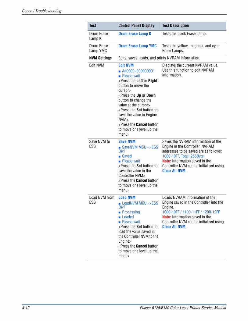
4-12 Phaser 6125/6130 Color Laser Printer Service Manual
General Troubleshooting
Drum Erase Lamp K
Drum Erase Lamp K Tests the black Erase Lamp.
Drum Erase Lamp YMC
Drum Erase Lamp YMC Tests the yellow, magenta, and cyan Erase Lamps.
NVM Settings Edits, saves, loads, and prints NVRAM information.
Edit NVM Edit NVM■ Ad0000=00000000*■ Please wait<Press the Left or Right button to move the cursor><Press the Up or Down button to change the value at the cursor><Press the Set button to save the value in Engine NVM><Press the Cancel button to move one level up the menu>
Displays the current NVRAM value. Use this function to edit NVRAM information.
Save NVM to ESS
Save NVM■ SaveNVM MCU -> ESS OK?■ Saved■ Please wait<Press the Set button to save the value in the Controller NVM><Press the Cancel button to move one level up the menu>
Saves the NVRAM information of the Engine in the Controller. NVRAM addresses to be saved are as follows:1000-10FF, Total: 256ByteNote: Information saved in the Controller NVM can be initialized using Clear All NVM.
Load NVM from ESS
Load NVM■ LoadNVM MCU -> ESS OK?■ Processing■ Loaded■ Please wait<Press the Set button to load the value saved in the Controller NVM to the Engine><Press the Cancel button to move one level up the menu>
Loads NVRAM information of the Engine saved in the Controller into the Engine.1000-10FF / 1100-11FF / 1200-12FFNote: Information saved in the Controller NVM can be initialized using Clear All NVM.
Test Control Panel Display Test Description
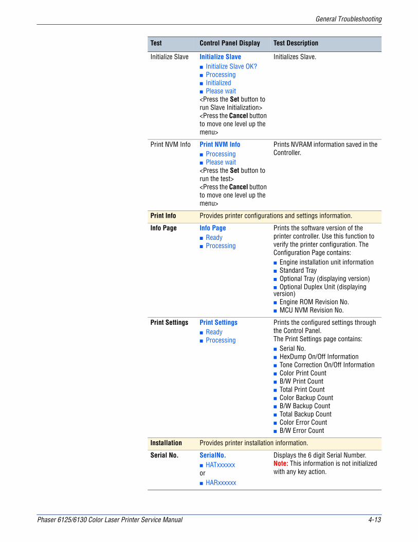
Phaser 6125/6130 Color Laser Printer Service Manual 4-13
General Troubleshooting
Initialize Slave Initialize Slave■ Initialize Slave OK?■ Processing■ Initialized■ Please wait<Press the Set button to run Slave Initialization><Press the Cancel button to move one level up the menu>
Initializes Slave.
Print NVM Info Print NVM Info■ Processing■ Please wait<Press the Set button to run the test><Press the Cancel button to move one level up the menu>
Prints NVRAM information saved in the Controller.
Print Info Provides printer configurations and settings information.
Info Page Info Page■ Ready■ Processing
Prints the software version of the printer controller. Use this function to verify the printer configuration. The Configuration Page contains:■ Engine installation unit information■ Standard Tray■ Optional Tray (displaying version)■ Optional Duplex Unit (displaying version)■ Engine ROM Revision No.■ MCU NVM Revision No.
Print Settings Print Settings■ Ready■ Processing
Prints the configured settings through the Control Panel. The Print Settings page contains:■ Serial No.■ HexDump On/Off Information■ Tone Correction On/Off Information■ Color Print Count■ B/W Print Count■ Total Print Count■ Color Backup Count■ B/W Backup Count■ Total Backup Count■ Color Error Count■ B/W Error Count
Installation Provides printer installation information.
Serial No. SerialNo.■ HATxxxxxxor■ HARxxxxxx
Displays the 6 digit Serial Number.Note: This information is not initialized with any key action.
Test Control Panel Display Test Description

4-14 Phaser 6125/6130 Color Laser Printer Service Manual
General Troubleshooting
Tone Correction Tone Correction■ ON *■ OFF <Press the Up or Down button to switch Tone Correction On/Off><Press the Set button to save the setting and move one level up the menu><Press the Cancel button to move one level up the menu without saving the value>
Controls TRC in conjunction with process control to keep the printer density constant. This function is implemented to turn Off tone correction control in case correction exceeds the limit due to machine-to-machine variation.Sets the printer Tone Correction mode On/Off.Note: When the Tone Correction has been changed, an “*” is displayed next to the text.Note: This information can be initialized by Initialize NVM (Printer Menu > Admin Menu > Maintenance Mode > Initialize NVM).
Display Counter
Not used in this printer.
Hex Dump HexDump■ OFF *■ ON <Press the Up or Down button to switch HexDump On/Off><Press the Set button to save the setting and move one level up the menu><Press the Cancel button to move one level up the menu without saving the value>
Displays the current HexDump On/Off information and sets mode On/Off.Note: This information is initialized by Clear All NVM.Note: When the Counter Type has been changed, an “*” is displayed next to the text.
Pixel Counter Pixel Counter■ Y: nn.n■ C: nn.n■ M: nn.n■ K: nn.n<Press the Set or Cancel button to move one level up the menu>
Displays the ratio (% used) of the number of pixel per C/M/Y/K counted by the Controller to A4 size area except 4 mm area from the edge on the last page print.■ 100% = empty Toner CartridgeThe value is rounded off to one decimal place.For B/W print, only K is displayed.The ranges are from 0-100% for each color (CMYK).
Configuration ■ Not used in this printer.
Counter Type Not used in this printer.
Test Control Panel Display Test Description

Phaser 6125/6130 Color Laser Printer Service Manual 4-15
General Troubleshooting
Print Counter Print Counter■ Color Print■ n■ B/W Print■ n■ Total Print■ n■ Color Backup■ n■ B/W Backup■ n■ Total Backup■ n■ Color Error■ n■ B/W Error■ nMenu Buttons<Press the Up or Down button to move from one item to another><Press the Cancel button to move one/two level(s) up the menu><Press the Set button to run the test>
Operates the print counter.
Copy Counter MtoB
CopyCounter MtoB■ OK?■ Processing■ Copied<Press the Cancel button to move one level up the menu><Press the Set button to run the test>
Copies the values from Master NVRAM to Backup NVRAM.■ Device-specific information called “Personal info” in the first 128 Byte■ PV counter master■ Printer counter master
Copy Counter BtoM
CopyCounter BtoM■ OK?■ Processing■ Copied<Press the Cancel button to move one level up the menu><Press the Set button to run the test>
Copies the values from Backup NVRAM to Master NVRAM.■ Device-specific information called “Personal info” in the first 128 Byte■ PV counter backup■ Printer counter backup
Test Control Panel Display Test Description
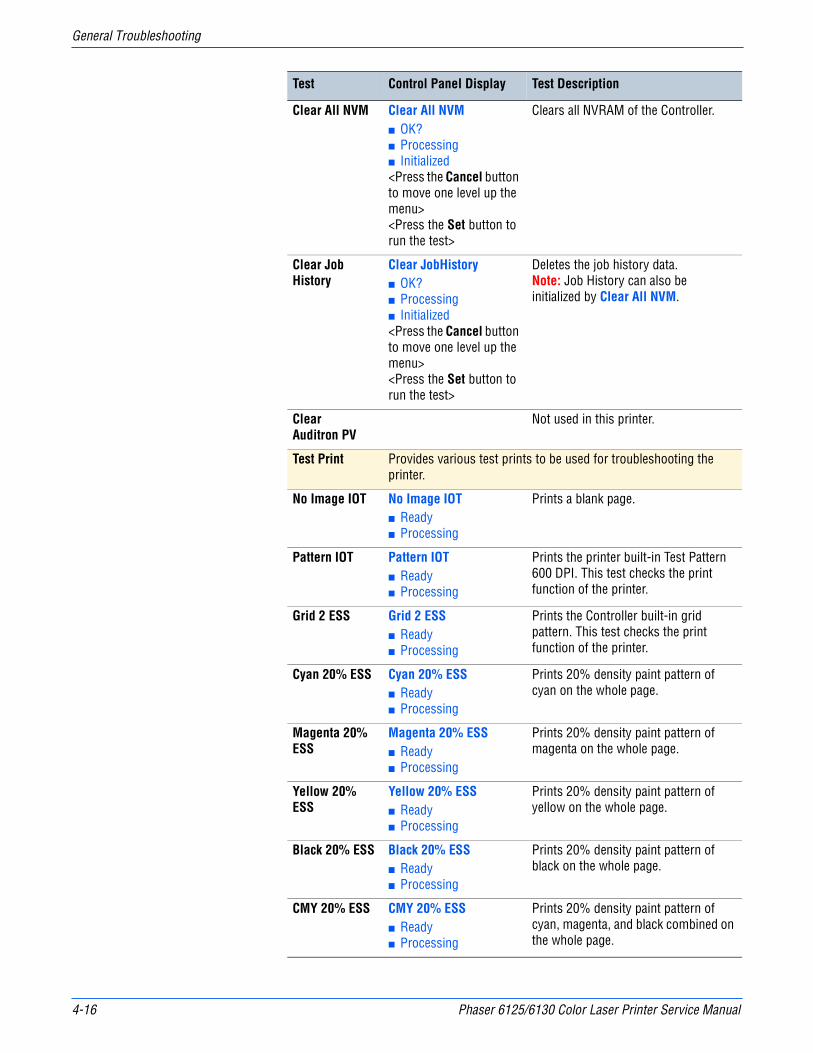
4-16 Phaser 6125/6130 Color Laser Printer Service Manual
General Troubleshooting
Clear All NVM Clear All NVM■ OK?■ Processing■ Initialized<Press the Cancel button to move one level up the menu><Press the Set button to run the test>
Clears all NVRAM of the Controller.
Clear Job History
Clear JobHistory■ OK?■ Processing■ Initialized<Press the Cancel button to move one level up the menu><Press the Set button to run the test>
Deletes the job history data.Note: Job History can also be initialized by Clear All NVM.
ClearAuditron PV
Not used in this printer.
Test Print Provides various test prints to be used for troubleshooting the printer.
No Image IOT No Image IOT■ Ready■ Processing
Prints a blank page.
Pattern IOT Pattern IOT■ Ready■ Processing
Prints the printer built-in Test Pattern 600 DPI. This test checks the print function of the printer.
Grid 2 ESS Grid 2 ESS■ Ready■ Processing
Prints the Controller built-in grid pattern. This test checks the print function of the printer.
Cyan 20% ESS Cyan 20% ESS■ Ready■ Processing
Prints 20% density paint pattern of cyan on the whole page.
Magenta 20% ESS
Magenta 20% ESS■ Ready■ Processing
Prints 20% density paint pattern of magenta on the whole page.
Yellow 20% ESS
Yellow 20% ESS■ Ready■ Processing
Prints 20% density paint pattern of yellow on the whole page.
Black 20% ESS Black 20% ESS■ Ready■ Processing
Prints 20% density paint pattern of black on the whole page.
CMY 20% ESS CMY 20% ESS■ Ready■ Processing
Prints 20% density paint pattern of cyan, magenta, and black combined on the whole page.
Test Control Panel Display Test Description

Phaser 6125/6130 Color Laser Printer Service Manual 4-17
General Troubleshooting
Gradation ESS Gradation ESS■ Ready■ Processing
Prints a pattern in which the density of each cyan, magenta, yellow, or black is varied from 0-100%.
Toner Pallet Check
Toner Pallet Check Prints a pattern of 100% density of each color.
Contamination Check
Contamination Check Prints a scale pattern for each color (sheets 1-4) and the Pitch Chart, a repeating defects page (sheet 5).
Parameter Reads/writes the parameter values, errors, and life counter values stored in the printer.
Slow Scan KtoP Slow Scan KtoP■ -128 *■ :■ 127 *
Adjusts the registration in the scanning direction.
Slow Scan 600M
Slow Scan 600M■ -30 *■ :■ 30 *
Slow Scan 600Y
Slow Scan 600Y■ -30 *■ :■ 30 *
Slow Scan 600C
Slow Scan 600C■ -30 *■ :■ 30 *
Fast Scan KtoM Fast Scan KtoM■ -30 *■ :■ 30 *
Sets the registration in the paper feeding direction for Manual Feed and Tray. Adjusts by one pixel per unit.
Fast Scan KtoY Fast Scan KtoY■ -30 *■ :■ 30 *
Fast Scan KtoC Fast Scan KtoC■ -30 *■ :■ 30 *
Fast ScanM-feed
Fast Scan M-feed■ -30 *■ :■ 30 *
Fast ScanTray
Fast Scan Tray■ -30 *■ :■ 30 *
Test Control Panel Display Test Description
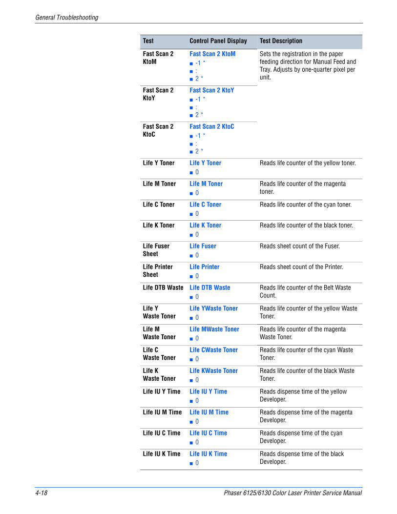
4-18 Phaser 6125/6130 Color Laser Printer Service Manual
General Troubleshooting
Fast Scan 2 KtoM
Fast Scan 2 KtoM■ -1 *■ :■ 2 *
Sets the registration in the paper feeding direction for Manual Feed and Tray. Adjusts by one-quarter pixel per unit.
Fast Scan 2 KtoY
Fast Scan 2 KtoY■ -1 *■ :■ 2 *
Fast Scan 2 KtoC
Fast Scan 2 KtoC■ -1 *■ :■ 2 *
Life Y Toner Life Y Toner■ 0
Reads life counter of the yellow toner.
Life M Toner Life M Toner■ 0
Reads life counter of the magenta toner.
Life C Toner Life C Toner■ 0
Reads life counter of the cyan toner.
Life K Toner Life K Toner■ 0
Reads life counter of the black toner.
Life Fuser Sheet
Life Fuser■ 0
Reads sheet count of the Fuser.
Life Printer Sheet
Life Printer■ 0
Reads sheet count of the Printer.
Life DTB Waste Life DTB Waste■ 0
Reads life counter of the Belt Waste Count.
Life YWaste Toner
Life YWaste Toner■ 0
Reads life counter of the yellow Waste Toner.
Life MWaste Toner
Life MWaste Toner■ 0
Reads life counter of the magenta Waste Toner.
Life CWaste Toner
Life CWaste Toner■ 0
Reads life counter of the cyan Waste Toner.
Life KWaste Toner
Life KWaste Toner■ 0
Reads life counter of the black Waste Toner.
Life IU Y Time Life IU Y Time■ 0
Reads dispense time of the yellow Developer.
Life IU M Time Life IU M Time■ 0
Reads dispense time of the magenta Developer.
Life IU C Time Life IU C Time■ 0
Reads dispense time of the cyan Developer.
Life IU K Time Life IU K Time■ 0
Reads dispense time of the black Developer.
Test Control Panel Display Test Description
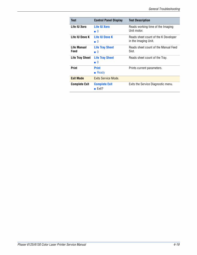
Phaser 6125/6130 Color Laser Printer Service Manual 4-19
General Troubleshooting
Life IU Xero Life IU Xero■ 0
Reads working time of the Imaging Unit motor.
Life IU Deve K Life IU Deve K■ 0
Reads sheet count of the K Developer in the Imaging Unit.
Life Manual Feed
Life Tray Sheet■ 0
Reads sheet count of the Manual Feed Slot.
Life Tray Sheet Life Tray Sheet■ 0
Reads sheet count of the Tray.
Print Print■ Ready
Prints current parameters.
Exit Mode Exits Service Mode.
Complete Exit Complete Exit■ Exit?
Exits the Service Diagnostic menu.
Test Control Panel Display Test Description
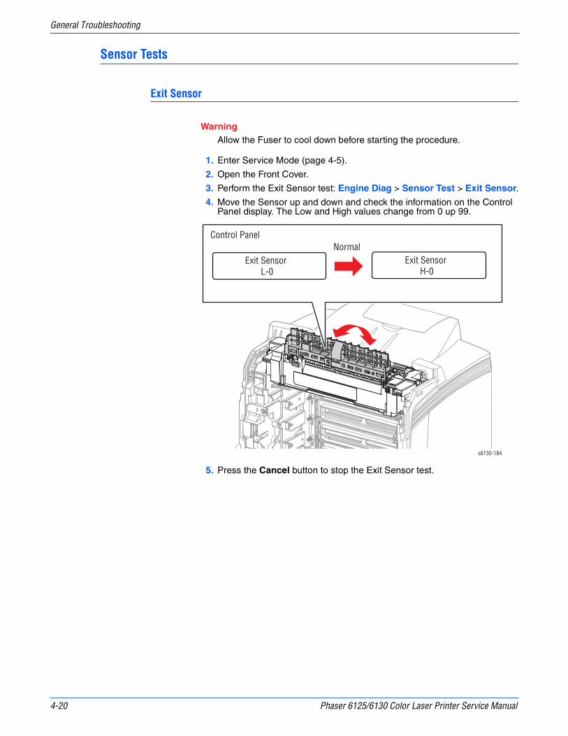
4-20 Phaser 6125/6130 Color Laser Printer Service Manual
General Troubleshooting
Sensor Tests
Exit Sensor
WarningAllow the Fuser to cool down before starting the procedure.
1. Enter Service Mode (page 4-5).
2. Open the Front Cover.
3. Perform the Exit Sensor test: Engine Diag > Sensor Test > Exit Sensor.
4. Move the Sensor up and down and check the information on the Control Panel display. The Low and High values change from 0 up 99.
5. Press the Cancel button to stop the Exit Sensor test.
s6130-184
Control PanelNormal
Exit Sensor L-0
Exit Sensor H-0
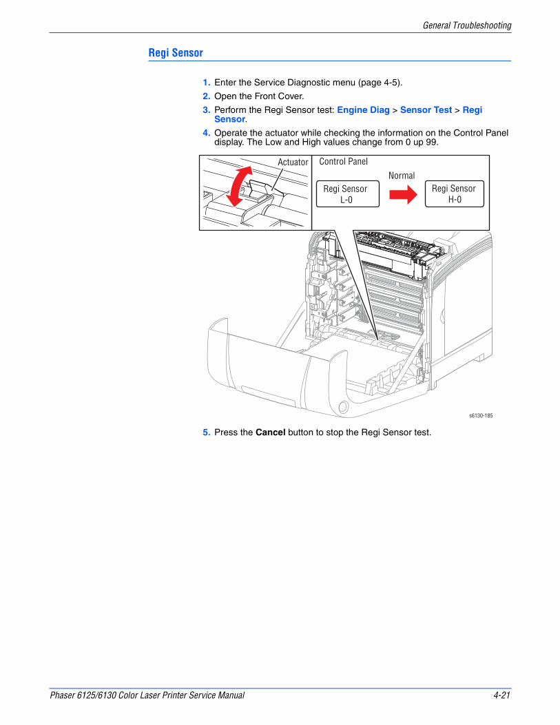
Phaser 6125/6130 Color Laser Printer Service Manual 4-21
General Troubleshooting
Regi Sensor
1. Enter the Service Diagnostic menu (page 4-5).
2. Open the Front Cover.
3. Perform the Regi Sensor test: Engine Diag > Sensor Test > Regi Sensor.
4. Operate the actuator while checking the information on the Control Panel display. The Low and High values change from 0 up 99.
5. Press the Cancel button to stop the Regi Sensor test.
Regi Sensor L-0
Regi Sensor H-0
Control PanelNormal
s6130-185
Actuator

4-22 Phaser 6125/6130 Color Laser Printer Service Manual
General Troubleshooting
Cover Open Sensor
CautionWhen performing this procedure, remove the Imaging Unit to avoid exposure to light.
1. Enter the Service Diagnostic menu (page 4-5).
2. Open the Front Cover.
3. Remove the Imaging Unit (page 8-8) and place in a dark location.
4. Perform the Interlock Switch test: Engine Diag > Sensor Test > Cover Open Sensor.
5. Open and close the Front Door while checking the information on the Control Panel display. The Low and High values change from 0 up to 99.
6. Press the Cancel button to stop the Cover Open Sensor test.
s6130-186
Control PanelNormal
Interlock Switch L-0
Interlock Switch H-0

Phaser 6125/6130 Color Laser Printer Service Manual 4-23
General Troubleshooting
K Mode Sensor
CautionWhen performing this procedure, remove and cover the Imaging Unit to avoid exposure to light.
1. Enter the Service Diagnostic menu (page 4-5).
2. Open the Front Cover.
3. Remove the Imaging Unit (page 8-8) and place in a dark location.
4. Remove the Left Side Cover (page 8-17).
5. Remove the Feed Drive Assembly (page 8-22) but do not unplug any of the cables.
6. Perform the K Mode Sensor test: Engine Diag > Sensor Test > K Mode Sensor.
7. Press the lever mounted on the Solenoid to retract the actuator from the sensor.
8. Move a strip of paper in and out of the sensor arms to simulate the action of the actuator. The Low and High values change from 0 up to 99.
9. Press the Cancel button to stop the CRU Sensor Y test.
s6130-187
Control PanelNormal
K Mode Sensor L-0
K Mode Sensor H-0
Paper
K Mode Sensor
K Mode Solenoid
Actuator
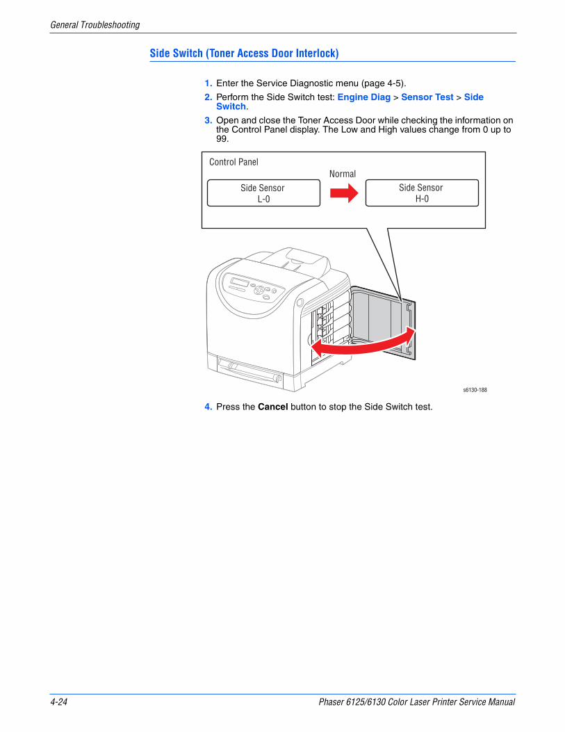
4-24 Phaser 6125/6130 Color Laser Printer Service Manual
General Troubleshooting
Side Switch (Toner Access Door Interlock)
1. Enter the Service Diagnostic menu (page 4-5).
2. Perform the Side Switch test: Engine Diag > Sensor Test > Side Switch.
3. Open and close the Toner Access Door while checking the information on the Control Panel display. The Low and High values change from 0 up to 99.
4. Press the Cancel button to stop the Side Switch test.
s6130-188
Control PanelNormal
Side Sensor L-0
Side Sensor H-0

Phaser 6125/6130 Color Laser Printer Service Manual 4-25
General Troubleshooting
Manual Feed Slot Paper Detect
1. Enter the Service Diagnostic menu (page 4-5).
2. Perform the Tray 1 (MPT) Sensor test: Engine Diag > Sensor Test > Manual Feed Sensor.
3. Slide a sheet of paper in and out of the Manual Feed Slot. The Low and High values change from 0 up to 99.
4. Press the Cancel button to stop the Tray 1 No Paper test.
s6130-189
Control PanelNormal
Manual Sheet Feed No PaperH-0
Manual Sheet Feed No PaperL-0
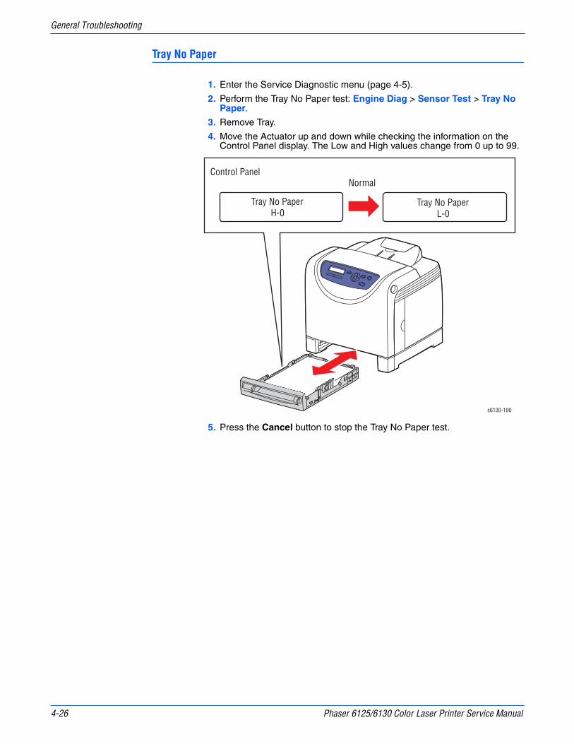
4-26 Phaser 6125/6130 Color Laser Printer Service Manual
General Troubleshooting
Tray No Paper
1. Enter the Service Diagnostic menu (page 4-5).
2. Perform the Tray No Paper test: Engine Diag > Sensor Test > Tray No Paper.
3. Remove Tray.
4. Move the Actuator up and down while checking the information on the Control Panel display. The Low and High values change from 0 up to 99.
5. Press the Cancel button to stop the Tray No Paper test.
s6130-190
Control PanelNormal
Tray No PaperH-0
Tray No PaperL-0

Phaser 6125/6130 Color Laser Printer Service Manual 4-27
General Troubleshooting
Motor Tests
Main Motor FULL2/FULL1/HALF
The Main Motor drives the Transfer Belt and Imaging Unit drums.
CautionIf the Front Cover will be open for more than 5 minutes, remove the Imaging Unit and cover it or place it in a dark location to avoid exposure to light.
NoteThe rotational speed order of the Main Motor Test is as follows:
■ FULL2 < FULL1 < HALF
1. Enter the Service Diagnostic menu (page 4-5).
2. Open the Front Cover.
3. Defeat the Front Cover Interlock Switch.
4. Perform the Main Motor test: Engine Diag > Motor Test > Main Motor FULL2/FULL1/HALF.
5. Verify that the Main Motor is running, the imaging unit drums are rotating, and the Transfer Belt is moving.
6. Press the Cancel button to stop the Main Motor test.
7. Remove the cheater from the Interlock Switch.
s6130-191
Drums
Belt
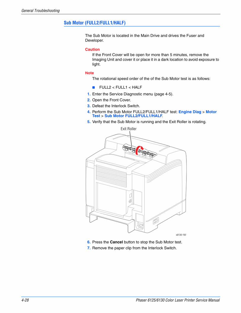
4-28 Phaser 6125/6130 Color Laser Printer Service Manual
General Troubleshooting
Sub Motor (FULL2/FULL1/HALF)
The Sub Motor is located in the Main Drive and drives the Fuser and Developer.
CautionIf the Front Cover will be open for more than 5 minutes, remove the Imaging Unit and cover it or place it in a dark location to avoid exposure to light.
NoteThe rotational speed order of the of the Sub Motor test is as follows:
■ FULL2 < FULL1 < HALF
1. Enter the Service Diagnostic menu (page 4-5).
2. Open the Front Cover.
3. Defeat the Interlock Switch.
4. Perform the Sub Motor FULL2/FULL1/HALF test: Engine Diag > Motor Test > Sub Motor FULL2/FULL1/HALF.
5. Verify that the Sub Motor is running and the Exit Roller is rotating.
6. Press the Cancel button to stop the Sub Motor test.
7. Remove the paper clip from the Interlock Switch.
s6130-192
Exit Roller
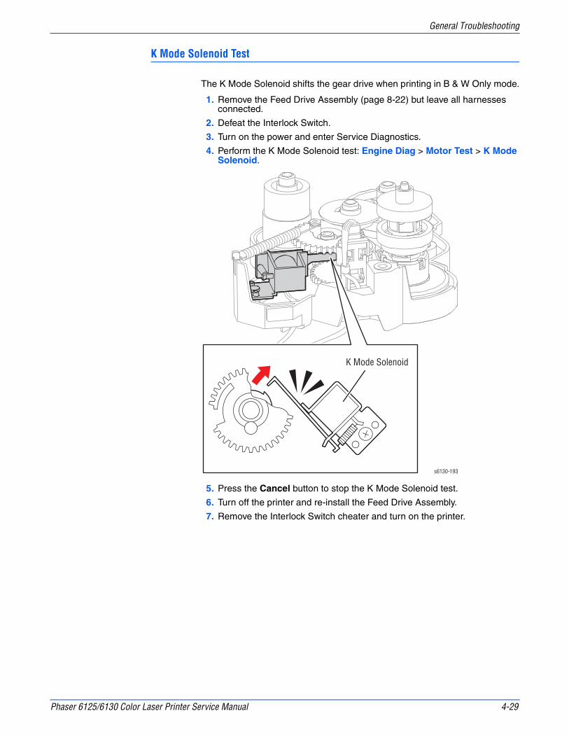
Phaser 6125/6130 Color Laser Printer Service Manual 4-29
General Troubleshooting
K Mode Solenoid Test
The K Mode Solenoid shifts the gear drive when printing in B & W Only mode.
1. Remove the Feed Drive Assembly (page 8-22) but leave all harnesses connected.
2. Defeat the Interlock Switch.
3. Turn on the power and enter Service Diagnostics.
4. Perform the K Mode Solenoid test: Engine Diag > Motor Test > K Mode Solenoid.
5. Press the Cancel button to stop the K Mode Solenoid test.
6. Turn off the printer and re-install the Feed Drive Assembly.
7. Remove the Interlock Switch cheater and turn on the printer.
s6130-193
K Mode Solenoid
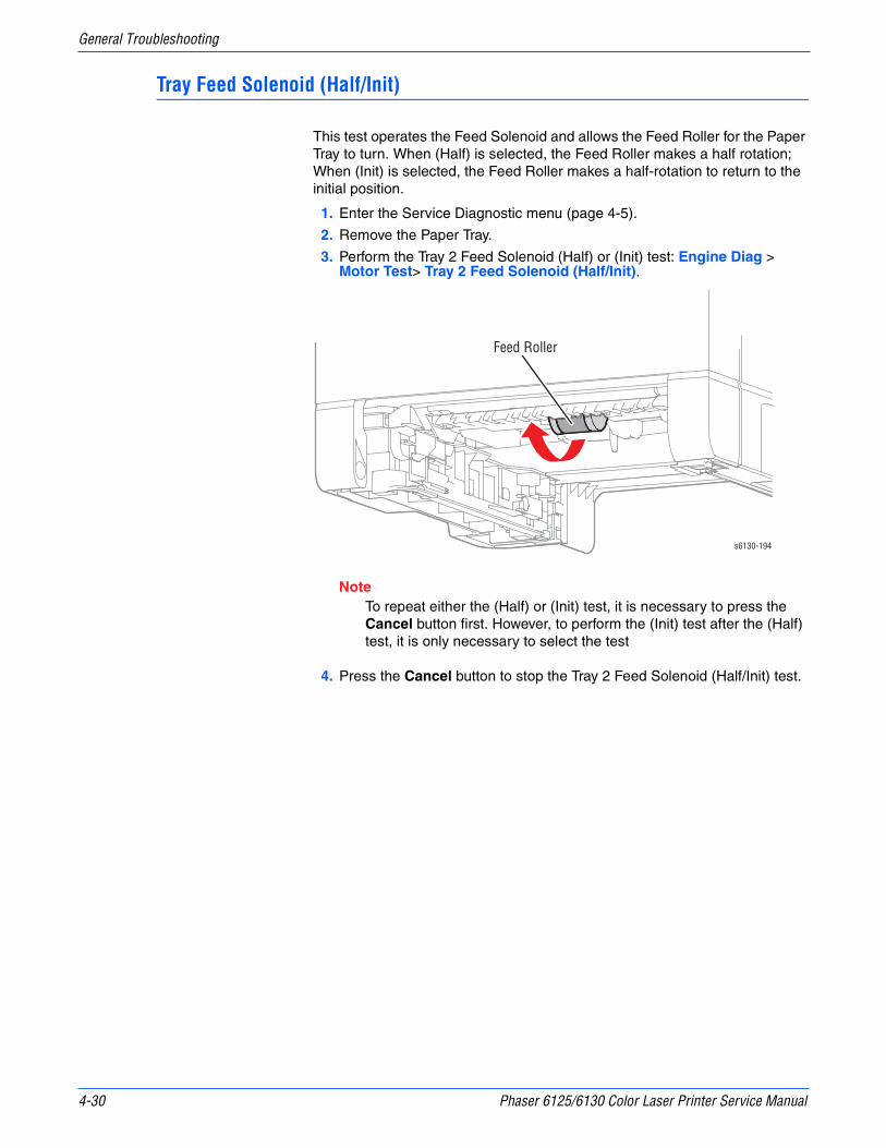
4-30 Phaser 6125/6130 Color Laser Printer Service Manual
General Troubleshooting
Tray Feed Solenoid (Half/Init)
This test operates the Feed Solenoid and allows the Feed Roller for the Paper Tray to turn. When (Half) is selected, the Feed Roller makes a half rotation; When (Init) is selected, the Feed Roller makes a half-rotation to return to the initial position.
1. Enter the Service Diagnostic menu (page 4-5).
2. Remove the Paper Tray.
3. Perform the Tray 2 Feed Solenoid (Half) or (Init) test: Engine Diag > Motor Test> Tray 2 Feed Solenoid (Half/Init).
NoteTo repeat either the (Half) or (Init) test, it is necessary to press the Cancel button first. However, to perform the (Init) test after the (Half) test, it is only necessary to select the test
4. Press the Cancel button to stop the Tray 2 Feed Solenoid (Half/Init) test.
s6130-194
Feed Roller

Phaser 6125/6130 Color Laser Printer Service Manual 4-31
General Troubleshooting
Fan (HIGH/LOW)
NoteThe rotational speed of the Motor is as follows:
■ LOW < HIGH
1. Enter the Service Diagnostic menu (page 4-5).
2. Perform the Fan (HIGH/LOW) test: Engine Diag > Motor Test > Fan (HIGH/LOW).
3. Verify that the fan is running.
4. Press the Cancel button to stop the Fan test.
s6130-195
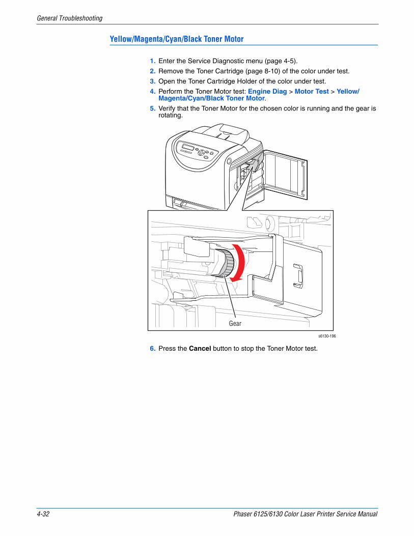
4-32 Phaser 6125/6130 Color Laser Printer Service Manual
General Troubleshooting
Yellow/Magenta/Cyan/Black Toner Motor
1. Enter the Service Diagnostic menu (page 4-5).
2. Remove the Toner Cartridge (page 8-10) of the color under test.
3. Open the Toner Cartridge Holder of the color under test.
4. Perform the Toner Motor test: Engine Diag > Motor Test > Yellow/Magenta/Cyan/Black Toner Motor.
5. Verify that the Toner Motor for the chosen color is running and the gear is rotating.
6. Press the Cancel button to stop the Toner Motor test.
s6130-196
Gear

Phaser 6125/6130 Color Laser Printer Service Manual 4-33
General Troubleshooting
Regi Clutch
The Regi clutch controls the drive to the Registration Roller.
CautionWhen performing this procedure, remove and cover the Imaging Unit to avoid exposure to light.
1. Enter the Service Diagnostic menu (page 4-5).
2. Open the Front Cover.
3. Remove the Imaging Unit (page 8-8).
4. Use a paper clip to secure the Interlock Switch.
5. Perform the Main Motor FULL2 test: Engine Diag > Motor Test > Main Motor FULL2.
6. While the Main Motor is running, press the Up Arrow button to find Regi Clutch. Press the OK button to run the Regi Clutch test.
NoteThe Registration Rollers rotate when the Main Motor FULL2 and the Registration Clutch tests are executed.
7. Verify that the Main Motor is running and the Registration Rollers are rotating.
8. Press the Cancel button to stop the Regi Clutch test.
9. Press the Down Arrow button to find Main Motor FULL2.
10. Press the Cancel button to stop the Main Motor test.
11. Remove the paper clip from the Interlock Switch.
12. Press the Cancel button to stop the ADC Sensor Solenoid test.
13. Remove the paper clip from the Interlock Switch.
s6130-197
Registration Rollers

4-34 Phaser 6125/6130 Color Laser Printer Service Manual
General Troubleshooting
Tray Feed Solenoid (Auto)
Solenoid that controls the drive of the Tray Feed Roll
NoteThis test should performed when the Feed Roller fails to rotate during the Tray 2 Feed Solenoid (Half) test.
CautionIf the front cover will be open for more than 5 minutes, remove the Imaging Unit and cover it or place it in a dark location to avoid exposure to light.
1. Remove the Left Side Cover (page 8-17).
2. Defeat the Front Cover interlock switch.
3. Enter the Service Diagnostic menu (page 4-5).
4. Perform the Tray 2 Feed Solenoid (Auto) test: Engine Diag > Motor Test> Tray 2 Feed Solenoid (Auto).
5. Observe the Feed Solenoid movement.
6. Press the Cancel button to stop the Tray 2 Feed Solenoid (Auto) test.
s6130-198
Tray 1 Feed Solenoid

Phaser 6125/6130 Color Laser Printer Service Manual 4-35
General Troubleshooting
Drum Erase Lamp (K)
CautionWhen performing this procedure, remove and cover the Imaging Unit to avoid exposure to light.
1. Enter the Service Diagnostic menu (page 4-5).
2. Open the Front Cover.
3. Remove the Imaging Unit (page 8-8).
4. Use a paper clip to secure the Interlock Switch.
5. Perform the Drum Erase Lamp K test: Engine Diag > Motor Test > Drum Erase Lamp K.
6. Verify that the Lamp is operating.
7. Press the Cancel button to stop the Drum Erase Lamp K test.
8. Remove the paper clip from the Interlock Switch.
s6130-199
Black Erase Lamp

4-36 Phaser 6125/6130 Color Laser Printer Service Manual
General Troubleshooting
Drum Erase Lamp (Y/M/C)
CautionWhen performing this procedure, remove and cover the Imaging Unit to avoid exposure to light.
1. Enter the Service Diagnostic menu (page 4-5).
2. Open the Front Cover.
3. Remove the Imaging Unit (page 8-8).
4. Use a paper clip to secure the Interlock Switch.
5. Perform the Drum Erase Lamp YMC test: Engine Diag > Motor Test > Drum Erase Lamp YMC.
6. Verify that the Lamps are operating.
7. Press the Cancel button to stop the Drum Erase Lamp YMC test.
8. Remove the paper clip from the Interlock Switch.
s6130-200
Cyan Erase Lamp
Magenta Erase Lamp
Yellow Erase Lamp

Phaser 6125/6130 Color Laser Printer Service Manual 4-37
General Troubleshooting
Control Panel Troubleshooting
Printer Does Not Come to a “Ready” State
1. Reseat connectors on the Image Processor Board (page 8-60).
2. Refer to “DC Power Supply Troubleshooting” on page 4-41.
3. Replace the Control Panel (page 8-13).
4. Replace the Control Panel wiring harness (page 8-54).
Control Panel LED is On, Control Panel Display is Blank
1. Remove and reseat the Image Processor Board (page 8-60).
2. Replace the Control Panel (page 8-13).
3. Replace the Control Panel wiring harness (page 8-54).
4. Replace the Image Processor Board (page 8-60).
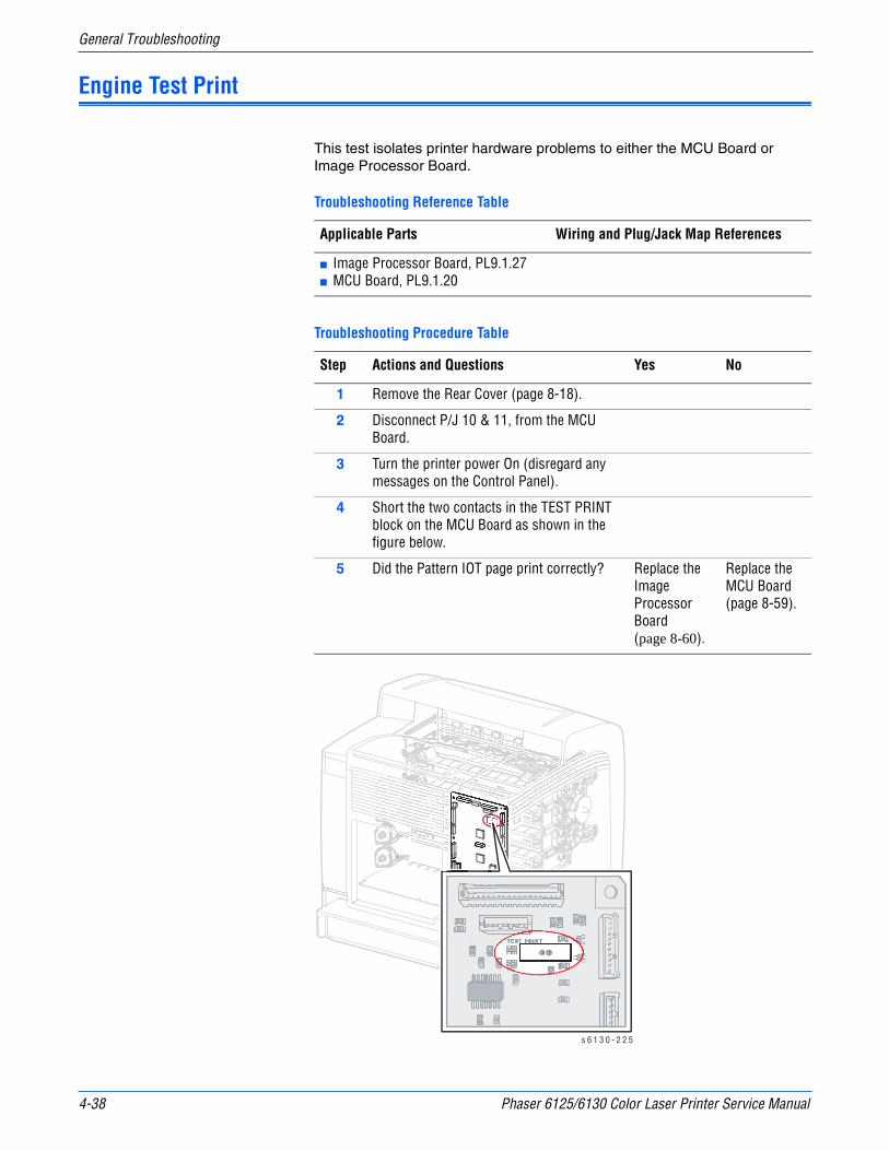
4-38 Phaser 6125/6130 Color Laser Printer Service Manual
General Troubleshooting
Engine Test Print
This test isolates printer hardware problems to either the MCU Board or Image Processor Board.
Troubleshooting Reference Table
Applicable Parts Wiring and Plug/Jack Map References
■ Image Processor Board, PL9.1.27■ MCU Board, PL9.1.20
Troubleshooting Procedure Table
Step Actions and Questions Yes No
1 Remove the Rear Cover (page 8-18).
2 Disconnect P/J 10 & 11, from the MCU Board.
3 Turn the printer power On (disregard any messages on the Control Panel).
4 Short the two contacts in the TEST PRINT block on the MCU Board as shown in the figure below.
5 Did the Pattern IOT page print correctly? Replace the Image Processor Board (page 8-60).
Replace the MCU Board (page 8-59).
s 6 1 3 0 - 2 2 5

Phaser 6125/6130 Color Laser Printer Service Manual 4-39
General Troubleshooting
Inoperable Printer Troubleshooting
Engine Power-Up Sequence
1. Machine Control Unit (MCU) Board logic check
2. Toner Cartridge (Missing, NVRAM (CRUM) Error, CRUM ID, Life Over)
3. Fuser (Missing, NVRAM (CRUM) Error, Life Over)
4. Transfer Unit (Missing, Life Over)
5. ADC Sensor (Error)
6. All paper Sensor (Jam)
7. Door (Open)
8. Environmental (Humidity/Temperature) Sensor (Error)
9. NVRAM (NVRAM Error)
10. Image Processor Board POST Diagnostic check
Printer Continually Displays Warming Up
1. Verify the correct Fuser (110 V vs. 220 V) is installed in the printer.
2. Refer to the Engine Power-Up Sequence (page 4-39).

4-40 Phaser 6125/6130 Color Laser Printer Service Manual
General Troubleshooting
AC Power Supply Troubleshooting
Troubleshooting Reference Table
Applicable Parts Wiring and Plug/Jack References
■ LVPS, PL9.1.4 ■ “DC Power Supply” on page 10-17
Troubleshooting Procedure Table
Step Actions and Questions Yes No
1 Check the voltage at the AC wall outlet. Is there approximately 110 VAC (or 220 VAC if the printer is a 220 V configuration) at the AC wall outlet?
Go to step 2. Notify the customer of improper AC output from the outlet.
2 Check the power cord for defects or a loose connection. Is the power cord loose or defective?
Replace or reconnect the power cord.
Replace the LVPS (page 8-55).

Phaser 6125/6130 Color Laser Printer Service Manual 4-41
General Troubleshooting
DC Power Supply Troubleshooting
LVPS Overcurrent Protection Circuit
This circuit stops all outputs if any of the Low Voltage Power Supply voltages 3.3 VDC, 5 VDC, or 24 VDC are shorted.
The circuit is reset when the short is removed, the power is turned Off, and then On again.
LVPS Overvoltage Protection Circuit
This circuit stops all outputs if the power supply voltage 3.3 VDC, 5 VDC, or 24 VDC exceeds the specified voltage respectively. The operating point is 32 VDC or less for 24 VDC, 7 VDC or less for 5 VDC, or 4.4 VDC for 3.3 VDC.
The circuit is reset when the power is turned Off, and then On again after certain time.
LVPS
Troubleshooting Reference Table
Applicable Parts Wiring and Plug/Jack Map References
■ LVPS, PL8.2.1■ MCU Board, PL8.2.13
■ “Map 4 - Toner Dispenser Motors, HVPS, MCU” on page 10-11■ “DC Power Supply” on page 10-17
Troubleshooting Procedure Table
Step Actions and Questions Yes No
1 Perform the AC power supply troubleshooting procedure. Does the problem persist?
Go to step 2. Complete.
2 Turn the AC power switch Off. Is the Fuse on the low-voltage power supply board open?
Replace the LVPS (page 8-55).
Go to step 3.
3 1. Disconnect the connectors J501 and J502 from the LVPS.
2. Turn the AC power Switch On.3. Measure the DC voltages between the
following pins on the LVPS:■ P501-1 <=> P501-2 = +5 V■ P501-3 <=> P501-4 = +3.3 V■ P502-1 <=> P502-2 = +24 VAre all of the voltages present?
Go to step 4. Replace the LVPS (page 8-55).

4-42 Phaser 6125/6130 Color Laser Printer Service Manual
General Troubleshooting
4 1. Turn the AC power Switch Off.2. Connect J501 to the LVPS then turn the
AC power Switch On.3. Measure the voltage between P501-3 <=>
P501-4?Is there 3.3 V present?
Go to step 7. Go to step 5.
5 Is there obvious damage to the MCU Board, PL8.2.13?
Replace the MCU Board (page 8-59), then go to step 6.
Go to step 7.
6 Does the problem still occur? Go to step 7. Complete.
7 1. Turn the AC power Switch Off.2. Connect J501 to the LVPS then turn the
AC power Switch On.3. Measure the voltage between P501-1 <=>
P501-2.Is there +5 V present?
Go to step 9. Replace the MCU Board (page 8-59), then go to step 8.
8 Does the error still occur? Go to step 9. Complete.
9 1. Turn the AC power Switch Off.2. Connect J502 to the LVPS then turn the
AC power Switch On.3. Measure the voltage between P502-1 <=>
P501-2?Is there +24 V present?
Complete. Go to step 10.
Troubleshooting Procedure Table (continued)
Step Actions and Questions Yes No
Phaser 6125/6130 Color Laser Printer Service Manual 4-43
General Troubleshooting
+24 VDC Interlock Switch
Troubleshooting Reference Table
Applicable Parts Wiring and Plug/Jack Map References
■ Interlock Harness, PL8.2.5■ LVPS, PL8.2.1■ Top LV Harness, PL10.1.16
■ “Map 4 - Toner Dispenser Motors, HVPS, MCU” on page 10-11■ “DC Power Supply” on page 10-17
Troubleshooting Procedure Table
Step Actions and Questions Yes No
1 Check the Interlock Harness for continuity.1. Disconnect P/J44.2. Check continuity between P/J44-1 <=> P/
J44-3.Is the circuit continuous when the Interlock is activated?
Complete Replace the Interlock Harness (page 8-54).

4-44 Phaser 6125/6130 Color Laser Printer Service Manual
General Troubleshooting
Abnormal Noise and Electrical Problems
Abnormal Noise When Power is Turned On
Troubleshooting Reference Table
Applicable Parts Wiring and Plug/Jack Map References
■ Imaging Unit (PL4.1.21) ■ Fuser (PL6.1.1)■ Transfer Unit (PL6.1.7)■ Sub Drive Assembly (PL7.1.1)■ Main Drive Assembly (PL7.1.2)
Troubleshooting Procedure Table
Step Actions and Questions Yes No
1 Perform the Main Motor test (page 4-27): Service Mode > Engine Diag > Motor Test > Main Motor FULL2.Is the noise still present?
Go to step 2. Go to step 5.
2 1. Reseat the Imaging Unit.2. Perform the Main Motor test (page 4-27):
Service Mode > Engine Diag > Motor Test > Main Motor FULL2.
Is the noise still present?
Go to step 3. Complete
3 1. Reseat the connectors on the Transfer Unit.
2. Perform the Main Motor test (page 4-27): Service Mode > Engine Diag > Motor Test > Main Motor FULL2.
Is the noise still present?
Go to step 4. Complete
4 1. Reseat the Main Drive Assembly.2. Perform the Main Motor test (page 4-27):
Service Mode > Engine Diag > Motor Test > Main Motor FULL2.
Is the noise still present?
Try replacing one after another: ■ Imaging Unit (page 8-8)■ Transfer Unit (page 8-41) ■ Main Drive Assembly (page 8-52).
Complete
5 Perform the Sub Motor test (page 4-28): Service Mode > Engine Diag > Motor Test > Sub Motor FULL2.Is the noise still present?
Go to step 6. Check the installation situation of printer.
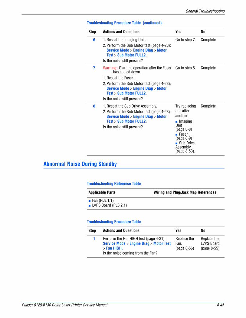
Phaser 6125/6130 Color Laser Printer Service Manual 4-45
General Troubleshooting
Abnormal Noise During Standby
6 1. Reseat the Imaging Unit.2. Perform the Sub Motor test (page 4-28):
Service Mode > Engine Diag > Motor Test > Sub Motor FULL2.
Is the noise still present?
Go to step 7. Complete
7 Warning: Start the operation after the Fuser has cooled down.
1. Reseat the Fuser.2. Perform the Sub Motor test (page 4-28):
Service Mode > Engine Diag > Motor Test > Sub Motor FULL2.
Is the noise still present?
Go to step 8. Complete
8 1. Reseat the Sub Drive Assembly.2. Perform the Sub Motor test (page 4-28):
Service Mode > Engine Diag > Motor Test > Sub Motor FULL2.
Is the noise still present?
Try replacing one after another:■ Imaging Unit (page 8-8)■ Fuser (page 8-9)■ Sub Drive Assembly (page 8-53).
Complete
Troubleshooting Reference Table
Applicable Parts Wiring and Plug/Jack Map References
■ Fan (PL8.1.1)■ LVPS Board (PL8.2.1)
Troubleshooting Procedure Table
Step Actions and Questions Yes No
1 Perform the Fan HIGH test (page 4-31): Service Mode > Engine Diag > Motor Test > Fan HIGH.Is the noise coming from the Fan?
Replace the Fan. (page 8-56)
Replace the LVPS Board. (page 8-55)
Troubleshooting Procedure Table (continued)
Step Actions and Questions Yes No
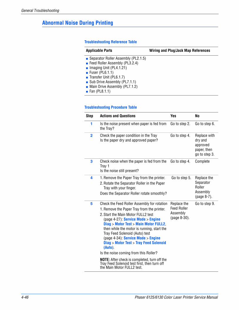
4-46 Phaser 6125/6130 Color Laser Printer Service Manual
General Troubleshooting
Abnormal Noise During Printing
Troubleshooting Reference Table
Applicable Parts Wiring and Plug/Jack Map References
■ Separator Roller Assembly (PL2.1.5)■ Feed Roller Assembly (PL3.2.4)■ Imaging Unit (PL4.1.21) ■ Fuser (PL6.1.1)■ Transfer Unit (PL6.1.7)■ Sub Drive Assembly (PL7.1.1)■ Main Drive Assembly (PL7.1.2)■ Fan (PL8.1.1)
Troubleshooting Procedure Table
Step Actions and Questions Yes No
1 Is the noise present when paper is fed from the Tray?
Go to step 2. Go to step 6.
2 Check the paper condition in the TrayIs the paper dry and approved paper?
Go to step 4. Replace with dry and approved paper, then go to step 3.
3 Check noise when the paper is fed from the Tray 1 Is the noise still present?
Go to step 4. Complete
4 1. Remove the Paper Tray from the printer.2. Rotate the Separator Roller in the Paper
Tray with your finger.Does the Separator Roller rotate smoothly?
Go to step 5. Replace the Separator Roller Assembly (page 8-7).
5 Check the Feed Roller Assembly for rotation1. Remove the Paper Tray from the printer.2. Start the Main Motor FULL2 test
(page 4-27): Service Mode > Engine Diag > Motor Test > Main Motor FULL2, then while the motor is running, start the Tray Feed Solenoid (Auto) test (page 4-34): Service Mode > Engine Diag > Motor Test > Tray Feed Solenoid (Auto).
Is the noise coming from this Roller?
NOTE: After check is completed, turn off the Tray Feed Solenoid test first, then turn off the Main Motor FULL2 test.
Replace the Feed Roller Assembly (page 8-30).
Go to step 9.
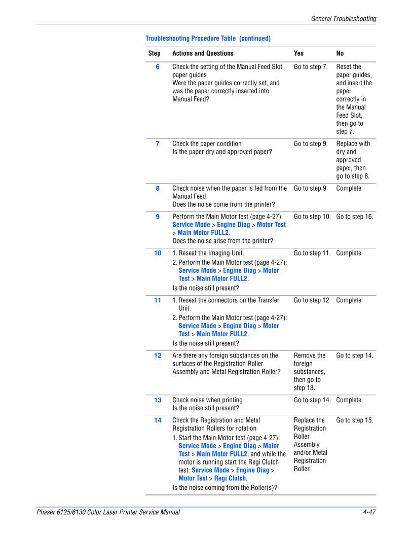
Phaser 6125/6130 Color Laser Printer Service Manual 4-47
General Troubleshooting
6 Check the setting of the Manual Feed Slot paper guides Were the paper guides correctly set, and was the paper correctly inserted into Manual Feed?
Go to step 7. Reset the paper guides, and insert the paper correctly in the Manual Feed Slot, then go to step 7.
7 Check the paper conditionIs the paper dry and approved paper?
Go to step 9. Replace with dry and approved paper, then go to step 8.
8 Check noise when the paper is fed from the Manual FeedDoes the noise come from the printer?
Go to step 9 Complete
9 Perform the Main Motor test (page 4-27): Service Mode > Engine Diag > Motor Test > Main Motor FULL2. Does the noise arise from the printer?
Go to step 10. Go to step 16.
10 1. Reseat the Imaging Unit.2. Perform the Main Motor test (page 4-27):
Service Mode > Engine Diag > Motor Test > Main Motor FULL2.
Is the noise still present?
Go to step 11. Complete
11 1. Reseat the connectors on the Transfer Unit.
2. Perform the Main Motor test (page 4-27): Service Mode > Engine Diag > Motor Test > Main Motor FULL2.
Is the noise still present?
Go to step 12. Complete
12 Are there any foreign substances on the surfaces of the Registration Roller Assembly and Metal Registration Roller?
Remove the foreign substances, then go to step 13.
Go to step 14.
13 Check noise when printingIs the noise still present?
Go to step 14. Complete
14 Check the Registration and Metal Registration Rollers for rotation1. Start the Main Motor test (page 4-27):
Service Mode > Engine Diag > Motor Test > Main Motor FULL2, and while the motor is running start the Regi Clutch test: Service Mode > Engine Diag > Motor Test > Regi Clutch.
Is the noise coming from the Roller(s)?
Replace the Registration Roller Assembly and/or Metal Registration Roller.
Go to step 15.
Troubleshooting Procedure Table (continued)
Step Actions and Questions Yes No
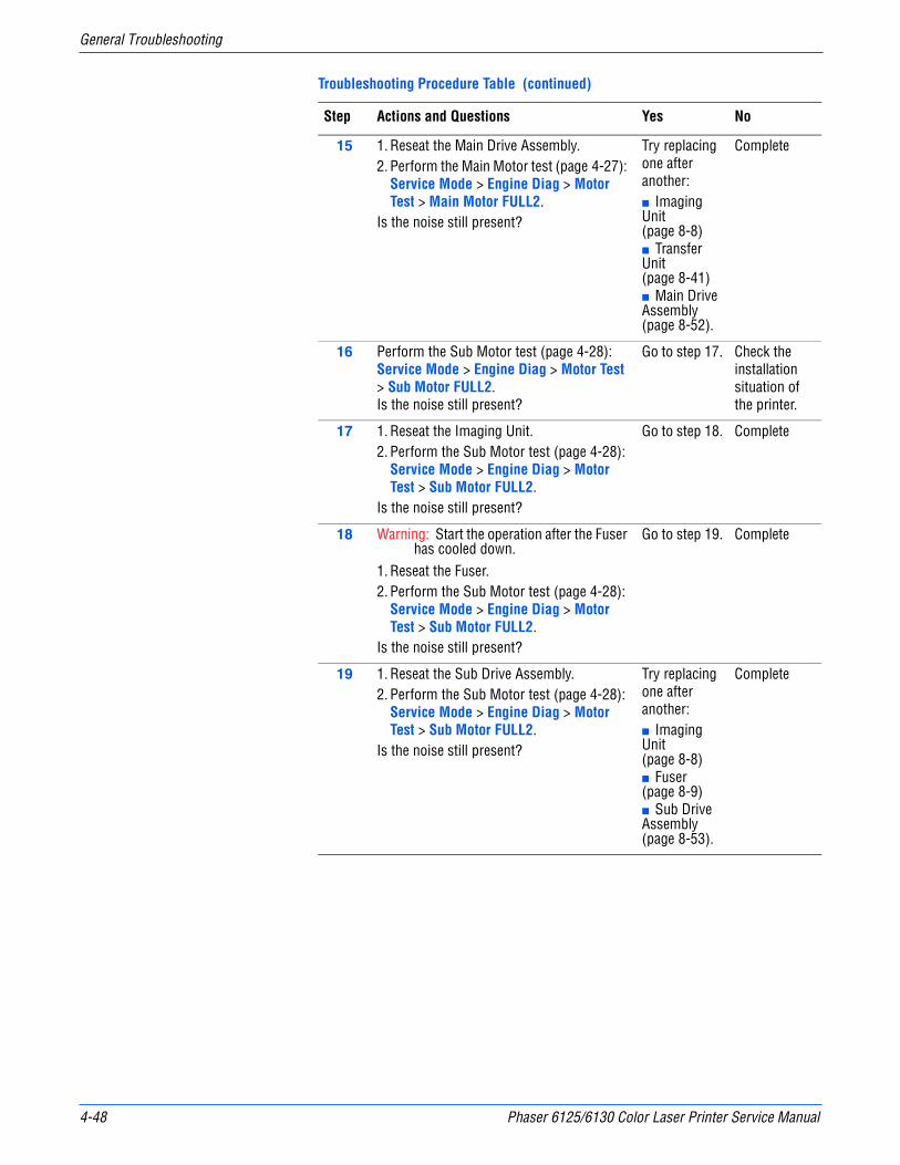
4-48 Phaser 6125/6130 Color Laser Printer Service Manual
General Troubleshooting
15 1. Reseat the Main Drive Assembly.2. Perform the Main Motor test (page 4-27):
Service Mode > Engine Diag > Motor Test > Main Motor FULL2.
Is the noise still present?
Try replacing one after another: ■ Imaging Unit (page 8-8)■ Transfer Unit (page 8-41) ■ Main Drive Assembly (page 8-52).
Complete
16 Perform the Sub Motor test (page 4-28): Service Mode > Engine Diag > Motor Test > Sub Motor FULL2.Is the noise still present?
Go to step 17. Check the installation situation of the printer.
17 1. Reseat the Imaging Unit.2. Perform the Sub Motor test (page 4-28):
Service Mode > Engine Diag > Motor Test > Sub Motor FULL2.
Is the noise still present?
Go to step 18. Complete
18 Warning: Start the operation after the Fuser has cooled down.
1. Reseat the Fuser.2. Perform the Sub Motor test (page 4-28):
Service Mode > Engine Diag > Motor Test > Sub Motor FULL2.
Is the noise still present?
Go to step 19. Complete
19 1. Reseat the Sub Drive Assembly.2. Perform the Sub Motor test (page 4-28):
Service Mode > Engine Diag > Motor Test > Sub Motor FULL2.
Is the noise still present?
Try replacing one after another:■ Imaging Unit (page 8-8)■ Fuser (page 8-9)■ Sub Drive Assembly (page 8-53).
Complete
Troubleshooting Procedure Table (continued)
Step Actions and Questions Yes No

Phaser 6125/6130 Color Laser Printer Service Manual 4-49
General Troubleshooting
Electrical Noise
There is a variable pitch sound coming from the printer. Electrical noise can be either noise in the electrical lines or static in electromagnetic communications.
Initial Actions
■ Cycle printer power.
■ If the problem persists, follow the procedure below.
Troubleshooting Reference Table
Applicable Parts Wiring and Plug/Jack Map References
■ HVPS, PL4.1.19■ Transfer Unit, PL6.1.7■ Imaging Unit, PL4.1.21
Troubleshooting Procedure Table
Step Actions and Questions Yes No
1 Check external noise.1. Are there other electrical appliances
within 3 meters of the printer?2. Turn the electrical appliances Off or
relocate the printer at least 6 meters away from other electrical appliances.
Does the error still occur?
Go to step 2. Complete
2 Check the AC groundIs AC power supply outlet wired and grounded appropriately?
Go to step 3. Request the client to fix AC power supply outlet.
3 1. Open the Front Cover.2. Inspect the four Transfer Unit HV
connections.Are the four terminals on the Transfer Unit, and the four springs on the frame (PL4.1.11, 12, 13 and 14) dirty and/or deformed?
Clean or replace the Transfer Unit (page 8-41) or clean the spring(s).
Go to step 4.
4 Check the Imaging Unit connection1. Remove the Imaging Unit.2. Inspect the five Imaging Unit HV
connections.Are the five HV terminals on the Imaging Unit, and five springs on the frame (PL4.1.10 and PL4.1.15 to 18) dirty and/or deformed?
Clean and/or replace the Imaging Unit (page 8-8) or clean the spring(s).
Go to step 5.

4-50 Phaser 6125/6130 Color Laser Printer Service Manual
General Troubleshooting
AC Supply Problems
5 Reseat the Imaging Unit.Does the electrical noise error still occur?
Go to step 6. Complete
6 Reseat the Transfer Unit.Does the electrical noise error still occur?
Reseat the HVPS.
Complete
Troubleshooting Reference Table
Applicable Parts Wiring and Plug/Jack Map References
■ LVPS, PL8.2.1
Troubleshooting Procedure Table
Step Actions and Questions Yes No
1 NOTE: During this test, close the Front Cover.Does the motor noise occur when the power is turned on?
Go to FIP-DC. Go to step 2.
2 1. Connect the printer power cord to another electrical outlet.
2. Turn the printer power On.Does the printer operate normally?
Complete Go to step 3.
3 1. Turn the printer power Off.2. Reconnect the printer power cord.3. Turn the printer power On.Does the printer operate normally?
Complete Go to step 4.
4 Test the GFI Breaker Does the GFI Breaker operate normally?
Complete Go to step 5.
5 1. Turn the printer power Off.2. Disconnect the power cord and wait for
one minute.3. Reseat the LVPS connectors.4. Turn the printer power On. Does the printer operate normally?
Complete Go to step 6.
6 1. Turn the printer power Off.2. Disconnect the printer power cord and
wait for one minute.3. Reconnect the power cord.4. Turn the printer power On. Does the printer operate normally?
Complete Replace the LVPS Board. (Refer to Removal 13/ Replacement 40.)
Troubleshooting Procedure Table (continued)
Step Actions and Questions Yes No
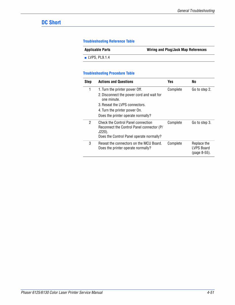
Phaser 6125/6130 Color Laser Printer Service Manual 4-51
General Troubleshooting
DC Short
Troubleshooting Reference Table
Applicable Parts Wiring and Plug/Jack Map References
■ LVPS, PL9.1.4
Troubleshooting Procedure Table
Step Actions and Questions Yes No
1 1. Turn the printer power Off.2. Disconnect the power cord and wait for
one minute.3. Reseat the LVPS connectors.4. Turn the printer power On. Does the printer operate normally?
Complete Go to step 2.
2 Check the Control Panel connectionReconnect the Control Panel connector (P/J220).Does the Control Panel operate normally?
Complete Go to step 3.
3 Reseat the connectors on the MCU Board.Does the printer operate normally?
Complete Replace the LVPS Board (page 8-55).
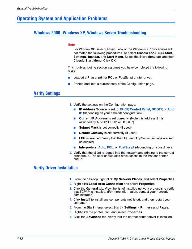
4-52 Phaser 6125/6130 Color Laser Printer Service Manual
General Troubleshooting
Operating System and Application Problems
Windows 2000, Windows XP, Windows Server Troubleshooting
NoteFor Window XP, select Classic Look or the Windows XP procedures will not match the following procedures. To select Classic Look, click Start, Settings, Taskbar, and Start Menu. Select the Start Menu tab, and then Classic Start Menu. Click OK.
This troubleshooting section assumes you have completed the following tasks.
■ Loaded a Phaser printer PCL or PostScript printer driver.
■ Printed and kept a current copy of the Configuration page.
Verify Settings
1. Verify the settings on the Configuration page.
■ IP Address Source is set to: DHCP, Control Panel, BOOTP, or Auto IP (depending on your network configuration).
■ Current IP Address is set correctly. (Note this address if it is assigned by Auto IP, DHCP, or BOOTP.)
■ Subnet Mask is set correctly (if used).
■ Default Gateway is set correctly (if used).
■ LPR is enabled. Verify that the LPR and AppSocket settings are set as desired.
■ Interpreters: Auto, PCL, or PostScript (depending on your driver).
2. Verify that the client is logged into the network and printing to the correct print queue. The user should also have access to the Phaser printer queue.
Verify Driver Installation
1. From the desktop, right-click My Network Places, and select Properties.
2. Right-click Local Area Connection and select Properties.
3. Click the General tab. View the list of installed network protocols to verify that TCP/IP is installed. (For more information, contact your network administrator.)
4. Click Install to install any components not listed, and then restart your computer.
5. From the Start menu, select Start > Settings > Printers and Faxes.
6. Right-click the printer icon, and select Properties.
7. Click the Advanced tab. Verify that the correct printer driver is installed.

Phaser 6125/6130 Color Laser Printer Service Manual 4-53
General Troubleshooting
8. Click the Ports tab. Verify that the IP Address in the Print to the Following Ports list is identical to the one on the Configuration page. You may need to click the Configure Port button to see the IP address. If necessary, re-select the TCP/IP number used for the printer.
Macintosh Troubleshooting (Mac OS 10.2 and Higher)
The following procedures eliminates cabling, communication, and connection problems. Once you complete these steps, print a test page from your software application.
NoteIf the job prints, no further system troubleshooting is necessary. If there are print-quality problems, refer to the User Guide at www.xerox.com/office/support.
Macintosh Troubleshooting OS 10.2 Step-by-Step
Perform these steps only for Mac OS 10.2 and higher.
1. For AppleTalk, perform the steps below. For TCP/IP, proceed to step 2.
a. From the printer’s Control Panel, verify that the EtherTalk is enabled. If it not, enable EtherTalk, and reset the printer.
b. Print the Configuration page and verify that EtherTalk is enabled.c. From the Configuration page, verity the Zone. If you have multiple
zones on your network, verify that your printer appears in the desired zone.
2. Open the Network Utility and click the Ping tab.
3. Enter the printer’s IP address.
4. Click Ping. If you do not get a response, verify that your TCP/IP settings are correct for your printer and computer.
NoteSee also: www.xerox.com/office/support

4-54 Phaser 6125/6130 Color Laser Printer Service Manual
General Troubleshooting
UNIX / Linux
This section includes:
■ Quick Install Steps
■ Additional Resources
Your printer supports connection to a variety of UNIX platforms through the Parallel and Network interface. The workstations currently supported by CentreWare for UNIX/Linux to a network-connected printer are:
■ Sun Solaris
■ IBM AIX
■ Hewlett-Packard HP-UX
■ Linux (i386) tested on SUSE 10.0, RedHat 9, Fedora Core1
The following procedures enable you to connect your printer using any of the supported versions of UNIX or Linux listed above.
Quick Install Steps
Perform the following procedures to set up the printer and install the appropriate drivers.
From the Printer
To set up the printer:
1. Verify that both TCP/IP protocol and the proper connector are enabled.
2. On the Control Panel, select one of these IP address options:
■ Allow the printer to set up a DHCP address
■ Enter the IP address manually
3. Print the Configuration page and keep it for reference.
From Your Computer
To install the CentreWare for Unix driver:
1. Go to www.xerox.com/office/drivers.
2. Select your printer, the platform your are running (UNIX), and file type (Drivers).
3. Click Go to Downloads.
4. From the list of provided files, download the PrinterPackageXPXX and the appropriate CentreWare printer driver for your platform <OS>XPXX 4.xx.x.tar.
a. As root, untar the Driver and Printer package, this will create two subdirectories. Cd to <O/S>InstallPackage and type ./setup to install the driver.
b. CD to the PrinterPackagexpxx and type ./setup to install the printer specific data files.

Phaser 6125/6130 Color Laser Printer Service Manual 4-55
General Troubleshooting
c. Type xpadmin to open the admin tool for creating print queues. Select the printer from the list of discovered printers you want to print to. Click on the printer icon at the top left of the screen to add a print queue.
5. Print a test page and verify the print quality of the printed page.
NoteIf print-quality problem exists, or your job did not print, refer to the User Guide at www.xerox.com/office/support.
Additional Resources
For users that want to use the CUPS driver instead of CentreWare for Unix, access the Xerox web site for the latest CUPS ppd package at www.xerox.com/office/drivers. To download printer drivers:
1. Find your printer. Click the Drivers & Downloads link. Select the platform you are running (UNIX), and the files you would like to download (Drivers).
2. Click the Go button.
3. Click the CUPSPrinterPackage.
4. Untar the printer package and select the ppd for the printer you want to install.
5. Copy the file to /usr/share/cups/model/Xerox. (This is the directory for SUSE10.1. The directory may not be in the same location on other Linux versions).
6. Open the printer manager supplied for the Linux release and follow the instructions for adding a print queue.
NoteThe print daemon may need restarting for the print manager to see the new PPD added to the CUPS ppd directory.

4-56 Phaser 6125/6130 Color Laser Printer Service Manual
General Troubleshooting
5Chapter
Print-Quality Troubleshooting
In this chapter...■ Print-Quality Problems Overview
■ Checklist Before Troubleshooting Print-Quality
■ Test Prints
■ Print-Quality Specifications
■ Print-Quality Troubleshooting
5-2 Phaser 6125/6130 Color Laser Printer Service Manual
Print-Quality Troubleshooting
Print-Quality Problems Overview
Print-quality defects can be attributed to printer components, consumables, media, internal software, external software applications, and environmental conditions. To successfully troubleshoot print-quality problems, eliminate as many variables as possible. The first step is to generate prints using information pages embedded in the printer on laser paper from the approved media list. Refer to “Media and Tray Specifications” on page 1-19 for supported and specialty media that have been tested and approved for use in the Phaser 6130 Color Laser Printer. Use paper from a fresh ream that is acclimated to room temperature and humidity.
If the print-quality defect is still present when printing on approved media from an unopened ream of paper, then investigate software applications and environmental conditions.
Print the Configuration page to determine the temperature and humidity under which the printer is operating. Compare this to the “Environmental Specifications” on page 1-13. Extreme temperature and humidity can adversely affect the xerographic and fusing characteristics of the printer.
When analyzing a print-quality defect, first determine if the defect occurs in all colors or only one color and if it is repeating or random occurrence. Continuous defects in the process direction, such as Voids and Lines, are the most difficult to diagnose. Inspect the visible surfaces of all Rollers for obvious defect. If no defects are found, replace the Imaging Unit, Laser Unit, Transfer Unit, and Fuser one at a time until the defect is eliminated.
Defects Associated with Specific Printer Components
Some print-quality problems can be associated with specific assemblies; the most common problems and the associated assemblies are listed in this section. Refer to the specific print-quality troubleshooting procedure for detail information.
Laser Unit
■ Light or Undertone Print
■ Blank Print (No Print)
■ Black Print
■ Vertical Blank Lines
■ Horizontal Band, Voids, or Streaks
■ Vertical Stripes
■ Horizontal Stripes
■ Partial Band
■ Random Spots
■ Repeating Bands, Lines, Marks, or Spots

Phaser 6125/6130 Color Laser Printer Service Manual 5-3
Print-Quality Troubleshooting
Transfer Unit
■ Light or Undertone Print
■ Horizontal Band, Voids, or Streaks
■ Vertical Stripes
■ Horizontal Stripes
■ Partial Band
■ Random Spots
■ Repeating Bands, Lines, Marks, or Spots
■ Background Contamination
Fuser
■ Vertical Stripes
■ Horizontal Stripes
■ Repeating Bands, Lines, Marks, or Spots
■ Unfused Image
Imaging Unit
■ Light or Undertone Print
■ Blank Print (No Print)
■ Black Print
■ Vertical Blank Lines
■ Horizontal Band, Voids, or Streaks
■ Vertical Stripes
■ Horizontal Stripes
■ Partial Band
■ Random Spots
■ Repeating Bands, Lines, Marks, or Spots
■ Background Contamination
■ Unfused Image

5-4 Phaser 6125/6130 Color Laser Printer Service Manual
Print-Quality Troubleshooting
Checklist Before Troubleshooting Print-Quality
Checking the Printer Condition
Toner
Low toner can cause print-quality problems, such as Fading, Streaking, White Lines, or Dropouts. Print a small document from different software applications to replicate the problem and check the amount of toner available. Use the CentreWare Internet Services (IS) to check the supplies status. To access the CentreWare IS:
1. Open your web browser.
2. In the Address field, enter the printer IP address.
3. Click the Status button.
4. Click the Supplies button.
5. The Supplies Status is displayed.
If the toner is low, you can extend the Toner Cartridge life by removing it from the printer, and gently shaking the Toner Cartridge from side-to-side.
Cleaning
Paper, toner, and dust particles can accumulate inside the printer and cause print-quality problems such as Smearing or Toner Specks. Clean the inside of the printer to prevent these problems.

Phaser 6125/6130 Color Laser Printer Service Manual 5-5
Print-Quality Troubleshooting
Checklist
Check the following items prior to performing troubleshooting. These procedures may help to resolve the problems without troubleshooting the printer.
1. Color is out of alignment.
NoteThis problem can occur after installing a new black Toner Cartridge if the Imaging Unit has not been cleaned.
a. Clean inside the printer.
2. Print is too light.
a. The toner may be too low. Check the amount of toner and change the Toner Cartridges if necessary.
b. In the printer Printing Preferences menu, Advanced > Details > Draft Mode, verify Off is selected.
c. If you are printing on an uneven print surface, change the paper type settings in the Tray Settings menu.
d. Verify that the correct type of paper is being used.
e. The Imaging Unit needs to be replaced.
3. Toner smears or print comes off page.
a. If you are printing on an uneven print surface, change the Media Type settings in the Tray Settings menu.
b. Verify that the paper is within the printer specifications (refer to “Media and Tray Specifications” on page 1-19).
Color Registration
Light or Undertone Print
Smudges or Smears
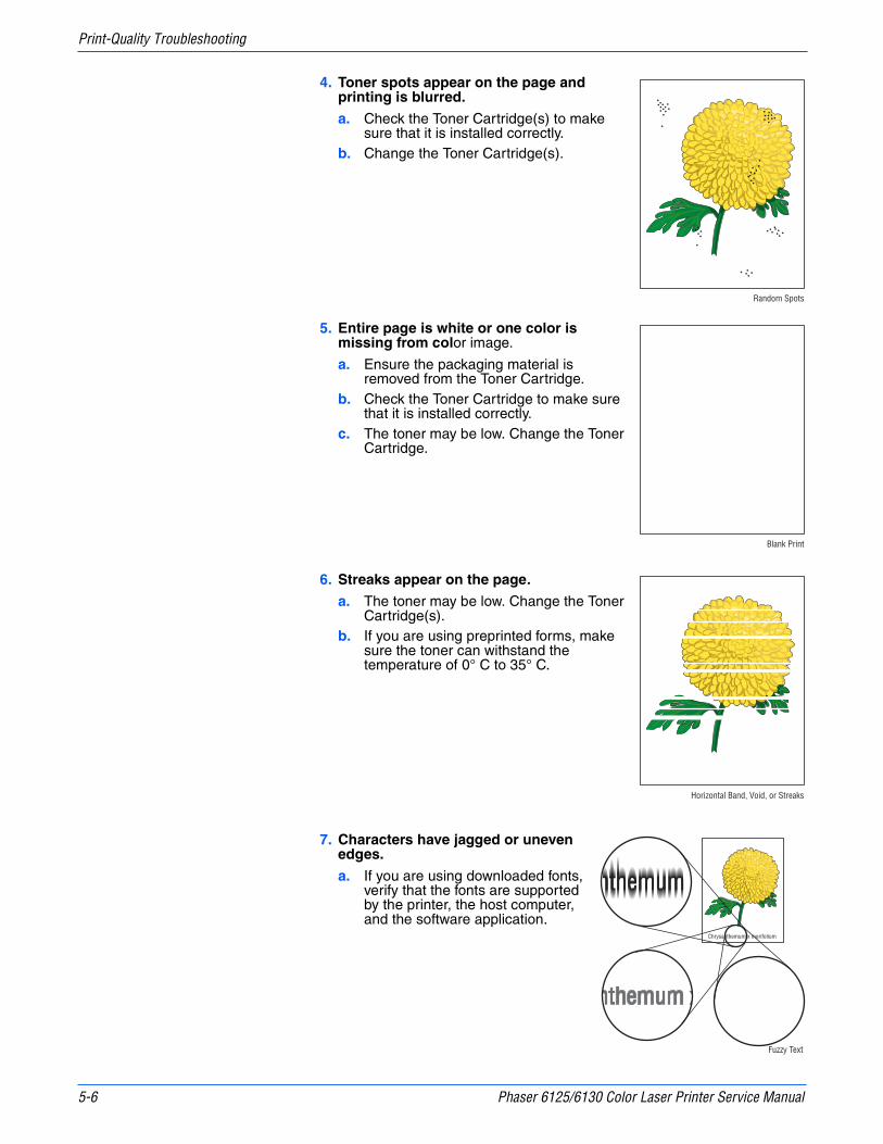
5-6 Phaser 6125/6130 Color Laser Printer Service Manual
Print-Quality Troubleshooting
4. Toner spots appear on the page and printing is blurred.
a. Check the Toner Cartridge(s) to make sure that it is installed correctly.
b. Change the Toner Cartridge(s).
5. Entire page is white or one color is missing from color image.
a. Ensure the packaging material is removed from the Toner Cartridge.
b. Check the Toner Cartridge to make sure that it is installed correctly.
c. The toner may be low. Change the Toner Cartridge.
6. Streaks appear on the page.
a. The toner may be low. Change the Toner Cartridge(s).
b. If you are using preprinted forms, make sure the toner can withstand the temperature of 0° C to 35° C.
7. Characters have jagged or uneven edges.
a. If you are using downloaded fonts, verify that the fonts are supported by the printer, the host computer, and the software application.
Random Spots
Blank Print
Horizontal Band, Void, or Streaks
Fuzzy Text
Chrysanthemum x morifolium
nthemum xnthemum x
nthemum xChrysanthemum x morifoliumnthemum xChrysanthemum x morifolium

Phaser 6125/6130 Color Laser Printer Service Manual 5-7
Print-Quality Troubleshooting
8. Part or all the page prints in cyan, magenta, yellow, or black.
a. Check the Toner Cartridges to make sure they are installed correctly.
9. The job prints, but the top and side margins are incorrect.
a. Make sure the Paper Size setting in the Tray Settings is correct.
b. Make sure the margins are set correctly in your software application.
Partial Band
Image Not Centered
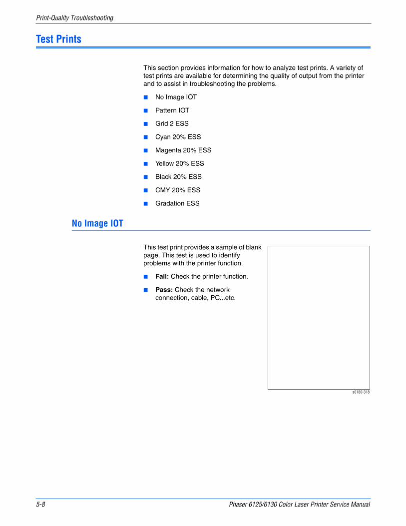
5-8 Phaser 6125/6130 Color Laser Printer Service Manual
Print-Quality Troubleshooting
Test Prints
This section provides information for how to analyze test prints. A variety of test prints are available for determining the quality of output from the printer and to assist in troubleshooting the problems.
■ No Image IOT
■ Pattern IOT
■ Grid 2 ESS
■ Cyan 20% ESS
■ Magenta 20% ESS
■ Yellow 20% ESS
■ Black 20% ESS
■ CMY 20% ESS
■ Gradation ESS
No Image IOT
This test print provides a sample of blank page. This test is used to identify problems with the printer function.
■ Fail: Check the printer function.
■ Pass: Check the network connection, cable, PC...etc.
s6180-318

Phaser 6125/6130 Color Laser Printer Service Manual 5-9
Print-Quality Troubleshooting
Pattern IOT
This test print provides the printer’s built-in test pattern. This test is used to identify problems with the printer function or the Image Processor Board. The colors should be aligned vertically and horizontally. Compare the print with the following chart to determine the problem.
■ Fail: Check the printer controller or the MCU Board.
■ Pass: Check the Image Processor Board.
Grid 2 ESS
This test print provides the Controller built-in grid pattern sample. This test is used to identify problems with the printer function. Compare the print with following chart to determine the problem.
■ Fail: Check the printer function and the Image Processor Board.
■ Pass: Check the network connection, cable, PC...etc.
s6180-152
s6180-390

5-10 Phaser 6125/6130 Color Laser Printer Service Manual
Print-Quality Troubleshooting
Cyan 20% ESS
This test print provides 20% cyan density on the whole page. This test is used to identify problems with cyan toner or another color toner. Compare the print with the following chart to determine the problem.
■ Fail: Check the cyan Toner Cartridge.
■ Pass: Check another Toner Cartridge.
Magenta 20% ESS
This test print provides 20% magenta density on the whole page. This test is used to identify problems with magenta toner or another color toner. Compare the print with the following chart to determine the problem.
■ Fail: Check the magenta Toner Cartridge.
■ Pass: Check another Toner Cartridge.
s6180-391
s6180-392
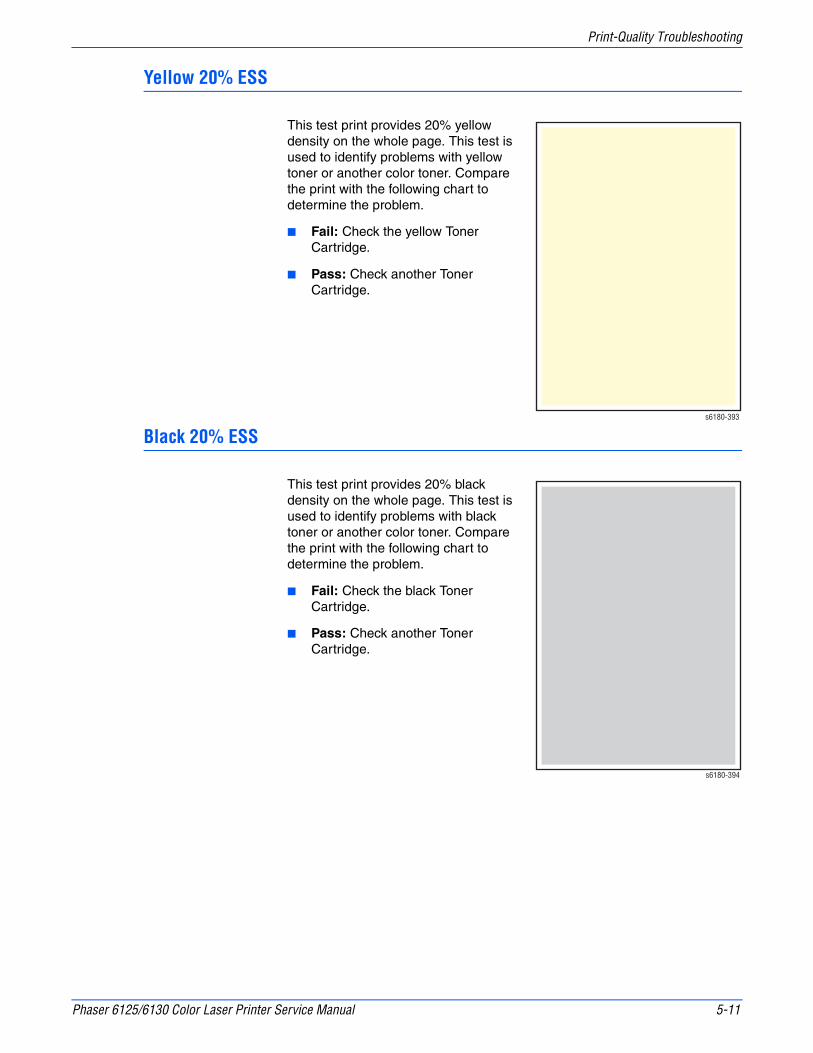
Phaser 6125/6130 Color Laser Printer Service Manual 5-11
Print-Quality Troubleshooting
Yellow 20% ESS
This test print provides 20% yellow density on the whole page. This test is used to identify problems with yellow toner or another color toner. Compare the print with the following chart to determine the problem.
■ Fail: Check the yellow Toner Cartridge.
■ Pass: Check another Toner Cartridge.
Black 20% ESS
This test print provides 20% black density on the whole page. This test is used to identify problems with black toner or another color toner. Compare the print with the following chart to determine the problem.
■ Fail: Check the black Toner Cartridge.
■ Pass: Check another Toner Cartridge.
s6180-393
s6180-394

5-12 Phaser 6125/6130 Color Laser Printer Service Manual
Print-Quality Troubleshooting
CMY 20% ESS
This test print provides 20% density for combination of cyan, magenta, and black on the whole page. This test is used to identify problems with balance of three color toners or another toner. Compare the print with the following chart to determine the problem.
■ Fail: Check the cyan, magenta, or yellow Toner Cartridge.
■ Pass: Check the black Toner Cartridge.
Gradation ESS
This test print provides 2 - 100% density for cyan, magenta, yellow, or black on the whole page. This test is used to identify problems with the printer function or the Image Processor Board. Compare the print with the following chart to determine the problem.
■ Fail: Check the printer function.
■ Pass: Check the Image Processor Board.
s6180-395
s6180-396
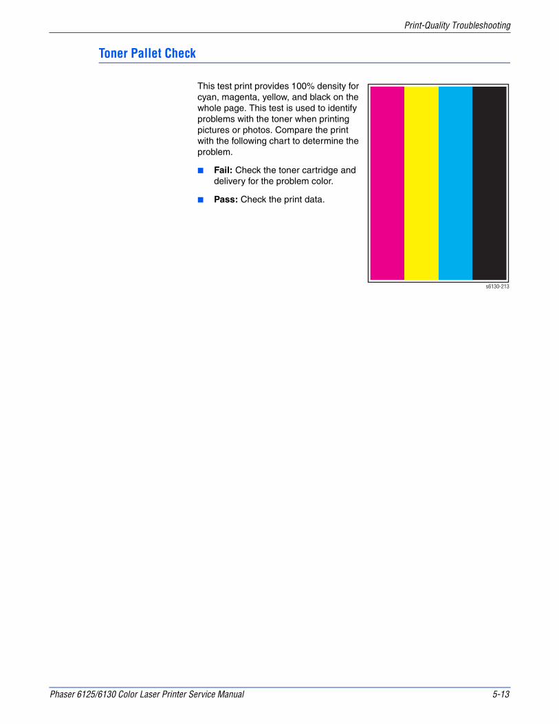
Phaser 6125/6130 Color Laser Printer Service Manual 5-13
Print-Quality Troubleshooting
Toner Pallet Check
This test print provides 100% density for cyan, magenta, yellow, and black on the whole page. This test is used to identify problems with the toner when printing pictures or photos. Compare the print with the following chart to determine the problem.
■ Fail: Check the toner cartridge and delivery for the problem color.
■ Pass: Check the print data.
s6130-213
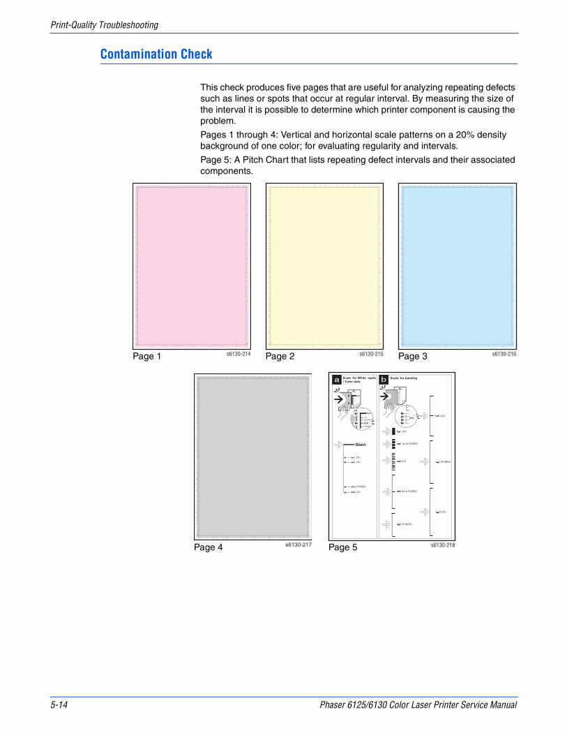
5-14 Phaser 6125/6130 Color Laser Printer Service Manual
Print-Quality Troubleshooting
Contamination Check
This check produces five pages that are useful for analyzing repeating defects such as lines or spots that occur at regular interval. By measuring the size of the interval it is possible to determine which printer component is causing the problem.
Pages 1 through 4: Vertical and horizontal scale patterns on a 20% density background of one color; for evaluating regularity and intervals.
Page 5: A Pitch Chart that lists repeating defect intervals and their associated components.
s6130-214
13
s6130-215
13
s6130-216
13
s6130-217
13
s6130-218
Page 1 Page 2 Page 3
Page 4 Page 5

Phaser 6125/6130 Color Laser Printer Service Manual 5-15
Print-Quality Troubleshooting
Print-Quality Specifications
The Print-Quality specifications are provided as follows.
Environmental Condition
■ Temperature: 10° C - 32° C
■ Humidity: 15% RH - 85% RH (85% RH at 28° C)
NoteDefects may occur due to condensation after around 30 minutes if the printer is turned On in a critical environment such as 85% at 10° C.
Quality Paper
The print-quality is best when quality paper is fed from the tray. The print-quality is evaluated on the maximum size of each standard paper.
■ Color Print-Quality: Xerox-brand X-Pression paper
■ Black and White Quality: Xerox-brand 4200 paper
Paper Condition
Paper should be fresh and stored in the operating environment for 12 hours before use for printing.
Printer Condition
The specified print-quality is guaranteed with the printer in specified normal environmental condition.

5-16 Phaser 6125/6130 Color Laser Printer Service Manual
Print-Quality Troubleshooting
Specifications
The following charts provide specifications for Skew, Parallelism, Linearity, Perpendicularity, Magnification Error, Registration, and Guaranteed and Maximum Print Areas.
Skew
■ 180 mm ± 1.1 mm
To measure Skew: Measure the margin of the paper at the leading edge of each corner, and then take the difference between them.
Lead Edge
A a = | T/E - C | Cb = | T/E - D |
Skew = a - b (within ±1.1 mm)
180 mm s6130-204
Skew 3
B A
Image Area
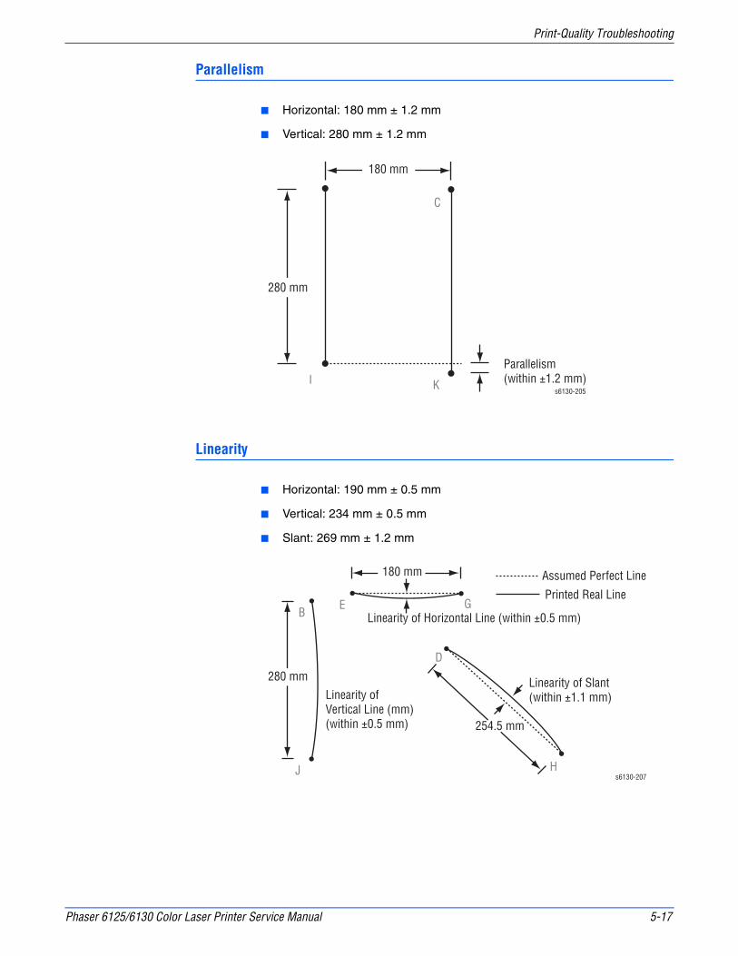
Phaser 6125/6130 Color Laser Printer Service Manual 5-17
Print-Quality Troubleshooting
Parallelism
■ Horizontal: 180 mm ± 1.2 mm
■ Vertical: 280 mm ± 1.2 mm
Linearity
■ Horizontal: 190 mm ± 0.5 mm
■ Vertical: 234 mm ± 0.5 mm
■ Slant: 269 mm ± 1.2 mm
s6130-205
280 mm
180 mm
I K
C
Parallelism (within ±1.2 mm)
BE G
J H
D
180 mm
280 mm
254.5 mm
Linearity ofVertical Line (mm)(within ±0.5 mm)
Linearity of Horizontal Line (within ±0.5 mm)
Linearity of Slant (within ±1.1 mm)
Assumed Perfect Line
Printed Real Line
s6130-207

5-18 Phaser 6125/6130 Color Laser Printer Service Manual
Print-Quality Troubleshooting
Perpendicularity
■ 114.5 mm ± 0.8 mm
Magnification Error
■ Horizontal Simplex: 190 mm ± 0.5%
■ Horizontal Duplex:190 mm ± 0.8%
■ Vertical Simplex: 234 mm ± 0.5%
■ Vertical Duplex: 234 mm ± 0.8%
Lead Edge
Assumed Perfect Line
Perpendicularity = B - b (within ±1.0 mm)
A B C
90140 mm
Fb
s6130-208
B
J
E G
Magnification = Measured Length / Nominal (within ±0.5%)
Nominal = 280 mmNominal = 180 mm
s6130-209
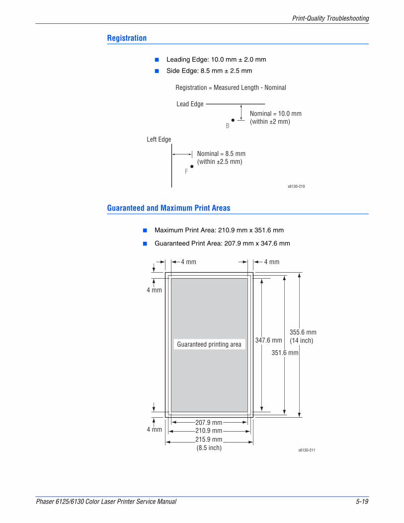
Phaser 6125/6130 Color Laser Printer Service Manual 5-19
Print-Quality Troubleshooting
Registration
■ Leading Edge: 10.0 mm ± 2.0 mm
■ Side Edge: 8.5 mm ± 2.5 mm
Guaranteed and Maximum Print Areas
■ Maximum Print Area: 210.9 mm x 351.6 mm
■ Guaranteed Print Area: 207.9 mm x 347.6 mm
Registration = Measured Length - Nominal
Lead EdgeNominal = 10.0 mm (within ±2 mm)
Nominal = 8.5 mm (within ±2.5 mm)
Left Edge
B
F
s6130-210
s6130-211
4 mm
4 mm
4 mm
4 mm
355.6 mm(14 inch)
215.9 mm(8.5 inch)
351.6 mm
347.6 mm
210.9 mm
Guaranteed printing area
207.9 mm

5-20 Phaser 6125/6130 Color Laser Printer Service Manual
Print-Quality Troubleshooting
Print-Quality Troubleshooting
Print-Quality Defect Definitions
The following table lists the print-quality defect corrective procedure, their definition, and the page where each procedure is provided.
Defect Definition Page
Light or Undertone Print
The overall image density is too light in all colors.
page 5-22
Blank Print (No Print)
The entire image area is blank. page 5-25
Black Print The entire image area is black. page 5-28
Vertical Blank Lines There are faded or completely non-printed lines along the page.
page 5-30
Horizontal Band, Voids, or Streaks
There are areas of the image that are extremely light or are missing entirely.
page 5-32
Vertical Stripes There are black lines along the page in the direction of the paper travel.
page 5-35
Horizontal Stripes There are dark lines running parallel with the leading edge of the print.
page 5-37
Partial Band There are areas of the image that are extremely light or are missing in a limited area.
page 5-39
Random Spots There are spots of toner randomly scattered across the page.
page 5-42
Repeating Bands, Lines, Marks, or Spots
There are recurring lines, marks, or spots on the page.
page 5-45
Background Contamination
There is toner contamination on all or most of the page.
page 5-48
Skew The printed image is not paralleled with both sides of the paper.
page 5-51
Damaged Paper The paper comes out from the printer wrinkled, folded, or worn-out.
page 5-54
Unfused Image The toner image is not completely fused to the paper. The image easily rubs off.
page 5-57
Color Registration A printed yellow or black image is not overlapped on a cyan or magenta image correctly.
page 5-59
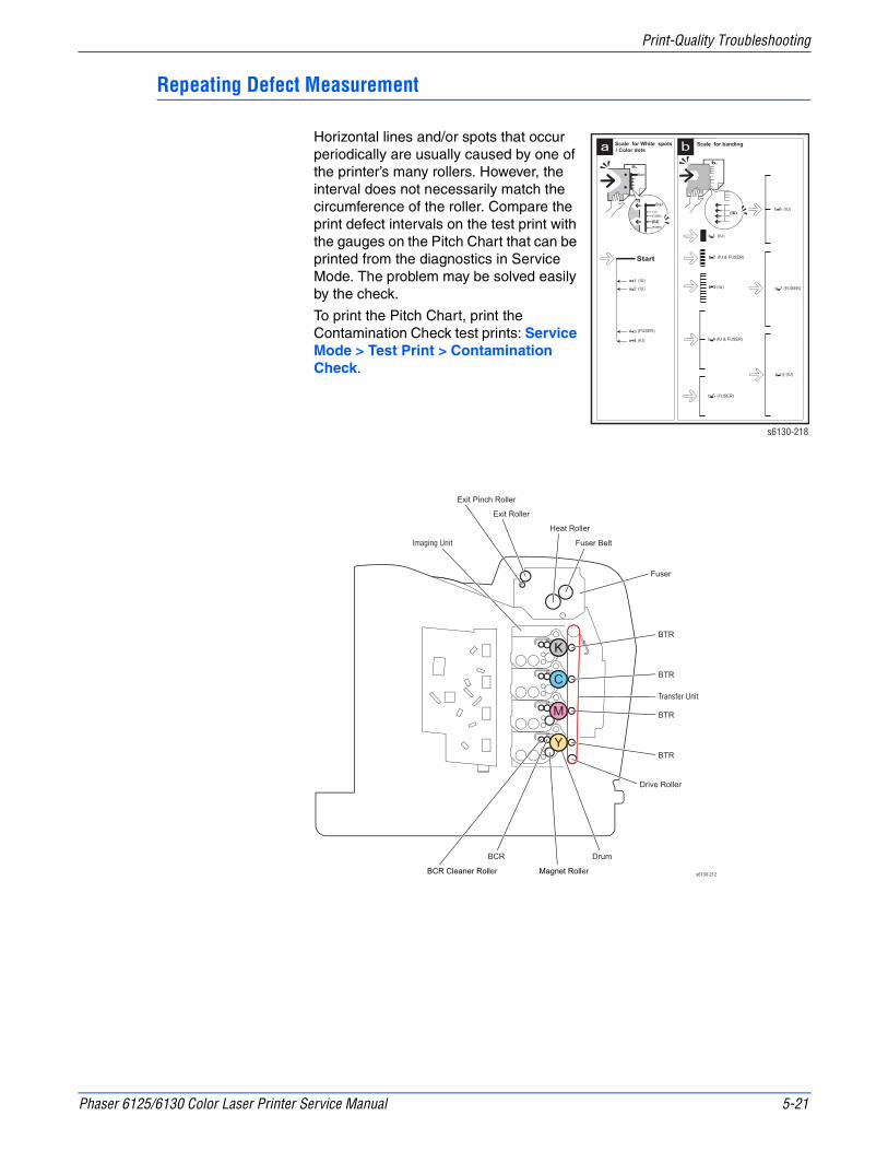
Phaser 6125/6130 Color Laser Printer Service Manual 5-21
Print-Quality Troubleshooting
Repeating Defect Measurement
Horizontal lines and/or spots that occur periodically are usually caused by one of the printer’s many rollers. However, the interval does not necessarily match the circumference of the roller. Compare the print defect intervals on the test print with the gauges on the Pitch Chart that can be printed from the diagnostics in Service Mode. The problem may be solved easily by the check.
To print the Pitch Chart, print the Contamination Check test prints: Service Mode > Test Print > Contamination Check.
s6130-218
s6130-212
Exit Roller
Heat Roller
Exit Pinch Roller
Fuser Belt
BTR
Imaging Unit
Drive Roller
Fuser
BTR
BTR
BTR
Drum
BCR Cleaner Roller Magnet Roller
BCR
Transfer Unit

5-22 Phaser 6125/6130 Color Laser Printer Service Manual
Print-Quality Troubleshooting
Light or Undertone Print
The overall image density is too light in all colors.
Initial Actions
■ Check the paper transfer path.
■ Ensure there is no debris on the transfer path.
Troubleshooting Reference Table
Applicable Parts Example Print
■ Laser Unit kit(PL4.1.99)■ Imaging Unit (PL4.1.21)■ Dispenser Assy (PL5.1.3)■ Toner Cartridge K (PL5.1.21)■ Toner Cartridge C (PL5.1.22)■ Toner Cartridge M (PL5.1.23)■ Toner Cartridge Y (PL5.1.24)■ Transfer Unit (PL6.1.7)■ IP Board (PL8.1.9)■ MCU Board (PL8.2.13)
Troubleshooting Procedure Table
Step Actions and Questions Yes No
1 Check the Toner TypeIs the Xerox Toner seated?
Go to step 2. Replace the toner with the Xerox toner.
2 Check the paper conditionIs the paper dry and recommended paper?
Go to step 4. Replace the paper with a new dry and recommended one, then go to step 3.
3 Is the image printed correctly? Complete Go to step 4.
ABCDE abcde 12345
s6180-317
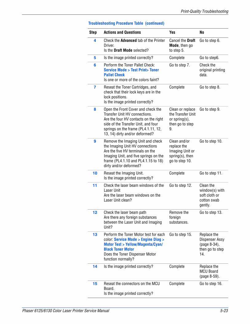
Phaser 6125/6130 Color Laser Printer Service Manual 5-23
Print-Quality Troubleshooting
4 Check the Advanced tab of the Printer Driver.Is the Draft Mode selected?
Cancel the Draft Mode, then go to step 5.
Go to step 6.
5 Is the image printed correctly? Complete Go to step6.
6 Perform the Toner Pallet Check: Service Mode > Test Print> Toner Pallet CheckIs one or more of the colors faint?
Go to step 7. Check the original printing data.
7 Reseat the Toner Cartridges, and check that their lock keys are in the lock positions.Is the image printed correctly?
Complete Go to step 8.
8 Open the Front Cover and check the Transfer Unit HV connections.Are the four HV contacts on the right side of the Transfer Unit, and four springs on the frame (PL4.1.11, 12, 13, 14) dirty and/or deformed?
Clean or replace the Transfer Unit or spring(s), then go to step 9.
Go to step 9.
9 Remove the Imaging Unit and check the Imaging Unit HV connectionsAre the five HV terminals on the Imaging Unit, and five springs on the frame (PL4.1.10 and PL4.1.15 to 18) dirty and/or deformed?
Clean and/or replace the Imaging Unit or spring(s), then go to step 10.
Go to step 10.
10 Reseat the Imaging Unit.Is the image printed correctly?
Complete Go to step 11.
11 Check the laser beam windows of the Laser UnitAre the laser beam windows on the Laser Unit clean?
Go to step 12. Clean the window(s) with soft cloth or cotton swab gently.
12 Check the laser beam pathAre there any foreign substances between the Laser Unit and Imaging Unit?
Remove the foreign substances.
Go to step 13.
13 Perform the Toner Motor test for each color: Service Mode > Engine Diag > Motor Test > Yellow/Magenta/Cyan/Black Toner MotorDoes the Toner Dispenser Motor function normally?
Go to step 15. Replace the Dispenser Assy (page 8-34), then go to step 14.
14 Is the image printed correctly? Complete Replace the MCU Board (page 8-59).
15 Reseat the connectors on the MCU Board.Is the image printed correctly?
Complete Go to step 16.
Troubleshooting Procedure Table (continued)
Step Actions and Questions Yes No
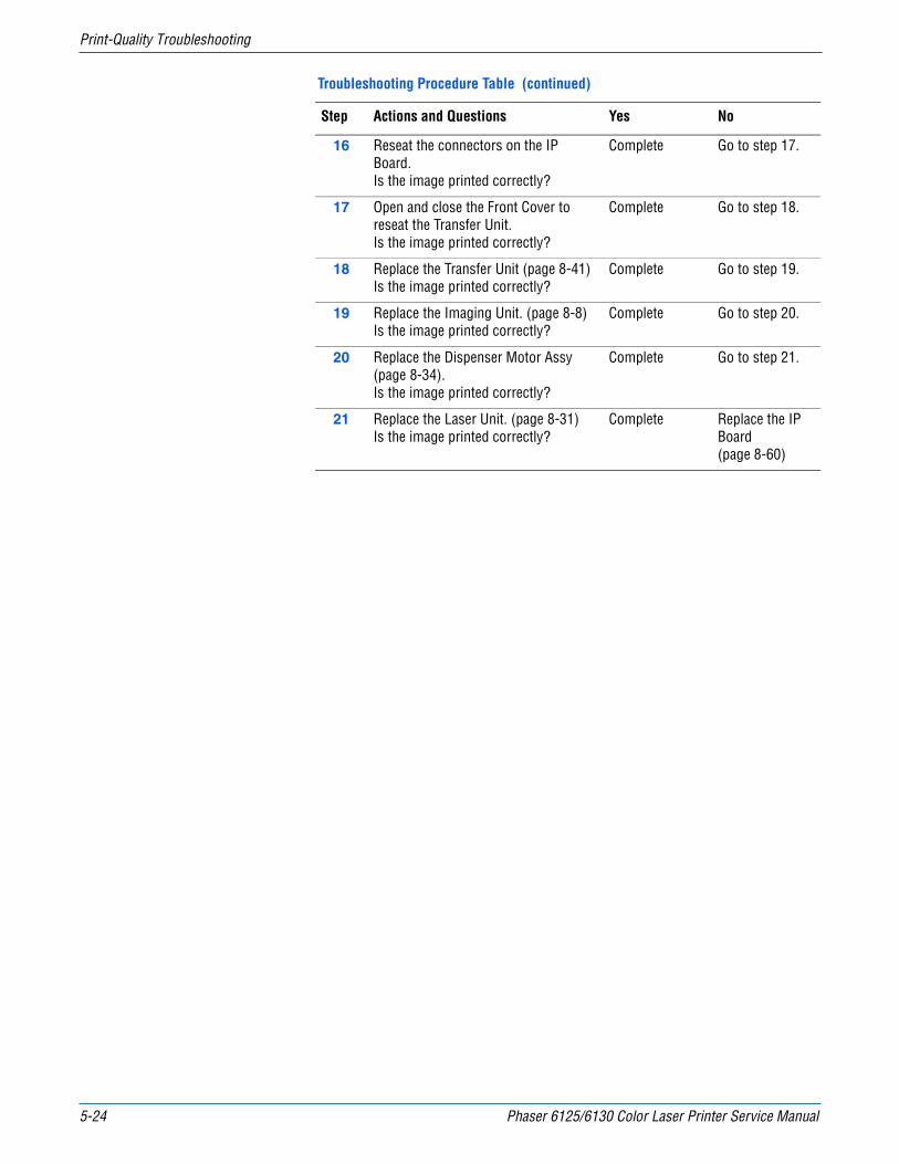
5-24 Phaser 6125/6130 Color Laser Printer Service Manual
Print-Quality Troubleshooting
16 Reseat the connectors on the IP Board.Is the image printed correctly?
Complete Go to step 17.
17 Open and close the Front Cover to reseat the Transfer Unit.Is the image printed correctly?
Complete Go to step 18.
18 Replace the Transfer Unit (page 8-41)Is the image printed correctly?
Complete Go to step 19.
19 Replace the Imaging Unit. (page 8-8)Is the image printed correctly?
Complete Go to step 20.
20 Replace the Dispenser Motor Assy (page 8-34).Is the image printed correctly?
Complete Go to step 21.
21 Replace the Laser Unit. (page 8-31)Is the image printed correctly?
Complete Replace the IP Board (page 8-60)
Troubleshooting Procedure Table (continued)
Step Actions and Questions Yes No

Phaser 6125/6130 Color Laser Printer Service Manual 5-25
Print-Quality Troubleshooting
Blank Print (No Print)
The entire image area is blank.
Initial Actions
■ Check the paper transfer path.
■ Ensure there are no debris on the transfer path.
Troubleshooting Reference Table
Applicable Parts Example Print
■ Laser Unit Kit (PL4.1.99)■ Imaging Unit (PL4.1.21)■ Dispenser Assy (PL5.1.1)■ Toner Cartridge K (PL5.1.21)■ Toner Cartridge C (PL5.1.22)■ Toner Cartridge M (PL5.1.23)■ Toner Cartridge Y (PL5.1.24)■ Transfer Unit (PL6.1.7)■ Sub Drive Assembly (PL7.1.1)■ Main Drive Assembly (PL7.1.2)■ Feed Drive Assembly (PL7.1.4)■ IP Board (PL8.1.9)■ MCU Board (PL8.2.13)
Troubleshooting Procedure Table
Step Actions and Questions Yes No
1 Check the Toner TypeIs non-Xerox Toner in use?
Replace the toner with the Xerox toner, then go to step 2.
Go to step 3.
2 Is the image printed correctly? Complete Replace the IP Board (page 8-60).
3 Reseat the Toner Cartridges, and check that their lock keys are in the lock positions.Is the image printed correctly?
Complete Go to step 4.
s6180-318

5-26 Phaser 6125/6130 Color Laser Printer Service Manual
Print-Quality Troubleshooting
4 Open the Front Cover and check the Transfer Unit HV connections.Are the four HV contacts on the right side of the Transfer Unit, and four springs on the frame (PL4.1.11, 12, 13, 14) dirty and/or deformed?
Clean or replace the Transfer Unit (page 8-41) or spring(s), then go to step 5.
Go to step 6.
5 Is the image printed correctly? Complete Go to step 6.
6 Check the paper conditionIs the paper dry and recommended paper?
Go to step 8. Replace the paper with a new dry and recommended one, then go to step 7.
7 Is the image printed correctly? Complete Go to step 8.
8 Check the Toner Cartridge life using CentreWare IS.Are one or more of the Toner Cartridges near end of life?
Replace the Toner Cartridge(s) (page 8-10).
Go to step 9.
9 Inspect the laser beam windows of the Laser UnitAre the laser beam windows on the Laser Unit clean?
Go to step 10. Clean the window(s) with soft cloth or cotton swab gently.
10 Inspect the laser beam pathAre there any foreign substances between the Laser Unit and Imaging Unit?
Remove the foreign substances.
Go to step 11.
11 Reseat the Imaging Unit.Is the image printed correctly?
Complete Go to step 12.
12 Perform the Toner Motor test for each color: Service Mode > Engine Diag > Motor Test > Yellow/Magenta/Cyan/Black Toner MotorDoes the Toner Dispenser Motor function normally?
Go to step 17. Go to step 13.
13 Inspect the connectors between the MCU Board and Toner Motor (Y/M/C/K) (Dispenser Motor Assy).Are P/J18, P/J19, P/J181, P/J182, P/J191 and P/J192 connected correctly?
Go to step 15. Securely reconnect the connectors, then go to step 14.
14 Is the image printed correctly? Complete Go to step 15.
Troubleshooting Procedure Table (continued)
Step Actions and Questions Yes No
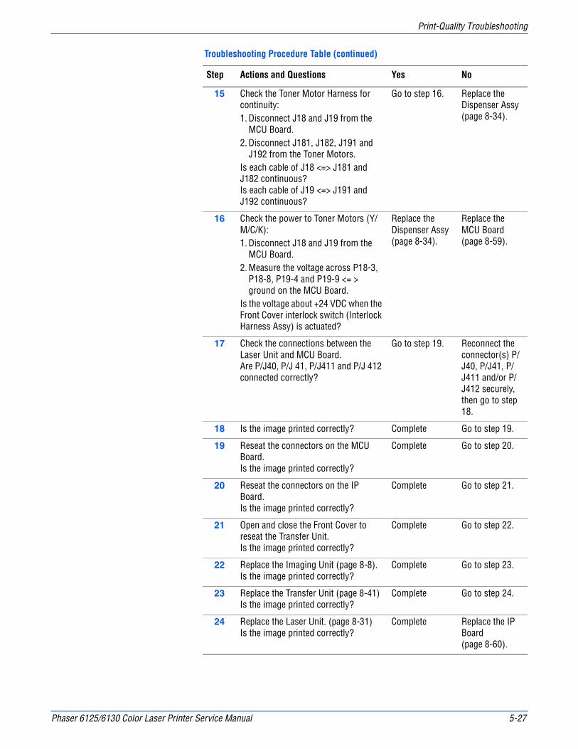
Phaser 6125/6130 Color Laser Printer Service Manual 5-27
Print-Quality Troubleshooting
15 Check the Toner Motor Harness for continuity:1. Disconnect J18 and J19 from the
MCU Board.2. Disconnect J181, J182, J191 and
J192 from the Toner Motors.Is each cable of J18 <=> J181 and J182 continuous?Is each cable of J19 <=> J191 and J192 continuous?
Go to step 16. Replace the Dispenser Assy (page 8-34).
16 Check the power to Toner Motors (Y/M/C/K):1. Disconnect J18 and J19 from the
MCU Board.2. Measure the voltage across P18-3,
P18-8, P19-4 and P19-9 <= > ground on the MCU Board.
Is the voltage about +24 VDC when the Front Cover interlock switch (Interlock Harness Assy) is actuated?
Replace the Dispenser Assy (page 8-34).
Replace the MCU Board (page 8-59).
17 Check the connections between the Laser Unit and MCU Board.Are P/J40, P/J 41, P/J411 and P/J 412 connected correctly?
Go to step 19. Reconnect the connector(s) P/J40, P/J41, P/J411 and/or P/J412 securely, then go to step 18.
18 Is the image printed correctly? Complete Go to step 19.
19 Reseat the connectors on the MCU Board.Is the image printed correctly?
Complete Go to step 20.
20 Reseat the connectors on the IP Board.Is the image printed correctly?
Complete Go to step 21.
21 Open and close the Front Cover to reseat the Transfer Unit.Is the image printed correctly?
Complete Go to step 22.
22 Replace the Imaging Unit (page 8-8).Is the image printed correctly?
Complete Go to step 23.
23 Replace the Transfer Unit (page 8-41)Is the image printed correctly?
Complete Go to step 24.
24 Replace the Laser Unit. (page 8-31)Is the image printed correctly?
Complete Replace the IP Board (page 8-60).
Troubleshooting Procedure Table (continued)
Step Actions and Questions Yes No
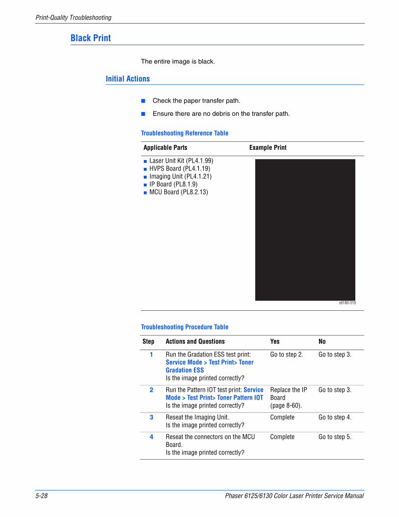
5-28 Phaser 6125/6130 Color Laser Printer Service Manual
Print-Quality Troubleshooting
Black Print
The entire image is black.
Initial Actions
■ Check the paper transfer path.
■ Ensure there are no debris on the transfer path.
Troubleshooting Reference Table
Applicable Parts Example Print
■ Laser Unit Kit (PL4.1.99)■ HVPS Board (PL4.1.19)■ Imaging Unit (PL4.1.21)■ IP Board (PL8.1.9)■ MCU Board (PL8.2.13)
Troubleshooting Procedure Table
Step Actions and Questions Yes No
1 Run the Gradation ESS test print: Service Mode > Test Print> Toner Gradation ESSIs the image printed correctly?
Go to step 2. Go to step 3.
2 Run the Pattern IOT test print: Service Mode > Test Print> Toner Pattern IOTIs the image printed correctly?
Replace the IP Board (page 8-60).
Go to step 3.
3 Reseat the Imaging Unit.Is the image printed correctly?
Complete Go to step 4.
4 Reseat the connectors on the MCU Board.Is the image printed correctly?
Complete Go to step 5.
s6180-319
Phaser 6125/6130 Color Laser Printer Service Manual 5-29
Print-Quality Troubleshooting
5 Reseat the connectors on the IP Board.Is the image printed correctly?
Complete Go to step 6.
6 Reseat the Laser Unit.Is the image printed correctly?
Complete Go to step 7.
7 Inspect the connections between the Laser Unit and MCU Board.Are P/J40, P/J 41, P/J411 and P/J 412 connected correctly?
Go to step 9. Reconnect the connectors securely, then go to step 8.
8 Is the image printed correctly? Complete Go to step 9.
9 Replace the Imaging Unit (page 8-8).Is the image printed correctly?
Complete Go to step 10.
10 Replace the IP Board (page 8-60).Is the image printed correctly?
Complete Go to step 11.
11 Replace the HVPS Board (page 8-43).Is the image printed correctly?
Complete Go to step 12.
12 Replace the Laser Unit (page 8-31).Is the image printed correctly?
Complete Replace the MCU Board (page 8-59).
Troubleshooting Procedure Table (continued)
Step Actions and Questions Yes No

5-30 Phaser 6125/6130 Color Laser Printer Service Manual
Print-Quality Troubleshooting
Vertical Blank Lines
There are faded or completely non-printed lines along the page in the direction of the paper travel from the leading edge to the trailing edge.
Initial Actions
■ Check the paper transfer path.
■ Ensure there are no debris on the transfer path.
Troubleshooting Reference Table
Applicable Parts Example Print
■ Laser Unit Kit (PL4.1.99)■ Imaging Unit (PL4.1.21)■ Transfer Unit (PL6.1.7)■ IP Board (PL8.1.9)■ MCU Board (PL8.2.13)
Troubleshooting Procedure Table
Step Actions and Questions Yes No
1 Check the paper conditionIs the paper dry and approved for use?
Go to step 3. Replace with dry, approved paper, then go to step 2.
2 Is the image printed correctly? Complete Go to step 3.
3 Inspect the paper path between the Transfer Unit and Fuser.Is there any debris or other foreign substance in the paper path?
Remove the debris or foreign substances, then go to step 4.
Go to step 5.
4 Is the image printed correctly? Complete Go to step 5.
ABCDE abcde 12345
s6180-320
Phaser 6125/6130 Color Laser Printer Service Manual 5-31
Print-Quality Troubleshooting
5 Inspect the Transfer Belt surface.Is there any damage to the Transfer Belt surface?
Replace the Transfer Unit (page 8-41).
Go to step 6.
6 1. Open the Front Cover.2. Inspect the four Transfer Unit HV
connections.Are the four terminals on the Transfer Unit, and the four springs on the frame (PL4.1.11, 12, 13 and 14) dirty and/or deformed?
Clean or replace the Transfer Unit contacts or spring(s).
Go to step 7.
7 Inspect the laser beam pathAre there any foreign substances between the Laser Unit and Imaging Unit?
Remove the foreign substances.
Go to step 8.
8 Check the Imaging Unit HV Connections1. Remove the Imaging Unit.2. Inspect the five Imaging Unit HV
connections.Are the five HV terminals on the Imaging Unit, and five springs on the frame (PL4.1.10 and PL4.1.15 to 18) dirty and/or deformed?
Clean or replace the Imaging Unit contacts or spring(s).
Go to step 9.
9 Reseat the Imaging Unit.Is the image printed correctly?
Complete Go to step 10.
10 Reseat the Fuser.
Warning: Start the operation after the Fuser has cooled down.
Is the image printed correctly?
Complete Go to step 11.
11 Reseat the connectors on the MCU Board.Is the image printed correctly?
Complete Go to step 12.
12 Reseat the connectors on the IP Board.Is the image printed correctly?
Complete Go to step 13.
13 Open and close the Front Cover to reseat the Transfer Unit.Is the image printed correctly?
Complete Go to step 14.
14 Replace the Imaging Unit (page 8-8).Is the image printed correctly?
Complete Go to step 15.
15 Replace the IP Board (page 8-60).Is the image printed correctly?
Complete Go to step 16.
16 Inspect the connections between the Laser Unit and MCU Board.Are P/J40, P/J 41, P/J411 and P/J 412 connected correctly?
Go to step 18. Reconnect the connectors securely, then go to step 17.
Troubleshooting Procedure Table (continued)
Step Actions and Questions Yes No
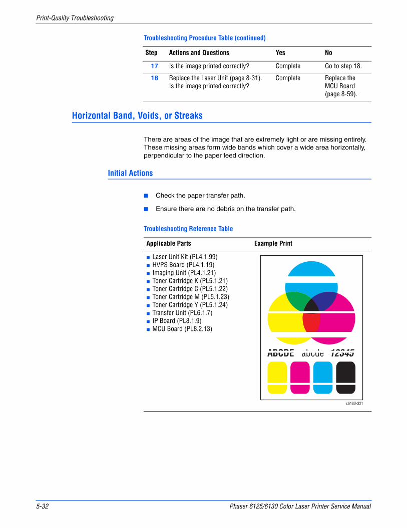
5-32 Phaser 6125/6130 Color Laser Printer Service Manual
Print-Quality Troubleshooting
Horizontal Band, Voids, or Streaks
There are areas of the image that are extremely light or are missing entirely. These missing areas form wide bands which cover a wide area horizontally, perpendicular to the paper feed direction.
Initial Actions
■ Check the paper transfer path.
■ Ensure there are no debris on the transfer path.
17 Is the image printed correctly? Complete Go to step 18.
18 Replace the Laser Unit (page 8-31).Is the image printed correctly?
Complete Replace the MCU Board (page 8-59).
Troubleshooting Reference Table
Applicable Parts Example Print
■ Laser Unit Kit (PL4.1.99)■ HVPS Board (PL4.1.19)■ Imaging Unit (PL4.1.21)■ Toner Cartridge K (PL5.1.21)■ Toner Cartridge C (PL5.1.22)■ Toner Cartridge M (PL5.1.23)■ Toner Cartridge Y (PL5.1.24)■ Transfer Unit (PL6.1.7)■ IP Board (PL8.1.9)■ MCU Board (PL8.2.13)
Troubleshooting Procedure Table (continued)
Step Actions and Questions Yes No
ABCDE abcde 12345
s6180-321

Phaser 6125/6130 Color Laser Printer Service Manual 5-33
Print-Quality Troubleshooting
Troubleshooting Procedure Table
Step Actions and Questions Yes No
1 Run the Contamination Check test print: Service Mode > Test Print > Contamination ChkCompare any horizontal dropout bands with the Pitch Chart (page 5-21). Do any of the horizontal bands match the chart?
Replace the corresponding parts
Go to step 2.
2 Check the paper conditionIs the paper dry and approved for use?
Go to step 4. Replace with dry, approved paper, then go to step 3.
3 Is the image printed correctly? Complete Go to step 4.
4 Inspect the Transfer Belt surface.Is there any damage to the Transfer Belt surface?
Replace the Transfer Unit (page 8-41).
Go to step 5.
5 1. Open the Front Cover.2. Inspect the four Transfer Unit HV
connections.Are the four terminals on the Transfer Unit, and the four springs on the frame (PL4.1.11, 12, 13 and 14) dirty and/or deformed?
Clean or replace the Transfer Unit contacts or spring(s).
Go to step 6.
6 Inspect the laser beam pathAre there any foreign substances between the Laser Unit and Imaging Unit?
Remove the foreign substances.
Go to step 7.
7 1. Remove the Imaging Unit.2. Inspect the five Imaging Unit HV
connections.Are the five HV terminals on the Imaging Unit, and five springs on the frame (PL4.1.10 and PL4.1.15 to 18) dirty and/or deformed?
Clean or replace the Imaging Unit contacts or spring(s).
Go to step 8.
8 Reseat the Imaging Unit.Is the image printed correctly?
Complete Go to step 9.
9 Reseat the Fuser.
Warning: Start the operation after the Fuser has cooled down.
Is the image printed correctly?
Complete Go to step 10.
10 Reseat the connectors on the MCU Board.Is the image printed correctly?
Complete Go to step 11.
11 Reseat the connectors on the IP Board.Is the image printed correctly?
Complete Go to step 12.

5-34 Phaser 6125/6130 Color Laser Printer Service Manual
Print-Quality Troubleshooting
12 Open and close the Front Cover to reseat the Transfer Unit.Is the image printed correctly?
Complete Go to step 13.
13 Replace the Toner Cartridge(s) (page 8-10).Is the image printed correctly?
Complete Go to step 14.
14 Replace the Imaging Unit (page 8-8).Is the image printed correctly?
Complete Go to step 15.
15 Replace the IP Board (page 8-60).Is the image printed correctly?
Complete Go to step 16.
16 Inspect the connections between the Laser Unit and MCU Board.Are P/J40, P/J 41, P/J411 and P/J 412 connected correctly?
Go to step 18. Reconnect the connectors securely, then go to step 17.
17 Is the image printed correctly? Complete Go to step 18.
18 Replace the HVPS Board (page 8-43).Is the image printed correctly?
Complete Go to step 19.
19 Replace the Laser Unit (page 8-31).Is the image printed correctly?
Complete Replace the MCU Board (page 8-59).
Troubleshooting Procedure Table (continued)
Step Actions and Questions Yes No
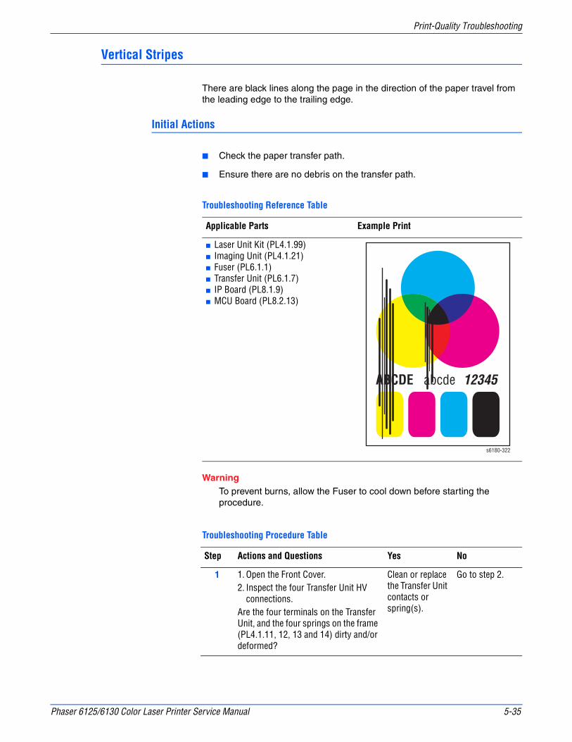
Phaser 6125/6130 Color Laser Printer Service Manual 5-35
Print-Quality Troubleshooting
Vertical Stripes
There are black lines along the page in the direction of the paper travel from the leading edge to the trailing edge.
Initial Actions
■ Check the paper transfer path.
■ Ensure there are no debris on the transfer path.
WarningTo prevent burns, allow the Fuser to cool down before starting the procedure.
Troubleshooting Reference Table
Applicable Parts Example Print
■ Laser Unit Kit (PL4.1.99)■ Imaging Unit (PL4.1.21)■ Fuser (PL6.1.1)■ Transfer Unit (PL6.1.7)■ IP Board (PL8.1.9)■ MCU Board (PL8.2.13)
Troubleshooting Procedure Table
Step Actions and Questions Yes No
1 1. Open the Front Cover.2. Inspect the four Transfer Unit HV
connections.Are the four terminals on the Transfer Unit, and the four springs on the frame (PL4.1.11, 12, 13 and 14) dirty and/or deformed?
Clean or replace the Transfer Unit contacts or spring(s).
Go to step 2.
ABCDE abcde 12345
s6180-322
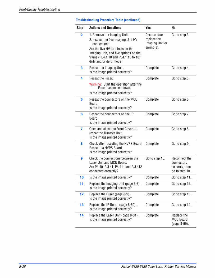
5-36 Phaser 6125/6130 Color Laser Printer Service Manual
Print-Quality Troubleshooting
2 1. Remove the Imaging Unit.2. Inspect the five Imaging Unit HV
connections.Are the five HV terminals on the Imaging Unit, and five springs on the frame (PL4.1.10 and PL4.1.15 to 18) dirty and/or deformed?
Clean and/or replace the Imaging Unit or spring(s).
Go to step 3.
3 Reseat the Imaging Unit.Is the image printed correctly?
Complete Go to step 4.
4 Reseat the Fuser.
Warning: Start the operation after the Fuser has cooled down.
Is the image printed correctly?
Complete Go to step 5.
5 Reseat the connectors on the MCU Board.Is the image printed correctly?
Complete Go to step 6.
6 Reseat the connectors on the IP Board.Is the image printed correctly?
Complete Go to step 7.
7 Open and close the Front Cover to reseat the Transfer Unit.Is the image printed correctly?
Complete Go to step 8.
8 Check after reseating the HVPS BoardReseat the HVPS Board.Is the image printed correctly?
Complete Go to step 9.
9 Check the connections between the Laser Unit and MCU Board.Are P/J40, P/J 41, P/J411 and P/J 412 connected correctly?
Go to step 10. Reconnect the connectors securely, then go to step 10.
10 Is the image printed correctly? Complete Go to step 11.
11 Replace the Imaging Unit (page 8-8).Is the image printed correctly?
Complete Go to step 12.
12 Replace the Fuser (page 8-9).Is the image printed correctly?
Complete Go to step 13.
13 Replace the IP Board (page 8-60).Is the image printed correctly?
Complete Go to step 14.
14 Replace the Laser Unit (page 8-31).Is the image printed correctly?
Complete Replace the MCU Board (page 8-59).
Troubleshooting Procedure Table (continued)
Step Actions and Questions Yes No

Phaser 6125/6130 Color Laser Printer Service Manual 5-37
Print-Quality Troubleshooting
Horizontal Stripes
There are black lines running parallel with the leading edge of the print, perpendicular to the direction of the paper travel.
Initial Actions
■ Check the paper transfer path.
■ Ensure there are no debris on the transfer path.
WarningTo prevent burns, allow the Fuser to cool down before starting the procedure.
Troubleshooting Reference Table
Applicable Notes Example Print
■ Laser Unit Kit (PL4.1.99)■ Imaging Unit (PL4.1.21)■ Toner Cartridge K (PL5.1.21)■ Toner Cartridge C (PL5.1.22)■ Toner Cartridge M (PL5.1.23)■ Toner Cartridge Y (PL5.1.24)■ Fuser (PL6.1.1)■ Transfer Unit (PL6.1.7)■ IP Board (PL8.1.9)■ MCU Board (PL8.2.13)
Troubleshooting Procedure Table
Step Actions and Questions Yes No
1 Run the Contamination Check test print: Service Mode > Test Print > Contamination ChkCompare any horizontal dropout bands with the Pitch Chart (page 5-21). Do any of the horizontal bands match the chart?
Replace the corresponding parts.
Go to step 2.
ABCDE abcde 12345
s6180-323
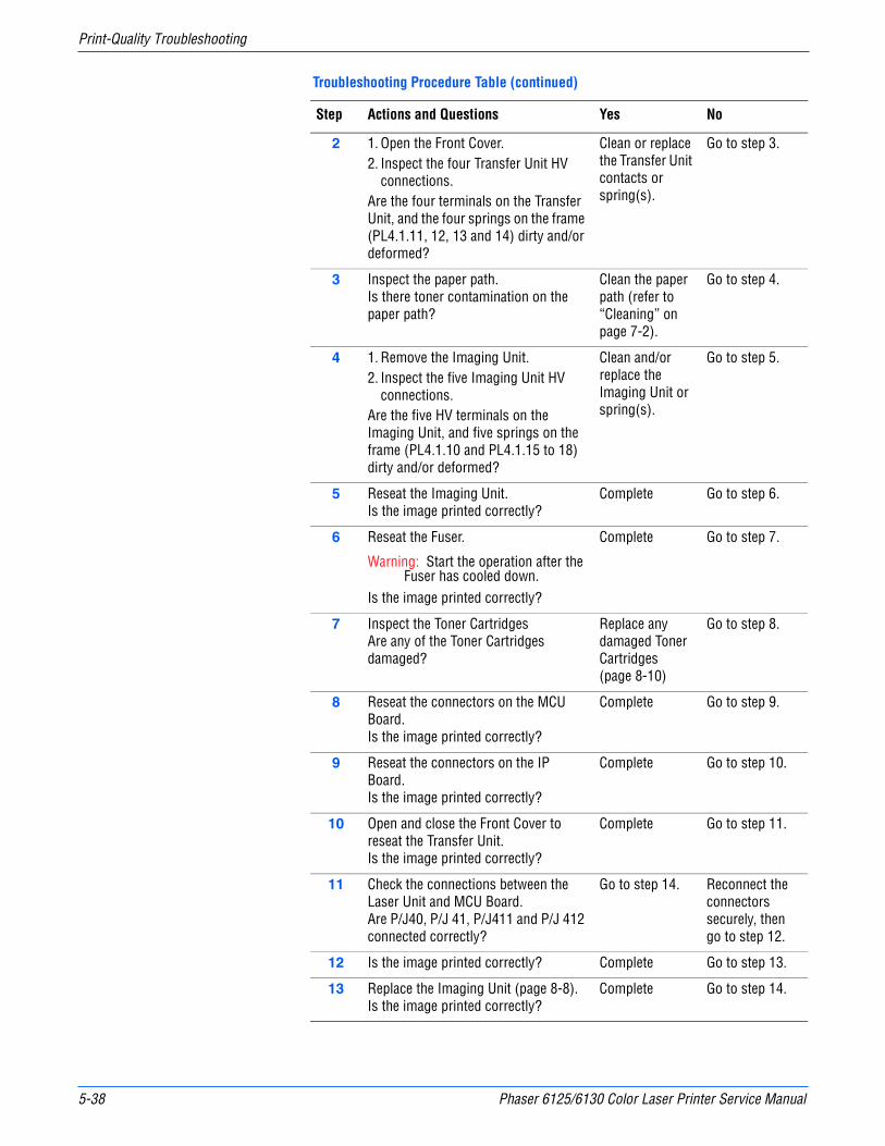
5-38 Phaser 6125/6130 Color Laser Printer Service Manual
Print-Quality Troubleshooting
2 1. Open the Front Cover.2. Inspect the four Transfer Unit HV
connections.Are the four terminals on the Transfer Unit, and the four springs on the frame (PL4.1.11, 12, 13 and 14) dirty and/or deformed?
Clean or replace the Transfer Unit contacts or spring(s).
Go to step 3.
3 Inspect the paper path.Is there toner contamination on the paper path?
Clean the paper path (refer to “Cleaning” on page 7-2).
Go to step 4.
4 1. Remove the Imaging Unit.2. Inspect the five Imaging Unit HV
connections.Are the five HV terminals on the Imaging Unit, and five springs on the frame (PL4.1.10 and PL4.1.15 to 18) dirty and/or deformed?
Clean and/or replace the Imaging Unit or spring(s).
Go to step 5.
5 Reseat the Imaging Unit.Is the image printed correctly?
Complete Go to step 6.
6 Reseat the Fuser.
Warning: Start the operation after the Fuser has cooled down.
Is the image printed correctly?
Complete Go to step 7.
7 Inspect the Toner CartridgesAre any of the Toner Cartridges damaged?
Replace any damaged Toner Cartridges (page 8-10)
Go to step 8.
8 Reseat the connectors on the MCU Board.Is the image printed correctly?
Complete Go to step 9.
9 Reseat the connectors on the IP Board.Is the image printed correctly?
Complete Go to step 10.
10 Open and close the Front Cover to reseat the Transfer Unit.Is the image printed correctly?
Complete Go to step 11.
11 Check the connections between the Laser Unit and MCU Board.Are P/J40, P/J 41, P/J411 and P/J 412 connected correctly?
Go to step 14. Reconnect the connectors securely, then go to step 12.
12 Is the image printed correctly? Complete Go to step 13.
13 Replace the Imaging Unit (page 8-8).Is the image printed correctly?
Complete Go to step 14.
Troubleshooting Procedure Table (continued)
Step Actions and Questions Yes No

Phaser 6125/6130 Color Laser Printer Service Manual 5-39
Print-Quality Troubleshooting
Partial Band
There are areas of the image that are extremely light or are missing in a limited area on the paper.
Initial Actions
■ Check the paper transfer path.
■ Ensure there are no debris on the transfer path.
14 Replace the Fuser (page 8-9).
Warning: Start the operation after the Fuser has cooled down.
Does the error still occur when printing?
Complete Go to step 15.
15 Replace the IP Board (page 8-60).Is the image printed correctly?
Complete Go to step 16.
16 Replace the Laser Unit (page 8-31).Is the image printed correctly?
Complete Replace the MCU Board (page 8-59).
Troubleshooting Reference Table
Applicable Notes Example Print
■ Laser Unit Kit (PL4.1.99)■ Imaging Unit (PL4.1.21)■ Transfer Unit (PL6.1.7)■ IP Board (PL8.1.9)■ MCU Board (PL8.2.13)
Troubleshooting Procedure Table (continued)
Step Actions and Questions Yes No
ABCDE abcde 12345
s6180-324
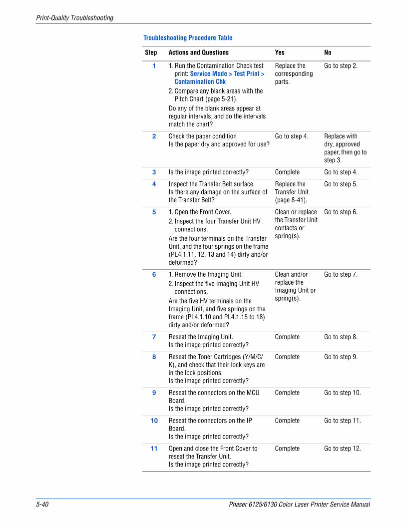
5-40 Phaser 6125/6130 Color Laser Printer Service Manual
Print-Quality Troubleshooting
Troubleshooting Procedure Table
Step Actions and Questions Yes No
1 1. Run the Contamination Check test print: Service Mode > Test Print > Contamination Chk
2. Compare any blank areas with the Pitch Chart (page 5-21).
Do any of the blank areas appear at regular intervals, and do the intervals match the chart?
Replace the corresponding parts.
Go to step 2.
2 Check the paper conditionIs the paper dry and approved for use?
Go to step 4. Replace with dry, approved paper, then go to step 3.
3 Is the image printed correctly? Complete Go to step 4.
4 Inspect the Transfer Belt surface.Is there any damage on the surface of the Transfer Belt?
Replace the Transfer Unit (page 8-41).
Go to step 5.
5 1. Open the Front Cover.2. Inspect the four Transfer Unit HV
connections.Are the four terminals on the Transfer Unit, and the four springs on the frame (PL4.1.11, 12, 13 and 14) dirty and/or deformed?
Clean or replace the Transfer Unit contacts or spring(s).
Go to step 6.
6 1. Remove the Imaging Unit.2. Inspect the five Imaging Unit HV
connections.Are the five HV terminals on the Imaging Unit, and five springs on the frame (PL4.1.10 and PL4.1.15 to 18) dirty and/or deformed?
Clean and/or replace the Imaging Unit or spring(s).
Go to step 7.
7 Reseat the Imaging Unit.Is the image printed correctly?
Complete Go to step 8.
8 Reseat the Toner Cartridges (Y/M/C/K), and check that their lock keys are in the lock positions.Is the image printed correctly?
Complete Go to step 9.
9 Reseat the connectors on the MCU Board.Is the image printed correctly?
Complete Go to step 10.
10 Reseat the connectors on the IP Board.Is the image printed correctly?
Complete Go to step 11.
11 Open and close the Front Cover to reseat the Transfer Unit.Is the image printed correctly?
Complete Go to step 12.
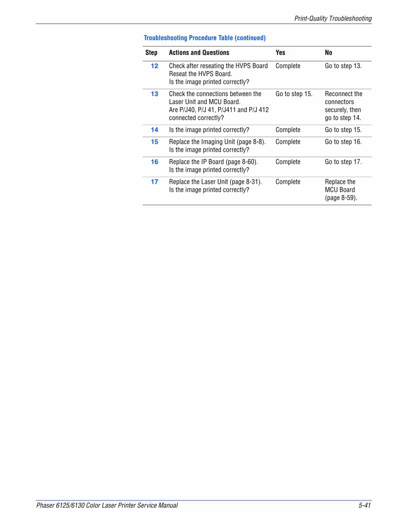
Phaser 6125/6130 Color Laser Printer Service Manual 5-41
Print-Quality Troubleshooting
12 Check after reseating the HVPS BoardReseat the HVPS Board.Is the image printed correctly?
Complete Go to step 13.
13 Check the connections between the Laser Unit and MCU Board.Are P/J40, P/J 41, P/J411 and P/J 412 connected correctly?
Go to step 15. Reconnect the connectors securely, then go to step 14.
14 Is the image printed correctly? Complete Go to step 15.
15 Replace the Imaging Unit (page 8-8).Is the image printed correctly?
Complete Go to step 16.
16 Replace the IP Board (page 8-60).Is the image printed correctly?
Complete Go to step 17.
17 Replace the Laser Unit (page 8-31).Is the image printed correctly?
Complete Replace the MCU Board (page 8-59).
Troubleshooting Procedure Table (continued)
Step Actions and Questions Yes No
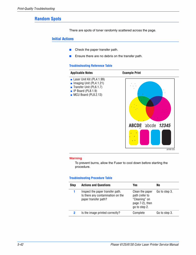
5-42 Phaser 6125/6130 Color Laser Printer Service Manual
Print-Quality Troubleshooting
Random Spots
There are spots of toner randomly scattered across the page.
Initial Actions
■ Check the paper transfer path.
■ Ensure there are no debris on the transfer path.
WarningTo prevent burns, allow the Fuser to cool down before starting the procedure.
Troubleshooting Reference Table
Applicable Notes Example Print
■ Laser Unit Kit (PL4.1.99)■ Imaging Unit (PL4.1.21)■ Transfer Unit (PL6.1.7)■ IP Board (PL8.1.9)■ MCU Board (PL8.2.13)
Troubleshooting Procedure Table
Step Actions and Questions Yes No
1 Inspect the paper transfer path.Is there any contamination on the paper transfer path?
Clean the paper path (refer to “Cleaning” on page 7-2), then go to step 2.
Go to step 3.
2 Is the image printed correctly? Complete Go to step 3.
ABCDE abcde 12345
s6180-325
Phaser 6125/6130 Color Laser Printer Service Manual 5-43
Print-Quality Troubleshooting
3 1. Run the Contamination Check test print: Service Mode > Test Print > Contamination Chk
2. Compare any spots with the Pitch Chart (page 5-21).
Do any of the spots appear at regular intervals, and do the intervals match the chart?
Replace the corresponding parts.
Go to step 4.
4 Inspect the paper being used.Is it approved paper?
Go to step 6. Use paper that is on the list of papers approved for the printer, then go to step 5.
5 Is the image printed correctly? Complete Go to step 6.
6 Inspect the Transfer Belt surface.Is there any damage on the surface of the Transfer Belt?
Replace the Transfer Unit (page 8-41).
Go to step 7.
7 1. Open the Front Cover.2. Inspect the four Transfer Unit HV
connections.Are the four terminals on the Transfer Unit, and the four springs on the frame (PL4.1.11, 12, 13 and 14) dirty and/or deformed?
Clean or replace the Transfer Unit contacts or spring(s).
Go to step 8.
8 1. Remove the Imaging Unit.2. Inspect the five Imaging Unit HV
connections.Are the five HV terminals on the Imaging Unit, and five springs on the frame (PL4.1.10 and PL4.1.15 to 18) dirty and/or deformed?
Clean and/or replace the Imaging Unit or spring(s).
Go to step 9.
9 Reseat the Imaging Unit.Is the image printed correctly?
Complete Go to step 10.
10 Reseat the Toner Cartridges (Y/M/C/K), and check that their lock keys are in the lock positions.Is the image printed correctly?
Complete Go to step 11.
11 Reseat the Fuser.
Warning: Start the operation after the Fuser has cooled down.
Is the image printed correctly?
Complete Go to step 12.
12 Reseat the connectors on the MCU Board.Is the image printed correctly?
Complete Go to step 13.
Troubleshooting Procedure Table (continued)
Step Actions and Questions Yes No
5-44 Phaser 6125/6130 Color Laser Printer Service Manual
Print-Quality Troubleshooting
13 Reseat the connectors on the IP Board.Is the image printed correctly?
Complete Go to step 14.
14 Open and close the Front Cover to reseat the Transfer Unit.Is the image printed correctly?
Complete Go to step 15.
15 Check the connections between the Laser Unit and MCU Board.Are P/J40, P/J 41, P/J411 and P/J 412 connected correctly?
Go to step 17. Reconnect the connectors securely, then go to step 16.
16 Is the image printed correctly? Complete Go to step 17.
17 Replace the Imaging Unit (page 8-8).Is the image printed correctly?
Complete Go to step 18.
18 Replace the IP Board (page 8-60).Is the image printed correctly?
Complete Go to step 19.
19 Replace the Laser Unit (page 8-31).Is the image printed correctly?
Complete Replace the MCU Board (page 8-59).
Troubleshooting Procedure Table (continued)
Step Actions and Questions Yes No
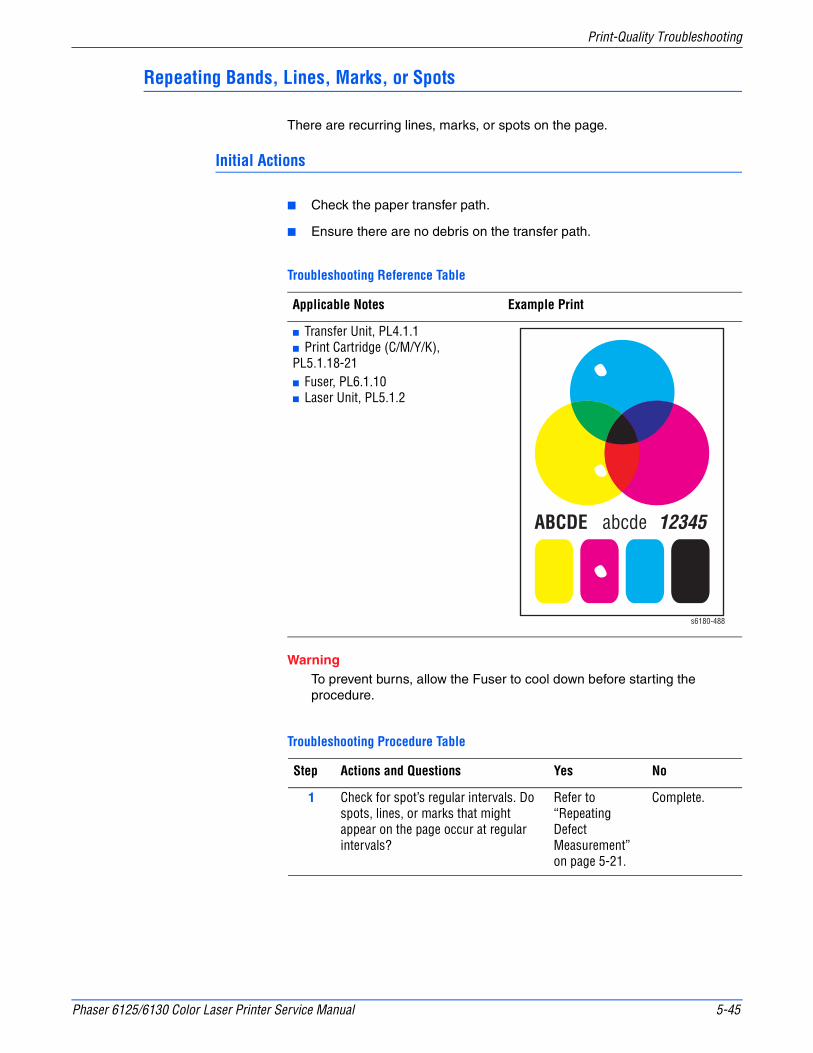
Phaser 6125/6130 Color Laser Printer Service Manual 5-45
Print-Quality Troubleshooting
Repeating Bands, Lines, Marks, or Spots
There are recurring lines, marks, or spots on the page.
Initial Actions
■ Check the paper transfer path.
■ Ensure there are no debris on the transfer path.
WarningTo prevent burns, allow the Fuser to cool down before starting the procedure.
Troubleshooting Reference Table
Applicable Notes Example Print
■ Transfer Unit, PL4.1.1■ Print Cartridge (C/M/Y/K),PL5.1.18-21■ Fuser, PL6.1.10■ Laser Unit, PL5.1.2
Troubleshooting Procedure Table
Step Actions and Questions Yes No
1 Check for spot’s regular intervals. Do spots, lines, or marks that might appear on the page occur at regular intervals?
Refer to “Repeating Defect Measurement” on page 5-21.
Complete.
ABCDE abcde 12345
s6180-488

5-46 Phaser 6125/6130 Color Laser Printer Service Manual
Print-Quality Troubleshooting
Residual Image or Ghosting
There are faint, ghostly images appearing on the page. The images may be either from a previous page or from the page currently being printed.
Initial Actions
■ Check the paper transfer path.
■ Ensure there are no debris on the transfer path.
WarningTo prevent burns, allow the Fuser to cool down before starting the procedure.
Troubleshooting Reference Table
Applicable Notes Example Print
■ Erase LED Assy (PL4.1.8)■ Imaging Unit (PL4.1.21)■ Fuser (PL6.1.1)■ Transfer Unit (PL6.1.7)■ IP Board (PL8.1.9)■ MCU Board (PL8.2.13)■ LVPS Harness Assy (PL9.1.3)
Troubleshooting Procedure Table
Step Actions and Questions Yes No
1 Did the client print a large number of the same image?
Go to step 2. Go to step 3.
2 Run the Contamination Check test print: Service Mode > Test Print > Contamination ChkIs the image printed correctly?
Complete Go to step 3.
ABCDE abcde 12345ABCDE abcde 12345
s6180-326

Phaser 6125/6130 Color Laser Printer Service Manual 5-47
Print-Quality Troubleshooting
3 1. Open the Front Cover, and remove the Imaging Unit.
2. Defeat the safety interlock switch.Do the four erase LEDs light correctly?
Go to step 6. Go to step 4.
4 Inspect the connections between the MCU Board and Erase LED Assy.Are P/J141 and P/J14 connected correctly?
Go to step 5. Reconnect the connectors securely, then go to step 5.
5 1. Disconnect J14 from the Erase LED Assy.
2. Measure the voltage across P14-15 <=> ground on the MCU Board.
Does the voltage measure about +3.3 VDC?
Replace the Erase LED Assy (page 8-37).
Replace the MCU Board (page 8-59).
6 1. Remove the Imaging Unit.2. Inspect the five Imaging Unit HV
connections.Are the five HV terminals on the Imaging Unit, and five springs on the frame (PL4.1.10 and PL4.1.15 to 18) dirty and/or deformed?
Clean and/or replace the Imaging Unit or spring(s), then go to step 7.
Go to step 8.
7 Reseat the Imaging Unit.Is the image printed correctly?
Complete Go to step 8.
8 1. Open the Front Cover.2. Inspect the four Transfer Unit HV
connections.Are the four terminals on the Transfer Unit, and the four springs on the frame (PL4.1.11, 12, 13 and 14) dirty and/or deformed?
Clean or replace the Transfer Unit contacts or spring(s).
Go to step 9.
9 Reseat the connectors on the MCU Board.Is the image printed correctly?
Complete Go to step 10.
10 Reseat the connectors on the IP Board.Is the image printed correctly?
Complete Go to step 11.
11 Open and close the Front Cover to reseat the Transfer Unit.Is the image printed correctly?
Complete Go to step 12.
12 Replace the Imaging Unit (page 8-8).Is the image printed correctly?
Complete Go to step 13.
13 Replace the Fuser (page 8-9).
Warning: Start the operation after the Fuser has cooled down.
Does the error still occur when printing?
Complete Go to step 14.
Troubleshooting Procedure Table (continued)
Step Actions and Questions Yes No
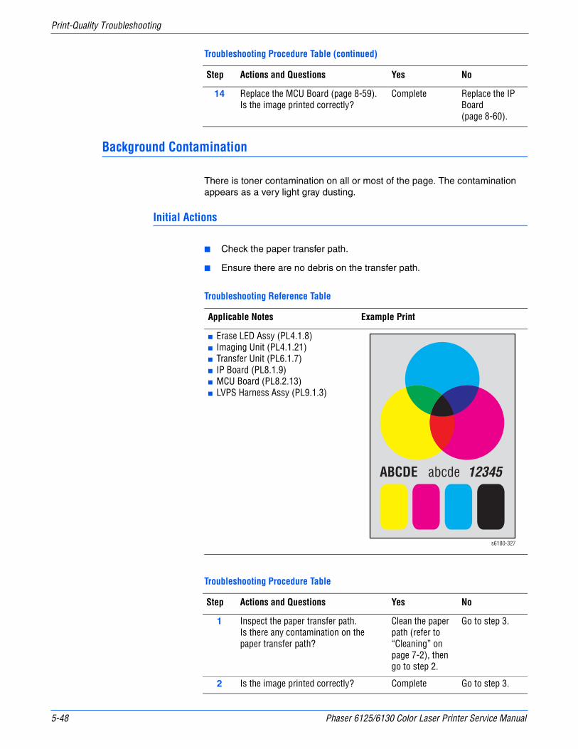
5-48 Phaser 6125/6130 Color Laser Printer Service Manual
Print-Quality Troubleshooting
Background Contamination
There is toner contamination on all or most of the page. The contamination appears as a very light gray dusting.
Initial Actions
■ Check the paper transfer path.
■ Ensure there are no debris on the transfer path.
14 Replace the MCU Board (page 8-59).Is the image printed correctly?
Complete Replace the IP Board (page 8-60).
Troubleshooting Reference Table
Applicable Notes Example Print
■ Erase LED Assy (PL4.1.8)■ Imaging Unit (PL4.1.21)■ Transfer Unit (PL6.1.7)■ IP Board (PL8.1.9)■ MCU Board (PL8.2.13)■ LVPS Harness Assy (PL9.1.3)
Troubleshooting Procedure Table
Step Actions and Questions Yes No
1 Inspect the paper transfer path.Is there any contamination on the paper transfer path?
Clean the paper path (refer to “Cleaning” on page 7-2), then go to step 2.
Go to step 3.
2 Is the image printed correctly? Complete Go to step 3.
Troubleshooting Procedure Table (continued)
Step Actions and Questions Yes No
ABCDE abcde 12345
s6180-327

Phaser 6125/6130 Color Laser Printer Service Manual 5-49
Print-Quality Troubleshooting
3 Print the Windows test page after printing the Demo page (Menu > Information Pages > Demo Page, or running Service Mode > Test Print > Toner Pallet Check).Is the image printed correctly?
Complete Go to step 4.
4 1. Open the Front Cover, and remove the Imaging Unit.
2. Defeat the safety interlock switch.Do the four erase LEDs light correctly?
Go to step 7. Go to step 5.
5 Check the connections between the MCU Board and Erase LED Assy.Are P/J141 and P/J14 connected correctly?
Go to step 6. Reconnect the connector(s) securely, then go to step 6.
6 1. Disconnect J14 from the Erase LED Assy.
2. Measure the voltage across P14-15 <=> ground on the MCU Board.
Does the voltage measure about +3.3 VDC?
Replace the Erase LED Assy (page 8-37).
Replace the MCU Board (page 8-59).
7 1. Open the Front Cover.2. Inspect the four Transfer Unit HV
connections.Are the four terminals on the Transfer Unit, and the four springs on the frame (PL4.1.11, 12, 13 and 14) dirty and/or deformed?
Clean or replace the Transfer Unit contacts or spring(s).
Go to step 8.
8 1. Remove the Imaging Unit.2. Inspect the five Imaging Unit HV
connections.Are the five HV terminals on the Imaging Unit, and five springs on the frame (PL4.1.10 and PL4.1.15 to 18) dirty and/or deformed?
Clean and/or replace the Imaging Unit or spring(s).
Go to step 9.
9 Reseat the connectors on the IP Board.Is the image printed correctly?
Complete Go to step 10.
10 Reseat the Toner Cartridges (Y/M/C/K), and check that their lock keys are in the lock positions.Is the image printed correctly?
Complete Go to step 11.
11 Check the connections between the Laser Unit and MCU Board.Are P/J40, P/J 41, P/J411 and P/J 412 connected correctly?
Go to step 13. Reconnect the connectors securely, then go to step 12.
12 Is the image printed correctly? Complete Go to step 13.
Troubleshooting Procedure Table (continued)
Step Actions and Questions Yes No

5-50 Phaser 6125/6130 Color Laser Printer Service Manual
Print-Quality Troubleshooting
13 Reseat the connectors on the MCU Board.Is the image printed correctly?
Complete Go to step 14.
14 Reseat the connectors on the IP Board.Is the image printed correctly?
Complete Go to step 15.
15 Open and close the Front Cover to reseat the Transfer Unit.Is the image printed correctly?
Complete Go to step 16.
16 Replace the Imaging Unit (page 8-8).Is the image printed correctly?
Complete Go to step 17.
17 Replace the IP Board (page 8-60).Is the image printed correctly?
Complete Replace the MCU Board (page 8-59).
Troubleshooting Procedure Table (continued)
Step Actions and Questions Yes No

Phaser 6125/6130 Color Laser Printer Service Manual 5-51
Print-Quality Troubleshooting
Skew
The printed image is not parallel with both sides of the paper.
Initial Actions
■ Check the paper transfer path.
■ Ensure there are no debris on the transfer path.
NoteThe Tray is recommended for paper feeding because paper fed via the Manual Feed is prone to skew depending on how the sheet is placed on Manual Feed.
Troubleshooting Reference Table
Applicable Notes Example Print
■ Separator Roller Assembly (PL2.1.5)■ Feed Roller Assembly (PL3.2.4)■ Registration Roller Assembly (PL3.2.9)■ Metal Registration Roller (PL3.2.10)
Troubleshooting Procedure Table
Step Actions and Questions Yes No
1 Inspect the paper being used.Is it approved paper?
Go to step 3. Use paper that is on the list of papers approved for the printer, then go to step 2.
2 Is the image printed correctly? Complete Go to step 3.
ABCDE abcde 12345
s6180-328
5-52 Phaser 6125/6130 Color Laser Printer Service Manual
Print-Quality Troubleshooting
3 Check the paper being used and its condition.Is the paper dry and recommended paper?
Go to step 5. Replace the paper with a new dry and recommended one, then go to step 4.
4 Is the image printed correctly? Complete Go to step 5.
5 Open and close the Front Cover.Does the Front Cover latch closed properly?
Complete Replace the defective parts, then go to step 6.
6 Is the image printed correctly? Complete Go to step 7.
7 Reseat the Imaging Unit.Is the image printed correctly?
Complete Go to step 8.
8 Open and close the Front Cover to reseat the Transfer Unit.Is the image printed correctly?
Complete Go to step 9.
9 Is the skewed paper being fed from the Manual Feed Slot?
Go to step 10. Go to step 14.
10 Check the setting of the Manual Feed Slot side guides and reset the side guides if needed.Is the image printed correctly?
Complete Go to step 11.
11 Inspect the paper path.Is there toner contamination on the paper path?
Clean the paper path (refer to “Cleaning” on page 7-2), then go to step 12.
Go to step 13.
12 Is the image printed correctly? Complete Go to step 13.
13 Reseat the Paper Tray.Is the image printed correctly?
Complete Go to step 14.
14 Reseat the paper in the Paper Tray.Is the image printed correctly?
Complete Go to step 15.
15 Reset the Paper Tray side guides.Is the image printed correctly?
Complete Go to step 16.
16 Reseat the Separator Roller Assembly.Is the image printed correctly?
Complete Go to step 17.
17 Replace the Separator Roller Assembly (page 8-7).Is the image printed correctly?
Complete Go to step 18.
18 Replace the Feed Roller (page 8-30).Is the image printed correctly?
Complete Go to step 19.
Troubleshooting Procedure Table (continued)
Step Actions and Questions Yes No
Phaser 6125/6130 Color Laser Printer Service Manual 5-53
Print-Quality Troubleshooting
19 NOTE: During this check, defeat the Front Cover interlock switch (HARN ASSY INTERLOCK).1. Start the Main Motor FULL2 test:
Service Mode > Engine Diag > Motor Test > Main Motor FULL2.
2. While it is running, start the Regi Clutch test: Service Mode > Engine Diag > Motor Test > Regi Clutch.
Do the Regi Roller Assy and Metal Regi Roller rotate?
Complete Replace the Feeder Assembly page 8-25.
Troubleshooting Procedure Table (continued)
Step Actions and Questions Yes No

5-54 Phaser 6125/6130 Color Laser Printer Service Manual
Print-Quality Troubleshooting
Damaged Paper
Paper comes out from the printer wrinkled, folded, or worn-out.
Initial Actions
■ Check the paper transfer path.
■ Ensure there are no debris on the transfer path.
NoteThe Tray is recommended for paper feeding because paper fed via the Manual Feed is prone to skew depending on how the sheet is placed on Manual Feed.
WarningTo prevent burns, allow the Fuser to cool down before starting the procedure.
Troubleshooting Reference Table
Applicable Notes Example Print
■ Separator Roller Assembly (PL2.1.5)■ Feed Roller Assembly (PL3.2.4)■ Registration Roller Assembly (PL3.2.9)■ Metal Registration Roller (PL3.2.10)
Troubleshooting Procedure Table
Step Actions and Questions Yes No
1 Check the paper conditionIs the paper dry and approved for use?
Go to step 3. Replace with dry, approved paper, then go to step 2.
2 Is the image printed correctly? Complete Go to step 3.
s6180-329

Phaser 6125/6130 Color Laser Printer Service Manual 5-55
Print-Quality Troubleshooting
3 Open and close the Front Cover.Does the Front Cover latch closed properly?
Complete Replace any defective parts, then go to step 4.
4 Is the image printed correctly? Complete Go to step 5.
5 Reseat the Imaging Unit.Is the image printed correctly?
Complete Go to step 6.
6 Reseat the Fuser.
Warning: Start the operation after the Fuser has cooled down.
Is the image printed correctly?
Complete Go to step 7.
7 Open and close the Front Cover to reseat the Transfer Unit.Is the image printed correctly?
Complete Go to step 8.
8 Is the paper damaged when fed from the Manual Feed Slot?
Go to step 9. Go to step 12.
9 Check the setting of the Manual Feed Slot side guides and reset the side guides if needed.Is the image printed correctly?
Complete Go to step 10.
10 Inspect the paper path.Is there any contamination on the paper path?
Clean the paper path (refer to “Cleaning” on page 7-2), then go to step 11.
Go to step 12.
11 Is the image printed correctly? Complete Go to step 12.
12 Reseat the Paper Tray.Is the image printed correctly?
Complete Go to step 13.
13 Reset the Paper Tray side guides.Is the image printed correctly?
Complete Go to step 14.
14 Replace the paper in the Paper Tray with new paper.Is the image printed correctly?
Complete Go to step 15.
15 Inspect the paper path.Is there any contamination on the paper path?
Clean the paper path (refer to “Cleaning” on page 7-2), then go to step 16.
Go to step 17.
16 Is the image printed correctly? Complete Go to step 17.
17 Reseat the Separator Roller Assembly.Is the image printed correctly?
Complete Go to step 18.
18 Replace the Separator Roller Assembly (page 8-7).Is the image printed correctly?
Complete Go to step 19.
Troubleshooting Procedure Table (continued)
Step Actions and Questions Yes No
5-56 Phaser 6125/6130 Color Laser Printer Service Manual
Print-Quality Troubleshooting
19 Replace the Feed Roller (page 8-30).Is the image printed correctly?
Complete Go to step 20.
20 NOTE: During this check, defeat the Front Cover interlock switch (HARN ASSY INTERLOCK).1. Start the Main Motor FULL2 test:
Service Mode > Engine Diag > Motor Test > Main Motor FULL2.
2. While it is running, start the Regi Clutch test: Service Mode > Engine Diag > Motor Test > Regi Clutch.
Do the Regi Roller Assy and Metal Regi Roller rotate?
Complete Replace the Feeder Assembly page 8-25.
Troubleshooting Procedure Table (continued)
Step Actions and Questions Yes No
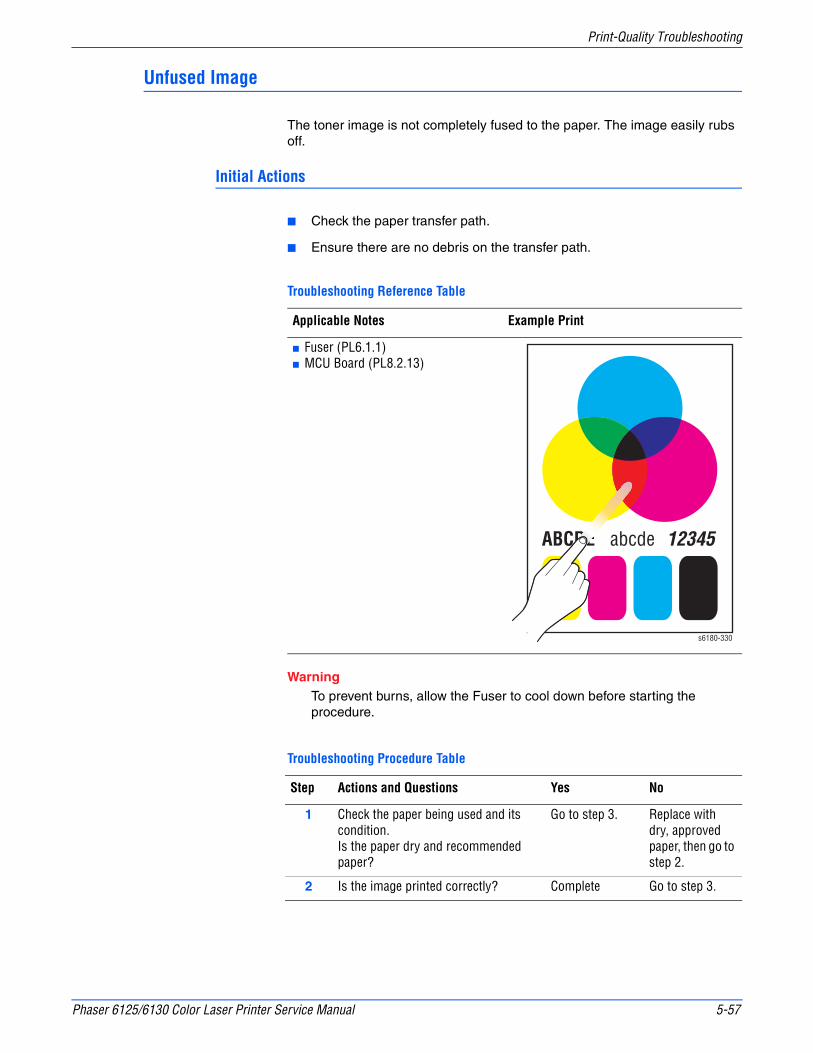
Phaser 6125/6130 Color Laser Printer Service Manual 5-57
Print-Quality Troubleshooting
Unfused Image
The toner image is not completely fused to the paper. The image easily rubs off.
Initial Actions
■ Check the paper transfer path.
■ Ensure there are no debris on the transfer path.
WarningTo prevent burns, allow the Fuser to cool down before starting the procedure.
Troubleshooting Reference Table
Applicable Notes Example Print
■ Fuser (PL6.1.1)■ MCU Board (PL8.2.13)
Troubleshooting Procedure Table
Step Actions and Questions Yes No
1 Check the paper being used and its condition.Is the paper dry and recommended paper?
Go to step 3. Replace with dry, approved paper, then go to step 2.
2 Is the image printed correctly? Complete Go to step 3.
ABCDE abcde 12345
s6180-330
5-58 Phaser 6125/6130 Color Laser Printer Service Manual
Print-Quality Troubleshooting
3 Check the Toner TypeIs non-Xerox Toner in use?
Replace the toner with the Xerox toner, then go to step 4.
Go to step 5.
4 Is the image printed correctly? Complete Go to step 5.
5 Reseat the Fuser.
Warning: Start the operation after the Fuser has cooled down.
Is the image printed correctly?
Complete Go to step 6.
6 Replace the Fuser (page 8-9).
Warning: Start the operation after the Fuser has cooled down.
Does the error still occur when printing?
Replace the MCU Board (page 8-59).
Complete
Troubleshooting Procedure Table (continued)
Step Actions and Questions Yes No
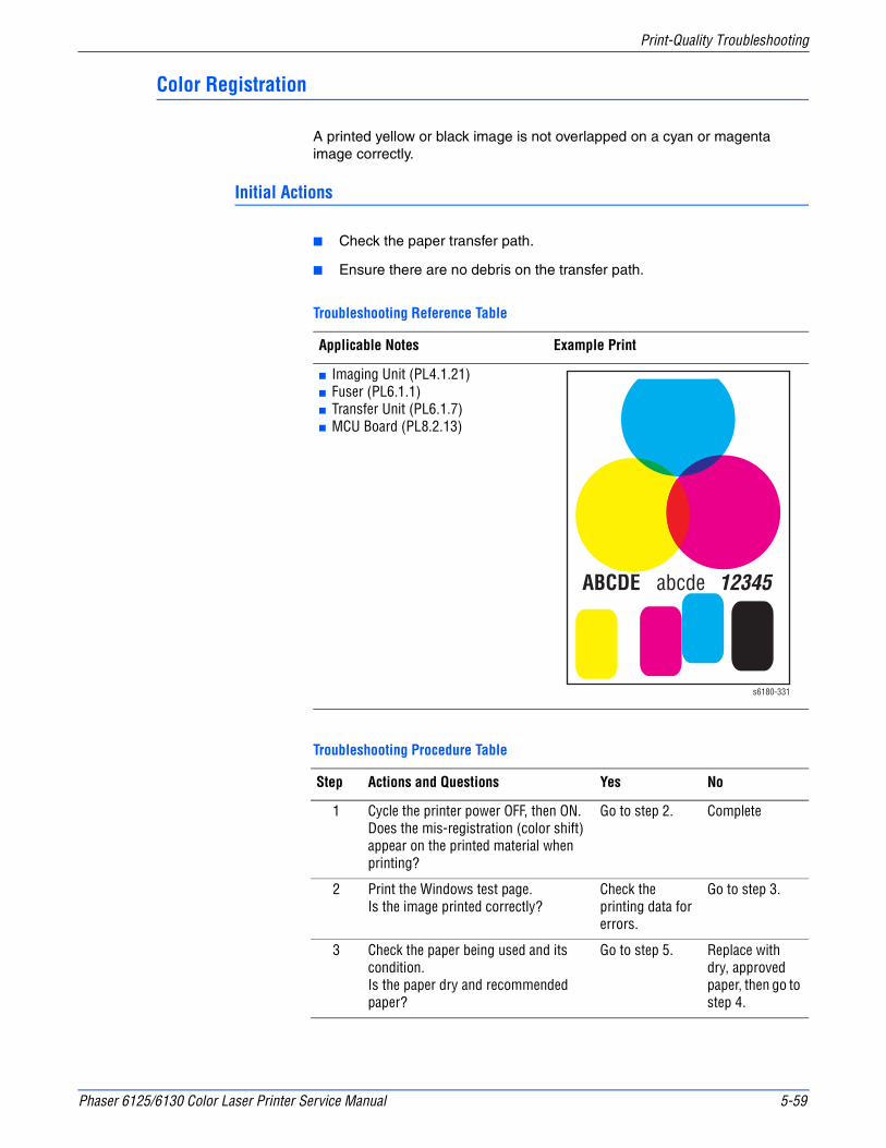
Phaser 6125/6130 Color Laser Printer Service Manual 5-59
Print-Quality Troubleshooting
Color Registration
A printed yellow or black image is not overlapped on a cyan or magenta image correctly.
Initial Actions
■ Check the paper transfer path.
■ Ensure there are no debris on the transfer path.
Troubleshooting Reference Table
Applicable Notes Example Print
■ Imaging Unit (PL4.1.21)■ Fuser (PL6.1.1)■ Transfer Unit (PL6.1.7)■ MCU Board (PL8.2.13)
Troubleshooting Procedure Table
Step Actions and Questions Yes No
1 Cycle the printer power OFF, then ON.Does the mis-registration (color shift) appear on the printed material when printing?
Go to step 2. Complete
2 Print the Windows test page.Is the image printed correctly?
Check the printing data for errors.
Go to step 3.
3 Check the paper being used and its condition.Is the paper dry and recommended paper?
Go to step 5. Replace with dry, approved paper, then go to step 4.
ABCDE abcde 12345
s6180-331
5-60 Phaser 6125/6130 Color Laser Printer Service Manual
Print-Quality Troubleshooting
4 Does the mis-registration (color shift) appear on the printed material when printing?
Go to step 5. Complete
5 Open and close the Front Cover.Does the Front Cover latch closed properly?
Complete Replace any defective parts, then go to step 6.
6 Open and close the Front Cover.Does the mis-registration (color shift) appear on the printed material when printing?
Go to step 7. Complete
7 Reseat the Imaging Unit.Does the mis-registration (color shift) appear on the printed material when printing?
Go to step 8. Go to step 8.
8 Open and close the Front Cover to reseat the Transfer Unit.Does the mis-registration (color shift) appear on the printed material when printing?
Go to step 8. Complete
9 Set the printer to adjust the color registration automatically: Menus > Admin Menu > Maintenance Mode > Automatic Registration Adjust.Does the mis-registration (color shift) appear on the printed material when printing?
Go to step 9. Complete
9 Adjust the color registration manually: Menus > Admin Menu > Maintenance Mode > Adjust Color Registration.(Refer to the User Guide.) Does the mis-registration (color shift) appear on the printed material when printing?
Go to step 10. Complete
10 Replace the Imaging Unit (page 8-8).Is the image printed correctly?
Go to step 11. Complete
11 Replace the Transfer Unit (page 8-41).Does the mis-registration (color shift) appear on the printed material when printing?
Go to step 12. Complete
12 Replace the MCU Board (page 8-59).Does the mis-registration (color shift) appear on the printed material when printing?
Replace the printer.
Complete
Troubleshooting Procedure Table (continued)
Step Actions and Questions Yes No

6Chapter
Adjustments and Calibrations
In this chapter...■ Adjustments
■ Calibrations
■ Parameter Setting

6-2 Phaser 6130 Color Laser Printer Service Manual
Adjustments and Calibrations
Adjustments
Color Registration
The Color Registration adjustment procedure allows the user to change or correct the alignment of the four color images to meet specifications and/or user’s requirements.
NoteAdjusting laser power from the default value impacts other print-quality parameters, such as background, halftone/fine line production, fuser fix, and toner consumption. This adjustment should not be performed without first discussing with the customer regarding its potential impact on overall print quality.
Printing the Color Registration Correction Chart
Before performing the Color Registration adjustment procedure, print the Color Registration Correction Chart for reference.
1. From the Control Panel, press the Menu button.
2. Press the Up Arrow or Down Arrow button to find Admin Menu. Press the OK button.
3. Press the Up Arrow or Down Arrow button to find Maintenance Mode. Press the OK button.
4. Press the Up Arrow or Down Arrow button find Adjust Color Regi. Press the OK button.
5. Press the Up Arrow or Down Arrow button to find Color Regi Chart. Press the OK button. The Color Registration Chart is printed. When printing is finished, the Ready menu is displayed.
NoteAfter printing the Color Registration Correction Chart, do not power OFF the printer until the printer motor has stopped running.
s6130-226
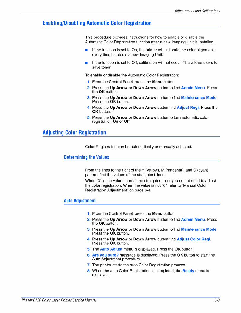
Phaser 6130 Color Laser Printer Service Manual 6-3
Adjustments and Calibrations
Enabling/Disabling Automatic Color Registration
This procedure provides instructions for how to enable or disable the Automatic Color Registration function after a new Imaging Unit is installed.
■ If the function is set to On, the printer will calibrate the color alignment every time it detects a new Imaging Unit.
■ If the function is set to Off, calibration will not occur. This allows users to save toner.
To enable or disable the Automatic Color Registration:
1. From the Control Panel, press the Menu button.
2. Press the Up Arrow or Down Arrow button to find Admin Menu. Press the OK button.
3. Press the Up Arrow or Down Arrow button to find Maintenance Mode. Press the OK button.
4. Press the Up Arrow or Down Arrow button find Adjust Regi. Press the OK button.
5. Press the Up Arrow or Down Arrow button to turn automatic color registration On or Off.
Adjusting Color Registration
Color Registration can be automatically or manually adjusted.
Determining the Values
From the lines to the right of the Y (yellow), M (magenta), and C (cyan) pattern, find the values of the straightest lines.
When “0” is the value nearest the straightest line, you do not need to adjust the color registration. When the value is not “0,” refer to “Manual Color Registration Adjustment” on page 6-4.
Auto Adjustment
1. From the Control Panel, press the Menu button.
2. Press the Up Arrow or Down Arrow button to find Admin Menu. Press the OK button.
3. Press the Up Arrow or Down Arrow button to find Maintenance Mode. Press the OK button.
4. Press the Up Arrow or Down Arrow button find Adjust Color Regi. Press the OK button.
5. The Auto Adjust menu is displayed. Press the OK button.
6. Are you sure? message is displayed. Press the OK button to start the Auto Adjustment procedure.
7. The printer starts the auto Color Registration process.
8. When the auto Color Registration is completed, the Ready menu is displayed.
6-4 Phaser 6130 Color Laser Printer Service Manual
Adjustments and Calibrations
Manual Color Registration Adjustment
Color registration can be adjusted manually by a user or automatically by the printer. Color registration should be adjusted any time the printer is moved. The color registration can be fine tuned by performing a manual adjustment.
NoteAn automatic color registration adjustment is performed every time a new Print Cartridge is installed.
Horizontal Registration
Section 1 of the Color Registration Correction Chart displays a series of lines. Some lines are straight, with both the colored and black segments aligned, while other lines are jagged, with the colored segments offset to the right or left. A value is listed next to each line. When the value is 0, the color registration needs no adjustment.
To determine correction values for Horizontal Registration, choose the straightest line. If the value listed next to the straight line is anything other than 0, follow the procedure below to enter values.
NoteThe densest colors of the grid can also be used to find the straightest lines. The colors printed at the highest density are those next to the straight lines.
To enter values:
1. From the Control Panel, press the Menu button.
2. Press the Up Arrow or Down Arrow button to find Admin Menu. Press the OK button.
3. Press the Up Arrow or Down Arrow button to find Maintenance Mode. Press the OK button.
4. Press the Up Arrow or Down Arrow button to find Adjust Color Regi. Press the OK button.
5. Press the Up Arrow or Down Arrow button to find Enter Number. Press the OK button.
6. Press the Up Arrow or Down Arrow button to find Fast Scan. Press the OK button.
7. Use the Up Arrow or Down Arrow button to enter the values and the Right Arrow button to move from Y to M to C.
8. Repeat step 2 to continue adjusting the color registration.
9. Press the OK button twice to print the Color Registration Correction Chart with the new values. The color registration adjustment is complete when the straightest Y, M, and C lines are next to the 0 line.
NoteIf 0 is not displayed next to the straightest lines, determine the values and adjust again.

Phaser 6130 Color Laser Printer Service Manual 6-5
Adjustments and Calibrations
Vertical Registration
Section 2 of the Color Registration Correction Chart displays three columns of color. In the center of each column is a wavy white column. This column of white needs to be centered as much as possible at 0.
To determine correction values for use in Vertical Registration adjustment, choose the value from each column that is best centered on the wavy white column.
To enter the correction values:
1. From the Control Panel, press the Menu button.
2. Press the Up Arrow or Down Arrow button to find Admin Menu. Press the OK button.
3. Press the Up Arrow or Down Arrow button to find Maintenance Mode. Press the OK button.
4. Press the Up Arrow or Down Arrow button to find Adjust Color Regi. Press the OK button.
5. Press the Up Arrow or Down Arrow button to find Enter Number. Press the OK button.
6. Press the Up Arrow or Down Arrow button to find Slow Scan. Press the OK button.
7. Use the Up Arrow or Down Arrow button to enter the values and the Right Arrow button to move from Y to M to C.
8. Repeat step 7 to continue adjusting the color registration.
9. Press the OK button twice to print the Color Registration Correction Chart with the new values. The color registration adjustment is complete when the columns of white are centered, as much as possible, on 0.
Resetting the Fuser
Fuser reset is required when a new Fuser is installed into the printer. This function sets the life counter to “0.”
1. From the Control Panel, press the Menu button.
2. Press the Up Arrow or Down Arrow button to find Admin Menu. Press the OK button.
3. Press the Up Arrow or Down Arrow button to find Maintenance Mode. Press the OK button.
4. Press the Up Arrow or Down Arrow button to find Reset Fuser. Press the OK button.
5. “Are you sure?” message is displayed. Press the OK button to start the process.
6. Initializing... --> Initialized messages are displayed. The Maintenance Mode - Reset Fuser menu is displayed when the process is completed.

6-6 Phaser 6130 Color Laser Printer Service Manual
Adjustments and Calibrations
Calibrations
Initializing Print Meter
This process initializes the Print Meter.
1. From the Control Panel, press the Menu button.
2. Press the Up Arrow or Down Arrow button to find Admin Menu. Press the OK button.
3. Press the Up Arrow or Down Arrow button to find Maintenance Mode. Press the OK button.
4. Press the Up Arrow or Down Arrow button to find Init PrintMeter. Press the OK button.
5. Are you sure? message is displayed. Press the OK button to start the process.
6. Initialized message is displayed. The Maintenance Mode - Init PrintMeter menu is displayed when the process is completed.
Initializing NVM (NVRAM)
This process initializes the settings stored in the NVRAM except for the network settings. The NVRAM is a non-volatile memory that stores the printer settings even after the power is turned Off. After executing this function and restarting the printer, all the menu parameters are reset to their default values.
1. From the Control Panel, press the Menu button.
2. Press the Up Arrow or Down Arrow button to find Admin Menu. Press the OK button.
3. Press the Up Arrow or Down Arrow button to find Maintenance Mode. Press the OK button.
4. Press the Up Arrow or Down Arrow button to find Initialize NVM. Press the OK button.
5. Are you sure? message is displayed. Press the OK button to start the process.
6. Initializing... --> Initialized messages are displayed.
7. The Maintenance Mode - Initialize NVM menu is displayed when the process is completed.
8. Turn the printer power Off and back On.

Phaser 6130 Color Laser Printer Service Manual 6-7
Adjustments and Calibrations
Parameter Setting
This function reads/writes the parameter values, errors, and life counter values stored in the printer.
NotePrint the parameter list from Service Mode > Parameter > Print before changing the registration value. The parameter list contains the parameter and life counter values currently stored in the engine.
To access the Parameter list:
1. Turn the printer power Off (if the printer is On).
2. Simultaneously press the Up Arrow and Down Arrow buttons and turn on the printer.
3. The Service Mode menu is displayed.
4. Press the Up Arrow or Down Arrow button to find Parameter. Press the OK button.
5. Select the appropriate item to change (i.e., Slow Scan KtoP). Press the OK button.
6. Enter the appropriate range using the Up Arrow or Down Arrow button. Press the OK button.
7. The new value “# *” is displayed.
Note“*” = data has been saved
8. Press the Cancel button to return to the Parameter menu.
Parameter Setting
Item Range Description
Slow Scan K to P -128 to 127 Sets the registration in the paper feeding direction.
Slow Scan 600 Y/M/C -30 to 30
Fast Scan K to M, Y, C -128 to 127 Sets the registration in the scanning direction.Fast Scan 2 K to M, Y, C -1 to 2
Fast Scan M-Feed, Tray -30 to 30
Life Counter — Reads the life counter and the printer.
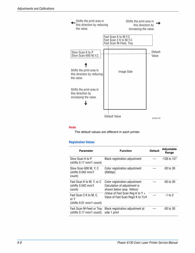
6-8 Phaser 6130 Color Laser Printer Service Manual
Adjustments and Calibrations
NoteThe default values are different in each printer.
Registration Values
Parameter Function DefaultAdjustable
Range
Slow Scan K to P(shifts 0.17 mm/1 count)
Black registration adjustment — -128 to 127
Slow Scan 600 M, Y, C(shifts 0.042 mm/1 count)
Color registration adjustment (600dpi)
— -30 to 30
Fast Scan K to M, Y, or C (shifts 0.042 mm/1 count)
Color registration adjustmentCalculation of adjustment is shown below (exp. Yellow)(Value of Fast Scan Reg K to Y + Value of Fast Scan Reg2 K to Y)/4
— -30 to 30
Fast Scan 2 K to M, C,or Y(shifts 0.01 mm/1 count)
— -1 to 2
Fast Scan M-Feed or Tray(shifts 0.17 mm/1 count)
Black registration adjustment at side 1 print
— -30 to 30
Shifts the print area in this direction by reducing the value.
Shifts the print area in this direction by reducing the value.
Shifts the print area in this direction by increasing the value.
Shifts the print area in this direction by
increasing the value.
Slow Scan K to PSlow Scan 600 M,Y,C
Fast Scan K to M,Y,CFast Scan 2 K to M,Y,CFast Scan M-Feed, Tray
Image Side
Default Value
DefaultValue
s6130-219
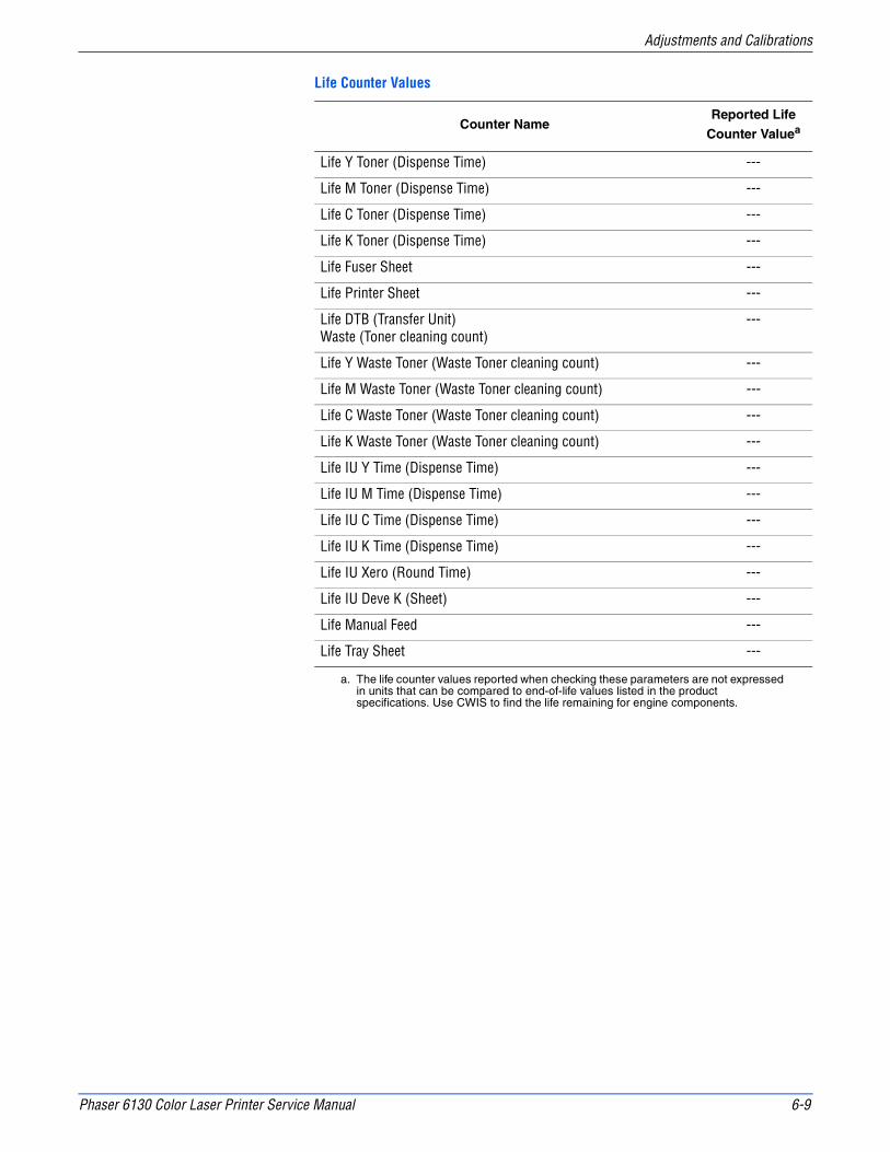
Phaser 6130 Color Laser Printer Service Manual 6-9
Adjustments and Calibrations
Life Counter Values
Counter NameReported Life
Counter Valuea
Life Y Toner (Dispense Time) ---
Life M Toner (Dispense Time) ---
Life C Toner (Dispense Time) ---
Life K Toner (Dispense Time) ---
Life Fuser Sheet ---
Life Printer Sheet ---
Life DTB (Transfer Unit) Waste (Toner cleaning count)
---
Life Y Waste Toner (Waste Toner cleaning count) ---
Life M Waste Toner (Waste Toner cleaning count) ---
Life C Waste Toner (Waste Toner cleaning count) ---
Life K Waste Toner (Waste Toner cleaning count) ---
Life IU Y Time (Dispense Time) ---
Life IU M Time (Dispense Time) ---
Life IU C Time (Dispense Time) ---
Life IU K Time (Dispense Time) ---
Life IU Xero (Round Time) ---
Life IU Deve K (Sheet) ---
Life Manual Feed ---
Life Tray Sheet ---
a. The life counter values reported when checking these parameters are not expressed in units that can be compared to end-of-life values listed in the product specifications. Use CWIS to find the life remaining for engine components.

6-10 Phaser 6130 Color Laser Printer Service Manual
Adjustments and Calibrations

7Chapter
Cleaning and MaintenanceIn this chapter...■ Service Maintenance Procedure
■ Cleaning
■ Maintenance

7-2 Phaser 6125/6130 Color Laser Printer Service Manual
Cleaning and Maintenance
Service Maintenance Procedure
Perform the following procedures whenever you check, service, or repair a printer. Cleaning the printer, as outlined in the following steps, assures proper operation of the printer and reduces the probability of having to service the printer in the future.
The frequency of use, Average Monthly Print Volume (AMPV), type of media printed on, and operating environment are factors in determining how critical cleaning the machine is and how often it is necessary. Record the number of sheets printed.
Recommended Tools
■ Toner vacuum cleaner
■ Clean water
■ Clean, dry, lint-free cloth
■ Black light-protective bag
Cleaning
Perform the following general cleaning steps as indicated by the printer’s operating environment.
CautionNever apply alcohol or other chemicals to any parts of the printer. Never use a damp cloth to clean up toner. If you remove the Imaging Unit, place it in a light-protective bag or otherwise protect it as exposure to light can quickly degrade performance and result in early failure.
1. Record number of sheets printed.
2. Print several sheets of paper to check for problems or defects.
3. Turn the printer power Off and disconnect the power cord.
4. Remove the Imaging Unit, Fuser, Toner Cartridges, Left and Right Side Covers, and Rear Cover before cleaning.
5. Remove the Top Cover and clean the Main Fan to remove excess dust.
6. Ensure that all cover vents are clean and free of obstructions.
7. Remove any debris or foreign objects from the Fuser, Transfer Unit, Imaging Unit, and inside of the printer.
8. Remove and clean the paper trays.
9. Clean all rubber rollers with a lint-free cloth slightly dampened with cold water.

Phaser 6125/6130 Color Laser Printer Service Manual 7-3
Cleaning and Maintenance
Maintenance
RIP (Repair, Inspect, and Prevent) Procedure
Perform these routine maintenance procedures during the course of servicing the printer.
■ Clean the Feed Rollers, Exit Rollers, and Guides; replace if necessary.
■ Remove and clean the paper trays.
■ Print a Configuration and Error History pages, diagnose, and repair any problems as indicated.
■ Check the printer engine and image processor firmware fans; if necessary, clean (dust or vacuum) these areas.
■ Check cleanliness of the interior and exterior, including fans; if necessary clean (dust or vacuum) these areas.
■ Review proper printer operation using a customer file, if possible. Check with the customer regarding any special applications they may be running.
■ Review with the customer all work that was performed and discuss proper printer care.

7-4 Phaser 6125/6130 Color Laser Printer Service Manual
Cleaning and Maintenance

8Chapter
Service Parts DisassemblyIn this chapter...■ Overview
■ Maintenance Items and Consumables
■ Covers
■ Paper Feeder
■ Xerographics
■ Frame
■ Drive
■ Electrical

8-2 Phaser 6125/6130 Color Laser Printer Service Manual
Service Parts Disassembly
Overview
This section contains the removal procedures for field-replaceable parts of the printer listed in the Parts List. In most cases, the replacement procedure is simply the reverse of the removal procedure. In some instances, additional steps are necessary and are provided for replacement of the parts. For specific assemblies and parts, refer to the “Parts List” in Chapter 9.
The procedures are organized by the consumer replacement parts and functions of the printer.
■ Maintenance Items and Consumables (page 8-7)
■ Separator Roller (page 8-7)
■ Imaging Unit (page 8-8)
■ Fuser (page 8-9)
■ Toner Cartridges (C, M, Y, K) (page 8-10)
■ Covers (page 8-11)
■ Paper Feeder (page 8-21)
■ Xerographics (page 8-31)
■ Frame (page 8-44)
■ Drive (page 8-52)
■ Electrical (page 8-54)
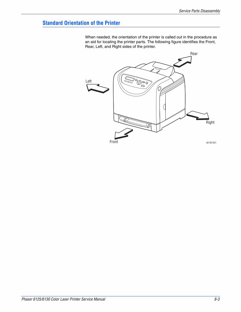
Phaser 6125/6130 Color Laser Printer Service Manual 8-3
Service Parts Disassembly
Standard Orientation of the Printer
When needed, the orientation of the printer is called out in the procedure as an aid for locating the printer parts. The following figure identifies the Front, Rear, Left, and Right sides of the printer.
s6130-051
Rear
Left
Right
Front

8-4 Phaser 6125/6130 Color Laser Printer Service Manual
Service Parts Disassembly
Preparation
Before you begin any removal and replacement procedure:
1. Wear an Electrostatic Discharge wrist strap to help prevent damage to the sensitive electronics of the printer circuit boards.
2. Turn Off the printer and disconnect the power cord from the wall outlet.
3. Disconnect all interface cables from the printer.
4. Remove the Paper Tray.
5. Open the Front Cover.
6. Remove the following Maintenance Items:
CautionDo not expose the Imaging Unit to light for more than 5 minutes. After removal, cover the Imaging Unit to minimize the amount of light striking the drums. Prolonged exposure to light significantly reduces Imaging Unit performance.
a. Imaging Unit (page 8-8).
s6130-052
Imaging Unit
Paper Tray
Fuser
Black Toner Cartridge
Cyan Toner Cartridge
Magenta Toner Cartridge
Yellow Toner Cartridge
Phaser 6125/6130 Color Laser Printer Service Manual 8-5
Service Parts Disassembly
WarningThe Fuser may be hot. Turn the printer power Off and allow at least 5 minutes for the Fuser to cool before removing the Fuser.
b. Fuser (page 8-9).
7. Open the Toner Access Door.
8. Remove the Toner Cartridges (page 8-10).
NoteNames of parts that appear in the removal and replacement procedures may not match the names that appear in the Parts List. For example, a part called the Registration Chute Assembly in a removal procedure may appear on the Parts List as Assembly, Registration Chute. When working on a removal procedure, ignore any prerequisite procedure for parts already removed.
CautionMany parts are secured by plastic tabs. DO NOT over flex or force these parts. DO NOT over torque the screws threaded into plastic parts.
WarningUnplug the AC power cord from the wall outlet before removing any printer part.
Notations in the Disassembly Text
■ The notation “(item X)” points to a numbered callout in the illustration corresponding to the disassembly procedure being performed.
■ The notation “PLX.X.X” indicates that this component is listed in the Parts List.
■ Bold arrows in an illustration show direction of movement when removing or replacing a component.
■ The notation “(tap, plastic, 10 mm)” or “(metal, 6 mm)” refer to the type of screw being removed.
NoteProvides information specific to the replacement of parts or assemblies.

8-6 Phaser 6125/6130 Color Laser Printer Service Manual
Service Parts Disassembly
Fastener Types
The following table lists the primary types of Posi-Drive screws used to assemble the printer. The procedures provide dimensional specifications for screws being removed.
CautionUse care when installing self-tapping screws in plastic. To properly start the screw in plastic, turn the screw counter-clockwise in the hole until you feel the screw engage the threads, then tighten as usual. Improperly aligning or over tightening the screw can result in damage to previously tapped threads.
Always use the correct type and size screw. Using the wrong screw can damage tapped holes. Do not use excessive force to remove or install either a screw or a printer part.
Posi-Drive Screw Types used in the Printer
Type Application Shape Characteristics
Self-tapping, plastic
1. Silver colored.2. Screw thread is coarse
compared to metal screw.3. Screw tip is thin.
Self-tapping, plastic, with flange
1. Black colored.2. Screw thread is coarse
compared to metal screw.3. Screw has a flange.4. Screw tip is thin.
Sheet Metal, silver
1. Silver colored.2. Diameter is uniform.
Sheet Metal, with flange
1. Silver colored.2. Screw has a flange.3. Diameter is uniform.
Sheet Metal, silver with lock washer
1. Silver colored.2. Includes a toothed washer.3. Diameter is uniform.4. Used for grounding
terminals.
Parts etc.Plastic
Coarse
Parts etc.Plastic
Coarse
Parts etc.Sheet Metal
Parts etc.SheetMetal
Parts etc. Sheet Metal

Phaser 6125/6130 Color Laser Printer Service Manual 8-7
Service Parts Disassembly
Maintenance Items and Consumables
Maintenance items include the Separator Roller in the Paper Tray, Imaging Unit, and Fuser. Consumables consist of the four Toner Cartridges.
Separator Roller
(PL2.1.5)1. Remove the Paper Tray completely from the printer.
2. Hold the tray and pinch the left and right hooks of the Separator Roller. Swing the Separator Roller to release the two hooks.
3. Pull the Separator Roller up to remove it from the Tray.
s6130-164
s6130-164

8-8 Phaser 6125/6130 Color Laser Printer Service Manual
Service Parts Disassembly
Imaging Unit
(PL4.1.21)
CautionDo not expose the drums on the Imaging Unit to light for more than 5 minutes. Cover the drums to avoid damage.
1. Open the Front Cover.
2. Rotate the four securing locks counter-clockwise.
CautionWhen removing the Imaging Unit, take particular care to neither drag nor drop the Imaging Unit on the Transfer Belt.
3. Grasp the left and right handles and pull the Imaging Unit straight forward until it is clear, then lift it out of the printer as shown. Take care to not touch the drums.
s6130-073 s6130-074
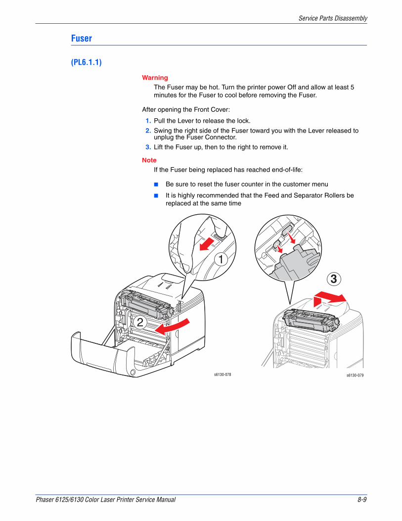
Phaser 6125/6130 Color Laser Printer Service Manual 8-9
Service Parts Disassembly
Fuser
(PL6.1.1)
WarningThe Fuser may be hot. Turn the printer power Off and allow at least 5 minutes for the Fuser to cool before removing the Fuser.
After opening the Front Cover:
1. Pull the Lever to release the lock.
2. Swing the right side of the Fuser toward you with the Lever released to unplug the Fuser Connector.
3. Lift the Fuser up, then to the right to remove it.
NoteIf the Fuser being replaced has reached end-of-life:
■ Be sure to reset the fuser counter in the customer menu
■ It is highly recommended that the Feed and Separator Rollers be replaced at the same time
s6130-078 s6130-079
3

8-10 Phaser 6125/6130 Color Laser Printer Service Manual
Service Parts Disassembly
Toner Cartridges (C, M, Y, K)
(PL5.1.21-24)
NoteThis procedure applies to all four toner cartridges.
1. Open the Toner Access Door.
2. Push the toner cartridge handle toward the rear to release the latch.
3. Swing open the toner cartridge holder and slide the toner cartridge out of the holder as shown.
s6130-075
s6130-076
s6130-077
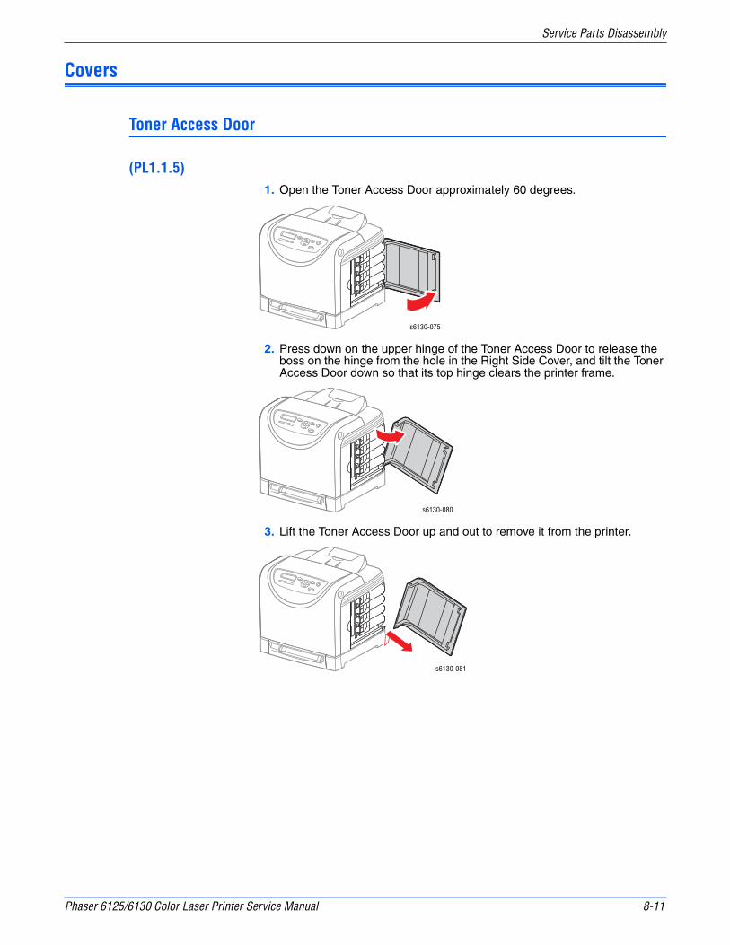
Phaser 6125/6130 Color Laser Printer Service Manual 8-11
Service Parts Disassembly
Covers
Toner Access Door
(PL1.1.5)1. Open the Toner Access Door approximately 60 degrees.
2. Press down on the upper hinge of the Toner Access Door to release the boss on the hinge from the hole in the Right Side Cover, and tilt the Toner Access Door down so that its top hinge clears the printer frame.
3. Lift the Toner Access Door up and out to remove it from the printer.
s6130-075
s6130-080
s6130-081

8-12 Phaser 6125/6130 Color Laser Printer Service Manual
Service Parts Disassembly
Rear Tray Cover
(PL1.1.4)1. Remove the Paper Tray from the printer.
2. Press the left and right sides of the Rear Tray Cover to release the two hooks from the holes in the printer and remove the cover.
Cassette Stopper
(PL3.1.7)1. Remove the Paper Tray.
2. Remove the Rear Tray Cover.
3. Remove the screw (silver, tapping) that attaches the Cassette Stopper to the Feeder Assembly, and remove the stopper from the printer.
s6130-166
s6130-071
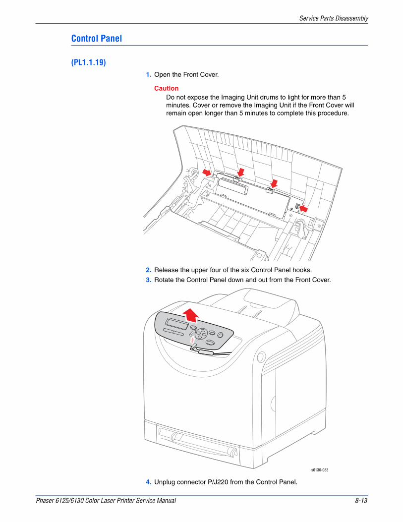
Phaser 6125/6130 Color Laser Printer Service Manual 8-13
Service Parts Disassembly
Control Panel
(PL1.1.19)1. Open the Front Cover.
CautionDo not expose the Imaging Unit drums to light for more than 5 minutes. Cover or remove the Imaging Unit if the Front Cover will remain open longer than 5 minutes to complete this procedure.
2. Release the upper four of the six Control Panel hooks.
3. Rotate the Control Panel down and out from the Front Cover.
4. Unplug connector P/J220 from the Control Panel.
s6130-083
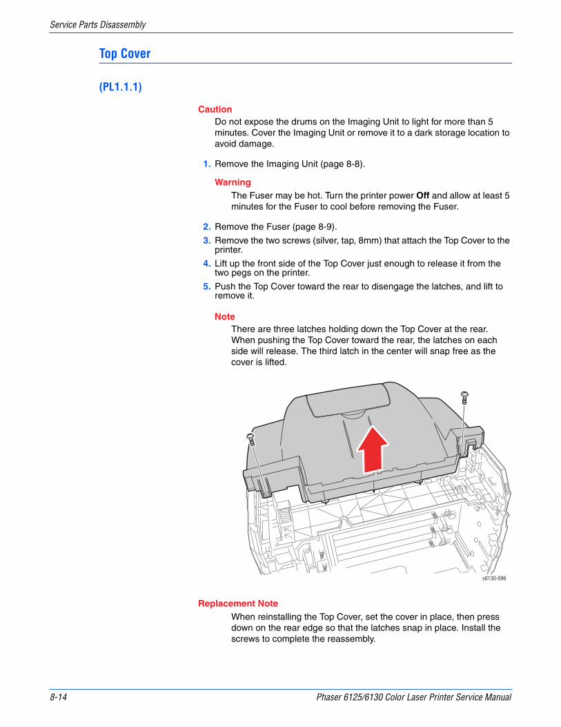
8-14 Phaser 6125/6130 Color Laser Printer Service Manual
Service Parts Disassembly
Top Cover
(PL1.1.1)
CautionDo not expose the drums on the Imaging Unit to light for more than 5 minutes. Cover the Imaging Unit or remove it to a dark storage location to avoid damage.
1. Remove the Imaging Unit (page 8-8).
WarningThe Fuser may be hot. Turn the printer power Off and allow at least 5 minutes for the Fuser to cool before removing the Fuser.
2. Remove the Fuser (page 8-9).
3. Remove the two screws (silver, tap, 8mm) that attach the Top Cover to the printer.
4. Lift up the front side of the Top Cover just enough to release it from the two pegs on the printer.
5. Push the Top Cover toward the rear to disengage the latches, and lift to remove it.
NoteThere are three latches holding down the Top Cover at the rear. When pushing the Top Cover toward the rear, the latches on each side will release. The third latch in the center will snap free as the cover is lifted.
Replacement NoteWhen reinstalling the Top Cover, set the cover in place, then press down on the rear edge so that the latches snap in place. Install the screws to complete the reassembly.
s6130-096

Phaser 6125/6130 Color Laser Printer Service Manual 8-15
Service Parts Disassembly
Output Tray Extension
(PL1.1.2)
NoteRemoval of the Output Tray Extension is a stand-alone procedure and is not required before removing any other part of the printer.
1. Open the Output Tray Extension.
2. Press the right side of the Output Tray Extension to the left to release the hole in the Output Tray Extension from the boss on the printer.
3. Remove the Output Tray Extension.
s6130-097
s6130-098

8-16 Phaser 6125/6130 Color Laser Printer Service Manual
Service Parts Disassembly
Right Side Cover
(PL1.1.6)1. Remove the Toner Access Door (page 8-11).
2. Remove the Rear Tray Cover (page 8-12).
3. Remove the Top Cover (page 8-14).
4. Remove the seven screws (silver, tap, 8mm) that attach the Right Side Cover to the printer.
5. Release the hook at the front and remove the Right Side Cover from the printer.
s6130-099
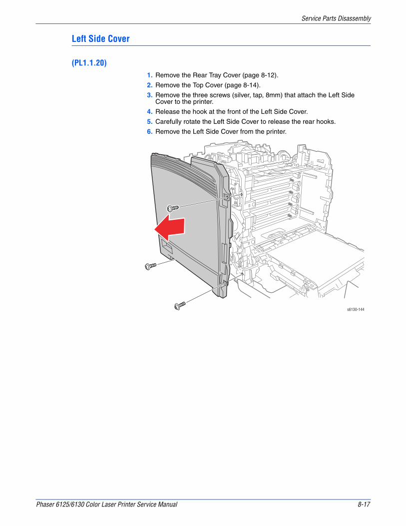
Phaser 6125/6130 Color Laser Printer Service Manual 8-17
Service Parts Disassembly
Left Side Cover
(PL1.1.20)1. Remove the Rear Tray Cover (page 8-12).
2. Remove the Top Cover (page 8-14).
3. Remove the three screws (silver, tap, 8mm) that attach the Left Side Cover to the printer.
4. Release the hook at the front of the Left Side Cover.
5. Carefully rotate the Left Side Cover to release the rear hooks.
6. Remove the Left Side Cover from the printer.
s6130-144

8-18 Phaser 6125/6130 Color Laser Printer Service Manual
Service Parts Disassembly
Rear Cover
(PL1.1.3)1. Remove the Right Side Cover (page 8-16).
2. Remove the Left Side Cover (page 8-17).
3. Remove 2 screws (8 mm) securing the Rear Cover.
4. Remove the Rear Cover from the printer.
s6130-145

Phaser 6125/6130 Color Laser Printer Service Manual 8-19
Service Parts Disassembly
Front Cover
(PL1.1.7)1. Remove the Right Side Cover (page 8-16).
2. Remove the Left Side Cover (page 8-17).
3. Remove the Paper Tray.
4. Remove the Left and Right Pivot Shafts. Release the latch in the shaft and pull it out of the printer.
5. Release the Control Panel Harness from the cable restraints in the frame.
6. Release the Control Panel Harness connector from the rib of the printer, and disconnect connector P/J2900 of the B Harness.
s6130-147
s6130-167
P/J2900
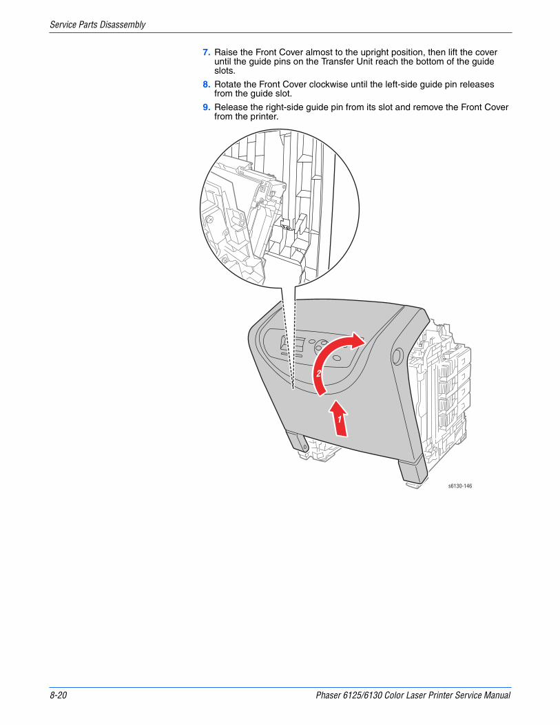
8-20 Phaser 6125/6130 Color Laser Printer Service Manual
Service Parts Disassembly
7. Raise the Front Cover almost to the upright position, then lift the cover until the guide pins on the Transfer Unit reach the bottom of the guide slots.
8. Rotate the Front Cover clockwise until the left-side guide pin releases from the guide slot.
9. Release the right-side guide pin from its slot and remove the Front Cover from the printer.
1
2
s6130-146
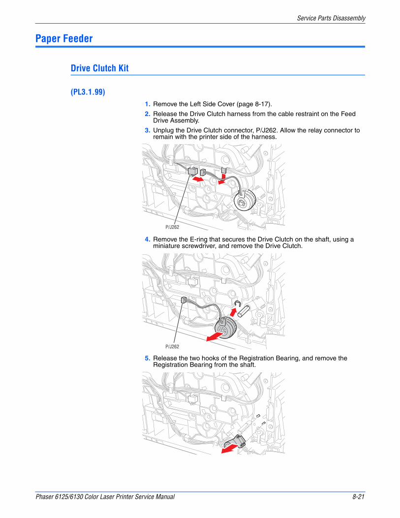
Phaser 6125/6130 Color Laser Printer Service Manual 8-21
Service Parts Disassembly
Paper Feeder
Drive Clutch Kit
(PL3.1.99)1. Remove the Left Side Cover (page 8-17).
2. Release the Drive Clutch harness from the cable restraint on the Feed Drive Assembly.
3. Unplug the Drive Clutch connector, P/J262. Allow the relay connector to remain with the printer side of the harness.
4. Remove the E-ring that secures the Drive Clutch on the shaft, using a miniature screwdriver, and remove the Drive Clutch.
5. Release the two hooks of the Registration Bearing, and remove the Registration Bearing from the shaft.
P/J262
P/J262
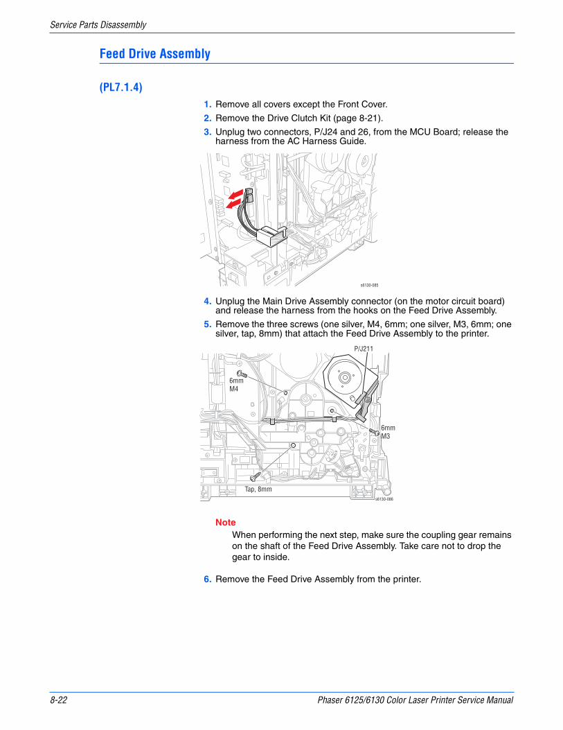
8-22 Phaser 6125/6130 Color Laser Printer Service Manual
Service Parts Disassembly
Feed Drive Assembly
(PL7.1.4)1. Remove all covers except the Front Cover.
2. Remove the Drive Clutch Kit (page 8-21).
3. Unplug two connectors, P/J24 and 26, from the MCU Board; release the harness from the AC Harness Guide.
4. Unplug the Main Drive Assembly connector (on the motor circuit board) and release the harness from the hooks on the Feed Drive Assembly.
5. Remove the three screws (one silver, M4, 6mm; one silver, M3, 6mm; one silver, tap, 8mm) that attach the Feed Drive Assembly to the printer.
NoteWhen performing the next step, make sure the coupling gear remains on the shaft of the Feed Drive Assembly. Take care not to drop the gear to inside.
6. Remove the Feed Drive Assembly from the printer.
s6130-085
s6130-086
6mmM4
Tap, 8mm
6mmM3
P/J211
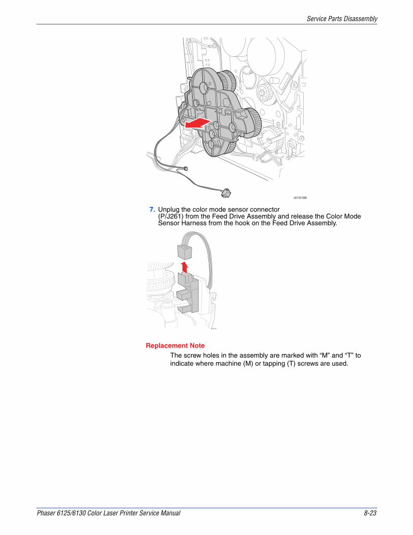
Phaser 6125/6130 Color Laser Printer Service Manual 8-23
Service Parts Disassembly
7. Unplug the color mode sensor connector (P/J261) from the Feed Drive Assembly and release the Color Mode Sensor Harness from the hook on the Feed Drive Assembly.
Replacement NoteThe screw holes in the assembly are marked with “M” and “T” to indicate where machine (M) or tapping (T) screws are used.
s6130-088
s6130-148

8-24 Phaser 6125/6130 Color Laser Printer Service Manual
Service Parts Disassembly
Feed Solenoid
(PL3.1.98)
NoteThe first step in this procedure requires removal of the Drive Clutch Kit and all of the printer’s covers except the Front Cover.
1. Remove the Feed Drive Assembly (page 8-22).
2. Release the Feed Gear Return Spring from the hook on the printer frame. Leave the spring connected to the arm on the Feed Gear.
3. Release the Feed Gear retainer hook and slide the Feed Gear off the Feed Shaft.
4. Remove the Lever Spring from the printer.
5. Release the Feed Lever hook and slide the Feed Lever off the shaft.
6. Release the Feed Solenoid harness from the cable restraints on the frame.
7. Unplug the Feed Solenoid connector (P/J231). Allow the relay connector to remain with the printer side of the harness.
8. Remove the screw (silver, tap, 8mm) that fastens the Feed Solenoid to the printer and remove the Feed Solenoid.
s6130-089Feed Return Spring
Lever Spring
s6130-090

Phaser 6125/6130 Color Laser Printer Service Manual 8-25
Service Parts Disassembly
Feeder Assembly
(PL3.1.3)
NoteSeparation of the Upper and Lower Assemblies involves almost complete disassembly of the printer.
1. Separate the Upper and Lower Assemblies (page 8-47).
2. Remove the eight screws (silver, tap, 8mm) that attach the HVPS Frame to the Feeder Assembly.
3. Remove the HVPS Frame from the Feeder Assembly together with the HVPS Board.
4. If replacing the Feeder Assembly, remove the GFI Breaker (page 8-57) and Humidity Sensor (page 8-58) for transfer to the new assembly.
s6130-091

8-26 Phaser 6125/6130 Color Laser Printer Service Manual
Service Parts Disassembly
Left Harness Assembly
PL 3.1.18
NotePay close attention to the routing of the wires as they are removed from the Feeder.
1. Remove the Manual Feed No Paper Sensor (page 8-28).
2. Remove the Drive Clutch Kit (page 8-21).
3. Remove the Feed Solenoid (page 8-24).
4. Separate the Upper and Lower Assemblies (page 8-47).
5. Release the Left Harness Assembly wires from the AC Harness Guide.
6. Remove the E-ring that retains the Feed Shaft assembly (PL3.2.2) in the bearing on the Left Feeder Chassis.
7. Release the Left Harness Assembly from the hooks in the Left Feeder Chassis.
8. Remove the four screws (silver, tap, 8mm) that secure the HVPS Frame to the Left Feeder Chassis.
9. Remove the three screws (silver, tap, 8mm) that attach the Left Feeder Chassis to the Regi Feeder Chute.
10. Separate the Left Feeder Chassis from the Regi Feeder Chute; pull the Left Harness Assembly through the square hole in the Left Feeder Chassis.
Hooks s6130-221
s6130-224

Phaser 6125/6130 Color Laser Printer Service Manual 8-27
Service Parts Disassembly
11. Release the harness wires from the hooks and retainers in the wire runs in the Regi Feeder Chute.
NoteDisconnecting the connectors from the photo sensors is usually easier if you remove the sensor from the chassis first. This may require further disassembly of the Regi Feeder Chute, including removal of the Regi Roller and the Feed Roller Shaft. Refer to the exploded drawings in the parts lists, PL 3.1 on page 9-8 and PL 3.2 on page 9-10.
12. Unplug the connectors from the Regi (P/J 232) and Tray No Paper (P/J234) sensors.
s6130-220
231234
233232
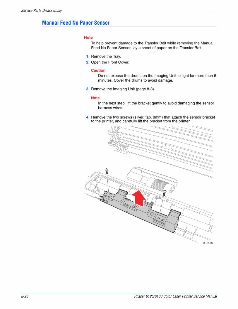
8-28 Phaser 6125/6130 Color Laser Printer Service Manual
Service Parts Disassembly
Manual Feed No Paper Sensor
NoteTo help prevent damage to the Transfer Belt while removing the Manual Feed No Paper Sensor, lay a sheet of paper on the Transfer Belt.
1. Remove the Tray.
2. Open the Front Cover.
CautionDo not expose the drums on the Imaging Unit to light for more than 5 minutes. Cover the drums to avoid damage.
3. Remove the Imaging Unit (page 8-8).
NoteIn the next step, lift the bracket gently to avoid damaging the sensor harness wires.
4. Remove the two screws (silver, tap, 8mm) that attach the sensor bracket to the printer, and carefully lift the bracket from the printer.
s6130-222
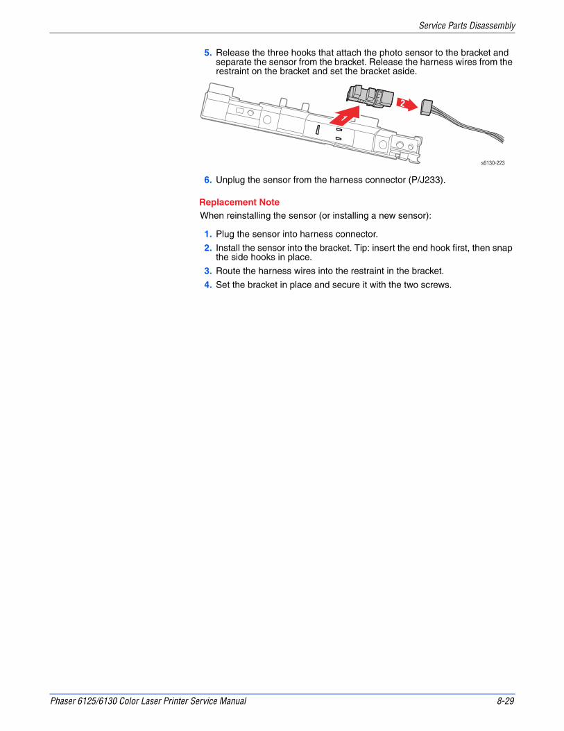
Phaser 6125/6130 Color Laser Printer Service Manual 8-29
Service Parts Disassembly
5. Release the three hooks that attach the photo sensor to the bracket and separate the sensor from the bracket. Release the harness wires from the restraint on the bracket and set the bracket aside.
6. Unplug the sensor from the harness connector (P/J233).
Replacement NoteWhen reinstalling the sensor (or installing a new sensor):
1. Plug the sensor into harness connector.
2. Install the sensor into the bracket. Tip: insert the end hook first, then snap the side hooks in place.
3. Route the harness wires into the restraint in the bracket.
4. Set the bracket in place and secure it with the two screws.
12
s6130-223
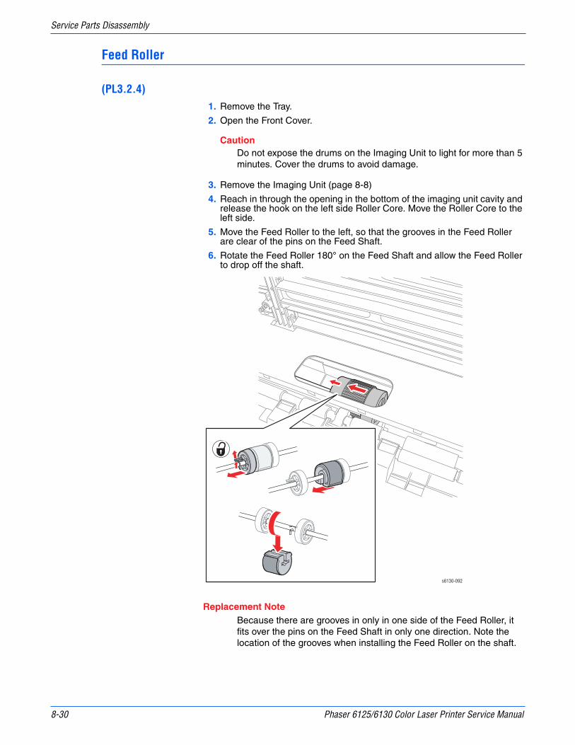
8-30 Phaser 6125/6130 Color Laser Printer Service Manual
Service Parts Disassembly
Feed Roller
(PL3.2.4)1. Remove the Tray.
2. Open the Front Cover.
CautionDo not expose the drums on the Imaging Unit to light for more than 5 minutes. Cover the drums to avoid damage.
3. Remove the Imaging Unit (page 8-8)
4. Reach in through the opening in the bottom of the imaging unit cavity and release the hook on the left side Roller Core. Move the Roller Core to the left side.
5. Move the Feed Roller to the left, so that the grooves in the Feed Roller are clear of the pins on the Feed Shaft.
6. Rotate the Feed Roller 180° on the Feed Shaft and allow the Feed Roller to drop off the shaft.
Replacement NoteBecause there are grooves in only in one side of the Feed Roller, it fits over the pins on the Feed Shaft in only one direction. Note the location of the grooves when installing the Feed Roller on the shaft.
s6130-092

Phaser 6125/6130 Color Laser Printer Service Manual 8-31
Service Parts Disassembly
Xerographics
Laser Unit
(PL4.1.1)1. Remove the I/P Board Cage (page 8-44)
2. Remove the MCU Board (page 8-59)
3. Remove the screw (silver, with washer, 6mm) that secures the GFI Ground Harness ground lead.
4. Unplug the Power Switch Harness connector (P/J48) from the LVPS Board.
5. Release the AC Harness Guide hook from the LVPS Frame and allow the guide to lay to the side.
s6130-093
s6130-094
Hook P/J48
P/J23
P/J24
P/J26
P/J20P/J28
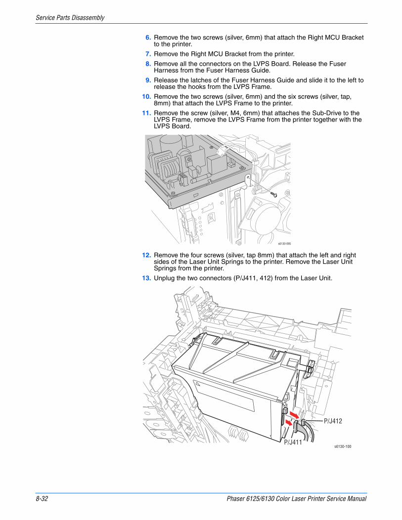
8-32 Phaser 6125/6130 Color Laser Printer Service Manual
Service Parts Disassembly
6. Remove the two screws (silver, 6mm) that attach the Right MCU Bracket to the printer.
7. Remove the Right MCU Bracket from the printer.
8. Remove all the connectors on the LVPS Board. Release the Fuser Harness from the Fuser Harness Guide.
9. Release the latches of the Fuser Harness Guide and slide it to the left to release the hooks from the LVPS Frame.
10. Remove the two screws (silver, 6mm) and the six screws (silver, tap, 8mm) that attach the LVPS Frame to the printer.
11. Remove the screw (silver, M4, 6mm) that attaches the Sub-Drive to the LVPS Frame, remove the LVPS Frame from the printer together with the LVPS Board.
12. Remove the four screws (silver, tap 8mm) that attach the left and right sides of the Laser Unit Springs to the printer. Remove the Laser Unit Springs from the printer.
13. Unplug the two connectors (P/J411, 412) from the Laser Unit.
s6130-095
s6130-100P/J411
P/J412

Phaser 6125/6130 Color Laser Printer Service Manual 8-33
Service Parts Disassembly
14. Lift up the Laser Unit slowly from the printer.
s6130-101

8-34 Phaser 6125/6130 Color Laser Printer Service Manual
Service Parts Disassembly
Dispenser Assembly
(PL5.1.1)1. Remove the Toner Cartridges (page 8-10).
2. Remove the Fan (page 8-56).
3. Remove the I/P Board Cage (page 8-44).
4. Remove the MCU Board (page 8-59).
5. Remove the screw (silver, with washer, 6mm) that secures the GFI Ground Harness ground lead.
6. Unplug the Power Switch Harness connector (P/J48) from the LVPS Board.
7. Release the AC Harness Guide hook from the LVPS Frame and allow the guide to lay to the side.
s6130-093
s6130-094
Hook P/J48
P/J23
P/J24
P/J26
P/J20P/J28

Phaser 6125/6130 Color Laser Printer Service Manual 8-35
Service Parts Disassembly
8. Remove the two screws (silver, 6mm) that attach the Right MCU Bracket to the printer.
9. Remove the Right MCU Bracket from the printer.
10. Remove all the connectors on the LVPS Board. Release the Fuser Harness from the Fuser Harness Guide.
11. Release the latches of the Fuser Harness Guide and slide it to the left to release the hooks from the LVPS Frame.
12. Remove the two screws (silver, 6mm) and the six screws (silver, tap, 8mm) that attach the LVPS Frame to the printer.
13. Remove the screw (silver, M4, 6mm) that attaches the Sub-Drive to the LVPS Frame, remove the LVPS Frame from the printer together with the LVPS Board.
14. Release the hook of the connector of the RL Test Harness using a pliers, and then remove it from the Dispenser Assembly.
s6130-163
s6130-095
s6130-102

8-36 Phaser 6125/6130 Color Laser Printer Service Manual
Service Parts Disassembly
15. Remove the Fuser Harness, LVPS Harness, 24V Harness, I/P Board Power Harness and Harness B from the hooks on the Dispenser Assembly.
16. Remove the four screws (silver, tap, 8mm) that attach the Dispenser Assembly to the printer.
17. Remove the screw (silver, 6mm) that attaches the rear side of the Dispenser Assembly to the printer.
s6130-170
s6130-103

Phaser 6125/6130 Color Laser Printer Service Manual 8-37
Service Parts Disassembly
18. Release the hole in the Dispenser Assembly from the boss on the printer. Move the Dispenser Assembly toward the rear to remove it from the printer.
Erase LED Assembly
(PL4.1.8)1. Remove the Right Side Cover (page 8-16).
2. Remove the two screws (silver, tap, 8mm) that attach the Erase LED Assembly to the printer.
3. Remove the Erase LED Assembly from the printer.
4. Unplug the connector (P/J141) of the Erase LED Assembly.
Boss
s6130-104
s6130-105
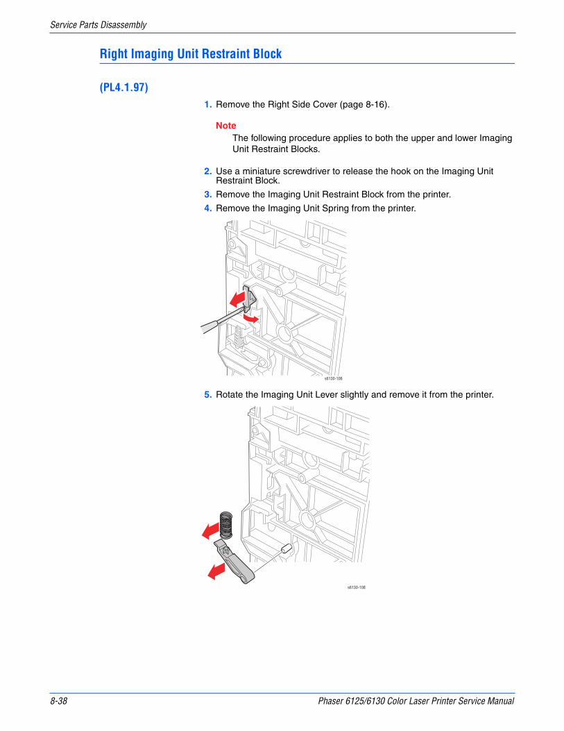
8-38 Phaser 6125/6130 Color Laser Printer Service Manual
Service Parts Disassembly
Right Imaging Unit Restraint Block
(PL4.1.97)1. Remove the Right Side Cover (page 8-16).
NoteThe following procedure applies to both the upper and lower Imaging Unit Restraint Blocks.
2. Use a miniature screwdriver to release the hook on the Imaging Unit Restraint Block.
3. Remove the Imaging Unit Restraint Block from the printer.
4. Remove the Imaging Unit Spring from the printer.
5. Rotate the Imaging Unit Lever slightly and remove it from the printer.
s6130-106
s6130-108

Phaser 6125/6130 Color Laser Printer Service Manual 8-39
Service Parts Disassembly
Left Imaging Unit Restraint Block
(PL4.1.98)1. Remove the Left Side Cover (page 8-17).
2. Remove the Main Drive Assembly (page 8-52).
NoteThe following procedure applies to both the upper and lower Imaging Unit Restraint Blocks.
3. Use a miniature screwdriver to release the hook on the Imaging Unit Restraint Block.
4. Remove the Imaging Unit Restraint Block from the printer.
5. Remove the Imaging Unit Spring from the printer.
6. Rotate the Imaging Unit Lever slightly and remove it from the printer.
s6130-109 s6130-110
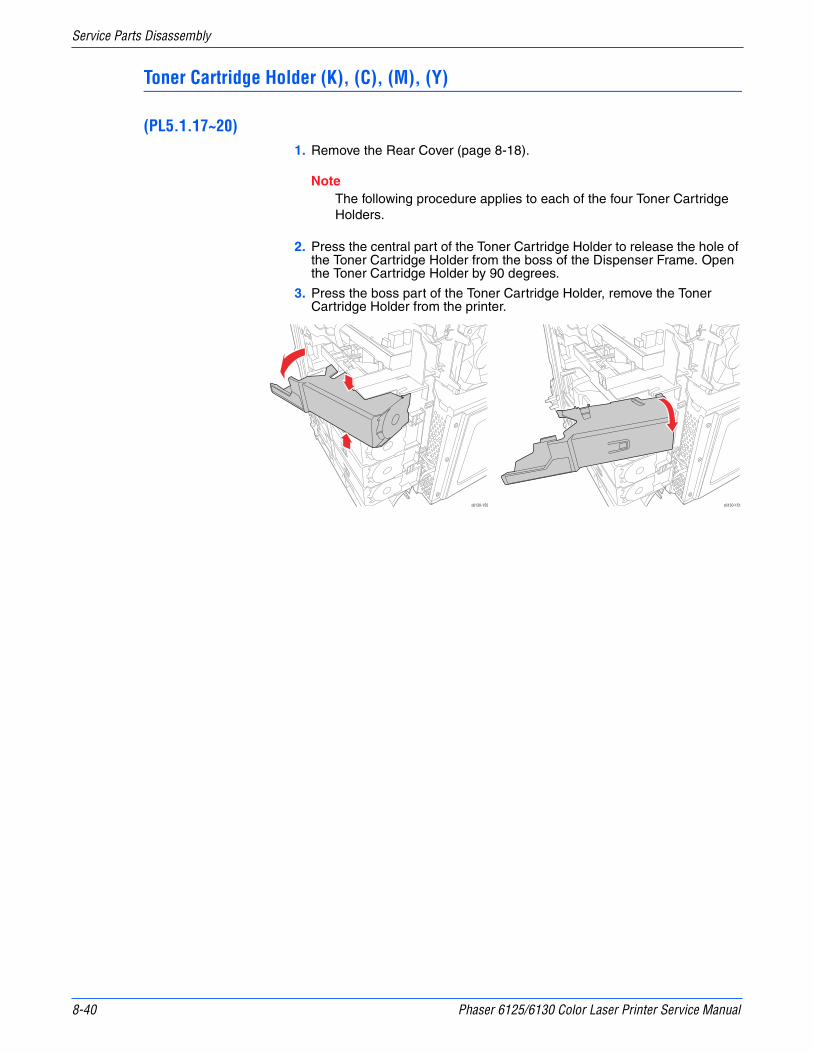
8-40 Phaser 6125/6130 Color Laser Printer Service Manual
Service Parts Disassembly
Toner Cartridge Holder (K), (C), (M), (Y)
(PL5.1.17~20)1. Remove the Rear Cover (page 8-18).
NoteThe following procedure applies to each of the four Toner Cartridge Holders.
2. Press the central part of the Toner Cartridge Holder to release the hole of the Toner Cartridge Holder from the boss of the Dispenser Frame. Open the Toner Cartridge Holder by 90 degrees.
3. Press the boss part of the Toner Cartridge Holder, remove the Toner Cartridge Holder from the printer.
s6130-150 s6130-151
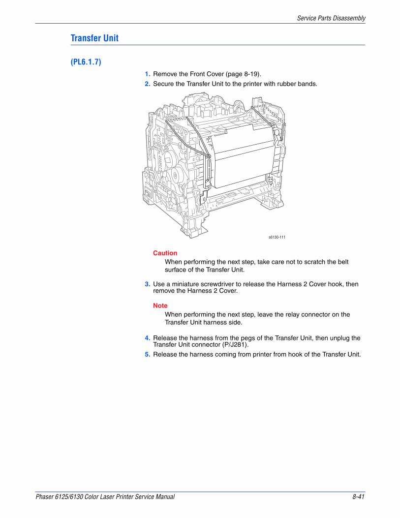
Phaser 6125/6130 Color Laser Printer Service Manual 8-41
Service Parts Disassembly
Transfer Unit
(PL6.1.7)1. Remove the Front Cover (page 8-19).
2. Secure the Transfer Unit to the printer with rubber bands.
CautionWhen performing the next step, take care not to scratch the belt surface of the Transfer Unit.
3. Use a miniature screwdriver to release the Harness 2 Cover hook, then remove the Harness 2 Cover.
NoteWhen performing the next step, leave the relay connector on the Transfer Unit harness side.
4. Release the harness from the pegs of the Transfer Unit, then unplug the Transfer Unit connector (P/J281).
5. Release the harness coming from printer from hook of the Transfer Unit.
s6130-111
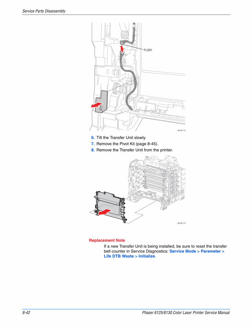
8-42 Phaser 6125/6130 Color Laser Printer Service Manual
Service Parts Disassembly
6. Tilt the Transfer Unit slowly.
7. Remove the Pivot Kit (page 8-45).
8. Remove the Transfer Unit from the printer.
Replacement NoteIf a new Transfer Unit is being installed, be sure to reset the transfer belt counter in Service Diagnostics: Service Mode > Parameter > Life DTB Waste > Initialize.
s6130-112
P/J281
s6130-113

Phaser 6125/6130 Color Laser Printer Service Manual 8-43
Service Parts Disassembly
HVPS Board
(PL4.1.19)1. Separate the Upper and Lower Assemblies (page 8-47).
2. Remove the seven screws (silver, 6mm) that attach the HVPS Board to the HVPS Frame.
3. Remove the HVPS Board from the HVPS Frame.
s6130-155

8-44 Phaser 6125/6130 Color Laser Printer Service Manual
Service Parts Disassembly
Frame
I/P Board Cage
This procedure removes the entire I/P board enclosure including the Fan Duct. Although it is not associated with any one part, it is a necessary prerequisite for other procedures.
1. Remove the Fan (page 8-56).
2. Remove the two screws with circles scribed around them at the bottom of the Image Processor Frame.
3. Unplug the cables at P10 and P11 on the MCU board.
4. Disconnect P40 from the LVPS and release the harness from restraints.
5. Disconnect P2200 and release the harness from restraints.
6. Remove the three circled screws at the top of the Image Processor Frame. (one screw is behind the Fan).
NoteLoosening or removing the screw that holds the Fan Duct to the IP Board Frame can ease the IP Board Frame removal. Do not remove the Fan Duct.
7. Swing the assembly out from the bottom and lift up enough to free the hook at the top.
P/J10
P/J11
s6130-141

Phaser 6125/6130 Color Laser Printer Service Manual 8-45
Service Parts Disassembly
Transfer Unit Pivot Kit
(PL6.1.99)This procedure removes the pivot shafts for the Transfer Unit.
1. Remove the Right Side Cover (page 8-16).
2. Remove the Left Side Cover (page 8-17).
3. Rotate the Pivot Stopper to align the tabs of the Pivot Stopper with the notches of the Main Drive Assembly.
4. Remove the Pivot Stopper from the printer.
NoteWhen performing the following procedure, take care not to drop Gear T4.
5. Pull out the Left Transfer Pivot, and remove the Gear T4 from the printer.
s6130-115 s6130-116
s6130-117Gear T4
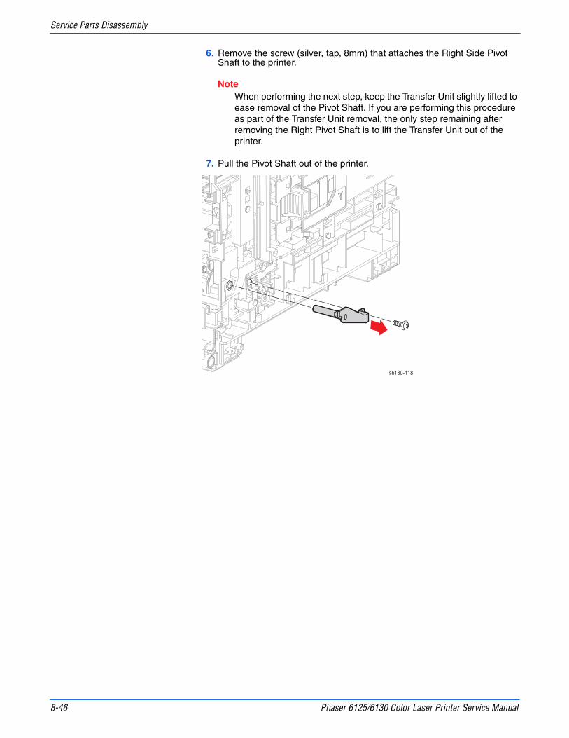
8-46 Phaser 6125/6130 Color Laser Printer Service Manual
Service Parts Disassembly
6. Remove the screw (silver, tap, 8mm) that attaches the Right Side Pivot Shaft to the printer.
NoteWhen performing the next step, keep the Transfer Unit slightly lifted to ease removal of the Pivot Shaft. If you are performing this procedure as part of the Transfer Unit removal, the only step remaining after removing the Right Pivot Shaft is to lift the Transfer Unit out of the printer.
7. Pull the Pivot Shaft out of the printer.
s6130-118
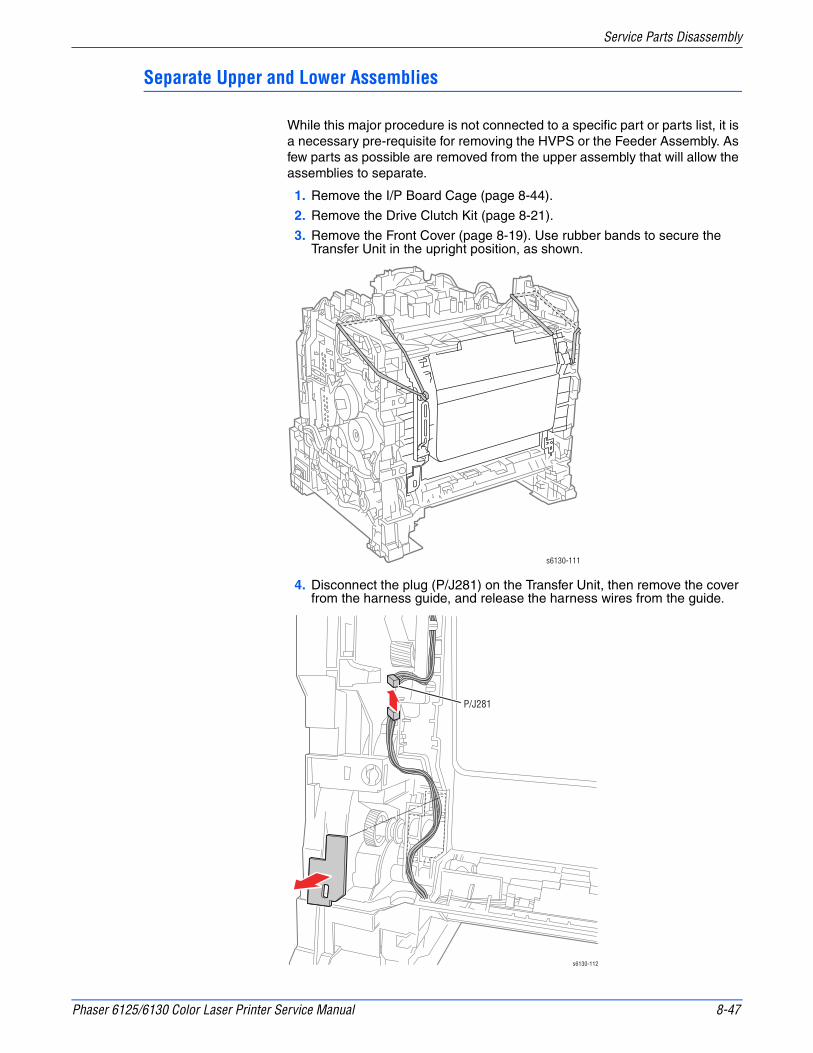
Phaser 6125/6130 Color Laser Printer Service Manual 8-47
Service Parts Disassembly
Separate Upper and Lower Assemblies
While this major procedure is not connected to a specific part or parts list, it is a necessary pre-requisite for removing the HVPS or the Feeder Assembly. As few parts as possible are removed from the upper assembly that will allow the assemblies to separate.
1. Remove the I/P Board Cage (page 8-44).
2. Remove the Drive Clutch Kit (page 8-21).
3. Remove the Front Cover (page 8-19). Use rubber bands to secure the Transfer Unit in the upright position, as shown.
4. Disconnect the plug (P/J281) on the Transfer Unit, then remove the cover from the harness guide, and release the harness wires from the guide.
s6130-111
s6130-112
P/J281
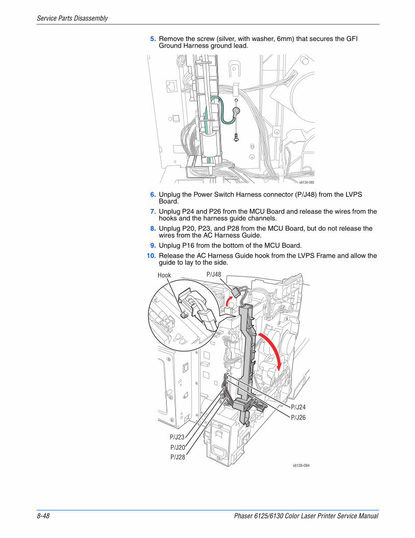
8-48 Phaser 6125/6130 Color Laser Printer Service Manual
Service Parts Disassembly
5. Remove the screw (silver, with washer, 6mm) that secures the GFI Ground Harness ground lead.
6. Unplug the Power Switch Harness connector (P/J48) from the LVPS Board.
7. Unplug P24 and P26 from the MCU Board and release the wires from the hooks and the harness guide channels.
8. Unplug P20, P23, and P28 from the MCU Board, but do not release the wires from the AC Harness Guide.
9. Unplug P16 from the bottom of the MCU Board.
10. Release the AC Harness Guide hook from the LVPS Frame and allow the guide to lay to the side.
s6130-093
s6130-094
Hook P/J48
P/J23
P/J24
P/J26
P/J20P/J28

Phaser 6125/6130 Color Laser Printer Service Manual 8-49
Service Parts Disassembly
11. Remove the screw (silver, machine, 6mm) that attaches bottom of the Right MCU Bracket to the HVPS bracket.
NoteWith the Transfer Unit in place, normal length screwdrivers cannot engage the two screws removed in the following step straight on. Use a short or offset screwdriver to remove the screws.
12. Remove the two screws that attach the front side of the printer frame.
s6130-171
s6130-120
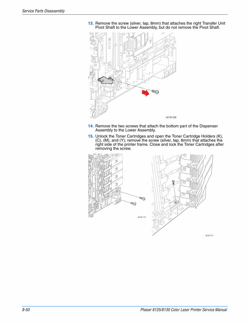
8-50 Phaser 6125/6130 Color Laser Printer Service Manual
Service Parts Disassembly
13. Remove the screw (silver, tap, 8mm) that attaches the right Transfer Unit Pivot Shaft to the Lower Assembly, but do not remove the Pivot Shaft.
14. Remove the two screws that attach the bottom part of the Dispenser Assembly to the Lower Assembly.
15. Unlock the Toner Cartridges and open the Toner Cartridge Holders (K), (C), (M), and (Y); remove the screw (silver, tap, 8mm) that attaches the right side of the printer frame. Close and lock the Toner Cartridges after removing the screw.
s6130-206
s6130-119
s6130-121

Phaser 6125/6130 Color Laser Printer Service Manual 8-51
Service Parts Disassembly
16. Remove the screw (silver, 6mm) that attaches the rear side of the Dispenser Assembly and the screw (silver, tap, 8mm) that attaches the MCU L.
17. Remove the screw (silver, tap, 8mm) that attaches the left side of the printer frame and the screw (silver, tap, 8mm) that attaches the BRACKET MCU L.
18. Lift the Upper Assembly off of the Lower Assembly.
s6130-122
s6130-123
s6130-124
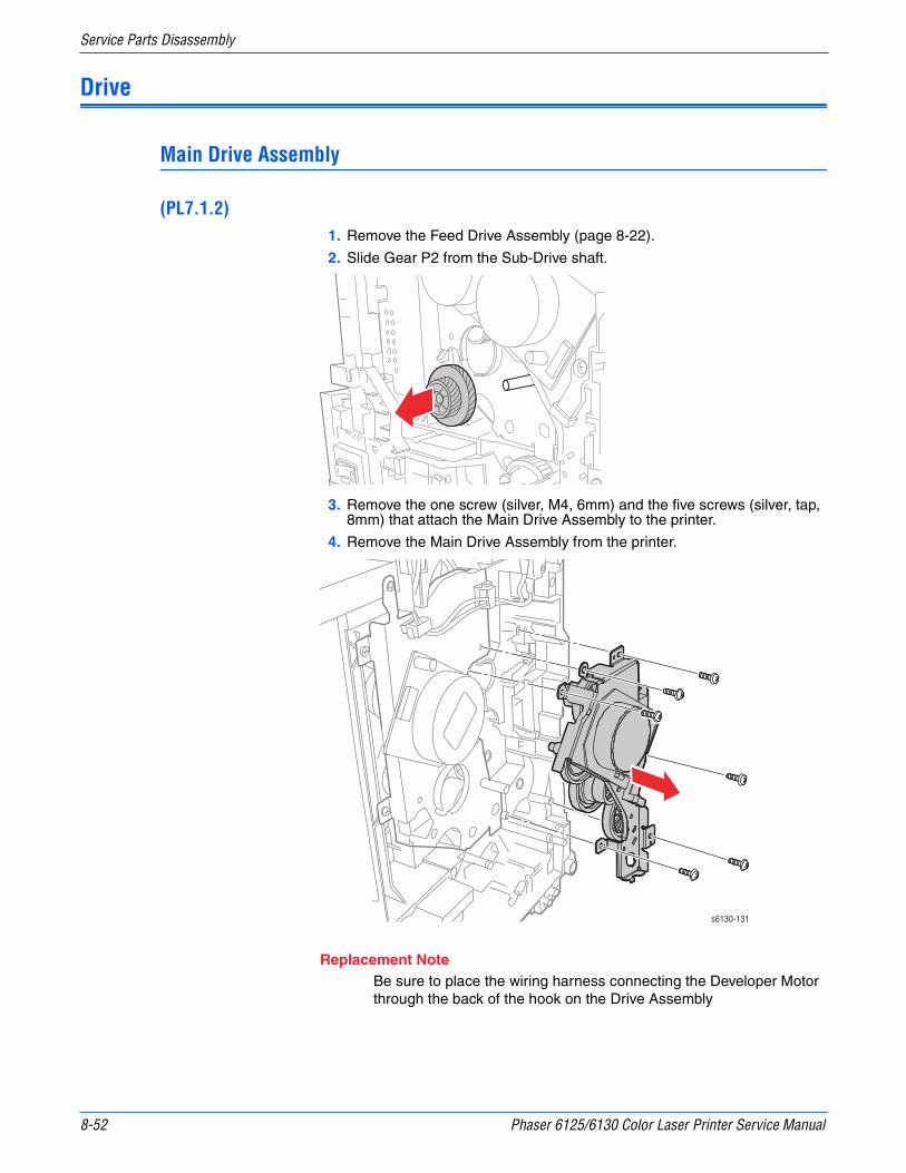
8-52 Phaser 6125/6130 Color Laser Printer Service Manual
Service Parts Disassembly
Drive
Main Drive Assembly
(PL7.1.2)1. Remove the Feed Drive Assembly (page 8-22).
2. Slide Gear P2 from the Sub-Drive shaft.
3. Remove the one screw (silver, M4, 6mm) and the five screws (silver, tap, 8mm) that attach the Main Drive Assembly to the printer.
4. Remove the Main Drive Assembly from the printer.
Replacement NoteBe sure to place the wiring harness connecting the Developer Motor through the back of the hook on the Drive Assembly
s6130-131

Phaser 6125/6130 Color Laser Printer Service Manual 8-53
Service Parts Disassembly
Sub-Drive
(PL7.1.1)1. Remove the Main Drive Assembly (page 8-52).
2. Remove the Interlock Harness (page 8-54).
3. Unplug the connector (P/J221) of the Sub-Drive.
4. Remove the one screw (silver, M4, 6mm) and the four screws (silver, tap, 8mm) that attach the Sub-Drive to the printer.
5. Remove the Sub-Drive from the printer.
P/J221
s6130-132

8-54 Phaser 6125/6130 Color Laser Printer Service Manual
Service Parts Disassembly
Electrical
Control Panel Harness
(PL1.1.17)1. Remove the Control Panel (page 8-13)
2. Remove the Front Cover (page 8-19).
3. Remove the two screws (silver, tapping) that attach the Right Guide to the Front Cover, and lift off the Right Guide.
4. Release the Control Panel Harness from the hooks in the Front Cover and remove the Control Panel Harness.
Interlock Harness
(PL8.2.5)1. Remove the Left Side Cover (page 8-17).
2. Unplug the connector (P/J44) of the Interlock Harness on the LVPS Board.
3. Release the clamps that attach the harness of the Interlock Harness, remove the harness.
4. Remove the screw (sliver, tap, 6mm) that attaches the Interlock Harness to the printer, remove the Interlock Harness.
s6130-149
P/J44

Phaser 6125/6130 Color Laser Printer Service Manual 8-55
Service Parts Disassembly
LVPS
(PL8.2.1)1. Remove the Top Cover (page 8-14).
2. Unplug all connectors from the LVPS Board.
3. Remove the seven screws (silver, 6mm) that attach the LVPS Board to the printer.
4. Remove the LVPS Board from the printer.
s6130-135
P/J501
P/J40
P/J47
P/J48
P/J44
s6130-134

8-56 Phaser 6125/6130 Color Laser Printer Service Manual
Service Parts Disassembly
Fan
(PL8.1.1)1. Remove the Rear Cover (page 8-18).
2. Unplug the Fan connector (P/J503) on the LVPS Board and release the Fan harness from the harness restraints on the Fan Duct.
3. Release the four hooks on the Fan Duct that hold the Fan in place, and remove the Fan from the Fan Duct.
Replacement NoteWhen replacing the Fan, the label faces the front of the printer.
P/J503 s6130-114
Label
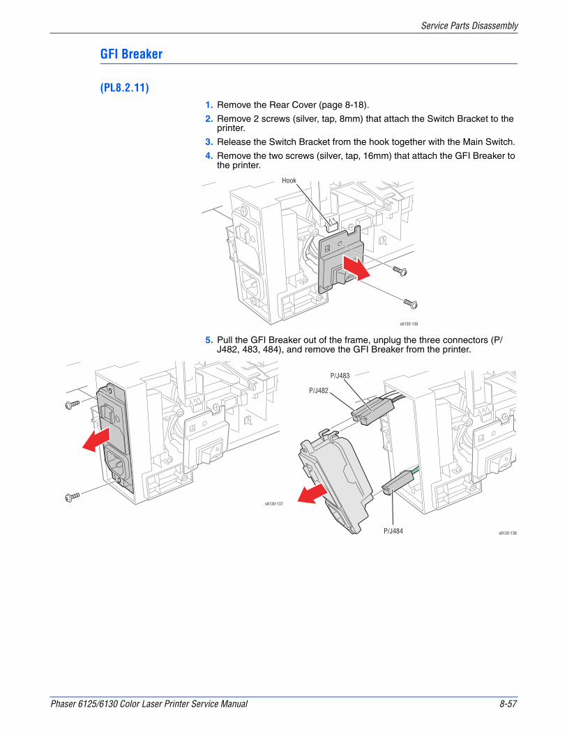
Phaser 6125/6130 Color Laser Printer Service Manual 8-57
Service Parts Disassembly
GFI Breaker
(PL8.2.11)1. Remove the Rear Cover (page 8-18).
2. Remove 2 screws (silver, tap, 8mm) that attach the Switch Bracket to the printer.
3. Release the Switch Bracket from the hook together with the Main Switch.
4. Remove the two screws (silver, tap, 16mm) that attach the GFI Breaker to the printer.
5. Pull the GFI Breaker out of the frame, unplug the three connectors (P/J482, 483, 484), and remove the GFI Breaker from the printer.
Hook
s6130-136
s6130-137
s6130-138
P/J482
P/J483
P/J484
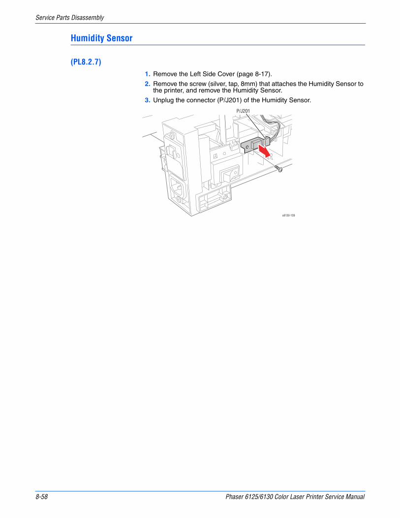
8-58 Phaser 6125/6130 Color Laser Printer Service Manual
Service Parts Disassembly
Humidity Sensor
(PL8.2.7)1. Remove the Left Side Cover (page 8-17).
2. Remove the screw (silver, tap, 8mm) that attaches the Humidity Sensor to the printer, and remove the Humidity Sensor.
3. Unplug the connector (P/J201) of the Humidity Sensor.
P/J201
s6130-139
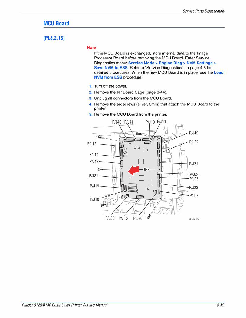
Phaser 6125/6130 Color Laser Printer Service Manual 8-59
Service Parts Disassembly
MCU Board
(PL8.2.13)
NoteIf the MCU Board is exchanged, store internal data to the Image Processor Board before removing the MCU Board. Enter Service Diagnostics menu: Service Mode > Engine Diag > NVM Settings > Save NVM to ESS. Refer to “Service Diagnostics” on page 4-5 for detailed procedures. When the new MCU Board is in place, use the Load NVM from ESS procedure.
1. Turn off the power.
2. Remove the I/P Board Cage (page 8-44).
3. Unplug all connectors from the MCU Board.
4. Remove the six screws (silver, 6mm) that attach the MCU Board to the printer.
5. Remove the MCU Board from the printer.
P/J16 P/J20
P/J28
P/J23
P/J26 P/J24
P/J21
P/J22
P/J42
P/J11P/J10P/J41P/J40
P/J15
P/J14
P/J17
P/J31
P/J18
P/J19
P/J29 s6130-140
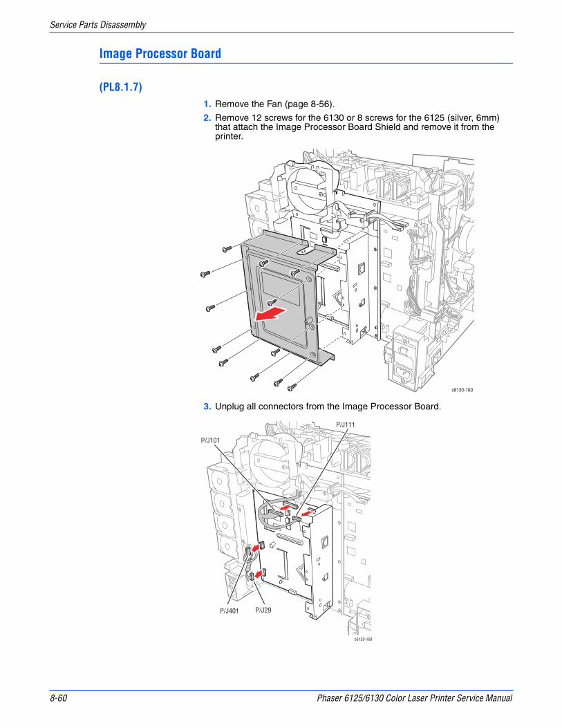
8-60 Phaser 6125/6130 Color Laser Printer Service Manual
Service Parts Disassembly
Image Processor Board
(PL8.1.7)1. Remove the Fan (page 8-56).
2. Remove 12 screws for the 6130 or 8 screws for the 6125 (silver, 6mm) that attach the Image Processor Board Shield and remove it from the printer.
3. Unplug all connectors from the Image Processor Board.
s6130-160
s6130-168
P/J101
P/J111
P/J401 P/J29
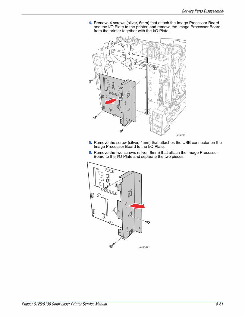
Phaser 6125/6130 Color Laser Printer Service Manual 8-61
Service Parts Disassembly
4. Remove 4 screws (silver, 6mm) that attach the Image Processor Board and the I/O Plate to the printer, and remove the Image Processor Board from the printer together with the I/O Plate.
5. Remove the screw (silver, 4mm) that attaches the USB connector on the Image Processor Board to the I/O Plate.
6. Remove the two screws (silver, 6mm) that attach the Image Processor Board to the I/O Plate and separate the two pieces.
s6130-161
s6130-162

8-62 Phaser 6125/6130 Color Laser Printer Service Manual
Service Parts Disassembly
Replacement NoteWhen installing a new I/P Board, move the NVRAM chips from the old I/P Board to the new I/P Board. Carefully check the correct location and orientation of each NVRAM chip when installing.
6125 NVRAM Location
6130 NVRAM Location
Notch
s6130-169

Phaser 6125/6130 Color Laser Printer Service Manual 8-63
Service Parts Disassembly
Toner Access Door Switch
(PL5.1.9)1. Remove the Right Side Cover (page 8-16).
2. Using a miniature screwdriver, release the hooks that latch the switch in the frame and remove the switch from the printer.
3. Unplug the switch from the harness connector (P/J291).
P/J291
s6130-152
1
2
3

8-64 Phaser 6125/6130 Color Laser Printer Service Manual
Service Parts Disassembly

9Chapter
Parts ListIn this chapter...■ Serial Number Format
■ Using the Parts List
■ Print Engine Parts
■ Xerox Supplies and Accessories
■ Service Kits
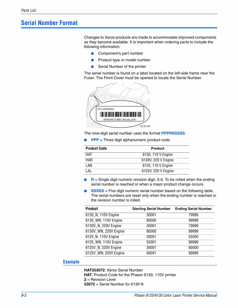
9-2 Phaser 6125/6130 Color Laser Printer Service Manual
Parts List
Serial Number Format
Changes to Xerox products are made to accommodate improved components as they become available. It is important when ordering parts to include the following information:
■ Component's part number
■ Product type or model number
■ Serial Number of the printer
The serial number is found on a label located on the left-side frame near the Fuser. The Front Cover must be opened to locate the Serial Number.
The nine-digit serial number uses the format PPPRSSSSS.
■ PPP = Three digit alphanumeric product code
■ R = Single digit numeric revision digit, 0-9. To be rolled when the ending serial number is reached or when a major product change occurs.
■ SSSSS = Five digit numeric serial number based on the following table. The serial numbers are reset only when the ending number is reached or the revision number is rolled.
Example
HAT253072: Xerox Serial NumberHAT: Product Code for the Phaser 6130, 110V printer2 = Revision Level53072 = Serial Number for 6130 N
Product Code Product
HAT 6130, 110 V EngineHAR 6130V, 220 V EngineLAN 6125, 110 V EngineLAL 6125V, 220 V Engine
Product Starting Serial Number Ending Serial Number
6130_N, 110V Engine 30001 799996130_WN, 110V Engine 80000 999996130V_N, 220V Engine 30001 799996130V_WN, 220V Engine 80000 999996125_N, 110V Engine 30001 550006125_WN, 110V Engine 55001 999996125V_N, 220V Engine 30001 600006125V_WN, 220V Engine 60001 99999
S/N: HAT030001
MANUFACTURED: January, 2007
s6130-226

Phaser 6125/6130 Color Laser Printer Service Manual 9-3
Parts List
Using the Parts List
■ ID No.: The callout number from the exploded part diagram.
■ Name/Description: The name of the part to be ordered and the number of parts supplied per order.
■ Part Number: The material part number used to order that specific part.
■ Parts identified throughout this manual are referenced PL#.#.#; For example, PL3.1.10 means the part is item 10 of Parts List 3.1.
■ A black triangle preceding a number followed by a parenthetical statement in an illustrated parts list means the item is a parent assembly, made up of the individual parts called out in parentheses.
■ The notation “with X~Y” following a part name indicates an assembly that is made up of components X through Y. For example, “1 (with 2~4)” means part 1 consists of part 2, part 3, and part 4.
■ An asterisk (*) following a part name indicates the page contains a note about this part.
■ The notation (NS) next to a part indicates that particular part is not spared, but contained in a kit or major assembly.
■ The notation “J1<>J2 and P2” is attached to a wire harness. It indicates that connector Jack 1 is attached to one end of the wire harness and connector J2 is attached to the other end that is plugged into P2.
NoteOnly parts showing part numbers are available for ordering by support. Parts not showing part numbers are available on the parent assembly.
Abbreviations
Abbreviation Meaning
C C-ring
E E-ring
KL K-clip
S Screw
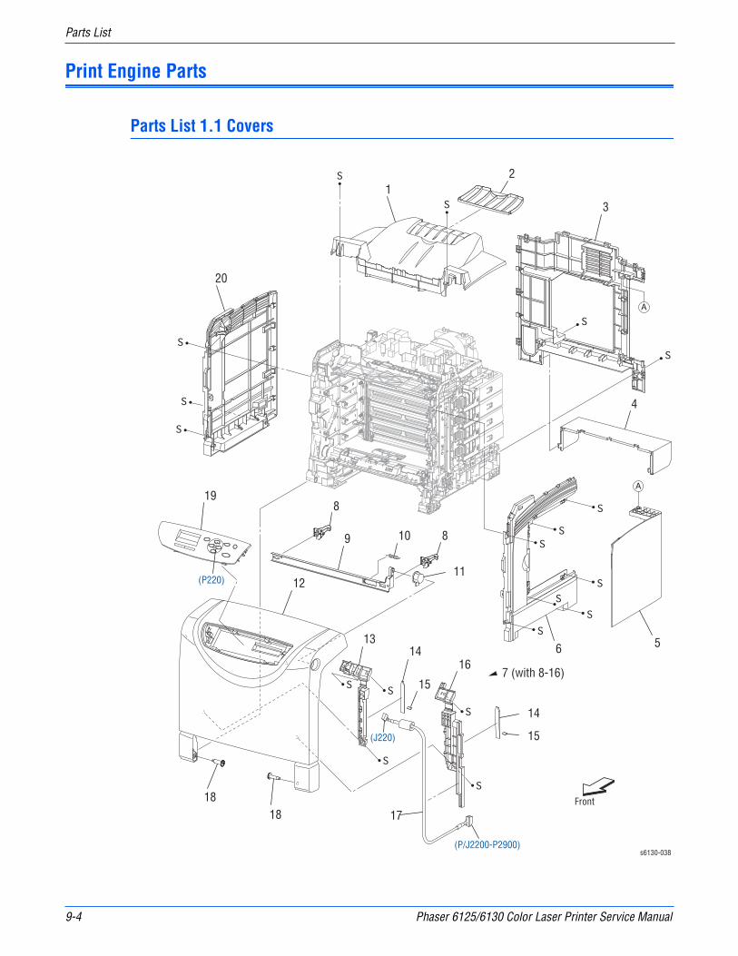
9-4 Phaser 6125/6130 Color Laser Printer Service Manual
Parts List
Print Engine Parts
Parts List 1.1 Covers
s6130-038
12
3
4
56
8
7 (with 8-16)
810
11
13
12
14
9
15
1818
20
17
19
(P/J2200-P2900)
14
15
16
(P220)
(J220)
Front

Phaser 6125/6130 Color Laser Printer Service Manual 9-5
Parts List
Parts List 1.1 Covers
ID No. Name/Description Part Number
1 Cover Top 848E20100
2 Tray Ext 050E24201
3 Cover Rear 848E20072
4 Cover Cst 848E20121
5 Cover Window Tnr (Toner Access Door) 848K10661
6 Cover Side R 848E20091
7 Cover Assy Front (with 8-17) 675K61041
8 Latch Front —
9 Plate Latch —
10 Spring Latch Out —
11 Button Latch —
12 Cover Front
13 Guide Belt —
14 Damper Front L —
15 Damper Front S —
16 Cover Harness —
17 Harness Assy A-OP (J2200-P2900) 962K60030
18 Shaft Pivot —
19A19B
Control Panel Assy PDL (6130)Control Panel Assy GDI (6125)
848K09303848K16161
20 Cover Side L 848E20081
21 — —
99 Kit Shaft Pivot (with 18 × 2pcs) 675K54050

9-6 Phaser 6125/6130 Color Laser Printer Service Manual
Parts List
Parts List 2.1 Paper Tray
s6130-039
Front
2
3
4
5 67
7
9
11
12
13
16
17
18
8
19
1516
14
10
1 (with 2-19)

Phaser 6125/6130 Color Laser Printer Service Manual 9-7
Parts List
Parts List 2.1 Paper Tray
ID No. Name/Description Part Number
1 CASSETTE ASSY 250 (with 2-19) 050K61151
2 PLATE ASSY BOTTOM —
3 SPRING N/F L —
4 SPRING N/F R —
5 SEPARATOR ROLLER ASSEMBLY 019K09470
6 GUIDE SIDE L —
7 GEAR PINION —
8 GUIDE SIDE ASSY R —
9 COVER SSI —
10 GUIDE SIDE SSI L —
11 RACK GUIDE SIDE SSI L —
12 RACK GUIDE SIDE SSI R —
13 GUIDE SIDE SSI R —
14 LATCH BOTTOM L —
15 LATCH BOTTOM R —
16 SPRING LEVER —
17 TRAY ASSY EXTENSION —
18 HOUSING CST 250 —
19 HANDLE CST —
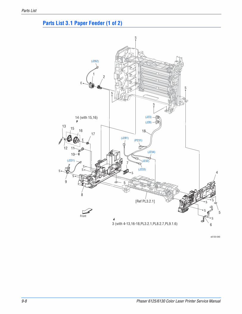
9-8 Phaser 6125/6130 Color Laser Printer Service Manual
Parts List
Parts List 3.1 Paper Feeder (1 of 2)
Front
s6130-040
1
4
8
9
10
1112
1716 18
1513
7
5
5
6
2
14 (with 15,16)
3 (with 4-13,16-18,PL3.2.1,PL8.2.7,PL9.1.6)
[Ref PL3.2.1]
(J231)
(P231)
(J23)
(J234)
(J232)
(J233)
(J28)
(J281)
(J262)

Phaser 6125/6130 Color Laser Printer Service Manual 9-9
Parts List
Parts List 3.1 Paper Feeder (1 of 2)
Item Parts name Part Number
1 CLUTCH ASSY DRV —
2 BEARING REGI —
3 FEEDER ASSY NV (with 4-13,16-18,PL3.2.1,PL8.2.7,PL9.1.6) 059K56390
4 CHASSIS FDR R —
5 FOOT —
6 PLATE EARTH PH —
7 STOPPER CST 003E73341
8 CHASSIS FDR L —
9 SOLENOID FEED MSI —
10 SPRING LEVER —
11 LEVER FEED —
12 SPRING FEED IN —
13 SPRING FEED OUT —
14 GEAR ASSY FEED (with 15,16) —
15 GEAR FEED OUT —
16 GEAR FEED IN —
17 BEARING —
18 HARN ASSY L SIDE (J23,J28-P231,J232,J233,J234,J281) 962K57541
98 KIT SOLENOID FEED (with 9-14) 675K54150
99 KIT CLUTCH ASSY DRV (with 1,2) 675K54230
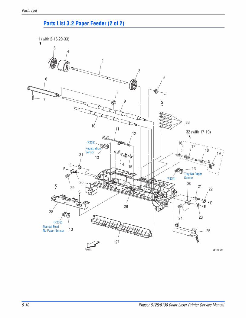
9-10 Phaser 6125/6130 Color Laser Printer Service Manual
Parts List
Parts List 3.2 Paper Feeder (2 of 2)
s6130-041Front
3
2
4
3
5
1 (with 2-16,20-33)
6
7
8
9
1011
12
1331
13
13
21
14 15
1617
1819
22
23
33
24
26
27
28
25
2029
30
(P232)
(P233)
(P234)
Manual FeedNo Paper Sensor
Tray No PaperSensor
RegistrationSensor
32 (with 17-19)
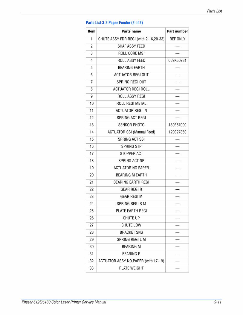
Phaser 6125/6130 Color Laser Printer Service Manual 9-11
Parts List
Parts List 3.2 Paper Feeder (2 of 2)
Item Parts name Part number
1 CHUTE ASSY FDR REGI (with 2-16,20-33) REF ONLY
2 SHAF ASSY FEED —
3 ROLL CORE MSI —
4 ROLL ASSY FEED 059K50731
5 BEARING EARTH —
6 ACTUATOR REGI OUT —
7 SPRING REGI OUT —
8 ACTUATOR REGI ROLL —
9 ROLL ASSY REGI —
10 ROLL REGI METAL —
11 ACTUATOR REGI IN —
12 SPRING ACT REGI —
13 SENSOR PHOTO 130E87090
14 ACTUATOR SSI (Manual Feed) 120E27850
15 SPRING ACT SSI —
16 SPRING STP —
17 STOPPER ACT —
18 SPRING ACT NP —
19 ACTUATOR NO PAPER —
20 BEARING M EARTH —
21 BEARING EARTH REGI —
22 GEAR REGI R —
23 GEAR REGI M —
24 SPRING REGI R M —
25 PLATE EARTH REGI —
26 CHUTE UP —
27 CHUTE LOW —
28 BRACKET SNS —
29 SPRING REGI L M —
30 BEARING M —
31 BEARING R —
32 ACTUATOR ASSY NO PAPER (with 17-19) —
33 PLATE WEIGHT —
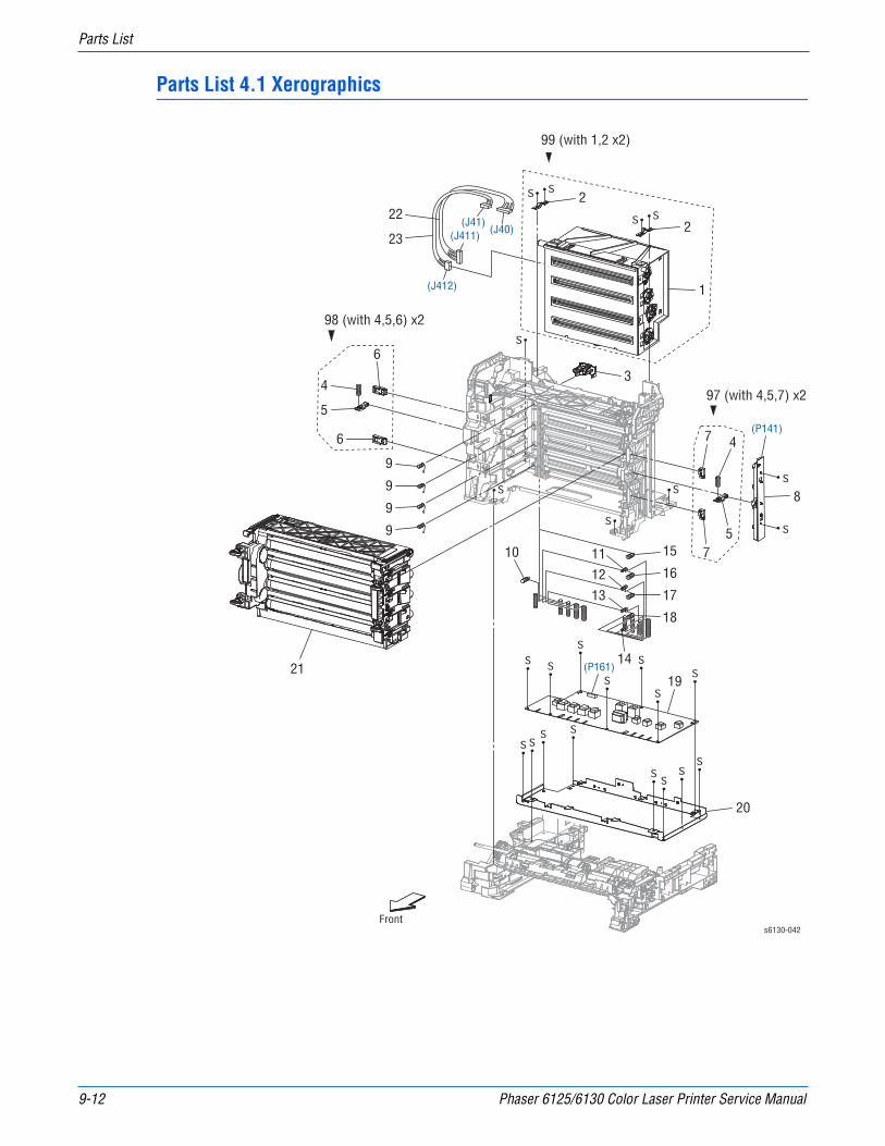
9-12 Phaser 6125/6130 Color Laser Printer Service Manual
Parts List
Parts List 4.1 Xerographics
s6130-042Front
2
1
34
2
5
6
7 4
7
8
5
6
9
9
9
9
10 11
12
13
14
15
16
17
18
19
20
21
22
23(J40)
(J41)(J411)
(J412)
(P141)
(P161)
97 (with 4,5,7) x2
98 (with 4,5,6) x2
99 (with 1,2 x2)

Phaser 6125/6130 Color Laser Printer Service Manual 9-13
Parts List
Parts List 4.1 Xerographics
ID No. Name/Description Part Number
1 ROS ASSY (Laser Unit)a —
2 SPRING ROS —
3 HOLDER CRUM —
4 SPRING PHD —
5 LEVER PHD —
6 BLOCK STOPPER PHD D —
7 BLOCK STOPPER PHD AD —
8 LED ASSY ERASE 122K94040
9 SPRING TRACKING —
10 SPRING CF —
11 SPRING TR4 —
12 SPRING TR3 —
13 SPRING TR2 —
14 SPRING TR1 —
15 SPRING D4 —
16 SPRING D3 —
17 SPRING D2 —
18 SPRING D1 —
19 PWBA HVPS 105K22661
20 FRAME HVPS 801E01503
21 PHD ASSY (Imaging Unit) 675K69240
22 HARN ASSY ROS RE (J40-J411) —
23 HARN ASSY ROS VIDEO (J41-J412) —
97 KIT BLOCK PHD RIGHT (with 4,5,7 × 2pcs) 675K54241
98 KIT BLOCK PHD LEFT (with 4,5,6 × 2pcs) 675K54251
99 KIT ROS (with 1,2 × 2pcs) (Laser Unit kit) 604K43050
a. Use PL4.1.99, Laser Unit kit, when ordering the Laser Unit.
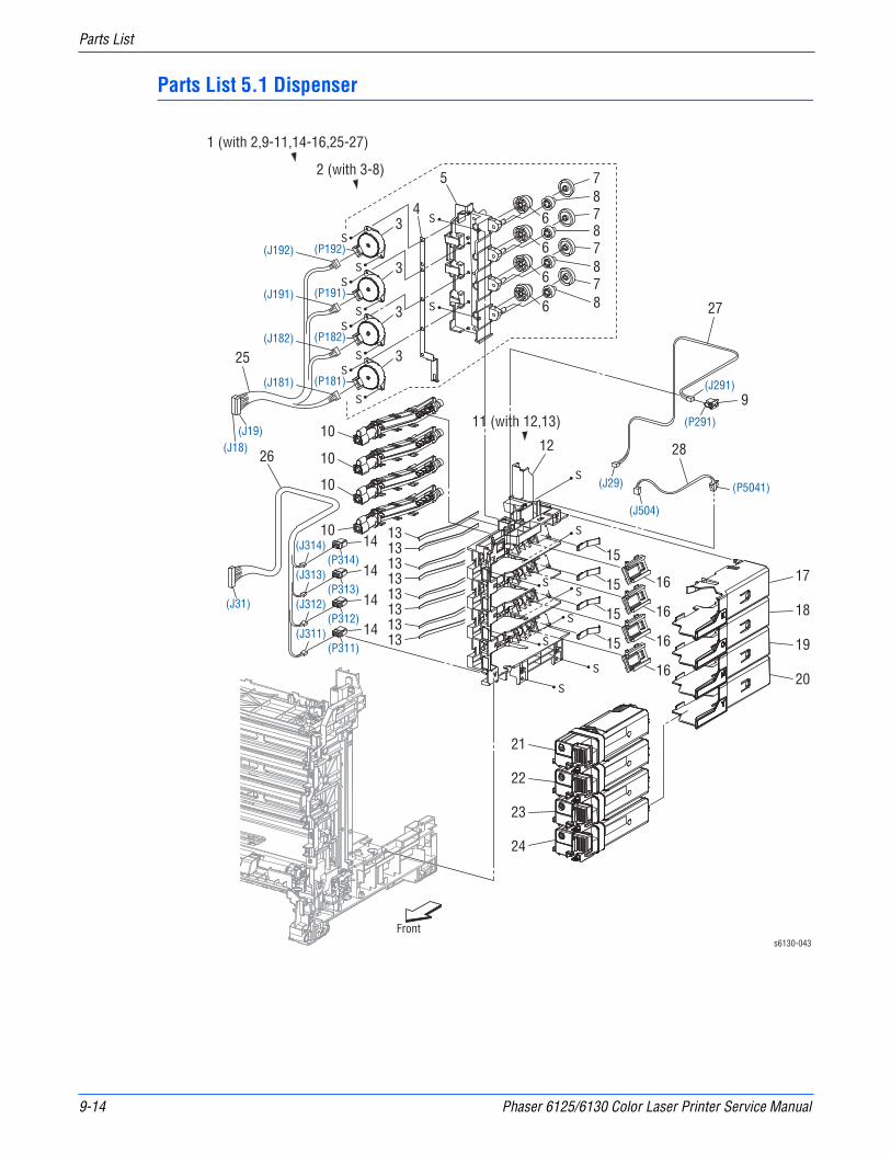
9-14 Phaser 6125/6130 Color Laser Printer Service Manual
Parts List
Parts List 5.1 Dispenser
Fronts6130-043
17
18
19
20
21
22
23
24
25
26
27
28
16
16
16
16
15
12
9
14
15
15
15131313131313131310
10
10
1011 (with 12,13)
2 (with 3-8)
1 (with 2,9-11,14-16,25-27)
34
3
3
3
5
6
78787878
6
6
6
14
14
14
(J191)
(P192)
(P191)
(P182)
(P181)
(J192)
(J182)
(J181)
(J311)
(J504)
(J29)
(J31)
(J19)(J18)
(J312)
(J313)
(J314)
(P311)
(P5041)
(P291)
(J291)
(P312)
(P313)
(P314)

Phaser 6125/6130 Color Laser Printer Service Manual 9-15
Parts List
Parts List 5.1 Dispenser
ID No. Name/Description Part Number
1 DISPENSER ASSY (with 2,9-11,14-16,25-27) 094K92290
2 FRAME ASSY MOT (with 3-8) —
3 MOTOR ASSY DISP —
4 CONDUCTOR MOTOR —
5 FRAME MOTOR —
6 GEAR IDLER —
7 GEAR IDLER AUG —
8 GEAR IDLER AGI —
9 SWITCH (R Side Door) 110E10200
10 HOUSING ASSY AUGER —
11 FRAME ASSY DISP (with 12,13) —
12 FRAME DISP —
13 SEAL DISP AUG —
14 CONNECTOR CRUM —
15 SPRING DISP —
16 JOINT ASSY DISP —
17 HOLDER TCRU K 604K44920
18 HOLDER TCRU C 604K44930
19 HOLDER TCRU M 604K44940
20 HOLDER TCRU Y 604K44950
21B TONER CARTRIDGE US/EU 2.5K (K) 675K59231
21C TONER CARTRIDGE DMO 2.5K (K) 675K59311
21D TONER CARTRIDGE US/EU (GDI) 6125 (K) 106R01334
21E TONER CARTRIDGE DMO (GDI) 6125 (K) 106R01338
22B TONER CARTRIDGE US/EU 2K (C) 675K59241
22C TONER CARTRIDGE DMO 2K (C) 675K59321
22D TONER CARTRIDGE US/EU (GDI) 6125 (C) 106R01331
22E TONER CARTRIDGE DMO (GDI) 6125(C) 106R01335
23B TONER CARTRIDGE US/EU 2K (M) 675K59251
23C TONER CARTRIDGE DMO 2K (M) 675K59331
23D TONER CARTRIDGE US/EU (GDI) 6125 (M) 106R01332
23E TONER CARTRIDGE DMO (GDI) 6125 (M) 106R01336
24B TONER CARTRIDGE US/EU 2K (Y) 675K59261
24C TONER CARTRIDGE DMO 2K (Y) 675K59341
24D TONER CARTRIDGE US/EU (GDI) 6125 (Y) 106R01333
24E TONER CARTRIDGE DMO (GDI) 6125 (Y) 106R01337
25 HARN ASSY TNR MOT (J18,J19-J181,J182,J191,J192) —
26 HARN ASSY TONER CRUM (J31-J311,J312,J313,J314) —
27 HARN ASSY SIDE SW (J29-J291) —
28 HARN ASSY TEST RL (J504-P5041) —

9-16 Phaser 6125/6130 Color Laser Printer Service Manual
Parts List
Parts List 6.1 Transfer & Fuser
s6130-044
1
2
5
6
78
43
(P171)
(J171)
(J17)
(J47)
(P281)
Front

Phaser 6125/6130 Color Laser Printer Service Manual 9-17
Parts List
Parts List 6.1 Transfer & Fuser
ID No. Name/Description Part Number
1A1B
Fuser 115VFuser 220V
126K24951126K24961
2 Harn Assy Fuser (J17,J47-P171) —
3 Stopper Pivot —
4 Pivot Trans L —
5 Gear T4 —
6 Shaft Assy Pivot —
7 Transfer (Unit) Belt 848K03270
8 Cover Harness 2 —
99 Kit Pivot (with 3-6) 675K54121
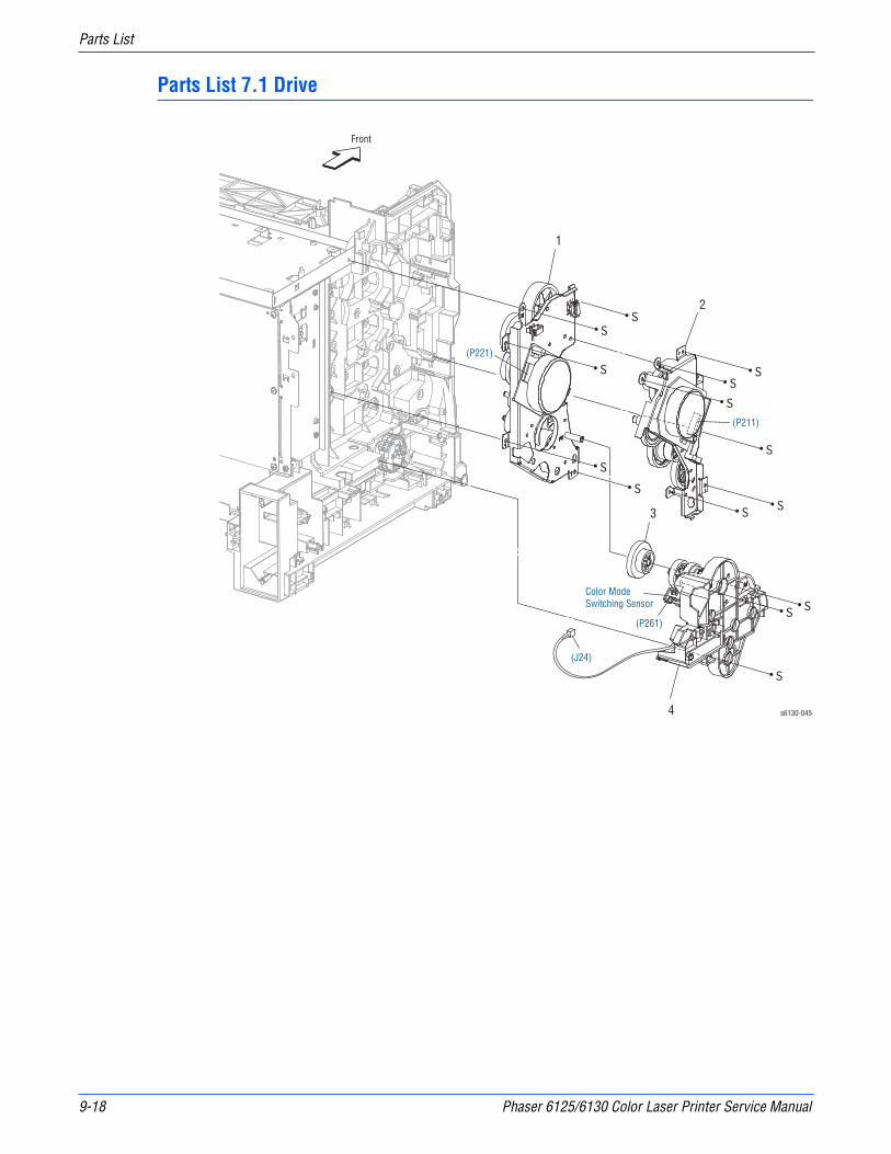
9-18 Phaser 6125/6130 Color Laser Printer Service Manual
Parts List
Parts List 7.1 Drive
s6130-045
Front
1
2
3
4
(J24)
(P261)
(P221)
(P211)
Color ModeSwitching Sensor

Phaser 6125/6130 Color Laser Printer Service Manual 9-19
Parts List
Parts List 7.1 Drive
ID No. Name/Description Part Number
1 Drive Assy Sub (Sub Drive Assembly) 007K94691
2 Drive Assy Main (Main Drive Assembly) 007K94685
3 Gear P2 807E15100
4 Drive Assy PH (Feed Drive Assembly) 007K94704
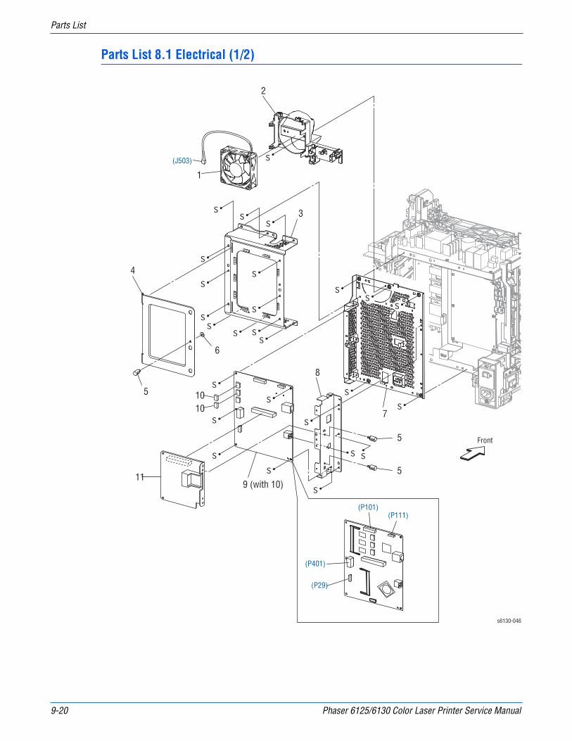
9-20 Phaser 6125/6130 Color Laser Printer Service Manual
Parts List
Parts List 8.1 Electrical (1/2)
s6130-046
Front
(J503)
1
3
4
5
7
8
1010
11
5
9 (with 10)
6
5
(P101)(P111)
(P29)
(P401)
2

Phaser 6125/6130 Color Laser Printer Service Manual 9-21
Parts List
Parts List 8.1 Electrical (1/2)
ID No. Name/Description Part Number
1 FAN 127E85360
2 DUCT FAN —
3 Shield Assy ESS (Image Processor Shield) —
4 PLATE ESS —
5 Screw Knurling —
6 Washer —
7 Frame ESS (Image Processor Frame) —
8 Plate IF —
9A 9B
PWBA ESS Phaser 6130 (with 10) (I/P Board)PWBA ESS Phaser 6125 (with 10) (I/P Board)
960K36163960K38520
10 NVM ROM REF ONLY
11 MULTI PROTOCOL CARD (OPTION) 097S03745

9-22 Phaser 6125/6130 Color Laser Printer Service Manual
Parts List
Parts List 8.2 Electrical (2/2)
s6130-047
Front
(J483)
(J44)
(J484)
(T484)
(J482)
(J48)
(P201)
(P144)
(P11)(P42)(P22)(P21)(P24)(P26)
(P15)(P14)(P17)
(P101)(P31)(P19)(P18)
(P29)(P16)
(P40)
(P503)(P502) (P504)
(P501)
(P41)(P10)
(P23)(P28)
(P20)
(P47)
(P48)
(P44)
(P40)1
23
4
5
6
7
89
10
11
12
13
14
15
16
17
18
19
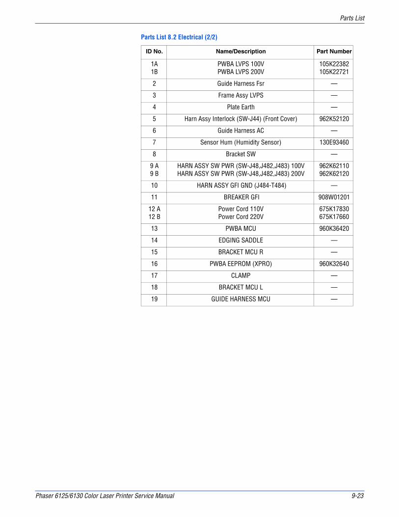
Phaser 6125/6130 Color Laser Printer Service Manual 9-23
Parts List
Parts List 8.2 Electrical (2/2)
ID No. Name/Description Part Number
1A1B
PWBA LVPS 100VPWBA LVPS 200V
105K22382105K22721
2 Guide Harness Fsr —
3 Frame Assy LVPS —
4 Plate Earth —
5 Harn Assy Interlock (SW-J44) (Front Cover) 962K52120
6 Guide Harness AC —
7 Sensor Hum (Humidity Sensor) 130E93460
8 Bracket SW —
9 A9 B
HARN ASSY SW PWR (SW-J48,J482,J483) 100VHARN ASSY SW PWR (SW-J48,J482,J483) 200V
962K62110962K62120
10 HARN ASSY GFI GND (J484-T484) —
11 BREAKER GFI 908W01201
12 A12 B
Power Cord 110VPower Cord 220V
675K17830675K17660
13 PWBA MCU 960K36420
14 EDGING SADDLE —
15 BRACKET MCU R —
16 PWBA EEPROM (XPRO) 960K32640
17 CLAMP —
18 BRACKET MCU L —
19 GUIDE HARNESS MCU —
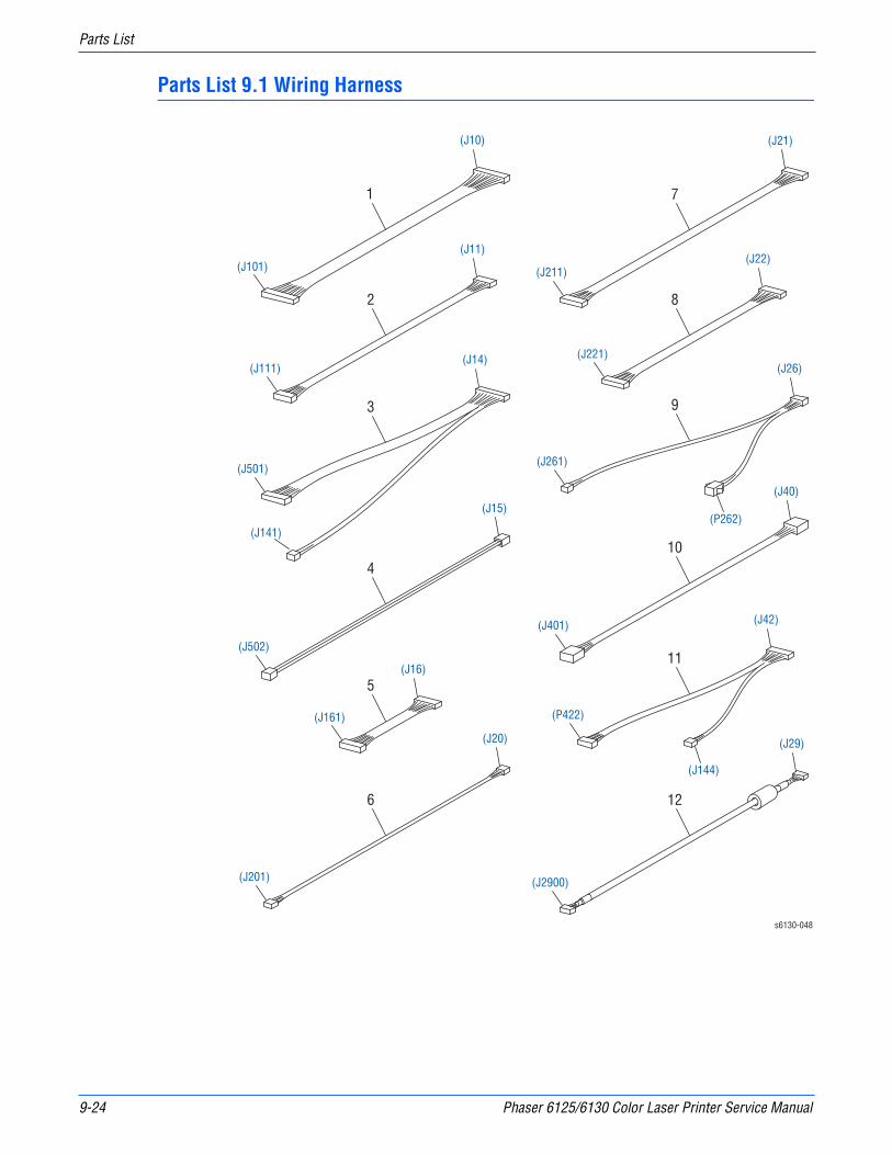
9-24 Phaser 6125/6130 Color Laser Printer Service Manual
Parts List
Parts List 9.1 Wiring Harness
s6130-048
1
2 8
9
10
11
12
7
4
3
5
6
(J10)
(J101)
(J21)
(J211)
(J40)
(J42)
(J29)
(J401)
(J2900)
(P422)
(J22)
(J26)(J221)
(J261)
(P262)
(J144)
(J11)
(J111)
(J15)
(J14)
(J502)
(J20)
(J201)
(J16)
(J161)
(J501)
(J141)

Phaser 6125/6130 Color Laser Printer Service Manual 9-25
Parts List
Parts List 9.1 Wiring Harness
ID No. Name/Description Part Number
1 Harn Assy ESS (Image Processor) (J10-J101) —
2 Harn Assy ESS (Image Processor) Video (J11-J111) —
3 Harn Assy LVPS (J14-J141,J501) —
4 Harn Assy 24V (J15-J502) —
5 Harn Assy HVPS (J16-J161) —
6 Harn Assy HUM (J20-J201) —
7 Harn Assy Main Mot (J21-J211) —
8 Harn Assy Sub Mot (J22-J221) —
9 Harn Assy KSNR REGCL (J26-J261,P262) —
10 Harn Assy ESS (Image Processor) Power (J40-J401) —
11 Harn Assy PHD XPRO (J42-J144,P422) —
12 Harness Assy B (J29-J2900) —
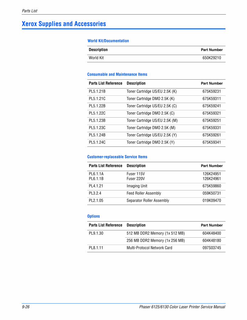
9-26 Phaser 6125/6130 Color Laser Printer Service Manual
Parts List
Xerox Supplies and Accessories
World Kit/Documentation
Description Part Number
World Kit 650K29210
Consumable and Maintenance Items
Parts List Reference Description Part Number
PL5.1.21B Toner Cartridge US/EU 2.5K (K) 675K59231
PL5.1.21C Toner Cartridge DMO 2.5K (K) 675K59311
PL5.1.22B Toner Cartridge US/EU 2.5K (C) 675K59241
PL5.1.22C Toner Cartridge DMO 2.5K (C) 675K59321
PL5.1.23B Toner Cartridge US/EU 2.5K (M) 675K59251
PL5.1.23C Toner Cartridge DMO 2.5K (M) 675K59331
PL5.1.24B Toner Cartridge US/EU 2.5K (Y) 675K59261
PL5.1.24C Toner Cartridge DMO 2.5K (Y) 675K59341
Customer-replaceable Service Items
Parts List Reference Description Part Number
PL6.1.1APL6.1.1B
Fuser 115VFuser 220V
126K24951126K24961
PL4.1.21 Imaging Unit 675K59860
PL3.2.4 Feed Roller Assembly 059K50731
PL2.1.05 Separator Roller Assembly 019K09470
Options
Parts List Reference Description Part Number
PL9.1.30 512 MB DDR2 Memory (1x 512 MB) 604K48400
256 MB DDR2 Memory (1x 256 MB) 604K48180
PL8.1.11 Multi-Protocol Network Card 097S03745
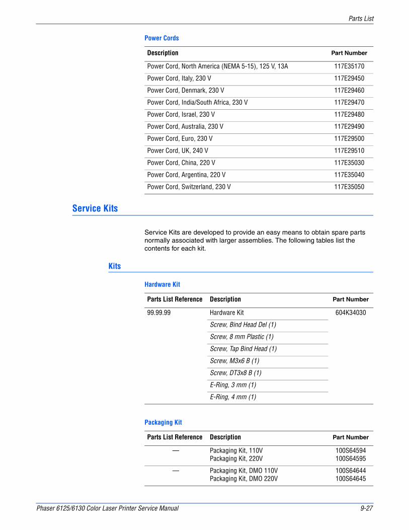
Phaser 6125/6130 Color Laser Printer Service Manual 9-27
Parts List
Service Kits
Service Kits are developed to provide an easy means to obtain spare parts normally associated with larger assemblies. The following tables list the contents for each kit.
Kits
Power Cords
Description Part Number
Power Cord, North America (NEMA 5-15), 125 V, 13A 117E35170
Power Cord, Italy, 230 V 117E29450
Power Cord, Denmark, 230 V 117E29460
Power Cord, India/South Africa, 230 V 117E29470
Power Cord, Israel, 230 V 117E29480
Power Cord, Australia, 230 V 117E29490
Power Cord, Euro, 230 V 117E29500
Power Cord, UK, 240 V 117E29510
Power Cord, China, 220 V 117E35030
Power Cord, Argentina, 220 V 117E35040
Power Cord, Switzerland, 230 V 117E35050
Hardware Kit
Parts List Reference Description Part Number
99.99.99 Hardware Kit 604K34030
Screw, Bind Head Del (1)
Screw, 8 mm Plastic (1)
Screw, Tap Bind Head (1)
Screw, M3x6 B (1)
Screw, DT3x8 B (1)
E-Ring, 3 mm (1)
E-Ring, 4 mm (1)
Packaging Kit
Parts List Reference Description Part Number
— Packaging Kit, 110VPackaging Kit, 220V
100S64594100S64595
— Packaging Kit, DMO 110VPackaging Kit, DMO 220V
100S64644100S64645

9-28 Phaser 6125/6130 Color Laser Printer Service Manual
Parts List

10Chapter
Plug/Jack and Wiring Diagrams
In this chapter...■ Plug/Jack Diagrams and Designators
■ Plug/Jack Locators
■ Notations Used in the Wiring Diagrams
■ Print Engine Wiring Diagrams

10-2 Phaser 6125/6130 Color Laser Printer Service Manual
Plug/Jack and Wiring Diagrams
Plug/Jack Diagrams and Designators
This chapter contains the Plug/Jack Designators, Locators, and wiring diagrams for the print engine and all options.
The Plug/Jack Locator diagrams show the P/J locations within the printer. Use these illustrations to locate connections called out in the Troubleshooting procedures presented in Sections 3, 4, and 5.
The Plug/Jack locators consist of the P/J Designator Tables and the P/J Locator Diagrams.
■ The P/J column lists the Plug/Jack numbers in numerical order.
■ The Map column provides the map number of the specific areas (i.e., Electrical, Laser Unit...etc.)
■ The Coordinates column lists the diagram coordinates for the location of the connector.
■ The Remarks column provides a brief description of each connection.
1. Locate the P/J connector designator in the first column of the table.
2. With this information, go to the map listed in the second column.
3. Use the coordinates to locate the connection indicated on the map with its P/J designation number.
Print Engine Plug/Jack Designators
Print Engine Plug/Jack Designators
P/J Map Coordinates Remarks
10 4 I-156 Connects MCU Board and Image Processor Harness Assy
11 4 I-156 Connects MCU Board and Image Processor Video Harness Assy
12 3 E-138 Connects Image Processor Board and Network Adaptor
14 4 H-157 Connects MCU Board and LVPS Harness Assy
15 4 H-156 Connects MCU Board and 24V Harness Assy
16 4 I-158 Connects MCU Board and HVPS Harness Assy
17 4 H-157 Connects MCU Board and Fuser Harness Assy
18 4 H-158 Connects MCU Board and TNR Motor Harness Assy
19 4 H-158 Connects MCU Board and TNR Motor Harness Assy
20 4 J-158 Connects MCU Board and HUM Harness Assy
21 4 J-157 Connects MCU Board and Main Motor Harness Assy
22 4 J-157 Connects MCU Board and Sub Motor Harness Assy
23 4 J-158 Connects MCU Board and L Side Harness Assy

Phaser 6125/6130 Color Laser Printer Service Manual 10-3
Plug/Jack and Wiring Diagrams
24 4 J-158 Connects MCU Board and Feeder Drive Assy (Color Mode Switching Solenoid)
26 4 J-158 Connects MCU Board and Ksnr Regcl Harness Assy
28 4 J-158 Connects MCU Board and L Side Harness Assy
29 3 C-139 Connects Image Processor Board and B Harness Assy
29 4 I-158 Connects MCU Board and Side Switch Harness Assy
31 4 H-157 Connects MCU Board and Toner CRUM Harness Assy
40 3 C-136 Connects LVPS Board and Image Processor Power Harness Assy
40 4 I-156 Connects MCU Board and Laser Unit RE Harness Assy
41 4 I-156 Connects MCU Board and Laser Unit Video Harness Assy
42 4 J-157 Connects MCU Board and Imaging Unit XPRO Harness Assy
44 3 G-136 Connects LVPS Board and Interlock Switch
47 3 F-136 Connects LVPS Board and Fuser Harness Assy
48 3 G-137 Connects LVPS Board and Power Switch Harness Assy
101 3 D-138 Connects Image Processor Board and Image Processor Harness Assy
101 4 I-157 Not Connect (Debug only)
111 3 E-138 Connects Image Processor Board and Image Processor Video Harness Assy
141 1 G-107 Connects Erase LED Assy and LVPS Harness Assy
144 4 G-151 Connects PWBA EEPROM and Imaging Unit XPRO Harness Assy
161 4 F-153 Connects PWBA HVPS and HVPS Harness Assy
171 1 H-106 Connects FUSER and Fuser Harness Assy
181 4 C-152 Connects Dispenser Assy (Y-Dispenser Motor Assy) and TNR Motor Harness Assy
182 4 C-151 Connects Dispenser Assy (M-Dispenser Motor Assy) and TNR Motor Harness Assy
191 4 C-151 Connects Dispenser Assy (C-Dispenser Motor Assy) and TNR Motor Harness Assy
192 4 C-150 Connects Dispenser Assy (K-Dispenser Motor Assy) and TNR Motor Harness Assy
Print Engine Plug/Jack Designators (continued)
P/J Map Coordinates Remarks

10-4 Phaser 6125/6130 Color Laser Printer Service Manual
Plug/Jack and Wiring Diagrams
201 3 H-140 Connects NV Feeder Assy (HUM Sensor) and HUM Harness Assy
211 3 J-138 Connects Main Drive Assy (Main Motor) and Main Motor Harness Assy
220 1 E-106 Connects Control Panel Assy and A-OP Harness Assy
221 3 H-138 Connects Sub Drive Assy (Sub Motor) and Sub Motor Harness Assy
231 2 C-125 Connects NV Feeder Assy (Feed Solenoid) and L Side Harness Assy
232 2 F-125 Connects NV Feeder Assy (REGI SensorI) and L Side Harness Assy
233 2 G-125 Connects NV Feeder Assy (SSI No Paper Sensor) and L Side Harness Assy
234 2 F-124 Connects NV Feeder Assy (Tray No Paper Sensor) and L Side Harness Assy
261 3 H-139 Connects Feeder Drive Assy (Color Mode Switching Sensor) and Ksnr Regcl Harness Assy
262 3 I-139 Connects Drive Clutch Assy and Ksnr Regcl Harness Assy
281 1 C-108 Connects Transfer Belt (ADC SNR2 Harness Assy) and L Side Harness Assy
291 1 H-107 Connects Dispenser Assy (Toner Access Door Switch) and Side Switch Harness Assy
311 1 H-110 Connects Dispenser Assy (Connector CRUM Y) and Toner CRUM Harness Assy
312 1 H-109 Connects Dispenser Assy (Connector CRUM M) and Toner CRUM Harness Assy
313 1 H-108 Connects Dispenser Assy (Connector CRUM C) and Toner CRUM Harness Assy
314 1 H-108 Connects Dispenser Assy (Connector CRUM K) and Toner CRUM Harness Assy
401 3 C-139 Connects Image Processor Board and Image Processor Power Harness Assy
411 2 D-122 Connects ROS ASSY and Laser Unit RE Harness Assy
412 2 D-123 Connects ROS ASSY and Laser Unit Video Harness Assy
422 4 G-150 Connects Imaging Unit (Eeprom Imaging Unit) and Imaging Unit XPRO Harness Assy
482 3 G-140 Connects GFI Breaker and Power Switch Harness Assy
Print Engine Plug/Jack Designators (continued)
P/J Map Coordinates Remarks

Phaser 6125/6130 Color Laser Printer Service Manual 10-5
Plug/Jack and Wiring Diagrams
483 3 G-140 Connects GFI Breaker and Power Switch Harness Assy
484 3 G-141 Connects GFI Breaker and GFI Ground Harness Assy
501 3 D-136 Connects LVPS Board and LVPS Harness Assy
502 3 C-136 Connects LVPS Board and 24V Harness Assy
503 3 C-136 Connects LVPS Board and FAN
504 3 D-136 Connects LVPS Board and RL Test Harness Assy
2811 1 D-107 Connects ADC Sensor and ADC SNR2 Harness Assy (Transfer Belt)
5041 1 I-107 No Connection (Used in production process only)
2200/2900
1 H-111 Connects A-OP Harness Assy and B Harness Assy
Print Engine Plug/Jack Designators (continued)
P/J Map Coordinates Remarks
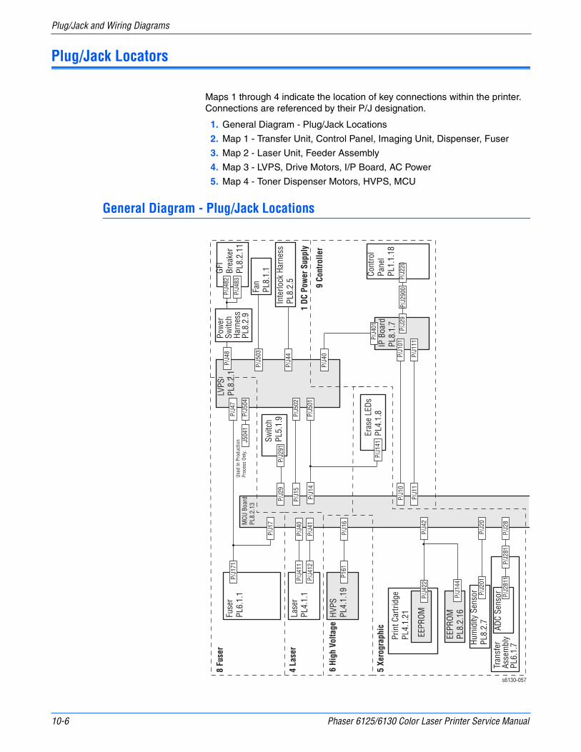
10-6 Phaser 6125/6130 Color Laser Printer Service Manual
Plug/Jack and Wiring Diagrams
Plug/Jack Locators
Maps 1 through 4 indicate the location of key connections within the printer. Connections are referenced by their P/J designation.
1. General Diagram - Plug/Jack Locations
2. Map 1 - Transfer Unit, Control Panel, Imaging Unit, Dispenser, Fuser
3. Map 2 - Laser Unit, Feeder Assembly
4. Map 3 - LVPS, Drive Motors, I/P Board, AC Power
5. Map 4 - Toner Dispenser Motors, HVPS, MCU
General Diagram - Plug/Jack Locations
MCU
Boa
rdPL
8.2.
13
HVPS
PL4.
1.19
P/J1
6P1
61
Hum
idity
Sen
sor
PL8.
2.7
P/J2
0
P/J4
2
P/J2
01
ADC
Sens
orP/
J281
P/J2
811
EEPR
OM
P/J2
8
EEPR
OMPL
8.2.
16P/
J144
P/J4
22
Eras
e LE
DsPL
4.1.
8P/
J141
Prin
t Car
tridg
ePL
4.1.
21
Tran
sfer
Asse
mbl
yPL
6.1.
7
P/J4
7
LVPS
PL8.
2.1
P/J4
0
IP B
oard
PL8.
1.7
Cont
rol
Pane
lPL
1.1.
18P/
J101
P/J1
11
P/J2
9
P/J4
01
P/J1
0
P/J1
1
P/J2
20P/
J290
0
8 Fu
ser
4 La
ser
6 Hi
gh V
olta
ge
5 Xe
rogr
aphi
c
P/J1
7
P/J1
71P/
J48
GFI
Brea
ker
PL8.
2.11
P/J4
83
P/J4
82
Fan
PL8.
1.1
Inte
rlock
Har
ness
PL8.
2.5
Switc
hPL
5.1.
9
P/J5
03
P/J4
4P/
J15
P/J5
02
P/J1
4P/
J501
P/J2
9P/
J291
Pow
er
Switc
h Ha
rnes
sPL
8.2.
9
Lase
rPL
4.1.
1
Fuse
rPL
6.1.
1
P/J4
12P/
J41
P/J4
11P/
J40
s6130-057
P/J5
04Us
ed In
Pro
duct
ion
Proc
ess
Only.
J504
1
1 DC
Pow
er S
uppl
y
9 Co
ntro
ller
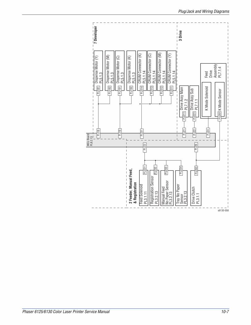
Phaser 6125/6130 Color Laser Printer Service Manual 10-7
Plug/Jack and Wiring Diagrams
MCU
Boa
rdPL
8.2.
13
Feed
Dr
ive
Asse
mbl
yPL
7.1.
4
Driv
e As
sy M
ain
PL7.
1.2
Driv
e As
sy S
ubPL
7.1.
1
P/J2
11P/
J21
P/J2
21P/
J22
K M
ode
Sole
noid
K M
ode
Sens
or
P/J2
4
P/J2
61
P/J2
6Dr
ive
Clut
chPL
3.1.
1P/
J262
Man
ual F
eed
No P
aper
Sen
sor
PL3.
2.13
P/J2
33
Tray
No
Pape
rSe
nsor
PL3.
2.13
P/J2
34
CRUM
Con
nect
or (K
)PL
5.1.
14P/
J314
CRUM
Con
nect
or (C
)PL
5.1.
14P/
J313
CRUM
Con
nect
or (M
)PL
5.1.
14P/
J312
CRUM
Con
nect
or (Y
)PL
5.1.
14P/
J311
P/J3
1
Disp
ense
Mot
or (Y
)PL
5.1.
3P/
J181
P/J1
8
Disp
ense
Mot
or (M
)PL
5.1.
3P/
J182
Disp
ense
Mot
or (C
)PL
5.1.
3P/
J191
Disp
ense
Mot
or (K
)PL
5.1.
3P/
J192
P/J1
9
Feed
Sol
enoi
dPL
3.1.
11P/
J23
P/J2
31
Regi
stra
tion
Sens
orPL
3.2.
13P/
J232
s6130-058
2 Fe
eder
, Man
ual F
eed,
& R
egis
tratio
n
3 Dr
ive
7 De
velo
per

10-8 Phaser 6125/6130 Color Laser Printer Service Manual
Plug/Jack and Wiring Diagrams
Map 1 - Transfer Unit, Control Panel, Imaging Unit, Dispenser, Fuser
A
132
133
134
135
136
137
138
139
140
141
142
143
144
145
131
B C D E F G H I J K L
s6130-053
2811
281
5041
291
141
314
313
312
311
2200/2900
171220

Phaser 6125/6130 Color Laser Printer Service Manual 10-9
Plug/Jack and Wiring Diagrams
Map 2 - Laser Unit, Feeder Assembly
A
132
133
134
135
136
137
138
139
140
141
142
143
144
145
131
B C D E F G H I J K L
s6130-054
411
412
231234
233232
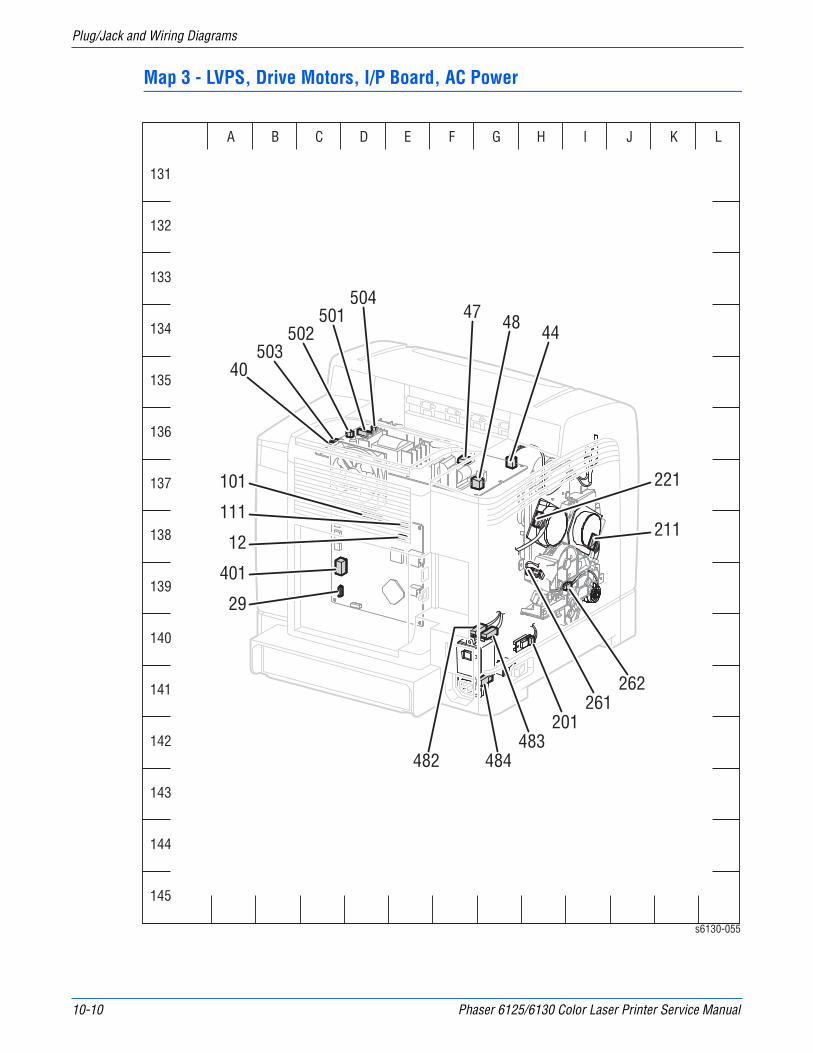
10-10 Phaser 6125/6130 Color Laser Printer Service Manual
Plug/Jack and Wiring Diagrams
Map 3 - LVPS, Drive Motors, I/P Board, AC Power
A
132
133
134
135
136
137
138
139
140
141
142
143
144
145
131
B C D E F G H I J K L
101 221
40
111
12
401
29
503502
501504
484483
201261
262
444847
211
482
s6130-055

Phaser 6125/6130 Color Laser Printer Service Manual 10-11
Plug/Jack and Wiring Diagrams
Map 4 - Toner Dispenser Motors, HVPS, MCU
A
132
133
134
135
136
137
138
139
140
141
142
143
144
145
131
B C D E F G H I J K L
114222212426
15
192
422
1417
101311918
40 41 10
29 16
161
20
2328
191
182
181
144
s6130-056
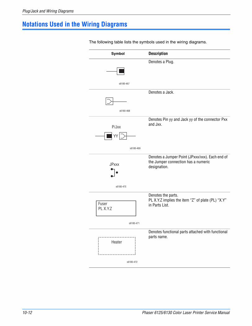
10-12 Phaser 6125/6130 Color Laser Printer Service Manual
Plug/Jack and Wiring Diagrams
Notations Used in the Wiring Diagrams
The following table lists the symbols used in the wiring diagrams.
Symbol Description
Denotes a Plug.
Denotes a Jack.
Denotes Pin yy and Jack yy of the connector Pxx and Jxx.
Denotes a Jumper Point (JPxxx/xxx). Each end of the Jumper connection has a numeric designation.
Denotes the parts.PL X.Y.Z implies the item “Z” of plate (PL) “X.Y” in Parts List.
Denotes functional parts attached with functional parts name.
s6180-467
s6180-468
P/Jxx
YY
s6180-469
JPxxx
s6180-470
FuserPL X.Y.Z
s6180-471
Heater
s6180-472
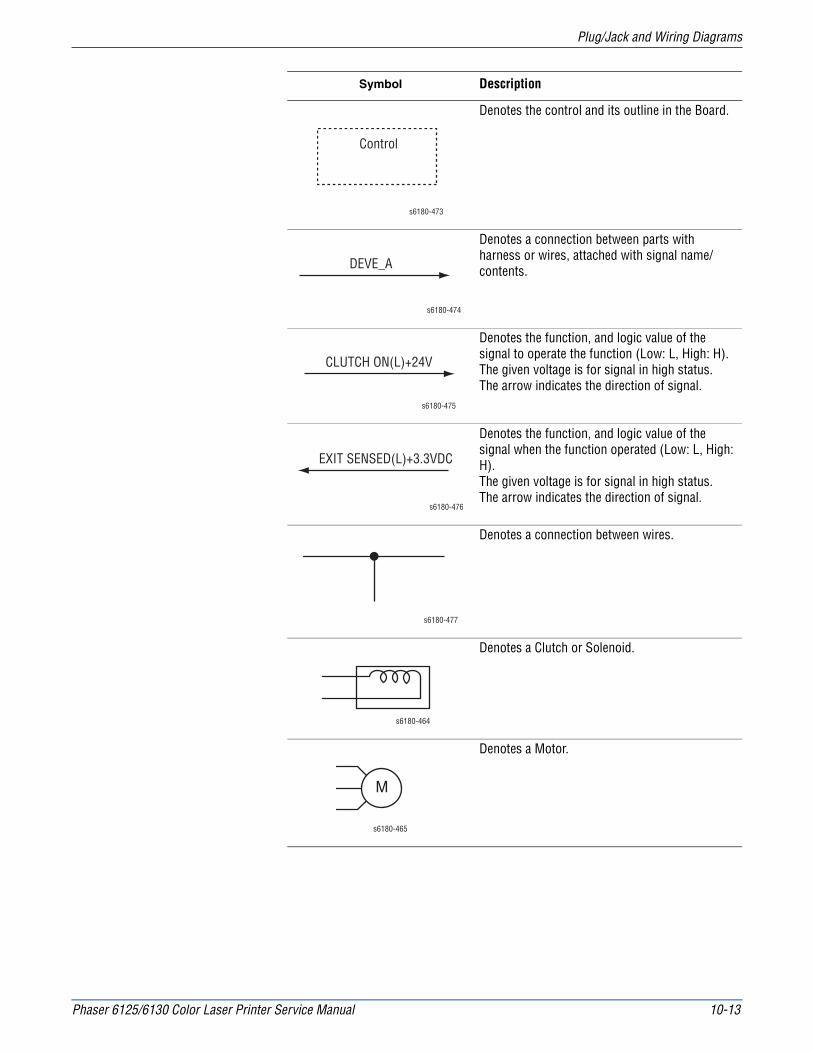
Phaser 6125/6130 Color Laser Printer Service Manual 10-13
Plug/Jack and Wiring Diagrams
Denotes the control and its outline in the Board.
Denotes a connection between parts with harness or wires, attached with signal name/contents.
Denotes the function, and logic value of the signal to operate the function (Low: L, High: H).The given voltage is for signal in high status.The arrow indicates the direction of signal.
Denotes the function, and logic value of the signal when the function operated (Low: L, High: H).The given voltage is for signal in high status.The arrow indicates the direction of signal.
Denotes a connection between wires.
Denotes a Clutch or Solenoid.
Denotes a Motor.
Symbol Description
Control
s6180-473
DEVE_A
s6180-474
CLUTCH ON(L)+24V
s6180-475
EXIT SENSED(L)+3.3VDC
s6180-476
s6180-477
s6180-464
M
s6180-465
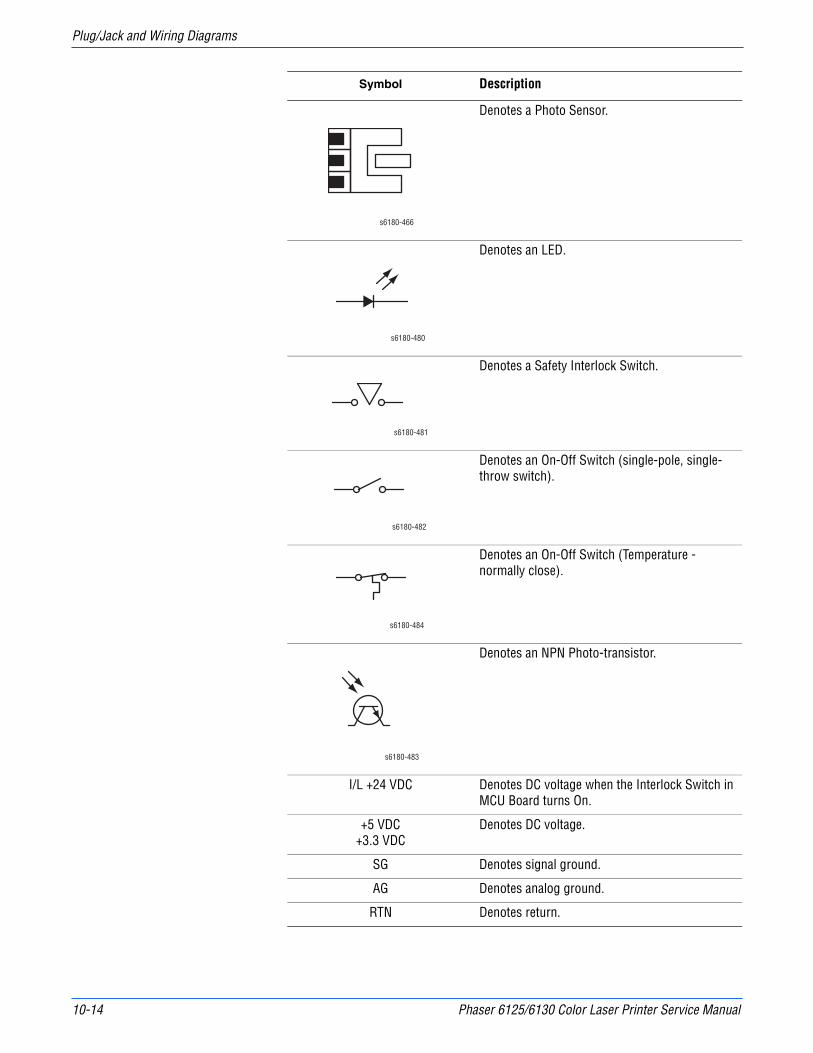
10-14 Phaser 6125/6130 Color Laser Printer Service Manual
Plug/Jack and Wiring Diagrams
Denotes a Photo Sensor.
Denotes an LED.
Denotes a Safety Interlock Switch.
Denotes an On-Off Switch (single-pole, single-throw switch).
Denotes an On-Off Switch (Temperature - normally close).
Denotes an NPN Photo-transistor.
I/L +24 VDC Denotes DC voltage when the Interlock Switch in MCU Board turns On.
+5 VDC+3.3 VDC
Denotes DC voltage.
SG Denotes signal ground.
AG Denotes analog ground.
RTN Denotes return.
Symbol Description
s6180-466
s6180-480
s6180-481
s6180-482
s6180-484
s6180-483

Phaser 6125/6130 Color Laser Printer Service Manual 10-15
Plug/Jack and Wiring Diagrams
Print Engine Wiring Diagrams
Wiring Diagrams Configurations
Wiring Diagram Description
DC Power Supply Connections of LVPS with MCU Board.
Connections of Power Switch with LVPS.
Connections of GFI Breaker with Power Switch.
Connections of Main Fan with LVPS.
Connections of Interlock Harness with LVPS.
Connections of RH Cover Switch with MCU Board.
Feeder, Manual Feed, & Registration
Connections of Feed Solenoid with MCU Board.
Connections of Registration Sensor with MCU Board.
Connections of Manual Feed (SSI) No Paper Sensor with MCU Board.
Connections of CST No Paper Sensor with MCU Board.
Connections of Drive Clutch with MCU Board.
Drive Connections of Feeder Drive with MCU Board.
Connections of Main Drive with MCU Board.
Connections of Sub-Drive with MCU Board.
Laser Unit (ROS) Connections of Laser Unit with MCU Board.
Xerographic Connections of EEPROM Board with MCU Board.
Connections of Imaging Unit (PHD) with MCU Board.
Connections of Humidity/Temperature Sensor with MCU Board.
Connections of Erase LEDs and MCU Board.
Connections of Transfer Unit with MCU Board.
High Voltage Connections of HVPS with MCU Board.
Developer Connections of Dispenser Motor (Y) with MCU Board.
Connections of Dispenser Motor (M) with MCU Board.
Connections of Dispenser Motor (C) with MCU Board.
Connections of Dispenser Motor (K) with MCU Board.
Connections of CRUM Connector (Y) with MCU Board.
Connections of CRUM Connector (M) with MCU Board.
Connections of CRUM Connector (C) with MCU Board.
Connections of CRUM Connector (K) with MCU Board.
10-16 Phaser 6125/6130 Color Laser Printer Service Manual
Plug/Jack and Wiring Diagrams
Fuser Connections of Fuser with MCU Board.
Connections of Fuser with LVPS.
Connections of MCU Board with LVPS.
Controller Connections of Image Processor Board (ESS) with MCU Board.
Connections of Control Panel with Image Processor Board.
Connections of LVPS with Image Processor Board.
Wiring Diagram Description
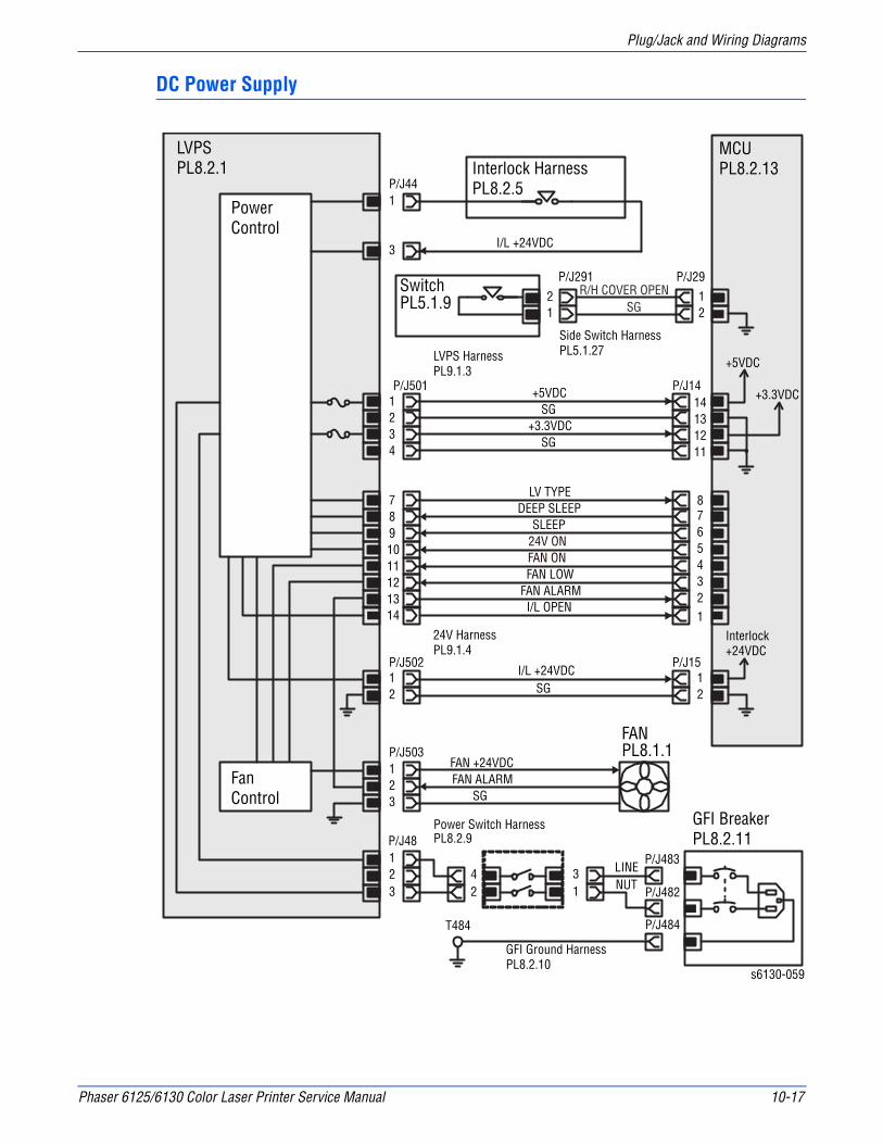
Phaser 6125/6130 Color Laser Printer Service Manual 10-17
Plug/Jack and Wiring Diagrams
DC Power Supply
MCUPL8.2.13
PowerControl
FanControl
1
3
P/J44
I/L +24VDC
12
P/J502
123
P/J503
LINENUT
FANPL8.1.1
FAN +24VDCFAN ALARM
SG
I/L +24VDC
P/J501 P/J14+3.3VDC
+5VDC
1234
78910111213
P/J1512SG
14131211
78
65432
42
123
Interlock HarnessPL8.2.5
SG+5VDC
R/H COVER OPENSG
+3.3VDCSG
12
21
P/J29P/J291SwitchPL5.1.9
LV TYPEDEEP SLEEP
SLEEP24V ONFAN ONFAN LOW
FAN ALARM
14 1I/L OPEN
Power Switch HarnessPL8.2.9
P/J482
P/J484
P/J48
T484
s6130-059
LVPSPL8.2.1
GFI BreakerPL8.2.11
GFI Ground HarnessPL8.2.10
LVPS HarnessPL9.1.3
Side Switch HarnessPL5.1.27
24V HarnessPL9.1.4
Interlock+24VDC
31
P/J483

10-18 Phaser 6125/6130 Color Laser Printer Service Manual
Plug/Jack and Wiring Diagrams
LVPS Over-Current Protection Circuit
This circuit stops all outputs if 3.3 VDC, 5 VDC, or 24 VDC is shorted.
LVPS Over-Voltage Protection Circuit
This circuit stops all outputs, if 3.3 VDC, 5 VDC, or 24 VDC exceeds the specified voltage respectively.
At this time, the operating point is 36 VDC or less for 24 VDC, 7 VDC or less for 5 VDC and 3.3 VDC.
Deep Sleep Mode (Power Saver)
The output of the following power supply are stopped according to the signals.
Signal Line Name Description
LV TYPE Controls signal of the LVPS.
DEEP SLEEP
SLEEP
24 V ON
FAN ON Drives control signal of the Main Fan.
FAN LOW
FAN ALARM
Signal +3.3 VDC +5 VDC +24 VDC
Sleep On Off Off
Deep Sleep Off Off Off

Phaser 6125/6130 Color Laser Printer Service Manual 10-19
Plug/Jack and Wiring Diagrams
Feeder, Manual Feed, & Registration
Signal Line Name Description
CST FEED CL ON (L) +24VDC
ON/OFF signal of the Feed Solenoid
REGI SENSED (L) +3.3VDC
Paper detect signal of the Registration area by the Photo Sensor (Registration Sensor).
PAPER EMPTY SENSED (H) +3.3VDC
Paper detect signal of the Manual Feed by the Photo Sensor (SSI No Paper Sensor).
PAPER EMPTY SENSED (L) +3.3VDC
Paper detect signal of the Paper Tray by the Photo Sensor (CST No Paper Sensor).
REGI CL ON (L) +24VDC ON/OFF signal of the Drive Clutch.
MCUPL8.2.13
Left Side HarnessPL3.1.18
91011
321
PULL UP +3.3VDCSG
PAPER EMPTY SENSED (L) +3.3VDC
Tray No PaperSensorPL3.2.13
P/J234
I/L +24VDCCST FEED CL ON (L) +24VDC
21
12
12
Feed SolenoidPL3.1.11
P/J231P/J23
+3.3VDC
6
78
KSNR Registration Clutch HarnessPL9.1.9
PAPER EMPTY SENSED (H) +3.3VDCSG
P/J233321
PULL UP +3.3VDCManual Sheet Feed No Paper SensorPL3.2.13
3
45 REGI SENSED (L) +3.3VDC
SG321
PULL UP +3.3VDCRegistration SensorPL3.2.13
P/J232
P/J2645
I/L +24VDCREGI CL ON (L) +24VDC
2
1
1
2
P/J262
Drive ClutchPL3.1.1
s6130-060
Interlock+24VDC
+3.3VDC
+3.3VDC

10-20 Phaser 6125/6130 Color Laser Printer Service Manual
Plug/Jack and Wiring Diagrams
Drive
SG
MCUPL8.2.13
Feed Drive AssemblyPL7.1.4
Main DrivePL7.1.2
Sub DrivePL7.1.11
2
456
3
89
10
7
P/J22
P/J24
P/J22110987654321
I/L +24VDCSG
I/L +24VDCSG
SUB MOTO ONSUB MOT ALARM
SUB MOT CLKSUB MOT LOW
SUB MOT BRAKE
M
SG12
456
3
8910
7
P/J21 P/J211
1011
98765432
I/L +24VDCSG
I/L +24VDCSG
MAIN MOT ONMAIN MOT ALARM
MAIN MOT CLKMAIN MOT LOW
MAIN MOT CW/CCW
M
s6130-061
Interlock+24VDC
Interlock+24VDC
12
Main Motor HarnessPL9.1.7
KSNR Registration Clutch HarnessPL9.1.9
Sub Motor HarnessPL9.1.8
I/L +24VDCK MODE SOL ON (L) +24VDC
Interlock+24VDC
123 K MODE SENSED (L) +3.3VDC
SG321
PULL UP +3.3VDCP/J261P/J26
+3.3VDC
K Mode Solenoid
K Mode Sensor
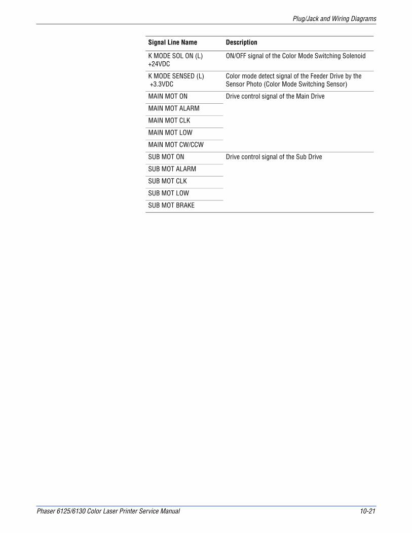
Phaser 6125/6130 Color Laser Printer Service Manual 10-21
Plug/Jack and Wiring Diagrams
Signal Line Name Description
K MODE SOL ON (L) +24VDC
ON/OFF signal of the Color Mode Switching Solenoid
K MODE SENSED (L) +3.3VDC
Color mode detect signal of the Feeder Drive by the Sensor Photo (Color Mode Switching Sensor)
MAIN MOT ON Drive control signal of the Main Drive
MAIN MOT ALARM
MAIN MOT CLK
MAIN MOT LOW
MAIN MOT CW/CCW
SUB MOT ON Drive control signal of the Sub Drive
SUB MOT ALARM
SUB MOT CLK
SUB MOT LOW
SUB MOT BRAKE

10-22 Phaser 6125/6130 Color Laser Printer Service Manual
Plug/Jack and Wiring Diagrams
Laser Unit
MCUPL8.2.13
P/J40 P/J411123456
SGI/L +24VDC
ROS MOT CLKSOS
789101112
LD ERRPCONT
SGV REF KV REF CV REF MV REF Y
ROS MOT ON
Laser RE HarnessPL4.1.22
LOCKROS MOT ON
SG+24VDC
+5VDCSOSSG
CLK
Laser UnitPL4.1.1
Laser Motor
SOS Board
s6130-062
1314
ENB
15
1514131211
12345
1098765
123
54321
321
4321
SG+3.3V LD
Interlock+24VDC
P/J41 P/J412123456
DATA KSG
DATA CSG
78
DATA MSG
DATA Y
SG
Laser Video HarnessPL4.1.23
87654321
From Xerography
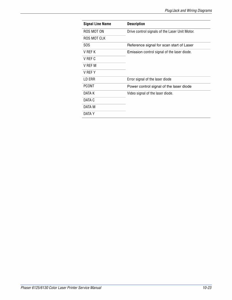
Phaser 6125/6130 Color Laser Printer Service Manual 10-23
Plug/Jack and Wiring Diagrams
Signal Line Name Description
ROS MOT ON Drive control signals of the Laser Unit Motor.
ROS MOT CLK
SOS Reference signal for scan start of Laser
V REF K Emission control signal of the laser diode.
V REF C
V REF M
V REF Y
LD ERR Error signal of the laser diode
PCONT Power control signal of the laser diode
DATA K Video signal of the laser diode.
DATA C
DATA M
DATA Y

10-24 Phaser 6125/6130 Color Laser Printer Service Manual
Plug/Jack and Wiring Diagrams
Xerographic
MCUPL8.2.13
P/J42
56789
10
Imaging Unit X Pro HarnessPL9.1.11
Humidity HarnessPL9.1.6
Imaging UnitPL4.1.21
P/J422654321
+3.3VLDDATA
CLOCK+3.3VDC
SG+3.3VDCCLOCKDATA
SG+3.3VLD
1234
ImagingUnitEEPROM
P/J144
4321
SG
+5VDCHUMI.
TEMP.P/J20
1234
P/J201
4321
PWBA EEPROMPL8.2.16
Humidity SensorPL8.2.7
LVPS HarnessPL9.1.3
ERASE Y/M/C ON (L) +3.3VDCERASE K ON (L) +3.3VDC
+3.3VDCP/J14
151617
P/J141
321
Erase LEDPL4.1.8
1234
Left Side Harness PL3.1.18
Transfer AssemblyPL6.1.7
54321
+5VDCADC SENSOR
LED REMADC V MONI
5
12345
SG
P/J2811P/J281P/J2854321
ADCSensor
s6130-063
+3.3VDC
+3.3VDC
+3.3VDC
+5VDC
To Laser Unit
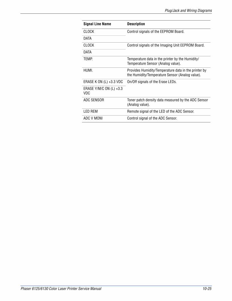
Phaser 6125/6130 Color Laser Printer Service Manual 10-25
Plug/Jack and Wiring Diagrams
Signal Line Name Description
CLOCK Control signals of the EEPROM Board.
DATA
CLOCK Control signals of the Imaging Unit EEPROM Board.
DATA
TEMP. Temperature data in the printer by the Humidity/Temperature Sensor (Analog value).
HUMI. Provides Humidity/Temperature data in the printer by the Humidity/Temperature Sensor (Analog value).
ERASE K ON (L) +3.3 VDC On/Off signals of the Erase LEDs.
ERASE Y/M/C ON (L) +3.3 VDC
ADC SENSOR Toner patch density data measured by the ADC Sensor (Analog value).
LED REM Remote signal of the LED of the ADC Sensor.
ADC V MONI Control signal of the ADC Sensor.

10-26 Phaser 6125/6130 Color Laser Printer Service Manual
Plug/Jack and Wiring Diagrams
High Voltage Power Supply
Signal Line Name Description
TR MON Controls signal of the HVPS.
CF MON
COLOR
DATA
CLK
MCUPL8.2.13
P/J16
1
2
3
4
5
6
7
8
HVPSPL4.1.19
P/J161A
E
I
H
G
F
BCR
BTR
BTR : Bias Transfer Roll
BCR : Bias Charge Roll
Developer
D
C
B
10
9
8
7
6
5
4
3
TR MON
CF MON
HV DO
HV LD
HV CLK
+3.0V REF
SG
9
10
2
1
MAIN CLK
SG
I/L +24V
s6130-064
K
C
M
Y
+3.0V REF
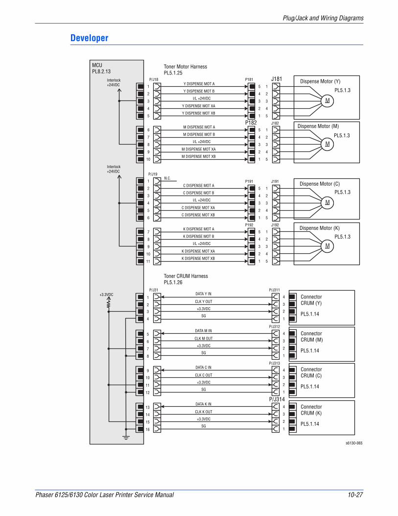
Phaser 6125/6130 Color Laser Printer Service Manual 10-27
Plug/Jack and Wiring Diagrams
Developer
MCUPL8.2.13
1
3
4
5
2
P/J18 P181
5
4
3
2
1
J1811
2
3
4
5
Dispense Motor (Y)
PL5.1.3Y DISPENSE MOT A
Y DISPENSE MOT B
I/L +24VDC
Y DISPENSE MOT XA
Y DISPENSE MOT XB
M DISPENSE MOT A
M DISPENSE MOT B
I/L +24VDC
M DISPENSE MOT XA
M DISPENSE MOT XB
C DISPENSE MOT A
C DISPENSE MOT B
I/L +24VDC
C DISPENSE MOT XA
C DISPENSE MOT XB
K DISPENSE MOT A
K DISPENSE MOT B
I/L +24VDC
K DISPENSE MOT XA
K DISPENSE MOT XB
N.C.
6
8
9
10
7
7
8
10
11
9
P1825
4
3
2
1
J182
1
2
3
4
5
Dispense Motor (M)
PL5.1.3
1
2
4
5
6
3
P191
P/J19
5
4
3
2
1
J191
1
2
3
4
5
Dispense Motor (C)
PL5.1.3
P192
5
4
3
2
1
J192
1
2
3
4
5
Dispense Motor (K)
PL5.1.3
Toner Motor HarnessPL5.1.25
Toner CRUM HarnessPL5.1.26
1
2
P/J311
Connector CRUM (Y)
PL5.1.14
P/J31DATA Y IN
CLK Y OUT
+3.3VDC
SG
DATA M IN
CLK M OUT
+3.3VDC
SG
DATA C IN
CLK C OUT
+3.3VDC
SG
DATA K IN
CLK K OUT
+3.3VDC
SG
s6130-065
4
3
23
4
Connector CRUM (M)
PL5.1.14
1
5
6
Connector CRUM (C)
PL5.1.14
4
3
7
8
P/J312
Connector CRUM (K)
PL5.1.14
2
1
9
10
4
11
12
P/J313
2
3
1
13
P/J3144
14
15
3
2
16 1
Interlock+24VDC
Interlock+24VDC
+3.3VDC
M
M
M
M
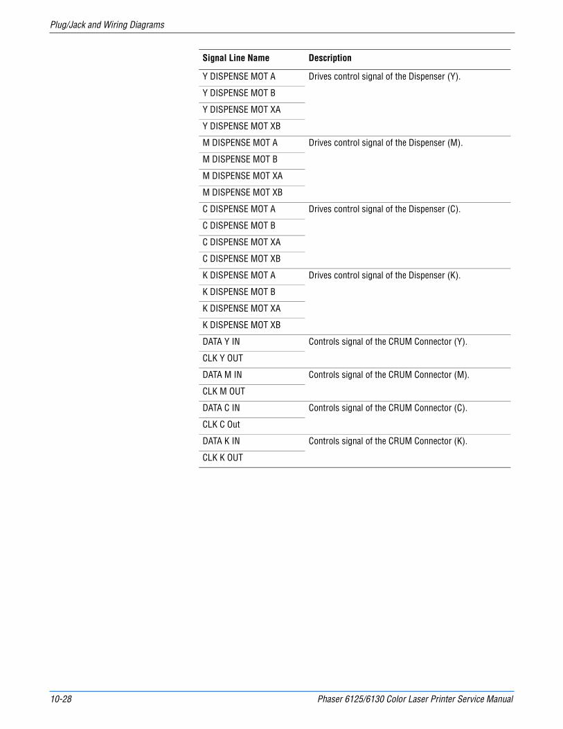
10-28 Phaser 6125/6130 Color Laser Printer Service Manual
Plug/Jack and Wiring Diagrams
Signal Line Name Description
Y DISPENSE MOT A Drives control signal of the Dispenser (Y).
Y DISPENSE MOT B
Y DISPENSE MOT XA
Y DISPENSE MOT XB
M DISPENSE MOT A Drives control signal of the Dispenser (M).
M DISPENSE MOT B
M DISPENSE MOT XA
M DISPENSE MOT XB
C DISPENSE MOT A Drives control signal of the Dispenser (C).
C DISPENSE MOT B
C DISPENSE MOT XA
C DISPENSE MOT XB
K DISPENSE MOT A Drives control signal of the Dispenser (K).
K DISPENSE MOT B
K DISPENSE MOT XA
K DISPENSE MOT XB
DATA Y IN Controls signal of the CRUM Connector (Y).
CLK Y OUT
DATA M IN Controls signal of the CRUM Connector (M).
CLK M OUT
DATA C IN Controls signal of the CRUM Connector (C).
CLK C Out
DATA K IN Controls signal of the CRUM Connector (K).
CLK K OUT

Phaser 6125/6130 Color Laser Printer Service Manual 10-29
Plug/Jack and Wiring Diagrams
Fuser
MCUPL8.2.13
P/J17 P/J171
54
SG
876
321
45
123
678 1
54
876
32
STS
3
1
N HEAT1
1
2
3
1
2
3LINE
VCVDSG
FUSER EXIT SENSED (L) +3.3VDC
Fuser HarnessPL6.1.2
Relay Test HarnessPL5.1.28
SGPULL UP +3.3VDC
FuserPL6.1.1
LVPSPL8.2.1
LampControl
s6130-066
Thermostat
Heater
NC SNS12
3P/J175
P/J176
P/J172
P1711P/J171
P/J47P/J14 P/J501P1712
P1713
P/J173
23 1
STS12
21
123
ExitSensor
123
321
230V Spec.
3
1
N HEAT11
2
3
1
2
3LINE
P/J171
P/J47
5
6
10
9
xHEAT1
FUSER ON
+3.3VDC
Used in production process only.
P/J504
J5041
12
23
RELAY TEST LOWRELAY TEST HIGH
1

10-30 Phaser 6125/6130 Color Laser Printer Service Manual
Plug/Jack and Wiring Diagrams
Signal Line Name Description
STS Heat Roll surface temperature data measured by the Humidity/Temperature Sensor for detecting high temperature (Analog value).
VC Temperature data measured by the Humidity/Temperature Sensor for controlling the temperature (Analog value).VD
FUSER EXIT SENSED (L) +3.3 VDC
Paper detects signal of the Fuser Exit by the Photo Sensor (Exit Sensor).
FUSER ON Displays lighting signal of the Fuser Lamp.
RELAY TEST LOW Tests signal of the LVPS (used in production process only)RELAY TEST HIGH

Phaser 6125/6130 Color Laser Printer Service Manual 10-31
Plug/Jack and Wiring Diagrams
Controller
IP BoardPL8.1.7
P/J101
1
2
3
4
5
6
7
8
9
10
11
12
13
14
15
16
P/J29
7
6
5
4
3
2
1
P/J401
1
2
3
4
P/J10TEST PRINT
IP HarnessPL9.1.1
IP Video HarnessPL9.1.2
IP Power HarnessPL9.1.10
Control Panel A HarnessPL1.1.20
SG
+3.3VDC
DEEP SLEEP
SG
STS
CMD
CREADY
SREADY
SG
VSYNC K
VSYNC C
VSYNC M
VSYNC Y
SG
HSYNC
SG
16
15
14
13
12
11
10
9
8
7
6
5
4
3
2
1
17
18
18
17
P/J40
1
2
3
4
P/J220
1
2
3
4
5
6
7
MCUPL8.2.13
LVPSPL8.2.1
Control PanelPL1.1.18
s6130-067
P/J111
1
2
3
4
5
6
7
8
P/J11SG
DATA K
SG
DATA C
SG
DATA M
SG
DATA Y
+5VDC
SG
+3.3VDC
SG
SG
DATA
CLK
+5VDC
LED ON
WAKE UP
+3.3VDC
6
5
4
3
2
1
8
7
+3.3VDC +3.3VDC
+5VDC
+3.3VDC
+5VDC +5VDC
+5VDC
+3.3VDC
1
2
3
4
5
6
7
7
6
5
4
3
2
1
P/J2900
Control Panel B HarnessPL9.1.12

10-32 Phaser 6125/6130 Color Laser Printer Service Manual
Plug/Jack and Wiring Diagrams
Signal Line Name Description
TEST PRINT Controls signal for the Test Print mode.
DEEP SLEEP Controls signal for the Deep Sleep mode.
STS Status signal transmitted from the MCU Board to the Image Processor Board.
CMD Commands signal transmitted from the Image Processor Board to the MCU Board.
CREADY Signal for indicating whether or not the printer is ready for receiving command signal.SREADY
VSYNC K Signal for indicating registration position of each of images Y, M, C, and K.VSYNC C
VSYNC M
VSYNC Y
HSYNC Signal for data.
DATA K Video data of four colors.
DATA C
DATA M
DATA Y
DATA Control signals of the Control Panel.
CLK
BACK LIGHT
BL +5 VDC

AAppendix
ReferenceContents...■ Phaser 6130 Menu Map
■ Firmware Update
■ Acronyms and Abbreviations

A-2 Phaser 6130 Color Laser Printer Service Manual
Reference
Phaser 6130 Menu Map
Billing Meters
Admin Menu
Information Pages
Requires:
Power SaverOff
OK
Cancel
Walk-Up Features*Menu Map
Demo Page
Configuration
PCL Fonts List
PCL Macro List
PS Fonts List
Job History
Error History
Print Meter
Stored Documents*
Adobe Protocol
Network Setup
USB Setup
System Setup
Maintenance Mode
PCL Setup
PostScript Setup
Control Panel
Tray Settings
Tray
Total Impression
Color Impression
Black Impression
Optional MemoryMulti-Protocol Network Card
***
Automatic Registration AdjustAdjust Color RegistrationClean DeveloperToner RefreshDrum RefreshInitialize Print MeterInitialize NVMReset Fuser
PS Error ReportPS Job Time-OutPaper Select ModeDefault Color
Panel LockChange Password
Paper TypePaper SizeDisplay Popup
EthernetTCP/IPProtocolHost Access ListReset DefaultsAdobe Protocol
PowerSaver TimeAudio TonesTime-OutPanel LanguageAuto Log PrintPrint IDPrint TextRAM Disk*Size Mismatchmm/inchStartup Page
Paper SizeOrientationFontSymbol SetFont SizeFont PitchForm LineQuantityImage EnhanceHex DumpDraft ModeLine TerminationDefault Color
Get IP AddressIP AddressNetwork MaskGateway Address
LPRPort 9100IPP**FTPNetWare**SNMPEmail AlertsCentreWare ISBonjour (mDNS)HTTP-SSL/TLS**
Menus
Phaser® 6130Printer
Page 1 of 1
Copyright © 2007 Xerox Corporation. All rights reserved.

Phaser 6130 Color Laser Printer Service Manual A-3
Reference
Firmware Update
Boot Controller Update
NoteBoot Code can be updated via USB port only.
1. Down load applicable files from the Xerox support web site.
2. Turn off the printer.
3. Ensure your USB cable is connected.
4. Press the Up Arrow, Down Arrow, and Menu buttons simultaneously and turn on the printer.
5. The FW Update Password is displayed.
6. Press the Down Arrow button 2 times.
7. Press the OK button.
8. The F/W Download is displayed.
9. Select DL Mode USB. Press the OK button.
10. The serial number of the printer is displayed. Then the DownLoad Mode Send F/W Data is displayed.
11. On your computer, locate the downloaded file. Open the Boot directory. Double-click the Xeroxfwup.exe file.
12. Select USB. Click the Next button.
13. The xeroxfwup window with the module number is displayed. Click the Next button.
14. On the printer Control Panel, the Erasing Flash... --> Diagnosing message is displayed. The the printer starts updating the firmware.
CautionDo Not reboot or turn off the printer. The printer will automatically reboot.
12. When the process is completed, the following messages are displayed on the printer Control Panel.
■ Xerox (TM) Print Cartridge
■ Processing... Ready
13. Print the printer Configuration page (Menu > Information Pgs > Configuration) and verify the Boot Version information.
A-4 Phaser 6130 Color Laser Printer Service Manual
Reference
Firmware Controller Update
1. Down load the applicable files from the Xerox support web site.
2. Ensure your appropriate downloading cable option (Ethernet or USB) is connected.
3. Reboot the printer.
4. On your computer, locate the downloaded file. Open the Main directory. Double-click the Xeroxfwup.exe file.
5. The xeroxfwup window with connection options is displayed. Select the appropriate downloading option (Network or USB). Click the Next button.
6. The xeroxfwup window is displayed.
a. For Network connection:
■If your printer IP address is available, select the appropriate box. Click the Next button.
■If your printer IP address in not listed, click the Add button. Enter your printer IP address. Click the OK button. Select the box with your printer IP address. Click the Next button.
■On the printer Control Panel, messages are displayed from Receiving data Port 9100 --> Writing... Port 9100 as the printer starts updating the firmware.
b. For USB connection:
■The xeroxfwup window with the module number is displayed. Click the Next button.
■On the printer Control Panel, messages are displayed from Receiving data USB --> Writing... USB as the printer starts updating the firmware.
■A Completed message is displayed on the Control Panel.
CautionDo Not reboot or turn off the printer. The printer will automatically reboot.
7. When the process is completed, the following messages are displayed on the printer Control Panel.
■ Diagnosing... Xerox (TM) Print Cartridge
■ Processing... Please wait... Calibrating... Ready
8. On your computer, verify that the firmware update has been sent. Click the Next button. Click the OK button.
9. Print the printer Configuration page (Menu > Information Pgs > Configuration) and verify the Firmware Version information.

Phaser 6130 Color Laser Printer Service Manual A-5
Reference
Firmware MPC Update
1. Down load the applicable files from the Xerox support web site.
2. Ensure your appropriate downloading cable option (Ethernet or USB) is connected.
3. Reboot the printer.
4. On your computer, locate the downloaded file. Double-click the Xeroxfwup.exe file.
5. The xeroxfwup window with connection options is displayed. Select the appropriate downloading option (Network or USB). Click the Next button.
6. The xeroxfwup window is displayed.
a. For Network connection:
■If your printer IP address is available, select the appropriate box. Click the Next button.
■If your printer IP address in not listed, click the Add button. Enter your printer IP address. Click the OK button. Select the box with your printer IP address. Click the Next button.
■On the printer Control Panel, messages are displayed from Receiving data Port 9100 --> Checking... Port 9100 --> Writing... Port 9100 as the printer starts updating the firmware.
b. For USB connection:
■The xeroxfwup window with the module number is displayed. Click the Next button.
■On the printer Control Panel, messages are displayed from Receiving data USB --> Checking... USB --> Writing... USB as the printer starts updating the firmware.
■A Diagnosing... message is displayed on the Control Panel.
CautionDo Not reboot or turn off the printer. The printer will automatically reboot.
7. When the process is completed, the following messages are displayed on the printer Control Panel.
■ Diagnosing... Xerox (TM) Toner Cartridge
■ Processing... Please wait... Calibrating... Ready
8. On your computer, verify that the firmware update has been sent. Click the Next button. Click the OK button.
9. Print the printer Configuration page (Menu > Information Pgs > Configuration) and verify the Firmware Version information.

A-6 Phaser 6130 Color Laser Printer Service Manual
Reference
Acronyms and Abbreviations
Acronym Description
A3 Paper size 297 millimeters (11.69 inches) x 420 millimeters (16.54 inches).
A4 Paper size 210 millimeters (8.27 inches) x 297 millimeters (11.69 inches).
A5 Paper size 148 millimeters (5.82 inches) x 210 millimeters (2.10 inches).
AC Alternating Current is type of current available at power source for the printer.
ADC Automatic Density Control
AMPV Average Monthly Print Volume
APC Auto Power Control
ASSY Assembly
BCR Bias Charge Roller
BOOTP Boot Parameter Protocol
BTR Bias Transfer Roller
CAM Cam Shaft
CCD Charge Coupled Device (Photoelectric Converter)
CCW Counter-Clock Wise
CMYK Toner colors for the printer:Y=yellow, C=cyan, M=magenta, K=black
CRU Customer Replaceable Unit
CRUM Customer Replaceable Unit Meter/Memory
CST Cassette
dB Decibel
DC Direct Current is type of power for printer components. Machine converts AC power from power source to DC power.
DDNS Dynamic Domain Name System
DDR2 DIMM Double Data Rate Dual In-Line Memory Module
DEV Developer
DHCP Dynamic Host Configuration Protocol
DPI Dot Per Inch
DRV Drive
DUP Duplex
Duplex 2-sided printing
EA Emulsion Aggregation (Toner)
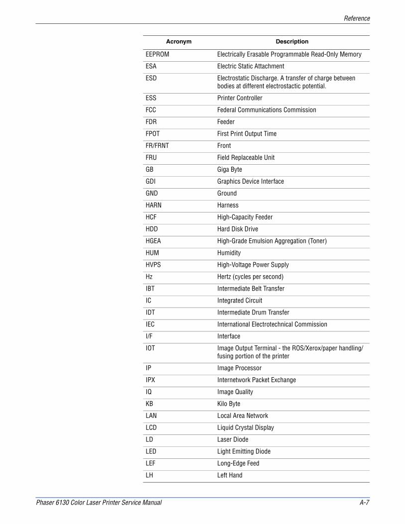
Phaser 6130 Color Laser Printer Service Manual A-7
Reference
EEPROM Electrically Erasable Programmable Read-Only Memory
ESA Electric Static Attachment
ESD Electrostatic Discharge. A transfer of charge between bodies at different electrostactic potential.
ESS Printer Controller
FCC Federal Communications Commission
FDR Feeder
FPOT First Print Output Time
FR/FRNT Front
FRU Field Replaceable Unit
GB Giga Byte
GDI Graphics Device Interface
GND Ground
HARN Harness
HCF High-Capacity Feeder
HDD Hard Disk Drive
HGEA High-Grade Emulsion Aggregation (Toner)
HUM Humidity
HVPS High-Voltage Power Supply
Hz Hertz (cycles per second)
IBT Intermediate Belt Transfer
IC Integrated Circuit
IDT Intermediate Drum Transfer
IEC International Electrotechnical Commission
I/F Interface
IOT Image Output Terminal - the ROS/Xerox/paper handling/fusing portion of the printer
IP Image Processor
IPX Internetwork Packet Exchange
IQ Image Quality
KB Kilo Byte
LAN Local Area Network
LCD Liquid Crystal Display
LD Laser Diode
LED Light Emitting Diode
LEF Long-Edge Feed
LH Left Hand
Acronym Description

A-8 Phaser 6130 Color Laser Printer Service Manual
Reference
LPD Line Printer Daemon
LPR Line Printer Remote
LTR Letter Size Paper (8.5 x 11 inches)
LVPS Low-Voltage Power Supply
MAC Media Access Control
MB Mega Byte
MCU Machine Control Unit (Engine Control Board)
MHz Mega Hertz
MIB Management Information Base
MICR Magnetic Ink Character Recognition
MM Millimeters
MOB Marks On Belt
MOT Motor
MPC Multi-Protocol Network Card
MPT Multi-Purpose Tray
NCS Non-Contact Sensor
NPP No Paper
NVM Non-Volatile Memory
NVRAM Non-Volatile Random Access Memory
OEM Original Equipment Manufacturer
OHP Overhead Paper (Transparency)
OPC Organic Photo Conductor
OPT Optional
OS Operating System
PC Personal Computer
PCB Printed Circuit Board
PCDC Pixel Count Dispense Control
PCL Printer Command Language
PDL Page Description Language
P/J Plug Jack (electrical connections)
PJL Printer Job Language
PL Parts List
POP3 Post Office Protocol version 3
PPD PostScript Printer Description
PPM Pages Per Minute
PPS Pages
Acronym Description

Phaser 6130 Color Laser Printer Service Manual A-9
Reference
PWB Printed Wiring Board
PWBA Printed Wiring Board Assembly
RAM Random Access Memory
RegiCon Registration Control
RET Retard
RH Relative Humidity
RLS Release
RMS Root Mean Square Voltage
ROM Read-Only Memory
ROS Raster Output Scanner - Laser Unit
RTD Retard
SEF Short-Edge Feed
SLP Service Location Protocol
SMB Server Message Block
SNMP Simple Network Management Protocol
SNR Sensor
SOL Solenoid
SOS Start of Scan
STS Soft Touch Sensor
TDC Toner Density Control
TNR Toner
TRNS Transport
UI User Interface
USB Universal Serial Bus
WINS Wireless Integrated Network Sensor
Acronym Description

A-10 Phaser 6130 Color Laser Printer Service Manual
Reference

Phaser 6130 Color Laser Printer Service Manual I – 1
Index
Index
A
abbreviationserror messages, 3-5Phaser 6130, A-6
AC powerplug/jack locator, 10-10troubleshooting, 4-40
ADC (CTD) error, 3-51ADC Sensor
control function, 2-36description, 2-23
adjustmentscolor registration, 6-2resetting Fuser life counter, 6-5setting parameter, 6-7
AMPV, 1-11ASIC error, 3-24
B
Bias Charge Roller (BCR), 2-4Bias Transfer Roller (BTR), 2-9black and white mode, 2-40boot controller, firmware update, A-3button functions, control panel, 1-6
C
calibrationsinitializing NVM, 6-6initializing print meter, 6-6
chain link codedescription, 3-2message summary, 3-6
check sum error, 3-21cleaning
tools, 7-2clearances, 1-17Clutch
Registration, 2-20collation, 1-21color mode switching, 2-29color registration, 2-36
adjustment, 6-2
adjustmentsauto adjustment, 6-3disabling, 6-3enabling, 6-3manual adjustment, 6-4
configuration page, 1-24consumables
Toner Cartridgedescription, 1-10part number, 9-25
Control Panelbuttons, 1-6LED states, 1-7operation, 2-31plug/jack locator, 10-8shortcuts, 1-7troubleshooting, 4-37
Control Panel Harnessremoval, 8-54
controller error, 3-24controller functions, 1-20
information pages, 1-24job control, 1-20maintenance function, 1-23non-genuine mode, 1-22toner remaining, 1-23
countersbilling print, 1-22
Coverfront, removal, 8-19left side, removal, 8-17output tray extension, removal, 8-15rear, removal, 8-18right side, removal, 8-16toner access door, removal, 8-11top, removal, 8-14
coversremoval, 8-11
CRUM Connectorlocation, 2-26operation, 2-26
D
DC powertroubleshooting, 4-41
Deep Sleep Mode, 10-18

I – 2 Phaser 6130 Color Laser Printer Service Manual
Index
demo page, 1-24Developer
wiring diagrams, 10-27Diagnostic Tests
Engine Diag, 4-10ESS DiagExit Mode, 4-19Installation, 4-13Parameter, 4-17Print Info, 4-13Test Print, 4-16
dimensions, 1-17disassembly
covers, 8-11drive, 8-52electrical, 8-54frame, 8-44paper feeder, 8-21separate upper and lower assemblies, 8-47Xerographics, 8-31
Dispenserlocation, 2-26operation, 2-26plug/jack locator, 10-8
Dispenser Assemblyremoval, 8-34
Doorside door open error, 3-73toner access open, 3-73
Download Mode error, 3-79Drive
black and white mode, 2-40color mode switching, 2-29components, 2-28development, 2-44excess toner collection, 2-44Feed Drive location, 2-28Feed Drive operation, 2-28K mode, 2-40Main Drive location, 2-28Main Drive operation, 2-28, 2-38Sub Drive, 2-40Sub Drive location, 2-28Sub Drive operation, 2-28wiring diagrams, 10-20
Drive Clutch Kitremoval, 8-21
Drive Motorsplug/jack locator, 10-10
E
EEPROM Boardlocation, 2-30operation, 2-31
electricaldata flow diagram, 2-33specifications, 1-12
electrostatic discharge (ESD), 1-viEnd Guide, Paper Tray
location, 2-15operation, 2-16
engine test print, 4-38Env Sensor error, 3-82envelopes
supported sizes, 1-19environmental specifications, 1-13erase flash error, 3-21Erase Lamp
operation, 2-28removal, LED assembly, 8-37troubleshooting, black, 4-35troubleshooting, YMC, 4-36
errorADC (CTD), 3-51ASIC, 3-24check sum, 3-21controller, 3-24cover open, 3-72download mode, 3-79erase flash, 3-21fan motor, 3-66fontROM, 3-24format, 3-21front cover open, 3-72Fuser, 3-62fuser, 3-64header, 3-21humidity sensor, 3-82imaging unit, 3-71imaging unit CRUM, 3-71insert fuser, 3-62insert imaging unit, 3-53insert output, 3-56invalid ID, 3-21invalid job, 3-78jam at exit, 3-44jam at front cover, 3-34, 3-42jam at manual feed, 3-37jam at registration roll, 3-46K mode solenoid, 3-80laser unit, 3-76load manual feed, 3-56, 3-57load tray, 3-59, 3-60low density YMCK, 3-54MACaddress, 3-24main motor, 3-67MCU communication, 3-77MCU firmware, 3-74MCU NVRAM, 3-75motor, 3-66MPC, 3-50network, 3-24NVRAM, 3-24out of memory, 3-22PAGEC time, 3-25paper settings, 3-56RAM, 3-24, 3-26range check, 3-21side door open, 3-73sub motor error, 3-69toner access door open, 3-73
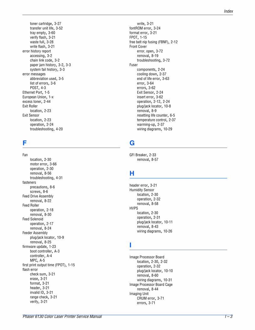
Phaser 6130 Color Laser Printer Service Manual I – 3
Index
toner cartridge, 3-27transfer unit life, 3-52tray empty, 3-60verify flash, 3-21waste full, 3-28write flash, 3-21
error history reportaccessing, 3-2chain link code, 3-2paper jam history, 3-2, 3-3system fail history, 3-3
error messagesabbreviation used, 3-5list of errors, 3-6POST, 4-3
Ethernet Port, 1-5European Union, 1-xexcess toner, 2-44Exit Roller
location, 2-23Exit Sensor
location, 2-23operation, 2-24troubleshooting, 4-20
F
Fanlocation, 2-30motor error, 3-66operation, 2-30removal, 8-56troubleshooting, 4-31
fastenersprecautions, 8-6screws, 8-6
Feed Drive Assemblyremoval, 8-22
Feed Rolleroperation, 2-18removal, 8-30
Feed Solenoidoperation, 2-17removal, 8-24
Feeder Assemblyplug/jack locator, 10-9removal, 8-25
firmware update, 1-23boot controller, A-3controller, A-4MPC, A-5
first print output time (FPOT), 1-15flash error
check sum, 3-21erase, 3-21format, 3-21header, 3-21invalid ID, 3-21range check, 3-21verify, 3-21
write, 3-21fontROM error, 3-24format error, 3-21FPOT, 1-15free belt nip fusing (FBNF), 2-12Front Cover
error, open, 3-72removal, 8-19troubleshooting, 3-72
Fusercomponents, 2-24cooling down, 2-37end of life error, 3-63error, 3-64errors, 3-62Exit Sensor, 2-24insert error, 3-62operation, 2-12, 2-24plug/jack locator, 10-8removal, 8-9resetting life counter, 6-5temperature control, 2-37warming-up, 2-37wiring diagrams, 10-29
G
GFI Breaker, 2-33removal, 8-57
H
header error, 3-21Humidity Sensor
location, 2-30operation, 2-32removal, 8-58
HVPSlocation, 2-30operation, 2-31plug/jack locator, 10-11removal, 8-43wiring diagrams, 10-26
I
Image Processor Boardlocation, 2-30, 2-32operation, 2-32plug/jack locator, 10-10removal, 8-60wiring diagrams, 10-31
Image Processor Board Cageremoval, 8-44
Imaging UnitCRUM error, 3-71errors, 3-71

I – 4 Phaser 6130 Color Laser Printer Service Manual
Index
insert error, 3-53plug/jack locator, 10-8removal, 8-8replace error, 3-71
Information pagesconfiguration, 1-24demo, 1-24error history, 1-27job history, 1-26PCL fonts, 1-25PCL macros, 1-25PostScript fonts, 1-26Print Meter, 1-27
insert fuser error, 3-62insert output to tray/MF, 3-56Interlock Harness
removal, 8-54Interlock Switch
location, 2-30operation, 2-32troubleshooting, 4-43
invalid ID, 3-21Invalid Job error, 3-78IP Board - See Image Processor Board
J
jam at tray error, 3-29jam error
at exit, 3-44at front cover, 3-34, 3-42at manual feed, 3-37at registration roll, 3-46jam at tray, 3-29
job control functionsbilling meters, 1-22cancel print, 1-20forced output, 1-20ID print, 1-22IP filter, 1-20job recovery, 1-20job timeout, 1-20print volume management, 1-20RAM disk, 1-20
K
K mode (see black and white mode), 2-40K Mode Solenoid error, 3-80
L
Laser Diodelocation, 2-24operation, 2-25
Laser Unitcomponents, 2-24
light quantity control, 2-34location, 2-24operation, 2-5, 2-24plug/jack locator, 10-9removal, 8-31troubleshooting, 3-76wiring diagrams, 10-22
LED indicators, 1-7Left Harness Assembly removal, 8-26Left Imaging Unit Restraint Block removal, 8-39Left Side Cover removal, 8-17load manual feed error, 3-56, 3-57load tray error, 3-59, 3-60low density YMCK error, 3-54LVPS
location, 2-30operation, 2-30overcurrent protection, 4-41overvoltage protection, 4-41plug/jack locator, 10-10removal, 8-55troubleshooting, 4-41
M
MACaddress error, 3-24Macintosh
operating system, 1-11troubleshooting, 4-53
Main Drive Assembly removal, 8-52maintenance
preventive, 7-2RIP, 7-3tools, 7-2
maintenance itemsFuser, 1-9Fuser removal, 8-9Imaging Unit, 1-9imaging unit removal, 8-8removal, 8-7Separator Roller, 1-9separator roller removal, 8-7toner cartridge removal, 8-10
Manual FeedNo Paper Sensor operation, 2-19No Paper Sensor removal, 8-28Registration Sensor operation, 2-19
MCU Boardcommunication error, 3-77errors, 3-74firmware error, 3-74location, 2-30NVRAM error, 3-75operation, 2-31plug/jack locator, 10-11removal, 8-59
Memorylocation, 2-32maximum, 1-12minimum, 1-12

Phaser 6130 Color Laser Printer Service Manual I – 5
Index
out of memory error, 3-22part number, 9-25specifications, 1-12supported types, 1-8, 1-12
menu mapPhaser 6130, A-2Service Mode, 4-6
Motormain motor error, 3-67sub motor error, 3-69troubleshooting Sub Motor, 4-28
motorerrors, 3-66troubleshooting Main Motor, 4-27
MPC Card, 2-33MPC card, 1-8MPC error, 3-50MPC part number, 9-25multiple sheet feed prevention, 2-16Multi-Protocol Network Card, 2-33
part number, 9-25
N
networkerror, 3-24Ethernet Port, 1-5Macintosh troubleshooting, 4-53UNIX troubleshooting, 4-54Windows troubleshooting, 4-52
Network Carddescription, 1-8MPC error, 3-50
No Paper Sensor, Traytroubleshooting, 4-26
NVRAMerror, 3-24initializing, 6-6location, 2-32troubleshooting, 3-75
O
operating environment, 1-13operating systems
specifications, 1-11troubleshooting, 4-52
output tray, 1-2Output Tray Extension removal, 8-15over-current protection, 10-18over-voltage protection, 10-18
P
PAGEC time error, 3-25paper
envelopes, 1-19
supported sizes, 1-19supported types and weights, 1-19
paper detection, 2-22paper path
components, 2-14flow diagram, 2-13
paper setting errors, 3-56paper size detection, 2-34Paper Tray
components, 2-15Feed Roller
operation, 2-18Feed Solenoid
operation, 2-17operation, 2-16
parametersetting, 6-7
Plug/Jackdesignators list, 10-2locator diagrams, 10-6
Power Cordconnector location, 1-5
Power On Self Test (POST)chain link, 4-3description, 4-3error display, 4-3process, 4-3type of tests, 4-3
power requirements, 1-12power saver mode, 1-12Power Switch
location, 1-5operation, 2-30
print meterinitializing, 6-6
print volume, 1-11printer
configurations, 1-3data flow, 2-33dimensions, 1-17job control functions, 1-20operating modes, 1-14options, 1-8print process, 2-3print process diagram, 2-2print speed, 1-13printing life, 1-11resolution, 1-11serial number, 9-2specifications, 1-11technology, 1-11
printer optionsmemory, 1-8MPC card, 1-8
print-qualitydefect definitions, 5-20mode, 1-11repeating defect, 5-21specifications, 5-15
guaranteed and maximum print areas, 5-19linearity, 5-17magnification error, 5-18

I – 6 Phaser 6130 Color Laser Printer Service Manual
Index
parallelism, 5-17perpendicularity, 5-18registration, 5-19skew, 5-16
troubleshooting, 5-20troubleshooting checklist, 5-5
process control parameters, 2-35admix mode, 2-36high area coverage mode, 2-36potential, 2-35toner density, 2-35
proof print, 1-21
R
RAM error, 3-24, 3-26range check error, 3-21Rear Cover removal, 8-18registration
components, 2-22operation, 2-21, 2-22
Registration Clutchoperation, 2-20troubleshooting, 4-33
Registration SensorManual Feed operation, 2-19troubleshooting, 4-21
repeating defectsmeasurements, 5-21Pitch Chart, 5-14, 5-21
replace fuser/fuser life error, 3-63report
error history, 1-27job history, 1-26PCL fonts list, 1-25PCL macro list, 1-25postscript fonts list, 1-26print meter, 1-27
resolution, 1-11resources, 4-55Right Imaging Unit Restraint Block
removal, 8-38Right Side Cover removal, 8-16
S
safety symbols, 1-ivScanner, laser, 2-25screw types, 8-6secure print, 1-21Sensor
ADC, 2-23color mode switching, 2-29error, humidity, 3-82Exit, 2-24Humidity, 2-32Manual Feed No Paper, 2-19Registration, 2-19Start of Scan (SOS), 2-25
Temperature, 2-32Tray No Paper, 2-17
Separator Rolleroperation, 2-16operation and location, 2-15removal, 8-7
serial numberformat, 9-2location, 9-2
Service Diagnosticsmenu map, 4-6
Service KitsHardware Kit
contents, 9-26part number, 9-26
Packaging Kit part number, 9-26Service Mode
accessingbutton functions, 4-5control panel display, 4-9diagnostic tests, 4-9menu map, 4-6
servicing instructions, 3-4Side Guide, Paper Tray
operation and location, 2-15Side Switch - see Toner Access Door Switchskew measurement, 5-16specifications, 1-11
electrical, 1-12environmental, 1-13functional, 1-11image, 1-16media and tray, 1-19memory, 1-12mounting surface, 1-18print-quality, 5-15regulatory - Canada, 1-ixregulatory - United States, 1-ix
Start of Scan (SOS), 2-25startup sequence, 4-2Sub Motor error, 3-69Sub-Drive removal, 8-53
T
technical support, 1-2Temperature Sensor
location, 2-30operation, 2-32
test printBlack 20% ESS, 5-11CMY 20% ESS, 5-12Contamination Check, 5-14Cyan 20% ESS, 5-10Gradation ESS, 5-12Grid 2 ESS, 5-9Magenta 20% ESS, 5-10no image IOT, 5-8Pattern IOT, 5-9Toner Pallet Check, 5-13Yellow 20% ESS, 5-11

Phaser 6130 Color Laser Printer Service Manual I – 7
Index
test print, engine, 4-38Toner Access Door removal, 8-11Toner Access Door Switch, 2-33
removal, 8-63Toner Cartridge
components, 2-26consumables, 1-10errors, 3-27location, 2-26non-Xerox type, 1-22operation, 2-7part number, 9-25print life, 1-10
Toner Cartridge Holder removal, 8-40Toner Dispenser Motors plug/jack locator, 10-11Top Cover removal, 8-14Transfer Unit
ADC Sensor, 2-23belt, 2-23end of life error, 3-52errors, 3-51operation, 2-9, 2-23pivot kit removal, 8-45plug/jack locator, 10-8removal, 8-41
Transfer Unit Pivot Kitremoval, 8-45
tray empty error, 3-60Tray No Paper Sensor, 2-17
troubleshooting, 4-26troubleshooting
electrical noise, 4-49Macintosh, 4-53print-quality, 5-2, 5-20UNIX, 4-54
U
UNIXoperating system, 1-11troubleshooting, 4-54
USB Port, 1-5
V
verify flash error, 3-21voltage
in-rush current, 1-12leakage current, 1-12power consumption, 1-12power supply, 1-12
W
warm-up time, 1-11waste full error, 3-28waste toner (see excess toner), 2-44Windows
operating system, 1-11troubleshooting, 4-52
Wiring Diagramsconfigurations, 10-15controller, 10-31DC power supply, 10-17developer, 10-27drive, 10-20feeder, 10-19fuser, 10-29HVPS, 10-26laser unit, 10-22manual feed, 10-19registration, 10-19xerograhic, 10-24
write flash error, 3-21
X
Xerographicwiring diagrams, 10-24

I – 8 Phaser 6130 Color Laser Printer Service Manual
Index


701P47834