
Performance of a Five-Phase Induction Machine With Optimized Air Gap Field Under Open Loop / Control
11
1046 IEEE TRANSACTIONS ON ENERGY CONVERSION, VOL. 23, NO. 4, DECEMBER 2008 Performance of a Five-Phase Induction Machine With Optimized Air Gap Field Under Open Loop V/f Control C´ esar Cataldo Scharlau, Lu´ ıs Fernando Alves Pereira, Lu´ ıs Alberto Pereira, and S´ ergio Haffner, Member, IEEE Abstract—The paper assesses the steady-state performance of a five-phase induction machine fed by a modified open loop constant volt/hertz (V/f) control method, which imposes a trapezoidal induc- tion waveform in the air gap under varying load conditions. The trapezoidal air gap induction is achieved through the imposition of an appropriate combination of the third harmonic and fundamen- tal stator voltages. This harmonic combination is determined from the steady-state model using a mathematical optimization proce- dure, which allows to obtain the optimal weighting factors for each harmonic component. The optimized reference voltages lead to a trapezoidal air gap induction, which allows a better iron utiliza- tion and higher output torque for the same rms stator current when compared to sinusoidal air gap induction. The resulting air gap induction is obtained from the induced voltage of a full pitch search coil placed in the air gap. The proposed control scheme was successfully simulated and implemented on a five-phase prototype machine running under different load conditions. Experimental and simulations results show an increase in the torque/ampere relationship for loads above 50% when compared to the conven- tional V/f method using only the fundamental current and air gap induction. A comparison between the simulation and experimental curves presents a very good agreement that confirms and validates the parameters and model used. Index Terms—AC motor drives, induction machines, modeling, volt/hertz (V/f) control. NOMENCLATURE v s Stator voltage. V s Phasor of stator voltage. i s Stator current. I s Phasor of the stator current. R s Stator resistance. L s Stator inductance. L s δ Stator leakage inductance. L ss x Stator phase inductance for the x-harmonic component. L s h Main stator inductance. I r Phasor of rotor current in stator reference frame. Manuscript received October 30, 2007; revised March 26, 2008. Current version published November 21, 2008. Paper no. TEC-00384-2007. C. C. Scharlau is with the Technology Faculty, National Indus- trial Training Service (SENAI), Porto Alegre 91140-000, Brazil (e-mail: [email protected]). L. F. A. Pereira and L. A. Pereira are with the Electrical Engineering De- partment, Pontifical Catholic University of Rio Grande do Sul (PUCRS), Porto Alegre 90619-900, Brazil (e-mail: [email protected]; [email protected]). S. Haffner is with the Electrical Engineering Department, Santa Catarina State University (UDESC), Joinville 89223-100, Brazil (e-mail: haffner@ ieee.org). Digital Object Identifier 10.1109/TEC.2008.2001437 R r Rotor resistance. R r Rotor resistance in stator reference frame. L r Rotor inductance. L r δ Rotor leakage inductance in stator reference frame. L r h Main rotor inductance. L sr Mutual inductance. m r Number of rotor phases. m s Number of stator phases. q number of stator slots per phase and pole. ω e Rotor speed in electrical degrees. ω m Rotor speed in mechanical degrees. s Rotor slip. B Flux density. u Induced voltage in the search coil. γ Angle between two stator slots. µ 0 Permeability of air. δ e Equivalent air gap. N s Number of turns per stator coil. θ Stator coordinate in electrical degrees. Machine axial length. D Internal stator diameter. R Internal stator radius. σ p Winding pitch. p Number of pole-pairs. f e Reference frequency. f b Base frequency. I. INTRODUCTION T HE INDUCTION machine has been widely used over the last two decades due to its robustness, versatility, and re- liability. The development of solid-state inverters and control schemes has opened a range of applications for the induction machine in areas where dc machines were dominant. A widely used control technique for induction machines is the constant volt/hertz (V/f) method. The principle of V/f operation is well understood and commonly used in variable-speed drives [1]. In almost any kind of application, three-phase induction ma- chines have been employed. The use of three-phase machines is based on long-established concepts where industrial power sources are three-phase systems. However, when the machine is not directly fed from the standard power sources, there is no need for a specified number of phases. In some cases, higher number of phases can be more appropriate and advantageous. Many published papers have shown that five-phase ma- chines have several advantages over conventional three-phase 0885-8969/$25.00 © 2008 IEEE Authorized licensed use limited to: UNIVERSIDADE DO ESTADO DE SANTA CATARINA. Downloaded on December 8, 2008 at 06:09 from IEEE Xplore. Restrictions apply.
-
Upload
kkkkkkkkkkkkkl -
Category
Documents
-
view
1 -
download
0
Transcript of Performance of a Five-Phase Induction Machine With Optimized Air Gap Field Under Open Loop / Control
1046 IEEE TRANSACTIONS ON ENERGY CONVERSION, VOL. 23, NO. 4, DECEMBER 2008
Performance of a Five-Phase Induction MachineWith Optimized Air Gap Field Under Open
Loop V/f ControlCesar Cataldo Scharlau, Luıs Fernando Alves Pereira, Luıs Alberto Pereira,
and Sergio Haffner, Member, IEEE
Abstract—The paper assesses the steady-state performance of afive-phase induction machine fed by a modified open loop constantvolt/hertz (V/f) control method, which imposes a trapezoidal induc-tion waveform in the air gap under varying load conditions. Thetrapezoidal air gap induction is achieved through the imposition ofan appropriate combination of the third harmonic and fundamen-tal stator voltages. This harmonic combination is determined fromthe steady-state model using a mathematical optimization proce-dure, which allows to obtain the optimal weighting factors for eachharmonic component. The optimized reference voltages lead to atrapezoidal air gap induction, which allows a better iron utiliza-tion and higher output torque for the same rms stator currentwhen compared to sinusoidal air gap induction. The resulting airgap induction is obtained from the induced voltage of a full pitchsearch coil placed in the air gap. The proposed control scheme wassuccessfully simulated and implemented on a five-phase prototypemachine running under different load conditions. Experimentaland simulations results show an increase in the torque/ampererelationship for loads above 50% when compared to the conven-tional V/f method using only the fundamental current and air gapinduction. A comparison between the simulation and experimentalcurves presents a very good agreement that confirms and validatesthe parameters and model used.
Index Terms—AC motor drives, induction machines, modeling,volt/hertz (V/f) control.
NOMENCLATURE
vs Stator voltage.V
sPhasor of stator voltage.
is Stator current.I
sPhasor of the stator current.
Rs Stator resistance.Ls Stator inductance.Ls
δ Stator leakage inductance.Lss
x Stator phase inductance for the x-harmoniccomponent.
Lsh Main stator inductance.
Ir ′
Phasor of rotor current in stator reference frame.
Manuscript received October 30, 2007; revised March 26, 2008. Currentversion published November 21, 2008. Paper no. TEC-00384-2007.
C. C. Scharlau is with the Technology Faculty, National Indus-trial Training Service (SENAI), Porto Alegre 91140-000, Brazil (e-mail:[email protected]).
L. F. A. Pereira and L. A. Pereira are with the Electrical Engineering De-partment, Pontifical Catholic University of Rio Grande do Sul (PUCRS), PortoAlegre 90619-900, Brazil (e-mail: [email protected]; [email protected]).
S. Haffner is with the Electrical Engineering Department, Santa CatarinaState University (UDESC), Joinville 89223-100, Brazil (e-mail: [email protected]).
Digital Object Identifier 10.1109/TEC.2008.2001437
Rr Rotor resistance.Rr ′ Rotor resistance in stator reference frame.Lr Rotor inductance.Lr ′
δ Rotor leakage inductance in stator reference frame.Lr
h Main rotor inductance.Lsr Mutual inductance.mr Number of rotor phases.ms Number of stator phases.q number of stator slots per phase and pole.ωe Rotor speed in electrical degrees.ωm Rotor speed in mechanical degrees.s Rotor slip.B Flux density.u Induced voltage in the search coil.γ Angle between two stator slots.µ0 Permeability of air.δe Equivalent air gap.Ns Number of turns per stator coil.θ Stator coordinate in electrical degrees.� Machine axial length.D Internal stator diameter.R Internal stator radius.σp Winding pitch.p Number of pole-pairs.fe Reference frequency.fb Base frequency.
I. INTRODUCTION
THE INDUCTION machine has been widely used over thelast two decades due to its robustness, versatility, and re-
liability. The development of solid-state inverters and controlschemes has opened a range of applications for the inductionmachine in areas where dc machines were dominant. A widelyused control technique for induction machines is the constantvolt/hertz (V/f) method. The principle of V/f operation is wellunderstood and commonly used in variable-speed drives [1].
In almost any kind of application, three-phase induction ma-chines have been employed. The use of three-phase machinesis based on long-established concepts where industrial powersources are three-phase systems. However, when the machineis not directly fed from the standard power sources, there is noneed for a specified number of phases. In some cases, highernumber of phases can be more appropriate and advantageous.
Many published papers have shown that five-phase ma-chines have several advantages over conventional three-phase
0885-8969/$25.00 © 2008 IEEE
Authorized licensed use limited to: UNIVERSIDADE DO ESTADO DE SANTA CATARINA. Downloaded on December 8, 2008 at 06:09 from IEEE Xplore. Restrictions apply.
SCHARLAU et al.: PERFORMANCE OF A FIVE-PHASE INDUCTION MACHINE 1047
ones [2]–[4]. One of these advantages is the fact that afive-phase induction machine can operate even when one phaseis missing, as shown in [5]. This issue makes use of this kindof machine very attractive for applications that demand higherreliability such as electrical or hybrid vehicles, ship propulsion,and aerospace applications.
Nowadays, the known advantages of using multiphase in-duction motors can be effectively put into practice, as previousresearch has focused on the development, optimization, andapplication of multiphase machines [6]–[8]. Based on the ad-ditional freedom degree resulting from the high phase number,new space vector pulse width modulation (SVPWM) techniqueshave been recently presented and evaluated for the applicationto multiphase machine [9]. Moreover, drives based on a specialseries connection of two five-phase machines have also been in-vestigated in [10]. It is shown that independent control of eachmachine is possible using a single current-controlled five-phasevoltage source inverter as the supply.
The performance of induction machines with different num-ber of phases for operation with static power converters is eval-uated in [11]. This study concludes that machines with fivephases can have a higher output torque/volume relationship ascompared to conventional three-phase machines. In addition, thesame study also showed that torque/volume relationship doesnot increase significantly when the phase number is increasedabove five.
One of the most important advantages of five-phase induc-tion machines is the possibility of using the third-harmonic airgap flux density component to increase the output torque. Thechoice of an appropriate combination of the fundamental andthe third-harmonic air gap flux density makes possible to obtaina trapezoidal induction waveform in the air gap. A trapezoidalflux density distribution improves the iron utilization leading toa higher power density and increased output torque.
In this paper, the performance of a five-phase machine withoptimized air gap induction is evaluated through simulation andexperimental results obtained from tests on a prototype machine.The machine is fed by a static PWM inverter employing an alter-native V/f control strategy, which imposes a fundamental and athird-harmonic current to the stator phases. Choosing an appro-priate combination of voltage components, a trapezoidal air gapinduction under varying load conditions is achieved. The con-trol strategy for five-phase induction machine is also presentedand evaluated by simulation and experimental tests on a pro-totype machine. The developed control scheme is based on thetraditional V/f technique in order to produce a third-harmoniccomponent in the air gap flux density and in the stator current,aiming to improve the output torque. Although the weightedcombinations of the fundamental and the third harmonic to im-prove the torque response had been already reported in pre-ceding works [12]–[14], one of the main contributions of thispaper is the determination of the weighting factors based on theelectromagnetic model of a five-phase induction machine ac-counting for the effects of higher harmonics in the air gap field,fully described in [15].
The paper is organized as follows. First, the optimal relation-ship between the fundamental and third-harmonic components
of air gap induction is determined based on the numericalsolution of a mathematical optimization problem. After this,the amplitudes of the fundamental and third-harmonic currentcomponents are calculated from the reference fundamental andthird-harmonic air gap induction using the steady-state machinemodel. In this part, it is also demonstrated that the harmoniccontent of the space distribution of the air gap induction and theharmonic content of the stator current are not the same. Con-sidering that the control scheme is based on the V/f technique,the fundamental and third-harmonic current components areemployed to obtain the fundamental and the third-harmonic ref-erence voltages used for the five-phase induction motor control,resulting in the required flux density waveform in the air gapunder different load conditions. The experimental setup allowsthe determination of the air gap induction from the induced volt-age in a search coil placed in the air gap. Finally, the simulationand experimental results obtained with an induction machineprototype are presented and discussed.
II. AIR GAP FLUX DENSITY
The main requirement on the control scheme is to keep theair gap induction waveform trapezoidal and independent of themachine load condition. Compared to a sinusoidal air gap wave-form, this particular air gap induction waveform results in a bet-ter iron utilization as a larger portion of the backiron attains thesame level of saturation. From this point of view, a rectangularwaveform would be the ideal one; this waveform is not possibleto achieve, in practice, using only the fundamental and the third-harmonic induction component. However, as shown in the nextsection, it is possible to find a combination of fundamental andthird-harmonic induction that best approximates the ideal wave-form. The mathematical description of the air gap induction isobtained from the electromagnetic model of five-phase induc-tion machines described in [15]. In this model, the variablesare first described by Fourier series, and then, transformed tosymmetrical components of instantaneous value, as describedin [16]. According to [15], the effect of the fundamental in-duction is linked to the first symmetrical component, while thethird-harmonic induction component is linked to the third sym-metrical component of the stator and rotor currents and voltages.
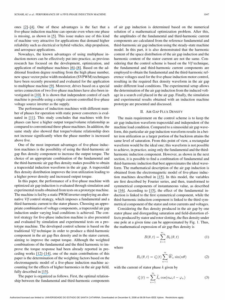
Considering the flux density produced in the air gap by onestator phase and disregarding saturation and field-distortion ef-fects produced by stator and rotor slotting, the flux density underone pole at a given time can be approximated by Fig. 1. Thus,the mathematical expression of air gap flux density is
B(θ, t) =ms∑k=1
Bk (θ, t) (1)
where
Bk (θ, t) = isk (t)∞∑
n=1
Wn sin(nθ) (2)
with the current of stator phase k given by
isk (t) =∞∑
n=1
In cos(nωet − ϕn ) (3)
Authorized licensed use limited to: UNIVERSIDADE DO ESTADO DE SANTA CATARINA. Downloaded on December 8, 2008 at 06:09 from IEEE Xplore. Restrictions apply.
1048 IEEE TRANSACTIONS ON ENERGY CONVERSION, VOL. 23, NO. 4, DECEMBER 2008
Fig. 1. Flux density in the air gap under one pole produced by one stator phasefor a five-phase machine with two slots per phase and pole at time t = 0.
Fig. 2. Search coil with integral pitch.
and the factor Wn defined as
Wn =4π
1n
cos(nγ
2
) µ0
δeNs. (4)
The factor Wn includes the effect of the winding distribution(winding factor) and the air gap effective permeance. Consider-ing only the effects of the fundamental and the third-harmonicinduction waves (n = 1 and n = 3), (1) can be rewritten as
B(θ, t) = B1 sin(θ + ωet − ϕ1) + B3 sin(3θ + 3ωet − ϕ3)
(5)
with
B1 =ms
2Is1 W1 (6)
and
B3 =ms
2Is3 W3 . (7)
In order to investigate the shape of the air gap induction, asearch coil with integral pitch has been placed in the stator,as shown in Fig. 2. Considering that the machine has ten slotper pole, the first coil side is located in slot 1 and the other inslot 11. The resulting flux crossing the coil area was calculatedconsidering two arbitrary positions for coil sides α and α + π,
according to (8), where α describes the position of the first coilside in the fixed stator reference frame
φ(α, t) =∫ α+π
α
�R
pB(θ, t)dθ. (8)
By substituting (5) in (8), the flux equation can be rewrittenas
φ(α, t) =�R
p
∫ α+π
α
[B1 sin(θ + ωet − ϕ1)
+ B3 sin(3θ + 3ωet − ϕ3)]dθ. (9)
Evaluating the integral in expression (9) yields
φ(α, t) =−2�R
p[B1 cos(α + ωet − ϕ1)
+B3
3cos(3α + 3ωet − ϕ3)]. (10)
The induced voltage at the search coil terminals is given bythe time derivative of (10) as
u(α, t) = − dφ(α, t)dt
u(α, t) =2ωe�R
p[B1 sin(α + ωet − ϕ1)
+ B3 sin(3α + 3ωet − ϕ3)]. (11)
Comparing (5) and (11), it is possible to conclude that theinduced voltage measured at the terminals of search coil presentsthe same shape as the induction produced in the air gap by thefundamental and third-harmonic currents. They differ only bya multiplying factor as the term in brackets is equal to (5).Therefore, the time distribution of the induced voltage u(α, t)corresponds exactly to the spatial induction distribution B(θ, t).This correspondence can be better understood by consideringan arbitrary instant of time, for example, t = 0, and an arbitrarystator position, for example, α = 0, in (5) and (11) as
B(θ, 0) = B1 sin(θ − ϕ1) + B3 sin(3θ − ϕ3) (12)
u(0, t) = Ku [B1 sin(ωet − ϕ1) + B3 sin(3ωet − ϕ3)] (13)
with
Ku =2ωe�R
p=
ωe�D
p. (14)
It must be pointed out that (5) and (13) have the same shape,differing from each other only by the amplitude factor Ku .Besides, B(θ, t) represents a rotating wave with a fixed patternand rotational speed ωe at any time instant. For brevity, in therest of the paper, the induction B(θ, t) will be referred to asB(θ), while the induced voltage u(α, t) as u(t).
The induced voltage given by (11) takes into account only thestator currents for no-load condition case. When the machineis under load, the resulting field in the air gap is produced bythe stator and rotor currents. The effect of the rotor currents onthe field in the air gap can be considered multiplying the stator
Authorized licensed use limited to: UNIVERSIDADE DO ESTADO DE SANTA CATARINA. Downloaded on December 8, 2008 at 06:09 from IEEE Xplore. Restrictions apply.
SCHARLAU et al.: PERFORMANCE OF A FIVE-PHASE INDUCTION MACHINE 1049
Fig. 3. Division of the trapezoidal waveform into four sections.
currents by the following complex factors:
Kr1 = 1 − mr
2ms
2(Lsr
1 )2
Ls1
jωe
[(Rr1/S) + jωeLr
1 ](15)
Kr1 = Kr
1 � ϕk1 (16)
Kr3 = 1 − mr
2ms
2(Lsr
3 )2
Ls3
j3ωe
[(Rr3/S) + j3ωeLr
3 ](17)
Kr3 = Kr
3 � ϕk3 . (18)
In this way, the steady-state expression of induced voltage inthe search coil considering the rotor current is given by
u(t) = Ku [B1Kr1 sin(ωet − ϕ1 + ϕk1)
+ B3Kr3 sin(3ωet − ϕ3 + ϕk3)]. (19)
III. V/f CONTROL FOR FIVE-PHASE INDUCTION MOTORS
The control for five-phase induction motors developed in thispaper aims to impose an optimized trapezoidal waveform fluxdensity in air gap, improving the iron utilization and increasingthe output torque. This objective is achieved by using the steady-state model of the induction machine and validated through theinduced voltage in a search coil placed in the air gap. Basedon the machine equations, it is possible to calculate the relativemagnitude of the fundamental and the third-harmonic statorvoltages to obtain the required induction waveform.
A. Stator Current Design
Using only the fundamental and the third-harmonic induc-tion waves, it is not possible to achieve an ideal rectangularwaveform for the induction in the air gap. However, a trape-zoidal waveform can be designed using the steady-state modelof the fundamental and third-harmonic air gap induction, whichis similar to a rectangular waveform. A trapezoidal waveform isconsidered better than a sine wave in terms of torque productionand iron utilization, as a larger portion of the iron attains themaximum induction value at the same time.
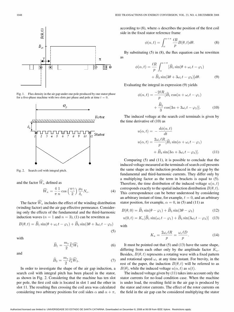
For the sake of analysis and current design practice, the re-quired trapezoidal wave was divided into four sections, as seenin Fig. 3. The shape of the curve is defined by the free parameterk and the corresponding Fourier series is given in the sequel
F (x, k) =∞∑
i=0
αi(k) sin(iπx
τ
)(20)
Fig. 4. Width of the flat portion b of the trapezoidal waveform curve dependingon the amplitude of the oscillation levels ε.
where
αi(k) =4πi
sin(kπi)kπi
, i = 1, 3, 5, . . . (21)
Considering only two terms (fundamental and third-harmoniccomponents), (20) can be rewritten as
F (x, k) = α1(k) sin(πx
τ
)+ α3(k) sin
(3πx
τ
). (22)
An optimal combination of the coefficients α1(k) and α3(k)can be determined through a formal optimization procedure, re-sulting in values for the coefficients that best approximate thedesired waveform. The optimization problem consists of obtain-ing a quasi-trapezoidal waveform with the largest flat portion,resulting in the following expression
maxk
b = |x1 − x2 | (23)
subject to |1 − F (x, k)| < ε ∀ x ∈ [x1 ;x2 ], where ε is a designfactor defined so as to reduce the oscillation of the flat leveland b is the width of the flat part of the wave, as shown inFig. 4. Choosing ε = 0.005, the solution of the optimizationproblem indicates that the wave with the largest flat portionis obtained for k = 0.1157. This condition yields α1 = 1.1587and α3 = 0.1588 (α3/α1 = 0.137). However, the practical im-plementation and experimental results obtained by using thisrelationship led to undesired oscillations of the flat portion ofthe air gap induction. Therefore, in order to minimize the os-cillations, the design factor ε had to be further reduced and theoptimization procedure repeated resulting in α3/α1 = 0.107.This relationship proved to be better, considering the practicalimplementation and the approximations introduced in the modelas it results in an air gap induction with a flat portion and nooscillation. Thus, α3/α1 = 0.107 was used for the experimentaltests presented in Section V.
To achieve the required trapezoidal induction waveform inthe air gap, an appropriate combination for the fundamentaland the third-harmonic induction amplitudes, B1 and B3 , must
Authorized licensed use limited to: UNIVERSIDADE DO ESTADO DE SANTA CATARINA. Downloaded on December 8, 2008 at 06:09 from IEEE Xplore. Restrictions apply.
1050 IEEE TRANSACTIONS ON ENERGY CONVERSION, VOL. 23, NO. 4, DECEMBER 2008
be found. This optimized combination can be obtained from acomparison of (5) and (22) as described next.
According to (6), B1 is proportional to Is1 and W1 , while
according to (7), B3 is proportional to Is3 and W3 . Considering
that (4) implies different values for W1 and W3 , it is noticeablethat to obtain a trapezoidal flux density in the air gap under onepole, the stator currents cannot have the same shape as the airgap induction wave.
The amplitude of the fundamental and the third-harmonicstator currents that must be imposed to obtain the trapezoidalwaveform can be calculated using (24) and (25). These equationsare obtained by comparison of (19) and (22) for the no-loadcondition case (Kr
1 = 1 and Kr3 = 1)
Is1 ref = Is
1 ref
√2 =
2B1
msW1(24)
Is3 ref = Is
3 ref
√2 =
2B3
msW3. (25)
Thus, for a given relationship B3/B1 , the corresponding re-lationship between the currents I3 and I1 is
I3
I1=
W1B3
W3B1. (26)
It can be seen from (26) that the relative amplitude betweenthe third harmonic and fundamental currents is different from therelative amplitude between the fundamental and third-harmonicinduction waves.
In order to assess the influence of the relationship betweenthe fundamental and the third-harmonic stator current compo-nents on the induction waveform, several simulations have beenperformed using [6], [7], and [19]. For a five-phase machine,with q = 2 and full pitch winding, the relationship between W3
and W1 is W3 ≈ 1/3W1 , resulting in
I3
I1≈ 3
B3
B1. (27)
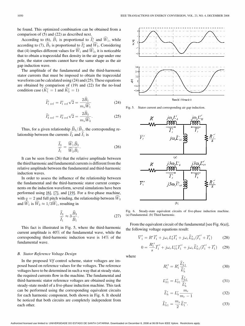
This fact is illustrated in Fig. 5, where the third-harmoniccurrent amplitude is 40% of the fundamental wave, while thecorresponding third-harmonic induction wave is 14% of thefundamental wave.
B. Stator Reference Voltage Design
In the proposed V/f control scheme, stator voltages are im-posed based on reference values for the voltages. The referencevoltages have to be determined in such a way that at steady state,the required currents flow in the machine. The fundamental andthird-harmonic stator reference voltages are obtained using thesteady-state model of a five-phase induction machine. This taskcan be performed using the corresponding equivalent circuitsfor each harmonic component, both shown in Fig. 6. It shouldbe noticed that both circuits are completely independent fromeach other.
Fig. 5. Stator current and corresponding air gap induction.
Fig. 6. Steady-state equivalent circuits of five-phase induction machine.(a) Fundamental. (b) Third harmonic.
From the equivalent circuit of the fundamental [see Fig. 6(a)],the following voltage equations result:
Vs1 = RsI
s1 + jωeL
sδ I
s1 + jωeL
sh1(I
r ′1 + I
s1) (28)
0 =Rr ′
1
sI
r ′1 + jωeL
r ′δ1I
r ′1 + jωeL
sh1(I
r ′1 + I
s1) (29)
where
Rr ′1 = Rr
1Ls
h1
Lrh
(30)
Lr ′δ1 = Lr
δ1Ls
h1
Lrh
(31)
Lrh = Lr
h
mr
mr − 1(32)
Lsh1 =
ms
2Lss
1 . (33)
Authorized licensed use limited to: UNIVERSIDADE DO ESTADO DE SANTA CATARINA. Downloaded on December 8, 2008 at 06:09 from IEEE Xplore. Restrictions apply.
SCHARLAU et al.: PERFORMANCE OF A FIVE-PHASE INDUCTION MACHINE 1051
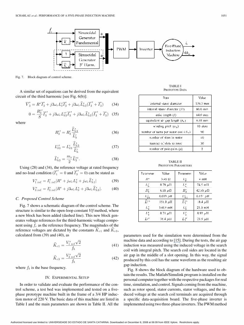
Fig. 7. Block diagram of control scheme.
A similar set of equations can be derived from the equivalentcircuit of the third harmonic [see Fig. 6(b)]:
Vs3 = RsI
s3 + j3ωeL
sδ I
s3 + j3ωeL
sh3(I
r ′3 + I
s3) (34)
0 =Rr ′
3
SI
r ′3 + j3ωeL
r ′δ3I
r ′3 + j3ωeL
sh3(I
r ′3 + I
s3) (35)
where
Rr ′3 = Rr
3Ls
h3
Lrh
(36)
Lr ′δ3 = Lr
δ3Ls
h3
Lrh
(37)
Lsh3 =
ms
2Lss
3 . (38)
Using (28) and (34), the reference voltage at rated frequencyand no-load condition (I
r ′1 = 0 and I
r ′3 = 0) can be stated as
V s1 ref = Is
1 ref |Rs + jωeLsδ + jωeL
sh1 | (39)
V s3 ref = Is
3 ref |Rs + j3ωeLsδ + j3ωeL
sh3 |. (40)
C. Proposed Control Scheme
Fig. 7 shows a schematic diagram of the control scheme. Thestructure is similar to the open-loop constant V/f method, wherea new block has been added (dashed line). This new block gen-erates voltage references for the third-harmonic voltage compo-nent using fe as the reference frequency. The magnitudes of thereference voltages are dictated by the constants Kv1 and Kv3 ,calculated from (39) and (40), as
Kv1 =V s
1 ref
√2
fb(41)
Kv3 =V s
3 ref
√2
fb(42)
where fb is the base frequency.
IV. EXPERIMENTAL SETUP
In order to validate and evaluate the performance of the con-trol scheme, a test bed was implemented and tested on a five-phase prototype machine built in the frame of a 3/4 HP induc-tion motor of 220 V. The basic data of this machine are listed inTable I and the main parameters are shown in Table II. All the
TABLE IPROTOTYPE DATA
TABLE IIPROTOTYPE PARAMETERS
parameters used for the simulation were determined from themachine data and according to [15]. During the tests, the air gapinduction was measured using the induced voltage in the searchcoil with integral pitch. The search coil sides are located in theair gap in the middle of a slot opening. In this way, the signalproduced by this coil has the same waveform as the resulting airgap induction.
Fig. 8 shows the block diagram of the hardware used to ob-tain the results. The Matlab/Simulink program is installed on thepersonal computer together with the respective packages for realtime, simulation, and control. Signals coming from the machine,such as rotor speed, stator currents, stator voltages, and the in-duced voltage at the search coil terminals are acquired througha specific data-acquisition board. The five-phase inverter isimplemented using two three-phase inverters. The PWM method
Authorized licensed use limited to: UNIVERSIDADE DO ESTADO DE SANTA CATARINA. Downloaded on December 8, 2008 at 06:09 from IEEE Xplore. Restrictions apply.
1052 IEEE TRANSACTIONS ON ENERGY CONVERSION, VOL. 23, NO. 4, DECEMBER 2008
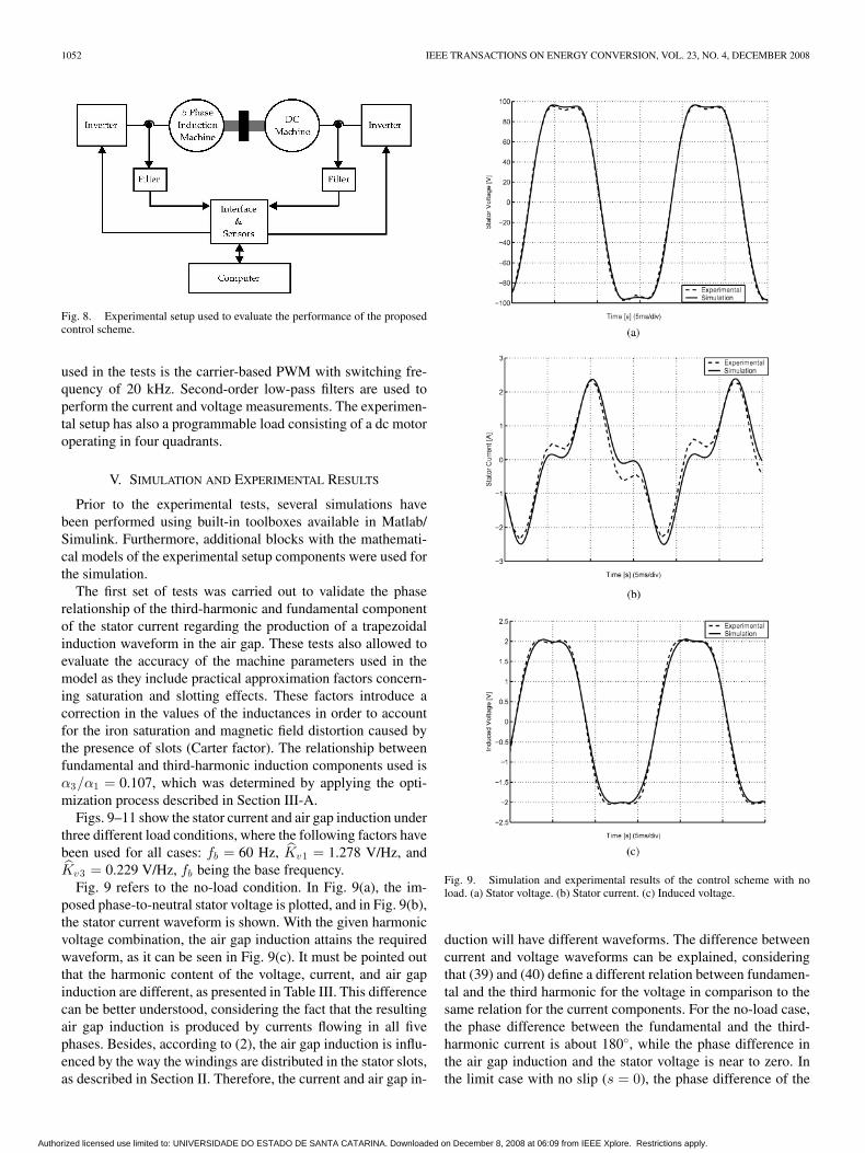
Fig. 8. Experimental setup used to evaluate the performance of the proposedcontrol scheme.
used in the tests is the carrier-based PWM with switching fre-quency of 20 kHz. Second-order low-pass filters are used toperform the current and voltage measurements. The experimen-tal setup has also a programmable load consisting of a dc motoroperating in four quadrants.
V. SIMULATION AND EXPERIMENTAL RESULTS
Prior to the experimental tests, several simulations havebeen performed using built-in toolboxes available in Matlab/Simulink. Furthermore, additional blocks with the mathemati-cal models of the experimental setup components were used forthe simulation.
The first set of tests was carried out to validate the phaserelationship of the third-harmonic and fundamental componentof the stator current regarding the production of a trapezoidalinduction waveform in the air gap. These tests also allowed toevaluate the accuracy of the machine parameters used in themodel as they include practical approximation factors concern-ing saturation and slotting effects. These factors introduce acorrection in the values of the inductances in order to accountfor the iron saturation and magnetic field distortion caused bythe presence of slots (Carter factor). The relationship betweenfundamental and third-harmonic induction components used isα3/α1 = 0.107, which was determined by applying the opti-mization process described in Section III-A.
Figs. 9–11 show the stator current and air gap induction underthree different load conditions, where the following factors havebeen used for all cases: fb = 60 Hz, Kv1 = 1.278 V/Hz, andKv3 = 0.229 V/Hz, fb being the base frequency.
Fig. 9 refers to the no-load condition. In Fig. 9(a), the im-posed phase-to-neutral stator voltage is plotted, and in Fig. 9(b),the stator current waveform is shown. With the given harmonicvoltage combination, the air gap induction attains the requiredwaveform, as it can be seen in Fig. 9(c). It must be pointed outthat the harmonic content of the voltage, current, and air gapinduction are different, as presented in Table III. This differencecan be better understood, considering the fact that the resultingair gap induction is produced by currents flowing in all fivephases. Besides, according to (2), the air gap induction is influ-enced by the way the windings are distributed in the stator slots,as described in Section II. Therefore, the current and air gap in-
Fig. 9. Simulation and experimental results of the control scheme with noload. (a) Stator voltage. (b) Stator current. (c) Induced voltage.
duction will have different waveforms. The difference betweencurrent and voltage waveforms can be explained, consideringthat (39) and (40) define a different relation between fundamen-tal and the third harmonic for the voltage in comparison to thesame relation for the current components. For the no-load case,the phase difference between the fundamental and the third-harmonic current is about 180◦, while the phase difference inthe air gap induction and the stator voltage is near to zero. Inthe limit case with no slip (s = 0), the phase difference of the
Authorized licensed use limited to: UNIVERSIDADE DO ESTADO DE SANTA CATARINA. Downloaded on December 8, 2008 at 06:09 from IEEE Xplore. Restrictions apply.
SCHARLAU et al.: PERFORMANCE OF A FIVE-PHASE INDUCTION MACHINE 1053
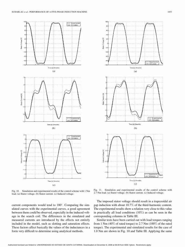
Fig. 10. Simulation and experimental results of the control scheme with 1 Nmload. (a) Stator voltage. (b) Stator current. (c) Induced voltage.
current components would tend to 180◦. Comparing the sim-ulated curves with the experimental curves, a good agreementbetween them could be observed, especially in the induced volt-age in the search coil. The differences in the simulated andmeasured currents are introduced by the effects not entirelyincluded in the model, such as slotting and saturation effects.These factors affect basically the values of the inductances in aform very difficult to determine using analytical methods.
Fig. 11. Simulation and experimental results of the control scheme with2.7 Nm load. (a) Stator voltage. (b) Stator current. (c) Induced voltage.
The imposed stator voltage should result in a trapezoidal airgap induction with about 10.7% of the third-harmonic content.The experimental results show a relation very close to this valuein practically all load conditions (10%) as can be seen in thecorresponding columns in Table III.
Similar tests have been carried out with load torques rangingfrom 1 Nm (40% of rated torque) to 2.7 Nm (100% of the ratedtorque). The experimental and simulated results for the case of1.0 Nm are shown in Fig. 10 and Table III. Applying the same
Authorized licensed use limited to: UNIVERSIDADE DO ESTADO DE SANTA CATARINA. Downloaded on December 8, 2008 at 06:09 from IEEE Xplore. Restrictions apply.
1054 IEEE TRANSACTIONS ON ENERGY CONVERSION, VOL. 23, NO. 4, DECEMBER 2008
TABLE IIIHARMONIC COMPONENTS
TABLE IVEXPERIMENTAL RESULTS
voltage as in the no-load case, a trapezoidal induction wave-form is produced in the air gap. However, the current waveformchanged. Comparing Figs. 9(b) and 10(b), it can be observedthat the phase difference between the harmonic components hasalso changed. The results for 2.7 Nm are presented in Fig. 11and Table III. The applied voltage, as given by (39) and (40), hasnot been changed. It can be observed that for all load conditions,the resulting air gap induction was kept trapezoidal as required.On the other hand, the stator current waveform changes signifi-cantly. This change can be explained considering that the equiv-alent circuit of each harmonic has a different input impedance.These impedances change with the load condition in a differentway, resulting in a different waveform for the current for eachload condition. The change in the current can also be explainedby considering that the resulting field in the air gap under loadis produced not only by the stator current but also by the rotorcurrents, as stated by (15)–(19). The air gap field is produced bythe composition of the rotor and stator field, each one producedby its corresponding current. Thus, the relationship between sta-tor and rotor currents change with the load condition in orderto maintain the same air gap induction waveform. In this way,the desired trapezoidal air gap induction is produced by statorcurrents having a waveform different from a trapezoidal. Theresults for the loaded machine also show that the simulated andmeasured curves agree very well.
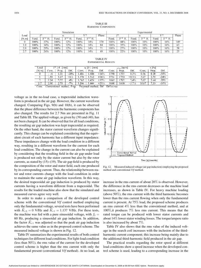
In order to make a comparison of the developed controlscheme with the conventional V/f control method employingonly the fundamental voltage, several tests have been performedwith Kv3 = 0 V/Hz and Kv1 = 1.137 V/Hz. For these tests,the machine was fed with a pure sinusoidal voltage, with fb =60 Hz, producing a sinusoidal air gap induction. In addition,the factor Kv1 was adjusted so that the peak air gap inductionachieves the same value as in the proposed control scheme. Themeasured induced voltage is shown in Fig. 12.
Table IV summarizes the experimental results of both controltechniques for different load conditions. For light-load condition(less than 50%), the rms value of the current for the developedcontrol scheme is higher than the rms current with only thefundamental present (conventional V/f method). At no load, an
Fig. 12. Measured induced voltage (air gap induction) employing the proposedmethod and conventional V/f method.
increase in the rms current of about 20% is observed. However,the difference in the rms current decreases as the machine loadincreases, as shown in Table IV. For heavy machine loading(above 50%), the rms current with the third harmonic becomeslower than the rms current flowing when only the fundamentalcurrent is present. At 75% load, the proposed scheme producesan rms current 4% less than the conventional method, and at100%,it produces 7% less rms current. This means that therated torque can be produced with lower stator currents andabout 14% lower stator winding losses. The torque/ampere ratiois also increased by about 7%.
Table IV also shows that the rms value of the induced volt-age in the search coil increases with the inclusion of the third-harmonic current component; this increase being mainly due tothe additional third-harmonic field produced in the air gap.
The practical results regarding the rotor speed at differentload conditions show a speed increase when the developed con-trol scheme is used, leading to a corresponding increase in the
Authorized licensed use limited to: UNIVERSIDADE DO ESTADO DE SANTA CATARINA. Downloaded on December 8, 2008 at 06:09 from IEEE Xplore. Restrictions apply.

SCHARLAU et al.: PERFORMANCE OF A FIVE-PHASE INDUCTION MACHINE 1055
mechanical power available on the shaft of about 4%. Thisincrease in speed results in lower slip values and lower ro-tor currents. The reduction in the rotor current also results inlower losses in the rotor circuit. These facts allow to concludethat the use of a trapezoidal air gap induction can, in fact, in-crease the torque and power capability of the machine. The sametorque is produced with lower currents and lower winding losses.The exact increase in the power capability is not trivial to state,as the change in the magnetic losses has not been consideredhere [17]. As shown in [18] and [19], a rectangular air gap in-duction changes the losses in the iron parts. Depending on thelosses division between hysteresis and eddy current losses,the magnetic losses can be increased or decreased. In addition,the temperature rise in the machine has also to be accounted toestablish the actual machine capability improvement. In orderto have a deeper insight into the torque improvement, a test wasundertaken allowing the load torque to increase until the statorcurrent achieves the rated value (2.9 A). Under this condition,a torque of 3.10 Nm was measured. Therefore, assuming thatthe magnetic losses do not change and that the temperature risedoes not exceed the value observed with the conventional V/fmethod, an increase in the torque capability of about 15% canbe achieved under steady state. Under the same condition, anincrease in the power capability of about 18% was observedwhen compared to the output power obtained for the same rmsstator current using the conventional V/f method.
It is worthwhile to point out that despite the factors Kv1and Kv3 having been adjusted to result in nearly trapezoidalinduction at no load, their values assure practically the same airgap waveform even under load. This came from the fact thatthe terminal voltage was imposed by the inverter. On the otherhand, the terminal voltage is balanced by the voltage inducedby the resulting air gap field plus the voltage drop in the leakagereactance and the winding resistance. However, this voltage dropis much smaller than the air gap induced voltage and its influencecan be disregarded. Hence, imposing the same terminal voltageunder different load conditions practically imposes a constantinduced voltage, and as a consequence, also imposes a constantair gap field. The currents, however, change to produce thenecessary field.
To limit the scope of the paper, issues such as efficiency, powerfactor, and machine temperature rise have not been addressed inthis paper, as they are complex issues making a fair comparisonbetween control strategies including third-harmonic inclusionvery difficult.
VI. CONCLUSION
This paper introduced a V/f-based control method for five-phase induction machines that generates a trapezoidal inductionwaveform in the air gap. This waveform best approximates theideal waveform and is obtained by producing a third-harmonicinduction component in the air gap. First, an optimal relation-ship between the fundamental and the third-harmonic inductioncomponents is determined, aiming to approximate a trapezoidalwaveform. Using the machine steady-state model, an optimal re-lation for the applied voltage was determined and used to design
the reference voltages. The proposed control scheme was simu-lated and applied to a prototype machine running under differentload conditions. At steady state, the experimental results showthat under light-load conditions (less than 50%), the conven-tional V/f method produces torque with lower rms current andlower stator losses. For load above 50%, the developed methodperforms better than the conventional method, as the same loadtorque is produced with lower stator and rotor currents. For theproposed control scheme, the rated torque is obtained with 7%less stator current and 14% less winding losses than the ratedvalue. Furthermore, the rated torque is obtained with a lowerslip, and thus, with lower rotor losses. If the stator rms current isallowed to increase up to the rated value and assuming that themagnetic losses do not change significantly, a torque increase ofabout 15% is obtained together with an increase of 18% in theoutput power. The torque increase comes from the additionaltorque produced by the third-harmonic current and inductioncomponent.
ACKNOWLEDGMENT
The authors would like to thank Prof. A. L. T. Ramos,Pontifıcia Universidade Catolica do Rio Grande do Sul(PUCRS) for his help in reviewing the text of this paper.
REFERENCES
[1] A. Munoz-Garcia, T. A. Lipo, and D. W. Novotny, “A new inductionmotor V/f control method capable of high-performance regulation at lowspeeds,” IEEE Trans. Ind. Appl., vol. 34, no. 4, pp. 813–821, Jul./Aug.1998.
[2] E. E. Ward and H. Harer, “Preliminary investigation of an inverter-fed5-phase induction motor,” Proc. Inst. Elect. Eng., vol. 116, pp. 980–984,Oct. 1984.
[3] E. A. Klingshirn, “High phase order induction motors (Parts I and II),”IEEE Trans. Power App. Syst., vol. PAS-102, no. 1, pp. 47–59, Jan. 1983.
[4] E. Levi, R. Bojoi, F. Profumo, and H. Toliyat, “Multiphase induction motordrives—A technology status review,” IET—Electric Power Appl., vol. 1,no. 4, pp. 489–516, 2007.
[5] H. A. Toliyat, “Analysis and simulation of five-phase variable-speed induc-tion motor drives under asymmetrical connections,” IEEE Trans. PowerElectron., vol. 13, no. 4, pp. 748–756, Jul. 1998.
[6] H. A. Toliyat, M. M. Rahimian, and T. A. Lipo, “dq modeling of five-phase synchronous reluctance machines including third harmonic of airgap mmf,” in Proc. IEEE Ind. Appl. Soc. Annu. Meet., Oct. 1991, pp. 231–237.
[7] P. De Silva, J. Fletcher, and B. Williams, “Design of a five-phase inductionmotor using flux distribution optimisation,” 3rd IET Int. Conf. PowerElectron., Mach. Drives, 2006, pp. 331–335.
[8] J. Apsley, S. Williamson, A. Smith, and M. Barnes, “Induction motorperformance as a function of phase number,” Proc. Inst. Elect. Eng.—Electr. Power Appl., vol. 153, no. 6, pp. 989–904, 2006.
[9] M. Duran, F. Barrero, S. Toral, and E. Levi, “Multi-dimensional spacevector pulse width modulation scheme for five-phase series-connectedtwo-motor drives,” in Electr. Mach. Drives Conf. IEMDC ’07, vol. 2,pp. 1208–1214.
[10] E. Levi, M. Jones, A. Iqbal, S. Vukosavic, and H. Toliyat, “Modeling,control, and experimental investigation of a five-phase series-connectedtwo-motor drive with single inverter supply,” IEEE Trans. Ind. Electron.,vol. 54, no. 3, pp. 1504–1516, Jun. 2007.
[11] H. A. Toliyat, T. Lipo, and J. C. White, “Analysis of a concentratedwinding induction machine for adjustable speed drive applications (partsi and ii),” IEEE Trans. Energy Convers., vol. 6, no. 4, pp. 679–692, Dec.1991.
[12] R. Shi, H. Toliyat, and A. El-Antably, “Field oriented control of five-phasesynchronous reluctance motor drive with flexible 3rd harmonic currentinjection for high specific torque,” 36th IEEE Ind. Appl. Conf., 2001,pp. 2097–2103.
Authorized licensed use limited to: UNIVERSIDADE DO ESTADO DE SANTA CATARINA. Downloaded on December 8, 2008 at 06:09 from IEEE Xplore. Restrictions apply.
1056 IEEE TRANSACTIONS ON ENERGY CONVERSION, VOL. 23, NO. 4, DECEMBER 2008
[13] H. Xu, H. Toliyat, and L. Petersen, “Five-phase induction motor driveswith DSP-based control system,” IEEE Trans. Power Electron., vol. 17,no. 4, pp. 524–533, Jul. 2002.
[14] H. Xu, H. A. Toliyat, and L. J. Petersen, “Rotor field oriented controlof five-phase induction motor with combined fundamental and third har-monic currents,” in Appl. Power Electron. Conf. Expo.—APEC 2001,vol. 1, pp. 392–398.
[15] L. A. Pereira, C. C. Scharlau, L. F. A. Pereira, and J. F. Haffner, “Generalmodel of a five-phase induction machine allowing for harmonics in theair gap field,” IEEE Trans. Energy Convers., vol. 21, no. 4, pp. 891–899,Dec. 2006.
[16] D. C. White and H. H. Woodson, Electromechanical Energy Conversion.New York: Wiley, 1959.
[17] L. Dupre, M. Wulf, D. Makaveev, V. Permiakov, A. Pulnikov, andJ. Melkebeek, “Modelling of electromagnetic losses in asynchronous ma-chines,” COMPEL, vol. 22, no. 4, pp. 1051–1065, 2004.
[18] L. Mthombeni and P. Pillay, “Core losses in motor laminations exposedto high-frequency or nonsinusoidal excitation,” IEEE Trans. Ind. Appl.,vol. 40, no. 5, pp. 1325–1332, Oct. 2004.
[19] F. Fiorillo and A. Novikov, “An improved approach to power losses inmagnetic laminations under nonsinusoidal induction waveform,” IEEETrans. Magn., vol. 26, no. 5, pp. 2904–2910, Sep. 1990.
Cesar Cataldo Scharlau received the B.E. degreein mechatronic engineering and the M.S. degree inelectrical engineering from Pontifıcia UniversidadeCatolica do Rio Grande do Sul (PUCRS), PortoAlegre, Brazil, in 2002 and 2005, respectively.
He is currently professor at the Technology Fac-ulty, National Industrial Training Service (SENAI),Porto Alegre. His current research interests in-clude control of electrical machines and industrialautomation.
Luıs Fernando Alves Pereira received the B.E. de-gree in electrical engineering from Pontifıcia Uni-versidade Catolica do Rio Grande do Sul (PUCRS),Porto Alegre, Brazil, in 1987, and the M.S. andDoctoral degrees from the Instituto Tecnologico deAeronautica (ITA), Sao Jose dos Campos, Brazil, in1989 and 1995, respectively.
He is currently a Professor of electrical, controland computer engineering at PUCRS. His current re-search interests include the development of robustnonlinear control techniques applied on electric ma-
chines, power electronic devices, and mobile robots.
Luıs Alberto Pereira received the B.E. degree inelectrical engineering from Santa Maria Federal Uni-versity, Santa Maria, Brazil, in 1986, the M.Sc. degreefrom Santa Catarina Federal University, Santa Cata-rina, Brazil, in 1992, and the Dr.-Ing. degree fromthe University of Kaiserslautern, Kaiserslautern, Ger-many, in 1997.
Since 1998, he has been a Professor of electricalengineering at Pontifical Catholic University of RioGrande do Sul (PUCRS), Porto Alegre, Brazil. Hiscurrent research interests include design and analysis
of electrical machines and devices.
Sergio Haffner (S’89–M’01) received the B.E. de-gree in electrical engineering from the PontificalCatholic University of Rio Grande do Sul (PUCRS),Porto Alegre, Brazil, in 1987, and the M.S. andDr. degrees in electrical engineering from State Uni-versity of Campinas (UNICAMP), Campinas, Brazil,in 1990 and 2000, respectively.
Currently, he is an Associate Professor of Elec-trical Engineering in the Electrical Engineering De-partment of the State University of Santa Catarina(UDESC). His research interests include the power
systems planning, operation, and optimization areas.
Authorized licensed use limited to: UNIVERSIDADE DO ESTADO DE SANTA CATARINA. Downloaded on December 8, 2008 at 06:09 from IEEE Xplore. Restrictions apply.