PE04-021 TOYOTA 6/4/04 ATTACHMENT 12 - NHTSA
91
PE04-021 TOYOTA 6/4/04 ATTACHMENT 12
-
Upload
khangminh22 -
Category
Documents
-
view
0 -
download
0
Transcript of PE04-021 TOYOTA 6/4/04 ATTACHMENT 12 - NHTSA

PE04-021
TOYOTA
6/4/04
ATTACHMENT 12

ENGINE
ENGINE — 2AZ-FE ENGINEEG-32
2AZ-FE ENGINE
�DESCRIPTION
� The 2AZ-FE engine, which is an in-line, 4-cylinder, 2.4-liter, 16-valve DOHC engine, based on the2AZ-FE engine on the ’01 Highlander.
� This engine has following features that have been optimized in order to realize the further improvementof the engine performance, fuel economy and to reduce exhaust emissions.
� The PS (Planetary reduction Segment conductor motor) starter has been adopted.
� Meets the ULEV (Ultra Low Emission Vehicle) regulation requirements.
� ETCS-i (Electronic Throttle Control System-intelligent) has been adopted.
� VVT-i (Variable Valve Timing-intelligent) system is used.
� A big bore / long port intake manifold is used.
� A balance shaft is used.
208EG01
208EG02

ENGINE — 2AZ-FE ENGINE EG-33
� Engine Specification�
Model Camry ’01 Highlander
Engine Type 2AZ-FE �
No. of Cyls. & Arrangement 4-cylinder, In-line �
Valve Mechanism 16-Valve, DOHC, Chain Drive
�
Combustion Chamber Pentroof Type �
Manifolds Cross-Flow �
Fuel System SFI �
Displacement cm3 (cu. in.) 2362 (144.2) �
Bore × Stroke mm (in.) 88.5 × 96.0 (3.48 × 3.78) �
Compression Ratio 9.6 : 1 �
Max. Output (SAE-NET) 117 kW @ 5600 rpm(157 HP @ 5600 rpm)
115 kW @ 5600 rpm(155 HP @ 5600 rpm)
Max. Torque (SAE-NET) 220 N⋅m @ 4000 rpm(162 ft⋅lbf @ 4000 rpm)
221 N⋅m @ 4000 rpm(163 ft⋅lbf @ 4000 rpm)
Firing Order 1-3-4-2 �
Research Octane Number 91 or more �
Octane Rating 87 or more �
Dry Weight kg (lb)M/T 127 (280) —
Dry Weight kg (lb)A/T 121 (267) �
Oil Grade API SJ, SL, EC or ILSAC API SH, SJ , EC or ILSAC
� Performance Curve� � Valve Timing �
206EG03198EG01
ft·lbfN·m
Torque
220210200190180170160
170
160
150
140
130
120
1000
Engine Speed (rpm)
160
150
140
130
120
110
100
90
80
70
60
50
40
30
20
10
0
120
110
100
90
80
70
60
50
40
30
20
10
0
: Intake Valve Opening Angle: Exhaust Valve Opening Angle
VVT-i OperationRange
TDC3° 4°
236°
45°
BDC10°VVT-i OperationRange
60°
Output228°
46°
kWHP
2000 3000 4000 5000 6000

ENGINE — 2AZ-FE ENGINEEG-34
�FEATURES OF 2AZ-FE ENGINE
The 2AZ-FE engine has been able to achieve the following performance through of the adoption of theitem listed below.
(1) High performance and fuel economy
(2) Low noise and vibration
(3) Lightweight and compact design
(4) Good serviceability
(5) Clean emission
Item (1) (2) (3) (4) (5) Camry Highlander
The VVT-i system is used. � � � �
The ETCS-i has been newly adopted. � � —
A cylinder block made of aluminum alloy along witha magnesium head cover has been adopted.
� � �
The taper squish shape has been adopted for the pis-ton head.
� � � �
The DIS (Direct Ignition System) makes ignitiontiming adjustment unnecessary.
� � � � �
A serpentine belt drive system has been adopted, andthe brackets and the engine have been integrated.
� � � �
Timing chain has been used. � � � �
The fuel returnless system has been adopted. � � � � �
Quick connectors are used to connect the fuel hosewith the fuel pipes.
� � �
12-hole type fuel injectors with high atomizing per-formance have been adopted.
� � � �
Iridium-tipped spark plugs have been adopted. � � � �
Intake manifold made of plastic has been adopted. � � �
A 2-way exhaust control system has been adopted.� � � �
The use of an air fuel ratio sensor allows precise con-trol.
� � �
A resin gear balance shaft has been adopted. � � � �
The PS (Planetary reduction-Segment conductormotor) starter has been adopted.
� � —
Other parts construction are the same as in the ’01 Highlander.

ENGINE — 2AZ-FE ENGINE
185EG35
Cylinder Head Cover Gasket
Integrated SparkPlug Gasket
Cylinder Head Cover
EG-35
�ENGINE PROPER
1. Cylinder Head Cover
� A lightweight magnesium alloy diecast cylinderhead cover is used.
� The cylinder head cover gasket and the spark pluggasket have been integrated to reduce the numberof parts.
2. Cylinder Head Gasket
A steel-laminate type cylinder head gasket has been adopted.
FIPG Coating
Front 208EG05

ENGINE — 2AZ-FE ENGINE
198EG29208EG67
Taper Squish
A – A Cross Section
EXIN
BypassPassage
Injector
Exhaust Side
A Intake Side
A
View from the Back Side
EG-36
3. Cylinder Head
� The taper squish combustion chamber has been used to realize the highly engine’s knocking resistanceand fuel efficiency.
� An upright intake port has been used to realize the highly intake efficiency.
� Installing the injectors in the cylinder head enables the injectors inject fuel as close as possible to thecombustion chamber. This prevents the fuel from adhering to the intake port walls, which reduces HCexhaust emissions.
� The routing of the water bypass jacket in the cylinder head has been optimized to realize the highlycooling performance. In addition, a water bypass passage has been provided below the exhaust portsto reduce the number of parts and to achieve weight reduction.

ENGINE — 2AZ-FE ENGINE
179EG04
� Air Flow During Engine Revolution �
Air Passage Hole
Air FlowAir ConditioningCompressor Bracket
Oil FilterBracket
Water PumpSwirl Chamber
Thermostat Housing
Crankcase
185EG42
EG-37
4. Cylinder Block
� Lightweight aluminum alloy is used for the cylinder block.
� By producing the thin cast-iron liners and aluminum alloy cylinder block as a unit to realize the compactdesign. The liner is thin, so that boring is not possible.
� Passage holes are provided in the bulkhead of the cylinder block. As a result, the air at the bottom ofthe cylinder flows smoother, and pumping loss (back pressure at the bottom of the piston generatedby thepiston’s reciprocal movement) is reduced.
� The oil filter and the air conditioning compressor bracket are integrated the crankcase, also the waterpump swirl chamber, the thermostat housing and the rear oil seal retainer integrated the cylinder block.
ENGINE — 2AZ-FE ENGINEEG-38
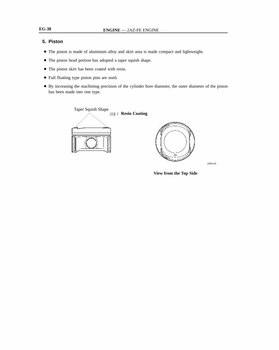
5. Piston
� The piston is made of aluminum alloy and skirt area is made compact and lightweight.
� The piston head portion has adopted a taper squish shape.
� The piston skirt has been coated with resin.
� Full floating type piston pins are used.
� By increasing the machining precision of the cylinder bore diameter, the outer diameter of the pistonhas been made into one type.
208EG06
Taper Squish Shape: Resin Coating
View from the Top Side

ENGINE — 2AZ-FE ENGINE
208EG61
Plastic Region Tightening Bolts
208EG68
Balance Weight
Oil HoleBalance Shaft Drive Gear
EG-39
6. Connecting Rod
� The connecting rods and caps are made of highstrength steel for weight reduction.
� Nutless-type plastic region tightening bolts of theconnecting rod are adopted for a lighter design.
7. Crankshaft
� The crankshaft has 5 journals and 8 balance weights.
� The precision and surface roughness of the pins and journals have been realized to reduce friction.
� The balance shaft drive gear has been installed onto the crankshaft.
� The crankshaft is made of forged steel.

ENGINE — 2AZ-FE ENGINEEG-40
8. Balance Shaft
� A balance shaft has been adopted to reduce vibrations.
� A direct-drive system has been adopted which makes use of a gear that is installed onto the counterweightof crankshaft.
� In addition, a resin gear has been adopted on the driven side to suppress noise and offer lightweightdesign.
198EG04
Balance Shaft No. 1
Balance Shaft No. 2
Balance Shaft Housing
Drive Gear
Crankshaft
: Resin Gear

ENGINE — 2AZ-FE ENGINE
181EG10
Chain Tensioner
VVT-i ControllerIntake Camshaft
Intake Valves
Chain Damper
Exhaust Valves
Exhaust Camshaft
Chain Slipper
EG-41
�VALVE MECHANISM
1. General
� Each cylinder is equipped with 2 intake valves and 2 exhaust valves. Intake and exhaust efficiency hasbeen increased due to the larger total port areas.
� The valves are directly opened and closed by 2 camshafts.
� The intake and exhaust camshafts are driven by a chain. The VVT-i system used for the intake camshaftis used to realize highly fuel economy, engine performance and reduce exhaust emissions. For details,see page EG-42 in the VVT-i system section.
� The shimless type valve lifter is used.

ENGINE — 2AZ-FE ENGINE
181EG11
VVT-i Controller
Intake CamshaftTiming Rotor
Exhaust Camshaft
Timing Sprocket
EG-42
2. Camshaft
� The intake camshaft is provided with timing rotor to trigger the camshaft position sensor.
� In conjunction with the adoption of the VVT-i system, an oil passage is provided in the intake camshaftin order to supply engine oil pressure to the VVT-i system.
� A VVT-i controller has been installed on the front of the intake camshaft to vary the timing of the intakevalves.

ENGINE — 2AZ-FE ENGINE
208EG69
Camshaft
Valve Lifter
Service Tip
EG-43
3. Intake and Exhaust Valves
� Intake and exhaust valves with large-diameter valve face have been adopted to improve the intake airand exhaust gas flow.
� Narrow valve stems have been adopted to reduce the intake and exhaust resistance and for weight reduc-tion.
� Along with the increased amount of valve lift, shimless valve lifters that provide a large cam contactsurface have been adopted. The adjustment of the valve clearance is accomplished by selecting and replac-ing the appropriate valve lifters.
The valve lifters are available in 35 size in increment of 0.020 mm (0.008 in.), from 5.060 (0.199 in.)to 5.740 (0.226 in.). For details, refer to see the 2002 Camry Repair Mnual (Pub. No. RM881U).

ENGINE — 2AZ-FE ENGINE
181EG13
181EG14
ChainTensioner
Chain Damper
Oil Jet
Chain Slipper
Cam Spring
Cam
PlungerSpring
EG-44
4. Timing Chain
� A roller chain with an 8 mm pitch has beenadopted.
� The timing chain is lubricated by an oil jet.
5. Chain Tensioner
� The chain tensioner uses a spring and oil pressureto maintain proper chain tension at all times.The chain tensioner suppresses noise generatedby the chain.A ratchet type non-return mechanism is also used.
� To improve serviceability, the chain tensioner isconstructed so that it can be removed and installedfrom the outside of the timing chain cover.

ENGINE — 2AZ-FE ENGINE
MAIN OIL HOLE
208EG07
208EG08
BYPASSVALVE
OIL FILTER
SUB OIL HOLE
OIL PUMP
OIL STRAINER
OIL PAN
CYLINDER HEAD
EXHAUSTCAMSHAFTJOURNAL
INTAKECAMSHAFTJOURNAL
CHAINTENSIONER
OIL JET
TIMING CHAIN PISTON
CRANKSHAFTJOURNAL
CONNECTING ROD
VVT-iCONTROLLER
Camshaft Timing Oil Control Valve
Chain Tensioner
Oil Pump
BALANCE SHAFT
OIL CONTROL VALVE
CYLINDER BLOCK
Oil Return Hole
RELIEFVALVE
EG-45
�LUBRICATION SYSTEM
1. General
� The lubrication circuit is fully pressurized and oil passes through an oil filter.
� The trochoidal type oil pump is chain-driven by the crankshaft.
� The oil filter is attached downward from the crankcase to improve serviceability.
� Along with the adoption of the VVT-i system, the cylinder head is provided with a VVT-i controllerand a camshaft timing oil control valve. This system is operated by the engine oil.

ENGINE — 2AZ-FE ENGINE
181EG43
Crankshaft
Relief Valve
Oil Pump
EG-46
� Specifications�
OilDry 4.5 liters (4.8 US qts, 4.0 Imp. qts)
OilCapacity
with Oil Filter 3.8 liters (4.0 US qts, 3.3 Imp. qts)Capacity
without Oil Filter 3.6 liters (3.8 US qts, 3.2 Imp. qts)
2. Oil Pump
� The trochoidal type oil pump is chain-driven bythe crankshaft, and fits compactly inside the tim-ing chain cover.
� Friction has been reduced by means of 2 reliefholes in the internal relief system.

ENGINE — 2AZ-FE ENGINE
208EG09
Cylinder Head
Cylinder Block
RadiatorThrottle Body
Heater Core
Thermostat
Water Pump
Bypass Passage
Bypass Passage
Throttle Body
To Radiator
Water Pump From Radiator
Reservoir Tank
208EG10
To Heater Core
EG-47
�COOLING SYSTEM
� The cooling system is a pressurized, forced-circulation type.
� A thermostat with a bypass valve is located on the water inlet housing to maintain suitable temperaturedistribution in the cooling system.This prevents sudden jumps in temperature while the engine is warming up.
� The flow of the engine coolant makes a U-turn in the cylinder block to ensure a smooth flow of theengine coolant. In addition, a bypass passage is enclosed in the cylinder head and the cylinder block.
� Warm water from the engine is sent to the throttle body to prevent freeze-up.

ENGINE — 2AZ-FE ENGINEEG-48
� Specifications�
Capacity liters (US qts, Imp. qts) 6.2 (6.6, 5.5)
Engine CoolantType TOYOTA Long Life Coolant
or Equivalent
Thermostat Opening Temperature °C (°F) 80 - 84 (176 - 183)

ENGINE — 2AZ-FE ENGINE
208EG11
Exhaust Manifold
TWC
Main MufflerIntake Manifold
Air Cleaner
TWC
EG-49
� INTAKE AND EXHAUST SYSTEM
1. General
� The two resonators, the side branch and PET* (Polyethylene Terephthalate) material have been newlyadopted to air cleaner inlet and air cleaner hose.
� The adoption of ETCS-i (Electronic Throttle Control System-intelligent) has realized excellent throttlecontrol.
� The intake manifold has been made of plastic to reduce the weight and the amount of heat transferredfrom the cylinder head.
� 2-way exhaust control system is provided to reduce noise and vibration in the main muffler.
*: Using porous material that permits it to breath, air intake pulsating pressure will be let out to the outsideof air cleaner inlet.

ENGINE — 2AZ-FE ENGINE
208EG12
Side Branch
Air Cleaner Inlet
Mass Air Flow Meter
PET Material
Resonator
Resonator
208EG13
Throttle Control Motor
Throttle Valve
Throttle Position Sensor Throttle Return Spring
EG-50
2. Air Cleaner
� A flameless, full-fabric air filter has been adopted to reduce weight and to simplify its disposal.
� The two resonators, the side branch and PET material have been newly adopted to air cleaner inlet andair cleaner hose to reduce the intake air noise.
3. Throttle Body
� The adoption of the link-less type ETCS-i has realized excellent throttle control.For details of ETCS-i control, refer to see page EG-40.
� A DC motor with excellent response and minimal power consumption is used for the throttle controlmotor. The ECM performs the duty ratio control of the direction and the amperage of the current thatflows to the throttle control motor in order to regulate the opening angle of the throttle valve.

ENGINE — 2AZ-FE ENGINE
198EG34
Intake Manifold Cover
208EG14
TWC
Air Fuel Ratio Sensor
TWC Cross Section
EG-51
4. Intake Manifold
� The intake manifold has been made of plastic to reduce the weight and the amount of heat transferredfrom the cylinder head. As a result, it has become possible to reduce the intake air temperature andimprove the intake volumetric efficiency.
� A resonator is installed inside the air intake chamber which makes use of the intake pulse to improvetorque in the mid-speed range.
� The intake manifold cover is used on the intake manifold to reduce intake air noise.
5. Exhaust Manifold
� A stainless steel exhaust manifold is used for weight reduction.
� An ultra thin-wall, high-cell ceramic type TWC (Three-Way Catalytic Converter) has been adopted.This TWC enables to improve exhaust emissions by optimizing the cells density.

ENGINE — 2AZ-FE ENGINE
208EG15
TWC Cross Section
TWC
Sub Muffler
Main Muffler
EG-52
6. Exhaust Pipe
General
� An ultra thin-wall, high-cell ceramic type TWC (Three-Way Catalytic Converter) has been adopted. ThisTWC enables to improve exhaust emissions by optimizing the cells density.
� 2-way exhaust control system is provided to reduce noise and vibration in the main muffler.

ENGINE — 2AZ-FE ENGINE
208EG16
Exhaust Gas
Control Valve Close Control Valve Open
Low Engine Speed Middle to High Engine Speed
EG-53
2-Way Exhaust Control System
� A 2-way exhaust control system is used. This system reduces the back pressure by opening and closinga variable valve that is enclosed in the main muffler, thus varying the exhaust gas pressure.
� The valve opens steplessly in accordance with the operating condition of the engine, thus enabling aquieter operation at lower engine speeds, and reducing back pressure at higher engine speeds.
1) Construction
The control valve is enclosed in the main-muffler. When the exhaust gas pressure overcomes the springpressure, the control valve opens steplessly in accordance with the exhaust gas pressure.
2) Operation
a. When Control Valve is Closed (low engine speed)
Since the pressure in the main muffler is low, the control valve is closed. Hence exhaust gas does notpass the bypass passage, and exhaust noise decreased by the main muffler.
b. When Control Valve is Open (middle to high engine speed)
The valve opens more as the engine speed and the back pressure in the muffler increase. This allowsa large volume of exhaust gas to pass the bypass passage, thereby substantially decreasing the backpressure.

ENGINE — 2AZ-FE ENGINE
208EG17
Pulsation Damper ORVR Valve
Injector
Fuel Tank
Fuel Pump
EG-54
�FUEL SYSTEM
1. General
� A fuel returnless system has been used to reduce evaporative emissions.
� A compact fuel pump in which a fuel filter and pressure regulator are integrated in the module fuelpump assembly has been adopted.
� A quick connector has been adopted to connect the fuel pipe with the fuel hose to improve serviceability.
� The aluminum die-cast delivery pipe has been integrated with the pulsation damper.
� A 12-hole type injector has been adopted.
� A tether has been provided on the fuel filler cap to prevent the cap from being lost, which results inpreventing the leakage of fuel or the evaporative gas.
� The quick-turn type fuel tank cap has been adopted to improve usability.
� The ORVR (On-board Refueling Vapor Recovery) system has been used.

ENGINE — 2AZ-FE ENGINE
181EG41
View from AA
�
EG-55
2. Fuel Returnless System
This system has been adopted to reduce the evaporative emission. As shown below, integrating the fuelfilter, pressure regulator, and fuel sender gauge with fuel pump assembly it possible to discontinue thereturn of fuel from the engine area and prevent temperature rise inside the fuel tank.
208EG18
Injector
Delivery Pipe
Pulsation Damper
Fuel Filter
Fuel Pump
Pressure Regulator
3. Fuel Injector
The compact 12-hole type injector with high atomiz-ing performancehas been adopted.

ENGINE — 2AZ-FE ENGINE
208EG19
Fuel Pump
Fuel Sender Gauge
EG-56
4. Fuel Pump
A compact fuel pump in which a fuel filter, pressureregulator, and fuel sender gauge are integrated in thefuel pump assembly has been adopted.
� Specification of Pressure Regulator�
Adjusting PressurekPa (kgf/cm2)
324 ± 3.0(3.3 ± 0.03)

ENGINE — 2AZ-FE ENGINE
165EG25
No.1Cylinder
+B
No.2Cylinder
No.3Cylinder
No.4Cylinder
ECM
G22
NE
IGT1
IGT2
IGT3
IGT4
IGF
CamshaftPositionSensor
CrankshaftPositionSensor
VariousSensors
Ignition Coil(with Igniter)
208EG70
Iridium Tip
EG-57
� IGNITION SYSTEM
1. General
� A DIS (Direct Ignition System) has been adopted. The DIS improves the ignition timing accuracy, reduceshigh-voltage loss, and enhances the overall reliability of the ignition system by eliminating the distributor.The DIS in this engine is an independent ignition system which has one ignition coil (with igniter) foreach cylinder.
� Iridium-tipped spark plugs have been adopted.
2. Ignition Coil
The DIS provides 4 ignition coils, one for each cylinder. The spark plug caps, which provide contact tothe spark plugs, are integrated with an ignition coil. Also, an igniter is enclosed to simplify the system.
3. Spark Plug
Iridium-tipped spark plugs have been adopted to realize a 120,000 mile (192,000 km) maintenance-freeoperation. By making the center electrode of iridium, the same ignition performance as of the platinum-tipped spark plug and further improvement of durability have been realized.
� Specifications�
DENSO SK20R11
NGK IFR6A11
Plug Gap 1.0 – 1.1 mm(0.0394 – 0.043 in.)

ENGINE — 2AZ-FE ENGINE
206EG18
Armature Brush
Yoke
206EG19
Length
Armature
Surface Commutator
Parmanent Magnet
Brush
EG-58
�STARTING SYSTEM
Starter
1) General
� A compact and lightweight PS (Planetary reduction-Segment conductor motor) starter has beenadopted on all models.
� Because the PS starter contains an armature that uses square-shaped conductors, and its surface func-tions as a commutator, it has resulted in both improving its output torque and reducing its overalllength.
� In place of the field coil used in the conventional starter, the PS starter uses two types of permanentmagnets: main magnets and interpolar magnets. The main magnets and interpolar magnets have beenefficiently arranged to increase the magnetic flux and to shorten the length of the yoke.
� Specifications�
Model PS Starter Conventional Type Starter
Length 128 mm (5.04 in.) 145 mm (5.71 in.)
Weight 2950 g 3800 g
Rating Voltage 12 V 12 V
Rating Output 1.6 kW 1.4 kW
Rotating of Direction Counterclockwise* �
*: Viewed from Pinion Side

ENGINE — 2AZ-FE ENGINE
206EG20
ArmatureBrush
Conventional Type Starter
Commutator
A
A
B
B
SurfaceCommutator
Armature
Brush
PS Starter
Square-Shaped Conductor
Round-Shaped Conductor Wire
A – A Cross Section B – B Cross Section
PS Starter Conventional TypeStarter
206EG21
Magnetic FluxGenerated byRelationshipbetween Mainand InterpolarMagnets
Magnetic Flux Generated by Main Magnets
Main Magnets
Armature
Cross Section of Yoke Portion
YokeInterpolar Magnets
N
S
S
SS
S N
N
N
N
EG-59
2) Construction
� Instead of the construction of the armature coil of the conventional starter that uses round-shapedconductor wires, the PS starter uses square conductors. With this type of construction, the same condi-tions that are realized by winding numerous round-shaped conductor wires can be achieved withoutincreasing the mass. As a result, the output torque has been increased, and the armature coil has beenmade more compact.
� Because the surface of the square-shaped conductors that are used in the armature coil functions asa commutator, the overall length of the PS starter has been shortened.
� Instead of the field coils used in the conventional starter, the PS starter has adopted two types ofpermanent magnets: the main magnets and the interpolar magnets. The main and interpolar magnetsare arranged alternately inside the yoke, allowing the magnetic flux that is generated between themain and interpolar magnets to be added to the magnetic flux that is generated by the main magnets.In addition to increasing the amount of magnetic flux, this construction shortens the overall lengthof the yoke.

ENGINE — 2AZ-FE ENGINE
198EG11
Idler Pulley for Automatic Tensioner
WaterPumpPulley
PowerSteeringPump Pulley
Crankshaft Pulley Air Conditioning
Compressor Pulley
Generator Pulley
181EG18
Idler Pulley
Tensioner
Arm
EG-60
�SERPENTINE BELT DRIVE SYSTEM
1. General
� Accessory components are driven by a serpentinebelt consisting of a single V-ribbed belt. It reducesthe overall engine length, weight and number ofengine parts.
� An automatic tensioner eliminates the need fortension adjustment.
2. Automatic Tensioner
� The automatic tensioner consists of an idler pulley, an arm, and a tensioner. The idler pulley maintainsbelt tension by the force of the spring that is located in the tensioner.
� Due to the different suppliers used, the tensioner comes in two types, although their basic operationremain the same and they are interchangeable.

ENGINE — 2AZ-FE ENGINE EG-61
�ENGINE CONTROL SYSTEM
1. General
The engine control system of the 2AZ-FE engine has following system.
System Outline
SFI(Sequential Multiport Fuel Injection)(For details, see page EG-39)
An L-type SFI system directly detects the intake air mass with a hotwire type mass air flow meter.
ESA(Electronic Spark Advance)(For details, see page EG-39)
Ignition timing is determined by the ECM based on signals from var-ious sensors. The ECM corrects ignition timing in response to en-gine knocking.
ETCS-i(Electronic Throttle ControlSystem-intelligent)(For details, see page EG-40)
Optimally controls the throttle valve opening in accordance with theamount of accelerator pedal effort and the condition of the engineand the vehicle.
VVT-i(Variable Valve Timing-intelligent)(For details, see page EG-42)
Controls the intake camshaft to an optimal valve timing in accor-dance with the engine condition.
Fuel Pump Control Fuel pump operation is controlled by signal from the ECM.
Air Fuel Ratio Sensor,Oxygen SensorHeater Control
Maintains the temperature of the air fuel ratio sensor or oxygen sensorat an appropriate level to increase accuracy of detection of the oxygenconcentration in the exhaust gas.
EvaporativeEmission Control(For details, see page EG-44)
• The ECM controls the purge flow of evaporative emission (HC) inthe charcoal canister in accordance with engine conditions.
• Using 3 VSVs and a vapor pressure sensor, the ECM detects anyevaoprative emission leakage occurring between the fuel tank andthe charcoal canister through the changes in the tank pressure.
Air ConditioningCut-off Control
By turning the air conditioning compressor ON or OFF in accor-dance with the engine condition, drivability is maintained.
Cooling Fan Control(For details, see page EG-43)
Radiator cooling fan operation is controlled by engine coolant tem-perature sensor signal (THW) and the condition of the air condition-ing operation.
Engine Immobiliser Prohibits fuel delivery and ignition if an attempt is made to start theengine with an invalid ignition key.
Diagnosis(For details, see page EG-49)
• When the ECM detects a malfunction, the ECM diagnoses andmemorizes the failed section.
• To increase the speed for processing the signals, the 32-bit CPUof the ECM has been adopted.
Fail-Safe(For details, see page EG-50)
When the ECM detects a malfunction, the ECM stops or controls theengine according to the data already stored in the memory.

ENGINE — 2AZ-FE ENGINE
(Continued)
IGT1~IGT4
VG
THA
THW
VTA
NE
G22
AF1A
OX1B
KNK1
NSW
SPD
STA
IGSW
PS
#10
#20#30
#40
IGF
OCV
HAF1A
FCECM
SENSORS
MASS AIR FLOW METER
INTAKE AIR TEMP. SENSOR
ENGINE COOLANT TEMP. SENSOR
THROTTLE POSITION SENSOR
CRANKSHAFT POSITION SENSOR
CAMSHAFT POSITION SENSOR
AIR FUEL RATIO SENSOR(Bank 1, Sensor 1)
HEATED OXYGEN SENSOR(Bank 1, Sensor 2)
ACCELERATOR PEDAL POSITION SENSOR
KNOCK SENSOR
IGNITION SWITCH• Starting Signal• Ignition Signal
PARK/NEUTRAL POSITION SWITCH*1
• Neutral Start Signal• Shift Lever Position Signal
COMBINATION METER• Vehicle Speed Signal
POWER STEERING OILPRESSURE SWITCH
VAPOR PRESSURE SENSOR
AIR CONDITIONING SWITCH*2
AIR CONDITIONING ECU*3
STOP LIGHT SWITCH
A/T FLUID TEMPERATURE SENSOR
ACTUATORS
SFI
No. 1 INJECTORNo. 2 INJECTORNo. 3 INJECTORNo. 4 INJECTOR
ESA
IGNITION COIL with IGNITER
SPARK PLUGS
VVT-i
CAMSHAFT TIMING OILCONTROL VALVE
ETCS-i
Throttle Control Motor
FUEL PUMP CONTROL
CIRCUIT OPENING RELAY
OXYGEN SENSOR HEATERCONTROL
AIR FUEL RATIO SENSOR
Bank 1, Sensor 1
HEATED OXYGEN SENSOR
Bank 1, Sensor 2
EVAPORATIVE EMISSIONCONTROL
VSV(for Canister Closed Valve)
VSV(for Pressure Switching Valve)
VSV (for EVAP)
AIR CONDITIONING CONTROL
MAGNETIC CLUTCH RELAY
COOLING FAN CONTROL
COOLING FAN RELAYS
VTA2
VPA
VPA2
P, R, ND, 2, L
PTNK
A/C S
A/C S
STP
THO
M
HT1B
CCV
TBP
EVP1
ACMG
FAN
208EG20
EG-62
2. ConstructionThe configuration of the engine control system in the 2AZ-FE engine in the ’02 Camry is as shown inthe following chart.

ENGINE — 2AZ-FE ENGINE
TXCTRXCKCODE
KSW
D
MREL
W
BATT+B
TRANSPONDER KEYAMPLIFIER* 4
UNLOCK WARNING SWITCH*4
CLUTCH PEDAL SWITCH*5
CRUISE CONTROL SWITCH
DATA LINK CONNECTOR 3
SECURITY INDICATOR LIGHT*4
EFI MAIN RELAY
MALFUNCTION INDICATORLIGHT
EFI MAIN RELAY BATTERY
*1: Automatic Transaxle Model Only*2: with Manual Air Conditioning System*3: with Automatic Air Conditioning System*4: with Engine Immobiliser System*5: Manual Transaxle Model Only
CCS
SILTC
IMLD
ECM
208EG21
EG-63

ENGINE — 2AZ-FE ENGINE
208EG22
Battery
IgnitionSwitch
Power SteeringOil PressureSwitch
ECM
CombinationMeter
Accelerator Pedal Position Sensor
DLC3
VehicleSpeed Signal
VSV(for Canister Closed Valve)
Circuit Opening Relay
CharcoalCanister
Fuel Pump
Vapor Pressure Sensor Camshaft
PositionSensor
Camshaft Timing Oil Control Valve
DIS
Air Fuel Ratio Sensor(Bank 1, Sensor 1)
Heated Oxygen Sensor(Bank 1, Sensor 2)
Injector
Knock Sensor
Crankshaft Position Sensor
Engine CoolantTemp. Sensor
Throttle Position SensorAir Cleaner
Air
Mass Air Flow Meter(Built-in Intake Air Temp. Sensor)
*: Automatic Transaxle Model Only
Throttle Control Motor
Malfunction Indicator Light
Park/Neutral* Position Switch
VSV(for Pressure Switching Valve)
VSV (for EVAP)
EG-64
3. Engine Control System Diagram

ENGINE — 2AZ-FE ENGINE
208EG23
Ignition Coil with Igniter Injector
VSV (for EVAP)
Accelerator Pedal Position Sensor
DLC3
Camshaft PositionSensor
Water Temp. Sensor
Mass Air Flow Meter
Throttle PositionSensor
Heated Oxygen Sensor(Bank 1, Sensor 2)
Air Fuel Ratio Sensor(Bank 1, Sensor 1)
Knock Sensor
CrankshaftPosition Sensor
Camshaft Timing OilControl Valve
VSV (for Canister Closed Valve)
ECM
Fuel Pump
EG-65
4. Layout of Main Components

ENGINE — 2AZ-FE ENGINEEG-66
5. Main Components of Engine Control System
General
The following table compares the main components.
Components Outline Quantity
ECM 32-bit ECU 1
Mass Air Flow Meter Hot-wire Type 1
Crankshaft Position Sensor (Rotor Teeth) Pick-up Coil Type (36-2) 1
Camshaft Position Sensor (Rotor Teeth) Pick-up Coil Type (3) 1
Throttle Position Sensor Linear Type 1
Accelerator Pedal Position Sensor Linear Type 1
Knock Sensor Built-in Piezoelectric Type 1
Air Fuel Ratio Sensor with Heater Type 1
Oxygen Sensor with Heater Type 1
Injector 12-hole Type 4
Mass Air Flow Meter
� This mass air flow meter, which is a plug-in type, allows a portion of the intake air to flow through thedetection area. By directly measuring the mass and the flow rate of the intake air, the detection precisionhas been improved and the intake air resistance has been reduced.
� This mass air flow meter has a built-in intake air temperature sensor.
199EG35
Thermistor
Platinum Hot-wire
Intake AirTemp.Sensor
Air Flow

ENGINE — 2AZ-FE ENGINE EG-67
Crankshaft Position Sensor
The timing rotor of the crankshaft consists of 34 teeth, with 2 teeth missing. The crankshaft positionsensor outputs the crankshaft rotation signals every 10°, and the missing teeth are used to determine thetop-dead-center.
208EG24
Timing Rotor
Crankshaft Position Sensor
Timing Rotor (720° CA)
10° CA
2-Teeth Missing
Camshaft Position Sensor
The camshaft position sensor is mounted on the left bank of cylinder head. To detect the camshaft position,a protrusion that is provided on the timing pulley is used to generate 1 pulse for every 2 revolution ofthe crankshaft.
Timing Rotor
Camshaft Position Sensor
208EG25
Timing Rotor (720° CA)
180° CA 180° CA 360° CA

ENGINE — 2AZ-FE ENGINEEG-68
Throttle Position Sensor
This sensor converts the throttle valve opening angles into electronic signals with two differing characteris-tics and outputs them to the ECM. One is the VTA signal that linearly outputs the voltage along the entirerange of the throttle valve opening angle. The other is the VTA2 signal that outputs an offset voltage.
Throttle Position Sensor
Open
Close
Close
Open
E2
208EG26
VTA2VTA VC
OutputVoltage
Close Open
VTA2
VTA
5.0
0
V
Accelerator Pedal Position Sensor
This sensor converts the accelerator pedal depressed angles into electric signals with two differing charac-teristics and outputs them to the ECM. One is the VPA signal that linearly outputs the voltage alongthe entire range of the accelerator pedal depressed angle. The other is the VPA2 signal that outputs onoffset voltage.
208EG27
Accelerator Pedal Position Sensor
OutputVoltage
EP2 VPA2
Open
Close
Close
Open
VCP2 EP1 VPA VCP1
VPA2
VPA
OpenClose
5.0
V
0

ENGINE — 2AZ-FE ENGINE EG-69
6. SFI (Sequential multiport electronic Fuel Injection) System
� An L-type SFI system directly detects the intake air mass with a hot wire type mass air flow meter.
� An independent injection system (in which fuel is injected once into each cylinder for each two revolutionof the crankshaft) has been adopted.Also, when the engine is starting, a group injection system (in which fuel is injected once into two cylin-ders for each one revolution of the crankshaft) has been adopted.
� There are two types of fuel injection:
a) One is synchronous injection in which corrections based on the signals from the sensors are addedto the basic injection time so that injection occurs always at the same timing.
b) The other is non-synchronous injection in which injection is effected by detecting the requests fromthe signals of the sensors regardless of the crankshaft angle.
Furthermore, to protect the engine and improve fuel economy, the system effects fuel cutoff in whichthe injection of fuel is stopped temporarily in accordance with the driving conditions.
Non-Synchronous Injection
208EG28
Synchronous Injection
Independent Injection
#1
#3
#4
#2
Ignition
#1
#3
#4
#2
208EG29
Synchronous Injection
Group Injection
Independent Injection
Group Injection
Engine Speed
Engine Coolant Temp.
Intake Combustion
Non-Synchronous Injection
7. ESA (Electronic Spark Advance)
This system selects the optimal ignition timing in accordance with the signals received from the sensorsand sends the (IGT) ignition signal to the igniter. The default ignition timing is set to 5° BTDC.

ENGINE — 2AZ-FE ENGINEEG-70
8. ETCS-i (Electronic Throttle Control System-intelligent)
General
� In the conventional throttle body, the throttle valve opening in determined invariably by the amount ofthe accelerator pedal effort. In contrast, the ETCS-i uses the ECM to calculate the optimal throttle valveopening that is appropriate for the respective driving condition and uses a throttle control motor to con-trol the opening.
� The accelerator cable and link have been discontinued, and an a accelerator position sensor has been pro-vided on the accelerator pedal.
� System Diagram�
FuelInjection
Accelerator PedalPosition Sensor
Throttle Valve
Throttle Position Sensor
ThrottleControlMotor
ECMMass AirFlow Meter
Ignition Coil 208EG30

ENGINE — 2AZ-FE ENGINE EG-71
Operation
1) General
The ECM drives the throttle control motor by determining the target throttle valve opening in accordancewith the respective vehicle operating condition.
� Idle Speed Control
� Shift Shock Reduction Control
� Cruise Control
2) Idle Speed Control
Controls the throttle valve in order to constantly effect ideal idle speed control.
3) Shift Shock Reduction Control
The throttle control is synchronized to the ECT (Electronically Controlled Transmission) control duringthe shifting of the transmission in order to reduce the shift shock.
4) Cruise Control
An ECM with an integrated cruise control ECU directly actuates the throttle valve to effect the operationof the cruise control.

ENGINE — 2AZ-FE ENGINE
198EG19
172CR07
Camshaft Position Sensor
Engine Coolant Temp. Sensor
CrankshaftPosition Sensor
Camshaft Timing Oil Control Valve
Throttle Position Sensor
ECM
Mass Air Flow Meter Vehicle Speed Signal
Crankshaft Position Sensor
Mass Air Flow Meter
Throttle Position Sensor
Engine Coolant Temp. Sensor
Camshaft Position Sensor
Vehicle Speed Signal
ECM
Target Valve Timing
Feedback
Correction
Actual Valve Timing
Camshaft TimingOil Control Valve
Duty Control
EG-72
9. VVT-i (Variable Valve Timing-intelligent) System
General
The VVT-i system is designed to control the intake camshaft within a wide range of 50° (of crankshaftangle) to provide a valve timing that is optimally suited to the engine condition, thus realizing improvedtorque in all the speed ranges and fuel economy, and reduce exhaust emissions. The actual intake valvetiming is feedback by means of the camshaft position sensor for constant control to the target valve timing.

ENGINE — 2AZ-FE ENGINE
A/C Pressure Switch
CDS
AM1
ALT
MAIN
ACCAM1
IG1ST1
Ignition SW
RDI
IG1Relay
Refrigerant Pressure Signal
ECM
Fan No. 1 Relay
Fan No. 2 Relay Fan
No. 3 Relay
A/C Condenser Motor
RadiatorFan Motor
208EG31
Engine Coolant Temperature Signal
Fan Relay
EG-73
10. Cooling Fan Control
In contrast to the previous electric cooling fan system, the water temperature switch has been discontinued.Instead, by sharing the engine coolant temperature sensor to control the fan motor, a simpler system hasbeen realized.This cooling fan control turns 3 fan relays ON/OFF in accordance with the water temperature and the operat-ing conditions of the air conditioner system. When it is ON, the control is switched to operate the 2 fanmotors at Low (serial) or High (parallel).
� Wiring Diagram �
� Cooling Fan Operation�
Air Conditioning Condition Engine Coolant Temperature
Compressor Refrigerant Pressure About 94°C (201°F)or Lower
About 95.5°C (204°F)or Higher
OFF 1.2 MPa (12.5 kgf/cm2, 177.8 psi)or Lower
OFF High
ON
1.2 MPa (12.5 kgf/cm2, 177.8 psi)or Lower
Low HighON
1.5 MPa (15.5 kgf/cm2, 220.5 psi)or Higher
High High

ENGINE — 2AZ-FE ENGINE
VSV(for EVAP)
ORVR (On-Board RefuelingVapor Recovery) Valve Vapor
PressureSensor
VacuumCheckValve
Tank ValveAssembly Tank Pressure
Valve
Charcoal Canister
Air Inlet ValveAir ValveAssembly
Air DrainValveVSV
(for PressureSwitching Valve)
VSV(for CanisterClosed Valve)
ServicePort
From AirConnector
To IntakeManifold
189EG31
Purge Line
Flesh Air Line
PressureSwitchingValve
CanisterClosedValve
PurgeValve
EG-74
11. Evaporative Emission Control System
General
The vacuum type has been adopted on the ’02 Camry to detect leaks in the evaporative emission controlsystem. This vacuum type detects leaks by forcefully introducing the purge vacuum into the entire systemand monitoring the changes in the pressure. It consists of the following main components:
� A VSV (for canister closed valve) that closes the fresh air line from the air cleaner to the charcoal canisterhas been adopted.
� A VSV (for pressure switching valve) that opens the evaporator line between the fuel tank and the char-coal canister has been adopted.
� Function to close the purge line from the air intake chamber to the charcoal canister for this system isadded to the original functions of VSV (for EVAP).
� A vapor pressure sensor that measures the pressure in the fuel tank while checking for evaporative emis-sion leaks and sends signals to the ECM has been adopted.

ENGINE — 2AZ-FE ENGINE
208EG32
Close
Close
Open
Close
From AirConnectorPipe
Open
To IntakeManifold
Open
208EG33
Open
Close
toAtmosphere
Open
Close
Close
Close
EG-75
Operation
1) Purge Flow
When the engine has reached predetermined parameters (closed loop, engine coolant temp. above 74°C(165°F), etc.), stored fuel vapors are purged from the charcoal canister whenever the purge valve is openedby the ECM. At the appropriate time, the ECM will turn on the VSV (for EVAP).The ECM will change the duty ratio cycle of the VSV (for EVAP) thus controlling purge flow volume.Purge flow volume is determined by manifold pressure and the duty ratio cycle of the VSV (for EVAP).Atmospheric pressure is allowed into the canister to ensure that purge flow is constantly maintainedwhenever purge vacuum is applied to the canister.
2) ORVR (On-Board Refueling Vapor Recovery)
During refueling, low pressure above the diaphragm in the onboard recovery valve lifts allowing fuelvapors into the charcoal canister. At the same time, the air drain valve opens and the charcoal absorbsthe fuel vapors.
ENGINE — 2AZ-FE ENGINE
189EG33
CanisterClosed Valve
PressureSwitching Valve
Purge Valve
OpenClose
CloseOpen
OpenClose
VSV (for CanisterClosed Valve), VSV (for Pressure SwitchingValve) Testing
Engine Coolant/Intake AirNear Same Temp.
NegativePressureOccurs
Fuel Tank &Charcoal Canister LeakCheck
NormalVapor Pressure
AbnormalVapor Pressure
Cold Start
EG-76
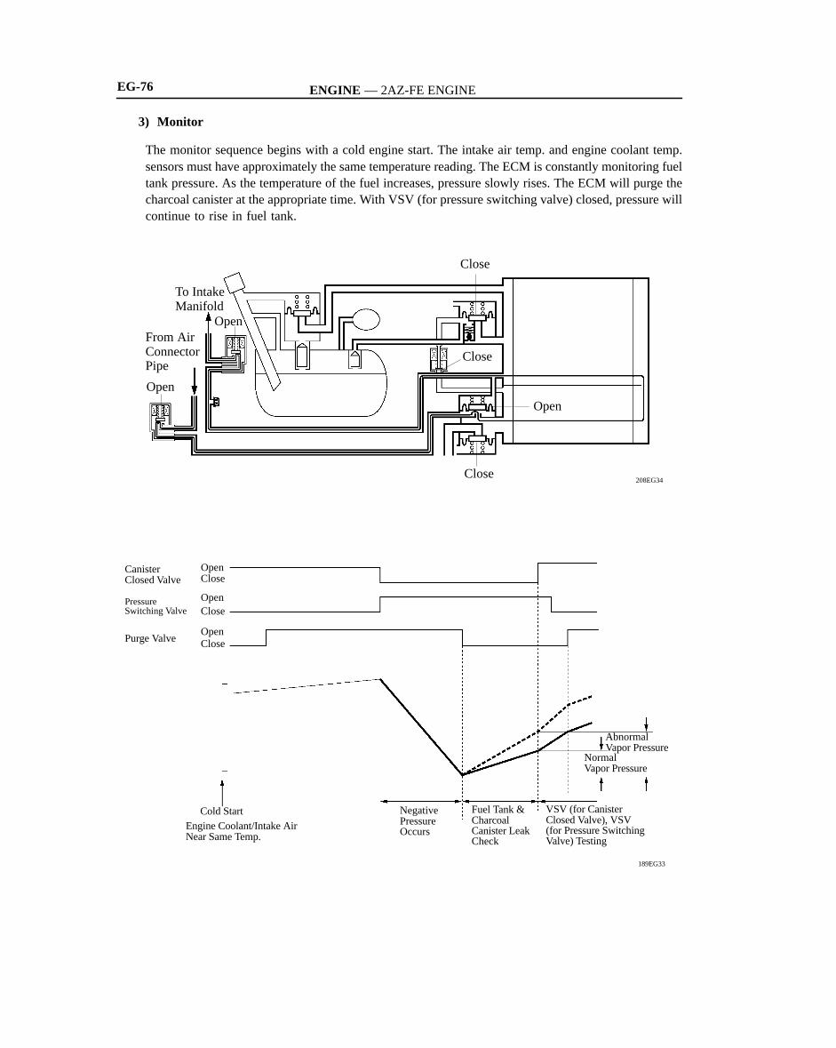
3) Monitor
The monitor sequence begins with a cold engine start. The intake air temp. and engine coolant temp.sensors must have approximately the same temperature reading. The ECM is constantly monitoring fueltank pressure. As the temperature of the fuel increases, pressure slowly rises. The ECM will purge thecharcoal canister at the appropriate time. With VSV (for pressure switching valve) closed, pressure willcontinue to rise in fuel tank.
208EG34
To IntakeManifold
From AirConnectorPipe
Open
Close
Close
Open
Close
Open

ENGINE — 2AZ-FE ENGINE
189EG34
Close
Close
CloseCloseClose
Open
189EG35
Close
CloseClose
Close
Open
Open
To IntakeManifold
EG-77
4) DTC P0440 (Evaporative Emission Control System Malfunction)
Initially, when the canister closed valve is closed, and the pressure switching valve and the purge valveare opened, a vacuum is applied to the purge line from the air intake to the charcoal canister and tothe evaporator line from the charcoal canister to the fuel tank. Next, the purge valve is closed in orderto maintain a vacuum from the VSV (for EVAP) to the inside of the fuel tank. Then, any subsequentchanges in the pressure are monitored by the vapor pressure sensor in order to check for evaporativeemission leaks.If a leak is detected, the MIL (Malfunction Indicator Lamp) illuminates to inform the driver. Also, theDTC (Diagnostic Trouble Code) can be accessed through the use of a hand-held tester.For details on the DTCs, refer to the 2002 Camry Repair Manual (Pub. No. RM881U).
5) DTC P0441 (Evaporative Emission Control System Incorrect Purge Flow)
At a predetermined point, the ECM closed the canister closed valve and opens the pressure switchingvalve causing a pressure drop in the entire EVAP system. The ECM continues to operate the VSV (forEVAP) until the pressure is lowered to a specified point at which time the ECM closed the purge valve.If the pressure did not drop, or if the drop in pressure increase beyond the specified limit, the ECMjudges the VSV (for EVAP) and related components to be faulty and the MIL illuminates to informthe driver. Also, the DTC can be accessed through the use of a hand-held tester.For details on the DTCs, refer to the 2002 Camry Repair Manual (Pub. No. RM881U).

ENGINE — 2AZ-FE ENGINE
208EG35
Close
From AirConnectorPipe
OpenOpen
Close
Close
Close
189EG37
Close
Close
Close
Close
CloseClose
EG-78
6) DTC P0446 (Evaporative Emission Control System Vent Control Malfunction)
a. Canister Closed Valve
This stage checks the VSV (for canister closed valve) and vent (air inlet side) operation. When thevapor pressure rises to a specified point, the ECM opens the canister closed valve. Pressure will increaserapidly because of the air allowed into the system. No increase or an increase below specifiedrate ofpressure increase indicates a restriction on the air inlet side. If a malfunction is detected, the MIL illumi-nates to inform the driver. Also, the DTC can be accessed through the use of a hand-held tester.For details on the DTCs, refer to the 2002 Camry Repair Manual (Pub. No. RM881U).
b. Pressure Switching Valve
The ECM closes the pressure switching valve. This action blocks air entire the tank side of the system.The pressure rise is no longer as great. If there was no change in pressure, the ECM will concludethe pressure switching valve did not close. If a malfunction is detected, the MIL illuminates to informthe driver. Also, the DTC can be accessed through the use of a hand-held tester.For details on the DTCs, refer to the 2002 Camry Repair Manual (Pub. No. RM881U).

ENGINE — 2AZ-FE ENGINE
Service Tip
EG-79
12. Diagnosis
When the ECM detects a malfunction, the ECM makes a diagnosis and memorizes the failed section. Furthermore, the MIL (Malfunction Indicator Lamp) in the combination meter illuminates or blinks toinform the driver.The ECM will also store the DTCs of the malfunctions.The DTCs can be accessed the use of the hand-held tester.
The length of time to clear the DTC via the battery terminal has been changed from the previous 10seconds to 1 minute.

ENGINE — 2AZ-FE ENGINEEG-80
13. Fail-Safe
General
When the ECM detects a malfunction, the ECM stops or controls the engine according to the data alreadystored in the memory.
� Fail-Safe Control List �
Location on Malfunction Description Control
Mass Air Flow Meter
In case of a signal malfunction, the engine could operate poor-ly or the catalyst could overheat if the engine continues to becontrolled with the signals from the sensors.Therefore, the ECM effects control by using the values in theECM or stops the engine.
Accelerator Pedal Position Sensor(For details, see page EG-89)
In case of a signal malfunction, the ECM calculates the accelera-tor pedal opening angle that is limited by the dual system sensorvalue and continues effecting throttle valve control. If both sys-tem malfunction, the ECM considers that the accelerator pedalis fully closed.
Throttle Position Sensor(For details, see page EG-90)
In case of a signal malfunction, the ECM cuts off the current tothe throttle control motor. The throttle valve returns to the pre-scribed opening by the force of the return spring. The ECM thenadjusts the engine output by controlling the fuel injection andignition timing in accordance with the accelerator pedal openingangle to enable the vehicle to continue driving.
Engine Coolant Temp. Sensorand
Intake Air Temp. Sensor
In case of a signal malfunction, the use of the values from the sen-sors will make the air-fuel ratio become too rich or too lean,which could causes the engine to stall or to run poorly during coldoperation. Therefore, the ECM fixes the air-fuel ratio to the stoi-chiometric ratio and uses the constant values of 80°C enginecoolant temperature and 20°C intake air temperature to performthe calculation.
Knock Sensor
In case of a malfunction in the knock sensor or in the knockingsignal system (open or short circuit), the engine could becomedamaged if the timing is advanced despite the presence of knock-ing. Therefore, if a malfunction is detected in the knock sensorsystem, the ECM turns the timing retard correction of the knocksensor into the maximum retard value.
Ignition Coil(with Igniter)
In case of a malfunction in the ignition system, such as an opencircuit in the ignition coil, the catalyst could be become over-heated due to engine misfire. Therefore, if the (IGf) ignition sig-nal is not input twice or more in a row, the ECM determines thata malfunction occurred in the ignition system and stops only theinjection of fuel into the cylinder with the malfunction.
Camshaft Position Sensor In case of a signal malfunction (open or short circuit) or a me-chanical malfunction, the ECM stops the VVT-i control.

ENGINE — 1MZ-FE ENGINE EG-81
1MZ-FE ENGINE
�DESCRIPTION
The 1MZ-FE engine, which is a V6, 3.0-liter, 24-valve DOHC engine, based on the 1MZ-FE engine onthe ’01 Camry.This engine has following features that have been newly adopted in order to realize the further improvementof the engine performance, fuel economy and to reduce exhaust emissions.
� The PS (Planetary reduction Segment conductor motor) starter has been adopted.
� Meets the ULEV (Ultra Low Emission Vehicle) regulation requirements
� Meets the SFTP (Supplementary Federal Test Procedure) regulation requirements
� ETCS-i (Electronic Throttle Control System-intelligent) has been adopted.
� Air intake control system has been adopted.
� Engine Specification�
Model ’02 Camry ’01 Camry
No. of Cyls. & Arrangement 6-Cylinder, V Type �
Valve Mechanism 24-Valve DOHC, Belt & Gear Drive
�
Combustion Chamber Pentroof Type �
Manifolds Cross-Flow �
Fuel System SFI �
Displacement cm3 (cu. in.) 2995 (182.8) �
Bore × Stroke mm (in.) 87.5 × 83.0 (3.44 × 3.27) �
Compression Ratio 10.5 : 1 �
Max. Output (SAE-NET) 143 kw @ 5300 rpm(192 HP @ 5300 rpm)
143 kw @ 5200 rpm(192 HP @ 5200 rpm)
Max. Torque (SAE-NET) 283 N⋅m @ 4400 rpm(209 lb⋅ft @ 4400 rpm)
281 N⋅m @ 4400 rpm(207 lb⋅ft @ 4400 rpm)
IntakeOpen 4°BTDC �
ValveIntake
Close 44°ABDC �ValveTiming
ExhaustOpen 46°BBDC �
ExhaustClose 2°ATDC �
Firing Order 1-2-3-4-5-6 �
Research Octane Number 91 or higher �
Octane Rating 87 or higher �
Dry Weight kg (lb) 158 (348) 155 (342)
Oil Grade API SJ, SL, EC or ILSAC API SH, SJ , EC or ILSAC

ENGINE — 1MZ-FE ENGINEEG-82
�FEATURES OF 1MZ-FE ENGINE
The 1MZ-FE engine has been able to achieve the following performance through the adoption of the itemlisted below.
(1) High performance and fuel economy
(2) Low noise and vibration
(3) Lightweight and compact design
(4) Good serviceability
(5) Clean emission
Item (1) (2) (3) (4) (5) ’02Camry
’01Camry
The ETCS-i has been adopted. � � —
A cylinder block made of aluminum alloy has beenadopted.
� � �
Independent type DIS (Direct Ignition System) hasbeen adopted.
� � � � —
The fuel returnless system has been adopted. � � � � �
Quick connectors are used to connect the fuel hosewith the fuel pipes.
� � �
12-hole type fuel injectors with high atomizing per-formance have been adopted.
� � � —
Iridium-tipped spark plugs have been adopted. � � � —
ACIS (Acoustic Control Induction System) is used.� � �
Air intake control system has been adopted. � � � —
EGR system is used. � � �
A 2-way exhaust control system has been adopted.� � � �
The use of an air fuel ratio sensor allows precise con-trol.
� � �*
The PS (Planetary reduction-Segment conductormotor) starter has been adopted.
� � —
*: California Specification Model
Other parts and construction are the same as in the ’01 Camry.

ENGINE — 1MZ-FE ENGINE EG-83
�ENGINE PROPER
1. Cylinder Head Cover
� Lightweight yet high-strength aluminum diecast cylinder head covers are used.
� An aluminum washer made of vibration-damping laminated aluminum sheet is used on the evenly spacedshoulder bolts which fasten the cylinder head covers.
208EG73
For Right Bank
Engine Front
Gasket
Rubber
CylinderHead Cover
Aluminum
A – A Cross Section
Cylinder Head
For Left Bank
A
A
2. Cylinder Head Gasket
� A metal type cylinder head gasket which offers superior pressure resistance and sealing performancehas been adopted.
208EG104
for Right Bank
for Left Bank
Engine Front

ENGINE — 1MZ-FE ENGINEEG-84
3. Cylinder Head
� The cylinder head, which is made of aluminum, has adopted a pentroof-type combustion chamber. Thespark plug has been located in the center of the combustion chamber.
� The angle of the intake and exhaust valves is narrowed and set at 22.5° to permit a compact cylinderhead.
� Upright, small-diameter intake ports are adopted.
� The cross section of the protrusion of the valve guide into the intake port has been reduced by decreasingthe valve stem diameter and the valve guide outer diameter.
� Plastic region tightening bolt is used for the cylinder head bolts for good axial tension.
187EG07
Exhaust Valve
Spark Plug Hole
Intake Valve
View of Back Side

ENGINE — 1MZ-FE ENGINE EG-85
4. Cylinder Block
� The cylinder block has a bank angle of 60°, a bank offset of 36.6 mm (1.44 in.) and a bore pitch of105.5 mm (4.15 in.), resulting in a compact block.
� Lightweight aluminum alloy is used for the cylinder block.
� A thin cast-iron liner is press- fit inside the cylinder to ensure an added reliability. This liner is thin,so that boring is not possible.
� A water pump swirl chamber and an inlet passage to the pump are provided in the V-bank to help makethe engine compact.
� Knock sensor bosses are provided at 2 locations in V-bank.
� The crankshaft bearing caps are tightened using 4 plastic- region bolts for each journal. In addition,each cap is tightened laterally to improve its reliability.
208EG63
187EG10
198EG38
Knock Sensor Bosses
View of Top Side
105.5 mm36.6 mm
Crankshaft Bearing Cap
Seal Washer
Plastic Region Tightening Bolts
Water Pump Swirl Chamber
60°

ENGINE — 1MZ-FE ENGINE
208EG106
Plastic RegionTightening Bolt
Knock Pin
EG-86
5. Piston
� The piston is made of aluminum alloy and skirt area is made compact and lightweight.
� The piston skirt has been coated with resin to reduce the friction loss.
� Full floating type piston pins are used.
� Each of the pistons is made specifically for the right or left bank.
208EG105
for Right Bank
Resin Coating
6. Connecting Rod
� Connecting rods that have been forged for highstrength are used for weight reduction.
� An aluminum bearing with overlay is used for theconnecting rod bearings.
� Plastic region tightening bolts are used.
� Knock pins are used at the mating surfaces of thebearing caps of the connecting rod to minimizethe shifting of the bearing caps during assembly.

ENGINE — 1MZ-FE ENGINE
208EG72
Balance Weight
Engine Front
Roll-Finished
No. 1 JournalNo. 4 Journal
187EG14
EngineFront
Cast Iron
TorsionalDamper Rubber
Steel
Aluminum
EG-87
7. Crankshaft
� The crankshaft is made of forged steel and has 4 journals and 9 balance weights.
� All pin and journal fillets are roll-finished to maintain adequate strength.
� The crankshaft bearings for the No.1 and No.4 journals are made wider to decrease noise and vibration,and those for the No.2 and No.3 journals are made narrower friction.
8. Crankshaft Pulley
� The crankshaft pulley hub is made of aluminumto reduce weight and vibration.
� The rigidity of the torsional damper rubber hasbeen optimized to reduce noise.

ENGINE — 1MZ-FE ENGINE
208EG107
Exhaust Camshaft
Intake Camshafts
Exhaust Valve
Intake Valves
ExhaustCamshaft
EG-88
�VALVE MECHANISM
1. General
� The valves are directly opened and closed by 4 camshafts.
� The exhaust camshafts are driven by a timing belt, while the intake camshafts are driven through gearson the exhaust camshafts.

ENGINE — 1MZ-FE ENGINE
208EG108
Timing Rotor
No. 2 Camshaft(Exhaust)
No. 1 Camshaft(Intake)
No. 3 Camshaft(Intake)
No. 4 Camshaft(Exhaust)
Scissors Gear Mechanism
Driven Gear
EG-89
2. Camshafts
� The camshafts are made of cast iron alloy.
� In conjunction with the use of the DIS (Direct Ignition System), the No.4 camshaft is provided withtiming rotor to trigger the camshaft position sensor.
� The intake camshafts are driven by gears on the exhaust camshafts.The scissors gear mechanism is usedon drive gear of the exhaust camshaft to control backlash and suppress gear noise.

ENGINE — 1MZ-FE ENGINE
208EG64
187EG17
Camshaft
Valve Lifter
Adjusting Shim
Valve
Adjusting Shim
Cutout
Valve Lifter
Service Tip
EG-90
3. Intake and Exhaust Valve and Valve Lifter
� Narrower valve stems have been adopted to reduce the intake and exhaust resistance and for weightreduction.
� The adjusting shim has been located directly above the valve lifter. This construction allows the adjustingshim to be replaced without removing the camshaft, which improves the serviceability during valveclearance adjustment.
� A cutout is provided in the valve lifter to improve the serviceability of replacing the adjusting shims.
The adjusting shims are available in 17 sizes in increments of 0.050 mm (0.0020 in.), from 2.500 (0.0984in.) to 3.300 (0.1299 in.).For details, refer to see the 2002 Camry Repair Manual (Pub. No. RM881U).

ENGINE — 1MZ-FE ENGINE
198EG40
198EG41
TimingBelt
No. 1 Idler (Tension Adjuster)
Crankshaft TimingPulley
Water PumpPulley
Camshaft Timing Pulleys
No. 2 Idler
Belt Tensioner
PlungerSpring
ReturnSpring
EG-91
4. Timing Belt
The timing belt tooth configuration has been de-signed to help to reduce noise and to enable the beltto transmit power under high load factors.
5. Timing Belt Tensioner
The timing belt tensioner uses a spring and siliconoil damper, and maintains proper timing belt tensionat all times.The timing belt tensioner suppresses noise generatedby the timing belt.

ENGINE — 1MZ-FE ENGINE
208EG109
208EG110
Oil Filter
Oil Pump
Oil Strainer
MAIN OIL HOLE
BYPASSVALVE
RELIEFVALVE
OIL FILTER
OIL PUMP
OILSTRAINER
OIL PAN
EXHAUSTCAMSHAFTJOURNALS
CYLINDER HEAD(FOR LEFT BANK)
CRANKSHAFTJOURNAL
OIL JETS
PISTONS
INTAKECAMSHAFTJOURNALS
INTAKECAMSHAFTJOURNALS
EXHAUSTCAMSHAFTJOURNALS
CYLINDER HEAD(FOR RIGHT BANK)
CRANKSAFTPINS
SCISSORS GEARMECHANISM
SCISSORS GEARMECHANISM
EG-92
�LUBRICATION SYSTEM
1. General
� The lubrication is fully pressurized and all oil passes through an oil filter.
� A trochoid gear type oil pump is directly driven by the crankshaft.

ENGINE — 1MZ-FE ENGINE EG-93
� Specifications�
Oil Capacity Dry 5.5 (5.8, 4.8)Oil Capacity
Li (US I )with Oil Filter 4.7 (5.0, 4.1)
Liters (US qts, Imp. qts) without Oil Filter 4.5 (4.8, 4.0)

ENGINE — 1MZ-FE ENGINE
208EG119
187EG25
Water PumpThermostat
To Heater
Bypass Passage
From HeaterWater Outlet
To Radiator
From Radiator
Intake Manifold
WaterPump
Bypass Passage
Radiator
Cylinder Block
Thermostat
Heater
Throttle Body
Heater Valve
EG-94
�COOLING SYSTEM
� The cooling system is a pressurized, forced-circulation type.
� A thermostat having a bypass valve is located on the water pump inlet side of the cooling circuit.

ENGINE — 1MZ-FE ENGINE EG-95
� Specifications�
Capacity liters (US qts, Imp. qts) 9.2 (9.7, 8.1)
Engine CoolantType TOYOTA Long Life Coolant
or Equivalent
Thermostat Opening Temperature °C (°F) 80 - 84 (176 - 183)

ENGINE — 1MZ-FE ENGINE
208EG111
Throttle Body
Intake Manifold
Intake Air Chamber
Exhaust Manifold
Main Muffler
TWCs
EGR Valve
EG-96
� INTAKE AND EXHAUST SYSTEM
1. General
� The adoption of the ETCS-i (Electronic Throttle Control System-intelligent) has realized excellentthrottle control.
� The adoption of the ACIS (Acoustic Control Induction System) has improved the engine performance.
� The adoption of the air intake control system has improved engine noise reduction and performance.For details, see page EG-86.
� 2-way exhaust control system is provided to reduce noise and vibration in the main muffler.
� The EGR (Exhaust Gas Recirculation) system is used to reduce and control NOx formation.

ENGINE — 1MZ-FE ENGINE
208EG112
Throttle PositionSensor
Throttle Control Motor
208EG46
Intake Air Control Valve
Actuator (for ACIS)
EG-97
2. Throttle Body
� The link-less type ETCS-i has adopted and it real-izes excellent throttle control.For details of ETCS-i control, refer to see pageEG-81.
� A DC motor with excellent response and minimalpower consumption is used for the throttle controlmotor. The ECM performs the duty ratio controlof the direction and the amperage of the currentthat flows to the throttle control motor in orderto regulate the opening angle of the throttle valve.
3. Intake Air Chamber
The intake air chamber consists of upper and lower sections and contains an intake air control valve. Thisvalve is activated by ACIS (Acoustic Control Induction System) and is used to alter the intake pipe lengthto improve the engine performance in all speed ranges. For details of ACIS control, refer to see page EG-83.

ENGINE — 1MZ-FE ENGINE
208EG66
IntakePort
Outer Side
Engine Coolant Passage
A – A Cross SectionEngine Coolant Passage
Rubber Coating
A
A
BB
B – B Cross Section
��
208EG113
Air Fuel Ratio Sensor (Bank 1, Sensor 1)
for Right Bank
Air Fuel Ratio Sensor (Bank 2, Sensor 1)TWCs
for Left Bank208EG114
EG-98
4. Intake Manifold
� The port diameter of the intake manifold has been increased and the port length has been optimizedto improve engine performance.
� An engine coolant passage connects the left and right banks at the rear end of the intake manifold.
� The intake manifold gaskets has rubber coating applied onto surface, and provide superior durability.
5. Exhaust Manifold
� A stainless steel exhaust manifold is used for improving the warm-up of three-way catalytic converterand for weight reduction.
� The air fuel ratio sensor has been adopted to the exhaust manifold.
� An ultra thin-wall, high-cell metal type TWC (Three-Way Catalytic Converter) has been adopted. ThisTWC enables to improve exhaust emissions by optimizing the cells density.

ENGINE — 1MZ-FE ENGINE
208EG115
TWC
Muffler
EG-99
6. Exhaust Pipe
� An ultra thin-wall, high-cell ceramic type TWC has been adopted. This TWC enables to improve exhaustemissions by optimizing the cells density.
� 2- way exhaust control system is provided to reduce noise and vibration in the main muffler. For details,see page EG-23 in 2AZ-FE engine section.

ENGINE — 1MZ-FE ENGINE
208EG116
Pulsation Damper
Injector
Fuel TankORVR Valve
Fuel Pump• Pressure Regulator• Sender Gauge• Fuel Filter
EG-100
�FUEL SYSTEM
1. General
� A fuel returnless system has been used to reduce evaporative emissions.
� A compact fuel pump in which a fuel filter and pressure regulator are integrated in the module fuelpump assembly has been adopted. For details, see page EG-26 in 2AZ-FE engine section.
� A quick connector has been adopted to connect the fuel pipe with the fuel hose to improve serviceability.
� A compact 12-hole type injector with high atomizing performance has been adopted to improve theatomization of fuel. As the result, the air assist system used on ’01 Camry has been discontinued.
� A tether has been provided on the fuel filter cap to prevent the cap from being lost, which results inpreventing the leakage of fuel or the evaporative gas.
� The quick-turn type fuel tank cap has been newly adopted to improve usability.
� The ORVR (On-board Refueling Vapor Recovery) system has been adopted. For details, see page EG-45.

ENGINE — 1MZ-FE ENGINE
208EG118
A
View A
EG-101
2. Fuel Returnless System
This system has been adopted to reduce the evaporative emission. As shown below, integrating the fuelfilter, pressure regulator, and fuel sender gauge with fuel pump assembly, it possible to discontinue thereturn of fuel from the engine area and prevent temperature rise inside the fuel tank.
208EG117
Fuel Filter
Fuel Pump
Pressure Regulator
Module FuelPump Assembly
Fuel Tank
Pulsation Damper
3. Fuel Injector
The 12-hole type injector has been adopted to im-prove the atomization of fuel.

ENGINE — 1MZ-FE ENGINE
161EG43
CamshaftPositionSensor
CrankshaftPositionSensor
VariousSensors
ECM
G22
NE
IGT1
IGT2
IGT3
IGT4
IGF
IGT5
IGT6
No. 1Cylinder
No. 2Cylinder
No. 3Cylinder
No. 4Cylinder
No. 5Cylinder
No. 6Cylinder
+BIgnition Coil (with Igniter)
EG-102
� IGNITION SYSTEM
1. General
� A DIS (Direct Ignition System) has been adopted. The DIS improves the ignition timing accuracy, reduceshigh-voltage loss, and enhances the overall reliability of the ignition system by eliminating the distributor.The DIS in this engine is an independent ignition system which has one ignition coil (with igniter) foreach cylinder.
� Iridium-tipped spark plugs have been adopted to realize a 120,000 mile (192,000 km) maintenance-freeoperation. For details, see page EG-27 in 2AZ-FE engine section.
2. Ignition Coil
The DIS provides 6 ignition coils, one for each cylinder. The spark plug caps, which provide contact tothe spark plugs, are integrated with an ignition coil. Also, an igniter is enclosed to simplify the system.

EG-103
�STARTING SYSTEM
A compact and lightweight PS (Planetary reduction-Segment conductor motor) starter has been adoptedon all models. For details, see page EG-28 in 2AZ-FE engine.

ENGINE — 1MZ-FE ENGINEEG-104
�ENGINE CONTROL SYSTEM
1. General
The engine control system of the 1MZ-FE engine has following system.
System Outline ’02Camry
’01Camry
SFI(Sequential MultiportFuel Injection)(For details, see page EG-80)
An L-type SFI system directly detects the intake air mass witha hot wire type mass air flow meter. � �
ESA(Electronic Spark Advance)(For details, see page EG-80)
Ignition timing is determined by the ECM based on signalsfrom various sensors. The ECM corrects ignition timing in re-sponse to engine knocking.
� �
ETCS-i(Electronic Throttle Control System-intelligent)(For details, see page EG-81)
Optimally controls the throttle valve opening in accordancewith the amount of accelerator pedal effort and the conditionof the engine and the vehicle.
� —
ACIS(Acoustic ControlInduction System)(For details, see page EG-83)
The intake air passages are switched according to the enginespeed and throttle valve opening angle to provide high perfor-mance in all speed ranges.
� �
Air Intake ControlSystem(For details, see page EG-86)
The intake air duct is divided into two areas, and the ECM con-trols the air intake control valve and the actuator that are pro-vided in one of the areas to reduce the amount of engine noise.
� —
Fuel Pump Control Fuel pump operation is controlled by signal from the ECM.� �
Air Fuel Ratio Sensor,Oxygen SensorHeater Control
Maintains the temperature of the air fuel ratio sensor or oxy-gen sensor at an appropriate level to increase accuracy ofdetection of the oxygen concentration in the exhaust gas.
� �
EGR (Exhaust Gas Recirculation) System
• This system recirculates a portion of the exhaust gasesthrough the intake in order to reduce the amount of NOx inthe exhaust gases.
• Cuts off EGR according to the engine condition to maintaindrivability of the vehicle and durability of the EGR compo-nents.
� �
EvaporativeEmission Control(For details, see page EG-44)
• The ECM controls the purge flow of evaporative emission(HC) in the charcoal canister in accordance with engineconditions.
• Using 3 VSVs and a vapor pressure sensor, the ECM detectsany evaoprative emission leakage occurring between thefuel tank and the charcoal canister through the changes inthe tank pressure.
� �
Air ConditioningCut-off Control
By turning the air conditioner compressor ON or OFF in accor-dance with the engine condition, drivability is maintained.� �
Engine Immobiliser Prohibits fuel delivery and ignition if an attempt is made tostart the engine with an invalid ignition key. � �
DiagnosisWhen the ECM detects a malfunction, the ECM diagnoses andmemorizes the failed section. � �
Diagnosis(For details, see page EG-87) To increase the speed for processing the signals, the 32-bit
CPU of the ECM has been adopted � —
Fail-Safe(For details, see page EG-88)
When the ECM detects a malfunction, the ECM stops or con-trols the engine according to the data already stored in thememory.
� �

ENGINE — 1MZ-FE ENGINE
(Continued)
IGT1~IGT6
VG
THA
THW
VTA1, 2
NE
G22
AFL
OX1B
KNK R
NSW
SPD
STA
IGSW
PS
#10#20
#30
#40
IGF
ECM
SENSORS
MASS AIR FLOW METER
INTAKE AIR TEMP. SENSOR
ENGINE COOLANT TEMP. SENSOR
THROTTLE POSITION SENSOR
CRANKSHAFT POSITION SENSOR
CAMSHAFT POSITION SENSOR
AIR FUEL RATIO SENSOR(Bank 1, Sensor 1)
HEATED OXYGEN SENSOR(Bank 1, Sensor 2)
ACCELERATOR PEDAL POSITION SENSOR
KNOCK SENSORS
IGNITION SWITCH• Starting Signal• Ignition Signal
• Neutral Start Signal• Shift Lever Position Signal
• Vehicle Speed Signal
POWER STEERING OILPRESSURE SWITCH
VAPOR PRESSURE SENSOR
STOP LIGHT SWITCH
ACTUATORS
SFI
No. 1 INJECTORNo. 2 INJECTORNo. 3 INJECTORNo. 4 INJECTOR
ESA
IGNITION COIL with IGNITER
SPARK PLUGS
EGR SYSTEM
ETCS-i
FUEL PUMP CONTROL
CIRCUIT OPENING RELAY
OXYGEN SENSOR HEATER CONTROL
AIR FUEL RATIO SENSORHEATER CONTROL
HEATED OXYGEN SENSORHEATER (Bank 1, Sensor 2)
VC
P, R, N
PTNK
STP
M
208EG36
AIR FUEL RATIO SENSOR(Bank 2, Sensor 1)
HEATED OXYGEN SENSOR(Bank 2, Sensor 2)
NEUTRAL START SWITCH
COMBINATION METER
No. 5 INJECTORNo. 6 INJECTOR
AIR INTAKE CONTROL SYSTEM
VSV
VSV
ACIS
VSV
AIR FUEL RATIO SENSORHEATER (Bank 1, Sensor 1)
AIR FUEL RATIO SENSORHEATER (Bank 2, Sensor 1)
AIR FUEL RATIO SENSORHEATER RELAY
EFI MAIN RELAY
HEATED OXYGEN SENSORHEATER (Bank 2, Sensor 2)
OX2B
KNK L
AFR
VPAVPA2
#50
#60
AICV
EGR
ACIS
FC
HAFR
HAFL
MREL
HT1B
HT2B
THROTTLE CONTROL MOTOR
EG-105
2. ConstructionThe configuration of the engine control system in the 1MZ-FE engine in the ’02 Camry is as shown inthe following chart.

ENGINE — 1MZ-FE ENGINE
TXCTRXCKCODE
KSW
W
BATT+B
TRANSPONDER KEYAMPLIFIER* 1
DATA LINK CONNECTOR 3MALFUNCTION INDICATOR
LIGHT
EFI MAIN RELAY BATTERY
SILTC
ECM
208EG37
UNLOCK WARNING SWITCH*1
CRUISE CONTROL SWITCH
A/T FLUID TEMPERATURESENSOR
GENERATOR
SKID CONTROL ECU*2
EGR VALVE POSITION SENSOR
EGR GAS TEMP. SENSOR
AIR CONDITIONING SWITCH*3
AIR CONDITIONING ECU*4
AIR CONDITIONING CONTROL
AIR CONDITIONING MAGNET CLUTCH
EVAPORATIVE EMISSIONCONTROL
VSV(for Canister Closed Valve)
VSV(for Pressure Switching Valve)
VSV (for EVAP)
COOLING FAN CONTROL
COOLING FAN RELAYS
CCS
THO
RL
TRCENG
EGLS
THG
A/C S
A/C S
CF
EVP 1
TBP
CCV
ACMG
*1: with Engine Immobiliser System*2: with VSC System*3: with Manual Air Conditioning System*4: with Automatic Air Conditioning System
EG-106

ENGINE — 1MZ-FE ENGINE
208EG38
Injector
Knock Sensor
Heated OxygenSensor(Bank 2, Sensor 2)
CrankshaftPosition Sensor
Heated OxygenSensor(Bank 1, Sensor 2)
Air FuelRatioSensor(Bank 2,Sensor 1)
ECM
DLC3
IgnitionSwitch
VSV(for EVAP)
Combination Meter
*: with Automatic Air Conditioning System
Air Fuel Ratio Sensor(Bank 1, Sensor 1)
Air Fuel Ratio Sensor Heater Relay
Battery
Intake AirTemp. Sensor
VSV (for Air IntakeControl Valve
Fuel Pump
CircuitOpening
Relay
EGR GasTemp. Sensor
Engine CoolantTemp. Sensor EGR
Valve
VSV (for EGR)
VSV (for Pressure Switching Valve)
TWC
TWCTWC
Ignition Coilwith Igniter
MIL Air ConditioningECU*
VSV (for ACIS)Throttle Control Motor
Stop Light Switch
Perk/Neutral Position Switch
Mass AirFlow Meter
Electronic Controlled Transmission Solenoid Valve
EFIMainRelay
VaporPressureSensor
PulsationDamper
VSV (for CanisterClosed Valve)
Throttle Position Sensor
Actuator VacuumTank
EG-107
3. Engine Control System Diagram

ENGINE — 1MZ-FE ENGINEEG-108
4. Layout of Main Component
208EG39
VSV(for Pressure Switching Valve)
Vapor PressureSensor
Fuel Pump
VSV(for Canister Closed Valve)
Mass Air Flow Meter
DLC3
Heated Oxygen Sensor(Bank 2, Sensor 2)
Crankshaft PositionSensor
Camshaft PositionSensor
Heated Oxygen Sensor(Bank 1, Sensor 2)
Engine CoolantTemp. Sensor
Throttle PositionSensor
Ignition Coilwith Igniter
VSV(for EVAP)
VSV(for ACIS)
Knock Sensors
Injector
ECM
VSV(for Air Intake Control Valve)
Air Fuel Ratio Sensor(Bank 2, Sensor 1)
Air Fuel Ratio Sensor(Bank 1, Sensor 1)
EGR Gas Temp. SensorEGR Valve
VSV (for EGR)

ENGINE — 1MZ-FE ENGINE EG-109
5. Main Components of Engine Control System
General
The following table compares the main components.
ComponentsNew Previous
ComponentsOutline Quantity Outline Quantity
ECM 32-bit CPU 1 16-bit CPU 1
Mass Air Flow Meter(For details, see page EG-36)
Hot-wire Type 1 �
Crankshaft Position Sensor (Rotor Teeth)
Pick-up Coil Type(36-2)
1 �
Camshaft Position Sensor(Rotor Teeth)
Pick-up Coil Type(3)
1 �
Throttle Position Sensor Linear Type 1 �
Accelerator Pedal Position Sensor(For details, see page EG-38)
Linear Type 1 —
Knock Sensor Built-in PiezoelectricType
1 �
Air Fuel Ratio Sensor(Bank 1, Sensor 1)(Bank 2, Sensor 1)
with Heater Type 2 � (A/T Model)
Oxygen Sensor(Bank 1 Sensor 2) with Heater Type 2 with Heater
3 (M/T Model)
(Bank 1, Sensor 2)(Bank 2, Sensor 2)
with Heater Type 2 with HeaterType 1
(A/T Model)Injector 12-hole Type 6 4-hole Type 6
Crankshaft Position Sensor
The timing rotor of the crankshaft consists of 34 teeth, with 2 teeth missing. The crankshaft positionsensor outputs the crankshaft rotation signals every 10°, and the missing teeth are used to determine thetop-dead-center.
208EG40Timing Rotor
CrankshaftPosition Sensor
2 TeethMissing
10° CA
Timing Rotor (720° CA)
EngineFront

ENGINE — 1MZ-FE ENGINEEG-110
Camshaft Position Sensor
The camshaft position sensor is mounted on the left side cylinder head. To detect the camshaft position,a timing rotor that is provided on the camshaft is used to generate 1 pulses for every 2 revolutions ofthe crankshaft.
208EG41
TimingRotor
Camshaft Position Sensor
Timing Rotor (720° CA)
EngineFront
Throttle Position Sensor
This sensor converts the throttle valve opening angles into electronic signals with two differing characteris-tics and outputs them to the ECM. One is the VTA signal that linearly outputs the voltage along the entirerange of the throttle valve opening angle. The other is the VTA 2 signal that outputs an offset voltage.
208EG42
Throttle Position Sensor
E2 VTA2 VTA VC
Close
OpenOpen
Close
V
5.0
OutputVoltage
VTA2
VTA
0Close Open

ENGINE — 1MZ-FE ENGINE EG-111
6. SFI (Sequential Multiport electronic Fuel Injection) System
� An L-type SFI system directly detects the intake air mass with a hot wire type mass air flow meter.
� An independent injection system (in which fuel is injected once into each cylinder for each two revolutionof the crankshaft) has been adopted.
� There are two types of fuel injection:
a) One is synchronous injection in which corrections based on the signals from the sensors are addedto the basic injection time so that injection occurs always at the same timing.
b) The other is non-synchronous injection in which injection is effected by detecting the requests fromthe signals of the sensors regardless of the crankshaft angle.
Furthermore, to protect the engine and improve fuel economy, the system effects fuel cutoff in whichthe injection of fuel is stopped temporarily in accordance with the driving conditions.
208EG43
#1
#2
#3
#4
#5
#6
Synchronous Injection
IgnitionNon-Synchronous Injection
Independent Injection
Intake Combustion
7. ESA (Electronic Spark Advance)
This system selects the optimal ignition timing in accordance with the signals received from the sensorsand sends the (IGT) ignition signal to the igniter. The default ignition timing is set to 5° BTDC.

ENGINE — 1MZ-FE ENGINEEG-112
8. ETCS-i (Electronic Throttle Control System-intelligent)
General
� In the conventional throttle body, the throttle valve opening in determined invariably by the amount ofthe accelerator pedal effort. In contrast, the ETCS-i uses the ECM to calculate the optimal throttle valveopening that is appropriate for the respective driving condition and uses a throttle control motor to con-trol the opening.
� The accelerator cable and link have been discontinued, and an a accelerator position sensor has been pro-vided on the accelerator pedal.
� System Diagram�
208EG44
Accelerator PedalPosition Sensor
Throttle Valve
Throttle Position Sensor
ThrottleControlMotor
Skid ControlECU
Mass AirFlow Meter ECM
FuelInjector
IgnitionCoil

ENGINE — 1MZ-FE ENGINE EG-113
Operation
1) General
The ECM drives the throttle control motor by determining the target throttle valve opening in accordancewith the respective vehicle operating condition.
� Idle Speed Control
� Shift Shock Reduction Control
� Cruise Control
2) Idle Speed Control
Controls the ECM and the throttle valve in order to constantly effect ideal idle speed control.
3) Shift Shock Reduction Control
The throttle control is synchronized to the ECT (Electronically Controlled Transmission) control duringthe shifting of the transmission in order to reduce the shift shock.
4) TRAC Throttle Control
As part of the TRAC system, the throttle valve is closed by a demand signal from the skid control ECUif an excessive amount of slippage is created at a driving wheel, thus facilitating the vehicle in ensuringstability and driving force.
5) VSC Coordination Control
In order to bring the effectiveness of the VSC system control into full play, the throttle valve openingangle is controlled by effecting a coordination control with the skid control ECU.
6) Cruise Control
An ECM with an integrated cruise control ECU directly actuates the throttle valve to effect the operationof the cruise control.

ENGINE — 1MZ-FE ENGINEEG-114
9. ACIS (Acoustic Control Induction System)
General
The ACIS is realized by using a bulkhead to divide the intake manifold into 2 stages, with an intakeair control valve in the bulkhead being opened and closed to vary the effective length of the intake manifoldin accordance with the engine speed and throttle valve opening angle. This increases the power outputin all ranges from low to high speed.
� System Diagram�
208EG45
ECM
VSV
Intake Air Control ValveActuator
Vacuum Tank
Engine Speed Throttle Opening Angle
To Surge Tank

ENGINE — 1MZ-FE ENGINE
208EG46
Intake Air Control Valve
Actuator
208EG47
Atmosphere
To ActuatorFrom Vacuum Tank
EG-115
General
1) Intake Air Control Valve
The intake air control valves, which are providedin the intake air chamber, open and close to changethe effective length of the intake manifold in twostages.
2) VSV (Vacuum Switching Valve)
Controls the vacuum that is applied to the actuatorby way of the signal (ACIS) that is output by theECM.
3) Vacuum Tank
Equipped with an internal check valve, the vacuum tank stores the vacuum that is applied to the actuatorin order to maintain the intake air control valve fully closed even during low-vacuum conditions.

ENGINE — 1MZ-FE ENGINEEG-116
Operation
1) When the Intake Control Valve Closes (VSV ON)
The ECM activates the VSV to match the longer pulsation cycle so that the negative pressure acts onthe diaphragm chamber of the actuator. This closes the control valve. As a result, the effective lengthof the intake manifold is lengthened and the intake efficiency in the low-to-medium speed range is im-proved due to the dynamic effect of the intake air, thereby increasing the power output.
208EG48
Engine Speed
: Effective Intake Manifold Length
ThrottleValve
Open
Close
Low High
VSV ON
2) When the Intake Control Valve Open (VSV OFF)
The ECM deactivates the VSV to match the shorter pulsation cycle so that atmospheric air is led intothe diaphragm chamber of the actuator and opens the control valve. When the control valve is open,the effective length of the intake air chamber is shortened and peak intake efficiency is shifted to thehigh engine speed range, thus providing greater output at high engine speeds.
208EG49
: Effective Intake Manifold Length
VSV OFF
Engine Speed
ThrottleValve
Open
Close
: Effective Intake Air Chamber
Low High

ENGINE — 1MZ-FE ENGINE EG-117
10. Air Intake Control System
General
The air cleaner inlet is divided into two areas, and a air intake control valve and an actuator have beenpro-vided in one of the areas. As a result, a reduction in intake noise in the low-speed range and an increase in the power output inthe high-speed range have been realized.
� Layout of Components�
208EG50
Air IntakeControl Valve
VSVActuator
Operation
When the engine is operating in the low-to mid-speed range, this control operates the air intake controlvalve to close one side of the air cleaner inlet. When the engine is operating in the high-speed range, this control operates the air intake control valveto open both side of the air cleaner inlet to effect the intake of air.
208EG51
Air IntakeControl Valve
Vacuum Tank
VSV
ThrottleOpeningAngle
Open
Engine SpeedAir Intake Control Valve Condition

ENGINE — 1MZ-FE ENGINE
Service Tip
EG-118
11. Diagnosis
When the ECM detects a malfunction, the ECM makes a diagnosis and memorizes the failed section. Furthermore, the MIL (Malfunction Indicator Light) in the combination meter illuminates or blinks to informthe driver.The ECM will also store the DTCs of the malfunctions.The DTCs can be accessed the use of the hand-held tester.
The length of time to clear the DTC via the battery terminal has been changed from the previous 10seconds to 1 minute.
— Changes (from ’01 Camry) —
The DTCs (Diagnostic Trouble Codes) listed below have been added or discontinued.
� Added DTCs�
DTC No. Detection Item
P0156 O2 Sensor Circuit Malfunction (Bank 2, Sensor 2)
P0161 O2 Sensor Heater Circuit Malfunction (Bank 2, Sensor 2)
P0430 Catalyst System Efficiency Below Threshold (Bank 2)
P0605 Internal Control Module Read Only Memory (ROM) Error
P1120 Accelerator Pedal Position Sensor Circuit Malfunction
P1121 Accelerator Pedal Position Sensor Range/Performance Problem
P1125 Throttle Control Motor Circuit Malfunction
P1127 ETCS Actuator Power Source Circuit Malfunction
P1128 Throttle Control Motor Lock Malfunction
P1129 Electric Throttle Control System Malfunction
P1633 ECM Malfunction (ETCS Circuit)
� Discontinued DTCs�
DTC No. Detection Item
P0130 O2 Sensor Circuit Malfunction (Bank 1, Sensor 1)
P0133 O2 Sensor Circuit Slow Response (Bank 1, Sensor 1)
P0135 O2 Sensor Heater Circuit Malfunction (Bank 1, Sensor 1)
P0150 O2 Sensor Circuit Malfunction (Bank 2, Sensor 1)
P0153 O2 Sensor Circuit Slow Response (Bank 2, Sensor 1)
P0155 O2 Sensor Heater Circuit Malfunction (Bank 2, Sensor 1)

ENGINE — 1MZ-FE ENGINE EG-119
12. Fail-Safe
General
When the ECM detects a malfunction, the ECM stops or controls the engine according to the data alreadystored in the memory.
� Fail-Safe Control List �
: New
Location on Malfunction Description Control
Mass Air Flow Meter
In case of a signal malfunction, the engine could operate poor-ly or the catalyst could overheat if the engine continues to becontrolled with the signals from the sensors.Therefore, the ECM effects control by using the values in theECM or stops the engine.
Accelerator Pedal Position Sensor(For details, see page EG-89)
In case of a signal malfunction, the ECM calculates the accel-erator pedal opening angle that is limited by the dual systemsensor value and continues effecting throttle valve control. Ifboth system malfunction, the ECM considers that the accelera-tor pedal is fully closed.
Throttle Position Sensor(For details, see page EG-90)
In case of a signal malfunction, the ECM cuts off the currentto the throttle control motor. The throttle valve returns to theprescribed opening by the force of the return spring. The ECMthen adjusts the engine output by controlling the fuel injectionand ignition timing in accordance with the accelerator pedalopening angle to enable the vehicle to continue driving.
Engine Coolant Temp. Sensorand
Intake Air Temp. Sensor
In case of a signal malfunction, the use of the values from thesensors will make the air-fuel ratio become too rich or too lean,which could causes the engine to stall or to run poorly duringcold operation. Therefore, the ECM fixes the air-fuel ratio tothe stoichiometric ratio and uses the constant values of 80°Cengine coolant temperature and 20°C intake air temperature toperform the calculation.
Knock Sensor
In case of a malfunction in the knock sensor or in the knockingsignal system (open or short circuit), the engine could becomedamaged if the timing is advanced despite the presence ofknocking. Therefore, if a malfunction is detected in the knocksensor system, the ECM turns the timing retard correction ofthe knock sensor into the maximum retard value.
Ignition Coil(with Igniter)
In case of a malfunction in the ignition system, such as an opencircuit in the ignition coil, the catalyst could be become over-heated due to engine misfire. Therefore, if the (IGF) ignitionsignal is not input twice or more in a row, the ECM determinesthat a malfunction occurred in the ignition system and stopsonly the injection of fuel into the cylinder with the malfunc-tion.

ENGINE — 1MZ-FE ENGINEEG-120
Fail-Safe of Accelerator Pedal Position Sensor
� The accelerator pedal position sensor comprises two (main, sub) sensor circuits. If a malfunction occursin either one of the sensor circuits, the ECM detects the abnormal signal voltage difference between thesetwo sensor circuit and switches to the limp mode. In the limp mode, the remaining circuit is used to calcu-late the accelerator pedal opening, in order to operate the vehicle under limp mode control.
199EG45
ECM
Accelerator PedalPosition Sensor
MainSub
Accelerator Pedal Throttle Body
Open
Throttle Valve
Main
SubThrottlePositionSensor
ReturnSpring
ThrottleControlMotor
� If both systems malfunction, the ECM detects the abnormal signal voltage between these two sensor cir-cuits and regards that the opening angle of the accelerator pedal is fully opened and then continues thethrottle control. At this time, the vehicle can be driven within its idling range.
199EG46
Close
ECM
Accelerator PedalPosition Sensor
MainSub
Accelerator Pedal Throttle Body
Throttle Valve
MainSub
ThrottlePositionSensor
ReturnSpring
ThrottleControlMotor

ENGINE — 1MZ-FE ENGINE EG-121
Fail-Safe of Throttle Position Sensor
� The throttle position sensor comprises two (main, sub) sensor circuits. If a malfunction occurs in eitherone of the sensor circuits, the ECM detects the abnormal signal voltage difference between these twosensor circuits, cuts off the current to the throttle control motor, and switches to the limp mode. Then,the force of the return spring causes the throttle valve to return and stay at the prescribed opening. Atthis time, the vehicle can be driven in the limp mode while the engine output is regulated through thecontrol of the fuel injection and ignition timing in accordance with the accelerator opening.
� The same control as above is effected if the ECM detects a malfunction in the throttle control motor sys-tem.
199EG47
ECM
Accelerator PedalPosition Sensor
Main Sub
Accelerator Pedal Throttle Body
Open
Throttle Valve
MainSub
ReturnSpring
ThrottleControlMotor
Injectors Ignition Coil