![Bles.ppt [Read-Only]](https://static.fdokumen.com/doc/165x107/633bffc7197a6737f10ceddf/blesppt-read-only.jpg)
PDF Only - Perko
204
-
Upload
khangminh22 -
Category
Documents
-
view
1 -
download
0
Transcript of PDF Only - Perko
-f■'
-C
■-
l!
'
]
©PERKO, INC. 1986 ALL RIGHTS RESERVED
PORTIONS OF THIS CATALOG PREVIOUSLY COPYRIGHTED 1936 THRU 1984 INCLUSIVE
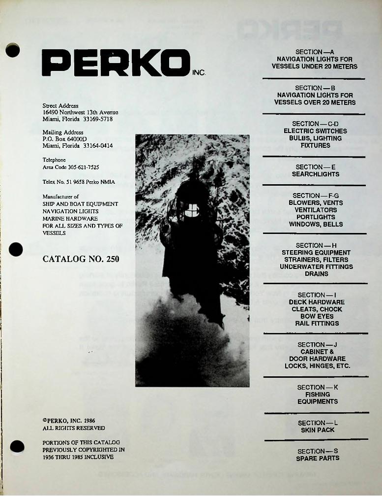
PERKO SECTION—A NAVIGATION LIGHTS FOR
VESSELS UNDER 20 METERSINC.
SECTION — B NAVIGATION LIGHTS FOR
VESSELS OVER 20 METERSStreet Address16490 Northwest 13 th Avenue Miami, Florida 33169-5718
SECTION —C-D ELECTRIC SWITCHES
BULBS, LIGHTING FIXTURES
Mailing AddressP.O. Box 64000DMiami, Florida 33164-0414
TelephoneArea Code 305-621-7525 SECTION —E
SEARCHLIGHTSTelex No. 51 9658 Perko NMIA
SECTION — F-G BLOWERS, VENTS
VENTILATORS PORTLIGHTS
WINDOWS, BELLS
Manufacturer ofSHIP AND BOAT EQUIPMENT NAVIGATION LIGHTS MARINE HARDWARE FOR ALL SIZES AND TYPES OF VESSELS
:
ISECTION —H
STEERING EQUIPMENT STRAINERS, FILTERS
UNDERWATER FITTINGS DRAINS
: CATALOG NO. 250\:iii1
I SECTION —I DECK HARDWARE CLEATS, CHOCK
BOW EYES RAIL FITTINGS
■
SECTION—J CABINET &
DOOR HARDWARE LOCKS, HINGES, ETC.
SECTION —K FISHING
EQUIPMENTS
©PERKO, INC. 1986 ALL RIGHTS RESERVED
SECTION —L SKIN PACK
PORTIONS OF THIS CATALOG PREVIOUSLY COPYRIGHTED IN 1936 THRU 1985 INCLUSIVE
SECTION —S SPARE PARTS
-I

305 • 621-752516490 N.W. 13TH AVENUE P 0. BOX 64000 D MIAMI. FLA. 33164PERKO INC.
(itMarvin S. Parkins PRESIDENT
To Our Friends:
For over 75 years, Perko has been manufacturing hardware for the marine industry worldwide.
We’re very proud of that fact. Proud that we were able to carry on the same philosophy the company was founded on ... to design and manufacture the highest quality marine hardware possible.
It was that kind of pride that motivated Frederick Perkins in 1907 to start his own company — a tiny one-room manufacturing plant in Manhattan serving northeastern ship owners.
It is with that same pride that the company is still producing top quality products and has blossomed into the world’s largest manufacturer of marine lights, hardware and accessories.
So, we’re proud to say “We Make It Right.” But, we’re also proud to say we make it “Right Here.” r
It was this country that offered Frederick Perkins the opportunity of starting his own company. And, it was this country that enabled Perko to grow from one small room in New York to a 250,000 square foot manufacturing operation in Florida offering over 5,000 marine items.
It is this country that will enable Perko to expand further.
Therefore, it is with great pride that we dedicate our catalog cover to the people and country that have made it^possible for us to savj, “We Make It
Ri9W-Ri9h*Here" jwvl—Marvin Perkins President
MANUFACTURER OF MARINE LIGHTS, HARDWARE AND ACCESSORIES
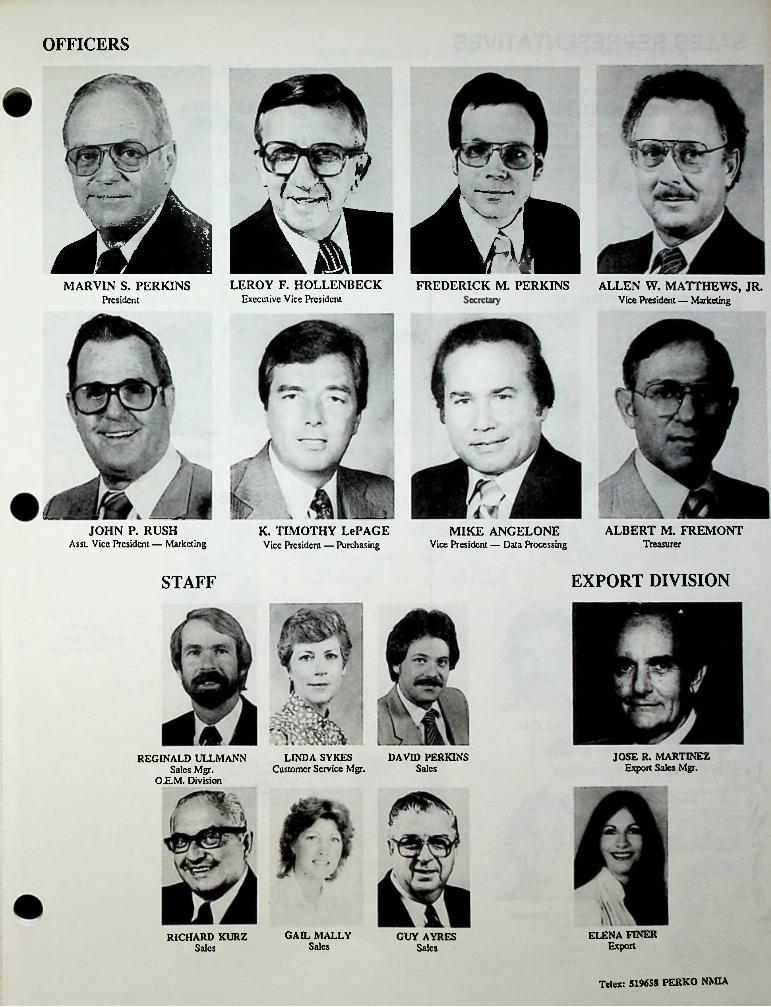
OFFICERS
f | y
*rA ij ilLEROY F. HOLLENBECK FREDERICK M. PERKINS ALLEN W. MATTHEWS, JR.MARVIN S. PERKINS
Executive Vice PresidentPresident Vice President — Marketing
ALBERT M. FREMONTJOHN P. RUSHAsst. Vice President — Marketing
K. TIMOTHY LePAGE MIKE ANGELONETreasurerVice President — Data ProcessingVice President — Purchasing
EXPORT DIVISIONSTAFF
JOSE R. MARTINEZ Export Sales Mgr.
LINDA SYKES Customer Service Mgr.
DAVID PERKINSREGINALD ULLMANN Sales Mgr.
O.E.M. DivisionSales
ELENA FINER Export
GAEL MALLY Sales
GUY AYRES Sales
RICHARD KURZSales
Telex: 519658 PERKO NMIA

SALES REPRESENTATIVES
GULF COAST AREAPACIFIC & WESTERN AREA
;Jim Tranchln Joe BcrggrenDan A. Naber
JAMES K DUGAN and ASSOCIATES, INC Southern CaliTomia — Nevada — Arizona — New Mexico 12900 Garden Grove Blvd.Suite 106Garden Grove, CA 92643 Phone 714-636-2381 IRj QJLJAMES K. DUGAN and ASSOCIATES, INC Northern CaliTomia — Utah — Colorado 3368 MeGraw Road LaFayeue,CA 94549 Phone 415-284-4855
Kyle McHugh Tennant Tranchin
F.F. TRANCHINA CO., INC Louisiana - Alabama - Mississippi - Tennessee 1005-13 Magazine Street New Orleans, LA 70130 Phone 504-524-7451
Wayne R. Mooers
Tom Harger Hugh W. Mulholland
F.F. TRANCHINA CO., INC Southern & Central Texas 1511 Lake Bank Court Seabrook.TX 77586 Phone 713-326-3291
JOHN B. MERIFIELDia incWashington — Oregon Idaho — Montana—
AlaskaWyoming —927 N.WV 50th Sl P.O. Box 70626 Seattle, WA 98107 Phone 206-789-1800
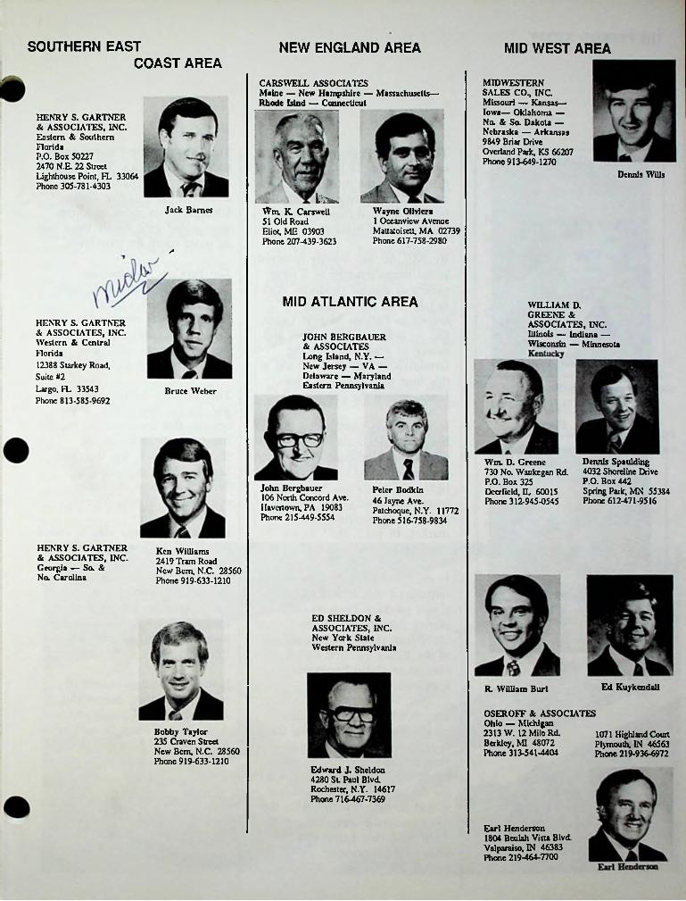
SOUTHERN EAST NEW ENGLAND AREA MID WEST AREACOAST AREA
MIDWESTERN SALES CO., INC Missouri — Kansas— Iowa— Oklahoma — No. 8c So. Dakota — Nebraska — Arkansas 9849 Briar Drive Overland Park, KS 66207 Phone 913-649-1270
CARSWELL ASSOCIATESMaine — New Hampshire — Massachusetts—Rhode Islnd — Connecticut
HENRY S. GARTNER & ASSOCIATES, INC. Eastern & Southern FloridaP.O. Box 50227 2470 N.R 22 Street Lighthouse Point, FL 33064 Phone 305-781-4303
Dennis Wills
List.Jack Barnes Wm. K. Carswell
51 Old Road Eliot, ME 03903 Phone 207-439-3623
Wayne Olivicra 1 Oceanvicw Avenue Mattaioisctt, MA 02739 Phone 617-758-2980
MID ATLANTIC AREA WILLIAM D.GREENE & ASSOCIATES, INC. Illinois — Indiana — Wisconsin — Minnesota
HENRY S. GARTNER & ASSOCIATES, INC. Western & Central Florida12388 Starkey Road, Suite #2Largo, FL 33543 Phone 813-585-9692
JOHN BERG BAUER & ASSOCIATES Long Island, N.Y. — New Jersey — VA — Delaware — Maryland Eastern PennsylvaniaBruce Weber
Dennis Spaulding 4032 Shoreline Drive P.O. Box 442 Spring Park, MN 55384 Phone 612-471-9516
Wm. D. Greene 730 No. Waukegan Rd. P.O. Box 325 Deerfield, IL 60015 Phone 312-945-0545
John Bergbauer 106 North Concord Ave. Havertown, PA 19083 Phone 215-449-5554
Peter Bodkin 46 Jayne Ave. Patchoquc, N.Y. 11772 Phone 516-758-9834
HENRY S. GARTNER & ASSOCIATES, INC. Georgia — So. &No. Carolina
Ken Williams 2419 Tram Road New Bern, N.C. 28560 Phone 919-633-1210
ED SHELDON & ASSOCIATES, INC. New York State Western Pennsylvania
Ed KuykendallR. William Burt
OSEROFF & ASSOCIATES Ohio — Michigan 2313 W. 12 Mile Rd.Berkley, MI 48072 Phone 313-541-4404
Bobby Taylor 235 Craven Street New Bern, N.C. 28560 Phone 919-633-1210
1071 Highland Court Plymouth, IN 46563 Phone 219-936-6972
Edward J. Sheldon 4280 St. Paul Blvd. Rochester, N.Y. 14617 Phone 716-467-7369
Earl Henderson 1804 Beulah Vista Blvd. Valparaiso, IN 46383 Phone 219-464-7700

THE PERKO® STORY
nThis growth period necessitated additional facilities. The original one story manufacturing plant in Brooklyn grew to five stories. Ultimately, six more buildings were added until finally there was no more room for expansion.
The origin of Perko may be traced back to the late 1800’s. It was then, just prior to the turn of the century, that Frederick Perkins founded a small manufacturing plant in lower Manhattan.
By 1907, he was heavily involved in the manufacturing of a large variety of marine products. And in late 1916, the company — known as Perkins Marine Lamp, Inc. — outgrew its facilities and moved to what was then the farmlands of Brooklyn. It was at this time that Frederick’s son, Louis, joined the company.
Lou Perkins, who became Perko’s president in 1947 upon the passing of his father, Frederick, was responsible for most of the plant expansion. It was in this year, also, that Lou’s son Marvin joined the firm.
Frederick Perkins The company continued to grow, and, by the late 1950’s, it was obvious that there was no more room for expansion in the Brooklyn site. It was then that Lou and Marvin made the decision to move the entire operation to Miami, Florida.
CO-FOUNDERSLouis E. Perkins New products were added to the
line, and sales activities expanded beyond the Northeast. The company offered cast bronze lights and hardware, first to the maritime industry, and then to the growing pleasure boat market. In 1922, the “Perko” trademark was introduced.
r
In 1960, Perko was able to entice Roy Hollenbeck into joining the company. Roy’s extensive experience in manufacturing, plating, engineering, designing, and production was perfectly suited for his first challenge — to plan and coordinate the move from New York to Miami.
In the late 1920’s the company introduced copper and nickel- plated products from its own plating department. When chromium plating was perfected in the 1930’s the first Perko chromium-plated hardware appeared.
The 1930’s was a period of exceptional growth. During this time, the company’s reputation for manufacturing fine marine lights, hardware, and accessories for the pleasure boating market spread far and fast. In 1932, the company name was changed to Perkins Marine Lamp and Hardware Corporation.
It was agreed that instead of separate facilities, everything should be placed under one roof. Additionally, since the new plant was to be quite large and extensive,
P

encompassing a whole range of complete in-house production capabilities — from mill material to finished product — most subcontractors could be eliminated. Roy spent a great deal of time in laying out the plans for the new building and supervising the construction to insure that everything was located precisely where the plans indicated.
Upon the passing of Louis Perkins in 1964, Marvin continued to add to Perko’s facilities. From an initial plant of 78,000 square feet, Perko’s facilities now span approximately 250,000 square feet of office and manufacturing space. With this tremendous growth and expansion, you might think that the company would go through a period of stabilization. Not so, however, Perko has continued to innovate, grow, and expand.
expanded to handle the complete seven-strike Perko-plate chromium plating process.
In 1973, the old foundry was totally replaced with an ultramodern, 20,000 square foot foundry facility incorporating larger and up-to-date molding and melting equipment. In 1977, the plating department was subsequently updated again with an automated quality-control system and increased capacity. In 1979, a 35,000 square foot plastics injection molding facility became operational.
Finally, in January 1961, the company moved into its present site in North Miami, Florida. In late 1961, Perko’s bronze foundry was established. In 1962, one die-cast machine was operational, Three years later, the die-casting operation had grown so extensively that a 47,000 square foot wrap-around extension was completed and a highly sophisticated die-casting system was established.
In the late 1960’s Marvin’s son Fred — one of the industry’s most knowledgeable authorities on navigational light requirements for vessels of all sizes — joined Perko. At the same time, the company introduced pressure- cast bronze hardware to the marine industry. In 1971, the plating department was
But from the very inception, and through every growth period, one thing remained constant —Perko’s commitment to excellence. In that respect, nothing has changed since the late 1800’s.
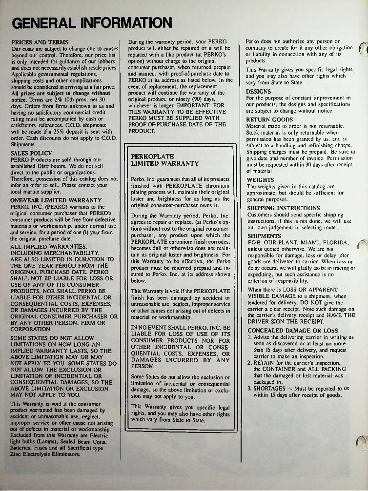
GENERAL INFORMATIONPcrko docs not authorize any person or company to create for it any other obligation f 1 or liability in connection with any of its ’products.This Warranty gives you specific legal rights, and you may also have other rights which vary from State to State.DESIGNSFor the purpose of constant improvement in our products, the designs and specifications arc subject to change without notice.RETURN GOODSMaterial made to order is not returnable.Stock material is only returnable when permission has been granted by us, and is subject to a handling and rcfinishing charge. Shipping charges must be prepaid. Be sure to give date and number of invoice. Permission must be requested within 30 days after receipt of material.WEIGHTSThe weights given in this catalog arc approximate, but should be sufficient for general purposes.SHIPPING INSTRUCTIONS Customers should send specific shipping instructions, if this is not done, we will use our own judgement in selecting route.SHIPMENTSF.O.B. OUR PLANT. MIAMI, FLORIDA unless quoted otherwise. We arc not responsible for damage, loss or delay after goods arc delivered to carrier. When loss or delay occurs, we will gladly assist in tracing or expediting, but such assistance is no criterion of responsibility.When there is LOSS OR APPARENT VISIBLE DAMAGE to a shipment, when tendered for deliver}'. DO NOT give the carrier a clear receipt. Note such damage on the carrier’s delivery receipt and HAVE THE DRIVER SIGN THE RECEIPT.CONCEALED DAMAGE OR LOSS1. Advise the delivering carrier in writing as
soon as discovered or at least no more than 15 days after delivery, and request carrier to make an inspection.
2. RETAIN for the carrier’s inspection, the CONTAINER and ALL PACKING that the damaged or lost material was packaged in.
3. SHORTAGES — Must be reported to us within 15 days after receipt of goods.
During the warranty period, your PERKO product will either be repaired or it will be replaced with a like product (at PERKO’s option) without charge to the original consumer purchaser, when returned prepaid and insured, with proof-of-purchasc date to PERKO at its address as listed below. In the event of replacement, the replacement product will continue the warranty of the original product, or ninety (90) days, whichever is longer. IMPORTANT: FOR THIS WARRANTY TO BE EFFECTIVE PERKO MUST BE SUPPLIED WITH PROOF-OF-PURCHASE DATE OF THE PRODUCT.
PRICES AND TERMSOur costs are subject to change due to causes beyond our control. Therefore, our price list is only intended for guidance of our jobbers and does not necessarily establish resale prices. Applicable governmental regulations, shipping costs and other complications should be considered in arriving at a fair price. All prices are subject to change without notice. Terms are 2% 10th prox. net 30 days. Orders from firms unknown to us and having no satisfactory commercial credit rating must be accompanied by cash or satisfactory' references. C.O.D. shipments will be made if a 25% deposit is sent with order. Cash discounts do not apply to C.O.D. Shipments.SALES POLICYPERKO Products are sold through our established Distributors. We do not sell direct to the public or organizations. Therefore, possession of this catalog does not infer an offer to sell. Please contact your local marine supplier.ONE-YEAR LIMITED WARRANTY PERKO, INC. (PERKO) warrants to the original consumer purchaser that PERKO’s consumer products will be free from defective materials or workmanship, under normal use and sendee, for a period of one (1) year from the original purchase date.ALL IMPLIED WARRANTIES,INCLUDING MERCHANTABILITY,ARE ALSO LIMITED IN DURATION TO THE ONE YEAR PERIOD FROM THE ORIGINAL PURCHASE DATE. PERKO SHALL NOT BE LIABLE FOR LOSS OR USE OF ANY OF ITS CONSUMER PRODUCTS. NOR SHALL PERKO BE LIABLE FOR OTHER INCIDENTAL OR CONSEQUENTIAL COSTS, EXPENSES, OR DAMAGES INCURRED BY THE ORIGINAL CONSUMER PURCHASER OR BY ANY OTHER PERSON, FIRM OR CORPORATION.SOME STATES DO NOT ALLOW LIMITATIONS ON HOW LONG AN IMPLIED WARRANTY LASTS, SO THE ABOVE LIMITATION MAY OR MAY NOT APPLY TO YOU. SOME STATES DO NOT ALLOW THE EXCLUSION OR LIMITATION OF INCIDENTAL OR CONSEQUENTIAL DAMAGES, SO THE ABOVE LIMITATION OR EXCLUSION MAY NOT APPLY TO YOU.This Warranty is void if the consumer product warranted has been damaged by accident or unreasonable use, neglect, improper service or other cause not arising out of defects in material or workmanship. Excluded from this Warranty are Electric light bulbs (Lamps), Sealed Beam Units, Batteries. Fuses and all Sacrificial type Zinc Electrolysis Eliminators.
PERKOPLATE LIMITED WARRANTY
Perko, Inc. guarantees that all of its products finished with PERKOPLATE chromium plating process will maintain their original luster and brightness for as long as the original consumer-purchaser owns it.
During the Warranty period, Perko, Inc. agrees to repair or replace, (at Pcrko’s option) without cost to the original consumer- purchaser, any product upon which the PERKOPLATE chromium finish corrodes, becomes dull or otherwise does not maintain its original luster and brightness. For this Warranty to be effective, the Perko product must be returned prepaid and insured to Perko, Inc. at its address shown below.
This Warranty is void if the PERKOPLATE finish has been damaged by accident or unreasonable use, neglect, improper service or other causes not arising out of defects in material or workmanship.
IN NO EVENT SHALL PERKO, INC. BE LIABLE FOR LOSS OF USE OF ITS CONSUMER PRODUCTS NOR FOR OTHER INCIDENTAL OR CONSEQUENTIAL COSTS, EXPENSES, OR DAMAGES INCURRED BY ANY PERSON.
Some States do not allow the exclusion or limitation of incidental or consequential damage, so the above limitation or exclusion may not apply to you.
This Warranty gives you specific legal rights, and you may also have other rights which vary from State to State.
• c
v7;
SECTION A11^;-..:
’. ’
• • ?4* J:Si
.
■
V-*<
. ■
.
it'-:
!•:. f® •*5
v
%
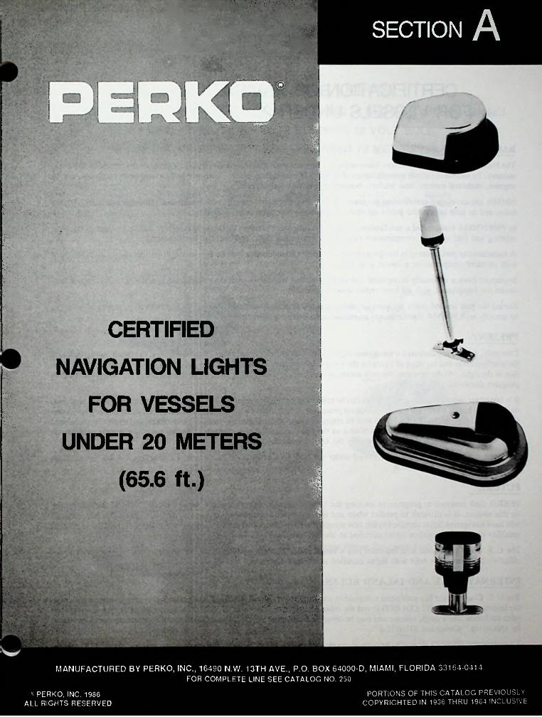
CERTIFIED
NAVIGATION LIGHTS
FOR VESSELS:C'T
. ,'•••'• V.-m &
■ ■
■
UNDER 20 METERS■
'
(65.6 ft.).
MANUFACTURED BY PERKO, INC., 16490 N.W. 13TH AVE., P.O. BOX 64000-D, MIAMI, FLORIDA 33164-0414FOR COMPLETE LINE SEE CATALOG NO. 250
PORTIONS OF THIS CATALOG PREVIOUSLY COPYRIGHTED IN 1936 THRU 19S4 INCLUSIVE
3 PERKO, INC. 1986 ALL RIGHTS RESERVED
A-2
1CERTIFICATION OF NAVIGATION LIGHTS
FOR VESSELS UNDER 20 METERS (65.6 Ft.)
BACKGROUNDThe National Marine Manufacturers Association is a national trade association serving all elements of the recreational boating industry. Its members include manufacturers of all types of boating equipment - outboard and inboard boats, sailboats, marine engines, outboard motors, boat trailers, boating accessories and supplies.NMMA has developed certification programs to help manufacturers comply with established standards and safety regulations, and to help inform the public of such compliance when purchasing equipment.In 1968 NMMA inaugurated a certification program for boat manufacturers including horsepower and load capacity, flotation, steering and fuel systems, compartment ventilation, navigation lights and backfire flame control.
A manufacturer participating in this program must certify all models less than 26 feet in length (except racing boats) as fitted with standard equipment on a model year basis.Inspectors from a nationally recognized independent testing laboratory visit the manufacturer, and physically inspect each model for compliance with all boat certification standards.During the past several years we have devoted a great deal of time and expense to field and laboratory testing in an effort to comply with NMMA standards and to enable us to certify accordingly.
PRESENTCurrently, federal regulations for navigation lights on vessels under 20 meters are split. The U.S.C.G. regulates and enforces the configuration and carriage of lights on the vessel, but industry standards regulate the design, manufacture, and certification of the lights. At the moment, the only means of certification widely recognized in the United States is through the NMMA program discussed above.It is important to note that navigation lights can be tested and certified to meet the 72 COLREGS in a foreign country, however, each country has its own testing and certification procedure, which differs from the U.S. procedure. This means that a navigation light certified to meet the 72 COLREGS may be referring to approvals granted by another government, and cannot be recognized by the USCG for U.S. vessels until such time as the light passes the U.S. Standard. At this time, our government has no plans to accept foreign approvals as meeting the U.S. Standard.Our navigation lights presently are certified under the NMMA Certification Procedure. The marking “A-16” on the light fixture indicates this certification.
FUTURE
PERKO shall continue to progress in meeting the latest standards. Due to the somewhat volatile nature of the rulemaking on this subject, it is difficult to predict when and in what exact form new regulations will appear. Once this happens, we will have navigation lights certified to the new standard well in advance of the “effective dates” (the dates that the regulation specifies that only navigation lights certified to the new standard may be installed on a vessel).
The U.S. Coast Guard has also indicated that a vessel under 20 meters which was fitted with navigation lights prior to the effective date, need not refit with lights certified to the new standard.
INTERNATIONAL AND INLAND RULESThe U.S. Coast Guard has published rulemaking covering the technical details of navigation lights in accordance with both the International Rules (72 COLREGS) and the Inland Navigation Rules Act of 1980 (Public Law 96-591). These navigation rules are bound into a single volume and may be obtained from either the U.S. Coast Guard or the Superintendent of Documents by specifying “Comdtinst M16672.2”.
To summarize, PERKO is, and will continue, to manufacture navigation lights that meet all current and future U.S. regula- 'iTeff^cfat^the^Ime513 at,°n °^a current mo<^e* PERKO navigation lights will assure the meeting of the U.S. regulation
rm]\ ALL UCHTS OH / \ THIS PACE HOW / \ AVAILABLE M /
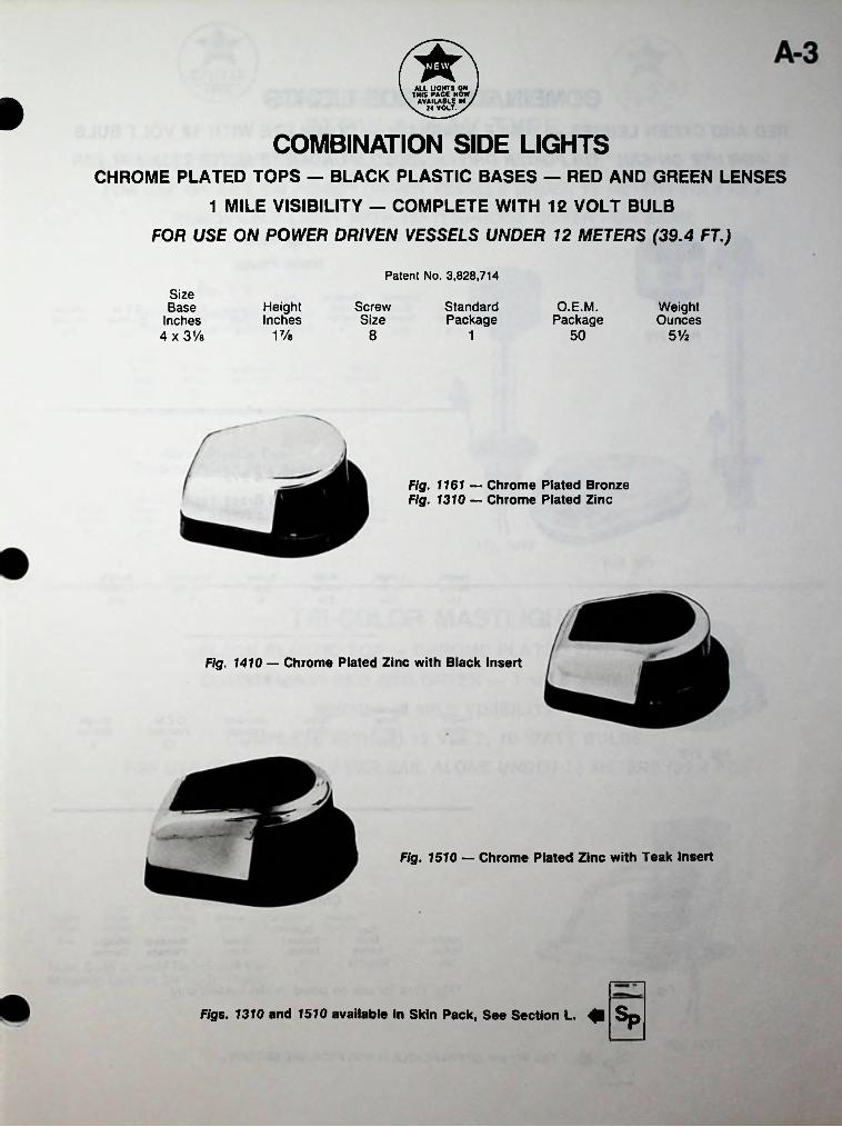
U VOLT./iCOMBINATION SIDE LIGHTS
CHROME PLATED TOPS — BLACK PLASTIC BASES — RED AND GREEN LENSES
1 MILE VISIBILITY — COMPLETE WITH 12 VOLT BULB
FOR USE ON POWER DRIVEN VESSELS UNDER 12 METERS (39.4 FT.)
Patent No. 3,828,714Size Base
Inches 4 x 3Ve
ScrewSize
StandardPackage
O.E.M.Package
HeightInches
WeightOunces
1 Vs 8 50 5V21
Fig. 1161 — Chrome Plated Bronze Fig. 1310 — Chrome Plated Zinc
Fig. 1410 — Chrome Plated Zinc with Black Insert
Fig. 1510 — Chrome Plated Zinc with Teak Insert
Figs. 1310 and 1510 available in Skin Pack, See Section L. Sp
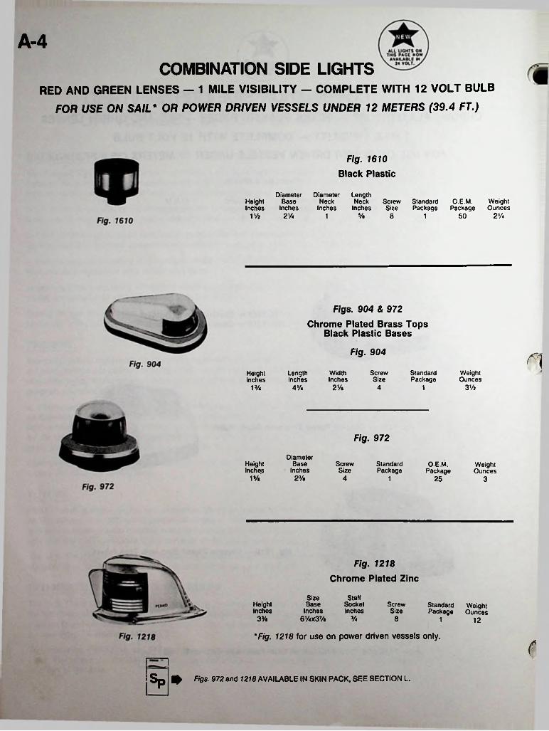
A-4COMBINATION SIDE LIGHTS
RED AND GREEN LENSES — 1 MILE VISIBILITY — COMPLETE WITH 12 VOLT BULB
FOR USE ON SAIL* OR POWER DRIVEN VESSELS UNDER 12 METERS (39.4 FT.)
Fig. 1610 Black Plastic
DiameterNeck
Inches
DiameterBase
Inches
LengthNeck Screw Standard
Inches Size PackageHeightInches
O.E.M. Weight Package Ounces
V/i 2'A V» 8 2'A501 1
Figs. 904 & 972
Chrome Plated Brass Tops Black Plastic Bases
Fig. 904
ScrewSize
StandardPackage
WeightOunces
LengthInches
WidthInches
HeightInches
2'A 3'AVA 4 'A 4 1
Fig. 972
DiameterBase
InchesO.E.M.
PackageScrewSize
HeightInches
StandardPackage
WeightOunces
VA 2 % 4 1 25 3
Fig. 1218Chrome Plated Zinc
SizeBase
Inches61/4X3%
StaffHeightInches
SocketInches
ScrewSize
StandardPackage
WeightOunces
3% 3/4 8 1 12
'Fig. 1218 for use on power driven vessels only.
fsp* Figs. 972 and 1218 AVAILABLE IN SKIN PACK, SEE SECTION L.
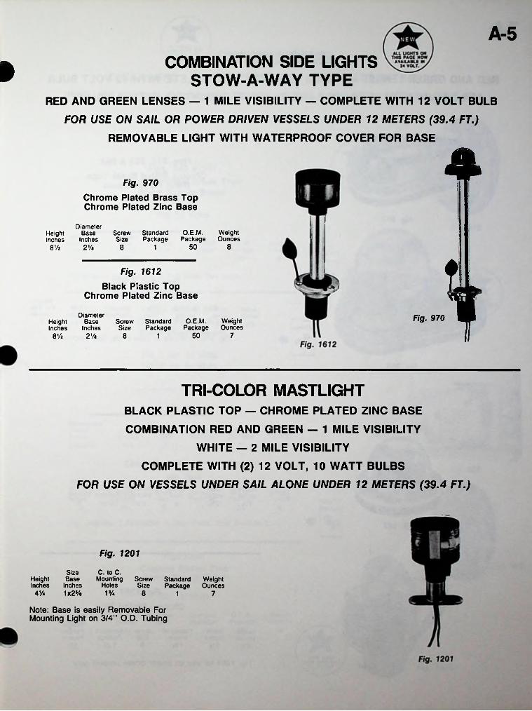
A-5COMBINATION SIDE LIGHTS
STOW-A-WAY TYPERED AND GREEN LENSES — 1 MILE VISIBILITY — COMPLETE WITH 12 VOLT BULB
FOR USE ON SAIL OR POWER DRIVEN VESSELS UNDER 12 METERS (39.4 FT.) REMOVABLE LIGHT WITH WATERPROOF COVER FOR BASE
»
4Fig. 970Chrome Plated Brass Top Chrome Plated Zinc Base
DiameterBase
InchesO.E.M. Weight
Package OuncesScrew Standard Size Package
HeightInches
50 88Vj 2Va 8 1
TFig. 1612
Black Plastic Top Chrome Plated Zinc Base
DiameterBase
InchesFig. 970O.E.M. Weight
Package OuncesScrew Standard Size Package
HeightInches
50 788% 2Ve 1
TRI-COLOR MASTLIGHTBLACK PLASTIC TOP — CHROME PLATED ZINC BASE
COMBINATION RED AND GREEN — 1 MILE VISIBILITY
WHITE — 2 MILE VISIBILITY
COMPLETE WITH (2) 12 VOLT, 10 WATT BULBS
FOR USE ON VESSELS UNDER SAIL ALONE UNDER 12 METERS (39.4 FT.)
Fig. 1201
SizeBase
Inches1x25/a
C. to C. Mounting
HolesHeightInches
Screw Standard Weight Size Package Ounces
41A VA 8 71
Note: Base is easily Removable For Mounting Light on 3/4" O.D. Tubing
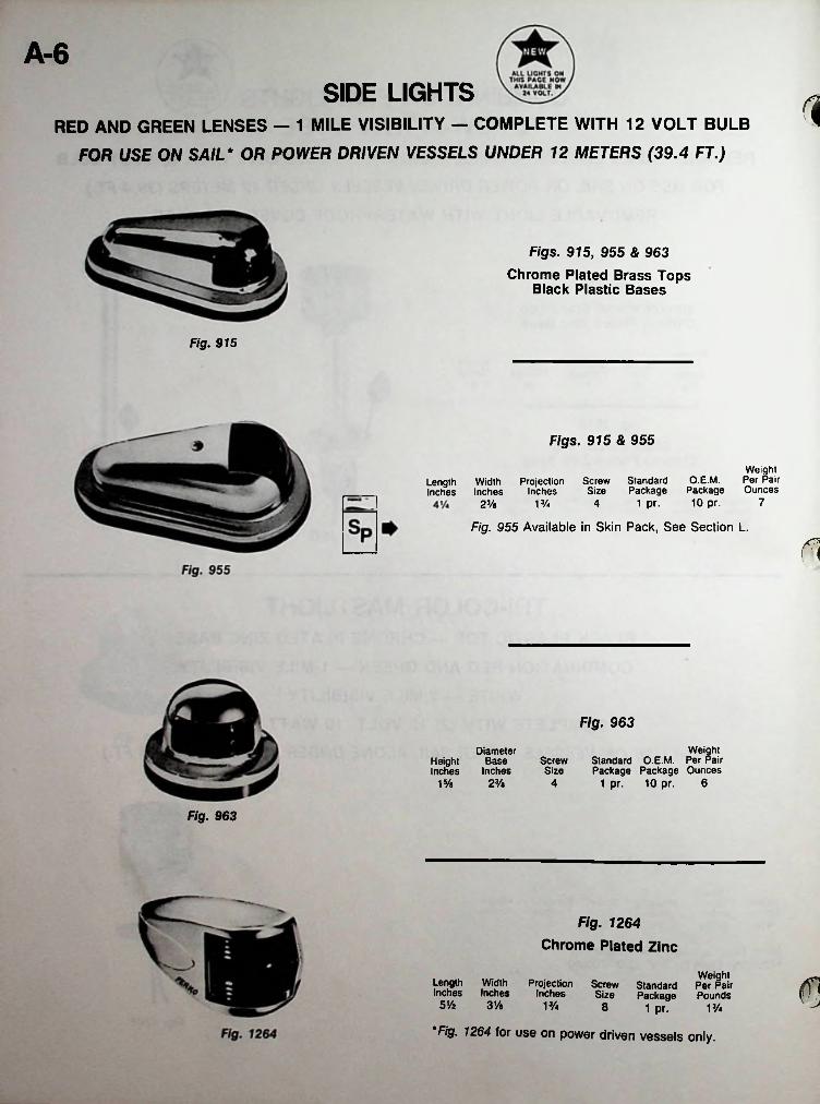
A-6SIDE LIGHTS
RED AND GREEN LENSES - 1 MILE VISIBILITY - COMPLETE WITH 12 VOLT BULB
FOR USE ON SAIL* OR POWER DRIVEN VESSELS UNDER 12 METERS (39.4 FT.)
1
Figs. 915, 955 & 963Chrome Plated Brass Tops
Black Plastic Bases
Fig. 915
Figs. 915 & 955
Weight PairO.E.M. Per
Package Ounces 10 pr.
Screw Standard Size Package
1 pr.
Length Width ProjectionInches Inches Inches
713/4 423/a
Fig. 955 Available in Skin Pack, See Section L.
Fig. 963
WeightStandard O.E.M. Per Pair Package Package Ounces
1 pr. 10 pr. 6
DiameterBase
InchesScrewSize
HeightInches
2% 415/a
Fig. 963
Fig. 1264Chrome Plated Zinc
WeightScrew Standard Per PairSize Package Pounds
1 pr.
Fig. 1264 for use on power driven vessels only.
Length WidthInches Inches
5Vz 31/e
ProjectionInches
13/4 8 13/4

A-7STERN LIGHTS
CLEAR LENS — 2 MILE VISIBILITY — COMPLETE WITH BULB
FOR USE ON SAIL OR POWER DRIVEN VESSELS UNDER 20 METERS (65.6 FT.)
»
IFigs. 945 & 965 Chrome Plated Brass Tops
Black Plastic Bases
For 12 VoltsFig. 945
DiameterBase
Inches
Height(Projection)Inches
O.E.M.Package
WeightOunces
StandardPackage
ScrewSize
25 323/e 4 115/e
These items are available in Skin Pack, See Section L.
Figs. 939 & 946 Chrome Plated Brass Black Plastic Bases Fig. 965
No. 1 for 12 Volts No. 3 for 32 Volts
Fig. 939DimensionsOverallInches53/i*x33/*
WeightOunces
O.E.M.StandardScrewDepthInches PackagePackageSize
6208Vh 1
Fig. 939Fig. 946
O.E.M. WeightOunces
StandardScrewDepthInches
DiameterInches PackageSize Package
25 413/4 8 13
Fig. 946 No. 1 Available in Skin Pack, See Section L.
Fig. 1332Fig. 946Chrome Plated Zinc
Black Plastic Base
For 12 Volts
O.E.M. WeightStandardScrewWidthInches
HeightInches33/4
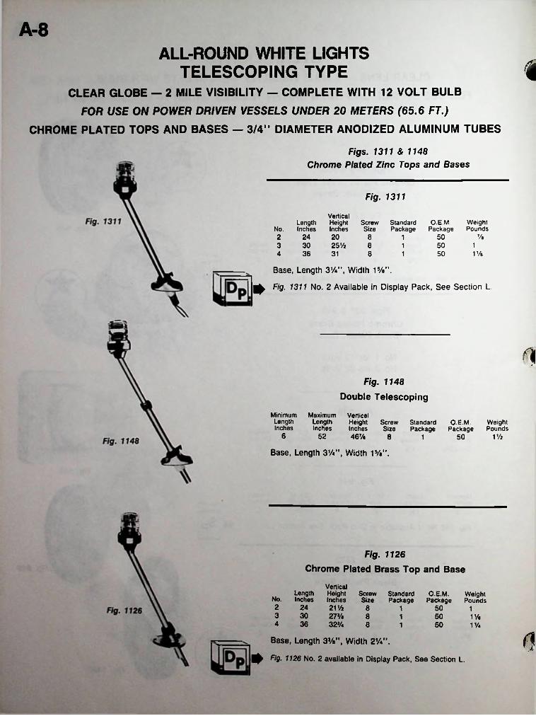
A-8ALL-ROUND WHITE LIGHTS
TELESCOPING TYPECLEAR GLOBE — 2 MILE VISIBILITY — COMPLETE WITH 12 VOLT BULB
FOR USE ON POWER DRIVEN VESSELS UNDER 20 METERS (65.6 FT.)CHROME PLATED TOPS AND BASES — 3/4” DIAMETER ANODIZED ALUMINUM TUBES
i
Figs. 1311 & 1148Chrome Plated Zinc Tops and Bases
Fig. 1311
VerticalLength Height Screw Standard
No. Inches Inches Size PackageO.E.M. Weight
Package Pounds%2 24 20 508 1
3 30 25% 8 501 1314 36 8 50 1 Vs1
Base, Length 31/4,,1 Width 15/a”.
^ Fig. 1311 No. 2 Available in Display Pack, See Section L.
<1Fig. 1148
Double Telescoping
MinimumLengthInches
Maximum VerticalLength Height Screw Standard O.E.M. WeightInches Inches Size Package Package Pounds
46%6 52 1 Vi8 501
Base, Length 3W\ Width 1%".
Fig. 1126
Chrome Plated Brass Top and Base
Vertical Length HeightInches Inches
24 21%30 27%36 323/4
Screw Standard Size Package
O.E.M.Package
WeightPoundsNo.
2 8 501 13 8 501 1%4 8 501 1V4
dBase, Length 3%”, Width 21/4M.
Fig. 1126 No. 2 available in Display Pack, See Section L.
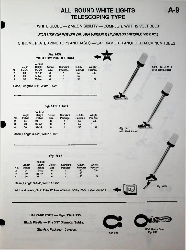
A-9ALL-ROUND WHITE LIGHTS
TELESCOPING TYPEI WHITE GLOBE — 2 MILE VISIBILITY — COMPLETE WITH 12 VOLT BULB
FOR USE ON POWER DRIVEN VESSELS UNDER 20 METERS (65.6 FT.)
CHROME PLATED ZINC TOPS AND BASES — 3/4" DIAMETER ANODIZED ALUMINUM TUBES
Fig. 1401WITH LOW PROFILE BASE
VerticalHeight Screw Inches Size20-1/2 827-3/433-3/4 8
Figs. 1401 & 1411StandardPackage
O.E.M.Package
WeightPounds
Length No. Inches with Black insert
50 7/81242501 13 30 8
1 50 1-1/8364
Base, Length 3-3/4", Width 1-1/2".
Fig. 1411 & 1511
VerticalHeightInches
O.E.M. Weight Package Pounds
StandardPackage
Length No. Inches
ScrewSize
50 7/824 21 12 8ft 50 13 30 26-3/432-1/2
8 150 1-1/84 36 18 Fig. 1511
with Teak InsertBase, Length 3-1/2", Width 1-1/2".
Fig. 1611
VerticalHeight Screw StandardInches Size Package19-1/2 825-1/4 8
O.E.M. Weight Package Pounds
Length No. Inches
7/85024 1250 13 30 150 1-1/84 36 31 18
Base, Length 3-1/4", Width 1 -5/8".
All the above lights in Size #2 Available in Display Pack. See Section L.Fig. 1611
HALYARD EYES — Figs. 234 & 235
Black Plastic — Fits 3/4" Diameter Tubing
Standard Package, 10 pieces. With Brass Snap Fig. 235Fig. 234

ALL-ROUND WHITE LIGHTS
STOW-A-WAY TYPEA-10
iCLEAR OR WHITE GLOBE — 2 MILE VISIBILITY — COMPLETE WITH 12 VOLT BULB
FOR USE ON POWER DRIVEN VESSELS UNDER 20 METERS (65.6 FT.)
CHROME PLATED TOPS AND BASES — 3/4" ANODIZED ALUMINUM TUBES
REMOVABLE LIGHT WITH WATERPROOF COVER FOR BASE
Fig. 1330 & 1630Chrome Plated Zinc Tops and Bases
Fig. 1330
Fig. 1330 VerticalHeight Screw Standard O.E.M. WeightInches Size Package Package Pounds
Length No. Inches2 24 19 8 1 50 13 30 25-1/2 8 1 50 1-1/84 36 31 18 50 1-1/4
Base, Length 3-1/4", Width 1-5/8".
Fig. 1630
VerticalHeightInches
Fig. 1630 Length No. Inches
ScrewSize
StandardPackage
O.E.M. Weight Package Pounds a242 19 8 1 50 1
3 30 25-1/2 8 1 50 1-1/8 *•4 36 31 8 1 50 1-1/46 48 43 8 1 50 1-1/27 54 47-1/2 8 1 50 1-5/8
Base, Length 3-1/4", Width 1-5/8".
Fig. 1209Chrome Plated Brass Top and Base
VerticalHeightInches20-1/227-1/432-3/4
Length No. Inches
ScrewSize
StandardPackage
O.E.M. Weight Package Pounds
2 24 8 1 50 13 30 8 1 50 1-1/4Fig.12094 36 8 1 50 1-1/2
Base, Length 3-3/8", Width 2-1/4".
All the above lights in Size #2 Available in Display Pack. See Section L.
Fig. 1631Chrome Plated Zinc Top and Base
VerticalHeight Screw Standard O.E.M. WeightInches Size Package Package Pounds
jrLength
No. Inches5 <n42 41 8 1 1-3/8506 48 47 8 1 1-1/250
TBase, Diameter 2-1/8".
Fig. 1631
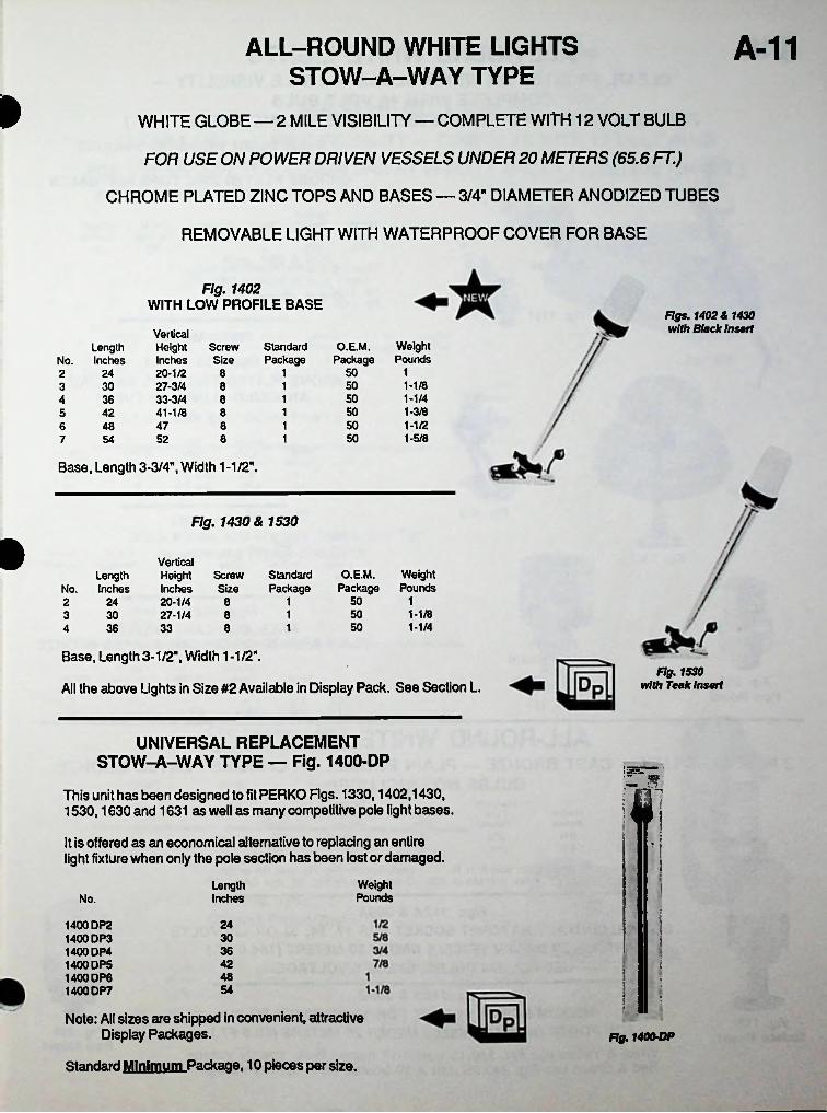
A-11ALL-ROUND WHITE LIGHTS
STOW-A-WAY TYPE»
WHITE GLOBE — 2 MILE VISIBILITY — COMPLETE WITH 12 VOLT BULB
FOR USE ON POWER DRIVEN VESSELS UNDER 20 METERS (65.6 FT.)
CHROME PLATED ZINC TOPS AND BASES — 3/4" DIAMETER ANODIZED TUBES
REMOVABLE LIGHT WITH WATERPROOF COVER FOR BASE
Fig. 1402WITH LOW PROFILE BASE
Figs. 1402 A 1430 with Black InsertVertical
Height Screw Inches Size20-1/2 827-3/4 833-3/4 841-1/8
O.E.M.Package
WeightPounds
StandardPackage
LengthInchesNo.
150124250 1-1/8130350 1-1/414 3650 1-3/8185 4250 1-1/2147 86 4850 1-5/8154 52 87
Base, Length 3-3/4", Width 1 -1/2".
Fig. 1430 & 1530
»VerticalHeight Screw Inches Size20-1/4 827-1/4 8
Standard O.E.M. WeightPackage Package Pounds
Length No. Inches
50 112421-1/81 503 30
50 1-1/414 36 33 8
Base, Length 3-1/2", Width 1-1/2".
All the above Lights in Size #2 Available in Display Pack. See Section L.Fig. 1530
with Teak Insert
UNIVERSAL REPLACEMENT STOW-A-WAY TYPE — Fig. 1400-DP
This unit has been designed to fit PERKO Figs. 1330,1402,1430,1530,1630 and 1631 as well as many competitive pole light bases.
'I »
ifl'It is offered as an economical alternative to replacing an entire light fixture when only the pole section has been lost or damaged.
Weight Pounds
?
LengthInchesNo.
.241400 DP2 1400 DP3 1400 DP4 1400 DPS 1400 DP6 1400 DP7
303642 i48 i54 :
l-Note: All sizes are shipped in convenient, attractive Display Packages.
Standard Minimum Package. 10 pieces per size.
Fig. 1400-DP
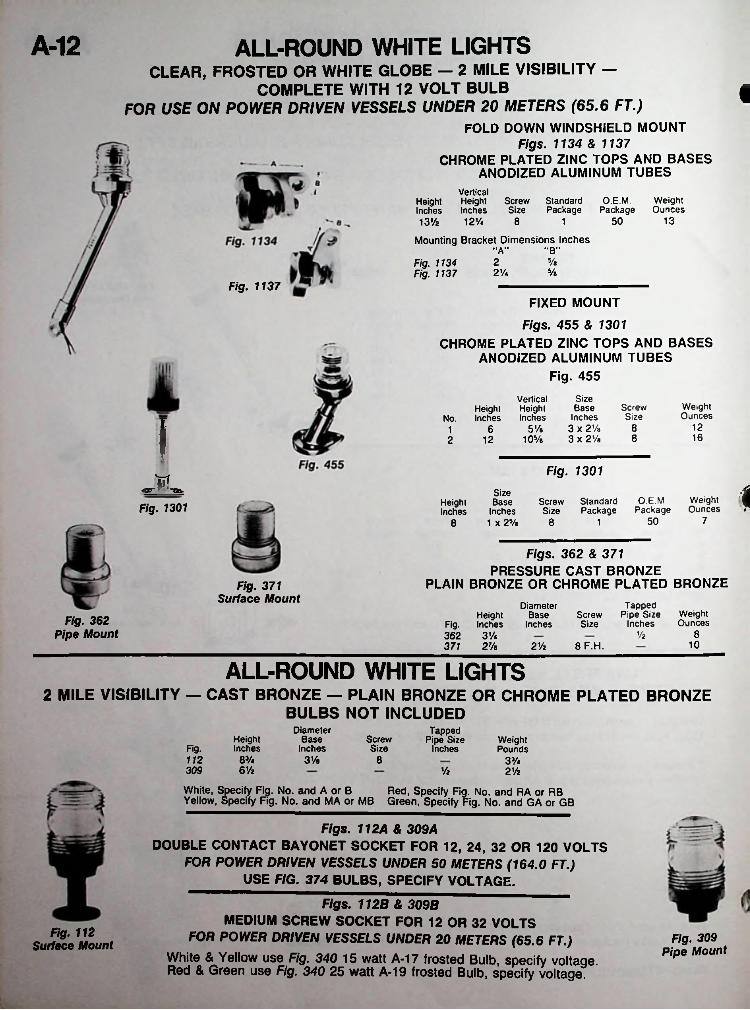
A-12 ALL-ROUND WHITE LIGHTSCLEAR, FROSTED OR WHITE GLOBE — 2 MILE VISIBILITY —
COMPLETE WITH 12 VOLT BULBFOR USE ON POWER DRIVEN VESSELS UNDER 20 METERS (65.6 FT.)
FOLD DOWN WINDSHIELD MOUNT Figs. 1134 & 1137
CHROME PLATED ZINC TOPS AND BASES ANODIZED ALUMINUM TUBES
I
VerticalHeight Height Screw StandardInches Inches Size Package13% 12%
O.E.M. Weight Package Ounces
13508 1
Mounting Bracket Dimensions Inches“B""A”
5/e2Fig. 1134 Fig. 1137 5/e2%
Fig. 1137FIXED MOUNT
Figs. 455 & 1301CHROME PLATED ZINC TOPS AND BASES
ANODIZED ALUMINUM TUBES Fig. 455
Size Base
Inches 3 x 2% 3 x 2%
Vertical Height Height
No. Inches InchesWeightOunces
ScrewSize
I 1285%6116810Va122
Fig. 1301iW
«gr ‘ta. ISize Base
Inches 1 X 25/e
O.E.M Weight Package Ounces
Screw Standard Size Package
HeightInchesFig. 1301
7508 18
Figs. 362 & 371PRESSURE CAST BRONZE
PLAIN BRONZE OR CHROME PLATED BRONZEFig. 371 Surface Mount Tapped
Pipe Size Inches
DiameterBase
InchesWeightOunces
ScrewSize
Height Fig. Inches 362 3%371 2V»
Fig. 362 Pipe Mount 8%
108 F.H.21/z
ALL-ROUND WHITE LIGHTS2 MILE VISIBILITY — CAST BRONZE — PLAIN BRONZE OR CHROME PLATED BRONZE
BULBS NOT INCLUDEDDiameter
BaseInches
Tapped Pipe Size
InchesScrewSize
HeightInches
WeightPoundsFig.
8%112 3% 8 3%309 61/2 % 2%
White, Specify Fig. No. and A or B Red, Specify Fig. No. and RA or RB Yellow, Specify Fig. No. and MA or MB Green, Specify Fig. No. and GA or GB
Figs. 112A & 309ADOUBLE CONTACT BAYONET SOCKET FOR 12, 24, 32 OR 120 VOLTS
FOR POWER DRIVEN VESSELS UNDER 50 METERS (164.0 FT.)USE FIG. 374 BULBS, SPECIFY VOLTAGE.
Figs. 112B & 309BMEDIUM SCREW SOCKET FOR 12 OR 32 VOLTS
FOR POWER DRIVEN VESSELS UNDER 20 METERS (65.6 FT.)White & Yellow use Fig. 340 15 watt A-17 frosted Bulb, specify voltage. Red & Green use Fig. 340 25 watt A-19 frosted Bulb, specify voltage.
Fig. 112 Surface Mount Fig. 309
Pipe Mount
■
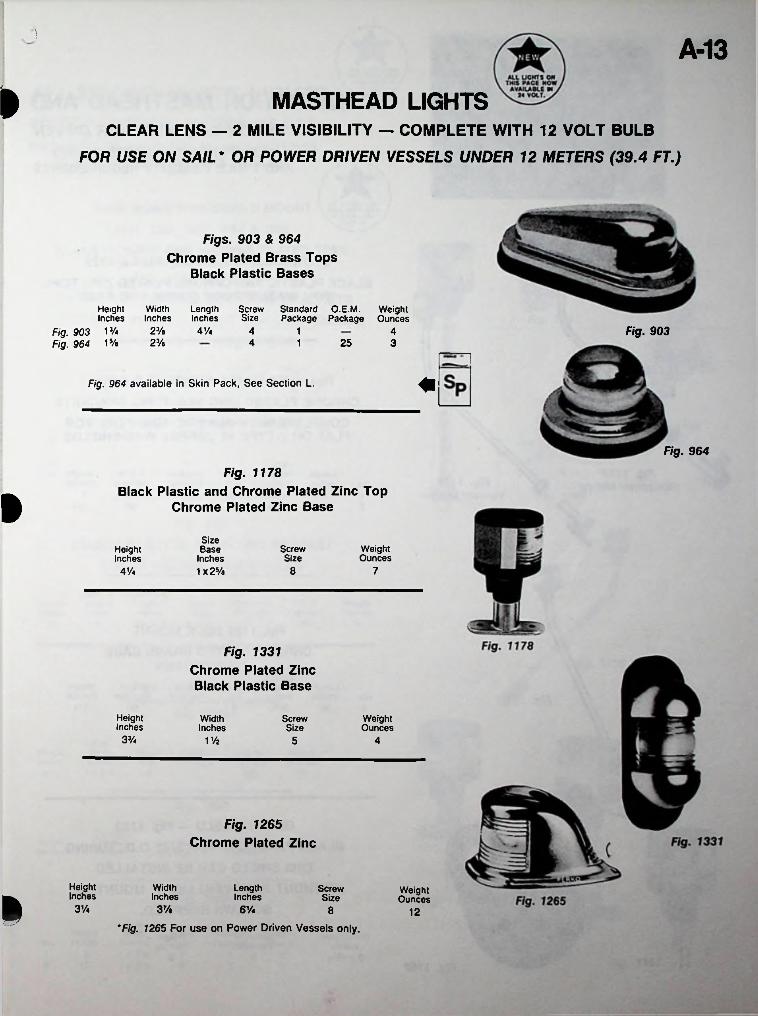
A-13» MASTHEAD LIGHTS
CLEAR LENS - 2 MILE VISIBILITY — COMPLETE WITH 12 VOLT BULB
FOR USE ON SAIL* OR POWER DRIVEN VESSELS UNDER 12 METERS (39.4 FT.)
Figs. 903 & 964 Chrome Plated Brass Tops
Black Plastic Bases
Screw Standard O.E.M. Weight Size Package Package Ounces
HeightInches
Fig. 903 13/« Fig. 964 15/a
WidthInches
LengthInches
Fig. 90323/b 4% 4 1 423/« 4 25 31
Fig. 964 available in Skin Pack, See Section L.
Fig. 964
Fig. 1178Black Plastic and Chrome Plated Zinc Top
Chrome Plated Zinc BaseiSize Base
Inches 1 x 2Vb
ScrewSize
WeightOunces
HeightInches4% 8 7
Fig. 1331Chrome Plated Zinc Black Plastic Base
HeightInches
WidthInches
ScrewSize
WeightOunces
3% V/2 5 4
Fig. 1265Chrome Plated Zinc
HeightInches
WidthInches
LengthInches
ScrewSize
WeightOuncesI 3Va 37/« 6 Vi 8 12
'Fig. 1265 For use on Power Driven Vessels only.
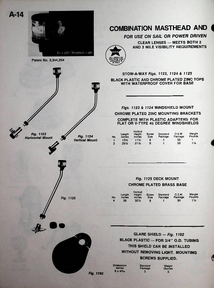
COMBINATION MASTHEAD AND {FOR USE ON SAIL OR POWER DRIVEN
CLEAR LENSES — MEETS BOTH 2 AND 3 MILE VISIBILITY REQUIREMENTS
V ALL UCHTS ON / \ THIS PACE NOW / \ AVAILABLE IN /N^volY/
As a 225° Masthead Light
Patent No. 3,344,264
STOW-A-WAY Figs. 1123, 1124 & 1125BLACK PLASTIC AND CHROME PLATED ZINC TOPS
WITH WATERPROOF COVER FOR BASE
Figs. 1123 & 1124 WINDSHIELD MOUNTCHROME PLATED ZINC MOUNTING BRACKETS
COMPLETE WITH PLASTIC ADAPTERS FOR FLAT OR V-TYPE 45 DEGREE WINDSHIELDS
VerticalHeight Screw StandardInches Size Package11 Va 8211/e 8
OEM. Weight Package Pounds
Fig. 1123 Length Inches 13V2 26 Vi
Fig. 1124 Vertical Mount
No.Horizontal Mount50 111 41V45012
Fig. 1125 DECK MOUNT CHROME PLATED BRASS BASE
VerticalLength Height Screw StandardInches Inches Size Package
36 32Va 8
O.E.M. Weight Package PoundsNo.
1V&504 1
GLARE SHIELD - Fig. 1192 BLACK PLASTIC — FOR 3/4” O.D. TUBING
THIS SHIELD CAN BE INSTALLED WITHOUT REMOVING LIGHT. MOUNTING
SCREWS SUPPLIED. tDimensions
Inches 6 X 4Vie
StandardPackage
WeightOunces
5 3Fig. 1192
nAhV ALL UGHTS ON / \ THIS PAGE NOW / \ AVAILABLE IN / \^2« VOLT^/
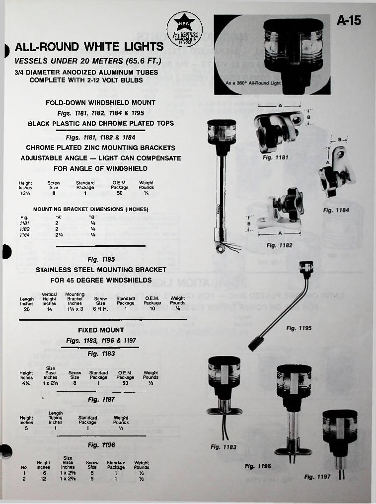
A-15
ALL-ROUND WHITE LIGHTS>
VESSELS UNDER 20 METERS (65.6 FT.)3/4 DIAMETER ANODIZED ALUMINUM TUBES
COMPLETE WITH 2-12 VOLT BULBS
FOLD-DOWN WINDSHIELD MOUNT Figs. 1181, 1182, 1184 & 1195
BLACK PLASTIC AND CHROME PLATED TOPS
A
Figs. 1181, 1182 & 1184CHROME PLATED ZINC MOUNTING BRACKETS
ADJUSTABLE ANGLE — LIGHT CAN COMPENSATE FOR ANGLE OF WINDSHIELD
OEM.Package
WeightPounds
ScrewSize
StandardPackage
HeightInchesl3Va 50 3/«8 1
SMOUNTING BRACKET DIMENSIONS (INCHES) S"B""A"Fig.
5/a211812 Va1182
Va2%1184
I Fig. 1195STAINLESS STEEL MOUNTING BRACKET
FOR 45 DEGREE WINDSHIELDS
Mounting Bracket Inches 13/a X 3
Vertical Length Height Inches Inches
O.E.M. WeightPackage Pounds
Screw StandardSize Package
6 R.H. 1 Va101420
FIXED MOUNT Figs. 1183, 1196 & 1197
Fig. 1183
5Size Base
Inches 1 X 25/a
Screw Standard Size Package
O.E.M. WeightPackage Pounds
HeightInches
Vk8 504V4 1
Fig. 1197
LengthTubingInches
StandardPackage
WeightPounds
HeightInches
5 1 1 Vz
Fig. 1196
Size Base
Inches 1 X 25/a 1 X 25/a
Screw Standard Weight Size Package Pounds
Height No. Inches Fig. 1196
86 1 Vz1 Fig.12 8 Vz2 1
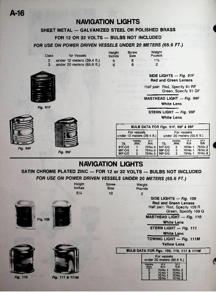
A-16NAVIGATION LIGHTS
SHEET METAL — GALVANIZED STEEL OR POLISHED BRASS
FOR 12 OR 32 VOLTS — BULBS NOT INCLUDED
FOR USE ON POWER DRIVEN VESSELS UNDER 20 METERS (65.6 FT.)Weight Pounds
<
ScrewSize
HeightInchesfor VesselsClass
2 under 12 meters (39.4 ft.)3 under 20 meters (65.6 ft.)
11/265266
SIDE LIGHTS — Fig. 91F Red and Green Lenses
Half pair: Red, Specify 91 RF Green, Specify 91 GF
MASTHEAD LIGHT — Fig. 98F White Lens
Fig. 9 IFSTERN LIGHT — Fig. 99F
White Lens
BULB DATA FOR Figs. 91F, 98F & 99FFor vessels
under 12 meters (39.4 ft.)For vessels
under 20 meters (65.6 ft.)32 V12 VVisibility
Miles
91F-C/2 198F-C/2 299F-C/2 2
12 V VisibilityMiles 4Bulbfig. BulbBulb Fig.
91F-C/3 2 70 No. 1 70 No. 298F-C/3 3 70 No. 1 70 No. 299F-C/3 2 70 No. 1 70 No. 2
70NO.070NO.070NO.0Fig. 99F
NAVIGATION LIGHTSSATIN CHROME PLATED ZINC — FOR 12 or 32 VOLTS — BULBS NOT INCLUDED
FOR USE ON POWER DRIVEN VESSELS UNDER 20 METERS (65.6 FT.)Height Inches
ScrewSize
WeightPounds
5Va 10 2SIDE LIGHTS — Fig. 109 Red and Green Lenses
Half pair: Red, Specify 109 R Green, Specify 109 G
MASTHEAD LIGHT — Fig. 110 White Lens
STERN LIGHT — Fig. 111 White Lens
TOWING LIGHT - Fig. 111M Yellow Lens
Fig. 109
BULB DATA FOR Figs. 109, 110, 111 & 111MFor vessels
under 20 meters (65.6 ft.) 4Visibility Miles
2 70 No. 1 70 No. 23 70 No. 1 70 No. 22 70NO.1 70 No. 22 70 No. 1 70 No. 2
12 V 32 VBulb Bulb
Fig. 111 8, 111M
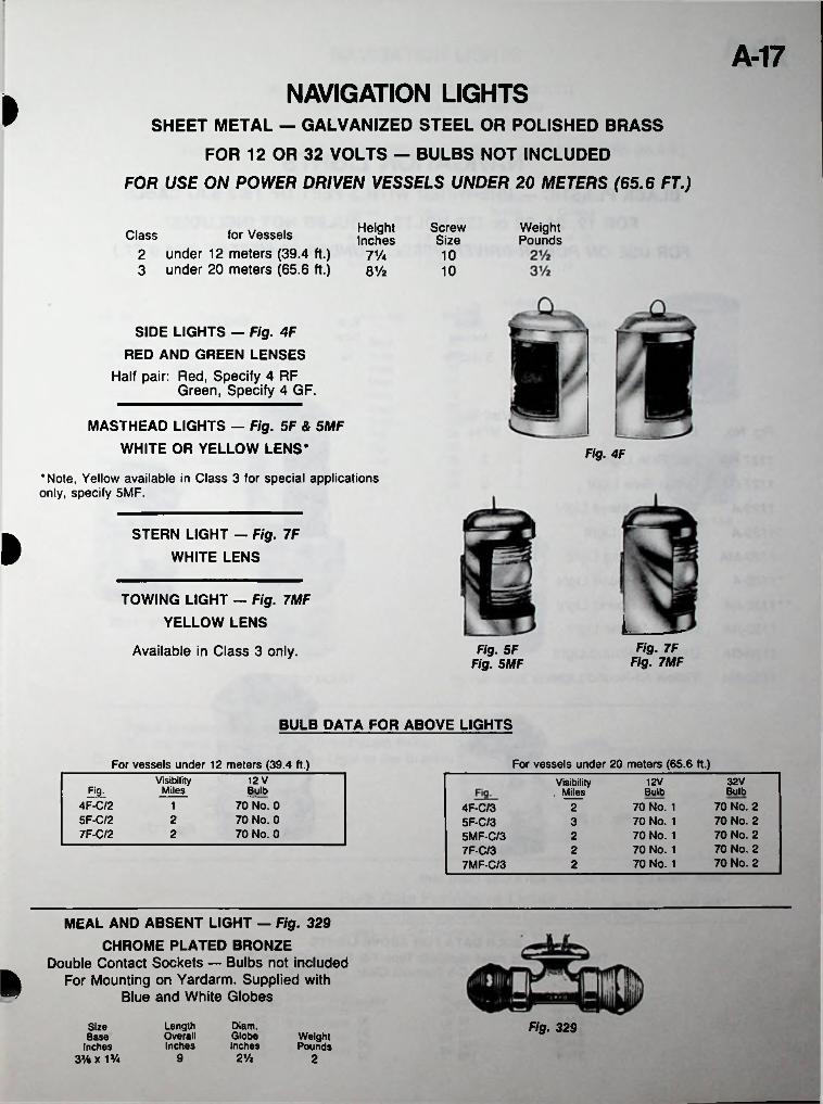
A-17NAVIGATION LIGHTSI SHEET METAL — GALVANIZED STEEL OR POLISHED BRASS
FOR 12 OR 32 VOLTS — BULBS NOT INCLUDED
FOR USE ON POWER DRIVEN VESSELS UNDER 20 METERS (65.6 FT.)
HeightInches
ScrewSize
WeightPoundsfor Vessels
2 under 12 meters (39.4 ft.)3 under 20 meters (65.6 ft.)
Class71/4 108V2 10
SIDE LIGHTS — Fig. 4FRED AND GREEN LENSES
Half pair: Red, Specify 4 RFGreen, Specify 4 GF.
MASTHEAD LIGHTS — Fig. 5F & 5MF WHITE OR YELLOW LENS* Fig. 4F
•Note, Yellow available in Class 3 for special applications only, specify 5MF.
ISTERN LIGHT — Fig. 7F WHITE LENSi
TOWING LIGHT — Fig. 7MF YELLOW LENS L
Fig. 7F Fig. 7MF
Fig. 5F Fig. 5MF
Available in Class 3 only.
BULB DATA FOR ABOVE LIGHTS
For vessels under 20 meters (65.6 ft.)For vessels under 12 meters (39.4 ft.)Visibility
Miles12 V 32V12VVisibility
, Milesfit Bulb BulbBulb4F-C/25F-C/27F-C/2
70 No. 0 70 No. 0 70 No. 0
1 70 No. 2 70 No. 2 70 No. 2 70 No. 2 70 No. 2
70 No. 1 70 No. 1 70 No. 1 70 No. 1 70 No. 1
24F-C/35F-C/35MF-C/37F-C/37MF-C/3
2 32 2
22
MEAL AND ABSENT LIGHT — Fig. 329CHROME PLATED BRONZE
Double Contact Sockets — Bulbs not included For Mounting on Yardarm. Supplied with
Blue and White Globes
Dlam.GlobeInches
Fig. 329LengthOverallInches
Size Base
Inches 3 Vt x VA
WeightPounds
9 2Va 2
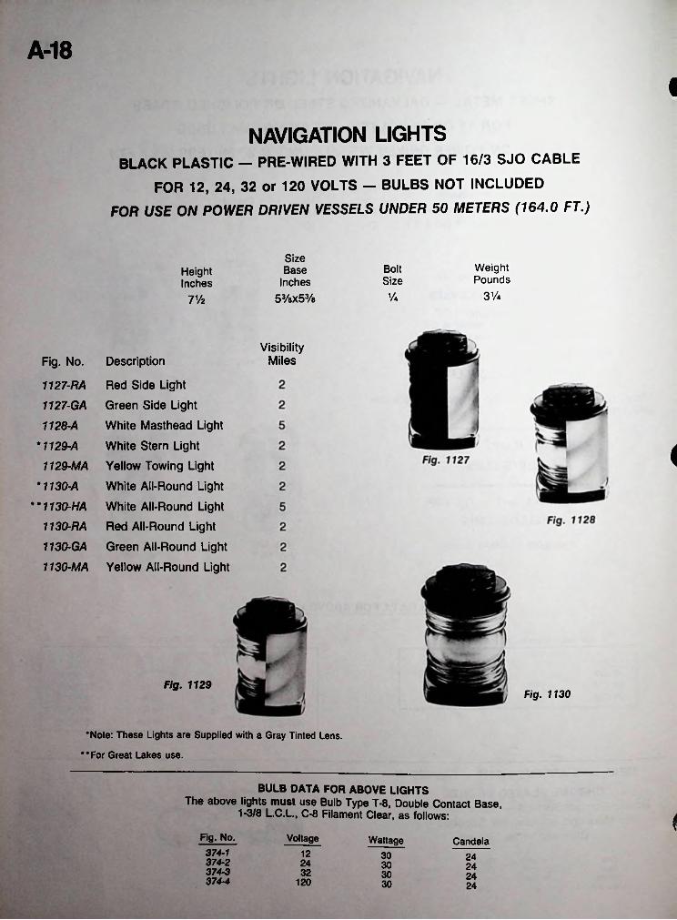
A-18I
NAVIGATION LIGHTSBLACK PLASTIC — PRE-WIRED WITH 3 FEET OF 16/3 SJO CABLE
FOR 12, 24, 32 or 120 VOLTS — BULBS NOT INCLUDED
FOR USE ON POWER DRIVEN VESSELS UNDER 50 METERS (164.0 FT.)
SizeBase
Inches53/sx53/8
WeightPounds
BoltHeightInches Size
31/4Va71/2
VisibilityMilesDescription
Red Side Light
Green Side Light
White Masthead Light
White Stern Light
Yellow Towing Light
White All-Round Light
White All-Round Light Red All-Round Light
Green All-Round Light
Yellow All-Round Light
Fig. No.
1127-RA
1127- GA
1128- A
*1129-A
1129- MA
*1130-A
i• * 1130-HA
1130-RA
1130-GA
1130-MA
Fig. 1129Fig. 1130
•Note: These Lights are Supplied with a Gray Tinted Lens.
••For Great Lakes use.
BULB DATA FOR ABOVE LIGHTSThe above lights must use Bulb Type T-8, Double Contact Base,
1-3/8 L.C.L., C-8 Filament Clear, as follows:
VoltageFig. No. Wattage Candela374-1374-2374-3374-4
12 30 2424 30 2432 30 24
120 30 24

A-19NAVIGATION LIGHTSBLACK PLASTIC - BASE, TOP OR RAIL MOUNT
Complete with 12,24, or 32 Volt Bulb Specify Voltage when ordering
FOR USE ON SAIL OR POWER DRIVEN VESSELS UNDER 20 METERS (65.6 ft.)
SizeBaseInches
HeightInches
ProjectionInches
WeightOunces
Base Mount Top Mount 200 TAB
4-7/8 3-5/16 8-1/23-9/16 114-13/16
3-5/16 138-5/8
VisibilityMilesDescription Mounting WattageFig. No.
Green Side Light Red Side Light White Masthead Light White Stern Light White All-Round Light Tri-Color LightTri-Color/White All-Round Light Combination Side Light Green Side Light Red Side Light White Masthead Light White Stern Light
Base 25 2200 SDB 200 PB 200 MB 200 SNB 200 SWB
•200 TB *200 TAB 200 BT 200 SDT 200 PT 200 MT 200 SNT
Base 25 225 3Base
Base 10 2Base 10 2Base 25 2Base 25/10 2/2Top 25 2Top 25 2Top 25 2Top 25 3Top 10 2
Fig. 200 TAB•For Use on Sail Alone.
»
5*
Fig. 200-TOP MOUNT Fig. 200 - BASE MOUNT
Pulpit Mounting Bracket - Fig. 200 M STS 18-8 Stainless Steel - For Pulpit and Stern Ralls
Complete with Screws for Mounting Light to the Bracket A- - '•
iRail Fig. 200 MSTSWeightOunces
SizeInches
5-1/23/4-1
Bulb Data For Above LightsThe above lights must use Bulb TypeT-8, Double Contact indexing base,
1 -3/8 L.C.L., C-8 Filament Clear, as follows:
VoltageFig. No. Wattage
i 37512V10W 37524V10W 37532V10W 37512V25W 37524V25W 37532V25W
101210241032251225242532

A-20NAVIGATION LIGHTS
SHEET METAL — GALVANIZED STEEL OR POLISHED BRASS
OIL LIGHTS OFFERED FOR EMERGENCY USE ONLY
FOR USE ON POWER DRIVEN VESSELS UNDER 20 METERS (65.6 FT.)Weight Pounds
ScrewHeightInchesClass
3101/2231/2121/z3
SIDE LIGHTS RED AND GREEN LENSES
OIL — Figs. 17 & 19 ELECTRIC — Figs. 17F & 19F
I
mTj:Half Pairs, Specify Fig. No. and
R for Red or G for Green.»t*rAl
Fig. 18 Class 2 Fig. 20 Class 3
Fig. 17 Class 2 Fig. 19 Class 3
MASTHEAD LIGHTS WHITE LENS
OIL — Figs. 18 & 20 ELECTRIC — Figs. 18F & 20F
f
nr
i. i,wKsmiSTERN LIGHT WHITE LENS
OIL — Figs. 97 & 102 ELECTRIC — Figs. 97F & 102F
_3
Fig. 97 Class 2 Fig. 102 Class 3
TOWING LIGHT YELLOW LENS
OIL — Fig. 102M ELECTRIC — Fig. 102MF
BULB DATA FOR ABOVE LIGHTSFor vessels
under 20 meters (65.6 ft.)For vessels
under 12 meters (39.4 ft.)32 vVisibility 12 V
Fig. Miles19F 2 70 No. 1 70 No. 220F 3 70 No. 1 70 No. 2
102F 2 70 No. 1 70 No. 2
Visibility Fig. Miles
12 VBulbBulb Bulb
17F 70 No. 0 70 No. 0 70 No. 0
118F 297F 2
ALL-ROUND LIGHTS WHITE LENS
SHEET METAL - GALVANIZED STEEL OR POLISHED BRASS OIL LIGHTS OFFERED FOR EMERGENCY USE ONLY
FOR USE ON POWER DRIVEN VESSELS UNDER 20 METERS (65.6 FT.)OIL — Fig. 02 & 06
ELECTRIC DOUBLE CONTACT — Figs. 02A & 06A ELECTRIC MED. SCREW — Fig. 06B
Fig. HeightInches
WeightPoundsNo.
02 8% 35/i«06 H3/4 4!4
D.C. Electric for use with No. 1004 Bulb.Med. Screw Electric for use with 15 Watt A-17 Bulb. Fig. 0-6
j
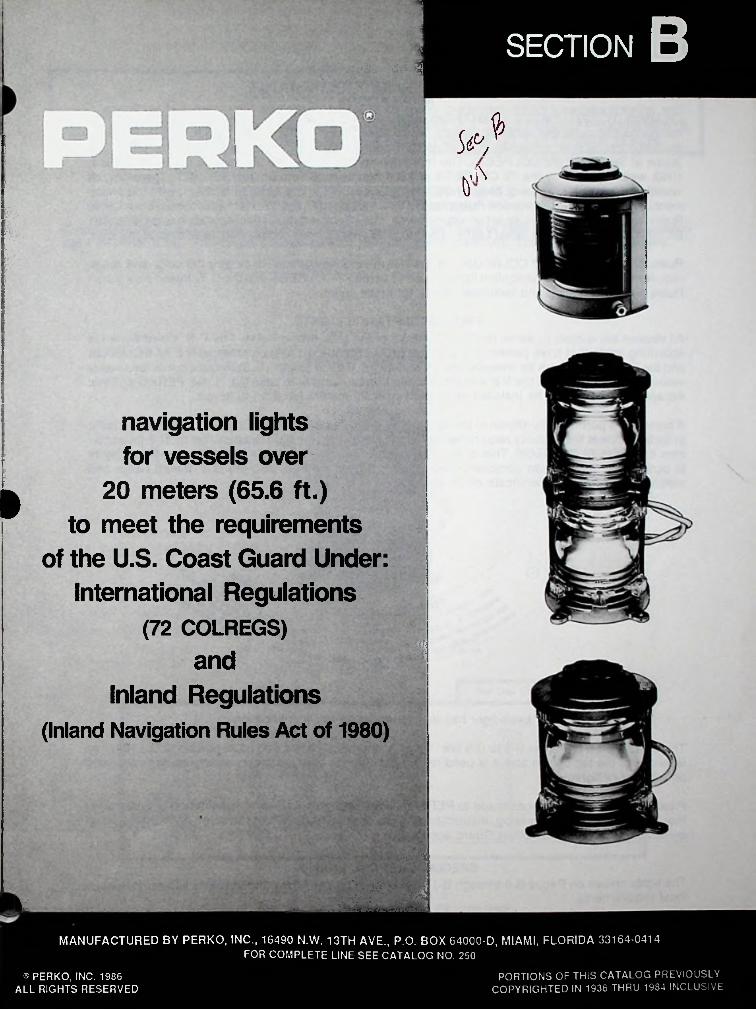
SECTION B: -!
5N
navigation lights
for vessels over
20 meters (65.6 ft.)
to meet the requirements
of the U.S. Coast Guard Under
International Regulations
(72 COLREGS)
'■ m»
■
"Mand
Inland Regulations
(Inland Navigation Rules Act of 1980)
■■
■IMANUFACTURED BY PERKO, INC., 16490 N.W. 13TH AVE., P.O. BOX 64000-D, MIAMI, FLORIDA 33164-0414
FOR COMPLETE LINE SEE CATALOG NO. 250
PORTIONS OF THIS CATALOG PREVIOUSLY COPYRIGHTED IN 1936 THRU 1984 INCLUSIVE
® PERKO, INC. 1986 ALL RIGHTS RESERVED
B-2
REGULATIONSOn March 31, 1977, the U.S. Coast Guard published in the Federal Register, an amendment to the navigation and navigable water regulations, which added a new subchapter DD, (33CFR 87). This subchapter contains rules implementing and interpreting the International Regulations for Preventing Collisions at Sea, 1972 (72 COLREGS). The International Regulations for Preventing Collisions at Sea, 1960, were replaced by the 72 COLREGS at 1200 hours, zone time on July 15, 1977. Therefore, all vessels on the high seas must comply with the 72 COLREGS at this time. In addition, with the enactment of the U.S. Inland Navigation Rules Act of 1980, the Inland Rules, Western Rules, and Great Lakes Rules were unified into a single set of requirements. The effective date for this legislation was December 24,1981 (March 1,1983 for Great Lakes). Therefore, all vessels must comply with these rules at this time.
Rules 21 and 22 of the 72 COLREGS and the U.S. Inland Navigation Rules give the color and range requirements for various navigation lights, Annex 1 to the 72 COLREGS and the U.S. Inland Navigation Rules gives positioning and technical details for these lights.
FINAL ACCEPTANCE LIGHTSAll vessels are subject to either the 72 COLREGS or the U.S. Inland Rules. The U.S. Coast Guard is accepting lights that have passed the U.L. tests (U.L. Standard 1104) as meeting the 72 COLREGS and the U.S. Inland Rules for Vessels over 20 Meters (65.6 ft.) in length. (U.S. Requirements for smaller vessels are less strict). As the first and only domestic manufacturer to pass U.L. 1104, PERKO’s “Final Acceptance” lights can be installed on vessels over 20 meters (65.6 ft.) in length.
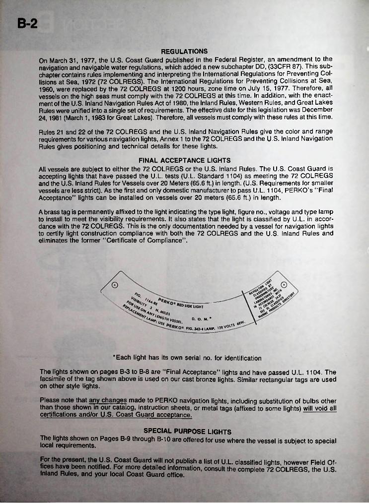
A brass tag is permanently affixed to the light indicating the type light, figure no., voltage and type lamp to install to meet the visibility requirements. It also states that the light is classified by U.L. in accordance with the 72 COLREGS. This is the only documentation needed by a vessel for navigation lights to certify light construction compliance with both the 72 COLREGS and the U.S. Inland Rules and eliminates the former “Certificate of Compliance”.
**DSIDE light
O. o. M. *FIG. 342-4 LAMP.
‘Each light has its own serial no. for identification
The lights shown on pages B-3 to B-8 are “Final Acceptance” lights and have passed U.L. 1104. The facsimile of the tag shown above is used on our cast bronze lights. Similar rectangular tags are used on other style lights.
Please note that any changes made to PERKO navigation lights, including substitution of bulbs other than those shown in our catalog, instruction sheets, or metal tags (affixed to some lights) will void all certifications and/or U.S. Coast Guard acceptance.
SPECIAL PURPOSE LIGHTSThe lights shown on Pages B-9 through B-10 are offered for use where the vessel is subject to special local requirements.
For the present, the U.S. Coast Guard will not publish a list of U.L. classified lights, however Field Offices have been notified. For more detailed information, consult the complete 72 COLREGS, the U.S. Inland Rules, and your local Coast Guard office.

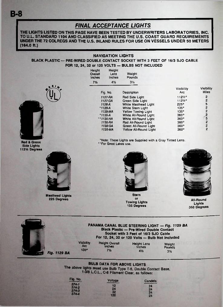
FINAL ACCEPTANCE LIGHTS► THE LIGHTS LISTED ON THIS PAGE HAVE BEEN TESTED BY UNDERWRITERS LABORATORIES, INC. TO U.L. STANDARD 1104 AND CLASSIFIED AS MEETING THE U.S. COAST GUARD REQUIREMENTS UNDER THE 72 COLREGS AND THE U.S. INLAND RULES FOR USE ON ANY LENGTH VESSEL.
SINGLE LENS NAVIGATION LIGHTS CAST BRONZE — WATERTIGHT
Complete with a Pre-Wired Medium Prefocus Bulb Socket with 3 Feet of 16/3-SO Cable through a watertight terminal tube. Watertight access cap for rebulbing and cleaning. 120 Volt Bulbs Included.
SINGLE LENS TYPE
i
HeightOverallInches
HeightLens
InchesWeightPounds
9 Vi 1063/<
I For Use On Any Length Vessel
Visibility VisibilityMiles
RequiredWattageDescription
Red Side Light Green Side Light White Masthead Light White Stern Light Yellow Towing Light White All-Round Light White All-Round Light Red All-Round Light Green All-Round Light Yellow All-Round Light
ArcFig. No. 1172-RE1172- GE1173- E
•1174-E1174- ME
•1169-E1169- HE1170- RE 1170-GE 1170-ME
112%°112’/2°
3 6060360225° 660135° 360135° 360360° 360360° 660360° 360360° 360360° 3
■
IMPORTANT BULB DATATo comply with U.L. Standard 1104, the lights listed on this page must use Perko Fig. 342-4 Bulbs.
•Note: These lights are supplied with Gray Tinted Lens. For Great Lakes use.

B-4FINAL ACCEPTANCE LIGHTS
THE LIGHTS LISTED ON THIS PAGE HAVE BEEN TESTED BY UNDERWRITERS LABORATORIES, INC. TO U.L. STANDARD 1104 AND CLASSIFIED AS MEETING THE U.S. COAST GUARD REQUIREMENTS UNDER THE 72 COLREGS AND THE U.S. INLAND RULES FOR USE ON ANY LENGTH VESSEL.
DOUBLE LENS NAVIGATION LIGHTS CAST BRONZE — WATERTIGHT
Each section contains a Pre-Wired Medium Prefocus Bulb Socket with 3 Feet of 16/3-SO Cable through a watertight terminal tube. Watertight access cap for rebulbing and cleaning. 120 Volt Bulbs Included.
DOUBLE LENS TYPE
i
HeightOverallInches Weight
Pounds181/4
Inches17% 63/4
I For Use On Any Length Vessel
Visibility VisibilityMiles
RequiredWattage
Fig. No. 1164-RE1164- GE1165- E
•1166-E1166- ME
•1167-E1167- HE 1166-RE 1166-GE 1166-ME
Description ArcRed Side Light Green Side Light White Masthead Light White Stern Light Yellow Towing Light White All-Round Light White All-Round Light Red All-Round Light Green All-Round Light Yellow All-Round Light
112%°112%°
3 603 60225° 6 60135° 3 60135° 3 60360° 3 60360° 6 60360° 3 60360° 3 60360° 3 60
iIMPORTANT BULB DATATo comply with U.L. Standard 1104, the lights listed on this page must use Perko Fig. 342-4 Bulbs.
•Note: These lights are supplied with Gray Tinted Lens. For Great Lakes use.• •
B-5FINAL ACCEPTANCE LIGHTS
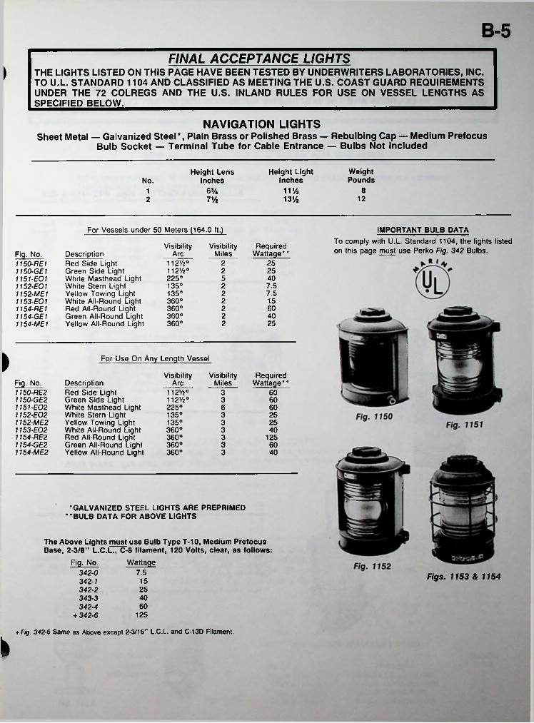
> THE LIGHTS LISTED ON THIS PAGE HAVE BEEN TESTED BY UNDERWRITERS LABORATORIES, INC. TO U.L. STANDARD 1104 AND CLASSIFIED AS MEETING THE U.S. COAST GUARD REQUIREMENTS UNDER THE 72 COLREGS AND THE U.S. INLAND RULES FOR USE ON VESSEL LENGTHS AS SPECIFIED BELOW.____________________________________________________________________
NAVIGATION LIGHTSSheet Metal — Galvanized Steel*, Plain Brass or Polished Brass — Rebulbing Cap — Medium Prefocus
Bulb Socket — Terminal Tube for Cable Entrance — Bulbs Not Included
Height Light Inches
WeightPounds
Height Lens InchesNo.
11 Vi 86Va11213%2 7%
For Vessels under 50 Meters (164.0 ft.) IMPORTANT BULB DATATo comply with U.L. Standard 1104, the lights listed on this page must use Perko Fig. 342 Bulbs.Required
WattageVisibility Visibility
MilesDescription Red Side Light Green Side Light White Masthead Light White Stern Light Yellow Towing Light White All-Round Light Red All-Round Light Green All-Round Light Yellow All-Round Light
ArcFig. No.1150-RE 11150- GE11151- E011152- E011152- ME11153- E011154- RE 1 1154-GE1 1154-ME1
112'/2°1l2'/2°225°
2522 25
405135° 2 7.5
7.5135° 2360° 2 15
60360° 22 40360°
25360° 2
i For Use On Any Length Vessel
Visibility VisibilityMiles
RequiredWattageFig. No.
1150-RE21150- GE21151- E021152- E021152- ME21153- E021154- RE2 1154-GE2 1154-ME2
Description ArcRed Side Light Green Side Light White Masthead Light White Stern Light Yellow Towing Light White All-Round Light Red All-Round Light Green All-Round Light Yellow All-Round Light
112»/2° 112%° 225°
3 603 606 60
135° 3 25135° 253360° 3 40360° 3 125360° 3 60360° 3 40
•GALVANIZED STEEL LIGHTS ARE PREPRIMED BULB DATA FOR ABOVE LIGHTS• •
The Above Lights must use Bulb Type T-10, Medium Prefocus Base, 2-3/8” L.C.L., C-8 filament, 120 Volts, clear, as follows:
WattageFig. No.7.5342-0
342-1342- 2343- 3 342-4
+ 342-6
Figs. 1153 & 115415254060
125
+ Fig. 342-6 Same as Above except 2-3/16” L.C.L. and C-13D Filament.
k
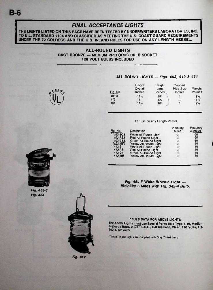
FINAL ACCEPTANCE LIGHTSTHE LIGHTS LISTED ON THIS PAGE HAVE BEEN TESTED BY UNDERWRITERS LABORATORIES, INC. TO U.L. STANDARD 1104 AND CLASSIFIED AS MEETING THE U.S. COAST GUARD REQUIREMENTS UNDER THE 72 COLREGS AND THE U.S. INLAND RULES FOR USE ON ANY LENGTH VESSEL.
ALL-ROUND LIGHTSCAST BRONZE — MEDIUM PREFOCUS BULB SOCKET
120 VOLT BULBS INCLUDED
ALL-ROUND LIGHTS — Figs. 403, 412 & 454
HeightOverallInches
HeightLens
Inches'
Tapped Pipe Size
InchesWeightPoundsFig. No.
403-3 11V2 9 Vi63A 1412 14 63/4 11%454 11 Vi 9 Vi63/4 1
For use on any Length Vessel
RequiredWattage*
VisibilityMilesFig. No. Description
* '403-EO3 White All-Round Light 403-RE3 Red All-Round Light 403-GE3_ Green All-Round Light
<4Q3WWE3 Yellow All-Round Light White All-Round Light Red All-Round Light Green All-Round Light Yellow All-Round Light
603603603 I603
* '412-E 412-RE 412-GE 412-ME
603603603603
Fig. 454-E White Whistle Light — Visibility 5 Miles with Fig. 342-4 Bulb.
Fig. 403-3 Fig. 454
•BULB DATA FOR ABOVE LIGHTS The Above Lights must use Special Perko Bulb Type T-10, Medium Prefocus Base, 2-3/8” L.C.L., C-8 filament, Clear, 120 Volts, Fig. 342-4, 60 watts.
Note: These Lights are Supplied with Gray Tinted Lens.
Fig. 412
B-7FINAL ACCEPTANCE LIGHTS>
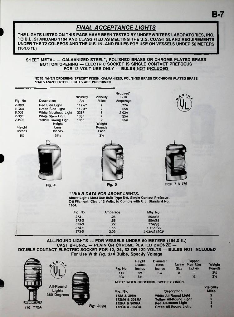
THE LIGHTS LISTED ON THIS PAGE HAVE BEEN TESTED BY UNDERWRITERS LABORATORIES, INC. TO U.L. STANDARD 1104 AND CLASSIFIED AS MEETING THE U.S. COAST GUARD REQUIREMENTS UNDER THE 72 COLREGS AND THE U.S. INLAND RULES FOR USE ON VESSELS UNDER 50 METERS (164.0 ft.)
SHEET METAL — GALVANIZED STEEL*, POLISHED BRASS OR CHROME PLATED BRASS BOTTOM OPENING — ELECTRIC SOCKET IS SINGLE CONTACT PREFOCUS
FOR 12 VOLT USE ONLY — BULBS NOT INCLUDED
NOTE: WHEN ORDERING, SPECIFY FINISH, GALVANIZED, POLISHED BRASS OR CHROME PLATED BRASS •GALVANIZED STEEL LIGHTS ARE PREPRIMED
Required**Bulb
Amperage.77A
Visibility VisibilityMilesFig. No
4-RD34- GD35- D03 7-D03 7-MD3
Description Red Side Light Green Side Light White Masthead Light 225° White Stern Light Yellow Towing Light 135°
Height Lens
Inches
Arc112Vi°112V2°
22 .55A5 2.03A
135° 2 .25A2 .55 A
WeightPounds
EachHeightInches
8 Vi 3 Vi
»
Figs. 7 & 7MFig. 5
BULB DATA FOR ABOVE LIGHTS.Above Lights Must Use Bulb Type S-8, Single Contact Prefocus, C-8 Filament, Clear, 12 Volts, to Comply with U.L. Standard No. 1104.
* *
Fig. No. 373-1 373-2 373-3 373-4 373-5
Amperage Mfg. No. 25A/S8 55A/S8 77A/S8
1.15A/S8 2.03A/S8SCP
.25
.55
.771.15
i 2.03
ALL-ROUND LIGHTS — FOR VESSELS UNDER 50 METERS (164.0 ft.)CAST BRONZE — PLAIN OR CHROME PLATED BRONZE —
DOUBLE CONTACT ELECTRIC SOCKET FOR 12, 24, 32 OR 120 VOLTS — BULBS NOT INCLUDEDFor Use With Fig. 374 Bulbs, Specify Voltage
Tapped Screw Pipe Size Size Inches
Height Overall
Fig. No. Inches
DiameterBase
InchesWeightPounds
3V*88% 3 Vs112Vz 2 Vi6 Vi309
I NOTE: WHEN ORDERING, SPECIFY FINISH.Visibility
MilesDescription White All-Round Light Yellow All-Round Light Red All-Round Light Green All-Round Light
Fig. No.112A & 309A 112MA & 309MA 112RA & 309RA 112GA & 309GA
222
Fig. 309A 2Fig. 112A
B-8FINAL ACCEPTANCE LIGHTS
THE LIGHTS LISTED ON THIS PAGE HAVE BEEN TESTED BY UNDERWRITERS LABORATORIES, INC. TO U.L. STANDARD 1104 AND CLASSIFIED AS MEETING THE U.S. COAST GUARD REQUIREMENTS UNDER THE 72 COLREGS AND THE U.S. INLAND RULES FOR USE ON VESSELS UNDER 50 METERS (164.0 ft.)
NAVIGATION LIGHTSBLACK PLASTIC - PRE-WIRED DOUBLE CONTACT SOCKET WITH 3 FEET OF 16/3 SJO CABLE
FOR 12, 24, 32 or 120 VOLTS - BULBS NOT INCLUDEDHeight Lens
Inches
HeightOverallInches
WeightPounds
31/27Vz 4 Vi
VisibilityMiles
VisibilityFig. No. 1127-RA1127- GA1128- A ‘1129-A
1129- MA *1130-A" 1130-HA
1130- RA 1130-GA 1130-MA
Description Red Side Light Green Side Light White Masthead Light White Stern Light Yellow Towing Light White All-Round Light White All-Round Light Red All-Round Light Green All-Round Light Yellow All-Round Light
Arc2112V2°
112V2°225°135°135°360°360°360°360°360°
252225222
'Note: These Lights are Supplied with a Gray Tinted Lens. "For Great Lakes use.Red & Green
Side Lights112% Degrees
SternMasthead Lights 225 Degrees or All-Round
Lights360 Degrees
Towing Lights 135 Degrees
PANAMA CANAL BLUE STEERING LIGHT — Fig. 1129 BA Black Plastic — Pre-Wired Double Contact
Socket with 3 Feet of 16/3 SJO Cable For 12, 24, 32 or 120 Volts — Bulb Not Included
Height Overall Inches
Visibility Height Lens Inches
WeightPoundsArc
135° V/z 4 % 31/2Fig. 1129 BA
BULB DATA FOR ABOVE LIGHTSThe above lights must use Bulb Type T-8, Double Contact Base,
1-3/8 L.C.L., C-8 Filament Clear, as follows:
VoltageFig. No. Candela374-1374-2374-3374-4
12 2424 2432 24
120 24
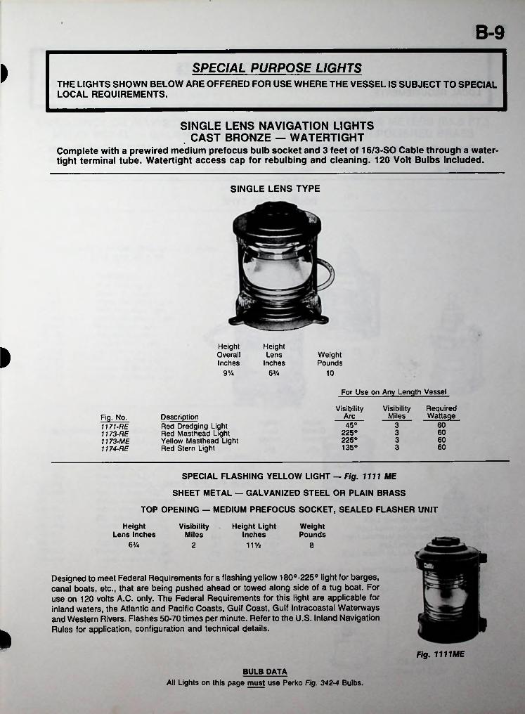
B-9SPECIAL PURPOSE LIGHTS>
THE LIGHTS SHOWN BELOW ARE OFFERED FOR USE WHERE THE VESSEL IS SUBJECT TO SPECIAL LOCAL REQUIREMENTS.
SINGLE LENS NAVIGATION LIGHTS , CAST BRONZE — WATERTIGHT
Complete with a prewired medium prefocus bulb socket and 3 feet of 16/3-SO Cable through a watertight terminal tube. Watertight access cap for rebulbing and cleaning. 120 Volt Bulbs Included.
SINGLE LENS TYPE
HeightOverallInches
HeightLens
Inches» Weight
Pounds91/4 6% 10
For Use on Any Length Vessel
Visibility Visibility Miles
RequiredWattageArcDescriptionFig. No.
1171-RE 1173-RE1173- ME1174- RE
3 6045°Red Dredging Light Red Masthead Light Yellow Masthead Light Red Stern Light
225°225°
3 603 60
60135° 3
SPECIAL FLASHING YELLOW LIGHT — Fig. 1111 ME
SHEET METAL — GALVANIZED STEEL OR PLAIN BRASS
TOP OPENING — MEDIUM PREFOCUS SOCKET, SEALED FLASHER UNIT
Height Lens Inches
VisibilityMiles
Height Light Inches
WeightPounds
6% 2 111/2 8
PDesigned to meet Federal Requirements for a flashing yellow 180°-2250 light for barges, canal boats, etc., that are being pushed ahead or towed along side of a tug boat. For use on 120 volts A.C. only. The Federal Requirements for this light are applicable for inland waters, the Atlantic and Pacific Coasts, Gulf Coast, Gulf Intracoastal Waterways and Western Rivers. Flashes 50-70 times per minute. Refer to the U.S. Inland Navigation Rules for application, configuration and technical details. i*
Fig. 1111ME
BULB DATAAll Lights on this page must use Perko Fig. 342-4 Bulbs.
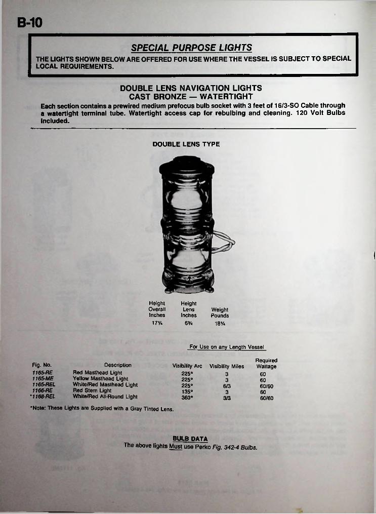
B-10SPECIAL PURPOSE LIGHTS
THE LIGHTS SHOWN BELOW ARE OFFERED FOR USE WHERE THE VESSEL IS SUBJECT TO SPECIAL LOCAL REQUIREMENTS.
DOUBLE LENS NAVIGATION LIGHTS CAST BRONZE — WATERTIGHT
Each section contains a prewired medium prefocus bulb socket with 3 feet of 16/3-SO Cable through a watertight terminal tube. Watertight access cap for rebulbing and cleaning. 120 Volt Bulbs Included.
DOUBLE LENS TYPE
l
HeightOverallInches
HeightLens
InchesWeightPounds
17% 63/4 18%
For Use on any Length Vessel
RequiredWattageFig. No.
1165-RE 1165-ME1165- REL1166- RE
•1168-REL
Description Red Masthead Light Yellow Masthead Light White/Red Masthead Light Red Stern Light White/Red All-Round Light
•Note: These Lights are Supplied with a Gray Tinted Lens.
Visibility Arc Visibility Miles 225°225°225°
3 603 60
6/3 60/60135° 3 60360° 3/3 60/60
BULB DATAThe above lights Must use Perko Fig. 342-4 Bulbs.
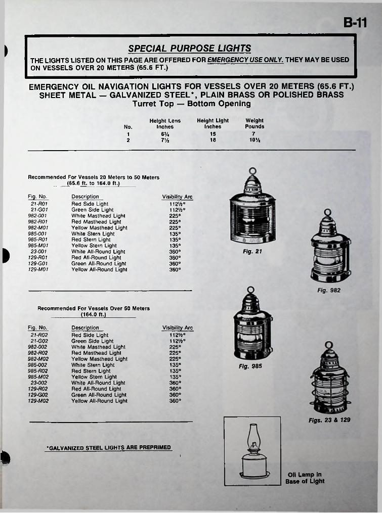
B-11SPECIAL PURPOSE LIGHTS)
THE LIGHTS LISTED ON THIS PAGE ARE OFFERED FOR EMERGENCY USE ONLY. THEY MAY BE USED ON VESSELS OVER 20 METERS (65.6 FT.)
EMERGENCY OIL NAVIGATION LIGHTS FOR VESSELS OVER 20 METERS (65.6 FT.) SHEET METAL — GALVANIZED STEEL*, PLAIN BRASS OR POLISHED BRASS
Turret Top — Bottom Opening
Height Light Inches
WeightPounds
Height Lens InchesNo.
7156%118 10%7%2
Recommended For Vessels 20 Meters to 50 Meters (65.6 ft. to 164.0 ft.)
Fig. No- Description Visibility Arc21-R01 21-G01
982-001 982-R01 982-M01 985-001 985-R01 985-M01 23-001
129-R01 129-G01 129-M01
Red Side Light Green Side Light White Masthead Light Red Masthead Light Yellow Masthead Light White Stern Light Red Stern Light Yellow Stern Light White All-Round Light Red All-Round Light Green All-Round Light Yellow All-Round Light
112%°112%°225°225°225°135°135°135°
I Fig. 21360°360°360°360°
Recommended For Vessels Over 50 Meters __________(164.0 ft.)__________
Fig. No- Description Red Side Light Green Side Light White Masthead Light Red Masthead Light Yellow Masthead Light White Stern Light Red Stern Light Yellow Stern Light White All-Round Light Red All-Round Light Green All-Round Light Yellow All-Round Light
Visibility Arc21-R0221-G02
982-002982-R02982-M02985-002985-R02985-M0223-002
129-R02129-G02129-M02
112%°112%°225°225°225°135° Fig. 985135°135°360°360°360°360°
Figs. 23 & 129
• GALVANIZED STEEL LIGHTS ARE PREPRIMED
ft i
Oil Lamp in Base of Light
B-12
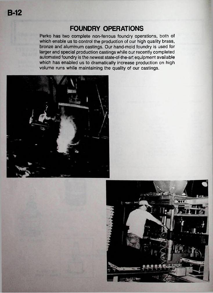
FOUNDRY OPERATIONSPerko has two complete non-ferrous foundry operations, both of which enable us to control the production of our high quality brass, bronze and aluminum castings. Our hand-mold foundry is used for larger and special production castings while our recently completed automated foundry is the newest state-of-the-art equipment available which has enabled us to dramatically increase production on high volume runs while maintaining the quality of our castings.

SECTION C-Dm ? ■ ■ 'nk
. <8>
—..—
©
LOT
SWITCHES, PANELS,
LIGHTING FIXTURES,
AND OTHER
ELECTRICAL EQUIPMENT
<
t ;
:i
OFF ONn ANCHOR Q V light u
Cl^ |0 RUNNINGLIGHTS
^ > 85 ©I
---------TTWIPER ©|
Oi ^\ .1— LT‘N 10 SEARCH
LIGHT
pcqKD
MANUFACTURED BY PERKO, INC., 16490 N.W. 13TH AVE., P.O. BOX 64000-D, MIAMI, FLORIDA 33164-0414FOR COMPLETE LINE SEE CATALOG NO. 250
« PERKO, INC. 1986 ALL RIGHTS RESERVED
PORTIONS OF THIS CATALOG PREVIOUSLY COPYRIGHTED IN 1936 THRU 1984 INCLUSIVE
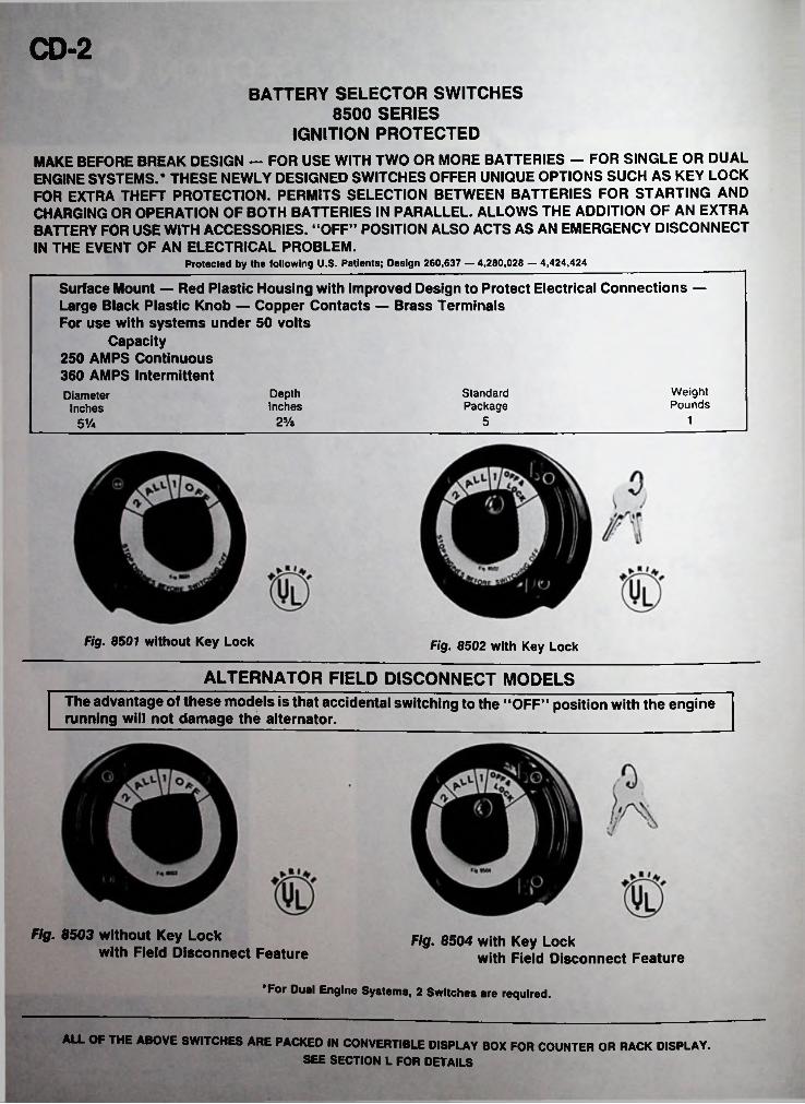
CD-2BATTERY SELECTOR SWITCHES
8500 SERIES IGNITION PROTECTED
MAKE BEFORE BREAK DESIGN — FOR USE WITH TWO OR MORE BATTERIES — FOR SINGLE OR DUAL ENGINE SYSTEMS.* THESE NEWLY DESIGNED SWITCHES OFFER UNIQUE OPTIONS SUCH AS KEY LOCK FOR EXTRA THEFT PROTECTION. PERMITS SELECTION BETWEEN BATTERIES FOR STARTING AND CHARGING OR OPERATION OF BOTH BATTERIES IN PARALLEL. ALLOWS THE ADDITION OF AN EXTRA BATTERY FOR USE WITH ACCESSORIES. “OFF” POSITION ALSO ACTS AS AN EMERGENCY DISCONNECT IN THE EVENT OF AN ELECTRICAL PROBLEM.
Protected by the following U.S. Patients; Design 260,637 — 4,280,028 — 4,424,424
Surface Mount — Red Plastic Housing with Improved Design to Protect Electrical Connections — Large Black Plastic Knob — Copper Contacts — Brass Terminals For use with systems under 50 volts
Capacity250 AMPS Continuous 360 AMPS IntermittentDiameter
InchesWeightPounds
StandardPackage
DepthInches
125/e 551/a
Fig. 8501 without Key Lock Fig. 8502 with Key Lock
ALTERNATOR FIELD DISCONNECT MODELSThe advantage of these models is that accidental switching to the “OFF” position with the engine running will not damage the alternator.
Fig. 8503 without Key Lockwith Field Disconnect Feature
Fig. 8504 with Key Lockwith Field Disconnect Feature
•For Dual Engine Systems, 2 Switches are required.
ALL OF THE ABOVE SWITCHES ARE PACKED IN CONVERTIBLE DISPLAY BOX FOR COUNTER OR RACK DISPLAY.SEE SECTION L FOR DETAILS
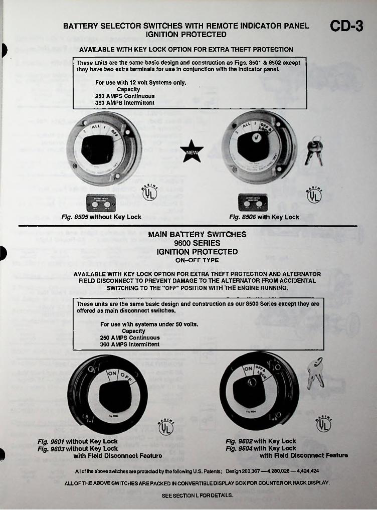
CD-3BATTERY SELECTOR SWITCHES WITH REMOTE INDICATOR PANELIGNITION PROTECTED
> AVAILABLE WITH KEY LOCK OPTION FOR EXTRA THEFT PROTECTION
These units are the same basic design and construction as Figs. 8501 & 8502 except they have two extra terminals for use in conjunction with the indicator panel.
For use with 12 volt Systems only. Capacity
250 AMPS Continuous 360 AMPS Intermittent
Fig. 8505 without Key Lock Fig. 8506 with Key Lock
MAIN BATTERY SWITCHES 9600 SERIES
IGNITION PROTECTED ON-OFF TYPE
»
AVAILABLE WITH KEY LOCK OPTION FOR EXTRA THEFT PROTECTION AND ALTERNATOR FIELD DISCONNECT TO PREVENT DAMAGE TO THE ALTERNATOR FROM ACCIDENTAL
SWITCHING TO THE "OFF' POSITION WITH THE ENGINE RUNNING.
These units are the same basic design and construction as our 8500 Series except they are offered as main disconnect switches.
For use with systems under 50 volts. Capacity
250 AMPS Continuous 360 AMPS Intermittent
Fig. 9602 with Key Lock Fig. 9604 with Key Lock
with Reid Disconnect Feature
Fig. 9601 without Key Lock Fig. 9603 without Key Lock
with Field Disconnect FeaturekAll of the above switches are protected by the following U.S. Patents; Design 260,367—4,280,028 —4,424,424
ALL OFTHE ABOVE SWITCHES ARE PACKED IN CONVERTIBLE DISPLAY BOX FOR COUNTER OR RACK DISPLAY.
SEE SECTION L FOR DETAILS.
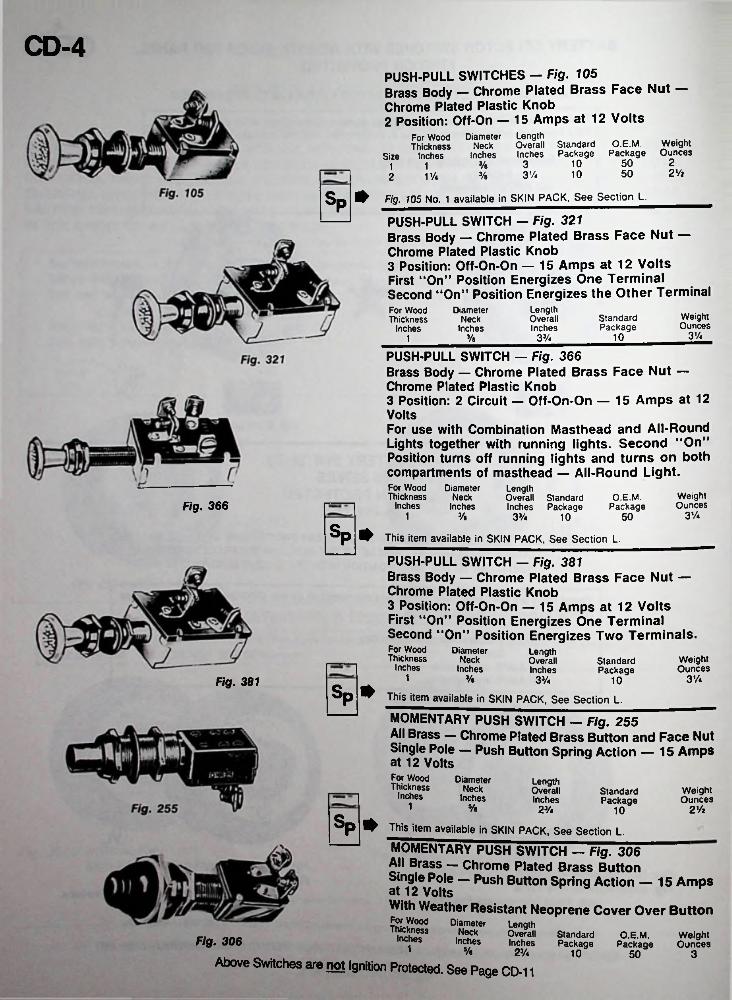
CD-4PUSH-PULL SWITCHES — Fig. 105Brass Body — Chrome Plated Brass Face Nut —Chrome Plated Plastic Knob2 Position: Off-On — 15 Amps at 12 Volts
LengthOverall Standard Inches Package
DiameterNeck
Inches
For Wood Thickness
Size InchesO.E.M. Weight
Package Ounces2501033/e11 2 Vi501031/43/e11/42
Sn ^ Fig. 105 No. 1 available in SKIN PACK. See Section L.PPUSH-PULL SWITCH — Fig. 321Brass Body — Chrome Plated Brass Face Nut —Chrome Plated Plastic Knob3 Position: Off-On-On — 15 Amps at 12 VoltsFirst “On” Position Energizes One TerminalSecond “On” Position Energizes the Other Terminal
Length Overall Inches
For Wood Thickness
Inches
DiameterNeck
InchesWeightOunces
StandardPackage
3V41033A3/e1
PUSH-PULL SWITCH — Fig. 366Brass Body — Chrome Plated Brass Face Nut —Chrome Plated Plastic Knob3 Position: 2 Circuit — Off-On-On — 15 Amps at 12 VoltsFor use with Combination Masthead and All-Round Lights together with running lights. Second “On” Position turns off running lights and turns on both compartments of masthead — All-Round Light.For Wood Thickness
Inches
DiameterNeck
Inches
LengthOverall Standard Inches Package
WeightOunces
O.E.M.PackageFig. 366
31/.1 3/« 33/4 5010
SP* This item available in SKIN PACK. See Section L.
PUSH-PULL SWITCH — Fig. 381Brass Body — Chrome Plated Brass Face Nut —Chrome Plated Plastic Knob3 Position: Off-On-On — 15 Amps at 12 VoltsFirst “On” Position Energizes One TerminalSecond “On” Position Energizes Two Terminals.For Wood Thickness
Inches
DiameterNeck
Inches
LengthOverallInches
WeightOunces
StandardPackage
1 3%3/e 33/4 10Fig. 381Sn » This item available in SKIN PACK. See Section L.P
MOMENTARY PUSH SWITCH — Fig. 255All Brass — Chrome Plated Brass Button and Face Nut Single Pole — Push Button Spring Action — 15 Amps at 12 VoltsFor Wood Thickness
Inches
DiameterNeck
Inches
LengthOverallInches
WeightOunces
StandardPackage1 5/b 23/4 2 V2- 10
^ This item available in SKIN PACK. See Section L.
MOMENTARY PUSH SWITCH — Fig. 306All Brass — Chrome Plated Brass Button Single Pole — Push Button Spring Action — 15 Amps at 12 VoltsWith Weather Resistant Neoprene Cover Over ButtonFor Wood Thickness
Inches1 % 2%
Above Switches are not Ignition Protected. See Page CD-11
DiameterNeck
Inches
LengthOverallInches
StandardPackage
O.E.M.Package
WeightOuncesFig. 306
10 350
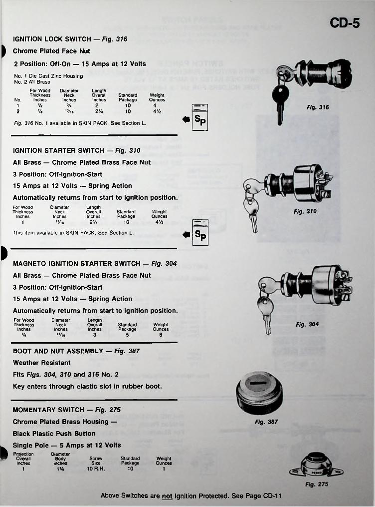
CD-5IGNITION LOCK SWITCH — Fig. 316
Chrome Plated Face Nut
2 Position: Off-On — 15 Amps at 12 Volts
>
No. 1 Die Cast Zinc Housing No. 2 All Brass
For Wood Thickness
No. Inches
LengthOverallInches
DiameterNeck
InchesStandardPackage
WeightOunces
V2 Va 2 10 41 Fig. 3167/«2 13/l6 2Va 10 4 Vi
«SpFig. 316 No. 1 available in SKIN PACK, See Section L.
IGNITION STARTER SWITCH — Fig. 310
All Brass — Chrome Plated Brass Face Nutr*3 Position: Off-Ignition-Start
15 Amps at 12 Volts — Spring Action
Automatically returns from start to ignition position.Length Overall Inches
DiameterNeck
Inches,3/f6
For Wood Thickness
InchesFig. 310Standard
PackageWeightOunces
4 Vi2 Va 101
♦ SpThis item available in SKIN PACK, See Section L.
>
MAGNETO IGNITION STARTER SWITCH — Fig. 304
All Brass — Chrome Plated Brass Face Nut
3 Position: Off-Ignition-Start
15 Amps at 12 Volts — Spring Action
Automatically returns from start to ignition position.Length Overall Inches
.M
For Wood Thickness
Inches
DiameterNeck
Inches13/l6
Fig. 304StandardPackage
WeightOunces
Va 3 5 8
BOOT AND NUT ASSEMBLY — Fig. 387
Weather Resistant
Fits Figs. 304, 310 and 316 No. 2
Key enters through elastic slot in rubber boot.
MOMENTARY SWITCH — Fig. 275
Chrome Plated Brass Housing —
Black Plastic Push Button
Fig. 387
Single Pole — 5 Amps at 12 VoltsProjection
OverallInches
DiameterBody
InchesScrewSize
10R.H.
StandardPackage
WeightOunces
101% 11
Above Switches are not Ignition Protected. See Page CD-11
CD-6
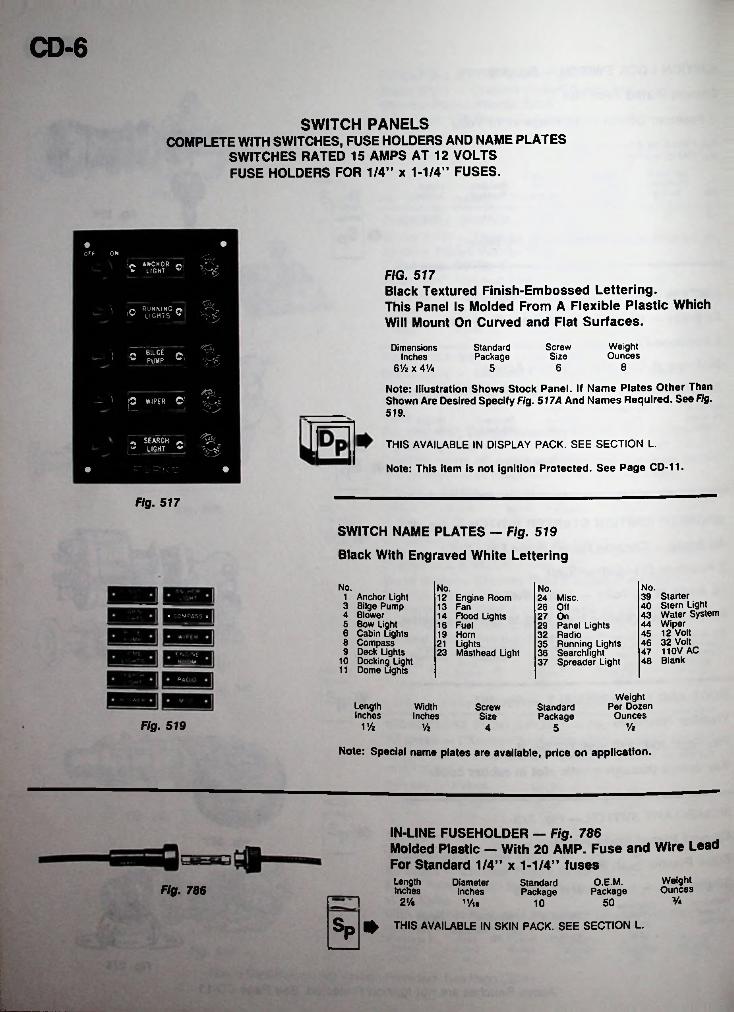
SWITCH PANELSCOMPLETE WITH SWITCHES, FUSE HOLDERS AND NAME PLATES
SWITCHES RATED 15 AMPS AT 12 VOLTS FUSE HOLDERS FOR 1/4” x 1-1/4” FUSES.
OFf OHANCHOR
LIGHT ©Ic FIG. 517Black Textured Finish-Embossed Lettering.This Panel Is Molded From A Flexible Plastic Which Will Mount On Curved and Flat Surfaces.
RUNNING r> U LIGHTS **
WeightOunces
ScrewSize
StandardPackage
Dimensions Inches
6Vi x 4V<'I O BILGE
PUMP c865
Note: Illustration Shows Stock Panel. If Name Plates Other Than Shown Are Desired Specify Fig. 517A And Names Required. See Fig.__ \ & WIPER ©; ^3 519.
„ SEARCH ^ LIGHT THIS AVAILABLE IN DISPLAY PACK. SEE SECTION L.
Note: This item is not ignition Protected. See Page CD-11.
Fig. 517
SWITCH NAME PLATES — Fig. 519
Black With Engraved White Lettering
No. No.No. No.39 Starter40 Stern Light43 Water System44 Wiper45 12 Volt46 32 Volt47 110V AC48 Blank
1 Anchor Light3 Bilge Pump4 Blower5 Bow Light6 Cabin Lights8 Compass9 Deck Lights
10 Docking Light11 Dome Lights
12 Engine Room13 Fan14 Flood Lights 16 Fuel19 Horn 21 Lights 23 Masthead Light
24 Misc.26 Off27 On29 Panel Lights 32 Radio35 Running Lights36 Searchlight37 Spreader Light
• OVPASS •
l r. G £ ROOM
E 1R&OiO
Weight Per Dozen
OuncesLengthInches
WidthInches
ScrewSize
StandardPackage
Fig. 519 V/z VzVz 4 5
Note: Special name plates are available, price on application.
IN-LINE FUSEHOLDER — Fig. 786Molded Plastic — With 20 AMP. Fuse and Wire LeadFor Standard 1/4” x 1-1/4” fusesLength Inches
WeightOunces
O.E.M.Package
DiameterInches
11/ie
StandardPackageFig. 786
V.%21/« 5010
Sp 0 THIS AVAILABLE IN SKIN PACK. SEE SECTION L.
i
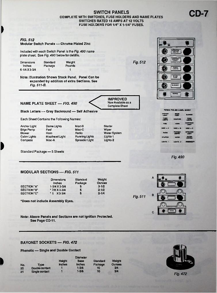
CD-7SWITCH PANELSCOMPLETE WITH SWITCHES, FUSE HOLDERS AND NAME PLATES
SWITCHES RATED 15 AMPS AT 12 VOLTS FUSE HOLDERS FOR 1/4" X 1-1/4" FUSES.
FIG. 512Modular Switch Panels — Chrome Plated Zinc n_orr y gw %
® HIncluded with each Switch Panel is the Fig. 490 name plate sheet. See Fig. 490 below for details.
Ji
€> J1QFig. 512Dimensions Inches
6-1/4 X 3-3/4
StandardPackage
WeightPounds
11
Note: Illustration Shows Stock Panel. Panel Can be expanded by addition of extra Sections. See Fig. 511-B. <^) | ,cowl" 1
» ; tn*Ko
<IMPROVEDNow Available as a Complete Sheet
NAME PLATE SHEET — FIG. 490
PERKO FTQ.490 LABEL SHEETBlack Letters — Gray Backround — Self AdhesiveMUX
Each Sheet Contains the Following Names: UOHT* UOMTS
run.Anchor Light Bilge Pump Blower Cabin Lights Compass
Dome Lights Misc-BMisc-CRadioRunning Lights Spreader Light
StarterWiperWater SystemUghts-1Lights-2
— A : — a — cFuelHornMasthead Light Misc-A
AMMO UOMTS
STAMTCM
UOMTS-3
Standard Package — 5 Sheets
Fig. 490
MODULAR SECTIONS — FIG. 511
WeightOunces3-1/2
Dimensions Inches
1-3/4 X 3-3/4• 7/8 X 3-3/4• 1 X 3-3/4
StandardPackage
SECTION "A“ SECTION "B“ SECTION "C"
52-1/252-1/45
Fig. 511‘Does not include Assembly Eyes.
Note: Above Panels and Sections are not ignition Protected. See Page CD-11.
BAYONET SOCKETS — FIG. 472
Phenolic — Single and Double Contact
DiameterBase
Inches1-3/8
i HeightInches
WeightOunces
StandardPackageType
20 Double contact21 Single contact
No.1 10 3/4
1-3/8 3/41 10
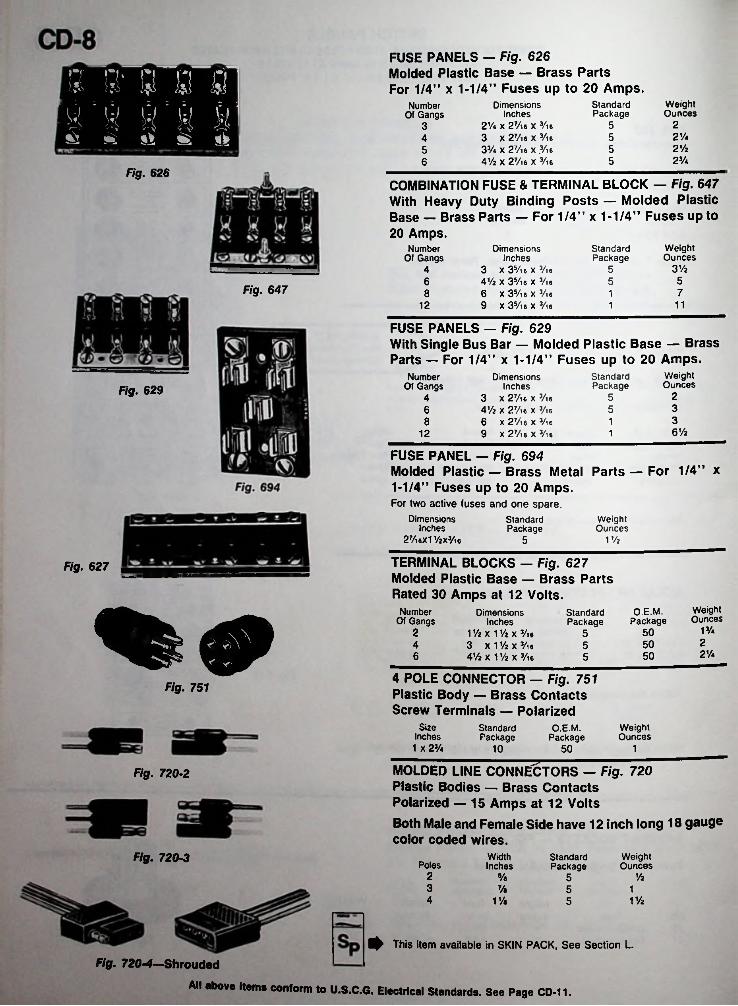
FUSE PANELS — Fig. 626Molded Plastic Base — Brass PartsFor 1/4” x 1-1/4” Fuses up to 20 Amps.5 S' s 2 SI
A \i H H H6 £ s «►
WeightOunces
StandardPackage
DimensionsInches
2V» x 2 Vi a x Vi 6 3 X 2 Vi 6 X Vi 633/4 X 27/l6 X .Vl64Vi X 2Vie X Vi6
Number Of Gangs
2532%5421/2552V.56
Fig. 626COMBINATION FUSE & TERMINAL BLOCK — Fig. 647 With Heavy Duty Binding Posts — Molded Plastic Base — Brass Parts — For 1/4” x 1-1/4” Fuses up to 20 Amps.
WeightOunces
Number Of Gangs
DimensionsInches
3 x 3 Vi 6 x Vi 6 4V2 X 3Vi6 X Vi6 6 x 3 Vi 6 x Vi 6 9 X 3 Vi 6 X Vi 6
StandardPackage
3V24 556 5
Fig. 647 78 11112 1
FUSE PANELS - Fig. 629With Single Bus Bar — Molded Plastic Base — Brass Parts — For 1/4” x 1-1/4” Fuses up to 20 Amps.
WeightOunces
StandardPackage
Number Of Gangs
DimensionsInches
3 X 2Vi6 x Vi6 4V2 x 2Vi6 x Vi6 6 x 2Vic x Vie 9 x 2Vi6 X Vi6
Fig. 629 25435638 16V212 1
FUSE PANEL - Fig. 694Molded Plastic — Brass Metal Parts — For 1/4” x 1-1/4” Fuses up to 20 Amps.For two active fuses and one spare.
Dimensions Inches
27/l6Xl1/2X3/l6
WeightOunces
StandardPackage
11/25
TERMINAL BLOCKS — Fig. 627 Molded Plastic Base — Brass Parts Rated 30 Amps at 12 Volts.
Fig. 627
WeightOunces
O.E.M.Package
Number Of Gangs
DimensionsInches
11/2 x 1V2 x Vi 6 3 x 1V2 x Vi 6 41/2 X 11/2 X Vi 6
StandardPackage
1V.2 5052504 52'A6 505
4 POLE CONNECTOR - Fig. 751 Plastic Body — Brass Contacts Screw Terminals — Polarized
O.E.M. Package
Fig. 751
Size Inches
1 X 2V.
WeightOunces
StandardPackage
10 50 1
MOLDED LINE CONNECTORS — Fig. 720 Plastic Bodies — Brass Contacts Polarized — 15 Amps at 12 VoltsBoth Male and Female Side have 12 inch long 18 gauge color coded wires.
Fig. 720-2
Fig. 720-3 WidthInches
WeightOunces
StandardPackagePoles
2 y2s/a 53 Ve 5 14 11/21Ve 5
^ This item available in SKIN PACK, See Section L.
Fig. 720-4—Shrouded
All above items conform to U.S.C.G. Electrical Standards. See Page CD-11.
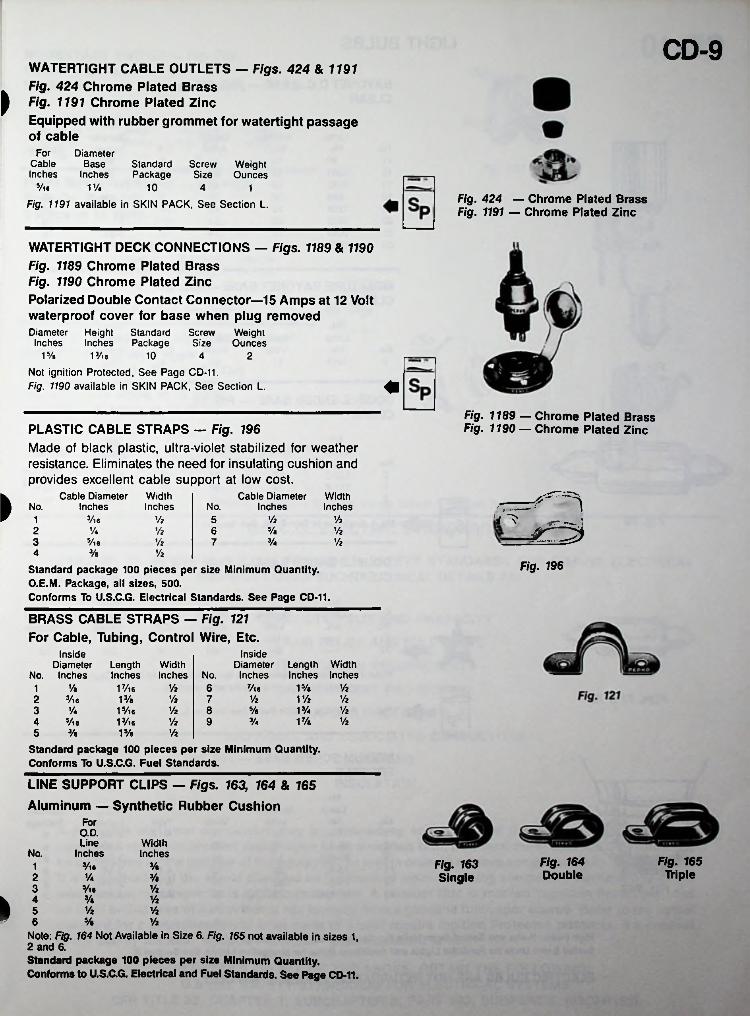
CD-9WATERTIGHT CABLE OUTLETS — Figs. 424 & 1191 Fig. 424 Chrome Plated Brass
I Fig. 1191 Chrome Plated Zinc
Equipped with rubber grommet for watertight passage of cable
For DiameterBase
InchesCableInches
Standard Screw Weight Package Size Ounces
Vl6 11/4 10 4 1Fig. 424 — Chrome Plated Brass Fig. 1191 — Chrome Plated Zinc
Fig. 1191 available in SKIN PACK, See Section L.
WATERTIGHT DECK CONNECTIONS — Figs. 1189 & 1190 Fig. 1189 Chrome Plated Brass Fig. 1190 Chrome Plated Zinc
Polarized Double Contact Connector—15 Amps at 12 Volt waterproof cover for base when plug removedDiameter Height Standard Screw WeightInches Inches Package Size Ounces
13/l6
Not ignition Protected, See Page CD-11.Fig. 1190 available in SKIN PACK, See Section L.
15/« 10 4 2
Fig. 1189 — Chrome Plated Brass Fig. 1190 — Chrome Plated ZincPLASTIC CABLE STRAPS — Fig. 196
Made of black plastic, ultra-violet stabilized for weather resistance. Eliminates the need for insulating cushion and provides excellent cable support at low cost.
Width Inches
Cable Diameter Inches
Cable Diameter Inches
WidthInches^ No. No. r, -
i ^3/l6 Vi y2y2 515/e2 Va y2 6 y23/43 Vie y2 y27
3/« y24Fig. 196Standard package 100 pieces per size Minimum Quantity.
O.E.M. Package, all sizes, 500.Conforms To U.S.C.G. Electrical Standards. See Page CD-11.
BRASS CABLE STRAPS — Fig. 121 For Cable, Tubing, Control Wire, Etc.
InsideDiameter Length Width
No. Inches Inches Inches
InsideDiameter Length
No. Inches Inches17/l613/a15/t6 13/16
WidthInches
15/» y2y« 1/2 6 7/ie1y2 y2 r/2 y22 3/l6 7y2 5/e 13/4 y23 1/4 8
VA 17/a 1/25/ie 1/2 943/a 15/« 1/25
Standard package 100 pieces per size Minimum Quantity. Conforms To U.S.C.G. Fuel Standards.
LINE SUPPORT CLIPS — Figs. 163, 164 & 765 Aluminum — Synthetic Rubber Cushion
ForO.D.Line
InchesWidthInchesNo.
Fig. 165 Triple
Fig. 164 Double
Fig. 163 Single
3/ie 3/«12 Va 3/e3 5/u 1/2
3/a Vi» J Vz Vi% 1/26
Note: Fig. 164 Not Available in Size 6. Fig. 165 not available in sizes 1, 2 and 6.Standard package 100 pieces per size Minimum Quantity. Conforms to U.S.C.G. Electrical and Fuel Standards. See Page CD-11.
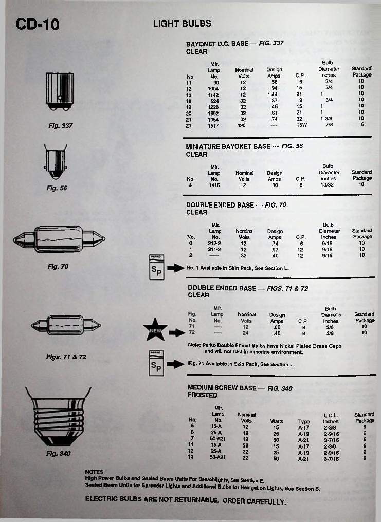
CD-10 LIGHT BULBS
BAYONET D.C. BASE — FIG. 337 CLEAR
BulbDiameterInches
Mfr.StandardPackage
DesignAmps
NominalVolts
LampC.P.No.No.
103/46.58129011103/415.9412100412101211.4412114213103/49.37326241810115.453212281910121.6132169220101-3/832.743210542167/815WFig. 337 12023 15T7
MINIATURE BAYONET BASE — FIG. 56 CLEAR
BulbMfr.StandardPackage
DiameterInches13/32
DesignAmps
Lamp NominalVolts C.P.No. No.
104 1416 .80 812
DOUBLE ENDED BASE — FIG. 70 CLEAR
Mfr. BulbStandardPackage
Lamp Nominal Design Amps
DiameterInches9/16
No. No. Volts C.P.100 212-2
211-212 .74 6
101 12 9/16.97 12102 32 9/16.40 12
Fig. 70 No. 1 Available In Skin Pack, See Section L.
DOUBLE ENDED BASE — FIGS. 71 & 72 CLEAR
BulbDiameterInches
StandardPackage
Nominal DesignAmps C.P.
10.80 3/8810.40 3/88
Note: Perfco Double Ended Bulbs have Nickel Plated Brass Caps and will not rust In a marine environment
Fig. 71 Available In Skin Pack, See Section L.Figs. 71 & 72
MEDIUM SCREW BASE — FIG. 340 FROSTED
Mfr.Lamp Nominal Standard
PackageL.C.L
Type InchesNo. No. Volts Watts5 15-A 12 615 A-17 2-3/86 25-A 12 625 2- 9/16
3- 7/16A-19
7 50-A21 12 650 A-2111 15-A 32 615 A-17 2-3/812 25-A 32 225 2- 9/16
3- 7/16Fig. 340 A-19
13 50-A21 32 250 A-21
NOTESHigh Power Bulbs end Sealed Beam Units For Searchlights, See Section E.Sealed Beam Units for Spreader Lights and Additional Bulbs for Navigation Lights, See Section S.
ELECTRIC BULBS ARE NOT RETURNABLE. ORDER CAREFULLY.
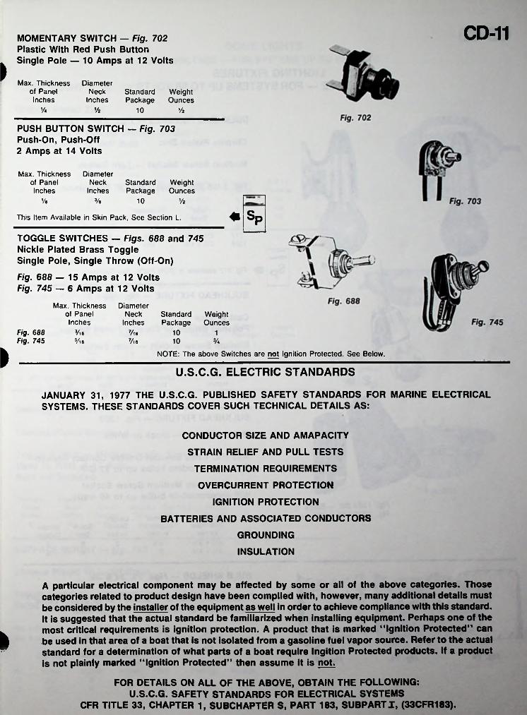
CD-11MOMENTARY SWITCH — Fig. 702 Plastic With Red Push Button Single Pole — 10 Amps at 12 Volts
>Max. Thickness
of Panel Inches
DiameterNeck
InchesStandard Weight Package Ounces
V« Vz 10 Vz
PUSH BUTTON SWITCH — Fig. 703 Push-On, Push-Off 2 Amps at 14 Volts
Max. Thickness of Panel Inches
DiameterNeck
InchesStandard Weight Package Ounces
Ve 3/b 10 Vz
♦ SpThis Item Available in Skin Pack, See Section L.
TOGGLE SWITCHES — Figs. 688 and 745 Nickle Plated Brass Toggle Single Pole, Single Throw (Off-On)
Fig. 688 — 15 Amps at 12 Volts Fig. 745 — 6 Amps at 12 Volts
Max. Thickness of Panel Inches
DiameterNeck
InchesStandard Weight Package Ounces
Fig. 688 Fig. 745
3/l6 7/l6 10 1S/l6 7/l6 Va10
ft NOTE: The above Switches are not Ignition Protected. See Below.
U.S.C.G. ELECTRIC STANDARDS
JANUARY 31, 1977 THE U.S.C.G. PUBLISHED SAFETY STANDARDS FOR MARINE ELECTRICAL SYSTEMS. THESE STANDARDS COVER SUCH TECHNICAL DETAILS AS:
CONDUCTOR SIZE AND AMAPACITY
STRAIN RELIEF AND PULL TESTS
TERMINATION REQUIREMENTS
OVERCURRENT PROTECTION
IGNITION PROTECTION
BATTERIES AND ASSOCIATED CONDUCTORS
GROUNDING
INSULATION
A particular electrical component may be affected by some or all of the above categories. Those categories related to product design have been complied with, however, many additional details must be considered by the installer of the equipment as well in order to achieve compliance with this standard. It is suggested that the actual standard be familiarized when installing equipment. Perhaps one of the most critical requirements is ignition protection. A product that is marked "Ignition Protected" can be used in that area of a boat that is not isolated from a gasoline fuel vapor source. Refer to the actual standard for a determination of what parts of a boat require Ingition Protected products. If a product is not plainly marked “Ignition Protected” then assume it is not.
FOR DETAILS ON ALL OF THE ABOVE, OBTAIN THE FOLLOWING:U.S.C.G. SAFETY STANDARDS FOR ELECTRICAL SYSTEMS
CFR TITLE 33, CHAPTER 1, SUBCHAPTER S, PART 183, SUBPART J, (33CFR183).
ft
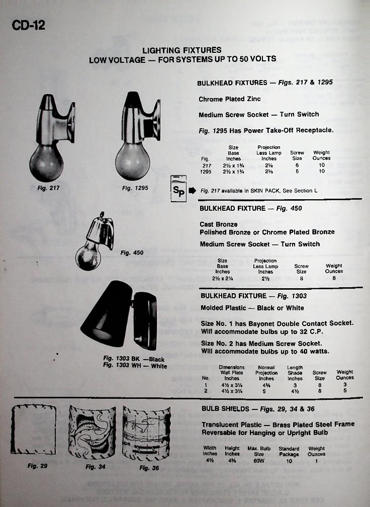
CD-12LIGHTING FIXTURES
LOW VOLTAGE — FOR SYSTEMS UP TO 50 VOLTS
BULKHEAD FIXTURES — Figs. 217 & 1295
Chrome Plated Zinc
Medium Screw Socket — Turn Switch
Fig. 1295 Has Power Take-Off Receptacle.
Projection Less Lamp
Inches
Size Base
Inches 217 2Vz x 1 Va
1295 2Vz x 13/«
WeightOunces
ScrewSizeFig.
1025/e 610625/b
Fig. 217 Sp Fig■ 217 available in SKIN PACK, See Section L
BULKHEAD FIXTURE — Fig. 450
Cast BronzePolished Bronze or Chrome Plated Bronze
Medium Screw Socket — Turn SwitchFig. 450
Size Base
Inches 2Vz x 2'A
Projection Less Lamp
InchesWeightOunces
ScrewSize
82Vz 8
BULKHEAD FIXTURE — Fig. 1303
Molded Plastic — Black or White
Size No. 1 has Bayonet Double Contact Socket. Will accommodate bulbs up to 32 C.P.
Size No. 2 has Medium Screw Socket.Will accommodate bulbs up to 40 watts.
Fig. 1303 BK —Black Fig. 1303 WH — White Dimensions
Wall Plate Inches
4 Vz x 31/4 4Vz x 31/«
NormalProjection
Inches
LengthShade Screw Inches Size
WeightOuncesNo.
31 843/e 352 85 41/2
BULB SHIELDS — Figs. 29, 34 & 36
Translucent Plastic — Brass Plated Steel Frame Reversable for Hanging or Upright Bulb
Width Height Max. Bulb Inches Inches Size
WeightOunces
StandardPackageV V % •.
4Vz 4% 60W 10 1Fig. 29 Fig. 34 Fig. 36
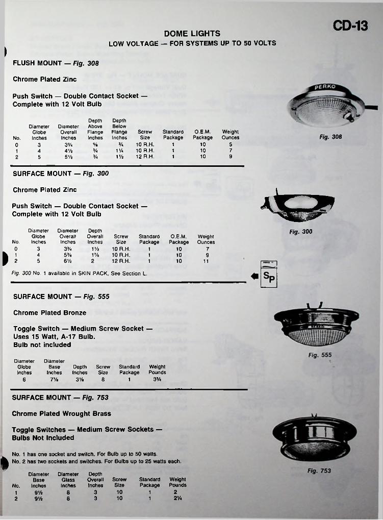
CD-13DOME LIGHTSLOW VOLTAGE — FOR SYSTEMS UP TO 50 VOLTS
IFLUSH MOUNT — Fig. 308
Chrome Plated Zinc
Push Switch — Double Contact Socket — Complete with 12 Volt Bulb
Depth Depth Diameter Above BelowOverall Flange Flange Screw StandardInches Inches Inches Size Package
Va 10 R.H.V/a 10 R.H.V/2 12 R.H.
Diameter Globe
No. InchesO.E.M. Weight
Package Ounces Fig. 30810 5Va 13Va0 310 7Va 14 Vi1 410 95 Vi Va 12 5
SURFACE MOUNT — Fig. 300
Chrome Plated Zinc
Push Switch — Double Contact Socket — Complete with 12 Volt Bulb
Diameter Globe
No. Inches
Diameter DepthOverall Overall Screw StandardInches Inches Size Package
1Vi 10 R.H.V/a 10 R.H.
12 R.H.
Fig. 300O.E.M.
PackageWeightOunces
0 3 3Va 101 7
l 2 53/e4 10 916 Vi5 2 101 11
Fig. 300 No. 1 available in SKIN PACK, See Section L.
SURFACE MOUNT — Fig. 555
Chrome Plated Bronze
Toggle Switch — Medium Screw Socket — Uses 15 Watt, A-17 Bulb.Bulb not included
DiameterGlobeInches
DiameterBase Depth Screw Standard
Inches Inches Size PackageWeightPounds
33/<7Va 3 Vi 86 1
SURFACE MOUNT — Fig. 753
Chrome Plated Wrought Brass
Toggle Switches — Medium Screw Sockets — Bulbs Not Included
No. 1 has one socket and switch. For Bulb up to 50 watts.No. 2 has two sockets and switches. For Bulbs up to 25 watts each.i
DiameterGlassInches
DepthOverall Screw Inches Size
Diameter Base
No. InchesStandard Weight Package Pounds
10 238 19Vz12Va1038 12 9 Vi
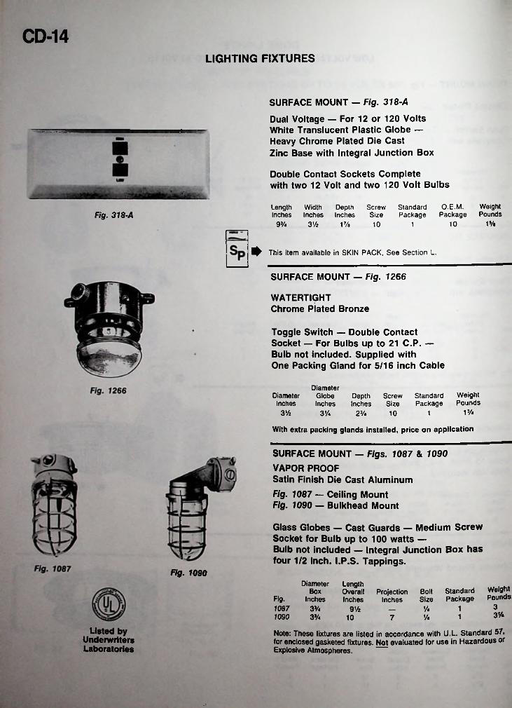
CD-14LIGHTING FIXTURES
SURFACE MOUNT — Fig. 318-A
Dual Voltage — For 12 or 120 Volts White Translucent Plastic Globe — Heavy Chrome Plated Die Cast Zinc Base with Integral Junction Box
Double Contact Sockets Complete with two 12 Volt and two 120 Volt Bulbs
O.E.M. Weight Package Pounds
Length Width Depth Screw Standard Inches Inches Inches Size PackageFig. 318-A
1%93/4 31/2 101 Ve 10 1
^ This item available in SKIN PACK, See Section L.
SURFACE MOUNT — Fig. 1266
WATERTIGHT Chrome Plated Bronze
Toggle Switch — Double Contact Socket — For Bulbs up to 21 C.P. — Bulb not included. Supplied with One Packing Gland for 5/16 inch Cable
DiameterGlobeInches
WeightPounds
DiameterInches
Depth Screw Standard Inches Size Package
13/43% 3 Vi 23/4 10 1
With extra packing glands installed, price on application
SURFACE MOUNT — Figs. 1087 & 1090 VAPOR PROOFSatin Finish Die Cast Aluminum
Fig. 1087 — Ceiling Mount Fig. 1090 — Bulkhead Mount
Glass Globes — Cast Guards — Medium Screw Socket for Bulb up to 100 watts —Bulb not included — Integral Junction Box has four 1/2 inch. I.P.S. Tappings.
Fig. 1090Diameter Length
Box Overall ProjectionInches Inches Inches
WeightPoundsBolt Standard
Size PackageFig.31087 3%
1090 3VaV* 191/2
3V*1/4 110 7
Listed by Underwriters Laboratories
Note: These fixtures are listed in accordance with U.L. Standard 57, for enclosed gasketed fixtures. Not evaluated for use in Hazardous or Explosive Atmospheres.
•t
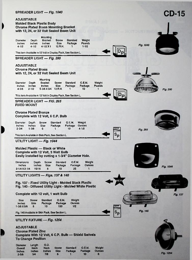
CD-15SPREADER LIGHT — Fig. 1040
ADJUSTABLEMolded Black Plastic BodyChrome Plated Brass Mounting Bracketwith 12, 24, or 32 Volt Sealed Beam Unit
>
Mounting Depth Bracket Inches Inches 4-1/2 4-1/2 X1
Screw Standard WeightSize Package Pounds
12 R.H. 1
DiameterInches4-1/2 Fig. 10401-1/2
This item Available in 12 Volt in Display Pack, See Section L.
SPREADER LIGHT — Fig. 280
ADJUSTABLEChrome Plated Brasswith 12, 24, or 32 Volt Sealed Beam Unit
MountingDiameter Depth Bracket Screw
Inches Inches Inches Size4-5/8 2-1/2 5-3/8 X 3/4 12 R.H.
Standard O.EM. Package Package
WeightPounds
1 10
This item Available in 12 Volt in Display Pack, See Section L.
SPREADER LIGHT — FIG. 265 FIXED MOUNT
Chrome Plated Bronze Complete with 12 Volt, 6 C.P. Bulb
Standard O.E.M. Weight Package Package Ounces
Diameter Depth ScrewInches Inches Size2-3/4 1-3/8 6I 10 4-1/21
This item Available in Skin Pack, See Section L.
UTILITY LIGHT — Fig. 1044
Molded Plastic — Black or WhiteComplete with 12 Volt, 3 Watt BulbEasily Installed by cutting a 1-3/4" Diameter Hole.
Dimensions Depth Screw Standard O.E.M. WeightInches Inches Size Package Package Ounces
2-1/4 X 2-1/4 15/16 6Fig. 1044
25 110
UTILITY LIGHTS — Figs. 137 & 140
Fig. 137 - Fixed Utility Light - Molded Black Plastic Fig. 140 - Diffused Utility Light - Molded White Plastic
Complete with 12 volt, 1 watt Bulb Fig. 137
Standard O.EM. WeightPackage Package Ounces
Size Screw Inches Size
1-3/8 X 5/8 6 1/210 100
Fig. 140Fig. 140 Available in Skin Pack, See Section L.
UTILITY FIXTURE — Fig. 1254
ADJUSTABLE Chrome Plated ZincComplete With 12 Volt, 6 C.P. Bulb — Shield Swivels To Change Position
Diameter Length O.D.OverallInches Inches2-5/8 3/4
INeck Neck Screw Standard O.E.M. Weight
Inches Size Package Package Ounces7/8 10 66 1
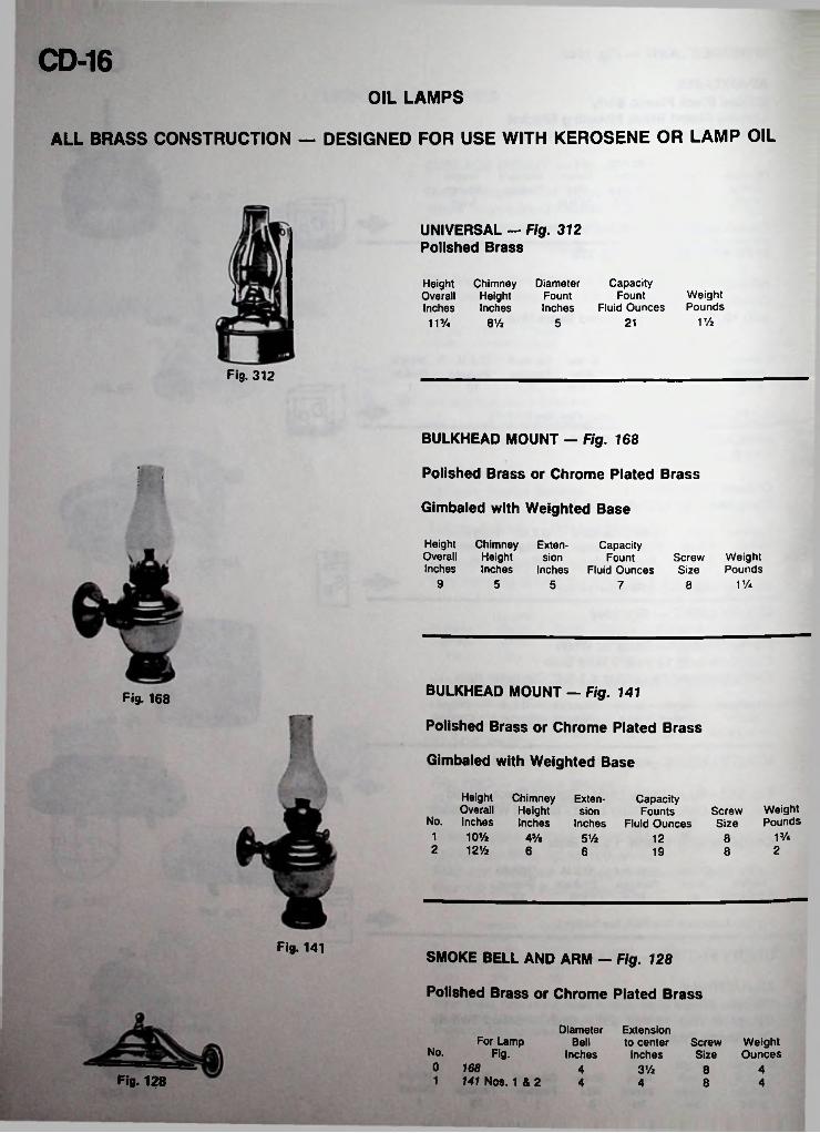
CD-16OIL LAMPS
ALL BRASS CONSTRUCTION — DESIGNED FOR USE WITH KEROSENE OR LAMP OIL
UNIVERSAL - Fig. 312 Polished Brass
Height Chimney Overall HeightInches Inches11J/4 8 Vi
DiameterFountInches
CapacityFount
Fluid OuncesWeightPounds
V/2215
Fig. 312
BULKHEAD MOUNT — Fig. 168
Polished Brass or Chrome Plated Brass.
Gimbaled with Weighted Base
HeightOverallInches
Chimney Exten- Height sion Inches Inches
CapacityFount
Fluid OuncesWeightPounds
ScrewSize
9 5 11/45 7 8
BULKHEAD MOUNT - Fig. 141Fig. 168
Polished Brass or Chrome Plated Brass
Gimbaled with Weighted Base
Height Chimney Overall Height
No. Inches Inches1 10Va2 12’/2
Extension
Inches
Capacity Founts
Fluid OuncesWeightPounds
ScrewSize
13/44% 51/2 12 826 6 819
Fig. 141SMOKE BELL AND ARM — Fig. 128
Polished Brass or Chrome Plated Brass
Diameter ExtensionBell to center Screw
Inches Inches SizeFor Lamp Weight
OuncesNo. Fig.0 16B1 141 Nos. 1 & 2
4 3Vz 48Fig. 128 4 8 44
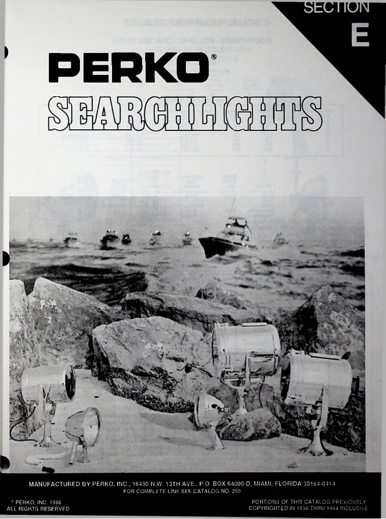
>
PERKO
■m-t
MANUFACTURED BY PERKO, INC., 16490 N.W. 13TH AVE., P.O. BOX 64000-D, MIAMI, FLORIDA 33164-0414FOR COMPLETE LINE SEE CATALOG NO. 250
PORTIONS OF THIS CATALOG PREVIOUSLY COPYRIGHTED IN 1936 THRU 1984 INCLUSIVE
® PERKO, INC. 1986 ALL RIGHTS RESERVED
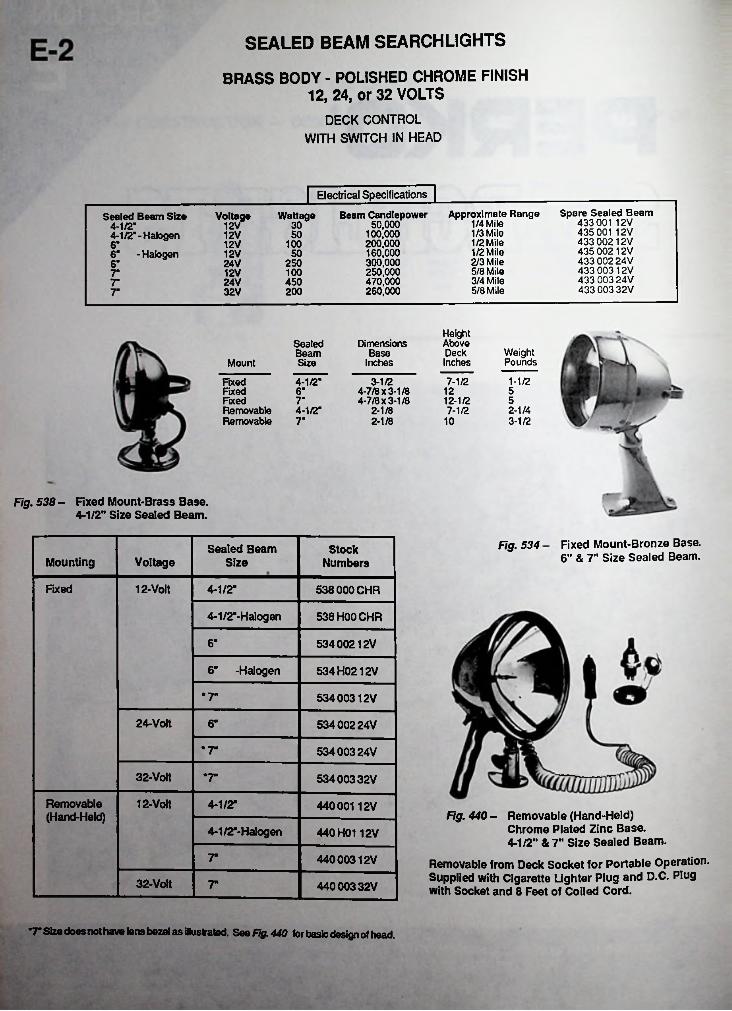
SEALED BEAM SEARCHLIGHTS
BRASS BODY - POLISHED CHROME FINISH 12, 24, or 32 VOLTS
DECK CONTROL WITH SWITCH IN HEAD
| Electrical SpecificationsSpare Sealed Beam
433 001 12V 435 001 12V 433 00212V 435 00212V 433 002 24V 433 00312V 433 003 24V 433 003 32V
Approximate Range 1/4 Mile 1/3 Mile 1/2 Mile 1/2 Mile 2/3 Mile 5/8 Mile 3/4 Mile 5/8 Mile
Wattage Beam Candlepower 50,000
100,000 200,000 160,000300.000250.000470.000260.000
Sealed Beam Size 4-1/2"4:1/2’-Halogen 6" - Halogen
Voltage12V 30
5012V10012V6"5012V
25024V6"10012V7"45024V7"
32V 2007"
HeightAboveDeckInches
DimensionsBase
Inches
SealedBeamSize
WeightPoundsMount
7-1/2 1-1/2FixedFixedFixedRemovableRemovable
4-1/2" 3-1/24-7/8 x 3-1/8 4-7/8 x 3-1/8
12 56"7" 512-1/2
2-1/44-1/2" 2-1/8 7-1/27" 2-1/8 10 3-1/2
Fig. 538 - Fixed Mount-Brass Base.4-1/2” Size Sealed Beam.
Fixed Mount-Bronze Base. 6" & 7" Size Sealed Beam.
Fig. 534Sealed Beam Size
StockNumbersMounting Voltage
Fixed 12-Volt 4-1/2“ 538 000 CHR
4-1/2"-Halogen 538 H00 CHR
6" 53400212V
6" -Halogen 534H0212V
*7" 53400312V
24-Volt 6“ 534 00224V
*7“ 53400324V
32-Volt *7“ 534 00332V
Removable(Hand-Held)
12-Volt 4-1/2“ 440001 12VFig. 440 - Removable (Hand-Held)
Chrome Plated Zinc Base.4-1/2" & 7" Size Sealed Beam.
Removable from Deck Socket for Portable Operation. Supplied with Cigarette Lighter Plug and D.C. Plug with Socket and 8 Feet of Coiled Cord.
4-1/2“-HaIogen 440 H0112V
7“ 44000312V
32-Volt 7“ 44000332V
*7" Size does not have lens bezel as illustrated. See Fig. 440 tor basic design of head
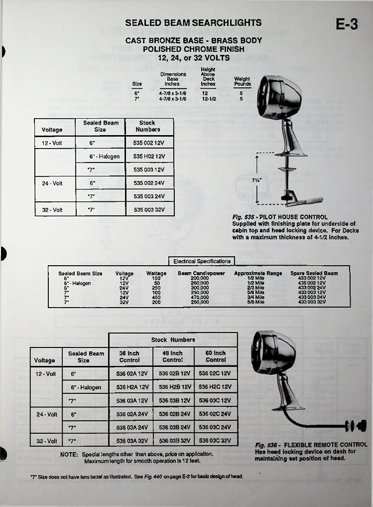
SEALED BEAM SEARCHLIGHTS
CAST BRONZE BASE - BRASS BODY POLISHED CHROME FINISH
12, 24, or 32 VOLTSIHeightAboveDimensions
BaseInches
WeightPounds
DeckSize Inches
6" 4-7/8 x 3-1/8 4-7/8 x 3-1/8
1212-1/27"
StockNumbers
Sealed Beam SizeVoltage
535 00212V12-Volt 6"
535H0212V6" - Halogen
535 00312V*7"
535 002 24V24-Volt 6"
535 003 24V*7"
535 003 32V32 - Volt •7"Fig. 535 - PILOT HOUSE CONTROL Supplied with finishing plate for underside of cabin top and head locking device. For Decks with a maximum thickness of 4-1/2 inches.
| Electrical Specifications |
Voltage Wattage Beam Candlepower 12V 100 200,000
260,000300.000250.000470.000260.000
Approximate Range Spare Sealed Beam 43300212V 43500212V 43300224V 43300312V 433 003 24V 433 003 32V
Sealed Beam Size1/2 Mile 1/2 Mile 2/3 Mile 5/8 Mile 3/4 Mile 5/8 Mile
6“6’ - Halogen 12V 50
24V 2506-12V 100T24V 4507"32 V 2007"
Stock Numbers
60 Inch Control
48 Inch Control
36 Inch Control
Sealed Beam SizeVoltage
536 02B12V 536 02C12V536 02A12V12-Volt 6"
536 H2B12V 536 H2C12V536 H2A12V6"- Halogen
536 03B12V 536 03C12V536 03A12V•7"
536 02B24V 536 02C24V536 02A24V24-Volt 6"
536 03B24V 536 03C24V536 03A 24V“7"
536 03B32V 536 03C32V536 03A32V32-Volt *7" Fig. 536- FLEXIBLE REMOTE CONTROL Has head locking device on dash for maintaining set position of head.
NOTE: Special lengths other than above, price on application. Maximum length for smooth operation is 12 feet.
*7” Size does not have lens bezel as illustrated. See Fig. 440 on page E-2 for basic design of head.
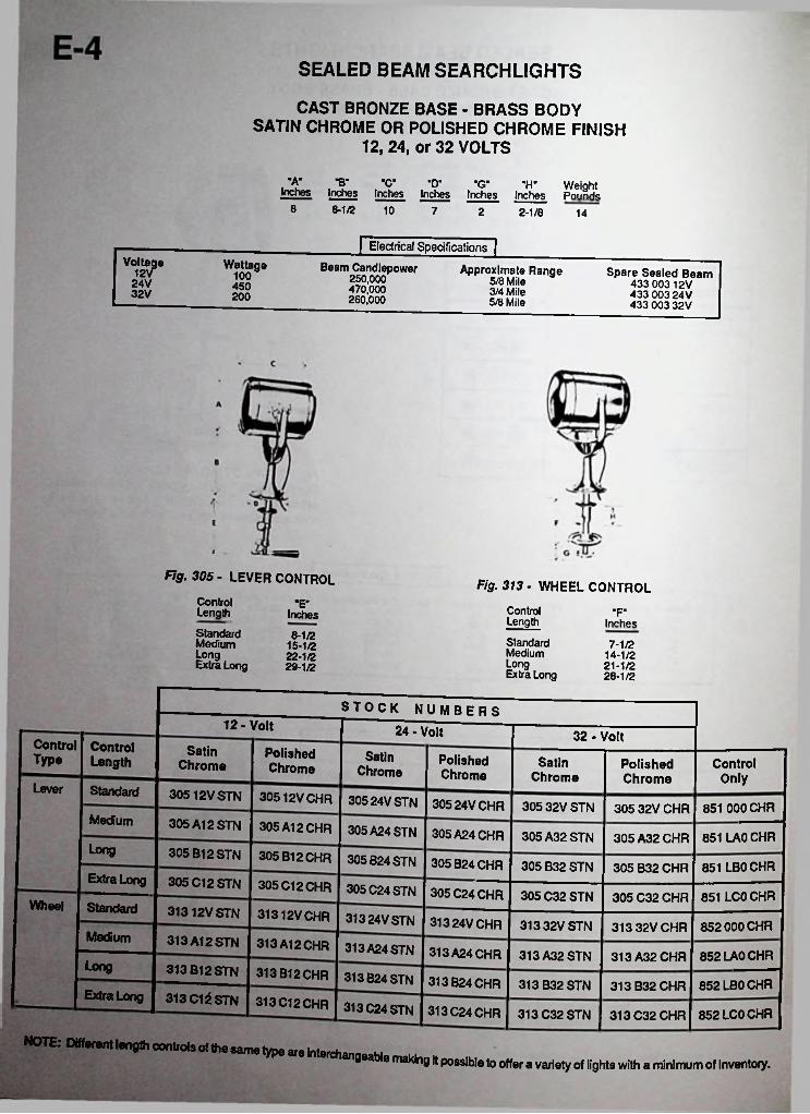
SEALED BEAM SEARCHLIGHTS
CAST BRONZE BASE - BRASS BODY SATIN CHROME OR POLISHED CHROME FINISH
12, 24, or 32 VOLTS
■A" •B' C D G H- Weight Inches Inches PoundsInches Inches Inches Inches
8-1/2 108 7 2 2-1/8 14
| Electrical Specifications |Voltage
12V Wattage Beam Candlepower250.000470.000260.000
Approximate Range5/8 Mile 3/4 Mile 5/8 Mile
Spare Sealed Beam 433 00312V 433 003 24V 433 003 32V
10024V 45032V 200
Fig. 305 - LEVER CONTROL
Control Length
Standard Medium
jExtra Long
Fig. 313 - WHEEL CONTROL■E" Control
Length"F“Inches
Inches8-1/2 Standard
MediumLongExtra Long
7-1/214-1/221-1/228-1/2
15-1/222-1/229-1/2
Long
STOCK NUMBERS12-Volt 24 - Volt 32 - Volt
ControlType
ControlLength
SatinChrome
PolishedChrome
SatinChrome
PolishedChrome
SatinChrome
ControlOnly
PolishedChrome
Lever Standard 30512VSTN 30512V CHR 30524VSTN 305 24V CHR 30532VSTN 851 000 CHR305 32V CHRMedium 305A12STN 305 A12 CHR 305A24STN 305A24CHR 305A32STN 851 LAO CHR305 A32 CHRLong 305 B12STN 305 B12CHR 305B24STN 305 B24CHR 305 B32 STN 851 LB0 CHR305 B32 CHRExtra Long
Standard
305 C12 STN 305 C12 CHR 305C24STN 305 C24 CHR 305 C32 STN 305C32CHR 851 LC0CHRWheel 31312V STN 31312V CHR 313 24V STN 313 24V CHR 313 32V STN 852 000 CHR313 32V CHRMedium 313 A12STN 313 A12 CHR 313 A24STN 313 A24 CHR 852 LAO CHR313A32STN 313 A32 CHRLong 313812 STN
313C12STN
313 B12 CHR 313B24STN 313 B24 CHR 852LB0CHR313 B32 STN 313 B32 CHRExtra Long 313 C12 CHR 313C24STN 313 C24 CHR 852LC0CHR313 C32 STN 313 C32 CHR
NOTE: Different length controls of the same typechangeable making it possible to offer a variety of lights with a minimum of inventory.
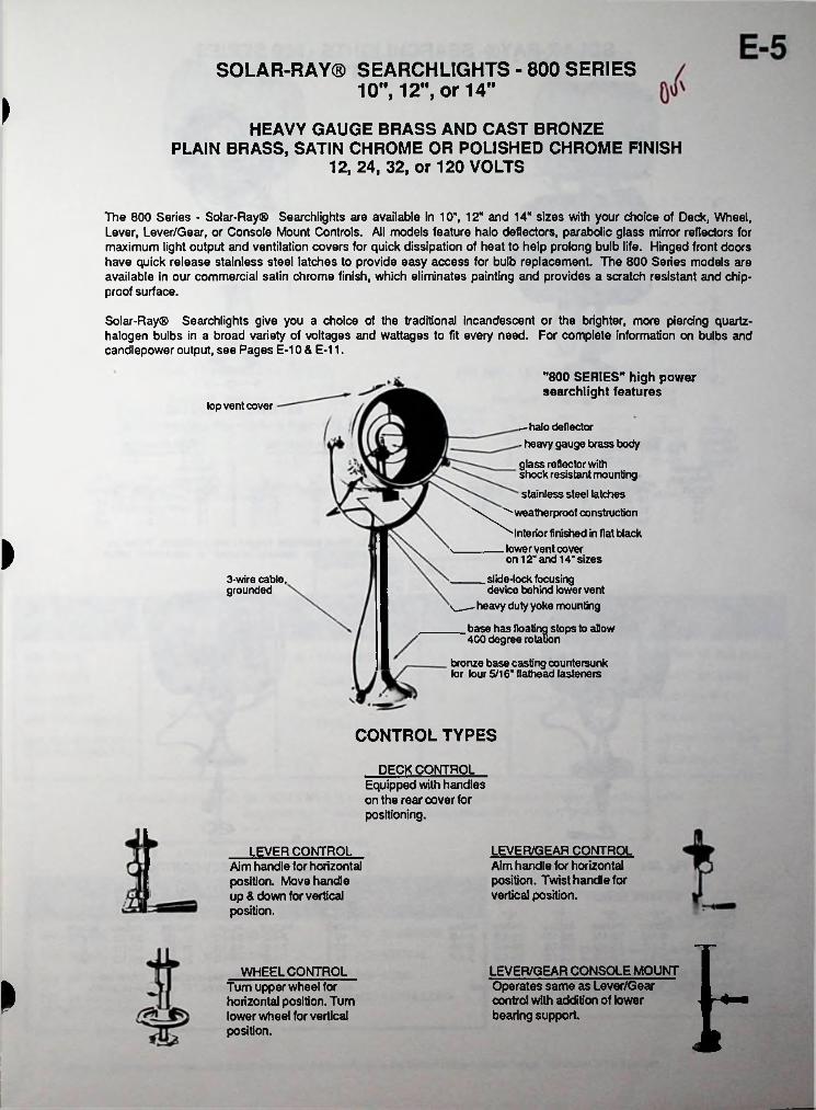
SOLAR-RAY® SEARCHLIGHTS - 800 SERIES 10", 12", or 14"
>HEAVY GAUGE BRASS AND CAST BRONZE
PLAIN BRASS, SATIN CHROME OR POLISHED CHROME FINISH12, 24, 32, or 120 VOLTS
The 800 Series - Solar-Ray® Searchlights are available in 10", 12" and 14" sizes with your choice of Deck, Wheel, Lever, Lever/Gear, or Console Mount Controls. All models feature halo deflectors, parabolic glass mirror reflectors for maximum light output and ventilation covers for quick dissipation of heat to help prolong bulb life. Hinged front doors have quick release stainless steel latches to provide easy access for bulb replacement. The 800 Series models are available in our commercial satin chrome finish, which eliminates painting and provides a scratch resistant and chip- proof surface.
Solar-Ray® Searchlights give you a choice of the traditional incandescent or the brighter, more piercing quartz- halogen bulbs in a broad variety of voltages and wattages to fit every need. For complete information on bulbs and candlepower output, see Pages E-10 & E-11.
"800 SERIES" high power searchlight features
top vent cover
—halo deflector- heavy gauge brass body
glass reflector with shock resistant mounting
stainless steel latches\ "'■weatherproof construction
^interior finished in flat blacks_______ lower vent cover
on 12“ and 14" sizes
_____slide-lock focusingdevice behind lower vent
v._- heavy duty yoke mounting
__base has floating stops to allow4CO degree rotation
bronze base casting countersunk for four 5/16“ fiathead fasteners
>
3-wire cable, grounded
CONTROL TYPES
DECK CONTROLEquipped with handles on the rear cover for positioning.
LEVER/GEAR CONTROLLEVER CONTROLAim handle for horizontal position. Twist handle for vertical position.
Aim handle for horizontal position. Move handle up & down for vertical position.
i-LEVER/GEAR CONSOLE MOUNTWHEEL CONTROLOperates same as Lever/Gear control with addition of lower bearing support.
Turn upper wheel for horizontal position. Turn lower wheel for vertical position.
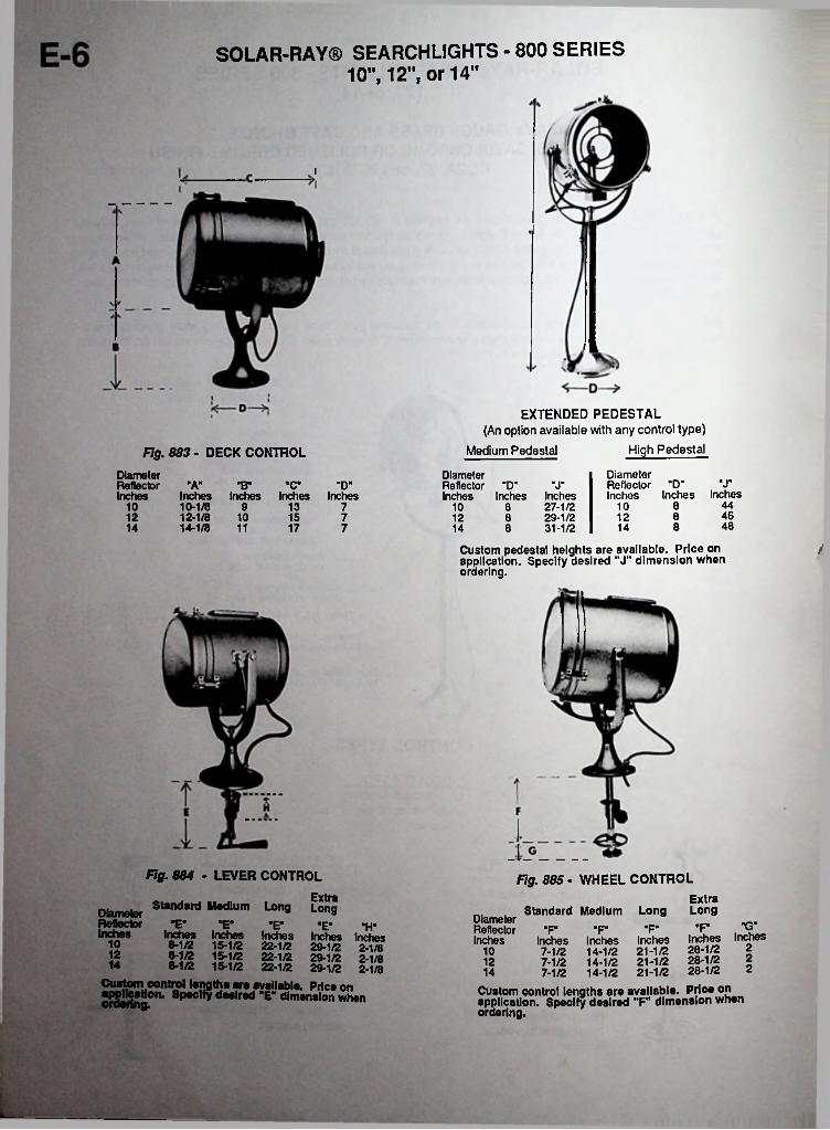
SOLAR-RAY® SEARCHLIGHTS - 800 SERIES 10", 12", or 14"
I
EXTENDED PEDESTAL(An option available with any control type)
High PedestalMedium PedestalFig. 883 - DECK CONTROL
DiameterReflector "D" ’J"Inches Inches Inches
DiameterReflector "A" "B' "C"Inches Inches Inches Inches Inches
10-1/8 912-1/8 1014-1/8 11
DiameterReflector "D" "J"Inches Inches Inches
8 27-1/28 29-1/28 31-1/2
Custom pedestal heights are available. Price on application. Specify desired "J" dimension when ordering.
■D"4481010 13 7 1046812 15 7 121248814 17 7 1414
/
Fig. 884 - LEVER CONTROL Fig. 885 - WHEEL CONTROL
Standard Medium Long LongExtra
Standard Medium Long LongDiameterReflector "E" "E"Inches Inches Inches
8-1/2 15-1/28-1/2 15-1/28-1/2 15-1/2
DiameterReflector "P "P "P Inches Inches Inches Inches
7-1/2 14-1/2 21-1/27-1/2 14-1/2 21-1/27-1/2 14-1/2 21-1/2
Custom control lengths are available. .application. Specify desired "F" dimension when ordering.
•E" “E- ■G""H" "PInches Inches Inches22-1/2 29-1/2 2-1/822-1/2 29-1/2 2-1/822-1/2 29-1/2 2-1/8
Custom control lengths are available. Price onorSering0n* 8p#c * d##,red "E" dimension when
Inches Inches28-1/2 228-1/2 228-1/2 2Price on
10 1012 1214 14
Ui
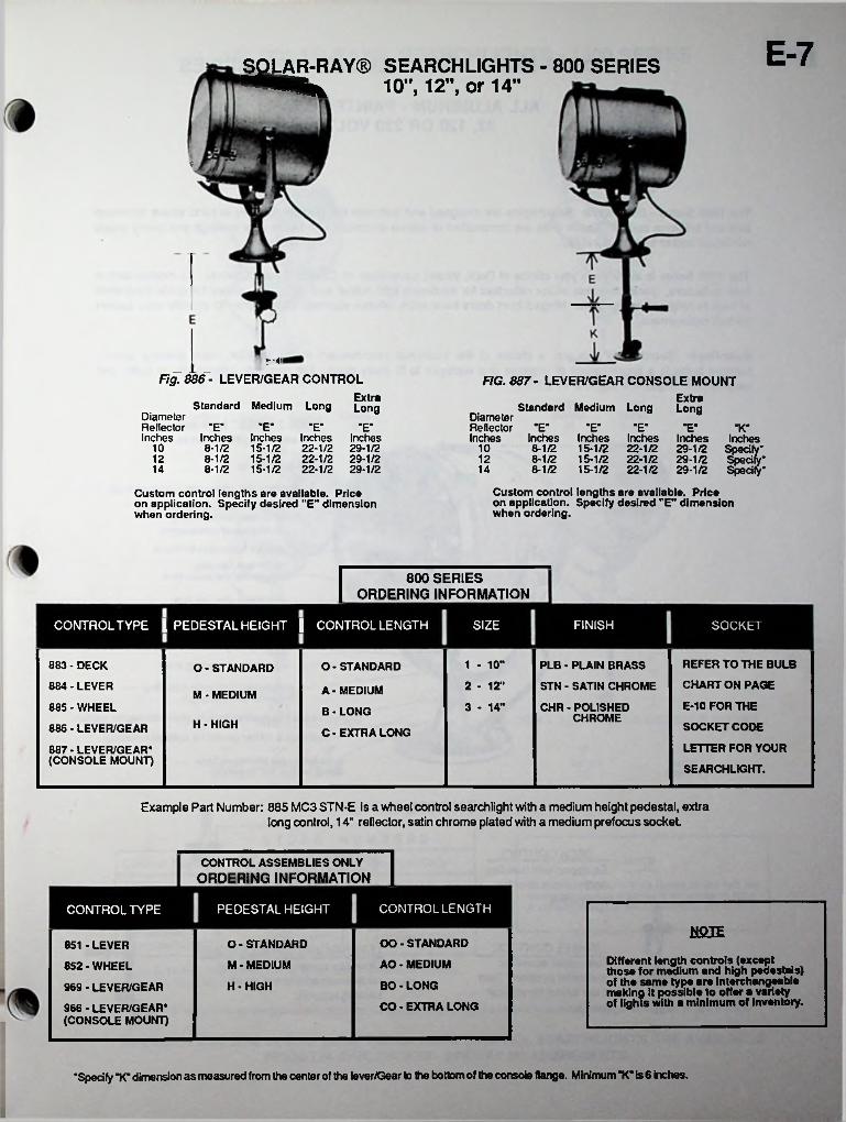
E-7SOLAR-RAY® SEARCHLIGHTS - 800 SERIES 10", 12", or 14"
%
Fig. 886- LEVER/GEAR CONTROL
Standard Medium Long
FIG. 887- LEVER/GEAR CONSOLE MOUNTExtra
Standard Medium Long LongExtraLong
DiameterReflectorInches
Diameter Reflector "E"Inches Inches Inches
8-1/2 15-1/28-1/2 15-1/28-1/2 15-1/2
E E E E *E“ -E- •E" "K"Inches Inches Inches Inches8-1/2 15-1/2 22-1/2 29-1/28-1/2 15-1/2 22-1/2 29-1/28-1/2 15-1/2 22-1/2 29-1/2
Inches Inches Inches22-1/2 29-1/2 Specify’22-1/2 29-1/2 Specify’22-1/2 29-1/2 Specify’
Custom control lengths are available. Price on application. Specify desired "E" dimension when ordering.
10 1012 1214 14
Custom control lengths are available. Price on application. Specify desired "E" dimension when ordering.
800 SERIESORDERING INFORMATION
SIZE FINISHCONTROL TYPE I PEDESTAL HEIGHT I CONTROL LENGTH SOCKET
REFER TO THE BULB CHART ON PAGE
1 - 10"883 • DECK PLB - PLAIN BRASSO- STANDARDO- STANDARD2 - 12"884 - LEVER STN - SATIN CHROMEA-MEDIUMM • MEDIUM
E-10 FOR THE885 - WHEEL 3 - 14" CHR - POLISHED CHROMEB•LONG
H - HIGH SOCKET CODE886 - LEVER/GEAR C - EXTRA LONGLETTER FOR YOUR887 - LEVER/GEAR*
(CONSOLE MOUNT)SEARCHLIGHT.
Example Part Number: 885 MC3 STN-E is a wheel control searchlight with a medium height pedestal, extra long control, 14" reflector, satin chrome plated with a medium prefocus socket.
CONTROL ASSEMBLIES ONLYORDERING INFORMATION
CONTROL LENGTHPEDESTAL HEIGHTCONTROL TYPE
NOTEOO - STANDARDO- STANDARD851 - LEVER
Different length controls (except those for medium and high pedestals) of the same type are Interchangeable making it possible to offer a variety of lights with a minimum of Inventory.
AO - MEDIUMM - MEDIUM852 - WHEEL
BO - LONGH • HIGH969 - LEVER/GEAR
966 - LEVER/GEAR* (CONSOLE MOUNT)
CO - EXTRA LONG
’Specify "K“ dimension as measured from the center of the lever/Gear to the bottom of the console flange. Minimum K" is 6 inches.
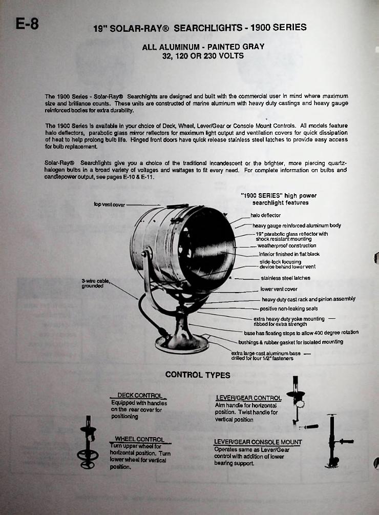
19" SOLAR-RAY® SEARCHLIGHTS - 1900 SERIES
ALL ALUMINUM - PAINTED GRAY 32, 120 OR 230 VOLTS
The 1900 Series - Solar-Ray® Searchlights are designed and built with the commercial user in mind where maximum size and brilliance counts. These units are constructed of marine aluminum with heavy duty castings and heavy gauge reinforced bodies for extra durability.
The 1900 Series is available in your choice of Deck, Wheel, Lever/Gear or Console Mount Controls. All models feature halo deflectors, parabolic glass mirror reflectors for maximum light output and ventilation covers for quick dissipation of heat to help prolong bulb life. Hinged front doors have quick release stainless steel latches to provide easy access for bulb replacement
Solar-Ray® Searchlights give you a choice of the traditional incandescent or the brighter, more piercing quartz- halogen bulbs in a broad variety of voltages and wattages to fit every need. For complete information on bulbs and candlepower output, see pages E-10 & E-11.
"1900 SERIES" high power searchlight featurestop vent cover
halo deflectorheavy gauge reinforced aluminum body-19" parabolic glass reflector with
shock resistant mounting _ weatherproof construction _interior finished in flat black
slide-lock focusing — device behind lower vent
rstainless steel latches3-wire cable,
grounded __ lower vent cover— heavy duty cast rack and pinion assembly— positive non-leaking seals
extra heavy duty yoke mounting — ribbed for extra strength
base has floating stops to allow 400 degree rotation bushings & rubber gasket for isolated mounting
extra large cast aluminum base — drilled for four 1/2" fasteners
CONTROL TYPES
_ DECK CONTROLEquipped with handles on the rear cover for positioning
LEVER/GEAR CONTROLAim handle for horizontal position. Twist handle for vertical position VWHEEL CONTROL
Turn upper wheel forhorizontal position. Turn lower wheel for vertical position.
LEVER/GEAR CONSOLE MOUNTOperates same as Lever/Gearcontrol with addition of lower bearing support.
n.
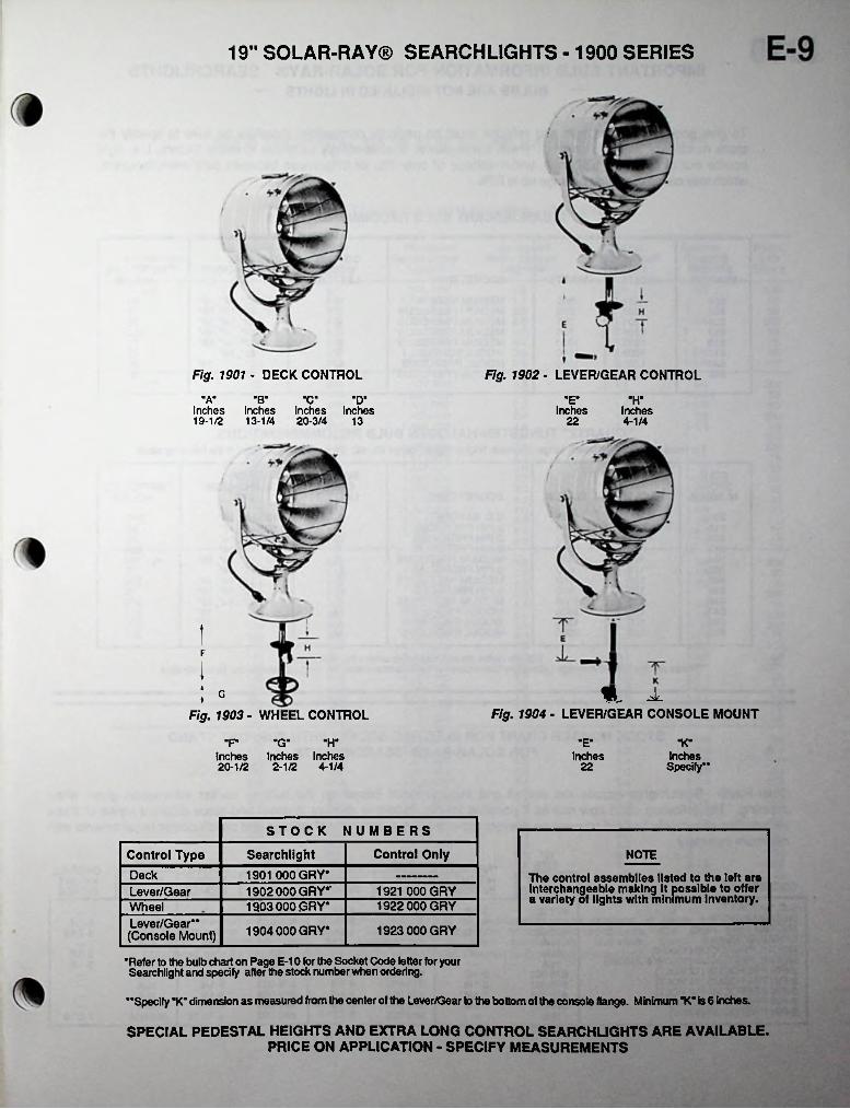
19” SOLAR-RAY® SEARCHLIGHTS - 1900 SERIES
Fig. 1901 - DECK CONTROL Fig. 1902 - LEVER/GEAR CONTROL
■A’ B C D "E" "H"Inches Inches Inches Inches19-1/2 13-1/4 20-3/4 13
Inches Inches22 4-1/4
iF
I» H a
Fig. 1904 - LEVER/GEAR CONSOLE MOUNT
G♦Fig. 1903 - WHEEL CONTROL
"H""P -G- •E" K-Inches Inches 2-1/2 4-1/4
Inches InchesSpecify**
Inches20-1/2 22
STOCK NUMBERSControl OnlySearchlightControl Type NOTE
1901 000 GRY*Deck The control assemblies listed to the left areInterchangeable making It possible to offer a variety of lights with minimum Inventory.1902 000 GRY*' 1921 000 GRYLever/Gear
1922 000 GRY1903 000,GRY*WheelLever/Gear** (Console Mount) 1904 000 GRY* 1923 000 GRY
•Refer to the bulb chart on Page E-10 for the Socket Code letter for your Searchlight and specify after the stock number when ordering.
••Specify "K" dimension as measured from the center of the Lever/Gear to the bottom of the console flange. Minimum "K"«s6 inches.
SPECIAL PEDESTAL HEIGHTS AND EXTRA LONG CONTROL SEARCHUGHTS ARE AVAILABLE. PRICE ON APPLICATION - SPECIFY MEASUREMENTS
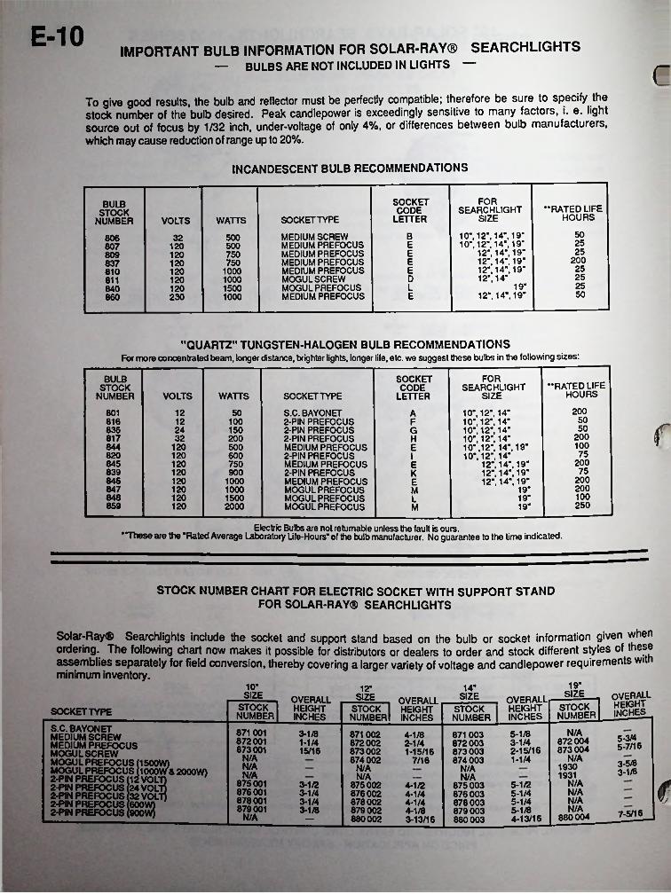
E-10 IMPORTANT BULB INFORMATION FOR SOLAR-RAY® SEARCHLIGHTS — BULBS ARE NOT INCLUDED IN LIGHTS — c
To give good results, the bulb and reflector must be perfectly compatible; therefore be sure to specify the stock number of the bulb desired. Peak candlepower is exceedingly sensitive to many factors, i. e. light
out of focus by 1/32 inch, under-voltage of only 4%, or differences between bulb manufacturers,sourcewhich may cause reduction of range up to 20%.
INCANDESCENT BULB RECOMMENDATIONS
FORSOCKETCODE
LETTER
BULBSTOCK
NUMBER-RATED LIFE
HOURSSEARCHLIGHT
SIZESOCKET TYPEVOLTS WATTS
5010", 12". 14". 19" 10“. 12’. 14“, 19“
12“. 14“. 19“ 12“. 14“. 19“ 12“. 14". 19" 12“. 14'
12“. 14'. 19“
BMEDIUM SCREW MEDIUM PREFOCUS MEDIUM PREFOCUS MEDIUM PREFOCUS MEDIUM PREFOCUS MOGULSCREW MOGUL PREFOCUS MEDIUM PREFOCUS
500806 32 25E500807 120 25E750809 120 200E750120837 25E1000810 120 25D1000811 120 2519“L120 1500840 50E230 1000860
’•QUARTZ" TUNGSTEN-HALOGEN BULB RECOMMENDATIONSFor more concentrated beam, longer distance, brighter lights, longer life, etc. we suggest these bulbs in the following sizes:
SOCKETCODE
LETTER
FORBULBSTOCK
NUMBER-RATED LIFE
HOURSSEARCHLIGHT
SIZEVOLTS WATTS SOCKET TYPE
200801 12 S.C. BAYONET 2-PIN PREFOCUS 2-PIN PREFOCUS 2-PIN PREFOCUS MEDIUM PREFOCUS 2-PIN PREFOCUS MEDIUM PREFOCUS 2-PIN PREFOCUS MEDIUM PREFOCUS MOGUL PREFOCUS MOGUL PREFOCUS MOGUL PREFOCUS
10", 12“, 14“10“. 12“. 14“10“, 12“, 14" 10“,12". 14“10" ,12“, 14", 19" 10", 12", 14'
12“, 14“, 19“ 12", 14“, 19" 12". 14". 19“
50 A50816 12 100 F
f50836 24 150 G200817 32 200 H100844 120 500 E75820 120 600 I 200845 120 750 E75839 120 900 K
200846 120 1000 E200847 120 1000 19“M100848 120 1500 19'L250859 120 2000 19'M
Electric Bulbs are not returnable unless the fault is ours.TTiese are the “Rated Average Laboratory Life-Hours' of the bulb manufacturer. No guarantee to the time indicated.
STOCK NUMBER CHART FOR ELECTRIC SOCKET WITH SUPPORT STAND FOR SOLAR-RAY® SEARCHLIGHTS
19’IQ- 14"12“ SIZE OVERALLHEIGHTinches
SIZE SIZE-£!2§—, OVERALL STOCK HEIGHT NUMBER! INCHES
—. OVERALL STOCK HEIGHT NUMBER! INCHES
OVERALLHEIGHTINCHES
STOCKNUMBER
STOCKNUMBERSOCKET TYPE
S.C. BAYONETMEDIUM SCREW MEDIUM PREFOCUS MOGULSCREW MOGUL PREFOCUS (1500W)MOGUL PREFOCUS (1000W& 2000W) 2-PIN PREFOCUS 12 VOLT)2-PIN PREFOCUS 24 VOLT)2-PIN PREFOCUS 132 VOLT)2-PIN PREFOCUS 600W)2-PIN PREFOCUS 900W)
871 001 872001 873001
N/A3-1/8 5-1/83-1/42-15/16
871002 4-1/8872002 2-1/4873002 1-15/16874 002 7/16
871 003 872003 873003 874 003
5-3/4872004 873 004
1-1/4 5-7/1615/16N/A N/A1-1/4 3-5/8N/A 1930N/A N/A 3-1/8N/A 1931N/A N/A
N/A875001876001878001879001
<r3-1/2 875002 876002 878002879 002 4-1/8880002 3-13/16
5-1/24-1/24-1/44-1/4
875003 876 003878 003879 003880 003
N/A3-1/4 5-1/4N/A3-1/4 5-1/4N/A3-1/8 5-1/8 7-5/16880004N/A 4-13/16

11
BULB TECHNICAL DATA FOR SOLAR RAY® SEARCHLIGHTS
The Following Chart is Provided to Aid in Proper Bulb Selection
BulbStock
Number
MaximumCandlepower
Output
Horizontal Beam Spread
Degrees
Vertical Beam Spread
Degrees
Approx.RangeMiles*
RatedSearchlight Life
Size Voltage Hours
IQ- 251.000 1,168,000
891.000571.000943.000908.000
1.332.0001.375.000
12 801 1.6 2.1 5/8 20012 816 1.7 1.4 1 5024 836 2.6 1.5 1 5032 817 2.6 1.7 3/4 200
80632 3.4 13.9 50120 820 4.4 2.2 1 75120 807 3.5 2.8 1-1/8 25120 844 3.1 3.4 1-1/8 100
12" 12 801 407.0001.617.0001.349.000
865.0001.496.000
977.0001.185.0001.410.0001.747.0001.790.0001.799.0001.816.0001.894.0001.911.0002.482.000
865.000
1.3 1.5 3/4 20012 816 1.5 1.2 1-1/4 5024 836 2.2 1.5 1-1/8 5032 817 2.4 1.6 7/8 20032 806 3.4 3.5 1-1/8 50
120 837 4.1 13.7 200120 845 3.7 15.2 200120 820 4.3 1.9 1-1/8 75120 809 3.6 3.4 1-1/4 25120 844 3.2 3.4 1-1/4 100120 807 3.3 1-1/43.1 25
811120 4.0 4.9 1-1/4 25120 810 4.0 3.8 1-3/8 25120 846 3.9 5.0 1-3/8 200120 839 4.5 5.5 1-1/2 75230 860 6.9 5.9 7/8 25
14" 12 801 443.0001.756.0001.367.000
943.0001.591.0001.254.0001.531.0001.626.0002.007.0002.249.0002.353.0002.361.0002.586.0002.621.0002.889.0001.021.000
1.2 1.4 3/4 20012 816 1.5 1.0 1-1/4 5024 836 2.3 12 1-1/8 5032 817 2.2 1.5 1 20032 806 4.0 3.7 1-1/8 50
120 837 3.9 1-1/84.5 200120 845 3.6 5.1 1-1/8 200
4.5120 820 1.9 1-1/4 75844 2.9120 32 1-3/8 100811120 4.0 5.1 1-3/8 25
120 807 3.2 32 1-1/2 253.7120 809 4.0 1-1/2 253.8120 846 5.0 1-1/2 200
810120 4.0 4.5 1-1/2 254.5 1-5/8120 839 5.2 757.7230 860 6.2 1 50
3.520.0002.076.0002.871.0003.191.0003.633.0003.659.0004.212.0004.454.0004.601.0005.596.0005.622.0005.769.0005.968.0002.162.000
3.519" 806 3.7 1-2/3 50323.6837 42 1-3/8 2001203.6845 5.4 1-5/8120 200
807 3.5 1-5/8 25120 4.0859 9.4 5.9 1-2/3 250120
4.5 1-2/3847 5.4 200120844 3.0 5.4 1-3/4 100120809 3.6 4.5 1-3/4 25120
4.5 5.4 1-7/8 200846120848 5.9 5.7 2 100120810 3.6 2 25120 42
755.9 5.4 28391202-1/8 25840 5.6 5.4120
7.9 50860 6.5 1-3/8230
*The approximate ranges listed above are based on photometric measurements of beam candlepower output under Ideal conditions. Many factors such as atmospheric conditions, size and color of target, background, etc., may reduce effective range considerably; therefore, these figures are offered only for use as a guide for comparison between different bulb and voltage options.
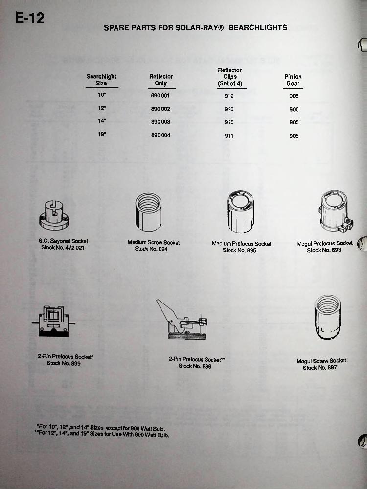
E-12SPARE PARTS FOR SOLAR-RAY® SEARCHLIGHTS
cReflector
Clips (Set of 4)
ReflectorOnly
SearchlightSize
PinionGear
10" 890001 910 905
12" 890 002 910 905
14" 890 003 910 905
19" 890004 911 905
.1JMogul Prefocus Socket ^
Stock No. 893S.C. Bayonet Socket Stock No. 472 021
Medium Screw Socket Stock No. 894
Medium Prefocus Socket Stock No. 895
2-Pin Prefocus Socket* Stock No. 899 2-Pin Prefocus Socket**
Stock No. 866Mogul Screw Socket
Stock No. 897
Tor 10", 12" ,and 14" Sizes except for 900 Watt Bulb. For 12", 14", and 19" Sizes for Use With 900 Watt Bulb. e
kM.,;
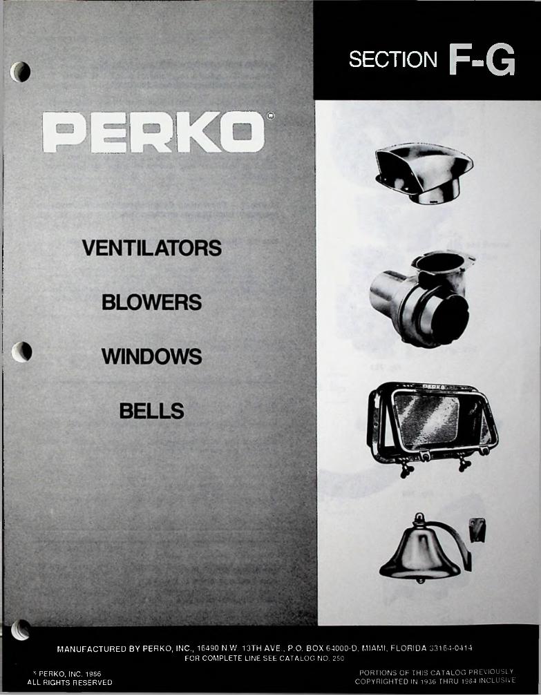
SECTION F-G
MANUFACTURED BY PERKO, INC., 16490 N.W. 13TH AVE., P.O. BOX 64000-D, MIAMI, FLORIDA 33164-0414FOR COMPLETE LINE SEE CATALOG NO. 250
PORTIONS OF THIS CATALOG PREVIOUSLY COPYRIGHTED IN 1936 THRU 1964 INCLUSIVE
» PERKO, INC. 1986 ALL RIGHTS RESERVED
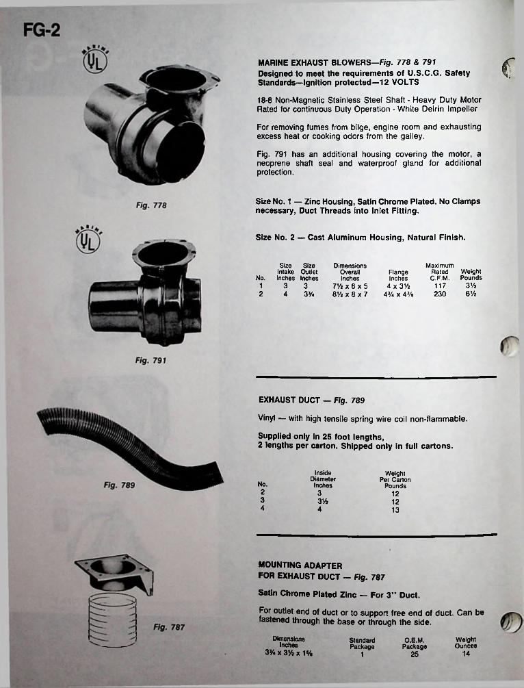
cMARINE EXHAUST BLOWERS-F/g. 778 & 791 Designed to meet the requirements of U.S.C.G. Safety Standards—Ignition protected—12 VOLTS
18-8 Non-Magnetic Stainless Steel Shaft - Heavy Duty Motor Rated for continuous Duty Operation - White Delrin Impeller
For removing fumes from bilge, engine room and exhausting excess heat or cooking odors from the galley.
Fig. 791 has an additional housing covering the motor, a neoprene shaft seal and waterproof gland for additional protection.
Size No. 1 — Zinc Housing, Satin Chrome Plated. No Clamps necessary, Duct Threads into Inlet Fitting.
Size No. 2 — Cast Aluminum Housing, Natural Finish.
Size Size Intake Outlet
No. Inches Inches1 3 32 4 33/4
Dimensions Overall Inches
7V4 x 6 x 5 8Vz x 8 x 7
Maximum Rated Weight C.F.M. Pounds
Flange Inches
4 x 3Va 43/. x 43/a
31/z1176%230
EXHAUST DUCT - Fig. 789
Vinyl — with high tensile spring wire coil non-flammable.
Supplied only in 25 foot lengths,2 lengths per carton. Shipped only in full cartons.
InsideDiameter
Inches
Weight Per Carton
Poundsk No.
2 3 123 3V2 124 4 13
MOUNTING ADAPTERFOR EXHAUST DUCT — Fig. 787
Satin Chrome Plated Zinc — For 3” Duct.
For outlet end of duct or to support free end of duct. Can be fastened through the base or through the side.
O.E.M.Package
DimensionsInches
3% x 3Vi x 1%
WeightOunces
StandardPackage
14251

FG-3CHROMALEX® COWL VENTILATOR — Fig. 1312
Chrome Plated Zinc CowlBlack Plastic Base - For 3 Inch Duct
Hose Clamps Not Required — Duct Threads into Neck.
MouthOpeningSquareInches
Width HeightOverall Overall Inches Inches
LengthOverallInches
StandardPackage
O.E.M.Package
WeightOunces
ScrewSize
87 5V* 43/s 25/s 1
THIS ITEM AVAILABLE IN SKIN PACK, SEE SECTION L.
COWL VENTILATORS — Figs. 654 & 870
Chrome Plated—For 3 Inch DuctFig. 654, Cowl is Cast Bronze, Base is ZincFig. 870, is Zinc.
Hose Clamps Not Required. Duct Threads into Neck.Mouth
Opening Length Square Overall Inches Inches
Fig. 654 Bronze Fig. 870 ZincWidth
OverallInches
HeightOverallInches
NominalWeightOunces
ScrewSize
23/4 10 257 51/4 4
CLAM SHELL VENTILATORS — Fig. 315
Chrome Plated Brass
BaseDimensions
InchesV/eXlVz
WidthOpening Screw Standard Inches Size Package
HeightOpeningInches
O.E.M.Package
WeightOunces Fig. 315
100Vl 6 Ve 10 Vi410 100 V/a2x2 Vl6 1 Ve 6
FIG. 315 NO. 2 AVAILABLE IN SKIN PACK, SEE SECTION L.
CLAM SHELL VENTILATOR — Fig. 339
Chrome Plated Brass
Fig. 339BaseDimensions
Inches 4 x 33/4
WidthOpening Screw Standard Inches Size Package
HeightOpeningInches
O.E.M.Package
WeightOunces
5 25 52Vi 61%
SFTHIS ITEM AVAILABLE IN SKIN PACK, SEE SECTION L.
COWL VENTILATORS — Fig. 510
White Painted Steel — Polished Brass or Chrome Plated Brass Cast Bronze Deck Plate Fig. 510
Internal thumb screw allows cowl to be locked in any position.
Steel ventilators are painted white inside and out. Polished brass and chrome plated ventilators are painted white inside only.
Diam. Height Mouth Overall Screw
Inches Inches Inches SizeWeightPounds
44 108 1165 1010 13
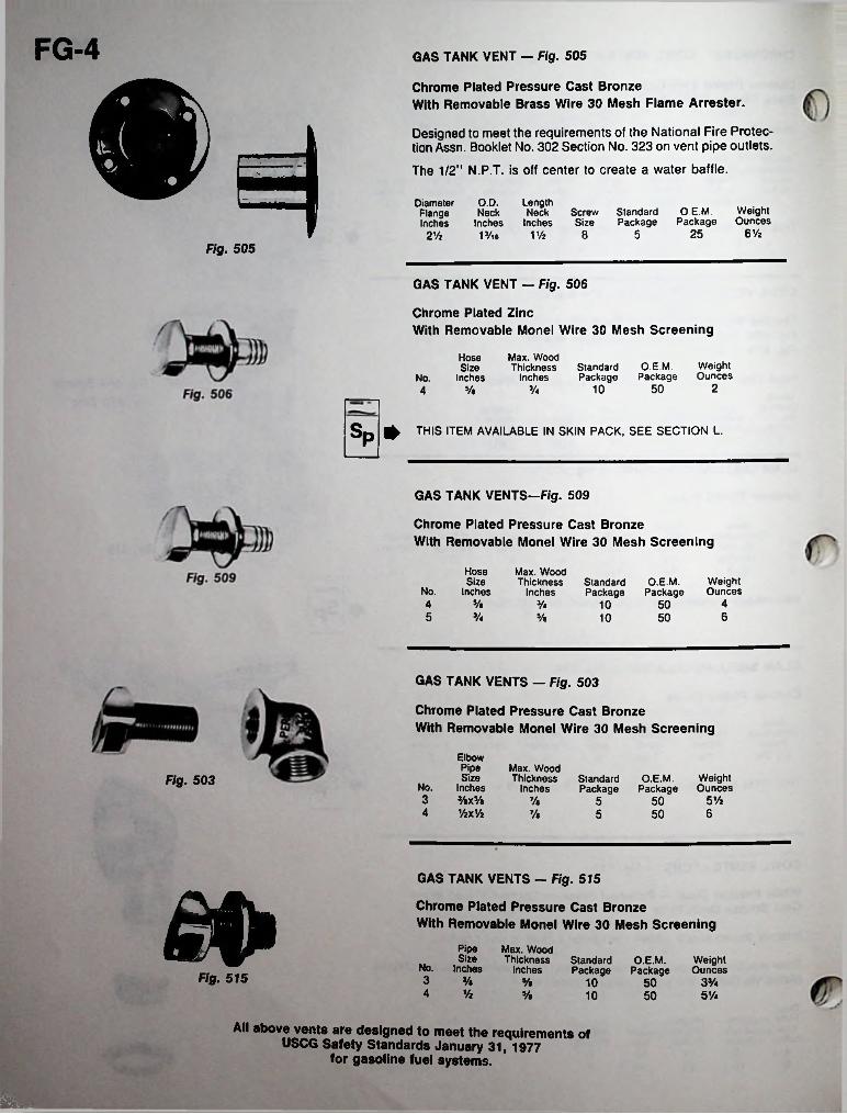
FG-4 GAS TANK VENT - Fig. 505
Chrome Plated Pressure Cast BronzeWith Removable Brass Wire 30 Mesh Flame Arrester.
Designed to meet the requirements of the National Fire Protection Assn. Booklet No. 302 Section No. 323 on vent pipe outlets.
The 1/2” N.P.T. is off center to create a water baffle.
O.D.Neck
Inches13/u
LengthNeck Screw Standard
Inches Size Package
DiameterFlangeInches
O.E.M. Weight Package Ounces
6%2558V/z2 ViFig. 505
GAS TANK VENT - Fig. 506
Chrome Plated ZincWith Removable Monel Wire 30 Mesh Screening
Max. Wood Thickness
Inches
HoseSize
InchesO.E.M. Weight
Package OuncesStandardPackageNo.
210 505/a4
Sp 0 THIS item available in skin pack, see section l.
GAS TANK VENTS-Fig. 509
Chrome Plated Pressure Cast BronzeWith Removable Monel Wire 30 Mesh Screening
HoseSize
Inches
Max. Wood Thickness
InchesWeightOunces
StandardPackage
O.E.M.PackageNo.
4 5/e 43/4 10 50Vi 65 y« 5010
GAS TANK VENTS - Fig. 503
Chrome Plated Pressure Cast BronzeWith Removable Monel Wire 30 Mesh Screening
ElbowPipeSize
No. Inches3 3/eX3/«4 VzxVz
Max. Wood Thickness
InchesO.E.M. Weight
Package OuncesStandardPackage
Fig. 5035 Vi7/« 50567/a 5 50
GAS TANK VENTS - Fig. 515
Chrome Plated Pressure Cast BronzeWith Removable Monel Wire 30 Mesh Screening£0 Pipe Max. Wood
Size ThicknessNo. Inches Inches
StandardPackage
WeightOunces
O.E.M.PackageFig. 515 3 Va Va 3%10 50
4 Vi Va 5Va10 50
All above vents are designed to meet the requirements of USCG Safety Standards January 31, 1977
for gasoline fuel systems.
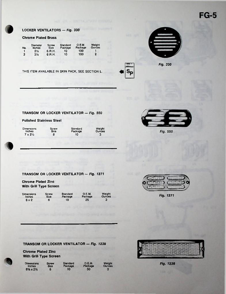
FG-5LOCKER VENTILATORS — Fig. 330
Chrome Plated Brass
WeightOunces
O.E.M.Package
Screw StandardSize Package
6 R.H. 106 R.H. 10
Diameter No. Inches
100 12V2121002 3%
Fig. 330
THIS ITEM AVAILABLE IN SKIN PACK, SEE SECTION L.
TRANSOM OR LOCKER VENTILATOR — Fig. 550
Polished Stainless Steel
Dimensions Inches
7 x 2 Vi
ScrewSize
StandardPackage
WeightOunces
8 10 3
TRANSOM OR LOCKER VENTILATOR — Fig. 1271
IOGZ22D t 1 - ^ ^ 6}Chrome Plated Zinc With Grill Type Screen ■V
O.E.M.Package
WeightOunces
StandardPackage
DimensionsInches6x2
ScrewSize Fig. 1271
310 258
TRANSOM OR LOCKER VENTILATOR — Fig. 1238
Chrome Plated Zinc With Grill Type Screen
StandardPackage
O.E.M.Package
Fig. 1238Dimensions Inches
83/a x 2Va
WeightOunces
ScrewSize
10 50 38
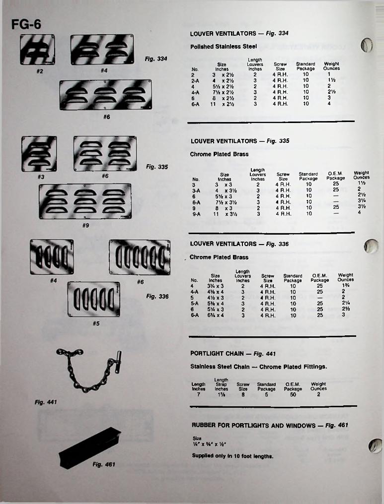
LOUVER VENTILATORS — Fig. 334
Polished Stainless Steel
Fig. 334 LengthLouversInches
WeightOunces
StandardPackage
Screw Size
4 R.H. 4 R.H. 4 R.H. 4 R.H. 4 R.H. 4 R.H.
SizeInches
3 x 2 Vi4 x 2% 51/a x 21/z 7Vi x 2% 8 x 2%
11 x2%
No.11022
10 1V232-A2102421/21034-A31026
10 436-A
#6
LOUVER VENTILATORS — Fig. 335
Chrome Plated Brass
Fig. 335 LengthLouversInches
WeightOunces
O.E.M.Package
StandardPackage
Screw Size
4 R.H. 4 R.H. 4 R.H. 4 R.H. 4 R.H. 4 R.H.
SizeInches
3 x 34 x 31/25 Vi x 3 IVi x 31/2 8 x 3
11 x 3%
No.1 Vi2510232251033-A2 Vi10263%1036-A3 Vi25102941039-A
LOUVER VENTILATORS - Fig. 336
Chrome Plated Brass
LengthLouversInches
WeightOunces
Size O.E.M.Package
Screw Size
4 R.H. 4 R.H. 4 R.H. 4 R.H. 4 R.H. 4 R.H.
StandardPackageNo. Inches
13/4253Va x 3 4% x 4 41/a x 3 5% x 4 5Va x 3 63/s x 4
4 2 102254-A 3 10
Fig. 336 25 2 102V*5-A 253 102Vi256 2 1036-A 253 10
PORTLIGHT CHAIN — Fig. 441
Stainless Steel Chain — Chrome Plated Fittings.
LengthLength Strap Screw StandardInches Inches Size Package
O.E.M. Weight Package Ounces
27 1% 8 5 50
RUBBER FOR PORTLIGHTS AND WINDOWS — Fig. 461
SizeVau x x Vi"
Supplied only in 10 foot lengths.Fig. 461
L
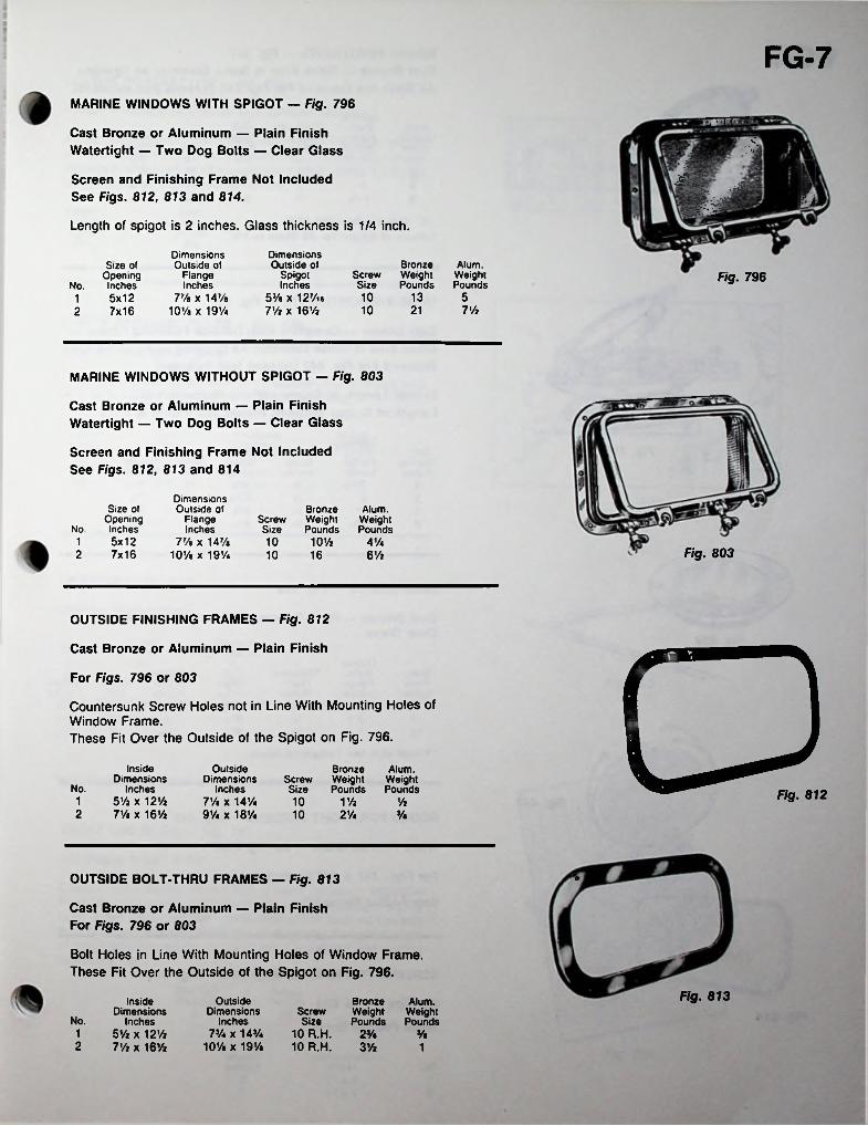
FG-7MARINE WINDOWS WITH SPIGOT - Fig. 796
i-if-
Cast Bronze or Aluminum — Plain Finish Watertight — Two Dog Bolts — Clear Glass
Screen and Finishing Frame Not Included See Figs. 812, 813 and 814.
Length of spigot is 2 inches. Glass thickness is 1/4 inch.
r : - i'; ;mDimensions Outside of
Spigot Inches
53/« x 127/ie 7% x 16%
Dimensions Outside of
Flange Inches
77/e x 14% 10% x 19%
Bronze Screw Weight Size Pounds
Alum.WeightPounds
Size of Opening
No. Inches1 5x122 7x16
Fig. 796
10 13 510 21 7%
MARINE WINDOWS WITHOUT SPIGOT — Fig. 803
Cast Bronze or Aluminum — Plain Finish Watertight — Two Dog Bolts — Clear Glass
Screen and Finishing Frame Not Included See Figs. 812, 813 and 814
Dimensions Outside of
Flange Inches
77/a X 147/a 10% x 19%
Size of Opening
No. Inches1 5x122 7x16
Bronze Screw WeightSize Pounds10 10%
Alum.WeightPounds
4%Fig. 80310 16 6%
OUTSIDE FINISHING FRAMES — Fig. 812
Cast Bronze or Aluminum — Plain Finish OFig. 812
For Figs. 796 or 803
Countersunk Screw Holes not in Line With Mounting Holes of Window Frame.These Fit Over the Outside of the Spigot on Fig. 796.
Inside Dimensions
Inches 5% x 12% 7% x 16%
Outside Dimensions
Inches 7% x 14% 9% x 18%
Bronze Alum. Screw Weight Weight Size Pounds PoundsNo.
1 10 1% %2 10 2% %
OUTSIDE BOLT-THRU FRAMES — Fig. 813 <3
Cast Bronze or Aluminum — Plain Finish For Figs. 796 or 803
Bolt Holes in Line With Mounting Holes of Window Frame. These Fit Over the Outside of the Spigot on Fig. 796.
Fig. 813Outside Dimensions
Inches 7% x 14%
10% x 19%
Inside Dimensions
Inches 5% x 12% 7% x 16%
Bronze Alum. Weight Weight Pounds Pounds
Screw Size
10 R.H. 2%10 R.H. 3%
No.1 %2 1
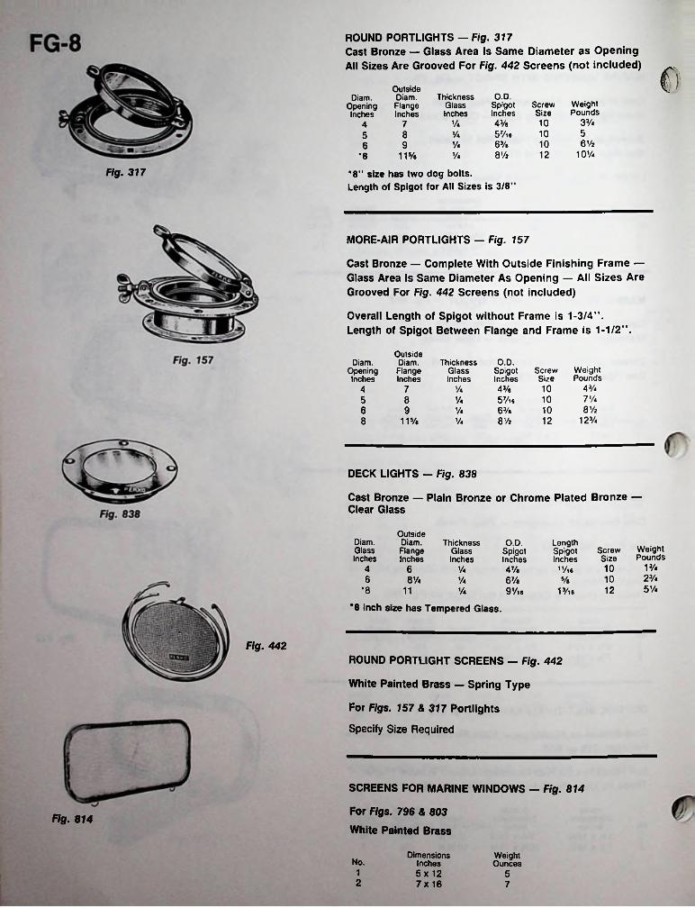
ROUND PORTLIGHTS - Fig. 317Cast Bronze — Glass Area Is Same Diameter as Opening All Sizes Are Grooved For Fig. 442 Screens (not included) cOutside
Diam.FlangeInches
O.D.ThicknessGlassInches
Diam.OpeningInches
WeightPounds
ScrewSize
SpigotInches
3Vi1043/a 5 Vi a 63/a 8V2
Vi745108 Vi56V2109 Vi6
10Vi12Vi115/e*8
Fig. 317 *8” size has two dog bolts.Length of Spigot for All Sizes is 3/8"
MORE-AIR PORTLIGHTS - Fig. 157
Cast Bronze — Complete With Outside Finishing Frame — Glass Area Is Same Diameter As Opening — All Sizes Are Grooved For Fig. 442 Screens (not included)
Overall Length of Spigot without Frame is 1-3/4”.Length of Spigot Between Flange and Frame is 1-1/2”.
OutsideDiam.FlangeInches
ThicknessGlassInches
O.D.Spigot Screw Inches Size43/e 105 Vi 6 1063/a 10
Diam.OpeningInches
WeightPounds
43/44 7 Vi7 Vi5 8 Vi8V26 9 Vi
12V.8 8V2 12115/a Vi
DECK LIGHTS - Fig. 838
Cast Bronze — Plain Bronze or Chrome Plated Bronze — Clear Glass
OutsideDiam.FlangeInches
Diam.GlassInches
ThicknessGlassInches
O.D. LengthSpigotInches
11/l6
WeightPounds
ScrewSize
SpigotInches
1 Vi104 6 Vi 47/e23/4106 8% Vi 6Va 5/a5V4*8 1211 Vi 9 Vie 13/ia
*8 inch size has Tempered Glass.
Fig. 442ROUND PORTLIGHT SCREENS - Fig. 442
White Painted Brass — Spring Type
For Figs. 157 & 317 Portlights
Specify Size Required
SCREENS FOR MARINE WINDOWS — Fig. 814
For Figs. 796 & 803 White Painted Brass
Fig. 814
Dimensions Inches 5x 12 7x 16
WeightOuncesNo.
1 52 7
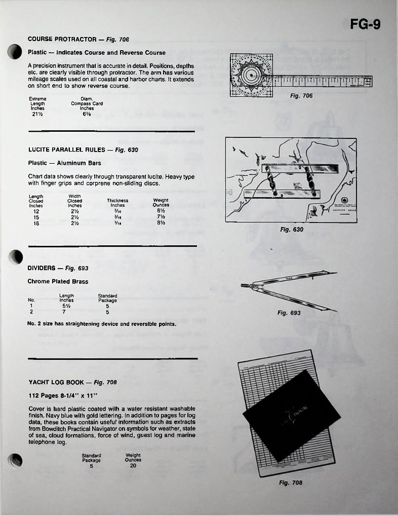
FG-9COURSE PROTRACTOR — Fig. 706
Plastic — Indicates Course and Reverse Course
A precision instrument that is accurate in detail. Positions, depths etc. are clearly visible through protractor. The arm has various mileage scales used on all coastal and harbor charts. It extends on short end to show reverse course. p•i ^ mV
:iExtreme Length Inches 21 Vi
Diam.Compass Card
Inches63/e
LUCITE PARALLEL RULES — Fig. 630
Plastic — Aluminum Bars
Chart data shows clearly through transparent lucite. Heavy type with finger grips and corprene non-sliding discs.
WidthClosedInches
LengthClosedInches
WeightOunces
ThicknessInches
6V23/ie2 Vi127 Vi3/l62 Vi158 Vi3/l82 Vi18
Fig. 630
DIVIDERS — Fig. 693
Chrome Plated Brass
LengthInches
StandardPackageNo.
1 5 Vi 52 7 5
No. 2 size has straightening device and reversible points.
YACHT LOG BOOK — Fig. 708
112 Pages 8-1/4” x 11”
Cover is hard plastic coated with a water resistant washable finish. Navy blue with gold lettering. In addition to pages for log data, these books contain useful information such as extracts from Bowditch Practical Navigator on symbols for weather, state of sea, cloud formations, force of wind, guest log and marine telephone log.
WeightOunces
StandardPackage
205

FG-10THE 8,10,12 AND 14 INCH BELLS LISTED ON PAGES FG-10 AND FG-11 HAVE BEEN REVIEWED BY THE U.S. COAST GUARD AND COMPLY WITH C.G. 169 REGULATIONS FOR SOUND SIGNAL APPLIANCES AS REQUIRED BY ANNEX III PARAGRAPH 2 OF THE 72 COLREGS. THE 8 AND 10 INCH SIZES ARE FOR USE ON VESSELS UNDER 20 METERS IN LENGTH. THE 12 AND 14 INCH SIZES ARE FOR USE ON ANY SIZE VESSEL.
G o CAST BRONZE FOG BELLS — Fig. 420LMJ Polished Bronze or Chrome Plated Bronze.__ 9
Medium Weight — Removable
HeightOverallInches
BottomDiameter
InchesWeightPounds
Screw Size
8 F.H. 8 F.H.
Fig. 4203 Vi566 Vi6 Vi8
CAST BRONZE FOG BELLS - Fig. 150
Plain Bronze — Polished Bronze — Chrome Plated Bronze
Heavy Weight — Removable
BottomDiameter
Inches
HeightOverallInches
Screw Size
12 F.H. 12 F.H. 12 F.H.
WeightPounds
8 8 910 101/a I6V212 12 31
CAST BRONZE FOG BELLS - Fig. 158
Plain Bronze — Polished Bronze — Chrome Plated Bronze
Heavy Weight — Fixed Mounting
BottomDiameter
Inches
HeightOverallInches
Bolt WeightPoundsSize
12 12 V* R.H. 1/4 R.H.
3114 13 351/2
WROUGHT BRASS FOG BELL — Fig. 179
Plain Brass
Light Weight — Fixed Mounting
BottomDiameterInches
HeightOverallInches
Screw Size
12 R.H.
WeightPounds
12 8 9
■
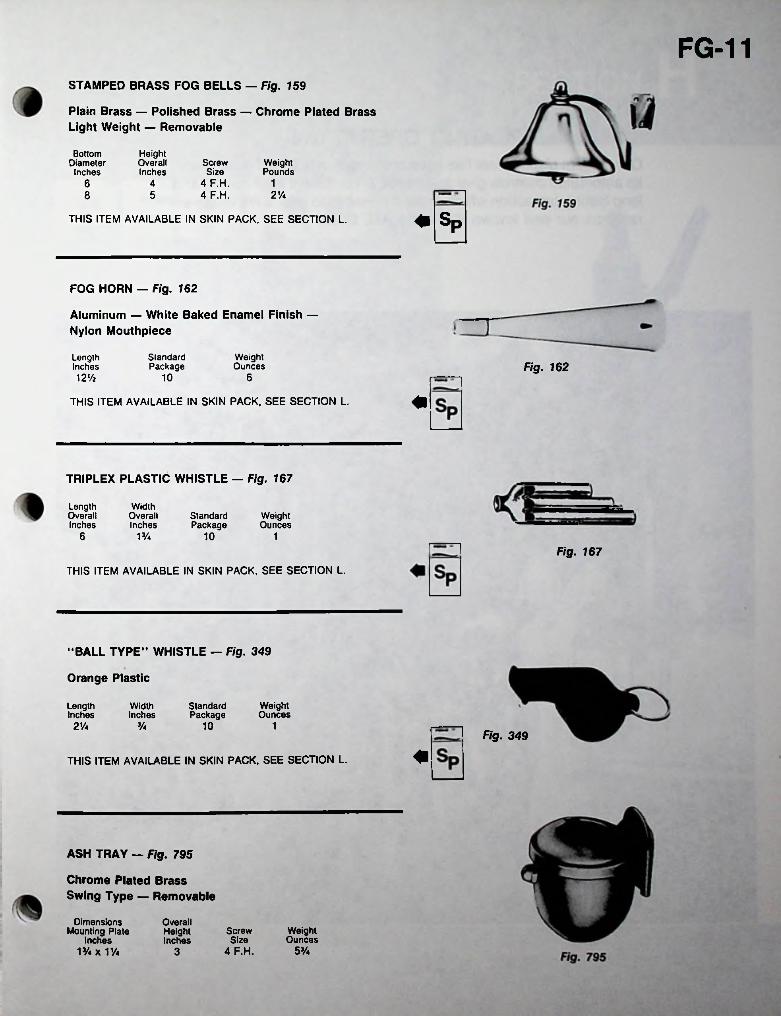
FG-11STAMPED BRASS FOG BELLS — Fig. 159
Plain Brass — Polished Brass — Chrome Plated Brass Light Weight — Removable
BottomDiameter
Inches
HeightOverallInches
Screw Size
4 F.H. 4 F.H.
WeightPounds
6 4 12%8 5
♦ SpTHIS ITEM AVAILABLE IN SKIN PACK, SEE SECTION L.
FOG HORN — Fig. 162
Aluminum — White Baked Enamel Finish — Nylon Mouthpiece
StandardPackage
WeightOunces
LengthInches12%
Fig. 16210 6
THIS ITEM AVAILABLE IN SKIN PACK, SEE SECTION L.
TRIPLEX PLASTIC WHISTLE — Fig. 167
LengthOverallInches
WidthOverallInches
StandardPackage
WeightOunces
6 V/a 10 1Fig. 167
THIS ITEM AVAILABLE IN SKIN PACK, SEE SECTION L.
“BALL TYPE” WHISTLE — Fig. 349
Orange Plastic
WidthInches
StandardPackage
WeightOunces
LengthInches2Va Va 10 1
Fig. 349
THIS ITEM AVAILABLE IN SKIN PACK, SEE SECTION L.
ASH TRAY — Fig. 795
Chrome Plated Brass Swing Type — Removable
Dimensions Mounting Plate
Inches V/4 x V/a
OverallHeightInches
WeightOunces
Screw Size
4 F.H. 53/»3
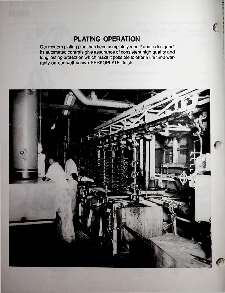
PLATING OPERATIONOur modern plating plant has been completely rebuilt and redesigned. Its automated controls give assurance of consistent high quality and long lasting protection which make it possible to offer a life time warranty on our well known PERKOPLATE finish.
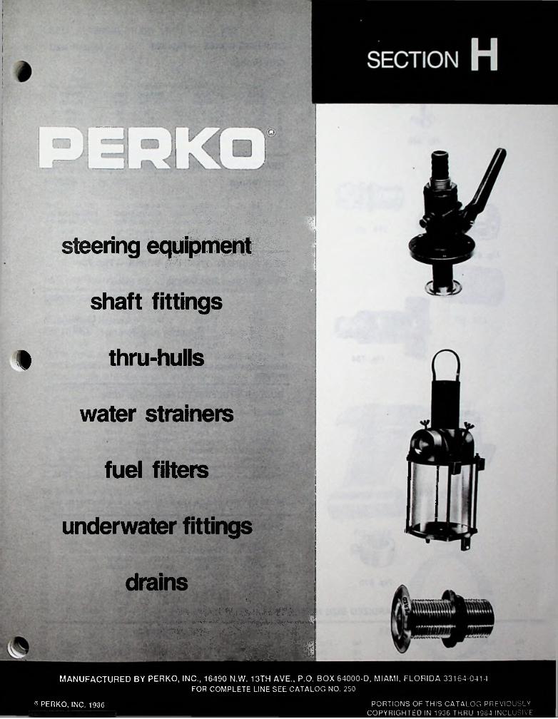
M| msteering equipment
Hshaft fittings \.;r. :
m■
thru-hulls
water strainers
fuel filters
underwater fittings
drains!'
<v.' '' ir-7 ■ '
■■
iwmmMANUFACTURED BY PERKO, INC., 16490 N.W. 13TH AVE., P.O. BOX 64000-D, MIAMI, FLORIDA 33164-0414
FOR COMPLETE LINE SEE CATALOG NO. 250
PORTIONS OF THIS CATALOG PREVIOUSLY COPYRIGHTED IN 1936 THRU 1984 INCLUSIVE
® PERKO, INC. 1986
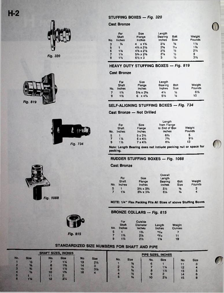
H-2STUFFING BOXES — Fig. 320
Cast Bronze
LengthBearingInches
For Size Flange Inches
4 x13/<AVa x 2 Vi 47/a x 2 Vi53/4 X 23/a 6V2 X 3
BoltSize
WeightPounds
Shaft No. Inches
3/a 1 Vi2Ve3 3/47/l6 13/425/a5 1
6 1Vi7 1Vi9 V/i
% 2%27/e% 327/e
F/g. 320 3 VzVi3
HEAVY DUTY STUFFING BOXES — Fig. 819
Cast Bronze
LengthBearing Bolt Inches Size
For Size Flange Inches
55/e x 3V« 6 x 43/a
WeightPounds
Shaft No. Inches 7 1%9 1 Vi
I[
6ViVi4 Vi10Vi5 Vi
IFig. 819
SELF-ALIGNING STUFFING BOXES — Fig. 734
Cast Bronze — Not Drilled
Length from Flange
to End of Box Inches
Size Flange Inches5 x 3%6 x 41/a7 x 41/2
Note: Length Bearing does not include packing nut or space for packing.
ForWeightPounds
Shaft No. Inches5 17 11/49 V/i
563/49 Vi7%
138 Vi
RUDDER STUFFING BOXES — Fig. 1088
Cast Bronze
OverallLengthBearingInches
For Size Flange Inches
33/a x 33/a 33/a x 33/4
WeightPounds
Shaft No. Inches 5 17 1 Va
BoltSize
33/a5Vi43/e61/4
1088NOTE: 1/4" Flax Packing Fits All Sizes of above Stuffing Boxes
BRONZE COLLARS — Fig. 815
For OutsideDiameter
InchesShaft
No. Inches5 17 1 Vt9 V/i
LengthInches
19/ie15/ie
WeightOunces
13/4 7Fig. 815 2Vt 112’/2 1 Va 19
STANDARDIZED SIZE NUMBERS FOR SHAFT AND PIPE
SHAFT SIZES, INCHES PIPE SIZES, INCHESSize No. Size No. Size No. Size No. Size SizeNo.Vz 7 1 Va 13 2’/2 1 1/a 6 1 311% 8 1% 14 3 2 1/4 7 V/a 12 41 ViVa 9 15 3 Vi 3 3/a 8 1 Vi 513% 10 V/a 16 4 4 Vi 9 2 6142111 5 Va 10 21/2 8151Vi 12 2’/4
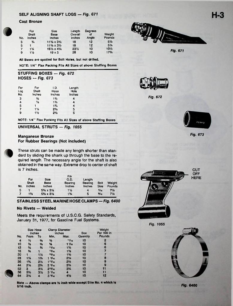
H-3SELF ALIGNING SHAFT LOGS — Fig. 671
Cast Bronze
Length Degrees Overall of Inches Angle
Size Base
Inches 11% x 3% 11% x 3% 16% x 4%
19x5
ForWeightPounds
Shaft No. Inches
SVa12% 1835%12185 1
7 1%9 1%
10%23% 10 Fig. 67117%28 10
All Bases are spotted for Bolt Holes, but not drilled.
NOTE: 1/4" Flax Packing Fits All Sizes of above Stuffing Boxes
STUFFING BOXES — Fig. 672 HOSES — Fig. 673
For For I.D. LengthShaft
InchesLog Hose
InchesHole
No. Inches Fig. 6723 % VA 47/a 1J/44 4
13/45 411%7 23/a 5
9 1% 2% 5
NOTE: 1/4" Flax Packing Fits All Sizes of above Stuffing Boxes
UNIVERSAL STRUTS — Fig. 1055
Fig. 673Manganese BronzeFor Rubber Bearings (Not Included)
These struts can be made any length shorter than standard by sliding the shank up through the base to the required length. The necessary angle for the shaft is also obtained in the same way. Extreme drop to center of shaft is 7 inches. CUT
OFFFor HEREFor Size
Base Inches
53/a x 3% 53/a X 3Va
O.D.BearingInches
LengthBearing Bolt Weight Inches Size Pounds
Shaft No. Inches 5 17 1%
1% Vie 7%413/4 Vie5 7%
STAINLESS STEEL MARINE HOSE CLAMPS — Fig. 6400
No Rivets — Welded
Meets the requirements of U.S.C.G. Safety Standards, January 31, 1977, for Gasoline Fuel Systems.
Size Hose Inches
From To
Clamp Diameter Inches
Weight Per 100 in
PoundsBox
QuantityNo. Min. Max.211/ie
1 Vie10% Ve 3/e410 610 3/a Ve Ve
61011/412 Ve 3/4 11/l6
13/ie13/ie
1 Vie 113/ie2 Vie 213/ie3 Vie 3 Vie
71016 1%3/4 110 720 1V.1%1
821/4 1028 1% 13/491023/436 13/4 21/49103%44 21/e
52 356 3%64 3%
23/433/4 10 1131/4
10 113% 410 124%4
Note — Above clamps are % Inch wide except Size No. 4 which is 5/16 inch. Fig. 6400

PIPE DECK PLATES
Plain Bronze or Chrome Plated BronzeFigs. 524 and 528 with Bronze Caps. Figs. 525 and 529 with Black Plastic Caps. All Caps have "O" Ring for water tightness and holes for key which is supplied. 1 -1/4" and 1 -1/2" sizes have slots between key holes.
StraightPipeSize
Inches
OutsideDiameter
Plate ScrewSize
WeightPoundsInches
2-7/8 5/81 81-1/4 3-5/16 7/88
3-5/81-1/2 8 14-1/4 1-1/22 84-5/82-1/2 10 25-3/8 10 2-1/23
STOCK NUMBERSSTRAIGHT PIPE SIZE
DECK PLATE MARKING CHROME PLATEDPLAIN BRONZE
1" 528 006 CHRUNMARKED 528 006 PLB
1-1/4’ UNMARKED 528 007 CHR528 007 PLB
528 G07CHRGAS" 528 G07 PLBFig. 524—MARKED WASTE*Fig. 528—MARKED WATER
GAS** DIESEL UNMARKED
DIESEL 528D07CHR528 D07 PLB
WATER 528 W07CHR528 W07 PLB
1-1/2’ UNMARKED 528 008 CHR528 008 PLB
GAS" 528 G08 CHR528 G08 PLB
DIESEL 528 D08CHR528 D08 PLB
WATER 528 W08CHR528 W08 PLB
WASTE* 524 000 CHRN/A
1-1/2" UNMARKED 529 000 CHR529 000 PLB
GAS- 529 GOO CHR529 GOO PLB(With Black Plastic Cap)
DIESEL 529 D00 CHR529 D00 PLB
WATER 529 WOO CHR529 WOO PLB
WASTE* 525 000 CHRN/AFig. 525—MARKED WASTE*Fig. 529—MARKED WATER
GAS** DIESEL UNMARKED
2" UNMARKED 528 009 CHR528 009 PLB
GAS** 528 G09 CHR528 G09 PLB
DIESEL 528 D09CHR528 D09 PLB
WATER 528 W09CHR528W09PLB
2-1/2’ UNMARKED 528 010 CHR528 010 PLB
3’ UNMARKED 528 011 CHR528011 PLB
Complies with adopted standard on "Fittings’ A.B.Y.C. recommended practices standards covering sewage holding and/or treatment devices for marine waste systems.
" Meets the requirements of U.S.C.G. Safety Standards, January31,1977, for Gasoline Fuel Systems.

DECK PLATES FOR HOSE
Chrome Plated Bronze or Chrome Plated Zinc
Figs. 507 and 520 are Bronze Flange and Cap. Figs. 508 and 521 are Bronze Range with Black Plastic Cap. Figs. 1269 and 1270 are Zinc Flange with Black Plastic Cap. All Caps have "O” Ring for water tightness, holes for key which is supplied, and slots between key holes. Gas, Diesel, and Water Deck Plates have Cap retaining cord.
DiameterRangeInches3-1/4
Neck Length Below Flange
InchesO.E.M.
PackageFig- Screw
SizeStandardPackage
WeightOuncesNo.
1 25507 3-3/8 825508 3-1/4 3-3/8 1825520 3-1/4 3-3/8 18253-3/8 1521 3-1/4 8251269 3-1/2 2-1/2 8 1251270 3-1/2 2-1/2 18
Fig. 507—Marked Waste* Fig. 520—Marked Water
STOCK NUMBERS
DECK PLATE MARKING
CHROME PLATED BRONZE
CHROME PLATED ZINC
HOSE Gas**SIZE Diesel
GAS** 520 G00CHR N/A1-1/2*
N/ADIESEL 520 D00CHR
N/AWATER 520 W00CHR
507 000 C HR N/AWASTE*
1270 GOO CHR1-1/2* GAS** 521 GOO CHR
521 D00 CHR 1270 DOOCHR(With Black Plastic Cap)
DIESELFig. 508—Marked Waste* Fig. 521 — Marked Water521 WOO CHR 1270 WOO CHRWATER
Fig. 1269—Marked Waste* Fig. 1270—Marked Water
Gas’* Diesel
Gas**1269 000 CHRWASTE- 508 000 CHR Diesel
•Complies with adopted standard on ’Finings* A.B.Y.C. recommended practices standards covering sewage holding and/or treatment devices for marine waste systems.
"Meets the requirements of U S C G Safety Standards, January 31,1977, for Gasoline Fuel Systems.
GAS TANK CAP — FIG. 1245
Chrome Plated ZincComplete with 7 inch monofilament cord attached to Cap Threaded
for HeightPipe Overall
Inches Inches1-1/2 1-1/8 3-1/8
DiameterDeck
RangeInches
Standard WeightPackage Ounces
9-1/2
ScrewSize
56
DECK PLATE KEYS — FIG. 1248Fig. 1245
Zinc— Natural Rnish For Deck Plate Size
Inches
LengthOverallInches
CtoC Of Lugs Inches
WeightOunces
Stock Number
1248 006 ZNC 11248 007 ZNC 1-1/41248 008 ZNC 1-1/21248 009 ZNC 21248 010 ZNC 2-1/2
Tl 1J3-3/8 25/83-3/8 21-1/8 Fig. 1248
1-1/8 3-3/8 22-1/21-11/16 4-3/8
4-3/8 2-1/22
NOTE: Above Keys Rt Rgs. 507,508,520,521,524,525,528,529,1269 and 1270.
SAFETY CORD — FOR DECK PLATES — FIG. 537
MONOFILAMENT Length StandardInches Package
57

H-6CHROMALEX® FILLS
Chrome Plated Zinc and Black Plastic, Impervious to Gasoline — Complete with Grounding Lug with Screw.
Cap has integral retainer feature and is equipped with gasket to assure water tightness.
1300 SERIES FILLS
DiameterOverallInches
Length Hose Neck
Inches
ForFigs. Figs. Weight
OuncesOEM
PackageHose Size
InchesScrew Standard Size Package1397 — LOCKING DIESEL
1398 — LOCKING WATER 1399* — LOCKING GAS
1313* — GAS1328 -DIESEL1329 —WATER
63Ve 17/a 5011/2 6 1
1400 SERIES FILLS
OverallDimensions
Inches3x3
Length Hose Neck
Inches
ForWeightOunces
OEMPackage
Hose Screw Standard Inches Size Package
717/e V/2 506 1
Fig.1499* — LOCKING GAS
Fig. 1513 GAS FILL
Same features as Fig. 1413 except cap is Teak.
'Figs. 1313, 1399, 1413, 1499 and Fig. 1513 Gas Fills have bead on Neck for Hose Retention.
LOCKING GAS CAP - Fig. 1324
Black Plastic Cap — Built-in Lock —Supplied with 2 Keys — Gasket to Prevent Moisture from Entering Tank.Locking Cap Will Fit all PERKO CHROMALEX® Gas Fills. Figs. 1313, 1413 and 1513
Fig.1513 — GAS
StandardPackage
• * WeightOunces
5 3• • Keyed Alike
Fig.Sp 0 f'9s■ 1313' 1333 and 1324, available in SKIN PACK, See Section L.
All Fills Meet The Requirements Of The U.S.C.G. Safety Standards, January 31, 1977 For Gasoline Fuel Systems.
1324
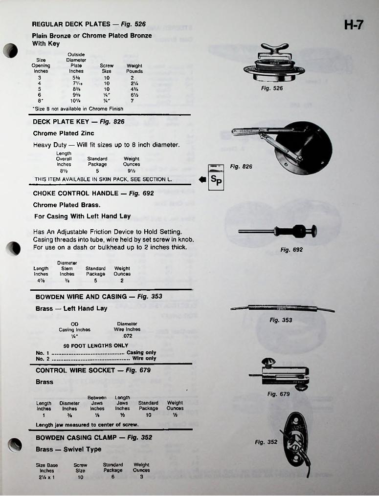
H-7REGULAR DECK PLATES — Fig. 526
Plain Bronze or Chrome Plated Bronze With Key
OutsideDiameter
PlateInches
SizeOpeningInches
ScrewSize
WeightPounds
3 53/a 10 27Vl6 10 2 Vi483/s5 10 4%
6 93/a Va"'A"
6Vz10V4
'Size 8 not available in Chrome Finish
8* 7
DECK PLATE KEY — Fig. 826
Chrome Plated Zinc
Heavy Duty — Will fit sizes up to 8 inch diameter.Length Overall Inches
StandardPackage
WeightOunces Fig. 826
9VzQVz 5
THIS ITEM AVAILABLE IN SKIN PACK, SEE SECTION L.
CHOKE CONTROL HANDLE — Fig. 692
Chrome Plated Brass.For Casing With Left Hand Lay
Has An Adjustable Friction Device to Hold Setting. Casing threads into tube, wire held by set screw in knob. For use on a dash or bulkhead up to 2 inches thick. Fig. 692
DiameterStem
InchesStandard Weight Package Ounces
LengthInches47/e 3/e 5 2
BOWDEN WIRE AND CASING — Fig. 353
Brass — Left Hand LayFig. 353
Diameter Wire Inches
.072
ODCasing Inches
Va”
50 FOOT LENGTHS ONLYCasing only ... Wire only
No. 1 No. 2
CONTROL WIRE SOCKET — Fig. 679
Brass
LengthJaws Standard
Inches Package
BetweenJawsInches
WeightOunces
Length Diameter Inches Inches
VzVzVa 10Va1
Length jaw measured to center of screw.
BOWDEN CASING CLAMP — Fig. 352
Brass — Swivel Type
Standard Weight Package Ounces
Size Base Inches 21/. x 1
ScrewSize
6 310
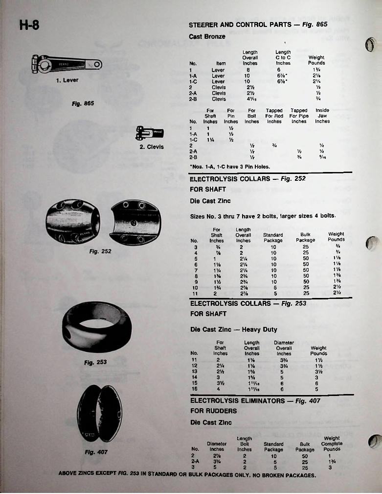
H-8 STEERER AND CONTROL PARTS — Fig. 865
Cast Bronze cLength C to C Inches
LengthOverallInches
WeightPoundsNo. Item
V/468LeverLeverLeverClevisClevisClevis
12Va67/a*
67/e*101-A
2V*1-C 10y221/22Vi2Vi
4Vl62-A
V*2-BFig. 865
Tapped For Pipe Inches
InsideFor For For Tapped For Rod Inches
JawShaft Pin Bolt Inches Inches Inches InchesNo.
Vi1 1Vi1-A 1
1-C V/4 ViViVi V422. ClevisVi2-A Vi Vi
3A Vl62-B Vi
•Nos. 1-A, 1-C have 3 Pin Holes.
ELECTROLYSIS COLLARS — Fig. 252 FOR SHAFT
Die Cast Zinc
Sizes No. 3 thru 7 have 2 bolts, larger sizes 4 bolts.
LengthOverallInches
ForWeightPounds
BulkPackage
StandardPackage
ShaftInches rNo.
3A25% 2 1033/4257/a 2 104
1 Va502'A 105 11 Va5021/4 106 V/a1 Va502 Vi 107 1 VaV/a50108 13/a 23/413/a501 Vi 2'A 1092 Vi25VA 2Va 51021/22527/a 5211
ELECTROLYSIS COLLARS — Fig. 253 FOR SHAFT
Die Cast Zinc — Heavy Duty
For LengthOverallInches
DiameterOverallInches
ShaftInches
WeightPoundsNo.
11 2 1 ViV/a 33/4Fig. 253 12 2 Vi V/a 1 Vi33/413 2Vi 31/215/a 514 3 315/e 515 3Vi 11,/ie
111/ie66
16 4 6 5
ELECTROLYSIS ELIMINATORS — Fig. 407 FOR RUDDERS
■ Die Cast Zinc
WeightBulk Complete
Package Pounds
LengthDiameter
No. InchesBolt Standard
PackageInchesFig. 4072 27/a 2 10 1502-A 1%3% 2 5 253 5 2 35 25
ABOVE ZINCS EXCEPT FIG. 253 IN STANDARD OR BULK PACKAGES ONLY. NO BROKEN PACKAGES.
1
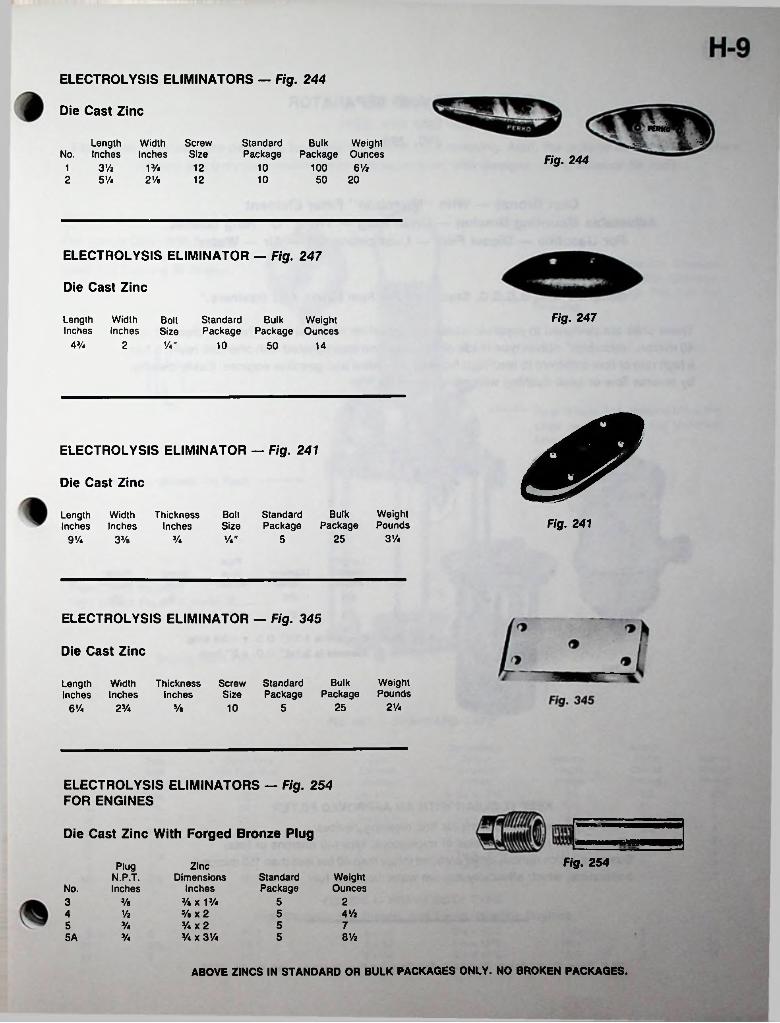
ELECTROLYSIS ELIMINATORS — Fig. 244
Die Cast ZincPCPKa
StandardPackage
i, -gLength Width ScrewNo. Inches Inches Size
Bulk Weight Package Ounces Fig. 244
3% V/a 12 10 100 6%12 5 Vi 2Ve 12 10 50 20
ELECTROLYSIS ELIMINATOR — Fig. 247
Die Cast Zinc
Fig. 247Length Width Bolt Standard Bulk WeightInches Inches Size Package Package Ounces
V«"4% 2 10 50 14
ELECTROLYSIS ELIMINATOR — Fig. 241
Die Cast Zinc
Bolt StandardSize Package
BulkPackage
WeightPounds
LengthInches
WidthInches
ThicknessInches Fig. 241
3Va25Va Va" 59% 33/s
ELECTROLYSIS ELIMINATOR — Fig. 345
Die Cast Zinc
BulkPackage
WeightPounds
Screw Standard Size Package
WidthInches
ThicknessInches
LengthInches
2Va2510 56V« 2Va 5/e
ELECTROLYSIS ELIMINATORS — Fig. 254 FOR ENGINES
Die Cast Zinc With Forged Bronze Plug
Fig. 254Plug ZincDimensions
Inches%X 13/4Vb X 2 Va X 2Va X 31/4
StandardPackage
WeightOunces
N.P.T.No. Inches
5 23 %4Va54 %
55 Va 78%Va 55A
ABOVE ZINCS IN STANDARD OR BULK PACKAGES ONLY. NO BROKEN PACKAGES.
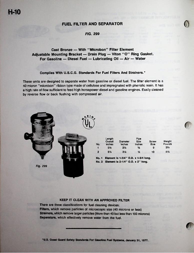
H-10
©FUEL FILTER AND SEPARATOR
FIG. 299
Cast Bronze — With "Microbon” Filter Element Adjustable Mounting Bracket — Drain Plug — Viton "O” Ring Gasket.
For Gasoline — Diesel Fuel — Lubricating Oil — Air — Water
Complies With U.S.C.G. Standards For Fuel Filters And Strainers.*
These units are designed to separate water from gasoline or diesel fuel. The filter element is a 40 micron “microbon” ribbon type made of cellulose and impregnated with phenolic resin. It has a high rate of flow sufficient to feed high horsepower diesel and gasoline engines. Easily cleaned by reverse flow or back flushing with compressed air.
Length Overall
No. Inches
PipeSize
InchesWeightPounds
DiameterInches
ScrewSize
3Va5 Vz 23/a 3/a 9151/22 61/4 3V« Vz 10
No. 1 Element is 1-3/4” O.D. x 1-3/4 long. No. 2 Element is 2-1/4” O.D. x 2” long.
KEEP IT CLEAN WITH AN APPROVED FILTERThere are three classifications for fuel cleaning devices:Filters, which remove particles of microscopic size (40 microns or less) Strainers, which remove larger particles (More than 40 but less than 150 microns) Separators, which effectively remove water from the fuel.
*U.S. Coast Guard Safety Standards For Gasoline Fuel Systems, January 31, 1977.
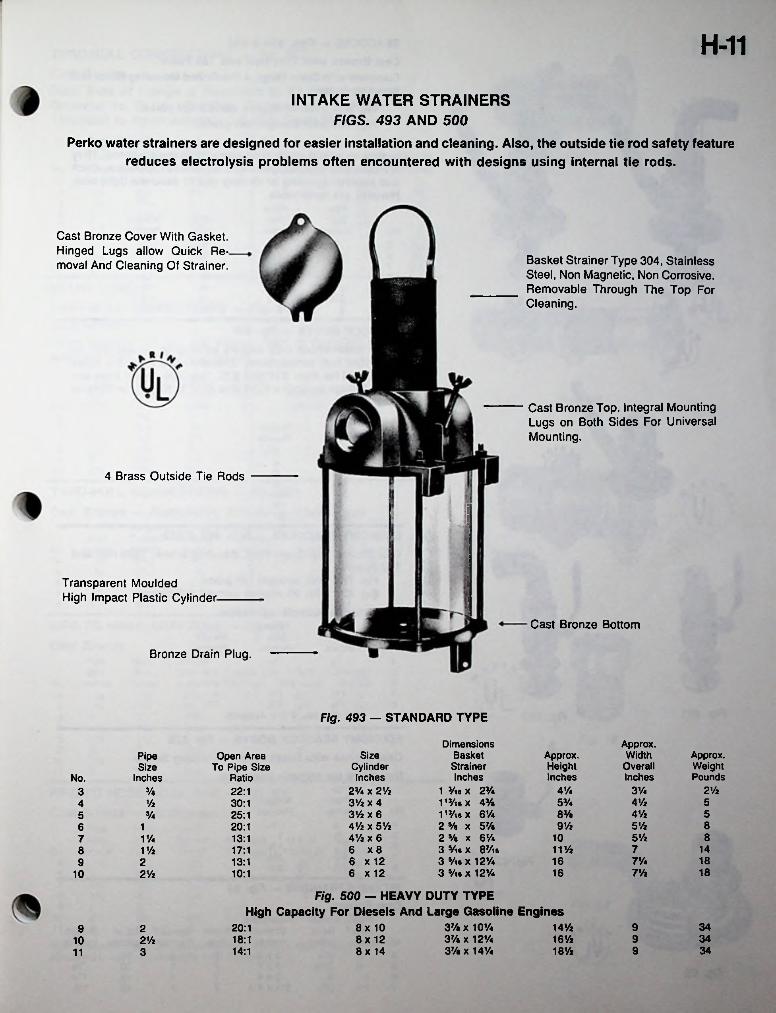
H-11
INTAKE WATER STRAINERS FIGS. 493 AND 500
Perko water strainers are designed for easier installation and cleaning. Also, the outside tie rod safety feature reduces electrolysis problems often encountered with designs using internal tie rods.
Cast Bronze Cover With Gasket. Hinged Lugs allow Quick Removal And Cleaning Of Strainer. Basket Strainer Type 304, Stainless
Steel, Non Magnetic, Non Corrosive. Removable Through The Top For Cleaning.
Cast Bronze Top. Integral Mounting Lugs on Both Sides For Universal Mounting.
4 Brass Outside Tie Rods
Transparent Moulded High Impact Plastic Cylinder-
Cast Bronze Bottom
Bronze Drain Plug.
Fig. 493 — STANDARD TYPE
DimensionsBasketStrainerInches
1 3/ie x 23A 113/ie X 43/a 1,3/ieX 6%2 Vs x 57/a2 5/a X 61A3 Vie X 87/ia 3 5/ie X 12V4 3 Viax 121/4
Approx.Width
OverallInches
Size Cylinder Inches
23/4 x 2V2 3% x 4 3% x 6 4% x 5% 41/2 x 66 X 86 x 12 6 x 12
Approx.HeightInches
Approx.WeightPounds
Open Area To Pipe Size
Ratio
PipeSize
InchesNo.4% 3yi 2’/23/a 22:13
4’/25% 5y2 30:1483/a 41/2 55 3/4 25:1
5y2 89y220:16 15’/2 81011/4 13:17
11% 7 1411/2 17:187% 18162 13:19
1816 7%10:110 21/2
Fig. 500 — HEAVY DUTY TYPE High Capacity For Diesels And Large Gasoline Engines
37/a X 10y»37/a X 12%37/a X 14%
14% 9 348x 10 8x 12 8x 14
20:19 216% 9 3418:12%1018% 9 3414:1311
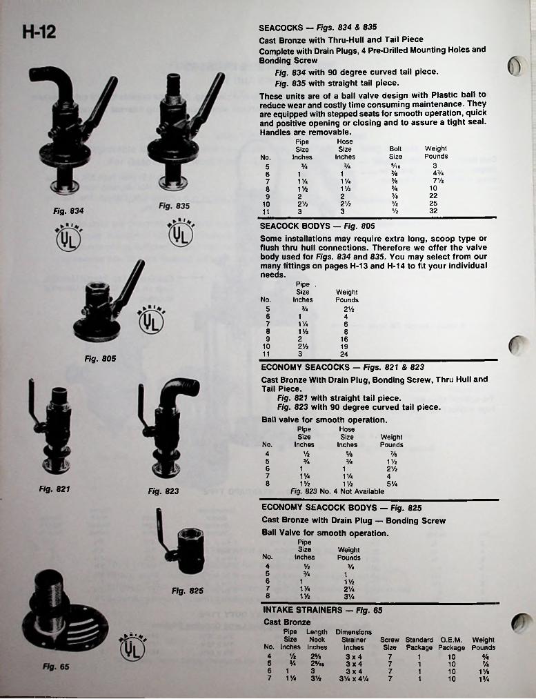
SEACOCKS — Figs. 834 & 835Cast Bronze with Thru-Hull and Tail PieceComplete with Drain Plugs, 4 Pre-Drilled Mounting Holes andBonding Screw
Fig. 834 with 90 degree curved tail piece.Fig. 835 with straight tail piece.
These units are of a ball valve design with Plastic ball to reduce wear and costly time consuming maintenance. They are equipped with stepped seats for smooth operation, quick and positive opening or closing and to assure a tight seal. Handles are removable.
Hose Size
Inches
PipeSize
InchesWeightPounds
BoltSizeNo.
3Vl 6VaVa5AVaVa16 17 ViVa1 Va V/a7
10VaViz1 Vi8223/«22925Vi2 Vi 2Vi10
Fig. 834 Vi 323311
SEACOCK BODYS — Fig. 805Some installations may require extra long, scoop type or flush thru hull connections. Therefore we offer the valve body used for Figs. 834 and 835. You may select from our many fittings on pages H-13 and H-14 to fit your individual needs.
Pipe . Size
InchesWeightPoundsNo.
5 Va 2 Vi6 1 47 V/a 68 1 Vi 89 2 16
10 2 Vi 1911 3 24Fig. 805ECONOMY SEACOCKS — Figs. 821 & 823Cast Bronze With Drain Plug, Bonding Screw, Thru Hull and Tail Piece.
Fig. 821 with straight tail piece.Fig. 823 with 90 degree curved tail piece.
Ball valve for smooth operation.Pipe Size
Inches
HoseSize
InchesWeightPoundsNo.
Vi4 Va Va5 Va Va V/i6 1 2Vi17 V/a V/a 48 1 Vi V/i 5VaFig. 821 Fig. 823 Fig. 823 No. 4 Not Available
ECONOMY SEACOCK BODYS — Fig. 825 Cast Bronze with Drain Plug — Bonding ScrewBall Valve for smooth operation.
Pipe Size
InchesWeightPoundsNo.
4 Vi Va5 Va 16 1 V/i7 V/a 2VaFig. 8258 V/i 3Va
INTAKE STRAINERS — Fig. 65 Cast Bronze
Pipe Length DimensionsSize Neck Strainer Screw Standard O.E.M. Weight
No. Inches Inches Inches Size Package Package Pounds4 Vi 2Va5 Va 29/ie
3x4 3x4 3x4
7 V/a 3Vi 3VaxAVa
7 Va1 107 1 10 Va
1 3 7 1 Va1 107 1 10 1 Va
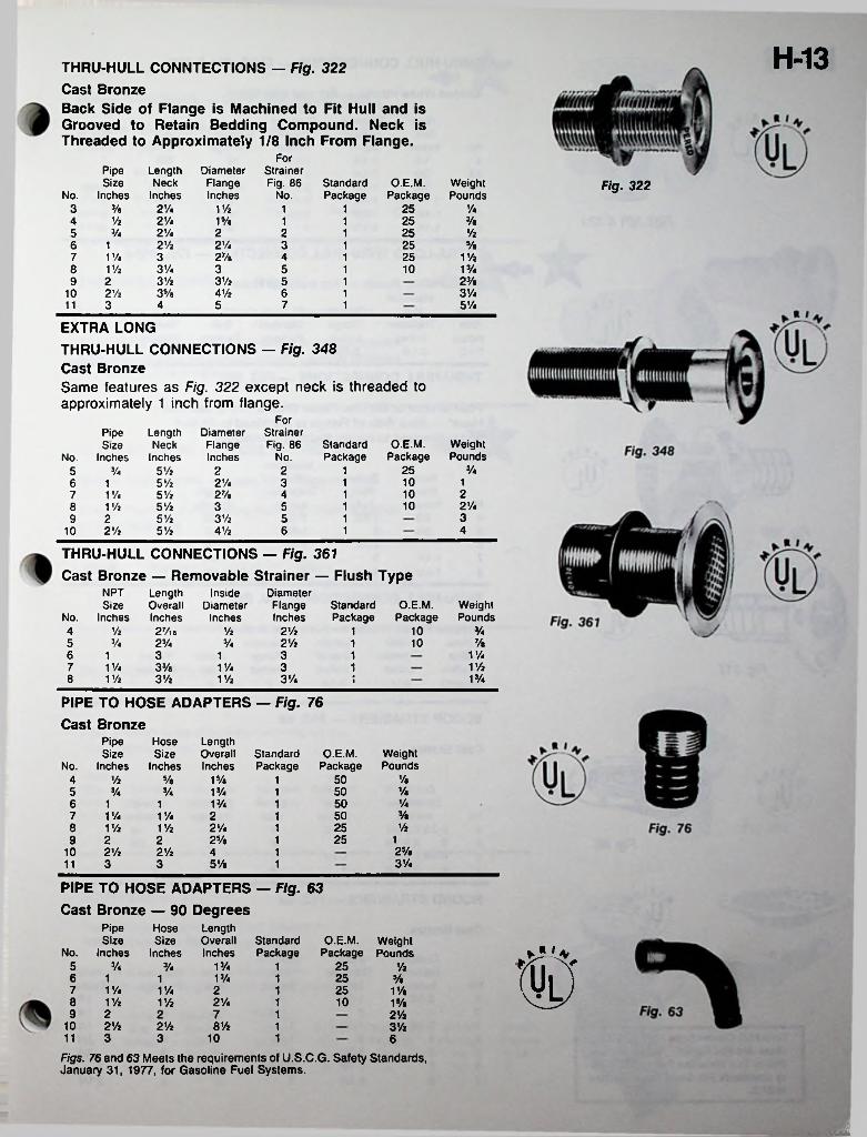
H-13THRU-HULL CONNTECTIONS — Fig. 322 Cast BronzeBack Side of Flange is Machined to Fit Hull and is Grooved to Retain Bedding Compound. Neck is Threaded to Approximately 1/8 Inch From Flange.
ForPipeSize
Inches
DiameterFlangeInches
Strainer Fig. 86
LengthNeck
InchesStandardPackage
O.E.M.Package
WeightPounds
Fig. 322No. No.
3 3/a 2Va V/i 25 Va11% 2 Vi 1 Va 3/a1 254 1
2 Vi Vi5 3/4 2 2 2512 Vz 2 Vi 3 25 5/a6 1 13 27/a V/i7 1 Va 4 2513% V/a8 1 Vi 3 5 101
9 3 Vi 3 Vi 23/e2 5 135/a 4 Vi 6 31/410 2 Vi 1
3 5 7 5 Vi4 111
EXTRA LONGTHRU-HULL CONNECTIONS — Fig. 348 Cast BronzeSame features as Fig. 322 except neck is threaded to approximately 1 inch from flange.
ForStrainer Fig. 86
DiameterFlangeInches
PipeSize
No. Inches
LengthNeck
InchesStandardPackage
O.E.M.Package
WeightPoundsNo.
3/4255 Vi 2 2 15 3/4
105 Vi 2Va 3 16 112107 1 Va
8 1 Vi9 2
10 2 Vi
5 Vi 27/e 4 12 Vi105 Vi 3 5 135 Vi 3 Vi 5 1465 Vi 4 Vi 1
THRU-HULL CONNECTIONS — Fig. 361Cast Bronze — Removable Strainer — Flush Type
DiameterFlange Standard O.E.M. Inches Package Package
NPTSize
No. Inches
InsideDiameter
Inches
LengthOverallInches27/l6
WeightPounds
VaVi 2 Vi 104 Vi 1Va 2 Vi 10 7/a5 23/4 Va 1
1 Va6 3 3 11 1V/i7 1 Va 33/a 1 Va 3 1
3 Vi 1 Va8 1 Vi 3 Vi V/i \
PIPE TO HOSE ADAPTERS — Fig. 76 Cast Bronze
PipeSize
Inches
HoseSize
Inches
LengthOverallInches
StandardPackage
O.E.M.Package
WeightPoundsNo.
ViVi Va 15/e 504 11/a505 Va Va 1 Va 1Va506 1 Va1 113/a7 1 Va 1 Va 2 501Vi8 V/i 2Va 25V/i 1
2Va 25 19 2 2 12Va10 2 Vi 2 Vi 4 13 Vi3 3 5 Vi11 1
PIPE TO HOSE ADAPTERS — Fig. 63 Cast Bronze — 90 Degrees
Pipe HoseSize
Inches
LengthOverallInches
Size StandardPackage
O.E.M. Weight Package Pounds t IwNo. Inches
5 Va 1 Va 25Va 1 Vi1 Va6 251 1 Va1
1 Va7 1 Va 2 251 1 Va1Vi8 V/i 2 Vi 101 1 Va
9 2 2 7 1 2Vi10 2 Vi 2 Vi 8 Vi 1 3Vi
311 3 10 1 6
Figs. 76 and 63 Meets the requirements of U.S.C.G. Safety Standards, January 31, 1977, for Gasoline Fuel Systems.
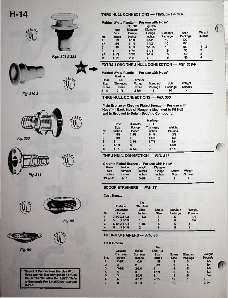
H-14 THRU-HULL CONNECTIONS — FIGS. 301 & 328
Molded White Plastic — For use with Hose* Fig. 301 Fig. 328Diameter DiameterFlange Inches
HoseSize
InchesWeightOunces
BulkStandardPackage
FlangeInches PackageNo.
1100101-1/21-1/41/241100101-1/25/8 1-1/44A1-1/2100102-1/163/4 1-1/2525052-1/41-7/81625051-7/8 2-1/41-1/86AFigs. 301 & 328 450531-1/2 2-1/28
EXTRA-LONG THRU-HULL CONNECTION — FIG. 319-8
Molded White Plastic — For use with Hose* Maximum
Hose HullSize Thickness
Inches Inches 1-1/2 2-1/8
DiameterRangeInches
WeightOunces
Standard Bulk Package Package
42-7/8 5 50Fig. 319-8
THRU-HULL CONNECTIONS — FIG. 350
Plain Bronze or Chrome Plated Bronze — For use with Hose* — Back Side of Flange is Machined to Fit Hull and is Grooved to Retain Bedding Compound.
MaximumHose Diameter
FlangeInches
HullSize Thickness
Inches1-1/4
WeightPoundsNo. Inches
4 5/8 1-5/8 3/85 3/4 2 1-5/8 1/26 1 2-3/8 1-7/8 7/87 1-1/4 3 1-3/82
1-1/21-1/2 3-1/8 28
THRU-HULL CONNECTION — FIG. 311
Chrome Plated Bronze — For use with Hose* Length Overall Inches 3-1/8
Hose InsideSize Diameter
Inches Indies
DiameterFlangeInches
WeightOunces
ScrewSizeFig. 311
3/4 and 1 9/16 72 8
SCOOP STRAINERS — FIG. 66
Cast Bronze
ForOutside
Dimension No. Inches1 3-1/2 X 2-1/22 5 X 3-1/43 6-1/4 X 4-1/44 8 X 5-1/8
Thru-HullSize
InchesWeightPounds
ScrewSize
StandardPackage
1/41/2 583/41 58
1-1/4 5 1852 8 2
ROUND STRAINERS — FIG. 86
Cast BronzeFor
Fig. 86 OutsideDiameterInches
InsideDiameter
Inches
Thru-HullWeightPounds
Size StandardPackage
ScrewSizeNo. Inches
1/51 2-1/2 51-5/8 1/2 81/42 3 3/4 52 81/33 3-1/2 1 52-3/8 8
* Thru-Hull Connections For Use With Hose Are Not Recommended For Use Below The Waterline Per ABYC "Safety Standards For Small Craft" Section H-27.3.
1/34 4 1-1/4 53 83/45 5 3-3/4 52 8
16 6 4-1/2 2-1/2 10 12-1/47 8 6-1/4 10 13

H-15THRU-HULL SCUPPER — FIG. 323
Molded White Plastic — Black Vinyl Flapper Valve
Complete with nut and mounting hardware for mounting through the transom.
MaximumHoseSize
Inches1-1/2
Hull DiameterFlangeInches2-7/8
ThicknessInches2-1/8
Standard O.E.M. WeightPackage Package Ounces
5 50 5
THRU-HULL SCUPPER — FIG. 356
Molded White Plastic — Black Vinyl Flapper Valve
Same as Fig. 323 except without nut and mounting hardware. Neck length can be cut to match mounting surface thickness as used on outboard wells, etc.
SCUPPER VALVE ASSEMBLY — FIG. 365
Molded White Plastic — Black Vinyl Flapper Valve
Without Thru-Hull and Mounting hardware. Used for surface mount applications.
DiameterFlangeInches2-7/8
StandardPackage
WeightOunces
O.E.M.Package
5 50 1
SCUPPER — FIG. 285
Molded White Plastic
Insert prevents large objects from entering without restricting water flow.
HoseSize Diameter Inches Range1-1/2 2-3/4
Diameter Standard O.E.M. WeightOpening Package Package Ounces
1-1/2 55 50
SCUPPERS — FIG. 142
Plain Bronze or Chrome Plated Bronze — With Rubber Ball Back Water Check
For use when outlet is below the waterline. Supplied with key-Angle of outlet is 45 degrees.
DiameterGrateInches
1- 13/162- 1/4
DiameterRangeInches3-1/43-3/4
HoseSize
No. InchesScrewSize
StandardPackage
O.E.M. Weight Package Pounds
Fig. 14211 8 10 1-1/418 1 102 1-1/2 2
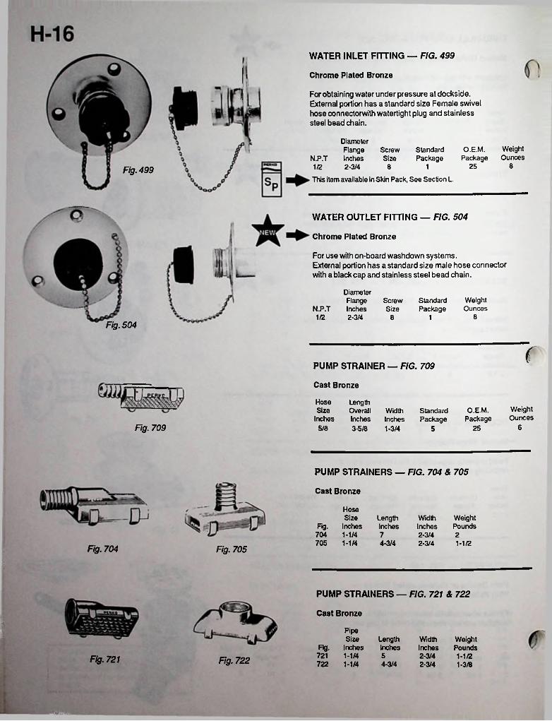
WATER INLET FITTING — FIG. 499
Chrome Plated Bronze
For obtaining water under pressure at dockside. External portion has a standard size Female swivel hose connectorwith watertight plug and stainless steel bead chain.
DiameterFlange Screw Standard
N.P.T Inches Size Package1/2 2-3/4
This item available in Skin Pack, See Section L.
O.E.M. Weight Package Ounces
82518Fig. 499
WATER OUTLET FITTING — FIG. 504
Chrome Plated Bronze
For use with on-board washdown systems.External portion has a standard size male hose connector with a black cap and stainless steel bead chain.
DiameterFlange ScrewInches Size2-3/4
WeightOunces
StandardPackageN.P.T
81/2 18Fig. 504
(PUMP STRAINER — FIG. 709
Cast Bronze
HoseSize
Inches
LengthOverall Width StandardInches Inches Package3-5/8 1-3/4
WeightOunces
O.E.M.Package
Fig. 709 65/8 255
PUMP STRAINERS — FIG. 704 & 705
Cast Bronze
HoseSize
Fig. Inches704 1-1/4705 1-1/4
Width WeightInches Pounds
LengthInches7 2-3/4 24-3/4 2-3/4 1-1/2
Fig. 704 Fig. 705i
PUMP STRAINERS — FIG. 721 & 722
Cast Bronze
PipeSize
Fig. InchesLengthInches
WidthInches
WeightPounds
721 1-1/4 5 2-3/4 1-1/2Fig. 721 Fig. 722 722 1-1/4 4-3/4 2-3/4 1-3/8
...
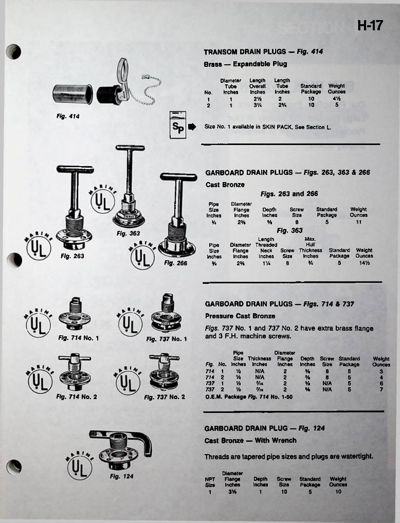
H-17TRANSOM DRAIN PLUGS - Fig. 414
Brass — Expandable Plug
Length Length Overall Tube Inches Inches
Diameter Tube
No. InchesStandard Weight Package Ounces
4%102% 21152% 103%2 1
Fig. 414
Size No. 1 available in SKIN PACK, See Section L.
GARBOARD DRAIN PLUGS — Figs. 263, 363 & 266
Cast BronzeFigs. 263 and 266
DiameterFlangeInches
PipeSize
InchesDepthInches
StandardPackage
WeightOunces
ScrewSize
5% 8 112%Va
Fig. 363Fig. 363Max.Length
Diameter Threaded Flange Neck Screw Thickness Standard WeightInches Inches Size Inches Package Ounces
ft I HullPipeI SizeInchesFig. 263
Fig. 266 Va 5 14%V/a 82V.Va
GARBOARD DRAIN PLUGS — Figs. 714 & 737
Pressure Cast Bronze
Figs. 737 No. 1 and 737 No. 2 have extra brass flange and 3 F.H. machine screws.Fig. 714 No. 1 Fig. 737 No. 1
Pipe DiameterSize Thickness Flange Depth Screw Standard
Fig. No. Inches Inches Inches Inches Size Package714 1 Vi N/A714 2 V* N/A737 1 % Vu737 2 % Vi.O.E.M. Package Fig. 714 No. 1-50
WeightOunces
2 V. 8 5 32 V. 8 5 42 y. N/A
V. N/A5 6
2 5 7Fig. 714 No. 2 Fig. 737 NO. 2
GARBOARD DRAIN PLUG — Fig. 124
Cast Bronze — With Wrench
Threads are tapered pipe sizes and plugs are watertight.
DiameterNPT Flange Depth Screw Standard WeightSize Inches Inches Size Package Ounces
3% 101 51
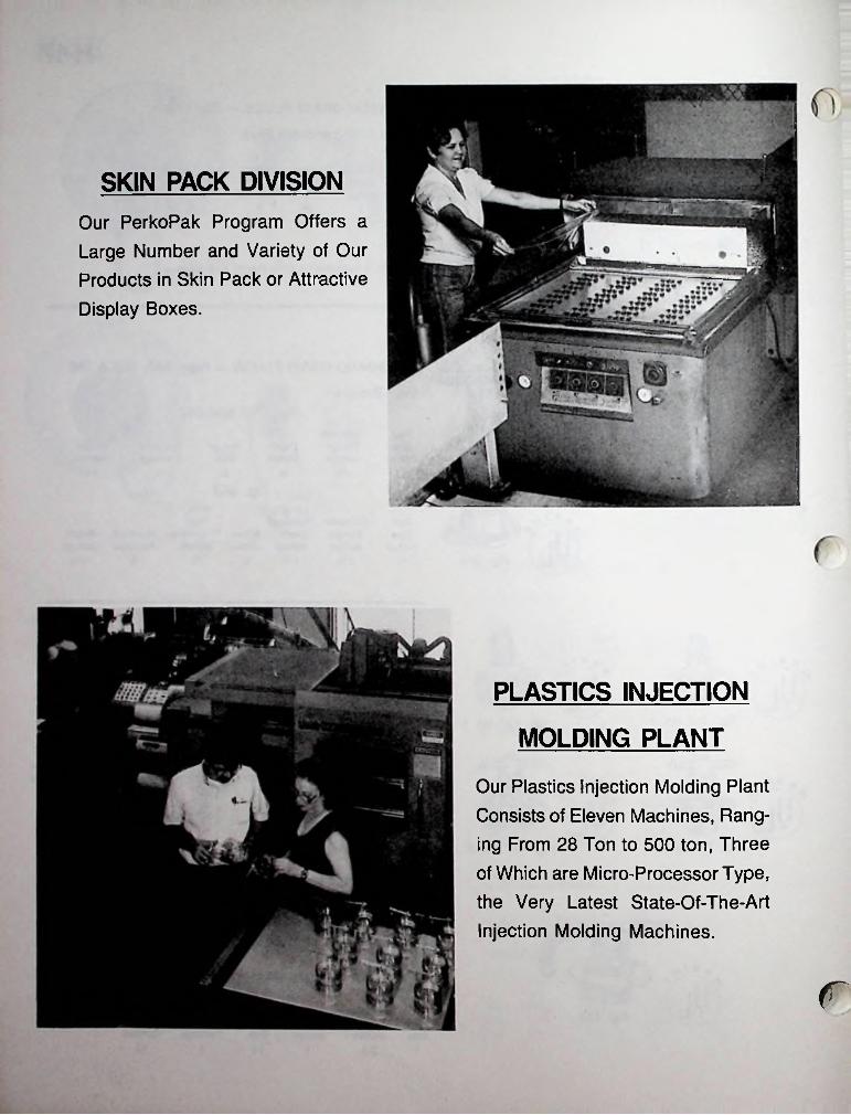
SKIN PACK DIVISIONOur PerkoPak Program Offers a
Large Number and Variety of Our
Products in Skin Pack or Attractive
Display Boxes.
PLASTICS INJECTION
MOLDING PLANTOur Plastics Injection Molding Plant Consists of Eleven Machines, Ranging From 28 Ton to 500 ton, Three
of Which are Micro-Processor Type, the Very Latest State-Of-The-Art Injection Molding Machines.
f
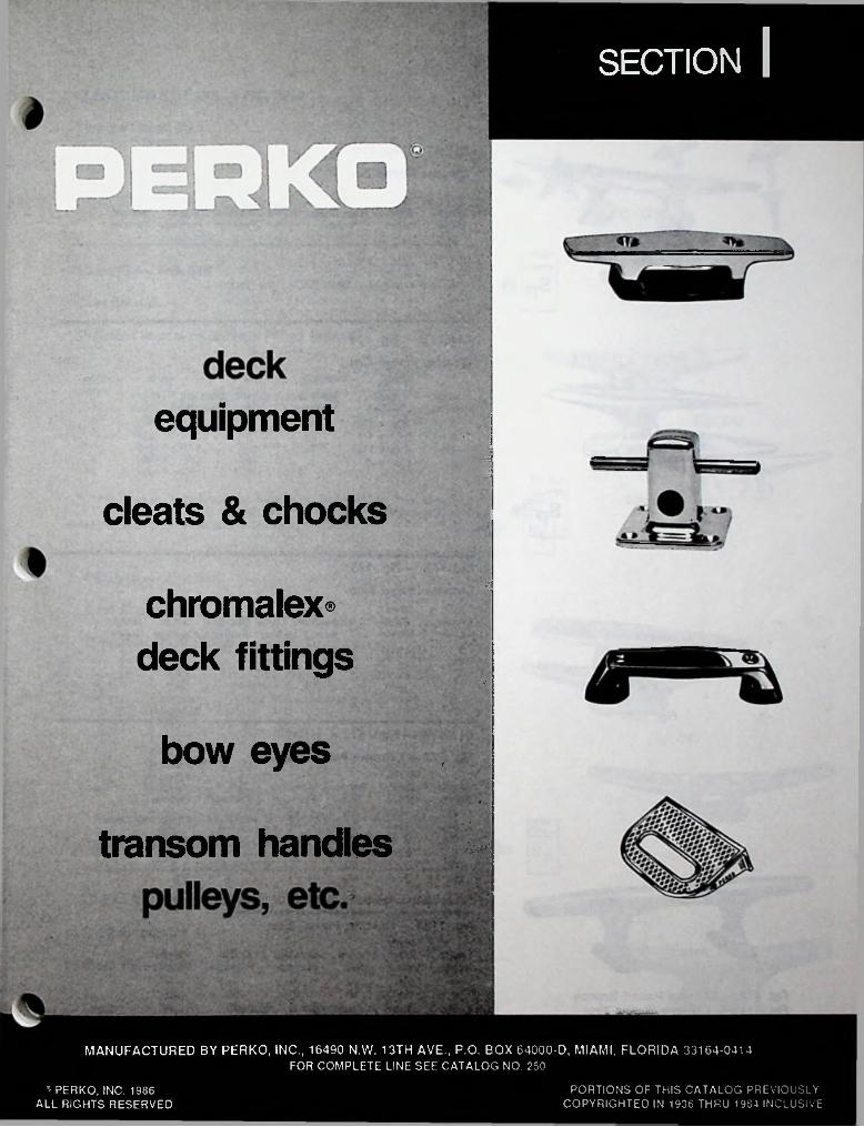
SECTION |
Vvr.-J'V •->
equipment.
cleats & chocks■
' chromalex
deck fittings.•
: •
bow eyes f .
: ^
transom handies
MANUFACTURED BY PERKO, INC., 16490 N.W. 13TH AVE., P.O. BOX 64000-D, MIAMI, FLORIDA 33164-0414FOR COMPLETE LINE SEE CATALOG NO. 250
v- PERKO, INC. 1986 ALL RIGHTS RESERVED
PORTIONS OF THIS CATALOG PREVIOUSLY COPYRIGHTED IN 1936 THRU 19S4 INCLUSIVE
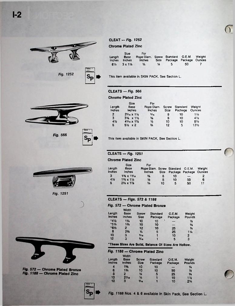
1-2
CLEAT - Fig. 1252 Chrome Plated Zinc
SizeLength Base Rope Diam. Screw Standard O.E.M. Weight inches Inches Inches Size Package Package Ounces
6% 3x1%
For
50 7Vs Vs 5
This item available in SKIN PACK, See Section L.
CLEATS - Fig. 566 Chrome Plated Zinc
Size Base
Inches 2tt«x1% 3% x V/2 47/l6 X 17/a 5% x 2
ForLengthInches
Rope Diam. Screw Standard Inches Size Package
WeightOunces
2 10 V/25/l6 63 Vs 8 10 4%4% 8 ViV2 10 106 13%Vs 12 5
Fig. 566This item available in SKIN PACK, See Section L.
CLEATS - Fig. 1251
Chrome Plated Zinc
SizeLength BaseInches Inches3 1J/ax 13/.e4% Vh x 1%6 23/e x V/s
ForRope Diam. Screw Standard O.E.M. Weight
Inches Size Package Package Ounces2Vs 8 10
% 68 10 50Vs 10 115 50
CLEATS — Figs. 572 & 1188
Fig. 572 — Chrome Plated BronzeWidth
Length Base Screw Standard O.E.M. Inches Inches Size Package Package
WeightPounds
•4% 1% 10 10 %*5% 1 Vs 10 10 5/«*6% 2 12 10 25 Vs8 23/a Vs 5 25 1 Vs
10 3 5/ie 1 10 212 3 5/i« 1 5 3
•These Sizes Are Solid, Balance Of Sizes Are Hollow.
Fig. 1188 — Chrome Plated ZincWidth
Length Base Screw Standard O.E.M. Inches Inches Size Package Package
WeightPounds
4 1 Vs 10 10 VsFig. 572 — Chrome Plated Bronze Fig. 1188 — Chrome Plated Zinc
6 1 Vs 10 10 50 %8 2 Vs 5 25 Vs
10 27/i. Vs 1 10 1%12 3 Vn 1 10 21/4
Fig. 1188 Nos. 4 & 6 available in Skin Pack, See Section L.
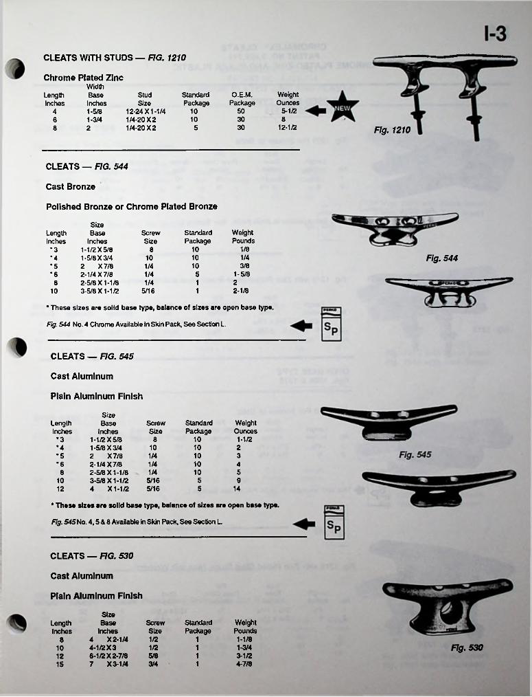
CLEATS WITH STUDS — FIG. 1210
Chrome Plated ZincWidth
WeightOunces
5-1/2
StandardPackage
O.E.M.Package
StudSize
LengthInches
BaseInches
5012-24X1-1/41/4-20X21/4-20X2
104 1-5/83010 86 1-3/430 12-1/258 2 Fig. 1210
CLEATS — FIG. 544
Cast Bronze
Polished Bronze or Chrome Plated Bronze
Size Base
Inches 1-1/2 X 5/81- 5/8 X 3/42 X7/82- 1/4 X 7/82- 5/8 X1-1/83- 5/8 X 1-1/2
WeightPounds
StandardPackage
ScrewSize
LengthInches
1/810*3 81/4 Fig. 5441010•4
10 3/81/4•55 1-5/81/4•6
1/4 1 282-1/8110 5/16
* These sizes are solid base type, balance of sizes are open base type.
Fig. 544 No. 4 Chrome Available in Skin Pack. See Section L.
CLEATS — FIG. 545
Cast Aluminum
Plain Aluminum Finish
SizeBase Standard
PackageWeightOunces
LengthInches
ScrewSizeInches
1-1/2 X 5/81- 5/8 X 3/4 2 X7/82- 1/4 X 7/82- 5/8 X1-1/83- 5/8 X1-1/2 4 X1-1/2
10 1-1/2*3 810 10 2•4
10 3*5 1/41/4 10*6 4
51/4 1085 910 5/165 145/1612
* These sizes are solid base type, balance of sizes are open base type.
Fig. 545No. 4.5 & 8 Available in Skin Pack. See Section L.
CLEATS — FIG. 530
Cast Aluminum
Plain Aluminum Finish
SizeStandardPackage
WeightPounds
ScrewSize
LengthInches
BaseInches
4 X 2-1/4 4-1/2 X 3 6-1/2 X 2-7/8 7 X 3-1/4
1/2 1 1-1/88Fig. 5301/2 1 1-3/410
5/8 1 3-1/2123/4 1 4-7/815
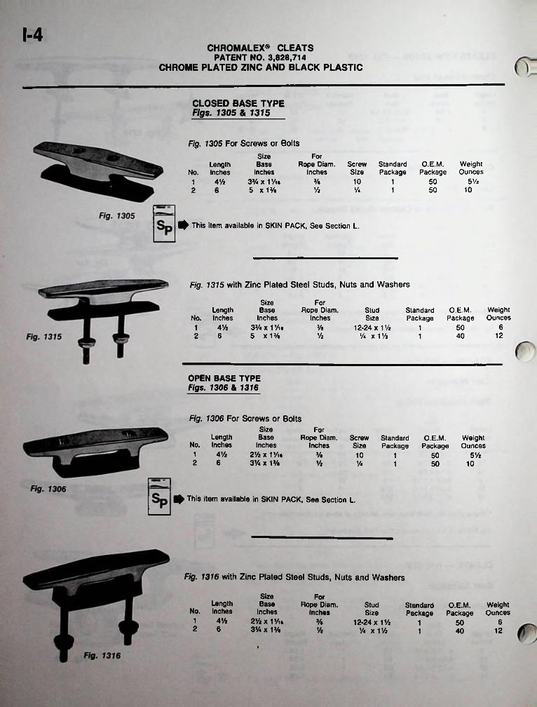
1-4CHROMALEX® CLEATS
PATENT NO. 3,828,714CHROME PLATED ZINC AND BLACK PLASTIC
CLOSED BASE TYPE Figs. 1305 & 1315
Fig. 1305 For Screws or Bolts
Size Base
Inches 3% x 1Vi6 5 x 13/e
ForRope Diam.
InchesScrewSize
StandardPackage
O.E.M. Weight Package Ounces
Length No. Inches
% 10 5 ViAVi 5011Vz V* 10502 6 1
^ This item available in SKIN PACK, See Section L.
Fig. 1315 with Zinc Plated Steel Studs, Nuts and Washers
Size Base
Inches 3V* x 1 y« 5 x 13/e
ForRope Diam.
InchesWeightOunces
Length No. Inches
StudSize
StandardPackage
O.E.M.Package
AVz 63/e 12-24 x 1 Vz Va x 1 Vi
1 501Vi 122 6 401
OPEN BASE TYPE Figs. 1306 & 1316
Fig. 1306 For Screws or Bolts Size Base
InchesA Vz 2Vi x 11/u
3Va x 13/«
ForLength
No. InchesRope Diam.
InchesScrewSize
StandardPackage
O.E.M. Weight Package Ounces
1 3/« 10 5Vi5012 6 Vi Va 50 101
0 This item available in SKIN PACK. See Section L.
Fig. 1316 with Zinc Plated Steel Studs, Nuts and Washers
Size Base
Inches 2ViXiyie 3Va x 1 V%
ForLength
No. InchesRope Diam.
InchesStud O.E.M. Weight
Package OuncesStandardPackageSize
AVi1 % 12-24 x V/i Va X Vh
65012 6 Vi 12401
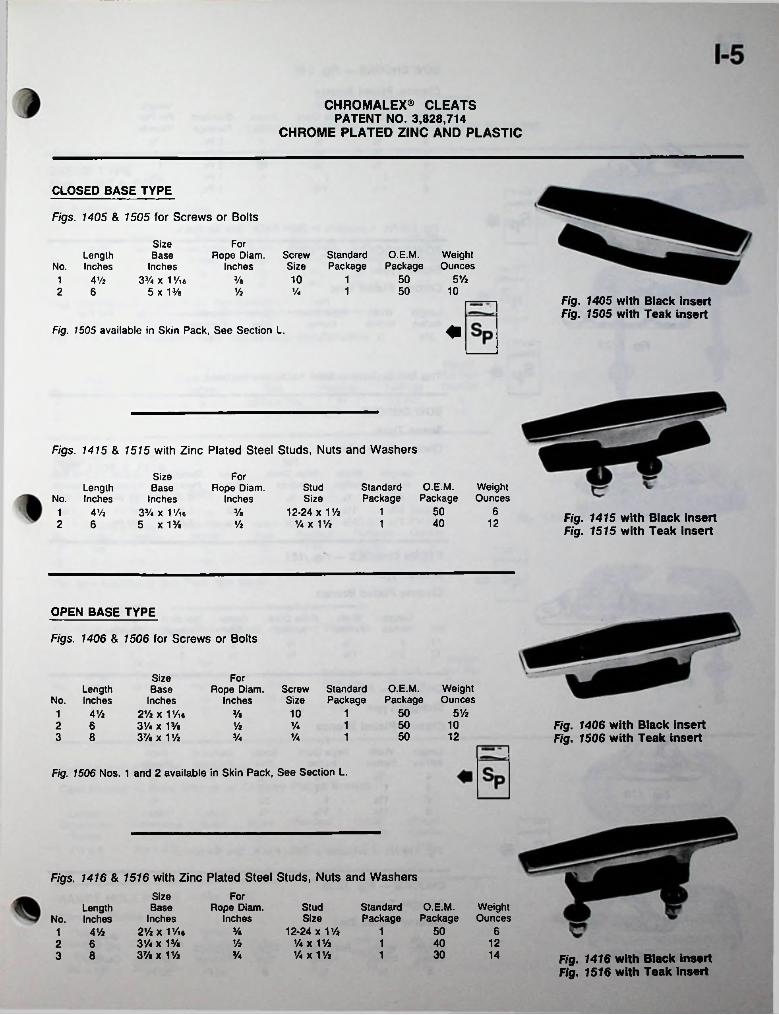
CHROMALEX® CLEATS PATENT NO. 3,828,714
CHROME PLATED ZINC AND PLASTIC
CLOSED BASE TYPE
Figs. 1405 & 1505 for Screws or Bolts
Size Base
Inches 37. x 1 Vie
5 X 13/e
ForScrewSize
StandardPackage
O.E.M.Package
WeightOunces
Rope Diam. Inches
Length No. Inches
10 1 50 5 Vz3/e1 4 Vi50 10V* 12 6 Vi
Fig. 1405 with Black insert Fig. 1505 with Teak insert
Fig. 1505 available in Skin Pack, See Section L.
Figs. 1415 & 1515 with Zinc Plated Steel Studs, Nuts and Washers
Size Base
Inches 33/. x 1Vie 5 x 13/e
ForO.E.M.
PackageStandardPackage
WeightOunces
StudSize
12-24 x 1 Vi V. x 1 Vi
Length No. Inches
Rope Diam. Inches
50 613/a1 4 Vi Fig. 1415 with Black insert Fig. 1515 with Teak insert
40 1212 6 Vi
OPEN BASE TYPE
Figs. 1406 & 1506 for Screws or Bolts
Size Base
Inches 2Vi x 1 Vi# 3V. x 13/a 37/a X 1 Vi
ForO.E.M.
PackageWeightOunces
ScrewSize
StandardPackage
Length No. Inches
Rope Diam. Inches
50 5 Vi13/a 101 4V2Fig. 1406 with Black insert Fig. 1506 with Teak insert
50 1012 63 8
Vi Va50 121Va Va
Fig. 1506 Nos. 1 and 2 available in Skin Pack, See Section L.
Figs. 1416 & 1516 with Zinc Plated Steel Studs, Nuts and Washers
Size Base
Inches4Vi 2Vi x 1 Vn
31/4 X 13/e 37a X 1 Vi
ForStandard O.E.M. Package Package
WeightOunces
Rope Diam. Inches
StudLength No. Inches Size
12-24 x 1 Vi 7.x 17* Va X 1 Vi
50 63/a 11Vi 40 1212 6
3 8 30Va 1 14 Fig. 1416 with Black insert Fig. 1516 with Teak Insert
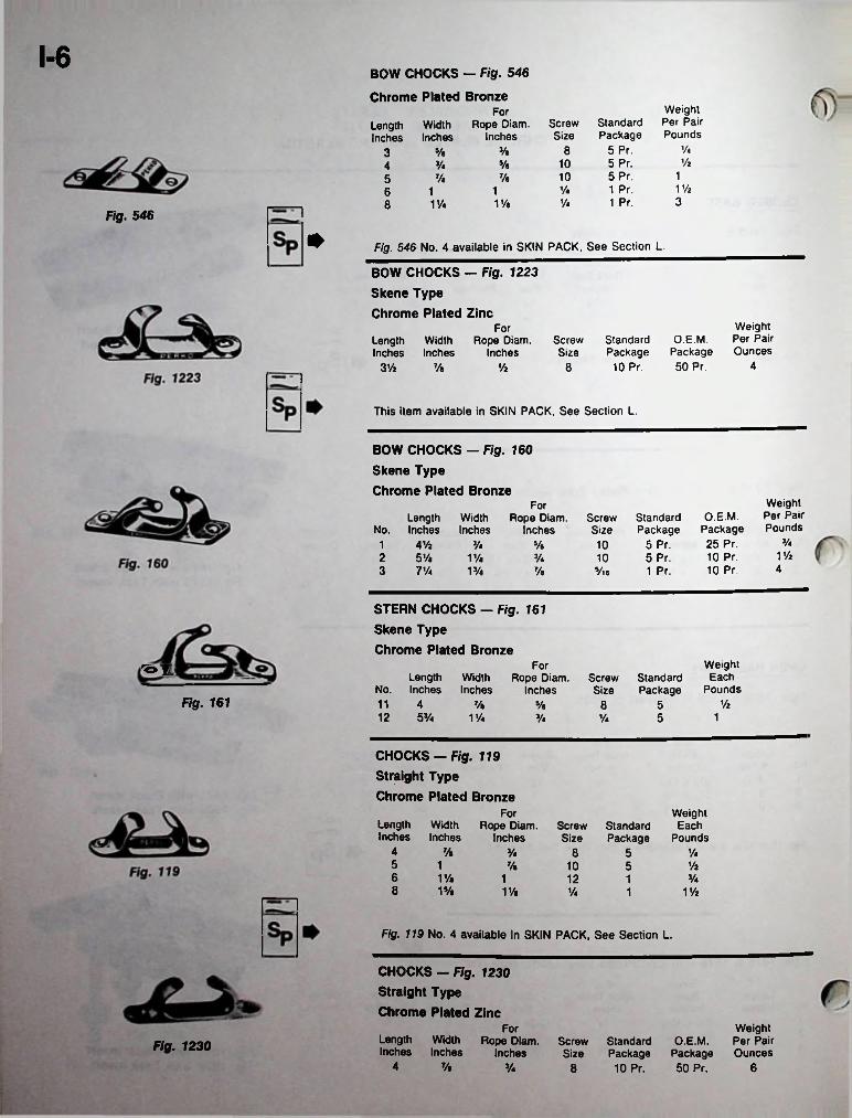
1-6BOW CHOCKS — Fig. 546 Chrome Plated Bronze
Weight Per Pair Pounds
ForStandard Package
5 Pr.5 Pr.5 Pr.
ScrewSize
Rope Diam. Inches
WidthInches
LengthInches
V*83/e8/s3Vi105/aVa4
1107/ay«5V/i1 Pr.Vi11631 Pr.Va1Vk1%8
Fig. 546
* Fig. 546 No. 4 available in SKIN PACK, See Section L.
BOW CHOCKS - Fig. 1223 Skene Type Chrome Plated Zinc
Weight Per Pair Ounces
ForO.E.M.
Package 50 Pr.
Screw StandardSize Package
10 Pr.
Rope Diam. Inches
LengthInches
WidthInches
483 Vi 7/e Vi
This item available in SKIN PACK, See Section L.
BOW CHOCKS — Fig. 160Skene TypeChrome Plated Bronze
Weight Per Pair Pounds
ForO.E.M.
Package 25 Pr. 10 Pr. 10 Pr.
Length No. Inches
WidthInches
Rope Diam. Inches
ScrewSize
Standard Package
5 Pr.5 Pr.1 Pr.
Va4 Vz1 Va 5/a 101 Vi2 5 Vi
3 7 VaV/i Va 10
413/e 7/e 5/ie
STERN CHOCKS - Fig. 161Skene TypeChrome Plated Bronze
WeightEach
Pounds
For'o fLength Width
No. Inches Inches11 412 53/4
Rope Diam. Inches
Screw Standard Size Package
Fig. 161 ViVi Vi 8 51 Vi 5 1Vi Vi
CHOCKS - Fig. 119 Straight Type Chrome Plated Bronze
For WeightEach
PoundsLength Width Inches Inches
Rope Diam. Inches
ScrewSize
StandardPackage
4 % Vi 8 5 Vi5 1 VzVi 10 56 1Va 1 12 Vi18 1% 11/a Vi V/i1
Fig. 119 No. 4 available in SKIN PACK, See Section L.
CHOCKS — Fig. 1230 Straight Type Chrome Plated Zinc
Weight O.E.M. Per Pair
Package Ounces 50 Pr.
ForLength Width Inches Inches
Rope Diam. Inches
Screw Standard Size Package
8 10 Pr.
Fig. 12304 Vi Vi 6
L

1-7CHROMALEX® CHOCKS
PATENT NO. 3,&28,714CHROME PLATED ZINC AND BLACK PLASTIC
SKENE TYPE Figs. 1307 & 1317
Fig. 1307 For Screws or BoltsFig. 1307
Width Length Base
No. Inches Inches
For Weight Per Pair Ounces
Rope Diam. Inches
ScrewSize
Standard Package
1 Pr.1 Pr.
O.E.M. Package 50 Pr. 25 Pr.
1 3’/a 7/e 3/e 10 52 5 V/a Va Va 12
This Item Available in Skin Pack. See Section L.
Fig. 1317 with Zinc Plated Steel Studs, Nuts and Washers
Weight Per Pair Ounces
Width Length Base
No. Inches Inches
ForStudSize
12-24 x V/a Va x V/a
Standard Package
1 Pr.1 Pr.
O.E.M. Package 25 Pr. 25 Pr.
Rope Diam. Inches
61 3Va 7/e 3/a Fig. 13172 5 14V/a Va
STRAIGHT TYPE Figs. 1308 & 1318
Fig. 1308 For Screws or BoltsWidth
Length Base No. Inches Inches
Weight Per Pair Ounces
ForO.E.M.
Package 50 Pr. 25 Pr.
Standard Package
1 Pr.1 Pr.
Rope Diam. Inches
ScrewSize
5103Va1 7/e 3/e122 5 Va VaV/a
This Item Available in Skin Pack, See Section L.
Fig. 1318 with Zinc Plated Steel Studs, Nuts and Washers
Weight Per Pair Ounces
Width Length Base
No. Inches Inches
ForStandard Package
1 Pr.1 Pr.
O.E.M. Package 25 Pr. 25 Pr.
StudSize
Rope Diam. Inches
63Va 12-24 x V/a Va x 13/4
1 7/a 3/a142 5 1V. Va
HAWSE HOLE PLATE — Fig. 752Cast Bronze — Plain Bronze or Chrome Plated Bronze
Outside Dimensions
Inches 4V. x 6
Inside Dimensions
Inches 2Va X 4Va
LengthSpigot Screw Standard Inches Size Package
O.E.M.Package
WeightPounds
10 15/a1V/a Va Fig. 752
HAWSE HOLE PLATE — Fig. 1250 Chrome Plated Zinc
Inside Dimensions
Inches2Vie X 41/ie 1
Outside Dimensions
Inches 35/a x 5»/a
LengthSpigot Screw Standard Inches Size Package
O.E.M. Weight Package Pounds
Va 1 10 VaFig. 1250
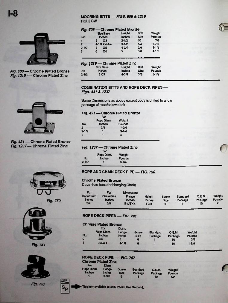
MOORING BITTS — FIGS. 608 & 1219 HOLLOW
Fig. 608 — Chrome Plated BronzeHeight Bolt WeightInches Size Pounds
Size Base Inches
o yq
4-1/4 X 4-1/4 2-1/2 5 X5
6 X6
No.7/82-1/2 101
1-7/81/43-1/224-3/4 3/8 3-1/2
4-1/25 3/83
Fig. 1219 — Chrome Plated ZincSize Base Height Bolt Weight
Inches Inches Size Pounds5X5 4-3/4 3/8 3-1/2
Fig. 608— Chrome Plated Bronze Fig. 1219 — Chrome Plated Zinc
No.2-1/2
COMBINATION BITTS AND ROPE DECK PIPES — Figs. 431 & 1237
Same Dimensions as above except body is drilled to allow passage of rope below deck.
Fig. 431 — Chrome Plated BronzeFor
Rope Diam. Inches
WeightPoundsNo.
3/42 1-3/42-1/2 1 3-1/43 1 4
Fig. 431 — Chrome Plated Bronze Fig. 1237— Chrome Plated Zinc Fig. 1237—Chrome Plated Zinc
ForRope Diam.
InchesWeightPoundsNo.
2-1/2 1 3-1/4
ROPE AND CHAIN DECK PIPE — FIG. 750
Chrome Plated BronzeCover has hook for Hanging Chain
T
For For Dimensions Range Inches
5-1/4 X 4
WeightPounds
Rope Diam. Inches
Chain Size Inches
O.E.M.Package
HeightInches
ScrewSize
StandardPackageFig. 750 23/4 3/8 101-3/8 18
ROPE DECK PIPES — FIG. 741
Chrome Plated BronzeFor Diam.
FlangeInches
Rope Diam. Inches
ScrewSize
WeightPounds
StandardPackage
O.E.M.PackageNo.
0 5/8 3 3/48 1 101 3/4 & 1 4-1/4 8 1-5/81 10Fig. 741a ROPE DECK PIPE — FIG. 757 Chrome Plated Zinc
Diam.Rope Diam. Range Screw
Inches Inches Size
For rStandard O.E.M. WeightPackage Package Pounds
1 3-3/8 8 1 10 1/2
Fig. 757This item available In SKIN PACK, See Section L.
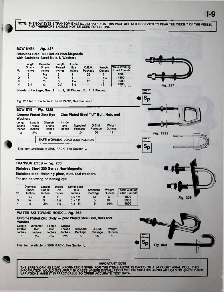
1-9note: and therIFore PAGE ARE N0T DES|GNED T0 bear the weight °F ™E vessel
BOW EYES — Fig. 237Stainless Steel 300 Series Non-Magnetic with Stainless Steel Nuts & Washers
Length Diameter Length InsideShank Shank Thread Eye
No. Inches Inches Inches Inches•Safe Working Load Pounds
1800 1800 3000 4600
O.E.M.Package
WeightOunces
1 3 3Vie 1 25 42 63 34 31/4
%6 6 1 5 Vi% 3 V/a 25 5
3VaVz V/z 12
Standard Package, Nos. 1 thru 3, 10 Pieces. No. 4, 5 Pieces.
Fig. 237 No. 1 available in SKIN PACK, See Section L.
BOW EYE — Fig. 1235Chrome Plated Zinc Eye — Zinc Plated Steel "U” Bolt, Nuts and WashersLength Shank Inches
InsideEye Standard
Inches Package
LengthThreadInches
DiameterShankInches
O.E.M. Weight Package Ounces
50 11103 2% 13/s
•SAFE WORKING LOAD 2000 POUNDS
This item available in SKIN PACK, See Section L.
TRANSOM EYES — Fig. 236 Stainless Steel 300 Series Non-Magnetic Stainless steel finishing plate, nuts and washers For use as towing or lashing eye v<*■=Diameter
Shank No. Inches
Length InsideShank Eye Inches Inches
DimensionsPlate
Inches3x1%3 x 1%4 x 1%
StandardPackage
WeightOunces
•Safe Working Load Pounds
1 1800%• 3 1 10 6 Fig. 2363 % 5 10 30003 V/a
46004 % 3V* 5 14%1Va
WATER SKI TOWING HOOK - Fig. 863Chrome Plated Zinc Body — Zinc Plated Steel Bolt, Nuts and WasherLength Overall Inches
Diameter Length LengthBolt Thread Standard O.E.M. Weight
Inches Inches Inches Package Package OuncesBolt
105 256 %. 31/4 2Vz
Fig. 863This item available in SKIN PACK, See Section L.
•IMPORTANT NOTETHE SAFE WORKING LOAD INFORMATION GIVEN FOR THE ITEMS ABOVE IS BASED ON A STRAIGHT AXIAL PULL. THIS INFORMATION WOULD NOT APPLY IN CASES WHERE INSTALLATION OR USE CREATES ANGULAR LOADING SINCE THESE VARIATIONS MAKE IT IMPRACTICABLE TO OFFER ACCURATE TEST DATA.
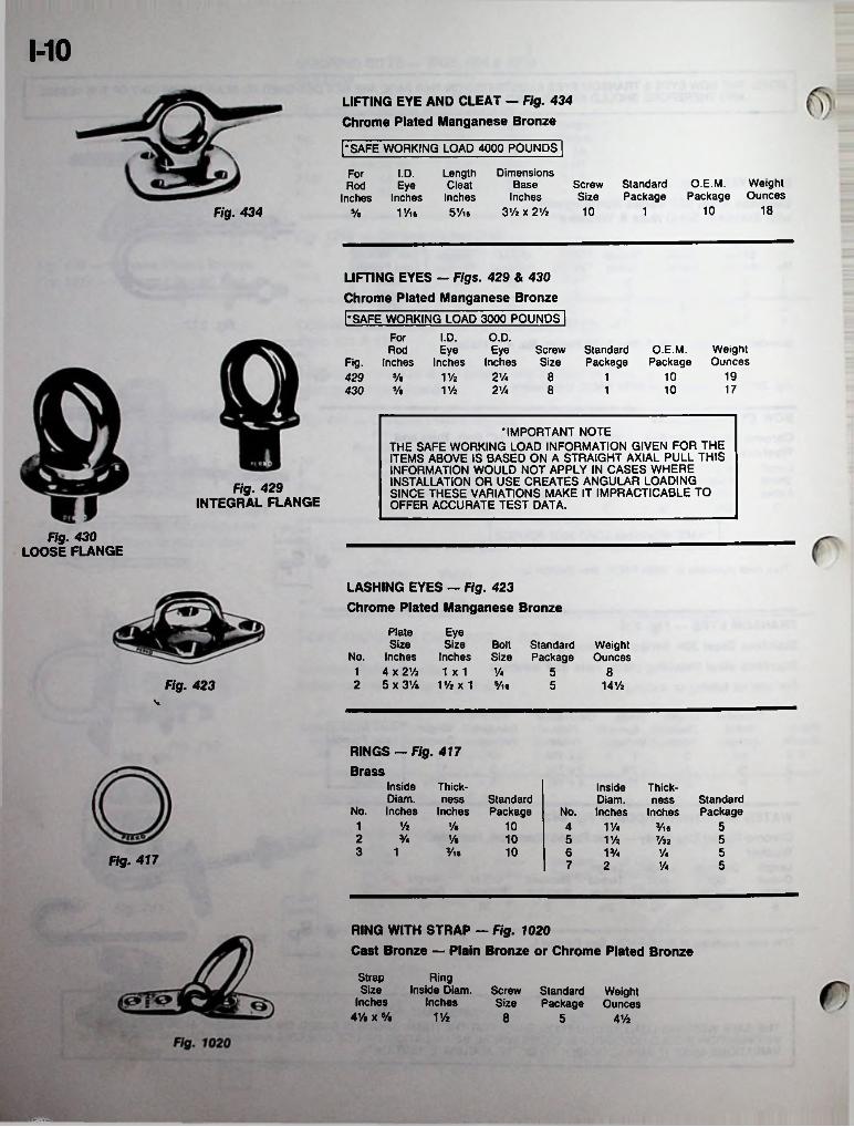
MOLIFTING EYE AND CLEAT — Fig. 434 Chrome Plated Manganese Bronze
[•SAFE WORKING LOAD 4000 POUNDS |
Dimensions Base
Inches 3% x 2Vz
For I.D. LengthRod Eye Cleat
Inches Inches Inches s/e 1 Vie 5Vie
O.E.M. Weight Package Ounces
Screw Standard Size Package
1810Fig. 434 10 1
LIFTING EYES - Figs. 429 & 430 Chrome Plated Manganese Bronzel-SAFE WORKING LOAD 3000 POUNDS |
I.D. O.D.Eye Eye Screw Standard
Fig. Inches Inches Inches Size Package
ForO.E.M. Weight
Package OuncesRod
1921/4 8 10429 5/e V/2 110 17% V/2 2Vt 8 1430
•IMPORTANT NOTETHE SAFE WORKING LOAD INFORMATION GIVEN FOR THE ITEMS ABOVE IS BASED ON A STRAIGHT AXIAL PULL THIS INFORMATION WOULD NOT APPLY IN CASES WHERE INSTALLATION OR USE CREATES ANGULAR LOADING SINCE THESE VARIATIONS MAKE IT IMPRACTICABLE TO OFFER ACCURATE TEST DATA.
Fig. 429INTEGRAL FLANGE
Fig. 430LOOSE FLANGE
LASHING EYES — Fig. 423 Chrome Plated Manganese Bronze
Plate Eye Size
No. Inches1 4 x 2Vz 1x1 1/42 5 x3V. 11/2x1 Vie
Size Bolt Standard WeightInches Size Package Ounces
5 8Fig. 423 5 UVz
RINGS — Fig. 417 Brass
Inside Diam.
No. Inches
Thickness
Inches
Inside Diam.
No. Inches
Thickness
InchesStandardPackage
StandardPackage
1 Vz y% 10 54 VU 3/ie2 % V. 10 5 V/z Vzz 53 1 y« 10 6 513/4 'AFig. 417 7 2 5V*
RING WITH STRAP — Fig. 1020Cast Bronze — Plain Bronze or Chrome Plated Bronze
Strap Size
Inches 4V$ x %
RingInside Diam.
InchesScrew Standard Weight Size Package Ounces
V/z 8 5 4 Vi
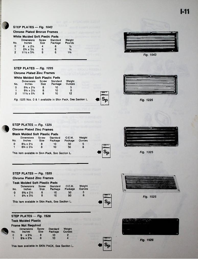
1-11
STEP PLATES — Fig. 1043 Chrome Plated Bronze Frames
White Molded Soft Pastic PadsScrew Standard Weight Size Package Pounds
Dimensions Inches
8 x 21/4 83/4 x 3'/.
111/2 x 53/4
No.0 6 Vz4
61 6 3/4
2 8 6 13/4
STEP PLATES — Fig. 1225 Chrome Plated Zinc FramesWhite Molded Soft Plastic Pads
Dimensions No. Inches0 83/e x 2’/4 81 83/4 x 31/4 82 111/2x53/4 8
WeightOunces
Screw Standard Size Package
51010 8
1210
Fig. 1225 Nos. 0 & 1 available in Skin Pack, See Section L. Fig. 1225
STEP PLATES — Fig. 1325 Chrome Plated Zinc Frames
Black Molded Soft Plastic PadsScrew Standard Size Package
Dimensions No. Inches0 83/e x 2Vi1 83/4 x 3Vi
O.E.M.Package
WeightOunces
58 10 5088 10 50
This item avalable in Skin Pack, See Section L.
STEP PLATES — Fig. 1525 Chrome Plated Zinc FramesTeak Molded Soft Plastic Pads
Dimensions No. Inches0 8% x 2Vi 81 8Vi x 3Vi 8
WeightOunces
O.E.M.Package
Screw Standard Size Package
5501085010
This item avalable in Skin Pack, See Section L.
STEP PLATES — Fig. 1526 Teak Molded Plastic Frame Not Required
Dimensions Inches
9 x 2 Vi 897/a X 27/a 8
V- -.A"eScrew Standard Weight Size Package Ounces
10 210 4
Fig. 1526
This item available in SKIN PACK, See Section L.
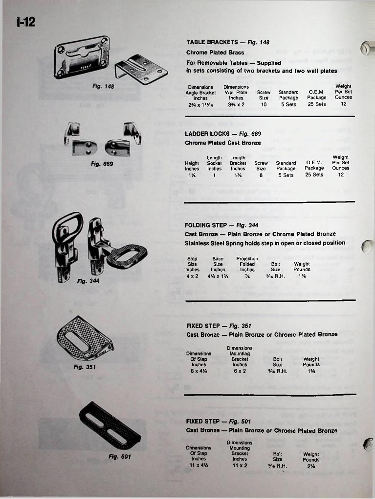
M2<? TABLE BRACKETS - Fig. 148
Chrome Plated Brass
For Removable Tables — Suppliedin sets consisting of two brackets and two wall plates
Weight O.E.M. Per Set
Package Ounces 25 Sets 12
Dimensions Wall Plate
Inches 33/e x 2
Dimensions Angle Bracket
Inches 23/4 x 1"/ie
Screw Standard Size Package 10 5 Sets
LADDER LOCKS — Fig. 669 Chrome Plated Cast Bronze
Weight Per Set Ounces
Length LengthHeight Socket Bracket Screw Inches Inches Inches Size
O.E.M. Package 25 Sets
Standard Package 5 Sets
Fig. 669
121V. 1 13/4 8
FOLDING STEP - Fig. 344Cast Bronze — Plain Bronze or Chrome Plated Bronze Stainless Steel Spring holds step in open or closed position
Step Size
Inches 4x2 4V4x13/4
BaseSize
Inches
ProjectionFoldedInches
WeightPounds
BoltSize
% Vie R.H. 17aFig. 344
FIXED STEP - Fig. 351Cast Bronze — Plain Bronze or Chrome Plated Bronze
DimensionsMountingBracketInches6x2
Dimensions Of Step Inches 6 x 41/4
Bolt WeightPoundsSizeFig. 351
Vie R.H. 1Ve
FIXED STEP — Fig. 501
Cast Bronze — Plain Bronze or Chrome Plated Bronze
rDimensions Mounting Bracket Inches 11 x2
Dimensions Of Step Inches
11 x 4V4
Bolt WeightPoundsFig. 501 Size
Vie R.H. 27a
■
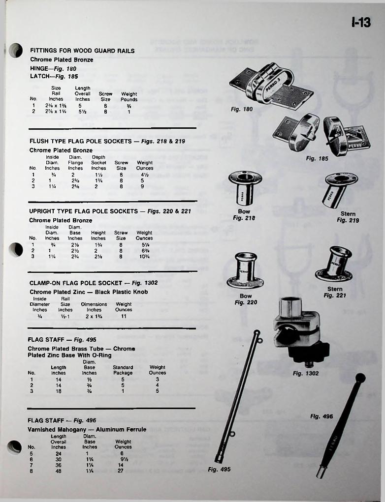
M3
FITTINGS FOR WOOD GUARD RAILS Chrome Plated Bronze HINGE—Fig. 180 LATCH—Fig. 185
Size LengthOverallInches
Rail ScrewSize
WeightPoundsNo. Inches
1 23/a x 13/a 52 27/a X 1 Va 5Vi
8 3/4
8 1
FLUSH TYPE FLAG POLE SOCKETS — Figs. 218 & 219
Chrome Plated BronzeInside Diam. DepthDiam. Flange Socket Screw Weight
No. Inches Inches Inches Size Ounces1 3/4 2 V/i 8 4 Vi2 23/a 8 51 13/43 V/a 25/a 2 8 9
UPRIGHT TYPE FLAG POLE SOCKETS — Figs. 220 & 221
Chrome Plated BronzeInside Diam.Diam. Base Height Screw Weight
No. Inches Inches Inches Size Ounces
BowFig. 218 Fig. 219
1 3/4 2Ya 8 5V413/42 2V2 2 8 63/413 V/a 2Va 2Va 8 103/4
CLAMP-ON FLAG POLE SOCKET — Fig. 1302 Chrome Plated Zinc — Black Plastic Knob Fig. 221
Inside RailDiameter Size
Inches InchesFig. 220Weight
OuncesDimensions
Inches 2 x 13/4 11Va Vi-1
FLAG STAFF — Fig. 495
Chrome Plated Brass Tube — Chrome Plated Zinc Base With O-Ring
Diam.Base
InchesWeightOunces
LengthInches
StandardPackageNo.
351 14 Vi42 514 Va53 18 Va 1
Fig. 496FLAG STAFF — Fig. 496
Varnished Mahogany — Aluminum FerruleDiam.Base
Inches
LengthOverallInches
WeightOuncesNo.
1 65 249V2V/a6 30
V/a 147 36Fig. 495278 V/a48
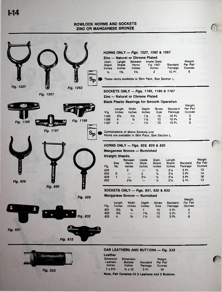
1-14ROWLOCK HORNS AND SOCKETS
ZINC OR MANGANESE BRONZE
HORNS ONLY - Figs. 1227, 1262 & 1267Zinc — Natural or Chrome PlatedDiam. Length BetweenShank Shank HomsInches Inches Inches
Weight Per Pair Ounces
Inside Diam. Fig. 1267
InchesStandard Package 10 Pr. 92V/a V/aVz
These items available in Skin Pack, See Section L.
SOCKETS ONLY — Figs. 1185, 1186 & 1187Zinc — Natural or Chrome PlatedBlack Plastic Bearings for Smooth Operation
Weight Per Pair Ounces
Screw Standard Size Package 10 10 Pr.10 10 Pr.10 10 Pr.
Length Fig. Inches1185 2V*1186 41187 4
Width Depth Inches Inches
51% 11/a9Va 11/e6V/a
Combinations of above Sockets andHorns are available in Skin Pack, See Section L.
HORNS ONLY — Figs. 828, 829 & 830 Manganese Bronze — BurnishedStraight Shanks
Between Inside Diam.Size Horns Diam. Shank
Fig. No. Inches Inches Inches
Weight Per Pair Ounces
LengthShankInches
Standard Package
5 Pr.5 Pr.5 Pr.5 Pr.
132 2Ve828 Vi14829 0
829 12Va2 Vi
162Va 2VeVi13830 2Va 2VeViFig. 828
Fig. 830SOCKETS ONLY — Figs. 831, 832 & 833 Manganese Bronze — BurnishedFig. 829
Weight Per Pair Ounces
LengthInches
WidthInches
Standard Package
5 Pr.5 Pr.5 Pr.
DepthInches
ScrewSizeFig.
831 2V» 7/e 10 41332 3Vt 713/e 10
Fig. 832 833 4 8Va V/a 10
Fig. 831
Fig. 833
OAR LEATHERS AND BUTTONS — Fig. 233 LeatherDimension Dimension Leathers Inches7 x 6Vi Vi x 13
Note, Pair Consists Of 2 Leathers and 2 Buttons.
Weight Standard Per Pair Package Ounces
5 Pr.
ButtonsInches
10Fig. 233
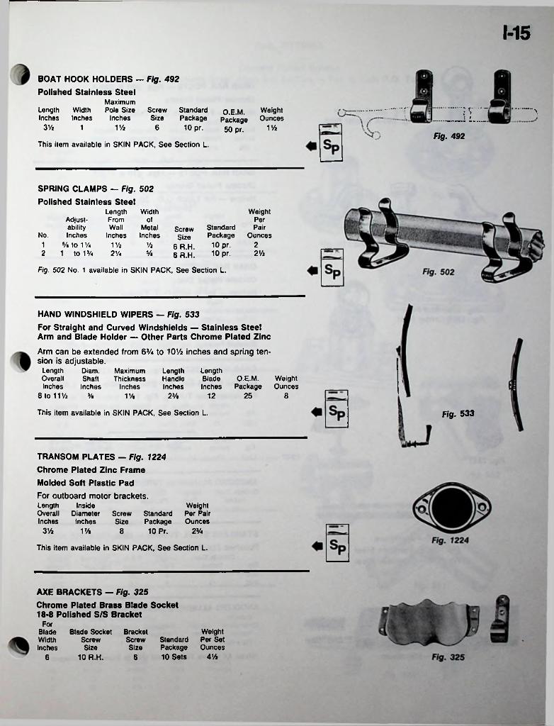
M5
BOAT HOOK HOLDERS — Fig. 492
Polished Stainless SteelMaximum
Length Width Pole Size Screw Standard Inches Inches Inches Size Package
10 pr.
■................... r —j
___ 1 L... .1WeightOunces
.... *~*\O.E.M. Package 50 pr.3 Vi V/i 61 VA
Fig. 492This item available in SKIN PACK, See Section L.
SPRING CLAMPS — Fig. 502
Polished Stainless SteelLength Width FromWall Metal
Inches Inches
WeightAdjustability
No. Inches1 5/e to 1!A V/i2 1 to V/4 2%
of PerStandard Package 10 pr. 10 pr.
PairOunces
Screw Size
6 R.H. 6 R.H.
Vi 22Vi5/«
Fig. 502 No. 1 available in SKIN PACK, See Section L.
HAND WINDSHIELD WIPERS — Fig. 533For Straight and Curved Windshields — Stainless Steel Arm and Blade Holder — Other Parts Chrome Plated Zinc
Arm can be extended from 6V* to lOVi inches and spring tension is adjustable.
Diam.Shaft
Inches
LengthOverallInches
LengthHandleInches
LengthBlade O.E.M. WeightInches Package Ounces
MaximumThickness
Inches8 to 11V2 25 83/a 23/« 1211/.
This item available in SKIN PACK, See Section L. Fig. 533
TRANSOM PLATES - Fig. 1224 Chrome Plated Zinc Frame Molded Soft Plastic PadFor outboard motor brackets.Length InsideOverall Diameter Screw Standard Inches Inches Size Package
10 Pr.
Weight Per Pair Ounces
3 Vi 23/417/« 8
This item available in SKIN PACK, See Section L.
AXE BRACKETS — Fig. 325Chrome Plated Brass Blade Socket 18-8 Polished S/S Bracket
ForWeight
Standard Per Set Package Ounces 10 Sets A Vi
Blade Blade Socket Width Inches
BracketScrewSize
ScrewSize
6 10 R.H. 6
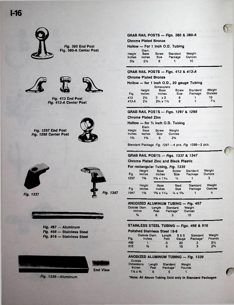
1-16
GRAB RAIL POSTS — Figs. 380 & 380-A Chrome Plated BronzeHollow — For 1 inch O.D. Tubing
Diam.Height Base Screw Standard Weight Inches Inches Size Package Ounces
Fig. 380 End Post Fig. 380-A Center Post
102Vi 83% 1
GRAB RAIL POSTS — Figs. 413 & 413-A Chrome Plated BronzeHollow — for 1 inch O.D., 20 gauge Tubing
Dimensions Base
Inches413 2V* 3 x 2413-A 2Vi 23/i x 1 % 8
WeightOunces
Screw Standard Size Package
Height Fig. Inches
108 1Fig. 413 End Post Fig. 413-A Center Post 7 Vi1
GRAB RAIL POSTS - Figs. 1297 & 1298 Chrome Plated ZincHollow — for Va inch O.D. Tubing
Diam.Height Base Screw Weight Inches Inches Size Ounces
Fig. 1297 End Post Fig. 1298 Center Post
1% 1Ve 6 2Va
Standard Package, Fig. 1297.—4 pcs. Fig. 1298—2 pcs.
GRAB RAIL POSTS — Figs. 1337 & 1347 Chrome Plated Zinc and Black PlasticFor rectangular Tubing, Fig. 1339
Height Fig. Inches1337 1% 13/e X 1 Vie 1/4r >
Fig. 1337 ft Fig' 1347
WeightOunces
Screw Standard Size Package
BaseInches
31
WeightOunces
Height Fig. Inches 1347 13/a
StandardPackage
Stud Size
1% X 1 Vie Vi X 13/4
BaseInches
41
ANODIZED ALUMINUM TUBING — Fig. 497 Length Standard Weight
Feet Package* OuncesOutside Diam.
Inches3/4 6 3 10
STAINLESS STEEL TUBING — Figs. 498 & 916Polished Stainless Steel 18-8
Length B & S Standard WeightFeet Gauge Package* Pounds
Fig. 497 — Aluminum Fig. 498 — Stainless Steel Fig. 916 — Stainless Steel Outside Diam.
InchesFig-498 2 Vi1 6 320
23/4916 % 6 18 3
ANODIZED ALUMINUM TUBING — Fig. 1339 Outside
Dimensions Length Standard WeightFeet Package* PoundsInches
End View iy.x% 6 5 1‘Note: All Above Tubing Sold only in Standard Packages
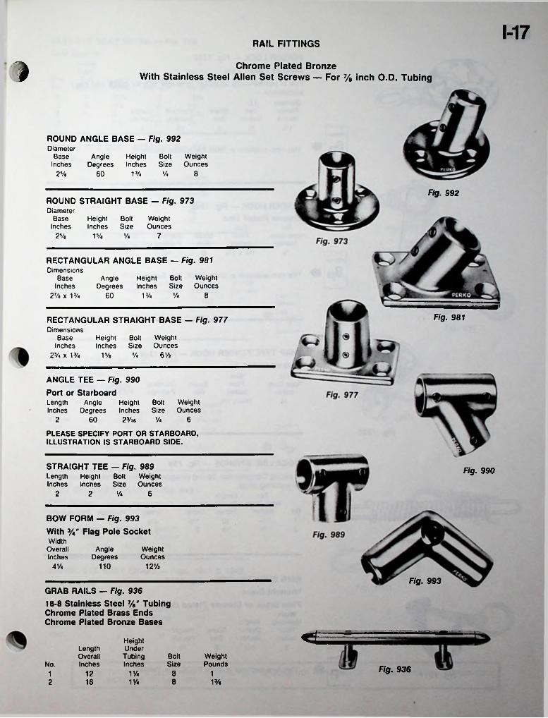
1-17RAIL FITTINGS
l Chrome Plated BronzeWith Stainless Steel Allen Set Screws — For 7/8 inch O.D. Tubing
ROUND ANGLE BASE — Fig. 992Diameter
Base Inches
Angle Height Bolt WeightDegrees Inches Size Ounces
2Ve 860 V/4 V4
Fig. 992ROUND STRAIGHT BASE — Fig. 973Diameter
Base Inches
Height Bolt Weight Inches Size Ounces
25/e V« 715/«
RECTANGULAR ANGLE BASE — Fig. 981Dimensions
Base Inches
2% x V/4
Height Bolt Weight Inches Size Ounces
AngleDegrees
860 V/4 V4
Fig. 981RECTANGULAR STRAIGHT BASE — Fig. 977Dimensions
Base Inches
23/4 X V/4
Height Bolt Weight Inches Size Ounces
6 ViV/a '/>
ANGLE TEE — Fig. 990 Port or StarboardLength Angle Height Bolt Weight Inches Degrees Inches Size Ounces
23/l6
PLEASE SPECIFY PORT OR STARBOARD, ILLUSTRATION IS STARBOARD SIDE.
2 660 y.
STRAIGHT TEE — Fig. 989Length Height Bolt Weight Inches Inches Size Ounces
Fig. 990
2 62 '/4
BOW FORM — Fig. 993With 3/4" Flag Pole SocketWidth
Overall Inches
AngleDegrees
WeightOunces
121/2110A'/4
Fig. 993GRAB RAILS — Fig. 93618-8 Stainless Steel %" Tubing Chrome Plated Brass Ends Chrome Plated Bronze Bases
HeightUnderTubingInches
LengthOverallInches
Bolt WeightPoundsSizeNo. Fig. 936V/4 812 11
18 VA 8 13/a2
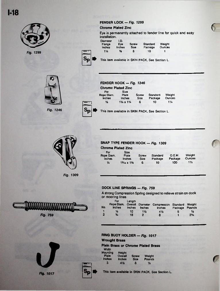
1-18FENDER LOCK — Fig. 1299 Chrome Plated Zinc
Eye is permanently attached to fender line for quick and easy installation.Diameter I.D.Flange Eye Screw Standard Weight Inches Inches Size Package Ounces
VA 3/a 8 10 1
^ This item available in SKIN PACK, See Section L.
FENDER HOOK — Fig. 1246Chrome Plated Zinc
Size Plate
Inches 13/« x VA
ForScrew Standard Weight Size Package Ounces
Rope Diam. Inches
3/a 6 10 VA
This item available in SKIN PACK, See Section L.
SNAP TYPE FENDER HOOK - Fig. 1309 Chrome Plated Zinc
Size Plate
Inches19/ie x 13/a 6
ForO.E.M. Weight
Package OuncesRope Diam.
inchesScrew Standard Size Package
VA10010y«
DOCK LINE SPRINGS — Fig. 759
A strong Compression Spring designed to relieve strain on dock or mooring lines
For LengthRope Diam. Overall Diameter Compression Standard Weight
Package PoundsNo. Inches Inches Inches Inches1 % 10 7/aV/2 4V2 52Fig. 759 3A 18 2 23/-8 1
RING BUOY HOLDER - Fig. 1017 Wrought Brass
J Plain Brass or Chrome Plated BrassWidth
Mounting Height Plate Overall
Inches InchesScrew Weight Size Pounds
3 VA 8 Vz
Sp ^ This item available in SKIN PACK, See Section L.Fig. 1017
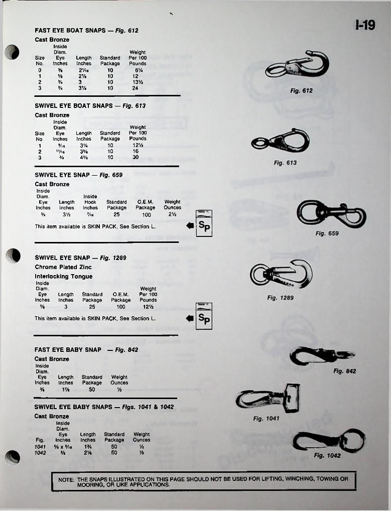
1-19FAST EYE BOAT SNAPS — Fig. 612Cast Bronze
Inside Diam.
Size Eye LengthNo. Inches Inches0 3/e 2Vie
Weight Standard Per 100 Package Pounds
10 6VaV«1 27/e 10 12V* 3 10 131/223/4 37/a3 10 24 Fig. 612
SWIVEL EYE BOAT SNAPS — Fig. 613
Cast BronzeInside Diam.
Size Eye Length StandardNo. Inches Inches Package
Vie 3 Vi2 "/ie 35/e
Weight Per 100 Pounds
121/a101161030103/4 45/a3
SWIVEL EYE SNAP — Fig. 659
Cast BronzeInside Diam.Eye Length
Inches Inches
InsideHook Standard
Inches PackageO.E.M.
PackageWeightOunces
2V23V2 253/4 7/ie 100
This item available is SKIN PACK, See Section L.
SWIVEL EYE SNAP — Fig. 1289 Chrome Plated ZincInterlocking TongueInsideDiam.Eye Length Standard O.E.M.
Inches Inches Package Package
Weight Per 100 Pounds
5/e 3 25 100 12%
This item available is SKIN PACK, See Section L.
FAST EYE BABY SNAP — Fig. 842Cast BronzeInsideDiam.Eye Length Standard Weight
Inches Inches Package Ounces
Fig. 842
3/e 5017/a 1/2
SWIVEL EYE BABY SNAPS — Figs. 1041 & 1042
Cast BronzeInsideDiam.Eye Length Standard Weight
Fig. Inches Inches Package Ounces1041 »/. x5/ia 13/.1042 3/a
50 Vz2Va 50 Vz Fig. 1042
NOTE: THE SNAPS ILLUSTRATED ON THIS PAGE SHOULD NOT BE USED FOR LIFTING, WINCHING. TOWING OR MOORING, OR LIKE APPLICATIONS.

1-20
FAST EYE SNAP HOOK - Fig. 614 18-8 STAINLESS STEEL — Non Magnetic Interlocking Tongue
Diam.Steel Standard Weight
Inches Package Ounces
I.D.Length Eye Inches Inches
2V2Vie 103/e3Fig. 614
| SAFE WORKING LOAD 350 POUNDs]
DOUBLE END SCRAPER — Fig. 1175
Steel — Heat Treated
Thickness
Inches
WidthBladeInches
StandardPackage
WeightPounds
Length Width Inches Inches
15 13/4 5 11 V*
CAULKING IRONS — Fig. 307 Malleable Iron
WidthSize Thickness Length Blade Standard WeightNo. Inches Inches Inches Package Ounces
Fig. 307 00 5V32 5 2 100 5V« 6V22% 101 Vi 57/e 72 Vi 10
SAIL MAKERS PALM - Fig. 411
Hide Mounted — Right Hand
StandardPackage
WeightOunces
10 2Fig. 411
WOOD HAND FIDS — Fig. 923
Varnished maple
Size Inches
12 x 13/i 14 x 13/4 16x2 18x2 20 x 2 Vi
StandardPackage
WeightOuncesNo.
0 2 4 Vi1 6V22Fig. 923 2 823 2 8V24 2 14
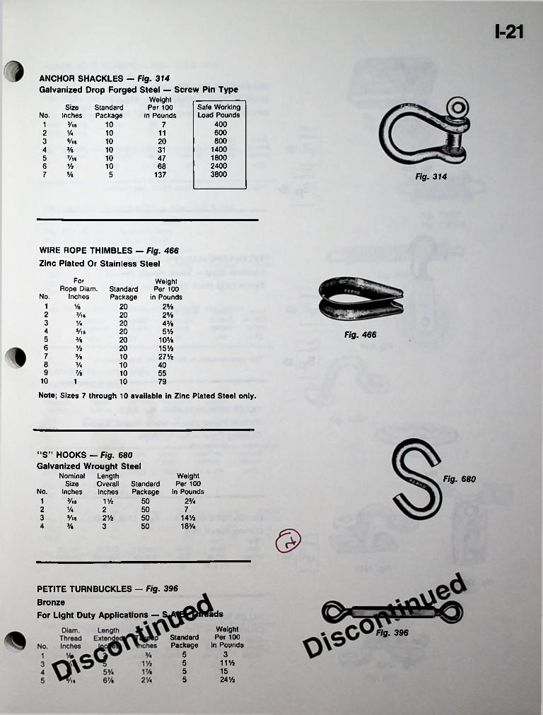
1-21
ANCHOR SHACKLES — Fig. 314Galvanized Drop Forged Steel — Screw Pin Type
Weight Per 100
in PoundsSafe Working Load Pounds
SizeInches
StandardPackageNo.
4003/,e 101 76002 % 10 118003 Vie 10 20
14004 3/e 10 3118005 7/l6 10 4724006 % 10 6838007 y8 5 137 Fig. 314
WIRE ROPE THIMBLES — Fig. 466 Zinc Plated Or Stainless Steel
For Weight Per 100
in PoundsRope Diam.
InchesStandardPackageNo.
1 % 20 25/e2 3/l6 20 25/a3 20% 4 3/»4 S/16 20 5% Fig. 4665 3/s 20 105/a6 Vz 20 15%7 5/e 10 27Vi8 3/4 10 409 7/« 10 55
10 1 10 79
Note; Sizes 7 through 10 available in Zinc Plated Steel only.
“S” HOOKS — Fig. 680 Galvanized Wrought Steel
Length Overall Inches
NominalSize
No. Inches
Weight Per 100
in PoundsFig. 680Standard
Package1 3/ie 1 Vi 50 23/42 50 7% 23 5/l6 2% 50 14%
183/44 3/e 3 50
PETITE TURNBUCKLES — Fig. 396 BronzeFor Light Duty Applications —
S^^Q^^ds
Standard Package
Weight Per 100
in PoundsFig. 396
355 11%5 155 24%
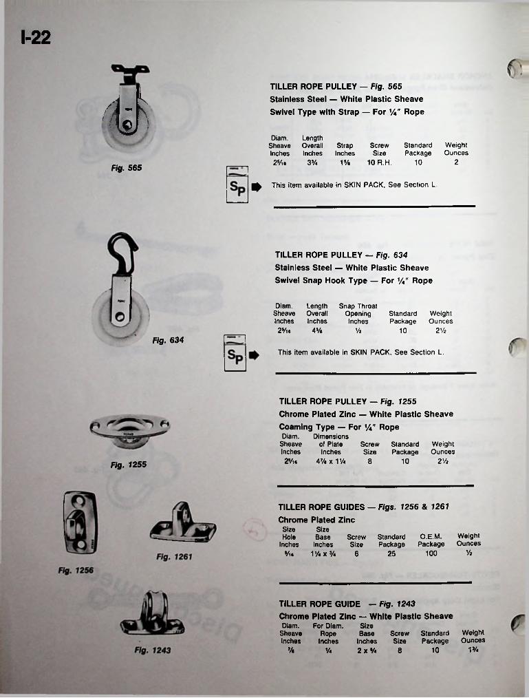
1-22
TILLER ROPE PULLEY — Fig. 565 Stainless Steel — White Plastic Sheave Swivel Type with Strap — For %" Ropev Diam. Length Sheave Overall StrapInches Inches Inches25/te
WeightOunces
Screw Standard Size Package
15/e 10 R.H. 10 233/4Fig. 565
^ This item available in SKIN PACK, See Section L.
TILLER ROPE PULLEY — Fig. 634 Stainless Steel — White Plastic Sheave Swivel Snap Hook Type — For 1/4" Rope
Diam. LengthSheave OverallInches Inches25/is 45/a
Snap Throat Opening Inches
Standard Weight Package Ounces
Vi 10 2 ViFig. 634
This item available in SKIN PACK, See Section L.
TILLER ROPE PULLEY — Fig. 1255 Chrome Plated Zinc — White Plastic SheaveCoaming Type — For %" RopeDiam. Dimensions
Sheave of Plate Inches Inches 25/ie 47/e X V/a 8
Screw Standard Size Package
WeightOunces
10 2 ViFig. 1255
TILLER ROPE GUIDES — Figs. 1256 & 1261Chrome Plated Zinc
Size Hole
Inches
SizeBase Screw Standard
Inches Size PackageV/a x Va 6
O.E.M. Weight Package Ounces
Vi10025Vie
TILLER ROPE GUIDE — Fig. 1243Chrome Plated Zinc — White Plastic SheaveDiam.
Sheave Inches
For Diam. Rope Inches
SizeBase Screw Standard
Inches Size Package2 x Va 8
WeightOunces
1J/47/« 10Va
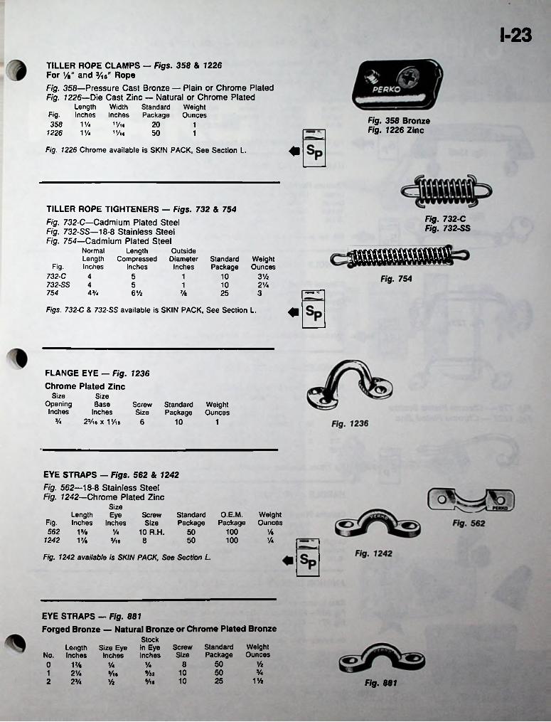
1-23TILLER ROPE CLAMPS — Figs. 358 & 1226 For Vi" and 3/i6" RopeFig. 358—Pressure Cast Bronze — Plain or Chrome Plated Fig. 7226—Die Cast Zinc — Natural or Chrome Plated
Length Width Standard WeightFig. Inches Inches Package Ounces358 VA
1226 V/4Fig. 358 Bronze Fig. 1226 Zinc
11/16
"/l620 150 1
Fig. 1226 Chrome available is SKIN PACK, See Section L.
TILLER ROPE TIGHTENERS — Figs. 732 & 754Fig. 732-C—Cadmium Plated Steel Fig. 732-SS—18-8 Stainless Steel Fig. 754—Cadmium Plated Steel
Length Compressed
Inches
Fig. 732-C Fig. 732-SS
NormalLengthInches
OutsideDiameter
InchesStandardPackage
WeightOuncesFig.
732-C 4732-SS 4
5 1 10 3Vi Fig. 7545 10 2Vi1
754 V/4 6 Vi 7/e 25 3
Figs. 732-C & 732-SS available is SKIN PACK, See Section L.
FLANGE EYE - Fig. 1236
Chrome Plated ZincSize
Opening Inches
Size Base
Inches 25/ie x 1 Vi6
Screw Standard Weight Size Package Ounces
V4 6 10 1
EYE STRAPS — Figs. 562 & 1242Fig. 562—18-8 Stainless Steel Fig. 7242—Chrome Plated Zinc
SizeLength Eye
Fig. Inches Inches 562 1%
1242 VA
O.E.M.Package
WeightOunces
Screw StandardSize Package
10 R.H. 50 100 y«'A50 100 v*S/16 8
Fig. 1242 available is SKIN PACK, See Section L.
EYE STRAPS — Fig. 881Forged Bronze — Natural Bronze or Chrome Plated Bronze
StockLength Size Eye in Eye Screw Standard Weight
No. Inches Inches Inches Size Package Ounces50 Vi80 17/e V4 1/4
*A10 501 21/4 »/32®/l.
25 1 Vi102 2’/4 5/ieVi Fig. 881

1-24 CHROMALEX® HANDLES — FIGS. 1336 & 1346
rChrome Plated Zinc and Black PlasticFig. 1336 for 1/4" ScrewsFig. 1346 with Studs, Nuts and Washers
HeightInside Stud Inches Size
1 1/4-20X1-1/2
LengthInsideInches
LengthOverallInches
Standard WeightPackage Ounces
1013-1/26-1/4
Fig. 1336 available in SKIN PACK, See Section L.
HANDLE — FIG. 1229
Chrome Plated Zinc Length Length HeightOverall Inside Inside Screw StandardInches Inches Inches Size Package5-1/4 3-1/2 1-1/2
O.E.M. Weight Package Ounces
2-1/46 10 100
This item available in SKIN PACK, See Section L.
HANDLE — FIG. 1231
Chrome Plated Zinc Length Length HeightOverall Inside Inside Screw Standard O.E.M.Inches Inches Inches Size Package Package
3-1/2 1-5/16 1/4-
WeightOunces
7-1/46 10 100
This item available in SKIN PACK, See Section L.
0HANDLES — FIG. 775 & 1222
Fig. 775—Chrome Plated Bronze Fig. 1222—Chrome Plated Zinc
Length Overall Inches
Fig. 775 — Chrome Plated Bronze Fig. 1222 — Chrome Plated Zinc
HeightInside
Fig. No. Inches775 1775 2 1-3/8
LengthInsideInches
WeightOunces
O.E.M.Package
StandardPackage
ScrewSize
27/8 504-1/4 2-5/8 6 1045-3/4 3-3/4 1083-1/21222 1-1/4 1005-3/4 103-3/4 8
Fig. 1234Fig. 775No. 2 available in SKIN PACK, See Section L.
I • • HANDLE — FIG. 1234
Chrome Plated ZincHeight Above
Length Deck Inches Inches
ScrewSize
Standard WeightPackage Ounces
5-1/26-1/2 2 8 10
ANCHOR CHOCKS — FIGS. 933 & 971
Cast Bronze — Plain Bronze or Chrome Plated BronzeFig. 933— Fits Dan forth ® Type Anchors up to 20 Pounds.Fig. 971 — Fits Danforth® Type Anchors from 22 to 90 Pounds.
Set consists of four parts illustrated.Weight Per Set Pounds
Screw Standard Package 5 Sets
Size10 2
Figs. 931 & 971 Chrome Plated available In SKIN PACK, See Section L.Figs. 933 & 971
SECTION J
door & cabinet ;
■; . :
C-y.
-■hardware
locks
latchcc
bolts
Ii
■■!j !
'
■■■■' • '''V'.V’T y:'
haspshinges
MANUFACTURED BY PERKO, INC., 16490 N.W. 13TH AVE., P.O. BOX 64000-D, MIAMI, FLORIDA 33164-0414FOR COMPLETE LINE SEE CATALOG NO. 250
PORTIONS OF THIS CATALOG PREVIOUSLY COPYRIGHTED IN 1936 THRU 1984 INCLUSIVE
* PERKO, INC. 1986 ALL RIGHTS RESERVED
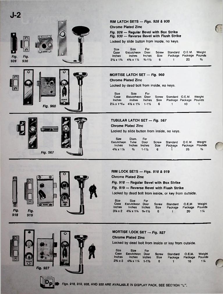
RIM LATCH SETS — Figs. 928 & 930 Chrome Plated ZincFig. 928 — Regular Bevel with Box Strike Fig. 930 — Reverse Bevel with Flush StrikeLocked by slide button from inside, no keys.
SizeEscutcheon Door Screw
Inches Inches Size 2*1X1’/. 4* x 1 * Va-V/z 6
ForSizeCase
InchesStandard O.E.M. Weight Package Package Pounds
Va201
MORTISE LATCH SET - Fig. 960 Chrome Plated ZincLocked by dead bolt from inside, no keys.
SizeEscutcheon Door Screw Standard O.E.M. Weight
Inches Inches Size Package Package Pounds2Va X 113/ie 43/a X 1 Va 1-1*
SizeCase
Inches
For
PCMKO
6 10 11Fig. 960
TUBULAR LATCH SET — Fig. 567 Chrome Plated ZincLocked by slide button from inside, no keys.
Size Diam. ForEscutcheon Tube Door Screw
Inches Inches Inches Size43/e X 1 Va Va 1-1* 6
Standard O.E.M. Weight Package Package Pounds
Va251Fig. 567
RIM LOCK SETS — Figs. 918 & 919 Chrome Plated ZincFig. 918 — Regular Bevel with Box Strike Fig. 919 — Reverse Bevel with Flush Strike Locked by dead bolt from inside, or key from outside.
o o
m *
SizeCase Escutcheon Door Screw Standard O.E.M. Weight
Inches Inches Inches Size Package Package Pounds3* x 2 43/a x 1 * %-1* 6
Size ForOFig. Fig. 1 *201918 919
MORTISE LOCK SET — Fig. 927 Chrome Plated ZincLocked by dead bolt from inside or key from outside.
*SizeCase Escutcheon Door Screw Standard O.E.M. Weight
Inches Inches Inches Size Package Package Pounds23/4 x 2 4% x 1 * 1-1*
Size For
1 *106 1
Fig. 927
0 Figs. 918, 919, 928, AND 930 ARE AVAILABLE IN DISPLAY PACK, SEE SECTION "L".
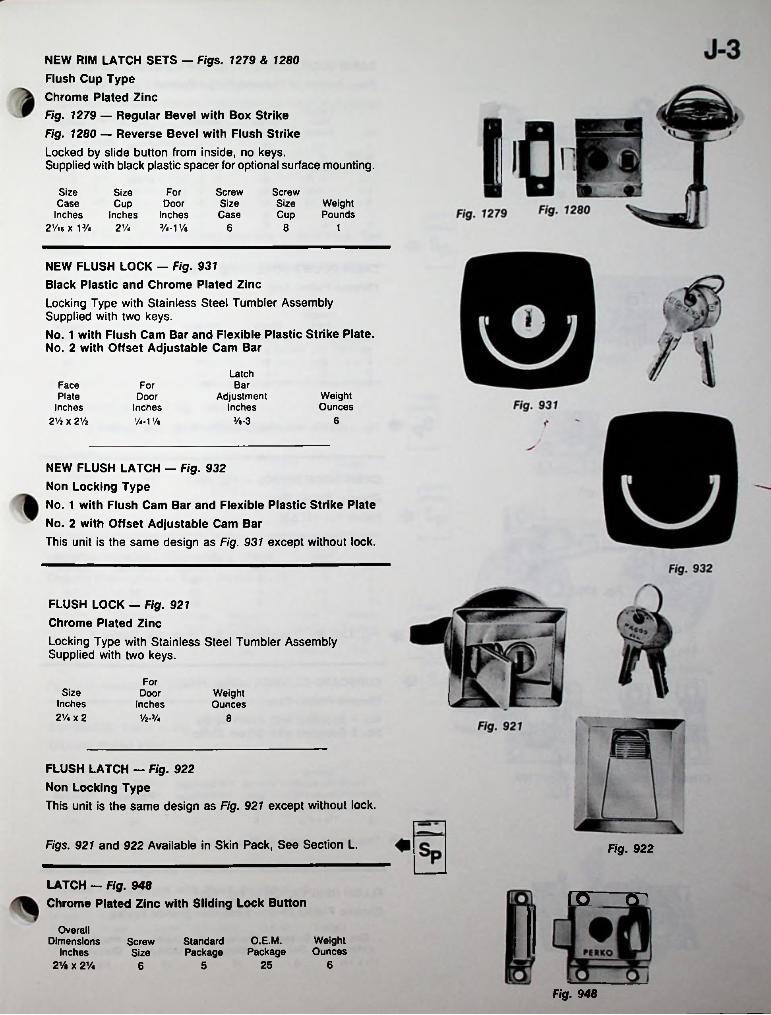
NEW RIM LATCH SETS — Figs. 1279 & 1280 Flush Cup Type Chrome Plated ZincFig. 1279 — Regular Bevel with Box Strike Fig. 1280 — Reverse Bevel with Flush StrikeLocked by slide button from inside, no keys.Supplied with black plastic spacer for optional surface mounting.
Size Case
Inches 2Vl6Xl3/4 2 Vi
ScrewSizeCup
SizeCup
Inches
For ScrewSizeCase
WeightPounds
DoorInches3/4-11/« 6 8 1
NEW FLUSH LOCK — Fig. 931 Black Plastic and Chrome Plated ZincLocking Type with Stainless Steel Tumbler Assembly Supplied with two keys.No. 1 with Flush Cam Bar and Flexible Plastic Strike Plate. No. 2 with Offset Adjustable Cam Bar
LatchBarFace
Plate Inches
2 Vi x 2 Vi
ForWeightOunces
Door Inches Vi-1 Vk
AdjustmentInches
6Ve-3
NEW FLUSH LATCH - Fig. 932 Non Locking TypeNo. 1 with Flush Cam Bar and Flexible Plastic Strike Plate No. 2 with Offset Adjustable Cam BarThis unit is the same design as Fig. 931 except without lock.
FLUSH LOCK — Fig. 921 Chrome Plated ZincLocking Type with Stainless Steel Tumbler Assembly Supplied with two keys.
ForSize
Inches 2 Vi x 2
DoorInches
’/a-3/.
WeightOunces
8
FLUSH LATCH — Fig. 922 Non Locking TypeThis unit is the same design as Fig. 921 except without lock.
Figs. 921 and 922 Available in Skin Pack, See Section L. Fig. 922
LATCH — Fig. 948Chrome Plated Zinc with Sliding Lock Button rer rr
Overall Dimensions
Inches 2 Vi X 21/4
O.E.M.Package
WeightOunces
StandardPackage
ScrewSize
25 656
Fig. 948
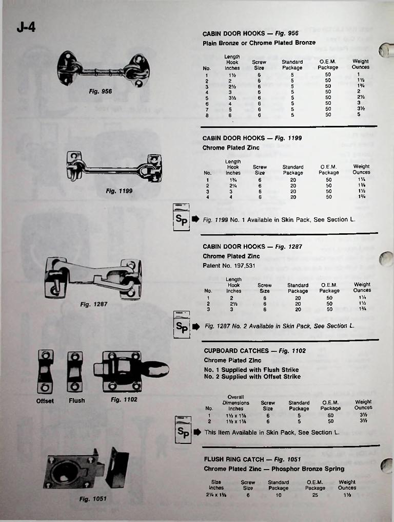
J-4 CABIN DOOR HOOKS — Fig. 956 Plain Bronze or Chrome Plated Bronze
LengthHook
InchesWeightOunces
O.E.M.Package
StandardPackage
ScrewSizeNo.
15051 Vi 611 Vz505622VA5052 Vi 63
Fig. 956 25053 642Vi5053Vi 65350566 43Vi5055 67550568 6
CABIN DOOR HOOKS — Fig. 1199 Chrome Plated Zinc
LengthHook
InchesWeightOunces
O.E.M.Package
ScrewSize
StandardPackageNo.
VA50VA 6 201VA502 2'A 6 20
Fig. 1199 VA50203 3 6VA506 204 4
1199 No. 1 Available in Skin Pack, See Section L.
CABIN DOOR HOOKS — Fig. 1287 Chrome Plated ZincPatent No. 197,531
LengthHook
InchesWeightOunces
O.E.M.Package
ScrewSize
StandardPackageNo.
VA2 501 6 201 Vi2 502Vi 6 20VA3 503 6 20
Sp ^ Fig. 1287 No. 2 Available in Skin Pack, See Section L.
CUPBOARD CATCHES — Fig. 1102 Chrome Plated ZincNo. 1 Supplied with Flush Strike No. 2 Supplied with Offset Strike
Overall Dimensions
No. InchesVAxVA
2 iy*xi7/8
^ This Item Available in Skin Pack, See Section L.
Fig. 1102FlushOffset WeightOunces
O.E.M.Package
ScrewSize
StandardPackage
3Vi5051 63 Vi506 5
FLUSH RING CATCH — Fig. 1051Chrome Plated Zinc — Phosphor Bronze Spring
Size Inches
2'/«x1 %
WeightOunces
ScrewSize
StandardPackage
O.E.M.Package
1 Vi256 10
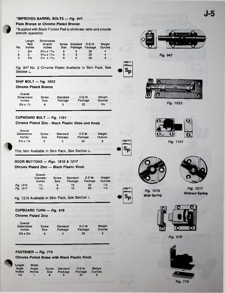
•IMPROVED BARREL BOLTS - Fig. 947Plain Bronze or Chrome Plated Bronze
A 'Supplied with Black Friction Pad to eliminate rattle and provide ^ smooth operation.
Length DimensionsOverall Inches
2% 37/t« x 17/i*45/n x 17/ie
4Vi 5Vi X 17/ie
Rod Screw Standard O.E.M. Weight Size Package Package OuncesNo. Inches
6 5 25 412 3 6 5 25 4 Fig. 9473 6 5 25 5
Fig. 947 No. 2 Chrome Plated Available in Skin Pack, See Section L.
SHIP BOLT — Fig. 1053 Chrome Plated Bronze
Overall Dimensions
Inches 2 Vi x 1 Vi
O.E.MPackage
WeightOunces
ScrewSize
StandardPackage
1%256 5
CUPBOARD BOLT — Fig. 1101
Chrome Plated Zinc - Black Plastic Slide and Knob
Overall Dimensions
Inches 2 Vi x 1%
ScrewSize
StandardPackage
O.E.MPackage
WeightOunces
50 26 5
This Item Available in Skin Pack, See Section L.
DOOR BUTTONS — Figs. 1216 & 1217 Chrome Plated Zinc — Black Plastic Knob
OverallDiameter
InchesaO.E.M.
PackageWeightOunces
Screw Standard Size Package
1%50Fig. 1216 Fig. 1217
101 Vi 61% Fig. 1217
Without Spring50101J/« 6
Fig. 1216 With Spring
Fig. 1216 Available in Skin Pack, See Section L.
CUPBOARD TURN — Fig. 978 Chrome Plated Zinc
Overall Dimensions
Inches 2 Vi x 2 Vi
WeightOunces
O.E.MPackage
ScrewSize
StandardPackage
5256 5
FASTENER — Fig. 719Chrome Plated Brass with Black Plastic Knob
Length WidthAngle AngleInches Inches
O.E.M. Weight Package Ounces
Screw Standard Size Package
1% 25 38 51
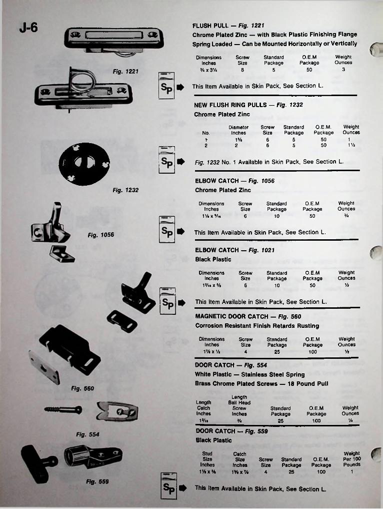
J-6 FLUSH PULL - Fig. 1221Chrome Plated Zinc — with Black Plastic Finishing Flange Spring Loaded — Can be Mounted Horizontally or Vertically
« E ID «5^ Weight
OuncesO.E.M
PackageScrewSize
StandardPackage
Dimensions Inches
5/« x 3V* 3508 5Fig. 1221
This Item Available in Skin Pack, See Section L.1 «NEW FLUSH RING PULLS - Fig. 1232 Chrome Plated Zinc
jrO.E.M. Weight
Package OuncesScrew Standard Size Package
DiameterInchesNo.
50 115/e 6 5tm 1 Vi506 52 2
Fig. 1232 No. 1 Available in Skin Pack, See Section L.
ELBOW CATCH — Fig. 1056 Chrome Plated ZincFig. 1232
WeightOunces
O.E.MPackage
DimensionsInches
iy.xVi6
ScrewSize
StandardPackage
V*506 10
This Item Available in Skin Pack, See Section L.Fig. 1056
ELBOW CATCH - Fig. 1021 Black Plastic
WeightOunces
DimensionsInches
iy«x%
ScrewSize
StandardPackage
O.E.MPackage
Vi6 5010
This Item Available in Skin Pack, See Section L.
MAGNETIC DOOR CATCH — Fig. 560 Corrosion Resistant Finish Retards Rusting
Dimensions Inches 17/. x Vi
WeightOunces
ScrewSize
StandardPackage
O.E.MPackage
Vi1004 25
DOOR CATCH — Fig. 554
White Plastic — Stainless Steel Spring
Brass Chrome Plated Screws — 18 Pound PullFig. 560
Length Ball Head
Screw Inches
LengthCatchInches
WeightOunces
O.E.MPackage
StandardPackage
1J/i. ViV* 10025
DOOR CATCH - Fig. 559 Black Plastic
Weight Per 100 Pounds
StudSize
Inches11/«x%
CatchSize
Inchesi%x%
Screw Standard Size Package
O.E.M.Package
125 1004
Fig. 559Sp ^ This Item Available in Skin Pack, See Section L.
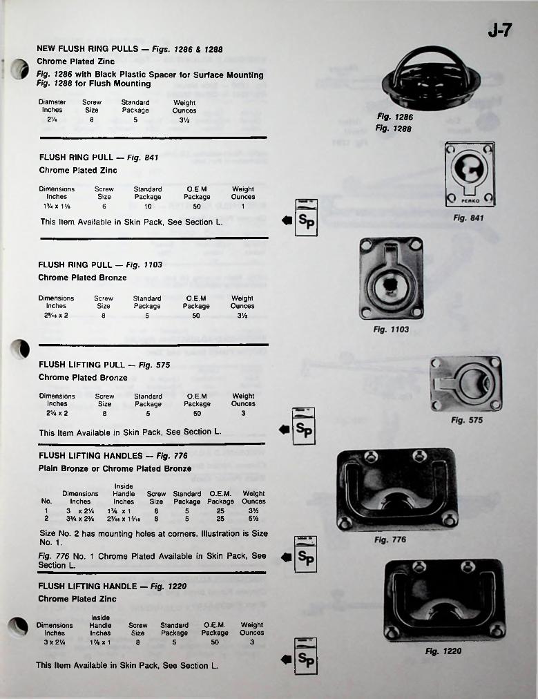
J-7NEW FLUSH RING PULLS - Figs. 1286 & 1288 Chrome Plated Zinc
Fig. 1286 with Black Plastic Spacer for Surface Mounting Fig. 1288 for Flush Mounting
DiameterInches
ScrewSize
StandardPackage
WeightOunces
Fig. 1286 Fig. 1288
2% 8 5 3Vt
FLUSH RING PULL — Fig. 841 Chrome Plated Zinc
Dimensions Inches
1%x 13/.
ScrewSize
StandardPackage
O.E.MPackage
WeightOunces
6 10 50 1
This Item Available in Skin Pack, See Section L.
FLUSH RING PULL — Fig. 1103 Chrome Plated Bronze
Dimensions Inches
29/i» x 2
ScrewSize
O.E.MPackage
WeightOunces
StandardPackage
3 Vz8 5 50
FLUSH LIFTING PULL — Fig. 575 Chrome Plated Bronze
Dimensions Inches 2V, x 2
WeightOunces
ScrewSize
StandardPackage
O.E.MPackage
38 505
This Item Available in Skin Pack, See Section L.
FLUSH LIFTING HANDLES — Fig. 776 Plain Bronze or Chrome Plated Bronze
InsideHandle Screw Standard O.E.M. WeightInches Size Package Package Ounces
17/* x 123/i6 x 1 Vie 8
Dimensions No. Inches
1 3 x 21/42 3V* x 2V.
Size No. 2 has mounting holes at corners. Illustration is Size No. 1.
Fig. 776 No. 1 Chrome Plated Available in Skin Pack, See ^1 Section L.
3 Vi258 55 Vi255
mm
FLUSH LIFTING HANDLE — Fig. 1220 Chrome Plated Zinc
Inside Handle Inches 17/«x 1
Dimensions Inches 3 x 2V<
O.E.M. Weight Package Ounces
Screw Standard Size Package
3508 5Ftg. 1220
This Item Available in Skin Pack, See Section L.
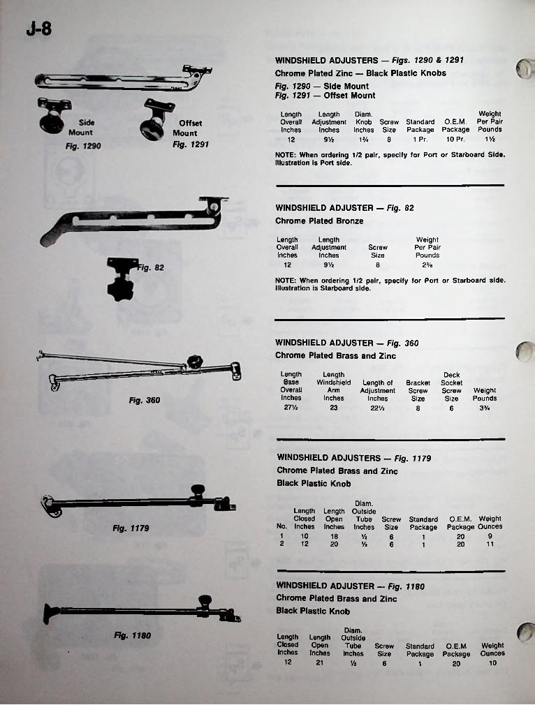
J-8WINDSHIELD ADJUSTERS — Figs. 1290 & 1291 Chrome Plated Zinc — Black Plastic KnobsFig. 1290 — Side Mount Fig. 1291 — Offset Mount
SrWeight
O.E.M. Per Pair Package Package Pounds
10 Pr.
Length Length Diam.Overall Adjustment Knob Screw StandardInches Inches Inches Size
Offset Mount Fig. 1291
V/z1 Pr.12 9 Vz 1% 8
NOTE: When ordering 1/2 pair, specify for Port or Starboard Side. Illustration Is Port side.
WINDSHIELD ADJUSTER - Fig. 82 Chrome Plated Bronze
LengthOverallInches
LengthAdjustment
Inches
Weight Per Pair Pounds
ScrewSize
12 9Vz 23/e8
NOTE: When ordering 1/2 pair, specify for Port or Starboard side. Illustration is Starboard side.
WINDSHIELD ADJUSTER - Fig. 360 Chrome Plated Brass and Zinc
HV
Length Base
Overall Inches 27 Vz
LengthWindshield Length of
Arm AdjustmentInches Inches
22 Vi
DeckSocketScrewSize
r= BracketScrewSize
WeightPoundsFig. 360
23 3J/48 6
WINDSHIELD ADJUSTERS - Fig. 1179 Chrome Plated Brass and Zinc Black Plastic Knob
% Diam.Length Length Outside Closed Open Tube Screw Standard
No. Inches Inches Inches Size PackageO.E.M. Weight
Package OuncesFig. 11791 10 918 Vi 206 12 12 20 Vz 116 201
WINDSHIELD ADJUSTER — Fig. 1180 Chrome Plated Brass and Zinc Black Plastic KnobM. %
Diam.Length Length Outside Closed Open Inches Inches
Fig. 1180Tube Screw Standard O.E.M Weight
Inches Size Package Package Ounces12 21 10Vz 6 201
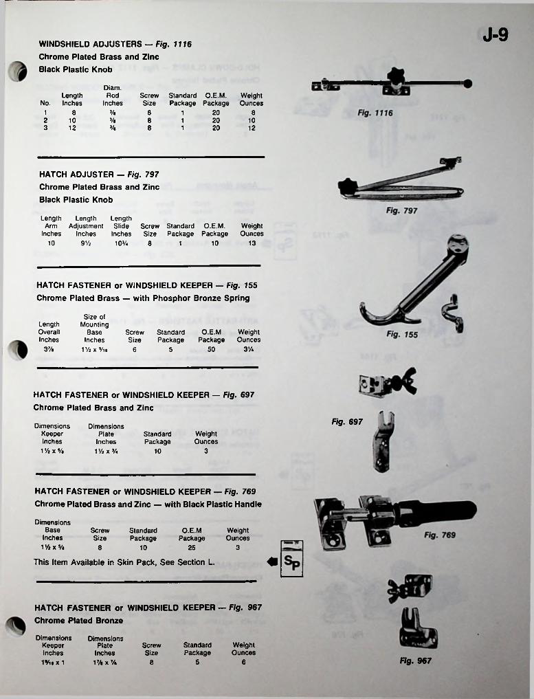
J-9WINDSHIELD ADJUSTERS — Fig. 1116 Chrome Plated Brass and Zinc Black Plastic Knob
Diam.Rod
InchesLength
No. InchesScrew Standard O.E.M. Size Package Package
WeightOunces
3/a 20 81 8 8 12 y.10 8 20 1013 12 y« 8 20 121
HATCH ADJUSTER — Fig. 797 Chrome Plated Brass and Zinc Black Plastic Knob
Length Length LengthArm Adjustment Slide Screw Standard O.E.M.
Inches Inches Inches Size Package Package103/«
WeightOunces
10 139 Vi 8 101
HATCH FASTENER or WINDSHIELD KEEPER — Fig. 155 Chrome Plated Brass — with Phosphor Bronze Spring
Size of Mounting
Base Inches
1 Vi x Vis
LengthOverallInches
O.E.M Weight Package Ounces
Screw Standard Size Package
37/a 3%506 5
HATCH FASTENER or WINDSHIELD KEEPER — Fig. 697 Chrome Plated Brass and Zinc
Fig. 697Dimensions
Keeper Inches
1 Vz x 5/a
DimensionsPlate
Inches1 % X J/4
StandardPackage
WeightOunces
310
HATCH FASTENER or WINDSHIELD KEEPER — Fig. 769 Chrome Plated Brass and Zinc — with Black Plastic Handle
Dimensions Base
Inches 1 Vt x s/a
ScrewSize
StandardPackage
O.E.MPackage
WeightOunces
8 25 310
This Item Available in Skin Pack, See Section L.
HATCH FASTENER or WINDSHIELD KEEPER — Fig. 967 Chrome Plated Bronze
Dimensions Keeper Inches 1*/ia x 1
Dimensions Plate
Inches 17/a X 7/a
StandardPackage
WeightOunces
ScrewSize
Fig. 9675 68
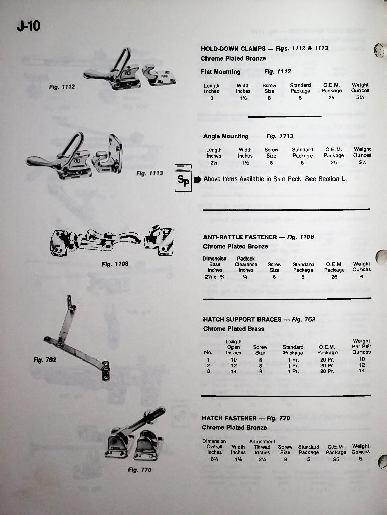
J-10
<3HOLD-DOWN CLAMPS — Figs. 1112 & 1113 Chrome Plated Bronze
Fig. 1112Flat Mounting
WeightOunces
O.E.M.Package
StandardPackage
ScrewSize
LengthInches
WidthInches
5 V»255V/z 83
Angle Mounting Fig. 1113
WeightOunces
O.E.M.Package
StandardPackage
LengthInches
WidthInches
ScrewSize
5 Vi252Vi 1 Vi 58
Sp ^ Above Items Available in Skin Pack, See Section L.
ANTI-RATTLE FASTENER — Fig. 1108 Chrome Plated Bronze
Dimension Base
Inches 23/.x 1%
PadlockClearance
InchesFig. 1108 Weight
OuncesScrewSize
O.E.M.Package
StandardPackage
425Va 56
HATCH SUPPORT BRACES — Fig. 762 Chrome Plated Brass
/
Weight Per Pair Ounces
LengthOpenInches
ScrewSize
Standard Package
1 Pr.
O.E.M. Package
20 Pr. 20 Pr. 20 Pr.
No.10Fig. 762 101 8122 12 8 1 Pr.143 14 8 1 Pr.
HATCH FASTENER — Fig. 770 Chrome Plated Bronze
Dimension Overall Width Inches Inches
AdjustmentThread Screw Standard O.E.M. Weight Inches Size Package Package Ounces c633/4 1% 2Va 5 258
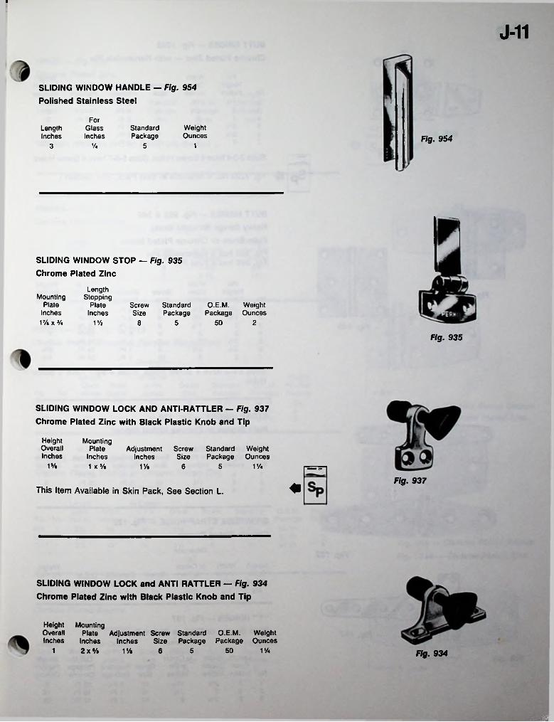
I
J-11
SLIDING WINDOW HANDLE — Fig. 954 Polished Stainless Steel
ForWeightOunces
GlassInches
StandardPackage
LengthInches Fig. 954
13 Va 5
SLIDING WINDOW STOP — Fig. 935 Chrome Plated Zinc
LengthStopping
PlateInches
Mounting Plate
Inches V/» x Va
Screw Standard Size Package
O.E.M.Package
WeightOunces M
50 2V/i 8 5
Fig. 935
SLIDING WINDOW LOCK AND ANTI-RATTLER — Fig. 937 Chrome Plated Zinc with Black Plastic Knob and Tip
HeightOverallInches
Mounting Plate
Inches 1 x */a
Screw Standard Weight Size Package Ounces
AdjustmentInches
1s/e 1%1% 6 5 •m rrFig. 937
This Item Available in Skin Pack, See Section L.
SLIDING WINDOW LOCK and ANTI RATTLER — Fig. 934 Chrome Plated Zinc with Black Plastic Knob and Tip
Height MountingOverall Plate Adjustment Screw Standard O.E.M. WeightInches Inches Inches Size Package Package Ounces
2 x 5/« V/a501 V/a 6 5 Fig. 934
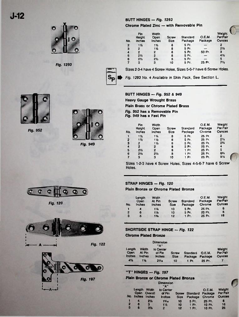
J-12BUTT HINGES — Fig. 1293
Chrome Plated Zinc — with Removable Pin
Weight Per Pair Ounces
Pin WidthOpenInches
O.E.M.Package
ScrewSize
Standard Package
5 Pr.5 Pr.5 Pr.5 Pr.
HeightinchesNo.
2V/i V/i 822 ViV/i 83 2350 Pr.82 244 Vi5 2 Vi 2 855 Pr.6 2Vi 2Vi 8
25 Pr.
Sizes 2-3-4 have 4 Screw Holes, Sizes 5-6-7 have 6 Screw Holes.
0 Fig. 1293 No. 4 Available in Skin Pack, See Section L.
7 Vi5 Pr.3 3 107Fig. 1293
BUTT HINGES - Fig. 952 & 949 Heavy Gauge Wrought Brass Plain Brass or Chrome Plated Brass
Fig. 952 has a Removable Pin Fig. 949 has a Fast Pin
Weight Per Pair Ounces
O.E.M. Package Chrome 25 Pr. 25 Pr. 25 Pr. 25 Pr. 25 Pr. 25 Pr. 25 Pr.
Pin WidthOpenInches
HeightInches
ScrewSize
Standard Package
5 Pr.5 Pr.5 Pr.5 Pr.1 Pr.1 Pr.1 Pr.
Fig. 952 No.21 Vi V/4 812Vi2 V/t V/i 82J/«3 2 V/i 8Fig. 949 424 2 855 2Vt 2 86 V*6 2Vi 2 Vi 89Va7 3 3 10
Sizes 1-2-3 have 4 Screw Holes, Sizes 4-5-6-7 have 6 Screw Holes.
STRAP HINGES - Fig. 120
Plain Bronze or Chrome Plated Bronze
Weight Per Pair Ounces
O.E.M. Package Chrome 25 Pr. 25 Pr. 25 Pr.
Length Open
No. Inches
Width At Pin Inches
Screw Standard Size Package
5 Pr.5 Pr.1 Pr.
Fig. 12061V.1 4 1082 6 V/t 10
163 8 1% 12
SHORTSIDE STRAP HINGE — Fig. 122 Chrome Plated Bronze
Dimension“A'*
Length Width Open At Pin Inches Inches
Weight Per Pair
Package Package Ounces 1 Pr. 25 Pr.
to Centerof Pin Screw Standard O.E.M.Inches Size
4Vt V/i 72Vti 10
I©“T” HINGES - Fig. 197
Plain Bronze or Chrome Plated BronzeFig. 197Dimension
"A"Length Width Open Overall
No. inches Inches1 4 2Vi2 6 33 8 3%
O.E.M. Weight Screw Standard Package Per Pair Size Package Chrome Ounces 10 5 Pr. 25 Pr.10 1 Pr. 10 Pr. 1612 1 Pr. 10 Pr. 25
to Center of Pin Inches
81Vi.V/i2
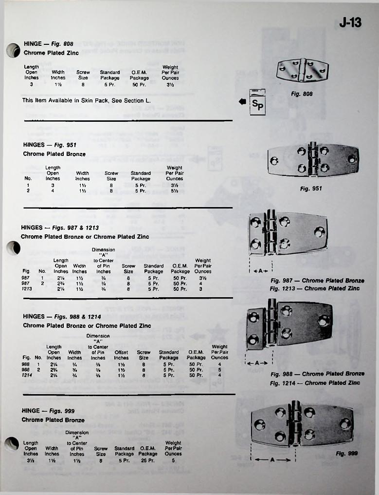
J-13HINGE — Fig. 808 Chrome Plated Zinc
LengthOpenInches
Weight Per Pair Ounces
WidthInches
ScrewSize
Standard Package
5 Pr.
O.E.M. Package 50 Pr.3 iVl 8 3Va
Fig. 808This Item Available in Skin Pack, See Section L.
HINGES — Fig. 951 Chrome Plated Bronze
oPo I6LengthOpenInches
Weight Per Pair Ounces
Standard Package
5 Pr.5 Pr.
WidthInches
ScrewSizeNo.
3Va1 3 V/2 8 Fig. 9512 4 V/2 8 5 Vi
HINGES — Figs. 987 & 1213Chrome Plated Bronze or Chrome Plated Zinc
Dimension"A"
LengthOpen Width
Fig. No. Inches Inches2 V. 1Vi
987 2 2V. 1Vi2V. 1Vi
Weight O.E.M. PerPair
Package Ounces 50 Pr. 3Vi50 Pr. 450 Pr. 3
to Center of Pin Inches
Standard Package
5 Pr.5 Pr.5 Pr.
ScrewSize
987 1 V. 8 Fig. 987 — Chrome Plated Bronze Fig. 1213 — Chrome Plated Zinc
v. 81213 V. 8
HINGES — Figs. 988 & 1214Chrome Plated Bronze or Chrome Plated Zinc
Dimension"A"
LengthOpen Width
Fig. No. Inches Inches988 1 2V.988 2 2V.
WeightPerPairOunces
to Center of Pin Offset Inches Inches
Standard Package
5 Pr.5 Pr.5 Pr.
O.E.M. Package 50 Pr. 50 Pr. 50 Pr.
ScrewSize
1Vi 8 4V. V.5V* y« 1Vi 8
Fig. 988 — Chrome Plated Bronze Fig. 1214 — Chrome Plated Zinc
1214 2V. 4V. 3/« 1Vi 8
HINGE — Figs. 999 Chrome Plated Bronze
Dimension“A”
LengthOpenInches
WeightScrew Standard O.E.M. PerPairSize Package Package Ounces
5 Pr. 25 Pr.
to Center Width of PinInches Inches
3Va V/2 5V/2 8
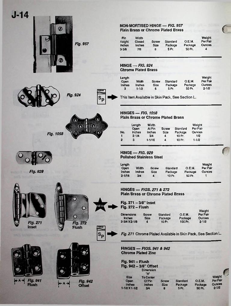
J-14NON-MORTISED HINGE — FIG. 957 Plain Brass or Chrome Plated Brass
Weight Per Pair Ounces
Pin WidthHeight ClosedInches Inches
O.E.M. Package
50 Pr.
Screw Standard Size Package
5 Pr.Fig. 957
43-3/8 7/8 8
HINGE — FIG. 924 Chrome Plated Brass
Weight Per Pair Ounces
2-1/2
LengthOpenInches
O.E.M. Package
50 Pr.
WidthInches
ScrewSize
Standard Package
5 Pr.3 1-1/2 6
Fig. 924 This item Available in Skin Pack, See Section L.
HINGES — FIG. 1058Plain Brass or Chrome Plated Brass
Length Open
No. Inches
Width At Pin Inches
WeightScrew Standard Per PairSize Package Ounces
10 Pr.10 Pr.
Fig. 1058 1 2-1/4 3/4 4 1/22 3 1-1/16 1-1/24
HINGE — FIG. 929 Polished Stainless Steelp>o oLengthOpen WidthInches Inches2-1/16 3/4
Weight O.E.M. Per Pair
Package Ounces 50 Pr.
ScrewSize
Standard Package
10 Pr.Fig. 929
14
R HINGES — FIGS. 271 & 272 Plain Brass or Chrome Plated Brass■
■ 9i Fig. 271 - 3/8" Inset Fig. 272-Flushm Weight
Per Pair Ounces 2-1/2
o Dimensions Inches
2-3/4 X 2-1/8
O.E.M. Package 100 Pr.
ScrewSize
Standard Package
10 Pr.1
4Fig. 271 Inset
Fig. 272 FlushV
Fig. 271 Chrome Plated Available in Skin Pack, See Section L.
HINGES — FIGS. 941 & 942 Chrome Plated Zinc
Fig. 941 - Flush Fig. 942-3/8" Offset cDimension
"A"Weight Per Pair Ounces 2-1/2
Size To Center Of Pin Inches
KA-*S Fig. 941 ' ‘ Flush
Open Inches
1-1/2 X1-1/2 3/4
Fig. 942 Offset
Screw Standard Size Package
O.E.M. Package 50 Pr.
!*■ A -*j i i 5 Pr.8
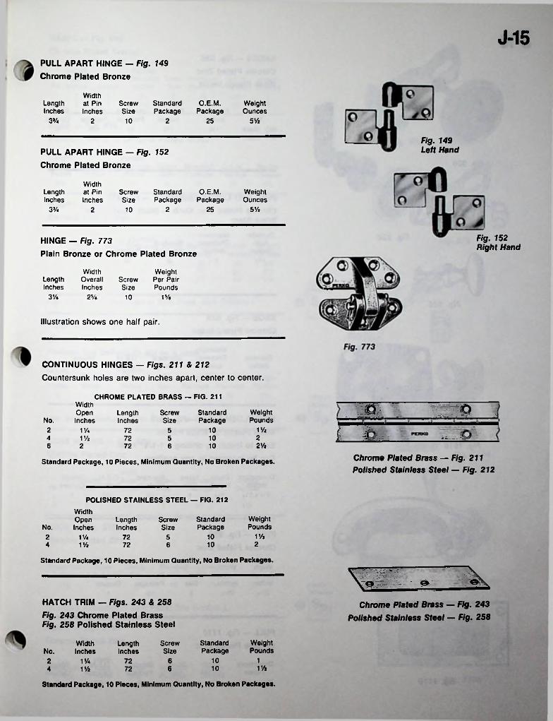
J-15PULL APART HINGE - Fig. 149 Chrome Plated Bronze
Width at Pin Inches
LengthInches
Screw Standard Size Package
O.E.M.Package
WeightOunces
3% 5Vz2 10 2 25
Fig. 149 Left HandPULL APART HINGE — Fig. 152
Chrome Plated Bronze
Width at Pin Inches
StandardPackage
O.E.M.Package
WeightOunces
LengthInches
ScrewSize
3% 5 Vi2 252 10
Fig. 152 Right Hand
HINGE — Fig. 773Plain Bronze or Chrome Plated Bronze
WidthOverallInches
Weight Per Pair Pounds
LengthInches
ScrewSize
3 Vi 15/e2V« 10
Illustration shows one half pair.
CONTINUOUS HINGES — Figs. 211 & 212 Countersunk holes are two inches apart, center to center.
CHROME PLATED BRASS — FIG. 211WidthOpenInches
13StandardPackage
WeightPounds
ScrewSize
LengthInchesNo.
1 Vi2 10V/a 72 5 i i2104 1 Vi 72 52Vi6 2 1072 6
Chrome Plated Brass — Fig. 211 Polished Stainless Steel — Fig. 212
Standard Package, 10 Pieces, Minimum Quantity, No Broken Packages.
POLISHED STAINLESS STEEL — FIG. 212
WidthOpenInches
WeightPounds
StandardPackage
ScrewSize
LengthInchesNo.
V/i102 V/a 57224 1% 1072 6
Standard Package, 10 Pieces, Minimum Quantity, No Broken Packages.
\vL_
HATCH TRIM — Figs. 243 & 258Fig. 243 Chrome Plated Brass Fig. 258 Polished Stainless Steel
Chrome Plated Brass — Fig. 243 Polished Stainless Steel — Fig. 258
WeightPounds
StandardPackage
WidthInches
ScrewSize
LengthInchesNo.
10 12 V/a 72 61 Vi6 104 1 Vi 72
Standard Package, 10 Pieces, Minimum Quantity, No Broken Packages.
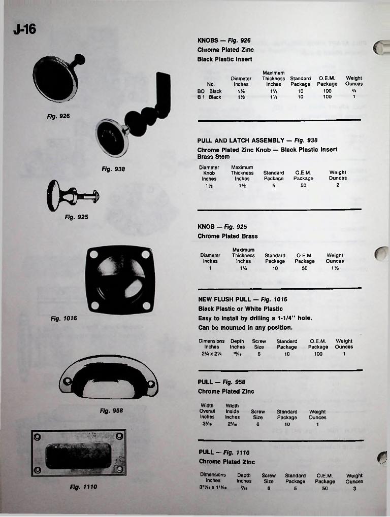
J-16KNOBS - Fig. 926 Chrome Plated Zinc Black Plastic Insert*
MaximumThickness Standard
Inches PackageO.E.M.
PackageWeightOunces
DiameterInchesNo.
V«10010BO Black B 1 Black
iy« 1 Vt100 11% 1 Va 10
Fig. 926
PULL AND LATCH ASSEMBLY - Fig. 938Chrome Plated Zinc Knob — Black Plastic Insert Brass Stem
MaximumThickness
Inches
DiameterKnob
Inches
Fig. 938 WeightOunces
O.E.M.Package
StandardPackage
250V/i 51%
Fig. 925
KNOB — Fig. 925 Chrome Plated Brass
MaximumThickness
InchesDiameterInches
StandardPackage
O.E.M.Package
WeightOunces
1V. V/z1 10 50
NEW FLUSH PULL - Fig. 1016 Black Plastic or White Plastic Easy to install by drilling a 1-1/4” hole. Can be mounted in any position.
Fig. 1016
Dimensions Depth Screw StandardInches Inches Size Package
2 Vi x 2V* 15/i*
O.E.M. Weight Package Ounces
6 10 100 1
PULL - Fig. 958 Chrome Plated Zinc
Width WidthOverall InsideInches Inches 3Vu 2*/,*
Fig. 958 ScrewSize
StandardPackage
WeightOunces
6 10 1.-v—^ -- • - -9©
PULL — Fig. 1110 Chrome Plated Zinc rs|
© DimensionsInches
3'VnxVVu
Depth Screw Standard O.E.M. WeightInches Size Package Package Ounces
Fig. 1110 V\% 6 5 50 3
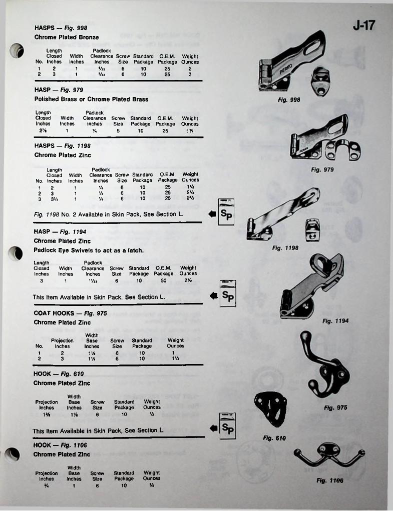
HASPS - Fig. 998 Chrome Plated Bronze
LengthClosed Width
No. Inches Inches
PadlockClearance Screw Standard O.E.M. Weight
Inches Size Package Package Ounces1 2 %21 6 10 25 22 3 ®/32 6 10 25 31
HASP — Fig. 979Polished Brass or Chrome Plated Brass Fig. 998
LengthClosed Width Inches Inches
PadlockClearance Screw Standard O.E.M. Weight
Inches Size Package Package Ounces27/« 1 y« 5 10 25 VA
HASPS — Fig. 1198 Chrome Plated Zinc
PadlockWidth Clearance Screw Standard Inches Inches
Length Closed
No. Inches 1 22 33 3j/4
O.E.M. Weight Size Package Package Ounces
11/225106V*12 Vi25106'A121/225106Va1
Fig. 1198 No. 2 Available in Skin Pack, See Section L.
HASP — Fig. 1194Chrome Plated ZincPadlock Eye Swivels to act as a latch.
LengthClosedInches
PadlockWidth Clearance Screw Standard O.E.M. WeightInches Inches Size Package Package Ounces
n/32 2'A50103 61
This Item Available in Skin Pack, See Section L.
COAT HOOKS - Fig. 975 Chrome Plated Zinc
WidthBase
InchesWeightOunces
Projection No. Inches
Screw Standard Size Package
10 12 61 VAVA102 3 VA 6
HOOK — Fig. 610 Chrome Plated Zinc
WidthProjection Base Screw Standard
Inches Inches Size PackageWeightOunces Fig. 975
'A10VA VA 6 r*
This Item Available in Skin Pack, See Section L.Fig. 610
HOOK — Fig. 1106 Chrome Plated Zinc
WidthProjection Base Screw Standard
Inches Inches Size PackageWeightOunces Fig. 1106
Va10Va 61

J-18DOOR HOLDER - Fig. 1065
Stainless Steel Clip — Chrome Plated Zinc Arrow
Fig. 1065 W
cBase of Base ofArrow Clip Projection Screw Standard WeightInches Inches Inches Size Package Ounces1%XJ/4 13/a X 7/ie 1% 8 5 2
t* DOOR STOP — Fig. 1177
Chrome Plated Zinc with Rubber BumperFig. 1177
DiameterInches
LengthInches
ScrewSize
StandardPackage
WeightOunces
1 Va 51 4 1Fig. 574
/
DOOR STOP AND HOLDER — Fig. 574 Chrome Plated Bronze with Rubber Bumper
Eyelet Fig. 907
Button Fig. 896
ScrewSizeWallPlate
Socket Fig. 898
STUD Fig. 901
ScrewSize
KeeperLength
No. InchesDiameter
InchesWeightOunces
4 Vi23/e V/a 61 8 r5 Vi2 63V« 13/. 8
4Clinch Stud Fig. 60
“DURABLE TYPE” FASTENERS Figs. 896, 898, 869, 901, and 907 Nickel Plated
STUD Fig. 869 Fig. 869 Stud is Stainless Steel with a 5/8“ Stainless Steel
Self Tapping Screw.For Canvas to Surface, use Figs. 869, 896, and 898.For Canvas to Canvas, use Figs. 896, 898, 901 and 907.
Standard Package, 100 Pieces — No Broken Packages
“LIFT TYPE” FASTENERS Figs. 60, 62, 116, 117 and 118 Nickel Plated
STUD Fig. 117
Clinch Washer Fig. 62
Fig. 117 Stud is Stainless Steel with a 5/8 Stainless Steel Self Tapping Screw.
rStandard Package, 100 Pieces — No Broken PackagesClinch Plate
Fig. 118
SOCKET Fig. 116
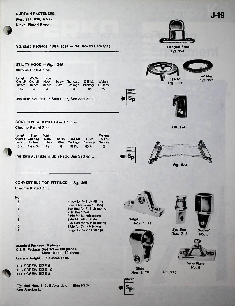
I
J-19CURTAIN FASTENERS Figs. 994, 996, & 997 Nickel Plated Brass
Standard Package, 100 Pieces — No Broken Packages Flanged Stud Fig. 994
UTILITY HOOK — Fig. 1249 Chrome Plated Zinc
Washer Fig. 997Length Width Inside
Overall Overall Hook Screw Standard O.E.M. WeightInches Inches Inches Size Package Package Ounces
15/ia
Eyelet Fig. 996
Vi Va 6 50 100 Vi
This Item Available in Skin Pack, See Section L.
BOAT COVER SOCKETS — Fig. 578 Chrome Plated Zinc Fig. 1249
Length Size Width Overall Opening Overall Inches Inches Inches
3% 1% x Vi 8 s/e
WeightScrew Standard O.E.M. Per Pair Size Package Package Ounces
8 10 Pr. 50 Pr.*• * *
2
- ...This Item Available in Skin Pack, See Section L.
Fig. 578
CONVERTIBLE TOP FITTINGS — Fig. 395 Chrome Plated Zinc
No.Hinge for Va inch fittings Socket for Va inch tubing Eye End for Va inch tubing with .049" Wall Slide for % inch tubing Side Mounting Plate Eye End for 7/e inch tubing Slide for 7/a inch tubing Hinge for 7/a inch fittings
135
6Hinge8
Nos. 1, 11910
Eye End Nos. 5, 9
Socket No. 3
11
Standard Package 10 pieces.O.E.M. Package Size 1-9 — 100 pieces.
Sizes 10-11 — 50 pieces.Average Weight — 2 ounces each.
Side Plate No. 8# 1 SCREW SIZE 8
# 8 SCREW SIZE 10 #11 SCREW SIZE 8 Fig. 395Nos. 6, 10
■MB IT
Fig. 395 Nos. 1,3,6 Available in Skin Pack, See Section L.

DIE CASTING OPERATIONSOur extensive die-casting division has five (5) machines producing zinc and one producing bronze parts. PERKO is the only marine manufacturer producing die-cast bronze parts which are well knownfor strength, uniformity, and high quality.

1
MANUFACTURED BY PERKO, INC., 16490 N.W. 13TH AVE., P.O. BOX 64000-D, MIAMI. FLORIDAFOR COMPLETE LINE SEE CATALOG NO. 250
PORTIONS OF THIS CA! A! OO,r\ i Mr* moc

K-2
OUTRIGGER POLES — Fig. 460
FIBERGLASS-TELESCOPIC
With Reinforced Joints
Overall OverallLength Length NumberOpen ClosedFeet Inches Sections
DiameterBase
No. Inches15 1.120
WeightPounds
of
2V436615
Will Fit Holders. Figs. 444, 451; No. 1. and 1314.
Supplied complete with Fig. 468 Guides, 2 each; Nos., 1,3,4.
FIBERGLASS OUTRIGGER KITS — Fig. 476Fig. 460
Consists of 1 pair Fig. 460 Poles, 2 Fig. 469
Clips and a set of Fig. 468 Guides.SOLD IN LOTS OF 3 KITS ONLY.Fig. 476
i
OUTRIGGER TROLLING PIN OR CLIP — Fig. 469
High Impact Black Plastic — Stainless Steel
Eyes and SpringStandardPackage
WeightOuncesDimensions
2Va x 1% 10 V/iFig. 469
Sp ^ This item available in SKIN PACK, See Section L.
& 6 OUTRIGGER POLE LINE GUIDES — Fig. 468
Stainless Steel Eye — Black Plastic BodyH
I.D.Body
InchesWeightOuncesNo. r1 Vie Vb Va
2 Vb Vb Va3 Va Vb Va4 1 Vb Va
Fig. 468 5 VAb Vb Vz6 1 Vb Vb Vi
Standard Package, 6 Pieces.
••iV: '
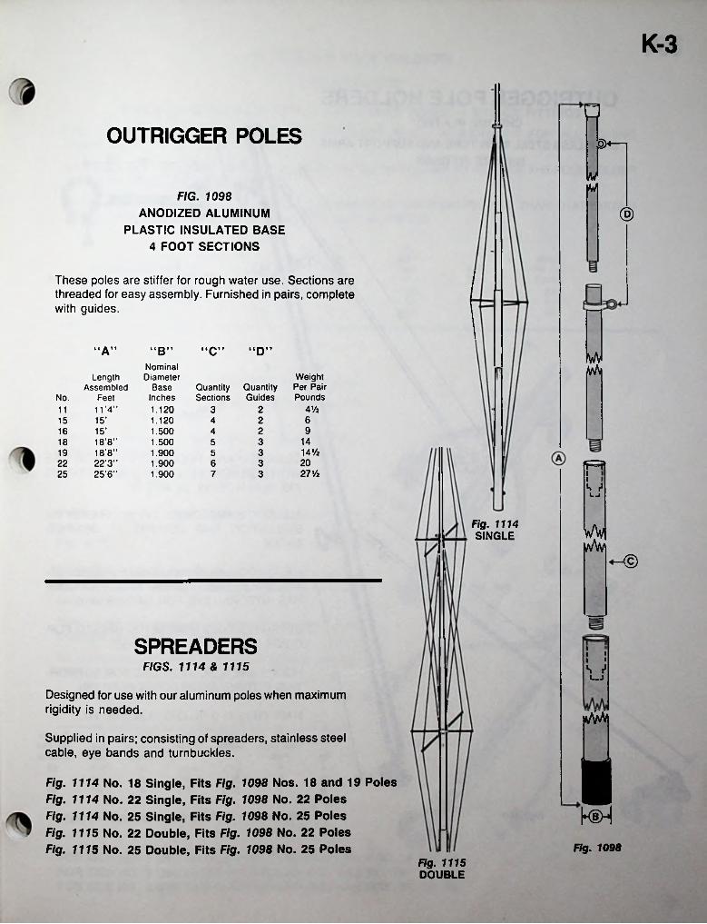
K-3
nOUTRIGGER POLES —
MFIG. 1098
ANODIZED ALUMINUM PLASTIC INSULATED BASE
4 FOOT SECTIONS
®
These poles are stiffer for rough water use. Sections are threaded for easy assembly. Furnished in pairs, complete with guides.
“A” “C”“B” “D” wvNominalDiameter
BaseInches1.1201.1201.5001.5001.9001.9001.900
Weight Per Pair Pounds
LengthAssembled Quantity
GuidesQuantitySectionsNo. Feet
A Vt11 ’4” 2311615’ 215 4916 15’ 24
1418’8”18’8"22’3"25'6"
318 514’/219 352022 3627 y225 7 3 i
i^ r1LJ
Fig. 1114 SINGLE wW
•©
SPREADERS iiiiiFIGS. 1114 & 1115 S r*
i—j
Designed for use with our aluminum poles when maximum rigidity is needed.
Supplied in pairs; consisting of spreaders, stainless steel cable, eye bands and turnbuckles. ■Fig. 1114 No. 18 Single, Fits Fig. 1098 Nos. 18 and 19 Poles Fig. 1114 No. 22 Single, Fits Fig. 1098 No. 22 Poles Fig. 1114 No. 25 Single, Fits Fig. 1098 No. 25 Poles Fig. 1115 No. 22 Double, Fits Fig. 1098 No. 22 Poles Fig. 1115 No. 25 Double, Fits Fig. 1098 No. 25 Poles Fig. 1098
Fig. 1115 DOUBLE
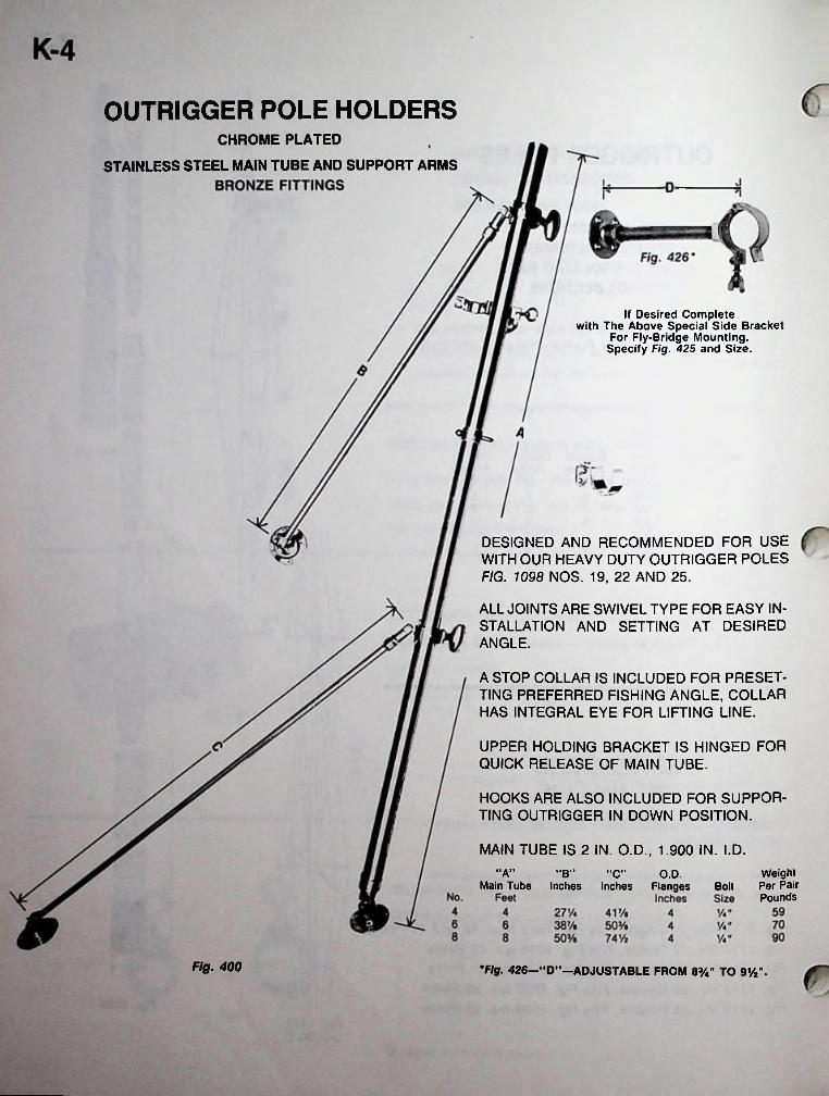
OUTRIGGER POLE HOLDERSCHROME PLATED
STAINLESS STEEL MAIN TUBE AND SUPPORT ARMS
If Desired Completewith The Above Special Side Bracket
For Fly-Bridge Mounting.Specify Fig. 425 and Size.
DESIGNED AND RECOMMENDED FOR USEWITH OUR HEAVY DUTY OUTRIGGER POLESFIG. 1098 NOS. 19, 22 AND 25.
ALL JOINTS ARE SWIVEL TYPE FOR EASY INSTALLATION AND SETTING AT DESIREDANGLE.
A STOP COLLAR IS INCLUDED FOR PRESETTING PREFERRED FISHING ANGLE, COLLARHAS INTEGRAL EYE FOR LIFTING LINE.
UPPER HOLDING BRACKET IS HINGED FORQUICK RELEASE OF MAIN TUBE.
HOOKS ARE ALSO INCLUDED FOR SUPPORTING OUTRIGGER IN DOWN POSITION.
MAIN TUBE IS 2 IN. O.D., 1.900 IN. I.D.Weight Per Pair Pounds
•‘A" "B" "C" O.D.Main Tube Inches Inches Flanges Bolt
Fig. 400 •Fig. 426—'"DM-ADJUSTABLE FROM 8y4" TO 91/2".
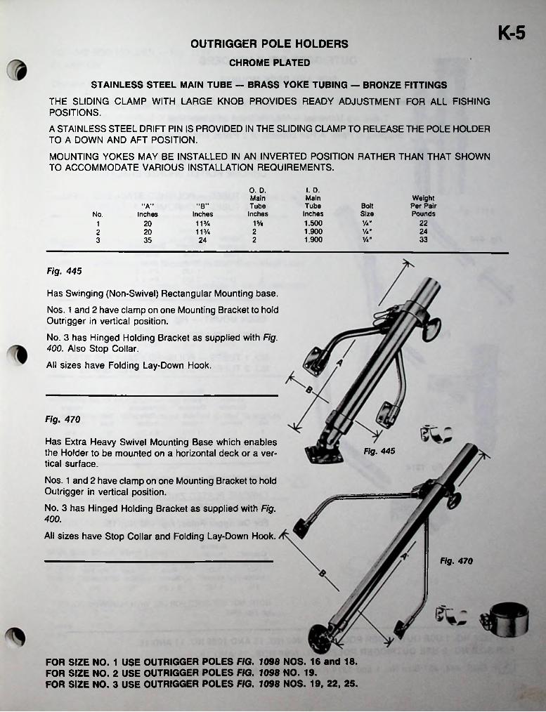
K-5OUTRIGGER POLE HOLDERS
CHROME PLATED
STAINLESS STEEL MAIN TUBE — BRASS YOKE TUBING — BRONZE FITTINGS
THE SLIDING CLAMP WITH LARGE KNOB PROVIDES READY ADJUSTMENT FOR ALL FISHING POSITIONS.
A STAINLESS STEEL DRIFT PIN IS PROVIDED IN THE SLIDING CLAMP TO RELEASE THE POLE HOLDER TO A DOWN AND AFT POSITION.
MOUNTING YOKES MAY BE INSTALLED IN AN INVERTED POSITION RATHER THAN THAT SHOWN TO ACCOMMODATE VARIOUS INSTALLATION REQUIREMENTS.
o. D. Main Tube
inches
I. D.MainTube
Inches1.5001.9001.900
Weight Per Pair Pounds
"B" Bolt"A"SizeInchesNo. Inches
15/e Va” 2220 11%12 Va" 2420 11%2
Va” 3323 35 24
Fig. 445
Has Swinging (Non-Swivel) Rectangular Mounting base.
Nos. 1 and 2 have clamp on one Mounting Bracket to hold Outrigger in vertical position.
No. 3 has Hinged Holding Bracket as supplied with Fig. 400. Also Stop Collar.
All sizes have Folding Lay-Down Hook.
Fig. 470
Has Extra Heavy Swivel Mounting Base which enables the Holder to be mounted on a horizontal deck or a vertical surface.
Nos. 1 and 2 have clamp on one Mounting Bracket to hold Outrigger in vertical position.
No. 3 has Hinged Holding Bracket as supplied with Fig. 400.
All sizes have Stop Collar and Folding Lay-Down Hook.
Fig. 445
Fig. 470
FOR SIZE NO. 1 USE OUTRIGGER POLES FIG. 1098 NOS. 16 and 18. FOR SIZE NO. 2 USE OUTRIGGER POLES FIG. 7098 NO. 19.FOR SIZE NO. 3 USE OUTRIGGER POLES FIG. 1098 NOS. 19, 22, 25.

OUTRIGGER POLE HOLDERSSIDE AND DECK MOUNTS
Removable Tubes — Tubes Lift and turn to 3 positions — Vertical, fishing, and lowered.
Tubes are Universal — May Be Used on Either Side
Supplied in Pairs. A Pair consists of 2 Plates and 2 Tubes.
SIDE MOUNT — Fig. 444
CHROME PLATED BRONZE BRACKETS
NO. 1 TUBES —POLISHED STAINLESS STEEL NO. 2 TUBES — CHROME PLATED BRASS
NominalInside
DiameterTubeInches1.1201.500
Outside Diameter
Tube No. Inches
Fig. 444 Weight Per Pair Pounds
Dimensions Bracket Inches 41/2 x 3 6V2 x 4
BoltSizey«"y«H
f 23/4V/a1715/e2
DECK MOUNT — Fig. 451
CHROME PLATED BRONZE PLATESFig. 451
NO. 1 TUBES — POLISHED STAINLESS STEEL NO. 2 TUBES — CHROME PLATED BRASS
5*
NominalInside
DiameterTube
Inches1.1201.500
Outside Diameter
Tube No. Inches
Weight Per Pair Pounds
DimensionsPlate
Inches5 x 21/26 x 3y2
BoltSizey."
5/l6"4y21 11/4
122 1%
Fig.DECK MOUNT — Fig. 1314
CHROME PLATED ZINC PLATES STAINLESS STEEL TUBES
For Outrigger Poles, Fig. 460 No. 15>1
NominalInside
DiameterTube
Inches1.120
OutsideDiameter
TubeInches
Dimensions Plate
Inches 5 x 21/2
Weight Bolt Per Pair Size Pounds
VA 2VaVa"
NOTE: NOT DESIGNED FOR USE WITH ALUMINUM POLES, i.e. Fig. 1098
FOR SIZE NO. 1 USE OUTRIGGER POLES FIGS. 460 NO. 15 AND 1098 NO. 11 AND 15. FOR SIZE NO. 2 USE OUTRIGGER POLES FIG. 1098 NOS. 16 AND 18.
FIGS- 444. 451 Size No. 1 and 1314 Available in Display Pack. See Section L.
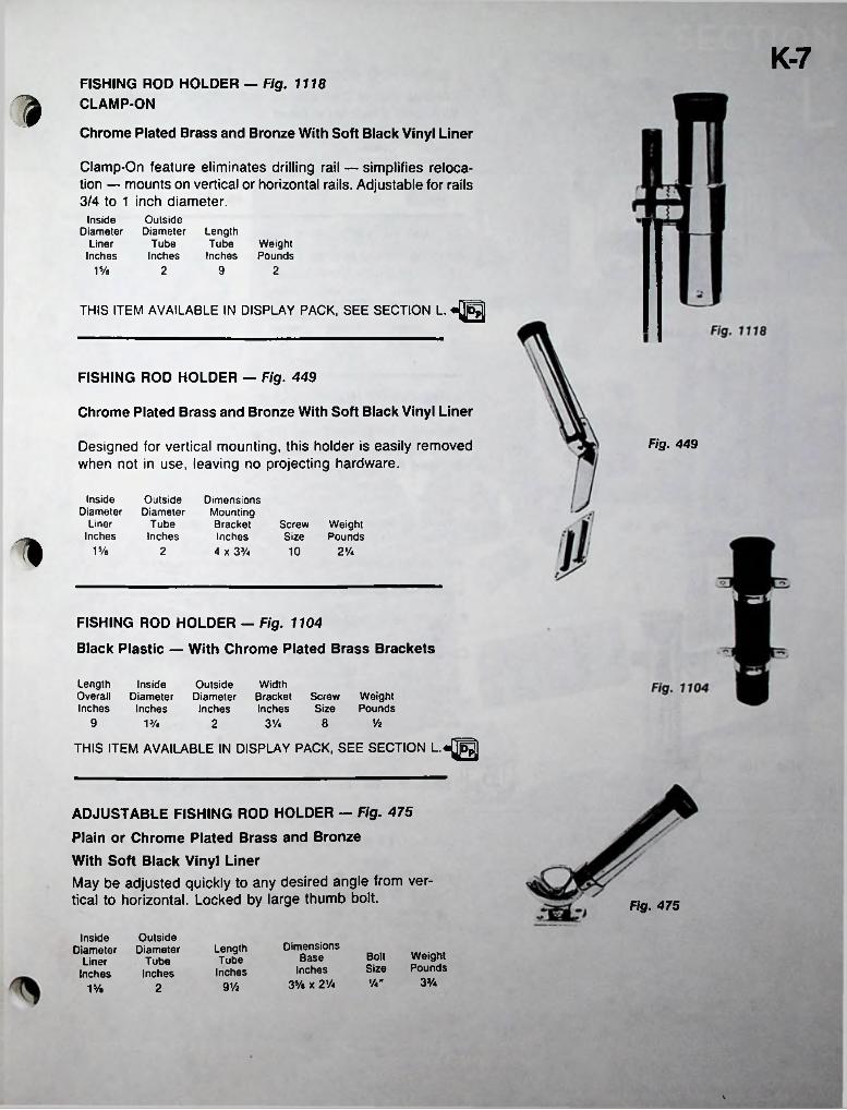
K-7FISHING ROD HOLDER — Fig. 1118 CLAMP-ON3Chrome Plated Brass and Bronze With Soft Black Vinyl Liner
Clamp-On feature eliminates drilling rail — simplifies relocation — mounts on vertical or horizontal rails. Adjustable for rails 3/4 to 1 inch diameter.
Outside Diameter
Tube Inches
InsideDiameter
LinerInches
LengthTube Weight
Inches Pounds915/e 2 2
THIS ITEM AVAILABLE IN DISPLAY PACK, SEE SECTION L. «p^j]
FISHING ROD HOLDER — Fig. 449
Chrome Plated Brass and Bronze With Soft Black Vinyl Liner
Fig. 449Designed for vertical mounting, this holder is easily removed when not in use, leaving no projecting hardware.
InsideDiameter
LinerInches
OutsideDiameter
TubeInches
Dimensions Mounting Bracket Inches 4 x 33/«
Screw Weight Size Pounds1 15/« 2 10 2'A
FISHING ROD HOLDER — Fig. 1104
Black Plastic — With Chrome Plated Brass Brackets
LengthOverallInches
InsideDiameter
Inches
OutsideDiameter
Inches
WidthBracket Screw Inches Size
WeightPounds
9 8 ViVA 2 3'A
THIS ITEM AVAILABLE IN DISPLAY PACK, SEE SECTION L.«pj|
ADJUSTABLE FISHING ROD HOLDER — Fig. 475
Plain or Chrome Plated Brass and Bronze With Soft Black Vinyl LinerMay be adjusted quickly to any desired angle from vertical to horizontal. Locked by large thumb bolt. Fig. 475
OutsideDiameter
TubeInches
InsideDiameter
LinerInches
Dimensions Base
Inches 35/e x 2 Vi
LengthWeightPounds
BoltTubeSizeInches
3%1/4"9Vz21 %
\
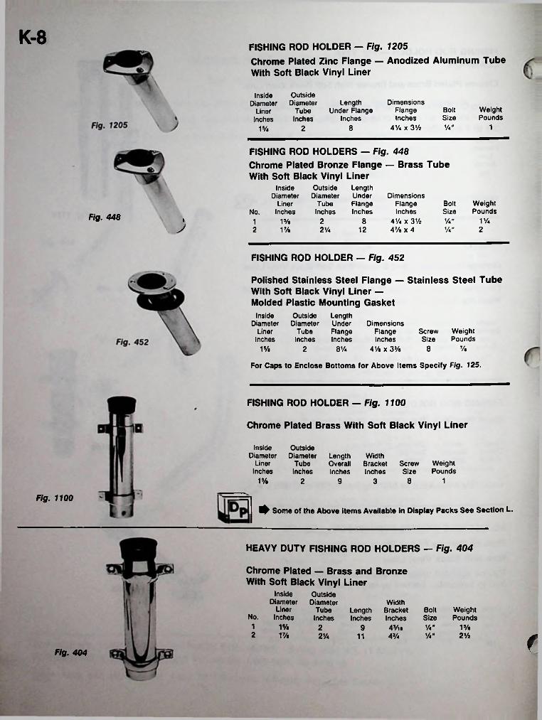
K-8 FISHING ROD HOLDER — Fig. 1205Chrome Plated Zinc Flange — Anodized Aluminum TubeWith Soft Black Vinyl Liner
OutsideDiameter
TubeInches
InsideDiameter
LinerInches
Dimensions Flange Inches
41/4 x 31/j
LengthUnder Flange
InchesWeightPounds
BoltSizeV*" 18215/e
FISHING ROD HOLDERS — Fig. 448 Chrome Plated Bronze Flange — Brass Tube With Soft Black Vinyl Liner
OutsideDiameter
TubeInches
Inside Diameter
Liner No. Inches
LengthUnderFlangeInches
Dimensions Flange Inches
4V« x 3V2 47/« x 4
Bolt WeightPoundsSize
Fig. 448 8 V*" V•"
11/4». 21 15/«J 12 22 V/t 2V*
FISHING ROD HOLDER — Fig. 452
Polished Stainless Steel Flange — Stainless Steel Tube With Soft Black Vinyl Liner —Molded Plastic Mounting Gasket
Outside Length Diameter Under
Tube Flange Inches Inches
InsideDiameter
LinerInches
Dimensions Flange Inches
41/e x 33/»
WeightPounds
ScrewSize
8 Vt15/a 2 81/4
For Caps to Enclose Bottoms for Above Items Specify Fig. 125.
FISHING ROD HOLDER — Fig. 1100
Chrome Plated Brass With Soft Black Vinyl Liner
InsideDiameter
LinerInches
OutsideDiameter
TubeInches
LengthOverallInches
WidthBracket Screw Inches Size
WeightPounds
1% 8 12 9 3
Fig. 1100^ Some of the Above Items Available in Display Packs See Section L.
HEAVY DUTY FISHING ROD HOLDERS — Fig. 404
Chrome Plated — Brass and Bronze With Soft Black Vinyl Liner
Inside Diameter
Liner No. Inches
OutsideDiameter
TubeInches
WidthLength Bracket Inches Inches
Bolt WeightPoundsSize
1 1% 2 y4» 15/e9 AVm2 VA y4« 2Va2V4 43/411 fFig. 404
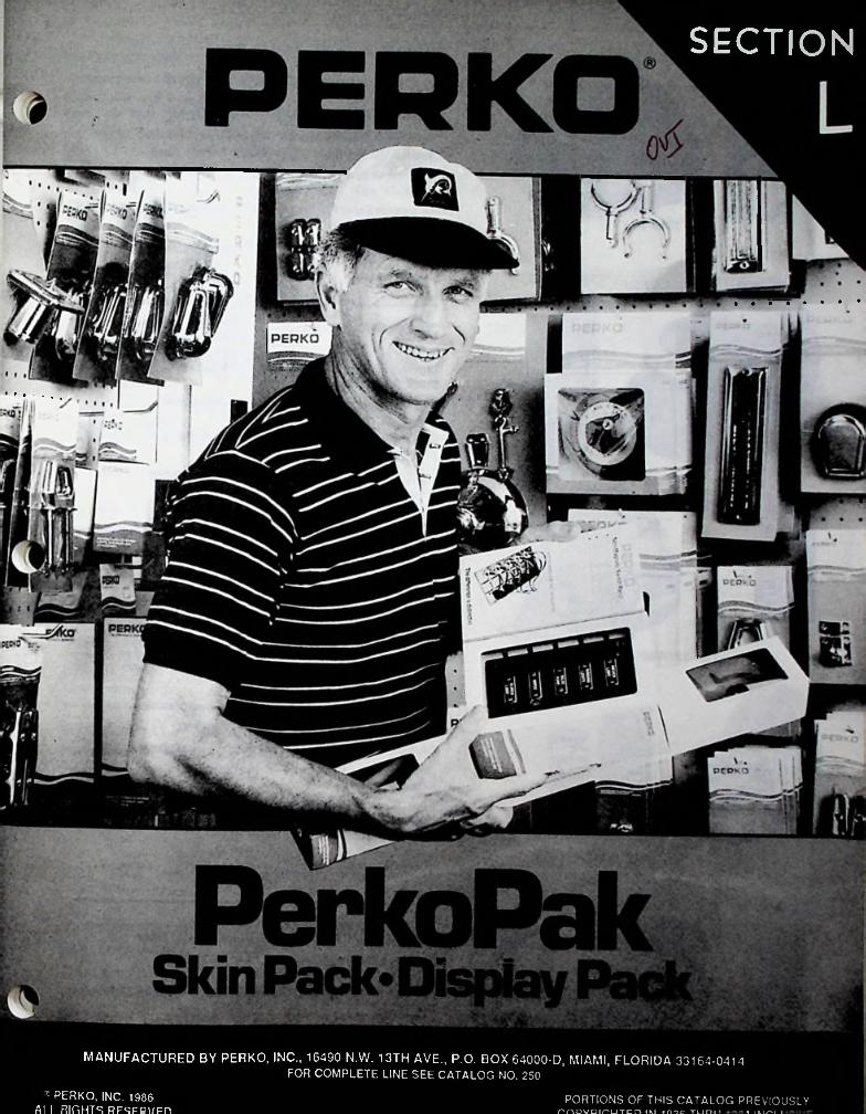
SECTION
MANUFACTURED BY PERKO, INC., 16490 N.W. 13TH AVE., P.O. BOX 64000-D, MIAMI, FLORIDA 33164-0414FOR COMPLETE LINE SEE CATALOG NO. 250
r PERKO, INC. 1986 Al I RIGHTS RFSFBVFn
PORTIONS OF THIS CATALOG PREVIOUSLYrnDVDiruTcn IM i me TUni 1 IM^I I
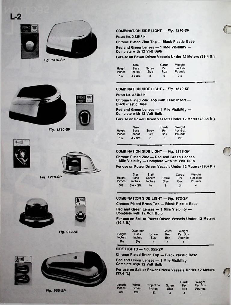
COMBINATION SIDE LIGHT — Fig. 1310-SP Patent No. 3,828,714Chrome Plated Zinc Top — Black Plastic BaseRed and Green Lenses — 1 Mile Visibility —Complete with 12 Volt BulbFor use on Power Driven Vessels Under 12 Meters (39.4 ft.)
it
Fig. 1310-SPCards Weight
Per Box Pounds
Size Base
Inches 4 x 3 Vi
ScrewSize
PerHeightInches Box
2 Vi6817/a
COMBINATION SIDE LIGHT — Fig. 1510-SP Patent No. 3,828,714
Chrome Plated Zinc Top with Teak Insert —Black Plastic BaseRed and Green Lenses — 1 Mile Visibility —Complete with 12 Volt BulbFor use on Power Driven Vessels Under 12 Meters (39.4 ft.)
SizeHeight Base ScrewInches Inches Size
17/. 4 x 3Vi 8
Cards Weight Per Box Pounds
Fig. 1510-SP PerBox
6 2 Vi
COMBINATION SIDE LIGHT — Fig. 1218-SPChrome Plated Zinc — Red and Green Lenses 1 Mile Visibility — Complete with 12 Volt BulbFor use on Power Driven Vessels Under 12 Meters (39.4 ft.)
SizeHeight BaseInches Inches
3% 61/4 x 37/a
StaffSocketInches
Weight Per Box Pounds
CardsFig. 1218-SP Screw
SizePerBox
V* 8 3 4
COMBINATION SIDE LIGHT — Fig. 972-SP Chrome Plated Brass Top — Black Plastic BaseRed and Green Lenses — 1 Mile Visibility —Complete with 12 Volt BulbFor use on Sail or Power Driven Vessels Under 12 Meters (39.4 ft.)B
DiameterBase
Inches
Cards WeightPer Per BoxBox Pounds
Fig. 972-SP HeightInches
ScrewSize
1s/. 2Vb 4 4 1
SIDE LIGHTS — Fig. 955-SP
Chrome Plated Brass Top — Black Plastic Base
Red and Green Lenses — 1 Mile Visibility Complete with 12 Volt Bulb
For use on Sail or Power Driven Vessels Under 12 Meters (39.4 ft.)
Cards WeightPer Per BoxBox Pounds
Length WidthInches Inches
ProjectionInches
ScrewSize
4’/« 2% 1J/4 4 24
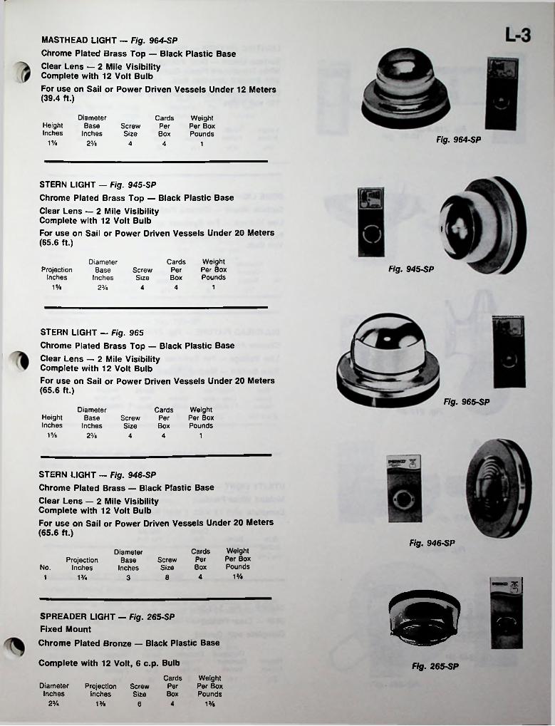
MASTHEAD LIGHT — Fig. 964-SPChrome Plated Brass Top — Black Plastic BaseClear Lens — 2 Mile Visibility Complete with 12 Volt BulbFor use on Sail or Power Driven Vessels Under 12 Meters (39.4 ft.)
DiameterBase
Inches
Cards Weight Per Box Pounds
HeightInches
ScrewSize
PerBox
Fig. 964-SP15/a 2J/a 4 4 1
STERN LIGHT — Fig. 945-SPChrome Plated Brass Top — Black Plastic BaseClear Lens — 2 Mile Visibility Complete with 12 Volt BulbFor use on Sail or Power Driven Vessels Under 20 Meters (65.6 ft.)
f
Cards WeightPer Per BoxBox Pounds
DiameterBase
InchesFig. 945-SPProjection
InchesScrewSize
15/a 23/a 4 14
STERN LIGHT — Fig. 965Chrome Plated Brass Top — Black Plastic BaseClear Lens — 2 Mile Visibility Complete with 12 Volt BulbFor use on Sail or Power Driven Vessels Under 20 Meters (65.6 ft.)
Fig. 965-SPDiameter
BaseInches
Weight Per Box Pounds
CardsHeightInches
ScrewSize
PerBox
15/a 23/a 4 14
STERN LIGHT — Fig. 946-SPChrome Plated Brass — Black Plastic BaseClear Lens — 2 Mile Visibility Complete with 12 Volt BulbFor use on Sail or Power Driven Vessels Under 20 Meters (65.6 ft.)
Fig. 946-SPWeight Per Box Pounds
CardsDiameterBase
InchesPerScrew
SizeProjection
InchesNo. Box13/e41 1% 83 IWSPREADER LIGHT - Fig. 265-SP
Fixed MountChrome Plated Bronze — Black Plastic Base
Complete with 12 Volt, 6 c.p. Bulb Fig. 265-SPCards Weight
Per Per BoxBox Pounds
DiameterInches
ProjectionInches
ScrewSize
23/4 13/e 1%46

L-4LIGHTING FIXTURE - Fig. 318-A-SPSurface Mount — Dual Voltage — For 12 or 120 Volts White Translucent Plastic Globe — Chrome Plated Zinc Base with Integral Junction Box.Double contact sockets complete with two 12 volt and two 120 volt bulbs.
¥
Weight Per Box Pounds
CardsFig. 318-ASP Depth Screw
Inches SizePerLength
InchesWidthInches Box
7%9% 31/a 17/« 10 4
DOME LIGHT — Fig. 300-SPSurface Mount — Chrome Plated ZincLow Voltage — For Systems up to 50 VoltsPush Switch — Double Contact Socket — Complete with 12 Volt Bulb
Fig. 300-SPCards Weight
Per Per Box Box Pounds
Diameter Overall
No. Inches
DiameterGlobeInches
ProjectionInches
ScrewSize
10R.H. 2 V*53/a1 17/e 34
BULKHEAD FIXTURE - Fig. 217-SP Chrome Plated ZincLow Voltage — For Systems up to 50 Volts Turn Switch — Medium Screw Socket
Weight Per Box Pounds
Size Base
Inches 2Vz x 13/«
Projection Less Lamp
Inches
CardsScrewSize
PerBoxFig. 217-SP 25/e 46 6
it UTILITY LIGHT — Fig. 140-SPMolded White PlasticComplete with 12 Volt, 1 Watt Bulb
Cards Weight Per Box Pounds
Size Inches 1% x %
ScrewSize
PerBoxFig. 140-SP
7 10 %
GLOBE — Fig. 248-SP 360° — Clear Plastic Complete with Gasket
OutsideDiameterInches
DiameterThreadInches
Cards Weight Per Box Pounds
HeightInches
PerBox
2% 13/4 2 10 1 %
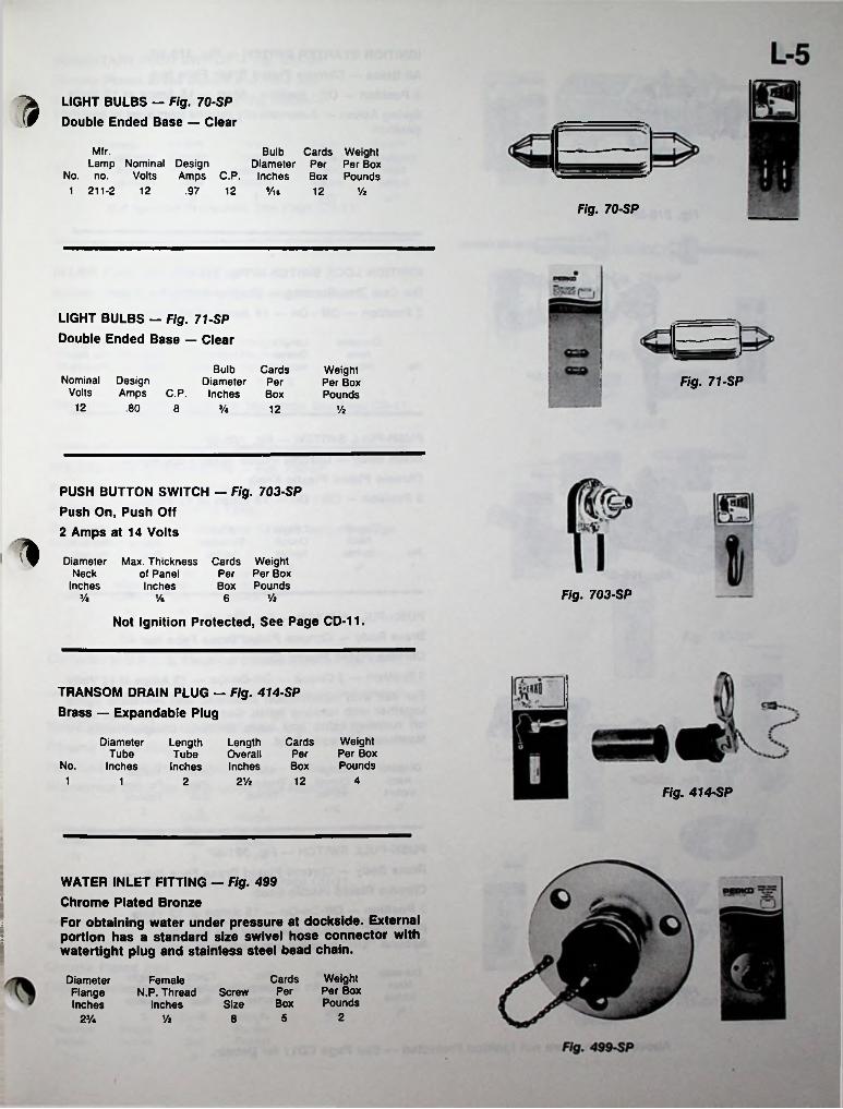
n LIGHT BULBS — Fig. 70-SP Double Ended Base — Clear
Mfr. Bulb Cards WeightDiameter Per Per Box
Amps C.P. Inches Box Pounds.97 12
Lamp Nominal Design No. no. Volts
1 211-2 12 Vie 12 Vi
Fig. 70-SP
LIGHT BULBS — Fig. 71-SP Double Ended Base — Clear
Bulb CardsDiameter Per
Inches Box
Weight Per Box Pounds
Nominal Design Volts Amps C.P.
Fig. 71-SP
12 .80 8 3/« 12 Vi
PUSH BUTTON SWITCH — Fig. 703-SP Push On, Push Off 2 Amps at 14 Volts
i* Diameter Max. Thickness Cards Weight Per Per Box Box Pounds
Neck of PanelInches Inches
Fig. 703-SPJ/e ViVe 6
Not Ignition Protected, See Page CD-11.
TRANSOM DRAIN PLUG — Fig. 414-SP Brass — Expandable Plug
Weight Per Box Pounds
DiameterTube
No. Inches
Length CardsOverall PerInches Box
LengthTube
Inches41 122 2Vi1
Fig. 414-SP
WATER INLET FITTING — Fig. 499 Chrome Plated BronzeFor obtaining water under pressure at dockside. External portion has a standard size swivel hose connector with watertight plug and stainless steel bead chain.
a
a
I
Cards WeightPer Per BoxBox Pounds
DiameterFlangeInches
Female N.P. Thread
InchesScrewSize
252V. Vi 8

IGNITION STARTER SWITCH — Fig. 310-SPAll Brass — Chrome Plated Brass Face Nut3 Position — Off - Ignition - Start — 15 Amps at 12 VoltsSpring Action — Automatically returns from start to ignitionposition
Cards Weight Per Box Pounds
Max.Thickness
Inches
LengthOverallInches
DiameterNeck
Inches1J/i«
PerBox
362V* 1
Fig. 310-SP
IGNITION LOCK SWITCH - Fig. 316-SPDie Cast Zinc Housing — Chrome Plated Face Nut2 Position — Off - On — 15 Amps at 12 Volts
Cards Weight Per Box Pounds
Max.Thickness
Inches
DiameterNeck
Inches
LengthOverallInches-1 Per
BoxNo.Fig. 316-SP 26J/4 2 Vi1
PUSH-PULL SWITCH — Fig. 105-SPBrass Body — Chrome Plated Brass Face Nut —Chrome Plated Plastic Knob2 Position — Off - On — 15 Amps at 12 Volts
DiameterNeck
Inches
Cards Weight Per Box Pounds
LengthOverallInches
Max.Thickness
InchesPer
No. Box1 3/a 33 121
PUSH-PULL SWITCH — Fig. 366-SPBrass Body — Chrome Plated Brass Face Nut —Chrome Plated Plastic Knob3 Position — 2 Circuit — Off-On-On — 15 Amps at 12 VoltsFor use with combination Masthead and All-round lights together with running lights. Second “on” position turns off running lights and turns on both compartments of Masthead All-round light.
DiameterNeck
Inches
LengthOverallInches
Max.Thickness
Inches
Cards WeightPer Per BoxBox Pounds
% 35/4 261
PUSH-PULL SWITCH — Fig. 381-SPBrass Body — Chrome Plated Brass Face Nut —Chrome Plated Plastic Knob3 Position — Off-On-On — 15 Amps at 12 VoltsFirst “On” position energizes one terminal. Second “On” position energizes two terminals.
Length Overall Inches
DiameterNeck
Inches
Weight Per Box Pounds
CardsMax.Thickness
InchesPerFig. 381-SPBox
% 3J/4 261
Above Switches are not Ignition Protected — See Page CD11 for Details.

L-7MOMENTARY PUSH SWITCH — Fig. 255-SP Chrome Plated Brass Button and Face NutSingle Pole — Push Button Spring Action — 15 Amps at 12 Volts
Cards Weight Per Box Pounds
Max.Thickness
Inches
DiameterNeck
Inches
LengthOverallInches
PerBoxNo.
32Va 65/a 11
Not Ignition Protected, See Page CD-11.
IN-LINE FUSE HOLDER — Fig. 786-SPMolded Plastic with 20 Amp Fuse and Wire LeadsFor Standard 1/4” x 1/4” fuses.
Fig. 786-SP
9Cards WeightPer Per BoxBox Pounds
LengthInches
DiameterInches
’Vie
Fig. 720-2
2Vt 10 Va
Conforms to U.S.C.G. Electrical Standards, See Page CD-11.Fig. 720-3
MOLDED LINE CONNECTORS — Fig. 720-SP Plastic Bodies — Brass Contacts Polarized — 15 Amps at 12 VoltsBoth male and female side have 12 inch long 18 gauge color coded wires.
Fig. 720-4
'-5Cards Weight
Per Per BoxBox Pounds mWidth
InchesPoles2 5/e 3/a53 7/a Vz54 1 Vz 5 Va Fig. 720-SP
Conforms to U.S.C.G. Electrical Standards, See Page CD-11.
iWATERTIGHT DECK CONNECTION - Fig. 1190-SP Chrome Plated ZincPolarized Double Contact Connector — 15 Amps at 12 Volts Waterproof cover for Base when Plug Removed
Cards Weight Per Box Pounds
DiameterInches
HeightInches
PerBox
1*/a V/z Vz5
Not Ignition Protected, See Page CD-11. Fig. 1190-SP
WATERTIGHT CABLE OUTLET — Fig. 1191-SP Chrome Plated ZincRubber Grommet for Watertight passage of Cable
Cards Weight Per Per BoxBox Pounds
Fig. 1191-SP
DiameterInches
HeightInches
iy« S/l6 Vz5

rCHROMALEX® GAS FILL — Fig. 1313-SPChrome Plated Zinc Body — Black Plastic Cap, Impervious to Gasoline — Complete with Grounding Lug with Screw.Cap has integral retainer feature and is equipped with gasket to assure water tightness.
CardsHose Size Screw Per
Inches Size Box
Weight Per Box Pounds
Length Hose Neck
Inches
ForDiameterOverallInches
1313-SP 3%1% 63% 15/e 7
CHROMALEX® LOCKING GAS FILL — Fig. 1399-SPSame Design and Construction as Fig. 1313 Except Equipped with Locking Cap. Cap has Gasket to Prevent Moisture from Entering Tank.
Fig. 1399-SP
LOCKING GAS CAP — Fig. 1324-SP*Black PlasticSupplied with Gasket to Prevent Moisture from Entering Tank.
>
Cards Weight Per Box Pounds
PerBox
6 VAFig. 1324-SP •Will fit all PERKO CHROMALEX® Gas Fills — Figs. 1313, 1413 & 1513.
DECK PLATE KEY — Fig. 826-SP Chrome Plated ZincHeavy Duty Pins — Will fit sizes up to 8 inch diameter
LengthOverallInches
Cards Weight Per Box Pounds
PerBox
8'A 6 4Fig. 826-SP
TRANSOM PLATES — Fig. 1224-SPChrome Plated Zinc Frame — Molded Soft Plastic PadFor outboard motor brackets
tWeight Per Box Pounds
LengthOverallInches
CardsInsideDiameterInches
* \ PerScrewSize Box
3 Vi3Vi 121% 8
All Fills On This Page Meet The Requirements ot The U.S.C.G. Safety Standards, January 31,1977 for Gasoline Fuel Systems.
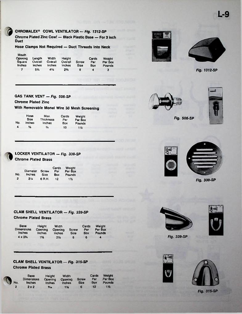
L-9
CHROMALEX® COWL VENTILATOR — Fig. 1312-SPChrome Plated Zinc Cowl — Black Plastic Base — For 3 inch DuctHose Clamps Not Required — Duct Threads into Neck
MouthOpening Length Width HeightSquare Overall Overall Overall ScrewInches Inches Inches Inches Size
Cards Weight Per Per Box Box Pounds
53/4 43/e7 25/e 8 4 3 Fig. 1312-SP
*
GAS TANK VENT - Fig. 506-SP Chrome Plated ZincWith Removable Monel Wire 30 Mesh Screening iHose
SizeNo. Inches
Max.Thickness
Inches
Cards WeightPer Per BoxBox Pounds
Fig. 506-SP5r
4 */e y« 10 1 Vi
LOCKER VENTILATOR — Fig. 330-SP Chrome Plated Brass
Cards Weight Diameter Screw Per Per Box
No. Inches Size Box Pounds6 R.H. 122 3’/4 11/2 Fig. 330-SP
HSlCLAM SHELL VENTILATOR — Fig. 339-SP Chrome Plated Brass
Base Height WidthDimensions Opening Opening
Inches Inches
Weight Per Box Pounds
Cards Screw Per Size BoxInches
4 x 3Va 15/e 2 Vi 6 6 4
CLAM SHELL VENTILATOR — Fig. 315-SP Chrome Plated Brass
Cards Weight Per Per Box Box Pounds
Base Height WidthDimensions Opening Opening Screw
Inches Inches SizeInchesV/2122x2 6Vie 1%
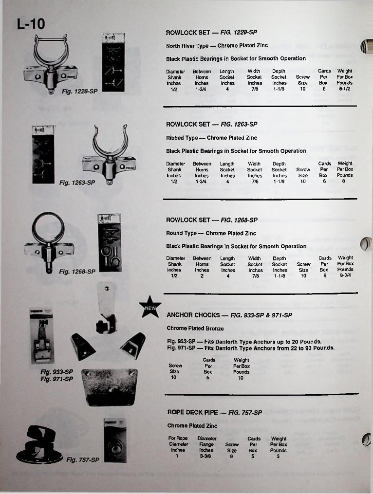
ROWLOCK SET — FIG. 1228-SP!rsnRNorth River Type — Chrome Plated Zinc
Black Plastic Bearings in Socket for Smooth OperationX?
Cards Weight Per Per Box Box Pounds
6 8-1/2
Width DepthSocket Socket ScrewInches Inches Size
1-1/8
LengthSocketInches
DiameterShankInches
BetweenHornsInches1-3/4
//
*107/841/2
ROWLOCK SET — FIG. 1263-SP
Ribbed Type — Chrome Plated Zinc
Black Plastic Bearings in Socket for Smooth Operation
Cards Weight Per Per Box Box Pounds
DiameterShankInches
Between LengthHorns SocketInches Inches1-3/4
WidthSocketInches
DepthSocket Screw Inches Size1-1/8 10 6 81/2 7/84
ROWLOCK SET — FIG. 1268-SP
Round Type — Chrome Plated Zinc
Black Plastic Bearings in Socket for Smooth Operation
Cards Weight Per Per Box Box Pounds
6 8-3/4
DiameterShankInches
Between Length Horns SocketInches Inches
Width DepthSocket Socket ScrewInches Inches Size
1-1/81/2 102 4 7/8
ANCHOR CHOCKS — FIG. 933-SP & 971-SP
Chrome Plated Bronze
Fig. 933-SP — Fits Danforth Type Anchors up to 20 Pounds.Fig. 971-SP — Fits Danforth Type Anchors from 22 to 90 Pounds.
Cards Weight Per Box Pounds
ScrewSize
PerFig. 933-SP Fig. 971-SP
Box10 5 10
ROPE DECK PIPE — FIG. 757-SP
Chrome Plated Zinca GFor Rope Diameter Inches
Diameter RangeInches Size Box
CardsScrew Per
Weight Per Box Pounds
1 3-3/8 5 38
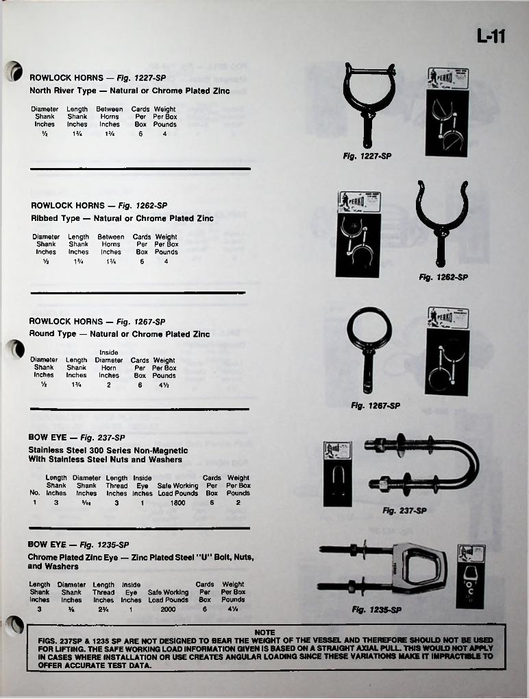
L-11
YROWLOCK HORNS — Fig. 1227-SPNorth River Type — Natural or Chrome Plated Zinc
Diameter Length Between Cards WeightShank Shank Horns Per Per BoxInches Inches Inches Box Pounds
Vz 1J/4 13/4 6 4
Fig. 1227-SP
YROWLOCK HORNS — Fig. 1262-SPRibbed Type — Natural or Chrome Plated Zinc
Diameter Length Between Cards WeightShank Shank Horns Per Per BoxInches Inches Inches Box Pounds
Vi 1S/4 1 Va 6 4
Fig. 1262-SP
ROWLOCK HORNS - Fig. 1267-SPRound Type — Natural or Chrome Plated Zinc
InsideDiameter Length Diameter Cards Weight
Per Per Box Box Pounds
6 4Vi
Shank Shank HornInches Inches Inches
Vi V/4 2
Fig. 1267-SP
BOW EYE — Fig. 237-SPStainless Steel 300 Series Non-Magnetic With Stainless Steel Nuts and Washers
Length Diameter Length Inside Shank
No. Inches
Cards Weight Shank Thread Eye Safe Working Per Per Box Inches Inches Inches Load Pounds Box Pounds
1 3 9/i« 6 23 18001
BOW EYE - Fig. 1235-SPChrome Plated Zinc Eye — Zinc Plated Steel “U” Bolt, Nuts, and Washers
Length Diameter Length InsideShank Shank Thread Eye Safe Working PerInches Inches Inches Inches Load Pounds
2000
Cards Weight Per Box
Box PoundsFig. 1235-SP41/«3 6% 2J/4 1
NOTEFIGS. 237SP & 1235 SP ARE NOT DESIGNED TO BEAR THE WEIGHT OF THE VESSEL AND THEREFORE SHOULD NOT BE USED FOR LIFTING. THE SAFE WORKING LOAD INFORMATION GIVEN IS BASED ON A STRAIGHT AXIAL PULL. THIS WOULD NOT APPLY IN CASES WHERE INSTALLATION OR USE CREATES ANGULAR LOADING SINCE THESE VARIATIONS MAKE IT IMPRACTIBLE TO OFFER ACCURATE TEST DATA. ____________________________________________________
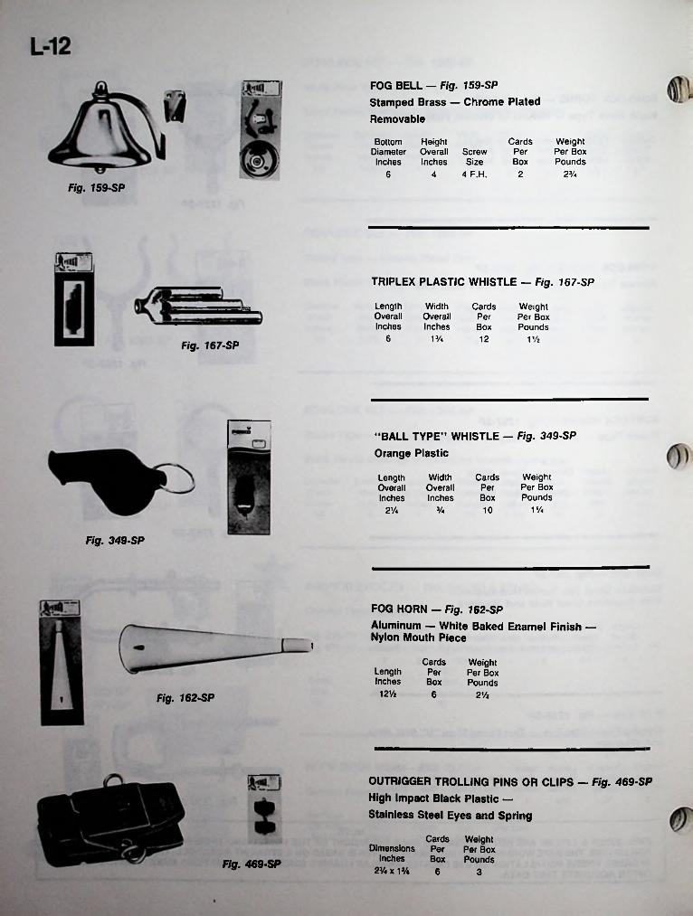
FOG BELL — Fig. 159-SP Stamped Brass — Chrome Plated Removable
Cards Weight Per Box Pounds
Bottom Height Diameter Overall ScrewInches Inches Size
4 4 F.H.
PerBox
2%26
Fig. 159-SP
TRIPLEX PLASTIC WHISTLE — Fig. 167-SP
LengthOverallInches
WidthOverallInches
Cards Weight Per Box Pounds
PerBox
6 V/a 12 V/zFig. 167-SP
“BALL TYPE” WHISTLE — Fig. 349-SP Orange Plastic
Cards Weight Per Box Pounds
LengthOverallInches
WidthOverallInches
PerBox
1%2V* 10
Fig. 349-SP
FOG HORN - Fig. 162-SPAluminum — White Baked Enamel Finish — Nylon Mouth Piece
i
Cards WeightPer Per BoxBox Pounds
LengthInches12ya 6 21/aFig. 162-SP
OUTRIGGER TROLLING PINS OR CLIPS — Fig. 469-SP High Impact Black Plastic —Stainless Steel Eyes and Spring
Cards Weight Per Per Box Box Pounds
DimensionsInches
2%xl%Fig. 469-SP
6 3

L-13
CHROMALEX® HANDLES — Fig. 1336-SP Chrome Plated Zinc and Black Plastic
LengthOverallInches
LengthInsideInches
HeightInsideInches
Cards Weight Screw Per Per Box Size Box Pounds
6Va 3Vi Va1 6 7
BFig. 1231-SP
HANDLES - Fig. 1231-SP Chrome Plated Zinc
Cards Weight Screw Per Per Box Size Box Pounds
LengthInsideInches
HeightInsideInches
1*/i«
LengthOverallInches
6Va6Va3 Vz6
HANDLES — Fig. 775-SP Chrome Plated Bronze
Cards Weight Per Per Box Box Pounds
Length Length HeightOverall Inside Inside
No. Inches Inches InchesScrewSize
cm cmFig. 775-SP2 SVa 3Va 1 Va 8 6 4
CHROMALEX® STEP PLATES — Figs. 1225-SP, 1325-SP, 1525-SP
Chrome Plated Zinc Frames — Molded Soft Plastic PadsFig. 1225-SP — White Pad Fig. 1325-SP — Black Pad Fig. 1525-SP — Teak Pad
Fig. 1225-SP — White
Fig. 1325-SP — Black
Fig. 1525—SP — Teak
Cards Weight Per Per Box Box Pounds
PlatesDimensions
No. Inches0 83/e x 2Va1 8% x 3 Va
ScrewSize
PerCard
62 689%2 68
STEP PLATES — Figs. 1526-SPTeak Molded Plastic — Frame Not Required
Plates Cards WeightPer Per Per Box
Card Box PoundsDimensions Screw
No. Inches Size 1 97/e x 27/e 8 Fig. 1526-SP6 3Vz2
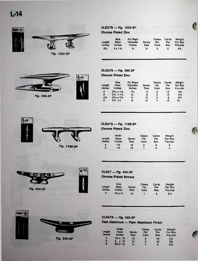
L-14
fCLEATS - Fig. 1252-SP Chrome Plated Zinc
SizeLength Base Inches Inches
6Vi 3x1%
For Rope Diameter
Inches
Cleats Cards Weight Per Box Pounds
ScrewSize
Per PerCard Box
V* Va 2 4 Vi5
CLEATS — Fig. 566-SP Chrome Plated Zinc
Size Base
Inches 2s/iex1% 3% x V/z 47/i* x 17/« 5 Vi x 2
For Rope Diameter
Inches
Cleats Cards Weight Per Box Pounds
LengthInches
ScrewSize
Per PerCard Box
2 s/te 6 2 12 3Vi3 % 8 2 5Vi124% Vi 8 Vi10 2 66 V* 12 12 131
CLEATS — Fig. 1188-SP Chrome Plated Zinc
WidthBase
Inches
Cleats Cards Weight Per Box Pounds
LengthInches
ScrewSize
Per PerCard Box
4 1% 10 2 6 51188-SP 6 13/4 10 1 6 4
CLEAT - Fig. 544-SP Chrome Plated Bronze
SizeBase
Inches1S/«XS/4
Cleats Cards Weight Per Box Pounds
LengthInches
ScrewSize
Per PerCard Box
4 10 2Vi1 6
CLEATS — Fig. 545-SPCast Aluminum — Plain Aluminum Finish
Width Base
Inches 1%x % 2 x % 2% x 1 V$
Cleats Cards Weight Per Box Pounds
LengthInches
Screw PerSize Card
PerBox
4Fig. 545-SP 10 2 2Vi105 Va 2 10 3%8 Va 1 5 2Vt
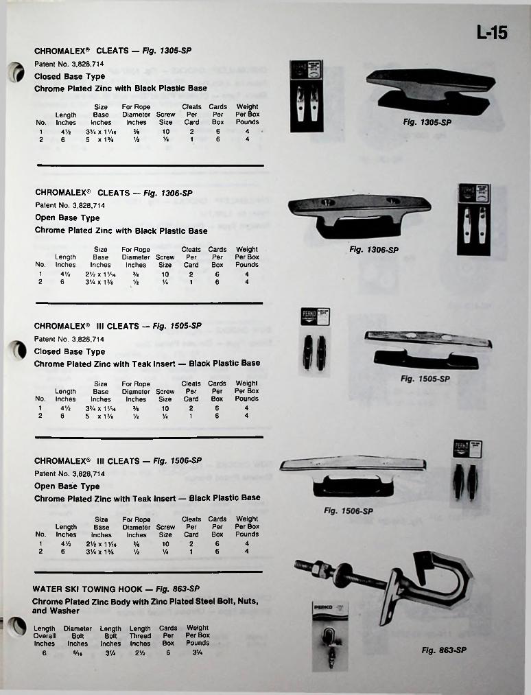
L-15CHROMALEX® CLEATS — Fig. 1305-SP Patent No. 3,828,714 Closed Base TypeChrome Plated Zinc with Black Plastic Base
Size For RopeLength Base Diameter Screw
No. Inches Inches Inches SizeA Vi 3V. x 1 Vi # >/•
5 x 13/a
Cleats Cards Weight Per Per Per Box
Card Box Pounds Fig. 1305-SP6 410 21
4Vi Va 62 16
CHROMALEX® CLEATS - Fig. 1306-SP Patent No. 3,828,714 Open Base TypeChrome Plated Zinc with Black Plastic Base
Fig. 1306-SPSize For Rope Length Base Diameter Screw Per Per
No. Inches Inches Inches Size Card BoxAVt 2Vi X 1 Vie 3/e
3 V. x 13/e
Cleats Cards Weight Per Box Pounds
1 6 410 22 6 Vi Va 6 A1
CHROMALEX® III CLEATS — Fig. 1505-SPPatent No. 3,828,714Closed Base TypeChrome Plated Zinc with Teak Insert — Black Plastic Base
Cleats Cards Weight Per Per Per Box
Card Box Pounds
Size For RopeLength Base Diameter Screw
No. Inches Inches Inches SizeA Vt 33/ix1Vi6 V.
5 x 13/e6 41 210
2 6 46 VaVi 1
CHROMALEX® III CLEATS — Fig. 1506-SP Patent No. 3,828,714 Open Base TypeChrome Plated Zinc with Teak Insert — Black Plastic Base
Cleats Cards Weight Per Per Per Box
Card Box Pounds
Size For RopeLength Base Diameter Screw
No. Inches Inches Inches Size4Vj 2Vi X1 Vu 3/e
3V. x 13/e Vt6 41 210
2 46 6Va 1
WATER SKI TOWING HOOK — Fig. 863-SPChrome Plated Zinc Body with Zinc Plated Steel Bolt, Nuts, and Washer
Length Diameter Length Length Cards Weight Overall Bolt Inches Inches
Bolt Thread Per Per BoxInches Inches Box Pounds
Fig. 863-SP3Va66 »/l6 3 V. 2Va

L-16CHROMALEX® CHOCKS - Fig. 1307-SP Patent No. 3,828,714Skene Type — Chrome Plated Zinc and Black Plastic
S FChocks Cards Weight
Per Per Per Box Card Box Pounds
h A Width For RopeLength Base Diameter Screw
No. Inches Inches Inches SizeFig. 1307-SP 3 Vi12Vt 10 1 pr.3% Vi1
6 4%Vi 1 pr.2 5 1
CHROMALEX® CHOCKS — Fig. 1308-SP Patent No. 3,828,714Straight Type — Chrome Plated Zinc and Black Plastic
Chocks Cards Weight Per Per Per Box
Card Box Pounds 10 1 pr. 12V* 1 pr. 6
Width Length Base
No. Inches Inches
For Rope Diameter Screw
Inches SizeFig. 1308-SP3 Vi3Vi Vi Vi1
2 5 4Vi1
BOW CHOCKS - Fig. 1223-SP Skene Type — Chrome Plated Zinc
*1 O Weight Per Box Pounds
For Rope Diameter Screw PerInches Size Card
1 pr-
Chocks Cardsi* LengthInches
WidthInches
PerBox' • 1
3Vi AVtVi Vi 128
BOW CHOCKS - Fig. 546-SP Chrome Plated Bronze
For Rope Diameter Screw Per
Inches Size Card10 1 pr.
Weight Per Box Pounds
Chocks CardsLength WidthInches Inches
PerBox
4 Va Vi 46
CHOCK — Fig. 119-SPStraight Type — Chrome Plated Bronze
For Rope Diameter Screw Per Per
Inches Size Card Box
Weight Per Box Pounds
Chocks CardsFig. 119-SP LengthInches
WidthInches
4 Vi Va 2Vi8 61

L-17
TILLER ROPE PULLEYS — Fig. 565-SPSwivel Type with Strap — For 1/4” Rope Stainless Steel — White Plastic Sheave
Length Diameter Length Overall Sheave Strap Inches Inches Inches
2s/n
Cards Weight Screw Per Per BoxSize Box Pounds
19/e 10R.H. 1233/« A Vi
Fig. 565-SP
9TILLER ROPE PULLEYS — Fig. 634-SPSwivel Snap Hook Type — For 1/4” Rope Stainless Steel — White Plastic Sheave
LengthOverallInches
Snap Throat Diameter Opening Sheave
Inches Inches2 Vi #
Cards Weight Per Per Box Box Pounds
& )
4V. Vt 12 51/4
Fig. 634-SP
TILLER ROPE TIGHTENERS - Fig. 732-SP 18-8 Stainless Steel or Cadmium Plated Steel
Cards Weight Per Per Box
Inches Box Pounds
Normal Length OutsideLength Compressed DiameterInches Inches
Fig. 732-SP - CAD. Fig. 732-SP — STS.5Vz124 5 1
ISTILLER ROPE CLAMPS — Fig. 1226-SP Chrome Plated Zinc For 1/8” and 3/16” Rope EM
Cards WeightPer Per BoxBox Pounds
Fig. 1226-SPLength Width Inches Inches
'Vi.V/a 12 2 Vi
EYE STRAPS — Fig. 1242-SP Chrome Plated Zinc
Straps Cards Weight Screw Per Per Per Box Size Card Box Pounds
SizeLength Eye Inches Inches
1% 2V.»/i« 8 106
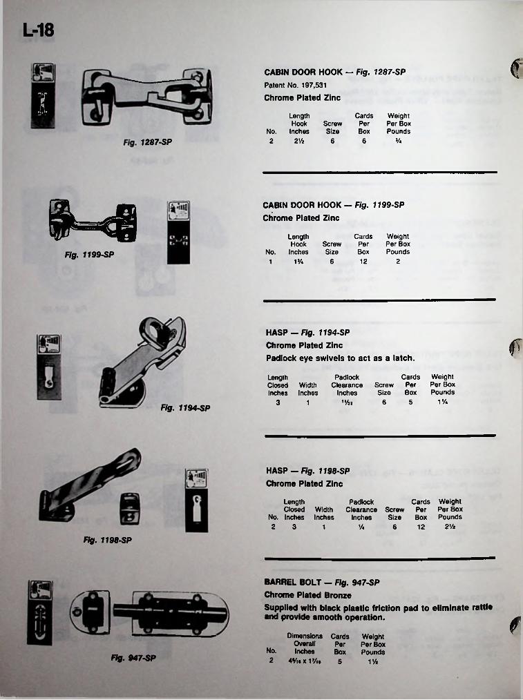
L-18
cCABIN DOOR HOOK - Fig. 1287-SP Patent No. 197,531 Chrome Plated ZincV4 CardsLength
Hook ScrewNo. Inches Size
Weight Per Box Pounds
PerBox
2Vz J/42 6 61287-SP
1=4 CABIN DOOR HOOK — Fig. 1199-SP Chrome Plated Zinc
Weight Per Box Pounds
CardsLength Hook
No. InchesScrewSize
PerBoxFig. 1199-SP
1% 6 12 21
HASP — Fig. 1194-SPChrome Plated ZincPadlock eye swivels to act as a latch.
w
fWeight Per Box Pounds
CardsScrew Per Size Box
PadlockClearance
Inches1,/J2
LengthClosed Width Inches Inches
1V46 53 1Fig. 1194-SP
HASP — Fig. 1198-SP Chrome Plated Zinc
Cards Weight Per Per Box Box Pounds
LengthClosed Width
No. Inches Inches 2 3
PadlockClearance Screw
Inches Size21/aV* 6 121
Fig. 1198-SP
BARREL BOLT — Fig. 947-SP Chrome Plated BronzeSupplied with black plastic friction pad to eliminate rattle and provide smooth operation. «
Dimensions Cards Overall Per
No. Inches 2 4*/,. x 1 Vi. 5
Weight Per Box
Box PoundsFig. 947-SP V/z
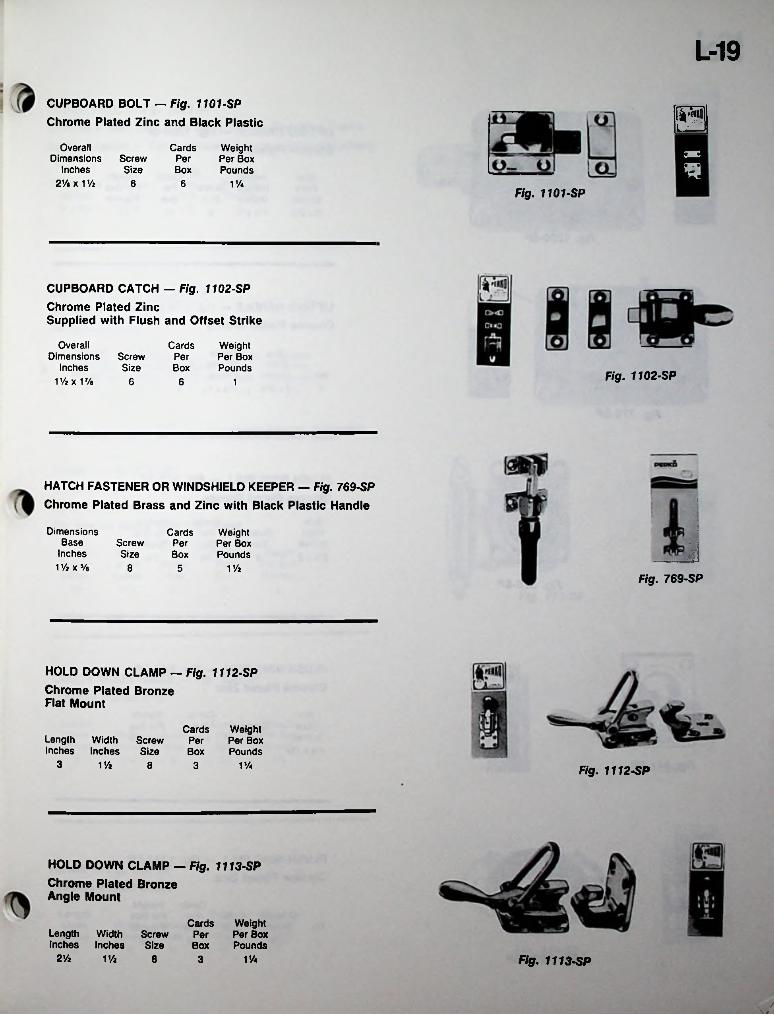
L-19CUPBOARD BOLT — Fig. 1101-SP Chrome Plated Zinc and Black Plastic is
Overall Dimensions
Inches 2 Vi x 1 Vz
Cards WeightPer Per BoxBox Pounds
3BScrewSize
6 6 V/aFig. 1101-SP
CUPBOARD CATCH — Fig. 1102-SPChrome Plated ZincSupplied with Flush and Offset Strike
OverallDimensions
Inches1Vjx 17/a
Cards WeightPer Per BoxBox Pounds
ScrewSize Fig. 1102-SP6 6 1
HATCH FASTENER OR WINDSHIELD KEEPER — Fig. 769-SP Chrome Plated Brass and Zinc with Black Plastic Handle
■
Dimensions Base
Inches V/z x 5/a
Cards Weight Per Box Pounds
ScrewSize
Per iiBox8 1 Vz5
Fig. 769-SP
HOLD DOWN CLAMP — Fig. 1112-SPChrome Plated Bronze Flat Mount
Cards Weight Per Per Box Box Pounds
Length Width Inches Inches
ScrewSize
3 1 Vz V/a8 3 Fig. 1112-SP
HOLD DOWN CLAMP — Fig. 1113-SPChrome Plated Bronze Angle Mount
Cards Weight Screw Per Per BoxSize Box Pounds
Length Width Inches Inches
2Vz 1 Vi 8 1Vi Fig. 1113-SP3
t
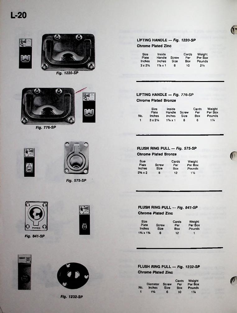
L-20
€LIFTING HANDLE — Fig. 1220-SP Chrome Plated Zinc
Size Plate
Inches 3 x 2 Vi
InsideHandle Screw Inches Size 17/.x1 8
Cards Weight Per Per Box Box Pounds10 2%
Fig. 1220-SP
LIFTING HANDLE — Fig. 776-SP Chrome Plated Bronze
SizePlate
No. Inches1 3 x 2Va
Cards Weight Per Box Pounds
InsideHandle Screw Inches Size 17/«x1 8
PerBox
V/46
Fig. 776-SP
FLUSH RING PULL - Fig. 575-SP Chrome Plated Bronze
Size Plate
Inches 2V» x 2
Cards Weight Per Box Pounds
ScrewSize
PerBox
8 12 1V4
FLUSH RING PULL — Fig. 841-SP Chrome Plated Zinc
Size Plate
Inches 1’/4X 1%
Cards Weight Per Box Pounds
& ScrewSize
PerBox
6 12 1Fig. 841-SP
FLUSH RING PULL — Fig. 1232-SP Chrome Plated Zinc* ►« fCards Weight
Diameter Screw Per Per BoxNo. Inches Size Box Pounds
1 1% 6 1%10
Fig. 1232-SP
\
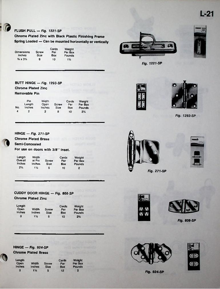
■FLUSH PULL — Fig. 1221-SP
Chrome Plated Zinc with Black Plastic Finishing Frame Spring Loaded — Can be mounted horizontally or vertically
Cards WeightPer Per BoxBox Pounds
Dimensions Inches
V* x 3%
ScrewSize
8 10 13/iFig. 1221-SP
BUTT HINGE - Fig. 1293-SP Chrome Plated Zinc Removable Pin
Pin WidthOpen Screw Per Inches Size Box
Cards Weight Per Box Pounds
Length No. Inches4 2 2 8 10 2V*
HINGE — Fig. 271-SP Chrome Plated Brass Semi-Concealed
For use on doors with 3/8” inset. rV
LengthOverallInches
Widthat Pin Screw Inches Size
Cards Weight Per Box Pounds
PerBox
2 Vi p1 Vz 5 10 2Fig. 271-SP
CUDDY DOOR HINGE — Fig. 808-SP Chrome Plated Zinc
LengthOpenInches
Cards Weight Per Box Pounds
»»WidthInches
ScrewSize
PerBox w«3 1 Vi 8 10 2J/4
Fig. 808-SP
noHINGE — Fig. 924-SP Chrome Plated Brass
LengthOpenInches
Weight Per Box Pounds
CardsWidthInches
ScrewSize
PerBox
3 V/2 6 12 2 Fig. 924-SP

L-22ELBOW CATCH - Fig. 1021-SP Black Plastic
Catches Cards Weight Per Per Per Box
Card Box Pounds 10 IVi
SizeBase Screw
Inches Size 1J/i«x*/« 6 6
Fig. 1021-SP
ELBOW CATCH — Fig. 1056-SP Chrome Plated Zinc
Catches Cards Weight Per Per Per Box
Card Box Pounds
SizeBase Screw
Inches Size 1 Vt x 9/ie 6 12 11
Fig. 1056-SP
DOOR CATCH — Fig. 559-SP Black Plastic
fl s Stud Size
Inches 1 V» x 3/« VA x V%
CatchSize
Inches
Cards Weight Screw Per Per Box Size Box PoundsFig. 559-SP
4 25 1
FLUSH LOCK — Fig. 921 -SP Chrome Plated Zinc
Cards WeightPer Per BoxBox Pounds
Size Inches 2 Vi x 2 5 2V*
FLUSH LATCH — Fig. 922-SP Chrome Plated Zinc Non-Locking Type
$Cards Weight
Per Per BoxBox Pounds
Size Inches 2% x 2 5 2%
Fig. 922-SP
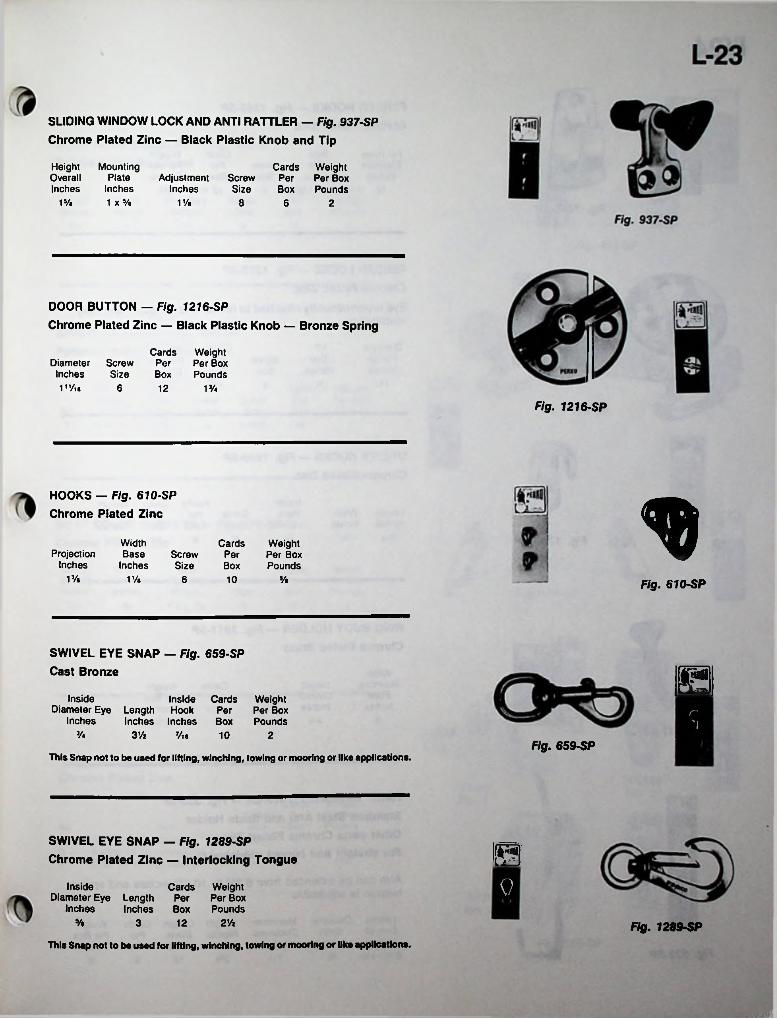
SLIDING WINDOW LOCK AND ANTI RATTLER — Fig. 937-SP Chrome Plated Zinc — Black Plastic Knob and Tip
Mounting Plate
Inches 1 x5/«
HeightOverallInches
Cards Weight Screw Per Per BoxSize Box Pounds
AdjustmentInches
1V« V/t 8 6 2
DOOR BUTTON — Fig. 1216-SPChrome Plated Zinc — Black Plastic Knob — Bronze Spring
Cards Weight Diameter Screw Per Per BoxInches Size Box PoundsV'At 6 12 1%
Fig. 1216-SP
HOOKS — Fig. 610-SP Chrome Plated Zinc
WidthBase
Inches
Cards Weight Per Box Pounds
ProjectionInches
ScrewSize
PerBox
1% V/t 6 10 % Fig. 610-SP
SWIVEL EYE SNAP - Fig. 659-SP Cast Bronze HInsideDiameter Eye Length Hook
Inches Inches Inches
Inside Cards Weight Per Per Box Box Pounds
n"I
3A 3 V2 7/ie 10 2Fig. 659-SP
This Snap not to be used for lifting, winching, towing or mooring or like applications.
SWIVEL EYE SNAP — Fig. 1289-SP Chrome Plated Zinc — Interlocking Tongue ©
0InsideDiameter Eye Length
Inches Inches
Cards Weight Per Per Box Box Pounds
% 2Vz3 12 Fig. 1289-SPThis Snap not to be used for lifting, winching, towing or mooring or like applications.
.
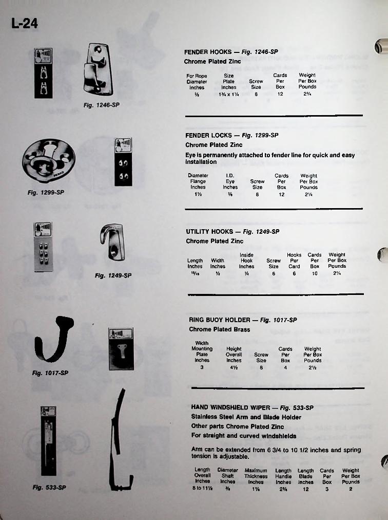
L-24
FENDER HOOKS — Fig. 1246-SP Chrome Plated Zinc
a Weight Per Box Pounds
CardsSize Plate
Inches 1% x I1/*
For Rope Diameter Inches
ScrewSize
Per
ft Box2V*1263/.
FENDER LOCKS - Fig. 1299-SP Chrome Plated Zinc
Eye is permanently attached to fender line for quick and easy installation
DiameterFlangeInches
I.D. Cards Weight Per Box Pounds
Eye ScrewSize
PerInches Box
1% Vt 8 12 2%
UTILITY HOOKS — Fig. 1249-SP Chrome Plated Zinc rHooks Cards Weight
Screw Per Per Per Box Size Card Box Pounds
InsideHook
InchesLength Width Inches Inches
2 Vi,5/te Vi V4 6 6 10Fig. 1249-SP
J RING BUOY HOLDER - Fig. 1017-SP Chrome Plated Brass
WidthMounting
PlateInches
HeightOverallInches
Cards WeightPer Per BoxBox Pounds
ScrewSize
3 4% 2 Vi8 4Fig. 1017-SP
HAND WINDSHIELD WIPER — Fig. 533-SP Stainless Steel Arm and Blade Holder Other parts Chrome Plated Zinc For straight and curved windshields
Arm can be extended from 6 3/4 to 10 1/2 inches and spring tension is adjustable. f
Length Diameter Maximum Overall ShaftInches Inches
8 to 11% %
Length Length Cards WeightThickness Handle Blade Per Per Box
Inches Inches Inches Box Pounds1% 22% 12 3
i
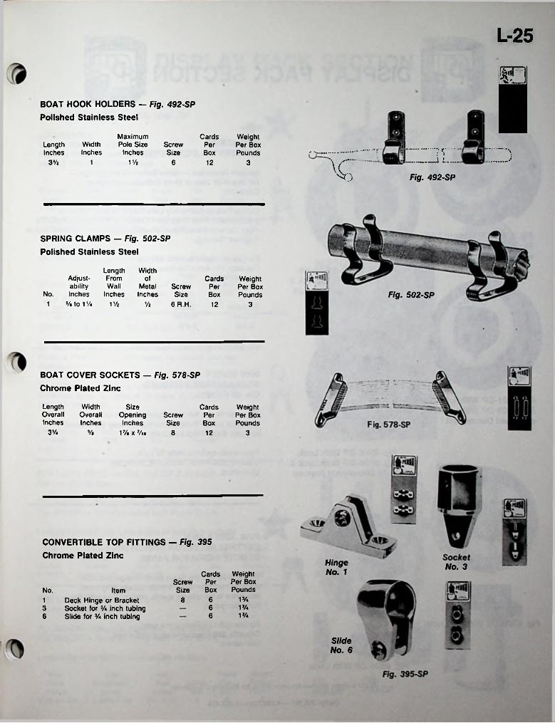
L-25
BOAT HOOK HOLDERS — Fig. 492-SP Polished Stainless Steel
Maximum Pole Size
Inches
Cards Weight Per Box Pounds
WidthInches
LengthInches
ScrewSize
Per —.... y....BoxJVC3 Vi 1 Vi1 6 12 3
Fig. 492-SP
’r.-.SPRING CLAMPS — Fig. 502-SP Polished Stainless Steel
[;■
Length Width Adjust- From ofability Wall Metal
No. Inches Inches Inches 1 */• to 1 % 1 Vi
Cards Weight Per Box Pounds
Screw Size
6 R.H.
PerFig. 502-SPBox
Vi 12 3
BOAT COVER SOCKETS — Fig. 578-SP Chrome Plated Zinc
LengthOverallInches
WidthOverallInches
SizeOpening Inches
17. x 7/i.
Cards Weight Per Box Pounds
ScrewSize
PerBox
3Vi v. 8 12 3
CONVERTIBLE TOP FITTINGS - Fig. 395 Chrome Plated Zinc
Hinge No. 1 No. 3
Cards Weight Per Box Pounds
PerScrewSize BoxNo. Item
Deck Hinge or Bracket Socket for V* inch tubing Slide for inch tubing
V/*681V/a63V/a66
Slide No. 6
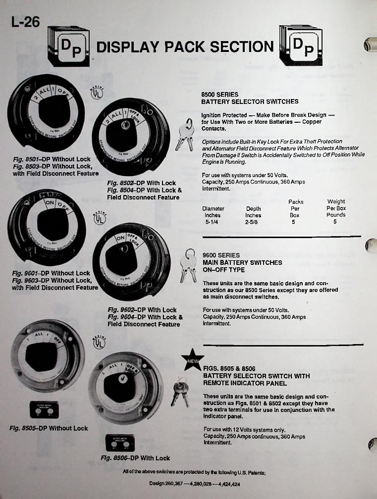
DDISPLAY PACK SECTION P:
8500 SERIESBATTERY SELECTOR SWITCHES
Ignition Protected — Make Before Break Design — for Use With Two or More Batteries — Copper Contacts.
Options include Built-in Key Lock For Extra Theft Protection and Alternator Field Disconnect Feature Which Protects Alternator From Damage if Switch is Accidentally Switched to Off Position While Engine is Running.Fig. 8507-DP Without Lock
Fig. 8503-DP Without Lock, ^with Field Disconnect Feature For use with systems under 50 Volts.
Capacity, 250 Amps Continuous, 360 Amps Intermittent.
Fig. 8502-DP With Lock Fig. 8504-DP With Lock &Field Disconnect Feature Weight
Per Box Pounds
PacksDiameter PerDepth
Inches2-5/8
Inches Box55-1/4 5
MAIN BATTERY SWITCHES ON-OFF TYPEFig. 9601-DP Without Lock
Fig. 9603-DP Without Lock, These units are the same basic design and construction as our 8500 Series except they are offered as main disconnect switches.
with Field Disconnect Feature
Fig. 9602-DP With Lock For use with systems under 50 Volts. Capacity, 250 Amps Continuous, 360 Amps intermittent.
Fig. 9604-DP With Lock &Field Disconnect Feature
FIGS. 8505 & 8506BATTERY SELECTOR SWITCH WITH REMOTE INDICATOR PANEL
These units are the same basic design and construction as Figs. 8501 & 8502 except they have two extra terminals for use in conjunction with the indicator panel.
For use with 12 Volts systems only.Capacity, 250 Amps continuous, 360 Amps Intermittent.
Fig. 8505-DP Without Lock
fFig. 8506-DP With Lock
All of the above switches are protected by the following U.S. Patents;
Design 260,367 —4,280,028 —4,424,424

L-27/-----
D DISPLAY PACK SECTION DP; P;SPREADER LIGHT — FIG. 1040 -DP
ADJUSTABLE Molded Black Plastic Body Chrome Plated Brass Mounting Bracket with 12 Volt Sealed Beam Unit
Packs WeightPer Per BoxBox Pounds
Mounting Depth Bracket Inches Inches 4-1/2 4-1 /2X1
DiameterInches
4-1/2
ScrewSize
12R.H.
Fig. 1040
5 9
SPREADER LIGHT — Fig. 280 - DP
ADJUSTABLEChrome Plated Brass with 12 Volt Sealed Beam Unit
Fig. 280-DPOFF ONMountingDiameter Depth BracketInches Inches Inches4-5/8 2-1/2 5-3/8X3/4 12
Weight Per Box Pounds
PacksScrew Per Size Box
!c ©!ANCHORLIGHT
5 6
1 lo RUNNINGLIGHTS c:
SWITCH PANEL — FIG. 517-DP
Black Textured Finish — Embossed Lettering — Molded Flexible Plastic which will mount on Curved and Flat Surfaces.
Fig. 517-DPComplete with switches, fuse holders, and name plates. Switches rated 15 Amps at 12 Volts. Fuse holders for 1/4" X 1-1/4” fuses. SEARCH
Weight Per Box Pounds
PacksDimensions
Inches 6-1/2 X 4-1/4
ScrewSize
PerBox5 46
RIM LOCK SETS — FIG. 918-DP & 919-DP Chrome Plated Zinc
Fig. 918-DP— Regular Bevel With Box Strike. Fig. 919-DP — Reverse Bevel With Flush Strike.
Locked by dead bolt from inside or key from outside.
5Weight Per Box Pounds
6-1/2
PacksDoor Screw Per
Inches Size Box3/4-1-1/2 6
SizeCaseInches
ForSizeEscutcheon
Inches 3-7/8 X 2 4-3/8 X1-1/4
Fig.Fig-918-DP 919-DP5
RIM LOCK SETS — FIG. 928-DP & 930-DP Chrome Plated Zinc
Fig. 928-DP—Regular Bevel With Box Strike. Fig. 930-DP— Reverse Bevel With Rush Strike.
Locked by slide button from inside, no keys.
Packs Weight Door Screw Per Per Box
Inches Size Box Pounds3/4-1-1/2 6
ForSize Case Inches
2-1/8 X1-3/4
SizeEscutcheon
Inches 4-3/8 X1-1/4
Fig.Fig.930-DP928-DP
45
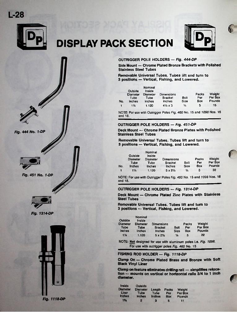
S3!DISPLAY PACK SECTIONOUTRIGGER POLE HOLDERS — Fig. 444-DP
Side Mount — Chrome Plated Bronze Brackets with PolishedStainless Steel Tubes
Removable Universal Tubes. Tubes lift and turn to 3 positions —■ Vertical, Fishing, and Lowered.
Nominal Outside Inside Diameter Diameter
Tube No. Inches
Packs Weight Per Per Box Box Pounds
Dimensions Bracket Inches AV2 x 3
TubeInches
BoltSize
15% 5VA 1.1201
NOTE: For use with Outrigger Poles Fig. 460 No. 15 and 1098 Nos. 16 and 18.
OUTRIGGER POLE HOLDERS - Fig. 451-DPDeck Mount — Chrome Plated Bronze Plates with PolishedStainless Steel Tubes
Removable Universal Tubes. Tubes lift and turn to 3 positions — Vertical, Fishing, and Lowered.
Fig. 444 No. 1-DP
NominalInside
DiameterTubeInches1.120
Outside Diameter
Tube No. Inches
.»» Packs Weight Per Per Box Box Pounds
Dimensions Bracket Inches 5 x 2Vz
A BoltSizey
30VA 5y«1Fig. 451 No. 1-DP NOTE: For use with Outrigger Poles Fig. 460 No. 15 and 7095 Nos. 16
and 18.
OUTRIGGER POLE HOLDERS — Fig. 1314-DPDeck Mount — Chrome Plated Zinc Plates with Stainless Steel TubesRemovable Universal Tubes. Tubes lift and turn to 3 positions — Vertical, Fishing, and Lowered.
Muy
Fig. 1314-DPNominal
Outside Inside Diameter Diameter
Tube Inches
Weight Per Box Pounds
Dimensions Bracket Inches 5 x 2Vz
Packs Bolt Per Size Box
TubeInches
VA 221.120 1/4 5
NOTE: Not designed for use with aluminum poles i.e. Fig. 1098. For use with outrigger poles Fig. 460 No.15________
FISHING ROD HOLDER - Fig. 1118-DPClamp On — Chrome Plated Brass and Bronze with Soft Black Vinyl Liner
Clamp on feature eliminates drilling rail — simplifies relocation — mounts on vertical or horizontal rails 3/4 to 1 inch diameter.
Inside OutsideDiameter Diameter Length Packs Weight
Liner Inches
TubeInches
Tube Per Per Box Inches Box Pounds
Fig. 1118-DP 1% 2 9 5 11
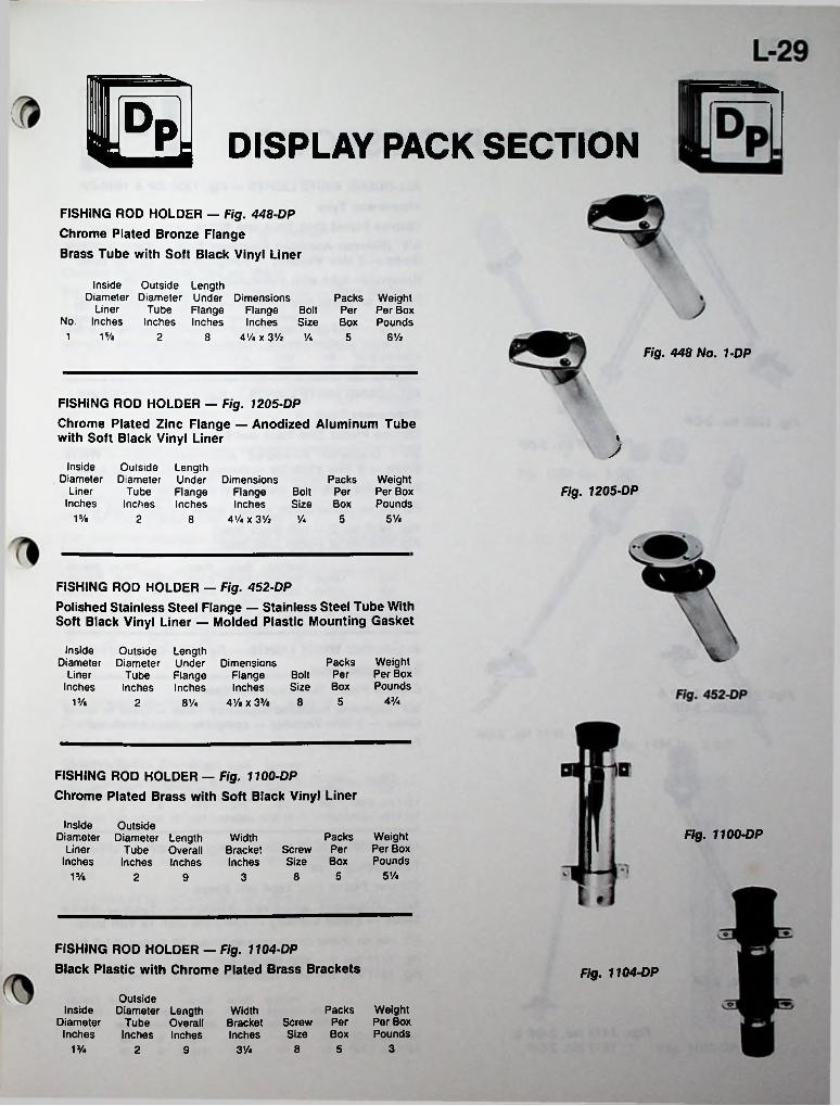
Us DISPLAY PACK SECTIONFISHING ROD HOLDER — Fig. 448-DP Chrome Plated Bronze Flange Brass Tube with Soft Black Vinyl Liner
Inside Outside Length Diameter Diameter Under Dimensions
Liner No. Inches
Packs Weight Per Box Pounds
Tube Flange Flange Bolt Inches Inches Inches Size
PerBox
15/a1 2 4% x 3 Vi Va 6 Vi8 5Fig. 448 No. 1-DP
FISHING ROD HOLDER — Fig. 1205-DPChrome Plated Zinc Flange — Anodized Aluminum Tube with Soft Black Vinyl Liner «
JInside
DiameterLiner
Inches
Outside LengthDiameter Under Dimensions
Tube Flange Flange BoltInches Inches Inches Size
4 Vi X 3 Vi Va
Packs Weight Per Per BoxBox Pounds
Fig. 1205-DP
15/a 5 Vi2 58
FISHING ROD HOLDER — Fig. 452-DPPolished Stainless Steel Flange — Stainless Steel Tube With Soft Black Vinyl Liner — Molded Plastic Mounting Gasket
InsideDiameter
LinerInches
Outside LengthDiameter Under Dimensions
Tube Flange Flange BoltInches Inches Inches Size
4Va X 3J/a 8
Packs Weight Per Per Box Box Pounds
4Va515/a 2 8%
FISHING ROD HOLDER — Fig. 1100-DP Chrome Plated Brass with Soft Black Vinyl Liner
Inside OutsideDiameter Diameter Length
Liner Tube OverallInches Inches Inches
Fig. 1100-DPWeight Per Box Pounds
PacksScrew Per Size Box
WidthBracketInches
SVa51s/a 82 39
FISHING ROD HOLDER — Fig. 1104-DP Black Plastic with Chrome Plated Brass Brackets Fig. 1104-DP
OutsideInside Diameter Length
Diameter Tube Overall Inches Inches Inches
Weight Per Box Pounds
Packs Screw Per Size Box
WidthBracketInches
31 Va 8 53Va2 9

L-30m DISPLAY PACK SECTIONALL-ROUND WHITE LIGHTS — Fig. 1330-DP & 1630-DP Stow-a-way TypeChrome Plated Zinc Tops and Bases3/4” Diameter Anodized Aluminum Tube — Clear or White Globe — 2 Mile Visibility — complete with 12 Volt bulb.Removable light with waterproof cover for base.For use on power driven vessels under 20 meters (65.6 ft.)
Vertical Base Base Fig. Length Height Length Width Screw Per Per BoxNo. Inches Inches Inches Inches Size Box Pounds
1330 No. 2-DP 24 19% 3% 1% 8 5 51630 No. 2-DP 24 19% 3V< 1% 8 5
Packs Weight
5
ALL-ROUND WHITE LIGHTS — Fig. 1430-DP & 1530-DP Stow-a-way TypeChrome Plated Zinc Tops and Bases3/4” Diameter Anodized Aluminum Tube — White Globe — 2 Mile Visibility — complete with 12 Volt bulb.Removable light with waterproof cover for base.For use on power driven vessels under 20 meters (65.6 ft.)Fig. 1430 No. 2 — with Black Insert Fig. 1530 No. 2 — with Teak Insert
Fig. 1330 No. 2-DPFig. 1630 No. 2-DP
Packs WeightBaseLength Height Length Width Screw Per Per Box Inches Inches Inches Inches Size
Vertical BaseFig.
Box PoundsNo.51430 No. 2-DP 24
1530 No. 2-DP 24520 Vi 3 Vi 1 Vi
20 Vi 3 Vi 1Vi8
558
ALL-ROUND WHITE LIGHTS — Fig. 1311-DP & 1611-DP Telescoping TypeChrome Plated Zinc Tops and Bases3/4” Diameter Anodized Aluminum Tube — Clear or White Globe — 2 Mile Visibility — complete with 12 Volt bulb.For use on power driven vessels under 20 meters (65.6 ft.)
Packs WeightFig. Length Height Length Width Screw Per Per BoxNo. Inches Inches Inches Inches Size Box Pounds
20 3 Vi 1% 8 519% 3V4 1% 8 5 5
Figs. 1430 No. 2-DP & 1530 No. 2-DP
Fig. 1611 No. 2-DP
Vertical Base Base
1311 No. 2-DP 24 1611 No. 2-DP 24
5
ALL-ROUND WHITE LIGHTS — Fig. 1411-DP & 1511-DP Telescoping TypeChrome Plated Zinc Tops and Bases3/4” Diameter Anodized Aluminum Tube — White Globe — 2 Mile Visibility — complete with 12 Volt bulb.For use on power driven vessels under 20 meters (65.6 ft.)Fig. 1411 No. 2 —with Black Insert Fig. 1511 No. 2 —with Teak Insert fFig. 1311 No. 2-DP
Packs WeightFig. Length Height Length Width Screw Per Per Box
Inches Inches Inches Inches Size Box Pounds21 3% 1% 8 5 521 3% 1% 8 5 5
Vertical Base Base
No.Figs. 1411 No. 2-DP &
1511 No. 2-DP1411 No. 2-DP 24 1511 No. 2-DP 24
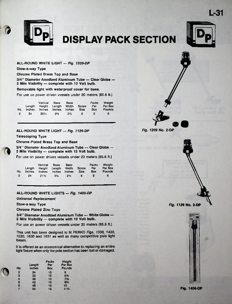
L-31!mDISPLAY PACK SECTION
ALL-ROUND WHITE LIGHT — Fig. 1209-DP Stow-a-way TypeChrome Plated Brass Top and Base3/4” Diameter Anodized Aluminum Tube — Clear Globe —2 Mile Visibility — complete with 12 Volt bulb.Removable light with waterproof cover for base.For use on power driven vessels under 20 meters (65.6 ft.)
Vertical Base BaseLength Height Length Width Screw
No. Inches Inches Inches Inches Size20V*
Packs Weight Per Per Box Box Pounds
62 24 33/a 2% 8 5
Fig. 1209 No. 2-DPALL-ROUND WHITE LIGHT — Fig. 1126-DP Telescoping TypeChrome Plated Brass Top and Base3/4” Diameter Anodized Aluminum Tube — Clear Globe — 2 Mile Visibility — complete with 12 Volt bulb.For use on power driven vessels under 20 meters (65.6 ft.)
Packs Weight Per Per Box Box Pounds
Vertical Base BaseLength Height Length Width Screw
No. Inches Inches Inches Inches Size21% 62 524 33/a 2 V* 8
ALL-ROUND WHITE LIGHTS — Fig. 1400-DP Universal Replacement Stow-a-way Type Chrome Plated Zinc Tops3/4” Diameter Anodized Aluminum Tube — White Globe — 2 Mile Visibility — complete with 12 Volt bulb.For use on power driven vessels under 20 meters (65.6 ft.)
This unit has been designed to fit PERKO Figs. 1330, 1430, 1530, 1630 and 1631 as well as many competitive pole light bases.
It is offered as an economical alternative to replacing an entire light fixture when only the pole section has been lost or damaged.
VFig. 1126 No. 2-DP
!:'
iff:
Weight Per Box Pounds
PacksLengthInches
PerNo. Box2 24 10 5
6%3 30 107%4 36 108%5 42 10 - :
6 48 10 10Fig. 1400-DP11%7 54 10
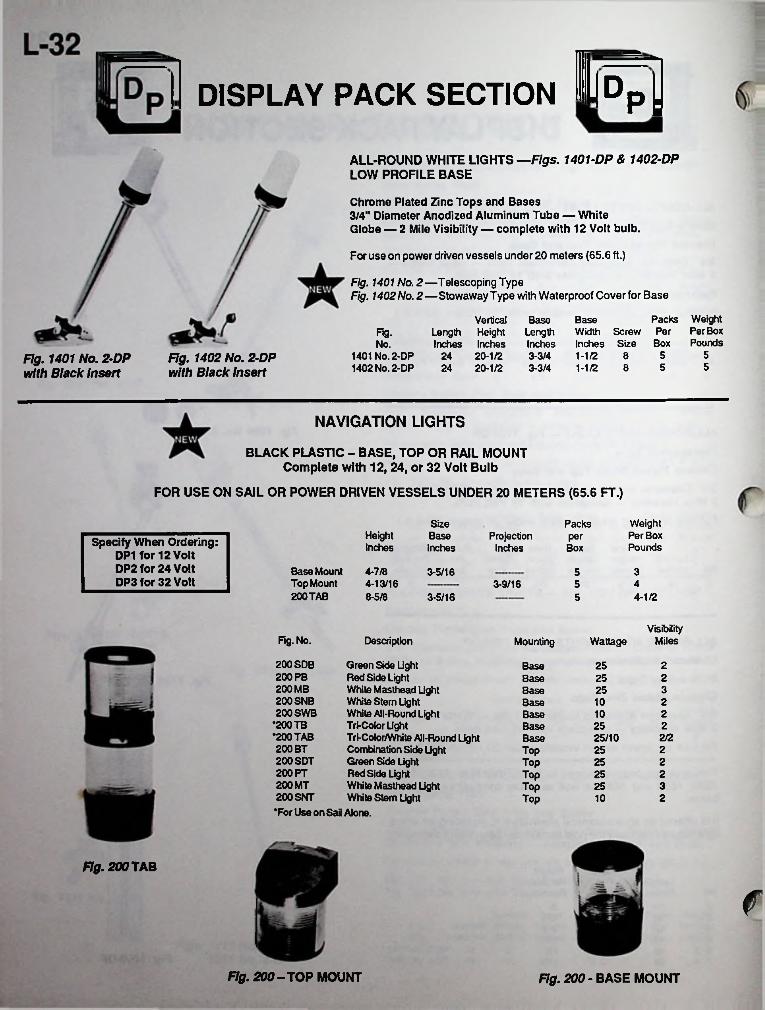
.DDISPLAY PACK SECTION P:ALL-ROUND WHITE LIGHTS — Figs. 1401-DP & 1402-DP LOW PROFILE BASE
Chrome Plated Zinc Tops and Bases3/4" Diameter Anodized Aluminum Tube — WhiteGlobe — 2 Mile Visibility — complete with 12 Volt bulb.
For use on power driven vessels under 20 meters (65.6 ft.)
Fig. 1401 No. 2—Telescoping TypeFig. 1402 No. 2—Stowaway Type with Waterproof Cover for Base
Packs Weight Width Screw Per Per BoxInches Size Box Pounds1-1/2 8 5
Vertical BaseLength Height LengthInches Inches Inches
24 20-1/2 3-3/424 20-1/2 3-3/4 1-1/2
BaseFig.No.
51401 No. 2-DP1402 No. 2-DP
Fig. 1402 No. 2-DP with Black Insert
Fig. 1401 No. 2-DP with Black Insert 558
NAVIGATION LIGHTS
BLACK PLASTIC - BASE, TOP OR RAIL MOUNT Complete with 12, 24, or 32 Volt Bulb
FOR USE ON SAIL OR POWER DRIVEN VESSELS UNDER 20 METERS (65.6 FT.)
Weight Per Box Pounds
SizeBaseInches
PacksHeightInches
ProjectionInches
perSpecify When Ordering: DP1 for 12 Volt DP2 for 24 Volt DP3 for 32 Volt
Box
Base Mount 4-7/8Top Mount 4-13/16200 TAB
3-5/16 353-9/16 5 4
8-5/8 3-5/16 5 4-1/2
VisibilityMilesFig. No. Description Mounting Wattage
200 SDB 200 PB 200 MB 200 SNB 200 SWB
•200 TB *200 TAB 200 BT 200 SDT 200 PT 200 MT 200 SNT •For Use on Sail Alone.
Green Side Light Red Side Light White Masthead Light White Stern Light White All-Round Light Tri-Color LightTri-Color/White All-Round Light Combination Side Light Green Side Light Red Side Light White Masthead Light White Stem Light
25 2Base2Base 25325Base
10 2Base10 2Base25 2Base
2/225/10Base25 2Top
2Top 2525 2Top
3Top 25Top 10 2
Fig. 200 TAB
fFig. 200-TOP MOUNT Fig. 200 - BASE MOUNT
SECTION
I■ ■ ••'•V .' •
.-• ;-.■■■■■:• ; :■•'
..
SPAREI
PARTSr.s,k
■ ■:ri"&■■ ■" v ■';
■iJ.
wmmmmrn;
IMANUFACTURED BY PERKO, INC., 16490 N.W. 13TH AVE., P.O. BOX 64000-D, MIAMI, FLORIDA 33164-0414FOR COMPLETE LINE SEE CATALOG NO. 250
PORTIONS OF THIS CATALOG PREVIOUSLY COPYRIGHTED IN 1936 THRU 1984 INCLUSIVE
v- PERKO, INC. 1986ALL RIGHTS RLSE
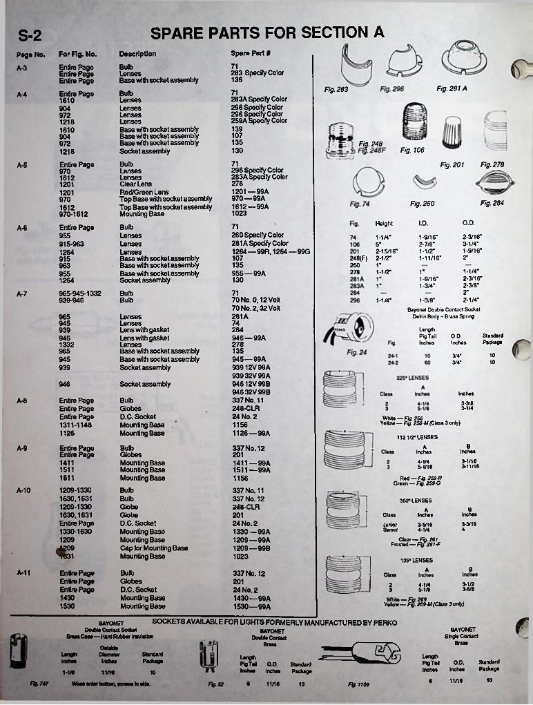
SPARE PARTS FOR SECTION AS-2Spare Part #DescriptionFor Fig. No.
Entire Page Entire Page Entire Page
Page No.71BulbA-3 283 Specify ColorLenses
Base with socket assembly 136Fig. 281AFig. 28371BulbEntire PageA-4 283A Specify Color
296 Specify Color 296 Specify Color 259A specify Color
Lenses1610LensesLensesLensesBase with socket assembly Base with socket assembly Base with socket assembly Socket assembly
9049721218
1391610107904135972 Fig. 248
Fig. 106130121871Bulb
LensesLensesClear LensRed/Green LensTop Base with socket assemblyTop Base with socket assemblyMounting Base
Fig. 278Entire Page Fig. 201A-5pecify Color Specify Cole
296 S970 283A1612 27812011201—99A 970—99A 1612—99A
1201970 Fig. 284Fig. 2601612
1023970-1612O.D.Height I.D.71BulbEntire PageA-6
260 Specify Color 281A Specify Color 1264 — 99R, 1264—99G
LensesLensesLensesBase with socket assembly Base with socket assembly Base with socket assembly Socket assembly
955 2- 3/16*3- 1/4" 1-9/16"
1- 9/16"2- 7/0" 1-1/2" 1-11/16"
1-1/4"915-963 5"
2-15/16" 248(F) 2-1/2"
1264107 2"915135 1"963 260
1- 1/4"2- 3/16" 2-3/0"
270 1-1/2" 1"955—99A9551-9/16"1-3/4"
13012642"71965-945-1332
939-946BulbA-7
70 No. 0,12 Volt 70 No. 2.32 Volt
Bulb 2-1/4"Bayonet Double Contact Socket
Delrin Body - Brass Spring
1-1/4" 1-3/0"
281A965 LensesLensesLens with gasket Lens with gasket LensesBase with socket assembly Base with socket assembly Socket assembly
74945284939 Length
Pig Tail Inches
StandardPackage
O.D.946 — 99A946Inches2781332
135965103/4*945—99A
93912V99A 93932V99A 94612V99B 94632V99B 337 No. 11 248-CLR 24 No. 2
945 103/4'939
Socket assembly946Inches
Entire Page Entire Page Entire Page 1311-1148
BulbA-8 3-3/8Globes D.C. Socket Mounting Base Mounting Base
3-1/4
White — Fig. 256 Yellow — Fig. 2S6M (Class 3 only)1156
1126 —99A1126 1121/2° LENSESBAEntire Page
Entire PageBulb 337 No. 12A-9 Inches
3-1/163-11/16
InchesGlobesMounting Base Mounting Base Mounting Base
2014-1/41411 1411—99A
1511— 99A 5-1/1615111611 1156 Red — Fig. 259 R
Green — Fig. 259-G1209-1330 1630,1631 1209-1330 1630,1631 Entire Page 1330-1630
A-10 Bulb 337 No. 11 337 No. 12 248-CLR
Bulb 360* LENSESGlobeGlobeD.C. SocketMounting BaseMounting BaseCap for Mounting BaseMounting Base
BA201 Inches
3-3/16Class Inches
24 No. 2 1330 —99A 1209—99A 1209 —99B
JuniorSenior
3-5/1644-1/4
1209 Clear—Fig. 261 Frosted — Fig. 261 -Fc 1023 135* LENSES
BAA-11 Entire Page Entire Page Entire Page
Bulb 337 No. 12 ClassGlobes D.C. Socket Mounting Base Mounting Base
201 3-1/22 4-1/424 No. 2 1430—99A 1530—99A
36/85-1/831430 White — Fig. 269
Yellow — Fig. 269M (Class 3 only)1530
fSOCKETS AVAILABLE FOR LIGHTS FORMERLY MANUFACTURED BY PERKOBAYONETDouble Contact Socket
BrusCase—Hard Rubber InsulationBAYONET
Single ContactBAYONET
Double ContactBrassBrass
OutsideLength Standard
PackageLengthPigTai O.D. Inches
LengthPigTai O.D. StandardInches Inches Package
Inches StandardPackage
1-1* 11/16 101011/166Bg.747 Wires enter bottom, screws in side. 6 11/16 10 Fig. 1109
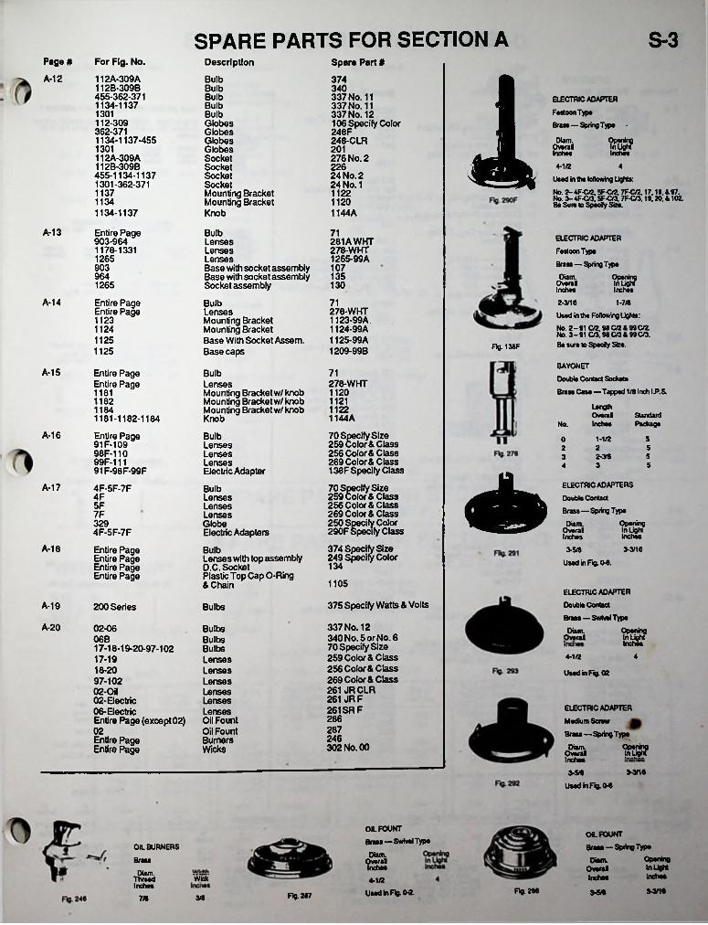
SPARE PARTS FOR SECTION A S-3Page# For Fig. No. Description Spare Part #
1A-12 112A-309A112B-309B455-362-3711134-1137
Bulb 374Bulb 340Bulb 337 No. 11
337 No. 11 337 No. 12 106 Specify Color 248F 248-CLR
ELECTRIC ADAPTER Festoon Type Brass—Spring Type
Bulb1301 Bulb112-309362-3711134-1137-455
GlobesGlobesGlobesGlobesSocketSocketSocketSocketMounting Bracket Mounting Bracket Knob
Diam.OverallInches1301 201 Inch®*112A-309A
112B-309B455-1134-11371301-362-371
276 No. 2226 4-1/2 424 No. 2 24 No. 1 UMd in the following lights:
No. 2-4F-C/2,5F-C/2,7F-C/2,17.18,897. No. 3- 4F-C/3,5F-C/3, 7F-C/3.19.20. * 102. Be Sure to Specify Size.
1137 11221134 11201134-1137 1144A
A-13 Entire Page903-9641178-1331
BulbLensesLensesLensesBase with socket assembly Base with socket assembly Socket assembly
BulbLensesMounting Bracket Mounting Bracket Base With Socket Assem. Base caps
71 ELECTRIC ADAPTER
Festoon TypeBrass — Spring Typ®
Diam. OpeningOverall In LightInches Inches
281AWHT 278-WHT 1265-99A1265
903 107964 1351265 130
A-14 Entire Page Entire Page11231124
71 2-3/18Used in the Following Lights:No. 2-91 C/2,98 C/2 4 99 C/2. No. 3-91 C/3,98C/38 99C/3. Be sure to Specify Size.
1-7/8278-WHT1123- 99A1124- 99A1125- 99A 1209-99B
1125Fig. 138F1125
BAYONETDouble Contact SocketsBrass Case—Tapped 1/8 Inch I.P.S.
Length Overal
No. Inches
A-15 71Entire Page Entire Page
Bulb278-WHTLenses
Mounting Bracket w/knob Mounting Bracket w/knob Mounting Bracket w/knob Knob
112011811121118211221184 Standard
Package1144A1181-1182-1184
A-16 70 Specify Size 259 color & Class 256 Color & Class 269 Color & Class 138F Specify Class
70 Specify Size 259 Color & Class 256 Color & Class 269 Color & Class 250 Specify Color 290F Specify Class
374 Specify Size 249 Specify
Entire Page91F-10998F-11099F-11191F-98F-99F
BulbLensesLensesLensesElectric Adapter
1-1/2 5o2 522-318 533 54
ELECTRIC ADAPTERS
Double ContactBrass—Spring Type
Diam.Overall Inches
A-17 4F-5F-7F Bulb4F Lenses
LensesLensesGlobeElectric Adapters
5F7F329 Opening
In light Inches
3-3/16
4F-5F-7F
A-18 Entire Page Entire Page Entire Page Entire Page
Bulb 3-5/8ColorLenses with top assembly
D.C. Socket Plastic Top Cap O-Ring & Chain
Used in Fig. 0-8.134
1105ELECTRIC ADAPTERDouble ContactBrass—Swivel Type
Diam.Overall
375 Specify Watts & VoltsA-19 200 Series Bulbs
A-20 337 No. 12 340 No. 5 or No. 6 70 Specify Size 259 Color & Class 256 Color & Class 269 Color & Class 261 JRCLR 261 JR F 261 SR F
02-06 BulbsBulbsBulbsLensesLensesLensesLensesLensesLensesOil FountOil FountBurnersWicks
Opening In light Inches06B
17-18-19-20-97-10217- 1918- 20 97-102 02-Oil 02-Bee trie 06-ElectricEntire Page (except 02)
44-1/2
Used in Fig. 02
ELECTRIC ADAPTERMedium Screw
Brass—Spring Type
Diam.Overal Inches
28628702246Entire Page
Entire Page 302 No. 00 'STS?3-3/18>5/8
Used in Fig. OS
OIL FOUNTBrass—Swivel Type
Diam.Overal Inches
OIL FOUNT Brass—Spring Type
Diam.Overal Inches
OIL BURNERSOpening In Light Inches
BrassDiam.
WickThreadInches
4-1/2Fig. 288 3-3/18Used In Fig. 02. 3MFig. 2873/87/8

SPARE PARTS FOR SECTION BS-4
Spare Part #Pago No. For Fig. No.
Entire Page Entire Page Entire Page Entire Page Entire Page Entire Page
Description
BulbsLensesLens Retaining Clip w/ Bolt Lens Gasket Med Prefocus Socket Plastic Top Cap, O-Ring with Chain
DUAL MEDIUM PREFOCU3 SOCKET ASSEMBLYPlug In Typa - Prewired - with two medium prefocu socket*. For use In double lens lights Fig 1164 series.
Overall Height
Inches
342 No. 4261 No. 1 Specify Color
B-3
11331143347 Overall
WidthInches
WeightOunces
8-1/21105
3-7/8 3-7/8BulbsLensesLens Retaining Clip w/Bolt Lens GasketDual Med. Prefocus Socket assemblyPlastic Top Cap, O-Ringwith ChainBulbsLenses—112-1/2°Lenses—135°Lenses—225°Lenses—360°Med. Prefocus Socket with CapPlastic Top Cap, O-Ring, and Chain.
342N0.4261 No. 1 Specify Color
Entire Page Entire Page Entire Page Entire Page Entire Page
Entire Page
Entire Page Entire Page Entire Page Entire Page Entire Page Entire Page
Entire Page
B-4Fig. 303
11331143
MEDIUM PREFOCUS SOCKETS Phenolic — 250 Volt* — 1000 Watt*
Overal Diam.
Inch®*
303
i1105WeightOunces
StandardPackage
Haiglt Inches
1-7/8 1-1/2
B-5 342 Specify Size 259 No. 1 or 2, Specify Color 269 No. 1 or 2, Specify Color 256 No. 1 or 2, Specify Color 261F No. 1 or 2, Specify Color
45
Fig. 347-A supplied with metal Mounting Cap Tapped lor 3/8* I.P.S.
347-A Fig. 347 A 347-A
1105
B-6 Entire Page Entire Page Entire Page
4-5-7112A-309-A
BulbsLensesMed. Prefocus Socket
BulbsBulbsLensesLensesLensesGlobesS.C. Bayonet Socket D.C. Bayonet Socket
BulbsLens & Top Assembly with GasketD.C. Socket Assembly Plastic Top Cap, O-Ring and Chain
BulbsLensesLensesLensesMed. Prefocus Socket Med. Prefocus Socket Plastic Top Cap, O-Ring, and Chain Flasher
BulbsLensesLens Rataining Clip with BoltLens GasketDual Med. Prefocus Socket AssemblyRastic Top Cap with O-Ring
Lenses—112°Lenses—135°Lenses—225°Lenses—360°Chimneys Burners Wicks Oil Founts
342N0.4261 No. 1 Specify Color DOUBLE CONTACT BAYONET BULBS
Cltar — 12, 24, 32, or 120 Volta Typa T-8, C-8, Filament —1-3/8* LC.L
Fig. No. 374 Voltage CandeBa
347
B-7 373 Specify Size374 Specify Size 259-CL3 Specify Color 256-CL3 Specify Color 269-CL3 Specify Color 106 Specify Color 294 No. 3276 No. 2
241214 242425 243237 241204112A-309A4-5-7112A-309A
B-8 Entire Page Entire Page
Entire Page Entire Page
374 Specify Size 249 Specify Color
MEDIUM PREFOCUS BULB8 Clear —120 Volt*
134 Wattag*Fig. No. 3427501105 151
252B-9 Entire Page
RE-1174RE 1173ME-1173RE 1111ME 1171-1173-1174 1111ME Entire Page
40342 No.4 261 Specify 261 Specify 256 No. 1 Yellow
36041171 Color
Color1258
347347A
SINGLE CONTACT PREFOCUS BULBS C-« FILAMENT Clear —12 VoK
Fig. No.373 Amperag* Mlg. No.25 25A/S8.55 55A/S8.77 77A/S8
1.15 1.15A/S8 n2.03 2.03A/S8SCP
11051111ME
Entire Page Entire Page Entire Page
Entire Page Entire Page
Entire Page
1331B-10 342 No. 4
261 No. 1 Specify Color23451133
1143
303
1105380° LENSES
With Top AsaemblyB-11 Entire Page Entire Page Entire Page Entire Page
^Entire Page Entire Page
Entire Page Entire Page
259 No. 1 or 2, Specify Color 269 No. 1 or 2, Specify Color 256 No. 1 or 2, Specify Color 261 No. 1 or 2, Specify Color
Diam.Ovarml
HaightOvaralInch**267
5-1/2242 5-3/4302 No.2 Fig 249 - Groan. Gray, Rad,
YaBow A Claar282
135* LENSES
ANo.ferin,' 1 2Whita -Fig 269Rad - Fig 269-R Yallow-Fig 26644
8-3/47-1/2B
Inchaa
4-1/26-5/8
'RSi-'SSSl,Yallow-Fig 26444
261 •BF 291-CFYallow -
Gray - 24144F

SPARE PARTS FOR SECTION C-D S-5Pag® No. For Fig. No. CD-6 517
Description
Switches Fuse Holders Fuse Holder Cap
Switches Fuse Holders Fuse Holder Cap
Connector
Socket with Knob Switch
Spar® Part #BURNERS514
517 516517 522
CD-7 511-512511-512511-512
514516522
CD-9 1189-1190 42 Fig. 242 Fig 231
CD-12 217-450-1295 223 ThreadDianwtar Standard
Wick*1303 701 For Standard Width PackagePackage Burner*CD-13 300-308
300-555BulbsGlobesGlobesGlobesSwitchesSwitchesSocketsSocketSocket
337 Specify 257 Specify Size 308-99A Specify Size
Size5 302 No. 00 3V5 302 No. 2 7/T
20308 20753 132
LAMP CHIMNEYS300-308555-759300-308
70174524 No. 1 346 No. 1555
753 1323CD-14 318A Bulbs
SwitchesGlobesSocketSwitchGuardsSocketsGlobes
337 No. 12 & No. 23 318A-99E 318A-99D 24 No. 1
318A318A318A-12661266 7451087-10901087-10901087-1090
1087-1090-99A 1087-1090-99B 1087-1090-99C
Fig 2S7 Fig 230Standard
Height PackageDiameter
CD-15 280-1040 432 Specify Voltage 70 No. 0
Sealed Beam Unit 3* 6-1/r 5V265 Bulb 2-1/16" 1-1/2■
6" 5265 Lens with Gasket 284 4-3/4" 5CD-16 312 94Chimney
ChimneyChimneyWicksWicksBurnerBurnerBurner
168-141 No. 1 141 No. 2 168-141 No. 1 312-141 No. 2
230267 250 Volt*—660 Volts302 No. 00 302 No. 2 Size Extreme
Thread No. Inches
HeightInches Inches Package
Diameter Standard312 173fig 346Specify
SpecifyFinishFinish
231168-141 No. 1 141 No. 2 1 1/« 2-1/8242 1-1/2 5
SPARE PARTS FOR SECTION E(SEE SECTION E)
SPARE PARTS FOR SECTION F-GPago No. For Fig. No.
FG-2 778-791 778-791
Spar® part#
822 Specify Size 824 Specify Size
526 Specify Size & Finish
See Below
Description
MotorsImpellers
Deck Plate
Bell Parts
FG-3 510
FG-10 420-150-158-179
SPARE PARTS SPECIFY SPARE PART NO., SIZE AND FINISH
EYEBOLTS ACORN NUTSCLAPPERSWALL PLATESARMS
Figure Spare Part No.
Figure Spare Part No.
Spare Part No.
Spare Part No.
Figure'X9 Spare Part No. lo.o.No.
465 No. 4 465*40.8
113 420-6"420-8"
153 420-6"420-8"
420-6"420-8"420-6" 127
420-8" 127
150-8" 127150-10" 150-99B-10" 150-12" 150-99B-12"
"158-12" 158-99A-12" "158-14" 158-99A-14"
"179 179-99A"Includes Arm_____
420-6"420-8"
420-99A-6" 144 123171150-8"150-10"150-12"
465 No. 8 .465 No. 9 465 No. 9
150-8"150-10"
"150-12"123144150-8"
150-10""150-12"
150-8"150-10"150-12"
171 150-99D150-99C150-99A-10"150-99A-12" 172172
465 No. 9 465No.9465 No. 8
"158-12""158-14"
172 158-12"158-14""158-12"
"158-14"172"158-12"
"158-14"158-99A-12" 158-99A-14" 172172
179179 179-99B"Includes Clapper
144179179 179-99A•includes Wall Bracket •Includes Eye Bolt
159-99A-Spedfy Finish 159-99B
FG-11 159 Arm159 6" Clapper
8" Clapper Eye Bolt Wall Plate Acorn Nut
153159113159166-Spedfy Finish 465 #4-Spedfy Finish
159159
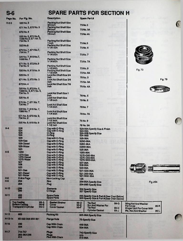
SPARE PARTS FOR SECTION HS-6Description
Packing Nut Shaft Size 3/4 InchPacking Nut Shaft Size 3/4 inchPackjng Nut Shaft Size 7/8 Inch
Page No. For Fig. No.
H-2-3 320 No. 3Spare Part#
€73 No.3671 No. 3,672 No. 3672 No. 4320 No. 5,672 No.5, 1088 No.5,671 No.5, 734 No. 5320NO.6
672 No. 7,671 No.7, 734 No. 7320 No. 7,819 No.7, 1088 No. 7671 No. 9,672 No.9 734 No. 9320 No. 9,819 No. 9 320 No. 3671 No. 3,672 No. 3672 No. 4320 No. 5.672 No. 5. 1088 No. 5,671 No.5, 734 No. 5320 No. 6672 No. 7.671 No.7, 734 No. 7302 No. 7,819 No. 7, 1088 No.7
671 No. 9,672 No. 9, 734 No. 9320 No. 9,819 No. 9
73N0.3A
73N0.4A
Packing Nut Shaft Size 1 inchPacking Nut Shaft Size 1-1/8 Inch
Packing Nut Shaft Size 1-1/4 inch
Packing Nut Shaft Size 1-1/4 inch
73 No.5
73 No. 6
73 No. 7
73N0.7A
Packing Nut Shaft Size 1-1/2 inchPacking Nut Shaft Size 1-1/2 inchLock Nut Shaft Size 3/4
73 No. 973 No. 9A
inch 79 No. 3Fig. 79Lock Nut Shaft Size 3/4
inch 79N0.3ALock Nut Shaft Size 7/8inch 79N0.4A
Lock Nut Shaft Size 1inch 79 No. 5Lock Nut Shaft Size 1-1/8 inch 79 No. 6Lock Nut Shaft Size 1-1/4 inch 79 No. 7Lock Nut Shaft Size 1-1/4 inch 79N0.7A
Lock Nut Shaft Size 1-1/2 inch Lock Nut Shaft Size 1-1/2 inch
79 No. 979 No. 9A528-99A Specify Size & Finish 524-99A528- 99B Specify Size524- 99B529- 99A 529G-99A 529D-99A 529W-99A525- 99A1269- 99A1270- G00-99A 1270-D00-99A 1270-W00-99A507- 99A508- 99A520- 99A521- G00-99A 521-D00-99A 521-W00-99A
H-4 528 Cap with O-Ring Cag with O-RingO-RingCap with O-Ring Cap with O-Ring Cap with O-Ring Cap with O-Ring Cap with O-Ring Cap with O-Ring Cap with O-Ring Cap with O-Ring Cap with O-Ring Cap with O-Ring Cap with O-Ring Cap with O-Ring Cap with O-Ring Cap with O-Ring Cap with O-Ring Non-Locking Cap
524528524529529-Gas529-Diesel529-Water525
H-5 12691270-Gas1270-Diesel1270-Water507508520521-Gas 521-Diesel 521-Water Entire PageH-6 126
H-9 254 Zinc 254-99A Specify Size 254-99B Specify Size
324 Specify 327 Specify Size
493 Specify Size & Part # (See Chart Below) 500 Speafy Size A Part # (See Chart Below)
Fig. 254254 Plug
H-10 299 ElementsO-Rings
Spare Paris Spare Parts
Size299H-11 493
500
Top Casting Bottom CastingTransparent Cylinder 99-C
99-A Basket Strainer CoverCover Gasket
99-D Tie RodNut And Washer For Tie RodCylinder Gasket
99-G Wing Nut And Washer For CoverHinged Bolt For Cover With Pin, Nut And Washer 99-L
99-B 99-E 99-K99-F 99-H99-J
805 Packing Kit Flange Nuts
Cap With Chain Cap With Chain
PlugsPlugsPlua With Chain
805-99A Specify Size 75-SpedfySize
499-99A504-99A
742-Spea'fy Size 370414-99A
H-13-14 65-322-348-350-361
H-16 499504
H-17 714-737263-363-266414
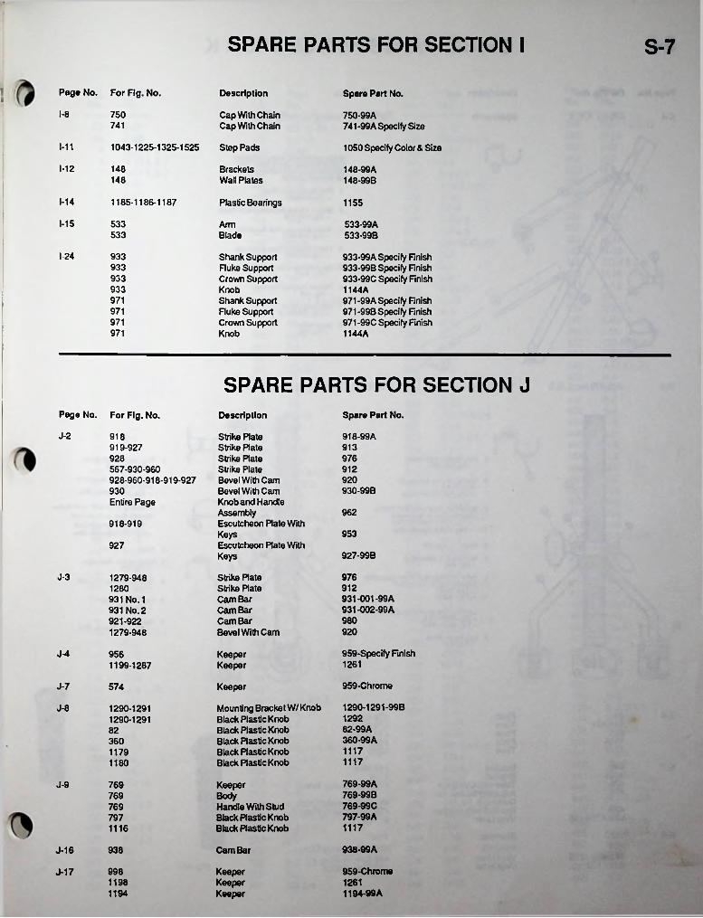
SPARE PARTS FOR SECTION I S-7
i Page No. For Fig. No. Description Spare Part No.■
1-8 750 Cap With Chain Cap With Chain 741-99A Specify Sizo741
1-11 1043-1225-1325-1525 Step Pads 1050 Specify Color & Size
1-12 148 Brackets Wall Plates
148-99A 148-99B148
1-14 1185-1186-1187 Plastic Bearings 1155
1-15 533 Arm 533-99A533-99B533 Blade
I-24 933 Shank Support Fluke Support Crown Support
933-99A Specify Finish 933-99B Specify Finish 933-99C Specify Finish 1144 A971-99A Specify Finish 971-99B Specify Finish 971-99C Specify Finish 1144 A
933933933 Knob971 Shank Support
Fluke Support Crown Support Knob
971971971
SPARE PARTS FOR SECTION JPage No. For Fig. No. Spare Part No.Description
J-2 918 Strike Plate Strike Rate Strike Rate Strike Plate Bevel With Cam Bevel With Cam Knob and Handle AssemblyEscutcheon Rate With KeysEscutcheon Plate With Keys
918-99A919-927 913
976928567-930-960928-960-918-919-927
912920930-99B930
Entire Page962
918-919953
927927-99B
J-3 976Strike Rate Strike Rate Cam Bar Cam Bar Cam Bar Bevel With Cam
1279-9489121280931-001-99A 931-002-99A
931 No. 1 931 No. 2 921-922 1279-948
980920
959-Specify FinishJ-4 956 KeeperKeeper 12611199-1287
959-ChromeJ-7 574 Keeper
1290-1291-99BMounting Bracket W/Knob Black Plastic Knob Black Plastic Knob Black Rastic Knob Black Plastic Knob Black Plastic Knob
J-8 1290-12911290-1291 1292
82-99A360-99A
82360
1117117911171180
769-99A769-99B769-99C797-99A
J-9 769 Keeper769 Body
Handle With Stud Black RasticKnob Black Ras tic Knob
769797
11171116
938-99A938 Cam BarJ-16
959-Chrome998 KeeperKeeperKeeper
J-171198 1261
1194-99A1194
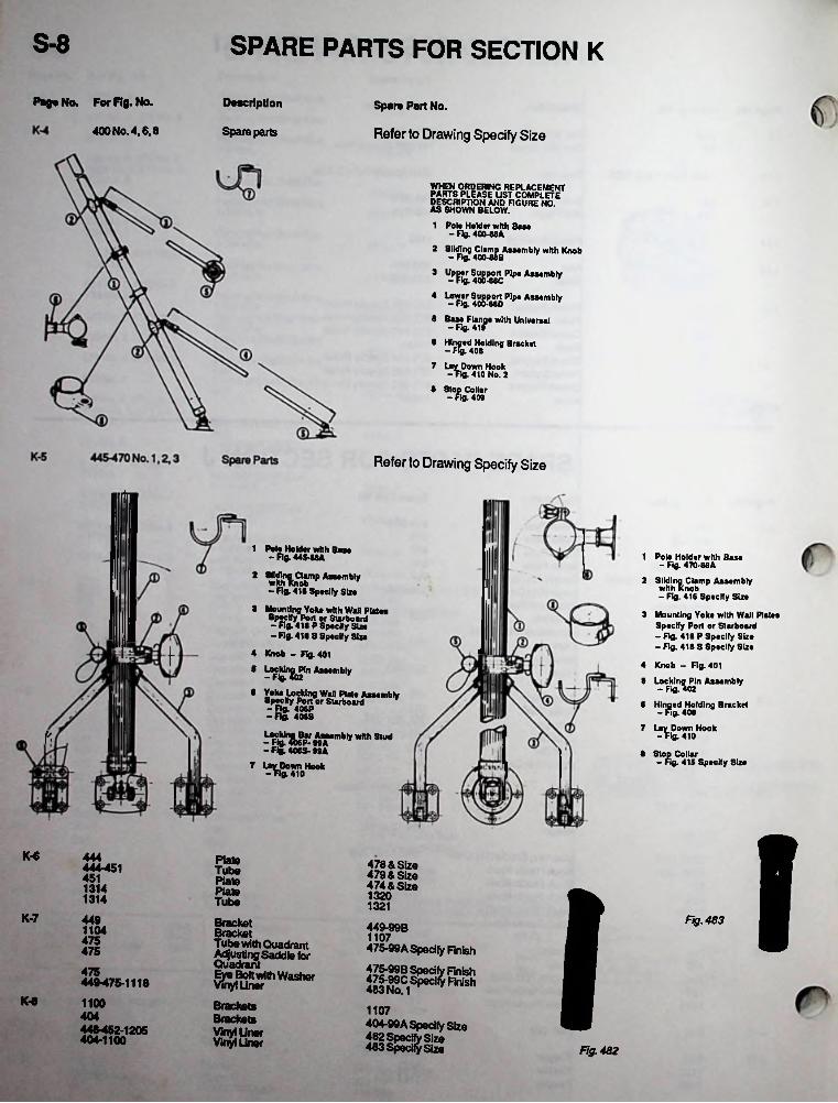
S-8 SPARE PARTS FOR SECTION K
Page No. For Rg. No. Description Spare Part No.
Refer to Drawing Specify Size400 No. 4,6.8 Spare parts
BUMsrAS SHOWN BELOW.
1 Polo Holder with Base - Fig. 400 MA
2 SUdh^j with Knob
* Up^or Sugj^Plpo Aosombly
4 lfFK40§-PMDP,P#A9Semb,y 8 BaseFlanpewith Universal
6 Hinged Holding B
Down Hook 410 No. 2
racket
7 '36• Stop Collar
- fig. 409
Refer to Drawing Specify Size
ftn
1 Pole Holder with Baa*- Fig. 445-88A
- Fig. 416 Specify Size
2 Mounting Yoke with Wall Plates 8pacify Port or Starboard- Fig. 418 P Specify Size- Fig. 418 8 8pecffy Size
4 Knob - Fig. 401 8 LocMn^Pin Assembly
8 Yoke Locking Wan Plat* Assembly Specify Port or Starboard -Rg. 406P -Fig. 406S
^HgAcS MA*mbV Whh StUd - f£ 406S- 99 A
7 Lay Down Hook -Fig. 410
1 Pol* Holder with Bose- Fig 470-88A
2 Sliding Clamp Assemblywhh Knob- Fig. 416 Specify Size
3 Mounting Yoke with Wall Plates Specify Port or Starboard- Fig 418 P Specify Size -Fig 418 S Specify Size
4 Knob - Fig 4018 Locking Pin Assembly
- Fig 402
8 Hinged Holding B- Fig 408
7 Lav Down Hook -Fig 410
8 Stop Collar- Fig 415 Specify Size
fracket
Y
IK-6 444 Plate 478 & Size479 & Size 474 & Size
444-451 Tube451 Plate1314 Plato I13201314 Tube 1321K-7 449 Fig. 483Bracket
BracketTube with Quadrant Adjusting Saddle lor QuadrantEj^ftWash*
Brackets Brackets Vinyl liner Vinyl Uner
449-99B1104 1107475475-99A Specify Finish475
47f^99C Specify 483 No. 1 7
FinishFinish
475440-475-1118
K-8 1100 1107404404-99A Specify Size448-452-1205
404-1100Fig. 482
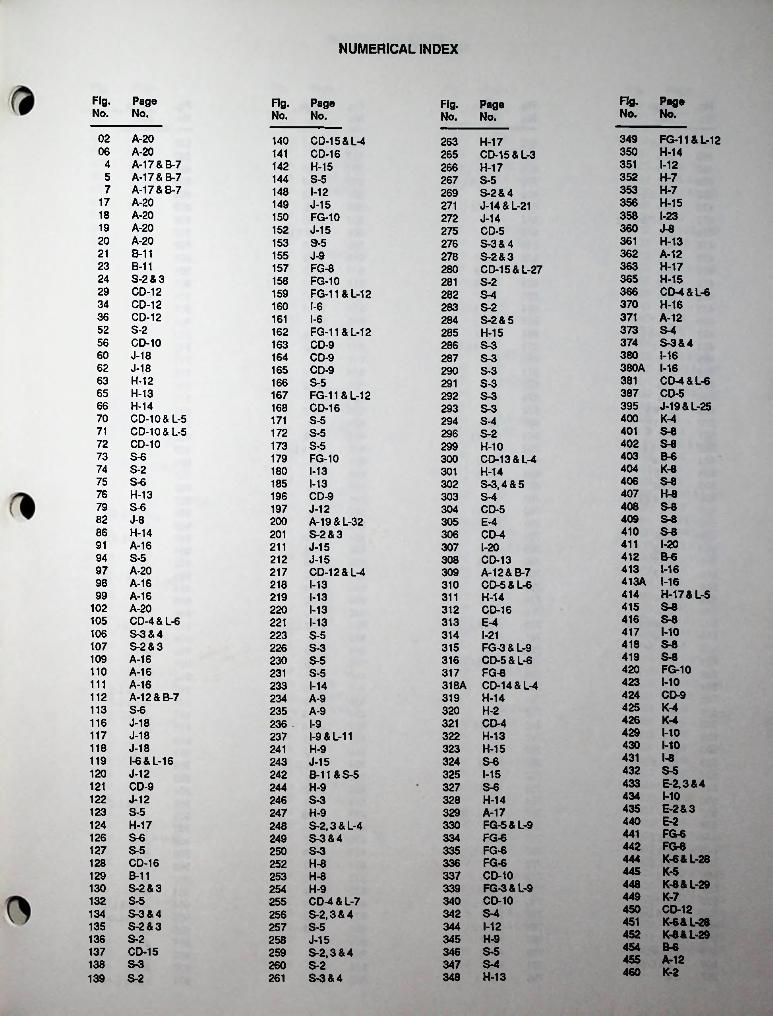
NUMERICAL INDEX
Fig. Pag© No. No.
Fig. Page No. No.
Fig. Page No. No.
Fig. Page No. No.
02 A-2006 A-20
4 A-17&B-75 A-17&B-77 A-17&B-7
17 A-2018 A-2019 A-2020 A-2021 B-1123 B-1124 S-2 & 329 CD-1234 CD-1236 CD-1252 S-256 CD-1060 J-1862 J-1863 H-1265 H-1366 H-1470 CD-10 &L-571 CD-10 & L-572 CD-1073 S-674 S-275 S-676 H-1379 S-682 J-886 H-1491 A-1694 S-597 A-2098 A-1699 A-16
102 A-20105 CD-4&L-6106 S-3&4107 S-2&3109 A-16110 A-16111 A-16112 A-12&B-7113 S-6116 J-18117 J-18118 J-18119 I-6&L-16120 J-12121 CD-9122 J-12123 S-5124 H-17126 S-6127 S-5128 CD-16129 B-11130 S-2&3132 S-5134 S-3&4135 S-2&3136 S-2137 CD-15138 S-3139 S-2
349 FG-11 &L-12350 H-14351 1-12352 H-7353 H-7356 H-15358 I-23360 J-8361 H-13362 A-12363 H-17365 H-15366 CD-4 & L-6370 H-16371 A-12373 S-4374 S-3&4380 1-16380A 1-16
140 CD-15& L-4141 CD-16142 H-15144 S-5148 1-12149 J-15150 FG-10152 J-15153 S-5155 J-9157 FG-8158 FG-10159 FG-11&L-12160 I-6161 I-6162 FG-11&L-12163 CD-9164 CD-9165 CD-9166 S-5167 FG-11&L-12168 CD-16171 S-5172 S-5173 S-5179 FG-10180 1-13185 1-13196 CD-9197 J-12200 A-19&L-32201 S-2&3211 J-15212 J-15217 CD-12 & L-4218 1-13219 1-13220 1-13221 1-13223 S-5226 S-3230 S-5231 S-5233 1-14234 A-9235 A-9236 I-9237 I-9&L-11241 H-9243 J-15242 B-11 & S-5244 H-9246 S-3247 H-9248 S-2,3 & L-4249 S-3&4250 S-3252 H-8253 H-8254 H-9255 CD-4&L-7256 S-2,3 & 4257 S-5258 J-15259 S-2,3 & 4260 S-2261 S-3&4
263 H-17265 CD-15 &L-3266 H-17267 S-5269 S-2&4271 J-14&L-21272 J-14275 CD-5276 S-3&4278 S-2&3280 CD-15&L-27281 S-2282 S-4283 S-2284 S-2&5285 H-15286 S-3287 S-3290 S-3291 S-3292 S-3293 S-3294 S-4296 S-2299 H-10300 CD-13 & L-4301 H-14302 S-3,4 & 5303 S-4304 CD-5305 E-4306 CD-4307 I-20308 CD-13309 A-12&B-7310 CD-5 & L-6311 H-14312 CD-16313 E-4314 1-21315 FG-3&L-9316 CD-5 & L-6317 FG-8318A CD-14 & L-4319 H-14320 H-2321 CD-4322 H-13323 H-15324 S-6325 1-15327 S-6328 H-14329 A-17330 FG-5&L-9334 FG-6335 FG-6336 FG-6337 CD-10339 FG-3&L-9340 CD-10342 S-4344 1-12345 H-9346 S-5347 S-4348 H-13
381 CD-4 & L-6387 CD-5 395 J-19&L-25400 K-4401 S-8402 S-8403 B-6404 K-8406 S-8407 H-8408 S-8409 S-8410 S-8411 I-20412 B-6413 1-16413A 1-16414 H-17&L-5415 S6416 S-8417 1-10418 S-8419 S-8420 FG-10423 1-10424 CD-9425 K-4426 K-4429 1-10430 MO431 I-8432 S-5433 E-2.3&4434 MO435 E-2&3440 E-2441 FG-6442 FG-8444 K-6&L-28445 K-5448 K-8&L-29449 K-7450 CD-12451 K-6&L-28452 K-8&L-29454 B-6455 A-12460 K-2
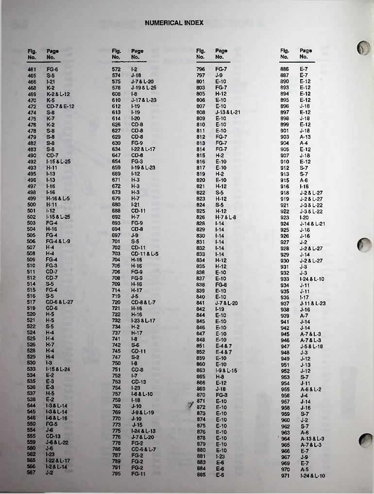
NUMERICAL INDEX
Fig. Page No. No.
Fig. Page No. No.
Rg. Page No. No.
Fig. Page No. No.
796 FG-7797 J-9801 E-10803 FG-7805 H-12806 E-10807 E-10808 J-13&L-21809 E-10810 E-10811 E-10812 FG-7813 FG-7814 FG-7815 H-2816 E-10817 E-10819 H-2820 E-10821 H-12822 S-5823 H-12824 S-5825 H-12826 H-7&L-8828 1-14829 1-14830 1-14831 1-14832 1-14833 1-14834 H-12835 H-12836 E-10837 E-10838 FG-8839 E-10840 E-10841 J-7&L-20842 1-19844 E-10845 E-10846 E-10847 E-10848 E-10851 E-4&7852 E-4 & 7859 E-10860 E-10863 I-9&L-15865 H-8866 E-12869 J-18870 FG-3
886 E-7887 E-7890 E-12893 E-12894 E-12895 E-12896 J-18897 E-12898 J-18899 E-12901 J-18903 A-13904 A-4905 E-12907 J-18910 E-12912 S-7913 S-7915 A-6916 1-16918 J-2&L-27919 J-2&L-27921 J-3&L-22922 J-3&L-22923 I-20924 J-14&L-21925 J-16926 J-16927 J-2928 J-2&L-27929 J-14930 J-2 & 1-27931 J-3932 J-3933 I-24&L-10934 J-11935 J-11936 1-17937 J-11 & L-23938 J-16939 A-7941 J-14942 J-14945 A-7&L-3946 A-7&L-3947 J-5&L-18948 J-3949 J-12951 J-13952 J-12953 S-7954 J-11955 A-6 & L-2956 J-4957 J-14958 J-16959 S-7960 J-2962 S-7963 A-6
'964 A-13&L-3965 A-7&L-3966 E-7967 J-9969 E-7970 A-5971 I-24&L-10
572 I-2574 J-18575 J-7&L-20578 J-19&L-25608 I-8610 J-17 & L-23612 1-19613 1-19614 I-20626 CD-8627 CD-8629 CD-8630 FG-9634 I-22&L-17647 CD-8654 FG-3659 1-19 & L-23669 1-12671 H-3672 H-3673 H-3679 H-7680 1-21688 CD-11692 H-7693 FG-9694 CD-8697 J-9701 S-5702 CD-11703 CD-11 & L-5704 H-16705 H-16706 FG-9708 FG-9709 H-16714 H-17719 J-5720 CD-8 & L-7721 H-16722 H-16732 I-23&L-17734 H-2737 H-17741 I-8742 S-6745 CD-11747 S-2750 1-8751 CD-8752 I-7753 CD-13754 I-23757 I-8&L-10759 1-18762 J-10769 J-9&L-19770 J-10773 J-15775 I-24&L-13776 J-7&L-20778 FG-2786 CD-6 & L-7787 FG-2789 FG-2791 FG-2795 FG-11
461 FG-6465 S-5466 1-21468 K-2469 K-2&L-12470 K-5472 CD-7 & E-12474 S-8475 K-7476 K-2478 S-8479 S-8482 S-8483 S-8 490 CD-7492 I-15&L-25493 H-11495 1-13496 1-13497 1-16498 1-16499 H-16 & L-5500 H-11501 1-12502 I-15&L-25503 FG-4504 H-16505 FG-4506 FG-4 & L-9507 H-4508 H-4509 FG-4510 FG-3511 CD-7512 CD-7514 S-5515 FG-4516 S-5517 CD-6&L-27519 CD-6520 H-5521 H-5522 S-5524 H-4525 H-4526 H-7528 H-4529 H-4530 1-3533 I-15&L-24534 E-2535 E-3536 E-3537 H-5538 E-2544 I-3&L-14545 I-3&L-14546 I-6&L-16 550 FG-5554 J-6555 CD-13559 J-6&L-22560 J-6562 I-23565 I-22&L-17566 I-2&L-14567 J-2
871f 872 E-10
873 E-10874 E-10875 E-10876 E-10878 E-10879 E-10880 E-10881 I-23883 E-6884 E-6885 E-6
E-10

NUMERICAL INDEX
Fig. Page No. No.
Fig. Page No. No.
Fig. Page No. No.
Fig. Page No. No.
972 A-4 & L-2 1125 A-14 1223 I-6&L-161224 1-15 &L-81225 I-11&L-131226 I-23&L-131227 I-14&L-111228 L-101229 I-241230 I-61231 I-24&L-131232 J-6&L-201234 I-241235 I-9&L-111236 I-231237 I-81238 FG-51242 I-23&L-171243 I-221245 H-51246 I-18&L-241248 H-51249 J-19&L-241250 I-71251 I-21252 I-2&L-141254 CD-151255 I-221256 I-221261 I-221262 I-14&L-111263 L-101264 A-61265 A-131266 CD-141267 I-14&L-111268 L-101269 H-51270 H-51271 FG-51279 J-31280 J-31286 J-71287 J-4&L-181288 J-71289 I-19&L-231290 J-81291 J-81293 J-12&L-211295 CD-121297 1-161298 1-161299 M8&L-241301 A-121302 1-131303 CD-121305 I-4&L-151306 I-4&L-151307 I-7&L-161308 I-7&L-161309 1-181310 A-3 & L-21311 A-8&L-301312 FG-3&L-91313 H-6&L-81314 K-6&L-281315 I-41316 I-41317 1-7
1318 I-71320 S-71321 S-71323 S-51324 H-6&L-81325 1-11 & L-131328 H-61329 H-61330 A-10& L-301331 A-131332 A-71336 I-24&L-131337 1-161339 1-161346 I-241347 1-161397 H-61398 H-61399 H-6&L-81400 A-11&L-311401 A-9&L-321402 A-11&L-321405 I-51406 I-51410 A-31411 A-9&L-301413 H-61415 I-51416 I-51430 A-11 & L-301499 H-61505 I-5&L-151506 I-5&L-151510 A-3 & L-21511 A-9&L-301513 H-61515 I-51516 I-51525 1-11 & L-131526 1-11 & L-131530 A-11& L-301610 A-41611 A-9&L-301612 A-51630 A-10& L-301631 A-101901 E-91902 E-91903 E-91904 E-91921 E-91922 E-91923 E-91930 E-101931 E-106400 H-38501 CD-2 & L-268502 CD-2 & L-268503 CD-26 L-268504 CD-2 & L-268505 CD-3 & L-268506 CD-3 & L-269601 CD-3 & L-269602 CD-3 6 L-269603 CD-3 & L-269604 CD-3 & L-26
1-17973 A-8&L-31A-18&B-8A-18&B-8A-18&B-8A-18&B-8
1126J-17975 1127
976 S-7 11281-17977 1129J-5978 1130J-17979 S-41133S-7980 1134 A-121-17981 1137 A-12B-11982 1143 S-4B-11985 S-3&71144J-13987 1148 A-8J-13988 1150 B-5
989 1-17 B-511511-17990 1152 B-5
992 1-17 B-511531-17993 B-51154J-19994 1155 S-7J-19996 1156 S-2
1161 A-3997 J-19J-17998 B-41164J-13999 B-4 & 10
B-4 & 101165
1016 J-16 11661017 I-18&L-241020 1-10
1167 B-4B-4 & 101168
1021 J-6 & L-22 1169 B-31023 S-21040 CD-15 &L-27
B-31170B-91171
1041 1-19 1172 B-31042 1-191043 1-111044 CD-151050 S-7
B-3&9B-3&9
117311741175 I-20
J-1811771051 J-4 1178 A-13
J-81053 J-51055 H-31056 J-6 & L-221058 J-141065 J-181087 CD-141088 H-21090 CD-141098 K-3
1179J-81180A-151181A-151182A-151183
1184 A-151-1411851-1411861-141187I-2&L-141100 K-8&L-29
J-4&L-19J-4&L-19
1188CD-91101 1189CD-9&L-7 CD-9 & L-7
1102 11901103 J-7 1191
1192 A-141194 J-17 & L-181195 A-15
1104 K-7&L-291105 S-41106 J-17
A-151107 S-8 11961197 A-151108 J-10
J-17 & L-18 J-4 & L-18
S-21109 1198J-161110 1199
1201 A-51111 B-9K-8&L-29A-10&L-31
J-10&L-19J-10&L-19
12051.11212091113
1-3K-3 12101114J-13K-3 12131115J-13J-9 12141116J-5&L-23S-7 12161117J-5K-7&L-28 12171118A-4 & L-21218S-31120I-61219S-31121J-7&L-20J-6&L-21
S-3 122011221123 A-14 1221
I-2412221124 A-14
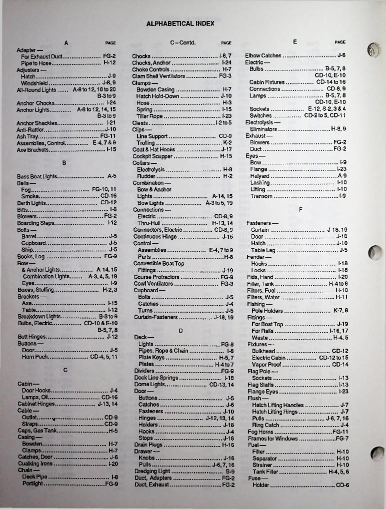
ALPHABETICAL INDEX
EC-Contd. PAGEA PAGE PAGE fAdapter—For Exhaust Duct.Pipe to Hose........
Adjusters —Hatch..................Windshield.........
All-Round Lights...
J-6Elbow Catches Electric—
Bulbs...........
1-6,7FG-2 Chocks...........................Chocks, Anchor............. .Choke Controls..............Clam Shell Ventilators.... Clamps —
Bowden Casing..........Hatch Hold-Down........Hose............................Spring.........................Tiller Rope...................
Cleats.............................Clips—
Line Support...............Trolling........................
Coat & Hat Hooks..........Cockpit Scupper............Collars—
Electrolysis..................Rudder........................
Combination —Bow & AnchorLights.........................Bow Lights..................
Connections —Electric.......................Thru-Hull.....................
Connectors, Electric.....Continuous Hinge.........Control —
Assemblies.................Parts...........................
Convertible Boat Top—Fittings.......................
Course Protractors........Cowl Ventilators...........
H-12 I-24.............B-5,7,8
CD-10, E-10...... CD-14 to 16............. CD-8,9............. B-5,7.8
CD-10, E-10 E-12, S-2,3 & 4
CD-2 to 5, CD-11
H-7J-9 FG-3
Cabin Fixtures Connections.. Lamps...........
.................. J-8,9A-8 to 12,18 to 20
B-3to9H-7
J-10I-24 H-3Anchor Chocks.
Anchor Lights... Sockets.......Switches.....
Electrolysis — Eliminators..
Exhaust—Blowers.......Duct...........
Eyes —Bow............Flange........Halyard......Lashing.......Lifting.........Transom....
1-15A-8 to 12,14,15 B-3 to 9 I-23
1-21 I-2 to 5Anchor Shackles.....Anti-Rattler..............Ash Tray..................Assemblies, Control. Axe Brackets..........
H-8,9J-10FG-11 CD-9
FG-2K-2E-4.7&9FG-21-15 J-17
H-15I-9B
I-23H-8A-9A-5 H-2Bass Boat Lights.
Bells— 1-101-10FG-10,11
__CD-16... CD-12
FogI-9.. A-14,15
A-3to 5,19Smoke....
Berth LightsI-8 FBitts.
FG-2 CD-8,9H-13,14CD-8,9
Blowers......................Boarding Steps..........Bolts—
Barrel.......................Cupboard...............Ship........................
Books, Log.................Bow—
& Anchor Lights.......Combination Lights.Eyes........................
Boxes, Stuffing...........Brackets—
1-12 Fasteners—Curtain......................Door...........................Hatch........................Table Leg..................
Fender—Hooks........................Locks........................
Fids, Hand...................Filler, Tank...................Filters, Fuel..................Filters, Water...............Fishing —
Pole Holders.............Fittings —
For Boat Top.............For Rails...................Waste.......................
Fixtures —Bulkhead..................Electric Cabin...........Vapor Proof..............
Flag Pole —Sockets.....................
Flag Staffs...................Flange Eyes.................Flush —
Hatch Lifting Handles Hatch Lifting Rings...Pulls..........................Ring Catch...............
Fog Horns...................Frames for Windows... Fuel —
Filter..........................Separator.................Strainer.....................Tank Filler.................
Fuse—Holder.......................
J-18,19J-5 J-10J-15J-5 J-10J-5 J-5E-4,7to9
FG-9 H-81-18
... A-14,15 A-3,4,5,19
1-18J-19I-20FG-9
I-9 FG-3 H-4to 6H-2,3 Cupboard— H-10
Bolts H-11J-51-15Axe. Catches............
Turns................Curtain-Fasteners
J-41-12Table...............
Breakdown Lights, Bulbs, Electric.....
K-7,8J-5........ B-3 to 9CD-10& E-10
J-18,19J-19
B-5,7,8 D 1-16,17 .. H-4,5Butt Hinges.,
Buttons —Door.........Horn Puch.
J-12 Deck—Lights.......................Pipes, Rope & ChainPlate Keys...............Plates.......................
Dividers......................Dock Line Springs.....Dome Lights...............Door—
Buttons....................Catches...................Fasteners................Hinges.....................Holders................... .Hooks......................Stops.......................
Drain Plugs.................Drawer—
Knobs......................Pulls
Dredging Light.Duct, Adapters Duct, Exhaust..
FG-8J-5 I-8 .......CD-12
CD-12 to 15 ....... CD-14
CD-4,5,11 .. H-5,7 H-4to7
C .FG-91-18 1-13
Cabin —Door Hooks..,Lamps, Oil__
Cabinet Hinges Cable—
Outlet.Straps,
Caps, Gas Tank. Casing—
Bowden......... .Clamps..........
Catches, Door.. Cualking Irons.. Chain—
Deck Pipe.....Portiight.........
CD-13,14 1-13J-4 I-23
.. CD-16 J-13,14
J-5J-6 J-7
J-10 J-7CD-9 J-12,13,14 .......... J-6,7,16TCD-9 J-18 J-4
H-5 J-4 FG-11J-18 FG-7
H-7 H-16H-7 H-10J-6 J-16 H-10I-20 J-6,7,16 H-10•••••••••••••••••••••••••••••••a
B-9 H-4.5.6I-8 FG-2
FG-9 FG-2 CD-6
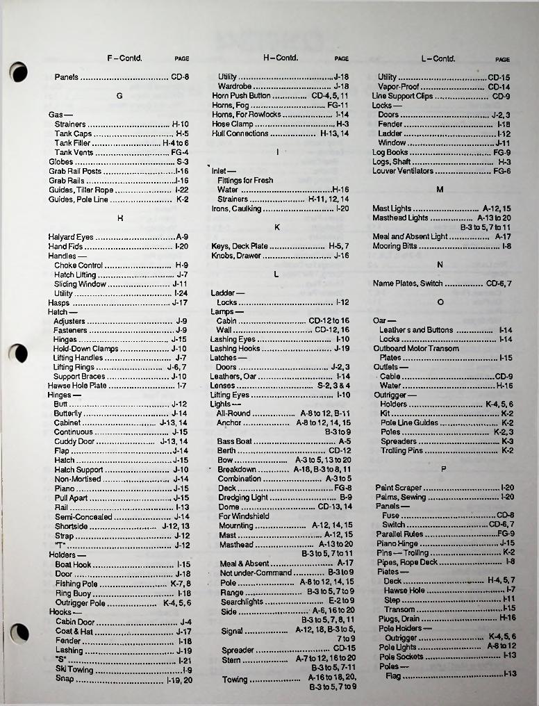
H-Contd.F-Contd. L-Contd.PAGE PAGE PAGE
Utility.....................Wardrobe..............
Horn Push Button....Horns, Fog...............Horns, For RowlocksHose Clamp.............Hull Connections.....
CD-8 J-18 Utility.................Vapor-Proof......
Line Support Clips Locks —
Doors............... .Fender..............Ladder..............Window.............
Log Books............Logs, Shaft..........Louver Ventilators
Panels CD-15CD-14J-18
CD-4,5,11 ......FG-11
G CD-9
1-14Gas —Strainers.............Tank Caps.........Tank Filler...........Tank Vents.........
Globes..................Grab Rail Posts....Grab Rails.............Guides, Tiller Rope Guides, Pole Line..
J-2,3H-3H-10 1-18
H-13,14H-5 1-12H-4 to 6 J-11
IFG-4 FG-9S-3 H-31-16 " Inlet—
Fittings for FreshWater...............Strainers.......... .
Irons, Caulking....
FG-6.1-16
H-16 MI-22H-11,12,14K-2
I-20 Mast Ughts........Masthead Lights
. A-12,15 A-13to20H
K B-3 to 5,7 to 11Meal and Absent Light Mooring Bitts..............
A-17Halyard Eyes...........Hand Fids.................Handles —
Choke Control.......Hatch Ufting......... .Sliding Window.....Utility......................
Hasps ......................Hatch —
Adjusters...............Fasteners..............Hinges...................Hold-Down ClampsLifting Handles.......Lifting Rings..........Support Braces.....
Hawse Hole Plate....
A-9Keys, Deck Plate Knobs, Drawer...
H-5,7I-20 I-8J-16
NH-9LJ-7
Name Plates, Switch CD-6,7J-11I-24 Ladder—
Locks..........Lamps —
Cabin..........Wall.............
Lashing Eyes.. Lashing Hooks Latches —
Doors...........Leathers, Oar.Lenses...........Ufting Eyes.... Lights —
All-Round.... Anchor........
1-12 OJ-17
CD-12 to 16 .. CD-12,16
Oar —Leather s and Buttons ..Locks............................
Outboard Motor TransomPlates...........................
Outlets —Cable............................Water........................... .
Outrigger—Holders.........................
J-9J-9 1-14
1-10 1-14J-15J-19J-10
J-7 1-15J-2,3J-6,7
1-14J-10 CD-9I-7 S-2.3&4 H-16
1-10Hinges —Butt J-12 K-4.5,6
A-8to12, B-11 A-8to 12,14,15
B-3 to 9
Butterfly.........Cabinet..........Continuous.... Cuddy Door...Flap...............Hatch.............Hatch Support Non-Mortised. Piano.............
J-14 Kit K-2J-13,14 Pole Une Guides
Poles................. .Spreaders.........Trolling Pins.......
K-2K-2.3J-15
K-3J-13,14 Bass Boat........Berth................Bow.................
■ Breakdown.....Combination...Deck................Dredging UghtDome............. .For WindshieldMournting.......Mast...............Masthead.......
A-5K-2J-14 ............... CD-12
A-3 to 5,13 to 20 A-18, B-3 to 8,11 .............. A-3 to 5
J-15PJ-10
J-14Paint Scraper.......Palms, Sewing..... Panels—
Fuse..................Switch...............
Parallel Rules......Piano Hinge.........Pins—Trolling .... Pipes, Rope Deck Plates—
Deck.................Hawse Hole.....Step..................Transom...........
Plugs, Drain........Pole Holders—
Outrigger.........Pole Ughts.........Pole Sockets......Poles—
I-20FG-8J-15I-20B-9J-15Pull Apart
CD-13,141-13RailCD-8J-14Semi-Concealed
Shortside...........Strap..................
CD-6,7....FG-9
.. A-12,14,15 ......... A-12,15..... A-13 to 20B-3 to 5,7 to 11
J-12,13J-12
J-15J-12T"K-2Holders —
Boat Hook.....Door..............Fishing Pole..Ring Buoy.....Outrigger Pole
Hooks —Cabin Door.... Coat & Hat....Fender...........Lashing.........
I-8A-17Meal & Absent..........J-18 • Not under-CommandK-7,8 Pole...........................
Range......................K-4,5,6 Searchlights..............
1-15............ B-3 to 9A-8to12,14.15 . B-3 to 5.7 to 9 ........... E-2to9
H-4,5,7I-71-18
HI1-15...... A-6,16 to 20
B-3 to 5,7,8,11 A-12,18, B-3 to 5,
SideH-16J-4
SignalJ-17 K-4,5.6 A-8to12
7 to 91-18.................CD-15A-7 to 12,16 to 20
B-3 to 5.7-11 ... A-16 to 18,20,
B-3 to 5,7 to 9
Spreader Stem.....
J-19 M3"S" 1-21Ski Towing I-9 1-13RagSnap Towing1-19,20

T-Contd. PAGES-Contd.P-Contd. PAGEPAGE
J-5Table Leg Fasteners..Terminal Blocks........Thimbles, Rope........Thru Hull Connections Tiller-
Rope Clamps ........Rope Guides.........Rope Pulleys.........Rope Tighteners.....
Towing Hooks..........Towing Lights..........
A-3 to 6,16 to 20 B-3 to 5,7,8,11
Outrigger...........Portlights..............Posts—
Grab Rail...........Stanchion..........
Protractors, CoursePulleys.................Pulls —
Drawer...............Flush.................
Pump Strainers.....
. K-2,3 FG-7,8
Side LightsCD-8
1-21Signal Lights, Portableor Fixed................
Ski Towing Hooks.....Skin Packed ProductsSmoke Bell & Arm.....Snap Hooks.............Sockets—
Boat Cover............Electric................Fishing Rod...........Flag Pole..............Rowlocks..............
H-13,14A-12, B-3 to 8,11.1-16I-91-16
I-23Section L ... CD-16 . 1-19,20
FG-9I-22I-22I-22I-23J-6,7,16
J-6,7,16 I-9J-19A-13to 18,20 B-3 to 5,7 to 9
CD-7, E-12, S-3,4 ............. K-7 to 9
H-16
Transom —1-13RI-9Eyes1-14
1-15Plates1-13StaffRail —Fittings................. .Hinges And Latches
Rails, Grab...............Range Lights...........
A-7Stern Light......Ventilators......
Tray, Ash..........Trim, Hatch........Trolling Pin........Tubing, Grab Rail Tri-Color Light.... Turns, Cupboard,
Section S . E-2&3
Spare Parts........... .Spotlights..............Spreaders.............Spreader Lights......Spring Clamps........Springs For Dockline Spring, Tiller Rope...Staffs, Flag............Steerer Parts..........Steps—
Boarding.............Folding...............
Step Plates............Stern—
Lights.................
1-16,17FG-5,6 . FG-11
1-13K-3.1-17
J-15CD-15...... A-13to20B-3 to 5,7,8,11 K-21-15
1-161-18J-2Rim Locks........Ring-
Buoy Holders .. Catches, FlushOn Plate........Pulls..............With Straps....
Rings —Brass.............Hatch Lifting...
Rope —Clamps.........Deck Pipe......Guides..........Pulleys..........Thimbles.......
Rope TightenersRowlocks.........Rudder—
Collars...........Stuffing Boxes,
Rules, Parallel...
A-5I-23J-51-131-18
J-6,7 H-8U1-10
J-6,7 1-12J-191-12 Utility Hooks
Utility Lights1-10
CD-151-111-10J-7 A-7 to 11,16 to 20
B-3 to 5,7 to 9 .......... A-8 to 12
V
Pole Lights Stop —
Door........Window....
Strainers—Fuel.........Gasoline...
CD-14.1-23 Vapor Proof Fixtures Ventilator—
Cowl......... .........Gas Tank........... .Locker................Louver................Shell Type..........Transom.............
1-8,FG-31-22 J-18
I-22 FG-4J-111-21 FG-5I-23 H-10 FG-61-14 H-10 FG-3
Hull H-12,13,14H-12,13,14
FG-5,6H-2 InletH-2 Pump.......
Water......Strap Hinges Straps —
Cable.......
H-16 W.FG-9 H-11
J-17J-12 Wardrobe HooksWaste Fitting.....Water Strainers..Whistles...........Window—
S H-4,5H-11CD-9
-S" Hooks....................Safety Cords................ .Sash—
Anti-Rattler................Scrapers.......................Screens, Portlight.........Scupper, Cockpit..........Seacocks.....................Searchlight Bulbs.........Searchlight Controls......Searchlights.................Separator, Fuel.............Shackles......................Shades for Cabin
Fixtures.....................Shaft Logs....................Shields—
For Fixtures...............For Pole or Mast Lights
1-21 Eye FG-11I-23H-5 Struts...........
Stuffing Boxes Switch —
Name Plate.Panels.......
Switches —Battery.......Electric.......Master.......Panels.......
Swivel —Eye Pulleys. Eye Snaps..
H-3J-11H-2,3 Handle, Sliding
J-11 J-11LockI-20 J-11CD-6,7
CD-6,7Stop...............
Windows........... Windshield —
Adjusters........Keeper & Plate Pole Light for...Wipers...........
Wire—Bowden.........Rope Thimbles
FG-8 FG-7H-15H-12 J-8,9..CD-2,3
CD-2 to 7E-10 J-9E-4.7&9 . E-2 to 9
CD-3 A-12,14,15CD-6,7 1-15
H-101-21 H-7I-22
1-19 1-21CD-12
H-3 T Z
CD-12 T-Hinges......Table Brackets
J-12 H-8,9ZincsA-14 1-12

1
PERKO INC.
RESERVED FORNOTES AND NEW PRODUCTS TO COME
*■
'
PERKO INC.
RESERVED FORNOTES AND NEW PRODUCTS TO COME
'
PERKO INC
RESERVED FORNOTES AND NEW PRODUCTS TO COME
i
I

PERKO INC.
RESERVED FORNOTES AND NEW PRODUCTS TO COME
fete;
________

WE ARE MEMBERS OF THE FOLLOWING
MARINE ASSOCIATIONS
NATIONAL MARINE
MANUFACTURERS ASSOCIATIONNMM,4
AMERICAN BOAT AND YACHT COUNCIL, INC. CHARTER MEMBER
THE PROPELLER CLUB OF THE
UNITED STATES
MARINE RETAILERS ASSOCIATION
OF AMERICA


![Tiernan Humphrys.ppt [Read-Only]](https://static.fdokumen.com/doc/165x107/631e0aba5ff22fc7450683ec/tiernan-humphrysppt-read-only.jpg)