Paving, Grading, and Drainage Improvements to serve Yukon ...
154
GEOTECHNICAL REPORT, SPECIFICATIONS, AND BID ITEMS FOR Paving, Grading, and Drainage Improvements to serve Yukon Road Extension COUNTY JUDGE Terry Johnson COUNTY COMMISSIONERS Scott Ramsey – Precinct 1 Robin Donnelly – Precinct 2 Luis D. Sanchez – Precinct 3 Randy Prude – Precinct 4 PREPARED BY Dunaway No. B001484.017 April 2021 ATTACHMENT A
-
Upload
khangminh22 -
Category
Documents
-
view
3 -
download
0
Transcript of Paving, Grading, and Drainage Improvements to serve Yukon ...

GEOTECHNICAL REPORT, SPECIFICATIONS, AND BID ITEMS
FOR
Paving, Grading, and Drainage Improvements
to serve
Yukon Road Extension
COUNTY JUDGE
Terry Johnson
COUNTY COMMISSIONERS
Scott Ramsey – Precinct 1
Robin Donnelly – Precinct 2
Luis D. Sanchez – Precinct 3
Randy Prude – Precinct 4
PREPARED BY
Dunaway No. B001484.017
April 2021
ATTACHMENT A

TABLE OF CONTENTS
PART A – Standard Specifications
PART B – Guide Schedule of Sampling and Testing – June 2019**
PART C – Geotechnical Report of Existing Conditions
PART D – Bid Quantities
**Laboratory and Field Testing to be provided by the County and is not considered a part of this bid.

PART A
STANDARD SPECIFICATIONS

216
125
Item 216
Proof Rolling
1. DESCRIPTION
Proof-roll earthwork, base, or both to locate unstable areas.
2. EQUIPMENT
2.1. Specified Equipment. Furnish rollers that weigh at least 25 tons when loaded. The maximum acceptable load is 50 tons. Provide rollers that meet the requirements of Section 210.2.4., “Pneumatic Tire Rollers.”
2.2. Alternative Equipment. The Contractor may use alternate compaction equipment that produces results equivalent to the specified equipment in the same period of time as approved. Discontinue the use of the alternative equipment and furnish the specified equipment if the desired results are not achieved.
3. CONSTRUCTION
Perform proof rolling as directed. Adjust the load and tire inflation pressures within the range of the manufacturer’s charts or tabulations, as directed. Make at least 2 coverages with the proof roller. Offset each trip of the roller by at most one tire width. Operate rollers at a speed between 2 and 6 mph, as directed. Correct unstable or nonuniform areas, if found, in accordance with the applicable Item.
4. MEASUREMENT
Rolling will be measured by the hour operated on surfaces being tested.
5. PAYMENT
The work performed and equipment furnished in accordance with this Item and measured as provided under “Measurement” will be paid for at the unit price bid for “Proof Rolling.” This price is full compensation for furnishing and operating equipment and for labor, materials, tools, and incidentals.

247
126
Item 247
Flexible Base
1. DESCRIPTION
Construct a foundation course composed of flexible base.
2. MATERIALS
Furnish uncontaminated materials of uniform quality that meet the requirements of the plans and specifications. Notify the Engineer of the proposed material sources and of changes to material sources. The Engineer may sample and test project materials at any time before compaction throughout the duration of the project to assure specification compliance. Use Tex-100-E material definitions.
2.1. Aggregate. Furnish aggregate of the type and grade shown on the plans and meeting the requirements of Table 1. Each source must meet Table 1 requirements for liquid limit, plasticity index, and wet ball mill for the grade specified. Do not use additives, such as but not limited to lime, cement, or fly ash to modify aggregates to meet the requirements of Table 1 unless shown on the plans.
Table 1 Material Requirements
2.1.1. Material Tolerances. The Engineer may accept material if no more than 1 of the 5 most recent gradation tests has an individual sieve outside the specified limits of the gradation.
When target grading is required by the plans, no single failing test may exceed the master grading by more than 5 percentage points on sieves No. 4 and larger or 3 percentage points on sieves smaller than No. 4.
Property Test Method Grade 1–2 Grade 3 Grade 42 Grade 5
Sampling Tex-400-A
Master gradation sieve size (cumulative % retained)
Tex-110-E
2-1/2" 0 0
As shown on the plans
0
1-3/4" 0–10 0–10 0–5
7/8" 10–35 – 10–35
3/8" 30–65 – 35–65
#4 45–75 45–75 45–75
#40 65–90 50–85 70–90
Liquid Limit, % Max Tex-104-E 40 40 As shown on
the plans 35
Plasticity Index, Max1
Tex-106-E
10 12 As shown on
the plans 10
Plasticity index, Min1 As shown on
the plans As shown on the
plans As shown on
the plans As shown on
the plans
Wet ball mill, % Max Tex-116-E
40 – As shown on
the plans 40
Wet ball mill, % Max increase passing the #40 sieve
20 – As shown on
the plans 20
Min compressive strength, psi
Tex-117-E
As shown on the plans
lateral pressure 0 psi 35 – –
lateral pressure 3 psi – – 90
lateral pressure 15 psi 175 – 175
1. Determine plastic index in accordance with Tex-107-E (linear shrinkage) when liquid limit is unattainable as defined in Tex-104-E.
2. Grade 4 may be further designated as Grade 4A, Grade 4B, etc.

247
127
The Engineer may accept material if no more than 1 of the 5 most recent plasticity index tests is outside the specified limit. No single failing test may exceed the allowable limit by more than 2 points.
2.1.2. Material Types. Do not use fillers or binders unless approved. Furnish the type specified on the plans in accordance with the following:
2.1.2.1. Type A. Crushed stone produced and graded from oversize quarried aggregate that originates from a single, naturally occurring source. Do not use gravel or multiple sources.
2.1.2.2. Type B. Crushed or uncrushed gravel. Blending of 2 or more sources is allowed.
2.1.2.3. Type C. Crushed gravel with a minimum of 60% of the particles retained on a No. 4 sieve with 2 or more crushed faces as determined by Tex-460-A, Part I. Blending of 2 or more sources is allowed.
2.1.2.4. Type D. Type A material or crushed concrete. Crushed concrete containing gravel will be considered Type D material. Crushed concrete must meet the requirements in Section 247.2.1.3.2., “Recycled Material (Including Crushed Concrete) Requirements,” and be managed in a way to provide for uniform quality. The Engineer may require separate dedicated stockpiles in order to verify compliance.
2.1.2.5. Type E. Caliche, iron ore or as otherwise shown on the plans.
2.1.3. Recycled Material. Reclaimed asphalt pavement (RAP) and other recycled materials may be used when shown on the plans. Request approval to blend 2 or more sources of recycled materials.
2.1.3.1. Limits on Percentage. Do not exceed 20% RAP by weight, when RAP is allowed, unless otherwise shown on the plans. The percentage limitations for other recycled materials will be as shown on the plans.
2.1.3.2. Recycled Material (Including Crushed Concrete) Requirements.
2.1.3.2.1. Contractor-Furnished Recycled Materials. Provide recycled materials, other than RAP, that have a maximum sulfate content of 3,000 ppm when tested in accordance with Tex-145-E. When the Contractor furnishes the recycled materials, including crushed concrete, the final product will be subject to the requirements of Table 1 for the grade specified. Certify compliance with DMS-11000, “Evaluating and Using Nonhazardous Recyclable Materials Guidelines,” for Contractor furnished recycled materials. In addition, recycled materials must be free from reinforcing steel and other objectionable material and have at most 1.5% deleterious material when tested in accordance with Tex-413-A. For RAP, do not exceed a maximum percent loss from decantation of 5.0% when tested in accordance with Tex-406-A. Test RAP without removing the asphalt.
2.1.3.2.2. Department-Furnished Required Recycled Materials. When the Department furnishes and requires the use of recycled materials, unless otherwise shown on the plans:
Department-required recycled material will not be subject to the requirements in Table 1,
Contractor-furnished materials are subject to the requirements in Table 1 and this Item,
the final product, blended, will be subject to the requirements in Table 1, and
for final product, unblended (100% Department-furnished required recycled material), the liquid limit,
plasticity index, wet ball mill, and compressive strength is waived.
Crush Department-furnished RAP so that 100% passes the 2 in. sieve. The Contractor is responsible for uniformly blending to meet the percentage required.
2.1.3.2.3. Department-Furnished and Allowed Recycled Materials. When the Department furnishes and allows the use of recycled materials or allows the Contractor to furnish recycled materials, the final blended product is subject to the requirements of Table 1 and the plans.

247
128
2.1.3.3. Recycled Material Sources. Department-owned recycled material is available to the Contractor only when shown on the plans. Return unused Department-owned recycled materials to the Department stockpile location designated by the Engineer unless otherwise shown on the plans.
The use of Contractor-owned recycled materials is allowed when shown on the plans. Contractor-owned surplus recycled materials remain the property of the Contractor. Remove Contractor-owned recycled materials from the project and dispose of them in accordance with federal, state, and local regulations before project acceptance. Do not intermingle Contractor-owned recycled material with Department-owned recycled material unless approved.
2.2. Water. Furnish water free of industrial wastes and other objectionable matter.
2.3. Material Sources. Expose the vertical faces of all strata of material proposed for use when non-commercial sources are used. Secure and process the material by successive vertical cuts extending through all exposed strata, when directed.
3. EQUIPMENT
Provide machinery, tools, and equipment necessary for proper execution of the work.
3.1. Provide rollers in accordance with Item 210, “Rolling.” Provide proof rollers in accordance with Item 216, “Proof Rolling,” when required.
3.2. When ride quality measurement is required, provide a high speed or lightweight inertial profiler certified at the Texas A&M Transportation Institute. Provide equipment certification documentation. Display a current decal on the equipment indicating the certification expiration date.
4. CONSTRUCTION
Construct each layer uniformly, free of loose or segregated areas, and with the required density and moisture content. Provide a smooth surface that conforms to the typical sections, lines, and grades shown on the plans or as directed.
Stockpile base material temporarily at an approved location before delivery to the roadway. Build stockpiles in layers no greater than 2 ft. thick. Stockpiles must have a total height between 10 and 16 ft. unless otherwise approved. After construction and acceptance of the stockpile, loading from the stockpile for delivery is allowed. Load by making successive vertical cuts through the entire depth of the stockpile.
Do not add or remove material from temporary stockpiles that require sampling and testing before delivery unless otherwise approved. Charges for additional sampling and testing required as a result of adding or removing material will be deducted from the Contractor’s estimates.
Haul approved flexible base in clean trucks. Deliver the required quantity to each 100-ft. station or designated stockpile site as shown on the plans. Prepare stockpile sites as directed. When delivery is to the 100-ft. station, manipulate in accordance with the applicable Items.
4.1. Preparation of Subgrade or Existing Base. Remove or scarify existing asphalt concrete pavement in accordance with Item 105, “Removing Treated and Untreated Base and Asphalt Pavement,” when shown on the plans or as directed. Shape the subgrade or existing base to conform to the typical sections shown on the plans or as directed.
When new base is required to be mixed with existing base, deliver, place, and spread the new flexible base in the required amount per station. Manipulate and thoroughly mix the new base with existing material to provide a uniform mixture to the specified depth before shaping.

247
129
Proof roll the roadbed in accordance with Item 216, “Proof Rolling,” before pulverizing or scarifying when shown on the plans or directed. Correct soft spots as directed.
4.2. Placing. Spread and shape flexible base into a uniform layer with an approved spreader the same day as delivered unless otherwise approved. Construct layers to the thickness shown on the plans. Maintain the shape of the course. Control dust by sprinkling, as directed. Correct or replace segregated areas as directed, at no additional expense to the Department.
Place successive base courses and finish courses using the same construction methods required for the first course.
4.3. Compaction. Compact using density control unless otherwise shown on the plans. Multiple lifts are permitted when shown on the plans or approved. Bring each layer to the moisture content directed. When necessary, sprinkle the material in accordance with Item 204, “Sprinkling.”
Begin rolling longitudinally at the sides and proceed towards the center, overlapping on successive trips by at least 1/2 the width of the roller unit. Begin rolling at the low side and progress toward the high side on superelevated curves. Offset alternate trips of the roller. Operate rollers at a speed between 2 and 6 mph as directed.
Rework, recompact, and refinish material that fails to meet or that loses required moisture, density, stability, or finish requirements before the next course is placed or the project is accepted. Continue work until specification requirements are met. Perform the work at no additional expense to the Department.
Before final acceptance, the Engineer will select the locations of tests and measure the flexible base depth in accordance with Tex-140-E. Correct areas deficient by more than 1/2 in. in thickness by scarifying, adding material as required, reshaping, recompacting, and refinishing at the Contractor’s expense.
4.3.1. Ordinary Compaction. Roll with approved compaction equipment as directed. Correct irregularities, depressions, and weak spots immediately by scarifying the areas affected, adding or removing approved material as required, reshaping, and recompacting.
4.3.2. Density Control. Compact to at least 100% of the maximum dry density determined by Tex-113-E, unless otherwise shown on the plans. Maintain moisture during compaction within ±2 percentage points of the optimum moisture content as determined by Tex-113-E. Measure the moisture content of the material in accordance with Tex-115-E or Tex-103-E during compaction daily and report the results the same day to the Engineer, unless otherwise shown on the plans or directed. Do not achieve density by drying the material after compaction.
The Engineer will determine roadway density and moisture content of completed sections in accordance with Tex-115-E. The Engineer may accept the section if no more than 1 of the 5 most recent density tests is below the specified density and the failing test is no more than 3 pcf below the specified density.
4.4. Finishing. After completing compaction, clip, skin, or tight-blade the surface with a maintainer or subgrade trimmer to a depth of approximately 1/4 in. Remove loosened material and dispose of it at an approved location. Seal the clipped surface immediately by rolling with a pneumatic tire roller until a smooth surface is attained. Add small increments of water as needed during rolling. Shape and maintain the course and surface in conformity with the typical sections, lines, and grades as shown on the plans or as directed.
Correct grade deviations greater than 1/4 in. in 16 feet measured longitudinally or greater than 1/4 in. over the entire width of the cross-section in areas where surfacing is to be placed. Correct by loosening and adding, or removing material. Reshape and re-compact in accordance with Section 247.4.3., “Compaction.”
4.5. Curing. Cure the finished section until the moisture content is at least 2 percentage points below optimum or as directed before applying the next successive course or prime coat.

247
130
4.6. Ride Quality. This section applies to the final travel lanes that receive a 1 or 2 course surface treatment for the final surface, unless otherwise shown on the plans. Measure ride quality of the base course after placement of the prime coat and before placement of the surface treatment, unless otherwise approved. Use a certified profiler operator from the Department’s MPL. When requested, furnish the Engineer documentation for the person certified to operate the profiler.
Provide all profile measurements to the Engineer in electronic data files within 3 days after placement of the prime coat using the format specified in Tex-1001-S. The Engineer will use Department software to evaluate longitudinal profiles to determine areas requiring corrective action. Correct 0.1-mi.sections having an average international roughness index (IRI) value greater than 100.0 in. per mile to an IRI value of 100.0 in. per mile or less for each wheel path, unless otherwise shown on the plans.
Re-profile and correct sections that fail to maintain ride quality until placement of the next course, as directed. Correct re-profiled sections until specification requirements are met, as approved. Perform this work at no additional expense to the Department.
5. MEASUREMENT
Flexible base will be measured as follows:
Flexible Base (Complete In Place). The ton, square yard, or any cubic yard method.
Flexible Base (Roadway Delivery). The ton or any cubic yard method.
Flexible Base (Stockpile Delivery). The ton, cubic yard in vehicle, or cubic yard in stockpile.
Measurement by the cubic yard in final position and square yard is a plans quantity measurement. The quantity to be paid for is the quantity shown in the proposal unless modified by Article 9.2., “Plans Quantity Measurement.” Additional measurements or calculations will be made if adjustments of quantities are required.
Measurement is further defined for payment as follows.
5.1. Cubic Yard in Vehicle. By the cubic yard in vehicles of uniform capacity at the point of delivery.
5.2. Cubic Yard in Stockpile. By the cubic yard in the final stockpile position by the method of average end areas.
5.3. Cubic Yard in Final Position. By the cubic yard in the completed and accepted final position. The volume of base course is computed in place by the method of average end areas between the original subgrade or existing base surfaces and the lines, grades, and slopes of the accepted base course as shown on the plans.
5.4. Square Yard. By the square yard of surface area in the completed and accepted final position. The surface area of the base course is based on the width of flexible base as shown on the plans.
5.5. Ton. By the ton of dry weight in vehicles as delivered. The dry weight is determined by deducting the weight of the moisture in the material at the time of weighing from the gross weight of the material. The Engineer will determine the moisture content in the material in accordance with Tex-103-E from samples taken at the time of weighing.
When material is measured in trucks, the weight of the material will be determined on certified scales, or the Contractor must provide a set of standard platform truck scales at a location approved by the Engineer. Scales must conform to the requirements of Item 520, “Weighing and Measuring Equipment.”
6. PAYMENT
The work performed and materials furnished in accordance with this Item and measured as provided under “Measurement” will be paid for at the unit price bid for the types of work shown below. No additional payment

247
131
will be made for thickness or width exceeding that shown on the typical section or provided on the plans for cubic yard in the final position or square yard measurement.
Sprinkling and rolling, except proof rolling, will not be paid for directly but will be subsidiary to this Item unless otherwise shown on the plans. When proof rolling is shown on the plans or directed, it will be paid for in accordance with Item 216, “Proof Rolling.”
Where subgrade is constructed under this Contract, correction of soft spots in the subgrade will be at the Contractor’s expense. Where subgrade is not constructed under this Contract, correction of soft spots in the subgrade will be paid in accordance with pertinent Items or Article 4.4., “Changes in the Work.”
6.1. Flexible Base (Complete In Place). Payment will be made for the type and grade specified. For cubic yard measurement, “In Vehicle,” “In Stockpile,” or “In Final Position” will be specified. For square yard measurement, a depth will be specified. This price is full compensation for furnishing materials, temporary stockpiling, assistance provided in stockpile sampling and operations to level stockpiles for measurement, loading, hauling, delivery of materials, spreading, blading, mixing, shaping, placing, compacting, reworking, finishing, correcting locations where thickness is deficient, curing, furnishing scales and labor for weighing and measuring, and equipment, labor, tools, and incidentals.
6.2. Flexible Base (Roadway Delivery). Payment will be made for the type and grade specified. For cubic yard measurement, “In Vehicle,” “In Stockpile,” or “In Final Position” will be specified. The unit price bid will not include processing at the roadway. This price is full compensation for furnishing materials, temporary stockpiling, assistance provided in stockpile sampling and operations to level stockpiles for measurement, loading, hauling, delivery of materials, furnishing scales and labor for weighing and measuring, and equipment, labor, tools, and incidentals.
6.3. Flexible Base (Stockpile Delivery). Payment will be made for the type and grade specified. For cubic yard measurement, “In Vehicle” or “In Stockpile” will be specified. The unit price bid will not include processing at the roadway. This price is full compensation for furnishing and disposing of materials, preparing the stockpile area, temporary or permanent stockpiling, assistance provided in stockpile sampling and operations to level stockpiles for measurement, loading, hauling, delivery of materials to the stockpile, furnishing scales and labor for weighing and measuring, and equipment, labor, tools, and incidentals.

300
173
Item 300
Asphalts, Oils, and Emulsions
1. DESCRIPTION
Provide asphalt cements, cutback and emulsified asphalts, performance-graded asphalt binders, and other miscellaneous asphalt materials as specified on the plans.
2. MATERIALS
Provide asphalt materials that meet the stated requirements when tested in accordance with the referenced Department, AASHTO, and ASTM test methods. Use asphalt containing recycled materials only if the recycled components meet the requirements of Article 6.9, “Recycled Materials.” Provide asphalt materials that have been preapproved for use by the Construction Division in accordance with Tex-545-C, “Asphalt Binder Quality Program.”
Acronyms used in this Item are defined in Table 1.
Table 1 Acronyms
Acronym Definition
Test Procedure Designations
Tex Department T or R AASHTO D ASTM
Polymer Modifier Designations
P polymer-modified SBR or L styrene-butadiene rubber (latex) SBS styrene-butadiene-styrene block co-polymer TR tire rubber (from ambient temperature grinding of truck and
passenger tires)
AC asphalt cement
AE asphalt emulsion
AE-P asphalt emulsion prime
A-R asphalt-rubber
C cationic
EAP&T emulsified asphalt prime and tack
H-suffix harder residue (lower penetration)
HF high float
MC medium-curing
MS medium-setting
PCE prime, cure, and erosion control
PG performance grade
RC rapid-curing
RS rapid-setting
S-suffix stockpile usage
SCM special cutback material
SS slow-setting

300
174
2.1. Asphalt Cement. Provide asphalt cement that is homogeneous, water-free, and nonfoaming when heated to 347°F, and meets the requirements in Table 2.
Table 2 Asphalt Cement
Property Test
Procedure
Viscosity Grade
AC-0.6 AC-1.5 AC-3 AC-5 AC-10
Min Max Min Max Min Max Min Max Min Max
Viscosity T 202 140°F, poise 40 80 100 200 250 350 400 600 800 1,200 275°F, poise 0.4 – 0.7 – 1.1 – 1.4 – 1.9 –
Penetration, 77°F, 100g, 5 sec.
T 49 350 – 250 – 210 – 135 – 85 –
Flash point, C.O.C., °F T 48 425 – 425 – 425 – 425 – 450 –
Solubility in trichloroethylene, %
T 44 99.0 – 99.0 – 99.0 – 99.0 – 99.0 –
Spot test Tex-509-C Neg. Neg. Neg. Neg. Neg.
Tests on residue from Thin-Film Oven Test: T 179
Viscosity, 140°F, poise T 202 – 180 – 450 – 900 – 1,500 – 3,000 Ductility,1 77°F
T 51 100 – 100 – 100 – 100 – 100 – 5 cm/min., cm
1. If AC-0.6 or AC-1.5 ductility at 77°F is less than 100 cm, material is acceptable if ductility at 60°F is more than 100 cm.
2.2. Polymer-Modified Asphalt Cement. Provide polymer-modified asphalt cement that is smooth, homogeneous, and meets the requirements of Table 3. Supply samples of the base asphalt cement and polymer additives if requested.
Table 3 Polymer-Modified Asphalt Cement
Property Test
Procedure
Polymer-Modified Viscosity Grade
AC-5 w/2% SBR
AC-10 w/2% SBR
AC-15P AC-20XP AC-10-2TR AC-20-5TR
Min Max Min Max Min Max Min Max Min Max Min Max
Polymer SBR SBR SBS SBS TR TR
Polymer content, % (solids basis) Tex-533-C 2.0 – 2.0 – 3.0 – – – 2.0 – 5.0 –
Dynamic shear, G*/sin , 64°C, 10 rad/s, kPa T 315 – – – – – –
1.0
– – – 1.0 –
Dynamic shear, G*/sin , 58°C, 10 rad/s, kPa T 315 – – – – – –
– – 1.0 – – –
Viscosity 140°F, poise T 202 700 – 1,300 – 1,500 – 2,000 – 1,000 – 2,000 – 275°F, poise T 202 – 7.0 – 8.0 – 8.0 – – – 8.0 – 10.0
Penetration, 77°F, 100 g, 5 sec. T 49 120 – 80 – 100 150 75 115 95 130 75 115
Ductility, 5cm/min., 39.2°F, cm T 51 70 – 60 – – – – – – – – –
Elastic recovery, 50°F, % Tex-539-C – – – – 55 – 55 – 30 – 55 –
Softening point, °F T 53 – – – – – – 120 – 110 – 120 –
Polymer separation, 48 hr. Tex-540-C None None None None None None
Flash point, C.O.C., °F T 48 425 – 425 – 425 – 425 – 425 – 425 –
Tests on residue from RTFOT aging and pressure aging:
Tex-541-C and R 28
Creep stiffness T 313 S, -18°C, MPa – – – – – 300 – 300 – 300 – 300 m-value, -18°C – – – – 0.300 – 0.300 – 0.300 – 0.300 –

300
175
2.3. Cutback Asphalt. Provide cutback asphalt that meets the requirements of Tables 4, 5, and 6 for the specified type and grade. Supply samples of the base asphalt cement and polymer additives if requested.
Table 4 Rapid-Curing Cutback Asphalt
Property Test
Procedure Type–Grade
RC-250 RC-800 RC-3000
Min Max Min Max Min Max
Kinematic viscosity, 140°F, cSt T 201 250 400 800 1,600 3,000 6,000
Water, % D95 – 0.2 – 0.2 – 0.2
Flash point, T.O.C., °F T 79 80 – 80 – 80 –
Distillation test: T 78 Distillate, percentage by volume of total
distillate to 680°F to 437°F 40 75 35 70 20 55 to 500°F 65 90 55 85 45 75 to 600°F 85 – 80 – 70 – Residue from distillation, volume % 70 – 75 – 82 –
Tests on distillation residue: Viscosity, 140°F, poise T 202 600 2400 600 2400 600 2400 Ductility, 5 cm/min., 77°F, cm T 51 100 – 100 – 100 – Solubility in trichloroethylene, % T 44 99.0 – 99.0 – 99.0 – Spot test Tex-509-C Neg. Neg. Neg.
Table 5
Medium-Curing Cutback Asphalt
Property Test
Procedure
Type–Grade
MC-30 MC-250 MC-800 MC-3000
Min Max Min Max Min Max Min Max
Kinematic viscosity, 140°F, cSt T 201 30 60 250 500 800 1,600 3,000 6,000
Water, % D95 – 0.2 – 0.2 – 0.2 – 0.2
Flash point, T.O.C., °F T 79 95 – 122 – 140 – 149 –
Distillation test: T 78
Distillate, percentage by volume of total distillate to 680°F
to 437°F – 35 – 20 – – – – to 500°F 30 75 5 55 – 40 – 15 to 600°F 75 95 60 90 45 85 15 75
Residue from distillation, volume % 50 – 67 – 75 – 80 –
Tests on distillation residue: Viscosity, 140°F, poise T 202 300 1200 300 1200 300 1200 300 1200 Ductility, 5 cm/min., 77°F, cm T 51 100 – 100 – 100 – 100 – Solubility in trichloroethylene, % T 44 99.0 – 99.0 – 99.0 – 99.0 – Spot test Tex-509-C Neg. Neg. Neg. Neg.

300
176
Table 6 Special-Use Cutback Asphalt
Property Test
Procedure
Type–Grade
MC-2400L SCM I SCM II
Min Max Min Max Min Max
Kinematic viscosity, 140°F, cSt T 201 2,400 4,800 500 1,000 1,000 2,000
Water, % D95 – 0.2 – 0.2 – 0.2
Flash point, T.O.C., °F T 79 150 – 175 – 175 –
Distillation test: T 78 Distillate, percentage by volume of total distillate to 680°F to 437°F – – – – – – to 500°F – 35 – 0.5 – 0.5 to 600°F 35 80 20 60 15 50 Residue from distillation, volume % 78 – 76 – 82 –
Tests on distillation residue: Polymer SBR – – Polymer content, % (solids basis) Tex-533-C 2.0 – – – – – Penetration, 100 g, 5 sec., 77°F T 49 150 300 180 – 180 – Ductility, 5 cm/min., 39.2°F, cm T 51 50 – – – – – Solubility in trichloroethylene, % T 44 99.0 – 99.0 – 99.0 –
2.4. Emulsified Asphalt. Provide emulsified asphalt that is homogeneous, does not separate after thorough mixing, and meets the requirements for the specified type and grade in Tables 7, 8, 9, and 10.
Table 7
Emulsified Asphalt
Property Test
Procedure
Type–Grade
Rapid-Setting Medium-Setting Slow-Setting
HFRS-2 MS-2 AES-300 SS-1 SS-1H
Min Max Min Max Min Max Min Max Min Max
Viscosity, Saybolt Furol T 72 77°F, sec. – – – – 75 400 20 100 20 100 122°F, sec. 150 400 100 300 – – – – – –
Sieve test, % T 59 – 0.1 – 0.1 – 0.1 – 0.1 – 0.1
Miscibility T 59 – – – Pass Pass
Cement mixing, % T 59 – – – – – – – 2.0 – 2.0
Coating ability and water resistance:
T 59
Dry aggregate/after spray – – Good/Fair – – Wet aggregate/after
spray – – Fair/Fair – –
Demulsibility, 35 ml of 0.02 N CaCl2, %
T 59 50 – – 30 – – – – – –
Storage stability, 1 day, % T 59 – 1 – 1 – 1 – 1 – 1
Freezing test, 3 cycles1 T 59 – Pass – Pass Pass
Distillation test: T 59 Residue by distillation, %
by wt. 65 – 65 – 65 – 60 – 60 –
Oil distillate, % by volume of emulsion
– 0.5 – 0.5 – 5 – 0.5 – 0.5
Tests on residue from distillation:
Penetration, 77°F, 100 g, 5 sec.
T 49 100 140 120 160 300 – 120 160 70 100
Solubility in trichloroethylene, %
T 44 97.5 – 97.5 97.5 – 97.5 – 97.5 –
Ductility, 77°F, 5 cm/min., cm
T 51 100 – 100 – – 100 – 80 –
Float test, 140°F, sec. T 50 1,200 – – 1,200 – – – – –
1. Applies only when the Engineer designates material for winter use.

300
177
Table 8 Cationic Emulsified Asphalt
Property Test
Procedure
Type–Grade
Rapid-Setting Medium-Setting Slow-Setting
CRS-2 CRS-2H CMS-2 CMS-2S CSS-1 CSS-1H
Min Max Min Max Min Max Min Max Min Max Min Max
Viscosity, Saybolt Furol T 72
77°F, sec. – – – – – – – – 20 100 20 100 122°F, sec. 150 400 150 400 100 300 100 300 – – – –
Sieve test, % T 59 – 0.1 – 0.1 – 0.1 – 0.1 – 0.1 – 0.1
Cement mixing, % T 59 – – – – – – – – – 2.0 – 2.0
Coating ability and water resistance: T 59
Dry aggregate/after spray – – Good/Fair Good/Fair – – Wet aggregate/after spray – – Fair/Fair Fair/Fair – –
Demulsibility, 35 ml of 0.8% Sodium dioctyl sulfosuccinate, %
T 59 70 – 70 – – – – – – – – –
Storage stability, 1 day, % T 59 – 1 – 1 – 1 – 1 – 1 – 1
Particle charge T 59 Positive Positive Positive Positive Positive Positive
Distillation test:
T 59
Residue by distillation, % by wt. 65 – 65 – 65 – 65 – 60 – 60 – Oil distillate, % by volume of
emulsion – 0.5 – 0.5 – 7 – 5 – 0.5 – 0.5
Tests on residue from distillation: Penetration, 77°F, 100 g, 5 sec. T 49 120 160 70 110 120 200 300 – 120 160 70 110 Solubility in trichloroethylene, % T 44 97.5 – 97.5 – 97.5 – 97.5 – 97.5 – 97.5 – Ductility, 77°F, 5 cm/min., cm T 51 100 – 80 – 100 – – – 100 – 80 –
Table 9
Polymer-Modified Emulsified Asphalt
Property Test
Procedure
Type–Grade
Rapid-Setting Medium-Setting Slow-Setting
RS-1P HFRS-2P AES-150P AES-300P AES-300S SS-1P
Min Max Min Max Min Max Min Max Min Max Min Max
Viscosity, Saybolt Furol T 72 77°F, sec. – – – – 75 400 75 400 75 400 30 100 122°F, sec. 50 200 150 400 – – – – – – – –
Sieve test, % T 59 – 0.1 – 0.1 – 0.1 – 0.1 – 0.1 – 0.1
Miscibility T 59 – – – – – Pass
Coating ability and water resistance: T 59 Dry aggregate/after spray – – Good/Fair Good/Fair Good/Fair – Wet aggregate/after spray – – Fair/Fair Fair/Fair Fair/Fair –
Demulsibility, 35 ml of 0.02 N CaCl2, % T 59 60 – 50 – – – – – – – – –
Storage stability, 1 day, % T 59 – 1 – 1 – 1 – 1 – 1 – 1
Breaking index, g Tex-542-C – 80 – – – – – – – – – –
Distillation test:1 T 59 Residue by distillation, % by wt. 65 – 65 – 65 – 65 – 65 – 60 – Oil distillate, % by volume of
emulsion – 3 – 0.5 – 3 – 5 – 7 – 0.5
Tests on residue from distillation: Polymer content, wt. % (solids basis) Tex-533-C – – 3.0 – – – – – – – 3.0 – Penetration, 77°F, 100 g, 5 sec. T 49 225 300 90 140 150 300 300 – 300 – 100 140 Solubility in trichloroethylene, % T 44 97.0 – 97.0 – 97.0 – 97.0 – 97.0 – 97.0 – Viscosity, 140°F, poise T 202 – – 1,500 – – – – – – – 1,300 – Float test, 140°F, sec. T 50 – – 1,200 – 1,200 – 1,200 – 1,200 – – – Ductility,2 39.2°F, 5 cm/min., cm T 51 – – 50 – – – – – – – 50 – Elastic recovery,2 50°F, % Tex-539-C 55 – 55 – – – – – – – – –
Tests on RTFO curing of distillation residue Tex-541-C Elastic recovery, 50°F, % Tex-539-C – – – – 50 – 50 – 30 – – –
1. Exception to T 59: Bring the temperature on the lower thermometer slowly to 350°F ±10°F. Maintain at this temperature for 20 min. Complete total distillation in 60 min. (±5 min.) from the first application of heat.
2. HFRS-2P must meet one of either the ductility or elastic recovery requirements.

300
178
Table 10 Polymer-Modified Cationic Emulsified Asphalt
Property Test
Procedure
Type-Grade
Rapid-Setting Medium-Setting Slow-Setting
CRS-1P CRS-2P CHFRS-2P CMS-1P3 CMS-2P3 CSS-1P
Min Max Min Max Min Max Min Max Min Max Min Max
Viscosity, Saybolt Furol T 72 77°F, sec. – – – – – – 20 100 – – 20 100 122°F, sec. 50 150 150 400 100 400 – – 50 400 – –
Sieve test, % T 59 – 0.1 – 0.1 – 0.1 – 0.1 – 0.1 – 0.1
Demulsibility, 35 ml of 0.8% Sodium dioctyl sulfosuccinate, %
T 59 60 – 70 – 60 – – – – – – –
Storage stability, 1 day, % T 59 – 1 – 1 – 1 – – – – – 1
Breaking index, g Tex-542-C – 80 – – – – – – – – – –
Particle charge T 59 Positive Positive Positive Positive Positive Positive
Distillation test:1 T 59 Residue by distillation, % by weight 65 – 65 – 65 – 65 – 65 – 62 – Oil distillate, % by volume of emulsion – 3 – 0.5 – 0.5 – 0.5 – 0.5 – 0.5
Tests on residue from distillation: Polymer content, wt. % (solids
basis) Tex-533-C
– – 3.0 – 3.0 – – – – – 3.0 –
Penetration, 77°F, 100 g, 5 sec. T 49 225 300 90 150 80 130 40 – 40 – 55 90 Viscosity, 140°F, poise T 202 – – 1,300 – 1,300 – – 5,000 – 5,000 – – Solubility in trichloroethylene, % T 44 97.0 – 97.0 – 95.0 – – – – – 97.0 – Softening point, °F T 53 – – – – 130 – – – – – 135 – Ductility, 77°F, 5 cm/min., cm T 51 – – – – – – – – – – 70 – Float test, 140°F, sec. T 50 – – – – 1,800 – – – – – Ductility,2 39.2°F, 5 cm/min., cm T 51 – – 50 – – – – – – – – – Elastic recovery,2 50°F, % Tex-539-C 45 – 55 – 55 – 45 – 45 – – –
Tests on rejuvenating agent: Viscosity, 140°F, cSt T 201 – – – – – – 50 175 50 175 – – Flash point, C.O.C., °F T 48 – – – – – – 380 – 380 – – – Saturates, % by weight D2007 – – – – – – – 30 – 30 – – Solubility in n-pentane, % by weight D2007 – – – – – – 99 – 99 – – –
Tests on rejuvenating agent after TFO or RTFO:
T 240 or T 179
Weight Change, % – – – – – – – 6.5 – 6.5 – – Viscosity Ratio – – – – – – – 3.0 – 3.0 – –
Tests on latex:4 Tensile strength, die C dumbbell,
psi D4125 – – – – – – 500 – 500 – – –
Change in mass after immersion in rejuvenating agent, %
D471 – – – – – – – 406 – 406 – –
1. Exception to T 59: Bring the temperature on the lower thermometer slowly to 350°F (±0°F). Maintain at this temperature for 20 min. Complete total distillation in 60 min. (±5 min.) from the first application of heat.
2. CRS-2P must meet one of either the ductility or elastic recovery requirements. 3. With all precertification samples of CMS-1P or CMS-2P, submit certified test reports showing that the rejuvenating agent and latex
meet the stated requirements. Submit samples of these raw materials if requested by the Engineer. 4. Preparation of latex films: Use any substrate which produces a film of uniform cross-section. Apply latex using a drawdown tool that
will deliver enough material to achieve desired residual thickness. Cure films for 14 days at 75°F and 50% relative humidity. 5. Cut samples for tensile strength determination using a crosshead speed of 20 in./min. 6. Specimen must remain intact after exposure and removal of excess rejuvenating agent.

300
179
2.5. Specialty Emulsions. Provide specialty emulsion that is either asphalt-based or resin-based and meets the requirements of Table 11.
Table 11 Specialty Emulsions
Property Test
Procedure
Type–Grade
Medium-Setting Slow-Setting
AE–P EAP&T PCE1
Min Max Min Max Min Max
Viscosity, Saybolt Furol T 72 77°F, sec. – – – – 10 100 122°F, sec. 15 150 – – – –
Sieve test, % T 59 – 0.1 – 0.1 – 0.1
Miscibility2 T 59 – Pass Pass
Demulsibility, 35 ml of 0.10 N CaCl2, % T 59 – 70 – – – –
Storage stability, 1 day, % T 59 – 1 – 1 – –
Particle size,5 % by volume < 2.5 m Tex-238-F3 – – 90 – 90 –
Asphalt emulsion distillation to 500°F followed by Cutback asphalt distillation of residue to 680°F:
T 59 & T 78
Residue after both distillations, % by wt. 40 – – – – – Total oil distillate from both distillations, %
by volume of emulsion 25 40 – – – –
Residue by distillation, % by wt. T 59 – – 60 – – –
Residue by evaporation,4 % by wt. T 59 – – – – 60 –
Tests on residue after all distillation(s): Viscosity, 140°F, poise T 202 – – 800 – – – Kinematic viscosity,5 140°F, cSt T 201 – – – – 100 350 Flash point C.O.C., °F T 48 – – – – 400 – Solubility in trichloroethylene, % T 44 97.5 – – – – – Float test, 122°F, sec. T 50 50 200 – – – –
1. Supply with each shipment of PCE: a copy of a lab report from an approved analytical lab, signed by a lab official, indicating the PCE formulation
does not meet any characteristics of a Resource Conservation Recovery Act (RCRA) hazardous waste;
a certification from the producer that the formulation supplied does not differ from the one tested and that no
listed RCRA hazardous wastes or Polychlorinated Biphenyls (PCBs) have been mixed with the product; and
a Material Safety Data Sheet.
2. Exception to T 59: In dilution, use 350 ml of distilled or deionized water and a 1,000-ml beaker. 3. Use Tex-238-F, beginning at “Particle Size Analysis by Laser Diffraction,” with distilled or deionized water as a
medium and no dispersant, or use another approved method. 4. Exception to T 59: Leave sample in the oven until foaming ceases, then cool and weigh. 5. PCE must meet either the kinematic viscosity requirement or the particle size requirement.
2.6. Recycling Agent. Recycling agent and emulsified recycling agent must meet the requirements in Table 12. Additionally, recycling agent and residue from emulsified recycling agent, when added in the specified proportions to the recycled asphalt, must meet the properties specified on the plans.

300
180
Table 12 Recycling Agent and Emulsified Recycling Agent
Property Test
Procedure Recycling Agent
Emulsified Recycling Agent
Min Max Min Max
Viscosity, Saybolt Furol, 77°F, sec. T 72 – – 15 100
Sieve test, % T 59 – – – 0.1
Miscibility1 T 59 – No coagulation
Residue by evaporation,2 % by wt. T 59 – – 60 –
Tests on recycling agent or residue from evaporation:
Flash point, C.O.C., °F T 48 400 – 400 –
Kinematic viscosity, T 201
140°F, cSt 75 200 75 200
275°F, cSt – 10.0 – 10.0
1. Exception to T 59: Use 0.02 N CaCl2 solution in place of water. 2. Exception to T 59: Maintain sample at 300°F until foaming ceases, then cool and weigh.
2.7. Crumb Rubber Modifier. Crumb rubber modifier (CRM) consists of automobile and truck tires processed by ambient temperature grinding.
CRM must be:
free from contaminants including fabric, metal, and mineral and other nonrubber substances;
free-flowing; and
nonfoaming when added to hot asphalt binder.
Ensure rubber gradation meets the requirements of the grades in Table 13 when tested in accordance with Tex-200-F, Part I, using a 50-g sample.
Table 13 CRM Gradations
Sieve Size (% Passing)
Grade A Grade B Grade C Grade D Grade E
Min Max Min Max Min Max
As shown on the plans
As approved
#8 100 – – – – –
#10 95 100 100 – – –
#16 – – 70 100 100 –
#30 – – 25 60 90 100
#40 – – – – 45 100
#50 0 10 – – – –
#200 – – 0 5 – –
2.8. Crack Sealer. Provide polymer-modified asphalt-emulsion crack sealer meeting the requirements of Table 14. Provide rubber-asphalt crack sealer meeting the requirements of Table 15.
Table 14 Polymer-Modified Asphalt-Emulsion Crack Sealer
Property Test Procedure Min Max
Rotational viscosity, 77°F, cP D2196, Method A 10,000 25,000
Sieve test, % T 59 – 0.1
Storage stability, 1 day, % T 59 – 1
Evaporation Tex-543-C Residue by evaporation, % by wt. 65 –
Tests on residue from evaporation: Penetration, 77°F, 100 g, 5 sec. T 49 35 75
Softening point, °F T 53 140 –
Ductility, 39.2°F, 5 cm/min., cm T 51 100 –

300
181
Table 15 Rubber-Asphalt Crack Sealer
Property Test Procedure Class A Class B
Min Max Min Max
CRM content, Grade A or B, % by wt. Tex-544-C 22 26 – –
CRM content, Grade B, % by wt. Tex-544-C – – 13 17
Virgin rubber content,1 % by wt. – – 2 –
Flash point,2 C.O.C., °F T 48 400 – 400 –
Penetration,3 77°F, 150 g, 5 sec. T 49 30 50 30 50
Penetration,3 32°F, 200 g, 60 sec. T 49 12 – 12 –
Softening point, °F T 53 – – 170 –
Bond Test, non-immersed, 0.5 in specimen, 50% extension, 20°F4 D5329 – Pass
1. Provide certification that the Min % virgin rubber was added. 2. Agitate the sealing compound with a 3/8- to 1/2-in. (9.5- to 12.7-mm) wide, square-end metal spatula to bring
the material on the bottom of the cup to the surface (i.e., turn the material over) before passing the test flame over the cup. Start at one side of the thermometer, move around to the other, and then return to the starting point using 8 to 10 rapid circular strokes. Accomplish agitation in 3 to 4 sec. Pass the test flame over the cup immediately after stirring is completed.
3. Exception to T 49: Substitute the cone specified in D217 for the penetration needle. 4. Allow no crack in the crack sealing materials or break in the bond between the sealer and the mortar blocks
over 1/4 in. deep for any specimen after completion of the test.
2.9. Asphalt-Rubber Binders. Provide asphalt-rubber (A-R) binders that are mixtures of asphalt binder and CRM, which have been reacted at elevated temperatures. Provide A-R binders meeting D6114 and containing a minimum of 15% CRM by weight. Provide Types I or II, containing CRM Grade C, for use in hot-mixed aggregate mixtures. Provide Types II or III, containing CRM Grade B, for use in surface treatment binder. Ensure binder properties meet the requirements of Table 16.
Table 16 A-R Binders
Property Test
Procedure
Binder Type
Type I Type II Type III
Min Max Min Max Min Max
Apparent viscosity, 347°F, cP D2196,
Method A 1,500 5,000 1,500 5,000 1,500 5,000
Penetration, 77°F, 100 g, 5 sec. T 49 25 75 25 75 50 100
Penetration, 39.2°F, 200 g, 60 sec. T 49 10 – 15 – 25 –
Softening point, °F T 53 135 – 130 – 125 –
Resilience, 77°F, % D5329 25 – 20 – 10 –
Flash point, C.O.C., °F T 48 450 – 450 – 450 –
Tests on residue from Thin-Film Oven Test:
T 179
Retained penetration ratio, 39.2°F, 200 g, 60 sec., % of original
T 49 75 – 75 – 75 –
2.10. Performance-Graded Binders. Provide PG binders that are smooth and homogeneous, show no separation when tested in accordance with Tex-540-C, and meet the requirements of Table 17.
Separation testing is not required if:
a modifier is introduced separately at the mix plant either by injection in the asphalt line or mixer,
the binder is blended on site in continuously agitated tanks, or
binder acceptance is based on field samples taken from an in-line sampling port at the hot-mix plant
after the addition of modifiers.
300
182
Table 17 Performance-Graded Binders
Property and Test Method
Performance Grade
PG 58 PG 64 PG 70 PG 76 PG 82
-22 -28 -34 -16 -22 -28 -34 -16 -22 -28 -34 -16 -22 -28 -34 -16 -22 -28
Average 7-day max pavement design temperature, °C1
< 58 < 64 < 70 < 76 < 82
Min pavement design temperature, °C1 >-22 >-28 >-34 >-16 >-22 >-28 >-34 >-16 >-22 >-28 >-34 >-16 >-22 >-28 >-34 >-16 >-22 >-28
Original Binder
Flash point, T 48, Min, °C 230
Viscosity, T 316:2,3 Max, 3.0 Pas, test temperature, °C 135
Dynamic shear, T 315:4
58 64 70 76 82 G*/sin(), Min, 1.00 kPa, Max, 2.00
kPa,7 Test temperature @ 10 rad/sec., °C
Elastic recovery, D6084, 50°F, % Min – – 30 – – 30 50 – 30 50 60 30 50 60 70 50 60 70
Rolling Thin-Film Oven (Tex-541-C)
Mass loss, Tex-541-C, Max, % 1.0
Dynamic shear, T 315:
58 64 70 76 82 G*/sin(, Min, 2.20 kPa, Max, 5.00
kPa,7 Test temperature @ 10 rad/sec., °C
Pressure Aging Vessel (PAV) Residue (R 28)
PAV aging temperature, °C 100
Dynamic shear, T 315:
25 22 19 28 25 22 19 28 25 22 19 28 25 22 19 28 25 22 G*sin(, Max, 5,000 kPa Test temperature @ 10 rad/sec., °C
Creep stiffness, T 313:5,6
-12 -18 -24 -6 -12 -18 -24 -6 -12 -18 -24 -6 -12 -18 -24 -6 -12 -18 S, max, 300 MPa,
m-value, Min, 0.300 Test temperature @ 60 sec., °C
Direct tension, T 314:6 -12 -18 -24 -6 -12 -18 -24 -6 -12 -18 -24 -6 -12 -18 -24 -6 -12 -18 Failure strain, Min, 1.0%
Test temperature @ 1.0 mm/min., °C
1. Pavement temperatures are estimated from air temperatures using an algorithm contained in a Department-supplied computer program, may be provided by the Department, or by following the procedures outlined in AASHTO MP 2 and PP 28.
2. This requirement may be waived at the Department’s discretion if the supplier warrants that the asphalt binder can be adequately pumped, mixed, and compacted at temperatures that meet all applicable safety, environmental, and constructability requirements. At test temperatures where the binder is a Newtonian fluid, any suitable standard means of viscosity measurement may be used, including capillary (T 201 or T 202) or rotational viscometry (T 316).
3. Viscosity at 135°C is an indicator of mixing and compaction temperatures that can be expected in the lab and field. High values may indicate high mixing and compaction temperatures. Additionally, significant variation can occur from batch to batch. Contractors should be aware that variation could significantly impact their mixing and compaction operations. Contractors are therefore responsible for addressing any constructability issues that may arise.
4. For quality control of unmodified asphalt binder production, measurement of the viscosity of the original asphalt binder may be
substituted for dynamic shear measurements of G*/sin() at test temperatures where the asphalt is a Newtonian fluid. Any suitable standard means of viscosity measurement may be used, including capillary (T 201 or T 202) or rotational viscometry (T 316).
5. Silicone beam molds, as described in AASHTO TP 1-93, are acceptable for use. 6. If creep stiffness is below 300 MPa, direct tension test is not required. If creep stiffness is between 300 and 600 MPa, the direct tension
failure strain requirement can be used instead of the creep stiffness requirement. The m-value requirement must be satisfied in both cases.
7. Maximum values for unaged and RTFO aged dynamic shear apply only to materials used as substitute binders, as described in specification items, 340, “Dense-Graded Hot-Mix Asphalt (Small Quantity),” 341, “Dense-Graded Hot-Mix Asphalt,” and 344, “Superpave Mixtures.”
3. EQUIPMENT
Provide all equipment necessary to transport, store, sample, heat, apply, and incorporate asphalts, oils, and emulsions.

300
183
4. CONSTRUCTION
Typical Material Use. Use materials shown in Table 18, unless otherwise determined by the Engineer.
Table 18 Typical Material Use
Material Application Typically Used Materials
Hot-mixed, hot-laid asphalt mixtures PG binders, A-R binders Types I and II
Surface treatment AC-5, AC-10, AC-5 w/2% SBR, AC-10 w/2% SBR, AC-15P, AC-20XP, AC-10-2TR, AC-20-5TR, HFRS-2, MS-2, CRS-2, CRS-2H, HFRS-2P,CRS-2P, CHFRS-2P, A-R binders Types II and III
Surface treatment (cool weather) RS-1P, CRS-1P, RC-250, RC-800, RC-3000, MC-250, MC-800, MC-3000, MC-2400L
Precoating AC-5, AC-10, PG 64-22, SS-1, SS-1H, CSS-1, CSS-1H
Tack coat PG Binders, SS-1H, CSS-1H, EAP&T
Fog seal SS-1, SS-1H, CSS-1, CSS-1H
Hot-mixed, cold-laid asphalt mixtures AC-0.6, AC-1.5, AC-3, AES-300, AES-300P, CMS-2, CMS-2S
Patching mix MC-800, SCM I, SCM II, AES-300S
Recycling AC-0.6, AC-1.5, AC-3, AES-150P, AES-300P, recycling agent, emulsified recycling agent
Crack sealing SS-1P, polymer mod AE crack sealant, rubber asphalt crack sealers (Class A, Class B)
Microsurfacing CSS-1P
Prime MC-30, AE-P, EAP&T, PCE
Curing membrane SS-1, SS-1H, CSS-1, CSS-1H, PCE
Erosion control SS-1, SS-1H, CSS-1, CSS-1H, PCE
4.1. Storage and Application Temperatures. Use storage and application temperatures in accordance with Table 19. Store and apply materials at the lowest temperature yielding satisfactory results. Follow the manufacturer’s instructions for any agitation requirements in storage. Manufacturer’s instructions regarding recommended application and storage temperatures supersede those of Table 19.
Table 19 Storage and Application Temperatures
Type–Grade
Application Storage Maximum
(°F) Recommended Range
(°F) Maximum Allowable
(°F)
AC-0.6, AC-1.5, AC-3 200–300 350 350
AC-5, AC-10 275–350 350 350
AC-5 w/2% SBR, AC-10 w/2% SBR, AC-15P, AC-20-5TR 300–375 375 360
RC-250 125–180 200 200
RC-800 170–230 260 260
RC-3000 215–275 285 285
MC-30, AE-P 70–150 175 175
MC-250 125–210 240 240
MC-800, SCM I, SCM II 175–260 275 275
MC-3000, MC-2400L 225–275 290 290
HFRS-2, MS-2, CRS-2, CRS-2H, HFRS-2P, CRS-2P, CMS-2, CMS-2S, AES-300, AES-300S, AES-150P, AES-300P
120–160 180 180
SS-1, SS-1H, CSS-1, CSS-1H, PCE, EAP&T, SS-1P, RS-1P, CRS-1P, CSS-1P, recycling agent, emulsified recycling agent, polymer mod AE crack sealant
50–130 140 140
PG binders 275–350 350 350
Rubber asphalt crack sealers (Class A, Class B) 350–375 400 –
A-R binders Types I, II, and III 325–425 425 425
5. MEASUREMENT AND PAYMENT
The work performed, materials furnished, equipment, labor, tools, and incidentals will not be measured or paid for directly but is subsidiary or is included in payment for other pertinent Items.

310
190
Item 310
Prime Coat
1. DESCRIPTION
Prepare and treat existing or newly constructed surface with an asphalt binder or other specialty prime coat binder material. Apply blotter material as required.
2. MATERIALS
2.1. Binder. Use material of the type and grade shown on the plans in accordance with Item 300, “Asphalts, Oils, and Emulsions,” or as listed in the Department’s MPL for prime coat binders.
2.2. Blotter. Use either base course sweepings obtained from cleaning the base or native sand as blotter materials unless otherwise shown on the plans or approved.
3. EQUIPMENT
Provide applicable equipment in accordance with Article 316.3., “Equipment.”
4. CONSTRUCTION
4.1. General. Apply the mixture when the air temperature is at or above 60°F, or above 50°F and rising. Measure the air temperature in the shade away from artificial heat. The Engineer will determine when weather conditions are suitable for application.
Do not permit traffic, hauling, or placement of subsequent courses over freshly constructed prime coats. Maintain the primed surface until placement of subsequent courses or acceptance of the work.
4.2. Surface Preparation. Prepare the surface by sweeping or other approved methods. Lightly sprinkle the surface with water before applying bituminous material, when directed, to control dust and ensure absorption.
4.3. Application.
4.3.1. Binder. The Engineer will select the application temperature within the limits recommended in Item 300, “Asphalts, Oils, and Emulsions,” or by the material manufacturer. Apply material within 15°F of the selected temperature but do not exceed the maximum allowable temperature.
Distribute the material smoothly and evenly at the rate selected by the Engineer. Roll the freshly applied prime coat with a pneumatic-tire roller to ensure penetration when directed.
4.3.2. Blotter. Spread blotter material before allowing traffic to use a primed surface. Apply blotter material to primed surface at the specified rate when “Prime Coat and Blotter” is shown on the plans as a bid item or as directed. Apply blotter to spot locations when “Prime Coat” is shown on the plans as a bid item or as directed to accommodate traffic movement through the work area. Remove blotter material before placing the surface. Dispose of blotter material according to applicable state and federal requirements.
5. MEASUREMENT
This Item will be measured by the gallon of binder placed and accepted.

310
191
6. PAYMENT
The work performed and materials furnished in accordance with this Item and measured as provided under “Measurement” will be paid for at the unit price bid for “Prime Coat” or “Prime Coat and Blotter” of the type and grade of binder specified. This price is full compensation for cleaning and sprinkling the area to be primed; materials, including blotter material; and rolling, equipment, labor, tools, and incidentals.


432
539
Item 432
Riprap
1. DESCRIPTION
Furnish and place concrete, stone, cement-stabilized, or special riprap.
2. MATERIALS
Furnish materials in accordance with the following Items.
Item 420, “Concrete Substructures,”
Item 421, “Hydraulic Cement Concrete,”
Item 431, “Pneumatically Placed Concrete,”
Item 440, “Reinforcement for Concrete,” and
DMS-6200, “Filter Fabric.”
2.1. Concrete Riprap. Use Class B Concrete unless otherwise shown on the plans.
2.2. Pneumatically Placed Concrete Riprap. Use Class II concrete that meets Item 431, “Pneumatically Placed Concrete,” unless otherwise shown on the plans.
2.3. Stone Riprap. Use durable natural stone with a bulk specific gravity of at least 2.50 as determined by Tex-403-A unless otherwise shown on the plans. Provide stone that, when tested in accordance with Tex-411-A, has weight loss of no more than 18% after 5 cycles of magnesium sulfate solution.
Perform a size verification test on the first 5,000 sq. yd. of finished riprap stone for all types of stone riprap at a location determined by the Engineer. Test the riprap stone in accordance with ASTM D5519. Additional tests may be required. Do not place additional riprap until the initial 5,000 sq. yd. of riprap has been approved.
Provide grout or mortar in accordance with Item 421, “Hydraulic Cement Concrete,” when specified. Provide grout with a consistency that will flow into and fill all voids.
Provide filter fabric in accordance with DMS-6200, “Filter Fabric.” Provide Type 2 filter fabric for protection stone riprap unless otherwise shown on the plans. Provide Type 2 filter fabric for Type R, F, or Common stone riprap when shown on the plans.
2.3.1. Type R. Use stones between 50 and 250 lb. with at least 50% of the stones heavier than 100 lb.
2.3.2. Type F. Use stones between 50 and 250 lb. with at least 40% of the stones heavier than 100 lb. Use stones with at least 1 broad flat surface.
2.3.3. Common. Use stones between 50 and 250 lb. Use stones that are at least 3 in. in their least dimension. Use stones that are at least twice as wide as they are thick. When shown on the plans or approved, material may consist of broken concrete removed under the Contract or from other approved sources. Cut exposed reinforcement flush with all surfaces before placement of each piece of broken concrete.
2.3.4. Protection. Use boulders or quarried rock that meets the gradation requirements of Table 1. Both the width and the thickness of each piece of riprap must be at least 1/3 of the length. When shown on the plans or as approved, material may consist of broken concrete removed under the Contract or from other approved sources. Cut exposed reinforcement flush with all surfaces before placement of each piece of broken

432
540
concrete. Determine gradation of the finished, in-place, riprap stone under the direct supervision of the Engineer in accordance with ASTM D5519.
Table 1 In-Place Protection Riprap Gradation Requirements
Size Maximum Size
(lb.) 90% Size1
(lb.) 50% Size2
(lb.) 8% Size3
Minimum (lb.)
12 in. 200 80–180 30–75 3
15 in. 320 170–300 60–165 20
18 in. 530 290–475 105–220 22
21 in. 800 460–720 175–300 25
24 in. 1,000 550–850 200–325 30
30 in. 2,600 1,150–2,250 400–900 40
1. Defined as that size such that 10% of the total riprap stone, by weight, is larger and 90% is smaller.
2. Defined as that size such that 50% of the total riprap stone, by weight, is larger and 50% is smaller.
3. Defined as that size such that 92% of the total riprap stone, by weight, is larger and 8% is smaller.
The Engineer may require in-place verification of the stone size. Determine the in-place size of the riprap stone by taking linear transects along the riprap and measuring the intermediate axis of the stone at select intervals. Place a tape measure along the riprap and determine the intermediate axis size of the stone at 2 ft. intervals. Measure a minimum of 100 stones, either in a single transect or in multiple transects, then follow ASTM D5519 Test Procedure Part B to determine the gradation. Table 2 is a guide for comparing the stone size in inches to the stone weight shown in Table 1.
Table 2 Protection Riprap Stone Size1
Size Dmax (in.)
D90 (in.)
D50 (in.)
D8 (in.)
12 in. 13.76 10.14–13.29 7.31–9.92 3.39
15 in. 16.10 13.04–15.75 9.21–12.91 6.39
18 in. 19.04 15.58–18.36 11.10–14.21 6.59
21 in. 21.85 18.17–21.09 13.16–15.75 6.88
24 in. 23.53 19.28–22.29 13.76–16.18 7.31
30 in. 32.36 24.65–30.84 17.34–22.72 8.05
1. Based on a Specific Gravity of 2.5 and using the following equation for the intermediate axis diameter D = {(12*W)/(Gs*62.4*0.85)}1/3 where: D = intermediate axis diameter in in.; W = weight of stone in lbs.; Gs = Specific Gravity of stone. Note—If the Specific Gravity of the stone is different than 2.5, then the above equation can be used to determine the appropriate size using the actual Specific Gravity.
If required, provide bedding stone that, in-place, meets the gradation requirements shown in Table 3 or as otherwise shown on the plans. Determine the size distribution in Table 3 in accordance with ASTM D6913.
Table 3 Protection Riprap Bedding Material Gradation Requirements
Sieve Size (Sq. Mesh) % by Weight Passing
3" 100
1-1/2" 50–80
3/4" 20–60
#4 0–15
#10 0–5
2.4. Cement-Stabilized Riprap. Provide aggregate that meets Item 247, “Flexible Base,” for the type and grade shown on the plans. Use cement-stabilized riprap with 7% hydraulic cement by dry weight of the aggregate.
2.5. Special Riprap. Furnish materials for special riprap according to the plans.

432
541
3. CONSTRUCTION
Dress slopes and protected areas to the line and grade shown on the plans before the placement of riprap. Place riprap and toe walls according to details and dimensions shown on the plans or as directed.
3.1. Concrete Riprap. Reinforce concrete riprap with 6 × 6 – W2.9 × W2.9 welded wire fabric or with No. 3 or No. 4 reinforcing bars spaced at a maximum of 18 in. in each direction unless otherwise shown. Alternative styles of welded wire fabric that provide at least 0.058 sq. in. of steel per foot in both directions may be used if approved. A combination of welded wire fabric and reinforcing bars may be provided when both are permitted. Provide a minimum 6-in. lap at all splices. Provide horizontal cover of at least 1 in. and no more than 3 in. at the edge of the riprap. Place the first parallel bar no more than 6 in. from the edge of concrete. Use approved supports to hold the reinforcement approximately equidistant from the top and bottom surface of the slab. Adjust reinforcement during concrete placement to maintain correct position.
Sprinkle or sprinkle and consolidate the subgrade before the concrete is placed as directed. All surfaces must be moist when concrete is placed.
Compact and shape the concrete once it has been placed to conform to the dimensions shown on the plans. Finish the surface with a wood float after it has set sufficiently to avoid slumping to secure a smooth surface or broom finish as approved.
Cure the riprap immediately after the finishing operation according to Item 420, “Concrete Substructures.”
3.2. Stone Riprap. Provide the following types of stone riprap when shown on the plans:
Dry Riprap. Stone riprap with voids filled with only spalls or small stones.
Grouted Riprap. Type R, F, or Common stone riprap with voids grouted after all the stones are in
place.
Mortared Riprap. Type F stone riprap laid and mortared as each stone is placed.
Use spalls and small stones lighter than 25 lb. to fill open joints and voids in stone riprap, and place to a tight fit.
Place mortar or grout only when the air temperature is above 35°F. Protect work from rapid drying for at least 3 days after placement.
Place filter fabric with the length running up and down the slope unless otherwise approved. Ensure fabric has a minimum overlap of 2 ft. Secure fabric with nails or pins. Use nails at least 2 in. long with washers or U-shaped pins with legs at least 9 in. long. Space nails or pins at a maximum of 10 ft. in each direction and 5 ft. along the seams. Alternative anchorage and spacing may be used when approved.
3.2.1. Type R. Construct riprap as shown in Figure 1 on the Stone Riprap Standard and as shown on the plans. Place stones in a single layer with close joints so most of their weight is carried by the earth and not the adjacent stones. Place the upright axis of the stones at an angle of approximately 90° to the embankment slope. Place each course from the bottom of the embankment upward with the larger stones in the lower courses.
Fill open joints between stones with spalls. Place stones to create a uniform finished top surface. Do not exceed a 6-in. variation between the tops of adjacent stones. Replace, embed deeper, or chip away stones that project more than the allowable amount above the finished surface.
Prevent earth, sand, or foreign material from filling the spaces between the stones when the plans require Type R stone riprap to be grouted. Wet the stones thoroughly after they are in place, fill the spaces between the stones with grout, and pack. Sweep the surface of the riprap with a stiff broom after grouting.

432
542
3.2.2. Type F.
3.2.2.1. Dry Placement. Construct riprap as shown in Figure 2 on the Stone Riprap Standard. Set the flat surface on a prepared horizontal earth bed, and overlap the underlying course to secure a lapped surface. Place the large stones first, roughly arranged in close contact. Fill the spaces between the large stones with suitably sized stones placed to leave the surface evenly stepped and conforming to the contour required. Place stone to drain water down the face of the slope.
3.2.2.2. Grouting. Construct riprap as shown in Figure 3 on the Stone Riprap Standard. Size, shape, and lay large flat-surfaced stones to produce an even surface with minimal voids. Place stones with the flat surface facing upward parallel to the slope. Place the largest stones near the base of the slope. Fill spaces between the larger stones with stones of suitable size, leaving the surface smooth, tight, and conforming to the contour required. Place the stones to create a plane surface with a variation no more than 6 in. in 10 ft. from true plane. Provide the same degree of accuracy for warped and curved surfaces. Prevent earth, sand, or foreign material from filling the spaces between the stones. Wet the stones thoroughly after they are in place, fill the spaces between them with grout, and pack. Sweep the surface with a stiff broom after grouting.
3.2.2.3. Mortaring. Construct riprap as shown in Figure 2 on the Stone Riprap Standard. Lap courses as described for dry placement. Wet the stones thoroughly before placing mortar. Bed the larger stones in fresh mortar as they are being place and shove adjacent stones into contact with one another. Spread excess mortar forced out during placement of the stones uniformly over them to fill all voids completely. Point up all joints roughly either with flush joints or shallow, smooth-raked joints as directed.
3.2.3. Common. Construct riprap as shown in Figure 4 on the Stone Riprap Standard. Place stones on a bed excavated for the base course. Bed the base course of stone well into the ground with the edges in contact. Bed and place each succeeding course in even contact with the preceding course. Use spalls and small stones to fill any open joints and voids in the riprap. Ensure the finished surface presents an even, tight surface, true to the line and grades of the typical sections.
Prevent earth, sand, or foreign material from filling the spaces between the stones when the plans require grouting common stone riprap. Wet the stones thoroughly after they are in place; fill the spaces between them with grout; and pack. Sweep the surface with a stiff broom after grouting.
3.2.4. Protection. Construct riprap as shown in Figure 5 on the Stone Riprap Standard. Place riprap stone on the slopes within the limits shown on the plans. Place stone for riprap on the filter fabric to produce a reasonably well-graded mass of riprap with the minimum practicable percentage of voids. Construct the riprap to the lines and grades shown on the plans or staked in the field. A tolerance of +6 in. and −0 in. from the slope line and grades shown on the plans is allowed in the finished surface of the riprap. Place riprap to its full thickness in a single operation. Avoid displacing the filter fabric. Ensure the entire mass of stones in their final position is free from objectionable pockets of small stones and clusters of larger stones. Do not place riprap in layers, and do not place it by dumping it into chutes, dumping it from the top of the slope, pushing it from the top of the slope, or any method likely to cause segregation of the various sizes. Obtain the desired distribution of the various sizes of stones throughout the mass by selective loading of material at the quarry or other source or by other methods of placement that will produce the specified results. Rearrange individual stones by mechanical equipment or by hand if necessary to obtain a reasonably well-graded distribution of stone sizes. Use the bedding thickness shown and place stone for riprap on the bedding material to produce a reasonably well-graded mass of riprap with the minimum practicable percentage of voids if required on the plans.
3.3. Pneumatically Placed Concrete Riprap, Class II. Meet Item 431, “Pneumatically Placed Concrete.” Provide reinforcement following the details on the plans and Item 440, “Reinforcement for Concrete.” Support reinforcement with approved supports throughout placement of concrete.
Give the surface a wood-float finish or a gun finish as directed. Cure the riprap with membrane-curing compound immediately after the finishing operation in accordance with Item 420, “Concrete Substructures.”

432
543
3.4. Cement-Stabilized Riprap. Follow the requirements of the plans and the provisions for concrete riprap except when reinforcement is not required. The Engineer will approve the design and mixing of the cement-stabilized riprap.
3.5. Special Riprap. Construct special riprap according to the plans.
4. MEASUREMENT
This Item will be measured by the cubic yard of material complete in place. Volume will be computed on the basis of the measured area in place and the thickness and toe wall width shown on the plans.
If required on the plans, the pay quantity of the bedding material for stone riprap for protection to be paid for will be measured by the cubic yard as computed from the measured area in place and the bedding thickness shown on the plans.
5. PAYMENT
The work performed and materials furnished in accordance with this Item and measured as provided under “Measurement” will be paid for at the unit price bid for “Riprap” of the type, thickness, and void-filling technique (Dry, Grout, Mortar) specified, as applicable. This price is full compensation for furnishing, hauling, and placing riprap and for filter fabric, expansion joint material, concrete and reinforcing steel, grout and mortar, scales, test weights, equipment, labor, tools, and incidentals.
Payment for excavation of toe wall trenches, for all necessary excavation below natural ground or bottom of excavated channel, and for shaping of slopes for riprap will be included in the unit price bid per cubic yard of riprap.
When bedding is required for protection stone riprap, payment will be made at the unit price for “Bedding Material” of the thickness specified. This price is full compensation for furnishing, hauling, placing, and maintaining the bedding material until placement of the riprap cover is completed and accepted; excavation required for placement of bedding material; and equipment, scales, test weights, labor, tools, and incidentals. No payment will be made for excess thickness of bedding nor for material required to replace embankment material lost by rain wash, wind erosion, or otherwise.

462
650
Item 462
Concrete Box Culverts and Drains
1. DESCRIPTION
Furnish, construct, and install concrete box culverts and drains.
2. MATERIALS
2.1. General. Furnish materials in accordance with the following.
Item 420, “Concrete Substructures,”
Item 421, “Hydraulic Cement Concrete,”
Item 440, “Reinforcement for Concrete,” and
Item 464, “Reinforced Concrete Pipe.”
Provide cast-in-place or precast, formed or machine-made, box culverts, and drains. Use Class S concrete for top slabs of cast-in-place concrete culverts for culverts with overlay, a 1- to 2-course surface treatment or a top slab that is the final riding surface unless otherwise shown on the plans. Use Class C concrete for the rest of the culvert and for all other cast-in-place boxes. Culverts with fill do not require Class S concrete.
Furnish material for machine-made precast boxes in accordance with DMS-7310, “Reinforced Concrete Pipe and Machine-Made Precast Concrete Box Culvert Fabrication and Plant Qualification.”
2.2. Fabrication.
2.2.1. Cast-in-Place. Meet Item 420, “Concrete Substructures” and Item 422, “Concrete Superstructures.”
2.2.2. Formed Precast. Meet Item 424, “Precast Concrete Structural Members (Fabrication).”
2.2.3. Machine-Made Precast. Machine-made precast box culvert fabrication plants must be approved in accordance with DMS-7310, “Reinforced Concrete Pipe and Machine-Made Precast Concrete Box Culvert Fabrication and Plant Qualification.” The Department’s MPL shows approved machine-made precast box culvert plants. Fabricate machine-made precast boxes in accordance with DMS-7310, “Reinforced Concrete Pipe and Machine-Made Precast Concrete Box Culvert Fabrication and Plant Qualification.”
2.3. Testing.
2.3.1. Cast-in-Place. Provide test specimens that meet Item 421, “Hydraulic Cement Concrete.”
2.3.2. Formed Precast. Make, cure, and test compressive test specimens in accordance with Tex-704-I.
2.3.3. Machine-Made Precast. Make, cure, and test compressive test specimens in accordance with DMS-7310, “Reinforced Concrete Pipe and Machine-Made Precast Concrete Box Culvert Fabrication and Plant Qualification.”
2.3.4. Testing Equipment. The producer must furnish all equipment required for testing concrete for boxes produced in a precasting plant.
2.4. Lifting Holes. Provide no more than 4 lifting holes in each section for precast boxes. Lifting holes may be cast, cut into fresh concrete after form removal, or drilled. Provide lifting holes large enough for adequate

462
651
lifting devices based on the size and weight of the box section. Use lifting holes no larger than 3 in. in diameter. Cut no more than 5 in. in any direction of reinforcement per layer for lifting holes.
2.5. Marking. Mark precast boxes with the following:
name or trademark of fabricator and plant location;
ASTM designation;
date of manufacture;
box size;
minimum and maximum fill heights;
designated fabricator’s approval stamp;
boxes to be used for jacking and boring (when applicable);
designation “SR” for boxes meeting sulfate-resistant concrete plan requirements (when applicable); and
match-marks for proper installation, when required under Section 462.2.6., “Tolerances.”
Mark 1 end of each box section, for boxes without lifting holes, on the inside and outside walls to indicate the top or bottom as it will be installed.
Indent markings into the box section or paint them on each box with waterproof paint.
2.6. Tolerances. Ensure precast sections meet the permissible variations listed in ASTM C1577 and that the sides of a section at each end do not vary from being perpendicular to the top and bottom by more than 1/2 in. when measured diagonally between opposite interior corners.
Ensure wall and slab thicknesses are not less than shown on the plans except for occasional deficiencies not greater than 3/16 in. or 5%, whichever is greater. If proper jointing is not affected, thicknesses in excess of plan requirements are acceptable.
Deviations from the above tolerances will be acceptable if the sections can be fitted at the plant or jobsite and the joint opening at any point does not exceed 1 in. Use match-marks for proper installation on sections that have been accepted in this manner.
2.6.1. Boxes for Jacking Operations. Use boxes for jacking operations as defined in Item 476, “Jacking, Boring, or Tunneling Pipe or Box,” meeting the following additional requirements:
The box ends must be square such that no point deviates more than 3/8 in. from a plane placed on the
end of the box that is perpendicular to the box sides, and
The slab and wall thicknesses must not be less than specified on the plans and must not exceed the
specified thickness by more than 1/2 in.
2.7. Defects and Repair. Fine cracks on the surface of the member that do not extend to the plane of the nearest reinforcement are acceptable unless the cracks are numerous and extensive. Repair cracks that extend into the plane of the reinforcing steel in an approved manner. Excessive damage, honeycomb, or cracking will be subject to structural review. The Engineer may accept boxes with repairs that are sound, properly finished, and cured in conformance with pertinent specifications. Discontinue further production of precast sections when fine cracks on the surface indicate poor curing practices until corrections are made and proper curing is provided.
Repair machine-made precast boxes in accordance with DMS-7310, “Reinforced Concrete Pipe and Machine-Made Precast Concrete Box Culvert Fabrication and Plant Qualification.”
2.8. Storage and Shipment. Store precast sections on a level surface. Do not place any load on the sections until design strength is reached and curing is complete. Shipment of sections is permissible when the design strength and curing requirements have been met.

462
652
Store and ship machine-made precast boxes in accordance with DMS-7310, “Reinforced Concrete Pipe and Machine-Made Precast Concrete Box Culvert Fabrication and Plant Qualification.”
3. CONSTRUCTION
3.1. Excavation, Shaping, Bedding, and Backfill. Excavate, shape, bed, and backfill in accordance with Item 400, “Excavation and Backfill for Structures,” except where jacking, boring, or tunneling methods are shown on the plans or permitted. Jack, bore, or tunnel in accordance with Item 476, “Jacking, Boring, or Tunneling Pipe or Box.” Immediate backfilling is permitted for all box structures where joints consist of materials other than mortar. Take precautions in placing and compacting the backfill to avoid any movement of the boxes or damage to the joints. Remove and replace boxes damaged by the Contractor at no expense to the Department.
3.2. Placement of Boxes. Place the box sections in conformance with the plans or as directed when precast boxes are used to form multiple barrel structures. Place material to be used between barrels as shown on the plans or as directed. Start the laying of boxes on the bedding at the outlet end and proceed toward the inlet end with the abutting sections properly matched unless otherwise authorized. Fit, match, and lay the boxes to form a smooth, uniform conduit true to the established lines and grades. Lower the box sections into the trench, for trench installations, without damaging the box or disturbing the bedding and the sides of the trench. Carefully clean the ends of the box before it is placed. Prevent the earth or bedding material from entering the box as it is laid. Remove and re-lay, without extra compensation, boxes that are not in alignment or show excessive settlement after laying. Form and place cast-in-place boxes in accordance with Item 420, “Concrete Substructures.”
3.3. Jointing. Use any of the jointing materials in accordance with the joint requirements specified in Item 464, “Reinforced Concrete Pipe,” unless otherwise shown on the plans. Box joints for rubber gasketed material may be substituted for tongue and groove joints, provided they meet the requirements of ASTM C1677 for design of the joints and permissible variations in dimensions.
3.4. Connections and Stub Ends. Make connections of boxes to existing boxes, pipes, drains, or drain appurtenances as shown on the plans. Mortar or concrete the bottom of existing structures if necessary to eliminate any drainage pockets created by the connections. Connect boxes to any required headwalls, wingwalls, safety end treatments or riprap, or other structures as shown on the plans or as directed. Repair any damage to the existing structure resulting from making the connections. Finish stub ends for connections to future work not shown on the plans by installing watertight plugs into the free end of the box.
Fill lifting holes with mortar or concrete and cure for precast boxes. Precast concrete or mortar plugs may be used.
3.5. Extending. Break back and extend existing culverts in accordance with Section 420.4.8 “Extending Existing Substructures,” and Section 422.4.5 “Extending Existing Slabs,” as applicable.
4. MEASUREMENT
This Item will be measured by the foot. Measurement will be made between the ends of the culvert or drain along the flow line, not including safety end treatments. Safety end treatments will be measured in accordance with Item 467, “Safety End Treatment.” Measurement of spurs, branches, or new connection box section will be made from the intersection of the flow line with the outside surface of the structure into which it connects. Where inlets, headwalls, wingwalls, catch basins, manholes, junction chambers, or other structures are included in lines of culverts or drains, the length of box section tying into the structure wall will be included for measurement, but no other portion of the structure length or width will be included.
The measured length of multiple barrel structures will be the sum of the lengths of the barrels.

464
654
Item 464
Reinforced Concrete Pipe
1. DESCRIPTION
Furnish and install reinforced concrete pipe, materials for precast concrete pipe culverts, or precast concrete storm drain mains, laterals, stubs, and inlet leads.
2. MATERIALS
2.1. Fabrication. Fabrication plants must be approved by the Construction Division in accordance with DMS-7310, “Reinforced Concrete Pipe and Machine-Made Precast Concrete Box Culvert Fabrication and Plant Qualification,” before furnishing precast reinforced concrete pipe for Department projects. The Department’s MPL has a list of approved reinforced concrete pipe plants.
Furnish material and fabricate reinforced concrete pipe in accordance with DMS-7310, “Reinforced Concrete Pipe and Machine-Made Precast Concrete Box Culvert Fabrication and Plant Qualification.”
2.2. Design.
2.2.1. General. The class and D-load equivalents are shown in Table 1. Furnish arch pipe in accordance with ASTM C506 and the dimensions shown in Table 2. Furnish horizontal elliptical pipe in accordance with ASTM C507 and the dimensions shown in Table 3. For arch pipe and horizontal elliptical pipe the minimum height of cover required is 1 ft.
Table 1 Circular Pipe
ASTM C76 & ASTM C655
Class D-Load
I 800
II 1,000
III 1,350
IV 2,000
V 3,000
Table 2 Arch Pipe
Design Size
Equivalent Diameter (in.)
Rise (in.)
Span (in.)
1 18 13-1/2 22
2 21 15-1/2 26
3 24 18 28-1/2
4 30 22-1/2 36-1/4
5 36 26-5/8 43-3/4
6 42 31-5/16 51-1/8
7 48 36 58-1/2
8 54 40 65
9 60 45 73
10 72 54 88

464
655
Table 3 Horizontal Elliptical Pipe
Design Size
Equivalent Diameter (in.)
Rise (in.)
Span (in.)
1 18 14 23
2 24 19 30
3 27 22 34
4 30 24 38
5 33 27 42
6 36 29 45
7 39 32 49
8 42 34 53
9 48 38 60
10 54 43 68
2.2.2. Jacking, Boring, or Tunneling. Design pipe for jacking, boring, or tunneling considering the specific installation conditions such as the soil conditions, installation methods, anticipated deflection angles, and jacking stresses. Provide design notes and drawings signed and sealed by a Texas licensed professional engineer when requested.
2.3. Marking. Furnish each section of reinforced concrete pipe marked with the following information specified in DMS-7310, “Reinforced Concrete Pipe and Machine-Made Precast Concrete Box Culvert Fabrication and Plant Qualification.”
class or D-load of pipe,
ASTM designation,
date of manufacture,
pipe size,
name or trademark of fabricator and plant location,
designated fabricator’s approval stamp,
pipe to be used for jacking and boring (when applicable), and
designation “SR” for pipe meeting sulfate-resistant concrete plan requirements (when applicable).
Clearly mark 1 end of each section during the process of manufacture or immediately thereafter for pipe with elliptical reinforcement. Mark the pipe on the inside and outside of opposite walls to show the location of the top or bottom of the pipe as it should be installed unless the external shape of the pipe is such that the correct position of the top and bottom is obvious. Mark the pipe section by indenting or painting with waterproof paint.
2.4. Inspection. Provide access for inspection of the finished pipe at the project site before and during installation.
2.5. Causes for Rejection. Individual section of pipe may be rejected for any of the conditions stated in the Annex of DMS-7310, “Reinforced Concrete Pipe and Machine-Made Precast Concrete Box Culvert Fabrication and Plant Qualification.”
2.6. Repairs. Make repairs if necessary as stated in the Annex of DMS-7310, “Reinforced Concrete Pipe and Machine-Made Precast Concrete Box Culvert Fabrication and Plant Qualification.”
2.7. Jointing Materials. Use any of the following materials for the making of joints unless otherwise shown on the plans. Furnish a manufacturer’s certificate of compliance for all jointing materials except mortar.
2.7.1. Mortar. Provide mortar for joints that meets the requirements of Section 464.3.3., “Jointing.”
2.7.2. Cold-Applied, Plastic Asphalt Sewer Joint Compound. Provide a material that consists of natural or processed asphalt base, suitable volatile solvents, and inert filler. Ensure the consistency is such that the ends of the pipe can be coated with a layer of the compound up to 1/2 in. thick by means of a trowel. Provide

464
656
a joint compound that cures to a firm, stiff plastic condition after application. Provide a material of a uniform mixture. Stir any small separation found in the container into a uniform mix before using.
Provide a material that meets the requirements of Table 4 when tested in accordance with Tex-526-C.
Table 4 Cold-Applied, Plastic Asphalt Sewer Joint Compound Material Requirements
Composition Analysis
Asphalt base, 100%–% volatiles–% ash, % by weight 28–45
Volatiles, 212°F evaporation, 24 hr., % by weight 10–26
Mineral matter, determined as ash, % by weight 30–55
Consistency, cone penetration, 150 q, 5 sec., 77°F 150–275
2.7.3. Rubber Gaskets. Provide gaskets that conform to ASTM C1619 Class A or C. Meet the requirements of ASTM C443 for design of the pipe joints and permissible variations in dimensions.
2.7.4. Pre-Formed Flexible Joint Sealants. Pre-formed flexible joint sealants may be used for sealing joints of tongue-and-groove concrete pipe. Provide flexible joint sealants that meet the requirements of ASTM C990. Use flexible joint sealants that do not depend on oxidizing, evaporating, or chemical action for its adhesive or cohesive strength. Supply in extruded rope form of suitable cross-section. Provide a size of the pre-formed flexible joint sealant in accordance with the manufacturer’s recommendations and large enough to properly seal the joint. Protect flexible joint sealants with a suitable wrapper able to maintain the integrity of the jointing material when the wrapper is removed.
3. CONSTRUCTION
3.1. Excavation, Shaping, Bedding, and Backfill. Excavate, shape, bed, and backfill in accordance with Item 400, “Excavation and Backfill for Structures,” except where jacking, boring, or tunneling methods are permitted. Jack, bore, or tunnel the pipe in accordance with Item 476, “Jacking, Boring, or Tunneling Pipe or Box.” Immediate backfilling is permitted if joints consist of materials other than mortar. Take special precautions in placing and compacting the backfill to avoid any movement of the pipe or damage to the joints. Do not use heavy earth-moving equipment to haul over the structure until a minimum of 4 ft. of permanent or temporary compacted fill has been placed over the structure unless otherwise shown on the plans or permitted in writing. Remove and replace pipe damaged by the Contractor at no expense to the Department.
3.2. Laying Pipe. Start the laying of pipe on the bedding at the outlet end with the spigot or tongue end pointing downstream, and proceed toward the inlet end with the abutting sections properly matched, true to the established lines and grades unless otherwise authorized. Fit, match, and lay the pipe to form a smooth, uniform conduit. Cut cross trenches in the foundation to allow the barrel of the pipe to rest firmly upon the bedding where bell-and-spigot pipe is used. Cut cross trenches no more than 2 in. larger than the bell ends of the pipe. Lower sections of pipe into the trench without damaging the pipe or disturbing the bedding and the sides of the trench. Carefully clean the ends of the pipe before the pipe is placed. Prevent the earth or bedding material from entering the pipe as it is laid. Lay the pipe in the trench, when elliptical pipe with circular reinforcing or circular pipe with elliptical reinforcing is used, so the markings for the top or bottom are not more than 5° from the vertical plane through the longitudinal axis of the pipe. Remove and re-lay, without extra compensation, pipe that is not in alignment or shows excessive settlement after laying.
Lay multiple lines of reinforced concrete pipe with the centerlines of the individual barrels parallel. Use the clear distances between outer surfaces of adjacent pipes shown in Table 5 unless otherwise shown on the plans. Use the equivalent diameter from Table 2 or Table 3 for arch pipe or horizontal elliptical pipe to determine the clear distance requirement in Table 5.

464
657
Table 5 Minimum Clear Distance between Pipes
Equivalent Diameter Min Clear Distance
18 in. 9 in.
24 in. 11 in.
30 in. 1 ft. 1 in.
36 in. 1 ft. 3 in.
42 in. 1 ft. 5 in.
48 in. 1 ft. 7 in.
54 in. 1 ft. 11 in.
60 to 84 in. 2 ft.
3.3. Jointing. Make available an appropriate rolling device similar to an automobile mechanic’s “creeper” for conveyance through small-size pipe structures.
3.3.1. Joints Sealed with Hydraulic Cement Mortar. Use Type S mortar meeting the requirements of ASTM C270. Clean and wet the pipe ends before making the joint. Plaster the lower half of the bell or groove and the upper half of the tongue or spigot with mortar. Pack mortar into the joint from both inside and outside the pipe after the pipes are tightly jointed. Finish the inside smooth and flush with adjacent joints of pipe. Form a bead of semicircular cross-section over tongue-and-groove joints outside the pipe, extending at least 1 in. on each side of the joint. Form the mortar for bell-and-spigot joints to a 45° fillet between the outer edge of the bell and the spigot. Cure mortar joints by keeping the joints wet for at least 48 hr. or until the backfill has been completed, whichever comes first. Place fill or backfill once the mortar jointing material has cured for at least 6 hr. Conduct jointing only when the atmospheric temperature is above 40°F. Protect mortared joints against freezing by backfilling or other approved methods for at least 24 hr.
Driveway culverts do not require mortar banding on the outside of the pipe.
Furnish pipes, with approval, that are large enough for a person to enter with the groove between 1/2 in. and 3/4 in. longer than the tongue. Such pipe may be laid and backfilled without mortar joints. Clean the space on the interior of the pipe between the end of the tongue and the groove of all foreign material, thoroughly wet and fill with mortar around the entire circumference of the pipe, and finish flush after the backfilling has been completed.
3.3.2. Joints Using Cold-Applied, Plastic Asphalt Sewer Joint Compound. Ensure both ends of the pipes are clean and dry. Trowel or otherwise place a 1/2–in. thick layer of the compound in the groove end of the pipe covering at least 2/3 of the joint face around the entire circumference. Shove home the tongue end of the next pipe with enough pressure to make a tight joint. Remove any excess mastic projecting into the pipe after the joint is made. Backfill after the joint has been inspected and approved.
3.3.3. Joints Using Rubber Gaskets. Make the joint assembly according to the recommendations of the gasket manufacturer. Make joints watertight when using rubber gaskets. Backfill after the joint has been inspected and approved.
3.3.4. Joints Using Pre-Formed Flexible Joint Sealants. Install pre-formed flexible joint sealants in accordance with the manufacturer’s recommendations. Place the joint sealer so no dirt or other deleterious materials come in contact with the joint sealing material. Pull or push home the pipe with enough force to properly seal the joint. Remove any joint material pushed out into the interior of the pipe that would tend to obstruct the flow. Store pre-formed flexible joint sealants in an area warmed naturally or artificially to above 70°F in an approved manner when the atmospheric temperature is below 60°F. Apply flexible joint sealants to pipe joints immediately before placing pipe in trench, and connect pipe to previously laid pipe. Backfill after the joint has been inspected and approved.
3.4. Connections and Stub Ends. Make connections of concrete pipe to existing pipes, pipe storm drains, or storm drain appurtenances as shown on the plans.
Mortar or concrete the bottom of existing structures if necessary to eliminate any drainage pockets created by the connections. Repair any damage to the existing structure resulting from making the connections.

464
658
Make connections between concrete pipe and corrugated metal pipe with a suitable concrete collar and a minimum thickness of 4 in. unless otherwise shown on the plans.
Finish stub ends for connections to future work not shown on the plans by installing watertight plugs into the free end of the pipe.
Fill lift holes with concrete, mortar, or precast concrete plugs after the pipe is in place.
4. MEASUREMENT
This Item will be measured by the foot. Measurement will be made between the ends of the pipe barrel along the flow line, not including safety end treatments. Safety end treatments will be measured in accordance with Item 467, “Safety End Treatment.” Pipe that will be jacked, bored, or tunneled will be measured in accordance with Item 476, “Jacking, Boring, or Tunneling Pipe or Box.” Measurement of spurs, branches, or new connecting pipe will be made from the intersection of the flow line with the outside surface of the pipe into which it connects. Where inlets, headwalls, catch basins, manholes, junction chambers, or other structures are included in lines of pipe, the length of pipe tying into the structure wall will be included for measurement, but no other portion of the structure length or width will be included.
For multiple pipes, the measured length will be the sum of the lengths of the barrels.
This is a plans quantity measurement Item. The quantity to be paid is the quantity shown in the proposal unless modified by Article 9.2., “Plans Quantity Measurement.” Additional measurements or calculations will be made if adjustments of quantities are required.
5. PAYMENT
The work performed and materials furnished in accordance with this Item and measured as provided under “Measurement” will be paid for at the unit price bid for “Reinforced Concrete Pipe,” “Reinforced Concrete Pipe (Arch),” or “Reinforced Concrete Pipe (Elliptical)” of the size and D-load specified or of the size and class specified. This price is full compensation for constructing, furnishing, transporting, placing, and joining pipes; shaping the bed; cutting pipes on skew or slope; connecting to new or existing structures; breaking back, removing, and disposing of portions of the existing structure; replacing portions of the existing structure; cutting pipe ends on skew or slope; and equipment, labor, tools, and incidentals.
Protection methods for excavations greater than 5 ft. deep will be measured and paid for as required under Item 402, “Trench Excavation Protection,” or Item 403, “Temporary Special Shoring.” Excavation, shaping, bedding, and backfill will be paid for in accordance with Item 400, “Excavation and Backfill for Structures.” When jacking, boring, or tunneling is used at the Contractor’s option, payment will be made under this Item. When jacking, boring or tunneling is required, payment will be made under Item 476, “Jacking, Boring or Tunneling Pipe or Box.”

466
663
Item 466
Headwalls and Wingwalls
1. DESCRIPTION
Furnish, construct, and install concrete headwalls and wingwalls for drainage structures and underpasses.
2. MATERIALS
2.1. General. Furnish materials in accordance with the following.
Item 420, “Concrete Substructures,”
Item 421, “Hydraulic Cement Concrete,” and
Item 440, “Reinforcement for Concrete.”
Use Class C concrete for cast-in-place and precast concrete units unless otherwise shown on the plans. Furnish cast-in-place or precast headwalls and wingwalls unless otherwise shown on the plans.
2.2. Fabrication.
2.2.1. General. Fabricate cast-in-place concrete units and precast units in accordance with Item 420 “Concrete Substructures.” Use the following definitions for headwalls and wingwalls:
“Headwalls” refers to all walls, including wings, at the ends of single-barrel and multiple-barrel pipe
culvert structures.
“Wingwalls” refers to all walls at the ends of single-barrel or multiple-barrel box culvert structures.
2.2.2. Lifting Holes. Provide no more than 4 lifting holes in each section for precast units. Lifting holes may be cast, cut into fresh concrete after form removal, or drilled. Provide lifting holes large enough for adequate lifting devices based on the size and weight of the section. The maximum hole diameter is 3 in. at the inside surface of the wall and 4 in. at the outside surface. Cut no more than 1 longitudinal wire or 2 circumferential wires per layer of reinforcing steel when locating lift holes. Repair spalled areas around lifting holes.
2.2.3. Marking. Clearly mark each precast unit before shipment from the casting or fabrication yard with the following:
the date of manufacture,
the name or trademark of the manufacturer, and
the type and size designation.
2.2.4. Storage and Shipment. Store precast units on a level surface. Do not place any loads on precast concrete units until design strength is reached. Do not ship units until design strength requirements have been met.
2.2.5. Causes for Rejection. Precast units may be rejected for not meeting any one of the specification requirements. Individual units may also be rejected for fractures or cracks passing through the wall or surface defects indicating honeycombed or open texture surfaces. Remove rejected units from the project, and replace them with acceptable units meeting the requirements of this Item.
2.2.6. Defects and Repairs. Occasional imperfections in manufacture or accidental damage sustained during handling may be repaired. The repaired units will be acceptable if they conform to the requirements of this Item and the repairs are sound, properly finished, and cured in conformance with pertinent specifications.

466
664
3. CONSTRUCTION
3.1. General. Remove portions of existing structures and drill, dowel, and grout in accordance with Item 420, “Concrete Substructures.”
3.2. Excavation, Shaping, Bedding, and Backfill. Excavate, shape, bed, and backfill in accordance with Item 400, “Excavation and Backfill for Structures.” Take special precautions in placing and compacting the backfill to avoid any movement or damage to the units. Bed precast units on foundations of firm and stable material accurately shaped to conform to the bases of the units.
3.3. Placement of Precast Units. Provide adequate means to lift and place the precast units. Fill lifting holes with mortar or concrete and cure. Precast concrete or mortar plugs may be used.
3.4. Connections. Make connections to new or existing structures in accordance with the details shown on the plans. Furnish jointing material in accordance with Item 464, “Reinforced Concrete Pipe,” or as shown on the plans.
Remove a length of the existing pipe from the headwall to the joint when removing existing headwalls as shown on the plans or as approved. Re-lay the removed pipe if approved, or furnish and lay a length of new pipe.
4. MEASUREMENT
This is a plans quantity measurement item. The quantity to be paid is the quantity shown in the proposal unless modified by Article 9.2., “Plans Quantity Measurement.” Additional measurements or calculations will be made if adjustments of quantities are required.
4.1. Headwalls. Headwalls will be measured by each end of a structure.
4.2. Wingwalls. Wingwalls will be measured by one of the following methods:
4.2.1. Square Foot. Wingwalls will be measured by the square foot of the front surface area of the wall of each type. The area will be measured from the top of the footing or apron to the top of the wall unless otherwise shown on the plans. If there is no footing or apron, then measurement is from the bottom of the wall.
4.2.2. Each. Wingwalls will be measured by each end of a structure.
5. PAYMENT
The work performed and materials furnished in accordance with this Item and measured as provided under “Measurement” will be paid for at the price bid for “Headwalls” of the type and pipe size (diameter or design) specified, “Wingwalls” of the type specified when measurement is by the square foot, or “Wingwalls” of the type and wall height specified when measurement is by each. For payment purposes, the wingwall height will be rounded to the nearest foot. All wingwalls and headwalls of the same type will be paid for equally when skew does not affect the type. This price is full compensation for constructing, furnishing, transporting, and installing the headwalls or wingwalls; connecting to existing structure; breaking back, removing and disposing of portions of the existing structure, and replacing portions of the existing structure as required to make connections; excavation and backfill; and concrete, reinforcing steel, corrugated metal pipe or reinforced concrete pipe, equipment, labor, tools, and incidentals.
Apron concrete or riprap between or around the wingwalls of single- or multiple-barrel box culvert structures will be measured and paid for in accordance with Item 432, “Riprap.”
The removal and re-laying of existing pipe or the furnishing of new pipe to replace existing pipe will not be paid for directly but will be considered subsidiary to this Item.

467
665
Item 467
Safety End Treatment
1. DESCRIPTION
Furnish, construct, and install safety end treatments for drainage structures, or install or replace pipe runners or pipe runner assemblies on existing drainage structures.
2. MATERIALS
2.1. General. Furnish materials in accordance with the following.
Item 420, “Concrete Substructures,”
Item 421, “Hydraulic Cement Concrete,”
Item 432, “Riprap,”
Item 440, “Reinforcement for Concrete,”
Item 442, “Metal for Structures,”
Item 445, “Galvanizing,”
Item 460, “Corrugated Metal Pipe,” and
Item 464, “Reinforced Concrete Pipe.”
Use Class C concrete for cast-in-place and precast concrete units unless otherwise shown on the plans. Furnish cast-in-place or precast safety end treatments unless otherwise shown on the plans. Furnish Class B concrete for concrete riprap unless otherwise shown on the plans. Provide galvanized steel for prefabricated metal end sections in accordance with Item 460, “Corrugated Metal Pipe.”
Furnish pipe runners in accordance with the following:
ASTM A1085;
ASTM A53, Type E or S, Grade B;
ASTM A500, Grade B; or
API 5L, Grade X42.
Furnish plates and angles in accordance with ASTM A36. Furnish nuts and bolts in accordance with ASTM A307. Galvanize pipes, plates, angles, nuts, and bolts in accordance with Item 445, “Galvanizing.”
2.2. Fabrication. Fabricate cast-in-place concrete units and precast units in accordance with Item 420, “Concrete Substructures.” Provide either prefabricated metal end sections or mitered CMP when specified for the pipe structure unless otherwise shown on the plans.
Provide one of the following when reinforced concrete pipe (RCP) is specified for the pipe structure, unless otherwise shown on the plans:
mitered RCP or
precast safety end treatment (SET) units. Provide riprap only if the plans specifically require it for this
alternative.
2.2.1. SET Types.
2.2.1.1. Type I. Provide Type I SET consisting of reinforced concrete headwalls or wingwalls and pipe runners in accordance with the details shown on the plans when required.

467
666
2.2.1.2. Type II. Provide Type II SET in accordance with the details shown on the plans consisting of the following:
CMP or RCP mitered to the proper slope, concrete riprap and pipe runners, when required;
prefabricated metal end sections, concrete riprap and pipe runners, when required; or
precast SET units, concrete riprap, when required, and pipe runners, when required.
2.2.2. Lifting Holes. Provide no more than 4 lifting holes in each section for precast units. Lifting holes may be cast, cut into fresh concrete after form removal, or drilled. Provide lifting holes large enough for adequate lifting devices based on the size and weight of the section. The maximum hole diameter is 3 in. at the inside surface of the wall and 4 in. at the outside surface. Cut no more than 1 longitudinal wire or 2 circumferential wires per layer of reinforcing steel when locating lift holes. Repair spalled areas around lifting holes.
2.2.3. Marking. Clearly mark the following on each precast unit, mitered CMP, mitered RCP, or metal end section before shipment from the casting or fabrication yard:
the date of manufacture,
the name or trademark of the manufacturer, and
the type and size designation.
2.2.4. Storage and Shipment. Store precast units on a level surface. Do not place any loads on precast units until the design strength is reached. Do not ship units until design strength requirements have been met.
2.2.5. Causes for Rejection. Precast units may be rejected for not meeting any one of the specification requirements. Individual units may also be rejected for fractures or cracks passing through the wall or surface defects indicating honeycombed or open texture surfaces. Remove rejected units from the project and replace with acceptable units meeting the requirements of this Item.
2.2.6. Defects and Repairs. Occasional imperfections in manufacture or accidental damage sustained during handling may be repaired. The repaired units will be acceptable if they conform to the requirements of this Item and the repairs are sound and properly finished and cured in conformance with pertinent specifications. Repair damaged galvanizing in accordance with Section 445.3.5., “Repairs.”
3. CONSTRUCTION
3.1. General. Remove portions of existing structures in accordance with Section 420.4.8., “Extending Existing Substructures.” Drill, dowel, and grout in accordance with Item 420, “Concrete Substructures.” Furnish concrete riprap in accordance with Item 432, “Riprap.”
Provide riprap on all prefabricated metal end sections.
3.2. Excavation, Shaping, Bedding, and Backfill. Excavate, shape, bed, and backfill in accordance with Item 400, “Excavation and Backfill for Structures.” Take special precautions in placing and compacting the backfill to avoid any movement or damage to the units. Bed precast units on foundations of firm and stable material accurately shaped to conform to the bases of the units.
3.3. Placement of Precast Units. Provide adequate means to lift and place the precast units. Fill lifting holes with mortar or concrete and cure. Precast concrete or mortar plugs may be used.
3.4. Connections. Make connections to new or existing structures in accordance with the details shown on the plans. Furnish jointing material in accordance with Item 464, “Reinforced Concrete Pipe.”
Also remove a length of the existing pipe from the headwall to the joint when removing existing headwalls as shown on the plans or as approved. Re-lay the removed pipe if approved, or furnish and lay a length of new pipe.
3.5. Install or Replace Pipe Runners or Assemblies. Install or replace individual pipe runners or pipe runner assemblies on existing drainage structures as indicated on the plans.

467
667
4. MEASUREMENT
SETs of all types will be measured by each barrel of each structure end.
Pipe runners or pipe runner assemblies installed or replaced on existing structure will be measured by each installed or replaced on each structure end.
5. PAYMENT
The work performed and materials furnished in accordance with this Item and measured as provided under “Measurement” will be paid for at the unit price bid for the various designations of “Safety End Treatment” specified as follows:
SET (Type I) (Barrel Span) (Wall Height) (Slope, Horizontal:Vertical) (Orientation, Cross or Parallel)
SET (Type I) (Pipe Diameter or Design) (Slope, Horizontal:Vertical) (Orientation, Cross or Parallel)
SET (Type II) (Pipe Diameter or Design) (Pipe Material) (Slope, Horizontal:Vertical) (Orientation, Cross
or Parallel)
SET (Pipe Runner)
SET (Pipe Runner Assembly)
For payment purposes, the wingwall heights of Type I SETs for box culverts will be rounded to the nearest foot.
This price is full compensation for constructing, furnishing, transporting, and installing the end treatments; pipe runners, or pipe runner assemblies, connecting to existing structure; breaking back, removing and disposing of portions of the existing structure, removing and disposing of existng pipe runner or pipe runner assemblies, and replacing portions of the existing structure as required to make connections; excavation and backfill; furnishing concrete, reinforcing steel, corrugated metal pipe or reinforced concrete pipe, and pipe runners; and concrete riprap, nuts, bolts, plates, angles, equipment, labor, tools, and incidentals.
The removal and re-laying of existing pipe or the furnishing of new pipe to replace existing pipe will not be paid for directly but will be considered subsidiary to this Item.
The mitered length of CMP or RCP that is a part of the SET (Type II) will not be paid for directly but will be considered subsidiary to this Item. The limits for payment for pipe will be as shown on the plans and paid for in accordance with the pertinent bid item.
The limits of riprap to be included in the price bid for each SET will be shown on the plans. Any riprap placed beyond the limits shown will be paid in accordance with Item 432, “Riprap.” Riprap between multiple precast SET units will be required as shown on the plans and is included in the price bid for SET.
When precast SETs are provided as an option to mitered RCP, riprap aprons will not be required unless the plans specifically require riprap aprons for precast SET units. The plans will show the limits of the riprap to be included with the precast SET for payment.

PART B
GUIDE SCHEDULE OF SAMPLING AND TESTING

GUIDE SCHEDULE OF SAMPLING & TESTING FOR DESIGN BID-BUILD (DBB) PROJECTS - (DBB Guide Schedule) JUNE 28, 2019

1
Using the Guide Schedule
Research of sampling and testing rates, listed for project tests in the following Guide Schedule, show that the Department’s and the Contractor’s risk of either rejecting “good” material or accepting “bad” material range from 20% to 40%. To reduce this risk, we recommend that the sampling rate be increased during initial production. A four-fold increase in testing frequency will generally reduce risk to approximately 5%. The intent of increasing testing, at the start of production, is to insure the Contractor’s processes are in control and to establish acceptability requirements early. There is a need to increase the frequency of testing for high-variability materials and when testing results do not meet specifications. The Engineer may require the Contractor to reimburse the Department for costs resulting from failing test results, in accordance with the specifications. Materials incorporated in TxDOT projects are subjected to various quality assurance procedures such as testing (as outlined in this document), certification, quality monitoring, approved lists, etc. The Engineer and testing staff should familiarize themselves with materials to be used before work begins by reviewing the specifications and this document. Discuss material testing requirements with the Contractor. Other testing required by the specifications, but not shown in the DBB Guide Schedule, should be performed at a frequency necessary to provide adequate confidence that materials meet specifications. NOTE—The TxDOT District Area Engineer or Director of Construction must submit a “Materials Certification Letter” at final acceptance of the project. The intent of this letter is to ensure that the quality of all materials incorporated into the project is in conformance with the plans and specifications, thus ensuring a service life equivalent to the design life. Any material represented by an acceptance test, that does not meet the criteria contained in the plans and specifications, is considered an exception. Exceptions must be listed in the materials certification letter. For projects with federal oversight, submit the materials certification letter (See Appendix D of DBB QAP) to the FHWA division administrator, with a copy to the Materials and Tests Division (MTD). For non-federal oversight projects, submit the material certification letter (Appendix E of DBB QAP) to the TxDOT District Engineer, with a copy to MTD. Refer to section 4.1 of the “Quality Assurance Program for Design-Bid-Build Projects” (DBB QAP). Assuring the quality of the product and proper incorporation of materials into the project begins with proper sampling practices. Sampling, testing, and construction inspection must be performed collaboratively to assure the specific attributes of the finished product reflect quality workmanship. Sampling guidance for hot-mix asphalt is contained in Tex-225-F, “Random Selection of Bituminous Mixture Samples,” and the respective specification for that material. All remaining materials are covered by method and materials specifications, to which the following applies.

This is a guide for minimum sampling and testing. Testing frequency may need to be increased for high material variability or when test results approach specification limits.
Enter customize text here for your needs or delete if not needed. 2
For acceptance testing, especially that which directly determines payment for the Contractor, sampling personnel should provide randomness in sampling by avoiding patterned sampling routines. Examples of such sampling practices are as follows:
• Soils/flexible base: Vary sampling between stockpiling operations, completed stockpile, windrow, and project site. Vary the time of day sampling is performed.
• Aggregates: Sample aggregates nearest the point of incorporation into the work. Vary sampling between stockpiling operations, completed stockpile, belt sampling, and if deemed necessary, railroad cars/trucks. Vary the time of day sampling is performed.
• Concrete (structural and miscellaneous): Always sample as near as practicable to the point of placement. For strength testing, vary the time of day or the number of truck from which the concrete is sampled. Tests for slump, air, and temperature should be done often to ensure the consistent control of the concrete production (not applicable to miscellaneous concrete).
This Guide Schedule is applicable to all contracts associated with the 2014 Standard Specifications.

This is a guide for minimum sampling and testing. Testing frequency may need to be increased for high material variability or when test results approach specification limits.
Enter customize text here for your needs or delete if not needed. 3
TABLE I – EMBANKMENTS, SUBGRADES, BACKFILL, AND BASE COURSES PROJECT TESTS
MATERIAL OR PRODUCT TEST FOR TEST NUMBER LOCATION OR TIME OF
SAMPLING (D) FREQUENCY OF SAMPLING (F)
REMARKS
EMBANKMENT (CUTS & FILLS)
Liquid Limit (A) Tex-104-E
During stockpiling operations, from
completed stockpile, or project site
(B)
Materials with PI ≤ 15: 10,000 CY
For Type A embankment or when required by the plans. This test may be waived for embankment cuts as directed by the Engineer. Determine a new liquid limit and plasticity index for each different material or notable change in material. Sample in accordance with Tex-100-E.
Plasticity Index (A) Tex-106-E Materials with
PI > 15: 5,000 CY
Gradation Tex-110-E Each 10,000 CY When shown on plans. This test may be waived for embankment cuts, as directed by the Engineer. Sample in accordance with Tex-100-E.
Moisture/Density Tex-114-E As directed by the Engineer
Not required for ordinary compaction. Determine a new optimum moisture and maximum density for each different material or notable change in material. Sample in accordance with Tex-100-E.
In-place Density (A) Tex-115-E As directed by the
Engineer
Fill: each 5,000 CY min. 1 per lift.
Not required for ordinary compaction. Determine a new optimum moisture and maximum density according to Tex-114-E for each different material or notable change in material. Correct the moisture contents measured by nuclear density gauge in Tex-115-E with the moisture contents determined in accordance with Tex-103-E, as necessary for control, for each different material or notable change in material and adjust the density accordingly. Materials such as RAP, gypsum, lime, cement, and iron ore tend to bias the counts for nuclear density gauges.
Cut: each 6,000 LF
RETAINING WALL (NON-SELECT BACKFILL)
As shown above for Embankment
(Cuts and Fills)
As shown above for Embankment
(Cuts and Fills)
As shown above for Embankment
(Cuts and Fills) Sample in accordance with Tex-100-E.
RETAINING WALL (SELECT BACKFILL)
Plasticity Index (A) Tex-106-E
During stockpiling operations, from
completed stockpile, or project site
(B)
Each 5,000 CY Required only for Type CS backfill. Test the fraction of
material finer than the No. 200 sieve. Sample in accordance with Tex-400-E.
Gradation Tex-110-E During stockpiling
operations, from completed stockpile, or
project site (B)
Each 5,000 CY
Required only for Drainage Aggregate. Sample in accordance with Tex-400-A.
Tex-401-A Required only for Select Backfill. Sample in accordance with Tex-400-A.
Resistivity (A) Tex-129-E
During stockpiling operations, from
completed stockpile, or project site
(B)
Each 5,000 CY
For material with resistivity between 1,500 and 3,000 ohm-cm, determine chloride and sulfate content, as specified in Item 423. Sample in accordance with Tex-400-A.
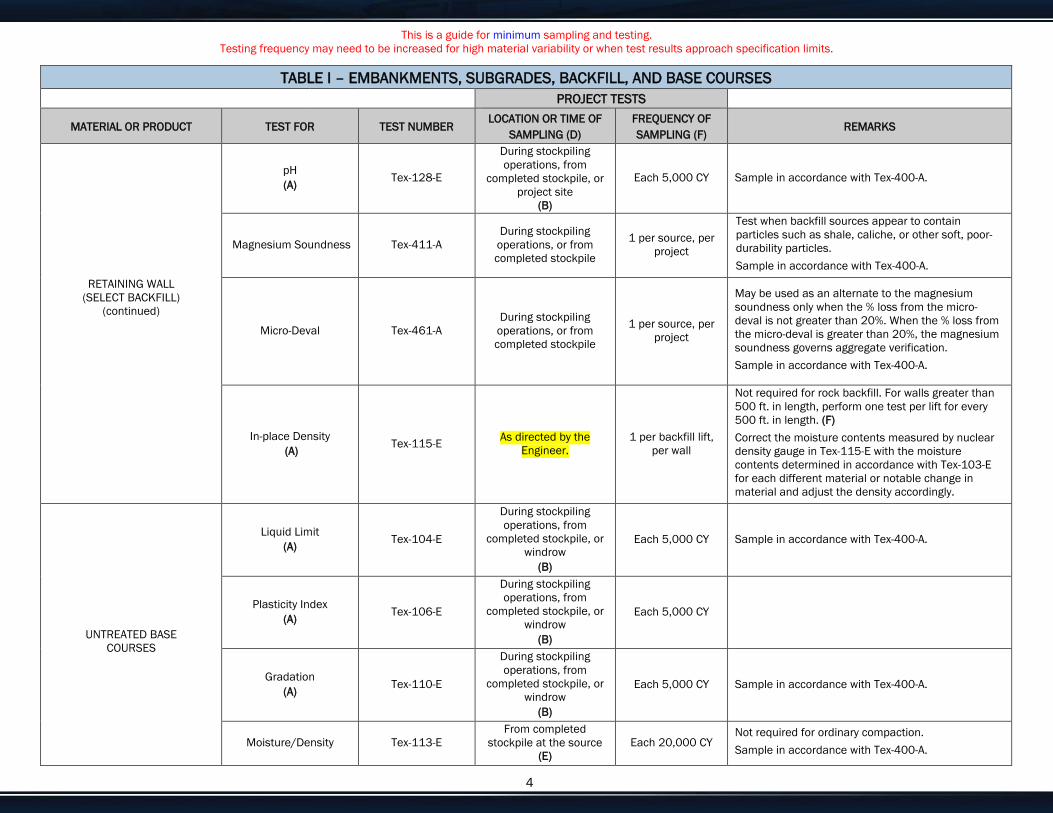
This is a guide for minimum sampling and testing. Testing frequency may need to be increased for high material variability or when test results approach specification limits.
Enter customize text here for your needs or delete if not needed. 4
TABLE I – EMBANKMENTS, SUBGRADES, BACKFILL, AND BASE COURSES PROJECT TESTS
MATERIAL OR PRODUCT TEST FOR TEST NUMBER LOCATION OR TIME OF
SAMPLING (D) FREQUENCY OF SAMPLING (F)
REMARKS
RETAINING WALL (SELECT BACKFILL)
(continued)
pH (A) Tex-128-E
During stockpiling operations, from
completed stockpile, or project site
(B)
Each 5,000 CY Sample in accordance with Tex-400-A.
Magnesium Soundness Tex-411-A During stockpiling
operations, or from completed stockpile
1 per source, per project
Test when backfill sources appear to contain particles such as shale, caliche, or other soft, poor-durability particles. Sample in accordance with Tex-400-A.
Micro-Deval Tex-461-A During stockpiling
operations, or from completed stockpile
1 per source, per project
May be used as an alternate to the magnesium soundness only when the % loss from the micro-deval is not greater than 20%. When the % loss from the micro-deval is greater than 20%, the magnesium soundness governs aggregate verification. Sample in accordance with Tex-400-A.
In-place Density (A) Tex-115-E As directed by the
Engineer. 1 per backfill lift,
per wall
Not required for rock backfill. For walls greater than 500 ft. in length, perform one test per lift for every 500 ft. in length. (F) Correct the moisture contents measured by nuclear density gauge in Tex-115-E with the moisture contents determined in accordance with Tex-103-E for each different material or notable change in material and adjust the density accordingly.
UNTREATED BASE COURSES
Liquid Limit (A) Tex-104-E
During stockpiling operations, from
completed stockpile, or windrow
(B)
Each 5,000 CY Sample in accordance with Tex-400-A.
Plasticity Index (A) Tex-106-E
During stockpiling operations, from
completed stockpile, or windrow
(B)
Each 5,000 CY
Gradation (A) Tex-110-E
During stockpiling operations, from
completed stockpile, or windrow
(B)
Each 5,000 CY Sample in accordance with Tex-400-A.
Moisture/Density Tex-113-E From completed
stockpile at the source (E)
Each 20,000 CY Not required for ordinary compaction. Sample in accordance with Tex-400-A.

This is a guide for minimum sampling and testing. Testing frequency may need to be increased for high material variability or when test results approach specification limits.
Enter customize text here for your needs or delete if not needed. 5
TABLE I – EMBANKMENTS, SUBGRADES, BACKFILL, AND BASE COURSES PROJECT TESTS
MATERIAL OR PRODUCT TEST FOR TEST NUMBER LOCATION OR TIME OF
SAMPLING (D) FREQUENCY OF SAMPLING (F)
REMARKS
UNTREATED BASE COURSES
(Continued)
Wet Ball Mill (A) Tex-116-E
From completed stockpile at the source
(E) Each 20,000 CY
Required for Grades 1–2 and 5, and as shown on the plans for Grade 4. Sample in accordance with Tex-400-A.
Strength (A) Tex-117-E
From completed stockpile at the source
(E) Each 20,000 CY
Required for Grades 1–2 and 5, and as shown on the plans for Grade 4. When base material is from a source where the District has a record of satisfactory triaxial results, the frequency of testing may be reduced to one per 30,000 CY. If any one test falls below the minimum value required, the frequency of testing will return to the original frequency of 20,000 CY. Sample in accordance with Tex-400-A.
In-place Density (A) Tex-115-E As directed by the
Engineer Each 3,000 CY, min. 1 per lift
Correct the moisture contents measured by nuclear density gauge in Tex-115-E with the moisture contents determined in accordance with Tex-103-E, as necessary for control, for each different material or notable change in material and adjust the density accordingly. Materials such as RAP, gypsum, lime, cement, and iron ore tend to bias the counts for nuclear density gauges.
Thickness (A) Tex-140-E As directed by the
Engineer Each 3,000 CY Not required where survey grade control documents are compliant.
Ride Quality (A)
Tex-1001-S Surface Test, Type B
Final riding surface of travel lanes
This applies to the final travel lanes that receive a 1- or 2-course surface treatment for the final surface, unless otherwise shown on the plans.
TREATED SUBGRADE AND BASE COURSES
SUBGRADE BEFORE
TREATMENT
Organic Content Tex-148-E As directed by the Engineer
1 per project, per source or as
directed by the Engineer
Required for existing subgrade material and material imported from a borrow source. Soil survey and geologic maps may be used to determine sampling locations. Sample in accordance with Tex-100-E.
Sulfate Content Tex-145-E As directed by the Engineer
1 per 500 feet or 5,000 CY
Required for existing subgrade material and material imported from a borrow source. Soil survey and geologic maps may be used to determine sampling locations. Sample in accordance with Tex-100-E.
NEW BASE MATERIAL
Liquid Limit (A) Tex-104-E
During stockpiling operations, from
completed stockpile, or windrow
(B)
Each 5,000 CY When central mix site or plant is used, windrow sampling may be waived. Sample in accordance with Tex-400-A.

This is a guide for minimum sampling and testing. Testing frequency may need to be increased for high material variability or when test results approach specification limits.
Enter customize text here for your needs or delete if not needed. 6
TABLE I – EMBANKMENTS, SUBGRADES, BACKFILL, AND BASE COURSES PROJECT TESTS
MATERIAL OR PRODUCT TEST FOR TEST NUMBER LOCATION OR TIME OF
SAMPLING (D) FREQUENCY OF SAMPLING (F)
REMARKS
TREATED SUBGRADE AND BASE COURSES
(Continued)
NEW BASE MATERIAL
(Continued)
Plasticity Index (A) Tex-106-E
During stockpiling operations, from
completed stockpile, or windrow
(B)
Each 5,000 CY
Gradation (A) Tex-110-E
During stockpiling operations, from
completed stockpile, or windrow
(B)
Each 5,000 CY Sample in accordance with Tex-400-A.
Wet Ball Mill (A) Tex-116-E
From completed stockpile at the source
(E) Each 20,000 CY
Required for Grades 1–2 and 5, and as shown on the plans for Grade 4. Sample in accordance with Tex-400-A.
Strength (A) Tex-117-E
From completed stockpile at the source
(E) Each 20,000 CY
Required for Grades 1–2 and 5, and as shown on the plans for Grade 4. When base material is from a source where the District has a record of satisfactory triaxial results, the frequency of testing may be reduced to one per 30,000 CY. If any one test falls below the minimum value required, the frequency of testing will return to the original frequency of 20,000 CY.
LIME Compliance with DMS-6350 Tex-600-J During delivery to project
Commercial Lime Slurry: each 200
tons of lime Carbide Lime
Slurry: each 100 tons of lime
Sample in accordance with Tex-600-J. Verify the source is listed on the current Material Producer List for Lime. Only materials appearing on the Material Producer List will be accepted. Sample frequency for Carbide Lime Slurry may be increased as directed by the Engineer. For Hydrated Lime and Quick Lime, project testing is not required but it is encouraged to sample and test the material at a rate of 1 per project as a best practice.
CEMENT Compliance with DMS-4600 Railroad car, truck, or
cement bins Verify the source is listed on the current Material Producer List for Cement. If not, sample and test in accordance with DMS-4600. (C)
FLY ASH MATERIAL
Compliance with DMS-4615
Project samples at location directed by the
Engineer
Verify the source is listed on the current Material Producer List for Fly Ash. Only materials from MTD approved sources appearing on the Material Producer List for Fly Ash will be accepted. Project testing is not required but it is encouraged to sample and test the material at a rate of 1 per project as a best practice. (C)

This is a guide for minimum sampling and testing. Testing frequency may need to be increased for high material variability or when test results approach specification limits.
Enter customize text here for your needs or delete if not needed. 7
TABLE I – EMBANKMENTS, SUBGRADES, BACKFILL, AND BASE COURSES PROJECT TESTS
MATERIAL OR PRODUCT TEST FOR TEST NUMBER LOCATION OR TIME OF
SAMPLING (D) FREQUENCY OF SAMPLING (F)
REMARKS
TREATED SUBGRADE AND BASE COURSES
(Continued)
COMPLETE MIXTURE
Pulverization Gradation Tex-101-E, Part III Roadway, after pulverization and mixing
As necessary for control
At the beginning of the project, one test must be made for each 4,500 CY or 6,000 tons until the Engineer is satisfied that acceptable pulverization results are being obtained. Sample in accordance with Tex-100-E.
Moisture/Density Curve and Strength
Tex-120-E, Part II, or Tex-121-E, Part II
From roadway windrow after treatment
(E) Each 20,000 CY
Not required for ordinary compaction. Determine a new moisture/density curve for each different or notable change in material. Perform Tex-120-E, Part II, for Cement Treated Material, and Tex-121-E, Part II, for Lime, Lime-Fly Ash, or Fly Ash Treated Material. If Tex-120-E, Part I, Tex-121-E, Part I, or Tex-127-E is performed before the project, this test may be waived. Sample in accordance with Tex-100-E.
Moisture/Density Curve and Strength
Tex-120-E, Part I, Tex-121-E, Part I, or
Tex-127-E
From roadway before treatment
As necessary for control
Perform Tex-120-E, Part I, on cement treated material, and Tex-121-E, Part I, for lime-fly ash or fly ash treated material. Verifies the field strength by comparing results from the mix design. Performed at the direction of the Engineer and when notable change in material, as described above for Part II of the test procedures. Sample in accordance with Tex-100-E.
In-place Density (A) Tex-115-E As directed by the
Engineer Each 3,000 CY,
min 1 per lift
Determine the appropriate moisture/density curve for each different material or notable change in material. Correct the moisture contents measured by nuclear density gauge in Tex-115-E with the moisture contents determined in accordance with Tex-103-E, as necessary for control, for each different material or notable change in material and adjust the density accordingly. Stabilizers and materials such as RAP, gypsum, and iron ore tend to bias the counts for nuclear density gauges.
Thickness (A) Tex-140-E As directed by the
Engineer Each 3,000 CY Not required where survey grade control documents are used for compliance.

This is a guide for minimum sampling and testing. Testing frequency may need to be increased for high material variability or when test results approach specification limits.
Enter customize text here for your needs or delete if not needed. 8
TABLE I – EMBANKMENTS, SUBGRADES, BACKFILL, AND BASE COURSES PROJECT TESTS
MATERIAL OR PRODUCT TEST FOR TEST NUMBER LOCATION OR TIME OF
SAMPLING (D) FREQUENCY OF SAMPLING (F)
REMARKS
RECLAIMED ASPHALT PAVEMENT (RAP), CRUSHED CONCRETE, and RECYCLED
MATERIALS
Sulfate Content Tex-145-E During stockpiling operations, from
completed stockpile, or windrow
Each 5,000 CY
Required only for contractor furnished recycled material, including crushed concrete. Not required for RAP. Sample in accordance with Tex-400-A.
Deleterious Material Tex-413-A Each 5,000 CY Required only for contractor furnished recycled material, including crushed concrete. Sample in accordance with Tex-400-A.
Decantation Tex-406-A
During stockpiling operations, from
completed stockpile, or windrow
Each 5,000 CY Required only for contractor furnished RAP. Sample in accordance with Tex-400-A.
TABLE I – FOOTNOTES
A When this project acceptance test fails, but the product is accepted, document the reasons for acceptance in SiteManager (SM), in the remarks field, and on the end of the Project Materials Certification Letter.
B Engineer will select any of these locations or any combinations thereof with the provision that the initial sample will be obtained from the completed stockpile at the source and at least one out of ten consecutive samples will be taken at the project site (from the windrow for treated and untreated bases and embankments when possible).
C Attach the corresponding QM test report for SiteManager projects to satisfy project sampling and testing requirements.
D
For acceptance testing, especially that which directly determines payment for the Contractor, sampling personnel should provide randomness in sampling by avoiding patterned sampling routines. Examples of such sampling practices are as follows:
• Soils/Flexible Base: For gradation, liquid limit, and plastic limit, vary sampling between stockpiling operations, completed stockpile, windrow, and project site. Vary the time of day sampling is performed.
• Aggregates: Sample aggregates nearest the point of incorporation into the work. Vary sampling between stockpiling operations, completed stockpile, belt sampling, and if deemed necessary, railroad cars/trucks. Vary the time of day sampling is performed.
E The Engineer will sample from the completed stockpile at the source and test before placement.
F Each test performed that is based on a quantity of material is considered “or fraction thereof” for calculating number of tests.

This is a guide for minimum sampling and testing. Testing frequency may need to be increased for high material variability or when test results approach specification limits.
Enter customize text here for your needs or delete if not needed. 9
TABLE IA – ASPHALT TREATED BASE (Plant Mix) PROJECT TESTS
MATERIAL OR PRODUCT TEST FOR TEST NUMBER LOCATION OR TIME OF
SAMPLING (C) FREQUENCY OF SAMPLING (D)
REMARKS
AGGREGATE
Liquid Limit (A) Tex-104-E
During stockpiling operations, from
completed stockpile, or before mixing
Each 5,000 CY Sample in accordance with Tex-400-A.
Plasticity Index (A) Tex-106-E
During stockpiling operations, from
completed stockpile, or before mixing
Each 5,000 CY
Wet Ball Mill (A) Tex-116-E
During stockpiling operations, from
completed stockpile, or before mixing
1 per project, per source
Sample in accordance with Tex-400-A. (B)
LIME Compliance with DMS-6350 During delivery to the
project
Hydrated Lime: 1 per project
Commercial Lime Slurry: each 200 tons of lime (D) Carbide Lime
Slurry: each 100 tons of lime (D)
Quick Lime: 1 per project
On projects requiring less than 50 tons, material from MTD approved sources may be accepted on the basis of Producer’s Certification without sampling.
RECLAIMED ASPHALT PAVEMENT (RAP), and
RECYCLED AGGREGATE Decantation Tex-406-A, Part I
During stockpiling operations, from
completed stockpile, or before mixing
Each 10,000 CY Sample in accordance with Tex-400-A.
RECYCLED ASPHALT SHINGLES (RAS) Decantation Tex-217-F,Part III
During stockpiling operations, from
completed stockpile, or before mixing
Each 10,000 CY Sample in accordance with Tex-400-A.
ASPHALT BINDER Compliance with Item 300 Sampling port nearest
the storage tank 1 per project, per grade, per source
Test a minimum of one sample taken from the project. Sample binder in accordance with Tex-500-C, Part II. Verify that the binder is from a preapproved source when it arrives on the project, and that the lab number on the shipping ticket is within the valid dates shown on the MTD QM test report or in the SiteManager (SM) Assistant. The Engineer must associate one QM sample per project in SM.

This is a guide for minimum sampling and testing. Testing frequency may need to be increased for high material variability or when test results approach specification limits.
Enter customize text here for your needs or delete if not needed. 10
TABLE IA – ASPHALT TREATED BASE (Plant Mix) PROJECT TESTS
MATERIAL OR PRODUCT TEST FOR TEST NUMBER LOCATION OR TIME OF
SAMPLING (C) FREQUENCY OF SAMPLING (D)
REMARKS
TACK COAT Compliance with Item 300 Distributor 1 per project, per
grade, per source
Test a minimum of one sample taken from the project. Sample tack coat in accordance with Tex-500-C, Part III. Verify that the binder is from a preapproved source when it arrives on the project, and that the lab number on the shipping ticket is within the valid dates shown on the MTD QM test report or in the SM Assistant. The Engineer must associate one QM sample per project in SM.
COMPLETE MIXTURE
Gradation (A) Tex-200-F, Part I Plant Mix
(C) 20,000 CY
(25,000 tons)
Sample in accordance with Tex-222-F. Determine the gradation of the aggregate from the complete mixture tested in accordance with Tex-236-F.
Laboratory Density (A) Tex-126-E Plant Mix
(C) 20,000 CY
(25,000 tons) Sample in accordance with Tex-222-F.
Percent Asphalt (A) Tex-236-F Plant Mix
(C)
Each 1,500 CY (2,000 tons) or days production
Determine an asphalt content correction factor for ignition oven at a minimum of one per project. Sample in accordance with Tex-222-F.
Indirect Tensile Strength – Dry Tex-226-F Plant Mix 1 per project, per
design Sample in accordance with Tex-222-F.
Moisture Susceptibility Tex-530-C As directed by the Engineer
1 per project, per design
This test may be waived, when shown on the plans. Sample in accordance with Tex-222-F.
ROADWAY
In-Place Air Voids (A) Tex-207-F
Roadway cores, as directed by the Engineer
(C, D)
Each 3,000 CY, min 1 per lift
Not required for ordinary compaction or when air void requirements are waived. Sample in accordance with Tex-222-F.
Ride Quality Tex-1001-S Surface Test, Type A On Finished Surface Unless otherwise shown on the plans.

This is a guide for minimum sampling and testing. Testing frequency may need to be increased for high material variability or when test results approach specification limits.
Enter customize text here for your needs or delete if not needed. 11
TABLE IA – FOOTNOTES
A When this project acceptance test fails, but the product is accepted, document the reasons for acceptance in SiteManager (SM), in the remarks field, and on the end of the Project Materials Certification Letter.
B Engineer will select any of these locations or any combinations thereof with the provision that at least one out of ten consecutive samples will be taken at the project site (from the windrow for treated and untreated bases and embankments when possible).
C
For acceptance testing, especially that which directly determines payment for the Contractor, sampling personnel should provide randomness in sampling by avoiding patterned sampling routines. Examples of such sampling practices are as follows:
• Soils/Flexible Base: Vary sampling between stockpiling operations, completed stockpile, windrow, and project site. Vary the time of day sampling is performed. • Aggregates: Sample aggregates nearest the point of incorporation into the work. Vary sampling between stockpiling operations, completed stockpile, belt sampling, and if
deemed necessary, railroad cars/trucks. Vary the time of day sampling is performed.
D Each test performed, that is based on a quantity of material, is considered “or fraction thereof” for calculating number of tests.

This is a guide for minimum sampling and testing. Testing frequency may need to be increased for high material variability or when test results approach specification limits.
Enter customize text here for your needs or delete if not needed. 12
TABLE II – SEAL COAT PROJECT TESTS
MATERIAL OR PRODUCT TEST FOR TEST NUMBER LOCATION OR TIME OF
SAMPLING (C) FREQUENCY OF SAMPLING (D)
REMARKS
AGGREGATE
Gradation (A) Tex-200-F, Part I Stockpile (At source or at
point of delivery) Each 1,000 CY
Rate may be reduced to each 2,000 CY if the Engineer approves a contractor quality control plan. Sample in accordance with Tex-221-F.
L. A. Abrasion (A) Tex-410-A Stockpile 1 per project, per
source
Verify the published value of the source, as listed on the current Material Producer List for BRSQC, meets the project specifications. If not, sample and test at 1 per 20,000 CY before use. Sample in accordance with Tex-221-F. (B)
Magnesium Soundness
(A) Tex-411-A Stockpile 1 per project, per
source
Verify the published value of the source, as listed on the current Material Producer List for BRSQC, meets the project specifications. If not, sample and test at 1 per 20,000 CY before use. Sample in accordance with Tex-221-F. (B)
Surface Aggregate Classification
(A)
Tex-612-J, Tex-411-A Stockpile 1 per project, per
source
Verify the published value of the source, as listed on the current Material Producer List for BRSQC, meets the project specifications. If not, sample and test at 1 per 20,000 CY before use. Sample in accordance with Tex-221-F. (B)
Pressure Slake (A) Tex-431-A Stockpile 1 per 20,000 CY
Same as above. Required only for lightweight aggregate. Sample in accordance with Tex-221-F.
Freeze Thaw (A) Tex-432-A Stockpile 1 per 20,000 CY
Same as above. Required only for lightweight aggregate. Sample in accordance with Tex-221-F.
Unit Weight Tex-404-A Stockpile 1 per 20,000 CY Same as above. Required only for lightweight aggregate. Sample in accordance with Tex-221-F.
24 hr. Water Absorption
(A) Tex-433-A Stockpile 1 per 20,000 CY
Same as above. Required only for lightweight aggregate. Sample in accordance with Tex-221-F.
Crushed Face Count Tex-460-A, Part I Stockpile 1 per 20,000 CY Only required for crushed gravel. Sample in accordance with Tex-221-F.
Deleterious Material (A) Tex-217-F, Part I Stockpile 1 per 10,000 CY
Not required for lightweight aggregate. Sample in accordance with Tex-221-F.
Decantation (A) Tex-406-A Stockpile 1 per 10,000 CY Sample in accordance with Tex-221-F.
Flakiness Index Tex-224-F Stockpile Frequency as
directed by the Engineer
Sample in accordance with Tex-221-F.

This is a guide for minimum sampling and testing. Testing frequency may need to be increased for high material variability or when test results approach specification limits.
Enter customize text here for your needs or delete if not needed. 13
TABLE II – SEAL COAT PROJECT TESTS
MATERIAL OR PRODUCT TEST FOR TEST NUMBER LOCATION OR TIME OF
SAMPLING (C) FREQUENCY OF SAMPLING (D)
REMARKS
AGGREGATE (Continued)
Micro Deval Tex-461-A Stockpile 1 per project or as
necessary for control
Compare result to published value listed on the current Material Producer List for BRSQC. Submit sample to MTD for Soundness and L.A. Abrasion testing when results differ by more than 3% points, unless otherwise directed by the Engineer. Sample in accordance with Tex-221-F.
White Rock Count Tex-220-F Stockpile Required only for Limestone Rock Asphalt. Not required when MTD provides inspection at the plant. Sample in accordance with Tex-221-F.
Naturally Impregnated Bitumen Content Tex-236-F Stockpile
Required only for Limestone Rock Asphalt. Not required when MTD provides inspection at the plant. Sample in accordance with Tex-221-F.
PRECOATED AGGREGATE Asphalt Content Tex-210-F Stockpile
Frequency as directed by the
Engineer when a target value is
specified
Sample in accordance with Tex-221-F.
ASPHALT BINDER Compliance with Item 300 Distributor 1 per project, per
grade, per source
Test a minimum of one sample taken from the project. Sample asphalt binder in accordance with Tex-500-C, Part III. Verify that the binder is from a preapproved source when it arrives on the project, and that the lab number on the shipping ticket is within the valid dates shown on the MTD QM test report or in the SM Assistant. The Engineer must associate one QM sample per project in SM.
TABLE II – FOOTNOTES
A When this project acceptance test fails, but the product is accepted, document the reasons for acceptance in SiteManager, in the remarks field, and on the end of the Project Materials Certification Letter.
B Attach the corresponding QM test report for SiteManager projects to satisfy project sampling and testing requirements.
C
For acceptance testing, especially that which directly determines payment for the Contractor, sampling personnel should provide randomness in sampling by avoiding patterned sampling routines. Examples of such sampling practices are as follows:
• Aggregates: Sample aggregates nearest the point of incorporation into the work. Vary sampling between stockpiling operations, completed stockpile, belt sampling, and if deemed necessary, railroad cars/trucks. Vary the time of day sampling is performed.
D Each test performed, that is based on a quantity of material, is considered “or fraction thereof” for calculating number of tests.

This is a guide for minimum sampling and testing. Testing frequency may need to be increased for high material variability or when test results approach specification limits.
Enter customize text here for your needs or delete if not needed. 14
TABLE III – HYDRAULIC CEMENT CONCRETE – STRUCTURAL (Classes: C, F, H, S, CO, K, LMC, or SS) PROJECT TESTS
MATERIAL OR PRODUCT TEST FOR TEST NUMBER LOCATION OR TIME OF
SAMPLING (D) FREQUENCY OF SAMPLING (E)
REMARKS
MINERAL AGGREGATE
COARSE AGGREGATE
Decantation (B) Tex-406-A
From stockpile at concrete plant
Each 20,000 CY of concrete (each
source) Sample in accordance with Tex-400-A.
Sieve Analysis (A) (B) Tex-401-A
Each 1,000 CY of concrete (each
source)
Test combined aggregate when used. Sample in accordance with Tex-400-A.
Deleterious Materials (B) Tex-413-A
1 per project or as necessary for
control Sample in accordance with Tex-400-A.
Los Angeles Abrasion (A) (B) Tex-410-A One, each source
Verify the value of the source, as listed on the current Material Producer list for CRSQC, meets the project specifications. If not, sample and submit to MTD for testing before use in accordance with Tex-499-A. Sample in accordance with Tex-400-A. (C)
Magnesium Soundness
(A) (B) Tex-411-A One, each source Verify the value of the source, as listed on the
current CRSQC, meets the project specifications. (C)
FINE AGGREGATE
Sand Equivalent (B) Tex-203-F
From stockpile at concrete plant
1 per project or as necessary for
control
Test combined aggregate when used. Sample in accordance with Tex-400-A.
Organic Impurities (B) Tex-408-A 1 per project, per
source Sample in accordance with Tex-400-A.
Sieve Analysis (A) (B) Tex-401-A
Each 1,000 CY of concrete (each
source) Sample in accordance with Tex-400-A.
Fineness Modulus (B) Tex-402-A
1 per project or as necessary for
control
Test combined aggregate when used. Test to confirm material variability when strength values are in question. Sample in accordance with Tex-400-A.
Deleterious Material (B) Tex-413-A
1 per project or as necessary for
control
Test to confirm material variability when strength values are in question. Sample in accordance with Tex-400-A.
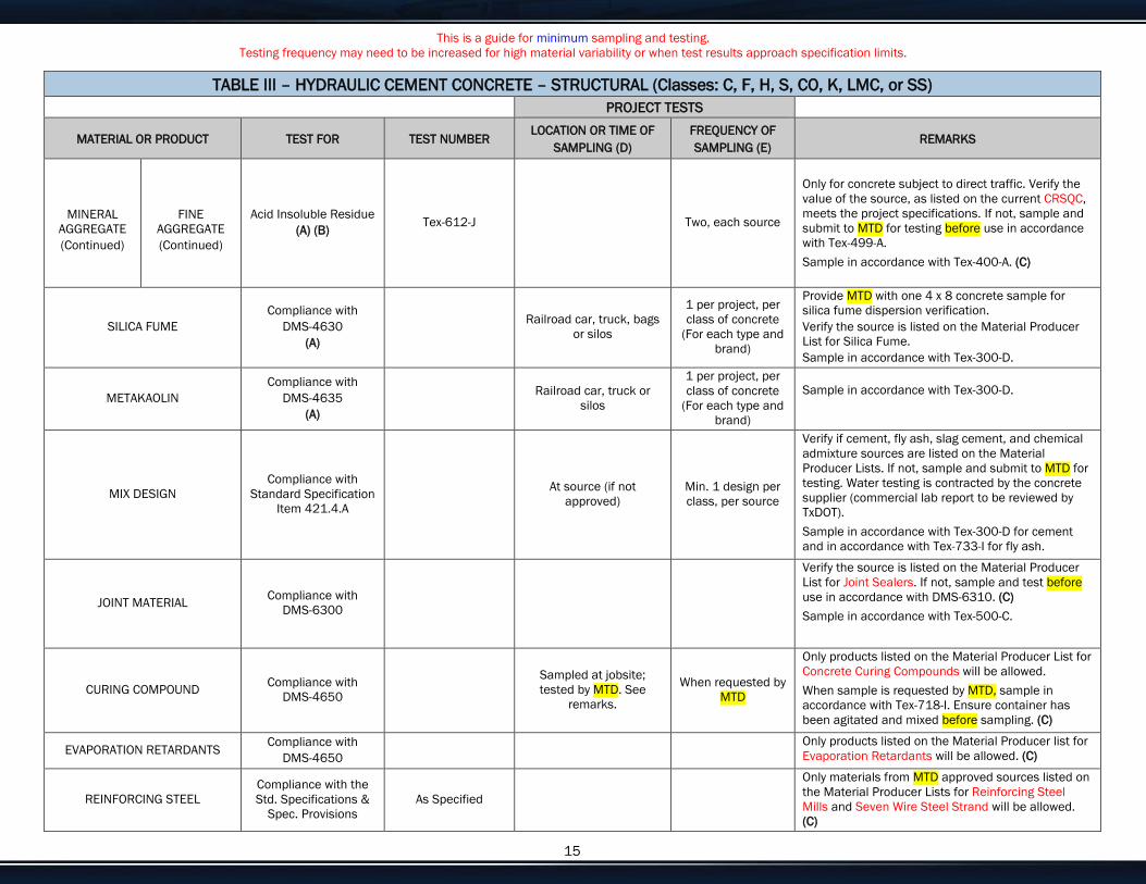
This is a guide for minimum sampling and testing. Testing frequency may need to be increased for high material variability or when test results approach specification limits.
Enter customize text here for your needs or delete if not needed. 15
TABLE III – HYDRAULIC CEMENT CONCRETE – STRUCTURAL (Classes: C, F, H, S, CO, K, LMC, or SS) PROJECT TESTS
MATERIAL OR PRODUCT TEST FOR TEST NUMBER LOCATION OR TIME OF
SAMPLING (D) FREQUENCY OF SAMPLING (E)
REMARKS
MINERAL AGGREGATE (Continued)
FINE AGGREGATE (Continued)
Acid Insoluble Residue (A) (B) Tex-612-J Two, each source
Only for concrete subject to direct traffic. Verify the value of the source, as listed on the current CRSQC, meets the project specifications. If not, sample and submit to MTD for testing before use in accordance with Tex-499-A. Sample in accordance with Tex-400-A. (C)
SILICA FUME Compliance with
DMS-4630 (A)
Railroad car, truck, bags or silos
1 per project, per class of concrete
(For each type and brand)
Provide MTD with one 4 x 8 concrete sample for silica fume dispersion verification. Verify the source is listed on the Material Producer List for Silica Fume. Sample in accordance with Tex-300-D.
METAKAOLIN Compliance with
DMS-4635 (A)
Railroad car, truck or silos
1 per project, per class of concrete
(For each type and brand)
Sample in accordance with Tex-300-D.
MIX DESIGN Compliance with
Standard Specification Item 421.4.A
At source (if not approved)
Min. 1 design per class, per source
Verify if cement, fly ash, slag cement, and chemical admixture sources are listed on the Material Producer Lists. If not, sample and submit to MTD for testing. Water testing is contracted by the concrete supplier (commercial lab report to be reviewed by TxDOT). Sample in accordance with Tex-300-D for cement and in accordance with Tex-733-I for fly ash.
JOINT MATERIAL Compliance with DMS-6300
Verify the source is listed on the Material Producer List for Joint Sealers. If not, sample and test before use in accordance with DMS-6310. (C) Sample in accordance with Tex-500-C.
CURING COMPOUND Compliance with DMS-4650
Sampled at jobsite; tested by MTD. See
remarks.
When requested by MTD
Only products listed on the Material Producer List for Concrete Curing Compounds will be allowed. When sample is requested by MTD, sample in accordance with Tex-718-I. Ensure container has been agitated and mixed before sampling. (C)
EVAPORATION RETARDANTS Compliance with DMS-4650
Only products listed on the Material Producer list for Evaporation Retardants will be allowed. (C)
REINFORCING STEEL Compliance with the Std. Specifications &
Spec. Provisions As Specified
Only materials from MTD approved sources listed on the Material Producer Lists for Reinforcing Steel Mills and Seven Wire Steel Strand will be allowed. (C)

This is a guide for minimum sampling and testing. Testing frequency may need to be increased for high material variability or when test results approach specification limits.
Enter customize text here for your needs or delete if not needed. 16
TABLE III – HYDRAULIC CEMENT CONCRETE – STRUCTURAL (Classes: C, F, H, S, CO, K, LMC, or SS) PROJECT TESTS
MATERIAL OR PRODUCT TEST FOR TEST NUMBER LOCATION OR TIME OF
SAMPLING (D) FREQUENCY OF SAMPLING (E)
REMARKS
MECHANICAL COUPLERS Compliance with DMS-4510 Tex-743-I Sampled at jobsite;
Tested by MTD
3 couplers per lot (500 couplers) for each type, model,
bar size, and grade
Only materials from MTD approved sources listed on the Material Producer List for Mechanical Couplers will be allowed. (C)
LATEX
Compliance with DMS-4640 for
concrete chemical admixtures
Verify the Latex is listed on the Material Producer List for Chemical Admixtures.
EPOXY Compliance with
DMS-6100, unless otherwise specified
Sampled at jobsite if not
pre-approved by MTD. 1 per batch or
shipment
Verify the source is listed on the Material Producer List for Epoxies and Adhesives. If not, sample and test before use in accordance with DMS-6100. Sample in accordance with Tex-734-I. (C)
CONCRETE
Compressive Strength (A) Tex-418-A
At point of concrete placement
4 cylinders for each 60 CY per class,
per day (For bridge railing and traffic railing,
testing may be reduced to 4
cylinders per 180 CY per class
regardless of days)
Sampling must be in accordance with Tex-407-A. Making additional cylinders for 56 day testing should be considered when slow strength gain mixtures are being used, or when the approved mix design has a history of failing to meet design strength at 28 days. Test two cylinders at 7 days, and if the average value is below the design strength, as defined in Item 421, Table 8, test the remaining 2 cylinders at 28 days, or 56 days if additional cylinder were not made. If the average value of the 2 cylinders tested at 7 days meets the minimum design strength, listed in Item 421, Table 8, the remaining cylinders are not required to be tested. If the average value of the 7 and 28 day cylinders are below the design strengths, and 56 day cylinders were made, test the remaining set at 56 days.
Slump Tex-415-A
1 test, per 4 strength
specimens
Sample in accordance with Tex-407-A. Perform slump and temperature tests on the same load from which strength test specimens are made. Perform entrained air test only when entrained air concrete is specified on the plans. Check temperature of every load for bridge slabs and mass concrete placements. Contractor’s required testing will be in accordance with specification requirements for the appropriate specification Item #.
Entrained Air (A)
Tex-416-A or Tex-414-A
Temperature of Concrete
(A) Tex-422-A

This is a guide for minimum sampling and testing. Testing frequency may need to be increased for high material variability or when test results approach specification limits.
Enter customize text here for your needs or delete if not needed. 17
TABLE III – HYDRAULIC CEMENT CONCRETE – STRUCTURAL (Classes: C, F, H, S, CO, K, LMC, or SS) PROJECT TESTS
MATERIAL OR PRODUCT TEST FOR TEST NUMBER LOCATION OR TIME OF
SAMPLING (D) FREQUENCY OF SAMPLING (E)
REMARKS
CONCRETE (Continued)
Bridge Deck or Culvert Top Slab Thickness
and Depth of Reinforcement
Tex-423-A, Part II
During dry run and during concrete placement
(Bridge decks and direct traffic culverts)
1 per span Min 6–Max 18 locations per span.
TABLE III – FOOTNOTES
A When this project acceptance test fails, but the product is accepted, document the reasons for acceptance in SiteManager, in the remarks field, and on the end of the Project Materials Certification Letter.
B These Project Tests may be used for one or more projects being furnished concrete from the same plant during the same period.
C Attach the corresponding QM test report for SiteManager projects to satisfy project sampling and testing requirements.
D
For acceptance testing, especially that which directly determines payment for the Contractor, sampling personnel should provide randomness in sampling by avoiding patterned sampling routines. Examples of such sampling practices are as follows:
• Aggregates: Sample aggregates nearest the point of incorporation into the work. Vary sampling between stockpiling operations, completed stockpile, and if deemed necessary, railroad cars/trucks. Vary the time of day sampling is performed.
• Concrete (structural): Always sample as near as practicable to the point of placement. For strength testing, vary the time of day or the number of truck from which the concrete is sampled. Test often for slump, air, and temperature to ensure the consistent control of the concrete production.
E Each test performed, that is based on a quantity of material, is considered “or fraction thereof” for calculating number of tests.

This is a guide for minimum sampling and testing. Testing frequency may need to be increased for high material variability or when test results approach specification limits.
Enter customize text here for your needs or delete if not needed. 18
TABLE IV – HYDRAULIC CEMENT CONCRETE – NON-STRUCTURAL CONCRETE (Classes: A, B, or E) PROJECT TESTS
MATERIAL OR PRODUCT TEST FOR TEST NUMBER LOCATION OR TIME OF
SAMPLING (B) FREQUENCY OF SAMPLING (C)
REMARKS
CONCRETE Compressive Strength (A) Tex-418-A At point of concrete
placement 2 cylinders per 180
CY, per class Sampling must be in accordance with Tex-407-A. Strength will be determined by 7-day specimens.
MIX DESIGN Compliance with the Standard Specification At source if not approved Min. 1 design per
class, per source
Verify if cement, fly ash, slag cement, and chemical admixture sources are listed on the Material Producer Lists. If not, sample and submit to MTD for testing. Sample in accordance with Tex-300-D for cement and in accordance with Tex-733-I for fly ash. Water testing is contracted by the concrete supplier (commercial lab report to be reviewed by TxDOT).
SILICA FUME Compliance with DMS-4630 Railroad car, truck, bags,
or silos
1 test per project, per class
(for each type and brand)
Sample in accordance with Tex-300-D. Provide MTD with one 4 x 8 concrete sample for silica fume dispersion verification. Verify the source is listed on the Material Producer List for Silica Fume.
METAKAOLIN Compliance with DMS-4635 Railroad car, truck, or
silos
1 test per project, per class
(for each type and brand)
Sample in accordance with Tex-300-D.
TABLE IV – FOOTNOTES
A When this project acceptance test fails, but the product is accepted, document the reasons for acceptance in SiteManager, in the remarks field, and on the end of the Project Materials Certification Letter.
B
For acceptance testing, especially that which directly determines payment for the Contractor, sampling personnel should provide randomness in sampling by avoiding patterned sampling routines. Examples of such sampling practices are as follows:
• Concrete (miscellaneous): Always sample as near as practicable to the point of placement. For strength testing, vary the time of day or the number of truck from which the concrete is sampled.
C Each test performed, that is based on a quantity of material, is considered “or fraction thereof” for calculating number of tests.

This is a guide for minimum sampling and testing. Testing frequency may need to be increased for high material variability or when test results approach specification limits.
Enter customize text here for your needs or delete if not needed. 19
TABLE V – HYDRAULIC CEMENT CONCRETE PAVEMENT (Classes: P or HES) PROJECT TESTS
MATERIAL OR PRODUCT TEST FOR TEST NUMBER LOCATION OR TIME OF
SAMPLING FREQUENCY OF SAMPLING (D)
REMARKS
MINERAL AGGREGATE
COARSE AGGREGATE
Decantation Tex-406-A
From stockpile at concrete plant
Each 20,000 CY of concrete (each source) Sample in accordance with Tex-400-A.
Sieve Analysis (A) Tex-401-A As necessary for control
Sample in accordance with Tex-400-A. Test combined aggregate when used.
Deleterious Materials Tex-413-A Each 20,000 CY of
concrete (each source) Sample in accordance with Tex-400-A.
L.A. Abrasion (A) Tex-410-A
One, each source
Verify the value of the source, as listed on the current CRSQC, meets the project specifications. If not, sample and submit to MTD for testing before use in accordance with Tex-499-A. Sample in accordance with Tex-400-A. (C)
Magnesium Soundness
(A) Tex-411-A
FINE AGGREGATE
Sand Equivalent Tex-203-F
From stockpile at concrete plant
Each 3,000 CY of concrete (Each source
or combination of sources)
Sample in accordance with Tex-400-A. Test combined aggregate when used. At least one per week’s production.
Organic Impurities Tex-408-A 1 per project, per source Sample in accordance with Tex-400-A.
Sieve Analysis (A) Tex-401-A
As necessary for control Sample in accordance with Tex-400-A. Test combined aggregate when used. Fineness Modulus
(B) Tex-402-A
Deleterious Material
(B) Tex-413-A Each 20,000 CY of
concrete (each source) Sample in accordance with Tex-400-A.
Acid Insoluble (A) Tex-612-J 1 per project, per
source
Verify the value of the source, as listed on the current CRSQC, meets the project specifications. If not, sample and submit to MTD for testing before use in accordance with Tex-499-A. Sample in accordance with Tex-400-A. (C)
MIX DESIGN
Compliance with the Standard Specifications Item 421.4.A
At source, if not approved
Min. 1 design, per class, per source
Verify if cement, fly ash, ground granulated blast furnace slag, and admixture sources are listed on the Material Producer List. If not, sample and submit to MTD for testing. Sample in accordance with Tex-300-D for cement and in accordance with Tex-733-I for fly ash. Water testing is contracted by the concrete supplier (commercial lab report to be reviewed by TxDOT).
SILICA FUME Compliance with DMS-4630 Railroad car, truck,
bags, or silos
1 per project, per class of concrete
(For each type and brand)
Sample in accordance with Tex-300-D. Provide MTD with one 4 x 8 concrete sample for silica fume dispersion verification. Verify the source is listed on the Material Producer List for Silica Fume.

This is a guide for minimum sampling and testing. Testing frequency may need to be increased for high material variability or when test results approach specification limits.
Enter customize text here for your needs or delete if not needed. 20
TABLE V – HYDRAULIC CEMENT CONCRETE PAVEMENT (Classes: P or HES) PROJECT TESTS
MATERIAL OR PRODUCT TEST FOR TEST NUMBER LOCATION OR TIME OF
SAMPLING FREQUENCY OF SAMPLING (D)
REMARKS
METAKAOLIN Compliance with DMS-4635 Railroad car, truck, or
silos
1 per project, per class of concrete
(For each type and brand)
Sample in accordance with Tex-300-D.
JOINT MATERIAL Compliance with DMS-6310
Sampled at jobsite if not sampled at source
by MTD; tested by MTD. See remarks.
1 per batch or shipment Sample in accordance with Tex-500-C. Sampling may be waived when the source is listed on the Material Producer List for Joint Sealers. (C)
CURING COMPOUND Compliance with DMS-4650
Sampled at jobsite; tested by MTD. See
remarks.
When requested by MTD
Only products listed on the Material Producer List for Concrete Curing Compounds will be allowed. When sample is requested by MTD, sample in accordance with Tex-718-I. Ensure container has been agitated and mixed before sampling. (C)
EVAPORATION RETARDANTS
Compliance with DMS-4650 Only products listed on the Material Producer List for
Evaporation Retardants will be allowed. (C)
REINFORCING STEEL
Compliance with the Std.
Specifications & Spec. Provisions
As Specified Only materials from MTD approved sources listed on the Material Producer List for Reinforcing Steel Mills and Seven Wire Steel Strand will be accepted. (C)
MULTIPLE PIECE TIE BARS Compliance with DMS-4515 Tex-712-I
Sampled at jobsite if not sampled at source
by MTD; tested by MTD. See remarks.
Refer to Tex-711-I for sampling rates
Only materials from MTD approved sources listed on the Material Producer List for Multiple Piece Tie-bars for Concrete Pavements will be allowed. Sample in accordance with Tex-711-I.
EPOXY Compliance with DMS-6100
Sampled at jobsite if not pre-approved by MTD. See remarks.
1 batch per shipment
Verify the source is listed on the Material Producer List for Epoxies and Adhesives. If not, sample and test before use in accordance with DMS-6100. Sample in accordance with Tex-734-I. (C)
CONCRETE
Strength (A) (B)
Tex-448-A or Tex-418-A
At point of concrete placement
2 cylinders for every 10 contractor job
control tests
Sample in accordance with Tex-407-A. When the contract requires the project testing to be by the Engineer, the frequency and job control testing will be in accordance with the item of work. Split sample verification testing used when contractor performs job control testing. When job control testing by the contractor is waived by the plans, the frequency of sampling will be one test (2 specimens) for each 3,000 SY of concrete or fraction thereof or per day and split sample verification testing will be waived. Contractor’s required testing will be in accordance with specification requirements for the appropriate specification Item #.
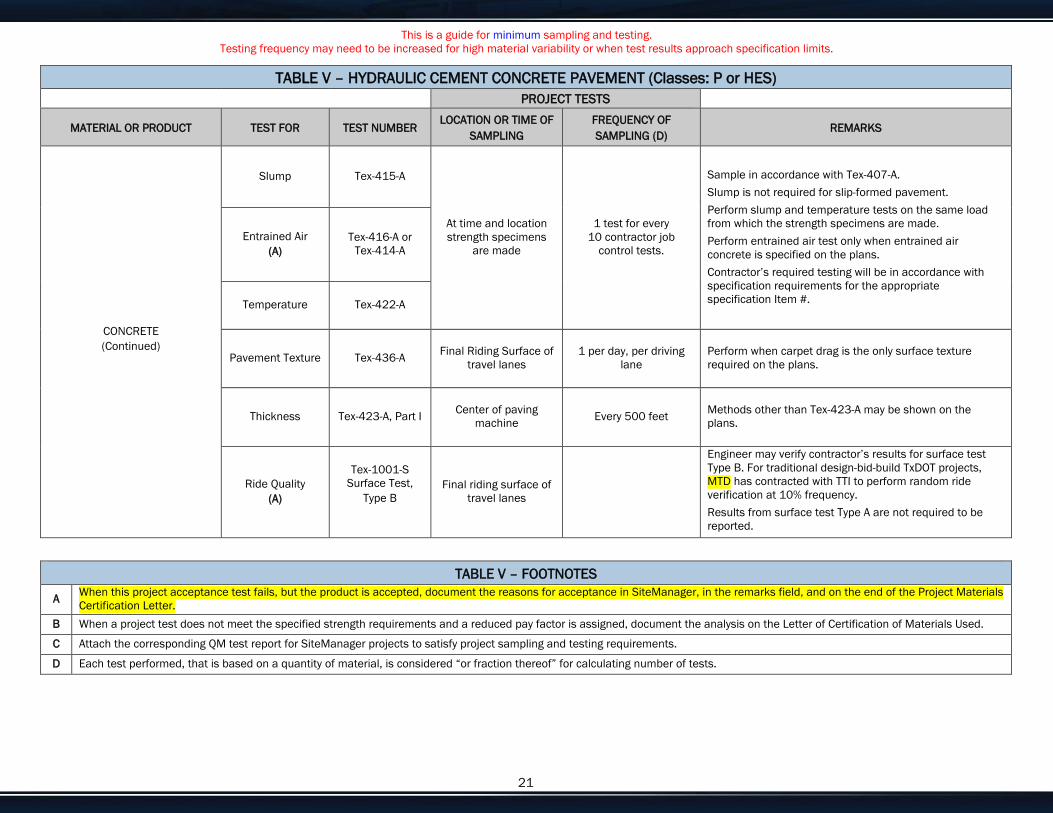
This is a guide for minimum sampling and testing. Testing frequency may need to be increased for high material variability or when test results approach specification limits.
Enter customize text here for your needs or delete if not needed. 21
TABLE V – HYDRAULIC CEMENT CONCRETE PAVEMENT (Classes: P or HES) PROJECT TESTS
MATERIAL OR PRODUCT TEST FOR TEST NUMBER LOCATION OR TIME OF
SAMPLING FREQUENCY OF SAMPLING (D)
REMARKS
CONCRETE (Continued)
Slump Tex-415-A
At time and location strength specimens
are made
1 test for every 10 contractor job
control tests.
Sample in accordance with Tex-407-A. Slump is not required for slip-formed pavement. Perform slump and temperature tests on the same load from which the strength specimens are made. Perform entrained air test only when entrained air concrete is specified on the plans. Contractor’s required testing will be in accordance with specification requirements for the appropriate specification Item #.
Entrained Air (A)
Tex-416-A or Tex-414-A
Temperature Tex-422-A
Pavement Texture Tex-436-A Final Riding Surface of travel lanes
1 per day, per driving lane
Perform when carpet drag is the only surface texture required on the plans.
Thickness Tex-423-A, Part I Center of paving machine Every 500 feet Methods other than Tex-423-A may be shown on the
plans.
Ride Quality (A)
Tex-1001-S Surface Test,
Type B
Final riding surface of travel lanes
Engineer may verify contractor’s results for surface test Type B. For traditional design-bid-build TxDOT projects, MTD has contracted with TTI to perform random ride verification at 10% frequency. Results from surface test Type A are not required to be reported.
TABLE V – FOOTNOTES
A When this project acceptance test fails, but the product is accepted, document the reasons for acceptance in SiteManager, in the remarks field, and on the end of the Project Materials Certification Letter.
B When a project test does not meet the specified strength requirements and a reduced pay factor is assigned, document the analysis on the Letter of Certification of Materials Used.
C Attach the corresponding QM test report for SiteManager projects to satisfy project sampling and testing requirements.
D Each test performed, that is based on a quantity of material, is considered “or fraction thereof” for calculating number of tests.

This is a guide for minimum sampling and testing. Testing frequency may need to be increased for high material variability or when test results approach specification limits.
Enter customize text here for your needs or delete if not needed. 22
TABLE VI – HOT-MIX ASPHALT PAVEMENT (Items 341, 342, 344, 346, 347 and 348) (All testing as noted in Table VI may be waived for exempt production as defined by specification.)
PROJECT TESTS
MATERIAL OR PRODUCT TEST FOR TEST NUMBER LOCATION
(Per Design) FREQUENCY OF SAMPLING (E)
REMARKS
COARSE AGGREGATE
L. A. Abrasion (A) Tex-410-A
Stockpile (B)
1 per project, per source
Verify the published value of the source, as listed on the current Material Producer list for BRSQC, meets the project specifications. If not, sample in accordance with Tex-221-F and submit to MTD for testing before use in accordance with Tex-499-A. (C)
Magnesium Soundness
(A) Tex-411-A
Surface Aggregate Classification
(A) Tex-499-A 1 per project, per
source
Micro Deval Tex-461-A 1 per project, per aggregate source
Not required when the Rated Source Soundness Magnesium loss is 15 or less as listed on the current published BRSQC. If testing is required, sample in accordance with Tex-221-F.
COMBINED AGGREGATE Sand Equivalent Tex-203-F Stockpiles, hot bins, or feeder belts
1 per project, per source, per design
Does not apply to Item 342. Sample in accordance with Tex-221-F. The timing of when the test is performed is at the discretion of the Engineer.
ASPHALT BINDER Compliance with
Item 300 (A)
Sampling port nearest the storage tank
1 per project, per grade, per source
Test a minimum of one sample taken from the project. Sample binder at hot- mix plant in accordance with Tex-500-C, Part II. Verify that the binder is from a preapproved source when it arrives on the project, and that the lab number on the shipping ticket is within the valid dates shown on the MTD QM test report or in the SM Assistant. The Engineer must associate one QM sample, per project in SM.
TACK COAT Compliance with
Item 300 (A)
Distributor 1 per project, per grade, per source
Test a minimum of one sample taken from the project. Sample tack coat in accordance with Tex-500-C, Part III. Verify that the binder is from a preapproved source when it arrives on the project, and that the lab number on the shipping ticket is within the valid dates shown on the MTD QM test report or in the SM Assistant. The Engineer must associate one QM sample, per project in SM.

This is a guide for minimum sampling and testing. Testing frequency may need to be increased for high material variability or when test results approach specification limits.
Enter customize text here for your needs or delete if not needed. 23
TABLE VI – HOT-MIX ASPHALT PAVEMENT (Items 341, 342, 344, 346, 347 and 348) (All testing as noted in Table VI may be waived for exempt production as defined by specification.)
PROJECT TESTS
MATERIAL OR PRODUCT TEST FOR TEST NUMBER LOCATION
(Per Design) FREQUENCY OF SAMPLING (E)
REMARKS
MIX DESIGN Compliance with
applicable specification
Tex-204-F At source (if not approved)
Min 1 design, per Mix Type and Asphalt Grade
Verify that aggregates, recycled asphalt pavement, recycled asphalt shingles, mineral filler, asphalt binder, anti-stripping additives, and warm mix systems are on the Material Producer List where applicable and that they meet project specification requirements. Project sampling and testing may be conducted on individual materials, as necessary, for control.
COMPLETE MIXTURE
Asphalt Content (A) Tex-236-F Engineer Truck Sample
(D) Minimum 1 per Lot
Sample in accordance with Tex-222-F. Determine correlation factors for ignition oven using Tex-236-F at a minimum of one per project. When Tex-236-F does not yield reliable results, use alternative methods for determining asphalt content, such as, Tex-210-F (ASTM D2172/AASHTO T164) and Tex-228-F (ASTM D4125/AASHTO T287).
Voids in Mineral Aggregates (VMA) Tex-204-F
Truck Sample Plant Produced
(D) 1 per Sublot
Sample in accordance with Tex-222-F. Contractor’s required testing will be in accordance with specification requirements for the appropriate specification Item #. Does not apply to Items 342 and 348.
Gradation (A)
Tex-200-F
Engineer Truck Sample (D)
Minimum 1, per 12 Sublots
(E)
Sample in accordance with Tex-222-F. Determine correction factors for ignition oven using Tex-236-F at a minimum of one per project.
Moisture Susceptibility Tex-530-C Truck Sample
1 per project
Sample in accordance with Tex-222-F, unless waived by the Engineer.
Indirect Tensile Strength – Dry Tex-226-F
Sample in accordance with Tex-222-F, unless waived by the Engineer. Does not apply to Items 342, 346, 347, and 348.
Moisture Content Tex-212-F, Part II Engineer Truck Sample Sample in accordance with Tex-222-F.
Lab Molded Density
(A)
Tex-207-F, Part I, VI, VIII
Truck Sample (D)
1 per Sublot 1 per Lot for Item 347
Sample in accordance with Tex-222-F. Contractor’s required testing will be in accordance with specification requirements for the appropriate specification Item #.
Drain Down Test (A) Tex-235-F Engineer Truck Sample 1 per 12 Sublots
Sample in accordance with Tex-222-F. Not required for Items 341, 344, and 347.
Hamburg Wheel Test (A)
Tex-242-F Engineer Truck Sample 1 per project Sample in accordance with Tex-222-F. Sample during production. Does not apply to Item 348 PFC-C, PFCR-C, and Thin Bonded Wearing Course –All Types.

This is a guide for minimum sampling and testing. Testing frequency may need to be increased for high material variability or when test results approach specification limits.
Enter customize text here for your needs or delete if not needed. 24
TABLE VI – HOT-MIX ASPHALT PAVEMENT (Items 341, 342, 344, 346, 347 and 348) (All testing as noted in Table VI may be waived for exempt production as defined by specification.)
PROJECT TESTS
MATERIAL OR PRODUCT TEST FOR TEST NUMBER LOCATION
(Per Design) FREQUENCY OF SAMPLING (E)
REMARKS
COMPLETE MIXTURE (Continued)
Cantabro Loss (A) Tex-245-F Engineer Truck Sample 1 per project
Sample in accordance with Tex-222-F. Sample during production. Does not apply to items 341, 344, 346, and 347.
Overlay Test (A) Tex-248-F Engineer Truck Sample 1 per project
Sample in accordance with Tex-222-F. Does not apply to Items 341, 344, and 348 PFC-C, PFCR-C, and Thin Bonded Wearing Course –All Types.
ROADWAY
In-Place Air Voids (A)
Tex-207-F, Part I, VI, VIII
Roadway (D) 2 cores per Sublot
Two cores taken per Sublot and averaged. Sample in accordance with Tex-222-F. Does not apply to Items 342, 347, and 348.
Segregation Profile
(A) Tex-207-F, Part V Roadway 1 per project
Not required when Contractor uses thermal imaging system. Does not apply to Items 342, 347, and 348.
Joint Density (A)
Tex-207-F, Part VII Roadway 1 per project
Thermal Profile Tex-244-F Immediately behind paver 1 per project
Not required when Contractor uses thermal imaging system.
Ride Quality Test Type B
(A) Tex-1001-S Final riding surface of
travel lanes 1 per project
Engineer may verify Contractor’s results for surface test Type B. For traditional design-bid-build TxDOT projects, MTD has contracted with TTI to perform random ride verification at 10% frequency. Results for surface test Type A are not required to be reported.
Permeability Tex-246-F Roadway 1 per project Permeability is encouraged to use with items 342 and 348. Only applies to Item 347.
FABRIC UNDERSEAL Compliance with DMS-6220 Sampled, tested, and
approved by MTD
Sampling must be in accordance with Tex-735-I. Verify the source is listed on the current Material Producer List for Silt Fence, Filter Fabric, and Fabric Underseals. If not, sample and test before use in accordance with DMS-6220.
TABLE VI – FOOTNOTES
A When this project acceptance test fails, but the product is accepted, document the reasons for acceptance in SiteManager, in the remarks field, and on the end of the Project Materials Certification Letter.
B Sampling may be performed at the plant, quarry, or both. Aggregate properties may be re-tested at any time during the project. These project tests may be used for one or more projects furnishing hot mix with the same aggregate source.
C Attach the corresponding QM test report for SiteManager projects to satisfy project sampling and testing requirements.
D Perform random sampling as specified in Tex-225-F, “Random Selection of Bituminous Mixture Samples.”
E Each test performed, that is based on a quantity of material, is considered “or fraction thereof” for calculating number of tests.

This is a guide for minimum sampling and testing. Testing frequency may need to be increased for high material variability or when test results approach specification limits.
Enter customize text here for your needs or delete if not needed. 25
TABLE VII – HOT-MIX ASPHALT PAVEMENT (Items 334) (Refer to DMS-9210, “Limestone Rock Asphalt (LRA),” for testing requirements for Item 330.)
PROJECT TESTS
MATERIAL OR PRODUCT TEST FOR TEST NUMBER LOCATION FREQUENCY (Per Design) (F) REMARKS
COARSE AGGREGATE
L. A. Abrasion (A) Tex-410-A
Stockpile (B)
1 per project, per source
Verify the published value of the source, as listed on the current Material Producer List for BRSQC, meets the project specifications. If not, sample in accordance with Tex-221-F and submit to MTD for testing before use in accordance with Tex-499-A. (D)
Magnesium Soundness
(A) Tex-411-A
Micro Deval Tex-461-A Sample in accordance with Tex-221-F. Testing frequency may be reduced or eliminated based on a satisfactory test history.
Surface Aggregate Classification
(A) Tex-499-A Stockpile
(B) 1 per project, per
source
Verify the published value of the source, as listed on the current Material Producer List for BRSQC, meets the project specifications. If not, sample in accordance with Tex-221-F and submit to MTD for testing before use in accordance with Tex-499-A. SiteManager Quality Monitoring test documentation is accomplished by attaching an approved mix design.
COMBINED AGGREGATE Sand Equivalent Tex-203-F Stockpiles, hot bins, or feeder belts
1 per project, per source
Sample in accordance with Tex-221-F. The timing of when the test is performed is at the discretion of the Engineer.
ASPHALT BINDER Compliance with
Item 300 (A)
Sampling port nearest the storage tank
1 per project, per grade, per source
Test a minimum of one sample taken from the project. Sample binder in accordance with Tex-500-C, Part II. Verify that the binder is from a preapproved source when it arrives on the project, and that the lab number on the shipping ticket is within the valid dates shown on the MTD QM test report or in the SM Assistant. The Engineer must associate one QM sample, per project in SM.
TACK COAT Compliance with
Item 300 (A) (C)
Distributor 1 per project, per grade, per source
Test a minimum of one sample taken from the project. Sample tack coat in accordance with Tex-500-C, Part III. Verify that the binder is from a preapproved source when it arrives on the project, and that the lab number on the shipping ticket is within the valid dates shown on the MTD QM test report or in the SM Assistant. The Engineer must associate one QM sample, per project in SM.

This is a guide for minimum sampling and testing. Testing frequency may need to be increased for high material variability or when test results approach specification limits.
Enter customize text here for your needs or delete if not needed. 26
TABLE VII – HOT-MIX ASPHALT PAVEMENT (Items 334) (Refer to DMS-9210, “Limestone Rock Asphalt (LRA),” for testing requirements for Item 330.)
PROJECT TESTS
MATERIAL OR PRODUCT TEST FOR TEST NUMBER LOCATION FREQUENCY (Per Design) (F) REMARKS
MIX DESIGN Compliance with
applicable specification
Tex-204-F At source (if not approved)
Min 1 design per Mix Type and Asphalt Grade
Verify that aggregates, recycled asphalt pavement, recycled asphalt shingles, mineral filler, asphalt binder, anti-stripping additives, and warm mix systems are on the Material Producer List where applicable and that they meet project specification requirements. Project sampling and testing may be conducted in individual materials as necessary for control.
COMPLETE MIXTURE
Asphalt Content (A) Tex-236-F Engineer Truck Sample
(E) Minimum of
1 per 5,000 tons
Sample in accordance with Tex-222-F. Determine correlation factors for ignition oven using Tex-236-F at a minimum of one per project.
Voids in Mineral Aggregates (VMA) Tex-204-F
Truck Sample Plant Produced
(E) 1 per 5,000 tons Sample in accordance with Tex-222-F.
Gradation (A) Tex-236-F Truck Sample Minimum 1 per 5,000
tons
Sample in accordance with Tex-222-F. Determine correlation factors for ignition oven using Tex-236-F at a minimum of one per project.
Boil Test Tex-530-C 1 per project Sample in accordance with Tex-222-F. The timing of when the test is performed is at the discretion of the Engineer.
Moisture Content Tex-212-F, Part II
Truck Sample
1 per 5,000 tons Sample in accordance with Tex-222-F. Performed by MTD at the point of production for payment calculations.
Hydrocarbon-Volatile Content Tex-213-F 1 per 5,000 tons
Sample in accordance with Tex-222-F. The timing of when the test is performed is at the discretion of the Engineer.
Lab Molded Density
(A) Tex-207-F 1 per 5,000 tons Sample in accordance with Tex-222-F.
Hveem Stability (A) Tex-208-F 1 per 5,000 tons
Sample in accordance with Tex-222-F. The timing of when the test is performed is at the discretion of the Engineer.
ROADWAY Ride Quality Test
Type B (A)
Tex-1001-S Final riding surface of travel lanes
Engineer may verify Contractor’s results for surface test Type B. For traditional design-bid-build TxDOT projects, MTD has contracted with TTI to perform random ride verification at 10% frequency. Results from surface test Type A are not required to be reported.

This is a guide for minimum sampling and testing. Testing frequency may need to be increased for high material variability or when test results approach specification limits.
Enter customize text here for your needs or delete if not needed. 27
TABLE VII – FOOTNOTES
A When this project acceptance test fails, but the product is accepted, document the reasons for acceptance in SiteManager, in the remarks field, and on the end of the Project Materials Certification Letter.
B Sampling may be performed at the plant, quarry, or both. Aggregate properties may be re-tested at any time during the project.
C Or as called for in the Specifications.
D Attach the corresponding QM test report for SiteManager projects to satisfy project sampling and testing requirements.
E Perform random sampling as specified in Tex-225-F, “Random Selection of Bituminous Mixture Samples.”
F Each test performed, that is based on a quantity of material, is considered “or fraction thereof” for calculating number of tests.

This is a guide for minimum sampling and testing. Testing frequency may need to be increased for high material variability or when test results approach specification limits.
Enter customize text here for your needs or delete if not needed. 28
TABLE VIII – HOT-MIX ASPHALT PAVEMENT (Item 340) PROJECT TESTS
MATERIAL OR PRODUCT TEST FOR TEST NUMBER LOCATION FREQUENCY REMARKS
COARSE AGGREGATE
L. A. Abrasion (A) Tex-410-A
Stockpile (B)
1 per project, per source
Verify the published value of the source, as listed on the current Material Producer List for BRSQC, meets the project specifications. If not, sample in accordance with Tex-221-F and submit to MTD for testing before use in accordance with Tex-499-A. (C)
Magnesium Soundness
(A) Tex-411-A
Micro Deval Tex-461-A Stockpile (B)
1 per project, per source
Sample in accordance with Tex-221-F. Testing frequency may be reduced or eliminated based on a satisfactory test history.
Surface Aggregate Classification
(A) Tex-499-A Stockpile
(B) 1 per project, per
source
Verify the published value of the source, as listed on the current Material Producer list for BRSQC, meets the project specifications. If not, sample in accordance with Tex-221-F and submit to MTD for testing before use in accordance with Tex-499-A. (C)
COMBINED AGGREGATE Sand Equivalent Tex-203-F Stockpiles, hot bins, or feeder belts
1 per project, per design Sample in accordance with Tex-221-F.
ASPHALT BINDER Compliance with
Item 300 (A)
Sampling port nearest the storage tank
1 per project, per grade, per source
Test a minimum of one sample taken from the project. Sample binder in accordance with Tex-500-C, Part II. Verify that the binder is from a preapproved source when it arrives on the project, and that the lab number on the shipping ticket is within the valid dates shown on the MTD QM test report or in the SM Assistant. The Engineer must associate one QM sample, per project in SM.
TACK COAT Compliance with
Item 300 (A)
Distributor 1 per project, per grade, per source
Test a minimum of one sample taken from the project. Sample tack coat in accordance with Tex-500-C, Part III. Verify that the binder is from a preapproved source when it arrives on the project, and that the lab number on the shipping ticket is within the valid dates shown on the MTD QM test report or in the SM Assistant. The Engineer must associate one QM sample, per project in SM.
MIX DESIGN Compliance with
applicable specification
Tex-204-F At source (if not approved)
Min. 1 design per Mix Type and Asphalt Grade
Verify that aggregates, recycled asphalt pavement, recycled asphalt shingles, mineral filler, asphalt binder, anti-stripping additives, and warm mix systems are on the Material Producer List where applicable and that they meet project specification requirements. Project sampling and testing may be conducted in individual materials as necessary for control.

This is a guide for minimum sampling and testing. Testing frequency may need to be increased for high material variability or when test results approach specification limits.
Enter customize text here for your needs or delete if not needed. 29
TABLE VIII – HOT-MIX ASPHALT PAVEMENT (Item 340) PROJECT TESTS
MATERIAL OR PRODUCT TEST FOR TEST NUMBER LOCATION FREQUENCY REMARKS
COMPLETE MIXTURE
Asphalt Content Tex-236-F Truck Sample (D) Minimum of 1 per day
Sample in accordance with Tex-222-F. Determine correlation factors for ignition oven using Tex-236-F at a minimum of one per project.
Voids in Mineral Aggregates (VMA) Tex-204-F
Truck Sample Plant Produced
(D) 1 per day Sample in accordance with Tex-222-F.
Gradation (A) Tex-236-F
Truck Sample Minimum 1 per day
Sample in accordance with Tex-222-F. Determine correlation factors for ignition oven using Tex-236-F at a minimum of one per project.
Boil Test Tex-530-C 1 per project Sample in accordance with Tex-222-F, unless waived by the Engineer.
Indirect Tensile Strength – Dry Tex-226-F 1 per project, per design Sample in accordance with Tex-222-F, unless waived by
the Engineer.
Lab Molded Density
(A) Tex-207-F
Truck Sample
1 per day Sample in accordance with Tex-222-F.
Hamburg Wheel Tracker
(A) Tex-242-F 1 per project Sample in accordance with Tex-222-F. Sample during
production.
ROADWAY
Air Voids (A) Tex-207-F
Selected by the Engineer
(D) 1 per day (2 Cores) Sample in accordance with Tex-222-F.
Ride Quality Test Type B
(A) Tex-1001-S Final riding surface of
travel lanes
Engineer may verify Contractor’s results for surface test Type B. For traditional design-bid-build TxDOT projects, MTD has contracted with TTI to perform random ride verification at 10% frequency. Results from surface test Type A are not required to be reported.
FABRIC UNDERSEAL Compliance with DMS-6220 Sampled, tested, and
approved by MTD
Sample in accordance with Tex-735-I. Verify the source is listed on the current Material Producer List for Silt Fence, Filter Fabric, and Fabric Underseals. If not, sample and submit to MTD for testing before use in accordance with DMS-6220.

This is a guide for minimum sampling and testing. Testing frequency may need to be increased for high material variability or when test results approach specification limits.
Enter customize text here for your needs or delete if not needed. 30
TABLE VIII – FOOTNOTES
A When this project acceptance test fails, but the product is accepted, document the reasons for acceptance in SiteManager, in the remarks field, and on the end of the Project Materials Certification Letter.
B Sampling may be performed at the plant, quarry, or both. Aggregate properties may be re-tested at any time during the project. These project tests may be used for one or more projects furnishing hot mix with the same aggregate source.
C Attach the corresponding QM test report for SiteManager projects to satisfy project sampling and testing requirements.
D Perform random sampling as specified in Tex-225-F, “Random Selection of Bituminous Mixture Samples.”

This is a guide for minimum sampling and testing. Testing frequency may need to be increased for high material variability or when test results approach specification limits.
Enter customize text here for your needs or delete if not needed. 31
TABLE IX – MICROSURFACING (Item 350) PROJECT TESTS
MATERIAL OR PRODUCT TEST FOR TEST NUMBER LOCATION OF SAMPLING
FREQUENCY (Per Design) REMARKS
AGGREGATE
Magnesium Soundness
(A) Tex-411-A
Stockpile (B)
1 per project, per source
Verify the published value of the source, as listed on the current Material Producer list for BRSQC meets the project specifications. If not, sample in accordance with Tex-221-F and submit to MTD for testing at 1 per project, per source. (C)
Gradation Tex-200-F, Part II 1 per project, per source Sample in accordance with Tex-221-F.
Crushed Face Count Tex-460-A 1 per project, per
source Sample in accordance with Tex-221-F.
Acid Insoluble (A) Tex-612-J 1 per project, per
source
Verify the value of the source, as listed on the current BRSQC, meets the project specifications. If not, sample and submit to MTD for testing before use in accordance with Tex-499-A. Sample in accordance with Tex-221-F. (C)
Surface Aggregate Classification Tex-499-A Stockpile, or BRSQC
(B) 1 per project, per
source
Verify the published value of the source, as listed on the current Material Producer list for BRSQC meets the project specifications. If not, sample in accordance with Tex-221-F and submit to MTD for testing at 1 per project, per source. (C)
COMBINED BLEND Sand Equivalent Tex-203-F Stockpile (B)
1 per project, per source Sample in accordance with Tex-221-F.
ASPHALT BINDER Compliance with
Item 300 (A)
Sampling port nearest the storage tank
1 per project, per grade, per source
Test a minimum of one sample taken from the project. Sample binder in accordance with Tex-500-C, Part II. Verify that the binder is from a preapproved source when it arrives on the project, and that the lab number on the shipping ticket is within the valid dates shown on the MTD QM test report or in the SM Assistant. The Engineer must associate one QM sample, per project in SM.
TACK COAT Compliance with
Item 300 (A)
Distributor 1 per project, per grade, per source
Test a minimum of one sample taken from the project. Sample tack coat in accordance with Tex-500-C, Part III. Verify that the binder is from a preapproved source when it arrives on the project, and that the lab number on the shipping ticket is within the valid dates shown on the MTD QM test report or in the SM Assistant. The Engineer must associate one QM sample, per project in SM.

This is a guide for minimum sampling and testing. Testing frequency may need to be increased for high material variability or when test results approach specification limits.
Enter customize text here for your needs or delete if not needed. 32
TABLE IX – MICROSURFACING (Item 350) PROJECT TESTS
MATERIAL OR PRODUCT TEST FOR TEST NUMBER LOCATION OF SAMPLING
FREQUENCY (Per Design) REMARKS
MIX DESIGN Compliance with
applicable specification
Tex-204-F At source (if not approved)
Min. 1 design per project
Submit to MTD for approval.
CEMENT Compliance with DMS-4600
Verify the source is listed on the current Material Producer List for Cement. If not, sample and submit to MTD for testing before use in accordance with DMS-4600.
COMPLETE MIX
Asphalt Content Tex-236-F
During production 1 per day
Sample in accordance with Tex-222-F. Determine correlation factors for ignition oven using Tex-236-F at a minimum of one per project.
Gradation Tex-200-F, Part II Tex-236-F
Sample in accordance with Tex-222-F. Determine correlation factors for ignition oven use at a minimum of one per project.
TABLE IX – FOOTNOTES
A When this project acceptance test fails, but the product is accepted, document the reasons for acceptance in SiteManager, in the remarks field, and on the end of the Project Materials Certification Letter.
B Sampling may be performed at the plant, quarry, or both. Aggregate properties may be re-tested at any time during the project. These project tests may be used for one or more projects furnishing hot mix with the same aggregate source.
C Attach the corresponding QM test report for SiteManager projects to satisfy project sampling and testing requirements.
D Each test performed, that is based on a quantity of material, is considered “or fraction thereof” for calculating number of tests.

PART C
GEOTECHNICAL REPORT OF EXISTING CONDITIONS

Geotechnical Engineering Report
Midland County ‐ Yukon Road Extension Odessa and Midland, Texas
April 14, 2020


D&S ENGINEERING LABS, LLC Midland County – Yukon Road Extension Odessa & Midland, Texas
G18-2150-B
TABLE OF CONTENTS
PROJECT DESCRIPTION............................................................................................ 1
PURPOSE AND SCOPE .............................................................................................. 1
FIELD AND LABORATORY INVESTIGATION ............................................................. 2
3.1 General .................................................................................................................. 2
3.2 Laboratory Testing ................................................................................................. 3
3.2.1 Overburden Swell Tests ................................................................................ 3
3.2.2 California Bearing Ratio ................................................................................ 3
SITE CONDITIONS ...................................................................................................... 4
4.1 Stratigraphy ............................................................................................................ 4
4.2 Groundwater .......................................................................................................... 4
ENGINEERING ANALYSIS .......................................................................................... 5
5.1 Estimated Potential Vertical Movement (PVM) ....................................................... 5
PAVEMENT RECOMMENDATIONS ............................................................................ 5
6.1 General .................................................................................................................. 5
6.2 Behavior of Soils beneath Pavement ..................................................................... 6
6.3 Pavement Subgrade Preparation Recommendations ............................................ 6
6.3.1 Soil Preparation ............................................................................................. 7
6.3.2 Cement Treatment Recommendations ......................................................... 8
6.3.3 Aggregate Base ............................................................................................ 9
6.4 Subgrade Strength Characteristics ......................................................................... 9
6.5 Pavement Design Assumptions ............................................................................. 9
6.6 Flexible Pavement Design and Recommendations .............................................. 11
6.7 Full Depth HMA .................................................................................................... 11
6.8 Additional Pavement Section Evaluations ............................................................ 11
6.9 HMA Installation and Testing ............................................................................... 11
CULVERTS ................................................................................................................. 12
RETAINING WALLS ................................................................................................... 13
8.1 Lateral Earth Pressures ........................................................................................ 13
OTHER CONSTRUCTION ......................................................................................... 15
9.1 Utility Lines and Culverts ...................................................................................... 15
9.2 Surface Drainage ................................................................................................. 16
9.3 Excavations and Excavation Difficulties ............................................................... 16
LIMITATIONS ............................................................................................................. 17
APPENDIX A – BORING LOGS AND SUPPORTING DATA APPENDIX B – GENERAL DESCRIPTION OF PROCEDURES

1
GEOTECHNICAL INVESTIGATION MIDLAND COUNTY – YUKON ROAD EXTENSION
ODESSA & MIDLAND, TEXAS
PROJECT DESCRIPTION
This report presents the results of the geotechnical investigation for planned new roadway that extends from the existing Yukon Road in Odessa, Texas on the west end and connects to FM 1788 at south Loop 40 on the east end, just west of Midland International Airport. The total length of proposed roadway is about 3.8 miles. The existing Yukon Road is a two-lane asphalt roadway of about 30 feet wide. We understand, the proposed extension will be similar to the existing roadway with a two-lane road. Culvert crossings are planned at 2 different locations along the new alignment. The soil borings were drilled along the new alignment.
Based on the aerial views and site visit, the new roadway segment site is generally bare soils and is recently cleared for the access. We expect that new roadway grades will be within 12 inches of existing ground grades.
PURPOSE AND SCOPE
The purpose of this investigation was to:
Identify the subsurface stratigraphy and groundwater conditions present at the site.
Evaluate the physical and engineering properties of the subsurface soil strata for use in the geotechnical analyses.
Provide geotechnical recommendations for use in design of the proposed pavement improvements and related site works.
The scope of this investigation included:
Drilling and sampling a total of twenty-one (21) borings along the alignments of proposed roadway and culvert crossings. Pavement Borings (P3 though P21) were drilled to depths of about 5 to 15 feet at about 1,000 feet interval along the new alignment. Pavement Borings P1 and P2 were not drilled due to high utility congestion at the locations. Culvert Borings (C1 and C2) were drilled to depths of about 5 to 14 feet.
Laboratory testing of selected soil samples obtained during the field investigation.
Preparation of a Geotechnical Report that includes:
o Recommendations for the design of pavements.
o Recommendations for earthwork and subgrade modifications.
o Recommendation for culvert foundations.
o Recommendation for retaining walls.

D&S ENGINEERING LABS, LLC Midland County – Yukon Road Extension Odessa & Midland, Texas
G18-2150-B
2
FIELD AND LABORATORY INVESTIGATION
3.1 General
Pavement core was obtained utilizing portable electric coring equipment at Boring P21. Below the pavement within Boring P21 and at the other boring locations, the borings were advanced using truck-mounted drilling equipment outfitted with solid continuous flight augers. Undisturbed samples of cohesive soils were obtained using 3-inch diameter tube samplers, which were advanced into the soils in 1-foot increments by the continuous thrust of a hydraulic ram located on the drilling equipment. After sample extrusion, a hand penetrometer measurement was performed on each cohesive soil sample to provide an estimate of soil stiffness
Soils were sampled in general accordance with the Standard Penetration Test (ASTM D1586). During this test, disturbed samples of subsurface material is recovered using a nominal 2-inch O.D. split-barrel sampler. The sampler is driven into the soil strata with an automatic hammer utilizing the energy equivalent of a 140-pound hammer falling freely from a height of 30 inches and striking an anvil located at the top of the drill string. The number of blows required to advance the sampler in three consecutive 6-inch increments is recorded, and the number of blows required for the final 12 inches is noted as the “N”-value. The test is terminated at the first occurrence of either of the following: 1) when the sampler has advanced a total of 18 inches; 2) When the sampler has advanced less than one complete 6-inch increment after 50 blows of the hammer; 3) when the total number of blows reaches 100; or 4) if there is no advancement of the sampler in any 10-blow interval.
Subsurface materials were also intermittently tested in-situ using cone penetration tests (TCP) in order to determine their resistance to penetration. For this test, a 3-inch diameter steel cone is driven by the energy equivalent of a 170-pound hammer falling freely from a height of 24 inches and striking an anvil located at the top of the drill string. Depending on the resistance of the soil and bedrock materials, either the number of blows of the hammer required to provide 12 inches of penetration is recorded (as two increments of 6 inches each), or the inches of penetration of the cone resulting from 100 blows of the hammer are recorded (as two increments of 50 blows each).
All samples obtained were extruded in the field, placed in plastic bags to minimize changes in the natural moisture condition, labeled to indicate the appropriate boring number and depth, then placed in protective, cardboard boxes for transportation to the laboratory. The approximate locations of borings advanced at the site are shown on the boring location map included in Appendix A. The specific depths, thicknesses, and descriptions of the strata encountered are presented on the individual Boring Log illustrations, which are also provided in Appendix A. Strata boundaries shown on the boring logs are approximate.
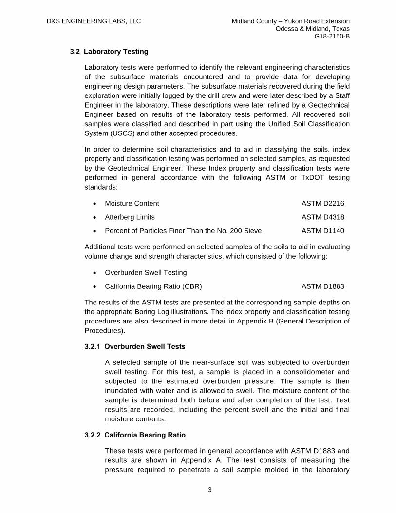
D&S ENGINEERING LABS, LLC Midland County – Yukon Road Extension Odessa & Midland, Texas
G18-2150-B
3
3.2 Laboratory Testing
Laboratory tests were performed to identify the relevant engineering characteristics of the subsurface materials encountered and to provide data for developing engineering design parameters. The subsurface materials recovered during the field exploration were initially logged by the drill crew and were later described by a Staff Engineer in the laboratory. These descriptions were later refined by a Geotechnical Engineer based on results of the laboratory tests performed. All recovered soil samples were classified and described in part using the Unified Soil Classification System (USCS) and other accepted procedures.
In order to determine soil characteristics and to aid in classifying the soils, index property and classification testing was performed on selected samples, as requested by the Geotechnical Engineer. These Index property and classification tests were performed in general accordance with the following ASTM or TxDOT testing standards:
Moisture Content ASTM D2216
Atterberg Limits ASTM D4318
Percent of Particles Finer Than the No. 200 Sieve ASTM D1140
Additional tests were performed on selected samples of the soils to aid in evaluating volume change and strength characteristics, which consisted of the following:
Overburden Swell Testing
California Bearing Ratio (CBR) ASTM D1883
The results of the ASTM tests are presented at the corresponding sample depths on the appropriate Boring Log illustrations. The index property and classification testing procedures are also described in more detail in Appendix B (General Description of Procedures).
A selected sample of the near-surface soil was subjected to overburden swell testing. For this test, a sample is placed in a consolidometer and subjected to the estimated overburden pressure. The sample is then inundated with water and is allowed to swell. The moisture content of the sample is determined both before and after completion of the test. Test results are recorded, including the percent swell and the initial and final moisture contents.
These tests were performed in general accordance with ASTM D1883 and results are shown in Appendix A. The test consists of measuring the pressure required to penetrate a soil sample molded in the laboratory

D&S ENGINEERING LABS, LLC Midland County – Yukon Road Extension Odessa & Midland, Texas
G18-2150-B
4
according to ASTM D698 (standard Proctor) with a plunger of standard area. The pressure is then recorded and divided by the pressure necessary to obtain equal penetration into a standard crushed rock material.
SITE CONDITIONS
4.1 Stratigraphy
Based upon a review of the samples recovered, along with the Geologic Atlas of Texas, Hobbs Sheet, this site is in an area underlain by soil strata associated with Quaternary Windblown cover sand that generally consists of silty quartz sand and caliche in dunes and dune ridges.
At the surface within Boring P21, asphalt pavement of 7.75 inches in thickness are present. The asphalt section is underlain with base course (flexible base) material of 6 inches thick. The base course materials generally consist of coarse gravel to coarse sand that are various shades of brown and red in color.
Below the pavement section within Boring P21 and at the surface within the remaining borings, either native sand or lean clay soils are present. The native sand soils present are generally loose to medium dense in condition, are various shades of brown in color and contain varying amounts of clays, silts, calcareous deposits and fine roots. The native lean clay soils present are generally soft to very stiff in consistency, are various shades of brown and red in color and contain varying amounts of sand, calcareous nodules and deposits and fine roots. These native sand and lean clay soils extend to depths of about 1 to 4 feet within the borings.
Below the native sand and clay soils within the borings, materials locally referred to as “caliche” (caliche caprock) are present. The “caliche” materials are generally comprised of sand soils. The caliche caprock sands are generally medium dense to very dense in condition, weakly cemented and are various shades of brown, white and red in color. Varying amounts of silts and clays are present within the sand strata. The caliche sand soils extend to the maximum depths explored of about 5 to 15 feet. Although auger refusal was not encountered within the caliche caprock materials, however very hard layers were encountered with TCP values as low as 0.125 to 0.5 inches per 100 blows.
Subsurface conditions at each boring location are described in detail on the individual boring log illustrations presented in Appendix A.
4.2 Groundwater
Groundwater seepage was not observed during drilling or upon completion of drilling within the borings performed at the site. Although not encountered, groundwater levels may be anticipated to fluctuate with seasonal and annual variations in rainfall and may also change as a result of local development.

D&S ENGINEERING LABS, LLC Midland County – Yukon Road Extension Odessa & Midland, Texas
G18-2150-B
5
ENGINEERING ANALYSIS
5.1 Estimated Potential Vertical Movement (PVM)
Potential Vertical Movement (PVM) was evaluated utilizing a variety of different methods for predicting movement, as described in Appendix B, and based on our experience and professional opinion.
At the time of our field investigation, the near-surface soils were generally found to be in a dry to average moisture condition. Based upon the results of our analysis, the site is estimated to possess a PVM of less than 1-inch at the soil moisture conditions existing at the time of the field investigation. Dry, average and wet are relative terms based on moisture content and plasticity.
The sandy soils present at the site are relatively non-expansive and are not subjected to appreciable vertical movements with changes in soil moisture content; however, they are subject to settlement with the application of load. The magnitude of settlement due to loading will depend on applied loading, soil conditions and on foundation type and geometry. Settlement of the existing soils under the anticipated typical traffic loading is estimated to be on the order of one-half inch assuming the soil is prepared in accordance with the recommendations outlined in this report.
PAVEMENT RECOMMENDATIONS
6.1 General
The pavement design recommendations provided here are derived from the subgrade information obtained during our geotechnical investigation, our experience with similar projects in this area, and from the guidelines and recommendations of the American Concrete Pavement Association (ACPA). WinPAS 12 software based on AASHTO 1993 from ACPA were used to develop the alternative suitable pavement sections, HMAC.
The pavement section recommendations provided herein are based on the assumptions outlined. Should actual requirements or projections deviate from those assumptions, a re-analysis may be necessary. Increased intensity and frequency of traffic loading will require more stringent design parameters than those provided herein. Prevailing local codes or ordinances may also be more stringent and should take precedence over the recommendations contained herein. It is the responsibility of the Civil Engineer of Record and/or other design professionals who are responsible for pavement design to seal the final pavement design plans and associated specifications for this project.
Proper drainage should be provided both during and after construction. Emphasis should be given to areas where the pavement is placed directly adjacent to intersecting roadways and drives. Pavements should include a regular maintenance

D&S ENGINEERING LABS, LLC Midland County – Yukon Road Extension Odessa & Midland, Texas
G18-2150-B
6
schedule to identify and seal cracks that may develop in the pavement surface to prevent water passing through the asphalt to the base or subgrade materials.
6.2 Behavior of Soils beneath Pavement
Near-surface soils at this site are considered to have a low potential for volume change with changes in soil moisture content. However, increased moisture content can result in reduced soil stiffness. The moisture content can be “stabilized” to some degree in these soils by covering them with an impermeable surface, such as pavement. However, if moisture is introduced as a result of surface water percolation through pavement joints and cracks or poor drainage, the soil strength can reduce, causing distress to pavements as traffic passes over.
The edges of pavement are particularly prone to moisture variations, and so these areas therefore often experience the most distress. When cracks appear on the surface of the pavement, these openings can allow moisture to enter the pavement subgrade, which can lead to further weakening of the pavement section as well as accelerated failure of the pavement surface.
In order to minimize the potential impacts of moisture-induced weakened soil on paved areas and to improve the long-term performance of the pavement, we have the following recommendations:
Provide a crowned pavement, which provides maximum drainage away from the roadway, with a minimum slope of five percent within the first 5 feet. Drainage ditches should be of sufficient size and capacity to prevent water from ponding at the edges of the road.
Subgrade treatments intended to increase the subgrade stability should extend to at least 18-inches beyond the back of curbs or edges of pavements.
6.3 Pavement Subgrade Preparation Recommendations
The anticipated subgrade soils in the proposed paving areas will consist of clayey sand, silty sand, silty clayey sand, sandy lean clay and lean clay with sand. These soils can become weak with appreciable increases in moisture content. A commonly used method to improve the strength properties of the subgrade soils, provide a working platform, and provide a uniform subgrade is to treat them with cement. Cement treatment is often used in conjunction with compacted aggregate base when appreciable or heavy traffic loading is anticipated, and/or to reduce the asphalt thickness.
The following recommendations discuss subgrade preparation and subgrade preparation alternatives.

D&S ENGINEERING LABS, LLC Midland County – Yukon Road Extension Odessa & Midland, Texas
G18-2150-B
7
Strip the site of all asphalt and base, vegetation and remove any remaining organic or deleterious material under the planned paved areas. Typically, 6 to 8 inches should be sufficient for this purpose, though some areas may require deeper excavations.
Cut as needed to required pavements subgrade elevation to accommodate the new roadways section.
After stripping and performing any necessary cuts, the exposed subgrade should be proof rolled. Proof rolling should consist of rolling the entire pavement subgrade with a heavily-loaded, tandem-axle dump truck or fully loaded water truck weighing at least 25 tons or other approved equipment capable of applying similar loading conditions. Any soft, wet or weak soils that are observed to rut more than about 1/2-inch or pump excessively (exhibiting “waving” action) during proof rolling should be removed and replaced with well-compacted, on-site clayey material as outlined below. The proof rolling operation should be performed under the observation of a qualified geotechnical engineer.
After proof rolling, scarify, rework, and recompact the exposed stripped subgrade to a minimum compacted depth of 6 inches. The scarified and reworked soils should be compacted to at least 95 percent of the maximum dry density, as determined by ASTM D698 (standard Proctor), and placed at a moisture content that is within two percentage points of the optimum moisture content, as determined by the same test (±2%). In areas that require fill, the fill should be placed in maximum 6-inch compacted lifts, compacted to at least 95 percent of the maximum dry density, as determined by ASTM D698 (standard Proctor), and placed at a moisture content within two percentage points of the optimum moisture content, as determined by the same test (±2%). Fill materials may be derived from on-site, or may be imported as long as the materials are essentially free of organic materials and particles in excess of 4 inches their maximum direction. Imported fill materials should have no less than 35 percent material passing a No. 200 mesh sieve and a Plasticity Index of no more than 30.
Water should not be allowed to pond on the prepared surface once the subgrade soil has been brought to required grade. To that end, the subgrade surface should be shaped in a way that will allow water to shed to one or both edges of the prepared subgrade.
Field density and moisture content testing should be performed at the rate of one test per lift per 300 linear feet of roadway.

D&S ENGINEERING LABS, LLC Midland County – Yukon Road Extension Odessa & Midland, Texas
G18-2150-B
8
Surface grading adjacent to the edges of pavements should be sloped away from the edges to the maximum degree possible. Where minimum recommended slopes of adjacent surface grades cannot be achieved, the edges of the pavement section should be thickened a minimum of 2-feet wide along each edge.
Once the subgrade is brought to required subgrade elevation, cement treatment may begin to achieve a treated compacted depth of 8-inches. We have the following recommendations for subgrade cement treatment:
Cement treated subgrade should be prepared in accordance with TxDOT Item 275 to the elevations shown on the plans using an estimated three (3) percent cement by dry weight measure of the subgrade soil. The actual percentage to be used should be determined once the subgrade is at rough grade elevation. The amount of cement used should be the minimum amount required to achieve a 7-day cured unconfined compressive strength of 100 pounds per square inch.
Cement should be applied such that mixing operations for a given area can be completed during the same working day.
The cement may be placed dry or by the slurry method (meaning that the cement should be mixed with water in trucks or in tanks and applied as a thin slurry).
After mixing, the soil-cement mixture should be tested for sufficient pulverization and mixing in accordance with TxDOT Item 275. The mixed material should meet the following requirements when tested dry by laboratory sieves:
o Minimum passing 1¾" sieve: 100%
o Minimum passing ¾” sieve: 85%
o Minimum passing No. 4 sieve: 60%
After sufficient re-mixing, the soil/cement mixture should be compacted to a minimum of 95% of Standard Proctor (ASTM D698) and to a moisture content that is at or above the optimum moisture, as determined by that same test. Compaction should be completed within 2 hours after the application of water to the mixture of soil and cement.
Cure for at least 3 days by “sprinkling” as described in TxDOT Item 204.
To reduce the potential for subgrade soil moisture changes at the edges of pavements, the cement stabilized subgrade should extend a minimum of 18-inches past the back of the roadway curbs or edges of pavements.

D&S ENGINEERING LABS, LLC Midland County – Yukon Road Extension Odessa & Midland, Texas
G18-2150-B
9
In order to reduce the potential for reflective cracking up through the pavement, particularly with asphalt pavement, the cement treated subgrade should be rolled with a vibratory roller 1 to 2 days after final compaction to create a network of hairline cracks (microcracking). Cure for at least 2 days by “sprinkling” as described in TxDOT Item 204 after completion of microcracking.
Field density and moisture content testing should be performed at the rate of one test per lift per 100 linear feet of roadway. These tests are necessary to determine if the recommended moisture and compaction requirements have been attained.
As an alternative to, or in conjunction with, cement treatment, aggregate base may be placed over the prepared subgrades in accordance with the following recommendations prior to placing the pavements.
After completing the subgrade preparation, place aggregate base as required in maximum 4 to 6-inch thick compacted lifts. The area of the aggregate base should extend a minimum of 18-inches beyond the edges of the pavement.
Aggregate base, should be TxDOT Type A or D and meet the gradation, durability and plasticity requirements of TxDOT Item 247 Grade 1-2 or better (2014). The aggregate base material should be uniformly compacted to a minimum of 98% of the maximum standard Proctor dry density (ASTM D698) and placed at a moisture content that is sufficient to achieve density, but with a minimum of 4% moisture.
Field density and moisture content testing should be performed at the rate of one test per 300 linear feet of roadway.
6.4 Subgrade Strength Characteristics
Based on the present information, we recommend that a California Bearing Ratio (CBR) value of 7 be used in the design with a corresponding resilient modulus of 7,300 psi. These values were selected considering that clayey sands, sandy lean clays and lean clay with sand are projected to be present at final subgrade elevation over significant length of the roadways alignment, and that these materials have a lower stiffness than the silty sands that are expected within few sections of the proposed roadways improvements.
6.5 Pavement Design Assumptions
Specific axle loading and traffic volume characteristics have not been provided at this time. After reviewing available traffic counts for roadways nearby the project site using TXDOT District Traffic Web Viewer 2018 GIS data, the average daily traffic (ADT)

D&S ENGINEERING LABS, LLC Midland County – Yukon Road Extension Odessa & Midland, Texas
G18-2150-B
10
varies significantly ranging from 616 at the west part of the proposed road to 4,935 to the east. In addition, the ADT for TX 191 and N State Highway 349 were 8,463 and 16,277, respectively. We understand the future extension to of the Yukon Road is to serve as one of the corridors to access Midland International Airport. Based on these assumptions, we have assumed the proposed roadway will serve as a collector road and have assumed an ADT of about 3,000 for our analysis and a percent trucks of 20%. If the actual number of ADT or percent trucks differs significantly from our assumptions, we recommend a separate analysis and pavement sections recommendations be performed.
Design Life: 15 years
Average Daily Traffic (ADT): 3,000
Equivalent Single Axle Loads (ESAL’s): 3,219,170
Directional Distribution Factor: 50%
Design Lane Distribution Factor: 100%
Growth Rate: 2.0%
Percent Trucks: 20.0%
Truck Factor (ESALs/Truck): 1.7
Initial Serviceability: 4.2
Terminal Serviceability: 2.25
Considering that this is a new county road in an industrial semi-rural environment, we have assumed a reliability factor of 75%. If a higher value of reliability is required, the overall section will increase. Please contact this office if significant deviations from the assumptions above are anticipated.
In determination of roadway section alternatives, we used WinPAS 12 software and the following assumptions were made.
Reliability: 75%
Overall Standard Deviation: 0.45
Subgrade Resilient Modulus: 7,300 psi
Drainage Coefficient: 1.0
Layer coefficient, Asphalt Cement Concrete: 0.44
Layer coefficient, Soil Cement or Cement treated reclaimed pavement: 0.20
Layer coefficient, Aggregate Base: 0.14
Minimizing subgrade saturation is an important factor in maintaining subgrade strength. Water should not be allowed to pond on or adjacent to the pavement that could saturate the pavement and lead to premature pavement deterioration. We

D&S ENGINEERING LABS, LLC Midland County – Yukon Road Extension Odessa & Midland, Texas
G18-2150-B
11
recommend that all pavement surfaces be sloped to provide rapid surface drainage. Positive surface drainage away from the edge of the paved areas should be maintained.
6.6 Flexible Pavement Design and Recommendations
Flexible pavement surface course should conform to TxDOT Item 341 – “Dense-graded Hot Mix Asphalt” (HMA), or TxDOT Item 340 “Dense-graded Hot Mix Asphalt” (Small Quantity). The following subparagraphs provide recommendations for HMA based on the design assumptions noted previously. Actual loading conditions may require modifications.
6.7 Full Depth HMA
Full-depth HMA may consist of at least 1.5 inches of Type C or D surface course over 2 inches of Type B base course as specified by TxDOT Item 341 (or Item 340 as appropriate), or be entirely comprised of the surface course. Alternative options for flexible pavement section are included in Table 1, and is based on the subgrade CBR (7) and modulus (7,300 psi) values noted above.
Table 1. Alternative Flexible Pavement Sections for ADT = 3,000
Material Types Based on Above Assumed Design Criteria
Alternative 1
Alternative 2 Alternative 3
HMAC (in.) 3 3 5.5
Aggregate base (in.) 7 19 11
Cement-treated soil materials (in.) 8 -- --
6.8 Additional Pavement Section Evaluations
Based on the above assumptions, additional pavement section valuations were performed considering Midland County pavement standards of 3 inches asphalt on 11 inches of base and City of Midland pavement standards of 5.5 inches of asphalt (1.5 inches of Type D and 4 inches of Type B) on 6 inches of base material which showed the design life of 2.5 and 5.5 years, respectively, for an ADT of 3,000 and 20% trucks. Also, two additional pavement sections were evaluated for a 10-year design life based on above assumptions. The sections corresponding to this evaluation showed 3 inches of asphalt on 16 inches of base materials and 5.5 inches of asphalt on 8 inches of base materials.
6.9 HMA Installation and Testing
The following is recommended for HMA:

D&S ENGINEERING LABS, LLC Midland County – Yukon Road Extension Odessa & Midland, Texas
G18-2150-B
12
HMAC should be placed and compacted to contain between 5 and 9 percent of air voids.
The target density for asphalt lifts should be 91 to 95 percent of the Maximum Theoretical Specific Gravity as determined by laboratory testing.
The following tests should be performed:
In place field density tests to establish a rolling pattern.
One extraction and gradation test per day’s HMAC placement.
Two cores to verify thickness and density per 5,000 feet of roadway placed.
CULVERTS
We understand that pre-cast concrete rectangular culverts will be provided at two locations (Borings C1 and C2) to convey runoff from one side of the roadway to the other. We anticipate that the culverts will be placed on a conventionally reinforced concrete mat foundation (base slab).
Recommendations for subgrade preparation to provide a working surface for construction and reduce the potential for bearing on soft soils are described below. The culverts mat foundation may be designed using an allowable bearing capacity of 2,000 pounds per square foot when placed on the prepared subgrade as described below.
The prepared subgrades for the culverts should be essentially free of any loose or soft material prior to the placement of the culvert.
For the culverts’ subgrades, we have the following recommendations for earthwork:
Strip the site of all vegetation, organic soil, and deleterious material within the new culvert area. Typically, 6 to 12 inches is sufficient for this purpose.
After stripping and performing any necessary cuts, excavate the culvert area to a depth of 2 feet below the underside of the base slab. The excavation should extend at least 5 feet beyond the edges of the new structure.
Place a filter fabric on top of the excavated subgrade followed by a geogrid. The geotextile may be US Fabrics US 315 or approved equivalent. Geogrid may be Tensar TX5, or approved equivalent. The fabric and grid should extend to the limits of the excavation.
Provide a minimum of 24-inches of flexible base on top of the geogrid. Flexible base should meet the gradation, plasticity, and durability requirements of TxDOT Standard Specification Item 247, Type A or D, Grade 3 or better (TxDOT 2014 specifications). These materials should be placed in maximum 4-inch thick compacted lifts and should be compacted to at least 95 percent of the maximum

D&S ENGINEERING LABS, LLC Midland County – Yukon Road Extension Odessa & Midland, Texas
G18-2150-B
13
density as determined by the Standard Moisture Density Relationship test (ASTM D698), and should be placed at a moisture content sufficient to achieve the required density.
Water should not be allowed to pond on the prepared subgrade either during fill placement, or after reaching final subgrade elevation. To that end, the subgrade surfaces should be shaped to shed water to the edges of the excavation.
Following placement of the culverts, in order to prevent a hard point with reference to the road surfacing we recommend a minimum of 15 inches of compacted clayey soil be provided over the top of the culverts and below the aggregate base of the asphalt pavement. The compacted soil should be placed as described in Section 6.3.1. The area of the aggregate base should extend a minimum of 18 inches beyond the edges of the asphalt pavement and be more or less flush with the top of asphalt. Surface grading adjacent to the edges of pavements should be sloped away from the edges to prevent ponding. The upper surface from the edge of pavement down to the top of culvert should be so designed to prevent erosion. Some routine maintenance of the edge should be anticipated.
Consideration should be given to streambed and bank erosion protection on both sides of the roadway. Erosion protection may be accomplished with gabion mattresses, concrete rip rap, or other large stone rip rap. Regardless of the final protective layer, a filter fabric be placed between the natural soil and the protective layer.
Each lift of fill placed should be tested for moisture content and degree of compaction by a testing laboratory at the rate of three tests performed per lift within the culvert pad. D&S would be pleased to provide these services in support of this project.
RETAINING WALLS
We understand that retaining walls will be provided for culverts headwalls and wingwalls within the crossings. We anticipate that the retaining walls will be placed on a conventionally reinforced concrete footing. The footing may be designed using an allowable bearing capacity of 2,000 pounds per square foot when placed on the prepared subgrade as described below.
8.1 Lateral Earth Pressures
Retaining walls will be subjected to lateral earth pressures and should be designed in consideration of these forces. Earth pressures will be influenced by structural design of the walls, conditions of wall restraint, methods of construction and/or compaction, the strength of the materials being restrained, and drainage conditions.
Two wall restraint conditions are typically considered. Active earth pressure is commonly used for design of free-standing cantilever retaining walls and assumes

D&S ENGINEERING LABS, LLC Midland County – Yukon Road Extension Odessa & Midland, Texas
G18-2150-B
14
some small outward rotation of the wall. This condition is applicable to site retaining walls. The "at-rest" condition assumes that no wall rotation or movement will occur. This condition is typically considered where minimal movement of the wall is desired, for movement sensitive walls, basement walls and walls rigidly connected to lower and upper floors (or roofs). “At-rest” condition would be applicable for the retaining wall.
The design lateral earth pressures recommended herein do not include a Factor of Safety and do not provide for dynamic pressures on the walls.
Lateral loads due to surcharge should be calculated as shown in Table 2. A coefficient of friction against sliding may be taken as 0.35 (ultimate) for concrete cast against compacted aggregate base. A passive pressure value of 230 psf may be used below a depth of 2 feet from final grade.
Figure 1: Lateral Earth Pressure
Table 2. Lateral Earth Pressures
Earth Pressure Conditions
Coefficient for Backfill Type
Undrained Equivalent Fluid
Density (pcf)
Surcharge Pressure (psf)
p1
Earth Pressure (psf)
p2
At-Rest (Ko) On-Site Soils - 0.58 99 (0.58) S1 (99) H2
Notes: (1) S = surcharge pressure (2) H = wall height
Applicable conditions to Table 2 above include:
Horizontal backfill, compacted to 95 to 98 percent of Standard Proctor maximum dry density for cohesive soils horizontal finished grades at the top and bottom of the retaining wall

D&S ENGINEERING LABS, LLC Midland County – Yukon Road Extension Odessa & Midland, Texas
G18-2150-B
15
Uniform surcharge, where S is surcharge pressure
A maximum in situ soil total unit weight of 125 pcf
No loading contribution from compaction equipment
Heavy compactors should not be allowed to operate within 5 feet of the walls during backfilling to avoid developing excessive temporary or long-term lateral soil pressures. A qualified geotechnical engineer or geotechnical representative should be present to monitor all foundation excavations and fill placement. D&S would be pleased to provide these services in support of this project.
For the retaining wall subgrade, we have the following recommendations for earthwork.
Strip the site of all vegetation, organic soil, and deleterious material within the new retaining walls area. Typically, 6 to 8 inches is sufficient for this purpose.
After stripping and performing any necessary cuts, excavate the retaining wall area to a depth of 2 feet below the underside of the retaining wall footing
Place a filter fabric on top of the excavated subgrade. The geotextile may be US Fabrics US 315 or approved equivalent.
Provide a minimum of 24-inches of flexible base on top of the filter fabric. Flexible base should meet the gradation, plasticity, and durability requirements of TxDOT Standard Specification Item 247, Type A or D, Grade 3 or better (TxDOT 2014 specifications). These materials should be placed in maximum 4-inch thick compacted lifts and should be compacted to at least 95 percent of the maximum density as determined by the Standard Moisture Density Relationship test (ASTM D698), and should be placed at a moisture content sufficient to achieve the required density.
Water should not be allowed to pond on the prepared subgrade either during fill placement, or after reaching final subgrade elevation. To that end, the subgrade surfaces should be shaped to shed water to the edges of the excavation.
Each lift of fill placed should be tested for moisture content and degree of compaction by a testing laboratory at the rate of three tests performed per lift within the culvert pad. D&S would be pleased to provide these services in support of this project.
OTHER CONSTRUCTION
9.1 Utility Lines and Culverts
Backfill placed within utility/culvert trenches that cross pavements should be properly compacted. If these areas are not properly compacted, settlement will occur and

D&S ENGINEERING LABS, LLC Midland County – Yukon Road Extension Odessa & Midland, Texas
G18-2150-B
16
distress to the pavement is likely. All backfill should be placed in lifts, properly compacted and tested in accordance to the appropriate earthwork recommendations provided.
Trenches should be opened a sufficient width to safely allow compaction equipment access to the backfill and for confirmation testing to occur. The backfill should be placed in horizontal lifts. Excavations greater than 5 feet in height/depth should be in accordance with OSHA 29CFR 1926, Subpart P. The site soils should be assumed to be Type “C” soil.
Backfill for utility lines should consist of on-site material and should be placed in accordance with the following recommendations. The on-site fill soil should be placed in maximum 6-inch compacted lifts, compacted to a minimum of 95 percent of the maximum dry density, as determined by ASTM D698 (standard Proctor), and placed at a moisture content that is at least the optimum moisture content, as determined by that same test. We also recommend that the utility trenches be visually inspected during the excavation process to ensure that undesirable fill that was not detected by the test borings does not exist at the site. This office should be notified immediately if any such fill is detected.
Utility excavations should be sloped so that water within excavations will flow to a low point away from the active construction where it can be removed from before backfilling. Compaction of bedding material should not be water-jetted. Compacted backfill above the utilities should be on-site clayey soils to limit the percolation of surface water.
9.2 Surface Drainage
Proper drainage is critical to the performance of the paved areas. Positive surface drainage should be provided that directs water away from pavements edges. Where possible, we recommend that a slope of at least 5 percent be provided for the first 5 feet away from pavement edges. The slopes should direct water away from the pavement and should be maintained throughout construction and the life of the pavement.
9.3 Excavations and Excavation Difficulties
Excavations greater than 5 feet in height/depth should be in accordance with OSHA 29CFR 1926, Subpart P. Temporary construction slopes should incorporate excavation protection systems or should be sloped back.
Although auger refusal was not encountered within the caliche caprock materials, however very hard layers were encountered with TCP values as low as 0.125 to 0.5 inches per 100 blows. Appropriate hard rock excavation equipment will be required for excavations in the caliche caprock materials. Such heavy equipment should be of a sufficient size and weight to excavate through the hard layers to reach the desired bearing stratum. These caliche materials can typically be excavated with backhoes/track-hoes equipped with rock teeth, single tooth rippers and hydraulic

D&S ENGINEERING LABS, LLC Midland County – Yukon Road Extension Odessa & Midland, Texas
G18-2150-B
17
impact hammers. Where it is desired to maintain close excavations tolerances, trenching machines, rock wheel excavators should also be considered. Another method commonly used for excavations into very hard materials is closely spaced, small-diameter holes drilled typically by air-rotary methods along an excavation line (commonly referred to as “line-drilling”). This line drilling creates a preferred plane of weakness for subsequent excavation. The excavated caliche caprock surface is expected to be irregular. Over breaks in the caliche should also be expected. Loose rock fragments should be removed from the exposed face of rock cuts. Any rock faces, which could be subject to spalling identified by the competent person, should be covered with metal chain link, welded wire mesh, or other suitable covering to avoid rock spalls. Rock bolts/anchors may also be used at approximately 4 to 5 foot centers. Surface water should be diverted away from excavations.
Overburden soils above the caliche caprock will need to be sloped at 1.5H:1V or flatter. A minimum 2-foot wide bench should be required at the base of the overburden soils, at the top of the caliche caprock. The caliche caprock can very likely be cut in the range 0.75H:1V to 0.5H:1V. As excavation proceeds through the caliche caprock, the surface of the exposed caliche should be carefully examined by the competent person for weakening due to weather exposure, joints and fractures, seepage, or other planes of weakness and the slope should be flattened or shored as required
Analyses of slope or trench wall stability in excavations are beyond the scope of this study and have not been performed. In all cases, the requirements of the Occupational Safety and Health Administration (OSHA) must be followed by the contractor. It is important for the contractor to monitor the slope and pit wall stability by observation and measurements, and to prevent excessive loads (especially heavy vibratory loads) from being applied to the slope. The contractor should be responsible for maintaining the slopes and pit walls in a safe condition during construction. A qualified geotechnical engineer or geotechnical representative should be present to monitor all foundation excavations and fill placement. D&S would be pleased to provide these services in support of this project.
LIMITATIONS
The professional geotechnical engineering services performed for this project, the findings obtained, and the recommendations prepared were accomplished in accordance with currently accepted geotechnical engineering principles and practices.
Variations in the subsurface conditions are noted at the specific boring locations for this study. As such, all users of this report should be aware that differences in depths and thicknesses of strata encountered can vary between the boring locations. Statements in the report as to subsurface conditions across the site are extrapolated from the data obtained at the specific boring locations. The number and spacing of the exploration borings were chosen to obtain geotechnical information for the design and construction of pavements, culverts and retaining walls. If there are any conditions differing significantly

D&S ENGINEERING LABS, LLC Midland County – Yukon Road Extension Odessa & Midland, Texas
G18-2150-B
18
from those described herein, D&S should be notified to re-evaluate the recommendations contained in this report.
Recommendations contained herein are not considered applicable for an indefinite period of time. Our office must be contacted to re-evaluate the contents of this report if construction does not begin within a one-year period after completion of this report.
The scope of services provided herein does not include an environmental assessment of the site or preliminary investigation for the presence or absence of hazardous materials in the soil, surface water, or groundwater.
All contractors referring to this geotechnical report should draw their own conclusions regarding excavations, construction, etc. for bidding purposes. D&S is not responsible for conclusions, opinions or recommendations made by others based on these data. The report is intended to guide preparation of project specifications and should not be used as a substitute for the project specifications.
Recommendations provided in this report are based on our understanding of information provided by the Client to us regarding the scope of work for this project. If the Client notes any differences, our office should be contacted immediately since this may materially alter the recommendations.

APPENDIX A - BORING LOGS AND SUPPORTING DATA

**BORING LOCATIONS ARE INTENDED FOR GRAPHICAL REFERENCE ONLY**
N.T.S.
ODESSA & MIDLAND TEXAS
SHEET NO.
DATE DRILLED
G1March 11 – 12, 2020
PLAN OF BORINGS
YUKON EXTENSION
*BORINGS P1 & P2 – Not Drilled

**BORING LOCATIONS ARE INTENDED FOR GRAPHICAL REFERENCE ONLY**
N.T.S.
ODESSA & MIDLAND TEXAS
SHEET NO.
DATE DRILLED
G2March 11 – 12, 2020
PLAN OF BORINGS
YUKON EXTENSION

**BORING LOCATIONS ARE INTENDED FOR GRAPHICAL REFERENCE ONLY**
N.T.S.
ODESSA & MIDLAND TEXAS
SHEET NO.
DATE DRILLED
G3March 11 – 12, 2020
PLAN OF BORINGS
YUKON EXTENSION

KEY TO SYMBOLS AND TERMS
CONSISTENCY: FINE GRAINED SOILS
CONDITION OF SOILS
SECONDARY COMPONENTS
WEATHERING OF ROCK MASS
TCP (#blows/ft)
< 88 - 20
20 - 6060 - 100
> 100
Relative Density (%)
0 - 1515 - 35
35 - 6565 - 85
85 - 100
SPT (# blows/ft)
0 - 23 - 4
5 - 89 - 15
16 - 30
> 30
UCS (tsf)
< 0.250.25 - 0.5
0.5 - 1.01.0 - 2.0
2.0 - 4.0
> 4.0
CONSISTENCY OF SOILSLITHOLOGIC SYMBOLS
CONDITION: COARSE GRAINED SOILS
QUANTITY DESCRIPTORS
RELATIVE HARDNESS OF ROCK MASS
SPT (# blows/ft)
0 - 45 - 10
11 - 3031 - 50
> 50
DescriptionNo visible sign of weatheringPenetrative weathering on open discontinuity surfaces,but only slight weathering of rock materialWeathering extends throughout rock mass, but the rockmaterial is not friableWeathering extends throughout rock mass, and the rockmaterial is partly friableRock is wholly decomposed and in a friable condition butthe rock texture and structure are preservedA soil material with the original texture, structure, andmineralogy of the rock completely destroyed
DesignationFreshSlightly weathered
Moderately weathered
Highly weathered
Completely weathered
Residual Soil
DescriptionCan be carved with a knife. Can be excavated readily withpoint of pick. Pieces 1" or more in thickness can be brokenby finger pressure. Readily scratched with fingernail.Can be gouged or grooved readily with knife or pick point.Can be excavated in chips to pieces several inches in sizeby moderate blows with the pick point. Small, thin piecescan be broken by finger pressure.Can be grooved or gouged 1/4" deep by firm pressure onknife or pick point. Can be excavated in small chips topieces about 1" maximum size by hard blows with the pointof a pick.Can be scratched with knife or pick. Gouges or grooves 1/4"deep can be excavated by hard blow of the point of a pick.Hand specimens can be detached by a moderate blow.Can be scratched with knife or pick only with difficulty.Hard blow of hammer required to detach a hand specimen.Cannot be scratched with knife or sharp pick. Breaking of handspecimens requires several hard blows from a hammer or pick.
TraceFewLittleSomeWith
DesignationVery Soft
Soft
Medium Hard
Moderately Hard
Hard
Very Hard
< 5% of sample5% to 10%10% to 25%25% to 35%> 35%
Condition
Very LooseLoose
Medium DenseDense
Very Dense
Consistency
Very SoftSoft
Medium StiffStiff
Very Stiff
HardAR
TIF
ICIA
L
Asphalt
Aggregate Base
Concrete
Fill
SO
ILR
OC
K
Limestone
Mudstone
Shale
Sandstone
Weathered Limestone
Weathered Shale
Weathered Sandstone
CH: High Plasticity Clay
CL: Low Plasticity Clay
GP: Poorly-graded Gravel
GW: Well-graded Gravel
SC: Clayey Sand
SP: Poorly-graded Sand
SW: Well-graded Sand


17.3
3.6
3.6
1.0 ft
14.1 ft
CLAYEY SAND (SC); loose; brown;trace fine rootsSILTY SAND (SM); very dense; lightbrown, white; weakly cemented;calcareous; locally referred to as"caliche"
End of boring at 14.1'
Notes:-dry during drilling-dry upon completion
S
T
N
N
T
NP NP NP
50=1.5"50=0.5"
3550=2.5"
17,35,28
50=0.25"50=0.25"
0.5
27
Depth(ft)
0
5
10
15
20
25
30
35
Atterberg Limits
Clay(%)
C1PAGE 1 OF 1
MC(%)
Legend: S-Shelby Tube N-Standard Penetration T-Texas Cone Penetration C-Core B-Bag Sample - Water Encountered
REC(%)
RQD(%)
SampleType
Swell(%)LL
(%)PL(%) PI
TotalSuction
(pF)
HandPen. (tsf)
orSPTor
TCP
HandPen. (tsf)
orSPTor
TCP
Passing#200Sieve(%)
BORING LOG
GraphicLog
DUW(pcf)
Unconf.Compr.Str (ksf)
CLIENT: Dunaway Associates
LOCATION: Odessa & Midland, TexasPROJECT: Yukon Road Extension
DRILLED BY: Charles Ray Stephens (D&S)
START DATE: 3/11/2020 DRILL METHOD: Hollow Stem Flight Auger
LOGGED BY: Erin Williams (D&S)
FINISH DATE: 3/11/2020
GROUND ELEVATION:
GPS COORDINATES: N31.933565, W102.264190
PROJECT NUMBER: G18-2150-B

14.0
2.4
2.0 ft
5.1 ft
CLAYEY SAND (SC); mediumdense; brown; few calcareousdeposits
SILTY SAND (SM); very dense; lightbrown, white; calcareous; locallyreferred to as "caliche"
End of boring at 5.1'
Notes:-dry during drilling-dry upon completion
S
T
23 15 8
50=1.25"50=0.5"
4.5+ 40
Depth(ft)
0
5
10
15
20
25
30
35
Atterberg Limits
Clay(%)
C2PAGE 1 OF 1
MC(%)
Legend: S-Shelby Tube N-Standard Penetration T-Texas Cone Penetration C-Core B-Bag Sample - Water Encountered
REC(%)
RQD(%)
SampleType
Swell(%)LL
(%)PL(%) PI
TotalSuction
(pF)
HandPen. (tsf)
orSPTor
TCP
HandPen. (tsf)
orSPTor
TCP
Passing#200Sieve(%)
BORING LOG
GraphicLog
DUW(pcf)
Unconf.Compr.Str (ksf)
CLIENT: Dunaway Associates
LOCATION: Odessa & Midland, TexasPROJECT: Yukon Road Extension
DRILLED BY: Charles Ray Stephens (D&S)
START DATE: 3/12/2020 DRILL METHOD: Hollow Stem Flight Auger
LOGGED BY: Erin Williams (D&S)
FINISH DATE: 3/12/2020
GROUND ELEVATION:
GPS COORDINATES: N31.926817, W102.248817
PROJECT NUMBER: G18-2150-B

21.1
7.5
1.0 ft
6.5 ft
CLAYEY SAND (SC); loose tomedium dense; brown; trace fine rootsSILTY SAND (SM); medium dense tovery dense; light brown, white; weaklycemented; calcareous; locally referredto as "caliche"
End of boring at 6.5'
Notes:-dry during drilling-dry upon completion
S
T
N
50=0.25"50=0.125"
12,10,12
1.0
24
Depth(ft)
0
5
10
15
20
25
30
35
Atterberg Limits
Clay(%)
P3PAGE 1 OF 1
MC(%)
Legend: S-Shelby Tube N-Standard Penetration T-Texas Cone Penetration C-Core B-Bag Sample - Water Encountered
REC(%)
RQD(%)
SampleType
Swell(%)LL
(%)PL(%) PI
TotalSuction
(pF)
HandPen. (tsf)
orSPTor
TCP
HandPen. (tsf)
orSPTor
TCP
Passing#200Sieve(%)
BORING LOG
GraphicLog
DUW(pcf)
Unconf.Compr.Str (ksf)
CLIENT: Dunaway Associates
LOCATION: Odessa & Midland, TexasPROJECT: Yukon Road Extension
DRILLED BY: Charles Ray Stephens (D&S)
START DATE: 3/11/2020 DRILL METHOD: Hollow Stem Flight Auger
LOGGED BY: Erin Williams (D&S)
FINISH DATE: 3/11/2020
GROUND ELEVATION:
GPS COORDINATES: N31.934708, W102.271422
PROJECT NUMBER: G18-2150-B

23.3
3.9
6.6
1.0 ft
14.5 ft
CLAYEY SAND (SC); mediumdense; brown; trace fine rootsSILTY SAND (SM); medium dense tovery dense; light brown, white; weaklycemented; calcareous; locally referredto as "caliche"
End of boring at 14.5'
Notes:-dry during drilling-dry upon completion
S
T
N
N
48 19 29
50=0.25"50=0.125"
50=2.0"
15,16,12
2.5
Depth(ft)
0
5
10
15
20
25
30
35
Atterberg Limits
Clay(%)
P4PAGE 1 OF 1
MC(%)
Legend: S-Shelby Tube N-Standard Penetration T-Texas Cone Penetration C-Core B-Bag Sample - Water Encountered
REC(%)
RQD(%)
SampleType
Swell(%)LL
(%)PL(%) PI
TotalSuction
(pF)
HandPen. (tsf)
orSPTor
TCP
HandPen. (tsf)
orSPTor
TCP
Passing#200Sieve(%)
BORING LOG
GraphicLog
DUW(pcf)
Unconf.Compr.Str (ksf)
CLIENT: Dunaway Associates
LOCATION: Odessa & Midland, TexasPROJECT: Yukon Road Extension
DRILLED BY: Charles Ray Stephens (D&S)
START DATE: 3/11/2020 DRILL METHOD: Hollow Stem Flight Auger
LOGGED BY: Erin Williams (D&S)
FINISH DATE: 3/11/2020
GROUND ELEVATION:
GPS COORDINATES: N31.934294, W102.268536
PROJECT NUMBER: G18-2150-B

16.1
15.1
10.5
4.5
3.0 ft
5.0 ft
SANDY LEAN CLAY (CL); stiff tovery stiff; brown, light brown; tracecalcareous nodules
SILTY SAND (SM); very dense; lightbrown, white; weakly cemented;calcareous; locally referred to as"caliche"
End of boring at 5.0'
Notes:-dry during drilling-dry upon completion
S
S
S
SN
30 16 14
12, 50=4.0"
0.25
1.0
0.25 55
Depth(ft)
0
5
10
15
20
25
30
35
Atterberg Limits
Clay(%)
P5PAGE 1 OF 1
MC(%)
Legend: S-Shelby Tube N-Standard Penetration T-Texas Cone Penetration C-Core B-Bag Sample - Water Encountered
REC(%)
RQD(%)
SampleType
Swell(%)LL
(%)PL(%) PI
TotalSuction
(pF)
HandPen. (tsf)
orSPTor
TCP
HandPen. (tsf)
orSPTor
TCP
Passing#200Sieve(%)
BORING LOG
GraphicLog
DUW(pcf)
Unconf.Compr.Str (ksf)
CLIENT: Dunaway Associates
LOCATION: Odessa & Midland, TexasPROJECT: Yukon Road Extension
DRILLED BY: Charles Ray Stephens (D&S)
START DATE: 3/11/2020 DRILL METHOD: Hollow Stem Flight Auger
LOGGED BY: Erin Williams (D&S)
FINISH DATE: 3/11/2020
GROUND ELEVATION:
GPS COORDINATES: N31.933895, W102.265336
PROJECT NUMBER: G18-2150-B

17.6
5.7
4.9
1.0 ft
10.1 ft
CLAYEY SAND (SC); loose; brown;trace fine roots and calcareousnodulesSILTY SAND (SM); medium dense tovery dense; light brown, white; weaklycemented; calcareous; locally referredto as "caliche"
End of boring at 10.1'
Notes:-dry during drilling-dry upon completion
S
T
N
N
T
50=1.5"50=1.0"
5,8,7
50=0.75"
50=0.25"50=0.125"
1.0
18
Depth(ft)
0
5
10
15
20
25
30
35
Atterberg Limits
Clay(%)
P6PAGE 1 OF 1
MC(%)
Legend: S-Shelby Tube N-Standard Penetration T-Texas Cone Penetration C-Core B-Bag Sample - Water Encountered
REC(%)
RQD(%)
SampleType
Swell(%)LL
(%)PL(%) PI
TotalSuction
(pF)
HandPen. (tsf)
orSPTor
TCP
HandPen. (tsf)
orSPTor
TCP
Passing#200Sieve(%)
BORING LOG
GraphicLog
DUW(pcf)
Unconf.Compr.Str (ksf)
CLIENT: Dunaway Associates
LOCATION: Odessa & Midland, TexasPROJECT: Yukon Road Extension
DRILLED BY: Charles Ray Stephens (D&S)
START DATE: 3/11/2020 DRILL METHOD: Hollow Stem Flight Auger
LOGGED BY: Erin Williams (D&S)
FINISH DATE: 3/11/2020
GROUND ELEVATION:
GPS COORDINATES: N31.932496, W102.262691
PROJECT NUMBER: G18-2150-B

19.6
17.6
5.7
2.0 ft
5.1 ft
SANDY LEAN CLAY (CL); mediumstiff to very stiff; brown, red; trace fineroots and calcareous nodules
CLAYEY SAND (SC); very dense;light brown, white; weakly cemented;calcareous; locally referred to as"caliche"
End of boring at 5.1'
Notes:-dry during drilling-dry upon completion
S
S
T
T
50=2.0"50=0.5"
50=0.25"50=0.25"
1.0
4.5+
64
67
41
Depth(ft)
0
5
10
15
20
25
30
35
Atterberg Limits
Clay(%)
P7PAGE 1 OF 1
MC(%)
Legend: S-Shelby Tube N-Standard Penetration T-Texas Cone Penetration C-Core B-Bag Sample - Water Encountered
REC(%)
RQD(%)
SampleType
Swell(%)LL
(%)PL(%) PI
TotalSuction
(pF)
HandPen. (tsf)
orSPTor
TCP
HandPen. (tsf)
orSPTor
TCP
Passing#200Sieve(%)
BORING LOG
GraphicLog
DUW(pcf)
Unconf.Compr.Str (ksf)
CLIENT: Dunaway Associates
LOCATION: Odessa & Midland, TexasPROJECT: Yukon Road Extension
DRILLED BY: Charles Ray Stephens (D&S)
START DATE: 3/11/2020 DRILL METHOD: Hollow Stem Flight Auger
LOGGED BY: Erin Williams (D&S)
FINISH DATE: 3/11/2020
GROUND ELEVATION:
GPS COORDINATES: N31.929841, W102.261712
PROJECT NUMBER: G18-2150-B

16.8
9.3
2.7
3.0 ft
10.6 ft
CLAYEY SAND (SC); loose tomedium dense; brown, red; trace fineroots
SILTY SAND (SM); very dense; lightbrown, white; weakly cemented;calcareous; locally referred to as"caliche"
End of boring at 10.6'
Notes:-dry during drilling-dry upon completion
S
S
S
T
T
T
33 15 18
50=2.75"50=1.5"
50=0.25"50=0.25"
50=4"50=3.5"
1.0
4.5+
4.5+
29
Depth(ft)
0
5
10
15
20
25
30
35
Atterberg Limits
Clay(%)
P8PAGE 1 OF 1
MC(%)
Legend: S-Shelby Tube N-Standard Penetration T-Texas Cone Penetration C-Core B-Bag Sample - Water Encountered
REC(%)
RQD(%)
SampleType
Swell(%)LL
(%)PL(%) PI
TotalSuction
(pF)
HandPen. (tsf)
orSPTor
TCP
HandPen. (tsf)
orSPTor
TCP
Passing#200Sieve(%)
BORING LOG
GraphicLog
DUW(pcf)
Unconf.Compr.Str (ksf)
CLIENT: Dunaway Associates
LOCATION: Odessa & Midland, TexasPROJECT: Yukon Road Extension
DRILLED BY: Charles Ray Stephens (D&S)
START DATE: 3/11/2020 DRILL METHOD: Hollow Stem Flight Auger
LOGGED BY: Erin Williams (D&S)
FINISH DATE: 3/11/2020
GROUND ELEVATION:
GPS COORDINATES: N31.927164, W102.260795
PROJECT NUMBER: G18-2150-B

11.4
6.9
6.0
7.1
4.0 ft
5.2 ft
SANDY LEAN CLAY (CL); mediumstiff to very stiff; light brown, brown;trace fine roots and calcareousdeposits
CLAYEY SAND (SC); very dense;light brown, white; calcareous; locallyreferred to as "caliche"
End of boring at 5.2'
Notes:-dry during drilling-dry upon completion
S
S
S
S
S
T
25 14 1150=1.75"50=1.5"
1.5
4.5+
4.5+
1.0
54
41
Depth(ft)
0
5
10
15
20
25
30
35
Atterberg Limits
Clay(%)
P9PAGE 1 OF 1
MC(%)
Legend: S-Shelby Tube N-Standard Penetration T-Texas Cone Penetration C-Core B-Bag Sample - Water Encountered
REC(%)
RQD(%)
SampleType
Swell(%)LL
(%)PL(%) PI
TotalSuction
(pF)
HandPen. (tsf)
orSPTor
TCP
HandPen. (tsf)
orSPTor
TCP
Passing#200Sieve(%)
BORING LOG
GraphicLog
DUW(pcf)
Unconf.Compr.Str (ksf)
CLIENT: Dunaway Associates
LOCATION: Odessa & Midland, TexasPROJECT: Yukon Road Extension
DRILLED BY: Charles Ray Stephens (D&S)
START DATE: 3/11/2020 DRILL METHOD: Hollow Stem Flight Auger
LOGGED BY: Erin Williams (D&S)
FINISH DATE: 3/11/2020
GROUND ELEVATION:
GPS COORDINATES: N31.92572, W102.25858
PROJECT NUMBER: G18-2150-B

22.3
4.5
11.9
2.0 ft
10.1 ft
LEAN CLAY WITH SAND (CL);medium stiff to very stiff; brown
SILTY SAND (SM); very dense; lightbrown, red, white; calcareous; locallyreferred to as "caliche"
End of boring at 10.1'
Notes:-dry during drilling-dry upon completion
S
S
T
B
B
T
44 21 23
50=4.25"50=3.0"
50=0.125"50=0"
1.0
4.5+
72
Depth(ft)
0
5
10
15
20
25
30
35
Atterberg Limits
Clay(%)
P10PAGE 1 OF 1
MC(%)
Legend: S-Shelby Tube N-Standard Penetration T-Texas Cone Penetration C-Core B-Bag Sample - Water Encountered
REC(%)
RQD(%)
SampleType
Swell(%)LL
(%)PL(%) PI
TotalSuction
(pF)
HandPen. (tsf)
orSPTor
TCP
HandPen. (tsf)
orSPTor
TCP
Passing#200Sieve(%)
BORING LOG
GraphicLog
DUW(pcf)
Unconf.Compr.Str (ksf)
CLIENT: Dunaway Associates
LOCATION: Odessa & Midland, TexasPROJECT: Yukon Road Extension
DRILLED BY: Charles Ray Stephens (D&S)
START DATE: 3/11/2020 DRILL METHOD: Hollow Stem Flight Auger
LOGGED BY: Erin Williams (D&S)
FINISH DATE: 3/11/2020
GROUND ELEVATION:
GPS COORDINATES: N31.925795, W102.255271
PROJECT NUMBER: G18-2150-B

16.3
6.4
2.0 ft
5.5 ft
SANDY LEAN CLAY (CL); very stiff;brown; trace calcareous deposits
SILTY SAND (SM); very loose to verydense; light brown, red, white;calcareous; locally referred to as"caliche"
End of boring at 5.5'
Notes:-dry during drilling-dry upon completion
S
T
N
27 13 14
50=1.5"50=0.5"
2,2,2
4.5+ 56
Depth(ft)
0
5
10
15
20
25
30
35
Atterberg Limits
Clay(%)
P11PAGE 1 OF 1
MC(%)
Legend: S-Shelby Tube N-Standard Penetration T-Texas Cone Penetration C-Core B-Bag Sample - Water Encountered
REC(%)
RQD(%)
SampleType
Swell(%)LL
(%)PL(%) PI
TotalSuction
(pF)
HandPen. (tsf)
orSPTor
TCP
HandPen. (tsf)
orSPTor
TCP
Passing#200Sieve(%)
BORING LOG
GraphicLog
DUW(pcf)
Unconf.Compr.Str (ksf)
CLIENT: Dunaway Associates
LOCATION: Odessa & Midland, TexasPROJECT: Yukon Road Extension
DRILLED BY: Charles Ray Stephens (D&S)
START DATE: 3/12/2020 DRILL METHOD: Hollow Stem Flight Auger
LOGGED BY: Erin Williams (D&S)
FINISH DATE: 3/12/2020
GROUND ELEVATION:
GPS COORDINATES: N31.926500, W102.252160
PROJECT NUMBER: G18-2150-B

19.4
3.4
2.0 ft
10.0 ft
CLAYEY SAND (SC); mediumdense; brown; trace fine roots andcalcareous deposits
CLAYEY SAND (SC); dense to verydense; white; weakly cemented;calcareous; locally referred to as"caliche"
End of boring at 10.0'
Notes:-dry during drilling-dry upon completion
S
S
T
N
N
1.342 17 2550=2.25"50=1.25"
22,23,12
39,22,28
3.0
4.5+
33
108.1
Depth(ft)
0
5
10
15
20
25
30
35
Atterberg Limits
Clay(%)
P12PAGE 1 OF 1
MC(%)
Legend: S-Shelby Tube N-Standard Penetration T-Texas Cone Penetration C-Core B-Bag Sample - Water Encountered
REC(%)
RQD(%)
SampleType
Swell(%)LL
(%)PL(%) PI
TotalSuction
(pF)
HandPen. (tsf)
orSPTor
TCP
HandPen. (tsf)
orSPTor
TCP
Passing#200Sieve(%)
BORING LOG
GraphicLog
DUW(pcf)
Unconf.Compr.Str (ksf)
CLIENT: Dunaway Associates
LOCATION: Odessa & Midland, TexasPROJECT: Yukon Road Extension
DRILLED BY: Charles Ray Stephens (D&S)
START DATE: 3/12/2020 DRILL METHOD: Hollow Stem Flight Auger
LOGGED BY: Erin Williams (D&S)
FINISH DATE: 3/12/2020
GROUND ELEVATION:
GPS COORDINATES: N31.926857, W102.249042
PROJECT NUMBER: G18-2150-B

12.7
7.2
6.5
3.5 ft
5.0 ft
CLAYEY SAND (SC); mediumdense; brown, light brown; trace fineroots and calcareous deposits
CLAYEY SAND (SC); dense; lightbrown, white; calcareous; locallyreferred to as "caliche"
End of boring at 5.0'
Notes:-dry during drilling-dry upon completion
S
S
S
S
S
28 15 13
3.5
4.5+
4.5+
4.5+
4.5+ 44
Depth(ft)
0
5
10
15
20
25
30
35
Atterberg Limits
Clay(%)
P13PAGE 1 OF 1
MC(%)
Legend: S-Shelby Tube N-Standard Penetration T-Texas Cone Penetration C-Core B-Bag Sample - Water Encountered
REC(%)
RQD(%)
SampleType
Swell(%)LL
(%)PL(%) PI
TotalSuction
(pF)
HandPen. (tsf)
orSPTor
TCP
HandPen. (tsf)
orSPTor
TCP
Passing#200Sieve(%)
BORING LOG
GraphicLog
DUW(pcf)
Unconf.Compr.Str (ksf)
CLIENT: Dunaway Associates
LOCATION: Odessa & Midland, TexasPROJECT: Yukon Road Extension
DRILLED BY: Charles Ray Stephens (D&S)
START DATE: 3/12/2020 DRILL METHOD: Hollow Stem Flight Auger
LOGGED BY: Erin Williams (D&S)
FINISH DATE: 3/12/2020
GROUND ELEVATION:
GPS COORDINATES: N31.926351, W102.245795
PROJECT NUMBER: G18-2150-B

14.7
3.9
5.0
3.0 ft
10.1 ft
CLAYEY SAND (SC); loose tomedium dense; brown, light brown;trace calcareous nodules
CLAYEY SAND (SC); dense to verydense; light brown, white; weaklycemented; calcareous; locally referredto as "caliche"
End of boring at 10.1'
Notes:-dry during drilling-dry upon completion
S
S
S
S
N
N
T
25 14 11
12,17,41
3150=2.0"
50=1.0"50=0.5"
2.0
2.0
4.5+
4.5+
48
Depth(ft)
0
5
10
15
20
25
30
35
Atterberg Limits
Clay(%)
P14PAGE 1 OF 1
MC(%)
Legend: S-Shelby Tube N-Standard Penetration T-Texas Cone Penetration C-Core B-Bag Sample - Water Encountered
REC(%)
RQD(%)
SampleType
Swell(%)LL
(%)PL(%) PI
TotalSuction
(pF)
HandPen. (tsf)
orSPTor
TCP
HandPen. (tsf)
orSPTor
TCP
Passing#200Sieve(%)
BORING LOG
GraphicLog
DUW(pcf)
Unconf.Compr.Str (ksf)
CLIENT: Dunaway Associates
LOCATION: Odessa & Midland, TexasPROJECT: Yukon Road Extension
DRILLED BY: Charles Ray Stephens (D&S)
START DATE: 3/12/2020 DRILL METHOD: Hollow Stem Flight Auger
LOGGED BY: Erin Williams (D&S)
FINISH DATE: 3/12/2020
GROUND ELEVATION:
GPS COORDINATES: N31.925325, W102.242757
PROJECT NUMBER: G18-2150-B
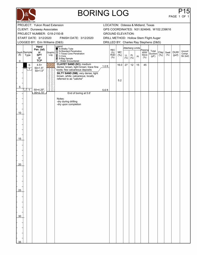
16.0
5.2
1.0 ft
5.6 ft
CLAYEY SAND (SC); mediumdense; brown, light brown; trace fineroots; few calcareous depositsSILTY SAND (SM); very dense; lightbrown, white; calcareous; locallyreferred to as "caliche"
End of boring at 5.6'
Notes:-dry during drilling-dry upon completion
S
T
T
27 12 1550=1.5",50=1.0"
50=4.25",50=2.75"
4.5+ 45
Depth(ft)
0
5
10
15
20
25
30
35
Atterberg Limits
Clay(%)
P15PAGE 1 OF 1
MC(%)
Legend: S-Shelby Tube N-Standard Penetration T-Texas Cone Penetration C-Core B-Bag Sample - Water Encountered
REC(%)
RQD(%)
SampleType
Swell(%)LL
(%)PL(%) PI
TotalSuction
(pF)
HandPen. (tsf)
orSPTor
TCP
HandPen. (tsf)
orSPTor
TCP
Passing#200Sieve(%)
BORING LOG
GraphicLog
DUW(pcf)
Unconf.Compr.Str (ksf)
CLIENT: Dunaway Associates
LOCATION: Odessa & Midland, TexasPROJECT: Yukon Road Extension
DRILLED BY: Charles Ray Stephens (D&S)
START DATE: 3/12/2020 DRILL METHOD: Hollow Stem Flight Auger
LOGGED BY: Erin Williams (D&S)
FINISH DATE: 3/12/2020
GROUND ELEVATION:
GPS COORDINATES: N31.924649, W102.239616
PROJECT NUMBER: G18-2150-B

17.7
6.2
6.2
1.0 ft
10.0 ft
CLAYEY SAND (SC); loose; brown,light brown; trace fine rootsSILTY CLAYEY SAND (SC-SM);medium dense to very dense; lightbrown, white; calcareous; locallyreferred to as "caliche"
End of boring at 10.0'
Notes:-dry during drilling-dry upon completion
S
T
T
N
N
23 19 4
50=0.5"50=0.25"
50=0.125"50=0.125"
15,21,30
8,10,12
2.0
28
Depth(ft)
0
5
10
15
20
25
30
35
Atterberg Limits
Clay(%)
P16PAGE 1 OF 1
MC(%)
Legend: S-Shelby Tube N-Standard Penetration T-Texas Cone Penetration C-Core B-Bag Sample - Water Encountered
REC(%)
RQD(%)
SampleType
Swell(%)LL
(%)PL(%) PI
TotalSuction
(pF)
HandPen. (tsf)
orSPTor
TCP
HandPen. (tsf)
orSPTor
TCP
Passing#200Sieve(%)
BORING LOG
GraphicLog
DUW(pcf)
Unconf.Compr.Str (ksf)
CLIENT: Dunaway Associates
LOCATION: Odessa & Midland, TexasPROJECT: Yukon Road Extension
DRILLED BY: Charles Ray Stephens (D&S)
START DATE: 3/12/2020 DRILL METHOD: Hollow Stem Flight Auger
LOGGED BY: Erin Williams (D&S)
FINISH DATE: 3/12/2020
GROUND ELEVATION:
GPS COORDINATES: N31.924995, W102.236412
PROJECT NUMBER: G18-2150-B

17.0
7.7
6.1
2.0 ft
4.5 ft
SANDY LEAN CLAY (CL); very stiff;brown; trace fine roots
SILTY SAND (SM); very dense; lightbrown, white; calcareous; locallyreferred to as "caliche"
End of boring at 4.5'
Notes:-dry during drilling-dry upon completion
S
S
N
N
41 18 23
50=4.5"
35,36,37
4.5+
4.5+
61
Depth(ft)
0
5
10
15
20
25
30
35
Atterberg Limits
Clay(%)
P17PAGE 1 OF 1
MC(%)
Legend: S-Shelby Tube N-Standard Penetration T-Texas Cone Penetration C-Core B-Bag Sample - Water Encountered
REC(%)
RQD(%)
SampleType
Swell(%)LL
(%)PL(%) PI
TotalSuction
(pF)
HandPen. (tsf)
orSPTor
TCP
HandPen. (tsf)
orSPTor
TCP
Passing#200Sieve(%)
BORING LOG
GraphicLog
DUW(pcf)
Unconf.Compr.Str (ksf)
CLIENT: Dunaway Associates
LOCATION: Odessa & Midland, TexasPROJECT: Yukon Road Extension
DRILLED BY: Charles Ray Stephens (D&S)
START DATE: 3/12/2020 DRILL METHOD: Hollow Stem Flight Auger
LOGGED BY: Erin Williams (D&S)
FINISH DATE: 3/12/2020
GROUND ELEVATION:
GPS COORDINATES: N31.925705, W102.233307
PROJECT NUMBER: G18-2150-B

15.9
4.0
1.0 ft
10.2 ft
CLAYEY SAND (SC); loose; brown;trace fine roots and calcareousdepositsSILTY SAND (SM); medium dense tovery dense; light brown, white; weaklycemented; calcareous; locally referredto as "caliche"
End of boring at 10.2'
Notes:-dry during drilling-dry upon completion
S
T
N
T
NP NP NP
50=1.0"50=0.5"
14,8,12
50=2.25"50=1.5"
0.25
27
Depth(ft)
0
5
10
15
20
25
30
35
Atterberg Limits
Clay(%)
P18PAGE 1 OF 1
MC(%)
Legend: S-Shelby Tube N-Standard Penetration T-Texas Cone Penetration C-Core B-Bag Sample - Water Encountered
REC(%)
RQD(%)
SampleType
Swell(%)LL
(%)PL(%) PI
TotalSuction
(pF)
HandPen. (tsf)
orSPTor
TCP
HandPen. (tsf)
orSPTor
TCP
Passing#200Sieve(%)
BORING LOG
GraphicLog
DUW(pcf)
Unconf.Compr.Str (ksf)
CLIENT: Dunaway Associates
LOCATION: Odessa & Midland, TexasPROJECT: Yukon Road Extension
DRILLED BY: Charles Ray Stephens (D&S)
START DATE: 3/12/2020 DRILL METHOD: Hollow Stem Flight Auger
LOGGED BY: Erin Williams (D&S)
FINISH DATE: 3/12/2020
GROUND ELEVATION:
GPS COORDINATES: N31.926439, W102.230194
PROJECT NUMBER: G18-2150-B

17.5
8.6
1.0 ft
5.5 ft
SILTY CLAYEY SAND (SC-SM);medium dense; brown; trace fine rootsand calcareous nodulesSILTY SAND (SM); medium dense tovery dense; light brown, white;calcareous; locally referred to as"caliche"
End of boring at 5.5'
Notes:-dry during drilling-dry upon completion
S
T
N
24 17 7
50=0.5"50=0.25"
8,13,12
3.0 35
36
Depth(ft)
0
5
10
15
20
25
30
35
Atterberg Limits
Clay(%)
P19PAGE 1 OF 1
MC(%)
Legend: S-Shelby Tube N-Standard Penetration T-Texas Cone Penetration C-Core B-Bag Sample - Water Encountered
REC(%)
RQD(%)
SampleType
Swell(%)LL
(%)PL(%) PI
TotalSuction
(pF)
HandPen. (tsf)
orSPTor
TCP
HandPen. (tsf)
orSPTor
TCP
Passing#200Sieve(%)
BORING LOG
GraphicLog
DUW(pcf)
Unconf.Compr.Str (ksf)
CLIENT: Dunaway Associates
LOCATION: Odessa & Midland, TexasPROJECT: Yukon Road Extension
DRILLED BY: Charles Ray Stephens (D&S)
START DATE: 3/12/2020 DRILL METHOD: Hollow Stem Flight Auger
LOGGED BY: Erin Williams (D&S)
FINISH DATE: 3/12/2020
GROUND ELEVATION:
GPS COORDINATES: N31.927167, W102.227095
PROJECT NUMBER: G18-2150-B

17.4
4.3
5.4
5.5
2.0 ft
10.1 ft
CLAYEY SAND (SC); loose; brown;trace fine roots and calcareousdeposits
SILTY SAND (SM); dense to verydense; light brown, white; calcareous;locally referred to as "caliche"
End of boring at 10.1'
Notes:-dry during drilling-dry upon completion
S
T
N
T
50=0.25"50=1.0"
12,27,19
50=0.25"50=0.125"
0.25
30
Depth(ft)
0
5
10
15
20
25
30
35
Atterberg Limits
Clay(%)
P20PAGE 1 OF 1
MC(%)
Legend: S-Shelby Tube N-Standard Penetration T-Texas Cone Penetration C-Core B-Bag Sample - Water Encountered
REC(%)
RQD(%)
SampleType
Swell(%)LL
(%)PL(%) PI
TotalSuction
(pF)
HandPen. (tsf)
orSPTor
TCP
HandPen. (tsf)
orSPTor
TCP
Passing#200Sieve(%)
BORING LOG
GraphicLog
DUW(pcf)
Unconf.Compr.Str (ksf)
CLIENT: Dunaway Associates
LOCATION: Odessa & Midland, TexasPROJECT: Yukon Road Extension
DRILLED BY: Charles Ray Stephens (D&S)
START DATE: 3/12/2020 DRILL METHOD: Hollow Stem Flight Auger
LOGGED BY: Erin Williams (D&S)
FINISH DATE: 3/12/2020
GROUND ELEVATION:
GPS COORDINATES: N31.928611, W102.224481
PROJECT NUMBER: G18-2150-B

0.7 ft 1.2 ft
2.2 ft
6.1 ft
ASPHALT; 7.75 inches
BASE; 6 inchesCLAYEY SAND (SC); mediumdense; brown, light brown; little tosome calcareous nodules anddepositsCLAYEY SAND (SC); very dense;light brown, brown, white; locallyreferred to as "caliche"
End of boring at 6.1'
Notes:-dry during drilling-dry upon completion
C
S
N
B
T
50=4.0"
50=1.0"50=0.0"
4.5+
Depth(ft)
0
5
10
15
20
25
30
35
Atterberg Limits
Clay(%)
P21PAGE 1 OF 1
MC(%)
Legend: S-Shelby Tube N-Standard Penetration T-Texas Cone Penetration C-Core B-Bag Sample - Water Encountered
REC(%)
RQD(%)
SampleType
Swell(%)LL
(%)PL(%) PI
TotalSuction
(pF)
HandPen. (tsf)
orSPTor
TCP
HandPen. (tsf)
orSPTor
TCP
Passing#200Sieve(%)
BORING LOG
GraphicLog
DUW(pcf)
Unconf.Compr.Str (ksf)
CLIENT: Dunaway Associates
LOCATION: Odessa & Midland, TexasPROJECT: Yukon Road Extension
DRILLED BY: Kevin Kavadas (D&S)
START DATE: 6/27/2018 DRILL METHOD: Hollow Stem Flight Auger
LOGGED BY: Sandip Adhikari (D&S)
FINISH DATE: 6/27/2018
GROUND ELEVATION:
GPS COORDINATES: N31.930666, W102.222387
PROJECT NUMBER: G18-2150-B

0
5
10
15
20
25
30
35
40
45
50
55
60
65
70
75
80
85
90
95
100
0.0010.010.1110
fine
SANDSILT OR CLAY
ASTM D6913
3 6 14 30 50 602
D30 %Clay
LL PI Cc
0.143
3
medium
GRAIN SIZE DISTRIBUTION
PL
10 40
coarse fine
GRAVELcoarse
5.0 16.0 60.5 23.5
D100 D10BOREHOLE DEPTH
P3
%Gravel %Sand %Silt
Cu
12.5
1 3/4
Description
3/81.5 1/2 4 8U.S. SIEVE OPENING IN INCHES
16 20
0.719
140 200U.S. SIEVE NUMBERS HYDROMETER
PE
RC
EN
T F
INE
R B
Y W
EIG
HT
GRAIN SIZE IN MILLIMETERS
D50
100
CLIENT: Dunaway Associates
LOCATION: Odessa & Midland, TexasPROJECT: Yukon Road Extension
DRILLED BY: Charles Ray Stephens (D&S)
START DATE: 3/11/2020 DRILL METHOD: Hollow Stem Flight Auger
LOGGED BY: Erin Williams (D&S)
FINISH DATE: 3/11/2020
GROUND ELEVATION:
GPS COORDINATES: N31.934708, W102.271422
PROJECT NUMBER: G18-2150-B

0
5
10
15
20
25
30
35
40
45
50
55
60
65
70
75
80
85
90
95
100
0.0010.010.1110
fine
SANDSILT OR CLAY
ASTM D6913
3 6 14 30 50 602
D30 %Clay
LL PI Cc
3
medium
GRAIN SIZE DISTRIBUTION
PL
10 40
coarse fine
GRAVELcoarse
1.0 0.0 34.2 32.1
D100 D10BOREHOLE DEPTH
P7
%Gravel %Sand %Silt
Cu
2
1 3/4
Description
3/8
33.7
1.5 1/2 4 8U.S. SIEVE OPENING IN INCHES
16 20
0.067
140 200U.S. SIEVE NUMBERS HYDROMETER
PE
RC
EN
T F
INE
R B
Y W
EIG
HT
GRAIN SIZE IN MILLIMETERS
D50
100
CLIENT: Dunaway Associates
LOCATION: Odessa & Midland, TexasPROJECT: Yukon Road Extension
DRILLED BY: Charles Ray Stephens (D&S)
START DATE: 3/11/2020 DRILL METHOD: Hollow Stem Flight Auger
LOGGED BY: Erin Williams (D&S)
FINISH DATE: 3/11/2020
GROUND ELEVATION:
GPS COORDINATES: N31.929841, W102.261712
PROJECT NUMBER: G18-2150-B

0
5
10
15
20
25
30
35
40
45
50
55
60
65
70
75
80
85
90
95
100
0.0010.010.1110
fine
SANDSILT OR CLAY
ASTM D6913
3 6 14 30 50 602
D30 %Clay
LL PI Cc
3
medium
GRAIN SIZE DISTRIBUTION
PL
10 40
coarse fine
GRAVELcoarse
3.0 3.4 55.8 40.8
D100 D10BOREHOLE DEPTH
P7
%Gravel %Sand %Silt
Cu
12.5
1 3/4
Description
3/81.5 1/2 4 8U.S. SIEVE OPENING IN INCHES
16 20
0.133
140 200U.S. SIEVE NUMBERS HYDROMETER
PE
RC
EN
T F
INE
R B
Y W
EIG
HT
GRAIN SIZE IN MILLIMETERS
D50
100
CLIENT: Dunaway Associates
LOCATION: Odessa & Midland, TexasPROJECT: Yukon Road Extension
DRILLED BY: Charles Ray Stephens (D&S)
START DATE: 3/11/2020 DRILL METHOD: Hollow Stem Flight Auger
LOGGED BY: Erin Williams (D&S)
FINISH DATE: 3/11/2020
GROUND ELEVATION:
GPS COORDINATES: N31.929841, W102.261712
PROJECT NUMBER: G18-2150-B

P12 1-2 19.4 22.5 131 1.3
BoringNumber
Depthfeet
Vertical Swell, %Final MoistureContent, %
Initial MoistureContent, %
Applied Pressure,psf
SWELL TEST RESULTSCLIENT: Dunaway AssociatesPROJECT: Yukon Road Extension
PROJECT NUMBER: G18-2150-B LOCATION: Odessa & Midland, Texas

LABORATORY CBR SUMMARY TABLE
PROJECT: Yukon Road Extension CLIENT: Dunaway Associates
PROJECT NUMBER: G18‐2150‐B LOCATION: Odessa & Midland, Texas
Soil Description LL (%)
PL (%)
PI (%)
‐200(%)
Standard Proctor CBR (performed at least 95% of standard Proctor)
(%)
Maximum Dry Density (pcf)
Optimum Moisture Content
(%)
CLAYEY SAND (combined sample)
27 14 13 43 112.9 13.6 7.4
5.5

APPENDIX B - GENERAL DESCRIPTION OF PROCEDURES

D&S ENGINEERING LABS, LLC Midland County – Yukon Road Extension Odessa & Midland, Texas
G18-2150-B
1
ANALYTICAL METHODS TO PREDICT MOVEMENT
INDEX PROPERTY AND CLASSIFICATION TESTING
Classification testing is perhaps the most basic, yet fundamental tool available for predicting potential movements of clay soils. Classification testing typically consists of moisture content, Atterberg Limits, and Grain-size distribution determinations. From these results a general assessment of a soil’s propensity for volume change with changes in soil moisture content can be made.
Moisture Content
By studying the moisture content of the soils at varying depths and comparing them with the results of Atterberg Limits, one can estimate a rough order of magnitude of potential soil movement at various moisture contents, as well as movements with moisture changes. These tests are typically performed in accordance with ASTM D2216.
Atterberg Limits
Atterberg limits determine the liquid limit (LL), plastic limit (PL), and plasticity index (PI) of a soil. The liquid limit is the moisture content at which a soil begins to behave as a viscous fluid. The plastic limit is the moisture content at which a soil becomes workable like putty, and at which a clay soil begins to crumble when rolled into a thin thread (1/8” diameter). The PI is the numerical difference between the moisture constants at the liquid limit and the plastic limit. This test is typically performed in accordance with ASTM D4318.
Clay mineralogy and the particle size influence the Atterberg Limits values, with certain minerals (e.g., montmorillonite) and smaller particle sizes having higher PI values, and therefore higher movement potential.
A soil with a PI below about 15 to 18 is considered to be generally stable and should not experience significant movement with changes in moisture content. Soils with a PI above about 30 to 35 are considered to be highly active and may exhibit considerable movement with changes in moisture content.
Fat clays with very high liquid limits, weakly cemented sandy clays, or silty clays are examples of soils in which it can be difficult to predict movement from classification testing alone.
Grain-size Distribution
The simplest grain-size distribution test involves washing a soil specimen over the No. 200 mesh sieve with an opening size of 0.075 mm (ASTM D1140). This particle size has been defined by the engineering community as the demarcation between coarse-grained and fine-grained soils. Particles smaller than this size can be further distinguished between silt-size and clay-size particles by use of a Hydrometer test (ASTM D422). A more complete grain-size distribution test that uses sieves to relative amount of particles according is the Sieve Gradation Analysis of Soils (ASTM D6913). Once the characteristics of the soil are determined through classification testing, a number of movement prediction techniques are available to predict the potential movement of the soils. Some of these are discussed in general below.

D&S ENGINEERING LABS, LLC Midland County – Yukon Road Extension Odessa & Midland, Texas
G18-2150-B
2
TEXAS DEPARTMENT OF TRANSPORTATION METHOD 124-E
The Texas Department of Transportation (TxDOT) has developed a generally simplistic method to predict movements for highways based on the plasticity index of the soil. The TxDOT method is empirical and is based on the Atterberg limits and moisture content of the subsurface soil. This method generally assumes three different initial moisture conditions: dry, “as-is”, and wet. Computation of each over an assumed depth of seasonal moisture variation (usually about 15 feet or less) provides an estimate of potential movement at each initial condition. This method requires a number of additional assumptions to develop a potential movement estimate. As such, the predicted movements generally possess large uncertainties when applied to the analysis of conditions under pavements.
POTENTIAL VERTICAL MOVEMENT
A general index for movement is known as the Potential Vertical Rise (PVR). The actual term PVR refers to the TxDOT Method 124-E mentioned above. For the purpose of this report the term Potential Vertical Movement (PVM) will be used since PVM estimates are derived using multiple analytical techniques, and not just TxDOT methods.
Vertical movement of clay soils under pavements resulting to soil moisture changes can result from a variety causes, including poor site grading and drainage, improperly prepared subgrade, trees and large shrubbery located too close to structures, utility leaks or breaks, poor subgrade maintenance such as inadequate or excessive irrigation, or other causes.
PVM is generally considered to be a measurement of the change in height of a foundation from the elevation it was originally placed. Experience and generally accepted practice suggests that if the PVM of a site is less than one inch, the associated differential movement will be minor and acceptable to most people.
TEXAS DEPARTMENT OF TRANSPORTATION METHOD 101-E
This method describes three procedures for preparation of soil and flexible base samples for soil constants and particle size analysis, compaction and triaxial, and sieve analysis of road-mixed material.
TEXAS DEPARTMENT OF TRANSPORTATION METHOD 401-A
This method involves sieve analysis and is used to determine the particle size distribution of mineral fillers and coarse and fine aggregates for Portland cement concrete.
TEXAS DEPARTMENT OF TRANSPORTATION METHOD 116-E
This method determines the resistance of aggregate in flexible base material to disintegration in the presence of water. The test provides a measure of the ability of the material to withstand degradation in the road base and detects soft aggregate that is subject to weathering. The result of this test is the Wet Ball Mill (WBM) value.

D&S ENGINEERING LABS, LLC Midland County – Yukon Road Extension Odessa & Midland, Texas
G18-2150-B
3
SPECIAL COMMENTARY ON CONCRETE AND EARTHWORK
UTILITY TRENCH EXCAVATION
Trench excavation for utilities should be sloped or braced in the interest of safety. Attention is drawn to OSHA Safety and Health Standards (29 CFR 1926/1910), Subpart P, regarding trench excavations greater than 5 feet in depth.
FIELD SUPERVISION AND DENSITY TESTING
Construction observation and testing by a field technician under the direction of a licensed geotechnical engineer should be provided. Some adjustments in the test frequencies may be required based upon the general fill types and soil conditions at the time of fill placement.
It is recommended that all site and subgrade preparation, proofrolling, and pavement construction be monitored by a qualified engineering firm. Density tests should be performed to verify proper compaction and moisture content of any earthwork. Inspection should be performed prior to and during concrete placement operations.

14805 Trinity Boulevard, Fort Worth, Texas 76155
Geotechnical 817.529.8464 Corporate 940.735.3733
www.dsenglabs.com
Texas Engineering Firm Registration # F‐12796
Oklahoma Engineering Firm Certificate of Authorization CA 7181

PART D
BID QUANTITIES

Item Description
1 Preparation of R.O.W. (130' ROW) 188 STA
2 16" HDPE - SDR9 Conduits 950 L.F.
3 Concrete Box Culvert for Conduits 300 L.F.
4 5 Strand Barb Wire Fence with H Braces 36,983 L.F.
5 Corner H-Braces 6 Ea.
6 24' Cattleguard and Electric Gate 2 Ea.
7 Gates 12 Ea.
8 Sawcut Existing Asphalt (full depth) 406 L.F.
9 Asphalt Excavation 18 C.Y.
10 Asphalt Haul Off 18 C.Y.
11 Remove Concrete Curb and Gutter 374 L.F.
12 Excavation/Earthwork* 2,266 C.Y.
13 Haul Off* 2,238 C.Y.
14 130'X5' Pipeline Cap 6 Ea.
15 Surface Pipeline Cap 1 Ea.
16 RCB - 3' X 2' 38 L.F.
17Saftey End Treatments with Flared Wings
(Type I) (S=3) (HW=3) (6:1)2 Ea.
18 Subgrade Preparation 79,972 S.Y.
19 19" Flexible Base 36,201 C.Y.
20 Prime Coat** 20,132 Gal.
Paving, Grading, and Drainage Improvements to serve Yukon Road
Base BidQuantity Unit Unit Price Total
Roadway Improvements for Midland County
Page 1 of 3

Item Description
Paving, Grading, and Drainage Improvements to serve Yukon Road
Base BidQuantity Unit Unit Price Total
Roadway Improvements for Midland County
21 Tack Coat** 927 Gal.
22 HMA Pavement - 3" thickness - Type D** 11,576 TON
23 1.5" Overlay - Dense Graded "D"** 267 TON
24 Type I Concrete Curb and Gutter 362 L.F.
25 Type II Concrete Curb and Gutter 407 L.F.
26 Sawtooth Type II Concrete Curb and Gutter 46 L.F.
27 Concrete Directional Island 335 S.Y.
28 Concrete Pavement at Intersection 1,863 S.Y.
29 32'x 50' Pitched Concrete Pavement Sections 2 Ea.
30 32'x30' Pitched Concrete Pavement Section 1 Ea.
31 Driveways 12 Ea.
32Reflective Marking (Type 1) 4" Yellow Double
Solid Striped2,052 L.F.
33Reflective Marking (Type 1) 4" Yellow Broken
Striped17,250 L.F.
34Reflective Marking (Type 1) 4" White Solid
Striped37,653 L.F.
35Reflective Marking (Type 1) 4" White Broken
Striped2,193 L.F.
36Reflective Marking (Type 1) 24" Yellow Solid
Striped50 L.F.
37Reflective Marking (Type 1) 18" White Stop
Bar75 L.F.
38Reflective Marking (Type 1) 18" White Yield
Triangles Bar46 L.F.
39 Thru Arrow 24 Ea.
40 Left Turn Arrow 9 Ea.
Page 2 of 3

Item Description
Paving, Grading, and Drainage Improvements to serve Yukon Road
Base BidQuantity Unit Unit Price Total
Roadway Improvements for Midland County
41 Thru or Right Turn Arrow 2 Ea.
42 Right Turn Arrow 1 Ea.
43 Lane Reduction Arrow 2 Ea.
44 "ONLY" Text 8 Ea.
45 Raised Pavement Markers 315 Ea.
46 Surface Preparation for Pavement Markings 1 L.S.
47 IN SM RD SN SUP&AM TY10BWG(1) SA (P) 33 Ea.
48 Aluminum Signs 264 S.F.
49 Erosion Control 1 L.S.
50 Traffic Control 1 L.S.
51 Mobilization 1 L.S.
*
** Rates used for calculation purposes only:
Prime Coat: 0.3 Gal/SY
Tack Coat: 0.3 Gal/SY
HMA Pavement - 3" thickness - Type D: 115
lb/SY*in
1.5" Overlay - Dense Graded "D": 115
lb/SY*in
Contractor shall notify the Engineer of Record of any discrepancies in quantities prior to the commencement of construction.
Quantities do not include factors for compaction and expansion.
TOTAL BASE BID
CONSTRUCTION START DATE
TOTAL CALENDAR DAYS
Page 3 of 3