
Parts List
376
FE4P20-35-BPT-001 Warning Operators should read and understand this manual and all warning labels on the forklift before using the forklift. Keep the manual for future reference! Parts List FE4P20~35 SERIES Battery Counterbalanced Forklift Truck ZheJiang Noblelift Equipment Joint Stock Co.,Ltd
-
Upload
khangminh22 -
Category
Documents
-
view
2 -
download
0
Transcript of Parts List
FE4P20-35-BPT-001
Warning Operators should read and understand this manual and all warning labels on the forklift before using the forklift. Keep the manual for future reference!
Parts List FE4P20~35 SERIES
Battery Counterbalanced Forklift Truck
ZheJiang Noblelift Equipment Joint Stock Co.,Ltd
- 1 -
Table of Contents Introduction......................................................... 4
1 Travel Motor and Gearbox............................................. 5-8
2 Travel Motor(3.0T,3.5T DC) .......................................... 9-10
3 Travel Motor(2.0T,3.5T DC) .......................................... 11-12
4 Travel Motor(3.0T,3.5T AC) .......................................... 13-14
5 Travel Motor(2.0T,2.5T AC) .......................................... 15-16
6 Differential ........................................................ 17-18
7 Drive Axle ......................................................... 19-22
8 Brake(3.0T,3.5T) .................................................... 23-26
9 Brake(2.0T,2.5T) .................................................... 27-30
10 Drive Wheel Assembly (3.0T,3.5T) .................................... 31-32
11 Drive Wheel Assembly (2.0T,2.5T) .................................... 33-34
12 Installation of electric parts(2.0T,2.5T) ........................... 35-38
13 Controller assembly(2.0T,2.5T,)(Curtis System ,DC) .................. 39-40
14 Controller assembly (2.0T,2.5T,)(Curtis System ,AC) ................. 41-42
15 Controller assembly (2.0T,2.5T,)(Curtis System ,AC2) ................ 43-44
16 Controller assembly (2.0T,2.5T,)( Zapi System ,AC) .................. 45-46
17 Controller assembly (2.0T,2.5T,)( Zapi System ,AC2) ................. 47-48
18 Installation of electric parts(3.0T,3.5T) ........................... 49-52
19 Controller assembly(3.0T,3.5,)(Curtis System ,DC) ................... 53-54
20 Controller assembly(3.0T,3.5,)(Curtis System ,AC).................... 55-56
21 Controller assembly(3.0T,3.5,)(Curtis System ,AC2)................... 57-58
22 Controller assembly(3.0T,3.5,)( Zapi Syste ,AC) ..................... 59-60
23 Controller assembly (3.0T,3.5,)(Zapi System ,AC2).................... 61-62
24 Power supply connector assembly...................................... 63-64
25 Battery and installation............................................. 65-66
26 Steering equipment and installation.................................. 67-68
27 Steering column assembly............................................. 69-70
28 Linking shaft assembly............................................... 71-72
29 Steering axle and installation ..................................... 73-76
30 Steering cylinder.................................................... 77-78
31 Steering wheel assembly............................................. 79-80
32 Frame and balance weight............................................. 81-84
33 Installation of instrument stand and cover.......................... 85-88
34 Foot braking operation............................................... 89-90
- 2 -
35 Hand braking operation............................................... 91-92
36 Accelerator and installation......................................... 93-94
37 Lifting motor and installation....................................... 95-96
38 Lifting Motor(2.0T,2.5T DC).......................................... 97-98
39 Lifting Motor(3.0T,3.5T DC).......................................... 99-100
40 Lifting Motor(2.0T,2.5T AC).......................................... 101-102
41 Lifting Motor(3.0T,3.5T AC).......................................... 103-104
42 Working fuel tank.................................................... 105-106
43 Operation of multiple directional control valve (Two position)....... 107-108
44 Operation of multiple directional control valve (Three position)..... 109-110
45 Operation of multitandem valve (Four unit)........................... 111-112
46 Hydraulic system..................................................... 113-116
47 Lifting Pipeline System of Mast (3.5T standard mast) ................ 117-118
48 Lifting Pipeline System of Mast (2.0T,2.5T,3.0T standard mast)........ 119-120
49 Lifting Pipeline System of Mast(3.5T 2-stage Full Free) ............. 121-122
50 Lifting Pipeline System of Mast (2.0T,2.5T,3.0T 2‐stage Full Free) ........ 123-124
51 Lifting Pipeline System of Mast (3.5T 3‐stage Full Free) .................. 125-128
52 Lifting Pipeline System of Mast (2.0T,2.5T,3.0T 3‐stage Full Free) ........ 129-132
53 Side Shifter & Pipeline Installation System (Standard Mast) ......... 133-134
54 Side Shifter & Pipeline Installation System (2-stage Full Free) ..... 135-140
55 Side Shifter & Pipeline Installation System (3-stage Full Free) ..... 141-144
56 Fork(3.0T,3.5T) ..................................................... 145-146
57 Fork(2.0T,2.5T) ..................................................... 147-148
58 Fork Frame (Standard Mast)........................................... 149-150
59 Fork Frame (2-stage Full Free)....................................... 151-152
60 Fork Frame (3-stage Full Free)....................................... 153-154
61 Mast (Standard Mast 3.0T,3.5T) .................................... 155-158
62 Mast(2.0,2.5T standard mast).......................................... 159-162
63 Mast(3.0T,3.5T 2-stage Full Free).................................... 163-166
64 Mast(2.0,2.5T 2-stage full free)..................................... 167-170
65 Mast(3.0T ,3.5T3-stage full free).................................... 171-174
66 Mast(2.0,2.5T 3-stage full free)..................................... 175-178
67 Lifting Oil Cylinder (Standard mast 3.5T )........................... 179-184
68 Lifting Oil Cylinder (Standard mast 3.0T ) .......................... 185-190
69 Lifting Oil Cylinder(2.0,2.5T Standard Mast)....................... 191-196
70 Short Lifting/Lowering Cylinder (3.5T 2-stage full free)............. 197-200
71 Short Lifting/Lowering Cylinder (3.0T 2-stage full free) ............ 201-204
- 3 -
72 Short Lifting/Lowering (2.0,2.5T 2-stage full free).................. 205-208
73 Lifting Cylinder (3.5T 2-level Full Free) ........................... 209-212
74 Lifting Cylinder (3.0T 2-level Full Free)............................ 213-216
75 Lift cylinder(2.0,2.5T 2-stage Full free).......................... 217-220
76 Short Lifting/Lowering Cylinder (3.5T 3-Stage Full Free) ............ 221-224
77 Short Lifting/Lowering Cylinder (3.0T 3-Stage Full Free) ............ 225-228
78 Short Lifting/Lowering Cylinder (2.0,2.5T 3-stage full free)......... 229-232
79 Lifting cylinder(3.5T 3-Stage Full Free)........................... 233-236
80 Lifting cylinder(3.0T 3-Stage Full Free)........................... 237-242
81 Lifting cylinder(2.0,2.5T 3-stage Full Free)....................... 243-248
82 Tilting Cylinder (3.0T,3.5T) ........................................ 249-250
83 Tilting Cylinder (2.0,2.5T).......................................... 251-252
84 Overhead Guard....................................................... 253-254
85 Labels............................................................... 255-256
- 4 -
Introduction
Welcome to use the Noblelift counterbalanced forklift truck!
1. This Parts List includes the parts of the FE4P20‐35 counter‐
balanced forklift truck.
2. Users can make desired inquiries according to Table of Contents.
3. Please use parts designated by Noblelift Company when replacing parts to
ensure the quality of the forklift.
4. When ordering parts, be sure to clearly indicate the model and ex‐factory
serial No. of the forklift, serial No. of the needed parts, and the required
quantity.
5. To further optimize the product, we reserve the right to modify our
product. The product is subject to change without prior notice and
thanks for your understanding for that. For the latest product
information, you can obtain them from the sales and parts departments
of Noblelift.
- 5 -
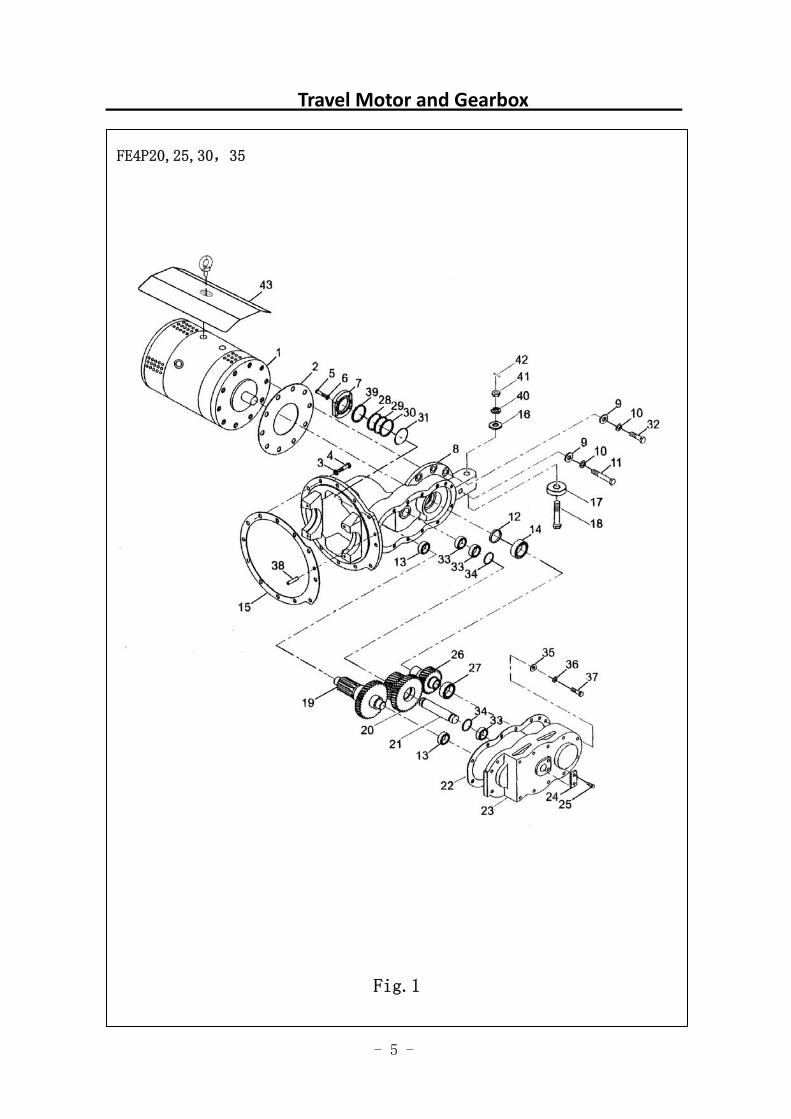
Travel Motor and Gearbox
FE4P20,25,30,35
Fig.1
- 6 -
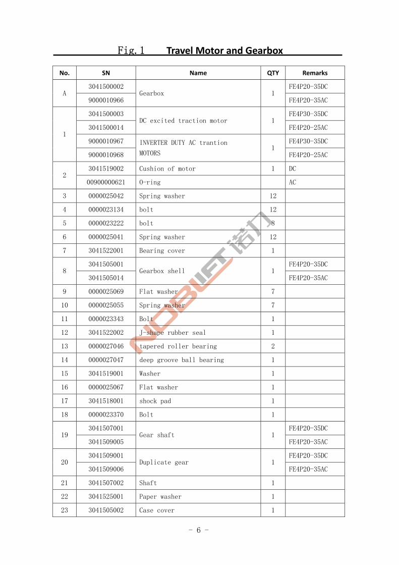
Fig.1 Travel Motor and Gearbox
No. SN Name QTY Remarks
3041500002 FE4P20-35DC A
9000010966 Gearbox 1
FE4P20-35AC
3041500003 FE4P30-35DC
3041500014 DC excited traction motor 1
FE4P20-25AC
9000010967 FE4P30-35DC 1
9000010968
INVERTER DUTY AC trantion
MOTORS 1
FE4P20-25AC
3041519002 Cushion of motor 1 DC 2
00900000621 O-ring AC
3 0000025042 Spring washer 12
4 0000023134 bolt 12
5 0000023222 bolt 8
6 0000025041 Spring washer 12
7 3041522001 Bearing cover 1
3041505001 FE4P20-35DC 8
3041505014 Gearbox shell 1
FE4P20-35AC
9 0000025069 Flat washer 7
10 0000025055 Spring washer 7
11 0000023343 Bolt 1
12 3041522002 J-shape rubber seal 1
13 0000027046 tapered roller bearing 2
14 0000027047 deep groove ball bearing 1
15 3041519001 Washer 1
16 0000025067 Flat washer 1
17 3041518001 shock pad 1
18 0000023370 Bolt 1
3041507001 FE4P20-35DC 19
3041509005 Gear shaft 1
FE4P20-35AC
3041509001 FE4P20-35DC 20
3041509006 Duplicate gear 1
FE4P20-35AC
21 3041507002 Shaft 1
22 3041525001 Paper washer 1
23 3041505002 Case cover 1
- 7 -
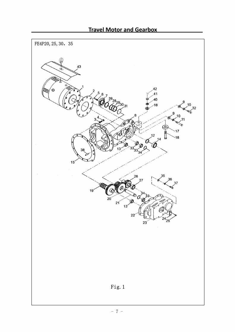
Travel Motor and Gearbox
图 1 行走电机及减速器 1
FE4P20,25,30,35
Fig.1
- 8 -
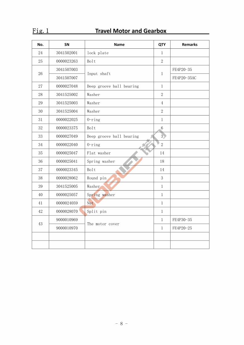
Fig.1 Travel Motor and Gearbox
No. SN Name QTY Remarks
24 3041502001 lock plate 1
25 0000023263 Bolt 2
3041507003 FE4P20-35 26
3041507007 Input shaft 1
FE4P20-35AC
27 0000027048 Deep groove ball bearing 1
28 3041525002 Washer 2
29 3041525003 Washer 4
30 3041525004 Washer 2
31 0000022025 O-ring 1
32 0000023375 Bolt 6
33 0000027049 Deep groove ball bearing 3
34 0000022040 O-ring 2
35 0000025047 Flat washer 14
36 0000025041 Spring washer 18
37 0000023345 Bolt 14
38 0000028062 Round pin 3
39 3041525005 Washer 1
40 0000025057 Spring washer 1
41 0000024059 Nut 1
42 0000028070 Split pin 1
9000010969 1 FE4P30-35 43
9000010970 The motor cover
1 FE4P20-25
- 9 -
FE4P30-35 Travel Motor DC
FE4P30,35
Fig 2
- 10 -
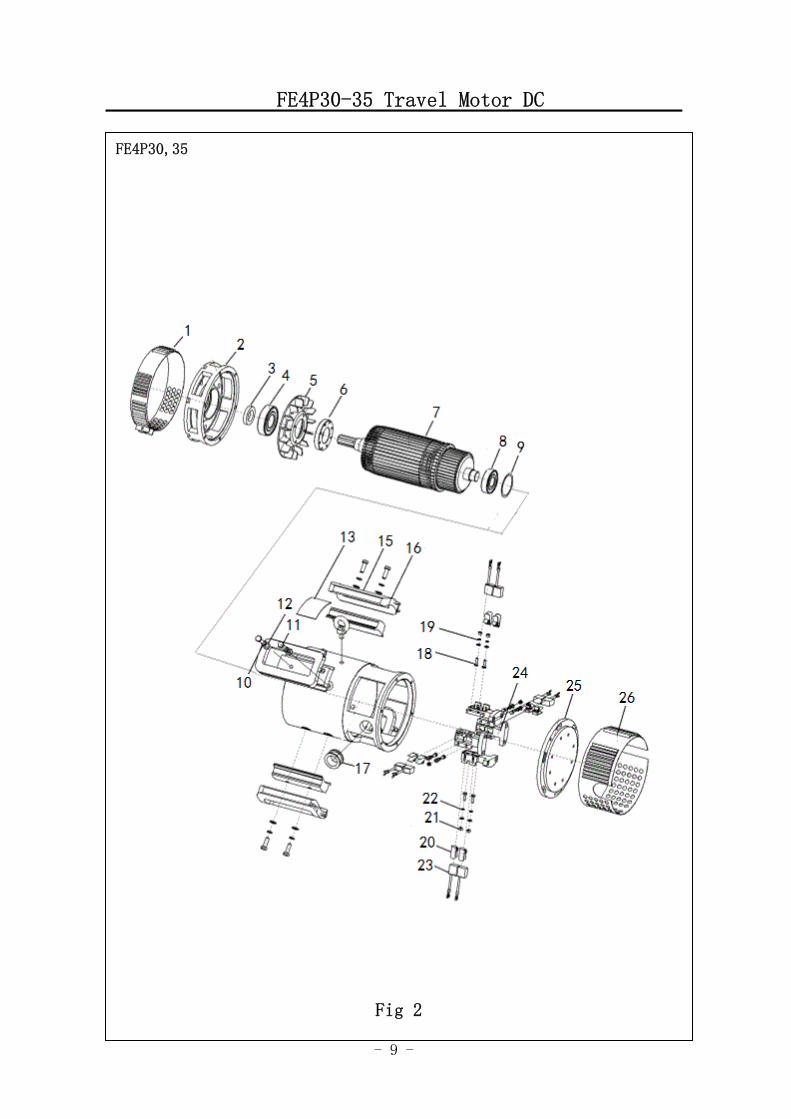
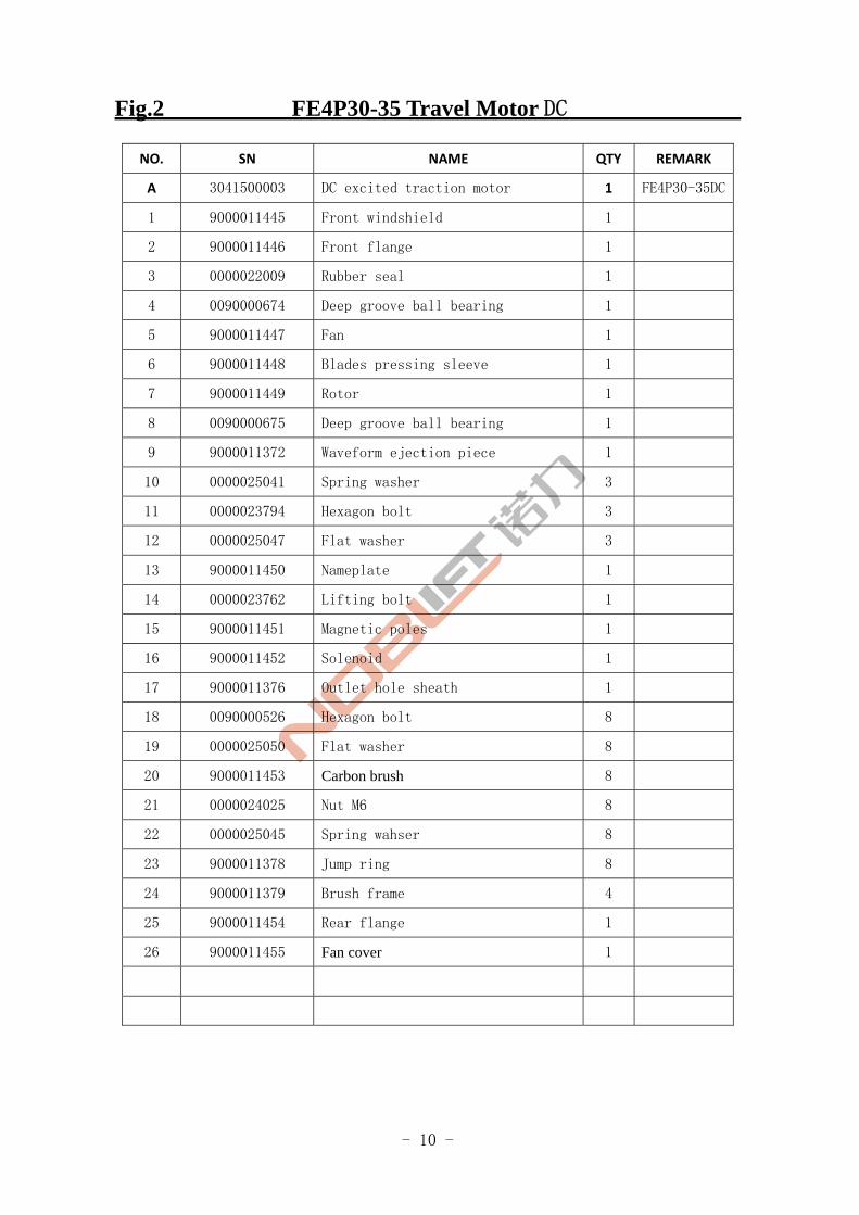
Fig.2 FE4P30-35 Travel Motor DC
NO. SN NAME QTY REMARK
A 3041500003 DC excited traction motor 1 FE4P30-35DC
1 9000011445 Front windshield 1
2 9000011446 Front flange 1
3 0000022009 Rubber seal 1
4 0090000674 Deep groove ball bearing 1
5 9000011447 Fan 1
6 9000011448 Blades pressing sleeve 1
7 9000011449 Rotor 1
8 0090000675 Deep groove ball bearing 1
9 9000011372 Waveform ejection piece 1
10 0000025041 Spring washer 3
11 0000023794 Hexagon bolt 3
12 0000025047 Flat washer 3
13 9000011450 Nameplate 1
14 0000023762 Lifting bolt 1
15 9000011451 Magnetic poles 1
16 9000011452 Solenoid 1
17 9000011376 Outlet hole sheath 1
18 0090000526 Hexagon bolt 8
19 0000025050 Flat washer 8
20 9000011453 Carbon brush 8
21 0000024025 Nut M6 8
22 0000025045 Spring wahser 8
23 9000011378 Jump ring 8
24 9000011379 Brush frame 4
25 9000011454 Rear flange 1
26 9000011455 Fan cover 1
- 11 -
FE4P20-25 Travel Motor DC
FE4P20,25
Fig 3
- 12 -
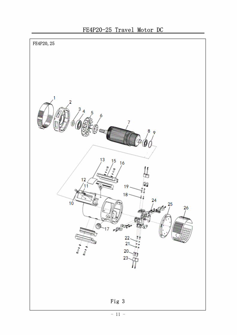
Fig.3 FE4P20-25 Travel Motor DC
NO. SN NAME QTY REMARK
A 3041500014 DC excited traction motor FE4P20-25DC
1 9000011414 Front windshield 1
2 9000011415 Front flange 1
3 0000022009 Framework oil seal 1
4 0090000674 Deep groove ball bearing 1
5 9000011416 Fan 1
6 9000011417 Blades pressing sleeve 1
7 9000011418 Rotor 1
8 0090000675 Deep groove ball bearing 1
9 9000011372 Waveform ejection piece 1
10 0000025041 Spring washer 3
11 0000023794 hexagon bolt 3
12 0000025047 Flat washer 3
13 9000011419 Nameplate 1
14 0000023762 Lifting eye bolt 1
15 9000011420 Magnetic pole 1
16 9000011421 Solenoid 1
17 9000011376 Outlet hole sheat 1
18 0090000526 Hexagon bolt 8
19 0000025050 Flat washer 8
20 9000011422 Carbon brush 8
21 0000024025 Nut 8
22 0000025045 Spring washer 8
23 9000011378 Jump ring 8
24 9000011379 Brush frame 4
25 9000011423 Rear flange 1
26 9000011424 End windshield 1
- 13 -
FE4P30-35 Travel MotorAC
FE4P30,35
Fig 4
- 14 -
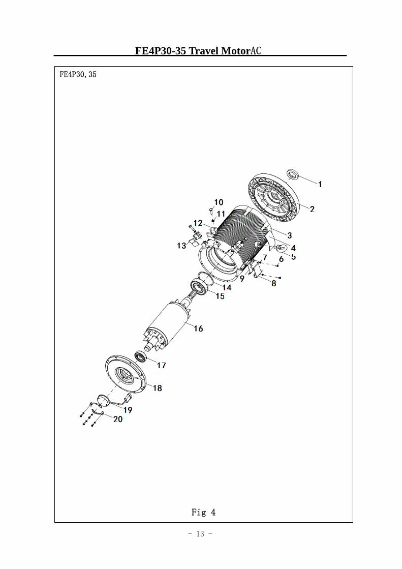
Fig 4 FE4P30-35Travel motorAC
NO. SN NAME QTY REMARK
A 9000010967 INVERTER DUTY AC trantion
MOTORS 1 FE4P30-35AC
1 0000022009 Framework oil seal 1
2 9000011456 Front flange 1
3 9000011457 Stator 1
4 9000011458 Nameplate 1
5 0000023762 Lifting eye bolt 1
6 0000023844 Screw 6
7 0000025044 Spring washer 6
8 9000011385 Encoder cover 1
9 9000011386 Encoder frame 1
10 0090000240 Hexagon bolt 3
11 0000025046 Spring washer 3
12 9000011387 Insulation block 3
13 9000011388 Insulation block 3
14 9000011389 Waveform spring 1
15 0090000674 Deep groove ball bearing 1
16 9000011459 Rotor 1
17 0000027012 Deep groove ball bearing 1
18 9000011460 Rear flange 1
19 9000011392 Encoder 1
20 9000011393 Encoder clamp 2
- 15 -
FE4P20-25 Travel motorAC
FE4P20,25
Fig 5
- 16 -
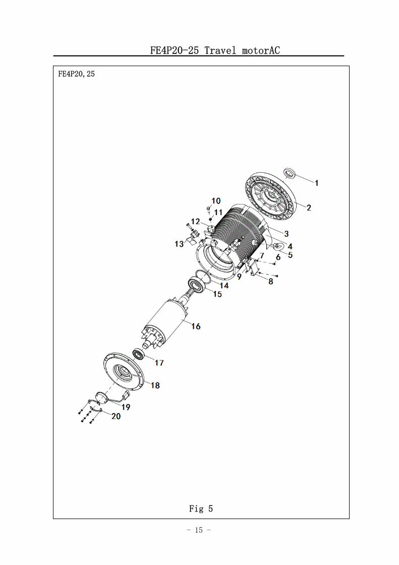
Fig 5 FE4P20-25Travel motor AC
NO. SN NAME QTY REMARK
A 9000010968 INVERTER DUTY AC trantion
MOTORS 1 FE4P20-25AC
1 0000022009 Framework oil seal 1
2 9000011425 Front flange 1
3 9000011426 Stator 1
4 9000011427 Nameplate 1
5 0000023762 Lifting eye bolt 1
6 0000023844 Phillips screws 6
7 0000025044 Spring washer 6
8 9000011385 Encoder cover 1
9 9000011386 Encoder frame 1
10 0090000240 Hexagon bolt 3
11 0000025046 Spring washer 3
12 9000011387 Insulation block 3
13 9000011388 Insulation block 3
14 9000011389 Waveform spring 1
15 0090000674 Deep groove ball bearing 1
16 9000011428 Rotor 1
17 0000027012 Deep groove ball bearing 1
18 9000011429 Rear flange 1
19 9000011392 Encoder 1
20 9000011393 Encoder clamp 2
- 17 -
Differential
图 1 行走电机及减速器 1
FE4P20,25,30,35
Fig.6
- 18 -
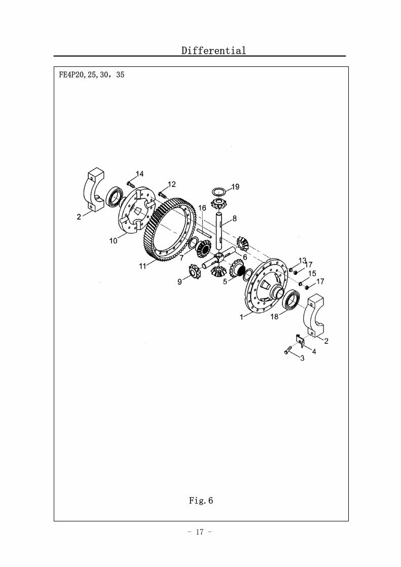
Fig.6 Differential
No. SN Name QTY Remarks
A 3041500004 Differential 1 Including 1-19
1 3041505003 Case of left differential 1
2 3041502002 Bearing seat 2
3 3041523001 Bolt 4
4 3041525006 Locking plate 4
5 3041509002 Axle shaft gear 2
6 3041507004 Shaft of small gear 1
7 3041525007 Washer 2
8 3041507005 Universal joint pin 1
9 3041509003 planetary gear 4
10 3041505004 Case of right differential 1
11 3041509004 Gear ring 1
12 3041523002 Bolt of gear ring 16
13 3041525008 Locking plate 8
14 3041523003 Bolt 1
15 3041525009 Locking washer 6
16 0000028032 Round pin 1
17 0000024051 Nut 28
18 0000027050 Bearing 2
19 3041525010 Washer 4
- 19 -
Driving axle
图 1 行走电机及减速器 1
FE4P20,25,30,35
Fig.7
- 20 -
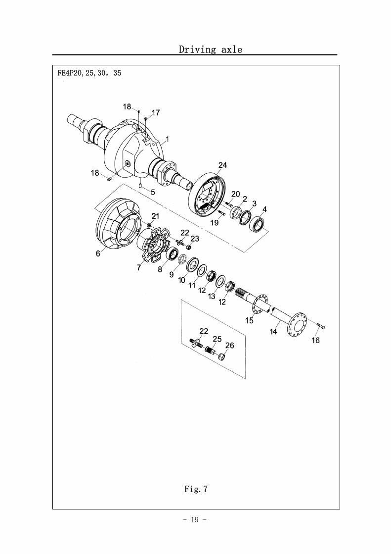
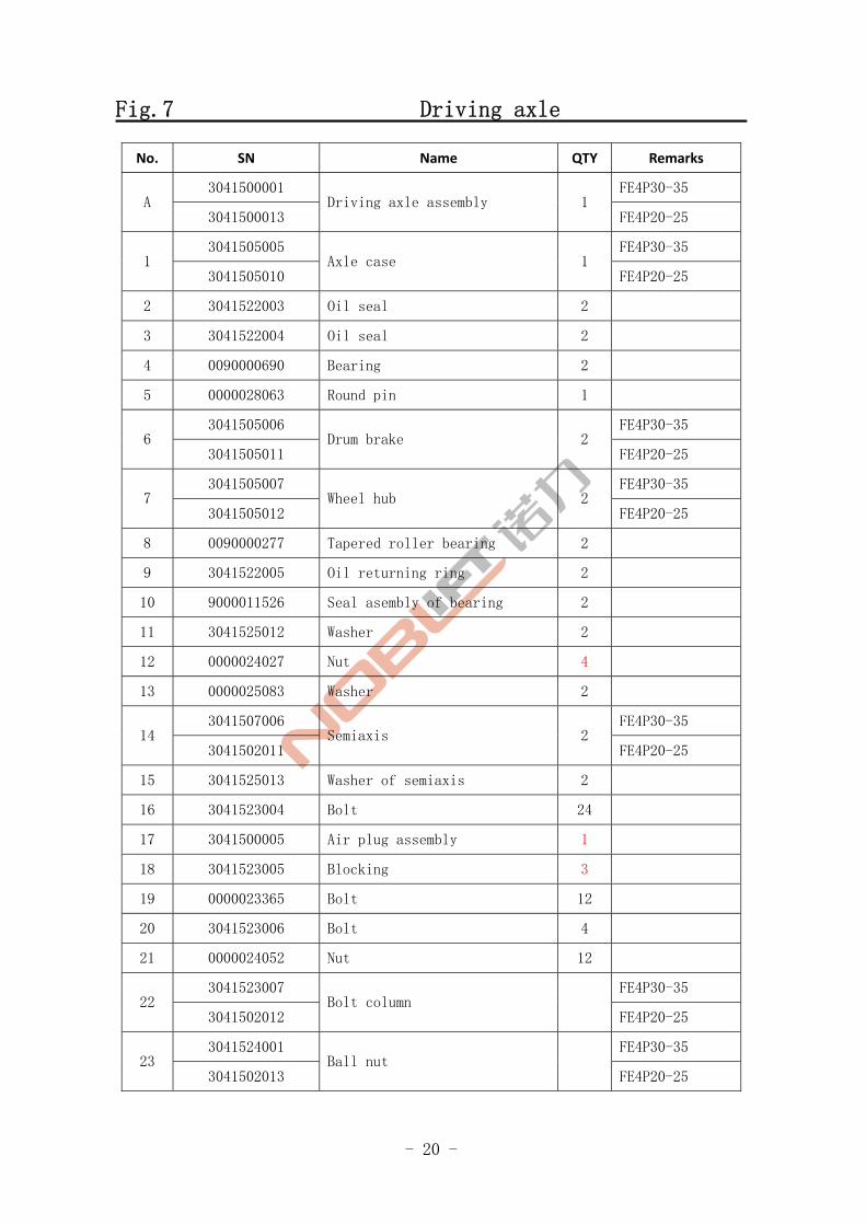
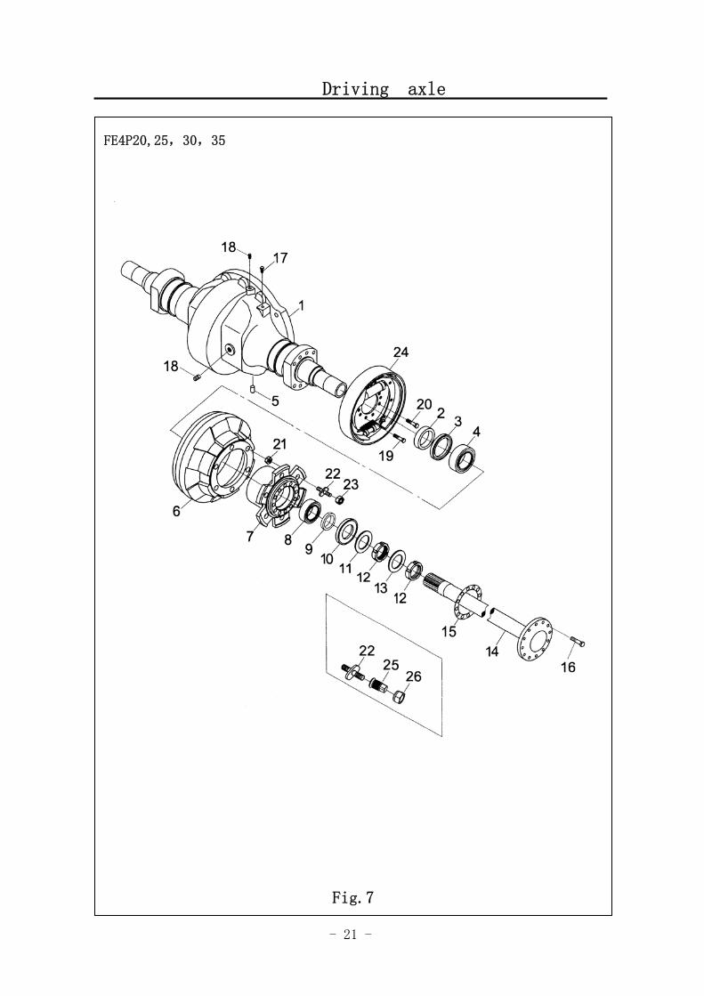
Fig.7 Driving axle
No. SN Name QTY Remarks
3041500001 FE4P30-35 A
3041500013 Driving axle assembly 1
FE4P20-25
3041505005 FE4P30-35 1
3041505010 Axle case 1
FE4P20-25
2 3041522003 Oil seal 2
3 3041522004 Oil seal 2
4 0090000690 Bearing 2
5 0000028063 Round pin 1
3041505006 FE4P30-35 6
3041505011 Drum brake 2
FE4P20-25
3041505007 FE4P30-35 7
3041505012 Wheel hub 2
FE4P20-25
8 0090000277 Tapered roller bearing 2
9 3041522005 Oil returning ring 2
10 9000011526 Seal asembly of bearing 2
11 3041525012 Washer 2
12 0000024027 Nut 4
13 0000025083 Washer 2
3041507006 FE4P30-35 14
3041502011 Semiaxis 2
FE4P20-25
15 3041525013 Washer of semiaxis 2
16 3041523004 Bolt 24
17 3041500005 Air plug assembly 1
18 3041523005 Blocking 3
19 0000023365 Bolt 12
20 3041523006 Bolt 4
21 0000024052 Nut 12
3041523007 FE4P30-35 22
3041502012 Bolt column
FE4P20-25
3041524001 FE4P30-35 23
3041502013 Ball nut
FE4P20-25
- 21 -
Driving axle
图 1 行走电机及减速器 1
FE4P20,25,30,35
Fig.7
- 22 -
Fig.7 Driving axle
No. SN Name QTY Remarks
3041500006 FE4P30-35 24
3041500015 Brake assembly 2
FE4P20-25
3041523008 FE4P30-35 25
3041502015 Twins bolt column 2
FE4P20-25
3041524003 FE4P30-35 26
3041502016 Twins bolt nut 2
FE4P20-25
- 23 -
Brake(3.0T,3.5T)
图 1 行走电机及减速器 1
FE4P30,35
Fig.8
- 24 -
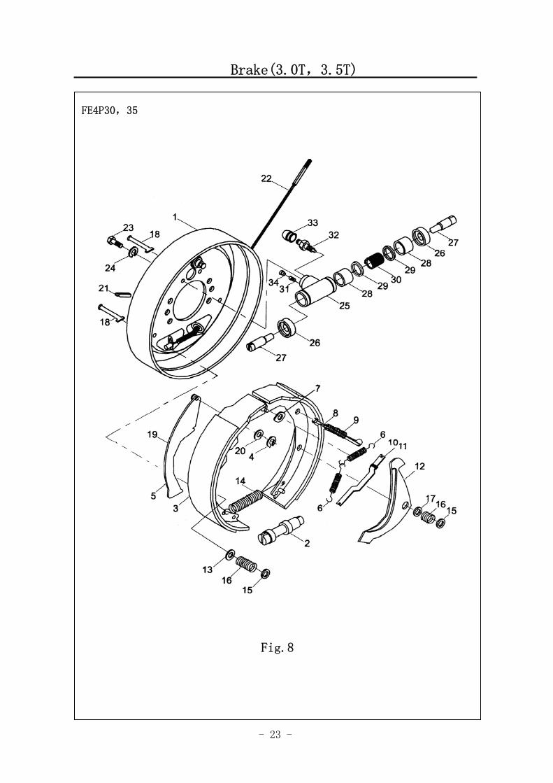
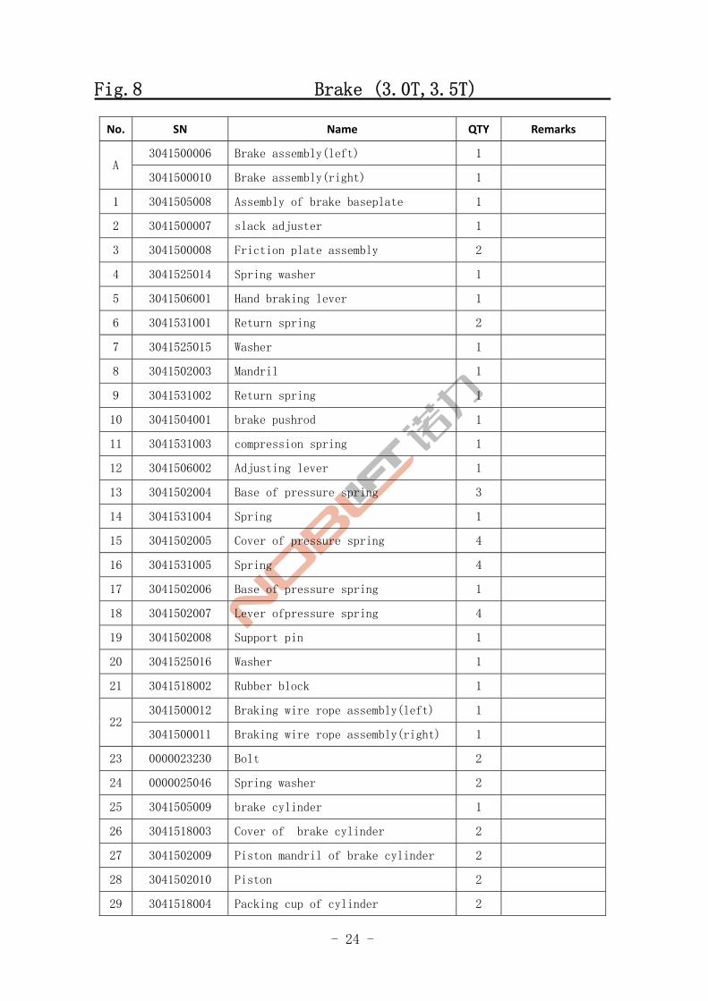
Fig.8 Brake (3.0T,3.5T)
No. SN Name QTY Remarks
3041500006 Brake assembly(left) 1 A
3041500010 Brake assembly(right) 1
1 3041505008 Assembly of brake baseplate 1
2 3041500007 slack adjuster 1
3 3041500008 Friction plate assembly 2
4 3041525014 Spring washer 1
5 3041506001 Hand braking lever 1
6 3041531001 Return spring 2
7 3041525015 Washer 1
8 3041502003 Mandril 1
9 3041531002 Return spring 1
10 3041504001 brake pushrod 1
11 3041531003 compression spring 1
12 3041506002 Adjusting lever 1
13 3041502004 Base of pressure spring 3
14 3041531004 Spring 1
15 3041502005 Cover of pressure spring 4
16 3041531005 Spring 4
17 3041502006 Base of pressure spring 1
18 3041502007 Lever ofpressure spring 4
19 3041502008 Support pin 1
20 3041525016 Washer 1
21 3041518002 Rubber block 1
3041500012 Braking wire rope assembly(left) 1 22
3041500011 Braking wire rope assembly(right) 1
23 0000023230 Bolt 2
24 0000025046 Spring washer 2
25 3041505009 brake cylinder 1
26 3041518003 Cover of brake cylinder 2
27 3041502009 Piston mandril of brake cylinder 2
28 3041502010 Piston 2
29 3041518004 Packing cup of cylinder 2

- 25 -
Brake (3.0T, 3.5T)
图 1 行走电机及减速器 1
FE4P30,35
Fig.8
- 26 -
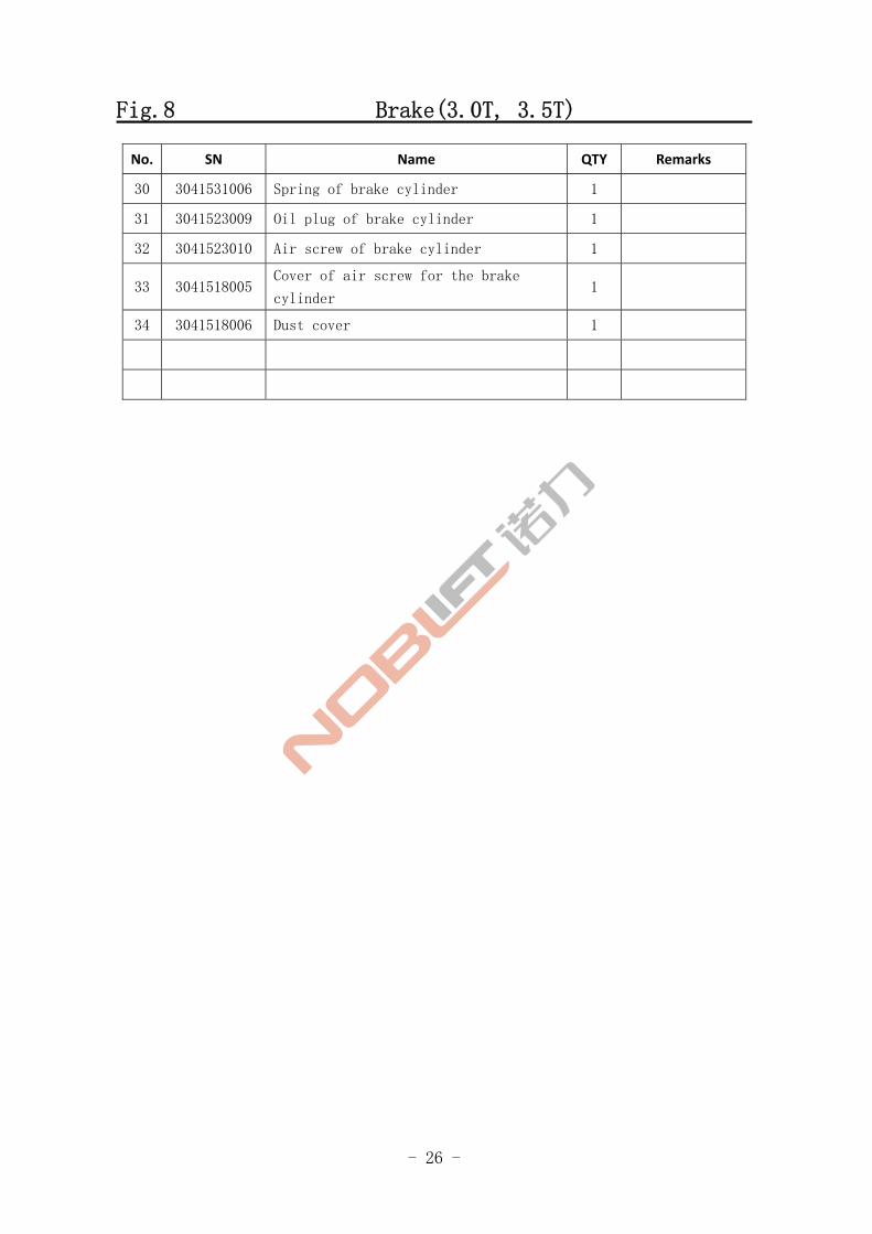
Fig.8 Brake(3.0T, 3.5T)
No. SN Name QTY Remarks
30 3041531006 Spring of brake cylinder 1
31 3041523009 Oil plug of brake cylinder 1
32 3041523010 Air screw of brake cylinder 1
33 3041518005 Cover of air screw for the brake
cylinder 1
34 3041518006 Dust cover 1
- 27 -
Brake(2.0,2.5T)
Fig.1 Travel motor and reducer 1
FE4P20,25
Fig.9
- 28 -
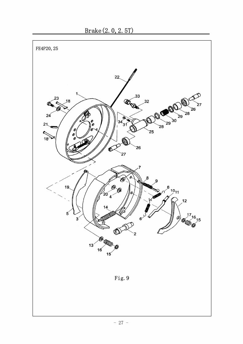
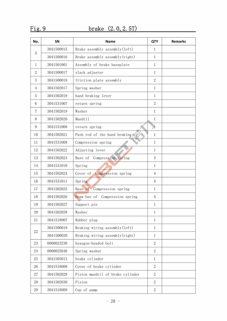
Fig.9 brake (2.0,2.5T)
No. SN Name QTY Remarks
3041500015 Brake assembly assembly(left) 1 A
3041500016 Brake assembly assembly(right) 1
1 3041501001 Assembly of brake baseplate 1
2 3041500017 slack adjuster 1
3 3041500018 friction plate assembly 2
4 3041502017 Spring washer 1
5 3041502018 hand braking lever 1
6 3041531007 return spring 2
7 3041502019 Washer 1
8 3041502020 Mandril 1
9 3041531008 return spring 1
10 3041502021 Push rod of the hand braking 1
11 3041531009 Compression spring 1
12 3041502022 Adjusting lever 1
13 3041502023 Base of Compression spring 3
14 3041531010 Spring 1
15 3041502024 Cover of Compression spring 4
16 3041531011 Spring 4
17 3041502025 Base of Compression spring 1
18 3041502026 Draw bar of Compression spring 4
19 3041502027 Support pin 1
20 3041502028 Washer 1
21 3041518007 Rubber plug 1
3041500019 Braking wiring assembly(left) 1 22
3041500020 Braking wiring assembly(right) 1
23 0000023230 hexagon-headed bolt 2
24 0000025046 Spring washer 2
25 3041505013 brake cylinder 1
26 3041518008 Cover of brake cylinder 2
27 3041502029 Piston mandril of brake cylinder 2
28 3041502030 Piston 2
29 3041518009 Cup of pump 2

- 29 -
Brake(2.0,2.5T)
Fig.1 Driving motor and reducer
FE4P20,25
Fig.9
- 30 -
Fig.9 Brake (2.0,2.5T)
No. SN Name QTY Remarks
30 3041531012 Spring of brake cylinder 1
31 3041502031 Oil plug of brake cylinder 1
32 3041502032 Air screw 1
33 3041518010 Cover of air screw 1
34 3041518011 Dust cover 1
- 31 -
Driving wheel assenbly(3.0T,3.5T)
Fig.1 Travel motor and reducer 1
FE4P30,35
Fig.10
- 32 -
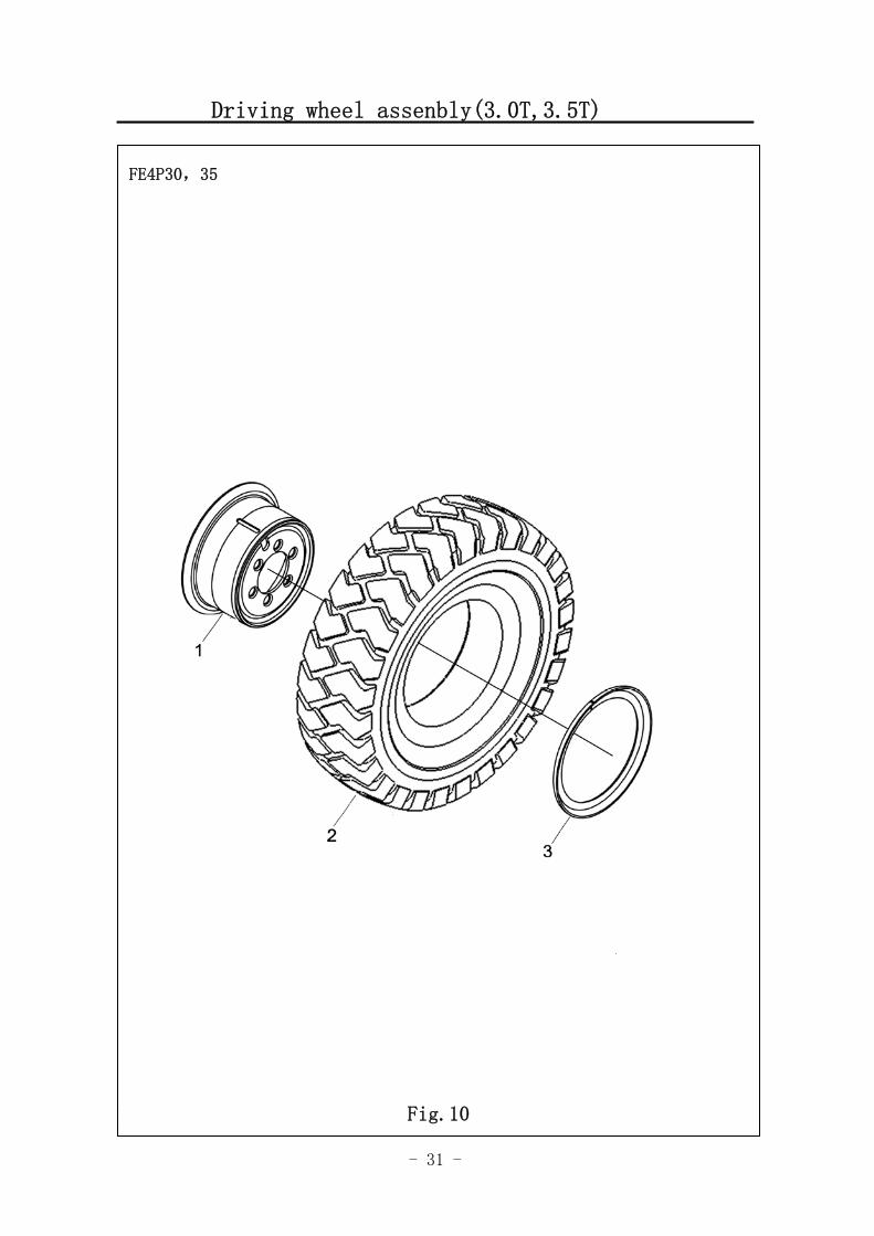
Fig.10 Driving wheel assenbly (3.0T,3.5T)
No. SN Name QTY Remarks
A 3063300002 Wheel rim assembly 2 Including 2-4
3063300001 Pneumatic-tyre wheel 2 1
3063300003 Solid tyre 2
2 3063305001 Rim 2
3 3063306002 Retaining ring 2
- 33 -
Driving wheel assenbly (2.0,2.5T)
FE4P20,25
Fig.11
- 34 -
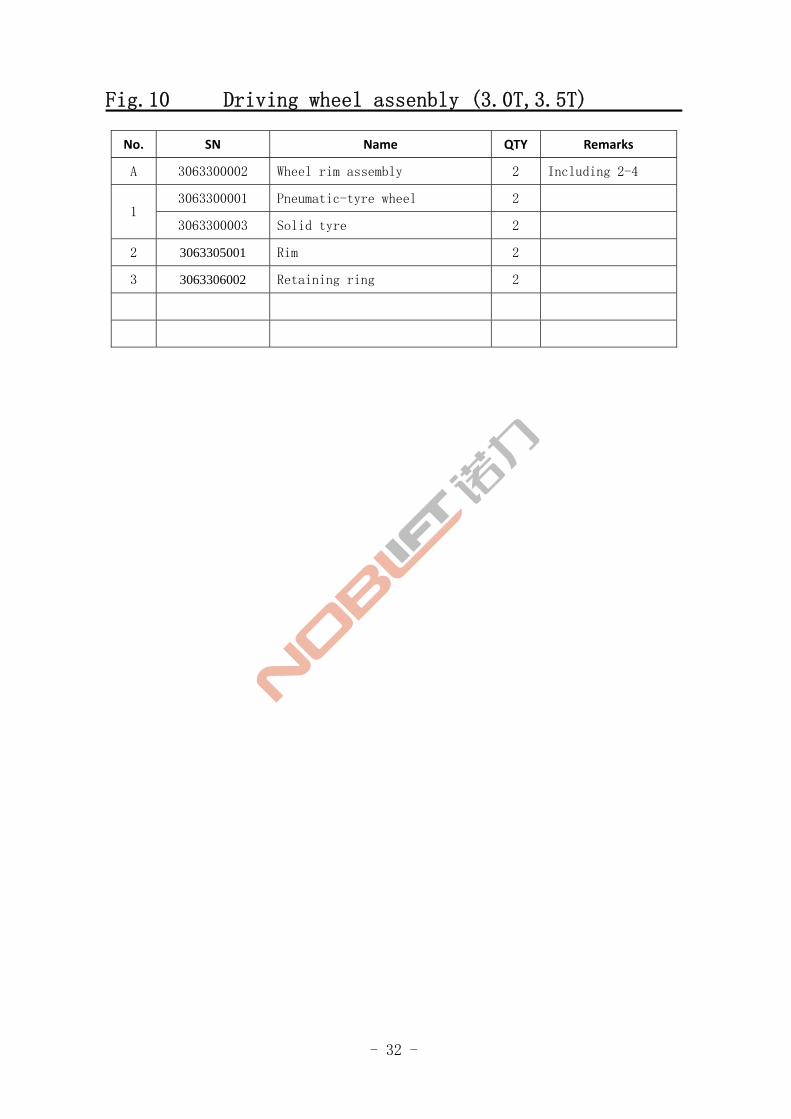
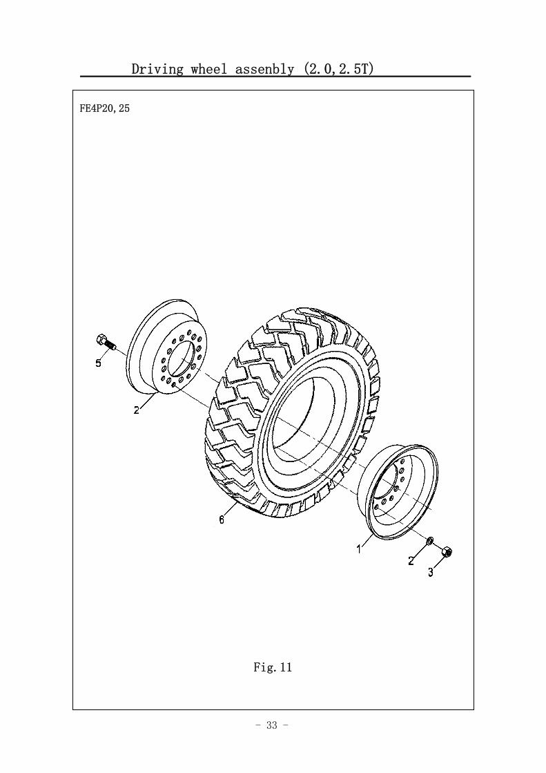
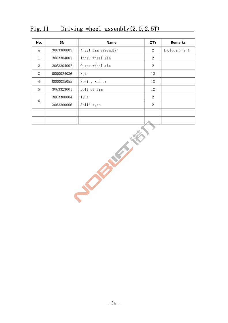
Fig.11 Driving wheel assenbly(2.0,2.5T)
No. SN Name QTY Remarks
A 3063300005 Wheel rim assembly 2 Including 2-4
1 3063304001 Inner wheel rim 2
2 3063304002 Outer wheel rim 2
3 0000024036 Nut 12
4 0000025055 Spring washer 12
5 3063323001 Bolt of rim 12
3063300004 Tyre 2 6
3063300006 Solid tyre 2
- 35 -
FE4P20-25 Installation of electrical parts
Fig.1 Travel Motor and Gearbox 1
FE4P20,25
Fig.12
- 36 -
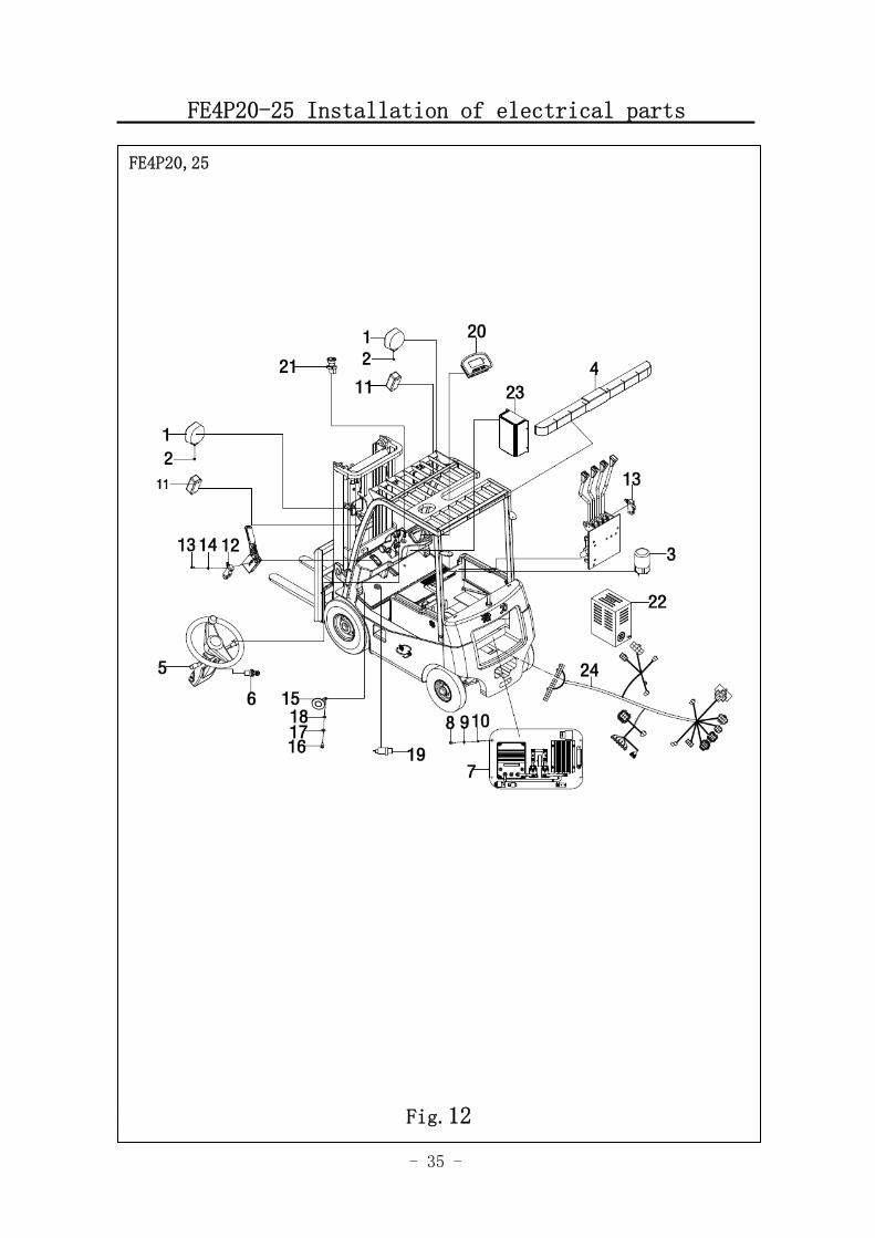
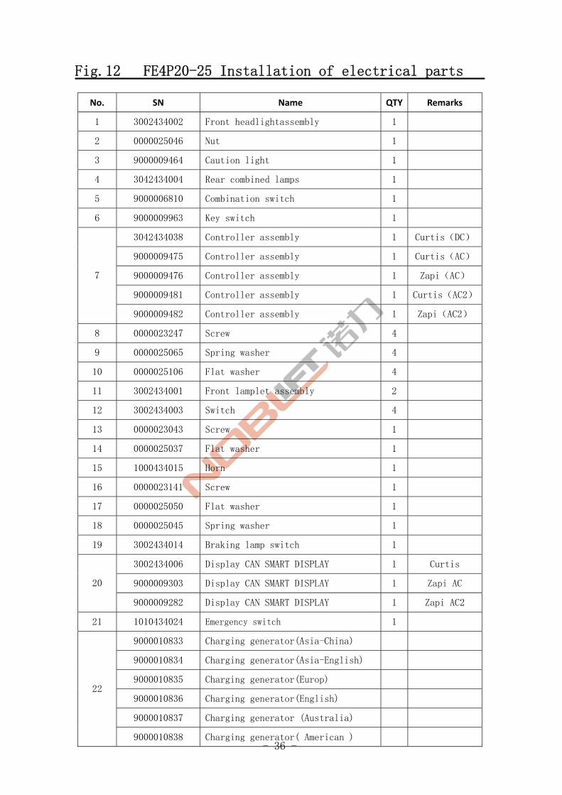
Fig.12 FE4P20-25 Installation of electrical parts
No. SN Name QTY Remarks
1 3002434002 Front headlightassembly 1
2 0000025046 Nut 1
3 9000009464 Caution light 1
4 3042434004 Rear combined lamps 1
5 9000006810 Combination switch 1
6 9000009963 Key switch 1
3042434038 Controller assembly 1 Curtis(DC)
9000009475 Controller assembly 1 Curtis(AC)
9000009476 Controller assembly 1 Zapi(AC)
9000009481 Controller assembly 1 Curtis(AC2)
7
9000009482 Controller assembly 1 Zapi(AC2)
8 0000023247 Screw 4
9 0000025065 Spring washer 4
10 0000025106 Flat washer 4
11 3002434001 Front lamplet assembly 2
12 3002434003 Switch 4
13 0000023043 Screw 1
14 0000025037 Flat washer 1
15 1000434015 Horn 1
16 0000023141 Screw 1
17 0000025050 Flat washer 1
18 0000025045 Spring washer 1
19 3002434014 Braking lamp switch 1
3002434006 Display CAN SMART DISPLAY 1 Curtis
9000009303 Display CAN SMART DISPLAY 1 Zapi AC 20
9000009282 Display CAN SMART DISPLAY 1 Zapi AC2
21 1010434024 Emergency switch 1
9000010833 Charging generator(Asia-China)
9000010834 Charging generator(Asia-English)
9000010835 Charging generator(Europ)
9000010836 Charging generator(English)
9000010837 Charging generator (Australia)
22
9000010838 Charging generator( American )
- 37 -
Fig.12 FE4P20-25 Installation of electrical parts
FE4P20,25
Fig.12
- 38 -
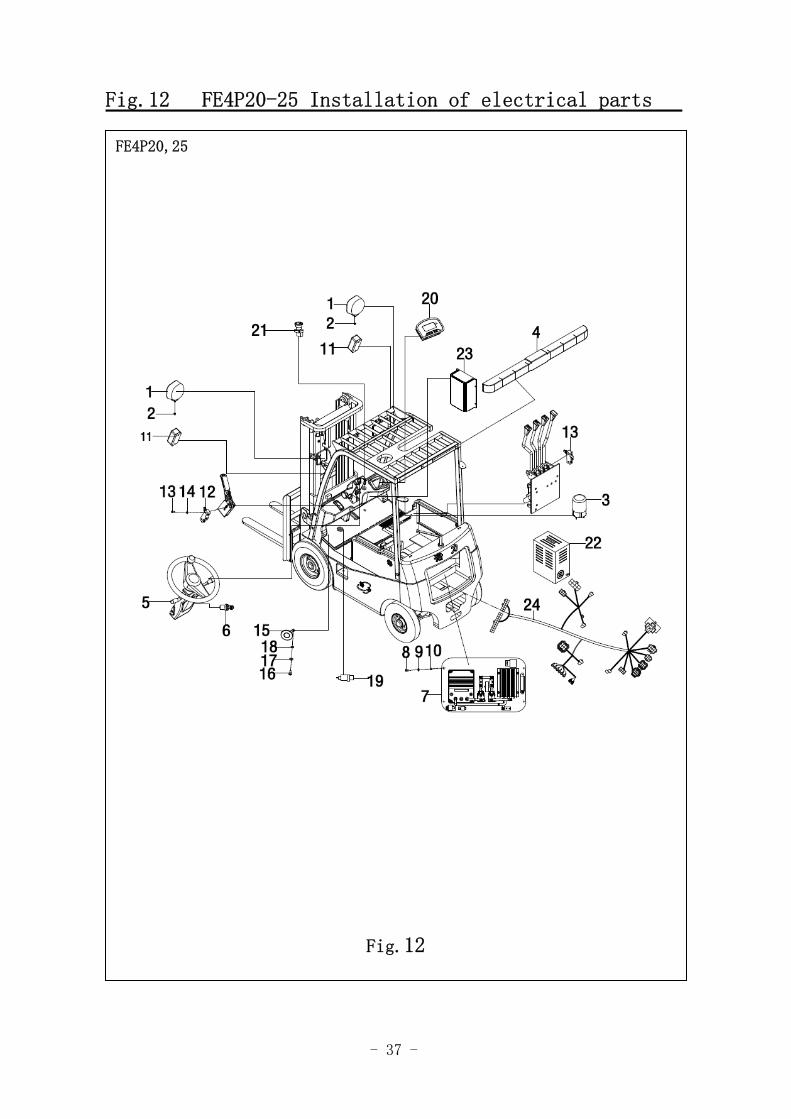
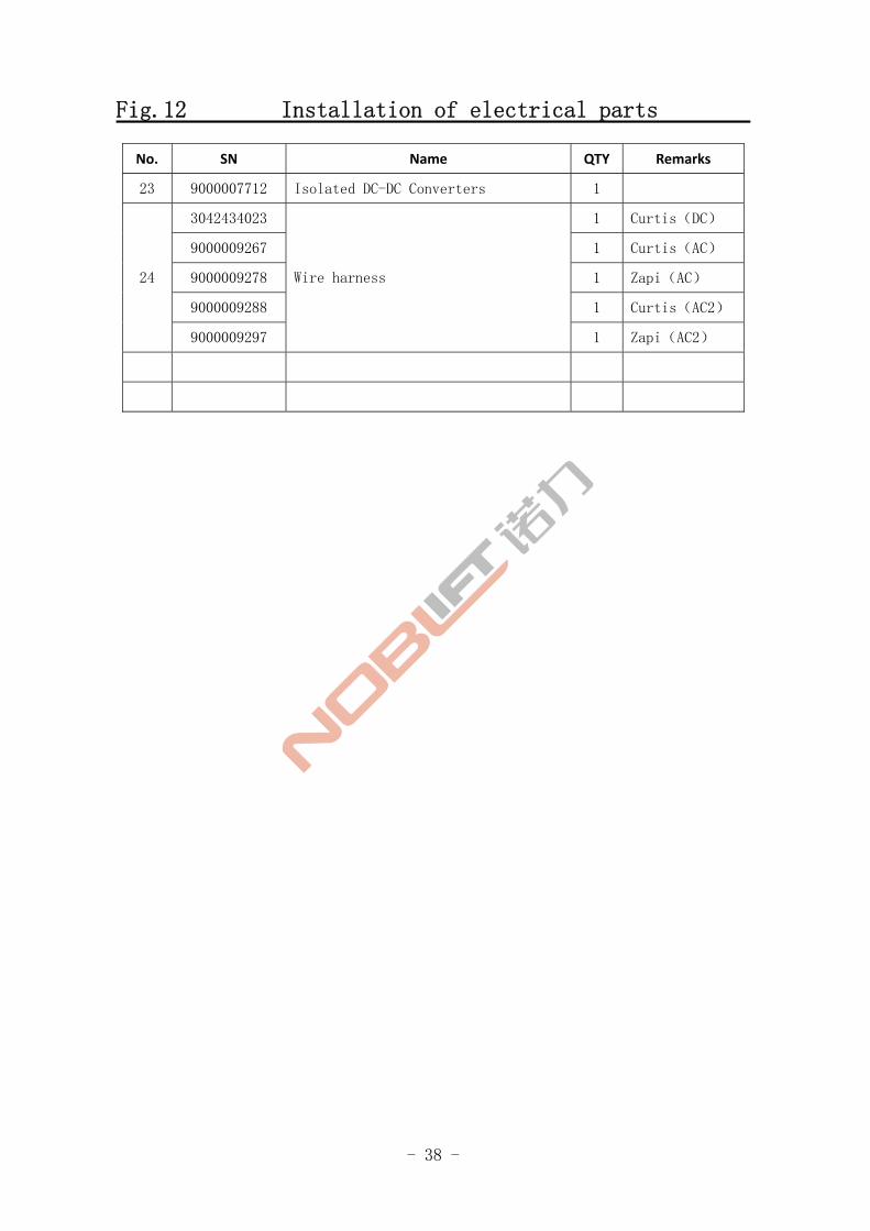
Fig.12 Installation of electrical parts
No. SN Name QTY Remarks
23 9000007712 Isolated DC-DC Converters 1
3042434023 1 Curtis(DC)
9000009267 1 Curtis(AC)
9000009278 1 Zapi(AC)
9000009288 1 Curtis(AC2)
24
9000009297
Wire harness
1 Zapi(AC2)
- 39 -
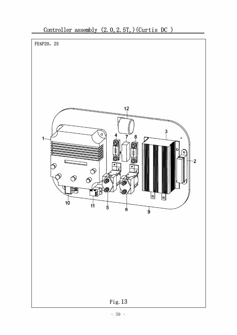
Controller assembly (2.0,2.5T,)(Curtis DC )
FE4P20,25
Fig.13
- 40 -
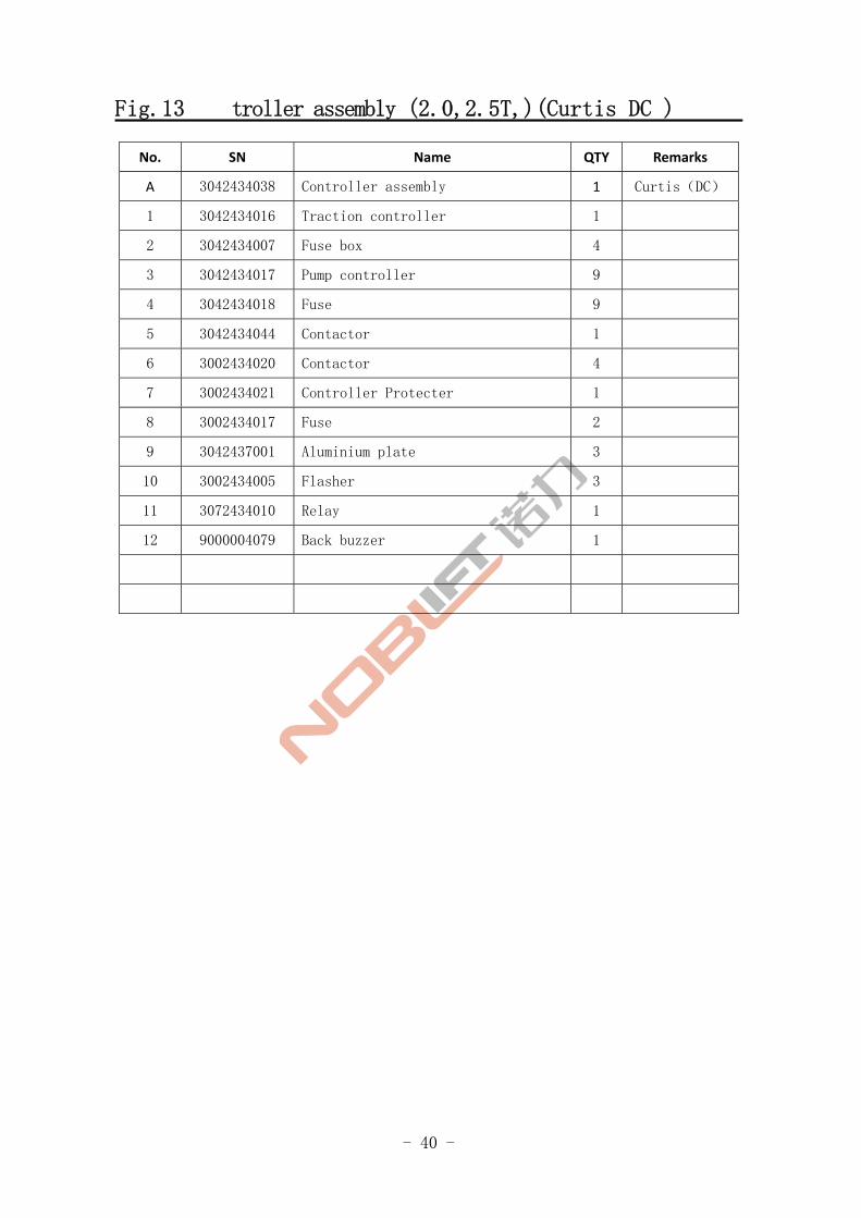
Fig.13 troller assembly (2.0,2.5T,)(Curtis DC )
No. SN Name QTY Remarks
A 3042434038 Controller assembly 1 Curtis(DC)
1 3042434016 Traction controller 1
2 3042434007 Fuse box 4
3 3042434017 Pump controller 9
4 3042434018 Fuse 9
5 3042434044 Contactor 1
6 3002434020 Contactor 4
7 3002434021 Controller Protecter 1
8 3002434017 Fuse 2
9 3042437001 Aluminium plate 3
10 3002434005 Flasher 3
11 3072434010 Relay 1
12 9000004079 Back buzzer 1
- 41 -
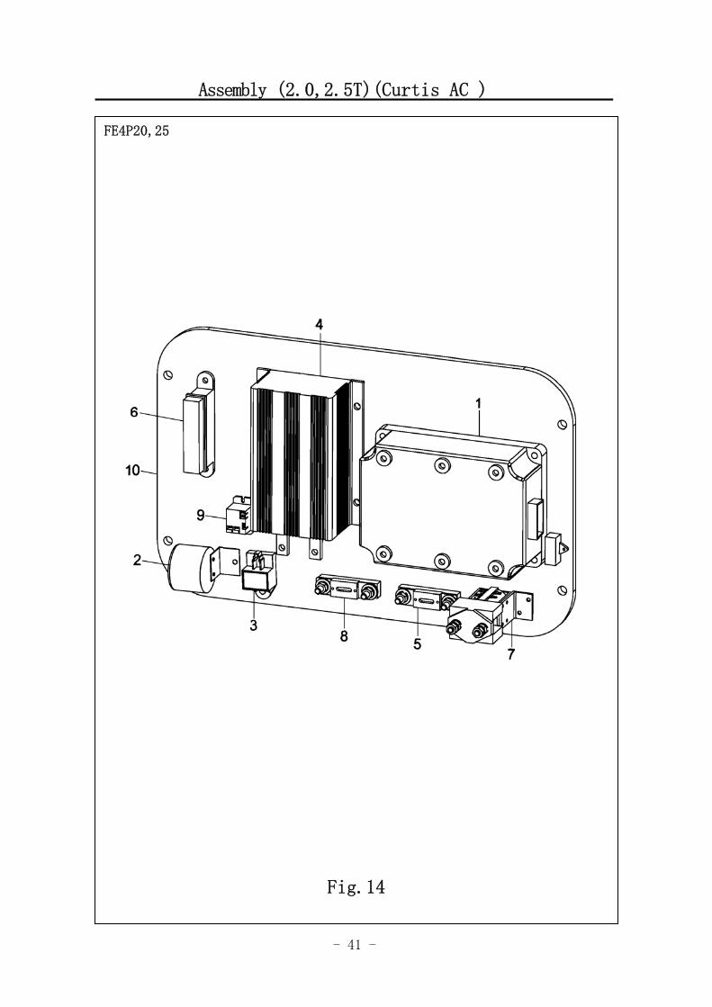
Assembly (2.0,2.5T)(Curtis AC )
FE4P20,25
Fig.14
- 42 -
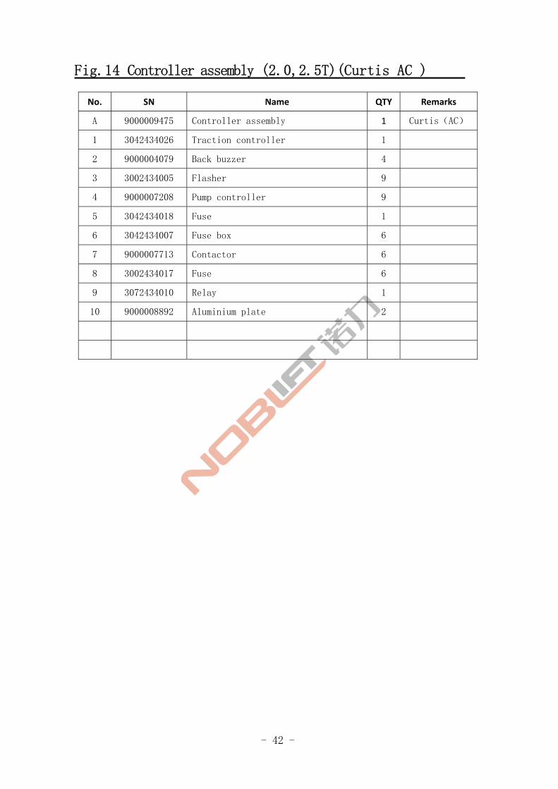
Fig.14 Controller assembly (2.0,2.5T)(Curtis AC )
No. SN Name QTY Remarks
A 9000009475 Controller assembly 1 Curtis(AC)
1 3042434026 Traction controller 1
2 9000004079 Back buzzer 4
3 3002434005 Flasher 9
4 9000007208 Pump controller 9
5 3042434018 Fuse 1
6 3042434007 Fuse box 6
7 9000007713 Contactor 6
8 3002434017 Fuse 6
9 3072434010 Relay 1
10 9000008892 Aluminium plate 2
- 43 -
Controller assembly (2.0,2.5T)(Curtis AC2 )
FE4P20,25
Fig.15
- 44 -
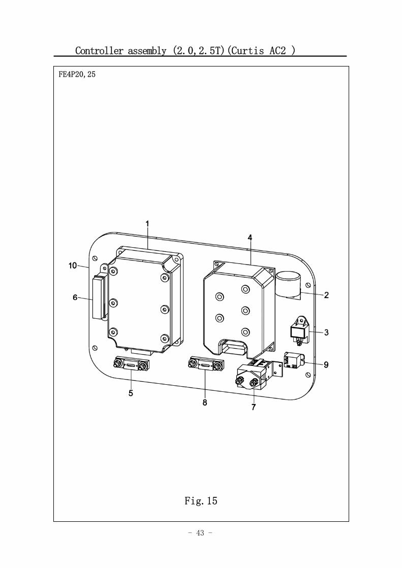
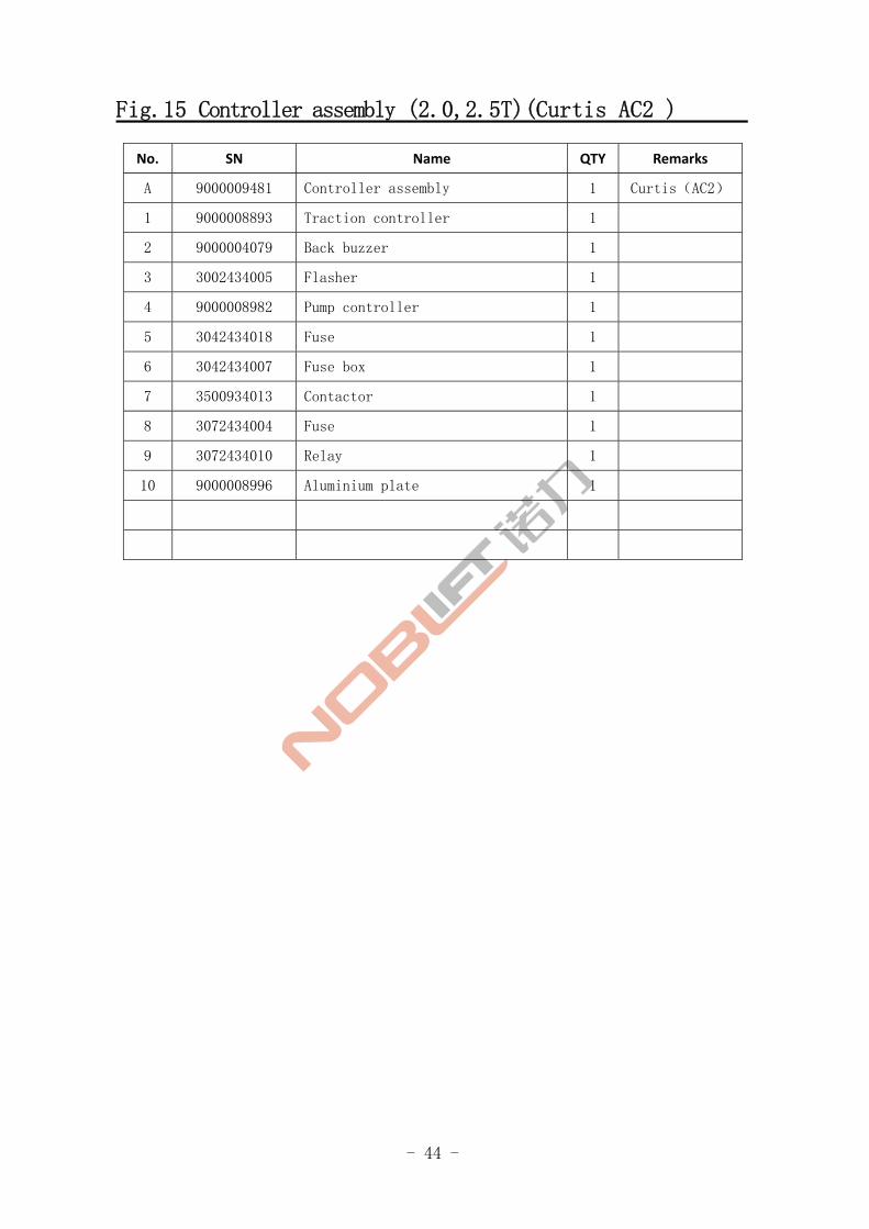
Fig.15 Controller assembly (2.0,2.5T)(Curtis AC2 )
No. SN Name QTY Remarks
A 9000009481 Controller assembly 1 Curtis(AC2)
1 9000008893 Traction controller 1
2 9000004079 Back buzzer 1
3 3002434005 Flasher 1
4 9000008982 Pump controller 1
5 3042434018 Fuse 1
6 3042434007 Fuse box 1
7 3500934013 Contactor 1
8 3072434004 Fuse 1
9 3072434010 Relay 1
10 9000008996 Aluminium plate 1
- 45 -
Controller assembly (2.0,2.5T)(Zapi AC )
FE4P20,25
Fig.16
- 46 -
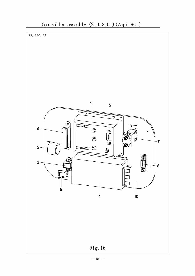
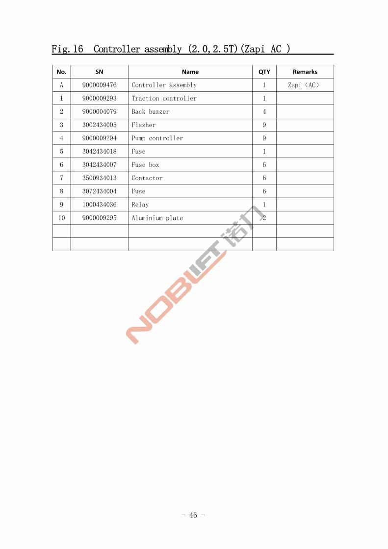
Fig.16 Controller assembly (2.0,2.5T)(Zapi AC )
No. SN Name QTY Remarks
A 9000009476 Controller assembly 1 Zapi(AC)
1 9000009293 Traction controller 1
2 9000004079 Back buzzer 4
3 3002434005 Flasher 9
4 9000009294 Pump controller 9
5 3042434018 Fuse 1
6 3042434007 Fuse box 6
7 3500934013 Contactor 6
8 3072434004 Fuse 6
9 1000434036 Relay 1
10 9000009295 Aluminium plate 2
- 47 -
Controller assembly (2.0,2.5T)(Zapi AC2 )
FE4P20,25
Fig.17
- 48 -
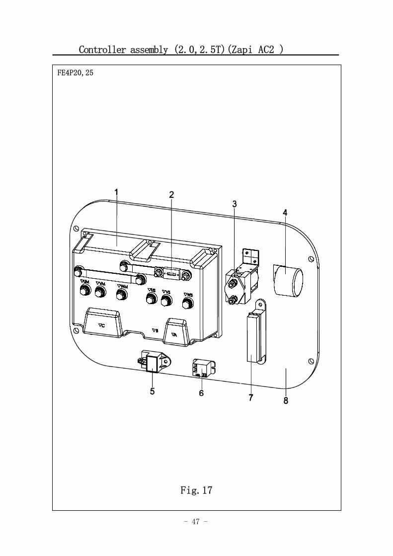
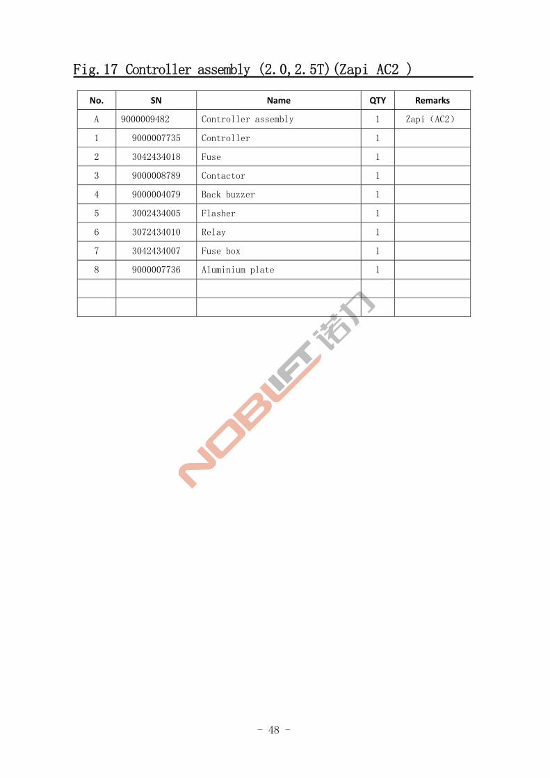
Fig.17 Controller assembly (2.0,2.5T)(Zapi AC2 )
No. SN Name QTY Remarks
A 9000009482 Controller assembly 1 Zapi(AC2)
1 9000007735 Controller 1
2 3042434018 Fuse 1
3 9000008789 Contactor 1
4 9000004079 Back buzzer 1
5 3002434005 Flasher 1
6 3072434010 Relay 1
7 3042434007 Fuse box 1
8 9000007736 Aluminium plate 1
- 49 -
FE4P30-35 电气系统元器件
FE4P30,35
Fig 18
- 50 -
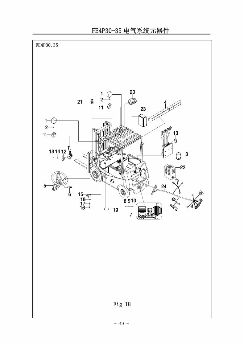
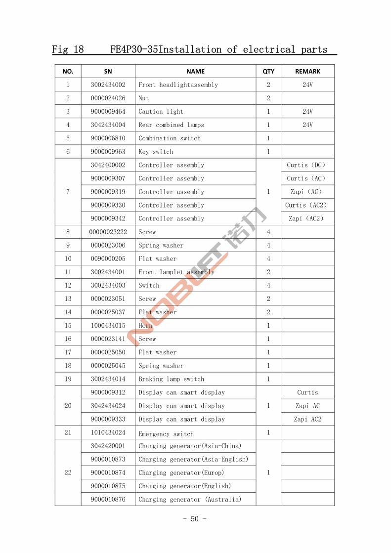
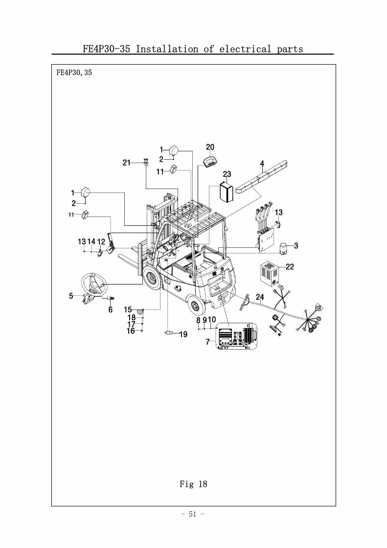
Fig 18 FE4P30-35Installation of electrical parts
NO. SN NAME QTY REMARK
1 3002434002 Front headlightassembly 2 24V
2 0000024026 Nut 2
3 9000009464 Caution light 1 24V
4 3042434004 Rear combined lamps 1 24V
5 9000006810 Combination switch 1
6 9000009963 Key switch 1
3042400002 Controller assembly Curtis(DC)
9000009307 Controller assembly Curtis(AC)
9000009319 Controller assembly Zapi(AC)
9000009330 Controller assembly Curtis(AC2)
7
9000009342 Controller assembly
1
Zapi(AC2)
8 00000023222 Screw 4
9 0000023006 Spring washer 4
10 0090000205 Flat washer 4
11 3002434001 Front lamplet assembly 2
12 3002434003 Switch 4
13 0000023051 Screw 2
14 0000025037 Flat washer 2
15 1000434015 Horn 1
16 0000023141 Screw 1
17 0000025050 Flat washer 1
18 0000025045 Spring washer 1
19 3002434014 Braking lamp switch 1
9000009312 Display can smart display Curtis
3042434024 Display can smart display Zapi AC 20
9000009333 Display can smart display
1
Zapi AC2
21 1010434024 Emergency switch 1
3042420001 Charging generator(Asia-China)
9000010873 Charging generator(Asia-English)
9000010874 Charging generator(Europ)
9000010875 Charging generator(English)
22
9000010876 Charging generator (Australia)
1
- 51 -
FE4P30-35 Installation of electrical parts
FE4P30,35
Fig 18
- 52 -
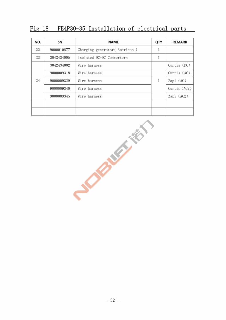
Fig 18 FE4P30-35 Installation of electrical parts
NO. SN NAME QTY REMARK
22 9000010877 Charging generator( American ) 1
23 3042434005 Isolated DC-DC Converters 1
3042434002 Wire harness Curtis(DC)
9000009318 Wire harness Curtis(AC)
9000009329 Wire harness Zapi(AC)
9000009340 Wire harness Curtis(AC2)
24
9000009345 Wire harness
1
Zapi(AC2)
- 53 -
Controller assembly (3.0,3.5T,)( Curtis DC )
FE4P30,35
Fig.19
- 54 -
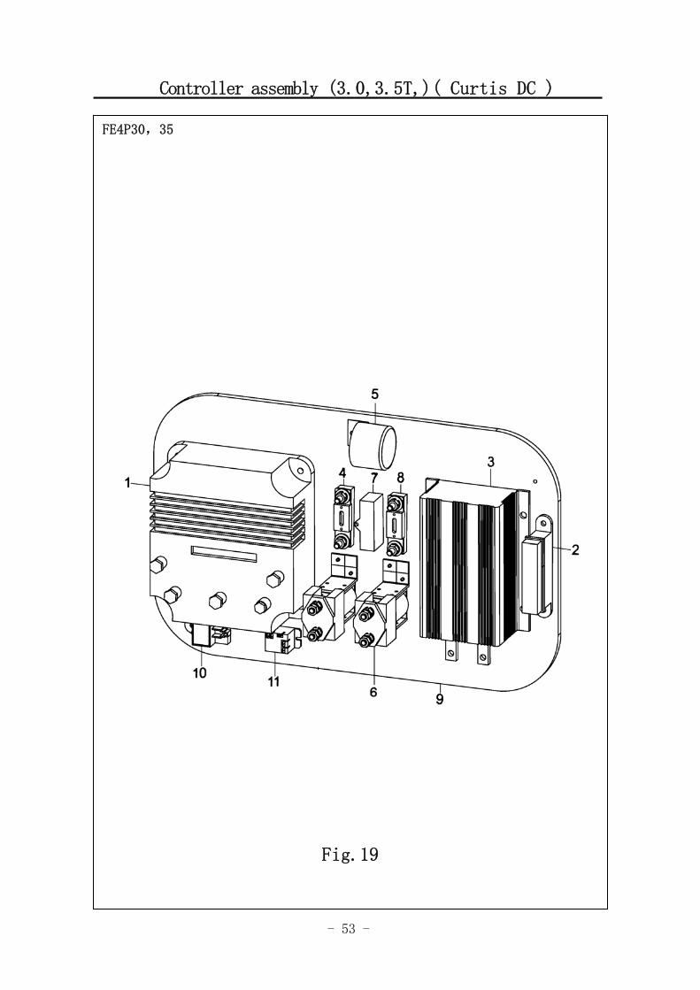
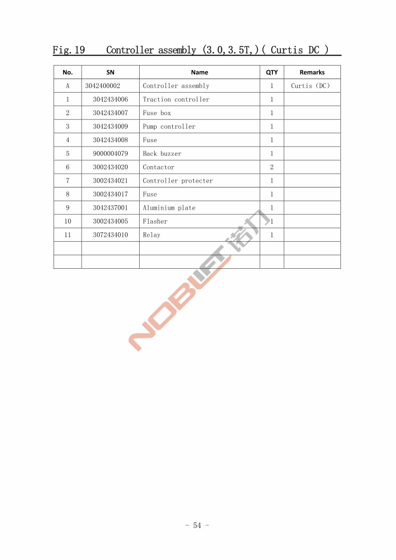
Fig.19 Controller assembly (3.0,3.5T,)( Curtis DC )
No. SN Name QTY Remarks
A 3042400002 Controller assembly 1 Curtis(DC)
1 3042434006 Traction controller 1
2 3042434007 Fuse box 1
3 3042434009 Pump controller 1
4 3042434008 Fuse 1
5 9000004079 Back buzzer 1
6 3002434020 Contactor 2
7 3002434021 Controller protecter 1
8 3002434017 Fuse 1
9 3042437001 Aluminium plate 1
10 3002434005 Flasher 1
11 3072434010 Relay 1
- 55 -
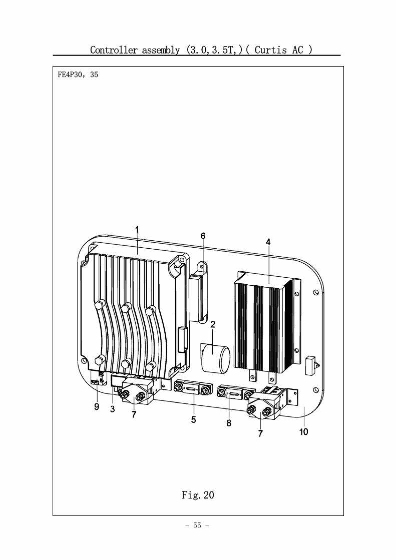
Controller assembly (3.0,3.5T,)( Curtis AC )
FE4P30,35
Fig.20
- 56 -
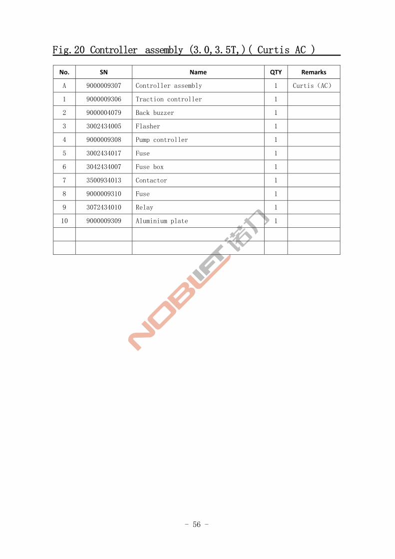
Fig.20 Controller assembly (3.0,3.5T,)( Curtis AC )
No. SN Name QTY Remarks
A 9000009307 Controller assembly 1 Curtis(AC)
1 9000009306 Traction controller 1
2 9000004079 Back buzzer 1
3 3002434005 Flasher 1
4 9000009308 Pump controller 1
5 3002434017 Fuse 1
6 3042434007 Fuse box 1
7 3500934013 Contactor 1
8 9000009310 Fuse 1
9 3072434010 Relay 1
10 9000009309 Aluminium plate 1
- 57 -
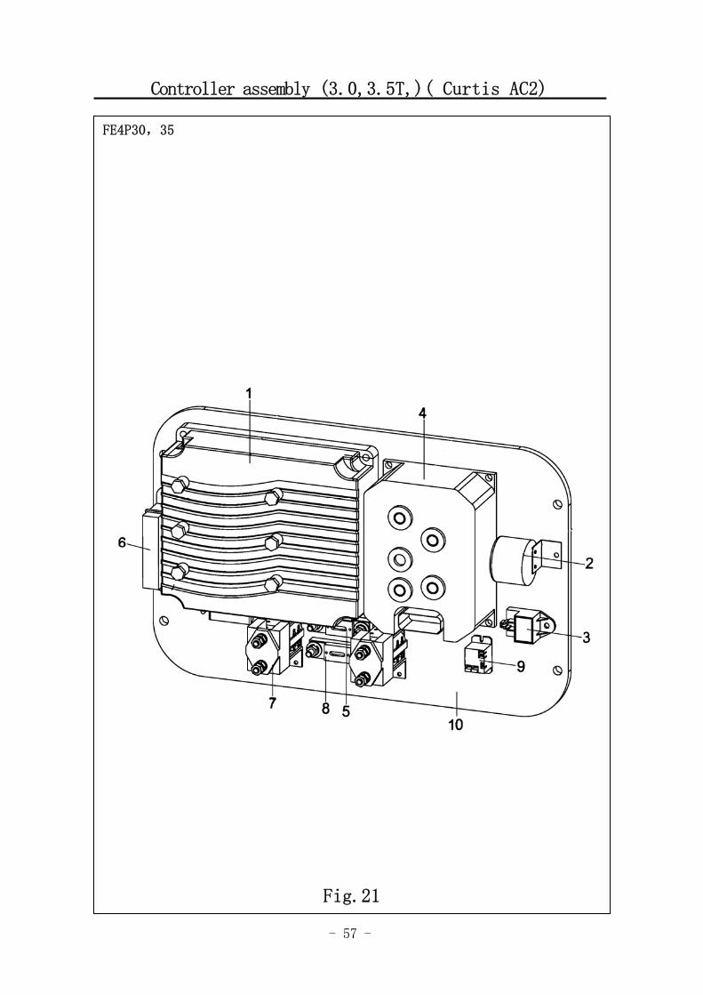
Controller assembly (3.0,3.5T,)( Curtis AC2)
FE4P30,35
Fig.21
- 58 -
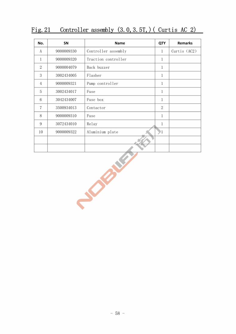
Fig.21 Controller assembly (3.0,3.5T,)( Curtis AC 2)
No. SN Name QTY Remarks
A 9000009330 Controller assembly 1 Curtis(AC2)
1 9000009320 Traction controller 1
2 9000004079 Back buzzer 1
3 3002434005 Flasher 1
4 9000009321 Pump controller 1
5 3002434017 Fuse 1
6 3042434007 Fuse box 1
7 3500934013 Contactor 2
8 9000009310 Fuse 1
9 3072434010 Relay 1
10 9000009322 Aluminium plate 1
- 59 -
Controller assembly (3.0,3.5T,)( Zapi AC )
FE4P30,35
Fig.22
- 60 -
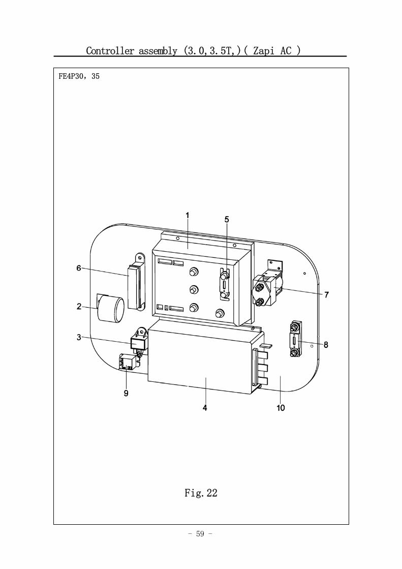
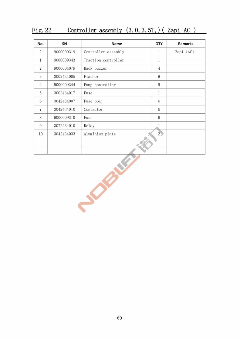
Fig.22 Controller assembly (3.0,3.5T,)( Zapi AC )
No. SN Name QTY Remarks
A 9000009319 Controller assembly 1 Zapi(AC)
1 9000009343 Traction controller 1
2 9000004079 Back buzzer 4
3 3002434005 Flasher 9
4 9000009344 Pump controller 9
5 3002434017 Fuse 1
6 3042434007 Fuse box 6
7 3042434010 Contactor 6
8 9000009310 Fuse 6
9 3072434010 Relay 1
10 3042434033 Aluminium plate 2
- 61 -
Controller assembly (3.0,3.5T,)( Zapi AC2 )
FE4P30,35
Fig.23
- 62 -
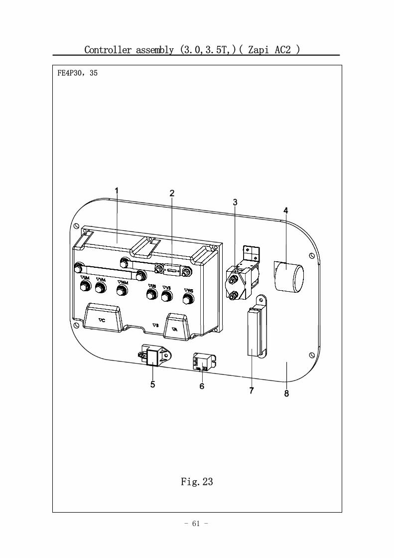
Fig.23 Controller assembly (3.0,3.5T,)( Zapi AC2 )
No. SN Name QTY Remarks
A 9000009342 Controller assembly 1 Zapi(AC2)
1 9000009331 Controller 1
2 3002434017 Fuse 4
3 3042434044 Contactor 9
4 9000004079 Back buzzer 9
5 3002434005 Flasher 1
6 3072434010 Relay 6
7 3042434007 Fuse box 6
8 9000009332 Aluminium plate 6
- 63 -
Power supply connector assembly
Fig.1 Travel Motor and Gearbox
FE4P20,25,30,35
Fig.24
- 64 -
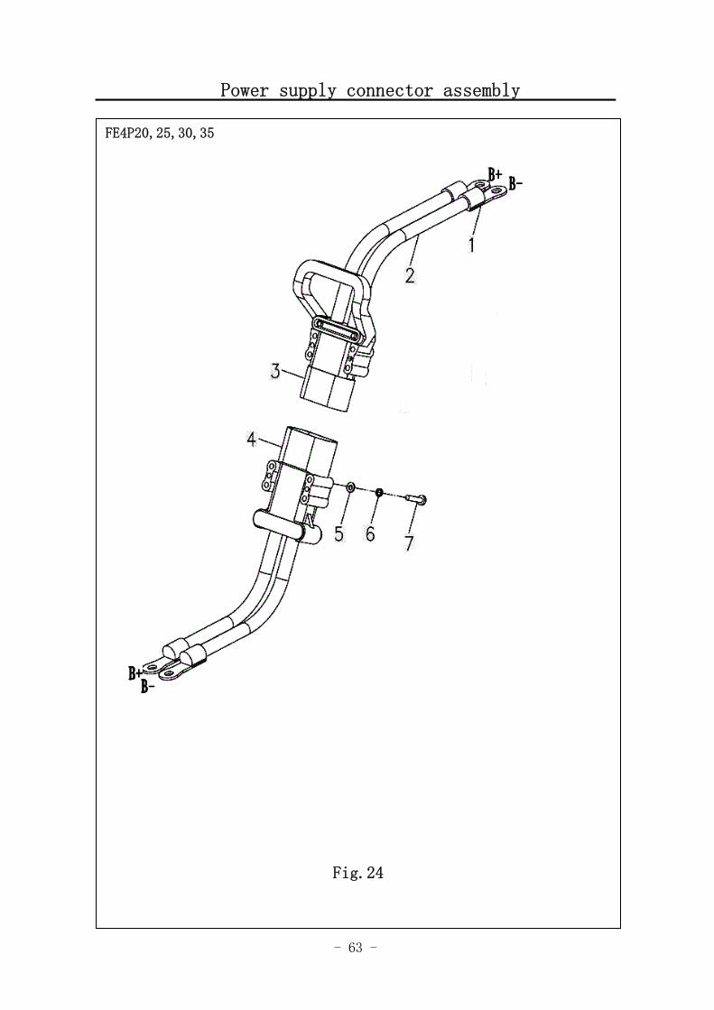
Fig.24 Power supply connector assembly
No. SN Name QTY Remarks
1 9000006982 Binding post 4
2 9000005639 70mm cable 2
3 3042434012 Connector female 1
4 3042434011 Connector male 1
5 0000025050 Flat washer 4
6 0000025045 Spring washer 4
7 0000023294 Screw 4
- 65 -
Battery and instalation
Fig.1 Travel Motor and Gearbox
FE4P20,25,30,35
Fig.25
- 66 -
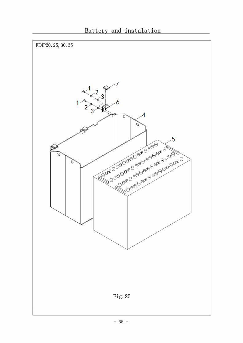
Fig.25 Battery and Installation
No. SN Name QTY Remarks
1 0000023834 Bolt 6
2 0000025047 Flat washer 6
3 0000025041 Spring washer 6
3041401001 FE4P30-35
3041401002 FE4P20-25 4
3041401003
Battery case 1
FE4P20-25
9000004136 40 FE4P35
3041400005 40 FE4P30 5
3041400008
Battery
25 FE4P20-25
6 3041402001 Support 3
7 3046418003 Bumper 3
- 67 -
Steering equipment and installation
Fig.1 Travel motor and gearbox 1
FE4P20,25,30,35
Fig.26
- 68 -
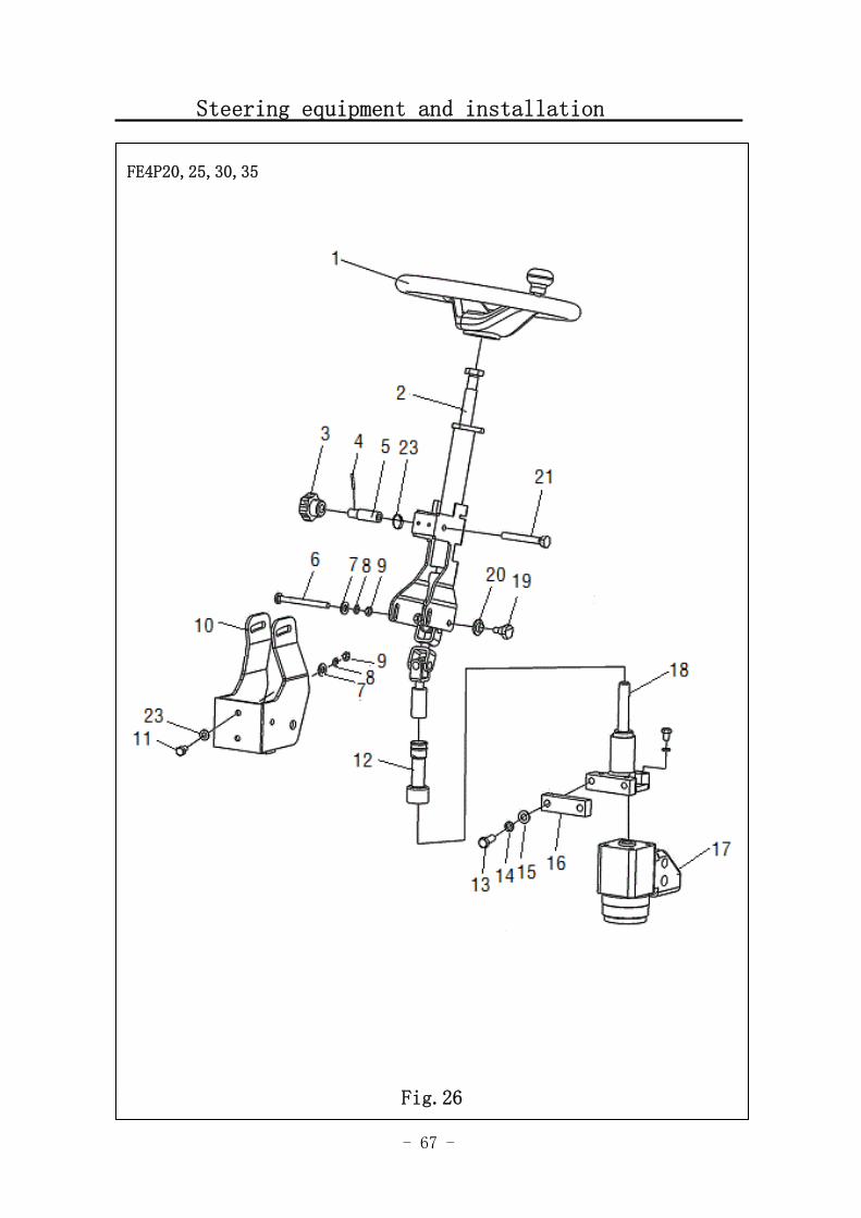
Fig.26 Steering equipment and installation
No. SN Name QTY Remarks
1 3044200004 Steering wheel assembly 1
2 3044201003 Steering Column assembly 1
3 0000014001 Five-star handle 1
4 0000028071 Elastic pin 1
5 3044202002 Clamp holderaxle sleeve 1
6 3004202005 Bolt 1
7 0000025047 Flat washer 3
8 0000025041 Spring washer 7
9 0000024018 Nut 1
10 3044201001 Support 1
11 0000023355 Bolt 6
12 3044218001 Protective sleeve 1
13 0000023329 Bolt 2
14 0000025042 Sring washer 2
15 0000025048 Flat washer 2
16 3044202001 Subplate 1
17 3044200001 pile-up valve 1
18 3044200002 Connecting shaft assembly 1
19 3004202004 Bolt 2
20 3004219002 Distance ring 2
21 3044202003 Shaft of clamp holder 1
- 69 -
Steering Column assembl
Fig.1 Travel motor and gearbox 1
FE4P20,25,30,35
Fig.27
- 70 -
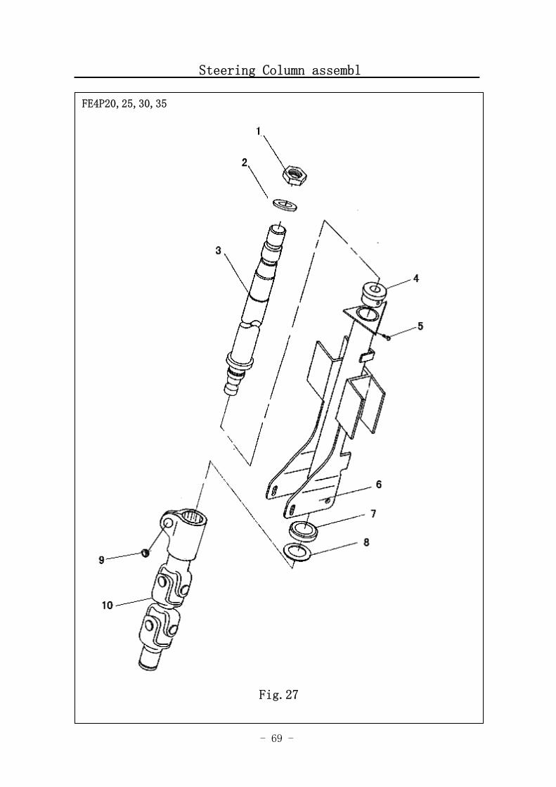
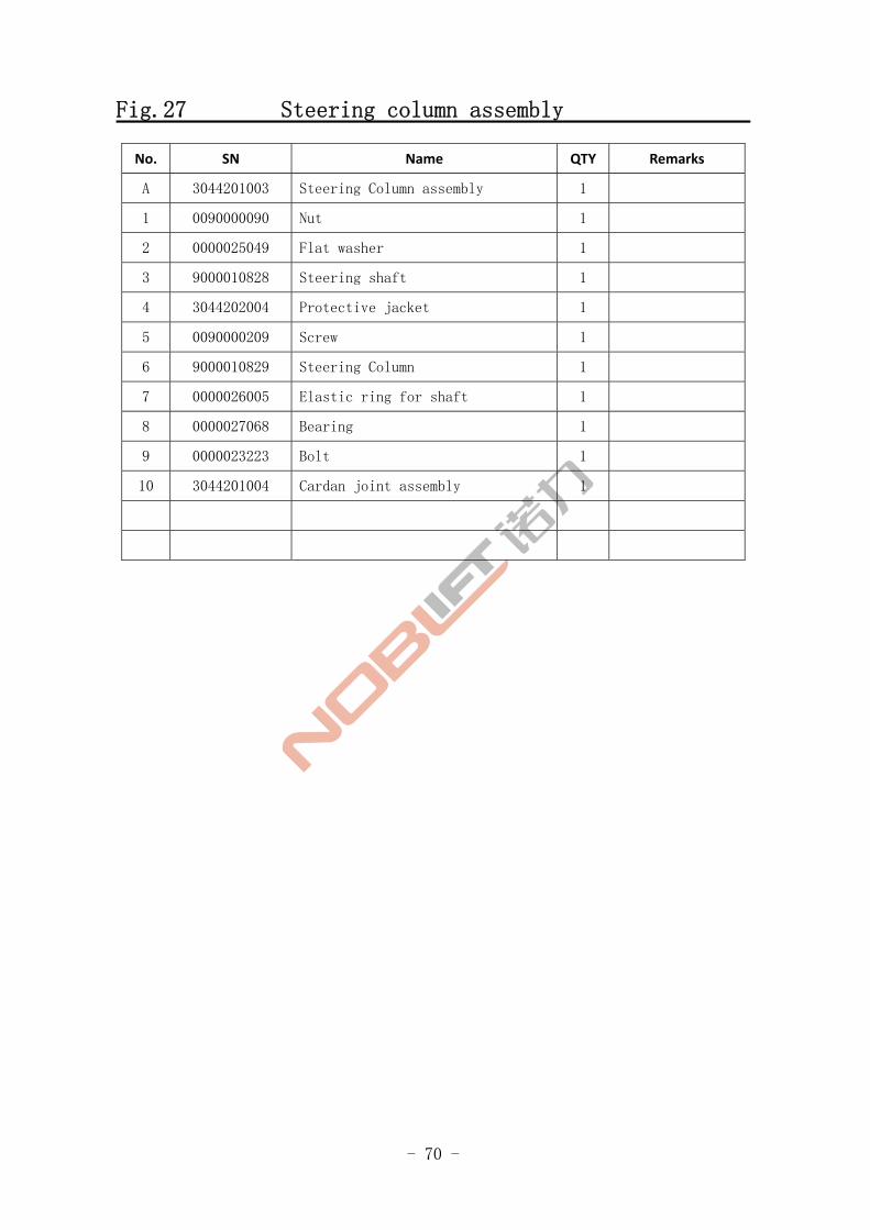
Fig.27 Steering column assembly
No. SN Name QTY Remarks
A 3044201003 Steering Column assembly 1
1 0090000090 Nut 1
2 0000025049 Flat washer 1
3 9000010828 Steering shaft 1
4 3044202004 Protective jacket 1
5 0090000209 Screw 1
6 9000010829 Steering Column 1
7 0000026005 Elastic ring for shaft 1
8 0000027068 Bearing 1
9 0000023223 Bolt 1
10 3044201004 Cardan joint assembly 1
- 71 -
Linking shaft assembly
Fig. 1 Travel motorand gearbox 1
FE4P20,25,30,35
Fig.28
- 72 -
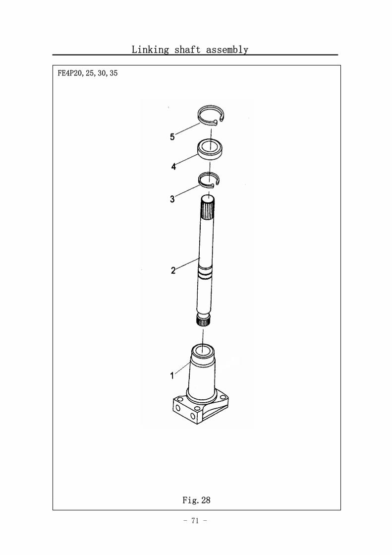
Fig.28 Linking shaft assembly
No. SN Name QTY Remarks
A 3044200002 Linking shaft assembly 1
1 3044205001 Linking flange 1
2 3044207002 Linking shaft 1
3 0000026003 Elastic ring for shaft 1
4 0000027016 Bearing 1
5 0000026012 Elastic ring for shaft 1

- 73 -
Steering axle and installation
Fig.1 Travel motor and gearbox 1
FE4P20,25,30,35
Fig.29
- 74 -
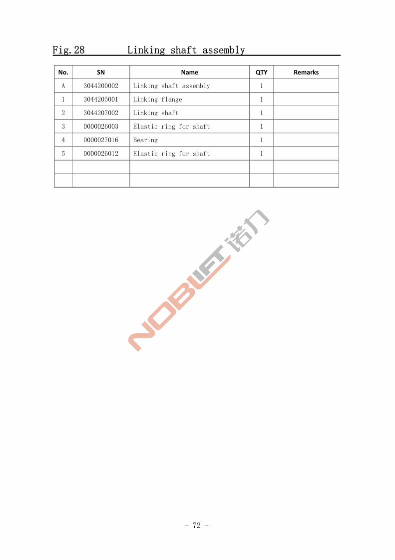
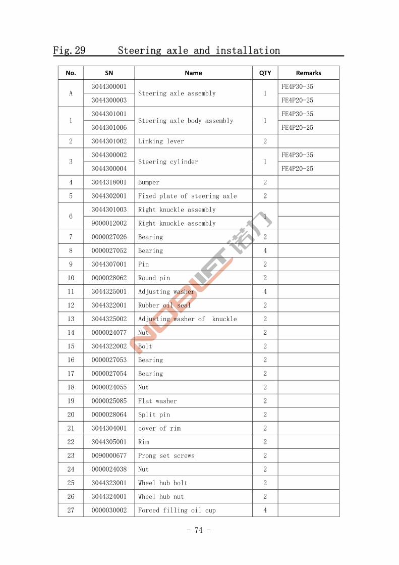
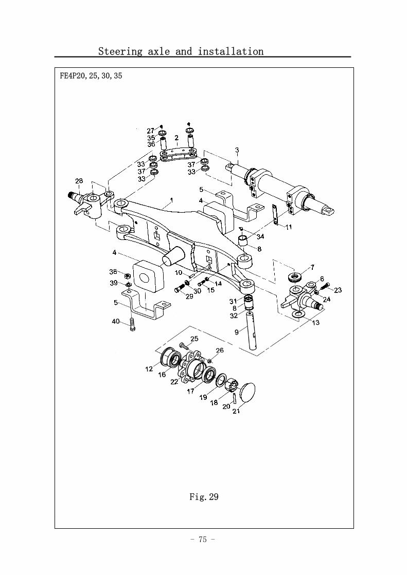
Fig.29 Steering axle and installation
No. SN Name QTY Remarks
3044300001 FE4P30-35 A
3044300003 Steering axle assembly 1
FE4P20-25
3044301001 FE4P30-35 1
3044301006 Steering axle body assembly 1
FE4P20-25
2 3044301002 Linking lever 2
3044300002 FE4P30-35 3
3044300004 Steering cylinder 1
FE4P20-25
4 3044318001 Bumper 2
5 3044302001 Fixed plate of steering axle 2
3044301003 Right knuckle assembly 6
9000012002 Right knuckle assembly 1
7 0000027026 Bearing 2
8 0000027052 Bearing 4
9 3044307001 Pin 2
10 0000028062 Round pin 2
11 3044325001 Adjusting washer 4
12 3044322001 Rubber oil seal 2
13 3044325002 Adjusting washer of knuckle 2
14 0000024077 Nut 2
15 3044322002 Bolt 2
16 0000027053 Bearing 2
17 0000027054 Bearing 2
18 0000024055 Nut 2
19 0000025085 Flat washer 2
20 0000028064 Split pin 2
21 3044304001 cover of rim 2
22 3044305001 Rim 2
23 0090000677 Prong set screws 2
24 0000024038 Nut 2
25 3044323001 Wheel hub bolt 2
26 3044324001 Wheel hub nut 2
27 0000030002 Forced filling oil cup 4
- 75 -
Steering axle and installation
Fig.1 Travel motor and gearbox 1
FE4P20,25,30,35
Fig.29
- 76 -
Fig.29 Steering axle and installation
No. SN Name QTY Remarks
3044301004 Left knuckle assembly 28
9000012003 Left knuckle assembly 1
29 0000023364 Bolt 4
30 0000025043 Spring washer 4
31 0000022079 O-ring 2
32 3044322003 Oil seal 2
33 3044313002 Bushing 6
34 0090000740 Flow nipple 4
35 0000030023 bead flange 4
36 3044307002 connecting pin 4
37 0000027055 oscillating bearing 4
38 0000024036 Nut 4
39 0000025055 Spring washer 4
40 0000023137 Bolt 4
- 77 -
Steering cylinder
Fig.1 Travel motor and gearbox 1
FE4P20,25,30,35
Fig.30
- 78 -
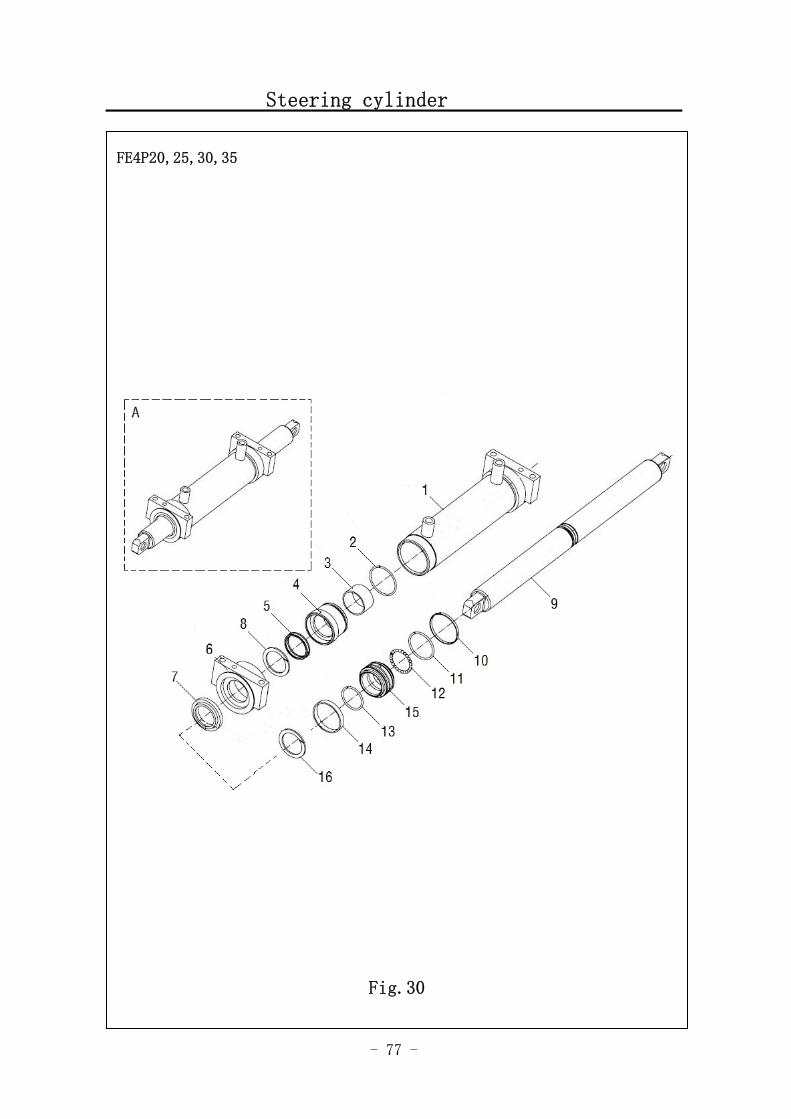
Fig.30 Steering cylinder
No. SN Name QTY Remarks
3044300002 FE4P30-35 A
3044300004 Steering cylinder 1
FE4P20-25
9000011993 FE4P30-35 1
9000011994 Cylinder body 1
FE4P20-25
2 0090000755 O-ring 2
3 3044313003 Bearing 2
4 9000011995 Sleeve cover 2
5 9000011996 Barrier chip 2
6 3044302004 Cover of cylinder 2
7 9000011997 Dust proof ring 2
8 9000011998 Retainer ring 2
3044307003 FE4P30-35 9
3044307004 Piston rod assembly 1
FE4P20-25
10 3044326001 Support ring 1
11 0000022077 O-ring 1
12 0000037001 ball 25
13 0000022310 O-ring 1
14 9000011999 Support ring 1
15 9000012000 Piston 1
16 9000012001 washer 2 组
- 79 -
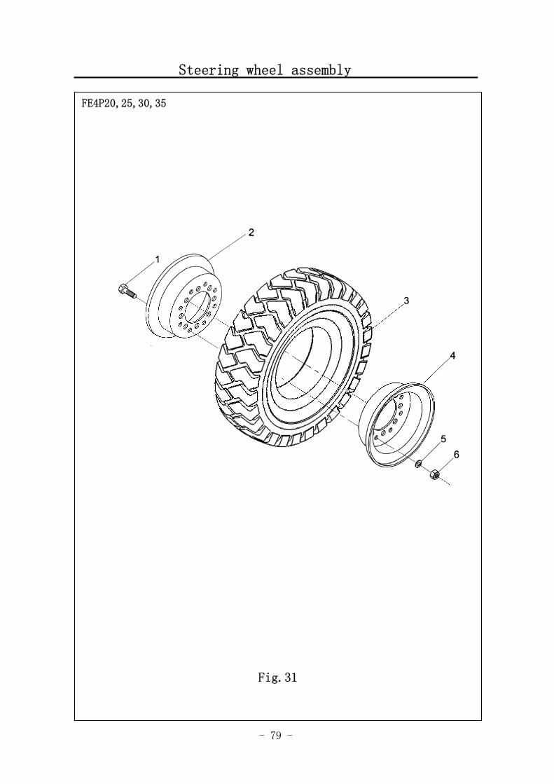
Steering wheel assembly
Fig.1 Travel motor and gearbox 1
FE4P20,25,30,35
Fig.31
- 80 -
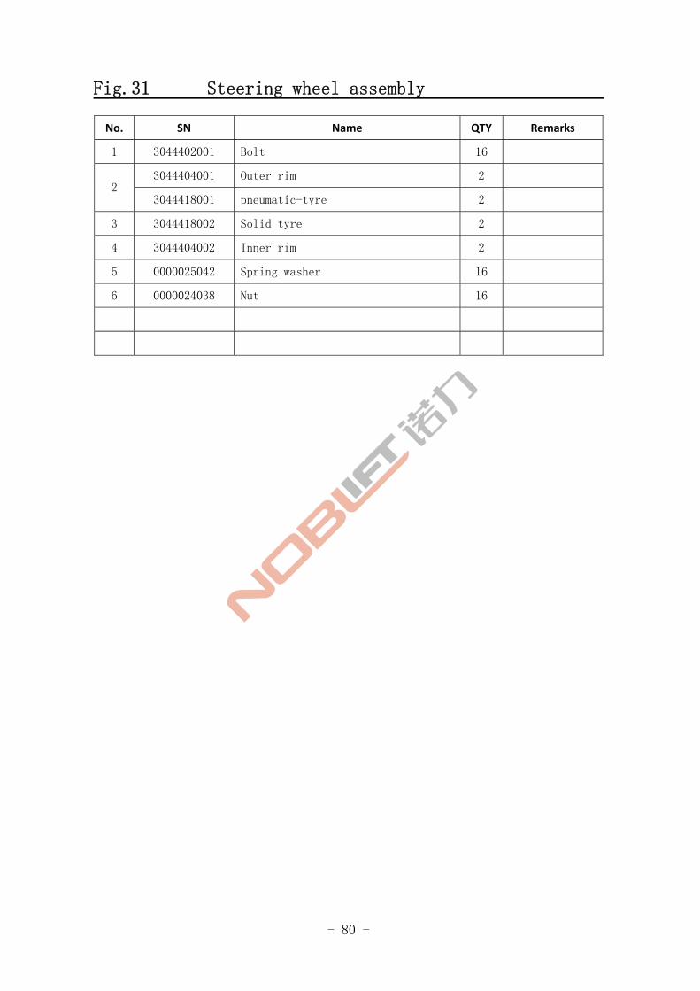
Fig.31 Steering wheel assembly
No. SN Name QTY Remarks
1 3044402001 Bolt 16
3044404001 Outer rim 2 2
3044418001 pneumatic-tyre 2
3 3044418002 Solid tyre 2
4 3044404002 Inner rim 2
5 0000025042 Spring washer 16
6 0000024038 Nut 16
- 81 -
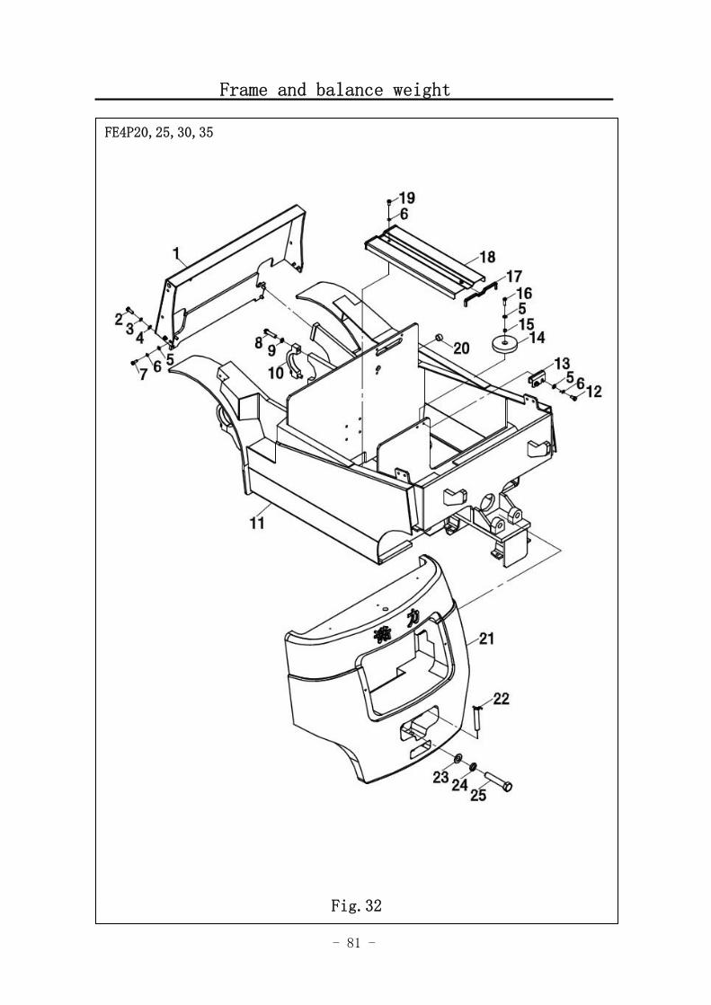
Frame and balance weight
Fig.1 Travel motor and gearbox 1
FE4P20,25,30,35
Fig.32
- 82 -
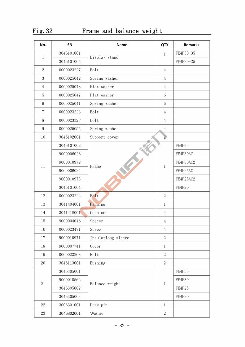
Fig.32 Frame and balance weight
No. SN Name QTY Remarks
3046101001 FE4P30-35 1
3046101005 Display stand
1
FE4P20-25
2 0000023227 Bolt 4
3 0000025042 Spring washer 4
4 0000025048 Flat washer 4
5 0000025047 Flat washer 6
6 0000025041 Spring washer 6
7 0000023223 Bolt 4
8 0000023328 Bolt 4
9 0000025055 Spring washer 4
10 3046102001 Support cover 2
3046101002 FE4P35
9000006028 FE4P30AC
9000010972 FE4P30AC2
9000006024 FE4P25AC
9000010973 FE4P25AC2
11
3046101004
Frame 1
FE4P20
12 0000023222 Bolt 2
13 3041404001 Hanging 1
14 3041418001 Cushion 4
15 9000004016 Spacer 4
16 0000023471 Screw 4
17 9000010971 Insulationg sleeve 2
18 9000007741 Cover 1
19 0000023263 Bolt 2
20 3046113001 Bushing 2
3046305001 FE4P35
9000010562 FE4P30
3046305002 FE4P25 21
3046305003
Balance weight 1
FE4P20
22 3006301001 Draw pin 1
23 3046302001 Washer 2

- 83 -
Frame and balance weight
FE4P20,25,30,35
Fig.32
- 84 -
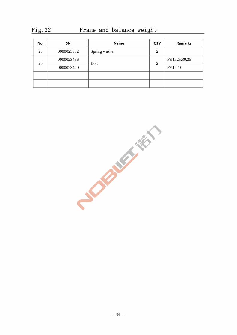
Fig.32 Frame and balance weight
No. SN Name QTY Remarks
23 0000025082 Spring washer 2
0000023456 FE4P25,30,35 25
0000023440 Bolt 2
FE4P20

- 85 -
Installation of Instrument stand and cover
Fig.1 Travel motor and gearbox 1
FE4P20,25,30,35
Fig.33
- 86 -
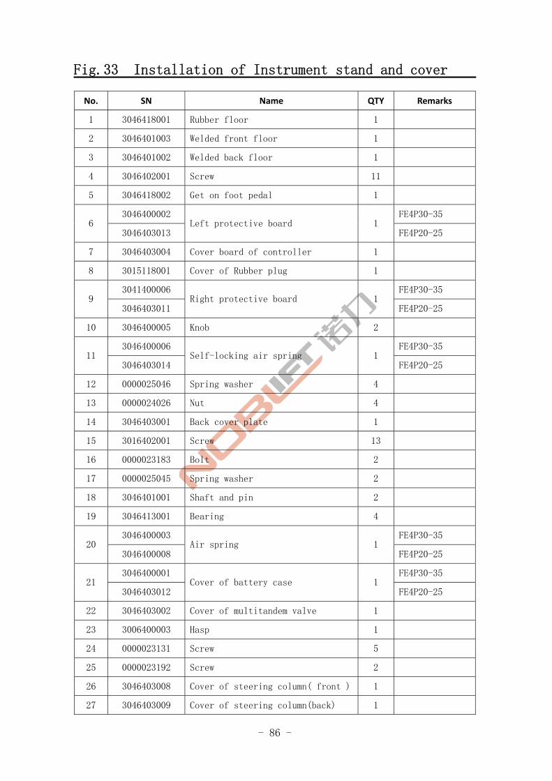
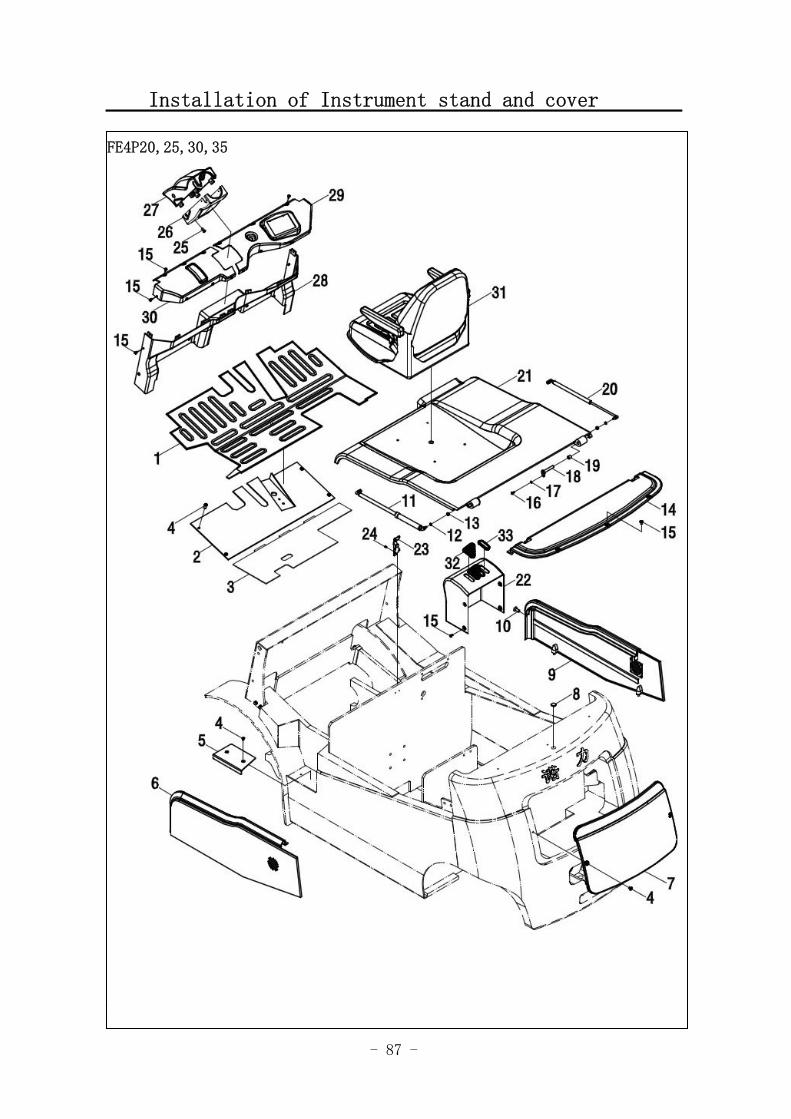
Fig.33 Installation of Instrument stand and cover
No. SN Name QTY Remarks
1 3046418001 Rubber floor 1
2 3046401003 Welded front floor 1
3 3046401002 Welded back floor 1
4 3046402001 Screw 11
5 3046418002 Get on foot pedal 1
3046400002 FE4P30-35 6
3046403013 Left protective board 1
FE4P20-25
7 3046403004 Cover board of controller 1
8 3015118001 Cover of Rubber plug 1
3041400006 FE4P30-35 9
3046403011 Right protective board 1
FE4P20-25
10 3046400005 Knob 2
3046400006 FE4P30-35 11
3046403014 Self-locking air spring 1
FE4P20-25
12 0000025046 Spring washer 4
13 0000024026 Nut 4
14 3046403001 Back cover plate 1
15 3016402001 Screw 13
16 0000023183 Bolt 2
17 0000025045 Spring washer 2
18 3046401001 Shaft and pin 2
19 3046413001 Bearing 4
3046400003 FE4P30-35 20
3046400008 Air spring 1
FE4P20-25
3046400001 FE4P30-35 21
3046403012 Cover of battery case 1
FE4P20-25
22 3046403002 Cover of multitandem valve 1
23 3006400003 Hasp 1
24 0000023131 Screw 5
25 0000023192 Screw 2
26 3046403008 Cover of steering column( front ) 1
27 3046403009 Cover of steering column(back) 1
- 87 -
Installation of Instrument stand and cover
Fig.1 Travel motor and gearbox 1
FE4P20,25,30,35
- 88 -
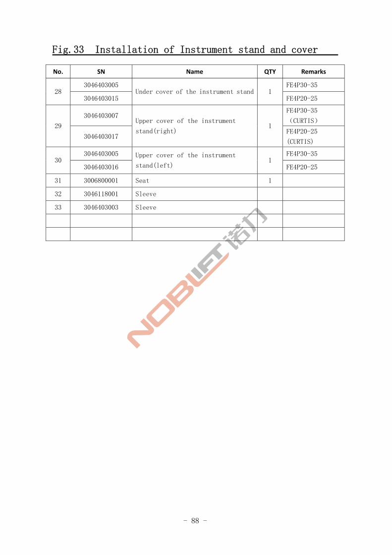
Fig.33 Installation of Instrument stand and cover
No. SN Name QTY Remarks
3046403005 FE4P30-35 28
3046403015 Under cover of the instrument stand 1
FE4P20-25
3046403007 FE4P30-35
(CURTIS) 29
3046403017
Upper cover of the instrument
stand(right) 1
FE4P20-25
(CURTIS)
3046403005 FE4P30-35 30
3046403016
Upper cover of the instrument
stand(left) 1
FE4P20-25
31 3006800001 Seat 1
32 3046118001 Sleeve
33 3046403003 Sleeve
- 89 -
Foot brake operation
Fig.1 Travel motor and gearbox 1
FE4P20,25,30,35
Fig.34
- 90 -
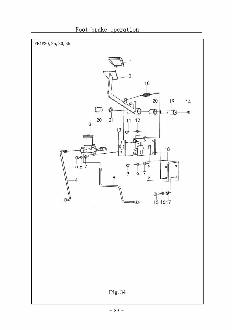
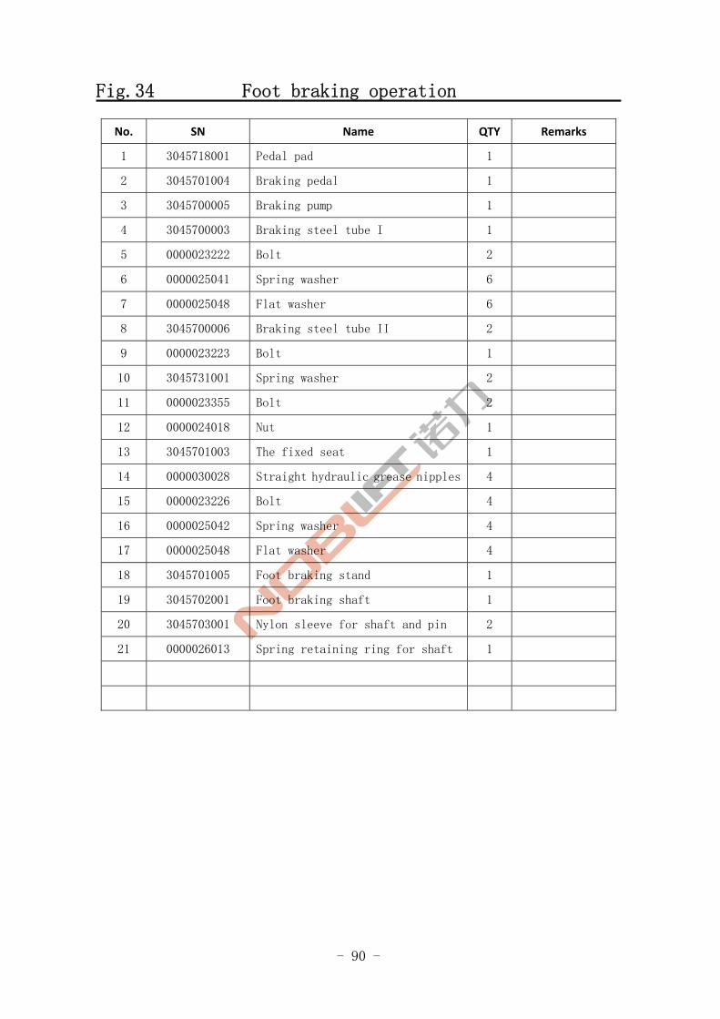
Fig.34 Foot braking operation
No. SN Name QTY Remarks
1 3045718001 Pedal pad 1
2 3045701004 Braking pedal 1
3 3045700005 Braking pump 1
4 3045700003 Braking steel tube I 1
5 0000023222 Bolt 2
6 0000025041 Spring washer 6
7 0000025048 Flat washer 6
8 3045700006 Braking steel tube II 2
9 0000023223 Bolt 1
10 3045731001 Spring washer 2
11 0000023355 Bolt 2
12 0000024018 Nut 1
13 3045701003 The fixed seat 1
14 0000030028 Straight hydraulic grease nipples 4
15 0000023226 Bolt 4
16 0000025042 Spring washer 4
17 0000025048 Flat washer 4
18 3045701005 Foot braking stand 1
19 3045702001 Foot braking shaft 1
20 3045703001 Nylon sleeve for shaft and pin 2
21 0000026013 Spring retaining ring for shaft 1
- 91 -
Hand braking operation
Fig.1 Travel motor and gearbox
FE4P20,25,30,35
Fig.35
- 92 -
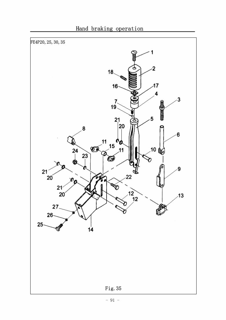
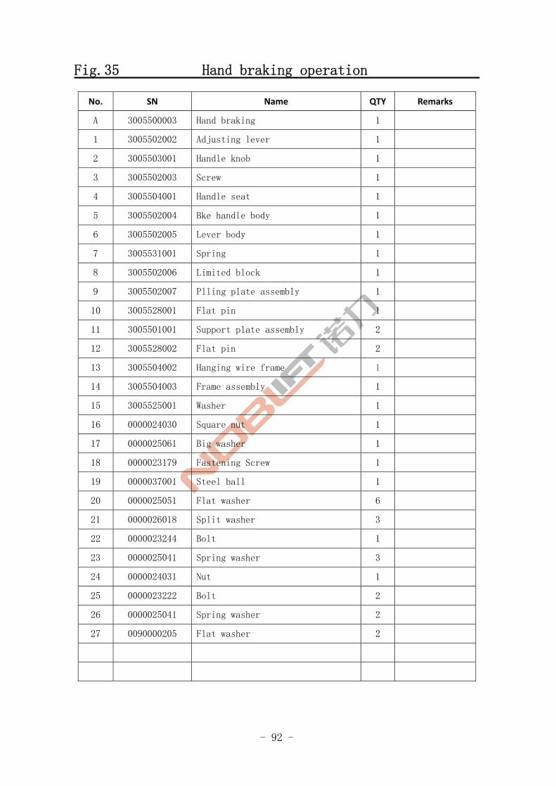
Fig.35 Hand braking operation
No. SN Name QTY Remarks
A 3005500003 Hand braking 1
1 3005502002 Adjusting lever 1
2 3005503001 Handle knob 1
3 3005502003 Screw 1
4 3005504001 Handle seat 1
5 3005502004 Bke handle body 1
6 3005502005 Lever body 1
7 3005531001 Spring 1
8 3005502006 Limited block 1
9 3005502007 Plling plate assembly 1
10 3005528001 Flat pin 1
11 3005501001 Support plate assembly 2
12 3005528002 Flat pin 2
13 3005504002 Hanging wire frame 1
14 3005504003 Frame assembly 1
15 3005525001 Washer 1
16 0000024030 Square nut 1
17 0000025061 Big washer 1
18 0000023179 Fastening Screw 1
19 0000037001 Steel ball 1
20 0000025051 Flat washer 6
21 0000026018 Split washer 3
22 0000023244 Bolt 1
23 0000025041 Spring washer 3
24 0000024031 Nut 1
25 0000023222 Bolt 2
26 0000025041 Spring washer 2
27 0090000205 Flat washer 2
- 93 -
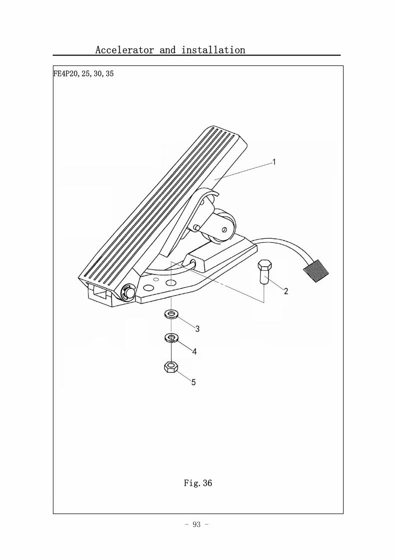
Accelerator and installation
Fig.1 Travel motor and gearbox
FE4P20,25,30,35
Fig.36
- 94 -
Fig.36 Accelerator and installation
No. SN Name QTY Remarks
3042800001 FE4P30,35(CURTIS)
9000009531 FE4P20,25(CURTIS) 1
3022800001
Accelerator 1
FE4P20,25,30,35(ZAPI)
2 0000023232 Bolt 2
3 0000025051 Flat washer
4 0000025046 Spring washer 2
5 0000024026 Nut 2
- 95 -
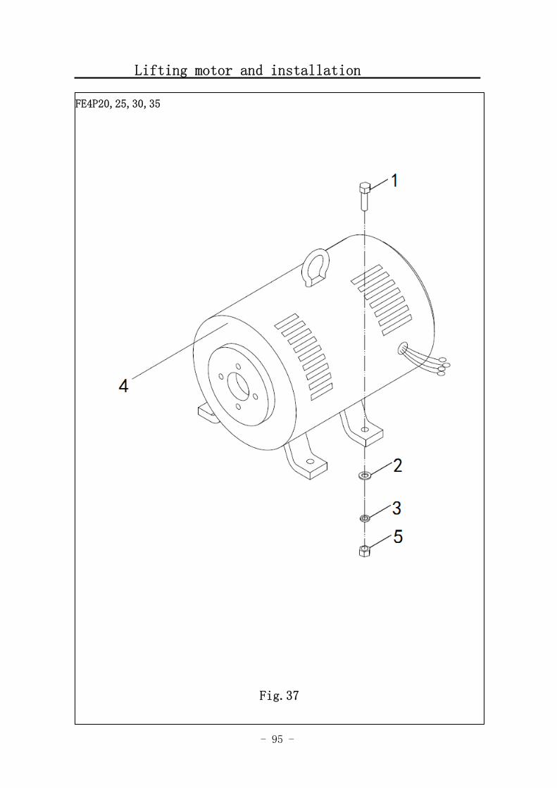
Lifting motor and installation
Fig.1 Travel motor and gearbox
FE4P20,25,30,35
Fig.37
- 96 -
Fig.37 Lifting motor and installation
No. SN Name QTY Remarks
1 0000023224 Bolt 4
2 0000025041 Spring washer 4
3 0000025047 Flat washer 4
3041800001 FE4P30-35DC
9000010975 FE4P30-35AC
3041800002 FE4P20-25DC 4
9000010976
Lifting motor 1
FE4P20-25AC
5 0000024018 Nut 4
- 97 -
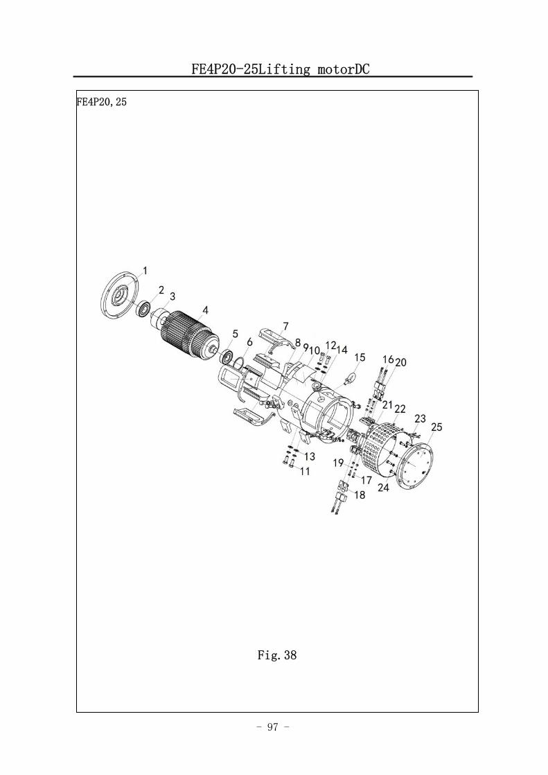
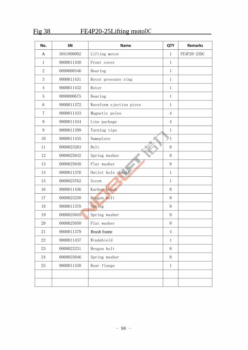
FE4P20-25Lifting motorDC
FE4P20,25
Fig.38
- 98 -
Fig 38 FE4P20-25Lifting motoDC
No. SN Name QTY Remarks
A 3041800002 Lifting motor 1 FE4P20-25DC
1 9000011430 Front cover 1
2 0090000546 Bearing 1
3 9000011431 Rotor pressure ring 1
4 9000011432 Rotor 1
5 0090000675 Bearing 1
6 9000011372 Waveform ejection piece 1
7 9000011433 Magnetic poles 4
8 9000011434 Line package 4
9 9000011399 Turning tips 1
10 9000011435 Nameplate 1
11 0000023263 Bolt 8
12 0000025042 Spring washer 8
13 0000025048 Flat washer 8
14 9000011376 Outlet hole sheath 1
15 0000023762 Screw 1
16 9000011436 Karbon brush 8
17 0000023258 Hexgon bolt 8
18 9000011378 Spring 8
19 0000025045 Spring washer 8
20 0000025050 Flat washer 8
21 9000011379 Brush frame 4
22 9000011437 Windshield 1
23 0000023231 Hexgon bolt 8
24 0000025046 Spring washer 8
25 9000011438 Rear flange 1
- 99 -
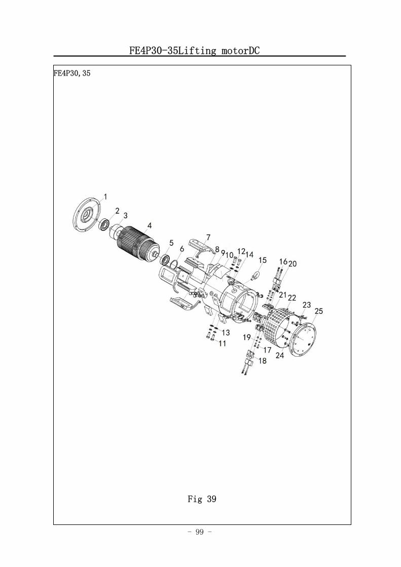
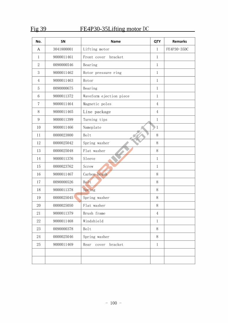
FE4P30-35Lifting motorDC
FE4P30,35
Fig 39
- 100 -
Fig 39 FE4P30-35Lifting motor DC
No. SN Name QTY Remarks
A 3041800001 Lifting motor 1 FE4P30-35DC
1 9000011461 Front cover bracket 1
2 0090000546 Bearing 1
3 9000011462 Rotor pressure ring 1
4 9000011463 Rotor 1
5 0090000675 Bearing 1
6 9000011372 Waveform ejection piece 1
7 9000011464 Magnetic poles 4
8 9000011465 Line package 4
9 9000011399 Turning tips 1
10 9000011466 Nameplate 1
11 0000023800 Bolt 8
12 0000025042 Spring washer 8
13 0000025048 Flat washer 8
14 9000011376 Sleeve 1
15 0000023762 Screw 1
16 9000011467 Carbon brush 8
17 0090000526 Bolt 8
18 9000011378 Spring 8
19 0000025045 Spring washer 8
20 0000025050 Flat washer 8
21 9000011379 Brush frame 4
22 9000011468 Windshield 1
23 0090000378 Bolt 8
24 0000025046 Spring washer 8
25 9000011469 Rear cover bracket 1
- 101 -
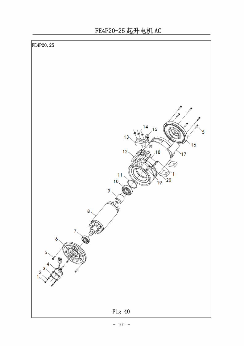
FE4P20-25 起升电机 AC
FE4P20,25
Fig 40
- 102 -
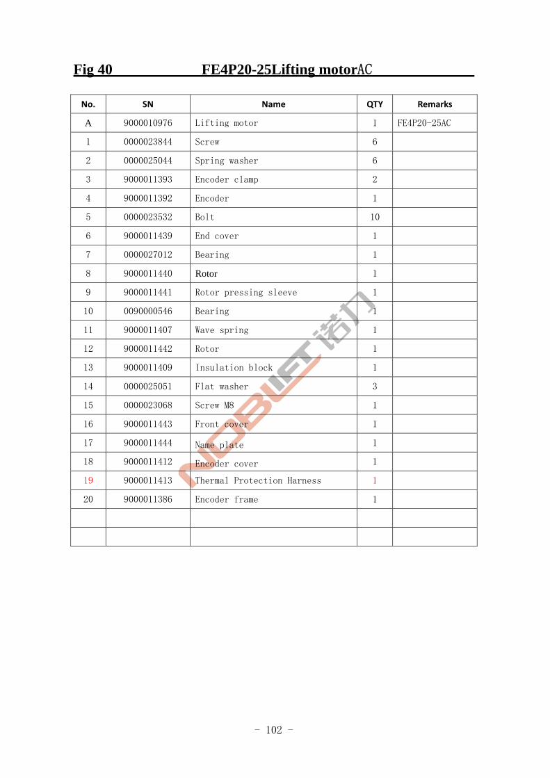
Fig 40 FE4P20-25Lifting motorAC
No. SN Name QTY Remarks
A 9000010976 Lifting motor 1 FE4P20-25AC
1 0000023844 Screw 6
2 0000025044 Spring washer 6
3 9000011393 Encoder clamp 2
4 9000011392 Encoder 1
5 0000023532 Bolt 10
6 9000011439 End cover 1
7 0000027012 Bearing 1
8 9000011440 Rotor 1
9 9000011441 Rotor pressing sleeve 1
10 0090000546 Bearing 1
11 9000011407 Wave spring 1
12 9000011442 Rotor 1
13 9000011409 Insulation block 1
14 0000025051 Flat washer 3
15 0000023068 Screw M8 1
16 9000011443 Front cover 1
17 9000011444 Name plate 1
18 9000011412 Encoder cover 1
19 9000011413 Thermal Protection Harness 1
20 9000011386 Encoder frame 1
- 103 -
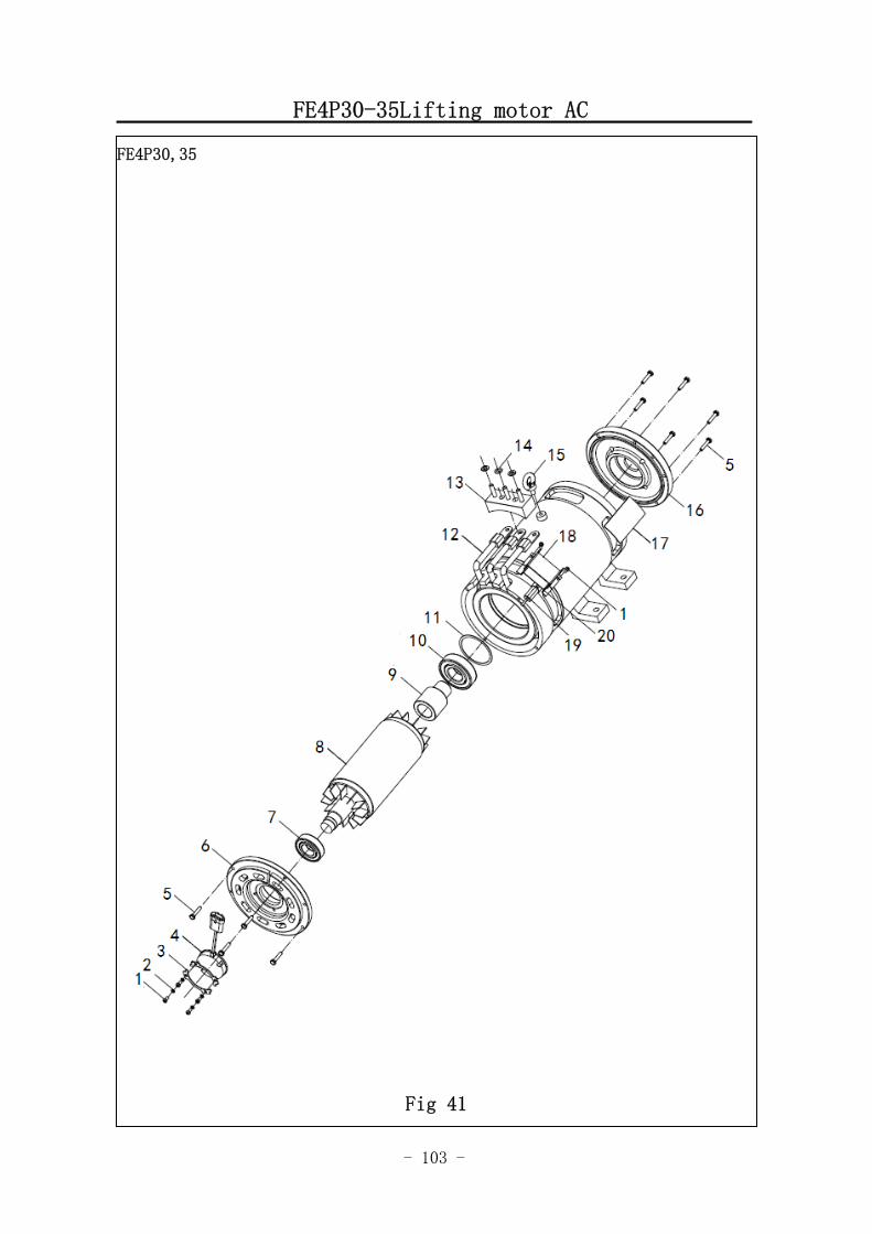
FE4P30-35Lifting motor AC
FE4P30,35
Fig 41
- 104 -
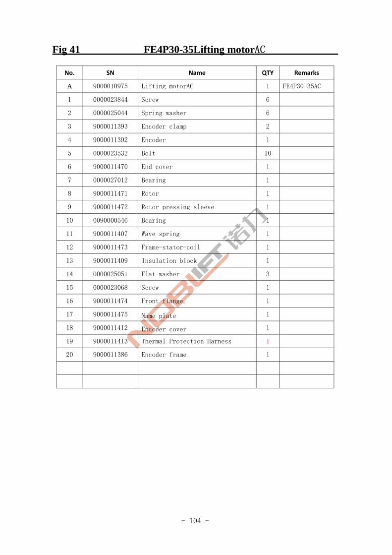
Fig 41 FE4P30-35Lifting motorAC
No. SN Name QTY Remarks
A 9000010975 Lifting motorAC 1 FE4P30-35AC
1 0000023844 Screw 6
2 0000025044 Spring washer 6
3 9000011393 Encoder clamp 2
4 9000011392 Encoder 1
5 0000023532 Bolt 10
6 9000011470 End cover 1
7 0000027012 Bearing 1
8 9000011471 Rotor 1
9 9000011472 Rotor pressing sleeve 1
10 0090000546 Bearing 1
11 9000011407 Wave spring 1
12 9000011473 Frame-stator-coil 1
13 9000011409 Insulation block 1
14 0000025051 Flat washer 3
15 0000023068 Screw 1
16 9000011474 Front flange, 1
17 9000011475 Name plate 1
18 9000011412 Encoder cover 1
19 9000011413 Thermal Protection Harness 1
20 9000011386 Encoder frame 1
- 105 -
Working fuel tank
Fig.1 Travel motor and gearbox A
FE4P20,25,30,35
Fig.42
- 106 -
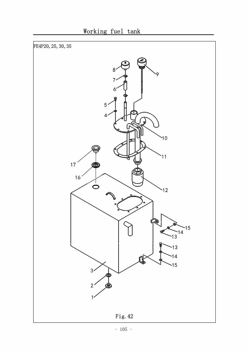
Fig.42 Working fuel tank
No. SN Name QTY Remarks
1 3047502001 Drain plug 1
2 0000022054 Compound washer 1
3 3047501002 Oil tank assembly 1
4 0000025046 Spring washer 8
5 0000023230 Bolt 8
6 3047517001 Hydraulic hoseⅠ 1
7 0000037008 Clamp 2
8 3017500001 Respirator 1
9 3047500001 Cover of refueller 1
10 3047501002 Oil tank cover assembly 1
11 3047522001 Seal washer 1
12 3007500001 Filter 1
13 0000023231 Bolt 3
14 0000025046 Spring washer 3
15 0000025051 Flat washer 3
16 0000022052 Cpmbination sealing washer
17 0090000472 Outside hexagonal screw
- 107 -
Operation of multiple directional control valve (Two position)
FE4P20,25,30,35
Fig.43
- 108 -
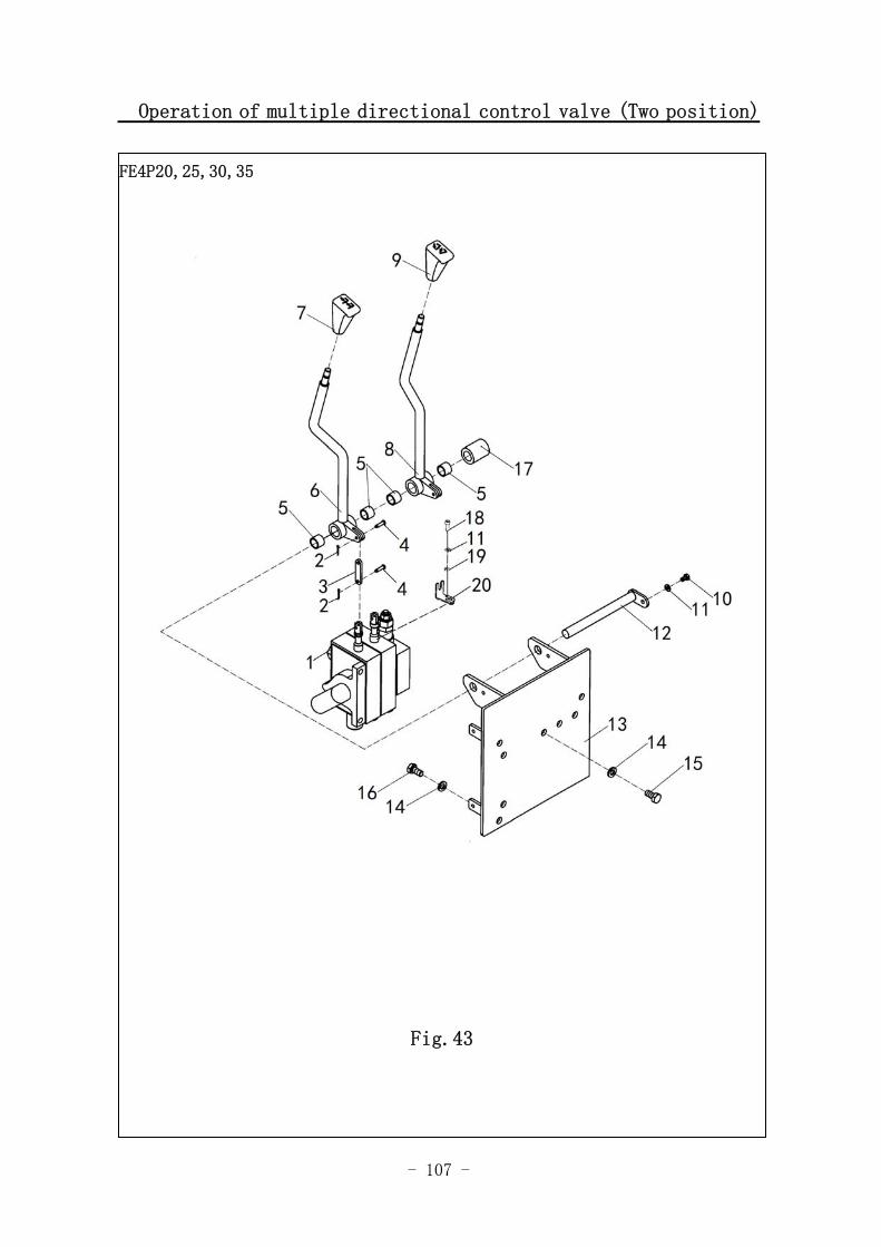
Fig.43 Operation of multiple directional control valve (Two position)
No. SN Name QTY Remarks
1 3047400001 Multitandem valve(Two position) 1
2 0000028066 Split pin 8
3 3017402004 Linking plate 4
4 0000028046 Shaft and pin 8
5 3046400007 Bearing 8
6 3047401002 Lifting joystick assembly 1
7 3007403003 Lifting handle ball 1
8 3047401003 Tilting joystick assembly 1
9 3007403006 Tilting handle knob 1
10 0000023728 Bolt 1
11 0000025010 Spring washer 3
12 3047401004 Installation shaft of multitandem
valve 6
13 3047401001 Installation support of multitandem
valve 1
14 0000025041 Spring washer 6
15 0000023357 Screw 3
16 0000023263 Bolt 3
17 3047402001 Shaft sleeve 1
18 0000023141 Screw 2
19 0000025050 Flat washer 2
20 9000004557 Frame 2
- 109 -
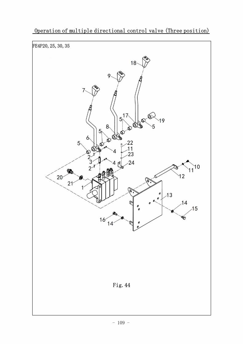
Operation of multiple directional control valve (Three position)
FE4P20,25,30,35
Fig.44
- 110 -
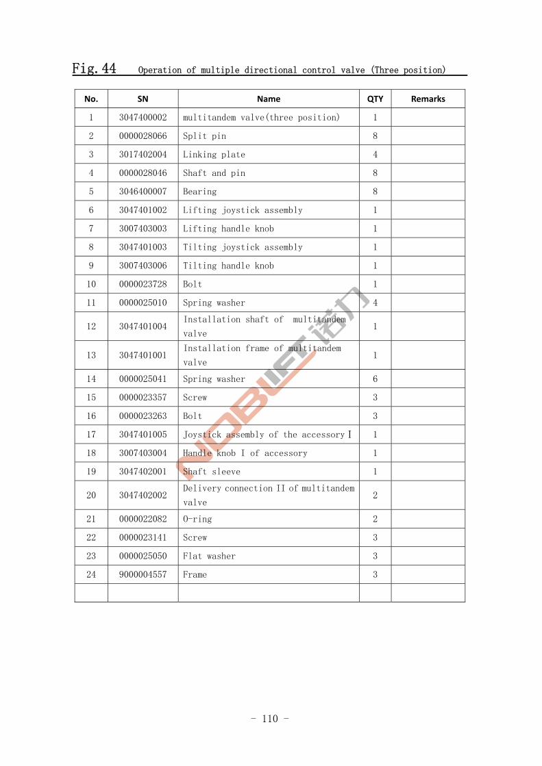
Fig.44 Operation of multiple directional control valve (Three position)
No. SN Name QTY Remarks
1 3047400002 multitandem valve(three position) 1
2 0000028066 Split pin 8
3 3017402004 Linking plate 4
4 0000028046 Shaft and pin 8
5 3046400007 Bearing 8
6 3047401002 Lifting joystick assembly 1
7 3007403003 Lifting handle knob 1
8 3047401003 Tilting joystick assembly 1
9 3007403006 Tilting handle knob 1
10 0000023728 Bolt 1
11 0000025010 Spring washer 4
12 3047401004 Installation shaft of multitandem
valve 1
13 3047401001 Installation frame of multitandem
valve 1
14 0000025041 Spring washer 6
15 0000023357 Screw 3
16 0000023263 Bolt 3
17 3047401005 Joystick assembly of the accessoryⅠ 1
18 3007403004 Handle knob I of accessory 1
19 3047402001 Shaft sleeve 1
20 3047402002 Delivery connection II of multitandem
valve 2
21 0000022082 O-ring 2
22 0000023141 Screw 3
23 0000025050 Flat washer 3
24 9000004557 Frame 3
- 111 -
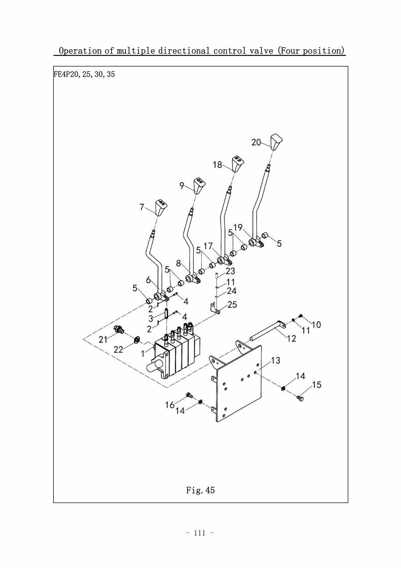
Operation of multiple directional control valve (Four position)
FE4P20,25,30,35
Fig.45
- 112 -
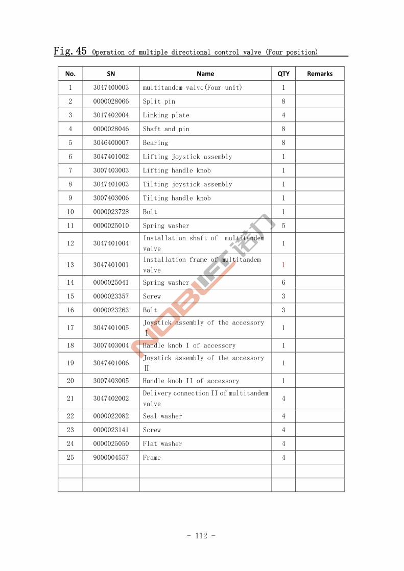
Fig.45 Operation of multiple directional control valve (Four position)
No. SN Name QTY Remarks
1 3047400003 multitandem valve(Four unit) 1
2 0000028066 Split pin 8
3 3017402004 Linking plate 4
4 0000028046 Shaft and pin 8
5 3046400007 Bearing 8
6 3047401002 Lifting joystick assembly 1
7 3007403003 Lifting handle knob 1
8 3047401003 Tilting joystick assembly 1
9 3007403006 Tilting handle knob 1
10 0000023728 Bolt 1
11 0000025010 Spring washer 5
12 3047401004 Installation shaft of multitandem
valve 1
13 3047401001 Installation frame of multitandem
valve 1
14 0000025041 Spring washer 6
15 0000023357 Screw 3
16 0000023263 Bolt 3
17 3047401005 Joystick assembly of the accessory
Ⅰ 1
18 3007403004 Handle knob I of accessory 1
19 3047401006 Joystick assembly of the accessory
Ⅱ 1
20 3007403005 Handle knob II of accessory 1
21 3047402002 Delivery connection II of multitandem
valve 4
22 0000022082 Seal washer 4
23 0000023141 Screw 4
24 0000025050 Flat washer 4
25 9000004557 Frame 4
- 113 -
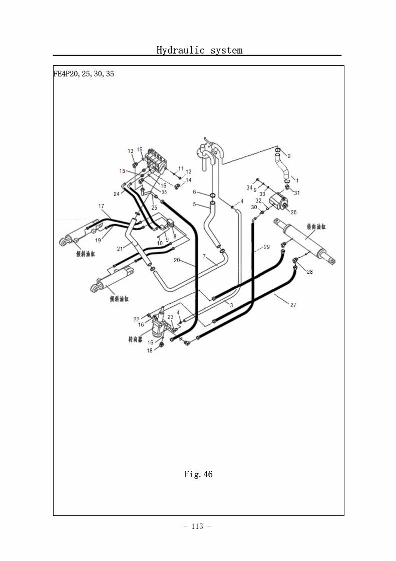
Hydraulic system
FE4P20,25,30,35
Fig.46
- 114 -
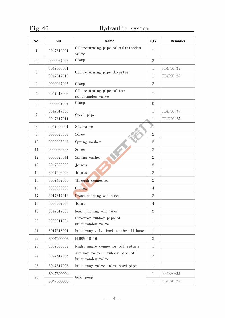
Fig.46 Hydraulic system
No. SN Name QTY Remarks
1 3047618001 Oil-returning pipe of multitandem
valve 1
2 0000037003 Clamp 2
3047603001 1 FE4P30-35 3
3047617010 Oil returning pipe diverter
1 FE4P20-25
4 0000037005 Clamp 2
5 3047618002 Oil returning pipe of the
multitandem valve 1
6 0000037002 Clamp 6
3047617009 1 FE4P30-35 7
3047617011 Steel pipe
1 FE4P20-25
8 3047600001 Six valve 1
9 0000023369 Screw 2
10 0000025046 Spring washer 2
11 0000023238 Screw 2
12 0000025041 Spring washer 2
13 3047600002 Joints 2
14 3047402002 Joints 2
15 3007402006 Through connector 2
16 0000022082 O-ring 4
17 3017617013 Front tilting oil tube 2
18 3008002068 Joint 4
19 3047617002 Rear tilting oil tube 2
20 9000011524 Diverter-rubber pipe of
multitandem valve 1
21 3017618001 Multi-way valve back to the oil hose 1
22 3007600003 ELBOW 18-16 2
23 3007600002 Right angle connector oil return 1
24 3047617005 six-way valve –rubber pipe of
Multitandem valve 2
25 3047617006 Multi-way valve inlet hard pipe 1
3047600004 1 FE4P30-35 26
3047600008 Gear pump
1 FE4P20-25

- 115 -
Hydraulic system
图 1 行走电机及减速器 A1
FE4P20,25,30,35
Fig.46
- 116 -
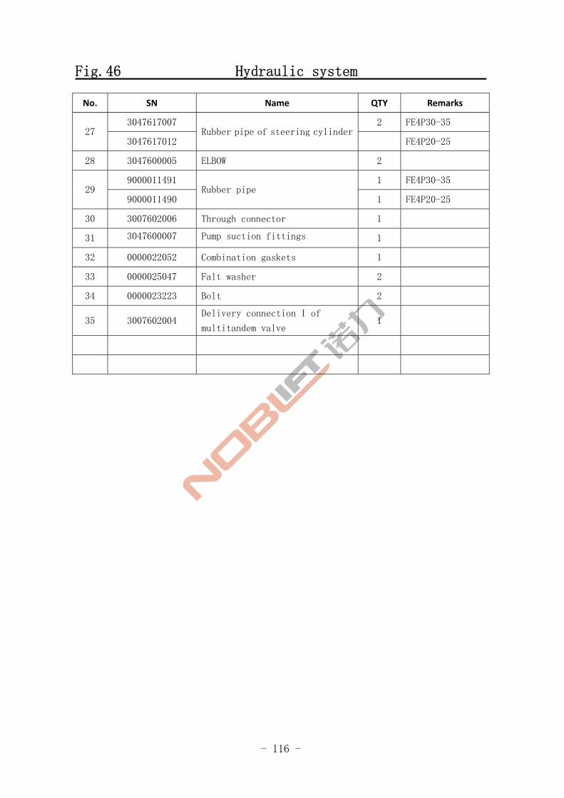
Fig.46 Hydraulic system
No. SN Name QTY Remarks
3047617007 2 FE4P30-35 27
3047617012 Rubber pipe of steering cylinder
FE4P20-25
28 3047600005 ELBOW 2
9000011491 1 FE4P30-35 29
9000011490 Rubber pipe
1 FE4P20-25
30 3007602006 Through connector 1
31 3047600007 Pump suction fittings 1
32 0000022052 Combination gaskets 1
33 0000025047 Falt washer 2
34 0000023223 Bolt 2
35 3007602004 Delivery connection I of
multitandem valve 1
- 117 -
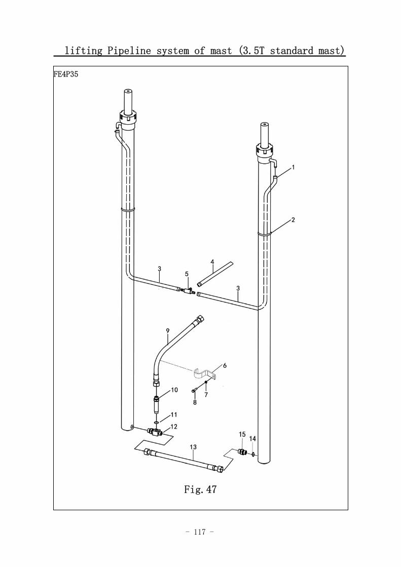
lifting Pipeline system of mast (3.5T standard mast)
FE4P35
Fig.47
- 118 -
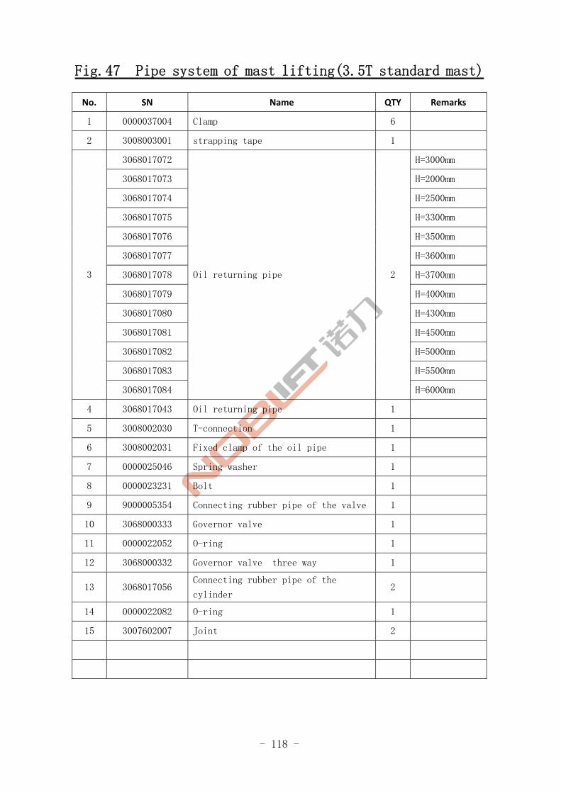
Fig.47 Pipe system of mast lifting(3.5T standard mast)
No. SN Name QTY Remarks
1 0000037004 Clamp 6
2 3008003001 strapping tape 1
3068017072 H=3000mm
3068017073 H=2000mm
3068017074 H=2500mm
3068017075 H=3300mm
3068017076 H=3500mm
3068017077 H=3600mm
3068017078 H=3700mm
3068017079 H=4000mm
3068017080 H=4300mm
3068017081 H=4500mm
3068017082 H=5000mm
3068017083 H=5500mm
3
3068017084
Oil returning pipe 2
H=6000mm
4 3068017043 Oil returning pipe 1
5 3008002030 T-connection 1
6 3008002031 Fixed clamp of the oil pipe 1
7 0000025046 Spring washer 1
8 0000023231 Bolt 1
9 9000005354 Connecting rubber pipe of the valve 1
10 3068000333 Governor valve 1
11 0000022052 O-ring 1
12 3068000332 Governor valve three way 1
13 3068017056 Connecting rubber pipe of the
cylinder 2
14 0000022082 O-ring 1
15 3007602007 Joint 2
- 119 -
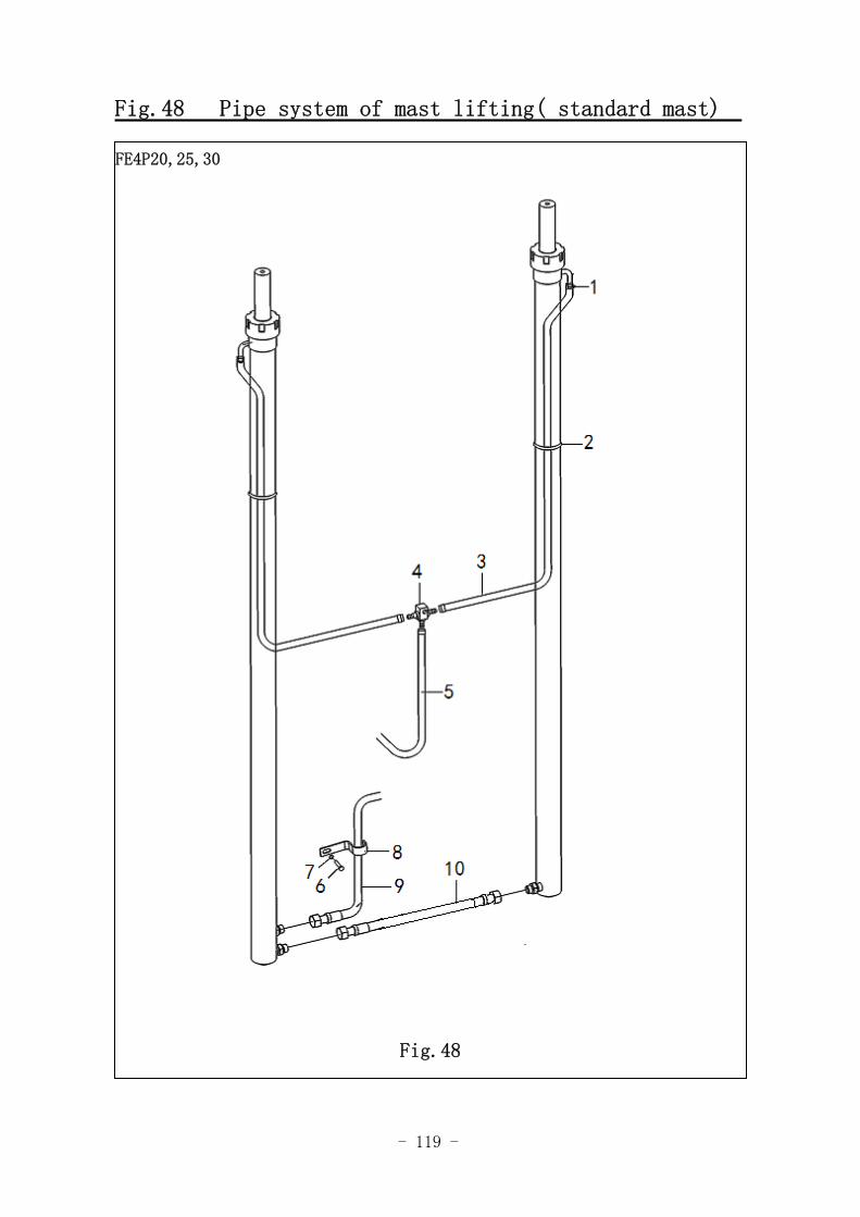
Fig.48 Pipe system of mast lifting( standard mast)
图 36 门架起升管路系统(标准门架)
FE4P20,25,30
Fig.48
- 120 -
Fig.48 Pipe system of mast lifting(standard mast)
No. SN Name QTY Remarks
1 0000037004 Clamp 6
2 3008003001 strapping tape 1
3068017001 H=3000mm
3068017004 H=2000mm
3068017005 H=2500mm
3068017006 H=3300mm
3068017015 H=3500mm
3068017007 H=3600mm
3068017008 H=3700mm
3068017009 H=4000mm
3068017010 H=4300mm
3068017011 H=4500mm
3068017012 H=5000mm
3068017013 H=5500mm
3
3068017014
Oil returning pipe 2
H=6000mm
4 3008002030 Tee joint 1
5 3068017043 Oil returning pipe 1
6 0000023231 Bolt 1
7 0000025046 Spring washer 1
8 3008002031 Fixed clamp of the oil pipe 1
9 3048017002 Rubber pipe from lifting cylinder
to multitandem valve 1
10 3068017003 Connecting rubber pipe of the
lifting cylinder 1
- 121 -
Lifting Pipeline System of Mast (3.5T 2‐stage Full Free)
FE4P35
Fig.49
- 122 -
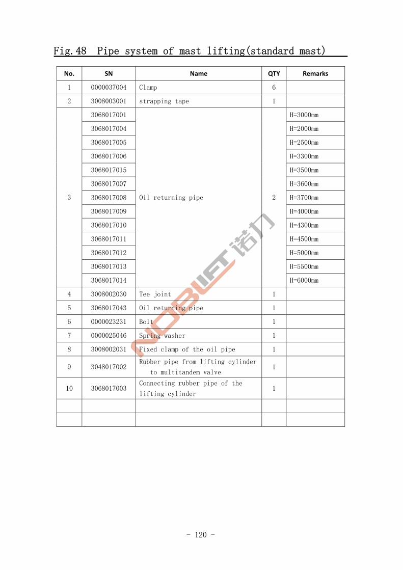
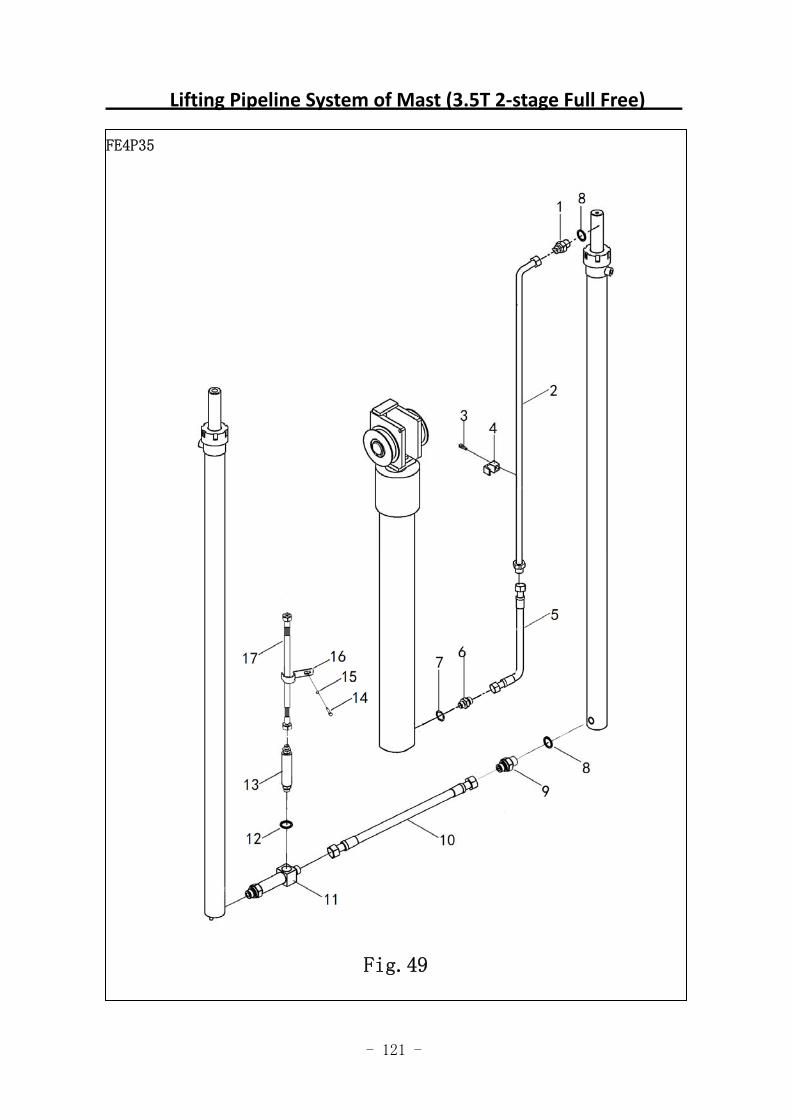
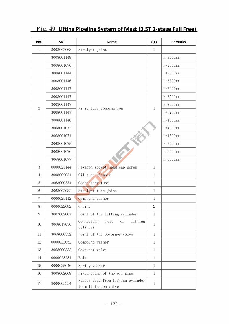
Fig.49 Lifting Pipeline System of Mast (3.5T 2‐stage Full Free)
No. SN Name QTY Remarks
1 3008002068 Straight joint 1
3008001149 H=3000mm
3068001070 H=2000mm
3008001144 H=2500mm
3008001146 H=3300mm
3008001147 H=3300mm
3008001147 H=3500mm
3008001147 H=3600mm
3008001147 H=3700mm
3008001148 H=4000mm
3068001073 H=4300mm
3068001074 H=4500mm
3068001075 H=5000mm
3068001076 H=5500mm
2
3068001077
Rigid tube combination 1
H=6000mm
3 0000023144 Hexagon socket head cap screw 1
4 3008002031 Oil tube clamper 1
5 3068000334 Connecting tube 1
6 3068002082 Straight tube joint 1
7 0000025112 Compound washer 1
8 0000022082 O-ring 2
9 3007602007 joint of the lifting cylinder 1
10 3068017056 Connecting hose of lifting
cylinder 1
11 3068000332 joint of the Governor valve 1
12 0000022052 Compound washer 1
13 3068000333 Governor valve 1
14 0000023231 Bolt 1
15 0000025046 Spring washer 1
16 3008002069 Fixed clamp of the oil pipe 1
17 9000005354 Rubber pipe from lifting cylinder
to multitandem valve 1
- 123 -
Lifting Pipeline System of Mast (2‐stage Full Free)
Fig.38Lifting Pipeline System of Mast (2‐stage Full Free)
FE4P20,25,30
Fig.50
- 124 -
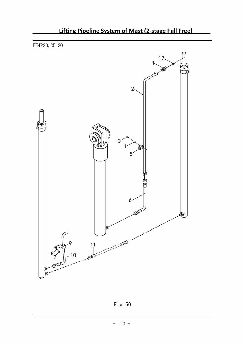
Fig.50 Lifting Pipeline System of Mast (2-stage Full Free)
No. SN Name QTY Remarks
1 3008002068 Straight joint 1
3008001149 H=3000mm
3068001070 H=2000mm
3008001144 H=2500mm
3008001146 H=3300mm
3008001147 H=3300mm
3008001147 H=3500mm
3008001147 H=3600mm
3008001147 H=3700mm
3008001148 H=4000mm
3068001073 H=4300mm
3068001074 H=4500mm
3068001075 H=5000mm
3068001076 H=5500mm
2
3068001077
Rigid tube combination 1
H=6000mm
3 0000023144 Screw 1
4 0000025045 Spring washer 1
5 3008002069 Oil tube clamper 1
6 3068017044 Connecting tube 1
7 0000023231 Bolt 1
8 0000025046 Spring washer 1
9 3008002031 Oil pipe clamper 1
10 3048017002 Oil tube between lifting cylinder
and multiple unit valve 1
11 3068017003 Connecting hose of lifting
cylinder 1
12 0000022082 O-ring 1
- 125 -
Lifting Pipeline System of Mast (3.5T 3‐stage Full Free)
FE4P35
Fig.51
- 126 -
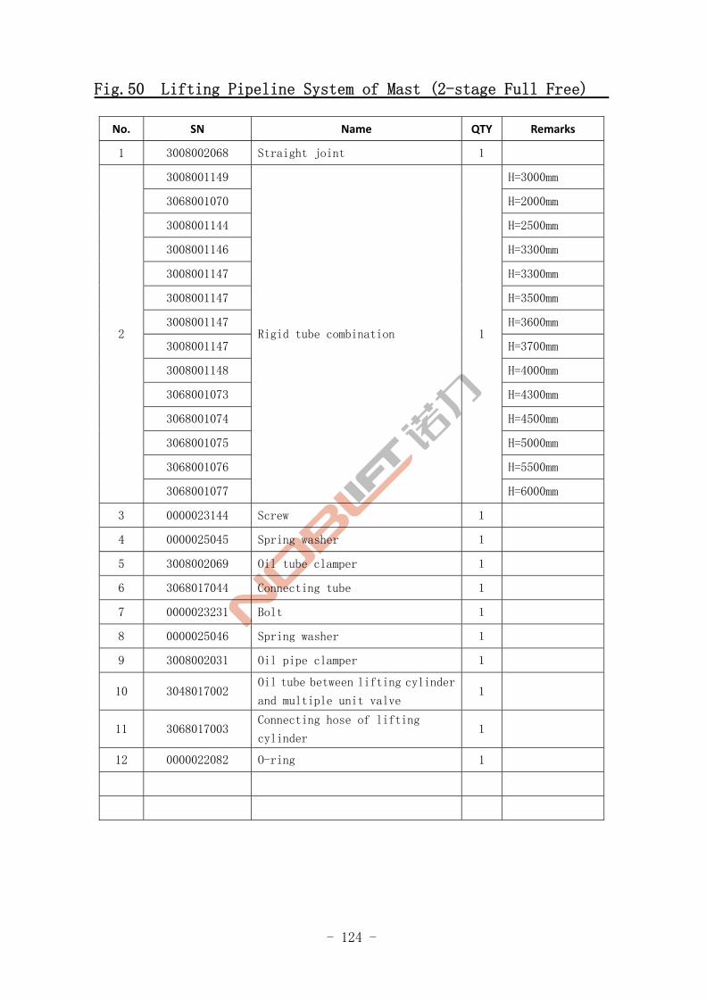
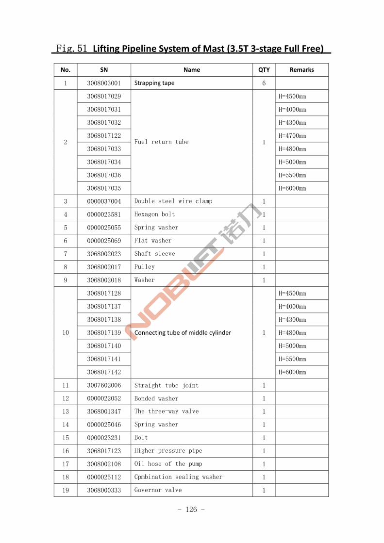
Fig.51 Lifting Pipeline System of Mast (3.5T 3‐stage Full Free)
No. SN Name QTY Remarks
1 3008003001 Strapping tape 6
3068017029 H=4500mm
3068017031 H=4000mm
3068017032 H=4300mm
3068017122 H=4700mm
3068017033 H=4800mm
3068017034 H=5000mm
3068017036 H=5500mm
2
3068017035
Fuel return tube 1
H=6000mm
3 0000037004 Double steel wire clamp 1
4 0000023581 Hexagon bolt 1
5 0000025055 Spring washer 1
6 0000025069 Flat washer 1
7 3068002023 Shaft sleeve 1
8 3068002017 Pulley 1
9 3068002018 Washer 1
3068017128 H=4500mm
3068017137 H=4000mm
3068017138 H=4300mm
3068017139 H=4800mm
3068017140 H=5000mm
3068017141 H=5500mm
10
3068017142
Connecting tube of middle cylinder 1
H=6000mm
11 3007602006 Straight tube joint 1
12 0000022052 Bonded washer 1
13 3068001347 The three-way valve 1
14 0000025046 Spring washer 1
15 0000023231 Bolt 1
16 3068017123 Higher pressure pipe 1
17 3008002108 Oil hose of the pump 1
18 0000025112 Cpmbination sealing washer 1
19 3068000333 Governor valve 1

- 127 -
Lifting Pipeline System of Mast (3.5T 3‐stage Full Free)
FE4P35
Fig.51
- 128 -
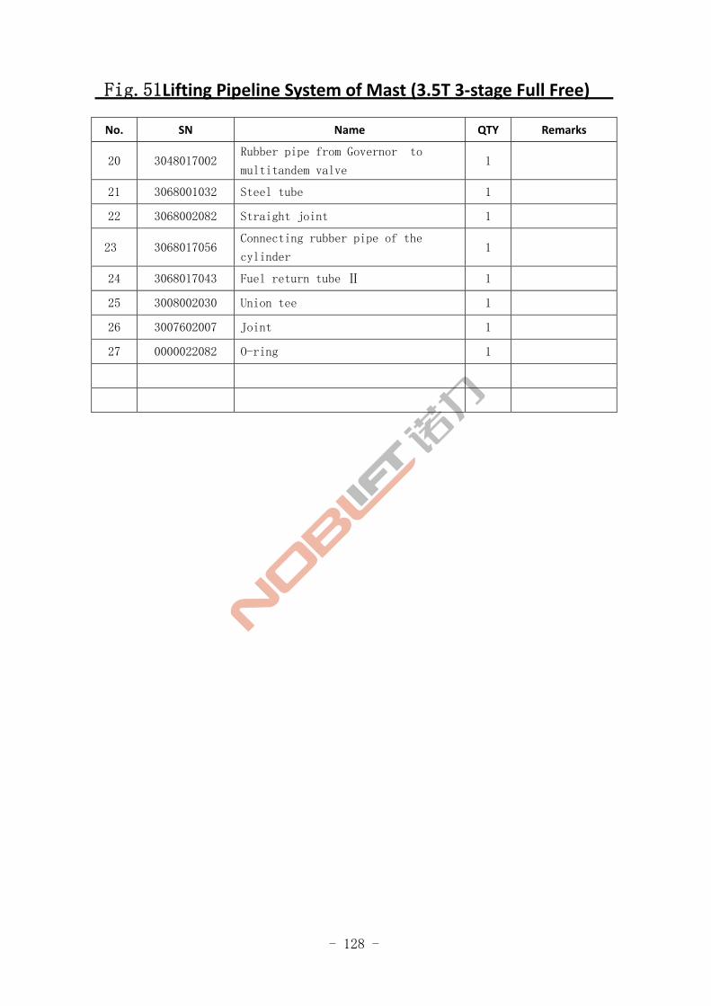
Fig.51Lifting Pipeline System of Mast (3.5T 3‐stage Full Free)
No. SN Name QTY Remarks
20 3048017002 Rubber pipe from Governor to
multitandem valve 1
21 3068001032 Steel tube 1
22 3068002082 Straight joint 1
23 3068017056 Connecting rubber pipe of the
cylinder 1
24 3068017043 Fuel return tube Ⅱ 1
25 3008002030 Union tee 1
26 3007602007 Joint 1
27 0000022082 O-ring 1
- 129 -
Lifting Pipeline System of Mast (3‐stage Full Free)
FE4P20,25,30
Fig.52
- 130 -
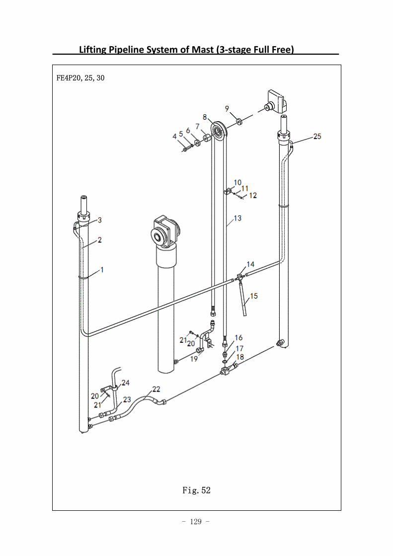
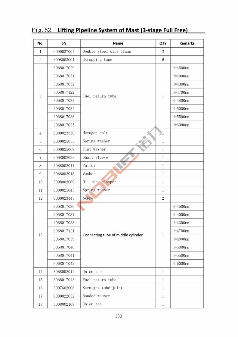
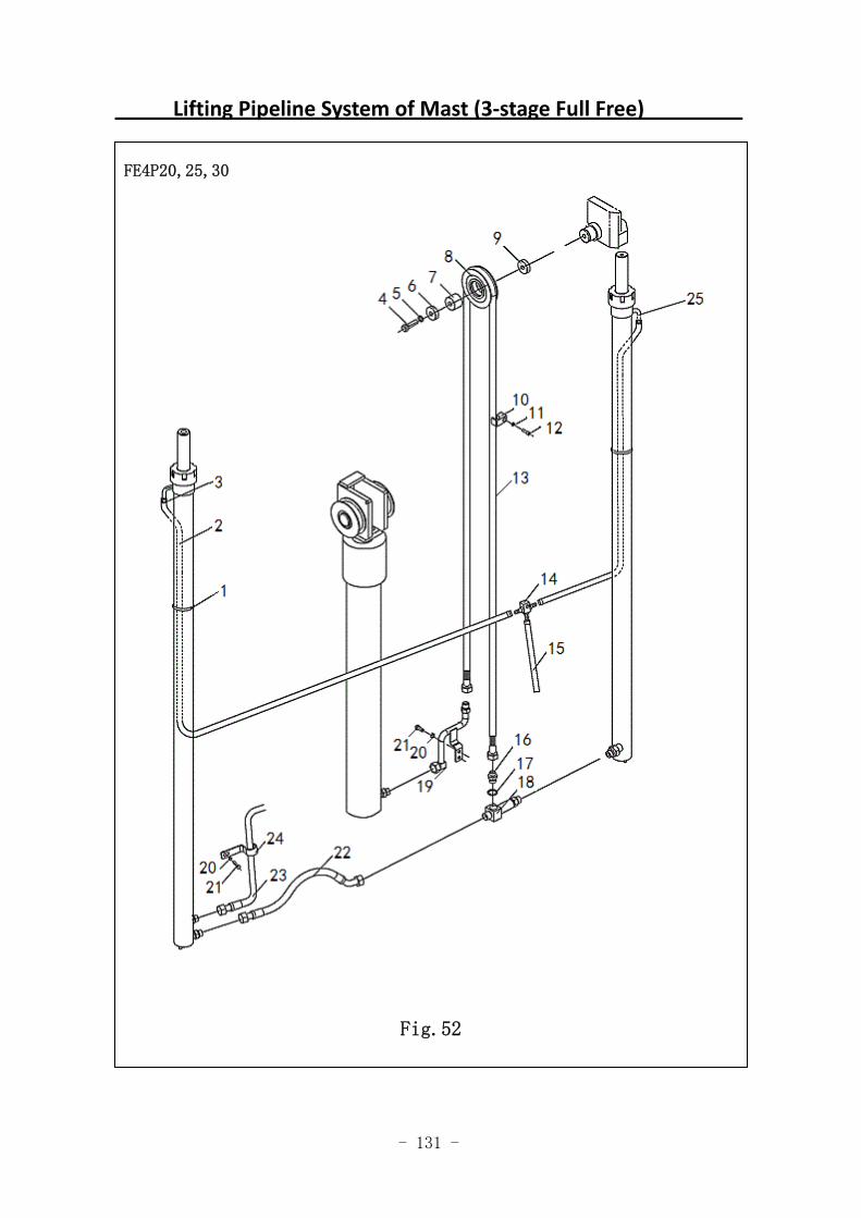
Fig.52 Lifting Pipeline System of Mast (3‐stage Full Free)
No. SN Name QTY Remarks
1 0000037004 Double steel wire clamp 2
2 3008003001 Strapping tape 6
3068017029 H=4500mm
3068017031 H=4000mm
3068017032 H=4300mm
3068017122 H=4700mm
3068017033 H=4800mm
3068017034 H=5000mm
3068017036 H=5500mm
3
3068017035
Fuel return tube 1
H=6000mm
4 0000023350 Hexagon bolt 1
5 0000025055 Spring washer 1
6 0000025069 Flat washer 1
7 3068002023 Shaft sleeve 1
8 3068002017 Pulley 1
9 3068002018 Washer 1
10 3008002069 Oil tube clamper 1
11 0000025045 Spring washer 1
12 0000023143 Screw 2
3068017030 H=4500mm
3068017037 H=4000mm
3068017038 H=4300mm
3068017121 H=4700mm
3068017039 H=4800mm
3068017040 H=5000mm
3068017041 H=5500mm
13
3068017042
Connecting tube of middle cylinder 1
H=6000mm
14 3068002012 Union tee 1
15 3068017043 Fuel return tube 1
16 3007602006 Straight tube joint 1
17 0000022052 Bonded washer 1
18 3008002108 Union tee 1
- 131 -
Lifting Pipeline System of Mast (3‐stage Full Free)
FE4P20,25,30
Fig.52
- 132 -
Fig.52 Lifting Pipeline System of Mast (3‐stage Full Free)
No. SN Name QTY Remarks
19 3068001032 Steel tube 1
20 0000025046 Spring washer 1
21 0000023231 Bolt 1
22 3068017056 Connecting hose of lifting cylinder 1
23 3048017002 Oil tube between lifting cylinder and
multiple unit valve 1
24 3008002031 Oil pipe clamper 1
25 3068002013 Joint 2
- 133 -
Side Shifter & Pipeline Installation System (Standard Mast)
\
FE4P20,25,30,35
Fig.53
- 134 -
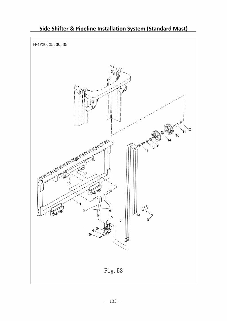
Fig.53 Side Shifter & Pipeline Installation System (Standard Mast)
No. SN Name QTY Remarks
3068000008 Side shifter FE4P30-35 1
3068000319 Side shifter 1
FE4P18-25
2 3068017016 Front short tube 1
3 3008001032 Four-hole oil distribution base 1
4 0000025046 Spring washer 1
5 0000023147 Hexagon socket head cap screw 2
3048017003 H=3000mm
3048017004 H=2000mm
3048017005 H=2500mm
3048017006 H=3300mm
3048017007 H=3500mm
3048017008 H=3600mm
3048017009 H=3700mm
3048017010 H=4000mm
3048017011 H=4300mm
3048017012 H=4500mm
3048017013 H=5000mm
3048017014 H=5500mm
6
3048017015
Hose of side shifter 2
H=6000mm
7 0000023333 Bolt 1
8 0000025055 Spring washer 1
9 0000025069 Flat washer 1
10 9000008246 Guide roller 2
11 3068002016 Shaft sleeve 1
12 3068002018 Washer 1
13 3068002020 Pressure plate base 1
14 3068002015 Sleeve 1
15 0000022196 O-ring 4
- 135 -
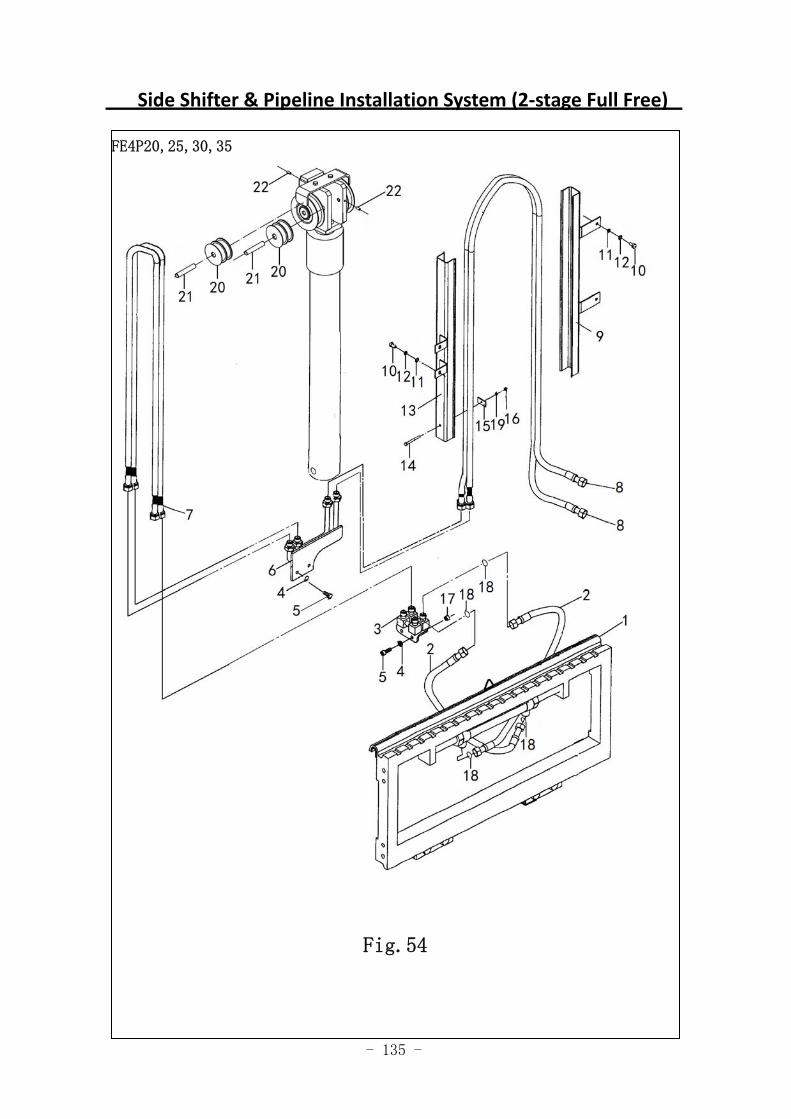
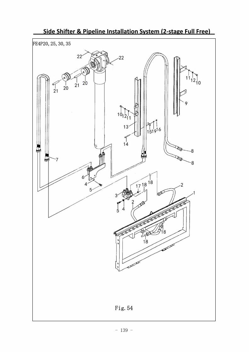
Side Shifter & Pipeline Installation System (2‐stage Full Free)
FE4P20,25,30,35
Fig.54
- 136 -
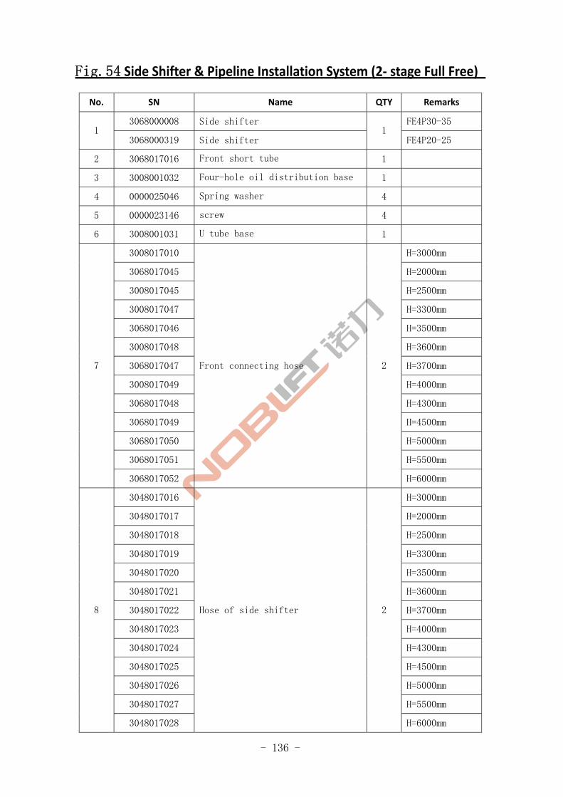
Fig.54 Side Shifter & Pipeline Installation System (2‐ stage Full Free)
No. SN Name QTY Remarks
3068000008 Side shifter FE4P30-35 1
3068000319 Side shifter 1
FE4P20-25
2 3068017016 Front short tube 1
3 3008001032 Four-hole oil distribution base 1
4 0000025046 Spring washer 4
5 0000023146 screw 4
6 3008001031 U tube base 1
3008017010 H=3000mm
3068017045 H=2000mm
3008017045 H=2500mm
3008017047 H=3300mm
3068017046 H=3500mm
3008017048 H=3600mm
3068017047 H=3700mm
3008017049 H=4000mm
3068017048 H=4300mm
3068017049 H=4500mm
3068017050 H=5000mm
3068017051 H=5500mm
7
3068017052
Front connecting hose 2
H=6000mm
3048017016 H=3000mm
3048017017 H=2000mm
3048017018 H=2500mm
3048017019 H=3300mm
3048017020 H=3500mm
3048017021 H=3600mm
3048017022 H=3700mm
3048017023 H=4000mm
3048017024 H=4300mm
3048017025 H=4500mm
3048017026 H=5000mm
3048017027 H=5500mm
8
3048017028
Hose of side shifter 2
H=6000mm
- 137 -
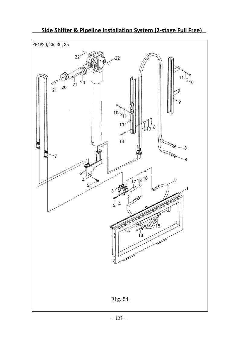
Side Shifter & Pipeline Installation System (2‐stage Full Free)
图 42 侧移管路系统(二级全自由)
FE4P20,25,30,35
Fig.54
- 138 -
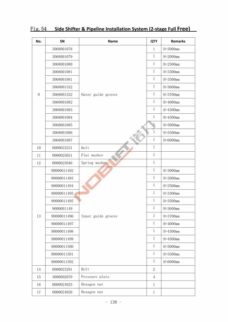
Fig.54 Side Shifter & Pipeline Installation System (2‐stage Full Free)
No. SN Name QTY Remarks
3068001078 1 H=3000mm
3068001079 1 H=2000mm
3068001080 1 H=2500mm
3068001081 1 H=3300mm
3068001081 1 H=3500mm
3068001332 1 H=3600mm
3068001332 1 H=3700mm
3068001082 1 H=4000mm
3068001083 1 H=4300mm
3068001084 1 H=4500mm
3068001085 1 H=5000mm
3068001086 1 H=5500mm
9
3068001087
Outer guide groove
1 H=6000mm
10 0000023231 Bolt 1
11 0000025051 Flat washer 1
12 0000025046 Spring washer 1
90000011492 1 H=3000mm
90000011493 1 H=2000mm
90000011494 1 H=2500mm
90000011495 1 H=3300mm
90000011495 1 H=3500mm
9000001149 1 H=3600mm
90000011496 1 H=3700mm
90000011497 1 H=4000mm
90000011498 1 H=4300mm
90000011499 1 H=4500mm
90000011500 1 H=5000mm
90000011501 1 H=5500mm
13
90000011502
Inner guide groove
1 H=6000mm
14 0000023291 Bolt 2
15 3008002070 Pressure plate 4
16 0000024025 Hexagon nut 1
17 0000024026 Hexagon nut 1
- 139 -
Side Shifter & Pipeline Installation System (2‐stage Full Free)
FE4P20,25,30,35
Fig.54
- 140 -
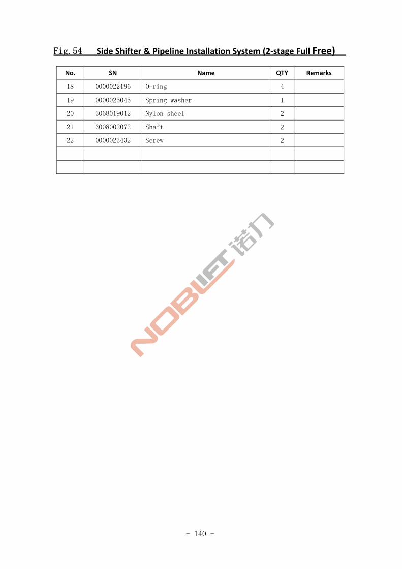
Fig.54 Side Shifter & Pipeline Installation System (2‐stage Full Free)
No. SN Name QTY Remarks
18 0000022196 O-ring 4
19 0000025045 Spring washer 1
20 3068019012 Nylon sheel 2
21 3008002072 Shaft 2
22 0000023432 Screw 2

- 141 -
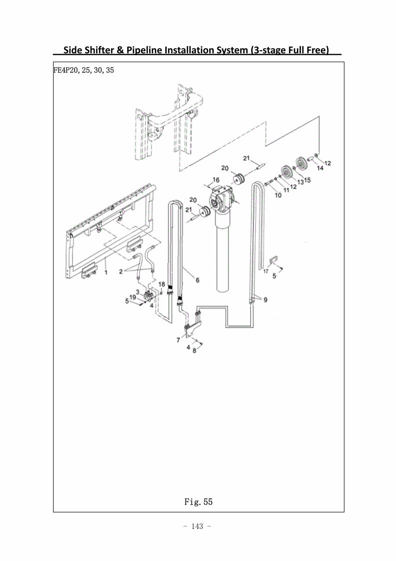
Side Shifter & Pipeline Installation System (3‐stage Full Free)
FE4P20,25,30,35
Fig.55
- 142 -
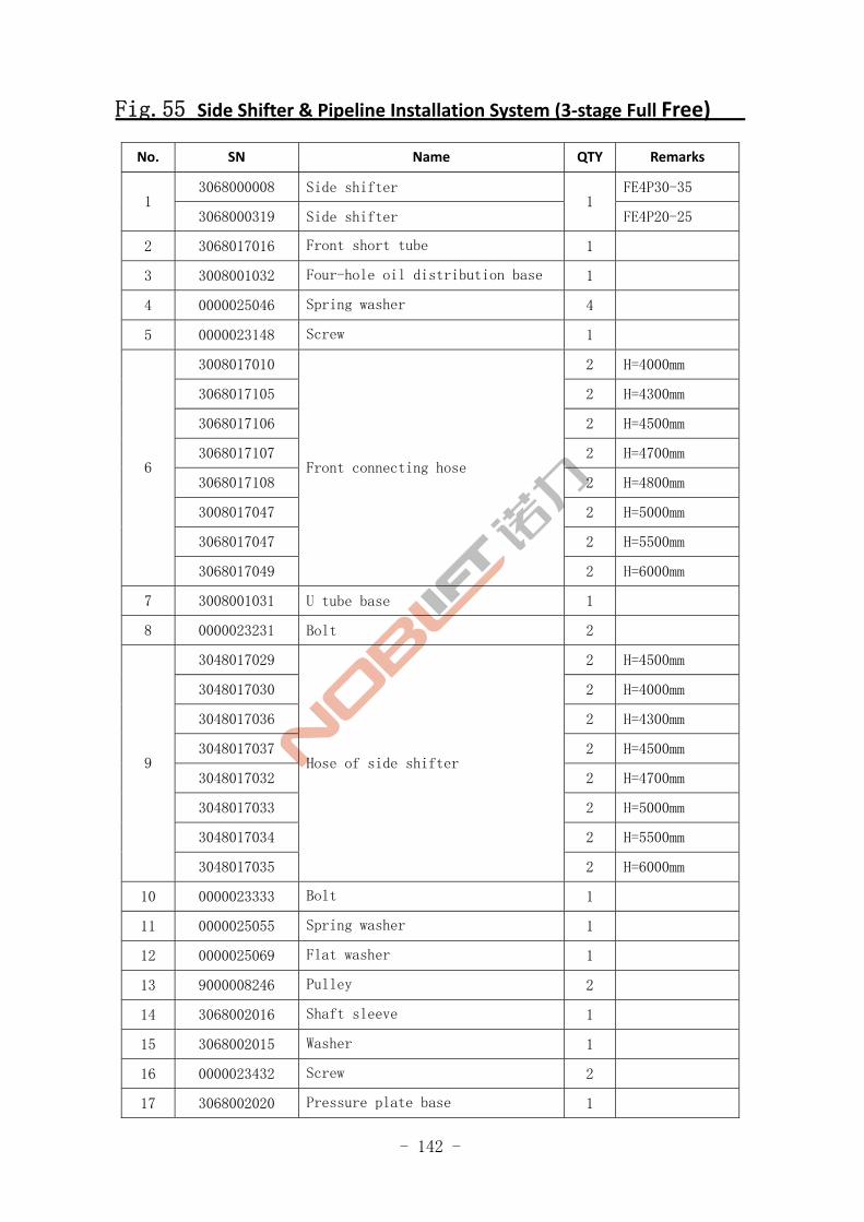
Fig.55 Side Shifter & Pipeline Installation System (3‐stage Full Free)
No. SN Name QTY Remarks
3068000008 Side shifter FE4P30-35 1
3068000319 Side shifter 1
FE4P20-25
2 3068017016 Front short tube 1
3 3008001032 Four-hole oil distribution base 1
4 0000025046 Spring washer 4
5 0000023148 Screw 1
3008017010 2 H=4000mm
3068017105 2 H=4300mm
3068017106 2 H=4500mm
3068017107 2 H=4700mm
3068017108 2 H=4800mm
3008017047 2 H=5000mm
3068017047 2 H=5500mm
6
3068017049
Front connecting hose
2 H=6000mm
7 3008001031 U tube base 1
8 0000023231 Bolt 2
3048017029 2 H=4500mm
3048017030 2 H=4000mm
3048017036 2 H=4300mm
3048017037 2 H=4500mm
3048017032 2 H=4700mm
3048017033 2 H=5000mm
3048017034 2 H=5500mm
9
3048017035
Hose of side shifter
2 H=6000mm
10 0000023333 Bolt 1
11 0000025055 Spring washer 1
12 0000025069 Flat washer 1
13 9000008246 Pulley 2
14 3068002016 Shaft sleeve 1
15 3068002015 Washer 1
16 0000023432 Screw 2
17 3068002020 Pressure plate base 1
- 143 -
Side Shifter & Pipeline Installation System (3‐stage Full Free)
FE4P20,25,30,35
Fig.55
- 144 -
Fig.55 Side Shifter & Pipeline Installation System (3‐stage Full Free)
No. SN Name QTY Remarks
18 0000024026 Nuts 1
19 0000025051 Flat washer 1
20 3068019012 Nylon wheel 2
21 3008002072 Shaft 2
- 145 -
Fork(3.0T,3.5T)
图 1 行走电机及减速器 A1
FE4P30,35
Fig.56
- 146 -
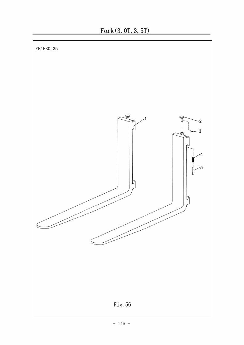
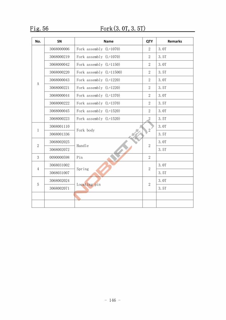
Fig.56 Fork(3.0T,3.5T)
No. SN Name QTY Remarks
3068000006 Fork assembly (L=1070) 2 3.0T
3068000219 Fork assembly (L=1070) 2 3.5T
3068000042 Fork assembly (L=1150) 2 3.0T
3068000220 Fork assembly (L=11500) 2 3.5T
3068000043 Fork assembly (L=1220) 2 3.0T
3068000221 Fork assembly (L=1220) 2 3.5T
3068000044 Fork assembly (L=1370) 2 3.0T
3068000222 Fork assembly (L=1370) 2 3.5T
3068000045 Fork assembly (L=1520) 2 3.0T
A
3068000223 Fork assembly (L=1520) 2 3.5T
3068001110 3.0T 1
3068001336 Fork body 2
3.5T
3068002025 3.0T 2
3068002072 Handle 2
3.5T
3 0090000598 Pin 2
3068031002 3.0T 4
3068031007 Spring 2
3.5T
3068002024 3.0T 5
3068002071 Locating pin 2
3.5T
- 147 -
Fork (2.0,2.5T)
图 1 行走电机及减速器 A1
FE4P20,25
- 148 -
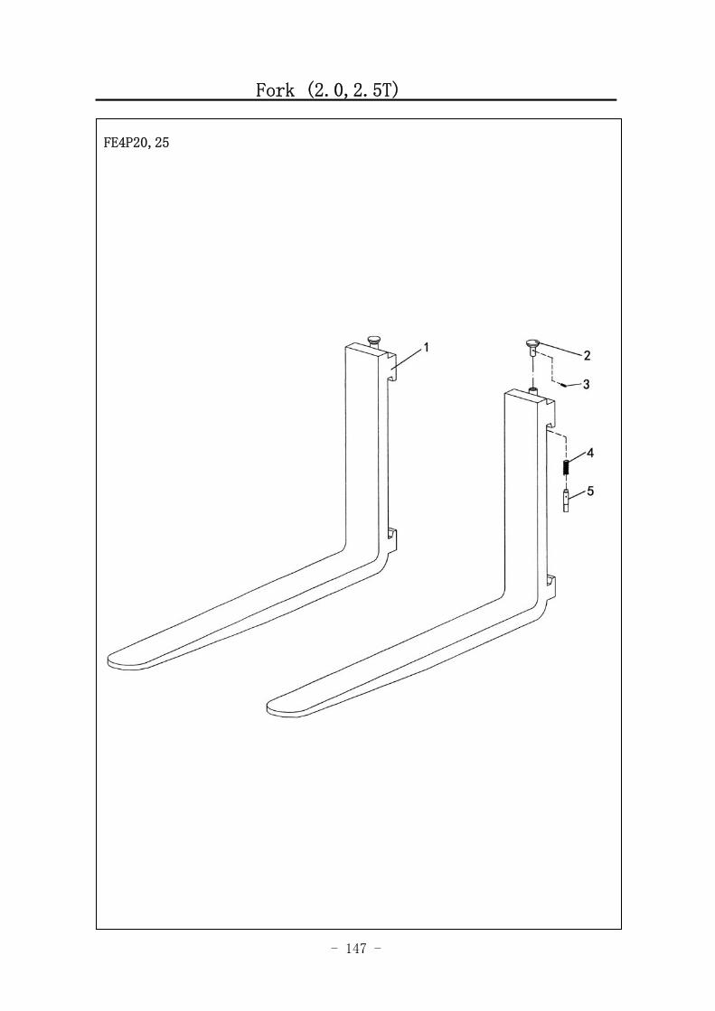
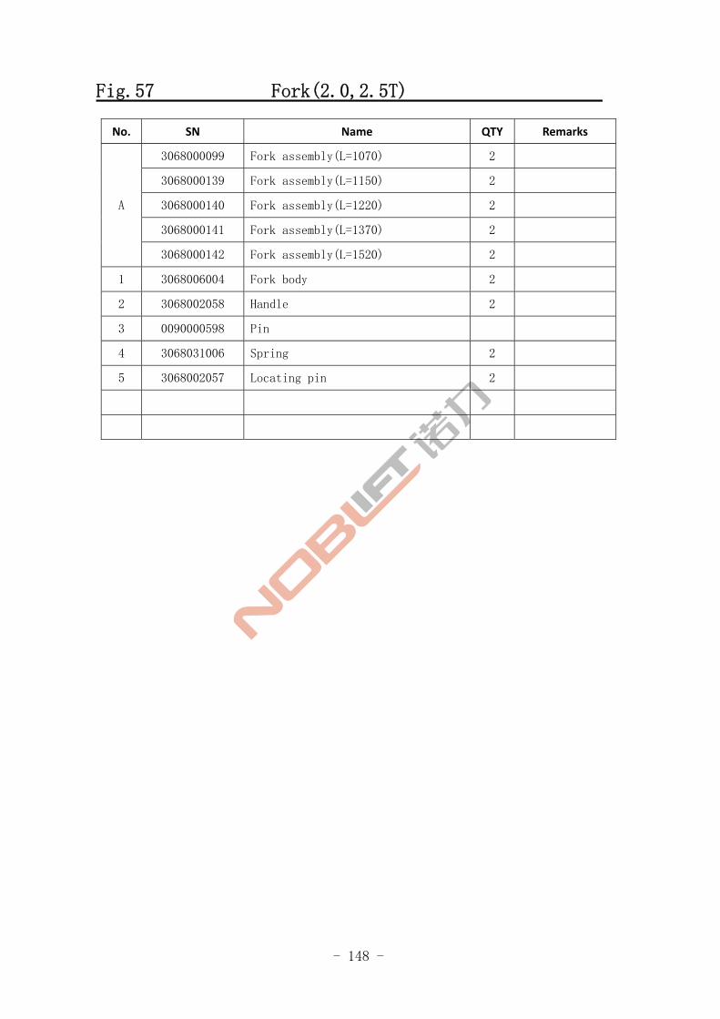
Fig.57 Fork(2.0,2.5T)
No. SN Name QTY Remarks
3068000099 Fork assembly(L=1070) 2
3068000139 Fork assembly(L=1150) 2
3068000140 Fork assembly(L=1220) 2
3068000141 Fork assembly(L=1370) 2
A
3068000142 Fork assembly(L=1520) 2
1 3068006004 Fork body 2
2 3068002058 Handle 2
3 0090000598 Pin
4 3068031006 Spring 2
5 3068002057 Locating pin 2
- 149 -
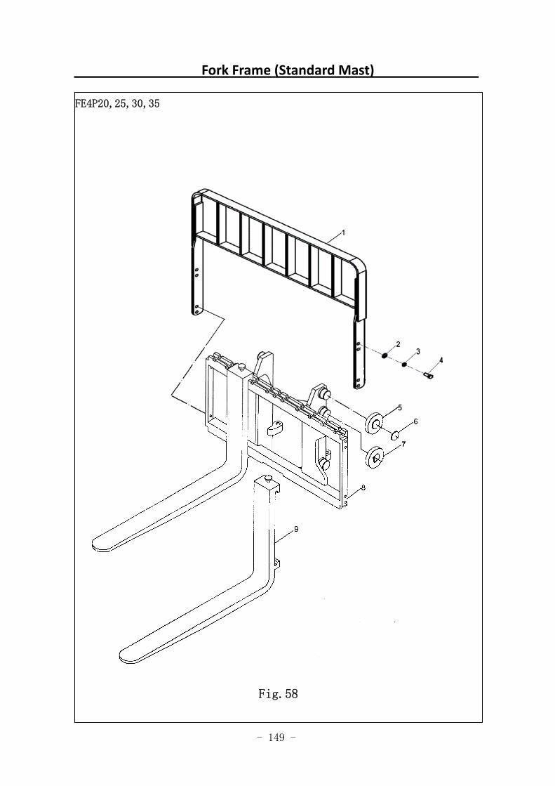
Fork Frame (Standard Mast)
图 1 行走电机及减速器 A1
FE4P20,25,30,35
Fig.58
- 150 -
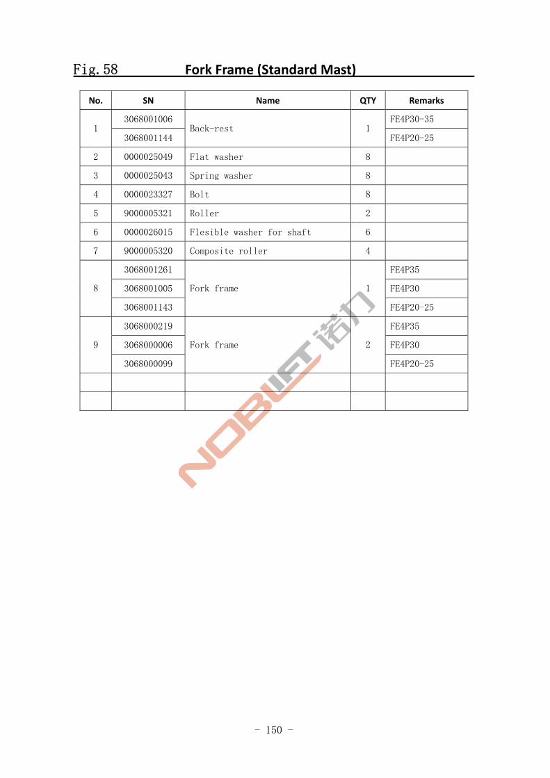
Fig.58 Fork Frame (Standard Mast)
No. SN Name QTY Remarks
3068001006 FE4P30-35 1
3068001144 Back-rest 1
FE4P20-25
2 0000025049 Flat washer 8
3 0000025043 Spring washer 8
4 0000023327 Bolt 8
5 9000005321 Roller 2
6 0000026015 Flesible washer for shaft 6
7 9000005320 Composite roller 4
3068001261 FE4P35
3068001005 FE4P30 8
3068001143
Fork frame 1
FE4P20-25
3068000219 FE4P35
3068000006 FE4P30 9
3068000099
Fork frame 2
FE4P20-25

- 151 -
Fork Frame (2‐stage Full Free)
图 1 行走电机及减速器 A1
FE4P20,25,30,35
Fig.59
- 152 -
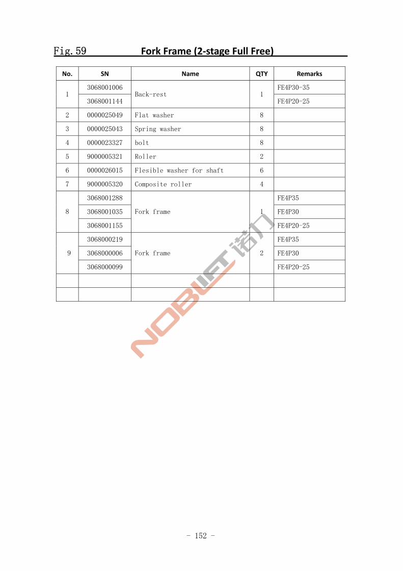
Fig.59 Fork Frame (2‐stage Full Free)
No. SN Name QTY Remarks
3068001006 FE4P30-35 1
3068001144 Back-rest 1
FE4P20-25
2 0000025049 Flat washer 8
3 0000025043 Spring washer 8
4 0000023327 bolt 8
5 9000005321 Roller 2
6 0000026015 Flesible washer for shaft 6
7 9000005320 Composite roller 4
3068001288 FE4P35
3068001035 FE4P30 8
3068001155
Fork frame 1
FE4P20-25
3068000219 FE4P35
3068000006 FE4P30 9
3068000099
Fork frame 2
FE4P20-25
- 153 -
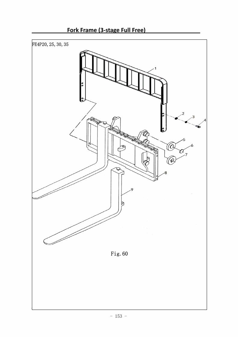
Fork Frame (3‐stage Full Free)
图 50 货叉架(标准门架)
FE4P20,25,30,35
Fig.60
- 154 -
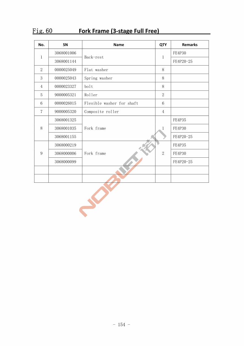
Fig.60 Fork Frame (3‐stage Full Free)
No. SN Name QTY Remarks
3068001006 FE4P30 1
3068001144 Back-rest 1
FE4P20-25
2 0000025049 Flat washer 8
3 0000025043 Spring washer 8
4 0000023327 bolt 8
5 9000005321 Roller 2
6 0000026015 Flesible washer for shaft 6
7 9000005320 Composite roller 4
3068001325 FE4P35
3068001035 FE4P30 8
3068001155
Fork frame 1
FE4P20-25
3068000219 FE4P35
3068000006 FE4P30 9
3068000099
Fork frame 2
FE4P20-25
- 155 -
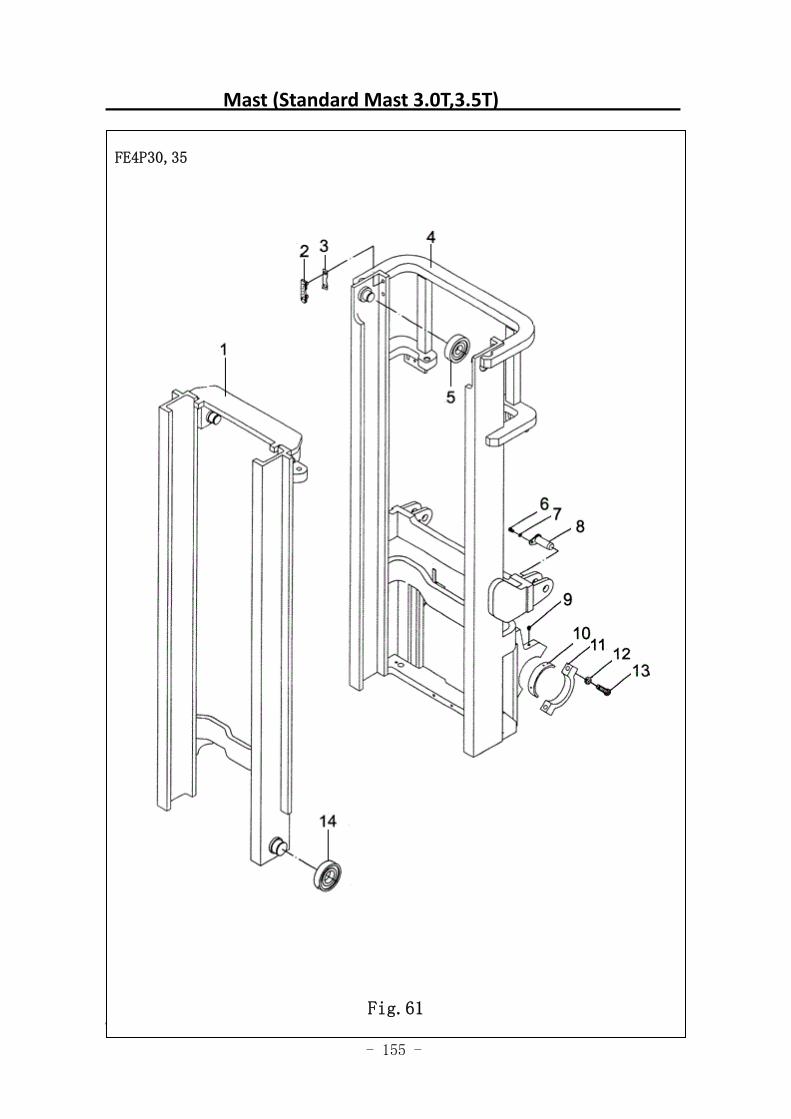
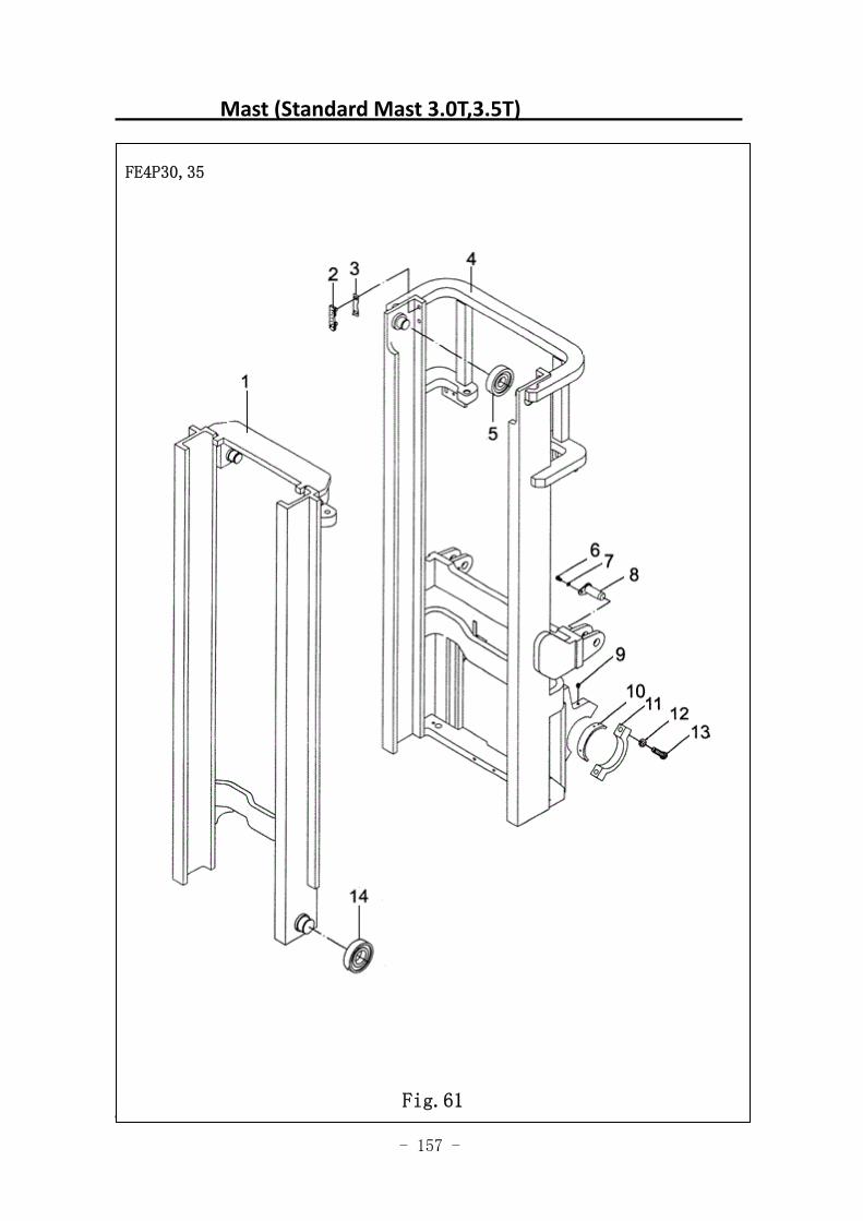
Mast (Standard Mast 3.0T,3.5T)
图 51 门架(基本型)
FE4P30,35
Fig.61
- 156 -
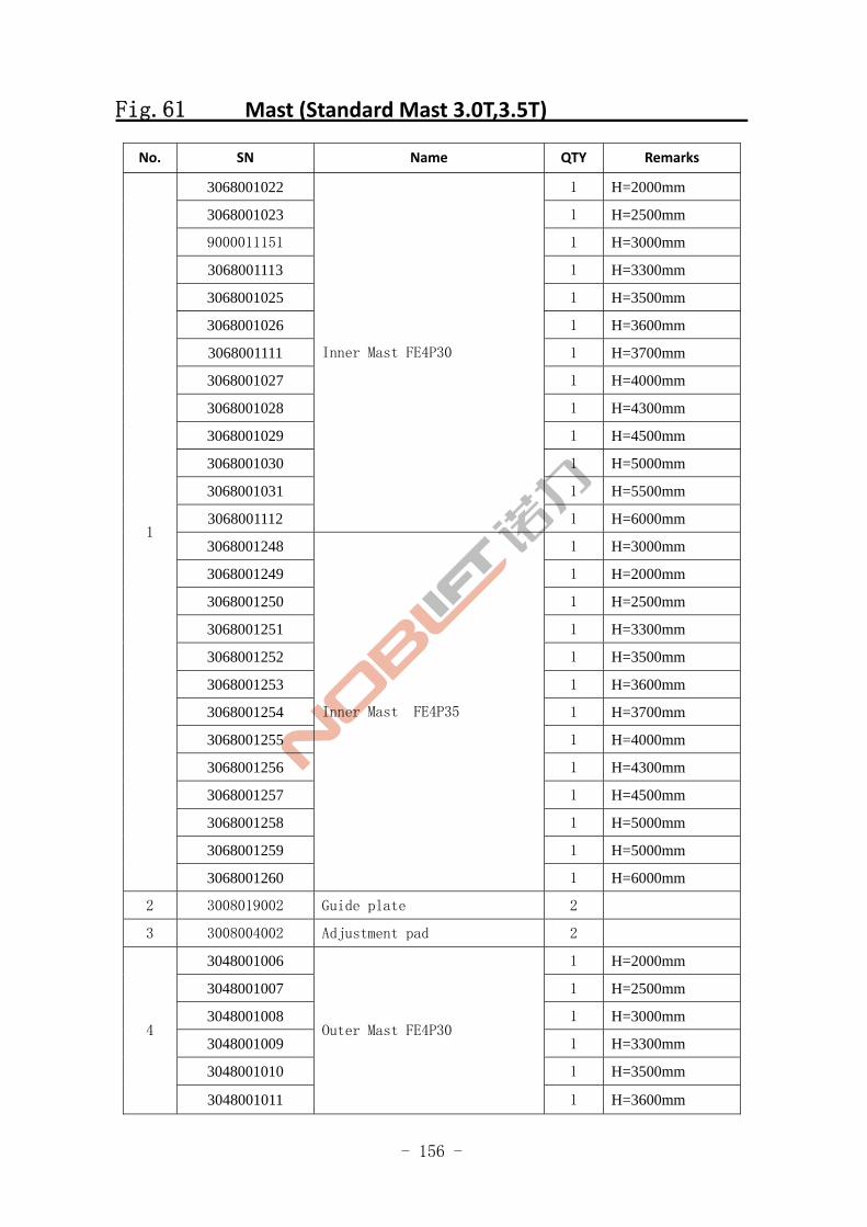
Fig.61 Mast (Standard Mast 3.0T,3.5T)
No. SN Name QTY Remarks
3068001022 1 H=2000mm
3068001023 1 H=2500mm
9000011151 1 H=3000mm
3068001113 1 H=3300mm
3068001025 1 H=3500mm
3068001026 1 H=3600mm
3068001111 1 H=3700mm
3068001027 1 H=4000mm
3068001028 1 H=4300mm
3068001029 1 H=4500mm
3068001030 1 H=5000mm
3068001031 1 H=5500mm
3068001112
Inner Mast FE4P30
1 H=6000mm
3068001248 1 H=3000mm
3068001249 1 H=2000mm
3068001250 1 H=2500mm
3068001251 1 H=3300mm
3068001252 1 H=3500mm
3068001253 1 H=3600mm
3068001254 1 H=3700mm
3068001255 1 H=4000mm
3068001256 1 H=4300mm
3068001257 1 H=4500mm
3068001258 1 H=5000mm
3068001259 1 H=5000mm
1
3068001260
Inner Mast FE4P35
1 H=6000mm
2 3008019002 Guide plate 2
3 3008004002 Adjustment pad 2
3048001006 1 H=2000mm
3048001007 1 H=2500mm
3048001008 1 H=3000mm
3048001009 1 H=3300mm
3048001010 1 H=3500mm
4
3048001011
Outer Mast FE4P30
1 H=3600mm
- 157 -
Mast (Standard Mast 3.0T,3.5T)
图 51 门架(基本型)
FE4P30,35
Fig.61
- 158 -
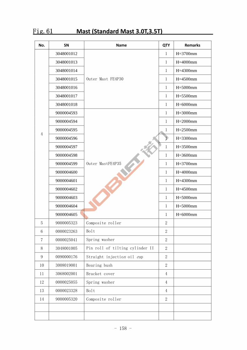
Fig.61 Mast (Standard Mast 3.0T,3.5T)
No. SN Name QTY Remarks
3048001012 1 H=3700mm
3048001013 1 H=4000mm
3048001014 1 H=4300mm
3048001015 1 H=4500mm
3048001016 1 H=5000mm
3048001017 1 H=5500mm
3048001018
Outer Mast FE4P30
1 H=6000mm
9000004593 1 H=3000mm
9000004594 1 H=2000mm
9000004595 1 H=2500mm
9000004596 1 H=3300mm
9000004597 1 H=3500mm
9000004598 1 H=3600mm
9000004599 1 H=3700mm
9000004600 1 H=4000mm
9000004601 1 H=4300mm
9000004602 1 H=4500mm
9000004603 1 H=5000mm
9000004604 1 H=5000mm
4
9000004605
Outer MastFE4P35
1 H=6000mm
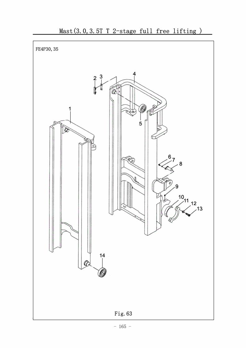
5 9000005323 Composite roller 2
6 0000023263 Bolt 2
7 0000025041 Spring washer 2
8 3048001005 Pin roll of tilting cylinder II 2
9 0090000176 Straight injection oil cup 2
10 3008019001 Bearing bush 2
11 3068002001 Bracket cover 4
12 0000025055 Spring washer 4
13 0000023328 Bolt 4
14 9000005320 Composite roller 2
- 159 -
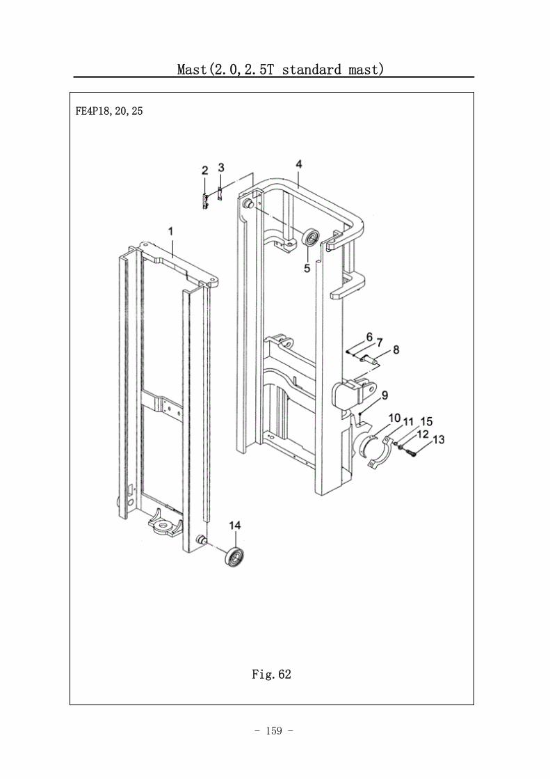
Mast(2.0,2.5T standard mast)
FE4P18,20,25
Fig.62
- 160 -
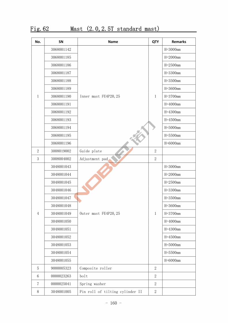
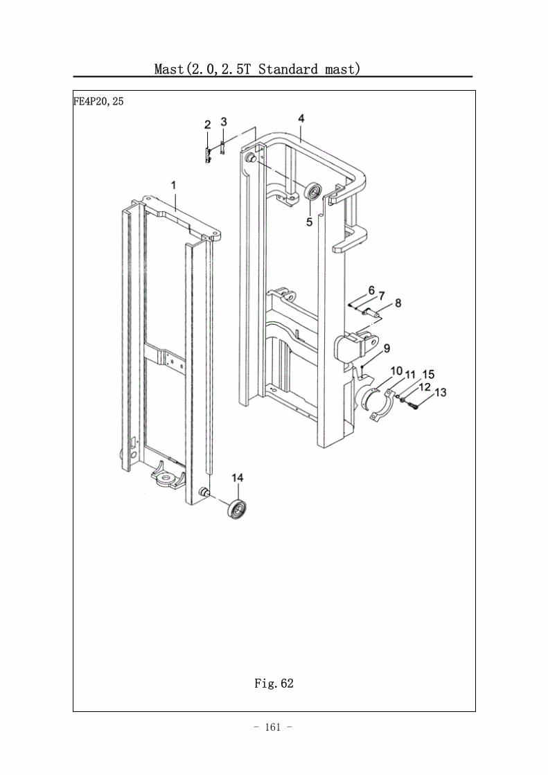
Fig.62 Mast (2.0,2.5T standard mast)
No. SN Name QTY Remarks
3068001142 H=3000mm
3068001185 H=2000mm
3068001186 H=2500mm
3068001187 H=3300mm
3068001188 H=3500mm
3068001189 H=3600mm
3068001190 H=3700mm
3068001191 H=4000mm
3068001192 H=4300mm
3068001193 H=4500mm
3068001194 H=5000mm
3068001195 H=5500mm
1
3068001196
Inner mast FE4P20,25 1
H=6000mm
2 3008019002 Guide plate 2
3 3008004002 Adjustment pad 2
3048001043 H=3000mm
3048001044 H=2000mm
3048001045 H=2500mm
3048001046 H=3300mm
3048001047 H=3500mm
3048001048 H=3600mm
3048001049 H=3700mm
3048001050 H=4000mm
3048001051 H=4300mm
3048001052 H=4500mm
3048001053 H=5000mm
3048001054 H=5500mm
4
3048001055
Outer mast FE4P20,25 1
H=6000mm
5 9000005323 Composite roller 2
6 0000023263 bolt 2
7 0000025041 Spring washer 2
8 3048001005 Pin roll of tilting cylinder II 2
- 161 -
Mast(2.0,2.5T Standard mast)
FE4P20,25
Fig.62
- 162 -
Fig.62 Mast(2.0,2.5T Standard mast)
No. SN Name QTY Remarks
9 0090000176 Straight injection oil cup 2
10 3008019001 Bearing bush 2
11 3068002001 Bracket cover 2
12 0000025055 Spring washer 4
13 0000023328 bolt 4
14 9000005320 Composite roller 2
15 0000025069 Flat washer 4
- 163 -
Mast(3.0T,3.5T 2‐stage Full Free)
图 1 行走电机及减速器 A1
FE4P30,35
Fig.63
- 164 -
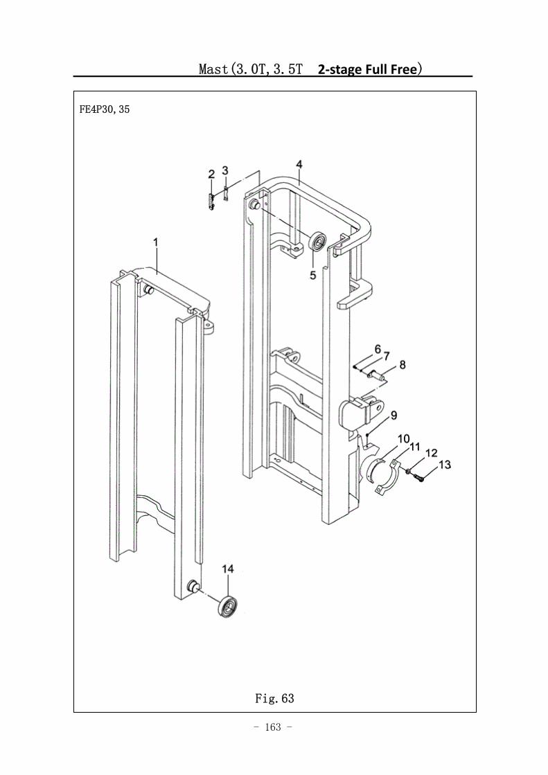
Fig.63 Mast (3.0T ,3.5T 2‐stage Full Free )
No. SN Name QTY Remarks
3068000002 H=3000mm
3068000012 H=2000mm
3068000013 H=2500mm
3068000014 H=3300mm
3068000015 H=3500mm
3068000016 H=3600mm
3068000017 H=3700mm
3068000018 H=4000mm
3068000019 H=4300mm
3068000020 H=4500mm
3068000021 H=5000mm
3068000022 H=5500mm
3068000023
Inner mast FE4P30 1
H=6000mm
3068001248 H=3000mm
3068001249 H=2000mm
3068001250 H=2500mm
3068001251 H=3300mm
3068001252 H=3500mm
3068001253 H=3600mm
3068001254 H=3700mm
3068001255 H=4000mm
3068001256 H=4300mm
3068001257 H=4500mm
3068001258 H=5000mm
3068001259 H=5500mm
1
3068001260
Inner mast FE4P35 1
H=6000mm
2 3008019002 Guide plate 2
3 3008004002 Adjustment pad 2
3048001020 H=3000mm
3048001021 H=2000mm
3048001022 H=2500mm 4
3048001023
Outer mast FE4P30 1
H=3300mm
- 165 -
Mast(3.0,3.5T T 2-stage full free lifting )
图 53 门架(二级全自由)
FE4P30,35
Fig.63
- 166 -
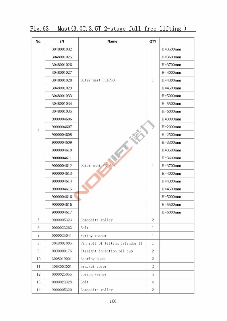
Fig.63 Mast(3.0T,3.5T 2-stage full free lifting )
No. SN Name QTY
3048001032 H=3500mm
3048001025 H=3600mm
3048001026 H=3700mm
3048001027 H=4000mm
3048001028 H=4300mm
3048001029 H=4500mm
3048001033 H=5000mm
3048001034 H=5500mm
3048001035
Outer mast FE4P30 1
H=6000mm
9000004606 H=3000mm
9000004607 H=2000mm
9000004608 H=2500mm
9000004609 H=3300mm
9000004610 H=3500mm
9000004611 H=3600mm
9000004612 H=3700mm
9000004613 H=4000mm
9000004614 H=4300mm
9000004615 H=4500mm
9000004616 H=5000mm
9000004616 H=5500mm
4
9000004617
Outer mast FE4P35 1
H=6000mm
5 9000005323 Composite roller 2
6 0000023263 Bolt 1
7 0000025041 Spring washer 1
8 3048001005 Pin roll of tilting cylinder II 1
9 0090000176 Straight injection oil cup 2
10 3008019001 Bearing bush 2
11 3068002001 Bracket cover 2
12 0000025055 Spring washer 4
13 0000023328 Bolt 4
14 9000005320 Composite roller 2
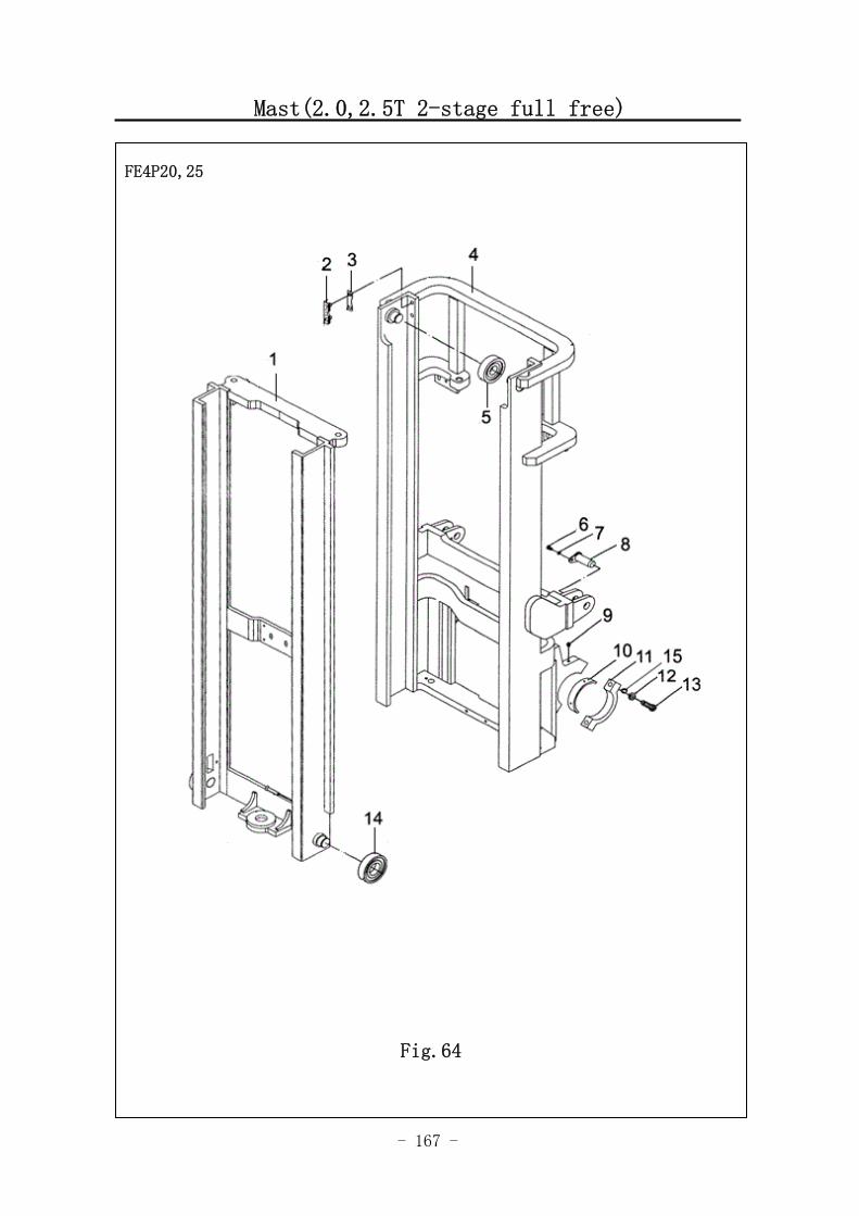
- 167 -
Mast(2.0,2.5T 2-stage full free)
图 1 行走电机及减速器 A1
FE4P20,25
Fig.64
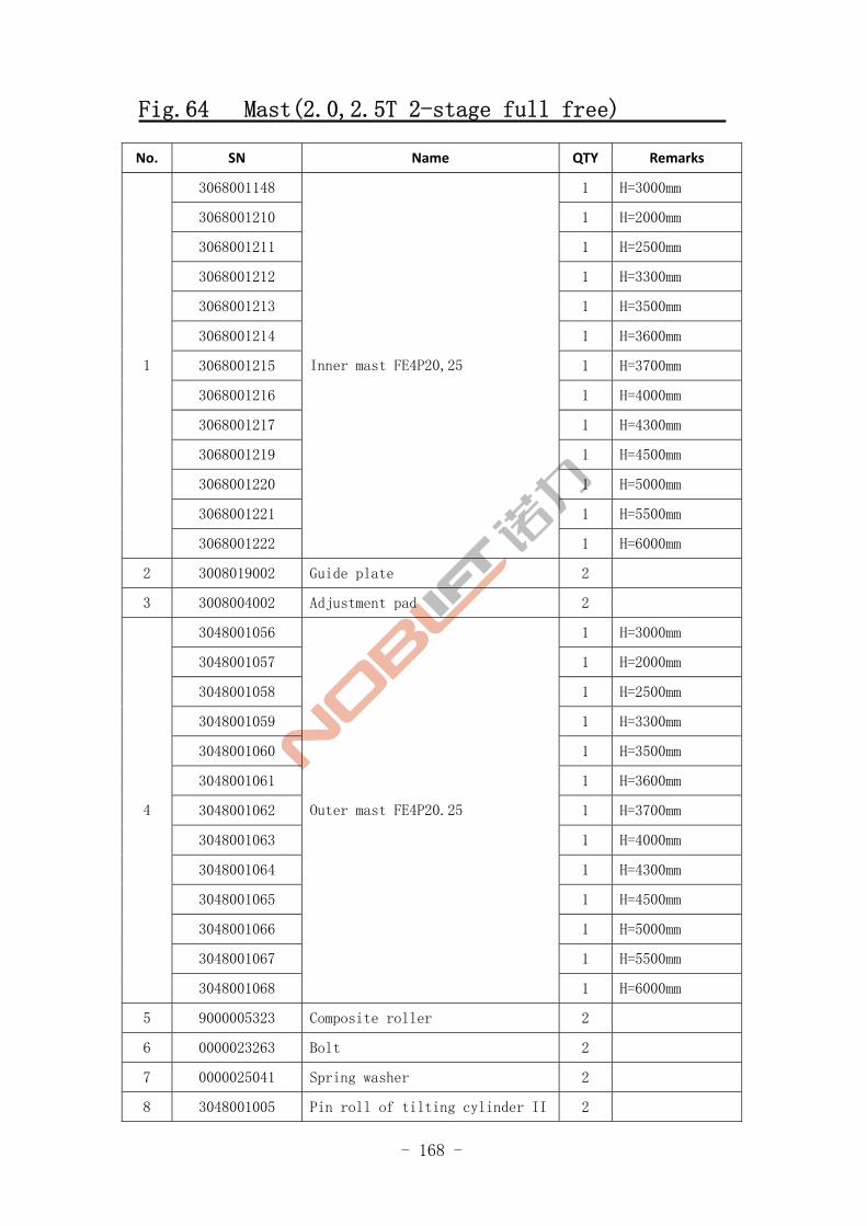
- 168 -
Fig.64 Mast(2.0,2.5T 2-stage full free)
No. SN Name QTY Remarks
3068001148 1 H=3000mm
3068001210 1 H=2000mm
3068001211 1 H=2500mm
3068001212 1 H=3300mm
3068001213 1 H=3500mm
3068001214 1 H=3600mm
3068001215 1 H=3700mm
3068001216 1 H=4000mm
3068001217 1 H=4300mm
3068001219 1 H=4500mm
3068001220 1 H=5000mm
3068001221 1 H=5500mm
1
3068001222
Inner mast FE4P20,25
1 H=6000mm
2 3008019002 Guide plate 2
3 3008004002 Adjustment pad 2
3048001056 1 H=3000mm
3048001057 1 H=2000mm
3048001058 1 H=2500mm
3048001059 1 H=3300mm
3048001060 1 H=3500mm
3048001061 1 H=3600mm
3048001062 1 H=3700mm
3048001063 1 H=4000mm
3048001064 1 H=4300mm
3048001065 1 H=4500mm
3048001066 1 H=5000mm
3048001067 1 H=5500mm
4
3048001068
Outer mast FE4P20.25
1 H=6000mm
5 9000005323 Composite roller 2
6 0000023263 Bolt 2
7 0000025041 Spring washer 2
8 3048001005 Pin roll of tilting cylinder II 2

- 169 -
Mast(2.0,2.5T 2-stage full free)
图 53 门架(二级全自由)
FE4P20,25
Fig.64
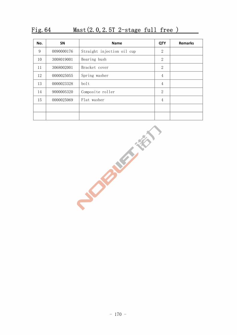
- 170 -
Fig.64 Mast(2.0,2.5T 2-stage full free )
No. SN Name QTY Remarks
9 0090000176 Straight injection oil cup 2
10 3008019001 Bearing bush 2
11 3068002001 Bracket cover 2
12 0000025055 Spring washer 4
13 0000023328 bolt 4
14 9000005320 Composite roller 2
15 0000025069 Flat washer 4
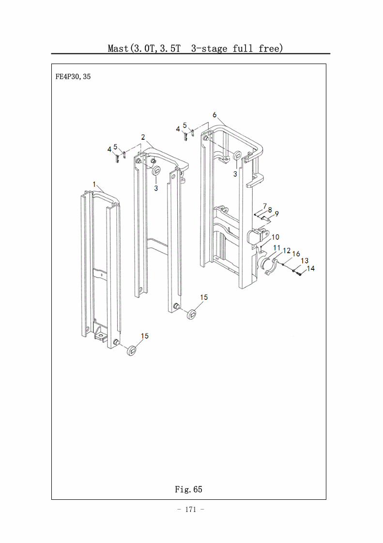
- 171 -
Mast(3.0T,3.5T 3-stage full free)
FE4P30,35
Fig.65
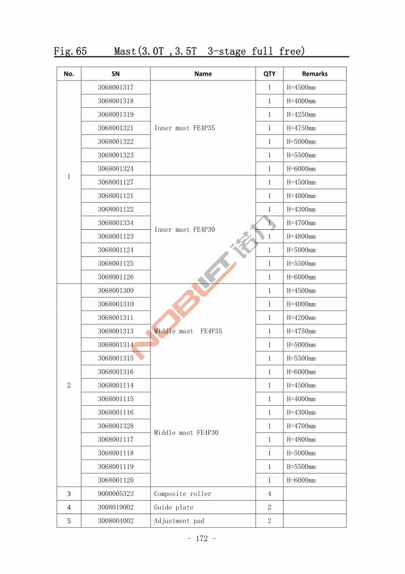
- 172 -
Fig.65 Mast(3.0T ,3.5T 3-stage full free)
No. SN Name QTY Remarks
3068001317 1 H=4500mm
3068001318 1 H=4000mm
3068001319 1 H=4250mm
3068001321 1 H=4750mm
3068001322 1 H=5000mm
3068001323 1 H=5500mm
3068001324
Inner mast FE4P35
1 H=6000mm
3068001127 1 H=4500mm
3068001121 1 H=4000mm
3068001122 1 H=4300mm
3068001334 1 H=4700mm
3068001123 1 H=4800mm
3068001124 1 H=5000mm
3068001125 1 H=5500mm
1
3068001126
Inner mast FE4P30
1 H=6000mm
3068001309 1 H=4500mm
3068001310 1 H=4000mm
3068001311 1 H=4200mm
3068001313 1 H=4750mm
3068001314 1 H=5000mm
3068001315 1 H=5500mm
3068001316
Middle mast FE4P35
1 H=6000mm
3068001114 1 H=4500mm
3068001115 1 H=4000mm
3068001116 1 H=4300mm
3068001328 1 H=4700mm
3068001117 1 H=4800mm
3068001118 1 H=5000mm
3068001119 1 H=5500mm
2
3068001120
Middle mast FE4P30
1 H=6000mm
3 9000005323 Composite roller 4
4 3008019002 Guide plate 2
5 3008004002 Adjustment pad 2
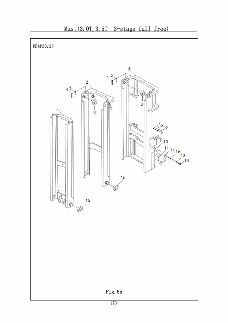
- 173 -
Mast(3.0T,3.5T 3-stage full free)
FE4P30,35
Fig.65
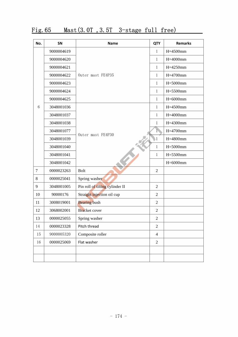
- 174 -
Fig.65 Mast(3.0T ,3.5T 3-stage full free)
No. SN Name QTY Remarks
9000004619 1 H=4500mm
9000004620 1 H=4000mm
9000004621 1 H=4250mm
9000004622 1 H=4700mm
9000004623 1 H=5000mm
9000004624 1 H=5500mm
9000004625
Outer mast FE4P35
1 H=6000mm
3048001036 1 H=4500mm
3048001037 1 H=4000mm
3048001038 1 H=4300mm
3048001077 1 H=4700mm
3048001039 1 H=4800mm
3048001040 1 H=5000mm
3048001041 1 H=5500mm
6
3048001042
Outer mast FE4P30
H=6000mm
7 0000023263 Bolt 2
8 0000025041 Spring washer
9 3048001005 Pin roll of tilting cylinder II 2
10 90000176 Straight injection oil cup 2
11 3008019001 Bearing bush 2
12 3068002001 Bracket cover 2
13 0000025055 Spring washer 2
14 0000023328 Pitch thread 2
15 9000005320 Composite roller 4
16 0000025069 Flat washer 2
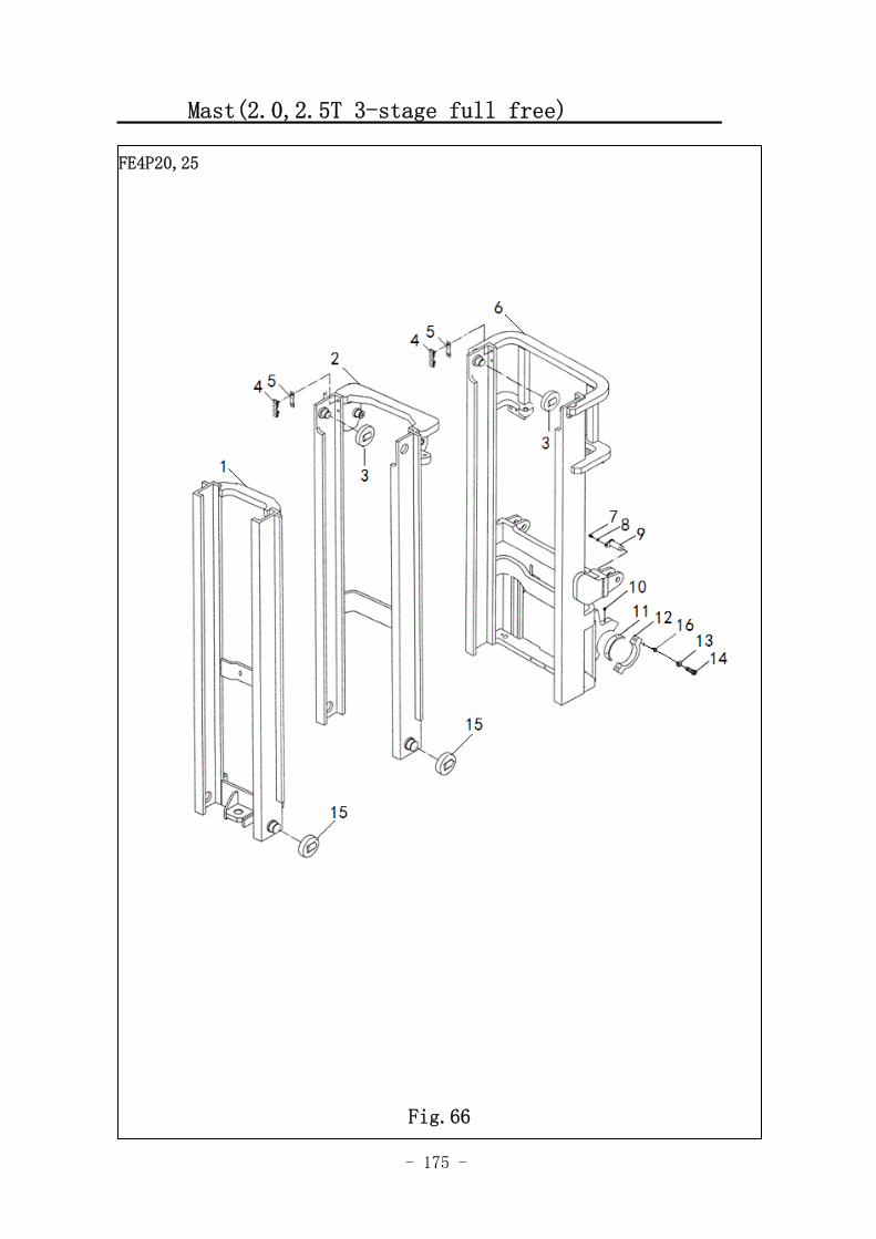
- 175 -
Mast(2.0,2.5T 3-stage full free)
图 1 行走电机及减速器 A1
FE4P20,25
Fig.66
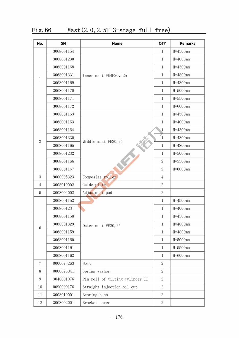
- 176 -
Fig.66 Mast(2.0,2.5T 3-stage full free)
No. SN Name QTY Remarks
3068001154 1 H=4500mm
3068001230 1 H=4000mm
3068001168 1 H=4300mm
3068001331 1 H=4800mm
3068001169 1 H=4800mm
3068001170 1 H=5000mm
3068001171 1 H=5500mm
1
3068001172
Inner mast FE4P20,25
1 H=6000mm
3068001153 1 H=4500mm
3068001163 1 H=4000mm
3068001164 1 H=4300mm
3068001330 1 H=4800mm
3068001165 1 H=4800mm
3068001232 1 H=5000mm
3068001166 2 H=5500mm
2
3068001167
Middle mast FE20,25
2 H=6000mm
3 9000005323 Composite roller 4
4 3008019002 Guide plate 2
5 3008004002 Adjustment pad 2
3068001152 1 H=4500mm
3068001231 1 H=4000mm
3068001158 1 H=4300mm
3068001329 1 H=4800mm
3068001159 1 H=4800mm
3068001160 1 H=5000mm
3068001161 1 H=5500mm
6
3068001162
Outer mast FE20,25
1 H=6000mm
7 0000023263 Bolt 2
8 0000025041 Spring washer 2
9 3048001076 Pin roll of tilting cylinder II 2
10 0090000176 Straight injection oil cup 2
11 3008019001 Bearing bush 2
12 3068002001 Bracket cover 2

- 177 -
Mast(2.0,2.5T 3-stage full free)
FE4P20,25
Fig.66
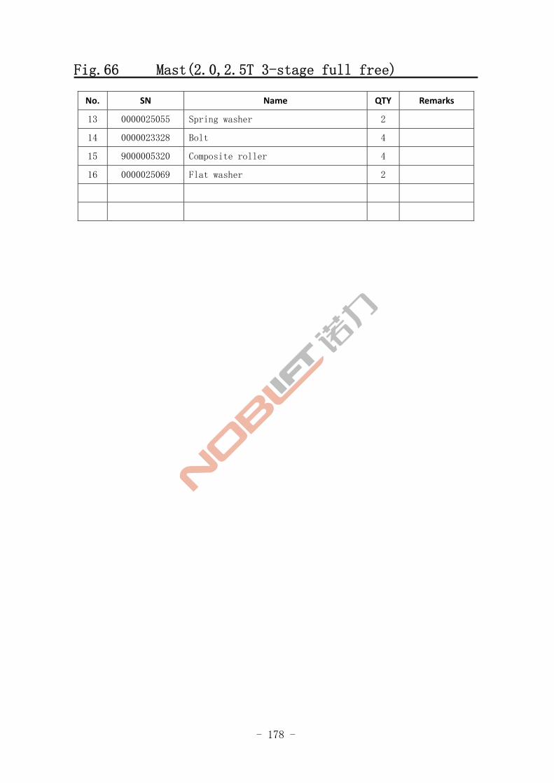
- 178 -
Fig.66 Mast(2.0,2.5T 3-stage full free)
No. SN Name QTY Remarks
13 0000025055 Spring washer 2
14 0000023328 Bolt 4
15 9000005320 Composite roller 4
16 0000025069 Flat washer 2
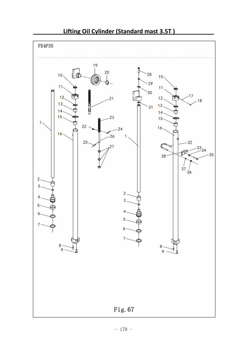
- 179 -
Lifting Oil Cylinder (Standard mast 3.5T )
FE4P35
Fig.67
- 180 -
Fig.67 Lifting Oil Cylinder (Standard mast 3.5T )
No. SN Name QTY Remarks
3068000179 1 H=3000mm
3068000180 1 H=2000mm
3068000181 1 H=2500mm
3068000182 1 H=3300mm
3068000183 1 H=3500mm
3068000184 1 H=3600mm
3068000185 1 H=3700mm
3068000186 1 H=4000mm
3068000187 1 H=4300mm
3068000188 1 H=4500mm
3068000189 1 H=5000mm
3068000190 1 H=5500mm
A
3068000191
Left lifting cylinder
1 H=6000mm
9000004933 1 H=3000mm
9000004934 1 H=2000mm
9000004935 1 H=2500mm
9000004936 1 H=3300mm
9000004937 1 H=3500mm
9000004938 1 H=3600mm
9000004939 1 H=3700mm
9000004940 1 H=4000mm
9000004941 1 H=4300mm
9000004942 1 H=4500mm
9000004943 1 H=5000mm
9000004944 1 H=5500mm
B
9000004945
Right lifting cylinder
1 H=6000mm
1 3068002064 Piston rod 1
2 3068002066 Adjusting sleeve 2
3 0000026048 Retaining ring 2
4 3068002067 Piston 2
5 3068022020 Support ring for hole 2
6 3068022021 Retaining ring 2
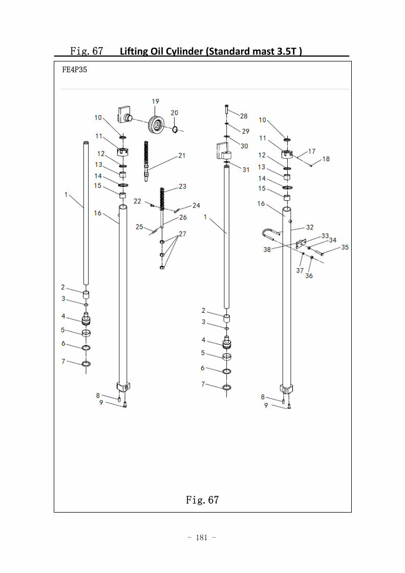
- 181 -
Fig.67 Lifting Oil Cylinder (Standard mast 3.5T )
FE4P35
Fig.67
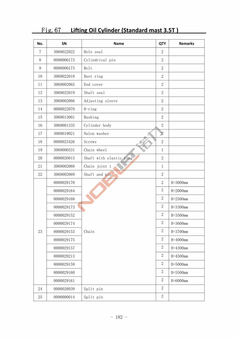
- 182 -
Fig.67 Lifting Oil Cylinder (Standard mast 3.5T )
No. SN Name QTY Remarks
7 3068022022 Hole seal 2
8 0090000173 Cylindrical pin 2
9 0090000173 Bolt 2
10 3068022018 Dust ring 2
11 3068002065 End cover 2
12 3068022019 Shaft seal 2
13 3068002066 Adjusting sleeve 2
14 0000022070 0-ring 2
15 3068013001 Bushing 2
16 3068001335 Cylinder body 2
17 3068019021 Nalon washer 2
18 0000023426 Screws 2
19 3068000331 Chain wheel 1
20 0000026015 Shaft with elastic ring 2
21 3068002068 Chain joint i 1
22 3068002069 Shaft and pin 2
0000029170 2 H=3000mm
0000029164 2 H=2000mm
0000029168 2 H=2500mm
0000029173 2 H=3300mm
0000029152 2 H=3500mm
0000029174 2 H=3600mm
0000029153 2 H=3700mm
0000029175 2 H=4000mm
0000029157 2 H=4300mm
0000029213 2 H=4500mm
0000029159 2 H=5000mm
0000029160 2 H=5500mm
23
0000029161
Chain
2 H=6000mm
24 0000028039 Split pin 2
25 0090000014 Split pin 2
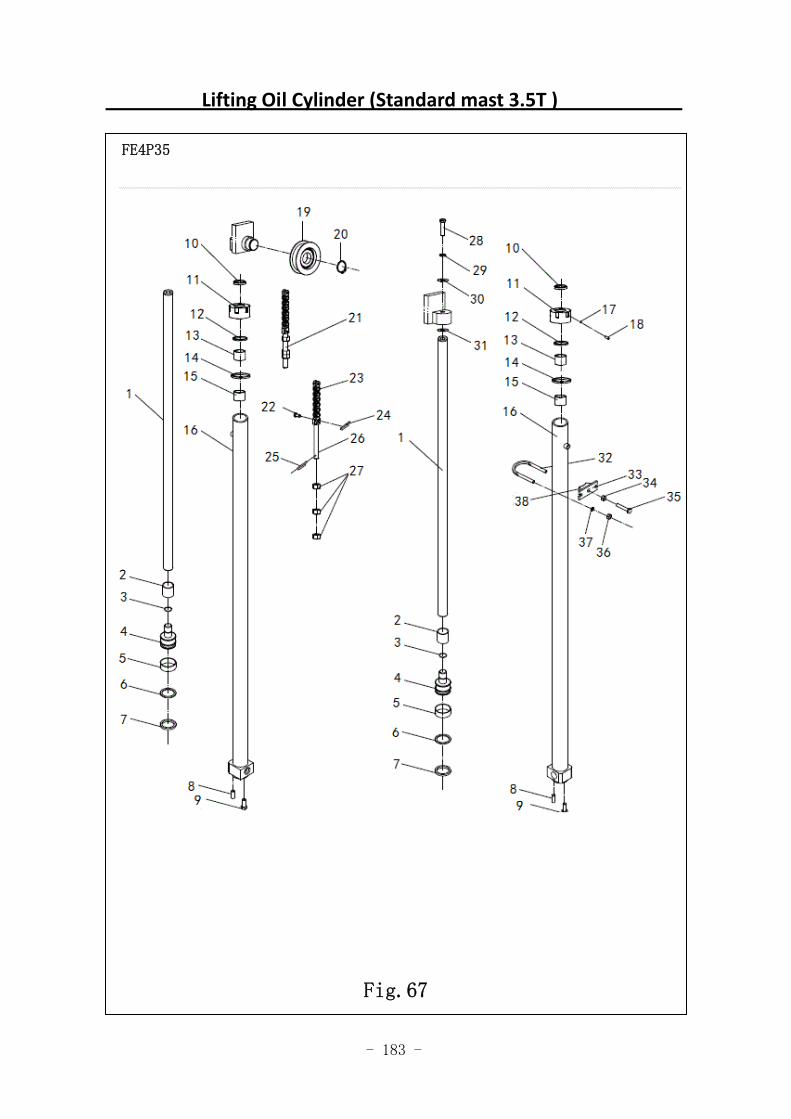
- 183 -
Lifting Oil Cylinder (Standard mast 3.5T )
FE4P35
Fig.67
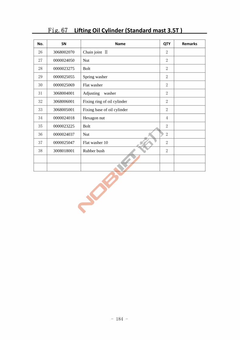
- 184 -
Fig.67 Lifting Oil Cylinder (Standard mast 3.5T )
No. SN Name QTY Remarks
26 3068002070 Chain joint Ⅱ 2
27 0000024050 Nut 2
28 0000023275 Bolt 2
29 0000025055 Spring washer 2
30 0000025069 Flat washer 2
31 3068004001 Adjusting washer 2
32 3068006001 Fixing ring of oil cylinder 2
33 3068005001 Fixing base of oil cylinder 2
34 0000024018 Hexagon nut 4
35 0000023225 Bolt 2
36 0000024037 Nut 2
37 0000025047 Flat washer 10 2
38 3008018001 Rubber bush 2
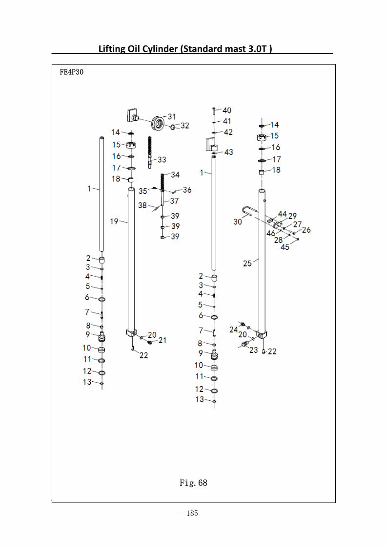
- 185 -
Lifting Oil Cylinder (Standard mast 3.0T )
图 57 起升油缸(基本型) G10
FE4P30
Fig.68
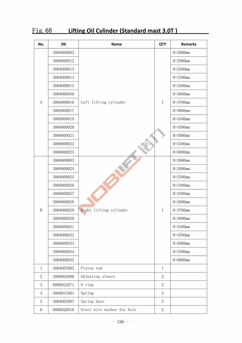
- 186 -
Fig.68 Lifting Oil Cylinder (Standard mast 3.0T )
No. SN Name QTY Remarks
3068000002 H=3000mm
3068000012 H=2000mm
3068000013 H=2500mm
3068000014 H=3300mm
3068000015 H=3500mm
3068000046 H=3600mm
3068000016 H=3700mm
3068000017 H=4000mm
3068000019 H=4300mm
3068000020 H=4500mm
3068000021 H=5000mm
3068000022 H=5500mm
A
3068000023
Left lifting cylinder 1
H=6000mm
3068000003 H=3000mm
3068000024 H=2000mm
3068000025 H=2500mm
3068000026 H=3300mm
3068000027 H=3500mm
3068000028 H=3600mm
3068000029 H=3700mm
3068000030 H=4000mm
3068000031 H=4300mm
3068000032 H=4500mm
3068000033 H=5000mm
3068000034 H=5500mm
B
3068000035
Right lifting cylinder 1
H=6000mm
1 3068007002 Piston rod 1
2 3068002006 Adjusting sleeve 2
3 0000022071 O ring 2
4 3068031001 Spring 2
5 3068002007 Spring base 2
6 0000026016 Steel wire washer for hole 2
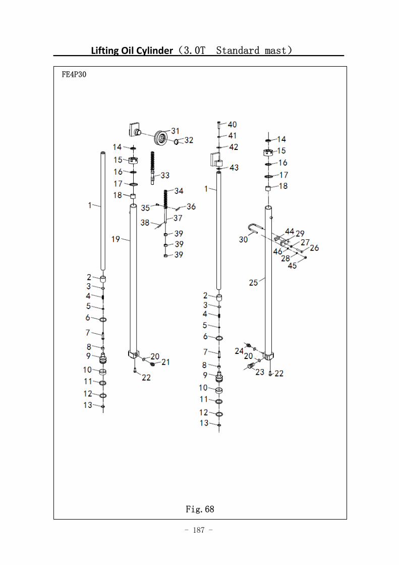
- 187 -
Lifting Oil Cylinder(3.0T Standard mast)
图 1 行走电机及减速器 A1
FE4P30
Fig.68
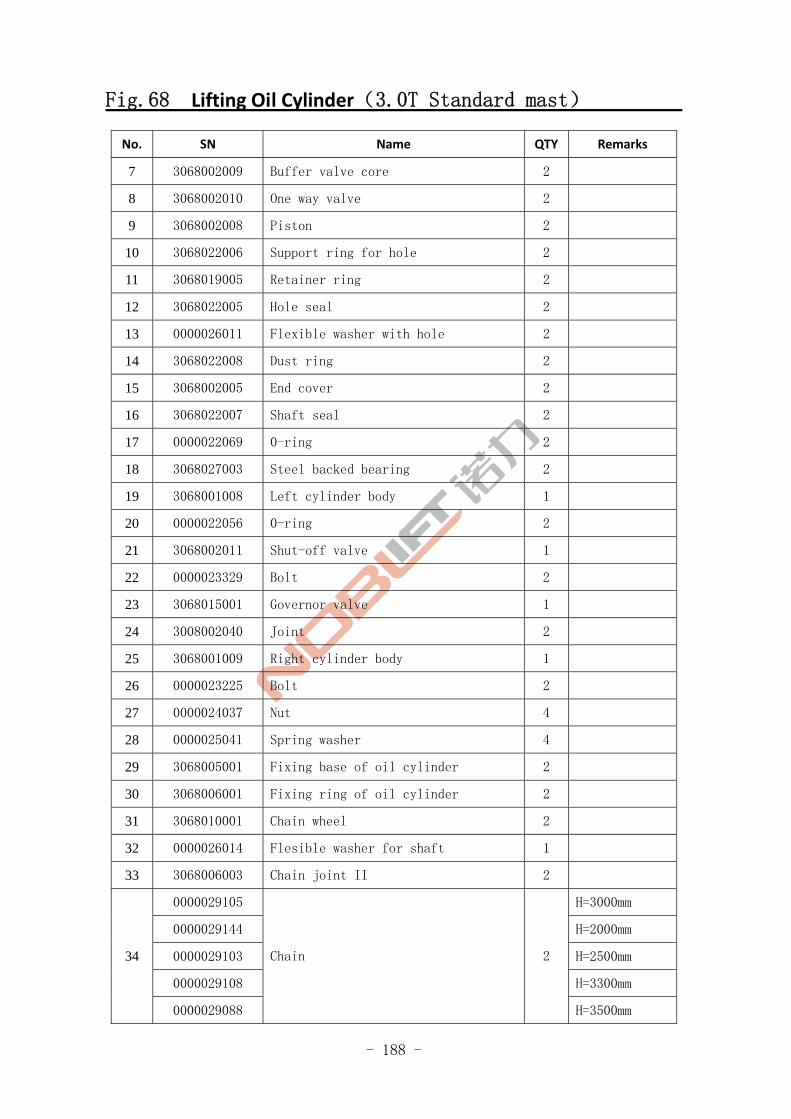
- 188 -
Fig.68 Lifting Oil Cylinder(3.0T Standard mast)
No. SN Name QTY Remarks
7 3068002009 Buffer valve core 2
8 3068002010 One way valve 2
9 3068002008 Piston 2
10 3068022006 Support ring for hole 2
11 3068019005 Retainer ring 2
12 3068022005 Hole seal 2
13 0000026011 Flexible washer with hole 2
14 3068022008 Dust ring 2
15 3068002005 End cover 2
16 3068022007 Shaft seal 2
17 0000022069 0-ring 2
18 3068027003 Steel backed bearing 2
19 3068001008 Left cylinder body 1
20 0000022056 0-ring 2
21 3068002011 Shut-off valve 1
22 0000023329 Bolt 2
23 3068015001 Governor valve 1
24 3008002040 Joint 2
25 3068001009 Right cylinder body 1
26 0000023225 Bolt 2
27 0000024037 Nut 4
28 0000025041 Spring washer 4
29 3068005001 Fixing base of oil cylinder 2
30 3068006001 Fixing ring of oil cylinder 2
31 3068010001 Chain wheel 2
32 0000026014 Flesible washer for shaft 1
33 3068006003 Chain joint II 2
0000029105 H=3000mm
0000029144 H=2000mm
0000029103 H=2500mm
0000029108 H=3300mm
34
0000029088
Chain 2
H=3500mm
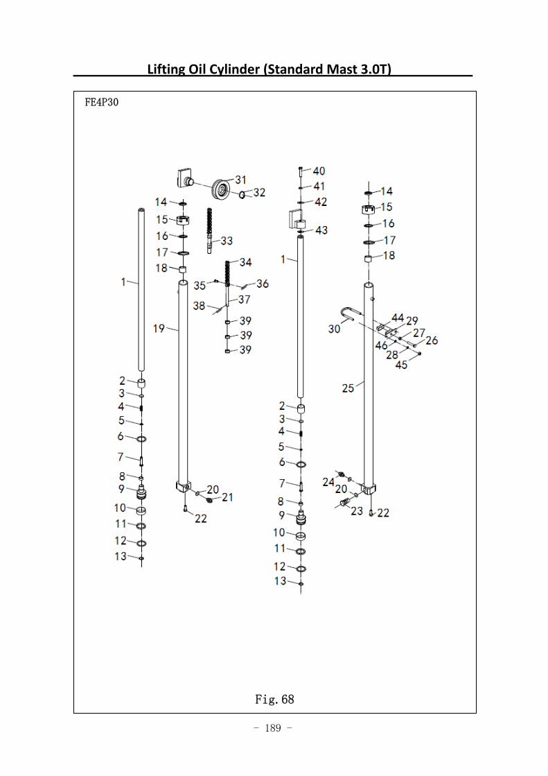
- 189 -
Lifting Oil Cylinder (Standard Mast 3.0T)
图 1 行走电机及减速器 A1
FE4P30
Fig.68
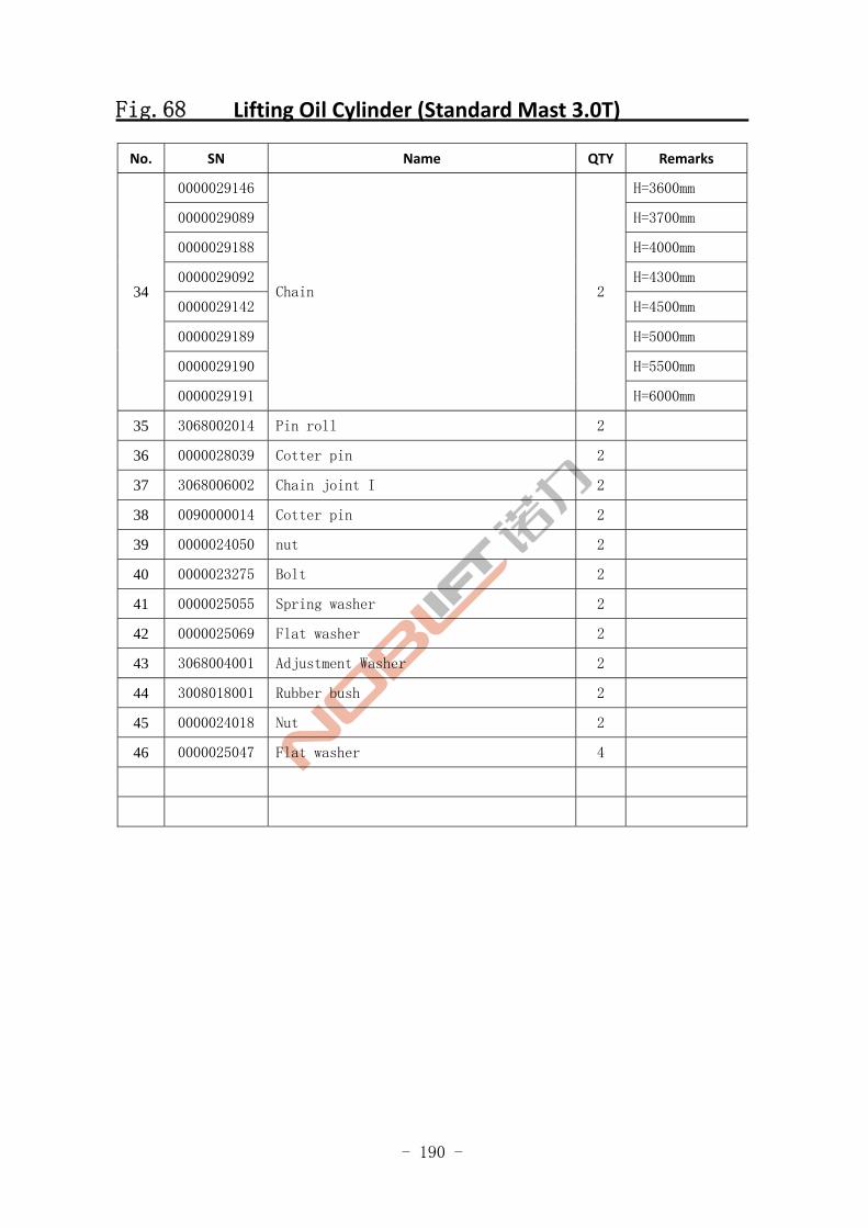
- 190 -
Fig.68 Lifting Oil Cylinder (Standard Mast 3.0T)
No. SN Name QTY Remarks
0000029146 H=3600mm
0000029089 H=3700mm
0000029188 H=4000mm
0000029092 H=4300mm
0000029142 H=4500mm
0000029189 H=5000mm
0000029190 H=5500mm
34
0000029191
Chain 2
H=6000mm
35 3068002014 Pin roll 2
36 0000028039 Cotter pin 2
37 3068006002 Chain joint I 2
38 0090000014 Cotter pin 2
39 0000024050 nut 2
40 0000023275 Bolt 2
41 0000025055 Spring washer 2
42 0000025069 Flat washer 2
43 3068004001 Adjustment Washer 2
44 3008018001 Rubber bush 2
45 0000024018 Nut 2
46 0000025047 Flat washer 4
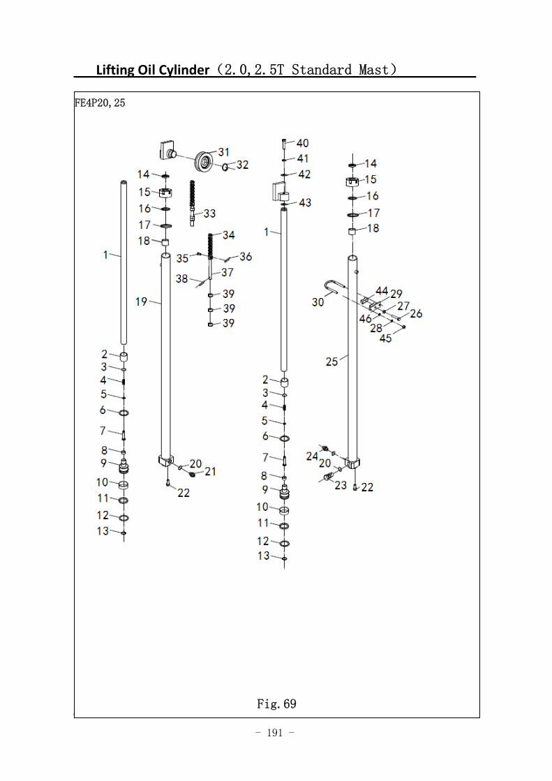
- 191 -
Lifting Oil Cylinder(2.0,2.5T Standard Mast)
图 57 起升油缸(基本型) G10
FE4P20,25
Fig.69
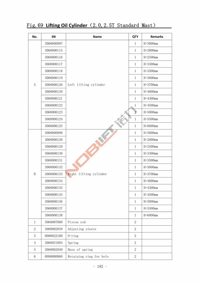
- 192 -
Fig.69 Lifting Oil Cylinder(2.0,2.5T Standard Mast)
No. SN Name QTY Remarks
3068000097 1 H=3000mm
3068000115 1 H=2000mm
3068000116 1 H=2500mm
3068000117 1 H=3300mm
3068000118 1 H=3500mm
3068000119 1 H=3600mm
3068000126 1 H=3700mm
3068000120 1 H=4000mm
3068000121 1 H=4300mm
3068000122 1 H=4500mm
3068000123 1 H=5000mm
3068000124 1 H=5500mm
A
3068000125
Left lifting cylinder
1 H=6000mm
3068000098 1 H=3000mm
3068000128 1 H=2000mm
3068000129 1 H=2500mm
3068000130 1 H=3300mm
3068000131 1 H=3500mm
3068000132 1 H=3600mm
3068000133 1 H=3700mm
3068000134 1 H=4000mm
3068000135 1 H=4300mm
3068000143 1 H=4500mm
3068000136 1 H=5000mm
3068000137 1 H=5500mm
B
3068000138
Right lifting cylinder
1 H=6000mm
1 3068007008 Piston rod 2
2 3068002039 Adjusting sleeve 2
3 0000022100 O-ring 2
4 3068031004 Spring 2
5 3068002040 Base of spring 2
6 0090000060 Retaining ring for hole 2
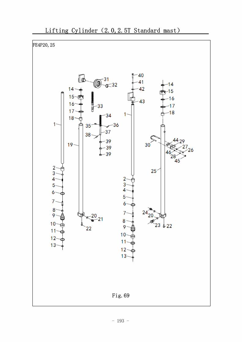
- 193 -
Lifting Cylinder(2.0,2.5T Standard mast)
FE4P20,25
Fig.69
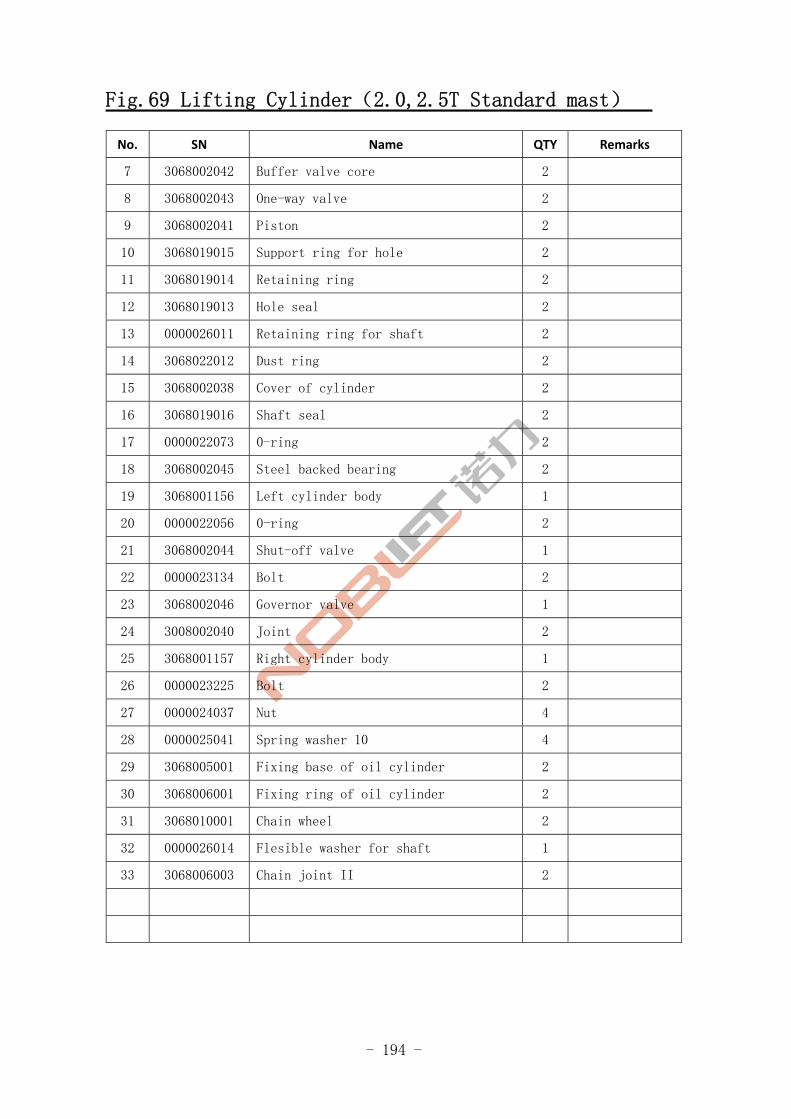
- 194 -
Fig.69 Lifting Cylinder(2.0,2.5T Standard mast)
No. SN Name QTY Remarks
7 3068002042 Buffer valve core 2
8 3068002043 One-way valve 2
9 3068002041 Piston 2
10 3068019015 Support ring for hole 2
11 3068019014 Retaining ring 2
12 3068019013 Hole seal 2
13 0000026011 Retaining ring for shaft 2
14 3068022012 Dust ring 2
15 3068002038 Cover of cylinder 2
16 3068019016 Shaft seal 2
17 0000022073 0-ring 2
18 3068002045 Steel backed bearing 2
19 3068001156 Left cylinder body 1
20 0000022056 0-ring 2
21 3068002044 Shut-off valve 1
22 0000023134 Bolt 2
23 3068002046 Governor valve 1
24 3008002040 Joint 2
25 3068001157 Right cylinder body 1
26 0000023225 Bolt 2
27 0000024037 Nut 4
28 0000025041 Spring washer 10 4
29 3068005001 Fixing base of oil cylinder 2
30 3068006001 Fixing ring of oil cylinder 2
31 3068010001 Chain wheel 2
32 0000026014 Flesible washer for shaft 1
33 3068006003 Chain joint II 2
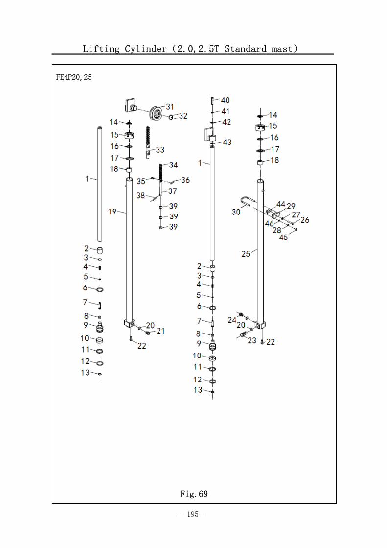
- 195 -
Lifting Cylinder(2.0,2.5T Standard mast)
图 1 行走电机及减速器 A1
FE4P20,25
Fig.69
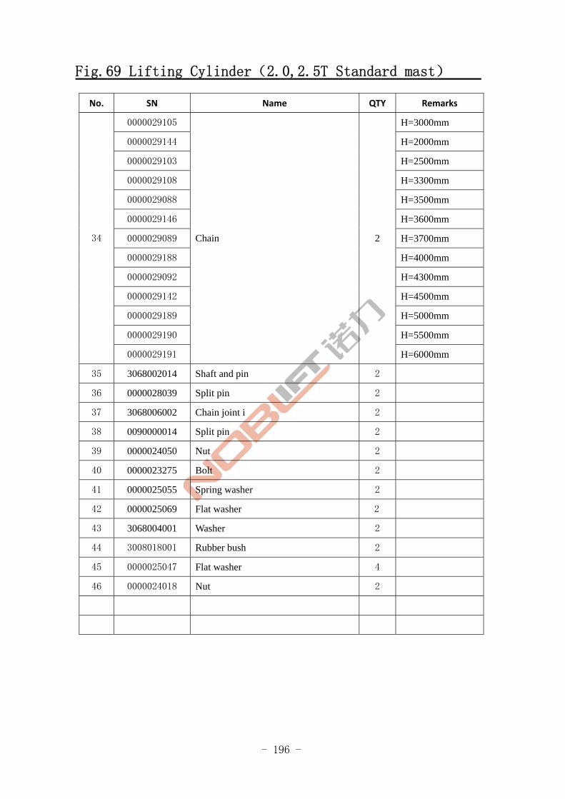
- 196 -
Fig.69 Lifting Cylinder(2.0,2.5T Standard mast)
No. SN Name QTY Remarks
0000029105 H=3000mm
0000029144 H=2000mm
0000029103 H=2500mm
0000029108 H=3300mm
0000029088 H=3500mm
0000029146 H=3600mm
0000029089 H=3700mm
0000029188 H=4000mm
0000029092 H=4300mm
0000029142 H=4500mm
0000029189 H=5000mm
0000029190 H=5500mm
34
0000029191
Chain 2
H=6000mm
35 3068002014 Shaft and pin 2
36 0000028039 Split pin 2
37 3068006002 Chain joint i 2
38 0090000014 Split pin 2
39 0000024050 Nut 2
40 0000023275 Bolt 2
41 0000025055 Spring washer 2
42 0000025069 Flat washer 2
43 3068004001 Washer 2
44 3008018001 Rubber bush 2
45 0000025047 Flat washer 4
46 0000024018 Nut 2
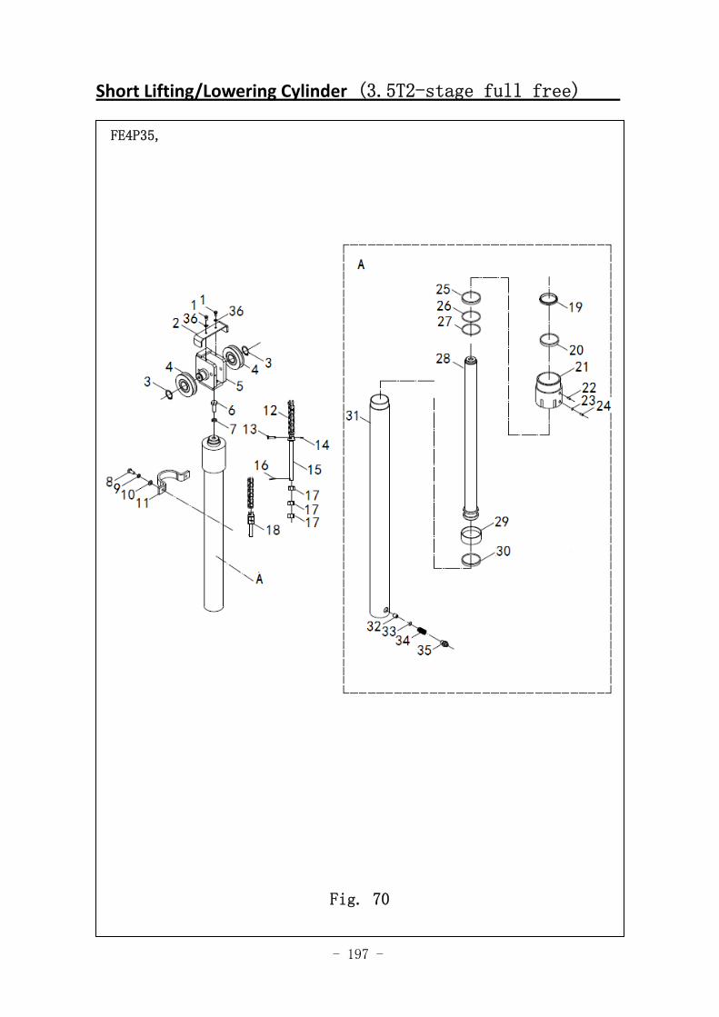
- 197 -
Short Lifting/Lowering Cylinder (3.5T2-stage full free)
FE4P35,
Fig. 70
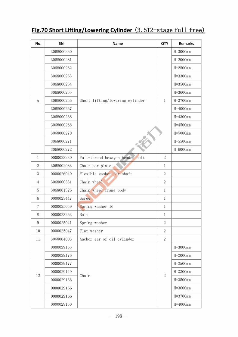
- 198 -
Fig.70 Short Lifting/Lowering Cylinder (3.5T2-stage full free)
No. SN Name QTY Remarks
3068000260 H=3000mm
3068000261 H=2000mm
3068000262 H=2500mm
3068000263 H=3300mm
3068000264 H=3500mm
3068000265 H=3600mm
3068000266 H=3700mm
3068000267 H=4000mm
3068000268 H=4300mm
3068000268 H=4500mm
3068000270 H=5000mm
3068000271 H=5500mm
A
3068000272
Short lifting/lowering cylinder 1
H=6000mm
1 0000023230 Full-thread hexagon headed bolt 2
2 3068002063 Chair bar plate 1
3 0000026049 Flesible washer for shaft 2
4 3068000331 Chain wheel 2
5 3068001326 Chain wheel frame body 1
6 0000023447 Screw 1
7 0000025059 Spring washer 16 1
8 0000023263 Bolt 1
9 0000025041 Spring washer 2
10 0000025047 Flat washer 2
11 3068004003 Anchor ear of oil cylinder 2
0000029165 H=3000mm
0000029176 H=2000mm
0000029177 H=2500mm
0000029149 H=3300mm
0000029166 H=3500mm
0000029166 H=3600mm
0000029166 H=3700mm
12
0000029150
Chain 2
H=4000mm
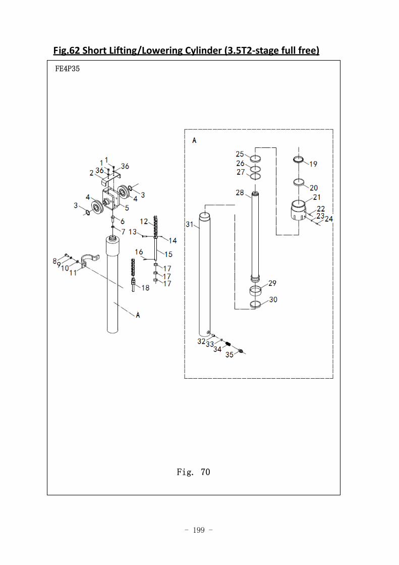
- 199 -
Fig.62 Short Lifting/Lowering Cylinder (3.5T2‐stage full free)
FE4P35
Fig. 70
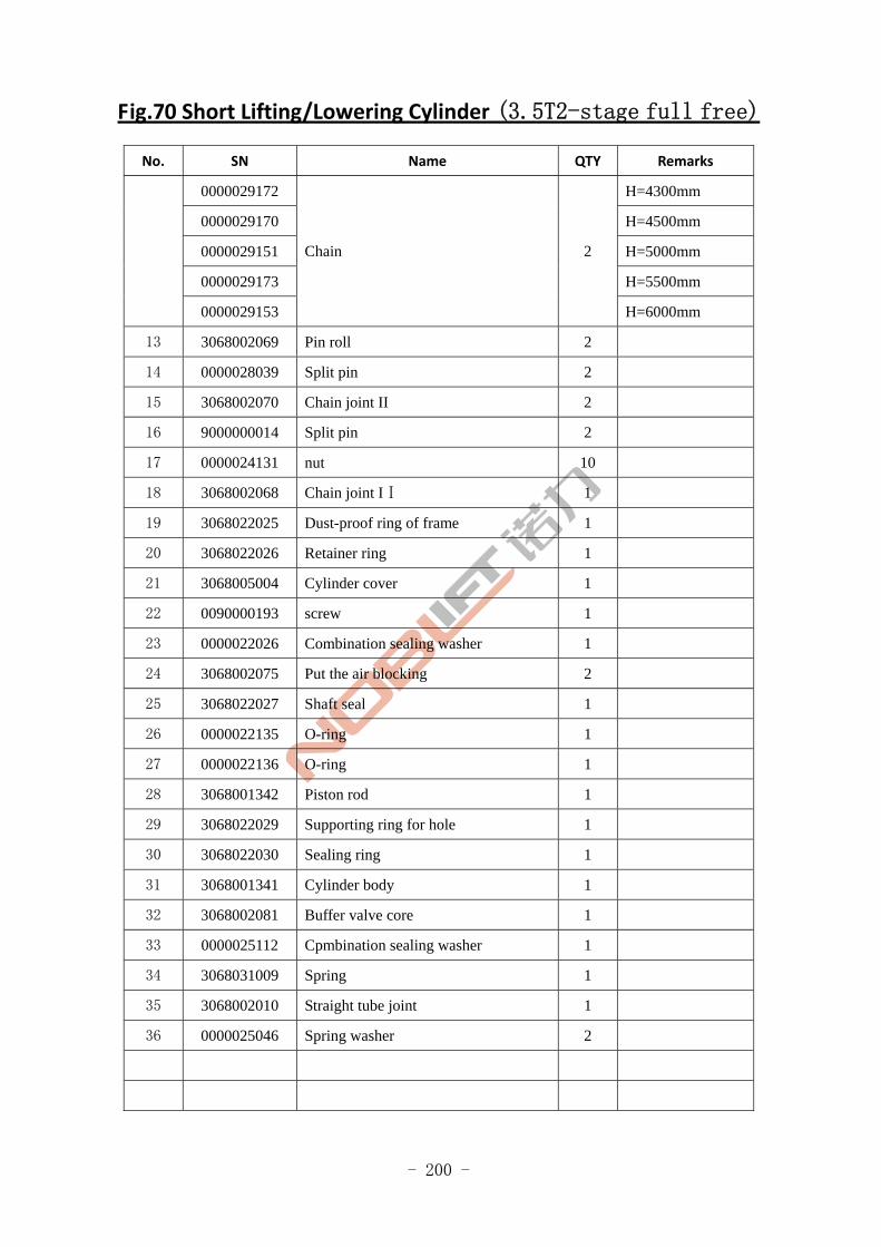
- 200 -
Fig.70 Short Lifting/Lowering Cylinder (3.5T2-stage full free)
No. SN Name QTY Remarks
0000029172 H=4300mm
0000029170 H=4500mm
0000029151 H=5000mm
0000029173 H=5500mm
0000029153
Chain 2
H=6000mm
13 3068002069 Pin roll 2
14 0000028039 Split pin 2
15 3068002070 Chain joint II 2
16 9000000014 Split pin 2
17 0000024131 nut 10
18 3068002068 Chain joint IⅠ 1
19 3068022025 Dust-proof ring of frame 1
20 3068022026 Retainer ring 1
21 3068005004 Cylinder cover 1
22 0090000193 screw 1
23 0000022026 Combination sealing washer 1
24 3068002075 Put the air blocking 2
25 3068022027 Shaft seal 1
26 0000022135 O-ring 1
27 0000022136 O-ring 1
28 3068001342 Piston rod 1
29 3068022029 Supporting ring for hole 1
30 3068022030 Sealing ring 1
31 3068001341 Cylinder body 1
32 3068002081 Buffer valve core 1
33 0000025112 Cpmbination sealing washer 1
34 3068031009 Spring 1
35 3068002010 Straight tube joint 1
36 0000025046 Spring washer 2
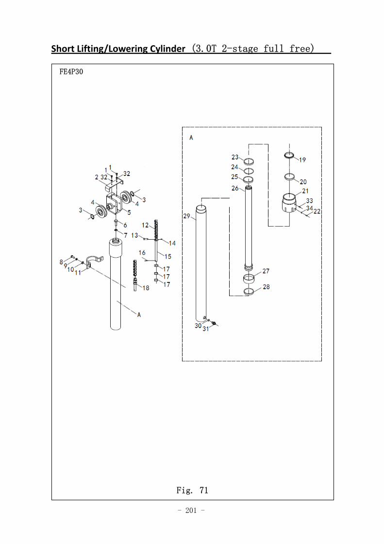
- 201 -
Short Lifting/Lowering Cylinder (3.0T 2-stage full free)
图 1 行走电机及减速器 A1
FE4P30
Fig. 71
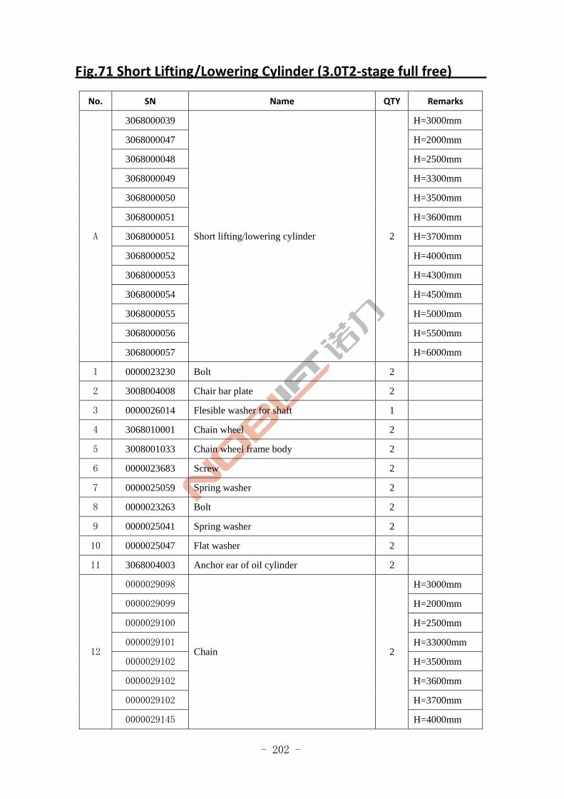
- 202 -
Fig.71 Short Lifting/Lowering Cylinder (3.0T2‐stage full free)
No. SN Name QTY Remarks
3068000039 H=3000mm
3068000047 H=2000mm
3068000048 H=2500mm
3068000049 H=3300mm
3068000050 H=3500mm
3068000051 H=3600mm
3068000051 H=3700mm
3068000052 H=4000mm
3068000053 H=4300mm
3068000054 H=4500mm
3068000055 H=5000mm
3068000056 H=5500mm
A
3068000057
Short lifting/lowering cylinder 2
H=6000mm
1 0000023230 Bolt 2
2 3008004008 Chair bar plate 2
3 0000026014 Flesible washer for shaft 1
4 3068010001 Chain wheel 2
5 3008001033 Chain wheel frame body 2
6 0000023683 Screw 2
7 0000025059 Spring washer 2
8 0000023263 Bolt 2
9 0000025041 Spring washer 2
10 0000025047 Flat washer 2
11 3068004003 Anchor ear of oil cylinder 2
0000029098 H=3000mm
0000029099 H=2000mm
0000029100 H=2500mm
0000029101 H=33000mm
0000029102 H=3500mm
0000029102 H=3600mm
0000029102 H=3700mm
12
0000029145
Chain 2
H=4000mm
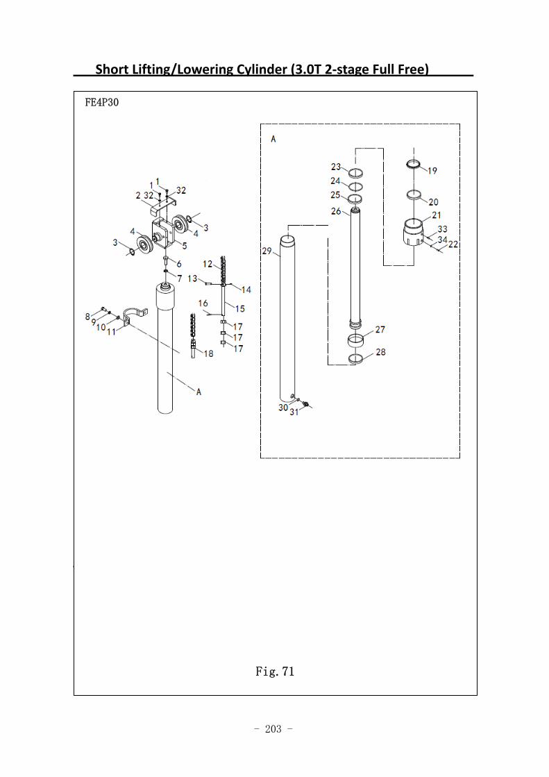
- 203 -
Short Lifting/Lowering Cylinder (3.0T 2‐stage Full Free)
图 59 前起升油缸(二级全自由)
FE4P30
Fig.71
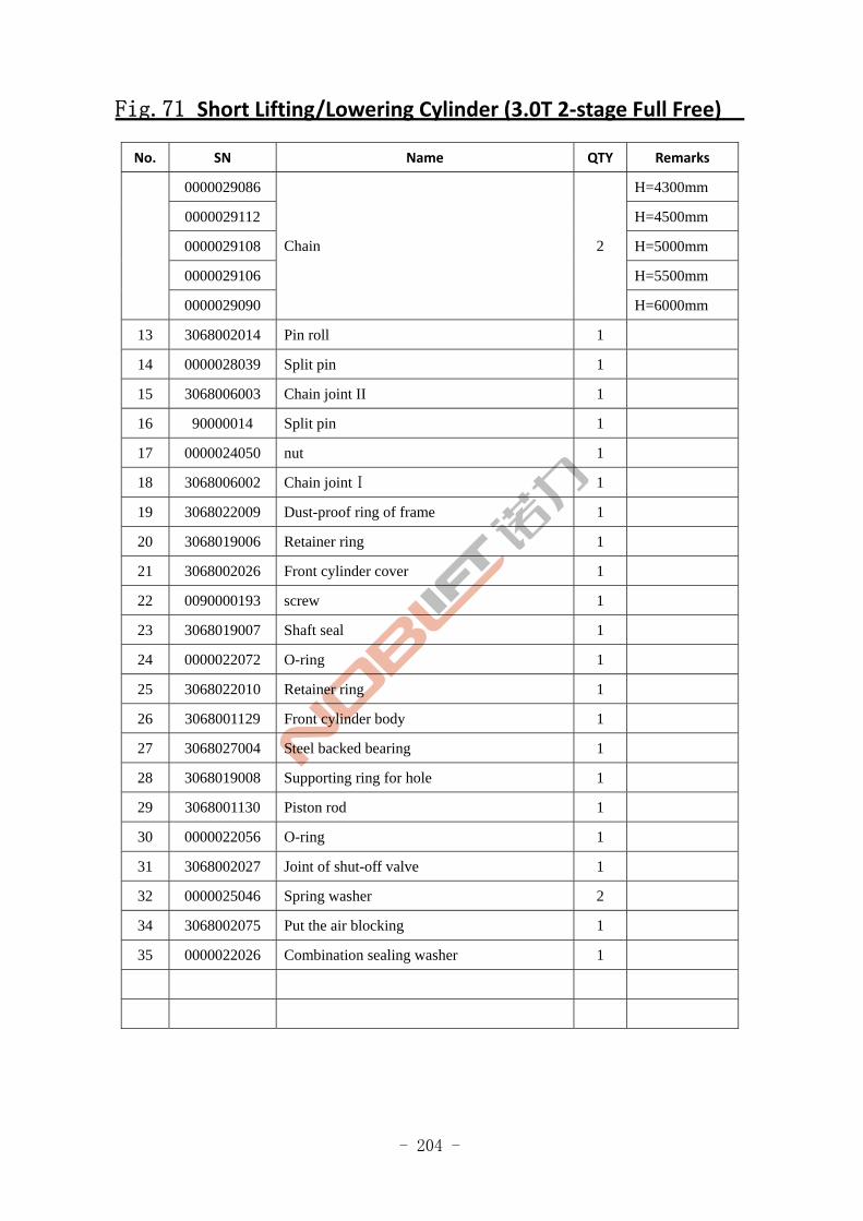
- 204 -
Fig.71 Short Lifting/Lowering Cylinder (3.0T 2‐stage Full Free)
No. SN Name QTY Remarks
0000029086 H=4300mm
0000029112 H=4500mm
0000029108 H=5000mm
0000029106 H=5500mm
0000029090
Chain 2
H=6000mm
13 3068002014 Pin roll 1
14 0000028039 Split pin 1
15 3068006003 Chain joint II 1
16 90000014 Split pin 1
17 0000024050 nut 1
18 3068006002 Chain jointⅠ 1
19 3068022009 Dust-proof ring of frame 1
20 3068019006 Retainer ring 1
21 3068002026 Front cylinder cover 1
22 0090000193 screw 1
23 3068019007 Shaft seal 1
24 0000022072 O-ring 1
25 3068022010 Retainer ring 1
26 3068001129 Front cylinder body 1
27 3068027004 Steel backed bearing 1
28 3068019008 Supporting ring for hole 1
29 3068001130 Piston rod 1
30 0000022056 O-ring 1
31 3068002027 Joint of shut-off valve 1
32 0000025046 Spring washer 2
34 3068002075 Put the air blocking 1
35 0000022026 Combination sealing washer 1
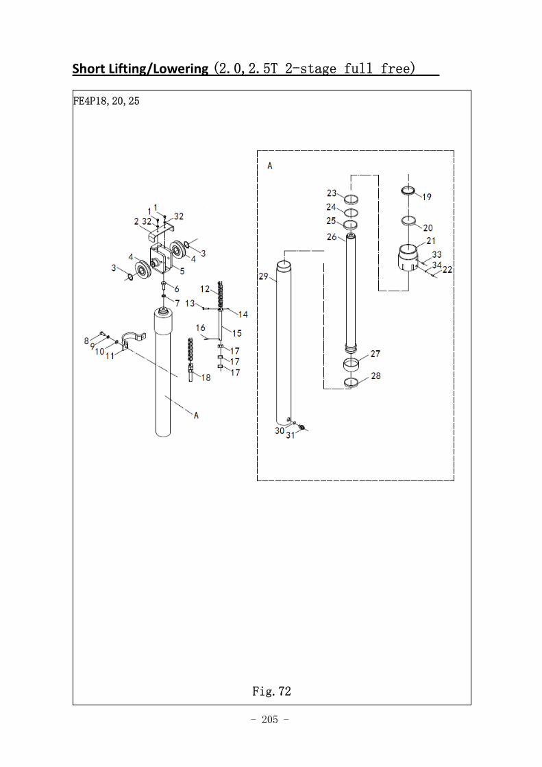
- 205 -
Short Lifting/Lowering (2.0,2.5T 2-stage full free)
图 1 行走电机及减速器 A1
FE4P18,20,25
Fig.72
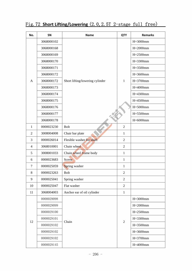
- 206 -
Fig.72 Short Lifting/Lowering (2.0,2.5T 2-stage full free)
No. SN Name QTY Remarks
3068000102 H=3000mm
3068000168 H=2000mm
3068000169 H=2500mm
3068000170 H=3300mm
3068000171 H=3500mm
3068000172 H=3600mm
3068000172 H=3700mm
3068000173 H=4000mm
3068000174 H=4300mm
3068000175 H=4500mm
3068000176 H=5000mm
3068000177 H=5500mm
A
3068000178
Short lifting/lowering cylinder 1
H=6000mm
1 0000023230 Bolt 2
2 3008004008 Chair bar plate 1
3 0000026014 Flesible washer for shaft 2
4 3068010001 Chain wheel 2
5 3008001033 Chain wheel frame body 1
6 0000023683 Screw 1
7 0000025059 Spring washer 1
8 0000023263 Bolt 2
9 0000025041 Spring washer 2
10 0000025047 Flat washer 2
11 3068004003 Anchor ear of oil cylinder 1
0000029098 H=3000mm
0000029099 H=2000mm
0000029100 H=2500mm
0000029101 H=3300mm
0000029102 H=3500mm
0000029102 H=3600mm
0000029102 H=3700mm
12
0000029145
Chain 2
H=4000mm
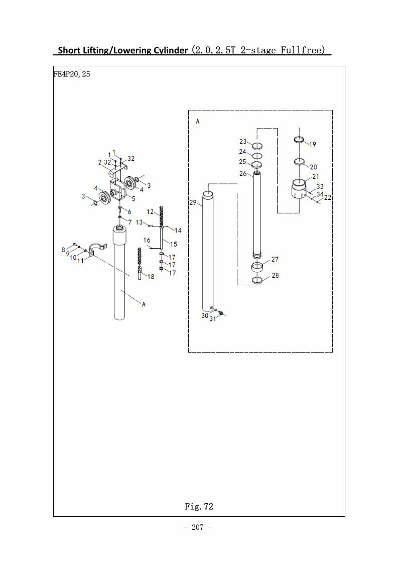
- 207 -
Short Lifting/Lowering Cylinder (2.0,2.5T 2-stage Fullfree)
图 59 前起升油缸(二级全自由)
图 59 短升降油缸(二级全自由)
FE4P20,25
Fig.72
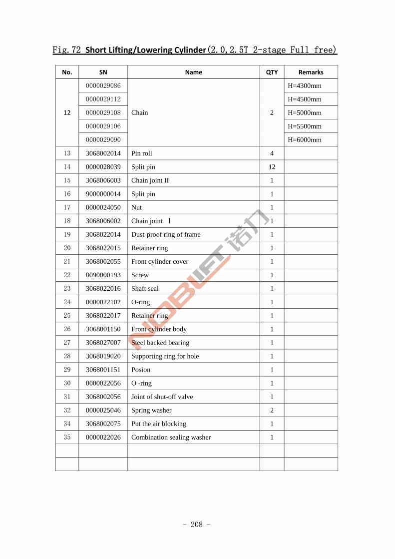
- 208 -
Fig.72 Short Lifting/Lowering Cylinder(2.0,2.5T 2-stage Full free)
No. SN Name QTY Remarks
0000029086 H=4300mm
0000029112 H=4500mm
0000029108 H=5000mm
0000029106 H=5500mm
12
0000029090
Chain 2
H=6000mm
13 3068002014 Pin roll 4
14 0000028039 Split pin 12
15 3068006003 Chain joint II 1
16 9000000014 Split pin 1
17 0000024050 Nut 1
18 3068006002 Chain joint Ⅰ 1
19 3068022014 Dust-proof ring of frame 1
20 3068022015 Retainer ring 1
21 3068002055 Front cylinder cover 1
22 0090000193 Screw 1
23 3068022016 Shaft seal 1
24 0000022102 O-ring 1
25 3068022017 Retainer ring 1
26 3068001150 Front cylinder body 1
27 3068027007 Steel backed bearing 1
28 3068019020 Supporting ring for hole 1
29 3068001151 Posion 1
30 0000022056 O -ring 1
31 3068002056 Joint of shut-off valve 1
32 0000025046 Spring washer 2
34 3068002075 Put the air blocking 1
35 0000022026 Combination sealing washer 1
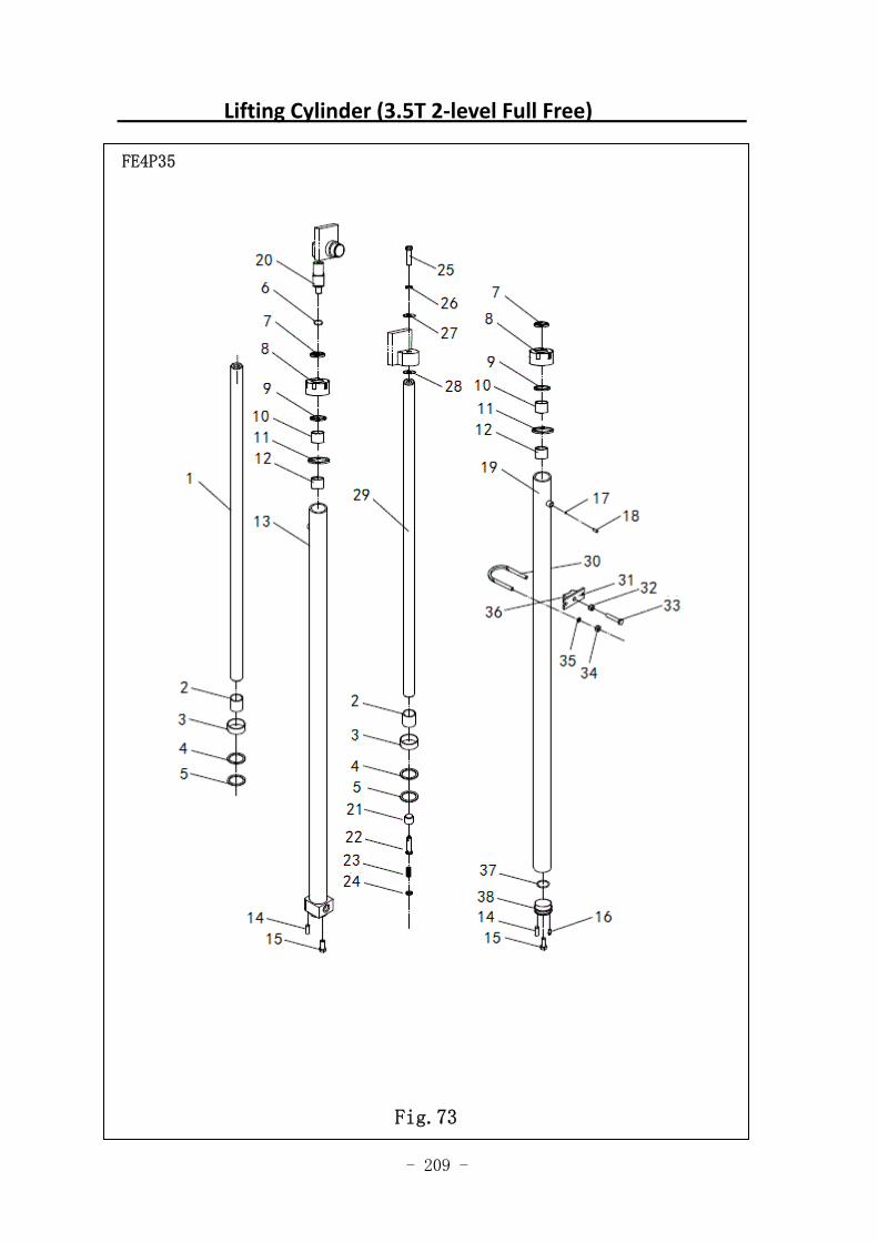
- 209 -
Lifting Cylinder (3.5T 2‐level Full Free)
FE4P35
Fig.73
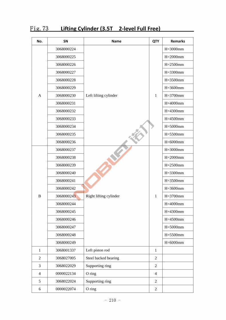
- 210 -
Fig.73 Lifting Cylinder (3.5T 2‐level Full Free)
No. SN Name QTY Remarks
3068000224 H=3000mm
3068000225 H=2000mm
3068000226 H=2500mm
3068000227 H=3300mm
3068000228 H=3500mm
3068000229 H=3600mm
3068000230 H=3700mm
3068000231 H=4000mm
3068000232 H=4300mm
3068000233 H=4500mm
3068000234 H=5000mm
3068000235 H=5500mm
A
3068000236
Left lifting cylinder 1
H=6000mm
3068000237 H=3000mm
3068000238 H=2000mm
3068000239 H=2500mm
3068000240 H=3300mm
3068000241 H=3500mm
3068000242 H=3600mm
3068000243 H=3700mm
3068000244 H=4000mm
3068000245 H=4300mm
3068000246 H=4500mm
3068000247 H=5000mm
3068000248 H=5500mm
B
3068000249
Right lifting cylinder 1
H=6000mm
1 3068001337 Left piston rod 1
2 3068027005 Steel backed bearing 2
3 3068022029 Supporting ring 2
4 0000022134 O ring 4
5 3068022024 Supporting ring 2
6 0000022074 O ring 2
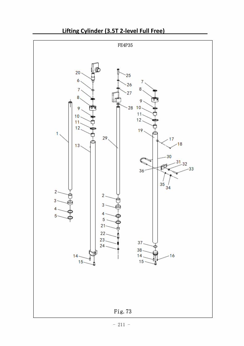
- 211 -
Lifting Cylinder (3.5T 2‐level Full Free)
FE4P35
Fig.73
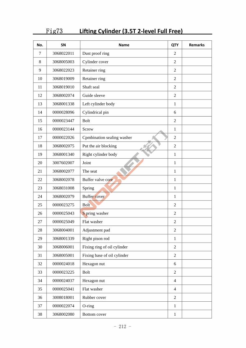
- 212 -
Fig73 Lifting Cylinder (3.5T 2‐level Full Free)
No. SN Name QTY Remarks
7 3068022011 Dust proof ring 2
8 3068005003 Cylinder cover 2
9 3068022023 Retainer ring 2
10 3068019009 Retainer ring 2
11 3068019010 Shaft seal 2
12 3068002074 Guide sleeve 2
13 3068001338 Left cylinder body 1
14 0000028096 Cylindrical pin 6
15 0000023447 Bolt 2
16 0000023144 Screw 1
17 0000022026 Cpmbination sealing washer 2
18 3068002075 Put the air blocking 2
19 3068001340 Right cylinder body 1
20 3007602007 Joint 1
21 3068002077 The seat 1
22 3068002078 Buffer valve core 1
23 3068031008 Spring 1
24 3068002079 Buffer cover 1
25 0000023275 Bolt 2
26 0000025043 S pring washer 2
27 0000025049 Flat washer 2
28 3068004001 Adjustment pad 2
29 3068001339 Right pison rod 1
30 3068006001 Fixing ring of oil cylinder 2
31 3068005001 Fixing base of oil cylinder 2
32 0000024018 Hexagon nut 6
33 0000023225 Bolt 2
34 0000024037 Hexagon nut 4
35 0000025041 Flat washer 4
36 3008018001 Rubber cover 2
37 0000022074 O-ring 1
38 3068002080 Bottom cover 1
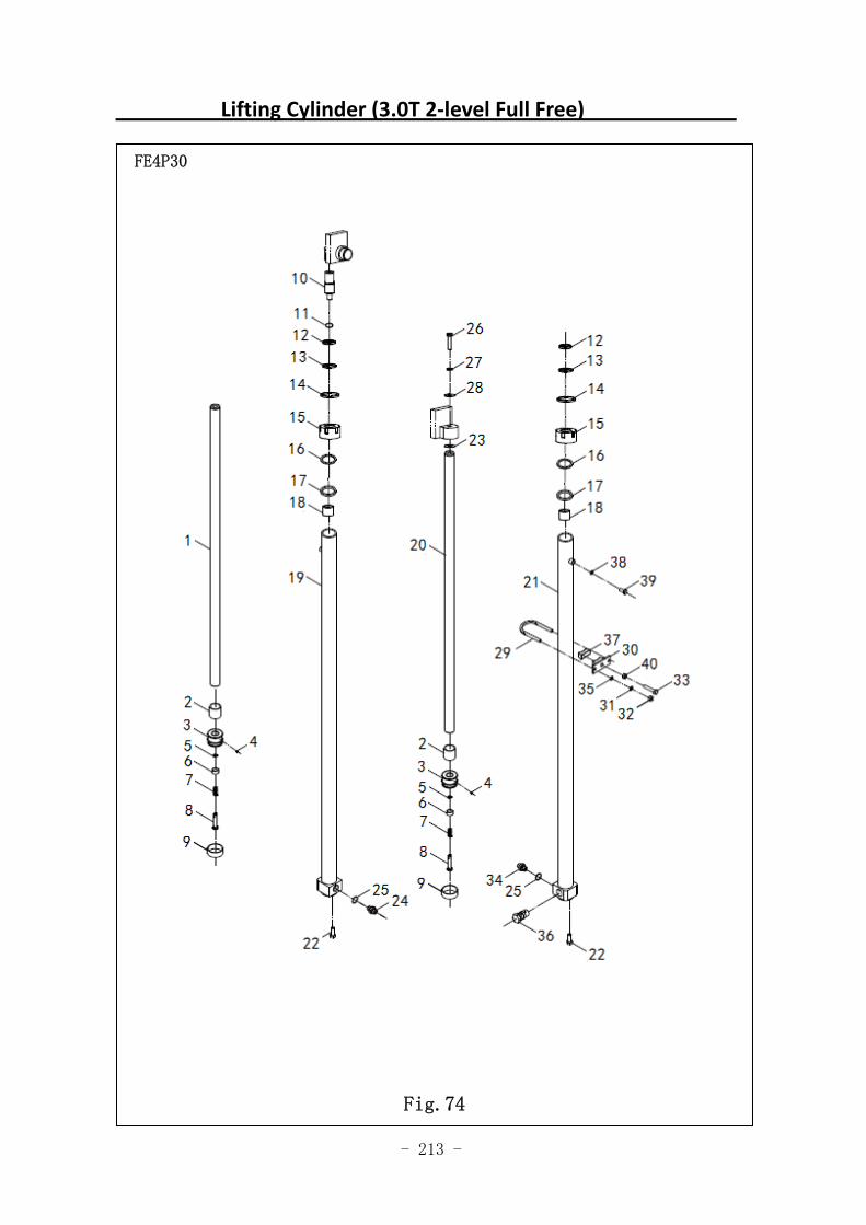
- 213 -
Lifting Cylinder (3.0T 2‐level Full Free)
FE4P30
Fig.74
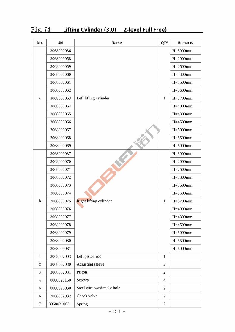
- 214 -
Fig.74 Lifting Cylinder (3.0T 2‐level Full Free)
No. SN Name QTY Remarks
3068000036 H=3000mm
3068000058 H=2000mm
3068000059 H=2500mm
3068000060 H=3300mm
3068000061 H=3500mm
3068000062 H=3600mm
3068000063 H=3700mm
3068000064 H=4000mm
3068000065 H=4300mm
3068000066 H=4500mm
3068000067 H=5000mm
3068000068 H=5500mm
A
3068000069
Left lifting cylinder 1
H=6000mm
3068000037 H=3000mm
3068000070 H=2000mm
3068000071 H=2500mm
3068000072 H=3300mm
3068000073 H=3500mm
3068000074 H=3600mm
3068000075 H=3700mm
3068000076 H=4000mm
3068000077 H=4300mm
3068000078 H=4500mm
3068000079 H=5000mm
3068000080 H=5500mm
B
3068000081
Right lifting cylinder 1
H=6000mm
1 3068007003 Left piston rod 1
2 3068002030 Adjusting sleeve 2
3 3068002031 Piston 2
4 0000023150 Screws 4
5 0000026030 Steel wire washer for hole 2
6 3068002032 Check valve 2
7 3068031003 Spring 2
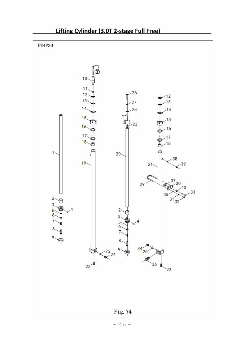
- 215 -
Lifting Cylinder (3.0T 2‐stage Full Free)
FE4P30
Fig.74
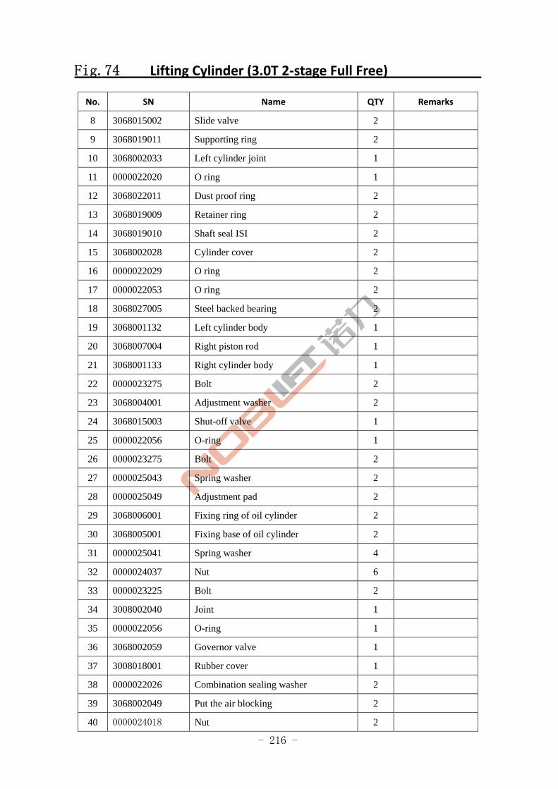
- 216 -
Fig.74 Lifting Cylinder (3.0T 2‐stage Full Free)
No. SN Name QTY Remarks
8 3068015002 Slide valve 2
9 3068019011 Supporting ring 2
10 3068002033 Left cylinder joint 1
11 0000022020 O ring 1
12 3068022011 Dust proof ring 2
13 3068019009 Retainer ring 2
14 3068019010 Shaft seal ISI 2
15 3068002028 Cylinder cover 2
16 0000022029 O ring 2
17 0000022053 O ring 2
18 3068027005 Steel backed bearing 2
19 3068001132 Left cylinder body 1
20 3068007004 Right piston rod 1
21 3068001133 Right cylinder body 1
22 0000023275 Bolt 2
23 3068004001 Adjustment washer 2
24 3068015003 Shut-off valve 1
25 0000022056 O-ring 1
26 0000023275 Bolt 2
27 0000025043 Spring washer 2
28 0000025049 Adjustment pad 2
29 3068006001 Fixing ring of oil cylinder 2
30 3068005001 Fixing base of oil cylinder 2
31 0000025041 Spring washer 4
32 0000024037 Nut 6
33 0000023225 Bolt 2
34 3008002040 Joint 1
35 0000022056 O-ring 1
36 3068002059 Governor valve 1
37 3008018001 Rubber cover 1
38 0000022026 Combination sealing washer 2
39 3068002049 Put the air blocking 2
40 0000024018 Nut 2
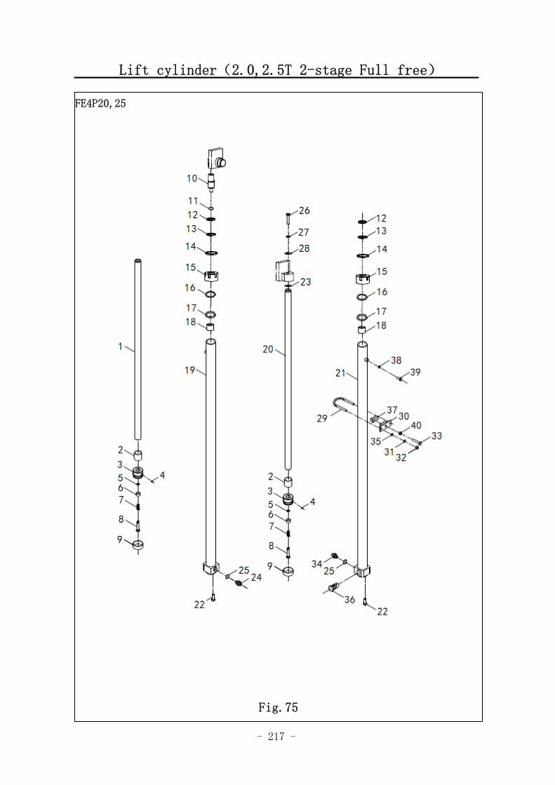
- 217 -
Lift cylinder(2.0,2.5T 2-stage Full free)
FE4P20,25
Fig.75
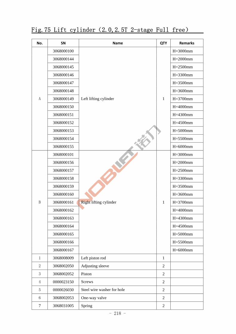
- 218 -
Fig.75 Lift cylinder(2.0,2.5T 2-stage Full free)
No. SN Name QTY Remarks
3068000100 H=3000mm
3068000144 H=2000mm
3068000145 H=2500mm
3068000146 H=3300mm
3068000147 H=3500mm
3068000148 H=3600mm
3068000149 H=3700mm
3068000150 H=4000mm
3068000151 H=4300mm
3068000152 H=4500mm
3068000153 H=5000mm
3068000154 H=5500mm
A
3068000155
Left lifting cylinder 1
H=6000mm
3068000101 H=3000mm
3068000156 H=2000mm
3068000157 H=2500mm
3068000158 H=3300mm
3068000159 H=3500mm
3068000160 H=3600mm
3068000161 H=3700mm
3068000162 H=4000mm
3068000163 H=4300mm
3068000164 H=4500mm
3068000165 H=5000mm
3068000166 H=5500mm
B
3068000167
Right lifting cylinder 1
H=6000mm
1 3068008009 Left piston rod 1
2 3068002050 Adjusting sleeve 2
3 3068002052 Piston 2
4 0000023150 Screws 2
5 0000026030 Steel wire washer for hole 2
6 3068002053 One-way valve 2
7 3068031005 Spring 2
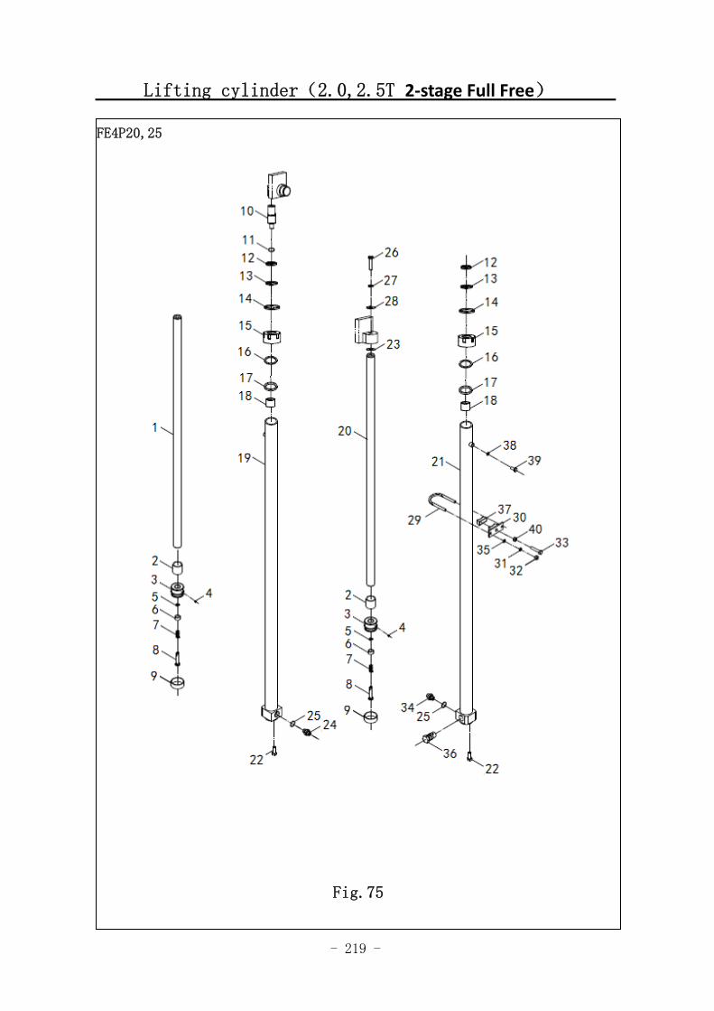
- 219 -
Lifting cylinder(2.0,2.5T 2‐stage Full Free)
FE4P20,25
Fig.75
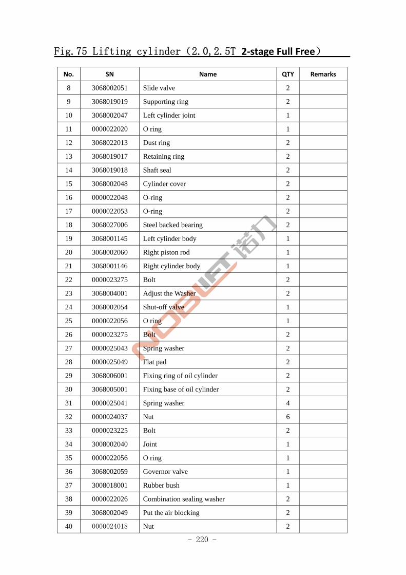
- 220 -
Fig.75 Lifting cylinder(2.0,2.5T 2‐stage Full Free)
No. SN Name QTY Remarks
8 3068002051 Slide valve 2
9 3068019019 Supporting ring 2
10 3068002047 Left cylinder joint 1
11 0000022020 O ring 1
12 3068022013 Dust ring 2
13 3068019017 Retaining ring 2
14 3068019018 Shaft seal 2
15 3068002048 Cylinder cover 2
16 0000022048 O-ring 2
17 0000022053 O-ring 2
18 3068027006 Steel backed bearing 2
19 3068001145 Left cylinder body 1
20 3068002060 Right piston rod 1
21 3068001146 Right cylinder body 1
22 0000023275 Bolt 2
23 3068004001 Adjust the Washer 2
24 3068002054 Shut-off valve 1
25 0000022056 O ring 1
26 0000023275 Bolt 2
27 0000025043 Spring washer 2
28 0000025049 Flat pad 2
29 3068006001 Fixing ring of oil cylinder 2
30 3068005001 Fixing base of oil cylinder 2
31 0000025041 Spring washer 4
32 0000024037 Nut 6
33 0000023225 Bolt 2
34 3008002040 Joint 1
35 0000022056 O ring 1
36 3068002059 Governor valve 1
37 3008018001 Rubber bush 1
38 0000022026 Combination sealing washer 2
39 3068002049 Put the air blocking 2
40 0000024018 Nut 2
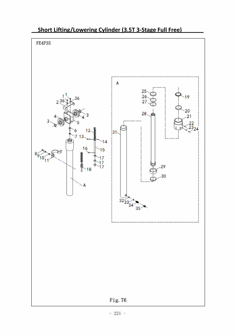
- 221 -
Short Lifting/Lowering Cylinder (3.5T 3‐Stage Full Free)
FE4P35
Fig.76
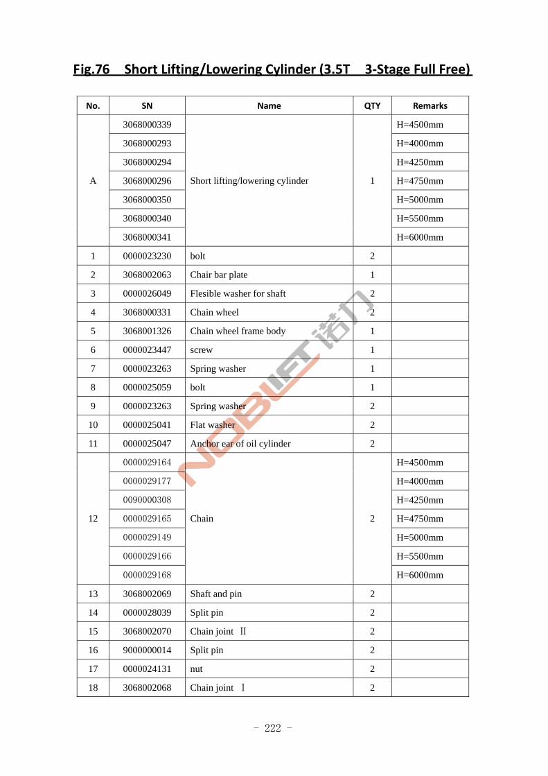
- 222 -
Fig.76 Short Lifting/Lowering Cylinder (3.5T 3‐Stage Full Free)
No. SN Name QTY Remarks
3068000339 H=4500mm
3068000293 H=4000mm
3068000294 H=4250mm
3068000296 H=4750mm
3068000350 H=5000mm
3068000340 H=5500mm
A
3068000341
Short lifting/lowering cylinder 1
H=6000mm
1 0000023230 bolt 2
2 3068002063 Chair bar plate 1
3 0000026049 Flesible washer for shaft 2
4 3068000331 Chain wheel 2
5 3068001326 Chain wheel frame body 1
6 0000023447 screw 1
7 0000023263 Spring washer 1
8 0000025059 bolt 1
9 0000023263 Spring washer 2
10 0000025041 Flat washer 2
11 0000025047 Anchor ear of oil cylinder 2
0000029164 H=4500mm
0000029177 H=4000mm
0090000308 H=4250mm
0000029165 H=4750mm
0000029149 H=5000mm
0000029166 H=5500mm
12
0000029168
Chain 2
H=6000mm
13 3068002069 Shaft and pin 2
14 0000028039 Split pin 2
15 3068002070 Chain joint Ⅱ 2
16 9000000014 Split pin 2
17 0000024131 nut 2
18 3068002068 Chain joint Ⅰ 2
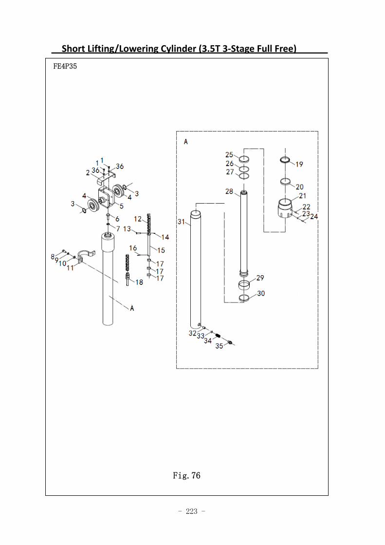
- 223 -
Short Lifting/Lowering Cylinder (3.5T 3‐Stage Full Free)
FE4P35
Fig.76
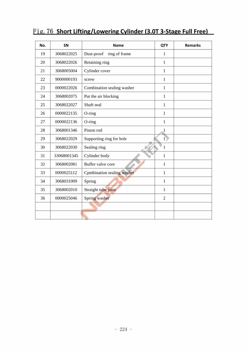
- 224 -
Fig.76 Short Lifting/Lowering Cylinder (3.0T 3‐Stage Full Free)
No. SN Name QTY Remarks
19 3068022025 Dust-proof ring of frame 1
20 3068022026 Retaining ring 1
21 3068005004 Cylinder cover 1
22 9000000193 screw 1
23 0000022026 Combination sealing washer 1
24 3068002075 Put the air blocking 1
25 3068022027 Shaft seal 1
26 0000022135 O-ring 1
27 0000022136 O-ring 1
28 3068001346 Piston rod 1
29 3068022029 Supporting ring for hole 1
30 3068022030 Sealing ring 1
31 33068001345 Cylinder body 1
32 3068002081 Buffer valve core 1
33 0000025112 Cpmbination sealing washer 1
34 3068031009 Spring 1
35 3068002010 Straight tube joint 1
36 0000025046 Spring washer 2
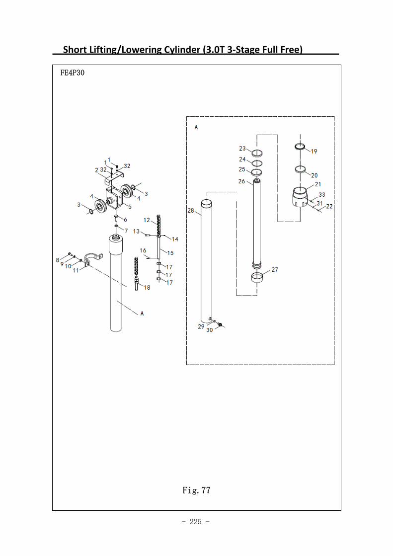
- 225 -
Short Lifting/Lowering Cylinder (3.0T 3‐Stage Full Free)
图 1 行走电机及减速器 A1
FE4P30
Fig.77
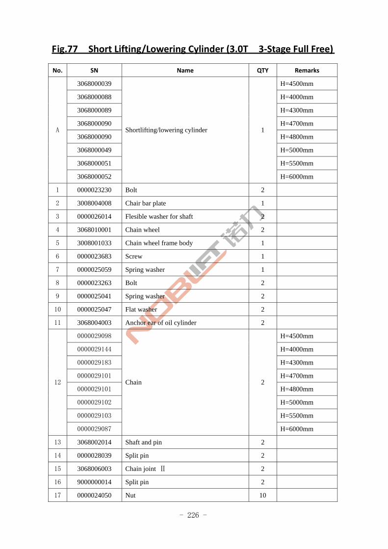
- 226 -
Fig.77 Short Lifting/Lowering Cylinder (3.0T 3‐Stage Full Free)
No. SN Name QTY Remarks
3068000039 H=4500mm
3068000088 H=4000mm
3068000089 H=4300mm
3068000090 H=4700mm
3068000090 H=4800mm
3068000049 H=5000mm
3068000051 H=5500mm
A
3068000052
Shortlifting/lowering cylinder 1
H=6000mm
1 0000023230 Bolt 2
2 3008004008 Chair bar plate 1
3 0000026014 Flesible washer for shaft 2
4 3068010001 Chain wheel 2
5 3008001033 Chain wheel frame body 1
6 0000023683 Screw 1
7 0000025059 Spring washer 1
8 0000023263 Bolt 2
9 0000025041 Spring washer 2
10 0000025047 Flat washer 2
11 3068004003 Anchor ear of oil cylinder 2
0000029098 H=4500mm
0000029144 H=4000mm
0000029183 H=4300mm
0000029101 H=4700mm
0000029101 H=4800mm
0000029102 H=5000mm
0000029103 H=5500mm
12
0000029087
Chain 2
H=6000mm
13 3068002014 Shaft and pin 2
14 0000028039 Split pin 2
15 3068006003 Chain joint Ⅱ 2
16 9000000014 Split pin 2
17 0000024050 Nut 10
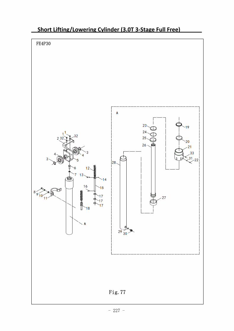
- 227 -
Short Lifting/Lowering Cylinder (3.0T 3‐Stage Full Free)
图 1 行走电机及减速器 A1
FE4P30
Fig.77
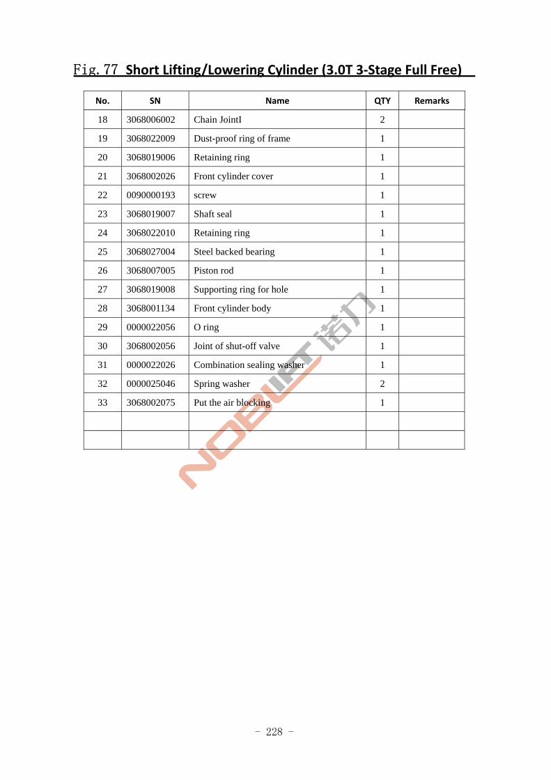
- 228 -
Fig.77 Short Lifting/Lowering Cylinder (3.0T 3‐Stage Full Free)
No. SN Name QTY Remarks
18 3068006002 Chain JointI 2
19 3068022009 Dust-proof ring of frame 1
20 3068019006 Retaining ring 1
21 3068002026 Front cylinder cover 1
22 0090000193 screw 1
23 3068019007 Shaft seal 1
24 3068022010 Retaining ring 1
25 3068027004 Steel backed bearing 1
26 3068007005 Piston rod 1
27 3068019008 Supporting ring for hole 1
28 3068001134 Front cylinder body 1
29 0000022056 O ring 1
30 3068002056 Joint of shut-off valve 1
31 0000022026 Combination sealing washer 1
32 0000025046 Spring washer 2
33 3068002075 Put the air blocking 1
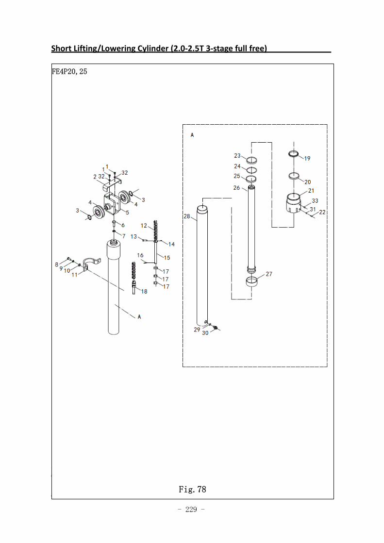
- 229 -
Short Lifting/Lowering Cylinder (2.0‐2.5T 3‐stage full free)
Fig.61Short Lifting/Lowering Cylinder (1.8,2.0,2.5T 3-stage full
free
FE4P20,25
Fig.78
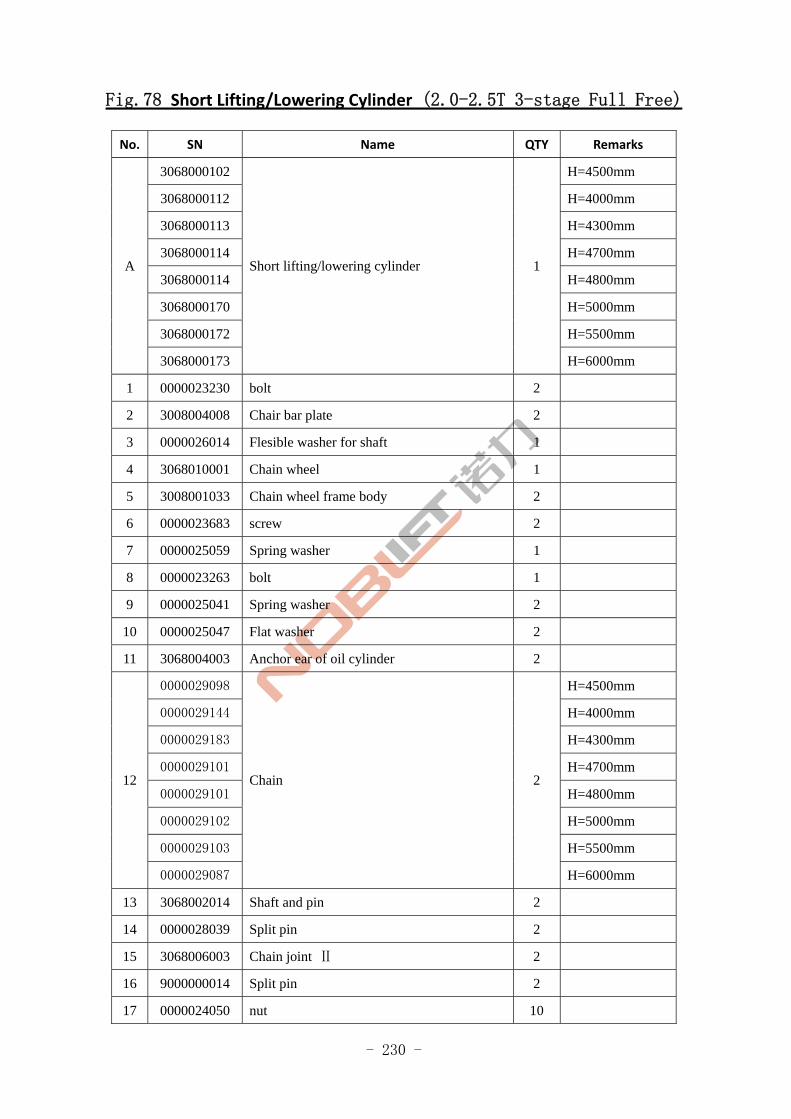
- 230 -
Fig.78 Short Lifting/Lowering Cylinder (2.0-2.5T 3-stage Full Free)
No. SN Name QTY Remarks
3068000102 H=4500mm
3068000112 H=4000mm
3068000113 H=4300mm
3068000114 H=4700mm
3068000114 H=4800mm
3068000170 H=5000mm
3068000172 H=5500mm
A
3068000173
Short lifting/lowering cylinder 1
H=6000mm
1 0000023230 bolt 2
2 3008004008 Chair bar plate 2
3 0000026014 Flesible washer for shaft 1
4 3068010001 Chain wheel 1
5 3008001033 Chain wheel frame body 2
6 0000023683 screw 2
7 0000025059 Spring washer 1
8 0000023263 bolt 1
9 0000025041 Spring washer 2
10 0000025047 Flat washer 2
11 3068004003 Anchor ear of oil cylinder 2
0000029098 H=4500mm
0000029144 H=4000mm
0000029183 H=4300mm
0000029101 H=4700mm
0000029101 H=4800mm
0000029102 H=5000mm
0000029103 H=5500mm
12
0000029087
Chain 2
H=6000mm
13 3068002014 Shaft and pin 2
14 0000028039 Split pin 2
15 3068006003 Chain joint Ⅱ 2
16 9000000014 Split pin 2
17 0000024050 nut 10
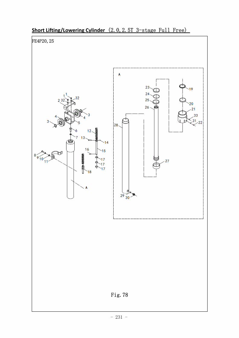
- 231 -
Short Lifting/Lowering Cylinder (2.0,2.5T 3-stage Full Free)
Fig.61 Short Lifting/Lowering Cylinder (1.8,2.0,2.5T 3-stage FullFree )
FE4P20,25
Fig.78
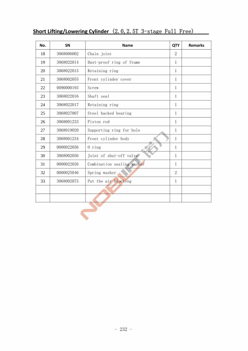
- 232 -
Short Lifting/Lowering Cylinder (2.0,2.5T 3-stage Full Free)
No. SN Name QTY Remarks
18 3068006002 Chain joint 2
19 3068022014 Dust-proof ring of frame 1
20 3068022015 Retaining ring 1
21 3068002055 Front cylinder cover 1
22 0090000193 Screw 1
23 3068022016 Shaft seal 1
24 3068022017 Retaining ring 1
25 3068027007 Steel backed bearing 1
26 3068001233 Piston rod 1
27 3068019020 Supporting ring for hole 1
28 3068001234 Front cylinder body 1
29 0000022056 O ring 1
30 3068002056 Joint of shut-off valve 1
31 0000022026 Combination sealing washer 1
32 0000025046 Spring washer 2
33 3068002075 Put the air blocking 1
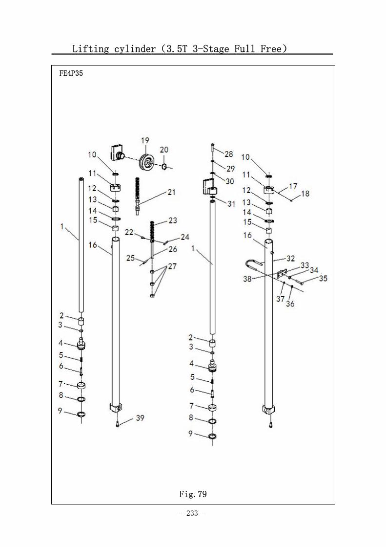
- 233 -
Lifting cylinder(3.5T 3-Stage Full Free)
FE4P35
Fig.79
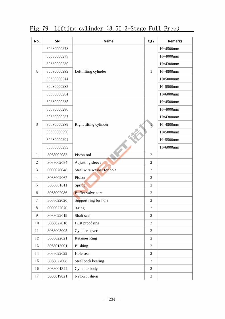
- 234 -
Fig.79 Lifting cylinder(3.5T 3-Stage Full Free)
No. SN Name QTY Remarks
30680000278 H=4500mm
30680000279 H=4000mm
30680000280 H=4300mm
30680000282 H=4800mm
30680000244 H=5000mm
30680000283 H=5500mm
A
30680000284
Left lifting cylinder 1
H=6000mm
30680000285 H=4500mm
30680000286 H=4000mm
30680000287 H=4300mm
30680000289 H=4800mm
30680000290 H=5000mm
30680000291 H=5500mm
B
30680000292
Right lifting cylinder 1
H=6000mm
1 3068002083 Piston rod 2
2 3068002084 Adjusting sleeve 2
3 0000026048 Steel wire washer for hole 2
4 3068002067 Piston 2
5 3068031011 Spring 2
6 3068002086 Buffer valve core 2
7 3068022020 Support ring for hole 2
8 0000022070 0-ring 2
9 3068022019 Shaft seal 2
10 3068022018 Dust proof ring 2
11 3068005005 Cyinder cover 2
12 3068022021 Retainer Ring 2
13 3068013001 Bushing 2
14 3068022022 Hole seal 2
15 3068027008 Steel back bearing 2
16 3068001344 Cylinder body 2
17 3068019021 Nylon cushion 2
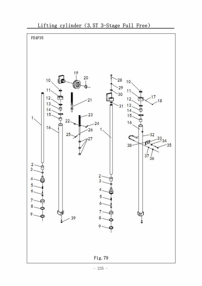
- 235 -
Lifting cylinder(3.5T 3-Stage Full Free)
FE4P35
Fig.79
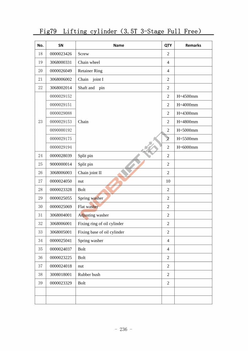
- 236 -
Fig79 Lifting cylinder(3.5T 3-Stage Full Free)
No. SN Name QTY Remarks
18 0000023426 Screw 2
19 3068000331 Chain wheel 4
20 0000026049 Retainer Ring 4
21 3068006002 Chain joint I 2
22 3068002014 Shaft and pin 2
0000029152 2 H=4500mm
0000029151 2 H=4000mm
0000029088 2 H=4300mm
0000029153 2 H=4800mm
0090000192 2 H=5000mm
0000029175 2 H=5500mm
23
0000029194
Chain
2 H=6000mm
24 0000028039 Split pin 2
25 9000000014 Split pin 2
26 3068006003 Chain joint II 2
27 0000024050 nut 10
28 0000023328 Bolt 2
29 0000025055 Spring washer 2
30 0000025069 Flat washer 2
31 3068004001 Adjusting washer 2
32 3068006001 Fixing ring of oil cylinder 2
33 3068005001 Fixing base of oil cylinder 2
34 0000025041 Spring washer 4
35 0000024037 Bolt 4
36 0000023225 Bolt 2
37 0000024018 nut 2
38 3008018001 Rubber bush 2
39 0000023329 Bolt 2
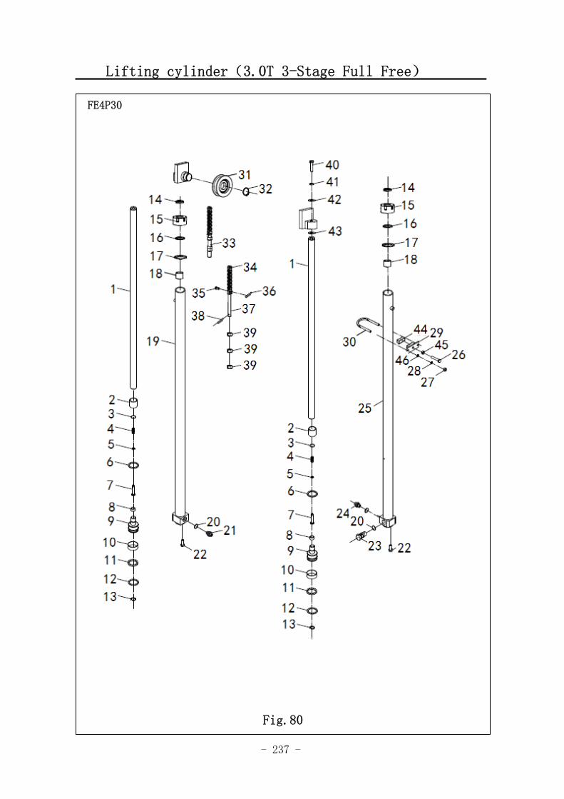
- 237 -
Lifting cylinder(3.0T 3-Stage Full Free)
图 1 行走电机及减速器 A1
FE4P30
Fig.80
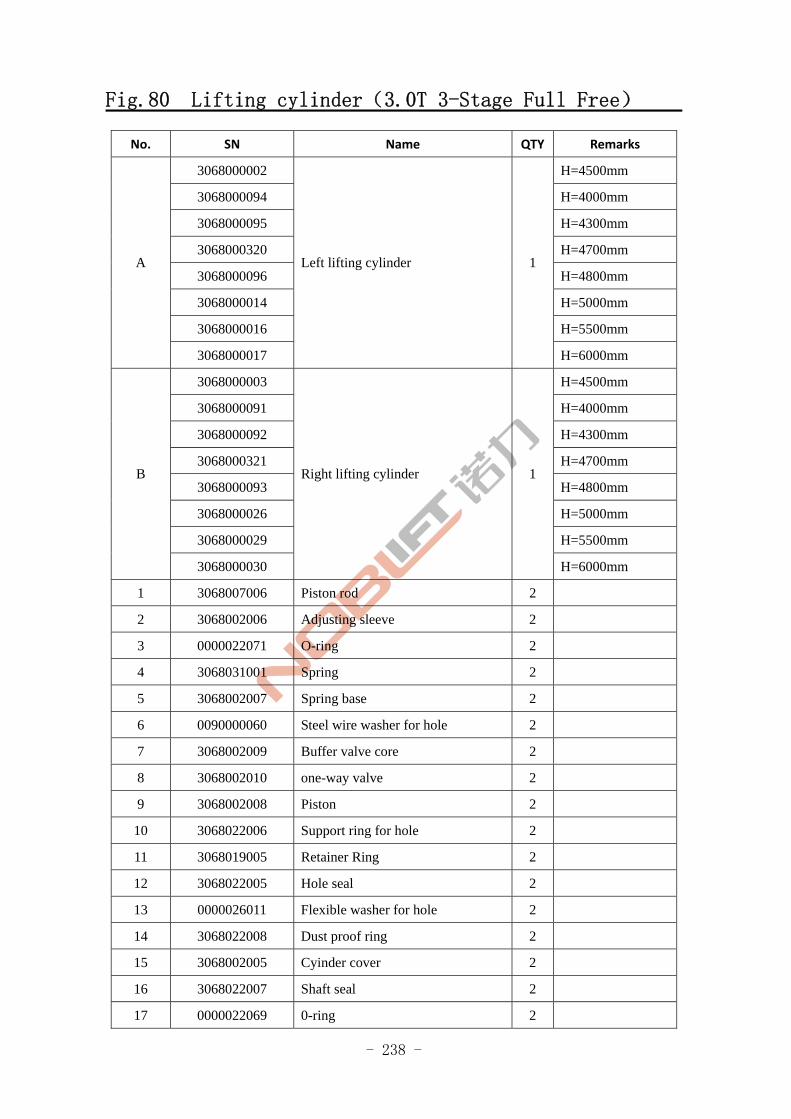
- 238 -
Fig.80 Lifting cylinder(3.0T 3-Stage Full Free)
No. SN Name QTY Remarks
3068000002 H=4500mm
3068000094 H=4000mm
3068000095 H=4300mm
3068000320 H=4700mm
3068000096 H=4800mm
3068000014 H=5000mm
3068000016 H=5500mm
A
3068000017
Left lifting cylinder 1
H=6000mm
3068000003 H=4500mm
3068000091 H=4000mm
3068000092 H=4300mm
3068000321 H=4700mm
3068000093 H=4800mm
3068000026 H=5000mm
3068000029 H=5500mm
B
3068000030
Right lifting cylinder 1
H=6000mm
1 3068007006 Piston rod 2
2 3068002006 Adjusting sleeve 2
3 0000022071 O-ring 2
4 3068031001 Spring 2
5 3068002007 Spring base 2
6 0090000060 Steel wire washer for hole 2
7 3068002009 Buffer valve core 2
8 3068002010 one-way valve 2
9 3068002008 Piston 2
10 3068022006 Support ring for hole 2
11 3068019005 Retainer Ring 2
12 3068022005 Hole seal 2
13 0000026011 Flexible washer for hole 2
14 3068022008 Dust proof ring 2
15 3068002005 Cyinder cover 2
16 3068022007 Shaft seal 2
17 0000022069 0-ring 2
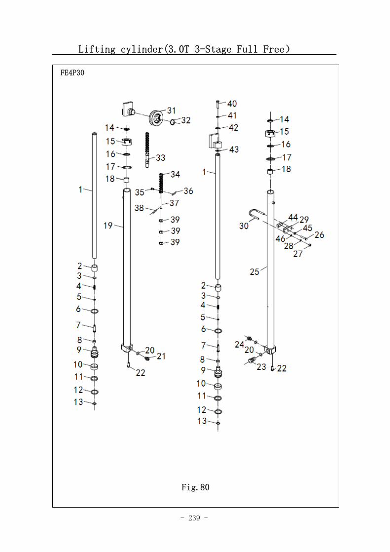
- 239 -
Lifting cylinder(3.0T 3-Stage Full Free)
图 1 行走电机及减速器 A1
FE4P30
Fig.80
- 240 -
Fig.80 Lifting cylinder(3.0T 3-Stage Full Free)
No. SN Name QTY Remarks
18 3068027003 Steel back bearing 2
19 3068001135 Left cylinder body 1
20 0000022056 0-ring 2
21 3068002011 Shut-off valve 1
22 0000023134 bolt 2
23 3068015001 Governor valve 1
24 3008002040 Joint 2
25 3068001009 Right cylinder body 1
26 0000023225 bolt 2
27 0000024037 nut 4
28 0000025041 Spring washer 4
29 3068005001 Fixing base of oil cylinder 2
30 3068006001 Fixing ring of oil cylinder 2
31 3068010001 Chain wheel 2
32 0000026014 Flesible washer for shaft 1
33 3068006003 Chain joint Ⅱ 2
0000029106 2 H=4500mm
0000029112 2 H=4000mm
0000029108 2 H=4300mm
0000029146 2 H=4700mm
0000029090 2 H=4800mm
0000029090 2 H=5000mm
0000029147 2 H=5500mm
34
0000029148
Chain
2 H=6000mm
35 3068002014 Pin and shaft 2
36 0000028039 Split pin 2
37 3068006002 Chain joint I 2
38 0090000014 Split pin 2
39 0000024050 Nut 2
40 0000023275 Bolt 2
41 0000025055 Spring washer 2
42 0000025069 Flat washer 2
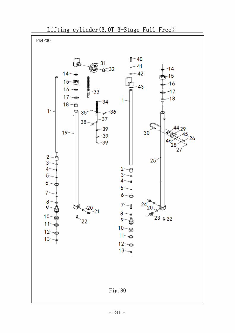
- 241 -
Lifting cylinder(3.0T 3-Stage Full Free)
FE4P30
Fig.80
- 242 -
Fig.80 Lifting cylinder(3.0T 3-Stage Full Free)
NO. SN NAME QTY REMARKS
43 3068004001 Adjusting washer 2
44 3008018001 Rubber bush 2
45 0000024018 Nut 2
46 0000025047 Flat washer 4
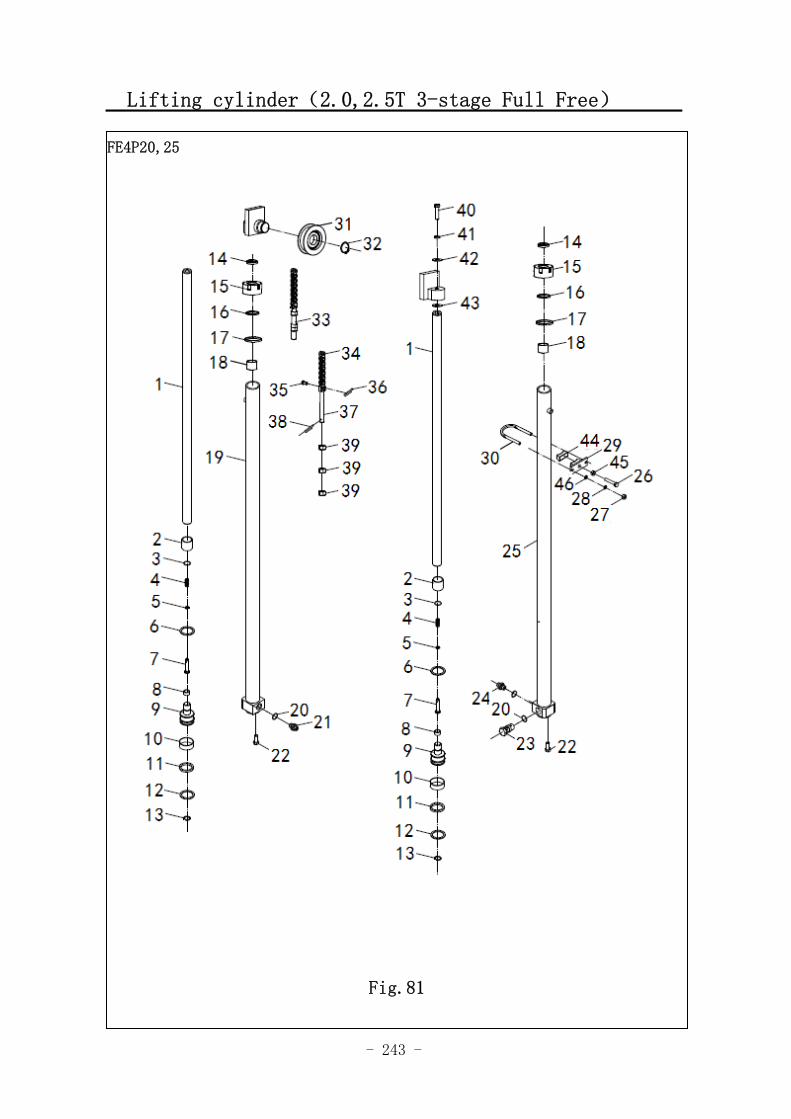
- 243 -
Lifting cylinder(2.0,2.5T 3-stage Full Free)
图 1 行走电机及减速器 A1
FE4P20,25
Fig.81
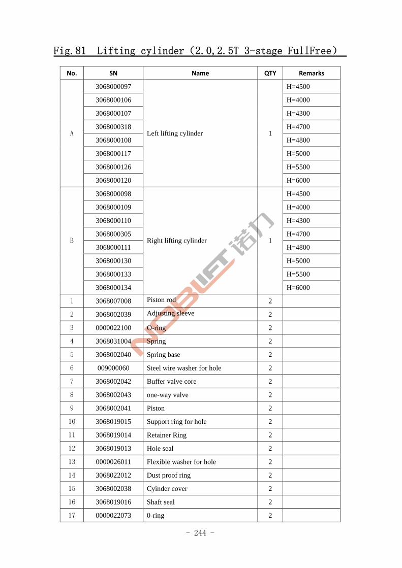
- 244 -
Fig.81 Lifting cylinder(2.0,2.5T 3-stage FullFree)
No. SN Name QTY Remarks
3068000097 H=4500
3068000106 H=4000
3068000107 H=4300
3068000318 H=4700
3068000108 H=4800
3068000117 H=5000
3068000126 H=5500
A
3068000120
Left lifting cylinder 1
H=6000
3068000098 H=4500
3068000109 H=4000
3068000110 H=4300
3068000305 H=4700
3068000111 H=4800
3068000130 H=5000
3068000133 H=5500
B
3068000134
Right lifting cylinder 1
H=6000
1 3068007008 Piston rod 2
2 3068002039 Adjusting sleeve 2
3 0000022100 O-ring 2
4 3068031004 Spring 2
5 3068002040 Spring base 2
6 009000060 Steel wire washer for hole 2
7 3068002042 Buffer valve core 2
8 3068002043 one-way valve 2
9 3068002041 Piston 2
10 3068019015 Support ring for hole 2
11 3068019014 Retainer Ring 2
12 3068019013 Hole seal 2
13 0000026011 Flexible washer for hole 2
14 3068022012 Dust proof ring 2
15 3068002038 Cyinder cover 2
16 3068019016 Shaft seal 2
17 0000022073 0-ring 2
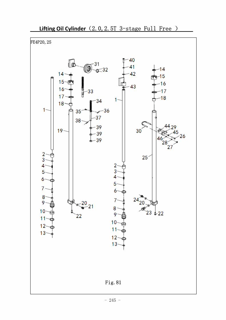
- 245 -
Lifting Oil Cylinder(2.0,2.5T 3-stage Full Free )
图 1 行走电机及减速器 A1
FE4P20,25
Fig.81
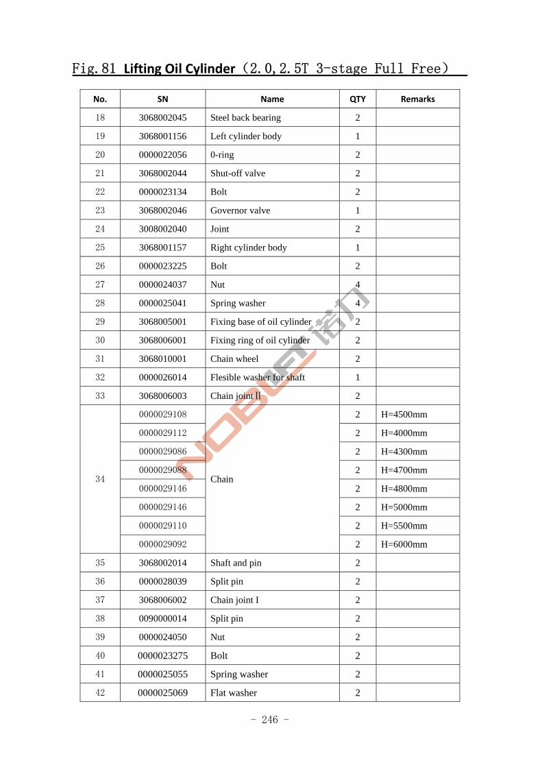
- 246 -
Fig.81 Lifting Oil Cylinder(2.0,2.5T 3-stage Full Free)
No. SN Name QTY Remarks
18 3068002045 Steel back bearing 2
19 3068001156 Left cylinder body 1
20 0000022056 0-ring 2
21 3068002044 Shut-off valve 2
22 0000023134 Bolt 2
23 3068002046 Governor valve 1
24 3008002040 Joint 2
25 3068001157 Right cylinder body 1
26 0000023225 Bolt 2
27 0000024037 Nut 4
28 0000025041 Spring washer 4
29 3068005001 Fixing base of oil cylinder 2
30 3068006001 Fixing ring of oil cylinder 2
31 3068010001 Chain wheel 2
32 0000026014 Flesible washer for shaft 1
33 3068006003 Chain jointⅡ 2
0000029108 2 H=4500mm
0000029112 2 H=4000mm
0000029086 2 H=4300mm
0000029088 2 H=4700mm
0000029146 2 H=4800mm
0000029146 2 H=5000mm
0000029110 2 H=5500mm
34
0000029092
Chain
2 H=6000mm
35 3068002014 Shaft and pin 2
36 0000028039 Split pin 2
37 3068006002 Chain joint I 2
38 0090000014 Split pin 2
39 0000024050 Nut 2
40 0000023275 Bolt 2
41 0000025055 Spring washer 2
42 0000025069 Flat washer 2
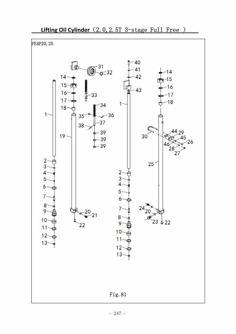
- 247 -
Lifting Oil Cylinder(2.0,2.5T 3-stage Full Free )
FE4P20,25
Fig.81
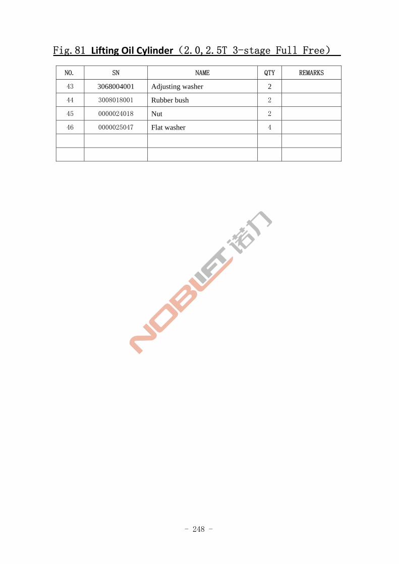
- 248 -
Fig.81 Lifting Oil Cylinder(2.0,2.5T 3-stage Full Free)
NO. SN NAME QTY REMARKS
43 3068004001 Adjusting washer 2
44 3008018001 Rubber bush 2
45 0000024018 Nut 2
46 0000025047 Flat washer 4
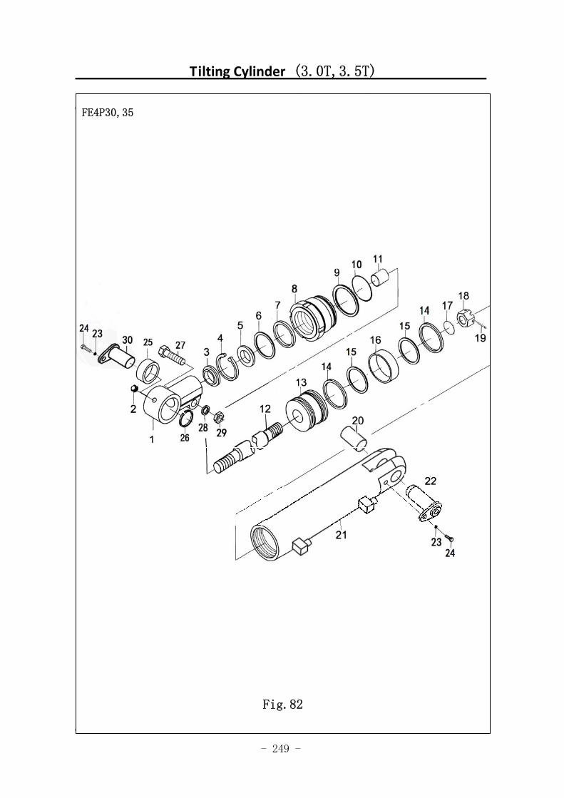
- 249 -
Tilting Cylinder (3.0T,3.5T)
Tilting Cylinder (3.0T,3.5T)
图 67 倾斜油缸
FE4P30,35
Fig.82
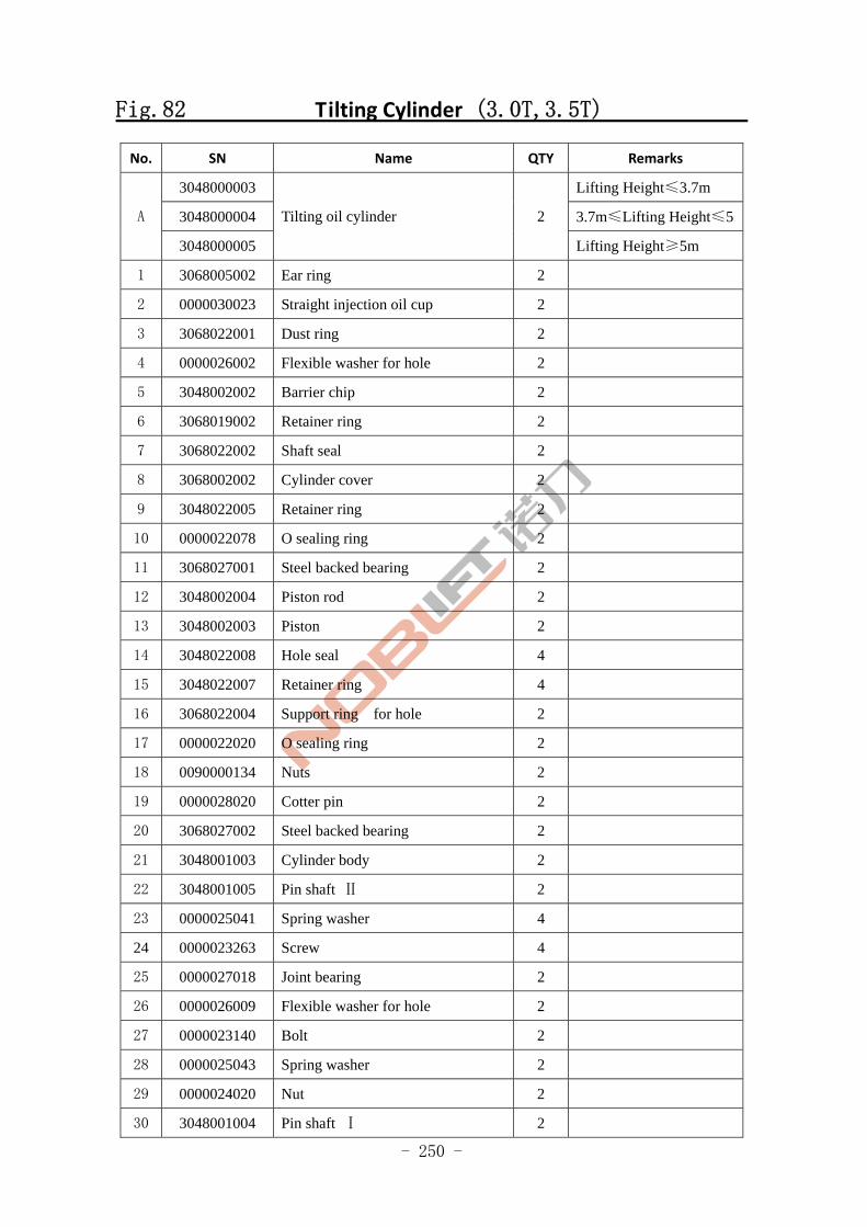
- 250 -
Fig.82 Tilting Cylinder (3.0T,3.5T)
No. SN Name QTY Remarks
3048000003 Lifting Height≤3.7m
3048000004 3.7m≤Lifting Height≤5A
3048000005
Tilting oil cylinder 2
Lifting Height≥5m
1 3068005002 Ear ring 2
2 0000030023 Straight injection oil cup 2
3 3068022001 Dust ring 2
4 0000026002 Flexible washer for hole 2
5 3048002002 Barrier chip 2
6 3068019002 Retainer ring 2
7 3068022002 Shaft seal 2
8 3068002002 Cylinder cover 2
9 3048022005 Retainer ring 2
10 0000022078 O sealing ring 2
11 3068027001 Steel backed bearing 2
12 3048002004 Piston rod 2
13 3048002003 Piston 2
14 3048022008 Hole seal 4
15 3048022007 Retainer ring 4
16 3068022004 Support ring for hole 2
17 0000022020 O sealing ring 2
18 0090000134 Nuts 2
19 0000028020 Cotter pin 2
20 3068027002 Steel backed bearing 2
21 3048001003 Cylinder body 2
22 3048001005 Pin shaft Ⅱ 2
23 0000025041 Spring washer 4
24 0000023263 Screw 4
25 0000027018 Joint bearing 2
26 0000026009 Flexible washer for hole 2
27 0000023140 Bolt 2
28 0000025043 Spring washer 2
29 0000024020 Nut 2
30 3048001004 Pin shaft Ⅰ 2
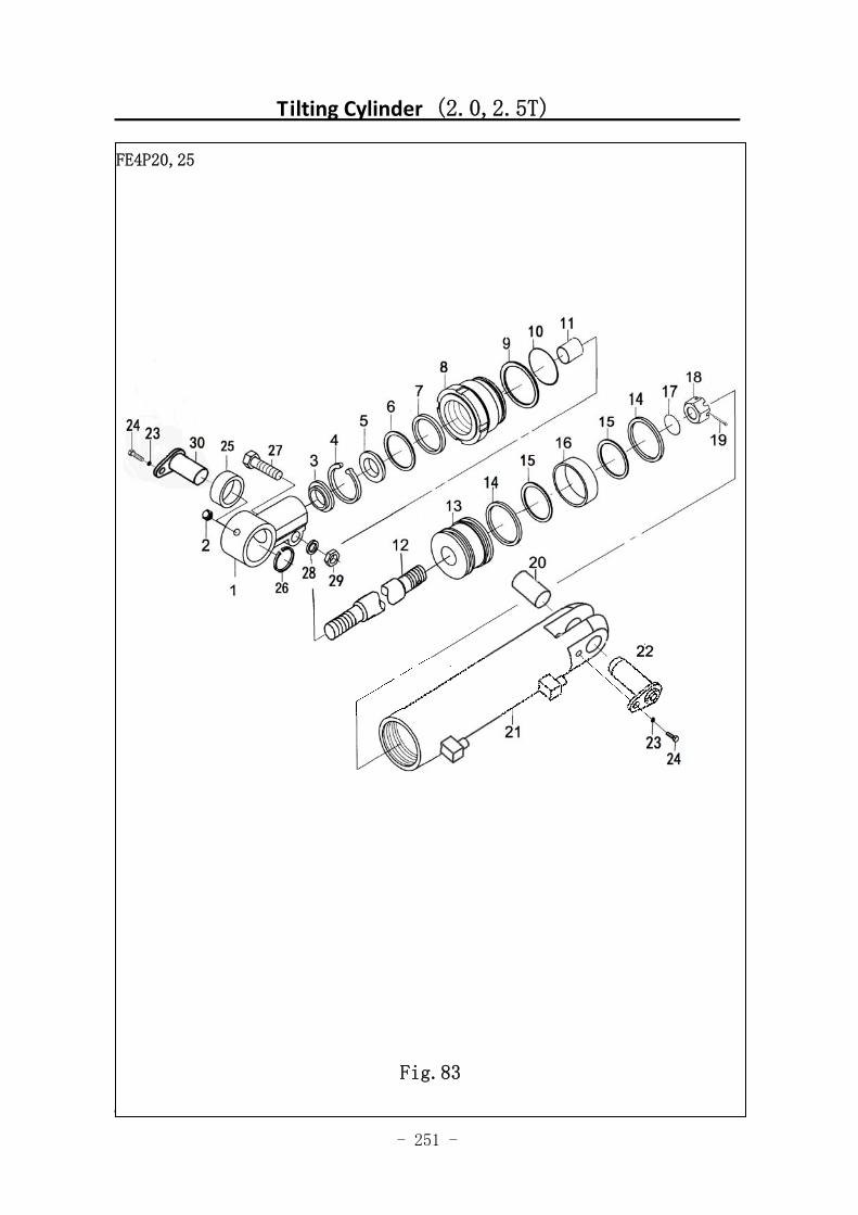
- 251 -
Tilting Cylinder (2.0,2.5T)
图 67 倾斜油缸
FE4P20,25
Fig.83
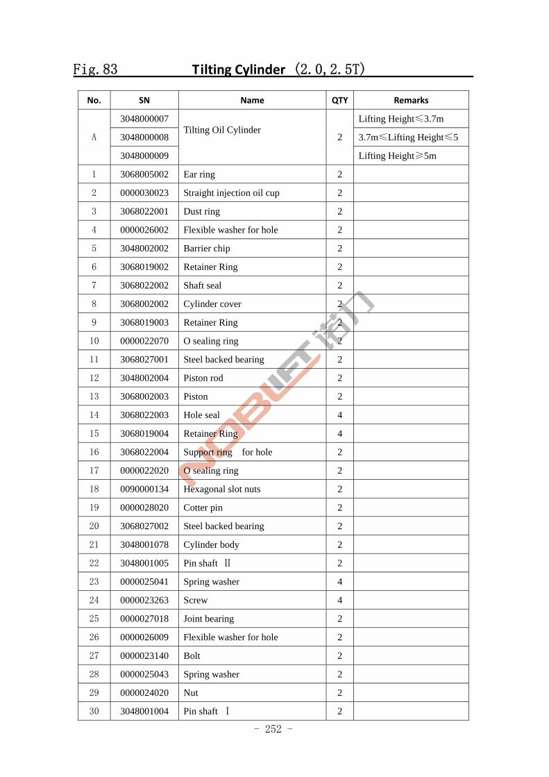
- 252 -
Fig.83 Tilting Cylinder (2.0,2.5T)
No. SN Name QTY Remarks
3048000007 Lifting Height≤3.7m
3048000008 3.7m≤Lifting Height≤5 A
3048000009
Tilting Oil Cylinder
2
Lifting Height≥5m
1 3068005002 Ear ring 2
2 0000030023 Straight injection oil cup 2
3 3068022001 Dust ring 2
4 0000026002 Flexible washer for hole 2
5 3048002002 Barrier chip 2
6 3068019002 Retainer Ring 2
7 3068022002 Shaft seal 2
8 3068002002 Cylinder cover 2
9 3068019003 Retainer Ring 2
10 0000022070 O sealing ring 2
11 3068027001 Steel backed bearing 2
12 3048002004 Piston rod 2
13 3068002003 Piston 2
14 3068022003 Hole seal 4
15 3068019004 Retainer Ring 4
16 3068022004 Support ring for hole 2
17 0000022020 O sealing ring 2
18 0090000134 Hexagonal slot nuts 2
19 0000028020 Cotter pin 2
20 3068027002 Steel backed bearing 2
21 3048001078 Cylinder body 2
22 3048001005 Pin shaft Ⅱ 2
23 0000025041 Spring washer 4
24 0000023263 Screw 4
25 0000027018 Joint bearing 2
26 0000026009 Flexible washer for hole 2
27 0000023140 Bolt 2
28 0000025043 Spring washer 2
29 0000024020 Nut 2
30 3048001004 Pin shaft Ⅰ 2
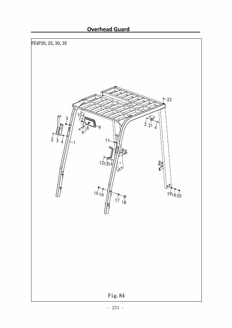
- 253 -
Overhead Guard
图 1 行走电机及减速器 1
FE4P20,25,30,35
Fig.84
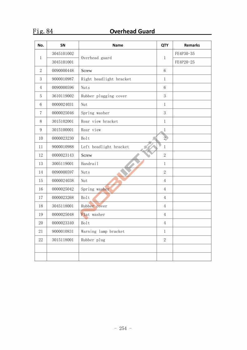
- 254 -
Fig.84 Overhead Guard
No. SN Name QTY Remarks
3045101002 FE4P30-35 1
3045101001 Overhead guard 1
FE4P20-25
2 0090000448 Screw 6
3 9000010987 Right headlight bracket 1
4 0090000596 Nuts 6
5 3610119002 Rubber plugging cover 3
6 0000024031 Nut 1
7 0000025046 Spring washer 3
8 3015102001 Rear view bracket 1
9 3015100001 Rear view 1
10 0000023230 Bolt 2
11 9000010988 Left headlight bracket 1
12 0000023143 Screw 2
13 3005119001 Handrail 1
14 0090000597 Nuts 2
15 0000024038 Nut 4
16 0000025042 Spring washer 4
17 0000023268 Bolt 4
18 3045118001 Rubber cover 4
19 0000025048 Flat washer 4
20 0000023340 Bolt 4
21 9000010831 Warning lamp bracket 1
22 3015118001 Rubber plug 2
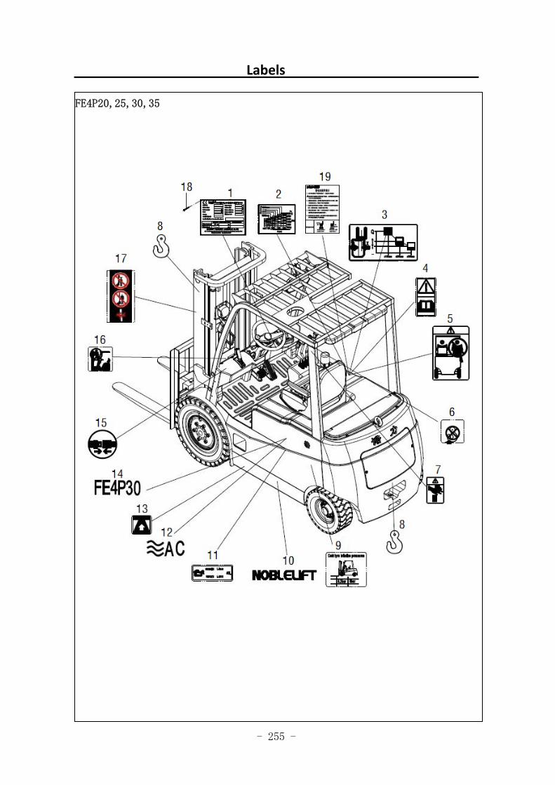
- 255 -
Labels
图 1 行走电机及减速器 1
FE4P20,25,30,35
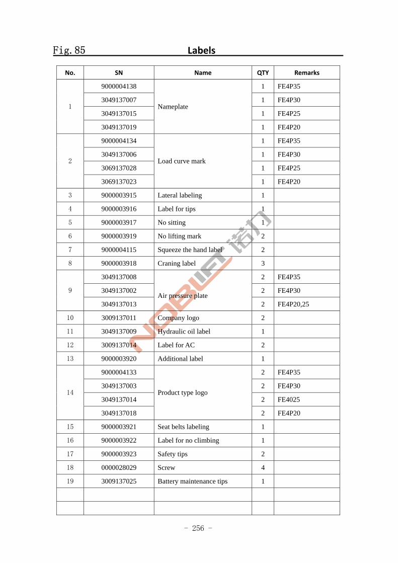
- 256 -
Fig.85 Labels
No. SN Name QTY Remarks
9000004138 1 FE4P35
3049137007 1 FE4P30
3049137015 1 FE4P25 1
3049137019
Nameplate
1 FE4P20
9000004134 1 FE4P35
3049137006 1 FE4P30
3069137028 1 FE4P25 2
3069137023
Load curve mark
1 FE4P20
3 9000003915 Lateral labeling 1
4 9000003916 Label for tips 1
5 9000003917 No sitting 1
6 9000003919 No lifting mark 2
7 9000004115 Squeeze the hand label 2
8 9000003918 Craning label 3
3049137008 2 FE4P35
3049137002 2 FE4P30 9
3049137013
Air pressure plate 2 FE4P20,25
10 3009137011 Company logo 2
11 3049137009 Hydraulic oil label 1
12 3009137014 Label for AC 2
13 9000003920 Additional label 1
9000004133 2 FE4P35
3049137003 2 FE4P30
3049137014 2 FE4025 14
3049137018
Product type logo
2 FE4P20
15 9000003921 Seat belts labeling 1
16 9000003922 Label for no climbing 1
17 9000003923 Safety tips 2
18 0000028029 Screw 4
19 3009137025 Battery maintenance tips 1
- 257 -
ZheJiang Noblelift Equipment Joint Stock Co.,Ltd
Tel: 86-572-6210776 6210788
Fax: 86-572-6210777 6128612
PC: 313100
Email: [email protected]
URL: www.noblelift.com www.noblelift.cn
Add: 528 Changzhou Road, Taihu Sub-district, Changxing, Zhejiang 313100 China
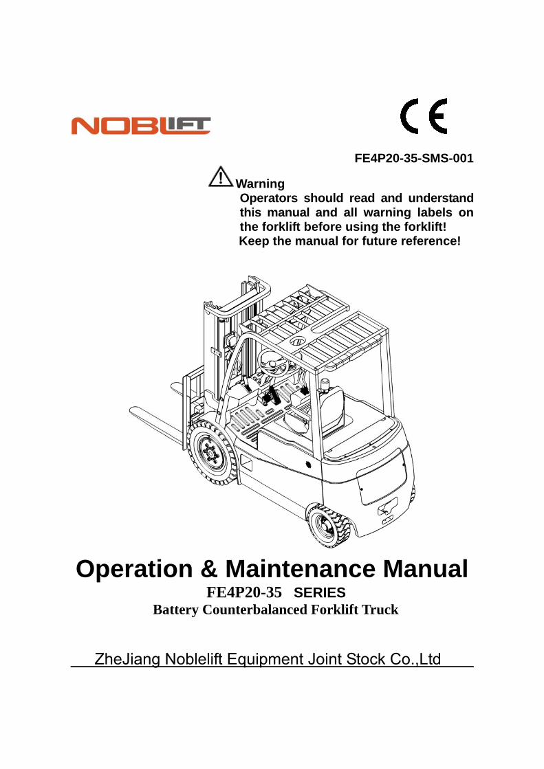
FE4P20-35-SMS-001 Warning Operators should read and understand this manual and all warning labels on the forklift before using the forklift! Keep the manual for future reference!
Operation & Maintenance Manual FE4P20-35 SERIES
Battery Counterbalanced Forklift Truck
ZheJiang Noblelift Equipment Joint Stock Co.,Ltd
1
Table of Contents
Introduction…………………………………………………………………………………………… 4
Chapter 1 Precautions of using forklift…………………………………………………………… 5
. Forklift transportationⅠ ....................................................................................................... 5
. Forklift storageⅡ ................................................................................................................. 5
. PreⅢ -use preparation......................................................................................................... 5
. Operation of the forkliftⅣ .................................................................................................... 5
. Charging of accumulator cellsⅤ ......................................................................................... 6
Chapter 2 Structure and main performance parameters of the forklift………………………… 7
. Overall Dimension anⅠ d Technical Parameters................................................................ 7
1. Overall dimension.......................................................................................................... 7
2 Technical Parameters..................................................................................................... 10
. Structure, principle and adjustment of the main componentsⅡ ......................................... 11
1. Transmission system..................................................................................................... 11
1.1 Overview.................................................................................................................... 11
1.2 Gearbox and differential ............................................................................................ 11
1.3 Drive axle................................................................................................................... 12
1.4 Installation of wheel hub............................................................................................ 13
1.5 Troubleshooting ......................................................................................................... 14
2. Braking system.............................................................................................................. 15
2.1 Overview.................................................................................................................... 15
2.2 Brake pedal ............................................................................................................... 15
2.3. Brake master cylinder............................................................................................... 15
2.4. Brake ........................................................................................................................ 16
2.5 Device for parking brake control ............................................................................... 18
2.6 Technical points for brake disassembly and adjustment......................................... 18
2.7 Adjustment of brake pedal ....................................................................................... 21
2.8 Troubleshooting ......................................................................................................... 22
2.9. Maintenance ............................................................................................................. 23
3 Steering system ........................................................................................................... 24
3.1 Overview.................................................................................................................... 24
3.2 Cycloid full hydraulic steering gear ........................................................................... 24
3.3 The steering axle ....................................................................................................... 25
3.4 Technical points for adjustment and repair................................................................ 28
3.5 Check of steering system after being re-installed ..................................................... 29
3.6 Trounble shooting...................................................................................................... 29
4 DC electrical system.................................................................................................... 30
4.1 Overview .................................................................................................................. 30
4.2 Electronic control assembly....................................................................................... 31
4.3 Combination instrument ............................................................................................ 33
4.4 Trouble shooting........................................................................................................ 34
2
5 AC electrical system(Curtis’ system) ......................................................................... 36
5.1 Overview .................................................................................................................. 36
5.2 Electronic control assembly ..................................................................................... 38
5.3 Combination instrument ............................................................................................ 40
5.4 Trouble shooting........................................................................................................ 41
6 AC electrical system(Zapi’s system) .......................................................................... 43
6.1 Overview.................................................................................................................... 43
6.2 Electronic control assembly....................................................................................... 45
6.3 Combination instrument ............................................................................................ 46
6.4 Trouble shooting........................................................................................................ 47
7.Accumulator…………………………………………………………………………………… 49
7.1 Accumulator safety precautions………………………………………………………… 49
7.2 Accumulator use precautions…………………………………………………………… 49
7.3 Charging of the accumulator……………………………………………………………… 50
7.4 Installation and replacement of the accumulator………………………………………… 52
8.Hydraulic system……………………………………………………………………………… 53
8.1 Overview…………………………………………………………………………………… 53
8.2 Oil pump…………………………………………………………………………………… 53
8.3 Multi-way valve…………………………………………………………………………… 53
8.4 Lifting cylinder and the lifting chain……………………………………………………… 56
8.5 Governor valve…………………………………………………………………………… 58
8.6 Tilt cylinder………………………………………………………………………………… 58
8.7 Hydraulic oil tank………………………………………………………………………… 59
8.8 Hydraulic pil pipe………………………………………………………………………… 60
8.9 Maintenance and adjustment…………………………………………………………… 61
8.10 Failure analysis………………………………………………………………………… 63
9.Lifting system………………………………………………………………………………… 64
9.1 Overview…………………………………………………………………………………… 64
9.2 Inner and outer main frame……………………………………………………………… 64
9.3 Fork frame………………………………………………………………………………… 65
9.4 Location of rollers………………………………………………………………………… 66
9.5 Maintenance and adjustment…………………………………………………………… 67
9.6 Installation of accessories………………………………………………………………… 68
10.Removal and installation…………………………………………………………………… 68
10.1 Precautions……………………………………………………………………………… 68
10.2 Lifting points of the detached parts…………………………………………………… 69
Chapter 3 0peration, use and safety of the forklift………………………………………………… 71
. Driving and operationⅠ ...................................................................................................... 71
1 Use of a new forklift........................................................................................................ 71
2 The relationship between forklift stability and load...................................................... 71
3 Load centre and load curve ......................................................................................... 71
4 Forklift stability ............................................................................................................. 71
3
5 Transportation and handling of the forklift ................................................................... 72
6 Preparation before driving ........................................................................................... 72
7 Driving.......................................................................................................................... 73
8 Parking and temporary parking ................................................................................... 74
9 Use method of the accumulator .................................................................................. 74
10 Stacking ..................................................................................................................... 76
11 Un-stacking ................................................................................................................ 76
12 Storage....................................................................................................................... 77
. Operation device and use methodⅡ ............................................................................... 78
1. Diagram on forklift parts and operation device ............................................................. 78
2 Combination instrument ................................................................................................. 78
3 Switches....................................................................................................................... 78
4 Controllers.................................................................................................................... 79
5 Forklift body ................................................................................................................. 82
. About safetyⅢ ..................................................................................................................... 83
1. Site and working environment of the forklift .................................................................. 83
2. Safety rules.................................................................................................................... 84
3 Handling of the forklift .................................................................................................. 94
4 How to avoid rollover and how to protect yourself from accidents.............................. 95
5 Safety issues during maintenance and protection ...................................................... 97
6 Safety during use of the accumulator.......................................................................... 98
7 Signs ............................................................................................................................ 100
Chapter IV Periodic inspection and maintenance of forklift................................................... 101
. Check before operationⅠ ................................................................................................... 101
1. Check points and contents............................................................................................ 101
2. Check procedures ......................................................................................................... 102
. Checking after operationⅡ ............................................................................................... 106
. Clean the forkliftⅢ ............................................................................................................... 106
1. Clean the forklift surface................................................................................................ 106
2. Clean the chain ............................................................................................................. 106
3 Clean the electric system ............................................................................................ 106
4 . After the cleaning.......................................................................................................... 106
. Regular maintenanceⅣ ...................................................................................................... 107
1. Regular maintenance schedule..................................................................................... 107
2. Replace critical safety components periodically ........................................................... 115
. Lubricating parts and recommended oilsⅤ ........................................................................ 116
1. Lubricating parts ............................................................................................................ 116
2. Recommended oils........................................................................................................ 116
4
Introduction
This manual briefly describes the technical parameters of the counterbalanced accumulator forklift made by our company, and the structure of its main components, working principle and requirements on operation and maintenance. Please read this manual carefully before operation, so as to achieve proper driving and maintenance, and to ensure safe and effective material handling. Meanwhile, this manual aims to guide operators to use the forklift in an appropriate way and to maximize its performance! We hope that operators and equipment managers could read it carefully before use! Please strictly observe the provisions and cautions stipulated in this manual and operate the forklift with caution and care, so that the forklift can be maintained in its best status and optimal performance can be ensured. When you lease or transfer your forklift, always keep this manual with it.
For highlighting purpose, the following icons are used in this manual:
1. ----refers to a potential danger; if not avoided, it may cause serious human injury, vehicle damage or fire.
2. ----refers to a potential danger; if not avoided,it may cause minor human injury, or local damage to the vehicle.。
3. ----Refers to general cuations and instructions during use.
Most parts of the product are made from recyclable steel. The recycling and disposal of cast-offs resulted during use, maintenance, cleaning and disassembling of the product has to comply with local regulations without pollution to the environment. The recycling and disposal of the cast-offs should only be operated by specialised personnel in the designated area. The cast-offs, such as hydraulic oil, batteries and electronic units, if improperly disposed, may be hazardous to the environment and human health.
Special Declaration: 1)This product is strictly prohibited for potentially explosive hazardous environments.
2)The Noise level of the normal use of this product is compliant with international standards EN 12,053.
3)The vibration level of the normal use of the product is compliant with international standards EN13059.
4)The normal use of the product's environmental requirements as follows: no more than 2000 meters above sea level and the temperature range of-5 ° C - +40 ° c, humidity should no more than 90%.The wind speed is not more than 5m/s.
If you need to use in the freezer for a long time or in special environment, it is needed to install special attachments. Please contact our technical staff.
5)Product recall serive is available when serial faulties occur.
Due to continuous product improvement, Noblelift reserves the right to make changes in product designs and specifications without prior notice. For the latest product parameters, please feel free to contact us. All parameters provided herein are as of the publication date of the Instruction Manual.
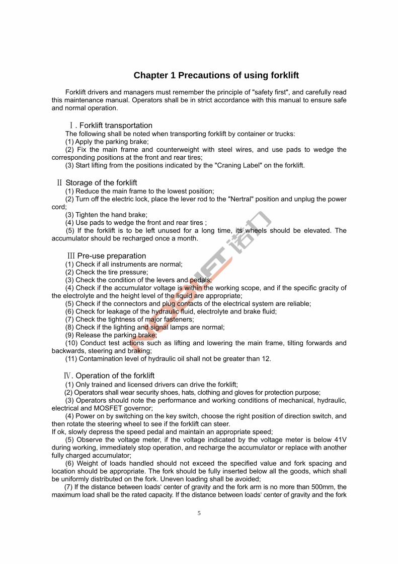
5
Chapter 1 Precautions of using forklift
Forklift drivers and managers must remember the principle of "safety first", and carefully read this maintenance manual. Operators shall be in strict accordance with this manual to ensure safe and normal operation.
. Forklift transportationⅠ
The following shall be noted when transporting forklift by container or trucks: (1) Apply the parking brake; (2) Fix the main frame and counterweight with steel wires, and use pads to wedge the corresponding positions at the front and rear tires; (3) Start lifting from the positions indicated by the "Craning Label" on the forklift. Storage of the forkliftⅡ (1) Reduce the main frame to the lowest position; (2) Turn off the electric lock, place the lever rod to the "Nertral" position and unplug the power cord; (3) Tighten the hand brake; (4) Use pads to wedge the front and rear tires ;
(5) If the forklift is to be left unused for a long time, its wheels should be elevated. The accumulator should be recharged once a month.
PreⅢ -use preparation
(1) Check if all instruments are normal; (2) Check the tire pressure; (3) Check the condition of the levers and pedals; (4) Check if the accumulator voltage is within the working scope, and if the specific gracity of the electrolyte and the height level of the liquid are appropriate; (5) Check if the connectors and plug contacts of the electrical system are reliable; (6) Check for leakage of the hydraulic fluid, electrolyte and brake fluid; (7) Check the tightness of major fasteners; (8) Check if the lighting and signal lamps are normal; (9) Release the parking brake; (10) Conduct test actions such as lifting and lowering the main frame, tilting forwards and backwards, steering and braking; (11) Contamination level of hydraulic oil shall not be greater than 12.
Ⅳ. Operation of the forklift
(1) Only trained and licensed drivers can drive the forklift; (2) Operators shall wear security shoes, hats, clothing and gloves for protection purpose; (3) Operators should note the performance and working conditions of mechanical, hydraulic, electrical and MOSFET governor; (4) Power on by switching on the key switch, choose the right position of direction switch, and then rotate the steering wheel to see if the forklift can steer. If ok, slowly depress the speed pedal and maintain an appropriate speed; (5) Observe the voltage meter, if the voltage indicated by the voltage meter is below 41V during working, immediately stop operation, and recharge the accumulator or replace with another fully charged accumulator;
(6) Weight of loads handled should not exceed the specified value and fork spacing and location should be appropriate. The fork should be fully inserted below all the goods, which shall be uniformly distributed on the fork. Uneven loading shall be avoided; (7) If the distance between loads‘ center of gravity and the fork arm is no more than 500mm, the maximum load shall be the rated capacity. If the distance between loads‘ center of gravity and the fork
6
arm is more than 500mm, the maximum load shall be less than the rated capacity; (8) When carrying loads, the main frame should tit backwards to the maximum extent and the
fork arm should be in contact with the goods. Raise the fork to about 200mm away from the ground before driving; (9) Standing under the fork and on the lifting fork are forbidden; (10) The initial velocity should not be too fast when lifting and lowering goods;
(11) Never operate the forklift and accessories at places other than the driver's seat; (12) When the main frame is moving forwards and backwards to the maximum extent, or
when the fork is lifted to its maximum height, the operator must rapidly set the lever to the neutral position;
(13) When the main frame is lifting, driving or turning of the forklift is not allowed; (14) When driving the forklift, drivers should pay attention to pedestrians, road obstacles and
potholes, and also note the gap above the forklift; (15) Drivers should be very careful when driving on ramps. When driving on a ramp with slope
gradient more than one-tenth, do move forward for up-hilling and backward for down-hilling. Never perform steering during up-hilling ad down-hilling process. And avoid loading and unloading when the forklift is down-hilling; (16) Slow down when steering on wet or slippery road surfaces; be very careful and drive slowly when driving on docks or temporary boards;
(17) For forklifts with lifting height greater than 3 meters, users shall be careful to guard against falling down of the goods overhead and take protective measures if necessary;
(18) Do not carry unfixed or loosely stacked goods and be careful when handling goods with large size;
(19) When driving the forklift with load, emergency braking should be avoided; (20) Before leaving the forklift, lower the fork down to the ground, set the lever at neutral
position and disconnect power. In case of parking on a ramp, apply the parking brake. Use wedge pads to fix the wheels if you need to park for a long time;
(21) The safety valve pressures of multiple unit valve and steering device have been tuned up before leaving the factory. During use, users shall not adjust it, because excessive pressure may cause damage to the entire hydraulic system or its components ,and the motor;
(22) Tire inflation pressure shall be in line with that stipulated on the "Air pressure" plate; (23) When moving with no load, forklift with accessories shall be operated in a way as if
carrying a load.
. Charging of accumulator cells Ⅴ (1) When charging the accumulator cells for the first time and further charging, users should
be in strict compliance with the instructions; (2) When operating the forklift, if the accumulator voltage decreases to 41V, or that of its
single cell drops below l.7V , or the instrument alarms, users shall immediately stop using the forklift and replace the accumulator or recharge it before further use;
(3) Check the specific gravity, liquid level and temperature of the electrolyte from time to time during the charging process;
(4) Forklift must be recharged as soon as possible after use. Never leave the forklift uncharged longer than 24 hours. When charging, pay attention to prevent insufficient charging and over-charging, so as not to damage the battery;
(5) Users should conduct balanced recharging to the forklift in normal use once a month, so as to adjust the proportion among the accumulator units.
Please refer to the relevant sections of this Mannual for detailed charging and maintenance methods.
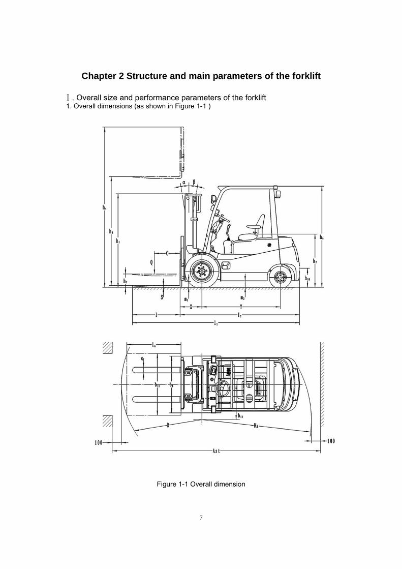
7
Chapter 2 Structure and main parameters of the forklift
. Overall size and performance parameters of the forklift Ⅰ 1. Overall dimensions (as shown in Figure 1-1 )
Figure 1-1 Overall dimension
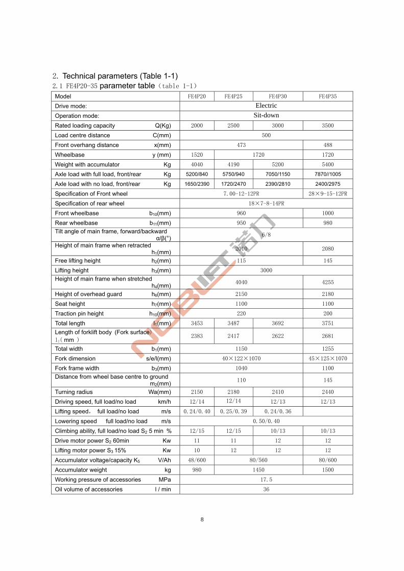
8
2. Technical parameters (Table 1-1) 2.1 FE4P20-35 parameter table(table 1-1)
Model FE4P20 FE4P25 FE4P30 FE4P35
Drive mode: Electric
Operation mode: Sit-down
Rated loading capacity Q(Kg) 2000 2500 3000 3500
Load centre distance C(mm) 500
Front overhang distance x(mm) 473 488
Wheelbase y (mm) 1520 1720 1720
Weight with accumulator Kg 4040 4190 5200 5400
Axle load with full load, front/rear Kg 5200/840 5750/940 7050/1150 7870//1005
Axle load with no load, front/rear Kg 1650/2390 1720/2470 2390/2810 2400/2975
Specification of Front wheel 7.00-12-12PR 28×9-15-12PR
Specification of rear wheel 18×7-8-14PR
Front wheelbase b10(mm) 960 1000
Rear wheelbase b11(mm) 950 980
Tilt angle of main frame, forward/backward α/β(°)
6/8
Height of main frame when retracted h1(mm)
2010 2080
Free lifting height h2(mm) 115 145
Lifting height h3(mm) 3000
Height of main frame when stretched h4(mm)
4040 4255
Height of overhead guard h6(mm) 2150 2180
Seat height h7(mm) 1100 1100
Traction pin height h10(mm) 220 200
Total length l1(mm) 3453 3487 3692 3751
Length of forklift body (Fork surface) l2( mm )
2383 2417 2622 2681
Total width b1(mm) 1150 1255
Fork dimension s/e/l(mm) 40×122×1070 45×125×1070
Fork frame width b3(mm) 1040 1100
Distance from wheel base centre to ground m2(mm)
110 145
Turning radius Wa(mm) 2150 2180 2410 2440
Driving speed, full load/no load km/h 12/14 12/14 12/13 12/13
Lifting speed, full load/no load m/s 0.24/0.40 0.25/0.39 0.24/0.36
Lowering speed full load/no load m/s 0.50/0.40
Climbing ability, full load/no load S2 5 min % 12/15 12/15 10/13 10/13
Drive motor power S2 60min Kw 11 11 12 12
Lifting motor power S3 15% Kw 10 12 12 12
Accumulator voltage/capacity K5 V/Ah 48/600 80/560 80/600
Accumulator weight kg 980 1450 1500
Working pressure of accessories MPa 17.5
Oil volume of accessories l / min 36

9
2.2 FE4P20-35AC parameter table(table 1-2)
Model FE4P20AC FE4P25AC FE4P30AC FE4P35AC
Drive mode: Electric
Operation mode: Sit-down
Rated loading capacity Q(Kg) 2000 2500 3000 3500
Load centre distance C(mm) 500
Front overhang distance x(mm) 473 488
Wheelbase y (mm) 1520 1720 1720
Weight with accumulator Kg 4040 4190 5200 5400
Axle load with full load, front/rear Kg 5200/840 5750/940 7050/1150 7870//1005
Axle load with no load, front/rear Kg 1650/2390 1720/2470 2390/2810 2400/2975
Specification of Front wheel 7.00-12-12PR 28×9-15-12PR
Specification of rear wheel 18×7-8-14PR
Front wheelbase b10(mm) 960 1000
Rear wheelbase b11(mm) 950 980
Tilt angle of main frame, forward/backward α/β(°)
6/8
Height of main frame when retracted h1(mm)
2010 2080
Free lifting height h2(mm) 115 145
Lifting height h3(mm) 3000
Height of main frame when stretched h4(mm)
4040 4255
Height of overhead guard h6(mm) 2150 2180
Seat height h7(mm) 1100 1100
Traction pin height h10(mm) 220 200
Total length l1(mm) 3453 3487 3692 3751
Length of forklift body (Fork surface) l2( mm )
2383 2417 2622 2681
Total width b1(mm) 1150 1255
Fork dimension s/e/l(mm) 40×122×1070 45×125×1070
Fork frame width b3(mm) 1040 1100
Distance from wheel base centre to ground m2(mm)
110 145
Turning radius Wa(mm) 2150 2180 2410 2440
Driving speed, full load/no load km/h 12/14 12/14 12/13 12/13
Lifting speed, full load/no load m/s 0.24/0.40 0.25/0.39 0.24/0.36
Lowering speed full load/no load m/s 0.50/0.40
Climbing ability, full load/no load S2 5 min % 12/15 12/15 10/13 10/13
Drive motor power S2 60min Kw 11 11 12 12
Lifting motor power S3 15% Kw 10 12 12 12
Accumulator voltage/capacity K5 V/Ah 48/600 80/560 80/600
Accumulator weight kg 980 1450 1500
Working pressure of accessories MPa 17.5
Oil volume of accessories l / min 36
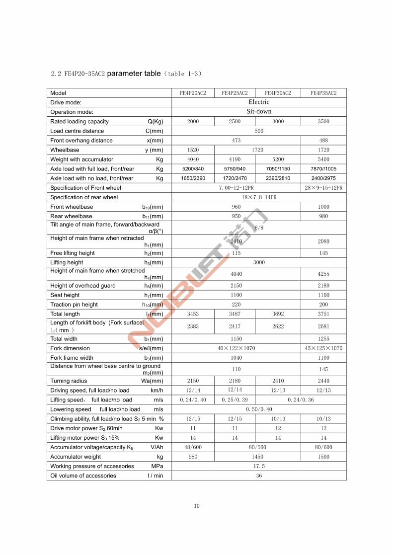
10
2.2 FE4P20-35AC2 parameter table(table 1-3)
Model FE4P20AC2 FE4P25AC2 FE4P30AC2 FE4P35AC2
Drive mode: Electric
Operation mode: Sit-down
Rated loading capacity Q(Kg) 2000 2500 3000 3500
Load centre distance C(mm) 500
Front overhang distance x(mm) 473 488
Wheelbase y (mm) 1520 1720 1720
Weight with accumulator Kg 4040 4190 5200 5400
Axle load with full load, front/rear Kg 5200/840 5750/940 7050/1150 7870//1005
Axle load with no load, front/rear Kg 1650/2390 1720/2470 2390/2810 2400/2975
Specification of Front wheel 7.00-12-12PR 28×9-15-12PR
Specification of rear wheel 18×7-8-14PR
Front wheelbase b10(mm) 960 1000
Rear wheelbase b11(mm) 950 980
Tilt angle of main frame, forward/backward α/β(°)
6/8
Height of main frame when retracted h1(mm)
2010 2080
Free lifting height h2(mm) 115 145
Lifting height h3(mm) 3000
Height of main frame when stretched h4(mm)
4040 4255
Height of overhead guard h6(mm) 2150 2180
Seat height h7(mm) 1100 1100
Traction pin height h10(mm) 220 200
Total length l1(mm) 3453 3487 3692 3751
Length of forklift body (Fork surface) l2( mm )
2383 2417 2622 2681
Total width b1(mm) 1150 1255
Fork dimension s/e/l(mm) 40×122×1070 45×125×1070
Fork frame width b3(mm) 1040 1100
Distance from wheel base centre to ground m2(mm)
110 145
Turning radius Wa(mm) 2150 2180 2410 2440
Driving speed, full load/no load km/h 12/14 12/14 12/13 12/13
Lifting speed, full load/no load m/s 0.24/0.40 0.25/0.39 0.24/0.36
Lowering speed full load/no load m/s 0.50/0.40
Climbing ability, full load/no load S2 5 min % 12/15 12/15 10/13 10/13
Drive motor power S2 60min Kw 11 11 12 12
Lifting motor power S3 15% Kw 14 14 14 14
Accumulator voltage/capacity K5 V/Ah 48/600 80/560 80/600
Accumulator weight kg 980 1450 1500
Working pressure of accessories MPa 17.5
Oil volume of accessories l / min 36
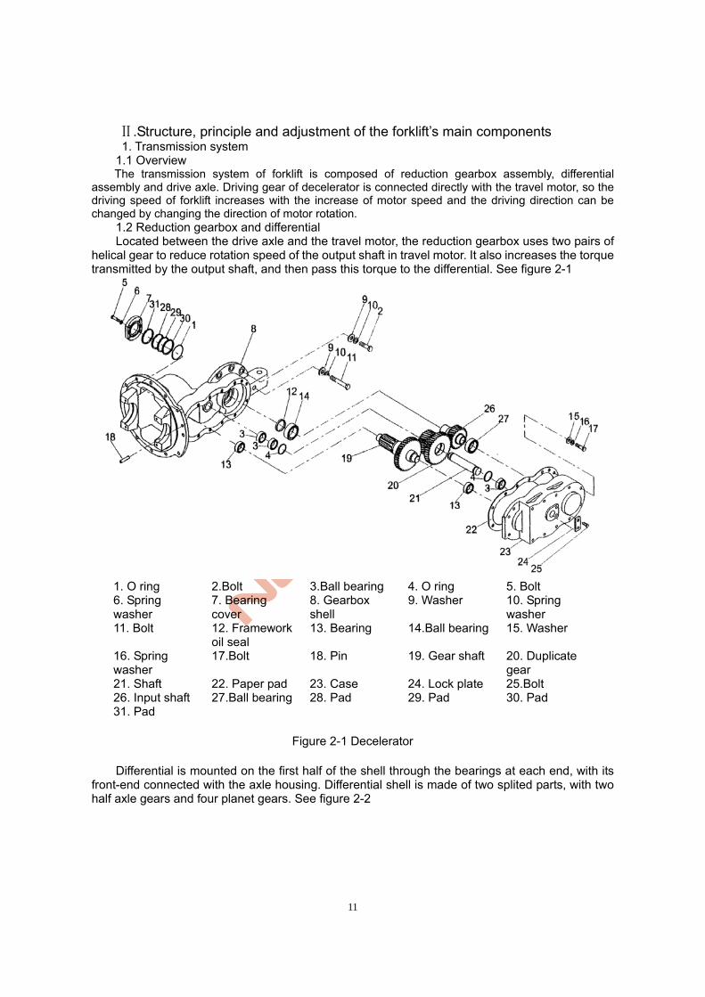
11
.Structure, principle and adjustment of the forklift’s main components Ⅱ 1. Transmission system 1.1 Overview The transmission system of forklift is composed of reduction gearbox assembly, differential
assembly and drive axle. Driving gear of decelerator is connected directly with the travel motor, so the driving speed of forklift increases with the increase of motor speed and the driving direction can be changed by changing the direction of motor rotation.
1.2 Reduction gearbox and differential Located between the drive axle and the travel motor, the reduction gearbox uses two pairs of
helical gear to reduce rotation speed of the output shaft in travel motor. It also increases the torque transmitted by the output shaft, and then pass this torque to the differential. See figure 2-1
1. O ring 2.Bolt 3.Ball bearing 4. O ring 5. Bolt 6. Spring washer
7. Bearing cover
8. Gearbox shell
9. Washer 10. Spring washer
11. Bolt 12. Framework oil seal
13. Bearing 14.Ball bearing 15. Washer
16. Spring washer
17.Bolt 18. Pin 19. Gear shaft 20. Duplicate gear
21. Shaft 22. Paper pad 23. Case 24. Lock plate 25.Bolt 26. Input shaft 27.Ball bearing 28. Pad 29. Pad 30. Pad 31. Pad
Figure 2-1 Decelerator
Differential is mounted on the first half of the shell through the bearings at each end, with its
front-end connected with the axle housing. Differential shell is made of two splited parts, with two half axle gears and four planet gears. See figure 2-2
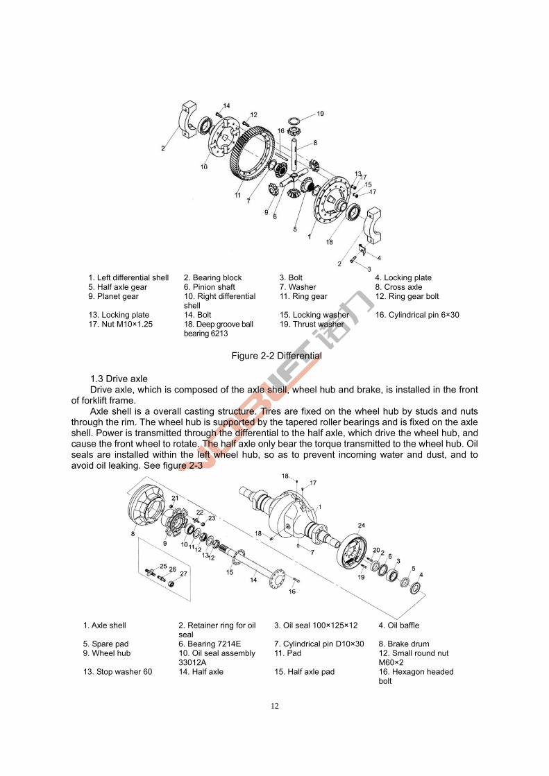
12
1. Left differential shell 2. Bearing block 3. Bolt 4. Locking plate 5. Half axle gear 6. Pinion shaft 7. Washer 8. Cross axle 9. Planet gear 10. Right differential
shell 11. Ring gear 12. Ring gear bolt
13. Locking plate 14. Bolt 15. Locking washer 16. Cylindrical pin 6×3017. Nut M10×1.25 18. Deep groove ball
bearing 6213 19. Thrust washer
Figure 2-2 Differential
1.3 Drive axle Drive axle, which is composed of the axle shell, wheel hub and brake, is installed in the front
of forklift frame. Axle shell is a overall casting structure. Tires are fixed on the wheel hub by studs and nuts
through the rim. The wheel hub is supported by the tapered roller bearings and is fixed on the axle shell. Power is transmitted through the differential to the half axle, which drive the wheel hub, and cause the front wheel to rotate. The half axle only bear the torque transmitted to the wheel hub. Oil seals are installed within the left wheel hub, so as to prevent incoming water and dust, and to avoid oil leaking. See figure 2-3
1. Axle shell 2. Retainer ring for oil
seal 3. Oil seal 100×125×12 4. Oil baffle
5. Spare pad 6. Bearing 7214E 7. Cylindrical pin D10×30 8. Brake drum 9. Wheel hub 10. Oil seal assembly
33012A 11. Pad 12. Small round nut
M60×2 13. Stop washer 60 14. Half axle 15. Half axle pad 16. Hexagon headed
bolt
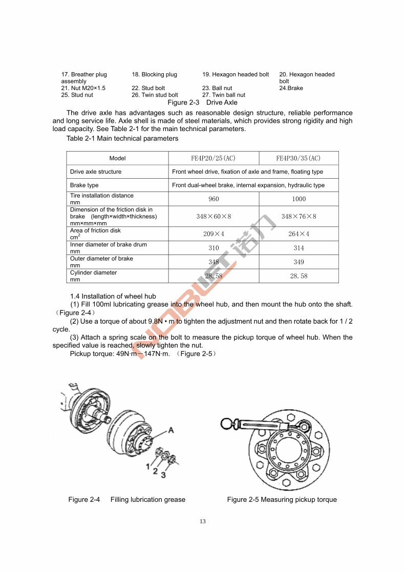
13
17. Breather plug assembly
18. Blocking plug 19. Hexagon headed bolt 20. Hexagon headed bolt
21. Nut M20×1.5 22. Stud bolt 23. Ball nut 24.Brake 25. Stud nut 26. Twin stud bolt 27. Twin ball nut
Figure 2-3 Drive Axle
The drive axle has advantages such as reasonable design structure, reliable performance and long service life. Axle shell is made of steel materials, which provides strong rigidity and high load capacity. See Table 2-1 for the main technical parameters.
Table 2-1 Main technical parameters
Model FE4P20/25(AC) FE4P30/35(AC)
Drive axle structure Front wheel drive, fixation of axle and frame, floating type
Brake type Front dual-wheel brake, internal expansion, hydraulic type
Tire installation distance mm 960 1000
Dimension of the friction disk in brake (length×width×thickness) mm×mm×mm
348×60×8 348×76×8
Area of friction disk cm2 209×4 264×4
Inner diameter of brake drum mm 310 314
Outer diameter of brake mm 348 349
Cylinder diameter mm 28.58 28.58
1.4 Installation of wheel hub (1) Fill 100ml lubricating grease into the wheel hub, and then mount the hub onto the shaft.
(Figure 2-4) (2) Use a torque of about 9.8N • m to tighten the adjustment nut and then rotate back for 1 / 2
cycle. (3) Attach a spring scale on the bolt to measure the pickup torque of wheel hub. When the
specified value is reached, slowly tighten the nut. Pickup torque: 49N·m-147N·m. (Figure 2-5)
Figure 2-4 Filling lubrication grease Figure 2-5 Measuring pickup torque
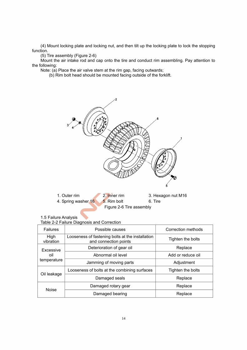
14
(4) Mount locking plate and locking nut, and then tilt up the locking plate to lock the stopping function.
(5) Tire assembly (Figure 2-6) Mount the air intake rod and cap onto the tire and conduct rim assembling. Pay attention to
the following: Note: (a) Place the air valve stem at the rim gap, facing outwards; (b) Rim bolt head should be mounted facing outside of the forklift.
1. Outer rim 2. Inner rim 3. Hexagon nut M16 4. Spring washer 16 5. Rim bolt 6. Tire
Figure 2-6 Tire assembly 1.5 Failure Analysis Table 2-2 Failure Diagnosis and Correction
Failures Possible causes Correction methods
High vibration
Looseness of fastening bolts at the installation and connection points
Tighten the bolts
Deterioration of gear oil Replace
Abnormal oil level Add or reduce oil Excessive
oil temperature
Jamming of moving parts Adjustment
Looseness of bolts at the combining surfaces Tighten the bolts Oil leakage
Damaged seals Replace
Damaged rotary gear Replace Noise
Damaged bearing Replace
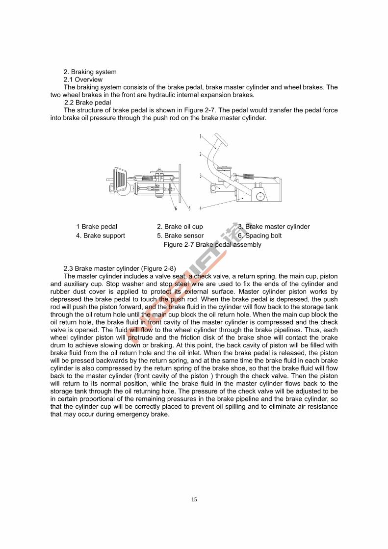
15
2. Braking system 2.1 Overview The braking system consists of the brake pedal, brake master cylinder and wheel brakes. The two wheel brakes in the front are hydraulic internal expansion brakes.
2.2 Brake pedal The structure of brake pedal is shown in Figure 2-7. The pedal would transfer the pedal force
into brake oil pressure through the push rod on the brake master cylinder.
1 Brake pedal 2. Brake oil cup 3. Brake master cylinder 4. Brake support 5. Brake sensor 6. Spacing bolt
Figure 2-7 Brake pedal assembly
2.3 Brake master cylinder (Figure 2-8) The master cylinder includes a valve seat, a check valve, a return spring, the main cup, piston
and auxiliary cup. Stop washer and stop steel wire are used to fix the ends of the cylinder and rubber dust cover is applied to protect its external surface. Master cylinder piston works by depressed the brake pedal to touch the push rod. When the brake pedal is depressed, the push rod will push the piston forward, and the brake fluid in the cylinder will flow back to the storage tank through the oil return hole until the main cup block the oil return hole. When the main cup block the oil return hole, the brake fluid in front cavity of the master cylinder is compressed and the check valve is opened. The fluid will flow to the wheel cylinder through the brake pipelines. Thus, each wheel cylinder piston will protrude and the friction disk of the brake shoe will contact the brake drum to achieve slowing down or braking. At this point, the back cavity of piston will be filled with brake fluid from the oil return hole and the oil inlet. When the brake pedal is released, the piston will be pressed backwards by the return spring, and at the same time the brake fluid in each brake cylinder is also compressed by the return spring of the brake shoe, so that the brake fluid will flow back to the master cylinder (front cavity of the piston ) through the check valve. Then the piston will return to its normal position, while the brake fluid in the master cylinder flows back to the storage tank through the oil returning hole. The pressure of the check valve will be adjusted to be in certain proportional of the remaining pressures in the brake pipeline and the brake cylinder, so that the cylinder cup will be correctly placed to prevent oil spilling and to eliminate air resistance that may occur during emergency brake.
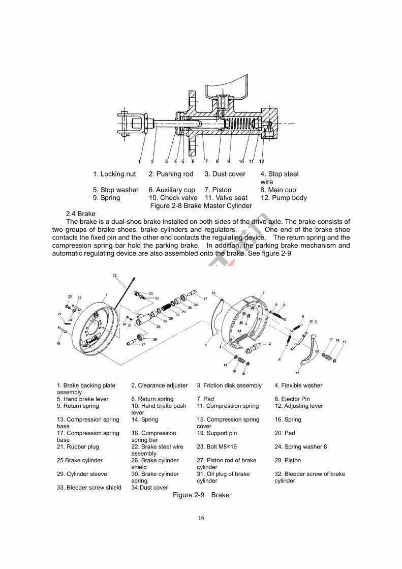
16
1. Locking nut 2. Pushing rod 3. Dust cover 4. Stop steel
wire 5. Stop washer 6. Auxiliary cup 7. Piston 8. Main cup 9. Spring 10. Check valve 11. Valve seat 12. Pump body
Figure 2-8 Brake Master Cylinder 2.4 Brake The brake is a dual-shoe brake installed on both sides of the drive axle. The brake consists of
two groups of brake shoes, brake cylinders and regulators. One end of the brake shoe contacts the fixed pin and the other end contacts the regulating device. The return spring and the compression spring bar hold the parking brake. In addition, the parking brake mechanism and automatic regulating device are also assembled onto the brake. See figure 2-9
1. Brake backing plate assembly
2. Clearance adjuster 3. Friction disk assembly 4. Flexible washer
5. Hand brake lever 6. Return spring 7. Pad 8. Ejector Pin 9. Return spring 10. Hand brake push
lever 11. Compression spring 12. Adjusting lever
13. Compression spring base
14. Spring 15. Compression spring cover
16. Spring
17. Compression spring base
18. Compression spring bar
19. Support pin 20. Pad
21. Rubber plug 22. Brake steel wire assembly
23. Bolt M8×16 24. Spring washer 8
25.Brake cylinder 26. Brake cylinder shield
27. Piston rod of brake cylinder
28. Piston
29. Cylinder sleeve 30. Brake cylinder spring
31. Oil plug of brake cylinder
32. Bleeder screw of brake cylinder
33. Bleeder screw shield 34.Dust cover Figure 2-9 Brake
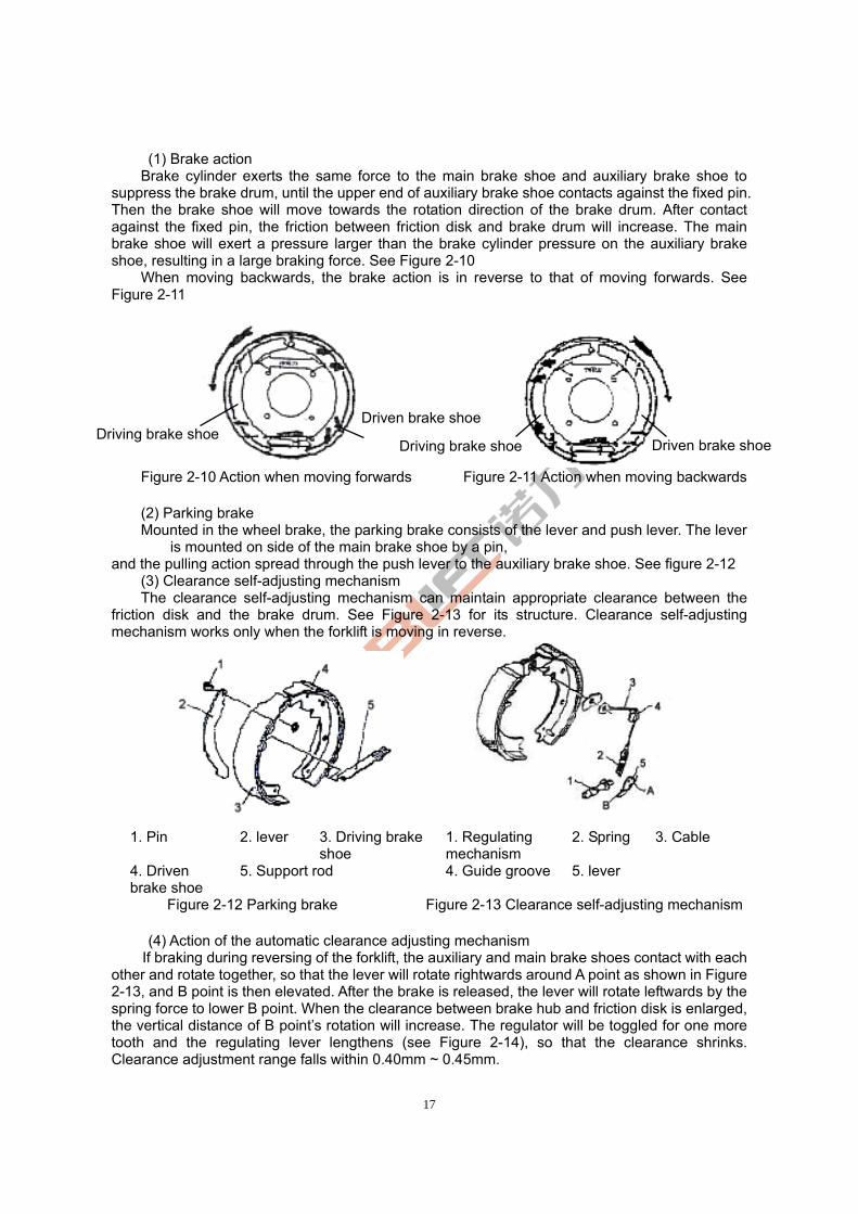
17
(1) Brake action Brake cylinder exerts the same force to the main brake shoe and auxiliary brake shoe to
suppress the brake drum, until the upper end of auxiliary brake shoe contacts against the fixed pin. Then the brake shoe will move towards the rotation direction of the brake drum. After contact against the fixed pin, the friction between friction disk and brake drum will increase. The main brake shoe will exert a pressure larger than the brake cylinder pressure on the auxiliary brake shoe, resulting in a large braking force. See Figure 2-10
When moving backwards, the brake action is in reverse to that of moving forwards. See Figure 2-11
Figure 2-10 Action when moving forwards Figure 2-11 Action when moving backwards
(2) Parking brake Mounted in the wheel brake, the parking brake consists of the lever and push lever. The lever
is mounted on side of the main brake shoe by a pin, and the pulling action spread through the push lever to the auxiliary brake shoe. See figure 2-12
(3) Clearance self-adjusting mechanism The clearance self-adjusting mechanism can maintain appropriate clearance between the
friction disk and the brake drum. See Figure 2-13 for its structure. Clearance self-adjusting mechanism works only when the forklift is moving in reverse.
Figure 2-12 Parking brake Figure 2-13 Clearance self-adjusting mechanism (4) Action of the automatic clearance adjusting mechanism If braking during reversing of the forklift, the auxiliary and main brake shoes contact with each
other and rotate together, so that the lever will rotate rightwards around A point as shown in Figure 2-13, and B point is then elevated. After the brake is released, the lever will rotate leftwards by the spring force to lower B point. When the clearance between brake hub and friction disk is enlarged, the vertical distance of B point’s rotation will increase. The regulator will be toggled for one more tooth and the regulating lever lengthens (see Figure 2-14), so that the clearance shrinks. Clearance adjustment range falls within 0.40mm ~ 0.45mm.
1. Pin 2. lever 3. Driving brake shoe
1. Regulating mechanism
2. Spring 3. Cable
4. Driven brake shoe
5. Support rod 4. Guide groove 5. lever
Driving brake shoe Driven brake shoe
Driving brake shoe Driven brake shoe
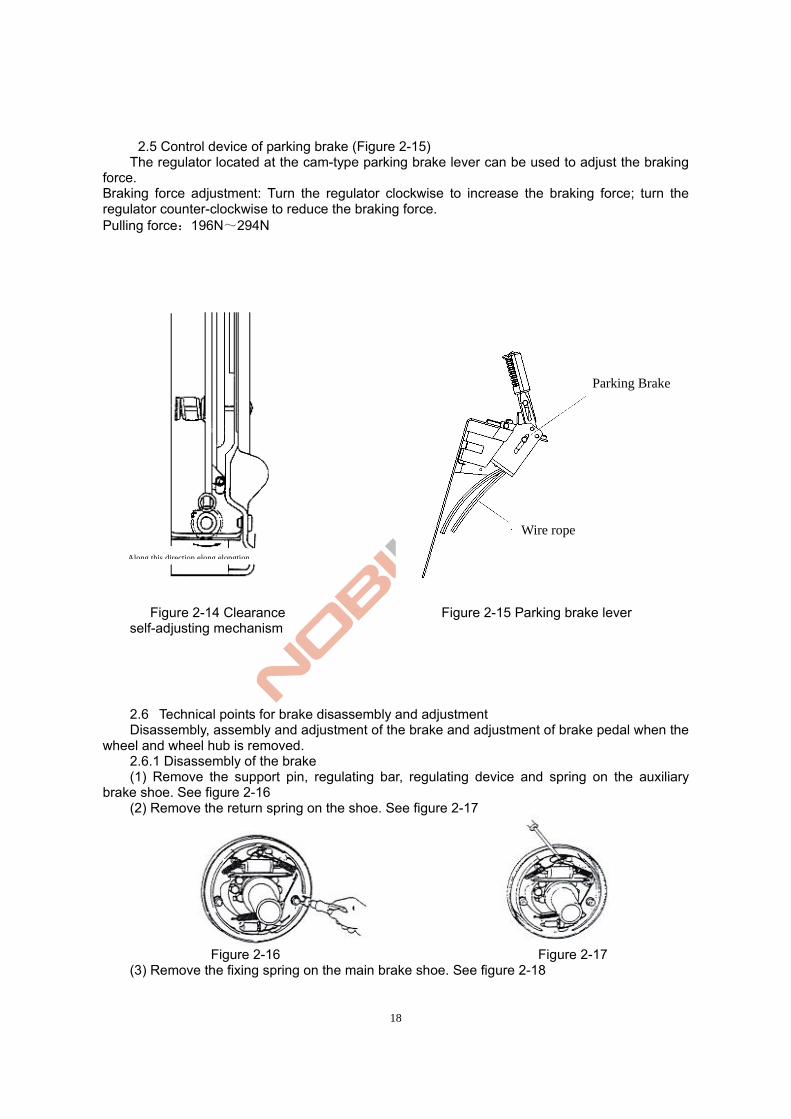
18
2.5 Control device of parking brake (Figure 2-15) The regulator located at the cam-type parking brake lever can be used to adjust the braking
force. Braking force adjustment: Turn the regulator clockwise to increase the braking force; turn the regulator counter-clockwise to reduce the braking force. Pulling force:196N~294N
Figure 2-14 Clearance Figure 2-15 Parking brake lever self-adjusting mechanism
2.6 Technical points for brake disassembly and adjustment Disassembly, assembly and adjustment of the brake and adjustment of brake pedal when the
wheel and wheel hub is removed. 2.6.1 Disassembly of the brake (1) Remove the support pin, regulating bar, regulating device and spring on the auxiliary
brake shoe. See figure 2-16 (2) Remove the return spring on the shoe. See figure 2-17
Figure 2-16 Figure 2-17
(3) Remove the fixing spring on the main brake shoe. See figure 2-18
Parking Brake
Wire rope
Along this direction elong elongtion
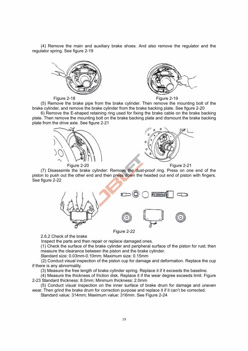
19
(4) Remove the main and auxiliary brake shoes. And also remove the regulator and the regulator spring. See figure 2-19
Figure 2-18 Figure 2-19
(5) Remove the brake pipe from the brake cylinder. Then remove the mounting bolt of the brake cylinder, and remove the brake cylinder from the brake backing plate. See figure 2-20
6) Remove the E-shaped retaining ring used for fixing the brake cable on the brake backing plate. Then remove the mounting bolt on the brake backing plate and dismount the brake backing plate from the drive axle. See figure 2-21
Figure 2-20 Figure 2-21
(7) Disassemle the brake cylinder: Remove the dust-proof ring. Press on one end of the piston to push out the other end and then press down the headed out end of piston with fingers. See figure 2-22
Figure 2-22
2.6.2 Check of the brake Inspect the parts and then repair or replace damaged ones. (1) Check the surface of the brake cylinder and peripheral surface of the piston for rust; then measure the clearance between the piston and the brake cylinder. Standard size: 0.03mm-0.10mm; Maximum size: 0.15mm (2) Conduct visual inspection of the piston cup for damage and deformation. Replace the cup
if there is any abnormality. (3) Measure the free length of brake cylinder spring. Replace it if it exceeds the baseline. (4) Measure the thickness of friction disk. Replace it if the wear degree exceeds limit. Figure
2-23 Standard thickness: 8.0mm; Minimum thickness: 2.0mm (5) Conduct visual inspection on the inner surface of brake drum for damage and uneven
wear. Then grind the brake drum for correction purpose and replace it if it can’t be corrected. Standard value: 314mm; Maximum value: 316mm. See Figure 2-24
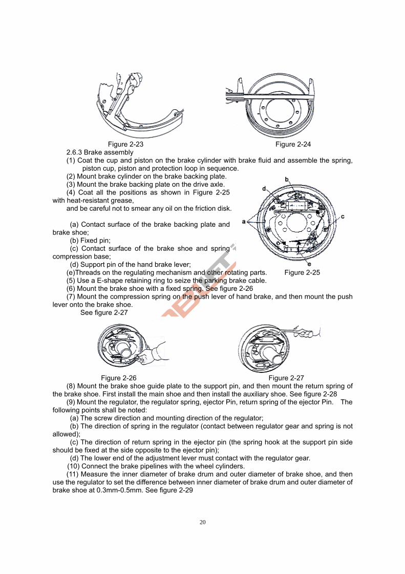
20
Figure 2-23 Figure 2-24
2.6.3 Brake assembly (1) Coat the cup and piston on the brake cylinder with brake fluid and assemble the spring,
piston cup, piston and protection loop in sequence. (2) Mount brake cylinder on the brake backing plate.
(3) Mount the brake backing plate on the drive axle. (4) Coat all the positions as shown in Figure 2-25
with heat-resistant grease, and be careful not to smear any oil on the friction disk.
(a) Contact surface of the brake backing plate and
brake shoe; (b) Fixed pin; (c) Contact surface of the brake shoe and spring
compression base; (d) Support pin of the hand brake lever; (e)Threads on the regulating mechanism and other rotating parts. Figure 2-25 (5) Use a E-shape retaining ring to seize the parking brake cable. (6) Mount the brake shoe with a fixed spring. See figure 2-26 (7) Mount the compression spring on the push lever of hand brake, and then mount the push
lever onto the brake shoe. See figure 2-27
Figure 2-26 Figure 2-27
(8) Mount the brake shoe guide plate to the support pin, and then mount the return spring of the brake shoe. First install the main shoe and then install the auxiliary shoe. See figure 2-28
(9) Mount the regulator, the regulator spring, ejector Pin, return spring of the ejector Pin. The following points shall be noted:
(a) The screw direction and mounting direction of the regulator; (b) The direction of spring in the regulator (contact between regulator gear and spring is not
allowed); (c) The direction of return spring in the ejector pin (the spring hook at the support pin side
should be fixed at the side opposite to the ejector pin); (d) The lower end of the adjustment lever must contact with the regulator gear.
(10) Connect the brake pipelines with the wheel cylinders. (11) Measure the inner diameter of brake drum and outer diameter of brake shoe, and then use the regulator to set the difference between inner diameter of brake drum and outer diameter of brake shoe at 0.3mm-0.5mm. See figure 2-29
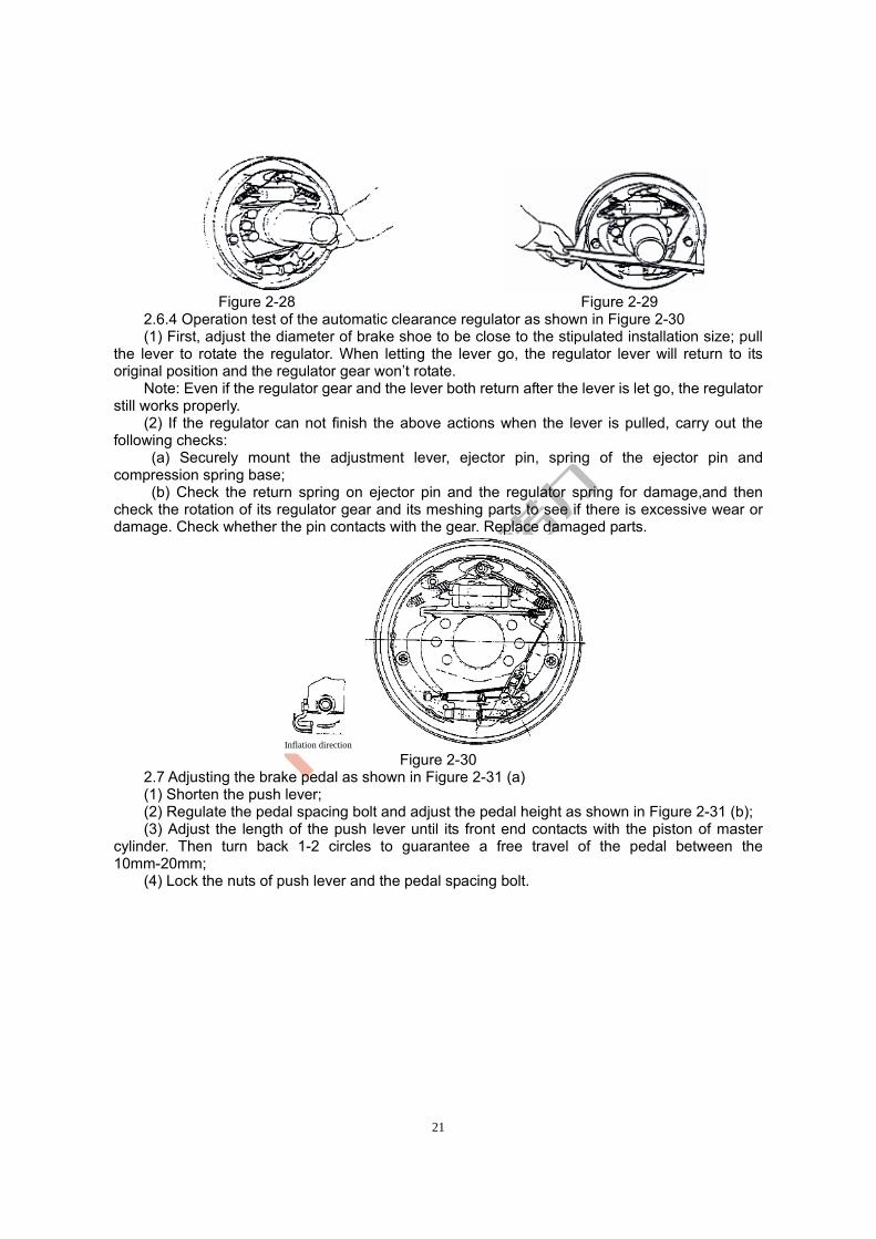
21
Figure 2-28 Figure 2-29
2.6.4 Operation test of the automatic clearance regulator as shown in Figure 2-30 (1) First, adjust the diameter of brake shoe to be close to the stipulated installation size; pull
the lever to rotate the regulator. When letting the lever go, the regulator lever will return to its original position and the regulator gear won’t rotate.
Note: Even if the regulator gear and the lever both return after the lever is let go, the regulator still works properly.
(2) If the regulator can not finish the above actions when the lever is pulled, carry out the following checks:
(a) Securely mount the adjustment lever, ejector pin, spring of the ejector pin and compression spring base;
(b) Check the return spring on ejector pin and the regulator spring for damage,and then check the rotation of its regulator gear and its meshing parts to see if there is excessive wear or damage. Check whether the pin contacts with the gear. Replace damaged parts.
Figure 2-30
2.7 Adjusting the brake pedal as shown in Figure 2-31 (a) (1) Shorten the push lever; (2) Regulate the pedal spacing bolt and adjust the pedal height as shown in Figure 2-31 (b); (3) Adjust the length of the push lever until its front end contacts with the piston of master
cylinder. Then turn back 1-2 circles to guarantee a free travel of the pedal between the 10mm-20mm;
(4) Lock the nuts of push lever and the pedal spacing bolt.
Inflation direction
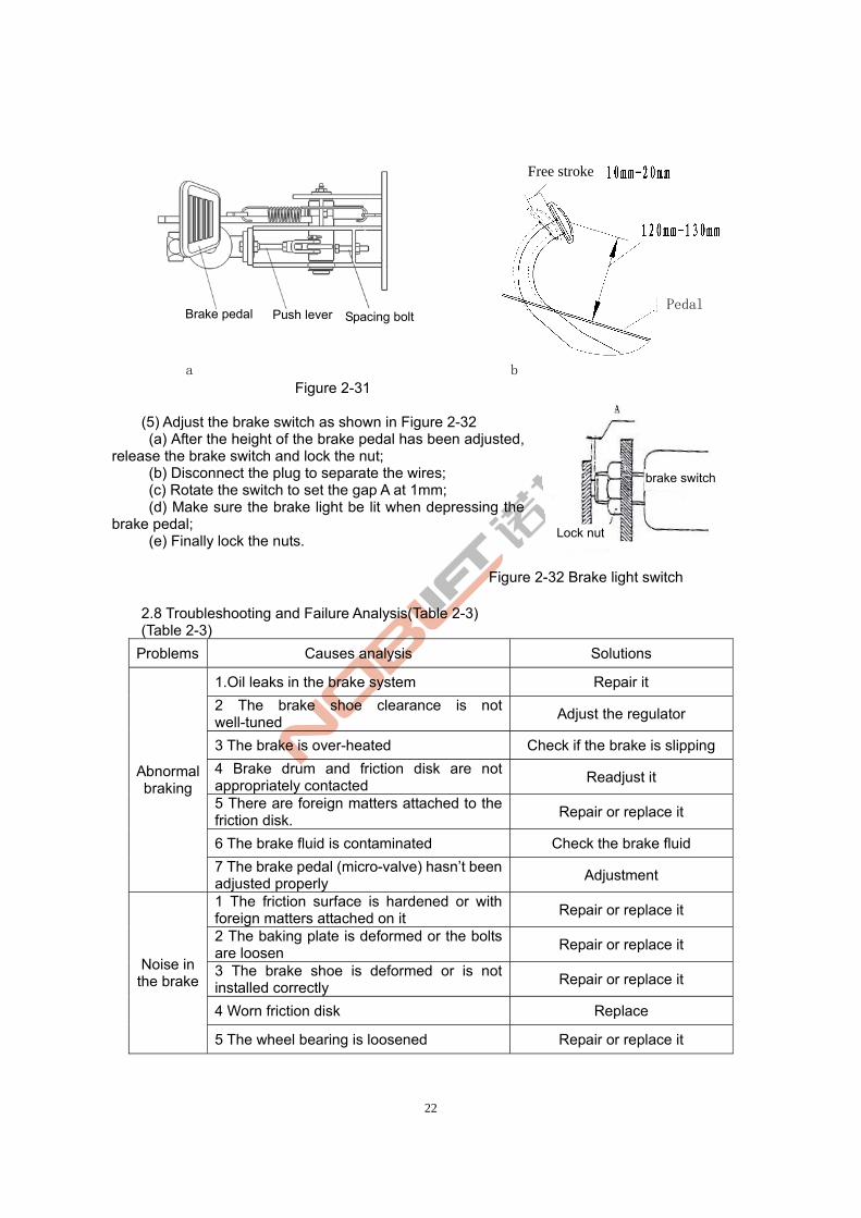
22
a b
Figure 2-31 (5) Adjust the brake switch as shown in Figure 2-32 (a) After the height of the brake pedal has been adjusted,
release the brake switch and lock the nut; (b) Disconnect the plug to separate the wires; (c) Rotate the switch to set the gap A at 1mm; (d) Make sure the brake light be lit when depressing the
brake pedal; (e) Finally lock the nuts.
Figure 2-32 Brake light switch
2.8 Troubleshooting and Failure Analysis(Table 2-3) (Table 2-3)
Problems Causes analysis Solutions
1.Oil leaks in the brake system Repair it
2 The brake shoe clearance is not well-tuned
Adjust the regulator
3 The brake is over-heated Check if the brake is slipping
4 Brake drum and friction disk are not appropriately contacted
Readjust it
5 There are foreign matters attached to the friction disk.
Repair or replace it
6 The brake fluid is contaminated Check the brake fluid
Abnormal braking
7 The brake pedal (micro-valve) hasn’t been adjusted properly
Adjustment
1 The friction surface is hardened or with foreign matters attached on it
Repair or replace it
2 The baking plate is deformed or the bolts are loosen
Repair or replace it
3 The brake shoe is deformed or is not installed correctly
Repair or replace it
4 Worn friction disk Replace
Noise in the brake
5 The wheel bearing is loosened Repair or replace it
Brake pedal Push lever Spacing bolt
brake switch
Lock nut
Pedal
Free stroke
23
1 There are oil stain on the friction disk Repair or replace it
2 The brake shoe clearance is not well-tuned
Adjust the regulator
3 The wheel cylinder fails Repair or replace it
4 The return spring of brake shoe is damaged
Replace
The braking
is uneven
5 The brake drum is deflected Repair or replace it
1.Oil leaks in the brake system Repair or replace it
2 The brake shoe clearance is not well-tuned
Adjust the regulator
3 Air is mixed within the brake system Let out the air
The
braking is
not enough 4 The brake pedal is not adjusted
appropriately Readjust it
2.9 Care and maintenance Before conducting running① -in test of a new drive axle, users shall fill in gear oil (gear oil
shall be selected in accordance with the instructions. Please refer to Table 2-1 for the specific requirements). Fill oil into the hole at top of the axle shell until oil is spilled out of the oil level hole in central axle.
The thickness of friction disk on brake shoe is 8mm. The minimum thickness allowed is ②2mm. These two are key components of the braking system and should be checked monthly. If excessive wear is found, the components shall be timely replaced to avoid accidents.
Technical maintenance after each 50h:③ . Change the gear oil if a new axle has been working for 50h along with the forklift. Clean Ⅰ
the axle before refilling new oil. . Check all thⅡ e fasteners. If any looseness is found, tighten it immediately. . Check the wheel axle and wheel hub connection for any oil leakage. ReⅢ -apply sealant if
any leakage is found. Monthly technical maintenance:④ . Check the brake drum for any destructive weaⅠ r. . Check the wear condition of brake shoe. If wearing is so serious that the brake shoe fails Ⅱ
to meet requirements, the brake shoe should be replaced immediately. . Check if the oil level in axle shell meets standards. If the oil level reduces, users sⅢ hould
promptly fill up. Semi⑤ -annual technical maintenance: Change the gear oil within the axle once every six
months of working. Annual technical maintenance: Disassemble the drive axle for inspection every year.⑥ Check and debug requirements during t⑦ he installation process:
When re-installing the wheel hub of the drive axle, users should regulate the clearance adjuster of the brake, so as to set the gap between brake drum and friction disk at 0.3mm ~ 0.5mm. Fill 100ml 3# lithium base grease into the tapered roller bearing on the wheel hub.
Adjustment of the bearing clearance on wheel hub: tighten the inner locking nut until the wheel brake drum can barely turn up. Then rotate the inner locking nut in reverse for 1 / 8 circle. At this moment wheel brake drum can be freely rotated without jamming, significant axial clearance or deflection. Finally, assemble the washer pad and tighten the outside locking nut.
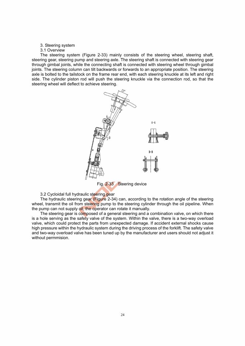
24
3. Steering system 3.1 Overview The steering system (Figure 2-33) mainly consists of the steering wheel, steering shaft,
steering gear, steering pump and steering axle. The steering shaft is connected with steering gear through gimbal joints, while the connecting shaft is connected with steering wheel through gimbal joints. The steering column can tilt backwards or forwards to an appropriate position. The steering axle is bolted to the tailstock on the frame rear end, with each steering knuckle at its left and right side. The cylinder piston rod will push the steering knuckle via the connection rod, so that the steering wheel will deflect to achieve steering.
Fig. 2-33 Steering device
3.2 Cycloidal full hydraulic steering gear The hydraulic steering gear (Figure 2-34) can, according to the rotation angle of the steering
wheel, transmit the oil from steering pump to the steering cylinder through the oil pipeline. When the pump can not supply oil, the operator can rotate it manually.
The steering gear is composed of a general steering and a combination valve, on which there is a hole serving as the safety valve of the system. Within the valve, there is a two-way overload valve, which could protect the parts from unexpected damage. If accident external shocks cause high pressure within the hydraulic system during the driving process of the forklift. The safety valve and two-way overload valve has been tuned up by the manufacturer and users should not adjust it without permmision.
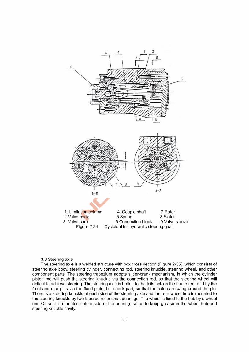
25
1. Limitation column 4. Couple shaft 7.Rotor 2.Valve body 5.Spring 8.Stator
3. Valve core 6.Connection block 9.Valve sleeve Figure 2-34 Cycloidal full hydraulic steering gear
3.3 Steering axle The steering axle is a welded structure with box cross section (Figure 2-35), which consists of
steering axle body, steering cylinder, connecting rod, steering knuckle, steering wheel, and other component parts. The steering trapezium adopts slider-crank mechanism, in which the cylinder piston rod will push the steering knuckle via the connection rod, so that the steering wheel will deflect to achieve steering. The steering axle is bolted to the tailstock on the frame rear end by the front and rear pins via the fixed plate, i.e. shock pad, so that the axle can swing around the pin. There is a steering knuckle at each side of the steering axle and the rear wheel hub is mounted to the steering knuckle by two tapered roller shaft bearings. The wheel is fixed to the hub by a wheel rim. Oil seal is mounted onto inside of the bearing, so as to keep grease in the wheel hub and steering knuckle cavity.
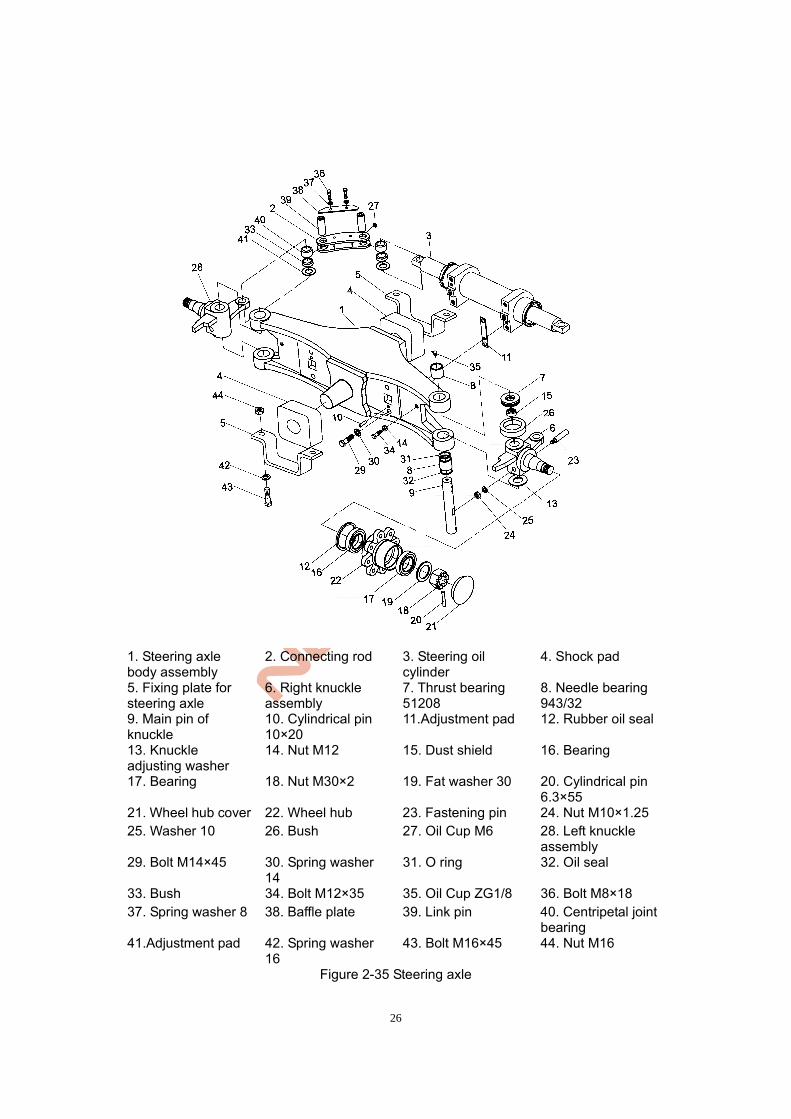
26
1. Steering axle body assembly
2. Connecting rod 3. Steering oil cylinder
4. Shock pad
5. Fixing plate for steering axle
6. Right knuckle assembly
7. Thrust bearing 51208
8. Needle bearing 943/32
9. Main pin of knuckle
10. Cylindrical pin 10×20
11.Adjustment pad 12. Rubber oil seal
13. Knuckle adjusting washer
14. Nut M12 15. Dust shield 16. Bearing
17. Bearing 18. Nut M30×2 19. Fat washer 30 20. Cylindrical pin 6.3×55
21. Wheel hub cover 22. Wheel hub 23. Fastening pin 24. Nut M10×1.25 25. Washer 10 26. Bush 27. Oil Cup M6 28. Left knuckle
assembly 29. Bolt M14×45 30. Spring washer
14 31. O ring 32. Oil seal
33. Bush 34. Bolt M12×35 35. Oil Cup ZG1/8 36. Bolt M8×18 37. Spring washer 8 38. Baffle plate 39. Link pin 40. Centripetal joint
bearing 41.Adjustment pad 42. Spring washer
16 43. Bolt M16×45 44. Nut M16
Figure 2-35 Steering axle
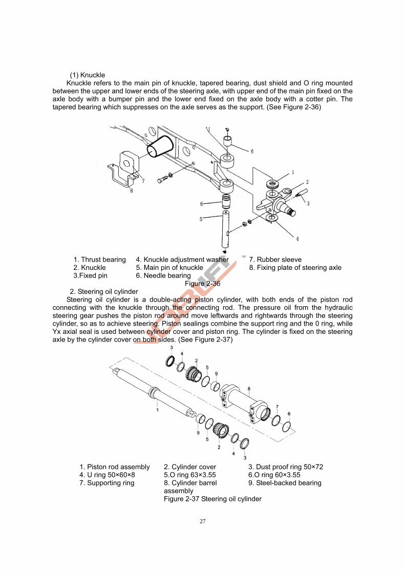
27
(1) Knuckle Knuckle refers to the main pin of knuckle, tapered bearing, dust shield and O ring mounted
between the upper and lower ends of the steering axle, with upper end of the main pin fixed on the axle body with a bumper pin and the lower end fixed on the axle body with a cotter pin. The tapered bearing which suppresses on the axle serves as the support. (See Figure 2-36)
1. Thrust bearing 4. Knuckle adjustment washer 7. Rubber sleeve 2. Knuckle 5. Main pin of knuckle 8. Fixing plate of steering axle 3.Fixed pin 6. Needle bearing
Figure 2-36 2. Steering oil cylinder Steering oil cylinder is a double-acting piston cylinder, with both ends of the piston rod
connecting with the knuckle through the connecting rod. The pressure oil from the hydraulic steering gear pushes the piston rod around move leftwards and rightwards through the steering cylinder, so as to achieve steering. Piston sealings combine the support ring and the 0 ring, while Yx axial seal is used between cylinder cover and piston ring. The cylinder is fixed on the steering axle by the cylinder cover on both sides. (See Figure 2-37)
1. Piston rod assembly 2. Cylinder cover 3. Dust proof ring 50×72 4. U ring 50×60×8 5.O ring 63×3.55 6.O ring 60×3.55 7. Supporting ring 8. Cylinder barrel
assembly 9. Steel-backed bearing
Figure 2-37 Steering oil cylinder
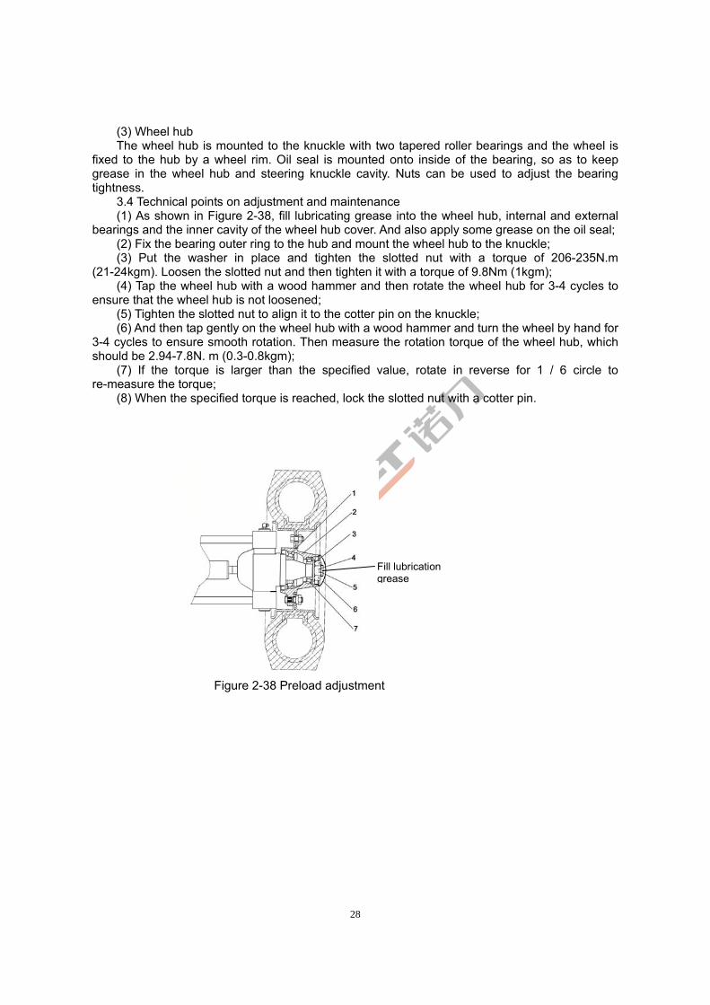
28
(3) Wheel hub The wheel hub is mounted to the knuckle with two tapered roller bearings and the wheel is fixed to the hub by a wheel rim. Oil seal is mounted onto inside of the bearing, so as to keep grease in the wheel hub and steering knuckle cavity. Nuts can be used to adjust the bearing tightness.
3.4 Technical points on adjustment and maintenance (1) As shown in Figure 2-38, fill lubricating grease into the wheel hub, internal and external
bearings and the inner cavity of the wheel hub cover. And also apply some grease on the oil seal; (2) Fix the bearing outer ring to the hub and mount the wheel hub to the knuckle; (3) Put the washer in place and tighten the slotted nut with a torque of 206-235N.m
(21-24kgm). Loosen the slotted nut and then tighten it with a torque of 9.8Nm (1kgm); (4) Tap the wheel hub with a wood hammer and then rotate the wheel hub for 3-4 cycles to
ensure that the wheel hub is not loosened; (5) Tighten the slotted nut to align it to the cotter pin on the knuckle; (6) And then tap gently on the wheel hub with a wood hammer and turn the wheel by hand for
3-4 cycles to ensure smooth rotation. Then measure the rotation torque of the wheel hub, which should be 2.94-7.8N. m (0.3-0.8kgm);
(7) If the torque is larger than the specified value, rotate in reverse for 1 / 6 circle to re-measure the torque;
(8) When the specified torque is reached, lock the slotted nut with a cotter pin.
Figure 2-38 Preload adjustment
Fill lubrication grease
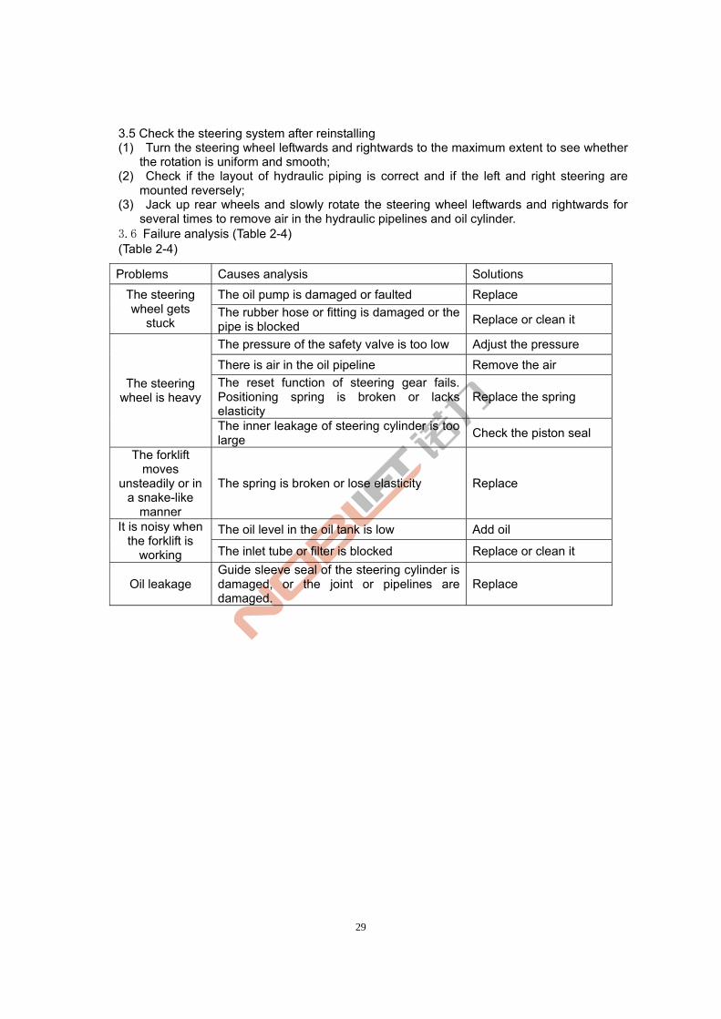
29
3.5 Check the steering system after reinstalling (1) Turn the steering wheel leftwards and rightwards to the maximum extent to see whether
the rotation is uniform and smooth; (2) Check if the layout of hydraulic piping is correct and if the left and right steering are
mounted reversely; (3) Jack up rear wheels and slowly rotate the steering wheel leftwards and rightwards for
several times to remove air in the hydraulic pipelines and oil cylinder. 3.6 Failure analysis (Table 2-4) (Table 2-4)
Problems Causes analysis Solutions
The oil pump is damaged or faulted Replace The steering wheel gets
stuck The rubber hose or fitting is damaged or the pipe is blocked
Replace or clean it
The pressure of the safety valve is too low Adjust the pressure
There is air in the oil pipeline Remove the air
The reset function of steering gear fails. Positioning spring is broken or lacks elasticity
Replace the spring The steering
wheel is heavy
The inner leakage of steering cylinder is too large
Check the piston seal
The forklift moves
unsteadily or in a snake-like
manner
The spring is broken or lose elasticity Replace
The oil level in the oil tank is low Add oil It is noisy when the forklift is
working The inlet tube or filter is blocked Replace or clean it
Oil leakage Guide sleeve seal of the steering cylinder is damaged, or the joint or pipelines are damaged.
Replace
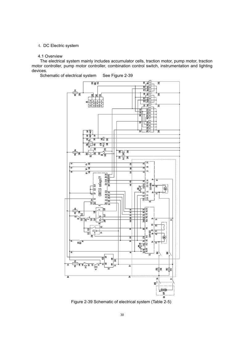
30
4. DC Electric system
4.1 Overview The electrical system mainly includes accumulator cells, traction motor, pump motor, traction motor controller, pump motor controller, combination control switch, instrumentation and lighting devices.
Schematic of electrical system See Figure 2-39
Figure 2-39 Schematic of electrical system (Table 2-5)
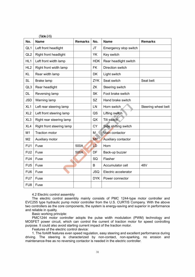
31
(Table 2-5)
No. Name Remarks No. Name Remarks
QL1 Left front headlight JT Emergency stop switch
QL2 Right front headlight YK Key switch
HL1 Left front width lamp HDK Rear headlight switch
HL2 Right front width lamp FK Direction switch
KL Rear width lamp DK Light switch
SL Brake lamp ZYK Seat switch Seat belt
QL3 Rear headlight ZK Steering switch
DL Reversing lamp SK Foot brake switch
JSD Warning lamp SZ Hand brake switch
XL1 Left rear steering lamp LN Horn switch Steering wheel belt
XL2 Left front steering lamp QS Lifting switch
XL3 Right rear steering lamp QX Tilt switch
XL4 Right front steering lamp CY Side shifting switch
M1 Traction motor M Main contactor
M2 Auxiliary motor MP Auxiliary contactor
FU1 Fuse 500A LD Horn
FU2 Fuse 500A DF Back-up buzzer
FU4 Fuse SQ Flasher
FU5 Fuse B Accumulator cell 48V
FU6 Fuse JSQ Electric accelerator
FU7 Fuse DYK Power connector
FU8 Fuse 4.2 Electric control assembly The electric control assembly mainly consists of PMC 1244-type motor controller and
EVC255 type hydraulic pump motor controller from the U.S. CURTIS Company. With the above two controllers as the core components, the system is energy-saving and superior in performance and reliable in quality.
Basic working principle: PMC1244 motor controller adopts the pulse width modulation (PWM) technology and
MOSFET power circuit, which can control the current of traction motor for speed controlling purpose. It could also avoid starting current impact of the traction motor.
Features of the electric control device: 1. The forklift features even speed regulation, easy steering and excellent performance during
driving. The steering is characterized by non-contact, non-sparking, no erosion and maintenance-free as no reversing contactor is needed in the electric controller.
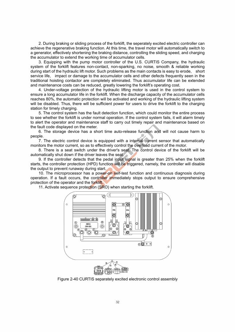
32
2. During braking or sliding process of the forklift, the seperately excited electric controller can achieve the regenerative braking function. At this time, the travel motor will automatically switch to a generator, effectively shortening the braking distance, controlling the sliding speed, and charging the accumulator to extend the working time of accumulator cells.
3. Equipping with the pump motor controller of the U.S. CURTIS Company, the hydraulic system of the forklift features non-contact, non-sparking, no noise, smooth & reliable working during start of the hydraulic lift motor. Such problems as the main contacts is easy to erode, short service life, impact or damage to the accumulator cells and other defects frequently seen in the traditional hoisting contactor are completely eliminated. Thus accumulator life can be extended and maintenance costs can be reduced, greatly lowering the forklift’s operating cost.
4. Under-voltage protection of the hydraulic lifting motor is used in the control system to ensure a long accumulator life in the forklift. When the discharge capacity of the accumulator cells reaches 80%, the automatic protection will be activated and working of the hydraulic lifting system will be disabled. Thus, there will be sufficient power for users to drive the forklift to the charging station for timely charging.
5. The control system has the fault detection function, which could monitor the entire process to see whether the forklift is under normal operation. If the control system fails, it will alarm timely to alert the operator and maintenance staff to carry out timely repair and maintenance based on the fault code displayed on the meter.
6. The storage device has a short time auto-release function and will not cause harm to people.
7. The electric control device is equipped with a internal current sensor that automatically monitors the motor current, so as to effectively control the overload current of the motor.
8. There is a seat switch under the driver's seat. The control device of the forklift will be automatically shut down if the driver leaves the seat.
9. If the controller detects that the pedal input signal is greater than 25% when the forklift starts, the controller protection (HPD) function will be triggered, namely, the controller will disable the output to prevent runaway during start.
10. The microprocessor has a power-on self-test function and continuous diagnosis during operation. If a fault occurs, the controller immediately stops output to ensure comprehensive protection of the operator and the forklift.
11. Activate sequence protection (SRO) when starting the forklift.
Figure 2-40 CURTIS separately excited electronic control assembly
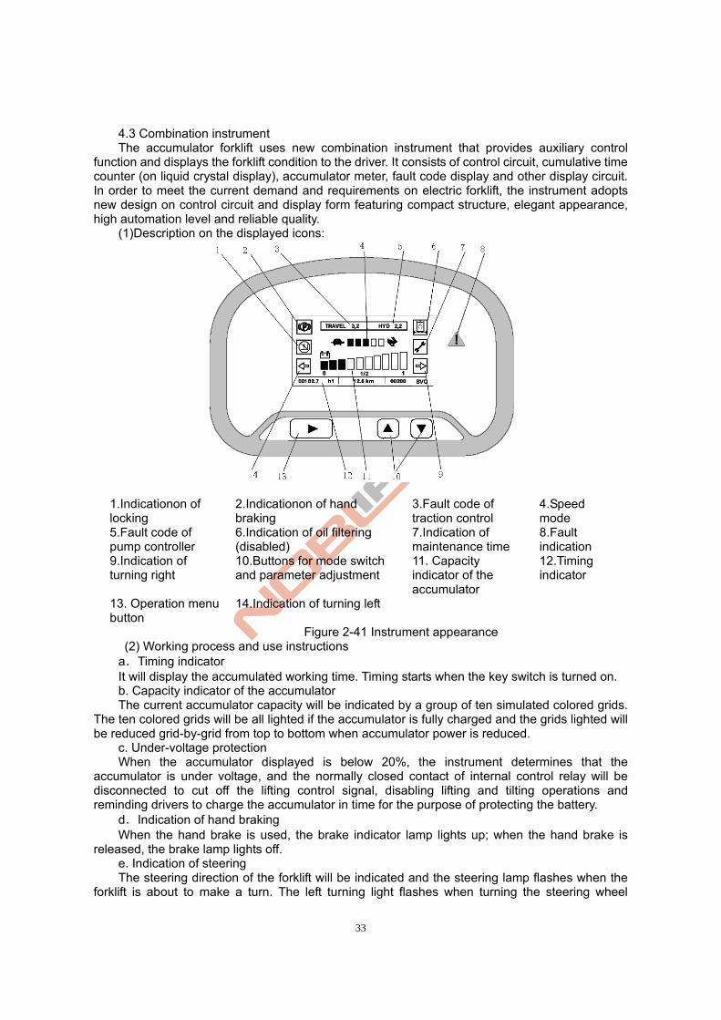
33
4.3 Combination instrument The accumulator forklift uses new combination instrument that provides auxiliary control
function and displays the forklift condition to the driver. It consists of control circuit, cumulative time counter (on liquid crystal display), accumulator meter, fault code display and other display circuit. In order to meet the current demand and requirements on electric forklift, the instrument adopts new design on control circuit and display form featuring compact structure, elegant appearance, high automation level and reliable quality.
(1)Description on the displayed icons:
1.Indicationon of locking
2.Indicationon of hand braking
3.Fault code of traction control
4.Speed mode
5.Fault code of pump controller
6.Indication of oil filtering (disabled)
7.Indication of maintenance time
8.Fault indication
9.Indication of turning right
10.Buttons for mode switch and parameter adjustment
11. Capacity indicator of the accumulator
12.Timing indicator
13. Operation menu button
14.Indication of turning left
Figure 2-41 Instrument appearance (2) Working process and use instructions a.Timing indicator It will display the accumulated working time. Timing starts when the key switch is turned on. b. Capacity indicator of the accumulator The current accumulator capacity will be indicated by a group of ten simulated colored grids.
The ten colored grids will be all lighted if the accumulator is fully charged and the grids lighted will be reduced grid-by-grid from top to bottom when accumulator power is reduced. c. Under-voltage protection
When the accumulator displayed is below 20%, the instrument determines that the accumulator is under voltage, and the normally closed contact of internal control relay will be disconnected to cut off the lifting control signal, disabling lifting and tilting operations and reminding drivers to charge the accumulator in time for the purpose of protecting the battery. d.Indication of hand braking When the hand brake is used, the brake indicator lamp lights up; when the hand brake is released, the brake lamp lights off.
e. Indication of steering The steering direction of the forklift will be indicated and the steering lamp flashes when the
forklift is about to make a turn. The left turning light flashes when turning the steering wheel
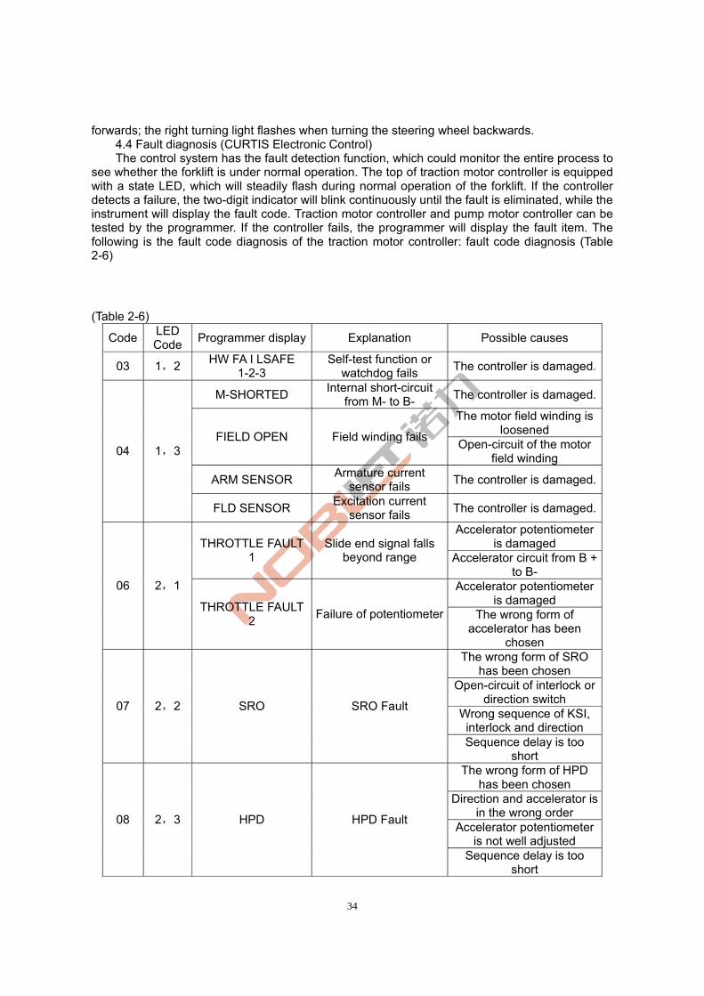
34
forwards; the right turning light flashes when turning the steering wheel backwards. 4.4 Fault diagnosis (CURTIS Electronic Control) The control system has the fault detection function, which could monitor the entire process to
see whether the forklift is under normal operation. The top of traction motor controller is equipped with a state LED, which will steadily flash during normal operation of the forklift. If the controller detects a failure, the two-digit indicator will blink continuously until the fault is eliminated, while the instrument will display the fault code. Traction motor controller and pump motor controller can be tested by the programmer. If the controller fails, the programmer will display the fault item. The following is the fault code diagnosis of the traction motor controller: fault code diagnosis (Table 2-6)
(Table 2-6)
Code LED Code
Programmer display Explanation Possible causes
03 1,2 HW FA I LSAFE
1-2-3 Self-test function or
watchdog fails The controller is damaged.
M-SHORTED Internal short-circuit
from M- to B- The controller is damaged.
The motor field winding is loosened
FIELD OPEN Field winding fails Open-circuit of the motor
field winding
ARM SENSOR Armature current
sensor fails The controller is damaged.
04 1,3
FLD SENSOR Excitation current
sensor fails The controller is damaged.
Accelerator potentiometer is damaged THROTTLE FAULT
1 Slide end signal falls
beyond range Accelerator circuit from B + to B-
Accelerator potentiometer is damaged
06 2,1
THROTTLE FAULT 2
Failure of potentiometer The wrong form of accelerator has been
chosen The wrong form of SRO
has been chosen Open-circuit of interlock or
direction switch Wrong sequence of KSI, interlock and direction
07 2,2 SRO SRO Fault
Sequence delay is too short
The wrong form of HPD has been chosen
Direction and accelerator is in the wrong order
Accelerator potentiometer is not well adjusted
08 2,3 HPD HPD Fault
Sequence delay is too short
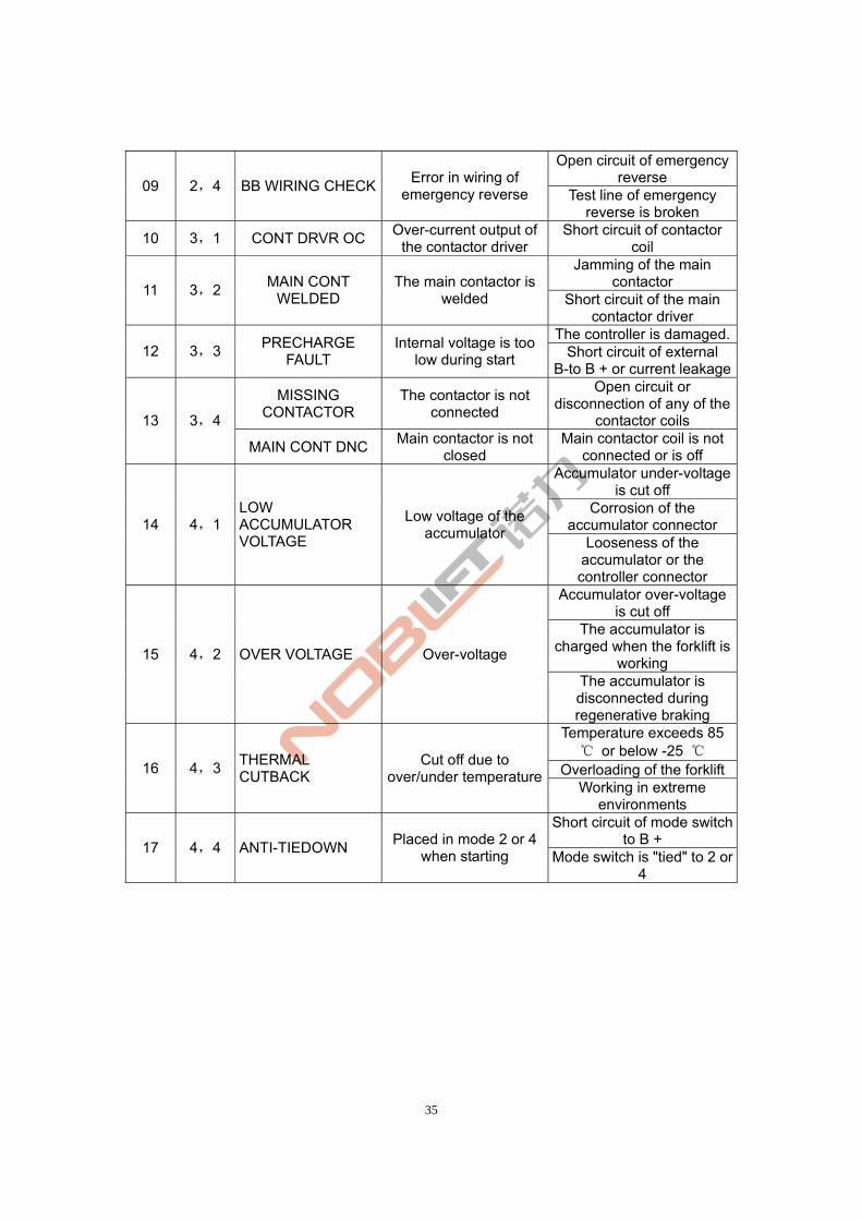
35
Open circuit of emergency reverse
09 2,4 BB WIRING CHECKError in wiring of
emergency reverse Test line of emergency reverse is broken
10 3,1 CONT DRVR OC Over-current output of
the contactor driver Short circuit of contactor
coil Jamming of the main
contactor 11 3,2
MAIN CONT WELDED
The main contactor is welded Short circuit of the main
contactor driver The controller is damaged.
12 3,3 PRECHARGE
FAULT Internal voltage is too
low during start Short circuit of external B-to B + or current leakage
MISSING CONTACTOR
The contactor is not connected
Open circuit or disconnection of any of the
contactor coils 13 3,4
MAIN CONT DNC Main contactor is not
closed Main contactor coil is not
connected or is off Accumulator under-voltage
is cut off Corrosion of the
accumulator connector 14 4,1 LOW ACCUMULATOR VOLTAGE
Low voltage of the accumulator
Looseness of the accumulator or the controller connector
Accumulator over-voltage is cut off
The accumulator is charged when the forklift is
working 15 4,2 OVER VOLTAGE Over-voltage
The accumulator is disconnected during regenerative braking
Temperature exceeds 85 ℃ or below -25 ℃
Overloading of the forklift16 4,3 THERMAL CUTBACK
Cut off due to over/under temperature
Working in extreme environments
Short circuit of mode switch to B +
17 4,4 ANTI-TIEDOWN Placed in mode 2 or 4
when starting Mode switch is "tied" to 2 or 4
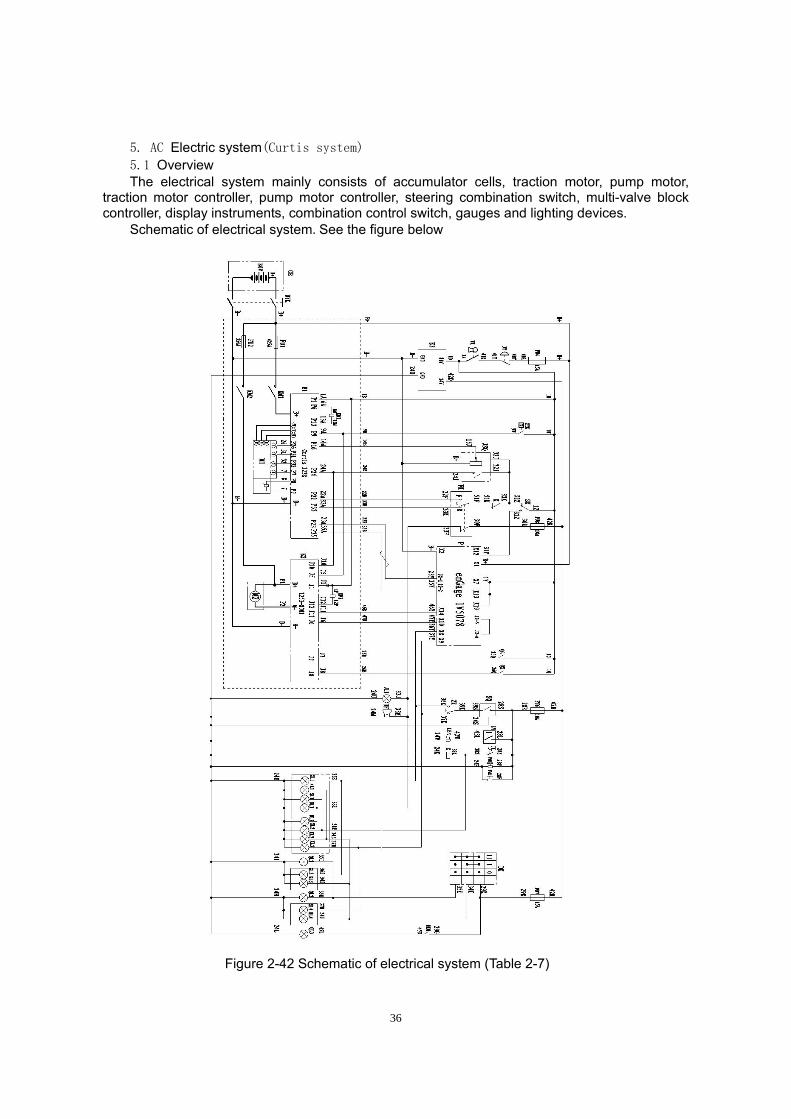
36
5. AC Electric system(Curtis system)
5.1 Overview The electrical system mainly consists of accumulator cells, traction motor, pump motor,
traction motor controller, pump motor controller, steering combination switch, multi-valve block controller, display instruments, combination control switch, gauges and lighting devices. Schematic of electrical system.See the figure below
Figure 2-42 Schematic of electrical system (Table 2-7)
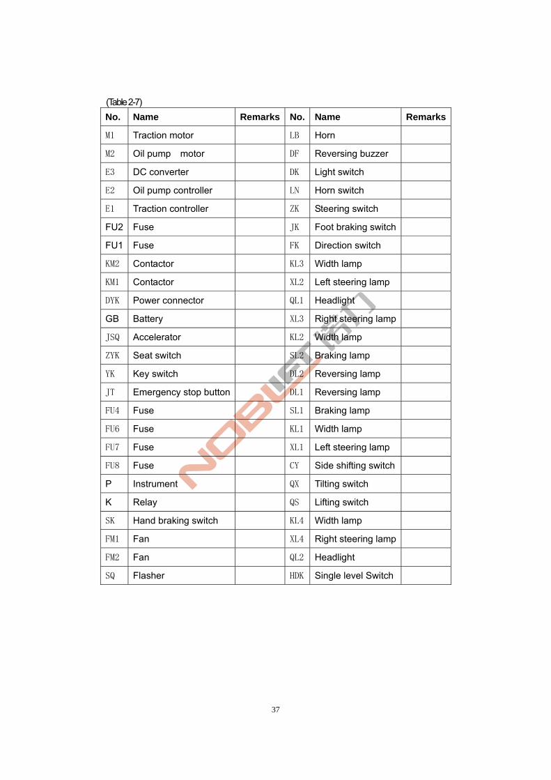
37
(Table 2-7)
No. Name Remarks No. Name Remarks
M1 Traction motor LB Horn
M2 Oil pump motor DF Reversing buzzer
E3 DC converter DK Light switch
E2 Oil pump controller LN Horn switch
E1 Traction controller ZK Steering switch
FU2 Fuse JK Foot braking switch
FU1 Fuse FK Direction switch
KM2 Contactor KL3 Width lamp
KM1 Contactor XL2 Left steering lamp
DYK Power connector QL1 Headlight
GB Battery XL3 Right steering lamp
JSQ Accelerator KL2 Width lamp
ZYK Seat switch SL2 Braking lamp
YK Key switch DL2 Reversing lamp
JT Emergency stop button DL1 Reversing lamp
FU4 Fuse SL1 Braking lamp
FU6 Fuse KL1 Width lamp
FU7 Fuse XL1 Left steering lamp
FU8 Fuse CY Side shifting switch
P Instrument QX Tilting switch
K Relay QS Lifting switch
SK Hand braking switch KL4 Width lamp
FM1 Fan XL4 Right steering lamp
FM2 Fan QL2 Headlight
SQ Flasher HDK Single level Switch
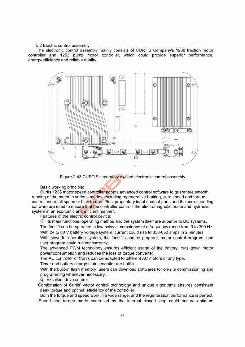
38
5.2 Electric control assembly The electronic control assembly mainly consists of CURTIS Company's 1238 traction motor
controller and 1253 pump motor controller, which could provide superior performance, energy-efficiency and reliable quality.
Figure 2-43 CURTIS separately excited electronic control assembly
Basic working principle: Curtis 1238 motor speed controller adopts advanced control software to guarantee smooth
running of the motor in various modes, including regenerative braking, zero speed and torque control under full speed or high torque. Plus, proprietary input / output ports and the corresponding software are used to ensure that the controller controls the electromagnetic brake and hydraulic system in an economic and efficient manner.
Features of the electric control device: ① Its main functions, operating method and the system itself are superior to DC systems.
The forklift can be operated in low noisy circumstance at a frequency range from 0 to 300 Hz. With 24 to 80 V battery voltage system, current could rise to 350-650 amps in 2 minutes. With powerful operating system, the forklift’s control program, motor control program, and
user program could run concurrently. The advanced PWM technology ensures efficient usage of the battery, cuts down motor
power consumption and reduces the loss of torque converter. The AC controller of Curtis can be adapted to different AC motors of any type. Timer and battery charge status monitor are built-in. With the built-in flash memory, users can download softwares for on-site commissioning and
programming whenever necessary. ② Excellent drive control
Combination of Curtis’ vector control technology and unique algorithms ensures consistent peak torque and optimal efficiency of the controller.
Both the torque and speed work in a wide range, and the regeneration performance is perfect. Speed and torque mode controlled by the internal closed loop could ensure optimum
39
performance without any additional device. The drive and braking performance can be adjusted to the best by setting the programmed
parameters. Torque control mode provides uniquely excellent performance to ensure smooth transition
and quick response in any state. With the unique pump control mode, the forklift could quickly respond to hydraulic changes. ③ Unmatched flexibility
Curtis's unique control language allows OEM manufacturers to design forklifts in an unprecedentedly easy way. With decades of industry experience, Curtis can not only provide you with various pre-setting functions, but also with the possibility of quickly and easily customized settings and new algorithms, so as to differentiate your system with similar products from your competitors.
VCL makes it possible for the controller to reflect and manage the system status of the forklift without additional hardware, saving your cost and design time.
Being widely applicable to a variety of I / O interface, it can meet all the needs of system control.
Through CAN BUS communication, it can be connected to other systems with a function of CAN BUS connection. (CAN OPEN, or customized through VCL)
The controller can be used for lifting or traction. (The specific model of corresponding software is built-in)
Users can easily perform programming by using the 1311 handheld programmer and 1314 PC programming station. ④ High security and reliability
Insulated metal base provides excellent heat dissipation, thus enhancing reliability of the controller.
Failure-safe power device Hardware watchdog Electrode reversal protection Short circuit protection of the output drive Settings on overheat protection, warning and automatic shutdown can protect the motor and
the electronic controller. Conforming to the IP65 protection standard, it could meet various harsh environmental
requirements. ⑤、 Equipping with the 1253 pump motor controller of the U.S. CURTIS Company, the
hydraulic system of the forklift features non-contact, non-sparking, no noise, smooth & reliable working during start of the hydraulic lift motor. Such problems as the main contacts is easy to erode, short service life, impact or damage to the accumulator cells and other defects frequently seen in the traditional hoisting contactor are completely eliminated. Thus accumulator life can be extended and maintenance costs can be reduced, greatly lowering the forklift’s operating cost.
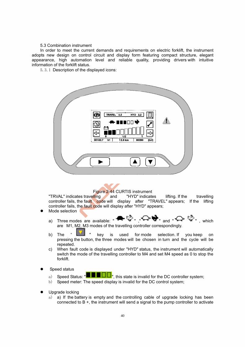
40
5.3 Combination instrument In order to meet the current demands and requirements on electric forklift, the instrument
adopts new design on control circuit and display form featuring compact structure, elegant appearance, high automation level and reliable quality, providing drivers with intuitive information of the forklift status.
5.3.1 Description of the displayed icons:
Figure 2-44 CURTIS instrument "TRVAL" indicates travelling and "HYD" indicates lifting. If the travelling controller fails, the fault code will display after "TRAVEL" appears; If the lifting controller fails, the fault code will display after "HYD" appears;
Mode selection
a) Three modes are available: " " ," " and " " , which are M1, M2, M3 modes of the travelling controller correspondingly.
b) The “ " key is used for mode selection. If you keep on pressing the button, the three modes will be chosen in turn and the cycle will be repeated.
c) When fault code is displayed under "HYD" status, the instrument will automatically switch the mode of the travelling controller to M4 and set M4 speed as 0 to stop the forklift.
Speed status
a) Speed Status: " ", this state is invalid for the DC controller system; b) Speed meter: The speed display is invalid for the DC control system;
Upgrade locking a) a) If the battery is empty and the controlling cable of upgrade locking has been
connected to B +, the instrument will send a signal to the pump controller to activate
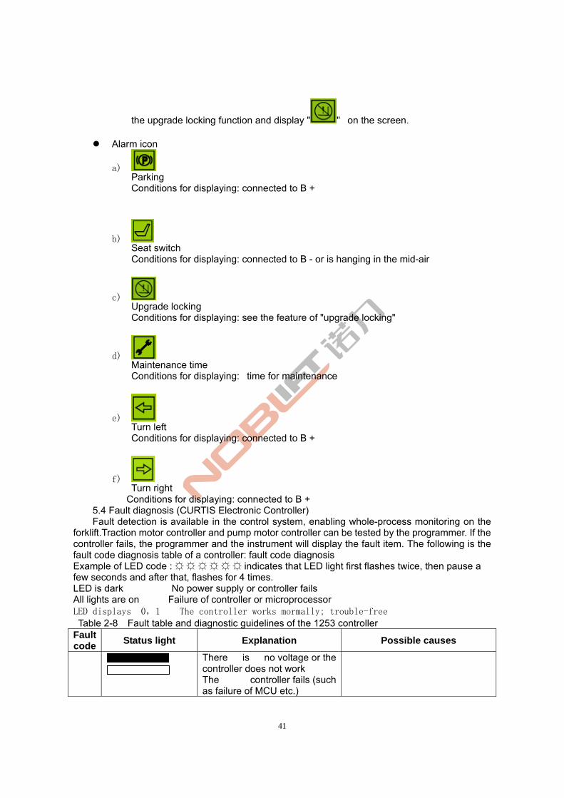
41
the upgrade locking function and display " " on the screen.
Alarm icon
a) Parking Conditions for displaying: connected to B +
b) Seat switch Conditions for displaying: connected to B - or is hanging in the mid-air
c) Upgrade locking Conditions for displaying: see the feature of "upgrade locking"
d) Maintenance time Conditions for displaying: time for maintenance
e) Turn left Conditions for displaying: connected to B +
f) Turn right
Conditions for displaying: connected to B + 5.4 Fault diagnosis (CURTIS Electronic Controller) Fault detection is available in the control system, enabling whole-process monitoring on the
forklift.Traction motor controller and pump motor controller can be tested by the programmer. If the controller fails, the programmer and the instrument will display the fault item. The following is the fault code diagnosis table of a controller: fault code diagnosis Example of LED code : ☼ ☼ ☼ ☼ ☼ ☼ indicates that LED light first flashes twice, then pause a few seconds and after that, flashes for 4 times. LED is dark No power supply or controller fails All lights are on Failure of controller or microprocessor LED displays 0,1 The controller works mormally; trouble-free Table 2-8 Fault table and diagnostic guidelines of the 1253 controller
Fault code
Status light Explanation Possible causes
There is no voltage or the controller does not work The controller fails (such as failure of MCU etc.)
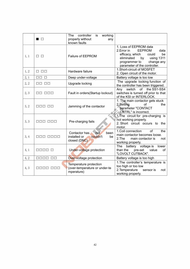
42
■ ¤ The controller is working properly without any known faults
1,1 ¤ ¤ Failure of EEPROM
1. Loss of EEPROM data 2.Error in EEPROM data
efficacy, which could be eliminated by using 1311 programmer to change any parameter of the controller.
1,2 ¤ ¤¤ Hardware failure 1.Short-circuit of MOSFET 2. Open circuit of the motor.
2,1 ¤¤ ¤ Deep under-voltage Battery voltage is too low
2,2 ¤¤ ¤¤ Upgrade locking The upgrade locking function of the controller has been triggered.
2,3 ¤¤ ¤¤¤ Fault in orders(Startup lockout)Any switch of the SS1-SS4 switches is turned off prior to that of the KSI or INTERLOCK.
3,2 ¤¤¤ ¤¤ Jamming of the contactor
1. The main contactor gets stuck 2.Setting of the
parameter "CONTACT CNTRL" is incorrect.
3,3 ¤¤¤ ¤¤¤ Pre-charging fails
1.The circuit for pre-charging is not working properly. 2. Short circuit occurs to the motor.
3,4 ¤¤¤ ¤¤¤¤ Contactor has not been installed or couldn't be closed (DNC)
1.Coil connection of the main contactor becomes loose. 2.The main contactor is not working properly.
4,1 ¤¤¤¤ ¤ Under-voltage protection The battery voltage is lower than the pre-set value of "LOVOLT CUTBACK".
4,2 ¤¤¤¤ ¤¤ Over-voltage protection Battery voltage is too high
4,3 ¤¤¤¤ ¤¤¤ Temperature protection (over-temperature or under-temperature)
1.The controller’s temperature is too high or too low 2.Temperature sensor is not working properly.
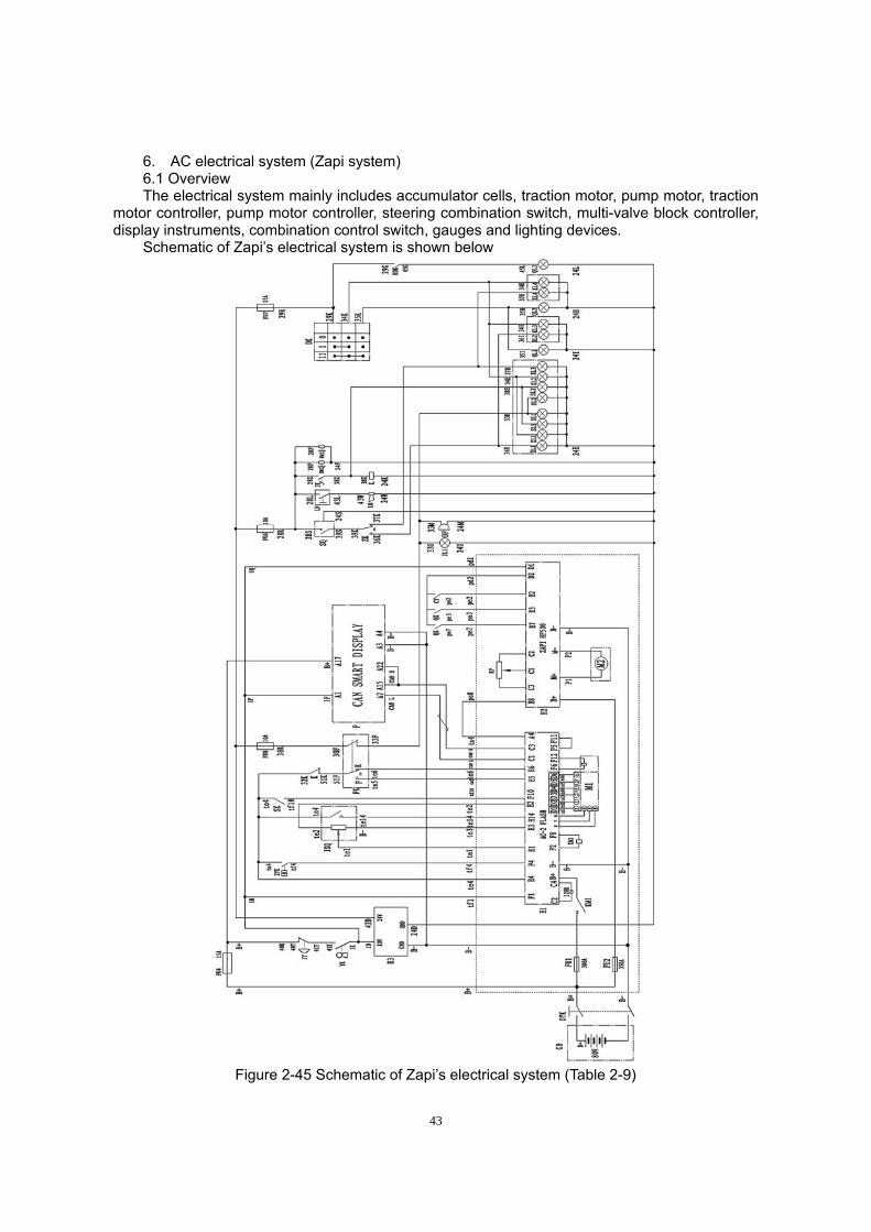
43
6. AC electrical system (Zapi system) 6.1 Overview The electrical system mainly includes accumulator cells, traction motor, pump motor, traction
motor controller, pump motor controller, steering combination switch, multi-valve block controller, display instruments, combination control switch, gauges and lighting devices.
Schematic of Zapi’s electrical system is shown below
Figure 2-45 Schematic of Zapi’s electrical system (Table 2-9)
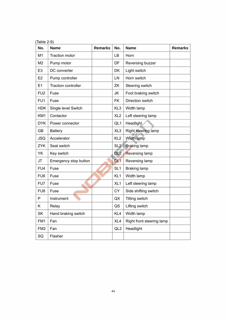
44
(Table 2-9)
No. Name Remarks No. Name Remarks
M1 Traction motor LB Horn
M2 Pump motor DF Reversing buzzer
E3 DC converter DK Light switch
E2 Pump controller LN Horn switch
E1 Traction controller ZK Steering switch
FU2 Fuse JK Foot braking switch
FU1 Fuse FK Direction switch
HDK Single level Switch KL3 Width lamp
KM1 Contactor XL2 Left steering lamp
DYK Power connector QL1 Headlight
GB Battery XL3 Right steering lamp
JSQ Accelerator KL2 Width lamp
ZYK Seat switch SL2 Braking lamp
YK Key switch DL2 Reversing lamp
JT Emergency stop button DL1 Reversing lamp
FU4 Fuse SL1 Braking lamp
FU6 Fuse KL1 Width lamp
FU7 Fuse XL1 Left steering lamp
FU8 Fuse CY Side shifting switch
P Instrument QX Tilting switch
K Relay QS Lifting switch
SK Hand braking switch KL4 Width lamp
FM1 Fan XL4 Right front steering lamp
FM2 Fan QL2 Headlight
SQ Flasher
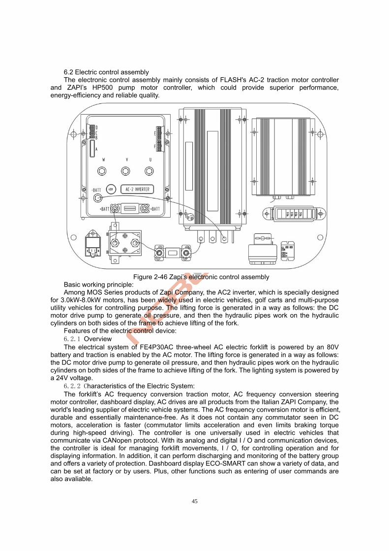
45
6.2 Electric control assembly The electronic control assembly mainly consists of FLASH's AC-2 traction motor controller
and ZAPI’s HP500 pump motor controller, which could provide superior performance, energy-efficiency and reliable quality.
Figure 2-46 Zapi’s electronic control assembly
Basic working principle: Among MOS Series products of Zapi Company, the AC2 inverter, which is specially designed
for 3.0kW-8.0kW motors, has been widely used in electric vehicles, golf carts and multi-purpose utility vehicles for controlling purpose. The lifting force is generated in a way as follows: the DC motor drive pump to generate oil pressure, and then the hydraulic pipes work on the hydraulic cylinders on both sides of the frame to achieve lifting of the fork.
Features of the electric control device: 6.2.1 Overview The electrical system of FE4P30AC three-wheel AC electric forklift is powered by an 80V
battery and traction is enabled by the AC motor. The lifting force is generated in a way as follows: the DC motor drive pump to generate oil pressure, and then hydraulic pipes work on the hydraulic cylinders on both sides of the frame to achieve lifting of the fork. The lighting system is powered by a 24V voltage.
6.2.2 Characteristics of the Electric System: The forklift’s AC frequency conversion traction motor, AC frequency conversion steering
motor controller, dashboard display, AC drives are all products from the Italian ZAPI Company, the world's leading supplier of electric vehicle systems. The AC frequency conversion motor is efficient, durable and essentially maintenance-free. As it does not contain any commutator seen in DC motors, acceleration is faster (commutator limits acceleration and even limits braking torque during high-speed driving). The controller is one universally used in electric vehicles that communicate via CANopen protocol. With its analog and digital I / O and communication devices, the controller is ideal for managing forklift movements, I / O, for controlling operation and for displaying information. In addition, it can perform discharging and monitoring of the battery group and offers a variety of protection. Dashboard display ECO-SMART can show a variety of data, and can be set at factory or by users. Plus, other functions such as entering of user commands are also avaliable.
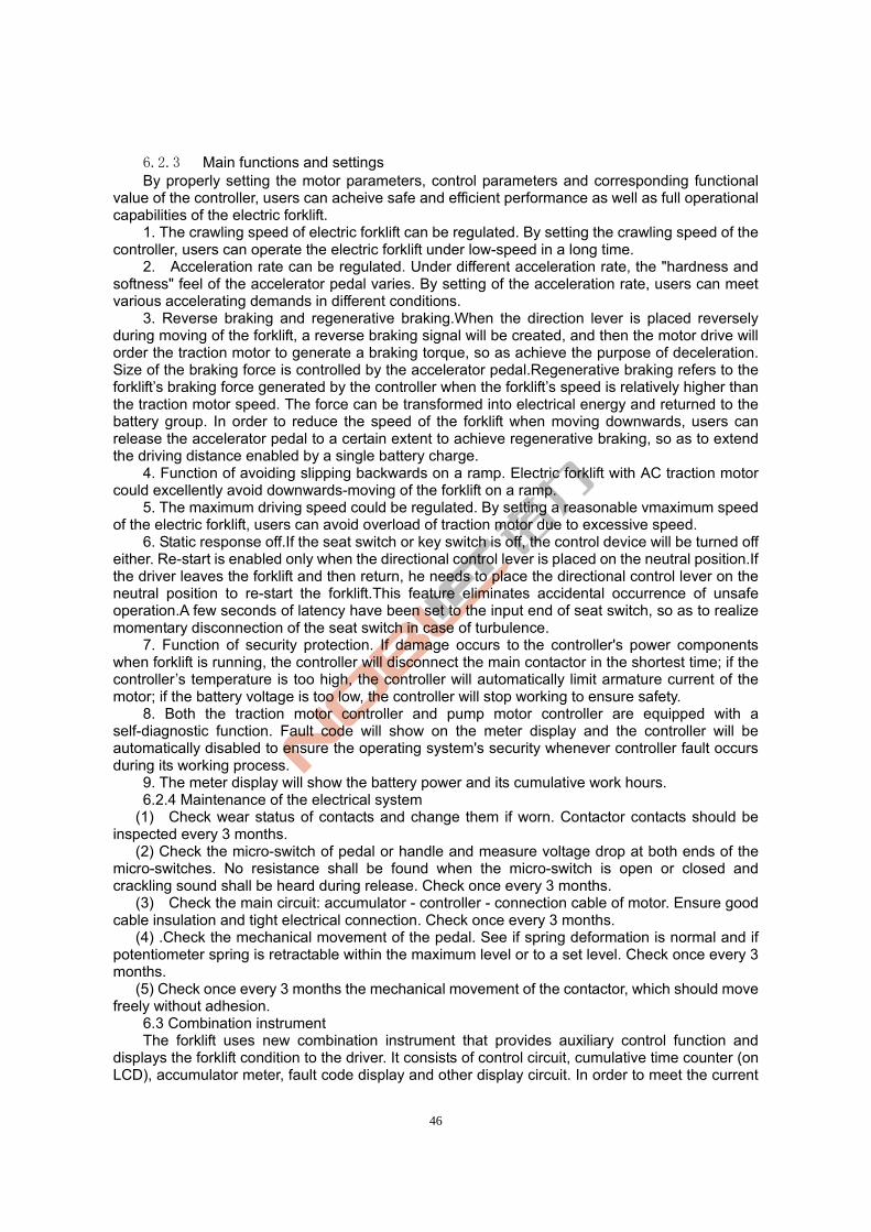
46
6.2.3 Main functions and settings By properly setting the motor parameters, control parameters and corresponding functional
value of the controller, users can acheive safe and efficient performance as well as full operational capabilities of the electric forklift.
1. The crawling speed of electric forklift can be regulated. By setting the crawling speed of the controller, users can operate the electric forklift under low-speed in a long time.
2. Acceleration rate can be regulated. Under different acceleration rate, the "hardness and softness" feel of the accelerator pedal varies. By setting of the acceleration rate, users can meet various accelerating demands in different conditions.
3. Reverse braking and regenerative braking.When the direction lever is placed reversely during moving of the forklift, a reverse braking signal will be created, and then the motor drive will order the traction motor to generate a braking torque, so as achieve the purpose of deceleration. Size of the braking force is controlled by the accelerator pedal.Regenerative braking refers to the forklift’s braking force generated by the controller when the forklift’s speed is relatively higher than the traction motor speed. The force can be transformed into electrical energy and returned to the battery group. In order to reduce the speed of the forklift when moving downwards, users can release the accelerator pedal to a certain extent to achieve regenerative braking, so as to extend the driving distance enabled by a single battery charge.
4. Function of avoiding slipping backwards on a ramp. Electric forklift with AC traction motor could excellently avoid downwards-moving of the forklift on a ramp.
5. The maximum driving speed could be regulated. By setting a reasonable vmaximum speed of the electric forklift, users can avoid overload of traction motor due to excessive speed.
6. Static response off.If the seat switch or key switch is off, the control device will be turned off either. Re-start is enabled only when the directional control lever is placed on the neutral position.If the driver leaves the forklift and then return, he needs to place the directional control lever on the neutral position to re-start the forklift.This feature eliminates accidental occurrence of unsafe operation.A few seconds of latency have been set to the input end of seat switch, so as to realize momentary disconnection of the seat switch in case of turbulence.
7. Function of security protection. If damage occurs to the controller's power components when forklift is running, the controller will disconnect the main contactor in the shortest time; if the controller’s temperature is too high, the controller will automatically limit armature current of the motor; if the battery voltage is too low, the controller will stop working to ensure safety.
8. Both the traction motor controller and pump motor controller are equipped with a self-diagnostic function. Fault code will show on the meter display and the controller will be automatically disabled to ensure the operating system's security whenever controller fault occurs during its working process.
9. The meter display will show the battery power and its cumulative work hours. 6.2.4 Maintenance of the electrical system
(1) Check wear status of contacts and change them if worn. Contactor contacts should be inspected every 3 months.
(2) Check the micro-switch of pedal or handle and measure voltage drop at both ends of the micro-switches. No resistance shall be found when the micro-switch is open or closed and crackling sound shall be heard during release. Check once every 3 months.
(3) Check the main circuit: accumulator - controller - connection cable of motor. Ensure good cable insulation and tight electrical connection. Check once every 3 months.
(4) .Check the mechanical movement of the pedal. See if spring deformation is normal and if potentiometer spring is retractable within the maximum level or to a set level. Check once every 3 months.
(5) Check once every 3 months the mechanical movement of the contactor, which should move freely without adhesion.
6.3 Combination instrument The forklift uses new combination instrument that provides auxiliary control function and
displays the forklift condition to the driver. It consists of control circuit, cumulative time counter (on LCD), accumulator meter, fault code display and other display circuit. In order to meet the current
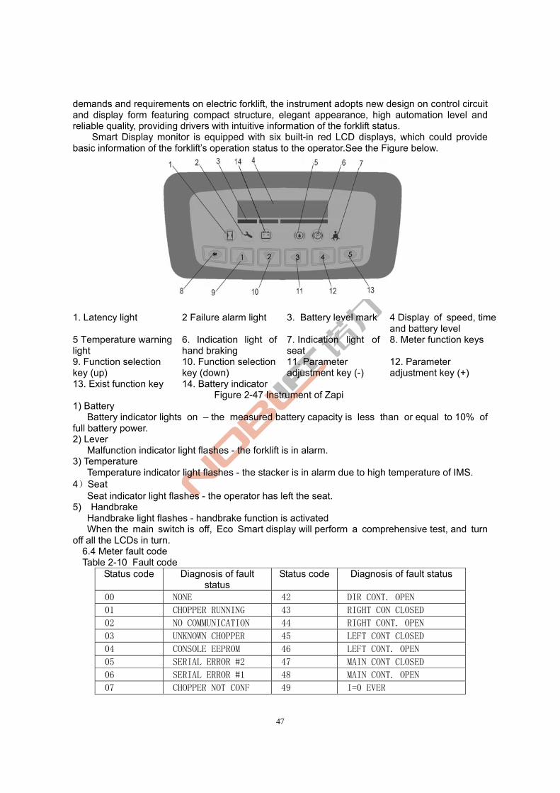
47
demands and requirements on electric forklift, the instrument adopts new design on control circuit and display form featuring compact structure, elegant appearance, high automation level and reliable quality, providing drivers with intuitive information of the forklift status.
Smart Display monitor is equipped with six built-in red LCD displays, which could provide basic information of the forklift’s operation status to the operator.See the Figure below.
1. Latency light 2 Failure alarm light 3. Battery level mark 4 Display of speed, time and battery level
5 Temperature warning light
6. Indication light of hand braking
7. Indication light of seat
8. Meter function keys
9. Function selection key (up)
10. Function selection key (down)
11. Parameter adjustment key (-)
12. Parameter adjustment key (+)
13. Exist function key 14. Battery indicator Figure 2-47 Instrument of Zapi
1) Battery Battery indicator lights on – the measured battery capacity is less than or equal to 10% of
full battery power. 2) Lever
Malfunction indicator light flashes - the forklift is in alarm. 3) Temperature
Temperature indicator light flashes - the stacker is in alarm due to high temperature of IMS. 4)Seat
Seat indicator light flashes - the operator has left the seat. 5) Handbrake
Handbrake light flashes - handbrake function is activated When the main switch is off, Eco Smart display will perform a comprehensive test, and turn off all the LCDs in turn.
6.4 Meter fault code Table 2-10 Fault code
Status code Diagnosis of fault status
Status code Diagnosis of fault status
00 NONE 42 DIR CONT. OPEN
01 CHOPPER RUNNING 43 RIGHT CON CLOSED
02 NO COMMUNICATION 44 RIGHT CONT. OPEN
03 UNKNOWN CHOPPER 45 LEFT CONT CLOSED
04 CONSOLE EEPROM 46 LEFT CONT. OPEN
05 SERIAL ERROR #2 47 MAIN CONT CLOSED
06 SERIAL ERROR #1 48 MAIN CONT. OPEN
07 CHOPPER NOT CONF 49 I=0 EVER
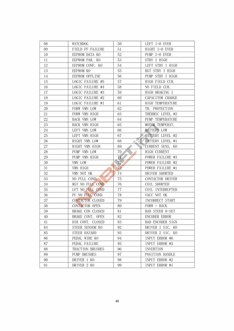
48
08 WATCHDOG 50 LEFT I=0 EVER
09 FIELD FF FAILURE 51 RIGHT I=0 EVER
10 EEPROM DATA KO 52 PUMP I=0 EVER
11 EEPROM PAR. KO 53 STBY I HIGH
12 EEPROM CONF. KO 54 LEFT STBY I HIGH
13 EEPROM KO 55 RGT STBY I HIGH
14 EEPROM OFFLINE 56 PUMP STBY I HIGH
15 LOGIC FAILURE #5 57 HIGH FIELD CUR.
16 LOGIC FAILURE #4 58 NO FIELD CUR.
17 LOGIC FAILURE #3 59 HIGH BRAKING I
18 LOGIC FAILURE #2 60 CAPACITOR CHARGE
19 LOGIC FAILURE #1 61 HIGH TEMPERATURE
20 FORW VMN LOW 62 TH. PROTECTION
21 FORW VMN HIGH 63 THERMIC LEVEL #2
22 BACK VMN LOW 64 PUMP TEMPERATURE
23 BACK VMN HIGH 65 MOTOR TEMPERAT.
24 LEFT VMN LOW 66 BATTERY LOW
25 LEFT VMN HIGH 67 BATTERY LEVEL #2
26 RIGHT VMN LOW 68 BATTERY LEVEL #1
27 RIGHT VMN HIGH 69 CURRENT SENS. KO
28 PUMP VMN LOW 70 HIGH CURRENT
29 PUMP VMN HIGH 71 POWER FAILURE #3
30 VMN LOW 72 POWER FAILURE #2
31 VMN HIGH 73 POWER FAILURE #1
32 VMN NOT OK 74 DRIVER SHORTED
33 NO FULL COND. 75 CONTACTOR DRIVER
34 RGT NO FULL COND 76 COIL SHORTED
35 LFT NO FULL COND 77 COIL INTERRUPTED
36 PU NO FULL COND 78 VACC NOT OK
37 CONTACTOR CLOSED 79 INCORRECT START
38 CONTACTOR OPEN 80 FORW + BACK
39 BRAKE CON CLOSED 81 BAD STEER 0-SET
40 BRAKE CONT. OPEN 82 ENCODER ERROR
41 DIR CONT. CLOSED 83 BAD ENCODER SIGN
84 STEER SENSOR KO 92 DRIVER 1 SIC. KO
85 STEER HAZARD 93 DRIVER 2 SIC. KO
86 PEDAL WIRE KO 94 INPUT ERROR #6
87 PEDAL FAILURE 95 INPUT ERROR #5
88 TRACTION BRUSHES 96 INVERTION
89 PUMP BRUSHES 97 POSITION HANDLE
90 DRIVER 1 KO 98 INPUT ERROR #2
91 DRIVER 2 KO 99 INPUT ERROR #1
49
7.Accumulator 7.1 Accumulator safety precautions: △ Appropriate ventilation measures shall be adopted because hydrogen and oxygen will be
generated at the end of the accumulator charging process. If spark occur during the process, explosion may be caused.
△ Harmful acid mist will also be generated during charging. Remove the mist promptly after charging and clean up the accumulator and the charging place promptly.
△ Please wear protective glasses and rubber gloves when charging the accumulator as it contains sulfuric acid. Careless use may cause skin burns and loss of vision. If you splash electrolyte (acid) in your eyes or skin, immediately wash with plenty of water and visit a doctor for treatment. Electrolyte on clothes can be washed off with water.
△ People who are not familiar with the operating method of the accumulator and its dangerousness shall not use the accumulator, so as to avoid harm to personnel caused by the dilute sulfuric acid.
△ Never place any metal objects or tools on the accumulator to eliminate the danger of short-circuit.
△ Unplug the power connector of the accumulator only when power is fully turned off. Hot plugging is strictly prohibited.
△ Before installing the accumulator, please read the instruction manual carefully. After reading, please keep it with you for future reference.
7.2 Accumulator use precautions Service life of the accumulator is generally 2 to 3 years, or even 4 years if it can be properly used
and maintained. In case of the improper use and maintenance, it may suffer early damage in a few months since initial use.
During use of the accumulator, users should regularly check the electrolyte level and the remaining accumulator capacity. Recharge the accumulator if necessary. Accumulator maintenance is relatively simple, but requires patience and meticulousness. Timely supplementing and density control of the electrolyte as well as cleanup of accumulator and polarity terminals can effectively extend the service life of accumulator.
Check if there is water in the accumulator box and drain the water immediately if any. In addition, the accumulator should not be stored with electrolyte in it. In case of short-term storage
of a fully charged accumulator, please charge the it every month during the storage period to compensate for self-discharge of the accumulator, preventing vulcanization of accumulator plate or eliminating minor vulcanization of the accumulator plates. Plus, users shall check the accumulator status frequently during the storage period. If the accumulator is being used, please conduct a fully discharge together with a fully charge each month. This could help maintain accumulator capacity and avoid plate salvation.
Please keep the external surface of the accumulator clean. Check the accumulator and the fixing status of wire leads. There should be no looseness. Check the accumulator case for cracking and damage and then check the pole and lead chuck to
see if they are burnt. Wipe clean dust on the external surface of the accumulator with a cloth. If electrolyte overflows to
the surface, please wipe with a cloth or rinse with hot water and wipe it dry with a cloth. Remove dirt and oxides on the post piling and wipe clean the external of lead cable and lead chuck. Unblock and clean up the vent on the filler cap. During the installation process, apply a thin layer of industrial Vaseline on the pole and lead chuck. Check the accumulator fluid level:
Vertically insert a glass tube with a diameter of 6 ~ 8mm and length of 150mm into the filler until reaching the upper edge of the plate. Then press the upper end of the tube with thumb and clip out the glass tube with the index finger, middle finger and ring finger. The height of the electrolyte within the tube is the height of electrolyte above the plate accumulator surface, which should be 15-25mm. Finally, return the electrolyte to the original single-cell accumulator.
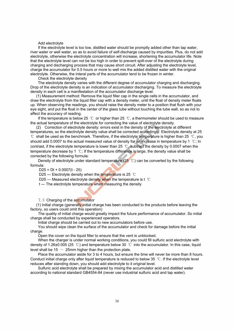
50
Add electrolyte If the electrolyte level is too low, distilled water should be promptly added other than tap water,
river water or well water, so as to avoid failure of self-discharge caused by impurities. Plus, do not add electrolyte, otherwise the electrolyte concentration will increase, shortening the accumulator life. Note that the electrolyte level can not be too high in order to prevent spill-over of the electrolyte during charging and discharging process that may cause short circuit. After adjusting the electrolyte level, charge the accumulator for 0.5 hours or more to well mix the added distilled water with the original electrolyte. Otherwise, the interal parts of the accumulator tend to be frozen in winter.
Check the electrolyte density The electrolyte density varies with the different degree of accumulator charging and discharging.
Drop of the electrolyte density is an indication of accumulator discharging. To measure the electrolyte density in each cell is a manifestation of the accumulator discharge level.
(1) Measurement method: Remove the liquid filler cap in the single cells in the accumulator, and draw the electrolyte from the liquid filler cap with a density meter, until the float of density meter floats up. When observing the readings, you should raise the density meter to a position that flush with your eye sight, and put the float in the center of the glass tube without touching the tube wall, so as not to affect the accuracy of reading.
If the temperature is below 25 ℃ or higher than 25 ℃, a thermometer should be used to measure the actual temperature of the electrolyte for correcting the value of electrolyte density.
(2) Correction of electrolyte density: errors exist in the density of the electrolyte at different temperatures, so the electrolyte density value shall be corrected accordingly. Electrolyte density at 25 ℃ shall be used as the benchmark. Therefore, if the electrolyte temperature is higher than 25 ℃, you should add 0.0007 to the actual measured value of density for an increase in temperature by 1 ℃; In contrast, if the electrolyte temperature is lower than 25 ℃, subtract the density by 0.0007 when the temperature decrease by 1 ℃; If the temperature difference is large, the density value shall be corrected by the following formula:
Density of electrolyte under standard temperature (25 ℃) can be converted by the following formula:
D25 = Dt + 0.0007(t - 25) D25 — Electrolyte density when the temperature is 25 ℃ D25 — Measured electrolyte density when the temperature is t ℃ t — The electrolyte temperature when measuring the density
7.3 Charging of the accumulator
(1) Initial charge (generally initial charge has been conducted to the products before leaving the factory, so users could omit this operation)
The quality of initial charge would greatly impact the future performance of accumulator. So initial charge shall be conducted by experienced operators.
Initial charge should be carried out to new accumulators before use. You should wipe clean the surface of the accumulator and check for damage before the initial
charge. Open the cover on the liquid filler to ensure that the vent is unblocked. When the charger is under normal working conditions, you could fill sulfuric acid electrolyte with
density of 1.26±0.005 (25 ℃) and temperature below 30 ℃ into the accumulator. In this case, liquid level shall be 15 ~ 25mm higher than the protection plate.
Place the accumulator aside for 3 to 4 hours, but ensure the time will never be more than 8 hours. Conduct initial charge only after liquid temperature is reduced to below 35 ℃. If the electrolyte level reduces after standing down, you should add electrolyte to it original level.
Sulfuric acid electrolyte shall be prepared by mixing the accumulator acid and distilled water according to national standard GB4554-84 (never use industrial sulfuric acid and tap water).
51
During preparation, please slowly fill the concentrated sulfuric acid into the distilled water by trickle and continuously stir with a acid-proof glass rod or with a lead covered wood stick. Filling of distilled water into the sulfuric acid is not allowed, otherwise it will cause boiling and splashing of solution, resulting in burning.
Connect the accumulator with the charger correctly in terms of polarity in a reliable manner, namely, ensure ro connect positive to positive and negative to negative.
For the first phase of initial charge, please use 0.5I5A (60A for D-600 accumulator) until the voltage of a single cell reaches 2.4V. Then we could shift to the second phase of initial charge;
For the second phase of the initial charge, you could use 0.25I5A (30A for D-600 accumulator) for charging;
The temperature of the electrolyte shall not exceed 45 ℃ during charging. Reduce the charge current by half or suspend the charge when the temperature is close to 45 ℃. Continue charging after the electrolyte temperature drops to below 35 ℃. In this case, the charging time shall be extended appropriatly;
Evidence of fully charged: In the second stage of the initial charging, charging voltage will be up to 2.6V and the voltage change shall be less than 0.005V; When electrolyte density is 1.28 ± 0.005 (25 ℃) , if there is no significant change within 2 hours and fine bubbles emerges intensely, the accumulator can be considered fully charged. The charging power is 4 to 5 times of the rated capacity and the charging time is about 70 hours;
In order to accurately control the content of sulfuric acid in the electrolyte, the density of the electrolyte should be checked at the end of the charging process; In case of any discrepancy, please use distilled water or sulfuric acid with density of 1.40 to adjust. Ensure the electrolyte density and height level is adjusted to the specified value within 2 hours since the charging starts;
Wipe clean the accumulator surface and cover the filler cap before putting into use.
((2) General Charge Do not use accumulator that is not fully charged. Users should pay close attention to the discharge
level of accumulator during use. If the discharge level exceeds the set value, conduct charge in time. Excessive discharge is strictly forbidden. When the voltage drops o 1.7V / cell, electrolyte density decreases to 1.17, stop discharge timely and conduct charge soon. Never delay charging for a long time. Don’t stop halfway without reason during the charging process.
When conducting general charge, first open the flip cover on the filler cap cover and check whether the electrolyte height meet requirements. If not, please fill distilled water to adjust the liquid level to the required height.
Connect the output of the charger with the accumulator in accordance with the requirements. Connect positive to positive and negative to negative. Pay attention not to connect it reversed.
The charger compatible with the accumulator could automatically regulate the charging current according to the charging capacity and conduct charging until the accumulator is fully charged. (Please refer to the manual of charger for details on observation of the charging state)
In order to keep the accumulator status updated, it is recommended to record each charge and discharge conducted for each accumulator, so as to provide useful basis for determining whether or not the accumulator in the future or not. During the charging process, measure and record the current, total voltage, voltage of each single cell(the cells shall be numbered) , changes in the electrolyte density and temperature (measure with a 0 ~ 100 mercury thermometer) every 1℃ -2 hour .
If large quantities of even and fine bubbles come into being, voltage of single cell is stabilized at 2.5-2.7V and electrolyte density and terminal voltage stops rising in 2-3 hours, then it can be determined that the accumulator is fully charged. If any cells have no or few bubbles, try to find out the reasons and fix the problem. Then record it in your work log.
Electrolyte temperature shall not exceed 45 during the charging process. The temperature of ℃the electrolyte during charging shall not exceed 45 . Suspend charging if the temperature is close to ℃45 and continue charging when the electrolyte temperature drops to below 35 . ℃ ℃
When the accumulator charging comes to end, the electrolyte density of the accumulator shall be checked and adjusted. If the electrolyte density fails to meet the requirements, draw some electrolyte from the original cells. If it is less denser than normal, fill concentrated electrolyte with density of 1.40
52
for adjustment; if it is denser than normal, dilute it by adding distilled water. After adjustment, the difference of electrolyte density of cells should not exceed 0.01 and the liquid level should meet relevant requirements. After adjusting the density, you could continue to charge with small current for 0.5 hours to mix the electrolyte. Then review the electrolyte density and adjust it if necessary. Finally, wipe clean and mount the accumulator for future use.
3)Balanced recharging Under normal circumstances, although all the accumulator cells run under the same situation, but
for some reasons, imbalance in the entire accumulator may occur. In such case, balanced recharging should be conducted to eliminate the charge difference between the accumulator cells, so as to achieve a balanced charging between all cells of the battery. Balanced recharging is simple and users can operate according to the instructions.
Perform balanced recharging to the accumulator once every two or three months during normal use. accumulators that are left unused for a long time should be charged before use.
7.4 Installation and replacement of the accumulator Perform installation and replacement of batteries in a fixed and reliable manner to avoid tipping;
Beating on the polar column and lead chuck with a tool is strictly forbidden; in the handling process, pay attention to avoid strong impact.
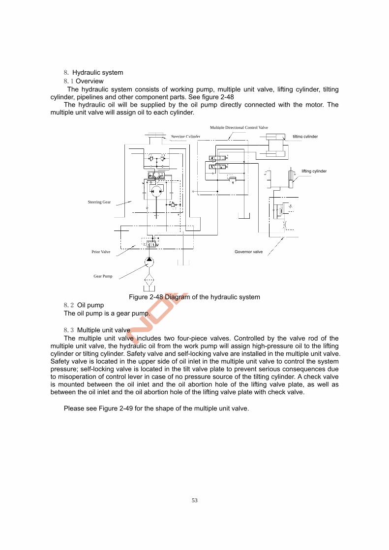
53
8. Hydraulic system
8.1 Overview The hydraulic system consists of working pump, multiple unit valve, lifting cylinder, tilting
cylinder, pipelines and other component parts. See figure 2-48 The hydraulic oil will be supplied by the oil pump directly connected with the motor. The
multiple unit valve will assign oil to each cylinder.
Figure 2-48 Diagram of the hydraulic system
8.2 Oil pump The oil pump is a gear pump.
8.3 Multiple unit valve The multiple unit valve includes two four-piece valves. Controlled by the valve rod of the
multiple unit valve, the hydraulic oil from the work pump will assign high-pressure oil to the lifting cylinder or tilting cylinder. Safety valve and self-locking valve are installed in the multiple unit valve. Safety valve is located in the upper side of oil inlet in the multiple unit valve to control the system pressure; self-locking valve is located in the tilt valve plate to prevent serious consequences due to misoperation of control lever in case of no pressure source of the tilting cylinder. A check valve is mounted between the oil inlet and the oil abortion hole of the lifting valve plate, as well as between the oil inlet and the oil abortion hole of the lifting valve plate with check valve.
Please see Figure 2-49 for the shape of the multiple unit valve.
Steering Cylinder
Multiple Directional Control Valve
lifting cylinder
tilting cylinder
Steering Gear
Gear Pump
Prior Valve Governor valve
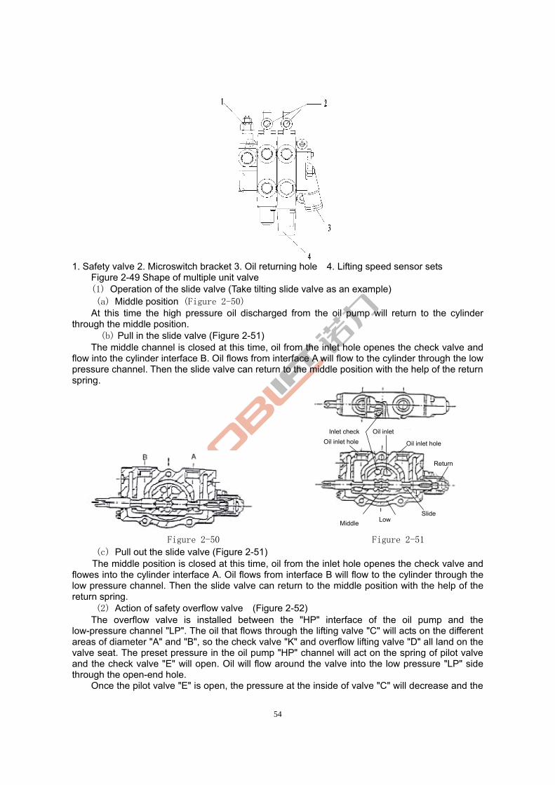
54
1. Safety valve 2. Microswitch bracket 3. Oil returning hole 4. Lifting speed sensor sets
Figure 2-49 Shape of multiple unit valve (1) Operation of the slide valve (Take tilting slide valve as an example) (a) Middle position (Figure 2-50)
At this time the high pressure oil discharged from the oil pump will return to the cylinder through the middle position.
(b) Pull in the slide valve (Figure 2-51) The middle channel is closed at this time, oil from the inlet hole openes the check valve and
flow into the cylinder interface B. Oil flows from interface A will flow to the cylinder through the low pressure channel. Then the slide valve can return to the middle position with the help of the return spring.
Figure 2-50 Figure 2-51
(c) Pull out the slide valve (Figure 2-51) The middle position is closed at this time, oil from the inlet hole openes the check valve and
flowes into the cylinder interface A. Oil flows from interface B will flow to the cylinder through the low pressure channel. Then the slide valve can return to the middle position with the help of the return spring.
(2) Action of safety overflow valve (Figure 2-52) The overflow valve is installed between the "HP" interface of the oil pump and the
low-pressure channel "LP". The oil that flows through the lifting valve "C" will acts on the different areas of diameter "A" and "B", so the check valve "K" and overflow lifting valve "D" all land on the valve seat. The preset pressure in the oil pump "HP" channel will act on the spring of pilot valve and the check valve "E" will open. Oil will flow around the valve into the low pressure "LP" side through the open-end hole.
Once the pilot valve "E" is open, the pressure at the inside of valve "C" will decrease and the
MiddleLow
Slide
Return
Oil inlet hole Inlet check
Oil inlet hole
Oil inlet
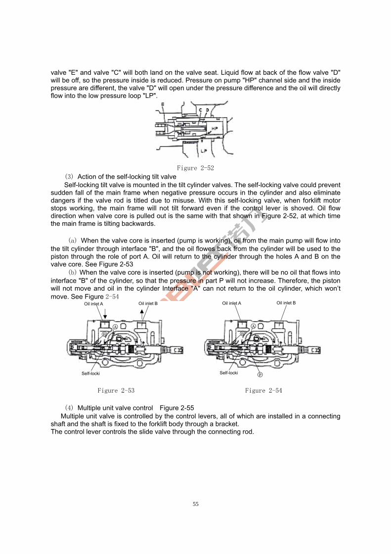
55
valve "E" and valve "C" will both land on the valve seat. Liquid flow at back of the flow valve "D" will be off, so the pressure inside is reduced. Pressure on pump "HP" channel side and the inside pressure are different, the valve "D" will open under the pressure difference and the oil will directly flow into the low pressure loop "LP".
Figure 2-52
(3) Action of the self-locking tilt valve Self-locking tilt valve is mounted in the tilt cylinder valves. The self-locking valve could prevent sudden fall of the main frame when negative pressure occurs in the cylinder and also eliminate dangers if the valve rod is titled due to misuse. With this self-locking valve, when forklift motor stops working, the main frame will not tilt forward even if the control lever is shoved. Oil flow direction when valve core is pulled out is the same with that shown in Figure 2-52, at which time the main frame is tilting backwards.
(a) When the valve core is inserted (pump is working), oil from the main pump will flow into the tilt cylinder through interface "B", and the oil flowes back from the cylinder will be used to the piston through the role of port A. Oil will return to the cylinder through the holes A and B on the valve core. See Figure 2-53
(b) When the valve core is inserted (pump is not working), there will be no oil that flows into interface "B" of the cylinder, so that the pressure in part P will not increase. Therefore, the piston will not move and oil in the cylinder Interface "A" can not return to the oil cylinder, which won’t move. See Figure 2-54
Figure 2-53 Figure 2-54
(4) Multiple unit valve control Figure 2-55 Multiple unit valve is controlled by the control levers, all of which are installed in a connecting shaft and the shaft is fixed to the forklift body through a bracket. The control lever controls the slide valve through the connecting rod.
Oil inlet A Oil inlet B
Self-locki
○A ○B
Oil inlet A Oil inlet B
Self-locki
○A ○B
○P
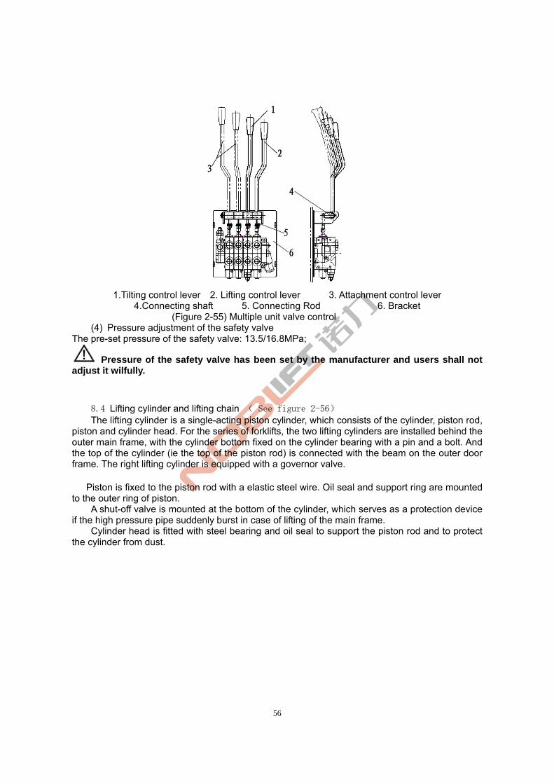
56
1.Tilting control lever 2. Lifting control lever 3. Attachment control lever
4.Connecting shaft 5. Connecting Rod 6. Bracket (Figure 2-55) Multiple unit valve control
(4) Pressure adjustment of the safety valve The pre-set pressure of the safety valve: 13.5/16.8MPa;
Pressure of the safety valve has been set by the manufacturer and users shall not adjust it wilfully.
8.4 Lifting cylinder and lifting chain ( See figure 2-56) The lifting cylinder is a single-acting piston cylinder, which consists of the cylinder, piston rod, piston and cylinder head. For the series of forklifts, the two lifting cylinders are installed behind the outer main frame, with the cylinder bottom fixed on the cylinder bearing with a pin and a bolt. And the top of the cylinder (ie the top of the piston rod) is connected with the beam on the outer door frame. The right lifting cylinder is equipped with a governor valve. Piston is fixed to the piston rod with a elastic steel wire. Oil seal and support ring are mounted to the outer ring of piston. A shut-off valve is mounted at the bottom of the cylinder, which serves as a protection device if the high pressure pipe suddenly burst in case of lifting of the main frame. Cylinder head is fitted with steel bearing and oil seal to support the piston rod and to protect the cylinder from dust.
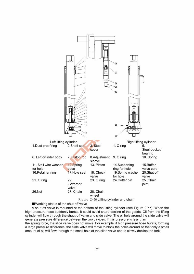
57
Left lifting cylinder Right lifting cylinder
1.Dust proof ring 2.Shaft seal 3. Steel cover
1. O ring 5. Steel-backed bearing
6. Left cylinder body 7. Piston rod 8.Adjustment sleeve
9. O ring 10. Spring
11. Stell wire washer for hole
12.Spring base
13. Piston 14.Supporting ring for hole
15.Buffer valve core
16.Retainer ring 17.Hole seal 18. Check valve
19.Spring washer for hole
20.Shut-off valve
21. O ring 22. Governor valve
23. O ring 24.Cotter pin 25. Chain joint
26.Nut 27. Chain 28. Chain wheel
Figure 2-56 Lifting cylinder and chain ■Working status of the shut-off valve A shut-off valve is mounted at the bottom of the lifting cylinder (see Figure 2-57). When the
high pressure hose suddenly bursts, it could avoid sharp decline of the goods. Oil from the lifting cylinder will flow through the shuut-off valve and slide valve. The oil hole around the slide valve will generate pressure difference between the two cavities. If this pressure is less than the spring force, the slide valve does not move. For example, if high pressure hose bursts, forming a large pressure difference, the slide valve will move to block the holes around so that only a small amount of oil will flow through the small hole at the slide valve end to slowly decline the fork.
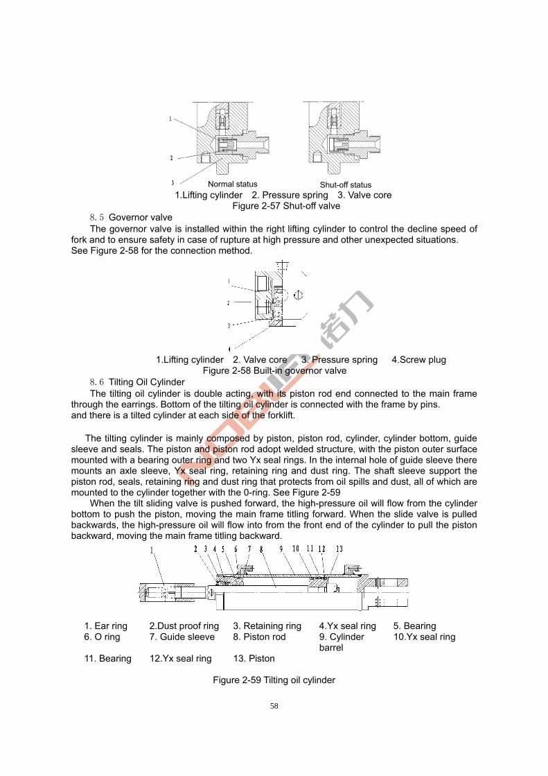
58
1.Lifting cylinder 2. Pressure spring 3. Valve core
Figure 2-57 Shut-off valve 8.5 Governor valve
The governor valve is installed within the right lifting cylinder to control the decline speed of fork and to ensure safety in case of rupture at high pressure and other unexpected situations. See Figure 2-58 for the connection method.
1.Lifting cylinder 2. Valve core 3. Pressure spring 4.Screw plug
Figure 2-58 Built-in governor valve 8.6 Tilting Oil Cylinder
The tilting oil cylinder is double acting, with its piston rod end connected to the main frame through the earrings. Bottom of the tilting oil cylinder is connected with the frame by pins. and there is a tilted cylinder at each side of the forklift. The tilting cylinder is mainly composed by piston, piston rod, cylinder, cylinder bottom, guide sleeve and seals. The piston and piston rod adopt welded structure, with the piston outer surface mounted with a bearing outer ring and two Yx seal rings. In the internal hole of guide sleeve there mounts an axle sleeve, Yx seal ring, retaining ring and dust ring. The shaft sleeve support the piston rod, seals, retaining ring and dust ring that protects from oil spills and dust, all of which are mounted to the cylinder together with the 0-ring. See Figure 2-59
When the tilt sliding valve is pushed forward, the high-pressure oil will flow from the cylinder bottom to push the piston, moving the main frame titling forward. When the slide valve is pulled backwards, the high-pressure oil will flow into from the front end of the cylinder to pull the piston backward, moving the main frame titling backward.
1. Ear ring 2.Dust proof ring 3. Retaining ring 4.Yx seal ring 5. Bearing 6. O ring 7. Guide sleeve 8. Piston rod 9. Cylinder
barrel 10.Yx seal ring
11. Bearing 12.Yx seal ring 13. Piston
Figure 2-59 Tilting oil cylinder
Normal status Shut-off status
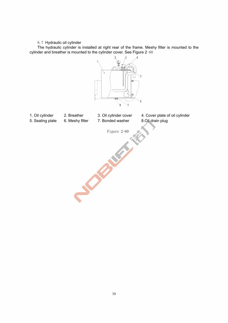
59
8.7 Hydraulic oil cylinder The hydraulic cylinder is installed at right rear of the frame. Meshy filter is mounted to the
cylinder and breather is mounted to the cylinder cover. See Figure 2-60
1. Oil cylinder 2. Breather 3. Oil cylinder cover 4. Cover plate of oil cylinder 5. Sealing plate 6. Meshy filter 7. Bonded washer 8.Oil drain plug
Figure 2-60
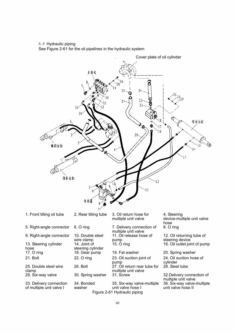
60
8.8 Hydraulic piping See Figure 2-61 for the oil pipelines in the hydraulic system
1. Front tilting oil tube 2. Rear tilting tube 3. Oil return hose for
multiple unit valve 4. Steering device-multiple unit valve hose
5. Right-angle connector 6. O ring 7. Delivery connection of multiple unit valve
8. O ring
9. Right-angle connector 10. Double steel wire clamp
11. Oil release hose of pump
12. Oil returning tube of steering device
13. Steering cylinder hose
14. Joint of steering cylinder
15. O ring 16. Oil outlet joint of pump
17. O ring 18. Gear pump 19. Fat washer 20. Spring washer 21. Bolt 22. O ring 23. Oil suction joint of
pump 24. Oil suction hose of cylinder
25. Double steel wire clamp
26. Bolt 27. Oil return rear tube for multiple unit valve
28. Steel tube
29. Six-way valve 30. Spring washer 31. Screw 32.Delivery connection of multiple unit valve
33. Delivery connection of multiple unit valve I
34. Bonded washer
35. Six-way valve-multiple unit valve hose I
36. Six-way valve-multiple unit valve hose II
Figure 2-61 Hydraulic piping
Cover plate of oil cylinder
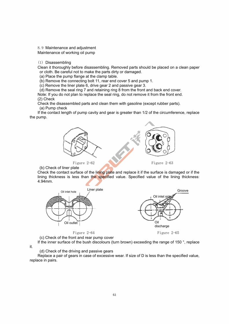
61
8.9 Maintenance and adjustment Maintenance of working oil pump
(1) Disassembling Clean it thoroughly before disassembling. Removed parts should be placed on a clean paper or cloth. Be careful not to make the parts dirty or damaged. (a) Place the pump flange at the clamp table. (b) Remove the connecting bolt 11, rear end cover 5 and pump 1. (c) Remove the liner plate 6, drive gear 2 and passive gear 3. (d) Remove the seal ring 7 and retaining ring 8 from the front and back end cover.
Note: If you do not plan to replace the seal ring, do not remove it from the front end. (2) Check Check the disassembled parts and clean them with gasoline (except rubber parts). (a) Pump check
If the contact length of pump cavity and gear is greater than 1/2 of the circumference, replace the pump.
Figure 2-62 Figure 2-63
(b) Check of liner plate Check the contact surface of the lining plate and replace it if the surface is damaged or if the
lining thickness is less than the specified value. Specified value of the lining thickness: 4.94mm.
Figure 2-64 Figure 2-65
(c) Check of the front and rear pump cover If the inner surface of the bush discolours (turn brown) exceeding the range of 150 °, replace
it. (d) Check of the driving and passive gears
Replace a pair of gears in case of excessive wear. If size of D is less than the specified value, replace in pairs.
Oil inlet hole
Oil outlet
Liner plate Groove
Oil discharge
Oil inlet side
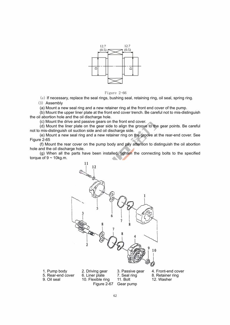
62
Figure 2-66
(e) If necessary, replace the seal rings, bushing seal, retaining ring, oil seal, spring ring. (3) Assembly (a) Mount a new seal ring and a new retainer ring at the front end cover of the pump. (b) Mount the upper liner plate at the front end cover trench. Be careful not to mis-distinguish
the oil abortion hole and the oil discharge hole. (c) Mount the drive and passive gears on the front end cover.
(d) Mount the liner plate on the gear side to align the groove to the gear points. Be careful not to mis-distinguish oil suction side and oil discharge side. (e) Mount a new seal ring and a new retainer ring on the groove at the rear-end cover. See Figure 2-65
(f) Mount the rear cover on the pump body and pay attention to distinguish the oil abortion hole and the oil discharge hole.
(g) When all the parts have been installed, tighten the connecting bolts to the specified torque of 9 ~ 10kg.m.
1. Pump body 2. Driving gear 3. Passive gear 4. Front-end cover 5. Rear-end cover 6. Liner plate 7. Seal ring 8. Retainer ring 9. Oil seal 10. Flexible ring 11. Bolt 12. Washer
Figure 2-67 Gear pump
12.7(0.5)
12.7(0.5)
D
D
63
(4) (4) Test run Conduct running-in of the pump to check if it functions properly. Then perform oil pump testing on the test bench or test by the following steps on the forklift truck: (If oil pump is subject to decomposition and maintenance due to serious wear and jamming caused by the hydraulic oil, the hydraulic oil and filter should be replaced before test-running on the forklift.) (a) Mount the pump onto the forklift and mount the pressure gauge onto the test hole of the multiple unit valve. (b) Loosen the adjusting screw of the overflow valve to keep the pump working for 5001000-1000rpm for about 10 minutes. Ensure that the oil pressure is lower than 10kg/cm ². (c) Increase the pump speed to 1500-2000rpm and keep it running for about 10 minutes. (d) Set the pump operating speed at 1500-2000rpm. Perform pressure increment of 20-30kg/cm ² and keep it running for 5 minutes after each increase, until the pressure reaches 175kg/cm ². Then keep each oil line working for 5 minutes and replace the oil returning filter. When increasing the oil pressure, pay attention to the oil temperature, pump surface temperature and the operation sound. If the oil temperature or the pump surface temperature rises excessively, reduce the load to lower the oil temperature before further testing.
(e) After testing, set the overflow pressure at 175kg/cm ² and measure the flow traffic. Determine the flow traffic by measuring lifting speed.
8.10 Failure analysis If the hydraulic system fails, please find out the causes according to the table below and
conduct necessary repairs. (1)Failure analysis of the multiple unit valve (Table 2-11) Table 2-11
Fault Cause Countermeasures
Jamming of the slide valve Clean it after disassemblingPressure of the lifting oil line can’t be increased Oil hole is blocked Clean it after disassembling
Jamming of the slide valve Clean it after disassemblingVibration Pressure rise is slow Inadequate exhaust of air Full exhaust
Jamming of the slide valve Clean it after disassemblingSteering oil pressure is greater than the specified value Oil hole is blocked Clean it after disassembling
Less than the required oil volume
Overflow valve is not well adjusted
Adjustment
Overflow valve is not well adjusted
Adjustment With noise
Wear of sliding surface Replace the overflow valve
Leakage (external) Aging or damage of the O
seal ring Replace the O seal ring
The spring is damaged Replace the spring The set pressure is low Damage of valve seat
surface Adjust or replace the
overflow valve
Leakage (internal) Damage of valve seat
surface Fix the seat surface
The set pressure is high Jamming of the valve Clean it after disassembling
64
(2)Failure Analysis of the oil pump(Table 2-12)
Table 2-12
Fault Cause Countermeasures The oil level in the oil tank is low
Add oil to the specified value Low volume of oil discharge
The tube or filter is blocked Clean or replace as needed●Liner plate damage ●Bearing damage ●Poorly functioned seal ring, bushing seal or retaining ring
Replace
Overflow valve is not well adjusted
Adjust the pressure of overflow valve to the specified value with a pressure gauge
Low pressure of the pump
There is air within the system
●Re-tighten the side tubing of the oil inlet ●Add oil ●Replace the oil pump seal
The inlet tube is damaged or the filter is blocked
Check the tube or repair oil filter
Looseness or leakage of the oil inlet
Tighten the loosened parts
Excessive oil viscosity
Replace the oil with viscosity compatible with the pump operating temperature
With noise when running
Bubbles in the oil Find out the cause of bubbles and take measures accordingly
The pump seal or seal ring is damaged
Replace The pump leaks oil
Pump is damaged Replace
9. Lifting system
9.1 Overview Composed by the inner and outer main frames as well as the forklift frame, the lifting system is a roller vertical elevating system with two levels. 9.2 Outer and inner main frames (Figure 2-68) Inner and outer main frames are welded structures. The bottom of the outer main frame is installed onto the drive axle by supporting parts. The central part of the outer main frame is connected with the frame by the tilting cylinder and can tilt forward and backward under the action of the tilting cylinder.
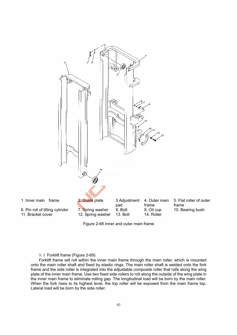
65
1. Inner main frame 2. Guide plate 3.Adjustment pad
4. Outer main frame
5. Flat roller of outer frame
6. Pin roll of tilting cylinder 7. Spring washer 8. Bolt 9. Oil cup 10. Bearing bush 11. Bracket cover 12. Spring washer 13. Bolt 14. Roller
Figure 2-68 Inner and outer main frame
9.3 Forklift frame (Figure 2-69) Forklift frame will roll within the inner main frame through the main roller, which is mounted
onto the main roller shaft and fixed by elastic rings. The main roller shaft is welded onto the fork frame and the side roller is integrated into the adjustable composite roller that rolls along the wing plate of the inner main frame. Use two fixed side rollers to roll along the outside of the wing plate in the inner main frame to eliminate rolling gap. The longitudinal load will be born by the main roller. When the fork rises to its highest level, the top roller will be exposed from the main frame top. Lateral load will be born by the side roller.
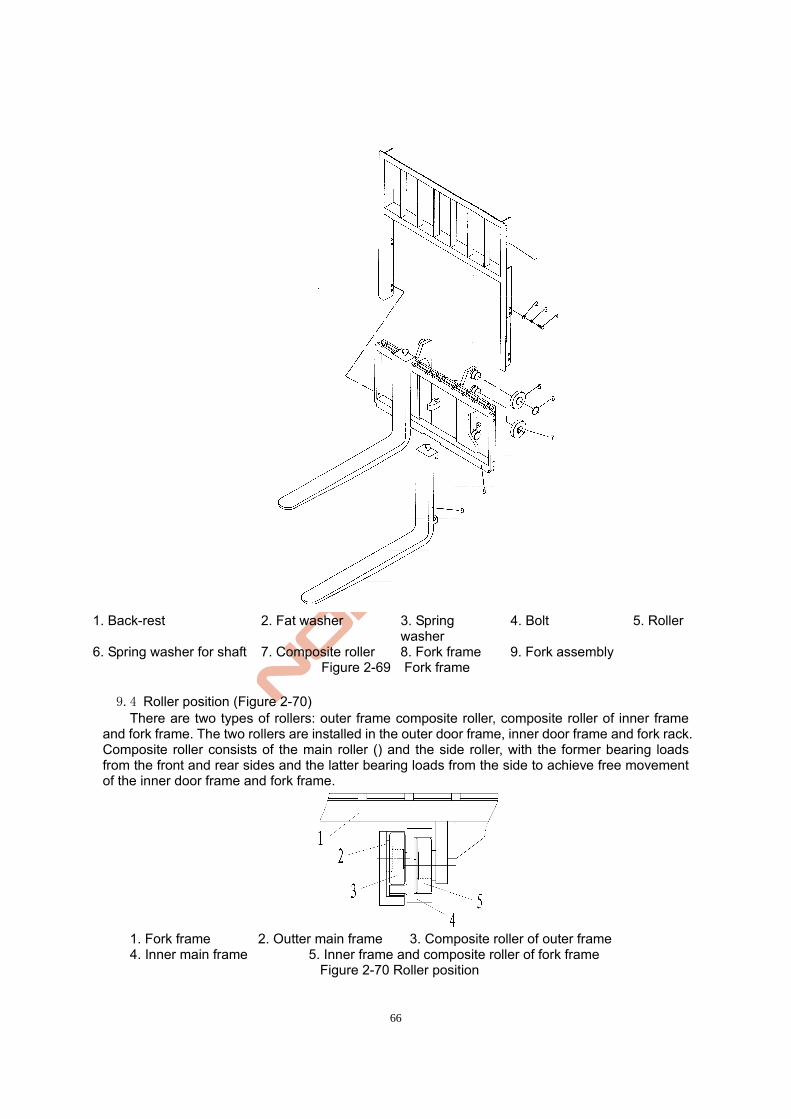
66
1. Back-rest 2. Fat washer 3. Spring
washer 4. Bolt 5. Roller
6. Spring washer for shaft 7. Composite roller 8. Fork frame 9. Fork assembly Figure 2-69 Fork frame
9.4 Roller position (Figure 2-70) There are two types of rollers: outer frame composite roller, composite roller of inner frame
and fork frame. The two rollers are installed in the outer door frame, inner door frame and fork rack. Composite roller consists of the main roller () and the side roller, with the former bearing loads from the front and rear sides and the latter bearing loads from the side to achieve free movement of the inner door frame and fork frame.
1. Fork frame 2. Outter main frame 3. Composite roller of outer frame
4. Inner main frame 5. Inner frame and composite roller of fork frame Figure 2-70 Roller position
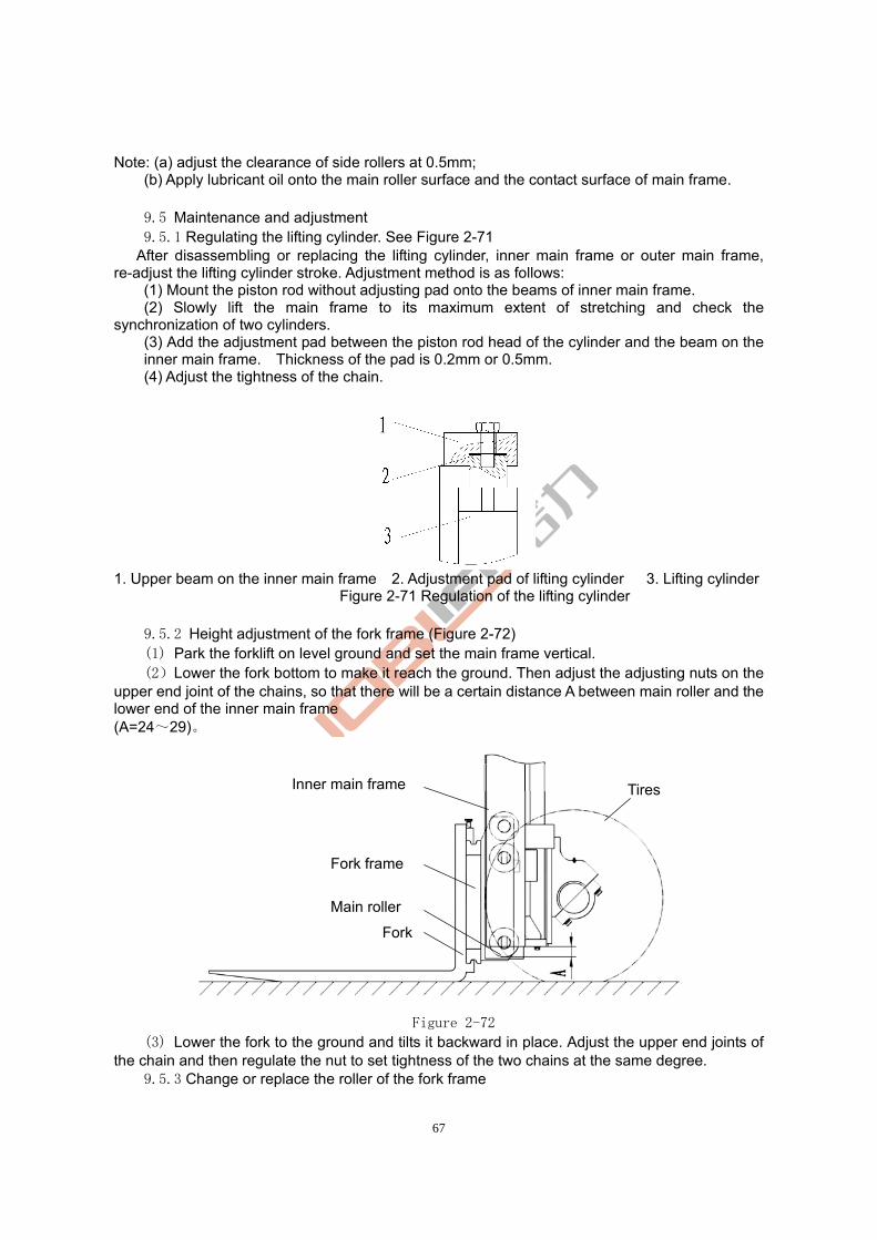
67
Note: (a) adjust the clearance of side rollers at 0.5mm; (b) Apply lubricant oil onto the main roller surface and the contact surface of main frame.
9.5 Maintenance and adjustment 9.5.1 Regulating the lifting cylinder. See Figure 2-71 After disassembling or replacing the lifting cylinder, inner main frame or outer main frame, re-adjust the lifting cylinder stroke. Adjustment method is as follows: (1) Mount the piston rod without adjusting pad onto the beams of inner main frame.
(2) Slowly lift the main frame to its maximum extent of stretching and check the synchronization of two cylinders.
(3) Add the adjustment pad between the piston rod head of the cylinder and the beam on the inner main frame. Thickness of the pad is 0.2mm or 0.5mm.
(4) Adjust the tightness of the chain.
1. Upper beam on the inner main frame 2. Adjustment pad of lifting cylinder 3. Lifting cylinder
Figure 2-71 Regulation of the lifting cylinder
9.5.2 Height adjustment of the fork frame (Figure 2-72) (1) Park the forklift on level ground and set the main frame vertical. (2)Lower the fork bottom to make it reach the ground. Then adjust the adjusting nuts on the
upper end joint of the chains, so that there will be a certain distance A between main roller and the lower end of the inner main frame (A=24~29)。
Figure 2-72
(3) Lower the fork to the ground and tilts it backward in place. Adjust the upper end joints of the chain and then regulate the nut to set tightness of the two chains at the same degree.
9.5.3 Change or replace the roller of the fork frame
Fork
Main roller
Fork frame
Inner main frame Tires
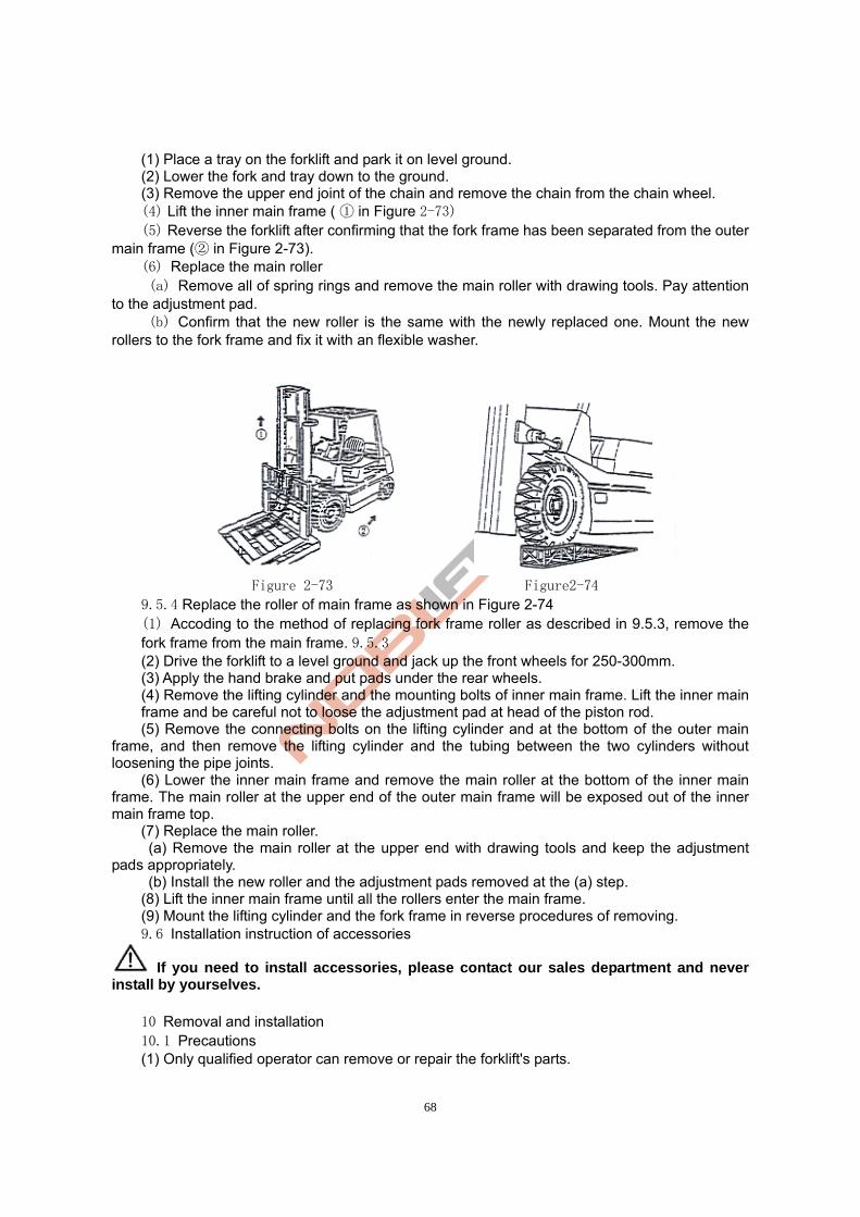
68
(1) Place a tray on the forklift and park it on level ground. (2) Lower the fork and tray down to the ground. (3) Remove the upper end joint of the chain and remove the chain from the chain wheel.
(4) Lift the inner main frame ( in Figure① 2-73) (5) Reverse the forklift after confirming that the fork frame has been separated from the outer
main frame ( in Figure 2② -73). (6) Replace the main roller (a) Remove all of spring rings and remove the main roller with drawing tools. Pay attention
to the adjustment pad. (b) Confirm that the new roller is the same with the newly replaced one. Mount the new rollers to the fork frame and fix it with an flexible washer.
Figure 2-73 Figure2-74
9.5.4 Replace the roller of main frame as shown in Figure 2-74 (1) Accoding to the method of replacing fork frame roller as described in 9.5.3, remove the fork frame from the main frame. 9.5.3 (2) Drive the forklift to a level ground and jack up the front wheels for 250-300mm. (3) Apply the hand brake and put pads under the rear wheels. (4) Remove the lifting cylinder and the mounting bolts of inner main frame. Lift the inner main frame and be careful not to loose the adjustment pad at head of the piston rod.
(5) Remove the connecting bolts on the lifting cylinder and at the bottom of the outer main frame, and then remove the lifting cylinder and the tubing between the two cylinders without loosening the pipe joints. (6) Lower the inner main frame and remove the main roller at the bottom of the inner main frame. The main roller at the upper end of the outer main frame will be exposed out of the inner main frame top. (7) Replace the main roller. (a) Remove the main roller at the upper end with drawing tools and keep the adjustment pads appropriately. (b) Install the new roller and the adjustment pads removed at the (a) step. (8) Lift the inner main frame until all the rollers enter the main frame.
(9) Mount the lifting cylinder and the fork frame in reverse procedures of removing. 9.6 Installation instruction of accessories
If you need to install accessories, please contact our sales department and never install by yourselves.
10 Removal and installation 10.1 Precautions (1) Only qualified operator can remove or repair the forklift's parts.
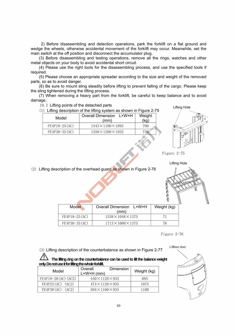
69
2) Before disassembling and detection operations, park the forklift on a flat ground and wedge the wheels, otherwise accidental movement of the forklift may occur. Meanwhile, set the main switch at the off position and disconnect the accumulator plug.
(3) Before disassembling and testing operations, remove all the rings, watches and other metal objects on your body to avoid accidental short circuit.
(4) Please use the right tools for the disassembling process, and use the specified tools if required.
(5) Please choose an appropriate spreader according to the size and weight of the removed parts, so as to avoid danger.
(6) Be sure to mount sling steadily before lifting to prevent falling of the cargo. Please keep the sling tightened during the lifting process.
(7) When removing a heavy part from the forklift, be careful to keep balance and to avoid damage.
10.2 Lifting points of the detached parts (1) Lifting description of the lifting system as shown in Figure 2-75
Model Overall Dimension L×W×H
(mm) Weight
(kg) FE4P18-25(AC) 1543×1100×1895 700
FE4P30-35(AC) 1558×1200×1935 730
Figure 2-75
(2) Lifting description of the overhead guard as shown in Figure 2-76
Model Overall Dimension L×W×H (mm)
Weight (kg)
FE4P18-25(AC) 1538×1048×1375 71
FE4P30-35(AC) 1713×1080×1375 76
Figure 2-76
(3) Lifting description of the counterbalance as shown in Figure 2-77
The lifting ring on the counterbalance can be used to lift the balance weight only. Do not use it for lifting the whole forklift.
Model Overall Dimension L×W×H (mm)
Weight (kg)
FE4P18-20(AC)(AC2) 440×1128×935 885
FE4P25(AC) (AC2) 474×1128×935 1075
FE4P30(AC) (AC2) 504×1160×935 1100
Lifting ring
Lifting Hole
Lifting Hole
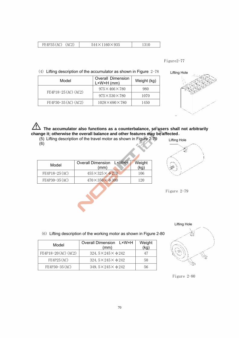
70
FE4P35(AC) (AC2) 544×1160×935 1310
Figure2-77
(4) Lifting description of the accumulator as shown in Figure 2-78
Figure 2-78
The accumulator also functions as a counterbalance, so users shall not arbitrarily change it; otherwise the overall balance and other features may be affected。
(5) Lifting description of the travel motor as shown in Figure 2-79 (6)
Figure 2-79
(6) Lifting description of the working motor as shown in Figure 2-80
Figure 2-80
Model Overall Dimension L×W×H (mm)
Weight (kg)
975×466×780 980 FE4P18-25(AC)(AC2)
975×530×780 1070
FE4P30-35(AC)(AC2) 1028×690×780 1450
Model Overall Dimension L×W×H
(mm) Weight
(kg)
FE4P18-25(AC) 455×325×φ270 106
FE4P30-35(AC) 470×350×φ300 120
Model Overall Dimension L×W×H
(mm) Weight
(kg)
FE4P18-20(AC)(AC2) 324.5×245×φ242 47
FE4P25(AC) 324.5×245×φ242 50
FE4P30-35(AC) 349.5×245×φ242 56
Lifting Hole
Lifting Hole
Lifting Hole
71
Chapter 3 0peration, use and safety of the forklift . Driving and operation Ⅰ
In order to ensure good performance, safety operation and economic use of the forklift, we specify the precautions below that should be noted during proper driving operation.
1. The use of a new forklift
•All the package materials removed from a new forklift shall be recycled according to local regulations.
• Test run should be carried out before using a new forklift to see if the forklift parts can work properly (see . Check before operation on page 75).Ⅰ
The service life of your forklift depends on your initial operation. When using it in the first 200 hours, please pay great attention to the following issues:
• Heat engine operation shall be conducted before use no matter what season it is. • Conduct maintenance in a timely and through manner. • Never operate it violently or rudely。
2. The relationship between forklift stability and load In the load curve, the front wheel centre of the forklift is taken as the fulcrum to keep the
forklift body and load on the fork balanced. Pay attention to load quantity and load centre when driving to maintain stability of the forklift.
·In case the load exceeds the load curve, rear wheels may be lifted and subject to extreme cases, and the forklift may rolling over, causing serious accidents. If goods are stacked at a place close to the sharp tip of fork, the risks above also exist. In this case, decrease the load weight.
3. Load centre and load curve Load centre refers to the distance between the front surface of the fork and the cargo’s centre of gravity. Load curve label indicating the relationship between the load centre and the allowed loading quantity (allowable load) is attached to the forklift. Replace the plate in case of damage or loss.
·If the forklift is equipped with accessories for cargo handling, such as the side shifter, bucket, or rotating fork, the allowable load shall be less than standard forklift (without accessories) for the following reasons: 1) Reduce loads equal to the weight of the accessories. 2) Since adding of accessory will move the load centre forward, the allowable load will be reduced accordingly. The installation of accessory will cause load centre shift forward, which is known as the "loss of load centre.”
Do not exceed the allowable load indicated by the load curve attached to the forklift or the accessory.
4. Forklift stability 4. Standard of forklift stability is specified in IS0 or other standards. However, the stability
described in these standards does not apply to all the running status and the stability of forklift varies with different operational status.
The maximum stability can be ensured under the following operating status:
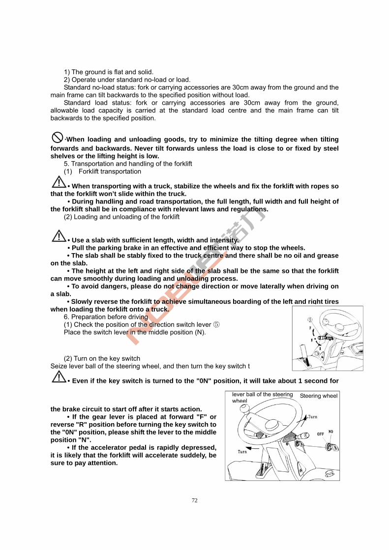
72
1) The ground is flat and solid. 2) Operate under standard no-load or load. Standard no-load status: fork or carrying accessories are 30cm away from the ground and the
main frame can tilt backwards to the specified position without load. Standard load status: fork or carrying accessories are 30cm away from the ground,
allowable load capacity is carried at the standard load centre and the main frame can tilt backwards to the specified position.
·When loading and unloading goods, try to minimize the tilting degree when tilting forwards and backwards. Never tilt forwards unless the load is close to or fixed by steel shelves or the lifting height is low.
5. Transportation and handling of the forklift (1) Forklift transportation
• When transporting with a truck, stabilize the wheels and fix the forklift with ropes so that the forklift won’t slide within the truck.
• During handling and road transportation, the full length, full width and full height of the forklift shall be in compliance with relevant laws and regulations.
(2) Loading and unloading of the forklift
• Use a slab with sufficient length, width and intensity. • Pull the parking brake in an effective and efficient way to stop the wheels. • The slab shall be stably fixed to the truck centre and there shall be no oil and grease
on the slab. • The height at the left and right side of the slab shall be the same so that the forklift
can move smoothly during loading and unloading process. • To avoid dangers, please do not change direction or move laterally when driving on
a slab. • Slowly reverse the forklift to achieve simultaneous boarding of the left and right tires
when loading the forklift onto a truck. 6. Preparation before driving (1) Check the position of the direction switch lever ⑤ Place the switch lever in the middle position (N).
(2) Turn on the key switch
Seize lever ball of the steering wheel, and then turn the key switch t
• Even if the key switch is turned to the "0N" position, it will take about 1 second for
the brake circuit to start off after it starts action. • If the gear lever is placed at forward "F" or
reverse "R" position before turning the key switch to the "0N" position, please shift the lever to the middle position "N".
• If the accelerator pedal is rapidly depressed, it is likely that the forklift will accelerate suddely, be sure to pay attention.
lever ball of the steering wheel
Steering wheel
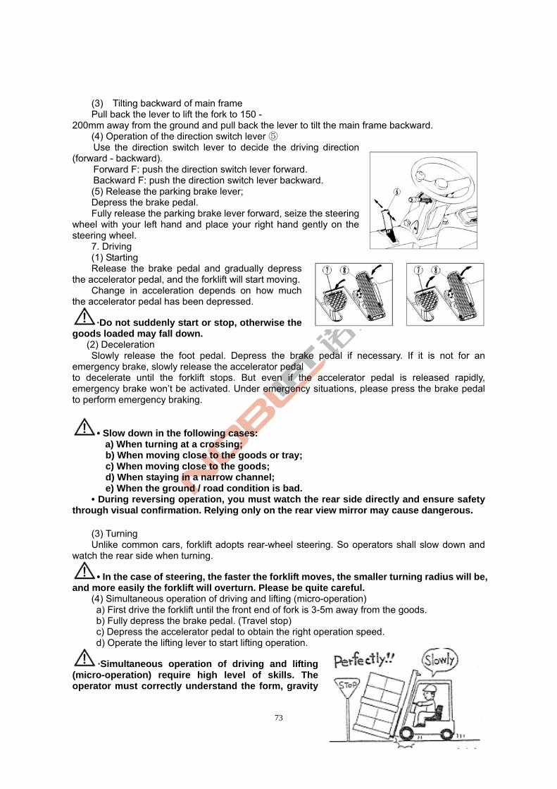
73
(3) Tilting backward of main frame Pull back the lever to lift the fork to 150 -
200mm away from the ground and pull back the lever to tilt the main frame backward. (4) Operation of the direction switch lever ⑤ Use the direction switch lever to decide the driving direction
(forward - backward). Forward F: push the direction switch lever forward. Backward F: push the direction switch lever backward. (5) Release the parking brake lever; Depress the brake pedal. Fully release the parking brake lever forward, seize the steering
wheel with your left hand and place your right hand gently on the steering wheel.
7. Driving (1) Starting Release the brake pedal and gradually depress
the accelerator pedal, and the forklift will start moving. Change in acceleration depends on how much
the accelerator pedal has been depressed.
·Do not suddenly start or stop, otherwise the goods loaded may fall down. (2) Deceleration
Slowly release the foot pedal. Depress the brake pedal if necessary. If it is not for an emergency brake, slowly release the accelerator pedal to decelerate until the forklift stops. But even if the accelerator pedal is released rapidly, emergency brake won’t be activated. Under emergency situations, please press the brake pedal to perform emergency braking.
• Slow down in the following cases: a) When turning at a crossing; b) When moving close to the goods or tray; c) When moving close to the goods; d) When staying in a narrow channel; e) When the ground / road condition is bad.
• During reversing operation, you must watch the rear side directly and ensure safety through visual confirmation. Relying only on the rear view mirror may cause dangerous.
(3) Turning Unlike common cars, forklift adopts rear-wheel steering. So operators shall slow down and
watch the rear side when turning.
• In the case of steering, the faster the forklift moves, the smaller turning radius will be, and more easily the forklift will overturn. Please be quite careful. (4) Simultaneous operation of driving and lifting (micro-operation)
a) First drive the forklift until the front end of fork is 3-5m away from the goods. b) Fully depress the brake pedal. (Travel stop) c) Depress the accelerator pedal to obtain the right operation speed. d) Operate the lifting lever to start lifting operation.
·Simultaneous operation of driving and lifting (micro-operation) require high level of skills. The operator must correctly understand the form, gravity
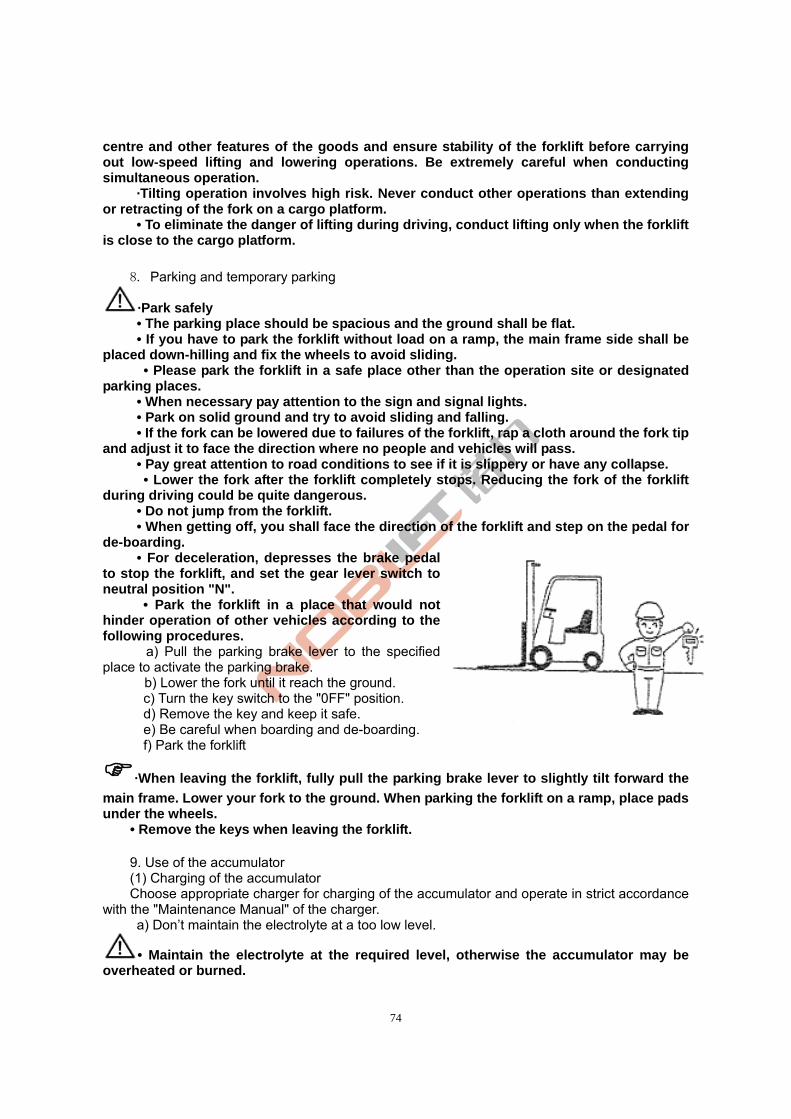
74
centre and other features of the goods and ensure stability of the forklift before carrying out low-speed lifting and lowering operations. Be extremely careful when conducting simultaneous operation.
·Tilting operation involves high risk. Never conduct other operations than extending or retracting of the fork on a cargo platform.
• To eliminate the danger of lifting during driving, conduct lifting only when the forklift is close to the cargo platform.
8. Parking and temporary parking
·Park safely • The parking place should be spacious and the ground shall be flat. • If you have to park the forklift without load on a ramp, the main frame side shall be
placed down-hilling and fix the wheels to avoid sliding. • Please park the forklift in a safe place other than the operation site or designated parking places. • When necessary pay attention to the sign and signal lights. • Park on solid ground and try to avoid sliding and falling.
• If the fork can be lowered due to failures of the forklift, rap a cloth around the fork tip and adjust it to face the direction where no people and vehicles will pass. • Pay great attention to road conditions to see if it is slippery or have any collapse. • Lower the fork after the forklift completely stops. Reducing the fork of the forklift during driving could be quite dangerous. • Do not jump from the forklift. • When getting off, you shall face the direction of the forklift and step on the pedal for de-boarding. • For deceleration, depresses the brake pedal to stop the forklift, and set the gear lever switch to neutral position "N".
• Park the forklift in a place that would not hinder operation of other vehicles according to the following procedures.
a) Pull the parking brake lever to the specified place to activate the parking brake.
b) Lower the fork until it reach the ground. c) Turn the key switch to the "0FF" position. d) Remove the key and keep it safe. e) Be careful when boarding and de-boarding. f) Park the forklift
·When leaving the forklift, fully pull the parking brake lever to slightly tilt forward the
main frame. Lower your fork to the ground. When parking the forklift on a ramp, place pads under the wheels.
• Remove the keys when leaving the forklift. 9. Use of the accumulator (1) Charging of the accumulator Choose appropriate charger for charging of the accumulator and operate in strict accordance
with the "Maintenance Manual" of the charger. a) Don’t maintain the electrolyte at a too low level.
• Maintain the electrolyte at the required level, otherwise the accumulator may be overheated or burned.
75
• When the electrolyte level is low, the accumulator life will be shortened. b) Add distilled water c) Overcharge is not allowed d) Charging should be carried out in a well ventilated place
• Charging should be carried out in a well ventilated and moisture proof place. b) Open the accumulator cover.
• Hydrogen will be generated during the charging process. Open the accumulator cover during charging.
f) Check the connecting terminal, cables and connectors.
• Users should check the connectors and cable lines for damage before charging. ·Never conduct charging in case of the following conditions:
- The connector electrode is damaged. - Connection terminals and cable lines are corroded.
These conditions can result in sparks, burning, fire or explosion。 g) Conduct charging after the key switch is turned off h) Check the specific gravity
Measure the specific gravity of electrolyte in all the single-cell accumulator before charging to identify abnormality of the accumulator. Understanding the specific gravity before charging could help eliminate the possibility of accidents.
i) When connecting and disconnecting the power connector, hold the plug or handle instead of holding the cable.
• Do not pull out the cable. • If the cable and power connectors are damaged, please contact our sales
department and replace the damaged cables and power connectors. j) Disconnecting the charging
·Disconnect the charging in strict accordance with steps required by the "Maintenance Manual" of the charger.
• Do not pull out the charger plug during charging, or else danger may be caused by sparks.
(2) Replace the accumulator If the accumulator on the forklift completely runs out of power, another fully charged
accumulator should be timely used to replace the original one. Then recharge the original accumulator.
·Before replacing the accumulator, ensure the new accumulator match the forklift. If a accumulator doesn’t match with the forklift used, working hours of the forklift will shorten or may cause rolling of the forklift.
·Replacement of the accumulator should be carried out on a platform 。 Follow these steps to replace the accumulator:
• When using another forklift to lift the accumulator to be replaced, appropriate spreader (accessory) should be used.
• Only experienced operators could lift the accumulator. a) Disconnect the accumulator plug. b) Open the accumulator top cover.
Take advantage of gas spring or other means to ensure that the accumulator top cover is locked, because its faliing may cause physical injury or damage to the forklift.
c) When lifting the accumulator out of the forklift, be careful not to damage the steering wheel or other forklift parts.
d) After a group of fully charged accumulator is well placed, securely connect the
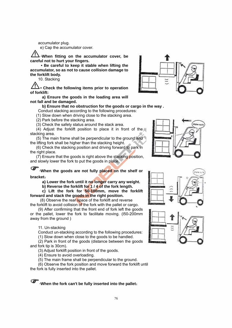
76
accumulator plug. e) Cap the accumulator cover.
·When fitting on the accumulator cover, be careful not to hurt your fingers.
• Be careful to keep it stable when lifting the accumulator, so as not to cause collision damage to the forklift body.
10. Stacking
• Check the following items prior to operation of forklift:
a) Ensure the goods in the loading area will not fall and be damaged.
b) Ensure that no obstruction for the goods or cargo in the way . Conduct stacking according to the following procedures:
(1) Slow down when driving close to the stacking area. (2) Park before the stacking area. (3) Check the safety status around the stack area. (4) Adjust the forklift position to place it in front of the
stacking area. (5) The main frame shall be perpendicular to the ground and
the lifting fork shall be higher than the stacking height. (6) Check the stacking position and driving forward to park in
the right place. (7) Ensure that the goods is right above the stacking position,
and slowly lower the fork to put the goods in place.
·When the goods are not fully placed on the shelf or
bracket: a) Lower the fork until it no longer carry any weight. b) Reverse the forklift for 1 / 4 of the fork length. c) Lift the fork for 50-100mm, move the forklift
forward and stack the goods in the right position. (8) Observe the rear space of the forklift and reverse
the forklift to avoid collision of the fork with the pallet or cargo. (9) After confirming that the front end of fork left the goods
or the pallet, lower the fork to facilitate moving. (l50-200mm away from the ground )
11. Un-stacking Conduct un-stacking according to the following procedures: (1) Slow down when close to the goods to be handled. (2) Park in front of the goods (distance between the goods
and fork tip is 30cm). (3) Adjust forklift position in front of the goods. (4) Ensure to avoid overloading. (5) The main frame shall be perpendicular to the ground. (6) Observe the fork position and move forward the forklift until
the fork is fully inserted into the pallet.
·When the fork can't be fully inserted into the pallet:
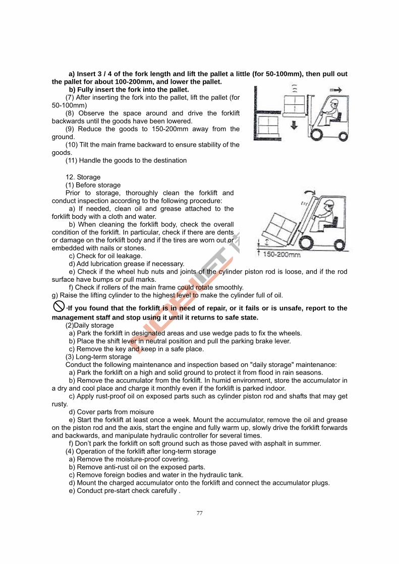
77
a) Insert 3 / 4 of the fork length and lift the pallet a little (for 50-100mm), then pull out the pallet for about 100-200mm, and lower the pallet.
b) Fully insert the fork into the pallet. (7) After inserting the fork into the pallet, lift the pallet (for
50-100mm) (8) Observe the space around and drive the forklift
backwards until the goods have been lowered. (9) Reduce the goods to 150-200mm away from the
ground. (10) Tilt the main frame backward to ensure stability of the
goods. (11) Handle the goods to the destination 12. Storage (1) Before storage Prior to storage, thoroughly clean the forklift and
conduct inspection according to the following procedure: a) If needed, clean oil and grease attached to the
forklift body with a cloth and water. b) When cleaning the forklift body, check the overall
condition of the forklift. In particular, check if there are dents or damage on the forklift body and if the tires are worn out or embedded with nails or stones.
c) Check for oil leakage. d) Add lubrication grease if necessary. e) Check if the wheel hub nuts and joints of the cylinder piston rod is loose, and if the rod
surface have bumps or pull marks. f) Check if rollers of the main frame could rotate smoothly.
g) Raise the lifting cylinder to the highest level to make the cylinder full of oil.
·If you found that the forklift is in need of repair, or it fails or is unsafe, report to the management staff and stop using it until it returns to safe state.
(2)Daily storage a) Park the forklift in designated areas and use wedge pads to fix the wheels. b) Place the shift lever in neutral position and pull the parking brake lever. c) Remove the key and keep in a safe place.
(3) Long-term storage Conduct the following maintenance and inspection based on "daily storage" maintenance: a) Park the forklift on a high and solid ground to protect it from flood in rain seasons. b) Remove the accumulator from the forklift. In humid environment, store the accumulator in
a dry and cool place and charge it monthly even if the forklift is parked indoor. c) Apply rust-proof oil on exposed parts such as cylinder piston rod and shafts that may get
rusty. d) Cover parts from moisure e) Start the forklift at least once a week. Mount the accumulator, remove the oil and grease
on the piston rod and the axis, start the engine and fully warm up, slowly drive the forklift forwards and backwards, and manipulate hydraulic controller for several times.
f) Don’t park the forklift on soft ground such as those paved with asphalt in summer. (4) Operation of the forklift after long-term storage a) Remove the moisture-proof covering. b) Remove anti-rust oil on the exposed parts. c) Remove foreign bodies and water in the hydraulic tank. d) Mount the charged accumulator onto the forklift and connect the accumulator plugs. e) Conduct pre-start check carefully .
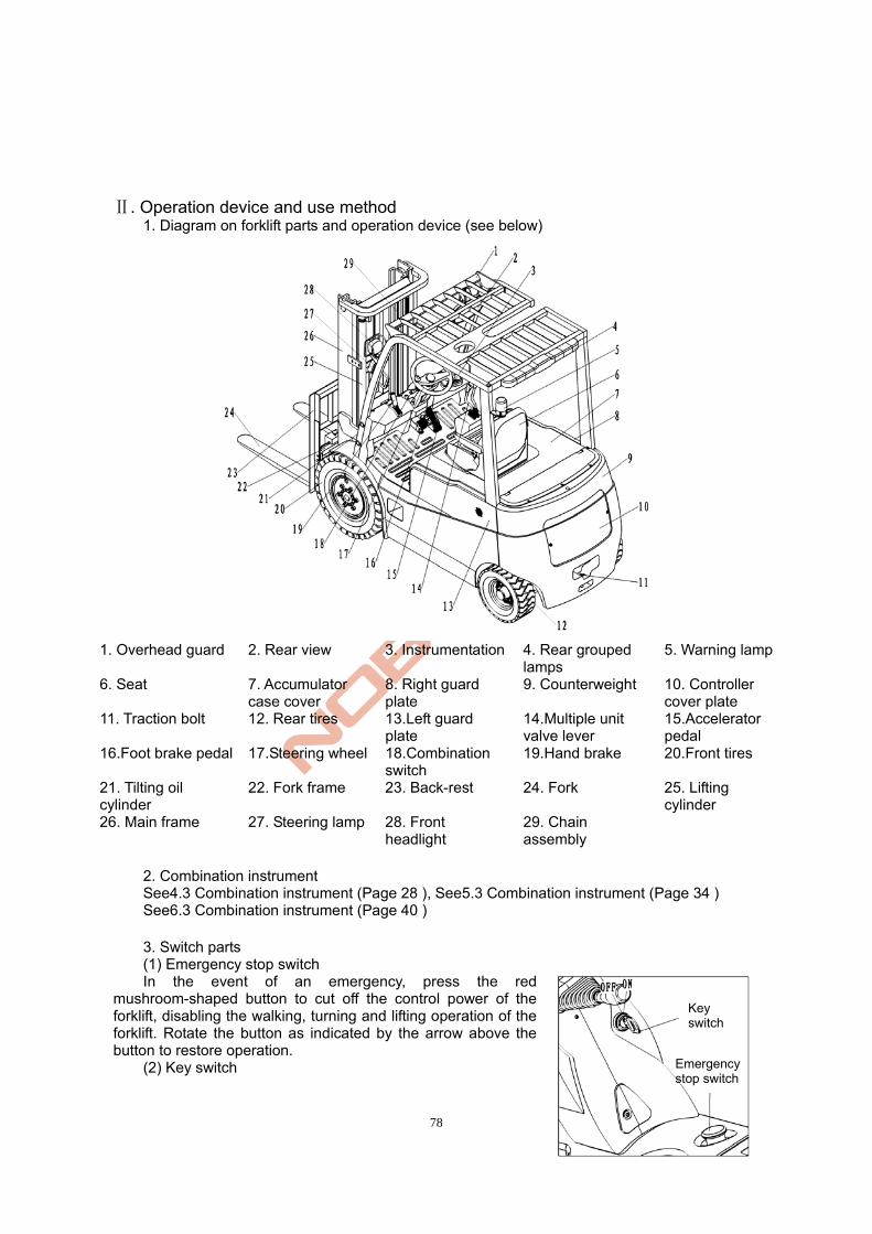
78
. Operation device and use method Ⅱ
1. Diagram on forklift parts and operation device (see below)
1. Overhead guard 2. Rear view 3. Instrumentation 4. Rear grouped
lamps 5. Warning lamp
6. Seat 7. Accumulator case cover
8. Right guard plate
9. Counterweight 10. Controller cover plate
11. Traction bolt 12. Rear tires 13.Left guard plate
14.Multiple unit valve lever
15.Accelerator pedal
16.Foot brake pedal 17.Steering wheel 18.Combination switch
19.Hand brake 20.Front tires
21. Tilting oil cylinder
22. Fork frame 23. Back-rest 24. Fork 25. Lifting cylinder
26. Main frame 27. Steering lamp 28. Front headlight
29. Chain assembly
2. Combination instrument See4.3 Combination instrument (Page 28 ), See5.3 Combination instrument (Page 34 ) See6.3 Combination instrument (Page 40 )
3. Switch parts (1) Emergency stop switch In the event of an emergency, press the red
mushroom-shaped button to cut off the control power of the forklift, disabling the walking, turning and lifting operation of the forklift. Rotate the button as indicated by the arrow above the button to restore operation.
(2) Key switch Emergency stop switch
Key switch
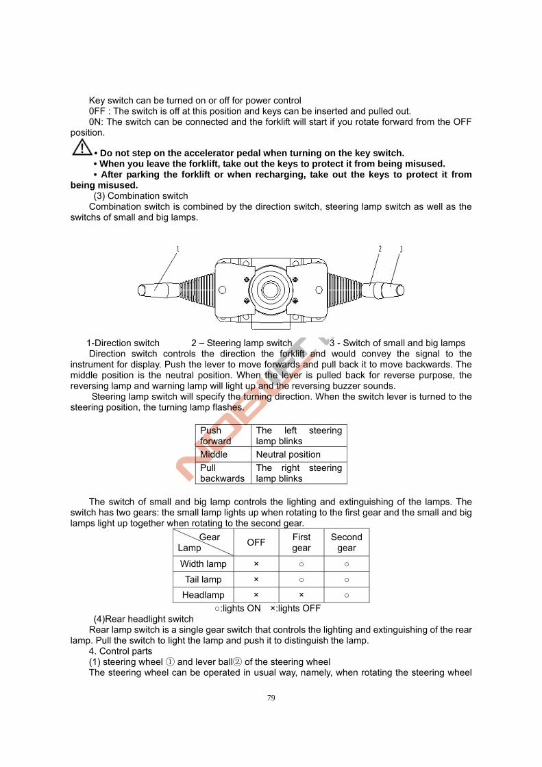
79
Key switch can be turned on or off for power control 0FF : The switch is off at this position and keys can be inserted and pulled out. 0N: The switch can be connected and the forklift will start if you rotate forward from the OFF
position.
• Do not step on the accelerator pedal when turning on the key switch. • When you leave the forklift, take out the keys to protect it from being misused. • After parking the forklift or when recharging, take out the keys to protect it from
being misused. (3) Combination switch Combination switch is combined by the direction switch, steering lamp switch as well as the
switchs of small and big lamps.
1-Direction switch 2 – Steering lamp switch 3 - Switch of small and big lamps Direction switch controls the direction the forklift and would convey the signal to the
instrument for display. Push the lever to move forwards and pull back it to move backwards. The middle position is the neutral position. When the lever is pulled back for reverse purpose, the reversing lamp and warning lamp will light up and the reversing buzzer sounds.
Steering lamp switch will specify the turning direction. When the switch lever is turned to the steering position, the turning lamp flashes.
Push forward
The left steering lamp blinks
Middle Neutral position
Pull backwards
The right steering lamp blinks
The switch of small and big lamp controls the lighting and extinguishing of the lamps. The
switch has two gears: the small lamp lights up when rotating to the first gear and the small and big lamps light up together when rotating to the second gear.
Gear Lamp
OFF First gear
Second gear
Width lamp × ○ ○
Tail lamp × ○ ○
Headlamp × × ○
○:lights ON ×:lights OFF (4)Rear headlight switch Rear lamp switch is a single gear switch that controls the lighting and extinguishing of the rear
lamp. Pull the switch to light the lamp and push it to distinguish the lamp. 4. Control parts (1) steering wheel and lever ball of the steering wheel① ②
The steering wheel can be operated in usual way, namely, when rotating the steering wheel
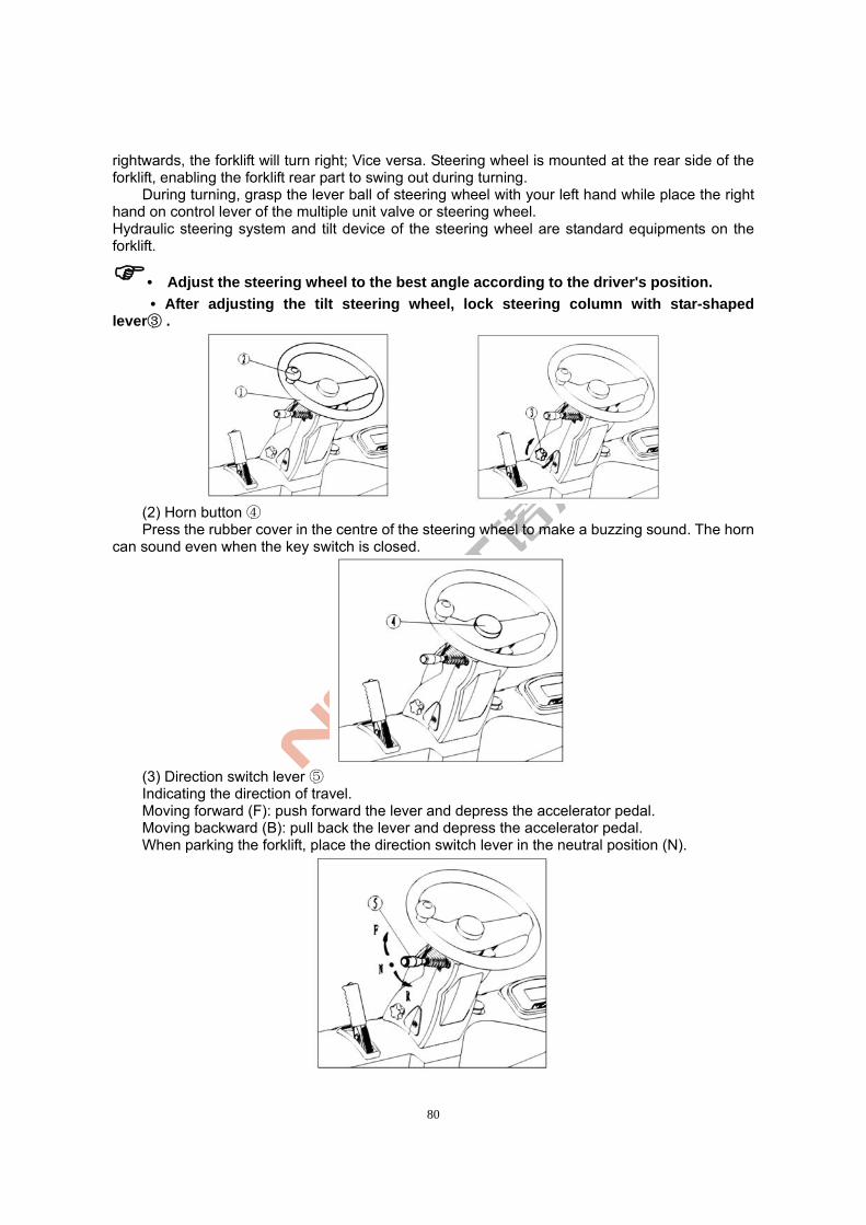
80
rightwards, the forklift will turn right; Vice versa. Steering wheel is mounted at the rear side of the forklift, enabling the forklift rear part to swing out during turning.
During turning, grasp the lever ball of steering wheel with your left hand while place the right hand on control lever of the multiple unit valve or steering wheel. Hydraulic steering system and tilt device of the steering wheel are standard equipments on the forklift.
• Adjust the steering wheel to the best angle according to the driver's position.
• After adjusting the tilt steering wheel, lock steering column with star-shaped lever .③
(2) Horn button ④ Press the rubber cover in the centre of the steering wheel to make a buzzing sound. The horn
can sound even when the key switch is closed.
(3) Direction switch lever ⑤ Indicating the direction of travel. Moving forward (F): push forward the lever and depress the accelerator pedal. Moving backward (B): pull back the lever and depress the accelerator pedal. When parking the forklift, place the direction switch lever in the neutral position (N).
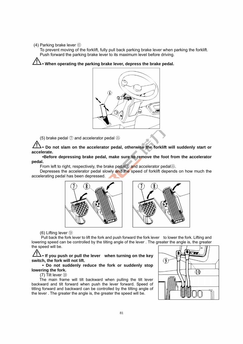
81
(4) Parking brake lever ⑥ To prevent moving of the forklift, fully pull back parking brake lever when parking the forklift. Push forward the parking brake lever to its maximum level before driving.
• When operating the parking brake lever, depress the brake pedal.
(5) brake pedal and accelerator pedal ⑦ ⑧
• Do not slam on the accelerator pedal, otherwise the forklift will suddenly start or accelerate.
•Before depressing brake pedal, make sure to remove the foot from the accelerator pedal.
From left to right, respectively, the brake pedal and accelerator pedal .⑦ ⑧ Depresses the accelerator pedal slowly and the speed of forklift depends on how much the
accelerating pedal has been depressed.
(6) Lifting lever ⑨ Pull back the fork lever to lift the fork and push forward the fork lever to lower the fork. Lifting and
lowering speed can be controlled by the tilting angle of the lever . The greater the angle is, the greater the speed will be.
• If you push or pull the lever when turning on the key switch, the fork will not lift.
• Do not suddenly reduce the fork or suddenly stop lowering the fork.
(7) Tilt lever ⑩ The main frame will tilt backward when pulling the tilt lever
backward and tilt forward when push the lever forward. Speed of titling forward and backward can be controlled by the tilting angle of the lever . The greater the angle is, the greater the speed will be.
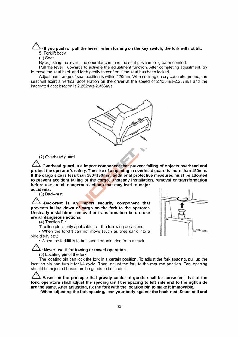
82
• If you push or pull the lever when turning on the key switch, the fork will not tilt. 5. Forklift body (1) Seat
By adjusting the lever , the operator can tune the seat position for greater comfort. Pull the lever upwards to activate the adjustment function. After completing adjustment, try
to move the seat back and forth gently to confirm if the seat has been locked. Adjustment range of seat position is within 120mm. When driving on dry concrete ground, the
seat will exert a vertical acceleration on the driver at the speed of 2.130m/s-2.237m/s and the integrated acceleration is 2.252m/s-2.356m/s.
(2) Overhead guard
·Overhead guard is a import component that prevent falling of objects overhead and protect the operator’s safety. The size of a opening in overhead guard is more than 150mm. If the cargo size is less than 150×150mm, additional protective measures must be adopted to prevent accident falling of the cargo. Unsteady installation, removal or transformation before use are all dangerous actions that may lead to major accidents.
(3) Back-rest
·Back-rest is an import security component that prevents falling down of cargo on the fork to the operator. Unsteady installation, removal or transformation before use are all dangerous actions.
(4) Traction Pin Traction pin is only applicable to the following occasions:
• When the forklift can not move (such as tires sank into a side ditch, etc.);
• When the forklift is to be loaded or unloaded from a truck.
• Never use it for towing or towed operation. (5) Locating pin of the fork The locating pin can lock the fork in a certain position. To adjust the fork spacing, pull up the
location pin and turn it for l/4 cycle. Then, adjust the fork to the required position. Fork spacing should be adjusted based on the goods to be loaded.
·Based on the principle that gravity center of goods shall be consistent that of the fork, operators shall adjust the spacing until the spacing to left side and to the right side are the same. After adjusting, fix the fork with the location pin to make it immovable.
·When adjusting the fork spacing, lean your body against the back-rest. Stand still and
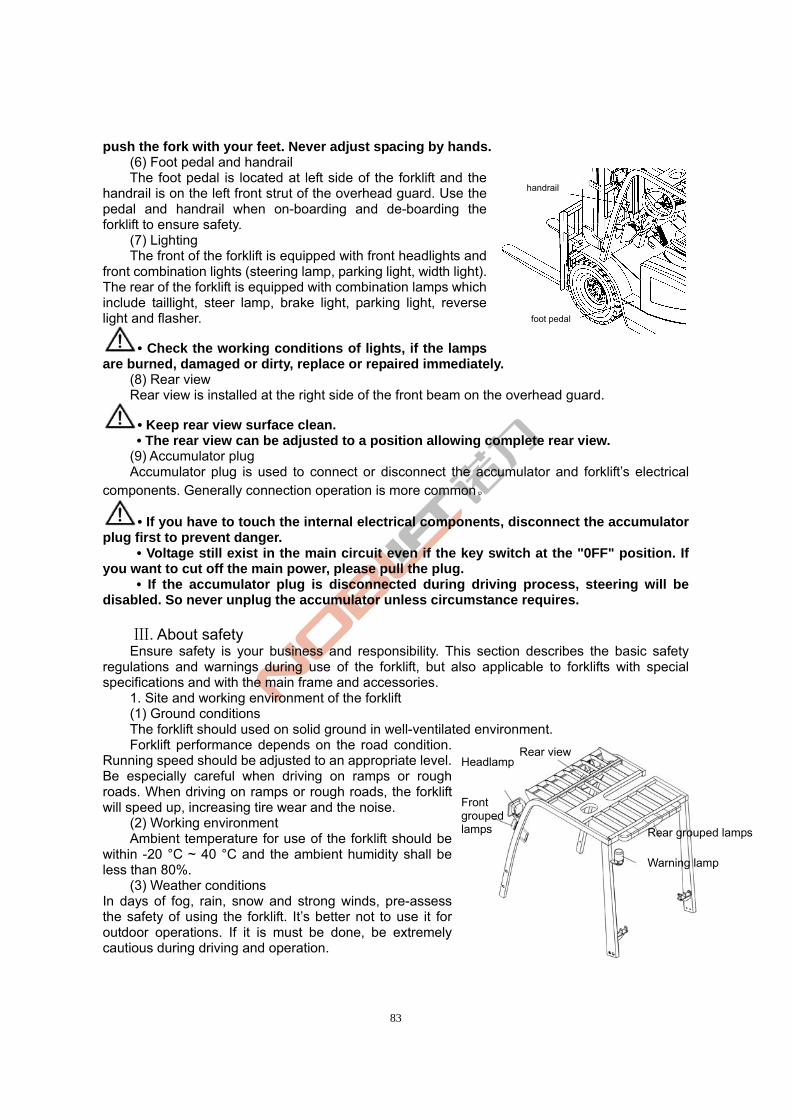
83
push the fork with your feet. Never adjust spacing by hands. (6) Foot pedal and handrail
The foot pedal is located at left side of the forklift and the handrail is on the left front strut of the overhead guard. Use the pedal and handrail when on-boarding and de-boarding the forklift to ensure safety.
(7) Lighting The front of the forklift is equipped with front headlights and
front combination lights (steering lamp, parking light, width light). The rear of the forklift is equipped with combination lamps which include taillight, steer lamp, brake light, parking light, reverse light and flasher.
• Check the working conditions of lights, if the lamps are burned, damaged or dirty, replace or repaired immediately.
(8) Rear view Rear view is installed at the right side of the front beam on the overhead guard.
• Keep rear view surface clean. • The rear view can be adjusted to a position allowing complete rear view.
(9) Accumulator plug Accumulator plug is used to connect or disconnect the accumulator and forklift’s electrical
components. Generally connection operation is more common。
• If you have to touch the internal electrical components, disconnect the accumulator plug first to prevent danger. • Voltage still exist in the main circuit even if the key switch at the "0FF" position. If you want to cut off the main power, please pull the plug.
• If the accumulator plug is disconnected during driving process, steering will be disabled. So never unplug the accumulator unless circumstance requires.
. About safetyⅢ
Ensure safety is your business and responsibility. This section describes the basic safety regulations and warnings during use of the forklift, but also applicable to forklifts with special specifications and with the main frame and accessories.
1. Site and working environment of the forklift (1) Ground conditions The forklift should used on solid ground in well-ventilated environment. Forklift performance depends on the road condition.
Running speed should be adjusted to an appropriate level. Be especially careful when driving on ramps or rough roads. When driving on ramps or rough roads, the forklift will speed up, increasing tire wear and the noise.
(2) Working environment Ambient temperature for use of the forklift should be
within -20 °C ~ 40 °C and the ambient humidity shall be less than 80%.
(3) Weather conditions In days of fog, rain, snow and strong winds, pre-assess the safety of using the forklift. It’s better not to use it for outdoor operations. If it is must be done, be extremely cautious during driving and operation.
handrail
foot pedal
Headlamp
Front grouped lamps
Rear view
Rear grouped lamps
Warning lamp
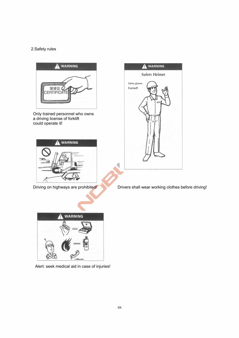
84
2.Safety rules
Only trained personnel who owns a driving license of forklift could operate it!
Driving on highways are prohibited! Drivers shall wear working clothes before driving!
Alert: seek medical aid in case of injuries!
Safety Helmet
Safety glasses
Earmuff
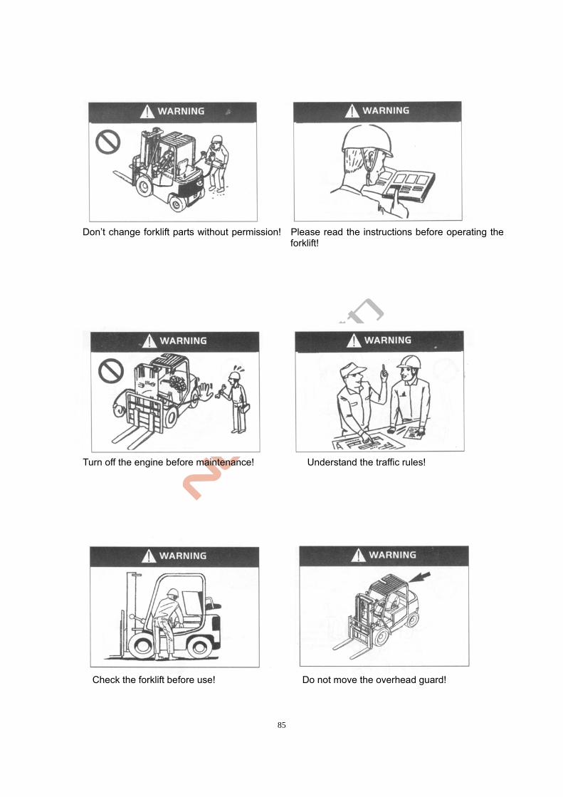
85
Don’t change forklift parts without permission! Please read the instructions before operating the
forklift!
Turn off the engine before maintenance! Understand the traffic rules!
Check the forklift before use! Do not move the overhead guard!
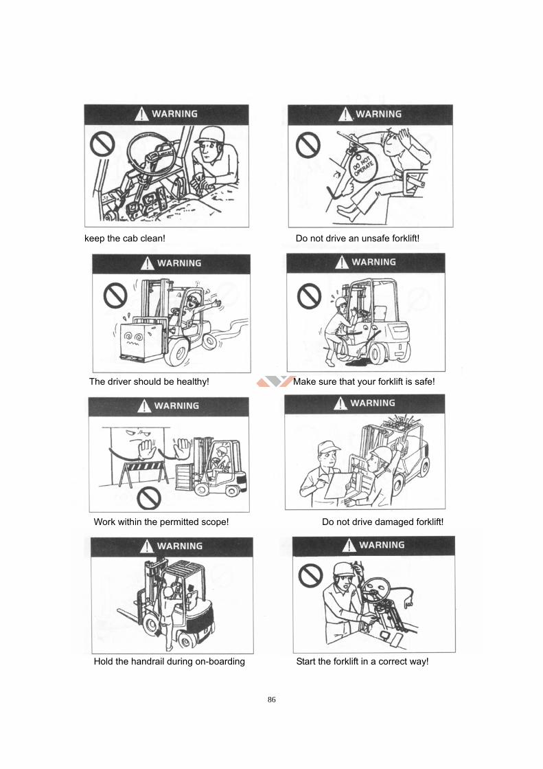
86
keep the cab clean! Do not drive an unsafe forklift!
The driver should be healthy! Make sure that your forklift is safe!
Work within the permitted scope! Do not drive damaged forklift!
Hold the handrail during on-boarding Start the forklift in a correct way!
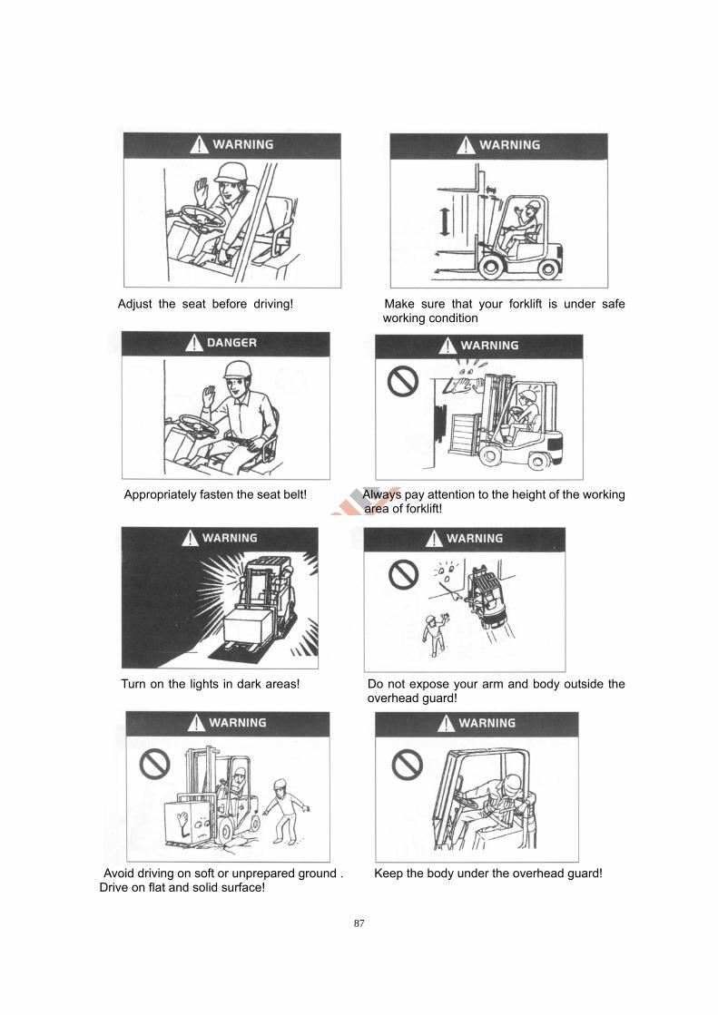
87
Adjust the seat before driving! Make sure that your forklift is under safe
working condition
Appropriately fasten the seat belt! Always pay attention to the height of the working
area of forklift!
Turn on the lights in dark areas! Do not expose your arm and body outside the
overhead guard!
Avoid driving on soft or unprepared ground . Keep the body under the overhead guard!
Drive on flat and solid surface!
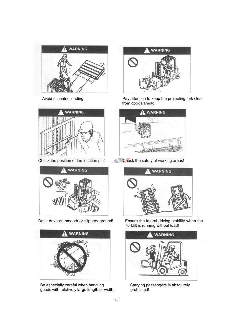
88
Avoid eccentric loading! Pay attention to keep the projecting fork clear
from goods ahead!
Check the position of the location pin! Check the safety of working areas!
Don’t drive on smooth or slippery ground! Ensure the lateral driving stability when the
forklift is running without load!
Be especially careful when handling Carrying passengers is absolutely goods with relatively large length or width! prohibited!
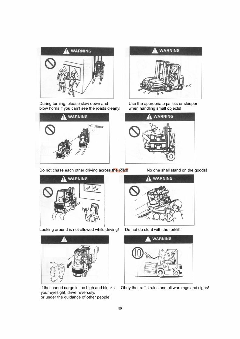
89
During turning, please slow down and Use the appropriate pallets or sleeper blow horns if you can’t see the roads clearly! when handling small objects!
Do not chase each other driving across the road! No one shall stand on the goods!
Looking around is not allowed while driving! Do not do stunt with the forklift!
If the loaded cargo is too high and blocks Obey the traffic rules and all warnings and signs! your eyesight, drive reversely. or under the guidance of other people!
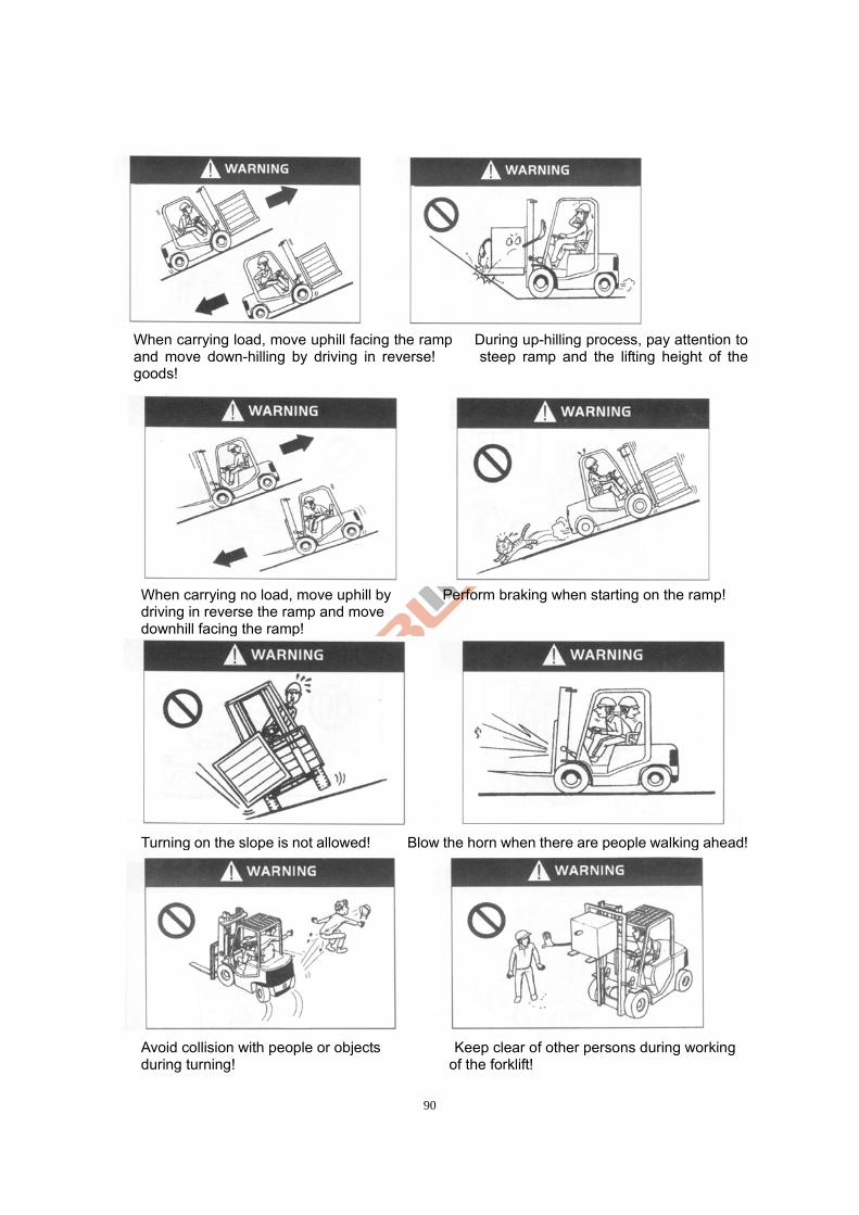
90
When carrying load, move uphill facing the ramp During up-hilling process, pay attention to
and move down-hilling by driving in reverse! steep ramp and the lifting height of the goods!
When carrying no load, move uphill by Perform braking when starting on the ramp! driving in reverse the ramp and move downhill facing the ramp!
Turning on the slope is not allowed! Blow the horn when there are people walking ahead!
Avoid collision with people or objects Keep clear of other persons during working during turning! of the forklift!
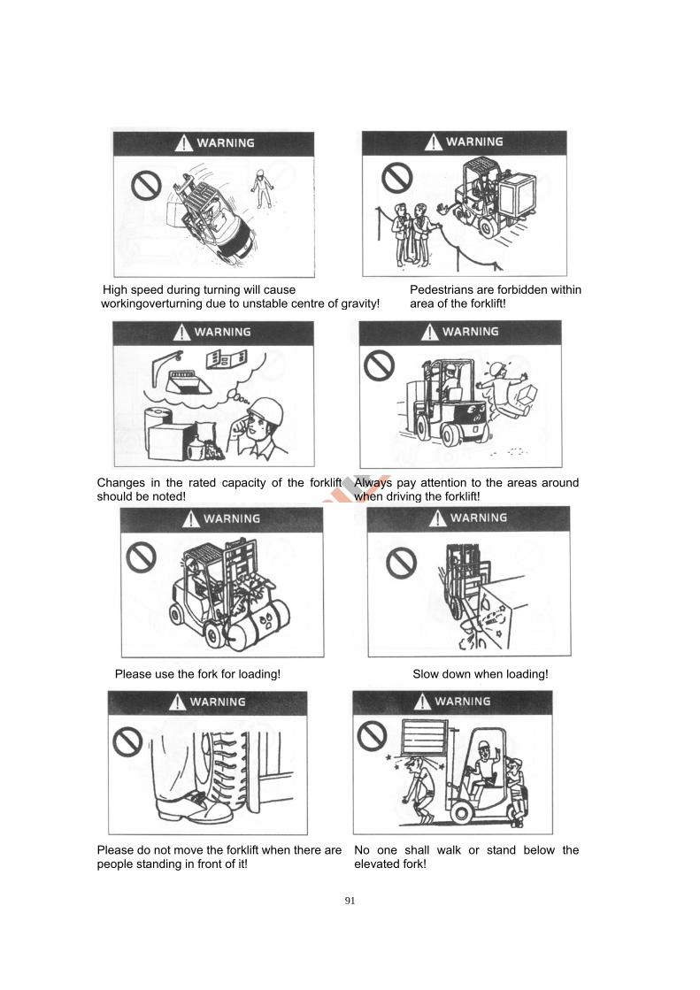
91
High speed during turning will cause Pedestrians are forbidden within workingoverturning due to unstable centre of gravity! area of the forklift!
Changes in the rated capacity of the forklift should be noted!
Always pay attention to the areas around when driving the forklift!
Please use the fork for loading! Slow down when loading!
Please do not move the forklift when there are people standing in front of it!
No one shall walk or stand below the elevated fork!
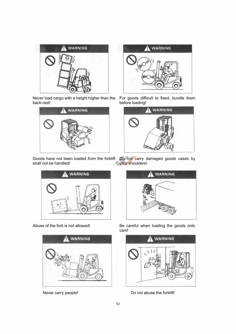
92
Never load cargo with a height higher than the back-rest!
For goods difficult to fixed, bundle them before loading!
Goods have not been loaded from the forklift shall not be handled!
Do not carry damaged goods cases by your shoulders!
Abuse of the fork is not allowed! Be careful when loading the goods onto
cars!
Never carry people! Do not abuse the forklift!
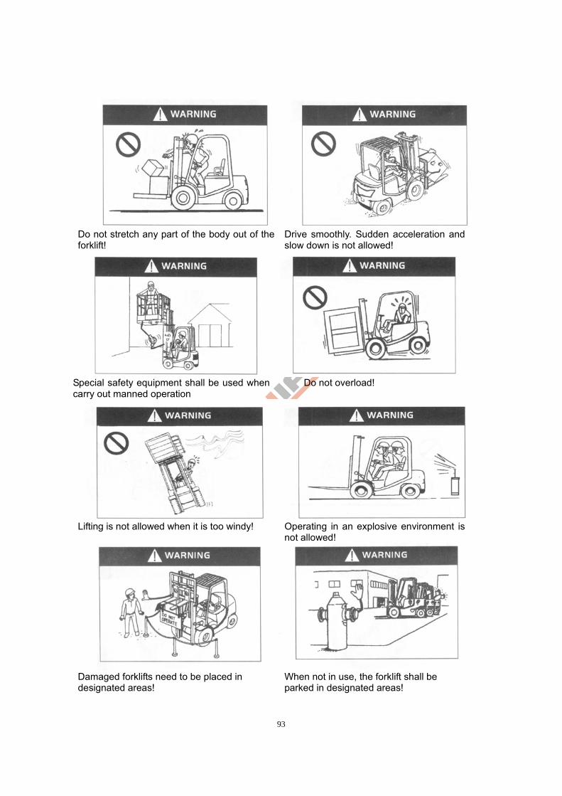
93
Do not stretch any part of the body out of the forklift!
Drive smoothly. Sudden acceleration and slow down is not allowed!
Special safety equipment shall be used when carry out manned operation
Do not overload!
Lifting is not allowed when it is too windy! Operating in an explosive environment is
not allowed!
Damaged forklifts need to be placed in designated areas!
When not in use, the forklift shall be parked in designated areas!
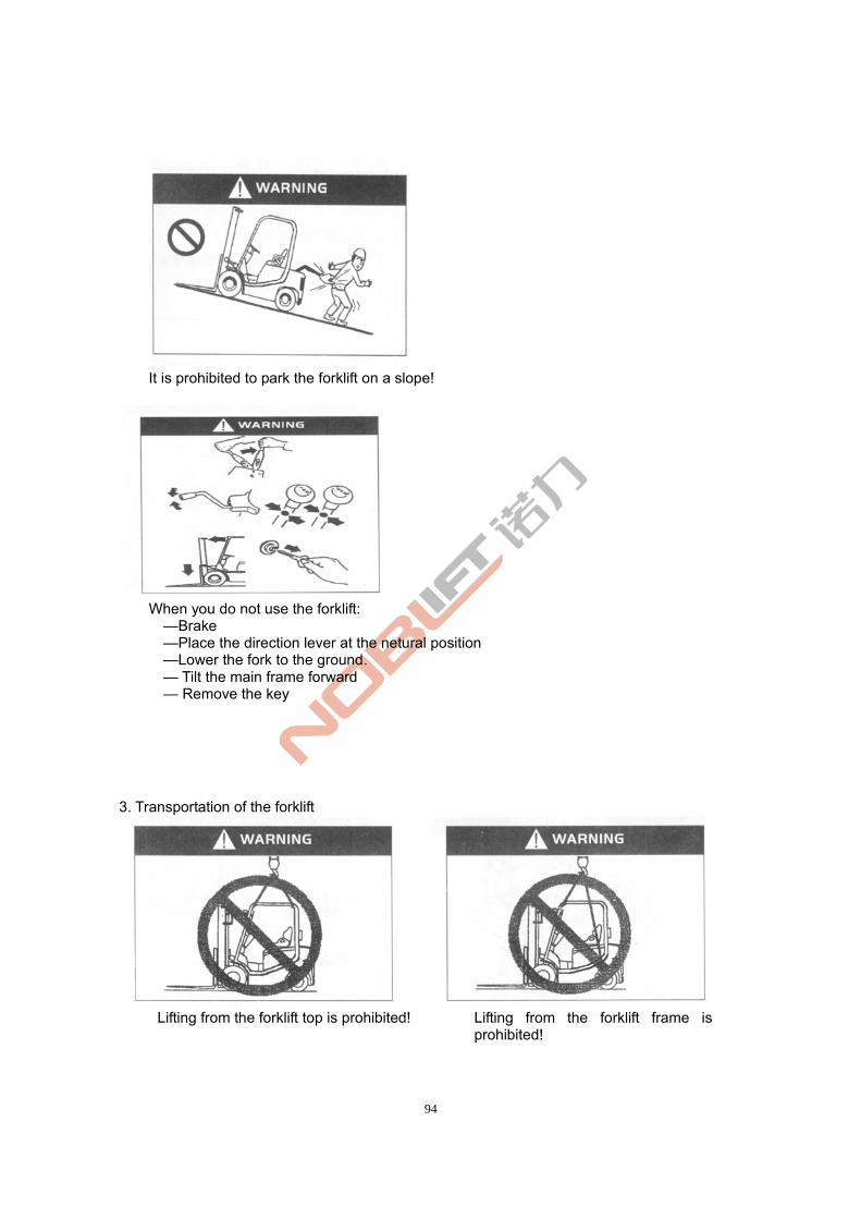
94
It is prohibited to park the forklift on a slope!
When you do not use the forklift:
—Brake —Place the direction lever at the netural position —Lower the fork to the ground.
— Tilt the main frame forward — Remove the key
3. Transportation of the forklift
Lifting from the forklift top is prohibited! Lifting from the forklift frame is
prohibited!
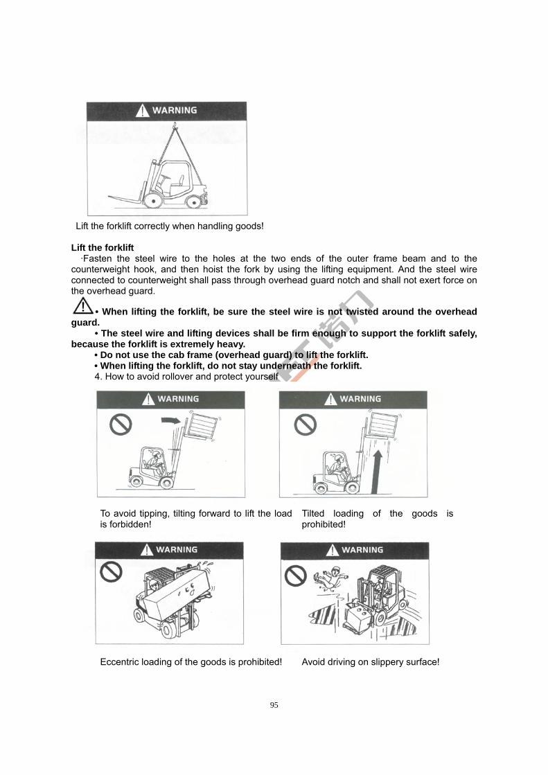
95
Lift the forklift correctly when handling goods!
Lift the forklift
·Fasten the steel wire to the holes at the two ends of the outer frame beam and to the counterweight hook, and then hoist the fork by using the lifting equipment. And the steel wire connected to counterweight shall pass through overhead guard notch and shall not exert force on the overhead guard.
• When lifting the forklift, be sure the steel wire is not twisted around the overhead guard.
• The steel wire and lifting devices shall be firm enough to support the forklift safely, because the forklift is extremely heavy.
• Do not use the cab frame (overhead guard) to lift the forklift. • When lifting the forklift, do not stay underneath the forklift. 4. How to avoid rollover and protect yourself
To avoid tipping, tilting forward to lift the load is forbidden!
Tilted loading of the goods is prohibited!
Eccentric loading of the goods is prohibited! Avoid driving on slippery surface!
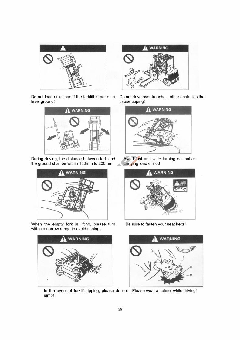
96
Do not load or unload if the forklift is not on a level ground!
Do not drive over trenches, other obstacles that cause tipping!
During driving, the distance between fork and the ground shall be within 150mm to 200mm!
Avoid fast and wide turning no matter carrying load or not!
When the empty fork is lifting, please turn within a narrow range to avoid tipping!
Be sure to fasten your seat belts!
In the event of forklift tipping, please do not jump!
Please wear a helmet while driving!
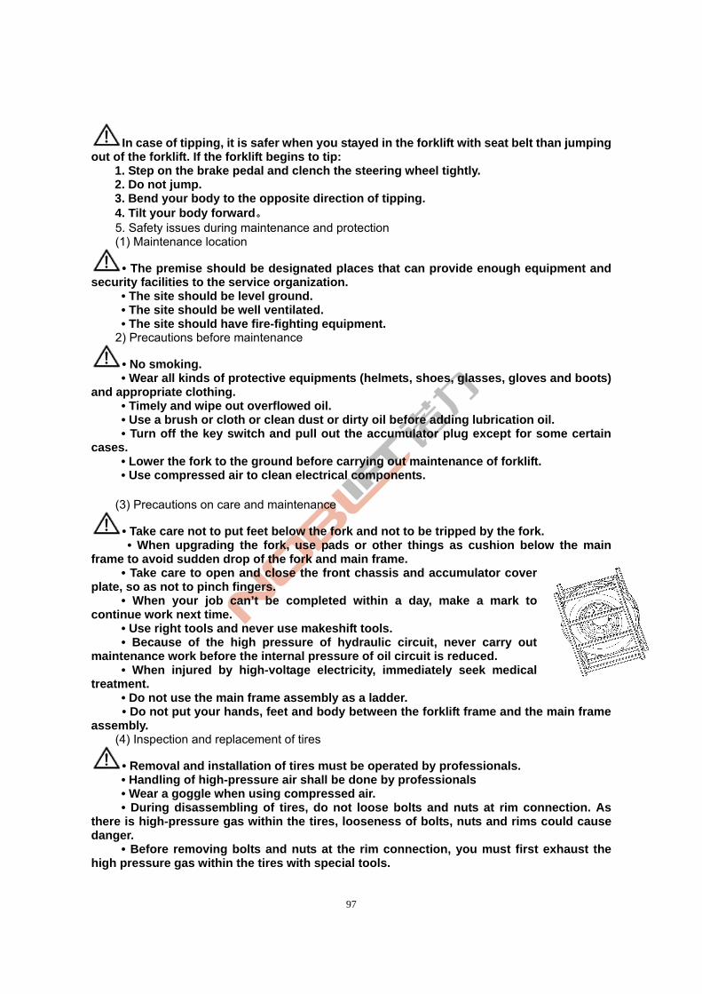
97
In case of tipping, it is safer when you stayed in the forklift with seat belt than jumping out of the forklift. If the forklift begins to tip:
1. Step on the brake pedal and clench the steering wheel tightly. 2. Do not jump. 3. Bend your body to the opposite direction of tipping. 4. Tilt your body forward。 5. Safety issues during maintenance and protection (1) Maintenance location
• The premise should be designated places that can provide enough equipment and security facilities to the service organization.
• The site should be level ground. • The site should be well ventilated. • The site should have fire-fighting equipment.
2) Precautions before maintenance
• No smoking. • Wear all kinds of protective equipments (helmets, shoes, glasses, gloves and boots)
and appropriate clothing. • Timely and wipe out overflowed oil. • Use a brush or cloth or clean dust or dirty oil before adding lubrication oil.
• Turn off the key switch and pull out the accumulator plug except for some certain cases.
• Lower the fork to the ground before carrying out maintenance of forklift. • Use compressed air to clean electrical components.
(3) Precautions on care and maintenance
• Take care not to put feet below the fork and not to be tripped by the fork. • When upgrading the fork, use pads or other things as cushion below the main frame to avoid sudden drop of the fork and main frame. • Take care to open and close the front chassis and accumulator cover plate, so as not to pinch fingers. • When your job can’t be completed within a day, make a mark to continue work next time. • Use right tools and never use makeshift tools. • Because of the high pressure of hydraulic circuit, never carry out maintenance work before the internal pressure of oil circuit is reduced. • When injured by high-voltage electricity, immediately seek medical treatment. • Do not use the main frame assembly as a ladder.
• Do not put your hands, feet and body between the forklift frame and the main frame assembly.
(4) Inspection and replacement of tires
• Removal and installation of tires must be operated by professionals. • Handling of high-pressure air shall be done by professionals • Wear a goggle when using compressed air.
• During disassembling of tires, do not loose bolts and nuts at rim connection. As there is high-pressure gas within the tires, looseness of bolts, nuts and rims could cause danger.
• Before removing bolts and nuts at the rim connection, you must first exhaust the high pressure gas within the tires with special tools.
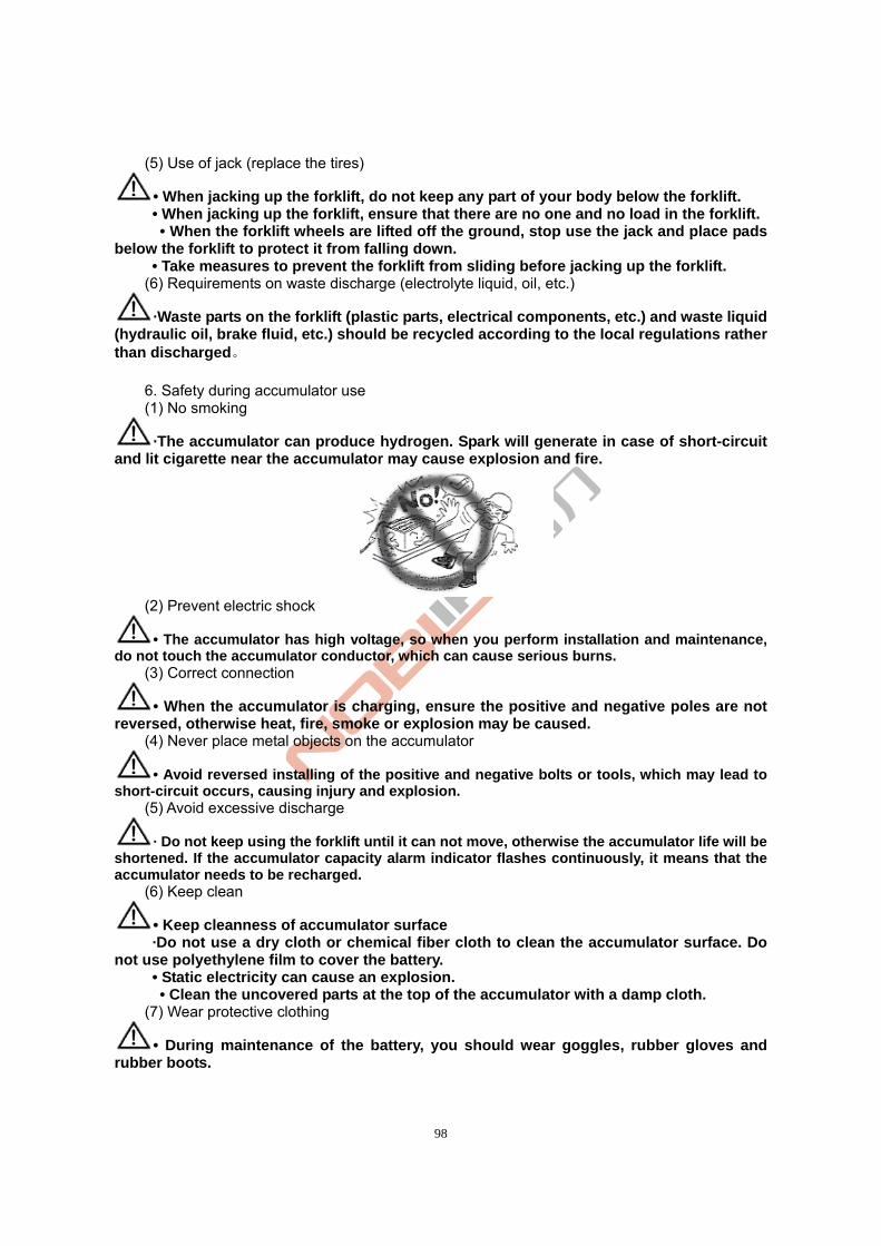
98
(5) Use of jack (replace the tires)
• When jacking up the forklift, do not keep any part of your body below the forklift. • When jacking up the forklift, ensure that there are no one and no load in the forklift.
• When the forklift wheels are lifted off the ground, stop use the jack and place pads below the forklift to protect it from falling down.
• Take measures to prevent the forklift from sliding before jacking up the forklift. (6) Requirements on waste discharge (electrolyte liquid, oil, etc.)
·Waste parts on the forklift (plastic parts, electrical components, etc.) and waste liquid (hydraulic oil, brake fluid, etc.) should be recycled according to the local regulations rather than discharged。
6. Safety during accumulator use (1) No smoking
·The accumulator can produce hydrogen. Spark will generate in case of short-circuit and lit cigarette near the accumulator may cause explosion and fire.
(2) Prevent electric shock
• The accumulator has high voltage, so when you perform installation and maintenance, do not touch the accumulator conductor, which can cause serious burns. (3) Correct connection
• When the accumulator is charging, ensure the positive and negative poles are not reversed, otherwise heat, fire, smoke or explosion may be caused.
(4) Never place metal objects on the accumulator
• Avoid reversed installing of the positive and negative bolts or tools, which may lead to short-circuit occurs, causing injury and explosion.
(5) Avoid excessive discharge
· Do not keep using the forklift until it can not move, otherwise the accumulator life will be shortened. If the accumulator capacity alarm indicator flashes continuously, it means that the accumulator needs to be recharged.
(6) Keep clean
• Keep cleanness of accumulator surface ·Do not use a dry cloth or chemical fiber cloth to clean the accumulator surface. Do
not use polyethylene film to cover the battery. • Static electricity can cause an explosion. • Clean the uncovered parts at the top of the accumulator with a damp cloth.
(7) Wear protective clothing
• During maintenance of the battery, you should wear goggles, rubber gloves and rubber boots.
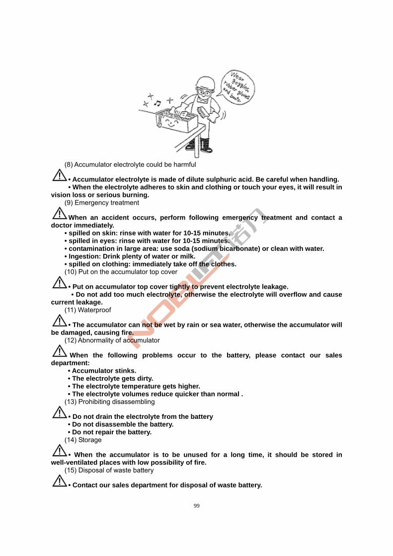
99
(8) Accumulator electrolyte could be harmful
• Accumulator electrolyte is made of dilute sulphuric acid. Be careful when handling. • When the electrolyte adheres to skin and clothing or touch your eyes, it will result in
vision loss or serious burning. (9) Emergency treatment
When an accident occurs, perform following emergency treatment and contact a doctor immediately. • spilled on skin: rinse with water for 10-15 minutes. • spilled in eyes: rinse with water for 10-15 minutes. • contamination in large area: use soda (sodium bicarbonate) or clean with water. • Ingestion: Drink plenty of water or milk.
• spilled on clothing: immediately take off the clothes. (10) Put on the accumulator top cover
• Put on accumulator top cover tightly to prevent electrolyte leakage. • Do not add too much electrolyte, otherwise the electrolyte will overflow and cause current leakage.
(11) Waterproof
• The accumulator can not be wet by rain or sea water, otherwise the accumulator will be damaged, causing fire.
(12) Abnormality of accumulator
When the following problems occur to the battery, please contact our sales department:
• Accumulator stinks. • The electrolyte gets dirty. • The electrolyte temperature gets higher. • The electrolyte volumes reduce quicker than normal .
(13) Prohibiting disassembling
• Do not drain the electrolyte from the battery • Do not disassemble the battery. • Do not repair the battery.
(14) Storage
• When the accumulator is to be unused for a long time, it should be stored in well-ventilated places with low possibility of fire.
(15) Disposal of waste battery
• Contact our sales department for disposal of waste battery.
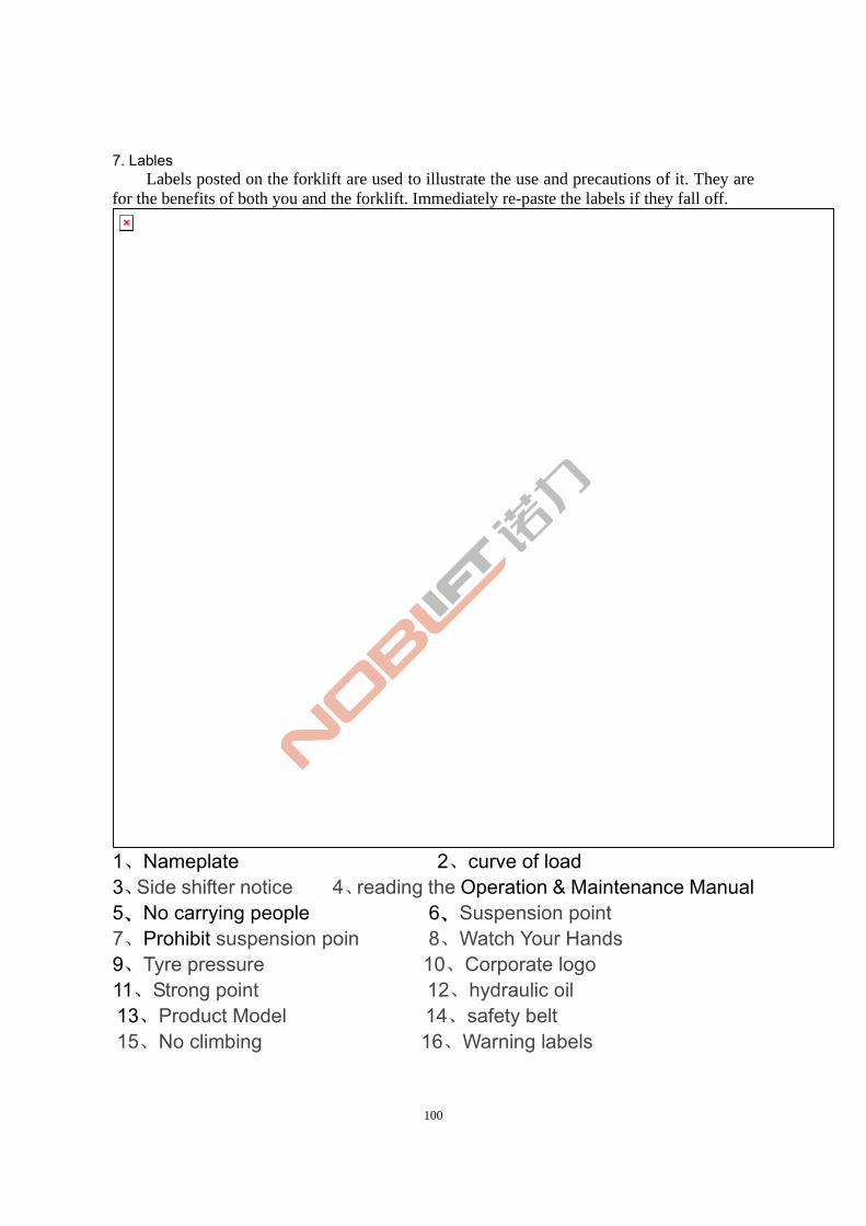
100
7. Lables Labels posted on the forklift are used to illustrate the use and precautions of it. They are
for the benefits of both you and the forklift. Immediately re-paste the labels if they fall off.
1、Nameplate 2、curve of load 3、Side shifter notice 4、reading the Operation & Maintenance Manual 5、No carrying people 6、Suspension point 7、Prohibit suspension poin 8、Watch Your Hands 9、Tyre pressure 10、Corporate logo 11、Strong point 12、hydraulic oil 13、Product Model 14、safety belt 15、No climbing 16、Warning labels
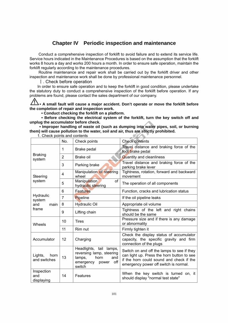
101
Chapter IV Periodic inspection and maintenance
Conduct a comprehensive inspection of forklift to avoid failure and to extend its service life. Service hours indicated in the Maintenance Procedures is based on the assumption that the forklift works 8 hours a day and works 200 hours a month. In order to ensure safe operation, maintain the forklift regularly according to the maintenance procedures.
Routine maintenance and repair work shall be carried out by the forklift driver and other inspection and maintenance work shall be done by professional maintenance personnel.
. Check before operation Ⅰ In order to ensure safe operation and to keep the forklift in good condition, please undertake
the statutory duty to conduct a comprehensive inspection of the forklift before operation. If any problems are found, please contact the sales department of our company.
• A small fault will cause a major accident. Don’t operate or move the forklift before the completion of repair and inspection work.
• Conduct checking the forklift on a platform. • Before checking the electrical system of the forklift, turn the key switch off and unplug the accumulator before check.
• Improper handling of waste oil (such as dumping into water pipes, soil, or burning them) will cause pollution to the water, soil and air, thus are strictly prohibited.
1. Check points and contents
No. Check points Check contents
1 Brake pedal Travel distance and braking force of the foot brake pedal
2 Brake oil Quantity and cleanliness Braking system
3 Parking brake Travel distance and braking force of the parking brake lever
4 Manipulation of steering wheel
Tightness, rotation, forward and backward movement Steering
system 5
Manipulation of hydraulic steering
The operation of all components
6 Features Function, cracks and lubrication status
7 Pipeline If the oil pipeline leaks
8 Hydraulic Oil Appropriate oil volume
Hydraulic system and main frame
9 Lifting chain Tightness of the left and right chains should be the same
10 Tires Pressure size and if there is any damage or abnormality Wheels
11 Rim nut Firmly tighten it
Accumulator 12 Charging Check the display status of accumulator capacity, the specific gravity and firm connection of the plugs
Lights, horn and switches
13
Headlights, tail lamps, reversing lamp, steering lamps, horn and emergency power off switch
Switch on and off the lamps to see if they can light up. Press the horn button to see if the horn could sound and check if the emergency power off switch is normal.
Inspection and displaying
14 Features When the key switch is turned on, it should display "normal test state"
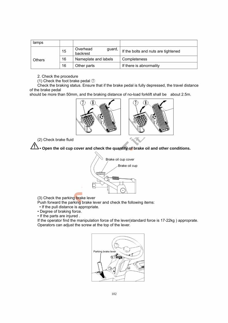
102
lamps
15 Overhead guard, backrest
If the bolts and nuts are tightened
16 Nameplate and labels Completeness Others
16 Other parts If there is abnormality
2. Check the procedure
(1) Check the foot brake pedal ⑦ Check the braking status. Ensure that if the brake pedal is fully depressed, the travel distance of the brake pedal should be more than 50mm, and the braking distance of no-load forklift shall be about 2.5m.
(2) Check brake fluid
• Open the oil cup cover and check the quantity of brake oil and other conditions.
(3) Check the parking brake lever Push forward the parking brake lever and check the following items: • If the pull distance is appropriate. • Degree of braking force. • If the parts are injured . If the operator find the manipulation force of the lever(standard force is 17-22kg ) approprate. Operators can adjust the screw at the top of the lever.
Parking brake lever
Brake oil cup cover
Brake oil cup
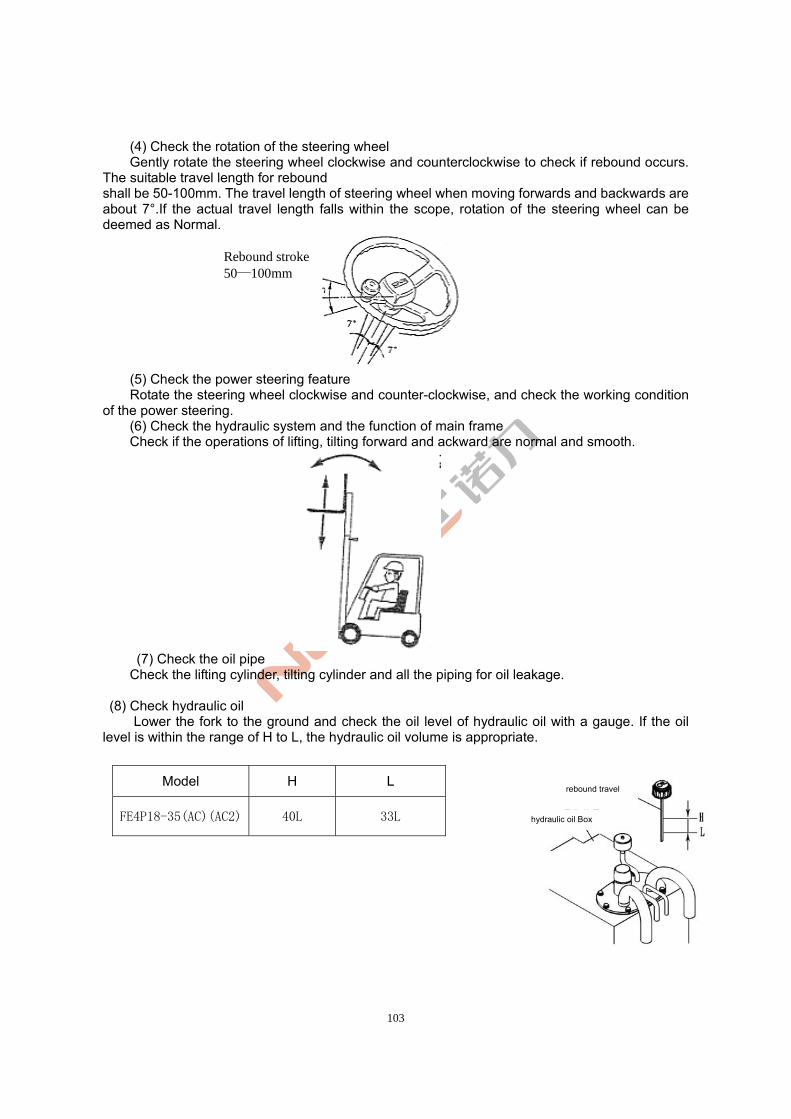
103
(4) Check the rotation of the steering wheel Gently rotate the steering wheel clockwise and counterclockwise to check if rebound occurs. The suitable travel length for rebound shall be 50-100mm. The travel length of steering wheel when moving forwards and backwards are about 7°.If the actual travel length falls within the scope, rotation of the steering wheel can be deemed as Normal.
(5) Check the power steering feature Rotate the steering wheel clockwise and counter-clockwise, and check the working condition
of the power steering. (6) Check the hydraulic system and the function of main frame Check if the operations of lifting, tilting forward and ackward are normal and smooth.
(7) Check the oil pipe Check the lifting cylinder, tilting cylinder and all the piping for oil leakage. (8) Check hydraulic oil
Lower the fork to the ground and check the oil level of hydraulic oil with a gauge. If the oil level is within the range of H to L, the hydraulic oil volume is appropriate.
Model H L
FE4P18-35(AC)(AC2) 40L 33L
rebound travel
Rebound stroke 50—100mm
hydraulic oil Box
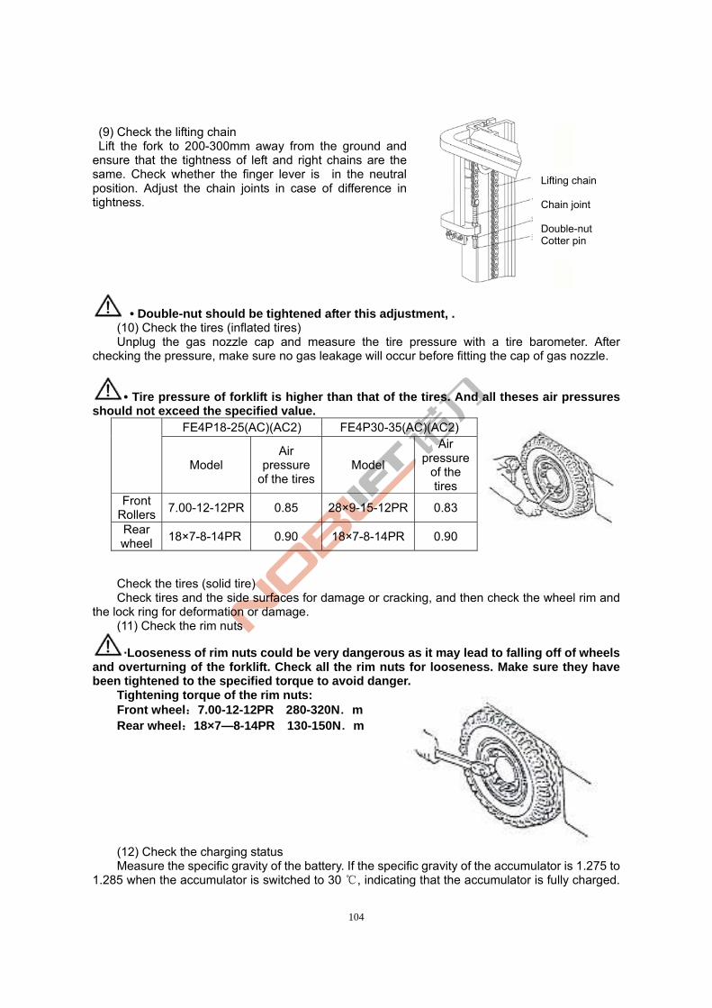
104
(9) Check the lifting chain Lift the fork to 200-300mm away from the ground and ensure that the tightness of left and right chains are the same. Check whether the finger lever is in the neutral position. Adjust the chain joints in case of difference in tightness.
• Double-nut should be tightened after this adjustment, . (10) Check the tires (inflated tires) Unplug the gas nozzle cap and measure the tire pressure with a tire barometer. After
checking the pressure, make sure no gas leakage will occur before fitting the cap of gas nozzle.
• Tire pressure of forklift is higher than that of the tires. And all theses air pressures should not exceed the specified value.
Check the tires (solid tire) Check tires and the side surfaces for damage or cracking, and then check the wheel rim and
the lock ring for deformation or damage. (11) Check the rim nuts
·Looseness of rim nuts could be very dangerous as it may lead to falling off of wheels and overturning of the forklift. Check all the rim nuts for looseness. Make sure they have been tightened to the specified torque to avoid danger.
Tightening torque of the rim nuts: Front wheel:7.00-12-12PR 280-320N.m Rear wheel:18×7—8-14PR 130-150N.m
(12) Check the charging status Measure the specific gravity of the battery. If the specific gravity of the accumulator is 1.275 to
1.285 when the accumulator is switched to 30 , indicating that the accumulator is fully charged. ℃
FE4P18-25(AC)(AC2) FE4P30-35(AC)(AC2)
Model
Air pressure
of the tiresModel
Air pressure
of the tires
Front Rollers
7.00-12-12PR 0.85 28×9-15-12PR 0.83
Rear wheel
18×7-8-14PR 0.90 18×7-8-14PR 0.90
Lifting chain Chain joint Double-nut Cotter pin
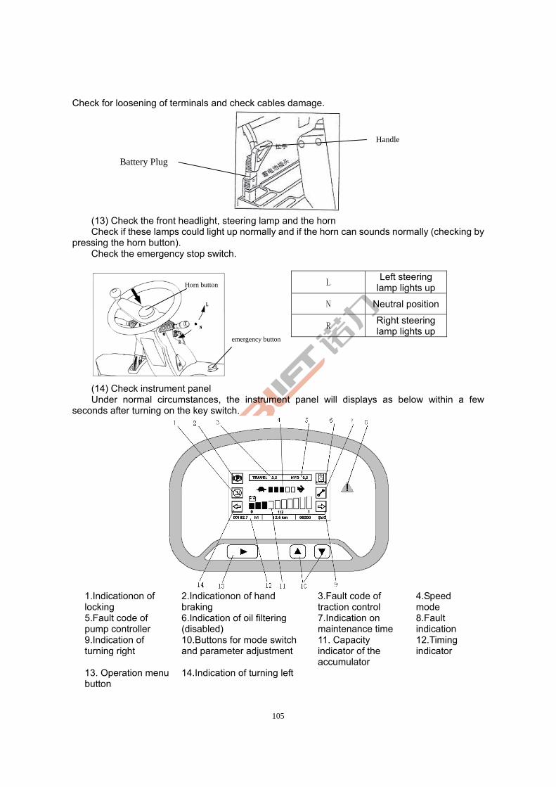
105
Check for loosening of terminals and check cables damage.
(13) Check the front headlight, steering lamp and the horn Check if these lamps could light up normally and if the horn can sounds normally (checking by
pressing the horn button). Check the emergency stop switch.
(14) Check instrument panel Under normal circumstances, the instrument panel will displays as below within a few
seconds after turning on the key switch.
1.Indicationon of locking
2.Indicationon of hand braking
3.Fault code of traction control
4.Speed mode
5.Fault code of pump controller
6.Indication of oil filtering (disabled)
7.Indication on maintenance time
8.Fault indication
9.Indication of turning right
10.Buttons for mode switch and parameter adjustment
11. Capacity indicator of the accumulator
12.Timing indicator
13. Operation menu button
14.Indication of turning left
L Left steering
lamp lights up
N Neutral position
R Right steering lamp lights up
Horn button
emergency button
Battery Plug
Handle
106
15) Check the overhead guard and backrest Check the bolts or nuts for looseness. 16) Check the integrity of the labels 17) Others Check for abnormalities on other components.
• In addition to checking of the lights and operating conditions, turn off key switch and unplug the accumulator before check the electric system.
.Checking after operationsⅡ After work, remove dirt from the forklift and check the following items: (1) Inspect all parts and components for damage or leakages. (2) Check for deformation, distortion, damage or breakage. (3) Add grease if necessary. (4) Lift the fork to the maximum height for several times after operations are finished. (After
you do not lift the fork to its maximum height in daily work, this allows the oil flow through the cylinder to prevent rusting.) )
(5) Replace abnormal components that cause failures during work.
• A small fault will cause a major accident. Do not operate or move the forklift before completion of repair and inspection.
.Clean the forkliftⅢ
• Park the forklift at the specified location. • Pull the parking brake lever. • Press the emergency stop switch. • Turn off the key switch and remove the key. • Disconnect the accumulator plug.
1. Clean the forklift surface
Do not use flammable liquids to clean the forklift and take safety measures to prevent short circuits.
·Use water and soluble detergent to clean the forklift. • Carefully clean the oil filler and the periphery of the lubricating port.
Please conduct lubrication timely if you clean the forklift frequently.
2. Clean the chain
Do not use chemical detergents, acids and other corrosive liquids to clean the chain. • Place a container under the main frame. • Use gasoline and other petrochemical derivatives to clean the chain. • Do not use any additives when cleaning with a steam nozzle. • Wipe the chain pin and water on chain surface immediately after cleaning. 3. Clean the electric system
Do not use water to clean the pump control and the connectors, so as to avoid damage to the electrical system.
Use non-metallic brush or low-power dryer to clean the electric system according to the manufacturer's instructions. Do not move the protective cover.
4. After cleaning • Thoroughly wipe off water stains on the forklift (compressed air could be used.) • Start the forklift according to the procedures.
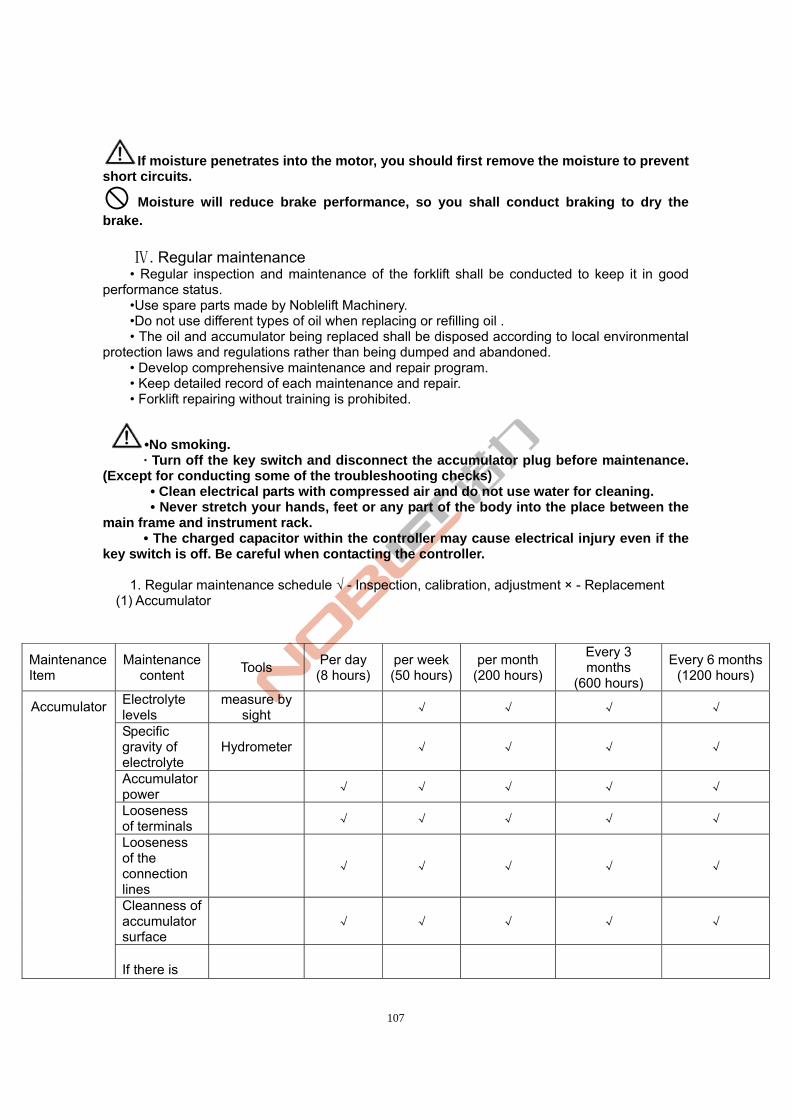
107
If moisture penetrates into the motor, you should first remove the moisture to prevent short circuits.
Moisture will reduce brake performance, so you shall conduct braking to dry the brake.
. Regular maintenanceⅣ • Regular inspection and maintenance of the forklift shall be conducted to keep it in good
performance status. •Use spare parts made by Noblelift Machinery. •Do not use different types of oil when replacing or refilling oil . • The oil and accumulator being replaced shall be disposed according to local environmental
protection laws and regulations rather than being dumped and abandoned. • Develop comprehensive maintenance and repair program. • Keep detailed record of each maintenance and repair. • Forklift repairing without training is prohibited.
•No smoking. · Turn off the key switch and disconnect the accumulator plug before maintenance.
(Except for conducting some of the troubleshooting checks) • Clean electrical parts with compressed air and do not use water for cleaning. • Never stretch your hands, feet or any part of the body into the place between the
main frame and instrument rack. • The charged capacitor within the controller may cause electrical injury even if the
key switch is off. Be careful when contacting the controller.
1. Regular maintenance schedule √ - Inspection, calibration, adjustment × - Replacement (1) Accumulator
Maintenance Item
Maintenance content
Tools Per day
(8 hours) per week(50 hours)
per month (200 hours)
Every 3 months
(600 hours)
Every 6 months(1200 hours)
Electrolyte levels
measure by sight
√ √ √ √
Specific gravity of electrolyte
Hydrometer √ √ √ √
Accumulator power
√ √ √ √ √
Looseness of terminals
√ √ √ √ √
Looseness of the connection lines
√ √ √ √ √
Cleanness of accumulator surface
√ √ √ √ √
Accumulator
If there is
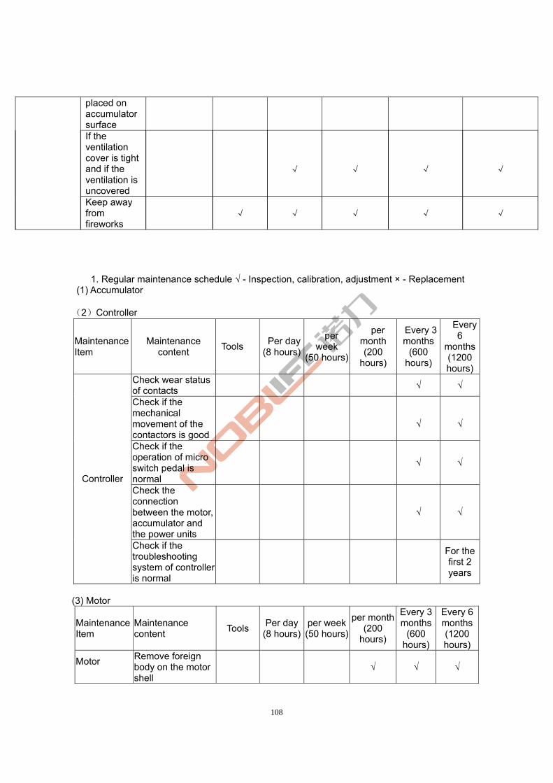
108
1. Regular maintenance schedule √ - Inspection, calibration, adjustment × - Replacement (1) Accumulator (2)Controller
Maintenance Item
Maintenance content
Tools Per day
(8 hours)
per week
(50 hours)
per month (200
hours)
Every 3 months
(600 hours)
Every 6
months(1200 hours)
Check wear status of contacts
√ √
Check if the mechanical movement of the contactors is good
√
√
Check if the operation of micro switch pedal is normal
√ √
Check the connection between the motor, accumulator and the power units
√ √
Controller
Check if the troubleshooting system of controller is normal
For the first 2 years
(3) Motor
Maintenance Item
Maintenance content
Tools Per day
(8 hours)per week(50 hours)
per month (200
hours)
Every 3 months
(600 hours)
Every 6 months(1200 hours)
Motor
Remove foreign body on the motor shell
√ √ √
placed on accumulator surface If the ventilation cover is tight and if the ventilation is uncovered
√
√
√
√
Keep away from fireworks
√ √ √ √ √
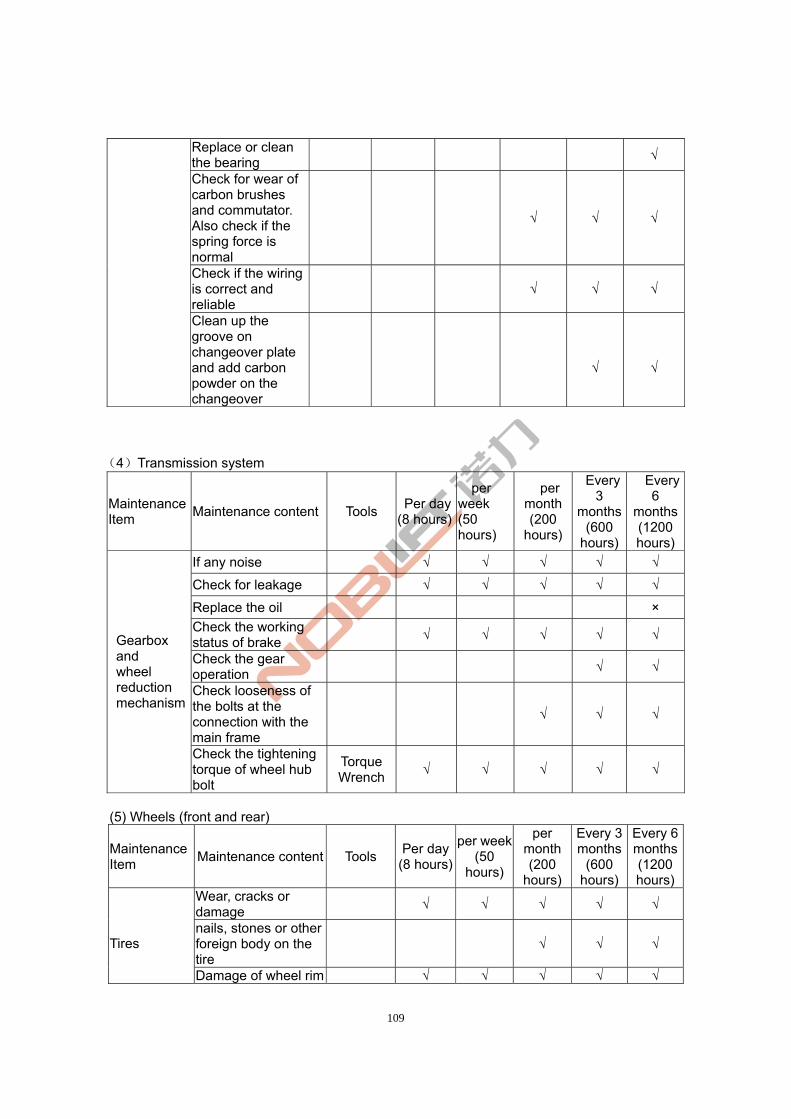
109
Replace or clean the bearing
√
Check for wear of carbon brushes and commutator. Also check if the spring force is normal
√ √ √
Check if the wiring is correct and reliable
√ √ √
Clean up the groove on changeover plate and add carbon powder on the changeover
√
√
(4)Transmission system
Maintenance Item
Maintenance content Tools Per day
(8 hours)
per week (50 hours)
per month (200
hours)
Every 3
months (600
hours)
Every 6
months(1200 hours)
If any noise √ √ √ √ √
Check for leakage √ √ √ √ √
Replace the oil ×
Check the working status of brake
√ √ √ √ √
Check the gear operation
√ √
Check looseness of the bolts at the connection with the main frame
√ √ √
Gearbox and wheel reduction mechanism
Check the tightening torque of wheel hub bolt
Torque Wrench
√ √ √ √ √
(5) Wheels (front and rear)
Maintenance Item
Maintenance content Tools Per day
(8 hours)
per week(50
hours)
per month (200
hours)
Every 3 months
(600 hours)
Every 6 months(1200 hours)
Wear, cracks or damage
√ √ √ √ √
nails, stones or other foreign body on the tire
√ √ √ Tires
Damage of wheel rim √ √ √ √ √
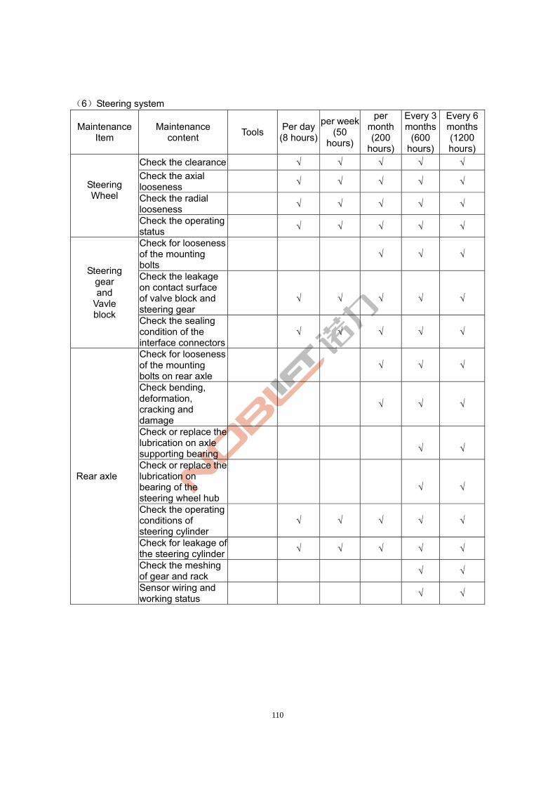
110
(6)Steering system
Maintenance Item
Maintenance content
Tools Per day
(8 hours)
per week(50
hours)
per month (200
hours)
Every 3 months
(600 hours)
Every 6 months(1200 hours)
Check the clearance √ √ √ √ √
Check the axial looseness
√ √ √ √ √
Check the radial looseness
√ √ √ √ √
Steering Wheel
Check the operating status
√ √ √ √ √
Check for looseness of the mounting bolts
√ √ √
Check the leakage on contact surface of valve block and steering gear
√
√
√
√
√
Steering gear and
Vavle block
Check the sealing condition of the interface connectors
√ √ √ √ √
Check for looseness of the mounting bolts on rear axle
√ √ √
Check bending, deformation, cracking and damage
√ √ √
Check or replace the lubrication on axle supporting bearing
√
√
Check or replace the lubrication on bearing of the steering wheel hub
√
√
Check the operating conditions of steering cylinder
√ √ √ √ √
Check for leakage of the steering cylinder
√ √ √ √ √
Check the meshing of gear and rack
√ √
Rear axle
Sensor wiring and working status
√ √
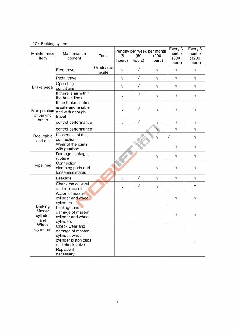
111
(7)Braking system
Maintenance Item
Maintenance content
Tools Per day
(8 hours)
per week(50
hours)
per month (200
hours)
Every 3 months
(600 hours)
Every 6 months(1200 hours)
Free travel Graduated
scale √ √ √ √ √
Pedal travel √ √ √ √ √
Operating conditions
√ √ √ √ √
Brake pedal
If there is air within the brake lines
√ √ √ √ √
If the brake control is safe and reliable and with enough travel
√ √ √ √ √
Manipulation of parking
brake control performance √ √ √ √ √
control performance √ √ √
Looseness of the connection
√ √ √ Rod, cable and etc
Wear of the joints with gearbox
√ √
Damage, leakage, rupture
√ √ √
Pipelines Connection, clamping parts and looseness status
√ √ √
Leakage √ √ √ √ √
Check the oil level and replace oil
√ √ √ ×
Action of master cylinder and wheel cylinders
√ √
Leakage and damage of master cylinder and wheel cylinders
√ √
Braking Master cylinder
and Wheel
Cylinders
Check wear and damage of master cylinder, wheel cylinder piston cups and check valve. Replace if necessary.
×
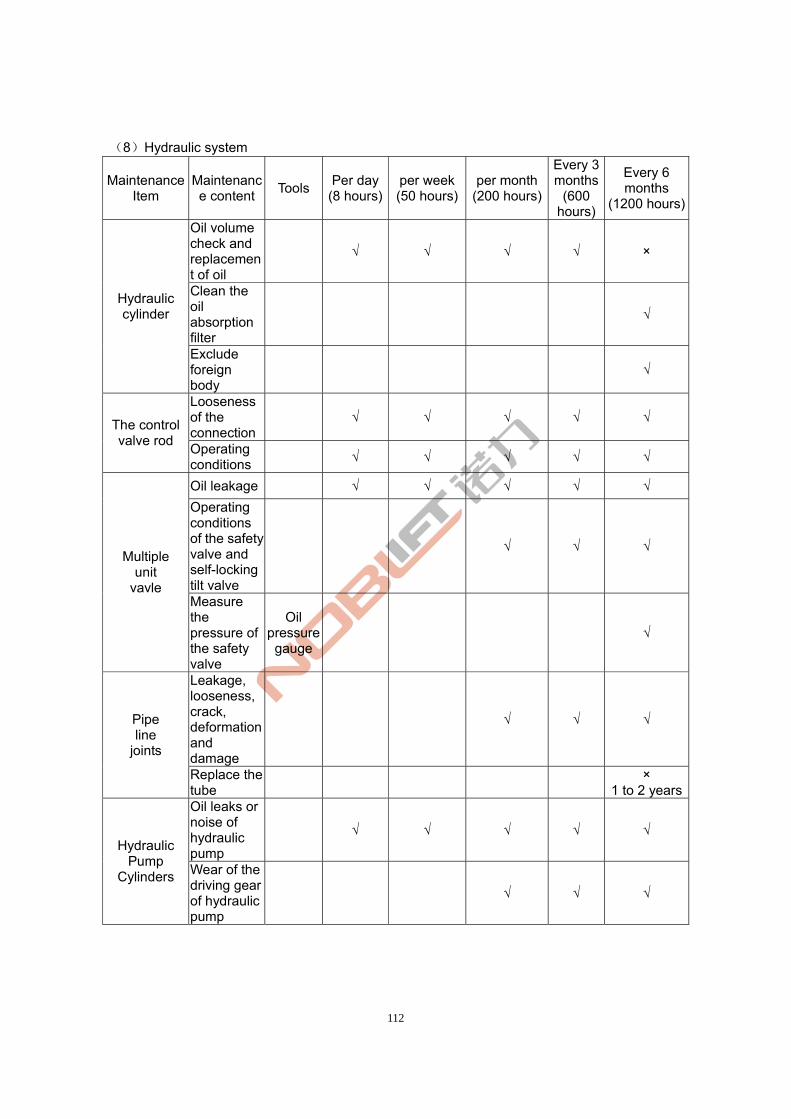
112
(8)Hydraulic system
Maintenance Item
Maintenance content
Tools Per day(8 hours)
per week(50 hours)
per month(200 hours)
Every 3 months
(600 hours)
Every 6 months
(1200 hours)
Oil volume check and replacement of oil
√ √ √ √ ×
Clean the oil absorption filter
√ Hydraulic cylinder
Exclude foreign body
√
Looseness of the connection
√ √ √ √ √ The control valve rod
Operating conditions
√ √ √ √ √
Oil leakage √ √ √ √ √
Operating conditions of the safety valve and self-locking tilt valve
√ √ √ Multiple
unit vavle
Measure the pressure of the safety valve
Oil pressure
gauge √
Leakage, looseness, crack, deformation and damage
√ √ √ Pipe line
joints
Replace the tube
×
1 to 2 yearsOil leaks or noise of hydraulic pump
√ √ √ √ √ Hydraulic
Pump Cylinders Wear of the
driving gear of hydraulic pump
√ √ √
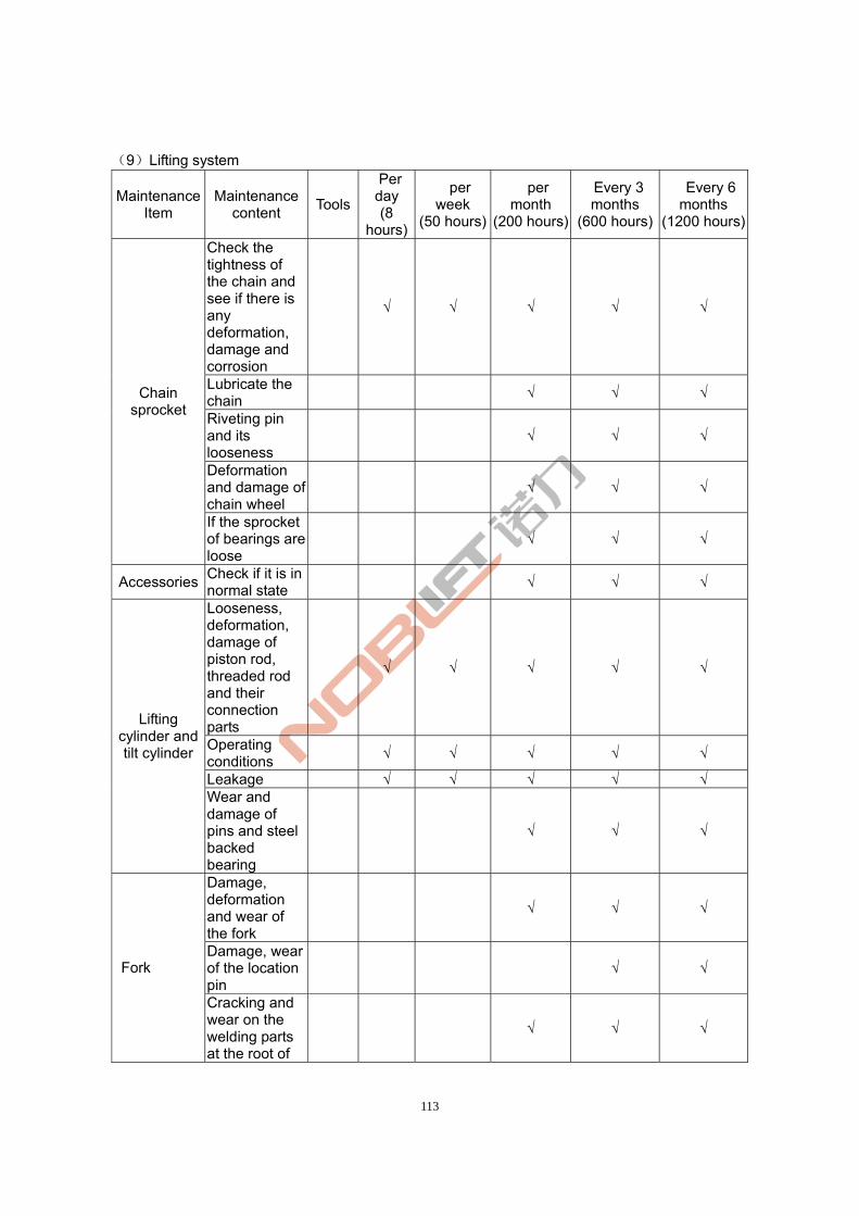
113
(9)Lifting system
Maintenance Item
Maintenance content
Tools
Per day (8
hours)
per week
(50 hours)
per month
(200 hours)
Every 3 months
(600 hours)
Every 6 months
(1200 hours)
Check the tightness of the chain and see if there is any deformation, damage and corrosion
√ √ √ √ √
Lubricate the chain
√ √ √
Riveting pin and its looseness
√ √ √
Deformation and damage of chain wheel
√ √ √
Chain sprocket
If the sprocket of bearings are loose
√ √ √
Accessories Check if it is in normal state
√ √ √
Looseness, deformation, damage of piston rod, threaded rod and their connection parts
√ √ √ √ √
Operating conditions
√ √ √ √ √
Leakage √ √ √ √ √
Lifting cylinder and tilt cylinder
Wear and damage of pins and steel backed bearing
√ √ √
Damage, deformation and wear of the fork
√ √ √
Damage, wear of the location pin
√ √ Fork
Cracking and wear on the welding parts at the root of
√ √ √
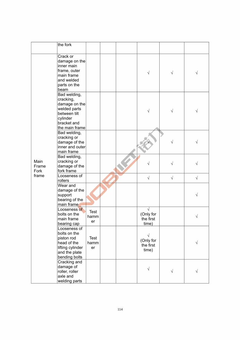
114
the fork
Crack or damage on the inner main frame, outer main frame and welded parts on the beam
√ √ √
Bad welding, cracking, damage on the welded parts between tilt cylinder bracket and the main frame
√ √ √
Bad welding, cracking or damage of the inner and outer main frame
√ √ √
Bad welding, cracking or damage of the fork frame
√ √ √
Looseness of rollers
√ √ √
Wear and damage of the support bearing of the main frame
√
Looseness of bolts on the main frame bearing cap
Test hamm
er
√ (Only for the first time)
√
Looseness of bolts on the piston rod head of the lifting cylinder and the plate bending bolts
Test hamm
er
√ (Only for the first time)
√
Main Frame Fork frame
Cracking and damage of roller, roller axle and welding parts
√
√ √
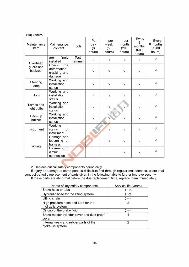
115
(10) Others
Maintenance Item
Maintenance content
Tools
Per day (8
hours)
per week (50
hours)
per month(200
hours)
Every 3
months (600
hours)
Every 6 months
(1200 hours)
are firmly installed
Test hammer
√ √ √ √ √ Overhead guard and backrest
Check the deformation, cracking and damage
√ √ √ √ √
Steering lamp
Working and installation status
√ √ √ √ √
Horn Working and installation status
√ √ √ √ √
Lamps and light bulbs
Working and installation status
√ √ √ √ √
Back-up buzzer
Working and installation status
√ √ √ √ √
Instrument Working status of instrument
√ √ √ √ √
Damage and loosening of harness
√ √ √ √
Wiring Loosening of circuit connection
√ √ √
2. Replace critical safety components periodically If injury or damage of some parts is difficult to find through regular maintenance, users shall
conduct periodic replacement of parts given in the following table to further improve security. If these parts are abnormal before the due replacement time, replace them immediately.
Name of key safety components Service life (years) Brake hose or tube l~2 Hydraulic hose for the lifting system l~2 Lifting chain 2~4 High pressure hose and tube for the hydraulic system
2
Oil cup of the brake fluid 2~4 Brake master cylinder cover and dust proof cover
1
Internal seals and rubber parts of the hydraulic system
2

116
.Ⅴ Lubricating parts and recommended oil 1. Lubricating parts ○: Replacement FO: Hydraulic oil ○: adding GO: Gear oil □: Check and adjustment CG: Lubricant grease BO: Brake oil W: Distilled water
2. Recommended oil
Name Nameplate, code Volume ( liters) )
Remarks
L-HM32 Winter Hydraulic Oil
L-HM46 40
Summer
Gear oil AFT DEXRONⅡ 4.5
Hydraulic fluid Caltex DOT3 0.2
Industrial Vaseline
2# accumulator
electrode column
Lubricant grease
Universal lithium grease for automobiles
Lifting chain CG
Direction column CG
Tilt cylinder shaft CG
Main frame support CG
Drive axle□CG
Brake pedalCG
Brake oil tank BO
Steering device□CG
Accumulator□W
117
ZheJiang Noblelift Equipment Joint Stock Co.,Ltd Tel: 86-572-6210776 6210788 Fax: 86-572-6210777 6128612 PC: 313100 Email: [email protected] URL: www.noblelift.com www.noblelift.cn Add: 528 Changzhou Road, Taihu Sub-district, Changxing, Zhejiang 313100 China