Part 70 Operating Permit Renewal OFFICE OF AIR QUALITY
386
Indiana Department of Environmental Management We Protect Hoosiers and Our Environment. 100 N. Senate Avenue • Indianapolis, IN 46204 (800) 451-6027 • (317) 232-8603 • www.idem.IN.gov Michael R. Pence Carol S. Comer Governor Commissioner An Equal Opportunity Employer Please Reduce, Reuse, Recycle Part 70 Operating Permit Renewal OFFICE OF AIR QUALITY Honda Manufacturing of Indiana, LLC 2755 North Michigan Avenue Greensburg, Indiana (herein known as the Permittee) is hereby authorized to operate subject to the conditions contained herein, the source described in Section A (Source Summary) of this permit. The Permittee must comply with all conditions of this permit. Noncompliance with any provisions of this permit is grounds for enforcement action; permit termination, revocation and reissuance, or modification; or denial of a permit renewal application. Noncompliance with any provision of this permit, except any provision specifically designated as not federally enforceable, constitutes a violation of the Clean Air Act. It shall not be a defense for the Permittee in an enforcement action that it would have been necessary to halt or reduce the permitted activity in order to maintain compliance with the conditions of this permit. An emergency does constitute an affirmative defense in an enforcement action provided the Permittee complies with the applicable requirements set forth in Section B, Emergency Provisions. This permit is issued in accordance with 326 IAC 2 and 40 CFR Part 70 Appendix A and contains the conditions and provisions specified in 326 IAC 2-7 as required by 42 U.S.C. 7401, et. seq. (Clean Air Act as amended by the 1990 Clean Air Act Amendments), 40 CFR Part 70.6, IC 13-15 and IC 13-17. Operation Permit No.: T031-37196-00026 Issued by: Josiah K. Balogun, Section Chief Permits Branch Office of Air Quality Issuance Date: Expiration Date:
-
Upload
khangminh22 -
Category
Documents
-
view
1 -
download
0
Transcript of Part 70 Operating Permit Renewal OFFICE OF AIR QUALITY

Indiana Department of Environmental Management We Protect Hoosiers and Our Environment.
100 N. Senate Avenue • Indianapolis, IN 46204
(800) 451-6027 • (317) 232-8603 • www.idem.IN.gov
Michael R. Pence Carol S. Comer Governor Commissioner
An Equal Opportunity Employer Please Reduce, Reuse, Recycle
Part 70 Operating Permit Renewal OFFICE OF AIR QUALITY
Honda Manufacturing of Indiana, LLC 2755 North Michigan Avenue
Greensburg, Indiana
(herein known as the Permittee) is hereby authorized to operate subject to the conditions contained herein, the source described in Section A (Source Summary) of this permit. The Permittee must comply with all conditions of this permit. Noncompliance with any provisions of this permit is grounds for enforcement action; permit termination, revocation and reissuance, or modification; or denial of a permit renewal application. Noncompliance with any provision of this permit, except any provision specifically designated as not federally enforceable, constitutes a violation of the Clean Air Act. It shall not be a defense for the Permittee in an enforcement action that it would have been necessary to halt or reduce the permitted activity in order to maintain compliance with the conditions of this permit. An emergency does constitute an affirmative defense in an enforcement action provided the Permittee complies with the applicable requirements set forth in Section B, Emergency Provisions. This permit is issued in accordance with 326 IAC 2 and 40 CFR Part 70 Appendix A and contains the conditions and provisions specified in 326 IAC 2-7 as required by 42 U.S.C. 7401, et. seq. (Clean Air Act as amended by the 1990 Clean Air Act Amendments), 40 CFR Part 70.6, IC 13-15 and IC 13-17. Operation Permit No.: T031-37196-00026
Issued by: Josiah K. Balogun, Section Chief Permits Branch Office of Air Quality
Issuance Date: Expiration Date:

Honda Manufacturing of Indiana, LLC Page 2 of 125 Greensburg, Indiana Part 70 Renewal No. T031-37196-00026 Permit Reviewer: Aida DeGuzman
TABLE OF CONTENTS
TABLE OF CONTENTS .......................................................................................................... 2
SECTION A SOURCE SUMMARY ......................................................................................................... 8
A.1 General Information [326 IAC 2-7-4(c)][326 IAC 2-7-5(14)][326 IAC 2-7-1(22)] ................ 8 A.2 Emission Units and Pollution Control Equipment Summary [326 IAC 2-7-4(c)(3)]
[326 IAC 2-7-5(14)] ............................................................................................................. 8 A.3 Specifically Regulated Insignificant Activities [326 IAC 2-7-1(21)] [326 IAC 2-7-4(c)]
[326 IAC 2-7-5(14)] ........................................................................................................... 13 A.4 Part 70 Permit Applicability [326 IAC 2-7-2] .................................................................... 18
SECTION B GENERAL CONDITIONS ................................................................................................. 19
B.1 Definitions [326 IAC 2-7-1] ................................................................................................ 19 B.2 Permit Term
[326 IAC 2-7-5(2)][326 IAC 2-1.1-9.5][326 IAC 2-7-4(a)(1)(D)][IC 13-15-3-6(a)] ............. 19 B.3 Term of Conditions [326 IAC 2-1.1-9.5] ............................................................................ 19 B.4 Enforceability [326 IAC 2-7-7] [IC 13-17-12] ..................................................................... 19 B.5 Severability [326 IAC 2-7-5(5)] .......................................................................................... 19 B.6 Property Rights or Exclusive Privilege [326 IAC 2-7-5(6)(D)] ........................................... 19 B.7 Duty to Provide Information [326 IAC 2-7-5(6)(E)] ............................................................ 19 B.8 Certification [326 IAC 2-7-4(f)][326 IAC 2-7-6(1)][326 IAC 2-7-5(3)(C)] ........................... 19 B.9 Annual Compliance Certification [326 IAC 2-7-6(5)] ......................................................... 20 B.10 Preventive Maintenance Plan [326 IAC 2-7-5(12)][326 IAC 1-6-3] ................................... 21 B.11 Emergency Provisions [326 IAC 2-7-16] ........................................................................... 22 B.12 Permit Shield [326 IAC 2-7-15][326 IAC 2-7-20][326 IAC 2-7-12] ................................... 23 B.13 Prior Permits Superseded [326 IAC 2-1.1-9.5][326 IAC 2-7-10.5] ................................... 24 B.14 Termination of Right to Operate [326 IAC 2-7-10][326 IAC 2-7-4(a)] ............................... 24 B.15 Permit Modification, Reopening, Revocation and Reissuance, or Termination
[326 IAC 2-7-5(6)(C)][326 IAC 2-7-8(a)][326 IAC 2-7-9] ................................................... 24 B.16 Permit Renewal [326 IAC 2-7-3][326 IAC 2-7-4][326 IAC 2-7-8(e)] .................................. 25 B.17 Permit Amendment or Modification [326 IAC 2-7-11][326 IAC 2-7-12] ............................. 26 B.18 Permit Revision Under Economic Incentives and Other Programs
[326 IAC 2-7-5(8)][326 IAC 2-7-12(b)(2)] .......................................................................... 26 B.19 Operational Flexibility [326 IAC 2-7-20][326 IAC 2-7-10.5]............................................... 26 B.20 Source Modification Requirement [326 IAC 2-7-10.5] ...................................................... 28 B.21 Inspection and Entry [326 IAC 2-7-6][IC 13-14-2-2][IC 13-30-3-1][IC 13-17-3-2] ............. 28 B.22 Transfer of Ownership or Operational Control [326 IAC 2-7-11] ...................................... 28 B.23 Annual Fee Payment [326 IAC 2-7-19] [326 IAC 2-7-5(7)][326 IAC 2-1.1-7] ................... 29 B.24 Credible Evidence [326 IAC 2-7-5(3)][326 IAC 2-7-6][62 FR 8314] [326 IAC 1-1-6] ........ 29
SECTION C SOURCE OPERATION CONDITIONS ............................................................................. 30
Emission Limitations and Standards [326 IAC 2-7-5(1)] ......................................................... 30 C.1 Particulate Emission Limitations For Processes with Process Weight Rates Less
Than One Hundred (100) Pounds per Hour [326 IAC 6-3-2] ............................................ 30 C.2 Opacity [326 IAC 5-1] ....................................................................................................... 30 C.3 Open Burning [326 IAC 4-1] [IC 13-17-9] ........................................................................ 30 C.4 Incineration [326 IAC 4-2] [326 IAC 9-1-2] ....................................................................... 30 C.5 Fugitive Dust Emissions [326 IAC 6-4] ............................................................................ 30 C.6 Stack Height [326 IAC 1-7] .............................................................................................. 30 C.7 Asbestos Abatement Projects [326 IAC 14-10] [326 IAC 18] [40 CFR 61, Subpart M] ... 30 Testing Requirements [326 IAC 2-7-6(1)] .................................................................................. 32 C.8 Performance Testing [326 IAC 3-6] ................................................................................. 32 Compliance Requirements [326 IAC 2-1.1-11] ......................................................................... 32 C.9 Compliance Requirements [326 IAC 2-1.1-11] ................................................................. 32

Honda Manufacturing of Indiana, LLC Page 3 of 125 Greensburg, Indiana Part 70 Renewal No. T031-37196-00026 Permit Reviewer: Aida DeGuzman
Compliance Monitoring Requirements [326 IAC 2-7-5(1)][326 IAC 2-7-6(1)] ......................... 32 C.10 Compliance Monitoring
[326 IAC 2-7-5(3)][326 IAC 2-7-6(1)][40 CFR 64][326 IAC 3-8] ....................................... 32 C.11 Instrument Specifications [326 IAC 2-1.1-11] [326 IAC 2-7-5(3)] [326 IAC 2-7-6(1)] ....... 33 Corrective Actions and Response Steps [326 IAC 2-7-5][326 IAC 2-7-6] .............................. 33 C.12 Emergency Reduction Plans [326 IAC 1-5-2] [326 IAC 1-5-3] ........................................ 33 C.13 Risk Management Plan [326 IAC 2-7-5(11)] [40 CFR 68] ................................................ 34 C.14 Response to Excursions or Exceedances [40 CFR 64][326 IAC 3-8][326 IAC 2-7-5]
[326 IAC 2-7-6] .................................................................................................................. 34 C.15 Actions Related to Noncompliance Demonstrated by a Stack Test
[326 IAC 2-7-5][326 IAC 2-7-6] ......................................................................................... 36 Record Keeping and Reporting Requirements [326 IAC 2-7-5(3)] [326 IAC 2-7-19] ............. 36 C.16 Emission Statement
[326 IAC 2-7-5(3)(C)(iii)][326 IAC 2-7-5(7)][326 IAC 2-7-19(c)][326 IAC 2-6] .................. 36 C.17 General Record Keeping Requirements [326 IAC 2-7-5(3)] [326 IAC 2-7-6]
[326 IAC 2-2][326 IAC 2-3] ................................................................................................ 37 C.18 General Reporting Requirements [326 IAC 2-7-5(3)(C)] [326 IAC 2-1.1-11]
[326 IAC 2-2] [326 IAC 2-3][40 CFR 64][326 IAC 3-8] ...................................................... 38 Stratospheric Ozone Protection ................................................................................................. 40 C.19 Compliance with 40 CFR 82 and 326 IAC 22-1 ................................................................ 40
SECTION D.1 EMISSIONS UNIT OPERATION CONDITIONS .............................................................. 41
Emission Limitations and Standards [326 IAC 2-7-5(1)] .......................................................... 41 D.1.1 Source-wide Prevention of Significant Deterioration (PSD) Limits [326 IAC 2-2-3] ......... 41 Compliance Determination Requirement [326 IAC 2-7-5(1)] .................................................... 41 D.1.2 Prevention of Significant Deterioration (PSD) VOC BACT limits [326 IAC 2-7-5(1)]
[326 IAC 2-2-3] .................................................................................................................. 41 D.1.3 Regenerative Thermal Oxidizers (RTOs) [326 IAC 2-2-3] ................................................ 41 Record Keeping and Reporting Requirement [326 IAC 2-7-5(3)][326 IAC 2-7-19] ................ 42 D.1.4 Record Keeping Requirements ......................................................................................... 42
SECTION D.2 EMISSION UNIT OPERATION CONDITIONS ................................................................. 43
Emission Limitations and Standards [326 IAC 2-7-5(1)] .......................................................... 43 D.2.1 Prevention of Significant Deterioration (PSD) - Best Available Control Technology for
Volatile Organic Compounds (VOC) [326 IAC 2-2-3] ....................................................... 43 D.2.2 Volatile Organic Compounds [326 IAC 8-2-2] ................................................................... 43 D.2.3 Preventive Maintenance Plan [326 IAC 2-7-5(12)] ........................................................... 44 Compliance Determination Requirements [326 IAC 2-7-5(1)] .................................................. 44 D.2.4 Regenerative Thermal Oxidizers (RTOs) [326 IAC 2-2][326 IAC 8-2-2] ........................... 44 D.2.5 Volatile Organic Compounds [326 IAC 8-2-2][326 IAC 8-1-2] .......................................... 44 D.2.6 Testing Requirements [326 IAC 2-2][326 IAC 2-7-6(1), (6)][326 IAC 2-1.1-11] ............... 44 D.2.7 Volatile Organic Compounds (VOC) [326 IAC 2-2][326 IAC 8-2-2] .................................. 44 Compliance Monitoring Requirements [326 IAC 2-7-6 (1)][326 IAC 2-7-5 (1)] ....................... 45 D.2.8 Regenerative Thermal Oxidizers (RTOs) Temperature [326 IAC 2-2-3][326 IAC 8-2-
2] ....................................................................................................................................... 45 D.2.9 Parametric Monitoring [326 IAC 8-2-2] ............................................................................. 46 Record Keeping and Reporting Requirements [326 IAC 2-7-5(3)][326 IAC 2-7-19] .............. 46 D.2.10 Record Keeping Requirements ......................................................................................... 46 D.2.11 Reporting Requirements ................................................................................................... 47

Honda Manufacturing of Indiana, LLC Page 4 of 125 Greensburg, Indiana Part 70 Renewal No. T031-37196-00026 Permit Reviewer: Aida DeGuzman
SECTION D.3 EMISSION UNIT OPERATION CONDITIONS ................................................................. 48
Emission Limitations and Standards [326 IAC 2-7-5(1)] .......................................................... 49 D.3.1 Prevention of Significant Deterioration (PSD) - Best Available Control Technology for
Volatile Organic Compounds (VOC) [326 IAC 2-2-3] ....................................................... 49 D.3.2 Volatile Organic Compounds [326 IAC 8-2-2] ................................................................... 49 D.3.3 PSD BACT for PM and PM10 [326 IAC 2-2-3] ................................................................. 49 D.3.4 Preventive Maintenance Plan [326 IAC 2-7-5(12)] ........................................................... 49 Compliance Determination Requirements [326 IAC 2-7-5(1)] .................................................. 49 D.3.5 Regenerative Thermal Oxidizers (RTOs) [326 IAC 2-2][326 IAC 8-2-2] ........................... 49 D.3.6 Volatile Organic Compounds [326 IAC 8-2-2][326 IAC 8-1-2] .......................................... 50 D.3.7 Testing Requirements [326 IAC 2-2][326 IAC 2-7-6(1), (6)][326 IAC 2-1.1-11] ............... 50 D.3.8 Volatile Organic Compounds (VOC) [326 IAC 2-2-3][326 IAC 8-2-2] ............................... 50 Compliance Monitoring Requirements [326 IAC 2-7-6 (1)][326 IAC 2-7-5 (1)] ....................... 51 D.3.9 Regenerative Thermal Oxidizers (RTOs) Temperature [326 IAC 2-2-3][326 IAC 8-2-
2][40 CFR 64] .................................................................................................................... 51 D.3.10 Water/Polymer Emulsion Wash and dry filters Monitoring [40 CFR 64] ........................... 52 D.3.11 Parametric Monitoring [326 IAC 8-2-2][40 CFR 64] .......................................................... 52 Record Keeping and Reporting Requirements [326 IAC 2-7-5(3)][326 IAC 2-7-19] .............. 52 D.3.12 Record Keeping Requirements ......................................................................................... 52 D.3.13 Reporting Requirements ................................................................................................... 54
SECTION D.4 EMISSION UNIT OPERATION CONDITIONS ................................................................. 55
Emission Limitations and Standards [326 IAC 2-7-5(1)] .......................................................... 56 D.4.1 Prevention of Significant Deterioration (PSD) - Best Available Control Technology for
Volatile Organic Compounds (VOC) [326 IAC 2-2-3] ....................................................... 56 D.4.2 Volatile Organic Compounds [326 IAC 8-2-2] [326 IAC 8-2-9] ......................................... 56 D.4.3 PSD BACT for PM and PM10 [326 IAC 2-2-3] ................................................................. 56 D.4.4 Preventive Maintenance Plan [326 IAC 2-7-5(12)] ........................................................... 57 Compliance Determination Requirements [326 IAC 2-7-5(1)] .................................................. 57 D.4.5 Regenerative Thermal Oxidizers (RTOs) [326 IAC 2-2][326 IAC 8-2-2] ........................... 57 D.4.6 Volatile Organic Compounds [326 IAC 8-2-2][326 IAC 8-1-2] .......................................... 57 D.4.7 Testing Requirements [326 IAC 2-2-3][326 IAC 2-7-6(1), (6)][326 IAC 2-1.1-11] ............ 57 D.4.8 Volatile Organic Compounds (VOC) [326 IAC 2-2-3][326 IAC 8-2-2] ............................... 58 Compliance Monitoring Requirements [326 IAC 2-7-5(1)][326 IAC 2-7-6(1) ........................... 59 D.4.9 Regenerative Thermal Oxidizers (RTOs) Temperature [326 IAC 2-2-3][326 IAC 8-2-
2][40 CFR 64] .................................................................................................................... 59 D.4.10 Water/Polymer Emulsion Wash and Dry Filters Monitoring .............................................. 60 D.4.11 Parametric Monitoring [326 IAC 8-2-2][40 CFR Part 64] .................................................. 60 Record Keeping and Reporting Requirements [326 IAC 2-7-5(3)][326 IAC 2-7-19] .............. 61 D.4.12 Record Keeping Requirements ......................................................................................... 61 D.4.13 Reporting Requirements ................................................................................................... 62
SECTION D.5 EMISSION UNIT OPERATION CONDITIONS ................................................................. 63
Emission Limitations and Standards [326 IAC 2-7-5(1)] .......................................................... 63 D.5.1 Prevention of Significant Deterioration (PSD) - Best Available Control Technology for
Volatile Organic Compounds (VOC) [326 IAC 2-2-3][326 IAC 8-1-6] ............................... 63 D.5.2 PSD BACT for PM and PM10 [326 IAC 2-2-3] ................................................................. 64 D.5.3 Particulate Emissions Limitations for Work Practices and Control Technologies [326
IAC 6-3-2(d)] ..................................................................................................................... 64 D.5.4 Preventive Maintenance Plan [326 IAC 2-7-5(12)] ........................................................... 65

Honda Manufacturing of Indiana, LLC Page 5 of 125 Greensburg, Indiana Part 70 Renewal No. T031-37196-00026 Permit Reviewer: Aida DeGuzman
Compliance Determination Requirements [326 IAC 2-7-5(1)] .................................................. 65 D.5.5 Regenerative Thermal Oxidizer (RTO) [326 IAC 2-2-3] .................................................... 65 D.5.6 Testing Requirements [326 IAC 2-2-3][326 IAC 2-7-6(1), (6)][326 IAC 2-1.1-11] ............ 65 D.5.7 Volatile Organic Compounds (VOC) [326 IAC 2-2-3] ....................................................... 65 Compliance Monitoring Requirements [326 IAC 2-7-5(1)][326 IAC 2-7-6(1)] .......................... 66 D.5.8 Regenerative Thermal Oxidizer (RTO) Temperature [326 IAC 2-2-3][40 CFR Part
64] ..................................................................................................................................... 66 D.5.9 Water/Polymer Emulsion Wash and Dry Filters Monitoring .............................................. 66 D.5.10 Parametric Monitoring [326 IAC 8-2-2][40 CFR Part 64] .................................................. 67 Record Keeping and Reporting Requirements [326 IAC 2-7-5(3)][326 IAC 2-7-19] .............. 67 D.5.11 Record Keeping Requirements ......................................................................................... 67 D.5.12 Reporting Requirements ................................................................................................... 68
SECTION D.6 EMISSION UNIT OPERATION CONDITIONS ................................................................. 69
Emission Limitations and Standards [326 IAC 2-7-5(1)] .......................................................... 69 D.6.1 Prevention of Significant Deterioration (PSD) - Best Available Control Technology for
Volatile Organic Compounds (VOC) [326 IAC 2-2-3][326 IAC 8-4-6] ............................... 69 D.6.2 Volatile Organic Compounds (VOC) [326 IAC 8-4-9] ....................................................... 70 D.6.3 Preventive Maintenance Plan [326 IAC 2-7-5(12)] ........................................................... 71 Compliance Determination Requirements [326 IAC 2-7-5(1)] .................................................. 71 D.6.4 Volatile Organic Compounds [326 IAC 2-2-3] ................................................................... 71 D.6.5 Testing Requirements [326 IAC 2-7-6(1),(6)][326 IAC 2-1.1-11] ...................................... 72 Compliance Monitoring Requirements [326 IAC 2-7-6(1)][326 IAC 2-7-5(1)] .......................... 72 D.6.6 Vapor Recovery System Operation .................................................................................. 72 Record Keeping and Reporting Requirements [326 IAC 2-7-5(3)][326 IAC 2-7-19] .............. 72 D.6.7 Record Keeping Requirements ......................................................................................... 72 D.6.8 Reporting Requirements ................................................................................................... 73
SECTION D.7 EMISSION UNIT OPERATION CONDITIONS ................................................................. 74
Emission Limitations and Standards [326 IAC 2-7-5(1)] ......................................................... 75 D.7.1 Prevention of Significant Deterioration (PSD) - Best Available Control Technology for
Volatile Organic Compounds (VOC) [326 IAC 2-2-3] ....................................................... 75 D.7.2 Prevention of Significant Deterioration (PSD) PM2.5 Minor Limits [326 IAC 2-2] ............ 75 D.7.3 Cleaning Work Practices [326 IAC 2-2] ............................................................................ 76 D.7.4 Cold Cleaner Degreaser Control Equipment and Operating Requirements [326 IAC
8-3-2] ................................................................................................................................. 76 D.7.5 Material Requirements for Cold Cleaner Degreasers [326 IAC 8-3-8] ............................. 77 D.7.6 PSD BACT for PM and PM10 [326 IAC 2-2-3] ................................................................. 77 D.7.7 Particulate Emission Limitations for Manufacturing Processes [326 IAC 6-3-2] .............. 77 D.7.8 Preventive Maintenance Plan [326 IAC 2-7-5(12)] ........................................................... 77 Compliance Determination Requirements [326 IAC 2-7-5(1)] .................................................. 78 D.7.9 Volatile Organic Compounds (VOC) [326 IAC 8-1-4(a)(3)][326 IAC 8-1-2(a)][326 IAC
2-2] .................................................................................................................................... 78 D.7.10 Volatile Organic Compounds (VOC) [326 IAC 8-1-2(a)(7)]............................................... 78 D.7.11 Particulate Control............................................................................................................. 78 D.7.12 Broken or Failed Bag Detection - Single Compartment Baghouse .................................. 78 Compliance Monitoring Requirements [326 IAC 2-7-6 (1)][326 IAC 2-7-5 (1)] ....................... 79 D.7.13 Visible Emissions Notations .............................................................................................. 79 Record Keeping and Reporting Requirements [326 IAC 2-7-5(3)][326 IAC 2-7-19] .............. 79 D.7.14 Record Keeping Requirements ......................................................................................... 79 D.7.15 Reporting Requirements ................................................................................................... 81

Honda Manufacturing of Indiana, LLC Page 6 of 125 Greensburg, Indiana Part 70 Renewal No. T031-37196-00026 Permit Reviewer: Aida DeGuzman
SECTION D.8 EMISSION UNIT OPERATION CONDITIONS ................................................................. 82
Emission Limitations and Standards [326 IAC 2-7-5(1)] .......................................................... 82 D.8.1 Prevention of Significant Deterioration (PSD) - Best Available Control Technology for
Volatile Organic Compounds (VOC) [326 IAC 2-2-3] ....................................................... 82 D.8.2 Preventive Maintenance Plan [326 IAC 2-7-5(12)] ........................................................... 83
SECTION D.9 EMISSION UNIT OPERATION CONDITIONS ................................................................. 84
Emission Limitations and Standards [326 IAC 2-7-5(1)] .......................................................... 84 D.9.1 Prevention of Significant Deterioration (PSD) - Best Available Control Technology for
Volatile Organic Compounds (VOC) [326 IAC 2-2-3][326 IAC 8-2-2] ............................... 84 D.9.2 PSD BACT for PM and PM10 [326 IAC 2-2-3] ................................................................. 84 D.9.3 Preventive Maintenance Plan [326 IAC 2-7-5(12)] ........................................................... 85 Compliance Determination Requirements [326 IAC 2-7-5(1)] .................................................. 85 D.9.4 Volatile Organic Compounds (VOC) [326 IAC 2-2] ........................................................... 85 Compliance Monitoring Requirements [326 IAC 2-7-6 (1)][326 IAC 2-7-5 (1)] ....................... 85 D.9.5 Dry Filters Monitoring ........................................................................................................ 85 Record Keeping and Reporting Requirement [326 IAC 2-7-5(3)][326 IAC 2-7-19] ................ 86 D.9.6 Record Keeping Requirements ......................................................................................... 86 D.9.7 Reporting Requirements ................................................................................................... 86
SECTION D.10 EMISSION UNIT OPERATION CONDITIONS ................................................................. 87 Emission Limitations and Standards [326 IAC 2-7-5(1)] ......................................................... 90 D.10.1 Prevention of Significant Deterioration (PSD) CO Minor Limit [326 IAC 2-2] ................... 90 D.10.2 Prevention of Significant Deterioration (PSD) - Best Available Control Technology for
Particulate Emissions (PM) and Nitrogen Oxides (NOx) [326 IAC 2-2-3] ......................... 90 D.10.3 Particulate Emission Limitations for Sources of Indirect Heating [326 IAC 6-2-4] ............ 91 Compliance Determination Requirements [326 IAC 2-7-5 (1)] ................................................. 92 D.10.4 Testing Requirements [326 IAC 2-7-5(1),(6)][326 IAC 2-1.1-11][326 IAC 2-2] ................ 92 Record Keeping and Reporting Requirement [326 IAC 2-7-5(3)][326 IAC 2-7-19] ................ 92 D.10.5 Record Keeping Requirements ......................................................................................... 92 D.10.6 Reporting Requirements ................................................................................................... 92
SECTION D.11 EMISSION UNIT OPERATION CONDITIONS ................................................................. 93
Emission Limitations and Standards [326 IAC 2-7-5(1)] .......................................................... 93 D.11.1 PSD BACT for PM and PM10 [326 IAC 2-2-3] ................................................................. 93 Record Keeping and Reporting Requirement [326 IAC 2-7-5(3)][326 IAC 2-7-19] ................ 94 D.11.2 Record Keeping Requirements ......................................................................................... 94
SECTION E.1 NSPS ................................................................................................................................ 95
New Source Performance Standards (NSPS) Requirements [326 IAC 2-7-5(1)] .................... 96 E.1.1 General Provisions Relating to New Source Performance Standards [326 IAC 12-
1][40 CFR Part 60, Subpart A] .......................................................................................... 96 E.1.2 Standard of Performance for Automobiles and Light-Duty Truck Surface Coating
Operations [326 IAC 12][40 CFR Part 60, Subpart MM]................................................... 97 SECTION E.2 NSPS ................................................................................................................................ 98
New Source Performance Standards (NSPS) Requirements [326 IAC 2-7-5(1)] .................... 98 E.2.1 General Provisions Relating to New Source Performance Standards [326 IAC 12-
1][40 CFR Part 60, Subpart A] .......................................................................................... 98 E.2.2 Standards of Performance for Stationary Compression Ignition Internal Combustion
Engines [326 IAC 12][40 CFR Part 60, Subpart IIII] ......................................................... 98

Honda Manufacturing of Indiana, LLC Page 7 of 125 Greensburg, Indiana Part 70 Renewal No. T031-37196-00026 Permit Reviewer: Aida DeGuzman
SECTION E.3 NESHAP ......................................................................................................................... 100
National Emission Standards for Hazardous Air Pollutants (NESHAP) Requirements [326 IAC 2-7-5(1)] ........................................................................................................... 104
E.3.1 General Provisions Relating to National Emission Standards for Hazardous Air Pollutants under 40 CFR Part 63 [326 IAC 20-1][40 CFR Part 63, Subpart A][326 IAC 20-1][40 CFR Part 63, Subpart A] ............................................................................ 104
E.3.2 Surface Coating of Plastic Parts and Products NESHAP [40 CFR Part 63, Subpart PPPP] .............................................................................................................................. 105
E.3.3 Surface Coating of Miscellaneous Metal Parts and Products NESHAP [40 CFR Part 63, Subpart MMMM]........................................................................................................ 105
E.3.4 Surface Coating of Automobiles and Light-Duty Trucks NESHAP [326 IAC 20-85][40 CFR Part 63, Subpart IIII] ............................................................................................... 105
E.3.5 Testing Requirements [326IAC 2-1.1-11] [326 IAC 2-7-6(1)] [326 IAC 2-7-5(1)] ........... 106 SECTION E.4 NESHAP ......................................................................................................................... 107
National Emission Standards for Hazardous Air Pollutants (NESHAP) Requirements [326 IAC 2-7-5(1)] ........................................................................................................... 107
E.4.1 General Provisions Relating to National Emission Standards for Hazardous Air Pollutants under 40 CFR Part 63 [326 IAC 20-1][40 CFR Part 63, Subpart A] .............. 107
E.4.2 Stationary Reciprocating Internal Combustion Engines NESHAP [326 IAC 20-82][40 CFR Part 63, Subpart ZZZZ] .......................................................................................... 107
CERTIFICATION ...................................................................................................................................... 109
EMERGENCY OCCURRENCE REPORT ................................................................................................ 110
Part 70 Quarterly Report ......................................................................................................................... 112 Part 70 Quarterly Report ......................................................................................................................... 113
Part 70 Quarterly Report ......................................................................................................................... 114
Part 70 Quarterly Report ......................................................................................................................... 115
Part 70 Quarterly Report ......................................................................................................................... 116
Quarterly Report ...................................................................................................................................... 117
Quarterly Report ...................................................................................................................................... 118 Quarterly Report ...................................................................................................................................... 119
Part 70 Quarterly Report ......................................................................................................................... 120
Quarterly Report ...................................................................................................................................... 121
Quarterly Report ...................................................................................................................................... 122
QUARTERLY DEVIATION AND COMPLIANCE MONITORING REPORT ............................................ 124
Attachment A - 40 CFR 60, Subpart MM- New Source Performance Standards for Automobile and
Light Duty Truck Surface Coating Operations Attachment B - 40 CFR 60, Subpart IIII- New Source Performance Standards for Stationary
Compression Ignition Internal Combustion Engines Attachment C - 40 CFR 63, Subpart IIII - National Emission Standards for Hazardous Air Pollutants
for Surface Coating of Automobiles and Light-Duty Trucks Attachment D - 40 CFR 63, Subpart ZZZZ- National Emission Standards for Hazardous Air Pollutants
for Stationary Reciprocating Internal Combustion Engines

Honda Manufacturing of Indiana, LLC Page 8 of 125 Greensburg, Indiana Part 70 Renewal No. T031-37196-00026 Permit Reviewer: Aida DeGuzman
SECTION A SOURCE SUMMARY
This permit is based on information requested by the Indiana Department of Environmental Management (IDEM), Office of Air Quality (OAQ). The information describing the source contained in conditions A.1 through A.3 is descriptive information and does not constitute enforceable conditions. However, the Permittee should be aware that a physical change or a change in the method of operation that may render this descriptive information obsolete or inaccurate may trigger requirements for the Permittee to obtain additional permits or seek modification of this permit pursuant to 326 IAC 2, or change other applicable requirements presented in the permit application. A.1 General Information [326 IAC 2-7-4(c)][326 IAC 2-7-5(14)][326 IAC 2-7-1(22)]
The Permittee owns and operates a stationary automobile and light-duty trucks manufacturing plant.
Source Address: 2755 North Michigan Avenue, Greensburg,, Indiana General Source Phone Number: 812) 651-6159 SIC Code: 3711 (Motor Vehicles and Passenger Car
Bodies 3714 (Motor Vehicle Parts and Accessories) County Location: Decatur Source Location Status: Attainment for all criteria pollutants Source Status: Part 70 Operating Permit Program Major Source, under PSD Rules
Major Source, Section 112 of the Clean Air Act Not 1 of 28 Source Categories
A.2 Emission Units and Pollution Control Equipment Summary [326 IAC 2-7-4(c)(3)]
[326 IAC 2-7-5(14)] This source consists of the following emission units and pollution control devices: (a) Body Painting Operations:
(1) Electrodeposition (E-Coat) Coating Line, identified as PA-02, with a capacity of 72 units per hour, approved in 2016 to add new voltage equipment, consisting of the following:
(A) Multistage pretreatment/Phosphate Process, identified as PA-01
IA.
(B) One (1) Electrodeposition coating dip tank, rinse stages and E-Coat oven, approved in 2006 for construction and approved in 2012 for modification, controlled by one (1) natural gas-fired regenerative thermal oxidizer (RTO), with a maximum heat input capacity of 14 million British thermal units per hour (MMBtu/hr), identified as Body Oven RTO with stack ID 1100.
(C) One (1) E-Coat oven pre-heat zone, with a maximum heat input
capacity of 3.7 MMBtu/hr, exhausting to stack ID 1003.
(D) One (1) natural gas-fired E-coat 5-stage oven tunnel approved in 2006 for construction and approved in 2012 for modification to extend the oven and add one (1) burner which consists of five (5) oven zones, each with a heat input capacity of 3.7 MMBtu/hr, controlled by one (1) RTO, identified as Body Oven RTO with stack ID 1100.

Honda Manufacturing of Indiana, LLC Page 9 of 125 Greensburg, Indiana Part 70 Renewal No. T031-37196-00026 Permit Reviewer: Aida DeGuzman
(E) One (1) cooling tunnel, exhausting to stack ID 1006.
(2) Sealer Deadener Coating Line, identified as PA-03, with a capacity of 73
units per hour, consisting of the following: (A) One (1) automatic and manual sealer deadener application area,
with one (1) sound deadener booth, approved in 2006 for construction and approved in 2012 for modification to add robotic coating application systems, and approved in 2016 for the addition of robotic applicators, using airless spray application system, exhausting to stack ID 1007.
(B) One (1) 9.0 MMBtu/hr natural gas-fired Sealer/Deadener oven,
approved in 2014 for construction at the Sealer Deadener Coating Line, identified as PA-03, exhausting to Stack ID 1007A.
(3) Primer/Surfacer Coating Line, identified as PA-05, with a capacity of 80
units per hour, consisting of the following:
(A) One (1) Primer/Surfacer spray coating booth, approved in 2006 for construction, approved in 2011 for modification and approved in 2012 for modification to add robotic coating application systems, and approved in 2016 for the addition of robotic applicators, utilizing High Volume Low Pressure (HVLP) and electrostatic bell application systems, using water/polymer emulsion wash system and dry filters to control particulate overspray, exhausting to stack ID 1014 and stack ID 1015.
(B) One (1) Primer/Surfacer flashoff area, with two (2) natural gas-
fired heaters, one with a maximum heat input capacity of 3.5 MMBtu/hr and one with a maximum heat input capacity of 2.6 MMBtu/hr.
(C) One (1) natural gas-fired Primer/Surfacer, 5-stage oven tunnel, approved in 2006 for construction and approved in 2012 for modification to extend the oven and add one (1) burner, which consists of five (5) zones, oven zones #1, #2, and #4, each with a heat input capacity of 2.6 MMBtu/hr and oven zone #3 and #5 with a heat input capacity of 1.7 MMBtu/hr each, controlled by one (1) RTO, identified as Body Oven RTO with stack ID 1100.
(D) One (1) oven exit hood exhaust, exhausting to stack ID 1021. (E) One (1) cooling tunnel, exhausting to stack ID 1022. (F) Air make-up units as follows:
(i) One (1) natural gas-fired air makeup unit, for the
primer/surfacer line, equipped with a two-stage burner, with a combined maximum heat input capacity of 7.8 MMBtu/hr.
(4) Topcoat Coating Operation, identified as PA-07, with two (2) Topcoat
Lines #1 and #2, approved in 2006 for construction and approved in

Honda Manufacturing of Indiana, LLC Page 10 of 125 Greensburg, Indiana Part 70 Renewal No. T031-37196-00026 Permit Reviewer: Aida DeGuzman
2012 for modification with a total capacity of 88 units per hour, consisting of the following:
(A) Two (2) basecoat spray booths, approved in 2006 for
construction and approved in 2012 modification to add robotic coating application systems, and approved in 2016 for the addition of robotic applicators, utilizing High Volume Low Pressure (HVLP) and electrostatic bell application systems, using water/polymer emulsion wash systems and dry filters to control particulate overspray, exhausting to stack ID 1032 and stack ID 1043.
(B) Two (2) basecoat flashoff areas, each with one (1) natural gas-
fired heater, each with a maximum heat input capacity of 2.6 MMBtu/hr, exhausting to stack ID 1033 and stack ID 1044.
(C) Two (2) clearcoat spray booths, each approved in 2006 for
construction each approved in 2011 for modification and approved in 2012 for modification to add robotic coating application systems, and approved in 2016 for the addition of robotic applicators, utilizing High Volume Low Pressure (HVLP) and electrostatic bell application systems. The automatic zones use water/polymer emulsion wash systems to control particulate overspray and the manual zones use dry filters. The manual zones are cascaded to the automatic zones, and the automatic zones are controlled by one (1) RTO, identified as Body Booth RTO with stack ID 1101.
(D) One (1) natural gas-fired Topcoat 5-stage oven tunnel, approved
in 2006 for construction and approved in 2012 for modification to extend the oven and add one (1) burner, which consists of five (5) zones, oven zone #1, with a heat input capacity of 3.5 MMBtu/hr, oven zone #2, with a heat input capacity of 2.6 MMBtu/hr, and oven zones #3, #4 and #5 each with a heat input capacity of 1.7 MMBtu/hr, controlled by one (1) RTO, identified as Body Oven RTO with stack ID 1100.
(E) One (1) cooling tunnel, exhausting to stack ID 1041. (F) One (1) oven exit hood exhaust, exhausting to stack ID 1037.
(G) Topcoat on-line repair, identified as PA-07 which includes:
(i) One (1) repair sanding booth, identified as PA-08
controlled by dust filters, exhausting to stack ID 1056. (ii) One (1) repair coating booth using water/polymer
emulsion wash system to control particulate overspray, exhausting to stack ID 1057.
(iii) One (1) natural gas-fired repair oven, with a maximum
heat input capacity of 2.6 MMBtu/hr, exhausting to stack ID 1058.
(iv) One (1) cooling tunnel, exhausting to stack ID 1060.

Honda Manufacturing of Indiana, LLC Page 11 of 125 Greensburg, Indiana Part 70 Renewal No. T031-37196-00026 Permit Reviewer: Aida DeGuzman
(v) One (1) small repair booth, exhausting to stack ID 1055,
with infrared curing that consists of three (3) banks of portable infrared lights.
(H) Air makeup units as follows:
(i) Two (2) natural gas-fired air makeup units (Basecoat #1 ASH and Basecoat #2 ASH), for the Topcoat Lines #1 and #2 basecoat booths, each equipped with a two-stage burner, each with a combined maximum heat input capacity of 8.0 MMBtu/hr.
(ii) Two (2) natural gas-fired air makeup units (Clearcoat #1
ASH and Clearcoat #2 ASH), for Topcoat Lines #1 and #2 clearcoat booths, each equipped with a two-stage burner, each with a combined maximum heat input capacity of 5.0 MMBtu/hr.
(iii) One (1) natural gas-fired air makeup unit, for the topcoat
on-line repair operations, equipped with a two-stage burner (Repair ASH 1 and Repair ASH 2), with a combined maximum heat input capacity of 12.2 MMBtu/hr.
(5) Blackout/Cavity wax coating booth, identified as PA-11, approved in
2006 for construction and approved in 2012 for modification to add two (2) robotic coating application systems, equipped with dry filters, exhausting to stack ID 1062.
(6) Miscellaneous cleaning and purge operation - paint operations,
consisting of the following:
(A) Purge and clean-up solvent usage and recovery system, identified as PA-14, including virgin solvent distribution, day tanks, small portable containers including containers that meet the definition of cold cleaners, and spent solvent recovery.
(7) Paint effluent system, identified as PA-17, consisting of sludge for
separation of paint solids form booth water/polymer emulsion wash systems for body and plastic parts painting. Solids are chemically separated and sent off-site. Water/polymer emulsion is recycled to paint booths or sent to wastewater treatment.
(8) One (1) natural gas-fired air makeup unit with a maximum heat input
capacity of 20.0 MMBtu/hr, identified as (Working Area ASH #1, PA-21). (9) One (1) natural gas-fired air makeup unit with a maximum heat input
capacity of 8.0 MMBtu/hr, identified as (Working Area ASH #2, PA-22). (10) One (1) natural gas -fired makeup unit with a maximum heat input
capacity of 5.0 MMBtu/hr, identified as (Working Area ASH #3, PA-23).
(11) One (1) natural gas-fired HVAC units, identified as HVAC ASH #2, PA-25, with a maximum heat input capacity of 13.0 MMBtu/hr.
(12) One (1) natural gas-fired HVAC unit, with a maximum heat input capacity

Honda Manufacturing of Indiana, LLC Page 12 of 125 Greensburg, Indiana Part 70 Renewal No. T031-37196-00026 Permit Reviewer: Aida DeGuzman
of 8.00 MMBtu/hr, identified as HVAC #3 ASH, PA-26.
(b) Plastics Operations:
(1) Plastic Parts Coating Line, identified as PO-02, with a capacity of 120 hangers per hour, consisting of the following:
(A) Alkaline pretreatment process, identified as PO-01.
(B) One (1) dry-off tunnel, exhausting to stack ID 2000. (C) One (1) primer spray booth, utilizing High Volume Low Pressure
(HVLP) and/or electrostatic application systems, using water/polymer emulsion wash to control particulate overspray, exhausting to stack ID 2002.
(D) One (1) basecoat spray booth, approved in 2006 for construction
and approved in 2011 for modification, utilizing High Volume Low Pressure (HVLP) and electrostatic bell application systems, using water/polymer emulsion wash system to control particulate overspray. If waterborne basecoat is utilized, the basecoat spray booth will exhaust to stack ID 2003 and stack ID 2004. If solventborne basecoat is utilized, the basecoat spray booth will be controlled by one (1) RTO, identified as Bumper RTO with stack ID 2029.
(E) One (1) clearcoat spray booth, approved in 2006 for construction
and approved in 2011 for modification, utilizing High Volume Low Pressure (HVLP) and electrostatic bell application systems, using water/polymer emulsion wash system to control particulate overspray, and VOC emissions controlled by one (1) RTO, with a maximum heat input capacity of 14.00 MMBtu/hr, identified as Bumper RTO, with stack ID 2029.
(F) One (1) clearcoat flashoff area. (G) One (1) plastic parts oven tunnel which consists of two (2)
zones, Topcoat Oven Zone #1 and Topcoat Oven Zone #2 each zone with a maximum heat input capacity of 2.6 MMBtu/hr burner controlled by one (1) RTO, identified as Bumper RTO with stack ID 2029.
(H) One (1) natural gas-fired air makeup unit, equipped with a two-
stage burner, with a combined maximum heat input capacity of 19.0 MMBtu/hr.
(2) Miscellaneous cleaning and purge operation - plastics painting,
consisting of the following: (A) Purge and clean-up solvent usage and recovery system,
identified as PO-05, including virgin solvent distribution, day tanks, small portable containers including containers that meet the definition of cold cleaners, and spent solvent recovery.
(3) Two (2) plastic parts injection molding machines, identified as PO-06 and
PO-07, with a combined maximum throughput of 4,050 pounds per hour

Honda Manufacturing of Indiana, LLC Page 13 of 125 Greensburg, Indiana Part 70 Renewal No. T031-37196-00026 Permit Reviewer: Aida DeGuzman
plastic pellets.
(4) Three (3) plastic pellets storage silos, storage #1 is identified as PO-11,
storage #2 is identified as PO-12 and storage #3 is identified as PO-18. (5) One (1) Plastic parts touchup booth, identified as PO-17, using dry filters
for particulate control and manual application systems. (6) Two (2) painted/raw plastic parts regrind machines, identified as PO-15
and PO-16. (7) Two (2) plastic flash torches, with a maximum heat input capacity of 0.10
MMBtu/hr each, identified as PO-14 and PO-19. (c) Final Assembly Operations:
(1) Assembly window install and miscellaneous operations, identified as AF-01, with a capacity of 70 units per hour, consisting of all coatings, sealers, lubricants and related cleaning solvents used for auto assembly, including processes used to install window glass in vehicles, including body primer, glass cleaner, glass primer, and glass adhesive. Includes robotic and manual application equipment, coating delivery/circulation systems and raw material storage containers, approved in 2016 for modification to add a location for the manual glass installation. Under 40 CFR 63, Subpart MMMM, this is considered a new affected source.
(2) Gasoline dispensing operation, with a capacity of 70 units per hour,
consisting of the following:
(A) Gasoline dispensing equipment, identified as AF-02, located at the assembly line, for filling new vehicles.
(B) One (1) gasoline storage tank, identified as FAC-99, located at
the tank farm, with a capacity of 19,800 gallons, equipped with submerged fill and Stage 1 vapor balance.
(d) Weld sealer process using manual and robotic weld sealer application
equipment, material delivery systems and raw material storage, identified as WE-01, approved in 2016 for modification to add two (2) robotic application systems.
A.3 Specifically Regulated Insignificant Activities [326 IAC 2-7-1(21)] [326 IAC 2-7-4(c)]
[326 IAC 2-7-5(14)] This source also includes the following insignificant activities which are specifically regulated, as defined in 326 IAC 2-7-1(21): (a) Painting Operations:
(1) E-Coat sanding and inspection booth, identified as PA-04, using dry filters for particulate control, exhausting to general ventilation.
(2) Primer/Surfacer sanding and inspection booth, identified as PA-06, using
dry filters for particulate control, exhausting to general ventilation. (3) Topcoat in-line repair, which includes repair area for small interior
topcoat, imperfections, manual application equipment, identified as PA-

Honda Manufacturing of Indiana, LLC Page 14 of 125 Greensburg, Indiana Part 70 Renewal No. T031-37196-00026 Permit Reviewer: Aida DeGuzman
09.
(4) Topcoat manual sanding and inspection area, identified as PA-10.
(A) One (1) laser/buzz point operation approved in 2014 for construction at the Topcoat manual sanding and inspection area, identified as PA-10.
(5) One (1) plastic coating line masking booth. (6) One (1) plastic coating line air blow booth. (7) Final Repair, identified as PA-12, which includes repair coating booths
and general areas, using manual application systems, and IR curing equipment.
(8) Final Repair - Air Dry, identified as PA-13, using air dry materials and
manual application system. (9) Paint Mix Rooms (Emissions accounted for in the emission
determinations at each respective source). (10) One (1) Plastic parts touchup booth, identified as PO-17, using dry filters
for particulate control and manual application systems. (b) Space heaters, process heaters, or boilers using the following fuels: Natural gas-
fired combustion sources with heat input equal to or less than ten million (10,000,000) Btu per hour.
(1) One (1) natural gas-fired hot water heater (FAC-110) for the purpose of
supplying hot water to the café kitchen, with a maximum heat input capacity of 0.50 MMBtu/hr.
(2) Four (4) natural gas-fired hot water generators, located in the body
painting area (PA-20), with a combined maximum heat input capacity of 24.5 MMBtu/hr.
(3) One (1) natural gas-fired air makeup unit for the Primer/Surfacer sanding
and inspection booth (PA-06), with a maximum heat input capacity of 6.4 MMBtu/hr.
(4) Twenty-eight (28) natural gas-fired space heaters (FAC-53 through FAC-72 with a combined maximum heat input capacity of 2.6 MMBtu/hr and (FAC-73 through FAC-80 with a combined maximum heat input capacity of 0.8 MMBtu/hr.
(5) Natural gas-fired HVAC units (FAC-01 through FAC-07, FAC-11 through
FAC-20, FAC-26 through FAC-30, FAC-32, FAC-35 through FAC-37, FAC-39 through FAC-41, FAC-43 through FAC-52, FAC-146 and FAC-147), with a combined maximum heat input capacity of 87.36 MMBtu/hr.
(6) Forty three (43) natural gas-fired space heaters (FAC-117 through FAC-
130, FAC-133 through FAC-139, FAC-148 through FAC-150 and FAC-151 through FAC-169), with a combined maximum heat input capacity of 6.83 MMBtu/hr.
(7) Four (4) natural gas-fired HVAC units (FAC-116, FAC-131, FAC-132 and

Honda Manufacturing of Indiana, LLC Page 15 of 125 Greensburg, Indiana Part 70 Renewal No. T031-37196-00026 Permit Reviewer: Aida DeGuzman
FAC-140), with a combined maximum heat input capacity of 2.13 MMBtu/hr.
(8) Two (2) natural gas-fired space heating units (PA-50), with a combined
heat input capacity of 0.475 MMBtu/hour, approved in 2016 for construction.
(9) One (1) natural gas-fired air makeup unit with a maximum heat input
capacity of 5.0 MMBtu/hr. (c) The following VOC and HAP storage containers:
(1) Storage tanks with capacity less than or equal to 1,000 gallons and annual throughput less than 12,000 gallons.
(A) Two (2) diesel fuel storage tanks for fire pumps, identified as
FAC-93 and FAC-94, each with a capacity of 300 gallons, each equipped with submerged fill.
(B) Three (3) diesel fuel storage tanks for generators, identified as
FAC-95, FAC-177 and FAC-178, each with a capacity of 150 gallons.
(C) Two (2) LPG storage tanks, identified as FAC-113 and FAC-114
each with a capacity of 1,000 gallons.
(2) Vessels storing lubricating oils, hydraulic oils, machining oils, and machining fluids.
(d) Degreasing operations that do not exceed 145 gallons per 12 months, except if
subject to 326 IAC 20-6. (e) Cleaners and solvents having a vapor pressure equal to or less than 2 kPa; 15
mm Hg; or 0.3 psi measured at 38 degrees C (100oF). (f) The following equipment related to manufacturing activities not resulting in the
emission of HAPs: brazing equipment, cutting torches, soldering equipment, welding equipment:
(1) One (1) Stamping Shop - Four (4) press stamping lines, stamped parts
repair and die maintenance activities, including hand held grinders, sanders, files, portable MIG welding, arc, welding, and stick welding, identified as ST-01.
(2) Body welding and finishing, identified as WE-02, approved in 2006 for
construction and approved in 2012 for modification to add fifty-six (56) robotic welders using resistance welding and grinding, and MIG welding stations, and approved in 2016 to add for (4) MIG welding robots and four (4) spot welding robots. The SR station "Stationary Robots" and back-up MIG welding and grinding operations are controlled by cartridge filters.
(3) Portable MIG, arc and TIG welding, identified as WE-06.
(4) One (1) seam resistance welding machine (WE-02), approved in 2014
for construction.

Honda Manufacturing of Indiana, LLC Page 16 of 125 Greensburg, Indiana Part 70 Renewal No. T031-37196-00026 Permit Reviewer: Aida DeGuzman
(g) Infrared cure equipment. (h) Activities associated with the treatment of wastewater streams with an oil and
grease content less than or equal to 1% by volume.
(1) Industrial WWT operations, identified as FAC-112, for pretreatment for metals removal using a chemical precipitation process.
(i) Any operation using aqueous solutions containing less than 1% by weight of
VOCs, excluding HAPs. (j) Noncontact cooling tower systems with forced and/or induced draft cooling tower
system not regulated under a NESHAP.
(1) One (1) forced draft chiller cooling tower, identified as FAC-105, with a capacity of 20,000 gallons per minute.
(2) One (1) forced draft air compressor cooling tower, identified as FAC-107,
with a capacity of 940 gallons per minute. (k) Replacement or repair of electrostatic precipitators, bags in baghouses and filters
in other air filtration equipment. (l) Heat exchanger cleaning and repair. (m) Process vessel degreasing and cleaning to prepare for internal repairs. (n) Paved and unpaved roads and parking lots with public access, identified as FAC-
108. (o) Purging of gas lines and vessels that is related to routing maintenance and repair
of buildings, structures, or vehicles at the source where air emissions from those activities would not be associated with any production process.
(p) Blowdown for any of the following: sight glass; boiler; compressors; pumps; and
cooling tower. (q) On-site fire and emergency response training approved by the department. (r) Emergency generators as follows: Diesel generators not exceeding 1600
horsepower.
(1) One (1) substation emergency generator, identified as FAC-81, with a capacity of 133 horsepower (HP).
(2) One (1) Consolidation Center emergency generator, identified as FAC-
89, with a capacity of 133 HP. (3) One (1) Credit Union building emergency generator, identified as FAC-
115, with a capacity of 133 HP.
(s) Other emergency and back-up equipment as follows:.
(1) Two (2) stationary fire pumps, identified as FAC-82 and FAC-83, each with a rated capacity of 183 horsepower.

Honda Manufacturing of Indiana, LLC Page 17 of 125 Greensburg, Indiana Part 70 Renewal No. T031-37196-00026 Permit Reviewer: Aida DeGuzman
(2) Two (2) diesel fired emergency generators, identified as FAC-84 and
FAC-85, each with a rated capacity of 757 HP.
(3) One (1) diesel fired back-up generator, identified as FAC-86, with a rated capacity equal to or less than 100 kilowatts (kW).
(t) Emergency generators as follows: Gasoline generators not exceeding 110
horsepower. (1) Two (2) emergency generators, identified as FAC-145 and FAC-175,
with a capacity of 5.5 HP each.
(u) A petroleum fuel, other than gasoline, dispensing facility having a storage capacity less than or equal to 10,500 gallons, and dispensing less than or equal to 230,000 gallons per month.
(v) Grinding and machining operations controlled with fabric filters, scrubbers, mist
collectors, wet collectors and electrostatic precipitators with a design grain loading of less than or equal to 0.03 grains per actual cubic foot and a gas flow rate less than or equal to 4000 actual cubic feet per minute, including the following: deburring; buffing; polishing; abrasive blasting; pneumatic conveying; and woodworking operations.
(1) One (1) tumbleblast unit, identified as PA-15. (2) One (1) Jig Cleaning Blast Unit, identified as PA-15A, equipped with a
baghouse for particulate control, exhausting inside the building, approved in 2016 for construction.
(w) A laboratory as defined in 326 IAC 2-7-1(21)(H). (x) Enclosed systems for conveying plastic raw materials and plastic finished goods
as defined in 326 IAC 2-7-1(21)(J)(xiv)(DD).
(y) Activities with emissions equal to or less than the following thresholds: 5 lb/hr or 26 lb/day PM; 5 lb/hr or 25 lb/day SO2; 5 lb/hr or 25 lb/day NOx; 3 lb/hr or 15 lb/day VOC; 1.0 ton/yr of a single HAP, or 2.5 ton/yr of any combination of HAPs:
(1) Windshield washer fluid fill operation, with a capacity of 70 units per
hour, consisting of the following:
(A) Water/methanol fluid mixing and dispensing equipment, identified as AF-03, located at the assembly line, for filling new vehicles.
(B) One (1) windshield washer fluid storage tank, identified as FAC-
102, located at the tank farm, with a capacity of 2,000 gallons, equipped with submerged fill.
(2) The following tanks, located at the Tank Farm:
(A) One (1) automatic transmission fluid storage tank, identified as FAC-96, with a capacity of 10,000 gallons, equipped with submerged fill.

Honda Manufacturing of Indiana, LLC Page 18 of 125 Greensburg, Indiana Part 70 Renewal No. T031-37196-00026 Permit Reviewer: Aida DeGuzman
(B) One (1) antifreeze storage tank, identified as FAC-103, with a
capacity of 10,000 gallons, equipped with submerged fill. (C) One (1) brake fluid storage tank, identified as FAC-98, with a
capacity of 2,000 gallons, equipped with submerged fill. (D) One (1) manual transmission fluid storage tank, identified as
FAC-104, with a capacity of 2,000 gallons, equipped with submerged fill.
(E) One (1) diesel fuel storage tank for yard truck operations,
identified as MS-01, with a capacity of 3,000 gallons, equipped with submerged fill.
(F) One (1) continuously variable transmission fluid storage,
identified as FAC 205, with a capacity of 10,000 gallons, equipped with submerged fill.
(3) The following tank, located at the Utility Building:
(A) One (1) diesel fuel storage tank, identified as FAC-90, with a
capacity of 2,000 gallons, equipped with submerged fill.
(4) Four (4) cold cleaner degreasers, identified as ST-02, MS-02, VQ-01, PA-27, located at designated areas.
(5) One (1) BPA Polish booth, identified as PO-04, consisting of manual air
tools for scuffing, polishing, and buffing painted plastic parts. (6) One (1) instrument panel application station and electric oven, identified
as PO-30, with a maximum throughput of 80 units per hour, approved in 2014 for construction.
A.4 Part 70 Permit Applicability [326 IAC 2-7-2]
This source is required to have a Part 70 permit by 326 IAC 2-7-2 (Applicability) because:
(a) It is a major source, as defined in 326 IAC 2-7-1(22);
(b) It is a source in a source category designated by the United States Environmental Protection Agency (U.S. EPA) under 40 CFR 70.3 (Part 70 - Applicability).

Honda Manufacturing of Indiana, LLC Page 19 of 125 Greensburg, Indiana Part 70 Renewal No. T031-37196-00026 Permit Reviewer: Aida DeGuzman
SECTION B GENERAL CONDITIONS
B.1 Definitions [326 IAC 2-7-1] Terms in this permit shall have the definition assigned to such terms in the referenced regulation. In the absence of definitions in the referenced regulation, the applicable definitions found in the statutes or regulations (IC 13-11, 326 IAC 1-2 and 326 IAC 2-7) shall prevail.
B.2 Permit Term [326 IAC 2-7-5(2)][326 IAC 2-1.1-9.5][326 IAC 2-7-4(a)(1)(D)][IC 13-15-3-6(a)]
(a) This permit, T031-37196-00026, is issued for a fixed term of five (5) years from the issuance date of this permit, as determined in accordance with IC 4-21.5-3-5(f) and IC 13-15-5-3. Subsequent revisions, modifications, or amendments of this permit do not affect the expiration date of this permit.
(b) If IDEM, OAQ, upon receiving a timely and complete renewal permit application, fails to
issue or deny the permit renewal prior to the expiration date of this permit, this existing permit shall not expire and all terms and conditions shall continue in effect, including any permit shield provided in 326 IAC 2-7-15, until the renewal permit has been issued or denied.
B.3 Term of Conditions [326 IAC 2-1.1-9.5]
Notwithstanding the permit term of a permit to construct, a permit to operate, or a permit modification, any condition established in a permit issued pursuant to a permitting program approved in the state implementation plan shall remain in effect until:
(a) the condition is modified in a subsequent permit action pursuant to Title I of the Clean Air
Act; or (b) the emission unit to which the condition pertains permanently ceases operation.
B.4 Enforceability [326 IAC 2-7-7] [IC 13-17-12] Unless otherwise stated, all terms and conditions in this permit, including any provisions designed to limit the source's potential to emit, are enforceable by IDEM, the United States Environmental Protection Agency (U.S. EPA) and by citizens in accordance with the Clean Air Act.
B.5 Severability [326 IAC 2-7-5(5)] The provisions of this permit are severable; a determination that any portion of this permit is invalid shall not affect the validity of the remainder of the permit.
B.6 Property Rights or Exclusive Privilege [326 IAC 2-7-5(6)(D)]
This permit does not convey any property rights of any sort or any exclusive privilege. B.7 Duty to Provide Information [326 IAC 2-7-5(6)(E)]
(a) The Permittee shall furnish to IDEM, OAQ, within a reasonable time, any information that IDEM, OAQ may request in writing to determine whether cause exists for modifying, revoking and reissuing, or terminating this permit, or to determine compliance with this permit. Upon request, the Permittee shall also furnish to IDEM, OAQ copies of records required to be kept by this permit.
(b) For information furnished by the Permittee to IDEM, OAQ, the Permittee may include a claim of confidentiality in accordance with 326 IAC 17.1. When furnishing copies of requested records directly to U. S. EPA, the Permittee may assert a claim of confidentiality in accordance with 40 CFR 2, Subpart B.
B.8 Certification [326 IAC 2-7-4(f)][326 IAC 2-7-6(1)][326 IAC 2-7-5(3)(C)]
(a) A certification required by this permit meets the requirements of 326 IAC 2-7-6(1) if:

Honda Manufacturing of Indiana, LLC Page 20 of 125 Greensburg, Indiana Part 70 Renewal No. T031-37196-00026 Permit Reviewer: Aida DeGuzman
(1) it contains a certification by a "responsible official" as defined by
326 IAC 2-7-1(35), and (2) the certification states that, based on information and belief formed after
reasonable inquiry, the statements and information in the document are true, accurate, and complete.
(b) The Permittee may use the attached Certification Form, or its equivalent with each
submittal requiring certification. One (1) certification may cover multiple forms in one (1) submittal.
(c) A "responsible official" is defined at 326 IAC 2-7-1(35). B.9 Annual Compliance Certification [326 IAC 2-7-6(5)]
(a) The Permittee shall annually submit a compliance certification report which addresses the status of the source’s compliance with the terms and conditions contained in this permit, including emission limitations, standards, or work practices. All certifications shall cover the time period from January 1 to December 31 of the previous year, and shall be submitted no later than July 1 of each year to: Indiana Department of Environmental Management Compliance and Enforcement Branch, Office of Air Quality 100 North Senate Avenue MC 61-53 IGCN 1003 Indianapolis, Indiana 46204-2251 and United States Environmental Protection Agency, Region V Air and Radiation Division, Air Enforcement Branch - Indiana (AE-17J) 77 West Jackson Boulevard Chicago, Illinois 60604-3590
(b) The annual compliance certification report required by this permit shall be considered timely if the date postmarked on the envelope or certified mail receipt, or affixed by the shipper on the private shipping receipt, is on or before the date it is due. If the document is submitted by any other means, it shall be considered timely if received by IDEM, OAQ on or before the date it is due.
(c) The annual compliance certification report shall include the following:
(1) The appropriate identification of each term or condition of this permit that is the basis of the certification;
(2) The compliance status; (3) Whether compliance was continuous or intermittent; (4) The methods used for determining the compliance status of the source, currently
and over the reporting period consistent with 326 IAC 2-7-5(3); and (5) Such other facts, as specified in Sections D of this permit, as IDEM, OAQ may
require to determine the compliance status of the source.

Honda Manufacturing of Indiana, LLC Page 21 of 125 Greensburg, Indiana Part 70 Renewal No. T031-37196-00026 Permit Reviewer: Aida DeGuzman
The submittal by the Permittee does require a certification that meets the requirements of 326 IAC 2-7-6(1) by a "responsible official" as defined by 326 IAC 2-7-1(35).
B.10 Preventive Maintenance Plan [326 IAC 2-7-5(12)][326 IAC 1-6-3]
(a) A Preventive Maintenance Plan meets the requirements of 326 IAC 1-6-3 if it includes, at a minimum: (1) Identification of the individual(s) responsible for inspecting, maintaining, and
repairing emission control devices; (2) A description of the items or conditions that will be inspected and the inspection
schedule for said items or conditions; and (3) Identification and quantification of the replacement parts that will be maintained
in inventory for quick replacement. The Permittee shall implement the PMPs.
(b) If required by specific condition(s) in Section D of this permit where no PMP was previously required, the Permittee shall prepare and maintain Preventive Maintenance Plans (PMPs) no later than ninety (90) days after issuance of this permit or ninety (90) days after initial start-up, whichever is later, including the following information on each facility:
(1) Identification of the individual(s) responsible for inspecting, maintaining, and
repairing emission control devices; (2) A description of the items or conditions that will be inspected and the inspection
schedule for said items or conditions; and (3) Identification and quantification of the replacement parts that will be maintained
in inventory for quick replacement. If, due to circumstances beyond the Permittee’s control, the PMPs cannot be prepared and maintained within the above time frame, the Permittee may extend the date an additional ninety (90) days provided the Permittee notifies: Indiana Department of Environmental Management Compliance and Enforcement Branch, Office of Air Quality 100 North Senate Avenue MC 61-53 IGCN 1003 Indianapolis, Indiana 46204-2251 The PMP extension notification does not require a certification that meets the requirements of 326 IAC 2-7-6(1) by a "responsible official" as defined by 326 IAC 2-7-1(35). The Permittee shall implement the PMPs.
(c) A copy of the PMPs shall be submitted to IDEM, OAQ upon request and within a reasonable time, and shall be subject to review and approval by IDEM, OAQ. IDEM, OAQ may require the Permittee to revise its PMPs whenever lack of proper maintenance causes or is the primary contributor to an exceedance of any limitation on emissions. The PMPs and their submittal do not require a certification that meets the requirements of 326 IAC 2-7-6(1) by a "responsible official" as defined by 326 IAC 2-7-1(35).

Honda Manufacturing of Indiana, LLC Page 22 of 125 Greensburg, Indiana Part 70 Renewal No. T031-37196-00026 Permit Reviewer: Aida DeGuzman
(d) To the extent the Permittee is required by 40 CFR Part 60/63 to have an Operation Maintenance, and Monitoring (OMM) Plan for a unit, such Plan is deemed to satisfy the PMP requirements of 326 IAC 1-6-3 for that unit.
B.11 Emergency Provisions [326 IAC 2-7-16]
(a) An emergency, as defined in 326 IAC 2-7-1(12), is not an affirmative defense for an action brought for noncompliance with a federal or state health-based emission limitation.
(b) An emergency, as defined in 326 IAC 2-7-1(12), constitutes an affirmative defense to an action brought for noncompliance with a technology-based emission limitation if the affirmative defense of an emergency is demonstrated through properly signed, contemporaneous operating logs or other relevant evidence that describe the following: (1) An emergency occurred and the Permittee can, to the extent possible, identify
the causes of the emergency; (2) The permitted facility was at the time being properly operated; (3) During the period of an emergency, the Permittee took all reasonable steps to
minimize levels of emissions that exceeded the emission standards or other requirements in this permit;
(4) For each emergency lasting one (1) hour or more, the Permittee notified IDEM,
OAQ within four (4) daytime business hours after the beginning of the emergency, or after the emergency was discovered or reasonably should have been discovered; Telephone Number: 1-800-451-6027 (ask for Office of Air Quality, Compliance and Enforcement Branch), or Telephone Number: 317-233-0178 (ask for Office of Air Quality, Compliance and Enforcement Branch) Facsimile Number: 317-233-6865
(5) For each emergency lasting one (1) hour or more, the Permittee submitted the attached Emergency Occurrence Report Form or its equivalent, either by mail or facsimile to: Indiana Department of Environmental Management Compliance and Enforcement Branch, Office of Air Quality 100 North Senate Avenue MC 61-53 IGCN 1003 Indianapolis, Indiana 46204-2251 within two (2) working days of the time when emission limitations were exceeded due to the emergency.
The notice fulfills the requirement of 326 IAC 2-7-5(3)(C)(ii) and must contain the following: (A) A description of the emergency;
(B) Any steps taken to mitigate the emissions; and
(C) Corrective actions taken.

Honda Manufacturing of Indiana, LLC Page 23 of 125 Greensburg, Indiana Part 70 Renewal No. T031-37196-00026 Permit Reviewer: Aida DeGuzman
The notification which shall be submitted by the Permittee does not require a certification that meets the requirements of 326 IAC 2-7-6(1) by a "responsible official" as defined by 326 IAC 2-7-1(35).
(6) The Permittee immediately took all reasonable steps to correct the emergency.
(c) In any enforcement proceeding, the Permittee seeking to establish the occurrence of an emergency has the burden of proof.
(d) This emergency provision supersedes 326 IAC 1-6 (Malfunctions). This permit condition is in addition to any emergency or upset provision contained in any applicable requirement.
(e) The Permittee seeking to establish the occurrence of an emergency shall make records available upon request to ensure that failure to implement a PMP did not cause or contribute to an exceedance of any limitations on emissions. However, IDEM, OAQ may require that the Preventive Maintenance Plans required under 326 IAC 2-7-4(c)(8) be revised in response to an emergency.
(f) Failure to notify IDEM, OAQ by telephone or facsimile of an emergency lasting more than one (1) hour in accordance with (b)(4) and (5) of this condition shall constitute a violation of 326 IAC 2-7 and any other applicable rules.
(g) If the emergency situation causes a deviation from a technology-based limit, the
Permittee may continue to operate the affected emitting facilities during the emergency provided the Permittee immediately takes all reasonable steps to correct the emergency and minimize emissions.
B.12 Permit Shield [326 IAC 2-7-15][326 IAC 2-7-20][326 IAC 2-7-12]
(a) Pursuant to 326 IAC 2-7-15, the Permittee has been granted a permit shield. The permit shield provides that compliance with the conditions of this permit shall be deemed compliance with any applicable requirements as of the date of permit issuance, provided that either the applicable requirements are included and specifically identified in this permit or the permit contains an explicit determination or concise summary of a determination that other specifically identified requirements are not applicable. The Indiana statutes from IC 13 and rules from 326 IAC, referenced in conditions in this permit, are those applicable at the time the permit was issued. The issuance or possession of this permit shall not alone constitute a defense against an alleged violation of any law, regulation or standard, except for the requirement to obtain a Part 70 permit under 326 IAC 2-7 or for applicable requirements for which a permit shield has been granted. This permit shield does not extend to applicable requirements which are promulgated after the date of issuance of this permit unless this permit has been modified to reflect such new requirements.
(b) If, after issuance of this permit, it is determined that the permit is in nonconformance with an applicable requirement that applied to the source on the date of permit issuance, IDEM, OAQ shall immediately take steps to reopen and revise this permit and issue a compliance order to the Permittee to ensure expeditious compliance with the applicable requirement until the permit is reissued. The permit shield shall continue in effect so long as the Permittee is in compliance with the compliance order.

Honda Manufacturing of Indiana, LLC Page 24 of 125 Greensburg, Indiana Part 70 Renewal No. T031-37196-00026 Permit Reviewer: Aida DeGuzman
(c) No permit shield shall apply to any permit term or condition that is determined after
issuance of this permit to have been based on erroneous information supplied in the permit application. Erroneous information means information that the Permittee knew to be false, or in the exercise of reasonable care should have been known to be false, at the time the information was submitted.
(d) Nothing in 326 IAC 2-7-15 or in this permit shall alter or affect the following: (1) The provisions of Section 303 of the Clean Air Act (emergency orders), including
the authority of the U.S. EPA under Section 303 of the Clean Air Act; (2) The liability of the Permittee for any violation of applicable requirements prior to
or at the time of this permit's issuance; (3) The applicable requirements of the acid rain program, consistent with Section
408(a) of the Clean Air Act; and (4) The ability of U.S. EPA to obtain information from the Permittee under Section
114 of the Clean Air Act.
(e) This permit shield is not applicable to any change made under 326 IAC 2-7-20(b)(2) (Sections 502(b)(10) of the Clean Air Act changes) and 326 IAC 2-7-20(c)(2) (trading based on State Implementation Plan (SIP) provisions).
(f) This permit shield is not applicable to modifications eligible for group processing until after IDEM, OAQ, has issued the modifications. [326 IAC 2-7-12(c)(7)]
(g) This permit shield is not applicable to minor Part 70 permit modifications until after IDEM, OAQ, has issued the modification. [326 IAC 2-7-12(b)(8)]
B.13 Prior Permits Superseded [326 IAC 2-1.1-9.5][326 IAC 2-7-10.5]
(a) All terms and conditions of permits established prior to T031-37196-00026 and issued pursuant to permitting programs approved into the state implementation plan have been either: (1) incorporated as originally stated, (2) revised under 326 IAC 2-7-10.5, or (3) deleted under 326 IAC 2-7-10.5.
(b) Provided that all terms and conditions are accurately reflected in this combined permit, all previous registrations and permits are superseded by this combined new source review and part 70 operating permit.
B.14 Termination of Right to Operate [326 IAC 2-7-10][326 IAC 2-7-4(a)]
The Permittee's right to operate this source terminates with the expiration of this permit unless a timely and complete renewal application is submitted at least nine (9) months prior to the date of expiration of the source’s existing permit, consistent with 326 IAC 2-7-3 and 326 IAC 2-7-4(a).
B.15 Permit Modification, Reopening, Revocation and Reissuance, or Termination
[326 IAC 2-7-5(6)(C)][326 IAC 2-7-8(a)][326 IAC 2-7-9] (a) This permit may be modified, reopened, revoked and reissued, or terminated for cause.
The filing of a request by the Permittee for a Part 70 Operating Permit modification, revocation and reissuance, or termination, or of a notification of planned changes or

Honda Manufacturing of Indiana, LLC Page 25 of 125 Greensburg, Indiana Part 70 Renewal No. T031-37196-00026 Permit Reviewer: Aida DeGuzman
anticipated noncompliance does not stay any condition of this permit. [326 IAC 2-7-5(6)(C)] The notification by the Permittee does require a certification that meets the requirements of 326 IAC 2-7-6(1) by a "responsible official" as defined by 326 IAC 2-7-1(35).
(b) This permit shall be reopened and revised under any of the circumstances listed in IC 13-15-7-2 or if IDEM, OAQ determines any of the following: (1) That this permit contains a material mistake. (2) That inaccurate statements were made in establishing the emissions standards
or other terms or conditions. (3) That this permit must be revised or revoked to assure compliance with an
applicable requirement. [326 IAC 2-7-9(a)(3)]
(c) Proceedings by IDEM, OAQ to reopen and revise this permit shall follow the same procedures as apply to initial permit issuance and shall affect only those parts of this permit for which cause to reopen exists. Such reopening and revision shall be made as expeditiously as practicable. [326 IAC 2-7-9(b)]
(d) The reopening and revision of this permit, under 326 IAC 2-7-9(a), shall not be initiated before notice of such intent is provided to the Permittee by IDEM, OAQ at least thirty (30) days in advance of the date this permit is to be reopened, except that IDEM, OAQ may provide a shorter time period in the case of an emergency. [326 IAC 2-7-9(c)]
B.16 Permit Renewal [326 IAC 2-7-3][326 IAC 2-7-4][326 IAC 2-7-8(e)]
(a) The application for renewal shall be submitted using the application form or forms prescribed by IDEM, OAQ and shall include the information specified in 326 IAC 2-7-4. Such information shall be included in the application for each emission unit at this source, except those emission units included on the trivial or insignificant activities list contained in 326 IAC 2-7-1(21) and 326 IAC 2-7-1(42). The renewal application does require a certification that meets the requirements of 326 IAC 2-7-6(1) by a "responsible official" as defined by 326 IAC 2-7-1(35).
Request for renewal shall be submitted to:
Indiana Department of Environmental Management Permit Administration and Support Section, Office of Air Quality 100 North Senate Avenue MC 61-53 IGCN 1003 Indianapolis, Indiana 46204-2251
(b) A timely renewal application is one that is:
(1) Submitted at least nine (9) months prior to the date of the expiration of this permit; and
(2) If the date postmarked on the envelope or certified mail receipt, or affixed by the
shipper on the private shipping receipt, is on or before the date it is due. If the document is submitted by any other means, it shall be considered timely if received by IDEM, OAQ on or before the date it is due.
(c) If the Permittee submits a timely and complete application for renewal of this permit, the
source’s failure to have a permit is not a violation of 326 IAC 2-7 until IDEM, OAQ takes

Honda Manufacturing of Indiana, LLC Page 26 of 125 Greensburg, Indiana Part 70 Renewal No. T031-37196-00026 Permit Reviewer: Aida DeGuzman
final action on the renewal application, except that this protection shall cease to apply if, subsequent to the completeness determination, the Permittee fails to submit by the deadline specified, pursuant to 326 IAC 2-7-4(a)(2)(D), in writing by IDEM, OAQ any additional information identified as being needed to process the application.
B.17 Permit Amendment or Modification [326 IAC 2-7-11][326 IAC 2-7-12] (a) Permit amendments and modifications are governed by the requirements of
326 IAC 2-7-11 or 326 IAC 2-7-12 whenever the Permittee seeks to amend or modify this permit.
(b) Any application requesting an amendment or modification of this permit shall be
submitted to: Indiana Department of Environmental Management Permit Administration and Support Section, Office of Air Quality 100 North Senate Avenue MC 61-53 IGCN 1003 Indianapolis, Indiana 46204-2251 Any such application does require a certification that meets the requirements of 326 IAC 2-7-6(1) by a "responsible official" as defined by 326 IAC 2-7-1(35).
(c) The Permittee may implement administrative amendment changes addressed in the request for an administrative amendment immediately upon submittal of the request. [326 IAC 2-7-11(c)(3)]
B.18 Permit Revision Under Economic Incentives and Other Programs [326 IAC 2-7-5(8)][326 IAC 2-7-12(b)(2)] (a) No Part 70 permit revision or notice shall be required under any approved economic
incentives, marketable Part 70 permits, emissions trading, and other similar programs or processes for changes that are provided for in a Part 70 permit.
(b) Notwithstanding 326 IAC 2-7-12(b)(1) and 326 IAC 2-7-12(c)(1), minor Part 70 permit modification procedures may be used for Part 70 modifications involving the use of economic incentives, marketable Part 70 permits, emissions trading, and other similar approaches to the extent that such minor Part 70 permit modification procedures are explicitly provided for in the applicable State Implementation Plan (SIP) or in applicable requirements promulgated or approved by the U.S. EPA.
B.19 Operational Flexibility [326 IAC 2-7-20][326 IAC 2-7-10.5]
(a) The Permittee may make any change or changes at the source that are described in 326 IAC 2-7-20(b) or (c) without a prior permit revision, if each of the following conditions is met: (1) The changes are not modifications under any provision of Title I of the Clean Air
Act; (2) Any preconstruction approval required by 326 IAC 2-7-10.5 has been obtained; (3) The changes do not result in emissions which exceed the limitations provided in
this permit (whether expressed herein as a rate of emissions or in terms of total emissions);
(4) The Permittee notifies the:

Honda Manufacturing of Indiana, LLC Page 27 of 125 Greensburg, Indiana Part 70 Renewal No. T031-37196-00026 Permit Reviewer: Aida DeGuzman
Indiana Department of Environmental Management Permit Administration and Support Section, Office of Air Quality 100 North Senate Avenue MC 61-53 IGCN 1003 Indianapolis, Indiana 46204-2251 and United States Environmental Protection Agency, Region V Air and Radiation Division, Regulation Development Branch - Indiana (AR-18J) 77 West Jackson Boulevard Chicago, Illinois 60604-3590
in advance of the change by written notification at least ten (10) days in advance of the proposed change. The Permittee shall attach every such notice to the Permittee's copy of this permit; and
(5) The Permittee maintains records on-site, on a rolling five (5) year basis, which
document all such changes and emission trades that are subject to 326 IAC 2-7-20(b)(1) and (c)(1). The Permittee shall make such records available, upon reasonable request, for public review.
Such records shall consist of all information required to be submitted to IDEM, OAQ in the notices specified in 326 IAC 2-7-20(b)(1) and (c)(1).
(b) The Permittee may make Section 502(b)(10) of the Clean Air Act changes (this term is
defined at 326 IAC 2-7-1(37)) without a permit revision, subject to the constraint of 326 IAC 2-7-20(a). For each such Section 502(b)(10) of the Clean Air Act change, the required written notification shall include the following: (1) A brief description of the change within the source; (2) The date on which the change will occur; (3) Any change in emissions; and (4) Any permit term or condition that is no longer applicable as a result of the
change. The notification which shall be submitted is not considered an application form, report or compliance certification. Therefore, the notification by the Permittee does not require a certification that meets the requirements of 326 IAC 2-7-6(1) by a "responsible official" as defined by 326 IAC 2-7-1(35).
(c) Emission Trades [326 IAC 2-7-20(c)] The Permittee may trade emissions increases and decreases at the source, where the applicable SIP provides for such emission trades without requiring a permit revision, subject to the constraints of Section (a) of this condition and those in 326 IAC 2-7-20(c).
(d) Alternative Operating Scenarios [326 IAC 2-7-20(d)] The Permittee may make changes at the source within the range of alternative operating scenarios that are described in the terms and conditions of this permit in accordance with 326 IAC 2-7-5(9). No prior notification of IDEM, OAQ or U.S. EPA is required.

Honda Manufacturing of Indiana, LLC Page 28 of 125 Greensburg, Indiana Part 70 Renewal No. T031-37196-00026 Permit Reviewer: Aida DeGuzman
(e) Backup fuel switches specifically addressed in, and limited under, Section D of this permit
shall not be considered alternative operating scenarios. Therefore, the notification requirements of part (a) of this condition do not apply.
B.20 Source Modification Requirement [326 IAC 2-7-10.5]
A modification, construction, or reconstruction is governed by the requirements of 326 IAC 2.
B.21 Inspection and Entry [326 IAC 2-7-6][IC 13-14-2-2][IC 13-30-3-1][IC 13-17-3-2] Upon presentation of proper identification cards, credentials, and other documents as may be required by law, and subject to the Permittee’s right under all applicable laws and regulations to assert that the information collected by the agency is confidential and entitled to be treated as such, the Permittee shall allow IDEM, OAQ, U.S. EPA, or an authorized representative to perform the following:
(a) Enter upon the Permittee's premises where a Part 70 source is located, or emissions
related activity is conducted, or where records must be kept under the conditions of this permit;
(b) As authorized by the Clean Air Act, IC 13-14-2-2, IC 13-17-3-2, and IC 13-30-3-1, have access to and copy any records that must be kept under the conditions of this permit;
(c) As authorized by the Clean Air Act, IC 13-14-2-2, IC 13-17-3-2, and IC 13-30-3-1, inspect any facilities, equipment (including monitoring and air pollution control equipment), practices, or operations regulated or required under this permit;
(d) As authorized by the Clean Air Act, IC 13-14-2-2, IC 13-17-3-2, and IC 13-30-3-1, sample or monitor substances or parameters for the purpose of assuring compliance with this permit or applicable requirements; and
(e) As authorized by the Clean Air Act, IC 13-14-2-2, IC 13-17-3-2, and IC 13-30-3-1, utilize any photographic, recording, testing, monitoring, or other equipment for the purpose of assuring compliance with this permit or applicable requirements.
B.22 Transfer of Ownership or Operational Control [326 IAC 2-7-11]
(a) The Permittee must comply with the requirements of 326 IAC 2-7-11 whenever the Permittee seeks to change the ownership or operational control of the source and no other change in the permit is necessary.
(b) Any application requesting a change in the ownership or operational control of the source shall contain a written agreement containing a specific date for transfer of permit responsibility, coverage and liability between the current and new Permittee. The application shall be submitted to: Indiana Department of Environmental Management Permit Administration and Support Section, Office of Air Quality 100 North Senate Avenue MC 61-53 IGCN 1003 Indianapolis, Indiana 46204-2251 Any such application does require a certification that meets the requirements of 326 IAC 2-7-6(1) by a "responsible official" as defined by 326 IAC 2-7-1(35).
(c) The Permittee may implement administrative amendment changes addressed in the request for an administrative amendment immediately upon submittal of the request. [326 IAC 2-7-11(c)(3)]

Honda Manufacturing of Indiana, LLC Page 29 of 125 Greensburg, Indiana Part 70 Renewal No. T031-37196-00026 Permit Reviewer: Aida DeGuzman
B.23 Annual Fee Payment [326 IAC 2-7-19] [326 IAC 2-7-5(7)][326 IAC 2-1.1-7]
(a) The Permittee shall pay annual fees to IDEM, OAQ within thirty (30) calendar days of receipt of a billing. Pursuant to 326 IAC 2-7-19(b), if the Permittee does not receive a bill from IDEM, OAQ the applicable fee is due April 1 of each year.
(b) Except as provided in 326 IAC 2-7-19(e), failure to pay may result in administrative
enforcement action or revocation of this permit. (c) The Permittee may call the following telephone numbers: 1-800-451-6027 or
317-233-4230 (ask for OAQ, Billing, Licensing, and Training Section), to determine the appropriate permit fee.
B.24 Credible Evidence [326 IAC 2-7-5(3)][326 IAC 2-7-6][62 FR 8314] [326 IAC 1-1-6]
For the purpose of submitting compliance certifications or establishing whether or not the Permittee has violated or is in violation of any condition of this permit, nothing in this permit shall preclude the use, including the exclusive use, of any credible evidence or information relevant to whether the Permittee would have been in compliance with the condition of this permit if the appropriate performance or compliance test or procedure had been performed.

Honda Manufacturing of Indiana, LLC Page 30 of 125 Greensburg, Indiana Part 70 Renewal No. T031-37196-00026 Permit Reviewer: Aida DeGuzman
SECTION C SOURCE OPERATION CONDITIONS
Entire Source
Emission Limitations and Standards [326 IAC 2-7-5(1)]
C.1 Particulate Emission Limitations For Processes with Process Weight Rates Less Than One Hundred (100) Pounds per Hour [326 IAC 6-3-2] Pursuant to 326 IAC 6-3-2(e)(2), particulate emissions from any process not exempt under 326 IAC 6-3-1(b) or (c) which has a maximum process weight rate less than 100 pounds per hour and the methods in 326 IAC 6-3-2(b) through (d) do not apply shall not exceed 0.551 pounds per hour.
C.2 Opacity [326 IAC 5-1] Pursuant to 326 IAC 5-1-2 (Opacity Limitations), except as provided in 326 IAC 5-1-1 (Applicability) and 326 IAC 5-1-3 (Temporary Alternative Opacity Limitations), opacity shall meet the following, unless otherwise stated in this permit:
(a) Opacity shall not exceed an average of forty percent (40%) in any one (1) six (6) minute
averaging period as determined in 326 IAC 5-1-4.
(b) Opacity shall not exceed sixty percent (60%) for more than a cumulative total of fifteen (15) minutes (sixty (60) readings as measured according to 40 CFR 60, Appendix A, Method 9 or fifteen (15) one (1) minute nonoverlapping integrated averages for a continuous opacity monitor) in a six (6) hour period.
C.3 Open Burning [326 IAC 4-1] [IC 13-17-9] The Permittee shall not open burn any material except as provided in 326 IAC 4-1-3, 326 IAC 4-1-4 or 326 IAC 4-1-6. The previous sentence notwithstanding, the Permittee may open burn in accordance with an open burning approval issued by the Commissioner under 326 IAC 4-1-4.1.
C.4 Incineration [326 IAC 4-2] [326 IAC 9-1-2]
The Permittee shall not operate an incinerator except as provided in 326 IAC 4-2 or in this permit. The Permittee shall not operate a refuse incinerator or refuse burning equipment except as provided in 326 IAC 9-1-2 or in this permit.
C.5 Fugitive Dust Emissions [326 IAC 6-4]
The Permittee shall not allow fugitive dust to escape beyond the property line or boundaries of the property, right-of-way, or easement on which the source is located, in a manner that would violate 326 IAC 6-4 (Fugitive Dust Emissions). 326 IAC 6-4-2(4) is not federally enforceable.
C.6 Stack Height [326 IAC 1-7]
The Permittee shall comply with the applicable provisions of 326 IAC 1-7 (Stack Height Provisions), for all exhaust stacks through which a potential (before controls) of twenty-five (25) tons per year or more of particulate matter or sulfur dioxide is emitted. The provisions of 326 IAC 1-7-1(3), 326 IAC 1-7-2, 326 IAC 1-7-3(c) and (d), 326 IAC 1-7-4, and 326 IAC 1-7-5(a), (b), and (d) are not federally enforceable.
C.7 Asbestos Abatement Projects [326 IAC 14-10] [326 IAC 18] [40 CFR 61, Subpart M]
(a) Notification requirements apply to each owner or operator. If the combined amount of regulated asbestos containing material (RACM) to be stripped, removed or disturbed is at least 260 linear feet on pipes or 160 square feet on other facility components, or at least

Honda Manufacturing of Indiana, LLC Page 31 of 125 Greensburg, Indiana Part 70 Renewal No. T031-37196-00026 Permit Reviewer: Aida DeGuzman
thirty-five (35) cubic feet on all facility components, then the notification requirements of 326 IAC 14-10-3 are mandatory. All demolition projects require notification whether or not asbestos is present.
(b) The Permittee shall ensure that a written notification is sent on a form provided by the Commissioner at least ten (10) working days before asbestos stripping or removal work or before demolition begins, per 326 IAC 14-10-3, and shall update such notice as necessary, including, but not limited to the following: (1) When the amount of affected asbestos containing material increases or
decreases by at least twenty percent (20%); or (2) If there is a change in the following:
(A) Asbestos removal or demolition start date;
(B) Removal or demolition contractor; or
(C) Waste disposal site.
(c) The Permittee shall ensure that the notice is postmarked or delivered according to the guidelines set forth in 326 IAC 14-10-3(2).
(d) The notice to be submitted shall include the information enumerated in 326 IAC 14-10-3(3). All required notifications shall be submitted to: Indiana Department of Environmental Management Compliance and Enforcement Branch, Office of Air Quality 100 North Senate Avenue MC 61-53 IGCN 1003 Indianapolis, Indiana 46204-2251
The notice shall include a signed certification from the owner or operator that the information provided in this notification is correct and that only Indiana licensed workers and project supervisors will be used to implement the asbestos removal project. The notifications do not require a certification that meets the requirements of 326 IAC 2-7-6(1) by a "responsible official" as defined by 326 IAC 2-7-1(35).
(e) Procedures for Asbestos Emission Control The Permittee shall comply with the applicable emission control procedures in 326 IAC 14-10-4 and 40 CFR 61.145(c). Per 326 IAC 14-10-1, emission control requirements are applicable for any removal or disturbance of RACM greater than three (3) linear feet on pipes or three (3) square feet on any other facility components or a total of at least 0.75 cubic feet on all facility components.
(f) Demolition and Renovation The Permittee shall thoroughly inspect the affected facility or part of the facility where the demolition or renovation will occur for the presence of asbestos pursuant to 40 CFR 61.145(a).
(g) Indiana Licensed Asbestos Inspector The Permittee shall comply with 326 IAC 14-10-1(a) that requires the owner or operator, prior to a renovation/demolition, to use an Indiana Licensed Asbestos Inspector to

Honda Manufacturing of Indiana, LLC Page 32 of 125 Greensburg, Indiana Part 70 Renewal No. T031-37196-00026 Permit Reviewer: Aida DeGuzman
thoroughly inspect the affected portion of the facility for the presence of asbestos. The requirement to use an Indiana Licensed Asbestos inspector is not federally enforceable.
Testing Requirements [326 IAC 2-7-6(1)]
C.8 Performance Testing [326 IAC 3-6] (a) For performance testing required by this permit, a test protocol, except as provided
elsewhere in this permit, shall be submitted to: Indiana Department of Environmental Management Compliance and Enforcement Branch, Office of Air Quality 100 North Senate Avenue MC 61-53 IGCN 1003 Indianapolis, Indiana 46204-2251 no later than thirty-five (35) days prior to the intended test date. The protocol submitted by the Permittee does not require a certification that meets the requirements of 326 IAC 2-7-6(1) by a "responsible official" as defined by 326 IAC 2-7-1(35).
(b) The Permittee shall notify IDEM, OAQ of the actual test date at least fourteen (14) days prior to the actual test date. The notification submitted by the Permittee does not require a certification that meets the requirements of 326 IAC 2-7-6(1) by a "responsible official" as defined by 326 IAC 2-7-1(35).
(c) Pursuant to 326 IAC 3-6-4(b), all test reports must be received by IDEM, OAQ not later than forty-five (45) days after the completion of the testing. An extension may be granted by IDEM, OAQ if the Permittee submits to IDEM, OAQ a reasonable written explanation not later than five (5) days prior to the end of the initial forty-five (45) day period.
Compliance Requirements [326 IAC 2-1.1-11]
C.9 Compliance Requirements [326 IAC 2-1.1-11] The commissioner may require stack testing, monitoring, or reporting at any time to assure compliance with all applicable requirements by issuing an order under 326 IAC 2-1.1-11. Any monitoring or testing shall be performed in accordance with 326 IAC 3 or other methods approved by the commissioner or the U. S. EPA.
Compliance Monitoring Requirements [326 IAC 2-7-5(1)][326 IAC 2-7-6(1)]
C.10 Compliance Monitoring [326 IAC 2-7-5(3)][326 IAC 2-7-6(1)][40 CFR 64][326 IAC 3-8] (a) For new units:
Unless otherwise specified in the approval for the new emission unit(s), compliance monitoring for new emission units shall be implemented on and after the date of initial start-up.
(b) For existing units: Unless otherwise specified in this permit, for all monitoring requirements not already legally required, the Permittee shall be allowed up to ninety (90) days from the date of permit issuance to begin such monitoring. If, due to circumstances beyond the Permittee's control, any monitoring equipment required by this permit cannot be installed and operated no later than ninety (90) days after permit issuance, the Permittee may extend the compliance schedule related to the equipment for an additional ninety (90) days provided the Permittee notifies:

Honda Manufacturing of Indiana, LLC Page 33 of 125 Greensburg, Indiana Part 70 Renewal No. T031-37196-00026 Permit Reviewer: Aida DeGuzman
Indiana Department of Environmental Management Compliance and Enforcement Branch, Office of Air Quality 100 North Senate Avenue MC 61-53 IGCN 1003 Indianapolis, Indiana 46204-2251 in writing, prior to the end of the initial ninety (90) day compliance schedule, with full justification of the reasons for the inability to meet this date. The notification which shall be submitted by the Permittee does require a certification that meets the requirements of 326 IAC 2-7-6(1) by a "responsible official" as defined by 326 IAC 2-7-1(35).
(c) For monitoring required by CAM, at all times, the Permittee shall maintain the monitoring, including but not limited to, maintaining necessary parts for routine repairs of the monitoring equipment.
(d) For monitoring required by CAM, except for, as applicable, monitoring malfunctions,
associated repairs, and required quality assurance or control activities (including, as applicable, calibration checks and required zero and span adjustments), the Permittee shall conduct all monitoring in continuous operation (or shall collect data at all required intervals) at all times that the pollutant-specific emissions unit is operating. Data recorded during monitoring malfunctions, associated repairs, and required quality assurance or control activities shall not be used for purposes of this part, including data averages and calculations, or fulfilling a minimum data availability requirement, if applicable. The owner or operator shall use all the data collected during all other periods in assessing the operation of the control device and associated control system. A monitoring malfunction is any sudden, infrequent, not reasonably preventable failure of the monitoring to provide valid data. Monitoring failures that are caused in part by poor maintenance or careless operation are not malfunctions.
C.11 Instrument Specifications [326 IAC 2-1.1-11] [326 IAC 2-7-5(3)] [326 IAC 2-7-6(1)]
(a) When required by any condition of this permit, an analog instrument used to measure a parameter related to the operation of an air pollution control device shall have a scale such that the expected maximum reading for the normal range shall be no less than twenty percent (20%) of full scale. The analog instrument shall be capable of measuring values outside of the normal range.
(b) The Permittee may request that the IDEM, OAQ approve the use of an instrument that
does not meet the above specifications provided the Permittee can demonstrate that an alternative instrument specification will adequately ensure compliance with permit conditions requiring the measurement of the parameters.
Corrective Actions and Response Steps [326 IAC 2-7-5][326 IAC 2-7-6]
C.12 Emergency Reduction Plans [326 IAC 1-5-2] [326 IAC 1-5-3] Pursuant to 326 IAC 1-5-2 (Emergency Reduction Plans; Submission):
(a) The Permittee shall maintain the most recently submitted written emergency reduction
plans (ERPs) consistent with safe operating procedures.
(b) Upon direct notification by IDEM, OAQ that a specific air pollution episode level is in effect, the Permittee shall immediately put into effect the actions stipulated in the approved ERP for the appropriate episode level. [326 IAC 1-5-3]

Honda Manufacturing of Indiana, LLC Page 34 of 125 Greensburg, Indiana Part 70 Renewal No. T031-37196-00026 Permit Reviewer: Aida DeGuzman
C.13 Risk Management Plan [326 IAC 2-7-5(11)] [40 CFR 68]
If a regulated substance, as defined in 40 CFR 68, is present at a source in more than a threshold quantity, the Permittee must comply with the applicable requirements of 40 CFR 68.
C.14 Response to Excursions or Exceedances [40 CFR 64][326 IAC 3-8][326 IAC 2-7-5]
[326 IAC 2-7-6] (I) Upon detecting an excursion where a response step is required by the D Section, or an
exceedance of a limitation, not subject to CAM, in this permit:
(a) The Permittee shall take reasonable response steps to restore operation of the emissions unit (including any control device and associated capture system) to its normal or usual manner of operation as expeditiously as practicable in accordance with good air pollution control practices for minimizing excess emissions.
(b) The response shall include minimizing the period of any startup, shutdown or malfunction. The response may include, but is not limited to, the following:
(1) initial inspection and evaluation;
(2) recording that operations returned or are returning to normal without operator action (such as through response by a computerized distribution control system); or
(3) any necessary follow-up actions to return operation to normal or usual manner of operation.
(c) A determination of whether the Permittee has used acceptable procedures in response to an excursion or exceedance will be based on information available, which may include, but is not limited to, the following:
(1) monitoring results;
(2) review of operation and maintenance procedures and records; and/or
(3) inspection of the control device, associated capture system, and the process.
(d) Failure to take reasonable response steps shall be considered a deviation from the permit.
(e) The Permittee shall record the reasonable response steps taken.
(II) (a) CAM Response to excursions or exceedances.
(1) Upon detecting an excursion or exceedance, subject to CAM, the Permittee shall restore operation of the pollutant-specific emissions unit (including the control device and associated capture system) to its normal or usual manner of operation as expeditiously as practicable in accordance with good air pollution control practices for minimizing emissions. The response shall include minimizing the period of any startup, shutdown or malfunction and taking any necessary corrective actions to restore normal operation and prevent the likely recurrence of the cause of an excursion or exceedance (other than those caused by excused startup or shutdown conditions). Such actions may include initial inspection and evaluation, recording that operations returned to normal

Honda Manufacturing of Indiana, LLC Page 35 of 125 Greensburg, Indiana Part 70 Renewal No. T031-37196-00026 Permit Reviewer: Aida DeGuzman
without operator action (such as through response by a computerized distribution control system), or any necessary follow-up actions to return operation to within the indicator range, designated condition, or below the applicable emission limitation or standard, as applicable.
(2) Determination of whether the Permittee has used acceptable procedures in response to an excursion or exceedance will be based on information available, which may include but is not limited to, monitoring results, review of operation and maintenance procedures and records, and inspection of the control device, associated capture system, and the process.
(b) If the Permittee identifies a failure to achieve compliance with an emission limitation, subject to CAM, or standard, subject to CAM, for which the approved monitoring did not provide an indication of an excursion or exceedance while providing valid data, or the results of compliance or performance testing document a need to modify the existing indicator ranges or designated conditions, the Permittee shall promptly notify the IDEM, OAQ and, if necessary, submit a proposed significant permit modification to this permit to address the necessary monitoring changes. Such a modification may include, but is not limited to, reestablishing indicator ranges or designated conditions, modifying the frequency of conducting monitoring and collecting data, or the monitoring of additional parameters.
(c) Based on the results of a determination made under paragraph (II)(a)(2) of this condition, the EPA or IDEM, OAQ may require the Permittee to develop and implement a Quality Improvement Plan (QIP). The Permittee shall develop and implement a QIP if notified to in writing by the EPA or IDEM, OAQ.
(d) Elements of a QIP: The Permittee shall maintain a written QIP, if required, and have it available for inspection. The plan shall conform to 40 CFR 64.8 b (2).
(e) If a QIP is required, the Permittee shall develop and implement a QIP as expeditiously as practicable and shall notify the IDEM, OAQ if the period for completing the improvements contained in the QIP exceeds 180 days from the date on which the need to implement the QIP was determined.
(f) Following implementation of a QIP, upon any subsequent determination pursuant to paragraph (II)(c) of this condition the EPA or the IDEM, OAQ may require that the Permittee make reasonable changes to the QIP if the QIP is found to have:
(1) Failed to address the cause of the control device performance problems; or
(2) Failed to provide adequate procedures for correcting control device performance problems as expeditiously as practicable in accordance with good air pollution control practices for minimizing emissions.
(g) Implementation of a QIP shall not excuse the Permittee from compliance with any existing emission limitation or standard, or any existing monitoring, testing, reporting or recordkeeping requirement that may apply under federal, state, or local law, or any other applicable requirements under the Act.
(h) CAM recordkeeping requirements. (1) The Permittee shall maintain records of monitoring data, monitor
performance data, corrective actions taken, any written quality

Honda Manufacturing of Indiana, LLC Page 36 of 125 Greensburg, Indiana Part 70 Renewal No. T031-37196-00026 Permit Reviewer: Aida DeGuzman
improvement plan required pursuant to paragraph (II)(c) of this condition and any activities undertaken to implement a quality improvement plan, and other supporting information required to be maintained under this condition (such as data used to document the adequacy of monitoring, or records of monitoring maintenance or corrective actions). Section C - General Record Keeping Requirements of this permit contains the Permittee's obligations with regard to the records required by this condition.
(2) Instead of paper records, the owner or operator may maintain records on alternative media, such as microfilm, computer files, magnetic tape disks, or microfiche, provided that the use of such alternative media allows for expeditious inspection and review, and does not conflict with other applicable recordkeeping requirements
C.15 Actions Related to Noncompliance Demonstrated by a Stack Test [326 IAC 2-7-5][326 IAC 2-7-6]
(a) When the results of a stack test performed in conformance with Section C - Performance Testing, of this permit exceed the level specified in any condition of this permit, the Permittee shall submit a description of its response actions to IDEM, OAQ no later than seventy-five (75) days after the date of the test.
(b) A retest to demonstrate compliance shall be performed no later than one hundred eighty (180) days after the date of the test. Should the Permittee demonstrate to IDEM, OAQ that retesting in one hundred eighty (180) days is not practicable, IDEM, OAQ may extend the retesting deadline.
(c) IDEM, OAQ reserves the authority to take any actions allowed under law in response to noncompliant stack tests.
The response action documents submitted pursuant to this condition do require a certification that meets the requirements of 326 IAC 2-7-6(1) by a "responsible official" as defined by 326 IAC 2-7-1(35).
Record Keeping and Reporting Requirements [326 IAC 2-7-5(3)] [326 IAC 2-7-19]
C.16 Emission Statement [326 IAC 2-7-5(3)(C)(iii)][326 IAC 2-7-5(7)][326 IAC 2-7-19(c)][326 IAC 2-6] Pursuant to 326 IAC 2-6-3(a)(1), the Permittee shall submit by July 1 of each year an emission statement covering the previous calendar year. The emission statement shall contain, at a minimum, the information specified in 326 IAC 2-6-4(c) and shall meet the following requirements: (1) Indicate estimated actual emissions of all pollutants listed in 326 IAC 2-6-4(a); (2) Indicate estimated actual emissions of regulated pollutants as defined by
326 IAC 2-7-1(33) (“Regulated pollutant, which is used only for purposes of Section 19 of this rule”) from the source, for purpose of fee assessment.
The statement must be submitted to: Indiana Department of Environmental Management Technical Support and Modeling Section, Office of Air Quality 100 North Senate Avenue MC 61-50 IGCN 1003 Indianapolis, Indiana 46204-2251 The emission statement does require a certification that meets the requirements of 326 IAC 2-7-6(1) by a "responsible official" as defined by 326 IAC 2-7-1(35).

Honda Manufacturing of Indiana, LLC Page 37 of 125 Greensburg, Indiana Part 70 Renewal No. T031-37196-00026 Permit Reviewer: Aida DeGuzman
C.17 General Record Keeping Requirements [326 IAC 2-7-5(3)] [326 IAC 2-7-6] [326 IAC 2-2][326 IAC 2-3] (a) Records of all required monitoring data, reports and support information required by this
permit shall be retained for a period of at least five (5) years from the date of monitoring sample, measurement, report, or application. Support information includes the following, where applicable:
(AA) All calibration and maintenance records. (BB) All original strip chart recordings for continuous monitoring
instrumentation. (CC) Copies of all reports required by the Part 70 permit.
Records of required monitoring information include the following, where applicable: (AA) The date, place, as defined in this permit, and time of sampling or
measurements. (BB) The dates analyses were performed. (CC) The company or entity that performed the analyses. (DD) The analytical techniques or methods used. (EE) The results of such analyses. (FF) The operating conditions as existing at the time of sampling or
measurement. These records shall be physically present or electronically accessible at the source location for a minimum of three (3) years. The records may be stored elsewhere for the remaining two (2) years as long as they are available upon request. If the Commissioner makes a request for records to the Permittee, the Permittee shall furnish the records to the Commissioner within a reasonable time.
(b) Unless otherwise specified in this permit, for all record keeping requirements not already legally required, the Permittee shall be allowed up to ninety (90) days from the date of permit issuance or the date of initial start-up, whichever is later, to begin such record keeping.
(c) If there is a reasonable possibility (as defined in 326 IAC 2-2-8 (b)(6)(A), 326 IAC 2-2-8
(b)(6)(B), 326 IAC 2-3-2 (l)(6)(A), and/or 326 IAC 2-3-2 (l)(6)(B)) that a “project” (as defined in 326 IAC 2-2-1(oo) and/or 326 IAC 2-3-1(jj)) at an existing emissions unit, other than projects at a source with a Plantwide Applicability Limitation (PAL), which is not part of a “major modification” (as defined in 326 IAC 2-2-1(dd) and/or 326 IAC 2-3-1(y)) may result in significant emissions increase and the Permittee elects to utilize the “projected actual emissions” (as defined in 326 IAC 2-2-1(pp) and/or 326 IAC 2-3-1(kk)), the Permittee shall comply with following:
(1) Before beginning actual construction of the “project” (as defined in 326 IAC 2-2-1(oo) and/or 326 IAC 2-3-1(jj)) at an existing emissions unit,
document and maintain the following records:
(A) A description of the project. (B) Identification of any emissions unit whose emissions of a regulated new
source review pollutant could be affected by the project. (C) A description of the applicability test used to determine that the project is
not a major modification for any regulated NSR pollutant, including:
(i) Baseline actual emissions; (ii) Projected actual emissions;

Honda Manufacturing of Indiana, LLC Page 38 of 125 Greensburg, Indiana Part 70 Renewal No. T031-37196-00026 Permit Reviewer: Aida DeGuzman
(iii) Amount of emissions excluded under section
326 IAC 2-2-1(pp)(2)(A)(iii) and/or 326 IAC 2-3-1 (kk)(2)(A)(iii); and
(iv) An explanation for why the amount was excluded, and any netting calculations, if applicable.
(d) If there is a reasonable possibility (as defined in 326 IAC 2-2-8 (b)(6)(A) and/or
326 IAC 2-3-2 (l)(6)(A)) that a “project” (as defined in 326 IAC 2-2-1(oo) and/or 326 IAC 2-3-1(jj)) at an existing emissions unit, other than projects at a source with a Plantwide Applicability Limitation (PAL), which is not part of a “major modification” (as defined in 326 IAC 2-2-1(dd) and/or 326 IAC 2-3-1(y)) may result in significant emissions increase and the Permittee elects to utilize the “projected actual emissions” (as defined in 326 IAC 2-2-1(pp) and/or 326 IAC 2-3-1(kk)), the Permittee shall comply with following:
(1) Monitor the emissions of any regulated NSR pollutant that could increase as a
result of the project and that is emitted by any existing emissions unit identified in (1)(B) above; and
(2) Calculate and maintain a record of the annual emissions, in tons per year on a
calendar year basis, for a period of five (5) years following resumption of regular operations after the change, or for a period of ten (10) years following resumption of regular operations after the change if the project increases the design capacity of or the potential to emit that regulated NSR pollutant at the emissions unit.
C.18 General Reporting Requirements [326 IAC 2-7-5(3)(C)] [326 IAC 2-1.1-11] [326 IAC 2-2]
[326 IAC 2-3][40 CFR 64][326 IAC 3-8] (a) The Permittee shall submit the attached Quarterly Deviation and Compliance Monitoring
Report or its equivalent. Proper notice submittal under Section B –Emergency Provisions satisfies the reporting requirements of this paragraph. Any deviation from permit requirements, the date(s) of each deviation, the cause of the deviation, and the response steps taken must be reported except that a deviation required to be reported pursuant to an applicable requirement that exists independent of this permit, shall be reported according to the schedule stated in the applicable requirement and does not need to be included in this report. This report shall be submitted not later than thirty (30) days after the end of the reporting period. The Quarterly Deviation and Compliance Monitoring Report shall include a certification that meets the requirements of 326 IAC 2-7-6(1) by a "responsible official" as defined by 326 IAC 2-7-1(35). A deviation is an exceedance of a permit limitation or a failure to comply with a requirement of the permit. On and after the date by which the Permittee must use monitoring that meets the requirements of 40 CFR Part 64 and 326 IAC 3-8, the Permittee shall submit CAM reports to the IDEM, OAQ. A report for monitoring under 40 CFR Part 64 and 326 IAC 3-8 shall include, at a minimum, the information required under paragraph (a) of this condition and the following information, as applicable: (1) Summary information on the number, duration and cause (including unknown
cause, if applicable) of excursions or exceedances, as applicable, and the corrective actions taken;
(2) Summary information on the number, duration and cause (including unknown cause, if applicable) for monitor downtime incidents (other than downtime associated with zero and span or other daily calibration checks, if applicable); and

Honda Manufacturing of Indiana, LLC Page 39 of 125 Greensburg, Indiana Part 70 Renewal No. T031-37196-00026 Permit Reviewer: Aida DeGuzman
(3) A description of the actions taken to implement a QIP during the reporting period
as specified in Section C-Response to Excursions or Exceedances. Upon completion of a QIP, the owner or operator shall include in the next summary report documentation that the implementation of the plan has been completed and reduced the likelihood of similar levels of excursions or exceedances occurring.
The Permittee may combine the Quarterly Deviation and Compliance Monitoring Report and a report pursuant to 40 CFR 64 and 326 IAC 3-8.
(b) The address for report submittal is: Indiana Department of Environmental Management Compliance and Enforcement Branch, Office of Air Quality 100 North Senate Avenue MC 61-53 IGCN 1003 Indianapolis, Indiana 46204-2251
(c) Unless otherwise specified in this permit, any notice, report, or other submission required by this permit shall be considered timely if the date postmarked on the envelope or certified mail receipt, or affixed by the shipper on the private shipping receipt, is on or before the date it is due. If the document is submitted by any other means, it shall be considered timely if received by IDEM, OAQ on or before the date it is due.
(d) Reporting periods are based on calendar years, unless otherwise specified in this permit.
For the purpose of this permit “calendar year” means the twelve (12) month period from January 1 to December 31 inclusive.
(e) If the Permittee is required to comply with the recordkeeping provisions of (d) in Section C - General Record Keeping Requirements for any “project” (as defined in 326 IAC 2-2-1 (oo) and/or 326 IAC 2-3-1 (jj)) at an existing emissions unit, and the project meets the following criteria, then the Permittee shall submit a report to IDEM, OAQ: (1) The annual emissions, in tons per year, from the project identified in (c)(1) in
Section C- General Record Keeping Requirements exceed the baseline actual emissions, as documented and maintained under Section C- General Record Keeping Requirements (c)(1)(C)(i), by a significant amount, as defined in 326 IAC 2-2-1 (ww) and/or 326 IAC 2-3-1 (pp), for that regulated NSR pollutant, and
(2) The emissions differ from the preconstruction projection as documented and
maintained under Section C - General Record Keeping Requirements (c)(1)(C)(ii).
(f) The report for project at an existing emissions unit shall be submitted no later than sixty
(60) days after the end of the year and contain the following:
(1) The name, address, and telephone number of the major stationary source. (2) The annual emissions calculated in accordance with (d)(1) and (2) in Section C -
General Record Keeping Requirements. (3) The emissions calculated under the actual-to-projected actual test stated in
326 IAC 2-2-2(d)(3) and/or 326 IAC 2-3-2(c)(3).

Honda Manufacturing of Indiana, LLC Page 40 of 125 Greensburg, Indiana Part 70 Renewal No. T031-37196-00026 Permit Reviewer: Aida DeGuzman
(4) Any other information that the Permittee wishes to include in this report such as
an explanation as to why the emissions differ from the preconstruction projection. Reports required in this part shall be submitted to: Indiana Department of Environmental Management Compliance and Enforcement Branch, Office of Air Quality 100 North Senate Avenue MC 61-53 IGCN 1003 Indianapolis, Indiana 46204-2251
(g) The Permittee shall make the information required to be documented and maintained in accordance with (c) in Section C- General Record Keeping Requirements available for review upon a request for inspection by IDEM, OAQ. The general public may request this information from the IDEM, OAQ under 326 IAC 17.1.
Stratospheric Ozone Protection
C.19 Compliance with 40 CFR 82 and 326 IAC 22-1 Pursuant to 40 CFR 82 (Protection of Stratospheric Ozone), Subpart F, except as provided for motor vehicle air conditioners in Subpart B, the Permittee shall comply with applicable standards for recycling and emissions reduction.

Honda Manufacturing of Indiana, LLC Page 41 of 125 Greensburg, Indiana Part 70 Renewal No. T031-37196-00026 Permit Reviewer: Aida DeGuzman
SECTION D.1 EMISSIONS UNIT OPERATION CONDITIONS
Source-Wide Operations
Emission Limitations and Standards [326 IAC 2-7-5(1)]
D.1.1 Source-wide Prevention of Significant Deterioration (PSD) Limits [326 IAC 2-2-3] Pursuant to 326 IAC 2-2-3 (BACT), the proposed automobile and light-duty truck assembly plant shall be limited as follows: (a) The plant's production rate shall be limited to 285,000 vehicles per twelve (12)
consecutive month period, with compliance determined at the end of each month. (b) The total VOC usage from all surface coating operations; E-Coat Line (PA-02),
Sealer/Deadener (PA-03), Primer/Surfacer (PA-05), Topcoat Coating Line and On-Line Repair (PA-07), Blackout/Cavity Wax Coating Line (PA-11), and Plastic Parts Coating Line (PO-02), shall be limited such that the total VOC emissions shall not exceed 330.2 tons per twelve (12) consecutive month period, with compliance determined at the end of each month.
Compliance Determination Requirement [326 IAC 2-7-5(1)]
D.1.2 Prevention of Significant Deterioration (PSD) VOC BACT limits [326 IAC 2-7-5(1)] [326 IAC 2-2-3] Compliance with the VOC limit in Condition D.1.1 shall be determined by using the following equation, which calculates the tons of VOC emissions per month, and adding the result to the calculated VOC emissions from the previous eleven months: Body Painting VOC Emissions (tons/month) = E-Coat Line (PA-02) + Sealer/Deadener (PA-03) +
Primer/Surfacer (PA-05) + Topcoat Coating Line and On-Line Repair (PA-07) + Blackout/Cavity Wax Coating Line (PA-11) + Plastic Parts Coating Line (PO-02), VOC
D.1.3 Regenerative Thermal Oxidizers (RTOs) [326 IAC 2-2-3]
(a) In order to demonstrate compliance status with Condition D.1.1 and the requirements of 326 IAC 2-2-3 (BACT), the regenerative thermal oxidizers (RTOs) shall operate at all times when the processes being controlled are in operation.
(b) The bypass line for each capture system shall not be used to divert emissions away from
the RTOs to the atmosphere, but shall only be used for VOC purge to prevent fire prior to the coating operation, and during cleaning operations, other non-standard equipment testing and non-production times when air supply houses remain in operation. If emissions occur from testing, cleaning and other activities, those emissions must be tracked separately.
(c) All paint lines exhausting any emissions to an RTO shall be equipped with "system
interlocks" as safety features, which automatically shut down all related conveyors and spray equipment if air flow is diverted by a bypass line away from the RTO and if the RTO's operating temperature drops below the three (3) hour average determined during the latest compliance stack tests. The interlocks shall automatically prohibit entry of additional vehicles to the spray booths.
(d) No new vehicle shall enter the paint line as the system is in process to empty the vehicles
during shutdown.

Honda Manufacturing of Indiana, LLC Page 42 of 125 Greensburg, Indiana Part 70 Renewal No. T031-37196-00026 Permit Reviewer: Aida DeGuzman
Record Keeping and Reporting Requirement [326 IAC 2-7-5(3)][326 IAC 2-7-19]
D.1.4 Record Keeping Requirements (a) To document the compliance status with Condition D.1.1, the Permittee shall maintain
records in accordance with (1) through (6) below. Records maintained for (1) through (6) shall be taken as stated below and shall be complete and sufficient to establish compliance with the automobile and light duty truck production limit, and the VOC emission limit established in Condition D.1.1(b). Records necessary to demonstrate the compliance status shall be available not later than 30 days of the end of each compliance period.
(1) The VOC content of each coating material and solvent used. (2) The amount of coating material and solvent used on a monthly basis.
(A) Records shall include, but not limited to purchase orders, invoices, and
material safety data sheets (MSDS) necessary to verify the type and amount used.
(B) Solvent usage records shall differentiate between those added to
coatings and those used as cleanup.
(3) The total VOC usage and emissions from coatings and solvents for each month. (4) The number of vehicles produced each month.
(b) To document the compliance status with Condition D.1.3, any shut down event shall be
recorded for investigation to countermeasure against future occurrences, and be kept on file for at least the past five (5) year period and made available upon request to IDEM, OAQ.
(c) Section C - General Record Keeping Requirements contains the Permittee's obligations with regard to the records required by this condition.
D.1.5 Reporting Requirements [326 IAC 2-7-5(3)][326 IAC 2-7-19]
(a) Reports of monthly vehicle production totals to document the compliance status with Condition D.1.1(a), shall be submitted to IDEM, OAQ using the reporting forms located at the end of this permit, or their equivalent, not later than thirty (30) days after the end of the quarter being reported. Section C - General Reporting contains the Permittee's obligation with regard to the reporting required by this condition. The report submitted by the Permittee does require a certification that meets the requirements of 326 IAC 2-7-6(1) by a “responsible official,” as defined by 326 IAC 2-7-1(35).
(b) Reports of monthly VOC emissions from body surface coating operations to document
the compliance status with Condition D.1.1(b), shall be submitted to IDEM, OAQ using the reporting forms located at the end of this permit, or their equivalent, not later than thirty (30) days after the end of the quarter being reported. Section C - General Reporting contains the Permittee's obligation with regard to the reporting required by this condition. The report submitted by the Permittee does require a certification that meets the requirements of 326 IAC 2-7-6(1) by a “responsible official,” as defined by 326 IAC 2-7-1(35).

Honda Manufacturing of Indiana, LLC Page 43 of 125 Greensburg, Indiana Part 70 Renewal No. T031-37196-00026 Permit Reviewer: Aida DeGuzman
SECTION D.2 EMISSION UNIT OPERATION CONDITIONS
Emissions Unit Description:
(a) Body Painting Operations: (1) Electrodeposition (E-Coat) Coating Line, identified as PA-02, with a capacity of 72 units
per hour, approved in 2016 to add new voltage equipment, consisting of the following: (A) Multistage pretreatment/Phosphate Process, identified as PA-01 IA. (B) One (1) Electrodeposition coating dip tank, rinse stages and E-Coat oven,
approved in 2006 for construction and approved in 2012 for modification, controlled by one (1) natural gas-fired regenerative thermal oxidizer (RTO), with a maximum heat input capacity of 14 million British thermal units per hour (MMBtu/hr), identified as Body Oven RTO with stack ID 1100..
(C) One (1) E-Coat pre-heat zone, with a maximum heat input capacity of 3.7
MMBtu/hr, exhausting to stack ID 1003. (D) One (1) natural gas-fired E-coat 5-stage oven tunnel approved in 2006 for
construction and approved in 2012 for modification to extend the oven and add one (1) burner which consists of five (5) oven zones, each with a heat input capacity of 3.7 MMBtu/hr, controlled by one (1) RTO, identified as Body Oven RTO with stack ID 1100
(E) One (1) cooling tunnel, exhausting to stack ID 1006.
(The information describing the process contained in this facility description box is descriptive information and does not constitute enforceable conditions.)
Emission Limitations and Standards [326 IAC 2-7-5(1)] D.2.1 Prevention of Significant Deterioration (PSD) - Best Available Control Technology for Volatile
Organic Compounds (VOC) [326 IAC 2-2-3] Pursuant to 326 IAC 2-2-3, the Best Available Control Technology (PSD BACT) for the E-Coat Coating Line, ID PA-02, shall be as follows: (a) The exhausts from the E-Coat tank, rinse stage, and drying oven shall be vented to
regenerative thermal oxidizer Body Oven RTO (with stack ID 1100), and shall have a capture system efficiency of 100%. The regenerative thermal oxidizers shall achieve a minimum VOC destruction efficiency of 95%.
(b) The VOC emissions, after control, from the E-Coat Coating Line ID PA-02, shall not
exceed 0.04 pound per gallon of applied coating solids (lb/gacs), based on a daily volume weighted average.
(c) The PSD BACT requirements for the combustion facilities in SECTION D.2, are
contained in SECTION D.10.
D.2.2 Volatile Organic Compounds [326 IAC 8-2-2] Pursuant to 326 IAC 8-2-2, the combined VOC delivered to the applicators from prime application, involving the Electrodeposition (E-Coat) Coating Line ID PA-02, and Primer/Surfacer

Honda Manufacturing of Indiana, LLC Page 44 of 125 Greensburg, Indiana Part 70 Renewal No. T031-37196-00026 Permit Reviewer: Aida DeGuzman
Coating Line ID PA-05 in SECTION D.3, including the flash-off area, and drying oven shall not exceed 0.23 kilogram per liter of coating (1.9 pounds per gallon), excluding water.
D.2.3 Preventive Maintenance Plan [326 IAC 2-7-5(12)] A Preventive Maintenance Plan is required for these facilities and their respective control devices. Section B - Preventive Maintenance Plan contains the Permittee's obligation with regard to the preventive maintenance plan required by this condition.
Compliance Determination Requirements [326 IAC 2-7-5(1)]
D.2.4 Regenerative Thermal Oxidizers (RTOs) [326 IAC 2-2][326 IAC 8-2-2] The exhausts from the E-coat tank, rinse stages and drying oven shall be vented to regenerative thermal oxidizer Body Oven RTO (with stack ID 1100) at all times when the E-Coat Coating Line (PA-02) is in operation.
D.2.5 Volatile Organic Compounds [326 IAC 8-2-2][326 IAC 8-1-2] Pursuant to 326 IAC 8-1-2(a), the combined VOC emission limitations under 326 IAC 8-2-2 in Condition D.2.2, for the Electrodeposition (E-Coat) Coating Line (PA-02), and the Primer/Surfacer Coating Line (PA-05) in SECTION D.3, shall be achieved through one (1) or any combination of the following: thermal incineration, use of higher solids (low solvent) coatings, and/or waterborne coatings.
D.2.6 Testing Requirements [326 IAC 2-2][326 IAC 2-7-6(1), (6)][326 IAC 2-1.1-11] Within 5 years after the most recent valid compliance demonstration, the Permittee shall conduct performance tests of the E-Coat Coating Line (PA-02) (E-Coat tank, rinse stages, and drying oven), Primer/Surfacer Coating Line (PA-05) (drying oven) in SECTION D.3, the Topcoat Coating Operation (PA-07) (drying oven) in SECTION D.4, and the Sealer Deadener (PA-03) (drying oven) in SECTION D.3, to determine compliance with the limits on VOC emissions, capture efficiency, and destruction efficiency of the regenerative thermal oxidizer (Body Oven RTO with stack ID 1100), utilizing methods as approved by the Commissioner. This testing shall be repeated at least once every five (5) years from the date of the most recent valid compliance demonstration. Testing shall be conducted in accordance with the provisions of 326 IAC 3-6 (Source Sampling Procedures). Section C - Performance Testing contains the Permittee's obligation with regard to performance testing required by this condition.
D.2.7 Volatile Organic Compounds (VOC) [326 IAC 2-2][326 IAC 8-2-2] (a) Compliance with the VOC content and usage limitations contained in Conditions D.2.1
and D.2.2 shall be determined pursuant to 326 IAC 8-1-4(a)(3) and 326 IAC 8-1-2(a) using formulation data supplied by the coating manufacturer. IDEM, OAQ, reserves the authority to determine compliance using Method 24 in conjunction with the analytical procedures specified in 326 IAC 8-1-4.
(b) Compliance with the PSD BACT limit in D.2.1(b) shall be determined using daily volume
weighted average of the coating solids consumed and actual transfer efficiencies and shall be determined using the following equation:
n DWA = ∑ (Ci)(Ui) x (1-(CE x DRE)) i = 1 n ∑ (Si x TE) i = 1

Honda Manufacturing of Indiana, LLC Page 45 of 125 Greensburg, Indiana Part 70 Renewal No. T031-37196-00026 Permit Reviewer: Aida DeGuzman
where: DWA = daily calculated volume weighted average emissions in pounds per gallon coating solids. C = VOC content of coating i, lb VOC/gal U = actual coating i usage, gal/day S = volume of solids in coating i consumed, gal/day TE = transfer efficiency of the applicator (100% for the E-Coat) n = no. of coatings used during the day CE = capture efficiency of the emission system vented to the RTO DRE =destruction/removal efficiency of the RTO
(c) Compliance with the VOC limitation in Condition D.2.2 shall be determined using a daily
volume weighted average of the coatings applied less water using the following equation:
n A = ∑ (Ci)(Ui) x (1-(CE x DRE)) i = 1 n ∑ (Ui x (1-Di)) i = 1
where: A = daily volume weighted average, lb VOC/gal less water C = VOC content of coating i, lb VOC/gal U = actual coating i usage, gal/day D = coating i volume % water n = no. of coatings used during the day CE = capture efficiency of the emission system vented to the RTO DRE =destruction/removal efficiency of the RTO
Compliance Monitoring Requirements [326 IAC 2-7-6 (1)][326 IAC 2-7-5 (1)]
D.2.8 Regenerative Thermal Oxidizers (RTOs) Temperature [326 IAC 2-2-3][326 IAC 8-2-2]
(a) A continuous monitoring system shall be calibrated, maintained, and operated on the Electrodeposition (E-Coat) Coating Line ID PA-02 regenerative thermal oxidizer (Body Oven RTO with stack ID 1100) for measuring operating temperature. For the purposes of this condition, continuous shall mean no less than once per fifteen (15) minutes. The output of this system shall be recorded as a three (3) hour average. From the date of issuance of this permit until the approved stack test results are available, the three (3) hour rolling average operating temperature of the thermal oxidizer shall be maintained at a minimum temperature of 1400oF. Whenever the three (3) hour average temperature is below 1400oF or the three (3) hour average temperature established during the latest stack test, the Permittee shall take reasonable response steps. Section C - Response to Excursions or Exceedances contains the Permittee's obligation with regard to the reasonable response steps required by this condition. Failure to take response steps shall be considered a deviation from this permit.
(b) The Permittee shall determine the three (3) hour average temperature from the most
recent valid stack test that demonstrates compliance with the limits in conditions D.2.1 and D.2.2, as approved by IDEM.
(c) On and after the date the approved stack test results are available, the Permittee shall
operate the thermal oxidizer at or above the three (3) hour rolling average temperature as observed during the compliant stack test.

Honda Manufacturing of Indiana, LLC Page 46 of 125 Greensburg, Indiana Part 70 Renewal No. T031-37196-00026 Permit Reviewer: Aida DeGuzman
The instruments used for determining the temperature shall comply with Section C - Instrument Specifications, of this permit, shall be subject to approval by IDEM, OAQ, and shall be calibrated or replaced at least once every six (6) months.
D.2.9 Parametric Monitoring [326 IAC 8-2-2] (a) The Permittee shall determine the appropriate duct pressure or fan amperage or fan
Hertz from the most recent valid stack test that demonstrates compliance with limits in condition D.2.1 and D.2.2, as approved by IDEM.
(b) The equipment to measure fan Hertz shall be equipped with “system interlocks”, which
shall automatically shut down the affected paint operations if fan Hertz is outside the normal range established in the most recent compliant stack test. The interlocks shall automatically prohibit entry of additional vehicles to the spray booths.
(c) No new vehicle shall enter the paint line as the system is in the process to empty the
vehicles during shutdown.
Record Keeping and Reporting Requirements [326 IAC 2-7-5(3)][326 IAC 2-7-19]
D.2.10 Record Keeping Requirements (a) To document the compliance status with Condition D.2.1(b), the Permittee shall maintain
records in accordance with (1) through (4) below. Records maintained for (1) through (4) shall be taken as stated below and shall be complete and sufficient to establish compliance with the VOC emission limit established in Condition D.2.1(b). Records necessary to demonstrate compliance shall be available not later than 30 days of the end of each compliance period.
(1) The amount and VOC content of each coating material and solvent used daily for
coatings applied by the E-Coat tank. (A) Records shall include, but not limited to purchase orders, invoices, and
material safety data sheets (MSDS) necessary to verify the type and amount used.
(B) Solvent usage records shall differentiate between those added to
coatings and those used as cleanup. (2) A log of the dates of use. (3) The solids content of each coating material used (as applied). (4) The calculated daily volume weighted average emission in pounds per gallon
coating solids as applied from the E-Coat tank.
(b) To document the compliance status with Condition D.2.2, the Permittee shall maintain records in accordance with (1) through (4) below. Records maintained for (1) through (4) shall be taken as stated below and shall be complete and sufficient to establish compliance with the VOC emission limit established in Condition D.2.2. Records necessary to demonstrate compliance shall be available not later than 30 days of the end of each compliance period.
(1) The amount and VOC content of each coating material and solvent used daily for
coatings applied by the E-Coat tank and the Primer/Surfacer Coating Line ID PA-05 in SECTION D.3.

Honda Manufacturing of Indiana, LLC Page 47 of 125 Greensburg, Indiana Part 70 Renewal No. T031-37196-00026 Permit Reviewer: Aida DeGuzman
(A) Records shall include, but not limited to purchase orders, invoices, and
material safety data sheets (MSDS) necessary to verify the type and amount used.
(B) Solvent usage records shall differentiate between those added to
coatings and those used as cleanup. (2) A log of the dates of use. (3) The water content of each coating material used (as applied). (4) The calculated daily volume weighted average VOC content per gallon of the
coatings less water as applied from the E-Coat tank and the Primer/Surfacer Coating Line (PA-05) in SECTION D.3.
(c) To document the compliance status with Condition D.2.8, the Permittee shall maintain
records of the continuous temperature records (on a three-hour average basis) for the E-Coat Coating Line ID PA-02 regenerative thermal oxidizer (Body Oven RTO with stack ID 1100) and the three-hour average temperature used to demonstrate compliance during the most recent compliant stack test.
(d) To document the compliance status with Condition D.2.9, the Permittee shall maintain
records of the Body Oven RTO shutdowns due to fan Hertz deviations. (e) Section C - General Record Keeping Requirements contains the Permittee's obligations
with regard to the records required by this condition.
D.2.11 Reporting Requirements A monthly summary of the information to document the compliance status with Condition D.2.1 shall be submitted to IDEM, OAQ using the reporting forms located at the end of this permit, or their equivalent, not later than thirty (30) days after the end of the quarter being reported. Section C - General Reporting contains the Permittee's obligation with regard to the reporting required by this condition. The report submitted by the Permittee does require a certification that meets the requirements of 326 IAC 2-7-6(1) by a “responsible official,” as defined by 326 IAC 2-7-1(35).

Honda Manufacturing of Indiana, LLC Page 48 of 125 Greensburg, Indiana Part 70 Renewal No. T031-37196-00026 Permit Reviewer: Aida DeGuzman
SECTION D.3 EMISSION UNIT OPERATION CONDITIONS
Emissions Unit Description: (a) Body Painting Operations:
(2) Sealer/Deadener Coating Line, identified as PA-03, with a capacity of 73 units per hour,
consisting of the following:
(A) One (1) automatic and manual sealer deadener application area, with one (1) sound deadener booth, approved in 2006 for construction and approved in 2012 for modification to add robotic coating application systems, and approved in 2016 for the addition of robotic applicators, using airless spray application system, exhausting to stack ID 1007.
(B) One (1) 9.0 MMBtu/hr natural gas-fired Sealer/Deadener oven, approved in 2014
for construction at the Sealer Deadener Coating Line, identified as PA-03, exhausting to Stack ID 1007A.
(3) Primer/Surfacer Coating Line, identified as PA-05, with a capacity of 80 units per hour,
consisting of the following:
(A) One (1) Primer/Surfacer spray coating booth, approved in 2006 for construction, approved in 2011 for modification and approved in 2012 for modification to add robotic coating application systems, and approved in 2016 for the addition of robotic applicators, utilizing High Volume Low Pressure (HVLP) and electrostatic bell application systems, using water/polymer emulsion wash system and dry filters to control particulate overspray, exhausting to stack ID 1014 and stack ID 1015.
(B) One (1) Primer/Surfacer flashoff area, with two (2) natural gas-fired heaters, one with a maximum heat input capacity of 3.5 MMBtu/hr and one with a maximum heat input capacity of 2.6 MMBtu/hr.
(C) One (1) natural gas-fired Primer/Surfacer, 5-stage oven tunnel, approved in 2006
for construction and approved in 2012 for modification to extend the oven and add one (1) burner, which consists of five (5) zones, oven zones #1, #2, and #4, each with a heat input capacity of 2.6 MMBtu/hr and oven zone #3 and #5 with a heat input capacity of 1.7 MMBtu/hr each, controlled by one (1) RTO, identified as Body Oven RTO with stack ID 1100.
(D) One (1) oven exit hood exhaust, exhausting to stack ID 1021. (E) One (1) cooling tunnel, exhausting to stack ID 1022. (F) Air make-up units as follows:
(i) One (1) natural gas-fired air makeup unit, for the primer/surfacer line, equipped with a two-stage burner, with a combined maximum heat input capacity of 7.8 MMBtu/hr.
(The information describing the process contained in this facility description box is descriptive information and does not constitute enforceable conditions.)

Honda Manufacturing of Indiana, LLC Page 49 of 125 Greensburg, Indiana Part 70 Renewal No. T031-37196-00026 Permit Reviewer: Aida DeGuzman
Emission Limitations and Standards [326 IAC 2-7-5(1)]
D.3.1 Prevention of Significant Deterioration (PSD) - Best Available Control Technology for Volatile Organic Compounds (VOC) [326 IAC 2-2-3] Pursuant to 326 IAC 2-2-3, the VOC Best Available Control Technology (PSD BACT) for the Primer/Surfacer Coating Line, identified as PA-05, shall be as follows: (a) The exhaust from the Primer/Surfacer Coating line drying oven shall be vented to
regenerative thermal oxidizer Body Oven RTO (with stack ID 1100). The thermal oxidizer shall achieve a minimum VOC destruction efficiency of 95%.
(b) The VOC emissions, from the Primer/Surfacer Coating Line (including controlled and
uncontrolled emissions), identified as PA-05, shall not exceed 3.46 pound per gallon of applied coating solids (lb/gacs), based on a daily volume weighted average.
(c) The VOC emissions, from the Sealer Deadener Coating Line, identified as PA-03, shall
not exceed 0.30 pounds of VOC per gallon of coating (lb/gal) used, based on a monthly volume weighted average.
(d) The PSD BACT requirements for the combustion facilities in SECTION D.3, are
contained in SECTION D.10.
D.3.2 Volatile Organic Compounds [326 IAC 8-2-2] Pursuant to 326 IAC 8-2-2, the combined VOC delivered to the applicators from prime application, involving the Primer/Surfacer Coating Line (PA-05), and Electrodeposition (E-Coat) Coating Line (PA-02) in SECTION D.2, including the flash-off area, and drying oven shall not exceed 0.23 kilogram per liter of coating (1.9 pounds per gallon), excluding water.
D.3.3 PSD BACT for PM and PM10 [326 IAC 2-2-3] Pursuant to 326 IAC 2-2-3, Best Available Control Technology (PSD BACT), the PM and PM10 emissions from the water/oil emulsion wash system and dry filters controlling the particulate emissions from the Primer/Surfacer Coating Line (PA-05) shall be limited to 0.0015 grains per standard cubic foot (gr/scf) of exhaust air, and 99% control efficiency. The Department may revise this permit to adjust the PM and PM10 limitation of 0.0015 gr/scf based upon the results of the stack test required in Condition D.3.7. PM-10 includes filterable and condensable PM. Any revisions of the emissions limits made as the result of this provision shall be subject to the best available control technology (BACT) review and air quality analysis, specified in 326 IAC 2-2. The Department will provide an opportunity for public notice and comment prior to finalizing any permit revision. IC 13-15-7-3 (revocation or Modification of a Permit: appeal to Board) shall apply to this permit condition.
D.3.4 Preventive Maintenance Plan [326 IAC 2-7-5(12)] A Preventive Maintenance Plan is required for these facilities and their respective control devices. Section B - Preventive Maintenance Plan contains the Permittee's obligation with regard to the preventive maintenance plan required by this condition.
Compliance Determination Requirements [326 IAC 2-7-5(1)]
D.3.5 Regenerative Thermal Oxidizers (RTOs) [326 IAC 2-2][326 IAC 8-2-2] The exhaust from the Primer/Surfacer Coating Line drying oven (PA-05) shall be vented to regenerative thermal oxidizer (Body Oven RTO with stack ID 1100) at all times when the line is in operation.

Honda Manufacturing of Indiana, LLC Page 50 of 125 Greensburg, Indiana Part 70 Renewal No. T031-37196-00026 Permit Reviewer: Aida DeGuzman
D.3.6 Volatile Organic Compounds [326 IAC 8-2-2][326 IAC 8-1-2]
Pursuant to 326 IAC 8-1-2(a), the combined VOC emission limitations under 326 IAC 8-2-2 in Condition D.3.2, for the Primer/Surfacer Coating Line (PA-05) and Electrodeposition (E-Coat) Coating Line (PA-02) in SECTION D.2, shall be achieved through one (1) or any combination of the following: thermal incineration, use of higher solids (low solvent) coatings, and/or waterborne coatings.
D.3.7 Testing Requirements [326 IAC 2-2][326 IAC 2-7-6(1), (6)][326 IAC 2-1.1-11] (a) Within 5 years after the most recent valid compliance demonstration, the Permittee shall
conduct performance tests of the Primer/Surfacer Coating Line (PA-05) (oven) in SECTION D.3, the E-Coat Coating Line (PA-02) (E-Coat tank, rinse stages, and oven) in SECTION D.2, and the Topcoat Coating Operation (PA-07) (two drying ovens) in SECTION D.4, to determine compliance with the limits on VOC emissions, capture efficiency, and destruction efficiency of the regenerative thermal oxidizer (Body Oven RTO with stack ID 1100), and applicators transfer efficiencies, utilizing methods as approved by the Commissioner. This testing shall be repeated at least once every five (5) years from the date of the most recent valid compliance demonstration. Testing shall be conducted in accordance with the provisions of 326 IAC 3-6 (Source Sampling Procedures). Section C - Performance Testing contains the Permittee's obligation with regard to performance testing required by this condition.
(b) Within 5 years after the most recent valid compliance demonstration, in order to
demonstrate compliance with Condition D.3.3, the Permittee shall conduct performance tests to measure the PM/PM10 emission rates in grains per standard cubic feet of exhaust air of the water/polymer emulsion wash and dry filters controlling the Primer/Surfacer coating booth, utilizing methods as approved by the Commissioner. PM-10 includes filterable and condensable PM. This testing shall be repeated at least once every five (5) years from the date of the most recent valid compliance demonstration. Testing shall be conducted in accordance with the provisions of 326 IAC 3-6 (Source Sampling Procedures). Section C - Performance Testing contains the Permittee's obligation with regard to performance testing required by this condition.
D.3.8 Volatile Organic Compounds (VOC) [326 IAC 2-2-3][326 IAC 8-2-2] (a) Compliance with the VOC content and usage limitations contained in Conditions D.3.1
and D.3.2 shall be determined pursuant to 326 IAC 8-1-4(a)(3) and 326 IAC 8-1-2(a) using formulation data supplied by the coating manufacturer. IDEM, OAQ, reserves the authority to determine compliance using Method 24 in conjunction with the analytical procedures specified in 326 IAC 8-1-4.
(b) Compliance with the PSD BACT limit in D.3.1(b) shall be determined using daily volume
weighted average of the coating solids consumed and actual transfer efficiencies and shall be determined using the following equation:
n DWA = ∑ (C i )(Ui) x (1-(CE x DRE))
i = 1 n
∑ (S i x TE) i = 1 where:
DWA = daily calculated volume weighted average emissions in pounds per gallon coating solids.
C = VOC content of coating i, lb VOC/gal U = actual coating i usage, gal/day S = volume of solids in coating i consumed, gal/day TE = transfer efficiency of the applicator

Honda Manufacturing of Indiana, LLC Page 51 of 125 Greensburg, Indiana Part 70 Renewal No. T031-37196-00026 Permit Reviewer: Aida DeGuzman
n = no. of coatings used during the day CE = capture efficiency of the emission system vented to the RTO DRE =destruction or removal efficiency of the RTO
(c) Compliance with the VOC limitation in Condition D.3.1(c) shall be determined using
monthly volume weighted average of the coating used using the following equation:
n DWA = ∑ (C i )(Ui)
i = 1 n
∑ U i i = 1 where:
DWA = monthly calculated volume weighted average emissions in pounds per gallon coating applied.
C = VOC content of coating i, lb VOC/gal U = actual coating i usage, gal/month n = no. of coatings used during the month
(d) Compliance with the VOC limitation in Condition D.3.2 shall be determined using a daily
volume weighted average of the coatings applied less water using the following equation:
n A = ∑ (C i )(Ui) x (1-(CE x DRE))
i = 1 n
∑ (U i x (1-Di)) i = 1 where:
A = daily volume weighted average, lb VOC/gal less water C = VOC content of coating i, lb VOC/gal U = actual coating i usage, gal/day D = coating i volume % water n = no. of coatings used during the day CE = capture efficiency of the emission system vented to the RTO DRE =destruction or removal efficiency of the RTO
Compliance Monitoring Requirements [326 IAC 2-7-6 (1)][326 IAC 2-7-5 (1)]
D.3.9 Regenerative Thermal Oxidizers (RTOs) Temperature [326 IAC 2-2-3][326 IAC 8-2-2][40 CFR 64] (a) A continuous monitoring system shall be calibrated, maintained, and operated on
the Primer/Surfacer Coating Line, ID PA-05 and Sealer/Deadener Coating Line, ID PA-03 thermal oxidizer (Body Oven RTO with stack ID 1100) for measuring operating temperature. For purposes of this condition, continuous shall mean no less than once per fifteen (15) minutes. The output of this system shall be recorded as a three (3) hour average. From the date of issuance of this permit until the approved stack test results are available, the three (3) hour rolling average operating temperature of the thermal oxidizer shall be maintained at a minimum temperature of 1400oF. Whenever the three (3) hour average temperature is below 1400oF or the three (3) hour average temperature established during the latest stack test, the Permittee shall take reasonable response. Section C - Response to Excursions or Exceedances contains the Permittee's obligation with regard to the

Honda Manufacturing of Indiana, LLC Page 52 of 125 Greensburg, Indiana Part 70 Renewal No. T031-37196-00026 Permit Reviewer: Aida DeGuzman
reasonable response steps required by this condition. Failure to take response steps shall be considered a deviation from this permit.
(b) The Permittee shall determine the three (3) hour average temperature from the most
recent valid stack test that demonstrates compliance with limits in conditions D.3.1 and D.3.2, as approved by IDEM.
(c) On and after the date the approved stack test results are available, the Permittee shall
operate the thermal oxidizer at or above the three (3) hour rolling average temperature as observed during the compliant stack test.
The instruments used for determining the temperature shall comply with Section C - Instrument Specifications, of this permit, shall be subject to approval by IDEM, OAQ, and shall be calibrated or replaced at least once every six (6) months.
D.3.10 Water/Polymer Emulsion Wash and dry filters Monitoring [40 CFR 64] (a) Daily inspection shall be performed prior to the paint booth's operation to verify the
proper placement and configuration of the dry filters. Daily visual inspections shall be performed on the water/polymer emulsion wash system associated with the Primer/Surfacer Coating Line (PA-05) during the paint booth's operation to verify the control system proper operation. A warning system shall be installed and operated that will automatically activates whenever the water/polymer emulsion circulation pump is down. Whenever a warning signal is received, the Permittee shall take reasonable response steps. Section C - Response to Excursions or Exceedances contains the Permittee's obligation with regard to the reasonable response steps required by this condition. Failure to take response steps shall be considered a deviation from this permit.
(b) Monthly inspections shall be performed of the coating emissions from the stacks
and the presence of overspray on the rooftops and the nearby ground, except during inclement weather. When a noticeable change in overspray emissions, or when evidence of overspray emissions is observed, the Permittee shall take reasonable response steps. Section C - Response to Excursions or Exceedances contains the Permittee's obligation with regard to the reasonable response steps required by this condition. Failure to take response steps shall be considered a deviation from this permit.
D.3.11 Parametric Monitoring [326 IAC 8-2-2][40 CFR 64]
(a) The Permittee shall determine the appropriate duct pressure or fan amperage or fan Hertz from the most recent valid stack test that demonstrates compliance with limits in condition D.3.1 and D.3.2, as approved by IDEM.
(b) The equipment to measure fan Hertz shall be equipped with “system interlocks”, which
shall automatically shut down the affected paint operations if fan Hertz is outside the normal range established in the most recent compliant stack test. The interlocks shall automatically prohibit entry of additional vehicles to the spray booths.
(c) No new vehicle shall enter the paint line as the system is in the process to empty the
vehicles during shutdown.
Record Keeping and Reporting Requirements [326 IAC 2-7-5(3)][326 IAC 2-7-19]
D.3.12 Record Keeping Requirements (a) To document the compliance status with Condition D.3.1(b), the Permittee shall maintain
records in accordance with (1) through (4) below. Records maintained for (1) through (4)

Honda Manufacturing of Indiana, LLC Page 53 of 125 Greensburg, Indiana Part 70 Renewal No. T031-37196-00026 Permit Reviewer: Aida DeGuzman
shall be taken as stated below and shall be complete and sufficient to establish the compliance status with the VOC emission limit established in Conditions D.3.1(b). Records necessary to demonstrate compliance shall be available not later than 30 days of the end of each compliance period.
(1) The amount and VOC content of each coating material and solvent used daily for
coatings applied by the Primer/Surfacer Coating Line (PA-05).
(A) Records shall include, but not limited to purchase orders, invoices, and material safety data sheets (MSDS) necessary to verify the type and amount used.
(B) Solvent usage records shall differentiate between those added to
coatings and those used as cleanup. (2) A log of the dates of use. (3) The solids content of each coating material used (as applied). (4) The calculated daily volume weighted average emission in pounds per gallon
coating solids as applied from the Primer/Surfacer Coating Line (PA-05). (b) To document the compliance status with Condition D.3.1(c), the Permittee shall maintain
records in accordance with (1) and (2) below. Records maintained for (1) and (2) shall be taken as stated below and shall be complete and sufficient to establish compliance with the VOC emission limit established in Conditions D.3.1(c). Records necessary to demonstrate compliance shall be available not later than 30 days of the end of each compliance period.
(1) The amount and VOC content of each coating material and solvent used
monthly.
(A) Records shall include, but not limited to purchase orders, invoices, and material safety data sheets (MSDS) necessary to verify the type and amount used.
(B) Solvent usage records shall differentiate between those added to
coatings and those used as cleanup.
(2) The calculated monthly volume weighted average emission in pounds per gallon coating as applied from the Sealer/Deadener Coating line (PA-03).
(c) To document the compliance status with Condition D.3.2, the Permittee shall maintain
records in accordance with (1) through (4) below. Records maintained for (1) through (4) shall be taken as stated below and shall be complete and sufficient to establish compliance with the VOC emission limit established in Condition D.3.2. Records necessary to demonstrate compliance shall be available not later than 30 days of the end of each compliance period.
(1) The amount and VOC content of each coating material and solvent used daily for
coatings applied by the Primer/Surfacer Coating Line (PA-05) and the E-Coat tank in SECTION D.2.
(A) Records shall include, but not limited to purchase orders, invoices, and
material safety data sheets (MSDS) necessary to verify the type and amount used.

Honda Manufacturing of Indiana, LLC Page 54 of 125 Greensburg, Indiana Part 70 Renewal No. T031-37196-00026 Permit Reviewer: Aida DeGuzman
(B) Solvent usage records shall differentiate between those added to
coatings and those used as cleanup. (2) A log of the dates of use. (3) The water content of each coating material used (as applied). (4) The calculated daily volume weighted average VOC content per gallon of the
coatings less water as applied from the Primer/Surfacer Coating Line (PA-05) and the E-Coat Line (PA-02) in SECTION D.2.
(d) To document the compliance status with Condition D.3.10, the Permittee shall maintain a
log of monthly overspray observation, records of daily visual inspection of the dry filters, dates of any water/polymer emulsion wash system warning system alarm and corrective actions taken and monthly inspections on the rooftops.
(e) To document the compliance status with Condition D.3.9, the Permittee shall maintain
records of the continuous temperature records (on a three-hour average basis) for the Primer/Surfacer Coating Line ID PA-05 regenerative thermal oxidizer (Body Oven RTO with stack ID 1100) and the three-hour average temperature used to demonstrate compliance during the most recent compliant stack test.
(f) To document the compliance status with Condition D.3.3, the Permittee shall maintain on
file vendors guarantees and/or certifications for the dry filters efficiency. (g) To document the compliance status with Condition D.3.11, the Permittee shall maintain
records of the Body Oven RTO shutdowns due to fan Hertz deviations (h) Section C - General Record Keeping Requirements contains the Permittee's obligations
with regard to the records required by this condition.
D.3.13 Reporting Requirements A monthly summary of the information to document the compliance status with Condition D.3.1 shall be submitted to IDEM, OAQ using the reporting forms located at the end of this permit, or their equivalent, not later than thirty (30) days after the end of the quarter being reported. Section C - General Reporting contains the Permittee's obligation with regard to the reporting required by this condition. The report submitted by the Permittee does require a certification that meets the requirements of 326 IAC 2-7-6(1) by a “responsible official,” as defined by 326 IAC 2-7-1(35).

Honda Manufacturing of Indiana, LLC Page 55 of 125 Greensburg, Indiana Part 70 Renewal No. T031-37196-00026 Permit Reviewer: Aida DeGuzman
SECTION D.4 EMISSION UNIT OPERATION CONDITIONS Emission Unit Description: (a) Body Painting Operations: (4) Topcoat Coating Operation, identified as PA-07, with two (2) Topcoat Lines #1 and #2,
approved in 2006 for construction and approved in 2012 for modification with a total capacity of 88 units per hour, consisting of the following:
(A) Two (2) basecoat spray booths, approved in 2006 for construction and approved
in 2012 modification to add robotic coating application systems, and approved in 2016 for the addition of robotic applicators, utilizing High Volume Low Pressure (HVLP) and electrostatic bell application systems, using water/polymer emulsion wash systems and dry filters to control particulate overspray, exhausting to stack ID 1032 and stack ID 1043.
(B) Two (2) basecoat flashoff areas, each with one (1) natural gas-fired heater, each
with a maximum heat input capacity of 2.6 MMBtu/hr, exhausting to stack ID 1033 and stack ID 1044.
(C) Two (2) clearcoat spray booths, each approved in 2006 for construction each
approved in 2011 for modification and approved in 2012 for modification to add robotic coating application systems, and approved in 2016 for the addition of robotic applicators, utilizing High Volume Low Pressure (HVLP) and electrostatic bell application systems. The automatic zones use water/polymer emulsion wash systems to control particulate overspray and the manual zones use dry filters. The manual zones are cascaded to the automatic zones, and the automatic zones are controlled by one (1) RTO, identified as Body Booth RTO with stack ID 1101..
(D) One (1) natural gas-fired Topcoat 5-stage oven tunnel, approved in 2006 for
construction and approved in 2012 for modification to extend the oven and add one (1) burner, which consists of five (5) zones, oven zone #1, with a heat input capacity of 3.5 MMBtu/hr, oven zone #2, with a heat input capacity of 2.6 MMBtu/hr, and oven zones #3, #4 and #5, each with a heat input capacity of 1.7 MMBtu/hr, controlled by one (1) RTO, identified as Body Oven RTO with stack ID 1100.
(E) One (1) cooling tunnel, exhausting to stack ID 1041. (F) One (1) oven exit hood exhaust, exhausting to stack ID 1037. (G) Topcoat on-line repair, identified as PA-07, which includes: (i) One (1) repair sanding booth, identified as PA-08, controlled by dust
filters, exhausting to stack ID 1056. (ii) One (1) repair coating booth using water wash system to control
particulate overspray, exhausting to stack ID 1057. (iii) One (1) natural gas-fired repair oven, with a maximum heat input
capacity of 2.6 MMBtu/hr, exhausting to stack ID 1058. (iv) One (1) cooling tunnel, exhausting to stack ID 1060. (v) One (1) small repair booth, exhausting to stack ID 1055, with infrared
curing, consists of three (3) banks and portable infrared lights.

Honda Manufacturing of Indiana, LLC Page 56 of 125 Greensburg, Indiana Part 70 Renewal No. T031-37196-00026 Permit Reviewer: Aida DeGuzman
(5) Blackout/Cavity wax coating booth, identified as PA-11, e approved in 2006 for
construction and approved in 2012 for modification to add two (2) robotic coating application systems, quipped with dry filters, exhausting to stack ID 1062.
(The information describing the process contained in this facility description box is descriptive information and does not constitute enforceable conditions.)
Emission Limitations and Standards [326 IAC 2-7-5(1)]
D.4.1 Prevention of Significant Deterioration (PSD) - Best Available Control Technology for Volatile Organic Compounds (VOC) [326 IAC 2-2-3] Pursuant to 326 IAC 2-2-3, the Best Available Control Technology (PSD BACT) for the Topcoat Coating Operation, Topcoat on-line repair, both identified as PA-07, and Topcoat in-line repair, identified as PA-09 shall be as follows: (a) The capture systems for the clearcoat booths of the Topcoat Lines #1 and #2 shall be
vented into one (1) RTO, identified as Body Booth RTO with stack ID 1101. The RTO shall achieve a minimum destruction efficiency of ninety-five percent (95%).
(b) The Topcoat drying oven shall be vented into one (1) RTO, identified as Body Oven RTO
with stack ID 1100. The RTO shall achieve a minimum destruction efficiency of ninety-five percent (95%).
(c) The VOC emissions, from the Topcoat Coating Operation Line #1 and Line #2 (including
controlled and uncontrolled emissions), combined with the uncontrolled Topcoat on-line repair, both identified as PA-07 shall not exceed 5.2 pounds per gallon of applied coating solids (lb/gacs), based on a daily volume weighted average.
(d) The daily volume weighted average of the VOC content of the Blackout (PA-11) coating
used, shall not exceed 0.74 pound per gallon of coating (lbs/gal) as applied. (e) The daily volume weighted average of the VOC content of the Cavity Wax used, shall not
exceed 2.9 pound per gallon of coating (lbs/gal). The Permittee shall implement good work practices for the Cavity Wax Coating (PA-11)
application. (f) The PSD BACT requirements for the combustion facilities in SECTION D.4, are
contained in SECTION D.10.
D.4.2 Volatile Organic Compounds [326 IAC 8-2-2] [326 IAC 8-2-9] (a) Pursuant to 326 IAC 8-2-2 (Automobile and Light Duty Truck Coating Operations), the
VOC delivered to the applicators from the Topcoat Coating Operation and Topcoat on-line repair, both identified as PA-07, including flash-off areas, and drying oven shall not exceed 0.34 kilogram per liter of coating (2.8 pounds per gallon), excluding water.
(b) Pursuant to 326 IAC 8-2-9, the owner or operator shall not allow the discharge into the
atmosphere VOC for the application of cavity wax in excess of three and five-tenths (3.5), pounds per gallon, excluding water.
D.4.3 PSD BACT for PM and PM10 [326 IAC 2-2-3]
(a) Pursuant to 326 IAC 2-2-3, Best Available Control Technology (PSD BACT), the PM and PM10 emissions from the water/polymer emulsion wash and dry filters controlling the particulate emissions from the Topcoat Lines #1 and #2, two (2) basecoat spray booths, and two (2) clearcoat spray booths shall be limited to 0.0015 grains per standard cubic

Honda Manufacturing of Indiana, LLC Page 57 of 125 Greensburg, Indiana Part 70 Renewal No. T031-37196-00026 Permit Reviewer: Aida DeGuzman
foot (gr/scf) of exhaust air and 99% control efficiency. The Department may revise this permit to adjust the PM and PM10 limitation of 0.0015 gr/scf based upon the results of the stack test required in Condition D.4.7. PM-10 includes filterable and condensable PM. Any revisions of the emissions limits made as the result of this provision shall be subject to the best available control technology (BACT) review and air quality analysis, specified in 326 IAC 2-2. The Department will provide an opportunity for public notice and comment prior to finalizing any permit revision. IC 13-15-7-3 (revocation or Modification of a Permit: appeal to Board) shall apply to this permit condition.
(b) Pursuant to 326 IAC 2-2-3, Best Available Control Technology (BACT), the PM and
PM10 emissions from the dry filters controlling the Topcoat on-line repair sanding booth, identified as PA-08, shall be limited to 0.0015 gr/scf of exhaust air and 98.5% control efficiency. PM-10 includes filterable and condensable PM.
(c) Pursuant to 326 IAC 2-2-3, Best Available Control Technology (BACT the PM and PM10
emissions from the dry filters controlling the Blackout/Cavity wax booth, identified as PA-11, shall be limited to 0.0015 gr/scf of exhaust air and 98% collection /control efficiency. PM-10 includes filterable and condensable PM.
D.4.4 Preventive Maintenance Plan [326 IAC 2-7-5(12)]
A Preventive Maintenance Plan is required for these facilities and their respective control devices. Section B - Preventive Maintenance Plan contains the Permittee's obligation with regard to the preventive maintenance plan required by this condition.
Compliance Determination Requirements [326 IAC 2-7-5(1)]
D.4.5 Regenerative Thermal Oxidizers (RTOs) [326 IAC 2-2][326 IAC 8-2-2] The exhausts from the clearcoat booths of the Topcoat Lines #1 and #2 shall be vented to regenerative thermal oxidizer (Body Booth RTO with stack ID 1101) at all times when one or both lines are in operation. The exhausts from the Topcoat Drying Oven shall be vented to regenerative thermal oxidizer (Body Oven RTO with stack ID1100) at all times when the oven is in operation.
D.4.6 Volatile Organic Compounds [326 IAC 8-2-2][326 IAC 8-1-2] Pursuant to 326 IAC 8-1-2(a), the VOC emission limitations under 326 IAC 8-2-2 in Condition D.4.2, for the Topcoat Coating Operation ID PA-07, shall be achieved through one (1) or any combination of the following: thermal incineration, use of higher solids (low solvent) coatings, and/or waterborne coatings.
D.4.7 Testing Requirements [326 IAC 2-2-3][326 IAC 2-7-6(1), (6)][326 IAC 2-1.1-11] (a) Within 5 years after the most recent valid compliance demonstration, the Permittee shall
conduct performance tests of the Topcoat Coating Operation (PA-07) (one drying oven), the E-Coat Coating Line (PA-02) (E-Coat tank, rinse stages, and drying oven) in SECTION D.2 , Primer/Surfacer Coating Line (PA-05) (drying oven), to determine compliance with the limits on VOC emissions, capture efficiency, and destruction efficiency of the regenerative thermal oxidizer (Body Oven RTO with stack ID 1100), and applicators transfer efficiencies, utilizing methods as approved by the Commissioner. This testing shall be repeated at least once every five (5) years from the date of the most recent valid compliance demonstration. Testing shall be conducted in accordance with the provisions of 326 IAC 3-6 (Source Sampling Procedures). Section C - performance Testing contains the Permittee's obligation with regard to performance testing required by this condition.
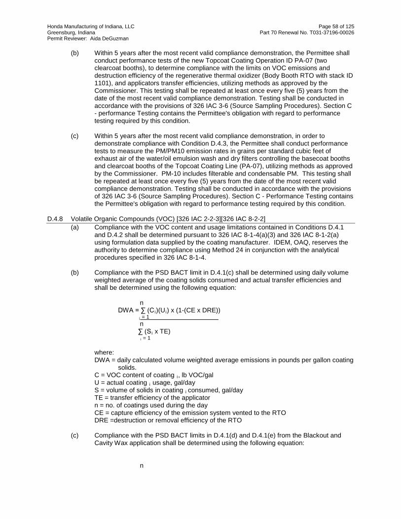
Honda Manufacturing of Indiana, LLC Page 58 of 125 Greensburg, Indiana Part 70 Renewal No. T031-37196-00026 Permit Reviewer: Aida DeGuzman
(b) Within 5 years after the most recent valid compliance demonstration, the Permittee shall
conduct performance tests of the new Topcoat Coating Operation ID PA-07 (two clearcoat booths), to determine compliance with the limits on VOC emissions and destruction efficiency of the regenerative thermal oxidizer (Body Booth RTO with stack ID 1101), and applicators transfer efficiencies, utilizing methods as approved by the Commissioner. This testing shall be repeated at least once every five (5) years from the date of the most recent valid compliance demonstration. Testing shall be conducted in accordance with the provisions of 326 IAC 3-6 (Source Sampling Procedures). Section C - performance Testing contains the Permittee's obligation with regard to performance testing required by this condition.
(c) Within 5 years after the most recent valid compliance demonstration, in order to
demonstrate compliance with Condition D.4.3, the Permittee shall conduct performance tests to measure the PM/PM10 emission rates in grains per standard cubic feet of exhaust air of the water/oil emulsion wash and dry filters controlling the basecoat booths and clearcoat booths of the Topcoat Coating Line (PA-07), utilizing methods as approved by the Commissioner. PM-10 includes filterable and condensable PM. This testing shall be repeated at least once every five (5) years from the date of the most recent valid compliance demonstration. Testing shall be conducted in accordance with the provisions of 326 IAC 3-6 (Source Sampling Procedures). Section C - Performance Testing contains the Permittee's obligation with regard to performance testing required by this condition.
D.4.8 Volatile Organic Compounds (VOC) [326 IAC 2-2-3][326 IAC 8-2-2]
(a) Compliance with the VOC content and usage limitations contained in Conditions D.4.1 and D.4.2 shall be determined pursuant to 326 IAC 8-1-4(a)(3) and 326 IAC 8-1-2(a) using formulation data supplied by the coating manufacturer. IDEM, OAQ, reserves the authority to determine compliance using Method 24 in conjunction with the analytical procedures specified in 326 IAC 8-1-4.
(b) Compliance with the PSD BACT limit in D.4.1(c) shall be determined using daily volume
weighted average of the coating solids consumed and actual transfer efficiencies and shall be determined using the following equation:
n DWA = ∑ (C i )(Ui) x (1-(CE x DRE))
i = 1 n
∑ (S i x TE) i = 1 where:
DWA = daily calculated volume weighted average emissions in pounds per gallon coating solids.
C = VOC content of coating i, lb VOC/gal U = actual coating i usage, gal/day S = volume of solids in coating i consumed, gal/day TE = transfer efficiency of the applicator n = no. of coatings used during the day CE = capture efficiency of the emission system vented to the RTO DRE =destruction or removal efficiency of the RTO
(c) Compliance with the PSD BACT limits in D.4.1(d) and D.4.1(e) from the Blackout and
Cavity Wax application shall be determined using the following equation:
n

Honda Manufacturing of Indiana, LLC Page 59 of 125 Greensburg, Indiana Part 70 Renewal No. T031-37196-00026 Permit Reviewer: Aida DeGuzman
DWA = ∑ (Ci)(Ui)
i = 1 n
∑ U i i = 1 where:
DWA = daily calculated volume weighted average emissions in pounds per gallon coating applied.
C = VOC content of coating i, lb VOC/gal U = actual coating i usage, gal/day n = no. of coatings used during the day
(d) Compliance with the VOC limitation in Condition D.4.2(a) shall be determined using a
daily volume weighted average of the coatings applied less water using the following equation:
n A = ∑ (C i )(Ui) x (1-(CE x DRE))
i = 1 n
∑ (U i x (1-Di)) i = 1 where:
A = daily volume weighted average, lb VOC/gal less water C = VOC content of coating i, lb VOC/gal U = actual coating i usage, gal/day D = coatingi volume % water n = no. of coatings used during the day CE = capture efficiency of the emission system vented to the RTO DRE =destruction or removal efficiency of the RTO
Compliance Monitoring Requirements [326 IAC 2-7-5(1)][326 IAC 2-7-6(1) D.4.9 Regenerative Thermal Oxidizers (RTOs) Temperature [326 IAC 2-2-3][326 IAC 8-2-2][40 CFR 64]
(a) A continuous monitoring system shall be calibrated, maintained, and operated on the Topcoat Coating Operation ID PA-07 regenerative thermal oxidizers (Body Oven RTO with stack ID 1100 and Body Booth RTO with stack ID 1101) for measuring operating temperature. For the purposes of the condition, continuous shall mean no less than once per fifteen (15) minutes. The output of this system shall be recorded as a three (3) hour average. From the date of issuance of this permit until the approved stack test results are available, the three (3) hour rolling average operating temperature of the thermal oxidizer shall be maintained at a minimum temperature of 1400oF. Whenever the three (3) hour average temperature is below 1400oF or the three (3) hour average temperature established during the latest stack test, the Permittee shall take reasonable response steps. Section C - Response to Excursions or Exceedances contains the Permittee's obligation with regard to the reasonable response steps required by this condition. Failure to take response steps shall be considered a deviation from this permit.
(b) The Permittee shall determine the three (3) hour average temperature from the most
recent valid stack test that demonstrates compliance with limits in conditions D.4.1 and D.4.2, as approved by IDEM.

Honda Manufacturing of Indiana, LLC Page 60 of 125 Greensburg, Indiana Part 70 Renewal No. T031-37196-00026 Permit Reviewer: Aida DeGuzman
(c) On and after the date the approved stack test results are available, the Permittee shall
operate the thermal oxidizer at or above the three (3) hour rolling average temperature as observed during the compliant stack test.
The instruments used for determining the temperature shall comply with Section C - Instrument Specifications, of this permit, shall be subject to approval by IDEM, OAQ, and shall be calibrated or replaced at least once every six (6) months.
D.4.10 Water/Polymer Emulsion Wash and Dry Filters Monitoring (a) For Topcoat Coating Operation, identified as PA-07 - Daily inspection shall be performed prior to the paint booth's operation to verify the
proper placement and configuration of the dry filters. Daily visual inspections shall be performed on the water/polymer emulsion wash system associated with Topcoat Coating Operation, identified as PA-07, during the paint booth's operation to verify the control system proper operation. A warning system shall be installed and operated that will automatically activates whenever the water/polymer emulsion circulation pump is down. Whenever a warning signal is received, the Permittee shall take reasonable response steps. Section C - Response to Excursions or Exceedances contains the Permittee's obligation with regard to the reasonable response steps required by this condition. Failure to take response steps shall be considered a deviation from this permit.
For Blackout/Cavity wax booth, identified as PA-11- Daily inspections shall be performed during the paint booth's operation to verify the proper placement of the dry filters. To monitor the performance of the dry filters, weekly observations shall be made of the overspray from the Blackout/Cavity wax booth, PA-11, stack (ID 1062), while it is operating.
If a condition exists which should result in a response step, the Permittee shall take reasonable response steps. Section C - Response to Excursions or Exceedances contains the Permittee's obligation with regard to the reasonable response steps required by this condition. Failure to take response steps shall be considered a deviation from this permit.
(b) Monthly inspections shall be performed of the coating emissions from the stacks and the presence of overspray on the rooftops and the nearby ground except during inclement weather. When a noticeable change in overspray emissions, or when evidence of overspray emissions is observed, the Permittee shall take reasonable response steps. Section C - Response to Excursions or Exceedances contains the Permittee's obligation with regard to the reasonable response steps required by this condition. Failure to take response steps shall be considered a deviation from this permit.
D.4.11 Parametric Monitoring [326 IAC 8-2-2][40 CFR Part 64]
(a) The Permittee shall determine the appropriate duct pressure or fan amperage or fan Hertz from the most recent valid stack test that demonstrates compliance with limits in condition D.4.1 and D.4.2, as approved by IDEM.
(b) The equipment to measure fan Hertz shall be equipped with “system interlocks”, which
shall automatically shut down the affected paint operations if fan Hertz is outside the normal range established in most recent compliant stack test. The interlocks shall automatically prohibit entry of additional vehicles to the spray booths.
(c) No new vehicle shall enter the paint line as the system is in the process to empty the
vehicles during shutdown.

Honda Manufacturing of Indiana, LLC Page 61 of 125 Greensburg, Indiana Part 70 Renewal No. T031-37196-00026 Permit Reviewer: Aida DeGuzman
Record Keeping and Reporting Requirements [326 IAC 2-7-5(3)][326 IAC 2-7-19]
D.4.12 Record Keeping Requirements (a) To document the compliance status with Condition D.4.1(c) and (d), the Permittee shall
maintain records in accordance with (1) through (4) below. Records maintained for (1) through (4) shall be taken as stated below and shall be complete and sufficient to establish the compliance status with the VOC emission limits established in Conditions D.4.1(c) and (d). Records necessary to demonstrate the compliance status shall be available not later than 30 days of the end of each compliance period.
(1) The amount and VOC content of each coating material and solvent used daily for
coatings applied by the Topcoat Coating Operation and Topcoat on-line repair, both identified as PA-07 and Blackout, identified as PA-11.
(A) Records shall include, but not limited to purchase orders, invoices, and
material safety data sheets (MSDS) necessary to verify the type and amount used.
(B) Solvent usage records shall differentiate between those added to
coatings and those used as cleanup. (2) A log of the dates of use.
(3) The solids content of each coating material used (as applied) for the Topcoat
Coating Operation and Topcoat on-line repair, both identified as PA-07.
(4) The calculated daily volume weighted average emission in pounds per gallon coating solids as applied from the Topcoat Coating Operation and the Topcoat on-line repair, both identified as PA-07 and the calculated daily volume weighted average emission in pounds per gallon of coating as applied from the Blackout operation, identified as PA-11.
(b) To document the compliance status with Condition D.4.1(e), the Permittee shall maintain
records in accordance with (1) and (2) below. Records maintained for (1) and (2) shall be taken as stated below and shall be complete and sufficient to establish the compliance status with the VOC emission limit established in Condition D.4.1(e). Records necessary to demonstrate compliance shall be available not later than 30 days of the end of each compliance period.
(1) The amount and VOC content of each coating material and solvent used
monthly.
(A) Records shall include, but not limited to purchase orders, invoices, and material safety data sheets (MSDS) necessary to verify the type and amount used.
(B) Solvent usage records shall differentiate between those added to
coatings and those used as cleanup.
(2) The calculated monthly volume weighted average emission in pounds per gallon coating as applied from each of the Black out and Cavity Wax.
(c) To document the compliance status with Condition D.4.2, the Permittee shall maintain
records in accordance with (1) through (4) below. Records maintained for (1) through (4) shall be taken as stated below and shall be complete and sufficient to establish the

Honda Manufacturing of Indiana, LLC Page 62 of 125 Greensburg, Indiana Part 70 Renewal No. T031-37196-00026 Permit Reviewer: Aida DeGuzman
compliance status with the VOC emission limit established in Condition D.4.2. Records necessary to demonstrate compliance shall be available not later than 30 days of the end of each compliance period.
(1) The amount and VOC content of each coating material and solvent used daily for
coatings applied by the Topcoat Coating Operation and Topcoat on-line repair, both identified as PA-07.
(A) Records shall include, but not limited to purchase orders, invoices, and
material safety data sheets (MSDS) necessary to verify the type and amount used.
(B) Solvent usage records shall differentiate between those added to
coatings and those used as cleanup.
(2) A log of the dates of use.
(3) The water content of each coating material used (as applied). (4) The calculated daily volume weighted average VOC content per gallon of the
coatings less water as applied from the Topcoat Coating Operation and the Topcoat on-line repair, both identified as PA-07.
(d) To document the compliance status with Condition D.4.10, the Permittee shall maintain a
log of the monthly overspray observations, records of daily visual inspection of the dry filters, dates of any water/polymer emulsion wash system warning system alarm and corrective actions taken and monthly inspections on the rooftops.
(e) To document the compliance status with Condition D.4.9, the Permittee shall maintain
records of the continuous temperature records (on a three-hour average basis) for the Topcoat Coating Operation, identified as PA-07 regenerative thermal oxidizers (Body Oven RTO with stack ID 1100 and Body Booth RTO with stack ID 1101) and the three-hour average temperature used to demonstrate compliance during the most recent compliant stack test.
(f) To document the compliance status with Condition D.4.3, the Permittee shall maintain on
file vendors guarantees and/or certifications for the dry filters efficiency. (g) To document the compliance status with Condition D.4.11, the Permittee shall maintain
records of the Body Booth RTO and Body Oven RTO shutdowns due to fan Hertz deviations
(h) Section C - General Record Keeping Requirements contains the Permittee's obligations
with regard to the records required by this condition.
D.4.13 Reporting Requirements A monthly summary of the information to document the compliance status with Condition D.4.1 shall be submitted to IDEM, OAQ using the reporting forms located at the end of this permit, or their equivalent, not later than thirty (30) days after the end of the quarter being reported. Section C - General Reporting contains the Permittee's obligation with regard to the reporting required by this condition. The report submitted by the Permittee does require a certification that meets the requirements of 326 IAC 2-7-6(1) by a “responsible official,” as defined by 326 IAC 2-7-1(35).
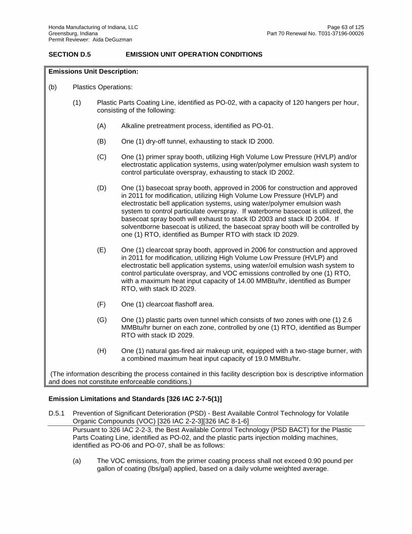
Honda Manufacturing of Indiana, LLC Page 63 of 125 Greensburg, Indiana Part 70 Renewal No. T031-37196-00026 Permit Reviewer: Aida DeGuzman
SECTION D.5 EMISSION UNIT OPERATION CONDITIONS Emissions Unit Description: (b) Plastics Operations:
(1) Plastic Parts Coating Line, identified as PO-02, with a capacity of 120 hangers per hour, consisting of the following:
(A) Alkaline pretreatment process, identified as PO-01. (B) One (1) dry-off tunnel, exhausting to stack ID 2000. (C) One (1) primer spray booth, utilizing High Volume Low Pressure (HVLP) and/or
electrostatic application systems, using water/polymer emulsion wash system to control particulate overspray, exhausting to stack ID 2002.
(D) One (1) basecoat spray booth, approved in 2006 for construction and approved
in 2011 for modification, utilizing High Volume Low Pressure (HVLP) and electrostatic bell application systems, using water/polymer emulsion wash system to control particulate overspray. If waterborne basecoat is utilized, the basecoat spray booth will exhaust to stack ID 2003 and stack ID 2004. If solventborne basecoat is utilized, the basecoat spray booth will be controlled by one (1) RTO, identified as Bumper RTO with stack ID 2029.
(E) One (1) clearcoat spray booth, approved in 2006 for construction and approved
in 2011 for modification, utilizing High Volume Low Pressure (HVLP) and electrostatic bell application systems, using water/oil emulsion wash system to control particulate overspray, and VOC emissions controlled by one (1) RTO, with a maximum heat input capacity of 14.00 MMBtu/hr, identified as Bumper RTO, with stack ID 2029.
(F) One (1) clearcoat flashoff area. (G) One (1) plastic parts oven tunnel which consists of two zones with one (1) 2.6
MMBtu/hr burner on each zone, controlled by one (1) RTO, identified as Bumper RTO with stack ID 2029.
(H) One (1) natural gas-fired air makeup unit, equipped with a two-stage burner, with
a combined maximum heat input capacity of 19.0 MMBtu/hr.
(The information describing the process contained in this facility description box is descriptive information and does not constitute enforceable conditions.) Emission Limitations and Standards [326 IAC 2-7-5(1)]
D.5.1 Prevention of Significant Deterioration (PSD) - Best Available Control Technology for Volatile Organic Compounds (VOC) [326 IAC 2-2-3][326 IAC 8-1-6] Pursuant to 326 IAC 2-2-3, the Best Available Control Technology (PSD BACT) for the Plastic Parts Coating Line, identified as PO-02, and the plastic parts injection molding machines, identified as PO-06 and PO-07, shall be as follows: (a) The VOC emissions, from the primer coating process shall not exceed 0.90 pound per
gallon of coating (lbs/gal) applied, based on a daily volume weighted average.

Honda Manufacturing of Indiana, LLC Page 64 of 125 Greensburg, Indiana Part 70 Renewal No. T031-37196-00026 Permit Reviewer: Aida DeGuzman
(b) The VOC emissions from the basecoat coating booth after control when using solvent-
borne basecoat, shall not exceed 1.15 lbs/gal of coating applied, based on a daily volume weighted average.
(c) The VOC emissions after control from the clearcoat coating booth, shall not exceed 3.25
lbs/gal of coating applied, based on a daily volume weighted average. (d) The capture system from the clearcoat booth of the Plastic Parts Coating Line shall be
vented into Bumper RTO with stack ID 2029. The Bumper RTO shall achieve a minimum destruction efficiency of ninety-five percent (95%).
(e) The daily volume weighted average of the VOC content of the coatings applied to the
Instrument Panel, shall not exceed 2.3 lbs/gallon less water of coating applied. (f) Good work practices which includes the following:
(1) The use of robotic automatic spray applicators to minimize paint usage. (2) All paint mixing containers, other than day tanks equipped with continuous
agitation systems, which contain organic VOC containing coatings and other materials shall have a cover with no visible gaps in place at all times except when material is being added to or removed from a container, or when mixing or pumping equipment is being placed in or removed from a container.
(3) Solvent collection containers shall be kept closed when not in use. (4) Clean-up rags with solvent shall be stored in closed containers. (5) VOC emissions shall be minimized during cleaning of storage, mixing, and
conveying equipment.
(g) The PSD BACT for the plastic parts production shall be the use of injection molding in the process to minimize VOC emissions.
(h) The PSD BACT requirements for the combustion facilities in SECTION D.5, are
contained in SECTION D.10. Compliance with (a) through (f) of this condition shall satisfy the requirements of 326 IAC 8-1-6.
D.5.2 PSD BACT for PM and PM10 [326 IAC 2-2-3] Pursuant to 326 IAC 2-2-3, Best Available Control Technology (PSD BACT), the PM and PM10 emissions from the water/polymer emulsion wash controlling the particulate emissions from the Plastic Parts Coating Line ID PO-02, shall be limited to 0.0015 grains per standard cubic foot (gr/scf) of exhaust air and 99% control efficiency. The Department may revise this permit to adjust the PM and PM10 limitation of 0.0015 gr/scf based upon the results of the stack test required in Condition D.5.5. PM-10 includes filterable and condensable PM. Any revisions of the emissions limits made as the result of this provision shall be subject to the best available control technology (BACT) review and air quality analysis, specified in 326 IAC 2-2. The Department will provide an opportunity for public notice and comment prior to finalizing any permit revision. IC 13-15-7-3 (revocation or Modification of a Permit: appeal to Board) shall apply to this permit condition.
D.5.3 Particulate Emissions Limitations for Work Practices and Control Technologies [326 IAC 6-3-2(d)] Pursuant to 326 IAC 6-3-2(d), particulate emissions from the spray booth at the Plastic Parts Coating Line, identified as PO-10, shall be controlled by a wet scrubber and the Permittee

Honda Manufacturing of Indiana, LLC Page 65 of 125 Greensburg, Indiana Part 70 Renewal No. T031-37196-00026 Permit Reviewer: Aida DeGuzman
shall operate the control device in accordance with manufacturer's specifications.
D.5.4 Preventive Maintenance Plan [326 IAC 2-7-5(12)] A Preventive Maintenance Plan is required for these facilities and their respective control devices. Section B - Preventive Maintenance Plan contains the Permittee's obligation with regard to the preventive maintenance plan required by this condition.
Compliance Determination Requirements [326 IAC 2-7-5(1)]
D.5.5 Regenerative Thermal Oxidizer (RTO) [326 IAC 2-2-3] The basecoat booth (when using solvent-borne basecoat), the clearcoat booth and the oven exhausts from the Plastic Parts Coating Line ID PO-02 shall be vented to regenerative thermal oxidizer (Bumper RTO with stack ID 2029) at all times when the line is in operation.
D.5.6 Testing Requirements [326 IAC 2-2-3][326 IAC 2-7-6(1), (6)][326 IAC 2-1.1-11] (a) Within 5 years after the most recent valid compliance demonstration, the Permittee shall
conduct performance tests of the Plastic Parts Coating Line ID PO-02, to determine compliance with the limits on VOC emissions and destruction efficiency of the regenerative thermal oxidizer (RTO #3 with stack ID 2029), utilizing methods as approved by the Commissioner. This testing shall be repeated at least once every five (5) years from the date of the most recent valid compliance demonstration. Testing shall be conducted in accordance with the provisions of 326 IAC 3-6 (Source Sampling Procedures). Section C - Performance Testing contains the Permittee's obligation with regard to performance testing required by this condition.
(b) Within 5 years after the most recent valid compliance demonstration, in order to
demonstrate compliance with Condition D.5.2, the Permittee shall conduct performance tests to measure the PM/PM10 emission rates in grains per standard cubic feet of exhaust air of the water/oil emulsion wash controlling the primer booth, basecoat booth, and clearcoat booth of the Plastic Parts Coating Line (PO-02), utilizing methods as approved by the Commissioner. PM-10 includes filterable and condensable PM. This testing shall be repeated at least once every five (5) years from the date of the most recent valid compliance demonstration. Testing shall be conducted in accordance with the provisions of 326 IAC 3-6 (Source Sampling Procedures). Section C - Performance Testing contains the Permittee's obligation with regard to performance testing required by this condition.
D.5.7 Volatile Organic Compounds (VOC) [326 IAC 2-2-3]
(a) Compliance with the VOC content and usage limitations contained in Condition D.5.1 shall be determined pursuant to 326 IAC 8-1-4(a)(3) and 326 IAC 8-1-2(a) using formulation data supplied by the coating manufacturer. IDEM, OAQ, reserves the authority to determine compliance using Method 24 in conjunction with the analytical procedures specified in 326 IAC 8-1-4.
(b) Compliance with the PSD BACT VOC limits in Condition D.5.1(a) through (c) which apply
after controls to emissions from the Plastic Parts Coating Line ID PO-02 shall be determined using the following equation:
n DWA = ∑ (C i )(Ui) x (1-(CE x DRE))
i = 1 n
∑ U i i = 1 where:

Honda Manufacturing of Indiana, LLC Page 66 of 125 Greensburg, Indiana Part 70 Renewal No. T031-37196-00026 Permit Reviewer: Aida DeGuzman
DWA = daily calculated volume weighted average emissions in pounds per gallon coating
applied. C = VOC content of coating i, lb VOC/gal U = actual coating i usage, gal/day n = no. of coatings used during the day CE = capture efficiency of the emission system vented to the RTO DRE =destruction/removal efficiency of the RTO
(c) Compliance with the PSD BACT VOC limit in Condition D.5.1(e) for coating instrument
panels shall utilize the same equation in (b).
Compliance Monitoring Requirements [326 IAC 2-7-5(1)][326 IAC 2-7-6(1)] D.5.8 Regenerative Thermal Oxidizer (RTO) Temperature [326 IAC 2-2-3][40 CFR Part 64]
(a) A continuous monitoring system shall be calibrated, maintained, and operated on the Plastic Parts Coating Line ID PO-02, regenerative thermal oxidizer (Bumper RTO with stack ID 2029) for measuring operating temperature. For the purposes of this condition, continuous shall mean no less than once per fifteen (15) minutes. The output of this system shall be recorded as a three (3) hour average. From the date of issuance of this permit until the approved stack test results are available, the three (3) hour rolling average operating temperature of the thermal oxidizer shall be maintained at a minimum temperature of 1400oF. Whenever the three (3) hour average temperature is below 1400oF or the three (3) hour average temperature established during the latest stack test, the Permittee shall take reasonable response. Section C - Response to Excursions or Exceedances contains the Permittee's obligation with regard to the reasonable response steps required by this condition. Failure to take response steps shall be considered a deviation from this permit.
(b) The Permittee shall determine the three (3) hour average temperature from the most
recent valid stack test that demonstrates compliance with limits in condition D.5.1 and D.5.2, as approved by IDEM.
(c) On and after the date the approved stack test results are available, the Permittee shall
operate the thermal oxidizer at or above the three (3) hour rolling average temperature as observed during the compliant stack test.
The instruments used for determining the temperature shall comply with Section C - Instrument Specifications, of this permit, shall be subject to approval by IDEM, OAQ, and shall be calibrated or replaced at least once every six (6) months.
D.5.9 Water/Polymer Emulsion Wash and Dry Filters Monitoring (a) For Plastic Parts Coating Line ID PO-02: Daily inspection shall be performed prior to the Plastic Parts Coating line operation
to verify the proper placement and configuration of the dry filters. Daily visual inspections shall be performed on the water/polymer emulsion wash system associated with the Plastic Parts Coating Line ID PO-02 stacks (ID 2002, ID 2203, ID 2204, and ID 2005) while one or more of the booths are in operation to verify the control system proper operation. A warning system shall be installed and operated that will automatically activates whenever the water/polymer emulsion circulation pump is down. Whenever a warning signal is received, the Permittee shall take reasonable response steps. Section C - Response to Excursions or Exceedances contains the Permittee's obligation with regard to the reasonable response steps required by this condition. Failure to take response steps shall be considered a

Honda Manufacturing of Indiana, LLC Page 67 of 125 Greensburg, Indiana Part 70 Renewal No. T031-37196-00026 Permit Reviewer: Aida DeGuzman
deviation from this permit.
(b) Monthly inspections shall be performed of the coating emissions from the stacks
and the presence of overspray on the rooftops and the nearby ground except during inclement weather. When a noticeable change in overspray emissions, or when evidence of overspray emissions is observed, the Permittee shall take reasonable response steps. Section C - Response to Excursions or Exceedances contains the Permittee's obligation with regard to the reasonable response steps required by this condition. Failure to take response steps shall be considered a deviation from this permit.
D.5.10 Parametric Monitoring [326 IAC 8-2-2][40 CFR Part 64]
(a) The Permittee shall determine the appropriate duct pressure or fan amperage or fan Hertz from the most recent valid stack test that demonstrates compliance with limit in condition D.5.1, as approved by IDEM.
(b) The equipment to measure fan Hertz shall be equipped with “system interlocks”, which
shall automatically shut down the affected paint operations if fan Hertz is outside the normal range established in the most recent compliant stack test. The interlocks shall automatically prohibit entry of additional vehicles to the spray booths.
(c) No new vehicle shall enter the paint line as the system is in the process to empty the
vehicles during shutdown.
Record Keeping and Reporting Requirements [326 IAC 2-7-5(3)][326 IAC 2-7-19]
D.5.11 Record Keeping Requirements (a) To document the compliance status with Condition D.5.1(a), (b), (c), and (e), the
Permittee shall maintain records in accordance with (1) through (3) below. Records maintained for (1) through (3) shall be taken as stated below and shall be complete and sufficient to establish the compliance status with the VOC emission limits established in Conditions D.5.1(a), (b), (c), and (e). Records necessary to demonstrate compliance shall be available not later than 30 days of the end of each compliance period.
(1) The amount and VOC content of each coating material and solvent used daily for
coatings applied by the Plastic Parts Coating Line, identified as PO-02.
(A) Records shall include, but not limited to purchase orders, invoices, and material safety data sheets (MSDS) necessary to verify the type and amount used.
(B) Solvent usage records shall differentiate between those added to
coatings and those used as cleanup.
(2) A log of the dates of use. (3) The calculated daily volume weighted average emission in pounds per gallon of
coating applied from the Plastic Parts Coating Line, identified as PO-02. (b) To document the compliance status with Condition D.5.9, the Permittee shall maintain a
log of the monthly overspray observations, records of daily visual inspection of the dry filters, dates of any water/polymer emulsion wash system warning system alarm and corrective actions taken and monthly inspections on the rooftops.

Honda Manufacturing of Indiana, LLC Page 68 of 125 Greensburg, Indiana Part 70 Renewal No. T031-37196-00026 Permit Reviewer: Aida DeGuzman
(c) To document the compliance status with Condition D.5.8, the Permittee shall maintain
records of the continuous temperature records (on a three-hour average basis) for the Plastic Parts Coating Line ID PO-02 regenerative Bumper RTO with stack ID 2029) and the three-hour average temperature used to demonstrate compliance during the most recent compliant stack test.
(d) To document the compliance status with Condition D.5.10, the Permittee shall maintain
records of the Bumper RTO shutdowns due to fan Hertz deviations (e) Section C - General Record Keeping Requirements contains the Permittee's obligations
with regard to the records required by this condition. D.5.12 Reporting Requirements
A monthly summary of the information to document compliance with Condition D.5.1 shall be submitted quarterly to IDEM, OAQ using the reporting forms located at the end of this permit, or their equivalent, not later than thirty (30) days after the end of the quarter being reported. Section C - General Reporting contains the Permittee's obligation with regard to the reporting required by this condition. The report submitted by the Permittee does require a certification that meets the requirements of 326 IAC 2-7-6(1) by a “responsible official,” as defined by 326 IAC 2-7-1(35).

Honda Manufacturing of Indiana, LLC Page 69 of 125 Greensburg, Indiana Part 70 Renewal No. T031-37196-00026 Permit Reviewer: Aida DeGuzman
SECTION D.6 EMISSION UNIT OPERATION CONDITIONS Emissions Unit Description: (c) Final Assembly Operations: (2) Gasoline dispensing operation, with a capacity of 70 units per hour, consisting of the
following: (A) Gasoline dispensing equipment, identified as AF-02, located at the assembly
line, for filling new vehicles. (B) One (1) gasoline storage tank, identified as FAC-99, located at the tank farm,
with a capacity of 19,800 gallons, equipped with submerged fill and Stage 1 vapor balance.
(The information describing the process contained in this facility description box is descriptive information and does not constitute enforceable conditions.)
Emission Limitations and Standards [326 IAC 2-7-5(1)]
D.6.1 Prevention of Significant Deterioration (PSD) - Best Available Control Technology for Volatile Organic Compounds (VOC) [326 IAC 2-2-3][326 IAC 8-4-6] Pursuant to 326 IAC 2-2-3, the Best Available Control Technology (PSD BACT) for the Gasoline Dispensing Facility, identified as AF-02, shall be as follows: (a) The throughput of gasoline to the one (1) gasoline storage tank, identified as FAC-99,
shall not exceed 1,125,000 gallons per twelve consecutive month period with compliance determined at the end of each month.
(b) The Permittee shall not allow the transfer of gasoline between any transport and any
storage tank unless such tank is equipped with the following:
(1) A submerged fill pipe. (2) Either a pressure relief valve set to release at no less than seven-tenths (0.7)
pounds per square inch or an orifice of five-tenths (0.5) inch in diameter. (3) A vapor balance system connected between the tank and the transport,
operating according to manufacturer's specifications. The Stage I vapor recovery system shall be in operation at all times when the one (1) gasoline storage tank, identified as FAC-99 is in operation.
(c) If the owner or employees of the owner of a gasoline dispensing facility are not present
during loading, it shall be the responsibility of the owner or the operator of the transport to make certain the vapor balance system is connected between the transport and the storage tank and is operating according to manufacturer's specifications.
(d) The Permittee shall conduct retesting for vapor leakage and blockage from all vapor
collection and control systems, including the associated permanent installation, and successfully pass the test, at least every five (5) years or upon major system replacement or modification. A major system modification is considered to be replacing, repairing, or upgrading seventy-five percent (75%) or more of a vapor collection and control system of a facility.

Honda Manufacturing of Indiana, LLC Page 70 of 125 Greensburg, Indiana Part 70 Renewal No. T031-37196-00026 Permit Reviewer: Aida DeGuzman
(e) All new vehicles produced for domestic sale that are fueled with gasoline must be
equipped with Onboard Refueling Vapor Recovery (ORVR) systems. The Permittee shall limit the VOC emissions from the Gasoline Dispensing equipment, identified as AF-02, used to initially fuel new vehicles manufactured for domestic and export sales, to less than 0.54 ton per twelve (12) consecutive month period with compliance determined at the end of each month.
Compliance with these conditions shall satisfy the requirements of 326 IAC 8-4-6.
D.6.2 Volatile Organic Compounds (VOC) [326 IAC 8-4-9] Pursuant to 326 IAC 8-4-9 (Leaks from transports and vapor collection systems, records) the owner of the gasoline transport system shall operate a vapor control system. The requirements are as follows: (a) The Permittee shall not allow a gasoline transport that is subject to this rule and that has
a capacity of two thousand (2,000) gallons or more to be filled or emptied unless the owner of the gasoline transport completes the following:
(1) Annual leak detection testing before the end of the twelfth (12th) calendar month
following the previous year's test, according to test procedures contained in 40 CFR 63.425 (e), as follows:
(A) Conduct the pressure and vacuum tests for the transport's cargo tank
using a time period of five (5) minutes. The initial pressure for the pressure test shall be four hundred sixty (460) millimeters H2O (eighteen (18) inches H2O) gauge. The initial vacuum for the vacuum test shall be one hundred fifty (150) millimeters H2O (six (6) inches H2O) gauge. The maximum allowable pressure or vacuum change is twenty-five (25) millimeters H2O (one (1) inch H2O) in five (5) minutes.
(B) Conduct the pressure test of the cargo tank's internal vapor valve as
follows:
(i) After completing the test under clause (A) of this condition, use the procedures in 40 CFR 60, Appendix A, Method 27 to repressurize the tank to four hundred sixty (460) millimeters H2O (eighteen (18) inches H2O) gauge. Close the transport's internal vapor valve or valves, thereby isolating the vapor return line and manifold from the tank.
(ii) Relieve the pressure in the vapor return line to atmospheric
pressure, then reseal the line. After five (5) minutes, record the gauge pressure in the vapor return line and manifold. The maximum allowable five (5) minute pressure increase is one hundred thirty (130) millimeters H2O (five (5) inches H2O).
(2) Repairs by the gasoline transport owner or operator, if the transport does not
meet the criteria of subdivision (1) of this condition, and retesting to prove compliance with the criteria of subdivision (1) of this condition.
(b) The annual test data remain valid until the end of the twelfth (12th) calendar month
following the test. The owner of the gasoline transport shall be responsible for compliance with subsection (a) of this condition, and shall provide the Permittee or the owner of the loading facility with the most recent valid modified 40 CFR 60, Appendix A, Method 27 test results upon request. The Permittee shall take all reasonable steps,

Honda Manufacturing of Indiana, LLC Page 71 of 125 Greensburg, Indiana Part 70 Renewal No. T031-37196-00026 Permit Reviewer: Aida DeGuzman
including reviewing the test date and tester's signature, to ensure that gasoline transports loading at its facility comply with subsection (a) of this condition.
(c) The Permittee shall:
(1) Design and operate the applicable system and the gasoline loading equipment in a manner that prevents: (A) Gauge pressure from exceeding four thousand five hundred (4,500)
pascals (eighteen (18) inches of H2O) and a vacuum from exceeding one thousand five hundred (1,500) pascals (six (6) inches of H2O) in the gasoline transport;
(B) A reading equal to or greater than twenty-one thousand (21,000) parts
per million as propane, from all points on the perimeter of a potential leak source when measured by the method referenced in 40 CFR 60, Appendix A, Method 21, or an equivalent procedure approved by the commissioner during loading or unloading operations at gasoline dispensing facilities, bulk plants, and bulk terminals; and
(C) Avoidable visible liquid leaks during loading or unloading operations at
gasoline dispensing facilities, bulk plants, and bulk terminals.
(2) Within fifteen (15) days, repair and retest a vapor balance, collection, or control system that exceeds the limits in subdivision (1) of this condition.
(d) The department may, at any time, monitor a gasoline transport, vapor balance, or vapor
control system to confirm continuing compliance with (a) of this condition. (e) If the commissioner allows alternative test procedures, such method shall be submitted to
the U.S. EPA as a SIP revision. (f) During compliance tests conducted under 326 IAC 3-6 (stack testing), each vapor
balance or control system shall be tested applying the standards described in subsection (c)(1)(B) of this condition. Testers shall use 40 CFR 60, Appendix A, Method 21 to determine if there are any leaks from the hatches and the flanges of the gasoline transports. If any leak is detected, the transport cannot be used for the capacity of the compliance test of gasoline storage tank, identified as FAC-99, and the one (1) gasoline dispensing unit, identified as AF-102. The threshold for leaks shall be ten thousand (10,000) parts per million methane.
D.6.3 Preventive Maintenance Plan [326 IAC 2-7-5(12)]
A Preventive Maintenance Plan is required for these facilities. Section B - Preventive Maintenance Plan contains the Permittee's obligation with regard to the preventive maintenance plan required by this condition.
Compliance Determination Requirements [326 IAC 2-7-5(1)]
D.6.4 Volatile Organic Compounds [326 IAC 2-2-3] (a) In order to comply with Condition D.6.1, the Stage I vapor recovery systems for VOC
control shall be in operation at all times when gasoline is being transferred, or dispensed. (b) Compliance with the VOC limit in Condition D.6.1(e) shall be determined by using the
following equation, which calculates the tons of VOC emissions per month, and adding the result to the calculated VOC emissions from the previous eleven months:

Honda Manufacturing of Indiana, LLC Page 72 of 125 Greensburg, Indiana Part 70 Renewal No. T031-37196-00026 Permit Reviewer: Aida DeGuzman
E = (GwORVR x 0.44 lbs/kgal + Gw/o ORVR x 11lbs/kgal)/2000 lbs/ton where : E = Emissions from initial fueling vehicles (tons/month) GwORVR = Amount of gasoline used in a month to fuel new vehicles
equipped with ORVR Gw/o ORVR = Amount of gasoline used in a month to fuel new vehicles not
equipped with ORVR
D.6.5 Testing Requirements [326 IAC 2-7-6(1),(6)][326 IAC 2-1.1-11] (a) To demonstrate compliance with Condition D.6.1, the Permittee shall perform testing
required in Condition D.6.2. (b) If the commissioner allows alternative test procedures in Condition D.6.2(c)(1)(B), such
method shall be submitted to the U.S. EPA as a SIP revision. (c) During compliance tests conducted under 326 IAC 3-6 (stack testing), each vapor
balance or control system shall be tested applying the standards described in Condition D.6.3(c)(1)(B). Testers shall use 40 CFR 60, Appendix A, Method 21 to determine if there are any leaks from the hatches and the flanges of the gasoline transports. If any leak is detected, the transport cannot be used for the capacity of the compliance test of gasoline storage tank (FAC-99) and the one (1) gasoline dispensing unit (AF-02). The threshold for leaks shall be ten thousand (10,000) parts per million methane.
Compliance Monitoring Requirements [326 IAC 2-7-6(1)][326 IAC 2-7-5(1)]
D.6.6 Vapor Recovery System Operation For the Stage I vapor recovery systems in order to document compliance with Condition D.6.1, the Permittee shall perform daily checks of the key operating parameters on days in which the filling of gasoline storage tanks is conducted, including venting for the Stage I vapor recovery system.
Record Keeping and Reporting Requirements [326 IAC 2-7-5(3)][326 IAC 2-7-19]
D.6.7 Record Keeping Requirements (a) To document the compliance status with the sourcewide VOC limit in Condition D.6.1(a),
the Permittee shall maintain records at the source that verify the throughput of gasoline received and dispensed.
(b) To document the compliance status with Condition D.6.2, the owner or operator of a
vapor balance or vapor control system subject to this section shall maintain records of all certification testing. The records shall identify the following:
(1) The vapor balance, vapor collection, or vapor control system. (2) The date of the test and, if applicable, retest. (3) The results of the test and, if applicable, retest.
(c) To document the compliance status with Condition D.6.2, the owner or operator of a
gasoline transport subject to this section shall keep a legible copy of the transport's most recent valid annual modified 40 CFR 60, Appendix A, Method 27 test either in the cab of the transport or affixed to the transport trailer. The test record shall identify the following: (1) The gasoline transport. (2) The type and date of the test and, if applicable, date of retest.

Honda Manufacturing of Indiana, LLC Page 73 of 125 Greensburg, Indiana Part 70 Renewal No. T031-37196-00026 Permit Reviewer: Aida DeGuzman
(3) The test methods, test data, and results certified as true, accurate, and in
compliance with this rule by the person who performs the test. This copy shall be made available immediately upon request to the department and to the owner of the loading facility for inspection and review. The department shall be allowed to make copies of the test results.
(d) To document the compliance status with Condition D.6.2, the Permittee shall maintain
records of the following:
(1) Certification testing required, if using an alternative testing procedure, as allowed under Condition D.6.2(e) from all vapor collection and control systems, including the associated permanent installation.
(2) Test required under Condition D.6.2(f).
(e) To document the compliance status with Condition D.6.6, the Permittee shall maintain records of the key operating parameters when the Stage I vapor recovery system is in use.
(f) To document the compliance status with Condition D.6.1(e), the Permittee shall
maintain a record of the VOC emissions from the Gasoline Dispensing equipment, identified as AF-02, on a monthly and 12-month rolling total basis.
(g) Section C - General Record Keeping Requirements contains the Permittee's obligations with regard to the records required by this condition.
D.6.8 Reporting Requirements
(a) A monthly summary of the information to document compliance with Condition D.6.1(a) shall be submitted quarterly to the addresses listed in Section C - General Reporting Requirements, of this permit, using the reporting forms located at the end of this permit, or their equivalent, within thirty (30) days after the end of the quarter being reported
(b) A monthly summary of the VOC emissions from the Gasoline Dispensing equipment,
identified as AF-02, to document the compliance status with Condition D.6.1(e), shall be submitted quarterly to the addresses listed in Section C - General Reporting Requirements of this permit using the reporting forms located at the end of this permit, or their equivalent, not later than thirty (30) days after the end of the quarter being reported.
(c) Section C - General Reporting contains the Permittee's obligation with regard to the
reporting required by this condition. The report submitted by the Permittee does require a certification that meets the requirements of 326 IAC 2-7-6(1) by a “responsible official,” as defined by 326 IAC 2-7-1(35).

Honda Manufacturing of Indiana, LLC Page 74 of 125 Greensburg, Indiana Part 70 Renewal No. T031-37196-00026 Permit Reviewer: Aida DeGuzman
SECTION D.7 EMISSION UNIT OPERATION CONDITIONS
Emissions Unit Description: (b) Plastics Operations
(2) Miscellaneous cleaning and purge operation - paint operations, consisting of the following:
(A) Purge and clean-up solvent usage and recovery system, identified as PA-14,
including virgin solvent distribution, day tanks, small portable containers including containers that meet the definition of cold cleaners, and spent solvent recovery.
(3) Two (2) plastic parts injection molding machines, identified as PO-06 and PO-07, with a
combined maximum throughput of 4,050 pounds per hour plastic pellets. (c) Final Assembly Operations:
(1) Assembly window install and miscellaneous operations, identified as AF-01, with a capacity of 70 units per hour, consisting of all coatings, sealers, lubricants and related cleaning solvents used for auto assembly, including processes used to install window glass in vehicles, including body primer, glass cleaner, glass primer, and glass adhesive. Includes robotic and manual application equipment, coating delivery/circulation systems and raw material storage containers, approved in 2016 for modification to add a location for the manual glass installation.
(d) Weld sealer process using manual and robotic weld sealer application equipment, material
delivery systems and raw material storage, identified as WE-01, approved in 2016 for modification to add two (2) robotic application systems.
Insignificant Activities: (f) The following equipment related to manufacturing activities not resulting in the emission of HAPs:
brazing equipment, brazing equipment, cutting torches, soldering equipment, welding equipment:
(2) Body welding and finishing, identified as WE-02, approved in 2006 for construction and approved in 2012 for modification to add fifty-six (56) robotic welders using resistance welding and grinding, and MIG welding stations. The SR station "Stationary Robots" and backup MIG welding and grinding operations are controlled by cartridge filters.
Insignificant Activities (v)(2) One (1) Jig Cleaning Blast Unit, identified as PA-15A, equipped with a baghouse for particulate
control, exhausting inside the building, approved in 2016 for construction. (y) Activities with emissions equal to or less than the following thresholds: 5 lb/hr or 26 lb/day PM; 5
lb/hr or 25 lb/day SO2; 5 lb/hr or 25 lb/day NOx; 3 lb/hr or 15 lb/day VOC; 1.0 ton/yr of a single HAP, or 2.5 ton/yr of any combination of HAPs:
(4) Four (4) cold cleaner degreasers, identified as ST-02, MS-02, VQ-01, PA-27, located at
designated areas.
(The information describing the process contained in this facility description box is descriptive information and does not constitute enforceable conditions.)

Honda Manufacturing of Indiana, LLC Page 75 of 125 Greensburg, Indiana Part 70 Renewal No. T031-37196-00026 Permit Reviewer: Aida DeGuzman
Emission Limitations and Standards [326 IAC 2-7-5(1)]
D.7.1 Prevention of Significant Deterioration (PSD) - Best Available Control Technology for Volatile Organic Compounds (VOC) [326 IAC 2-2-3] Pursuant to 326 IAC 2-2-3, the Best Available Control Technology for Volatile Organic Compounds (VOC) for the following emission units shall be as follows: (a) The annual VOC usages of wiping/cleaning solvents and purge solvents from the Plastic
operations, identified as PO-05, minus the amount of VOC in the purge material collected shall be limited to 39.12 tons per twelve (12) consecutive month period with compliance determined at the end of each month. This VOC limit shall account for the capture efficiency from the purge solvent capture systems used each time that any coating applicator is purged.
(b) The annual VOC usages of wiping/cleaning solvents and purge solvents from the Body
Painting operations, identified as PA-14, minus the amount of VOC in the purge material collected shall be limited to 67.09 tons per twelve (12) consecutive month period with compliance determined at the end of each month. This VOC limit shall account for the capture efficiency from the purge solvent capture systems used each time that any coating applicator is purged.
(c) The monthly volume weighted average of the VOC content of the coatings used at the
Weld Sealer (WE-01), shall not exceed 0.30 pound per gallon of coating (lbs/gal) as applied.
(d) The monthly volume weighted average of the VOC content of the coatings used in the
Assembly Window Install and Miscellaneous operations, identified as AF-01, shall not exceed 0.40 pounds of VOC per gallon of coating, as applied (lb/gal of coating). The annual VOC emissions from this operation shall not exceed 24.78 tons per twelve (12) consecutive month period with compliance determined at the end of each month.
(e) The purge solvent capture systems from the body paint coating operations shall have a
minimum purge solvent capture efficiency of 90%. (f) The purge solvent capture systems from the plastic painting operation shall have a
minimum purge solvent capture efficiency of 85%. (g) Collected purge materials from the body paint coating lines and plastic painting lines shall
be retained in closed containers until recycled on-site or shipped offsite for recycling or disposal.
(h) The total plant-wide VOC emissions from the miscellaneous operations in this SECTION
D.7, which is the summation of the VOC emissions in (a) through (d) of this condition, shall not exceed 134.9 tons per twelve (12) consecutive month period with compliance determined at the end of each month.
(i) The PSD BACT requirements for the combustion facilities in SECTION D.7, are
contained in SECTION D.10.
D.7.2 Prevention of Significant Deterioration (PSD) PM2.5 Minor Limits [326 IAC 2-2] In order to render the requirements of 326 IAC 2-2 (Prevention of Significant Deterioration (PSD)) not applicable, the Permittee shall with the following: The PM2.5 emissions from the Jig Cleaning Blast Unit, identified as PA-15A shall not exceed 2.0 pounds per hour.

Honda Manufacturing of Indiana, LLC Page 76 of 125 Greensburg, Indiana Part 70 Renewal No. T031-37196-00026 Permit Reviewer: Aida DeGuzman
Compliance with this limit shall ensure that PM2.5 emissions are less than 10 tons per year, which render the requirements of 326 IAC 2-2 (Prevention of Significant Deterioration) not applicable to the 2016 modification.
D.7.3 Cleaning Work Practices [326 IAC 2-2] The following work practices for cleaning and solvent purging operations shall be observed: (a) Use of plastic and paper masking to cover certain equipment in booths and floors around
the booths to reduce solvent usage; (b) Capture of paint line cleaning solvent for off-site recycling or disposal to reduce VOC
emissions; (c) Use of low VOC or water-based solvents in certain processes, where applicable, (water-
based grate masking, high pressure blasting); (d) Use of metal shot blasting and alkaline painting stripping; (e) Avoid spillage and splashing during handling of solvent, and if spillage, splashing, or
leaks occur, they should be repaired or corrected immediately; (f) Use covers or closed containers for both fresh and waste cleaning solvent; (g) Avoid using absorbent or porous items, such as rags, bags, etc., for handling the solvent-
wetted items; and (h) Use closed containers to store or dispose of cloth, paper or other material impregnated
with VOC. In addition to these work practices, multi-feed paint lines directly to automatic applicators shall be installed, which reduces the amount of paint lines that need to be cleaned.
D.7.4 Cold Cleaner Degreaser Control Equipment and Operating Requirements [326 IAC 8-3-2] Pursuant to 326 IAC 8-3-2 (Cold Cleaner Degreaser Control Equipment and Operating Requirements), the Permittee shall: (a) Ensure the following control equipment and operating requirements are met:
(1) Equip the degreaser with a cover. (2) Equip the degreaser with a device for draining cleaned parts. (3) Close the degreaser cover whenever parts are not being handled in the
degreaser. (4) Drain cleaned parts for at least fifteen (15) seconds or until dripping ceases; (5) Provide a permanent, conspicuous label that lists the operating requirements in
subdivisions (3), (4), (6), and (7). (6) Store waste solvent only in closed containers. (7) Prohibit the disposal or transfer of waste solvent in such a manner that could
allow greater than twenty percent (20%) of the waste solvent (by weight) to evaporate into the atmosphere.

Honda Manufacturing of Indiana, LLC Page 77 of 125 Greensburg, Indiana Part 70 Renewal No. T031-37196-00026 Permit Reviewer: Aida DeGuzman
(b) Ensure the following additional control equipment and operating requirements are met:
(1) Equip the degreaser with one (1) of the following control devices if the solvent is heated to a temperature of greater than forty-eight and nine-tenths (48.9) degrees Celsius (one hundred twenty (120) degrees Fahrenheit):
(A) A freeboard that attains a freeboard ratio of seventy-five hundredths
(0.75) or greater. (B) A water cover when solvent used is insoluble in, and heavier than, water. (C) A refrigerated chiller. (D) Carbon adsorption. (E) An alternative system of demonstrated equivalent or better control as
those outlined in clauses (A) through (D) that is approved by the department. An alternative system shall be submitted to the U.S. EPA as a SIP revision.
(2) Ensure the degreaser cover is designed so that it can be easily operated with
one (1) hand if the solvent is agitated or heated. (3) If used, solvent spray:
(A) must be a solid, fluid stream; and (B) shall be applied at a pressure that does not cause excessive splashing.
D.7.5 Material Requirements for Cold Cleaner Degreasers [326 IAC 8-3-8]
Pursuant to 326 IAC 8-3-8 (Material Requirements for Cold Cleaner Degreasers), the Permittee shall not operate a cold cleaning degreaser with a solvent that has a VOC composite partial vapor pressure that exceeds one (1) millimeter of mercury (nineteen-thousandths (0.019) pound per square inch) measured at twenty (20) degrees Celsius (sixty-eight (68) degrees Fahrenheit).
D.7.6 PSD BACT for PM and PM10 [326 IAC 2-2-3] Pursuant to 326 IAC 2-2-3, Best Available Control Technology (BACT), the PM and PM10 emissions from the cartridge filters controlling the body shop welding and finishing (WE-02 and WE-03) shall be limited to 0.0015 grains per standard cubic foot (gr/scf) of exhaust air and 99% control efficiency. PM-10 includes filterable and condensable PM.
D.7.7 Particulate Emission Limitations for Manufacturing Processes [326 IAC 6-3-2] Pursuant to 326 IAC 6-3-2, the allowable particulate (PM) emissions from the Jig Cleaning Blast
Unit, identified as PA-15A shall not exceed 2.03 pounds per hour when operating at a process weight rate of 700 pounds per hour. The pounds per hour limitation was calculated with the following equation:
Interpolation of the data for the process weight rate up to 60,000 pounds per hour shall be
accomplished by use of the equation: E = 4.10 P0.67 where E = rate of emission in pounds per hour; and P = process weight rate in tons per hour
D.7.8 Preventive Maintenance Plan [326 IAC 2-7-5(12)]
A Preventive Maintenance Plan is required for these facilities. Section B - Preventive Maintenance Plan contains the Permittee's obligation with regard to the preventive maintenance plan required by this condition.

Honda Manufacturing of Indiana, LLC Page 78 of 125 Greensburg, Indiana Part 70 Renewal No. T031-37196-00026 Permit Reviewer: Aida DeGuzman
Compliance Determination Requirements [326 IAC 2-7-5(1)]
D.7.9 Volatile Organic Compounds (VOC) [326 IAC 8-1-4(a)(3)][326 IAC 8-1-2(a)][326 IAC 2-2] Compliance with the VOC content and usage limitations contained in Condition D.7.1(a), (b), (c), (d), and (h) shall be determined pursuant to 326 IAC 8-1-4(a)(3) and 326 IAC 8-1-2(a) by preparing or obtaining from the manufacturer the copies of the “as supplied” and “as applied” VOC data sheets. IDEM, OAQ, reserves the authority to determine compliance using Method 24 in conjunction with the analytical procedures specified in 326 IAC 8-1-4.
D.7.10 Volatile Organic Compounds (VOC) [326 IAC 8-1-2(a)(7)] (a) Compliance with the VOC limits for the solvent purging operation in Condition D.7.1(e)
and (f) shall be determined through the following:
(1) Purge solvent usage and collection shall be monitored separately for the Plastic operations and Body Painting operations. For each of the Plastic operations and Body Painting coating systems, the Permittee shall record the volume of purge solvent delivered to the spray applicators, and shall use collection and shipping records to monitor the volume of the purge materials collected for recycling or disposal. The purge material collection/capture, as a percentage of purge solvent usage shall be determined on a monthly basis as follows:
Purge Solvent Collection/Capture Efficiency = Sr * VOCr Pu * VOCv Where: Sr = Purge material collected and/or shipped for recovery (gallons)
Pu = Purge solvent usage (gallons) VOCv = VOC content virgin purge (lb/gal) VOCr = VOC content in purge materials collected and/or shipped for recovery
(lb/gal) (b) Pursuant to 326 IAC 8-1-2(a)(7), when volume weighted averaging of the coatings is
used to determine compliance with the limitation set in Conditions D.7.1(c) and D.7.1(d), shall be determined by the following equation:
n A = ∑ (C i )(Ui)
i = 1 n
∑ U i i = 1
where: A = monthly calculated volume weighted average emissions in pounds per gallon coating applied. C = VOC content of coating i, lb VOC/gal U = actual coating i usage, gal/month n = no. of coatings used during the day
D.7.11 Particulate Control
In order to comply with the limit in Condition D.7.2, the baghouse for PM2.5 control shall be in operation and control emissions from the Jig Cleaning Blast Unit, identified as PA-15A at all times this blasting unit is in operation.
D.7.12 Broken or Failed Bag Detection - Single Compartment Baghouse (a) For a single compartment baghouse controlling emissions from a process operated
continuously, a failed unit and the associated process shall be shut down immediately

Honda Manufacturing of Indiana, LLC Page 79 of 125 Greensburg, Indiana Part 70 Renewal No. T031-37196-00026 Permit Reviewer: Aida DeGuzman
until the failed unit has been repaired or replaced. Operations may continue only if the event qualifies as an emergency and the Permittee satisfies the requirements of the emergency provisions of this permit (Section B - Emergency Provisions).
(b) For a single compartment baghouse controlling emissions from a batch process, the feed
to the process shall be shut down immediately until the failed unit has been repaired or replaced. The emissions unit shall be shut down no later than the completion of the processing of the material in the line. Operations may continue only if the event qualifies as an emergency and the Permittee satisfies the requirements of the emergency provisions of this permit (Section B - Emergency Provisions).
Bag failure can be indicated by a significant drop in the baghouse's pressure reading with abnormal visible emissions, by an opacity violation, or by other means such as gas temperature, flow rate, air infiltration, leaks, dust traces or triboflows.
Compliance Monitoring Requirements [326 IAC 2-7-6 (1)][326 IAC 2-7-5 (1)]
D.7.13 Visible Emissions Notations (a) Visible emission notations of the Jig Cleaning Blast Unit (PA-15A) baghouse stack
exhausts shall be performed once weekly during normal daylight operations. A trained employee shall record whether emissions are normal or abnormal.
(b) For processes operated continuously, "normal" means those conditions prevailing, or
expected to prevail, eighty percent (80%) of the time the process is in operation, not counting startup or shut down time.
(c) In the case of batch or discontinuous operations, readings shall be taken during that part
of the operation that would normally be expected to cause the greatest emissions. (d) A trained employee is an employee who has worked at the plant at least one (1) month
and has been trained in the appearance and characteristics of normal visible emissions for that specific process.
(e) If abnormal emissions are observed, the Permittee shall take a reasonable response.
Section C – Response to Excursions and Exceedances contains the Permittee's obligation with regard to the reasonable response steps required by this condition. Failure to take response steps shall be considered a deviation from this permit.
Record Keeping and Reporting Requirements [326 IAC 2-7-5(3)][326 IAC 2-7-19]
D.7.14 Record Keeping Requirements (a) To document the compliance status with Condition D.7.1(a) and (b), the Permittee shall
maintain records in accordance with (1) through (3) below. Records maintained for (1) through (3) shall be taken as stated below and shall be complete and sufficient to establish the compliance status with the VOC usage limits and the VOC emission limits established in Condition D.7.1(a) and (b). Records necessary to demonstrate compliance shall be available not later than thirty (30) days of the end of each compliance period.
(1) The amount and VOC content of each wiping/cleaning solvent and each purge
solvent used monthly from the purge and clean-up solvent and recovery systems for the Paint Operations (PA-14) and the Plastic Operations (PO-05).
(A) Records shall include, but not limited to, purchase orders, invoices, and
material safety data sheets (MSDS) necessary to verify the type and amount used.

Honda Manufacturing of Indiana, LLC Page 80 of 125 Greensburg, Indiana Part 70 Renewal No. T031-37196-00026 Permit Reviewer: Aida DeGuzman
(B) Solvent usage records shall differentiate between those added to
coatings and those used as cleanup solvents.
(2) The amount and percentage of purge material collected and/or shipped on a monthly basis.
(3) The calculated monthly VOC emissions from the wiping/cleaning and purge
solvent usage from the purge and clean-up solvent and recovery systems for the Paint Operations (PA-14) and the Plastic Operations (PO-05).
(b) To document the compliance status with Condition D.7.1(c) and (d), the Permittee shall
maintain records in accordance with (1) and (2) below. Records maintained for (1) and (2) shall be taken as stated below and shall be complete and sufficient to establish the compliance status with the VOC usage limits and the VOC emission limits established in Condition D.7.1(c) and (d). Records necessary to demonstrate compliance shall be available within thirty (30) days of the end of each compliance period.
(1) The amount and VOC content of each coating, sealer, and adhesive material,
and each solvent used monthly from the Weld Sealer (WE-01) and from the Assembly Window Install and Miscellaneous operations (AF-01).
(A) Records shall include, but not limited to, purchase orders, invoices, and
material safety data sheets (MSDS) necessary to verify the type and amount used.
(B) Solvent usage records shall differentiate between those added to
coatings and those used as cleanup solvents. (2) The calculated monthly volume weighted average VOC emitted in pounds per
gallon of the coatings used as applied, (sealers, adhesives, oils) for each month. (c) To document the compliance status with Condition D.7.5, the Permittee shall maintain the
following records for each purchase of solvent used in the cold cleaner degreasing operations. These records shall be retained on-site or accessible electronically for the most recent three (3) year period and shall be reasonably accessible for an additional two (2) year period.
(1) The name and address of the solvent supplier. (2) The date of purchase (or invoice/bill dates of contract servicer indicating service
date). (3) The type of solvent purchased. (4) The total volume of the solvent purchased. (5) The true vapor pressure of the solvent measured in millimeters of mercury at
twenty (20) degrees Celsius (sixty-eight (68) degrees Fahrenheit).
(d) To document the compliance status with Condition D.7.6, the Permittee shall maintain on file vendors guarantees and/or certifications for the cartridge filters efficiency.
(e) To document the compliance status with Condition D.7.13, the Permittee shall maintain
records of once weekly visible emission notations of the Jig Cleaning Blast Unit (PA-15A) exhaust. The Permittee shall include in its weekly record when a visible emission

Honda Manufacturing of Indiana, LLC Page 81 of 125 Greensburg, Indiana Part 70 Renewal No. T031-37196-00026 Permit Reviewer: Aida DeGuzman
notation is not taken and the reason for the lack of visible emission notation (e.g. the process did not operate that week).
(f) Section C - General Record Keeping Requirements contains the Permittee's obligations
with regard to the records required by this condition.
D.7.15 Reporting Requirements A quarterly summary of the information to document compliance with Conditions D.7.1 shall be submitted to IDEM, OAQ using the reporting forms located at the end of this permit, or their equivalent, not later than thirty (30) days after the end of the quarter being reported. Section C - General Reporting contains the Permittee's obligation with regard to the reporting required by this condition. The report submitted by the Permittee does require a certification that meets the requirements of 326 IAC 2-7-6(1) by a “responsible official,” as defined by 326 IAC 2-7-1(35).

Honda Manufacturing of Indiana, LLC Page 82 of 125 Greensburg, Indiana Part 70 Renewal No. T031-37196-00026 Permit Reviewer: Aida DeGuzman
SECTION D.8 EMISSION UNIT OPERATION CONDITIONS Emissions Unit Description: Insignificant Activities (c) The following VOC and HAP storage containers:
(1) Storage tanks with capacity less than or equal to 1,000 gallons and annual throughput less than 12,000 gallons.
(A) Two (2) diesel fuel storage tanks for fire pumps, identified as FAC-93 and FAC-
94, each with a capacity of 300 gallons, each equipped with submerged fill. (B) Three (3) diesel fuel storage tanks for generators, identified as FAC-95, FAC-177
and FAC-178, each with a capacity of 150 gallons. (z) Activities with emissions equal to or less than the following thresholds: 5 lb/hr or 26 lb/day PM; 5
lb/hr or 25 lb/day SO2; 5 lb/hr or 25 lb/day NOx; 3 lb/hr or 15 lb/day VOC; 1.0 ton/yr of a single HAP, or 2.5 ton/yr of any combination of HAPs:
(1) Windshield washer fluid fill operation, with a capacity of 70 units per hour, consisting of
the following:
(A) Water/methanol fluid mixing and dispensing equipment, identified as AF-03, located at the assembly line, for filling new vehicles.
(B) One (1) windshield washer fluid storage tank, identified as FAC-102, located at the tank farm, with a capacity of 2,000 gallons, equipped with submerged fill.
(2) The following tanks, located at the Tank Farm:
(A) One (1) automatic transmission fluid storage tank, identified as FAC-96, with a
capacity of 10,000 gallons, equipped with submerged fill. [326 IAC 12] (B) One (1) antifreeze storage tank, identified as FAC-103, with a capacity of 10,000
gallons, equipped with submerged fill. [326 IAC 12] (C) One (1) brake fluid storage tank, identified as FAC-98, with a capacity of 2,000
gallons, equipped with submerged fill. (D) One (1) manual transmission fluid storage tank, identified as FAC-104, with a
capacity of 2,000 gallons, equipped with submerged fill. (E) One (1) diesel fuel storage tank for yard truck operations, identified as MS-01,
with a capacity of 3,000 gallons, equipped with submerged fill.
(3) The following tanks, located at the Utility Building:
(A) One (1) diesel fuel storage tank, identified as FAC-90, with a capacity of 2,000 gallons, equipped with submerged fill.
(The information describing the process contained in this facility description box is descriptive information and does not constitute enforceable conditions.)
Emission Limitations and Standards [326 IAC 2-7-5(1)]
D.8.1 Prevention of Significant Deterioration (PSD) - Best Available Control Technology for Volatile Organic Compounds (VOC) [326 IAC 2-2-3] Pursuant to 326 IAC 2-2-3, VOC BACT for the facilities described in this section is the following:

Honda Manufacturing of Indiana, LLC Page 83 of 125 Greensburg, Indiana Part 70 Renewal No. T031-37196-00026 Permit Reviewer: Aida DeGuzman
(a) All diesel fuel and windshield washer storage tanks in this section shall be equipped with:
(1) a fixed roof, and (2) a submerged fill pipe.
D.8.2 Preventive Maintenance Plan [326 IAC 2-7-5(12)]
A Preventive Maintenance Plan is required for these facilities. Section B - Preventive Maintenance Plan contains the Permittee's obligation with regard to the preventive maintenance plan required by this condition.

Honda Manufacturing of Indiana, LLC Page 84 of 125 Greensburg, Indiana Part 70 Renewal No. T031-37196-00026 Permit Reviewer: Aida DeGuzman
SECTION D.9 EMISSION UNIT OPERATION CONDITIONS
Emissions Unit Description: Repair Operations Insignificant Activities (a) Painting Operations:
(3) Topcoat in-line repair, which includes repair area for small interior topcoat, imperfections, manual application equipment, identified as PA-09.
(7) Final Repair, identified as PA-12, which includes repair coating booths and general areas, using manual application systems, and IR curing equipment.
(8) Final Repair - Air Dry, identified as PA-13, using air dry materials and manual application system.
(10) Plastic Parts Touch-up Booth, identified as PO-17, using dry filters for particulates control
and manual application systems.
(The information describing the process contained in this facility description box is descriptive information and does not constitute enforceable conditions.)
Emission Limitations and Standards [326 IAC 2-7-5(1)]
D.9.1 Prevention of Significant Deterioration (PSD) - Best Available Control Technology for Volatile Organic Compounds (VOC) [326 IAC 2-2-3][326 IAC 8-2-2] (a) Pursuant to 326 IAC 2-2-3, Best Available Control Technology (PSD BACT), and 326 IAC
8-2-2, the VOC content of the coatings used in the Final Repair, identified as PA-12, shall not exceed a daily volume weighted average of 4.8 pounds per gallon of coatings less water as applied.
(b) Pursuant to 326 IAC 2-2-3, Best Available Control Technology (PSD BACT), the VOC
usage from Final Repair-Air dry, identified as PA-13, shall be less than 15 pounds per day. Compliance with this limit shall make 326 IAC 8-2-2, not applicable.
(c) Pursuant to 326 IAC 2-2-3, Best Available Control Technology (PSD BACT), the VOC
usage from Topcoat in-line repair, identified as PA-09, shall be less than 15 pounds per day. Compliance with this limit shall make 326 IAC 8-2-2, not applicable.
(d) Pursuant to 326 IAC 2-2-3, Best Available Control Technology (PSD BACT), the VOC
usage from Plastic Parts Touch-up booth, identified as PO-17, shall be less than 10.0 pounds per day.
D.9.2 PSD BACT for PM and PM10 [326 IAC 2-2-3]
Pursuant to 326 IAC 2-2, Best Available Control Technology (BACT), the PM and PM10 emissions from the dry filters controlling the Final Repair, identified as PA-12 and Plastic Parts Touch-up Booth, identified as PO-17, shall be limited to 0.0015 grains per standard cubic foot (gr/scf) of exhaust air and 98% control efficiency. PM-10 includes filterable and condensable PM.

Honda Manufacturing of Indiana, LLC Page 85 of 125 Greensburg, Indiana Part 70 Renewal No. T031-37196-00026 Permit Reviewer: Aida DeGuzman
D.9.3 Preventive Maintenance Plan [326 IAC 2-7-5(12)]
A Preventive Maintenance Plan is required for these facilities and their respective control devices. Section B - Preventive Maintenance Plan contains the Permittee's obligation with regard to the preventive maintenance plan required by this condition.
Compliance Determination Requirements [326 IAC 2-7-5(1)]
D.9.4 Volatile Organic Compounds (VOC) [326 IAC 2-2] (a) Compliance with the VOC content and usage limitations contained in Condition D.9.1
shall be determined pursuant to 326 IAC 8-1-4(a)(3) and 326 IAC 8-1-2(a) using formulation data supplied by the coating manufacturer. IDEM, OAQ, reserves the authority to determine compliance using Method 24 in conjunction with the analytical procedures specified in 326 IAC 8-1-4.
(b) Compliance with the PSD BACT VOC limits in Condition D.9.1(a) shall be determined
using the following equation: n DWA = ∑ (C i )(Ui)
i = 1 n
∑ U i i = 1 where:
DWA = daily calculated volume weighted average emissions in pounds per gallon coating applied.
C = VOC content of coating i, lb VOC/gal U = actual coating i usage, gal/day n = no. of coatings used during the day
Compliance Monitoring Requirements [326 IAC 2-7-6 (1)][326 IAC 2-7-5 (1)]
D.9.5 Dry Filters Monitoring (a) Daily inspections shall be performed to verify the placement, integrity and particle
loading of the filters. To monitor the performance of the dry filters, weekly observations shall be made of the overspray from the Final Repair, identified as PA-12 stack (ID 1063) and Plastic Parts Touch-up Booth, identified as PO-17 stack (ID 2010) while the repair is in operation. If a condition exists which should result in a response step, the Permittee shall take reasonable response steps. Section C - Response to Excursions or Exceedances contains the Permittee's obligation with regard to the reasonable response steps required by this condition. Failure to take response steps shall be considered a deviation from this permit.
(b) Monthly inspections shall be performed of the coating emissions from the stacks
and the presence of overspray on the rooftops and the nearby ground, except during inclement weather. When a noticeable change in overspray emissions, or when evidence of overspray emissions is observed, the Permittee shall take reasonable response steps. Section C - Response to Excursions or Exceedances contains the Permittee's obligation with regard to the reasonable response steps required by this condition. Failure to take response steps shall be considered a deviation from this permit.

Honda Manufacturing of Indiana, LLC Page 86 of 125 Greensburg, Indiana Part 70 Renewal No. T031-37196-00026 Permit Reviewer: Aida DeGuzman
Record Keeping and Reporting Requirement [326 IAC 2-7-5(3)][326 IAC 2-7-19]
D.9.6 Record Keeping Requirements (a) To document the compliance status with Condition D.9.1, the Permittee shall maintain
records in accordance with (1) through (4) below. Records maintained for (1) through (4) shall be taken as stated below and shall be complete and sufficient to establish the compliance status with the VOC emission limits established in Condition D.9.1. Records necessary to demonstrate compliance shall be available not later than 30 days of the end of each compliance period.
(1) The amount and VOC content of each coating material and solvent used daily for
coatings applied by the Topcoat in-line repair, identified as PA-09, Final Repair, identified as PA-12, and Final Repair-Air Dry, identified as PA-13.
(A) Records shall include, but not limited to purchase orders, invoices, and
material safety data sheets (MSDS) necessary to verify the type and amount used.
(B) Solvent usage records shall differentiate between those added to
coatings and those used as cleanup. (2) A log of the dates of use. (3) The calculated daily volume weighted average VOC emission in pounds per
gallon as applied from Final Repair, identified as PA-12. (4) The calculated daily VOC emissions from Topcoat in-line repair, identified as PA-
09, Final Repair-Air Dry, identified as PA-13, and Plastic Parts Touch-up Booth, identified as PO-17.
(b) To document the compliance status with Condition D.9.5, the Permittee shall maintain a
log of the weekly overspray observations, and the daily and monthly inspections. (c) To document the compliance status with Condition D.9.2, the Permittee shall maintain on
file vendors guarantees and/or certifications for the dry filters efficiency. (d) Section C - General Record Keeping Requirements contains the Permittee's obligations
with regard to the records required by this condition.
D.9.7 Reporting Requirements A monthly summary of the information to document compliance with Condition D.9.1 shall be submitted quarterly to IDEM, OAQ using the reporting forms located at the end of this permit, or their equivalent, not later than thirty (30) days after the end of the quarter being reported. Section C - General Reporting contains the Permittee's obligation with regard to the reporting required by this condition. The report submitted by the Permittee does require a certification that meets the requirements of 326 IAC 2-7-6(1) by a “responsible official,” as defined by 326 IAC 2-7-1(35).
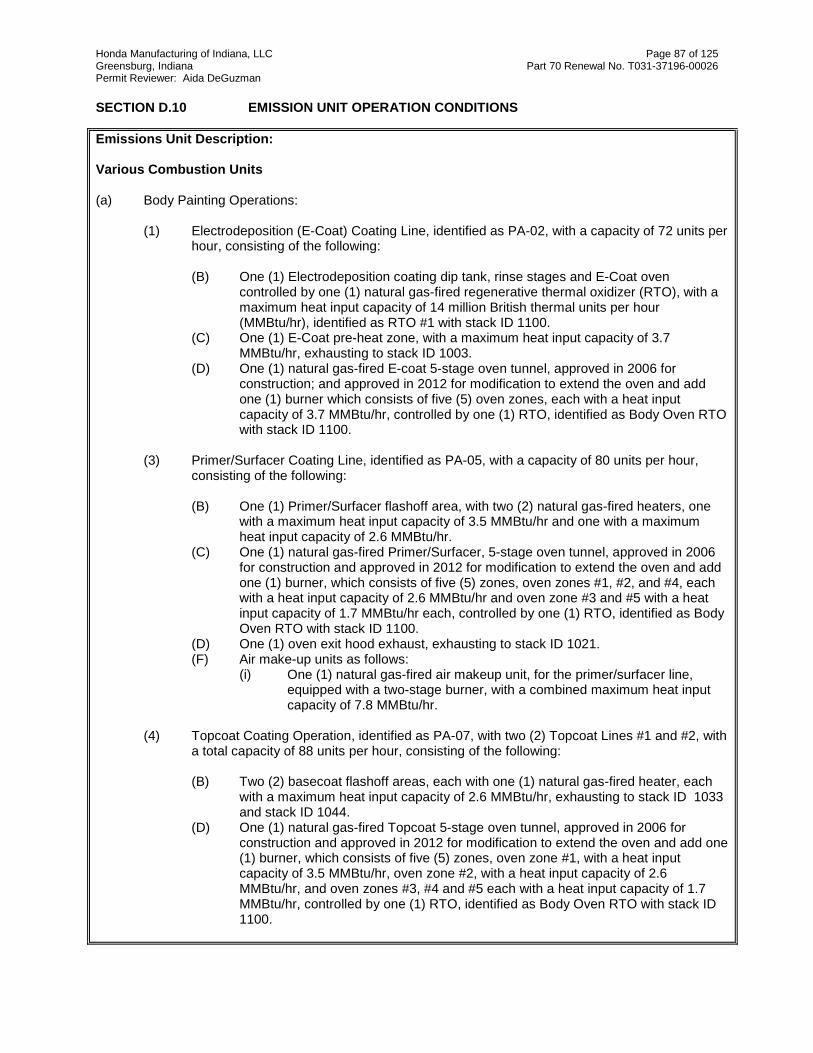
Honda Manufacturing of Indiana, LLC Page 87 of 125 Greensburg, Indiana Part 70 Renewal No. T031-37196-00026 Permit Reviewer: Aida DeGuzman
SECTION D.10 EMISSION UNIT OPERATION CONDITIONS
Emissions Unit Description: Various Combustion Units (a) Body Painting Operations:
(1) Electrodeposition (E-Coat) Coating Line, identified as PA-02, with a capacity of 72 units per hour, consisting of the following:
(B) One (1) Electrodeposition coating dip tank, rinse stages and E-Coat oven
controlled by one (1) natural gas-fired regenerative thermal oxidizer (RTO), with a maximum heat input capacity of 14 million British thermal units per hour (MMBtu/hr), identified as RTO #1 with stack ID 1100.
(C) One (1) E-Coat pre-heat zone, with a maximum heat input capacity of 3.7 MMBtu/hr, exhausting to stack ID 1003.
(D) One (1) natural gas-fired E-coat 5-stage oven tunnel, approved in 2006 for construction; and approved in 2012 for modification to extend the oven and add one (1) burner which consists of five (5) oven zones, each with a heat input capacity of 3.7 MMBtu/hr, controlled by one (1) RTO, identified as Body Oven RTO with stack ID 1100.
(3) Primer/Surfacer Coating Line, identified as PA-05, with a capacity of 80 units per hour,
consisting of the following: (B) One (1) Primer/Surfacer flashoff area, with two (2) natural gas-fired heaters, one
with a maximum heat input capacity of 3.5 MMBtu/hr and one with a maximum heat input capacity of 2.6 MMBtu/hr.
(C) One (1) natural gas-fired Primer/Surfacer, 5-stage oven tunnel, approved in 2006 for construction and approved in 2012 for modification to extend the oven and add one (1) burner, which consists of five (5) zones, oven zones #1, #2, and #4, each with a heat input capacity of 2.6 MMBtu/hr and oven zone #3 and #5 with a heat input capacity of 1.7 MMBtu/hr each, controlled by one (1) RTO, identified as Body Oven RTO with stack ID 1100.
(D) One (1) oven exit hood exhaust, exhausting to stack ID 1021. (F) Air make-up units as follows:
(i) One (1) natural gas-fired air makeup unit, for the primer/surfacer line, equipped with a two-stage burner, with a combined maximum heat input capacity of 7.8 MMBtu/hr.
(4) Topcoat Coating Operation, identified as PA-07, with two (2) Topcoat Lines #1 and #2, with
a total capacity of 88 units per hour, consisting of the following: (B) Two (2) basecoat flashoff areas, each with one (1) natural gas-fired heater, each
with a maximum heat input capacity of 2.6 MMBtu/hr, exhausting to stack ID 1033 and stack ID 1044.
(D) One (1) natural gas-fired Topcoat 5-stage oven tunnel, approved in 2006 for construction and approved in 2012 for modification to extend the oven and add one (1) burner, which consists of five (5) zones, oven zone #1, with a heat input capacity of 3.5 MMBtu/hr, oven zone #2, with a heat input capacity of 2.6 MMBtu/hr, and oven zones #3, #4 and #5 each with a heat input capacity of 1.7 MMBtu/hr, controlled by one (1) RTO, identified as Body Oven RTO with stack ID 1100.

Honda Manufacturing of Indiana, LLC Page 88 of 125 Greensburg, Indiana Part 70 Renewal No. T031-37196-00026 Permit Reviewer: Aida DeGuzman
SECTION D.10 EMISSION UNIT OPERATION CONDITIONS
(F) One (1) oven exit hood exhaust, exhausting to stack ID 1037. (G) Topcoat on-line repair, identified as PA-07, which includes:
(iii) One (1) natural gas-fired repair oven, with a maximum heat input capacity
of 2.6 MMBtu/hr, exhausting to stack ID 1058.
(H) Air makeup units as follows:
(i) Two (2) natural gas-fired air makeup units (Basecoat #1 ASH and Basecoat #2 ASH), for the Topcoat Lines #1 and #2 basecoat booths, each equipped with a two-stage burner, each with a combined maximum heat input capacity of 8.0 MMBtu/hr.
(ii) Two (2) natural gas-fired air makeup units (Clearcoat #1 ASH and Clearcoat #2 ASH), for Topcoat Lines #1 and #2 clearcoat booths, each equipped with a two-stage burner, each with a combined maximum heat input capacity of 5.0 MMBtu/hr.
(iii) One (1) natural gas-fired air makeup unit, for the topcoat on-line repair operations, equipped with a two-stage burner (Repair ASH 1 and Repair ASH 2), with a combined maximum heat input capacity of 12.2 MMBtu/hr.
(8) One (1) natural gas-fired air makeup unit with a maximum heat input capacity of 20.0
MMBtu/hr, identified as (Working Area ASH #1, PA-21).
(9) One (1) natural gas-fired air makeup unit with a maximum heat input capacity of 8.0 MMBtu/hr, identified as (Working Area ASH #2, PA-22).
(10) One (1) natural gas -fired makeup unit with a maximum heat input capacity of 5.0
MMBtu/hr, identified as (Working Area ASH #3, PA-23). (11) One (1) natural gas-fired HVAC units, identified as HVAC ASH #2, PA-25, each with a
maximum heat input capacity of 13.0 MMBtu/hr. (12) One (1) natural gas-fired HVAC unit, with a maximum heat input capacity of 8.00
MMBtu/hr, identified as HVAC #3 ASH, PA-26.
(b) Plastics Operations: (1) Plastic Parts Coating Line, identified as PO-02, with a capacity of 120 hangers per hour,
consisting of the following:
(E) One clearcoat spray booth, utilizing High Volume Low Pressure (HVLP) and electrostatic bell application systems, using water wash or oil emulsion system to control particulate overspray, and VOC emissions controlled by one (1) RTO, with a maximum heat input capacity of 14.0 MMBtu/hr, identified as Bumper RTO with stack ID 2029.
(G) One (1) plastic parts oven tunnel which consists of two (2) zones with one (1) 2.6 MMBtu/hr burner on each zone, controlled by one (1) RTO, identified as Bumper RTO with stack ID 2029.
(H) One (1) natural gas-fired air makeup unit, equipped with a two-stage burner, with a combined maximum heat input capacity of 19.0 MMBtu/hr.

Honda Manufacturing of Indiana, LLC Page 89 of 125 Greensburg, Indiana Part 70 Renewal No. T031-37196-00026 Permit Reviewer: Aida DeGuzman
SECTION D.10 EMISSION UNIT OPERATION CONDITIONS
Insignificant Activities (b) Space heaters, process heaters, or boilers using the following fuels: Natural gas-fired combustion
sources with heat input equal to or less than ten million (10,000,000) Btu per hour. (1) One (1) natural gas-fired hot water heater (FAC-110) for the purpose of supplying hot water
to the café kitchen, with a maximum heat input capacity of 0.50 MMBtu/hr. (2) Four (4) natural gas-fired hot water generators, located in the body painting area, with a
combined maximum heat input capacity of 24.5 MMBtu/hr.
(3) One (1) natural gas-fired air makeup unit for the Primer/Surfacer sanding and inspection booth (PA-06), with a maximum heat input capacity of 6.4 MMBtu/hr.
(4) Twenty-eight (28) natural gas-fired space heaters (FAC-53 through FAC-72 with a
combined maximum heat input capacity of 2.6 MMBtu/hr and (FAC-73 through FAC-80 with a combined maximum heat input capacity of 0.8 MMBtu/hr.
(5) Natural gas-fired HVAC units (FAC-01 through FAC-07, FAC-11 through FAC-20, FAC-26
through FAC-30, FAC-32, FAC-35 through FAC-37, FAC-39 through FAC-41, FAC-43 through FAC-52, FAC-146 and FAC-147), with a combined maximum heat input capacity of 87.36 MMBtu/hr.
(6) Forty three (43) natural gas-fired space heaters (FAC-117 through FAC-130, FAC-133
through FAC-139, FAC-148 through FAC-150 and FAC-151 through FAC-169), with a combined maximum heat input capacity of 6.83 MMBtu/hr.
(7) Four (4) natural gas-fired HVAC units (FAC-116, FAC-131, FAC-132 and FAC-140), with a combined maximum heat input capacity of 2.13 MMBtu/hr.
(8) Two (2) natural gas-fired space heating units (PA-50), with a combined heat input capacity
of 0.475 MMBtu/hour, approved in 2016 for construction.
(9) One (1) natural gas-fired air makeup unit with a maximum heat input capacity of 5.0 MMBtu/hr.
(r) Emergency generators as follows: Diesel generators not exceeding 1600 horsepower.
(1) One (1) substation emergency generator, identified as FAC-81, with a capacity of 133
horsepower (HP). (2) One (1) Consolidation Center emergency generator, identified as FAC-89, with a capacity
of 133 HP. (3) One (1) Credit Union building emergency generator, identified as FAC-115, with a capacity
of 133 HP.
(s) Other emergency and back-up equipment as follows: (1) Two (2) stationary fire pumps, identified as FAC-82 and FAC-83, each with a rated capacity
of 183 horsepower. (2) Two (2) diesel fired emergency generators, identified as FAC-84 and FAC-85, each with a

Honda Manufacturing of Indiana, LLC Page 90 of 125 Greensburg, Indiana Part 70 Renewal No. T031-37196-00026 Permit Reviewer: Aida DeGuzman
SECTION D.10 EMISSION UNIT OPERATION CONDITIONS
rated capacity of 757 HP. (3) One (1) diesel fired back-up generator, identified as FAC-86, with a rated capacity equal to
or less than 100 kilowatts (kW).
(t) Emergency generators as follows: Gasoline generators not exceeding 110 horsepower. (1) Two (2) emergency generators, identified as FAC-145 and FAC-175, with a capacity
of 5.5 HP each.
(The information describing the process contained in this facility description box is descriptive information and does not constitute enforceable conditions.)
Emission Limitations and Standards [326 IAC 2-7-5(1)]
D.10.1 Prevention of Significant Deterioration (PSD) CO Minor Limit [326 IAC 2-2] In order to render the requirements of 326 IAC 2-2 (Prevention of Significant Deterioration (PSD)) not applicable, the Permittee shall with the following: The CO emissions from all natural gas combustion units in this SECTION D.10 shall not exceed 187.6 pounds per million cubic feet (lb/MMCF), and the total natural gas fuel usage shall be limited to 976 million cubic feet (1,000,000 decatherms) per 12 consecutive month period with compliance determined at the end of each month. Compliance with this limit in conjunction with the PTE of eight (8) emergency generators, identified as FAC-81, FAC-84, FAC-85, FAC-86, FAC-89, FAC-115, FAC-145, FAC-175 and two (2) emergency fire pumps, identified as FAC-82 and FAC-83, limits the CO emissions to less than 100 tons per year, which renders the requirements of 326 IAC 2-2 (Prevention of Significant Deterioration (PSD)) not applicable to the 2006 initial project for CO emissions.
D.10.2 Prevention of Significant Deterioration (PSD) - Best Available Control Technology for Particulate Emissions (PM) and Nitrogen Oxides (NOx) [326 IAC 2-2-3] (a) Pursuant to 326 IAC 2-2-3, the Best Available Control Technology (PSD BACT) for the
generators, identified as FAC-81 and FAC-84 through FAC-86, and the fire pumps, identified as FAC-82 and FAC-83, shall be as follows:
Emission Unit IDs Emission Limitation
Operating Hours per year NOx PM FAC-81 Substation Generator (133 hp), FAC-89 Consolidation Center Generator (133 hp), FAC-115 Credit Union Generator (133 hp)
500 3 g/hp-hr Use of Ultra Low
Sulfur Diesel (ULSD)
0.22 g/hp-hr Use of ULSD
FAC-82, FAC-83: Fire Pumps (183 hp each)
500 7.8 g/hp-hr Use of ULSD
0.4 g/hp-hr Use of ULSD
FAC-84, FAC-85: Emergency Generators (757 hp, each)
500 4.5 g/hp-hr Use of ULSD
0.15 g/hp-hr Use of ULSD
FAC-86, 158 hp backup generator
500 3 g/hp-hr Use of ULSD
0.22 g/hp-hr Use of ULSD
Note: ULSD (Ultra Low Sulfur Diesel)

Honda Manufacturing of Indiana, LLC Page 91 of 125 Greensburg, Indiana Part 70 Renewal No. T031-37196-00026 Permit Reviewer: Aida DeGuzman
(b) Pursuant to 326 IAC 2-2-3, the Best Available Control Technology (PSD BACT) for the
Natural Gas Combustion (small heaters < 15 MMBtu/hr maximum heat input capacity), shall be as follows:
Emission Unit IDs Emission Limitation (lb/MMBTU) NOx PM
FAC-01 through FAC-07, FAC-11 through FAC-19, FAC-35, FAC-116, PA-05 air supply house, PA-06 air supply house, PA-07 air supply house, PA-21 through PA-26, PO-02
0.08 lb NOX/MMBtu 0.0075 lb PM/MMBtu Natural gas only
FAC-20, FAC-26, FAC-28, FAC-29, FAC-32, FAC-37, FAC-41, FAC-43 through FAC-52, FAC-140, FAC-146, FAC-147
0.10 lb NOx/MMBtu
0.0075 lb PM/MMBtu Natural gas only
Propane for FAC-37,
FAC-41, and FAC-140 PA-20
0.04 lb NOx/MMBtu
PA-02 bake oven, PA-05 bake oven zones 3, 4 & 5, PA-07 repair oven, PO-02 bake oven zone 2, PA-07 zones 3, 4 & 5
0.02 lb NOx/MMBtu
0.0075 lb PM/MMBtu Natural gas only
FAC-27, FAC-30
0.10 lb NOx/MMBtu
PA-05 flash off heaters 1 and 2, PA -05 bake oven zones 1 and 2, PA-07 basecoat flash off heaters 1 and 2, PA-07 topcoat bake oven zones 1 and 2, PO-02 bake oven zone 1
0.048 lb NOx/MMBtu 0.0075 lb PM/MMBtu Natural gas only
FAC-36, FAC-39, FAC-40, FAC-53 through FAC-80, FAC-110, FAC-117 through FAC-139, FAC-148 through FAC-169, 3 regenerative thermal oxidizers
0.10 lb NOx/MMBtu 0.0075 lb PM/MMBtu Natural gas only
(c) Pursuant to 326 IAC 2-2-3, low NOx burners shall be installed, maintained, and operated
on the above combustion sources in (a) and (b) of this condition.
D.10.3 Particulate Emission Limitations for Sources of Indirect Heating [326 IAC 6-2-4] Pursuant to 326 IAC 6-2-4 (Particulate Emission Limitations for Sources of Indirect Heating) the PM emissions from the following facilities shall be limited to 0.38 pound per million British thermal units (lb/mmBtu): FAC-20, FAC-26 through FAC-30, FAC-32, FAC-35 through FAC-37, FAC-39 through FAC-41, FAC-43 through FAC-80, FAC-117 through, FAC-140, FAC-146 through FAC-169, FAC-110, PA-05, PA-07, and PO-02 (burners for heated flash areas and bake ovens); PA-20 (process water heaters) and the café water heaters (FAC-110 and FAC-111).
The limit shall be established using the following equation: Pt = 1.09/(Q^0.26) Where: Pt = Pounds of particulate matter emitted per million BTU (lb/MMBtu) heat input Q = Total source maximum operating capacity rating in million Btu per hour
(MMBtu/hr)

Honda Manufacturing of Indiana, LLC Page 92 of 125 Greensburg, Indiana Part 70 Renewal No. T031-37196-00026 Permit Reviewer: Aida DeGuzman
Q = 58.3 MMBtu heat input
Compliance Determination Requirements [326 IAC 2-7-5 (1)]
D.10.4 Testing Requirements [326 IAC 2-7-5(1),(6)][326 IAC 2-1.1-11][326 IAC 2-2] In order to demonstrate compliance with the NOx limits in Condition D.10.2, the Permittee shall conduct performance tests utilizing methods as approved by the Commissioner at least once every five (5) years from the date of the most recent valid compliance demonstration for the following emission units: (a) One RTO (b) One ASH rated at 17 MMBtu/hr (PO-02); and (c) One (1) of the following ASH units: (1) Basecoat #1 or #2 ASH each, with 8.0 MMBtu/hr (PA-07) The NOx testing for the RTOs shall be repeated at least once every five (5) years from the date of the most recent valid compliance demonstration. Testing of the RTOs shall be conducted such that every fifteen (15) years each of the three (3) RTOs is tested. Testing shall be conducted in accordance with the provisions of 326 IAC 3-6 (Source Sampling Procedures). Section C - Performance Testing contains the Permittee's obligation with regard to the performance testing required by this condition.
Record Keeping and Reporting Requirement [326 IAC 2-7-5(3)][326 IAC 2-7-19]
D.10.5 Record Keeping Requirements (a) To document the compliance status with Condition D.10.1, the Permittee shall maintain
records of the total natural gas usage from all combustion units in this SECTION. (b) To document the compliance status with Condition D.10.2, the Permittee shall maintain
on file vendors guarantees and/or certifications for NOx emissions, excluding space heaters used for comfort, where guarantees and/or certifications are not readily available.
(c) Section C - General Record Keeping Requirements contains the Permittee's obligations
with regard to the records required by this condition.
D.10.6 Reporting Requirements Report of monthly natural gas usage to document the compliance status with Condition D.10.1 shall be submitted to IDEM, OAQ using the reporting forms located at the end of this permit, or their equivalent, not later than thirty (30) days after the end of the quarter being reported. Section C - General Reporting contains the Permittee's obligation with regard to the reporting required by this condition. The report submitted by the Permittee does require a certification that meets the requirements of 326 IAC 2-7-6(1) by a “responsible official,” as defined by 326 IAC 2-7-1(35).

Honda Manufacturing of Indiana, LLC Page 93 of 125 Greensburg, Indiana Part 70 Renewal No. T031-37196-00026 Permit Reviewer: Aida DeGuzman
SECTION D.11 EMISSION UNIT OPERATION CONDITIONS
Emissions Unit Description: Insignificant Activities: (a) Painting Operations:
(1) E-Coat sanding and inspection booth, identified as PA-04, using dry filters for particulate control, exhausting to general ventilation.
(2) Primer/Surfacer sanding and inspection booth, identified as PA-06, using dry filters for particulate control, exhausting to general ventilation.
(k) Noncontact cooling tower systems with forced and/or induced draft cooling tower system not
regulated under a NESHAP.
(1) One (1) forced draft chiller cooling tower, identified as FAC-105, with a capacity of 20,000 gallons per minute.
(2) One (1) forced draft air compressor cooling tower, identified as FAC-107, with a capacity of 940 gallons per minute.
(o) Paved and unpaved roads and parking lots with public access. (w) Grinding and machining operations controlled with fabric filters, scrubbers, mist collectors, wet
collectors and electrostatic precipitators with a design grain loading of less than or equal to 0.03 grains per actual cubic foot and a gas flow rate less than or equal to 4000 actual cubic feet per minute, including the following: deburring; buffing; polishing; abrasive blasting; pneumatic conveying; and woodworking operations.
(1) One (1) tumbleblast unit, identified as PA-15.
(The information describing the process contained in this facility description box is descriptive information and does not constitute enforceable conditions.)
Emission Limitations and Standards [326 IAC 2-7-5(1)]
D.11.1 PSD BACT for PM and PM10 [326 IAC 2-2-3] (a) Pursuant to 326 IAC 2-2-3, Best Available Control Technology (PSD BACT), the PM and
PM10 emissions from each dry filters controlling the E-Coat sanding and inspection booth, identified as PA-04, and Primer/Surfacer sanding and inspection booth, identified as PA-06, shall each be limited to 0.0015 grains per standard cubic foot (gr/scf) of exhaust air and 98.5% control efficiency.
(b) Pursuant to 326 IAC 2-2-3, Best Available Control Technology (PSD BACT), the PM and
PM10 emissions from the cartridge filters controlling the tumbleblast unit, identified as PA-15, shall be limited to 0.0032 gr/scf of exhaust air.
(c) The cooling towers shall be controlled by drift eliminators with 0.002% drift. The
Permittee shall submit to IDEM, OAQ design specification of the cooling towers upon initial startup of the cooling towers.
(d) The Permittee shall minimize unpaved roads through ground cover in the form of grass,
landscaping to prevent erosion and subsequent deposition of windborne particulate upon the roads. Use water to suppress fugitive dust from paved and unpaved roads when necessary.

Honda Manufacturing of Indiana, LLC Page 94 of 125 Greensburg, Indiana Part 70 Renewal No. T031-37196-00026 Permit Reviewer: Aida DeGuzman
Record Keeping and Reporting Requirement [326 IAC 2-7-5(3)][326 IAC 2-7-19]
D.11.2 Record Keeping Requirements (a) To document the compliance status with Condition D.11.1, the Permittee shall maintain on
file vendors guarantees and/or certifications for the dry filters and cartridge filters efficiencies.
(b) Section C - General Record Keeping Requirements contains the Permittee's obligations
with regard to the records required by this condition.

Honda Manufacturing of Indiana, LLC Page 95 of 125 Greensburg, Indiana Part 70 Renewal No. T031-37196-00026 Permit Reviewer: Aida DeGuzman
SECTION E.1 NSPS
Facility Description [326 IAC 2-7-5(14)] (a) Body Painting Operations: (1) Electrodeposition (E-Coat) Coating Line, identified as PA-02, with a capacity of 72 units
per hour, approved in 2016 to add new voltage equipment consisting of the following: B) One (1) Electrodeposition coating dip tank, rinse stages and E-Coat oven,
approved in 2006 for construction and approved in 2012 for modification, controlled by one (1) natural gas-fired regenerative thermal oxidizer (RTO), with a maximum heat input capacity of 14 million British thermal units per hour (MMBtu/hr), identified as Body Oven RTO with stack ID 1100
(C) One (1) E-Coat pre-heat zone, with a maximum heat input capacity of 3.7
MMBtu/hr, exhausting to stack ID 1003. (D) One (1) natural gas-fired E-coat 5-stage oven tunnel, approved in 2006 for
construction and approved in 2012 for modification to extend the oven and add one (1) burner which consists of five (5) oven zones, each with a heat input capacity of 3.7 MMBtu/hr, controlled by one (1) RTO, identified as Body Oven RTO with stack ID 1100.
(E) One (1) cooling tunnel, exhausting to stack ID 1006. Under 40 CFR 60, Subpart MM, this operation is considered a prime coat operation. (3) Primer/Surfacer Coating Line, identified as PA-05, with a capacity of 80 units per hour,
consisting of the following: (A) One (1) Primer/Surfacer spray coating booth, approved in 2006 for construction,
approved in 2011 for modification and approved in 2012 for modification to add robotic coating application systems, and approved in 2016 for the addition of robotic applicators, utilizing High Volume Low Pressure (HVLP) and electrostatic bell application systems, using water/polymer emulsion wash system and dry filters to control particulate overspray, exhausting to stack ID 1014 and stack ID 1015.
(B) One (1) Primer/Surfacer flashoff area, with two (2) natural gas-fired heaters, one
with a maximum heat input capacity of 3.5 MMBtu/hr and one with a maximum heat input capacity of 2.6 MMBtu/hr.
(C) One (1) natural gas-fired Primer/Surfacer, 5-stage oven tunnel, approved in 2006
for construction and approved in 2012 for modification to extend the oven and add one (1) burner, which consists of five (5) zones, oven zones #1, #2, and #4, each with a heat input capacity of 2.6 MMBtu/hr and oven zone #3 and #5 with a heat input capacity of 1.7 MMBtu/hr each, controlled by one (1) RTO, identified as Body Oven RTO with stack ID 1100.
(D) One oven exit hood exhaust, exhausting to stack ID 1021. (E) One (1) cooling tunnel, exhausting to stack ID 1022. Under 40 CFR 60, Subpart MM, this operation is considered a guide coat operation.

Honda Manufacturing of Indiana, LLC Page 96 of 125 Greensburg, Indiana Part 70 Renewal No. T031-37196-00026 Permit Reviewer: Aida DeGuzman
(4) Topcoat Coating Operation, identified as PA-07, with two (2) Topcoat Lines #1 and #2,
approved in 2006 for construction and approved in 2012 for modification with a total capacity of 88 units per hour, consisting of the following:
(A) Two (2) basecoat spray booths, approved in 2006 for construction and approved
in 2012 modification to add robotic coating application systems, and approved in 2016 for the addition of robotic applicators, utilizing High Volume Low Pressure (HVLP) and electrostatic bell application systems, using water/polymer emulsion wash systems and dry filters to control particulate overspray, exhausting to stack ID 1032 and stack ID 1043.
(B) Two (2) basecoat flashoff areas, each with one (1) natural gas-fired heater, each
with a maximum heat input capacity of 2.6 MMBtu/hr, exhausting to stack ID 1033 and stack ID 1044.
(C) Two (2) clearcoat spray booths, each approved in 2006 for construction each
approved in 2011 for modification and approved in 2012 for modification to add robotic coating application systems, and approved in 2016 for the addition of robotic applicators, utilizing High Volume Low Pressure (HVLP) and electrostatic bell application systems. The automatic zones use water/polymer emulsion wash systems to control particulate overspray and the manual zones use dry filters. The manual zones are cascaded to the automatic zones, and the automatic zones are controlled by one (1) RTO, identified as Body Booth RTO with stack ID 1101.
(D) One (1) natural gas-fired Topcoat 5-stage oven tunnel, approved in 2006 for
construction and approved in 2012 for modification to extend the oven and add one (1) burner, which consists of five (5) zones, oven zone #1, with a heat input capacity of 3.5 MMBtu/hr, oven zone #2, with a heat input capacity of 2.6 MMBtu/hr, and oven zones #3, #4 and #5, each with a heat input capacity of 1.7 MMBtu/hr, controlled by one (1) RTO, identified as Body Oven RTO with stack ID 1100.
(E) One (1) cooling tunnel, exhausting to stack ID 1041. (F) One (1) oven exit hood exhaust, exhausting to stack ID 1037. (The information describing the process contained in this facility description box is descriptive information
and does not constitute enforceable conditions. New Source Performance Standards (NSPS) Requirements [326 IAC 2-7-5(1)] E.1.1 General Provisions Relating to New Source Performance Standards [326 IAC 12-1][40 CFR Part
60, Subpart A] (a) Pursuant to 40 CFR 60.1, the Permittee shall comply with the provisions of 40 CFR Part
60, Subpart A - General Provisions, which are incorporated by reference as 326 IAC 12-1, for the emission units listed above, except as otherwise specified in 40 CFR Part 60, Subpart MM.
(b) Pursuant to 40 CFR 60.4, the Permittee shall submit all required notifications and reports
to:

Honda Manufacturing of Indiana, LLC Page 97 of 125 Greensburg, Indiana Part 70 Renewal No. T031-37196-00026 Permit Reviewer: Aida DeGuzman
Indiana Department of Environmental Management Compliance and Enforcement Branch, Office of Air Quality 100 North Senate Avenue MC 61-53 IGCN 1003 Indianapolis, Indiana 46204-2251
E.1.2 Standard of Performance for Automobiles and Light-Duty Truck Surface Coating Operations [326
IAC 12][40 CFR Part 60, Subpart MM] The Permittee shall comply with the following provisions of 40 CFR Part 60, Subpart MM (included as Attachment A) to the operating permit), which are incorporated by reference as 326 IAC 12, for the emission units listed above:
(1) 40 CFR Part 60.390 (2) 40 CFR Part 60.391 (3) 40 CFR Part 60.392 (4) 40 CFR Part 60.393 (5) 40 CFR Part 60.394 (6) 40 CFR Part 60.395 (7) 40 CFR Part 60.396 (8) 40 CFR Part 60.397 (9) 40 CFR Part 60.398

Honda Manufacturing of Indiana, LLC Page 98 of 125 Greensburg, Indiana Part 70 Renewal No. T031-37196-00026 Permit Reviewer: Aida DeGuzman
SECTION E.2 NSPS
Emissions Unit Description: Insignificant Activities (r) Emergency generators as follows: Diesel generators not exceeding 1600 horsepower. (1) Three (3) emergency generators, identified as FAC-81, FAC-89 and FAC-115, each with
a capacity of 133 HP Under 40 CFR 60, Subpart IIII, these units are considered model year 2007 emergency stationary internal combustion engines.
(s) Other emergency and back-up equipment as follows. (1) Two (2) stationary fire pumps, identified as FAC-82 and FAC-83, each with a rated
capacity of 183 HP. Under 40 CFR 60, Subpart IIII, these units are considered model year 2007 fire pump engines.
(2) Two (2) diesel fired emergency generators, identified as FAC-84 and FAC-85, each with
a rated capacity of 757 HP. (3) One (1) diesel fired back-up generator, identified as FAC-86, with a rated capacity equal
to or less than 100 kilowatts (kW). (The information describing the process contained in this facility description box is descriptive information and does not constitute enforceable conditions.) New Source Performance Standards (NSPS) Requirements [326 IAC 2-7-5(1)]
E.2.1 General Provisions Relating to New Source Performance Standards [326 IAC 12-1][40 CFR Part 60, Subpart A] (a) Pursuant to 40 CFR 60.1, the Permittee shall comply with the provisions of 40 CFR Part
60, Subpart A - General Provisions, which are incorporated by reference as 326 IAC 12-1, for the emission units listed above, except as otherwise specified in 40 CFR Part 60, Subpart IIII.
(b) Pursuant to 40 CFR 60.4, the Permittee shall submit all required notifications and reports to:
Indiana Department of Environmental Management Compliance and Enforcement Branch, Office of Air Quality 100 North Senate Avenue MC 61-53 IGCN 1003 Indianapolis, Indiana 46204-2251
E.2.2 Standards of Performance for Stationary Compression Ignition Internal Combustion Engines [326
IAC 12][40 CFR Part 60, Subpart IIII] The Permittee shall comply with the following provisions of 40 CFR Part 60, Subpart IIII (included as Attachment B to the operating permit), which are incorporated by reference as 326 IAC 12, for the emission units listed above: (1) 40 CFR 60.4200(a)(2)(i), (4) (2) 40 CFR 60.4205(b), (c) (3) 40 CFR 60.4206

Honda Manufacturing of Indiana, LLC Page 99 of 125 Greensburg, Indiana Part 70 Renewal No. T031-37196-00026 Permit Reviewer: Aida DeGuzman
(4) 40 CFR 60.4207(b) (5) 40 CFR 60.4208 (6) 40 CFR 60.4209 (7) 40 CFR 60.4211(a), (c) (8) 40 CFR 60.4212 (9) 40 CFR 60.4214(b) (10) 40 CFR 60.4218 (11) 40 CFR 60.4219 (12) Table 2 to Subpart IIII of Part 60 (the applicable portions) (13) Table 4 to Subpart IIII of Part 60 (the applicable portions)
(14) Table 8 to Subpart IIII of Part 60 (the applicable portions)

Honda Manufacturing of Indiana, LLC Page 100 of 125 Greensburg, Indiana Part 70 Renewal No. T031-37196-00026 Permit Reviewer: Aida DeGuzman
SECTION E.3 NESHAP
Emission Unit Description: (a) Body Painting Operations:
(1) Electrodeposition (E-Coat) Coating Line, identified as PA-02, with a capacity of 72 units per hour, approved in 2016 to add new voltage equipment, consisting of the following:
(A) Multistage pretreatment/Phosphate Process, identified as PA-01 IA. (B) One (1) Electrodeposition coating dip tank, rinse stages and E-Coat oven,
approved in 2006 for construction and approved in 2012 for modification, controlled by one (1) natural gas-fired regenerative thermal oxidizer (RTO), with a maximum heat input capacity of 14 million British thermal units per hour (MMBtu/hr), identified as Body Oven RTO with stack ID 1100.
(C) One (1) E-Coat pre-heat zone, with a maximum heat input capacity of 3.7
MMBtu/hr, exhausting to stack ID 1003. (D) One (1) natural gas-fired E-coat 5-stage oven tunnel, approved in 2006 for
construction and approved in 2012 for modification to extend the oven and add one (1) burner which consists of five (5) oven zones, each with a heat input capacity of 3.7 MMBtu/hr, controlled by one (1) RTO, identified as Body Oven RTO with stack ID 1100.
(E) One (1) cooling tunnel, exhausting to stack ID 1006.
(2) Sealer Deadener Coating Line, identified as PA-03, with a capacity of 73 units per hour, consisting of the following:
(A) One (1) automatic and manual sealer deadener application area, with one (1)
sound deadener booth, approved in 2006 for construction and approved in 2012 for modification to add robotic coating application systems, and approved in 2016 for the addition of robotic applicators, using airless spray application system, exhausting to stack ID 1007.
(B) One (1) 9.0 MMBtu/hr natural gas-fired Sealer/Deadener oven, approved in 2014
for construction at the Sealer Deadener Coating Line, identified as PA-03, exhausting to Stack ID 1007A.
(3) Primer/Surfacer Coating Line, identified as PA-05, with a capacity of 80 units per hour,
consisting of the following:
(A) One (1) Primer/Surfacer spray coating booth, approved in 2006 for construction, approved in 2011 for modification and approved in 2012 for modification to add robotic coating application systems, and approved in 2016 for the addition of robotic applicators, utilizing High Volume Low Pressure (HVLP) and electrostatic bell application systems, using water/polymer emulsion wash system and dry filters to control particulate overspray, exhausting to stack ID 1014 and stack ID 1015.
(B) One (1) Primer/Surfacer flashoff area, with two (2) natural gas-fired heaters, one with a maximum heat input capacity of 3.5 MMBtu/hr and one with a maximum

Honda Manufacturing of Indiana, LLC Page 101 of 125 Greensburg, Indiana Part 70 Renewal No. T031-37196-00026 Permit Reviewer: Aida DeGuzman
SECTION E.3 NESHAP
heat input capacity of 2.6 MMBtu/hr. (C) One (1) natural gas-fired Primer/Surfacer, 5-stage oven tunnel, approved in 2006
for construction and approved in 2012 for modification to extend the oven and add one (1) burner, which consists of five (5) zones, oven zones #1, #2, and #4, each with a heat input capacity of 2.6 MMBtu/hr and oven zone #3 and #5 with a heat input capacity of 1.7 MMBtu/hr each, controlled by one (1) RTO, identified as Body Oven RTO with stack ID 1100.
(D) One (1) oven exit hood exhaust, exhausting to stack ID 1021. (E) One (1) cooling tunnel, exhausting to stack ID 1022. (F) Air make-up units as follows:
(i) One (1) natural gas-fired air makeup unit, for the primer/surfacer line, equipped with a two-stage burner, with a combined maximum heat input capacity of 7.8 MMBtu/hr.
(4) Topcoat Coating Operation, identified as PA-07, with two (2) Topcoat Lines #1 and #2,
approved in 2006 for construction and approved in 2012 for modification with a total capacity of 88 units per hour, consisting of the following:
(A) Two (2) basecoat spray booths, approved in 2006 for construction and approved
in 2012 modification to add robotic coating application systems, and approved in 2016 for the addition of robotic applicators, utilizing High Volume Low Pressure (HVLP) and electrostatic bell application systems, using water/polymer emulsion wash systems and dry filters to control particulate overspray, exhausting to stack ID 1032 and stack ID 1043.
(B) Two (2) basecoat flashoff areas, each with one (1) natural gas-fired heater, each
with a maximum heat input capacity of 2.6 MMBtu/hr, exhausting to stack ID 1033 and stack ID 1044.
(C) Two (2) clearcoat spray booths, each approved in 2006 for construction each
approved in 2011 for modification and approved in 2012 for modification to add robotic coating application systems, and approved in 2016 for the addition of robotic applicators, utilizing High Volume Low Pressure (HVLP) and electrostatic bell application systems. The automatic zones use water/polymer emulsion wash systems to control particulate overspray and the manual zones use dry filters. The manual zones are cascaded to the automatic zones, and the automatic zones are controlled by one (1) RTO, identified as Body Booth RTO with stack ID 1101.
(D) One (1) natural gas-fired Topcoat 5-stage oven tunnel, approved in 2006 for
construction and approved in 2012 for modification to extend the oven and add one (1) burner, which consists of five (5) zones, oven zone #1, with a heat input capacity of 3.5 MMBtu/hr, oven zone #2, with a heat input capacity of 2.6 MMBtu/hr, and oven zones #3, #4 and #5, each with a heat input capacity of 1.7 MMBtu/hr, controlled by one (1) RTO, identified as Body Oven RTO with stack ID 1100.
(E) One (1) cooling tunnel, exhausting to stack ID 1041.

Honda Manufacturing of Indiana, LLC Page 102 of 125 Greensburg, Indiana Part 70 Renewal No. T031-37196-00026 Permit Reviewer: Aida DeGuzman
SECTION E.3 NESHAP
(F) One oven exit hood exhaust, exhausting to stack ID 1037. (G) Topcoat on-line repair, identified as PA-07 which includes:
(i) One (1) repair sanding booth, identified as PA-08 controlled by dust
filters, exhausting to stack ID 1056. (ii) One (1) repair coating booth using water wash system to control
particulate overspray, exhausting to stack ID 1057. (iii) One (1) natural gas-fired repair oven, with a maximum heat input
capacity of 2.6 MMBtu/hr, exhausting to stack ID 1058. (iv) One (1) Cooling tunnel, exhausting to stack ID 1060. (v) One (1) small repair booth, exhausting to stack ID 1055, with infrared
curing, consists of three (3) banks and portable infrared lights.
This topcoat on-line repair booth is used before the vehicles are not completely assembled; therefore, under 40 CFR 63, Subpart MMMM, this is considered a new in-line repair operation.
(5) Blackout/Cavity wax coating booth, identified as PA-11, approved in 2006 for construction and approved in 2012 for modification to add two (2) robotic coating application systems, equipped with dry filters, exhausting to stack ID 1062.
(6) Miscellaneous cleaning and purge operation - paint operations, consisting of the
following: (A) Purge and clean-up solvent usage and recovery system, identified as PA-14,
including virgin solvent distribution, day tanks, small portable containers including containers that meet the definition of cold cleaners, and spent solvent recovery.
(7) Paint effluent system, identified as PA-17, consisting of sludge for separation of paint solids form booth water/polymer emulsion wash systems for body and plastic parts painting. Solids are chemically separated and sent off-site. Water/polymer emulsion is recycled to paint booths or sent to wastewater.
(8) One (1) natural gas-fired air makeup unit with a maximum heat input capacity of 20.0
MMBtu/hr, identified as (Working Area ASH #1, PA-21). (9) One (1) natural gas-fired air makeup unit with a maximum heat input capacity of 8.0
MMBtu/hr, identified as (Working Area ASH #2, PA-22). (10) One (1) natural gas -fired makeup unit with a maximum heat input capacity of 5.0
MMBtu/hr, identified as (Working Area ASH #3, PA-23). (11) One (1) natural gas-fired HVAC units, identified as HVAC ASH #2, PA-25, with a
maximum heat input capacity of 13.0 MMBtu/hr. (12) One (1) natural gas-fired HVAC unit, with a maximum heat input capacity of 8.00
MMBtu/hr, identified as HVAC #3 ASH, PA-26.
(b) Plastics Operations: (1) Plastic Parts Coating Line, identified as PO-02, with a capacity of 120 hangers per hour,

Honda Manufacturing of Indiana, LLC Page 103 of 125 Greensburg, Indiana Part 70 Renewal No. T031-37196-00026 Permit Reviewer: Aida DeGuzman
SECTION E.3 NESHAP
consisting of the following: (A) Alkaline pretreatment process, identified as PO-01. (B) One (1) dry-off tunnel, exhausting to stack ID 2000. (C) One (1) primer spray booth, utilizing High Volume Low Pressure (HVLP) and/or
electrostatic application systems, using water/polymer emulsion wash to control particulate overspray, exhausting to stack ID 2002.
(D) One (1) basecoat spray booth, approved in 2006 for construction and approved in
2011 for modification, utilizing High Volume Low Pressure (HVLP) and electrostatic bell application systems, using water/polymer emulsion wash system to control particulate overspray. If waterborne basecoat is utilized, the basecoat spray booth will exhaust to stack ID 2003 and stack ID 2004. If solventborne basecoat is utilized, the basecoat spray booth will be controlled by one (1) RTO, identified as Bumper RTO with stack ID 2029.
(E) One (1) clearcoat spray booth, approved in 2006 for construction and approved in 2011 for modification, utilizing High Volume Low Pressure (HVLP) and electrostatic bell application systems, using water/polymer emulsion wash system to control particulate overspray, and VOC emissions controlled by one (1) RTO, with a maximum heat input capacity of 14.00 MMBtu/hr, identified as Bumper RTO, with stack ID 2029.
(F) One (1) clearcoat flashoff area. (G) One (1) plastic parts oven tunnel which consists of two (2) zones, Topcoat Oven
Zone #1 and Topcoat Oven Zone #2 each zone with a maximum heat input capacity of 2.6 MMBtu/hr burner controlled by one (1) RTO, identified as Bumper RTO with stack ID 2029.
(H) One (1) natural gas-fired air makeup unit, equipped with a two-stage burner, with a combined maximum heat input capacity of 19.0 MMBtu/hr.
(3) Miscellaneous cleaning and purge operation - plastics painting, consisting of the following:
(A) Purge and clean-up solvent usage and recovery system, identified as PO-05,
including virgin solvent distribution, day tanks, small portable containers including containers that meet the definition of cold cleaners, and spent solvent recovery.
(4) One (1) Plastic parts touchup booth, identified as PO-17, using dry filters for particulate
control and manual application systems. (5) Two (2) painted/raw plastic parts regrind machines, identified as PO-15 and PO-16. (6) Two (2) plastic flash torches, with a maximum heat input capacity of 0.10 MMBtu/hr each,
identified as PO-14 and PO-19.
(c) Final Assembly Operations:
(1) Assembly window install and miscellaneous operations, identified as AF-01, with a

Honda Manufacturing of Indiana, LLC Page 104 of 125 Greensburg, Indiana Part 70 Renewal No. T031-37196-00026 Permit Reviewer: Aida DeGuzman
SECTION E.3 NESHAP
capacity of 70 units per hour, consisting of all coatings, sealers, lubricants and related cleaning solvents used for auto assembly, including processes used to install window glass in vehicles, including body primer, glass cleaner, glass primer, and glass adhesive. Includes robotic and manual application equipment, coating delivery/circulation systems and raw material storage containers, approved in 2016 for modification to add a location for the manual glass installation. Under 40 CFR 63, Subpart MMMM, this is considered a new affected source.
(d) Weld sealer process using manual and robotic weld sealer application equipment, material
delivery systems and raw material storage, identified as WE-01, approved in 2016 for modification to add two (2) robotic application systems.
Insignificant Activities: (a) Painting Operations:
(3) Topcoat in-line repair, which includes repair area for small interior topcoat, imperfections, manual application equipment, identified as PA-09. Under 40 CFR 63, Subpart MMMM, this is considered a new in-line repair operation.
(7) Final repair, identified as PA-12, which includes repair coating booths and general areas,
using manual application systems, and IR curing equipment. Under 40 CFR 63, Subpart MMMM, this is considered a new final repair operation.
(8) Final repair, identified as PA-13, using air dry materials and manual application system.
Under 40 CFR 63, Subpart MMMM, this is considered a new final repair operation.
(9) Paint Mix Rooms (Emissions accounted for in the emission determinations at each respective source). All storage containers and mixing vessels associated with affected source are subject to the requirements of 40 CFR 63, Subpart MMMM.
(10) One (1) Plastic parts touchup booth, identified as PO-17, using dry filters for particulate
control and manual application systems.
(b) Space heaters, process heaters, or boilers using the following fuels: Natural gas-fired combustion sources with heat input equal to or less than ten million (10,000,000) Btu per hour
(3) One (1) natural gas-fired air makeup unit for the Primer/Surfacer sanding and inspection
booth (PA-06), with a maximum heat input capacity of 6.4 MMBtu/hr
(The information describing the process contained in this facility description box is descriptive information and does not constitute enforceable conditions.) National Emission Standards for Hazardous Air Pollutants (NESHAP) Requirements [326 IAC 2-7-5(1)]
E.3.1 General Provisions Relating to National Emission Standards for Hazardous Air Pollutants under
40 CFR Part 63 [326 IAC 20-1][40 CFR Part 63, Subpart A][326 IAC 20-1][40 CFR Part 63, Subpart A] (a) Pursuant to 40 CFR 63.1 the Permittee shall comply with the provisions of 40 CFR Part
63, Subpart A - General Provisions, which are incorporated by reference as 326 IAC 20-1, for the emission units listed above, except as otherwise specified in 40 CFR 63 Subpart IIII.

Honda Manufacturing of Indiana, LLC Page 105 of 125 Greensburg, Indiana Part 70 Renewal No. T031-37196-00026 Permit Reviewer: Aida DeGuzman
(b) Pursuant to 40 CFR 63.10, the Permittee shall submit all required notifications and
reports to:
Indiana Department of Environmental Management Compliance and Enforcement Branch, Office of Air Quality 100 North Senate Avenue MC 61-53 IGCN 1003 Indianapolis, Indiana 46204-2251
E.3.2 Surface Coating of Plastic Parts and Products NESHAP [40 CFR Part 63, Subpart PPPP]
The Permittee which engages in surface coating of plastic parts and products shall comply with the provisions of 40 CFR Part 63, Subpart IIII, in lieu of 40 CFR Part 63, Subpart PPPP.
E.3.3 Surface Coating of Miscellaneous Metal Parts and Products NESHAP [40 CFR Part 63, Subpart MMMM] The Permittee which engages in surface coating of miscellaneous metal parts and products shall comply with the provisions of 40 CFR Part 63, Subpart IIII, in lieu of 40 CFR Part 63, Subpart MMMM.
E.3.4 Surface Coating of Automobiles and Light-Duty Trucks NESHAP [326 IAC 20-85][40 CFR Part 63, Subpart IIII] The Permittee shall comply with the following provisions of 40 CFR Part 63, Subpart IIII (included as Attachment C to the operating permit), which are incorporated by reference as 326 IAC 20-85 for the emission units listed above: (1) 40 CFR 63.3080 (2) 40 CFR 63.3081 (3) 40 CFR 63.3082(a), (b), (c), (d), (e) (4) 40 CFR 63.3083(a)(2), and (d) (5) 40 CFR 63.3090 (6) 40 CFR 63.3092 through 40 CFR Part 63.3094 (7) 40 CFR 63.3100 (8) 40 CFR 63.3101 (9) 40 CFR 63.3110(a) and (b) (10) 40 CFR 63.3120 (11) 40 CFR 63.3130 (12) 40 CFR 63.3131 (13) 40 CFR 63.3150 through 40 CFR 63.3152 (14) 40 CFR 63.3160(a), (c) (15) 40 CFR 63.3161 (16) 40 CFR 63.3162 (17) 40 CFR 63.3163(a), (b), (c), (d) (e), (f), (g), and (h) (18) 40 CFR 63.3164 through 40 CFR 63.3166 (19) 40 CFR 63.3167(a) and (f) (20) 40 CFR 63.3168(a), (b), (c)(1), (3), and (g) (21) 40 CFR 63.3170(a) (22) 40 CFR 63.3171 (23) 40 CFR 63.3172 (24) 40 CFR 63.3173 (25) 40 CFR t 63.3175
(26) 40 CFR 63.3176 (27) Table 1 to Subpart IIII of 63 (28) Table 2 to Subpart IIII of Part 63 (29) Table 3 to Subpart IIII of Part 63 (30) Table 4 to Subpart IIII of Part 63

Honda Manufacturing of Indiana, LLC Page 106 of 125 Greensburg, Indiana Part 70 Renewal No. T031-37196-00026 Permit Reviewer: Aida DeGuzman
(31) Appendix A to Subpart IIII of Part 63
E.3.5 Testing Requirements [326IAC 2-1.1-11] [326 IAC 2-7-6(1)] [326 IAC 2-7-5(1)]
In order to document the compliance status with Condition E.4.4, the Permittee shall perform the testing required under 40 CFR Part 63, Subpart IIII, utilizing methods as approved by the Commissioner, at least once every five (5) years from the date of the most recent valid compliance demonstration. Section C- Performance Testing contains the Permittee's obligation with regard to the performance testing required by this condition

Honda Manufacturing of Indiana, LLC Page 107 of 125 Greensburg, Indiana Part 70 Renewal No. T031-37196-00026 Permit Reviewer: Aida DeGuzman
SECTION E.4 NESHAP
Emissions Unit Description: Insignificant Activities (r) Emergency generators as follows: Diesel generators not exceeding 1600 horsepower. (1) Three (3) emergency generators, identified as FAC-81, FAC-89 and FAC-115, each with
a capacity of 133 HP Under 40 CFR 60, Subpart IIII, these units are considered model year 2007 emergency stationary internal combustion engines.
(s) Other emergency and back-up equipment as follows. (1) Two (2) stationary fire pumps, identified as FAC-82 and FAC-83, each with a rated
capacity of 183 HP. Under 40 CFR 60, Subpart IIII, these units are considered model year 2007 fire pump engines.
(2) Two (2) diesel fired emergency generators, identified as FAC-84 and FAC-85, each with
a rated capacity of 757 HP. (3) One (1) diesel fired back-up generator, identified as FAC-86, with a rated capacity equal
to or less than 100 kilowatts (kW).
(The information describing the process contained in this facility description box is descriptive information and does not constitute enforceable conditions.
National Emission Standards for Hazardous Air Pollutants (NESHAP) Requirements [326 IAC 2-7-5(1)] E.4.1 General Provisions Relating to National Emission Standards for Hazardous Air Pollutants under
40 CFR Part 63 [326 IAC 20-1][40 CFR Part 63, Subpart A] (a) The provisions of 40 CFR Part 63.1, the Permittee shall comply with the provisions of 40
CFR Part 63, Subpart A- General Provisions, which are incorporated by reference as 326 IAC 20-1 for the emission units listed above, except when otherwise specified in 40 CFR Part 63, Subpart ZZZZ.
(b) Pursuant to 40 CFR 63.10, the Permittee shall submit all required notifications and
reports to:
Indiana Department of Environmental Management Compliance and Enforcement Branch, Office of Air Quality 100 North Senate Avenue MC 61-53 IGCN 1003 Indianapolis, Indiana 46204-2251
E.4.2 Stationary Reciprocating Internal Combustion Engines NESHAP [326 IAC 20-82][40 CFR Part
63, Subpart ZZZZ] (a) The Permittee shall comply with the following provisions of 40 CFR Part 63, Subpart
ZZZZ (included as Attachment D to the operating permit), which are incorporated by reference as 326 IAC 20-82 for emission units, FAC-81, FAC-82, FAC-83, FAC-86-FAC-89 and FAC-115:
(1) 40 CFR 63.6580 (2) 40 CFR 63.6585

Honda Manufacturing of Indiana, LLC Page 108 of 125 Greensburg, Indiana Part 70 Renewal No. T031-37196-00026 Permit Reviewer: Aida DeGuzman
(3) 40 CFR 63.6590(a)(2)(ii), (c)(2),(3),(6) (4) 40 CFR 63.6595(a)(5, (c) (5) 40 CFR 63.6602 (6) 40 CFR 63.6604(c (7) 40 CFR 63.6605 (8) 40 CFR 63.6640(f)(i),(ii),(iii) (9) 40 CFR 63.6645(f) (10) 40 CFR 63.6665 (11) 40 CFR 63.6670 (12) 40 CFR 63.6675
(b) The Permittee shall comply with the following provisions of 40 CFR Part 63, Subpart
ZZZZ (included as Attachment D to the operating permit), which are incorporated by reference as 326 IAC 20-82 for emission units, FAC-84 and FAC-85:
(1) 40 CFR 63.6580 (2) 40 CFR t 63.6585 (3) 40 CFR 63.6590(a)(2)(i) (4) 40 CFR 63.6595(a)(3) (5) 40 CFR 63.6600(c) (6) 40 CFR 63.6604(c) (7) 40 CFR 63.6605 (8) 40 CFR 63.6640(f)(i),(ii),(iii) (9) 40 CFR 63.6645(f)
(10) 40 CFR 63.6665 (11) 40 CFR 63.6670 (12) 40 CFR 63.6675

Honda Manufacturing of Indiana, LLC Page 109 of 125 Greensburg, Indiana Part 70 Renewal No. T031-37196-00026 Permit Reviewer: Aida DeGuzman
INDIANA DEPARTMENT OF ENVIRONMENTAL MANAGEMENT OFFICE OF AIR QUALITY
COMPLIANCE AND ENFORCEMENT BRANCH PART 70 OPERATING PERMIT
CERTIFICATION
Source Name: Honda Manufacturing of Indiana, LLC Source Address: 2755 North Michigan Avenue, Greensburg,, Indiana 47240 Part 70 Permit No.: T031-37196-00026
This certification shall be included when submitting monitoring, testing reports/results or other documents as required by this permit.
Please check what document is being certified: Annual Compliance Certification Letter Test Result (specify) Report (specify) Notification (specify) Affidavit (specify) Other (specify)
I certify that, based on information and belief formed after reasonable inquiry, the statements and information in the document are true, accurate, and complete.
Signature: Printed Name:
Title/Position:
Phone:
Date:

Honda Manufacturing of Indiana, LLC Page 110 of 125 Greensburg, Indiana Part 70 Renewal No. T031-37196-00026 Permit Reviewer: Aida DeGuzman
INDIANA DEPARTMENT OF ENVIRONMENTAL MANAGEMENT
OFFICE OF AIR QUALITY COMPLIANCE AND ENFORCEMENT BRANCH
100 North Senate Avenue MC 61-53 IGCN 1003
Indianapolis, Indiana 46204-2251 Phone: (317) 233-0178
Fax: (317) 233-6865
PART 70 OPERATING PERMIT EMERGENCY OCCURRENCE REPORT
Source Name: Honda Manufacturing of Indiana, LLC Source Address: 2755 North Michigan Avenue, Greensburg,, Indiana 47240 Part 70 Permit No.: T031-37196-00026 This form consists of 2 pages Page 1 of 2
This is an emergency as defined in 326 IAC 2-7-1(12) • The Permittee must notify the Office of Air Quality (OAQ), within four (4) daytime
business hours (1-800-451-6027 or 317-233-0178, ask for Compliance Section); and • The Permittee must submit notice in writing or by facsimile within two (2) working days
(Facsimile Number: 317-233-6865), and follow the other requirements of 326 IAC 2-7-16.
If any of the following are not applicable, mark N/A
Facility/Equipment/Operation:
Control Equipment:
Permit Condition or Operation Limitation in Permit:
Description of the Emergency:
Describe the cause of the Emergency:

Honda Manufacturing of Indiana, LLC Page 111 of 125 Greensburg, Indiana Part 70 Renewal No. T031-37196-00026 Permit Reviewer: Aida DeGuzman
If any of the following are not applicable, mark N/A Page 2 of 2
Date/Time Emergency started:
Date/Time Emergency was corrected:
Was the facility being properly operated at the time of the emergency? Y N
Type of Pollutants Emitted: TSP, PM-10, SO2, VOC, NOX, CO, Pb, other:
Estimated amount of pollutant(s) emitted during emergency:
Describe the steps taken to mitigate the problem:
Describe the corrective actions/response steps taken:
Describe the measures taken to minimize emissions:
If applicable, describe the reasons why continued operation of the facilities are necessary to prevent imminent injury to persons, severe damage to equipment, substantial loss of capital investment, or loss of product or raw materials of substantial economic value:
Form Completed by: Title / Position: Date: Phone:
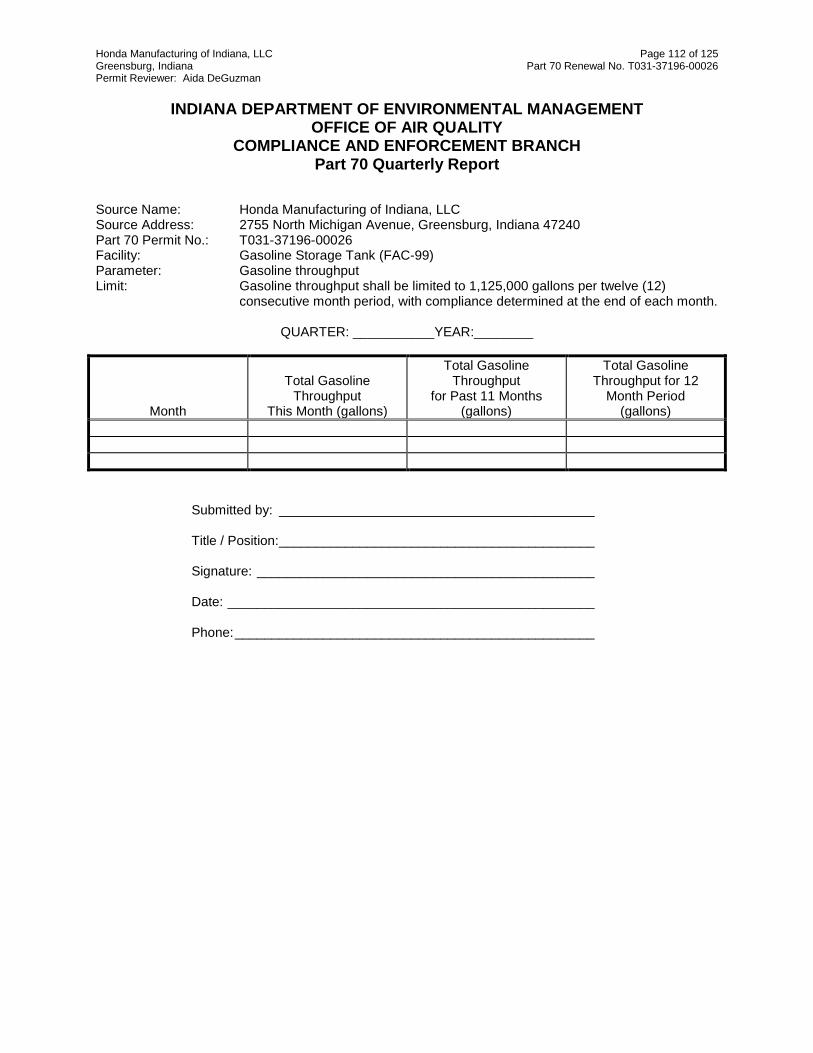
Honda Manufacturing of Indiana, LLC Page 112 of 125 Greensburg, Indiana Part 70 Renewal No. T031-37196-00026 Permit Reviewer: Aida DeGuzman
INDIANA DEPARTMENT OF ENVIRONMENTAL MANAGEMENT
OFFICE OF AIR QUALITY COMPLIANCE AND ENFORCEMENT BRANCH
Part 70 Quarterly Report
Source Name: Honda Manufacturing of Indiana, LLC Source Address: 2755 North Michigan Avenue, Greensburg, Indiana 47240 Part 70 Permit No.: T031-37196-00026 Facility: Gasoline Storage Tank (FAC-99) Parameter: Gasoline throughput Limit: Gasoline throughput shall be limited to 1,125,000 gallons per twelve (12)
consecutive month period, with compliance determined at the end of each month.
QUARTER: ___________YEAR:________
Month
Total Gasoline Throughput
This Month (gallons)
Total Gasoline Throughput
for Past 11 Months (gallons)
Total Gasoline Throughput for 12
Month Period (gallons)
Submitted by: ___________________________________________
Title / Position: ___________________________________________
Signature: ______________________________________________
Date: __________________________________________________
Phone: _________________________________________________

Honda Manufacturing of Indiana, LLC Page 113 of 125 Greensburg, Indiana Part 70 Renewal No. T031-37196-00026 Permit Reviewer: Aida DeGuzman
INDIANA DEPARTMENT OF ENVIRONMENTAL MANAGEMENT
OFFICE OF AIR QUALITY COMPLIANCE AND ENFORCEMENT BRANCH
Part 70 Quarterly Report
Source Name: Honda Manufacturing of Indiana, LLC Source Address: 2755 North Michigan Avenue, Greensburg, Indiana 47240 Part 70 Permit No.: T031-37196-00026 Facility: Gasoline Dispensing Facility (AF-02) Parameter: VOC emissions Limit: Limited to less than 0.54 tons per twelve consecutive month period.
QUARTER: ___________YEAR:________
Month VOC Emitted
This Month (tons)
VOC Emitted for Past 11 Months
(tons)
VOC Emitted for 12 Month Period
(tons)
E = (GwORVR x 0.44 lbs/kgal + Gw/o ORVR x 11lbs/kgal)/2000 lbs/ton where: E = Emissions from initial fueling vehicles (tons/month) GwORVR = Amount of gasoline used in a month to fuel new vehicles
equipped with ORVR Gw/o ORVR = Amount of gasoline used in a month to fuel new vehicles not
equipped with ORVR
Submitted by: ___________________________________________
Title / Position: ___________________________________________
Signature: ______________________________________________
Date: __________________________________________________
Phone: _________________________________________________

Honda Manufacturing of Indiana, LLC Page 114 of 125 Greensburg, Indiana Part 70 Renewal No. T031-37196-00026 Permit Reviewer: Aida DeGuzman
INDIANA DEPARTMENT OF ENVIRONMENTAL MANAGEMENT
OFFICE OF AIR QUALITY Compliance Data Section
Part 70 Quarterly Report
Source Name: Honda Manufacturing of Indiana, LLC Source Address: 2755 North Michigan Avenue, Greensburg, Indiana 47240 Part 70 Permit No.: 031-37196-00026 Facility: Source-wide Parameter: # vehicles produced Limit: 285,000 vehicles per twelve (12) consecutive month period, with compliance
determined at the end of each month.
QUARTER: ___________YEAR:________
Month Vehicle Production
This Month(# vehicles)
Vehicle Production for Past 11 Months
(# vehicles)
Total Vehicle Production for 12 Month Period
(# vehicles)
Submitted by: ___________________________________________
Title / Position: ___________________________________________
Signature: ______________________________________________
Date: __________________________________________________
Phone: _________________________________________________

Honda Manufacturing of Indiana, LLC Page 115 of 125 Greensburg, Indiana Part 70 Renewal No. T031-37196-00026 Permit Reviewer: Aida DeGuzman
INDIANA DEPARTMENT OF ENVIRONMENTAL MANAGEMENT
OFFICE OF AIR QUALITY COMPLIANCE AND ENFORCEMENT BRANCH
Part 70 Quarterly Report
Source Name: Honda Manufacturing of Indiana, LLC Source Address: 2755 North Michigan Avenue, Greensburg, Indiana 47240 Part 70 Permit No.: T031-37196-00026 Facility: E-Coat Line (PA-02), Sealer/Deadener (PA-03), Primer/Surfacer (PA-05),
Topcoat Coating Line and On-Line Repair (PA-07), Blackout/Cavity Wax Coating Line (PA-11), and Plastic Parts,
Parameter: VOC Limit: Shall not exceed 330.2 tons VOC per twelve (12) consecutive month period with
compliance determined at the end of each month.
QUARTER: ___________YEAR_____________
Month VOC Emissions
This Month (tons)
VOC Emissions for Past 11 Months
(tons)
VOC Emissions for 12 Month Period
(tons)
Submitted by: ___________________________________________
Title / Position: ___________________________________________
Signature: ______________________________________________
Date: __________________________________________________
Phone: _________________________________________________

Honda Manufacturing of Indiana, LLC Page 116 of 125 Greensburg, Indiana Part 70 Renewal No. T031-37196-00026 Permit Reviewer: Aida DeGuzman
INDIANA DEPARTMENT OF ENVIRONMENTAL MANAGEMENT
OFFICE OF AIR QUALITY COMPLIANCE AND ENFORCEMENT BRANCH
Part 70 Quarterly Report
Source Name: Honda Manufacturing of Indiana, LLC Source Address: 2755 North Michigan Avenue, Greensburg, Indiana 47240 Part 70 Permit No.: T031-37196-00026 Facility: Natural gas combustion sources in SECTION D.10 Parameter: VOC Limit: 187.6 pounds of CO per MMCF of natural gas and
976 million cubic feet (1,000,000 decatherms) of natural gas per twelve (12) consecutive month period, with compliance determined at the end of each month.
QUARTER: ___________YEAR:________
Month Natural Gas Usage This Month (MMCF)
Natural Gas Usage for Past 11 Months
(MMCF)
Natural Gas Usage for 12 Month Period
(MMCF)
Submitted by: ___________________________________________
Title / Position: ___________________________________________
Signature: ______________________________________________
Date: __________________________________________________
Phone: _________________________________________________

Honda Manufacturing of Indiana, LLC Page 117 of 125 Greensburg, Indiana Part 70 Renewal No. T031-37196-00026 Permit Reviewer: Aida DeGuzman
INDIANA DEPARTMENT OF ENVIRONMENTAL MANAGEMENT
OFFICE OF AIR QUALITY COMPLIANCE AND ENFORCEMENT BRANCH
Quarterly Report
Source Name: Honda Manufacturing of Indiana, LLC Source Address: 2755 North Michigan Avenue, Greensburg, Indiana 47240 Part 70 Permit No.: T031-37196-00026 Facility: E-Coat tank, rinse and oven (PA-02), Primer/Surfacer (PA-05), Topcoat coating line
and Topcoat on-line repair (PA-07), Parameter: VOC Limits: E-Coat tank, rinse, and oven (PA-02) - 0.04 pound per gallon of applied coating
solids (lb/gacs Primer/Surfacer (PA-05) - 4.1 lb/gacs Topcoat Coating Line and Topcoat On-Line Repair (PA-07) - 5.2 lb/gacs The VOC limits shall be based on a daily-volume- weighted average of the
coatings applied, actual transfer efficiencies, and RTOs for control.
Quarter: _________Year ___________ Day E-Coat tank,
rinse, and oven (PA-02) (lb/gacs)
Primer/Surfacer (PA-05) (lb/gacs)
Topcoat Coating Line and Topcoat On-Line
Repair (PA-07) (lb/gacs)
Day
E-Coat tank, rinse, and oven
(PA-02) (lb/gacs)
Primer Surfacer (PA-05) (lb/gacs)
Topcoat Coating Line and Topcoat On-Line
Repair (PA-07) (lb/gacs)
1
17
2
18
3
19
4
20
5
21
6
22
7
23
8
24
9
25
10
26
11
27
12
28
13
29
14
30
15
31
16
Submitted by: _______________________Signature:______________________
Title/Position: _______________________Date: : ______________________

Honda Manufacturing of Indiana, LLC Page 118 of 125 Greensburg, Indiana Part 70 Renewal No. T031-37196-00026 Permit Reviewer: Aida DeGuzman
INDIANA DEPARTMENT OF ENVIRONMENTAL MANAGEMENT
OFFICE OF AIR QUALITY COMPLIANCE AND ENFORCEMENT BRANCH
Quarterly Report
Source Name: Honda Manufacturing of Indiana, LLC Source Address: 2755 North Michigan Avenue, Greensburg, Indiana 47240 Part 70 Permit No.: T031-37196-00026 Facility: Sealer/Deadener (PA-03) Parameter: VOC Limits: Sealer/Deadener - 0.30 lb/gallon controlled by RTO The VOC shall be based on a monthly-volume- weighted average of the coating
used with RTO control.
Quarter: ________Year ___________
Month
Sealer/ Deadener
Average This Month (lb/gal)
Sealer/ Deadener
Average for Past 11 Months (lb/gal)
Sealer/ Deadener
Total Average for 12 Month Period
(lb/gal)
Submitted by:____________________ Date: ________________________ Title / Position:____________________ Phone: _______________________ Signature:________________________

Honda Manufacturing of Indiana, LLC Page 119 of 125 Greensburg, Indiana Part 70 Renewal No. T031-37196-00026 Permit Reviewer: Aida DeGuzman
INDIANA DEPARTMENT OF ENVIRONMENTAL MANAGEMENT
OFFICE OF AIR QUALITY COMPLIANCE AND ENFORCEMENT BRANCH
Quarterly Report
Source Name: Honda Manufacturing of Indiana, LLC Source Address: 2755 North Michigan Avenue, Greensburg, Indiana 47240 Part 70 Permit No.: T031-37196-00026 Facility: Cavity Wax Parameter: VOC Limits: Cavity Wax - 2.9 lb/gallon (uncontrolled)
The VOC limit for the Cavity Wax shall be based on a daily-volume- weighted
average of the coating/wax used with no control.
Day Cavity Wax Average This Day (lb/gal)
Day
Cavity Wax Wax Average This Day
(lb/gal) 1
17
2
18
3
19
4
20
5
21
6
22
7
23
8
24
9
25
10
26
11
27
12
28
13
29
14
30
15
31
16
Submitted by:____________________ Date: ________________________ Title / Position:____________________ Phone: _______________________ Signature:________________________

Honda Manufacturing of Indiana, LLC Page 120 of 125 Greensburg, Indiana Part 70 Renewal No. T031-37196-00026 Permit Reviewer: Aida DeGuzman
INDIANA DEPARTMENT OF ENVIRONMENTAL MANAGEMENT OFFICE OF AIR QUALITY
COMPLIANCE AND ENFORCEMENT BRANCH
Part 70 Quarterly Report
Source Name: Honda Manufacturing of Indiana, LLC Source Address: 2755 North Michigan Avenue, Greensburg, Indiana 47240 Part 70 Permit No.: T031-37196-00026 Facility: Plastic Parts Coating Line, identified as PO-02, Instrument Panel, identified as PO-03, Blackout
coating - 0.74lb/gallon (uncontrolled) Parameter: VOC Limit: Primer coating shall not exceed 0.90 pounds per gallon of coating as applied. Basecoat coating shall not exceed 1.15 pounds per gallon of coating as applied. Clearcoat coating shall not exceed 3.25 pounds per gallon of coating as applied. Instrument Panel, identified as PO-03 shall not exceed 2.3 pounds per gallon less water of coating as applied. Blackout coating, identified as PA-11 shall not exceed 0.74 lb/gallon as applied These limits shall be based on a daily volume weighted average of the coatings applied and RTOs for control. .
QUARTER ___________YEAR ___________ Day Primer
Coating (lb/gal)
Basecoat Coating (lb/gal)
Clearcoat Coating (lb/gal)
Instrument Panel
(lb/gal - water)
Black out (lb/gal)
Day
Primer Coating (lb/gal)
Basecoat Coating (lb/gal)
Clearcoat Coating (lb/gal)
Instrument Panel
(lb/gal - water)
Black out (lb/gal)
1
17
2
18
3
19
4
20
5
21
6
22
7
23
8
24
9
25
10
26
11
27
12
28
13
29
14
30
15
31
16
Submitted by:____________________ Date: ________________________ Title / Position:____________________ Phone: _______________________ Signature:________________________.

Honda Manufacturing of Indiana, LLC Page 121 of 125 Greensburg, Indiana Part 70 Renewal No. T031-37196-00026 Permit Reviewer: Aida DeGuzman
INDIANA DEPARTMENT OF ENVIRONMENTAL MANAGEMENT
OFFICE OF AIR QUALITY COMPLIANCE AND ENFORCEMENT BRANCH
Quarterly Report
Source Name: Honda Manufacturing of Indiana, LLC Source Address: 2755 North Michigan Avenue, Greensburg, Indiana 47240 Part 70 Permit No.: T031-37196-00026 Facility: Final Repair-Air Dry, identified as PA-13, Topcoat In-Line Repair, identified as
PA-09, Final Repair, identified as PA-12 Parameter: VOC Limits: Final Repair-Air Dry, identified as PA-13 - less than 15 pounds per day (lbs/day). Topcoat In-Line Repair, identified as PA-09 - less than 15 lbs/day. Final Repair, identified as PA-12 - 4.8 lb/gallon. This lb/gal limit shall be based on
a daily-volume weighted average of the coatings applied. Month __________ Year _____
Day
Final Repair (PA-12)
Average VOC Applied (lb/gal)
Final Repair (PA-13) VOC Input Usage
(lb/day)
Topcoat In-Line Repair,
identified as PA-09 VOC Input Usage
(lb/day)
Day
Final Repair, identified as
PA-12 VOC of
Coatings Applied (lb/gal)
Final Repair
(PA-13) VOC Input
Usage (lb/day)
Topcoat In-Line Repair, identified as
PA-09 VOC Input
Usage (lb/day) 1
17
2
18
3
19
4
20
5
21
6
22
7
23
8
24
9
25
10
26
11
27
12
28
13
29
14
30
15
31
16
Submitted by: _______________________Signature:______________________ Title/Position: _______________________Date: : ______________________

Honda Manufacturing of Indiana, LLC Page 122 of 125 Greensburg, Indiana Part 70 Renewal No. T031-37196-00026 Permit Reviewer: Aida DeGuzman
INDIANA DEPARTMENT OF ENVIRONMENTAL MANAGEMENT OFFICE OF AIR QUALITY
COMPLIANCE AND ENFORCEMENT BRANCH Quarterly Report
Source Name: Honda Manufacturing of Indiana, LLC Source Address: 2755 North Michigan Avenue, Greensburg, Indiana 47240 Part 70 Permit No.: T031-37196-00026 Facility: Miscellaneous Operations: Weld Sealer, Assembly Window Install, Wiping/Cleaning
and Purge Solvent from Plastic Operation, Wiping/Cleaning and Purge Solvent from Body Painting Operation
Parameter: VOC Limits: Weld Sealer - 0.30 lb/gallon Assembly Window Install - 0.40 lb/gallon The VOC limits shall be based on a monthly-volume- weighted average of the
coatings applied.
Quarter: ________Year ___________ Page 1 of 2
Month
Weld Sealer
Average VOC of
Coatings Applied
This Month (lb/gal)
Weld Sealer
Average VOC of
Coatings Applied for Past
11 Months (lb/gal)
Weld Sealer
Average VOC of
Coatings Applied for 12 Month
Period (lb/gal)
Assembly Window Install
Average VOC of
Coatings Applied
This Month (lb/gal)
Assembly Window Install
Average VOC of
Coatings Applied for
Past 11 Months (lb/gal)
Assembly Window Install
Average VOC of
Coatings Applied for 12 Months
(lb/gal)

Honda Manufacturing of Indiana, LLC Page 123 of 125 Greensburg, Indiana Part 70 Renewal No. T031-37196-00026 Permit Reviewer: Aida DeGuzman
Additional Limits: Miscellaneous Operations, including the Weld Sealer VOC emissions: Total limit of 134.9 tons per twelve consecutive
month period with compliance determined at the end of each month. Facility/Operation
VOC Limits (tons/year)
Assembly Window Install
24.78
Wiping/Cleaning and Purge Solvent from Body Paint Operation
67.09
Wiping/Cleaning and Purge Solvent from Plastic Operation
39.12
Page 2 of 2
Month
Weld Sealer VOC
Usage (tons)
Assembly Window Install VOC
Usage (tons)
Wiping/ Cleaning
and Purge
Solvent from
Plastic Operatio
n VOC
Usage (tons)
Wiping/ Cleaning
and Purge Solvent
from Body Painting
Operation VOC Usage (tons)
TOTAL VOC
USAGE (TONS)
Weld Sealer
VOC Usage (tons)
Window Install VOC
Usage (tons)
Wiping/ Cleaning
and Purge Solvent
from Plastic
Operation VOC
Usage (tons)
Wiping/ Cleaning
and Purge Solvent
from Body Painting
Operation VOC Usage (tons
TOTAL VOC
USAGE (TONS
Weld Sealer VOC
Usage (tons)
Window Install VOC
Usage (tons)
Wiping/ Cleaning
and Purge Solvent
from Plastic
Operation VOC
Usage (tons)
Wiping/ Cleaning
and Purge
Solvent from Body Painting
Operation VOC
Usage (tons)
TOTAL VOC
USAGE (TONS)
This Month
This Month
This Month
This Month
This Month
Previous 11 Months
Previous 11 Months
Previous 11 Months
Previous 11 Months
Previous 11 Months
12 Months Total
12 Months Total
12 Months Total
12 Months Total
12 Months Total
Submitted by: _______________________Signature:______________________
Submitted by: _______________________Signature:______________________
Title/Position: _______________________Date: : ______________________

Honda Manufacturing of Indiana, LLC Page 124 of 125 Greensburg, Indiana Part 70 Renewal No. T031-37196-00026 Permit Reviewer: Aida DeGuzman
INDIANA DEPARTMENT OF ENVIRONMENTAL MANAGEMENT OFFICE OF AIR QUALITY
COMPLIANCE AND ENFORCEMENT BRANCH PART 70 OPERATING PERMIT
QUARTERLY DEVIATION AND COMPLIANCE MONITORING REPORT
Source Name: Honda Manufacturing of Indiana, LLC Source Address: 2755 North Michigan Avenue, Greensburg, Indiana 47240 Part 70 Permit No.: T031-37196-00026
Months: to Year:
Page 1 of 2
This report shall be submitted quarterly based on a calendar year. Proper notice submittal under Section B –Emergency Provisions satisfies the reporting requirements of paragraph (a) of Section C-General Reporting. Any deviation from the requirements of this permit, the date(s) of each deviation, the probable cause of the deviation, and the response steps taken must be reported. A deviation required to be reported pursuant to an applicable requirement that exists independent of the permit, shall be reported according to the schedule stated in the applicable requirement and does not need to be included in this report. Additional pages may be attached if necessary. If no deviations occurred, please specify in the box marked "No deviations occurred this reporting period".
NO DEVIATIONS OCCURRED THIS REPORTING PERIOD.
THE FOLLOWING DEVIATIONS OCCURRED THIS REPORTING PERIOD
Permit Requirement (specify permit condition #)
Date of Deviation:
Duration of Deviation:
Number of Deviations:
Probable Cause of Deviation:
Response Steps Taken:
Permit Requirement (specify permit condition #)
Date of Deviation:
Duration of Deviation:
Number of Deviations:
Probable Cause of Deviation:
Response Steps Taken:

Honda Manufacturing of Indiana, LLC Page 125 of 125 Greensburg, Indiana Part 70 Renewal No. T031-37196-00026 Permit Reviewer: Aida DeGuzman
Page 2 of 2
Permit Requirement (specify permit condition #)
Date of Deviation:
Duration of Deviation:
Number of Deviations:
Probable Cause of Deviation:
Response Steps Taken:
Permit Requirement (specify permit condition #)
Date of Deviation:
Duration of Deviation:
Number of Deviations:
Probable Cause of Deviation:
Response Steps Taken:
Permit Requirement (specify permit condition #)
Date of Deviation:
Duration of Deviation:
Number of Deviations:
Probable Cause of Deviation:
Response Steps Taken:
Form Completed by: Title / Position: Date: Phone:

Attachment A Part 70 Operating Permit No: 031-37196-00026
Electronic Code of Federal Regulations
Title 40: Protection of Environment
PART 60—STANDARDS OF PERFORMANCE FOR NEW STATIONARY SOURCES
Subpart MM—Standards of Performance for Automobile and Light Duty Truck Surface Coating Operations
Source: 45 FR 85415, Dec. 24, 1980, unless otherwise noted.
§60.390 Applicability and designation of affected facility.
(a) The provisions of this subpart apply to the following affected facilities in an automobile or light-duty truck assembly plant: each prime coat operation, each guide coat operation, and each topcoat operation.
(b) Exempted from the provisions of this subpart are operations used to coat plastic body components or all-plastic automobile or light-duty truck bodies on separate coating lines. The attachment of plastic body parts to a metal body before the body is coated does not cause the metal body coating operation to be exempted.
(c) The provisions of this subpart apply to any affected facility identified in paragraph (a) of this section that begins construction, reconstruction, or modification after October 5, 1979.
§60.391 Definitions.
(a) All terms used in this subpart that are not defined below have the meaning given to them in the Act and in subpart A of this part.
Applied coating solids means the volume of dried or cured coating solids which is deposited and remains on the surface of the automobile or light-duty truck body.
Automobile means a motor vehicle capable of carrying no more than 12 passengers.
Automobile and light-duty truck body means the exterior surface of an automobile or light-duty truck including hoods, fenders, cargo boxes, doors, and grill opening panels.
Bake oven means a device that uses heat to dry or cure coatings.
Electrodeposition (EDP) means a method of applying a prime coat by which the automobile or light-duty truck body is submerged in a tank filled with coating material and an electrical field is used to effect the deposition of the coating material on the body.
Electrostatic spray application means a spray application method that uses an electrical potential to increase the transfer efficiency of the coating solids. Electrostatic spray application can be used for prime coat, guide coat, or topcoat operations.
Flash-off area means the structure on automobile and light-duty truck assembly lines between the coating application system (dip tank or spray booth) and the bake oven.
Guide coat operation means the guide coat spray booth, flash-off area and bake oven(s) which are used to apply and dry or cure a surface coating between the prime coat and topcoat operation on the components of automobile and light-duty truck bodies.

40 CFR 60, Subpart MM Page 2 of 15 Attachment A TV No. 031-37196-00026 Light-duty truck means any motor vehicle rated at 3,850 kilograms gross vehicle weight or less, designed mainly to transport property.
Plastic body means an automobile or light-duty truck body constructed of synthetic organic material.
Plastic body component means any component of an automobile or light-duty truck exterior surface constructed of synthetic organic material.
Prime coat operation means the prime coat spray booth or dip tank, flash-off area, and bake oven(s) which are used to apply and dry or cure the initial coating on components of automobile or light-duty truck bodies.
Purge or line purge means the coating material expelled from the spray system when clearing it.
Solids Turnover Ratio (RT) means the ratio of total volume of coating solids that is added to the EDP system in a calendar month divided by the total volume design capacity of the EDP system.
Solvent-borne means a coating which contains five percent or less water by weight in its volatile fraction.
Spray application means a method of applying coatings by atomizing the coating material and directing the atomized material toward the part to be coated. Spray applications can be used for prime coat, guide coat, and topcoat operations.
Spray booth means a structure housing automatic or manual spray application equipment where prime coat, guide coat, or topcoat is applied to components of automobile or light-duty truck bodies.
Surface coating operation means any prime coat, guide coat, or topcoat operation on an automobile or light-duty truck surface coating line.
Topcoat operation means the topcoat spray booth, flash-off area, and bake oven(s) which are used to apply and dry or cure the final coating(s) on components of automobile and light-duty truck bodies.
Transfer efficiency means the ratio of the amount of coating solids transferred onto the surface of a part or product to the total amount of coating solids used.
VOC content means all volatile organic compounds that are in a coating expressed as kilograms of VOC per liter of coating solids.
Volume Design Capacity of EDP System (LE) means the total liquid volume that is contained in the EDP system (tank, pumps, recirculating lines, filters, etc.) at its designed liquid operating level.
Waterborne or water reducible means a coating which contains more than five weight percent water in its volatile fraction.
(b) The nomenclature used in this subpart has the following meanings:
Caj = concentration of VOC (as carbon) in the effluent gas flowing through stack (j) leaving the control device (parts per million by volume),
Cbi = concentration of VOC (as carbon) in the effluent gas flowing through stack (i) entering the control device (parts per million by volume),
Cfk = concentration of VOC (as carbon) in the effluent gas flowing through exhaust stack (k) not entering the control device (parts per million by volume),
Dci = density of each coating (i) as received (kilograms per liter),
Ddj = density of each type VOC dilution solvent (j) added to the coatings, as received (kilograms per liter),

40 CFR 60, Subpart MM Page 3 of 15 Attachment A TV No. 031-37196-00026 Dr = density of VOC recovered from an affected facility (kilograms per liter),
E = VOC destruction or removal efficiency of the control device,
F = fraction of total VOC which is emitted by an affected facility that enters the control device,
G = volume weighted average mass of VOC per volume of applied solids (kilograms per liter),
Lci = volume of each coating (i) consumed, as received (liters),
Lcil = Volume of each coating (i) consumed by each application method (l), as received (liters),
Ldj = volume of each type VOC dilution solvent (j) added to the coatings, as received (liters),
Lr = volume of VOC recovered from an affected facility (liters),
Ls = volume of solids in coatings consumed (liters),
LE = the total volume of the EDP system (liters),
Md = total mass of VOC in dilution solvent (kilograms),
M0 = total mass of VOC in coatings as received (kilograms),
Mr = total mass of VOC recovered from an affected facility (kilograms),
N = volume weighted average mass of VOC per volume of applied coating solids after the control device
Qaj = volumetric flow rate of the effluent gas flowing through stack (j) leaving the control device (dry standard cubic meters per hour),
Qbi = volumetric flow rate of the effluent gas flowing through stack (i) entering the control device (dry standard cubic meters per hour),
Qfk = volumetric flow rate of the effluent gas flowing through exhaust stack (k) not entering the control device (dry standard cubic meters per hour),
T = overall transfer efficiency,
Tl = transfer efficiency for application method (l),
Vsi = proportion of solids by volume in each coating (i) as received
Woi = proportion of VOC by weight in each coating (i), as received
[45 FR 85415, Dec. 24, 1980, as amended at 59 FR 51386, Oct. 11, 1994; 65 FR 61760, Oct. 17, 2000]

40 CFR 60, Subpart MM Page 4 of 15 Attachment A TV No. 031-37196-00026 §60.392 Standards for volatile organic compounds.
On and after the date on which the initial performance test required by §60.8 is completed, no owner or operator subject to the provisions of this subpart shall discharge or cause the discharge into the atmosphere from any affected facility VOC emissions in excess of:
(a) Prime Coat Operation. (1) For each EDP prime coat operation:
(i) 0.17 kilogram of VOC per liter of applied coating solids when RT is 0.16 or greater.
(ii) 0.17 × 350 (0.160-RT) kg of VOC per liter of applied coating solids when RT is greater than or equal to 0.040 and
less than 0.160.
(iii) When RT is less than 0.040, there is no emission limit.
(2) For each nonelectrodeposition prime coat operation: 0.17 kilogram of VOC per liter of applied coating solids.
(b) 1.40 kilograms of VOC per liter of applied coating solids from each guide coat operation.
(c) 1.47 kilograms of VOC per liter of applied coating solids from each topcoat operation.
[45 FR 85415, Dec. 24, 1980, as amended at 59 FR 51386, Oct. 11, 1994]
§60.393 Performance test and compliance provisions.
(a) Section 60.8 (d) and (f) do not apply to the performance test procedures required by this section.
(b) The owner or operator of an affected facility shall conduct an initial performance test in accordance with §60.8(a) and thereafter for each calendar month for each affected facility according to the procedures in this section.
(c) The owner or operator shall use the following procedures for determining the monthly volume weighted average mass of VOC emitted per volume of applied coating solids.
(1) The owner or operator shall use the following procedures for each affected facility which does not use a capture system and a control device to comply with the applicable emission limit specified under §60.392.
(i) Calculate the volume weighted average mass of VOC per volume of applied coating solids for each calendar month for each affected facility. The owner or operator shall determine the composition of the coatings by formulation data supplied by the manufacturer of the coating or from data determined by an analysis of each coating, as received, by Method 24. The Administrator may require the owner or operator who uses formulation data supplied by the manufacturer of the coating to determine data used in the calculation of the VOC content of coatings by Method 24 or an equivalent or alternative method. The owner or operator shall determine from company records on a monthly basis the volume of coating consumed, as received, and the mass of solvent used for thinning purposes. The volume weighted average of the total mass of VOC per volume of coating solids used each calendar month will be determined by the following procedures.
(A) Calculate the mass of VOC used in each calendar month for each affected facility by the following equation where “n” is the total number of coatings used and “m” is the total number of VOC solvents used:
[ΣLdjDdj will be zero if no VOC solvent is added to the coatings, as received].
(B) Calculate the total volume of coating solids used in each calendar month for each affected facility by the following equation where “n” is the total number of coatings used:

40 CFR 60, Subpart MM Page 5 of 15 Attachment A TV No. 031-37196-00026
(C) Select the appropriate transfer efficiency (T) from the following tables for each surface coating operation:
Application method Transfer efficiency
Air Atomized Spray (waterborne coating) 0.39
Air Atomized Spray (solvent-borne coating) 0.50
Manual Electrostatic Spray 0.75
Automatic Electrostatic Spray 0.95
Electrodeposition 1.00
The values in the table above represent an overall system efficiency which includes a total capture of purge. If a spray system uses line purging after each vehicle and does not collect any of the purge material, the following table shall be used:
Application method Transfer efficiency
Air Atomized Spray (waterborne coating) 0.30
Air Atomized Spray (solvent-borne coating) 0.40
Manual Electrostatic Spray 0.62
Automatic Electrostatic Spray 0.75
If the owner or operator can justify to the Administrator's satisfaction that other values for transfer efficiencies are appropriate, the Administrator will approve their use on a case-by-case basis.
(1) When more than one application method (l) is used on an individual surface coating operation, the owner or operator shall perform an analysis to determine an average transfer efficiency by the following equation where “n” is the total number of coatings used and “p” is the total number of application methods:
(D) Calculate the volume weighted average mass of VOC per volume of applied coating solids (G) during each calendar month for each affected facility by the following equation:

40 CFR 60, Subpart MM Page 6 of 15 Attachment A TV No. 031-37196-00026
(E) For each EDP prime coat operation, calculate the turnover ratio (RT) by the following equation:
Then calculate or select the appropriate limit according to §60.392(a).
(ii) If the volume weighted average mass of VOC per volume of applied coating solids (G), calculated on a calendar month basis, is less than or equal to the applicable emission limit specified in §60.392, the affected facility is in compliance. Each monthly calculation is a performance test for the purpose of this subpart.
(2) The owner or operator shall use the following procedures for each affected facility which uses a capture system and a control device that destroys VOC (e.g., incinerator) to comply with the applicable emission limit specified under §60.392.
(i) Calculate the volume weighted average mass of VOC per volume of applied coating solids (G) during each calendar month for each affected facility as described under §60.393(c)(1)(i).
(ii) Calculate the volume weighted average mass of VOC per volume of applied solids emitted after the control device, by the following equation: N = G[1-FE]
(A) Determine the fraction of total VOC which is emitted by an affected facility that enters the control device by using the following equation where “n” is the total number of stacks entering the control device and “p” is the total number of stacks not connected to the control device:
If the owner can justify to the Administrator's satisfaction that another method will give comparable results, the Administrator will approve its use on a case-by-case basis.
(1) In subsequent months, the owner or operator shall use the most recently determined capture fraction for the performance test.
(B) Determines the destruction efficiency of the control device using values of the volumetric flow rate of the gas streams and the VOC content (as carbon) of each of the gas streams in and out of the device by the following equation where “n” is the total number of stacks entering the control device and “m” is the total number of stacks leaving the control device:
(1) In subsequent months, the owner or operator shall use the most recently determined VOC destruction efficiency for the performance test.
(C) If an emission control device controls the emissions from more than one affected facility, the owner or operator shall measure the VOC concentration (Cbi) in the effluent gas entering the control device (in parts per million by volume) and the volumetric flow rate (Qbi) of the effluent gas (in dry standard cubic meters per hour) entering the

40 CFR 60, Subpart MM Page 7 of 15 Attachment A TV No. 031-37196-00026 device through each stack. The destruction or removal efficiency determined using these data shall be applied to each affected facility served by the control device.
(iii) If the volume weighted average mass of VOC per volume of applied solids emitted after the control device (N) calculated on a calendar month basis is less than or equal to the applicable emission limit specified in §60.392, the affected facility is in compliance. Each monthly calculation is a performance test for the purposes of this subpart.
(3) The owner or operator shall use the following procedures for each affected facility which uses a capture system and a control device that recovers the VOC (e.g., carbon adsorber) to comply with the applicable emission limit specified under §60.392.
(i) Calculate the mass of VOC (Mo + Md) used during each calendar month for each affected facility as described under §60.393(c)(1)(i).
(ii) Calculate the total volume of coating solids (Ls) used in each calendar month for each affected facility as described under §60.393(c)(1)(i).
(iii) Calculate the mass of VOC recovered (Mr) each calendar month for each affected facility by the following equation: Mr = Lr Dr
(iv) Calculate the volume weighted average mass of VOC per volume of applied coating solids emitted after the control device during a calendar month by the following equation:
(v) If the volume weighted average mass of VOC per volume of applied solids emitted after the control device (N) calculated on a calendar month basis is less than or equal to the applicable emission limit specified in §60.392, the affected facility is in compliance. Each monthly calculation is a performance test for the purposes of this subpart.
[45 FR 85415, Dec. 24, 1980, as amended at 59 FR 51387, Oct. 11, 1994; 65 FR 61760, Oct. 17, 2000]
§60.394 Monitoring of emissions and operations.
The owner or operator of an affected facility which uses an incinerator to comply with the emission limits specified under §60.392 shall install, calibrate, maintain, and operate temperature measurement devices as prescribed below:
(a) Where thermal incineration is used, a temperature measurement device shall be installed in the firebox. Where catalytic incineration is used, a temperature measurement device shall be installed in the gas stream immediately before and after the catalyst bed.
(b) Each temperature measurement device shall be installed, calibrated, and maintained according to accepted practice and the manufacturer's specifications. The device shall have an accuracy of the greater of ±5 percent of the temperature being measured expressed in degrees Celsius or ±2.5 °C.
(c) Each temperature measurement device shall be equipped with a recording device so that a permanent record is produced.
§60.395 Reporting and recordkeeping requirements.
(a) Each owner or operator of an affected facility shall include the data outlined in paragraphs (a)(1) and (2) in the initial compliance report required by §60.8.
(1) The owner or operator shall report the volume weighted average mass of VOC per volume of applied coating solids for each affected facility.

40 CFR 60, Subpart MM Page 8 of 15 Attachment A TV No. 031-37196-00026 (2) Where compliance is achieved through the use of incineration, the owner or operator shall include the following additional data in the control device initial performance test requried by §60.8(a) or subsequent performance tests at which destruction efficiency is determined: the combustion temperature (or the gas temperature upstream and downstream of the catalyst bed), the total mass of VOC per volume of applied coating solids before and after the incinerator, capture efficiency, the destruction efficiency of the incinerator used to attain compliance with the applicable emission limit specified in §60.392 and a description of the method used to establish the fraction of VOC captured and sent to the control device.
(b) Following the initial performance test, the owner or operator of an affected facility shall identify, record, and submit a written report to the Administrator every calendar quarter of each instance in which the volume-weighted average of the total mass of VOC's emitted to the atmosphere per volume of applied coating solids (N) is greater than the limit specified under §60.392. If no such instances have occurred during a particular quarter, a report stating this shall be submitted to the Administrator semiannually. Where compliance is achieved through the use of a capture system and control device, the volume-weighted average after the control device should be reported.
(c) Where compliance with §60.392 is achieved through the use of incineration, the owner or operator shall continuously record the incinerator combustion temperature during coating operations for thermal incineration or the gas temperature upstream and downstream of the incinerator catalyst bed during coating operations for catalytic incineration. The owner or operator shall submit a written report at the frequency specified in §60.7(c) and as defined below.
(1) For thermal incinerators, every three-hour period shall be reported during which the average temperature measured is more than 28 °C less than the average temperature during the most recent control device performance test at which the destruction efficiency was determined as specified under §60.393.
(2) For catalytic incinerators, every three-hour period shall be reported during which the average temperature immediately before the catalyst bed, when the coating system is operational, is more than 28 °C less than the average temperature immediately before the catalyst bed during the most recent control device performance test at which destruction efficiency was determined as specified under §60.393. In addition, every three-hour period shall be reported each quarter during which the average temperature difference across the catalyst bed when the coating system is operational is less than 80 percent of the average temperature difference of the device during the most recent control device performance test at which destruction efficiency was determined as specified under §60.393.
(3) For thermal and catalytic incinerators, if no such periods occur, the owner or operator shall submit a negative report.
(d) The owner or operator shall notify the Administrator 30 days in advance of any test by Method 25.
[45 FR 85415, Dec. 24, 1980, as amended at 55 FR 51383, Dec. 13, 1990; 65 FR 61760, Oct. 17, 2000]
§60.396 Reference methods and procedures.
(a) The reference methods in appendix A to this part, except as provided in §60.8 shall be used to conduct performance tests.
(1) Method 24 or an equivalent or alternative method approved by the Administrator shall be used for the determination of the data used in the calculation of the VOC content of the coatings used for each affected facility. Manufacturers' formulation data is approved by the Administrator as an alternative method to Method 24. In the event of dispute, Method 24 shall be the referee method.
(2) Method 25 or an equivalent or alternative method approved by the Administrator shall be used for the determination of the VOC concentration in the effluent gas entering and leaving the emission control device for each stack equipped with an emission control device and in the effluent gas leaving each stack not equipped with a control device.
(3) The following methods shall be used to determine the volumetric flow rate in the effluent gas in a stack:

40 CFR 60, Subpart MM Page 9 of 15 Attachment A TV No. 031-37196-00026 (i) Method 1 for sample and velocity traverses,
(ii) Method 2 for velocity and volumetric flow rate,
(iii) Method 3 for gas analysis, and
(iv) Method 4 for stack gas moisture.
(b) For Method 24, the coating sample must be a 1-liter sample taken in a 1-liter container.
(c) For Method 25, the sampling time for each of three runs must be at least one hour. The minimum sample volume must be 0.003 dscm except that shorter sampling times or smaller volumes, when necessitated by process variables or other factors, may be approved by the Administrator. The Administrator will approve the sampling of representative stacks on a case-by-case basis if the owner or operator can demonstrate to the satisfaction of the Administrator that the testing of representative stacks would yield results comparable to those that would be obtained by testing all stacks.
[45 FR 85415, Dec. 24, 1980, as amended at 65 FR 61760, Oct. 17, 2000]
§60.397 Modifications.
The following physical or operational changes are not, by themselves, considered modifications of existing facilities:
(a) Changes as a result of model year changeovers or switches to larger cars.
(b) Changes in the application of the coatings to increase coating film thickness.
§60.398 Innovative technology waivers.
(a) General Motors Corporation, Wentzville, Missouri, automobile assembly plant. (1) Pursuant to section 111(j) of the Clean Air Act, 42 U.S.C. 7411(j), each topcoat operation at General Motors Corporation automobile assembly plant located in Wentzville, Missouri, shall comply with the following conditions:
(i) The General Motors Corporation shall obtain the necessary permits as required by section 173 of the Clean Air Act, as amended August 1977, to operate the Wentzville assembly plant.
(ii) Commencing on February 4, 1983, and continuing to December 31, 1986, or until the base coat/clear coat topcoat system that can achieve the standard specified in 40 CFR 60.392(c) (Dec. 24, 1980) is demonstrated to the Administrator's satisfaction the General Motors Corporation shall limit the discharge of VOC emissions to the atmosphere from each topcoat operation at the Wentzville, Missouri, assembly plant, to either:
(A) 1.9 kilograms of VOC per liter of applied coating solids from base coat/clear coat topcoats, and 1.47 kilograms of VOC per liter of applied coating solids from all other topcoat coatings; or
(B) 1.47 kilograms of VOC per liter of applied coating solids from all topcoat coatings.
(iii) Commencing on the day after the expiration of the period described in paragraph (a)(1)(ii) of this section, and continuing thereafter, emissions of VOC from each topcoat operations shall not exceed 1.47 kilograms of VOC per liter of applied coating solids as specified in 40 CFR 60.392(c) (Dec. 24, 1980).
(iv) Each topcoat operation shall comply with the provisions of §§60.393, 60.394, 60.395, 60.396, and 60.397. Separate calculations shall be made for base coat/clear coat coatings and all other topcoat coatings when necessary to demonstrate compliance with the emission limits in paragraph (a)(1)(ii)(A) of this section.
(v) A technology development report shall be sent to EPA Region VII, 324 East 11th Street, Kansas City, MO 64106, postmarked before 60 days after the promulgation of this waiver and annually thereafter while this waiver is in effect. The technology development report shall summarize the base coat/clear coat development work including the results

40 CFR 60, Subpart MM Page 10 of 15 Attachment A TV No. 031-37196-00026 of exposure and endurance tests of the various coatings being evaluated. The report shall include an updated schedule of attainment of 40 CFR 60.392(c) (Dec. 24, 1980) based on the most current information.
(2) This waiver shall be a federally promulgated standard of performance. As such, it shall be unlawful for General Motors Corporation to operate a topcoat operation in violation of the requirements established in this waiver. Violation of the terms and conditions of this waiver shall subject the General Motors Corporation to enforcement under section 113 (b) and (c), 42 U.S.C. 7412 (b) and (c), and section 120, 42 U.S.C. 7420, of the Act as well as possible citizen enforcement under section 304 of the Act, 42 U.S.C. 7604.
(b) General Motors Corporation, Detroit, Michigan, Automobile Assembly plant. (1) Pursuant to section 111(j) of the Clean Air Act, 42 U.S.C. 7411(j), each topcoat operation at General Motors Corporation's automobile assembly plant located in Detroit, MI, shall comply with the following conditions:
(i) The General Motors Corporation shall obtain the necessary permits as required by section 173 of the Clean Air Act, as amended August 1977, to operate the Detroit assembly plant.
(ii) Commencing on February 4, 1983, and continuing to December 31, 1986, or until the base coat/clear coat topcoat system that can achieve the standard specified in 40 CFR 60.392(c) (Dec. 24, 1980), is demonstrated to the Administrator's satisfaction, the General Motors Corporation shall limit the discharge of VOC emissions to the atmosphere from each topcoat operation at the Detroit, MI, assembly plant, to either:
(A) 1.9 kilograms of VOC per liter of applied coating solids from base coat/clear coat topcoats, and 1.47 kilograms of VOC per liter of applied coating solids from all other topcoat coatings; or
(B) 1.47 kilograms of VOC per liter of applied coating solids from all topcoat coatings.
(iii) Commencing on the day after the expiration of the period described in paragraph (b)(ii) of this section, and continuing thereafter, emissions of VOC from each topcoat operation shall not exceed 1.47 kilograms of VOC per liter of applied coating solids as specified in 40 CFR 60.392(c) (December 24, 1980).
(iv) Each topcoat operation shall comply with the provisions of §§60.393, 60.394, 60.395, 60.396, and 60.397. Separate calculations shall be made for base coat/clear coat coatings and all other topcoat coatings when necessary to demonstrate compliance with the emission limits in paragraph (b)(1)(ii)(A) of this section.
(v) A technology development report shall be sent to EPA Region V, 230 South Dearborn Street, Chicago, IL 60604, postmarked before 60 days after the promulgation of this waiver and annually thereafter while this waiver is in effect. The technology development report shall summarize the base coat/clear coat development work including the results of exposure and endurance tests of the various coatings being evaluated. The report shall include an updated schedule of attainment of 40 CFR 60.392(c) (Dec. 24, 1980) based on the most current information.
(2) This waiver shall be a federally promulgated standard of performance. As such, it shall be unlawful for General Motors Corporation to operate a topcoat operation in violation of the requirements established in this waiver. Violation of the terms and conditions of this waiver shall subject the General Motors Corporation to enforcement under section 113 (b) and (c), 42 U.S.C. 7412 (b) and (c), and section 120, 42 U.S.C. 7420, of the Act as well as possible citizen enforcement under section 304 of the Act, 42 U.S.C. 7604.
(c) General Motors Corporation, Orion Township, MI, automobile assembly plant. (1) Pursuant to section 111(j) of the Clean Air Act, 42 U.S.C. 7411(j), each topcoat operation at General Motors Corporation automobile assembly plant located in Orion Township, MI, shall comply with the following conditions:
(i) The General Motors Corporation shall obtain the necessary permits as required by section 173 of the Clean Air Act, as amended August 1977, to operate the Orion Township assembly plant.
(ii) Commencing on February 4, 1983, and continuing to December 31, 1986, or until the base coat/clear coat topcoat system that can achieve the standard specified in 40 CFR 60.392(c) (Dec. 24, 1980) is demonstrated to the

40 CFR 60, Subpart MM Page 11 of 15 Attachment A TV No. 031-37196-00026 Administrator's satisfaction, the General Motors Corporation shall limit the discharge of VOC emissions to the atmosphere from each topcoat operation at the Orion Township, MI, assembly plant, to either:
(A) 1.9 kilograms of VOC per liter of applied coating solids from base coat/clear coat topcoats, and 1.47 kilograms of VOC per liter of applied coating solids from all other topcoat coatings; or
(B) 1.47 kilograms of VOC per liter of applied coating solids from all topcoat coatings.
(iii) Commencing on the day after the expiration of the period described in paragraph (c)(l)(ii) of this section and continuing thereafter, emissions of VOC from each topcoat operation shall not exceed 1.47 kilograms of VOC per liter of applied coating solids as specified in 40 CFR 60.392(c) (Dec. 24, 1980).
(iv) Each topcoat operation shall comply with the provisions of §§60.393, 60.394, 60.395, 60.396, and 60.397. Separate calculations shall be made for base coat/clear coat coatings and all other topcoat coatings when necessary to demonstrate compliance with the emission limits in paragraph (c)(l) (ii)(A) of this section.
(v) A technology development report shall be sent to EPA Region V, 230 South Dearborn Street, Chicago, IL 60604, postmarked before 60 days after the promulgation of this waiver and annually thereafter while this waiver is in effect. The technology development report shall summarize the base coat/clear coat development work including the results of exposure and endurance tests of the various coatings being evaluated. The report shall include an updated schedule of attainment of 40 CFR 60.392(c) (December 24, 1980) based on the most current information.
(2) This waiver shall be a federally promulgated standard of performance. As such, it shall be unlawful for General Motors Corporation to operate a topcoat operation in violation of the requirements established in this waiver. Violation of the terms and conditions of this waiver shall subject the General Motors Corporation to enforcement under section 113 (b) and (c), 42 U.S.C. 7412 (b) and (c), and section 120, 42 U.S.C. 7420, of the Act as well as possible citizen enforcement under section 304 of the Act, 42 U.S.C. 7604.
(d) Honda of America Manufacturing, Incorporated (Honda), Marysville, Ohio, automobile assembly plant. (1) Pursuant to section 111(j) of the Clean Air Act, 42 U.S.C. 7411(j), each topcoat operation at Honda's automobile assembly plant located in Marysville, OH, shall comply with the following conditions:
(i) Honda shall obtain the necessary permits as required by section 173 of the Clean Air Act, as amended August 1977, to operate the Marysville assembly plant.
(ii) Commencing on February 4, 1983, and continuing for 4 years or to December 31, 1986, whichever is sooner, or until the base coat/clear coat topcoat system that can achieve the standard specified in 40 CFR 60.392(c) (Dec. 24, 1980) is demonstrated to the Administrator's satisfaction, Honda shall limit the discharge of VOC emissions to the atmosphere from each topcoat operation at Marysville, OH, assembly plant, to either:
(A) 3.1 kilograms of VOC per liter of applied coating solids from base coat/clear coat topcoats, and 1.47 kilograms of VOC per liter of applied coating solids from all other topcoat coatings; or
(B) 1.47 kilograms of VOC per liter of applied coating solids from all topcoat coatings.
(iii) Commencing on the day after the expiration of the period described in paragraph (d)(1)(ii) of this section and continuing thereafter, emissions of VOC from each topcoat operation shall not exceed 1.47 kilograms of VOC per liter of applied coating solids as specified in 40 CFR 60.392(c) (December 24, 1980).
(iv) Each topcoat operation shall comply with the provisions of §§60.393, 60.394, 60.395, 60.396, and 60.397. Separate calculations shall be made for base coat/clear coat coatings and all other topcoat coatings when necessary to demonstrate compliance with the emission limits in paragraph (d)(1)(ii)(A) of this section.
(v) A technology development report shall be sent to EPA Region V, 230 South Dearborn Street, Chicago, IL 60604, postmarked before 60 days after the promulgation of this waiver and annually thereafter while this waiver is in effect. The technology development report shall summarize the base coat/clear coat development work including the results

40 CFR 60, Subpart MM Page 12 of 15 Attachment A TV No. 031-37196-00026 of exposure and endurance tests of the various coatings being evaluated. The report shall include an updated schedule of attainment of 40 CFR 60.392(c) (Dec. 24, 1980) based on the most current information.
(2) This waiver shall be a federally promulgated standard of performance. As such, it shall be unlawful for Honda to operate a topcoat operation in violation of the requirements established in this waiver. Violation of the terms and conditions of this waiver shall subject Honda to enforcement under section 113(b) and (c), 42 U.S.C. 7412(b) and (c), and section 120, 42 U.S.C. 7420, of the Act as well as possible citizen enforcement under section 304 of the Act, 42 U.S.C. 7604.
(e) Nissan Motor Manufacturing Corporation, U.S.A. (Nissan), Smyrna, TN, light-duty truck assembly plant. (1) Pursuant to section 111(j) of the Clean Air Act, 42 U.S.C. 7411(j), each topcoat operation at Nissan's light-duty truck assembly plant located in Smyrna, Tennessee, shall comply with the following conditions:
(i) Nissan shall obtain the necessary permits as required by section 173 of the Clean Air Act, as amended August 1977, to operate the Smyrna assembly plant.
(ii) Commencing on February 4, 1983, and continuing for 4 years or to December 31, 1986, whichever is sooner, or until the base coat/clear coat topcoat system that can achieve the standard specified in 40 CFR 60.392(c) (Dec. 24, 1980), is demonstrated to the Administrator's satisfaction, Nissan shall limit the discharge of VOC emissions to the atmosphere from each topcoat operation at the Smyrna, TN, assembly plant, to either:
(A) 2.3 kilograms of VOC per liter of applied coating solids from base coat/clear coat topcoats, and 1.47 kilograms of VOC per liter of applied coating solids from all other topcoat coatings; or
(B) 1.47 kilograms of VOC per liter of applied coating solids from all topcoat coatings.
(iii) Commencing on the day after the expiration of the period described in paragraph (e)(1)(ii) of this section and continuing thereafter, emissions of VOC from each topcoat operation shall not exceed 1.47 kilograms of VOC per liter of applied coating solids as specified in 40 CFR 60.392(c) (Dec. 24, 1980).
Each topcoat operation shall comply with the provisions of §§60.393, 60.394, 60.395, 60.396, and 60.397. Separate calculations shall be made for base coat/clear coat coatings and all other topcoat coatings when necessary to demonstrate compliance with the emission limits in paragraph (e)(1)(ii)(A) of this section.
(f) Chrysler Corporation, Sterling Heights, MI, automobile assembly plant. (1) Pursuant to section 111(j) of the Clean Air Act, 42 U.S.C. 7411(j), each topcoat operation at Chrysler Corporation's automobile assembly plant located in Sterling Heights, MI, shall comply with the following conditions:
(i) The Chrysler Corporation shall obtain the necessary permits as required under Parts C and D of the Clean Air Act, as amended August 1977, to operate the Sterling Heights assembly plant.
(ii) Commencing on September 9, 1985, and continuing to December 31, 1986, or until the basecoat/clearcoat (BC/CC) topcoat system that can achieve the standard specified under §60.392(c) of this subpart is demonstrated to the Administrator's satisfaction, whichever is sooner, the Chrysler Corporation shall limit the discharge of VOC emissions to the atmosphere from each topcoat operation at the Sterling Heights, MI assembly plant, to either:
(A) 1.7 kilograms of VOC per liter of applied coating solids from BC/CC topcoats, and 1.47 kilograms of VOC per liter of applied coating solids from all other topcoat coatings; or
(B) 1.47 kilograms of VOC per liter of applied coating solids from all topcoat coatings.
(iii) Commencing on the day after the expiration of the period described in paragraph (f)(1)(ii) and continuing thereafter, emissions of VOC's from each topcoat operation shall not exceed 1.47 kilograms of VOC per liter of applied coating solids as specified under §60.392(c) of this subpart.

40 CFR 60, Subpart MM Page 13 of 15 Attachment A TV No. 031-37196-00026 (iv) Each topcoat operation shall comply with the provisions of §§60.393, 60.394, 60.395, 60.396, and 60.397. Separate calculations shall be made for BC/CC coatings and all other topcoat coatings when necessary to demonstrate compliance with the emission limits specified under paragraph (f)(1)(ii)(A) of this section.
(v) A technology development report shall be sent to EPA Region V, 230 South Dearborn Street, Chicago, IL 60604, postmarked before 60 days after the promulgation of this waiver and annually thereafter while this waiver is in effect. A copy of this report shall be sent to Director, Emission Standards and Engineering Division, U.S. Environmental Protection Agency, MD-13, Research Triangle Park, NC 27711. The technology development report shall summarize the BC/CC development work including the results of exposure and endurance tests of the various coatings being evaluated. The report shall include an updated schedule of attainment of §60.392(c) of this subpart, based on the most current information.
(2) This waiver shall be a federally promulgated standard of performance. As such, it shall be unlawful for the Chrysler Corporation to operate a topcoat operation in violation of the requirements established in this waiver. Violation of the terms and conditions of this waiver shall subject the Chrysler Corporation to enforcement under sections 113 (b) and (c) of the Act (42 U.S.C. 7412 (b) and (c)) and under section 120 of the Act (42 U.S.C. 7420), as well as possible citizen enforcement under section 304 of the Act (42 U.S.C. 7604).
(3) This waiver shall not be construed to constrain the State of Michigan from imposing upon the Chrysler Corporation any emission reduction requirement at Chrysler's Sterling Heights automobile assembly plant necessary for the maintenance of reasonable further progress or the attainment of the national ambient air quality standard for ozone or the maintenance of the national ambient air quality standard for ozone. Furthermore, this waiver shall not be construed as granting any exemptions from the applicability, enforcement, or other provisions of any other standards that apply or may apply to topcoat operations or any other operations at this automobile assembly plant.
(g) Ford Motor Company, Hapeville, GA, automotive assemply plant. (1) Pursuant to section 111(j) of the Clean Air Act, 42 U.S.C. 7411(j), each topcoat operation at Ford Motor Company's automobile assembly plant located in Hapeville, GA, shall comply with the following conditions:
(i) The Ford Motor Company shall obtain the necessary permits as required under parts C and D of the Clean Air Act, as amended August 1977, to operate the Hapeville assembly plant.
(ii) Commencing on September 9, 1985, and continuing to December 31, 1986, or until the basecoat/clearcoat (BC/CC) topcoat system that can achieve the standard specified under §60.392(c) of this subpart is demonstrated to the Administrator's satisfaction, whichever is sooner, the Ford Motor Company shall limit the discharge of VOC emissions to the atmosphere from each topcoat operation at the Hapeville, GA, assembly plant, to either:
(A) 2.6 kilograms of VOC per liter of applied coating solids from BC/CC topcoats, and 1.47 kilograms of VOC per liter of applied coating solids from all other topcoat coatings; or
(B) 1.47 kilograms of VOC per liter of applied coating solids from all topcoat coatings.
(iii) Commencing on the day after the expiration of the period described in paragraph (g)(1)(ii) and continuing thereafter, emissions of VOC's from each topcoat operation shall not exceed 1.47 kilograms of VOC per liter of applied coating solids as specified under §60.392(c) of this subpart.
(iv) Each topcoat operation shall comply with the provisions of §§60.393, 60.394, 60.395, 60.396, and 60.397. Separate calculations shall be made for BC/CC coatings and all other topcoat coatings when necessary to demonstrate compliance with the emission limits specified under paragraph (g)(1)(ii)(A) of this section.
(v) A technology development report shall be sent to EPA Region IV, 345 Courtland Street, NE., Atlanta, GA 30365, postmarked before 60 days after the promulgation of this waiver and annually thereafter while this waiver is in effect. A copy of this report shall be sent to Director, Emission Standards and Engineering Division, U.S. Environmental Protection Agency, MD-13, Research Triangle Park, NC 27711. The technology development report shall summarize the BC/CC development work including the results of exposure and endurance tests of the various coatings being

40 CFR 60, Subpart MM Page 14 of 15 Attachment A TV No. 031-37196-00026 evaluated. The report shall include an updated schedule of attainment of §60.392(c) of this subpart, based on the most current information.
(2) This waiver shall be a federally promulgated standard of performance. As such, it shall be unlawful for the Ford Motor Company to operate a topcoat operation in violation of the requirements established in this waiver. Violation of the terms and conditions of this waiver shall subject the Ford Motor Company to enforcement under section 113 (b) and (c) and the Act (42 U.S.C. 7412 (b) and (c)) and under section 120 of the Act (42 U.S.C. 7420), as well as possible citizen enforcement under section 304 of the Act (42 U.S.C. 7604).
(3) This waiver shall not be construed to constrain the State of Georgia from imposing upon the Ford Motor Corporation any emission reduction requirement at Ford's Hapeville automobile assembly plant necessary for the maintenance of reasonable further progress or the attainment of the national ambient air quality standard for ozone or the maintenance of the national ambient air quality standard for ozone. Furthermore, this waiver shall not be construed as granting any exemptions from the applicability, enforcement, or other provisions of any other standards that apply or may apply to topcoat operations or any other operations at this automobile assembly plant.
(h) Ford Motor Company, St. Paul, MN, light-duty truck assembly plant. (1) Pursuant to section 111(j) of the Clean Air Act, 42 U.S.C. 7411(j), each topcoat operation at Ford Motor Company's automobile assembly plant located in St. Paul, MN, shall comply with the following conditions:
(i) The Ford Motor Company shall obtain the necessary permits as required under parts C and D of the Clean Air Act, as amended August 1977, to operate the St. Paul assembly plant.
(ii) Commencing on September 9, 1985, and continuing to December 31, 1986, or until the basecoat/clearcoat (BC/CC) topcoat system that can achieve the standard specified under §60.392(c) of this subpart, is demonstrated to the Administrator's satisfaction, whichever is sooner, the Ford Motor Company shall limit the discharge of VOC emissions to the atmosphere from each topcoat operation at the St. Paul, MN, assembly plant, to either:
(A) 2.0 kilograms of VOC per liter of applied coating solids from BC/CC topcoats, and 1.47 kilograms of VOC per liter of applied coating solids from all other topcoat coatings; or
(B) 1.47 kilograms of VOC per liter of applied coating solids from all topcoat coatings.
(iii) Commencing on the day after the expiration of the period described in paragraph (h)(1)(ii) and continuing thereafter, emissions of VOC's from each topcoat operation shall not exceed 1.47 kilograms of VOC per liter of applied coating solids as specified under §60.392(c) of this subpart.
(iv) Each topcoat operation shall comply with the provisions of §§60.393, 60.394, 60.395, 60.396, and 60.397. Separate calculations shall be made for BC/CC coatings and all other topcoat coatings when necessary to demonstrate compliance with the emission limits specified under paragraph (h)(1)(ii)(A) of this section.
(v) A technology development report shall be sent to EPA Region V, 230 South Dearborn Street, Chicago, IL 60604, postmarked before 60 days after the promulgation of this waiver and annually thereafter while this waiver is in effect. A copy of this report shall be sent to Director, Emission Standards and Engineering Division, U.S. Environmental Protection Agency, MD-13, Research Triangle Park, NC 27711. The technology development report shall summarize the BC/CC development work including the results of exposure and endurance tests of the various coatings being evaluated. The report shall include an updated schedule of attainment of §60.392(c) of this subpart, based on the most current information.
(2) This waiver shall be a federally promulgated standard of performance. As such, it shall be unlawful for the Ford Motor Company to operate a topcoat operation in violation of the requirements established in this waiver. Violation of the terms and conditions of this wavier shall subject the Ford Motor Company to enforcement under section 113 (b) and (c) of the Act (42 U.S.C. 7412 (b) and (c)) and under section 120 of the Act (42 U.S.C. 7420), as well as possible citizen enforcement under section 304 of the Act (42 U.S.C. 7604).

40 CFR 60, Subpart MM Page 15 of 15 Attachment A TV No. 031-37196-00026 (3) This waiver shall not be construed to constrain the State of Minnesota from imposing upon the Ford Motor Corporation any emission reduction requirements at Ford's St. Paul light-duty truck assembly plant necessary for the maintenance of reasonable further progress or the attainment of the national ambient air quality standard for ozone or the maintenance of the national ambient air quality standard for ozone. Furthermore, this waiver shall not be construed as granting any exemptions from the applicability, enforcement, or other provisions of any other standards that apply or may apply to topcoat operations or any other operations at this light-duty truck assembly plant.
(i) Ford Motor Company, Hazelwood, MO, passenger van assembly plant. (1) Pursuant to section 111(j) of the Clean Air Act, 42 U.S.C. 7411(j), each topcoat operation at Ford Motor Company's passenger van assembly plant located in Hazelwood, MO, shall comply with the following conditions:
(i) The Ford Motor Company shall obtain the necessary permits as required under parts C and D of the Clean Air Act, as amended August 1977, to operate the Hazelwood assembly plant.
(ii) Commencing on September 9, 1985, and continuing to December 31, 1986, or until the basecoat/clearcoat (BC/CC) topcoat system that can achieve the standard specified under §60.392(c) of this subpart is demonstrated to the Administrator's satisfaction, whichever is sooner, the Ford Motor Company shall limit the discharge of VOC emissions to the atmosphere from each topcoat operation at the Hazelwood, MO, assembly plant, to either:
(A) 2.5 kilograms of VOC per liter of applied coating solids from BC/CC topcoats, and 1.47 kilograms of VOC per liter of applied coating solids from all other topcoat coatings; or
(B) 1.47 kilograms of VOC per liter of applied coating solids from all topcoat coatings.
(iii) Commencing on the day after the expiration of the period described in paragraph (i)(1)(ii) and continuing thereafter, emissions of VOC's from each topcoat operation shall not exceed 1.47 kilograms of VOC per liter of applied coating solids as specified under §60.392(c) of this subpart.
(iv) Each topcoat operation shall comply with the provisions of §§60.393, 60.394, 60.395, 60.396, and 60.397. Separate calculations shall be made for BC/CC coatings and all other topcoat coatings when necessary to demonstrate compliance with the emission limits specified under paragraph (i)(1)(ii)(A) of this section.
(v) A technology development report shall be sent to EPA Region VII, 726 Minnesota Avenue, Kansas City, KS 61101, postmarked before 60 days after the promulgation of this waiver and annually thereafter while this waiver is in effect. A copy of this report shall be sent to Director, Emission Standards and Engineering Division, U.S. Environmental Protection Agency, MD-13, Research Triangle Park, NC 27711. The technology development report shall summarize the BC/CC development work including the results of exposure and endurance tests of the various coatings being evaluated. The report shall include an updated schedule of attainment of §60.392(c) of this subpart, based on the most current information.
(2) This waiver shall be a federally promulgated standard of performance. As such, it shall be unlawful for the Ford Motor Company to operate a topcoat operation in violation of the requirements established in this waiver. Violation of the terms and conditions of this waiver shall subject the Ford Motor Company to enforcement under section 113 (b) and (c) of the Act (42 U.S.C. 7412 (b) and (c)) and under section 120 of the Act (42 U.S.C. 7420), as well as possible citizen enforcement under section 304 of the Act (42 U.S.C. 7604).
(3) This waiver shall not be construed to constrain the State of Missouri from imposing upon the Ford Motor Corporation any emission reduction at Ford's Hazelwood passenger van assembly plant necessary for the maintenance of reasonable further progress or the attainment of the national ambient air quality standards for ozone or the maintenance of the national ambient air quality standard for ozone. Furthermore, this waiver shall not be construed as granting any exemptions from the applicability, enforcement, or other provisions of any other standards that apply or may apply to topcoat operations or any other operations at this passenger van assembly plant.
[48 FR 5454, Feb. 4, 1983, as amended at 50 FR 36834, Sept. 9, 1985]

Attachment B Part 70 Operating Permit No: 031-37196-00026
[Downloaded from the eCFR on September 30, 2014]
Electronic Code of Federal Regulations
Title 40: Protection of Environment
PART 60—STANDARDS OF PERFORMANCE FOR NEW STATIONARY SOURCES
Subpart IIII—Standards of Performance for Stationary Compression Ignition Internal Combustion Engines
SOURCE: 71 FR 39172, July 11, 2006, unless otherwise noted.
What This Subpart Covers
§60.4200 Am I subject to this subpart?
(a) The provisions of this subpart are applicable to manufacturers, owners, and operators of stationary compression ignition (CI) internal combustion engines (ICE) and other persons as specified in paragraphs (a)(1) through (4) of this section. For the purposes of this subpart, the date that construction commences is the date the engine is ordered by the owner or operator.
(1) Manufacturers of stationary CI ICE with a displacement of less than 30 liters per cylinder where the model year is:
(i) 2007 or later, for engines that are not fire pump engines;
(ii) The model year listed in Table 3 to this subpart or later model year, for fire pump engines.
(2) Owners and operators of stationary CI ICE that commence construction after July 11, 2005, where the stationary CI ICE are:
(i) Manufactured after April 1, 2006, and are not fire pump engines, or
(ii) Manufactured as a certified National Fire Protection Association (NFPA) fire pump engine after July 1, 2006.
(3) Owners and operators of any stationary CI ICE that are modified or reconstructed after July 11, 2005 and any person that modifies or reconstructs any stationary CI ICE after July 11, 2005.
(4) The provisions of §60.4208 of this subpart are applicable to all owners and operators of stationary CI ICE that commence construction after July 11, 2005.
(b) The provisions of this subpart are not applicable to stationary CI ICE being tested at a stationary CI ICE test cell/stand.
(c) If you are an owner or operator of an area source subject to this subpart, you are exempt from the obligation to obtain a permit under 40 CFR part 70 or 40 CFR part 71, provided you are not required to obtain a permit under 40 CFR 70.3(a) or 40 CFR 71.3(a) for a reason other than your status as an area source under this subpart. Notwithstanding the previous sentence, you must continue to comply with the provisions of this subpart applicable to area sources.
(d) Stationary CI ICE may be eligible for exemption from the requirements of this subpart as described in 40 CFR part 1068, subpart C (or the exemptions described in 40 CFR part 89, subpart J and 40 CFR part 94, subpart J, for

40 CFR 60, Subpart IIII Page 2 of 28 Attachment B TV No. 031-37196-00026
engines that would need to be certified to standards in those parts), except that owners and operators, as well as manufacturers, may be eligible to request an exemption for national security.
(e) Owners and operators of facilities with CI ICE that are acting as temporary replacement units and that are located at a stationary source for less than 1 year and that have been properly certified as meeting the standards that would be applicable to such engine under the appropriate nonroad engine provisions, are not required to meet any other provisions under this subpart with regard to such engines.
[71 FR 39172, July 11, 2006, as amended at 76 FR 37967, June 28, 2011]
Emission Standards for Manufacturers
§60.4201 What emission standards must I meet for non-emergency engines if I am a stationary CI internal combustion engine manufacturer?
(a) Stationary CI internal combustion engine manufacturers must certify their 2007 model year and later non-emergency stationary CI ICE with a maximum engine power less than or equal to 2,237 kilowatt (KW) (3,000 horsepower (HP)) and a displacement of less than 10 liters per cylinder to the certification emission standards for new nonroad CI engines in 40 CFR 89.112, 40 CFR 89.113, 40 CFR 1039.101, 40 CFR 1039.102, 40 CFR 1039.104, 40 CFR 1039.105, 40 CFR 1039.107, and 40 CFR 1039.115, as applicable, for all pollutants, for the same model year and maximum engine power.
(b) Stationary CI internal combustion engine manufacturers must certify their 2007 through 2010 model year non-emergency stationary CI ICE with a maximum engine power greater than 2,237 KW (3,000 HP) and a displacement of less than 10 liters per cylinder to the emission standards in table 1 to this subpart, for all pollutants, for the same maximum engine power.
(c) Stationary CI internal combustion engine manufacturers must certify their 2011 model year and later non-emergency stationary CI ICE with a maximum engine power greater than 2,237 KW (3,000 HP) and a displacement of less than 10 liters per cylinder to the certification emission standards for new nonroad CI engines in 40 CFR 1039.101, 40 CFR 1039.102, 40 CFR 1039.104, 40 CFR 1039.105, 40 CFR 1039.107, and 40 CFR 1039.115, as applicable, for all pollutants, for the same maximum engine power.
(d) Stationary CI internal combustion engine manufacturers must certify the following non-emergency stationary CI ICE to the certification emission standards for new marine CI engines in 40 CFR 94.8, as applicable, for all pollutants, for the same displacement and maximum engine power:
(1) Their 2007 model year through 2012 non-emergency stationary CI ICE with a displacement of greater than or equal to 10 liters per cylinder and less than 30 liters per cylinder;
(2) Their 2013 model year non-emergency stationary CI ICE with a maximum engine power greater than or equal to 3,700 KW (4,958 HP) and a displacement of greater than or equal to 10 liters per cylinder and less than 15 liters per cylinder; and
(3) Their 2013 model year non-emergency stationary CI ICE with a displacement of greater than or equal to 15 liters per cylinder and less than 30 liters per cylinder.
(e) Stationary CI internal combustion engine manufacturers must certify the following non-emergency stationary CI ICE to the certification emission standards and other requirements for new marine CI engines in 40 CFR 1042.101, 40 CFR 1042.107, 40 CFR 1042.110, 40 CFR 1042.115, 40 CFR 1042.120, and 40 CFR 1042.145, as applicable, for all pollutants, for the same displacement and maximum engine power:
(1) Their 2013 model year non-emergency stationary CI ICE with a maximum engine power less than 3,700 KW (4,958 HP) and a displacement of greater than or equal to 10 liters per cylinder and less than 15 liters per cylinder; and

40 CFR 60, Subpart IIII Page 3 of 28 Attachment B TV No. 031-37196-00026
(2) Their 2014 model year and later non-emergency stationary CI ICE with a displacement of greater than or equal to 10 liters per cylinder and less than 30 liters per cylinder.
(f) Notwithstanding the requirements in paragraphs (a) through (c) of this section, stationary non-emergency CI ICE identified in paragraphs (a) and (c) may be certified to the provisions of 40 CFR part 94 or, if Table 1 to 40 CFR 1042.1 identifies 40 CFR part 1042 as being applicable, 40 CFR part 1042, if the engines will be used solely in either or both of the following locations:
(1) Areas of Alaska not accessible by the Federal Aid Highway System (FAHS); and
(2) Marine offshore installations.
(g) Notwithstanding the requirements in paragraphs (a) through (f) of this section, stationary CI internal combustion engine manufacturers are not required to certify reconstructed engines; however manufacturers may elect to do so. The reconstructed engine must be certified to the emission standards specified in paragraphs (a) through (e) of this section that are applicable to the model year, maximum engine power, and displacement of the reconstructed stationary CI ICE.
[71 FR 39172, July 11, 2006, as amended at 76 FR 37967, June 28, 2011]
§60.4202 What emission standards must I meet for emergency engines if I am a stationary CI internal combustion engine manufacturer?
(a) Stationary CI internal combustion engine manufacturers must certify their 2007 model year and later emergency stationary CI ICE with a maximum engine power less than or equal to 2,237 KW (3,000 HP) and a displacement of less than 10 liters per cylinder that are not fire pump engines to the emission standards specified in paragraphs (a)(1) through (2) of this section.
(1) For engines with a maximum engine power less than 37 KW (50 HP):
(i) The certification emission standards for new nonroad CI engines for the same model year and maximum engine power in 40 CFR 89.112 and 40 CFR 89.113 for all pollutants for model year 2007 engines, and
(ii) The certification emission standards for new nonroad CI engines in 40 CFR 1039.104, 40 CFR 1039.105, 40 CFR 1039.107, 40 CFR 1039.115, and table 2 to this subpart, for 2008 model year and later engines.
(2) For engines with a maximum engine power greater than or equal to 37 KW (50 HP), the certification emission standards for new nonroad CI engines for the same model year and maximum engine power in 40 CFR 89.112 and 40 CFR 89.113 for all pollutants beginning in model year 2007.
(b) Stationary CI internal combustion engine manufacturers must certify their 2007 model year and later emergency stationary CI ICE with a maximum engine power greater than 2,237 KW (3,000 HP) and a displacement of less than 10 liters per cylinder that are not fire pump engines to the emission standards specified in paragraphs (b)(1) through (2) of this section.
(1) For 2007 through 2010 model years, the emission standards in table 1 to this subpart, for all pollutants, for the same maximum engine power.
(2) For 2011 model year and later, the certification emission standards for new nonroad CI engines for engines of the same model year and maximum engine power in 40 CFR 89.112 and 40 CFR 89.113 for all pollutants.
(c) [Reserved]
(d) Beginning with the model years in table 3 to this subpart, stationary CI internal combustion engine manufacturers must certify their fire pump stationary CI ICE to the emission standards in table 4 to this subpart, for all pollutants, for the same model year and NFPA nameplate power.

40 CFR 60, Subpart IIII Page 4 of 28 Attachment B TV No. 031-37196-00026
(e) Stationary CI internal combustion engine manufacturers must certify the following emergency stationary CI ICE that are not fire pump engines to the certification emission standards for new marine CI engines in 40 CFR 94.8, as applicable, for all pollutants, for the same displacement and maximum engine power:
(1) Their 2007 model year through 2012 emergency stationary CI ICE with a displacement of greater than or equal to 10 liters per cylinder and less than 30 liters per cylinder;
(2) Their 2013 model year and later emergency stationary CI ICE with a maximum engine power greater than or equal to 3,700 KW (4,958 HP) and a displacement of greater than or equal to 10 liters per cylinder and less than 15 liters per cylinder;
(3) Their 2013 model year emergency stationary CI ICE with a displacement of greater than or equal to 15 liters per cylinder and less than 30 liters per cylinder; and
(4) Their 2014 model year and later emergency stationary CI ICE with a maximum engine power greater than or equal to 2,000 KW (2,682 HP) and a displacement of greater than or equal to 15 liters per cylinder and less than 30 liters per cylinder.
(f) Stationary CI internal combustion engine manufacturers must certify the following emergency stationary CI ICE to the certification emission standards and other requirements applicable to Tier 3 new marine CI engines in 40 CFR 1042.101, 40 CFR 1042.107, 40 CFR 1042.115, 40 CFR 1042.120, and 40 CFR 1042.145, for all pollutants, for the same displacement and maximum engine power:
(1) Their 2013 model year and later emergency stationary CI ICE with a maximum engine power less than 3,700 KW (4,958 HP) and a displacement of greater than or equal to 10 liters per cylinder and less than 15 liters per cylinder; and
(2) Their 2014 model year and later emergency stationary CI ICE with a maximum engine power less than 2,000 KW (2,682 HP) and a displacement of greater than or equal to 15 liters per cylinder and less than 30 liters per cylinder.
(g) Notwithstanding the requirements in paragraphs (a) through (d) of this section, stationary emergency CI internal combustion engines identified in paragraphs (a) and (c) may be certified to the provisions of 40 CFR part 94 or, if Table 2 to 40 CFR 1042.101 identifies Tier 3 standards as being applicable, the requirements applicable to Tier 3 engines in 40 CFR part 1042, if the engines will be used solely in either or both of the following locations:
(1) Areas of Alaska not accessible by the FAHS; and
(2) Marine offshore installations.
(h) Notwithstanding the requirements in paragraphs (a) through (f) of this section, stationary CI internal combustion engine manufacturers are not required to certify reconstructed engines; however manufacturers may elect to do so. The reconstructed engine must be certified to the emission standards specified in paragraphs (a) through (f) of this section that are applicable to the model year, maximum engine power and displacement of the reconstructed emergency stationary CI ICE.
[71 FR 39172, July 11, 2006, as amended at 76 FR 37968, June 28, 2011]
§60.4203 How long must my engines meet the emission standards if I am a manufacturer of stationary CI internal combustion engines?
Engines manufactured by stationary CI internal combustion engine manufacturers must meet the emission standards as required in §§60.4201 and 60.4202 during the certified emissions life of the engines.
[76 FR 37968, June 28, 2011]

40 CFR 60, Subpart IIII Page 5 of 28 Attachment B TV No. 031-37196-00026
Emission Standards for Owners and Operators
§60.4204 What emission standards must I meet for non-emergency engines if I am an owner or operator of a stationary CI internal combustion engine?
(a) Owners and operators of pre-2007 model year non-emergency stationary CI ICE with a displacement of less than 10 liters per cylinder must comply with the emission standards in table 1 to this subpart. Owners and operators of pre-2007 model year non-emergency stationary CI ICE with a displacement of greater than or equal to 10 liters per cylinder and less than 30 liters per cylinder must comply with the emission standards in 40 CFR 94.8(a)(1).
(b) Owners and operators of 2007 model year and later non-emergency stationary CI ICE with a displacement of less than 30 liters per cylinder must comply with the emission standards for new CI engines in §60.4201 for their 2007 model year and later stationary CI ICE, as applicable.
(c) Owners and operators of non-emergency stationary CI engines with a displacement of greater than or equal to 30 liters per cylinder must meet the following requirements:
(1) For engines installed prior to January 1, 2012, limit the emissions of NOX in the stationary CI internal combustion engine exhaust to the following:
(i) 17.0 grams per kilowatt-hour (g/KW-hr) (12.7 grams per horsepower-hr (g/HP-hr)) when maximum engine speed is less than 130 revolutions per minute (rpm);
(ii) 45 · n−0.2 g/KW-hr (34 · n−0.2 g/HP-hr) when maximum engine speed is 130 or more but less than 2,000 rpm, where n is maximum engine speed; and
(iii) 9.8 g/KW-hr (7.3 g/HP-hr) when maximum engine speed is 2,000 rpm or more.
(2) For engines installed on or after January 1, 2012 and before January 1, 2016, limit the emissions of NOX in the stationary CI internal combustion engine exhaust to the following:
(i) 14.4 g/KW-hr (10.7 g/HP-hr) when maximum engine speed is less than 130 rpm;
(ii) 44 · n−0.23 g/KW-hr (33 · n−0.23 g/HP-hr) when maximum engine speed is greater than or equal to 130 but less than 2,000 rpm and where n is maximum engine speed; and
(iii) 7.7 g/KW-hr (5.7 g/HP-hr) when maximum engine speed is greater than or equal to 2,000 rpm.
(3) For engines installed on or after January 1, 2016, limit the emissions of NOX in the stationary CI internal combustion engine exhaust to the following:
(i) 3.4 g/KW-hr (2.5 g/HP-hr) when maximum engine speed is less than 130 rpm;
(ii) 9.0 · n−0.20 g/KW-hr (6.7 · n−0.20 g/HP-hr) where n (maximum engine speed) is 130 or more but less than 2,000 rpm; and
(iii) 2.0 g/KW-hr (1.5 g/HP-hr) where maximum engine speed is greater than or equal to 2,000 rpm.
(4) Reduce particulate matter (PM) emissions by 60 percent or more, or limit the emissions of PM in the stationary CI internal combustion engine exhaust to 0.15 g/KW-hr (0.11 g/HP-hr).
(d) Owners and operators of non-emergency stationary CI ICE with a displacement of less than 30 liters per cylinder who conduct performance tests in-use must meet the not-to-exceed (NTE) standards as indicated in §60.4212.

40 CFR 60, Subpart IIII Page 6 of 28 Attachment B TV No. 031-37196-00026
(e) Owners and operators of any modified or reconstructed non-emergency stationary CI ICE subject to this subpart must meet the emission standards applicable to the model year, maximum engine power, and displacement of the modified or reconstructed non-emergency stationary CI ICE that are specified in paragraphs (a) through (d) of this section.
[71 FR 39172, July 11, 2006, as amended at 76 FR 37968, June 28, 2011]
§60.4205 What emission standards must I meet for emergency engines if I am an owner or operator of a stationary CI internal combustion engine?
(a) Owners and operators of pre-2007 model year emergency stationary CI ICE with a displacement of less than 10 liters per cylinder that are not fire pump engines must comply with the emission standards in Table 1 to this subpart. Owners and operators of pre-2007 model year emergency stationary CI ICE with a displacement of greater than or equal to 10 liters per cylinder and less than 30 liters per cylinder that are not fire pump engines must comply with the emission standards in 40 CFR 94.8(a)(1).
(b) Owners and operators of 2007 model year and later emergency stationary CI ICE with a displacement of less than 30 liters per cylinder that are not fire pump engines must comply with the emission standards for new nonroad CI engines in §60.4202, for all pollutants, for the same model year and maximum engine power for their 2007 model year and later emergency stationary CI ICE.
(c) Owners and operators of fire pump engines with a displacement of less than 30 liters per cylinder must comply with the emission standards in table 4 to this subpart, for all pollutants.
(d) Owners and operators of emergency stationary CI engines with a displacement of greater than or equal to 30 liters per cylinder must meet the requirements in this section.
(1) For engines installed prior to January 1, 2012, limit the emissions of NOX in the stationary CI internal combustion engine exhaust to the following:
(i) 17.0 g/KW-hr (12.7 g/HP-hr) when maximum engine speed is less than 130 rpm;
(ii) 45 · n−0.2 g/KW-hr (34 · n−0.2 g/HP-hr) when maximum engine speed is 130 or more but less than 2,000 rpm, where n is maximum engine speed; and
(iii) 9.8 g/kW-hr (7.3 g/HP-hr) when maximum engine speed is 2,000 rpm or more.
(2) For engines installed on or after January 1, 2012, limit the emissions of NOX in the stationary CI internal combustion engine exhaust to the following:
(i) 14.4 g/KW-hr (10.7 g/HP-hr) when maximum engine speed is less than 130 rpm;
(ii) 44 · n−0.23 g/KW-hr (33 · n−0.23 g/HP-hr) when maximum engine speed is greater than or equal to 130 but less than 2,000 rpm and where n is maximum engine speed; and
(iii) 7.7 g/KW-hr (5.7 g/HP-hr) when maximum engine speed is greater than or equal to 2,000 rpm.
(3) Limit the emissions of PM in the stationary CI internal combustion engine exhaust to 0.40 g/KW-hr (0.30 g/HP-hr).
(e) Owners and operators of emergency stationary CI ICE with a displacement of less than 30 liters per cylinder who conduct performance tests in-use must meet the NTE standards as indicated in §60.4212.
(f) Owners and operators of any modified or reconstructed emergency stationary CI ICE subject to this subpart must meet the emission standards applicable to the model year, maximum engine power, and displacement of the modified or reconstructed CI ICE that are specified in paragraphs (a) through (e) of this section.

40 CFR 60, Subpart IIII Page 7 of 28 Attachment B TV No. 031-37196-00026
[71 FR 39172, July 11, 2006, as amended at 76 FR 37969, June 28, 2011]
§60.4206 How long must I meet the emission standards if I am an owner or operator of a stationary CI internal combustion engine?
Owners and operators of stationary CI ICE must operate and maintain stationary CI ICE that achieve the emission standards as required in §§60.4204 and 60.4205 over the entire life of the engine.
[76 FR 37969, June 28, 2011]
Fuel Requirements for Owners and Operators
§60.4207 What fuel requirements must I meet if I am an owner or operator of a stationary CI internal combustion engine subject to this subpart?
(a) Beginning October 1, 2007, owners and operators of stationary CI ICE subject to this subpart that use diesel fuel must use diesel fuel that meets the requirements of 40 CFR 80.510(a).
(b) Beginning October 1, 2010, owners and operators of stationary CI ICE subject to this subpart with a displacement of less than 30 liters per cylinder that use diesel fuel must use diesel fuel that meets the requirements of 40 CFR 80.510(b) for nonroad diesel fuel, except that any existing diesel fuel purchased (or otherwise obtained) prior to October 1, 2010, may be used until depleted.
(c) [Reserved]
(d) Beginning June 1, 2012, owners and operators of stationary CI ICE subject to this subpart with a displacement of greater than or equal to 30 liters per cylinder are no longer subject to the requirements of paragraph (a) of this section, and must use fuel that meets a maximum per-gallon sulfur content of 1,000 parts per million (ppm).
(e) Stationary CI ICE that have a national security exemption under §60.4200(d) are also exempt from the fuel requirements in this section.
[71 FR 39172, July 11, 2006, as amended at 76 FR 37969, June 28, 2011; 78 FR 6695, Jan. 30, 2013]
Other Requirements for Owners and Operators
§60.4208 What is the deadline for importing or installing stationary CI ICE produced in previous model years?
(a) After December 31, 2008, owners and operators may not install stationary CI ICE (excluding fire pump engines) that do not meet the applicable requirements for 2007 model year engines.
(b) After December 31, 2009, owners and operators may not install stationary CI ICE with a maximum engine power of less than 19 KW (25 HP) (excluding fire pump engines) that do not meet the applicable requirements for 2008 model year engines.
(c) After December 31, 2014, owners and operators may not install non-emergency stationary CI ICE with a maximum engine power of greater than or equal to 19 KW (25 HP) and less than 56 KW (75 HP) that do not meet the applicable requirements for 2013 model year non-emergency engines.
(d) After December 31, 2013, owners and operators may not install non-emergency stationary CI ICE with a maximum engine power of greater than or equal to 56 KW (75 HP) and less than 130 KW (175 HP) that do not meet the applicable requirements for 2012 model year non-emergency engines.

40 CFR 60, Subpart IIII Page 8 of 28 Attachment B TV No. 031-37196-00026
(e) After December 31, 2012, owners and operators may not install non-emergency stationary CI ICE with a maximum engine power of greater than or equal to 130 KW (175 HP), including those above 560 KW (750 HP), that do not meet the applicable requirements for 2011 model year non-emergency engines.
(f) After December 31, 2016, owners and operators may not install non-emergency stationary CI ICE with a maximum engine power of greater than or equal to 560 KW (750 HP) that do not meet the applicable requirements for 2015 model year non-emergency engines.
(g) After December 31, 2018, owners and operators may not install non-emergency stationary CI ICE with a maximum engine power greater than or equal to 600 KW (804 HP) and less than 2,000 KW (2,680 HP) and a displacement of greater than or equal to 10 liters per cylinder and less than 30 liters per cylinder that do not meet the applicable requirements for 2017 model year non-emergency engines.
(h) In addition to the requirements specified in §§60.4201, 60.4202, 60.4204, and 60.4205, it is prohibited to import stationary CI ICE with a displacement of less than 30 liters per cylinder that do not meet the applicable requirements specified in paragraphs (a) through (g) of this section after the dates specified in paragraphs (a) through (g) of this section.
(i) The requirements of this section do not apply to owners or operators of stationary CI ICE that have been modified, reconstructed, and do not apply to engines that were removed from one existing location and reinstalled at a new location.
[71 FR 39172, July 11, 2006, as amended at 76 FR 37969, June 28, 2011]
§60.4209 What are the monitoring requirements if I am an owner or operator of a stationary CI internal combustion engine?
If you are an owner or operator, you must meet the monitoring requirements of this section. In addition, you must also meet the monitoring requirements specified in §60.4211.
(a) If you are an owner or operator of an emergency stationary CI internal combustion engine that does not meet the standards applicable to non-emergency engines, you must install a non-resettable hour meter prior to startup of the engine.
(b) If you are an owner or operator of a stationary CI internal combustion engine equipped with a diesel particulate filter to comply with the emission standards in §60.4204, the diesel particulate filter must be installed with a backpressure monitor that notifies the owner or operator when the high backpressure limit of the engine is approached.
[71 FR 39172, July 11, 2006, as amended at 76 FR 37969, June 28, 2011]
Compliance Requirements
§60.4210 What are my compliance requirements if I am a stationary CI internal combustion engine manufacturer?
(a) Stationary CI internal combustion engine manufacturers must certify their stationary CI ICE with a displacement of less than 10 liters per cylinder to the emission standards specified in §60.4201(a) through (c) and §60.4202(a), (b) and (d) using the certification procedures required in 40 CFR part 89, subpart B, or 40 CFR part 1039, subpart C, as applicable, and must test their engines as specified in those parts. For the purposes of this subpart, engines certified to the standards in table 1 to this subpart shall be subject to the same requirements as engines certified to the standards in 40 CFR part 89. For the purposes of this subpart, engines certified to the standards in table 4 to this subpart shall be subject to the same requirements as engines certified to the standards in 40 CFR part 89, except that engines with NFPA nameplate power of less than 37 KW (50 HP) certified to model year 2011 or later standards shall be subject to the same requirements as engines certified to the standards in 40 CFR part 1039.

40 CFR 60, Subpart IIII Page 9 of 28 Attachment B TV No. 031-37196-00026
(b) Stationary CI internal combustion engine manufacturers must certify their stationary CI ICE with a displacement of greater than or equal to 10 liters per cylinder and less than 30 liters per cylinder to the emission standards specified in §60.4201(d) and (e) and §60.4202(e) and (f) using the certification procedures required in 40 CFR part 94, subpart C, or 40 CFR part 1042, subpart C, as applicable, and must test their engines as specified in 40 CFR part 94 or 1042, as applicable.
(c) Stationary CI internal combustion engine manufacturers must meet the requirements of 40 CFR 1039.120, 1039.125, 1039.130, and 1039.135, and 40 CFR part 1068 for engines that are certified to the emission standards in 40 CFR part 1039. Stationary CI internal combustion engine manufacturers must meet the corresponding provisions of 40 CFR part 89, 40 CFR part 94 or 40 CFR part 1042 for engines that would be covered by that part if they were nonroad (including marine) engines. Labels on such engines must refer to stationary engines, rather than or in addition to nonroad or marine engines, as appropriate. Stationary CI internal combustion engine manufacturers must label their engines according to paragraphs (c)(1) through (3) of this section.
(1) Stationary CI internal combustion engines manufactured from January 1, 2006 to March 31, 2006 (January 1, 2006 to June 30, 2006 for fire pump engines), other than those that are part of certified engine families under the nonroad CI engine regulations, must be labeled according to 40 CFR 1039.20.
(2) Stationary CI internal combustion engines manufactured from April 1, 2006 to December 31, 2006 (or, for fire pump engines, July 1, 2006 to December 31 of the year preceding the year listed in table 3 to this subpart) must be labeled according to paragraphs (c)(2)(i) through (iii) of this section:
(i) Stationary CI internal combustion engines that are part of certified engine families under the nonroad regulations must meet the labeling requirements for nonroad CI engines, but do not have to meet the labeling requirements in 40 CFR 1039.20.
(ii) Stationary CI internal combustion engines that meet Tier 1 requirements (or requirements for fire pumps) under this subpart, but do not meet the requirements applicable to nonroad CI engines must be labeled according to 40 CFR 1039.20. The engine manufacturer may add language to the label clarifying that the engine meets Tier 1 requirements (or requirements for fire pumps) of this subpart.
(iii) Stationary CI internal combustion engines manufactured after April 1, 2006 that do not meet Tier 1 requirements of this subpart, or fire pumps engines manufactured after July 1, 2006 that do not meet the requirements for fire pumps under this subpart, may not be used in the U.S. If any such engines are manufactured in the U.S. after April 1, 2006 (July 1, 2006 for fire pump engines), they must be exported or must be brought into compliance with the appropriate standards prior to initial operation. The export provisions of 40 CFR 1068.230 would apply to engines for export and the manufacturers must label such engines according to 40 CFR 1068.230.
(3) Stationary CI internal combustion engines manufactured after January 1, 2007 (for fire pump engines, after January 1 of the year listed in table 3 to this subpart, as applicable) must be labeled according to paragraphs (c)(3)(i) through (iii) of this section.
(i) Stationary CI internal combustion engines that meet the requirements of this subpart and the corresponding requirements for nonroad (including marine) engines of the same model year and HP must be labeled according to the provisions in 40 CFR parts 89, 94, 1039 or 1042, as appropriate.
(ii) Stationary CI internal combustion engines that meet the requirements of this subpart, but are not certified to the standards applicable to nonroad (including marine) engines of the same model year and HP must be labeled according to the provisions in 40 CFR parts 89, 94, 1039 or 1042, as appropriate, but the words “stationary” must be included instead of “nonroad” or “marine” on the label. In addition, such engines must be labeled according to 40 CFR 1039.20.
(iii) Stationary CI internal combustion engines that do not meet the requirements of this subpart must be labeled according to 40 CFR 1068.230 and must be exported under the provisions of 40 CFR 1068.230.
(d) An engine manufacturer certifying an engine family or families to standards under this subpart that are identical to standards applicable under 40 CFR parts 89, 94, 1039 or 1042 for that model year may certify any such family that contains both nonroad (including marine) and stationary engines as a single engine family and/or may include any

40 CFR 60, Subpart IIII Page 10 of 28 Attachment B TV No. 031-37196-00026
such family containing stationary engines in the averaging, banking and trading provisions applicable for such engines under those parts.
(e) Manufacturers of engine families discussed in paragraph (d) of this section may meet the labeling requirements referred to in paragraph (c) of this section for stationary CI ICE by either adding a separate label containing the information required in paragraph (c) of this section or by adding the words “and stationary” after the word “nonroad” or “marine,” as appropriate, to the label.
(f) Starting with the model years shown in table 5 to this subpart, stationary CI internal combustion engine manufacturers must add a permanent label stating that the engine is for stationary emergency use only to each new emergency stationary CI internal combustion engine greater than or equal to 19 KW (25 HP) that meets all the emission standards for emergency engines in §60.4202 but does not meet all the emission standards for non-emergency engines in §60.4201. The label must be added according to the labeling requirements specified in 40 CFR 1039.135(b). Engine manufacturers must specify in the owner's manual that operation of emergency engines is limited to emergency operations and required maintenance and testing.
(g) Manufacturers of fire pump engines may use the test cycle in table 6 to this subpart for testing fire pump engines and may test at the NFPA certified nameplate HP, provided that the engine is labeled as “Fire Pump Applications Only”.
(h) Engine manufacturers, including importers, may introduce into commerce uncertified engines or engines certified to earlier standards that were manufactured before the new or changed standards took effect until inventories are depleted, as long as such engines are part of normal inventory. For example, if the engine manufacturers' normal industry practice is to keep on hand a one-month supply of engines based on its projected sales, and a new tier of standards starts to apply for the 2009 model year, the engine manufacturer may manufacture engines based on the normal inventory requirements late in the 2008 model year, and sell those engines for installation. The engine manufacturer may not circumvent the provisions of §§60.4201 or 60.4202 by stockpiling engines that are built before new or changed standards take effect. Stockpiling of such engines beyond normal industry practice is a violation of this subpart.
(i) The replacement engine provisions of 40 CFR 89.1003(b)(7), 40 CFR 94.1103(b)(3), 40 CFR 94.1103(b)(4) and 40 CFR 1068.240 are applicable to stationary CI engines replacing existing equipment that is less than 15 years old.
[71 FR 39172, July 11, 2006, as amended at 76 FR 37969, June 28, 2011]
§60.4211 What are my compliance requirements if I am an owner or operator of a stationary CI internal combustion engine?
(a) If you are an owner or operator and must comply with the emission standards specified in this subpart, you must do all of the following, except as permitted under paragraph (g) of this section:
(1) Operate and maintain the stationary CI internal combustion engine and control device according to the manufacturer's emission-related written instructions;
(2) Change only those emission-related settings that are permitted by the manufacturer; and
(3) Meet the requirements of 40 CFR parts 89, 94 and/or 1068, as they apply to you.
(b) If you are an owner or operator of a pre-2007 model year stationary CI internal combustion engine and must comply with the emission standards specified in §§60.4204(a) or 60.4205(a), or if you are an owner or operator of a CI fire pump engine that is manufactured prior to the model years in table 3 to this subpart and must comply with the emission standards specified in §60.4205(c), you must demonstrate compliance according to one of the methods specified in paragraphs (b)(1) through (5) of this section.
(1) Purchasing an engine certified according to 40 CFR part 89 or 40 CFR part 94, as applicable, for the same model year and maximum engine power. The engine must be installed and configured according to the manufacturer's specifications.

40 CFR 60, Subpart IIII Page 11 of 28 Attachment B TV No. 031-37196-00026
(2) Keeping records of performance test results for each pollutant for a test conducted on a similar engine. The test must have been conducted using the same methods specified in this subpart and these methods must have been followed correctly.
(3) Keeping records of engine manufacturer data indicating compliance with the standards.
(4) Keeping records of control device vendor data indicating compliance with the standards.
(5) Conducting an initial performance test to demonstrate compliance with the emission standards according to the requirements specified in §60.4212, as applicable.
(c) If you are an owner or operator of a 2007 model year and later stationary CI internal combustion engine and must comply with the emission standards specified in §60.4204(b) or §60.4205(b), or if you are an owner or operator of a CI fire pump engine that is manufactured during or after the model year that applies to your fire pump engine power rating in table 3 to this subpart and must comply with the emission standards specified in §60.4205(c), you must comply by purchasing an engine certified to the emission standards in §60.4204(b), or §60.4205(b) or (c), as applicable, for the same model year and maximum (or in the case of fire pumps, NFPA nameplate) engine power. The engine must be installed and configured according to the manufacturer's emission-related specifications, except as permitted in paragraph (g) of this section.
(d) If you are an owner or operator and must comply with the emission standards specified in §60.4204(c) or §60.4205(d), you must demonstrate compliance according to the requirements specified in paragraphs (d)(1) through (3) of this section.
(1) Conducting an initial performance test to demonstrate initial compliance with the emission standards as specified in §60.4213.
(2) Establishing operating parameters to be monitored continuously to ensure the stationary internal combustion engine continues to meet the emission standards. The owner or operator must petition the Administrator for approval of operating parameters to be monitored continuously. The petition must include the information described in paragraphs (d)(2)(i) through (v) of this section.
(i) Identification of the specific parameters you propose to monitor continuously;
(ii) A discussion of the relationship between these parameters and NOX and PM emissions, identifying how the emissions of these pollutants change with changes in these parameters, and how limitations on these parameters will serve to limit NOX and PM emissions;
(iii) A discussion of how you will establish the upper and/or lower values for these parameters which will establish the limits on these parameters in the operating limitations;
(iv) A discussion identifying the methods and the instruments you will use to monitor these parameters, as well as the relative accuracy and precision of these methods and instruments; and
(v) A discussion identifying the frequency and methods for recalibrating the instruments you will use for monitoring these parameters.
(3) For non-emergency engines with a displacement of greater than or equal to 30 liters per cylinder, conducting annual performance tests to demonstrate continuous compliance with the emission standards as specified in §60.4213.
(e) If you are an owner or operator of a modified or reconstructed stationary CI internal combustion engine and must comply with the emission standards specified in §60.4204(e) or §60.4205(f), you must demonstrate compliance according to one of the methods specified in paragraphs (e)(1) or (2) of this section.
(1) Purchasing, or otherwise owning or operating, an engine certified to the emission standards in §60.4204(e) or §60.4205(f), as applicable.

40 CFR 60, Subpart IIII Page 12 of 28 Attachment B TV No. 031-37196-00026
(2) Conducting a performance test to demonstrate initial compliance with the emission standards according to the requirements specified in §60.4212 or §60.4213, as appropriate. The test must be conducted within 60 days after the engine commences operation after the modification or reconstruction.
(f) If you own or operate an emergency stationary ICE, you must operate the emergency stationary ICE according to the requirements in paragraphs (f)(1) through (3) of this section. In order for the engine to be considered an emergency stationary ICE under this subpart, any operation other than emergency operation, maintenance and testing, emergency demand response, and operation in non-emergency situations for 50 hours per year, as described in paragraphs (f)(1) through (3) of this section, is prohibited. If you do not operate the engine according to the requirements in paragraphs (f)(1) through (3) of this section, the engine will not be considered an emergency engine under this subpart and must meet all requirements for non-emergency engines.
(1) There is no time limit on the use of emergency stationary ICE in emergency situations.
(2) You may operate your emergency stationary ICE for any combination of the purposes specified in paragraphs (f)(2)(i) through (iii) of this section for a maximum of 100 hours per calendar year. Any operation for non-emergency situations as allowed by paragraph (f)(3) of this section counts as part of the 100 hours per calendar year allowed by this paragraph (f)(2).
(i) Emergency stationary ICE may be operated for maintenance checks and readiness testing, provided that the tests are recommended by federal, state or local government, the manufacturer, the vendor, the regional transmission organization or equivalent balancing authority and transmission operator, or the insurance company associated with the engine. The owner or operator may petition the Administrator for approval of additional hours to be used for maintenance checks and readiness testing, but a petition is not required if the owner or operator maintains records indicating that federal, state, or local standards require maintenance and testing of emergency ICE beyond 100 hours per calendar year.
(ii) Emergency stationary ICE may be operated for emergency demand response for periods in which the Reliability Coordinator under the North American Electric Reliability Corporation (NERC) Reliability Standard EOP-002-3, Capacity and Energy Emergencies (incorporated by reference, see §60.17), or other authorized entity as determined by the Reliability Coordinator, has declared an Energy Emergency Alert Level 2 as defined in the NERC Reliability Standard EOP-002-3.
(iii) Emergency stationary ICE may be operated for periods where there is a deviation of voltage or frequency of 5 percent or greater below standard voltage or frequency.
(3) Emergency stationary ICE may be operated for up to 50 hours per calendar year in non-emergency situations. The 50 hours of operation in non-emergency situations are counted as part of the 100 hours per calendar year for maintenance and testing and emergency demand response provided in paragraph (f)(2) of this section. Except as provided in paragraph (f)(3)(i) of this section, the 50 hours per calendar year for non-emergency situations cannot be used for peak shaving or non-emergency demand response, or to generate income for a facility to an electric grid or otherwise supply power as part of a financial arrangement with another entity.
(i) The 50 hours per year for non-emergency situations can be used to supply power as part of a financial arrangement with another entity if all of the following conditions are met:
(A) The engine is dispatched by the local balancing authority or local transmission and distribution system operator;
(B) The dispatch is intended to mitigate local transmission and/or distribution limitations so as to avert potential voltage collapse or line overloads that could lead to the interruption of power supply in a local area or region.
(C) The dispatch follows reliability, emergency operation or similar protocols that follow specific NERC, regional, state, public utility commission or local standards or guidelines.
(D) The power is provided only to the facility itself or to support the local transmission and distribution system.
(E) The owner or operator identifies and records the entity that dispatches the engine and the specific NERC, regional, state, public utility commission or local standards or guidelines that are being followed for dispatching the

40 CFR 60, Subpart IIII Page 13 of 28 Attachment B TV No. 031-37196-00026
engine. The local balancing authority or local transmission and distribution system operator may keep these records on behalf of the engine owner or operator.
(ii) [Reserved]
(g) If you do not install, configure, operate, and maintain your engine and control device according to the manufacturer's emission-related written instructions, or you change emission-related settings in a way that is not permitted by the manufacturer, you must demonstrate compliance as follows:
(1) If you are an owner or operator of a stationary CI internal combustion engine with maximum engine power less than 100 HP, you must keep a maintenance plan and records of conducted maintenance to demonstrate compliance and must, to the extent practicable, maintain and operate the engine in a manner consistent with good air pollution control practice for minimizing emissions. In addition, if you do not install and configure the engine and control device according to the manufacturer's emission-related written instructions, or you change the emission-related settings in a way that is not permitted by the manufacturer, you must conduct an initial performance test to demonstrate compliance with the applicable emission standards within 1 year of such action.
(2) If you are an owner or operator of a stationary CI internal combustion engine greater than or equal to 100 HP and less than or equal to 500 HP, you must keep a maintenance plan and records of conducted maintenance and must, to the extent practicable, maintain and operate the engine in a manner consistent with good air pollution control practice for minimizing emissions. In addition, you must conduct an initial performance test to demonstrate compliance with the applicable emission standards within 1 year of startup, or within 1 year after an engine and control device is no longer installed, configured, operated, and maintained in accordance with the manufacturer's emission-related written instructions, or within 1 year after you change emission-related settings in a way that is not permitted by the manufacturer.
(3) If you are an owner or operator of a stationary CI internal combustion engine greater than 500 HP, you must keep a maintenance plan and records of conducted maintenance and must, to the extent practicable, maintain and operate the engine in a manner consistent with good air pollution control practice for minimizing emissions. In addition, you must conduct an initial performance test to demonstrate compliance with the applicable emission standards within 1 year of startup, or within 1 year after an engine and control device is no longer installed, configured, operated, and maintained in accordance with the manufacturer's emission-related written instructions, or within 1 year after you change emission-related settings in a way that is not permitted by the manufacturer. You must conduct subsequent performance testing every 8,760 hours of engine operation or 3 years, whichever comes first, thereafter to demonstrate compliance with the applicable emission standards.
[71 FR 39172, July 11, 2006, as amended at 76 FR 37970, June 28, 2011; 78 FR 6695, Jan. 30, 2013]
Testing Requirements for Owners and Operators
§60.4212 What test methods and other procedures must I use if I am an owner or operator of a stationary CI internal combustion engine with a displacement of less than 30 liters per cylinder?
Owners and operators of stationary CI ICE with a displacement of less than 30 liters per cylinder who conduct performance tests pursuant to this subpart must do so according to paragraphs (a) through (e) of this section.
(a) The performance test must be conducted according to the in-use testing procedures in 40 CFR part 1039, subpart F, for stationary CI ICE with a displacement of less than 10 liters per cylinder, and according to 40 CFR part 1042, subpart F, for stationary CI ICE with a displacement of greater than or equal to 10 liters per cylinder and less than 30 liters per cylinder.
(b) Exhaust emissions from stationary CI ICE that are complying with the emission standards for new CI engines in 40 CFR part 1039 must not exceed the not-to-exceed (NTE) standards for the same model year and maximum engine power as required in 40 CFR 1039.101(e) and 40 CFR 1039.102(g)(1), except as specified in 40 CFR 1039.104(d). This requirement starts when NTE requirements take effect for nonroad diesel engines under 40 CFR part 1039.

40 CFR 60, Subpart IIII Page 14 of 28 Attachment B TV No. 031-37196-00026
(c) Exhaust emissions from stationary CI ICE that are complying with the emission standards for new CI engines in 40 CFR 89.112 or 40 CFR 94.8, as applicable, must not exceed the NTE numerical requirements, rounded to the same number of decimal places as the applicable standard in 40 CFR 89.112 or 40 CFR 94.8, as applicable, determined from the following equation:
Where:
STD = The standard specified for that pollutant in 40 CFR 89.112 or 40 CFR 94.8, as applicable.
Alternatively, stationary CI ICE that are complying with the emission standards for new CI engines in 40 CFR 89.112 or 40 CFR 94.8 may follow the testing procedures specified in §60.4213 of this subpart, as appropriate.
(d) Exhaust emissions from stationary CI ICE that are complying with the emission standards for pre-2007 model year engines in §60.4204(a), §60.4205(a), or §60.4205(c) must not exceed the NTE numerical requirements, rounded to the same number of decimal places as the applicable standard in §60.4204(a), §60.4205(a), or §60.4205(c), determined from the equation in paragraph (c) of this section.
Where:
STD = The standard specified for that pollutant in §60.4204(a), §60.4205(a), or §60.4205(c).
Alternatively, stationary CI ICE that are complying with the emission standards for pre-2007 model year engines in §60.4204(a), §60.4205(a), or §60.4205(c) may follow the testing procedures specified in §60.4213, as appropriate.
(e) Exhaust emissions from stationary CI ICE that are complying with the emission standards for new CI engines in 40 CFR part 1042 must not exceed the NTE standards for the same model year and maximum engine power as required in 40 CFR 1042.101(c).
[71 FR 39172, July 11, 2006, as amended at 76 FR 37971, June 28, 2011]
§60.4213 What test methods and other procedures must I use if I am an owner or operator of a stationary CI internal combustion engine with a displacement of greater than or equal to 30 liters per cylinder?
Owners and operators of stationary CI ICE with a displacement of greater than or equal to 30 liters per cylinder must conduct performance tests according to paragraphs (a) through (f) of this section.
(a) Each performance test must be conducted according to the requirements in §60.8 and under the specific conditions that this subpart specifies in table 7. The test must be conducted within 10 percent of 100 percent peak (or the highest achievable) load.
(b) You may not conduct performance tests during periods of startup, shutdown, or malfunction, as specified in §60.8(c).
(c) You must conduct three separate test runs for each performance test required in this section, as specified in §60.8(f). Each test run must last at least 1 hour.
(d) To determine compliance with the percent reduction requirement, you must follow the requirements as specified in paragraphs (d)(1) through (3) of this section.
(1) You must use Equation 2 of this section to determine compliance with the percent reduction requirement:

40 CFR 60, Subpart IIII Page 15 of 28 Attachment B TV No. 031-37196-00026
Where:
Ci = concentration of NOX or PM at the control device inlet,
Co = concentration of NOX or PM at the control device outlet, and
R = percent reduction of NOX or PM emissions.
(2) You must normalize the NOX or PM concentrations at the inlet and outlet of the control device to a dry basis and to 15 percent oxygen (O2) using Equation 3 of this section, or an equivalent percent carbon dioxide (CO2) using the procedures described in paragraph (d)(3) of this section.
Where:
Cadj = Calculated NOX or PM concentration adjusted to 15 percent O2.
Cd = Measured concentration of NOX or PM, uncorrected.
5.9 = 20.9 percent O2−15 percent O2, the defined O2 correction value, percent.
%O2 = Measured O2 concentration, dry basis, percent.
(3) If pollutant concentrations are to be corrected to 15 percent O2 and CO2 concentration is measured in lieu of O2 concentration measurement, a CO2 correction factor is needed. Calculate the CO2 correction factor as described in paragraphs (d)(3)(i) through (iii) of this section.
(i) Calculate the fuel-specific Fo value for the fuel burned during the test using values obtained from Method 19, Section 5.2, and the following equation:
Where:
Fo = Fuel factor based on the ratio of O2 volume to the ultimate CO2 volume produced by the fuel at zero percent excess air.
0.209 = Fraction of air that is O2, percent/100.
Fd = Ratio of the volume of dry effluent gas to the gross calorific value of the fuel from Method 19, dsm3/J (dscf/106 Btu).
Fc = Ratio of the volume of CO2 produced to the gross calorific value of the fuel from Method 19, dsm3/J (dscf/106 Btu).

40 CFR 60, Subpart IIII Page 16 of 28 Attachment B TV No. 031-37196-00026
(ii) Calculate the CO2 correction factor for correcting measurement data to 15 percent O2, as follows:
Where:
XCO2 = CO2 correction factor, percent.
5.9 = 20.9 percent O2−15 percent O2, the defined O2 correction value, percent.
(iii) Calculate the NOX and PM gas concentrations adjusted to 15 percent O2 using CO2 as follows:
Where:
Cadj = Calculated NOX or PM concentration adjusted to 15 percent O2.
Cd = Measured concentration of NOX or PM, uncorrected.
%CO2 = Measured CO2 concentration, dry basis, percent.
(e) To determine compliance with the NOX mass per unit output emission limitation, convert the concentration of NOX in the engine exhaust using Equation 7 of this section:
Where:
ER = Emission rate in grams per KW-hour.
Cd = Measured NOX concentration in ppm.
1.912x10−3 = Conversion constant for ppm NOX to grams per standard cubic meter at 25 degrees Celsius.
Q = Stack gas volumetric flow rate, in standard cubic meter per hour.
T = Time of test run, in hours.
KW-hour = Brake work of the engine, in KW-hour.
(f) To determine compliance with the PM mass per unit output emission limitation, convert the concentration of PM in the engine exhaust using Equation 8 of this section:
Where:

40 CFR 60, Subpart IIII Page 17 of 28 Attachment B TV No. 031-37196-00026
ER = Emission rate in grams per KW-hour.
Cadj = Calculated PM concentration in grams per standard cubic meter.
Q = Stack gas volumetric flow rate, in standard cubic meter per hour.
T = Time of test run, in hours.
KW-hour = Energy output of the engine, in KW.
[71 FR 39172, July 11, 2006, as amended at 76 FR 37971, June 28, 2011]
Notification, Reports, and Records for Owners and Operators
§60.4214 What are my notification, reporting, and recordkeeping requirements if I am an owner or operator of a stationary CI internal combustion engine?
(a) Owners and operators of non-emergency stationary CI ICE that are greater than 2,237 KW (3,000 HP), or have a displacement of greater than or equal to 10 liters per cylinder, or are pre-2007 model year engines that are greater than 130 KW (175 HP) and not certified, must meet the requirements of paragraphs (a)(1) and (2) of this section.
(1) Submit an initial notification as required in §60.7(a)(1). The notification must include the information in paragraphs (a)(1)(i) through (v) of this section.
(i) Name and address of the owner or operator;
(ii) The address of the affected source;
(iii) Engine information including make, model, engine family, serial number, model year, maximum engine power, and engine displacement;
(iv) Emission control equipment; and
(v) Fuel used.
(2) Keep records of the information in paragraphs (a)(2)(i) through (iv) of this section.
(i) All notifications submitted to comply with this subpart and all documentation supporting any notification.
(ii) Maintenance conducted on the engine.
(iii) If the stationary CI internal combustion is a certified engine, documentation from the manufacturer that the engine is certified to meet the emission standards.
(iv) If the stationary CI internal combustion is not a certified engine, documentation that the engine meets the emission standards.
(b) If the stationary CI internal combustion engine is an emergency stationary internal combustion engine, the owner or operator is not required to submit an initial notification. Starting with the model years in table 5 to this subpart, if the emergency engine does not meet the standards applicable to non-emergency engines in the applicable model year, the owner or operator must keep records of the operation of the engine in emergency and non-emergency service that are recorded through the non-resettable hour meter. The owner must record the time of operation of the engine and the reason the engine was in operation during that time.

40 CFR 60, Subpart IIII Page 18 of 28 Attachment B TV No. 031-37196-00026
(c) If the stationary CI internal combustion engine is equipped with a diesel particulate filter, the owner or operator must keep records of any corrective action taken after the backpressure monitor has notified the owner or operator that the high backpressure limit of the engine is approached.
(d) If you own or operate an emergency stationary CI ICE with a maximum engine power more than 100 HP that operates or is contractually obligated to be available for more than 15 hours per calendar year for the purposes specified in §60.4211(f)(2)(ii) and (iii) or that operates for the purposes specified in §60.4211(f)(3)(i), you must submit an annual report according to the requirements in paragraphs (d)(1) through (3) of this section.
(1) The report must contain the following information:
(i) Company name and address where the engine is located.
(ii) Date of the report and beginning and ending dates of the reporting period.
(iii) Engine site rating and model year.
(iv) Latitude and longitude of the engine in decimal degrees reported to the fifth decimal place.
(v) Hours operated for the purposes specified in §60.4211(f)(2)(ii) and (iii), including the date, start time, and end time for engine operation for the purposes specified in §60.4211(f)(2)(ii) and (iii).
(vi) Number of hours the engine is contractually obligated to be available for the purposes specified in §60.4211(f)(2)(ii) and (iii).
(vii) Hours spent for operation for the purposes specified in §60.4211(f)(3)(i), including the date, start time, and end time for engine operation for the purposes specified in §60.4211(f)(3)(i). The report must also identify the entity that dispatched the engine and the situation that necessitated the dispatch of the engine.
(2) The first annual report must cover the calendar year 2015 and must be submitted no later than March 31, 2016. Subsequent annual reports for each calendar year must be submitted no later than March 31 of the following calendar year.
(3) The annual report must be submitted electronically using the subpart specific reporting form in the Compliance and Emissions Data Reporting Interface (CEDRI) that is accessed through EPA's Central Data Exchange (CDX) (www.epa.gov/cdx). However, if the reporting form specific to this subpart is not available in CEDRI at the time that the report is due, the written report must be submitted to the Administrator at the appropriate address listed in §60.4.
[71 FR 39172, July 11, 2006, as amended at 78 FR 6696, Jan. 30, 2013]
Special Requirements
§60.4215 What requirements must I meet for engines used in Guam, American Samoa, or the Commonwealth of the Northern Mariana Islands?
(a) Stationary CI ICE with a displacement of less than 30 liters per cylinder that are used in Guam, American Samoa, or the Commonwealth of the Northern Mariana Islands are required to meet the applicable emission standards in §§60.4202 and 60.4205.
(b) Stationary CI ICE that are used in Guam, American Samoa, or the Commonwealth of the Northern Mariana Islands are not required to meet the fuel requirements in §60.4207.
(c) Stationary CI ICE with a displacement of greater than or equal to 30 liters per cylinder that are used in Guam, American Samoa, or the Commonwealth of the Northern Mariana Islands are required to meet the following emission standards:

40 CFR 60, Subpart IIII Page 19 of 28 Attachment B TV No. 031-37196-00026
(1) For engines installed prior to January 1, 2012, limit the emissions of NOX in the stationary CI internal combustion engine exhaust to the following:
(i) 17.0 g/KW-hr (12.7 g/HP-hr) when maximum engine speed is less than 130 rpm;
(ii) 45 · n−0.2 g/KW-hr (34 · n−0.2 g/HP-hr) when maximum engine speed is 130 or more but less than 2,000 rpm, where n is maximum engine speed; and
(iii) 9.8 g/KW-hr (7.3 g/HP-hr) when maximum engine speed is 2,000 rpm or more.
(2) For engines installed on or after January 1, 2012, limit the emissions of NOX in the stationary CI internal combustion engine exhaust to the following:
(i) 14.4 g/KW-hr (10.7 g/HP-hr) when maximum engine speed is less than 130 rpm;
(ii) 44 · n−0.23 g/KW-hr (33 · n−0.23 g/HP-hr) when maximum engine speed is greater than or equal to 130 but less than 2,000 rpm and where n is maximum engine speed; and
(iii) 7.7 g/KW-hr (5.7 g/HP-hr) when maximum engine speed is greater than or equal to 2,000 rpm.
(3) Limit the emissions of PM in the stationary CI internal combustion engine exhaust to 0.40 g/KW-hr (0.30 g/HP-hr).
[71 FR 39172, July 11, 2006, as amended at 76 FR 37971, June 28, 2011]
§60.4216 What requirements must I meet for engines used in Alaska?
(a) Prior to December 1, 2010, owners and operators of stationary CI ICE with a displacement of less than 30 liters per cylinder located in areas of Alaska not accessible by the FAHS should refer to 40 CFR part 69 to determine the diesel fuel requirements applicable to such engines.
(b) Except as indicated in paragraph (c) of this section, manufacturers, owners and operators of stationary CI ICE with a displacement of less than 10 liters per cylinder located in areas of Alaska not accessible by the FAHS may meet the requirements of this subpart by manufacturing and installing engines meeting the requirements of 40 CFR parts 94 or 1042, as appropriate, rather than the otherwise applicable requirements of 40 CFR parts 89 and 1039, as indicated in sections §§60.4201(f) and 60.4202(g) of this subpart.
(c) Manufacturers, owners and operators of stationary CI ICE that are located in areas of Alaska not accessible by the FAHS may choose to meet the applicable emission standards for emergency engines in §60.4202 and §60.4205, and not those for non-emergency engines in §60.4201 and §60.4204, except that for 2014 model year and later non-emergency CI ICE, the owner or operator of any such engine that was not certified as meeting Tier 4 PM standards, must meet the applicable requirements for PM in §60.4201 and §60.4204 or install a PM emission control device that achieves PM emission reductions of 85 percent, or 60 percent for engines with a displacement of greater than or equal to 30 liters per cylinder, compared to engine-out emissions.
(d) The provisions of §60.4207 do not apply to owners and operators of pre-2014 model year stationary CI ICE subject to this subpart that are located in areas of Alaska not accessible by the FAHS.
(e) The provisions of §60.4208(a) do not apply to owners and operators of stationary CI ICE subject to this subpart that are located in areas of Alaska not accessible by the FAHS until after December 31, 2009.
(f) The provisions of this section and §60.4207 do not prevent owners and operators of stationary CI ICE subject to this subpart that are located in areas of Alaska not accessible by the FAHS from using fuels mixed with used lubricating oil, in volumes of up to 1.75 percent of the total fuel. The sulfur content of the used lubricating oil must be less than 200 parts per million. The used lubricating oil must meet the on-specification levels and properties for used oil in 40 CFR 279.11.

40 CFR 60, Subpart IIII Page 20 of 28 Attachment B TV No. 031-37196-00026
[76 FR 37971, June 28, 2011]
§60.4217 What emission standards must I meet if I am an owner or operator of a stationary internal combustion engine using special fuels?
Owners and operators of stationary CI ICE that do not use diesel fuel may petition the Administrator for approval of alternative emission standards, if they can demonstrate that they use a fuel that is not the fuel on which the manufacturer of the engine certified the engine and that the engine cannot meet the applicable standards required in §60.4204 or §60.4205 using such fuels and that use of such fuel is appropriate and reasonably necessary, considering cost, energy, technical feasibility, human health and environmental, and other factors, for the operation of the engine.
[76 FR 37972, June 28, 2011]
General Provisions
§60.4218 What parts of the General Provisions apply to me?
Table 8 to this subpart shows which parts of the General Provisions in §§60.1 through 60.19 apply to you.
Definitions
§60.4219 What definitions apply to this subpart?
As used in this subpart, all terms not defined herein shall have the meaning given them in the CAA and in subpart A of this part.
Certified emissions life means the period during which the engine is designed to properly function in terms of reliability and fuel consumption, without being remanufactured, specified as a number of hours of operation or calendar years, whichever comes first. The values for certified emissions life for stationary CI ICE with a displacement of less than 10 liters per cylinder are given in 40 CFR 1039.101(g). The values for certified emissions life for stationary CI ICE with a displacement of greater than or equal to 10 liters per cylinder and less than 30 liters per cylinder are given in 40 CFR 94.9(a).
Combustion turbine means all equipment, including but not limited to the turbine, the fuel, air, lubrication and exhaust gas systems, control systems (except emissions control equipment), and any ancillary components and sub-components comprising any simple cycle combustion turbine, any regenerative/recuperative cycle combustion turbine, the combustion turbine portion of any cogeneration cycle combustion system, or the combustion turbine portion of any combined cycle steam/electric generating system.
Compression ignition means relating to a type of stationary internal combustion engine that is not a spark ignition engine.
Date of manufacture means one of the following things:
(1) For freshly manufactured engines and modified engines, date of manufacture means the date the engine is originally produced.
(2) For reconstructed engines, date of manufacture means the date the engine was originally produced, except as specified in paragraph (3) of this definition.
(3) Reconstructed engines are assigned a new date of manufacture if the fixed capital cost of the new and refurbished components exceeds 75 percent of the fixed capital cost of a comparable entirely new facility. An engine that is produced from a previously used engine block does not retain the date of manufacture of the engine in which the engine block was previously used if the engine is produced using all new components except for the engine block. In these cases, the date of manufacture is the date of reconstruction or the date the new engine is produced.

40 CFR 60, Subpart IIII Page 21 of 28 Attachment B TV No. 031-37196-00026
Diesel fuel means any liquid obtained from the distillation of petroleum with a boiling point of approximately 150 to 360 degrees Celsius. One commonly used form is number 2 distillate oil.
Diesel particulate filter means an emission control technology that reduces PM emissions by trapping the particles in a flow filter substrate and periodically removes the collected particles by either physical action or by oxidizing (burning off) the particles in a process called regeneration.
Emergency stationary internal combustion engine means any stationary reciprocating internal combustion engine that meets all of the criteria in paragraphs (1) through (3) of this definition. All emergency stationary ICE must comply with the requirements specified in §60.4211(f) in order to be considered emergency stationary ICE. If the engine does not comply with the requirements specified in §60.4211(f), then it is not considered to be an emergency stationary ICE under this subpart.
(1) The stationary ICE is operated to provide electrical power or mechanical work during an emergency situation. Examples include stationary ICE used to produce power for critical networks or equipment (including power supplied to portions of a facility) when electric power from the local utility (or the normal power source, if the facility runs on its own power production) is interrupted, or stationary ICE used to pump water in the case of fire or flood, etc.
(2) The stationary ICE is operated under limited circumstances for situations not included in paragraph (1) of this definition, as specified in §60.4211(f).
(3) The stationary ICE operates as part of a financial arrangement with another entity in situations not included in paragraph (1) of this definition only as allowed in §60.4211(f)(2)(ii) or (iii) and §60.4211(f)(3)(i).
Engine manufacturer means the manufacturer of the engine. See the definition of “manufacturer” in this section.
Fire pump engine means an emergency stationary internal combustion engine certified to NFPA requirements that is used to provide power to pump water for fire suppression or protection.
Freshly manufactured engine means an engine that has not been placed into service. An engine becomes freshly manufactured when it is originally produced.
Installed means the engine is placed and secured at the location where it is intended to be operated.
Manufacturer has the meaning given in section 216(1) of the Act. In general, this term includes any person who manufactures a stationary engine for sale in the United States or otherwise introduces a new stationary engine into commerce in the United States. This includes importers who import stationary engines for sale or resale.
Maximum engine power means maximum engine power as defined in 40 CFR 1039.801.
Model year means the calendar year in which an engine is manufactured (see “date of manufacture”), except as follows:
(1) Model year means the annual new model production period of the engine manufacturer in which an engine is manufactured (see “date of manufacture”), if the annual new model production period is different than the calendar year and includes January 1 of the calendar year for which the model year is named. It may not begin before January 2 of the previous calendar year and it must end by December 31 of the named calendar year.
(2) For an engine that is converted to a stationary engine after being placed into service as a nonroad or other non-stationary engine, model year means the calendar year or new model production period in which the engine was manufactured (see “date of manufacture”).
Other internal combustion engine means any internal combustion engine, except combustion turbines, which is not a reciprocating internal combustion engine or rotary internal combustion engine.

40 CFR 60, Subpart IIII Page 22 of 28 Attachment B TV No. 031-37196-00026
Reciprocating internal combustion engine means any internal combustion engine which uses reciprocating motion to convert heat energy into mechanical work.
Rotary internal combustion engine means any internal combustion engine which uses rotary motion to convert heat energy into mechanical work.
Spark ignition means relating to a gasoline, natural gas, or liquefied petroleum gas fueled engine or any other type of engine with a spark plug (or other sparking device) and with operating characteristics significantly similar to the theoretical Otto combustion cycle. Spark ignition engines usually use a throttle to regulate intake air flow to control power during normal operation. Dual-fuel engines in which a liquid fuel (typically diesel fuel) is used for CI and gaseous fuel (typically natural gas) is used as the primary fuel at an annual average ratio of less than 2 parts diesel fuel to 100 parts total fuel on an energy equivalent basis are spark ignition engines.
Stationary internal combustion engine means any internal combustion engine, except combustion turbines, that converts heat energy into mechanical work and is not mobile. Stationary ICE differ from mobile ICE in that a stationary internal combustion engine is not a nonroad engine as defined at 40 CFR 1068.30 (excluding paragraph (2)(ii) of that definition), and is not used to propel a motor vehicle, aircraft, or a vehicle used solely for competition. Stationary ICE include reciprocating ICE, rotary ICE, and other ICE, except combustion turbines.
Subpart means 40 CFR part 60, subpart IIII.
[71 FR 39172, July 11, 2006, as amended at 76 FR 37972, June 28, 2011; 78 FR 6696, Jan. 30, 2013]
Table 1 to Subpart IIII of Part 60—Emission Standards for Stationary Pre-2007 Model Year Engines With a Displacement of <10 Liters per Cylinder and 2007-2010 Model Year Engines >2,237 KW (3,000 HP) and With a Displacement of <10 Liters per Cylinder
[As stated in §§60.4201(b), 60.4202(b), 60.4204(a), and 60.4205(a), you must comply with the following emission standards]
Maximum engine power
Emission standards for stationary pre-2007 model year engines with a displacement of <10 liters per cylinder and 2007-2010 model year engines >2,237 KW (3,000 HP) and with a
displacement of <10 liters per cylinder in g/KW-hr (g/HP-hr) NMHC + NOX HC NOX CO PM
KW<8 (HP<11) 10.5 (7.8) 8.0 (6.0) 1.0 (0.75) 8≤KW<19 (11≤HP<25) 9.5 (7.1) 6.6 (4.9) 0.80 (0.60)
19≤KW<37 (25≤HP<50) 9.5 (7.1) 5.5 (4.1) 0.80 (0.60)
37≤KW<56 (50≤HP<75) 9.2 (6.9) 56≤KW<75 (75≤HP<100) 9.2 (6.9) 75≤KW<130 (100≤HP<175) 9.2 (6.9) 130≤KW<225 (175≤HP<300) 1.3 (1.0) 9.2 (6.9) 11.4 (8.5) 0.54 (0.40)
225≤KW<450 (300≤HP<600) 1.3 (1.0) 9.2 (6.9) 11.4 (8.5) 0.54 (0.40)
450≤KW≤560 (600≤HP≤750) 1.3 (1.0) 9.2 (6.9) 11.4 (8.5) 0.54 (0.40)
KW>560 (HP>750) 1.3 (1.0) 9.2 (6.9) 11.4 (8.5) 0.54 (0.40)

40 CFR 60, Subpart IIII Page 23 of 28 Attachment B TV No. 031-37196-00026
Table 2 to Subpart IIII of Part 60—Emission Standards for 2008 Model Year and Later Emergency Stationary CI ICE <37 KW (50 HP) With a Displacement of <10 Liters per Cylinder
[As stated in §60.4202(a)(1), you must comply with the following emission standards]
Engine power Emission standards for 2008 model year and later emergency stationary CI ICE <37 KW (50
HP) with a displacement of <10 liters per cylinder in g/KW-hr (g/HP-hr) Model year(s) NOX + NMHC CO PM
KW<8 (HP<11) 2008+ 7.5 (5.6) 8.0 (6.0) 0.40 (0.30) 8≤KW<19 (11≤HP<25) 2008+ 7.5 (5.6) 6.6 (4.9) 0.40 (0.30)
19≤KW<37 (25≤HP<50) 2008+ 7.5 (5.6) 5.5 (4.1) 0.30 (0.22)
Table 3 to Subpart IIII of Part 60—Certification Requirements for Stationary Fire Pump Engines
As stated in §60.4202(d), you must certify new stationary fire pump engines beginning with the following model years:
Engine power
Starting model year engine manufacturers must certify new
stationary fire pump engines
according to §60.4202(d)1
KW<75 (HP<100) 2011
75≤KW<130 (100≤HP<175) 2010
130≤KW≤560 (175≤HP≤750) 2009
KW>560 (HP>750) 2008
1Manufacturers of fire pump stationary CI ICE with a maximum engine power greater than or equal to 37 kW (50 HP) and less than 450 KW (600 HP) and a rated speed of greater than 2,650 revolutions per minute (rpm) are not required to certify such engines until three model years following the model year indicated in this Table 3 for engines in the applicable engine power category.
[71 FR 39172, July 11, 2006, as amended at 76 FR 37972, June 28, 2011]
Table 4 to Subpart IIII of Part 60—Emission Standards for Stationary Fire Pump Engines
[As stated in §§60.4202(d) and 60.4205(c), you must comply with the following emission standards for stationary fire pump engines]
Maximum engine power Model year(s) NMHC + NOX CO PM KW<8 (HP<11) 2010 and earlier 10.5 (7.8) 8.0 (6.0) 1.0 (0.75) 2011+ 7.5 (5.6) 0.40 (0.30) 8≤KW<19 (11≤HP<25) 2010 and earlier 9.5 (7.1) 6.6 (4.9) 0.80 (0.60) 2011+ 7.5 (5.6) 0.40 (0.30) 19≤KW<37 (25≤HP<50) 2010 and earlier 9.5 (7.1) 5.5 (4.1) 0.80 (0.60)

40 CFR 60, Subpart IIII Page 24 of 28 Attachment B TV No. 031-37196-00026
Maximum engine power Model year(s) NMHC + NOX CO PM 2011+ 7.5 (5.6) 0.30 (0.22) 37≤KW<56 (50≤HP<75) 2010 and earlier 10.5 (7.8) 5.0 (3.7) 0.80 (0.60) 2011+1 4.7 (3.5) 0.40 (0.30) 56≤KW<75 (75≤HP<100) 2010 and earlier 10.5 (7.8) 5.0 (3.7) 0.80 (0.60) 2011+1 4.7 (3.5) 0.40 (0.30) 75≤KW<130 (100≤HP<175) 2009 and earlier 10.5 (7.8) 5.0 (3.7) 0.80 (0.60) 2010+2 4.0 (3.0) 0.30 (0.22) 130≤KW<225 (175≤HP<300) 2008 and earlier 10.5 (7.8) 3.5 (2.6) 0.54 (0.40) 2009+3 4.0 (3.0) 0.20 (0.15) 225≤KW<450 (300≤HP<600) 2008 and earlier 10.5 (7.8) 3.5 (2.6) 0.54 (0.40) 2009+3 4.0 (3.0) 0.20 (0.15) 450≤KW≤560 (600≤HP≤750) 2008 and earlier 10.5 (7.8) 3.5 (2.6) 0.54 (0.40) 2009+ 4.0 (3.0) 0.20 (0.15) KW>560 (HP>750) 2007 and earlier 10.5 (7.8) 3.5 (2.6) 0.54 (0.40) 2008+ 6.4 (4.8) 0.20 (0.15)
1For model years 2011-2013, manufacturers, owners and operators of fire pump stationary CI ICE in this engine power category with a rated speed of greater than 2,650 revolutions per minute (rpm) may comply with the emission limitations for 2010 model year engines.
2For model years 2010-2012, manufacturers, owners and operators of fire pump stationary CI ICE in this engine power category with a rated speed of greater than 2,650 rpm may comply with the emission limitations for 2009 model year engines.
3In model years 2009-2011, manufacturers of fire pump stationary CI ICE in this engine power category with a rated speed of greater than 2,650 rpm may comply with the emission limitations for 2008 model year engines.
Table 5 to Subpart IIII of Part 60—Labeling and Recordkeeping Requirements for New Stationary Emergency Engines
[You must comply with the labeling requirements in §60.4210(f) and the recordkeeping requirements in §60.4214(b) for new emergency stationary CI ICE beginning in the following model years:]
Engine power Starting model year 19≤KW<56 (25≤HP<75) 2013 56≤KW<130 (75≤HP<175) 2012 KW≥130 (HP≥175) 2011
Table 6 to Subpart IIII of Part 60—Optional 3-Mode Test Cycle for Stationary Fire Pump Engines
[As stated in §60.4210(g), manufacturers of fire pump engines may use the following test cycle for testing fire pump engines:]
Mode No. Engine speed1 Torque (percent)2
Weighting factors
1 Rated 100 0.30 2 Rated 75 0.50 3 Rated 50 0.20

40 CFR 60, Subpart IIII Page 25 of 28 Attachment B TV No. 031-37196-00026
1Engine speed: ±2 percent of point.
2Torque: NFPA certified nameplate HP for 100 percent point. All points should be ±2 percent of engine percent load value.
Table 7 to Subpart IIII of Part 60—Requirements for Performance Tests for Stationary CI ICE With a Displacement of ≥30 Liters per Cylinder
As stated in §60.4213, you must comply with the following requirements for performance tests for stationary CI ICE with a displacement of ≥30 liters per cylinder:
Each Complying with the requirement
to You must Using According to the following
requirements
1. Stationary CI internal combustion engine with a displacement of ≥ 30 liters per cylinder
a. Reduce NOX emissions by 90 percent or more;
i. Select the sampling port location and number/location of traverse points at the inlet and outlet of the control device;
(a) For NOX, O2, and moisture measurement, ducts ≤6 inches in diameter may be sampled at a single point located at the duct centroid and ducts >6 and ≤12 inches in diameter may be sampled at 3 traverse points located at 16.7, 50.0, and 83.3% of the measurement line ('3-point long line'). If the duct is >12 inches in diameter and the sampling port location meets the two and half-diameter criterion of Section 11.1.1 of Method 1 of 40 CFR part 60, appendix A-1, the duct may be sampled at '3-point long line'; otherwise, conduct the stratification testing and select sampling points according to Section 8.1.2 of Method 7E of 40 CFR part 60, appendix A-4.
ii. Measure O2 at the inlet and outlet of the control device;
(1) Method 3, 3A, or 3B of 40 CFR part 60, appendix A-2
(b) Measurements to determine O2 concentration must be made at the same time as the measurements for NOX concentration.
iii. If necessary, measure moisture content at the inlet and outlet of the control device; and
(2) Method 4 of 40 CFR part 60, appendix A-3, Method 320 of 40 CFR part 63, appendix A, or ASTM D 6348-03 (incorporated by reference, see §60.17)
(c) Measurements to determine moisture content must be made at the same time as the measurements for NOX concentration.

40 CFR 60, Subpart IIII Page 26 of 28 Attachment B TV No. 031-37196-00026
Each Complying with the requirement
to You must Using According to the following
requirements
iv. Measure NOX at the inlet and outlet of the control device.
(3) Method 7E of 40 CFR part 60, appendix A-4, Method 320 of 40 CFR part 63, appendix A, or ASTM D 6348-03 (incorporated by reference, see §60.17)
(d) NOX concentration must be at 15 percent O2, dry basis. Results of this test consist of the average of the three 1-hour or longer runs.
b. Limit the concentration of NOX in the stationary CI internal combustion engine exhaust.
i. Select the sampling port location and number/location of traverse points at the exhaust of the stationary internal combustion engine;
(a) For NOX, O2, and moisture measurement, ducts ≤6 inches in diameter may be sampled at a single point located at the duct centroid and ducts >6 and ≤12 inches in diameter may be sampled at 3 traverse points located at 16.7, 50.0, and 83.3% of the measurement line ('3-point long line'). If the duct is >12 inches in diameter and the sampling port location meets the two and half-diameter criterion of Section 11.1.1 of Method 1 of 40 CFR part 60, appendix A-1, the duct may be sampled at '3-point long line'; otherwise, conduct the stratification testing and select sampling points according to Section 8.1.2 of Method 7E of 40 CFR part 60, appendix A-4.
ii. Determine the O2 concentration of the stationary internal combustion engine exhaust at the sampling port location;
(1) Method 3, 3A, or 3B of 40 CFR part 60, appendix A-2
(b) Measurements to determine O2 concentration must be made at the same time as the measurement for NOX concentration.
iii. If necessary, measure moisture content of the stationary internal combustion engine exhaust at the sampling port location; and
(2) Method 4 of 40 CFR part 60, appendix A-3, Method 320 of 40 CFR part 63, appendix A, or ASTM D 6348-03 (incorporated by reference, see §60.17)
(c) Measurements to determine moisture content must be made at the same time as the measurement for NOX concentration.
iv. Measure NOX at the exhaust of the stationary internal combustion engine; if using a control device, the sampling site must be located at the outlet of the control device.
(3) Method 7E of 40 CFR part 60, Appendix A-4, Method 320 of 40 CFR part 63, appendix A, or ASTM D 6348-03 (incorporated by reference, see §60.17)
(d) NOX concentration must be at 15 percent O2, dry basis. Results of this test consist of the average of the three 1-hour or longer runs.

40 CFR 60, Subpart IIII Page 27 of 28 Attachment B TV No. 031-37196-00026
Each Complying with the requirement
to You must Using According to the following
requirements
c. Reduce PM emissions by 60 percent or more
i. Select the sampling port location and the number of traverse points;
(1) Method 1 or 1A of 40 CFR part 60, appendix A-1
(a) Sampling sites must be located at the inlet and outlet of the control device.
ii. Measure O2 at the inlet and outlet of the control device;
(2) Method 3, 3A, or 3B of 40 CFR part 60, appendix A-2
(b) Measurements to determine O2 concentration must be made at the same time as the measurements for PM concentration.
iii. If necessary, measure moisture content at the inlet and outlet of the control device; and
(3) Method 4 of 40 CFR part 60, appendix A-3
(c) Measurements to determine and moisture content must be made at the same time as the measurements for PM concentration.
iv. Measure PM at the inlet and outlet of the control device.
(4) Method 5 of 40 CFR part 60, appendix A-3
(d) PM concentration must be at 15 percent O2, dry basis. Results of this test consist of the average of the three 1-hour or longer runs.
d. Limit the concentration of PM in the stationary CI internal combustion engine exhaust
i. Select the sampling port location and the number of traverse points;
(1) Method 1 or 1A of 40 CFR part 60, appendix A-1
(a) If using a control device, the sampling site must be located at the outlet of the control device.
ii. Determine the O2 concentration of the stationary internal combustion engine exhaust at the sampling port location;
(2) Method 3, 3A, or 3B of 40 CFR part 60, appendix A-2
(b) Measurements to determine O2 concentration must be made at the same time as the measurements for PM concentration.
iii. If necessary, measure moisture content of the stationary internal combustion engine exhaust at the sampling port location; and
(3) Method 4 of 40 CFR part 60, appendix A-3
(c) Measurements to determine moisture content must be made at the same time as the measurements for PM concentration.
iv. Measure PM at the exhaust of the stationary internal combustion engine.
(4) Method 5 of 40 CFR part 60, appendix A-3.
(d) PM concentration must be at 15 percent O2, dry basis. Results of this test consist of the average of the three 1-hour or longer runs.
[79 FR 11251, Feb. 27, 2014]

40 CFR 60, Subpart IIII Page 28 of 28 Attachment B TV No. 031-37196-00026
Table 8 to Subpart IIII of Part 60—Applicability of General Provisions to Subpart IIII
[As stated in §60.4218, you must comply with the following applicable General Provisions:]
General Provisions
citation Subject of citation
Applies to
subpart Explanation
§60.1 General applicability of the General Provisions Yes
§60.2 Definitions Yes Additional terms defined in §60.4219. §60.3 Units and abbreviations Yes §60.4 Address Yes §60.5 Determination of construction or
modification Yes §60.6 Review of plans Yes §60.7 Notification and Recordkeeping Yes Except that §60.7 only applies as specified in §60.4214(a).
§60.8 Performance tests Yes Except that §60.8 only applies to stationary CI ICE with a displacement of (≥30 liters per cylinder and engines that are not certified.
§60.9 Availability of information Yes §60.10 State Authority Yes §60.11 Compliance with standards and
maintenance requirements No Requirements are specified in subpart IIII.
§60.12 Circumvention Yes §60.13 Monitoring requirements Yes Except that §60.13 only applies to stationary CI ICE with a
displacement of (≥30 liters per cylinder. §60.14 Modification Yes §60.15 Reconstruction Yes §60.16 Priority list Yes §60.17 Incorporations by reference Yes §60.18 General control device
requirements No
§60.19 General notification and reporting requirements Yes

Attachment C Part 70 Operating Permit No: 031-37196-00026
[Downloaded from the eCFR on November 6, 2013]
Electronic Code of Federal Regulations
Title 40: Protection of Environment
PART 63—NATIONAL EMISSION STANDARDS FOR HAZARDOUS AIR POLLUTANTS FOR SOURCE CATEGORIES
Subpart IIII—National Emission Standards for Hazardous Air Pollutants: Surface Coating of Automobiles and Light-Duty Trucks
Source: 69 FR 22623, Apr. 26, 2004, unless otherwise noted.
What This Subpart Covers
§63.3080 What is the purpose of this subpart?
This subpart establishes national emission standards for hazardous air pollutants (NESHAP) for facilities which surface coat new automobile or new light-duty truck bodies or body parts for new automobiles or new light-duty trucks. This subpart also establishes NESHAP for facilities which surface coat new other motor vehicle bodies or body parts for new other motor vehicles which you choose to include in your affected source pursuant to §63.3082(c). This subpart also establishes requirements to demonstrate initial and continuous compliance with the emission limitations.
[71 FR 76926, Dec. 22, 2006]
§63.3081 Am I subject to this subpart?
(a) Except as provided in paragraph (c) of this section, the source category to which this subpart applies is automobile and light-duty truck surface coating.
(b) You are subject to this subpart if you own or operate a new, reconstructed, or existing affected source, as defined in §63.3082, that, except as noted in paragraph (b)(1) of this section, is located at a facility which applies topcoat to new automobile or new light-duty truck bodies or body parts for new automobiles or new light-duty trucks, and that is a major source, is located at a major source, or is part of a major source of emissions of hazardous air pollutants (HAP). You are subject to this subpart if you own or operate a new, reconstructed, or existing affected source, as defined in §63.3082, in which you choose to include, pursuant to §63.3082(c), any coating operations which apply coatings to new other motor vehicle bodies or body parts for new other motor vehicles; parts intended for use in new automobiles, new light-duty trucks, or new other motor vehicles; or aftermarket repair or replacement parts for automobiles, light-duty trucks, or other motor vehicles; and the affected source is located at a facility that is a major source, is located at a major source, or is part of a major source of emissions of HAP. A major source of HAP emissions is any stationary source or group of stationary sources located within a contiguous area and under common control that emits or has the potential to emit any single HAP at a rate of 9.07 megagrams (Mg) (10 tons) or more per year or any combination of HAP at a rate of 22.68 Mg (25 tons) or more per year.
(1) You are not subject to this subpart if you meet all of the criteria of paragraphs (b)(1)(i) through (iii) of this section:
(i) Your coating operation is located at a plastic or composites molding facility;
(ii) All of the body parts topcoated at your facility for use in new automobiles or new light-duty trucks were fabricated (molded, stamped, formed, etc.) at your facility or at another plastic or composites molding facility which you own or operate, and none of the new vehicles in which these body parts are used are assembled at your facility; and

40 CFR 60, Subpart IIII Page 2 of 66 Attachment C TV No. 031-37196-00026 (iii) You do not topcoat all of the body parts for any single new automobile or new light-duty truck at your facility.
(2) [Reserved]
(c) This subpart does not apply to surface coating, surface preparation, or cleaning activities that meet the criteria of paragraph (c)(1) or (2) of this section.
(1) Surface coating subject to any other NESHAP in this part as of June 25, 2004 except as provided in §63.3082(c).
(2) Surface coating that occurs during research or laboratory activities or that is part of janitorial, building, and facility maintenance operations, including maintenance spray booths used for painting production equipment, furniture, signage, etc., for use within the plant.
[57 FR 61992, Dec. 29, 1992, as amended at 72 FR 20233, Apr. 24, 2007]
§63.3082 What parts of my plant does this subpart cover?
(a) This subpart applies to each new, reconstructed, and existing affected source.
(b) The affected source is the collection of all of the items listed in paragraphs (b)(1) through (4) of this section that are used for surface coating of new automobile or new light-duty truck bodies, or body parts for new automobiles or new light-duty trucks:
(1) All coating operations as defined in §63.3176.
(2) All storage containers and mixing vessels in which coatings, thinners, and cleaning materials are stored or mixed.
(3) All manual and automated equipment and containers used for conveying coatings, thinners, and cleaning materials.
(4) All storage containers and all manual and automated equipment and containers used for conveying waste materials generated by a coating operation.
(c) In addition, you may choose to include in your affected source, and thereby make subject to the requirements of this subpart, any coating operations, as defined in §63.3176, which would otherwise be subject to the National Emission Standards for Hazardous Air Pollutants for Surface Coating of Miscellaneous Metal Parts and Products (subpart MMMM of this part) or the National Emission Standards for Hazardous Air Pollutants for Surface Coating of Plastic Parts and Products (subpart PPPP of this part) which apply coatings to new other motor vehicle bodies or body parts for new other motor vehicles, parts intended for use in new automobiles, new light-duty trucks, or new other motor vehicles, or aftermarket repair or replacement parts for automobiles, light-duty trucks, or other motor vehicles.
(d) For all coating operations which you choose to add to your affected source pursuant to paragraph (c) of this section:
(1) All associated storage containers and mixing vessels in which coatings, thinners, and cleaning materials are stored or mixed; manual and automated equipment and containers used for conveying coatings, thinners, and cleaning materials; and storage containers and manual and automated equipment and containers used for conveying waste materials are also included in your affected source and are subject to the requirements of this subpart.
(2) All cleaning and purging of equipment associated with the added surface coating operations is subject to the requirements of this subpart.
(3) You must identify and describe all additions to the affected source made pursuant to paragraph (c) of this section in the initial notification required in §63.3110(b).

40 CFR 60, Subpart IIII Page 3 of 66 Attachment C TV No. 031-37196-00026 (e) An affected source is a new affected source if:
(1) You commenced its construction after December 24, 2002; and
(2) The construction is of a completely new automobile and light-duty truck assembly plant, automobile and light-duty truck paint shop, automobile and light-duty truck topcoat operation, other motor vehicle assembly plant, other motor vehicle paint shop, or other motor vehicle topcoat operation where previously no automobile and light-duty truck assembly plant, automobile and light-duty truck assembly paint shop, or automobile and light-duty truck assembly topcoat operation had existed; and
(i) No other motor vehicle assembly plant, other motor vehicle paint shop, or other motor vehicle topcoat operation had existed previously; or
(ii) No previously existing other motor vehicle assembly plant, other motor vehicle paint shop, or other motor vehicle topcoat operation is subject to this subpart; or
(iii) If the facility was previously not a major source for HAP, no previously existing other motor vehicle assembly plant, other motor vehicle paint shop, or other motor vehicle topcoat operation is made part of the affected source under this subpart.
(f) An affected source is reconstructed if its paint shop undergoes replacement of components to such an extent that:
(1) The fixed capital cost of the new components exceeded 50 percent of the fixed capital cost that would be required to construct a new paint shop; and
(2) It was technologically and economically feasible for the reconstructed source to meet the relevant standards established by the Administrator pursuant to section 112 of the Clean Air Act (CAA).
(g) An affected source is existing if it is not new or reconstructed.
[69 FR 22623, Apr. 26, 2004, as amended at 71 FR 76926, Dec. 22, 2006]
§63.3083 When do I have to comply with this subpart?
The date by which you must comply with this subpart is called the compliance date. The compliance date for each type of affected source is specified in paragraphs (a) through (c) of this section. The compliance date begins the initial compliance period during which you conduct the initial compliance demonstrations described in §§63.3150, 63.3160, and 63.3170.
(a) For a new or reconstructed affected source, the compliance date is the applicable date in paragraph (a)(1) or (2) of this section:
(1) If the initial startup of your new or reconstructed affected source is before June 25, 2004, the compliance date is June 25, 2004.
(2) If the initial startup of your new or reconstructed affected source occurs after June 25, 2004, the compliance date is the date of initial startup of your affected source.
(b) For an existing affected source, the compliance date is April 26, 2007.
(c) For an area source that increases its emissions or its potential to emit such that it becomes a major source of HAP emissions, the compliance date is specified in paragraphs (c)(1) and (2) of this section.
(1) For any portion of the source that becomes a new or reconstructed affected source subject to this subpart, the compliance date is the date of initial startup of the affected source or June 25, 2004, whichever is later.

40 CFR 60, Subpart IIII Page 4 of 66 Attachment C TV No. 031-37196-00026 (2) For any portion of the source that becomes an existing affected source subject to this subpart, the compliance date is the date 1 year after the area source becomes a major source or April 26, 2007, whichever is later.
(d) You must meet the notification requirements in §63.3110 according to the dates specified in that section and in subpart A of this part. Some of the notifications must be submitted before the compliance dates described in paragraphs (a) through (c) of this section.
Emission Limitations
§63.3090 What emission limits must I meet for a new or reconstructed affected source?
(a) Except as provided in paragraph (b) of this section, you must limit combined organic HAP emissions to the atmosphere from electrodeposition primer, primer-surfacer, topcoat, final repair, glass bonding primer and glass bonding adhesive operations plus all coatings and thinners, except for deadener materials and for adhesive and sealer materials that are not components of glass bonding systems, used in coating operations added to the affected source pursuant to §63.3082(c) to no more than 0.036 kilogram (kg)/liter (0.30 pound (lb)/gallon (gal)) of coating solids deposited during each month, determined according to the requirements in §63.3161.
(b) If you meet the operating limits of §63.3092(a) or (b), you must either meet the emission limits of paragraph (a) of this section or limit combined organic HAP emissions to the atmosphere from primer-surfacer, topcoat, final repair, glass bonding primer, and glass bonding adhesive operations plus all coatings and thinners, except for deadener materials and for adhesive and sealer materials that are not components of glass bonding systems, used in coating operations added to the affected source pursuant to §63.3082(c) to no more than 0.060 kg/liter (0.50 lb/gal) of applied coating solids used during each month, determined according to the requirements in §63.3171. If you do not have an electrodeposition primer system, you must limit combined organic HAP emissions to the atmosphere from primer-surfacer, topcoat, final repair, glass bonding primer, and glass bonding adhesive operations plus all coatings and thinners, except for deadener materials and for adhesive and sealer materials that are not components of glass bonding systems, used in coating operations added to the affected source pursuant to §63.3082(c) to no more than 0.060 kg/liter (0.50 lb/gal) of applied coating solids used during each month, determined according to the requirements in §63.3171.
(c) You must limit average organic HAP emissions from all adhesive and sealer materials other than materials used as components of glass bonding systems to no more than 0.010 kg/kg (lb/lb) of adhesive and sealer material used during each month.
(d) You must limit average organic HAP emissions from all deadener materials to no more than 0.010 kg/kg (lb/lb) of deadener material used during each month.
(e) For coatings and thinners used in coating operations added to the affected source pursuant to §63.3082(c):
(1) Adhesive and sealer materials that are not components of glass bonding systems are subject to and must be included in your demonstration of compliance for paragraph (c) of this section.
(2) Deadener materials are subject to and must be included in your demonstration of compliance for paragraph (d) of this section.
(3) All other coatings and thinners are subject to and must be included in your demonstration of compliance for paragraphs (a) or (b) of this section.
(f) If your facility has multiple paint lines (e.g., two or more totally distinct paint lines each serving a distinct assembly line, or a facility with two or more paint lines sharing the same paint kitchen or mix room), then for the operations addressed in paragraphs (a) and (b) of this section:
(1) You may choose to use a single grouping under paragraph (a) of this section for all of your electrodeposition primer, primer-surfacer, topcoat, final repair, glass bonding primer, and glass bonding adhesive operations.
40 CFR 60, Subpart IIII Page 5 of 66 Attachment C TV No. 031-37196-00026 (2) You may choose to use a single grouping under paragraph (b) of this section for all of your primer-surfacer, topcoat, final repair, glass bonding primer, and glass bonding adhesive operations as long as each of your electrodeposition primer systems meets the operating limits of §63.3092(a) or (b).
(3) You may choose to use one or more groupings under paragraph (a) of this section for the electrodeposition primer, primer-surfacer, topcoat, final repair, glass bonding primer, and glass bonding adhesive operations from one or more of your paint lines; and one or more groupings under paragraph (b) of this section for the primer-surfacer, topcoat, final repair, glass bonding primer, and glass bonding adhesive operations from the remainder of your paint lines, as long as each electrodeposition primer system associated with each paint line you include in a grouping under paragraph (b) of this section meets the operating limits of §63.3092(a) or (b). For example, if your facility has three paint lines, you may choose to use one grouping under paragraph (a) of this section for two of the paint lines; and a separate grouping under paragraph (b) of this section for the third paint line, as long as the electrodeposition primer system associated with the paint line you include in the grouping under paragraph (b) of this section meets the operating limits of §63.3092(a) or (b). Alternatively, you may choose to use one grouping for two of the paint lines and a separate grouping of the same type for the third paint line. Again, each electrodeposition primer system associated with each paint line you include in a grouping under paragraph (b) of this section must meet the operating limits of §63.3092(a) or (b).
(4) You may choose to consider the electrodeposition primer, primer-surfacer, topcoat, final repair, glass bonding primer, and glass bonding adhesive operations from each of your paint lines as a separate grouping under either paragraph (a) or paragraph (b) of this section. The electrodeposition primer system associated with each paint line you choose to consider in a grouping under paragraph (b) of this section must meet the operating limits of §63.3092(a) or (b). For example, if your facility has two paint lines, you may choose to use the grouping under paragraph (a) of this section for one paint line and the grouping under paragraph (b) of this section for the other paint line.
§63.3091 What emission limits must I meet for an existing affected source?
(a) Except as provided in paragraph (b) of this section, you must limit combined organic HAP emissions to the atmosphere from electrodeposition primer, primer-surfacer, topcoat, final repair, glass bonding primer, and glass bonding adhesive operations plus all coatings and thinners, except for deadener materials and for adhesive and sealer materials that are not components of glass bonding systems, used in coating operations added to the affected source pursuant to §63.3082(c) to no more than 0.072 kg/liter (0.60 lb/gal) of coating solids deposited during each month, determined according to the requirements in §63.3161.
(b) If you meet the operating limits of §63.3092(a) or (b), you must either meet the emission limits of paragraph (a) of this section or limit combined organic HAP emissions to the atmosphere from primer-surfacer, topcoat, final repair, glass bonding primer, and glass bonding adhesive operations plus all coatings and thinners, except for deadener materials and for adhesive and sealer materials that are not components of glass bonding systems, used in coating operations added to the affected source pursuant to §63.3082(c) to no more than 0.132 kg/liter (1.10 lb/gal) of coating solids deposited during each month, determined according to the requirements in §63.3171. If you do not have an electrodeposition primer system, you must limit combined organic HAP emissions to the atmosphere from primer-surfacer, topcoat, final repair, glass bonding primer, and glass bonding adhesive operations plus all coatings and thinners, except for deadener materials and for adhesive and sealer materials that are not components of glass bonding systems, used in coating operations added to the affected source pursuant to §63.3082(c) to no more than 0.132 kg/liter (1.10 lb/gal) of coating solids deposited during each month, determined according to the requirements in §63.3171.
(c) You must limit average organic HAP emissions from all adhesive and sealer materials other than materials used as components of glass bonding systems to no more than 0.010 kg/kg (lb/lb) of adhesive and sealer material used during each month.
(d) You must limit average organic HAP emissions from all deadener materials to no more than 0.010 kg/kg (lb/lb) of deadener material used during each month.
(e) For coatings and thinners used in coating operations added to the affected source pursuant to §63.3082(c):

40 CFR 60, Subpart IIII Page 6 of 66 Attachment C TV No. 031-37196-00026 (1) Adhesive and sealer materials that are not components of glass bonding systems are subject to and must be included in your demonstration of compliance for paragraph (c) of this section.
(2) Deadener materials are subject to and must be included in your demonstration of compliance for paragraph (d) of this section.
(3) All other coatings and thinners are subject to and must be included in your demonstration of compliance for paragraphs (a) or (b) of this section.
(f) If your facility has multiple paint lines (e.g., two or more totally distinct paint lines each serving a distinct assembly line, or a facility with two or more paint lines sharing the same paint kitchen or mix room), then for the operations addressed in paragraphs (a) and (b) of this section:
(1) You may choose to use a single grouping under paragraph (a) of this section for all of your electrodeposition primer, primer-surfacer, topcoat, final repair, glass bonding primer, and glass bonding adhesive operations.
(2) You may choose to use a single grouping under paragraph (b) of this section for all of your primer-surfacer, topcoat, final repair, glass bonding primer, and glass bonding adhesive operations, as long as each of your electrodeposition primer systems meets the operating limits of §63.3092(a) or (b).
(3) You may choose to use one or more groupings under paragraph (a) of this section for the electrodeposition primer, primer-surfacer, topcoat, final repair, glass bonding primer, and glass bonding adhesive operations from one or more of your paint lines; and one or more groupings under paragraph (b) of this section for the primer-surfacer, topcoat, final repair, glass bonding primer, and glass bonding adhesive operations from the remainder of your paint lines, as long as each electrodeposition primer system associated with each paint line you include in a grouping under paragraph (b) of this section meets the operating limits of §63.3092(a) or (b). For example, if your facility has three paint lines, you may choose to use one grouping under paragraph (a) of this section for two of the paint lines and a separate grouping under paragraph (b) of this section for the third paint line, as long as the electrodeposition primer system associated with the paint line you include in the grouping under paragraph (b) of this section meets the operating limits of §63.3092(a) or (b). Alternatively, you may choose to use one grouping for two of the paint lines and a separate grouping of the same type for the third paint line. Again, each electrodeposition primer system associated with each paint line you include in a grouping under paragraph (b) of this section must meet the operating limits of §63.3092(a) or (b).
(4) You may choose to consider the electrodeposition primer, primer-surfacer, topcoat, final repair, glass bonding primer, and glass bonding adhesive operations from each of your paint lines as a separate grouping under either paragraph (a) or paragraph (b) of this section. The electrodeposition primer system associated with each paint line you choose to consider in a grouping under paragraph (b) of this section must meet the operating limits of §63.3092(a) or (b). For example, if your facility has two paint lines, you may choose to use the grouping under paragraph (a) of this section for one paint line and the grouping under paragraph (b) of this section for the other paint line.
§63.3092 How must I control emissions from my electrodeposition primer system if I want to comply with the combined primer-surfacer, topcoat, final repair, glass bonding primer, and glass bonding adhesive emission limit?
If your electrodeposition primer system meets the requirements of either paragraph (a) or (b) of this section, you may choose to comply with the emission limits of §63.3090(b) or §63.3091(b) instead of the emission limits of §63.3090(a) or §63.3091(a).
(a) Each individual material added to the electrodeposition primer system contains no more than:
(1) 1.0 percent by weight of any organic HAP; and
(2) 0.10 percent by weight of any organic HAP which is an Occupational Safety and Health Administration (OSHA)-defined carcinogen as specified in 29 CFR 1910.1200(d)(4).

40 CFR 60, Subpart IIII Page 7 of 66 Attachment C TV No. 031-37196-00026 (b) Emissions from all bake ovens used to cure electrodeposition primers must be captured and ducted to a control device having a destruction or removal efficiency of at least 95 percent.
§63.3093 What operating limits must I meet?
(a) You are not required to meet any operating limits for any coating operation(s) without add-on controls.
(b) Except as provided in paragraph (d) of this section, for any controlled coating operation(s), you must meet the operating limits specified in Table 1 to this subpart. These operating limits apply to the emission capture and add-on control systems on the coating operation(s) for which you use this option, and you must establish the operating limits during the performance test according to the requirements in §63.3167. You must meet the operating limits at all times after you establish them.
(c) If you choose to meet the emission limitations of §63.3092(b) and the emission limits of §63.3090(b) or §63.3091(b), then except as provided in paragraph (d) of this section, you must operate the capture system and add-on control device used to capture and control emissions from your electrodeposition primer bake oven(s) so that they meet the operating limits specified in Table 1 to this subpart.
(d) If you use an add-on control device other than those listed in Table 1 to this subpart, or wish to monitor an alternative parameter and comply with a different operating limit, you must apply to the Administrator for approval of alternative monitoring under §63.8(f).
§63.3094 What work practice standards must I meet?
(a) [Reserved]
(b) You must develop and implement a work practice plan to minimize organic HAP emissions from the storage, mixing, and conveying of coatings, thinners, and cleaning materials used in, and waste materials generated by, all coating operations for which emission limits are established under §63.3090(a) through (d) or §63.3091(a) through (d). The plan must specify practices and procedures to ensure that, at a minimum, the elements specified in paragraphs (b)(1) through (5) of this section are implemented.
(1) All organic-HAP-containing coatings, thinners, cleaning materials, and waste materials must be stored in closed containers.
(2) The risk of spills of organic-HAP-containing coatings, thinners, cleaning materials, and waste materials must be minimized.
(3) Organic-HAP-containing coatings, thinners, cleaning materials, and waste materials must be conveyed from one location to another in closed containers or pipes.
(4) Mixing vessels, other than day tanks equipped with continuous agitation systems, which contain organic-HAP-containing coatings and other materials must be closed except when adding to, removing, or mixing the contents.
(5) Emissions of organic HAP must be minimized during cleaning of storage, mixing, and conveying equipment.
(c) You must develop and implement a work practice plan to minimize organic HAP emissions from cleaning and from purging of equipment associated with all coating operations for which emission limits are established under §63.3090(a) through (d) or §63.3091(a) through (d).
(1) The plan shall, at a minimum, address each of the operations listed in paragraphs (c)(1)(i) through (viii) of this section in which you use organic-HAP-containing materials or in which there is a potential for emission of organic HAP.
(i) The plan must address vehicle body wipe emissions through one or more of the techniques listed in paragraphs (c)(1)(i)(A) through (E) of this section, or an approved alternative.

40 CFR 60, Subpart IIII Page 8 of 66 Attachment C TV No. 031-37196-00026 (A) Use of solvent-moistened wipes.
(B) Keeping solvent containers closed when not in use.
(C) Keeping wipe disposal/recovery containers closed when not in use.
(D) Use of tack-wipes.
(E) Use of solvents containing less than 1 percent organic HAP by weight.
(ii) The plan must address coating line purging emissions through one or more of the techniques listed in paragraphs (c)(1)(ii)(A) through (D) of this section, or an approved alternative.
(A) Air/solvent push-out.
(B) Capture and reclaim or recovery of purge materials (excluding applicator nozzles/tips).
(C) Block painting to the maximum extent feasible.
(D) Use of low-HAP or no-HAP solvents for purge.
(iii) The plan must address emissions from flushing of coating systems through one or more of the techniques listed in paragraphs (c)(1)(iii)(A) through (D) of this section, or an approved alternative.
(A) Keeping solvent tanks closed.
(B) Recovering and recycling solvents.
(C) Keeping recovered/recycled solvent tanks closed.
(D) Use of low-HAP or no-HAP solvents.
(iv) The plan must address emissions from cleaning of spray booth grates through one or more of the techniques listed in paragraphs (c)(1)(iv)(A) through (E) of this section, or an approved alternative.
(A) Controlled burn-off.
(B) Rinsing with high-pressure water (in place).
(C) Rinsing with high-pressure water (off line).
(D) Use of spray-on masking or other type of liquid masking.
(E) Use of low-HAP or no-HAP content cleaners.
(v) The plan must address emissions from cleaning of spray booth walls through one or more of the techniques listed in paragraphs (c)(1)(v)(A) through (E) of this section, or an approved alternative.
(A) Use of masking materials (contact paper, plastic sheet, or other similar type of material).
(B) Use of spray-on masking.
(C) Use of rags and manual wipes instead of spray application when cleaning walls.

40 CFR 60, Subpart IIII Page 9 of 66 Attachment C TV No. 031-37196-00026 (D) Use of low-HAP or no-HAP content cleaners.
(E) Controlled access to cleaning solvents.
(vi) The plan must address emissions from cleaning of spray booth equipment through one or more of the techniques listed in paragraphs (c)(1)(vi)(A) through (E) of this section, or an approved alternative.
(A) Use of covers on equipment (disposable or reusable).
(B) Use of parts cleaners (off-line submersion cleaning).
(C) Use of spray-on masking or other protective coatings.
(D) Use of low-HAP or no-HAP content cleaners.
(E) Controlled access to cleaning solvents.
(vii) The plan must address emissions from cleaning of external spray booth areas through one or more of the techniques listed in paragraphs (c)(1)(vii)(A) through (F) of this section, or an approved alternative.
(A) Use of removable floor coverings (paper, foil, plastic, or similar type of material).
(B) Use of manual and/or mechanical scrubbers, rags, or wipes instead of spray application.
(C) Use of shoe cleaners to eliminate coating track-out from spray booths.
(D) Use of booties or shoe wraps.
(E) Use of low-HAP or no-HAP content cleaners.
(F) Controlled access to cleaning solvents.
(viii) The plan must address emissions from housekeeping measures not addressed in paragraphs (c)(1)(i) through (vii) of this section through one or more of the techniques listed in paragraphs (c)(1)(viii)(A) through (C) of this section, or an approved alternative.
(A) Keeping solvent-laden articles (cloths, paper, plastic, rags, wipes, and similar items) in covered containers when not in use.
(B) Storing new and used solvents in closed containers.
(C) Transferring of solvents in a manner to minimize the risk of spills.
(2) Notwithstanding the requirements of paragraphs (c)(1)(i) through (viii) of this section, if the type of coatings used in any facility with surface coating operations subject to the requirements of this section are of such a nature that the need for one or more of the practices specified under paragraphs (c)(1)(i) through (viii) is eliminated, then the plan may include approved alternative or equivalent measures that are applicable or necessary during cleaning of storage, conveying, and application equipment.
(d) As provided in §63.6(g), we, the Environmental Protection Agency (EPA), may choose to grant you permission to use an alternative to the work practice standards in this section.

40 CFR 60, Subpart IIII Page 10 of 66 Attachment C TV No. 031-37196-00026 (e) The work practice plans developed in accordance with paragraphs (b) and (c) of this section are not required to be incorporated in your title V permit. Any revisions to the work practice plans developed in accordance with paragraphs (b) and (c) of this section do not constitute revisions to your title V permit.
(f) Copies of the current work practice plans developed in accordance with paragraphs (b) and (c) of this section, as well as plans developed within the preceding 5 years must be available on-site for inspection and copying by the permitting authority.
General Compliance Requirements
§63.3100 What are my general requirements for complying with this subpart?
(a) You must be in compliance with the emission limitations in §§63.3090 and 63.3091 at all times, as determined on a monthly basis.
(b) The coating operations must be in compliance with the operating limits for emission capture systems and add-on control devices required by §63.3093 at all times except during periods of startup, shutdown, and malfunction.
(c) You must be in compliance with the work practice standards in §63.3094 at all times.
(d) You must always operate and maintain your affected source including all air pollution control and monitoring equipment you use for purposes of complying with this subpart according to the provisions in §63.6(e)(1)(i).
(e) You must maintain a log detailing the operation and maintenance of the emission capture systems, add-on control devices, and continuous parameter monitoring systems (CPMS) during the period between the compliance date specified for your affected source in §63.3083 and the date when the initial emission capture system and add-on control device performance tests have been completed, as specified in §63.3160.
(f) If your affected source uses emission capture systems and add-on control devices, you must develop a written startup, shutdown, and malfunction plan (SSMP) according to the provisions in §63.6(e)(3). The SSMP must address startup, shutdown, and corrective actions in the event of a malfunction of the emission capture system or the add-on control devices.
[69 FR 22623, Apr. 26, 2004, as amended at 71 FR 20464, Apr. 20, 2006]
§63.3101 What parts of the General Provisions apply to me?
Table 2 to this subpart shows which parts of the General Provisions in §§63.1 through 63.15 apply to you.
Notifications, Reports, and Records
§63.3110 What notifications must I submit?
(a) General. You must submit the notifications in §§63.7(b) and (c), 63.8(f)(4), and 63.9(b) through (e) and (h) that apply to you by the dates specified in those sections, except as provided in paragraphs (b) and (c) of this section.
(b) You must submit the Initial Notification required by §63.9(b) for a new or reconstructed affected source no later than 120 days after initial startup or 120 days after June 25, 2004, whichever is later. For an existing affected source, you must submit the Initial Notification no later than 1 year after April 26, 2004. Existing sources that have previously submitted notifications of applicability of this rule pursuant to §112(j) of the CAA are not required to submit an Initial Notification under §63.9(b) except to identify and describe all additions to the affected source made pursuant to §63.3082(c). If you elect to include the surface coating of new other motor vehicle bodies, body parts for new other motor vehicles, parts for new other motor vehicles, or aftermarket repair or replacement parts for other motor vehicles in your affected source pursuant to §63.3082(c) and your affected source has an initial startup before February 20, 2007, then you must submit an Initial Notification of this election no later than 120 days after initial startup or February 20, 2007, whichever is later.

40 CFR 60, Subpart IIII Page 11 of 66 Attachment C TV No. 031-37196-00026 (c) Notification of compliance status. If you have an existing source, you must submit the Notification of Compliance Status required by §63.9(h) no later than 30 days following the end of the initial compliance period described in §63.3160. If you have a new source, you must submit the Notification of Compliance Status required by §63.9(h) no later than 60 days after the first day of the first full month following completion of all applicable performance tests. The Notification of Compliance Status must contain the information specified in paragraphs (c)(1) through (12) of this section and in §63.9(h).
(1) Company name and address.
(2) Statement by a responsible official with that official's name, title, and signature, certifying the truth, accuracy, and completeness of the content of the report.
(3) Date of the report and beginning and ending dates of the reporting period. The reporting period is the initial compliance period described in §63.3160 that applies to your affected source.
(4) Identification of the compliance option specified in §63.3090(a) or (b) or §63.3091(a) or (b) that you used for electrodeposition primer, primer-surfacer, topcoat, final repair, glass bonding primer, and glass bonding adhesive operations plus all coatings and thinners, except for deadener materials and for adhesive and sealer materials that are not components of glass bonding systems, used in coating operations added to the affected source pursuant to §63.3082(c) in the affected source during the initial compliance period.
(5) Statement of whether or not the affected source achieved the emission limitations for the initial compliance period.
(6) If you had a deviation, include the information in paragraphs (c)(6)(i) and (ii) of this section.
(i) A description and statement of the cause of the deviation.
(ii) If you failed to meet any of the applicable emission limits in §63.3090 or §63.3091, include all the calculations you used to determine the applicable emission rate or applicable average organic HAP content for the emission limit(s) that you failed to meet. You do not need to submit information provided by the materials suppliers or manufacturers, or test reports.
(7) All data and calculations used to determine the monthly average mass of organic HAP emitted per volume of applied coating solids from:
(i) The combined primer-surfacer, topcoat, final repair, glass bonding primer, and glass bonding adhesive operations plus all coatings and thinners, except for deadener materials and for adhesive and sealer materials that are not components of glass bonding systems, used in coating operations added to the affected source pursuant to §63.3082(c) if you were eligible for and chose to comply with the emission limits of §63.3090(b) or §63.3091(b); or
(ii) The combined electrodeposition primer, primer-surfacer, topcoat, final repair, glass bonding primer, and glass bonding adhesive operations plus all coatings and thinners, except for deadener materials and for adhesive and sealer materials that are not components of glass bonding systems, used in coating operations added to the affected source pursuant to §63.3082(c).
(8) All data and calculations used to determine compliance with the separate limits for electrodeposition primer in §63.3092(a) or (b) if you were eligible for and chose to comply with the emission limits of §63.3090(b) or §63.3091(b).
(9) All data and calculations used to determine the monthly mass average HAP content of materials subject to the emission limits of §63.3090(c) or (d) or the emission limits of §63.3091(c) or (d).
(10) All data and calculations used to determine the transfer efficiency for primer-surfacer and topcoat coatings, and for all coatings, except for deadener and for adhesive and sealer that are not components of glass bonding systems, used in coating operations added to the affected source pursuant to §63.3082(c).
(11) You must include the information specified in paragraphs (c)(11)(i) through (iii) of this section.

40 CFR 60, Subpart IIII Page 12 of 66 Attachment C TV No. 031-37196-00026 (i) For each emission capture system, a summary of the data and copies of the calculations supporting the determination that the emission capture system is a permanent total enclosure (PTE) or a measurement of the emission capture system efficiency. Include a description of the procedure followed for measuring capture efficiency, summaries of any capture efficiency tests conducted, and any calculations supporting the capture efficiency determination. If you use the data quality objective (DQO) or lower confidence limit (LCL) approach, you must also include the statistical calculations to show you meet the DQO or LCL criteria in appendix A to subpart KK of this part. You do not need to submit complete test reports.
(ii) A summary of the results of each add-on control device performance test. You do not need to submit complete test reports unless requested.
(iii) A list of each emission capture system's and add-on control device's operating limits and a summary of the data used to calculate those limits.
(12) A statement of whether or not you developed and implemented the work practice plans required by §63.3094(b) and (c).
[69 FR 22623, Apr. 26, 2004, as amended at 71 FR 76927, Dec. 22, 2006]
§63.3120 What reports must I submit?
(a) Semiannual compliance reports. You must submit semiannual compliance reports for each affected source according to the requirements of paragraphs (a)(1) through (9) of this section. The semiannual compliance reporting requirements may be satisfied by reports required under other parts of the CAA, as specified in paragraph (a)(2) of this section.
(1) Dates. Unless the Administrator has approved a different schedule for submission of reports under §63.10(a), you must prepare and submit each semiannual compliance report according to the dates specified in paragraphs (a)(1)(i) through (iv) of this section.
(i) The first semiannual compliance report must cover the first semiannual reporting period which begins the day after the end of the initial compliance period described in §63.3160 that applies to your affected source and ends on June 30 or December 31, whichever occurs first following the end of the initial compliance period.
(ii) Each subsequent semiannual compliance report must cover the subsequent semiannual reporting period from January 1 through June 30 or the semiannual reporting period from July 1 through December 31.
(iii) Each semiannual compliance report must be postmarked or delivered no later than July 31 or January 31, whichever date is the first date following the end of the semiannual reporting period.
(iv) For each affected source that is subject to permitting regulations pursuant to 40 CFR part 70 or 40 CFR part 71, and if the permitting authority has established dates for submitting semiannual reports pursuant to 40 CFR 70.6(a)(3)(iii)(A) or 40 CFR 71.6(a)(3)(iii)(A), you may submit the first and subsequent compliance reports according to the dates the permitting authority has established instead of according to the date specified in paragraph (a)(1)(iii) of this section.
(2) Inclusion with title V report. If you have obtained a title V operating permit pursuant to 40 CFR part 70 or 40 CFR part 71, you must report all deviations as defined in this subpart in the semiannual monitoring report required by 40 CFR 70.6(a)(3)(iii)(A) or 40 CFR 71.6(a)(3)(iii)(A). If you submit a semiannual compliance report pursuant to this section along with, or as part of, the semiannual monitoring report required by 40 CFR 70.6(a)(3)(iii)(A) or 40 CFR 71.6(a)(3)(iii)(A), and the semiannual compliance report includes all required information concerning deviations from any emission limit, operating limit, or work practice in this subpart, its submission shall be deemed to satisfy any obligation to report the same deviations in the semiannual monitoring report. However, submission of a semiannual compliance report shall not otherwise affect any obligation you may have to report deviations from permit requirements to the permitting authority.

40 CFR 60, Subpart IIII Page 13 of 66 Attachment C TV No. 031-37196-00026 (3) General requirements. The semiannual compliance report must contain the information specified in paragraphs (a)(3)(i) through (iv) of this section, and the information specified in paragraphs (a)(4) through (9) and (c)(1) of this section that are applicable to your affected source.
(i) Company name and address.
(ii) Statement by a responsible official with that official's name, title, and signature, certifying the truth, accuracy, and completeness of the content of the report.
(iii) Date of report and beginning and ending dates of the reporting period. The reporting period is the 6-month period ending on June 30 or December 31.
(iv) Identification of the compliance option specified in §63.3090(b) or §63.3091(b) that you used for electrodeposition primer, primer-surfacer, topcoat, final repair, glass bonding primer, and glass bonding adhesive operations plus all coatings and thinners, except for deadener materials and for adhesive and sealer materials that are not components of glass bonding systems, used in coating operations added to the affected source pursuant to §63.3082(c) in the affected source during the initial compliance period.
(4) No deviations. If there were no deviations from the emission limitations, operating limits, or work practices in §§63.3090, 63.3091, 63.3092, 63.3093, and 63.3094 that apply to you, the semiannual compliance report must include a statement that there were no deviations from the emission limitations during the reporting period. If you used control devices to comply with the emission limits, and there were no periods during which the CPMS were out of control as specified in §63.8(c)(7), the semiannual compliance report must include a statement that there were no periods during which the CPMS were out of control during the reporting period.
(5) Deviations: adhesive, sealer, and deadener. If there was a deviation from the applicable emission limits in §63.3090(c) and (d) or §63.3091(c) and (d), the semiannual compliance report must contain the information in paragraphs (a)(5)(i) through (iv) of this section.
(i) The beginning and ending dates of each month during which the monthly average organic HAP content exceeded the applicable emission limit in §63.3090(c) and (d) or §63.3091(c) and (d).
(ii) The volume and organic HAP content of each material used that is subject to the applicable organic HAP content limit.
(iii) The calculation used to determine the average monthly organic HAP content for the month in which the deviation occurred.
(iv) The reason for the deviation.
(6) Deviations: combined electrodeposition primer, primer-surfacer, topcoat, final repair, glass bonding primer and glass bonding adhesive, or combined primer-surfacer, topcoat, final repair, glass bonding primer, and glass bonding adhesive plus all coatings and thinners, except for deadener materials and for adhesive and sealer materials that are not components of glass bonding systems, used in coating operations added to the affected source pursuant to §63.3082(c). If there was a deviation from the applicable emission limits in §63.3090(a) or (b) or §63.3091(a) or (b), the semiannual compliance report must contain the information in paragraphs (a)(6)(i) through (xiv) of this section.
(i) The beginning and ending dates of each month during which the monthly organic HAP emission rate from combined electrodeposition primer, primer-surfacer, topcoat, final repair, glass bonding primer, and glass bonding adhesive plus all coatings and thinners, except for deadener materials and for adhesive and sealer materials that are not components of glass bonding systems, used in coating operations added to the affected source pursuant to §63.3082(c) exceeded the applicable emission limit in §63.3090(a) or §63.3091(a); or the monthly organic HAP emission rate from combined primer-surfacer, topcoat, final repair, glass bonding primer, and glass bonding adhesive plus all coatings and thinners, except for deadener materials and for adhesive and sealer materials that are not components of glass bonding systems, used in coating operations added to the affected source pursuant to §63.3082(c) exceeded the applicable emission limit in §63.3090(b) or §63.3091(b).

40 CFR 60, Subpart IIII Page 14 of 66 Attachment C TV No. 031-37196-00026 (ii) The calculation used to determine the monthly organic HAP emission rate in accordance with §63.3161 or §63.3171. You do not need to submit the background data supporting these calculations, for example information provided by materials suppliers or manufacturers, or test reports.
(iii) The date and time that any malfunctions of the capture system or add-on control devices used to control emissions from these operations started and stopped.
(iv) A brief description of the CPMS.
(v) The date of the latest CPMS certification or audit.
(vi) The date and time that each CPMS was inoperative, except for zero (low-level) and high-level checks.
(vii) The date and time period that each CPMS was out of control, including the information in §63.8(c)(8).
(viii) The date and time period of each deviation from an operating limit in Table 1 to this subpart; date and time period of each bypass of an add-on control device; and whether each deviation occurred during a period of startup, shutdown, or malfunction or during another period.
(ix) A summary of the total duration and the percent of the total source operating time of the deviations from each operating limit in Table 1 to this subpart and the bypass of each add-on control device during the semiannual reporting period.
(x) A breakdown of the total duration of the deviations from each operating limit in Table 1 to this subpart and bypasses of each add-on control device during the semiannual reporting period into those that were due to startup, shutdown, control equipment problems, process problems, other known causes, and other unknown causes.
(xi) A summary of the total duration and the percent of the total source operating time of the downtime for each CPMS during the semiannual reporting period.
(xii) A description of any changes in the CPMS, coating operation, emission capture system, or add-on control devices since the last semiannual reporting period.
(xiii) For each deviation from the work practice standards, a description of the deviation, the date and time period of the deviation, and the actions you took to correct the deviation.
(xiv) A statement of the cause of each deviation.
(7) Deviations: separate electrodeposition primer organic HAP content limit. If you used the separate electrodeposition primer organic HAP content limits in §63.3092(a), and there was a deviation from these limits, the semiannual compliance report must contain the information in paragraphs (a)(7)(i) through (iii) of this section.
(i) Identification of each material used that deviated from the emission limit, and the dates and time periods each was used.
(ii) The determination of mass fraction of each organic HAP for each material identified in paragraph (a)(7)(i) of this section. You do not need to submit background data supporting this calculation, for example, information provided by material suppliers or manufacturers, or test reports.
(iii) A statement of the cause of each deviation.
(8) Deviations: separate electrodeposition primer bake oven capture and control limitations. If you used the separate electrodeposition primer bake oven capture and control limitations in §63.3092(b), and there was a deviation from these limitations, the semiannual compliance report must contain the information in paragraphs (a)(8)(i) through (xii) of this section.

40 CFR 60, Subpart IIII Page 15 of 66 Attachment C TV No. 031-37196-00026 (i) The beginning and ending dates of each month during which there was a deviation from the separate electrodeposition primer bake oven capture and control limitations in §63.3092(b).
(ii) The date and time that any malfunctions of the capture systems or control devices used to control emissions from the electrodeposition primer bake oven started and stopped.
(iii) A brief description of the CPMS.
(iv) The date of the latest CPMS certification or audit.
(v) The date and time that each CPMS was inoperative, except for zero (low-level) and high-level checks.
(vi) The date, time, and duration that each CPMS was out of control, including the information in §63.8(c)(8).
(vii) The date and time period of each deviation from an operating limit in Table 1 to this subpart; date and time period of each bypass of an add-on control device; and whether each deviation occurred during a period of startup, shutdown, or malfunction or during another period.
(viii) A summary of the total duration and the percent of the total source operating time of the deviations from each operating limit in Table 1 to this subpart and the bypasses of each add-on control device during the semiannual reporting period.
(ix) A breakdown of the total duration of the deviations from each operating limit in Table 1 to this subpart and bypasses of each add-on control device during the semiannual reporting period into those that were due to startup, shutdown, control equipment problems, process problems, other known causes, and other unknown causes.
(x) A summary of the total duration and the percent of the total source operating time of the downtime for each CPMS during the semiannual reporting period.
(xi) A description of any changes in the CPMS, coating operation, emission capture system, or add-on control devices since the last semiannual reporting period.
(xii) A statement of the cause of each deviation.
(9) Deviations: work practice plans. If there was a deviation from an applicable work practice plan developed in accordance with §63.3094(b) or (c), the semiannual compliance report must contain the information in paragraphs (a)(9)(i) through (iii) of this section.
(i) The time period during which each deviation occurred.
(ii) The nature of each deviation.
(iii) The corrective action(s) taken to bring the applicable work practices into compliance with the work practice plan.
(b) Performance test reports. If you use add-on control devices, you must submit reports of performance test results for emission capture systems and add-on control devices no later than 60 days after completing the tests as specified in §63.10(d)(2). You must submit reports of transfer efficiency tests no later than 60 days after completing the tests as specified in §63.10(d)(2).
(c) Startup, shutdown, and malfunction reports. If you used add-on control devices and you had a startup, shutdown, or malfunction during the semiannual reporting period, you must submit the reports specified in paragraphs (c)(1) and (2) of this section.
(1) If your actions were consistent with your SSMP, you must include the information specified in §63.10(d) in the semiannual compliance report required by paragraph (a) of this section.

40 CFR 60, Subpart IIII Page 16 of 66 Attachment C TV No. 031-37196-00026 (2) If your actions were not consistent with your SSMP, you must submit an immediate startup, shutdown, and malfunction report as described in paragraphs (c)(2)(i) and (ii) of this section.
(i) You must describe the actions taken during the event in a report delivered by facsimile, telephone, or other means to the Administrator within 2 working days after starting actions that are inconsistent with the plan.
(ii) You must submit a letter to the Administrator within 7 working days after the end of the event, unless you have made alternative arrangements with the Administrator as specified in §63.10(d)(5)(ii). The letter must contain the information specified in §63.10(d)(5)(ii).
§63.3130 What records must I keep?
You must collect and keep records of the data and information specified in this section. Failure to collect and keep these records is a deviation from the applicable standard.
(a) A copy of each notification and report that you submitted to comply with this subpart, and the documentation supporting each notification and report.
(b) A current copy of information provided by materials suppliers or manufacturers, such as manufacturer's formulation data, or test data used to determine the mass fraction of organic HAP, the density and the volume fraction of coating solids for each coating, the mass fraction of organic HAP and the density for each thinner, and the mass fraction of organic HAP for each cleaning material. If you conducted testing to determine mass fraction of organic HAP, density, or volume fraction of coating solids, you must keep a copy of the complete test report. If you use information provided to you by the manufacturer or supplier of the material that was based on testing, you must keep the summary sheet of results provided to you by the manufacturer or supplier. If you use the results of an analysis conducted by an outside testing lab, you must keep a copy of the test report. You are not required to obtain the test report or other supporting documentation from the manufacturer or supplier.
(c) For each month, the records specified in paragraphs (c)(1) through (6) of this section.
(1) For each coating used for electrodeposition primer, primer-surfacer, topcoat, final repair, glass bonding primer, and glass bonding adhesive operations and for each coating, except for deadener and for adhesive and sealer that are not components of glass bonding systems, used in coating operations added to the affected source pursuant to §63.3082(c), a record of the volume used in each month, the mass fraction organic HAP content, the density, and the volume fraction of solids.
(2) For each thinner used for electrodeposition primer, primer-surfacer, topcoat, final repair, glass bonding primer, and glass bonding adhesive operations and for each thinner, except for thinner used for deadener and for adhesive and sealer that are not components of glass bonding systems, used in coating operations added to the affected source pursuant to §63.3082(c), a record of the volume used in each month, the mass fraction organic HAP content, and the density.
(3) For each deadener material and for each adhesive and sealer material, a record of the mass used in each month and the mass organic HAP content.
(4) A record of the calculation of the organic HAP emission rate for electrodeposition primer, primer-surfacer, topcoat, final repair, glass bonding primer, and glass bonding adhesive plus all coatings and thinners, except for deadener materials and for adhesive and sealer materials that are not components of glass bonding systems, used in coating operations added to the affected source pursuant to §63.3082(c) for each month if subject to the emission limit of §63.3090(a) or §63.3091(a). This record must include all raw data, algorithms, and intermediate calculations. If the guidelines presented in the “Protocol for Determining Daily Volatile Organic Compound Emission Rate of Automobile and Light-Duty Truck Topcoat Operations,” EPA-450/3-88-018 (Docket ID No. OAR-2002-0093 and Docket ID No. A-2001-22), are used, you must keep records of all data input to this protocol. If these data are maintained as electronic files, the electronic files, as well as any paper copies must be maintained. These data must be provided to the permitting authority on request on paper, and in (if calculations are done electronically) electronic form.

40 CFR 60, Subpart IIII Page 17 of 66 Attachment C TV No. 031-37196-00026 (5) A record of the calculation of the organic HAP emission rate for primer-surfacer, topcoat, final repair, glass bonding primer, and glass bonding adhesive plus all coatings and thinners, except for deadener materials and for adhesive and sealer materials that are not components of glass bonding systems, used in coating operations added to the affected source pursuant to §63.3082(c) for each month if subject to the emission limit of §63.3090(b) or §63.3091(b), and a record of the weight fraction of each organic HAP in each material added to the electrodeposition primer system if subject to the limitations of §63.3092(a). This record must include all raw data, algorithms, and intermediate calculations. If the guidelines presented in the “Protocol for Determining Daily Volatile Organic Compound Emission Rate of Automobile and Light-Duty Truck Topcoat Operations,” EPA-450/3-88-018 (Docket ID No. OAR-2002-0093 and Docket ID No. A-2001-22), are used, you must keep records of all data input to this protocol. If these data are maintained as electronic files, the electronic files, as well as any paper copies must be maintained. These data must be provided to the permitting authority on request on paper, and in (if calculations are done electronically) electronic form.
(6) A record, for each month, of the calculation of the average monthly mass organic HAP content of:
(i) Sealers and adhesives; and
(ii) Deadeners.
(d) A record of the name and volume of each cleaning material used during each month.
(e) A record of the mass fraction of organic HAP for each cleaning material used during each month.
(f) A record of the density for each cleaning material used during each month.
(g) A record of the date, time, and duration of each deviation, and for each deviation, a record of whether the deviation occurred during a period of startup, shutdown, or malfunction.
(h) The records required by §63.6(e)(3)(iii) through (v) related to startup, shutdown, and malfunction.
(i) For each capture system that is a PTE, the data and documentation you used to support a determination that the capture system meets the criteria in Method 204 of appendix M to 40 CFR part 51 for a PTE and has a capture efficiency of 100 percent, as specified in §63.3165(a).
(j) For each capture system that is not a PTE, the data and documentation you used to determine capture efficiency according to the requirements specified in §§63.3164 and 63.3165(b) through (g), including the records specified in paragraphs (j)(1) through (4) of this section that apply to you.
(1) Records for a liquid-to-uncaptured-gas protocol using a temporary total enclosure or building enclosure. Records of the mass of total volatile hydrocarbon (TVH), as measured by Method 204A or F of appendix M to 40 CFR part 51, for each material used in the coating operation, and the total TVH for all materials used during each capture efficiency test run, including a copy of the test report. Records of the mass of TVH emissions not captured by the capture system that exited the temporary total enclosure or building enclosure during each capture efficiency test run, as measured by Method 204D or E of appendix M to 40 CFR part 51, including a copy of the test report. Records documenting that the enclosure used for the capture efficiency test met the criteria in Method 204 of appendix M to 40 CFR part 51 for either a temporary total enclosure or a building enclosure.
(2) Records for a gas-to-gas protocol using a temporary total enclosure or a building enclosure. Records of the mass of TVH emissions captured by the emission capture system, as measured by Method 204B or C of appendix M to 40 CFR part 51, at the inlet to the add-on control device, including a copy of the test report. Records of the mass of TVH emissions not captured by the capture system that exited the temporary total enclosure or building enclosure during each capture efficiency test run, as measured by Method 204D or E of appendix M to 40 CFR part 51, including a copy of the test report. Records documenting that the enclosure used for the capture efficiency test met the criteria in Method 204 of appendix M to 40 CFR part 51 for either a temporary total enclosure or a building enclosure.

40 CFR 60, Subpart IIII Page 18 of 66 Attachment C TV No. 031-37196-00026 (3) Records for panel tests. Records needed to document a capture efficiency determination using a panel test as described in §63.3165(e) and (g), including a copy of the test report and calculations performed to convert the panel test results to percent capture efficiency values.
(4) Records for an alternative protocol. Records needed to document a capture efficiency determination using an alternative method or protocol, as specified in §63.3165(f), if applicable.
(k) The records specified in paragraphs (k)(1) and (2) of this section for each add-on control device organic HAP destruction or removal efficiency determination as specified in §63.3166.
(1) Records of each add-on control device performance test conducted according to §§63.3164 and 63.3166.
(2) Records of the coating operation conditions during the add-on control device performance test showing that the performance test was conducted under representative operating conditions.
(l) Records of the data and calculations you used to establish the emission capture and add-on control device operating limits as specified in §63.3167 and to document compliance with the operating limits as specified in Table 1 to this subpart.
(m) Records of the data and calculations you used to determine the transfer efficiency for primer-surfacer and topcoat coatings and for all coatings, except for deadener and for adhesive and sealer that are not components of glass bonding systems, used in coating operations added to the affected source pursuant to §63.3082(c).
(n) A record of the work practice plans required by §63.3094(b) and (c) and documentation that you are implementing the plans on a continuous basis. Appropriate documentation may include operational and maintenance records, records of documented inspections, and records of internal audits.
(o) For each add-on control device and for each continuous parameter monitoring system, a copy of the equipment operating instructions must be maintained on-site for the life of the equipment in a location readily available to plant operators and inspectors. You may prepare your own equipment operating instructions, or they may be provided to you by the equipment supplier or other third party.
[69 FR 22623, Apr. 26, 2004, as amended at 72 FR 20233, Apr. 24, 2007]
§63.3131 In what form and for how long must I keep my records?
(a) Your records must be in a form suitable and readily available for expeditious review according to §63.10(b)(1). Where appropriate, the records may be maintained as electronic spreadsheets or as a database.
(b) Except as provided in §63.3130(o), you must keep each record for 5 years following the date of each occurrence, measurement, maintenance, corrective action, report, or record, as specified in §63.10(b)(1).
(c) Except as provided in §63.3130(o), you must keep each record on site for at least 2 years after the date of each occurrence, measurement, maintenance, corrective action, report, or record according to §63.10(b)(1). You may keep the records off site for the remaining 3 years.
Compliance Requirements for Adhesive, Sealer, and Deadener
§63.3150 By what date must I conduct the initial compliance demonstration?
You must complete the initial compliance demonstration for the initial compliance period according to the requirements of §63.3151. The initial compliance period begins on the applicable compliance date specified in §63.3083 and ends on the last day of the month following the compliance date. If the compliance date occurs on any day other than the first day of a month, then the initial compliance period extends through the end of that month plus the next month. You must determine the mass average organic HAP content of the materials used each month for each group of materials for which an emission limitation is established in §63.3090(c) and (d) or §63.3091(c) and (d).

40 CFR 60, Subpart IIII Page 19 of 66 Attachment C TV No. 031-37196-00026 The initial compliance demonstration includes the calculations according to §63.3151 and supporting documentation showing that during the initial compliance period, the mass average organic HAP content for each group of materials was equal to or less than the applicable emission limits in §63.3090(c) and (d) or §63.3091(c) and (d).
§63.3151 How do I demonstrate initial compliance with the emission limitations?
You must separately calculate the mass average organic HAP content of the materials used during the initial compliance period for each group of materials for which an emission limit is established in §63.3090(c) and (d) or §63.3091(c) and (d). If every individual material used within a group of materials meets the emission limit for that group of materials, you may demonstrate compliance with that emission limit by documenting the name and the organic HAP content of each material used during the initial compliance period. If any individual material used within a group of materials exceeds the emission limit for that group of materials, you must determine the mass average organic HAP content according to the procedures of paragraph (d) of this section.
(a) Determine the mass fraction of organic HAP for each material used. You must determine the mass fraction of organic HAP for each material used during the compliance period by using one of the options in paragraphs (a)(1) through (5) of this section.
(1) Method 311 (appendix A to 40 CFR part 63). You may use Method 311 for determining the mass fraction of organic HAP. Use the procedures specified in paragraphs (a)(1)(i) and (ii) of this section when performing a Method 311 test.
(i) Count each organic HAP that is measured to be present at 0.1 percent by mass or more for OSHA-defined carcinogens, as specified in 29 CFR 1910.1200(d)(4), and at 1.0 percent by mass or more for other compounds. For example, if toluene (not an OSHA carcinogen) is measured to be 0.5 percent of the material by mass, you do not have to count it. Express the mass fraction of each organic HAP you count as a value truncated to four places after the decimal point (e.g., 0.3791).
(ii) Calculate the total mass fraction of organic HAP in the test material by adding up the individual organic HAP mass fractions and truncating the result to three places after the decimal point (e.g., 0.7638 truncates to 0.763).
(2) Method 24 (appendix A to 40 CFR part 60). For coatings, you may use Method 24 to determine the mass fraction of nonaqueous volatile matter and use that value as a substitute for mass fraction of organic HAP.
(3) Alternative method. You may use an alternative test method for determining the mass fraction of organic HAP once the Administrator has approved it. You must follow the procedure in §63.7(f) to submit an alternative test method for approval.
(4) Information from the supplier or manufacturer of the material. You may rely on information other than that generated by the test methods specified in paragraphs (a)(1) through (3) of this section, such as manufacturer's formulation data, if it represents each organic HAP that is present at 0.1 percent by mass or more for OSHA-defined carcinogens, as specified in 29 CFR 1910.1200(d)(4), and at 1.0 percent by mass or more for other compounds. For example, if toluene (not an OSHA carcinogen) is 0.5 percent of the material by mass, you do not have to count it. If there is a disagreement between such information and results of a test conducted according to paragraphs (a)(1) through (3) of this section, then the test method results will take precedence, unless after consultation, the facility demonstrates to the satisfaction of the enforcement authority that the facility's data are correct.
(5) Solvent blends. Solvent blends may be listed as single components for some materials in data provided by manufacturers or suppliers. Solvent blends may contain organic HAP which must be counted toward the total organic HAP mass fraction of the materials. When neither test data nor manufacturer's data for solvent blends are available, you may use the default values for the mass fraction of organic HAP in the solvent blends listed in Table 3 or 4 to this subpart. If you use the tables, you must use the values in Table 3 for all solvent blends that match Table 3 entries, and you may only use Table 4 if the solvent blends in the materials you use do not match any of the solvent blends in Table 3 and you only know whether the blend is aliphatic or aromatic. However, if the results of a Method 311 test indicate higher values than those listed on Table 3 or 4 to this subpart, the Method 311 results will take precedence, unless after consultation, the facility demonstrates to the satisfaction of the enforcement authority that the data from Table 3 or 4 are correct.

40 CFR 60, Subpart IIII Page 20 of 66 Attachment C TV No. 031-37196-00026 (b) Determine the density of each material used. Determine the density of each material used during the compliance period from test results using ASTM Method D1475-98 (Reapproved 2003), “Standard Test Method for Density of Liquid Coatings, Inks, and Related Products” (incorporated by reference, see §63.14), or for powder coatings, test method A or test method B of ASTM Method D5965-02, “Standard Test Methods for Specific Gravity of Coating Powders,” (incorporated by reference, see §63.14), or information from the supplier or manufacturer of the material. If there is disagreement between ASTM Method D1475-98 (Reapproved 2003) test results or ASTM Method D5965-02, test method A or test method B test results and the supplier's or manufacturer's information, the test results will take precedence unless after consultation, the facility demonstrates to the satisfaction of the enforcement authority that the facility's data are correct.
(c) Determine the volume of each material used. Determine the volume (liters) of each material used during each month by measurement or usage records.
(d) Determine the mass average organic HAP content for each group of materials. Determine the mass average organic HAP content of the materials used during the initial compliance period for each group of materials for which an emission limit is established in §63.3090(c) and (d) or §63.3091(c) and (d), using Equations 1 and 2 of this section.
(1) Calculate the mass average organic HAP content of adhesive and sealer materials other than components of the glass bonding system used in the initial compliance period using Equation 1 of this section:
Where:
Cavg,as = Mass average organic HAP content of adhesives and sealer materials used, kg/kg.
Vol as,j = Volume of adhesive or sealer material, j, used, liters.
D as,j = Density of adhesive or sealer material, j, used, kg per liter.
W as,j = Mass fraction of organic HAP in adhesive or sealer material, j, kg/kg.
r = Number of adhesive and sealer materials used.
(2) Calculate the mass average organic HAP content of deadener materials used in the initial compliance period using Equation 2 of this section:
Where:
C avg,d = Mass average organic HAP content of deadener material used, kg/kg.
Vol d,m = Volume of deadener material, m, used, liters.

40 CFR 60, Subpart IIII Page 21 of 66 Attachment C TV No. 031-37196-00026 D d,m = Density of deadener material, m, used, kg per liter.
W d,m = Mass fraction of organic HAP in deadener material, m, kg/kg.
s = Number of deadener materials used.
(e) Compliance demonstration. The mass average organic HAP content for the compliance period must be less than or equal to the applicable emission limit in §63.3090(c) and (d) or §63.3091(c) and (d). You must keep all records as required by §§63.3130 and 63.3131. As part of the Notification of Compliance Status required by §63.3110, you must submit a statement that the coating operations were in compliance with the emission limitations during the initial compliance period because the mass average organic HAP content was less than or equal to the applicable emission limits in §63.3090(c) and (d) or §63.3091(c) and (d), determined according to this section.
§63.3152 How do I demonstrate continuous compliance with the emission limitations?
(a) To demonstrate continuous compliance, the mass average organic HAP content for each compliance period, determined according to §63.3151(a) through (d), must be less than or equal to the applicable emission limit in §63.3090(c) and (d) or §63.3091(c) and (d). A compliance period consists of 1 month. Each month after the end of the initial compliance period described in §63.3150 is a compliance period consisting of that month.
(b) If the mass average organic HAP emission content for any compliance period exceeds the applicable emission limit in §63.3090(c) and (d) or §63.3091(c) and (d), this is a deviation from the emission limitations for that compliance period and must be reported as specified in §§63.3110(c)(6) and 63.3120(a)(5).
(c) You must maintain records as specified in §§63.3130 and 63.3131.
Compliance Requirements for the Combined Electrodeposition Primer, Primer-Surfacer, Topcoat, Final Repair, Glass Bonding Primer, and Glass Bonding Adhesive Emission Limitations
§63.3160 By what date must I conduct performance tests and other initial compliance demonstrations?
(a) New and reconstructed affected sources. For a new or reconstructed affected source, you must meet the requirements of paragraphs (a)(1) through (4) of this section.
(1) All emission capture systems, add-on control devices, and CPMS must be installed and operating no later than the applicable compliance date specified in §63.3083. You must conduct a performance test of each capture system and add-on control device according to §§63.3164 through 63.3166 and establish the operating limits required by §63.3093 no later than 180 days after the applicable compliance date specified in §63.3083.
(2) You must develop and begin implementing the work practice plans required by §63.3094(b) and (c) no later than the compliance date specified in §63.3083.
(3) You must complete the initial compliance demonstration for the initial compliance period according to the requirements of §63.3161. The initial compliance period begins on the applicable compliance date specified in §63.3083 and ends on the last day of the month following the compliance date. If the compliance date occurs on any day other than the first day of a month, then the initial compliance period extends through the end of that month plus the next month. You must determine the mass of organic HAP emissions and volume of coating solids deposited in the initial compliance period. The initial compliance demonstration includes the results of emission capture system and add-on control device performance tests conducted according to §§63.3164 through 63.3166; supporting documentation showing that during the initial compliance period the organic HAP emission rate was equal to or less than the emission limit in §63.3090(a); the operating limits established during the performance tests and the results of the continuous parameter monitoring required by §63.3168; and documentation of whether you developed and implemented the work practice plans required by §63.3094(b) and (c).
(4) You do not need to comply with the operating limits for the emission capture system and add-on control device required by §63.3093 until after you have completed the performance tests specified in paragraph (a)(1) of this section. Instead, you must maintain a log detailing the operation and maintenance of the emission capture system,
40 CFR 60, Subpart IIII Page 22 of 66 Attachment C TV No. 031-37196-00026 add-on control device, and CPMS during the period between the compliance date and the performance test. You must begin complying with the operating limits for your affected source on the date you complete the performance tests specified in paragraph (a)(1) of this section.
(b) Existing affected sources. For an existing affected source, you must meet the requirements of paragraphs (b)(1) through (3) of this section.
(1) All emission capture systems, add-on control devices, and CPMS must be installed and operating no later than the applicable compliance date specified in §63.3083. You must conduct a performance test of each capture system and add-on control device according to the procedures in §§63.3164 through 63.3166 and establish the operating limits required by §63.3093 no later than the compliance date specified in §63.3083.
(2) You must develop and begin implementing the work practice plans required by §63.3094(b) and (c) no later than the compliance date specified in §63.3083.
(3) You must complete the initial compliance demonstration for the initial compliance period according to the requirements of §63.3161. The initial compliance period begins on the applicable compliance date specified in §63.3083 and ends on the last day of the month following the compliance date. If the compliance date occurs on any day other than the first day of a month, then the initial compliance period extends through the end of that month plus the next month. You must determine the mass of organic HAP emissions and volume of coating solids deposited during the initial compliance period. The initial compliance demonstration includes the results of emission capture system and add-on control device performance tests conducted according to §§63.3164 through 63.3166; supporting documentation showing that during the initial compliance period the organic HAP emission rate was equal to or less than the emission limits in §63.3091(a); the operating limits established during the performance tests and the results of the continuous parameter monitoring required by §63.3168; and documentation of whether you developed and implemented the work practice plans required by §63.3094(b) and (c).
(c) You are not required to conduct an initial performance test to determine capture efficiency or destruction efficiency of a capture system or control device if you receive approval to use the results of a performance test that has been previously conducted on that capture system (either a previous stack test or a previous panel test) or control device. You are not required to conduct an initial test to determine transfer efficiency if you receive approval to use the results of a test that has been previously conducted. Any such previous tests must meet the conditions described in paragraphs (c)(1) through (3) of this section.
(1) The previous test must have been conducted using the methods and conditions specified in this subpart.
(2) Either no process or equipment changes have been made since the previous test was performed or the owner or operator must be able to demonstrate that the results of the performance test reliably demonstrate compliance despite process or equipment changes.
(3) Either the required operating parameters were established in the previous test or sufficient data were collected in the previous test to establish the required operating parameters.
§63.3161 How do I demonstrate initial compliance?
(a) You must meet all of the requirements of this section to demonstrate initial compliance. To demonstrate initial compliance, the organic HAP emissions from the combined electrodeposition primer, primer-surfacer, topcoat, final repair, glass bonding primer, and glass bonding adhesive operations plus all coatings and thinners, except for deadener materials and for adhesive and sealer materials that are not components of glass bonding systems, used in coating operations added to the affected source pursuant to §63.3082(c) must meet the applicable emission limitation in §63.3090(a) or §63.3091(a).
(b) Compliance with operating limits. Except as provided in §63.3160(a)(4), you must establish and demonstrate continuous compliance during the initial compliance period with the operating limits required by §63.3093, using the procedures specified in §§63.3167 and 63.3168.

40 CFR 60, Subpart IIII Page 23 of 66 Attachment C TV No. 031-37196-00026 (c) Compliance with work practice requirements. You must develop, implement, and document your implementation of the work practice plans required by §63.3094(b) and (c) during the initial compliance period, as specified in §63.3130.
(d) Compliance with emission limits. You must follow the procedures in paragraphs (e) through (o) of this section to demonstrate compliance with the applicable emission limit in §63.3090(a) or §63.3091(a). You may also use the guidelines presented in “Protocol for Determining Daily Volatile Organic Compound Emission Rate of Automobile and Light-Duty Truck Topcoat Operations,” EPA-450/3-88-018 (Docket ID No. OAR-2002-0093 and Docket ID No. A-2001-22) in making this demonstration.
(e) Determine the mass fraction of organic HAP, density, and volume used. Follow the procedures specified in §63.3151(a) through (c) to determine the mass fraction of organic HAP and the density and volume of each coating and thinner used during each month. For electrodeposition primer operations, the mass fraction of organic HAP, density, and volume used must be determined for each material added to the tank or system during each month.
(f) Determine the volume fraction of coating solids for each coating. You must determine the volume fraction of coating solids (liter of coating solids per liter of coating) for each coating used during the compliance period by a test or by information provided by the supplier or the manufacturer of the material, as specified in paragraphs (f)(1) and (2) of this section. For electrodeposition primer operations, the volume fraction of solids must be determined for each material added to the tank or system during each month. If test results obtained according to paragraph (f)(1) of this section do not agree with the information obtained under paragraph (f)(2) of this section, the test results will take precedence unless, after consultation, the facility demonstrates to the satisfaction of the enforcement authority that the facility's data are correct.
(1) ASTM Method D2697-86 (Reapproved 1998) or ASTM Method D6093-97 (Reapproved 2003). You may use ASTM Method D2697-86 (Reapproved 1998), “Standard Test Method for Volume Nonvolatile Matter in Clear or Pigmented Coatings” (incorporated by reference, see §63.14), or ASTM Method D6093-97 (Reapproved 2003), “Standard Test Method for Percent Volume Nonvolatile Matter in Clear or Pigmented Coatings Using a Helium Gas Pycnometer” (incorporated by reference, see §63.14), to determine the volume fraction of coating solids for each coating. Divide the nonvolatile volume percent obtained with the methods by 100 to calculate volume fraction of coating solids.
(2) Information from the supplier or manufacturer of the material. You may obtain the volume fraction of coating solids for each coating from the supplier or manufacturer.
(g) Determine the transfer efficiency for each coating. You must determine the transfer efficiency for each primer-surfacer and topcoat coating, and for all coatings, except for deadener and for adhesive and sealer that are not components of glass bonding systems, used in coating operations added to the affected source pursuant to §63.3082(c) using ASTM Method D5066-91 (Reapproved 2001), “Standard Test Method for Determination of the Transfer Efficiency Under Production Conditions for Spray Application of Automotive Paints-Weight Basis” (incorporated by reference, see §63.14), or the guidelines presented in “Protocol for Determining Daily Volatile Organic Compound Emission Rate of Automobile and Light-Duty Truck Topcoat Operations,” EPA-450/3-88-018 (Docket ID No. OAR-2002-0093 and Docket ID No. A-2001-22). You may conduct transfer efficiency testing on representative coatings and for representative spray booths as described in “Protocol for Determining Daily Volatile Organic Compound Emission Rate of Automobile and Light-Duty Truck Topcoat Operations,” EPA-450/3-88-018 (Docket ID No. OAR-2002-0093 and Docket ID No. A-2001-22). You may assume 100 percent transfer efficiency for electrodeposition primer coatings, glass bonding primers, and glass bonding adhesives. For final repair coatings, you may assume 40 percent transfer efficiency for air atomized spray and 55 percent transfer efficiency for electrostatic spray and high volume, low pressure spray. For blackout, chip resistant edge primer, interior color, in-line repair, lower body anti-chip coatings, or underbody anti-chip coatings, you may assume 40 percent transfer efficiency for air atomized spray, 55 percent transfer efficiency for electrostatic spray and high volume-low pressure spray, and 80 percent transfer efficiency for airless spray.
(h) Calculate the total mass of organic HAP emissions before add-on controls. Calculate the total mass of organic HAP emissions before consideration of add-on controls from all coatings and thinners used during each month in the combined electrodeposition primer, primer-surfacer, topcoat, final repair, glass bonding primer, and glass bonding adhesive operations plus all coatings and thinners, except for deadener materials and for adhesive and sealer materials that are not components of glass bonding systems, used in coating operations added to the affected source pursuant to §63.3082(c) using Equation 1 of this section:

40 CFR 60, Subpart IIII Page 24 of 66 Attachment C TV No. 031-37196-00026
Where:
HBC = Total mass of organic HAP emissions before consideration of add-on controls during the month, kg.
A = Total mass of organic HAP in the coatings used during the month, kg, as calculated in Equation 1A of this section.
B = Total mass of organic HAP in the thinners used during the month, kg, as calculated in Equation 1B of this section.
(1) Calculate the kg organic HAP in the coatings used during the month using Equation 1A of this section:
Where:
A = Total mass of organic HAP in the coatings used during the month, kg.
Volc,i = Total volume of coating, i, used during the month, liters.
Dc,i = Density of coating, i, kg coating per liter coating.
Wc,i = Mass fraction of organic HAP in coating, i, kg organic HAP per kg coating.
m = Number of different coatings used during the month.
(2) Calculate the kg of organic HAP in the thinners used during the month using Equation 1B of this section:
Where:
B = Total mass of organic HAP in the thinners used during the month, kg.
Volt,j = Total volume of thinner, j, used during the month, liters.
Dt,j = Density of thinner, j, kg per liter.
Wt,j = Mass fraction of organic HAP in thinner, j, kg organic HAP per kg thinner.
n = Number of different thinners used during the month.
(i) Calculate the organic HAP emission reduction for each controlled coating operation. Determine the mass of organic HAP emissions reduced for each controlled coating operation during each month. The emission reduction determination quantifies the total organic HAP emissions captured by the emission capture system and destroyed or removed by the add-on control device. Use the procedures in paragraph (j) of this section to calculate the mass of organic HAP emission reduction for each controlled coating operation using an emission capture system and add-on control device other than a solvent recovery system for which you conduct liquid-liquid material balances. For each

40 CFR 60, Subpart IIII Page 25 of 66 Attachment C TV No. 031-37196-00026 controlled coating operation using a solvent recovery system for which you conduct a liquid-liquid material balance, use the procedures in paragraph (k) of this section to calculate the organic HAP emission reduction.
(j) Calculate the organic HAP emission reduction for each controlled coating operation not using liquid-liquid material balances. For each controlled coating operation using an emission capture system and add-on control device other than a solvent recovery system for which you conduct liquid-liquid material balances, calculate the mass of organic HAP emission reduction for the controlled coating operation, excluding all periods of time in which a deviation, including a deviation during a period of startup, shutdown, or malfunction, from an operating limit or from any CPMS requirement for the capture system or control device serving the controlled coating operation occurred, during the month using Equation 2 of this section. The calculation of mass of organic HAP emission reduction for the controlled coating operation during the month applies the emission capture system efficiency and add-on control device efficiency to the mass of organic HAP contained in the coatings and thinners that are used in the coating operation served by the emission capture system and add-on control device during each month. Except as provided in paragraph (p) of this section, for any period of time in which a deviation, including a deviation during a period of startup, shutdown, or malfunction, from an operating limit or from any CPMS requirement of the capture system or control device serving the controlled coating operation occurred, you must assume zero efficiency for the emission capture system and add-on control device. Equation 2 of this section treats the materials used during such a deviation as if they were used on an uncontrolled coating operation for the time period of the deviation.
Where:
HCn = Mass of organic HAP emission reduction, excluding all periods of time in which a deviation, including a deviation during a period of startup, shutdown, or malfunction, from an operating limit or from any CPMS requirement for the capture system or control device serving the controlled coating operation occurred, for the controlled coating operation during the month, kg.
AC = Total mass of organic HAP in the coatings used in the controlled coating operation during the month, kg, as calculated in Equation 2A of this section.
BC = Total mass of organic HAP in the thinners used in the controlled coating operation during the month, kg, as calculated in Equation 2B of this section.
Aunc = Total mass of organic HAP in the coatings used during all periods of time in which a deviation, including a deviation during a period of startup, shutdown, or malfunction, from an operating limit or from any CPMS requirement for the capture system or control device serving the controlled coating operation occurred for the controlled coating operation during the month, kg, as calculated in Equation 2C of this section.
Bunc = Total mass of organic HAP in the thinners used during all periods of time in which a deviation, including a deviation during a period of startup, shutdown, or malfunction, from an operating limit or from any CPMS requirement for the capture system or control device serving the controlled coating operation occurred for the controlled coating operation during the month, kg, as calculated in Equation 2D of this section.
CE = Capture efficiency of the emission capture system vented to the add-on control device, percent. Use the test methods and procedures specified in §§63.3164 and 63.3165 to measure and record capture efficiency.
DRE = Organic HAP destruction or removal efficiency of the add-on control device, percent. Use the test methods and procedures in §§63.3164 and 63.3166 to measure and record the organic HAP destruction or removal efficiency.
(1) Calculate the mass of organic HAP in the coatings used in the controlled coating operation, kg, using Equation 2A of this section.

40 CFR 60, Subpart IIII Page 26 of 66 Attachment C TV No. 031-37196-00026
Where:
AC = Total mass of organic HAP in the coatings used in the controlled coating operation during the month, kg.
Volc,i = Total volume of coating, i, used during the month, liters.
Dc,i = Density of coating, i, kg per liter.
Wc,i = Mass fraction of organic HAP in coating, i, kg per kg.
m = Number of different coatings used.
(2) Calculate the mass of organic HAP in the thinners used in the controlled coating operation, kg, using Equation 2B of this section.
Where:
BC = Total mass of organic HAP in the thinners used in the controlled coating operation during the month, kg.
Volt,j = Total volume of thinner, j, used during the month, liters.
Dt,j = Density of thinner, j, kg per liter.
Wt,j = Mass fraction of organic HAP in thinner, j, kg per kg.
n = Number of different thinners used.
(3) Calculate the mass of organic HAP in the coatings used in the controlled coating operation during deviations specified in §63.3163(c) and (d), using Equation 2C of this section:
Where:
Aunc = Total mass of organic HAP in the coatings used during all periods of time in which a deviation, including a deviation during a period of startup, shutdown, or malfunction, from an operating limit or from any CPMS requirement for the capture system or control device serving the controlled coating operation occurred for the controlled coating operation during the month, kg.
VOLDi = Total volume of coating, i, used in the controlled coating operation during deviations, liters.
Di = Density of coating, i, kg per liter.

40 CFR 60, Subpart IIII Page 27 of 66 Attachment C TV No. 031-37196-00026 Wi = Mass fraction of organic HAP in coating, i, kg organic HAP per kg coating.
m = Number of different coatings.
(4) Calculate the mass of organic HAP in the thinners used in the controlled coating operation during deviations specified in §63.3163(c) and (d), using Equation 2D of this section:
Where:
Bunc = Total mass of organic HAP in the thinners used during all periods of time in which a deviation, including a deviation during a period of startup, shutdown, or malfunction, from an operating limit or from any CPMS requirement for the capture system or control device serving the controlled coating operation occurred for the controlled coating operation during the month, kg.
VOLDj = Total volume of thinner, j, used in the controlled coating operation during deviations, liters.
Dj = Density of thinner, j, kg per liter.
Wh = Mass fraction of organic HAP in thinner, j, kg organic HAP per kg coating.
n = Number of different thinners.
(k) Calculate the organic HAP emission reduction for each controlled coating operation using liquid-liquid material balances. For each controlled coating operation using a solvent recovery system for which you conduct liquid-liquid material balances, calculate the mass of organic HAP emission reduction for the coating operation controlled by the solvent recovery system using a liquid-liquid material balance during the month by applying the volatile organic matter collection and recovery efficiency to the mass of organic HAP contained in the coatings and thinners used in the coating operation controlled by the solvent recovery system during each month. Perform a liquid-liquid material balance for each month as specified in paragraphs (k)(1) through (6) of this section. Calculate the mass of organic HAP emission reduction by the solvent recovery system as specified in paragraph (k)(7) of this section.
(1) For each solvent recovery system, install, calibrate, maintain, and operate according to the manufacturer's specifications, a device that indicates the cumulative amount of volatile organic matter recovered by the solvent recovery system each month. The device must be initially certified by the manufacturer to be accurate to within ±2.0 percent of the mass of volatile organic matter recovered.
(2) For each solvent recovery system, determine the mass of volatile organic matter recovered for the month, kg, based on measurement with the device required in paragraph (k)(1) of this section.
(3) Determine the mass fraction of volatile organic matter for each coating and thinner used in the coating operation controlled by the solvent recovery system during the month, kg volatile organic matter per kg coating. You may determine the volatile organic matter mass fraction using Method 24 of 40 CFR part 60, appendix A, or an EPA approved alternative method, or you may use information provided by the manufacturer or supplier of the coating. In the event of any inconsistency between information provided by the manufacturer or supplier and the results of Method 24 of 40 CFR part 60, appendix A, or an approved alternative method, the test method results will govern unless after consultation, the facility demonstrates to the satisfaction of the enforcement authority that the facility's data are correct.
(4) Determine the density of each coating and thinner used in the coating operation controlled by the solvent recovery system during the month, kg per liter, according to §63.3151(b).

40 CFR 60, Subpart IIII Page 28 of 66 Attachment C TV No. 031-37196-00026 (5) Measure the volume of each coating and thinner used in the coating operation controlled by the solvent recovery system during the month, liters.
(6) Each month, calculate the solvent recovery system's volatile organic matter collection and recovery efficiency, using Equation 3 of this section:
Where:
RV = Volatile organic matter collection and recovery efficiency of the solvent recovery system during the month, percent.
MVR = Mass of volatile organic matter recovered by the solvent recovery system during the month, kg.
Voli = Volume of coating, i, used in the coating operation controlled by the solvent recovery system during the month, liters.
Di = Density of coating, i, kg per liter.
WVc,i = Mass fraction of volatile organic matter for coating, i, kg volatile organic matter per kg coating.
Volj = Volume of thinner, j, used in the coating operation controlled by the solvent recovery system during the month, liters.
Dj = Density of thinner, j, kg per liter.
WVt,j = Mass fraction of volatile organic matter for thinner, j, kg volatile organic matter per kg thinner.
m = Number of different coatings used in the coating operation controlled by the solvent recovery system during the month.
n = Number of different thinners used in the coating operation controlled by the solvent recovery system during the month.
(7) Calculate the mass of organic HAP emission reduction for the coating operation controlled by the solvent recovery system during the month, using Equation 4 of this section:
Where:
HCSR = Mass of organic HAP emission reduction for the coating operation controlled by the solvent recovery system using a liquid-liquid material balance during the month, kg.
ACSR = Total mass of organic HAP in the coatings used in the coating operation controlled by the solvent recovery system, kg, calculated using Equation 4A of this section.

40 CFR 60, Subpart IIII Page 29 of 66 Attachment C TV No. 031-37196-00026 BCSR = Total mass of organic HAP in the thinners used in the coating operation controlled by the solvent recovery system, kg, calculated using Equation 4B of this section.
RV = Volatile organic matter collection and recovery efficiency of the solvent recovery system, percent, from Equation 3 of this section.
(i) Calculate the mass of organic HAP in the coatings used in the coating operation controlled by the solvent recovery system, kg, using Equation 4A of this section.
Where:
ACSR = Total mass of organic HAP in the coatings used in the coating operation controlled by the solvent recovery system during the month, kg.
Volc,i = Total volume of coating, i, used during the month in the coating operation controlled by the solvent recovery system, liters.
Dc,i = Density of coating, i, kg per liter.
Wc,i = Mass fraction of organic HAP in coating, i, kg per kg.
m = Number of different coatings used.
(ii) Calculate the mass of organic HAP in the thinners used in the coating operation controlled by the solvent recovery system, kg, using Equation 4B of this section.
Where:
BCSR = Total mass of organic HAP in the thinners used in the coating operation controlled by the solvent recovery system during the month, kg.
Volt,j = Total volume of thinner, j, used during the month in the coating operation controlled by the solvent recovery system, liters.
Dt,j = Density of thinner, j, kg per liter.
Wt,j = Mass fraction of organic HAP in thinner, j, kg per kg.
n = Number of different thinners used.
(l) Calculate the total volume of coating solids deposited. Determine the total volume of coating solids deposited, liters, in the combined electrodeposition primer, primer-surfacer, topcoat, final repair, glass bonding primer, and glass bonding adhesive operations plus all coatings and thinners, except for deadener materials and for adhesive and sealer materials that are not components of glass bonding systems used in coating operations added to the affected source pursuant to §63.3082(c) using Equation 5 of this section:

40 CFR 60, Subpart IIII Page 30 of 66 Attachment C TV No. 031-37196-00026
Where:
Vsdep = Total volume of coating solids deposited during the month, liters.
Volc,i = Total volume of coating, i, used during the month, liters.
Vs,i = Volume fraction of coating solids for coating, i, liter solids per liter coating, determined according to §63.3161(f).
TEc,i = Transfer efficiency of coating, i, determined according to §63.3161(g), expressed as a decimal, for example 60 percent must be expressed as 0.60.
M = Number of coatings used during the month.
(m) Calculate the mass of organic HAP emissions for each month. Determine the mass of organic HAP emissions, kg, during each month, using Equation 6 of this section.
Where:
HHAP = Total mass of organic HAP emissions for the month, kg.
HBC = Total mass of organic HAP emissions before add-on controls from all the coatings and thinners used during the month, kg, determined according to paragraph (h) of this section.
HCn,i = Total mass of organic HAP emission reduction for controlled coating operation, i, not using a liquid-liquid material balance, excluding all periods of time in which a deviation, including a deviation during a period of startup, shutdown, or malfunction, from an operating limit or from any CPMS requirement for the capture system or control device serving the controlled coating operation occurred, for the controlled coating operation during the month, from Equation 2 of this section.
HCSR,j = Total mass of organic HAP emission reduction for coating operation, j, controlled by a solvent recovery system using a liquid-liquid material balance, during the month, kg, from Equation 4 of this section.
HDEV,k,m = Mass of organic HAP emission reduction, based on the capture system and control device efficiency approved under paragraph (p) of this section for period of deviation, m, for controlled coating operation, k, kg, as determined using Equation 8 of this section.
q = Number of controlled coating operations not using a liquid-liquid material balance.
r = Number of coating operations controlled by a solvent recovery system using a liquid-liquid material balance.
Sk = Number of periods of deviation in the month for which non-zero capture and control device efficiencies have been approved for controlled coating operation, k.
(n) Calculate the organic HAP emission rate for the month. Determine the organic HAP emission rate for the month, kg organic HAP per liter coating solids deposited, using Equation 7 of this section:

40 CFR 60, Subpart IIII Page 31 of 66 Attachment C TV No. 031-37196-00026
Where:
Hrate = Organic HAP emission rate for the month compliance period, kg organic HAP per liter coating solids deposited.
HHAP = Mass of organic HAP emissions for the month, kg, determined according to Equation 6 of this section.
Vsdep = Total volume of coating solids deposited during the month, liters, from Equation 5 of this section.
(o) Compliance demonstration. To demonstrate initial compliance, the organic HAP emissions from the combined electrodeposition primer, primer-surfacer, topcoat, final repair, glass bonding primer, and glass bonding adhesive operations plus all coatings and thinners, except for deadener materials and for adhesive and sealer materials that are not components of glass bonding systems, used in coating operations added to the affected source pursuant to §63.3082(c) must be less than or equal to the applicable emission limitation in §63.3090(a) or §63.3091(a). You must keep all records as required by §§63.3130 and 63.3131. As part of the Notification of Compliance Status required by §63.3110, you must submit a statement that the coating operation(s) was (were) in compliance with the emission limitations during the initial compliance period because the organic HAP emission rate was less than or equal to the applicable emission limit in §63.3090(a) or §63.3091(a) and you achieved the operating limits required by §63.3093 and the work practice standards required by §63.3094.
(p) You may request approval from the Administrator to use non-zero capture efficiencies and add-on control device efficiencies for any period of time in which a deviation, including a deviation during a period of startup, shutdown, or malfunction, from an operating limit or from any CPMS requirement for the capture system or add-on control device serving a controlled coating operation occurred.
(1) If you have manually collected parameter data indicating that a capture system or add-on control device was operating normally during a CPMS malfunction, a CPMS out-of-control period, or associated repair, then these data may be used to support and document your request to use the normal capture efficiency or add-on control device efficiency for that period of deviation.
(2) If you have data indicating the actual performance of a capture system or add-on control device (e.g., capture efficiency measured at a reduced flow rate or add-on control device efficiency measured at a reduced thermal oxidizer temperature) during a deviation, including a deviation during a period of startup, shutdown, or malfunction, from an operating limit or from any CPMS requirement for the capture system or add-on control device serving a controlled coating operation, then these data may be used to support and document your request to use these values for that period of deviation.
(3) The organic HAP emission reduction achieved during each period of deviation, including a deviation during a period of startup, shutdown, or malfunction, from an operating limit or from any CPMS requirement for the capture system or add-on control device serving a controlled coating operation for which the Administrator has approved the use of non-zero capture efficiency and add-on control device efficiency values is calculated using Equation 8 of this section.
Where:
HDEV = Mass of organic HAP emission reduction achieved during a period of deviation for the controlled coating operation, kg.
ADEV = Total mass of organic HAP in the coatings used in the controlled coating operation during the period of deviation, kg, as calculated in Equation 8A of this section.

40 CFR 60, Subpart IIII Page 32 of 66 Attachment C TV No. 031-37196-00026 BDEV = Total mass of organic HAP in the thinners used in the controlled coating operation during the period of deviation, kg, as calculated in Equation 8B of this section.
CEDEV = Capture efficiency of the emission capture system vented to the add-on control device, approved for the period of deviation, percent.
DREDEV = Organic HAP destruction or removal efficiency of the add-on control device approved for the period of deviation, percent.
(4) Calculate the total mass of organic HAP in the coatings used in the controlled coating operation during the period of deviation using equation 8A of this section:
Where:
ADEV = Total mass of organic HAP in the coatings used in the controlled coating operation during the period of deviation, kg.
VOLCDEV,i = total volume of coating, i, used in the controlled coating operation during the period of deviation, liters.
Dc,i = Density of coating, i, kg per liter.
Wc,i = Mass fraction of organic HAP in coating, i, kg per kg.
m = Number of different coatings used.
(5) Calculate the total mass of organic HAP in the thinners used in the controlled coating operation during the period of deviation using equation 8B of this section:
Where:
BDEV = Total mass of organic HAP in the thinners used in the controlled coating operation during the period of deviation, kg.
VOLTDEV,j = Total volume of thinner, j, used in the controlled coating operation during the period of deviation, liters.
Dt,j = Density of thinner, j, kg per liter.
Wt,j = Mass fraction of organic HAP in thinner, j, kg per kg.
n = Number of different thinners used.
[69 FR 22623, Apr. 26, 2004, as amended at 72 FR 20233, Apr. 24, 2007]

40 CFR 60, Subpart IIII Page 33 of 66 Attachment C TV No. 031-37196-00026 §63.3162 [Reserved]
§63.3163 How do I demonstrate continuous compliance with the emission limitations?
(a) To demonstrate continuous compliance with the applicable emission limit in §63.3090(a) or §63.3091(a), the organic HAP emission rate for each compliance period, determined according to the procedures in §63.3161, must be equal to or less than the applicable emission limit in §63.3090(a) or §63.3091(a). A compliance period consists of 1 month. Each month after the end of the initial compliance period described in §63.3160 is a compliance period consisting of that month. You must perform the calculations in §63.3161 on a monthly basis.
(b) If the organic HAP emission rate for any 1 month compliance period exceeded the applicable emission limit in §63.3090(a) or §63.3091(a), this is a deviation from the emission limitation for that compliance period and must be reported as specified in §§63.3110(c)(6) and 63.3120(a)(6).
(c) You must demonstrate continuous compliance with each operating limit required by §63.3093 that applies to you, as specified in Table 1 to this subpart.
(1) If an operating parameter is out of the allowed range specified in Table 1 to this subpart, this is a deviation from the operating limit that must be reported as specified in §§63.3110(c)(6) and 63.3120(a)(6).
(2) If an operating parameter deviates from the operating limit specified in Table 1 to this subpart, then you must assume that the emission capture system and add-on control device were achieving zero efficiency during the time period of the deviation except as provided in §63.3161(p).
(d) You must meet the requirements for bypass lines in §63.3168(b) for control devices other than solvent recovery systems for which you conduct liquid-liquid material balances. If any bypass line is opened and emissions are diverted to the atmosphere when the coating operation is running, this is a deviation that must be reported as specified in §63.3110(c)(6) and 63.3120(a)(6). For the purposes of completing the compliance calculations specified in §63.3161(k), you must assume that the emission capture system and add-on control device were achieving zero efficiency during the time period of the deviation.
(e) You must demonstrate continuous compliance with the work practice standards in §63.3094. If you did not develop a work practice plan, if you did not implement the plan, or if you did not keep the records required by §63.3130(n), this is a deviation from the work practice standards that must be reported as specified in §§63.3110(c)(6) and 63.3120(a)(6).
(f) If there were no deviations from the emission limitations, submit a statement as part of the semiannual compliance report that you were in compliance with the emission limitations during the reporting period because the organic HAP emission rate for each compliance period was less than or equal to the applicable emission limit in §63.3090(a) or §63.3091(a), and you achieved the operating limits required by §63.3093 and the work practice standards required by §63.3094 during each compliance period.
(g) [Reserved]
(h) Consistent with §§63.6(e) and 63.7(e)(1), deviations that occur during a period of startup, shutdown, or malfunction of the emission capture system, add-on control device, or coating operation that may affect emission capture or control device efficiency are not violations if you demonstrate to the Administrator's satisfaction that you were operating in accordance with §63.6(e)(1). The Administrator will determine whether deviations that occur during a period you identify as a startup, shutdown, or malfunction are violations according to the provisions in §63.6(e).
(i) [Reserved]
(j) You must maintain records as specified in §§63.3130 and 63.3131.
[69 FR 22623, Apr. 26, 2004, as amended at 71 FR 20464, Apr. 20, 2006]

40 CFR 60, Subpart IIII Page 34 of 66 Attachment C TV No. 031-37196-00026 §63.3164 What are the general requirements for performance tests?
(a) You must conduct each performance test required by §63.3160 according to the requirements in §63.7(e)(1) and under the conditions in this section unless you obtain a waiver of the performance test according to the provisions in §63.7(h).
(1) Representative coating operation operating conditions. You must conduct the performance test under representative operating conditions for the coating operation. Operations during periods of startup, shutdown, or malfunction, and during periods of nonoperation do not constitute representative conditions. You must record the process information that is necessary to document operating conditions during the test and explain why the conditions represent normal operation.
(2) Representative emission capture system and add-on control device operating conditions. You must conduct the performance test when the emission capture system and add-on control device are operating at a representative flow rate, and the add-on control device is operating at a representative inlet concentration. You must record information that is necessary to document emission capture system and add-on control device operating conditions during the test and explain why the conditions represent normal operation.
(b) You must conduct each performance test of an emission capture system according to the requirements in §63.3165. You must conduct each performance test of an add-on control device according to the requirements in §63.3166.
§63.3165 How do I determine the emission capture system efficiency?
You must use the procedures and test methods in this section to determine capture efficiency as part of the performance test required by §63.3160. For purposes of this subpart, a spray booth air seal is not considered a natural draft opening in a PTE or a temporary total enclosure provided you demonstrate that the direction of air movement across the interface between the spray booth air seal and the spray booth is into the spray booth. For purposes of this subpart, a bake oven air seal is not considered a natural draft opening in a PTE or a temporary total enclosure provided you demonstrate that the direction of air movement across the interface between the bake oven air seal and the bake oven is into the bake oven. You may use lightweight strips of fabric or paper, or smoke tubes to make such demonstrations as part of showing that your capture system is a PTE or conducting a capture efficiency test using a temporary total enclosure. You cannot count air flowing from a spray booth air seal into a spray booth as air flowing through a natural draft opening into a PTE or into a temporary total enclosure unless you elect to treat that spray booth air seal as a natural draft opening. You cannot count air flowing from a bake oven air seal into a bake oven as air flowing through a natural draft opening into a PTE or into a temporary total enclosure unless you elect to treat that bake oven air seal as a natural draft opening.
(a) Assuming 100 percent capture efficiency. You may assume the capture system efficiency is 100 percent if both of the conditions in paragraphs (a)(1) and (2) of this section are met:
(1) The capture system meets the criteria in Method 204 of appendix M to 40 CFR part 51 for a PTE and directs all the exhaust gases from the enclosure to an add-on control device.
(2) All coatings and thinners used in the coating operation are applied within the capture system, and coating solvent flash-off and coating curing and drying occurs within the capture system. For example, this criterion is not met if parts enter the open shop environment when being moved between a spray booth and a curing oven.
(b) Measuring capture efficiency. If the capture system does not meet both of the criteria in paragraphs (a)(1) and (2) of this section, then you must use one of the five procedures described in paragraphs (c) through (g) of this section to measure capture efficiency. The capture efficiency measurements use TVH capture efficiency as a surrogate for organic HAP capture efficiency. For the protocols in paragraphs (c) and (d) of this section, the capture efficiency measurement must consist of three test runs. Each test run must be at least 3 hours duration or the length of a production run, whichever is longer, up to 8 hours. For the purposes of this test, a production run means the time required for a single part to go from the beginning to the end of production, which includes surface preparation activities and drying or curing time.

40 CFR 60, Subpart IIII Page 35 of 66 Attachment C TV No. 031-37196-00026 (c) Liquid-to-uncaptured-gas protocol using a temporary total enclosure or building enclosure. The liquid-to-uncaptured-gas protocol compares the mass of liquid TVH in materials used in the coating operation to the mass of TVH emissions not captured by the emission capture system. Use a temporary total enclosure or a building enclosure and the procedures in paragraphs (c)(1) through (6) of this section to measure emission capture system efficiency using the liquid-to-uncaptured-gas protocol.
(1) Either use a building enclosure or construct an enclosure around the coating operation where coatings and thinners are applied, and all areas where emissions from these applied coatings and thinners subsequently occur, such as flash-off, curing, and drying areas. The areas of the coating operation where capture devices collect emissions for routing to an add-on control device, such as the entrance and exit areas of an oven or spray booth, must also be inside the enclosure. The enclosure must meet the applicable definition of a temporary total enclosure or building enclosure in Method 204 of appendix M to 40 CFR part 51.
(2) Use Method 204A or F of appendix M to 40 CFR part 51 to determine the mass fraction of TVH liquid input from each coating and thinner used in the coating operation during each capture efficiency test run. To make the determination, substitute TVH for each occurrence of the term volatile organic compounds (VOC) in the methods.
(3) Use Equation 1 of this section to calculate the total mass of TVH liquid input from all the coatings and thinners used in the coating operation during each capture efficiency test run.
Where:
TVHi = Mass fraction of TVH in coating or thinner, i, used in the coating operation during the capture efficiency test run, kg TVH per kg material.
Voli = Total volume of coating or thinner, i, used in the coating operation during the capture efficiency test run, liters.
Di = Density of coating or thinner, i, kg material per liter material.
n = Number of different coatings and thinners used in the coating operation during the capture efficiency test run.
(4) Use Method 204D or E of appendix M to 40 CFR part 51 to measure the total mass, kg, of TVH emissions that are not captured by the emission capture system; they are measured as they exit the temporary total enclosure or building enclosure during each capture efficiency test run. To make the measurement, substitute TVH for each occurrence of the term VOC in the methods.
(i) Use Method 204D if the enclosure is a temporary total enclosure.
(ii) Use Method 204E if the enclosure is a building enclosure. During the capture efficiency measurement, all organic compound emitting operations inside the building enclosure, other than the coating operation for which capture efficiency is being determined, must be shut down, but all fans and blowers must be operating normally.
(5) For each capture efficiency test run, determine the percent capture efficiency of the emission capture system using Equation 2 of this section:
Where:

40 CFR 60, Subpart IIII Page 36 of 66 Attachment C TV No. 031-37196-00026 CE = Capture efficiency of the emission capture system vented to the add-on control device, percent.
TVH used = Total mass of TVH liquid input used in the coating operation during the capture efficiency test run, kg.
TVH uncaptured = Total mass of TVH that is not captured by the emission capture system and that exits from the temporary total enclosure or building enclosure during the capture efficiency test run, kg.
(6) Determine the capture efficiency of the emission capture system as the average of the capture efficiencies measured in the three test runs.
(d) Gas-to-gas protocol using a temporary total enclosure or a building enclosure. The gas-to-gas protocol compares the mass of TVH emissions captured by the emission capture system to the mass of TVH emissions not captured. Use a temporary total enclosure or a building enclosure and the procedures in paragraphs (d)(1) through (5) of this section to measure emission capture system efficiency using the gas-to-gas protocol.
(1) Either use a building enclosure or construct an enclosure around the coating operation where coatings and thinners are applied, and all areas where emissions from these applied coatings and thinners subsequently occur, such as flash-off, curing, and drying areas. The areas of the coating operation where capture devices collect emissions generated by the coating operation for routing to an add-on control device, such as the entrance and exit areas of an oven or a spray booth, must also be inside the enclosure. The enclosure must meet the applicable definition of a temporary total enclosure or building enclosure in Method 204 of appendix M to 40 CFR part 51.
(2) Use Method 204B or C of appendix M to 40 CFR part 51 to measure the total mass, kg, of TVH emissions captured by the emission capture system during each capture efficiency test run as measured at the inlet to the add-on control device. To make the measurement, substitute TVH for each occurrence of the term VOC in the methods.
(i) The sampling points for the Method 204B or C measurement must be upstream from the add-on control device and must represent total emissions routed from the capture system and entering the add-on control device.
(ii) If multiple emission streams from the capture system enter the add-on control device without a single common duct, then the emissions entering the add-on control device must be simultaneously or sequentially measured in each duct, and the total emissions entering the add-on control device must be determined.
(3) Use Method 204D or E of appendix M to 40 CFR part 51 to measure the total mass, kg, of TVH emissions that are not captured by the emission capture system; they are measured as they exit the temporary total enclosure or building enclosure during each capture efficiency test run. To make the measurement, substitute TVH for each occurrence of the term VOC in the methods.
(i) Use Method 204D if the enclosure is a temporary total enclosure.
(ii) Use Method 204E if the enclosure is a building enclosure. During the capture efficiency measurement, all organic compound emitting operations inside the building enclosure, other than the coating operation for which capture efficiency is being determined, must be shut down, but all fans and blowers must be operating normally.
(4) For each capture efficiency test run, determine the percent capture efficiency of the emission capture system using Equation 3 of this section:
Where:
CE = Capture efficiency of the emission capture system vented to the add-on control device, percent.

40 CFR 60, Subpart IIII Page 37 of 66 Attachment C TV No. 031-37196-00026 TVHcaptured = Total mass of TVH captured by the emission capture system as measured at the inlet to the add-on control device during the emission capture efficiency test run, kg.
TVHuncaptured = Total mass of TVH that is not captured by the emission capture system and that exits from the temporary total enclosure or building enclosure during the capture efficiency test run, kg.
(5) Determine the capture efficiency of the emission capture system as the average of the capture efficiencies measured in the three test runs.
(e) Panel testing to determine the capture efficiency of flash-off or bake oven emissions. You may conduct panel testing to determine the capture efficiency of flash-off or bake oven emissions using ASTM Method D5087-02, “Standard Test Method for Determining Amount of Volatile Organic Compound (VOC) Released from Solventborne Automotive Coatings and Available for Removal in a VOC Control Device (Abatement)” (incorporated by reference, see §63.14), ASTM Method D6266-00a, “Test Method for Determining the Amount of Volatile Organic Compound (VOC) Released from Waterborne Automotive Coatings and Available for Removal in a VOC Control Device (Abatement)” (incorporated by reference, see §63.14), or the guidelines presented in “Protocol for Determining Daily Volatile Organic Compound Emission Rate of Automobile and Light-Duty Truck Topcoat Operations,” EPA-450/3-88-018 (Docket ID No. OAR-2002-0093 and Docket ID No. A-2001-22). You may conduct panel testing on representative coatings as described in “Protocol for Determining Daily Volatile Organic Compound Emission Rate of Automobile and Light-Duty Truck Topcoat Operations,” EPA-450/3-88-018 (Docket ID No. OAR-2002-0093 and Docket ID No. A-2001-22). The results of these panel testing procedures are in units of mass of VOC per volume of coating solids deposited and must be converted to a percent value for use in this subpart. If you panel test representative coatings, then you may convert the panel test result for each representative coating either to a unique percent capture efficiency for each coating grouped with that representative coating by using coating specific values for the volume of coating solids deposited per volume of coating used, mass of VOC per volume of coating, volume fraction solids, transfer efficiency, density and mass fraction VOC in Equations 4 through 6 of this section; or to a composite percent capture efficiency for the group of coatings by using composite values for the group of coatings for the volume of coating solids deposited per volume of coating used and for the mass of VOC per volume of coating, and average values for the group of coatings for volume fraction solids, transfer efficiency, density and mass fraction VOC in Equations 4 through 6 of this section. If you panel test each coating, then you must convert the panel test result for each coating to a unique percent capture efficiency for that coating by using coating specific values for the volume of coating solids deposited per volume of coating used, mass of VOC per volume of coating, volume fraction solids, transfer efficiency, density, and mass fraction VOC in Equations 4 through 6 of this section. Panel test results expressed in units of mass of VOC per volume of coating solids deposited must be converted to percent capture efficiency using Equation 4 of this section. (An alternative for using panel test results expressed in units of mass of VOC per mass of coating solids deposited is presented in paragraph (e)(3) of this section.)
Where:
CEi = Capture efficiency for coating, i, or for the group of coatings, including coating, i, for the flash-off area or bake oven for which the panel test is conducted, percent.
Pv,i = Panel test result for coating, i, or for the coating representing coating, i, in the panel test, kg of VOC per liter of coating solids deposited.
Vsdep,i = Volume of coating solids deposited per volume of coating used for coating, i, or composite volume of coating solids deposited per volume of coating used for the group of coatings including coating, i, in the spray booth(s) preceding the flash-off area or bake oven for which the panel test is conducted, liter of coating solids deposited per liter of coating used, from Equation 5 of this section.
VOCi = Mass of VOC per volume of coating for coating, i, or composite mass of VOC per volume of coating for the group of coatings including coating, i, kg per liter, from Equation 6 of this section.
(1) Calculate the volume of coating solids deposited per volume of coating used for coating, i, or the composite volume of coating solids deposited per volume of coating used for the group of coatings including coating, i, used

40 CFR 60, Subpart IIII Page 38 of 66 Attachment C TV No. 031-37196-00026 during the month in the spray booth(s) preceding the flash-off area or bake oven for which the panel test is conducted using Equation 5 of this section:
Where:
Vsdep,i = Volume of coating solids deposited per volume of coating used for coating, i, or composite volume of coating solids deposited per volume of coating used for the group of coatings including coating, i, in the spray booth(s) preceding the flash-off area or bake oven for which the panel test is conducted, liter of coating solids deposited per liter of coating used.
Vs,i = Volume fraction of coating solids for coating, i, or average volume fraction of coating solids for the group of coatings including coating, i, liter coating solids per liter coating, determined according to §63.3161(f).
TEc,i = Transfer efficiency of coating, i, or average transfer efficiency for the group of coatings including coating, i, in the spray booth(s) for the flash-off area or bake oven for which the panel test is conducted determined according to §63.3161(g), expressed as a decimal, for example 60 percent must be expressed as 0.60. (Transfer efficiency also may be determined by testing representative coatings. The same coating groupings may be appropriate for both transfer efficiency testing and panel testing. In this case, all of the coatings in a panel test grouping would have the same transfer efficiency.)
(2) Calculate the mass of VOC per volume of coating for coating, i, or the composite mass of VOC per volume of coating for the group of coatings including coating, i, used during the month in the spray booth(s) preceding the flash-off area or bake oven for which the panel test is conducted, kg, using Equation 6 of this section:
Where:
VOCi = Mass of VOC per volume of coating for coating, i, or composite mass of VOC per volume of coating for the group of coatings including coating, i, used during the month in the spray booth(s) preceding the flash-off area or bake oven for which the panel test is conducted, kg VOC per liter coating.
Dc,i = Density of coating, i, or average density of the group of coatings, including coating, i, kg coating per liter coating, density determined according to §63.3151(b).
Wvocc,i = Mass fraction of VOC in coating, i, or average mass fraction of VOC for the group of coatings, including coating, i, kg VOC per kg coating, determined by Method 24 (appendix A to 40 CFR part 60) or the guidelines for combining analytical VOC content and formulation solvent content presented in Section 9 of “Protocol for Determining Daily Volatile Organic Compound Emission Rate of Automobile and Light-Duty Truck Topcoat Operations,” EPA-450/3-88-018 (Docket ID No. OAR-2002-0093 and Docket ID No. A-2001-22).
(3) As an alternative, you may choose to express the results of your panel tests in units of mass of VOC per mass of coating solids deposited and convert such results to a percent using Equation 7 of this section. If you panel test representative coatings, then you may convert the panel test result for each representative coating either to a unique percent capture efficiency for each coating grouped with that representative coating by using coating specific values for the mass of coating solids deposited per mass of coating used, mass fraction VOC, transfer efficiency, and mass fraction solids in Equations 7 and 8 of this section; or to a composite percent capture efficiency for the group of coatings by using composite values for the group of coatings for the mass of coating solids deposited per mass of coating used and average values for the mass of VOC per volume of coating, average values for the group of coatings for mass fraction VOC, transfer efficiency, and mass fraction solids in Equations 7 and 8 of this section. If you panel test each coating, then you must convert the panel test result for each coating to a unique percent capture efficiency for that coating by using coating specific values for the mass of coating solids deposited per mass of coating used, mass fraction VOC, transfer efficiency, and mass fraction solids in Equations 7 and 8 of this section.

40 CFR 60, Subpart IIII Page 39 of 66 Attachment C TV No. 031-37196-00026 Panel test results expressed in units of mass of VOC per mass of coating solids deposited must be converted to percent capture efficiency using Equation 7 of this section:
Where:
CEi = Capture efficiency for coating, i, or for the group of coatings including coating, i, for the flash-off area or bake oven for which the panel test is conducted, percent.
Pm,i = Panel test result for coating, i, or for the coating representing coating, i, in the panel test, kg of VOC per kg of coating solids deposited.
Wsdep,i = Mass of coating solids deposited per mass of coating used for coating, i, or composite mass of coating solids deposited per mass of coating used for the group of coatings, including coating, i, in the spray booth(s) preceding the flash-off area or bake oven for which the panel test is conducted, kg of solids deposited per kg of coating used, from Equation 8 of this section.
Wvocc,i = Mass fraction of VOC in coating, i, or average mass fraction of VOC for the group of coatings, including coating, i, kg VOC per kg coating, determined by Method 24 (appendix A to 40 CFR part 60) or the guidelines for combining analytical VOC content and formulation solvent content presented in Section 9 of “Protocol for Determining Daily Volatile Organic Compound Emission Rate of Automobile and Light-Duty Truck Topcoat Operations,” EPA-450/3-88-018 (Docket ID No. OAR-2002-0093 and Docket ID No. A-2001-22).
(4) Calculate the mass of coating solids deposited per mass of coating used for each coating or the composite mass of coating solids deposited per mass of coating used for each group of coatings used during the month in the spray booth(s) preceding the flash-off area or bake oven for which the panel test is conducted using Equation 8 of this section:
Where:
Wsdep,i = Mass of coating solids deposited per mass of coating used for coating, i, or composite mass of coating solids deposited per mass of coating used for the group of coatings including coating, i, in the spray booth(s) preceding the flash-off area or bake oven for which the panel test is conducted, kg coating solids deposited per kg coating used.
Ws,i = Mass fraction of coating solids for coating, i, or average mass fraction of coating solids for the group of coatings including coating, i, kg coating solids per kg coating, determined by Method 24 (appendix A to 40 CFR part 60) or the guidelines for combining analytical VOC content and formulation solvent content presented in “Protocol for Determining Daily Volatile Organic Compound Emission Rate of Automobile and Light-Duty Truck Topcoat Operations,” EPA-450/3-88-018 (Docket ID No. OAR-2002-0093 and Docket ID No. A-2001-22).
TEc,i = Transfer efficiency of coating, i, or average transfer efficiency for the group of coatings including coating, i, in the spray booth(s) for the flash-off area or bake oven for which the panel test is conducted determined according to §63.3161(g), expressed as a decimal, for example 60 percent must be expressed as 0.60. (Transfer efficiency also may be determined by testing representative coatings. The same coating groupings may be appropriate used for both transfer efficiency testing and panel testing. In this case, all of the coatings in a panel test grouping would have the same transfer efficiency.)
(f) Alternative capture efficiency procedure. As an alternative to the procedures specified in paragraphs (c) through (e) and (g) of this section, you may determine capture efficiency using any other capture efficiency protocol and test methods that satisfy the criteria of either the DQO or LCL approach as described in appendix A to subpart KK of this part.

40 CFR 60, Subpart IIII Page 40 of 66 Attachment C TV No. 031-37196-00026 (g) Panel testing to determine the capture efficiency of spray booth emissions from solvent-borne coatings. You may conduct panel testing to determine the capture efficiency of spray booth emissions from solvent-borne coatings using the procedure in appendix A to this subpart.
[69 FR 22623, Apr. 26, 2004, as amended at 72 FR 20234, Apr. 24, 2007]
§63.3166 How do I determine the add-on control device emission destruction or removal efficiency?
You must use the procedures and test methods in this section to determine the add-on control device emission destruction or removal efficiency as part of the performance test required by §63.3160. You must conduct three test runs as specified in §63.7(e)(3), and each test run must last at least 1 hour.
(a) For all types of add-on control devices, use the test methods specified in paragraphs (a)(1) through (5) of this section.
(1) Use Method 1 or 1A of appendix A to 40 CFR part 60, as appropriate, to select sampling sites and velocity traverse points.
(2) Use Method 2, 2A, 2C, 2D, 2F, or 2G of appendix A to 40 CFR part 60, as appropriate, to measure gas volumetric flow rate.
(3) Use Method 3, 3A, or 3B of appendix A to 40 CFR part 60, as appropriate, for gas analysis to determine dry molecular weight. The ANSI/ASME PTC 19.10-1981, “Flue and Exhaust Gas Analyses [Part 10, Instruments and Apparatus]” (incorporated by reference, see §63.14), may be used as an alternative to Method 3B.
(4) Use Method 4 of appendix A to 40 CFR part 60 to determine stack gas moisture.
(5) Methods for determining gas volumetric flow rate, dry molecular weight, and stack gas moisture must be performed, as applicable, during each test run.
(b) Measure total gaseous organic mass emissions as carbon at the inlet and outlet of the add-on control device simultaneously, using either Method 25 or 25A of appendix A to 40 CFR part 60, as specified in paragraphs (b)(1) through (3) of this section. You must use the same method for both the inlet and outlet measurements.
(1) Use Method 25 if the add-on control device is an oxidizer and you expect the total gaseous organic concentration as carbon to be more than 50 parts per million by volume (ppmv) at the control device outlet.
(2) Use Method 25A if the add-on control device is an oxidizer and you expect the total gaseous organic concentration as carbon to be 50 ppmv or less at the control device outlet.
(3) Use Method 25A if the add-control device is not an oxidizer.
(c) If two or more add-on control devices are used for the same emission stream, then you must measure emissions at the outlet of each device. For example, if one add-on control device is a concentrator with an outlet for the high-volume, dilute stream that has been treated by the concentrator, and a second add-on control device is an oxidizer with an outlet for the low-volume, concentrated stream that is treated with the oxidizer, you must measure emissions at the outlet of the oxidizer and the high volume dilute stream outlet of the concentrator.
(d) For each test run, determine the total gaseous organic emissions mass flow rates for the inlet and the outlet of the add-on control device, using Equation 1 of this section. If there is more than one inlet or outlet to the add-on control device, you must calculate the total gaseous organic mass flow rate using Equation 1 of this section for each inlet and each outlet and then total all of the inlet emissions and total all of the outlet emissions.

40 CFR 60, Subpart IIII Page 41 of 66 Attachment C TV No. 031-37196-00026 Where:
Mf = Total gaseous organic emissions mass flow rate, kg per hour (kg/h).
Cc = Concentration of organic compounds as carbon in the vent gas, as determined by Method 25 or Method 25A, ppmv, dry basis.
Qsd = Volumetric flow rate of gases entering or exiting the add-on control device, as determined by Method 2, 2A, 2C, 2D, 2F, or 2G, dry standard cubic meters per hour (dscm/h).
0.0416 = Conversion factor for molar volume, kg-moles per cubic meter (mol/m3) (@ 293 Kelvin (K) and 760 millimeters of mercury (mmHg)).
(e) For each test run, determine the add-on control device organic emissions destruction or removal efficiency using Equation 2 of this section:
Where:
DRE = Organic emissions destruction or removal efficiency of the add-on control device, percent.
Mfi = Total gaseous organic emissions mass flow rate at the inlet(s) to the add-on control device, using Equation 1 of this section, kg/h.
Mfo = Total gaseous organic emissions mass flow rate at the outlet(s) of the add-on control device, using Equation 1 of this section, kg/h.
(f) Determine the emission destruction or removal efficiency of the add-on control device as the average of the efficiencies determined in the three test runs and calculated in Equation 2 of this section.
§63.3167 How do I establish the add-on control device operating limits during the performance test?
During the performance test required by §63.3160 and described in §§63.3164 and 63.3166, you must establish the operating limits required by §63.3093 according to this section, unless you have received approval for alternative monitoring and operating limits under §63.8(f) as specified in §63.3093.
(a) Thermal oxidizers. If your add-on control device is a thermal oxidizer, establish the operating limit according to paragraphs (a)(1) through (3) of this section.
(1) During the performance test, you must monitor and record the combustion temperature at least once every 15 minutes during each of the three test runs. You must monitor the temperature in the firebox of the thermal oxidizer or immediately downstream of the firebox before any substantial heat exchange occurs.
(2) Use all valid data collected during the performance test to calculate and record the average combustion temperature maintained during the performance test. This average combustion temperature is the minimum 3-hour average operating limit for your thermal oxidizer.
(3) As an alternative, if the latest operating permit issued before April 26, 2007, for the thermal oxidizer at your facility contains recordkeeping and reporting requirements for the combustion temperature that are consistent with the requirements for thermal oxidizers in 40 CFR 60.395(c), then you may set the minimum operating limit for the combustion temperature for each such thermal oxidizer at your affected source at 28 degrees Celsius (50 degrees Fahrenheit) below the average combustion temperature during the performance test of that thermal oxidizer. If you do

40 CFR 60, Subpart IIII Page 42 of 66 Attachment C TV No. 031-37196-00026 not have an operating permit for the thermal oxidizer at your facility and the latest construction permit issued before April 26, 2007, for the thermal oxidizer at your facility contains recordkeeping and reporting requirements for the combustion temperature that are consistent with the requirements for thermal oxidizers in 40 CFR 60.395(c), then you may set the minimum operating limit for the combustion temperature for each such thermal oxidizer at your affected source at 28 degrees Celsius (50 degrees Fahrenheit) below the average combustion temperature during the performance test of that thermal oxidizer. If you use 28 degrees Celsius (50 degrees Fahrenheit) below the combustion temperature maintained during the performance test as the minimum operating limit for a thermal oxidizer, then you must keep the combustion temperature set point on that thermal oxidizer no lower than 14 degrees Celsius (25 degrees Fahrenheit) below the lower of that set point during the performance test for that thermal oxidizer and the average combustion temperature maintained during the performance test for that thermal oxidizer.
(b) Catalytic oxidizers. If your add-on control device is a catalytic oxidizer, establish the operating limits according to either paragraphs (b)(1) through (3) or paragraphs (b)(4) through (6) of this section.
(1) During the performance test, you must monitor and record the temperature just before the catalyst bed and the temperature difference across the catalyst bed at least once every 15 minutes during each of the three test runs.
(2) Use all valid data collected during the performance test to calculate and record the average temperature just before the catalyst bed and the average temperature difference across the catalyst bed maintained during the performance test. The minimum 3-hour average operating limits for your catalytic oxidizer are the average temperature just before the catalyst bed maintained during the performance test of that catalytic oxidizer and 80 percent of the average temperature difference across the catalyst bed maintained during the performance test of that catalytic oxidizer, except during periods of low production, the latter minimum operating limit is to maintain a positive temperature gradient across the catalyst bed. A low production period is when production is less than 80 percent of production rate during the performance test of that catalytic oxidizer.
(3) As an alternative, if the latest operating permit issued before April 26, 2007, for the catalytic oxidizer at your facility contains recordkeeping and reporting requirements for the temperature before the catalyst bed that are consistent with the requirements for catalytic oxidizers in 40 CFR 60.395(c), then you may set the minimum operating limits for each such catalytic oxidizer at your affected source at 28 degrees Celsius (50 degrees Fahrenheit) below the average temperature just before the catalyst bed maintained during the performance test for that catalytic oxidizer and 80 percent of the average temperature difference across the catalyst bed maintained during the performance test for that catalytic oxidizer, except during periods of low production the latter minimum operating limit is to maintain a positive temperature gradient across the catalyst bed. If you do not have an operating permit for the catalytic oxidizer at your facility and the latest construction permit issued before April 26, 2007, for the catalytic oxidizer at your facility contains recordkeeping and reporting requirements for the temperature before the catalyst bed that are consistent with the requirements for catalytic oxidizers in 40 CFR 60.395(c), then you may set the minimum operating limits for each such catalytic oxidizer at your affected source at 28 degrees Celsius (50 degrees Fahrenheit) below the average temperature just before the catalyst bed maintained during the performance test for that catalytic oxidizer and 80 percent of the average temperature difference across the catalyst bed maintained during the performance test for that catalytic oxidizer, except during periods of low production the latter minimum operating limit is to maintain a positive temperature gradient across the catalyst bed. A low production period is when production is less than 80 percent of production rate during the performance test. If you use 28 degrees Celsius (50 degrees Fahrenheit) below the average temperature just before the catalyst bed maintained during the performance test as the minimum operating limits for a catalytic oxidizer, then you must keep the set point for the temperature just before the catalyst bed on that catalytic oxidizer no lower than 14 degrees Celsius (25 degrees Fahrenheit) below the lower of that set point during the performance test for that catalytic oxidizer and the average temperature just before the catalyst bed maintained during the performance test for that catalytic oxidizer.
(4) As an alternative to monitoring the temperature difference across the catalyst bed, you may monitor the temperature at the inlet to the catalyst bed and implement a site-specific inspection and maintenance plan for your catalytic oxidizer as specified in paragraph (b)(6) of this section. During the performance test, you must monitor and record the temperature just before the catalyst bed at least once every 15 minutes during each of the three test runs. Use all valid data collected during the performance test to calculate and record the average temperature just before the catalyst bed during the performance test. This is the minimum operating limit for your catalytic oxidizer.
(5) If the latest operating permit issued before April 26, 2007, for the catalytic oxidizer at your facility contains recordkeeping and reporting requirements for the temperature before the catalyst bed that are consistent with the requirements for catalytic oxidizers in 40 CFR 60.395(c), then you may set the minimum operating limit for each such
40 CFR 60, Subpart IIII Page 43 of 66 Attachment C TV No. 031-37196-00026 catalytic oxidizer at your affected source at 28 degrees Celsius (50 degrees Fahrenheit) below the average temperature just before the catalyst bed maintained during the performance test for that catalytic oxidizer. If you do not have an operating permit for the catalytic oxidizer at your facility and the latest construction permit issued before April 26, 2007, for the catalytic oxidizer at your facility contains recordkeeping and reporting requirements for the temperature before the catalyst bed that are consistent with the requirements for catalytic oxidizers in 40 CFR 60.395(c), then you may set the minimum operating limit for each such catalytic oxidizer at your affected source at 28 degrees Celsius (50 degrees Fahrenheit) below the average temperature just before the catalyst bed maintained during the performance test for that catalytic oxidizer. If you use 28 degrees Celsius (50 degrees Fahrenheit) below the average temperature just before the catalyst bed maintained during the performance test as the minimum operating limit for a catalytic oxidizer, then you must keep the set point for the temperature just before the catalyst bed on that catalytic oxidizer no lower than 14 degrees Celsius (25 degrees Fahrenheit) below the lower of that set point during the performance test for that catalytic oxidizer and the average temperature just before the catalyst bed maintained during the performance test for that catalytic oxidizer.
(6) You must develop and implement an inspection and maintenance plan for your catalytic oxidizer(s) for which you elect to monitor according to paragraph (b)(4) or (b)(5) of this section. The plan must address, at a minimum, the elements specified in paragraphs (b)(6)(i) through (iii) of this section.
(i) Annual sampling and analysis of the catalyst activity (i.e., conversion efficiency) following the manufacturer's or catalyst supplier's recommended procedures. If problems are found during the catalyst activity test, you must replace the catalyst bed or take other corrective action consistent with the manufacturer's recommendations.
(ii) Monthly external inspection of the catalytic oxidizer system, including the burner assembly and fuel supply lines for problems and, as necessary, adjust the equipment to assure proper air-to-fuel mixtures.
(iii) Annual internal inspection of the catalyst bed to check for channeling, abrasion, and settling. If problems are found during the annual internal inspection of the catalyst, you must replace the catalyst bed or take other corrective action consistent with the manufacturer's recommendations. If the catalyst bed is replaced and is not of like or better kind and quality as the old catalyst, then you must conduct a new performance test to determine destruction efficiency according to §63.3166. If a catalyst bed is replaced and the replacement catalyst is of like or better kind and quality as the old catalyst, then a new performance test to determine destruction efficiency is not required and you may continue to use the previously established operating limits for that catalytic oxidizer.
(c) Regenerative carbon adsorbers. If your add-on control device is a regenerative carbon adsorber, establish the operating limits according to paragraphs (c)(1) and (2) of this section.
(1) You must monitor and record the total regeneration desorbing gas (e.g., steam or nitrogen) mass flow for each regeneration cycle and the carbon bed temperature after each carbon bed regeneration and cooling cycle for the regeneration cycle either immediately preceding or immediately following the performance test.
(2) The operating limits for your carbon adsorber are the minimum total desorbing gas mass flow recorded during the regeneration cycle and the maximum carbon bed temperature recorded after the cooling cycle.
(d) Condensers. If your add-on control device is a condenser, establish the operating limits according to paragraphs (d)(1) and (2) of this section.
(1) During the performance test, you must monitor and record the condenser outlet (product side) gas temperature at least once every 15 minutes during each of the three test runs.
(2) Use all valid data collected during the performance test to calculate and record the average condenser outlet (product side) gas temperature maintained during the performance test. This average condenser outlet gas temperature is the maximum 3-hour average operating limit for your condenser.
(e) Concentrators. If your add-on control device includes a concentrator, you must establish operating limits for the concentrator according to paragraphs (e)(1) and (2)of this section.

40 CFR 60, Subpart IIII Page 44 of 66 Attachment C TV No. 031-37196-00026 (1) During the performance test, you must monitor and record the desorption gas inlet temperature at least once every 15 minutes during each of the three runs of the performance test.
(2) Use all valid data collected during the performance test to calculate and record the average desorption gas inlet temperature. The minimum operating limit for the concentrator is 8 degrees Celsius (15 degrees Fahrenheit) below the average desorption gas inlet temperature maintained during the performance test for that concentrator. You must keep the set point for the desorption gas inlet temperature no lower than 6 degrees Celsius (10 degrees Fahrenheit) below the lower of that set point during the performance test for that concentrator and the average desorption gas inlet temperature maintained during the performance test for that concentrator.
(f) Emission capture systems. For each capture device that is not part of a PTE that meets the criteria of §63.3165(a) and that is not capturing emissions from a downdraft spray booth or from a flash-off area or bake oven associated with a downdraft spray booth, establish an operating limit for either the gas volumetric flow rate or duct static pressure, as specified in paragraphs (f)(1) and (2) of this section. The operating limit for a PTE is specified in Table 1 to this subpart.
(1) During the capture efficiency determination required by §63.3160 and described in §§63.3164 and 63.3165, you must monitor and record either the gas volumetric flow rate or the duct static pressure for each separate capture device in your emission capture system at least once every 15 minutes during each of the three test runs at a point in the duct between the capture device and the add-on control device inlet.
(2) Calculate and record the average gas volumetric flow rate or duct static pressure for the three test runs for each capture device, using all valid data. This average gas volumetric flow rate or duct static pressure is the minimum operating limit for that specific capture device.
[69 FR 22623, Apr. 26, 2004, as amended at 72 FR 20235, Apr. 24, 2007]
§63.3168 What are the requirements for continuous parameter monitoring system installation, operation, and maintenance?
(a) General. You must install, operate, and maintain each CPMS specified in paragraphs (c), (e), (f), and (g) of this section according to paragraphs (a)(1) through (6) of this section. You must install, operate, and maintain each CPMS specified in paragraphs (b) and (d) of this section according to paragraphs (a)(3) through (5) of this section.
(1) The CPMS must complete a minimum of one cycle of operation for each successive 15-minute period. You must have a minimum of four equally-spaced successive cycles of CPMS operation in 1 hour.
(2) You must determine the average of all recorded readings for each successive 3-hour period of the emission capture system and add-on control device operation.
(3) You must record the results of each inspection, calibration, and validation check of the CPMS.
(4) You must maintain the CPMS at all times and have available necessary parts for routine repairs of the monitoring equipment.
(5) You must operate the CPMS and collect emission capture system and add-on control device parameter data at all times that a controlled coating operation is operating, except during monitoring malfunctions, associated repairs, and required quality assurance or control activities (including, if applicable, calibration checks and required zero and span adjustments).
(6) You must not use emission capture system or add-on control device parameter data recorded during monitoring malfunctions, associated repairs, out-of-control periods, or required quality assurance or control activities when calculating data averages. You must use all the data collected during all other periods in calculating the data averages for determining compliance with the emission capture system and add-on control device operating limits.
(7) A monitoring malfunction is any sudden, infrequent, not reasonably preventable failure of the CPMS to provide valid data. Monitoring failures that are caused in part by poor maintenance or careless operation are not

40 CFR 60, Subpart IIII Page 45 of 66 Attachment C TV No. 031-37196-00026 malfunctions. Any period for which the monitoring system is out of control and data are not available for required calculations is a deviation from the monitoring requirements.
(b) Capture system bypass line. You must meet the requirements of paragraphs (b)(1) and (2) of this section for each emission capture system that contains bypass lines that could divert emissions away from the add-on control device to the atmosphere.
(1) You must monitor or secure the valve or closure mechanism controlling the bypass line in a nondiverting position in such a way that the valve or closure mechanism cannot be opened without creating a record that the valve was opened. The method used to monitor or secure the valve or closure mechanism must meet one of the requirements specified in paragraphs (b)(1)(i) through (iv) of this section.
(i) Flow control position indicator. Install, calibrate, maintain, and operate according to the manufacturer's specifications a flow control position indicator that takes a reading at least once every 15 minutes and provides a record indicating whether the emissions are directed to the add-on control device or diverted from the add-on control device. The time of occurrence and flow control position must be recorded, as well as every time the flow direction is changed. The flow control position indicator must be installed at the entrance to any bypass line that could divert the emissions away from the add-on control device to the atmosphere.
(ii) Car-seal or lock-and-key valve closures. Secure any bypass line valve in the closed position with a car-seal or a lock-and-key type configuration. You must visually inspect the seal or closure mechanism at least once every month to ensure that the valve is maintained in the closed position, and the emissions are not diverted away from the add-on control device to the atmosphere.
(iii) Valve closure monitoring. Ensure that any bypass line valve is in the closed (nondiverting) position through monitoring of valve position at least once every 15 minutes. You must inspect the monitoring system at least once every month to verify that the monitor will indicate valve position.
(iv) Automatic shutdown system. Use an automatic shutdown system in which the coating operation is stopped when flow is diverted by the bypass line away from the add-on control device to the atmosphere when the coating operation is running. You must inspect the automatic shutdown system at least once every month to verify that it will detect diversions of flow and shut down the coating operation.
(2) If any bypass line is opened, you must include a description of why the bypass line was opened and the length of time it remained open in the semiannual compliance reports required in §63.3120.
(c) Thermal oxidizers and catalytic oxidizers. If you are using a thermal oxidizer or catalytic oxidizer as an add-on control device (including those used to treat desorbed concentrate streams from concentrators or carbon adsorbers), you must comply with the requirements in paragraphs (c)(1) through (3) of this section:
(1) For a thermal oxidizer, install a gas temperature monitor in the firebox of the thermal oxidizer or in the duct immediately downstream of the firebox before any substantial heat exchange occurs.
(2) For a catalytic oxidizer, install a gas temperature monitor upstream of the catalyst bed. If you establish the operating parameters for a catalytic oxidizer under §63.3167(b)(1) through (3), you must also install a gas temperature monitor downstream of the catalyst bed. The temperature monitors must be in the gas stream immediately before and after the catalyst bed to measure the temperature difference across the bed. If you establish the operating parameters for a catalytic oxidizer under §63.3167(b)(4) through (6), you need not install a gas temperature monitor downstream of the catalyst bed.
(3) For all thermal oxidizers and catalytic oxidizers, you must meet the requirements in paragraphs (a)(1) through (6) and (c)(3)(i) through (vii) of this section for each gas temperature monitoring device.
(i) Locate the temperature sensor in a position that provides a representative temperature.
(ii) Use a temperature sensor with a measurement sensitivity of 4 degrees Fahrenheit or 0.75 percent of the temperature value, whichever is larger.

40 CFR 60, Subpart IIII Page 46 of 66 Attachment C TV No. 031-37196-00026 (iii) Shield the temperature sensor system from electromagnetic interference and chemical contaminants.
(iv) If a gas temperature chart recorder is used, it must have a measurement sensitivity in the minor division of at least 20 degrees Fahrenheit.
(v) Perform an electronic calibration at least semiannually according to the procedures in the manufacturer's owners manual. Following the electronic calibration, you must conduct a temperature sensor validation check in which a second or redundant temperature sensor placed nearby the process temperature sensor must yield a reading within 30 degrees Fahrenheit of the process temperature sensor reading.
(vi) Conduct calibration and validation checks any time the sensor exceeds the manufacturer's specified maximum operating temperature range or install a new temperature sensor.
(vii) At least monthly, inspect components for integrity and electrical connections for continuity, oxidation, and galvanic corrosion.
(d) Regenerative carbon adsorbers. If you are using a regenerative carbon adsorber as an add-on control device, you must monitor the total regeneration desorbing gas (e.g., steam or nitrogen) mass flow for each regeneration cycle, the carbon bed temperature after each regeneration and cooling cycle, and comply with paragraphs (a)(3) through (5) and (d)(1) and (2) of this section.
(1) The regeneration desorbing gas mass flow monitor must be an integrating device having a measurement sensitivity of plus or minus 10 percent, capable of recording the total regeneration desorbing gas mass flow for each regeneration cycle.
(2) The carbon bed temperature monitor must have a measurement sensitivity of 1 percent of the temperature (as expressed in degrees Fahrenheit) recorded or 1 degree Fahrenheit, whichever is greater, and must be capable of recording the temperature within 15 minutes of completing any carbon bed cooling cycle.
(e) Condensers. If you are using a condenser, you must monitor the condenser outlet (product side) gas temperature and comply with paragraphs (a)(1) through (6) and (e)(1) and (2) of this section.
(1) The gas temperature monitor must have a measurement sensitivity of 1 percent of the temperature (expressed in degrees Fahrenheit) recorded or 1 degree Fahrenheit, whichever is greater.
(2) The temperature monitor must provide a gas temperature record at least once every 15 minutes.
(f) Concentrators. If you are using a concentrator, such as a zeolite wheel or rotary carbon bed concentrator, you must install a temperature monitor in the desorption gas stream. The temperature monitor must meet the requirements in paragraphs (a)(1) through (6) and (c)(3) of this section.
(g) Emission capture systems. The capture system monitoring system must comply with the applicable requirements in paragraphs (g)(1) and (2) of this section.
(1) For each flow measurement device, you must meet the requirements in paragraphs (a)(1) through (6) and (g)(1)(i) through (iv) of this section.
(i) Locate a flow sensor in a position that provides a representative flow measurement in the duct from each capture device in the emission capture system to the add-on control device.
(ii) Reduce swirling flow or abnormal velocity distributions due to upstream and downstream disturbances.
(iii) Conduct a flow sensor calibration check at least semiannually.
(iv) At least monthly, inspect components for integrity, electrical connections for continuity, and mechanical connections for leakage.

40 CFR 60, Subpart IIII Page 47 of 66 Attachment C TV No. 031-37196-00026 (2) For each pressure drop measurement device, you must comply with the requirements in paragraphs (a)(1) through (6) and (g)(2)(i) through (vi) of this section.
(i) Locate the pressure tap(s) in a position that provides a representative measurement of the pressure drop across each opening you are monitoring.
(ii) Minimize or eliminate pulsating pressure, vibration, and internal and external corrosion.
(iii) Check pressure tap pluggage daily.
(iv) Using an inclined manometer with a measurement sensitivity of 0.0002 inch water, check gauge calibration quarterly and transducer calibration monthly.
(v) Conduct calibration checks any time the sensor exceeds the manufacturer's specified maximum operating pressure range or install a new pressure sensor.
(vi) At least monthly, inspect components for integrity, electrical connections for continuity, and mechanical connections for leakage.
§63.3169 What are the requirements for a capture system or add-on control device which is not taken into account when demonstrating compliance with the applicable emission limitations?
You may have capture systems or add-on control devices which you choose not to take into account when demonstrating compliance with the applicable emission limitations. For any such capture system or add-on control device, you are not required to comply with the requirements of §§63.3093, 63.3100, 63.3110, 63.3120, 63.3130, 63.3131, and 63.3160 through 63.3168 with regard to notification, reporting, recordkeeping, performance tests, monitoring, operating parameters, capture efficiency, add-on control device efficiency, destruction efficiency, or removal efficiency. If, at a later date, you decide to take any such capture system or add-on control device into account when demonstrating compliance with the emission limitations, then at that time you must comply with the requirements of §§63.3093, 63.3100, 63.3110, 63.3120, 63.3130, 63.3131, and 63.3160 through 63.3168 with regard to notification, recordkeeping, performance tests, monitoring, operating parameters, capture efficiency, add-on control device efficiency, destruction efficiency, and removal efficiency, as applicable, for that capture system or add-on control device.
[72 FR 20235, Apr. 24, 2007]
Compliance Requirements for the Combined Primer-Surfacer, Topcoat, Final Repair, Glass Bonding Primer, and Glass Bonding Adhesive Emission Limitations and the Separate Electrodeposition Primer Emission Limitations
§63.3170 By what date must I conduct performance tests and other initial compliance demonstrations?
(a) New and reconstructed affected sources. For a new or reconstructed affected source, you must meet the requirements of paragraphs (a)(1) through (4) of §63.3160.
(b) Existing affected sources. For an existing affected source, you must meet the requirements of paragraphs (b)(1) through (3) of §63.3160.
§63.3171 How do I demonstrate initial compliance?
(a) You must meet all of the requirements of this section to demonstrate initial compliance. To demonstrate initial compliance, the organic HAP emissions from the combined primer-surfacer, topcoat, final repair, glass bonding primer, and glass bonding adhesive operations plus all coatings and thinners, except for deadener materials and for adhesive and sealer materials that are not components of glass bonding systems, used in coating operations added to the affected source pursuant to §63.3082(c) must meet the applicable emission limitation in §63.3090(b) or

40 CFR 60, Subpart IIII Page 48 of 66 Attachment C TV No. 031-37196-00026 §63.3091(b); and the organic HAP emissions from the electrodeposition primer operation must meet the applicable emissions limitations in §63.3092(a) or (b).
(b) Compliance with operating limits. Except as provided in §63.3160(a)(4), you must establish and demonstrate continuous compliance during the initial compliance period with the operating limits required by §63.3093, using the procedures specified in §§63.3167 and 63.3168.
(c) Compliance with work practice requirements. You must develop, implement, and document your implementation of the work practice plans required by §63.3094(b) and (c) during the initial compliance period, as specified in §63.3130.
(d) Compliance with emission limits. You must follow the procedures in §63.3161(e) through (n), excluding materials used in electrodeposition primer operations, to demonstrate compliance with the applicable emission limit in §63.3090(b) or §63.3091(b). You must follow the procedures in paragraph (e) of this section to demonstrate compliance with the emission limit in §63.3092(a), or paragraphs (f) through (g) of this section to demonstrate compliance with the emission limitations in §63.3092(b).
(e) Determine the mass fraction of each organic HAP in each material used in the electrodeposition primer operation. You must determine the mass fraction of each organic HAP for each material used in the electrodeposition primer operation during the compliance period by using one of the options in paragraphs (e)(1) through (3) of this section.
(1) Method 311 (appendix A to 40 CFR part 63). You may use Method 311 for determining the mass fraction of each organic HAP.
(2) Alternative method. You may use an alternative test method for determining the mass fraction of organic HAP once the Administrator has approved it. You must follow the procedure in §63.7(f) to submit an alternative test method for approval.
(3) Information from the supplier or manufacturer of the material. You may rely on information other than that generated by the test methods specified in paragraphs (e)(1) and (2) of this section, such as manufacturer's formulation data, if it represents each organic HAP that is present at 0.1 percent by mass or more for OSHA-defined carcinogens, as specified in 29 CFR 1910.1200(d)(4), and at 1.0 percent by mass or more for other compounds. If there is a disagreement between such information and results of a test conducted according to paragraph (e)(1) or (2) of this section, then the test method results will take precedence unless after consultation, the facility demonstrates to the satisfaction of the enforcement authority that the facility's data are correct.
(f) Capture of electrodeposition bake oven emissions. You must show that the electrodeposition bake oven meets the criteria in sections 5.3 through 5.5 of Method 204 of appendix M to 40 CFR part 51 and directs all of the exhaust gases from the bake oven to an add-on control device. For purposes of this showing, an electrodeposition bake oven air seal is not considered a natural draft opening provided you demonstrate that the direction of air movement across the interface between the bake oven air seal and the bake oven is into the bake oven. You may use lightweight strips of fabric or paper, or smoke tubes to make such demonstrations. You cannot count air flowing from an electrodeposition bake oven air seal into an electrodeposition bake oven as air flowing through a natural draft opening unless you elect to treat that electrodeposition bake oven air seal as a natural draft opening.
(g) Control of electrodeposition bake oven emissions. Determine the efficiency of each control device on each electrodeposition bake oven using the procedures in §§63.3164 and 63.3166.
(h) Compliance demonstration. To demonstrate initial compliance, the organic HAP emissions from the combined primer-surfacer, topcoat, final repair, glass bonding primer, and glass bonding adhesive operations plus all coatings and thinners, except for deadener materials and for adhesive and sealer materials that are not components of glass bonding systems, used in coating operations added to the affected source pursuant to §63.3082(c) must meet the applicable emission limitation in §63.3090(b) or §63.3091(b); the organic HAP emissions from the electrodeposition primer operation must meet the applicable emissions limitations in §63.3092(a) or (b). You must keep all records as required by §§63.3130 and 63.3131. As part of the Notification of Compliance Status required by §63.3110, you must submit a statement that the coating operation(s) was (were) in compliance with the emission limitations during the initial compliance period because the organic HAP emission rate from the combined primer-surfacer, topcoat, final repair, glass bonding primer, and glass bonding adhesive operations plus all coatings and thinners, except for

40 CFR 60, Subpart IIII Page 49 of 66 Attachment C TV No. 031-37196-00026 deadener materials and for adhesive and sealer materials that are not components of glass bonding systems, used in coating operations added to the affected source pursuant to §63.3082(c) was less than or equal to the applicable emission limit in §63.3090(b) or §63.3091(b), and the organic HAP emissions from the electrodeposition primer operation met the applicable emissions limitations in §63.3092(a) or (b), and you achieved the operating limits required by §63.3093 and the work practice standards required by §63.3094.
[69 FR 22623, Apr. 26, 2004, as amended at 72 FR 20235, Apr. 24, 2007]
§63.3172 [Reserved]
§63.3173 How do I demonstrate continuous compliance with the emission limitations?
(a) To demonstrate continuous compliance with the applicable emission limit in §63.3090(b) or §63.3091(b), the organic HAP emission rate for each compliance period determined according to the procedures in §63.3171 must be equal to or less than the applicable emission limit in §63.3090(b) or §63.3091(b). A compliance period consists of 1 month. Each month after the end of the initial compliance period described in §63.3170 is a compliance period consisting of that month. You must perform the calculations in §63.3171 on a monthly basis.
(b) If the organic HAP emission rate for any 1 month compliance period exceeded the applicable emission limit in §63.3090(b) or §63.3091(b), this is a deviation from the emission limitation for that compliance period and must be reported as specified in §§63.3110(c)(6) and 63.3120(a)(6).
(c) You must meet the requirements of §63.3163(c) through (j).
§63.3174 What are the requirements for a capture system or add-on control device which is not taken into account when demonstrating compliance with the applicable emission limitations?
You may have capture systems or add-on control devices which you choose not to take into account when demonstrating compliance with the applicable emission limitations. For any such capture system or add-on control device, you are not required to comply with the requirements of §§63.3093, 63.3100, 63.3110, 63.3120, 63.3130, 63.3131, and 63.3160 through 63.3168 with regard to notification, reporting, recordkeeping, performance tests, monitoring, operating parameters, capture efficiency, add-on control device efficiency, destruction efficiency, or removal efficiency. If, at a later date, you decide to take any such capture system or add-on control device into account when demonstrating compliance with the emission limitations, then at that time you must comply with the requirements of §§63.3093, 63.3100, 63.3110, 63.3120, 63.3130, 63.3131, and 63.3160 through 63.3168 with regard to notification, reporting, recordkeeping, performance tests, monitoring, operating parameters, capture efficiency, add-on control device efficiency, destruction efficiency, and removal efficiency, as applicable, for that capture system or add-on control device.
[72 FR 20236, Apr. 24, 2007]
Other Requirements and Information
§63.3175 Who implements and enforces this subpart?
(a) This subpart can be implemented and enforced by us, EPA, or a delegated authority such as your State, local, or tribal agency. If the Administrator has delegated authority to your State, local, or tribal agency, then that agency (as well as EPA) has the authority to implement and enforce this subpart. You should contact your EPA Regional Office to find out if implementation and enforcement of this subpart is delegated to your State, local, or tribal agency.
(b) In delegating implementation and enforcement authority of this subpart to a State, local, or tribal agency under subpart E of this part, the authorities contained in paragraph (c) of this section are retained by the EPA Administrator and are not transferred to the State, local, or tribal agency.
(c) The authorities that will not be delegated to State, local, or tribal agencies are listed in paragraphs (c)(1) through (4) of this section:

40 CFR 60, Subpart IIII Page 50 of 66 Attachment C TV No. 031-37196-00026 (1) Approval of alternatives to the work practice standards in §63.3094 under §63.6(g).
(2) Approval of major alternatives to test methods under §63.7(e)(2)(ii) and (f) and as defined in §63.90.
(3) Approval of major alternatives to monitoring under §63.8(f) and as defined in §63.90.
(4) Approval of major alternatives to recordkeeping and reporting under §63.10(f) and as defined in §63.90.
§63.3176 What definitions apply to this subpart?
Terms used in this subpart are defined in the CAA, in the General Provisions of this part, and in this section as follows:
Add-on control device means an air pollution control device, such as a thermal oxidizer or carbon adsorber, that reduces pollution in an air stream by destruction or removal before discharge to the atmosphere.
Add-on control device efficiency means the ratio of the emissions collected or destroyed by an add-on air pollution control device to the total emissions that are introduced into the control device, expressed as a percentage.
Adhesive means any chemical substance that is applied for the purpose of bonding two surfaces together.
Adhesive and sealer material means adhesives, sealers and thinners added to adhesives or sealers.
Anti-chip coating means a specialty type of coating designed to reduce stone chipping damage. Anti-chip coating may be applied to broad areas of the vehicle or to selected vehicle surfaces that are most vulnerable to impingement by stones and other road debris. Anti-chip coating is typically applied after the electrodeposition primer and before the topcoat. Anti-chip coating is a type of primer-surfacer.
Automobile means a motor vehicle designed to carry up to eight passengers, excluding vans, sport utility vehicles, and motor vehicles designed primarily to transport light loads of property. See also Light-duty truck.
Automobile and light-duty truck assembly plant means a facility which assembles automobiles or light-duty trucks, including coating facilities and processes.
Bake oven air seal means an entry or entry vestibule to or an exit or exit vestibule from a bake oven which isolates the bake oven from the area immediately preceding (for an entry or entry vestibule) or immediately following (for an exit or exit vestibule) the bake oven. No significant VOC generating activity takes place in a bake oven air seal. Fresh air is supplied into a bake oven air seal and is then directed in part into the bake oven and in part into the area immediately preceding or immediately following the bake oven. All types of bake ovens, including ovens associated with spray booths and electrodeposition primer bake ovens, may have bake oven air seals.
Basecoat/clearcoat means a topcoat system applied to exterior and selected interior vehicle surfaces primarily to provide an aesthetically pleasing appearance and acceptable durability performance. It consists of a layer of pigmented basecoat color coating, followed directly by a layer of a clear or semitransparent coating. It may include multiple layers of color coats or tinted clear materials.
Blackout coating means a type of specialty coating applied on selected vehicle surfaces (including areas of the engine compartment visible through the grill, and window and pillar trim) to provide a cosmetic appearance. Typically black or dark gray color. Blackout coating may be included in either the primer-surfacer or topcoat operations.
Body part means exterior parts such as hoods, fenders, doors, roof, quarter panels, decklids, tail gates, and cargo beds. Body parts were traditionally made of sheet metal, but now are also made of plastic. Bumpers, fascia, and cladding are not body parts.
Capture device means a hood, enclosure, room, floor sweep, or other means of containing or collecting emissions and directing those emissions into an add-on air pollution control device.

40 CFR 60, Subpart IIII Page 51 of 66 Attachment C TV No. 031-37196-00026 Capture efficiency or capture system efficiency means the portion (expressed as a percentage) of the pollutants from an emission source that is delivered to an add-on control device.
Capture system means one or more capture devices intended to collect emissions generated by a coating operation in the use of coatings, both at the point of application and at subsequent points where emissions from the coatings occur, such as flash-off, drying, or curing. As used in this subpart, multiple capture devices that collect emissions generated by a coating operation are considered a single capture system.
Catalytic oxidizer means a device for oxidizing pollutants or waste materials via flame and heat incorporating a catalyst to aid the combustion at lower operating temperature.
Chip resistant edge primer means an anti-chip coating applied to the leading edge of parts such as the hood or roof.
Cleaning material means a solvent used to remove contaminants and other materials such as dirt, grease, oil, and dried (e.g., depainting) or wet coating from a substrate before or after coating application; or from equipment associated with a coating operation, such as spray booths, spray guns, tanks, and hangers. Thus, it includes any cleaning material used on substrates or equipment or both.
Coating means a material applied to a substrate for decorative, protective, or functional purposes. Such materials include, but are not limited to, paints, sealants, caulks, inks, adhesives, primers, deadeners, and maskants. Decorative, protective, or functional materials that consist only of protective oils for metal, acids, bases, or any combination of these substances are not considered coatings for the purposes of this subpart.
Coating operation means equipment used to apply coating to a substrate (coating application) and to dry or cure the coating after application. A single coating operation always includes at least the point at which a coating is applied and all subsequent points in the affected source where organic HAP emissions from that coating occur. There may be multiple coating operations in an affected source. Coating application with hand-held nonrefillable aerosol containers, touchup bottles, touchup markers, marking pens, or pinstriping equipment is not a coating operation for the purposes of this subpart. The application of temporary materials such as protective oils and “travel waxes” that are designed to be removed from the vehicle before it is delivered to a retail purchaser is not a coating operation for the purposes of this subpart.
Coating solids means the nonvolatile portion of the coating.
Container means a receptacle, such as a can, vessel, tote, or tank, in which coatings, solvents or cleaning materials are held, stored, mixed, or carried.
Continuous parameter monitoring system (CPMS) means the total equipment that may be required to meet the data acquisition and availability requirements of this subpart; used to sample, condition (if applicable), analyze, and provide a record of coating operation, or capture system, or add-on control device parameters.
Controlled coating operation means a coating operation from which some or all of the organic HAP emissions are routed through a capture system and an add-on control device which are taken into account when demonstrating compliance with an emission limitation in this subpart.
Day tank means tank with agitation and pumping system used for mixing and continuous circulation of coatings from the paint storage area to the spray booth area of the paint shop.
Deadener means a specialty coating applied to selected vehicle surfaces primarily for the purpose of reducing the sound of road noise in the passenger compartment.
Deadener material means deadener and thinner added to deadener.
Deposited solids means the coating solids which remain on the substrate or object being painted.

40 CFR 60, Subpart IIII Page 52 of 66 Attachment C TV No. 031-37196-00026 Deviation means any instance in which an affected source subject to this subpart, or an owner or operator of such a source fails to meet any requirement or obligation established by this subpart including, but not limited to, any emission limit, operating limit, or work practice standard; fails to meet any term or condition that is adopted to implement an applicable requirement in this subpart and that is included in the operating permit for any affected source required to obtain such a permit; or fails to meet any emission limit or operating limit or work practice standard in this subpart during startup, shutdown, or malfunction, regardless of whether or not such failure is permitted by this subpart. A deviation is not always a violation.
Electrodeposition primer or electrocoating primer means a process of applying a protective, corrosion-resistant waterborne primer on exterior and interior surfaces that provides thorough coverage of recessed areas. It is a dip coating method that uses an electrical field to apply or deposit the conductive coating onto the part. The object being painted acts as an electrode that is oppositely charged from the particles of paint in the dip tank. Also referred to as E-Coat, Uni-Prime, and ELPO Primer.
Emission limitation means an emission limit, operating limit, or work practice standard.
Final repair means the operations performed and coating(s) applied to completely-assembled motor vehicles or to parts that are not yet on a completely assembled motor vehicle to correct damage or imperfections in the coating. The curing of the coatings applied in these operations is accomplished at a lower temperature than that used for curing primer-surfacer and topcoat. This lower temperature cure avoids the need to send parts that are not yet on a completely assembled vehicle through the same type of curing process used for primer-surfacer and topcoat and is necessary to protect heat sensitive components on completely assembled motor vehicles.
Flash-off area means the portion of a coating process between the coating application station and the next coating application station or drying oven where solvent begins to evaporate from the coated vehicle.
Glass bonding adhesive means an adhesive used to bond windshield or other glass to an automobile or light-duty truck body.
Glass bonding primer means a primer applied to windshield or other glass, or to body openings to prepare the glass or body openings for the application of glass bonding adhesive, or the installation of adhesive bonded glass.
Guide coat means Primer-surfacer.
In-line repair means the operation performed and coating(s) applied to correct damage or imperfections in the topcoat on parts that are not yet on a completely assembled motor vehicle. The curing of the coatingspplied in these operations is accomplished at essentially the same temperature as that used for curing the previously applied topcoat. Also referred to as high bake repair or high bake reprocess. In-line repair is considered part of the topcoat operation.
Light-duty truck means vans, sport utility vehicles, and motor vehicles designed primarily to transport light loads of property with gross vehicle weight rating of 8,500 lbs or less.
Lower body anti-chip coating means an anti-chip coating applied to lower body surfaces such as rocker panels, valence panels, lower portions of doors, or lower portions of fenders.
Manufacturer's formulation data means data on a material (such as a coating) that are supplied by the material manufacturer based on knowledge of the ingredients used to manufacture that material, rather than based on testing of the material with the test methods specified in §§63.3151 and 63.3161. Manufacturer's formulation data may include, but are not limited to, information on density, organic HAP content, volatile organic matter content, and coating solids content.
Mass fraction of organic HAP means the ratio of the mass of organic HAP to the mass of a material in which it is contained, expressed as kg of organic HAP per kg of material.
Month means a calendar month or a pre-specified period of 28 days to 35 days to allow for flexibility in recordkeeping when data are based on a business accounting period.
40 CFR 60, Subpart IIII Page 53 of 66 Attachment C TV No. 031-37196-00026 Organic HAP content means the mass of organic HAP per mass of coating material.
Other motor vehicle means a self-propelled vehicle designed for transporting persons or property on a street or highway that has a gross vehicle weight rating over 8,500 pounds. You may choose to make the coating of other motor vehicles subject to this subpart pursuant to §63.3082(c).
Other motor vehicle assembly plant means a facility which assembles other motor vehicles, including coating facilities and processes.
Paint line means a set of coating operations which includes a topcoat operation and, if present, includes electrodeposition primer, primer-surfacer, final repair, glass bonding primer and glass bonding adhesive operations in which the same new automobile or new light-duty truck bodies, or body parts for new automobiles, or new light-duty trucks are coated. The most typical paint line consists of a set of electrodeposition primer, primer-surfacer, topcoat, final repair, glass bonding primer, and glass bonding adhesive operations in which the same new automobile or new light-duty truck bodies are coated.
Paint shop means the collection of all areas at the facility in which new automobile or new light-duty truck bodies, or body parts for new automobiles or new light-duty trucks are phosphated and coated (including application, flash-off, drying and curing of electrodeposition primer, primer-surfacer, topcoat, final repair, glass bonding primer, glass bonding adhesive, deadener, adhesives and sealers); all coating operations added to the affected source pursuant to §63.3082(c); all areas at the facility in which substrates or equipment are cleaned relating to the coating of new automobile or new light-duty truck bodies, the coating of body parts for new automobiles or new light-duty trucks, or coating operations added to the affected source pursuant to §63.3082(c); and all areas at the facility used for storage, mixing, conveying and waste handling of coatings, thinners and cleaning materials related to the coating of new automobile or new light-duty truck bodies, the coating of body parts for new automobiles or new light-duty trucks, or coating operations added to the affected source pursuant to §63.3082(c). If there is no application of topcoat to new automobile or new light-duty truck bodies, or body parts for new automobiles or new light-duty trucks at the facility, then for purposes of this subpart the facility does not have a paint shop.
Permanent total enclosure (PTE) means a permanently installed enclosure that meets the criteria of Method 204 of appendix M, 40 CFR part 51, for a PTE and that directs all the exhaust gases from the enclosure to an add-on control device.
Plastic or composites molding facility means a facility where the purchase cost of capital equipment used for plastic or composites molding, including presses, tooling, and associated material processing and handling equipment, is greater than the purchase cost of capital equipment used for the surface coating of new automobile or new light-duty truck bodies or body parts for new automobiles or new light-duty trucks.
Primer-surfacer means an intermediate protective coating applied on the electrodeposition primer and under the topcoat. Primer-surfacer provides adhesion, protection, and appearance properties to the total finish. Primer-surfacer may also be called guide coat or surfacer. Anti-chip coating is a type of primer-surfacer.
Purge/clean operation means the process of flushing paint out and cleaning the spray lines when changing colors or to remove undesired material. It includes use of air and solvents to clean the lines.
Purge capture means the capture of purge solvent and materials into a closed collection system immediately after purging the system. It is used to prevent the release of organic HAP emissions and includes the disposal of the captured purge material.
Purge material means the coating and associated cleaning solvent materials expelled from the spray system during the process of cleaning the spray lines and applicators when color-changing or to maintain the cleanliness of the spray system.
Protective oil means an organic material that is applied to metal for the purpose of providing lubrication or protection from corrosion without forming a solid film. This definition of protective oil includes, but is not limited to, lubricating oils, evaporative oils (including those that evaporate completely), and extrusion oils.
40 CFR 60, Subpart IIII Page 54 of 66 Attachment C TV No. 031-37196-00026 Research or laboratory operations means surface coating for which the primary purpose is research and development of new processes and products, that is conducted under the close supervision of technically trained personnel, and that is not part of the manufacture of final or intermediate products for commercial purposes, except in a de minimis manner.
Responsible official means responsible official as defined in 40 CFR 70.2.
Sealer means a high solids, high viscosity material, generally, but not always, applied in the paint shop after the body has received an electrodeposition primer coating. The primary purpose of sealers is to fill body joints completely so that there is no intrusion of water, gases or corrosive materials into the passenger area of the body compartment. Also referred to as sealants.
Spray booth means a ventilated structure housing automatic and/or manual spray application equipment for coating operations. Includes facilities for the capture and entrapment of particulate overspray.
Spray booth air seal means an entry or entry vestibule to or exit or exit vestibule from a spray booth which isolates the spray booth from the area immediately preceding (for an entry or entry vestibule) or immediately following (for an exit or exit vestibule) the spray booth. No coating application or other VOC generating activity takes place in a spray booth air seal. Fresh air is supplied into a spray booth air seal and is then directed in part into the spray booth and in part into the area immediately preceding or immediately following the spray booth.
Startup, initial means the first time equipment is used in a facility to produce a salable product.
Surface preparation means use of a cleaning material on a portion of or all of a substrate. This includes use of a cleaning material to remove dried coating, which is sometimes called “depainting.”
Surfacer means Primer-surfacer.
Tack-wipe means solvent impregnated cloth used to remove dust from surfaces prior to application of coatings.
Temporary total enclosure means an enclosure constructed for the purpose of measuring the capture efficiency of pollutants emitted from a given source as defined in Method 204 of appendix M, 40 CFR part 51.
Thermal oxidizer means a device for oxidizing air pollutants or waste materials via flame and heat.
Thinner means an organic solvent that is added to a coating after the coating is received from the supplier.
Topcoat means the final coating system applied to provide the final color and/or a protective finish. The topcoat may be a monocoat color or basecoat/clearcoat system. In-line repair and two-tone are part of topcoat.
Total volatile hydrocarbon (TVH) means the total amount of nonaqueous volatile organic matter determined according to Methods 204 and 204A through F of appendix M to 40 CFR part 51 and substituting the term TVH each place in the methods where the term VOC is used. The TVH includes both VOC and non-VOC.
Touchup bottle means a coating container with a volume of 0.25 liter or less used with a brush or other non-atomizing applicator.
Transfer efficiency means the ratio of the amount of coating solids deposited onto the surface of the object to the total amount of coating solids sprayed while applying the coating to the object.
Uncontrolled coating operation means a coating operation from which none of the organic HAP emissions are routed through an emission capture system and add-on control device.
Underbody anti-chip coating means an anti-chip coating applied to the underbody or wheel wells primarily for the purpose of protecting these areas of the vehicle from stone chipping.

40 CFR 60, Subpart IIII Page 55 of 66 Attachment C TV No. 031-37196-00026 Volatile organic compound (VOC) means any compound defined as VOC in 40 CFR 51.100(s).
Volume fraction of coating solids means the ratio of the volume of coating solids (also known as volume of nonvolatiles) to the volume of coating; liters of coating solids per liter of coating.
[69 FR 22623, Apr. 26, 2004, as amended at 71 FR 76927, Dec. 22, 2006; 72 FR 20236, Apr. 24, 2007]
Table 1 to Subpart IIII of Part 63—Operating Limits for Capture Systems and Add-On Control Devices
If you are required to comply with operating limits by §63.3093, you must comply with the applicable operating limits in the following table
For the following device . . .
You must meet the following operating limit . . .
And you must demonstrate continuous compliance with the operating limit by
1. Thermal oxidizer a. The average combustion temperature in any 3-hour period must not fall below the combustion temperature limit established according to §63.3167(a)
i. Collecting the combustion temperature data according to §63.3168(c); ii. Reducing the data to 3-hour block averages; and iii. Maintaining the 3-hour average combustion temperature at or above temperature limit.
2. Catalytic oxidizer
a. The average temperature measured just before the catalyst bed in any 3-hour period must not fall below the limit established according to §63.3167(b); and either
i. Collecting the temperature data temperature according to §63.3168(c); ii. Reducing the data to 3-hour block averages; and iii. Maintaining the 3-hour average temperature before the catalyst bed at or above the temperature limit.
b. Ensure that the average temperature difference across the catalyst bed in any 3-hour period does not fall below the temperature difference limit established according to §63.3167(b)(2); or
i. Collecting the temperature data according to §63.3168(c); ii. Reducing the data to 3-hour block averages; and iii. Maintaining the 3-hour average temperature difference at or above the temperature difference limit; or
c. Develop and implement an inspection and maintenance plan according to §63.3167(b)(4)
i. Maintaining an up-to-date inspection maintenance plan, records of annual catalyst activity checks, records of monthly inspections of the oxidizer system, and records of the annual internal inspections of the catalyst bed. If a problem is discovered during a monthly or annual inspection required by §63.3167(b)(4), you must take corrective action as soon as practicable consistent with the manufacturer's recommendations.
3. Regenerative carbon adsorber
a. The total regeneration desorbing gas (e.g., steam or nitrogen) mass flow for each carbon bed regeneration cycle must not fall below the total regeneration desorbing gas mass flow limit established according to §63.3167(c)
i. Measuring the total regeneration desorbing gas (e.g., steam or nitrogen) mass flow for each regeneration cycle according to §63.3168(d); and ii. Maintaining the total regeneration desorbing gas mass flow at or above the mass flow limit.
b. The temperature of the carbon bed after completing each regeneration and any cooling cycle must not exceed the carbon bed temperature limit established according to §63.3167(c)
i. Measuring the temperature of the carbon bed after completing each regeneration and any cooling cycle according to §63.3168(d); and ii. Operating the carbon beds such that each carbon bed is not returned to service until completing each regeneration and any cooling

40 CFR 60, Subpart IIII Page 56 of 66 Attachment C TV No. 031-37196-00026
cycle until the recorded temperature of the carbon bed is at or below the temperature limit.
4. Condenser a. The average condenser outlet (product side) gas temperature in any 3-hour period must not exceed the temperature limit established according to §63.3167(d)
i. Collecting the condenser outlet (product side) gas temperature according to §63.3168(e); ii. Reducing the data to 3-hour block averages; and iii. Maintaining the 3-hour average gas temperature at the outlet at or below the temperature limit.
5. Concentrators, including zeolite wheels and rotary carbon adsorbers
a. The average desorption gas inlet temperature in any 3-hour period must not fall below the limit established according to §63.3167(e)
i. Collecting the temperature data according to §63.3168(f); ii. Reducing the data to 3-hour block averages; and iii. maintaining the 3-hour average temperature at or above the temperature limit.
6. Emission capture system that is a PTE
a. The direction of the air flow at all times must be into the enclosure; and either b. The average facial velocity of air through all natural draft openings in the enclosure must be at least 200 feet per minute; or c. The pressure drop across the enclosure must be at least 0.007 inch water, as established in Method 204 of appendix M to 40 CFR part 51
i. Collecting the direction of air flow, and either the facial velocity of air through all natural draft openings according to §63.3168(g)(1) or the pressure drop across the enclosure according to §63.3168(g)(2); and ii. Maintaining the facial velocity of air flow through all natural draft openings or the pressure drop at or above the facial velocity limit or pressure drop limit, and maintaining the direction of air flow into the enclosure at all times.
7. Emission capture system that is not a PTE
a. The average gas volumetric flow rate or duct static pressure in each duct between a capture device and add-on control device inlet in any 3-hour period must not fall below the average volumetric flow rate or duct static pressure limit established for that capture device according to §63.3167(f). This applies only to capture devices that are not part of a PTE that meets the criteria of §63.3165(a) and that are not capturing emissions from a downdraft spray booth or from a flashoff area or bake oven associated with a downdraft spray booth
i. Collecting the gas volumetric flow rate or duct static pressure for each capture device according to §63.3168(g); ii. Reducing the data to 3-hour block averages; and iii. Maintaining the 3-hour average gas volumetric flow rate or duct static pressure for each capture device at or above the gas volumetric flow rate or duct static pressure limit.
[69 FR 22623, Apr. 26, 2004, as amended at 72 FR 20236, Apr. 24, 2007]
Table 2 to Subpart IIII of Part 63—Applicability of General Provisions to Subpart IIII of Part 63
You must comply with the applicable General Provisions requirements according to the following table
Citation Subject
Applicable to subpart IIII Explanation
§63.1(a)(1)-(12) General Applicability Yes
§63.1(b)(1)-(3) Initial Applicability Determination Yes Applicability to subpart IIII is also specified in §63.3081.
§63.1(c)(1) Applicability After Standard Established Yes
§63.1(c)(2) Applicability of Permit Program for Area Sources
No Area sources are not subject to subpart IIII.

40 CFR 60, Subpart IIII Page 57 of 66 Attachment C TV No. 031-37196-00026
§63.1(c)(5) Extensions and Notifications Yes
§63.1(e) Applicability of Permit Program Before Relevant Standard is Set
Yes
§63.2 Definitions Yes Additional definitions are specified in §63.3176.
§63.3(a)-(c) Units and Abbreviations Yes
§63.4(a)(1)-(5) Prohibited Activities Yes
§63.4(b)-(c) Circumvention/Fragmentation Yes
§63.5(a) Preconstruction Review Applicability Yes
§63.5(b)(1)-(6) Requirements for Existing, Newly Constructed, and Reconstructed Sources
Yes
§63.5(d) Application for Approval of Construction/Reconstruction
Yes
§63.5(e) Approval of Construction/Reconstruction Yes
§63.5(f) Approval of Construction/Reconstruction Based on Prior State Review
Yes
§63.6(a) Compliance With Standards and Maintenance Requirements—Applicability
Yes
§63.6(b)(1)-(7) Compliance Dates for New and Reconstructed Sources
Yes Section 63.3083 specifies the compliance dates.
§63.6(c)(1)-(5) Compliance Dates for Existing Sources Yes Section 63.3083 specifies the compliance dates.
§63.6(e)(1)-(2) Operation and Maintenance Yes
§63.6(e)(3) SSMP Yes Only sources using an add-on control device to comply with the standard must complete SSMP.
§63.6(f)(1) Compliance Except During Startup, Shutdown, and Malfunction
Yes Applies only to sources using an add-on control device to comply with the standards.
§63.6(f)(2)-(3) Methods for Determining Compliance Yes.
§63.6(g)(1)-(3) Use of an Alternative Standard Yes.
§63.6(h) Compliance With Opacity/Visible Emission Standards
No Subpart IIII does not establish opacity standards and does not require continuous opacity monitoring systems (COMS).
§63.6(i) Extension of Compliance Yes.
63.6(j) Presidential Compliance Exemption Yes.
§63.7(a)(1) Performance Test Requirements—Applicability
Yes Applies to all affected sources. Additional requirements for performance testing are specified in §§63.3164 and 63.3166.
§63.7(a)(2) Performance Test Requirements—Dates Yes Applies only to performance tests for capture system and control device efficiency at sources using these to comply with the standards. Section 63.3160 specifies the schedule for performance test requirements

40 CFR 60, Subpart IIII Page 58 of 66 Attachment C TV No. 031-37196-00026
that are earlier than those specified in §63.7(a)(2).
§63.7(a)(3) Performance Tests Required By the Administrator
Yes.
§63.7(b)-(e) Performance Test Requirements—Notification, Quality Assurance, Facilities Necessary for Safe Testing Conditions During Test
Yes Applies only to performance tests for capture system and add-on control device efficiency at sources using these to comply with the standards.
§63.7(f) Performance Test Requirements—Use of Alternative Test Method
Yes Applies to all test methods except those used to determine capture system efficiency.
§63.7(g)-(h) Performance Test Requirements—Data Analysis, Recordkeeping, Reporting, Waiver of Test
Yes Applies only to performance tests for capture system and add-on control device efficiency at sources using these to comply with the standards.
§63.8(a)(1)-(3) Monitoring Requirements—Applicability Yes Applies only to monitoring of capture system and add-on control device efficiency at sources using these to comply with the standards. Additional requirements for monitoring are specified in §63.3168.
§63.8(a)(4) Additional Monitoring Requirements No Subpart IIII does not have monitoring requirements for flares.
§63.8(b) Conduct of Monitoring Yes
63.8(c)(1)-(3) Continuous Monitoring Systems (CMS) Operation and Maintenance
Yes Applies only to monitoring of capture system and add-on control device efficiency at sources using these to comply with the standards. Additional requirements for CMS operations and maintenance are specified in §63.3168.
§63.8(c)(4) CMS No Section 63.3168 specifies the requirements for the operation of CMS for capture systems and add-on control devices at sources using these to comply with the standards.
§63.89(c)(5) COMS No Subpart IIII does not have opacity or visible emission standards.
§63.8(c)(6) CMS Requirements No Section 63.3168 specifies the requirements for monitoring systems for capture systems and add-on control devices at sources using these to comply with the standards.
§63.8(c)(7) CMS Out-of-Control Periods No
§63.8(c)(8) CMS Out-of-Control Periods Reporting No Section 63.3120 requires reporting of CMS out-of-control periods.
§63.8(d)-(e) Quality Control Program and CMS Performance Evaluation
No Subpart IIII does not require the use of continuous emissions monitoring systems.
§63.8(f)(1)-(5) Use of an Alternative Monitoring Method Yes.
§63.8(f)(6) Alternative to Relative Accuracy Test No Subpart IIII does not require the use of continuous emissions monitoring systems.
§63.8(g)(1)-(5) Data Reduction No Sections 63.3167 and 63.3168 specify monitoring data reduction.

40 CFR 60, Subpart IIII Page 59 of 66 Attachment C TV No. 031-37196-00026
§63.9(a)-(d) Notification Requirements Yes.
§63.9(e) Notification of Performance Test Yes Applies only to capture system and add-on control device performance tests at sources using these to comply with the standards.
§63.9(f) Notification of Visible Emissions/Opacity Test
No Subpart IIII does not have opacity or visible emission standards.
§63.9(g)(1)-(3) Additional Notifications When Using CMS No Subpart IIII does not require the use of continuous emissions monitoring systems.
§63.9(h) Notification of Compliance Status Yes Section 63.3110 specifies the dates for submitting the notification of compliance status.
§63.9(i) Adjustment of Submittal Deadlines Yes
§63.9(j) Change in Previous Information Yes.
§63.10(a) Recordkeeping/Reporting—Applicability and General Information
Yes.
§63.10(b)(1) General Recordkeeping Requirements Yes Additional requirements are specified in §§63.3130 and 63.3131.
§63.10(b)(2)(i)-(v)
Recordkeeping Relevant to Startup, Shutdown, and Malfunction Periods and CMS
Yes Requirements for startup, shutdown, and malfunction records only apply to capture systems and add-on control devices used to comply with the standards.
§63.10(b)(2)(vi)-(xi)
Yes.
§63.10(b)(2)(xii) Records Yes.
§63.10(b)(2)(xiii) No Subpart IIII does not require the use of continuous emissions monitoring systems.
§63.10(b)(2)(xiv) Yes.
§63.10(b)(3) Recordkeeping Requirements for Applicability Determinations
Yes.
§63.10(c)(1)-(6) Additional Recordkeeping Requirements for Sources with CMS
Yes.
§63.10(c)(7)-(8) No The same records are required in §63.3120(a)(6).
§63.10(c)(9)-(15)
Yes
§63.10(d)(1) General Reporting Requirements Yes Additional requirements are specified in §63.3120.
§63.10(d)(2) Report of Performance Test Results Yes Additional requirements are specified in §63.3120(b).
§63.10(d)(3) Reporting Opacity or Visible Emissions Observations
No Subpart IIII does not require opacity or visible emissions observations.
§63.10(d)(4) Progress Reports for Sources With Compliance Extensions
Yes.
§63.10(d)(5) Startup, Shutdown, and Malfunction Reports
Yes Applies only to capture systems and add-on control devices used to comply with the

40 CFR 60, Subpart IIII Page 60 of 66 Attachment C TV No. 031-37196-00026
standards.
§63.10(e)(1)-(2) Additional CMS Reports No Subpart IIII does not require the use of continuous emissions monitoring systems.
§63.10(e)(3) Excess Emissions/CMS Performance Reports
No Section 63.3120(b) specifies the contents of periodic compliance reports.
§63.10(e)(4) COMS Data Reports No Subpart IIII does not specify requirements for opacity or COMS.
§63.10(f) Recordkeeping/Reporting Waiver Yes
§63.11 Control Device Requirements/Flares No Subpart IIII does not specify use of flares for compliance.
§63.12 State Authority and Delegations Yes.
§63.13 Addresses Yes.
§63.14 Incorporation by Reference Yes.
§63.15 Availability of Information/Confidentiality Yes.
Table 3 to Subpart IIII of Part 63—Default Organic HAP Mass Fraction for Solvents and Solvent Blends
You may use the mass fraction values in the following table for solvent blends for which you do not have test data or manufacturer's formulation data
Solvent/solvent blend CAS. No.
Average organic HAP mass fraction Typical organic HAP, percent by mass
1. Toluene 108-88-3 1.0 Toluene.
2. Xylene(s) 1330-20-7 1.0 Xylenes, ethylbenzene.
3. Hexane 110-54-3 0.5 n-hexane.
4. n-Hexane 110-54-3 1.0 n-hexane.
5. Ethylbenzene 100-41-4 1.0 Ethylbenzene.
6. Aliphatic 140 0 None.
7. Aromatic 100 0.02 1% xylene, 1% cumene.
8. Aromatic 150 0.09 Naphthalene.
9. Aromatic naphtha 64742-95-6 0.02 1% xylene, 1% cumene.
10. Aromatic solvent 64742-94-5 0.1 Naphthalene.
11. Exempt mineral spirits 8032-32-4 0 None.
12. Ligroines (VM & P) 8032-32-4 0 None.
13. Lactol spirits 64742-89-6 0.15 Toluene.
14. Low aromatic white spirit 64742-82-1 0 None.
15. Mineral spirits 64742-88-7 0.01 Xylenes.
16. Hydrotreated naphtha 64742-48-9 0 None.
17. Hydrotreated light distillate 64742-47-8 0.001 Toluene.

40 CFR 60, Subpart IIII Page 61 of 66 Attachment C TV No. 031-37196-00026
18. Stoddard solvent 8052-41-3 0.01 Xylenes.
19. Super high-flash naphtha 64742-95-6 0.05 Xylenes.
20. Varsol® solvent 8052-49-3 0.01 0.5% xylenes, 0.5% ethylbenzene.
21. VM & P naphtha 64742-89-8 0.06 3% toluene, 3% xylene.
22. Petroleum distillate mixture 68477-31-6 0.08 4% naphthalene, 4% biphenyl.
Table 4 to Subpart IIII of Part 63—Default Organic HAP Mass Fraction for Petroleum Solvent Groupsa
You may use the mass fraction values in the following table for solvent blends for which you do not have test data or manufacturer's formulation data
Solvent type
Average organic HAP mass fraction Typical organic HAP, percent by mass
Aliphaticb 0.03 1% Xylene, 1% Toluene, and 1% Ethylbenzene.
Aromaticc 0.06 4% Xylene, 1% Toluene, and 1% Ethylbenzene.
aUse this table only if the solvent blend does not match any of the solvent blends in Table 3 to this subpart, and you only know whether the blend is aliphatic or aromatic.
bE.g., Mineral Spirits 135, Mineral Spirits 150 EC, Naphtha, Mixed Hydrocarbon, Aliphatic Hydrocarbon, Aliphatic Naphtha, Naphthol Spirits, Petroleum Spirits, Petroleum Oil, Petroleum Naphtha, Solvent Naphtha, Solvent Blend.
cE.g., Medium-flash Naphtha, High-flash Naphtha, Aromatic Naphtha, Light Aromatic Naphtha, Light Aromatic Hydrocarbons, Aromatic Hydrocarbons, Light Aromatic Solvent.
Appendix A to Subpart IIII of Part 63—Determination of Capture Efficiency of Automobile and Light-Duty Truck Spray Booth Emissions From Solvent-borne Coatings Using Panel Testing
1.0 Applicability, Principle, and Summary of Procedure.
1.1 Applicability.
This procedure applies to the determination of capture efficiency of automobile and light-duty truck spray booth emissions from solvent-borne coatings using panel testing. This procedure can be used to determine capture efficiency for partially controlled spray booths (e.g., automated spray zones controlled and manual spray zones not controlled) and for fully controlled spray booths.
1.2 Principle.
1.2.1 The volatile organic compounds (VOC) associated with the coating solids deposited on a part (or panel) in a controlled spray booth zone (or group of contiguous controlled spray booth zones) partition themselves between the VOC that volatilize in the controlled spray booth zone (principally between the spray gun and the part) and the VOC that remain on the part (or panel) when the part (or panel) leaves the controlled spray booth zone. For solvent-borne coatings essentially all of the VOC associated with the coating solids deposited on a part (or panel) in a controlled spray booth zone that volatilize in the controlled spray booth zone pass through the waterwash and are exhausted from the controlled spray booth zone to the control device.
1.2.2 The VOC associated with the overspray coating solids in a controlled spray booth zone partition themselves between the VOC that volatilize in the controlled spray booth zone and the VOC that are still tied to the overspray coating solids when the overspray coating solids hit the waterwash. For solvent-borne coatings almost all of the VOC

40 CFR 60, Subpart IIII Page 62 of 66 Attachment C TV No. 031-37196-00026 associated with the overspray coating solids that volatilize in the controlled spray booth zone pass through the waterwash and are exhausted from the controlled spray booth zone to the control device. The exact fate of the VOC still tied to the overspray coating solids when the overspray coating solids hit the waterwash is unknown. This procedure assumes that none of the VOC still tied to the overspray coating solids when the overspray coating solids hit the waterwash are captured and delivered to the control device. Much of this VOC may become entrained in the water along with the overspray coating solids. Most of the VOC that become entrained in the water along with the overspray coating solids leave the water, but the point at which this VOC leave the water is unknown. Some of the VOC still tied to the overspray coating solids when the overspray coating solids hit the waterwash may pass through the waterwash and be exhausted from the controlled spray booth zone to the control device.
1.2.3 This procedure assumes that the portion of the VOC associated with the overspray coating solids in a controlled spray booth zone that volatilizes in the controlled spray booth zone, passes through the waterwash and is exhausted from the controlled spray booth zone to the control device is equal to the portion of the VOC associated with the coating solids deposited on a part (or panel) in that controlled spray booth zone that volatilizes in the controlled spray booth zone, passes through the waterwash, and is exhausted from the controlled spray booth zone to the control device. This assumption is equivalent to treating all of the coating solids sprayed in the controlled spray booth zone as if they are deposited coating solids (i.e., assuming 100 percent transfer efficiency) for purposes of using a panel test to determine spray booth capture efficiency.
1.2.4 This is a conservative (low) assumption for the portion of the VOC associated with the overspray coating solids in a controlled spray booth zone that volatilizes in the controlled spray booth zone. Thus, this assumption results in an underestimate of conservative capture efficiency. The overspray coating solids have more travel time and distance from the spray gun to the waterwash than the deposited coating solids have between the spray gun and the part (or panel). Therefore, the portion of the VOC associated with the overspray coating solids in a controlled spray booth zone that volatilizes in the controlled spray booth zone should be greater than the portion of the VOC associated with the coating solids deposited on a part (or panel) in that controlled spray booth zone that volatilizes in that controlled spray booth zone.
1.3 Summary of Procedure.
1.3.1 A panel test is performed to determine the mass of VOC that remains on the panel when the panel leaves a controlled spray booth zone. The total mass of VOC associated with the coating solids deposited on the panel is calculated.
1.3.2 The percent of the total VOC associated with the coating solids deposited on the panel in the controlled spray booth zone that remains on the panel when the panel leaves the controlled section of the spray booth is then calculated from the ratio of the two previously determined masses. The percent of the total VOC associated with the coating solids deposited on the panel in the controlled spray booth zone that is captured and delivered to the control device equals 100 minus this percentage. (The mass of VOC associated with the coating solids deposited on the panel which is volatilized and captured in the controlled spray booth zone equals the difference between the total mass of VOC associated with the coating solids deposited on the panel and the mass of VOC remaining with the coating solids deposited on the panel when the panel leaves the controlled spray booth zone.)
1.3.3 The percent of the total VOC associated with the coating sprayed in the controlled spray booth zone that is captured and delivered to the control device is assumed to be equal to the percent of the total VOC associated with the coating solids deposited on the panel in the controlled spray booth zone that is captured and delivered to the control device. The percent of the total VOC associated with the coating sprayed in the entire spray booth that is captured and delivered to the control device can be calculated by multiplying the percent of the total VOC associated with the coating sprayed in the controlled spray booth zone that is captured and delivered to the control device by the fraction of coating sprayed in the spray booth that is sprayed in the controlled spray booth zone.
2.0 Procedure.
2.1 You may conduct panel testing to determine the capture efficiency of spray booth emissions. You must follow the instructions and calculations in this appendix A, and use the panel testing procedures in ASTM Method D5087-02, “Standard Test Method for Determining Amount of Volatile Organic Compound (VOC) Released from Solventborne Automotive Coatings and Available for Removal in a VOC Control Device (Abatement)” (incorporated by reference, see §63.14), or the guidelines presented in “Protocol for Determining Daily Volatile Organic Compound Emission Rate of Automobile and Light-Duty Truck Topcoat Operations,” EPA-450/3-88-018 (Docket ID No. OAR-

40 CFR 60, Subpart IIII Page 63 of 66 Attachment C TV No. 031-37196-00026 2002-0093 and Docket ID No. A-2001-22). You must weigh panels at the points described in section 2.5 of this appendix A and perform calculations as described in sections 3 and 4 of this appendix A. You may conduct panel tests on the production paint line in your facility or in a laboratory simulation of the production paint line in your facility.
2.2 You may conduct panel testing on representative coatings as described in “Protocol for Determining Daily Volatile Organic Compound Emission Rate of Automobile and Light-Duty Truck Topcoat Operations,” EPA-450/3-88-018 (Docket ID No. OAR-2002-0093 and Docket ID No. A-2001-22). If you panel test representative coatings, then you may calculate either a unique percent capture efficiency value for each coating grouped with that representative coating, or a composite percent capture efficiency value for the group of coatings. If you panel test each coating, then you must convert the panel test result for each coating to a unique percent capture efficiency value for that coating.
2.3 Identification of Controlled Spray Booth Zones.
You must identify each controlled spray booth zone or each group of contiguous controlled spray booth zones to be tested. (For example, a controlled bell zone immediately followed by a controlled robotic zone.) Separate panel tests are required for non-contiguous controlled spray booth zones. The flash zone between the last basecoat zone and the first clearcoat zone makes these zones non-contiguous.
2.4 Where to Apply Coating to the Panel.
If you are conducting a panel test for a single controlled spray booth zone, then you must apply coating to the panel only in that controlled spray booth zone. If you are conducting a panel test for a group of contiguous controlled spray booth zones, then you must apply coating to the panel only in that group of contiguous controlled spray booth zones.
2.5 How to Process and When to Weigh the Panel.
The instructions in this section pertain to panel testing of coating, i, or of the coating representing the group of coatings that includes coating, i.
2.5.1 You must weigh the blank panel. (Same as in bake oven panel test.) The mass of the blank panel is represented by Wblank,i (grams).
2.5.2 Apply coating, i, or the coating representing coating, i, to the panel in the controlled spray booth zone or group of contiguous controlled spray booth zones being tested (in plant test), or in a simulation of the controlled spray booth zone or group of contiguous controlled spray booth zones being tested (laboratory test).
2.5.3 Remove and weigh the wet panel as soon as the wet panel leaves the controlled spray booth zone or group of contiguous controlled spray booth zones being tested. (Different than bake oven panel test.) This weighing must be conducted quickly to avoid further evaporation of VOC. The mass of the wet panel is represented by Wwet,i (grams).
2.5.4 Return the wet panel to the point in the coating process or simulation of the coating process where it was removed for weighing.
2.5.5 Allow the panel to travel through the rest of the coating process in the plant or laboratory simulation of the coating process. You must not apply any more coating to the panel after it leaves the controlled spray booth zone (or group of contiguous controlled spray booth zones) being tested. The rest of the coating process or simulation of the coating process consists of:
2.5.5.1 All of the spray booth zone(s) or simulation of all of the spray booth zone(s) located after the controlled spray booth zone or group of contiguous controlled spray booth zones being tested and before the bake oven where the coating applied to the panel is cured,
2.5.5.2 All of the flash-off area(s) or simulation of all of the flash-off area(s) located after the controlled spray booth zone or group of contiguous controlled spray booth zones being tested and before the bake oven where the coating applied to the panel is cured, and

40 CFR 60, Subpart IIII Page 64 of 66 Attachment C TV No. 031-37196-00026 2.5.5.3 The bake oven or simulation of the bake oven where the coating applied to the panel is cured.
2.5.6 After the panel exits the bake oven, you must cool and weigh the baked panel. (Same as in bake oven panel test.) The mass of the baked panel is represented by Wbaked,i (grams).
3.0 Panel Calculations.
The instructions in this section pertain to panel testing of coating, i, or of the coating representing the group of coatings that includes coating, i.
3.1 The mass of coating solids (from coating, i, or from the coating representing coating, i, in the panel test) deposited on the panel equals the mass of the baked panel minus the mass of the blank panel as shown in Equation A-1.
Where:
Wsdep,i = Mass of coating solids (from coating, i, or from the coating representing coating, i, in the panel test) deposited on the panel, grams.
3.2 The mass of VOC (from coating, i, or from the coating representing coating, i, in the panel test) remaining on the wet panel when the wet panel leaves the controlled spray booth zone or group of contiguous controlled spray booth zones being tested equals the mass of the wet panel when the wet panel leaves the controlled spray booth zone or group of contiguous controlled spray booth zones being tested minus the mass of the baked panel as shown in Equation A-2.
Where:
Wrem,i = Mass of VOC (from coating, i, or from the coating representing coating, i, in the panel test) remaining on the wet panel when the wet panel leaves the controlled spray booth zone or group of contiguous controlled spray booth zones being tested, grams.
3.3 Calculate the mass of VOC (from coating, i, or from the coating representing coating, i, in the panel test) remaining on the wet panel when the wet panel leaves the controlled spray booth zone or group of contiguous controlled spray booth zones being tested per mass of coating solids deposited on the panel as shown in Equation A-3.
Where:
Pm,i = Mass of VOC (from coating, i, or from the coating representing coating, i, in the panel test) remaining on the wet panel when the wet panel leaves the controlled spray booth zone or group of contiguous controlled spray booth zones being tested per mass of coating solids deposited on the panel, grams of VOC remaining per gram of coating solids deposited.
Wrem,i = Mass of VOC (from coating, i, or from the coating representing coating, i, in the panel test) remaining on the wet panel when the wet panel leaves the controlled spray booth zone or group of contiguous controlled spray booth zones being tested, grams.

40 CFR 60, Subpart IIII Page 65 of 66 Attachment C TV No. 031-37196-00026 Wsdep,i = Mass of coating solids (from coating, i, or from the coating representing coating, i, in the panel test) deposited on the panel, grams.
4.0 Converting Panel Result to Percent Capture.
The instructions in this section pertain to panel testing of for coating, i, or of the coating representing the group of coatings that includes coating, i.
4.1 If you panel test representative coatings, then you may convert the panel test result for each representative coating from section 3.3 of this appendix A either to a unique percent capture efficiency value for each coating grouped with that representative coating by using coating specific values for the mass fraction coating solids and mass fraction VOC in section 4.2 of this appendix A, or to a composite percent capture efficiency value for the group of coatings by using the average values for the group of coatings for mass fraction coating solids and mass fraction VOC in section 4.2 of this appendix A. If you panel test each coating, then you must convert the panel test result for each coating to a unique percent capture efficiency value by using coating specific values for the mass fraction coating solids and mass fraction VOC in section 4.2 of this appendix A. The mass fraction of VOC in the coating and the mass fraction of solids in the coating must be determined by Method 24 (appendix A to 40 CFR part 60) or by following the guidelines for combining analytical VOC content and formulation solvent content presented in “Protocol for Determining Daily Volatile Organic Compound Emission Rate of Automobile and Light-Duty Truck Topcoat Operations,” EPA-450/3-88-018 (Docket ID No. OAR-2002-0093 and Docket ID No. A-2001-22).
4.2 The percent of VOC for coating, i, or composite percent of VOC for the group of coatings including coating, i, associated with the coating solids deposited on the panel that remains on the wet panel when the wet panel leaves the controlled spray booth zone or group of contiguous controlled spray booth zones being tested is calculated using Equation A-4.
Where:
Pvocpan,i = Percent of VOC for coating, i, or composite percent of VOC for the group of coatings including coating, i, associated with the coating solids deposited on the panel that remains on the wet panel when the wet panel leaves the controlled spray booth zone (or group of contiguous controlled spray booth zones) being tested, percent.
Pm,i = Mass of VOC (from coating, i, or from the coating representing coating, i, in the panel test) remaining on the wet panel when the wet panel leaves the controlled spray booth zone or group of contiguous controlled spray booth zones being tested per mass of coating solids deposited on the panel, grams of VOC remaining per gram of coating solids deposited.
Ws,i = Mass fraction of coating solids for coating, i, or average mass fraction of coating solids for the group of coatings including coating, i, grams coating solids per gram coating, determined by Method 24 (appendix A to 40 CFR part 60) or by following the guidelines for combining analytical VOC content and formulation solvent content presented in “Protocol for Determining Daily Volatile Organic Compound Emission Rate of Automobile and Light-Duty Truck Topcoat Operations,” EPA-450/3-88-018 (Docket ID No. OAR-2002-0093 and Docket ID No. A-2001-22).
Wvocc,i = Mass fraction of VOC in coating, i, or average mass fraction of VOC for the group of coatings including coating, i, grams VOC per grams coating, determined by Method 24 (appendix A to 40 CFR part 60) or the guidelines for combining analytical VOC content and formulation solvent content presented in “Protocol for Determining Daily Volatile Organic Compound Emission Rate of Automobile and Light-Duty Truck Topcoat Operations,” EPA-450/3-88-018 (Docket ID No. OAR-2002-0093 and Docket ID No. A-2001-22).
4.3 The percent of VOC for coating, i, or composite percent of VOC for the group of coatings including coating, i, associated with the coating sprayed in the controlled spray booth zone (or group of contiguous controlled spray booth zones) being tested that is captured in the controlled spray booth zone or group of contiguous controlled spray booth zones being tested, CEzone,i (percent), is calculated using Equation A-5.

40 CFR 60, Subpart IIII Page 66 of 66 Attachment C TV No. 031-37196-00026
Where:
CEzone,i = Capture efficiency for coating, i, or for the group of coatings including coating, i, in the controlled spray booth zone or group of contiguous controlled spray booth zones being tested as a percentage of the VOC in the coating, i, or of the group of coatings including coating, i, sprayed in the controlled spray booth zone or group of contiguous controlled spray booth zones being tested, percent.
4.4 Calculate the percent of VOC for coating, i, or composite percent of VOC for the group of coatings including coating, i, associated with the entire volume of coating, i, or with the total volume of all of the coatings grouped with coating, i, sprayed in the entire spray booth that is captured in the controlled spray booth zone or group of contiguous controlled spray booth zones being tested, using Equation A-6. The volume of coating, i, or of the group of coatings including coating, i, sprayed in the controlled spray booth zone or group of contiguous controlled spray booth zones being tested, and the volume of coating, i, or of the group of coatings including coating, i, sprayed in the entire spray booth may be determined from gun on times and fluid flow rates or from direct measurements of coating usage.
Where:
CEi = Capture efficiency for coating, i, or for the group of coatings including coating, i, in the controlled spray booth zone (or group of contiguous controlled spray booth zones) being tested as a percentage of the VOC in the coating, i, or of the group of coatings including coating, i, sprayed in the entire spray booth in which the controlled spray booth zone (or group of contiguous controlled spray booth zones) being tested, percent.
Vzone,i = Volume of coating, i, or of the group of coatings including coating, i, sprayed in the controlled spray booth zone or group of contiguous controlled spray booth zones being tested, liters.
Vbooth,i = Volume of coating, i, or of the group of coatings including coating, i, sprayed in the entire spray booth containing the controlled spray booth zone (or group of contiguous controlled spray booth zones) being tested, liters.
4.5 If you conduct multiple panel tests for the same coating or same group of coatings in the same spray booth (either because the coating or group of coatings is controlled in non-contiguous zones of the spray booth, or because you choose to conduct separate panel tests for contiguous controlled spray booth zones), then you may add the result from section 4.4 for each such panel test to get the total capture efficiency for the coating or group of coatings over all of the controlled zones in the spray booth for the coating or group of coatings.

ATTACHMENT D 40 CFR 63, Subpart ZZZZ Electronic Code of Federal Regulations
Title 40: Protection of Environment
PART 63— National Emissions Standards for Hazardous Air Pollutants
Subpart ZZZZ—National Emissions Standards for Hazardous Air Pollutants for Stationary Reciprocating Internal Combustion Engines
What This Subpart Covers
§63.6580 What is the purpose of subpart ZZZZ?
Subpart ZZZZ establishes national emission limitations and operating limitations for hazardous air pollutants (HAP) emitted from stationary reciprocating internal combustion engines (RICE) located at major and area sources of HAP emissions. This subpart also establishes requirements to demonstrate initial and continuous compliance with the emission limitations and operating limitations.
[73 FR 3603, Jan. 18, 2008]
§63.6585 Am I subject to this subpart?
You are subject to this subpart if you own or operate a stationary RICE at a major or area source of HAP emissions, except if the stationary RICE is being tested at a stationary RICE test cell/stand.
(a) A stationary RICE is any internal combustion engine which uses reciprocating motion to convert heat energy into mechanical work and which is not mobile. Stationary RICE differ from mobile RICE in that a stationary RICE is not a non-road engine as defined at 40 CFR 1068.30, and is not used to propel a motor vehicle or a vehicle used solely for competition.
(b) A major source of HAP emissions is a plant site that emits or has the potential to emit any single HAP at a rate of 10 tons (9.07 megagrams) or more per year or any combination of HAP at a rate of 25 tons (22.68 megagrams) or more per year, except that for oil and gas production facilities, a major source of HAP emissions is determined for each surface site.
(c) An area source of HAP emissions is a source that is not a major source.
(d) If you are an owner or operator of an area source subject to this subpart, your status as an entity subject to a standard or other requirements under this subpart does not subject you to the obligation to obtain a permit under 40 CFR part 70 or 71, provided you are not required to obtain a permit under 40 CFR 70.3(a) or 40 CFR 71.3(a) for a reason other than your status as an area source under this subpart. Notwithstanding the previous sentence, you must continue to comply with the provisions of this subpart as applicable.
(e) If you are an owner or operator of a stationary RICE used for national security purposes, you may be eligible to request an exemption from the requirements of this subpart as described in 40 CFR part 1068, subpart C.
(f) The emergency stationary RICE listed in paragraphs (f)(1) through (3) of this section are not subject to this subpart. The stationary RICE must meet the definition of an emergency stationary RICE in §63.6675, which includes operating according to the provisions specified in §63.6640(f).
(1) Existing residential emergency stationary RICE located at an area source of HAP emissions that do not operate or are not contractually obligated to be available for more than 15 hours per calendar year for the purposes specified in §63.6640(f)(2)(ii) and (iii) and that do not operate for the purpose specified in §63.6640(f)(4)(ii).
(2) Existing commercial emergency stationary RICE located at an area source of HAP emissions that do not operate

40 CFR 63, Subpart ZZZZ Page 2 of 71 Attachment D Part 70 No. T031-37196-00026
or are not contractually obligated to be available for more than 15 hours per calendar year for the purposes specified in §63.6640(f)(2)(ii) and (iii) and that do not operate for the purpose specified in §63.6640(f)(4)(ii).
(3) Existing institutional emergency stationary RICE located at an area source of HAP emissions that do not operate or are not contractually obligated to be available for more than 15 hours per calendar year for the purposes specified in §63.6640(f)(2)(ii) and (iii) and that do not operate for the purpose specified in §63.6640(f)(4)(ii).
[69 FR 33506, June 15, 2004, as amended at 73 FR 3603, Jan. 18, 2008; 78 FR 6700, Jan. 30, 2013]
§63.6590 What parts of my plant does this subpart cover?
This subpart applies to each affected source.
(a) Affected source. An affected source is any existing, new, or reconstructed stationary RICE located at a major or area source of HAP emissions, excluding stationary RICE being tested at a stationary RICE test cell/stand.
(1) Existing stationary RICE.
(i) For stationary RICE with a site rating of more than 500 brake horsepower (HP) located at a major source of HAP emissions, a stationary RICE is existing if you commenced construction or reconstruction of the stationary RICE before December 19, 2002.
(ii) For stationary RICE with a site rating of less than or equal to 500 brake HP located at a major source of HAP emissions, a stationary RICE is existing if you commenced construction or reconstruction of the stationary RICE before June 12, 2006.
(iii) For stationary RICE located at an area source of HAP emissions, a stationary RICE is existing if you commenced construction or reconstruction of the stationary RICE before June 12, 2006.
(iv) A change in ownership of an existing stationary RICE does not make that stationary RICE a new or reconstructed stationary RICE.
(2) New stationary RICE. (i) A stationary RICE with a site rating of more than 500 brake HP located at a major source of HAP emissions is new if you commenced construction of the stationary RICE on or after December 19, 2002.
(ii) A stationary RICE with a site rating of equal to or less than 500 brake HP located at a major source of HAP emissions is new if you commenced construction of the stationary RICE on or after June 12, 2006.
(iii) A stationary RICE located at an area source of HAP emissions is new if you commenced construction of the stationary RICE on or after June 12, 2006.
(3) Reconstructed stationary RICE. (i) A stationary RICE with a site rating of more than 500 brake HP located at a major source of HAP emissions is reconstructed if you meet the definition of reconstruction in §63.2 and reconstruction is commenced on or after December 19, 2002.
(ii) A stationary RICE with a site rating of equal to or less than 500 brake HP located at a major source of HAP emissions is reconstructed if you meet the definition of reconstruction in §63.2 and reconstruction is commenced on or after June 12, 2006.
(iii) A stationary RICE located at an area source of HAP emissions is reconstructed if you meet the definition of reconstruction in §63.2 and reconstruction is commenced on or after June 12, 2006.
(b) Stationary RICE subject to limited requirements. (1) An affected source which meets either of the criteria in paragraphs (b)(1)(i) through (ii) of this section does not have to meet the requirements of this subpart and of subpart A of this part except for the initial notification requirements of §63.6645(f).

40 CFR 63, Subpart ZZZZ Page 3 of 71 Attachment D Part 70 No. T031-37196-00026
(i) The stationary RICE is a new or reconstructed emergency stationary RICE with a site rating of more than 500 brake HP located at a major source of HAP emissions that does not operate or is not contractually obligated to be available for more than 15 hours per calendar year for the purposes specified in §63.6640(f)(2)(ii) and (iii).
(ii) The stationary RICE is a new or reconstructed limited use stationary RICE with a site rating of more than 500 brake HP located at a major source of HAP emissions.
(2) A new or reconstructed stationary RICE with a site rating of more than 500 brake HP located at a major source of HAP emissions which combusts landfill or digester gas equivalent to 10 percent or more of the gross heat input on an annual basis must meet the initial notification requirements of §63.6645(f) and the requirements of §§63.6625(c), 63.6650(g), and 63.6655(c). These stationary RICE do not have to meet the emission limitations and operating limitations of this subpart.
(3) The following stationary RICE do not have to meet the requirements of this subpart and of subpart A of this part, including initial notification requirements:
(i) Existing spark ignition 2 stroke lean burn (2SLB) stationary RICE with a site rating of more than 500 brake HP located at a major source of HAP emissions;
(ii) Existing spark ignition 4 stroke lean burn (4SLB) stationary RICE with a site rating of more than 500 brake HP located at a major source of HAP emissions;
(iii) Existing emergency stationary RICE with a site rating of more than 500 brake HP located at a major source of HAP emissions that does not operate or is not contractually obligated to be available for more than 15 hours per calendar year for the purposes specified in §63.6640(f)(2)(ii) and (iii).
(iv) Existing limited use stationary RICE with a site rating of more than 500 brake HP located at a major source of HAP emissions;
(v) Existing stationary RICE with a site rating of more than 500 brake HP located at a major source of HAP emissions that combusts landfill gas or digester gas equivalent to 10 percent or more of the gross heat input on an annual basis;
(c) Stationary RICE subject to Regulations under 40 CFR Part 60. An affected source that meets any of the criteria in paragraphs (c)(1) through (7) of this section must meet the requirements of this part by meeting the requirements of 40 CFR part 60 subpart IIII, for compression ignition engines or 40 CFR part 60 subpart JJJJ, for spark ignition engines. No further requirements apply for such engines under this part.
(1) A new or reconstructed stationary RICE located at an area source;
(2) A new or reconstructed 2SLB stationary RICE with a site rating of less than or equal to 500 brake HP located at a major source of HAP emissions;
(3) A new or reconstructed 4SLB stationary RICE with a site rating of less than 250 brake HP located at a major source of HAP emissions;
(4) A new or reconstructed spark ignition 4 stroke rich burn (4SRB) stationary RICE with a site rating of less than or equal to 500 brake HP located at a major source of HAP emissions;
(5) A new or reconstructed stationary RICE with a site rating of less than or equal to 500 brake HP located at a major source of HAP emissions which combusts landfill or digester gas equivalent to 10 percent or more of the gross heat input on an annual basis;
(6) A new or reconstructed emergency or limited use stationary RICE with a site rating of less than or equal to 500 brake HP located at a major source of HAP emissions;

40 CFR 63, Subpart ZZZZ Page 4 of 71 Attachment D Part 70 No. T031-37196-00026
(7) A new or reconstructed compression ignition (CI) stationary RICE with a site rating of less than or equal to 500 brake HP located at a major source of HAP emissions.
[69 FR 33506, June 15, 2004, as amended at 73 FR 3604, Jan. 18, 2008; 75 FR 9674, Mar. 3, 2010; 75 FR 37733, June 30, 2010; 75 FR 51588, Aug. 20, 2010; 78 FR 6700, Jan. 30, 2013] §63.6595 When do I have to comply with this subpart?
(a) Affected sources. (1) If you have an existing stationary RICE, excluding existing non-emergency CI stationary RICE, with a site rating of more than 500 brake HP located at a major source of HAP emissions, you must comply with the applicable emission limitations, operating limitations and other requirements no later than June 15, 2007. If you have an existing non-emergency CI stationary RICE with a site rating of more than 500 brake HP located at a major source of HAP emissions, an existing stationary CI RICE with a site rating of less than or equal to 500 brake HP located at a major source of HAP emissions, or an existing stationary CI RICE located at an area source of HAP emissions, you must comply with the applicable emission limitations, operating limitations, and other requirements no later than May 3, 2013. If you have an existing stationary SI RICE with a site rating of less than or equal to 500 brake HP located at a major source of HAP emissions, or an existing stationary SI RICE located at an area source of HAP emissions, you must comply with the applicable emission limitations, operating limitations, and other requirements no later than October 19, 2013.
(2) If you start up your new or reconstructed stationary RICE with a site rating of more than 500 brake HP located at a major source of HAP emissions before August 16, 2004, you must comply with the applicable emission limitations and operating limitations in this subpart no later than August 16, 2004.
(3) If you start up your new or reconstructed stationary RICE with a site rating of more than 500 brake HP located at a major source of HAP emissions after August 16, 2004, you must comply with the applicable emission limitations and operating limitations in this subpart upon startup of your affected source.
(4) If you start up your new or reconstructed stationary RICE with a site rating of less than or equal to 500 brake HP located at a major source of HAP emissions before January 18, 2008, you must comply with the applicable emission limitations and operating limitations in this subpart no later than January 18, 2008.
(5) If you start up your new or reconstructed stationary RICE with a site rating of less than or equal to 500 brake HP located at a major source of HAP emissions after January 18, 2008, you must comply with the applicable emission limitations and operating limitations in this subpart upon startup of your affected source.
(6) If you start up your new or reconstructed stationary RICE located at an area source of HAP emissions before January 18, 2008, you must comply with the applicable emission limitations and operating limitations in this subpart no later than January 18, 2008.
(7) If you start up your new or reconstructed stationary RICE located at an area source of HAP emissions after January 18, 2008, you must comply with the applicable emission limitations and operating limitations in this subpart upon startup of your affected source.
(b) Area sources that become major sources. If you have an area source that increases its emissions or its potential to emit such that it becomes a major source of HAP, the compliance dates in paragraphs (b)(1) and (2) of this section apply to you.
(1) Any stationary RICE for which construction or reconstruction is commenced after the date when your area source becomes a major source of HAP must be in compliance with this subpart upon startup of your affected source.
(2) Any stationary RICE for which construction or reconstruction is commenced before your area source becomes a major source of HAP must be in compliance with the provisions of this subpart that are applicable to RICE located at major sources within 3 years after your area source becomes a major source of HAP.

40 CFR 63, Subpart ZZZZ Page 5 of 71 Attachment D Part 70 No. T031-37196-00026
(c) If you own or operate an affected source, you must meet the applicable notification requirements in §63.6645 and in 40 CFR part 63, subpart A.
[69 FR 33506, June 15, 2004, as amended at 73 FR 3604, Jan. 18, 2008; 75 FR 9675, Mar. 3, 2010; 75 FR 51589, Aug. 20, 2010; 78 FR 6701, Jan. 30, 2013]
Emission and Operating Limitations
§63.6600 What emission limitations and operating limitations must I meet if I own or operate a stationary RICE with a site rating of more than 500 brake HP located at a major source of HAP emissions?
Compliance with the numerical emission limitations established in this subpart is based on the results of testing the average of three 1-hour runs using the testing requirements and procedures in §63.6620 and Table 4 to this subpart.
(a) If you own or operate an existing, new, or reconstructed spark ignition 4SRB stationary RICE with a site rating of more than 500 brake HP located at a major source of HAP emissions, you must comply with the emission limitations in Table 1a to this subpart and the operating limitations in Table 1b to this subpart which apply to you.
(b) If you own or operate a new or reconstructed 2SLB stationary RICE with a site rating of more than 500 brake HP located at major source of HAP emissions, a new or reconstructed 4SLB stationary RICE with a site rating of more than 500 brake HP located at major source of HAP emissions, or a new or reconstructed CI stationary RICE with a site rating of more than 500 brake HP located at a major source of HAP emissions, you must comply with the emission limitations in Table 2a to this subpart and the operating limitations in Table 2b to this subpart which apply to you.
(c) If you own or operate any of the following stationary RICE with a site rating of more than 500 brake HP located at a major source of HAP emissions, you do not need to comply with the emission limitations in Tables 1a, 2a, 2c, and 2d to this subpart or operating limitations in Tables 1b and 2b to this subpart: an existing 2SLB stationary RICE; an existing 4SLB stationary RICE; a stationary RICE that combusts landfill gas or digester gas equivalent to 10 percent or more of the gross heat input on an annual basis; an emergency stationary RICE; or a limited use stationary RICE.
(d) If you own or operate an existing non-emergency stationary CI RICE with a site rating of more than 500 brake HP located at a major source of HAP emissions, you must comply with the emission limitations in Table 2c to this subpart and the operating limitations in Table 2b to this subpart which apply to you.
[73 FR 3605, Jan. 18, 2008, as amended at 75 FR 9675, Mar. 3, 2010]
§63.6601 What emission limitations must I meet if I own or operate a new or reconstructed 4SLB stationary RICE with a site rating of greater than or equal to 250 brake HP and less than or equal to 500 brake HP located at a major source of HAP emissions?
Compliance with the numerical emission limitations established in this subpart is based on the results of testing the average of three 1-hour runs using the testing requirements and procedures in §63.6620 and Table 4 to this subpart. If you own or operate a new or reconstructed 4SLB stationary RICE with a site rating of greater than or equal to 250 and less than or equal to 500 brake HP located at major source of HAP emissions manufactured on or after January 1, 2008, you must comply with the emission limitations in Table 2a to this subpart and the operating limitations in Table 2b to this subpart which apply to you.
[73 FR 3605, Jan. 18, 2008, as amended at 75 FR 9675, Mar. 3, 2010; 75 FR 51589, Aug. 20, 2010]
§63.6602 What emission limitations and other requirements must I meet if I own or operate an existing stationary RICE with a site rating of equal to or less than 500 brake HP located at a major source of HAP emissions?
If you own or operate an existing stationary RICE with a site rating of equal to or less than 500 brake HP located at a

40 CFR 63, Subpart ZZZZ Page 6 of 71 Attachment D Part 70 No. T031-37196-00026
major source of HAP emissions, you must comply with the emission limitations and other requirements in Table 2c to this subpart which apply to you. Compliance with the numerical emission limitations established in this subpart is based on the results of testing the average of three 1-hour runs using the testing requirements and procedures in §63.6620 and Table 4 to this subpart.
[78 FR 6701, Jan. 30, 2013]
§63.6603 What emission limitations, operating limitations, and other requirements must I meet if I own or operate an existing stationary RICE located at an area source of HAP emissions?
Compliance with the numerical emission limitations established in this subpart is based on the results of testing the average of three 1-hour runs using the testing requirements and procedures in §63.6620 and Table 4 to this subpart.
(a) If you own or operate an existing stationary RICE located at an area source of HAP emissions, you must comply with the requirements in Table 2d to this subpart and the operating limitations in Table 2b to this subpart that apply to you.
(b) If you own or operate an existing stationary non-emergency CI RICE with a site rating of more than 300 HP located at an area source of HAP that meets either paragraph (b)(1) or (2) of this section, you do not have to meet the numerical CO emission limitations specified in Table 2d of this subpart. Existing stationary non-emergency CI RICE with a site rating of more than 300 HP located at an area source of HAP that meet either paragraph (b)(1) or (2) of this section must meet the management practices that are shown for stationary non-emergency CI RICE with a site rating of less than or equal to 300 HP in Table 2d of this subpart.
(1) The area source is located in an area of Alaska that is not accessible by the Federal Aid Highway System (FAHS).
(2) The stationary RICE is located at an area source that meets paragraphs (b)(2)(i), (ii), and (iii) of this section.
(i) The only connection to the FAHS is through the Alaska Marine Highway System (AMHS), or the stationary RICE operation is within an isolated grid in Alaska that is not connected to the statewide electrical grid referred to as the Alaska Railbelt Grid.
(ii) At least 10 percent of the power generated by the stationary RICE on an annual basis is used for residential purposes.
(iii) The generating capacity of the area source is less than 12 megawatts, or the stationary RICE is used exclusively for backup power for renewable energy.
(c) If you own or operate an existing stationary non-emergency CI RICE with a site rating of more than 300 HP located on an offshore vessel that is an area source of HAP and is a nonroad vehicle that is an Outer Continental Shelf (OCS) source as defined in 40 CFR 55.2, you do not have to meet the numerical CO emission limitations specified in Table 2d of this subpart. You must meet all of the following management practices:
(1) Change oil every 1,000 hours of operation or annually, whichever comes first. Sources have the option to utilize an oil analysis program as described in §63.6625(i) in order to extend the specified oil change requirement.
(2) Inspect and clean air filters every 750 hours of operation or annually, whichever comes first, and replace as necessary.
(3) Inspect fuel filters and belts, if installed, every 750 hours of operation or annually, whichever comes first, and replace as necessary.
(4) Inspect all flexible hoses every 1,000 hours of operation or annually, whichever comes first, and replace as necessary.

40 CFR 63, Subpart ZZZZ Page 7 of 71 Attachment D Part 70 No. T031-37196-00026
(d) If you own or operate an existing non-emergency CI RICE with a site rating of more than 300 HP located at an area source of HAP emissions that is certified to the Tier 1 or Tier 2 emission standards in Table 1 of 40 CFR 89.112 and that is subject to an enforceable state or local standard that requires the engine to be replaced no later than June 1, 2018, you may until January 1, 2015, or 12 years after the installation date of the engine (whichever is later), but not later than June 1, 2018, choose to comply with the management practices that are shown for stationary non-emergency CI RICE with a site rating of less than or equal to 300 HP in Table 2d of this subpart instead of the applicable emission limitations in Table 2d, operating limitations in Table 2b, and crankcase ventilation system requirements in §63.6625(g). You must comply with the emission limitations in Table 2d and operating limitations in Table 2b that apply for non-emergency CI RICE with a site rating of more than 300 HP located at an area source of HAP emissions by January 1, 2015, or 12 years after the installation date of the engine (whichever is later), but not later than June 1, 2018. You must also comply with the crankcase ventilation system requirements in §63.6625(g) by January 1, 2015, or 12 years after the installation date of the engine (whichever is later), but not later than June 1, 2018.
(e) If you own or operate an existing non-emergency CI RICE with a site rating of more than 300 HP located at an area source of HAP emissions that is certified to the Tier 3 (Tier 2 for engines above 560 kilowatt (kW)) emission standards in Table 1 of 40 CFR 89.112, you may comply with the requirements under this part by meeting the requirements for Tier 3 engines (Tier 2 for engines above 560 kW) in 40 CFR part 60 subpart IIII instead of the emission limitations and other requirements that would otherwise apply under this part for existing non-emergency CI RICE with a site rating of more than 300 HP located at an area source of HAP emissions.
(f) An existing non-emergency SI 4SLB and 4SRB stationary RICE with a site rating of more than 500 HP located at area sources of HAP must meet the definition of remote stationary RICE in §63.6675 on the initial compliance date for the engine, October 19, 2013, in order to be considered a remote stationary RICE under this subpart. Owners and operators of existing non-emergency SI 4SLB and 4SRB stationary RICE with a site rating of more than 500 HP located at area sources of HAP that meet the definition of remote stationary RICE in §63.6675 of this subpart as of October 19, 2013 must evaluate the status of their stationary RICE every 12 months. Owners and operators must keep records of the initial and annual evaluation of the status of the engine. If the evaluation indicates that the stationary RICE no longer meets the definition of remote stationary RICE in §63.6675 of this subpart, the owner or operator must comply with all of the requirements for existing non-emergency SI 4SLB and 4SRB stationary RICE with a site rating of more than 500 HP located at area sources of HAP that are not remote stationary RICE within 1 year of the evaluation.
[75 FR 9675, Mar. 3, 2010, as amended at 75 FR 51589, Aug. 20, 2010; 76 FR 12866, Mar. 9, 2011; 78 FR 6701, Jan. 30, 2013]
§63.6604 What fuel requirements must I meet if I own or operate a stationary CI RICE?
(a) If you own or operate an existing non-emergency, non-black start CI stationary RICE with a site rating of more than 300 brake HP with a displacement of less than 30 liters per cylinder that uses diesel fuel, you must use diesel fuel that meets the requirements in 40 CFR 80.510(b) for nonroad diesel fuel.
(b) Beginning January 1, 2015, if you own or operate an existing emergency CI stationary RICE with a site rating of more than 100 brake HP and a displacement of less than 30 liters per cylinder that uses diesel fuel and operates or is contractually obligated to be available for more than 15 hours per calendar year for the purposes specified in §63.6640(f)(2)(ii) and (iii) or that operates for the purpose specified in §63.6640(f)(4)(ii), you must use diesel fuel that meets the requirements in 40 CFR 80.510(b) for nonroad diesel fuel, except that any existing diesel fuel purchased (or otherwise obtained) prior to January 1, 2015, may be used until depleted.
(c) Beginning January 1, 2015, if you own or operate a new emergency CI stationary RICE with a site rating of more than 500 brake HP and a displacement of less than 30 liters per cylinder located at a major source of HAP that uses diesel fuel and operates or is contractually obligated to be available for more than 15 hours per calendar year for the purposes specified in §63.6640(f)(2)(ii) and (iii), you must use diesel fuel that meets the requirements in 40 CFR 80.510(b) for nonroad diesel fuel, except that any existing diesel fuel purchased (or otherwise obtained) prior to

40 CFR 63, Subpart ZZZZ Page 8 of 71 Attachment D Part 70 No. T031-37196-00026
January 1, 2015, may be used until depleted.
(d) Existing CI stationary RICE located in Guam, American Samoa, the Commonwealth of the Northern Mariana Islands, at area sources in areas of Alaska that meet either §63.6603(b)(1) or §63.6603(b)(2), or are on offshore vessels that meet §63.6603(c) are exempt from the requirements of this section.
[78 FR 6702, Jan. 30, 2013]
General Compliance Requirements
§63.6605 What are my general requirements for complying with this subpart?
(a) You must be in compliance with the emission limitations, operating limitations, and other requirements in this subpart that apply to you at all times.
(b) At all times you must operate and maintain any affected source, including associated air pollution control equipment and monitoring equipment, in a manner consistent with safety and good air pollution control practices for minimizing emissions. The general duty to minimize emissions does not require you to make any further efforts to reduce emissions if levels required by this standard have been achieved. Determination of whether such operation and maintenance procedures are being used will be based on information available to the Administrator which may include, but is not limited to, monitoring results, review of operation and maintenance procedures, review of operation and maintenance records, and inspection of the source.
[75 FR 9675, Mar. 3, 2010, as amended at 78 FR 6702, Jan. 30, 2013]
Testing and Initial Compliance Requirements
§63.6610 By what date must I conduct the initial performance tests or other initial compliance demonstrations if I own or operate a stationary RICE with a site rating of more than 500 brake HP located at a major source of HAP emissions?
If you own or operate a stationary RICE with a site rating of more than 500 brake HP located at a major source of HAP emissions you are subject to the requirements of this section.
(a) You must conduct the initial performance test or other initial compliance demonstrations in Table 4 to this subpart that apply to you within 180 days after the compliance date that is specified for your stationary RICE in §63.6595 and according to the provisions in §63.7(a)(2).
(b) If you commenced construction or reconstruction between December 19, 2002 and June 15, 2004 and own or operate stationary RICE with a site rating of more than 500 brake HP located at a major source of HAP emissions, you must demonstrate initial compliance with either the proposed emission limitations or the promulgated emission limitations no later than February 10, 2005 or no later than 180 days after startup of the source, whichever is later, according to §63.7(a)(2)(ix).
(c) If you commenced construction or reconstruction between December 19, 2002 and June 15, 2004 and own or operate stationary RICE with a site rating of more than 500 brake HP located at a major source of HAP emissions, and you chose to comply with the proposed emission limitations when demonstrating initial compliance, you must conduct a second performance test to demonstrate compliance with the promulgated emission limitations by December 13, 2007 or after startup of the source, whichever is later, according to §63.7(a)(2)(ix).
(d) An owner or operator is not required to conduct an initial performance test on units for which a performance test has been previously conducted, but the test must meet all of the conditions described in paragraphs (d)(1) through (5) of this section.
(1) The test must have been conducted using the same methods specified in this subpart, and these methods must

40 CFR 63, Subpart ZZZZ Page 9 of 71 Attachment D Part 70 No. T031-37196-00026
have been followed correctly.
(2) The test must not be older than 2 years.
(3) The test must be reviewed and accepted by the Administrator.
(4) Either no process or equipment changes must have been made since the test was performed, or the owner or operator must be able to demonstrate that the results of the performance test, with or without adjustments, reliably demonstrate compliance despite process or equipment changes.
(5) The test must be conducted at any load condition within plus or minus 10 percent of 100 percent load.
[69 FR 33506, June 15, 2004, as amended at 73 FR 3605, Jan. 18, 2008]
§63.6611 By what date must I conduct the initial performance tests or other initial compliance demonstrations if I own or operate a new or reconstructed 4SLB SI stationary RICE with a site rating of greater than or equal to 250 and less than or equal to 500 brake HP located at a major source of HAP emissions?
If you own or operate a new or reconstructed 4SLB stationary RICE with a site rating of greater than or equal to 250 and less than or equal to 500 brake HP located at a major source of HAP emissions, you must conduct an initial performance test within 240 days after the compliance date that is specified for your stationary RICE in §63.6595 and according to the provisions specified in Table 4 to this subpart, as appropriate.
[73 FR 3605, Jan. 18, 2008, as amended at 75 FR 51589, Aug. 20, 2010]
§63.6612 By what date must I conduct the initial performance tests or other initial compliance demonstrations if I own or operate an existing stationary RICE with a site rating of less than or equal to 500 brake HP located at a major source of HAP emissions or an existing stationary RICE located at an area source of HAP emissions?
If you own or operate an existing stationary RICE with a site rating of less than or equal to 500 brake HP located at a major source of HAP emissions or an existing stationary RICE located at an area source of HAP emissions you are subject to the requirements of this section.
(a) You must conduct any initial performance test or other initial compliance demonstration according to Tables 4 and 5 to this subpart that apply to you within 180 days after the compliance date that is specified for your stationary RICE in §63.6595 and according to the provisions in §63.7(a)(2).
(b) An owner or operator is not required to conduct an initial performance test on a unit for which a performance test has been previously conducted, but the test must meet all of the conditions described in paragraphs (b)(1) through (4) of this section.
(1) The test must have been conducted using the same methods specified in this subpart, and these methods must have been followed correctly.
(2) The test must not be older than 2 years.
(3) The test must be reviewed and accepted by the Administrator.
(4) Either no process or equipment changes must have been made since the test was performed, or the owner or operator must be able to demonstrate that the results of the performance test, with or without adjustments, reliably demonstrate compliance despite process or equipment changes.
[75 FR 9676, Mar. 3, 2010, as amended at 75 FR 51589, Aug. 20, 2010]

40 CFR 63, Subpart ZZZZ Page 10 of 71 Attachment D Part 70 No. T031-37196-00026
§63.6615 When must I conduct subsequent performance tests?
If you must comply with the emission limitations and operating limitations, you must conduct subsequent performance tests as specified in Table 3 of this subpart.
§63.6620 What performance tests and other procedures must I use?
(a) You must conduct each performance test in Tables 3 and 4 of this subpart that applies to you.
(b) Each performance test must be conducted according to the requirements that this subpart specifies in Table 4 to this subpart. If you own or operate a non-operational stationary RICE that is subject to performance testing, you do not need to start up the engine solely to conduct the performance test. Owners and operators of a non-operational engine can conduct the performance test when the engine is started up again. The test must be conducted at any load condition within plus or minus 10 percent of 100 percent load for the stationary RICE listed in paragraphs (b)(1) through (4) of this section.
(1) Non-emergency 4SRB stationary RICE with a site rating of greater than 500 brake HP located at a major source of HAP emissions.
(2) New non-emergency 4SLB stationary RICE with a site rating of greater than or equal to 250 brake HP located at a major source of HAP emissions.
(3) New non-emergency 2SLB stationary RICE with a site rating of greater than 500 brake HP located at a major source of HAP emissions.
(4) New non-emergency CI stationary RICE with a site rating of greater than 500 brake HP located at a major source of HAP emissions.
(c) [Reserved]
(d) You must conduct three separate test runs for each performance test required in this section, as specified in §63.7(e)(3). Each test run must last at least 1 hour, unless otherwise specified in this subpart.
(e)(1) You must use Equation 1 of this section to determine compliance with the percent reduction requirement:
Where:
Ci = concentration of carbon monoxide (CO), total hydrocarbons (THC), or formaldehyde at the control device inlet,
Co = concentration of CO, THC, or formaldehyde at the control device outlet, and
R = percent reduction of CO, THC, or formaldehyde emissions.
(2) You must normalize the CO, THC, or formaldehyde concentrations at the inlet and outlet of the control device to a dry basis and to 15 percent oxygen, or an equivalent percent carbon dioxide (CO2). If pollutant concentrations are to be corrected to 15 percent oxygen and CO2 concentration is measured in lieu of oxygen concentration measurement, a CO2 correction factor is needed. Calculate the CO2 correction factor as described in paragraphs (e)(2)(i) through (iii) of this section.
(i) Calculate the fuel-specific Fo value for the fuel burned during the test using values obtained from Method 19, Section 5.2, and the following equation:

40 CFR 63, Subpart ZZZZ Page 11 of 71 Attachment D Part 70 No. T031-37196-00026
Where:
Fo = Fuel factor based on the ratio of oxygen volume to the ultimate CO2 volume produced by the fuel at zero percent excess air.
0.209 = Fraction of air that is oxygen, percent/100.
Fd = Ratio of the volume of dry effluent gas to the gross calorific value of the fuel from Method 19, dsm3/J (dscf/106 Btu).
Fc = Ratio of the volume of CO2 produced to the gross calorific value of the fuel from Method 19, dsm3/J (dscf/106 Btu)
(ii) Calculate the CO2 correction factor for correcting measurement data to 15 percent O2, as follows:
Where:
XCO2 = CO2 correction factor, percent.
5.9 = 20.9 percent O2—15 percent O2, the defined O2 correction value, percent.
(iii) Calculate the CO, THC, and formaldehyde gas concentrations adjusted to 15 percent O2 using CO2 as follows:
Where:
Cadj = Calculated concentration of CO, THC, or formaldehyde adjusted to 15 percent O2.
Cd = Measured concentration of CO, THC, or formaldehyde, uncorrected.
XCO2 = CO2 correction factor, percent.
%CO2 = Measured CO2 concentration measured, dry basis, percent.
(f) If you comply with the emission limitation to reduce CO and you are not using an oxidation catalyst, if you comply with the emission limitation to reduce formaldehyde and you are not using NSCR, or if you comply with the emission limitation to limit the concentration of formaldehyde in the stationary RICE exhaust and you are not using an oxidation catalyst or NSCR, you must petition the Administrator for operating limitations to be established during the initial performance test and continuously monitored thereafter; or for approval of no operating limitations. You must not conduct the initial performance test until after the petition has been approved by the Administrator.
(g) If you petition the Administrator for approval of operating limitations, your petition must include the information described in paragraphs (g)(1) through (5) of this section.
(1) Identification of the specific parameters you propose to use as operating limitations;
(2) A discussion of the relationship between these parameters and HAP emissions, identifying how HAP emissions change with changes in these parameters, and how limitations on these parameters will serve to limit HAP emissions;

40 CFR 63, Subpart ZZZZ Page 12 of 71 Attachment D Part 70 No. T031-37196-00026
(3) A discussion of how you will establish the upper and/or lower values for these parameters which will establish the limits on these parameters in the operating limitations;
(4) A discussion identifying the methods you will use to measure and the instruments you will use to monitor these parameters, as well as the relative accuracy and precision of these methods and instruments; and
(5) A discussion identifying the frequency and methods for recalibrating the instruments you will use for monitoring these parameters.
(h) If you petition the Administrator for approval of no operating limitations, your petition must include the information described in paragraphs (h)(1) through (7) of this section.
(1) Identification of the parameters associated with operation of the stationary RICE and any emission control device which could change intentionally (e.g., operator adjustment, automatic controller adjustment, etc.) or unintentionally (e.g., wear and tear, error, etc.) on a routine basis or over time;
(2) A discussion of the relationship, if any, between changes in the parameters and changes in HAP emissions;
(3) For the parameters which could change in such a way as to increase HAP emissions, a discussion of whether establishing limitations on the parameters would serve to limit HAP emissions;
(4) For the parameters which could change in such a way as to increase HAP emissions, a discussion of how you could establish upper and/or lower values for the parameters which would establish limits on the parameters in operating limitations;
(5) For the parameters, a discussion identifying the methods you could use to measure them and the instruments you could use to monitor them, as well as the relative accuracy and precision of the methods and instruments;
(6) For the parameters, a discussion identifying the frequency and methods for recalibrating the instruments you could use to monitor them; and
(7) A discussion of why, from your point of view, it is infeasible or unreasonable to adopt the parameters as operating limitations.
(i) The engine percent load during a performance test must be determined by documenting the calculations, assumptions, and measurement devices used to measure or estimate the percent load in a specific application. A written report of the average percent load determination must be included in the notification of compliance status. The following information must be included in the written report: the engine model number, the engine manufacturer, the year of purchase, the manufacturer's site-rated brake horsepower, the ambient temperature, pressure, and humidity during the performance test, and all assumptions that were made to estimate or calculate percent load during the performance test must be clearly explained. If measurement devices such as flow meters, kilowatt meters, beta analyzers, stain gauges, etc. are used, the model number of the measurement device, and an estimate of its accurate in percentage of true value must be provided.
[69 FR 33506, June 15, 2004, as amended at 75 FR 9676, Mar. 3, 2010; 78 FR 6702, Jan. 30, 2013]
§63.6625 What are my monitoring, installation, collection, operation, and maintenance requirements?
(a) If you elect to install a CEMS as specified in Table 5 of this subpart, you must install, operate, and maintain a CEMS to monitor CO and either O2 or CO2 according to the requirements in paragraphs (a)(1) through (4) of this section. If you are meeting a requirement to reduce CO emissions, the CEMS must be installed at both the inlet and outlet of the control device. If you are meeting a requirement to limit the concentration of CO, the CEMS must be installed at the outlet of the control device.
(1) Each CEMS must be installed, operated, and maintained according to the applicable performance specifications

40 CFR 63, Subpart ZZZZ Page 13 of 71 Attachment D Part 70 No. T031-37196-00026
of 40 CFR part 60, appendix B.
(2) You must conduct an initial performance evaluation and an annual relative accuracy test audit (RATA) of each CEMS according to the requirements in §63.8 and according to the applicable performance specifications of 40 CFR part 60, appendix B as well as daily and periodic data quality checks in accordance with 40 CFR part 60, appendix F, procedure 1.
(3) As specified in §63.8(c)(4)(ii), each CEMS must complete a minimum of one cycle of operation (sampling, analyzing, and data recording) for each successive 15-minute period. You must have at least two data points, with each representing a different 15-minute period, to have a valid hour of data.
(4) The CEMS data must be reduced as specified in §63.8(g)(2) and recorded in parts per million or parts per billion (as appropriate for the applicable limitation) at 15 percent oxygen or the equivalent CO2 concentration.
(b) If you are required to install a continuous parameter monitoring system (CPMS) as specified in Table 5 of this subpart, you must install, operate, and maintain each CPMS according to the requirements in paragraphs (b)(1) through (6) of this section. For an affected source that is complying with the emission limitations and operating limitations on March 9, 2011, the requirements in paragraph (b) of this section are applicable September 6, 2011.
(1) You must prepare a site-specific monitoring plan that addresses the monitoring system design, data collection, and the quality assurance and quality control elements outlined in paragraphs (b)(1)(i) through (v) of this section and in §63.8(d). As specified in §63.8(f)(4), you may request approval of monitoring system quality assurance and quality control procedures alternative to those specified in paragraphs (b)(1) through (5) of this section in your site-specific monitoring plan.
(i) The performance criteria and design specifications for the monitoring system equipment, including the sample interface, detector signal analyzer, and data acquisition and calculations;
(ii) Sampling interface (e.g., thermocouple) location such that the monitoring system will provide representative measurements;
(iii) Equipment performance evaluations, system accuracy audits, or other audit procedures;
(iv) Ongoing operation and maintenance procedures in accordance with provisions in §63.8(c)(1)(ii) and (c)(3); and
(v) Ongoing reporting and recordkeeping procedures in accordance with provisions in §63.10(c), (e)(1), and (e)(2)(i).
(2) You must install, operate, and maintain each CPMS in continuous operation according to the procedures in your site-specific monitoring plan.
(3) The CPMS must collect data at least once every 15 minutes (see also §63.6635).
(4) For a CPMS for measuring temperature range, the temperature sensor must have a minimum tolerance of 2.8 degrees Celsius (5 degrees Fahrenheit) or 1 percent of the measurement range, whichever is larger.
(5) You must conduct the CPMS equipment performance evaluation, system accuracy audits, or other audit procedures specified in your site-specific monitoring plan at least annually.
(6) You must conduct a performance evaluation of each CPMS in accordance with your site-specific monitoring plan.
(c) If you are operating a new or reconstructed stationary RICE which fires landfill gas or digester gas equivalent to 10 percent or more of the gross heat input on an annual basis, you must monitor and record your fuel usage daily with separate fuel meters to measure the volumetric flow rate of each fuel. In addition, you must operate your stationary RICE in a manner which reasonably minimizes HAP emissions.
(d) If you are operating a new or reconstructed emergency 4SLB stationary RICE with a site rating of greater than or

40 CFR 63, Subpart ZZZZ Page 14 of 71 Attachment D Part 70 No. T031-37196-00026
equal to 250 and less than or equal to 500 brake HP located at a major source of HAP emissions, you must install a non-resettable hour meter prior to the startup of the engine.
(e) If you own or operate any of the following stationary RICE, you must operate and maintain the stationary RICE and after-treatment control device (if any) according to the manufacturer's emission-related written instructions or develop your own maintenance plan which must provide to the extent practicable for the maintenance and operation of the engine in a manner consistent with good air pollution control practice for minimizing emissions:
(1) An existing stationary RICE with a site rating of less than 100 HP located at a major source of HAP emissions;
(2) An existing emergency or black start stationary RICE with a site rating of less than or equal to 500 HP located at a major source of HAP emissions;
(3) An existing emergency or black start stationary RICE located at an area source of HAP emissions;
(4) An existing non-emergency, non-black start stationary CI RICE with a site rating less than or equal to 300 HP located at an area source of HAP emissions;
(5) An existing non-emergency, non-black start 2SLB stationary RICE located at an area source of HAP emissions;
(6) An existing non-emergency, non-black start stationary RICE located at an area source of HAP emissions which combusts landfill or digester gas equivalent to 10 percent or more of the gross heat input on an annual basis.
(7) An existing non-emergency, non-black start 4SLB stationary RICE with a site rating less than or equal to 500 HP located at an area source of HAP emissions;
(8) An existing non-emergency, non-black start 4SRB stationary RICE with a site rating less than or equal to 500 HP located at an area source of HAP emissions;
(9) An existing, non-emergency, non-black start 4SLB stationary RICE with a site rating greater than 500 HP located at an area source of HAP emissions that is operated 24 hours or less per calendar year; and
(10) An existing, non-emergency, non-black start 4SRB stationary RICE with a site rating greater than 500 HP located at an area source of HAP emissions that is operated 24 hours or less per calendar year.
(f) If you own or operate an existing emergency stationary RICE with a site rating of less than or equal to 500 brake HP located at a major source of HAP emissions or an existing emergency stationary RICE located at an area source of HAP emissions, you must install a non-resettable hour meter if one is not already installed.
(g) If you own or operate an existing non-emergency, non-black start CI engine greater than or equal to 300 HP that is not equipped with a closed crankcase ventilation system, you must comply with either paragraph (g)(1) or paragraph (2) of this section. Owners and operators must follow the manufacturer's specified maintenance requirements for operating and maintaining the open or closed crankcase ventilation systems and replacing the crankcase filters, or can request the Administrator to approve different maintenance requirements that are as protective as manufacturer requirements. Existing CI engines located at area sources in areas of Alaska that meet either §63.6603(b)(1) or §63.6603(b)(2) do not have to meet the requirements of this paragraph (g). Existing CI engines located on offshore vessels that meet §63.6603(c) do not have to meet the requirements of this paragraph (g).
(1) Install a closed crankcase ventilation system that prevents crankcase emissions from being emitted to the atmosphere, or
(2) Install an open crankcase filtration emission control system that reduces emissions from the crankcase by filtering the exhaust stream to remove oil mist, particulates and metals.

40 CFR 63, Subpart ZZZZ Page 15 of 71 Attachment D Part 70 No. T031-37196-00026
(h) If you operate a new, reconstructed, or existing stationary engine, you must minimize the engine's time spent at idle during startup and minimize the engine's startup time to a period needed for appropriate and safe loading of the engine, not to exceed 30 minutes, after which time the emission standards applicable to all times other than startup in Tables 1a, 2a, 2c, and 2d to this subpart apply.
(i) If you own or operate a stationary CI engine that is subject to the work, operation or management practices in items 1 or 2 of Table 2c to this subpart or in items 1 or 4 of Table 2d to this subpart, you have the option of utilizing an oil analysis program in order to extend the specified oil change requirement in Tables 2c and 2d to this subpart. The oil analysis must be performed at the same frequency specified for changing the oil in Table 2c or 2d to this subpart. The analysis program must at a minimum analyze the following three parameters: Total Base Number, viscosity, and percent water content. The condemning limits for these parameters are as follows: Total Base Number is less than 30 percent of the Total Base Number of the oil when new; viscosity of the oil has changed by more than 20 percent from the viscosity of the oil when new; or percent water content (by volume) is greater than 0.5. If all of these condemning limits are not exceeded, the engine owner or operator is not required to change the oil. If any of the limits are exceeded, the engine owner or operator must change the oil within 2 business days of receiving the results of the analysis; if the engine is not in operation when the results of the analysis are received, the engine owner or operator must change the oil within 2 business days or before commencing operation, whichever is later. The owner or operator must keep records of the parameters that are analyzed as part of the program, the results of the analysis, and the oil changes for the engine. The analysis program must be part of the maintenance plan for the engine.
(j) If you own or operate a stationary SI engine that is subject to the work, operation or management practices in items 6, 7, or 8 of Table 2c to this subpart or in items 5, 6, 7, 9, or 11 of Table 2d to this subpart, you have the option of utilizing an oil analysis program in order to extend the specified oil change requirement in Tables 2c and 2d to this subpart. The oil analysis must be performed at the same frequency specified for changing the oil in Table 2c or 2d to this subpart. The analysis program must at a minimum analyze the following three parameters: Total Acid Number, viscosity, and percent water content. The condemning limits for these parameters are as follows: Total Acid Number increases by more than 3.0 milligrams of potassium hydroxide (KOH) per gram from Total Acid Number of the oil when new; viscosity of the oil has changed by more than 20 percent from the viscosity of the oil when new; or percent water content (by volume) is greater than 0.5. If all of these condemning limits are not exceeded, the engine owner or operator is not required to change the oil. If any of the limits are exceeded, the engine owner or operator must change the oil within 2 business days of receiving the results of the analysis; if the engine is not in operation when the results of the analysis are received, the engine owner or operator must change the oil within 2 business days or before commencing operation, whichever is later. The owner or operator must keep records of the parameters that are analyzed as part of the program, the results of the analysis, and the oil changes for the engine. The analysis program must be part of the maintenance plan for the engine.
[69 FR 33506, June 15, 2004, as amended at 73 FR 3606, Jan. 18, 2008; 75 FR 9676, Mar. 3, 2010; 75 FR 51589, Aug. 20, 2010; 76 FR 12866, Mar. 9, 2011; 78 FR 6703, Jan. 30, 2013]
§63.6630 How do I demonstrate initial compliance with the emission limitations, operating limitations, and other requirements?
(a) You must demonstrate initial compliance with each emission limitation, operating limitation, and other requirement that applies to you according to Table 5 of this subpart.
(b) During the initial performance test, you must establish each operating limitation in Tables 1b and 2b of this subpart that applies to you.
(c) You must submit the Notification of Compliance Status containing the results of the initial compliance demonstration according to the requirements in §63.6645.
(d) Non-emergency 4SRB stationary RICE complying with the requirement to reduce formaldehyde emissions by 76 percent or more can demonstrate initial compliance with the formaldehyde emission limit by testing for THC instead of formaldehyde. The testing must be conducted according to the requirements in Table 4 of this subpart. The average

40 CFR 63, Subpart ZZZZ Page 16 of 71 Attachment D Part 70 No. T031-37196-00026
reduction of emissions of THC determined from the performance test must be equal to or greater than 30 percent.
(e) The initial compliance demonstration required for existing non-emergency 4SLB and 4SRB stationary RICE with a site rating of more than 500 HP located at an area source of HAP that are not remote stationary RICE and that are operated more than 24 hours per calendar year must be conducted according to the following requirements:
(1) The compliance demonstration must consist of at least three test runs.
(2) Each test run must be of at least 15 minute duration, except that each test conducted using the method in appendix A to this subpart must consist of at least one measurement cycle and include at least 2 minutes of test data phase measurement.
(3) If you are demonstrating compliance with the CO concentration or CO percent reduction requirement, you must measure CO emissions using one of the CO measurement methods specified in Table 4 of this subpart, or using appendix A to this subpart.
(4) If you are demonstrating compliance with the THC percent reduction requirement, you must measure THC emissions using Method 25A, reported as propane, of 40 CFR part 60, appendix A.
(5) You must measure O2 using one of the O2 measurement methods specified in Table 4 of this subpart. Measurements to determine O2 concentration must be made at the same time as the measurements for CO or THC concentration.
(6) If you are demonstrating compliance with the CO or THC percent reduction requirement, you must measure CO or THC emissions and O2 emissions simultaneously at the inlet and outlet of the control device.
[69 FR 33506, June 15, 2004, as amended at 78 FR 6704, Jan. 30, 2013]
Continuous Compliance Requirements
§63.6635 How do I monitor and collect data to demonstrate continuous compliance?
(a) If you must comply with emission and operating limitations, you must monitor and collect data according to this section.
(b) Except for monitor malfunctions, associated repairs, required performance evaluations, and required quality assurance or control activities, you must monitor continuously at all times that the stationary RICE is operating. A monitoring malfunction is any sudden, infrequent, not reasonably preventable failure of the monitoring to provide valid data. Monitoring failures that are caused in part by poor maintenance or careless operation are not malfunctions.
(c) You may not use data recorded during monitoring malfunctions, associated repairs, and required quality assurance or control activities in data averages and calculations used to report emission or operating levels. You must, however, use all the valid data collected during all other periods.
[69 FR 33506, June 15, 2004, as amended at 76 FR 12867, Mar. 9, 2011]
§63.6640 How do I demonstrate continuous compliance with the emission limitations, operating limitations, and other requirements?
(a) You must demonstrate continuous compliance with each emission limitation, operating limitation, and other requirements in Tables 1a and 1b, Tables 2a and 2b, Table 2c, and Table 2d to this subpart that apply to you according to methods specified in Table 6 to this subpart.
(b) You must report each instance in which you did not meet each emission limitation or operating limitation in Tables 1a and 1b, Tables 2a and 2b, Table 2c, and Table 2d to this subpart that apply to you. These instances are deviations from the emission and operating limitations in this subpart. These deviations must be reported according to

40 CFR 63, Subpart ZZZZ Page 17 of 71 Attachment D Part 70 No. T031-37196-00026
the requirements in §63.6650. If you change your catalyst, you must reestablish the values of the operating parameters measured during the initial performance test. When you reestablish the values of your operating parameters, you must also conduct a performance test to demonstrate that you are meeting the required emission limitation applicable to your stationary RICE.
(c) The annual compliance demonstration required for existing non-emergency 4SLB and 4SRB stationary RICE with a site rating of more than 500 HP located at an area source of HAP that are not remote stationary RICE and that are operated more than 24 hours per calendar year must be conducted according to the following requirements:
(1) The compliance demonstration must consist of at least one test run.
(2) Each test run must be of at least 15 minute duration, except that each test conducted using the method in appendix A to this subpart must consist of at least one measurement cycle and include at least 2 minutes of test data phase measurement.
(3) If you are demonstrating compliance with the CO concentration or CO percent reduction requirement, you must measure CO emissions using one of the CO measurement methods specified in Table 4 of this subpart, or using appendix A to this subpart.
(4) If you are demonstrating compliance with the THC percent reduction requirement, you must measure THC emissions using Method 25A, reported as propane, of 40 CFR part 60, appendix A.
(5) You must measure O2 using one of the O2 measurement methods specified in Table 4 of this subpart. Measurements to determine O2 concentration must be made at the same time as the measurements for CO or THC concentration.
(6) If you are demonstrating compliance with the CO or THC percent reduction requirement, you must measure CO or THC emissions and O2 emissions simultaneously at the inlet and outlet of the control device.
(7) If the results of the annual compliance demonstration show that the emissions exceed the levels specified in Table 6 of this subpart, the stationary RICE must be shut down as soon as safely possible, and appropriate corrective action must be taken (e.g., repairs, catalyst cleaning, catalyst replacement). The stationary RICE must be retested within 7 days of being restarted and the emissions must meet the levels specified in Table 6 of this subpart. If the retest shows that the emissions continue to exceed the specified levels, the stationary RICE must again be shut down as soon as safely possible, and the stationary RICE may not operate, except for purposes of startup and testing, until the owner/operator demonstrates through testing that the emissions do not exceed the levels specified in Table 6 of this subpart.
(d) For new, reconstructed, and rebuilt stationary RICE, deviations from the emission or operating limitations that occur during the first 200 hours of operation from engine startup (engine burn-in period) are not violations. Rebuilt stationary RICE means a stationary RICE that has been rebuilt as that term is defined in 40 CFR 94.11(a).
(e) You must also report each instance in which you did not meet the requirements in Table 8 to this subpart that apply to you. If you own or operate a new or reconstructed stationary RICE with a site rating of less than or equal to 500 brake HP located at a major source of HAP emissions (except new or reconstructed 4SLB engines greater than or equal to 250 and less than or equal to 500 brake HP), a new or reconstructed stationary RICE located at an area source of HAP emissions, or any of the following RICE with a site rating of more than 500 brake HP located at a major source of HAP emissions, you do not need to comply with the requirements in Table 8 to this subpart: An existing 2SLB stationary RICE, an existing 4SLB stationary RICE, an existing emergency stationary RICE, an existing limited use stationary RICE, or an existing stationary RICE which fires landfill gas or digester gas equivalent to 10 percent or more of the gross heat input on an annual basis. If you own or operate any of the following RICE with a site rating of more than 500 brake HP located at a major source of HAP emissions, you do not need to comply with the requirements in Table 8 to this subpart, except for the initial notification requirements: a new or reconstructed stationary RICE that combusts landfill gas or digester gas equivalent to 10 percent or more of the gross heat input on an annual basis, a new or reconstructed emergency stationary RICE, or a new or reconstructed limited use stationary

40 CFR 63, Subpart ZZZZ Page 18 of 71 Attachment D Part 70 No. T031-37196-00026
RICE.
(f) If you own or operate an emergency stationary RICE, you must operate the emergency stationary RICE according to the requirements in paragraphs (f)(1) through (4) of this section. In order for the engine to be considered an emergency stationary RICE under this subpart, any operation other than emergency operation, maintenance and testing, emergency demand response, and operation in non-emergency situations for 50 hours per year, as described in paragraphs (f)(1) through (4) of this section, is prohibited. If you do not operate the engine according to the requirements in paragraphs (f)(1) through (4) of this section, the engine will not be considered an emergency engine under this subpart and must meet all requirements for non-emergency engines.
(1) There is no time limit on the use of emergency stationary RICE in emergency situations.
(2) You may operate your emergency stationary RICE for any combination of the purposes specified in paragraphs (f)(2)(i) through (iii) of this section for a maximum of 100 hours per calendar year. Any operation for non-emergency situations as allowed by paragraphs (f)(3) and (4) of this section counts as part of the 100 hours per calendar year allowed by this paragraph (f)(2).
(i) Emergency stationary RICE may be operated for maintenance checks and readiness testing, provided that the tests are recommended by federal, state or local government, the manufacturer, the vendor, the regional transmission organization or equivalent balancing authority and transmission operator, or the insurance company associated with the engine. The owner or operator may petition the Administrator for approval of additional hours to be used for maintenance checks and readiness testing, but a petition is not required if the owner or operator maintains records indicating that federal, state, or local standards require maintenance and testing of emergency RICE beyond 100 hours per calendar year.
(ii) Emergency stationary RICE may be operated for emergency demand response for periods in which the Reliability Coordinator under the North American Electric Reliability Corporation (NERC) Reliability Standard EOP-002-3, Capacity and Energy Emergencies (incorporated by reference, see §63.14), or other authorized entity as determined by the Reliability Coordinator, has declared an Energy Emergency Alert Level 2 as defined in the NERC Reliability Standard EOP-002-3.
(iii) Emergency stationary RICE may be operated for periods where there is a deviation of voltage or frequency of 5 percent or greater below standard voltage or frequency.
(3) Emergency stationary RICE located at major sources of HAP may be operated for up to 50 hours per calendar year in non-emergency situations. The 50 hours of operation in non-emergency situations are counted as part of the 100 hours per calendar year for maintenance and testing and emergency demand response provided in paragraph (f)(2) of this section. The 50 hours per year for non-emergency situations cannot be used for peak shaving or non-emergency demand response, or to generate income for a facility to supply power to an electric grid or otherwise supply power as part of a financial arrangement with another entity.
(4) Emergency stationary RICE located at area sources of HAP may be operated for up to 50 hours per calendar year in non-emergency situations. The 50 hours of operation in non-emergency situations are counted as part of the 100 hours per calendar year for maintenance and testing and emergency demand response provided in paragraph (f)(2) of this section. Except as provided in paragraphs (f)(4)(i) and (ii) of this section, the 50 hours per year for non-emergency situations cannot be used for peak shaving or non-emergency demand response, or to generate income for a facility to an electric grid or otherwise supply power as part of a financial arrangement with another entity.
(i) Prior to May 3, 2014, the 50 hours per year for non-emergency situations can be used for peak shaving or non-emergency demand response to generate income for a facility, or to otherwise supply power as part of a financial arrangement with another entity if the engine is operated as part of a peak shaving (load management program) with the local distribution system operator and the power is provided only to the facility itself or to support the local distribution system.
(ii) The 50 hours per year for non-emergency situations can be used to supply power as part of a financial

40 CFR 63, Subpart ZZZZ Page 19 of 71 Attachment D Part 70 No. T031-37196-00026
arrangement with another entity if all of the following conditions are met:
(A) The engine is dispatched by the local balancing authority or local transmission and distribution system operator.
(B) The dispatch is intended to mitigate local transmission and/or distribution limitations so as to avert potential voltage collapse or line overloads that could lead to the interruption of power supply in a local area or region.
(C) The dispatch follows reliability, emergency operation or similar protocols that follow specific NERC, regional, state, public utility commission or local standards or guidelines.
(D) The power is provided only to the facility itself or to support the local transmission and distribution system.
(E) The owner or operator identifies and records the entity that dispatches the engine and the specific NERC, regional, state, public utility commission or local standards or guidelines that are being followed for dispatching the engine. The local balancing authority or local transmission and distribution system operator may keep these records on behalf of the engine owner or operator.
[69 FR 33506, June 15, 2004, as amended at 71 FR 20467, Apr. 20, 2006; 73 FR 3606, Jan. 18, 2008; 75 FR 9676, Mar. 3, 2010; 75 FR 51591, Aug. 20, 2010; 78 FR 6704, Jan. 30, 2013]
Notifications, Reports, and Records
§63.6645 What notifications must I submit and when?
(a) You must submit all of the notifications in §§63.7(b) and (c), 63.8(e), (f)(4) and (f)(6), 63.9(b) through (e), and (g) and (h) that apply to you by the dates specified if you own or operate any of the following;
(1) An existing stationary RICE with a site rating of less than or equal to 500 brake HP located at a major source of HAP emissions.
(2) An existing stationary RICE located at an area source of HAP emissions.
(3) A stationary RICE with a site rating of more than 500 brake HP located at a major source of HAP emissions.
(4) A new or reconstructed 4SLB stationary RICE with a site rating of greater than or equal to 250 HP located at a major source of HAP emissions.
(5) This requirement does not apply if you own or operate an existing stationary RICE less than 100 HP, an existing stationary emergency RICE, or an existing stationary RICE that is not subject to any numerical emission standards.
(b) As specified in §63.9(b)(2), if you start up your stationary RICE with a site rating of more than 500 brake HP located at a major source of HAP emissions before the effective date of this subpart, you must submit an Initial Notification not later than December 13, 2004.
(c) If you start up your new or reconstructed stationary RICE with a site rating of more than 500 brake HP located at a major source of HAP emissions on or after August 16, 2004, you must submit an Initial Notification not later than 120 days after you become subject to this subpart.
(d) As specified in §63.9(b)(2), if you start up your stationary RICE with a site rating of equal to or less than 500 brake HP located at a major source of HAP emissions before the effective date of this subpart and you are required to submit an initial notification, you must submit an Initial Notification not later than July 16, 2008.
(e) If you start up your new or reconstructed stationary RICE with a site rating of equal to or less than 500 brake HP located at a major source of HAP emissions on or after March 18, 2008 and you are required to submit an initial notification, you must submit an Initial Notification not later than 120 days after you become subject to this subpart.

40 CFR 63, Subpart ZZZZ Page 20 of 71 Attachment D Part 70 No. T031-37196-00026
(f) If you are required to submit an Initial Notification but are otherwise not affected by the requirements of this subpart, in accordance with §63.6590(b), your notification should include the information in §63.9(b)(2)(i) through (v), and a statement that your stationary RICE has no additional requirements and explain the basis of the exclusion (for example, that it operates exclusively as an emergency stationary RICE if it has a site rating of more than 500 brake HP located at a major source of HAP emissions).
(g) If you are required to conduct a performance test, you must submit a Notification of Intent to conduct a performance test at least 60 days before the performance test is scheduled to begin as required in §63.7(b)(1).
(h) If you are required to conduct a performance test or other initial compliance demonstration as specified in Tables 4 and 5 to this subpart, you must submit a Notification of Compliance Status according to §63.9(h)(2)(ii).
(1) For each initial compliance demonstration required in Table 5 to this subpart that does not include a performance test, you must submit the Notification of Compliance Status before the close of business on the 30th day following the completion of the initial compliance demonstration.
(2) For each initial compliance demonstration required in Table 5 to this subpart that includes a performance test conducted according to the requirements in Table 3 to this subpart, you must submit the Notification of Compliance Status, including the performance test results, before the close of business on the 60th day following the completion of the performance test according to §63.10(d)(2).
(i) If you own or operate an existing non-emergency CI RICE with a site rating of more than 300 HP located at an area source of HAP emissions that is certified to the Tier 1 or Tier 2 emission standards in Table 1 of 40 CFR 89.112 and subject to an enforceable state or local standard requiring engine replacement and you intend to meet management practices rather than emission limits, as specified in §63.6603(d), you must submit a notification by March 3, 2013, stating that you intend to use the provision in §63.6603(d) and identifying the state or local regulation that the engine is subject to.
[73 FR 3606, Jan. 18, 2008, as amended at 75 FR 9677, Mar. 3, 2010; 75 FR 51591, Aug. 20, 2010; 78 FR 6705, Jan. 30, 2013]
§63.6650 What reports must I submit and when?
(a) You must submit each report in Table 7 of this subpart that applies to you.
(b) Unless the Administrator has approved a different schedule for submission of reports under §63.10(a), you must submit each report by the date in Table 7 of this subpart and according to the requirements in paragraphs (b)(1) through (b)(9) of this section.
(1) For semiannual Compliance reports, the first Compliance report must cover the period beginning on the compliance date that is specified for your affected source in §63.6595 and ending on June 30 or December 31, whichever date is the first date following the end of the first calendar half after the compliance date that is specified for your source in §63.6595.
(2) For semiannual Compliance reports, the first Compliance report must be postmarked or delivered no later than July 31 or January 31, whichever date follows the end of the first calendar half after the compliance date that is specified for your affected source in §63.6595.
(3) For semiannual Compliance reports, each subsequent Compliance report must cover the semiannual reporting period from January 1 through June 30 or the semiannual reporting period from July 1 through December 31.
(4) For semiannual Compliance reports, each subsequent Compliance report must be postmarked or delivered no later than July 31 or January 31, whichever date is the first date following the end of the semiannual reporting period.
(5) For each stationary RICE that is subject to permitting regulations pursuant to 40 CFR part 70 or 71, and if the

40 CFR 63, Subpart ZZZZ Page 21 of 71 Attachment D Part 70 No. T031-37196-00026
permitting authority has established dates for submitting semiannual reports pursuant to 40 CFR 70.6(a)(3)(iii)(A) or 40 CFR 71.6 (a)(3)(iii)(A), you may submit the first and subsequent Compliance reports according to the dates the permitting authority has established instead of according to the dates in paragraphs (b)(1) through (b)(4) of this section.
(6) For annual Compliance reports, the first Compliance report must cover the period beginning on the compliance date that is specified for your affected source in §63.6595 and ending on December 31.
(7) For annual Compliance reports, the first Compliance report must be postmarked or delivered no later than January 31 following the end of the first calendar year after the compliance date that is specified for your affected source in §63.6595.
(8) For annual Compliance reports, each subsequent Compliance report must cover the annual reporting period from January 1 through December 31.
(9) For annual Compliance reports, each subsequent Compliance report must be postmarked or delivered no later than January 31.
(c) The Compliance report must contain the information in paragraphs (c)(1) through (6) of this section.
(1) Company name and address.
(2) Statement by a responsible official, with that official's name, title, and signature, certifying the accuracy of the content of the report.
(3) Date of report and beginning and ending dates of the reporting period.
(4) If you had a malfunction during the reporting period, the compliance report must include the number, duration, and a brief description for each type of malfunction which occurred during the reporting period and which caused or may have caused any applicable emission limitation to be exceeded. The report must also include a description of actions taken by an owner or operator during a malfunction of an affected source to minimize emissions in accordance with §63.6605(b), including actions taken to correct a malfunction.
(5) If there are no deviations from any emission or operating limitations that apply to you, a statement that there were no deviations from the emission or operating limitations during the reporting period.
(6) If there were no periods during which the continuous monitoring system (CMS), including CEMS and CPMS, was out-of-control, as specified in §63.8(c)(7), a statement that there were no periods during which the CMS was out-of-control during the reporting period.
(d) For each deviation from an emission or operating limitation that occurs for a stationary RICE where you are not using a CMS to comply with the emission or operating limitations in this subpart, the Compliance report must contain the information in paragraphs (c)(1) through (4) of this section and the information in paragraphs (d)(1) and (2) of this section.
(1) The total operating time of the stationary RICE at which the deviation occurred during the reporting period.
(2) Information on the number, duration, and cause of deviations (including unknown cause, if applicable), as applicable, and the corrective action taken.
(e) For each deviation from an emission or operating limitation occurring for a stationary RICE where you are using a CMS to comply with the emission and operating limitations in this subpart, you must include information in paragraphs (c)(1) through (4) and (e)(1) through (12) of this section.
(1) The date and time that each malfunction started and stopped.

40 CFR 63, Subpart ZZZZ Page 22 of 71 Attachment D Part 70 No. T031-37196-00026
(2) The date, time, and duration that each CMS was inoperative, except for zero (low-level) and high-level checks.
(3) The date, time, and duration that each CMS was out-of-control, including the information in §63.8(c)(8).
(4) The date and time that each deviation started and stopped, and whether each deviation occurred during a period of malfunction or during another period.
(5) A summary of the total duration of the deviation during the reporting period, and the total duration as a percent of the total source operating time during that reporting period.
(6) A breakdown of the total duration of the deviations during the reporting period into those that are due to control equipment problems, process problems, other known causes, and other unknown causes.
(7) A summary of the total duration of CMS downtime during the reporting period, and the total duration of CMS downtime as a percent of the total operating time of the stationary RICE at which the CMS downtime occurred during that reporting period.
(8) An identification of each parameter and pollutant (CO or formaldehyde) that was monitored at the stationary RICE.
(9) A brief description of the stationary RICE.
(10) A brief description of the CMS.
(11) The date of the latest CMS certification or audit.
(12) A description of any changes in CMS, processes, or controls since the last reporting period.
(f) Each affected source that has obtained a title V operating permit pursuant to 40 CFR part 70 or 71 must report all deviations as defined in this subpart in the semiannual monitoring report required by 40 CFR 70.6 (a)(3)(iii)(A) or 40 CFR 71.6(a)(3)(iii)(A). If an affected source submits a Compliance report pursuant to Table 7 of this subpart along with, or as part of, the semiannual monitoring report required by 40 CFR 70.6(a)(3)(iii)(A) or 40 CFR 71.6(a)(3)(iii)(A), and the Compliance report includes all required information concerning deviations from any emission or operating limitation in this subpart, submission of the Compliance report shall be deemed to satisfy any obligation to report the same deviations in the semiannual monitoring report. However, submission of a Compliance report shall not otherwise affect any obligation the affected source may have to report deviations from permit requirements to the permit authority.
(g) If you are operating as a new or reconstructed stationary RICE which fires landfill gas or digester gas equivalent to 10 percent or more of the gross heat input on an annual basis, you must submit an annual report according to Table 7 of this subpart by the date specified unless the Administrator has approved a different schedule, according to the information described in paragraphs (b)(1) through (b)(5) of this section. You must report the data specified in (g)(1) through (g)(3) of this section.
(1) Fuel flow rate of each fuel and the heating values that were used in your calculations. You must also demonstrate that the percentage of heat input provided by landfill gas or digester gas is equivalent to 10 percent or more of the total fuel consumption on an annual basis.
(2) The operating limits provided in your federally enforceable permit, and any deviations from these limits.
(3) Any problems or errors suspected with the meters.
(h) If you own or operate an emergency stationary RICE with a site rating of more than 100 brake HP that operates or is contractually obligated to be available for more than 15 hours per calendar year for the purposes specified in §63.6640(f)(2)(ii) and (iii) or that operates for the purpose specified in §63.6640(f)(4)(ii), you must submit an annual report according to the requirements in paragraphs (h)(1) through (3) of this section.

40 CFR 63, Subpart ZZZZ Page 23 of 71 Attachment D Part 70 No. T031-37196-00026
(1) The report must contain the following information:
(i) Company name and address where the engine is located.
(ii) Date of the report and beginning and ending dates of the reporting period.
(iii) Engine site rating and model year.
(iv) Latitude and longitude of the engine in decimal degrees reported to the fifth decimal place.
(v) Hours operated for the purposes specified in §63.6640(f)(2)(ii) and (iii), including the date, start time, and end time for engine operation for the purposes specified in §63.6640(f)(2)(ii) and (iii).
(vi) Number of hours the engine is contractually obligated to be available for the purposes specified in §63.6640(f)(2)(ii) and (iii).
(vii) Hours spent for operation for the purpose specified in §63.6640(f)(4)(ii), including the date, start time, and end time for engine operation for the purposes specified in §63.6640(f)(4)(ii). The report must also identify the entity that dispatched the engine and the situation that necessitated the dispatch of the engine.
(viii) If there were no deviations from the fuel requirements in §63.6604 that apply to the engine (if any), a statement that there were no deviations from the fuel requirements during the reporting period.
(ix) If there were deviations from the fuel requirements in §63.6604 that apply to the engine (if any), information on the number, duration, and cause of deviations, and the corrective action taken.
(2) The first annual report must cover the calendar year 2015 and must be submitted no later than March 31, 2016. Subsequent annual reports for each calendar year must be submitted no later than March 31 of the following calendar year.
(3) The annual report must be submitted electronically using the subpart specific reporting form in the Compliance and Emissions Data Reporting Interface (CEDRI) that is accessed through EPA's Central Data Exchange (CDX) (www.epa.gov/cdx). However, if the reporting form specific to this subpart is not available in CEDRI at the time that the report is due, the written report must be submitted to the Administrator at the appropriate address listed in §63.13.
[69 FR 33506, June 15, 2004, as amended at 75 FR 9677, Mar. 3, 2010; 78 FR 6705, Jan. 30, 2013]
§63.6655 What records must I keep?
(a) If you must comply with the emission and operating limitations, you must keep the records described in paragraphs (a)(1) through (a)(5), (b)(1) through (b)(3) and (c) of this section.
(1) A copy of each notification and report that you submitted to comply with this subpart, including all documentation supporting any Initial Notification or Notification of Compliance Status that you submitted, according to the requirement in §63.10(b)(2)(xiv).
(2) Records of the occurrence and duration of each malfunction of operation (i.e., process equipment) or the air pollution control and monitoring equipment.
(3) Records of performance tests and performance evaluations as required in §63.10(b)(2)(viii).
(4) Records of all required maintenance performed on the air pollution control and monitoring equipment.
(5) Records of actions taken during periods of malfunction to minimize emissions in accordance with §63.6605(b), including corrective actions to restore malfunctioning process and air pollution control and monitoring equipment to its normal or usual manner of operation.

40 CFR 63, Subpart ZZZZ Page 24 of 71 Attachment D Part 70 No. T031-37196-00026
(b) For each CEMS or CPMS, you must keep the records listed in paragraphs (b)(1) through (3) of this section.
(1) Records described in §63.10(b)(2)(vi) through (xi).
(2) Previous (i.e., superseded) versions of the performance evaluation plan as required in §63.8(d)(3).
(3) Requests for alternatives to the relative accuracy test for CEMS or CPMS as required in §63.8(f)(6)(i), if applicable.
(c) If you are operating a new or reconstructed stationary RICE which fires landfill gas or digester gas equivalent to 10 percent or more of the gross heat input on an annual basis, you must keep the records of your daily fuel usage monitors.
(d) You must keep the records required in Table 6 of this subpart to show continuous compliance with each emission or operating limitation that applies to you.
(e) You must keep records of the maintenance conducted on the stationary RICE in order to demonstrate that you operated and maintained the stationary RICE and after-treatment control device (if any) according to your own maintenance plan if you own or operate any of the following stationary RICE;
(1) An existing stationary RICE with a site rating of less than 100 brake HP located at a major source of HAP emissions.
(2) An existing stationary emergency RICE.
(3) An existing stationary RICE located at an area source of HAP emissions subject to management practices as shown in Table 2d to this subpart.
(f) If you own or operate any of the stationary RICE in paragraphs (f)(1) through (2) of this section, you must keep records of the hours of operation of the engine that is recorded through the non-resettable hour meter. The owner or operator must document how many hours are spent for emergency operation, including what classified the operation as emergency and how many hours are spent for non-emergency operation. If the engine is used for the purposes specified in §63.6640(f)(2)(ii) or (iii) or §63.6640(f)(4)(ii), the owner or operator must keep records of the notification of the emergency situation, and the date, start time, and end time of engine operation for these purposes.
(1) An existing emergency stationary RICE with a site rating of less than or equal to 500 brake HP located at a major source of HAP emissions that does not meet the standards applicable to non-emergency engines.
(2) An existing emergency stationary RICE located at an area source of HAP emissions that does not meet the standards applicable to non-emergency engines.
[69 FR 33506, June 15, 2004, as amended at 75 FR 9678, Mar. 3, 2010; 75 FR 51592, Aug. 20, 2010; 78 FR 6706, Jan. 30, 2013]
§63.6660 In what form and how long must I keep my records?
(a) Your records must be in a form suitable and readily available for expeditious review according to §63.10(b)(1).
(b) As specified in §63.10(b)(1), you must keep each record for 5 years following the date of each occurrence, measurement, maintenance, corrective action, report, or record.
(c) You must keep each record readily accessible in hard copy or electronic form for at least 5 years after the date of each occurrence, measurement, maintenance, corrective action, report, or record, according to §63.10(b)(1).
[69 FR 33506, June 15, 2004, as amended at 75 FR 9678, Mar. 3, 2010]

40 CFR 63, Subpart ZZZZ Page 25 of 71 Attachment D Part 70 No. T031-37196-00026
Other Requirements and Information
§63.6665 What parts of the General Provisions apply to me?
Table 8 to this subpart shows which parts of the General Provisions in §§63.1 through 63.15 apply to you. If you own or operate a new or reconstructed stationary RICE with a site rating of less than or equal to 500 brake HP located at a major source of HAP emissions (except new or reconstructed 4SLB engines greater than or equal to 250 and less than or equal to 500 brake HP), a new or reconstructed stationary RICE located at an area source of HAP emissions, or any of the following RICE with a site rating of more than 500 brake HP located at a major source of HAP emissions, you do not need to comply with any of the requirements of the General Provisions specified in Table 8: An existing 2SLB stationary RICE, an existing 4SLB stationary RICE, an existing stationary RICE that combusts landfill or digester gas equivalent to 10 percent or more of the gross heat input on an annual basis, an existing emergency stationary RICE, or an existing limited use stationary RICE. If you own or operate any of the following RICE with a site rating of more than 500 brake HP located at a major source of HAP emissions, you do not need to comply with the requirements in the General Provisions specified in Table 8 except for the initial notification requirements: A new stationary RICE that combusts landfill gas or digester gas equivalent to 10 percent or more of the gross heat input on an annual basis, a new emergency stationary RICE, or a new limited use stationary RICE.
[75 FR 9678, Mar. 3, 2010]
§63.6670 Who implements and enforces this subpart?
(a) This subpart is implemented and enforced by the U.S. EPA, or a delegated authority such as your State, local, or tribal agency. If the U.S. EPA Administrator has delegated authority to your State, local, or tribal agency, then that agency (as well as the U.S. EPA) has the authority to implement and enforce this subpart. You should contact your U.S. EPA Regional Office to find out whether this subpart is delegated to your State, local, or tribal agency.
(b) In delegating implementation and enforcement authority of this subpart to a State, local, or tribal agency under 40 CFR part 63, subpart E, the authorities contained in paragraph (c) of this section are retained by the Administrator of the U.S. EPA and are not transferred to the State, local, or tribal agency.
(c) The authorities that will not be delegated to State, local, or tribal agencies are:
(1) Approval of alternatives to the non-opacity emission limitations and operating limitations in §63.6600 under §63.6(g).
(2) Approval of major alternatives to test methods under §63.7(e)(2)(ii) and (f) and as defined in §63.90.
(3) Approval of major alternatives to monitoring under §63.8(f) and as defined in §63.90.
(4) Approval of major alternatives to recordkeeping and reporting under §63.10(f) and as defined in §63.90.
(5) Approval of a performance test which was conducted prior to the effective date of the rule, as specified in §63.6610(b).
§63.6675 What definitions apply to this subpart?
Terms used in this subpart are defined in the Clean Air Act (CAA); in 40 CFR 63.2, the General Provisions of this part; and in this section as follows:
Alaska Railbelt Grid means the service areas of the six regulated public utilities that extend from Fairbanks to Anchorage and the Kenai Peninsula. These utilities are Golden Valley Electric Association; Chugach Electric Association; Matanuska Electric Association; Homer Electric Association; Anchorage Municipal Light & Power; and the City of Seward Electric System.

40 CFR 63, Subpart ZZZZ Page 26 of 71 Attachment D Part 70 No. T031-37196-00026
Area source means any stationary source of HAP that is not a major source as defined in part 63.
Associated equipment as used in this subpart and as referred to in section 112(n)(4) of the CAA, means equipment associated with an oil or natural gas exploration or production well, and includes all equipment from the well bore to the point of custody transfer, except glycol dehydration units, storage vessels with potential for flash emissions, combustion turbines, and stationary RICE.
Backup power for renewable energy means an engine that provides backup power to a facility that generates electricity from renewable energy resources, as that term is defined in Alaska Statute 42.45.045(l)(5) (incorporated by reference, see §63.14).
Black start engine means an engine whose only purpose is to start up a combustion turbine.
CAA means the Clean Air Act (42 U.S.C. 7401 et seq., as amended by Public Law 101-549, 104 Stat. 2399).
Commercial emergency stationary RICE means an emergency stationary RICE used in commercial establishments such as office buildings, hotels, stores, telecommunications facilities, restaurants, financial institutions such as banks, doctor's offices, and sports and performing arts facilities.
Compression ignition means relating to a type of stationary internal combustion engine that is not a spark ignition engine.
Custody transfer means the transfer of hydrocarbon liquids or natural gas: After processing and/or treatment in the producing operations, or from storage vessels or automatic transfer facilities or other such equipment, including product loading racks, to pipelines or any other forms of transportation. For the purposes of this subpart, the point at which such liquids or natural gas enters a natural gas processing plant is a point of custody transfer.
Deviation means any instance in which an affected source subject to this subpart, or an owner or operator of such a source:
(1) Fails to meet any requirement or obligation established by this subpart, including but not limited to any emission limitation or operating limitation;
(2) Fails to meet any term or condition that is adopted to implement an applicable requirement in this subpart and that is included in the operating permit for any affected source required to obtain such a permit; or
(3) Fails to meet any emission limitation or operating limitation in this subpart during malfunction, regardless or whether or not such failure is permitted by this subpart.
(4) Fails to satisfy the general duty to minimize emissions established by §63.6(e)(1)(i).
Diesel engine means any stationary RICE in which a high boiling point liquid fuel injected into the combustion chamber ignites when the air charge has been compressed to a temperature sufficiently high for auto-ignition. This process is also known as compression ignition.
Diesel fuel means any liquid obtained from the distillation of petroleum with a boiling point of approximately 150 to 360 degrees Celsius. One commonly used form is fuel oil number 2. Diesel fuel also includes any non-distillate fuel with comparable physical and chemical properties (e.g. biodiesel) that is suitable for use in compression ignition engines.
Digester gas means any gaseous by-product of wastewater treatment typically formed through the anaerobic decomposition of organic waste materials and composed principally of methane and CO2.
Dual-fuel engine means any stationary RICE in which a liquid fuel (typically diesel fuel) is used for compression ignition and gaseous fuel (typically natural gas) is used as the primary fuel.

40 CFR 63, Subpart ZZZZ Page 27 of 71 Attachment D Part 70 No. T031-37196-00026
Emergency stationary RICE means any stationary reciprocating internal combustion engine that meets all of the criteria in paragraphs (1) through (3) of this definition. All emergency stationary RICE must comply with the requirements specified in §63.6640(f) in order to be considered emergency stationary RICE. If the engine does not comply with the requirements specified in §63.6640(f), then it is not considered to be an emergency stationary RICE under this subpart.
(1) The stationary RICE is operated to provide electrical power or mechanical work during an emergency situation. Examples include stationary RICE used to produce power for critical networks or equipment (including power supplied to portions of a facility) when electric power from the local utility (or the normal power source, if the facility runs on its own power production) is interrupted, or stationary RICE used to pump water in the case of fire or flood, etc.
(2) The stationary RICE is operated under limited circumstances for situations not included in paragraph (1) of this definition, as specified in §63.6640(f).
(3) The stationary RICE operates as part of a financial arrangement with another entity in situations not included in paragraph (1) of this definition only as allowed in §63.6640(f)(2)(ii) or (iii) and §63.6640(f)(4)(i) or (ii).
Engine startup means the time from initial start until applied load and engine and associated equipment reaches steady state or normal operation. For stationary engine with catalytic controls, engine startup means the time from initial start until applied load and engine and associated equipment, including the catalyst, reaches steady state or normal operation.
Four-stroke engine means any type of engine which completes the power cycle in two crankshaft revolutions, with intake and compression strokes in the first revolution and power and exhaust strokes in the second revolution.
Gaseous fuel means a material used for combustion which is in the gaseous state at standard atmospheric temperature and pressure conditions.
Gasoline means any fuel sold in any State for use in motor vehicles and motor vehicle engines, or nonroad or stationary engines, and commonly or commercially known or sold as gasoline.
Glycol dehydration unit means a device in which a liquid glycol (including, but not limited to, ethylene glycol, diethylene glycol, or triethylene glycol) absorbent directly contacts a natural gas stream and absorbs water in a contact tower or absorption column (absorber). The glycol contacts and absorbs water vapor and other gas stream constituents from the natural gas and becomes “rich” glycol. This glycol is then regenerated in the glycol dehydration unit reboiler. The “lean” glycol is then recycled.
Hazardous air pollutants (HAP) means any air pollutants listed in or pursuant to section 112(b) of the CAA.
Institutional emergency stationary RICE means an emergency stationary RICE used in institutional establishments such as medical centers, nursing homes, research centers, institutions of higher education, correctional facilities, elementary and secondary schools, libraries, religious establishments, police stations, and fire stations.
ISO standard day conditions means 288 degrees Kelvin (15 degrees Celsius), 60 percent relative humidity and 101.3 kilopascals pressure.
Landfill gas means a gaseous by-product of the land application of municipal refuse typically formed through the anaerobic decomposition of waste materials and composed principally of methane and CO2.
Lean burn engine means any two-stroke or four-stroke spark ignited engine that does not meet the definition of a rich burn engine.
Limited use stationary RICE means any stationary RICE that operates less than 100 hours per year.

40 CFR 63, Subpart ZZZZ Page 28 of 71 Attachment D Part 70 No. T031-37196-00026
Liquefied petroleum gas means any liquefied hydrocarbon gas obtained as a by-product in petroleum refining of natural gas production.
Liquid fuel means any fuel in liquid form at standard temperature and pressure, including but not limited to diesel, residual/crude oil, kerosene/naphtha (jet fuel), and gasoline.
Major Source, as used in this subpart, shall have the same meaning as in §63.2, except that:
(1) Emissions from any oil or gas exploration or production well (with its associated equipment (as defined in this section)) and emissions from any pipeline compressor station or pump station shall not be aggregated with emissions from other similar units, to determine whether such emission points or stations are major sources, even when emission points are in a contiguous area or under common control;
(2) For oil and gas production facilities, emissions from processes, operations, or equipment that are not part of the same oil and gas production facility, as defined in §63.1271 of subpart HHH of this part, shall not be aggregated;
(3) For production field facilities, only HAP emissions from glycol dehydration units, storage vessel with the potential for flash emissions, combustion turbines and reciprocating internal combustion engines shall be aggregated for a major source determination; and
(4) Emissions from processes, operations, and equipment that are not part of the same natural gas transmission and storage facility, as defined in §63.1271 of subpart HHH of this part, shall not be aggregated.
Malfunction means any sudden, infrequent, and not reasonably preventable failure of air pollution control equipment, process equipment, or a process to operate in a normal or usual manner which causes, or has the potential to cause, the emission limitations in an applicable standard to be exceeded. Failures that are caused in part by poor maintenance or careless operation are not malfunctions.
Natural gas means a naturally occurring mixture of hydrocarbon and non-hydrocarbon gases found in geologic formations beneath the Earth's surface, of which the principal constituent is methane. Natural gas may be field or pipeline quality.
Non-selective catalytic reduction (NSCR) means an add-on catalytic nitrogen oxides (NOX) control device for rich burn engines that, in a two-step reaction, promotes the conversion of excess oxygen, NOX, CO, and volatile organic compounds (VOC) into CO2, nitrogen, and water.
Oil and gas production facility as used in this subpart means any grouping of equipment where hydrocarbon liquids are processed, upgraded (i.e., remove impurities or other constituents to meet contract specifications), or stored prior to the point of custody transfer; or where natural gas is processed, upgraded, or stored prior to entering the natural gas transmission and storage source category. For purposes of a major source determination, facility (including a building, structure, or installation) means oil and natural gas production and processing equipment that is located within the boundaries of an individual surface site as defined in this section. Equipment that is part of a facility will typically be located within close proximity to other equipment located at the same facility. Pieces of production equipment or groupings of equipment located on different oil and gas leases, mineral fee tracts, lease tracts, subsurface or surface unit areas, surface fee tracts, surface lease tracts, or separate surface sites, whether or not connected by a road, waterway, power line or pipeline, shall not be considered part of the same facility. Examples of facilities in the oil and natural gas production source category include, but are not limited to, well sites, satellite tank batteries, central tank batteries, a compressor station that transports natural gas to a natural gas processing plant, and natural gas processing plants.
Oxidation catalyst means an add-on catalytic control device that controls CO and VOC by oxidation.
Peaking unit or engine means any standby engine intended for use during periods of high demand that are not emergencies.

40 CFR 63, Subpart ZZZZ Page 29 of 71 Attachment D Part 70 No. T031-37196-00026
Percent load means the fractional power of an engine compared to its maximum manufacturer's design capacity at engine site conditions. Percent load may range between 0 percent to above 100 percent.
Potential to emit means the maximum capacity of a stationary source to emit a pollutant under its physical and operational design. Any physical or operational limitation on the capacity of the stationary source to emit a pollutant, including air pollution control equipment and restrictions on hours of operation or on the type or amount of material combusted, stored, or processed, shall be treated as part of its design if the limitation or the effect it would have on emissions is federally enforceable. For oil and natural gas production facilities subject to subpart HH of this part, the potential to emit provisions in §63.760(a) may be used. For natural gas transmission and storage facilities subject to subpart HHH of this part, the maximum annual facility gas throughput for storage facilities may be determined according to §63.1270(a)(1) and the maximum annual throughput for transmission facilities may be determined according to §63.1270(a)(2).
Production field facility means those oil and gas production facilities located prior to the point of custody transfer.
Production well means any hole drilled in the earth from which crude oil, condensate, or field natural gas is extracted.
Propane means a colorless gas derived from petroleum and natural gas, with the molecular structure C3H8.
Remote stationary RICE means stationary RICE meeting any of the following criteria:
(1) Stationary RICE located in an offshore area that is beyond the line of ordinary low water along that portion of the coast of the United States that is in direct contact with the open seas and beyond the line marking the seaward limit of inland waters.
(2) Stationary RICE located on a pipeline segment that meets both of the criteria in paragraphs (2)(i) and (ii) of this definition.
(i) A pipeline segment with 10 or fewer buildings intended for human occupancy and no buildings with four or more stories within 220 yards (200 meters) on either side of the centerline of any continuous 1-mile (1.6 kilometers) length of pipeline. Each separate dwelling unit in a multiple dwelling unit building is counted as a separate building intended for human occupancy.
(ii) The pipeline segment does not lie within 100 yards (91 meters) of either a building or a small, well-defined outside area (such as a playground, recreation area, outdoor theater, or other place of public assembly) that is occupied by 20 or more persons on at least 5 days a week for 10 weeks in any 12-month period. The days and weeks need not be consecutive. The building or area is considered occupied for a full day if it is occupied for any portion of the day.
(iii) For purposes of this paragraph (2), the term pipeline segment means all parts of those physical facilities through which gas moves in transportation, including but not limited to pipe, valves, and other appurtenance attached to pipe, compressor units, metering stations, regulator stations, delivery stations, holders, and fabricated assemblies. Stationary RICE located within 50 yards (46 meters) of the pipeline segment providing power for equipment on a pipeline segment are part of the pipeline segment. Transportation of gas means the gathering, transmission, or distribution of gas by pipeline, or the storage of gas. A building is intended for human occupancy if its primary use is for a purpose involving the presence of humans.
(3) Stationary RICE that are not located on gas pipelines and that have 5 or fewer buildings intended for human occupancy and no buildings with four or more stories within a 0.25 mile radius around the engine. A building is intended for human occupancy if its primary use is for a purpose involving the presence of humans.
Residential emergency stationary RICE means an emergency stationary RICE used in residential establishments such as homes or apartment buildings.
Responsible official means responsible official as defined in 40 CFR 70.2.

40 CFR 63, Subpart ZZZZ Page 30 of 71 Attachment D Part 70 No. T031-37196-00026
Rich burn engine means any four-stroke spark ignited engine where the manufacturer's recommended operating air/fuel ratio divided by the stoichiometric air/fuel ratio at full load conditions is less than or equal to 1.1. Engines originally manufactured as rich burn engines, but modified prior to December 19, 2002 with passive emission control technology for NOX (such as pre-combustion chambers) will be considered lean burn engines. Also, existing engines where there are no manufacturer's recommendations regarding air/fuel ratio will be considered a rich burn engine if the excess oxygen content of the exhaust at full load conditions is less than or equal to 2 percent.
Site-rated HP means the maximum manufacturer's design capacity at engine site conditions.
Spark ignition means relating to either: A gasoline-fueled engine; or any other type of engine with a spark plug (or other sparking device) and with operating characteristics significantly similar to the theoretical Otto combustion cycle. Spark ignition engines usually use a throttle to regulate intake air flow to control power during normal operation. Dual-fuel engines in which a liquid fuel (typically diesel fuel) is used for CI and gaseous fuel (typically natural gas) is used as the primary fuel at an annual average ratio of less than 2 parts diesel fuel to 100 parts total fuel on an energy equivalent basis are spark ignition engines.
Stationary reciprocating internal combustion engine (RICE) means any reciprocating internal combustion engine which uses reciprocating motion to convert heat energy into mechanical work and which is not mobile. Stationary RICE differ from mobile RICE in that a stationary RICE is not a non-road engine as defined at 40 CFR 1068.30, and is not used to propel a motor vehicle or a vehicle used solely for competition.
Stationary RICE test cell/stand means an engine test cell/stand, as defined in subpart PPPPP of this part, that tests stationary RICE.
Stoichiometric means the theoretical air-to-fuel ratio required for complete combustion.
Storage vessel with the potential for flash emissions means any storage vessel that contains a hydrocarbon liquid with a stock tank gas-to-oil ratio equal to or greater than 0.31 cubic meters per liter and an American Petroleum Institute gravity equal to or greater than 40 degrees and an actual annual average hydrocarbon liquid throughput equal to or greater than 79,500 liters per day. Flash emissions occur when dissolved hydrocarbons in the fluid evolve from solution when the fluid pressure is reduced.
Subpart means 40 CFR part 63, subpart ZZZZ.
Surface site means any combination of one or more graded pad sites, gravel pad sites, foundations, platforms, or the immediate physical location upon which equipment is physically affixed.
Two-stroke engine means a type of engine which completes the power cycle in single crankshaft revolution by combining the intake and compression operations into one stroke and the power and exhaust operations into a second stroke. This system requires auxiliary scavenging and inherently runs lean of stoichiometric.
[69 FR 33506, June 15, 2004, as amended at 71 FR 20467, Apr. 20, 2006; 73 FR 3607, Jan. 18, 2008; 75 FR 9679, Mar. 3, 2010; 75 FR 51592, Aug. 20, 2010; 76 FR 12867, Mar. 9, 2011; 78 FR 6706, Jan. 30, 2013]

40 CFR 63, Subpart ZZZZ Page 31 of 71 Attachment D Part 70 No. T031-37196-00026
Table 1a to Subpart ZZZZ of Part 63—Emission Limitations for Existing, New, and Reconstructed Spark Ignition, 4SRB Stationary RICE >500 HP Located at a Major Source of HAP Emissions
As stated in §§63.6600 and 63.6640, you must comply with the following emission limitations at 100 percent load plus or minus 10 percent for existing, new and reconstructed 4SRB stationary RICE >500 HP located at a major source of HAP emissions:
For each . . .
You must meet the following emission limitation, except during periods of startup . . . During periods of startup you must . . .
1. 4SRB stationary RICE
a. Reduce formaldehyde emissions by 76 percent or more. If you commenced construction or reconstruction between December 19, 2002 and June 15, 2004, you may reduce formaldehyde emissions by 75 percent or more until June 15, 2007 or
Minimize the engine's time spent at idle and minimize the engine's startup time at startup to a period needed for appropriate and safe loading of the engine, not to exceed 30 minutes, after which time the non-startup emission limitations apply.1
b. Limit the concentration of formaldehyde in the stationary RICE exhaust to 350 ppbvd or less at 15 percent O2
1 Sources can petition the Administrator pursuant to the requirements of 40 CFR 63.6(g) for alternative work practices.
[75 FR 9679, Mar. 3, 2010, as amended at 75 FR 51592, Aug. 20, 2010]
Table 1b to Subpart ZZZZ of Part 63—Operating Limitations for Existing, New, and Reconstructed SI 4SRB Stationary RICE >500 HP Located at a Major Source of HAP Emissions
As stated in §§63.6600, 63.6603, 63.6630 and 63.6640, you must comply with the following operating limitations for existing, new and reconstructed 4SRB stationary RICE >500 HP located at a major source of HAP emissions:
For each . . . You must meet the following operating limitation, except during periods of startup . . .
1. existing, new and reconstructed 4SRB stationary RICE >500 HP located at a major source of HAP emissions complying with the requirement to reduce formaldehyde emissions by 76 percent or more (or by 75 percent or more, if applicable) and using NSCR; or existing, new and reconstructed 4SRB stationary RICE >500 HP located at a major source of HAP emissions complying with the requirement to limit the concentration of formaldehyde in the stationary RICE exhaust to 350 ppbvd or less at 15 percent O2 and using NSCR;
a. maintain your catalyst so that the pressure drop across the catalyst does not change by more than 2 inches of water at 100 percent load plus or minus 10 percent from the pressure drop across the catalyst measured during the initial performance test; and b. maintain the temperature of your stationary RICE exhaust so that the catalyst inlet temperature is greater than or equal to 750 °F and less than or equal to 1250 °F.1
2. existing, new and reconstructed 4SRB stationary RICE >500 HP located at a major source of HAP emissions complying with the requirement to reduce formaldehyde
Comply with any operating limitations approved by the Administrator.

40 CFR 63, Subpart ZZZZ Page 32 of 71 Attachment D Part 70 No. T031-37196-00026
emissions by 76 percent or more (or by 75 percent or more, if applicable) and not using NSCR; or
existing, new and reconstructed 4SRB stationary RICE >500 HP located at a major source of HAP emissions complying with the requirement to limit the concentration of formaldehyde in the stationary RICE exhaust to 350 ppbvd or less at 15 percent O2 and not using NSCR.
1Sources can petition the Administrator pursuant to the requirements of 40 CFR 63.8(f) for a different temperature range.
[78 FR 6706, Jan. 30, 2013]
Table 2a to Subpart ZZZZ of Part 63—Emission Limitations for New and Reconstructed 2SLB and Compression Ignition Stationary RICE >500 HP and New and Reconstructed 4SLB Stationary RICE ≥250 HP Located at a Major Source of HAP Emissions
As stated in §§63.6600 and 63.6640, you must comply with the following emission limitations for new and reconstructed lean burn and new and reconstructed compression ignition stationary RICE at 100 percent load plus or minus 10 percent:
For each . . .
You must meet the following emission limitation, except during periods of startup . . . During periods of startup you must . . .
1. 2SLB stationary RICE
a. Reduce CO emissions by 58 percent or more; or b. Limit concentration of formaldehyde in the stationary RICE exhaust to 12 ppmvd or less at 15 percent O2. If you commenced construction or reconstruction between December 19, 2002 and June 15, 2004, you may limit concentration of formaldehyde to 17 ppmvd or less at 15 percent O2 until June 15, 2007
Minimize the engine's time spent at idle and minimize the engine's startup time at startup to a period needed for appropriate and safe loading of the engine, not to exceed 30 minutes, after which time the non-startup emission limitations apply.1
2. 4SLB stationary RICE
a. Reduce CO emissions by 93 percent or more; or
b. Limit concentration of formaldehyde in the stationary RICE exhaust to 14 ppmvd or less at 15 percent O2
3. CI stationary RICE
a. Reduce CO emissions by 70 percent or more; or
b. Limit concentration of formaldehyde in the stationary RICE exhaust to 580 ppbvd or less at 15 percent O2
1Sources can petition the Administrator pursuant to the requirements of 40 CFR 63.6(g) for alternative work practices.
[75 FR 9680, Mar. 3, 2010]

40 CFR 63, Subpart ZZZZ Page 33 of 71 Attachment D Part 70 No. T031-37196-00026
Table 2b to Subpart ZZZZ of Part 63—Operating Limitations for New and Reconstructed 2SLB and CI Stationary RICE >500 HP Located at a Major Source of HAP Emissions, New and Reconstructed 4SLB Stationary RICE ≥250 HP Located at a Major Source of HAP Emissions, Existing CI Stationary RICE >500 HP
As stated in §§63.6600, 63.6601, 63.6603, 63.6630, and 63.6640, you must comply with the following operating limitations for new and reconstructed 2SLB and CI stationary RICE >500 HP located at a major source of HAP emissions; new and reconstructed 4SLB stationary RICE ≥250 HP located at a major source of HAP emissions; and existing CI stationary RICE >500 HP:
For each . . . You must meet the following operating limitation, except during periods of startup . . .
1. New and reconstructed 2SLB and CI stationary RICE >500 HP located at a major source of HAP emissions and new and reconstructed 4SLB stationary RICE ≥250 HP located at a major source of HAP emissions complying with the requirement to reduce CO emissions and using an oxidation catalyst; and New and reconstructed 2SLB and CI stationary RICE >500 HP located at a major source of HAP emissions and new and reconstructed 4SLB stationary RICE ≥250 HP located at a major source of HAP emissions complying with the requirement to limit the concentration of formaldehyde in the stationary RICE exhaust and using an oxidation catalyst.
a. maintain your catalyst so that the pressure drop across the catalyst does not change by more than 2 inches of water at 100 percent load plus or minus 10 percent from the pressure drop across the catalyst that was measured during the initial performance test; and b. maintain the temperature of your stationary RICE exhaust so that the catalyst inlet temperature is greater than or equal to 450 °F and less than or equal to 1350 °F.1
2. Existing CI stationary RICE >500 HP complying with the requirement to limit or reduce the concentration of CO in the stationary RICE exhaust and using an oxidation catalyst
a. maintain your catalyst so that the pressure drop across the catalyst does not change by more than 2 inches of water from the pressure drop across the catalyst that was measured during the initial performance test; and
b. maintain the temperature of your stationary RICE exhaust so that the catalyst inlet temperature is greater than or equal to 450 °F and less than or equal to 1350 °F.1
3. New and reconstructed 2SLB and CI stationary RICE >500 HP located at a major source of HAP emissions and new and reconstructed 4SLB stationary RICE ≥250 HP located at a major source of HAP emissions complying with the requirement to reduce CO emissions and not using an oxidation catalyst; and
Comply with any operating limitations approved by the Administrator.
New and reconstructed 2SLB and CI stationary RICE >500 HP located at a major source of HAP emissions and new and reconstructed 4SLB stationary RICE ≥250 HP located at a major source of HAP emissions complying with the requirement to limit the concentration of formaldehyde in the stationary RICE exhaust and not using an oxidation catalyst; and
existing CI stationary RICE >500 HP complying with the requirement to limit or reduce the concentration of CO in the

40 CFR 63, Subpart ZZZZ Page 34 of 71 Attachment D Part 70 No. T031-37196-00026
stationary RICE exhaust and not using an oxidation catalyst.
1Sources can petition the Administrator pursuant to the requirements of 40 CFR 63.8(f) for a different temperature range.
[78 FR 6707, Jan. 30, 2013]
Table 2c to Subpart ZZZZ of Part 63—Requirements for Existing Compression Ignition Stationary RICE Located at a Major Source of HAP Emissions and Existing Spark Ignition Stationary RICE ≤500 HP Located at a Major Source of HAP Emissions
As stated in §§63.6600, 63.6602, and 63.6640, you must comply with the following requirements for existing compression ignition stationary RICE located at a major source of HAP emissions and existing spark ignition stationary RICE ≤500 HP located at a major source of HAP emissions:
For each . . .
You must meet the following requirement, except during periods of startup . . . During periods of startup you must . . .
1. Emergency stationary CI RICE and black start stationary CI RICE1
a. Change oil and filter every 500 hours of operation or annually, whichever comes first.2 b. Inspect air cleaner every 1,000 hours of operation or annually, whichever comes first, and replace as necessary; c. Inspect all hoses and belts every 500 hours of operation or annually, whichever comes first, and replace as necessary.3
Minimize the engine's time spent at idle and minimize the engine's startup time at startup to a period needed for appropriate and safe loading of the engine, not to exceed 30 minutes, after which time the non-startup emission limitations apply.3
2. Non-Emergency, non-black start stationary CI RICE <100 HP
a. Change oil and filter every 1,000 hours of operation or annually, whichever comes first.2 b. Inspect air cleaner every 1,000 hours of operation or annually, whichever comes first, and replace as necessary;

40 CFR 63, Subpart ZZZZ Page 35 of 71 Attachment D Part 70 No. T031-37196-00026
c. Inspect all hoses and belts every 500 hours of operation or annually, whichever comes first, and replace as necessary.3
3. Non-Emergency, non-black start CI stationary RICE 100≤HP≤300 HP
Limit concentration of CO in the stationary RICE exhaust to 230 ppmvd or less at 15 percent O2.
4. Non-Emergency, non-black start CI stationary RICE 300<HP≤500
a. Limit concentration of CO in the stationary RICE exhaust to 49 ppmvd or less at 15 percent O2; or b. Reduce CO emissions by 70 percent or more.
5. Non-Emergency, non-black start stationary CI RICE >500 HP
a. Limit concentration of CO in the stationary RICE exhaust to 23 ppmvd or less at 15 percent O2; or b. Reduce CO emissions by 70 percent or more.
6. Emergency stationary SI RICE and black start stationary SI RICE.1
a. Change oil and filter every 500 hours of operation or annually, whichever comes first;2 b. Inspect spark plugs every 1,000 hours of operation or annually, whichever comes first, and replace as necessary; c. Inspect all hoses and belts every 500 hours of operation or annually, whichever comes first, and replace as necessary.3
7. Non-Emergency, non-black start stationary SI RICE <100 HP that are not 2SLB stationary RICE
a. Change oil and filter every 1,440 hours of operation or annually, whichever comes first;2 b. Inspect spark plugs every 1,440 hours of operation or annually, whichever comes first, and replace as necessary;

40 CFR 63, Subpart ZZZZ Page 36 of 71 Attachment D Part 70 No. T031-37196-00026
c. Inspect all hoses and belts every 1,440 hours of operation or annually, whichever comes first, and replace as necessary.3
8. Non-Emergency, non-black start 2SLB stationary SI RICE <100 HP
a. Change oil and filter every 4,320 hours of operation or annually, whichever comes first;2 b. Inspect spark plugs every 4,320 hours of operation or annually, whichever comes first, and replace as necessary;
c. Inspect all hoses and belts every 4,320 hours of operation or annually, whichever comes first, and replace as necessary.3
9. Non-emergency, non-black start 2SLB stationary RICE 100≤HP≤500
Limit concentration of CO in the stationary RICE exhaust to 225 ppmvd or less at 15 percent O2.
10. Non-emergency, non-black start 4SLB stationary RICE 100≤HP≤500
Limit concentration of CO in the stationary RICE exhaust to 47 ppmvd or less at 15 percent O2.
11. Non-emergency, non-black start 4SRB stationary RICE 100≤HP≤500
Limit concentration of formaldehyde in the stationary RICE exhaust to 10.3 ppmvd or less at 15 percent O2.
12. Non-emergency, non-black start stationary RICE 100≤HP≤500 which combusts landfill or digester gas equivalent to 10 percent or more of the gross heat input on an annual basis
Limit concentration of CO in the stationary RICE exhaust to 177 ppmvd or less at 15 percent O2.
1If an emergency engine is operating during an emergency and it is not possible to shut down the engine in order to perform the work practice requirements on the schedule required in Table 2c of this subpart, or if performing the work practice on the required schedule would otherwise pose an unacceptable risk under federal, state, or local law, the work practice can be delayed until the emergency is over or the unacceptable risk under federal, state, or local law has abated. The work practice should be performed as soon as practicable after the emergency has ended or the unacceptable risk under federal, state, or local law has abated. Sources must report any failure to perform the work practice on the schedule required and the federal, state or local law under which the risk was deemed unacceptable.

40 CFR 63, Subpart ZZZZ Page 37 of 71 Attachment D Part 70 No. T031-37196-00026
2Sources have the option to utilize an oil analysis program as described in §63.6625(i) or (j) in order to extend the specified oil change requirement in Table 2c of this subpart.
3Sources can petition the Administrator pursuant to the requirements of 40 CFR 63.6(g) for alternative work practices.
[78 FR 6708, Jan. 30, 2013, as amended at 78 FR 14457, Mar. 6, 2013]
Table 2d to Subpart ZZZZ of Part 63—Requirements for Existing Stationary RICE Located at Area Sources of HAP Emissions
As stated in §§63.6603 and 63.6640, you must comply with the following requirements for existing stationary RICE located at area sources of HAP emissions:
For each . . .
You must meet the following requirement, except during periods of startup . . .
During periods of startup you must . . .
1. Non-Emergency, non-black start CI stationary RICE ≤300 HP
a. Change oil and filter every 1,000 hours of operation or annually, whichever comes first;1 b. Inspect air cleaner every 1,000 hours of operation or annually, whichever comes first, and replace as necessary; c. Inspect all hoses and belts every 500 hours of operation or annually, whichever comes first, and replace as necessary.
Minimize the engine's time spent at idle and minimize the engine's startup time at startup to a period needed for appropriate and safe loading of the engine, not to exceed 30 minutes, after which time the non-startup emission limitations apply.
2. Non-Emergency, non-black start CI stationary RICE 300<HP≤500
a. Limit concentration of CO in the stationary RICE exhaust to 49 ppmvd at 15 percent O2; or

40 CFR 63, Subpart ZZZZ Page 38 of 71 Attachment D Part 70 No. T031-37196-00026
b. Reduce CO emissions by 70 percent or more.
3. Non-Emergency, non-black start CI stationary RICE >500 HP
a. Limit concentration of CO in the stationary RICE exhaust to 23 ppmvd at 15 percent O2; or
b. Reduce CO emissions by 70 percent or more.
4. Emergency stationary CI RICE and black start stationary CI RICE.2
a. Change oil and filter every 500 hours of operation or annually, whichever comes first;1
b. Inspect air cleaner every 1,000 hours of operation or annually, whichever comes first, and replace as necessary; and
c. Inspect all hoses and belts every 500 hours of operation or annually, whichever comes first, and replace as necessary.
5. Emergency stationary SI RICE; black start stationary SI RICE; non-emergency, non-black start 4SLB stationary RICE >500 HP that operate 24 hours or less per calendar year; non-emergency, non-black start 4SRB stationary RICE >500 HP that operate 24 hours or less per calendar year.2
a. Change oil and filter every 500 hours of operation or annually, whichever comes first;1; b. Inspect spark plugs every 1,000 hours of operation or annually, whichever comes first, and replace as necessary; and c. Inspect all hoses and belts every 500 hours of operation or annually, whichever comes first, and replace as necessary.
6. Non-emergency, non-black start 2SLB stationary RICE
a. Change oil and filter every 4,320 hours of operation or annually, whichever comes first;1

40 CFR 63, Subpart ZZZZ Page 39 of 71 Attachment D Part 70 No. T031-37196-00026
b. Inspect spark plugs every 4,320 hours of operation or annually, whichever comes first, and replace as necessary; and
c. Inspect all hoses and belts every 4,320 hours of operation or annually, whichever comes first, and replace as necessary.
7. Non-emergency, non-black start 4SLB stationary RICE ≤500 HP
a. Change oil and filter every 1,440 hours of operation or annually, whichever comes first;1
b. Inspect spark plugs every 1,440 hours of operation or annually, whichever comes first, and replace as necessary; and
c. Inspect all hoses and belts every 1,440 hours of operation or annually, whichever comes first, and replace as necessary.
8. Non-emergency, non-black start 4SLB remote stationary RICE >500 HP
a. Change oil and filter every 2,160 hours of operation or annually, whichever comes first;1
b. Inspect spark plugs every 2,160 hours of operation or annually, whichever comes first, and replace as necessary; and
c. Inspect all hoses and belts every 2,160 hours of operation or annually, whichever comes first, and replace as necessary.
9. Non-emergency, non-black start 4SLB stationary RICE >500 HP that are not remote
Install an oxidation catalyst to reduce HAP emissions
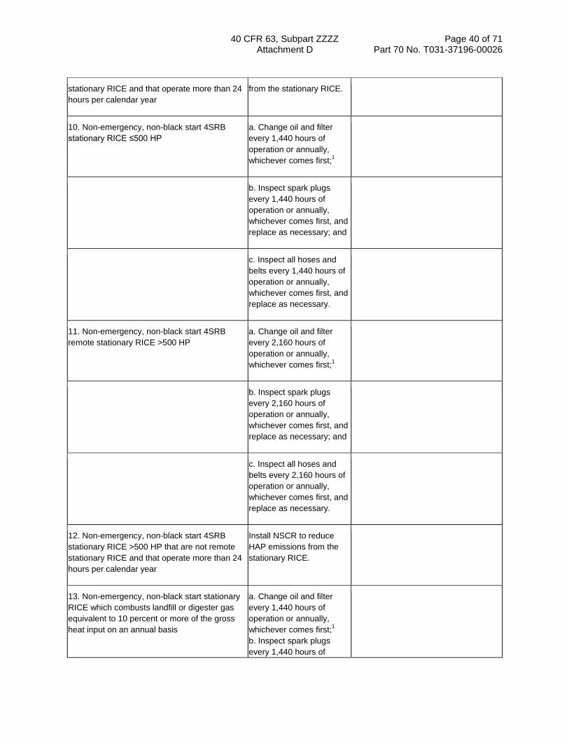
40 CFR 63, Subpart ZZZZ Page 40 of 71 Attachment D Part 70 No. T031-37196-00026
stationary RICE and that operate more than 24 hours per calendar year
from the stationary RICE.
10. Non-emergency, non-black start 4SRB stationary RICE ≤500 HP
a. Change oil and filter every 1,440 hours of operation or annually, whichever comes first;1
b. Inspect spark plugs every 1,440 hours of operation or annually, whichever comes first, and replace as necessary; and
c. Inspect all hoses and belts every 1,440 hours of operation or annually, whichever comes first, and replace as necessary.
11. Non-emergency, non-black start 4SRB remote stationary RICE >500 HP
a. Change oil and filter every 2,160 hours of operation or annually, whichever comes first;1
b. Inspect spark plugs every 2,160 hours of operation or annually, whichever comes first, and replace as necessary; and
c. Inspect all hoses and belts every 2,160 hours of operation or annually, whichever comes first, and replace as necessary.
12. Non-emergency, non-black start 4SRB stationary RICE >500 HP that are not remote stationary RICE and that operate more than 24 hours per calendar year
Install NSCR to reduce HAP emissions from the stationary RICE.
13. Non-emergency, non-black start stationary RICE which combusts landfill or digester gas equivalent to 10 percent or more of the gross heat input on an annual basis
a. Change oil and filter every 1,440 hours of operation or annually, whichever comes first;1 b. Inspect spark plugs every 1,440 hours of

40 CFR 63, Subpart ZZZZ Page 41 of 71 Attachment D Part 70 No. T031-37196-00026
operation or annually, whichever comes first, and replace as necessary; and
c. Inspect all hoses and belts every 1,440 hours of operation or annually, whichever comes first, and replace as necessary.
1Sources have the option to utilize an oil analysis program as described in §63.6625(i) or (j) in order to extend the specified oil change requirement in Table 2d of this subpart.
2If an emergency engine is operating during an emergency and it is not possible to shut down the engine in order to perform the management practice requirements on the schedule required in Table 2d of this subpart, or if performing the management practice on the required schedule would otherwise pose an unacceptable risk under federal, state, or local law, the management practice can be delayed until the emergency is over or the unacceptable risk under federal, state, or local law has abated. The management practice should be performed as soon as practicable after the emergency has ended or the unacceptable risk under federal, state, or local law has abated. Sources must report any failure to perform the management practice on the schedule required and the federal, state or local law under which the risk was deemed unacceptable.
[78 FR 6709, Jan. 30, 2013]
Table 3 to Subpart ZZZZ of Part 63—Subsequent Performance Tests
As stated in §§63.6615 and 63.6620, you must comply with the following subsequent performance test requirements:
For each . . . Complying with the requirement to . . . You must . . .
1. New or reconstructed 2SLB stationary RICE >500 HP located at major sources; new or reconstructed 4SLB stationary RICE ≥250 HP located at major sources; and new or reconstructed CI stationary RICE >500 HP located at major sources
Reduce CO emissions and not using a CEMS
Conduct subsequent performance tests semiannually.1
2. 4SRB stationary RICE ≥5,000 HP located at major sources
Reduce formaldehyde emissions
Conduct subsequent performance tests semiannually.1
3. Stationary RICE >500 HP located at major sources and new or reconstructed 4SLB stationary RICE 250≤HP≤500 located at major sources
Limit the concentration of formaldehyde in the stationary RICE exhaust
Conduct subsequent performance tests semiannually.1
4. Existing non-emergency, non-black start CI stationary RICE >500 HP that are not limited use stationary RICE
Limit or reduce CO emissions and not using a CEMS
Conduct subsequent performance tests every 8,760 hours or 3 years, whichever comes first.

40 CFR 63, Subpart ZZZZ Page 42 of 71 Attachment D Part 70 No. T031-37196-00026
5. Existing non-emergency, non-black start CI stationary RICE >500 HP that are limited use stationary RICE
Limit or reduce CO emissions and not using a CEMS
Conduct subsequent performance tests every 8,760 hours or 5 years, whichever comes first.
1After you have demonstrated compliance for two consecutive tests, you may reduce the frequency of subsequent performance tests to annually. If the results of any subsequent annual performance test indicate the stationary RICE is not in compliance with the CO or formaldehyde emission limitation, or you deviate from any of your operating limitations, you must resume semiannual performance tests.
[78 FR 6711, Jan. 30, 2013]
Table 4 to Subpart ZZZZ of Part 63—Requirements for Performance Tests
As stated in §§63.6610, 63.6611, 63.6620, and 63.6640, you must comply with the following requirements for performance tests for stationary RICE:
For each . . .
Complying with the requirement to . . . You must . . . Using . . .
According to the following requirements . . .
1. 2SLB, 4SLB, and CI stationary RICE
a. reduce CO emissions
i. Select the sampling port location and the number/location of traverse points at the inlet and outlet of the control device; and
(a) For CO and O2 measurement, ducts ≤6 inches in diameter may be sampled at a single point located at the duct centroid and ducts >6 and ≤12 inches in diameter may be sampled at 3 traverse points located at 16.7, 50.0, and 83.3% of the measurement line (`3-point long line'). If the duct is >12 inches in diameter and the sampling port location meets the two and half-diameter criterion of Section 11.1.1 of Method 1 of 40 CFR part 60, appendix A-1, the duct may be sampled at `3-point long line'; otherwise, conduct the stratification testing and select sampling points according to Section 8.1.2 of Method 7E of 40 CFR part 60, appendix A-4.
ii. Measure the O2 at the inlet and outlet of the control device; and
(1) Method 3 or 3A or 3B of 40 CFR part 60, appendix A-2, or ASTM Method D6522-00 (Reapproved 2005)ac (heated probe not necessary)
(b) Measurements to determine O2 must be made at the same time as the measurements for CO concentration.

40 CFR 63, Subpart ZZZZ Page 43 of 71 Attachment D Part 70 No. T031-37196-00026
iii. Measure the CO at the inlet and the outlet of the control device
(1) ASTM D6522-00 (Reapproved 2005)abc (heated probe not necessary) or Method 10 of 40 CFR part 60, appendix A-4
(c) The CO concentration must be at 15 percent O2, dry basis.
2. 4SRB stationary RICE
a. reduce formaldehyde emissions
i. Select the sampling port location and the number/location of traverse points at the inlet and outlet of the control device; and
(a) For formaldehyde, O2, and moisture measurement, ducts ≤6 inches in diameter may be sampled at a single point located at the duct centroid and ducts >6 and ≤12 inches in diameter may be sampled at 3 traverse points located at 16.7, 50.0, and 83.3% of the measurement line (`3-point long line'). If the duct is >12 inches in diameter and the sampling port location meets the two and half-diameter criterion of Section 11.1.1 of Method 1 of 40 CFR part 60, appendix A, the duct may be sampled at `3-point long line'; otherwise, conduct the stratification testing and select sampling points according to Section 8.1.2 of Method 7E of 40 CFR part 60, appendix A.
ii. Measure O2 at the inlet and outlet of the control device; and
(1) Method 3 or 3A or 3B of 40 CFR part 60, appendix A-2, or ASTM Method D6522-00 (Reapproved 2005)a (heated probe not necessary)
(a) Measurements to determine O2 concentration must be made at the same time as the measurements for formaldehyde or THC concentration.
iii. Measure moisture content at the inlet and outlet of the control device; and
(1) Method 4 of 40 CFR part 60, appendix A-3, or Method 320 of 40 CFR part 63, appendix A, or ASTM D 6348-03a
(a) Measurements to determine moisture content must be made at the same time and location as the measurements for formaldehyde or THC concentration.
iv. If demonstrating compliance with the formaldehyde percent reduction requirement, measure formalde-hyde at the inlet and the outlet of the control
(1) Method 320 or 323 of 40 CFR part 63, appendix A; or ASTM D6348-03a, provided in ASTM D6348-03 Annex A5 (Analyte Spiking Technique), the percent R must be greater than
(a) Formaldehyde concentration must be at 15 percent O2, dry basis. Results of this test consist of the average of the three 1-hour or longer runs.
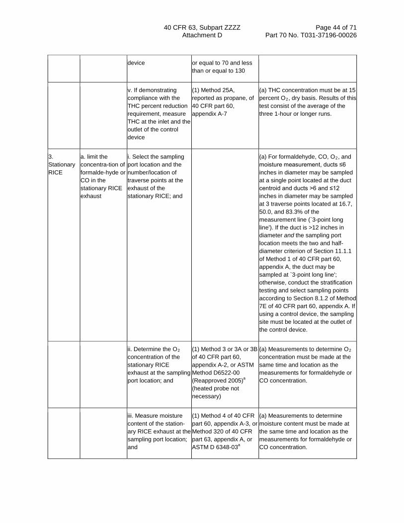
40 CFR 63, Subpart ZZZZ Page 44 of 71 Attachment D Part 70 No. T031-37196-00026
device or equal to 70 and less than or equal to 130
v. If demonstrating compliance with the THC percent reduction requirement, measure THC at the inlet and the outlet of the control device
(1) Method 25A, reported as propane, of 40 CFR part 60, appendix A-7
(a) THC concentration must be at 15 percent O2, dry basis. Results of this test consist of the average of the three 1-hour or longer runs.
3. Stationary RICE
a. limit the concentra-tion of formalde-hyde or CO in the stationary RICE exhaust
i. Select the sampling port location and the number/location of traverse points at the exhaust of the stationary RICE; and
(a) For formaldehyde, CO, O2, and moisture measurement, ducts ≤6 inches in diameter may be sampled at a single point located at the duct centroid and ducts >6 and ≤12 inches in diameter may be sampled at 3 traverse points located at 16.7, 50.0, and 83.3% of the measurement line (`3-point long line'). If the duct is >12 inches in diameter and the sampling port location meets the two and half-diameter criterion of Section 11.1.1 of Method 1 of 40 CFR part 60, appendix A, the duct may be sampled at `3-point long line'; otherwise, conduct the stratification testing and select sampling points according to Section 8.1.2 of Method 7E of 40 CFR part 60, appendix A. If using a control device, the sampling site must be located at the outlet of the control device.
ii. Determine the O2 concentration of the stationary RICE exhaust at the sampling port location; and
(1) Method 3 or 3A or 3B of 40 CFR part 60, appendix A-2, or ASTM Method D6522-00 (Reapproved 2005)a (heated probe not necessary)
(a) Measurements to determine O2 concentration must be made at the same time and location as the measurements for formaldehyde or CO concentration.
iii. Measure moisture content of the station-ary RICE exhaust at the sampling port location; and
(1) Method 4 of 40 CFR part 60, appendix A-3, or Method 320 of 40 CFR part 63, appendix A, or ASTM D 6348-03a
(a) Measurements to determine moisture content must be made at the same time and location as the measurements for formaldehyde or CO concentration.

40 CFR 63, Subpart ZZZZ Page 45 of 71 Attachment D Part 70 No. T031-37196-00026
iv. Measure formalde-hyde at the exhaust of the station-ary RICE; or
(1) Method 320 or 323 of 40 CFR part 63, appendix A; or ASTM D6348-03a, provided in ASTM D6348-03 Annex A5 (Analyte Spiking Technique), the percent R must be greater than or equal to 70 and less than or equal to 130
(a) Formaldehyde concentration must be at 15 percent O2, dry basis. Results of this test consist of the average of the three 1-hour or longer runs.
v. measure CO at the exhaust of the station-ary RICE
(1) Method 10 of 40 CFR part 60, appendix A-4, ASTM Method D6522-00 (2005)ac, Method 320 of 40 CFR part 63, appendix A, or ASTM D6348-03a
(a) CO concentration must be at 15 percent O2, dry basis. Results of this test consist of the average of the three 1-hour or longer runs.
aYou may also use Methods 3A and 10 as options to ASTM-D6522-00 (2005). You may obtain a copy of ASTM-D6522-00 (2005) from at least one of the following addresses: American Society for Testing and Materials, 100 Barr Harbor Drive, West Conshohocken, PA 19428-2959, or University Microfilms International, 300 North Zeeb Road, Ann Arbor, MI 48106.
bYou may obtain a copy of ASTM-D6348-03 from at least one of the following addresses: American Society for Testing and Materials, 100 Barr Harbor Drive, West Conshohocken, PA 19428-2959, or University Microfilms International, 300 North Zeeb Road, Ann Arbor, MI 48106.
[79 FR 11290, Feb. 27, 2014]
Table 5 to Subpart ZZZZ of Part 63—Initial Compliance With Emission Limitations, Operating Limitations, and Other Requirements
As stated in §§63.6612, 63.6625 and 63.6630, you must initially comply with the emission and operating limitations as required by the following:
For each . . . Complying with the requirement to . . .
You have demonstrated initial compliance if . . .
1. New or reconstructed non-emergency 2SLB stationary RICE >500 HP located at a major source of HAP, new or reconstructed non-emergency 4SLB stationary RICE ≥250 HP located at a major source of HAP, non-emergency stationary CI RICE >500 HP located at a major source of HAP, and existing non-emergency stationary CI RICE >500 HP located at an area source of HAP
a. Reduce CO emissions and using oxidation catalyst, and using a CPMS
i. The average reduction of emissions of CO determined from the initial performance test achieves the required CO percent reduction; and ii. You have installed a CPMS to continuously monitor catalyst inlet temperature according to the requirements in §63.6625(b); and iii. You have recorded the catalyst pressure drop and catalyst inlet temperature during the initial performance test.

40 CFR 63, Subpart ZZZZ Page 46 of 71 Attachment D Part 70 No. T031-37196-00026
2. Non-emergency stationary CI RICE >500 HP located at a major source of HAP, and existing non-emergency stationary CI RICE >500 HP located at an area source of HAP
a. Limit the concentration of CO, using oxidation catalyst, and using a CPMS
i. The average CO concentration determined from the initial performance test is less than or equal to the CO emission limitation; and
ii. You have installed a CPMS to continuously monitor catalyst inlet temperature according to the requirements in §63.6625(b); and
iii. You have recorded the catalyst pressure drop and catalyst inlet temperature during the initial performance test.
3. New or reconstructed non-emergency 2SLB stationary RICE >500 HP located at a major source of HAP, new or reconstructed non-emergency 4SLB stationary RICE ≥250 HP located at a major source of HAP, non-emergency stationary CI RICE >500 HP located at a major source of HAP, and existing non-emergency stationary CI RICE >500 HP located at an area source of HAP
a. Reduce CO emissions and not using oxidation catalyst
i. The average reduction of emissions of CO determined from the initial performance test achieves the required CO percent reduction; and ii. You have installed a CPMS to continuously monitor operating parameters approved by the Administrator (if any) according to the requirements in §63.6625(b); and iii. You have recorded the approved operating parameters (if any) during the initial performance test.
4. Non-emergency stationary CI RICE >500 HP located at a major source of HAP, and existing non-emergency stationary CI RICE >500 HP located at an area source of HAP
a. Limit the concentration of CO, and not using oxidation catalyst
i. The average CO concentration determined from the initial performance test is less than or equal to the CO emission limitation; and ii. You have installed a CPMS to continuously monitor operating parameters approved by the Administrator (if any) according to the requirements in §63.6625(b); and
iii. You have recorded the approved operating parameters (if any) during the initial performance test.
5. New or reconstructed non-emergency 2SLB stationary RICE >500 HP located at a major source of HAP, new or reconstructed non-emergency 4SLB stationary RICE ≥250 HP located at a major source of HAP, non-emergency stationary CI RICE >500 HP located at a major source of HAP, and existing non-
a. Reduce CO emissions, and using a CEMS
i. You have installed a CEMS to continuously monitor CO and either O2 or CO2 at both the inlet and outlet of the oxidation catalyst according to the requirements in §63.6625(a); and ii. You have conducted a performance evaluation of your CEMS using PS 3 and

40 CFR 63, Subpart ZZZZ Page 47 of 71 Attachment D Part 70 No. T031-37196-00026
emergency stationary CI RICE >500 HP located at an area source of HAP
4A of 40 CFR part 60, appendix B; and
iii. The average reduction of CO calculated using §63.6620 equals or exceeds the required percent reduction. The initial test comprises the first 4-hour period after successful validation of the CEMS. Compliance is based on the average percent reduction achieved during the 4-hour period.
6. Non-emergency stationary CI RICE >500 HP located at a major source of HAP, and existing non-emergency stationary CI RICE >500 HP located at an area source of HAP
a. Limit the concentration of CO, and using a CEMS
i. You have installed a CEMS to continuously monitor CO and either O2 or CO2 at the outlet of the oxidation catalyst according to the requirements in §63.6625(a); and
ii. You have conducted a performance evaluation of your CEMS using PS 3 and 4A of 40 CFR part 60, appendix B; and
iii. The average concentration of CO calculated using §63.6620 is less than or equal to the CO emission limitation. The initial test comprises the first 4-hour period after successful validation of the CEMS. Compliance is based on the average concentration measured during the 4-hour period.
7. Non-emergency 4SRB stationary RICE >500 HP located at a major source of HAP
a. Reduce formaldehyde emissions and using NSCR
i. The average reduction of emissions of formaldehyde determined from the initial performance test is equal to or greater than the required formaldehyde percent reduction, or the average reduction of emissions of THC determined from the initial performance test is equal to or greater than 30 percent; and
ii. You have installed a CPMS to continuously monitor catalyst inlet temperature according to the requirements in §63.6625(b); and
iii. You have recorded the catalyst pressure drop and catalyst inlet temperature during the initial performance test.

40 CFR 63, Subpart ZZZZ Page 48 of 71 Attachment D Part 70 No. T031-37196-00026
8. Non-emergency 4SRB stationary RICE >500 HP located at a major source of HAP
a. Reduce formaldehyde emissions and not using NSCR
i. The average reduction of emissions of formaldehyde determined from the initial performance test is equal to or greater than the required formaldehyde percent reduction or the average reduction of emissions of THC determined from the initial performance test is equal to or greater than 30 percent; and
ii. You have installed a CPMS to continuously monitor operating parameters approved by the Administrator (if any) according to the requirements in §63.6625(b); and
iii. You have recorded the approved operating parameters (if any) during the initial performance test.
9. New or reconstructed non-emergency stationary RICE >500 HP located at a major source of HAP, new or reconstructed non-emergency 4SLB stationary RICE 250≤HP≤500 located at a major source of HAP, and existing non-emergency 4SRB stationary RICE >500 HP located at a major source of HAP
a. Limit the concentration of formaldehyde in the stationary RICE exhaust and using oxidation catalyst or NSCR
i. The average formaldehyde concentration, corrected to 15 percent O2, dry basis, from the three test runs is less than or equal to the formaldehyde emission limitation; and ii. You have installed a CPMS to continuously monitor catalyst inlet temperature according to the requirements in §63.6625(b); and
iii. You have recorded the catalyst pressure drop and catalyst inlet temperature during the initial performance test.
10. New or reconstructed non-emergency stationary RICE >500 HP located at a major source of HAP, new or reconstructed non-emergency 4SLB stationary RICE 250≤HP≤500 located at a major source of HAP, and existing non-emergency 4SRB stationary RICE >500 HP located at a major source of HAP
a. Limit the concentration of formaldehyde in the stationary RICE exhaust and not using oxidation catalyst or NSCR
i. The average formaldehyde concentration, corrected to 15 percent O2, dry basis, from the three test runs is less than or equal to the formaldehyde emission limitation; and ii. You have installed a CPMS to continuously monitor operating parameters approved by the Administrator (if any) according to the requirements in §63.6625(b); and
iii. You have recorded the approved operating parameters (if any) during the initial performance test.
11. Existing non-emergency stationary RICE 100≤HP≤500 located at a major source of HAP, and existing non-emergency stationary CI RICE
a. Reduce CO emissions
i. The average reduction of emissions of CO or formaldehyde, as applicable determined from the initial performance test

40 CFR 63, Subpart ZZZZ Page 49 of 71 Attachment D Part 70 No. T031-37196-00026
300<HP≤500 located at an area source of HAP is equal to or greater than the required CO or formaldehyde, as applicable, percent reduction.
12. Existing non-emergency stationary RICE 100≤HP≤500 located at a major source of HAP, and existing non-emergency stationary CI RICE 300<HP≤500 located at an area source of HAP
a. Limit the concentration of formaldehyde or CO in the stationary RICE exhaust
i. The average formaldehyde or CO concentration, as applicable, corrected to 15 percent O2, dry basis, from the three test runs is less than or equal to the formaldehyde or CO emission limitation, as applicable.
13. Existing non-emergency 4SLB stationary RICE >500 HP located at an area source of HAP that are not remote stationary RICE and that are operated more than 24 hours per calendar year
a. Install an oxidation catalyst
i. You have conducted an initial compliance demonstration as specified in §63.6630(e) to show that the average reduction of emissions of CO is 93 percent or more, or the average CO concentration is less than or equal to 47 ppmvd at 15 percent O2;
ii. You have installed a CPMS to continuously monitor catalyst inlet temperature according to the requirements in §63.6625(b), or you have installed equipment to automatically shut down the engine if the catalyst inlet temperature exceeds 1350 °F.
14. Existing non-emergency 4SRB stationary RICE >500 HP located at an area source of HAP that are not remote stationary RICE and that are operated more than 24 hours per calendar year
a. Install NSCR i. You have conducted an initial compliance demonstration as specified in §63.6630(e) to show that the average reduction of emissions of CO is 75 percent or more, the average CO concentration is less than or equal to 270 ppmvd at 15 percent O2, or the average reduction of emissions of THC is 30 percent or more;
ii. You have installed a CPMS to continuously monitor catalyst inlet temperature according to the requirements in §63.6625(b), or you have installed equipment to automatically shut down the engine if the catalyst inlet temperature exceeds 1250 °F.
[78 FR 6712, Jan. 30, 2013]
Table 6 to Subpart ZZZZ of Part 63—Continuous Compliance With Emission Limitations, and Other Requirements
As stated in §63.6640, you must continuously comply with the emissions and operating limitations and work or management practices as required by the following:

40 CFR 63, Subpart ZZZZ Page 50 of 71 Attachment D Part 70 No. T031-37196-00026
For each . . . Complying with the requirement to . . .
You must demonstrate continuous compliance by . . .
1. New or reconstructed non-emergency 2SLB stationary RICE >500 HP located at a major source of HAP, new or reconstructed non-emergency 4SLB stationary RICE ≥250 HP located at a major source of HAP, and new or reconstructed non-emergency CI stationary RICE >500 HP located at a major source of HAP
a. Reduce CO emissions and using an oxidation catalyst, and using a CPMS
i. Conducting semiannual performance tests for CO to demonstrate that the required CO percent reduction is achieveda; and ii. Collecting the catalyst inlet temperature data according to §63.6625(b); and iii. Reducing these data to 4-hour rolling averages; and
iv. Maintaining the 4-hour rolling averages within the operating limitations for the catalyst inlet temperature; and
v. Measuring the pressure drop across the catalyst once per month and demonstrating that the pressure drop across the catalyst is within the operating limitation established during the performance test.
2. New or reconstructed non-emergency 2SLB stationary RICE >500 HP located at a major source of HAP, new or reconstructed non-emergency 4SLB stationary RICE ≥250 HP located at a major source of HAP, and new or reconstructed non-emergency CI stationary RICE >500 HP located at a major source of HAP
a. Reduce CO emissions and not using an oxidation catalyst, and using a CPMS
i. Conducting semiannual performance tests for CO to demonstrate that the required CO percent reduction is achieveda; and ii. Collecting the approved operating parameter (if any) data according to §63.6625(b); and iii. Reducing these data to 4-hour rolling averages; and
iv. Maintaining the 4-hour rolling averages within the operating limitations for the operating parameters established during the performance test.

40 CFR 63, Subpart ZZZZ Page 51 of 71 Attachment D Part 70 No. T031-37196-00026
3. New or reconstructed non-emergency 2SLB stationary RICE >500 HP located at a major source of HAP, new or reconstructed non-emergency 4SLB stationary RICE ≥250 HP located at a major source of HAP, new or reconstructed non-emergency stationary CI RICE >500 HP located at a major source of HAP, and existing non-emergency stationary CI RICE >500 HP
a. Reduce CO emissions or limit the concentration of CO in the stationary RICE exhaust, and using a CEMS
i. Collecting the monitoring data according to §63.6625(a), reducing the measurements to 1-hour averages, calculating the percent reduction or concentration of CO emissions according to §63.6620; and ii. Demonstrating that the catalyst achieves the required percent reduction of CO emissions over the 4-hour averaging period, or that the emission remain at or below the CO concentration limit; and
iii. Conducting an annual RATA of your CEMS using PS 3 and 4A of 40 CFR part 60, appendix B, as well as daily and periodic data quality checks in accordance with 40 CFR part 60, appendix F, procedure 1.
4. Non-emergency 4SRB stationary RICE >500 HP located at a major source of HAP
a. Reduce formaldehyde emissions and using NSCR
i. Collecting the catalyst inlet temperature data according to §63.6625(b); and
ii. Reducing these data to 4-hour rolling averages; and
iii. Maintaining the 4-hour rolling averages within the operating limitations for the catalyst inlet temperature; and
iv. Measuring the pressure drop across the catalyst once per month and demonstrating that the pressure drop across the catalyst is within the operating limitation established during the performance test.
5. Non-emergency 4SRB stationary RICE >500 HP located at a major source of HAP
a. Reduce formaldehyde emissions and not using NSCR
i. Collecting the approved operating parameter (if any) data according to §63.6625(b); and
ii. Reducing these data to 4-hour rolling averages; and
iii. Maintaining the 4-hour rolling averages within the operating limitations for the

40 CFR 63, Subpart ZZZZ Page 52 of 71 Attachment D Part 70 No. T031-37196-00026
operating parameters established during the performance test.
6. Non-emergency 4SRB stationary RICE with a brake HP ≥5,000 located at a major source of HAP
a. Reduce formaldehyde emissions
Conducting semiannual performance tests for formaldehyde to demonstrate that the required formaldehyde percent reduction is achieved, or to demonstrate that the average reduction of emissions of THC determined from the performance test is equal to or greater than 30 percent.a
7. New or reconstructed non-emergency stationary RICE >500 HP located at a major source of HAP and new or reconstructed non-emergency 4SLB stationary RICE 250≤HP≤500 located at a major source of HAP
a. Limit the concentration of formaldehyde in the stationary RICE exhaust and using oxidation catalyst or NSCR
i. Conducting semiannual performance tests for formaldehyde to demonstrate that your emissions remain at or below the formaldehyde concentration limita; and ii. Collecting the catalyst inlet temperature data according to §63.6625(b); and
iii. Reducing these data to 4-hour rolling averages; and
iv. Maintaining the 4-hour rolling averages within the operating limitations for the catalyst inlet temperature; and
v. Measuring the pressure drop across the catalyst once per month and demonstrating that the pressure drop across the catalyst is within the operating limitation established during the performance test.
8. New or reconstructed non-emergency stationary RICE >500 HP located at a major source of HAP and new or reconstructed non-emergency 4SLB stationary RICE 250≤HP≤500 located at a major source of HAP
a. Limit the concentration of formaldehyde in the stationary RICE exhaust and not using oxidation catalyst or NSCR
i. Conducting semiannual performance tests for formaldehyde to demonstrate that your emissions remain at or below the formaldehyde concentration limita; and ii. Collecting the approved operating parameter (if any) data according to §63.6625(b); and
iii. Reducing these data to 4-hour rolling averages; and
iv. Maintaining the 4-hour rolling averages within the operating limitations for the operating parameters established during the performance test.

40 CFR 63, Subpart ZZZZ Page 53 of 71 Attachment D Part 70 No. T031-37196-00026
9. Existing emergency and black start stationary RICE ≤500 HP located at a major source of HAP, existing non-emergency stationary RICE <100 HP located at a major source of HAP, existing emergency and black start stationary RICE located at an area source of HAP, existing non-emergency stationary CI RICE ≤300 HP located at an area source of HAP, existing non-emergency 2SLB stationary RICE located at an area source of HAP, existing non-emergency stationary SI RICE located at an area source of HAP which combusts landfill or digester gas equivalent to 10 percent or more of the gross heat input on an annual basis, existing non-emergency 4SLB and 4SRB stationary RICE ≤500 HP located at an area source of HAP, existing non-emergency 4SLB and 4SRB stationary RICE >500 HP located at an area source of HAP that operate 24 hours or less per calendar year, and existing non-emergency 4SLB and 4SRB stationary RICE >500 HP located at an area source of HAP that are remote stationary RICE
a. Work or Management practices
i. Operating and maintaining the stationary RICE according to the manufacturer's emission-related operation and maintenance instructions; or ii. Develop and follow your own maintenance plan which must provide to the extent practicable for the maintenance and operation of the engine in a manner consistent with good air pollution control practice for minimizing emissions.
10. Existing stationary CI RICE >500 HP that are not limited use stationary RICE
a. Reduce CO emissions, or limit the concentration of CO in the stationary RICE exhaust, and using oxidation catalyst
i. Conducting performance tests every 8,760 hours or 3 years, whichever comes first, for CO or formaldehyde, as appropriate, to demonstrate that the required CO or formaldehyde, as appropriate, percent reduction is achieved or that your emissions remain at or below the CO or formaldehyde concentration limit; and
ii. Collecting the catalyst inlet temperature data according to §63.6625(b); and
iii. Reducing these data to 4-hour rolling averages; and
iv. Maintaining the 4-hour rolling averages within the operating limitations for the catalyst inlet temperature; and
v. Measuring the pressure drop across the catalyst once per month and demonstrating that the pressure drop across the catalyst is within the operating limitation established during the
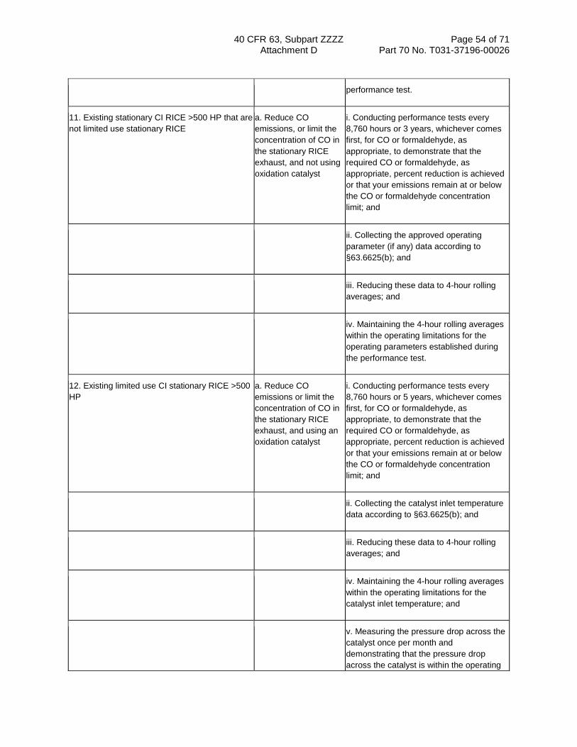
40 CFR 63, Subpart ZZZZ Page 54 of 71 Attachment D Part 70 No. T031-37196-00026
performance test.
11. Existing stationary CI RICE >500 HP that are not limited use stationary RICE
a. Reduce CO emissions, or limit the concentration of CO in the stationary RICE exhaust, and not using oxidation catalyst
i. Conducting performance tests every 8,760 hours or 3 years, whichever comes first, for CO or formaldehyde, as appropriate, to demonstrate that the required CO or formaldehyde, as appropriate, percent reduction is achieved or that your emissions remain at or below the CO or formaldehyde concentration limit; and
ii. Collecting the approved operating parameter (if any) data according to §63.6625(b); and
iii. Reducing these data to 4-hour rolling averages; and
iv. Maintaining the 4-hour rolling averages within the operating limitations for the operating parameters established during the performance test.
12. Existing limited use CI stationary RICE >500 HP
a. Reduce CO emissions or limit the concentration of CO in the stationary RICE exhaust, and using an oxidation catalyst
i. Conducting performance tests every 8,760 hours or 5 years, whichever comes first, for CO or formaldehyde, as appropriate, to demonstrate that the required CO or formaldehyde, as appropriate, percent reduction is achieved or that your emissions remain at or below the CO or formaldehyde concentration limit; and
ii. Collecting the catalyst inlet temperature data according to §63.6625(b); and
iii. Reducing these data to 4-hour rolling averages; and
iv. Maintaining the 4-hour rolling averages within the operating limitations for the catalyst inlet temperature; and
v. Measuring the pressure drop across the catalyst once per month and demonstrating that the pressure drop across the catalyst is within the operating

40 CFR 63, Subpart ZZZZ Page 55 of 71 Attachment D Part 70 No. T031-37196-00026
limitation established during the performance test.
13. Existing limited use CI stationary RICE >500 HP
a. Reduce CO emissions or limit the concentration of CO in the stationary RICE exhaust, and not using an oxidation catalyst
i. Conducting performance tests every 8,760 hours or 5 years, whichever comes first, for CO or formaldehyde, as appropriate, to demonstrate that the required CO or formaldehyde, as appropriate, percent reduction is achieved or that your emissions remain at or below the CO or formaldehyde concentration limit; and
ii. Collecting the approved operating parameter (if any) data according to §63.6625(b); and
iii. Reducing these data to 4-hour rolling averages; and
iv. Maintaining the 4-hour rolling averages within the operating limitations for the operating parameters established during the performance test.
14. Existing non-emergency 4SLB stationary RICE >500 HP located at an area source of HAP that are not remote stationary RICE and that are operated more than 24 hours per calendar year
a. Install an oxidation catalyst
i. Conducting annual compliance demonstrations as specified in §63.6640(c) to show that the average reduction of emissions of CO is 93 percent or more, or the average CO concentration is less than or equal to 47 ppmvd at 15 percent O2; and either ii. Collecting the catalyst inlet temperature data according to §63.6625(b), reducing these data to 4-hour rolling averages; and maintaining the 4-hour rolling averages within the limitation of greater than 450 °F and less than or equal to 1350 °F for the catalyst inlet temperature; or iii. Immediately shutting down the engine if the catalyst inlet temperature exceeds 1350 °F.
15. Existing non-emergency 4SRB stationary RICE >500 HP located at an area source of HAP that are not remote stationary RICE and that are operated more than 24 hours per calendar year
a. Install NSCR i. Conducting annual compliance demonstrations as specified in §63.6640(c) to show that the average reduction of emissions of CO is 75 percent or more, the average CO concentration is less than or equal to 270 ppmvd at 15 percent O2, or

40 CFR 63, Subpart ZZZZ Page 56 of 71 Attachment D Part 70 No. T031-37196-00026
the average reduction of emissions of THC is 30 percent or more; and either ii. Collecting the catalyst inlet temperature data according to §63.6625(b), reducing these data to 4-hour rolling averages; and maintaining the 4-hour rolling averages within the limitation of greater than or equal to 750 °F and less than or equal to 1250 °F for the catalyst inlet temperature; or iii. Immediately shutting down the engine if the catalyst inlet temperature exceeds 1250 °F.
aAfter you have demonstrated compliance for two consecutive tests, you may reduce the frequency of subsequent performance tests to annually. If the results of any subsequent annual performance test indicate the stationary RICE is not in compliance with the CO or formaldehyde emission limitation, or you deviate from any of your operating limitations, you must resume semiannual performance tests.
[78 FR 6715, Jan. 30, 2013]
Table 7 to Subpart ZZZZ of Part 63—Requirements for Reports
As stated in §63.6650, you must comply with the following requirements for reports:
For each . . .
You must submit a . . . The report must contain . . .
You must submit the report . . .
1. Existing non-emergency, non-black start stationary RICE 100≤HP≤500 located at a major source of HAP; existing non-emergency, non-black start stationary CI RICE >500 HP located at a major source of HAP; existing non-emergency 4SRB stationary RICE >500 HP located at a major source of HAP; existing non-emergency, non-black start stationary CI RICE >300 HP located at an area source of HAP; new or reconstructed non-emergency stationary RICE >500 HP located at a major source of HAP; and new or reconstructed non-emergency 4SLB stationary RICE 250≤HP≤500 located at a major source of HAP
Compliance report
a. If there are no deviations from any emission limitations or operating limitations that apply to you, a statement that there were no deviations from the emission limitations or operating limitations during the reporting period. If there were no periods during which the CMS, including CEMS and CPMS, was out-of-control, as specified in §63.8(c)(7), a statement that there were not periods during which the CMS was out-of-control during the reporting period; or
i. Semiannually according to the requirements in §63.6650(b)(1)-(5) for engines that are not limited use stationary RICE subject to numerical emission limitations; and ii. Annually according to the requirements in §63.6650(b)(6)-(9) for engines that are limited use stationary RICE subject to numerical emission limitations.

40 CFR 63, Subpart ZZZZ Page 57 of 71 Attachment D Part 70 No. T031-37196-00026
b. If you had a deviation from any emission limitation or operating limitation during the reporting period, the information in §63.6650(d). If there were periods during which the CMS, including CEMS and CPMS, was out-of-control, as specified in §63.8(c)(7), the information in §63.6650(e); or
i. Semiannually according to the requirements in §63.6650(b).
c. If you had a malfunction during the reporting period, the information in §63.6650(c)(4).
i. Semiannually according to the requirements in §63.6650(b).
2. New or reconstructed non-emergency stationary RICE that combusts landfill gas or digester gas equivalent to 10 percent or more of the gross heat input on an annual basis
Report a. The fuel flow rate of each fuel and the heating values that were used in your calculations, and you must demonstrate that the percentage of heat input provided by landfill gas or digester gas, is equivalent to 10 percent or more of the gross heat input on an annual basis; and
i. Annually, according to the requirements in §63.6650.
b. The operating limits provided in your federally enforceable permit, and any deviations from these limits; and
i. See item 2.a.i.
c. Any problems or errors suspected with the meters.
i. See item 2.a.i.
3. Existing non-emergency, non-black start 4SLB and 4SRB stationary RICE >500 HP located at an area source of HAP that are not remote stationary RICE and that operate more than 24 hours per calendar year
Compliance report
a. The results of the annual compliance demonstration, if conducted during the reporting period.
i. Semiannually according to the requirements in §63.6650(b)(1)-(5).
4. Emergency stationary RICE that operate or are contractually obligated to be available for more than 15 hours per year for the purposes specified in §63.6640(f)(2)(ii) and (iii) or that operate for the purposes specified in §63.6640(f)(4)(ii)
Report a. The information in §63.6650(h)(1) i. annually according to the requirements in §63.6650(h)(2)-(3).
[78 FR 6719, Jan. 30, 2013]
Table 8 to Subpart ZZZZ of Part 63—Applicability of General Provisions to Subpart ZZZZ.
As stated in §63.6665, you must comply with the following applicable general provisions.

40 CFR 63, Subpart ZZZZ Page 58 of 71 Attachment D Part 70 No. T031-37196-00026
General provisions citation Subject of citation Applies to subpart Explanation
§63.1 General applicability of the General Provisions
Yes.
§63.2 Definitions Yes Additional terms defined in §63.6675.
§63.3 Units and abbreviations Yes.
§63.4 Prohibited activities and circumvention
Yes.
§63.5 Construction and reconstruction Yes.
§63.6(a) Applicability Yes.
§63.6(b)(1)-(4) Compliance dates for new and reconstructed sources
Yes.
§63.6(b)(5) Notification Yes.
§63.6(b)(6) [Reserved]
§63.6(b)(7) Compliance dates for new and reconstructed area sources that become major sources
Yes.
§63.6(c)(1)-(2) Compliance dates for existing sources
Yes.
§63.6(c)(3)-(4) [Reserved]
§63.6(c)(5) Compliance dates for existing area sources that become major sources
Yes.
§63.6(d) [Reserved]
§63.6(e) Operation and maintenance No.
§63.6(f)(1) Applicability of standards No.

40 CFR 63, Subpart ZZZZ Page 59 of 71 Attachment D Part 70 No. T031-37196-00026
§63.6(f)(2) Methods for determining compliance
Yes.
§63.6(f)(3) Finding of compliance Yes.
§63.6(g)(1)-(3) Use of alternate standard Yes.
§63.6(h) Opacity and visible emission standards
No Subpart ZZZZ does not contain opacity or visible emission standards.
§63.6(i) Compliance extension procedures and criteria
Yes.
§63.6(j) Presidential compliance exemption Yes.
§63.7(a)(1)-(2) Performance test dates Yes Subpart ZZZZ contains performance test dates at §§63.6610, 63.6611, and 63.6612.
§63.7(a)(3) CAA section 114 authority Yes.
§63.7(b)(1) Notification of performance test Yes Except that §63.7(b)(1) only applies as specified in §63.6645.
§63.7(b)(2) Notification of rescheduling Yes Except that §63.7(b)(2) only applies as specified in §63.6645.
§63.7(c) Quality assurance/test plan Yes Except that §63.7(c) only applies as specified in §63.6645.
§63.7(d) Testing facilities Yes.
§63.7(e)(1) Conditions for conducting performance tests
No. Subpart ZZZZ specifies conditions for conducting performance tests at §63.6620.
§63.7(e)(2) Conduct of performance tests and reduction of data
Yes Subpart ZZZZ specifies test methods at §63.6620.
§63.7(e)(3) Test run duration Yes.
§63.7(e)(4) Administrator may require other testing under section 114 of the CAA
Yes.

40 CFR 63, Subpart ZZZZ Page 60 of 71 Attachment D Part 70 No. T031-37196-00026
§63.7(f) Alternative test method provisions Yes.
§63.7(g) Performance test data analysis, recordkeeping, and reporting
Yes.
§63.7(h) Waiver of tests Yes.
§63.8(a)(1) Applicability of monitoring requirements
Yes Subpart ZZZZ contains specific requirements for monitoring at §63.6625.
§63.8(a)(2) Performance specifications Yes.
§63.8(a)(3) [Reserved]
§63.8(a)(4) Monitoring for control devices No.
§63.8(b)(1) Monitoring Yes.
§63.8(b)(2)-(3) Multiple effluents and multiple monitoring systems
Yes.
§63.8(c)(1) Monitoring system operation and maintenance
Yes.
§63.8(c)(1)(i) Routine and predictable SSM No
§63.8(c)(1)(ii) SSM not in Startup Shutdown Malfunction Plan
Yes.
§63.8(c)(1)(iii) Compliance with operation and maintenance requirements
No
§63.8(c)(2)-(3) Monitoring system installation Yes.
§63.8(c)(4) Continuous monitoring system (CMS) requirements
Yes Except that subpart ZZZZ does not require Continuous Opacity Monitoring System (COMS).
§63.8(c)(5) COMS minimum procedures No Subpart ZZZZ does not require COMS.
§63.8(c)(6)-(8) CMS requirements Yes Except that subpart ZZZZ does not require COMS.

40 CFR 63, Subpart ZZZZ Page 61 of 71 Attachment D Part 70 No. T031-37196-00026
§63.8(d) CMS quality control Yes.
§63.8(e) CMS performance evaluation Yes Except for §63.8(e)(5)(ii), which applies to COMS.
Except that §63.8(e) only applies as specified in §63.6645.
§63.8(f)(1)-(5) Alternative monitoring method Yes Except that §63.8(f)(4) only applies as specified in §63.6645.
§63.8(f)(6) Alternative to relative accuracy test Yes Except that §63.8(f)(6) only applies as specified in §63.6645.
§63.8(g) Data reduction Yes Except that provisions for COMS are not applicable. Averaging periods for demonstrating compliance are specified at §§63.6635 and 63.6640.
§63.9(a) Applicability and State delegation of notification requirements
Yes.
§63.9(b)(1)-(5) Initial notifications Yes Except that §63.9(b)(3) is reserved.
Except that §63.9(b) only applies as specified in §63.6645.
§63.9(c) Request for compliance extension Yes Except that §63.9(c) only applies as specified in §63.6645.
§63.9(d) Notification of special compliance requirements for new sources
Yes Except that §63.9(d) only applies as specified in §63.6645.
§63.9(e) Notification of performance test Yes Except that §63.9(e) only applies as specified in §63.6645.
§63.9(f) Notification of visible emission (VE)/opacity test
No Subpart ZZZZ does not contain opacity or VE standards.
§63.9(g)(1) Notification of performance evaluation
Yes Except that §63.9(g) only applies as specified in §63.6645.

40 CFR 63, Subpart ZZZZ Page 62 of 71 Attachment D Part 70 No. T031-37196-00026
§63.9(g)(2) Notification of use of COMS data No Subpart ZZZZ does not contain opacity or VE standards.
§63.9(g)(3) Notification that criterion for alternative to RATA is exceeded
Yes If alternative is in use.
Except that §63.9(g) only applies as specified in §63.6645.
§63.9(h)(1)-(6) Notification of compliance status Yes Except that notifications for sources using a CEMS are due 30 days after completion of performance evaluations. §63.9(h)(4) is reserved.
Except that §63.9(h) only applies as specified in §63.6645.
§63.9(i) Adjustment of submittal deadlines Yes.
§63.9(j) Change in previous information Yes.
§63.10(a) Administrative provisions for recordkeeping/reporting
Yes.
§63.10(b)(1) Record retention Yes Except that the most recent 2 years of data do not have to be retained on site.
§63.10(b)(2)(i)-(v) Records related to SSM No.
§63.10(b)(2)(vi)-(xi)
Records Yes.
§63.10(b)(2)(xii) Record when under waiver Yes.
§63.10(b)(2)(xiii) Records when using alternative to RATA
Yes For CO standard if using RATA alternative.
§63.10(b)(2)(xiv) Records of supporting documentation
Yes.
§63.10(b)(3) Records of applicability determination
Yes.

40 CFR 63, Subpart ZZZZ Page 63 of 71 Attachment D Part 70 No. T031-37196-00026
§63.10(c) Additional records for sources using CEMS
Yes Except that §63.10(c)(2)-(4) and (9) are reserved.
§63.10(d)(1) General reporting requirements Yes.
§63.10(d)(2) Report of performance test results Yes.
§63.10(d)(3) Reporting opacity or VE observations
No Subpart ZZZZ does not contain opacity or VE standards.
§63.10(d)(4) Progress reports Yes.
§63.10(d)(5) Startup, shutdown, and malfunction reports
No.
§63.10(e)(1) and (2)(i)
Additional CMS Reports Yes.
§63.10(e)(2)(ii) COMS-related report No Subpart ZZZZ does not require COMS.
§63.10(e)(3) Excess emission and parameter exceedances reports
Yes. Except that §63.10(e)(3)(i) (C) is reserved.
§63.10(e)(4) Reporting COMS data No Subpart ZZZZ does not require COMS.
§63.10(f) Waiver for recordkeeping/reporting Yes.
§63.11 Flares No.
§63.12 State authority and delegations Yes.
§63.13 Addresses Yes.
§63.14 Incorporation by reference Yes.
§63.15 Availability of information Yes.
[75 FR 9688, Mar. 3, 2010, as amended at 78 FR 6720, Jan. 30, 2013]
Appendix A to Subpart ZZZZ of Part 63—Protocol for Using an Electrochemical Analyzer to Determine Oxygen and Carbon Monoxide Concentrations From Certain Engines
1.0 Scope and Application. What is this Protocol?
This protocol is a procedure for using portable electrochemical (EC) cells for measuring carbon monoxide (CO) and oxygen (O2) concentrations in controlled and uncontrolled emissions from existing stationary 4-stroke lean burn and

40 CFR 63, Subpart ZZZZ Page 64 of 71 Attachment D Part 70 No. T031-37196-00026
4-stroke rich burn reciprocating internal combustion engines as specified in the applicable rule.
1.1 Analytes. What does this protocol determine?
This protocol measures the engine exhaust gas concentrations of carbon monoxide (CO) and oxygen (O2).
Analyte CAS No. Sensitivity
Carbon monoxide (CO)
630-08-0 Minimum detectable limit should be 2 percent of the nominal range or 1 ppm, whichever is less restrictive.
Oxygen (O2) 7782-44-7
1.2 Applicability. When is this protocol acceptable?
This protocol is applicable to 40 CFR part 63, subpart ZZZZ. Because of inherent cross sensitivities of EC cells, you must not apply this protocol to other emissions sources without specific instruction to that effect.
1.3 Data Quality Objectives. How good must my collected data be?
Refer to Section 13 to verify and document acceptable analyzer performance.
1.4 Range. What is the targeted analytical range for this protocol?
The measurement system and EC cell design(s) conforming to this protocol will determine the analytical range for each gas component. The nominal ranges are defined by choosing up-scale calibration gas concentrations near the maximum anticipated flue gas concentrations for CO and O2, or no more than twice the permitted CO level.
1.5 Sensitivity. What minimum detectable limit will this protocol yield for a particular gas component?
The minimum detectable limit depends on the nominal range and resolution of the specific EC cell used, and the signal to noise ratio of the measurement system. The minimum detectable limit should be 2 percent of the nominal range or 1 ppm, whichever is less restrictive.
2.0 Summary of Protocol
In this protocol, a gas sample is extracted from an engine exhaust system and then conveyed to a portable EC analyzer for measurement of CO and O2 gas concentrations. This method provides measurement system performance specifications and sampling protocols to ensure reliable data. You may use additions to, or modifications of vendor supplied measurement systems (e.g., heated or unheated sample lines, thermocouples, flow meters, selective gas scrubbers, etc.) to meet the design specifications of this protocol. Do not make changes to the measurement system from the as-verified configuration (Section 3.12).
3.0 Definitions
3.1 Measurement System. The total equipment required for the measurement of CO and O2 concentrations. The measurement system consists of the following major subsystems:
3.1.1 Data Recorder. A strip chart recorder, computer or digital recorder for logging measurement data from the analyzer output. You may record measurement data from the digital data display manually or electronically.
3.1.2 Electrochemical (EC) Cell. A device, similar to a fuel cell, used to sense the presence of a specific analyte and generate an electrical current output proportional to the analyte concentration.

40 CFR 63, Subpart ZZZZ Page 65 of 71 Attachment D Part 70 No. T031-37196-00026
3.1.3 Interference Gas Scrubber. A device used to remove or neutralize chemical compounds that may interfere with the selective operation of an EC cell.
3.1.4 Moisture Removal System. Any device used to reduce the concentration of moisture in the sample stream so as to protect the EC cells from the damaging effects of condensation and to minimize errors in measurements caused by the scrubbing of soluble gases.
3.1.5 Sample Interface. The portion of the system used for one or more of the following: sample acquisition; sample transport; sample conditioning or protection of the EC cell from any degrading effects of the engine exhaust effluent; removal of particulate matter and condensed moisture.
3.2 Nominal Range. The range of analyte concentrations over which each EC cell is operated (normally 25 percent to 150 percent of up-scale calibration gas value). Several nominal ranges can be used for any given cell so long as the calibration and repeatability checks for that range remain within specifications.
3.3 Calibration Gas. A vendor certified concentration of a specific analyte in an appropriate balance gas.
3.4 Zero Calibration Error. The analyte concentration output exhibited by the EC cell in response to zero-level calibration gas.
3.5 Up-Scale Calibration Error. The mean of the difference between the analyte concentration exhibited by the EC cell and the certified concentration of the up-scale calibration gas.
3.6 Interference Check. A procedure for quantifying analytical interference from components in the engine exhaust gas other than the targeted analytes.
3.7 Repeatability Check. A protocol for demonstrating that an EC cell operated over a given nominal analyte concentration range provides a stable and consistent response and is not significantly affected by repeated exposure to that gas.
3.8 Sample Flow Rate. The flow rate of the gas sample as it passes through the EC cell. In some situations, EC cells can experience drift with changes in flow rate. The flow rate must be monitored and documented during all phases of a sampling run.
3.9 Sampling Run. A timed three-phase event whereby an EC cell's response rises and plateaus in a sample conditioning phase, remains relatively constant during a measurement data phase, then declines during a refresh phase. The sample conditioning phase exposes the EC cell to the gas sample for a length of time sufficient to reach a constant response. The measurement data phase is the time interval during which gas sample measurements can be made that meet the acceptance criteria of this protocol. The refresh phase then purges the EC cells with CO-free air. The refresh phase replenishes requisite O2 and moisture in the electrolyte reserve and provides a mechanism to de-gas or desorb any interference gas scrubbers or filters so as to enable a stable CO EC cell response. There are four primary types of sampling runs: pre- sampling calibrations; stack gas sampling; post-sampling calibration checks; and measurement system repeatability checks. Stack gas sampling runs can be chained together for extended evaluations, providing all other procedural specifications are met.
3.10 Sampling Day. A time not to exceed twelve hours from the time of the pre-sampling calibration to the post-sampling calibration check. During this time, stack gas sampling runs can be repeated without repeated recalibrations, providing all other sampling specifications have been met.
3.11 Pre-Sampling Calibration/Post-Sampling Calibration Check. The protocols executed at the beginning and end of each sampling day to bracket measurement readings with controlled performance checks.
3.12 Performance-Established Configuration. The EC cell and sampling system configuration that existed at the time that it initially met the performance requirements of this protocol.

40 CFR 63, Subpart ZZZZ Page 66 of 71 Attachment D Part 70 No. T031-37196-00026
4.0 Interferences.
When present in sufficient concentrations, NO and NO2 are two gas species that have been reported to interfere with CO concentration measurements. In the likelihood of this occurrence, it is the protocol user's responsibility to employ and properly maintain an appropriate CO EC cell filter or scrubber for removal of these gases, as described in Section 6.2.12.
5.0 Safety. [Reserved]
6.0 Equipment and Supplies.
6.1 What equipment do I need for the measurement system?
The system must maintain the gas sample at conditions that will prevent moisture condensation in the sample transport lines, both before and as the sample gas contacts the EC cells. The essential components of the measurement system are described below.
6.2 Measurement System Components.
6.2.1 Sample Probe. A single extraction-point probe constructed of glass, stainless steel or other non-reactive material, and of length sufficient to reach any designated sampling point. The sample probe must be designed to prevent plugging due to condensation or particulate matter.
6.2.2 Sample Line. Non-reactive tubing to transport the effluent from the sample probe to the EC cell.
6.2.3 Calibration Assembly (optional). A three-way valve assembly or equivalent to introduce calibration gases at ambient pressure at the exit end of the sample probe during calibration checks. The assembly must be designed such that only stack gas or calibration gas flows in the sample line and all gases flow through any gas path filters.
6.2.4 Particulate Filter (optional). Filters before the inlet of the EC cell to prevent accumulation of particulate material in the measurement system and extend the useful life of the components. All filters must be fabricated of materials that are non-reactive to the gas mixtures being sampled.
6.2.5 Sample Pump. A leak-free pump to provide undiluted sample gas to the system at a flow rate sufficient to minimize the response time of the measurement system. If located upstream of the EC cells, the pump must be constructed of a material that is non-reactive to the gas mixtures being sampled.
6.2.8 Sample Flow Rate Monitoring. An adjustable rotameter or equivalent device used to adjust and maintain the sample flow rate through the analyzer as prescribed.
6.2.9 Sample Gas Manifold (optional). A manifold to divert a portion of the sample gas stream to the analyzer and the remainder to a by-pass discharge vent. The sample gas manifold may also include provisions for introducing calibration gases directly to the analyzer. The manifold must be constructed of a material that is non-reactive to the gas mixtures being sampled.
6.2.10 EC cell. A device containing one or more EC cells to determine the CO and O2 concentrations in the sample gas stream. The EC cell(s) must meet the applicable performance specifications of Section 13 of this protocol.
6.2.11 Data Recorder. A strip chart recorder, computer or digital recorder to make a record of analyzer output data. The data recorder resolution (i.e., readability) must be no greater than 1 ppm for CO; 0.1 percent for O2; and one degree (either °C or °F) for temperature. Alternatively, you may use a digital or analog meter having the same resolution to observe and manually record the analyzer responses.
6.2.12 Interference Gas Filter or Scrubber. A device to remove interfering compounds upstream of the CO EC cell. Specific interference gas filters or scrubbers used in the performance-established configuration of the analyzer must

40 CFR 63, Subpart ZZZZ Page 67 of 71 Attachment D Part 70 No. T031-37196-00026
continue to be used. Such a filter or scrubber must have a means to determine when the removal agent is exhausted. Periodically replace or replenish it in accordance with the manufacturer's recommendations.
7.0 Reagents and Standards. What calibration gases are needed?
7.1 Calibration Gases. CO calibration gases for the EC cell must be CO in nitrogen or CO in a mixture of nitrogen and O2. Use CO calibration gases with labeled concentration values certified by the manufacturer to be within ±5 percent of the label value. Dry ambient air (20.9 percent O2) is acceptable for calibration of the O2 cell. If needed, any lower percentage O2 calibration gas must be a mixture of O2 in nitrogen.
7.1.1 Up-Scale CO Calibration Gas Concentration. Choose one or more up-scale gas concentrations such that the average of the stack gas measurements for each stack gas sampling run are between 25 and 150 percent of those concentrations. Alternatively, choose an up-scale gas that does not exceed twice the concentration of the applicable outlet standard. If a measured gas value exceeds 150 percent of the up-scale CO calibration gas value at any time during the stack gas sampling run, the run must be discarded and repeated.
7.1.2 Up-Scale O2 Calibration Gas Concentration.
Select an O2 gas concentration such that the difference between the gas concentration and the average stack gas measurement or reading for each sample run is less than 15 percent O2. When the average exhaust gas O2 readings are above 6 percent, you may use dry ambient air (20.9 percent O2) for the up-scale O2 calibration gas.
7.1.3 Zero Gas. Use an inert gas that contains less than 0.25 percent of the up-scale CO calibration gas concentration. You may use dry air that is free from ambient CO and other combustion gas products (e.g., CO2).
8.0 Sample Collection and Analysis
8.1 Selection of Sampling Sites.
8.1.1 Control Device Inlet. Select a sampling site sufficiently downstream of the engine so that the combustion gases should be well mixed. Use a single sampling extraction point near the center of the duct (e.g., within the 10 percent centroidal area), unless instructed otherwise.
8.1.2 Exhaust Gas Outlet. Select a sampling site located at least two stack diameters downstream of any disturbance (e.g., turbocharger exhaust, crossover junction or recirculation take-off) and at least one-half stack diameter upstream of the gas discharge to the atmosphere. Use a single sampling extraction point near the center of the duct (e.g., within the 10 percent centroidal area), unless instructed otherwise.
8.2 Stack Gas Collection and Analysis. Prior to the first stack gas sampling run, conduct that the pre-sampling calibration in accordance with Section 10.1. Use Figure 1 to record all data. Zero the analyzer with zero gas. Confirm and record that the scrubber media color is correct and not exhausted. Then position the probe at the sampling point and begin the sampling run at the same flow rate used during the up-scale calibration. Record the start time. Record all EC cell output responses and the flow rate during the “sample conditioning phase” once per minute until constant readings are obtained. Then begin the “measurement data phase” and record readings every 15 seconds for at least two minutes (or eight readings), or as otherwise required to achieve two continuous minutes of data that meet the specification given in Section 13.1. Finally, perform the “refresh phase” by introducing dry air, free from CO and other combustion gases, until several minute-to-minute readings of consistent value have been obtained. For each run use the “measurement data phase” readings to calculate the average stack gas CO and O2 concentrations.
8.3 EC Cell Rate. Maintain the EC cell sample flow rate so that it does not vary by more than ±10 percent throughout the pre-sampling calibration, stack gas sampling and post-sampling calibration check. Alternatively, the EC cell sample flow rate can be maintained within a tolerance range that does not affect the gas concentration readings by more than ±3 percent, as instructed by the EC cell manufacturer.
9.0 Quality Control (Reserved)

40 CFR 63, Subpart ZZZZ Page 68 of 71 Attachment D Part 70 No. T031-37196-00026
10.0 Calibration and Standardization
10.1 Pre-Sampling Calibration. Conduct the following protocol once for each nominal range to be used on each EC cell before performing a stack gas sampling run on each field sampling day. Repeat the calibration if you replace an EC cell before completing all of the sampling runs. There is no prescribed order for calibration of the EC cells; however, each cell must complete the measurement data phase during calibration. Assemble the measurement system by following the manufacturer's recommended protocols including for preparing and preconditioning the EC cell. Assure the measurement system has no leaks and verify the gas scrubbing agent is not depleted. Use Figure 1 to record all data.
10.1.1 Zero Calibration. For both the O2 and CO cells, introduce zero gas to the measurement system (e.g., at the calibration assembly) and record the concentration reading every minute until readings are constant for at least two consecutive minutes. Include the time and sample flow rate. Repeat the steps in this section at least once to verify the zero calibration for each component gas.
10.1.2 Zero Calibration Tolerance. For each zero gas introduction, the zero level output must be less than or equal to ±3 percent of the up-scale gas value or ±1 ppm, whichever is less restrictive, for the CO channel and less than or equal to ±0.3 percent O2 for the O2 channel.
10.1.3 Up-Scale Calibration. Individually introduce each calibration gas to the measurement system (e.g., at the calibration assembly) and record the start time. Record all EC cell output responses and the flow rate during this “sample conditioning phase” once per minute until readings are constant for at least two minutes. Then begin the “measurement data phase” and record readings every 15 seconds for a total of two minutes, or as otherwise required. Finally, perform the “refresh phase” by introducing dry air, free from CO and other combustion gases, until readings are constant for at least two consecutive minutes. Then repeat the steps in this section at least once to verify the calibration for each component gas. Introduce all gases to flow through the entire sample handling system (i.e., at the exit end of the sampling probe or the calibration assembly).
10.1.4 Up-Scale Calibration Error. The mean of the difference of the “measurement data phase” readings from the reported standard gas value must be less than or equal to ±5 percent or ±1 ppm for CO or ±0.5 percent O2, whichever is less restrictive, respectively. The maximum allowable deviation from the mean measured value of any single “measurement data phase” reading must be less than or equal to ±2 percent or ±1 ppm for CO or ±0.5 percent O2, whichever is less restrictive, respectively.
10.2 Post-Sampling Calibration Check. Conduct a stack gas post-sampling calibration check after the stack gas sampling run or set of runs and within 12 hours of the initial calibration. Conduct up-scale and zero calibration checks using the protocol in Section 10.1. Make no changes to the sampling system or EC cell calibration until all post-sampling calibration checks have been recorded. If either the zero or up-scale calibration error exceeds the respective specification in Sections 10.1.2 and 10.1.4 then all measurement data collected since the previous successful calibrations are invalid and re-calibration and re-sampling are required. If the sampling system is disassembled or the EC cell calibration is adjusted, repeat the calibration check before conducting the next analyzer sampling run.
11.0 Analytical Procedure
The analytical procedure is fully discussed in Section 8.
12.0 Calculations and Data Analysis
Determine the CO and O2 concentrations for each stack gas sampling run by calculating the mean gas concentrations of the data recorded during the “measurement data phase”.
13.0 Protocol Performance
Use the following protocols to verify consistent analyzer performance during each field sampling day.

40 CFR 63, Subpart ZZZZ Page 69 of 71 Attachment D Part 70 No. T031-37196-00026
13.1 Measurement Data Phase Performance Check. Calculate the mean of the readings from the “measurement data phase”. The maximum allowable deviation from the mean for each of the individual readings is ±2 percent, or ±1 ppm, whichever is less restrictive. Record the mean value and maximum deviation for each gas monitored. Data must conform to Section 10.1.4. The EC cell flow rate must conform to the specification in Section 8.3.
Example: A measurement data phase is invalid if the maximum deviation of any single reading comprising that mean is greater than ±2 percent or ±1 ppm (the default criteria). For example, if the mean = 30 ppm, single readings of below 29 ppm and above 31 ppm are disallowed).
13.2 Interference Check. Before the initial use of the EC cell and interference gas scrubber in the field, and semi-annually thereafter, challenge the interference gas scrubber with NO and NO2 gas standards that are generally recognized as representative of diesel-fueled engine NO and NO2 emission values. Record the responses displayed by the CO EC cell and other pertinent data on Figure 1 or a similar form.
13.2.1 Interference Response. The combined NO and NO2 interference response should be less than or equal to ±5 percent of the up-scale CO calibration gas concentration.
13.3 Repeatability Check. Conduct the following check once for each nominal range that is to be used on the CO EC cell within 5 days prior to each field sampling program. If a field sampling program lasts longer than 5 days, repeat this check every 5 days. Immediately repeat the check if the EC cell is replaced or if the EC cell is exposed to gas concentrations greater than 150 percent of the highest up-scale gas concentration.
13.3.1 Repeatability Check Procedure. Perform a complete EC cell sampling run (all three phases) by introducing the CO calibration gas to the measurement system and record the response. Follow Section 10.1.3. Use Figure 1 to record all data. Repeat the run three times for a total of four complete runs. During the four repeatability check runs, do not adjust the system except where necessary to achieve the correct calibration gas flow rate at the analyzer.
13.3.2 Repeatability Check Calculations. Determine the highest and lowest average “measurement data phase” CO concentrations from the four repeatability check runs and record the results on Figure 1 or a similar form. The absolute value of the difference between the maximum and minimum average values recorded must not vary more than ±3 percent or ±1 ppm of the up-scale gas value, whichever is less restrictive.
14.0 Pollution Prevention (Reserved)
15.0 Waste Management (Reserved)
16.0 Alternative Procedures (Reserved)
17.0 References
(1) “Development of an Electrochemical Cell Emission Analyzer Test Protocol”, Topical Report, Phil Juneau, Emission Monitoring, Inc., July 1997.
(2) “Determination of Nitrogen Oxides, Carbon Monoxide, and Oxygen Emissions from Natural Gas-Fired Engines, Boilers, and Process Heaters Using Portable Analyzers”, EMC Conditional Test Protocol 30 (CTM-30), Gas Research Institute Protocol GRI-96/0008, Revision 7, October 13, 1997.
(3) “ICAC Test Protocol for Periodic Monitoring”, EMC Conditional Test Protocol 34 (CTM-034), The Institute of Clean Air Companies, September 8, 1999.
(4) “Code of Federal Regulations”, Protection of Environment, 40 CFR, Part 60, Appendix A, Methods 1-4; 10.
Table 1: Appendix A—Sampling Run Data.

40 CFR 63, Subpart ZZZZ Page 70 of 71 Attachment D Part 70 No. T031-37196-00026
Facility__________ Engine I.D.__________ Date______
Run Type: (_) (_) (_) (_)
(X) Pre-Sample Calibration
Stack Gas Sample Post-Sample Cal. Check Repeatability Check
Run # 1 1 2 2 3 3 4 4 Time Scrub. OK
Flow- Rate
Gas O2 CO O2 CO O2 CO O2 CO
Sample Cond. Phase
″
″
″
″
Measurement Data Phase
″
″
″
″
″
″
″
″

40 CFR 63, Subpart ZZZZ Page 71 of 71 Attachment D Part 70 No. T031-37196-00026
″
″
Mean
Refresh Phase
″
″
″
″
[78 FR 6721, Jan. 30, 2013]

Indiana Department of Environmental Management Office of Air Quality
Technical Support Document (TSD) for a for a Part 70 Operating Permit Renewal
Source Background and Description
Source Name: Honda Manufacturing of Indiana, LLC Source Location: 2755 North Michigan Avenue, Greensburg, Indiana
47240 County: Decatur SIC Code: 3711 (Motor Vehicles and Passenger Car Bodies)
3714 (Motor Vehicle Parts and Accessories) Permit Renewal No.: T031-37196-00026 Permit Reviewer: Aida De Guzman
The Office of Air Quality (OAQ) has reviewed the operating permit renewal application from Honda Manufacturing of Indiana, LLC relating to the operation stationary automobile and light duty truck assembly source. On May 17, 2016, Honda Manufacturing of Indiana, LLC submitted an application to the OAQ requesting to renew its operating permit. Honda Manufacturing of Indiana, LLC was issued its first Part 70 Operating Permit Renewal T031-30127-00026 on February 21, 2012.
Permitted Emission Units and Pollution Control Equipment
The source consists of the following permitted emission units: (a) Body Painting Operations:
(1) Electrodeposition (E-Coat) Coating Line, identified as PA-02, with a capacity of 72 units per hour, approved in 2016 to add new voltage equipment, consisting of the following:
(A) Multistage pretreatment/Phosphate Process, identified as PA-01
IA.
(B) One (1) Electrodeposition coating dip tank, rinse stages and E-Coat oven, approved in 2006 for construction and approved in 2012 for modification, controlled by one (1) natural gas-fired regenerative thermal oxidizer (RTO), with a maximum heat input capacity of 14 million British thermal units per hour (MMBtu/hr), identified as Body Oven RTO with stack ID 1100.
(C) One (1) E-Coat oven pre-heat zone, with a maximum heat input
capacity of 3.7 MMBtu/hr, exhausting to stack ID 1003.
(D) One (1) natural gas-fired E-coat 5-stage oven tunnel approved in 2006 for construction and approved in 2012 for modification to extend the oven and add one (1) burner which consists of five (5) oven zones, each with a heat input capacity of 3.7 MMBtu/hr, controlled by one (1) RTO, identified as Body Oven RTO with stack ID 1100.
(E) One (1) cooling tunnel, exhausting to stack ID 1006.

Honda Manufacturing of Indiana, LLC Page 2 of 39 Greensburg, Indiana Part 70 Operating Permit Renewal 031-37196-00026 Permit Reviewer: Aida De Guzman
(2) Sealer Deadener Coating Line, identified as PA-03, with a capacity of 73 units per hour, consisting of the following:
(A) One (1) automatic and manual sealer deadener application area,
with one (1) sound deadener booth, approved in 2006 for construction and approved in 2012 for modification to add robotic coating application systems, and approved in 2016 for the addition of robotic applicators, using airless spray application system, exhausting to stack ID 1007.
(B) One (1) 9.0 MMBtu/hr natural gas-fired Sealer/Deadener oven,
approved in 2014 for construction at the Sealer Deadener Coating Line, identified as PA-03, exhausting to Stack ID 1007A.
(3) Primer/Surfacer Coating Line, identified as PA-05, with a capacity of 80
units per hour, consisting of the following:
(A) One (1) Primer/Surfacer spray coating booth, approved in 2006 for construction, approved in 2011 for modification and approved in 2012 for modification to add robotic coating application systems, and approved in 2016 for the addition of robotic applicators, utilizing High Volume Low Pressure (HVLP) and electrostatic bell application systems, using water/polymer emulsion wash system and dry filters to control particulate overspray, exhausting to stack ID 1014 and stack ID 1015.
(B) One (1) Primer/Surfacer flashoff area, with two (2) natural gas-
fired heaters, one with a maximum heat input capacity of 3.5 MMBtu/hr and one with a maximum heat input capacity of 2.6 MMBtu/hr.
(C) One (1) natural gas-fired Primer/Surfacer, 5-stage oven tunnel, approved in 2006 for construction and approved in 2012 for modification to extend the oven and add one (1) burner, which consists of five (5) zones, oven zones #1, #2, and #4, each with a heat input capacity of 2.6 MMBtu/hr and oven zone #3 and #5 with a heat input capacity of 1.7 MMBtu/hr each, controlled by one (1) RTO, identified as Body Oven RTO with stack ID 1100.
(D) One (1) oven exit hood exhaust, exhausting to stack ID 1021. (E) One (1) cooling tunnel, exhausting to stack ID 1022. (F) Air make-up units as follows:
(i) One (1) natural gas-fired air makeup unit, for the
primer/surfacer line, equipped with a two-stage burner, with a combined maximum heat input capacity of 7.8 MMBtu/hr.
(4) Topcoat Coating Operation, identified as PA-07, with two (2) Topcoat
Lines #1 and #2, approved in 2006 for construction and approved in 2012 for modification with a total capacity of 88 units per hour, consisting of the following:

Honda Manufacturing of Indiana, LLC Page 3 of 39 Greensburg, Indiana Part 70 Operating Permit Renewal 031-37196-00026 Permit Reviewer: Aida De Guzman
(A) Two (2) basecoat spray booths, approved in 2006 for construction and approved in 2012 modification to add robotic coating application systems, and approved in 2016 for the addition of robotic applicators, utilizing High Volume Low Pressure (HVLP) and electrostatic bell application systems, using water/polymer emulsion wash systems and dry filters to control particulate overspray, exhausting to stack ID 1032 and stack ID 1043.
(B) Two (2) basecoat flashoff areas, each with one (1) natural gas-
fired heater, each with a maximum heat input capacity of 2.6 MMBtu/hr, exhausting to stack ID 1033 and stack ID 1044.
(C) Two (2) clearcoat spray booths, each approved in 2006 for
construction each approved in 2011 for modification and approved in 2012 for modification to add robotic coating application systems, and approved in 2016 for the addition of robotic applicators, utilizing High Volume Low Pressure (HVLP) and electrostatic bell application systems. The automatic zones use water/polymer emulsion wash systems to control particulate overspray and the manual zones use dry filters. The manual zones are cascaded to the automatic zones, and the automatic zones are controlled by one (1) RTO, identified as Body Booth RTO with stack ID 1101.
(D) One (1) natural gas-fired Topcoat 5-stage oven tunnel, approved
in 2006 for construction and approved in 2012 for modification to extend the oven and add one (1) burner, which consists of five (5) zones, oven zone #1, with a heat input capacity of 3.5 MMBtu/hr, oven zone #2, with a heat input capacity of 2.6 MMBtu/hr, and oven zones #3, #4 and #5 each with a heat input capacity of 1.7 MMBtu/hr, controlled by one (1) RTO, identified as Body Oven RTO with stack ID 1100.
(E) One (1) cooling tunnel, exhausting to stack ID 1041. (F) One (1) oven exit hood exhaust, exhausting to stack ID 1037.
(G) Topcoat on-line repair, identified as PA-07 which includes:
(i) One (1) repair sanding booth, identified as PA-08
controlled by dust filters, exhausting to stack ID 1056. (ii) One (1) repair coating booth using water/polymer
emulsion wash system to control particulate overspray, exhausting to stack ID 1057.
(iii) One (1) natural gas-fired repair oven, with a maximum
heat input capacity of 2.6 MMBtu/hr, exhausting to stack ID 1058.
(iv) One (1) cooling tunnel, exhausting to stack ID 1060. (v) One (1) small repair booth, exhausting to stack ID 1055,
with infrared curing that consists of three (3) banks of portable infrared lights.

Honda Manufacturing of Indiana, LLC Page 4 of 39 Greensburg, Indiana Part 70 Operating Permit Renewal 031-37196-00026 Permit Reviewer: Aida De Guzman
(H) Air makeup units as follows:
(i) Two (2) natural gas-fired air makeup units (Basecoat #1 ASH and Basecoat #2 ASH), for the Topcoat Lines #1 and #2 basecoat booths, each equipped with a two-stage burner, each with a combined maximum heat input capacity of 8.0 MMBtu/hr.
(ii) Two (2) natural gas-fired air makeup units (Clearcoat #1
ASH and Clearcoat #2 ASH), for Topcoat Lines #1 and #2 clearcoat booths, each equipped with a two-stage burner, each with a combined maximum heat input capacity of 5.0 MMBtu/hr.
(iii) One (1) natural gas-fired air makeup unit, for the topcoat
on-line repair operations, equipped with a two-stage burner (Repair ASH 1 and Repair ASH 2), with a combined maximum heat input capacity of 12.2 MMBtu/hr.
(5) Blackout/Cavity wax coating booth, identified as PA-11, approved in
2006 for construction and approved in 2012 for modification to add two (2) robotic coating application systems, equipped with dry filters, exhausting to stack ID 1062.
(6) Miscellaneous cleaning and purge operation - paint operations,
consisting of the following:
(A) Purge and clean-up solvent usage and recovery system, identified as PA-14, including virgin solvent distribution, day tanks, small portable containers including containers that meet the definition of cold cleaners, and spent solvent recovery.
(7) Paint effluent system, identified as PA-17, consisting of sludge for
separation of paint solids form booth water/polymer emulsion wash systems for body and plastic parts painting. Solids are chemically separated and sent off-site. Water/polymer emulsion is recycled to paint booths or sent to wastewater treatment.
(8) One (1) natural gas-fired air makeup unit with a maximum heat input
capacity of 20.0 MMBtu/hr, identified as (Working Area ASH #1, PA-21). (9) One (1) natural gas-fired air makeup unit with a maximum heat input
capacity of 8.0 MMBtu/hr, identified as (Working Area ASH #2, PA-22). (10) One (1) natural gas -fired makeup unit with a maximum heat input
capacity of 5.0 MMBtu/hr, identified as (Working Area ASH #3, PA-23).
(11) One (1) natural gas-fired HVAC units, identified as HVAC ASH #2, PA-25, with a maximum heat input capacity of 13.0 MMBtu/hr.
(12) One (1) natural gas-fired HVAC unit, with a maximum heat input capacity of 8.00 MMBtu/hr, identified as HVAC #3 ASH, PA-26.

Honda Manufacturing of Indiana, LLC Page 5 of 39 Greensburg, Indiana Part 70 Operating Permit Renewal 031-37196-00026 Permit Reviewer: Aida De Guzman
(b) Plastics Operations:
(1) Plastic Parts/Fascia Bumper Coating Line, identified as PO-02, with a capacity of 120 hangers per hour, consisting of the following:
(A) Alkaline pretreatment process, identified as PO-01.
(B) One (1) dry-off tunnel, exhausting to stack ID 2000. (C) One (1) primer spray booth, utilizing High Volume Low Pressure
(HVLP) and/or electrostatic application systems, using water/polymer emulsion wash to control particulate overspray, exhausting to stack ID 2002.
(D) One (1) basecoat spray booth, approved in 2006 for construction
and approved in 2011 for modification, utilizing High Volume Low Pressure (HVLP) and electrostatic bell application systems, using water/polymer emulsion wash system to control particulate overspray. If waterborne basecoat is utilized, the basecoat spray booth will exhaust to stack ID 2003 and stack ID 2004. If solventborne basecoat is utilized, the basecoat spray booth will be controlled by one (1) RTO, identified as Bumper RTO with stack ID 2029.
(E) One (1) clearcoat spray booth, approved in 2006 for construction
and approved in 2011 for modification, utilizing High Volume Low Pressure (HVLP) and electrostatic bell application systems, using water/polymer emulsion wash system to control particulate overspray, and VOC emissions controlled by one (1) RTO, with a maximum heat input capacity of 14.00 MMBtu/hr, identified as Bumper RTO, with stack ID 2029.
(F) One (1) clearcoat flashoff area. (G) One (1) plastic parts oven tunnel which consists of two (2)
zones, Topcoat Oven Zone #1 and Topcoat Oven Zone #2 each zone with a maximum heat input capacity of 2.6 MMBtu/hr burner controlled by one (1) RTO, identified as Bumper RTO with stack ID 2029.
(H) One (1) natural gas-fired air makeup unit, equipped with a two-
stage burner, with a combined maximum heat input capacity of 19.0 MMBtu/hr.
(2) Miscellaneous cleaning and purge operation - plastics painting,
consisting of the following: (A) Purge and clean-up solvent usage and recovery system,
identified as PO-05, including virgin solvent distribution, day tanks, small portable containers including containers that meet the definition of cold cleaners, and spent solvent recovery.
(3) Two (2) plastic parts injection molding machines, identified as PO-06 and
PO-07, with a combined maximum throughput of 4,050 pounds per hour plastic pellets.

Honda Manufacturing of Indiana, LLC Page 6 of 39 Greensburg, Indiana Part 70 Operating Permit Renewal 031-37196-00026 Permit Reviewer: Aida De Guzman
(4) Three (3) plastic pellets storage silos, storage #1 is identified as PO-11, storage #2 is identified as PO-12 and storage #3 is identified as PO-18.
(5) One (1) Plastic parts touchup booth, identified as PO-17, using dry filters
for particulate control and manual application systems. (6) Two (2) painted/raw plastic parts regrind machines, identified as PO-15
and PO-16. (7) Two (2) plastic flash torches, with a maximum heat input capacity of 0.10
MMBtu/hr each, identified as PO-14 and PO-19. (c) Final Assembly Operations:
(1) Assembly window install and miscellaneous operations, identified as AF-01, with a capacity of 70 units per hour, consisting of all coatings, sealers, lubricants and related cleaning solvents used for auto assembly, including processes used to install window glass in vehicles, including body primer, glass cleaner, glass primer, and glass adhesive. Includes robotic and manual application equipment, coating delivery/circulation systems and raw material storage containers, approved in 2016 for modification to add a location for the manual glass installation. Under 40 CFR 63, Subpart MMMM, this is considered a new affected source.
(2) Gasoline dispensing operation, with a capacity of 70 units per hour,
consisting of the following:
(A) Gasoline dispensing equipment, identified as AF-02, located at the assembly line, for filling new vehicles.
(B) One (1) gasoline storage tank, identified as FAC-99, located at
the tank farm, with a capacity of 19,800 gallons, equipped with submerged fill and Stage 1 vapor balance.
(d) Weld sealer process using manual and robotic weld sealer application
equipment, material delivery systems and raw material storage, identified as WE-01, approved in 2016 for modification to add two (2) robotic application systems.
Emission Units and Pollution Control Equipment Removed From the Source
The source has removed the following emission units:
(a) Plastic Parts Coating Line, identified as PO-10, approved in 2012 for construction
with a capacity of 60 hangers per hour, consisting of the following: (1) One (1) waterborne spray booth, utilizing High Volume Low Pressure
(HVLP) and electrostatic bell application systems, using a wet scrubber to control particulate overspray, exhausting to stack ID 2250.
(2) One (1) natural gas-fired oven with a maximum heat input capacity of 6
MMBtu/hr, exhausting to stack ID 2251. (b) One (1) power steering fluid storage tank, identified as FAC-204, with a capacity
of 2,000 gallons, equipped with submerged fill.

Honda Manufacturing of Indiana, LLC Page 7 of 39 Greensburg, Indiana Part 70 Operating Permit Renewal 031-37196-00026 Permit Reviewer: Aida De Guzman
(c) One (1) compressed natural gas tank, identified as AF-04, for filling CNG vehicles.
(d) Four (4) cold cleaner degreasers, identified as WE-07, AF-05, PO-20 and FAC-
176, located at designated areas.
Insignificant Activities The source also consists of the following insignificant activities: (a) Painting Operations:
(1) E-Coat sanding and inspection booth, identified as PA-04, using dry filters for particulate control, exhausting to general ventilation.
(2) Primer/Surfacer sanding and inspection booth, identified as PA-06, using
dry filters for particulate control, exhausting to general ventilation. (3) Topcoat in-line repair, which includes repair area for small interior
topcoat, imperfections, manual application equipment, identified as PA-09.
(4) Topcoat manual sanding and inspection area, identified as PA-10.
(A) One (1) laser/buzz point operation approved in 2014 for construction at the Topcoat manual sanding and inspection area, identified as PA-10.
(5) One (1) plastic coating line masking booth. (6) One (1) plastic coating line air blow booth. (7) Final Repair, identified as PA-12, which includes repair coating booths
and general areas, using manual application systems, and IR curing equipment.
(8) Final Repair - Air Dry, identified as PA-13, using air dry materials and
manual application system. (9) Paint Mix Rooms (Emissions accounted for in the emission
determinations at each respective source). (10) One (1) Plastic parts touchup booth, identified as PO-17, using dry filters
for particulate control and manual application systems. (b) Space heaters, process heaters, or boilers using the following fuels: Natural gas-
fired combustion sources with heat input equal to or less than ten million (10,000,000) Btu per hour.
(1) One (1) natural gas-fired hot water heater (FAC-110) for the purpose of
supplying hot water to the café kitchen, with a maximum heat input capacity of 0.50 MMBtu/hr.
(2) Four (4) natural gas-fired hot water generators, located in the body
painting area (PA-20), with a combined maximum heat input capacity of 24.5 MMBtu/hr.

Honda Manufacturing of Indiana, LLC Page 8 of 39 Greensburg, Indiana Part 70 Operating Permit Renewal 031-37196-00026 Permit Reviewer: Aida De Guzman
(3) One (1) natural gas-fired air makeup unit for the Primer/Surfacer sanding and inspection booth (PA-06), with a maximum heat input capacity of 6.4 MMBtu/hr.
(4) Twenty-eight (28) natural gas-fired space heaters (FAC-53 through FAC-72 with a combined maximum heat input capacity of 2.6 MMBtu/hr and (FAC-73 through FAC-80 with a combined maximum heat input capacity of 0.8 MMBtu/hr.
(5) Natural gas-fired HVAC units (FAC-01 through FAC-07, FAC-11 through
FAC-20, FAC-26 through FAC-30, FAC-32, FAC-35 through FAC-37, FAC-39 through FAC-41, FAC-43 through FAC-52, FAC-146 and FAC-147), with a combined maximum heat input capacity of 87.36 MMBtu/hr.
(6) Forty three (43) natural gas-fired space heaters (FAC-117 through FAC-
130, FAC-133 through FAC-139, FAC-148 through FAC-150 and FAC-151 through FAC-169), with a combined maximum heat input capacity of 6.83 MMBtu/hr.
(7) Four (4) natural gas-fired HVAC units (FAC-116, FAC-131, FAC-132 and
FAC-140), with a combined maximum heat input capacity of 2.13 MMBtu/hr.
(8) Two (2) natural gas-fired space heating units (PA-50), with a combined
heat input capacity of 0.475 MMBtu/hour, approved in 2016 for construction.
(9) One (1) natural gas-fired air makeup unit with a maximum heat input
capacity of 5.0 MMBtu/hr. (c) The following VOC and HAP storage containers:
(1) Storage tanks with capacity less than or equal to 1,000 gallons and annual throughput less than 12,000 gallons.
(A) Two (2) diesel fuel storage tanks for fire pumps, identified as
FAC-93 and FAC-94, each with a capacity of 300 gallons, each equipped with submerged fill.
(B) Three (3) diesel fuel storage tanks for generators, identified as
FAC-95, FAC-177 and FAC-178, each with a capacity of 150 gallons.
(C) Two (2) LPG storage tanks, identified as FAC-113 and FAC-114
each with a capacity of 1,000 gallons.
(2) Vessels storing lubricating oils, hydraulic oils, machining oils, and machining fluids.
(d) Degreasing operations that do not exceed 145 gallons per 12 months, except if
subject to 326 IAC 20-6. (e) Cleaners and solvents having a vapor pressure equal to or less than 2 kPa; 15
mm Hg; or 0.3 psi measured at 38 degrees C (100oF). (f) The following equipment related to manufacturing activities not resulting in the

Honda Manufacturing of Indiana, LLC Page 9 of 39 Greensburg, Indiana Part 70 Operating Permit Renewal 031-37196-00026 Permit Reviewer: Aida De Guzman
emission of HAPs: brazing equipment, cutting torches, soldering equipment, welding equipment:
(1) One (1) Stamping Shop - Four (4) press stamping lines, stamped parts
repair and die maintenance activities, including hand held grinders, sanders, files, portable MIG welding, arc, welding, and stick welding, identified as ST-01.
(2) Body welding and finishing, identified as WE-02, approved in 2006 for
construction and approved in 2012 for modification to add fifty-six (56) robotic welders using resistance welding and grinding, and MIG welding stations, and approved in 2016 to add for (4) MIG welding robots and four (4) spot welding robots. The SR station "Stationary Robots" and back-up MIG welding and grinding operations are controlled by cartridge filters.
(3) Portable MIG, arc and TIG welding, identified as WE-06.
(4) One (1) seam resistance welding machine (WE-02), approved in 2014
for construction. (g) Infrared cure equipment. (h) Activities associated with the treatment of wastewater streams with an oil and
grease content less than or equal to 1% by volume.
(1) Industrial WWT operations, identified as FAC-112, for pretreatment for metals removal using a chemical precipitation process.
(i) Any operation using aqueous solutions containing less than 1% by weight of
VOCs, excluding HAPs. (j) Noncontact cooling tower systems with forced and/or induced draft cooling tower
system not regulated under a NESHAP.
(1) One (1) forced draft chiller cooling tower, identified as FAC-105, with a capacity of 20,000 gallons per minute.
(2) One (1) forced draft air compressor cooling tower, identified as FAC-107,
with a capacity of 940 gallons per minute. (k) Replacement or repair of electrostatic precipitators, bags in baghouses and filters
in other air filtration equipment. (l) Heat exchanger cleaning and repair. (m) Process vessel degreasing and cleaning to prepare for internal repairs. (n) Paved and unpaved roads and parking lots with public access, identified as FAC-
108. (o) Purging of gas lines and vessels that is related to routing maintenance and repair
of buildings, structures, or vehicles at the source where air emissions from those activities would not be associated with any production process.

Honda Manufacturing of Indiana, LLC Page 10 of 39 Greensburg, Indiana Part 70 Operating Permit Renewal 031-37196-00026 Permit Reviewer: Aida De Guzman
(p) Blowdown for any of the following: sight glass; boiler; compressors; pumps; and cooling tower.
(q) On-site fire and emergency response training approved by the department. (r) Emergency generators as follows: Diesel generators not exceeding 1600
horsepower.
(1) One (1) substation emergency generator, identified as FAC-81, with a capacity of 133 horsepower (HP).
(2) One (1) Consolidation Center emergency generator, identified as FAC-
89, with a capacity of 133 HP. (3) One (1) Credit Union building emergency generator, identified as FAC-
115, with a capacity of 133 HP.
(s) Other emergency and back-up equipment as follows:.
(1) Two (2) stationary fire pumps, identified as FAC-82 and FAC-83, each with a rated capacity of 183 horsepower.
(2) Two (2) diesel fired emergency generators, identified as FAC-84 and
FAC-85, each with a rated capacity of 757 HP.
(3) One (1) diesel fired back-up generator, identified as FAC-86, with a rated capacity equal to or less than 100 kilowatts (kW).
(t) Emergency generators as follows: Gasoline generators not exceeding 110
horsepower. (1) Two (2) emergency generators, identified as FAC-145 and FAC-175,
with a capacity of 5.5 HP each.
(u) A petroleum fuel, other than gasoline, dispensing facility having a storage capacity less than or equal to 10,500 gallons, and dispensing less than or equal to 230,000 gallons per month.
(v) Grinding and machining operations controlled with fabric filters, scrubbers, mist
collectors, wet collectors and electrostatic precipitators with a design grain loading of less than or equal to 0.03 grains per actual cubic foot and a gas flow rate less than or equal to 4000 actual cubic feet per minute, including the following: deburring; buffing; polishing; abrasive blasting; pneumatic conveying; and woodworking operations.
(1) One (1) tumbleblast unit, identified as PA-15. (2) One (1) Jig Cleaning Blast Unit, identified as PA-15A, equipped with a
baghouse for particulate control, exhausting inside the building, approved in 2016 for construction.
(w) A laboratory as defined in 326 IAC 2-7-1(21)(H). (x) Enclosed systems for conveying plastic raw materials and plastic finished goods
as defined in 326 IAC 2-7-1(21)(J)(xiv)(DD).

Honda Manufacturing of Indiana, LLC Page 11 of 39 Greensburg, Indiana Part 70 Operating Permit Renewal 031-37196-00026 Permit Reviewer: Aida De Guzman
(y) Activities with emissions equal to or less than the following thresholds: 5 lb/hr or 26 lb/day PM; 5 lb/hr or 25 lb/day SO2; 5 lb/hr or 25 lb/day NOx; 3 lb/hr or 15 lb/day VOC; 1.0 ton/yr of a single HAP, or 2.5 ton/yr of any combination of HAPs:
(1) Windshield washer fluid fill operation, with a capacity of 70 units per
hour, consisting of the following:
(A) Water/methanol fluid mixing and dispensing equipment, identified as AF-03, located at the assembly line, for filling new vehicles.
(B) One (1) windshield washer fluid storage tank, identified as FAC-
102, located at the tank farm, with a capacity of 2,000 gallons, equipped with submerged fill.
(2) The following tanks, located at the Tank Farm:
(A) One (1) automatic transmission fluid storage tank, identified as FAC-96, with a capacity of 10,000 gallons, equipped with submerged fill.
(B) One (1) antifreeze storage tank, identified as FAC-103, with a
capacity of 10,000 gallons, equipped with submerged fill. (C) One (1) brake fluid storage tank, identified as FAC-98, with a
capacity of 2,000 gallons, equipped with submerged fill. (D) One (1) manual transmission fluid storage tank, identified as
FAC-104, with a capacity of 2,000 gallons, equipped with submerged fill.
(E) One (1) diesel fuel storage tank for yard truck operations,
identified as MS-01, with a capacity of 3,000 gallons, equipped with submerged fill.
(F) One (1) continuously variable transmission fluid storage,
identified as FAC 205, with a capacity of 10,000 gallons, equipped with submerged fill.
(3) The following tank, located at the Utility Building:
(A) One (1) diesel fuel storage tank, identified as FAC-90, with a
capacity of 2,000 gallons, equipped with submerged fill.
(4) Four (4) cold cleaner degreasers, identified as ST-02, MS-02, VQ-01, PA-27, located at designated areas.
(5) One (1) BPA Polish booth, identified as PO-04, consisting of manual air
tools for scuffing, polishing, and buffing painted plastic parts. (6) One (1) instrument panel application station and electric oven, identified
as PO-30, with a maximum throughput of 80 units per hour, approved in 2014 for construction.

Honda Manufacturing of Indiana, LLC Page 12 of 39 Greensburg, Indiana Part 70 Operating Permit Renewal 031-37196-00026 Permit Reviewer: Aida De Guzman
Existing Approvals
Since the issuance of the Part 70 Operating Permit 031-30127-00026 on February 21, 2012 the source has constructed or has been operating under the following additional approvals: (a) Significant Source Modification No. 031-30713-00026, issued on September 27, 2011; (b) Significant Permit Modification No. 031-30735-00026, issued on October 13, 2011; (c) Minor Source Modification No. 031-31640-00026, issued on May 14, 2012;
(d) Significant Permit Modification No. 031-31641-00026, issued on July 9, 2012; (e) PSD/Significant Source Modification No. 031-32879-00026, issued on June 13, 2013; (f) Significant Permit Modification No. 031-32881-00026, issued July 2, 2013;
(g) Significant Permit Modification No. 031-34340-00026, issued on July 11, 2014; (h) Administrative Amendment No. 031-35822-00026, issued on June 17, 2015; (i) Minor Source Modification No. 031-36822-00026, issued on April 7, 2016; and (j) Significant Permit Modification No. 031-36893-00026, issued on June 3, 2016.
All terms and conditions of previous permits issued pursuant to permitting programs approved into the State Implementation Plan have been either incorporated as originally stated, revised, or deleted by this permit. All previous registrations and permits are superseded by this permit.
Enforcement Issue There are no enforcement actions pending.
Emission Calculations
See Appendix A of this document for detailed emission calculations.
County Attainment Status The source is located in Decatur County.
Pollutant Designation SO2 Better than national standards. CO Unclassifiable or attainment effective November 15, 1990. O3 Unclassifiable or attainment effective July 20, 2012, for the 2008
8-hour ozone standard.1 PM2.5 Unclassifiable or attainment effective April 5, 2005, for the
annual PM2.5 standard. PM2.5 Unclassifiable or attainment effective December 13, 2009, for
the 24-hour PM2.5 standard. PM10 Unclassifiable effective November 15, 1990. NO2 Cannot be classified or better than national standards.

Honda Manufacturing of Indiana, LLC Page 13 of 39 Greensburg, Indiana Part 70 Operating Permit Renewal 031-37196-00026 Permit Reviewer: Aida De Guzman
Pollutant Designation Pb Unclassifiable or attainment effective December 31, 2011.
1Unclassifiable or attainment effective October 18, 2000, for the 1-hour ozone standard which was revoked effective June 15, 2005.
(a) Ozone Standards
Volatile organic compounds (VOC) and Nitrogen Oxides (NOx) are regulated under the Clean Air Act (CAA) for the purposes of attaining and maintaining the National Ambient Air Quality Standards (NAAQS) for ozone. Therefore, VOC and NOx emissions are considered when evaluating the rule applicability relating to ozone. Decatur County has been designated as attainment or unclassifiable for ozone. Therefore, VOC and NOx emissions were reviewed pursuant to the requirements for Prevention of Significant Deterioration (PSD), 326 IAC 2-2.
(b) PM2.5
Decatur County has been classified as attainment for PM2.5. Therefore, direct PM2.5, SO2, and NOx emissions were reviewed pursuant to the requirements for Prevention of Significant Deterioration (PSD), 326 IAC 2-2.
(c) Other Criteria Pollutants
Decatur County has been classified as attainment or unclassifiable in Indiana for PM, PM10 and CO. Therefore, these emissions were reviewed pursuant to the requirements for Prevention of Significant Deterioration (PSD), 326 IAC 2-2.
Fugitive Emissions
This type of operation is not one of the twenty-eight (28) listed source categories under 326 IAC 2-2, 326 IAC 2-3, or 326 IAC 2-7, however, there is an applicable New Source Performance Standard (Subpart MM) that was in effect on August 7, 1980, therefore fugitive emissions, from the affected facilities to which the New Source Performance Standard is applicable, are counted toward the determination of PSD, Emission Offset, and Part 70 Permit applicability.
Unrestricted Potential Emissions
This table reflects the unrestricted potential emissions of the source.
Unrestricted Potential Emissions
Pollutant Tons/year
PM 547.7
PM10 544.0
PM2.5 544.0
SO2 2.2
NOx 136.1
VOC 995.7
CO 142.2
Single HAP >10
Total HAP 88.3 Note: PM is not regulated under the Part 70 Operating Permit Program

Honda Manufacturing of Indiana, LLC Page 14 of 39 Greensburg, Indiana Part 70 Operating Permit Renewal 031-37196-00026 Permit Reviewer: Aida De Guzman
The main operations (E-Coat Line(PA-02), Sealer/Deadener (PA-03), Primer/Surfacer (PA-05), Topcoat Coating Line (PA-07), Topcoat On-line Repair (PA-07), Blackout/Wax Coating Line (PA-11), Fascia/Bumper Coating Line (PO-02) and miscellaneous combustion units) at Honda predate May 8, 2008, the promulgation of the Implementation of New Source Review Requirements for PM2.5. However, for TV applicability purposes, PM2.5 was assumed equal to PM10.
Appendix A of this TSD reflects the updated unrestricted potential to emit of the source.
On June 23, 2014, in the case of Utility Air Regulatory Group v. EPA, cause no. 12-1146, (available at http://www.supremecourt.gov/opinions/13pdf/12-1146_4g18.pdf ) the United States Supreme Court ruled that the U.S. EPA does not have the authority to treat greenhouse gases (GHGs) as an air pollutant for the purpose of determining operating permit applicability or PSD Major source status. On July 24, 2014, the U.S. EPA issued a memorandum to the Regional Administrators outlining next steps in permitting decisions in light of the Supreme Court’s decision. U.S. EPA’s guidance states that U.S. EPA will no longer require PSD or Title V permits for sources “previously classified as ‘Major’ based solely on greenhouse gas emissions.” The Indiana Environmental Rules Board adopted the GHG regulations required by U.S. EPA at 326 IAC 2-2-1(zz), pursuant to Ind. Code § 13-14-9-8(h) (Section 8 rulemaking). A rule, or part of a rule, adopted under Section 8 is automatically invalidated when the corresponding federal rule, or part of the rule, is invalidated. Due to the United States Supreme Court Ruling, IDEM, OAQ cannot consider GHGs emissions to determine operating permit applicability or PSD applicability to a source or modification.
(a) The potential to emit (as defined in 326 IAC 2-7-1(30)) of at least one regulated pollutant PM10, PM2.5, VOC, CO and NOx is equal to or greater than 100 tons per year. Therefore, the source is subject to the provisions of 326 IAC 2-7 and will be issued a Part 70 Operating Permit Renewal.
(b) The potential to emit (as defined in 326 IAC 2-7-1(30)) of any single HAP is equal to or
greater than ten (10) tons per year and/or the potential to emit (as defined in 326 IAC 2-7-1(30)) of a combination of HAPs is equal to or greater than twenty-five (25) tons per year. Therefore, the source is subject to the provisions of 326 IAC 2-7.
Actual Emissions
The following table shows the actual emissions as reported by the source. This information reflects the 2014 OAQ emission data.
Pollutant Actual Emissions (tons/year)
PM 2.0
PM10 2.0
PM2.5 2.0 SO2 0.0 NOx 25.0 VOC 181.0 CO 21
HAP (specify) ----

Honda Manufacturing of Indiana, LLC Page 15 of 39 Greensburg, Indiana Part 70 Operating Permit Renewal 031-37196-00026 Permit Reviewer: Aida De Guzman
Part 70 Permit Conditions
This source is subject to the requirements of 326 IAC 2-7, because the source met the following:
(a) Emission limitations and standards, including those operational requirements and limitations that assure compliance with all applicable requirements at the time of issuance of Part 70 permits.
(b) Monitoring and related record keeping requirements which assume that all reasonable
information is provided to evaluate continuous compliance with the applicable requirements.
Potential to Emit After Issuance
The table below summarizes the potential to emit, reflecting all limits, of the emission units. Any new control equipment is considered federally enforceable only after issuance of this Part 70 permit renewal, and only to the extent that the effect of the control equipment is made practically enforceable in the permit.
Emission Units
Potential to Emit After Issuance of Renewal (tons/year)
NOx CO PM PM10/PM2.5 SO2 VOC HAPs
Painting Operations E-Coat Line (PA-02) -- -- -- -- -- 1.47 0.00 Sealer/Deadener (PA-03) -- -- -- -- -- 138.8 34.69 Primer/Surfacer (PA-05) -- -- 0.55 0.55 -- 46.79 0.63 Topcoat Coating Line (PA-07) -- -- 0.34 0.34 -- 120.66 0.71 Topcoat On-line Repair (PA-07) -- -- 0.13 0.13 -- 12.28 0.00 Misc. Sanding (PA-04, PA-06, PA-08, PA-10)
-- -- 0.27 0.27
-- 0.11 0.00
Topcoat on-line Repair (PA-09) -- -- 0.00 0.00 -- 0.63 0.00 Blackout/Wax Coating Line (PA-11) -- -- 0.02 0.02 -- 8.00 0.00 Final Repair (PA-12) -- -- 0.06 0.06 -- 2.74 0.86 Final Repair - Air Dry (PA-13) -- -- 0.12 0.12 -- 0.47 0.61 Misc. Cleaning & Purge (PA-14) -- -- 0.00 0.00 -- 67.09 12.1 Paint Test Lab (PA-16) -- -- 0.00 0.00 -- 0.05 0.01 Paint Effluent System (PA-17) -- -- 0.00 0.00 -- 4.01 0.00 Wheelabrator/Shotblaster (PA-15) -- -- 0.02 0.02 -- 0.00 0.00 Wheelabrator/Shotblaster (PA-15A) 8.76 8.76 0.00 0.00 Plastic Operations Fascia/Bumper Coating Line (solvent BC) (PO-02)
-- -- 2.23 2.23
-- 57.58 8.79
BPa Polishing (PO-04) -- -- 0.00 0.00 -- 0.34 0.00 Misc. Cleaning & Purge (PO-05) -- -- 0.00 0.00 -- 39.12 3.34 Plastic Injection Molding (PO-06, PO-07, PO-08)
-- -- 0.00 0.00
-- 7.45 0.00
Plastic Pellet Storage Silos (PO-11, PO-12)
-- -- 0.13 0.13
-- 0.00 0.00
IP Padding Operation (PO-30) -- -- -- -- -- 0.66 0.00 Misc. Operations
NG Combustion (PA and FAC Emission Units) 50.00 91.50 3.73 3.73 0.29 2.70 0.92 Emergency Generators & Firepumps 18.98 4.09 1.35 1.35 1.25 1.54 0.02

Honda Manufacturing of Indiana, LLC Page 16 of 39 Greensburg, Indiana Part 70 Operating Permit Renewal 031-37196-00026 Permit Reviewer: Aida De Guzman
Emission Units
Potential to Emit After Issuance of Renewal (tons/year)
NOx CO PM PM10/PM2.5 SO2 VOC HAPs
Weld Sealer Process (WE-01) -- -- 0.00 0.00 -- 20.47 0.01 Body Welding (WE-02) & Finishing (WE-03)
-- -- 0.01 0.01
-- 5.11 0.00
Cooling Towers -- -- 2.60 2.60 -- 0.00 0.00 Storage Tanks -- -- 0.00 0.00 -- 9.96 4.41 Glass Assembly, Gas & Wwfluid Dispensing (AF-02, AF-03)
-- -- 0.00 0.00
-- 28.17 0.34
Roadways -- -- 0.01 0.00 -- -- --
Total Sourcewide PTE (tons/yr) 69.0 95.6 20.3 20.3 1.5 576.2 67.4 PSD Major Source Thresholds 250 250 250 250 250 250 NA
The main operations (E-Coat Line(PA-02), Sealer/Deadener (PA-03), Primer/Surfacer (PA-05), Topcoat Coating Line (PA-07), Topcoat On-line Repair (PA-07), Blackout/Wax Coating Line (PA-11), Fascia/Bumper Coating Line (PO-02) and miscellaneous combustion units) at Honda predate May 8, 2008, the promulgation of the Implementation of New Source Review Requirements for PM2.5. On June 23, 2014, in the case of Utility Air Regulatory Group v. EPA, cause no. 12-1146, (available at http://www.supremecourt.gov/opinions/13pdf/12-1146_4g18.pdf ) the United States Supreme Court ruled that the U.S. EPA does not have the authority to treat greenhouse gases (GHGs) as an air pollutant for the purpose of determining operating permit applicability or PSD Major source status. On July 24, 2014, the U.S. EPA issued a memorandum to the Regional Administrators outlining next steps in permitting decisions in light of the Supreme Court’s decision. U.S. EPA’s guidance states that U.S. EPA will no longer require PSD or Title V permits for sources “previously classified as ‘Major’ based solely on greenhouse gas emissions.” The Indiana Environmental Rules Board adopted the GHG regulations required by U.S. EPA at 326 IAC 2-2-1(zz), pursuant to Ind. Code § 13-14-9-8(h) (Section 8 rulemaking). A rule, or part of a rule, adopted under Section 8 is automatically invalidated when the corresponding federal rule, or part of the rule, is invalidated. Due to the United States Supreme Court Ruling, IDEM, OAQ cannot consider GHGs emissions to determine operating permit applicability or PSD applicability to a source or modification. (a) This existing source is a major stationary source, under PSD (326 IAC 2-2), because a
PSD regulated pollutant is emitted at a rate of 250 tons per year or more, and it is not one of the twenty-eight (28) listed source categories, as specified in 326 IAC 2-2-1(ff)(1).
(b) This existing source went through PSD review as a greenfield source in 2006 for VOC,
because this attainment pollutant was emitted in amounts equal to or greater than 250 tons per year. Likewise Honda went through PSD review for other attainment pollutants (PM, PM10 and NOx) because each pollutant was emitted in amounts equal to or greater than the significant PSD levels.
Note: During the initial PSD review the natural gas was limited at 2,285.7 million cubic
feet per year (MMCF/yr) which resulted in the PM emissions sourcewide greater than 25 tons/yr and subject to PSD review. This limit was reduced to 976 MMCF/yr, with corresponding PM emissions now at less than 25 tons/yr.
(c) These emissions are based upon the updated emission calculations made in this Part 70
Renewal No. 031-37196-00026.

Honda Manufacturing of Indiana, LLC Page 17 of 39 Greensburg, Indiana Part 70 Operating Permit Renewal 031-37196-00026 Permit Reviewer: Aida De Guzman
(d) This existing source is a major source of HAPs, as defined in 40 CFR 63.2, because HAP emissions are greater than ten (10) tons per year for a single HAP and greater than twenty-five (25) tons per year for a combination of HAPs. Therefore, this source is a major source under Section 112 of the Clean Air Act (CAA).
Federal Rule Applicability
(a) Pursuant to 40 CFR 64.2, Compliance Assurance Monitoring (CAM) is applicable to each
existing pollutant-specific emission unit that meets the following criteria: (1) has a potential to emit before controls equal to or greater than the major source
threshold for the pollutant involved; (2) is subject to an emission limitation or standard for that pollutant; and (3) uses a control device, as defined in 40 CFR 64.1, to comply with that emission
limitation or standard.
The following table is used to identify the applicability of each of the criteria, under 40 CFR 64.1, to each existing emission unit and specified pollutant subject to CAM:
Emission Unit / Pollutant Control Device Used
Applicable Emission Limitation
(Y/N)
Uncontrolled PTE (tons/year)
Controlled PTE
(tons/year)
Major Source Threshold (tons/year)
CAM Applicable
(Y/N)
Large Unit (Y/N)
Sealer/Deadener/VOC No control 326 IAC 2-2 138.79 20.13 100 N ---
Top Coat Lines 1 and 2 (PA-07)/VOC
Clearcoat booths 1 and 2 combined
RTO 326 IAC 2-2 298.5 120.7 100
Y Y
Drying Oven RTO
Fascia Bumper Coating Line (PO-02)/VOC
Primer Booth No Control
326 IAC 2-2 -
22 22 100 Y N
Basecoat Booth
RTO
125 18 100 Y N
Clearcoat Booth 124 18 100 Y N
Fascia Bumper Coating Line (PO-02)/ PM/PM10/ PM2.5
Primer Booth
Dry Filters 326 IAC 2-2
48 0.48 100 N ---
Basecoat Booth 93 0.93 100 N ---
Clearcoat Booth 75 0.75 100 N ---
Primer Surfacer/ Guidecoat PM/PM10/PM2.5
Water Wash 326 IAC 2-2 161.2 0.55 100 Y N
Note: This table only shows the booths with PTE at major threshold levels.
Based on this evaluation, under this permitting action TV Renewal 031-37196-00026 the requirements of 40 CFR Part 64, CAM are still applicable to the Clearcoat booths 1 and 2 and Drying Oven at the Top Coat Lines 1 and 2 (PA-07), Basecoat Booth and Clearcoat Booth at the Fascia Bumper/Plastic Parts Coating Line (PO-02) for Volatile Organic Compounds (VOC). Although, these booths are subject to NESHAP, Subpart IIII that was promulgated after November 15, 1990, they are not exempt from the CAM rule because this NESHAP does not regulate VOC.

Honda Manufacturing of Indiana, LLC Page 18 of 39 Greensburg, Indiana Part 70 Operating Permit Renewal 031-37196-00026 Permit Reviewer: Aida De Guzman
The entire automobile painting operation is not subject to CAM for HAPs because it is subject to 40 CFR 63, Subpart IIII. The proposed Part 70 Operating Renewal will include the CAM for these emission units. Currently, only Primer Surfacer (PA-05) is subject to CAM for PM/PM0. Based on this evaluation, under this permitting action TV Renewal 031-37196-00026 the requirements of 40 CFR Part 64, CAM are applicable to the Primer Surfacer (PA-05) and Fascia Bumper Coating Line (PO-02) for PM/PM10/PM2.5. Although, this operation is subject to NESHAP, Subpart IIII that was promulgated after November 15, 1990, it is not exempt from the CAM rule because this NESHAP does not regulate PM, PM10 and PM2.5. The proposed Part 70 Operating Renewal will include the CAM for these emission units.
(b) New Source Performance Standards (NSPS) (326 IAC 12 and 40 CFR Part 60): (1) 40 CFR Part 60.390, Subpart MM - This source still is subject to the New Source
Performance Standards for Automobile and Light-Duty Truck Surface Coating, (40 CFR Part 60.390, Subpart MM), which is incorporated by reference as 326 IAC 12 - The provisions of this subpart apply to the following affected facilities in an automobile or light-duty truck assembly plant: each prime coat operation, each guide coat operation, and each topcoat operation:
(A) Electrodeposition (E-Coat) Coating Line, identified as PA-02,
with a capacity of 72 units per hour, approved in 2016 to add new voltage equipment, consisting of the following:
(i) Multistage pretreatment/Phosphate Process, identified
as PA-01 IA.
(ii) One (1) Electrodeposition coating dip tank, rinse stages and E-Coat oven, approved in 2006 for construction and approved in 2012 for modification, controlled by one (1) natural gas-fired regenerative thermal oxidizer (RTO), with a maximum heat input capacity of 14 million British thermal units per hour (MMBtu/hr), identified as Body Oven RTO with stack ID 1100.
(iii) One (1) E-Coat oven pre-heat zone, with a maximum
heat input capacity of 3.7 MMBtu/hr, exhausting to stack ID 1003.
(iv) One (1) natural gas-fired E-coat 5-stage oven tunnel
approved in 2006 for construction and approved in 2012 for modification to extend the oven and add one (1) burner which consists of five (5) oven zones, each with a heat input capacity of 3.7 MMBtu/hr, controlled by one (1) RTO, identified as Body Oven RTO with stack ID 1100.
(v) One (1) cooling tunnel, exhausting to stack ID 1006.
(B) Primer/Surfacer Coating Line, identified as PA-05, with a
capacity of 80 units per hour, consisting of the following:

Honda Manufacturing of Indiana, LLC Page 19 of 39 Greensburg, Indiana Part 70 Operating Permit Renewal 031-37196-00026 Permit Reviewer: Aida De Guzman
(i) One (1) Primer/Surfacer spray coating booth, approved in 2006 for construction, approved in 2011 for modification and approved in 2012 for modification to add robotic coating application systems, and approved in 2016 for the addition of robotic applicators, utilizing High Volume Low Pressure (HVLP) and electrostatic bell application systems, using water/polymer emulsion wash system and dry filters to control particulate overspray, exhausting to stack ID 1014 and stack ID 1015.
(ii) One (1) Primer/Surfacer flashoff area, with two (2)
natural gas-fired heaters, one with a maximum heat input capacity of 3.5 MMBtu/hr and one with a maximum heat input capacity of 2.6 MMBtu/hr.
(iii) One (1) natural gas-fired Primer/Surfacer, 5-stage oven
tunnel, approved in 2006 for construction and approved in 2012 for modification to extend the oven and add one (1) burner, which consists of five (5) zones, oven zones #1, #2, and #4, each with a heat input capacity of 2.6 MMBtu/hr and oven zone #3 and #5 with a heat input capacity of 1.7 MMBtu/hr each, controlled by one (1) RTO, identified as Body Oven RTO with stack ID 1100.
(iv) One (1) oven exit hood exhaust, exhausting to stack ID
1021. (v) One (1) cooling tunnel, exhausting to stack ID 1022.
(C) Topcoat Coating Operation, identified as PA-07, with two (2)
Topcoat Lines #1 and #2, approved in 2006 for construction and approved in 2012 for modification with a total capacity of 88 units per hour, consisting of the following:
(i) Two (2) basecoat spray booths, approved in 2006 for
construction and approved in 2012 modification to add robotic coating application systems, and approved in 2016 for the addition of robotic applicators, utilizing High Volume Low Pressure (HVLP) and electrostatic bell application systems, using water/polymer emulsion wash systems and dry filters to control particulate overspray, exhausting to stack ID 1032 and stack ID 1043.
(ii) Two (2) basecoat flashoff areas, each with one (1)
natural gas-fired heater, each with a maximum heat input capacity of 2.6 MMBtu/hr, exhausting to stack ID 1033 and stack ID 1044.
(iii) Two (2) clearcoat spray booths, each approved in 2006
for construction each approved in 2011 for modification and approved in 2012 for modification to add robotic coating application systems, and approved in 2016 for the addition of robotic applicators, utilizing High Volume Low Pressure (HVLP) and electrostatic bell application systems. The automatic zones use water/polymer emulsion wash systems to control particulate overspray

Honda Manufacturing of Indiana, LLC Page 20 of 39 Greensburg, Indiana Part 70 Operating Permit Renewal 031-37196-00026 Permit Reviewer: Aida De Guzman
and the manual zones use dry filters. The manual zones are cascaded to the automatic zones, and the automatic zones are controlled by one (1) RTO, identified as Body Booth RTO with stack ID 1101.
(iv) One (1) natural gas-fired Topcoat 5-stage oven tunnel, approved
in 2006 for construction and approved in 2012 for modification to extend the oven and add one (1) burner, which consists of five (5) zones, oven zone #1, with a heat input capacity of 3.5 MMBtu/hr, oven zone #2, with a heat input capacity of 2.6 MMBtu/hr, and oven zones #3, #4 and #5 each with a heat input capacity of 1.7 MMBtu/hr, controlled by one (1) RTO, identified as Body Oven RTO with stack ID 1100.
(v) One (1) cooling tunnel, exhausting to stack ID 1041. (vi) One (1) oven exit hood exhaust, exhausting to stack ID 1037. The emission units above are subject to the following portions of 40 CFR 60, Subpart MM:
(1) 40 CFR Part 60.390 (2) 40 CFR Part 60.391 (3) 40 CFR Part 60.392 (4) 40 CFR Part 60.393 (5) 40 CFR Part 60.394 (6) 40 CFR Part 60.395 (7) 40 CFR Part 60.396 (8) 40 CFR Part 60.397 (9) 40 CFR Part 60.398
(2) 40 CFR Part 60.4200, Subpart IIII - This source still is subject to the New Source
Performance Standards for Stationary Compression Ignition Internal Combustion Engines (40 CFR Part 60.4200, Subpart IIII), which is incorporated by reference as 326 IAC 12.
On May 4, 2016, the U.S. Court of Appeals for the D.C. Circuit issued a mandate vacating paragraphs 40 CFR 60.4211(f)(2)(ii) - (iii) of NSPS Subpart IIII. Therefore, these paragraphs no longer have any legal effect and any engine that is operated for purposes specified in these paragraphs becomes a non-emergency engine and must comply with all applicable requirements for a non-emergency engine.
For additional information, please refer to the USEPA’s Guidance Memo: https://www3.epa.gov/airtoxics/icengines/docs/RICEVacaturGuidance041516.pdf Since the federal rule has not been updated to remove these vacated requirements, the text below shows the vacated language as strikethrough text. At this time, IDEM is not making any changes to the permit’s attachment due to this vacatur. However, the permit will not reference the vacated requirements, as applicable. 40 CFR 60.4211(f)(2) You may operate your emergency stationary ICE for any combination of the purposes specified in paragraphs (f)(2)(i) through (iii) of this section for a maximum of 100 hours per calendar year. Any operation for non-

Honda Manufacturing of Indiana, LLC Page 21 of 39 Greensburg, Indiana Part 70 Operating Permit Renewal 031-37196-00026 Permit Reviewer: Aida De Guzman
emergency situations as allowed by paragraph (f)(3) of this section counts as part of the 100 hours per calendar year allowed by this paragraph (f)(2).
(i) Emergency stationary ICE may be operated for maintenance checks and
readiness testing, provided that the tests are recommended by federal, state or local government, the manufacturer, the vendor, the regional transmission organization or equivalent balancing authority and transmission operator, or the insurance company associated with the engine. The owner or operator may petition the Administrator for approval of additional hours to be used for maintenance checks and readiness testing, but a petition is not required if the owner or operator maintains records indicating that federal, state, or local standards require maintenance and testing of emergency ICE beyond 100 hours per calendar year.
(ii) Emergency stationary ICE may be operated for emergency demand
response for periods in which the Reliability Coordinator under the North American Electric Reliability Corporation (NERC) Reliability Standard EOP-002-3, Capacity and Energy Emergencies (incorporated by reference, see §60.17), or other authorized entity as determined by the Reliability Coordinator, has declared an Energy Emergency Alert Level 2 as defined in the NERC Reliability Standard EOP-002-3.
(iii) Emergency stationary ICE may be operated for periods where there is a
deviation of voltage or frequency of 5 percent or greater below standard voltage or frequency.
This rule applies to manufacturers, owners and operators of stationary CI ICE that commence construction after July 11, 2005.
Other emergency and back-up equipment as follows:
(i) Two (2) stationary fire pumps, identified as FAC-82 and FAC-83, each with a rated capacity of 183 HP. Under 40 CFR 60, Subpart IIII, these units are considered model year 2007 fire pump engines.
(ii) Two (2) diesel fired emergency generators, identified as FAC-84 and
FAC-85, each with a rated capacity of 757 HP. Under 40 CFR 60, Subpart IIII, these units are considered model year 2007 stationary internal combustion engines.
(iii) One diesel fired back-up generator, identified as FAC-86, with a rated
capacity equal to or less than 158 HP. Under 40 CFR 60, Subpart IIII, this unit is considered a model year 2007 stationary internal combustion engine.
Emergency generators as follows: Diesel generators not exceeding 1600 horsepower: (iv) Three (3) emergency generators, identified as FAC-81, FAC-89 and
FAC-115, each with a capacity of 133 HP Under 40 CFR 60, Subpart IIII, these units are considered model year 2007 emergency stationary internal combustion engines.

Honda Manufacturing of Indiana, LLC Page 22 of 39 Greensburg, Indiana Part 70 Operating Permit Renewal 031-37196-00026 Permit Reviewer: Aida De Guzman
The emission units above are subject to the following portions of 40 CFR 60, Subpart IIII:
(1) 40 CFR 60.4200(a)(2)(i), (4) (2) 40 CFR 60.4205(b), (c) (3) 40 CFR 60.4206 (4) 40 CFR 60.4207(b) (5) 40 CFR 60.4208 (6) 40 CFR 60.4209 (7) 40 CFR 60.4211(a), (c) (8) 40 CFR 60.4212 (9) 40 CFR 60.4214(b) (10) 40 CFR 60.4218 (11) 40 CFR 60.4219 (12) Table 2 to Subpart IIII of Part 60 (the applicable portions) (13) Table 4 to Subpart IIII of Part 60 (the applicable portions)
(14) Table 8 to Subpart IIII of Part 60 (the applicable portions)
(3) 40 CFR 60, Subpart JJJJ - Standard of Performance for Stationary Spark Ignition Internal Combustion Engines Standard of Performance for Stationary Spark Ignition Internal Combustion Engine.
The source indicated that the following spark ignition (SI) internal combustion engines (ICE) were installed between January and February 2008 which predates the applicability date of July 1, 2008. Therefore they are not subject to 40 CFR 60, Subpart JJJJ: (i) Two (2) emergency generators, identified as FAC-145 and FAC-175,
with a capacity of 5.5 HP each. (4) 40 CFR Part 60.390, Subpart Kb - Standard of Performance Volatile Organic
Vessels (Including Petroleum Liquid Storage Vessels, which is incorporated by reference in 326 IAC 12. This subpart applies to each storage vessel with a capacity greater than or equal to 75 cubic meters (m3) (19,812.9 gal) that is used to store volatile organic liquids (VOL) for which construction, reconstruction, or modification is commenced after July 23, 1984.
40 CFR 60, Subpart, Kb does not apply to the following storage vessels because each vessel has a capacity less than 19,812.9 gallons.
Tank Description Unit ID Volume (gallons) Diesel Fuel Storage Tank FAC-90 2,000 Gasoline Storage FAC-99 19800 WW Fluid FAC-102 2,000 Brake Fluid FAC-98 2,000 Manual Trans. Fluid FAC-104 2,000 Automatic Trans. Fluid FAC-96 10,000 Antifreeze Fluid FAC-103 10,000 Diesel Fuel Storage Tank MS-01 3,000

Honda Manufacturing of Indiana, LLC Page 23 of 39 Greensburg, Indiana Part 70 Operating Permit Renewal 031-37196-00026 Permit Reviewer: Aida De Guzman
(5) There are no other New Source Performance Standards (NSPS) (326 IAC 12 and 40 CFR Part 60) included in the permit for this source
(c) National Emission Standards for Hazardous Air Pollutants (NESHAP) (326 IAC 14, 326
IAC 20 and 40 CFR Part 63) (1) CFR Part 63, Subpart MMMM - This source still is subject to the National
Emission Standards for Hazardous Air Pollutants for Surface Coating of Miscellaneous Metal Parts and Products (40 CFR Part 63, Subpart MMMM), which is incorporated by reference as 326 IAC 20-80.
In lieu of complying with 40 CFR, Subpart MMMM, the source shall continue to
comply with the provisions of 326 IAC 20-85 and 40 CFR Part 63, Subpart IIII for Surface Coating of Automobiles and Light-Duty Trucks.
(2) 40 CFR Part 63, Subpart PPPP - This source still is subject to the National
Emission Standards for Hazardous Air Pollutants for Surface Coating of Plastic Parts and Products (40 CFR Part 63, Subpart PPPP), which is incorporated by reference as 326 IAC 20-81. The NESHAP, Subpart PPPP applies to a new, reconstructed, and existing affected source within each of the four subcategories; general use, automotive lamp coating, TPO coating, and assembled on-road vehicle coating, listed in Part 63.4481(a).
In lieu of complying with 40 CFR, Subpart PPPP, the source shall continue to
comply with the provisions of 326 IAC 20-85 and 40 CFR Part 63, Subpart IIII for Surface Coating of Automobiles and Light-Duty Trucks.
(3) 40 CFR Part 63, Subpart IIII - This source still is subject to the National Emission
Standards for Hazardous Air Pollutants for Surface Coating of Automobiles and Light-Duty Trucks (40 CFR Part 63, Subpart IIII), which is incorporated by reference as 326 IAC 20-85. The emission units subject to this rule include the following:
Body Painting Operations:
(i) Electrodeposition (E-Coat) Coating Line, identified as PA-02, with a
capacity of 72 units per hour, approved in 2016 to add new voltage equipment, consisting of the following:
(ii) Multistage pretreatment/Phosphate Process, identified as PA-01 IA. (iii) One (1) Electrodeposition coating dip tank, rinse stages and E-Coat
oven, approved in 2006 for construction and approved in 2012 for modification, controlled by one (1) natural gas-fired regenerative thermal oxidizer (RTO), with a maximum heat input capacity of 14 million British thermal units per hour (MMBtu/hr), identified as Body Oven RTO with stack ID 1100.
(iv) One (1) E-Coat pre-heat zone, with a maximum heat input capacity of
3.7 MMBtu/hr, exhausting to stack ID 1003.
(v) One (1) natural gas-fired E-coat 5-stage oven tunnel, approved in 2006 for construction and approved in 2012 for modification to extend the oven and add one (1) burner which consists of five (5) oven zones, each with a heat input capacity of 3.7 MMBtu/hr, controlled by one (1) RTO, identified as Body Oven RTO with stack ID 1100.
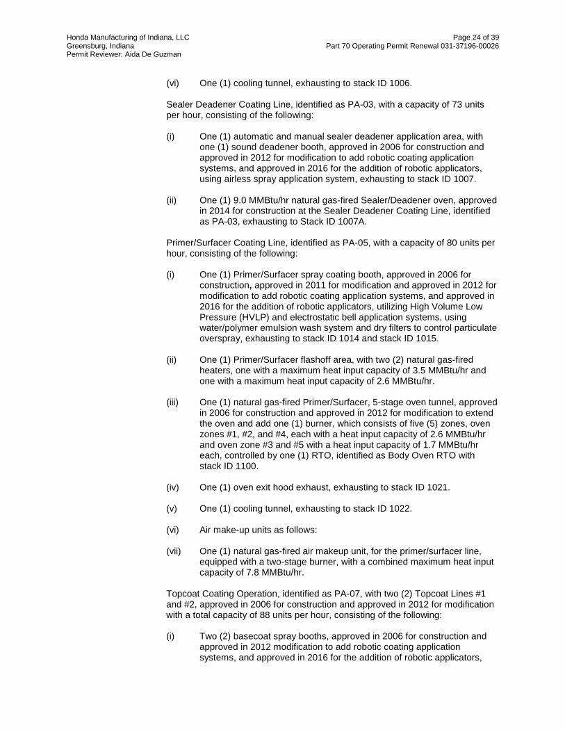
Honda Manufacturing of Indiana, LLC Page 24 of 39 Greensburg, Indiana Part 70 Operating Permit Renewal 031-37196-00026 Permit Reviewer: Aida De Guzman
(vi) One (1) cooling tunnel, exhausting to stack ID 1006.
Sealer Deadener Coating Line, identified as PA-03, with a capacity of 73 units per hour, consisting of the following:
(i) One (1) automatic and manual sealer deadener application area, with
one (1) sound deadener booth, approved in 2006 for construction and approved in 2012 for modification to add robotic coating application systems, and approved in 2016 for the addition of robotic applicators, using airless spray application system, exhausting to stack ID 1007.
(ii) One (1) 9.0 MMBtu/hr natural gas-fired Sealer/Deadener oven, approved
in 2014 for construction at the Sealer Deadener Coating Line, identified as PA-03, exhausting to Stack ID 1007A.
Primer/Surfacer Coating Line, identified as PA-05, with a capacity of 80 units per hour, consisting of the following:
(i) One (1) Primer/Surfacer spray coating booth, approved in 2006 for
construction, approved in 2011 for modification and approved in 2012 for modification to add robotic coating application systems, and approved in 2016 for the addition of robotic applicators, utilizing High Volume Low Pressure (HVLP) and electrostatic bell application systems, using water/polymer emulsion wash system and dry filters to control particulate overspray, exhausting to stack ID 1014 and stack ID 1015.
(ii) One (1) Primer/Surfacer flashoff area, with two (2) natural gas-fired
heaters, one with a maximum heat input capacity of 3.5 MMBtu/hr and one with a maximum heat input capacity of 2.6 MMBtu/hr.
(iii) One (1) natural gas-fired Primer/Surfacer, 5-stage oven tunnel, approved
in 2006 for construction and approved in 2012 for modification to extend the oven and add one (1) burner, which consists of five (5) zones, oven zones #1, #2, and #4, each with a heat input capacity of 2.6 MMBtu/hr and oven zone #3 and #5 with a heat input capacity of 1.7 MMBtu/hr each, controlled by one (1) RTO, identified as Body Oven RTO with stack ID 1100.
(iv) One (1) oven exit hood exhaust, exhausting to stack ID 1021. (v) One (1) cooling tunnel, exhausting to stack ID 1022. (vi) Air make-up units as follows:
(vii) One (1) natural gas-fired air makeup unit, for the primer/surfacer line,
equipped with a two-stage burner, with a combined maximum heat input capacity of 7.8 MMBtu/hr.
Topcoat Coating Operation, identified as PA-07, with two (2) Topcoat Lines #1 and #2, approved in 2006 for construction and approved in 2012 for modification with a total capacity of 88 units per hour, consisting of the following:
(i) Two (2) basecoat spray booths, approved in 2006 for construction and
approved in 2012 modification to add robotic coating application systems, and approved in 2016 for the addition of robotic applicators,

Honda Manufacturing of Indiana, LLC Page 25 of 39 Greensburg, Indiana Part 70 Operating Permit Renewal 031-37196-00026 Permit Reviewer: Aida De Guzman
utilizing High Volume Low Pressure (HVLP) and electrostatic bell application systems, using water/polymer emulsion wash systems and dry filters to control particulate overspray, exhausting to stack ID 1032 and stack ID 1043.
(ii) Two (2) basecoat flashoff areas, each with one (1) natural gas-fired
heater, each with a maximum heat input capacity of 2.6 MMBtu/hr, exhausting to stack ID 1033 and stack ID 1044.
(iii) Two (2) clearcoat spray booths, each approved in 2006 for construction
each approved in 2011 for modification and approved in 2012 for modification to add robotic coating application systems, and approved in 2016 for the addition of robotic applicators, utilizing High Volume Low Pressure (HVLP) and electrostatic bell application systems. The automatic zones use water/polymer emulsion wash systems to control particulate overspray and the manual zones use dry filters. The manual zones are cascaded to the automatic zones, and the automatic zones are controlled by one (1) RTO, identified as Body Booth RTO with stack ID 1101.
(iv) One (1) natural gas-fired Topcoat 5-stage oven tunnel, approved in 2006
for construction and approved in 2012 for modification to extend the oven and add one (1) burner, which consists of five (5) zones, oven zone #1, with a heat input capacity of 3.5 MMBtu/hr, oven zone #2, with a heat input capacity of 2.6 MMBtu/hr, and oven zones #3, #4 and #5, each with a heat input capacity of 1.7 MMBtu/hr, controlled by one (1) RTO, identified as Body Oven RTO with stack ID 1100.
(v) One (1) cooling tunnel, exhausting to stack ID 1041. (vi) One oven exit hood exhaust, exhausting to stack ID 1037. (vii) Topcoat on-line repair, identified as PA-07 which includes:
(A) One (1) repair sanding booth, identified as PA-08 controlled by
dust filters, exhausting to stack ID 1056. (B) One (1) repair coating booth using water wash system to control
particulate overspray, exhausting to stack ID 1057. (C) One (1) natural gas-fired repair oven, with a maximum heat input
capacity of 2.6 MMBtu/hr, exhausting to stack ID 1058. (D) One (1) Cooling tunnel, exhausting to stack ID 1060. (E) One (1) small repair booth, exhausting to stack ID 1055, with
infrared curing, consists of three (3) banks and portable infrared lights.
This topcoat on-line repair booth is used before the vehicles are not completely assembled; therefore, under 40 CFR 63, Subpart MMMM, this is considered a new in-line repair operation.
Blackout/Cavity wax coating booth, identified as PA-11, approved in 2006 for construction and approved in 2012 for modification to add two (2) robotic coating application systems, equipped with dry filters, exhausting to stack ID 1062. Miscellaneous cleaning and purge operation - paint operations, consisting of the following:

Honda Manufacturing of Indiana, LLC Page 26 of 39 Greensburg, Indiana Part 70 Operating Permit Renewal 031-37196-00026 Permit Reviewer: Aida De Guzman
(i) Purge and clean-up solvent usage and recovery system, identified as
PA-14, including virgin solvent distribution, day tanks, small portable containers including containers that meet the definition of cold cleaners, and spent solvent recovery.
Paint effluent system, identified as PA-17, consisting of sludge for separation of paint solids form booth water/polymer emulsion wash systems for body and plastic parts painting. Solids are chemically separated and sent off-site. Water/polymer emulsion is recycled to paint booths or sent to wastewater.
One (1) natural gas-fired air makeup unit with a maximum heat input capacity of 20.0 MMBtu/hr, identified as (Working Area ASH #1, PA-21). One (1) natural gas-fired air makeup unit with a maximum heat input capacity of 8.0 MMBtu/hr, identified as (Working Area ASH #2, PA-22). One (1) natural gas -fired makeup unit with a maximum heat input capacity of 5.0 MMBtu/hr, identified as (Working Area ASH #3, PA-23). One (1) natural gas-fired HVAC units, identified as HVAC ASH #2, PA-25, with a maximum heat input capacity of 13.0 MMBtu/hr. One (1) natural gas-fired HVAC unit, with a maximum heat input capacity of 8.00 MMBtu/hr, identified as HVAC #3 ASH, PA-26. Plastics Operations:
(i) Plastic Parts/Fascia Bumper Coating Line, identified as PO-02, with a
capacity of 120 hangers per hour, consisting of the following:
(ii) Alkaline pretreatment process, identified as PO-01. (iii) One (1) dry-off tunnel, exhausting to stack ID 2000. (iv) One (1) primer spray booth, utilizing High Volume Low Pressure (HVLP)
and/or electrostatic application systems, using water/polymer emulsion wash to control particulate overspray, exhausting to stack ID 2002.
(v) One (1) basecoat spray booth, approved in 2006 for construction and
approved in 2011 for modification, utilizing High Volume Low Pressure (HVLP) and electrostatic bell application systems, using water/polymer emulsion wash system to control particulate overspray. If waterborne basecoat is utilized, the basecoat spray booth will exhaust to stack ID 2003 and stack ID 2004. If solventborne basecoat is utilized, the basecoat spray booth will be controlled by one (1) RTO, identified as Bumper RTO with stack ID 2029.
(vi) One (1) clearcoat spray booth, approved in 2006 for construction and
approved in 2011 for modification, utilizing High Volume Low Pressure (HVLP) and electrostatic bell application systems, using water/polymer emulsion wash system to control particulate overspray, and VOC emissions controlled by one (1) RTO, with a maximum heat input capacity of 14.00 MMBtu/hr, identified as Bumper RTO, with stack ID 2029.

Honda Manufacturing of Indiana, LLC Page 27 of 39 Greensburg, Indiana Part 70 Operating Permit Renewal 031-37196-00026 Permit Reviewer: Aida De Guzman
(vii) One (1) clearcoat flashoff area. (viii) One (1) plastic parts oven tunnel which consists of two (2) zones,
Topcoat Oven Zone #1 and Topcoat Oven Zone #2 each zone with a maximum heat input capacity of 2.6 MMBtu/hr burner controlled by one (1) RTO, identified as Bumper RTO with stack ID 2029.
(ix) One (1) natural gas-fired air makeup unit, equipped with a two-stage
burner, with a combined maximum heat input capacity of 19.0 MMBtu/hr. Miscellaneous cleaning and purge operation - plastics painting, consisting of the following: (i) Purge and clean-up solvent usage and recovery system, identified as
PO-05, including virgin solvent distribution, day tanks, small portable containers including containers that meet the definition of cold cleaners, and spent solvent recovery.
One (1) Plastic parts touchup booth, identified as PO-17, using dry filters for particulate control and manual application systems.
Two (2) painted/raw plastic parts regrind machines, identified as PO-15 and PO-16.
Two (2) plastic flash torches, with a maximum heat input capacity of 0.10 MMBtu/hr each, identified as PO-14 and PO-19.
Final Assembly Operations:
(i) Assembly window install and miscellaneous operations, identified as AF-
01, with a capacity of 70 units per hour, consisting of all coatings, sealers, lubricants and related cleaning solvents used for auto assembly, including processes used to install window glass in vehicles, including body primer, glass cleaner, glass primer, and glass adhesive. Includes robotic and manual application equipment, coating delivery/circulation systems and raw material storage containers, approved in 2016 for modification to add a location for the manual glass installation. Under 40 CFR 63, Subpart MMMM, this is considered a new affected source.
Weld sealer process using manual and robotic weld sealer application equipment, material delivery systems and raw material storage, identified as WE-01, approved in 2016 for modification to add two (2) robotic application systems.
Insignificant Activities:
Painting Operations:
(i) Topcoat in-line repair, which includes repair area for small interior
topcoat, imperfections, manual application equipment, identified as PA-09. Under 40 CFR 63, Subpart MMMM, this is considered a new in-line repair operation.
(ii) Final repair, identified as PA-12, which includes repair coating booths
and general areas, using manual application systems, and IR curing equipment. Under 40 CFR 63, Subpart MMMM, this is considered a new final repair operation.

Honda Manufacturing of Indiana, LLC Page 28 of 39 Greensburg, Indiana Part 70 Operating Permit Renewal 031-37196-00026 Permit Reviewer: Aida De Guzman
(iii) Final repair, identified as PA-13, using air dry materials and manual application system. Under 40 CFR 63, Subpart MMMM, this is considered a new final repair operation.
(iv) Paint Mix Rooms (Emissions accounted for in the emission
determinations at each respective source). All storage containers and mixing vessels associated with affected source are subject to the requirements of 40 CFR 63, Subpart MMMM.
(v) One (1) Plastic parts touchup booth, identified as PO-17, using dry filters
for particulate control and manual application systems.
Space heaters, process heaters, or boilers using the following fuels: Natural gas-fired combustion sources with heat input equal to or less than ten million (10,000,000) Btu per hour
(i) One (1) natural gas-fired air makeup unit for the Primer/Surfacer sanding
and inspection booth (PA-06), with a maximum heat input capacity of 6.4 MMBtu/hr
The emission units above are subject to the following portions of 40 CFR 63, Subpart IIII
(1) 40 CFR 63.3080 (2) 40 CFR 63.3081 (3) 40 CFR 63.3082(a), (b), (c), (d), (e) (4) 40 CFR 63.3083(a)(2), and (d) (5) 40 CFR 63.3090 (6) 40 CFR 63.3092 through 40 CFR Part 63.3094 (7) 40 CFR 63.3100 (8) 40 CFR 63.3101 (9) 40 CFR 63.3110(a) and (b) (10) 40 CFR 63.3120 (11) 40 CFR 63.3130 (12) 40 CFR 63.3131 (13) 40 CFR 63.3150 through 40 CFR 63.3152 (14) 40 CFR 63.3160(a), (c) (15) 40 CFR 63.3161 (16) 40 CFR 63.3162 (17) 40 CFR 63.3163(a), (b), (c), (d) (e), (f), (g), and (h) (18) 40 CFR 63.3164 through 40 CFR 63.3166 (19) 40 CFR 63.3167(a) and (f) (20) 40 CFR 63.3168(a), (b), (c)(1), (3), and (g) (21) 40 CFR 63.3170(a) (22) 40 CFR 63.3171 (23) 40 CFR 63.3172 (24) 40 CFR 63.3173 (25) 40 CFR t 63.3175
(26) 40 CFR 63.3176 (27) Table 1 to Subpart IIII of 63 (28) Table 2 to Subpart IIII of Part 63 (29) Table 3 to Subpart IIII of Part 63 (30) Table 4 to Subpart IIII of Part 63 (31) Appendix A to Subpart IIII of Part 63

Honda Manufacturing of Indiana, LLC Page 29 of 39 Greensburg, Indiana Part 70 Operating Permit Renewal 031-37196-00026 Permit Reviewer: Aida De Guzman
The provisions of 40 CFR 63 Subpart A – General Provisions, which are incorporated as 326 IAC 20-1-1, apply to the facility described in this section except when otherwise specified in 40 CFR 63 Subpart IIII.
(4) 40 CFR 63, Subpart ZZZZ - National Emission Standards for Hazardous Air
Pollutants (NESHAPs) for Stationary Reciprocating Internal Combustion Engines - This subpart applies to any existing, new, or reconstructed stationary RICE located at a major or area source of HAP emissions, excluding stationary RICE being tested at a stationary RICE test cell/stand.
Based on the existing permit, this source is subject to 40 CFR 63,Subpart ZZZZ. On May 4, 2016, the U.S. Court of Appeals for the D.C. Circuit issued a mandate vacating paragraphs 40 CFR 63.6640(f)(2)(ii) - (iii) of NESHAP Subpart ZZZZ. Therefore, these paragraphs no longer have any legal effect and any engine that is operated for purposes specified in these paragraphs becomes a non-emergency engine and must comply with all applicable requirements for a non-emergency engine.
For additional information, please refer to the USEPA’s Guidance Memo: https://www3.epa.gov/airtoxics/icengines/docs/RICEVacaturGuidance041516.pdf Since the federal rule has not been updated to remove these vacated requirements, the text below shows the vacated language as strikethrough text. At this time, IDEM is not making any changes to the permit’s attachment due to this vacatur. However, the permit will not reference the vacated requirements, as applicable. 40 CFR 63.6640(f)(2) You may operate your emergency stationary RICE for any combination of the purposes specified in paragraphs (f)(2)(i) through (iii) of this section for a maximum of 100 hours per calendar year. Any operation for non-emergency situations as allowed by paragraphs (f)(3) and (4) of this section counts as part of the 100 hours per calendar year allowed by this paragraph (f)(2).
(i) Emergency stationary RICE may be operated for maintenance checks
and readiness testing, provided that the tests are recommended by federal, state or local government, the manufacturer, the vendor, the regional transmission organization or equivalent balancing authority and transmission operator, or the insurance company associated with the engine. The owner or operator may petition the Administrator for approval of additional hours to be used for maintenance checks and readiness testing, but a petition is not required if the owner or operator maintains records indicating that federal, state, or local standards require maintenance and testing of emergency RICE beyond 100 hours per calendar year.
(ii) Emergency stationary RICE may be operated for emergency demand
response for periods in which the Reliability Coordinator under the North American Electric Reliability Corporation (NERC) Reliability Standard EOP-002-3, Capacity and Energy Emergencies (incorporated by reference, see §63.14), or other authorized entity as determined by the Reliability Coordinator, has declared an Energy Emergency Alert Level 2 as defined in the NERC Reliability Standard EOP-002-3.

Honda Manufacturing of Indiana, LLC Page 30 of 39 Greensburg, Indiana Part 70 Operating Permit Renewal 031-37196-00026 Permit Reviewer: Aida De Guzman
(iii) Emergency stationary RICE may be operated for periods where there is a deviation of voltage or frequency of 5 percent or greater below standard voltage or frequency.
The following emission units are subject to 40 CFR, Subpart ZZZZ. However,
there are no requirements for units using gasoline for fuel.
Gasoline Generator, FAC-145 5.5 (spark ignition)
Gasoline Generator, FAC-175 5.5 (spark ignition)
The following existing generators and pumps at the source are considered new
stationary RICE with a site rating of equal to or less than 500 brake HP located at a major source with commencement of construction on or after June 12, 2006. These engines are currently not subject to any of the requirements of 40 CFR Subpart ZZZZ.
Based on this new applicability evaluation, these engines are subject to this
regulation, pursuant to 40 CFR 63.6590(c)(1),(2),(6), 40 CFR 63.6590(c)(1), for new 2SLB stationary RICE with a site rating of less
than or equal to 500 brake HP located at a major source of HAP emissions; 40 CFR 63.6590(c)(2), for new or reconstructed 4SLB stationary RICE with a site
rating of less than 250 brake HP located at a major source of HAP emissions;and 40 CFR 63.6590(c)(6) For new emergency or limited use stationary RICE with
a site rating of less than or equal to 500 brake HP located at a major source of HAP emissions.
Emergency Generators/Fire Pumps ID Site Rating (HP)
Generator, FAC-81 133 Generator, FAC-86 158 Generator, FAC-89 133 Generator, FAC-115 133 Fire Pump, FAC-82 183 Fire Pump, FAC-83 183
The emission units above are subject to the following portions of 40 CFR 63, Subpart ZZZZ: (1) 40 CFR 63.6580
(2) 40 CFR 63.6585 (3) 40 CFR 63.6590(2)(ii), (c)(2),(3),(6) (4) 40 CFR 63.6595(a)(5, (c) (5) 40 CFR 63.6602 (6) 40 CFR 63.6604(c (7) 40 CFR 63.6605 (8) 40 CFR 63.6640(f)(i),(ii),(iii) (9) 40 CFR 63.6645(f)
(10) 40 CFR 63.6665

Honda Manufacturing of Indiana, LLC Page 31 of 39 Greensburg, Indiana Part 70 Operating Permit Renewal 031-37196-00026 Permit Reviewer: Aida De Guzman
(11) 40 CFR 63.6670 (12) 40 CFR 63.6675
The following emergency generators at the source are considered new stationary RICE with a site rating of more than 500 brake HP located at a major source with commencement of construction on or after December 19, 2002 are still subject to 40 CFR 63, Subpart ZZZZ:
Emergency Generators/Fire Pumps ID Site Rating (HP)
Generator, FAC-84 757 Generator, FAC-85 757
The emission units above are subject to the following portions of 40 CFR 63, Subpart ZZZZ:
(1) 40 CFR 63.6580
(2) 40 CFR t 63.6585 (3) 40 CFR 63.6590(2)(i) (4) 40 CFR 63.6595(a)(3) (5) 40 CFR 63.6600(c) (6) 40 CFR 63.6604(c) (7) 40 CFR 63.6605 (8) 40 CFR 63.6640(f)(i),(ii),(iii) (9) 40 CFR 63.6645(f)
(10) 40 CFR 63.6665 (11) 40 CFR 63.6670 (12) 40 CFR 63.6675
(5) 40 CFR Part 63, Subpart WWWW - National Emission Standards for Hazardous
Air Pollutants: Reinforced Plastic Composites Production - The two (2) plastic parts injection molding machines, identified as PO-06 and PO-07, are not subject to 40 CFR Part 63, Subpart WWWW, because they are not used to produce fiberglass parts or reinforced plastic composites.
(6) 40 CFR Part 63, Subpart T – Standards for Halogenated Solvent Cleaning: The existing eight (8) cold cleaner degreasers, identified as ST-02, MS-02, WE-07, AF-05, VQ-01, PA-27, PO-20 and FAC-176, which are classified as insignificant activities are not subject to this rule because they do not use any halogenated solvent for cleaning.
(7) 40 CFR Part 63, Subpart DDDDD - National Emission Standards for Hazardous Air Pollutants for Industrial, Commercial, and Institutional Boilers and Process Heaters:
This rule applies to new, reconstructed and existing industrial, commercial, or institutional boiler or process heater as defined in 40 CFR 63.7575 that is located at, or is part of, a major source of HAP, except as specified in 40 CFR 63.7491.
The following emission units are not subject to 40 CFR 63, Subpart DDDDD because they are part of the affected source under 40 CFR 63, Subpart IIII:

Honda Manufacturing of Indiana, LLC Page 32 of 39 Greensburg, Indiana Part 70 Operating Permit Renewal 031-37196-00026 Permit Reviewer: Aida De Guzman
Body Painting Operations: (i) One (1) E-Coat pre-heat zone, with a maximum heat input capacity of
3.7 MMBtu/hr, exhausting to stack ID 1003. Primer/Surfacer Coating Line, identified as PA-05, with a capacity of 80 units per hour, consisting of the following: (ii) One (1) Primer/Surfacer flashoff area, with two (2) natural gas-fired
heaters, one with a maximum heat input capacity of 3.5 MMBtu/hr and one with a maximum heat input capacity of 2.6 MMBtu/hr.
Topcoat Coating Operation, identified as PA-07, with two (2) Topcoat Lines #1 and #2, with a total capacity of 88 units per hour, consisting of the following: (iii) Two (2) basecoat flashoff areas, each with one (1) natural gas-fired
heater, each with a maximum heat input capacity of 2.6 MMBtu/hr, exhausting to stack ID 1033 and stack ID 1044.
The following emission units are not subject to 40 CFR 63, Subpart DDDDD because 40 CFR 63.7491(d) states that "a hot water heater as defined in this subpart" is not subject to Subpart DDDDD. The hot water heater is defined in Subpart DDDDD as "a closed vessel with a capacity of no more than 120 U.S. gallons in which water is heated by combustion of gaseous, liquid or biomass/bio-based solid fuel and is withdrawn for use external to the vessel." These four (4) natural gas-fired hot water generators, located in the body painting area, identified as PA-20, are hot water heaters with capacities of less than 120 gallons, each:" (i) Four (4) natural gas-fired hot water generators, located in the body
painting area, with a combined maximum heat input capacity of 24.5 MMBtu/hr.
State Rule Applicability - Entire Source
326 IAC 2-2 (Prevention of Significant Deterioration) This source is a major source for PSD because the potential to emit of one of the regulated pollutant is emitted at a rate greater than 250 tons per year and is not in 1 of 28 source categories. Therefore, pursuant to 326 IAC 2-2, this is a major source for PSD.
PSD/Part 70 Operating Permit No. 031-23360-00026, issued on October 19, 2006 -
Honda Manufacturing of Indiana, LLC. is an existing major PSD source, with an initial PSD permit, 031-23360-00026, issued on October 19, 2006. This PSD permit authorized the initial construction of the automobile and light-duty truck manufacturing plant. This PSD permit limited the source vehicle production to 250,000 vehicles per year, with the VOC, PM, PM10 and NOx emissions from this source reviewed pursuant to the requirements of 326 IAC 2-2 (PSD). BACT for VOC was determined to be a combination of source-wide yearly limit, and coating emissions limit, specific application methods, and the use of Regenerative Thermal Oxidizers (RTOs). BACT for NOx was determined to be a combination of lb NOx per MMBtu emission limits, the use of only low-NOx natural gas burners, and a limit on source-wide natural gas combustion. The source-wide natural gas combustion likewise limited the CO emissions to avoid the requirements of PSD for this pollutant. The PTE of SO2 was less than the PSD significance level and therefore was not subject to the requirements of PSD.

Honda Manufacturing of Indiana, LLC Page 33 of 39 Greensburg, Indiana Part 70 Operating Permit Renewal 031-37196-00026 Permit Reviewer: Aida De Guzman
PSD/SSM No.031-24760-00026, issued on September 18, 2007 - Honda at this time had not started construction of the plant. Honda applied to change the original size, design and number of emission units (process heaters, burners, ovens, generators, storage tanks, etc.) and added new emission units (degreasers, robotic welding stations, etc.). The PSD BACT limits that were originally required for these emission units were re-evaluated. PSD/SSM No. 031-25695-00026, issued on April 25, 2008 - Honda applied for a permit to change the sizes of PSD emission units, forty-three (43) heaters, addition of another combustions units,which required PSD BACT re-evaluation, change in the PSD BACT required for the Backout/Cavity Wax Booth (PA-11) due to a cost effectiveness issue and the removal of the Gasoline Dispensing Operation (AF-02) PSD BACT requirement for a separate Stage 2 vapor recovery system when filling up some of the manufactured vehicles that already have on-board refueling vapor recovery system (ORVR).
SSM No. 031-30713-00026, issued on September27, 2011 This involved modification to existing emission units by constructing additional robots at the Primer/Surfacer Coating Line (PA-05), the Topcoat Coating Operation (PA-07), and the Plastic Parts Coating Line (PO-02), and installation of new storage tank at the tank farm. The source has provided information as part of the application for this approval that the modification is not subject to the requirements of 326 IAC 2-2, PSD for VOC, PM PM10 and PM2.5, based upon the baseline actual to projected actual (ATPA) test. Likewise, the source will continue to comply with the existing PSD BACT emission limitations, pursuant to 326 IAC 2-2-3 (Control Technology Review; Requirements) required for these modified existing emission units.
MSM No. 031-31640-00026, issued on May 14, 2012 This source modification allowed for the construction of new emission units and modiifcation to existing units to accommodate the increase to the production line speed of the facility. PSD/SSM No. 031-32879, issued on June 13, 2013 This source modification allowed for the increase in yearly vehicle production which resulted in increased utilization from upstream and downstream processes or emission units. A PSD-BACT re-evaluation was performed since the yearly vehicle production was established under 326 IAC 2-2-3 (Control Technology Review; Requirements) MSM No. 031-36822-00026, issued on April 7, 2016 This source modification allowed for the construction of new emission units and modification to existing E-Coat, sealer deadener, primer surfacer and topcoat systems, to accommodate the production of a new model Honda vehicle. The yearly vehicle production limit of 285,000 vehicles was not affected by this modification. 326 IAC 1-6-3 (Preventive Maintenance Plan) The source is subject to 326 IAC 1-6-3.
326 IAC 1-5-2 (Emergency Reduction Plans) The source which is subject to 326 IAC 1-5-2 has submitted their Emergency Reduction Plans on January 23, 2009. 326 IAC 2-6 (Emission Reporting) This source is subject to 326 IAC 2-6 (Emission Reporting) because it is required to have an operating permit pursuant to 326 IAC 2-7 (Part 70). The potential to emit of VOC is greater than 250 tons per year. Therefore, pursuant to 326 IAC 2-6-3(a)(1), annual reporting is required. An emission statement shall be submitted by July 1, 2017 and every year thereafter. The emission statement shall contain, at a minimum, the information specified in 326 IAC 2-6-4.

Honda Manufacturing of Indiana, LLC Page 34 of 39 Greensburg, Indiana Part 70 Operating Permit Renewal 031-37196-00026 Permit Reviewer: Aida De Guzman
326 IAC 2-7-6(5) (Annual Compliance Cerification) The U.S. EPA Federal Register 79 FR 54978 notice does not exempt Title V Permittees from the requirements of 40 CFR 70.6(c)(5)(iv) or 326 IAC 2-7-6(5)(D), but the submittal of the Title V annual compliance certification to IDEM satisfies the requirement to submit the Title V annual compliance certifications to EPA. IDEM does not intend to revise any permits since the requirements of 40 CFR 70.6(c)(5)(iv) or 326 IAC 2-7-6(5)(D) still apply, but Permittees can note on their Title V annual compliance certification that submission to IDEM has satisfied reporting to EPA per Federal Register 79 FR 54978. This only applies to Title V Permittees and Title V compliance certifications. 326 IAC 5-1 (Opacity Limitations) This source is subject to the opacity limitations specified in 326 IAC 5-1-2(1)
326 IAC 6.5 PM Limitations Except Lake County This source is not subject to 326 IAC 6.5 because it is not located in one of the following counties: Clark, Dearborn, Dubois, Howard, Marion, St. Joseph, Vanderburgh, Vigo or Wayne. 326 IAC 6-4 (Fugitive Dust Emissions) The Permittee shall not allow fugitive dust to escape beyond the property line or boundaries of the property, right-of-way, or easement on which the source is located, in a manner that would violate 326 IAC 6-4 (Fugitive Dust Emissions). 326 IAC 6-5 (Fugitive Particulate Matter Emission Limitations) This rule does not apply to the source because it does not have fugitive emissions equal to or greater than 25 tons per year.
State Rule Applicability – Individual Facilities 326 IAC 6-2 (Particulate Emission Limitations from Indirect Heating) The following facilities are subject to 326 IAC 6-2-4, (Particulate Emission Limitations for Sources of Indirect Heating) and still subject to the same limit of 0.38 lb/MMBtu: FAC-20, FAC-26 through FAC-30, FAC-32, FAC-36, FAC-37, FAC-39 through FAC-41, FAC-43 through FAC-80, FAC-110, FAC-117 through FAC-140, FAC-146 through FAC-169, PA-05 (surfacer flash off #1 heater, surfacer flash off #2 heater, surfacer oven zone 1 and surfacer oven zone 2), PA-07 (basecoat flash off #1 heater, basecoat flash off #2 heater, topcoat oven zone 1 and topcoat oven zone 2), PO-02 (topcoat oven zone 1 and topcoat oven zone 2).
This rule limits the particulate emissions to 0.38 pound per million Btu heat input from each of these facilities using the following equation:
Pt = 1.09/(Q^0.26) Where: Pt = Pounds of particulate matter emitted per million Btu (lb/mmBtu) heat input Q = Total Source maximum operating capacity rating in million Btu per hour (mmBtu/hr)
heat input Q = 58.3 MMBtu heat input Pt = 0.38 lb/MMBtu of heat input Each emission unit is in compliance with the PM emission limit of 0.38 lb/MMBtu, using natural gas with PM emissions of 0.0076 lb/MMBtu.

Honda Manufacturing of Indiana, LLC Page 35 of 39 Greensburg, Indiana Part 70 Operating Permit Renewal 031-37196-00026 Permit Reviewer: Aida De Guzman
326 IAC 8-2-2 (Automobile and Light-Duty Truck Coating Operations) This rule applies to the existing automobile and light-duty truck assembly plant, which limits the VOC from the application, flash-off, and curing of prime and topcoat coatings on automobile and light-duty truck bodies, hoods, fenders, cargo boxes, doors and grill opening panels as follows: (1) 0.23 kilograms per liter of coating (1.9 pounds per gallon), excluding water,
delivered to the applicator from prime application, flash-off area and oven operations.
(2) 0.34 kilograms per liter of coating (2.8 pounds per gallon) excluding water,
delivered to the applicator from topcoat application, flash-off area and oven operations.
(3) 0.58 kilograms per liter of coating (4.8 pounds per gallon) excluding water,
delivered to the applicator from final repair application, flash-off area and oven operations.
Note: EPA has indicated that the 1.9 pound per gallon less water limit under this rule should be a combined limit between the E-Coat and Primer operation, since E-Coat is considered a primer. The VOC content limitations under this rule shall be determined using a daily volume weighted average of the coatings applied less water using the following equation:
n A = ∑ (C i )(Ui)
i = 1 x (1-CE) n
∑ (U i x (1-Di)) i = 1 where:
A = daily or monthly volume weighted average, lb VOC/gal less water C = VOC content of coating i, lb VOC/gal U = maximum coating i usage, gal/day or gal/month D = coatingi volume % water n = no. of coatings used during the day or month CE= overall control efficiency of the control system
326 IAC 8-1-2 (Compliance Methods) Pursuant to 326 IAC 8-1-2(a), the Permittee chose to install thermal incinerators, higher solids (low solvent) coatings, and waterborne coatings, to comply with the VOC limits in 326 IAC 8-2-2. Therefore, no equivalency limits are necessary as required in 326 IAC 8-1-2(a)(5), (b), and (c).
326 IAC 2-4.1-1 (New Source Toxics Control) This rule is not applicable to the source, because it is subject to NESHAP.
326 IAC 6-3-2 (Particulate Emission Limitations for Manufacturing Processes) - Pursuant to 326 IAC 6-3-(1)(c)(1), particulate matter limitations under 326 IAC 6-3 does not apply to existing units at the source because they are subject to a more stringent PM limitations under 326 IAC 2-2-3 (Control Technology Review Requirements).
326 IAC 7-1 (Sulfur Dioxide Emission Limitations) This rule applies to all emission units with potential to emit 25 tons/year or 10 pounds/hour SO2. This rule does not apply to the combustion emission units at the source because none of them have the potential to emit twenty-five (25) tons per year or ten (10) pounds per hour of SO2.

Honda Manufacturing of Indiana, LLC Page 36 of 39 Greensburg, Indiana Part 70 Operating Permit Renewal 031-37196-00026 Permit Reviewer: Aida De Guzman
326 IAC 8-1-6 (General Reduction Requirements) This rule requires that new facilities (as of January 1, 1980), which have potential VOC emissions of 25 tons or more per year, located anywhere in the state, which are not otherwise regulated by other provisions of 326 IAC 8, shall reduce VOC emissions using Best Available Control Technology (BACT). The source is subject to 326 IAC 2-2-3 (PSD BACT), therefore, PSD BACT will satisfy for the requirements of 326 IAC 8-1-6 at this source. (1) Plastic coating operation – The entire source was subject to PSD BACT requirements,
pursuant to 326 IAC 2-2-3 (Control Technology Review Requirements), including the plastic coating operation. The PSD BACT determined for the plastic coating operation shall satisfy the requirements of 326 IAC 8-1-6 (General Reduction Requirements).
(2) Plastic injection molding operation - The PSD BACT requirements included the plastic
injection molding operation. However, the injection molding is not subject to 326 IAC 8-1-6 because its VOC potential emission is less than 25 tons per year.
(3) All surface coating operations subject to 326 IAC 8-2-2 are not subject to 326 IAC 8-1-6.
326 IAC 8-3-2 (Cold Cleaner Degreaser Control Equipment and Operating Requirements) The eight (8) cold cleaner degreasers, identified as ST-02, MS-02, WE-07, AF-05, VQ-01, PA-27, PO-20 and FAC-176 (insignificant activities) are subject to 326 IAC 8-3-2, for cold cleaning operations constructed after January 1, 1980 326 IAC 8-3-8 (Material Requirements for Cold Cleaner Degreasers) The eight (8) cold cleaner degreasers, identified as ST-02, MS-02, WE-07, AF-05, VQ-01, PA-27, PO-20 and FAC-176 are subject to 326 IAC 8-3-8.
326 IAC 8-4-6 (Gasoline Dispensing Facilities) and 326 IAC 8-4-9 (Leaks from Transports and Vapor Collection Systems, Records) - This rule requirements were determined in PSD/TV 031-23360-00026 to be applicable to the gasoline dispensing facility, identified as AF-02 which also were determined to be the PSD BACT, pursuant to 326 AC 2-2-3 for this facility.
326 IAC 8-2-9 (Miscellaneous Metal and Plastic Parts Coating Operations) -
326 IAC 8-2-9 applies to facilities which commences construction after July 1, 1990, located in any county and which have actual emissions of greater than fifteen (15) pounds of VOC per day before add-on controls. This rule applies to the following:
(1) The blackout/cavity wax, PA-11, is subject to 326 IAC 8-2-9 which limits the VOC
emissions to 3.5 pounds/gallon less water delivered to a coating applicator that applies extreme performance coatings.
Compliance Determination and Monitoring Requirements
Permits issued under 326 IAC 2-7 are required to ensure that sources can demonstrate compliance with all applicable state and federal rules on a continuous basis. All state and federal rules contain compliance provisions, however, these provisions do not always fulfill the requirement for a continuous demonstration. When this occurs, IDEM, OAQ, in conjunction with the source, must develop specific conditions to satisfy 326 IAC 2-7-5. As a result, Compliance Determination Requirements are included in the permit. The Compliance Determination Requirements in Section D of the permit are those conditions that are found directly within state and federal rules and the violation of which serves as grounds for enforcement action. If the Compliance Determination Requirements are not sufficient to demonstrate continuous compliance, they will be supplemented with Compliance Monitoring Requirements, also in Section D of the permit. Unlike Compliance Determination Requirements, failure to meet Compliance Monitoring conditions would serve as a trigger for corrective actions and not grounds
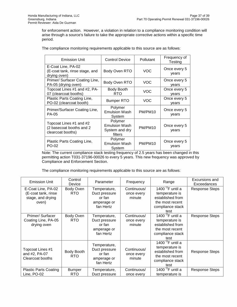
Honda Manufacturing of Indiana, LLC Page 37 of 39 Greensburg, Indiana Part 70 Operating Permit Renewal 031-37196-00026 Permit Reviewer: Aida De Guzman
for enforcement action. However, a violation in relation to a compliance monitoring condition will arise through a source's failure to take the appropriate corrective actions within a specific time period.
The compliance monitoring requirements applicable to this source are as follows:
Emission Unit Control Device Pollutant Frequency of Testing
E-Coat Line, PA-02 (E-coat tank, rinse stage, and drying oven)
Body Oven RTO VOC Once every 5 years
Primer/ Surfacer Coating Line, PA-05 (drying oven) Body Oven RTO VOC Once every 5
years Topcoat Lines #1 and #2, PA-07 (clearcoat booths)
Body Booth RTO VOC Once every 5
years Plastic Parts Coating Line, PO-02 (clearcoat booth) Bumper RTO VOC Once every 5
years
Primer/Surfacer Coating Line, PA-05
Polymer Emulsion Wash
System PM/PM10 Once every 5
years
Topcoat Lines #1 and #2 (2 basecoat booths and 2 clearcoat booths)
Polymer Emulsion Wash System and dry
filters
PM/PM10 Once every 5 years
Plastic Parts Coating Line, PO-02
Polymer Emulsion Wash
System PM/PM10 Once every 5
years
Note: The current compliance stack testing frequency of 2.5 years has been changed in this permitting action T031-37196-00026 to every 5 years. This new frequency was approved by Compliance and Enforcement Section. The compliance monitoring requirements applicable to this source are as follows:
Emission Unit Control Device Parameter Frequency Range Excursions and
Exceedances E-Coat Line, PA-02 (E-coat tank, rinse stage, and drying
oven)
Body Oven RTO
Temperature, Duct pressure
or fan amperage or
fan Hertz
Continuous/ once every
minute
1400 OF until a temperature is
established from the most recent
compliance stack test
Response Steps
Primer/ Surfacer Coating Line, PA-05
drying oven
Body Oven RTO
Temperature, Duct pressure
or fan amperage or
fan Hertz
Continuous/ once every
minute
1400 OF until a temperature is
established from the most recent
compliance stack test
Response Steps
Topcoat Lines #1 and #2, PA-07 Clearcoat booths
Body Booth RTO
Temperature, Duct pressure
or fan amperage or
fan Hertz
Continuous/ once every
minute
1400 OF until a temperature is
established from the most recent
compliance stack test
Response Steps
Plastic Parts Coating Line, PO-02
Bumper RTO
Temperature, Duct pressure
Continuous/ once every
1400 OF until a temperature is
Response Steps

Honda Manufacturing of Indiana, LLC Page 38 of 39 Greensburg, Indiana Part 70 Operating Permit Renewal 031-37196-00026 Permit Reviewer: Aida De Guzman
Emission Unit Control Device Parameter Frequency Range Excursions and
Exceedances clearcoat booth or fan
amperage or fan Hertz
minute established from the most recent
compliance stack test
Primer/Surfacer Coating Line, PA-05
Polymer Emulsion
Wash System
Visual checks of each booth flood pans and water/polymer emulsion circulation. Warning system to ensure water circulation pump is operational
Once Daily -
Response Steps- required if water/polymer emulsion is not flowing freely and alarm goes off
Dry filters Placement inspection
Once Daily -
Response Steps- required if overspray is visible on the rooftops and nearby ground
Topcoat Lines #1 and #2 (2 basecoat booths and 2 clearcoat booths)
Polymer Emulsion
Wash System
Visual checks of each booth flood pans and water/polymer emulsion circulation. Warning system to ensure water circulation pump is operational
Once Daily -
Response Steps- required if water/polymer emulsion is not flowing freely and alarm goes off
Dry filters Placement inspection
Once Daily -
Response Steps - required if overspray is visible on the rooftops and nearby ground
Plastic Parts Coating Line, PO-02
Polymer Emulsion
Wash System
Visual checks of each booth flood pans and water/polymer emulsion circulation. Warning system to ensure water circulation pump is operational
Daily -
Response Steps- required if water/polymer emulsion is not flowing freely and alarm goes off
These monitoring conditions are necessary to ensure compliance with 326 IAC 2-2-3 (Control Technology Review; Requirements), 326 IAC 8-2-2 (Automobile and Light-Duty Truck Coating

Honda Manufacturing of Indiana, LLC Page 39 of 39 Greensburg, Indiana Part 70 Operating Permit Renewal 031-37196-00026 Permit Reviewer: Aida De Guzman
Operations), 326 IAC 8-2-9 Miscellaneous Metal and Plastic Parts Coating Operations, and 326 IAC 8-1-6 (General Reduction Requirements).
Recommendation
The staff recommends to the Commissioner that the Part 70 Operating Permit Renewal No. 031-37196-00026 be approved. This recommendation is based on the following facts and conditions: Unless otherwise stated, information used in this review was derived from the application and additional information submitted by the applicant. An application for the purposes of this review was received on May 17, 2016.
Conclusion
The operation of this stationary automobile and light duty truck assembly source shall be subject to the conditions of the attached Part 70 Operating Permit Renewal No. 031-37196-00026.
IDEM Contact
(a) Questions regarding this proposed permit can be directed to Aida DeGuzman at the Indiana
Department Environmental Management, Office of Air Quality, Permits Branch, 100 North Senate Avenue, MC 61-53 IGCN 1003, Indianapolis, Indiana 46204-2251 or by telephone at (317) 233-4972 or toll free at 1-800-451-6027 extension 3-4972.
(b) A copy of the findings is available on the Internet at: http://www.in.gov/ai/appfiles/idem-caats/ (c) For additional information about air permits and how the public and interested parties can
participate, refer to the IDEM Permit Guide on the Internet at: http://www.in.gov/idem/5881.htm; and the Citizens' Guide to IDEM on the Internet at: http://www.in.gov/idem/6900.htm.

Page 1 of 41 TSD App AAppendix A: Emissions Calculations
VOC and ParticulateFrom Surface Coating Operations
Company Name: Honda Manufacturing of Indiana, LLC Address City IN Zip: 2755 N. Michigan Avenue, Greensburg, IN 47240Part 70 Renewal No.: 031-37196-00026
Reviewer: Aida DeGuzman
NOx CO PM PM10/PM2.5 SO2 VOC HAPs GHGs NOx CO PM PM10/PM
2.5 SO2 VOC HAPs GHGsPainting OperationsE-Coat Line (PA-02) 2 0.00 0.00 0.00 0.00 0.00 29.50 0.00 0.00 0.00 0.00 0.00 0.00 0.00 1.47 0.00 0.00Sealer/Deadener (PA-03) 3 0.00 0.00 0.00 0.00 0.00 138.79 34.69 0.00 0.00 0.00 0.00 0.00 0.00 138.79 34.69 0.00Primer/Surfacer (PA-05) 4 0.00 0.00 161.16 161.16 0.00 51.71 0.70 0.00 0.00 0.00 0.55 0.55 0.00 46.79 0.63 0.00Topcoat Coating Line (PA-07) 5 0.00 0.00 94.98 94.98 0.00 298.48 1.21 0.00 0.00 0.00 0.34 0.34 0.00 120.66 0.71 0.00Topcoat On-line Repair (PA-07) 9 0.00 0.00 9.26 9.26 0.00 12.28 0.00 0.00 0.00 0.00 0.13 0.13 0.00 12.28 0.00 0.00Misc. Sanding (PA-04, PA-06, PA-08, PA-10) 6, 7, 8, 11 0.00 0.00 11.27 11.27 0.00 0.11 0.00 0.00 0.00 0.00 0.27 0.27 0.00 0.11 0.00 0.00Topcoat on-line Repair (PA-09) 10 0.00 0.00 0.00 0.00 0.00 0.63 0.00 0.00 0.00 0.00 0.00 0.00 0.00 0.63 0.00 0.00Blackout/Wax Coating Line (PA-11) 12 0.00 0.00 0.76 0.76 0.00 8.00 0.00 0.00 0.00 0.00 0.02 0.02 0.00 8.00 0.00 0.00Final Repair (PA-12) 13 0.00 0.00 2.95 2.95 0.00 2.74 0.86 0.00 0.00 0.00 0.06 0.06 0.00 2.74 0.86 0.00Final Repair - Air Dry (PA-13) 14 0.00 0.00 0.12 0.12 0.00 0.47 0.61 0.00 0.00 0.00 0.12 0.12 0.00 0.47 0.61 0.00Misc. Cleaning & Purge (PA-14) 15 0.00 0.00 0.00 0.00 0.00 67.09 12.10 0.00 0.00 0.00 0.00 0.00 0.00 67.09 12.10 0.00Paint Test Lab (PA-16) 16 0.00 0.00 0.05 0.05 0.00 0.05 0.01 0.00 0.00 0.00 0.00 0.00 0.00 0.05 0.01 0.00Paint Effluent System (PA-17) 17 0.00 0.00 0.00 0.00 0.00 4.01 0.00 0.00 0.00 0.00 0.00 0.00 0.00 4.01 0.00 0.00Wheelabrator/Shotblaster (PA-15) 18 - 21 0.00 0.00 13.14 13.14 0.00 0.00 0.00 0.00 0.00 0.00 0.02 0.02 0.00 0.00 0.00 0.00Wheelabrator/Shotblaster (PA-15A) 22 0.00 0.00 12.01 12.01 0.00 0.00 0.00 0.00 0.00 0.00 8.76 8.76 0.00 0.00 0.00 0.00Plastic OperationsFascia/Bumper Coating Line (solvent BC) (PO-02) 23 0.00 0.00 218.40 218.40 0.00 270.68 27.08 0.00 0.00 0.00 2.18 2.18 0.00 57.58 8.73 0.00BPa Polishing (PO-04) 24 0.00 0.00 0.00 0.00 0.00 0.34 0.00 0.00 0.00 0.00 0.00 0.00 0.00 0.34 0.00 0.00Misc. Cleaning & Purge (PO-05) 25 0.00 0.00 0.00 0.00 0.00 28.35 3.34 0.00 0.00 0.00 0.00 0.00 0.00 39.12 3.34 0.00Plastic Injection Molding (PO-06, PO-07, PO-08) 26 0.00 0.00 0.00 0.00 0.00 7.45 0.00 0.00 0.00 0.00 0.00 0.00 0.00 7.45 0.00 0.00Plastic Pellet Storage Silos (PO-11, PO-12) 27 0.00 0.00 0.13 0.13 0.00 0.00 0.00 0.00 0.00 0.00 0.13 0.13 0.00 0.00 0.00 0.00IP Padding Operation (PO-30) 28 0.00 0.00 0.00 0.00 0.00 0.66 0.00 0.00 0.00 0.00 0.00 0.00 0.00 0.66 0.00 0.00Misc. OperationsNG Combustion (PA and FAC Emission Units) 29-32 117.12 138.07 12.33 12.13 0.99 9.07 2.90 185,603 50.00 91.50 3.73 3.73 0.29 2.70 0.92 79,236Emergency Generators & Firepumps 33-34 18.97 4.09 1.35 1.35 1.25 1.54 0.02 0.00 18.97 4.09 1.35 1.35 1.25 1.54 0.02 0.00Weld Sealer Process (WE-01) 35 0.00 0.00 0.00 0.00 0.00 20.47 0.01 0.00 0.00 0.00 0.00 0.00 0.00 20.47 0.01 0.00Body Welding (WE-02) & Finishing (WE-03) 36 0.00 0.00 1.03 1.03 0.00 5.11 0.00 0.00 0.00 0.00 0.01 0.01 0.00 5.11 0.00 0.00Cooling Towers 37 0.00 0.00 2.60 2.60 0.00 0.00 0.00 0.00 0.00 0.00 2.60 2.60 0.00 0.00 0.00 0.00Storage Tanks 38 0.00 0.00 0.00 0.00 0.00 9.96 4.41 0.00 0.00 0.00 0.00 0.00 0.00 9.96 4.41 0.00Glass Assembly, Gas & Wwfluid Dispensing (AF-02, 39 0.00 0.00 0.00 0.00 0.00 28.17 0.34 0.00 0.00 0.00 0.00 0.00 0.00 28.17 0.34 0.00Roadways 40-41 0.00 0.00 6.13 2.63 0.00 0.00 0.00 0.00 0.00 0.00 0.01 0.00 0.00 0.00 0.00 0.00Total PTE (tons/yr) 136.09 142.15 547.7 544.0 2.2 995.7 88.3 185,603 69.0 95.6 20.3 20.3 1.5 576.2 67.4 79,236
Notes:The uncontrolled and controlled PTEs (tpy) of VOC from the Plastic Painting Line (PO-02) are based on the worst case emissions.
Emission Units Page
Uncontrolled PTE (tpy) Limited PTE (tpy)

Appendix A: Emissions Calculations Page 2 of 41 TSD App A VOC and Particulate
From Surface Coating Operations
Company Name: Honda Manufacturing of Indiana, LLCAddress City IN Zip: 2755 N. Michigan Avenue, Greensburg, IN 47240Part 70 Renewal No.: 031-37196-00026
Reviewer: Aida DeGuzman
Emission Unit (Source) ID: Electrodeposition (E-coat) Coating Line (PA-02) 285,000 units/yr units/hrEmission Unit Description:
curing oven
VOC EMISSIONS CALCULATIONSMaterial VOC Uncontrolled Tank/Oven Incinerator Controlled Solids TE Applied HAP HAPUsage Content VOC PTE Capture Efficiency VOC PTE Content Solids Content Emissions
Material Name (gal/unit) (gal/yr) (lb VOC/gal) tons/yr (%) (%) (tons/year) (%vol) (gal/yr) (lb/gal) (lb/yr)e-Coat 1.150 327,750 0.18 29.50 100.0% 95.0% 1.47 0.00% 100% 0 0.00 0
327,750 29.50 1.47 00.52 lb/gal < water uncontrolled
Volume Material Pounds of VOC 0.03 lb/gal < water controlled% Water Usage Less Per Year (lb/yr) Controlled) 0.02 lb/gal coating solids (lb/gacs)
Material Name Water (gal/yr)e-Coat 65.2% 113991.45 58995TOTAL 113991.45 58995
Note: The entire E-Coat operation (E-Coat Tank, rinse up to the oven) is all 100% captured. Methodology:Uncontrolled PTE, ton/yr = gal/yr usage * lb VOC or HAP/gal * ton/2000 lb Controlled PTE, tons/yr = Uncontrolled PTE, tons/yr * (1-%capture *%control)lb/gacs after control = VOC emissions after control, lbs/yr * yr/gallons, solids applied Material Usage Less water= gal/yr usage * (1-Volume % water)Pounds of VOC/yr = gal/yr usage * lb VOC/galPounds of VOC/gal less water = lb of VOC/yr /gal/yr usage * lb VOC/gal * (1-(%capture* %destruction))
Source includes electrodeposition coating dip tank, rinse stages and curing oven.

Appendix A: Emissions Calculations Page 3 of 41 TSD App A VOC and Particulate
From Surface Coating Operations
Company Name: Honda Manufacturing of Indiana, LLCAddress City IN Zip: 2755 N. Michigan Avenue, Greensburg, IN 47240Part 70 Renewal No.: 031-37196-00026
Reviewer: Aida DeGuzman
Emission Unit (Source) ID: Sealer/Deadener Coating Process (PA-03) 285,000 units/yr 73 units/hrEmission Unit Description: Sealer/Deadener & LASD Process
Material Density of VOC HAP Oven IncineratorUsage Coating Content Content VOC HAP Capture Efficiency VOC HAP
Chemical (gal/unit) (gal/yr) (lb/gal) (lb VOC/gal) (lb HAP/gal) (tons/year) (tons/year) (%) (%) (tons/year) (tons/year)Deadener 1.103 314,355 10.51 0.29 0.11 46 17 0.0% 0.0% 46 17Sealer 1.420 404,700 12.20 0.09 0.09 17 17 0.0% 0.0% 17 17LASD 1.400 399,000 12.91 0.38 0.00 76 0 0.0% 0.0% 76 0
Total (tons) 1,118,055 138.79 34.69 138.79 34.690.2483 lb/gal <0.30 lb/gal BACT limit
There is no particulate emissions (PM) from the sealer or deadener operation because no overspray results when the material is sprayed, however, drips occur due to the material's consistency (caulk type material).
Methodology:Uncontrolled PTE = gal/yr usage * lb/gal VOC or HAP content * ton/2000 lbsControlled PTE = tons/yr uncontrolled PTE*(1- %oven capture*% incinerator efficiency)
Emissions after controlUncontrolled Emissions

Appendix A: Emissions Calculations Page 4 of 41 TSD App A VOC and Particulate
From Surface Coating Operations
Company Name: Honda Manufacturing of Indiana, LLCAddress City IN Zip: 2755 N. Michigan Avenue, Greensburg, IN 47240Part 70 Renewal No.: 031-37196-00026
Reviewer: Aida DeGuzman
Emission Unit (Source) ID: Primer/Surfacer (Guidecoat) Coating Line (PA-05) 285,000 units/yr 80 units/hrEmission Unit Description:
ANNUAL EMISSION CALCULATIONS
Material VOC HAP Booth Oven IncineratorUsage Content Content VOC HAP Capture Capture Efficiency VOC HAP
Chemical (gal/unit) (gal/yr) (lb VOC/gal) (lb HAP/gal) (lb/yr) (lb/yr) (%) (%) (%) (lb/yr) (lb/yr)Chip primer 0.025 7,125 1.97 0.00 14,036 0 0.00% 10.00% 95.00% 12,703 0Primer - waterborne 0.490 139,650 0.64 0.01 89,376 1,397 0.00% 10.00% 95.00% 80,885 1,264
Total 146,775 51.71 0.70 46.79 0.63
Material Coating Solid Total Transfer Uncontrolled Waterwash Recirc. Recir. Filter Emissions Solids SolidsUsage Density Content Solids Efficiency Emissions Efficiency Filter Efficiency after Control Content Applied
Chemical (gal/unit) (gal/yr) (lb/gal) (%wt) (lb/yr) (%) (lb PM/yr) (%) Capture (%) (%) (lb PM/yr) (%vol) (gal/yr)Chip primer 0.025 7,125 8.52 25.10% 15,237 50.00% 7,618 99.00% 66.39% 99.00% 26.11 18.07% 644Primer - waterborne 0.490 139,650 10.12 55.67% 786,761 60.00% 314,704 99.00% 66.39% 99.00% 1,078.61 45.43% 38,066
Total 146,775 401.00 161.16 0.55 38,710lb VOC/gacs 2.42 controlled
Volume Material Pounds of VOC lb/gal less water 1.19 uncontrolled % Water Usage Less Per Year (lb/yr) lb/gal less water 1.07 controlled
Material Name Water (gal/yr)Chip Primer 49.07% 3628.7625 14,036.25 Primer -Waterborne 40.2% 83482.77 89,376.00
- TOTAL 87111.5325 103412.25
VOC or HAPs Controlled PTE = usage, gal/yr * VOC or HAP lb/gal * ton/2000 lb * (1-(% booth capture + % oven capture/carry over) * % incinerator DRE)PM Uncontrolled PTE = usage, gal/yr * coating density, lb/gal * % solids * ton/2000 lb * (1-transfer efficiency) PM Controlled PTE = Uncontrolled PTE, tons/yr * (1-scubber efficiency) * (1-filter efficiency)lb/gacs after control = VOC emissions after control, lbs/yr * yr/gallons, solids applied Material Usage Less water= gal/yr usage * (1-Volume % water)Pounds of VOC/yr = gal/yr usage * lb VOC/galPounds of VOC/gal less water = lb of VOC/yr /gal/yr usage * lb VOC/gal * (1-(%capture* %destruction))
Note: The worst case PM/PM10 emisssions account for the waterwash removal. However, the waterwash emissions are filtered through dry filters before being discharged into the room.
Uncontrolled Emissions Emissions after control
Source includes guidecoat coating booth, robotic and manual application equipment, guidecoat curing oven, coating circulation systems and raw material storage.
Annual PM Emission Calculations
Annual VOC & HAP Emission Calculations As Applied

Appendix A: Emissions Calculations Page 5 of 41 TSD App AVOC and Particulate
From Surface Coating Operations
Company Name: Honda Manufacturing of Indiana, LLCAddress City IN Zip: 2755 N. Michigan Avenue, Greensburg, IN 47240Part 70 Renewal No.: 031-37196-00026
Reviewer: Aida DeGuzman
Emission Unit (Source) ID: Topcoat Coating Line (PA-07) units/yr units/hrEmission Unit Description: Production Max 285,000 88
ANNUAL EMISSION CALCULATIONS
Material Booth Oven IncineratorUsage Capture pture/Carry O Efficiency
Chemical (gal/unit) (gal/yr) (%) (%) (%)Basecoats - waterborne 0.480 136,800 1.43 0.01 195,624 1,368 0.00% 7.50% 95.0% 181,686 1,271Clearcoats 0.370 105,450 3.79 0.01 399,656 1,055 65.00% 25.00% 95.0% 57,950 153Spot Primer 0.0010 285 5.90 0.01 1,682 3 0.00% 0.00% 95.0% 1,682 3
Total (tons/year) 298.48 1.21 120.66 0.71controlled 4.43 lb/gacs (Topcoat only)
Material Coating Solid Content TotalTransfer
Efficiency Uncontrolled Scrubber Recirc. Filter Recirc. Filter Emissions Solids SolidsUsage Density % wt Solids Emissions Efficiency Capture Efficiency after Control Content Applied
Material Name (gal/unit) (gal/yr) (lb/gal) (lb/yr) % (lb PM/yr) (%) Efficiency (%) (%) (lb PM/yr) (%vol) (gal/yr)Basecoats - waterborne 0.480 136,800 8.62 43.78% 516,261 76% 123,903 99.00% 67.35% 99.00% 413 25.50% 26,512 Clearcoats 0.370 105,450 8.35 53.23% 468,694 86% 65,617 99.00% 58.86% 99.00% 274 58.16% 52,744 Spot Primer 0.0010 285 8.53 30.78% 748 40% 449 98.00% 67.35% 99.00% 3 18.25% 21
Total 242,535 492.85 94.98 0.34 79,276 TOTAL lb/gacs after control 3.04
Material NameVolume %
Water
Material Usage Less Water (gal/yr)
Pounds of VOC/year (lb/yr)
Basecoat -waterborne 0.00% 136,800 181686Clearcoats 0.00% 105,450 57950Spot Primer 0.00% 285 1682Topcoat On-Line Repair 1,365 24560
TOTAL 243,900 265877Notes: pound/gallon less water 1.09 Topcoat Coat Line (PA-07) + Topcoat On-Line Repair
1. Basecoat: Estimated 82.5% of VOC emitted in Basecoat Booth, 10% of VOC emitted in Basecoat Flashoff Zone and 7.5% of VOC emitted in topcoat oven.
VOC Emission After Control (lbs/yr)
Solids Applied (gal/yr)
2. Clearcoat: Estimated 65% of VOC emitted in Clearcoat Booth, 10% in the BC flash oven and 25% of VOC emitted in topcoat oven. 239,636 79,255 Topcoat Coat Line (PA-07)1,682 21 Topcoat Coat On-Line Repair (PA-07)
241,317.34 79,276.20 TOTALMethodology:VOC or HAPs Uncontrolled PTE = usage, gal/yr * VOC or HAP lb/gal * ton/2000 lb VOC or HAPs Controlled PTE = usage, gal/yr * VOC or HAP lb/gal * ton/2000 lb * (1-(% booth capture + % oven capture/carry over) * % incinerator DRE)PM Uncontrolled PTE = usage, gal/yr * coating density, lb/gal * % solids * ton/2000 lb * (1-transfer efficiency) PM Controlled PTE = Uncontrolled PTE, tons/yr * (1-scubber efficiency) * (1-filter efficiency)lb/gacs after control = VOC emissions after control, lbs/yr * yr/gallons,solids applied
Emissions after control
Annual PM Emission Calculations
Source includes basecoat coating booths, heated flash areas, clearcoat coating booths & topcoat curing ovens) Clearcoat Auto Zone Booth and Topcoat Oven Control using RTO
Annual VOC & HAP Emission CalculationsEmissions after control
HAP(lb/yr)
As Applied HAP Content
(lb HAP/gal)
Uncontrolled VOC(lb/yr)
As Applied VOC Content
(lb VOC/gal)
Uncontrolled Emissions VOC
(lb/yr)Emissions HAP
(lb/yr)
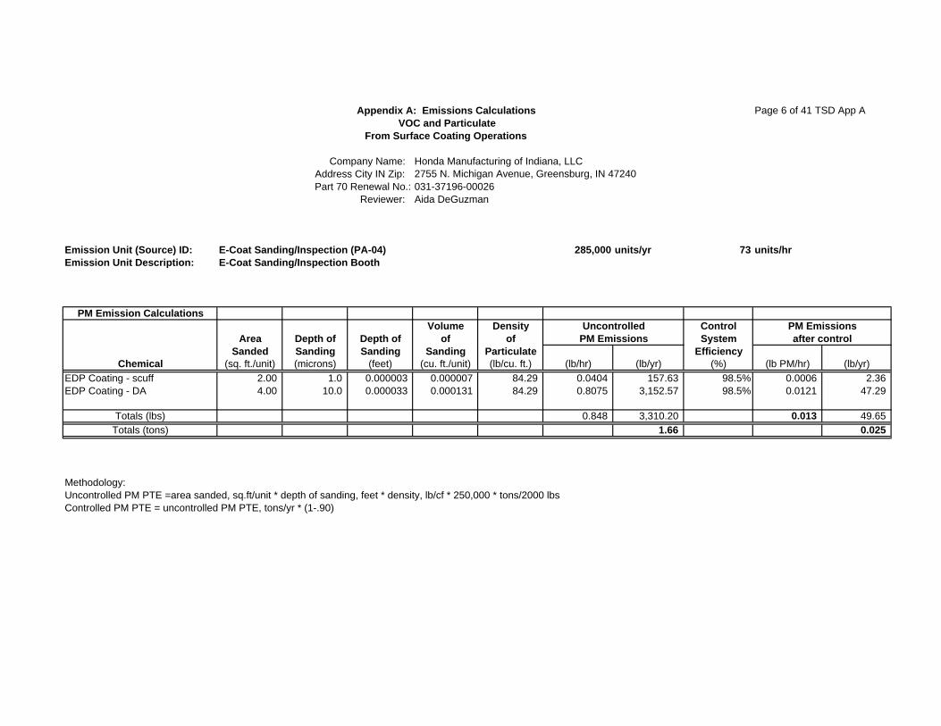
Appendix A: Emissions Calculations Page 6 of 41 TSD App A VOC and Particulate
From Surface Coating Operations
Company Name: Honda Manufacturing of Indiana, LLCAddress City IN Zip: 2755 N. Michigan Avenue, Greensburg, IN 47240Part 70 Renewal No.: 031-37196-00026
Reviewer: Aida DeGuzman
Emission Unit (Source) ID: E-Coat Sanding/Inspection (PA-04) 285,000 units/yr 73 units/hrEmission Unit Description: E-Coat Sanding/Inspection Booth
PM Emission CalculationsVolume Density Control
Area Depth of Depth of of of SystemSanded Sanding Sanding Sanding Particulate Efficiency
Chemical (sq. ft./unit) (microns) (feet) (cu. ft./unit) (lb/cu. ft.) (lb/hr) (lb/yr) (%) (lb PM/hr) (lb/yr)EDP Coating - scuff 2.00 1.0 0.000003 0.000007 84.29 0.0404 157.63 98.5% 0.0006 2.36 EDP Coating - DA 4.00 10.0 0.000033 0.000131 84.29 0.8075 3,152.57 98.5% 0.0121 47.29
Totals (lbs) 0.848 3,310.20 0.013 49.65 Totals (tons) 1.66 0.025
Methodology:Uncontrolled PM PTE =area sanded, sq.ft/unit * depth of sanding, feet * density, lb/cf * 250,000 * tons/2000 lbsControlled PM PTE = uncontrolled PM PTE, tons/yr * (1-.90)
PM Emissionsafter control
UncontrolledPM Emissions

Appendix A: Emissions Calculations Page 7 of 41 TSD App AVOC and Particulate
From Surface Coating Operations
Company Name: Honda Manufacturing of Indiana, LLCAddress City IN Zip: 2755 N. Michigan Avenue, Greensburg, IN 47240Part 70 Renewal No.: 031-37196-00026
Reviewer: Aida DeGuzman
Emission Unit (Source) ID: Surfacer Sanding/Inspection Booth (PA-06) 285,000 units/yr 73 units/hrEmission Unit Description: Surfacer Sanding/Inspection Booth
PM Emission CalculationsVolume Density Control
Area Depth of Depth of of of SystemSanded Sanding Sanding Sanding Particulate Efficiency
Chemical (sq. ft./unit) (microns) (feet) (cu. ft./unit) (lb/cu. ft.) (lb/hr) (lb/yr) (%) (lb PM/hr) (lb/yr)EDP Coating 1.00 10.0 0.000033 0.000033 84.29 0.20 788.14 98.5% 0.00 11.82 Primer Coating 9.00 12.5 0.000041 0.000369 99.90 2.69 10,508.64 98.5% 0.04 157.63
Totals 0.000402 2.89 11,296.78 0.04 169.45 Totals (tons) 5.65 0.085
Methodology:Uncontrolled PM PTE =area sanded, sq.ft/unit * depth of sanding, feet * density, lb/cf * 250,000 * tons/2000 lbsControlled PM PTE = uncontrolled PM PTE, tons/yr * (1-.90)
UncontrolledPM Emissions
PM Emissionsafter control

Appendix A: Emissions Calculations Page 8 of 41 TSD APP AVOC and Particulate
From Surface Coating Operations
Company Name: Honda Manufacturing of Indiana, LLCAddress City IN Zip: 2755 N. Michigan Avenue, Greensburg, IN 47240Part 70 Renewal No.: 031-37196-00026
Reviewer: Aida DeGuzman
Emission Unit (Source) ID: On-Line Repair Sanding Booth (PA-08) 35,000 units/yr 12 units/hrEmission Unit Description: On-Line Repair Sanding Booth
PM Emission CalculationsVolume Density Control
Area Depth of Depth of of of SystemSanded Sanding Sanding Sanding Particulate Efficiency
Chemical (sq. ft./unit) (microns) (feet) (cu. ft./unit) (lb/cu. ft.) (lb/hr) (lb/yr) (%) (lb PM/hr) (lb/yr)EDP Coating 1.00 10.0 0.000033 0.000033 84.29 0.0332 96.79 98.5% 0.0005 1.45 Primer Coating 4.00 35.0 0.000115 0.000459 99.90 0.5506 1,606.00 98.5% 0.0083 24.09 Basecoat 10.00 8.0 0.000026 0.000262 106.15 0.3343 975.13 98.5% 0.0050 14.63 Clearcoat 32.00 20.0 0.000066 0.002100 68.68 1.7305 5,047.33 98.5% 0.0260 75.71
Totals (lbs) 0.002854 2.649 7,725.25 0.040 115.88 Totals (tons) 3.86 0.06
Methodology:Uncontrolled PM PTE =area sanded, sq.ft/unit * depth of sanding, feet * density, lb/cf * 250,000 * tons/2000 lbsControlled PM PTE = uncontrolled PM PTE, tons/yr * (1-.90)
UncontrolledPM Emissions
PM Emissionsafter control

Appendix A: Emissions Calculations Page 9 of 41 TSD App AVOC and Particulate
From Surface Coating Operations
Company Name: Honda Manufacturing of Indiana, LLCAddress City IN Zip: 2755 N. Michigan Avenue, Greensburg, IN 47240Part 70 Renewal No.: 031-37196-00026
Reviewer: Aida DeGuzman
Emission Unit (Source) ID: Topcoat On-line Repair Process (PA-07) units/yr units/hrEmission Unit Description: Maximum Production 285,000 88
Maximum Repair 35,000 12
ANNUAL EMISSION CALCULATIONS
Material Booth Oven IncineratorVolume %
Water
Material Usage Less Water
Usage Capture Capture EfficiencyChemical (gal/unit) (gal/yr) (%) (%) (%) (gal/yr)
Repair - Primer 0.030 1,050 4.12 4,326 0.00% 0.00% 95.0% 4,326 0.0% 1050Spot Primer 0.007 245 5.91 1,448 0.00% 0.00% 95.0% 1,448 0.0% 245Repair - basecoat 0.060 2,100 4.69 9,849 0.00% 0.00% 95.0% 9,849 0.0% 2100Repair - clearcoat 0.060 2,100 4.26 8,946 0.00% 0.00% 95.0% 8,946 0.0% 2100
Total (tons) 5,495 12.28 12.28 5495Total 1364.94
Material Coating Solid Total Transfer Uncontrolled Scrubber Emissions Solids SolidsUsage Density Content Solids Efficiency Emissions Efficiency after Control Content Applied
Chemical (gal/unit) (gal/yr) (lb/gal) (%wt) (lb/yr) (%) (lb PM/yr) (%) (lb PM/yr) (%vol) (gal/yr)Repair - Primer 0.030 1,050 10.47 60.57% 6,659 40.00% 3,995 99.00% 40 46.30% 194 Spot Primer 0.007 245 8.53 30.78% 643 40.00% 386 99.00% 4 18.25% 18 Repair - basecoat 0.060 2,100 8.74 65.70% 12,059 40.00% 7,235 99.00% 72 46.42% 390 Repair - clearcoat 0.060 2,100 8.35 65.70% 11,520 40.00% 6,912 98.00% 138 58.16% 489
Total (tons) 5,495 15.44 9.26 0.13 1,091
HAP COMPONENT EMISSION CALCULATIONSMaterialUsage
Chemical (gal/hr)Repair - Primer 0.72 0.22 - - - - - - - - - - - - - - - Spot - Primer 0.17 0.86 1.72 0.43 - - - - - - - - - - - - - Repair - basecoat 1.44 1.35 0.31 0.31 - 0.10 0.21 - - 0.39 - - - - - - - Repair - clearcoat 1.44 1.11 - 0.42 0.42 0.08 0.17 0.09 0.08 - - - - - - - 0.11
MaterialUsage
Chemical (gal/hr)Repair - Primer 1,050.00 0.12 - - - - - - - - - - - - - - - Spot - Primer 245.00 0.11 0.21 0.05 - - - - - - - - - - - - - Repair - basecoat 2,100.00 1.42 0.33 0.33 - 0.11 0.22 - - 0.41 - - - - - - - Repair - clearcoat 2,100.00 1.17 - 0.44 0.42 0.08 0.18 0.09 0.08 - - - - - - - 0.12
Total 5,495.00 1.42 0.33 0.44 0.42 0.11 0.22 0.09 0.08 0.41 - - - - - - 0.12
Methodology: 3.63 VOC or HAPs Uncontrolled PTE = usage, gal/yr * VOC or HAP lb/gal * ton/2000 lb 1.42 VOC or HAPs Controlled PTE = usage, gal/yr * VOC or HAP lb/gal * ton/2000 lb * (1-(% booth capture + % oven capture/carry over) * % incinerator DRE)PM Uncontrolled PTE = usage, gal/yr * coating density, lb/gal * % solids * ton/2000 lb * (1-transfer efficiency) PM Controlled PTE = Uncontrolled PTE, tons/yr * (1-scubber efficiency) * (1-filter efficiency)lb/gacs after control = VOC emissions after control, lbs/yr * yr/gallons, solids applied
VOC(lb VOC/gal) (lb/yr) (lb/yr)
Methyl Isobutyl Ketone
108-88-3
Hexane110-54-3
Phenol108-95-2
Cumene98-82-8
Xylene1330-20-7
Toluene108-88-3
Ethyl benzene100-41-4
Form-aldehyde50-00-0
Methanol67-56-1
Naph-thalene91-20-3
Styrene100-42-5
Methanol67-56-1
Naphthalene91-20-3
2-Butoxyethyl
AcetatePhenol
108-95-2Styrene100-42-5
HAP Component (lb/gal of coating)
Xylene1330-20-7
Toluene108-88-3
Ethyl benzene100-41-4
Formaldehyde50-00-0
Cumene98-82-8
Source includes small repair booth & IR ovens, On-line Repair Booth & Oven
Annual VOC & HAP Emission Calculations
Annual PM Emission Calculations
As Applied
VOC ContentVOC
Worst Single HAP
HAP Component Emissions (tons/yr) - before control/after control
TOTAL HAP
Emissions after control
Chloroform67-66-3
Chloroform67-66-3
Di-Sec-Octyl Phthalate117-81-7
2-Butoxyethyl
Acetate
Ethylene Glycol
Monohexyl
2-(2-Butoxy-ethoxy) Ethanol
Uncontrolled Emissions
Di-Sec-Octyl Phthalate117-81-7
Ethylene Glycol
Monohexyl
2-(2-Butoxy-ethoxy) Ethanol
Methyl Isobutyl Ketone
108-88-3
Hexane110-54-3

Appendix A: Emissions Calculations Page 10 of 41 TSD App A VOC and Particulate
From Surface Coating Operations
Company Name: Honda Manufacturing of Indiana, LLCAddress City IN Zip: 2755 N. Michigan Avenue, Greensburg, IN 47240Part 70 Renewal No.: 031-37196-00026
Reviewer: Aida DeGuzman
Emission Unit (Source) ID: Topcoat In-line Repair (PA-09) units/yr units/hrEmission Unit Description: Production Max 285,000 88
ANNUAL EMISSION CALCULATIONS
Material Booth Oven IncineratorUsage Capture Capture Efficiency
Chemical (gal/unit) (gal/yr) (%) (%) (%)Air Dry Coatings 0.0012 342 3.6667 1,254 0.00% 0.00% 95.0% 1,254
Total (tons) 342 0.63 0.63
Methodology:VOC Uncontrolled PTE = usage, gal/yr * VOC or HAP lb/gal * ton/2000 lb VOCControlled PTE = usage, gal/yr * VOC or HAP lb/gal * ton/2000 lb * (1-(% booth capture + % oven capture/carry over) * % incinerator DRE)
VOC(lb/yr)
Emissions after controlUncontrolled EmissionsVOC(lb/yr)
Source includes repair area for small interior topcoat imperfections, manual application equipment
Annual VOC & HAP Emission Calculations As Applied
Content(lb VOC/gal)
VOC

Appendix A: Emissions Calculations Page 11 of 41 TSD App A VOC and Particulate
From Surface Coating Operations
Company Name: Honda Manufacturing of Indiana, LLCAddress City IN Zip: 2755 N. Michigan Avenue, Greensburg, IN 47240Part 70 Renewal No.: 031-37196-00026
Reviewer: Aida DeGuzman
Emission Unit (Source) ID: Topcoat Inspection Sanding (PA-10) 285,000 units/yr 80 units/hrEmission Unit Description: Topcoat Inspection Sanding Area - manual sanding
VOC Emission Factor (lb/unit)PM/PM10/PM2.5 Emission Factor
(lb/unit)
VOC Emission (tons/yr)
PM/PM10/PM2.5 Emissions (tons/yr)
0.0007533 0.00075 0.11 0.11

Appendix A: Emissions Calculations Page 12 of 41 TSD App A VOC and Particulate
From Surface Coating Operations
Company Name: Honda Manufacturing of Indiana, LLCAddress City IN Zip: 2755 N. Michigan Avenue, Greensburg, IN 47240Part 70 Renewal No.: 031-37196-00026
Reviewer: Aida DeGuzman
Emission Unit (Source) ID: Blackout/Wax Coating Line (PA-11) 285,000 units/yr 80 units/hrEmission Unit Description: Blackout/Wax Coating Booth
ANNUAL EMISSION CALCULATIONS
Material VOC HAP Booth Oven IncineratorUsage Content Content VOC HAP Capture Capture Efficiency VOC HAP
Chemical (gal/unit) (gal/yr) (lb VOC/gal) (lb HAP/gal) (lb/yr) (lb/yr) (%) (%) (%) (lb/yr) (lb/yr)Blackout 0.003 855 0.62 0.00 530 0 0.00% 0.00% 95.00% 530 0Wax 0.030 5,371 2.88 0.00 15,468 0 0.00% 0.00% 95.00% 15,468 0
Total (tons) 6,226 8.00 0.00 8.00 0.00Blackout 0.62 lb/galwax 2.88 lb/gal
vol wt. ave. 2.57 lb/gal
FilterMaterial Coating Solid Total Transfer Uncontrolled Removal Emissions Solids SolidsUsage Density Content Solids Efficiency Emissions Efficiency after Control Content Applied
Chemical (gal/unit) (gal/yr) (lb/gal) (%wt) (lb/yr) (%) (lb PM/yr) (%) (lb PM/yr) (%vol) (gal/yr)Blackout 0.003 855 8.81 28.32% 2,133 40.00% 1,280 98.00% 25.60 50.38% 172Wax 0.030 5,371 7.30 61.30% 24,035 99.00% 240 98.00% 4.81 42.80% 2,276
Total (tons) 6,226 13.08 0.76 0.02 2,448
Methodology:VOC or HAPs Uncontrolled PTE = usage, gal/yr * VOC or HAP lb/gal * ton/2000 lb VOC or HAPs Controlled PTE = usage, gal/yr * VOC or HAP lb/gal * ton/2000 lb * (1-(% booth capture + % oven capture/carry over) * % incinerator DRE)PM Uncontrolled PTE = usage, gal/yr * coating density, lb/gal * % solids * ton/2000 lb * (1-transfer efficiency) PM Controlled PTE = Uncontrolled PTE, tons/yr * (1-scubber efficiency) * (1-filter efficiency)Vol. weighted average,lb/gal after control = VOC emissions after control, lbs/yr * yr/gallons coating usage
Uncontrolled Emissions Emissions after control
Annual PM Emission Calculations
Annual VOC & HAP Emission Calculations As Applied

Appendix A: Emissions Calculations Page 13 of 41 TSD APP A VOC and Particulate
From Surface Coating Operations
Company Name: Honda Manufacturing of Indiana, LLCAddress City IN Zip: 2755 N. Michigan Avenue, Greensburg, IN 47240Part 70 Renewal No.: 031-37196-00026
Reviewer: Aida DeGuzman
Emission Unit (Source) ID: Final Repair (PA-12) Units/yr units/hrEmission Unit Description: Production Max 285,000 88
Repair 57,000 30
HOURLY EMISSION CALCULATIONS
ANNUAL EMISSION CALCULATIONS
Material VOC HAP Booth Oven Incinerator Volume % Pound /GallonUsage Content Content VOC HAP Capture Capture Efficiency VOC HAP Water Less Water
Chemical (gal/unit) (gal/yr) (lb VOC/gal) (lb HAP/gal) (lb/yr) (lb/yr) (%) (%) (%) (lb/yr) (lb/yr)Repair - Primer 0.0030 171 4.12 0.22 705 38 0.00% 0.00% 95.0% 705 38 0.00% 4.12 Repair - basecoat 0.0070 399 4.69 1.71 1,871 682 0.00% 0.00% 95.0% 1,871 682 0.00% 4.69 Clearcoat 0.0120 684 4.26 1.53 2,914 1,047 0.00% 0.00% 95.0% 2,914 1,047 0.00% 4.26
Total (tons) 1,254 2.74 0.88 2.74 0.88 All coatings are in compliance with the limit of 4.8 lb/gal less water in 326 IAC 8-2-2.
FilterMaterial Coating Solid Total Transfer Uncontrolled Removal Emissions Solids SolidsUsage Density Content Solids Efficiency Emissions Efficiency after Control Content Applied
Chemical (gal/unit) (gal/yr) (lb/gal) (%wt) (lb/yr) (%) (lb PM/yr) (%) (lb PM/yr) (%vol) (gal/yr)Repair - Primer 0.0030 171 11.23 67.57% 1,298 25.00% 973 98.00% 19.5 52.65% 22.51 Repair - basecoat 0.0070 399 9.94 59.28% 2,351 25.00% 1,763 98.00% 35.3 42.16% 42.05 Clearcoat 0.0120 684 9.75 63.17% 4,213 25.00% 3,160 98.00% 63.2 49.42% 84.51
Total (tons) 1,254 3.93 2.95 0.06 149.07
HAP COMPONENT EMISSION CALCULATIONSMaterialUsage
Chemical (gal/hr)Repair - Primer 0.18 0.22 - - - - - - - - - - - - - - - Repair - basecoat 0.42 1.44 0.31 0.31 - 0.10 0.21 - - 0.39 - - - - - - - Clearcoat 0.72 1.44 - 0.42 0.42 0.08 0.17 0.09 0.08 - - - - - - - 0.11
- -
MaterialUsage
Chemical (gal/yr)Repair - Primer 150.00 0.02 - - - - - - - - - - - - - - - Repair - basecoat 350.00 0.25 0.05 0.05 - 0.02 0.04 - - 0.07 - - - - - - - Clearcoat 600.00 0.43 - 0.13 0.13 0.02 0.05 0.03 0.02 - - - - - - - 0.03
Total 1,100.00 0.33 0.05 0.13 0.13 0.02 0.05 0.03 0.02 0.07 - - - - - - 0.03 Note: 0.86 tons/yr total HAPs is worse than 0.77 ton/yr determined in the first table of this page. Worst TOTAL HAP 0.86
Worst Single HAP 0.33 Methodology:VOC or HAPs Uncontrolled PTE = usage, gal/yr * VOC or HAP lb/gal * ton/2000 lb VOC or HAPs Controlled PTE = usage, gal/yr * VOC or HAP lb/gal * ton/2000 lb * (1-(% booth capture + % oven capture/carry over) * % incinerator DRE)PM Uncontrolled PTE = usage, gal/yr * coating density, lb/gal * % solids * ton/2000 lb * (1-transfer efficiency) PM Controlled PTE = Uncontrolled PTE, tons/yr * (1-scubber efficiency) * (1-filter efficiency)Pound/gallon less water = coating VOC content, lb/gal / 1-volume % water
Ethylene Glycol
Monohexy
2-(2-Butoxy-ethoxy) Ethanol
Di-Sec-Octyl Phthalate117-81-7
Chloroform67-66-3
Methyl Isobutyl Ketone
Hexane110-54-3
Phenol108-95-2
2-Butoxyethyl Acetate
112-07-2Methanol67-56-1
Naph-thalene91-20-3
Styrene100-42-5
Xylene1330-20-7
Toluene108-88-3
Ethyl benzene100-41-4
Form-aldehyde50-00-0
Cumene98-82-8
Hexane110-54-3
Phenol108-95-2
2-Butoxyethyl Acetate
112-07-2
Ethylene Glycol
MonohexyMethanol67-56-1
Naph-thalene91-20-3
Styrene100-42-5
HAP Component Emissions (tons/year) - before control/after control
Xylene1330-20-7
Toluene108-88-3
Ethyl benzene100-41-4
Form-aldehyde50-00-0
Chloroform67-66-3
2-(2-Butoxy-ethoxy) Ethanol
Cumene98-82-8
Source includes repair coating booths and general areas, manual application equipment, IR curing equipment, coating delivery systems, & ovens
Annual VOC & HAP Emission Calculations
Annual PM Emission Calculations
As Applied
Di-Sec-Octyl Phthalate117-81-7
Emissions after controlUncontrolled Emissions
Methyl Isobutyl Ketone
HAP Component (lb/gal of coating)

Appendix A: Emissions Calculations Page 14 of 41 TSD App A VOC and Particulate
From Surface Coating Operations
Company Name: Honda Manufacturing of Indiana, LLCAddress City IN Zip: 2755 N. Michigan Avenue, Greensburg, IN 47240Part 70 Renewal No.: 031-37196-00026
Reviewer: Aida DeGuzman
Emission Unit (Source) ID: Final Repair - Air Dry (PA-13) Units/yr units/hrEmission Unit Description: Production Max 285,000 88
Repair 57,000 30
ANNUAL EMISSION CALCULATIONS
Material Booth Oven IncineratorUsage Capture Capture Efficiency
Chemical (gal/unit) (gal/yr) (%) (%) (%)Air Dry Coatings 0.0026 148 6.37 944 0.00% 0.00% 95.0% 944
Total (tons) 148 0.47 0.47
Material Coating Solid Total Transfer Uncontrolled Removal Emissions Solids SolidsUsage Density Content Solids Efficiency Emissions Efficiency after Control Content Applied
Chemical (gal/unit) (gal/yr) (lb/gal) (%wt) (lb/yr) (%) (lb PM/yr) (%) (lb PM/yr) (%vol) (gal/yr)Air Dry Coatings 0.0026 148 7.91 27.33% 320 25.00% 240 0.00% 240.3 15.04% 5.57
Total (tons) 148 0.16 0.12 0.12 5.57
HAP COMPONENT EMISSION CALCULATIONSMaterialUsage
Chemical (gal/hr)Air Dry Coatings 0.12 1.81 3.93 0.51 0.42 0.08 0.42 0.09 0.08 1.58 - - 0.37 - - - 0.11
MaterialUsage
Chemical (gal/yr)Air Dry Coatings 130.00 0.12 0.26 0.03 0.03 0.01 0.03 0.01 0.01 0.10 - - 0.02 - - - 0.01
Total 130.00 0.12 0.26 0.03 0.03 0.01 0.03 0.01 0.01 0.10 - - 0.02 - - - 0.01
Total HAPs 0.61 Limit = <15 lb/day to avoid 326 IAC 8-2-2 Worst Single HAP 0.26
Methodology:VOC or HAPs Uncontrolled PTE = usage, gal/yr * VOC or HAP lb/gal * ton/2000 lb VOC or HAPs Controlled PTE = usage, gal/yr * VOC or HAP lb/gal * ton/2000 lb * (1-(% booth capture + % oven capture/carry over) * % incinerator DRE)PM Uncontrolled PTE = usage, gal/yr * coating density, lb/gal * % solids * ton/2000 lb * (1-transfer efficiency) PM Controlled PTE = Uncontrolled PTE, tons/yr * (1-scubber efficiency) * (1-filter efficiency)lb/gacs after control = VOC emissions after control, lbs/yr * yr/gallons,solids applied
Chloroform67-66-3
Chloroform67-66-3
Phenol108-95-2
2-Butoxyethyl Acetate
112-07-2
2-(2-Butoxy-ethoxy) Ethanol
112-34-5
Di-Sec-Octyl Phthalate117-81-7
2-(2-Butoxy-ethoxy) Ethanol
112-34-5
Di-Sec-Octyl Phthalate117-81-7
Ethylene Glycol Monohexyl Ether
112-25-4
Ethylene Glycol Monohexyl Ether
112-25-4
Ethyl benzene100-41-4
Form-aldehyde50-00-0
Phenol108-95-2
2-Butoxyethyl Acetate
112-07-2
Methyl Isobutyl Ketone
Hexane110-54-3
HAP Component Emissions (tons/yr) - before control/after control
Hexane110-54-3
Cumene98-82-8
Methanol67-56-1
Naph-thalene91-20-3
Ethyl benzene100-41-4
Form-aldehyde50-00-0
Cumene98-82-8
Xylene1330-20-7
Methanol67-56-1
Styrene100-42-5
Methyl Isobutyl Ketone
Naph-thalene91-20-3
Styrene100-42-5
Toluene108-88-3
Source includes repair coating areas using air dry materials, manual application equipment
HAP Component (lb/gal of coating)
Xylene1330-20-7
Toluene108-88-3
Emissions after controlUncontrolled EmissionsAnnual VOC Emission Calculations
Annual PM Emission Calculations
As Applied VOC
Content(lb VOC/gal)
VOC(lb/yr)
VOC(lb/yr)

Appendix A: Emissions Calculations Page 15 of 41 TSD App A VOC and Particulate
From Surface Coating Operations
Company Name: Honda Manufacturing of Indiana, LLCAddress City IN Zip: 2755 N. Michigan Avenue, Greensburg, IN 47240Part 70 Renewal No.: 031-37196-00026
Reviewer: Aida DeGuzman
Emission Unit (Source) ID: Miscellaneous Cleaning & Purge Solvent (PA-14) 285,000 units/yrEmission Unit Description:
Usage VOC VOC HAP HAPContent Emissions Content Emissions
Chemical (gal/yr) (lb VOC/gal) (lb VOC/yr) (lb HAP/gal) (lb HAP/yr)Purge Solvent (6-75-584) 35,000 7.29 255,150 4.37 152,950 Cleaning Solvent - A (B/A) 5,200 7.35 38,220 - - Cleaning Solvent - B (SC-100) 3,100 7.30 22,630 0.82 2,542 Cleaning Solvent - C (3608S) 2,750 4.62 12,705 1.02 2,805 Cleaning Solvent - D (SC-150) 2,500 7.49 18,725 1.42 3,550 Cleaning Solvent - E (IPA) 2,500 6.55 16,375 - - Purge Recovery (90% of purge) (229,635) (137,655)
Totals 51,050 134,170 24,192Totals (tons) 67.09 12.10
@4,000 hrs/y 33.54 lb VOC/hr 6.05 lb HAP/hr
HAP COMPONENT EMISSION CALCULATIONS
MaterialUsage
Chemical (gal/r)Purge Solvent (6-75-584) 8.75 3.65 - 0.73 - - - - - - - - - - - - - Cleaning Solvent - A (B/A) 1.30 1.42 1.42 1.42 - 0.11 1.42 0.60 0.08 1.42 - - - - - - - Cleaning Solvent - B (SC-100) 0.78 1.42 1.42 1.42 - 0.11 1.42 0.60 0.08 1.42 - - - - - - -
MaterialUsage
Chemical (gal/yr)Purge Solvent (6-75-584) 35,000.00 63.88 - 12.78 - - - - - - - - - - - - - Cleaning Solvent - A (B/A) 5,200.00 3.69 3.69 3.69 - 0.29 3.69 1.56 0.21 3.69 - - - - - - - Cleaning Solvent - B (SC-100) 3,100.00 2.20 2.20 2.20 - 0.17 2.20 0.93 0.12 2.20 - - - - - -
Total 43,300.00 69.77 5.89 18.67 - 0.46 5.89 2.49 0.33 5.89 - - - - - - - Note: 109.39 tons/yr total HAPs is worse than 12.1 ton/yr determined in the first table of this page. Worst TOTAL HAP 109.39
Worst Single HAP 69.77
Di-Sec-Octyl Phthalate117-81-7
Chloroform67-66-3
Methyl Isobutyl Ketone
Hexane110-54-3
Phenol108-95-2
2-Butoxye
thyl
HAP Component (lb/gal) - before control/after control
Formaldehyde50-00-0
Ethylene Glycol
Monohexyl
2-(2-Butoxy-ethoxy)
Cumene98-82-8
Methanol67-56-1
Naph-thalene91-20-3
Styrene100-42-
5
Hexane110-54-3
Phenol108-95-2
Methanol67-56-1
Naph-thalene91-20-3
Styrene100-42-
5
Methyl Isobutyl Ketone
Ethyl benzene100-41-4
Xylene1330-20-7
Toluene108-88-3
Ethyl benzene100-41-4
Form-aldehyde50-00-0
2-(2-Butoxy-ethoxy)
Di-Sec-Octyl Phthalate117-81-7
Chloroform67-66-3
2-Butoxye
thyl
Ethylene Glycol
Monohexyl
Purge solvent usage and cleaning activities throughout the paint
HAP Component (lb/gal of coating)
Xylene1330-20-7
Toluene108-88-3
Cumene98-82-8
VOC Emission Calculations

Appendix A: Emissions Calculations Page 16 of 41 TSD App A VOC and Particulate
From Surface Coating Operations
Company Name: Honda Manufacturing of Indiana, LLCAddress City IN Zip: 2755 N. Michigan Avenue, Greensburg, IN 47240Part 70 Renewal No.: 031-37196-00026
Reviewer: Aida DeGuzman
Emission Unit (Source) ID: Paint Test Lab (PA-16) panels/yr panels/hrEmission Unit Description: Production Max 1,000 15
ANNUAL EMISSION CALCULATIONS
Material Booth Oven IncineratorUsage Capture Capture Efficiency VOC HAP
Chemical gram/panel (gal/yr) (%) (%) (%) (lb/yr) (lb/yr)Repair - Primer 31.0 6 4.12 25 0.00% 0.00% 95.0% 25 0Repair - basecoat 46.0 10 4.69 48 0.00% 0.00% 95.0% 48 0Clearcoat 22.0 5 4.26 21 0.00% 0.00% 95.0% 21 0
Total (tons) 21 0.05 - 0.05 -
Material Avg. Coating Avg. Solid Total Transfer Uncontrolled Removal Emissions Solids SolidsUsage Density Content Solids Efficiency Emissions Efficiency after Control Content Applied
Chemical gram/panel (gal/yr) (lb/gal) (%wt) (lb/yr) (%) (lb PM/yr) (%) (lb PM/yr) (%vol) (gal/yr)Repair - Primer 31.0 6.08 11.23 67.57% 46 25.00% 35 95.00% 1.7 52.65% 0.80 Repair - basecoat 46.0 10.19 9.94 59.28% 60 25.00% 45 95.00% 2.3 42.16% 1.07 Clearcoat 22.0 4.97 9.75 63.17% 31 25.00% 23 95.00% 1.1 49.42% 0.61
Total (tons) 21.24 0.07 0.05 0.00 2.49
HAP COMPONENT EMISSION CALCULATIONSHAP Component (lb/gal) of Coating
MaterialUsage
Chemical (gal/hr)Repair -Primer 0.09 0.22 - - - - - - - - - - - - - - - Repair - basecoat 0.15 1.35 0.31 0.31 - 0.21 0.21 - - 0.39 - - - - - - - Clearcoat 0.07 1.11 - 0.42 0.42 0.17 0.17 0.09 0.08 - - - - - - - 0.11
MaterialUsage
Chemical (gal/yr)Repair -Primer 6.00 0.00 - - - - - - - - - - - - - - - Repair - basecoat 10.00 0.01 0.00 0.00 - 0.00 0.00 - - - - - - - - - - Clearcoat 5.00 0.00 - 0.00 0.00 0.00 0.00 - 0.00 - - - - - - - 0.00
Total 21.00 0.01 0.00 0.00 0.00 0.00 0.00 0.00 0.00 - - - 0.00 TOTAL HAP 0.01
Methodology: Worst Single HAP 0.01VOC or HAPs Uncontrolled PTE = usage, gal/yr * VOC or HAP lb/gal * ton/2000 lb VOC or HAPs Controlled PTE = usage, gal/yr * VOC or HAP lb/gal * ton/2000 lb * (1-(% booth capture + % oven capture/carry over) * % incinerator DRE)PM Uncontrolled PTE = usage, gal/yr * coating density, lb/gal * % solids * ton/2000 lb * (1-transfer efficiency) PM Controlled PTE = Uncontrolled PTE, tons/yr * (1-scubber efficiency) * (1-filter efficiency)lb/gacs after control = VOC emissions after control, lbs/yr * yr/gallons,solids applied
As Applied Emissions after controlUncontrolled Emissions
Test lab for material quality
Annual VOC & HAP Emission Calculations VOC
Annual PM Emission Calculations
Methyl Isobutyl Ketone
Xylene1330-20-7
Toluene108-88-3
Ethyl benzene100-41-4
Form-aldehyde50-00-0
2-(2-Butoxy-ethoxy) Ethanol
Di-Sec-Octyl Phthalate117-81-7
Chloroform67-66-3
Content VOC(lb/yr)(lb VOC/gal)
Ethylene Glycol
Monohexyl
HAP Component Emissions (tons/yr) - before control/after control
Hexane110-54-3
Phenol108-95-2
2-Butoxyethyl Acetate
112-07-2Methanol67-56-1
Cumene98-82-8
Naph-thalene91-20-3
Styrene100-42-5
Xylene1330-20-7
Toluene108-88-3
Ethyl benzene100-41-4
Form-aldehyde50-00-0
Cumene98-82-8
Methanol67-56-1
Ethylene Glycol
Monohexyl
2-(2-Butoxy-ethoxy) Ethanol
Di-Sec-Octyl Phthalate117-81-7
Chloroform67-66-3
Naph-thalene91-20-3
Styrene100-42-5
Methyl Isobutyl Ketone
Hexane110-54-3
Phenol108-95-2
2-Butoxyethyl Acetate
112-07-2

Appendix A: Emissions Calculations Page 17 of 41 TSD App A VOC and Particulate
From Surface Coating Operations
Company Name: Honda Manufacturing of Indiana, LLCAddress City IN Zip: 2755 N. Michigan Avenue, Greensburg, IN 47240Part 70 Renewal No.: 031-37196-00026
Reviewer: Aida DeGuzman
Emission Unit (Source) ID: Paint Effluent System (PA-17) 285,000 units/yrEmission Unit Description: Main Body Paint Sludge Pit Operations
VOC Emission CalculationsUsage VOC VOC Density Material
Content Emissions UsageChemical (gal/yr) (lb VOC/gal) (lb VOC/yr) (lb/gal) (lb/yr)
Paint Kill 9512 57,000 0.01 570 8.59 489,630 PolyEZ 55452 4,600 1.19 5,474 8.42 38,732 PolyEZ 55451 1,800 1.09 1,962 8.42 15,156 Nalco 7330 - biocide 180 0.07 13 8.56 1,541
Totals 63,580 8,019 545,059Totals (tons/year) 4.01 272.53
HAP Emission CalculationsUsage HAP Maximum HAP
Content EmissionsChemical (gal/yr) (lb HAP/gal) (lb HAP/yr)
Paint Kill 9512 57,000 - - PolyEZ 55452 4,600 0.000 - PolyEZ 55451 1,800 0.000 - Nalco 7330 - biocide 180 0.000 -
Totals 63,580 0Totals (tons/year) 0.00

Appendix A: Emissions Calculations Page 18 of 41 TSD App A Particulate Emissions from Blasting Operation
Company Name: Honda Manufacturing of Indiana, LLCAddress City IN Zip: 2755 N. Michigan Avenue, Greensburg, IN 47240Part 70 Renewal No.: 031-37196-00026
Reviewer: Aida DeGuzman
Wheelabrator/Shotblaster (PA-15):
Customer: HONDA BCP Job #: B0500769R1Date:
1) FOR WHEEL BLAST EQUIPMENT :
D/C Type: FILTER COLLECTORAir flow: 2,800 CFM @ 70 F D/C Size: JPSM-2D 6Hour/day: 24 Filter media:Days/week: 7 A/C Ratio 2.1212:1Weeks/yr: 50 Work piece area: 35 sq.ft.
Wheel Data: 15" dia x 2.5" wide, single sided
Wheel Dia. RPM Velocity(inches) fps 7.5 10 15 20 25 30
10.5 3600 210 275 385 565 715 91512.5 3600 240 210 295 435 550 700 86913.5 3600 265 180 240 360 450 580 710
15 3600 300 280 350 450 55015 3000 250 405 505 650 790
17.5 3600 350 205 255 330 40517.5 3000 290 300 375 480 59019.5 3000 320 245 305 395 485
24 1800 240 435 550 700 86026 1800 265 380 460 590 730
16/11/2005
Throwing capacity (lbs/min @ HP)
CARTR 220

Company Name: Honda Manufacturing of Indiana, LLC Page 19 of 41 TSD App AAddress City IN Zip: 2755 N. Michigan Avenue, Greensburg, IN 47240
Part 70 Operating Permit Renewal No.: 031-30127Plt ID: 031-00026
Reviewer: Aida DeGuzman Application Receipt Date : 1/18/2011
Wheel Dia. RPM Velocity(inches) fps 40 50 60 75 100
10.5 3600 21012.5 3600 240 114013.5 3600 265 930 1120 1350
15 3600 300 725 870 1050 1350 180015 3000 250 1045 1250 1510 1940 2590
17.5 3600 350 532 640 770 990 132017.5 3000 290 775 930 1120 1445 192519.5 3000 320 635 765 920 1185 1580
24 1800 240 1130 1360 1640 2100 279226 1800 265 950 1150 1385 1780 2375
2) PRODUCTION :
Wheel Diameter 13 Motor Rpm 3600No. of Wheels: 1 Horsepower per wheel: 20Abrasive Thrown/ Wheel: 360 lbs/min Total Abrasive Thrown: 360 lbs/minEmpirical data: Cleaning rate varies from .5 to 1.5 sq.ft./min/wheel horsepower depending on
condition of work and cleanliness desired. Use 1.2 sq.ft./min/whl hpCleaning Rate = sq.ft. x 1 x 1 x 1 = minutes
part sq.ft. HP no.of partmin/whl hp wheel wheels
= 35 x 1 x 1 x 1 = 1.51 1.2 20 1
Production RateLoad conveyor 0.0Move part into machine 5.0Blast time 20.0Move part out of machine 5.0Unload conveyor 0.0Total Cycle Time 30.0 minutes
Percentage of blast time to total cycle time 66.7 %
Number of parts per hour 2.0
Number of sq.ft. per hour cleaned 70.0 sq.ft/hr
Yearly production= unit x hour x days x weeks = units hour day week year year
units = 2.0 x 24 x 7 x 50 = 16800year
Throwing capacity (lbs/min @ HP)

Company Name: Honda Manufacturing of Indiana, LLC Page 20 of 41 TSD App AAddress City IN Zip: 2755 N. Michigan Avenue, Greensburg, IN 47240
Part 70 Operating Permit Renewal No.: 031-30127Plt ID: 031-00026
Reviewer: Aida DeGuzman Application Receipt Date : 1/18/2011
3) DUST FROM WORK PIECE :
Surface contaminants:Area processed per hour 70.0 sq.ft/hrSurface material removed: = 0.085 lb/sq.ft.Total dust generated: = 6.0 lb/hrPercent dust to collector: 50 % = 3.0 lb/hr
4) DUST FROM ABRASIVE BREAKDOWN :
Abrasive type: ZINC 230 lb/cu.ft. Breakdown rate: 0.5 %Abrasive thrown = lb/min thrown x Percentage of blast time to total cycle time
360 x 66.7 /100 240 lb/min = 14,400 lb/hrTotal abrasive breakdown: 1.2 lb/min 72.0 lb/hrPercent dust to collector: 50 % = 36.0 lb/hr
5) DUST LOADING AND EMISSION :
Inlet dust loading to collector = Surface contaminants + Abrasive breakdown = 3.0 lb/hr + 36.0 lb/hr = 39.0 lb/hr
Inlet grain loading to collector = lb x hours x grains x minutes(1lb = 7000g = hour minutes lb cu.ft.
= 38.975 x 1 x 7000 x 160 1 2,800
= 1.62395833 gr/scfBefore Control PM Emissions= 3 lb/hr * 8760 hrs/yr * ton/2000 lb = 13.14 tons/yr
6) FILTER EFFICIENCY 99.80 % (This first filtration system that is in the wheel blast unit is used to recover the shots)
7) DUST EMISSION FROM DUST COLLECTOR EXHAUST :
Emission from collector = inlet dust load in gr/scf x 100-filter efficiency/100 = 1.624 x 0.002 = 0.0032 gr/scf
Metric units = grams x mg x cu.ft. x grains = mg/m3grains grams cu.meters cu.ft.
1 x 1000 x 1 x 0.0032 = 7.4415.4324 1 0.0283
Hourly emissions = 38.975 lb/hr x (100-filter eff.) x 100 = 0.08 lb/hrDaily emissions = 24 hr/day x 0.0780 lb/hr = 1.9 lb/dayYearly emissions = 350 days/yr x 1.8708 lb/day = 654.8 lb/year /20000
PAINT

Company Name: Honda Manufacturing of Indiana, LLC Page 21 of 41 TSD App AAddress City IN Zip: 2755 N. Michigan Avenue, Greensburg, IN 47240
Part 70 Operating Permit Renewal No.: 031-30127Plt ID: 031-00026
Reviewer: Aida DeGuzman Application Receipt Date : 1/18/2011
8) AFTER FILTER EFFICIENCY : = 95 % (This is a 2nd filtration system)
9) EMISSIONS FROM AFTER FILTER EXHAUST :
Emission from a/f filters = D/C emissions in gr/scf gr/scf x 100-filter efficiency/100 = 0.0032 x 0.05 = 0.00016 gr/scf
Metric units = grams x mg x cu.ft. x grains = mg/m3grains grams cu.meters cu.ft.
1 x 1000 x 1 x 0.0000 = 0.37215.4324 1 0.0283
Hourly emissions = 0.0780 lb/hr x (100-filter eff.) x 100 = 0.0039 lb/hrDaily emissions = 24 hr/day x 0.0039 lb/hr = 0.0935 lb/dayYearly emissions = 350 days/yr x 0.0935 lb/day = 32.7 lb/year
= 0.02 ton/yr
10) TOTAL SOLID WASTE COLLECTED :
= inlet load to == x 99.8 + 36.00 + 2.975 = 77.87 lb/hr
100Daily material collected = 24 hr/day x 77.8721 lb/hr = 1868.9 lb/dayYearly material collected = 350 days x 1868.9 lbs x 1 Ton
year day 2000 lbs= 327.1 Tons/year
(*) SPECIAL NOTES:
1) American Co 38.975Value) for "nuisance particulates" at…… 1 mg/m3. Emissions for above are………………. 0.372 mg/m3. This is…… 37.18 % of the TLV.
2) The above value is for the maximum surface area exposed to blasting at any time. This will relatively vary with the size and geometry of the components being cleaned.
3) The final value as stated in note.1 varies with the type of surface and rust on the components.Hence any change in surface / rust level will have direct impact on emission value.
4) The final value as stated in note.1 varies with time. Hence any change in loading-unloading will have direct impact on Emission value.
5) The final value as stated in note.1 varies with type and quality of abrasive media being used. Hence any change in quality of abrasive media will have direct impact on Emission value.
6) These calculations are strictly empirical and are based on the past field installation experience. Hence Wheelabrator is not responsible for any deviation in the values during actual field test.

Appendix A: Emissions Calculations Page 22 of 41 TSD App A Particulate Emissions from Blasting Operation
Company Name: Honda Manufacturing of Indiana, LLCAddress City IN Zip: 2755 N. Michigan Avenue, Greensburg, IN 47240Part 70 Renewal No.: 031-37196-00026
Reviewer: Aida DeGuzman
PTEControlled (tons/yr)
2000 98% 0.0032 0.240Uncontrolled
(tons/yr)Controlled Emissions (tons/yr) = Air Flow (acfm) x Grain Loading (g 12.014Uncontrolled Emission (tons/yr) = Controlled Emissions /(1 - Control Efficiency)
Limited PTE
PTE Uncontrolled Emissions (tons/yr)
2 8.760
Limited Potential Emissions (tons/yr) = Limited Emissions Rate (lb/hr) x 8760 hrs/yr x 1 ton/2,000 lbs
Air Flow (acfm)Control Efficiency
(%)Grain Loading
(gr/dscf)

Appendix A: Emissions Calculations Page 23 of 41 TSD App A VOC and Particulate
From Surface Coating Operations
Company Name: Honda Manufacturing of Indiana, LLCAddress City IN Zip: 2755 N. Michigan Avenue, Greensburg, IN 47240Part 70 Renewal No.: 031-37196-00026
Reviewer: Aida DeGuzman
Emission Unit (Source) ID: Fascia/Bumper Coating Line (PO-02) Production Maximum ProductionEmission Unit Description: Sets/hr Sets/yr
Annual Production Target 120 285,000
Repaint Hangers 120 42,750 Service Hangers 120 28,500
ANNUAL EMISSION CALCULATIONS
Material Avg VOC Avg HAP Booth Oven IncineratorHangers/yr Usage Content Content VOC HAP Capture Capture Efficiency VOC HAP
Chemical (gal/hanger) (gal/yr) (lb VOC/gal) (lb HAP/gal) (ton/yr) (ton/yr) (%) (%) (%) (ton/yr) (ton/yr)Waterborne Primer 0.127 285,000 36,195 1.03 0.27 19 5 0.00% 0.00% 0.00% 19 5Waterborne Repaint Primer 0.127 42,750 5,429 1.03 0.27 3 1 0.00% 0.00% 0.00% 3 1Solventborne Basecoat 0.158 327,750 51,621 4.35 0.48 112 12 90.00% 0.00% 95.00% 16 2Solventborne Clearcoat 0.150 327,750 49,163 4.57 0.37 112 9 80.00% 10.00% 95.00% 16 1Catalyst (Basecoat) 0.039 356,250 14,027 1.88 0.00 13 0 90.00% 0.00% 95.00% 2 0Catalyst (Clearcoat) 0.038 327,750 12,291 1.88 0.00 12 0 80.00% 10.00% 95.00% 2 0
Total (tons) 168,725 270.68 27.08 57.58 8.73
Type VOC (lb/gal) VOC (lb/gal)Before Control After Control
Material Avg. Coating Avg. Solid Total Transfer Uncontrolled Scrubber Emissions Primer Waterborne 1.03 1.03Usage Density Content Solids Efficiency Emissions Efficiency after Control BC Solventborne 3.87 0.56
Chemical (gal/unit) (gal/yr) (lb/gal) (%wt) (ton/yr) (%) (ton PM/yr) (%) (ton PM/yr) CC Solventborne 4.03 0.58Waterborne Primer 0.127 36,195 9.53 32.4% 56 25% 42 99.00% 0.42Waterborne Repaint Primer 0.127 5,429 9.53 32.4% 8 25% 6 99.00% 0.06 Overall Control Efficiency (%) 78.73%Solventborne Basecoat 0.158 51,621 8.27 49.9% 107 40% 64 99.00% 0.64 Material Usage VOC (lb/gal) VOC (lb/gal)Solventborne Clearcoat 0.150 49,163 8.12 45.6% 91 45% 50 99.00% 0.50 ga/yr Before Control After ControlCatalyst (Basecoat) 0.039 14,027 9.23 80.3% 52 40% 31 99.00% 0.31 SC 65,648 3.86 0.56Catalyst (Clearcoat) 0.038 12,291 9.23 80.3% 46 45% 25 99.00% 0.25 IP Booth 36195 1.01 1.01
Total (tons) 168,725 359.32 218.40 2.18 Including IP Painting Booth Weighted Averag 0.72
Methodology:Uncontrolled VOC/HAP Emissions (ton/yr) = [Number of Hangers/yr * Material Usage (gal/hanger) * Avg. VOC/HAP Content (lb (VOC/HAP)/gal)]/2000 lb/tonControlled VOC/HAP Emissions (ton/yr) = Uncontrolled Emissions (VOC/HAP (ton/yr) * [1- (Booth Capture Efficiency (%) + Oven Capture Efficiency (%) * Incinerator Efficiency (%)]
Primer VOC (lb/gal) Before Control = [Uncontrolled VOC (Waterborne Primer + Waterborne Repaint Primer) (ton/yr)] * (2000 lb/ton) / [Material Usage (Waterborne Primer + Waterborne Repaint Primer) (gal/yr)]Basecoat VOC (lb/gal) Before Control = [Uncontrolled VOC (Solventborne Basecoat + Solventborne Service Parts Basecoat + Catalyst (Basecoat)) (ton/yr)] * 2000 lb/ton / [Material Usage (Solventborne Basecoat+ Solventborne Service Parts Basecoat + Catalyst (Basecoat)) Clearcoat VOC (lb/gal) Before Control = [Uncontrolled VOC (Solventborne Clearcoat + Catalyst (Clearcoat)) (ton/yr)] * 2000 lb/ton / [Material Usage (Solventborne Clearcoat+ Catalyst (Clearcoat)) (gal/yr)]
Primer VOC (lb/gal) After Control = [Controlled VOC (Waterborne Primer + Waterborne Repaint Primer) (ton/yr)] * (2000 lb/ton) / [Material Usage (Waterborne Primer + Waterborne Repaint Primer) (gal/yr)]Basecoat VOC (lb/gal) After Control = [Controlled VOC (Solventborne Basecoat + Solventborne Service Parts Basecoat + Catalyst (Basecoat)) (ton/yr)] * 2000 lb/ton / [Material Usage (Solventborne Basecoat+ Solventborne Service Parts Basecoat + Catalyst (Basecoat)) (galClearcoat VOC (lb/gal) After Control = [Controlled VOC (Solventborne Clearcoat + Catalyst (Clearcoat)) (ton/yr)] * 2000 lb/ton / [Material Usage (Solventborne Clearcoat+ Catalyst (Clearcoat)) (gal/yr)]
Total Solids (ton PM/yr) = (Material usage (gal/yr) * Avg. Coating Density (lb/gal) * Avg. Solid Content (% wt)) / 2000 (lb/ton)Uncontrolled Emissions (ton PM/yr) = Total Solids (ton/yr) * (1- Transfer Efficiency (%))Emissions after Control (ton PM/yr) = Uncontrolled Emissions (Ton PM/yr) * (1-Scrubber Efficiency)
Overall Control Efficiency (%) = 1 - (Controlled Emissions (ton/yr)/(Uncontrolled Emissions (ton/yr))
Emissions after control
Annual PM Emission Calculations
Primer Booth, Basecoat Booth, Clearcoat Booth, Topcoat Oven, and associated flash zones using waterborne primer, solventborne basecoat, and solventborne clearcoat
Annual VOC & HAP Emission Calculations Package VOCUncontrolled Emissions

(gal/y
/yr

Appendix A: Emissions Calculations Page 24 of 41 TSD App ABPa Polishing (PO-04)
Company Name: Honda Manufacturing of Indiana, LLCAddress City IN Zip: 2755 N. Michigan Avenue, Greensburg, IN 47240Part 70 Renewal No.: 031-37196-00026
Reviewer: Aida DeGuzman
Emission Unit (Source) ID: BPa Polishing (PO-04)Emission Unit Description:
Usage VOC VOC HAP Total HAP Individual HAPsMSDS Content Emissions Content Emissions Xylene -mixed Name (gal/yr) (lb VOC/gal) (lb VOC/year) (lb HAP/gal) (lb HAP/year) isomers (lb/year)
3M FINESSE-IT POLISH - PURPLE; PN 51055, PN 51056 100.0 1.21 121 0.00 0.00 0.003M FINESSE-IT MARINE PASTE COMPOUND - WHITE 100.0 3.08 308 0.02 1.98 1.983M FINESSE-IT FINISHING MATERIAL, PN 051144-81820 100.0 2.46 246 0.00 0.00 0.00
Totals (lbs/yr) 300.0 675 1.98 1.98Totals (tons/yr) 0.34 0.0010 0.0010
Density HAP Content (wt%)
lb/galXylene (mixed
isomers)1330-20-7
9.9 0.2%
Methodology:VOC/HAP Emissions (lb/yr) = Material Usage (gal/yr) * Avg. VOC/HAP Content (lb (VOC/HAP)/gal)VOC/HAP Emissions (ton/yr) = VOC/HAP Emissions (lb/yr) / 2000 (lb/ton)
3M FINESSE-IT MARINE PASTE COMPOUND - WHITE
Booth for polishing and scuffing plastic parts with air powered hand tools
HAP Data

Page 25 of 41 TSD App APurge and Cleanup
Company Name: Honda Manufacturing of Indiana, LLCAddress City IN Zip: 2755 N. Michigan Avenue, Greensburg, IN 47240Part 70 Renewal No.: 031-37196-00026
Reviewer: Aida DeGuzman
Emission Unit (Source) ID: Miscellaneous Cleaning & Purge Solvent (PO-05)Emission Unit Description:
VOC Emission CalculationsUsage VOC VOC HAP HAP
Content Emissions Content EmissionsChemical (gal/yr) (lb VOC/gal) (lb VOC/yr) (lb HAP/gal) (lb HAP/yr)
Bumper Purge 59,688 7.22 430,944 1.01 60,284 Ethyl Acetate 100 7.51 751 - - Isopropyl Alcohol 1,500 6.55 9,825 - - Methanol 100 6.61 661 6.61 661 Methyl Amyl Ketone 100 6.80 680 - - IPA Pre-saturated Wipers 300 5.63 1,689 - -
Recovered Bumper Purge (90%) (387,849) (54,256)Totals 61,788 56,700 6,689Totals (tons/year) 28.35 3.34
Methodology:VOC/HAP Emissions (lb/yr) = Material Usage (gal/yr) * VOC/HAP Content (lb (VOC/HAP)/gal)Total VOC/HAP Emissions (lb/yr) = VOC/HAP Emissions (lb/yr) - Recovered Bumper Purge (%)VOC/HAP Emissions (ton/yr) = VOC/HAP Emissions (lb/yr) / 2000 (lb/ton)
HAP COMPONENT EMISSION CALCULATIONS
MaterialUsage
Chemical (gal/hr)Bumper Purge 14.92 0.36 0.07 0.72 Ethyl Acetate 0.03 Isopropyl Alcohol 0.38 Methanol 0.03 6.61 Methyl Amyl Ketone 0.03 IPA Pre-saturated Wipers 0.08
MaterialUsage
Chemical (gal/hr)Bumper Purge 14.92 5.37 1.04 10.74 Ethyl Acetate 0.03 - - - Isopropyl Alcohol 0.38 - - - Methanol 0.03 0.17 Methyl Amyl Ketone 0.03 - IPA Pre-saturated Wipers 0.08
Total 15.45 5.37 1.04 10.91
Xylene1330-20-7
Ethyl benzene100-41-4
Methanol67-56-1
Appendix A: Emissions Calculations
Purge solvent usage and cleaning activities throughout the plastics department
Xylene1330-20-7
Ethyl benzene100-41-4
HAP Component (lb/gal of coating)
Methanol67-56-1
HAP Component Emissions (lb/hr) - before control

Page 26 of 41 TSD App APlastic Injection Molding
Company Name: Honda Manufacturing of Indiana, LLCAddress City IN Zip: 2755 N. Michigan Avenue, Greensburg, IN 47240Part 70 Renewal No.: 031-37196-00026
Reviewer: Aida DeGuzman
Emission Unit (Source) ID: Plastic Injection Molding (PO-06, PO-07, PO-08)Emission Unit Description:
Molding Emissions:
Molding polymer usage rate (lb/hour) = 1350
VOC Emissions:Maximum VOC content of polymer = 1%
Molded Polymer Emissions:
MachineMax. Usage
(lb/hr)Max. Usage (ton/year) VOC (lb/lb) lb/hour
Potential tons/year
1 1350 5913 0.0003 0.405 1.7742 1350 5913 0.0003 0.405 1.7743 1350 5913 0.0003 0.405 1.774
Total 4050 1.215 5.322
Misc. Release Agents/Cleaner Emissions (Total for 3 Machines):
MaterialMax. Usage (gal/hour)
Material Density (lb/gal)
Max. Usage (lb/hour)
max. Usage (gal/year) VOC (lb/gal) VOC (lb/hour)
VOC Emissions (tons/year)
Mold release 0.034 5.8 0.20 136 5.80 0.20 0.39Mold protectant 0.009 6.7 0.06 36 5.65 0.05 0.10Mold cleaner 0.020 6.3 0.13 80 6.30 0.13 0.25Cleaning solvent 0.1050 6.6 0.69 420 6.60 0.69 1.39
Total 0.17 1.08 671 1.07 2.13
lb/hr tons/yrTotal VOC 2.28 7.45
VOC Emissions
Closed injection molding of plastic parts.
Appendix A: Emissions Calculations

Emission Unit (Source) ID: Plastic Pellet Storage Silos (PO-11, PO-12 and PO-18)Emission Unit Description: Closed
Maximum silo loading rate(tons plastic/hr)
PM Emission
Factor(lb PE/ton)
PM Emissions (ton/year)
48 0.0006 0.13
AP-42 Emission Factors in grams/kilogram, Table 6.6-2-1, Edition 9/91 (Reformatted 1/95) 0.0003 gram/kg Controlled EF = 0.0003 gram/kg * lb/453.6 gram * 907.18 kg/ton =- 0.0006 lb/ton
Injection Machine Rate (lbs/hour)Number of Machines
PM Emission Factor
(lb PE/ton)PM Emissions
(ton/year)1,350 3 0.0006 0.005
Emission CalculationsAppendix A: Page 27 of 41 TSD App A
031-37196-00026Part 70 Renewal:2755 N. Michigan Avenue, Greensburg, IN 47240Address, City, IN Zip:Honda Manufacturing of Indiana, LLC Company Name:
Plastic Handling Emission Calculations (Particulate)
Aida DeGuzmanReviewer:

Honda Manufacturing of Indiana, LLC2755 N. Michigan Avenue, Greensburg, IN 47240
Aida DeGuzman
Capacity (units/yr) VOC Emission Factor (lb/unit) VOC PTE (ton/yr)285000 0.0046 0.6555
The IP Padding EF was based on mass loss study at Honda's Maryville, OH plant and was based upon bake time and temperature that resulted in complete compromise of the samples,rendering them unusable for production purposes, which is above and beyond normal operating time and temperature of the process. Therefore, the EF represents the worst case emissions for theIP PAD/Adhesive Material.
Page 28 of 41 TSD App A
031-37196-00026
Company Name:Address, City, IN Zip:
Part 70 Renewal:Reviewer:

Appendix A: Emission Calculations
Honda Manufacturing of Indiana, LLC Page 29 of 41 TSD App A 2755 N. Michigan Avenue, Greensburg, IN 47240
Reviewer: Aida DeGuzman
Sourcewide Natural Gas Combustion Emissions with Usage Limitation
Natural Gas
Emission Factors:NOx "Worst-case" based on BACT determinationsCO
"Worst-case" based on NOx BACT determinationsPM (total) AP-42 1.4 Natural Gas Combustion Table 1.4-2 (7/98) assuming 1025 BTU/cubic foot heating value
7.6 lb/million cubic feetSO2 AP-42 1.4 Natural Gas Combustion Table 1.4-2 (7/98) assuming 1025 BTU/cubic foot heating value
0.6 lb/million cubic feetVOC AP-42 1.4 Natural Gas Combustion Table 1.4-2 (7/98) assuming 1025 BTU/cubic foot heating value
5.5 lb/million cubic feet
Usage limitation = 1,000,000 decatherms@ average of 1025 MMBtu/MMCF
Maximum rolling 12-month emissions (tons/rolling 12-months) 976 MMCFNOx 50.0CO 91.5 CO Limit 0.183 lb/MMBtu * 1025 MMBtu/MMCF = 187.6 lb/MMCFPM (total) 3.7SO2 0.3 529 MMBtu/hr*VOC 2.7 Note*: sourcewide natural gas fired heat input - propane fired heaters
Note: 1 decatherm = 1 MMBtuCO = N.G. limit, decatherm/yr * CO Ef (lb/MMBtu) * ton/2000 lbFuel limit , MMCF = 1,000,000 decatherm * 1 MMBtu/1 decatherm * 1 MMCF/1025 MMBtu
Total HAP Metallic HAP Total HAP Metallic HAP 699.615CAS # Name (lb/scf6) (lb/MMBTU) (tons/year) (tons/year) (tons/year) (tons/year)
91-57-6 2-Methylnaphthalene 0.000024 2.3529E-08 1.17647E-05 -- 5.4518E-05 --56-49-5 3-Methylchloranthrene 0.0000018 1.7647E-09 8.82353E-07 -- 4.0889E-06 --
7,12-Dimethylbenz(a)anthracene 0.000016 1.5686E-08 7.84314E-06 -- 3.6345E-05 --83-32-9 Acenaphthene 0.0000018 1.7647E-09 8.82353E-07 -- 4.0889E-06 --203-96-8 Acenaphthylene 0.0000018 1.7647E-09 8.82353E-07 -- 4.0889E-06 --120-12-7 Anthracene 0.0000024 2.3529E-09 1.17647E-06 -- 5.4518E-06 --56-55-3 Benz(a)anthracene 0.0000018 1.7647E-09 8.82353E-07 -- 4.0889E-06 --71-43-2 Benzene 0.0021 2.0588E-06 0.001029412 -- 0.00477034 --50-32-8 Benzo(a)pyrene 0.0000012 1.1765E-09 5.88235E-07 -- 2.7259E-06 --205-99-2 Benzo(b)fluoranthene 0.0000018 1.7647E-09 8.82353E-07 -- 4.0889E-06 --191-24-2 Benzo(g,h,i)perylene 0.0000012 1.1765E-09 5.88235E-07 -- 2.7259E-06 --205-82-3 Benzo(k)fluoranthene 0.0000018 1.7647E-09 8.82353E-07 -- 4.0889E-06 --218-01-9 Chrysene 0.0000018 1.7647E-09 8.82353E-07 -- 4.0889E-06 --53-70-3 Dibenzo(a,h)anthracene 0.0000012 1.1765E-09 5.88235E-07 -- 2.7259E-06 --25321-22-6Dichlorobenzene 0.0012 1.1765E-06 0.000588235 -- 0.00272591 --206-44-0 Fluoranthene 0.000003 2.9412E-09 1.47059E-06 -- 6.8148E-06 --86-73-7 Fluorene 0.0000028 2.7451E-09 1.37255E-06 -- 6.3604E-06 --50-00-0 Formaldehyde 0.075 7.3529E-05 0.036764706 -- 0.17036912 --110-54-3 Hexane 1.8 0.00176471 0.882352941 -- 4.08885882 --193-39-5 Indeno(1,2,3-cd)pyrene 0.0000018 1.7647E-09 8.82353E-07 -- 4.0889E-06 --91-20-3 Naphthalene 0.00061 5.9804E-07 0.00029902 -- 0.00138567 --85-01-8 Phenanathrene 0.000017 1.6667E-08 8.33333E-06 -- 3.8617E-05 --129-00-0 Pyrene 0.000005 4.902E-09 2.45098E-06 -- 1.1358E-05 --108-88-3 Toluene 0.0034 3.3333E-06 0.001666667 -- 0.0077234 --7440-38-2 Arsenic 0.0002 1.9608E-07 -- 9.80392E-05 -- 0.0004543187440-41-7 Beryllium 0.000012 1.1765E-08 -- 5.88235E-06 -- 2.72591E-057440-43-9 Cadmium 0.0011 1.0784E-06 -- 0.000539216 -- 0.0024987477440-47-3 Chromium 0.0014 1.3725E-06 -- 0.000686275 -- 0.0031802247440-48-4 Cobalt 0.000084 8.2353E-08 -- 4.11765E-05 -- 0.0001908137439-96-5 Manganese 0.00038 3.7255E-07 -- 0.000186275 -- 0.0008632047439-97-6 Mercury 0.00026 2.549E-07 -- 0.000127451 -- 0.0005906137440-02-0 Nickel 0.0021 2.0588E-06 -- 0.001029412 -- 0.0047703357782-49-2 Selenium 0.000024 2.3529E-08 -- 1.17647E-05 -- 5.45181E-05N420 Lead Compounds 0.0005 4.90E-07 -- 0.000245098 -- 1.14E-03
Total 0.92 0.00 4.28 0.01
Company Name: Address, City, IN Zip:
Unlimited PTE
HAP Emission Factor
0.10 lb/MMBTU
0.183 lb/MMBTU
0.0074 lb/MMBTU
0.000585 lb/MMBTU
0.00536 lb/MMBTU
Unlimited PTELimited PTE
031-37196-00026
Fuel Limit
Part 70 Renewal:

Page 30 of 41 TSD App A
Process Related Burners Potential Emissions - Criteria
Paint Process Burners
Max Heat Input
(MMBtu/hr) TypeE-Coat Oven Preheat 3.700 Direct 0.0840 1.36 0.020 0.32 0.0075 0.12 0.0055 0.09 0.0076 0.12 0.0006 0.01E-Coat Oven Zone 1 3.700 Direct 0.0840 1.36 0.020 0.32 0.0075 0.12 0.0055 0.09 0.0076 0.12 0.0006 0.01E-Coat Oven Zone 2 3.700 Direct 0.0840 1.36 0.020 0.32 0.0075 0.12 0.0055 0.09 0.0076 0.12 0.0006 0.01E-Coat Oven Zone 4 3.700 Direct 0.0840 1.36 0.020 0.32 0.0075 0.12 0.0055 0.09 0.0076 0.12 0.0006 0.01E-Coat Oven Zone 5 3.700 Direct 0.0840 1.36 0.020 0.32 0.0075 0.12 0.0055 0.09 0.0076 0.12 0.0006 0.01E-Coat Oven Zone 6 3.700 Direct 0.0840 1.36 0.020 0.32 0.0075 0.12 0.0055 0.09 0.0076 0.12 0.0006 0.01
Oven 9.000 Direct 0.0840 3.31 0.020 0.79 0.0075 0.30 0.0055 0.22 0.0076 0.30 0.0006 0.02Surfacer ASH Preheat 7.00 Direct 0.0840 2.58 0.080 2.45 0.0075 0.23 0.0055 0.17 0.0076 0.23 0.0006 0.02Surfacer ASH Reheat 0.80 Direct 0.0840 0.29 0.080 0.28 0.0075 0.03 0.0055 0.02 0.0076 0.03 0.0006 0.00
Surfacer Flash Off #1 Heater 3.50 Indirect 0.0840 1.29 0.048 0.74 0.0075 0.11 0.0055 0.08 0.0076 0.12 0.0006 0.01Surfacer Flash Off #2 Heater 2.60 Indirect 0.0840 0.96 0.048 0.55 0.0075 0.09 0.0055 0.06 0.0076 0.09 0.0006 0.01
Surfacer Oven Zone 1 2.60 Indirect 0.0840 0.96 0.048 0.55 0.0075 0.09 0.0055 0.06 0.0076 0.09 0.0006 0.01Surfacer Oven Zone 2 2.60 Indirect 0.0840 0.96 0.048 0.55 0.0075 0.09 0.0055 0.06 0.0076 0.09 0.0006 0.01Surfacer Oven Zone 3 1.70 Indirect 0.0840 0.63 0.020 0.15 0.0075 0.06 0.0055 0.04 0.0076 0.06 0.0006 0.00Surfacer Oven Zone 4 1.70 Direct 0.0840 0.63 0.020 0.15 0.0075 0.06 0.0055 0.04 0.0076 0.06 0.0006 0.00Surfacer Oven Zone 5 2.60 Direct 0.0840 0.96 0.020 0.23 0.0075 0.09 0.0055 0.06 0.0076 0.09 0.0006 0.01
Assc. w/PA-06 Surfacer Inspection ASH Preheat 6.40 Direct 0.0840 2.35 0.080 2.24 0.0075 0.21 0.0055 0.15 0.0076 0.21 0.0006 0.02
Basecoat #1 ASH Preheat 8.00 Direct 0.0840 2.94 0.080 2.80 0.0075 0.26 0.0055 0.19 0.0076 0.27 0.0006 0.02Basecoat #2 ASH Preheat 8.00 Direct 0.0840 2.94 0.080 2.80 0.0075 0.26 0.0055 0.19 0.0076 0.27 0.0006 0.02Clearcoat #1 ASH Preheat 5.00 Direct 0.0840 1.84 0.080 1.75 0.0075 0.16 0.0055 0.12 0.0076 0.17 0.0006 0.01Clearcoat #2 ASH Preheat 5.00 Direct 0.0840 1.84 0.080 1.75 0.0075 0.16 0.0055 0.12 0.0076 0.17 0.0006 0.01
Repair ASH Preheat 11.00 Direct 0.0840 4.05 0.080 3.85 0.0075 0.36 0.0055 0.26 0.0076 0.0006 0.03Basecoat #1 ASH Reheat 1.20 Direct 0.0840 0.44 0.080 0.42 0.0075 0.04 0.0055 0.03 0.0076 0.04 0.0006 0.00Basecoat #2 ASH Reheat 1.20 Direct 0.0840 0.44 0.080 0.42 0.0075 0.04 0.0055 0.03 0.0076 0.04 0.0006 0.00Clearcoat #1 ASH Reheat 0.80 Direct 0.0840 0.29 0.080 0.28 0.0075 0.03 0.0055 0.02 0.0076 0.03 0.0006 0.00Clearcoat #2 ASH Reheat 0.80 Direct 0.0840 0.29 0.080 0.28 0.0075 0.03 0.0055 0.02 0.0076 0.03 0.0006 0.00
Repair ASH Reheat 1.20 Direct 0.0840 0.44 0.080 0.42 0.0075 0.04 0.0055 0.03 0.0076 0.04 0.0006 0.00Basecoat Flash Off #1 Heater 2.60 Indirect 0.0840 0.96 0.048 0.55 0.0075 0.09 0.0055 0.06 0.0076 0.09 0.0006 0.01Basecoat Flash Off #2 Heater 2.60 Indirect 0.0840 0.96 0.048 0.55 0.0075 0.09 0.0055 0.06 0.0076 0.09 0.0006 0.01
Topcoat Oven Zone 1 3.50 Indirect 0.0840 1.29 0.048 0.74 0.0075 0.11 0.0055 0.08 0.0076 0.12 0.0006 0.01Topcoat Oven Zone 2 2.60 Indirect 0.0840 0.96 0.048 0.55 0.0075 0.09 0.0055 0.06 0.0076 0.09 0.0006 0.01Topcoat Oven Zone 3 1.70 Direct 0.0840 0.63 0.020 0.15 0.0075 0.06 0.0055 0.04 0.0076 0.06 0.0006 0.00Topcoat Oven Zone 4 1.70 Direct 0.0840 0.63 0.020 0.15 0.0075 0.06 0.0055 0.04 0.0076 0.06 0.0006 0.00Topcoat Oven Zone 5 1.70 Direct 0.0840 0.63 0.020 0.15 0.0075 0.06 0.0055 0.04 0.0076 0.06 0.0006 0.00
Repair Oven 2.60 Direct 0.0840 0.96 0.020 0.23 0.0075 0.09 0.0055 0.06 0.0076 0.09 0.0006 0.01Hot water generator 6.12 Direct 0.0840 2.25 0.040 1.07 0.0075 0.20 0.0055 0.15 0.0076 0.20 0.0006 0.02Hot water generator 6.12 Direct 0.0840 2.25 0.040 1.07 0.0075 0.20 0.0055 0.15 0.0076 0.20 0.0006 0.02Hot water generator 6.12 Direct 0.0840 2.25 0.040 1.07 0.0075 0.20 0.0055 0.15 0.0076 0.20 0.0006 0.02Hot water generator 6.12 Direct 0.0840 2.25 0.040 1.07 0.0075 0.20 0.0055 0.15 0.0076 0.20 0.0006 0.02
PA-21 Working Area ASH #1 20.00 Direct 0.0840 7.36 0.080 7.01 0.0075 0.66 0.0055 0.48 0.0076 0.67 0.0006 0.05PA-22 Working Area ASH #2 8.00 Direct 0.0840 2.94 0.080 2.80 0.0075 0.26 0.0055 0.19 0.0076 0.27 0.0006 0.02PA-23 Working Area ASH #3 5.00 Direct 0.0840 1.84 0.080 1.75 0.0075 0.16 0.0055 0.12 0.0076 0.17 0.0006 0.01PA-25 HVAC #2 ASH 13.00 Direct 0.0840 4.78 0.080 4.56 0.0075 0.43 0.0055 0.31 0.0076 0.43 0.0006 0.03PA-26 HVAC #3 ASH 8.00 Direct 0.0840 2.94 0.080 2.80 0.0075 0.26 0.0055 0.19 0.0076 0.27 0.0006 0.02PA-50 Space Heater 0.48 Direct 0.0840 0.17 0.080 0.17 0.0075 0.02 0.0055 0.01 0.0076 0.02 0.0006 0.00
Regenerative Thermal Oxidizer for control of Body Paint emissions (PA-
02, PA-03, PA-05, PA-07) 14.00 Direct 0.0840 5.15 0.100 6.13 0.0075 0.46 0.0055 0.34 0.0076 0.47 0.0006 0.04Regenerative Thermal Oxidizer for
control of Body Paint emissions (PA-02, PA-03, PA-05, PA-07) 14.00 Direct 0.0840 5.15 0.100 6.13 0.0075 0.46 0.0055 0.34 0.0076 0.47 0.0006 0.04
Plastic Process Burners 0.0006 0.00PO-10 IP Oven 6.00 Direct 0.0840 2.21 0.080 2.10 0.0075 0.20 0.0055 0.14 0.0076 0.20 0.0006 0.02
Booth #1 ASH Preheat 17.00 Direct 0.0840 6.25 0.080 5.96 0.0075 0.56 0.0055 0.41 0.0076 0.57 0.0006 0.04Booth #1 ASH Reheat 2.00 Direct 0.0840 0.74 0.080 0.70 0.0075 0.07 0.0055 0.05 0.0076 0.07 0.0006 0.01Topcoat Oven Zone 1 2.60 Indirect 0.0840 0.96 0.048 0.55 0.0075 0.09 0.0055 0.06 0.0076 0.09 0.0006 0.01Topcoat Oven Zone 2 2.60 Indirect 0.0840 0.96 0.020 0.228 0.0075 0.09 0.0055 0.06 0.0076 0.09 0.0006 0.01
No Sep ID
Regenerative Thermal Oxidizer forcontrol of Bumper Painting
Emissions (PO-02) 14.00 Direct 0.0840 5.15 0.100 6.13 0.0075 0.46 0.0055 0.34 0.0076 0.47 0.0006 0.04275.1 101.20 79.76 9.04 6.63 8.79 0.7227.80 MMBtu/hour
Total FAC-HVAC Indirect Units 30.5 MMBtu/hour
MethodologyPTE, tons/yr = Heart input, MMBtu/hr * EF , lb/MMBtu * 8760 hr/yr * ton/2000 lbs
IAC 6-2-4(a) Particulate emissions for indirect heating facilities
Pt = 1.09/(Q^0.26)
Pounds of particulate matter emitted per million Btu (lb/mmBtu) heat inpuTotal Source maximum operating capacity rating in million Btu per hour (mmBtu/hr) heat inpuFor Q < 10 mmBtu/hr, Pt shall not exceed 0.6For Q => 10,000 mmBtu/hr, Pt shall not exceed 0.1 lb/mmBtu heat input
58.30 MMBtu heat input0.38 lb/MMBtu of heat input
Associated with PA-05
Total PA Indirect UnitsTotal (Process Burners)
Associated with PO-02
Associated with PA-07
Assc. w/PA-20
No Sep ID
Part 70 Renewal: 031-37196-00026Reviewer: Aida DeGuzman
Appendix A: Emission Calculations
Company Name: Honda Manufacturing of Indiana, LLC Address, City, IN Zip: 2755 N. Michigan Avenue, Greensburg, IN 47240
Associated with PA-02
SO2 EF (lb/MMBtu)
SO2 PTE (tons/yr)
PM BACT limit
(lb/MMBtu)PM PTE (tons/yr)
VOC EF (lb/MMBtu)
VOC PTE (tons/yr)
PM10/Direct PM2.5
EF(lb/MMBtu)PM10/Direct
PM2.5 (tons/yr)CO EF
(lb/MMBtuCO PTE (tons/yr)
NOx BACT Limit
(lb/MMBtu)NOx PTE (tons/yr)

Appendix A: Emission Calculations Page 31 of 41 TSD App A
Company Name: Honda Manufacturing of Indiana, LLC Address, City, IN Zip: 2755 N. Michigan Avenue, Greensburg, IN 47240
Part 70 Renewal:Reviewer: Aida DeGuzman
FAC-01 290-AHU-01 QUALITY/ASSEMBLY 7.776 Direct 0.0840 2.86 0.080 2.72 0.0075 0.26 0.0055 0.19 0.0076 0.26 0.0006 0.02FAC-02 290-AHU-03 ASSEMBLY 4.147 Direct 0.0840 1.53 0.080 1.45 0.0075 0.14 0.0055 0.10 0.0076 0.14 0.0006 0.01FAC-03 290-AHU-04 ASSEMBLY 4.147 Direct 0.0840 1.53 0.080 1.45 0.0075 0.14 0.0055 0.10 0.0076 0.14 0.0006 0.01FAC-04 290-AHU-05 ASSEMBLY 4.147 Direct 0.0840 1.53 0.080 1.45 0.0075 0.14 0.0055 0.10 0.0076 0.14 0.0006 0.01FAC-05 290-AHU-06 ASSEMBLY 4.147 Direct 0.0840 1.53 0.080 1.45 0.0075 0.14 0.0055 0.10 0.0076 0.14 0.0006 0.01FAC-06 290-AHU-07 ASSEMBLY 4.147 Direct 0.0840 1.53 0.080 1.45 0.0075 0.14 0.0055 0.10 0.0076 0.14 0.0006 0.01FAC-07 290-AHU-08 ASSEMBLY 4.147 Direct 0.0840 1.53 0.080 1.45 0.0075 0.14 0.0055 0.10 0.0076 0.14 0.0006 0.01
sub-total 32.658 0.0055
FAC-11290-AHU-02
MAT SERVICE SOUTH DOCKS 2.592 Direct 0.0840 0.95 0.080 0.91 0.0075 0.09 0.0055 0.06 0.0076 0.09 0.0006 0.01
FAC-12290-AHU-13
MAT SERVICE NORTH DOCKS 7.776 Direct 0.0840 2.86 0.080 2.72 0.0075 0.26 0.0055 0.19 0.0076 0.26 0.0006 0.02
FAC-13 290-AHU-09 WELD 4.147 Direct 0.0840 1.53 0.080 1.45 0.0075 0.14 0.0055 0.10 0.0076 0.14 0.0006 0.01FAC-14 290-AHU-10 WELD 4.147 Direct 0.0840 1.53 0.080 1.45 0.0075 0.14 0.0055 0.10 0.0076 0.14 0.0006 0.01FAC-15 290-AHU-11 WELD 4.147 Direct 0.0840 1.53 0.080 1.45 0.0075 0.14 0.0055 0.10 0.0076 0.14 0.0006 0.01
FAC-16290-AHU-12
MAT SERVICE NORTH DOCKS 7.776 Direct 0.0840 2.86 0.080 2.72 0.0075 0.26 0.0055 0.19 0.0076 0.26 0.0006 0.02
FAC-17 290-AHU-15 STAMPING 2.765 Direct 0.0840 1.02 0.080 0.97 0.0075 0.09 0.0055 0.07 0.0076 0.09 0.0006 0.01FAC-18 290-AHU-16 STAMPING 2.765 Direct 0.0840 1.02 0.080 0.97 0.0075 0.09 0.0055 0.07 0.0076 0.09 0.0006 0.01FAC-19 290-AHU-14 PLASTICS 2.765 Direct 0.0840 1.02 0.080 0.97 0.0075 0.09 0.0055 0.07 0.0076 0.09 0.0006 0.01FAC-20 290-HVAC-01 FAC HVAC 0.078 Indirect 0.0840 0.03 0.100 0.03 0.0075 0.00 0.0055 0.00 0.0076 0.00 0.0006 0.00
sub-total 38.958FAC-26 290-HVAC-02 Prod Office Area C 0.620 Indirect 0.0840 0.23 0.100 0.27 0.0075 0.02 0.0055 0.01 0.0076 0.02 0.0006 0.00
FAC-27810-HVAC-07
Welcome Center Locker Rooms 0.984 Indirect 0.0840 0.36 0.100 0.43 0.0075 0.03 0.0055 0.02 0.0076 0.03 0.0006 0.00
FAC-28 810-HVAC-08 Welcome Center Area 0.640 Indirect 0.0840 0.24 0.100 0.28 0.0075 0.02 0.0055 0.02 0.0076 0.02 0.0006 0.00
FAC-29810-HVAC-01
Adm Bldg.- Ground HVAC 0.705 Indirect 0.0840 0.26 0.100 0.31 0.0075 0.02 0.0055 0.02 0.0076 0.02 0.0006 0.00
FAC-30810-HVAC-02
Adm Bldg. - Second Floor 1.359 Indirect 0.0840 0.50 0.100 0.60 0.0075 0.04 0.0055 0.03 0.0076 0.05 0.0006 0.00
FAC-32 810-HVAC-05 Kitchen HVAC 0.831 Indirect 0.0840 0.31 0.100 0.36 0.0075 0.03 0.0055 0.02 0.0076 0.03 0.0006 0.00sub-total 5.139FAC-35 130-AHU-01 WWT HVAC - General 1.650 Direct 0.0840 0.61 0.080 0.58 0.0075 0.05 0.0055 0.04 0.0076 0.05 0.0006 0.00FAC-36 130-AHU-02 WWT HVAC - Office 0.137 Indirect 0.0840 0.05 0.100 0.06 0.0075 0.00 0.0055 0.00 0.0076 0.00 0.0006 0.00
FAC-37811-HVAC-01
Distribution Center HVAC 0.373 Indirect propane 0.13 0.100 0.16 0.0075 0.01 propane 0.02 propane 0.02 propane 0.00
sub-total 2.160
FAC-39810-HVU-01
B115 Emergency Response 0.116 Indirect 0.0840 0.04 0.100 0.05 0.0075 0.00 0.0055 0.00 0.0076 0.00 0.0006 0.00
FAC-40 810-HVAC-04 Fire Living Quarters 0.026 Indirect 0.0840 0.01 0.100 0.01 0.0075 0.00 0.0055 0.00 0.0076 0.00 0.0006 0.00FAC-41 AH-41 Railroad Bldg. HVAC 0.300 Indirect propane 0.11 0.100 0.13 0.0075 0.01 propane 0.01 propane 0.01 propane 0.00
sub-total 0.442FAC-43 AH-43 CC Center HVAC 0.850 Indirect 0.0840 0.31 0.100 0.37 0.0075 0.03 0.0055 0.02 0.0076 0.03 0.0006 0.00FAC-44 AH-44 CC Center HVAC 0.850 Indirect 0.0840 0.31 0.100 0.37 0.0075 0.03 0.0055 0.02 0.0076 0.03 0.0006 0.00FAC-45 AH-45 CC Center HVAC 0.850 Indirect 0.0840 0.31 0.100 0.37 0.0075 0.03 0.0055 0.02 0.0076 0.03 0.0006 0.00FAC-46 AH-46 CC Center HVAC 0.850 Indirect 0.0840 0.31 0.100 0.37 0.0075 0.03 0.0055 0.02 0.0076 0.03 0.0006 0.00FAC-47 AH-47 CC Center HVAC 0.850 Indirect 0.0840 0.31 0.100 0.37 0.0075 0.03 0.0055 0.02 0.0076 0.03 0.0006 0.00FAC-48 AH-48 CC Center HVAC 0.850 Indirect 0.0840 0.31 0.100 0.37 0.0075 0.03 0.0055 0.02 0.0076 0.03 0.0006 0.00FAC-49 AH-49 CC Center HVAC 0.850 Indirect 0.0840 0.31 0.100 0.37 0.0075 0.03 0.0055 0.02 0.0076 0.03 0.0006 0.00FAC-50 AH-50 CC Center HVAC 0.850 Indirect 0.0840 0.31 0.100 0.37 0.0075 0.03 0.0055 0.02 0.0076 0.03 0.0006 0.00FAC-51 ,200-AHU-09 CC Center Office HVAC 0.250 Indirect 0.0840 0.09 0.100 0.11 0.0075 0.01 0.0055 0.01 0.0076 0.01 0.0006 0.00
FAC-52,200-AHU-10 CC Center Locker Room 0.450 Indirect 0.0840 0.17 0.100 0.20 0.0075 0.01 0.0055 0.01 0.0076 0.01 0.0006 0.00
FAC-53-FAC-72Unit Heaters (20 @ 0.13
MMBTU/each 2.600 Indirect 0.0840 0.96 0.100 1.14 0.0075 0.09 0.0055 0.06 0.0076 0.09 0.0006 0.01FAC-73 - FAC-
80Unit Heaters (8 @ 0.1
MMBTU/each 0.800 Indirect 0.0840 0.29 0.100 0.35 0.0075 0.03 0.0055 0.02 0.0076 0.03 0.0006 0.00sub-total 10.900 0.00FAC-116 290-AHU-17 TRAINING CENTER 1.382 Direct 0.0840 0.51 0.080 0.48 0.0075 0.05 0.0055 0.03 0.0076 0.05 0.0006 0.00
FAC-117 - FAC-130
Unit Heaters (14 @ 0.13 MMBTU/each 1.820 Indirect 0.0840 0.67 0.100 0.80 0.0075 0.06 0.0055 0.04 0.0076 0.06 0.0006 0.00
FAC-131 155-HVAC-01 Main Substation HVAC 0.125 Indirect 0.0840 0.05 0.100 0.05 0.0075 0.00 0.0055 0.00 0.0076 0.00 0.0006 0.00FAC-132 155-HVAC-02 Main Substation HVAC 0.125 Indirect 0.0840 0.05 0.100 0.05 0.0075 0.00 0.0055 0.00 0.0076 0.00 0.0006 0.00
FAC-133 - FAC-139
Unit Heaters (7 @ 0.13 MMBTU/each 0.910 Indirect 0.0840 0.33 0.100 0.40 0.0075 0.03 0.0055 0.02 0.0076 0.03 0.0006 0.00
FAC-140 812-HVAC-01 Credit Union HVAC 0.500 Indirect propane 0.18 0.100 0.22 0.0075 0.02 propane 0.02 propane 0.02 propane 0.00sub-total 4.862FAC-146 CC bldg. CC Building 0.250 Indirect 0.0840 0.09 0.100 0.11 0.0075 0.01 0.0055 0.01 0.0076 0.01 0.0006 0.00FAC-147 CC bldg. CC Building 0.250 Indirect 0.0840 0.09 0.100 0.11 0.0075 0.01 0.0055 0.01 0.0076 0.01 0.0006 0.00
FAC-148 - FAC-150 CC Bldg. Unit Heaters
Unit Heaters (3 @ 0.10 MMBTU/each) 0.300 Indirect 0.0840 0.11 0.100 0.13 0.0075 0.01 0.0055 0.01 0.0076 0.01 0.0006 0.00
FAC-151 - FAC-169 CC Bldg. Radiant Heaters
Radiant Heaters (19 @ 0.2 MMBTU/each) 3.800 Indirect 0.0840 1.40 0.100 1.66 0.0075 0.12 0.0055 0.09 0.0076 0.13 0.0006 0.01
FAC 110 café water heater 0.500 Indirect 0.0840 0.18 0.100 0.22 0.0075 0.02 0.0055 0.01 0.0076 0.02 0.0006 0.00sub-total 4.600
99.7 36.9 37.4 3.3 2.4 3.3 0.3Total Indirect Heating units 30.5
PROPOANE UNITS:FAC -37 Throughput (kgal/yr)
FAC -41 Throughput (kgal/yr)
FAC -140 Throughput (kgal/yr)
Emission Factor in lb/kgal
PM* PM10* direct PM2.5* SO2 NOx VOC CO35.71 28.72 47.87 0.2 0.7 0.7 0.05 13 1.0 7.50
**see below
Methodology:PTE, tons/yr = Heart input, MMBtu/hr * EF , lb/MMBtu * 8760 hr/yr * ton/2000 lbs
Type CO EF (lb/MMBtuPM PTE (tons/yr)
Emission Unit ID
**Emission Factors for NOx: Uncontrolled = 100, Low NOx Burner = 50, Low NOx Burners/Flue gas recirculation = 32
CO PTE (tons/yr)
NOx BACT Limit (lb/MMBtu)
NOx PTE (tons/yr)
PM BACT limit (lb/MMBtu)Honda ID Description
Maximum Heat Input
(MMBTU/hr)
MMBtu/hrTotal Heat Input, MMBtu/hr
031-37196-00026
SO2 PTE (tons/yr)
VOC PTE (tons/yr)
PM10/Direct PM2.5
EF(lb/MMBtu)PM10/Direct
PM2.5 (tons/yr)SO2 EF (lb/MMBtu)
VOC EF (lb/MMBtu

Appendix A: Emission Calculations Page 32 of 41 TSD App A
Natural Gas Combustion OnlyMMBTU/HR >100
Utility Boiler
Propane Heat Input Capacity Propane Potential ThroughputMMBtu/hr MMCF/yr MMBtu/hr Kgals/yr
351.0 3074.7 1.17 112.30
98.5 MMBtu/hr total FAC-HVAC units FAC-37 @ 0.373 Mbtu/hr252.5 MMBtu/hr total paint booth burners FAC-41 @ 0.30 MMBtu/hr
FAC-140 @ 0.50 MMBtu/hr
Benzene Dichlorobenzene Formaldehyde Hexane Toluene2.1E-03 1.2E-03 7.5E-02 1.8E+00 3.4E-03
0.0032 0.0018 0.1153 2.7672 0.0052
Lead Cadmium Chromium Manganese Nickel5.0E-04 1.1E-03 1.4E-03 3.8E-04 2.1E-03
0.0008 0.0017 0.0022 0.0006 0.0032
The five highest organic and metal HAPs emission factors are provided above. Total HAPs 2.9012Additional HAPs emission factors are available in AP-42, Chapter 1.4. 2.7672
CO2 (lb/MMCF) CH4 (lb/MMCF) N2O (lb/MMCF) CO2 (lb/kgal) CH4 (lb/kgal) N2O (lb/kgal)120,000 2.3 2.2 12,500 0.2 0.9
184,480 3.5 3.4 702 0.01 0.05
Summed Potential Emissions in tons/yr 184,487 702
CO2e Total in tons/yr 185,603 718
The N2O Emission Factor for uncontrolled is 2.2. The N2O Emission Factor for low Nox burner is 0.64.
Greenhouse Warming Potentials (GWP) from Table A-1 of 40 CFR Part 98 Subpart A.
Greenhouse Gas From Propane
Emission (tons/yr) = Throughput (MMCF/yr) x Emission Factor (lb/MMCF)/2,000 lb/ton
All emission factors are based on normal firing.MMBtu = 1,000,000 BtuMMCF = 1,000,000 Cubic Feet of GasPotential Throughput (MMCF) = Heat Input Capacity (MMBtu/hr) x 8,760 hrs/yr x 1 MMCF/1,000 MMBtuEmission Factors from AP 42, Chapter 1.4, Tables 1.4-1, 1.4-2, and 1.4-3, SCC #1-01-006-01, 1-01-006-04(AP-42 Supplement D 3/98)
HAPs - Organics
Potential Emission in tons/yr
HAPs - Metals
Emission Factor in lb/MMcf
Potential Emission in tons/yr
Reviewer: Aida DeGuzman
CO2e (tons/yr) = CO2 Potential Emission ton/yr x CO2 GWP (1) + CH4 Potential Emission ton/yr x CH4 GWP (21) + N2O Potential Emission ton/yr x N2O GWP (310).
Greenhouse Gas From N.G.
Emission Factor in lb/MMcf
Potential Emission in tons/yr
Methodology
Emission Factors are from AP 42, Table 1.4-2 SCC #1-02-006-02, 1-01-006-02, 1-03-006-02, and 1-03-006-03.
Worst Single HAP
Emission (tons/yr) = Throughput (MMCF/yr) x Emission Factor (lb/MMCF)/2,000 lb/ton
N.G. Heat Input Capacity N. G. Potential Throughput
Emission Factor in lb/MMcf
Part 70 Renewal: 031-37196-00026
Appendix A: Emission CalculationsCompany Name: Honda Manufacturing of Indiana, LLC
Address, City, IN Zip: 2755 N. Michigan Avenue, Greensburg, IN 47240

Appendix A: Emission Calculations Page 33 of 41 TSD App AReciprocating Internal Combustion Engines - Diesel Fuel
Output Rating (<=600 HP)Maximum Input Rate (<=4.2 MMBtu/hr)
Company Name: Honda Manufacturing of Indiana, LLCAddress City IN Zip: 2755 N. Michigan Ave., Greensburg, IN 47240Part 70 Renewal No.:
Reviewer: Aida DeGuzman
Diesel Fired Emergency Generators and Fire PumpsHP Output
RatingFAC-81, Generator 133FAC-82, Fire Pump 183FAC-83, Fire Pump 183FAC-84, Generator 757FAC-85, Generator 757FAC-86, Generator 158FAC-89, Generator 133FAC-115, Generator 133
Total Output Horsepower Rating (hp) 2437.0Maximum Hours Operated per Year 500
Potential Throughput (hp-hr/yr) 1,218,500
PollutantPM* PM10* direct PM2.5* SO2 NOx VOC CO
Emission Factor in lb/hp-hr 0.0022 0.0022 0.0022 0.0021 0.0310 0.0025 0.0067Potential Emission in tons/yr 1.34 1.34 1.34 1.25 18.89 1.53 4.07
Hazardous Air Pollutants (HAPs)Pollutant
Total PAHBenzene Toluene Xylene 1,3-Butadiene Formaldehyde Acetaldehyde Acrolein HAPs***
Emission Factor in lb/hp-hr**** 6.53E-06 2.86E-06 2.00E-06 2.74E-07 8.26E-06 5.37E-06 6.48E-07 1.18E-06Potential Emission in tons/yr 3.98E-03 1.74E-03 1.22E-03 1.67E-04 5.03E-03 3.27E-03 3.94E-04 7.16E-04***PAH = Polyaromatic Hydrocarbon (PAHs are considered HAPs, since they are considered Polycyclic Organic Matter)
Potential Emission of Total HAPs (tons/yr) 0.02
Green House Gas Emissions (GHG)Pollutant
CO2 CH4 N2OEmission Factor in lb/hp-hr 1.15E+00 4.63E-05 9.26E-06Potential Emission in tons/yr 7.01E+02 2.82E-02 5.64E-03
Summed Potential Emissions in tons/yr 700.67CO2e Total in tons/yr 702.98
MethodologyEmission Factors are from AP42 (Supplement B 10/96), Tables 3.3-1 and 3.3-2CH4 and N2O Emission Factor from 40 CFR 98 Subpart C Table C-2.Greenhouse Warming Potentials (GWP) from Table A-1 of 40 CFR Part 98 Subpart A.Potential Throughput (hp-hr/yr) = [Output Horsepower Rating (hp)] * [Maximum Hours Operated per Year]Potential Emission (tons/yr) = [Potential Throughput (hp-hr/yr)] * [Emission Factor (lb/hp-hr)] / [2,000 lb/ton]
*PM and PM2.5 emission factors are assumed to be equivalent to PM10 emission factors. No information was given regarding which method was used to determine the factor or the fraction of PM10 which is condensable.
****Emission factors in lb/hp-hr were calculated using emission factors in lb/MMBtu and a brake specific fuel consumption of 7,000 Btu / hp-hr (AP-42 Table 3.3-1).
CO2e (tons/yr) = CO2 Potential Emission ton/yr x CO2 GWP (1) + CH4 Potential Emission ton/yr x CH4 GWP (21) + N2O Potential Emission ton/yr x N2O GWP (310).
031-37196-00026

Appendix A: Emission Calculations Page 34 of 41 TSD App AReciprocating Internal Combustion Engines - Diesel Fuel
Output Rating (<=600 HP)Maximum Input Rate (<=4.2 MMBtu/hr)
Company Name: Honda Manufacturing of Indiana, LLCAddress City IN Zip: 2755 N. Michigan Ave., Greensburg, IN 47240
Part 70 Renewal No.: Reviewer: Aida DeGuzman
Gasoline Fired Emergency Generators:FAC-145 Generator 5.50 HPFAC-175 Generator 5.50 HP
Total Output Horsepower Rating (hp) 11.0Maximum Hours Operated per Year 500
Potential Throughput (hp-hr/yr) 5,500
PollutantPM* PM10* direct PM2.5* SO2 NOx VOC CO
Emission Factor in lb/hp-hr 0.0022 0.0022 0.0022 0.0021 0.0310 0.0025 0.0067Potential Emission in tons/yr 0.01 0.01 0.01 0.01 0.09 0.01 0.02*PM and PM2.5
Hazardous Air Pollutants (HAPs)Pollutant
Total PAHBenzene Toluene Xylene 1,3-Butadiene Formaldehyde Acetaldehyde Acrolein HAPs***
Emission Factor in lb/hp-hr**** 6.53E-06 2.86E-06 2.00E-06 2.74E-07 8.26E-06 5.37E-06 6.48E-07 1.18E-06Potential Emission in tons/yr 1.80E-05 7.87E-06 5.49E-06 7.53E-07 2.27E-05 1.48E-05 1.78E-06 3.23E-06***PAH = Polyaromatic Hydrocarbon (PAHs are considered HAPs, since they are considered Polycyclic Organic Matter)
Potential Emission of Total HAPs (tons/yr) 7.46E-05
Green House Gas Emissions (GHG)Pollutant
CO2 CH4 N2OEmission Factor in lb/hp-hr 1.15E+00 4.63E-05 9.26E-06Potential Emission in tons/yr 3.16E+00 1.27E-04 2.55E-05
Summed Potential Emissions in tons/yr 3.16E+00CO2e Total in tons/yr 3.17E+00
MethodologyEmission Factors are from AP42 (Supplement B 10/96), Tables 3.3-1 and 3.3-2CH4 and N2O Emission Factor from 40 CFR 98 Subpart C Table C-2.Greenhouse Warming Potentials (GWP) from Table A-1 of 40 CFR Part 98 Subpart A.Potential Throughput (MMBtu/yr) = [Heat Input Capacity (MMBtu/hr)] * [Maximum Hours Operated per Year]Potential Emission (tons/yr) = [Potential Throughput (MMBtu/yr)] * [Emission Factor (lb/MMBtu)] / [2,000 lb/ton]
****Emission factors in lb/hp-hr were calculated using emission factors in lb/MMBtu and a brake specific fuel consumption of 7,000 Btu / hp-hr (AP-42 Table 3.3-1).
CO2e (tons/yr) = CO2 Potential Emission ton/yr x CO2 GWP (1) + CH4 Potential Emission ton/yr x CH4 GWP (21) + N2O Potential Emission ton/yr x N2O GWP (310).
031-37196-00026

Appendix A: Page 35 of 41 TSD App A
Company Name:Address, City, IN Zip:Part 70 Renewal No.:
Reviewer:
Weld Sealer Process WE-01
VOC Emission CalculationsProduction Usage Maximum Annual Density of VOC Total Xylene Toluene Ethylbenzene Diethanolamine
Usage Emitted VOC HAP 1330-20-7 108-88-3 100-41-4 111-42-2Chemical Use (units/yr) (lb/unit) (gal/unit) (gal/yr) (lb VOC/gal) (tons/yr) (tons/yr) (%wt) (tons/yr) (%wt) (%wt)
Weld Sealers/AdhesivesSika Seal 700 Mastic Seal Weld Sealer/adhesive 285,000 0.200 57000.00 0.25 7.0 0.000 0.00 0.00 0.00 0.00Terostat 321OZ Spot Sealer Weld Sealer/adhesive 285,000 0.320 91200.00 0.26 11.9 0.000 0.00 0.00 0.00 0.00Terostat 491 Mastic Seal Weld Sealer/adhesive 285,000 0.030 8550.00 0.10 0.4 0.000 0.00 0.00 0.00 0.00Betamate 73305 Structural Adhesive Weld Sealer/adhesive 285,000 0.240 68400.00 0.00 0.0 0.000 0.00 0.00 0.00 0.00
Cleaning SolventsWeld Sealer Wipe Clean-up of weld sealer/adhesive 285,000 0.0016 0.0002 54.29 0.00 0.0 0.007 0.00 0.00 0.00 0.01
Miscellaneous MaterialsBluecoat 5000 Anti-Spatter 285,000 0.0120 0.001 386.44 0.12 0.0 0.000 0.00 0.00 0.00 0.00Glycerin/water mix 285,000 0.1300 0.013 3746.97 0.60 1.1 0.000 0.00 0.00 0.00 0.00
Total 20.47 0.01 0.000 0.000 0.000 0.01
Material InformationXylene Toluene Ethylbenzene Diethanolamine
Density Solids Water Volatile VOC Total HAP1 1330-20-7 108-88-3 100-41-4 111-42-2(lb/gal) (%wt) (%wt) (%wt) (lb/gal) (%wt) (%wt) (%wt) (%wt) (%wt)
0.25 0.00%0.26 0.00%0.10 0.00%0.00 0.00%
8.40 0.00% 40.00% 100.0% 5.17 2.90% 2.9%8.85 10.25% 88.40% 1.4% 0.12 0.00%9.89 0.00% 28.00% 100.0% 0.60 0.00%
MethodologyVOC Actual Emissions @ 250,000 units/yr = Maximum Annual Usage (gal/yr) * Density of Emitted VOC (lb VOC/gal) / 2000 (lb/ton)Individual HAP Actual Emissions @ 250,000 units/yr = Production (units/yr) * Usage (lb/unit) * Individual HAP (% wt) / 2000 (lb/ton)HAP Actual Emissions @ 250,000 units/yr = Production (units/yr) * Usage (lb/unit) * Total HAP (% wt) / 2000 (lb/ton)
Notes:1. All HAP as defined by the MACT regulations is included (i.e. Individual HAP's >1% by weight if non-carcinogenic and >0.1% by weight if carcinogenic)
Honda Manufacturing of Indiana, LLC 2755 N. Michigan Avenue, Greensburg, IN 47240
Aida DeGuzman031-37196-00026
Emission Calculations
Potential Emissions @ 250,000 units/year
Individual HAP Potential Emissions @ 250,000 units/year(tons/year)
ChemicalsSika Seal 700 Mastic SealTerostat 321OZ Spot Sealer
Bluecoat 5000 Anti-SpatterGlycerin/water mix
Terostat 491 Mastic SealBetamate 73305 Structural AdhesiveWeld Sealer Wipe (Ashland 6-75-806D Honda Weldwipe)

Appendix A: Page 36 of 41 TSD App A
Company Name:Address, City, IN Zip:Part 70 Renewal No.:
Reviewer:
Body Welding and Finishing WE-02
Resistance (Spot) Welding Emissions
Resistance (spot) Welding OperationsUnits Spot Welds per Area of Weld and Amount Mill Oil Total VOC Total VOC
Unit Vaporized Area per Weld Area Emissions EmissionsWeld Off Production (units/hr) (#/Unit) (ft²/#) (lb VOC/ft²) (lb VOC/hr) (tons VOC/yr)
PRODUCTION 80 3,200 0.0035 0.000605 0.542 2.374
Totals (tons) 0.542 2.374
MethodologyTotal VOC Emissions (lbs VOC/yr) = Units (units/hr) * Spot Welds per Unit (#/Unit) * Area of Weld and Vaporized Area (ft2/#) * Amount Mill Oil per Weld Area (lb VOC/ft2)Total VOC Emissions (tons VOC/yr) = Total VOC Emissions (lbs VOC/yr) * 8760 (hrs/yr) / 2000 (lbs/ton)
Mig Weld Emissions
Weld Wire (lbs/unit) 0.295Units/hour 80Emission Factor 0.01 lbs PM emitted/lb of MIG Wire
Mig Weld Particulate Emissions
Source
Hourly Emissions
(lb/hr)Annual Emissions
(tons/year)Hourly Emissions
(lb/hr)Annual Emissions
(tons/year)
MIG Welding 0.236 1.034 0.002 0.010
MethodologyHourly Emissions (lb/hr) (uncontrolled) = Units/hr * Emission Factor (lb PM emitted/lb of MIG Wire)Annual Emissions (ton/yr) (uncontrolled) = Hourly Emissions (lb/hr) (uncontrolled) * 8760 (hrs/yr) / 2000 (lb/ton)Hourly Emissions (lb/hr) (controlled) = Hourly Emissions (lb/hr) (uncontrolled) * (1-control efficiency)Annual Emissions (lb/hr) (controlled) = Annual Emissions (lb/hr) (uncontrolled) * (1-control efficiency)
Notes:1. Weld Emission Factor is from American Welding Co. and professional experience.2. Assumed control efficiency of 99% for cartridge particulate removal system with 100% capture efficiency.
Weld Rust Prevention WE-03
Rust Prevention (White body panels and parts)Rust Prevention Potential to Emit
Units Maximum Daily Total VOCEmission Rate Emissions
(Units/hr) (lb) (tons VOC/yr)Protective coating may be applied prior to 80 15 2.738extended shutdown periods (July/December)
Totals (tons) 2.738
MethodologyAnnual Emissions (ton/yr) = Maximu Daily Emission Rate (lbs) * 8760 (hrs/yr) / 2000 (lbs/ton)
Potential to Emit
Potential to Emit (uncontrolled) Potential to Emit (controlled)
Emission Calculations
Honda Manufacturing of Indiana, LLC 2755 N. Michigan Avenue, Greensburg, IN 47240
Aida DeGuzman031-37196-00026

Appendix A: Page 37 of 41 TSD App A
Company Name:Address, City, IN Zip:Part 70 Renewal No.:
Reviewer:
Cooling Towersrs - Potential Emissions
Circulation Rate Drift Loss
Maximum Operating Schedule
PM10
Emissions7
(gpm) (%) (hrs/yr) (ppm) lb/gal (tpy)
CT-01 Chillers Cooling Tower 20,0000.002 8,760 2,560 0.021 2.23
CT-02 Air Compressor Cooling Tower 2,370
0.002 8,760 2,560 0.021 0.26CT-03 ST/PO Tower Cooling Tower 877 0.002 8,760 2,560 0.021 0.10
TOTAL 2.60
1 ppm = 8.30E-06 lb/galPM/PM10/PM2.5 PTE, tons/yr = circulation rate, gal/min * 60 min/hr * 8760 hrs/yr *TDS, lbs/gal * drift loss, %/100 * ton/2000 lbs
EU ID EU DescriptionTDS Content
Emission Calculations
Honda Manufacturing of Indiana, LLC 2755 N. Michigan Avenue, Greensburg, IN 47240
Aida DeGuzman031-37196-00026

Appendix A:
Company Name:Address, City, IN Zip:Part 70 Renewal No.:
Reviewer:
Tank Description Unit ID Volume Annual
Throughput Total HAPHAP
Emission(gallons) (gallons/yr) (lbs/yr) (ton/yr) (% wt.) (ton/yr)
Virgin Purge - Paint PA-18 7000 35000 20.53 0.01 100.00% 0.01Spent Purge - Paint PA-19 7000 45000 237.17 0.12 100.00% 0.12Virgin Purge - Plastics PO-09 7000 59688 62.84 0.03 100.00% 0.03Spent Purge - Plastics PO-10 7000 59688 365.29 0.18 100.00% 0.18Gasoline Storage FAC-99 19800 1125000 9573.07 4.79 42.00% 2.01Premium Gasoline Storage FAC-101 19800 1125000 9573.07 4.79 42.00% 2.01WW Fluid FAC-102 4900 34000 85.45 0.04 100.00% 0.04
Totals: 9.96 4.41
Methodology
Tank Description Unit ID Volume Annual
Throughput VOC Potential
Emissions(gallons) (gallons/yr) (ton/yr)
Brake Fluid FAC-98 6,600 60,000 0.001Power Steering Fluid FAC-204 8,000 73,000 0.001Manual Trans. Fluid FAC-105 4,000 21,000 0.0003Automatic Trans. Fluid FAC-96 15,000 250,000 0.003Antifreeze Fluid FAC-103 15,000 300,000 0.004Diesel Fuel (total tankage) varies 9,100 208,400 0.003
Total: 0.012
Methodology
1. Emission factor of 0.027 lbs/1000 gallon throughput was from G. Demis of the Ohio EPA. This emission factor is the SCC emissionfactor for transfer operations from diesel storage tanks. It is assumed that the same emission factor applies to other low volatilefluids.
Page 38 of 41 TSD App A
HAP Emission (ton/yr) = Potential Emissions (ton/yr) * Total HAP (% wt.)
Storage Tank Emissions Summary
Potential VOC Emissions
Potential Emissions calculated using EPA TANKS 4.0PA-19 and PO-10, TANKs calculation was performed with the turnover set at 365 to simulate the frequent unloading of the the spent purge.
Emission Calculations
031-37196-00026
Honda Manufacturing of Indiana, LLC 2755 N. Michigan Avenue, Greensburg, IN 47240
Aida DeGuzman

Appendix A: Page 39 of 41 TSD App A
Company Name:Address, City, IN Zip:Part 70 Renewal No.:
Reviewer:
VOC (tons/yr)
HAPs (tons/yr)
PM/PM10/PM2.5 (tons/yr)
Glass Asse,n;u 285000 0.48 0.4 0 0% 100% 27.360 0.000 0.000Total 27.360 0.000 0.000
Emission Unit Description: Gasoline Dispensing - Assembly
VOC Emission Calculations - GasolineSCC Code Emission Factor Total HAP
Source (lb/1000 gal) (%wt)Balanced Submerged Filling 4-06-003-06 0.3 1125.0 0.169 42.00% 0.071Vehicle refueling Displacement Losses 4-06-004-01 0.44 1125.0 0.248 42.00% 0.104Vehicle Refueling Spillage Losses 4-06-004-02 0.7 1125.0 0.394 42.00% 0.165Total 0.810 0.340
Calculation Notes:Aboveground Storage TankVB-2 Vapor control system (on-board vapor recovery or Stage II)Emission factors based on AP-42 Table 5.2-7 1/95Gasoline BP Unleaded with MBTE is worst case total HAP (%wt) = 42%
Maximum VOC Emissions (ton/yr) = (Emission Factor/2000 lb/ton) * Maximum Annual Gasoline Usage Maximum HAP Emissions (ton/yr) = Maximum VOC Emissions (ton/yr) * Total HAP (%wt)
Dispensing Losses:
Production rate: 250,000 vehicle/yrUsage per vehicle = 0.136 gallonsUsage = 34000 gallons/year
Using equation (1) from AP-42 5.2-4 to estimate emissions:
LL = 12.46 *(SPM/T) Where:LL = Loading loss, pounds per 1,000 gallons (lb/103 gal) of liquid loadedS = 1.45 [a saturation factor (Table 5.2-1), Splash Loading - Dedicated Normal Service]P = 1.953 [true vapor pressure of liquid loaded, pounds per square inch absolute (psia)]M = 32.04 [Molecular weight of vapors, pounds per pound-mole (lb/lb-mole) (Table 7.1-2)]
Loading loss/1000 gallons of liquid loaded = 2.13 lb/1000 gallonsLiquid throughput is 100% HAP (%wt)
VOC/HAP Emissions = 0.004 lb/year
Transfer Efficiency
(%)
Proposed Potential Emissions
SourceThroughput (units/yr)
Proposed Potential Usage
(gal/unit)Density (lb/gal)
VOC Content (lb/gal)
HAP Content (lb/gal)
Solids Content
Emission Calculations
Honda Manufacturing of Indiana, LLC 2755 N. Michigan Avenue, Greensburg, IN 47240
Aida DeGuzman031-37196-00026
Maximum VOC Emissions
(ton/yr)Maximum HAP
Emissions (ton/yr)
Windshield Washer Fluid Fill AF-03
Gasoline Dispensing Losses AF-02
Maximum Annual Gasoline Usage
(1000 gal)

Appendix A: Page 40 of 41 TSD App A
Company Name:Address, City, IN Zip:Part 70 Renewal No.:
Reviewer:
k k k Non-operation Days of Days of RACM1 BACM2
(PM 30) (PM 10) (PM 2.5) Traffic Operation Rain Control Eff. Control Eff.LBS/VMT LBS/VMT LBS/VMT Factor (days/yr) (days/yr) Sweeping Sweeping
0.082 0.016 0.004 0.1 275 120 70% 34%
AVERAGE TRIP Vehicles Mean Silt EF PM-30 TOTAL TOTAL TOTAL TOTAL TOTALLENGTH VEHICLE QTY. AVG. WT. TRAVEL TOTAL Weight Loading Vehicles PM-30 PM-10 PM-10 PM-2.5 PM-2.5
ROADWAY DESIGNATION (Feet) (Miles) TYPE (V/DAY) (tons) (VMT/DAY) (VMT/YR) (tons) (g/sq. m) LBS/VMT TPY TPY (LB/DAY) TPY (LB/DAY)1 Associate Entrance Drive 10,450 1.979 Car 2,500 2 4,948 1,405,208 2 0.04 0.0035 0.74 0.32 2.24 0.12 0.852 Associate Parking 875 0.166 Car 2,500 2 414 117,661 2 0.06 0.0046 0.08 0.03 0.24 0.01 0.093 Pump House Drive 4,600 0.871 Car 10 2 9 2,474 2 0.04 0.0035 0.00 0.00 0.00 0.00 0.004 Truck Entrance 5,200 0.985 Car 500 2 492 139,848 13.5 0.04 0.0616 2.58 1.11 7.81 0.42 2.96
5,200 0.985 18-Wheeler 500 25 492 139,8485 CC Container Storage Yard 925 0.175 Car 100 2 18 4,975 21.2 0.06 0.1573 0.70 0.30 2.13 0.11 0.81
925 0.175 18-Wheeler 500 25 88 24,8776 West Access Road 5,300 1.004 Car 400 2 402 114,030 10.8 0.04 0.0443 1.23 0.53 3.72 0.20 1.41
5,300 1.004 18-Wheeler 250 25 251 71,2697 South Container Lot 450 0.085 Car 100 2 9 2,420 18.4 0.06 0.1278 0.16 0.07 0.49 0.03 0.19
450 0.085 18-Wheeler 250 25 21 6,0518 Repair Lot 750 0.142 Car 200 2 28 8,068 2 0.04 0.0035 0.00 0.00 0.01 0.00 0.009 Short Test Track 1,500 0.284 Car 1,000 2 284 80,682 2 0.04 0.0035 0.04 0.02 0.13 0.01 0.0510 Test Track 8,200 1.553 Car 1,000 2 1,553 441,061 2 0.04 0.0035 0.23 0.10 0.70 0.04 0.2711 South Road to CBU Lot 3,900 0.739 Car 1,000 2 739 209,773 2 0.04 0.0035 0.11 0.05 0.33 0.02 0.1312 AH CBU Lot 3,050 0.578 Car 1,000 2 578 164,053 2.2 0.04 0.0041 0.13 0.06 0.40 0.02 0.15
6,100 1.155 Shuttle 150 3 173 49,21613 AH Entry Drive 6,350 1.203 Car 80 2 96 27,324 14.8 0.04 0.0705 0.65 0.28 1.97 0.11 0.74
6,350 1.203 18-Wheeler 100 25 120 34,15514 Gas Meter Building Drive 1,200 0.227 Car 10 2 2 645 2 0.04 0.0035 0.00 0.00 0.00 0.00 0.00
10,717 3,043,641 TOTAL: 6.68 2.87 20.18 1.09 7.64TOTAL (with rain factor) 6.13 2.63 1.00
Equations:Emissions, TPY = Emission Factor * Annual VMT (1 – P/(4 * 365)) AP-42 chp.13.2.1 Paved Roads, Eq. 2 (12/03)
Where: VMT = Vehicle miles traveled in miles per yearP = Number of "wet" days with at least 0.254 mm (0.01 in) of precipitation during the averaging period [AP-42 chp. 13.2.1 Paved Roads, Figure 13.2.1-2 (12/03)]
EF = k (sL/2)0.65 (W/3)1.5 AP-42 chp.13.2.1 Paved Roads, Eq. 1 (12/03)Where:k = particulate size multipler for particulate size range [AP-42 chp. 13.2.1, Table 13.2-1.1 (12/03)]sL = road surface silt loading (grams per square meter)(g/m3) - See Note 3W = average weight (tons) fo the vehicles traveling the road
Notes:1. RACM control efficiency is used for PM-30 emissions only. From Table 2.1.1-3 of the Reasonably Available Control Measures guide for fugitive dust sources.2. BACM control efficiency is used for PM-10 emissions only. From Table 4-3 of the "Fugitive Dust Background Document and Technical Information Document for Best Available Control Measures".3. Silt loading based on test samples from ELP and MAP sites.
Emission Cclculations
Honda Manufacturing of Indiana, LLC 2755 N. Michigan Avenue, Greensburg, IN 47240
Aida DeGuzman031-37196-00026
Emission Unit Description: Fugitive Emissions from Paved Roadways and Parking Areas

Appendix A: Page 41 of 41 TSD App A
Company Name:Address, City, IN Zip:Part 70 Renewal No.:
Reviewer:
k k k Non-operation Days of Days of RACM1
(PM 30) (PM 10) (PM 2.5) Traffic Operation Rain Control Eff.LBS/VMT LBS/VMT LBS/VMT Factor (days/yr) (days/yr) Surf. Improve
4.9 1.5 0.23 0.1 275 120 30%
AVERAGE TRIP Vehicles Mean Silt EF PM-30 TOTAL TOTAL TOTAL TOTAL TOTALLENGTH VEHICLE QTY. AVG. WT. TRAVEL TOTAL Weight Content Vehicles PM-30 PM-10 PM-10 PM-2.5 PM-2.5
ROADWAY DESIGNATION (Feet) (Miles) TYPE (V/DAY) (tons) (VMT/DAY) (VMT/YR) (tons) (%) LBS/VMT TPY TPY (LB/DAY) TPY (LB/DAY)U1 Contractors Lot 2,000 0.379 Car 5 2 1.9 538 4.3 6.0 0.06 0.01 0.00 0.03 0.00 0.01
2,000 0.379 Truck 2 10 0.8 215U2 Gravel Access Road 3,000 0.568 Car 5 2 2.8 807 2.0 6.0 0.04 0.01 0.00 0.02 0.00 0.01
5 1,560 TOTAL: 0.01 0.01 0.05 0.00 0.01TOTAL (with rain factor) 0.01 0.00 0.00
Modeling (lb/hr) - 0.00 0.00Equations:Emissions, TPY = Emission Factor * Annual VMT (1 – P/365) AP-42 chp. 13.2.2, Unpaved Roads, Eq. 2 (12/03)
Where: VMT = Vehicle miles traveled in miles per yearP = Number of "wet" days with at least 0.254 mm (0.01 in) of precipitation during the averaging period [AP-42 chp. 13.2.1 Paved Roads, Figure 13.2.1-2 (12/03)]
EF = k (s/12)0.9 (W/3)0.45 [PM-10/PM-2.5] AP-42 chp. 13.2.2, Unpaved Roads, Eq. 1a (12/03)EF = k (s/12)0.7 (W/3)0.45 [PM-30] AP-42 chp. 13.2.2, Unpaved Roads, Eq. 1a (12/03)
Where:k = particulate size multipler for particulate size range (lb/VMT) [AP-42 chp. 13.2.1, Table 13.2-1.1 (21/03)]s = surface material silt content - See Note 2W = Mean vehicle weight (tons)
Notes:1. RACM control efficiency is used for PM-30 emissions only. From Table 2.1.1-3 of the Reasonably Available Control Measures guide for fugitive dust sources.2. Silt content from Table 13.2.2-1 of AP-42 (12/03).
Emission Unit Description: Fugitive Emissions from Paved Roadways and Parking Areas
Emission Calculations
Honda Manufacturing of Indiana, LLC 2755 N. Michigan Avenue, Greensburg, IN 47240T 031-30127-00026Aida De Guzman