Grasping Weber's illusion: The effect of receptor density differences on grasping and matching

8 Parallel Wrists for Enhancing Grasping Performance
Massimo Callegari, Luca Carbonari, Giacomo Palmieri and Matteo-Claudio Palpacelli
Department of Industrial Engineering & Mathematical Sciences Polytechnic University of Marche Via Brecce Bianche – 60131 Ancona (AN) – Italy
Abstract Good grasping and effective manipulation heavily depend on the per-formance of robotic wrists such as, e.g., the number of degrees of freedom, the kind of motion that is generated, the dexterity of the operations, the stiffness and the size of the mechanical structure; such characteristics heavily affect kinematic and dynamic performance of the manipulation and can lead to a successful grasp or to an unexpected failure, if not taken into consideration since the early design steps. This chapter, after an introduction recalling the wrist structure of the indus-trial manipulators, focuses on parallel kinematics wrists, a rather new kind of me-chanical architecture that hasn’t found so far relevant industrial applications but shows very promising features, such as mechanical stiffness, high accuracy, lightweight construction, etc. After presenting a powerful kinematical tool for the synthesis of parallel kinematics machines (SPM), which is based on Lie algebra, the design of a novel spherical wrist is discussed in details. A prototype machine, actuated by three brushless linear motors, has been built with the aim of obtaining good static and dynamic performance.
8.1 Introduction
Since its origins, robotics has been inspired by the features of human beings, both in terms of motor skills, related to the mechanical structure of human body, and in terms of control architecture and mental processing.
Looking at the human body from outside, a serial anthropomorphic structure can be recognized, typically adopted in industrial manipulators, which gives them specific properties including large workspace and high manipulability. On the contrary, by analyzing human joints in more detail, it is possible to identify paral-lel kinematic chains which result from the complex pattern created by tendons and bones.
Even the performance which are required to a grasping tool are usually com-pared to those of the human hand, that is able to grab and manipulate several kinds of objects, different in shape and dimension, and to keep them stable even in the

2
presence of disturbing forces. Industrial devices, however, imitate only partially the hand behavior, preferring economy of scope and simplicity of realization to more complex manipulation capabilities (see for example the common 2-finger grippers which are only able to switch from the open to the close configuration). On the other hand, industrial manipulators are usually equipped by a 2- or 3-axes wrist that allow them to set the gripper in the best grasping conditions, overcom-ing its motion limitations.
The human hand is able to rotate through the three rotational degrees of free-dom provided by the wrist and the forearm: the former is responsible for the hand radial/ulnar deviation and flexion/extension, while the latter for the hand prona-tion/supination rotation; several research studies on wrists and grippers have been proposed in the literature during past years (Rosheim 1989; Pennestrì 1991; Sara-vanan et al. 2009; Charles and Hogan 2010), while a sample design of a humanoid robot wrist is provided by Schäfer and Dillmann (2001).
The dexterity of a 6-axes serial manipulator is mainly due to its wrist, which has to concentrate in a compact space three axes of rotation; the robotic arm, in-stead, is mainly responsible for the positioning of the wrist. For a 6-dof fully par-allel manipulator, such as the Gough-Stewart Platform (Fichter et al. 2009), rota-tion and positioning are obtained by a proper coordination of robot actuators, since the moving platform is driven by 6 actuated legs which concurrently manage its six degrees of freedom: for this kind of spatial parallel manipulators end-effector rotations and translations in space are highly coupled by the mechanical structure. Sometimes it is preferable to decouple the motion referring to spherical parallel wrists: in this case, a 3-axes platform rotates around a fixed point, which repre-sents the wrist centre of rotation (Di Gregorio 2002).
8.2 Wrist kinematics
The most successful architectures of industrial robot wrists belong to the families of Pitch-Yaw-Roll (PYR), Roll-Pitch-Roll (RPR) and 3-Roll wrists, according to the orientation of joint axes.
The kinematics of PYR wrists closely resembles the human hand, with the pitch and yaw axes mimicking the flexion/extension and the radial/ulnar deviation and the roll axis performing the rotation of the forearm. The difficulty in laying the three axes so that they intersect at a common point prevents the attainment of a spherical motion: in this way singular configurations are avoided but the design is more complex and highly coupled; as a matter of fact, nowadays PYR wrists are not used anymore.
Figure 8.1 shows the most popular industrial wrists, based on the RPR and 3-Roll serial kinematics. The joint axes of Roll-Pitch-Roll wrists always meet at a common point, thus realizing a spherical motion: the possible occurrence of singu-lar configurations at the center of their mobility range represents their major

3
drawback, but their simple and modular architecture paved the way to the success of such design.
The 3-Roll solution, see Figure 8.1b, is characterized by three rotations around consecutive roll axes: such architecture does not realize a spherical motion since the three axes do not intersect at a common point, but the possibility to obtain large rotations of the joints enhances the dexterity of the wrist. In Figure 8.1c two incident axes of rotation, which follow the first roll axis, provide only one degree of freedom because they are connected by a bevel gear transmission. Figure 8.1d shows the Lemma wrist, which is similar to the PYR architecture and is still used in some painting or coating applications.
(a) (b)
(c) (d)
Fig. 8.1. Typical industrial wrist architectures: Roll-Pitch-Roll (a), 3-Roll (b), modified 3-Roll (c) and Lemma (d)
The weight and the dynamic loads of the hand, including the grasped object, must be supported by the wrist in the most severe conditions: to this aim stiffness and accuracy are required for the wrist in order to reduce possibilities of task fail-ure and to achieve a more stable grasping operation.
A good design of robot grasping devices must aim at integrating actuators and transmissions within its mechanical structure, maintaining a modularity where each device is autonomous and responsible for carrying out its own functions: the robot hand for the grasping, the wrist for the orientation of the hand and the robot-ic arm for the positioning of the wrist.
The robot wrist is therefore concerned with the hand rotation, undergoing the bending moment due to the load applied to the gripper: in order to provide the ro-

4
bot with the ability to manipulate different kinds of objects, in terms of weight and dimension, a parallel kinematics may be conveniently considered as an interesting alternative to a serial architecture for the wrist design, waiving part of the robot mobility in favor of compactness and a high power-to-mass ratio with a greater load capacity and stiffness.
8.3 Parallel kinematics wrists
Parallel Kinematics Machines (PKM’s) offer several features that make them at-tractive for grasping operations: high mechanical stiffness, high accuracy, light-weight construction, compact size (with reference to payload capacity); on the contrary they generally have a limited workspace and a complex direct kinematics. Therefore they can be profitably used in applications where the mentioned charac-teristics are required, for instance in biomedicine and surgery (Bürger et al. 2001). A great number of parallel kinematics machines have been proposed as haptic de-vices in the field of human wrist or ankle rehabilitation, see e.g. Takaiwa and Nor-itsugu (2005); Arata et al. (2011) proposed a redundantly actuated 3-dof parallel machine to be used as haptic device, while Unal and Patoglu (2008) designed two exoskeletons based on parallel kinematics and Saltaren et al. (2007) investigated the performance of 3-dof spherical parallel manipulators in humanoid robotics.
Spherical Parallel Machines (SPM’s) are the class of parallel machines which are able to perform motions of pure rotations: such research field was first intro-duced by the work of Asada and Granito (1985) but the most relevant results have been obtained by Gosselin and Angeles (1989), that conceived the Agile Eye, the most known mechanism of this family upon which many prototype machines have been designed since then. The Agile Eye is based on the 3-RRR overconstrained kinematics, with three identical legs composed by two links and characterised by a sequence of three revolute joints, as shown in Figure 8.2a. Few other studies on the subject are available during the 90’s (Lee and Chang 1992; Innocenti and Parenti-Castelli 1993; Alizade et al. 1994), while a renewed interest characterized the beginning of the new century and produced interesting results.
The use of synthesis methods based on screw theory, for instance, has been ex-ploited by Kong and Gosselin (2004a and 2004b) that provide comprehensive list-ings of both overconstrained and nonoverconstrained SPM’s; Hervé and Karouia, on the other hand, use the theory of Lie group of displacements to devise novel ar-chitectures, as the four main families in (Karouia & Hervè 2002) or the 3-UPU, 3-RCC, 3-CCR, 3-CRC kinematics specifically treated in (Karouia & Hervè 2000, 2002, 2006); Fang and Tsai (2004) use the theory of reciprocal screws to present a systematic methodology for the structural synthesis of a class of 3-DOF rotational parallel manipulators (e.g. 3-RRS, 3-CRU, 3-CRC, 3-UPC). Further interesting non-overconstrained architectures are the 3-URC, 3-RUU, 3-RRS and 3-RSR, studied by Di Gregorio (2001a, 2001b and 2004a, 2004b), and the 3-URU by Hu-da and Takeda (2007).

5
Parallel kinematics becomes a forced option for small size devices, where the scale factor requires the use of passive flexible joints and conjugate pairs are only exploited for the actuated ground joints. Specific results have been reached in this field by Yi et al. (2003), Lusk & Howell (2008) and Callegari et al. (2009).
Sometimes the wrist only needs 2 d.o.f.’s to perform the grasping, in which case different design solutions have been identified: Fontana et al. (2006) present-ed a novel robotic wrist with high angulation capability, Carricato and Parenti-Castelli (2004) proposed a fully decoupled 2-dof parallel wrist. An example of a 2-dof spherical device is shown in Figure 8.2b, where a simplified version of the Agile Eye is sketched: in this case the moving platform is not able to spin around its own axis.
(a) (b)
Fig. 8.2. Kinematics of the Agile Eye: original 3-RRR kinematics (a) and simplified 2-dof ver-sion (b)
8.4 Kinematic synthesis of spherical parallel machines
A useful aid for the kinematic synthesis of SPM’s is provided by the contribution of Karouia and Hervé (2000), whose work has been then reformulated by Kong and Gosselin (2004). By following such approach, Callegari et al. (2004) studied a new kinematics based on the 3-CPU structure, upon which a spherical wrist has been designed and eventually prototyped: the main synthesis steps of such ma-chine are outlined in the following paragraphs.
It is anticipated that the synthesis process has been driven by some heuristic rules. First of all, it was decided to focalize the study only on non-overconstrained mechanisms: this choice avoids practical problems such as the strict dimensional and geometric tolerances needed by overconstrained machines during manufactur-ing and assembly phases. Moreover, the use of passive spherical pairs directly joining the platform to the base has been avoided and for economic reasons only modular solutions composed of three identical legs have been studied.

6
Fig. 8.3. Limb of connectivity 5 able to generate a spherical motion of the platform
A simple mobility analysis shows that, in order to design a moving platform connected to the ground by identical legs and characterized by 3 d.o.f.’s, it must be composed by 3 limbs of connectivity 5. In the general case, each leg is com-posed by 4 links connected to each other (and to mobile platform and fixed ground at the distal ends) by 5 lower joints (revolute R or prismatic P). To allow the end effector have 3 d.o.f.’s of pure rotation, 3 out of the 5 pairs in each limb must be revolute joints with concurrent axes: if such points of intersection are the same for all the three legs, the platform will only rotate around this common point O. In this way, each limb generates a 5-dimensional manifold that must contain the 3-dimensional group of spherical motions around the point O. The well-known wrist Agile Eye by Gosselin and Angeles is realized exactly in this way; nevertheless in this case 2 revolute pairs in each limb are locked and the mechanism results over-constrained, as shown in Fig. 8.3.
Fig. 8.4. Limb with subgroup RRR generating the subgroup of planar displacements
The spherical motion can be obtained also by using 5 revolute pairs R1-R5 where the axes of the joints R1, R3 and R5 still intersect at a common point while the axes of pairs R2 and R4 are parallel to the direction of R3. In such a way, the 3 joints R2, R3 and R4 will generate the 3-dimensional subgroup of planar displace-

7
ments G(П), i.e. the set of translations lying in П and rotations around axes per-pendicular to П. The same subgroup G(П) is generated also in case the axis of revolute joint R3 is still perpendicular to plane П but does not cross the rotation center O, as shown in Fig. 8.4; therefore also with this limb kinematics a spherical wrist can be obtained.
On the other hand, by following the same line of reasoning, the same subgroup of planar displacements G(П) can be generated by substituting one or two revolute joints among the R2, R3, R4 set with prismatic pairs whose axes lie in the plane П, thus obtaining limbs whose central joints are characterized by one of the sequenc-es PRR, RPR, PPR, PRP, RRP, RPP. Of course, two adjacent joints in limbs kin-ematics can be merged to yield simpler architectures with fewer links: for instance two revolute joints with orthogonal axes can be superimposed to give a universal (U) joint, while the set of one revolute joint and one prismatic pair with the same axes are equivalent to a cylindrical (C) joint, as shown in Fig. 8.5.
(a) (b)
Fig. 8.5. Merge of two adjacent joints able to yield universal (a) or cylindrical (b) pairs
The kinematic chains described above prevent the ith limb’s end from translat-ing in the direction normal to the plane Пi, i=1,2,3; therefore, if three such chains are used for the limbs and the three normals to the planes Пi are linearly independ-ent, all the possible translations in space are locked and the mobile platform, at-tached to the three limbs, can only rotate around a fixed point.
In this way, seven alternative design concepts have been considered, which are: 3-URU, 3-CRU, 3-URC, 3-UPU, 3-CPU, 3-UPC, 3-CRC. Figures 8.6-8.10 show the synthesis steps leading to the specific limb topology (a) and sketch a possible arrangement of the introduced joints (b). If the three limbs of each machine are ar-ranged in the simplest possible setting (at least from a merely visual point of view), they will all lie within vertical planes: unfortunately in this case the 3 nor-mals to limbs’ planes are all parallel to the horizontal plane and therefore result linearly dependent, allowing the platforms to translate along the vertical direction. Of course there are many different settings of these normal axes in space that grant them to be linearly independent: Fig. 8.6b-8.10b show that limbs’ planes have been tilted in such a way that they become mutually orthogonal in the initial con-figuration (or “home” position) of the wrist. In this manner the kinematic relations of the related machines are greatly simplified and above all, even if this arrange-ment changes during operation of the machine, this configuration is the most far from the singular setting previously outlined, therefore granting a better kinematic manipulability of the wrists.

8
(a) (b)
Fig. 8.6. Synthesis of URU limbs (a) and sketch of the 3-URU mechanism (b)
(a) (b)
Fig. 8.7. Synthesis of CRU and URC limbs (a) and sketch of the 3-CRU mechanism (b)
(a) (b)
Fig. 8.8. Synthesis of UPU limb (a) and sketch of the 3-UPU mechanism (b)

9
(a) (b)
Fig. 8.9. Synthesis of CPU and UPC limbs (a) and sketch of the 3-CPU mechanism (b)
(a) (b)
Fig. 8.10. Synthesis of CRC limbs (a) and sketch of the 3-CRC mechanism (b)
The kinematics of all these concepts has been investigated and in view of the design of a physical prototype, the 3-CPU architecture of Fig. 8.9 has been con-sidered for further development; in making this choice it has been considered that: if cylindrical pairs must be arranged on the mobile platform, its design will
be cumbersome due to the stroke of the linear motion of the joints, unless a very limited workspace is accepted;
if the intermediate pair is revolute, machine’s kinematics is usually more complex than the case it is prismatic: see for instance the kinematics of the 3-CRU (Callegari et al. 2009) in comparison with the present 3-CPU case;
the 3-UPU mechanism has been studied already by other researchers and, in case it is actuated by motors placed on the ground, it suffers from singu-larities in its home configuration, as shown for instance in (Zlatanov et al. 2002; Bonev and Zlatanov, 2001).
As a matter of fact, next sections will show many benefits of the 3-CPU archi-tecture, such as the simplicity of the kinematic relations, the compactness of the mechanical design, the easiness of actuation and, finally, the novelty of the con-cept. Before entering the study of the 3-CPU SPM, it is marginally noted that the same limbs’ topology, with different joints arrangements, is able to provide sever-al kinds of motions (Carbonari 2012), included the pure translation (Callegari and

10
Palpacelli 2008); moreover, the 3-CRU mechanism of Fig. 8.7, even if character-ized by a far more complex kinematics, is extensively studied in (Callegari et al. 2009) in view of the realization of a SPM for miniaturized assembly tasks.
8.5 Geometry and reference frames
Making reference to Fig. 8.11, the axes of cylindrical joints Ai, i=1,2,3 intersect at point O (center of the motion) and are aligned to the axes x, y, z respectively of a (fixed) Cartesian frame centered in O. The first member of each link (1) is perpen-dicular to Ai and has a variable length bi due to the presence of the prismatic joint Di: the second link (2) of the leg is set parallel the base cylindrical pair. The uni-versal joint Bi is composed by two revolute pairs with orthogonal axes: one is per-pendicular to leg’s plane while the other intersects at a common point P with the corresponding joints of the other limbs; such directions, for the legs i=1,2,3 order-ly, are aligned to the axes u, v, w respectively of a (mobile) Cartesian frame, lo-cated in P and attached to the rotating platform. For a successful operation of the mechanism, such manufacturing conditions must be accompanied by a proper mounting condition: assembly should be performed in such a way that the two frames O(x,y,z) and P(u,v,w) come to coincide. If these conditions are verified, the points P and O remain coincident during the motion and the moving platform performs a spherical motion. In the initial configuration the linear displacements ai of the cylindrical joints are equal to the length c of the second link and the dis-placements bi of the prismatic joints are equal to the constant length d for all the limbs. It is also evident that, for practical design considerations, SPM’s based on the 3-CPU concept are efficiently actuated by driving the linear displacements of the cylindrical pairs coupling the limbs with the frame: therefore in the following kinematic analysis it will be made reference to this case (i.e. joint variables ai, i=1,2,3 will be considered the actuation parameters).
(a) (b)
Fig. 8.11. Reference frames in home configuration (a) and geometry of a single limb (b)

11
Two auxiliary frames, O*(x*,y*,z*) and P*(u*,v*,w*), are introduced, as shown in Fig. 8.12a, in order to better define the spatial configuration of the plat-form and to be able to easily visualize and understand the assigned tasks and the obtained results. The frame P*(u*,v*,w*) is attached to the mobile platform and is defined as follows: the origin P* is located at the center of the equilateral triangle formed by the
points B1, B2 and B3; the w* axis is normal to the platform (outward direction); the u* axis has the direction (P* - B1); the v* axis is placed according to the right-hand rule.
The fixed frame O*(x*,y*,z*) is coincident with the mobile frame P*(u*,v*,w*) when the platform is in its initial configuration. Of course, since the frames are not placed at the center of the spherical motion, the two origins O* and P* will be coincident only in the home configuration, see Fig. 8.12b.
(a) (b)
Fig. 8.12. Placement of auxiliary frames O*(x*,y*,z*) and P*(u*,v*,w*): home pose (a) and per-turbed setting (b)
The orientation of the platform can be easily described by assigning the relative rotation between the mobile frame attached to the platform and the fixed frame solid with the ground. In the development of robot’s kinematics, the two frames O(x,y,z) and P(u,v,w) will be used for the purpose and the rotation matrix will be expressed by means of the following , , Cardan angles set:
cccssscsscsc
csccssssccss
ssccc
OP zyx ,, RRRR
(8.1)
Path planning and wrist’s control, on the other hand, shall be developed by as-signing the orientation of P*(u*,v*,w*) frame with respect to O*(x*,y*,z*) frame,

12
and the corresponding set x,y, z of Cardan angles is defined in the same manner by:
zzyyxxzyxOP ***
** ,, RRRR (8.2)
Since the attitude of the frame O* with respect to the frame O is provided by the constant rotation matrix ∗ , the orientation of the mobile platform, if known in the O(x,y,z) space, can be easily mapped in the O*(x*,y*,z*) space by:
RRRR OO
OP
TOO
OP **
** (8.3)
where the obvious identity ∗ ∗ has been used.
8.6 Analysis of mobility
It is now shown that, if the mentioned assembly and mounting conditions are satis-fied, the mobile platform is characterized by motions of pure rotation, as anticipat-ed in previous section; with reference to Fig. 8.11, such conditions may be geo-metrically expressed by: 1. and incident in P; 2. perpendicular to the plane ⟨ , ⟩ (i.e. ∙ 0 and ∙0);
3. lying in plane ⟨ , ⟩ (by taking into account (2), it leads to: );
4. not parallel to , therefore (for simplicity, the condition ∙ 0 has been taken).
If the point P is considered belonging to the ith leg (i=1,2,3), its velocity can be written as follows:
riii PPP 2 (8.4)
where is the velocity of point P if considered attached to the 2nd link:
iiiiii dBP 4222 ˆ wωBωBP (8.5)
and is the velocity of point P relative to a frame attached to link 2 and centered in point Bi:
iiiiiiri dBP 433 33 ˆ ˆˆ wwwP (8.6)

13
In (8.5), is the angular velocity of link 2:
iii 11 2 wω (8.7)
In the same way, with obvious meaning of the symbols, the vector describing the velocity of point B can be expressed as:
riii BBB 1 (8.8)
where:
iiiii
iiiiiii
iiiiii
da
daa
ABa
4111
41111
111
ˆ ˆˆ
ˆ ˆˆˆ
ˆ
www
wwww
ωwB
(8.9)
iiri b 2wB (8.10)
If (8.5)-(8.10) are substituted back in (8.4), it is found:
iiiiiiii dab 433 12 ˆ ˆˆˆ wwwwP (8.11)
By dot-multiplying (8.11) by and by taking into account the conditions (1)-(4), it is finally obtained:
0ˆ 3 ii Pw (8.12)
that can be differentiated to yield:
0ˆˆ 33 iiii PwPw (8.13)
Equations (8.12) and (8.13), written for the 3 legs, build up a system of 6 linear algebraic equations in 6 unknowns, the scalar components of and . Such a system can be written in matrix form as follows:
0P
PL
i
i
(8.14)
The 6x6 matrix L collects the coefficients of the linear system and can be parti-tioned as:

14
HH
0HL (8.15)
with:
T
T
T
33
32
31
ˆ
ˆ
ˆ
w
w
w
H (8.16)
and 0 being the null 3x3 matrix. If the matrix L is not singular, the system (8.14) only admits the trivial null so-
lution:
0PP (8.17)
which means that the point P does not move in space, i.e. the moving platform on-ly rotates around P. On the other hand, it is possible to identify the singular con-figurations of the wrist by posing:
0detdet 2 HL (8.18)
that leads to:
0ˆˆˆdet 333231 wwwH (8.19)
Equation (19) is satisfied only when the three unit vectors , and are linearly dependent; therefore the platform will incur in a singularity configura-tion if and only if the three vectors are linearly dependent. It might happen when:
the planes containing the three legs are simultaneously perpendicular to the base plane;
such planes are coincident with the base plane (configuration not reachable); at least two out of the three aforementioned planes are characterized by normal
unit vectors which are parallel.
This justifies the previous choice of having the legs laid on mutual orthogonal planes, since such configuration results the most far from translation singularities.

15
8.7 Orientation kinematics
Orientation kinematics is based on the definition of the relative rotation between mobile frame P(u,v,w) and fixed frame O(x,y,z), with P≡O; it can be solved by writing one loop-closure equation for each leg as follows:
0 iiiiii BPDBADPA (8.20)
Equation (8.20) is conveniently expressed in a local frame Oi(xi, yi, zi), i=1,2,3 which is defined for each leg as follows: the xi axis is aligned with cylindrical joint’s axis and the yi axis is chosen parallel to limb’s first link, when it is laid in the initial configuration. It is obtained:
0RR
i
POP
iO
ii
ii
i
BP
c
sb
cb
a
0
0
0
0
0
1
1
(8.21)
In inverse kinematics the values of Cardan angles (or equivalently the elements rij of the rotation matrix ) are known and the joint variables ai must be found; in this case loop closure equations (8.21) for i=1,2,3 represent three decou-pled systems of non-linear algebraic equations in the unknowns ai, 1i and bi, that can be solved to find the solutions:
13
213
13
113
112113
313
12
132
12
332
331312
232
11
321
11
221
223211
121
or
,atan2
or
,atan2
or
,atan2
s
rdb
c
rdb
rr
rdca
s
rdb
c
rdb
rr
rdca
s
rdb
c
rdb
rr
rdca
(8.22)
Equation (8.22) accounts for 8 different solutions of the inverse kinematics problem, i.e. they are as many as the number of possible configurations of the 3 legs (2 possible configurations per leg). It is noted, however, that only one value is found for the displacement of each actuated joint when the orientation of the plat-form is given.
The direct kinematic problem, on the other hand, assumes the knowledge of joint variables ai, i=1,2,3 and aims at finding all the admissible attitudes of the platform in the space. The analysis is performed by means of simple trigonometric manipulations; by substituting in (8.22) the expression of rij given in (8.1), it is ob-tained:

16
d
acsscscr
d
accsr
d
acscr
331
223
112
(8.23)
Direct kinematics is solved when the full rotation matrix has been comput-ed, starting from the knowledge of the three components r12, r23, r31 given by (8.23). By taking into consideration that the columns of represent the unit vec-tors of a Cartesian reference frame, the 3 relations of unitary modulus and the 3 re-lations of mutual orthogonality could be exploited in order to find the 6 unknown components, but the 6 arising non-linear equations would be pretty difficult to solve in closed form. In the present case it is simpler to parameterize the rotation matrix by means of the Cardan angles set given by (8.1) and to find the values of by solving the non-linear system (8.23). It is noted that the parameteriza-tion (but not wrist kinematics) degenerates when β=±π/2.
By considering separately the singular cases, from the first two equations in (8.23) it is obtained:
sr
rs
12
23 (8.24)
and by considering the first and the last equations in (8.23) it results:
12
22
31222
31
2
212
cc
ssrssr
s
r (8.25)
Equation (8.25) can be elaborated so as to obtain:
22222
31222
31222222
12
1
21
sssss
ssrssrsssssr
(8.26)
and taking into consideration (8.24):
0 24 ss (8.27)
with:
17
0
01
012
212
212
223
231
2232
12
223
12
2331
r
rrr
rr
r
r
rr
(8.28)
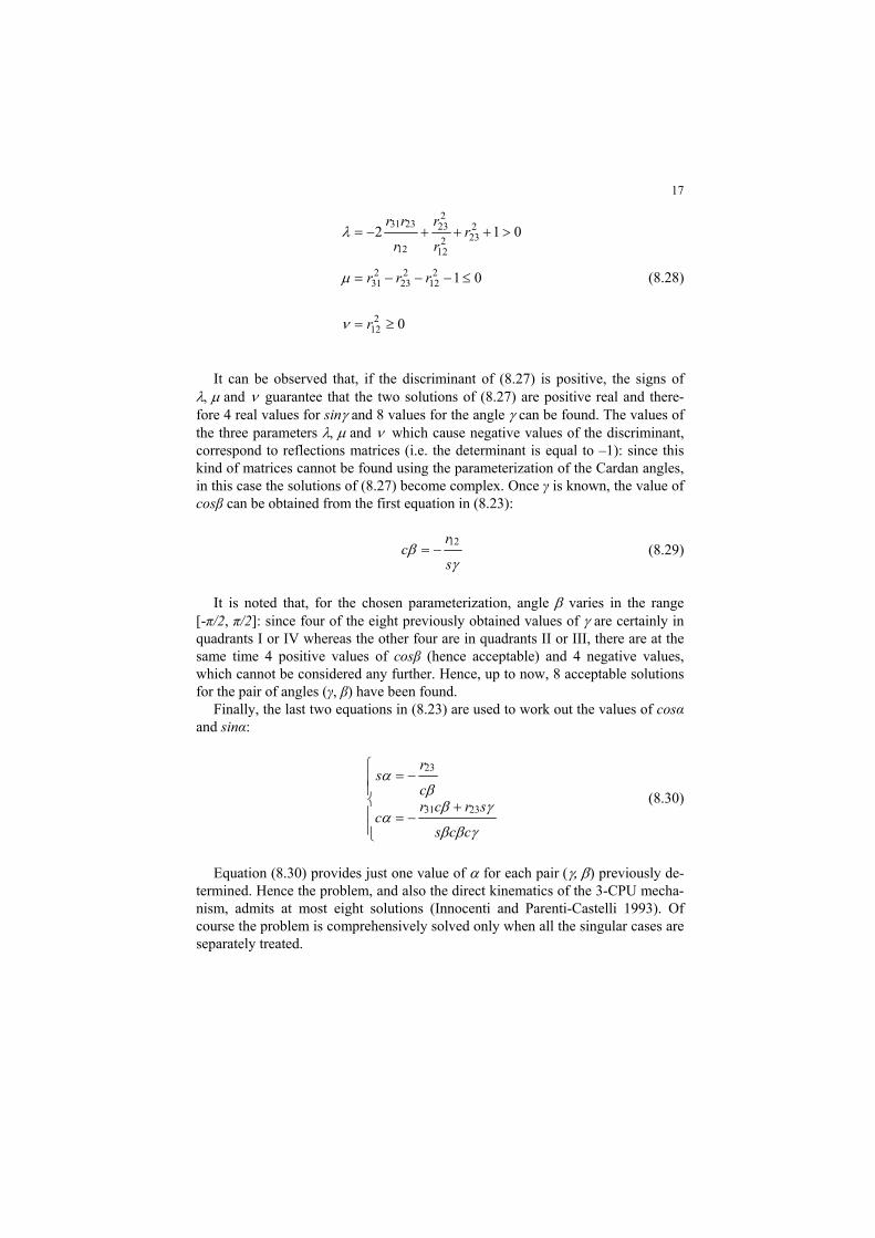
It can be observed that, if the discriminant of (8.27) is positive, the signs of and guarantee that the two solutions of (8.27) are positive real and there-fore 4 real values for sin and 8 values for the angle can be found. The values of the three parameters and which cause negative values of the discriminant, correspond to reflections matrices (i.e. the determinant is equal to –1): since this kind of matrices cannot be found using the parameterization of the Cardan angles, in this case the solutions of (8.27) become complex. Once γ is known, the value of cosβ can be obtained from the first equation in (8.23):
s
rc
12 (8.29)
It is noted that, for the chosen parameterization, angle varies in the range [-π/2, π/2]: since four of the eight previously obtained values of are certainly in quadrants I or IV whereas the other four are in quadrants II or III, there are at the same time 4 positive values of cosβ (hence acceptable) and 4 negative values, which cannot be considered any further. Hence, up to now, 8 acceptable solutions for the pair of angles (γ, β) have been found.
Finally, the last two equations in (8.23) are used to work out the values of cosα and sinα:
ccs
srcrc
c
rs
2331
23
(8.30)
Equation (8.30) provides just one value of for each pair ) previously de-termined. Hence the problem, and also the direct kinematics of the 3-CPU mecha-nism, admits at most eight solutions (Innocenti and Parenti-Castelli 1993). Of course the problem is comprehensively solved only when all the singular cases are separately treated.

18
8.8 Differential kinematics
By direct differentiation of the equations (8.22), the analytic Jacobian matrix JA is obtained:
A
csssccccsccss
sscc
ccss
d
a
a
a
J0
0
3
2
1
(8.31)
The vector of angular velocity ω of the platform is related to the derivatives of the Cardan angles by the relation:
0
0
01
T
ccs
csc
s
z
y
x
(8.32)
Using equations (8.31) and (8.32) it is possible to work out the expression of the geometric Jacobian JG of the mobile-platform:
z
y
x
G
z
y
x
AA
a
a
a
JTJJ 1
3
2
1
(8.33)
with:
0
0
0
ccsccss
scc
ssscccsssc
dGJ (8.34)
It is noted that the geometric Jacobian JG is not a function of geometric pa-rameters, therefore machine’s manipulability cannot be optimized by a proper se-lection of functional dimensions.
Turning to the analysis of singular poses, it is evident that limbs’ structure does not allow for inverse kinematics singularities; on the other hand, direct kinematics singularities can be found by letting the determinant of the geometric Jacobian JG vanish:
223det sssccsdG J (8.35)
The zeroes of this equation all lie on closed surfaces of the three dimensional space α, β, γ; their intersections with the coordinate planes generate straight lines, as given by:

19
20
2 ,
20
20
(8.36)
(a) (b)
Fig. 8.13. Singularity surfaces of , , (a) and ∗ , , (b)
(a) (b)
Fig. 8.14. Color plot of the determinant of , , (left) and ∗ , , (right) on several planes (black regions represent almost null values)
Figures 8.13a and 8.13b represent the singularity surfaces in the α, β, γ and in the , , spaces respectively.
Due to the complexity of the geometries represented in Fig. 8.13, it can be use-ful to plot the value of the determinant on several layers of the workspace, as shown in Fig. 8.14 for the two Cardan angles sets used in this work.

20
In Fig. 8.15a, moreover, the workspace volumes whose determinant assumes values in the range [–0,05, +0,05] have been taken out of the representation, while the color map still represents the local determinant value: it is now more apprecia-ble the extent of singularity-free regions inside the workspace, Fig. 8.15b, where the planning of a motion could be performed: e.g. for the mechanism under design a sphere with a radius of about 50° can be internally inscribed.
Finally, the translation singularities found in (8.19) can be easily expressed as a function of articular coordinates 1i by:
131211131211 cccsss (8.37)
and taking into consideration inverse kinematics (8.22) it is also obtained:
33 22 11 21 13 32 rrrrrr (8.38)
Equation (8.38) is a useful expression of translation singularities in task space, where the elements of the rotation matrix are used; the definition of the rotation matrix (8.1) and few trigonometric manipulations yield an alternative expression in function of Cardan angles :
022 sssccs (8.39)
It is noted that (8.39) is satisfied for the same values of that make (8.35) vanish: therefore translation singularities coincide with direct kinematics singu-larities, i.e. no additional singular surfaces are present inside workspace.
(a) (b)
Fig. 8.15. Singularity surface in the space: color map representing local determinant values (a) and close-up view of a connected singularity-free region (b)

21
8.9 Dynamics
8.9.1 Analysis of static loads
The static analysis is useful in the first phases of machine design for the selec-tion of machine’s motors and for a first design of the links, with the related con-necting bearings. The base relation is provided as usual by the well-known duality between kinematics and statics, which allows a straightforward assessment of the actuation efforts needed to balance a moment npl applied at the mobile platform:
plz
ply
plxT
G
n
n
n
J
3
2
1
(8.40)
It must be noted that the application of a force fpl at the center of the spherical motion does not require balancing forces by the actuators but it is entirely born by frame bearings: the internal reactions at the bearings caused by the application of the mentioned external wrench have been evaluated as well and used during struc-tural design.
8.9.2 Inverse dynamics model
Depending on the kind of tasks the wrist will be required to perform, it may not be sufficient to grant assigned static features, but wrist’s dynamics should be ac-counted for as well. In this section an inverse dynamics model of the 3-CPU mechanism is worked out by using the virtual work principle: it is assumed that frictional forces at the joints are negligible, therefore the work produced by the constraint forces at the joints is zero and only active forces (including the gravita-tional effects) must be accounted in the developments.
In the derivation of the model, the notation is based on Fig. 8.11b and the se-cond subscript i (i=1,2,3) indicates the ith limb while the first subscript j (j=1,2) refers to the first or second link respectively. Namely, mji and Iji are the mass and (central) inertia tensor of the jth member of the ith limb; ji is its angular velocity and vji is the linear velocity of its centre of mass; mpl, Ipl, pl, vpl are the same quantities referred to the mobile platform. The total wrench of active and inertial effects acting on the centre of mass of jth member of the ith limb is written as:
jijijijiji
jijiji
ji
jiji
mm
ωIωωI
vg
n
fF
(8.41)

22
In the same manner, the total wrench acting on the centre of mass of the mobile platform is:
eplplplplpl
eplpl
pl
plpl
m
nωIωωI
fvg
n
fF
(8.42)
where fe and ne are the external force and moment applied to its centre of mass; it is accidentally noted that the centre of mass of the platform does not coincide with the fixed point O. If is the vector of the actuation forces and q are the corre-sponding displacements, the principle of virtual work can be written for the pre-sent case:
03
1
2
1
i j
jiT
jiplT
plT δδδ FxFxτq (8.43)
where the vector xji gathers the position of the centre of mass of jth member of the ith limb and the orientation of the same link and xpl expresses the position of the centre of mass of the mobile platform and its orientation. It is noted that all the infinitesimal rotations appearing in (8.43) must be expressed as functions of the angular velocity of the respective link, e.g. for the platform:
tωωωvvv Tplzplyplxplzplyplxpl x (8.44)
Since all the virtual displacements in (8.44) must be compatible with the con-straints, they are not independent but can rather be expressed as functions of an independent set of Lagrangian coordinates; if the Cardan angles φ=[]T of the mobile platform are chosen for this purpose, the following relations hold be-tween the introduced virtual displacements:
φJq δ δ φJx δ δ jiji φJx δ δ plpl (8.45)
where J, Jji and Jpl are proper Jacobian matrices that can be found through the usual velocity analysis of the mechanism. Equation (8.43) can be written again as:
03
1
2
1
i j
jiTjipl
Tpl
TT FJFJτJφ (8.46)
Since (8.46) is valid for any virtual displacement φ of the platform, in non-singular configurations it is:

23
3
1
2
1i j
jiTjipl
Tpl
T FJFJJτ (8.47)
Equation (8.47) completely describes manipulator’s dynamics; all the elements in it have been worked out and the resulting model has been proofed by compari-son with commercial packages’ output.
8.9.3 Dynamic analysis in the task space
The dynamic expression (8.47) is usefully re-worked in order to explicit the dependency on a proper set of Lagrangian coordinates and its derivatives. In the case of parallel kinematics machines, the dynamic model results quite naturally written in the task space, due to the (usually) difficult expression of DKP; there-fore in the present case, after some cumbersome manipulation, it is obtained:
φGφφφCφφMhJτ ,Tpl (8.48)
with: τJτ T , moments acting at the end-effector and corresponding to actual
forces at actuated joints; φMφ , Cartesian mass matrix of the manipulator;
φφC ,φ , vector of centrifugal and Coriolis terms; φGφ , vector of gravity mo-
ments; h, vector of external forces and moments acting at the centre of mass of the mobile platform.
Fig. 8.16. Values of mass matrix’ elements for null roll angle, i.e. =0 (note the different scales of the plots)

24
Fig. 8.17. Plots of mass matrix’ elements, normalised by determinant value, for null roll angle, i.e. =0 (note that all the scales of the graphs are multiplied by 10-6 but M(1,2) and M(2,3) which are multiplied by 10-7).
In view of the realisation of possible control schemes based on the inversion of manipulator’s dynamics, it is useful to study the variability of mass matrix throughout the workspace. In fact, a major simplification of the model would be yielded by neglecting the 6 non-diagonal terms of the mass matrix, whether actu-ally allowed by their comparative magnitude; otherwise, all the elements in M and C could be considered constant. First simulation results show that in this case both simplifying assumptions could be taken into consideration, even if the validi-ty of the reduced models weakens when the operating trajectories get closer to singularity surfaces, as expected.
Figure 8.16, for instance, shows the values of mass matrix’ elements in differ-ent workspace configurations characterised by null roll angle, i.e. =0: for robot’s parameters it has been made reference to the virtual prototype, whose mass prop-erties, presented in the following Table 8.1, are very similar to physical prototype (h is the total length of the lower part of the three limbs). In Fig. 8.17 the same plots have been normalised by dividing the matrix element by the (local) value of matrix determinant, to allow a relative comparison among elements that have very different magnitudes. It can be seen that near the isotropic point () the diagonal elements are dominant and matrix variability is limited, while off-diagonal elements show a stronger influence when getting closer to workspace boundaries; moreover, element M(3,1) is generally an order of magnitude greater than M(2,1) and M(2,3). Such behaviour gets even more evident if one moves away from the plane =0. The plots have been traced for pitch and yaw angles varying between -50° and +50° because the sphere of 50° radius in the Cardan an-gles space is completely free of singularities, as shown already in Fig. 8.15.
Other kinds of tests have been performed, aiming at identifying the relative contribute of various dynamic terms: for instance it seems that, even for high dy-namics manoeuvres, the contribute of gravity is never negligible, while Coriolis

25
and centrifugal forces account for 10%-16% maximum; on the other hand, the mass and inertia of the mobile platform affect very slightly the overall dynamic behaviour of the machine, possibly allowing for a major simplification of system’s model.
Table 8.1. Main data used by the numerical model
Geometrical data Mass data
c 210 mm slider 7,15 kg
d 490 mm link 1 1,90 kg
h 280 mm link 2 2,21 kg
ai min 319 mm platform 11,73 kg
ai max 661 mm
bi min 130 mm
bi max 210 mm
8.9.4 Dynamic manipulability
Machines’ manipulability is usually studied only from a kinematic point of view, but high speed tasks may require to study also the dynamic behaviour of the device when required to attain quick manipulation operations; on the other hand, this is particularly important when the device to be studied or designed is a ma-nipulator’s wrist, since the capability to develop high accelerations is usually one of the most important features.
The this aim, the dynamic manipulability ellipsoids introduced by Yoshikawa (1985, 2000) are a useful means to study the dynamic properties of a mechanism: they express graphically the capability of a given device to yield accelerations in all the directions stemming from one attitude of its workspace. As a matter of fact, many other measures of manipulability have been proposed by different research-ers since that pioneering work, see e.g. (Di Gregorio and Parenti-Castelli 2002), but very few applications dealt with orienting devices.
Let us consider all the actuation forces with unit norm:
1ττT (8.49)
By manipulating (8.48) in order to work out , it is obtained:
biasφT φφMJτ (8.50)
having defined:

26
hJGφCMφ Tplφφbias 1
(8.51)
A meaningful formulation of dynamic manipulability must be expressed as a direct function of the angular acceleration ω , therefore the mapping between the rate of change of the Cardan angles φ and the angular velocity must be made
explicit:
φφEω
css
csc
s
z
y
x
0
0
01
(8.52)
φφ,ωφφEω 1 (8.53)
If φ is taken out of (8.53) and substituted in (8.50) it is then obtained:
biasφT ωωEMJτ 1 (8.54)
having defined:
hJGφCMJEMωω Tplφφ
Tbias 11
1 (8.55)
The constraint expressed by (8.49) can be finally written in the following quad-ratic form:
1 ΩφΓΩ T (8.56)
with obvious meaning of the introduced terms:
hJGφCMJEMωωωωΩ Tplφφ
Tbias 11
1 (8.57)
11 EMJJMEφΓ φTTT
(8.58)
The inspection of (8.57)-(8.58) shows that gravity merely induces a translation of the dynamic manipulability ellipsoid while in general velocity has a complex, non-negligible effect on manipulability. Making reference to the remarkable case of a fixed platform ( 0φ ) with no external or gravity action applied (h=Gφ=0),
(8.56) provides:
1 ωφΓω T (8.59)

27
(a) (b)
(c) (d)
Fig. 8.18. Dynamic manipulability ellipsoids at different poses (): (0°,0°,0°) (a), (20°,20°,-5°) (b), (40°,40°,10°) (c), (54°,53°,10°) (d)
The quadratic form (8.59) represents an ellipsoid in the Cartesian space of the angular accelerations: its eigenvalues express the square root of the maximum and minimum accelerations that can be developed with unit actuator forces while the eigenvectors represent the associated directions in the orientation space. Figure 8.18 represents graphically some dynamic manipulability ellipsoids of the robot in the poses sketched aside.
Two dynamic figures can be defined in order to sum up some relevant aspects of the dynamic manipulability analysis. The measure of the dynamic manipulabil-ity, w, defined as:
φΓdetw (8.60)
results proportional to the volume of the manipulation ellipsoid and therefore yields an overall information on the global manipulation capabilities, but fails to capture the closeness to singular configurations or even the anisotropy of local dy-namics. On the other hand, the index of dynamic manipulability, i, is independent from the volume of the ellipsoid and vanishes close to singular configurations:
max
min
i (8.61)
with min, max minimum and maximum eigenvalues of the matrix φΓ .
Usually a dynamic optimization of the design aims at trying to maximize the global dynamic manipulability of the wrist while still guaranteeing a minimum threshold of the local features. Figure 8.19, for instance, shows sample plots of the index of dynamic manipulability as a function of actuators strokes ai on the three coordinate planes for the final design of the wrist. For instance, in the four config-urations shown in Fig. 8.18 the indexes assume the values: 0.7755, 0.1374,

28
0.3571, 0.0341 respectively, while it has been obtained a mean value of iave=0.502 over the central ± 30° span of the workspace.
(a) (b) (c) Fig. 8.19. Plots of the index of dynamic manipulability as a function of actuators strokes on the
three coordinate planes a1=0 (a), a2=0 (b), a3=0 (c)
8.10 Prototype design
The design of a first prototype has been developed, with the aim of obtaining high dynamic performance; as reference figures, the following requirements have been posed:
orientation range (elevation and azimuth): 150° maximum angular velocity: 500 °/s maximum angular acceleration: 5 000 °/s2 spatial resolution: 0.01 ° overall dimensions of the machine: maximum volume of 1 m3.
(a) (b)
Fig. 8.20. CAD model of spherical wrist (a) and picture of a first laboratory prototype (b)
The particular form of the Jacobian matrix (8.34) does not allow for a mechani-cal design based on the optimization of kinematic properties, since JG is not func-tion of robot’s geometry, therefore heuristic considerations and several computer simulations allowed to refine the design.
Figure 8.20a sketches the design of a prototype meeting the posed require-ments; in Fig. 8.20b a picture of the machine is presented. The limbs are made of

29
avional (an aluminum-copper alloy) in order to join good mechanical properties with a lightweight construction. The mobile platform is made of bronze, therefore allowing the precise machining in a single placement of the 3 journal bearings that have to meet orthogonally in a single point: in this way it has been obtained a high stiffness together with precise geometrical alignments. It must be noted that such revolute joints are idle, since no rotation occurs at all if all the manufacturing and mounting conditions are correctly satisfied.
The actuation is based on 3 brushless linear motors Phase WVS 20.6.3, able to provide a maximum thrust of 184 N at the speed of 6 m/s, with a maximum accel-eration of 14.3 g and is controlled by Nation Instrument hardware (Flex-motion/PXI architecture). Table 8.2 collects the most relevant data of prototype actuation.
Table 8.2. Main actuation data
Characteristics of the three linear motors
Ms 2,95 kg Stator mass
Kt 58 N A⁄ Torque constant
In 3 A Nominal supply current
Tn 184 N Nominal thrust
vn 6 m s⁄ Nominal speed
8.11 Conclusions
The chapter has presented the mechanical features of robotic wrists, especially ad-dressing the kinematics of mechatronic devices to be used in grasping and ma-nipulation tasks. A powerful kinematical tool for the synthesis of such kind of ma-chines, based on Lie algebra, has been presented and an innovative spherical parallel wrist developed at the Polytechnic University of Marche in Ancona has been described, revisiting all the main design steps, from kinematic synthesis up to physical prototyping.
The mechanical architecture of the machine is based on the 3-CPU kinematics, that allows simple actuation and is characterized by easy direct and inverse rela-tions; the 3-CRU variant has been discarded due to a much more complex kine-matics but it could be taken into consideration for the design of mini- or micro- machines.
Position and rate kinematics have been worked out in closed form and all the singularity surfaces have been analyzed: it has been pointed out that the mecha-nism does not possess inverse kinematics singularities, while direct kinematics singularities and translation singularities lie on the same closed surface. The inner space, where motion paths can be safely planned, has been identified and unfortu-

30
nately it cannot be enlarged by kinematics optimization because machine’s Jaco-bian does not depend on geometrical parameters.
The kinematic concept of the mechanism has been developed up to the stage of designing a spherical wrist to be used in cooperation with a translation machine for assembly tasks. The physical prototyping of the machine allowed to validate the good properties envisaged during the design phase, e.g. the high dynamics mainly provided by the three direct drive linear motors. On the other hand, few disadvantages of the concept itself have showed up: they are mainly due to the scarce accessibility of the center of the spherical motion, which is common to most parallel wrists, and to the difficult assembly, which requires a precise align-ment of joints axes: this problem has been partially overcome by the manufactur-ing of specific fixtures that are characterized by very high accuracy and are used while assembling the machine.
In view of the strict cooperation of this wrist with a parallel translating machine for grasping and assembly tasks, specific position and interaction control schemes have been developed but the related results have been presented already elsewhere by Carbonari et al. (2011) and Bruzzone and Callegari (2010).
8.12 References
Alizade RI, Tagiyev NR, Duffy J (1994) A forward and reverse displacement analysis of an in-parallel spherical manipulator. Mech Mach Theory 29:125-137. doi:10.1016/0094-114X(94)90025-6
Arata J, Kondo H, Ikedo N, Fujimoto H (2011) Haptic Device Using a Newly Developed Re-dundant Parallel Mechanism. IEEE Trans Robotics 27:201-214. doi:10.1109/TRO.2010.2098272
Asada H, Granito C (1985) Kinematic and static characterization of wrist joints and their optimal design. Proc IEEE Int Conf Robotics Autom. St Louis, USA. 244-250. doi:10.1109/ROBOT.1985.1087324
Bonev IA, Zlatanov D (2001) The Mystery of the Singular SNU Translational Parallel Robot, available online at http://www.parallemic.org/Reviews/Review004.html
Bruzzone L, Callegari M (2010) Application of the Rotation Matrix Natural Invariants to Imped-ance Control of Purely Rotational Parallel Robots. Advances in Mechanical Engineering. doi:10.1155/2010/284976
Bürger T, Laible U, Pritschow G (2001) Design and Test of a Safe Numerical Control for Robot-ic Surgery. CIRP Ann – Manuf Technol 50:295-298. doi:10.1016/S0007-8506(07)62125-8
Callegari M, Cammarata A, Gabrielli A, Ruggiu M, Sinatra R (2009) Analysis and Design of a Spherical Micromechanism with Flexure Hinges. J Mech Des 131:051003-051013. doi:10.1115/1.3086796
Callegari M, Marzetti P, Olivieri B (2004) Kinematics of a Parallel Mechanism for the Genera-tion of Spherical Motions. In: Lenarcic J, Galletti CU (Eds) Advances in Robot Kinematics. Kluwer, Dordrecht.
Callegari M, Palpacelli M-C (2008) Prototype design of a translating parallel robot. Meccanica 43:133-151. doi:10.1007/s11012-008-9116-8
Carbonari L, Bruzzone L, Callegari M (2011) Impedance Control of a Spherical Parallel Plat-form. Int J Intell Mechatron Robotics 1:40-60. doi:10.4018/ijimr.2011010103

31
Carbonari L. (2012) Extended Analysis of the 3-CPU Reconfigurable Class of Parallel Robotic Manipulators, Ph.D. Thesis, Polytechnic University of Marche, Ancona, Italy
Carricato M, Parenti-Castelli V (2004) A Novel Fully Decoupled Two-Degrees-of-Freedom Par-allel Wrist. Int J Robotics Res 23:661-667. doi:10.1177/0278364904044077
Charles SK, Hogan N (2010) Dynamics of wrist rotations. J Biomech 44:614-621. doi:10.1016/j.jbiomech.2010.11.016
Di Gregorio R (2001a) Kinematics of a new spherical parallel manipulator with three equal legs: the 3-URC wrist. J. Robotic Syst 18:213-219. doi:10.1002/rob.1017
Di Gregorio R (2001b) A new parallel wrist using only revolute pairs: the 3-RUU wrist. Robot-ica 19:305-309. doi:10.1017/S0263574700003192
Di Gregorio R (2002) A New Family of Spherical Parallel Manipulators. Robotica 20:353-358. doi:10.1017/S0263574702004174
Di Gregorio R (2004a) The 3-RRS Wrist: A New, Simple and Non-Overconstrained Spherical Parallel Manipulator. J Mech Des 126:850-855. doi:10.1115/1.1767819
Di Gregorio R (2004b) Kinematics of the 3-RSR Wrist. IEEE Trans Robotics 20:750-754. doi:10.1109/TRO.2004.829451
Di Gregorio R, Parenti-Castelli V (2002) Dynamic Performance Indices for 3-DOF Parallel Ma-nipulators, In: Lenarcic J, Thomas F (Eds) Advances in Robot Kinematics. Kluwer, Dor-drecht.
Fang Y, Tsai L-W (2004) Structure synthesis of a class of 3-DOF rotational parallel manipula-tors, IEEE Trans Robotics and Autom 20:117-121. doi:10.1109/TRA.2003.819597
Fichter EF, Kerr DR, Rees-Jones J (2009) The Gough–Stewart platform parallel manipulator: a retrospective appreciation. Proc Inst Mech Eng, Part C: J Mech Eng Sci 223:243-281. doi:10.1243/09544062JMES1137
Fontana M, Frisoli A, Salsedo F, Bergamasco M (2006) Kinematics of a New 2-DoF Wrist with High Angulation Capability, Proc IEEE Int Conf Robotics Autom. Orlando, Florida. doi:10.1109/ROBOT.2006.1641924
Gosselin CM, Angeles J (1989) The optimum kinematic design of a spherical three-degree-of-freedom parallel manipulator. ASME J Mech Trans and Automat Des 111:202-207.
Huda S, Takeda Y (2007) Kinematic Analysis and Synthesis of a 3-URU Pure Rotational Paral-lel Mechanism with Respect to Singularity and Workspace. J Adv Mech Des Syst Manuf 1:81-92. doi:10.1299/jamdsm.1.81
Innocenti C, Parenti-Castelli V (1993) Echelon form solution of direct kinematics for the general fully-parallel spherical wrist. Mech Mach Theory 28:553-561. doi:10.1016/0094-114X(93)90035-T
Karouia M, Hervé JM (2000) A three-dof tripod for generating spherical rotation. In: Lenarcic J, Stanisic MM (Eds) Advances Robot Kinematics. Kluwer, Dordrecht.
Karouia M, Hervé JM (2002) A Family of Novel Orientational 3-DOF Parallel Robots. Proc 14th RoManSy. Udine, Italy. 359-368.
Karouia M, Hervé JM (2006) Non-overconstrained 3-dof spherical parallel manipulators of type: 3-RCC, 3-CCR, 3-CRC. Robotica 24:85-94. doi:10.1017/S0263574705001827
Kong X, Gosselin CM (2004a) Type synthesis of 3-DOF spherical parallel manipulators based on screw theory. J Mech Des 126:101-108. doi:10.1115/1.1637655
Kong X, Gosselin CM (2004b) Type synthesis of three-degree-of-freedom spherical parallel ma-nipulators, Int J Robotics Res 23:237-245. doi:10.1177/0278364904041562
Lee JJ, Chang S-L (1992) On the kinematics of the UPS wrist for real time control. Proc 22nd ASME Bienn Mech Conf Robotics, Spatial Mech and Mech Syst. Scottsdale, USA. 305-312.
Lusk, C.P. and Howell, L.L. (2008a) Components, Building Blocks, and Demonstrations of Spherical Mechanisms in Microelectromechanical Systems, J Mech Des 130:034503-1:4. doi:10.1115/1.2829914
Lusk, C.P. and Howell, L.L. (2008b) Spherical Bistable Micromechanism, J Mech Des 130:045001-1:6. doi:10.1115/1.2885079
Pennestrì E (1991) On the kinematic analysis of geared robotic wrists. Meccanica 26:155-160. doi:10.1007/BF00429883

32
Rosheim ME (1989) Robot Wrist Actuators. John Wiley & Sons Inc. Saltaren RJ, Sabater JM, Yime E, Azorin JM, Aracil R, Garcia N (2007) Performance evaluation
of spherical parallel platforms for humanoid robots. Robotica 25:257-267. doi:10.1017/S0263574706003043
Saravanan R, Ramabalan S, Godwin Raja Ebenezer N, Dharmaraja C (2009) Evolutionary multi criteria design optimization of robot grippers. Appl Soft Comput 9:159-172. doi:10.1016/j.asoc.2008.04.001
Schäfer C, Dillmann R (2001) Kinematic Design of a Humanoid Robot Wrist. J Robotic Syst 18:747–754. doi:10.1002/rob.8113
Takaiwa M, Noritsugu T (2005) Development of Wrist Rehabilitation Equipment Using Pneu-matic Parallel Manipulator. Proc IEEE Int Conf Robotics Autom. Barcelona, Spain. 2302-2307. doi:10.1109/ROBOT.2005.1570456
Unal R, Patoglu V (2008) Optimal Dimensional Synthesis of Force Feedback Lower Arm Exo-skeletons. Proc IEEE/RAS-EMBS Int Conf Biomed Robotics and Biomechatron. Scottsdale, AZ, USA. 329-334. doi:10.1109/BIOROB.2008.4762871
Yi, B.-J., Chung, G.B., Na, H.Y., Kim, W.K. and Suh, I.H. (2003) Design and experiment of a 3-DOF parallel micromechanism utilizing flexure hinges, IEEE Trans Robotics, 19:604-612. doi:10.1109/TRA.2003.814511
Yoshikawa T (1985) Dynamic Manipulability of Robot Manipulators. J Robotic Syst 2:113-124. Yoshikawa T (2000) Erratum to “Dynamic Manipulability of Robot Manipulators”. J Robotic
Syst 17:449. doi:10.1002/1097-4563(200008)17:8<449::AID-ROB5>3.0.CO;2-M Zlatanov D, Bonev IA, Gosselin CM (2002) Constraint Singularities of Parallel Mechanisms,
Proc. IEEE Int Conf Robotics Autom. Washington, USA. 496-502.
Copyright © 2022 FDOKUMEN