Panasonic Air Conditioner
136
© 2006 Matsushita Electric Industrial Co., Ltd. All rights reserved. Unauthorized copying and distribution is a violation of law. INDOOR UNIT CS-ME7DKEG CS-ME10DD3EW CS-ME10DTEG CS-E15DB4EW CS-ME7DKDG CS-E9DKDW CS-E9DKEW CS-E12DKDW CS-E12DKEW CS-E15DKDW CS-E15DKEW CS-E18DKDW CS-E18DKEW CS-E15DTEW CS-E18DTEW CS-E15DD3EW CS-E18DD3EW CS-E18DB4EW OUTDOOR UNIT CU-3E18EBE Multi Air Conditioner Order No. RAC0602011C2
-
Upload
khangminh22 -
Category
Documents
-
view
0 -
download
0
Transcript of Panasonic Air Conditioner

© 2006 Matsushita Electric Industrial Co., Ltd. Allrights reserved. Unauthorized copying anddistribution is a violation of law.
INDOOR UNITCS-ME7DKEG CS-ME10DD3EWCS-ME10DTEG CS-E15DB4EWCS-ME7DKDG CS-E9DKDWCS-E9DKEW CS-E12DKDWCS-E12DKEW CS-E15DKDWCS-E15DKEW CS-E18DKDWCS-E18DKEW CS-E15DTEWCS-E18DTEW CS-E15DD3EWCS-E18DD3EW CS-E18DB4EW
OUTDOOR UNITCU-3E18EBE
Multi Air Conditioner
Order No. RAC0602011C2

1 Safety Precautions 3 2 Features 5
2.1. Wall Type 6
2.2. Duct Type 9
2.3. Ceiling Floor Type 12
2.4. Mini-Cassette Type 14
3 Product Specifications 16 3.1. Wall Type 16
3.2. Duct Type 17
3.3. Ceiling Floor Type 18
3.4. Mini-Cassette Type 19
3.5. Outdoor unit: CU-3E18EBE 20
4 Dimensions 21 4.1. Wall Type 21
4.2. Duct Type 23
4.3. Ceiling Floor Type 25
4.4. Mini-Cassette Type 26
4.5. Outdoor Unit 27
5 Refrigeration Cycle Diagram 28 6 Wiring Diagram 29
6.1. Wall Type 29
6.2. Duct Type 30
6.3. Ceiling Floor Type 31
6.4. Mini-Cassette Type 32
6.5. Outdoor Unit 33
7 Electronic Circuit Diagram 34 8 Operation Details 36
8.1. Wall Type 36
8.2. Duct Type 53
8.3. Ceiling Floor Type 59
8.4. Mini-Cassette Type 73
8.5. Outdoor Unit Operation 87
8.6. Forced Cooling Operation Control 88
8.7. Wiring Error Check Control 89
8.8. Outdoor Unit - Check Point 90
9 Self Diagnosis Display 91 9.1. Breakdown Self Diagnosis Function (Three Digits
Alphanumeric Code) 91
9.2. Error Code 92
10 Installation Information 96 11 Installation Instructions 97 12 Disassembly of Parts 108
12.1. Wall Type 108
12.2. Duct Type 110
12.3. Ceiling Floor Type 112
12.4. Mini-Cassette Type 113
12.5. Outdoor Unit 115
13 Technical Data 117 13.1. Operation Characteristics 117
14 Exploded View and Replacement Parts List 119 14.1. Wall Type 119
14.2. Duct Type 125
14.3. Ceiling Floor Type 127
14.4. Mini-Cassette Type 129
14.5. Outdoor Unit 134
CONTENTS Page Page
2

1 Safety Precautions • Read the following “SAFETY PRECAUTIONS” carefully before perform any servicing. • Electrical work must be installed or serviced by a licensed electrician. Be sure to use the correct rating of the power plug and
main circuit for the model installed. • The caution items stated here must be followed because these important contents are related to safety. The meaning of each
indication used is as below.Incorrect installation or servicing due to ignoring of the instruction will cause harm or damage, and the seriousness is classifiedby the following indications.
This indication shows the possibility of causing death or serious injury.
This indication shows the possibility of causing injury or damage to properties.
The items to be followed are classified by the symbols:
This symbol denotes item that is PROHIBITED from doing.
• Carry out test running to confirm that no abnormality occurs after the servicing. Then, explain to user the operation, care andmaintenance as stated in instructions. Please remind the customer to keep the operating instructions for future reference.
1. Engage dealer or specialist for installation and servicing. If installation or servicing done by the user is defective, it will cause water leakage,electrical shock or fire.
2. Install according to this installation instructions strictly. If installation is defective, it will cause water leakage, electrical shock or fire.3. Use the attached accessories parts and specified parts for installation and servicing. Otherwise, it will cause the set to fall, water leakage,
fire or electrical shock.4. Install at a strong and firm location which is able to withstand the set´s weight. If the strength is not enough or installation is not properly
done, the set will drop and cause injury.5. For electrical work, follow the local national wiring standard, regulation and the installation instruction. An independent circuit and single
outlet must be used. If electrical circuit capacity is not enough or defect found in electrical work, it will cause electrical shock or fire.6. Use the specified cable and connect tightly for indoor/outdoor connection. Connect tightly and clamp the cable so that no external force will
be acted on the terminal. If connection or fixing is not perfect, it will cause heat-up or fire at the connection.7. Wire routing must be properly arranged so that control board cover is fixed properly. If control board cover is not fixed perfectly, it will cause
heat-up at connection point of terminal, fire or electrical shock.8. When connecting the piping, do not allow air or any substances other than the specified refrigerant to enter the
refrigeration cycle. Otherwise, this may lower the capacity, cause abnormally high pressure in the refrigeration cycle, andpossibly result in explosion and injury.
9. Thickness of copper pipes used must be more than 0.8 mm. Never use copper pipes thinner than 0.8 mm.
10. It is desirable that the amount of residual oil is less than 40 mg/10 m.
11. Do not modify the length of the power supply cord or use of the extension cord, and do not share the single outlet withother electrical appliances. Otherwise, it will cause fire or electrical shock.
1. The equipment must be earthed. It may cause electrical shock if grounding is not perfect.2. Do not install the unit at place where leakage of flammable gas may occur. In case gas leaks and accumulates at
surrounding of the unit, it may cause fire.
3. Carry out drainage piping as mentioned in installation instructions. If drainage is not perfect, water may enter the room and damage thefurniture.
3

4. Pb free solder has a higher melting point than standard solder; typically the melting point is 50 - 70°F (30 - 40°C) higher. Please use a hightemperature soldering iron. In case of the soldering iron with temperature control, please set it to 700 20°F (370 10°C).Pb free solder will tend to splash when heated too high (about 1100°F/600°C).
1. Selection of the installation location. Select an installation location which is rigid and strong enough to support or hold the unit, and selecta location for easy maintenance.
2. Power supply connection to the conditioner. Connect the power supply cord of the air conditioner to the mains using one of the followingmethods. Power supply point shall be the place where there is ease for access for the power disconnection in case of emergency.In some countries, permanent connection of this room air conditioner to the power supply is prohibited. 1. Power supply connection to the receptacle using a power plug. Use an approved power plug with earth pin for the connection to the
socket.
2. Power supply connection to a circuit breaker for the permanent connection. Use an approved circuit breaker for the permanentconnection. It must be a double pole switch with a minimum 3.5 mm contact gap.
3. Do not release refrigerant during piping work for installation, servicing reinstallation and during repairing a refrigeration parts. Take care ofthe liquid refrigerant, it may cause frostbite.
4. Installation work. It may need two people to carry out the installation work.5. Do not install this appliance in a laundry room or other location where water may drip from the ceiling, etc.
4

• Serviceability − Self diagnosis − Test Run at both Cooling and Heating rated frequency
• Built-in drain pump (Cassette and Duct type) − A drain pump is built in.
The pipe can rise to 200 mm above the drain outlet.
2 Features • Product
− A single OUTDOOR unit enable air conditioning of up to three separate rooms for CU-3E18EBE.
Remarks for CU-3E18EBE: 1. At least two indoor units must be connected. 2. The total nominal cooling capacity of indoor units that will be connected to outdoor unit must be within connectable
capacity range of indoor unit. (shown in the above table.)Example: The below indoor units combination is possible to connect CU-3E18EBE.(Total nominal capacity of indoor units is 5.0 kW and 9.0 kW)1) Two CS-ME7DKEG only. (Total nominal cooling capacity is 4.4 kW.)2) Three CS-E12DKEW only. (Total nominal cooling capacity is 9.6 kW.)
5

2.1. Wall Type
2.1.1. Remote Control
6

2.1.2. Indoor Unit
7

8

2.2. Duct Type
2.2.1. Remote Control
9

2.2.2. Indoor Unit
10

11

2.3. Ceiling Floor Type
2.3.1. Remote Control
12

2.3.2. Indoor Unit
13

2.4. Mini-Cassette Type
2.4.1. Remote Control
14

2.4.2. Indoor Unit
15

3 Product Specifications3.1. Wall Type
Model Unit CS-ME7DKEG CS-E9DKEW CS-E12DKEW CS-E15DKEW CS-E18DKEWCS-ME7DKDG CS-E9DKDW CS-E12DKDW CS-E15DKDW CS-E18DKDW
Item Wall TypePower Source Outdoor power Single 230V 50HzAir Volume Cooling m3/min
(cfm)High: 9.6
(340)High: 10.7
(380)High: 11.0
(390)High: 13.9
(490)Heating m3/min
(cfm)High: 10.0
(350)High: 11.2
(400)High: 11.8
(420)High: 15.2
(540)Noise Level Cooling
(Power)dB(A)(dB)
High: 40 (53)Low: 29
High: 44 (57)Low: 32
High: 44 (57)Low: 32
High: 46 (59)Low: 33
Heating(Power)
dB(A)(dB)
High: 40 (53)Low: 29
High: 44 (57)Low: 32
High: 44 (57)Low: 33
High: 46 (59)Low: 35
Moisture Removal L/h(Pint/h)
1.3(2.8)
1.6(3.4)
1.8(3.8)
2.3(4.8)
2.8(5.9)
RefrigerationPiping
Connection Liquid mm(inch)
6.35 (1/4”)
Gas mm(inch)
9.52 (3/8”) 12.7 (1/2”)
Type of Indoor / Outdoor connecting cable mm 4 × 1.5 mm2 flexible cord, type designation 245 IEC 57 (H05RN-F)DrainHose
Inner diameter mm 16Length m 0.65
Dimensions Height mm(inch)
280 (11 - 1/32) 275 (10 - 13/16)
Width mm(inch)
799 (31 - 15/32) 998 (39 - 9/32)
Depth mm(inch)
183 (7 - 7/32) 230 (9 - 1/16)
Net Weight lb (kg) 20 (9.0) 24 (11.0)Air Circulation Type Cross-flow Fan
Motor Type Transistor (8-poles)Output W 30
Heat Exchanger Plate fin configuration, forced draftRow /Stage
2/15
Thermostat Electronic ControlProtection Device Electronic ControlAir Filter P.P. Honeycomb
• Specifications are subject to change without notice for further improvement.
16

3.2. Duct TypeModel Unit CS-ME10DD3EG CS-E15DD3EW CS-E18DD3EW
Item Duct TypePower Source Outdoor power Single 230V 50HzAir Volume Cooling m3/min
(cfm)High: 7.0
(250)High: 7.8
(280)High: 10.3
(360)Heating m3/min
(cfm)High: 8.9
(310)High: 12.6
(440)Noise Level Cooling
(Power)dB(A)(dB)
High: 31 (47)Low: 27
High: 33 (49)Low: 27
High: 41 (57)Low: 30
Heating(Power)
dB(A)(dB)
High: 35 (51)Low: 27
High: 35 (51)Low: 28
High: 41 (57)Low: 32
Moisture Removal L/h(Pint/h)
1.6(3.4)
2.3(4.9)
2.8(5.9)
RefrigerationPiping
Connection Liquid mm (inch) 6.35 (1/4”)Gas mm (inch) 9.52 (3/8”) 12.7 (1/2”)
Type of Indoor / Outdoor connecting cable mm 4 × 1.5 mm2 flexible cord, type designation 245 IEC 57 (H05RN-F)DrainHose
Inner diameter mm VP20Length m 0.255
Dimensions Height mm (inch) 235 (9 - 1/4) 285 (11 - 7/32)Width mm (inch) 750 (29 - 17/32)Depth mm (inch) 370 (14 - 9/16)
Net Weight lb (kg) 17 (37) 18 (40)Air Circulation Type Sirocco Fan
Motor Type Transistor 8-polesOutput W 30
Heat Exchanger Plate fin configuration, forced draftRow / Stage 2/8 3/12
Thermostat Electronic ControlProtection Device Electronic ControlAir Filter —
• Specifications are subject to change without notice for further improvement.
17

3.3. Ceiling Floor TypeModel Unit CS-ME10DTEG CS-E15DTEW CS-E18DTEW
Item Ceiling Floor TypePower Source Outdoor power Single 230V 50HzAir Volume Cooling m3/min
(cfm)High: 9.3
(330)High: 11.7
(410)High: 12.1
(430)Heating m3/min
(cfm)High: 9.3
(330)High: 12.0
(420)High: 12.5
(440)Noise Level Cooling
(Power)dB(A)(dB)
High: 39 (52)Low: 31
High: 45 (58)Low: 37
High: 46 (59)Low: 39
Heating(Power)
dB(A)(dB)
High: 40 (53)Low: 31
High: 45 (58)Low: 33
High: 47 (60)Low: 35
Moisture Removal L/h(Pint/h)
1.6(3.3)
2.3(4.9)
2.8(5.9)
RefrigerationPiping
Connection Liquid mm (inch) 6.35 (1/4”)Gas mm (inch) 9.52 (3/8”) 12.7 (1/2”)
Type of Indoor / Outdoor connecting cable mm 4 × 1.5 mm2 flexible cord, type designation 245 IEC 57 (H05RN-F)DrainHose
Inner diameter mm 16Length m 0.65
Dimensions Height mm (inch) 540 (21 - 9/32)Width mm (inch) 1028 (40 - 1/2)Depth mm (inch) 200 (7 - 7/8)
Net Weight lb (kg) 17 (37) 18 (40)Air Circulation Type Backward Fan
Motor Type Transistor 8-polesRate Output W 51
Heat Exchanger Plate fin configuration, forced draftRow / Stage 2/12
Thermostat Electronic ControlProtection Device Electronic ControlAir Filter P.P. Honeycomb
• Specifications are subject to change without notice for further improvement.
18

3.4. Mini-Cassette TypeModel Unit CS-E15DB4EW CS-E18DB4EW
Item Mini-Cassette TypePower Source Outdoor power Single 230V / 240V, 50HzAir Volume Cooling m3/min
(cfm)High: 10.5
(370)High: 11.0
(390)Heating m3/min
(cfm)High: 10.8
(380)High: 11.5
(405)Noise Level Cooling
(Power)dB(A)(dB)
High: 34 (47)Low: 26
High: 36 (49)Low: 28
Heating(Power)
dB(A)(dB)
High: 35 (48)Low: 28
High: 37 (50)Low: 29
Moisture Removal L/h(Pint/h)
2.3(4.9)
2.8(5.9)
RefrigerationPiping
Connection Liquid mm (inch) 6.35 (1/4”)Gas mm (inch) 12.7 (1/2”)
Type of Indoor / Outdoor connecting cable mm 4 × 1.5 mm2 flexible cord, type designation 245 IEC 57 (H05RN-F)DrainHose
Inner diameter mm 30Length m 0.193
Dimensions Height mm (inch) 260 (10 - 1/4)Width mm (inch) 575 (22 - 5/8)Depth mm (inch) 575 (22 - 5/8)
Net Weight lb (kg) 18 (40)Air Circulation Type Backward Fan
Motor Type Transistor (8-poles)Rate Output W 40
Heat Exchanger Plate fin configuration, forced draftRow / Stage 2/10
Thermostat Electronic ControlProtection Device Electronic ControlAir Filter P.P. Honeycomb
• Specifications are subject to change without notice for further improvement.
19

3.5. Outdoor unit: CU-3E18EBEOutdoor Unit Indoor unit combination Operation
modeCapacity (kW) Power input (kW) Current (A)
Operation Class (kW) Rating mini - max Rating mini - maxCU-3E18EBE One-room
Operation2.2 Cooling 2.20 1.8 - 2.9 0.50 0.34 - 0.81 2.5
Heating 3.20 1.2 - 4.1 0.74 0.30 - 1.23 3.72.8 Cooling 2.80 1.8 - 2.9 0.70 0.34 - 0.81 3.3
Heating 4.00 1.2 - 4.3 1.05 0.30 - 1.23 5.03.2 Cooling 3.20 1.8 - 3.8 0.80 0.34 - 1.36 3.7
Heating 4.50 1.2 - 5.8 1.23 0.30 - 2.10 5.84.0 Cooling 4.00 1.8 - 4.3 1.24 0.34 - 1.99 5.6
Heating 5.60 1.2 - 6.8 1.72 0.30 - 2.93 7.75.0 Cooling 5.00 1.9 - 5.7 1.55 0.34 - 2.13 6.8
Heating 6.80 1.2 - 6.9 2.10 0.30 - 2.52 9.2Two-roomOperation
2.2 + 2.2 Cooling 4.40 1.9 - 6.2 1.11 0.35 - 2.10 4.9Heating 5.80 1.4 - 7.0 1.45 0.31 - 2.55 6.4
2.2 + 2.8 Cooling 5.00 1.9 - 6.2 1.41 0.35 - 2.10 6.2Heating 6.40 1.4 - 7.0 1.72 0.31 - 2.55 7.6
2.2 + 3.2 Cooling 5.20 1.9 - 6.3 1.49 0.35 - 2.11 6.6Heating 6.80 1.4 - 7.3 1.84 0.31 - 2.52 8.2
2.2 + 4.0 Cooling 5.20 1.9 - 6.4 1.45 0.35 - 2.11 6.4Heating 6.80 1.4 - 7.3 1.80 0.31 - 2.51 7.9
2.2 + 5.0 Cooling 5.20 1.9 - 6.8 1.29 0.36 - 2.15 5.7Heating 6.80 1.4 - 8.0 1.52 0.31 - 2.20 6.7
2.8 + 2.8 Cooling 5.20 1.9 - 6.2 1.54 0.35 - 2.10 6.8Heating 6.80 1.4 - 7.0 1.93 0.31 - 2.55 8.5
2.8 + 3.2 Cooling 5.20 1.9 - 6.3 1.48 0.35 - 2.11 6.5Heating 6.80 1.4 - 7.3 1.84 0.31 - 2.52 8.1
2.8 + 4.0 Cooling 5.20 1.9 - 6.4 1.44 0.35 - 2.11 6.4Heating 6.80 1.4 - 7.3 1.80 0.31 - 2.51 8.0
2.8 + 5.0 Cooling 5.20 1.9 - 6.8 1.29 0.36 - 2.15 5.7Heating 6.80 1.4 - 8.0 1.52 0.31 - 2.20 6.7
3.2 + 3.2 Cooling 5.20 1.9 - 6.4 1.45 0.35 - 2.12 6.4Heating 6.80 1.4 - 7.5 1.75 0.31 - 2.49 7.7
3.2 + 4.0 Cooling 5.20 1.9 - 6.5 1.41 0.35 - 2.12 6.3Heating 6.80 1.4 - 7.5 1.75 0.31 - 2.47 7.8
3.2 + 5.0 Cooling 5.20 1.9 - 6.9 1.25 0.36 - 2.15 5.5Heating 6.80 1.4 - 8.0 1.50 0.31 - 2.18 6.6
4.0 + 4.0 Cooling 5.20 1.9 - 6.5 1.41 0.35 - 2.12 6.2Heating 6.80 1.4 - 7.6 1.71 0.31 - 2.47 7.5
4.0 + 5.0 Cooling 5.20 1.9 - 6.9 1.25 0.36 - 2.16 5.5Heating 6.80 1.4 - 8.0 1.50 0.31 - 2.17 6.6
Three-roomOperation
2.2 + 2.2 +2.2
Cooling 5.20 1.9 - 7.2 1.24 0.36 - 2.17 5.4Heating 6.78 1.5 - 8.1 1.53 0.32 - 2.12 6.7
2.2 + 2.2 +2.8
Cooling 5.20 1.9 - 7.2 1.24 0.36 - 2.17 5.4Heating 6.80 1.5 - 8.1 1.53 0.32 - 2.12 6.7
2.2 + 2.2 +3.2
Cooling 5.20 1.9 - 7.2 1.23 0.36 - 2.18 5.4Heating 6.80 1.4 - 8.3 1.49 0.32 - 2.11 6.5
2.2 + 2.2 +4.0
Cooling 5.20 1.8 - 7.3 1.23 0.36 - 2.18 5.4Heating 6.80 1.6 - 8.3 1.46 0.32 - 2.11 6.4
2.2 + 2.8 +2.8
Cooling 5.20 1.9 - 7.2 1.24 0.36 - 2.17 5.4Heating 6.80 1.5 - 8.1 1.53 0.32 - 2.12 6.7
2.2 + 2.8 +3.2
Cooling 5.20 1.9 - 7.2 1.23 0.36 - 2.18 5.4Heating 6.80 1.4 - 8.3 1.49 0.32 - 2.11 6.5
2.2 + 2.8 +4.0
Cooling 5.20 1.8 - 7.3 1.22 0.36 - 2.18 5.4Heating 6.80 1.6 - 8.3 1.42 0.32 - 2.11 6.5
2.2 + 3.2 +3.2
Cooling 5.20 1.8 - 7.3 1.22 0.36 - 2.18 5.4Heating 6.80 1.6 - 8.3 1.43 0.32 - 2.10 6.3
2.8 + 2.8 +2.8
Cooling 5.19 1.9 - 7.2 1.24 0.36 - 2.17 5.4Heating 6.80 1.5 - 8.1 1.53 0.32 - 2.12 6.7
2.8 + 2.8 +3.2
Cooling 5.20 1.9 - 7.2 1.23 0.36 - 2.18 5.4Heating 6.80 1.4 - 8.3 1.49 0.32 - 2.11 6.5
20

4 Dimensions4.1. Wall Type
21
22

4.2. Duct Type
23

24

4.3. Ceiling Floor Type
25

4.4. Mini-Cassette Type
26

4.5. Outdoor Unit
27

5 Refrigeration Cycle Diagram
28

6 Wiring Diagram6.1. Wall Type
29

6.2. Duct Type
30

6.3. Ceiling Floor Type
31

6.4. Mini-Cassette Type
32

6.5. Outdoor Unit
33
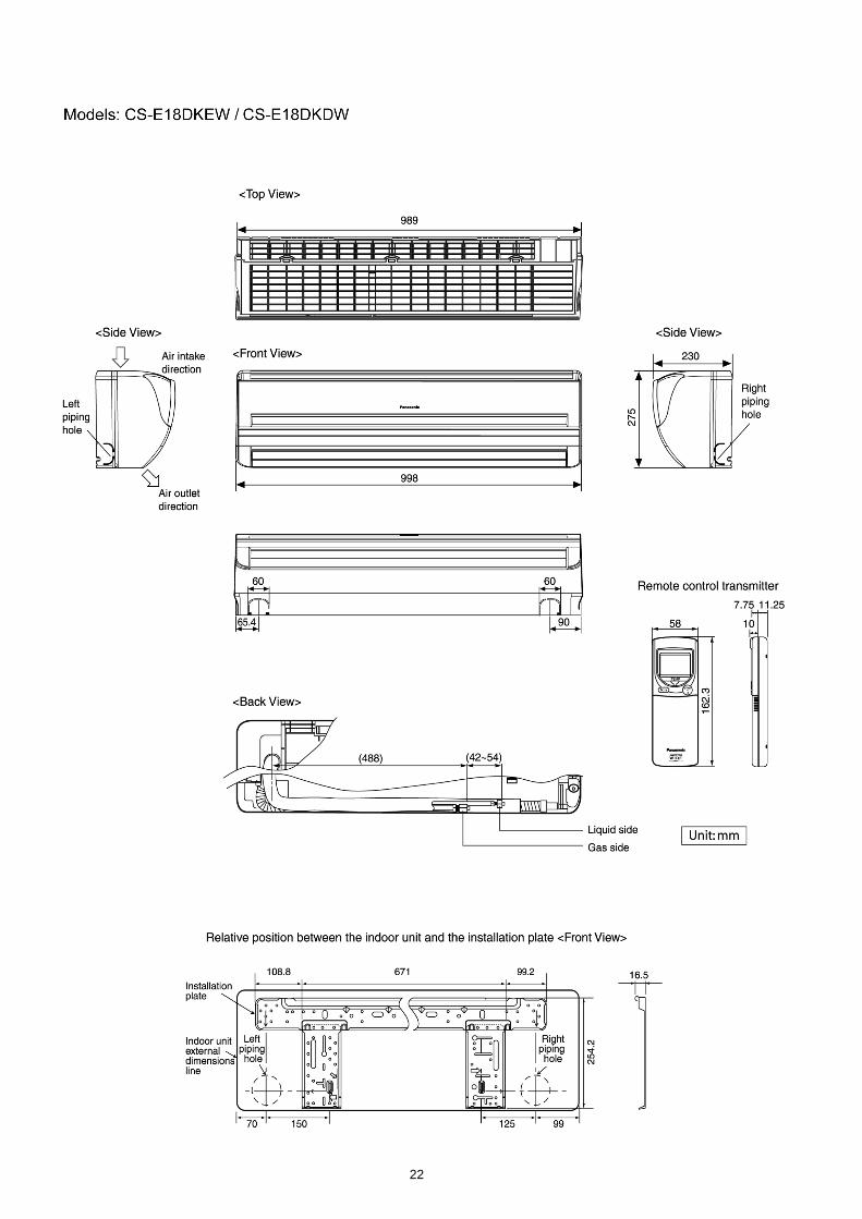
7 Electronic Circuit Diagram
34

Printed Circuit BoardCU-3E18EBE
35

8 Operation Details8.1. Wall Type8.1.1. Basic Function
Inverter control, which equipped with a microcomputer in determining the most suitable operating mode as time passes,automatically adjusts output power for maximum comfort always. In order to achieve the suitable operating mode, themicrocomputer maintains the set temperature by measuring the temperature of the environment and performing temperatureshifting. The compressor at outdoor unit is operating following the frequency instructed by the microcomputer at indoor unit thatjudging the condition according to internal setting temperature and intake air temperature.
8.1.1.1. Internal Setting TemperatureOnce the operation starts, remote control setting temperature will be taken as base value for temperature shifting processes.These shifting processes are depending on the air conditioner settings and the operation environment. The final shifted valuewill be used as internal setting temperature and it is updated continuously whenever the electrical power is supplied to the unit.
Table (a): Auto Operation Mode SettingMode Shift: Temperature Shift (°C)
Cooling/Soft Dry → Heating -2.0Heating → Cooling/Soft Dry +2.0
Table (b): Outdoor Air Temperature ShiftingMode: Outdoor Temperature, X (°C): Temperature Shift (°C)
Cooling/Soft Dry 30 X +0.5X 30 +1.0
Heating 9 X -1.05 X 9 -0.51 X 5 0.0
X 1 +1.0
Table (c): Power Mode ShiftingMode Temperature Shift (°C)
Cooling -4.0Soft Dry -2.0Heating +6.0
36

Table (d): Indoor Air Temperature Shifting 1. Target room temperature shift value (dGetaDst)
• To offset the absolute gap between detection temperature with actual room temperature. • The heat exchanger unit’s temperature is different based on operation mode, it becomes the action operation mode
value.
Actual operation mode Target room temperature offset value (dGetaDst)Cooling (1)Heating (2)Soft Dry (0)
2. Room temperature shift value (dGeta) • When compressor ON/OFF, correction of detected room temperature by shift value during defrost etc.
i) Initial value when operation starts, or changing the actual operation mode.Set the offset value at each operation mode. However, in order to improve the heating startup efficiency, the offset valuewill be changed based on the gap between setting temperature and room temperature.
Actual operation mode Gap between setting temperature and room temperature Room temperature offset value(dGeta)
Cool — (0)Heat (Operation start set temp. - room temp.) 4°C (4)
(Operation start set temp.) 4°C (4)Soft Dry — (0)
ii) Updating during operationDuring operation, it will compare with the target room temperature offset value at specific period, then the roomtemperature will be updated.
Actual operation mode Room temperature zone Updating period (sec.)Cool — (180)Heat A, B, C, D zone (15)
Soft Dry — (180)
Update the room temperature offset value (dGeta)
Temperature condition Room temp. offset value after modified (dGeta)Target room temp. offset value Room temp. offset
value (dGetaDst dGeta)dGeta + (0.5)
Target room temp. offset value Room temp. offsetvalue (dGetaDst dGeta)
dGeta - (0.5)
Target room temp. offset value = Room temp. offsetvalue (dGetaDst = dGeta)
Do not change.
However, if the following condition is occurred, temperature cannot detect correctly and therefore no updating will bedone.
• Heating zone E and above (Temperature gap is big and great capacity increased.) • During deice • After deice complete *within 600 sec. • Comp. stop
Comp. starting *within 600 sec.
37

1. Operation modes which can be selected using theremote control unit:Automatic, Cooling, Soft Dry, Heating, Fan operation mode.
2. Types of operations modes which can be performedsimultaneously • Cooling operation and cooling, Soft Dry or fan operation • Heating operation and heating operation
3. Types of operation modes which cannot be performedsimultaneously • While a cooling operation is in progress, a heating
operation cannot be performed by an indoor unit inanother room.In the room where the operation button for cooling waspressed first, the operation is continued. In the roomwhere the operation button for heating was pressedafterward, the operation lamp of the indoor unit blinks,where the attempt is made to establish the heatingoperation. Its fan is stopped, and the air does notdischarged.
• While a heating operation is in progress, a coolingoperation cannot be performed by an indoor unit inanother room.In the room where the operation button for heating waspressed first, the operation is continued. In the roomwhere the operation button for cooling was pressedafterward, the operation lamp of the indoor unit blinks,where the attempt is made to establish the coolingoperation. Its fan is stopped, and the air does notdischarged.
4. Operation mode priority control • The operation mode designated first by the indoor unit
has priority. • If the priority indoor unit stops operation or initiates the
fan operation, the priority is transferred to other indoorunits.
8.1.1.2. Simultaneous Operation Control
38

8.1.1.3. Cooling Operation8.1.1.3.1. Thermostat control • Compressor is OFF when Intake Air Temperature - Internal Setting Temperature < -1.5°C. • Compressor is ON after waiting for 3 minutes, if the Intake Air Temperature - Internal Setting Temperature > Compressor OFF
point.
8.1.1.4. Soft Dry Operation8.1.1.4.1. Thermostat control • Compressor is OFF when Intake Air Temperature - Internal Setting Temperature < -2.0°C. • Compressor is ON after waiting for 3 minutes, if the Intake Air Temperature - Internal Setting Temperature > Compressor OFF
point.
8.1.1.5. Heating Operation8.1.1.5.1. Thermostat control • Compressor is OFF when Intake Air Temperature - Internal Setting Temperature < +2.0°C. • Compressor is ON after waiting for 3 minutes, if the Intake Air Temperature - Internal Setting Temperature > Compressor OFF
point.
39

8.1.1.6. Automatic OperationThis mode can be set using remote control and the operation is decided by remote control setting temperature, indoor intake airtemperature and outdoor air temperature.During operation mode judgment, indoor fan motor (with speed of Lo-) and outdoor fan motor are running for 30 seconds to detectthe indoor intake and outdoor air temperature. The operation mode is decided based on below chart.
Values of T1, T2, and T3 depend on remote control setting temperature, as shown in below table. After the adjustment of T1, T2and T3 values, the operation mode for that particular environment and remote control setting is judged and performed, based onthe above operation mode chart, every 3 hours.
Remote Control Setting Temperature (°C) T1 T2 T316 ~ 18 +10 -3 -519 ~ 22 +8 -3 -723 ~ 26 +7 -3 -727 ~ 30 +6 -3 -8
There is a temperature shifting on T1, T2, and T3 if the operation mode judged is changed from Cooling/Soft Dry to Heating or viceverse.
Operation Mode change from Temperature shifts (°C)Cooling/Soft Dry → Heating -2Heating → Cooling/Soft Dry +2
Example of operation mode chart adjustment:
From the above table, if remote control setting temperature = 25,
T1 = 25 + 7 = 32; T2 = 25 - 3 = 22; T3 = 25 - 7 = 18
The operation mode chart for this example is as shown in below figure and the operation mode to be performed will depend onindoor intake air temperature and outdoor air temperature at the time when the judgment is made.
40

Notes:
8.1.1.7. Indoor Fan Motor OperationA. Basic Rotation Speed (rpm)
• Required rotation speed for fan is set to respond to the remote control setting (10 rpm unit)
[Cooling, Soft Dry, Fan]Remote Control — — O O O O O — — —
Tab (rpm) PSHi SHi Hi Me+ Me Me- Lo Lo- SLo SSLoCS-ME7DKEG 1320 1320 1280 1210 1040 970 920 860 720 710CS-E9DKEW 1320 1320 1280 1210 1040 970 920 860 720 710
CS-E12DKEW 1460 1460 1420 1320 1220 1120 1020 950 720 710CS-E15DKEW 1500 1500 1460 1350 1240 1130 1020 950 720 710CS-E18DKEW 1540 1540 1450 1340 1240 1140 1040 980 770 640
[Heating]Remote Control — — O O O O O — — —
Tab (rpm) PSHi SSHi SHi Me+ Me Me- Lo Lo- SLo SSLoCS-ME7DKEG 1440 1440 1400 1290 1170 1060 950 870 720 710CS-E9DKEW 1440 1440 1400 1290 1170 1060 950 870 720 710
CS-E12DKEW 1540 1540 1500 1400 1290 1180 1070 990 720 710CS-E15DKEW 1570 1570 1560 1430 1310 1190 1070 990 720 710CS-E18DKEW 1640 1640 1580 1470 1350 1230 1110 1040 400 300
1. Refer to the CS-ME7DKEG column for CS-ME7DKDG. 2. Refer to the CS-E9DKEW column for CS-E9DKDW. 3. Refer to the CS-E12DKEW column for CS-E12DKDW. 4. Refer to the CS-E15DKEW column for CS-E15DKDW. 5. Refer to the CS-E18DKEW column for CS-E18DKDW.
41

B. Indoor Fan Controli. Indoor fan control operation outline
1. Cooling / Soft Dry
42

2. Heating
ii. Auto Fan Speed 1. Cooling
Model No. A No. B No. CPowerful Program CS-ME7DKEG, CS-E9DKEW 1110 1130 1150
CS-E12DKEW 1230 1250 1270CS-E15DKEW 1300 1320 1340CS-E18DKEW 1390 1410 1430
Normal Program CS-ME7DKEG, CS-E9DKEW 1050 1070 1090CS-E12DKEW 1170 1190 1210CS-E15DKEW 1240 1260 1280CS-E18DKEW 1330 1350 1370
Quiet Program CS-ME7DKEG, CS-E9DKEW 1030 1050 1070CS-E12DKEW 1150 1170 1190CS-E15DKEW 1220 1240 1260CS-E18DKEW 1310 1330 1350
• Refer to the CS-ME7DKEG column for CS-ME7DKDG. • Refer to the CS-E9DKEW column for CS-E9DKDW. • Refer to the CS-E12DKEW column for CS-E12DKDW. • Refer to the CS-E15DKEW column for CS-E15DKDW. • Refer to the CS-E18DKEW column for CS-E18DKDW.
43

2. Heating
Note: a. UP:
• If move from Lo, the fan speed will be shifted to Maximum 1,520 rpm. • If move from Maximum, the fan speed no change. • In up zone, 10 rpm is added for every 10 seconds until Maximum 1,520 rpm.
b. DOWN: • The fan speed will be decreased one step every 10 seconds until Minimum 1,270 rpm.
c. Current Output Fixed: • Maintain at present fan speed.
d. Instantaneous Maximum: • Fan speed will be increased to maximum auto fan speed.
e. Temperature in ( ) is for Powerful Mode operation.
C. Fan Motor Control 1. Motor specification
High voltage PWM Motor 2. Feedback Control
a. Number-of -rotations feedbackImmediately after the fan started, rpm is checked and duty is added, and feedback control is performed. For high voltagePWM motor. It is done once every 0.5 seconds.
b. Offset duty T max/min limitHigh voltage PWM motor has maximum offset duty.(Refer to indoor fan motor control basic rotation speed.)
3. Abnormal detection ControlConditions: a. Out of rhythm signal input b. If feedback number of rotations exceeded 2,550 rpm or when less than 50 rpm.Control: Fans stop.Return: Restart after 5 seconds.* It will not detect out of rhythm condition within 5 seconds for phase control motor (PWM motor is when duty = 0) after start.A fan stops when condition (1) and (2) happen within 25.0 seconds after fan starting, and if this happens for continuously7 times, it will not retry.→ FM lock processing
4. Restart Prohibition ControlRestart is prohibited within 5 seconds for phase control motor (PWM motor is when duty = 0) after dan stop (except re-ONthe power supply)
44

D. Deodorizing Controli. Control conditionControl at cooling/soft dry operation and auto fan speed.No Deodorizing Control is performed during ON timer standby operation and during freeze prevention control.
ii. OperationThe odor status is arranged as below and it is shifted as follows.
* When COMP is ON 1 → 2 → 3(Shift to 4 when COMP is OFF)
* When COMP is OFF 4 → 5 → 6 → 7 → 6 ←→ 7(Shift to 1 when COMP is ON)
* Start from 4 if the Thermostat is OFF during the start operation.
8.1.1.8. Airflow Direction 1. There are two types of airflow, vertical airflow (directed by horizontal vane) and horizontal airflow (directed by vertical vanes). 2. Control of airflow direction can be automatic (angles of direction is determined by operation mode, heat exchanger temperature
and intake air temperature) and manual (angles of direction can be adjusted using remote control).
Vertical AirflowOperation Mode Airflow Direction Vane Angle (°)
1 2 3 4 5Heating Auto with Heat Exchanger A Upward fix 3
Temperature B Downward fix 64C Downward fix 3D Downward fix 3
Manual 3 17 33 49 63Cooling, Soft Dry and Ion Auto 8 ~ 36
Manual 8 15 22 30 36Mode judgment in Auto Auto 8
Manual 8 15 22 30 36
1. Automatic vertical airflow direction can be set using remote control; the vane swings up and down within the angles as statedabove. For heating mode operation, the angle of the vane depends on the indoor heat exchanger temperature as Figure 1below. When the air conditioner is stopped using remote control, the vane will shift to close position.
2. Manual vertical airflow direction can be set using remote control; the angles of the vane are as stated above and thepositions of the vane are as Figure 2 below. When the air conditioner is stopped using remote control, the vane will shift toclose position.
45

Horizontal Airflow 1. Automatic horizontal airflow direction can be set using remote control; the vane swings left and right within the angles as
stated below. For heating mode operation, the angle of the vane depends on the indoor heat exchanger temperature asFigure 1 below.
Operation Mode Vane Angle (°)Heating, with heat exchanger temperature A 65 ~ 115
B 90Cooling, Soft Dry and Ion 65 ~ 115
2. Manual horizontal airflow direction can be set using remote control; the angles of the vane are as stated below and thepositions of the vane are as Figure 2 above.
Pattern 1 2 3 4 5Airflow DirectionPatterns at RemoteControlVane Angle (°) 90 65 78 102 115
8.1.1.9. Quiet operation (Cooling Mode/Cooling area of Soft Dry Mode)
A. PurposeTo provide quiet cooling operation compare to normal operation.
B. Control conditiona. Quiet operation start condition • When “quiet” button at remote control is pressed.
Quiet LED illuminates.
b. Quiet operation stop condition 1. When one of the following conditions is satisfied, quiet operation stops:
a. Powerful button is pressed. b. Stop by OFF/ON switch. c. Timer “off” activates. d. Quiet button is pressed again.
46

2. When quiet operation is stopped, operation is shifted to normal operation with previous setting. 3. When fan speed is changed, quiet operation is shifted to quiet operation of the new fan speed. 4. When operation mode is changed, quiet operation is shifted to quiet operation of the new mode. 5. During quiet operation, if timer “on” activates, quiet operation maintains. 6. After off, when on back, quiet operation is not memorised.
C. Control contents 1. Fan speed is changed from normal setting to quiet setting of respective fan speed.
This is to reduce sound of Hi, Me, Lo for 3dB. 2. Fan speed for quiet operation is -1 step from setting fan speed.
8.1.1.10. Quiet operation (Heating)A. Purpose
To provide quiet heating operation compare to normal operation.
B. Control conditiona. Quiet operation start condition • When “quiet” button at remote control is pressed.
Quiet LED illuminates.
b. Quiet operation stop condition 1. When one of the following conditions is satisfied, quiet operation stops:
a. Powerful button is pressed. b. Stop by OFF/ON switch. c. Timer “off” activates. d. Quiet button is pressed again.
2. When quiet operation is stopped, operation is shifted to normal operation with previous setting. 3. When fan speed is changed, quiet operation is shifted to quiet operation of the new fan speed. 4. When operation mode is changed, quiet operation is shifted to quiet operation of the new mode, except fan only mode. 5. During quiet operation, if timer “on” activates, quiet operation maintains. 6. After off, when on back, quiet operation is not memorised.
C. Control contentsa. Fan Speed manual 1. Fan speed is changed from normal setting to quiet setting of respective fan speed.
This is to reduce sound of Hi, Me, Lo for 3dB. 2. Fan speed for quiet operation is -1 step from setting fan speed. 3. Fan Speed Auto
Indoor FM RPM depends on pipe temp sensor of indoor heat exchanger.
47

8.1.1.11. Powerful Mode OperationWhen the powerful mode is selected, the internal setting temperature will shift to achieve the setting temperature quickly.
(a) Cooling Operation
(b) Soft Dry Operation
(c) Heating Operation
8.1.1.12. ON Timer ControlON timer can be set using remote control, the unit with timer set will start operate earlier than the setting time. This is to providea comfortable environment when reaching the set ON time.
60 minutes before the set time, indoor (at fan speed of Lo-) and outdoor fan motor start operate for 30 seconds to determine theindoor intake air temperature and outdoor air temperature in order to judge the operation starting time.
From the above judgment, the decided operation will start operate earlier than the set time as shown below.
8.1.1.13. OFF Timer ControlOFF timer can be set using remote control, the unit with timer set will stop operate at set time.
48

8.1.1.14. Auto Restart Control • If there is a power failure, operation will automatically be restarted when the power is resumed. It will start with the previous
operation mode and airflow direction. (Timer Delay Safety Control is valid.) 1. Control start conditions
• The 24-hour timer must not be set. • The sleep timer must not be set.Auto start control is not available when timer or sleep mode is set.
2. Description of control • In the case of manual operation, the operation mode, temperature setting, fan speed and airflow direction before the power
is turned off are restored. • In the case of automatic operation, after the power is restored operation starts with the determination of the mode. • While the air conditioner odour clear timer has been set, the setting is cancelled, and operation is transferred to the mode
before the power is turned off. • While the air conditioner odour clear operation (with timer / without timer setting) are being performed, both of these
operations are completed, and operation is transferred to the operation mode prior to these operations.
Example: When the power is turned off during an outdoor unit cooling operation.
8.1.1.15. Indication Panel
LED POWER TIMER QUIET POWERFUL ION ALLERGENBUSTER
Color Green Orange Orange Orange Green BlueLight ON Operation ON Timer Setting ON Quiet Mode ON Powerful Mode ON Ion Mode ON Operation ONLight OFF Operation OFF Timer Setting OFF Quiet Mode OFF Powerful Mode
OFFIon Mode OFF Operation OFF
Note: • If POWER LED is blinking, the possible operations of the unit are Hot Start, during Deice operation, operation mode
judgment, or delay ON timer sampling. • If timer LED is blinking, there is an abnormality operation occurs. • If ionizer LED is blinking, there is an abnormality of ionizer occurs.
49

8.1.1.16. Auto Operation Switch
1. When the switch is pressed between 0 to 5 seconds, Auto Mode operation starts to function. 2. When the switch is pressed between 5 to 8 seconds, the unit is forced to operate in Cooling Mode. 3. When the switch is pressed between 8 to 11 seconds, the unit will enter forced Heating Mode standby. Press timer decrement
button for 5s for the unit to operate in Heating Mode. 4. When the switch is pressed between 11 to 16 seconds and together with the signal from remote control (timer decrement button
for 5s), the unit can be changed to different controlling setting (4 type of transmission codes). 5. When the switch is pressed between 16 to 21 seconds, either “H14” error detection selection mode or the remote control signal
receiving sound can be cancelled or turned on.
8.1.1.17. Ionizer OperationPurpose
To provide fresh air effect to users by discharging minus ion to air.
Control Condition
a. Ionizer Only Operation. 1. When air-conditioner unit is at “OFF” condition (standby) and ION operation button at remote control is pressed.
Fan & ionizer on, ION LED illuminates, ION and power LEDs illuminate. (1 → 2)However, fan speed can be adjusted later by customer during this operation.
Airflow direction (Horizontal Vane) control:Follow vane direction control at cooling mode.Horizontal vane can be changed by customer during ion only operation.
50

b. Operation Mode + Ionizer Operation. 1. Ionising Operation Start Condition
When air conditioner unit is in “ON” condition (Heat, Cool, Dry, Fan, Auto mode) and an ION operation button at remotecontrol is pressed. Ionizer on & ION LED illuminates. (3 → 4)Power LED also illuminates.
2. Ionising Operation Stop ConditionWhen one of the following conditions is satisfied, ION operation stops. a. Stopped by ON/OFF switch. b. Timer OFF activates. c. ION feedback signal shows error.
3. When "ION" is displayed on the remote controller, Ionizer operates.
c. Timer during ionizer operationRefer to case study in next page for details.
8.1.1.17.1. Ionizer Problem Detection Controli. PurposeTo inform user of ionizer problems and detection.
ii. Two types of problem detection control:
Control Detection Method Protection Recovery
ERRORPROTECTION
(i) Actual ion: ON (i) Actual ion ON for 10s & OFF for30 min. continuously for 24 times(approx. 11 hr. 30 min.)
(i) Actual ion is permanently OFF & ionLED is blinking.
(i) Press ON/OFF buttonto OFF
(ii) ion feedback signal:0V
(ii) Within 24 counts, if anytimeCONDITION becomes false thencount is cleared.
(ii) Press remote control ion button fora) ON: Ion LED blink & buzzer = beepb) OFF: Ion LED OFF & buzzer = beep
(ii)
(iii)
Reset power
Off by force operation
BREAKDOWNPROTECTION
(i)
(ii)
Actual ion: OFF
ion feedback signal:5V
(i) Actual ion OFF 2s (i)Case 1: During Air-Con. ON.Air-Cond OFF with abnormal no. H26 isactivated with timer LED is blinkingpermanently.
(i) When anytimeCONDITION becomesfalse.
(i)Case 2: During Air-Con. OFF.Abnormal no. H26 is activated withtimer LED is blinking permanently forboth cases 1 & 2.
(ii) Once recovered, ion &Timer LED stopsblinking permanently.
(ii) Press remote control ion button fora) ON: Ion LED blinkb) OFF: Ion LED OFF
(iii) Main power reset.
(iii) Press any remote control button toa) ON: Buzzer = beep beep beep beepb) OFF: Buzzer = beep beep beep beep
51

8.1.1.17.2. Ionizer Operation case study
Case 1
8.1.2. Freeze Prevention Control 1. When indoor heat exchanger temperature is lower than 2°C continuously for six minutes, compressor will stop operating. 2. Compressor will resume its operation three minutes after the indoor heat exchanger is higher than 10°C. 3. At the same time, indoor fan speed increase +20 rpm compared to its normal operation. 4. If indoor heat exchanger temperature is higher than 10°C for five minutes, the fan speed will return to its normal operation.
52

1. Operation modes which can be selected using theremote control unit:Automatic, Cooling, Soft Dry, Heating, Fan operation mode.
2. Types of operations modes which can be performedsimultaneously • Cooling operation and cooling, Soft Dry or fan operation • Heating operation and heating operation
3. Types of operation modes which cannot be performedsimultaneously • While a cooling operation is in progress, a heating
operation cannot be performed by an indoor unit inanother room.In the room where the operation button for cooling waspressed first, the operation is continued. In the roomwhere the operation button for heating was pressedafterward, the operation lamp of the indoor unit blinks,where the attempt is made to establish the heatingoperation. Its fan is stopped, and the air does notdischarged.
• While a heating operation is in progress, a coolingoperation cannot be performed by an indoor unit inanother room.In the room where the operation button for heating waspressed first, the operation is continued. In the roomwhere the operation button for cooling was pressedafterward, the operation lamp of the indoor unit blinks,where the attempt is made to establish the coolingoperation. Its fan is stopped, and the air does notdischarged.
4. Operation mode priority control • The operation mode designated first by the indoor unit
has priority. • If the priority indoor unit stops operation or initiates the
fan operation, the priority is transferred to other indoorunits.
8.2. Duct Type8.2.1. Simultaneous Operation Control
53

8.2.2. Indoor Fan Control • The following shows how fan speed changes depending on the setting made with the FAN SPEED button and other operating
conditions. • Actual fan speed may differ from that you set with remote control.
54

8.2.3. Drain Pump ControlBasic operation
• The drain pump starts 50 seconds after the indoor unit starts or the thermostat comes on (i.e., 10 seconds after the fanmotor starts).The drain pump stops 30 seconds after the indoor unit stops or the thermostat turns off.
• The drain pump repeats a cycle of on for 30 seconds then off for between 50 and 90 seconds as long as the unit isoperating. Operation while the unit is off is determined by the difference between the temperature setting and the roomtemperature.
Float switch operation • When the float switch turns on for 10 seconds continuously, the thermostat of the indoor unit turns off and the drain pump
operates continuously. • When the float switch stays on for 150 seconds continuously, the drain pump and indoor unit stop and the timer lamp
flashed indicating an H21 error.
55

8.2.4. Auto Restart Control • If there is a power failure, operation will automatically be restarted when the power is resumed. It will start with the previous
operation mode and airflow direction. (Timer Delay Safety Control is valid.) 1. Control start conditions
• The 24-hour timer must not be set. • The sleep timer must not be set.Auto start control is not available when timer or sleep mode is set.
2. Description of control • In the case of manual operation, the operation mode, temperature setting, fan speed and airflow direction before the power
is turned off are restored. • In the case of automatic operation, after the power is restored operation starts with the determination of the mode. • While the air conditioner odour clear timer has been set, the setting is cancelled, and operation is transferred to the mode
before the power is turned off. • While the air conditioner odour clear operation (with timer / without timer setting) are being performed, both of these
operations are completed., and operation is transferred to the operation mode prior to these operations.
Example: When the power is turned off during an outdoor unit cooling operation.
56

8.2.5. Other Indoor Unit Operation Functions
8.2.5.1. Auto buttonProceed with operation when the air conditioner is stopped.(When the auto button is pressed during operation, the air conditioner is stopped.)
1. Emergency operationPress the auto button and release it within 5 seconds to perform emergency operation.Under normal condition (failure is not occurred) automatic operation is performed. In the event of a failure that still enablesoperation to be performed, emergency operation is performed.
2. Forced cooling operationpress the auto button about 5-8 seconds (1 beep sound) to perform the forced cooling operation.The air conditioner does not operate for 2 minutes if the room temperature is low (intake temperature below 16°C) sojust wait. The forced operation is performed after 2 minutes have elapsed.
3. Forced heating operationPress the auto button about 8-11 seconds (2 beeps sound) to perform the forced heating operation.
4. Setting modes (Remote control transmission code, current switching mode)The remote control transmission code selection mode is established by pressing the AUTO button about 11-16 seconds (3beeps sound).
Select Remote Control Transmission Code • There are 4 types of remote control transmission code could be selected and stored in EEPROM of indoor unit. The
indoor unit will only operate when received signal with same transmission code from remote control. This could preventsignal interference when there are 2 more indoor unit installed nearby together.
• To change remote control transmission code, short or open jumpers at the remote control printed circuit board.
57

• Under various setting mode, after select the transmission code combination of remote control, press any button ofremote control to transmit a signal to indoor unit. The transmission code will be stored in EEPROM.
• After signal is received, the various setting mode is cancelled and return to normal operation.
5. Individual setting modeThe H14 error detection selection mode is established by pressing the auto button about 21 seconds (5 beeps sound). Nowremove the remote control unit’s battery cover, and short the “SET” terminals to established the beep sound mode.
*If the auto button is pressed and 26 seconds or so are allowed to elapse, the auto button operation mode is restored.When nothing happens for 60 seconds in the “Setting mode”, “Odour clear setting mode” or “Individual setting mode”or if a remote control code is received, the mode concerned is canceled.
8.2.5.2. Drain Test (SW1)When installing the unit and you want the Drain pump to operate independently, press the DRAIN TEST switch to operate it forabout 5 minutes.
8.2.5.3. High Static Pressure Switch (High state switch SW2)To increase the fan speed, open the control box and the control board switch the HIGH STATE switch (SW2) to “HI”.
58

8.3. Ceiling Floor Type8.3.1. Basic Function
Inverter control, which equipped with a microcomputer in determining the most suitable operating mode as time passes,automatically adjusts output power for maximum comfort always. In order to achieve the suitable operating mode, themicrocomputer maintains the set temperature by measuring the temperature of the environment and performing temperatureshifting. The compressor at outdoor unit is operating following the frequency instructed by the microcomputer at indoor unit thatjudging the condition according to internal setting temperature and intake air temperature.
8.3.1.1. Internal Setting TemperatureOnce the operation starts, remote control setting temperature will be taken as base value for temperature shifting processes.These shifting processes are depending on the air conditioner settings and the operation environment. The final shifted valuewill be used as internal setting temperature and it is updated continuously whenever the electrical power is supplied to the unit.
Table (a): Auto Operation Mode SettingMode Shift: Temperature Shift (°C)
Cooling/Soft Dry → Heating -2.0Heating → Cooling/Soft Dry +2.0
Table (b): Outdoor Air Temperature ShiftingMode: Outdoor Temperature, X (°C): Temperature Shift (°C)
Cooling/Soft Dry 30 X +0.5X 30 +1.0
Heating 9 X -1.05 X 9 -0.51 X 5 0.0
X 1 +1.0
Table (c): Power Mode ShiftingMode: Temperature Shift (°C)
Cooling -4.0Soft Dry -2.0Heating +6.0
59

Table (d): Indoor Air Temperature Shifting 1. Target room temperature shift value (dGetaDst)
• To offset the absolute gap between detection temperature with actual room temperature. • The heat exchanger unit’s temperature is different based on operation mode, it becomes the action operation mode
value.
Actual operation mode Target room temperature offset value (dGetaDst)Cooling (1)Heating (2)Soft Dry (0)
2. Room temperature shift value (dGeta) • When compressor ON/OFF, correction of detected room temperature by shift value during defrost etc.
i) Initial value when operation starts, or changing the actual operation mode.Set the offset value at each operation mode. However, in order to improve the heating startup efficiency, the offset valuewill be changed based on the gap between setting temperature and room temperature.
Actual operation mode Gap between setting temperature and room temperature Room temperature offset value(dGeta)
Cool — (0)Heat (Operation start set temp. - room temp.) 4°C (4)
(Operation start set temp.) 4°C (4)Soft Dry — (0)
ii) Updating during operationDuring operation, it will compare with the target room temperature offset value at specific period, then the roomtemperature will be updated.
Actual operation mode Room temperature zone Updating period (sec.)Cool — (180)Heat A, B, C, D zone (15)
Soft Dry — (180)
Update the room temperature offset value (dGeta)
Temperature condition Room temp. offset value after modified (dGeta)Target room temp. offset value Room temp. offset
value (dGetaDst dGeta)dGeta + (0.5)
Target room temp. offset value Room temp. offsetvalue (dGetaDst dGeta)
dGeta - (0.5)
Target room temp. offset value = Room temp. offsetvalue (dGetaDst = dGeta)
Do not change.
However, if the following condition is occurred, temperature cannot detect correctly and therefore no updating will bedone.
• Heating zone E and above (Temperature gap is big and great capacity increased.) • During deice • After deice complete *within 600 sec. • Comp. stop
Comp. starting *within 600 sec.
Table (e)Installation position change heating shift -4°C
60

1. Operation modes which can be selected using theremote control unit:Automatic, Cooling, Soft Dry, Heating, Fan operation mode.
2. Types of operations modes which can be performedsimultaneously • Cooling operation and cooling, Soft Dry or fan operation • Heating operation and heating operation
3. Types of operation modes which cannot be performedsimultaneously • While a cooling operation is in progress, a heating
operation cannot be performed by an indoor unit inanother room.In the room where the operation button for cooling waspressed first, the operation is continued. In the roomwhere the operation button for heating was pressedafterward, the operation lamp of the indoor unit blinks,where the attempt is made to establish the heatingoperation. Its fan is stopped, and the air does notdischarged.
• While a heating operation is in progress, a coolingoperation cannot be performed by an indoor unit inanother room.In the room where the operation button for heating waspressed first, the operation is continued. In the roomwhere the operation button for cooling was pressedafterward, the operation lamp of the indoor unit blinks,where the attempt is made to establish the coolingoperation. Its fan is stopped, and the air does notdischarged.
4. Operation mode priority control • The operation mode designated first by the indoor unit
has priority. • If the priority indoor unit stops operation or initiates the
fan operation, the priority is transferred to other indoorunits.
8.3.1.2. Simultaneous Operation Control
61

8.3.1.3. Cooling Operation8.3.1.3.1. Thermostat control • Compressor is OFF when Intake Air Temperature - Internal Setting Temperature < -1.5°C. • Compressor is ON after waiting for 3 minutes, if the Intake Air Temperature - Internal Setting Temperature > Compressor OFF
point.
8.3.1.4. Soft Dry Operation8.3.1.4.1. Thermostat control • Compressor is OFF when Intake Air Temperature - Internal Setting Temperature < -2.0°C. • Compressor is ON after waiting for 3 minutes, if the Intake Air Temperature - Internal Setting Temperature > Compressor OFF
point.
8.3.1.5. Heating Operation8.3.1.5.1. Thermostat control • Compressor is OFF when Intake Air Temperature - Internal Setting Temperature < +2.0°C. • Compressor is ON after waiting for 3 minutes, if the Intake Air Temperature - Internal Setting Temperature > Compressor OFF
point.
62

8.3.1.6. Automatic OperationThis mode can be set using remote control and the operation is decided by remote control setting temperature, indoor intake airtemperature and outdoor air temperature.During operation mode judgment, indoor fan motor (with speed of Lo-) and outdoor fan motor are running for 30 seconds to detectthe indoor intake and outdoor air temperature. The operation mode is decided based on below chart.
Values of T1, T2, and T3 depend on remote control setting temperature, as shown in below table. After the adjustment of T1, T2and T3 values, the operation mode for that particular environment and remote control setting is judged and performed, based onthe above operation mode chart, every 30 minutes.
Remote Control Setting Temperature (°C) T1 T2 T316 ~ 18 +10 -3 -519 ~ 22 +8 -3 -723 ~ 26 +7 -3 -727 ~ 30 +6 -3 -8
There is a temperature shifting on T1, T2, and T3 if the operation mode judged is changed from Cooling/Dry to Heating or viceverse.
Operation Mode change from Temperature shifts (°C)Cooling/Soft Dry → Heating -2
Heating → Cooling/Dry +2
Example of operation mode chart adjustment:
From the above table, if remote control setting temperature = 25,
T1 = 25 + 7 = 32; T2 = 25 - 3 = 22; T3 = 25 - 7 = 18
The operation mode chart for this example is as shown in below figure and the operation mode to be performed will depend onindoor intake air temperature and outdoor air temperature at the time when the judgment is made.
63

8.3.1.7. Indoor Fan Motor OperationA. Basic Rotation Speed (rpm)
• Required rotation speed for fan is set to respond to the remote control setting (10 rpm unit)
[Cooling, Soft Dry, Fan]Remote Control — — O O O O O — — —
Tab (rpm) PSHi SHi Hi Me+ Me Me- Lo Lo- SLo SSLoCS-ME10DTEG 900 900 830 790 740 690 640 590 530 370CS-E15DTEW 1070 1070 1000 940 870 800 730 680 630 370CS-E18DTEW 1110 1110 1040 970 920 850 790 740 630 370
[Heating]Remote Control — — O O O O O — — —
Tab (rpm) PSHi SHi Hi Me+ Me Me- Lo Lo- SLo SSLoCS-ME10DTEG 900 900 830 780 730 680 630 590 530 370CS-E15DTEW 1080 1080 1010 920 830 730 630 590 530 300CS-E18DTEW 1110 1110 1050 950 860 770 680 630 540 370
64

B. Indoor Fan Controli. Indoor fan control operation outline
1. Cooling / Soft Dry
65

2. Heating
ii. Auto Fan Speed 1. Cooling
Model No. A No. B No. CPowerful Program CS-ME10DTEG 790 810 830
CS-E15DTEW 940 960 980CS-E18DTEW 990 1010 1030
Normal Program CS-ME10DTEG 730 750 770CS-E15DTEW 880 900 920CS-E18DTEW 930 950 970
Quiet Program CS-ME10DTEG 710 730 750CS-E15DTEW 860 880 900CS-E18DTEW 910 930 950
66

2. Heating
Note: a. UP:
• If move from Lo, the fan speed will be shifted to Maximum 1,520 rpm. • If move from Maximum, the fan speed no change. • In up zone, 10 rpm is added for every 10s until Maximum 1,520 rpm.
b. DOWN: • The fan speed will be decreased one step every 10 sec. until Minimum 1,270 rpm.
c. Current Output Fixed: • Maintain at present fan speed.
d. Instantaneous Maximum: • Fan speed will be increased to maximum auto fan speed.
e. Temperature in ( ) is for Powerful Mode operation.
C. Fan Motor Control 1. Motor specification
Phase control motor
D. Deodorizing Controli. Control conditionControl at cooling/soft dry operation and auto fan speed setting.No Deodorizing Control is performed during ON timer standby operation and during Freeze Prevention Control.
ii. OperationThe odor status is arranged as below and it is shifted as follows.
* When COMP is ON 1 → 2 → 3(Shift to 4 when COMP is OFF)
* When COMP is OFF 4 → 5 → 6 → 7 → 6 ←→ 7(Shift to 1 when COMP is ON)
* Start from 4 if the Thermostat is OFF during the start operation.
67

8.3.1.8. Airflow Direction 1. There is one type of airflow, vertical airflow (directed by horizontal vane). 2. Control of airflow direction can be automatic (angles of direction is determined by operation mode, heat exchanger temperature
and intake air temperature) and manual (angles of direction can be adjusted using remote control).
Vertical AirflowOperation Mode Airflow Direction Vane Angle (°)
1 2 3 4 5Heating Auto with Heat Exchanger A Upward fix 161
Temperature B Downward fix 161C Downward fix 197D Downward fix 197
Manual 197 — — — 161Cooling, Soft Dry and Ion Auto 26 ~ 49
Manual 49 — — — 26
1. Automatic vertical airflow direction can be set using remote control; the vane swings up and down within the angles as statedabove. For heating mode operation, the angle of the vane depends on the indoor heat exchanger temperature as Figure 1below. When the air conditioner is stopped using remote control, the vane will shift to close position.
2. Manual vertical airflow direction can be set using remote control; the angles of the vane are as stated above and thepositions of the vane are as Figure 2 below. When the air conditioner is stopped using remote control, the vane will shift toclose position.
68

8.3.1.9. Quiet operation (Cooling Mode/Cooling area of Soft Dry Mode)
A. PurposeTo provide quiet cooling operation compare to normal operation.
B. Control conditiona. Quiet operation start condition • When “quiet” button at remote control is pressed.
Quiet LED illuminates.
b. Quiet operation stop condition 1. When one of the following conditions is satisfied, quiet operation stops:
a. Powerful button is pressed. b. Stop by OFF/ON switch. c. Timer “off” activates. d. Quiet button pressed again.
2. When quiet operation is stopped, operation is shifted to normal operation with previous setting. 3. When fan speed is changed, quiet operation is shifted to quiet operation of the new fan speed. 4. When operation mode is changed, quiet operation is shifted to quiet operation of the new mode. 5. During quiet operation, if timer “on” activates, quiet operation maintains. 6. After off, when on back, quiet operation is not memorised.
C. Control contents 1. Fan speed is changed from normal setting to quiet setting of respective fan speed.
This is to reduce sound of Hi, Me, Lo for 3dB. 2. Fan speed for quiet operation is -1 step from setting fan speed.
8.3.1.10. Quiet operation (Heating)A. Purpose
To provide quiet heating operation compare to normal operation.
B. Control conditiona. Quiet operation start condition • When “quiet” button at remote control is pressed.
Quiet LED illuminates.
b. Quiet operation stop condition 1. When one of the following conditions is satisfied, quiet operation stops:
a. Powerful button is pressed. b. Stop by OFF/ON switch. c. Timer “off” activates. d. Quiet button is pressed again.
2. When quiet operation is stopped, operation is shifted to normal operation with previous setting. 3. When fan speed is changed, quiet operation is shifted to quiet operation of the new fan speed. 4. When operation mode is changed, quiet operation is shifted to quiet operation of the new mode, except fan only mode. 5. During quiet operation, if timer “on” activates, quiet operation maintains. 6. After off, when on back, quiet operation is not memorised.
69

C. Control contentsa. Fan Speed manual 1. Fan speed is changed from normal setting to quiet setting of respective fan speed.
This is to reduce sound of Hi, Me, Lo for 3dB. 2. Fan speed for quiet operation is -1 step from setting fan speed. 3. Fan Speed Auto
Indoor FM RPM depends on pipe temp sensor of indoor heat exchanger.
8.3.1.11. Powerful Mode OperationWhen the powerful mode is selected, the internal setting temperature will shift to achieve the setting temperature quickly.
(a) Cooling Operation
(b) Soft Dry Operation
(c) Heating Operation
8.3.1.12. ON Timer ControlON timer can be set using remote control, the unit with timer set will start operate earlier than the setting time. This is to providea comfortable environment when reaching the set ON time.
60 minutes before the set time, indoor (at fan speed of Lo-) and outdoor fan motor start operate for 30 seconds to determine theindoor intake air temperature and outdoor air temperature in order to judge the operation starting time.
From the above judgment, the decided operation will start operate earlier than the set time as shown below.
70

8.3.1.13. OFF Timer ControlOFF timer can be set using remote control, the unit with timer set will stop operate at set time.
8.3.1.14. Auto Restart Control 1. When the power supply is cut off during the operation of air conditioner, the compressor will re-operate within three to four
minutes (there are 10 patterns between 2 minutes 58 seconds and 3 minutes 52 seconds to be selected randomly) after powersupply resumes.
2. This type of control is not applicable during ON/OFF Timer setting.
8.3.1.15. Indication PanelLED POWER TIMER QUIET POWERFUL AIR SWINGColor Green Orange Orange Orange Orange
Light ON Operation ON Timer Setting ON Quiet Mode ON Powerful Mode ON Auto Air Swing ONLight OFF Operation OFF Timer Setting OFF Quiet Mode OFF Powerful Mode OFF Auto Air Swing OFF
Note: • If POWER LED is blinking, the possible operations of the unit are Hot Start, during Deice operation, operation mode
judgment, or delay ON timer sampling. • If timer LED is blinking, there is an abnormality operation occurs.
8.3.1.16. Auto Operation Switch
1. When the switch is pressed between 0 to 5 seconds, Auto Mode operation starts to function. 2. When the switch is pressed between 5 to 8 seconds, the unit is forced to operate in Cooling Mode. 3. When the switch is pressed between 8 to 11 seconds, the unit will enter forced Heating Mode standby. Press timer decrement
button for 5s for the unit to operate in Heating Mode. 4. When the switch is pressed between 11 to 16 seconds and together with the signal from remote control (timer decrement button
for 5s), the unit can be changed to different controlling setting (4 type of transmission codes). 5. When the switch is pressed between 16 to 21 seconds, either “H14” error detection selection mode or the remote control signal
receiving sound can be cancelled or turned on.
71

8.3.1.17. Freeze Prevention Control 1. When indoor heat exchanger temperature is lower than 2°C continuously for six minutes, compressor will stop operating. 2. Compressor will resume its operation three minutes after the indoor heat exchanger is higher than 10°C. 3. At the same time, indoor fan speed increase +20 rpm compared to its normal operation. 4. If indoor heat exchanger temperature is higher than 10°C for five minutes, the fan speed will return to its normal operation.
8.3.1.18. Dew Prevention Controla. PurposeTo prevent dew.
b. Control start conditionsWhen indoor units are ceiling floor, duct and mini-cassette.
c. Control contentsHz control is carried out according to the dew prevention status transmitted from indoor.
Dew preventionstatus (transmitted indoor)
Control contentsRelative control domain MAX domain
0 (it usually controls) Usually, control Usually, control1 (rise) Relative change control priority On tap up/10 seconds2 (changeless) Changeless Changeless3 (down) -2 Hz/10 seconds -2 Hz/10 seconds
Change is once to 10 seconds.* Once the stand-up went into the down domain by Fcmax as for the Fcmax domain, it shifts to relative changes control domain.
When the higher rank of relative control has this control and the status signal od 2-3 has come out.Relative change control is stopped and follows directions of spray control.Priority is given to the which is larger when freeze prevention down status and dew prevention down status are transmittedsimultaneously.In the case of dew prevention status 0, it is referred to as maxFc.
72

8.4. Mini-Cassette Type8.4.1. Basic Function
Inverter control, which equipped with a microcomputer in determining the most suitable operating mode as time passes,automatically adjusts output power for maximum comfort always. In order to achieve the suitable operating mode, themicrocomputer maintains the set temperature by measuring the temperature of the environment and performing temperatureshifting. The compressor at outdoor unit is operating following the frequency instructed by the microcomputer at indoor unit thatjudging the condition according to internal setting temperature and intake air temperature.
8.4.1.1. Internal Setting TemperatureOnce the operation starts, remote control setting temperature will be taken as base value for temperature shifting processes.These shifting processes are depending on the air conditioner settings and the operation environment. The final shifted valuewill be used as internal setting temperature and it is updated continuously whenever the electrical power is supplied to the unit.
Table (a): Auto Operation Mode SettingMode Shift: Temperature Shift (°C)
Cooling/Soft Dry → Heating -2.0Heating → Cooling/Soft Dry +2.0
Table (b): Outdoor Air Temperature ShiftingMode: Outdoor Temperature, X (°C): Temperature Shift (°C)
Cooling/Soft Dry 30 X +0.5X 30 +1.0
Heating 9 X -1.05 X 9 -0.51 X 5 0.0
X 1 +1.0
Table (c): Power Mode ShiftingMode: Temperature Shift (°C)
Cooling -4.0Soft Dry -2.0Heating +6.0
73

Table (d): Indoor Air Temperature Shifting 1. Target room temperature shift value (dGetaDst)
• To offset the absolute gap between detection temperature with actual room temperature. • The heat exchanger unit’s temperature is different based on operation mode, it becomes the action operation mode
value.
Actual operation mode Target room temperature offset value (dGetaDst)Cooling (1)Heating (2)Soft Dry (0)
2. Room temperature shift value (dGeta) • When compressor ON/OFF, correction of detected room temperature by shift value during defrost etc.
i) Initial value when operation starts, or changing the actual operation mode.Set the offset value at each operation mode. However, in order to improve the heating startup efficiency, the offset valuewill be changed based on the gap between setting temperature and room temperature.
Actual operation mode Gap between setting temperature and room temperature Room temperature offset value(dGeta)
Cool — (0)Heat (Operation start set temp. - room temp.) 4°C (4)
(Operation start set temp.) 4°C (4)Soft Dry — (0)
ii) Updating during operationDuring operation, it will compare with the target room temperature offset value at specific period, then the roomtemperature will be updated.
Actual operation mode Room temperature zone Updating period (sec.)Cool — (180)Heat A, B, C, D zone (15)
Soft Dry — (180)
Update the room temperature offset value (dGeta)
Temperature condition Room temp. offset value after modified (dGeta)Target room temp. offset value Room temp. offset
value (dGetaDst dGeta)dGeta + (0.5)
Target room temp. offset value Room temp. offsetvalue (dGetaDst dGeta)
dGeta - (0.5)
Target room temp. offset value = Room temp. offsetvalue (dGetaDst = dGeta)
Do not change.
However, if the following condition is occurred, temperature cannot detect correctly and therefore no updating will bedone.
• Heating zone E and above (Temperature gap is big and great capacity increased.) • During deice • After deice complete *within 600 sec. • Comp. stop
Comp. starting *within 600 sec.
74

1. Operation modes which can be selected using theremote control unit:Automatic, Cooling, Soft Dry, Heating, Fan operation mode.
2. Types of operations mode which can be performedsimultaneously • Cooling operation and cooling, Soft Dry or fan operation • Heating operation and heating operation
3. Types of operation modes which cannot be performedsimultaneously • While a cooling operation is in progress, a heating
operation cannot be performed by an indoor unit inanother room.In the room where the operation is in progress, a coolingwas pressed first, operation is continued. In the roomwhere the operation button for heating was pressedafterward, the operation lamp of the indoor unit blinks,where the attempt is made to establish the heatingoperation. Its fan is stopped, and the air does notdischarged.
• While a cooling operation is in progress, a heatingoperation cannot be performed by an indoor unit inanother room.In the room where the operation is in progress, a coolingwas pressed first, operation is continued. In the roomwhere the operation button for cooling was pressedafterward, the operation lamp of the indoor unit blinks,where the attempt is made to establish the coolingoperation. Its fan is stopped, and the air does notdischarged.
4. Operation mode priority control • The operation mode designated first by the indoor unit
has priority. • If the priority indoor unit stops operation or initiates the
fan operation, the priority is transferred to other indoorunits.
8.4.1.2. Simultaneous Operation Control
75

8.4.1.3. Cooling Operation8.4.1.3.1. Thermostat control • Compressor is OFF when Intake Air Temperature - Internal Setting Temperature < -1.5°C. • Compressor is ON after waiting for 3 minutes, if the Intake Air Temperature - Internal Setting Temperature > Compressor OFF
point.
8.4.1.4. Soft Dry Operation8.4.1.4.1. Thermostat control • Compressor is OFF when Intake Air Temperature - Internal Setting Temperature < -2.0°C. • Compressor is ON after waiting for 3 minutes, if the Intake Air Temperature - Internal Setting Temperature > Compressor OFF
point.
8.4.1.5. Heating Operation8.4.1.5.1. Thermostat control • Compressor is OFF when Intake Air Temperature - Internal Setting Temperature < +2.0°C. • Compressor is ON after waiting for 3 minutes, if the Intake Air Temperature - Internal Setting Temperature > Compressor OFF
point.
76

8.4.1.6. Automatic OperationThis mode can be set using remote control and the operation is decided by remote control setting temperature, indoor intake airtemperature and outdoor air temperature.During operation mode judgment, indoor fan motor (with speed of Lo-) and outdoor fan motor are running for 30 seconds to detectthe indoor intake and outdoor air temperature. The operation mode is decided based on below chart.
Values of T1, T2, and T3 depend on remote control setting temperature, as shown in below table. After the adjustment of T1, T2and T3 values, the operation mode for that particular environment and remote control setting is judged and performed, based onthe above operation mode chart, every 30 minutes.
Remote Control Setting Temperature (°C) T1 T2 T316 ~ 18 +10 -3 -519 ~ 22 +8 -3 -723 ~ 26 +7 -3 -727 ~ 30 +6 -3 -8
There is a temperature shifting on T1, T2, and T3 if the operation mode judged is changed from Cooling/Soft Dry to Heating or viceversa.
Operation Mode change from Temperature shifts (°C)Cooling/Soft Dry → Heating -2
Heating → Cooling/ Dry +2
Example of operation mode chart adjustment:
From the above table, if remote control setting temperature = 25,
T1 = 25 + 7 = 32; T2 = 25 - 3 = 22; T3 = 25 - 7 = 18
The operation mode chart for this example is as shown in below figure and the operation mode to be performed will depend onindoor intake air temperature and outdoor air temperature at the time when the judgment is made.
77

8.4.1.7. Indoor Fan Motor OperationA. Basic Rotation Speed (rpm)
• Required rotation speed for fan is set to respond to the remote control setting (10 rpm unit)
[Cooling, Soft Dry, Fan]Remote Control — — O O O O O — — —
Tab (rpm) PSHi SHi Hi Me+ Me Me- Lo Lo- SLo SSLoCS-E15DB4EW 600 600 560 520 480 440 400 350 310 200CS-E18DB4EW 640 640 590 550 510 470 430 390 350 200
[Heating]Remote Control — — O O O O O — — —
Tab (rpm) PSHi SHI Hi Me+ Me Me- Lo Lo- SLo SSLoCS-E15DB4EW 650 650 600 570 540 510 480 460 300 300CS-E18DB4EW 690 690 640 600 570 530 490 470 320 300
78

B. Indoor Fan Controli. Indoor fan control operation outline
1. Cooling / Soft Dry
79

2. Heating
ii. Auto Fan Speed 1. Cooling
Model No. A No. B No. CPowerful Program CS-E15DB4EW 540 560 580
CS-E18DB4EW 605 625 645Normal Program CS-E15DB4EW 480 500 520
CS-E18DB4EW 545 565 585Quiet Program CS-E15DB4EW 460 480 500
CS-E18DB4EW 525 545 565
80

2. Heating
Note: a. UP:
• If move from Lo, the fan speed will be shifted to Maximum 1,520 rpm. • If move from Maximum, the fan speed no change. • In up zone, 10 rpm is added for every 10s until Maximum 1,520 rpm.
b. DOWN: • The fan speed will be decreased one step every 10 sec. until Minimum 1,270 rpm.
c. Current Output Fixed: • Maintain at present fan speed.
d. Instantaneous Maximum: • Fan speed will be increased to maximum auto fan speed.
e. Temperature in ( ) is for Powerful Mode operation.
C. Fan Motor Control 1. Motor specification
High voltage PWM Motor 2. Feedback Control
a. Number-of -rotations feedbackImmediately after the fan started, rpm is checked and duty is added, and feedback control is performed. For high voltagePWM motor. It is done once every 0.5 seconds.
b. Offset duty T max/min limitHigh voltage PWM motor has maximum offset duty.(Refer to indoor fan motor control basic rotation speed.)
3. Abnormal detection ControlConditions: a. Out of rhythm signal input b. If feedback number of rotations exceeded #2550 r/min or when less than #50 r/min.Control: Fans stop.Return: Restart after 5 seconds.* It will not detect out of rhythm condition within 5s for phase control motor (PWM motor is when duty = 0) after start.A fan stops when condition (1) and (2) happen within 25.0 seconds after fan starting, and if this happens for continuously7 times, it will not retry.→ FM lock processing
4. Restart Prohibition ControlRestart is prohibited within 5s for phase control motor (PWM motor is when duty = 0) after dan stop (except re-ON the powersupply)
81

D. Deodorizing Controli. Control conditionControl at cooling/soft dry operation and auto fan speed setting.No Deodorizing Control is performed during ON timer standby operation and during freeze prevention control.
ii. OperationThe odor status is arranged as below and it is shifted as follows.
* When COMP is ON 1 → 2 → 3(Shift to 4 when COMP is OFF)
* When COMP is OFF 4 → 5 → 6 → 7 → 6 ←→ 7(Shift to 1 when COMP is ON)
* Start from 4 if the Thermostat is OFF during the start operation.
8.4.1.8. Airflow Direction 1. There is one type of airflow, vertical airflow (directed by horizontal vane). 2. Control of airflow direction can be automatic (angles of direction is determined by operation mode, heat exchanger temperature
and intake air temperature) and manual (angles of direction can be adjusted using remote control).
Vertical AirflowOperation Mode Airflow Direction Vane Angle (°)
1 2 3 4 5Heating Auto with Heat Exchanger A Upward fix 70
Temperature B Downward fix 70C Downward fix 20D Downward fix 20
Manual 20 — — — 70Cooling, Soft Dry and Ion Auto 20 ~ 70
Manual 20 — — — 70
1. Automatic vertical airflow direction can be set using remote control; the vane swings up and down within the angles as statedabove. For heating mode operation, the angle of the vane depends on the indoor heat exchanger temperature as Figure 1below. When the air conditioner is stopped using remote control, the vane will shift to close position.
2. Manual vertical airflow direction can be set using remote control; the angles of the vane are as stated above and thepositions of the vane are as Figure 2 below. When the air conditioner is stopped using remote control, the vane will shift toclose position.
82

8.4.1.9. Quiet operation (Cooling Mode/Cooling area of Soft Dry Mode)
A. PurposeTo provide quiet cooling operation compare to normal operation.
B. Control conditiona. Quiet operation start condition • When “quiet” button at remote control is pressed.
Quiet LED illuminates.
b. Quiet operation stop condition 1. When one of the following conditions is satisfied, quiet operation stops:
a. Powerful button is pressed. b. Stop by OFF/ON switch. c. Timer “off” activates. d. Quiet button is pressed again.
2. When quiet operation is stopped, operation is shifted to normal operation with previous setting. 3. When fan speed is changed, quiet operation is shifted to quiet operation of the new fan speed. 4. When operation mode is changed, quiet operation is shifted to quiet operation of the new mode. 5. During quiet operation, if timer “on” activates, quiet operation maintains. 6. After off, when on back, quiet operation is not memorised.
C. Control contents 1. Fan speed is changed from normal setting to quiet setting of respective fan speed.
This is to reduce sound of Hi, Me, Lo for 3dB. 2. Fan speed for quiet operation is -1 step from setting fan speed.
8.4.1.10. Quiet operation (Heating)A. Purpose
To provide quiet heating operation compare to normal operation.
B. Control conditiona. Quiet operation start condition • When “quiet” button at remote control is pressed.
Quiet LED illuminates.
83

b. Quiet operation stop condition 1. When one of the following conditions is satisfied, quiet operation stops:
a. Powerful button is pressed. b. Stop by OFF/ON switch. c. Timer “off” activates. d. Quiet button is pressed again.
2. When quiet operation is stopped, operation is shifted to normal operation with previous setting. 3. When fan speed is changed, quiet operation is shifted to quiet operation of the new fan speed. 4. When operation mode is changed, quiet operation is shifted to quiet operation of the new mode, except fan only mode. 5. During quiet operation, if timer “on” activates, quiet operation maintains. 6. After off, when on back, quiet operation is not memorised.
C. Control contentsa. Fan Speed manual 1. Fan speed is changed from normal setting to quiet setting of respective fan speed.
This is to reduce sound of Hi, Me, Lo for 3dB. 2. Fan speed for quiet operation is -1 step from setting fan speed. 3. Fan Speed Auto
Indoor FM RPM depends on pipe temp sensor of indoor heat exchanger.
8.4.1.11. Powerful Mode OperationWhen the powerful mode is selected, the internal setting temperature will shift to achieve the setting temperature quickly.(a) Cooling Operation
(b) Soft Dry Operation
(c) Heating Operation
84

8.4.1.12. ON Timer ControlON timer can be set using remote control, the unit with timer set will start operate earlier than the setting time. This is to providea comfortable environment when reaching the set ON time.
60 minutes before the set time, indoor (at fan speed of Lo-) and outdoor fan motor start operate for 30 seconds to determine theindoor intake air temperature and outdoor air temperature in order to judge the operation starting time.
From the above judgment, the decided operation will start operate earlier than the set time as shown below.
8.4.1.13. OFF Timer ControlOFF timer can be set using remote control, the unit with timer set will stop operate at set time.
8.4.1.14. Auto Restart Control 1. When the power supply is cut off during the operation of air conditioner, the compressor will re-operate within three to four
minutes (there are 10 patterns between 2 minutes 58 seconds and 3 minutes 52 seconds to be selected randomly) after powersupply resumes.
2. This type of control is not applicable during ON/OFF Timer setting.
8.4.1.15. Indication PanelLED POWER TIMER QUIET POWERFUL AIR SWINGColor Green Orange Orange Orange Orange
Light ON Operation ON Timer Setting ON Quiet Mode ON Powerful Mode ON Auto Air Swing ONLight OFF Operation OFF Timer Setting OFF Quiet Mode OFF Powerful Mode OFF Auto Air Swing OFF
Note: • If POWER LED is blinking, the possible operations of the unit are Hot Start, during Deice operation, operation mode
judgment, or delay ON timer sampling. • If timer LED is blinking, there is an abnormality operation occurs.
8.4.1.16. Auto Operation Switch
1. When the switch is pressed between 0 to 5 seconds, Auto Mode operation starts to function. 2. When the switch is pressed between 5 to 8 seconds, the unit is forced to operate in Cooling Mode. 3. When the switch is pressed between 8 to 11 seconds, the unit will enter forced Heating Mode standby. Press timer decrement
button for 5s for the unit to operate in Heating Mode.
85

4. When the switch is pressed between 11 to 16 seconds and together with the signal from remote control (timer decrement buttonfor 5s), the unit can be changed to different controlling setting (4 type of transmission codes).
5. When the switch is pressed between 16 to 21 seconds, either “H14” error detection selection mode or the remote control signalreceiving sound can be cancelled or turned on.
8.4.1.17. Freeze Prevention Control 1. When indoor heat exchanger temperature is lower than 2°C continuously for six minutes, compressor will stop operating. 2. Compressor will resume its operation three minutes after the indoor heat exchanger is higher than 10°C. 3. At the same time, indoor fan speed increase +20 rpm compared to its normal operation. 4. If indoor heat exchanger temperature is higher than 10°C for five minutes, the fan speed will return to its normal operation.
8.4.1.18. Dew Prevention Controla. PurposeTo prevent dew.
b. Control start conditionsWhen indoor units are ceiling floor, duct and mini-cassette.
c. Control contentsHz control is carried out according to the dew prevention status transmitted from indoor.
Dew preventionstatus (transmitted indoor)
Control contentsRelative control domain MAX domain
0 (it usually controls) Usually, control Usually, control1 (rise) Relative change control priority On tap up/10 seconds2 (changeless) Changeless Changeless3 (down) -2 Hz/10 seconds -2 Hz/10 seconds
Change is once to 10 seconds.* Once the stand-up went into the down domain by Fcmax as for the Fcmax domain, it shifts to relative changes control domain.
When the higher rank of relative control has this control and the status signal od 2-3 has come out.Relative change control is stopped and follows directions of spray control.Priority is given to the which is larger when freeze prevention down status and dew prevention down status are transmittedsimultaneously.In the case of dew prevention status 0, it is referred to as maxFc.
86

8.5. Outdoor Unit Operation8.5.1. Room Temperature Control
8.5.1.1. Cooling, Soft Dry and Heating Operations 1. Immediately after the compressor has started up during an ongoing operation, the initial frequency is determined on the basis
of the information obtained from the heat exchanger capacities of the indoor units (thermostat ON) and the airflows set by theirremote controls.
2. During an ongoing operation, the difference between the temperature set in each of the rooms and the room temperature isdetected, the total load is calculated, and the compressor frequency is determined on the basis of this information.
3. When one room turns the thermostat OFF while two or more indoor units are operating, the automatic expansion valve closesto restrict the flow of refrigerant, the compressor control is temporarily suspended, and both the initial frequency and total loadare determined again.
4. When the thermostat is turned OFF during 1-room operation, the outdoor unit´s compressor and fan stop. (The outdoor unit’sfan stops 60 seconds after the compressor.)
5. It takes about 180 seconds for the compressor to be restarted after it has stopped. (Re-start control)
8.5.1.2. Deice Operation Control <Heating>Outline Heat Pump Only
Defrosting is carried out by the cooling cycle (reverse cycle). The defrosting time or outdoor heat exchangertemperature must be more than its fixed value when finishing.
Detail Conditions for Starting DefrostThe starting conditions must be made with the outdoor air temperature and heat exchanger temperature.Under the conditions that the system is in heating operation, 6 minutes after the compressor is started andmore than 38 minutes of accumulated time pass since the start of the operation or ending the defrosting.Conditions for Canceling DefrostThe target heat exchanger temperature as the canceling condition is selected in the range of 4°C<Te<12°Caccording to the air temperature as the following formula.
The target heat exchanger temperature=-(45/65)(ambient temperature)+14
The defrost operation surely operates in 120 seconds after the start. (A→B)After then the defrost operation stops at the following conditions. 1. When the heat exchanger temperature reaches the target heat exchanger temperature. (B→C)
2. When 650 seconds have passed after the start even if the heat exchanger temperature does not reachesthe target heat exchanger temperature. (C)
87

• Forced cooling operations can be performed by the outdoorunit.
1. Set the operation mode setting switch (SW2) to COOL. 2. The forced cooling operation is performed when the forced
operation switch (SW1) is pressed.* The forced cooling operation stops when the forcedoperation switch (SW1) is pressed again.
8.6. Forced Cooling Operation Control
88

The useful wiring error check function automatically correctswiring errors using a microcomputer.In cases where wires are embedded or the locations ofconnecting wires are not known for other reasons, for instance,pressing the wiring error check switch inside the right sidepanel of the outdoor unit enables operation as is even if thewires to room A are connected to room B by mistake. Wiringerror checks cannot be performed in the following situations: • For about 30 seconds (during the initial settings) after the
power was turned on. • During the 3-minute standby after the compressor has
stopped. • When the outside air temperature is below 5 °C. • When trouble has occurred in the indoor unit (including
trouble in transmission to all rooms).This function need not be used if the correct piping andwiring are completely done.
Operation method 1. Remove the service panel (right side panel). (5 screws) 2. Press the writing error check switch on the service monitor
P.C. Board to start the writing error check operation. 3. The writing error check is automatically completed in about
10 to 15 minutes. 4. When the faulty wiring check is completed, the service
monitor LEDs blink.LED 1 2 3 4 Judgement
Display All LEDs blink Blinking Automatic Correctioncannot be done.
Blink in squence Off Automatic Correctionhave been
implemented.
Automatic correction have been implemented: LEDs 1, 2 and 3blink in sequence (LED4 is off).Automatic correction cannot be done: LEDs 1 to 4 blinksimultaneously to indicate: • A transmission problem in one of the indoor units. • A disconnected heat exchanger thermistor in an indoor unit • Trouble in an indoor unit (when the trouble has occurred
during the wiring error check)Trouble stopping: One of the LEDs 1 to 4 lights.Precautions
1. About 10 to 15 minutes are required to conduct thecheck after the wiring error switch is pressed. (Onlywiring error between an unit A and unit B cannot becorrected.)
2. If liquid pipes and gas pipe connected to different unit itcannot be corrected "automatically", be absolutely sureto run the liquid pipes and gas pipes in pairs.
3. If the wiring error check switch is pressed again duringa wiring error check, the wiring error check can beforcibly terminated. In this case, what is stored in themicrocomputer will be the initial statuses (wiring room A→ piping A port, wiring room B → piping B port).
4. The wiring error check function MUST be used whenthe outdoor unit P.C. Board is replaced.
Basic knowledge • The principle operation of this function is as follows:
The refrigerant flows in succession from the port A,and by detecting the temperature of the indoor unitheat exchanger sensor, the connected pipes andwires are collated.
• The sound of ice forming (a crackling noise) may beheard from the indoor unit while this function isoperating: this is normal and not indicative of amalfunction. (This phenomenon occurs because theheat exchanger temperature is lowered to 0 °C orbelow in order to improve the detection accuracy.)
• The indoor fan is also set to ON and OFF at thesame time.
How to check the information currently stored in themicrocomputer
This information can be checked by observing the blinkingof the LEDs on the service monitor upon completion of thewiring error check, during forced operation or after stopped.LED1: Wiring room A, LED2: wiring room BThe first LED to blink denotes the piping port A and thesecond LED denotes the piping port B.The LED which has lighted first denotes the room whosewiring is connected to the piping port A, and the next LEDdenotes the port B.<Example> When the LEDs blink as shown below
The LEDs in this figure denote that the piping port A hasbeen connected (automatically corrected) to the wiringroom B and that the piping port B has been connected(automatically corrected) to the wiring room A.
8.7. Wiring Error Check Control
89

8.8. Outdoor Unit - Check Point
90

• Once abnormality has been detected during operation, theunit will immediately stop its operation. (Timer LED blinks.)
• Although timer LED goes off when power supply is turnedoff, if the unit is operated under a breakdown condition, theLED will light up again.
• In operation after breakdown repair, error code is notdisplayed. The last error code (abnormality) will be saved inIC memory.
• Timer LED Blinking in Abnormal Operation: 1. Automatically stops the operation. 2. Timer LED on display of the indoor unit blinks. 3. The LED will be off if the unit is turned off or the Error
RESET button on the remote controller is pressed. • To display memorized error (Protective operation)
status: 1. Turn the unit on. 2. Press the CHECK button on the remote controller for
continuously 5 seconds or more with a pointed object toappear “--” on the display.
3. Press the “TIMER” or button on the remotecontroller to appear “H00” on the display. Signal istransmitted to the main unit.
4. Press the “TIMER” button (When the buttonis pressed, the display goes back.) repeatedly andslowly until Beeps sound (about 5 secondsintermittently) is heard from main unit.
5. Then, displayed error code matches to the error codesaved in unit memory. The power LED on the main unitalso lights up.Mote: When the CHECK button is pressedcontinuously for 5 seconds again, or when nooperation continues for 30 seconds, or when theRESET button on remote controller is pressed witha pointed object, the display is cancelled.
• To clear memorized error (Protective operation) statusafter repair: 1. Press the AUTO button in main unit continuously for 5
seconds or more and release it. (Test run / Pump downoperation: Beep sound)
2. Press the CHECK button on remote controller for about1 second with a pointed object to transmit signal to mainunit. A beep sound is heard from main unit and the datais cleared.
• Temporary Operation (Depending on breakdownstatus) 1. Press the ON/OFF button after selecting Cooling or
Heating operation. (Receiving Beep sound is heard andthe TIMER LED blinks.)
2. The unit can temporarily be used until repaired.
Error Code Operation Temporary itemsH23 Cooling Emergency Operation
with limited powerH27, H28 Cooling, Heating
9 Self Diagnosis Display9.1. Breakdown Self Diagnosis Function (Three Digits Alphanumeric Code)
91

9.2. Error CodeSymbol Diagnosis Diagnosis method
H11 Indoor / Outdoorabnormalcommunication
This error occurs when indoor/outdoor unit communication fails to be established after 30 seconds or more.<Diagnosis checkpoint> 1. Measure the voltage of the indoor/outdoor unit communication cables, and check whether the voltage is being
supplied properly to the outdoor unit or whether it is being returned from the outdoor unit to the indoor units.H12 Indoor unit capacity
unmatchedThis error occurs when wrong in the total connection capacity and wrong connection in each capacity.The error is determined within 2 minutes after the power is turned on.<Diagnosis checkpoint> 1. Check the total capacity of the units connected and check that the models are compatible for connection.
H14 Intake air temp.sensor
This error occurs when the intake air temperature has exceeded above 46°C continuously for 2 minutes ordropped below -54°C continuously for 5 seconds during operation.<Diagnosis checkpoint> 1. This error occurs when a temperature which is impossibly high or low from a normal standpoint has been
detected.
Check the sensor, and if open-circulating (more than 500k ohms) or short-circulating (less than 6.5k ohms)is not found, defective contact of the connector is possible.
H16 Outdoor CurrentTransformer
When the total current has dropped below the set current level continuously for 20 seconds during operationbeyond the set capacity, operation is stopped. Three minutes later, operation is started up again, and when thetrouble occurs on 4 successive occasions, the error occurs (the timer lamp blinks).<Diagnosis checkpoint> 1. Check the refrigerating cycle: Gas may be leaking (the amount of refrigerant is extremely low).
2. Check the control P.C. Board: Check for a broken wire (open-circuit) in the current transformer. (If open-circuit is found, replace the control P.C. Board.)
In the case of a scroll compressor (DC motor), H16 is detected only when the regular compressor isoperating.
H19 Indoor fan motormechanism lock
• High-voltage PWM: When a state in which the fan motor speed is not synchronized with the control signal hasbeen detected on 7 successive occasions:
• Low-voltage PAM: When the fan lock detection signal has been detected on 7 successive occasions or it hasbeen detected continuously for 25 seconds or when a state in which the fan motor speed is not synchronizedwith the control signal has been detected on 7 successive occasions:
The error occurs (the timer lamp blinks).
<Diagnosis checkpoint> 1. Check the nature of the fan lockup trouble.
2. Check for disconnections of the fan motor connectors and for defects in contact, in the fan motor and in thecontrol P.C. Board.
H21 Indoor float switchabnormality
Error occurs when the float switch is open for 150 seconds.<Diagnosis checkpoint> 1. Drain blockage
2. Check the conductivity of float switch.
3. Check that the resistance of the drain motor is about 200 ohms.H23 Indoor heat exchanger
temp. sensorThis error occurs when a temperature of under approximately -40°C or above approximately 80°C has beendetected by the heat exchanger temperature sensor continuously for 5 seconds.(This error is not detected during de-icing.)<Diagnosis checkpoint> 1. This error occurs when a temperature which is impossibly high or low from a normal standpoint has been
detected.
Check the sensor, and if open-circuit (more than 500k ohms) or short-circuit (less than 2.5k ohms) is notfound, defective contact of the connector or a defective control P.C. Board is possible.
H27 Outdoor air temp.sensor
This error occurs when a temperature of under approximately -40°C or above approximately 150°C has beendetected by the outdoor air temperature sensor for 2 to 5 seconds. (This error is not detected during de-icing.)<Diagnosis checkpoint> 1. This error occurs when a temperature which is impossibly high or low from a normal standpoint has been
detected.
Check the sensor, and if open-circuit (more than 500k ohms) or short-circuit (less than 0.5k ohms) is notfound, defective contact of the connector or a defective control P.C. Board is possible.
H28 Outdoor heatexchanger temp.sensor 1
This error occurs when a temperature of under approximately -60°C or above approximately 110°C has beendetected by the heat exchanger temperature sensor for 2 to 5 seconds. (This error is not detected during de-icing.)<Diagnosis checkpoint> 1. This error occurs when a temperature which is impossibly high or low from a normal standpoint has been
detected.
Check the sensor, and if open-circuit (more than 500k ohms) or short-circuit (less than 0.5k ohms) is notfound, defective contact of the connector or a defective control P.C. Board is possible.
92

Symbol Diagnosis Diagnosis methodH30 Outdoor discharge
pipe temp. sensorDisconnected discharge sensor • When the condensation temperature is higher than the discharge temperature + (plus) 6°C, a sensor
disconnection is detected, operation stops, and the error occurs (the timer lamp blinks).
<Diagnosis checkpoint> 1. This error occurs when a temperature which is impossibly high or low from a normal standpoint has been
detected.
Check the sensor, and if open-circuit (more than 500k ohms) or short-circuit (less than 0.5k ohms) is notfound, defective contact of the connector or a defective control P.C. Board is possible.
H32 Outdoor heatexchanger temp.sensor 2(discharge pipe temp.)
This error occurs when a temperature of under approximately -60°C or over approximately 110°C has beendetected continuously for 2 to 5 seconds by the outlet temperature sensor of the heat exchanger.<Diagnosis checkpoint> 1. This error occurs when a temperature which is impossibly high or low from a normal standpoint has been
detected.
Check the sensor, and if open-circuit (more than 500k ohms) or short-circuit (less than 0.5k ohms) is notfound, defective contact of the connector or a defective control P.C. Board is possible.
H34 Outdoor heatsinktemp. sensor
This error occurs when a temperature of under -43°C or above 80°C has been detected by the outdoor unitradiator fin sensor continuously for 2 seconds.<Diagnosis checkpoint> 1. This error occurs when a temperature which is impossibly high or low from a normal standpoint has been
detected.
Check the sensor, and if open-circuit (more than 500k ohms) or short-circuit (less than 0.5k ohms) is notfound, defective contact of the connector or a defective control P.C. Board is possible.
H35 Drainage or drainpump abnormality
This error occurs if the float switch is open three times for 10 seconds or more during a twenty-minute period.<Diagnosis checkpoint> 1. Drain blockage
2. Check the conductivity of float switch.
3. Check that the resistance of the drain motor is about 200 ohms.H36 Outdoor gas pipe
temp. sensorThis error occurs when a temperature of under -45°C or above approximately 149°C has been detected by theoutdoor unit gas side pipe temperature sensor continuously for 2 to 5 seconds.<Diagnosis checkpoint> 1. This error occurs when a temperature which is impossibly high or low from a normal standpoint has been
detected.
Check the sensor, and if open-circuit (more than 500k ohms) or short-circuit (less than 0.5k ohms) is notfound, defective contact of the connector or a defective control P.C. Board is possible.
H37 Outdoor liquid pipetemp. sensor
This error occurs when a temperature of under -45°C or above 149°C has been detected by the outdoor unit liquidside pipe temperature sensor continuously for 2 seconds.<Diagnosis checkpoint> 1. This error occurs when a temperature which is impossibly high or low from a normal standpoint has been
detected.
Check the sensor, and if open-circuit (more than 500k ohms) or short-circuit (less than 0.5k ohms) is notfound, defective contact of the connector or a defective control P.C. Board is possible.
H39 Abnormal indooroperating unit orstandby units
This error occurs in rooms other than one in which indoor freezing error has occurred when the pipes have beenconnected incorrectly, when an outdoor expansion valve is defective or when an expansion valve connector hasbecome disconnected.
H97 Outdoor fan motormechanism lock
When the fan motor speed detected when its maximum output is demanded is below 30 rpm. continuously for 15seconds, the fan motor stops for 3 minutes and then restarted.When this happens on 16 occasions (the error is cleared when the value is normal for 5 minutes), the H97diagnostic symbol is stored in the memory, and the fan motor stops.<Diagnosis checkpoint> 1. Check the nature of the fan lockup error.
2. Check for disconnections of the fan motor connectors and for defects in contact, in the fan motor and in thecontrol P.C. Board.
H98 Indoor high pressureprotection
The restriction on the compressor frequency is started when the temperature of the indoor unit heat exchangersource is between 50°C and 52°C, the compressor stops at a temperature from 62°C to 65°C, it is restarted 3minutes later at below 62°C to 65°C, and the restriction on the compressor frequency is released at a temperaturebetween 48°C and 50°C. (No error occurs.)<Diagnosis checkpoint> 1. Check the indoor unit heat exchanger temperature sensor (check for changes in its characteristics and check
its resistance): Symptoms include no hot start when operation is started, a failure of the thermostat to turn on(no outdoor unit operation). And, frequent repetition of stopping and startup.
2. Check also for short-circuits indoors and clogging of the air filters.
93

Symbol Diagnosis Diagnosis methodH99 Indoor operating unit
freezingThe restriction on the compressor frequency is started when the indoor unit heat exchanger temperature isbetween 8°C and 12°C. Operation stops if a temperature below 0°C continues for 6 minutes. Three minutes later,operation is started up at a temperature from 3°C to 8°C. The restriction on the compressor frequency is releasedat a temperature between 13°C and 14°C.<Diagnosis checkpoint> 1. A cooling or dry mode operation conducted at a low outside air temperature is mainly possible: this
is not indicative of any malfunctioning.
If the outdoor air temperature rises during automatic operation in the winter months, the dry modeoperation is selected. The H99 diagnostic display also appears at such a time.
2. Check the refrigerating cycle: Gas may be leaking (the amount of refrigerant is low) or a pipe may be broken,etc.
3. Check also for short-circuits indoors and clogging of the air filters.F11 4-way valve switching
failureWhen a difference of 0°C to 5°C has been detected between the outdoor unit heat exchanger temperature andliquid side pipe temperature on 5 occasions, the error occurs.<Diagnosis checkpoint> 1. Check the 4-way valve coil: Check that no power is supplied to the coil during cooling and dry mode
operations, and that power is supplied during heating operation. Inspect the coil for broken wires (open-circuit).
2. If the coil trouble-free, the switching action of the 4-way valve may be defective.F17 Indoor standby units
freezingWhen the difference of an intake temperature (room temperature sensor) and the indoor unit heat exchangertemperature (piping sensor) is higher than 10°C or an indoor unit heat exchanger temperature of below -1°C hasbeen detected continuously for 5 minutes, operation stops. Three minutes later, it is started up, and the erroroccurs when this has occurred on 3 consecutive occasions.<Diagnosis checkpoint> 1. Check the refrigerating cycle: Expansion valve leakage
2. Check the indoor unit pipe temperature sensor. (Check for changes in its characteristics and check itsresistance.)
F90 PFC circuit protection When a DC voltage over 393V to 424V has been detected on 16 occasions, this error occurs.<Diagnosis checkpoint> 1. To check whether the shutting valve has been left close by mistake, operation is performed for one to several
minutes after the compressor has started up, F93 is stored in the memory as the symptom, and operationstops.
2. Check the inverter circuit (for open-circuiting) in the control P.C. Board: Check the IPM base current (6locations) within 3 minutes after the power has been turned back on. As the symptom, F93 is stored in thememory 30 seconds after the compressor has started up, and operation stops. The error occurs after 4restarts.
3. Check for broken wires (for open-circuiting) in the compressor winding: Approximately 1 ohm under normalconditions for each phase (same symptom as in 2.)
4. Check the power supply voltage has been fluctuating or not.F91 Refrigeration cycle
abnormalityWhen the compressor frequency is above 55 Hz and the current drops below the prescribed level continuouslyfor 7 minutes, operation stops, and it is restarted 3 minutes later.When the compressor discharge temperature has exceeded the setting and the expansion valve has remainedfully open for 80 seconds, operation stops, and it is restarted 3 minutes later.When the stopping described above has occurred on 4 occasions, operation stops, and the error occurs.<Diagnosis checkpoint> 1. Check the refrigerating cycle: Gas may be leaking (more than one-half of the volume of the gas has gone).
The diagnosis displays resulting from a gas leak generally change in the following sequence depending onthe extent of the gas leak: H99 → F97 → F91 → H16.
The range of this error (F91) is limited. (Compressor protection at the start of the season)F93 Compressor abnormal
revolutionWhen a state in which the rotation of the compressor is not synchronized with the control signal has beendetected on 8 successive occasions, operation stops, and the error occurs.<Diagnosis checkpoint> 1. To check whether the shutting valve has been left close by mistake, operation is performed for one to several
minutes after the compressor has started up, F93 is stored in the memory as the symptom, and operationstops.
2. Check the inverter circuit (for open-circuit) in the control P.C. Board: Check the IPM base current (6 locations)within 3 minutes after the power has been turned back on. As the symptom, F93 is stored in the memory 30seconds after the compressor has started up, and operation stops. The error occurs after 4 restarts.
3. Check for broken wires (open-circuit) in the compressor winding: Approximately 1 ohm under normalconditions for each phase (same symptom as in 2.)
F96 IPM (Power transistormodule) orcompressoroverheating
When error occurs from the electrical parts radiation fin temperature sensor and OLP output during operation,operation stops, and it is restarted 3 minutes later. If the trouble occurs on 4 occasions, operation stops, and theerror occurs.<Diagnosis checkpoint> 1. Something may be interfering with the dissipation of the heat outdoors or the outdoor unit fan may be
defective. (The outdoor unit fan is not running.)
2. Defective IPM (Outdoor unit control P.C. Board)
3. Gas leaks. Shutting valve is not opened.
94

Symbol Diagnosis Diagnosis methodF97 Compressor high
discharge temperatureThis error occurs and operation stops when this happens on 6 occasions (it is cleared when the operation isnormal for 20 minutes).<Diagnosis checkpoint> 1. Check the refrigerating cycle: Gas may be leaking (The amount of refrigerant is low). The stopping of the
outdoor unit from time to time is a symptom of this error.
2. When operation steps with this error occurs, check the compressor temperature sensor. (Check for changesin its characteristics and check its resistance.)
3. Something may be interfering with the dissipation of the heat outdoors or the outdoor unit fan may bedefective. (The fan will not run because of open-circuiting.)
(The protection may be activated by an overload, and the F97 error will remain stored in the memory.)F98 Total running current
protectionWhen the total current exceeds the setting (17A to 20A), frequency control is started, and if it then exceeds thesetting, operation stops, and the error occurs.<Diagnosis checkpoint> 1. Check the AC voltage at the outdoor unit terminal board during operation: The voltage drop must be within
5% of the voltage when operation has stopped (±110% of rated voltage even during operation). If the voltagedrop exceeds 5% of if the voltage changes suddenly, inspect whether the power supply cord andindoor/outdoor unit connection cables are too long or too small in diameter, etc.
2. Check whether something is interfering with the dissipation of the heat exchanger outdoors (during coolingoperation): Normally, the capacity is limited by the current so that outdoor unit doesn’t stop, and thediagnostic display does not appear.
F99 DC peak detection When "Output current error", which occurs when the prescribed current level is exceeded, has occurred on 16consecutive occasions, operation stops, and the error occurs.<Diagnosis checkpoint> 1. Check whether the compressor is defective (locked up or shorted winding). Check the outdoor unit control
P.C. Board.
95

10 Installation Information
96

11 Installation Instructions
97

98

99

100

101

102

103

104

105

106

107

1. Remove the Front Grille.
2. Remove the Indoor Control Board.
Fig. 2
Fig. 3
Fig. 4
Fig. 5
12 Disassembly of Parts12.1. Wall Type12.1.1. Indoor Control Board Removal Procedures
Fig. 1
108

1. Remove Main Electronic Controller
Fig. 6
1. Remove Cross Flow Fan and Fan Motor.
Fig. 8
Fig. 9
Fig. 7
Fig. 10
12.1.2. Electronic Controller Removal Procedures
12.1.3. Cross Flow Fan and Fan Motor Removal Procedures
109

12.2. Duct Type
12.2.1. Detaching the Upper and Inner Casing
12.2.2. Detaching the Control Board
110

12.2.3. Detaching the Fan
12.2.4. Detaching the Fan Motor and Drain Motor
111

12.3.1. Front Grille Removal Procedure 1. Remove the Intake Grille and Air Filter from the Front Grille
(Fig. 1).
Fig. 1
2. Remove the Front Grille by removing the screws (Fig. 2).
Fig. 2
3. Fan Motor and Control Board (Fig. 3).
Fig. 3
12.3.2. Fan Motor Removal Procedure 1. Remove two Air Guider Blower Wheels (Fig. 4).
Fig. 4
2. Remove Fan Motor by: • Releasing the connector Fan Motor (Fig. 5). • Removing the Fan Motor supporter screws (Fig. 5). • Removing the Blower Wheel bolts (Fig. 5).
Fig. 5
12.3.3. Electronic Controller Removalprocedure
1. Remove the Control Board Cover by removing the screws(Fig. 6).
Fig. 6
2. Electronic Controller (Fig. 7).
Fig. 7
12.3. Ceiling Floor Type
112

1. Open the Intake Grille from the Front Grille by moving thecatchers to center (Fig. 1).
Fig. 1
2. Remove the Control Board Cover by removing the screws(Fig. 2).
Fig. 2
3. Release the following parts (Fig. 3): • CN-STM1(WHT) connector • CN-STM1(WHT) connector • CN-STM2(YLM) connector • CN-DISP(WHT) connector • CN-FM(WHT) connector • CN-TH1(WHT) connector • CN-TH2(BLU) connector • CN-DRMTR1(BLU) connector • AC01(BLK), AC02(WHT) and CN-DRMTR2(RED) from
Terminal Board • GR01(GRN) screw • Two T-BLK connectors • CN-T1(WHT) • CN-T2(YLW)
Fig. 3
4. To remove the Electronic Controller, release the 6 hooksholding the Control Board (Fig. 4).
Fig. 4
12.4. Mini-Cassette Type12.4.1. Disassembly of Parts
113

5. Remove the Front Grille by removing the screw A andscrew B, C & D half way open (Fig. 5).
Fig. 5
6. Remove the Air Guider and Drain Pan complete byremoving the screws (Fig. 6).
Fig. 6
7. Remove the Turbo Fan by removing the bolt (Fig. 7).
Fig. 7
8. Remove the Fan Motor by releasing the Fan Motor leadwire connectors and Fan Motor screws (Fig. 8).
Fig. 8
114

12.5. Outdoor Unit
High voltages are generated in the electrical parts area by the capacitor. Ensure that the capacitor has discharged sufficiently before proceedingwith repair work. Failure to heed this caution may result in electric shocks.
12.5.1. Removing the Cabinet Top Plate and Cabinet Front Plate
115

12.5.2. Removing the Control P.C. Board
12.5.3. Removing the Propeller Fan and Fan Motor
116

13 Technical Data13.1. Operation Characteristics
117

118

14 Exploded View and Replacement Parts List14.1. Wall Type14.1.1. Exploded View (Indoor Unit)
119

14.1.2. Replacement Parts List (Indoor Unit)Models:CS-ME7DKEG / CS-ME7DKDG /CS-E9DKEW / CS-E9DKDW /CS-E12DKEW / CS-E12DKDWREF. NO. PART NAME & DESCRIPTION QTY. CS-ME7DKEG
CS-ME7DKDGCS-E9DKEWCS-E9DKDW
CS-E12DKEWCS-E12DKDW
REMARKS
1 CHASSY COMPLETE 1 CWD50C1431 ← ←2 FAN MOTOR 1 CWA981149 ← ←3 CROSS FLOW FAN COMPLETE 1 CWH02C1031 ← ←4 BEARING ASS’Y 1 CWH64K007 ← ←5 SCREW - CROSS FLOW FAN 1 CWH4580304 ← ←6 EVAPORATOR 1 CWB30C1597 ← CWB30C1726
7 FLARE NUT 1 CWT25086 (1/4") ← ←8 FLARE NUT 1 CWT25087 (3/8") ← CWT25096 (1/2")
9 HOLDER SENSOR 1 CWH32143 ← ←10 DISCHARGE GRILLE COMPLETE 1 CWE20C2343 ← ←11 VERTICAL VANE 9 CWE241150 ← ←12 CONNECTING BAR 1 CWE261072 ← ←13 CONNECTING BAR 1 CWE261065 ← ←14 AIR SWING MOTOR 1 CWA98260 ← ←15 LEAD WIRE - AIR SWING MOTOR 1 CWA67C3849 ← ←16 CAP - DRAIN TRAY 1 CWH521096 ← ←17 HORIZONTAL VANE 1 CWE241173 ← ←18 BACK COVER CHASSIS 1 CWD932454 ← ←19 CONTROL BOARD CASING 1 CWH102259 ← ←20 TERMINAL BOARD COMPLETE 1 CWA28C2082 ← ←21 POWER SUPPLY CORD 1 — ← —
22 ELECTRONIC CONTROLLER - MAIN 1 CWA73C1679 CWA73C1667 CWA73C1668
23 LEAD WIRE - AIR SWING MOTOR 1 CWA67C3977 ← ←24 SENSOR COMPLETE 1 CWA50C2122 ← ←25 CONTROL BOARD FRONT COVER 1 CWH13C1120 ← ←26 INDICATOR COMPLETE 1 CWE39C1126 ← ←27 INDICATOR HOLDER 1 CWD932429 ← ←28 INDICATOR HOLDER 1 CWD932430 ← ←29 CONTOL BOARD TOP COVER 1 CWH131207 ← ←30 REMOTE CONTROL COMPLETE 1 CWA75C2616 ← ←31 FRONT GRILLE COMPLETE 1 CWE11C3138 ← ←32 INTAKE GRILLE 1 CWE22C1154 ← ←33 GRILLE DOOR 1 CWE141073 ← ←34 AIR FILTER 2 CWD001144 ← ←35 SCREW - FRONT GRILLE 2 XTT4+16C ← ←36 CAP - FRONT GRILLE 2 CWH521109 ← ←37 DRAIN HOSE 1 CWH851063 ← ←38 INSTALLATION PLATE 1 CWH361067 ← ←39 BAG COMPLETE - INSTALLATION SCREW 1 CWH82C067 ← ←40 FULCRUM 1 CWH621046 ← ←41 ELECTRONIC CONTROLLER - IONIZER 1 CWA743675 ← ←42 CASING - IONIZER 1 CWD932464 ← ←43 CASING - IONIZER 1 CWD932431 ← ←44 ION GENERATOR 1 CWH94C0001 ← ←45 SUPERSOINC AIR PURIFYING DEVICE 1 CWH91C1013 ← ←46 ELECTRONIC CONTROLLER SUPERSONIC 1 CWA743874 ← ←47 SUPERSONIC ALLERU BUSTER FILTER 1 CWD00C1133 ← ←48 FRAME FR AIR FILTER SUPERSONIC 1 CWD011026 ← ←49 FRAME FR AIR FILTER SUPERSONIC 1 CWD011027 ← ←
(Note) • All parts are compliant with EU RoHS legislation. • All parts are supplied from PHAAM, Malaysia (Vendor Code: 061). • “ ” marked parts are recommended to be kept in stock.
120

14.1.3. Exploded View (Indoor Unit)
121

14.1.4. Replacement Parts List (Indoor Unit)Models:CS-E15DKEW / CS-E15DKDWREF. NO. PART NAME & DESCRIPTION QTY. CS-E15DKEW CS-E15DKDW REMARKS
1 CHASSY COMPLETE 1 CWD50C1431 ←2 FAN MOTOR 1 CWA981149J ←3 CROSS FOLW FAN COMPLETE 1 CWH02C1031 ←4 BEARING ASS’Y 1 CWH64K007 ←5 SCREW - CROSS FLOW FAN 1 CWH4580304 ←6 EVAPORATOR 1 CWB30C1726 ←7 FLARE NUT 1 CWT251030 (1/4") ←8 FLARE NUT 1 CWT251032 (1/2") ←9 HOLDER SENSOR 1 CWH32143 ←10 DISCHARGE GRILLE COMPLETE 1 CWE20C2343 ←11 VERTICAL VANE 9 CWE241150 ←12 CONNECTING BAR 1 CWE261072 ←13 CONNECTING BAR 1 CWE261065 ←14 AIR SWING MOTOR 2 CWA98260+MJ ←15 LEAD WIRE - AIR SWING MOTOR 1 CWA67C3849 ←16 CAP - DRAIN TRAY 1 CWH521096 ←17 HORIZONTAL VANE 1 CWE241173 ←18 BACK COVER CHASSIS 1 CWD932454 ←19 CONTROL BOARD CASING 1 CWH102259 ←20 TERMINAL BOARD COMPLETE 1 CWA28C2082J ←21 POWER SUPPLY CORD 1 — ←22 ELECTRONIC CONTROLLER - MAIN 1 CWA73C1669 ←23 LEAD WIRE - AIR SWING MOTOR 1 CWA67C3977 ←24 SENSOR COMPLETE 1 CWA50C2122 ←25 CONTROL BOARD FRONT COVER 1 CWH13C1120 ←26 INDICATOR COMPLETE 1 CWE39C1126-1 ←27 INDICATOR HOLDER 1 CWD932429 ←28 INDICATOR HOLDER 1 CWD932430 ←29 CONTROL BOARD TOP COVER 1 CWH131207 ←30 REMOTE CONTROL COMPLETE 1 CWA75C2616 ←31 FRONT GRILLE COMPLETE 1 CWE11C3138 ←32 INTAKE GRILLE 1 CWE22C1154 ←33 GRILLE DOOR 1 CWE141073 ←34 AIR FILTER 2 CWD001144 ←35 SCREW - FRONT GRILLE 2 XTT4+16CFJ ←36 CAP - FRONT GRILLE 2 CWH521109 ←37 DRAIN HOSE 1 CWH851063 ←38 INSTALLATION PLATE 1 CWH361067 ←39 BAG COMPLETE - INSTALLATION SCREW 1 CWH82C067 ←40 FULCRUM 1 CWH621046 ←41 ELECTRONIC CONTROLLER - IONIZER 1 CWA743675 ←42 CASING - IONIZER 1 CWD932464 ←43 CASING - IONIZER 1 CWD932431 ←44 ION GENERATOR 1 CWH94C0001 ←45 SUPERSONIC AIR PURIFYING DEVICE 1 CWH91C1013 ←46 ELECTRONIC CONTROLLER SUPERSONIC 1 CWA743874 ←47 SUPER ALLERU BUSTER FILTER 1 CWD00C1133 ←48 FRAME FR AIR FILTER SUPERSONIC 1 CWD011026 ←49 RRAME FR AIR FILTER SUPERSONIC 1 CWD011027 ←
(Note) • All parts are compliant with EU RoHS legislation. • All parts are supplied from PHAAM, Malaysia (Vendor Code: 061). • “ ” marked parts are recommended to be kept in stock.
122

14.1.5. Exploded View (Indoor Unit)
123

14.1.6. Replacement Parts List (Indoor Unit)Models:CS-E18DKEW / CS-E18DKDWREF. NO. PART NAME & DESCRIPTION QTY. CS-E18DKEW CS-E18DKDW REMARKS
1 CHASSY COMPLETE 1 CWD50C1382 ←2 FAN MOTOR 1 CWA981149J ←3 CROSS FOLW FAN COMPLETE 1 CWH02C1010 ←4 SCREW - CROSS FLOW FAN 1 CWH551146 ←5 BEARING ASS’Y 1 CWH64K007 ←6 EVAPORATOR 1 CWB30C1533 ←7 FLARE NUT 1 CWT251030 (1/4") ←8 FLARE NUT 1 CWT251032 (1/2") ←9 HOLDER SENSOR 1 CWH32143 ←10 DISCHARGE GRILLE COMPLETE 1 CWE20C2441 ←11 VERTICAL VANE 15 CWE241088 ←12 CONNECTING BAR 1 CWE261025 ←13 AIR SWING MOTOR 1 CWA98260+MJ ←13a LEAD WIRE - AIR SWING MOTOR 1 CWA67C3849 ←14 AIR SWING MOTOR 1 CWA98K1008 ←15 LEAD WIRE - AIR SWING MOTOR 1 CWA67C3731 ←16 HORIZONTAL VANE 1 CWE241152A ←17 HORIZONTAL VANE 1 CWE241153A ←18 CAP - DRAIN TRAY 1 CWH52C1001 ←19 BACK COVER CHASSIS 1 CWD932162B ←20 CONTROL BOARD CASING 1 CWH102250 ←21 TERMINAL BOARD COMPLETE 1 CWA28C2082J ←22 POWER SUPPLY CORD 1 — ←23 ELECTRONIC CONTROLLER - MAIN 1 CWA73C1670 ←24 INDICATOR COMPLETE 1 CWE39C1116 ←25 INDICATOR HOLDER 1 CWD932435 ←26 INDICATOR HOLDER 1 CWD932436 ←27 SENSOR COMPLETE 1 CWA50C2122 ←28 CONTROL BOARD TOP COVER 1 CWH131209 ←29 CONTROL BOARD FRONT COVER 1 CWH131210 ←30 REMOTE CONTROL COMPLETE 1 CWA75C2616 ←31 FRONT GRILLE COMPLETE 1 CWE11C3160 ←32 INTAKE GRILLE COMPLETE 1 CWE22C1159 ←33 GRILLE DOOR 1 CWE141076 ←34 AIR FILTER (L) 1 CWD001137 ←35 AIR FILTER (R) 1 CWD001138 ←36 SCREW - FRONT GRILLE 3 XTT4+16CFJ ←37 CAP - FRONT GRILLE 3 CWH521062A ←38 DRAIN HOSE 1 CWH851063 ←39 BAG COMPLETE - INSTALLATION SCREW 1 CWH82C067 ←40 INSTALLATION PLATE 1 CWH36K1007 ←41 FULCRUM 2 CWH621047 ←42 ELECTRONIC CONTROLLER - IONIZER 1 CWA743675 ←43 CASING - IONIZER 1 CWD932464 ←44 CASING - IONIZER 1 CWD932527 ←45 ION GENERATOR 1 CWH94C0001 ←46 SUPERSONIC AIR PURIFYING DEVICE 1 CWH91C1013 ←47 ELECTRONIC CONTROLLER SUPERSONIC 1 CWA743874 ←48 SUPER ALLERU BUSTER FILTER 1 CWD00C1133 ←49 FRAME FR AIR FILTER SUPERSONIC 1 CWD011026 ←50 RRAME FR AIR FILTER SUPERSONIC 1 CWD011027 ←
(Note) • All parts are compliant with EU RoHS legislation. • All parts are supplied from PHAAM, Malaysia (Vendor Code: 061). • “ ” marked parts are recommended to be kept in stock.
124

14.2. Duct Type14.2.1. Exploded View (Indoor Unit)
125

14.2.2. Replacement Parts List (Indoor Unit)Models:CS-ME10DD3EG / CS-E15DD3EW / CS-E18DD3EWREF NO. PART NAME & DESCRIPTION QTY. CS-ME10DD3EG CS-E15DD3EW CS-E18DD3EW REMARKS
1 FLOAT SWITCH 1 CWA12161 ← ←2 THERMAL FUSE 1 CWA16C1038 ← ←3 TERMINAL BOARD COMPLETE 1 CWA28K1045J ← ←6 SENSOR COMPLETE 1 CWA50C2270 ← ←9 REMOTE CONTROL (RECEIVER) 1 CWA75C2773 ← ←10 REMOTE CONTROL 1 CWA75C2610X ← ←11 FAN MOTOR 1 ARW41G8P30AC ← ←12 EVAPORATOR 1 CWB302123XA CWB302123XB CWB302356X
13 DRAIN PUMP COMPLETE 1 CWB53C1010 ← ←14 PARTICULAR PLATE-1 1 CWD11024XA ← CWD11026XA
15 AIR GUIDER-1 2 CWD32091 ← ←16 AIR GUIDER-2 2 CWD32092 ← ←17 BOTTOM PLATE 1 CWD52259X ← ←18 BULKHEAD 1 CWD531019 ← ←19 BRACKET FAN MOTOR 1 CWD541036 ← ←20 PARTICULER PLATE-2 1 CWD74100 ← ←22 HOLDER LEAD WIRE-1 1 CWH31103 ← ←23 PARTICULER PLATE-3 1 CWD90K080 ← CWD90K086
24 PARTICULER PLATE-4 1 CWD90616 ← CWD90635
25 PARTICULER PLATE-5 1 CWD90618 ← ←26 PARTICULER PLATE-6 1 CWD90766 ← ←27 CABINET BACK PLATE 1 CWE02079 ← ←28 CABINET TOP PLATE-1 1 CWE03034 ← ←29 CABINET TOP PLATE-2 2 CWE03035X ← ←30 CABINET SIDE PLATE-1 1 CWE04071 ← CWE04079
31 CABINET SIDE PLATE-2 1 CWE04072X ← CWE04080X
42 INSULATION SHEET-1 1 CWG07165 ← CWG07174
43 INSULATION SHEET-2 1 CWG07166 ← CWG07175
44 INSULATION SHEET-3 1 CWG07167 ← CWG07176
45 CROSS-FLOW FAN COMPLETE 1 CWH01C005 ← ←47 CONTROL BOARD BOX 1 CWH10527 ← ←48 CONTROL COVER 1 CWH131144X ← ←49 HOLDER LEAD WIRE-2 1 CWH31044 ← ←50 HOLDER LEAD WIRE-3 1 CWH31030 ← ←51 HOLDER LEAD WIRE-4 1 CWD77013 ← ←53 DRAIN TRAY 1 CWH40C061 ← ←54 BELT 1 CWH4605008 ← ←55 BUSHING-1 2 CWH4610440 ← ←56 CAP-1 (1/4" LIQUID SIDE) 1 CWH52061 ← ←59 BUSHING-2 1 CWH50147 ← ←60 BUSHING-3 1 CWH50146 ← ←61 BUSHING-4 1 CWH51134 ← ←62 CAP-2 (GAS SIDE) 1 CWH52062 (3/8") CWH52063 (1/2") ←64 FULCRUM 1 CWH64C015 ← ←65 GUIDER-1 1 CWH691004 ← ←66 GUIDER-2 1 CWH69025 ← ←67 FLARE NUT (1/4") 1 CWT25086 ← ←68 DRAIN HOSE COMPLETE 1 CWH85C008 ← ←71 FLARE NUT (GAS SIDE) 1 CWT25087 (3/8") CWT25096 (1/2") ←81 COVER FOR RECEIVER 1 CWD66132B ← ←82 RECEIVER PIECE-1 1 CWD90650 ← ←83 PARTICULER PIECE-1 2 CWD93435 ← ←85 PARTICULER PIECE-2 2 CWD93436 ← ←86 CABINET BOTTOM PLATE 1 CWE05012X ← ←87 HOLDER SENSOR-2 1 CWH32137 ← ←88 PC BOARD (MAIN) 1 CWA73C1840 CWA73C1841 CWA73C1842
89 TRASFORMER (ON-BOARD) 1 CWA40C1027 ← ←90 FUSE (250V 3.15A) 1 XBA2C31TRO ← ←91 ZNR 1 ERZVEAV511 ← ←92 BAG COMPLETE-1 (SCREWS, HOLDER) 1 CWG86C994 ← ←93 BAG COMPLETE-2 (SCREWS, BELT, ETC.) 1 CWH82C1277 ← ←
(Note) • All parts are compliant with EU RoHS legislation. • All parts are supplied from ACD in Japan. • “ ” marked parts are recommended to be kept in stock.
126

14.3. Ceiling Floor Type14.3.1. Exploded View (Indoor Unit)
127

14.3.2. Replacement Parts List (Indoor Unit)Models:CS-ME10DTEG / CS-E15DTEW / CS-E18DTEWREF NO. PART NAME & DESCRIPTION QTY. CS-ME10DTEG CS-E15DTEW CS-E18DTEW REMARKS
1 CHASSY COMPLETE 1 CWD50C1419 ← ←2 FAN MOTOR 1 CWA921158J ← ←3 SUPPORTER FAN MOTOR 2 CWD932270 ← ←4 BLOWER WHEEL ASS’Y 2 CWH01K1014 ← ←5 AIR GUIDER B.W. 2 CWD321046 ← ←6 CONTROL BOARD ASS’Y 1 CWH10K1055 ← ←7 FLARE NUT (1/2") 1 CWT251032 ← ←8 TERMINAL BOARD ASS’Y 1 CWA28K1036J ← ←10 ELECTRONIC CONTROLLER 1 CWA73C1774 CWA73C1771 CWA73C1772
11 SENSOR ASS’Y COMP. 1 CWA50C2157 ← ←12 LEAD WIRE FAN MOTOR 1 CWA67C4431 ← ←13 LEAD WIRE FAN MOTOR 1 CWA67C4474 ← ←14 EVAPORATOR 1 CWB30C1975 CWB30C1663 CWB30C1661
15 SUPPORTER TUBE ASS’Y 1 CWD932259 ← ←16 FLARE NUT (1/4") 1 CWT251030 ← ←17 DRAIN PAN COMPLETE 1 CWH40C1023 ← ←18 TAP DRAIN TRAY 1 CWH401031 ← ←19 DISCHARGE GRILLE COMPLETE 1 CWE20C2223 ← ←20 DISCHARGE GRILLE 1 CWE201046 ← ←21 VANE - AIR SWING 1 CWE241124 ← ←22 CONNECTING BAR 2 CWE261052 ← ←23 CONNECTING BAR 2 CWE261053 ← ←24 VANE 14 CWE241126 ← ←25 AIR SWING MOTOR 1 CWA981085J ← ←26 INDICATOR COMP. 1 CWE39C1128 ← ←28 CONTROL BOARD CASING ASS’Y 1 CWH13K1015 ← ←31 INTAKE GRILLE COMPLETE 1 CWE22C1185 ← ←32 AIR FILTER 2 CWJ0HBJY000003 ← ←33 REMOTE CONTROL COMPLETE 1 CWA75C2610 ← ←36 DRAIN HOSE 1 CWH85284 ← ←37 INSTALLATION HOLDER 1 CWH361018 ← ←38 ACCESSORY COMPLETE 1 CWH82C1286 ← ←39 FULCRUM 3 CWH621030 ← ←40 FRONT GRILLE COMPLETE 1 CWE11C3209 ← ←41 STRING COMPLETE 1 CWH84C1006 ← ←
(Note) • All parts are compliant with EU RoHS legislation. • All parts are supplied from PHAAM, Malaysia (Vendor Code: 061). • “ ” marked parts are recommended to be kept in stock.
128

14.4. Mini-Cassette Type14.4.1. Exploded View (Indoor Unit)
129

130

14.4.2. Replacement Parts List (Indoor Unit)Models:CS-E15DB4EW / CS-E18DB4EWREF NO. PART NAME & DESCRIPTION QTY. CS-E15DB4EW CS-E18DB4EW REMARKS
1 BASE PAN ASS’Y 1 CWD52K1100 ←2 INNER POLYSTYRENE COMPLETE 1 CWG07C1047 ←3 CABINET SIDE PLATE ASS’Y 1 CWE041121 ←4 CABINET SIDE PLATE ASS’Y 1 CWE041122 ←5 LEAD WIRE - FAN MOTOR 1 CWA67C5136 ←6 FAN MOTOR 1 EHDS50A40AC ←7 ANTI-VIBRATION BUSHING 3 CWH501065 ←8 CORD HOLDER 1 CWD741024 ←9 SCREW - FAN MOTOR 3 CWH7080300J ←11 TURBO FAN 1 CWH03K1022 ←12 NUT FOR TURBO FAN 1 CWH561042 ←13 SP WASHER 1 XWA8BFJ ←14 WASHER 1 XWG8H22FJ ←15 EVAPORATOR COMPLETE 1 CWB30C1688 ←16 FLARE NUT (1/2") 1 CWT251032 ←17 HEATPROOF TUBE 1 CWG021024 ←18 HEADPROOF TUBE 1 CWG021064 ←19 FLARE NUT (1/4") 1 CWT251030 ←21 PIPE COVER 1 CWD93C1050 ←22 SENSOR - EVAPORATOR 1 CWA50C2274 ←23 HOLD SENSOR 1 CWH32143 ←24 EVAPORATOR SURPORTER 3 CWD911529A ←25 TUBE ASS’Y (CAPIL. TUBE) 1 CWT07K1188 ←26 DRAIN PUMP COMPLETE 1 CWB53C1015 ←27 PANEL DRAIN PUMP ASS’Y 1 CWD93K1008 ←28 DRAIN PUMP 1 CWB532043J ←29 ANTI - VIBRATION BUSHING 3 CWH501080 ←30 FLOAT SWITCH - DRAIN PUMP 1 CWA121215 ←31 FLEXIBLE PIPE 1 CWH85C1033 ←32 DRAIN NOZZLE 1 CWH411011 ←33 DRAIN HOSE HEAT INSULATION 1 CWG321050 ←35 DRAIN PAN - COMPLETE 1 CWH40C1034 ←36 DRAIN PLUG 1 CWB821008 ←37 AIR GUIDER BLOWER WHEEL 1 CWD321058 ←38 CONTROL BOARD CASING 1 CWH10K1048 ←39 ELECTRONIC CONTROLLER (MAIN) 1 CWA73C1778 CWA73C1779
40 SPACER 6 CWH541026 ←41 TRANSFORMER 1 CWA40C1030 ←43 TERMINAL BOARD - (3 PIN) 1 CWA28K1076J ←44 LEAD WIRE - AIR TEMP. SENSOR 1 CWA67C5139 ←47 CONTROL BOARD COVER 1 CWH13C1100 ←48 ACCESSORY COMPLETE 1 CWH82C127 ←48A HEATPROOF TUBE 1 CWG021025 ←51 WIRELESS REMOTE CONTROL COMPLETE 1 CWA75C2610 ←
(Note) • All parts are compliant with EU RoHS legislation. • All parts are supplied from PHAAM, Malaysia (Vendor Code: 061). • “ ” marked parts are recommended to be kept in stock.
131

14.4.3. Exploded View (Indoor Unit Front Grille)
132

14.4.4. Replacement Parts List (Indoor Unit Front Grille)Model:CZ-BT12DE (Front Grille Complete)REF NO. PART NAME & DESCRIPTION QTY. PART NO. REMARKS
1 FRONT GRILLE - COMPLETE 1 CWE11C3105
2 FRONE - FRONT GRILLE CO. 1 CWE11C3353
4 A.S. MOTOR DC SINGLE 12V 250 OHM 2 CWA981105J
5 BRACKET - A.S. MOTOR 1 CWD932522
6 VANE 4 CWE241159
7 SHAFT 6 CWH631038
8 SHAFT 2 CWH631045
9 CONNECTOR - SHAFT 4 CWH081007
10 BEARING 6 CWH641008
11 LEAD WIRE - A.S. MOTOR 1 CWA67C5117
12 PLATE COVER FOR A.S. MOTOR 1 CWD911459
13 PLATE COVER FOR CONNECTING SHAFT 2 CWD911460
14 PLATE COVER FOR END SHAFT 1 CWD911461
21 ELECTRONIC CONT. (RECEIVER & INDICATOR) 1 CWA743610
22 LEAD WIRE - COMPLETE 1 CWA67C5576
24 INTAKE GRILLE 1 CWE221131
28 LEVER ARM 2 CWH651029
29 AIR FILTER 1 CWD001142
(Note) • All parts are compliant with EU RoHS legislation. • All parts are supplied from PHAAM, Malaysia (Vendor Code: 061). • “ ” marked parts are recommended to be kept in stock.
133

14.5. Outdoor Unit
134

14.5.1. Replacement Parts List (Outdoor Unit)Models:CU-3E18EBE
REF NO. PART NAME & DESCRIPTION QTY. CU-3E18EBE REMARKS
A1 SWING COMPRESSOR 1 CW1684728
A2 VIBRATION ISOLATOR 3 CW128989J
A3 NUT WITH WASHER 2 CW390214J
A4 TERMINAL COVER 1 CW1262647
A5 RUBBER BUSH, LEAD WIRE 1 CW0401393
A6 RETAINER, OVER-LOAD RELAY 1 CW380620
A8 SOUND INSULATION (SLEEVE) 1 CW1684735
A9 SOUND INSULATION (INNER) 1 CW1684742
A10 SOUND INSULATION (TOP) 1 CW1684759
A13 SOUND INSULATION (MID TOP) 1 CW1684766
B1 CROSS-FIN CONDENSER ASS’Y 1 CW1684773
B1-1 DISTRIBUTOR 1 CW120410J
B3-1 SET PLATE, STOP VALVE (1) 1 CW136410J
B3-2 SET PLATE, STOP VALVE (2) 1 CW130699J
B3-3-1 STOP VALVE ASS’Y (LIQUID LINE) 1 CW130584J
B3-3-2 BODY, MOTORIZED EXP. VALVE 3 CW1684780
B3-3-3 SINGLE UNION JOINT 3 CW060321J
B3-3-4 STRAINER (FOR REF.) 3 CW131823J
B3-3-5 STRAINER (FOR REF.) 1 CW008529J
B3-3-6 PUTTY 3 CW130701J
B3-3-7 FIXTURE, THERMISTOR 3 CW1303896
B3-3-8 PUTTY 1 CW131313J
B3-3-9 SOUNDPROOF PUTTY 1 CW165662J
B3-4-1 STOP VALVE ASS’Y (GAS LINE) 1 CW1684797
B3-4-2 HALF UNION JOINT 3 CW257587J
B3-4-3 FITTING SPRING, THERMISTOR 3 CW380120
B3-5 FIXTURE, UNION JOINT 1 CW131314J
B3-6 FIXTURE, UNION JOINT 1 CW131315J
B3-7 RETAINER, UNION JOINT 1 CW380013J
B3-8 RETAINER 1 CW380080J
B4-1 BODY, FOUR WAY VALVE 1 CW1672857
B4-2-1 MUFFLER 1 CW1170298
B6 FLARE NUT 3 CW119847J
B7 FLARE NUT 3 CW008034J
B9 BLIND CAP, FLARE NUT 3 CW1020920
B10 BLIND CAP, FLARE NUT 3 CW1020937
B12 CAP, STOP VALVE 1 CW045432J
B13 CAP, STOP VALVE 1 CW007993J
B14 SOUNDPROOF PUTTY 1 CW1666085
B15 SOUND ABSORBING PUTTY 1 CW112853J
B18 FITTING SPRING, THERMISTOR 1 CW380120
B19 FIXTURE, THERMISTOR 1 CW1107384
B22 SEALING MATERIAL (HEAT EXCH. TOP) 3 CW1684805
C1 FAN BLADE ASS’Y 1 CW1684812
C2 LOCK NUT, FAN BLADE 1 CW847002J
C3 GUARD NET 1 CW118238J
C4 AIR DISCHARGE GRILLE 1 CW163114J
E1 BODY, SWITCH BOX 1 CW1684829
E3 HEAT SINK ASS’Y 1 CW1684836
E4 SWITCH BOX ASS’Y 1 CW1684843
E4-1 SEALING MATERIAL 1 CW1684850
E5 WIRE HARNESS ASS’Y 1 CW1684867
E6 PRINTED CIRCUIT ASS’Y (CONTROL) 1 CW1684874
E6-1 FUSE 1 CW1684881
E6-2 FUSE 2 CW153875J
E7 PRINTED CIRCUIT ASS’Y (SERVICE) 1 CW1684898
E8 TERMINAL BLOCK ASS’Y 1 CW1684906
E8-1 TERMINAL BLOCK 1 CW1684913
E8-2 TERMINAL BLOCK 3 CW1684920
E11 THERMISTOR ASS’Y (LIQUID) 1 CW130943J
E12 THERMISTOR ASS’Y (GAS) 1 CW1684937
E13 OVER LOAD RELAY 1 CW622423J
E14 REACTOR 1 CW1684944
E15 THERMISTOR ASS’Y 1 CW1684951
E17 COIL ASS’Y, FOUR WAY VALVE 1 CW1684968
E17-1 COIL, FOUR WAY VALVE 1 CW148574J
E18 COIL ASS’Y, MOTORIZED EXP. VALVE 1 CW131335J
E18-1 COIL, MOTORIZED EXP. VALVE 1 CW130523J
E18-2 COIL, MOTORIZED EXP. VALVE 1 CW130524J
135

REF NO. PART NAME & DESCRIPTION QTY. CU-3E18EBE REMARKS
E18-3 COIL, MOTORIZED EXP. VALVE 1 CW130521J
E19 INSULATOR 1 CW137031J
E20 DC FAN MOTOR ASS’Y 1 CW1684975
E21 SET SCREW 1 CW136116J
E22 GROUNDING TIP (W/WASHER) 2 CW113783J
E23 CUSHION RUBBER, SWITCH BOX 1 CW130707J
E24 LATCH 1 CW0444491
E25 WIRE HARNESS (FOR COMP.) 1 CW1684982
E26 CLAMP, LEAD WIRE 1 CW1364156
F1 BOTTOM FRAME ASS’Y 1 CW165694J
F2 SIDE PLATE ASS’Y (RIGHT) 1 CW1684999
F2-1 SIDE PLATE (RIGHT) 1 CW130728J
F2-2 SOUND INSULATION (RIGHT) 1 CW1685000
F2-3 SEALING MATERIAL (RIGHT SIDE) 1 CW1685017
F3 FRONT PLATE ASS’Y 1 CW139741J
F4 FRONT PLATE ASS,Y 1 CW1685024
F5 PARTITION PLATE 1 CW1685031
F6 MOTOR BASE 1 CW163127J
F7 COVER, STOP VALVE 1 CW165665J
F7-1 SOUND INSULATION (STOP VALVE) 1 CW1685048
F7-2 SEALING MATERIAL 1 CW1685055
F9 HANDLE 1 CW1379754
F12 TAPPING SCREW 4 CW140380J
F14 HEX. HEAD TAPPING SCREW 19 CW109224J
F15 TRUSS HEAD TAPPING SCREW 17 CW008203J
F17 TOP PLATE 1 CW118234J
F18 SEALED BOARD ASS’Y 1 CW1685062
F18-1 SEAL PLATE 1 CW137974J
F18-2 SEALING MATERIAL 2 CW1437410
F21 HOLE PROTECTION RUBBER 1 CW144136J
K1 NAME PLATE 1 CW1685079
K2 DRAIN JOINT 1 CW0589565
K3 SCREW KIT 1 CW136424J
K4 COLLECTIVE INDICATIONS LABEL 1 CW1685086
K5 OPERATION NAME PLATE 1 CW1387793
K6 CAUTION LABEL 1 CWF734916
K7 INDICATION LABEL (TERMINAL) 1 CW1685093
K8 BADGE 1 CW1685101
K9 NAME PLATE 1 CW1685118
K11 OPERATION MANUAL ASS’Y 1 CWF565237
K12 OPERATION MANUAL ASS’Y 1 CWF565238
K13 INSTALLATION MANUAL (OUTDOOR UNIT) 1 CWF612778
K14 INSTALLATION MANUAL (OUTDOOR UNIT) 1 CWF612779
K15 INSTALLATION MANUAL (OUTDOOR UNIT) 1 CWF612780
K16 INSTALLATION MANUAL (CELLING FLOOR TYPE) 1 CWF612822
K17 INSTALLATION MANUAL (CELLING FLOOR TYPE) 1 CWF612823
K18 INSTALLATION MANUAL (CELLING FLOOR TYPE) 1 CWF612824
K19 INSTALLATION MANUAL (MINI-CASSETTE) 1 CWF612825
K20 INSTALLATION MANUAL (MINI-CASSETTE) 1 CWF612826
K21 INSTALLATION MANUAL (MINI-CASSETTE) 1 CWF612827
K22 INSTALLATION MANUAL (WALL TYPE) 1 CWF612819
K23 INSTALLATION MANUAL (WALL TYPE) 1 CWF612820
K24 INSTALLATION MANUAL (WALL TYPE) 1 CWF612821
K25 INSTALLATION MANUAL (WALL TYPE) 1 CWF612816
K26 INSTALLATION MANUAL (WALL TYPE) 1 CWF612817
K27 INSTALLATION MANUAL (WALL TYPE) 1 CWF612818
(Note) • Parts other the operation manual and installation manual are parts for RoHS. • “ ” marked parts are recommended to be kept in stock.
136 [ACD] Printed in Japan