P.013751 R 1105 002 - Bharat Petroleum
115
S.No. Document/ Drawing No. Rev. No. Pages Page No. II VOLUME II OF II 1 P.013751 R 1105 002 0 3 1 1 MR P.013751 M 11071 001 1 15 4 2 DATA SHEET P.013751 M11048 001 0 2 19 3 DATA SHEET P.013751 M11048 002 0 2 21 4 DATA SHEET P.013751 M11048 003 1 2 23 5 DATA SHEET P.013751 D 11087 009 1 2 25 6 DATA SHEET P.013751 D 11087 016 0 5 27 7 PTS P.013751 M 11071 001 0 15 32 8 PTS P.013751 M 11071 002 1 4 47 9 PTS P.013751 M 11071 018 0 4 51 10 GTS 7000 740 GTS/402 0 34 55 11 GTS 7000 740 GTS/403 1 10 89 12 PMS 013751 D 11077 057 0 6 99 13 QCT P.013751 D 11083 011 B 5 105 14 PTS P.013751 M 11071 003 0 3 110 15 DRAWING TE IND -STD-G-J-4000 0 1 113 P.013751 R 1105 002 Description MATERIAL REQUISITION TABLE OF CONTENTS PROJECT-DEVELOPMENT OF CGD NETWORK IN THE GA OF AHMEDNAGAR -AURANGABAD & SATARA - SANGLI DIST – MAHARASHTRA STATE (VALVE)) TECHNICAL INTRODUCTION GAS OVER OIL OPERATED BALL VALVES (UNDER GROUND) SIZE - 16" TO 24" PTS - GAS OVER OIL ACTUATORS PTS – PIPING CLASSES GAS OVER OIL OPERATED BALL VALVES (ABOVE GROUND) SIZE - 8" TO 24" MANUAL BALL VALVES (ABOVE GROUND) SIZE - 4" ABOVE MANUAL BALL VALVES (UNDERGROUND) SIZE - 4" ABOVE GAS OVER OIL OPERATED ACTUATOR PIPELINE VALVES PIPELINE VALVES ELECTRICAL,PNEUAMTIC AND GAS OVER OIL ACTUATORS WIRING DIAGRAM FOR ACTUATOR PIPING SPECIFICATION- PIPING CLASSES (3C1) PAINTING SYSTEM ANCD COLOUR CODE FOR FINAL LAYER DRAWING BALL VALVE Rev. 1 City Gas Distribution Project Page 1 of 1
-
Upload
khangminh22 -
Category
Documents
-
view
3 -
download
0
Transcript of P.013751 R 1105 002 - Bharat Petroleum

S.No. Document/ Drawing No. Rev. No. Pages Page No.
II VOLUME II OF II
1 P.013751 R 1105 002 0 3 1
1 MR P.013751 M 11071 001 1 15 4
2 DATA SHEET P.013751 M11048 001 0 2 19
3 DATA SHEET P.013751 M11048 002 0 2 21
4 DATA SHEET P.013751 M11048 003 1 2 23
5 DATA SHEET P.013751 D 11087 009 1 2 25
6 DATA SHEET P.013751 D 11087 016 0 5 27
7 PTS P.013751 M 11071 001 0 15 32
8 PTS P.013751 M 11071 002 1 4 47
9 PTS P.013751 M 11071 018 0 4 51
10 GTS 7000 740 GTS/402 0 34 55
11 GTS 7000 740 GTS/403 1 10 89
12 PMS 013751 D 11077 057 0 6 99
13 QCT P.013751 D 11083 011 B 5 105
14 PTS P.013751 M 11071 003 0 3 110
15 DRAWING TE IND -STD-G-J-4000 0 1 113
P.013751
R 1105
002
Description
MATERIAL REQUISITION
TABLE OF CONTENTS
PROJECT-DEVELOPMENT OF CGD NETWORK IN THE
GA OF AHMEDNAGAR -AURANGABAD & SATARA -
SANGLI DIST – MAHARASHTRA STATE
(VALVE))
TECHNICAL
INTRODUCTION
GAS OVER OIL OPERATED BALL VALVES (UNDER GROUND)
SIZE - 16" TO 24"
PTS - GAS OVER OIL ACTUATORS
PTS – PIPING CLASSES
GAS OVER OIL OPERATED BALL VALVES (ABOVE
GROUND) SIZE - 8" TO 24"
MANUAL BALL VALVES (ABOVE GROUND) SIZE - 4"
ABOVE
MANUAL BALL VALVES (UNDERGROUND) SIZE - 4"
ABOVE
GAS OVER OIL OPERATED ACTUATOR
PIPELINE VALVES
PIPELINE VALVES
ELECTRICAL,PNEUAMTIC AND GAS OVER OIL
ACTUATORS
WIRING DIAGRAM FOR ACTUATOR
PIPING SPECIFICATION- PIPING CLASSES (3C1)
PAINTING SYSTEM ANCD COLOUR CODE FOR FINAL
LAYER
DRAWING
BALL VALVE
Rev. 1 City Gas Distribution Project Page 1 of 1

INTRODUCTION
P.013751
R 11050
002
BHARAT GAS RESOURCES LIMITED (BGRL)
CITY GAS DISTRIBUTION
SUPPLY OF VALVES FOR AHMEDNAGAR – AURANGABAD AND
SATARA – SANGLI (MAHARASHTRA STATE)
INTRODUCTION
A 06.01.2020 Issued for Procurement VA RP GSS
Rev. Date Description Prepared By Checked By Approved By

INTRODUCTION
P.013751
R 11050
002
Rev. A City Gas Distribution Page I of I
TABLE OF CONTENTS
1. INTRODUCTION ................................................................................................................... 1
2. TECHNICAL SPECIFICATIONS .............................................................................................. 1

INTRODUCTION
P.013751
R 11050
002
Rev. A City Gas Distribution Page 1 of 1
1. INTRODUCTION
BHARAT GAS RESOURSE LIMITED (BGRL) plans to augment the city gas expansion network. It
supplies natural gas to domestic & commercial consumers in the State of Maharashtra
TRACTEBEL ENGINEERING Pvt. Ltd. is now inviting tenders for procurement of Ball & Globe Valves
for this project.
The present document covers the technical specifications for the enquiry.
2. TECHNICAL SPECIFICATIONS
The technical specifications for this present enquiry are as listed in Material Requisition (Ref. No. P.013751
M11071 001).

MATERIAL REQUISITION P.013751
M 11071
001
VENDOR LOGO
IRCA LOGO
BHARAT GAS RESOURCES LIMITED (BGRL)
CITY GAS DISTRIBUTION
SUPPLY OF VALVES FOR AHMEDNAGAR – AURANGABAD AND SATARA – SANGLI (MAHARASHTRA STATE)
MATERIAL REQUISITION
RERT
B 19.03.2020 Generally Revised VA RP GSS
A 06.01.2020 Issued for Procurement VA RP GSS
Rev. Date Description Prepared By Checked By Approved By
MATERIALREQUISTIONMATERIAL REQUISITION

MATERIAL REQUISITION P.013751
M 11071
001
Rev. B City Gas Distribution Page 1 of 14
Project : City Gas Distribution Project in the Maharashtra GA
Subject : VALVES for GAs OF AHMEDNAGAR – AURANGABAD & SATARA –SANGLI DIST –
MAHARASHTRA STATE
DESCRIPTION OF GOODS AND/OR SERVICES
Item Quantity/ Unit Description Identification
Number
1. For Type and Quantity of Ball Valves,
Refer Table # 1.
PART A: VALVES FOR AHMEDNAGAR &
AURANGABAD GA IN THE STATE OF
MAHARASTRA
PART B: VALVES FOR SATARA & SANGHLI GA
IN THE STATE OF MAHARASTRA
2. Technical Comparison Format:
Refer Table # 2

MATERIAL REQUISITION P.013751
M 11071
001
Rev. B City Gas Distribution Page 2 of 14
TABLE # 1
MTO –VALVES
PART A: VALVES FOR AHMEDNAGAR & AURANGABAD GA IN THE STATE OF MAHARASTRA
SR.
NO. ITEM TYPE DESCRIPTION
TYPE OF
ACTUATOR
PIPING
SPEC.
ANSI PR.
CLASS
MEDI
UM
SIZE
(INCH)
END
CONNECT
ION
DIM. /
STANDARD
MATERIAL /
SPEC.
SERVICE /
DESIGN PR. /
DESIGN
TEMP
TOTAL
QTY.
(NOS.)
ACTUATED BALL VALVES
1
BALL
VALVE
(BW)
(UG)
BV
HYDRAULIC
ACTUATED BALL
VALVES FOR
UNDER GROUND
SERVICE WITH
STEM EXTENSION,
BUTT WELDED
ENDS, FULL BORE
HYDRAULIC
ACTUATOR 3C1 300 NG 24"
BW-ANSI
B16.25
API 6D
& AS PER
DATASHEET
(VBA-3C1U)
As per
Datasheet
(VBA-3C1U)
Refer
Datasheet
(VBA-3C1U)
5
2
BALL
VALVE
(BW)
(UG)
BV
HYDRAULIC
ACTUATED BALL
VALVES FOR
UNDER GROUND
SERVICE WITH
STEM EXTENSION,
BUTT WELDED
ENDS, FULL BORE
HYDRAULIC
ACTUATOR 3C1 300 NG 18"
BW-ANSI
B16.25
API 6D
& AS PER
DATASHEET
(VBA-3C1U)
As per
Datasheet
(VBA-3C1U)
Refer
Datasheet
(VBA-3C1U)
2
3
BALL
VALVE
(BW)
(UG)
BV
HYDRAULIC
ACTUATED BALL
VALVES FOR
UNDER GROUND
SERVICE WITH
STEM EXTENSION,
BUTT WELDED
ENDS, FULL BORE
HYDRAULIC
ACTUATOR 3C1 300 NG 16"
BW-ANSI
B16.25
API 6D
& AS PER
DATASHEET
(VBA-3C1U)
As per
Datasheet
(VBA-3C1U)
Refer
Datasheet
(VBA-3C1U)
3

MATERIAL REQUISITION P.013751
M 11071
001
Rev. B City Gas Distribution Page 3 of 14
SR.
NO. ITEM TYPE DESCRIPTION
TYPE OF
ACTUATOR
PIPING
SPEC.
ANSI PR.
CLASS
MEDI
UM
SIZE
(INCH)
END
CONNECT
ION
DIM. /
STANDARD
MATERIAL /
SPEC.
SERVICE /
DESIGN PR. /
DESIGN
TEMP
TOTAL
QTY.
(NOS.)
4
BALL
VALVE
(BW)
(AG)
BV
HYDRAULIC
ACTUATED BALL
VALVES FOR
ABOVE GROUND
SERVICE, BUTT
WELDED ENDS,
FULL BORE
HYDRAULIC
ACTUATOR 3C1 300 NG 24"
BW-ANSI
B16.25
API 6D
& AS PER
DATASHEET
(VBA-3C1)
As per
Datasheet
(VBA-3C1)
Refer
Datasheet
(VBA-3C1)
5
5
BALL
VALVE
(BW)
(AG)
BV
HYDRAULIC
ACTUATED BALL
VALVES FOR
ABOVE GROUND
SERVICE, BUTT
WELDED ENDS,
FULL BORE
HYDRAULIC
ACTUATOR 3C1 300 NG 16"
BW-ANSI
B16.25
API 6D
& AS PER
DATASHEET
(VBA-3C1)
As per
Datasheet
(VBA-3C1)
Refer
Datasheet
(VBA-3C1)
2
6
BALL
VALVE
(BW)
(UG)
XV
ACTUATED BALL
VALVES FOR
UNDER GROUND
SERVICE WITH
STEM EXTENSION,
BUTT WELDED
ENDS, FULL BORE
GAS OVER
OIL
ACTUATOR 3C1 300 NG 24"
BW-ANSI
B16.25
API 6D
& AS PER
DATASHEET
(VBA-XV-
3C1U)
As per
Datasheet
(VBA-XV-
3C1U)
Refer
Datasheet
(VBA-XV-
3C1U)
3
7
BALL
VALVE
(BW)
(UG)
XV
ACTUATED BALL
VALVES FOR
UNDER GROUND
SERVICE WITH
STEM EXTENSION,
BUTT WELDED
ENDS, FULL BORE
GAS OVER
OIL
ACTUATOR 3C1 300 NG 16"
BW-ANSI
B16.25
API 6D
& AS PER
DATASHEET
(VBA-XV-
3C1U)
As per
Datasheet
(VBA-XV-
3C1U)
Refer
Datasheet
(VBA-XV-
3C1U)
1

MATERIAL REQUISITION P.013751
M 11071
001
Rev. B City Gas Distribution Page 4 of 14
SR.
NO. ITEM TYPE DESCRIPTION
TYPE OF
ACTUATOR
PIPING
SPEC.
ANSI PR.
CLASS
MEDI
UM
SIZE
(INCH)
END
CONNECT
ION
DIM. /
STANDARD
MATERIAL /
SPEC.
SERVICE /
DESIGN PR. /
DESIGN
TEMP
TOTAL
QTY.
(NOS.)
8
BALL
VALVE
(BW)
(AG)
XV
ACTUATED BALL
VALVES FOR
ABOVE GROUND
SERVICE, BUTT
WELDED ENDS,
FULL BORE
GAS OVER
OIL
ACTUATOR
3C1 300 NG 24" BW-ANSI
B16.25
API 6D
& AS PER
DATASHEET
(VBA-XV-
3C1)
As per
Datasheet
(VBA-XV-3C1)
Refer
Datasheet
(VBA-XV-
3C1)
3
9
BALL
VALVE
(BW)
(AG)
XV
ACTUATED BALL
VALVES FOR
ABOVE GROUND
SERVICE, BUTT
WELDED ENDS,
FULL BORE
GAS OVER
OIL
ACTUATOR
3C1 300 NG 18" BW-ANSI
B16.25
API 6D
& AS PER
DATASHEET
(VBA-XV-
3C1)
As per
Datasheet
(VBA-XV-3C1)
Refer
Datasheet
(VBA-XV-
3C1)
1
10
BALL
VALVE
(BW)
(AG)
XV
ACTUATED BALL
VALVES FOR
ABOVE GROUND
SERVICE, BUTT
WELDED ENDS,
FULL BORE
GAS OVER
OIL
ACTUATOR
3C1 300 NG 16" BW-ANSI
B16.25
API 6D
& AS PER
DATASHEET
(VBA-XV-
3C1)
As per
Datasheet
(VBA-XV-3C1)
Refer
Datasheet
(VBA-XV-
3C1)
1

MATERIAL REQUISITION P.013751
M 11071
001
Rev. B City Gas Distribution Page 5 of 14
PART B: VALVES FOR SATARA & SANGHLI GA IN THE STATE OF MAHARASTRA
SR.
NO. ITEM TYPE DESCRIPTION
TYPE OF
ACTUATOR
PIPING
SPEC.
ANSI PR.
CLASS
MEDI
UM
SIZE
(INCH)
END
CONN
ECTIO
N
DIM. /
STANDARD
MATERIAL /
SPEC.
SERVICE /
DESIGN
PR. /
DESIGN
TEMP
TOTAL
QTY.
(NOS.)
ACTUATED BALL VALVES
1
BALL
VALVE
(BW)
(UG)
BV
HYDRAULIC
ACTUATED BALL
VALVES FOR
UNDER GROUND
SERVICE WITH
STEM
EXTENSION,
BUTT WELDED
ENDS, FULL
BORE
HYDRAULIC
ACTUATOR 3C1 300 NG 18"
BW-
ANSI
B16.25
API 6D
& AS PER
DATASHEET
(VBA-3C1U)
As per
Datasheet
(VBA-3C1U)
Refer
Datasheet
(VBA-
3C1U)
1
2
BALL
VALVE
(BW)
(AG)
BV
HYDRAULIC
ACTUATED BALL
VALVES FOR
ABOVE GROUND
SERVICE, BUTT
WELDED ENDS,
FULL BORE
HYDRAULIC
ACTUATOR 3C1 300 NG 18"
BW-
ANSI
B16.25
API 6D
& AS PER
DATASHEET(
VBA-3C1)
As per
Datasheet
(VBA-3C1)
Refer
Datasheet
(VBA-3C1)
2
3
BALL
VALVE
(BW)
(UG)
BV
HYDRAULIC
ACTUATED BALL
VALVES FOR
UNDER GROUND
SERVICE WITH
STEM
EXTENSION,
BUTT WELDED
ENDS, FULL
BORE
HYDRAULIC
ACTUATOR 3C1 300 NG 16"
BW-
ANSI
B16.25
API 6D
& AS PER
DATASHEET
(VBA-3C1U)
As per
Datasheet
(VBA-3C1U)
Refer
Datasheet
(VBA-
3C1U)
3

MATERIAL REQUISITION P.013751
M 11071
001
Rev. B City Gas Distribution Page 6 of 14
SR.
NO. ITEM TYPE DESCRIPTION
TYPE OF
ACTUATOR
PIPING
SPEC.
ANSI PR.
CLASS
MEDI
UM
SIZE
(INCH)
END
CONN
ECTIO
N
DIM. /
STANDARD
MATERIAL /
SPEC.
SERVICE /
DESIGN
PR. /
DESIGN
TEMP
TOTAL
QTY.
(NOS.)
4
BALL
VALVE
(BW)
(AG)
BV
HYDRAULIC
ACTUATED BALL
VALVES FOR
ABOVE GROUND
SERVICE, BUTT
WELDED ENDS,
FULL BORE
HYDRAULIC
ACTUATOR 3C1 300 NG 16"
BW-
ANSI
B16.25
API 6D
& AS PER
DATASHEET(
VBA-3C1)
As per
Datasheet
(VBA-3C1)
Refer
Datasheet
(VBA-3C1)
4
5
BALL
VALVE
(BW)
(AG)
XV
ACTUATED BALL
VALVES FOR
ABOVE GROUND
SERVICE, BUTT
WELDED ENDS,
FULL BORE
GAS OVER
OIL
ACTUATOR
3C1 300 NG 18"
BW-
ANSI
B16.25
API 6D
& AS PER
DATASHEET(
VBA-XV-3C1)
As per
Datasheet
(VBA-XV-3C1)
Refer
Datasheet
(VBA-XV-
3C1)
1
6
BALL
VALVE
(BW)
(UG)
XV
ACTUATED BALL
VALVES FOR
UNDER GROUND
SERVICE, BUTT
WELDED ENDS
WITH STEM
EXTENSION,
FULL BORE
GAS OVER
OIL
ACTUATOR 3C1 300 NG 16"
BW-
ANSI
B16.25
API 6D
& AS PER
DATASHEET(
VBA-XV-
3C1U)
As per
Datasheet
(VBA-XV-
3C1U)
Refer
Datasheet
(VBA-XV-
3C1U)
1
7
BALL
VALVE
(BW)
(AG)
XV
ACTUATED BALL
VALVES FOR
ABOVE GROUND
SERVICE, BUTT
WELDED ENDS,
FULL BORE
GAS OVER
OIL
ACTUATOR
3C1 300 NG 16"
BW-
ANSI
B16.25
API 6D
& AS PER
DATASHEET(
VBA-XV-3C1)
As per
Datasheet
(VBA-XV-3C1)
Refer
Datasheet
(VBA-XV-
3C1)
4

MATERIAL REQUISITION P.013751
M 11071
001
Rev. B City Gas Distribution Page 7 of 14
NOTE:
1. Material / Requirements indicated in Data Sheet, Specifications (PTS, GTS etc) are minimum requirement. Equivalent or superior materials are permitted without any additional
cost impact. Document in support for proving alternate material as equivalent or superior have to be provided. This information needs to be tabulated in one place in the format
given
2. Following make of Gas over Oil Actuators are approved:
i. BIFFI
ii. LEEDEN
iii. ROTORK
iv. BITTIS
v. SCHUCK
LEGEND:
END CONNECTION:
BW = BUTT WELDED
FE = FLANGED END (RAISED FACE)
SERVICES:
NG = NATURAL GAS
NG (BD) = BLOW DOWN
INSTALLATION:
AG = ABOVE GROUND,
UG = UNDERGROUND.
MATERIAL REQUISITION P.013751
M 11071
001
Rev. B City Gas Distribution Page 8 of 14
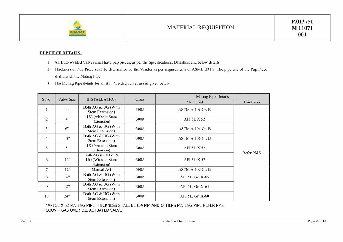
*API 5L X 52 MATING PIPE THICKNESS SHALL BE 6.4 MM AND OTHERS MATING PIPE REFER PMS
GOOV – GAS OVER OIL ACTUATED VALVE
PUP PIECE DETAILS:
1. All Butt-Welded Valves shall have pup pieces, as per the Specifications, Datasheet and below details:
2. Thickness of Pup Piece shall be determined by the Vendor as per requirements of ASME B31.8. The pipe end of the Pup Piece
shall match the Mating Pipe.
3. The Mating Pipe details for all Butt-Welded valves are as given below:
S No. Valve Size INSTALLATION Class Mating Pipe Details
* Material Thickness
1 4" Both AG & UG (With
Stem Extension) 300# ASTM A 106 Gr. B
Refer PMS
2 4" UG (without Stem
Extension) 300# API 5L X 52
3 6" Both AG & UG (With
Stem Extension) 300# ASTM A 106 Gr. B
4 8" Both AG & UG (With
Stem Extension) 300# ASTM A 106 Gr. B
5 8" UG (without Stem
Extension) 300# API 5L X 52
6 12"
Both AG (GOOV) &
UG (Without Stem
Extension)
300# API 5L X 52
7 12" Manual AG 300# ASTM A 106 Gr. B
8 16" Both AG & UG (With
Stem Extension) 300# API 5L, Gr. X-65
9 18" Both AG & UG (With
Stem Extension) 300# API 5L, Gr. X-65
10 24" Both AG & UG (With
Stem Extension) 300# API 5L, Gr. X-60

MATERIAL REQUISITION P.013751
M 11071
001
Rev. B City Gas Distribution Page 9 of 14
TABLE # 2
TECHNICAL COMPARISON FORMAT
SR.
NO.
Technical Requirements as per Data
Sheet, PTS, GTS etc.)
Reference Clause no.
Equivalent / Superior
material offered
Back up is Provided or
not? (Yes/ No)
Remarks
Item Material / Other
Requirements
(SEAL AND SIGNATURE OF BIDDER)

MATERIAL REQUISITION P.013751
M 11071
001
Rev. B City Gas Distribution Page 10 of 14
REMARKS / COMMENTS
1. GENERAL NOTES
VENDOR's compliance
Vendor shall submit his bid in full compliance with the requirements of this MR and attachments.
Vendor must include the following statement in his bid:
We certify that our bid is fully complying with your enquiry dated…………… and referenced………………….
Compliance with this material requisition in any instance shall not relieve the Vendor of his responsibility to
meet the specified performance.
2. COMPLIANCE WITH SPECIFICATION
The Vendor shall be completely responsible for the design, materials, fabrication, testing, inspection, preparation
for shipment and transport of the above equipment strictly in accordance with the Material Requisition and all
attachments thereto.
All pressure retaining and pressure controlling parts of Valves and Actuators shall be provided with EN 10204-
3.2 certificates.
3. VENDOR'S SCOPE
Vendor scope of work includes the equipment with all internals and accessories shown on the data sheets,
specifications and all unmentioned parts necessary for a satisfactory operation and testing except those which are
indicated to be out of the Vendor's supply.
4. INSPECTION
Inspection work shall be performed by BGRL’s designated Third Party Inspection Agency or BGRL delegate as
per approved QAP, as set out and specified in the codes/specification forming this Material Requisition.
5. APPLICABLE DOCUMENTS
General prescriptions, requirements and information are listed in annex C of this Material Requisition.
6. VENDOR'S DOCUMENTS
Vendor shall submit the documents as listed under point D of this Material Requisition.
All documents shall be submitted in English language.
7. DOCUMENTS NUMBERING AND FORMAT
Vendor shall strictly follow the document numbering procedure and document formats in their document, as per
Client’s requirement.

MATERIAL REQUISITION P.013751
M 11071
001
Rev. B City Gas Distribution Page 11 of 14
C. LIST OF ATTACHMENTS
The table herebelow lists the documents which are integral part of
this Material Requisition. The applicable revision index of each
document is mentioned in the column below the current Material
Requisition revision index.
Material Requisition revision
When the Material Requisition revision index is "A" or "1", all
listed documents are attached. For other Material Requisition
revision index, only modified or new documents are attached.
Documents Revision of documents
Particular Technical Specification – Pipeline Valves
Doc No : P.013751 D 11097 016
B
Particular Technical Specification – Gas Over Oil Actuator
Doc No : P.013751 D 11097 017
A
General Technical Specification – Pipeline Valves
Doc No : 70000/740/GTS/402
7
General Technical Specification – Actuators for Pipeline Valves
Doc No : 70000/740/GTS/403
1
Particular Technical Specification – Painting System and Colour
Code for Final Layer
Doc. No. : P.013751 M 11076 001
A
Particular Technical Specification – Piping Class
Doc. No. : P.013751 D 11097 018
A
Piping Specification – 3C1
B
Data Sheet – Ball Valves
P.013751 M11048 001, P.013751 M11048 002, P.013751
M11048 003, P.013751 M11048 004, P.013751 M11048 005,
P.013751 M11048 006, P.013751 M11048 015 & P.013751
M11048 016
A
QCT – Ball Valves
Doc. No : P.013751 D 11083 011 B
QCT – Globe Valves
Doc. No : P.013751 D 11083 012 B
Wiring Diagram for ON- OFF Gas Over Oil Actuated Valve 0

MATERIAL REQUISITION P.013751
M 11071
001
Rev. B City Gas Distribution Page 12 of 14
D. DOCUMENTS & DATA REQUIREMENTS
The table hereunder specifies the quantities and the nature of the documents to be submitted by the CONTRACTOR to the
ENGINEER.
The documents required at the inquiry stage and to be included in the bid are listed under column A.
The documents required after award of the AGREEMENT and subject to the written approval of the ENGINEER are listed
under column B.
The final and certified documents are listed under column C.
Any document, even when preliminary, shall be binding and therefore duly identified and signed by the CONTRACTOR. It
shall bear the ENGINEER's Project reference, the Material Requisition number and the identification number.
THE DOCUMENTS ARE FULLY PART OF THE SUPPLY WHICH SHALL BE COMPLETE ONLY IF AND WHEN THE
DOCUMENTS COMPLYING FULLY WITH THE MATERIAL REQUISITION REQUIREMENTS ARE RECEIVED BY
THE ENGINEER.
Item Documents and Data
Document
Index No.
A B C
No. of
copies
No. of
copies Required
date
No. of
copies Required date
1 Completed data sheet CDS 2 2 2 weeks 2 2 weeks before
despatch with
final techn. file
2 Drawing / data submittal list /
schedule
DLS 2 2 2 weeks +
monthly
2 2 weeks
3 Fabrication, test and delivery
schedule (per item)
FTD - 2 2 weeks +
monthly
2 2 weeks
4 Progress report PRT - 2 2 weeks +
monthly
2 2 weeks
5 Catalogues / References
(only for information)
CRS - - - 2 With final techn.
file
6 Outline drawing + material
specification + unit weight
(per valve and actuator)
OMS - 2 2 Weeks 2 With final techn.
file
7 Packing/shipping list with
weights and dimensions
PLD -
2 2 weeks
before
shipping
2 2 weeks before
despatch with
final techn. file

MATERIAL REQUISITION P.013751
M 11071
001
Rev. B City Gas Distribution Page 13 of 14
Item Documents and Data
Document
Index No.
A B C
No. of
copies
No. of
copies Required
date
No. of
copies Required date
8 Detail drawing + material
specification + unit weight +
calculations + Welding details for
the pups.
(per valve and actuator)
DMU -
2 2 weeks 2 2 weeks before
despatch with
final techn. file
9 Code compliance certificate CCC - 2 2 weeks 2 2 weeks before
despatch with
final techn. file
10 Bill of materials (on drawings) BOM - 2 2 weeks 2 2 weeks before
despatch with
final techn. file
11 Recommended spare parts list
(for erection and commissioning)
RSE - - - 2 2 weeks before
despatch with
final techn. file
12 Recommended spare parts list
(for 2 years operation)
RSO - - - 2 2 weeks before
despatch with
final techn. file
13 Welding procedure specification
and records WPS/PQR
WPS - 2 2 weeks 2 2 weeks before
despatch with
final techn. file
14 Compliance of QA/QC program* QAP 2 2 2 weeks 2 2 weeks before
despatch with
final techn. file
15 Inspection and test procedures ITP - 2 2 weeks 2 2 weeks before
despatch with
final techn. file
16 List of fabrication and control
operations (LOFC)
LOF - 2 2 weeks 2 2 weeks before
despatch with
final techn. file
17 Test reports TRS - 2 1 week after
test
2 2 weeks before
despatch with
final techn. file
18 NDE reports NDR - 2 1 week after
test
2 2 weeks before
despatch with
final techn. file
19 Heat treatment reports HTT - 2 1 week after
test
2 2 weeks before
despatch with
final techn. file

MATERIAL REQUISITION P.013751
M 11071
001
Rev. B City Gas Distribution Page 14 of 14
Item Documents and Data
Document
Index No.
A B C
No. of
copies
No. of
copies Required
date
No. of
copies Required date
20 Hydrotest and Air test report HTR - 2 1 week after
test
2 2 weeks before
despatch with
final techn. file
21 Maintenance and operating
manuals
MOM - 2 2 weeks
before
shipping
2 2 weeks before
despatch with
final techn. file
22 Installation instructions
Site inspection procedure
ITS - 2 2 weeks
before
shipping
2 2 weeks before
despatch with
final techn. file
23 Material certificate 3.2 MCT - 2 1 week after
test
2 2 weeks before
despatch with
final techn. file
24 Painting system description PSD - 2 2 weeks 2 2 weeks before
despatch with
final techn. file
25 Duly Filled Table # 2 &
Compliance letter as per B.1 of
MR if applicable
--- 2 2 2 weeks before
despatch with
final techn. file
26 List of subcontractors with their
scope
LSS 2 2 2 weeks
27 Final technical file (In Soft &
Hard copy)
FTF - - - 2 Before shipping
* QA/QC Program shall comprise of In-House testing facilities, Resources and Quality Procedure being followed by
the vendor to ensure Quality of Product in line with tender requirement.
NOTES
1) Durations in column B (Required date) are weeks after LOA as indicated in table.
Durations in column C (Required date) are weeks after document approval as indicated in table.
Due date of each document may be proposed.
2) Final technical file shall be supplied in hard copy as indicated, and in electronic format (.pdf Acrobat files) on
Two (2) CD-ROMs.

I. PROCESS DATA
- PIPE CLASS : 3C1 - CORROSION ALLOWANCE : 1.6 MM
- FLUID : Natural Gas
- FLUID SYMBOL : NG
- OPERATING CONDITIONS :
Pressure (barg) : 15 - 35
Temperature (°C) : 10 - 50
- DESIGN CONDITIONS :
Pressure (barg) : 49
Temperature (°C) : 0 - 60 at inner pressure of 6 barg with soap suds to check external leak of Body, Stem and all external taps.
II. VALVE DATA :
- APPLICABLE SPECIFICATION : P.013751 D 11097 016 (PTS -PIPELINE VALVES)
- CONSTRUCTION DESIGN : API 6D
- RATING : 300 #
- TYPE : TRUNION MOUNTED - DOUBLE BLOCK AND BLEED - FULLY WELDED BODY
- VALVE BORE : AS PER MR
- END CONNECTION : AS PER MR
- : ASTM A 216 GR. WCB / ASTM A 234 GR. WPB
- : (ASTM A 216 GR. WCB / ASTM A 234 GR. WPB) + MINIMUM 75 MICRONS ENP
- : AISI 4140 + MINIMUM 75 MICRONS ENP COATING / AISI 410
- : VITON / DEVLON
- : AISI 4140 + MINIMUM 75 MICRONS ENP COATING / AISI 410
- : VITON / PTFE
- : ASTM A 193 Gr. B 7 / ASTM A 194 GR. 2H
- : METAL TO METAL
- : DEVLON / RPTFE or Equivalent
- FIRE SAFE : Yes
- ANTI-BLOW OUT : Yes
- ANTISTATIC : Yes
- OPERATOR : GAS-HYDRAULIC
- EXTENSION STEM : 2.4 m from TOP of Pipe (Tentative, Finalised During Detail Engineering)
- PUPS (Applicable only for BW end)
LENGTH : 1.5 x ND or 300 mm (Whichever is higher)
MATERIAL OF CONSTRUCTION : Refer PMS
THICKNESS : Refer PMS
-
Surface preparation : SA 2.5
Primer :
Finish :
- : No
VA
PREPARED BY CHECKED BY
RP GSS ISSUED FOR PROCUREMENT
STEM SEAL
STUD BOLTS/NUTS
PRIMARY SEAT
SECONDARY SEAT
DESCRIPTIONAPPROVED BY
PAINTING
Date
06.01.2020
Rev.
BHARAT GAS RESOURCES LIMITED.
INSULATION
BODY MATERIAL
BALL MATERIAL
SEAT SEAL
STEM
BODY SEAT RINGS
A
Final Shade/Color code of valve shall be as per attached painting specification (P.013751 M 11076 001).
Final Paint DFT - 1000 Microns minimum for PUR / 500 Microns Mininum for High Build Epoxy Resin
(DIN 30677/2).
GAS OVER OIL OPERATED BALL VALVES DATA SHEET No
P.013751 M11048 001
DATA SHEET
UNDERGROUND SERVICE
SIZE - 16" TO 24"
Page 1 of 2
VBA-XV-3C1U
City Gas Distribution Project

III.
- HYDROSTATIC SHELL TEST
Test pressure : 1.5 x Design Pressure Test Medium : Water
Test Duration : 15 mins.
- HYDROSTATIC SEAT TEST
Test pressure : 1.1 x Design Pressure Test Medium : Water
Test Duration : 5 mins.
- AIR SEAT TEST
Test pressure : 6 bar Test Medium : Air
Test Duration : 5 mins.
- FUNCTIONAL TEST : 3 Opening / Closing (with actuator mounted on the valve)
Test pressure : Atmospheric & Maximum differential pressure
- EXTERNAL LEAK TEST : at inner pressure of 6 barg with soap suds to check external leak of Body, Stem and all external taps.
- DOUBLE BLOCK & BLEED TEST : Yes
- TORQUE TEST : Yes (API 6D) (valve and actuator)
- ANTISTATIC TEST : BS 5146
- VISUAL AND DIMENSIONAL EXAMINATION TEST: : MSS-SP-55 / API 1104
- FIRE SAFE TEST : API 6FA
IV. QUALITY CONTROL see quality control table for CS valves
- MATERIAL CERTIFICATES :
- ALL TESTING CERTIFICATES :
V. OPERATOR:
- APPLICABLE SPECIFICATION : GTS & Detailed Data Sheet of GAS OVER OIL ACTUATOR
APPROVED BY DESCRIPTIONDate Rev. PREPARED BY CHECKED BY
06.01.2020 A GG RP MC ISSUED FOR PROCUREMENT
NOTE :
TEST CERTIFICATES INCLUDING, FIRE SAFE, ANTISTATIC, PHYSICAL IMPACT, CHEMICAL,
PAINTING ETC.
TEST (valve and actuator)
P.013751 M11048 001
Unless otherwise stated, all tests will be witnessed by the purchaser.
Page 2 of 2
ALL PRESSURE RETAINING AND PRESSURE CONTROLLING PARTS OF VALVES SHALL BE
SUPPLIED WITH EN 10204 - 3.2 CERTIFICATES.
BHARAT GAS RESOURCES LIMITED. DATA SHEET
SIZE - 16" TO 24"
UNDERGROUND SERVICE
DATA SHEET NoGAS OVER OIL OPERATED BALL VALVES
VBA-XV-3C1U
City Gas Distribution Project

I. PROCESS DATA
- PIPE CLASS : 3C1 - CORROSION ALLOWANCE : 1.6 mm
- FLUID : Natural Gas
- FLUID SYMBOL : NG
- OPERATING CONDITIONS
Pressure (barg) : 15 - 35
Temperature (°C) : 10 - 50
- DESIGN CONDITIONS
Pressure (barg) :
Temperature (°C) :
II. VALVE DATA
- APPLICABLE SPECIFICATION : P.013751 D 11097 016 (PTS -PIPELINE VALVES)
- CONSTRUCTION DESIGN : API 6D
- RATING : 300 #
- TYPE :
- VALVE BORE : AS PER MR
- END CONNECTION : AS PER MR
- : ASTM A 216 GR. WCB / ASTM A 234 GR. WPB
- : (ASTM A 216 GR. WCB / ASTM A 234 GR. WPB) + MINIMUM 75 MICRONS ENP
- : AISI 4140 + MINIMUM 75 MICRONS ENP COATING / AISI 410
- : VITON / DEVLON
- : AISI 4140 + MINIMUM 75 MICRONS ENP COATING / AISI 410
- : VITON / PTFE
- STUD BOLTS/NUTS : ASTM A 193 Gr. B 7 / ASTM A 194 GR. 2H
- : METAL TO METAL
- : DEVLON / RPTFE or Equivalent
- FIRE SAFE : Yes
- ANTI-BLOW OUT : Yes
- ANTISTATIC : Yes
- EXTENSION STEM : No
- OPERATOR : GAS-HYDRAULIC
- PUPS (Applicable only for BW end) :
LENGTH : 1.5 x ND or 300 mm (Whichever is higher)
MATERIAL OF CONSTRUCTION : Refer PMS
THICKNESS : Refer PMS
- PAINTING
Surface preparation : SA 2.5
Primer : 30 - 40 µm
Finish : 30 - 40 µm
Final Paint DFT : 300 µm (min.)
BHARAT GAS RESOURCES LIMITED.
49
DATA SHEET No
P.013751 M11048 002
VBA-XV-3C1
GAS OVER OIL OPERATED BALL VALVES
ABOVEGROUND SERVICE
SIZE - 8" TO 24"
DATA SHEET Page 1 of 2
0 - 60
TRUNION MOUNTED - DOUBLE BLOCK AND BLEED - FULLY WELDED / BOLTED
BODY
PRIMARY SEAT
SECONDARY SEAT
STEM SEAL
STEM
BODY SEAT RINGS
SEAT SEAL
See Para.11 of PTS- PIPELINE VALVES & Painting System &
Colour Code for Final Layer (P.013751 M 11076 001)
BODY MATERIAL
BALL MATERIAL
APPROVED BY DESCRIPTION
06.01.2020 A VA
PREPARED BY CHECKED BY
RP GSS ISSUED FOR PROCUREMENT
DATE REV
REISSUED FOR PROCUREMENT20.03.2020 B VA RP GSS
City Gas Distribution Project

III. TEST :
- HYDROSTATIC SHELL TEST
Test pressure : 1.5 x Design Pressure Test Medium : Water
Test Duration : 15 mins.
- HYDROSTATIC SEAT TEST
Test pressure : 1.1 x Design Pressure Test Medium : Water
Test Duration : 5 mins.
- AIR SEAT TEST
Test pressure : 6 bar Test Medium : Air
Test Duration : 5 mins.
- FUNCTIONAL TEST : 3 Opening / Closing (with actuator mounted on the valve)
Test pressure : Atmospheric & Maximum differential pressure
- EXTERNAL LEAK TEST : at inner pressure of 6 barg with soap suds to check external leak of Body, Stem and all external taps.
- DOUBLE BLOCK & BLEED TEST : Yes
- TORQUE TEST : Yes (valve and actuator)
- ANTISTATIC TEST : BS 5146
- VISUAL AND DIMENSIONAL EXAMINATION TEST : MSS-SP-55 / API 1104
- FIRE SAFE TEST : API 6FA
Unless otherwise stated, all tests will be witnessed by the purchaser.
IV. QUALITY CONTROL See quality control table for valves
- MATERIAL CERTIFICATES :
- ALL TESTING CERTIFICATES :
V. OPERATOR:
- APPLICABLE SPECIFICATION : GTS & Detailed Data Sheet of GAS OVER OIL ACTUATOR
DATE REV PREPARED BY
06.01.2020 A GG
DESCRIPTION
ISSUED FOR PROCUREMENTRP
RP GSS REVISED FOR PROCUREMENT
GSS
CHECKED BY APPROVED BY
20.03.2020 B GG
DATA SHEET NO
ALL PRESSURE RETAINING AND PRESSURE CONTROLLING PARTS OF VALVES SHALL BE SUPPLIED WITH
EN 10204 - 3.2 CERTIFICATES.
TEST CERTIFICATES INCLUDING, FIRE SAFE, ANTISTATIC, PHYSICAL IMPACT, CHEMICAL, PAINTING ETC.
Page 2 of 2
P.013751 M11048 002ABOVEGROUND SERVICE
TEST (valve and actuator)
BHARAT GAS RESOURCES LIMITED. DATA SHEET
SIZE - 8" TO 24"
GAS OVER OIL OPERATED BALL VALVES
VBA-XV-3C1
NOTE :
City Gas Distribution Project
I. PROCESS DATA :
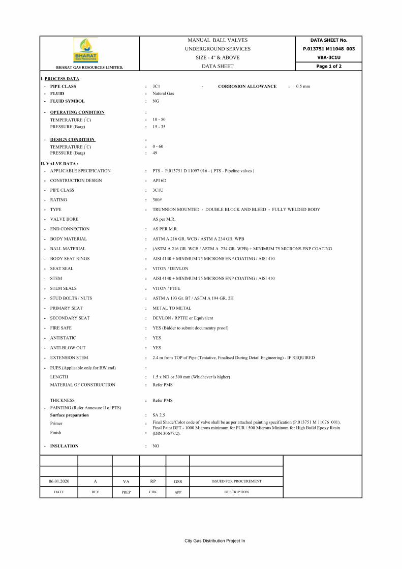
- PIPE CLASS : 3C1 - CORROSION ALLOWANCE : 0.5 mm
- FLUID : Natural Gas
- FLUID SYMBOL : NG
- OPERATING CONDITION :
TEMPERATURE (°C) : 10 - 50
PRESSURE (Barg) : 15 - 35
- DESIGN CONDITION :
TEMPERATURE (°C) : 0 - 60
PRESSURE (Barg) : 49
II. VALVE DATA :
- APPLICABLE SPECIFICATION : PTS - P.013751 D 11097 016 - ( PTS - Pipeline valves )
- CONSTRUCTION DESIGN : API 6D
- PIPE CLASS : 3C1U
- RATING : 300#
- TYPE : TRUNNION MOUNTED - DOUBLE BLOCK AND BLEED - FULLY WELDED BODY
- VALVE BORE AS per M.R.
- END CONNECTION : AS PER M.R.
- BODY MATERIAL : ASTM A 216 GR. WCB / ASTM A 234 GR. WPB
- BALL MATERIAL : (ASTM A 216 GR. WCB / ASTM A 234 GR. WPB) + MINIMUM 75 MICRONS ENP COATING
- BODY SEAT RINGS : AISI 4140 + MINIMUM 75 MICRONS ENP COATING / AISI 410
- SEAT SEAL : VITON / DEVLON
- STEM : AISI 4140 + MINIMUM 75 MICRONS ENP COATING / AISI 410
- STEM SEALS : VITON / PTFE
- STUD BOLTS / NUTS : ASTM A 193 Gr. B7 / ASTM A 194 GR. 2H
- PRIMARY SEAT : METAL TO METAL
- SECONDARY SEAT : DEVLON / RPTFE or Equivalent
- FIRE SAFE : YES (Bidder to submit documentry proof)
- ANTISTATIC : YES
- ANTI-BLOW OUT : YES
- EXTENSION STEM : 2.4 m from TOP of Pipe (Tentative, Finalised During Detail Engineering) - IF REQUIRED
- PUPS (Applicable only for BW end) :
LENGTH : 1.5 x ND or 300 mm (Whichever is higher)
MATERIAL OF CONSTRUCTION : Refer PMS
THICKNESS : Refer PMS
- PAINTING (Refer Annexure II of PTS)
Surface preparation : SA 2.5
Primer :
Finish :
- INSULATION : NO
VA GSS
PREP APP
BHARAT GAS RESOURCES LIMITED.
UNDERGROUND SERVICES
SIZE - 4" & ABOVE
DATA SHEET
DATE REV
A06.01.2020
P.013751 M11048 003
DATA SHEET No.
VBA-3C1U
Page 1 of 2
Final Shade/Color code of valve shall be as per attached painting specification (P.013751 M 11076 001).
Final Paint DFT - 1000 Microns minimum for PUR / 500 Microns Mininum for High Build Epoxy Resin
(DIN 30677/2).
RP
CHK DESCRIPTION
ISSUED FOR PROCUREMENT
MANUAL BALL VALVES
City Gas Distribution Project In

- :
III TEST (Valves)
- HYDROSTATIC SHELL TEST :
Test pressure : 1.5 x Design Pressure Test Medium : Water
Test Duration : 15 mins.
- HYDROSTATIC SEAT TEST :
Test pressure : 1.1 x Design Pressure Test Medium : Water
Test Duration : 5 mins.
- AIR SEAT TEST :
Test pressure : 6 barg Test Medium : Air
Test Duration : 5 mins.
- FUNCTIONAL TEST : 3 Opening / Closing
Test pressure : Atmospheric & Maximum differential pressure
- EXTERNAL LEAK TEST :
- DOUBLE BLOCK & BLEED TEST : Yes
- TORQUE TEST : Yes (API 6D)
- ANTISTATIC TEST : BS 5146
- : MSS-SP-55 / API 1104
- FIRE TEST : API 6FA
IV QUALITY CONTROL : See quality control table for Valves
- MATERIAL CERTIFICATES :
- ALL TEST CERTIFICATES :
NOTES:-
1 Unless otherwise stated, all tests will be witnessed by the purchaser/control authority.
VA
PREP
Hydraulic Actuated
16" - 24" (Note2)
For Hydraulic Actuated valves, Consider additional requirements i.e.
Position Switches : Eex "d", "e" or "I"
Quantity : 4 (TWO OPENED-TWO CLOSED)
Wrench Operated
(Manual)
Upto 2"
Gear Operated
(Manual)
Above 2" -12"
Operator
at inner pressure of 6 barg with soap suds to check external leak of Body, Stem and
all external taps.
VISUAL AND DIMENSIONAL
EXAMINATION TEST
ALL PRESSURE RETAINING AND PRESSURE CONTROLLING PARTS OF
VALVES SHALL BE SUPPLIED WITH EN 10204 - 3.2 CERTIFICATES.
TEST CERTIFICATES INCLUDING, FIRE SAFE, ANTISTATIC, PHYSICAL
IMPACT, CHEMICAL, PAINTING ETC.
2
DATA SHEET No.
P.013751 M11048 003
VBA-3C1U
Page 2 of 2BHARAT GAS RESOURCES LIMITED.
MANUAL BALL VALVES
UNDERGROUND SERVICES
SIZE - 4" ABOVE
DATA SHEET
DATE REV
06.01.2020
DESCRIPTIONCHK APP
A ISSUED FOR PROCUREMENTRP GSS
City Gas Distribution Project

I. PROCESS DATA : -
- PIPE CLASS : 3C1 - CORROSION ALLOWANCE : 0.5 mm
- FLUID : Natural Gas
- FLUID SYMBOL : NG
- OPERATING CONDITION
TEMPERATURE (°C) : 10 - 50
PRESSURE (Barg) : 19 - 35
- DESIGN CONDITION
TEMPERATURE (°C) : 0 - 60
PRESSURE (Barg) : 49
II. VALVE DATA :
- APPLICABLE SPECIFICATION : PTS - P.013751 D 11097 016 - ( PTS - Pipeline valves )
- CONSTRUCTION DESIGN : API 6D
- PIPE CLASS : 3C1
- RATING : 300#
- VALVE BORE : AS per M.R.
- TYPE :
- END CONNECTION : AS PER M.R.
- BODY MATERIAL : ASTM A 216 GR. WCB / ASTM A 234 GR. WPB
- BALL MATERIAL :
- BODY SEAT RINGS : AISI 4140 + MINIMUM 75 MICRONS ENP COATING / AISI 410
- SEAT SEAL : VITON / DEVLON
- : AISI 4140 + MINIMUM 75 MICRONS ENP COATING / AISI 410
- STEM SEALS : VITON / PTFE
- STUD BOLTS/NUTS : ASTM A 193 Gr. B7 / ASTM A 194 GR. 2H
- PRIMARY SEAT : METAL TO METAL
- ANTISTATIC : YES
- ANTI-BLOW OUT : YES
- EXTENSION STEM : NO
- PUPS (Applicable only for BW end)
LENGTH : 1.5 x ND or 300 mm (Whichever is higher)
MATERIAL OF CONSTRUCTION : Refer PMS
THICKNESS : Refer PMS
- PAINTING (Refer Annexure II of PTS)
Surface preparation : SA 2.5
Primer : 30 - 40 µm
Finish : 30 - 40 µm
Final Paint DFT : 300 µm (min.)
- INSULATION : NO
VA RP GSS
PREP CHK APP
See Para.11 of PTS- PIPELINE VALVES & Painting
System & Colour Code for Final Layer (P.013751 M
11076 001)
(ASTM A 216 GR. WCB / ASTM A 234 GR. WPB) + MINIMUM 75
MICRONS ENP
DESCRIPTION
ISSUED FOR PROCUREMENT
DATE REV
A11.07.18
STEM
Page 1 of 2BHARAT GAS RESOURCES LIMITED.
DATA SHEET No.
ABOVEGROUND SERVICES
SIZE - 4" & ABOVE
DATA SHEET
P.013751 M11048 004
MANUAL BALL VALVES
VBA-3C1
TRUNNION MOUNTED - DOUBLE BLOCK AND BLEED - FULLY
WELDED / BOLTED CONSTRUCTION
City Gas Distribution Project

- :
III TEST
- HYDROSTATIC SHELL TEST :
Test pressure : 1.5 x Design Pressure Test Medium : Water
Test Duration : 15 mins.
- HYDROSTATIC SEAT TEST :
Test pressure : 1.1 x Design Pressure Test Medium : Water
Test Duration : 5 mins.
- PNEUMATIC SEAT TEST :
Test pressure : 6 barg Test Medium : Air
Test Duration : 5 mins.
- FUNCTIONAL TEST : : 3 Opening / Closing
Test pressure : Atmospheric & Maximum differential pressure
- EXTERNAL LEAK TEST :
- DOUBLE BLOCK & BLEED TEST : Yes
- TORQUE TEST : Yes
- ANTISTATIC TEST : BS 5146
- : MSS-SP-55 / API 1104
- FIRE TEST : API 6FA
IV QUALITY CONTROL : See quality control table for valves
- MATERIAL CERTIFICATES :
- ALL TEST CERTIFICATES :
NOTES:-
1 Unless otherwise stated, all tests will be witnessed by the purchaser/control authority.
VA RP GSS
PREP CHK APP
2
For Hydraulic Actuated valves, Consider additional requirements i.e.
Position Switches : Eex "d", "e" or "I"
Quantity : 4 (TWO OPENED-TWO CLOSED)
MANUAL BALL VALVES
ABOVEGROUND SERVICES
SIZE - 4" & ABOVE
DATA SHEET
TEST CERTIFICATES INCLUDING, FIRE SAFE, ANTISTATIC, PHYSICAL
IMPACT, CHEMICAL, PAINTING ETC.
VISUAL AND DIMENSIONAL
EXAMINATION TEST:
VBA-3C1
Wrench Operated
(Manual)
Upto 2"
Gear Operated (Manual)
Above 2" -12"
Page 2 of 2
DATA SHEET No.
at inner pressure of 6 barg with soap suds to check external leak of Body,
Stem and all external taps.
P.013751 M11048 004
BHARAT GAS RESOURCES LIMITED.
Operator
REV
06.01.2020
Hydraulic Actuated
16" - 24" (Note2)
A
ALL PRESSURE RETAINING AND PRESSURE CONTROLLING PARTS OF
VALVES SHALL BE SUPPLIED WITH EN 10204 - 3.2 CERTIFICATES.
DESCRIPTION
ISSUED FOR PROCUREMENT
DATE
City Gas Distribution Project

1
2
3
4
5
6
6
7
8
9
10
11
12 Min/Max
13 Min/Max
14 Min/Max
15 Min/Max
16 Min/Max
17
18
19
20
21
22
23
24
25
26
27
28
29
30
31
32
33
34
35
36
37
38
39
40
41
Panel Enclosure Protection WP- IP 65- Ex proof
Gas Storage and Hydraulic Cylinder Capacity
AC
TU
AT
OR
Type Gas Over Oil Actuator ,Quarter Turn Operation
Min. Pressure For Actuator Sizing 15 Barg
Design Pressure As per Process Parameters given in Tender
Power Gas supply Connection Vendor to Provide
Tubing Material SS316
Tubing Size Vendor to Provide
Filter Regulator \ Relief
Min one Open & one close operations in case of
loss of line pressure
Stroke Time/Response Time
DATA SHEET
GAS OVER OIL OPERATED ACTUATOR
P.013751
M11048
016
GE
NE
RA
L
Tag Numbers As per Approved P&ID
Quantity As per Approved P&ID
Line Number As per Approved P&ID
Service Natural Gas
Line Size & Line Schedule As per Approved P&ID's and Valve data sheet
Actutator
(Make / Model No)Vendor to Provide
Valve Position Indicator
(Make/Model No)Vendor to Provide
Solenoid valve
(Make / Model No)Vendor to Provide
PR
OC
ES
S D
AT
A
Manual Override Required
Failure Position Stay Put
Required
Filter regulator Material \ Filter Element SS316\ 2-5 Micron
Painting Mfr Standard (Subject to Approval)
Cabinet/Panel Material SS316/Manufacturer Standard
Valve Position Indicator Required
Relief Valve Required - Material: SS316
Pressure Gauge Required - Material: SS316
Differential Pressure SwitchAs per Attached Datasheet - Integral with
Actuator Assembly
Vendor to Provide for Opening & Closing @ Min
& Max Pressure
Safety Factor
Actuator torque shall be minimum 1.25 times
the maximum valve break torque required at
full rated differential pressure of valve (1.25
Times)
Tube Fittings SS316
Flow Rate
Operating Pressure
Opearating Temp
Design Temperature
Density (Kg/m³) : Min
Fluid State Gas
As per Process Parameters
As per Process Parameters
Position Switches Required for both open and close positions
Solenoid Valves As per Attached Datasheet
Control panel
(Make / Model No)Vendor to Provide
Junction box
(Make / Model No)Vendor to Provide
Differential Pressure switch
Make / Model no.Vendor to provide
MA
KE
/
MO
DE
L
-20 °C / 60 °C
As per Tender
As per Process Parameters
Design Pressure As per Process Parameters
Pressure Drop Max line pressure
Page 1 of 5

DATA SHEET
GAS OVER OIL OPERATED ACTUATOR
P.013751
M11048
016
42
43
44
45
46
47
48
49
50
51
52
53
54
55
56
57
58 Required
59 24 V DC, 2 Amp
60
61
62
63
64
65
JUN
CT
I
ON
BO
X
1
2
3
4
5
6
7
8
9
10
11
12
13
14
15
16
17
18
19
20
21
22
23
AC
TU
AT
OR
Vendor to Provide
Oil Content Vendor to Provide
Adjustable Stoppers for Actuator and Torque Limiting
DeviceRequired for both opening and closing
Stem Extension As per valve data sheetV
AL
VE
PO
SIT
ION
SW
ITC
H
Area Classification Zone- 1,2, Gr.II A/B, T3 or Better
Switch Type Sealed micro type lever operated, Intrinsically safe
Contact DPDT,Gold Palted
Contact Rating 24V DC, 2 Amp
Cable Entry 1/2" NPTF (2 Nos.)
Switch Quantity 2 nos (one open and one close)
Enclosure Material Dia cast aluminum
Enclosure Class
Vendor to Provide
Flameproof & WP to IP-65 or Better
Hydraulic Fluid Cleanliness As per NAS 1638 / ISO 4406 - Latest Editions
Hand Pump Required
Gas Consumption \ Displacement Vendor to Provide
Oil Displacement Vendor to Provide
Tank Capacity
Explosion proof to Exd. IIA/IIB, T3 and weather
proof to IP 65 and made up of dia cast aluminium.
PE
RF
OR
MA
NC
E /
TO
RQ
UE
TA
BL
E
Break to Open (BTO) Vendor to Provide
End to Open Vendor to Provide
GE
NE
RA
L
Tag Numbers As per Approved P&ID
Quantity Vendor to provide
Location Mounted in/with Actuator Cabinet
Service Natural Gas
Area Classification Zone-1,2, Gr.II A/B,T3 or Better
Enclosure Class WP to IP-65 or Better, Intrinsically safe
VA
LV
E
Body Size/ Rating Vendor to provide
Type (Pilot / Manual) Vendor to provide
Body Material SS316 / SS316L
Process Connection Vendor to provide
Orifice Size Vendor to provide
Trim Material SS316 / SS316L
Operation :Direct/Pilot Vendor to provide
Operating Mode NC/NO/UNIVERSAL Vendor to provide
On De-Energised Condition,Port Vendor to provide
On Energised Condition,Ports Vendor to provide
Manual operation facility
SO
LE
NO
ID V
AL
VE
Style of Coil Vendor to provide
Coil Voltage 24 VDC
Coil Insulation Class Class F
Electrical Connection Required
Cable Entry 1/2" NPTF
Supply Volt 24 VDC
Required
SOLENOID VALVE FOR GOOV
LO
CA
L /
RE
MO
TE
SW
ITC
H
L/R selector switch
Rating
Break to Close Vendor to Provide
End to Close Vendor to Provide
Junction Box
Running
Page 2 of 5

DATA SHEET
GAS OVER OIL OPERATED ACTUATOR
P.013751
M11048
016
1
2
3
4
5
6
7
8
9
10
11
12
13
14
15
16
17
18
19
20
21
22
23
24
25
26
27
28
1
2
3
4
5
6
7
8
1
2
3
4
5
6
7
8
The Solenoid valves shall be intrinsically safe/Ex proof to specified area classification. Surge suppression diodes shall be provided
across the coil
GE
NE
RA
L
Tag Numbers As per Approved P&ID
Quantity As per Approved P&ID
Service Natural gas
Type Electric ,Differential Pressure
Location Mounted in/with Actuator Cabinet
Area Classification Zone-1,2, GR.II A/B,T3 or Better, Exia/Exd
Enclosure Class Flameproof & WP to IP-65 or Better
Housing Material LM-6 Cast Aluminum
±1% of Span
Hysterisis / Dead Band Details Vendor to provide
Terminal Block Required
Set Point adjustment External type with Locking arrangement.
Differential RangeDifferential range shall be Fixed and such that
reset pressure shall be 10% below set pressure.
TypeMicro Switch, Hermetically Sealed with Gold
plated contacts
Current Vendor to provide
Load Type Inductive
Conduit conn. 1/4"NPTF / 1/2"NPTF
No. of Entries Two
Manifold Connection 1/2" NPTF
Element Material SS316
DP SWITCH FOR GOOV (For information) supplied by others
Pressure Element Diaphragm with SS316 pressure chamber
150% of FSD
Repeatability
Manifold Type 5 Valve Manifold (As Applicable)
Manifold Material SS316
Accuracy ±1% of Span
Process Connection 1/2" NPTF,Bottom and side
Over Range Protection
DIF
FE
RE
NT
IAL
PR
ES
SU
RE
SW
ITC
H
Electrical output Contact
Contact DPDT
Certification required :
Overall Dimension Drawing
Weather Proof Certificates or Flame Proof \ Ex. Proof Certificates. The Certificate from a statutory body like UL /FM
/ CSA / BASEEFA\ATEX or equal shall be submitted.
Functional Test Reports
Test Certificates for Actuator. Also CCOE certificate for Limit switch, DP switch and Solenoid valve shall be
furnished for specified area classification".
Calibration Report of Relief Valve with Serial No marked on Valve
Calibration Report of Pressure Gauge and DPS with Serial No marked
Blasting , Surface Preparation & Painting Report
Operational , Maintenace & Installation Manual
Catalogues for all the accessories
Electrical Wiring Diagram
Interconnection loop Diagram
Pnuematic/Hydraulic Operating Diagram
The control logic shall enable the following:
Actuator GA Drawing
Tank Sizing Calculation of OEM
Junction Box Details with GA Drawing.
Torque table with calculated Break, Running torque, selected actuator Break, Running and torque"
Documents Required:
Page 3 of 5

DATA SHEET
GAS OVER OIL OPERATED ACTUATOR
P.013751
M11048
016
a)
b)
c)
d)
e)
f)
Note
1
DATE REV PREPARED BY REVIEWED BY APPROVED BY DESCRIPTION
06.01.2020 0 MA SD NC Issued for Procurement
Actuator vendor shall provide ex proof junction with actuator. In coming cable and size shall be as per vendor
and out going cable entries in JB shall be 2 nos 1", 2 nos 1 1/2" and 2 nos 1/2" with SS plugs)
High differential pressure inhibit switch shall inhibit the remote operation of the valve, when differential becomes
high (more than 3 bars). However it shall be possible to operate the valve manually using hand pump.
Opposite movement inhibitor shall be provided
Safety factor shall be applicable for entire operation i.e open to close & close to open
Local and remote selection in field. When selected in local, valve shall be operated from hand pump. When selected in
remote, valve shall be operated from remotely. Hold on contract while opening and closing shall be done. Reset
holding through respective limit switch. High Differential pressure interlock shall be provided during opening of
valve.
Following signals shall be made available for remote connectivity.
1. open close status.
2. L/R indication.
3. DPSH indication.
4. Open and close from remote
Manual local hydraulic operation of valve , with hand pumps, in case of non availability of pneumatic (gas)
operation.
Page 4 of 5

Break Torque
(Nm)
Running
Torque (Nm)
Max Allowable
Valve Stem
Torque (Nm)
Break Torque
(Nm)
Running Torque
(Nm)
Break
Torque (Nm)
Running Torque
(Nm)
1 2 3 4 5 6 7
Note –
1
2
Actuator Generated Torque
(Note)Actuator Model
Selected
TORQUE TABLE TO BE FILLED BY SUPPLIER
Actuator running torque under col.(7) shall be greater than or equal to minimum required torque indicated under col (5) and actuator break torque under col (6) shall
be greater than equal to minimum required torque indicated under col (4)
Actuator break torque col (6) shall be less than max allowable torque for valve stem under col (3). Valve manufacturer shall ensure that valve stem is designed to
withstand actuator break torque.
Sl. No Tag No Qty Size Class
Data from Ball Valve Vendor forBall Valve Torque Figure with a
safety Factor of 1.25

PTS – PIPELINE VALVES P.013751
M 11071
001
BHARAT GAS RESOURCES LIMITED (BGRL)
CITY GAS DIRTIBUTION PROJECT
SUPPLY OF VALVES FOR AHMEDNAGAR – AURANGABAD AND SATARA – SANGLI (MAHARASHTRA STATE)
PTS – PIPELINE VALVES
B 20.03.2020 Generally Revised VA RP GSS
A 06.01.2020 Issued as Standard Specification VA RP GSS
Rev. Date Description Prepared By Checked By Approved By

PTS – PIPELINE VALVES P.013751
M 11071
001
Rev. B City Gas Distribution Page 1 of 1
TABLE OF CONTENT
1.0 SCOPE ................................................................................................................................ 1
2.0 DEFINITIONS ..................................................................................................................... 1
3.0 PRELIMINARY STATEMENT ............................................................................................... 1
4.0 GENERAL ............................................................................................................................ 2
5.0 CODES, NORMS AND STANDARDS ..................................................................................... 2
6.0 DESIGN AND CONSTRUCTION ........................................................................................... 2
7.0 MATERIALS ........................................................................................................................ 6
8.0 FABRICATION AND TEST ................................................................................................... 7
9.0 MARKING ........................................................................................................................... 9
10.0 INSPECTION....................................................................................................................... 9
11.0 PAINTING AND COATING ................................................................................................ 10
12.0 SPARES AND ACCESSORIES ............................................................................................. 10
∑ ∑ ∑

PTS – PIPELINE VALVES P.013751
M 11071
001
Rev. B City Gas Distribution Page 1 of 13
1.0 SCOPE
This Document (PTS - Particular Technical Specification for PIPELINE VALVES) lists the Specification
for Manufacturing of Valves, for the pipeline project for the service of natural gas.
The present specification has to be read in conjunction with General Technical Specification
70000/740/GTS/402 rev. 7 (The GTS) which it amends and/or complements.
The present specification can confirm, complete or modify certain sections/paragraphs of said «General
Technical Specification». The PTS will govern the requirements for all such sections.
Add:
The present Particular Technical Specification relates to the manufacture of “Pipeline Valves” (for above
and underground) for the pipeline project for the service of natural gas.
2.0 DEFINITIONS
Add:
Purchaser shall mean Bharat Gas Resources Ltd., Maharashtra, India.
GTS means << General Technical Specification 70000/740/GTS/402
rev. 7 >> and all documents it refers to.
PTS means the present <<Particular Technical specification P.013751
M 11071 001 >> and all its appendices, if any.
Manufacturer means the Manufacturer of the valves as well as its sub-
contractor(s).
Control Authority Owner/Engineer or their Authorised Inspection Agency
Inspection Agency or Third-Party
Inspection Agency (TPIA)
means the Inspection Agency to be appointed by the
Manufacturer.
Engineer/ Owner’s the entity of the purchaser or the company nominated by representative the purchaser. the entity of the purchaser or the company nominated by the
purchaser.
3.0 PRELIMINARY STATEMENT
Add:
• In case of conflict between the requirements in technical documents, the most stringent requirements shall
apply.
• A valid copy of API 6D monogram/certificate shall be included in the offer.
Modify para 10 & 11:
• For any control, test or examination required under the supervision of the Authorised Control authority
(LOFC Intervention points included), the latter shall be informed in writing FIVE (5) working days in
advance by the Manufacturer (Fifteen working days in case of supply of foreign origin) about place and
time with a copy to the Client/Engineer. Wages and travel expenditure of the Authorised Control Authority
are at the Client’s expenses.
• As the manufacturing is to be carried out under LOFC concept, the Manufacturer shall send for approval a
List of Operation in Manufacturing and Control (see annex 1) to the Authorised Control Authority and
Client, TEN (10) working days before manufacturing. This list shall be in conformity with the annex 1 to
this document. Before starting any manufacturing, the Manufacturer shall be in possession of this approved
document, filled in with all intervention points.

PTS – PIPELINE VALVES P.013751
M 11071
001
Rev. B City Gas Distribution Page 2 of 13
4.0 GENERAL
Add:
Valve design shall meet the requirements of API Specification 6D and shall be suitab le for the service
conditions indicated in the Valve Data Sheet. The ASME Boiler & Pressure Vessel Code, Section VIII,
Division 1 shall be used to design the valve body.
Allowable stress requirements shall comply the provisions of above code. In addition, corrosion allowance
indicated in Valve Data Sheet shall be considered in valve design.
The manufacturer shall have valid license to use API monogram on valves manufactured as per API 6D. The
ball valves shall be bi-directional.
5.0 CODES, NORMS AND STANDARDS
Add:
API 598 : Valve Inspection and Testing
ISO/DIS 14313 : Petroleum and Natural Gas Industries - Pipeline Transportation
Systems – Pipeline valves.
Note:
In case of conflict between the requirements of this specification, Codes, Standards and Specifications
referred in above, the most stringent requirement specification shall govern.
6.0 DESIGN AND CONSTRUCTION
6.1 Design
6.1.1 Welding ends
Add:
The valve manufacturer shall supply all butt weld valves with a welded pups/Transition piece at both ends
which shall be considered as an integral part of the valve & hence such as strength test, hydrostatic test &
Leak test should be done with pup-piece/transition piece weld on valve.
The chemical composition of the steel of the Pup/Transition piece meets the following requirements
Maximum limit of chemical elements which may be used in material under this Particular Technical
Specification.
% maximum % maximum % maximum
C 0.230 Mn 1.60 Si 0.50
P 0.030 S 0.025 Nb. 0.080
V 0.120 Mo 0.250 Nt 0.015
Alternate alloy elements may be used but they shall be discussed with the user prior to delivery of the
material. This table is not intended to represent the composition of any heat of steel, but me rely to record
the maximum permissible amounts of one element. The combination of elements of any heat must conform
to the carbon equivalent, computed like following:
Carbon equivalent shall be computed by "check analysis", the following equation is applicable:
and shall not exceed 0.40 %. The CE (IIW) limits shall not apply if C< 0.12% and shall not exceed 0.43

PTS – PIPELINE VALVES P.013751
M 11071
001
Rev. B City Gas Distribution Page 3 of 13
For each heat the manufacturer shall analyse the following elements: C, Mn, Si, P, S, Nb, V, Cr, Mo, Ni and
Cu.
The intentional addition of elements other than those specified is not permitted unless agreed up by the
Client.
In any case, for unintentional additions, the following limitations shall be respected:
Cr < 0.15% Mo < 0.05% Cu < 0.20%
Ni < 0.30% Co < 0.01% Al < 0.07%
The content of N total (Nt) may be up to 0.0150% and must be guaranteed by the manufacturer. If the
manufacturer cannot give any guaranty of N content, he shall analyse this element.
The total content for Nb + V will be limited to 0.150%.
In grades X42 through X70 for each reduction of 0.01% below the maximum carbon content, an increase of
0.05% manganese above the specified maximum is permissible, up to a maximum of 1.70%.
The choice and use of alloying elements made from low alloy steels to give the Mechanical Properties of
API 5L Gr. X52 (in table hereafter), is of the responsibility of the manufacturer.
Symbol Yield Strength (min.) Tensile Strength (min.) Elongation in 2 in.
Ksi Mpa Ksi Mpa Min. percent
X60 60200 415 75400 520 20
X65 65300 450 77600 535 20
X 52 52200 360 66700 460 24
The ratio of effective yield strength to effective tensile strength of the steel shall not exceed 0.90.
If the butt-welding end of the valve has a thickness and/or a steel grade not equal to the connecting pipe,
butt-welding ends shall be in accordance with any of the suggestive figures given in Appendix I of ASME B
31.8 or an appropriate combination selected by the valve manufacturers to ensure that availability of
uniform pig passage without sacrificing pressure-temperature design requirement.
Butt weld end valves shall be provided with pup piece. Pup piece length shall be of at least 1.5 ND or 300
mm, whichever is higher.
No repair is permitted on pup pieces. 100 % UT shall be performed on pup pieces.
Thickness of Pup Piece shall be determined by the Vendor as per Code requirements. The pipe end of the
Pup Piece shall match the Material, diameter and thickness of linepipe where the valve is required to be
welded. Table below indicate the size, thickness, material of the linepipe for various sizes of Ball valves:
Size of Ball valve (FB) Material of construction
4’’ ASTM A 106 Gr. B *
6” ASTM A 106 Gr. B
8” ASTM A 106 Gr. B *
12” ASTM A 106 Gr. B *
16” API 5L Gr. X-65
18” API 5L Gr. X-65
24” API 5L Gr. X-60
* Pup Piece material is required API 5L X 52 (PSL 2 ) for Underground Valve (without Stem Extension). These
Valve shall be installed in the Valve Pit.
The Valve Manufacturers shall submit all necessary details regarding welding of BW end of valve with Line
pipe along with calculation for provided thickness for approval of Owner/Owner’s representative.

PTS – PIPELINE VALVES P.013751
M 11071
001
Rev. B City Gas Distribution Page 4 of 13
The Charpy V-notch impact testing of pup piece (for API 5L material) as indicated in data sheet shall be
carried out as following:
Location Impact Test
Temp.
Impact Energy Absorption Value (Minimum)
Avg. Value Individual Value
For Base 0 °C 40 J 32 J
For Weld & HAZ
Metal
0 °C 27 J 22 J
In addition to above the Charpy V-notch impact testing of pup piece, Valve body and other pressure
containing parts of valve (for CS or LTCS steel material) as indicated in data sheet / piping material
specification shall be carried out as per following requirements
Material Impact Test Temp.
Impact Energy Absorption Value (Minimum)
Avg. Value (J) Individual Value (J)
Carbon Steel
Material
0 Deg. C SMYS (Mpa)/10,
with a minimum
of 27 J, for the
transerve
direction.
It shall not be less than
80 % of the Minimum
required average value,
for the transerve
direction
For LTC Material testing shall be done at -20 Degree C and Energy absorbed min. 28 J & Avg. 35 J. These
valves shall be installed in the Blow down line.
The pup piece shall be subjected to all the testing (Charpy, Tensile, Hardness, NDT etc.) requirements as
mentioned in QAP. Inspection frequency, acceptance criteria & reference standards shall be as per
applicable specifications/QAP.
6.1.2 Design features
Add in Para 1:
For above ground valves, body design shall be either fully welded or bolted type. For buried valves, valve
body design shall be fully welded type only. Valve body joints with threads are not permitted. In the valve
body outlets also, threading is not permitted.
Ball shall be of single piece, solid type construction.
The full bore valve shall provide an unobstructed profile for pigging operations in either direction. Full bore
valves shall be designed to minimize accumulation of debris in the seat ring region to ensure that ba ll
movement is not impeded. Also, when the full bore ball valve is in fully open position, the ball shall not
obstruct the passage of flow/pig run. Manufacturer shall demonstrate the same through manual and actuated
operation.
Modify:
For 4” & above size, valve shall be trunnion mounted ball valve. All trunnion mounted ball valve shall be
fitted with following devices:
Double piston effect: when the pressure is applied to one side, let us say upstream” side, and when
upstream ball seat is leaking, transfer pressure shall have a positive shut-off effect on the downstream seat
(acting, for instance, on the back face of this seat) and thus reinforcing the global tightness of the
valve. (Not applicable)

PTS – PIPELINE VALVES P.013751
M 11071
001
Rev. B City Gas Distribution Page 5 of 13
Add :
Vent, sealant etc. shall be adequately supported on the stem and body using clamps
Corrosion allowance of ball valve shall be 2mm
For valves with primary metal to metal contact and secondary soft seats, O-rings or other seals if used for
drip tight sealing shall be encased in a suitable groove in such a manner that it cannot be removed from seat
ring and there is no extrusion during opening or closing operation of valve at maximum differential pressure
corresponding to valve class rating. The seat rings shall be so designed as to ensure sealing at low as well as
high differential pressures.
For soft seated valves seat rings may be provided with soft insert. The same shall be positively locked in
position. All such ball valves shall comply fire safe design and qualified by fire testing as per API 6FA
specification for Fire test for valves.
Valves shall be designed to withstand a sustained internal vacuum of at least 1 (one) milli -bar(a) in both
open and closed positions.
Valve design shall be such as to avoid bimetallic corrosion between carbon steel and high alloy steel
components. Suitable insulation shall be provided, if required.
Valve design shall ensure repair of stem seals/packing under full line pressure.
Valve shall be provided with ball position indicator and stops of rugged construction at the fully open and
fully closed positions
6.1.3 Auxiliary Connection
Add / Modify:
Schematic for drain vent and stem /Sealant point for “Above Ground Installation” and “Under Ground
Installation” refer Appendix – I.
6.1.4 Stem extension for underground valve
Add:
Stem extension material shall be equivalent to stem material or as indicated in the data sheets for below
ground valves. Stem shall be single piece construction & no joints are permitted. The length of stem
extension shall be as indicated in the MR.
Valves provided with stem extension shall have water proof outer casing. Length of stem extension shall be
as indicated in Valve Data Sheet. The length indicated corresponds to the distance between centreline of the
valve opening and the top of mounting flange for valve operating device (gear operator/power actuator as
applicable).
Outer casing of stem extension shall have ⅜”" or ½" NPT plugs at the top and bottom, for draining and
filling with oil to prevent internal corrosion. Outer casing material shall be ASTM A333 Gr. 6 & thickness
shall be minimum Sch 160 for 2” and below.
6.2 Operation
6.2.1 Add:
Valves shall have a Gas over Oil (GOO) actuator or manual operator or hydraulic operator as indicated in
the Valve Data Sheet. All mainline valves shall be equipped with Gas over Oil (GOO) actuators except
where specifically indicated otherwise. Valves of size, DN upto 100 mm (4”) shall be wrench operated,
valves of size DN 150 mm (6”) to DN 300 mm (12”) shall be gear operated and valves of sizes above DN
300 mm (12”) shall be hydraulic operated unless otherwise indicated in the valve data sheets. Actuated
valve shall also have hand wheel for manual operation. Each wrench-operated valve shall be supplied with
wrench. Valve design shall be such that damage due to malfunctioning of the operator or its controls will

PTS – PIPELINE VALVES P.013751
M 11071
001
Rev. B City Gas Distribution Page 6 of 13
only occur in the operator gear train or power cylinder and that damaged parts can be replaced without the
valve cover being removed.
The Gas over Oil (GOO) actuator shall be in accordance with the specification issued for the purpose and as
indicated in the Valve and Actuator Data Sheet. Operating time shall be as indicated in Process Data Sheets
for valves / Material Requisition. Valve operating time shall correspond to full close to full open/ full open
to full close under maximum differential pressure corresponding to the valve rating. For actuated valves, the
actuator’s rated torque output shall be 1.25 times the break torque required to operate the ball valve under
the maximum differential pressure corresponding to the Valve Class Rating.
Valves shall be subjected to Operational Torque Test as per API 6D (Annexure B) under hydraulic pressure
equal to maximum differential pressure corresponding to the applicable ANSI class rating of valve.
6.2.2 Add :
Manufacturer shall also indicate the number of turns of hand wheel in case of gear operators (along with
their offer) required for operating the valve from full open to full close position.
When indicated in Material Requisition, valves shall have locking devices to lock the valve either in full
open (LO) or full close (LC) positions. Locking devices shall be permanently attached to the valve operator
and shall not interfere with operation of the valve.
6.2.3 Add:
No casting is permitted for stem and stem extension material of all valves. Valve stem shall be capable of
withstanding the maximum operating torque required to operate the valve against the maximum differential
pressure corresponding to applicable class rating for a minimum of 500 open-close-open cycles for a design
life of 40 years. The combined stress shall not exceed the maximum allowable stresses specified in ASME
section VIII, Division 1. For power actuated valves, the valve stem shall be designed for maximu m output
torque of the selected power actuator (including gear box, if any) at valve stem
7.0 MATERIALS
7.1 Pressure Retaining Parts
Modify clause no. 7.2.1 as below:
Bodies, including end flanges and welding ends (other than for field welding), bonnet and covers of valves
shall be made in material conforming to API 6D spec. (or another material specification accepted by the
Client/Engineer) and be furnished with certificates EN 10204-3.2 stating the quality, the mechanical
properties (yield strength, tensile strength, percent elongation, impact test value at the temperature
specified under per Section 8.4.2 of GTS) the chemical analysis, the manufacturing process and the marking
(e.g. the heat number) of the steel. These certificates shall be added to the CMTR.
7.1.1 Modify:
• The carbon equivalent shall not exceed 0.43
• Add:
In case of LTCS material of Ball and Seat Ring, ENP coating of 75 micron shall be applied as per ASTM B733-
15. Minimum hardness of plating 48-50 HRC (as plated) and 62-63 HRC (after heat treatment).
• Modify:
The ratio of yield strength to tensile strength shall not exceed 0.90.
7.2 Bonnet, Cover and Body Bolting
Modify first paragraph as below:
Bonnet flange cover and body bolting shall be in conformance to ASTM A320 Gr. L7. Nuts shall conform to
ASTM A194 Gr.4/Gr. 7. All bought out items shall be procured with certificates EN 10204-3.2 including
Valve actuator. These certificates shall be added to CMTR.

PTS – PIPELINE VALVES P.013751
M 11071
001
Rev. B City Gas Distribution Page 7 of 13
Add:
All studs and nuts shall be hot dip zinc coated.
7.3 Non – Metallic Parts
Add:
Non-metallic parts of the valves (including O-rings, soft seals etc.) intended for hydrocarbon gas service
shall be resistant to explosive decompression.
7.4 Sour Gas Service
Not Applicable
8.0 FABRICATION AND TEST
8.1 Welding Fabrication
Replace third point by:
The joints shall be furnished in accordance with the requirements of Section VIII of ASME Boiler and
Pressure Vessel Code - Division 1 and Section IX.
Add:
Vendor shall provide detail instruction for carrying out welding; pre heating etc and testing of weld joints
between pipe and valves at site. Vendor shall depute engineer for welding instruction at site
8.2 Heat Treatment
Add
Chemical composition and mechanical properties shall be checked as per this specification and relevant
material standards, for each heat of steel used. All testing frequency shall be as per Inspection & Test Plan/
QAP. Heat treatment chart for forging material shall be witness & start/stop time signed by TPIA.
8.2.1 Impact test
Charpy V-notch test on each heat of base material shall be conducted as per API 6D-Clause 8.5, for all
pressure containing parts such as body, ball, seat, stem, end flanges and welding ends as well as bolting
material for pressure containing parts. The Charpy V-notch test requirements of applicable material
standard shall be conducted. The impact test temperature shall be lower of the temperature specified in
material standard and -45C.
8.3 Non Destructive Examinations (NDE)
The following non destructive examination shall be performed by the Manufacturer under the supervision of
the TPIA and the certificates shall be added to the CMTR.
8.3.1 List of NDE
Add :
• Body castings of all valves shall be radiographically examined as per ASME B16.34. Procedure and
acceptance criteria shall be as per ASME B16.34. The extent of the radiography shall be 100% for all class
rating of all sizes.
• Radiography shall be performed after the final heat treatment also.
• Internal surfaces for all castings shall be 100% wet magnetic particle inspected. Method and acceptance
shall comply with ASME B16.34.

PTS – PIPELINE VALVES P.013751
M 11071
001
Rev. B City Gas Distribution Page 8 of 13
• All valves made by forgings shall be ultrasonically examined in accordance with the procedure and
acceptance standard of Annexure E of ASME B16.34. Body fabricated from plates is not acceptable.
• Internal surfaces of all forgings shall be 100% wet magnetic particle inspected. Method and acceptance
shall comply with ASME B16.34.
• Full inspection by radiography shall be carried out on all welds of pressure containing parts including 100%
radiography of the weld joint between valve and pup pieces. Acceptance criteria shall be as per ASME
B31.8 and API 1104.
• Welds & valve body weld joints, which in Company's opinion cannot be inspected by radiographic
methods, shall be checked by ultrasonic or magnetic particle methods and acceptance criteria shall be as per
ASME Sec. VIII, Division 1, Appendix 12 and Appendix 6 respectively.
8.4 PRESSURE TESTING
8.4.1 Add
In addition to above the helium leak test shall be carried out as per ASME Sec. V, Subsection A, Article 10
(Detector Probe Technique), Appendix IV. Helium leak testing shall be done at 25% of rated pressure for 30
mins.
8.5 OPERATIONAL TORQUE TEST
GOV actuated & Hydraulic operated valves shall be tested after assembly of the valve and actuator, at the
valve Manufacturer’s works. At least five Open-Close-Open cycles without internal pressure and five Open-
Close-Open cycles with maximum differential pressure corresponding to the valve rating shall be performed
on the valve actuator assembly. The time for Full Open to Full Close shall be recorded during testing. If
required, the actuator shall be adjusted to ensure that the opening and closing time is within the limits stated
in Process Data Sheets for valves.
Hand operator provided on the actuator shall also be checked after above testing, for satisfactory manual
over-ride performance.
The above tests shall be conducted on all valves.
8.6 ANTI-STATIC DEVICE TESTING
“If requested in the purchase order, all ball valves shall be submitted of to an anti -static electricity testing in
accordance with BS 5146 and this certificate shall be added to the CMTR”.
Subsequent to successful testing as specified in above clause, one (1) valve per size out of the total ordered
quantity shall be randomly selected by the Owner / Owner’s Representative for cyclic testing as mentioned
below:
a) The valve shall be subjected to at least 100 Open-Close-Open cycles with maximum differential pressure
corresponding to the valve rating.
b) Subsequent to the above, the valve shall be subjected to hydrostatic test and supplementary air seat test.
Air seat test shall be carried out at 7 barg and not 6 barg as mentioned in GTS.
In case this valve fails to pass these tests, the valve shall be rejected and two more valves of same size shall
be selected randomly and subjected to testing as indicated above. If both valves pass these tests, all valves
manufactured for that size (except the valve that failed) shall be deemed acceptable. If either of the two
valves fails to pass these tests, all valves of that size shall be rejected or each valve shall be test ed at the
option of manufacturer.
Previously carried out test of similar nature shall be considered acceptable if the same has been carried out
by Manufacturer in last two years. Valves of same size and rating previously tested shall be qualified.

PTS – PIPELINE VALVES P.013751
M 11071
001
Rev. B City Gas Distribution Page 9 of 13
9.0 MARKING
Add:
All valves shall be marked as per API 6D. The units of marking shall be metric except nominal diameter,
which shall be in inches.
Valve ends shall be suitably protected to avoid any damage during transit. All threaded and machined
surfaces subject to corrosion shall be well protected by Moly coat type grease or other suitable material. All
valves shall be provided with suitable protectors for flange faces, securely attached to the valves. Bevel ends
shall be protected with metallic or high impact plastic bevel protectors.
All sealant lines and other cavities of the valve shall be filled with sealant before shipment
On packages, following shall be marked legibly with suitable marking ink:
a) Order Number
b) Manufacturer's Name
c) Valve size and rating
d) Tag Number
e) Serial Number
10.0 INSPECTION
10.1 Information
Add:
In case of supply from foreign origin, the Manufacturer shall inform the Control Authority min. fifteen (15)
working days in advance of any intervention required by this specification and shall send a copy of it to the
Client/Engineer (by fax).
Valve’s certification requirements shall comply with European Standard EN 10204 (latest edition)
3.2Certificate.
Add:
PACKING
Ball valves are to be suitably packed, crated (seaworthy crate in the case of foreign vendors) and handled
properly to prevent damages or deteriorations during transportation by sea (in the case foreign vendors) and
road to the designated ware houses (as detailed in the commercial volume of the tender).
Vendors shall submit drawings and details of the proposed packing / crating method clearly indicating the
following:
• Secure bolting arrangement of the ball valve to the robust base of the crate for packing.
• Lateral staying arrangement to prevent movement of the valve inside the crate resulting damage during
transportation and handling.
• Also all extended parts such as drain and vent piping shall be securely supported to the valve body to prevent
damage during transportation and also subsequent installation and use in operations.
10.2 Documents
Add:
Owner’s representative shall obtain the following documents from manufacturer and verify before
placement of order:
• General arrangement/ Sectional drawing & blow-up drawing of seat assembly shall be submitted.
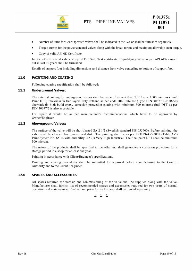
PTS – PIPELINE VALVES P.013751
M 11071
001
Rev. B City Gas Distribution Page 10 of 13
• Number of turns for Gear Operated valves shall be indicated in the GA or shall be furnished separately.
• Torque curves for the power actuated valves along with the break torque and maximum allowable stem torque.
• Copy of valid API 6D Certificate.
In case of soft seated valves, copy of Fire Safe Test certificate of qualifying valve as per API 6FA carried
out in last 10 years shall be furnished.
Details of support foot including dimensions and distance from valve centerline to bottom of support foot.
11.0 PAINTING AND COATING
Following coating specification shall be followed:
11.1 Underground Valves:
The external coating for underground valves shall be made of solvent free PUR / min. 1000 microns (Final
Paint DFT) thickness in two layers Polyurethane as per code DIN 30677/2 (Type DIN 30677/2-PUR-50)
alternatively high build epoxy corrosion protection coating with minimum 500 microns final DFT as per
DIN 30677/2 is also acceptable.
For repair it would be as per manufacturer’s recommendations which have to be approved by
Owner/Engineer.
11.2 Aboveground Valves:
The surface of the valve will be shot-blasted SA 2 1/2 (Swedish standard SIS 055900). Before painting, the
valve shall be cleaned from grease and dirt. The painting shall be as per ISO12944-5-2007 (Table A-5)
Paint System No. S5.14 with durability C-5 (I) Very High Industrial. The final paint DFT shall be minimum
300 microns.
The nature of the products shall be specified in the offer and shall guarantee a corrosion protection for a
storage period in a shop for at least one year.
Painting in accordance with Client/Engineer's specifications.
Painting and coating procedures shall be submitted for approval before manufacturing to the Control
Authority and to the Client / engineer.
12.0 SPARES AND ACCESSORIES
All spares required for start-up and commissioning of the valve shall be supplied along with the valve.
Manufacturer shall furnish list of recommended spares and accessories required for two years of normal
operation and maintenance of valves and price for such spares shall be quoted separately.
∑ ∑ ∑

PTS – PIPELINE VALVES P.013751
M 11071
001
Rev. B City Gas Distribution Page 11 of 13

PTS – PIPELINE VALVES P.013751
M 11071
001
Rev. B City Gas Distribution Page 12 of 13
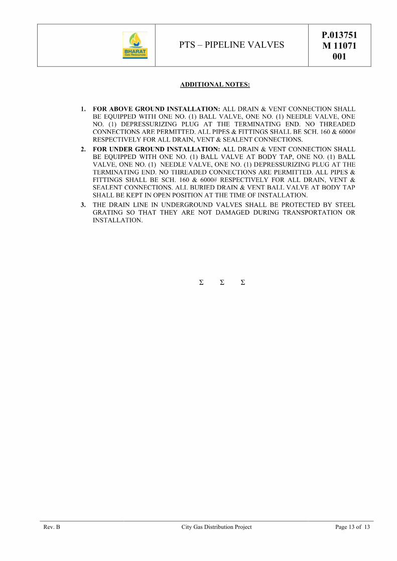
PTS – PIPELINE VALVES P.013751
M 11071
001
Rev. B City Gas Distribution Project Page 13 of 13
Σ Σ Σ

PTS - GAS OVER OIL
ACTUATORS
P.013751
M 11071
002
BHARAT GAS RESOURCES LIMITED (BGRL)
CITY GAS DISTRIBUTION
SUPPLY OF VALVES FOR AHMEDNAGAR – AURANGABAD AND SATARA –
SANGLI (MAHARASHTRA STATE)
PTS - GAS OVER OIL ACTUATORS
A 06.01.2020 Issued for Procurement VA RP GSS
Rev. Date Description Prepared By Checked By Approved By

PTS - GAS OVER OIL
ACTUATORS
P.013751
M 11071
002
Rev. A –06.01.2020 City Gas Distribution Page 1 of 1
TABLE OF CONTENTS
1.0 SCOPE .................................................................................................................................. 1
2.0 ACTUATOR SIZING .............................................................................................................. 1
3.0 DESIGN FEATURES .............................................................................................................. 1

PTS - GAS OVER OIL
ACTUATORS
P.013751
M 11071
002
Rev. A –06.01.2020 City Gas Distribution Page 1 of 2
1.0 SCOPE
This specification covers the minimum requirements for the design, manufacture, inspection, testing and shipping
of valve actuators complete with accessories for quarter turn ball valve.
Contractor shall supply Valve and actuator as a single assembly complete in all respect and ready for installation at
site.
Actuator shall be supplied along with electronic type differential pressure switch across the valve and shall have
the interlocks during opening and closing of the valve.
2.0 ACTUATOR SIZING
For sizing the actuator, valve manufacturer shall furnish to the actuator manufacturer the following information:
• Actuator shall be along with open & close limit switches, open & close solenoid valve, local/Remote
selection switch, differential pressure switch and junction box.
• The maximum break-away torque or thrust required at the valve stem with manual/remote operation to open
and close a valve at the shut off pressure in the line. The actuator shall be sized the safety factor of 1.25 times
as required by the valve operation at the shut-off pressure in the line.
• The actuator shall be capable of opening/closing a valve between 0.5 to 3 seconds per inch nominal valve port
diameter. Opening and closing times shall be adjustable between these limits.
• Actuator manufacturer shall provide the complete model no. decoding catalogue for actuators and its
accessories.
• Complete details of Gas circuit with complete sequencing of port from open to close and close to open position
shall be furnished in the offer for review.
• Manufacturer shall furnish the detailed calculation for actuator sizing after placement of order. The calculation
so furnished by manufacturer shall satisfy the sizing criteria as per above clauses. Manufacturer shall agree to
upgrade the actuators offered to meet the sizing criteria without any price and schedule impact.
3.0 DESIGN FEATURES
• The actuators shall be powered by Natural Gas from the main pipeline.
• Actuator shall be GAS OVER OIL OPERATED. The actuator shall be provided with a hydraulic pump for
manual operation. If there is no gas pressure available to actuator, it shall be possible to actuate Direct
Pneumatic Actuator by means of Nitrogen bottles or similar pressure source. Actuator manufacturer shall
furnish the capacity and set pressure of nitrogen bottle/source (gas) for at least two opening and two closing
strokes of the actuator.
• The actuator shall be suitable for gas operating conditions and ambient temperature as specified in data sheets.
The presence of methane in the gas shall not affect the service of the Actuator.
• The actuator and its accessories shall be suitable for outdoor installation and have weatherproof enclosure as
per NEMA 4 or equivalent.
• All compartments and housing containing electrical devices such as switches, contactors, relay, fuses, terminal
box etc. shall be explosion proof suitable for Zone 2, Gr. IIA & IIB, T4 or equivalent. The cable glands shall be
1” NPT thread. The unused cable entries must be plugged off with solid metal plugs.
• Solenoid valves shall be of explosion proof design certified for Zone 2, Gr. IIA & IIB, T4 or equivalent with

PTS - GAS OVER OIL
ACTUATORS
P.013751
M 11071
002
Rev. A –06.01.2020 City Gas Distribution Page 2 of 2
molded continuous duty coils and stainless steel valve body.
• All pressure containing parts shall be designed to ASME Section VIII.
• The actuator shall be suitable for direct mounting to the valve without changing the standard top works of the
valve and shall have the capability to be mounted or removed from the valve when the valve is in service. The
actuator shall be flanged and bolted directly on the valve body or extension. The connection between actuator
and the valve or between the operators, the outer casing of the extension and the valve shall be such that there
is no movement between these connections when the valve is actuated by the actuator under any load.
• Actuator shall be suitable for installation on a vertical stem unless otherwise specified in the data sheet.
• Provision shall be made to prevent accidental pressure build up in the actuator.
• A position indicator on the actuator shall show the valve in the open, closed or partially open positions.
• A high pressure dehydrating filter cartridge shall be provided to remove condensate, moisture, foreign particles
and any corrosive contaminants from pipeline gas.
• The actuator shall be operated by either of the following two methods:
a) For the remote control, the actuator shall have a solenoid valve, limit switches, relays, etc. and shall be
suitable for remote and local operation. Electrical signal supplied is a momentary type with 1 sec duration
signal, Actuator shall have a self-retaining system of the above signal in its control circuit.
b) For the local-control the actuator shall be suitable for local operation with line gas feed lines or through
nitrogen bottles. The devices and accessories, which do not require the electricity for their operation, shall
be provided in the actuators as per this specification. The actuators shall have a hand pump in conjunction
with the oil circuit to achieve local control with hydraulic shock functionality.
• The actuators shall be provided with limit switches for open and close positions. The position of switches
shall be adjustable near the valve open and close positions. The limit switches shall be wired up to
terminal block and shall be numbered for proper identification. The limit switches shall have 2 sets of contacts
for each open and close position. The contact rating shall be as specified in the data sheet. The power to
solenoid valves shall be cut-off when the actuator has travelled to extreme positions (close and open).
• The limit switches shall be wired in the actuator control circuit by the vendor so as to cut off power to the
actuator once the end positions of the valve are reached. This is required to de-energize the solenoid valves in
the steady state condition and failure of electrical power will not affect the valve position.
• Local/ remote switch shall be wired up to the junction box as per circuit diagram.
• All control accessories, pneumatic and hydraulic, shall be mounted in an enclosure and shall be fully wired and
tubed. The enclosure shall be weatherproof as per NEMA-4 or equivalent.
• All mounting accessories needed for installing the actuator, tanks etc. are in manufacturer’s scope
of supply.
• The interconnecting cabling, interconnecting pipe work between the actuator and the valve, adapters, tubing,
cable glands, junction box are in manufacturer’s scope of supply.

PTS – PIPING CLASSES
P.013751
D 1177
018
BHARAT GAS RESOURCES LIMITED (BGRL)
CITY GAS DISTRIBUTION PROJECT
SUPPLY OF VALVES FOR AHMEDNAGAR – AURANGABAD AND SATARA – SANGLI (MAHARASHTRA STATE)
PTS - PIPING CLASSES
A 06.01.2020 Issued for Procurement VA RP GSS
Rev. Date Description Prepared By Checked By Approved By

PTS – PIPING CLASSES
P.013751
D 1177
018
Rev. A – 06.01.2020 City Gas Distribution Page I of 1
TABLE OF CONTENTS
1. SCOPE ................................................................................................................................... 1
1.1. Coding of Piping Classes ...................................................................................................... 1
1.2. Wall Thickness ..................................................................................................................... 1
1.3. Corrosion Allowance ............................................................................................................ 1
1.4. Wall Thickness Calculation .................................................................................................. 2

PTS – PIPING CLASSES
P.013751
D 1177
018
Rev. A – 06.01.2020 City Gas Distribution Page 1 of 2
1. SCOPE
Piping classes are established taking into account the following criteria:
⚫ The medium to be handled.
⚫ The surrounding.
⚫ The referenced codes.
⚫ The temperature-pressure rating.
1.1. Coding of Piping Classes
Each class is named by a code consisting in three of four parts:
First part
A figure designating the rating and the code:
⚫ 1 = 150 lbs ANSI
⚫ 3 = 300 lbs ANSI
⚫ 6 = 600 lbs ANSI
⚫ 9 = 900 lbs ANSI
Second part
A letter designating the material:
⚫ A = Alloy steel
⚫ C = Carbon steel
⚫ F = Fiberglass reinforced plastic/epoxy (FRP)
⚫ G = Galvanized
⚫ P = Plastic (PEHD, ...)
⚫ S = Stainless steel
⚫ V = PVC
Third part
A sequential number to differentiate two or more piping classes of the same rating and same material but
presenting some differences related to the handled fluid.
1.2. Wall Thickness
The wall thickness of pipe shall be as follows:
Wall thickness of pipe shall be calculated as specified in the applicable sections of:
⚫ ANSI B 31.8 for classes covering the main process and auxiliary gas lines.
⚫ ANSI B 31.3 for classes covering utilities lines.
1.3. Corrosion Allowance
The minimum corrosion allowance used to calculate wall thickness as follows:
⚫ Carbon steel and ferritic alloys in classes calculated following ANSI B 31.8: 1.6 mm
⚫ Carbon steel and ferritic alloys in classes calculated following ANSI B 31.3: 1.6 mm
⚫ Stainless steel: 0 mm
⚫ Plastic and FRP pipes: 0 mm.

PTS – PIPING CLASSES
P.013751
D 1177
018
Rev. A – 06.01.2020 City Gas Distribution Page 2 of 2
1.4. Wall Thickness Calculation
a) Pipes for natural gas shall comply with ASME/ANSI B 31.8 code. Pipe wall thickness will be
calculated as follows:
tPD
xSxFxExTc= +
2 (1)
t = nominal wall thickness (mm)
P = design pressure (MPa)
S = minimum yield strength (MPa)
D = nominal outside diameter (mm)
F = design factor = 0.40
E = longitudinal joint factor
= 1.0 for API 5L Gr 60 / API 5L Gr. B (seamless or ERW or SAW)
T = temperature derating factor = 1.0
c = corrosion allowance (mm)
b) Pipes for utilities lines have a wall thickness complying with ASME/ANSI B 31.3 code:
tPD
x SE PYc x a=
++
+
21
( )( )
t = nominal wall thickness (mm)
D = nominal outside diameter (mm)
S = allowable stress (MPa)
P = design pressure (MPa)
E = longitudinal joint factor
Y = coefficient as per table 304.1.1
C = corrosion allowance (mm)
a = negative fabrication tolerance (%)
GENERAL TECHNICAL
SPECIFICATION
70000 740
GTS/402
PIPELINE VALVES
7 08/04/15 Logo Changed AR NC SKH
6 22/09/08 Logo Changed AA PK NC
5 27/01/04 Updated + Logo Changed MRY MRT DKB
4 30/10/02 Updated MRY LEP LEP
3 01/07/02 Updated MRY LEP LEP
2 07/11/01 Updated AES LEP LEP
1 22/06/00 First issue AES LEP LEP

GENERAL TECHNICAL
SPECIFICATION
70000 740
GTS/402
Rev. 7 – 08/04/15 Page I of II
TABLE OF CONTENTS
1. SCOPE ........................................................................................................................................ 1
2. DEFINITIONS .............................................................................................................................. 1
3. PRELIMINARY STATEMENT ..................................................................................................... 1
4. GENERAL ................................................................................................................................... 3
5. CODES, NORMS AND STANDARDS ......................................................................................... 3
6. DESIGN AND CONSTRUCTION ................................................................................................. 5
6.1. RATINGS ............................................................................................................................. 5
6.2. DESIGN ............................................................................................................................... 6
6.3. OPERATION ..................................................................................................................... 10
7. MATERIALS ............................................................................................................................. 11
7.1. STEEL USED .................................................................................................................... 11
7.2. PRESSURE RETAINING PARTS ...................................................................................... 11
7.3. BONNET, COVER AND BODY BOLTING ......................................................................... 13
7.4. NON-METALLIC PARTS ................................................................................................... 13
7.5. OTHER PARTS ................................................................................................................. 13
7.6. SOUR GAS SERVICE ....................................................................................................... 13
8. FABRICATION AND TEST ....................................................................................................... 13
8.1. WELDING FABRICATION ................................................................................................. 13
8.2. WELDING PROCEDURES ................................................................................................ 14
8.3. HEAT TREATMENT .......................................................................................................... 15
8.4. MECHANICAL TESTS ON THE PARTS USED FOR WELDING CONNECTION WITH THE LINE PIPES ..................................................................................................... 15
8.5. NON DESTRUCTIVE EXAMINATION (NDE) .................................................................... 16
8.6. PRESSURE TESTING ....................................................................................................... 18
GENERAL TECHNICAL
SPECIFICATION
70000 740
GTS/402
Rev. 7 – 08/04/15 Page II of II
8.7. OPERATIONAL TORQUE TEST ....................................................................................... 21
8.8. FIRE TEST ........................................................................................................................ 21
8.9. ANTI-STATIC DEVICE TESTING ...................................................................................... 21
8.10. VISUAL AND DIMENSIONAL EXAMINATION ................................................................... 21
9. MARKING ................................................................................................................................. 21
10. INSPECTION............................................................................................................................. 22
10.1. INFORMATION .................................................................................................................. 22
10.2. DOCUMENTS.................................................................................................................... 22
10.3. CERTIFIED MATERIAL TEST REPORT ........................................................................... 23
10.4. QRN 23
10.5. REPAIR ............................................................................................................................. 23
10.6. REJECTION ...................................................................................................................... 23
11. PAINTING AND COATING ....................................................................................................... 23
TABLE I : CHEMICAL COMPOSITION FOR WELDING END OF VALVES
TABLE II : TENSILE REQUIREMENTS OF THE WELDING END OF VALVES
ANNEX I : LOFC (LIST OF OPERATIONS OF FABRICATIONS AND CONTROLS)
S S S

GENERAL TECHNICAL
SPECIFICATION
70000 740
GTS/402
Rev. 7 – 08/04/15 Page 1 of 31
1. SCOPE
This General Technical Specification covers the supply of pipeline valves used in high pressure natural gas transport and distribution systems. It describes the general requirements, controls, tests, QA/QC, examination and final acceptance criteria which needs to be fulfilled.
This specification is general and is updated / amended by the Particular Technical Specification dedicated to the project.
2. DEFINITIONS
Engineer : The Entity of the Purchaser or the Company nominated by the Purchaser to design the natural gas transport or distribution system and to specify the equipment.
Purchaser : The Company which makes the purchase order.
Control Authority or CA : The Organisation put in place/requested by the Purchaser/Engineer to proceed to Quality Controls and Certification.
Manufacturer : Manufacturer who receive the purchase order
3. PRELIMINARY STATEMENT
The name of Control Organisation shall be mentioned in the purchase order.
Eventual interpretations and deviations to this specification by the Manufacturer shall be requested by writing in his offer with detailed justification and approved by the Purchaser/Engineer and the Control Authority before the eventual order to the Manufacturer. The latter is responsible and shall indemnify the Purchaser/Engineer for any damage resulting from the non-respect of this obligation.
The specifications of the steel used, the material Manufacturer and all potential subcontractors (such as forging plant, heat treatment, weld fabrication, …) will be described in the offer. After order, no change will be accepted except for justified "force majeure". In that case, the asked changes shall be supported by a technical file submitted to the Purchaser/Engineer for approval.
The Manufacturer shall provide a technical description of the manufacturing method that might influence the quality of the material.
When the order is placed, the Manufacturer shall promptly inform the Purchaser/Engineer about his subcontractor's names, addresses, phone numbers as well as sub-order numbers, extent and delivery terms. On this basis, the Manufacturer shall send a general planning including at least the raw material supply, the manufacturing stages (machining, welding, part assembly, …), testing , painting and packing/dispatching. This planning shall be updated by the Manufacturer at least every month unless otherwise provided in the purchase order. A Dispatcher/Inspector

GENERAL TECHNICAL
SPECIFICATION
70000 740
GTS/402
Rev. 7 – 08/04/15 Page 2 of 31
delegated by the Purchaser is entitled to follow, examine and verify the planning's' relevance and effectiveness.
The Purchaser keeps the right to audit the Manufacturers and subcontractor's manufacturing process and control methods. All costs form such an audit shall be borne by the Manufacturer except the wages and travel expenditures of the auditor(s) supported by the Purchaser.
The manufacturing processes and the laboratories, in which welding tests, destructive and non destructive tests are carried out, shall be approved by the Control Authority.
The Purchaser/Engineer and the Control Authority shall have, at any time, free access to all parts of the Manufacturer's facilities and to those of all his subcontractors involved in the order manufacturing. All reasonable means shall be placed at the inspector(s)'s disposal to enable him to check that the product is being manufactured in accordance with this specification. All tests and inspections required in this specification shall be carried out, prior to shipment, in the Manufacturer's plant (or subcontractor's plant) and at the Manufacturer's expenses, unless otherwise provided in the order. The Purchaser/Engineer and the Control Authority shall try not to interfere unnecessarily with other Manufacturer's works when running these tests and inspection.
A valid copy of the ISO 9001 certificate shall be included in the offer.
For any control, test or examination required under the supervision of the Control Authority (LOFC intervention points included), the latter shall be informed in writing FIFTEEN (15) working days in advance by the Manufacturer about place and time with a copy to the Purchaser/Engineer.
If manufacturing is to be carried out under LOFC concept, the Manufacturer shall send for approval a List of Operation in Manufacturing and Control to the Control Authority and Purchaser/Engineer, TEN (10) working days before manufacturing. This list shall be in conformity with the annex 1 to this document. Before starting any manufacturing, the Manufacturer shall be in possession of this approved document, filled in with all intervention points.
Material, even released by the Control Authority and in which injurious defects are found after delivery, shall be rejected. The Manufacturer shall be notified and the material replaced : all costs involved, including wages and travel expenditure of the Control Authority's representative, Purchaser and Engineer shall be borne by the Manufacturer.
An approval of documents can never be considered as an acceptance of deviations on relaxations to requirements. A deviation is only possible after specific request to the purchaser.

GENERAL TECHNICAL
SPECIFICATION
70000 740
GTS/402
Rev. 7 – 08/04/15 Page 3 of 31
4. GENERAL
� Valves are intended to be used in aboveground or underground, with cathodic protection services.
All particular conditions for each valve are described in attached data sheet and valve list.
All valves shall conform to API 6D spec. Whenever this specification and API 6D spec. conflict, this specification shall prevail.
Unless otherwise specified, pipeline valves covered by this specification are suitable for use in gas transmission and distribution systems, and in accordance with ASME B31.8.
5. CODES, NORMS AND STANDARDS
Latest edition of following standards are applicable.
� ASME STANDARDS
ASME B16.5 Pipe flanges and flanged fittings
ASME B16.34 Valves- flanged and butt welding end
ASME B31.8 Gas transmission and distribution piping systems
� ASTM STANDARDS
ASTM A 53 Pipe, steel, black and hot-dipped zinc coated welded and seamless
ASTM A 105/A 105 M Forgings, carbon steel, for piping components
ASTM A 106 Seamless carbon steel pipe for high temperature service
ASTM A 193/A 193 M Alloy steel and stainless steel bolting materials for high temperature service
ASTM A 194/A 194 M Carbon and alloy steel nuts for bolts for high temperature service
ASTM A 234/A 234 M Piping, fittings of wrought carbon steel and alloy steel for moderate and elevated temperatures
ASTM A 320/A 320 M Alloy steel bolting materials for low temperature service

GENERAL TECHNICAL
SPECIFICATION
70000 740
GTS/402
Rev. 7 – 08/04/15 Page 4 of 31
ASTM A 333 Seamless & Steel Pipes for low temperature service
ASTM A 350/A 350 M Forgings, carbon and low alloy steel, requiring notch toughness testing for piping components
ASTM A 370 Mechanical testing of steel products
ASTM A 381 Metal-arc-welded steel pipe for use with high-pressure transmission systems
ASTM A 420/A 420 M Piping fittings of wrought carbon steel and alloy steel for low temperature service
ASTM A 694/A 694 M Forgings, carbon and alloy steel, for pipe flanges, fittings, valves, and parts for high-pressure transmission service
ASTM A 707/A 707 M Flanges, forged, carbon and alloy steel for low temperature service
� API STANDARDS
API 5L Specification for line pipe
API 6D Specification for pipeline valves, end closures, connectors and swivels
API 6FA Fire test for valves
API 605 Large diameter carbon steel flanges
� MSS STANDARDS
MSS SP 6 Standard Finishes for Contact Faces of Pipe Flanges & Connecting – End Flanges of Valves and Fittings
MSS SP 25 Standard marking system for valves, fittings, flanges and unions
MSS SP 44 Steel pipeline flanges
MSS SP 54 Quality Standard for Steel Castings for Valves, Flanges and Fittings and Other Piping Components Radiographic Examination Method
MSS SP 55 Quality standard for steel castings for valves, flanges and fittings and other piping components (visual method)

GENERAL TECHNICAL
SPECIFICATION
70000 740
GTS/402
Rev. 7 – 08/04/15 Page 5 of 31
MSS SP 72 Ball valves with flanged or butt welding ends for general service
MSS SP 75 Specification for high test wrought butt welding fittings
� ASME STANDARDS
ASME Boiler and Pressure Vessel code
� EN STANDARDS
EN 10204 Metallic products : types of inspection documents
EN 10045/1 Metallic products : Charpy impact test – test methods (V and U notches)
� ISO STANDARDS
ISO 148 Acier – Essai de résilience Charpy (entaille V)
ISO 9001 : Quality management standard
� BRITISH STANDARDS
BS 5146 Inspection and test of valves
BS 5351 Steel ball valves for the petroleum, petrochemical and allied industries
� NACE STANDARDS
MR0175 Sulphide Stress Cracking Resistant Metallic Materials for Oilfield Equipment.
6. DESIGN AND CONSTRUCTION
6.1. RATINGS
1) The pressure temperature ratings of flanged and butt welding end valves shall be in accordance with ASME B16.34.
2) The temperature and pressure ranges of valves shall be in accordance with the indicated values on the appropriated piping specification and valve data sheet.
3) Wall thickness for parts used for the welding connection with the line pipes shall meet the following requirements :

GENERAL TECHNICAL
SPECIFICATION
70000 740
GTS/402
Rev. 7 – 08/04/15 Page 6 of 31
� The maximum allowable stress in the material of the butt weld connection for butt welding end valves shall be equal to fifty per cent of the minimum yield strength guaranteed by the specification of the steel used.
� The minimum wall thickness for butt welding connection must be greater than or equal to the largest value of either the calculated minimum thickness of butt welding connection or the nominal thickness of the pipe as indicated on data sheet.
� If the butt welding connection has a yield strength lower than the yield strength of the pipe to which it is intended to be welded, the wall thickness in each zone of the butt welding connection is at least equal to the specified pipe wall thickness times the ratio of the minimum yield strength guaranteed by the specification of the steel of the pipe and the minimum yield strength guaranteed by the specification of the steel of the butt welding connection.
� The specified pipe wall thickness and grade (with reference to the equivalent grade in API 5L spec. or ASTM spec.) with which the valve is intended to be used is specified in the data sheet/piping class.
4) The Manufacturer shall submit for approval to the Control Authority and to the Purchaser/Engineer the dimensional drawings, the calculation of the parts used for the welding connection to the pipeline and the material part list for all the types of valves. All these documents must be identified with the individual valve number according to attached valve list and shall be attached to the CMTR.
5) The design shall take into consideration performance requirements prescribed in the next paragraph.
All valves under this specification shall be designed to withstand a field hydrostatic test pressure with non corrosive water, after installation, during 24 hours when the gate, plug, ball or piston is partially or fully open at a pressure of 1.5 times the 38OC pressure rating gauged by ASME B16.34
During this test the closure element shall not be moved.
6.2. DESIGN
6.2.1. Face-to-face and end-to-end dimensions
Face-to-face and end-to-end dimensions for ball valves shall be in accordance with API spec. 6D.
Valves may be made to special dimension by agreement between the Manufacturer and the Purchaser.

GENERAL TECHNICAL
SPECIFICATION
70000 740
GTS/402
Rev. 7 – 08/04/15 Page 7 of 31
6.2.2. Welding ends
The connecting pipe outside diameter, wall thickness, specified minimum yield strength and material grade are mentioned in the relevant piping specification and valve data sheet.
Butt-welding ends shall be in accordance with figure 1 for wall thickness up to 20.0 mm; for thicker walls, refer to figure 2. The inside diameter at the welding end shall be equal to that of the pipe on which the valve shall be welded. If a welding end of a valve has a thickness not equal to the pipe with which it is intended to be used, the welding end preparation at the joint has to be in conformity with fig. 3.
The tolerance of the inside diameter at the bevel end shall be following :
NPS Tolerance of inside diameter at bevel end (1) (mm)
2" - 10"
12" - 48"
+ 1.6
+ 2.4
-0.4
-0.8
(1) Tolerance refers to variation from specified ID calculation by (OD spec. - 2t spec). OD = outside diameter t = wall thickness
The out-of roundness at a welding end, defined as the difference between the maximum and the minimum inside diameter at the welding pipe end shall not exceed 1% of the specified inside diameter.
The length of the butt end shall be sufficient to allow welding and heat treatment without damage of the internal parts of the valve. If Purchaser/Engineer accepts design which do not meet this requirement, than Manufacturer shall inform the Purchaser/Engineer about the precautions which needs to be fulfilled in order to guarantee that during welding of the butt welding ends no damage shall occur to the seat. These precautions shall be highlighted by the Manufacturer in the erection and installation instruction book.
6.2.3. End flanges
End flanges shall be furnished in the same class as the valve body with raised face or ring-joint face, as specified by the valve data sheet. Dimensions and tolerances (including drilling templates, flange facing, spot facing and back facing) shall conform to :
� ASME B16.5 standard for NPS 24" and smaller
� MSS SP-44 for NPS 26" to 60"
� MSS SP-6 for flange facing.
GENERAL TECHNICAL
SPECIFICATION
70000 740
GTS/402
Rev. 7 – 08/04/15 Page 8 of 31
6.2.4. Design features
All ball valves shall be full bore - to allow pigging - unless stipulated otherwise on the valve data sheet.
All trunnion mounted ball valves shall be fitted with following devices :
� Double block and bleed : design of a valve with two seating surfaces between which the cavity can be vented through a bleed connection and thus confirm the tightness of the valve, at least in closed position, when pressure is applied to any side or both sides of the valve.
� Double piston effect : when the pressure is applied to one side, let us say "upstream" side, and when upstream ball seat is leaking, transfer pressure shall have a positive shut-off effect on the downstream seat (acting, for instance, on the back face of this seat) and thus reinforcing the global tightness of the valve.
� Anti-static design : all ball valves shall be fitted with anti-static device conforming to BS 5351.
� Stem retention (anti blow-out) : In conformity with BS 5351 valve shall be designed with an anti blow-out stem so that the stem cannot be fully ejected by pressure inside the valve with the stem packing, gland retainer bolting removed.
� Secondary seat and stem sealing : all ball valves NPS 6" shall be fitted with a secondary stem sealing and all ball valves greater or equal to NPS 8" shall be fitted with a secondary seat and stem sealing. This system permits an injection of sealant and shall be fitted with an integral check valve. The number and the location of sealing points shall be on the Manufacturer's responsibility.
Purchaser is allowed to request the check of this system design and its operation, specially for modified or new valve model.
� A drain connection shall be located at the lowest part of the body cavity.
6.2.5. Auxiliary connections
The Manufacturer shall complete the valve data sheet with the size and allowable pressure for the following auxiliary piping connections.
a) Aboveground valves
� The drain shall be plugged.
� The vent/bleed connection for valves NPS 6" and above shall be equipped with one block valve plus one needle valve, each with anti blow-out stem. The block valve shall be of ball type. The needle valve shall have screwed connections, shall be preferably of angular pattern and shall be fitted with a special plug at the outlet : this plug shall be designed to relieve slowly the pressure without being ejected.

GENERAL TECHNICAL
SPECIFICATION
70000 740
GTS/402
Rev. 7 – 08/04/15 Page 9 of 31
� For valve size < NPS 6", the vent/bleed connection shall be equipped with this anti blow-out, depressurising plug only.
� Each secondary stem - and each secondary seat sealing device, when required (see § 6.2.4.), shall be fitted with a check valve integrated in the body plus a sealant fitting with built-in, spring loaded ball check valve, as mentioned in the valve data sheet.
b) Underground valves
� Vent/bleed connection shall be plugged and this functionality is by passed through the drain.
� Drain shall be fitted with a normally open block valve (ball type with anti blow-out stem) at the drain tap, piped to the upper part of the extension and ended by one ball valve plus one needle valve, each with anti blow-out stem.
� The needle valve shall have screwed connections, shall be preferably of angular pattern and shall be fixed with an anti blow-out, depressurising plug, at the outlet.
� Each stem and seat sealing connection, when required (see § 6.2.4) shall have a check valve integrated in the main valve body, a block valve (ball type with anti blow-out stem) closed to the body tap, shall be piped up to the upper part of the extension and equipped with a block valve (same type) plus a sealant fitting with built-in, spring loaded check valve, as mentioned in the valve data sheet.
� Valves and tubing shall be carefully fastened to the valve body and/or extension.
Valve bodies shall have tapped holes with a minimum effective threaded engagement at least equal to the nominal thread diameter. If body wall thickness is too thin, then unthreaded side of OEP/OET (One End Plain/One End Threaded) piece of pipe of a material compatible with the body, shall be welded to the valve body with full penetration or via a boss. Anyway, weld on threads is prohibited.
Material of auxiliary connections (pipe, tube, fittings, valve, …) shall be, at the least of the same material quality as the main valve and can be in stainless steel series AISI 300.
6.2.6. Stem extension for underground valve
When a stem extension is required (see valve data sheet), the configuration and the length H shall be in accordance with this valve data sheet.
In this case and except otherwise specified in the purchase order, valves shall be fitted with drain and sealant extensions well fixed to the stem extension and clearly indicated in the as built design. The stem extension shall be fully watertight, but shall be provided with a means to prevent overpressure built up in the mechanism resulting from stem or bonnet seal leakage.
Valves, equipped with stem extension and/or actuator, shall be delivered completely equipped and mounted (in one piece).

GENERAL TECHNICAL
SPECIFICATION
70000 740
GTS/402
Rev. 7 – 08/04/15 Page 10 of 31
Underground actuated valves shall be provided with one identification plate on the valve body and one on the upper part of the extension.
6.2.7. Miscellaneous
Lifting lugs are required on all valves NPS 6" and larger. The lifting lugs shall be stamped with the safe working load. Number of lugs shall be sufficient for safe handling on site. Valve support : All valves greater than NPS 24" shall be equipped with supports to permit the installation of the valve in horizontal position directly on the floor. These supports shall be directly welded or fitted on the body of the valve.
6.2.8. Design review
The Manufacturer shall submit for approval to the Engineer/Purchaser and Control Authority the calculation for all bonnet, cover and body bolting for pressure retaining parts conforming to ASME B16.34.
6.3. OPERATION
6.3.1. Valve shall be operated by a hand-wheel, wrench, manual key or actuator.
Manual override devices shall be provided on all valves. Hand-wheels of electric actuators, shall be normally disengaged and shall automatically disengage when the actuator is operated.
6.3.2. The length of the wrench or diameter of the hand-wheel for direct or gear operated valves shall (after opening and closing a new valve at last three times) be such that a force not exceeding 350 N shall be required to operate the ball from either the open or closed position under the maximum differential pressure recommended by the Manufacturer.
For valves without stem extension equipped with a hand-wheel in vertical position, the maximum radius of the hand-wheel is equal to the distance between the centre line of the pipe and the centre of the hand-wheel minus 120 mm. In this case no extruding lugs on hand-wheel are permitted, and provision for by-pass valve shall be kept.
6.3.3. Hand-wheel shall be marked to indicate the direction of closing.
6.3.4. Hand-wheels and wrenches shall be fitted in such a way that whilst held securely they can be removed and replaced where necessary.
6.3.5. All ball valves shall be provided with a mark on the stem to show the position of the ball in order to enable a good regulation of the actuator without seeing the ball. Exception can be made for valves with gear boxes for underground service.

GENERAL TECHNICAL
SPECIFICATION
70000 740
GTS/402
Rev. 7 – 08/04/15 Page 11 of 31
6.3.6. Ball manual direct operated valves shall be fitted out with fully open and fully closed stops. These stops shall be well fixed to the body of the valve in order to withstand many extreme opening and closing actions. These stops shall be easily removable. Ball gear operated valves shall be fitted out with fully open and fully closed stops shall be adjusted and fixed on the gear box.
6.3.7. The Manufacturer shall advise the maximum operating torque or force which can be sustained without causing permanent damage anywhere in the drive train from the actuator to the obturator. The Manufacturer shall also provide the torque graph : torque value in function of opening angle of the ball and pressure.
Deflection in the extended drive train must be limited so that the closing position contact reflects exactly the real position of the obturator.
6.3.8. Maximum rated differential pressure (MRDP)
The MRDP is the maximum difference between the valve upstream and downstream pressure at which the obturator (closure member) may be operated (opening). The Manufacturer shall specify this value and shall mark it on the valve name plate.
For the specification of different types of actuator refer to the concerned GTS/740/403.
7. MATERIALS
7.1. STEEL USED
The steel used in the valve Manufacturing shall be selected by the Manufacturer and filled in data sheet form
This list shall be submitted for approval to the purchaser/Engineer at the time of the offer. This list shall be added to the CMTR.
7.2. PRESSURE RETAINING PARTS
For pressure retaining parts the following requirements must be fulfilled
7.2.1. Bodies, including end flanges and welding ends (other than for field welding), bonnet and covers of valves shall be made in material conforming to API 6D spec. (or another material specification accepted by the Purchaser/Engineer) and be furnished with certificates EN 10204-3.1. B stating the quality, the mechanical properties (yield strength, tensile strength, percent elongation, impact test value at the temperature specified under per Section 8.4.2), the chemical analysis, the manufacturing process and the marking (e.g. the heat number) of the steel. These certificates shall be added to the CMTR.
For the valves with butt welding end, for the part on which the line pipe shall be welded, see paragraph 7.2.4. and 8.4.

GENERAL TECHNICAL
SPECIFICATION
70000 740
GTS/402
Rev. 7 – 08/04/15 Page 12 of 31
7.2.2. Notch toughness properties
The impact test temperature conditions and temperature are defined under Section 8.4.2.
7.2.3. The carbon content of parts involved in welding operation (except for those parts which shall be used for the welding connection with the line pipes) shall be restricted as follows :
� maximum percentage of carbon : 0.230
� C + Mn
6 ≤ 0.41
7.2.4. For parts used for the welding connection with the line pipes the following supplementary requirements must be fulfilled :
� The chemical composition of the steel meets the requirements of table 1. The choice and use of alloying elements made from high strength low alloy steels to give the tensile properties prescribed in table 2 shall be made by the Manufacturer and included and reported to identify the type of steel.
� For each heat, the Manufacturer shall analyse the following elements : C, Mn, Si, P, S, Nb, V, Cr, Mo, Ni and Cu.
� The carbon equivalent shall be computed by the following equation :
C.E. = C + Mn
6 +
Cr Mo V+ +
5 +
Ni Cu+
15
and shall not exceed 0.45.
� The steel used shall be fully killed, fine grain practice.
� The steel used shall be suitable for field welding to pipes, flanges or fittings manufactured under ASTM A53, A105, A106, A234, A333, A350, A381, A420, A694, A707 or API 5L, 605 or MSS SP-44, SP-72, SP-75, EN10208-2.
� The steel used has tensile properties conforming to requirements prescribed in table 2 and capable of meeting the valve design.
� The ratio of yield strength to tensile strength shall not exceed 0.85.
� Mechanical tests as prescribed in section 8.4. shall be performed after final heat treatment.

GENERAL TECHNICAL
SPECIFICATION
70000 740
GTS/402
Rev. 7 – 08/04/15 Page 13 of 31
7.3. BONNET, COVER AND BODY BOLTING
Bonnet flange cover, and body bolting shall be conform to ASTM A320 Gr L7 or L7M or ASTM A193 grade B7 or B7M. Nuts shall be conform to ASTM A194 Gr 7 or 7M or 2H. For NPS greater than 4", they must be supplied with certificates EN 10204-3.1.C. and for NPS 4" and smaller with certificates EN 10204.3.1.B. These certificates shall be added to CMTR.
Bolt design shall be done to withstand safety all stresses occurring under operating conditions, calculations shall be submitted for approval.
Materials shall be compatible in order to avoid galvanic corrosion and shall not be susceptible to hydrogen embrittlement or stress corrosion cracking. Manufacturer must take into account that the materials shall be eventually cathodic protected.
7.4. NON-METALLIC PARTS
Non-metallic parts and elements, which usually include such items as packing, injectable material and lubricants, shall be suitable for the service and must be defined in the offer.
7.5. OTHER PARTS
Metal parts, which usually include such items as yokes, yoke nuts, stems, glands, gland bushing, gates, balls, plugs, discs, pistons, hand-wheel, gearing and motor drive attachments, shall be of material suitable for the service and must be defined in the offer.
7.6. SOUR GAS SERVICE
When sour gas service or NACE is specified, all process wetted, pressure containing parts and bolting shall meet the requirements of NACE MR0175.
8. FABRICATION AND TEST
Prior to manufacturing a meeting shall be organised between Manufacturer, Purchasing agent, Engineer and Control Authority.
8.1. WELDING FABRICATION
1) Welds and repair welds shall be performed according to written procedures. The welding procedure must be submitted for approval to the Control Authority before any fabrication and/or repair.
2) Only welders and welder operators who are qualified shall be used in production.
3) The joints shall be furnished in accordance with the requirements of Section VIII of ASME Boiler and Pressure Vessel Code - Division 1.

GENERAL TECHNICAL
SPECIFICATION
70000 740
GTS/402
Rev. 7 – 08/04/15 Page 14 of 31
4) The machine welding shall be done by an electric process, preferably by submerged arc.
5) Repair by welding is prohibited on forged material.
8.2. WELDING PROCEDURES
8.2.1. All welds, repair welds and repair by welding shall be performed according to written procedures. These welding procedures shall be qualified according to the requirements of the ASME Boiler and Pressure Vessel Code, Section IX.
The welding procedure tests are required on material which is on the high side of the chemistry specification.
The Manufacturer shall maintain a weld record of the procedure and performance test results.
For the tensile test, the rupture of the specimen must take place in the unaffected parent material.
The welding procedure qualification must include an impact test set in the weld and in the HAZ with requirements of paragraph 8.4.2. and a macrographic examination described in paragraph 8.2.2. These tests shall be performed after eventual final heat treatment. If weld thickness is higher than 25 mm, even covered by the PQR, additional impact test shall be performed on the test specimens taken in weld thickness layers.
8.2.2. Macrographic examination : the etched surface of the macro test specimen viewed macroscopically must display the image of a well performed welded joint with sufficient penetration, free from linear defects and important inclusions. In case of doubt, the etched surface must be examined microscopically and additional macroscopic examinations of other areas may be required.
The macrographic examination will include hardness measurements in the weld and the HAZ. The hardness will not exceed the values measured on the parent metal by more than 80 points for the welds and 100 point for HAZ, with an absolute maximum of 350HV10.
The acceptance of inclusions can be decided upon with the NDE of the welded plates (see paragraph 8.5.).
8.2.3. Additional requirements for "Sour Gas". Qualified welding procedure shall guarantee a good geometry without stress concentration and shall be realised according to NACE MR 0175 (max. 1% Ni in welding consumables).
On the macro, series of hardness tests shall be performed in the base metal, weld and Heat affected zone; results shall be maximum 248HV10.

GENERAL TECHNICAL
SPECIFICATION
70000 740
GTS/402
Rev. 7 – 08/04/15 Page 15 of 31
8.3. HEAT TREATMENT
8.3.1. After hot working and before re-heating for normalising heat treatment, forging or casting shall be allowed to cool substantially below the transformation range. All forging or casting shall be heat treated by normalising. Normalising shall be carried out in such a way that the base material acquires a fine grained perlitic structure.
8.3.2. Heat treatment of welds : the rules of ASME VIII Div. 1 are applicable. If a required treatment is not feasible (seat damage, etc, …), special agreement must be obtained from Purchaser/Engineer and Control Authority ACA, after the Manufacturer has proved good quality of welds.
8.3.3. The Manufacturer shall include in the CMTR data of this heat treatment.
8.4. MECHANICAL TESTS ON THE PARTS USED FOR WELDING CONNECTION WITH THE LINE PIPES
The following mechanical tests shall be performed on these parts after final heat treatment under the supervision of the Control Authority's delegate and the certificates shall be added to the CMTR.
Test specimens may only be cut after a marking transfer by the Control Authority.
8.4.1. Tensile testing
Requirements :
The material shall be in conformity with table 2. The ratio of yield strength to tensile strength shall not exceed 0.85.
Test specimen :
The test specimen represents any part of the same shape, the same heat of steel and the same heat treatment lot.
Number of test : one
Test location and orientation :
The test specimen shall be orientated transversally to direction of lamination and if this orientation is not feasible, it shall be orientated longitudinally. For castings only one orientation is applicable.
Test method :
Testing shall be performed in accordance with ASTM A370 standard rectangular plate type 1 1/2" wide (fig. 4 - A370) or standard round (fig. 5 or fig. 6 - A370).

GENERAL TECHNICAL
SPECIFICATION
70000 740
GTS/402
Rev. 7 – 08/04/15 Page 16 of 31
Yield strength shall be determined either by the 0.2 % offset or the 0.5 % extension under load (EUL) method. If another material are accepted by the Purchaser, the test method will be as specified in the material specification.
8.4.2. Impact test
Requirements :
The standard impact test temperature is -20°C, except if otherwise stated in the "Material Requisition" or particular Technical Specification. The average value of a set of 3 test specimens shall be equal to 35 J/cm². The minimum value per test specimen shall be equal to 35 J/cm² but this value may drop to 28 J/cm² for only one test specimen per series.
� Test specimen :
The test specimen represents any part of the same shape, the same heat of steel and the same heat treatment lot.
� Number of tests :
2 test sets (3 test specimens constitute one test set). For castings only 1 test set.
� Test location and orientation :
1 set shall be orientated longitudinally and another one transversally. For castings only one orientation is applicable.
� Test method :
The notched bar impact test shall be performed in accordance with ISO 148 or A370- Charpy V - Notch.
If the wall thickness of these parts or the coupon does not enable machining of full size specimens, the largest possible size must be used but not less than (10 x 5) mm. The axis of the notch shall be orientated through the wall thickness of these parts. If the weld thickness is > 25 mm, several specimen sets shall be taken in the weld thickness with min one (1) set per 12.5 mm of thickness, the specimen sets shall be selected in agreement with the Purchaser/Engineer and Authorised Control Authority.
8.5. NON DESTRUCTIVE EXAMINATION (NDE)
The following NDE will be performed after the final heat treatment and before coating.
8.5.1. List of NDE
� All butt welds shall be examined by a radiographic examination. If the thickness exceeds 15 mm or if the radiographic examination is not feasible than welds are only examined by ultrasonic examination to the largest extent possible.

GENERAL TECHNICAL
SPECIFICATION
70000 740
GTS/402
Rev. 7 – 08/04/15 Page 17 of 31
The radiographic examination shall be executed in accordance with ASME Boiler and Pressure Vessel Code, section V, art. 2 - using fine grain film and lead screens.
� Butt welding ends on cast bodies shall be examined before fabrication welding end, by radiography in accordance to MSS-SP-54 and over a width of 70 mm.
� 25 mm of base material at each side of each weld and each weld shall be 100 % ultrasonically examined.
The ultrasonic examination shall be executed in accordance with ASME Boiler and Pressure Vessel Code, section 5, art. 5.
� Body for all valves NPS 6" and greater shall be tested by magnetic particle examination in conformity with ASME Boiler and Pressure Vessel Code, section V, art. 7.
� All valves shall be visually examined.
� All valves shall be dimensionally examined.
� For butt welding end valves after machining, the finished bevel end pipe used for field welding shall be submitted to the following tests :
� Magnetic (ASME V Art. 7) or liquid penetrant (ASME V Art. 6).
� Ultrasonic inspection (ASME V Art. 5) or radiographic examination (ASME V Art. 2)on 25 mm of base material.
� Visual and dimensional examination.
� If any repair by welding is performed, the concerned parts shall be completely re-examined.
8.5.2. Additional NDE requirement for "SOUR Gas"
A series of hardness test on surfaces in contact with the fluid shall be performed to NACE MR 0175. Results shall be 22 HRC or 248 HV 10 max.
8.5.3. Acceptance criteria of the different NDE
� Radiographic examination :
ASME Boiler and Pressure Vessel Code, section VIII, division 1, UW 51 for forged steel
ASME Boiler and Pressure Vessel Code, section VIII, division 1, appendix 7 for casted steel. The control will done on width of 70mm with.
On the first 40mm A1,B1,C1 acceptable, D, E, F and G are rejected.

GENERAL TECHNICAL
SPECIFICATION
70000 740
GTS/402
Rev. 7 – 08/04/15 Page 18 of 31
Between 40mm and 70mm, A2, B3, C3 acceptables; D, E, F, G are rejected.
� Ultrasonic inspection of weldings and HAZ:
ASME Boiler and Pressure Vessel Code, section VIII, division 1, Appendix 12.
� Magnetic particle inspection of the body:
ASME Boiler and Pressure Vessel Code, section VIII, division 1, Appendix 6.
For casted pieces refer to Appendix 7.
� Visual examination
MSS-SP-55.
� Magnetic particle or liquid penetrant of the finished bevel:
The following defects are unacceptable :
� Defects extending into the bevel provided the lamination is parallel to the surface and has a transverse dimension exceeding 6.35 mm.
� All defects not parallel to the surface extending into the bevel.
All the NDE (except radiographic examination) shall be performed under the supervision of the control authority's delegate and the certificates shall be added to the CMTR.
8.6. PRESSURE TESTING
8.6.1. General requirements
� Each valve shall be tested by the Manufacturer under the supervision of the Control Authority after final completion of all welding and all heat treatment operations.
� Hydrostatic and air seat test shall be performed after an acceptable shell test.
� Fluid for shell and hydrostatic seat tests shall be liquid as water (which may contain a corrosion inhibitor), kerosene, or other fluid with a viscosity not greater than that of water. Temperature of the test fluid shall not exceed 50°C.
� Valves shall be substantially relieved of air when tested with liquid.
� Valves shall be shell tested prior to painting.
� Valve test fixture loads applied to valve ends shall be limited to those required to effectively seal the valve ends.
� Pressure testing certificates shall be included in the CMTR.

GENERAL TECHNICAL
SPECIFICATION
70000 740
GTS/402
Rev. 7 – 08/04/15 Page 19 of 31
� Drain, the sealant and the bleed valve shall be included in all pressure tests.
� If any supplementary welding, repair by welding or treatment are performed, valve shall be completely re-tested.
8.6.2. Shell test
� Each valve shall be given a shell test at the gauge pressure not less than 1.5 times the 38°C rating gauged by ASME B16.34, rounded off to the next higher 1 bar increment.
� Shell test shall be conducted with the valve in a partially open position and with the valve ends closed.
� Drain lines and valves
Shall be either included in the hydrostatic shell test, or tested separately.
� Duration of the shell test
NPS up to 18" shall not be less than 15 minutes.
NPS 20" and larger shall not be less than 30 minutes.
� Visual leakage or harmful inelastic deformation are not accepted.
8.6.3. Hydrostatic seat test
� Each valve shall be given a hydrostatic seat test at the gauge pressure not less than 1.1 times the 38°C rating gauged by ASME B16.34, rounded off to the next higher 1 bar increment.
� Seat closure testing shall be performed with seat surfaces free of sealant, grease or other foreign material that aids in sealing except as provided hereafter :
� When necessary to prevent damage during valve actuation, a light oil of viscosity not greater than that of kerosene may be applied to sealing surface.
� When valve primary design is based on the presence of a sealant material (lubricated plug valve), the sealant material may be in place.
� For valve of the double seating type such as gate, plug and ball valve, the test pressure shall be applied successively to each end of the closed valve and leakage to opposite end checked. Provision shall be taken before, for de energising the self relieving pressure system.
� For soft seated valves there shall be no visible leakage - for metal seated valves the leakage rate shall not exceed 0.006 ml per minute and per mm of nominal pipe size (ND).

GENERAL TECHNICAL
SPECIFICATION
70000 740
GTS/402
Rev. 7 – 08/04/15 Page 20 of 31
� For double block and bleed valve the following tests shall be performed :
Close valve, open body vent, apply seat test pressure to both ends of the valve.
Close valve, open body vent, apply seat test pressure to one end of the valve, release pressure and repeat test for the other end of the valve.
� For double piston effect valve the following test shall be performed :
Release pressure, close valve, open body vent, apply seat test pressure through the body vent.
� For other valve type, the test pressure shall be applied across the closure member in the direction producing the most adverse seating conditions. For example, a globe valve shall be tested with pressure under the disc. A check valve, globe valve or other valve type designed, sold and marked as a one-way valve, requires a closure test only in the appropriate direction.
� The duration of the hydrostatic seat test shall not be less than 5 minutes for each end.
� Visual leakage or harmful inelastic deformation are not accepted.
8.6.4. External leak testing
Under the supervision of the Control Authority's delegate, the Manufacturer shall check the external leak tightness of body, stem and all external taps. This shall be done with soap suds at an inner pressure of 6 bar. For underground valves, this test shall include piping, fittings and valves of the auxiliary lines for drain, vent/bleed and sealant connections.
8.6.5. Air seat test
� Each valve shall be given an air seat test at 6 bar.
� This test shall be performed in the same manner as hydrostatic seat test.
� The duration of this test shall not be less than 5 minutes for each end.
� No signs of leakage are accepted.
8.6.6. Procedure
Procedure of all pressure tests shall be included in the offer.
8.6.7. After tests
After test, any auxiliary connections shall not be removed, and auxiliary piping shall be cleaned and dried, especially the sealant piping.

GENERAL TECHNICAL
SPECIFICATION
70000 740
GTS/402
Rev. 7 – 08/04/15 Page 21 of 31
8.7. OPERATIONAL TORQUE TEST
For valves operated with an actuator the Manufacturer shall perform an operational torque test at full rated differential pressure and at ambient temperature. The procedure must be included in the offer. The certificates shall be included in the CMTR.
8.8. FIRE TEST
The Manufacturer shall supply valves qualified by fire testing as specified in API 6FA and this certificate shall be added to the CMTR.
8.9. ANTI-STATIC DEVICE TESTING
If requested in the purchase order, all ball valves shall be submitted of to an anti-static electricity testing in accordance with BS 5146 and this certificate shall be added to the CMTR.
8.10. VISUAL AND DIMENSIONAL EXAMINATION
All valves shall be visually and dimensionally examined, according to API 1104 and MSS-SP-55.
9. MARKING
9.1.1. All valves supplied under this specification shall be clearly identified on the body, on the identification plate and on the valve flange edge.
9.1.2. Body markings
The following markings shall be cast, stamped, forged or engraved on the body of the valve :
c) Manufacturer's name or trademark.
Individual tag number according to attached valves list.
The monogram of the Control Authority. This marking shall only be applied after complete approval of the CMTR.
Flow direction on unidirectional valve.
9.1.3. Permanently attached identification plate markings
On minimum the following markings shall be shown on permanently attached identification plates :

GENERAL TECHNICAL
SPECIFICATION
70000 740
GTS/402
Rev. 7 – 08/04/15 Page 22 of 31
a) Manufacturer's name or trademark.
b) Individual valve fabrication number (serial number).
c) Individual tag number.
d) The maximum operating pressure;
e) The min and maximum operating temperatures
f) Body material designation (conforming MSS SP-25).
g) Rating designation (conforming ASME B16.34).
h) Valve trim identification (conforming MSS SP-25).
i) Nominal valve size.
j) Monogram of the Control Authority.
10. INSPECTION
10.1. INFORMATION
The Manufacturer shall inform the Control Authority min. five (5) working days in advance of any intervention required by this specification and shall send a copy of it to the Purchaser/Engineer (by fax).
10.2. DOCUMENTS
Before starting any fabrication, the Manufacturer shall submit for approval to the Control Authority and the Purchaser/Engineer the following documents :
� Detailed fabrication drawing and calculations.
� Fabrication and control procedure.
� Qualified welding procedures;
� Welders performances qualifications;
� NDT procedures;
� List of Operations in Fabrication and Control (LOFC) in accordance with annex 1.
Each company dealing in the order by fabrication and/or control shall implement a LOFC for all operations and interventions performed in its organisation. They shall also be responsible for the implementation of the same by their subcontractors.

GENERAL TECHNICAL
SPECIFICATION
70000 740
GTS/402
Rev. 7 – 08/04/15 Page 23 of 31
10.3. CERTIFIED MATERIAL TEST REPORT
A Certified Material Test Report (CMTR) shall be furnished listing as built drawings and calculations, the LOFC (see paragraph 10.2.), the base material certificate, the chemical check analysis of the welding ends. The certificate of the heat treatment, the mechanical test, the non-destructive examination, the pressure testing, the operational torque test, the quality release note (see paragraph 10.4.) and any special test required by the purchase order. The valve individual number (see paragraph 9.1.2.) must be indicated in the CMTR to permit the correct traceability of each valve. The Manufacturer shall furnish one copy of the CMTR to the Control Authority's delegate and one original and one copy to the Purchaser/Engineer.
10.4. QRN
After final approval of valves and the acceptance of the CMTR, the control authority's delegate shall furnish to the Purchaser/Engineer and to the Manufacturer a Quality Release Note (QRN). The Manufacturer shall deliver one copy of the QRN with the valves and one copy shall be included in the CMTR (see paragraph 10.3.).
10.5. REPAIR
Defects in material may only be repaired provided written acceptance by the contracting parties and the Control Authority has first been obtained.
This written acceptance must be given case per case. Defective material, that cannot be satisfactory repaired or repaired without written approval shall be definitively rejected.
10.6. REJECTION
Each valve in which injurious defects are found after delivery shall be rejected. The Manufacturer shall be notified. In this case, the valve shall be replaced immediately. All the costs involved, including wages and travel expenses of the Control Authority's delegate shall be borne by the Manufacturer.
11. PAINTING AND COATING
The surface of the valve will be shot-blasted SA 2 1/2 (Swedish standard SIS 055900). Before painting, the valve shall be cleaned from grease and dirt. The painting shall consist of a primer coating (30 - 40 µm) and a finish coating (30 - 40 µm).
The nature of the products shall be specified in the offer and shall guarantee a corrosion protection for a storage period in a shop for at least one year.
Painting in accordance with Purchaser/Engineer's specifications.
Painting and coating procedures shall be submitted for approval before manufacturing to the authorized Control authority and to the purchaser / engineer.

GENERAL TECHNICAL
SPECIFICATION
70000 740
GTS/402
Rev. 7 – 08/04/15 Page 24 of 31
For underground valves the Manufacturer shall propose an adequate protection at the time of offer. This adequate protection shall be in accordance with the Purchaser/Engineer's specification.

GENERAL TECHNICAL
SPECIFICATION
70000 740
GTS/402
Rev. 7 – 08/04/15 Page 25 of 31
TABLE 1
CHEMICAL COMPOSITION FOR WELDING END OF VALVES
Maximum limit of chemical elements which may be used in material under this standard.
% Maximum
C 0.230
Mn 1.60
Si 0.50
P 0.030
S 0.025
Nb 0.080
V 0.120
Mo 0.250
Nt 0.0150
Alternate alloy elements may be used but they shall be discussed with the user prior to delivery of the material. This table is not intended to represent the composition of any heat of steel, but merely to record the maximum permissible amounts of one element. The combination of elements of any heat must conform to the carbon equivalent, subsection 3.2.4.3.
For each heat the Manufacturer shall analyse the following elements :
C, Mn, Si, P, S, Nb, V, Cr, Mo, Ni and Cu.
The intentional addition of elements other than those specified is not permitted unless agreed upon by the Purchaser.
In any case, for unintentional additions, the following limitations shall be respected :
Cr ≤ 0.15 % Mo ≤ 0.05 % Cu ≤ 0.20 %

GENERAL TECHNICAL
SPECIFICATION
70000 740
GTS/402
Rev. 7 – 08/04/15 Page 26 of 31
Ni ≤ 0.30 % Co ≤ 0.01 % Al ≤ 0.07 %
The content of N total (Nt) may be up to 0.0150 % and Must be guaranteed by the
Manufacturer. If the Manufacturer cannot give any guaranty of N content, he shall analyse this element.
The total content for Nb + V will be limited to 0.150 %.
In grades X42 through X60 for each reduction of 0.01 % below the maximum carbon content, an increase of 0.05 % manganese above the specified maximum is permissible, up to a maximum of 1.70 %.

GENERAL TECHNICAL
SPECIFICATION
70000 740
GTS/402
Rev. 7 – 08/04/15 Page 27 of 31
TABLE 2
TENSILE REQUIREMENTS OF THE WELDING END OF VALVES
CLASS
SYMBOL
FIELD STRENGTH (min)
TENSILE STRENGTH
(min)
ELONGATION in 2" min. %
KSI MPa KSI MPa
B 35 241 60 413 25
X42 42 289 60 413 25
X46 46 317 63 434 25
X52 52 358 66 455 25
X60 60 413 75 517 20
The ratio of effective yield strength to effective tensile strength of the steel shall not exceed 0.85.

GENERAL TECHNICAL
SPECIFICATION
70000 740
GTS/402
Rev. 7 – 08/04/15 Page 28 of 31
Figure 1
Figure 2

GENERAL TECHNICAL
SPECIFICATION
70000 740
GTS/402
Rev. 7 – 08/04/15 Page 29 of 31
Figure 3
ACCEPTABLE DESIGN FOR UNEQUAL WALL THICKNESS AT WELDING END OF VALVE
Notes
(1) No minimum when materials joined have equal yield strength.
(2) Dimension to be limited to a minimum.
When the minimum specified yield strengths of the sections to be joined are unequal :
� the deposited weld metal shall have mechanical properties at least equal to those of the section of the higher strength.
� tD shall be equal to at least t times the ratio of min. specified yield strength of pipe by those of welding end of valve.
� tD ≥ tx valvetheofendweldingtheofsteeltheofdardtansthebyguaranteedstrengthyield.Min
pipetheofsteeltheofdardtansthebyguaranteedstrengthYield.Min

GENERAL TECHNICAL
SPECIFICATION
70000 740
GTS/402
Rev. 7 – 08/04/15 Page 30 of 31
ANNEX 1
LOFC (LIST OF OPERATIONS OF FABRICATIONS AND CONTROLS)
Each LOFC must contain the following information as a minimum (all clearly marked and separated) :
k) Company name and references relating to the order.
l) All technical and other information required in order to define the items covered.
The area of application will be limited to that item or those considered as in fabrication and control.
m) A numerical sequence of operations with description will be built-up in a logical way of work progress.
� The first operation will be the control of the incoming material(s) and documents.
� The last operation will be the control of the CMTR.
The following operations have to be included (not limited to) :
� Each fabrication step.
� Each step which calls for own quality control (eventually QA).
� Each applicable examination as part of this specification.
� Document controls - stamping and final documentation.
n) Each operation will be followed by the applicable specification or procedure number (with the latest revision).
o) Columns to be provided for possible interventions of :
� the Manufacturer's fabrication control,
� the Manufacturer's quality control (eventually QA),
� Control Authority,
� the Purchaser/Engineer,
and place of intervention if not by the Manufacturer.
The interventions will be indicated per operation with H or W and/or R.
H = hold point No further steps may be undertaken before the intervention of the appointed responsible takes place.

GENERAL TECHNICAL
SPECIFICATION
70000 740
GTS/402
Rev. 7 – 08/04/15 Page 31 of 31
W = witness point The appointed responsible has to be notified of the operation in advance, but production will continue whether the intervention took place or not.
R = point for which a control report or a recording has to be made.
The Manufacturer will fill in his own H, W and R points. The Control Authority and the Purchaser/Engineer will do the same in their designated columns, but this will not implicate a relaxation or wearing of the requirements of the Manufacturer's controls.
Each intervention has to be signed and dated by the person acting as controller. Only the original documents will be presented for this purpose.
p) One column to be provided for report or record numbers (points marked R) and one for the review of these documents by the Control Authority.
q) Two extra columns may give reference to a non-conformity report if any and to the resolution given to it.
Completion of the LOFC does not automatically give rise to a release of the material or it must be stipulated otherwise in the contract.
S S S

GENERAL TECHNICAL
SPECIFICATION
70000 740
GTS/403
���������������� ������� ����������������������� �
���������������� ����� ����
1 04.09.09 Logo Changed AS SD KNC
0 23.05.07 Logo Changed PKS KNC KNC
B 07.03.07 MG SBA NTC
A 26.06.06 First issue AES LEP LEP
Rev. Date Subject of revision Author Checked Approved
w97
_98_
gts.
dot

GENERAL TECHNICAL
SPECIFICATION
70000 740
GTS/403
Rev. 1 – 04.09.09 Page I of I
��� ����������
��� �������������������������������������������������������������������������������������������������������������������������������������������������
�� ��� ���� ����������������������������������������������������������������������������������������������������������������������������������
��� ������� ����������� ������������������������������������������������������������������������������������������������������������
��� �� �������������������������������������������������������������������������������������������������������������������������������������������
��� � ��� ���� ��������� ������ ���� �����������������������������������������������������������������������
��� ���� �� �������� ����������� �������������������������������������������������������������������������������������
����� ����� �����������������������������������������������������������������������������������������������������������������������������������
����� ��������������������� ����������������������������������������������������������������������������������������
����� � ������� ���������������������������������������������������������������������������������������������������������������������
����� ������������������������������������������������������������������������������������������������������������������������������������������
����� �����������������������������������������������������������������������������������������������������������������������������������������
����� �������������������������������������������������������������������������������������������������������������������������������������
����� ����������� ������������������������������������������������������������������������������������������������������������������������
��� ��� �� ���������������������������������������������������������������������������������������������������������������������������������������
��� ����� �����������������������������������������������������������������������������������������������������������������������������������������
S S S
GENERAL TECHNICAL
SPECIFICATION
70000 740
GTS/403
Rev. 1 – 04.09.09 Page 1 of 8
�� ������
This General Technical Specification covers the supply of actuators for valves (mainly ball ones), used in high-pressure natural gas transmission and distribution systems, as far as design, material and inspection requirements are concerned.
This document specifies the controls, tests and examinations that need to be carried out in production, to give a proof that the material complies with the requirements.
� ��� ���� ��
Engineer : Tractebel Engineers & Constructors Pvt. Ltd.
Purchaser : Purchaser who make the purchase order
Authorised Control Authority or ACA
: The Organisation put in place by the Purchaser/Engineer to proceed to Quality Controls and Certification
Authorised Inspection Organisation
: Authorised Control Authority
Manufacturer : Manufacturer who receive the purchase order
�� ������� ����������� ��
� Eventual interpretations or deviations which the Manufacturer wants to apply to this specification must be reported in his offer with detailed justification and resolved with the Purchaser/Engineer and the Authorised Control Authority before the eventual order to the Manufacturer charge and responsibility.
� The specification of the steel used, the material Manufacturer and all potential subcontractors (such as forging plant, heat treatment, weld fabrication, …) shall absolutely be mentioned in the offer. No change will be accepted after eventual order except in case of justified "force majeure". In that case, asked changes shall be supported by a technical file transmitted to the Purchaser/Engineer for approval.
� The Manufacturer shall give a technical description of the manufacturing method that may have an influence on the quality of the material.
� At order time, the Manufacturer shall inform promptly the Purchaser/Engineer about his subcontractor's names and co-ordinates, sub-order-numbers, -extent and -delivery times. On this base, Manufacturer shall send general planning including minimum the raw material supply, fabrication phases (machining, welding, part assembly,…), testing, painting and packing/dispatch. This planning shall be updated by the Manufacturer at least every month unless otherwise mentioned in the purchase order. Expeditor, delegated by the Purchaser/Engineer, has the right to follow, examine, and verify the groundwork and the effectiveness of planning's.
� The Purchaser/Engineer reserves him the right to audit for agreement the manufacturing process and control method of the manufacturers and subcontractors. All costs resulting form such an audit shall be borne by the Manufacturer with the exception of the wages and travel expenses.
� The manufacturing procedures and the laboratories in which weld testing, destructive testing and non destructive examinations takes place, shall be approved by the Authorised Control Authority.

GENERAL TECHNICAL
SPECIFICATION
70000 740
GTS/403
Rev. 1 – 04.09.09 Page 2 of 8
� At all times, while work on Purchaser/Engineer order is being performed, Purchaser/Engineer and Authorised Control Authority shall have free entry to all parts of the Manufacturer facilities and those of all his subcontractors who are involved in the order manufacture. All accordance with this specification. All tests and inspection required in these specification shall be made in the Manufacturer plant (or subcontractor plant) prior to shipment, and at Manufacturer expenses, unless otherwise specified in the order. These tests and inspection will be so conducted as to not interfere unnecessarily with other Manufacturer work.
� For any control, test or examination required under the supervision of the Authorised Control Authority (LOFC intervention points included), Manufacturer has to warn him by mail about place and time, FIVE (5) working days before, with copy to the Purchaser/Engineer. Wages and travel expenses are at Purchaser charge.
� If fabrication is to be carried out under LOFC concept, Manufacturer shall send, TEN (10) working days before starting any reasonable facilities shall be afforded to the inspector(s) to satisfy him (them) that the product is being manufactured in fabrication, for approval, a List of Operation in Fabrication and Control to the Authorised Control Authority and to the Purchaser/Engineer. This list shall be in accordance with the appendix to this document. Before starting any fabrication, Manufacturer shall be in the possession of this approved document, filled-in with intervention points.
� Material, even released by the Authorised Control Authority, and in which injurious defects are found after delivery, shall be rejected. Manufacturer shall be notified and material shall be replaced : all costs involved, including wages and travel expenses of Authorised Control Authority delegate, shall be borne by the Manufacturer.
�� �� �����
This specification is to be read in conjunction with :
� specific data sheets and eventual valve data sheet (as listed in the material requisition).
Actuators are intended to be used in gas stations aboveground, outdoors without any weather protection.
�� � ��� ���� ��������� ������ ���� ����
Latest edition of following standards are applicable:
ASME B31.8 Gas transmission and distribution systems
ASME B1.20.1. Pipe threads, general purpose
ASME IX Boiler and Pressure Vessel Code. Welding and Brazing Qualifications
ASNT SNT-TC-1A Recommended practice for non-destructive testing.
ASTM A 182 Forged or rolled alloy-steel pipe flanges, forged fittings, and valves and parts for high temperature service.
ASTM A 193 Alloy steel and stainless steel bolting material for high temperature service.

GENERAL TECHNICAL
SPECIFICATION
70000 740
GTS/403
Rev. 1 – 04.09.09 Page 3 of 8
ASTM A 194 Carbon and alloy steel nuts for bolts for high pressure and high temperature service
ASTM A 352 Steel castings, ferritic and martensitic, for pressure containing parts, suitable for low temperature
ASTM A 370 Mechanical testing of steel products
ASTM A 530 General requirements for specialised carbon and alloy steel pipe
ASTM A 694 Forgings, carbon and alloy steel, for pipe flanges, fittings, valves, and parts for high-pressure transmission service
API STD 1104 Welding of Pipelines and Related Facilities
AD-MERKBLATTER Technical rules for pressure vessel
BS 5351 Steel ball valves for the petroleum, petrochemical and allied industries
EN 473 Qualification and certification of NDT personnel General principles
EN 10 204 Metallic product : types of inspection documents
EN 50 019 Electric apparatus for potentially explosive atmosphere - Increased safety (e)
EN 50 020 Electric apparatus for potentially explosive atmosphere - Intrinsic safety (i)
EN 50 039 Electric apparatus for potentially explosive atmosphere - Intrinsically safe electrical system (i)
MSS SP-25 Standard marking system for valves, fittings, flanges and unions
MSS SP-55 Quality standard for steel castings for valves, flanges and fittings and other piping components (visual method)
MSS SP-72 Ball valves with flanged or butt-welding ends for general service
In case of contradiction, the most stringent shall apply.
�� ���� �� �������� ����������� ���
���� �� �!"#�
� This General Technical Specification relates to electrical, gas-over-oil or pneumatic valve operating systems for activating mainly, ball valves. Operating fluid of the pneumatic actuators is the high pressure, in-line gas, air or any other fluid as mentioned in the data sheet.
� General design code of gas installation : ASME B31.8 and the additional requirements according to National Regulation. For pressure vessels, ASME Boiler Code, section VIII, Div. I is of application.

GENERAL TECHNICAL
SPECIFICATION
70000 740
GTS/403
Rev. 1 – 04.09.09 Page 4 of 8
� Electrical material shall be conform to IEC classification IP65 for area classification zone 1, gas group IIB, temperature class T4 minimum according to CENELEC/European standards.
Protection modes of the solenoid valves shall be Eexd, e or m. Voltage shall be 24 VDC.
For the position switches : Eexd +e, or i.
For junction boxes : Eexd with only one outlet cable gland for the multi-wire, Purchaser/Engineer cable.
� Choice and design of the actuator shall be based on the following criteria :
� The design of the actuator system, the machining precision of its components and the choice of the moving part material shall be such as to guarantee performance with a long-life and great accuracy. Particularly, great care shall be taken for the corrosion resistance, roughness and hardness of the friction surfaces of the moving parts.
� Actuator shall be able to produce 150% of the mechanical power (couple, translation force, etc…) required to open the valve form the fully closed position and under the required maximum design differential pressure of the valve and perform the travel under the required stroke time. For pneumatic (gas or air) and hydro-pneumatic (gas-over-oil) actuators, this condition shall be fulfilled with the minimum pressure of the air or gas supply. Moreover, the curve power/valve travel of the actuator shall be suitable for the resisting forces of the valve during full travel.
� The actuator shall be equipped with torque limiting devices, if required, for operation with full maximum pressure of the motor fluid.
� Unless otherwise specified in the data sheet, actuators shall be equipped with an emergency, local device to open or close manually the valve. This device consists generally of a hand-wheel for pneumatic and electrical actuators, and of an oil handpump for oil-over-gas ones. The manual operating device shall be safe, normally de-clutched and thus shall not move when actuator is in operation. A de-clutching device, generally a lever, shall permit a safe manual operation without any influence of a remote signal : manual operation shall have the full priority over motorised operation during the whole de-clutching duration.
Moreover, when required, local motorised operation shall also be possible, to open or close the valve, by means of push button(s) generally. Electrical actuators shall always be equipped with these local, motorised operation devices.
� The required failure position of the valve, as mentioned in the data sheet (generally fail as it is) shall be guaranteed as soon as one of the following supply is lost :
� remote electrical control signal
� gas or air for pneumatic or gas-over-oil actuators
� electrical power supply for electrical actuators (causes always "fail as it is" position).
� Actuator shall be equipped with local position indicators and position limit switches (open/closed) for remote indication.
� When required in the data sheet, actuator shall be equipped with a positioner in order to receive a remote proportional signal for intermediate position of the valve.
GENERAL TECHNICAL
SPECIFICATION
70000 740
GTS/403
Rev. 1 – 04.09.09 Page 5 of 8
��� � �$%"&'(�" )��"*+�,�!+�'#��(&$"&-!*�
� Actuator with all its accessories shall be designed to form a stiff assembly by means of a stiffening support frame or equivalent. All accessories, including pneumatic and electrical parts shall be protected against damage as well in operation as during erection handling. The assembly shall be equipped with minimum two lifting devices.
� Regulation and connecting pressure-retaining devices (tubing and accessories) shall be able to sustain tests at 1.5 times the design pressure as mentioned in the data sheet. Relevant test reports are to be available at factory.
� Supply of actuator shall include :
� Transition piece according to specified valve model.
� Manual emergency mechanical opening/closing device (hand-wheel or hand pump).
� Manual pneumatic actuation device(s) for local operation.
� Limiting torque device(s) : to be detailed in Manufacturer quotation.
� Readable actuator position indicators (open and closed).
� Limit switches : 2 for open position, 2 for closed position.
� Gas or air filter at the pneumatic supply with F-NPT tap inlet.
� Solenoid valves, for pneumatic control.
� Exhaust control valve, with silencer, in order to adjust travel time of the main valve at maximum working pressure.
� Connecting piping shall be made of stainless steel in metric series, with stainless steel compression fittings, Swagelock type, metric x NPT series. Manufacturer shall state conformity of its material in its quotation.
� Junction box(es) with cable gland for Purchaser/Engineer multi-wire control cable. This box shall be attached to the actuator assembly and shall enclose the screw terminals : flying leads and connectors are prohibited.
� When required by data sheet, the air or gas volume boosters complete with accessories and able to perform the required quantity of actuator full strokes at working conditions.
� When required by data sheet, the positioner.
���� �#�(&!'("#��(&$"&-!*�
Supply of actuator shall include :
� Transmission piece according to specified valve model.
� Manual emergency mechanical opening/closing device (hand-wheel).

GENERAL TECHNICAL
SPECIFICATION
70000 740
GTS/403
Rev. 1 – 04.09.09 Page 6 of 8
� Manual local electrical opening/closing devices (push buttons) under protection.
� Limit switches : 2 for open, 2 for closed position.
� Readable actuator position indicators (open and closed).
� Limiting torque device(s) : to be detailed in the Manufacturer quotation.
� Junction box with cable glands for Purchaser/Engineer multiple-wire control and power cable. This box shall be attached to the actuator and shall enclose the screw terminals : flying leads and connectors are prohibited.
� When required by data sheet, the positioner.
���� ��*&' .�
� Prior to hydrostatic tests, actuators shall be dimensionally and visually checked, including the valve/actuator transition piece; actuator assembly shall also be conforming to the hydraulic logical diagram and to the electrical wiring diagram.
� All hydraulic/pneumatic enclosures like actuator cylinders, oil tanks, booster tanks, etc shall be hydro-statically (structural and tightness) tested at a pressure of 1.5 times the (tubing, fittings, filter, solenoid valves, and all other accessories) shall be checked for leak under a pressure of 1.1. times the maximum operating pressure. Actuator and accessories connections shall not be dismounted after these tests. Manufacturer shall inform Purchaser/Engineer about test procedures in its quotation.
� Following functional tests shall be performed at the required maximum operating pressure and shall include :
Running test with all required actuation means : remote signal, manual local (hand-wheel or handpump), manual motorised (push button), etc.
Checking of additional trials when positioner require.
Control and adjustment of travel stops, torque limiting devices, if any, limit switches and position indicators and stroke speed.
Measurement of the actuator output torque at maximum design differential pressure of the valve. For pneumatic actuators, measure shall be performed at air or gas minimum and maximum pressure supply.
� Dielectric test on electric components (1 kV - 1 minutes).
���� �"!/' .�
The following markings shall be cast, stamped, forged or engraved on the body of the actuator.
a) Manufacturer's name or trademark.
b) Manufacturer serial number.
c) Individual client's.

GENERAL TECHNICAL
SPECIFICATION
70000 740
GTS/403
Rev. 1 – 04.09.09 Page 7 of 8
Permanently attached identification plate markings. The following markings, at least, shall be shown on permanently attached identification plates on actuator and pressure tanks.
a) Manufacturer's name or trademark.
b) Manufacturer serial number.
c) Individual client's equipment number (except for the electrical actuators and tanks).
d) Design pressures for pneumatic actuators. Feeding voltage/power supply for electrical ones).
e) Hydrostatic test pressure for tanks.
���� � *0�(&'- �
Each company dealing in the order by fabrication and/or control shall implement a Quality system for all operations and interventions performed in its organisation. They shall also be responsible for the implementation of the same by their subcontractor(s).
Before starting any fabrication, the Manufacturer shall submit the following documents for approval to the Purchaser/Engineer :
� Detailed fabrication drawing, regulation diagrams and calculations (2 copies to the Purchaser/Engineer who will send back one with jointed comments/approval to the Manufacturer).
� Manufacturer fabrication and control procedures
Other requirements are mentioned in the introduction to this specification.
A Certified Material Test Report (CMTR) shall be furnished in 2 copies addressed to the Purchaser/Engineer including the following documents :
� Approved calculation sheets and drawings, including hydro-pneumatical schemes and electrical wiring diagrams.
� Compliance material certificates for pressure retaining parts, moving parts and vessels as well as CENELEC certificates for electrical components.
� Non destructive examination and test reports.
� Functional test reports.
The Manufacturer serial number and the individual client number (see marking section) shall be indicated in the CMTR to permit the correct traceability of each actuator.
���� �'%'&�-1��$00#2�
� Actuator with all required accessories, and specific tools for actuator maintenance.
� CMTR including :

GENERAL TECHNICAL
SPECIFICATION
70000 740
GTS/403
Rev. 1 – 04.09.09 Page 8 of 8
� Design calculation sheets, hydro-pneumatic schemes, electrical wiring diagrams and as-built drawings, with part list.
� Compliance certificates for materials of pressure retaining, moving parts and vessels.
� CENELEC certificates for electrical components.
� All control, trial and test certificates and reports, required by specification.
� Installation, operation (including setting procedures and performance characteristics) and maintenance manuals.
� Recommended spare parts for 2 years operation.
� All the documents must be identified with the Manufacturer serial number and the individual client number (see marking section).
�� ��� �� ��
Painting shall be conforming to Purchaser/Engineer specification for aboveground system.
�� ����� ��
Special care shall be taken in order to protect the actuator and all its accessories during transportation. All open piping connections shall be plugged by plastic caps.
S S S

SPECIFICATION NO
P.013751 D 11077 057
( 3C1 )
SHEET 1 OF 6
DESIGN CODE ASME B31.8 Carbon Steel 0 to 65 Carbon Steel 49.00
PRIMARY FLANGE RATING 300#-RF LTCS - 20 to 65 LTCS 49.00
BASIC MATERIAL(BARE PIPE - TO BE
PAINTED AT SITE)
1/2" to 8" LTCS (See Note 3)
24", 18" & 16" (Mainline) Carbon Steel
CORROSION ALLOWACE 0.5 mm
X-RAYS 100%
SIZE RANGE 1/2"-28"
CODE ANSI B 31.8
B 20.03.2020 VA RP AR
A 04.01.2020 VA RP AR
REV DATE PREPARED BY CHECKED BY APPROVED BY
2. ALL ABOVE GROUND (A/G) STATION PIPES SHALL BE BARE PIPES. THE PIPES SHALL BE PAINTED AT SITE, AS PER PROJECT
SPECIFICATIONS FOR PAINTING OF ABOVE GROUND STATION PIPING.
3. BLOW DOWN / VENT PIPING SHALL BE ASTM A 333, GRADE 6 (LTCS). LTCS MATERIAL SHALL BE CHARPY IMPACT TESTED AT (-20
°C).
Note :
1. '3C1' INDICATES - 300# PIPING AND PIPELINE
MAXIMUM DESIGN CONDITIONS
TEMPERATURE ° C PRESSURE bar g
FLUIDS
AG : ACTUATING GAS
DESCRIPTION
REVISED
ISSUE FOR WORK
BASIC PIPING SPECIFICATION DATAS
NG : NATURAL GAS
PIPING
SPECIFICATION
City Gas Distribution Project

SPECIFICATION NO
P.013751 D 11077 057
( 3C1 )
SHEET 2 OF 6
ITEM SHORT SIZE END RATING DIMENSION MATERIAL REMARKS
CODE FROM- CONNECTION AND/OR STANDARD
THRU SCHED.
1/2" - 2" BE-ANSI B16.25 160 ANSI B36.10 ASTM A 106 Gr. B SEAMLESS
3" - 4" BE-ANSI B16.25 80 ANSI B36.10 ASTM A 106 Gr. B SEAMLESS
6" - 12" BE-ANSI B16.25 40 ANSI B36.10 ASTM A 106 Gr. B SEAMLESS
1/2" - 2" BE-ANSI B16.25 160 ANSI B36.10 ASTM A 333 Gr. 6 SEAMLESS LTCS (Blow Down/Vent)
3" - 4" BE-ANSI B16.25 80 ANSI B36.10 ASTM A 333 Gr. 6 SEAMLESS LTCS (Blow Down/Vent)
6" - 8" BE-ANSI B16.25 40 ANSI B36.10 ASTM A 333 Gr. 6 SEAMLESS LTCS (Blow Down/Vent)
12'' BE-ANSI B16.25 6.4 mm API 5L API 5L X 52 HFW / SAW (NON PIGGABLE MAINLINE)
16'' BE-ANSI B16.25 6.4 mm API 5L API 5L X 65 HFW / SAW ( PIGGABLE MAINLINE)
18'' BE-ANSI B16.25 7.1 mm API 5L API 5L X 65 HFW / SAW ( PIGGABLE MAINLINE)
24'' BE-ANSI B16.25 9.5 mm API 5L API 5L X 60 SAW ( PIGGABLE MAINLINE)
16'' BE-ANSI B16.25 7.1 mm API 5L API 5L X 65 HFW / SAW (Hot Induction bend)
18'' BE-ANSI B16.25 7.9 mm API 5L API 5L X 65 HFW / SAW (Hot Induction bend)
24'' BE-ANSI B16.25 11.1 mm API 5L API 5L X 60 SAW (Hot Induction bend)
ELBOWS 90 LR E 1/2"- 12" BW - ANSI B16.25 SEE PIPE & NOTE 1 ANSI B16.9 ASTM A 234 WPB SEAMLESS
1/2"- 8" BW - ANSI B16.25 SEE PIPE & NOTE 1 ANSI B16.9 ASTM A 420 WPL6 SEAMLESS LTCS (Blow Down/Vent)
16" - 18'' BW - ANSI B16.25 SEE PIPE & NOTE 1 ANSI B16.9
API 5L X 65 or ASTM
A860 WPHY 65
24'' BW - ANSI B16.25 SEE PIPE & NOTE 1 ANSI B16.9API 5L X 60 or ASTM
A860 WPHY 60
ELBOWS 45 LR E45 1/2"- 12" BW - ANSI B16.25 SEE PIPE & NOTE 1 ANSI B16.9 ASTM A 234 WPB SEAMLESS
1/2"- 8" BW - ANSI B16.25 SEE PIPE & NOTE 1 ANSI B16.9 ASTM A 420 WPL6 SEAMLESS LTCS (Blow Down/Vent)
16" - 18'' BW - ANSI B16.25 SEE PIPE & NOTE 1 ANSI B16.9
API 5L X 65 or ASTM
A860 WPHY 65
24'' BW - ANSI B16.25 SEE PIPE & NOTE 1 ANSI B16.9API 5L X 60 or ASTM
A860 WPHY 60
ELBOWS 30 LR E30 1/2"- 12" BW - ANSI B16.25 SEE PIPE & NOTE 1 ANSI B16.9 ASTM A 234 WPB SEAMLESS
1/2"- 8" BW - ANSI B16.25 SEE PIPE & NOTE 1 ANSI B16.9 ASTM A 420 WPL6 SEAMLESS LTCS (Blow Down/Vent)
16" - 18'' BW - ANSI B16.25 SEE PIPE & NOTE 1 ANSI B16.9API 5L X 65 or ASTM
A860 WPHY 65
24'' BW - ANSI B16.25 SEE PIPE & NOTE 1 ANSI B16.9
API 5L X 60 or ASTM
A860 WPHY 60
ELBOWS 22.5 LR E22.5 1/2"- 12" BW - ANSI B16.25 SEE PIPE & NOTE 1 ANSI B16.9 ASTM A 234 WPB SEAMLESS
1/2"- 8" BW - ANSI B16.25 SEE PIPE & NOTE 1 ANSI B16.9 ASTM A 420 WPL6 SEAMLESS LTCS (Blow Down/Vent)
16" - 18'' BW - ANSI B16.25 SEE PIPE & NOTE 1 ANSI B16.9API 5L X 65 or ASTM
A860 WPHY 65
24'' BW - ANSI B16.25 SEE PIPE & NOTE 1 ANSI B16.9
API 5L X 60 or ASTM
A860 WPHY 60
ELBOWS 15 LR E15 1/2"- 12" BW - ANSI B16.25 SEE PIPE & NOTE 1 ANSI B16.9 ASTM A 234 WPB SEAMLESS
1/2"- 8" BW - ANSI B16.25 SEE PIPE & NOTE 1 ANSI B16.9 ASTM A 420 WPL6 SEAMLESS LTCS (Blow Down/Vent)
16" - 18'' BW - ANSI B16.25 SEE PIPE & NOTE 1 ANSI B16.9API 5L X 65 or ASTM
A860 WPHY 65
24'' BW - ANSI B16.25 SEE PIPE & NOTE 1 ANSI B16.9
API 5L X 60 or ASTM
A860 WPHY 60
REDUCERS RC 1/2"- 12" BW - ANSI B16.25 SEE PIPE & NOTE 1 ANSI B16.9 ASTM A 234 WPB SEAMLESS
1/2"- 8" BW - ANSI B16.25 SEE PIPE & NOTE 1 ANSI B16.9 ASTM A 420 WPL6 SEAMLESS LTCS (Blow Down/Vent)
CONCENTRIC 16" - 18'' BW - ANSI B16.25 SEE PIPE & NOTE 1 ANSI B16.9
API 5L X 65 or ASTM
A860 WPHY 65
24'' BW - ANSI B16.25 SEE PIPE & NOTE 1 ANSI B16.9
API 5L X 60 or ASTM
A860 WPHY 60
REDUCERS RE 1/2"- 12" BW - ANSI B16.25 SEE PIPE & NOTE 1 ANSI B16.9 ASTM A 234 WPB SEAMLESS
1/2"- 8" BW - ANSI B16.25 SEE PIPE & NOTE 1 ANSI B16.9 ASTM A 420 WPL6 SEAMLESS LTCS (Blow Down/Vent)
ECCENTRIC 16" - 18'' BW - ANSI B16.25 SEE PIPE & NOTE 1 ANSI B16.9
API 5L X 65 or ASTM
A860 WPHY 65
24'' BW - ANSI B16.25 SEE PIPE & NOTE 1 ANSI B16.9
API 5L X 60 or ASTM
A860 WPHY 60
T 1/2"- 12" BW - ANSI B16.25 SEE PIPE & NOTE 1 ANSI B16.9 ASTM A 234 WPB SEAMLESS
1/2"- 8" BW - ANSI B16.25 SEE PIPE & NOTE 1 ANSI B16.9 ASTM A 420 WPL6 SEAMLESS LTCS (Blow Down/Vent)
16" - 18'' BW - ANSI B16.25 SEE PIPE & NOTE 1 ANSI B16.9
API 5L X 65 or ASTM
A860 WPHY 65
24'' BW - ANSI B16.25 SEE PIPE & NOTE 1 ANSI B16.9
API 5L X 60 or ASTM
A860 WPHY 60
TR 1/2"- 12" BW - ANSI B16.25 SEE PIPE & NOTE 1 ANSI B16.9 ASTM A 234 WPB SEAMLESS
1/2"- 8" BW - ANSI B16.25 SEE PIPE & NOTE 1 ANSI B16.9 ASTM A 420 WPL6 SEAMLESS LTCS (Blow Down/Vent)
16" - 18'' BW - ANSI B16.25 SEE PIPE & NOTE 1 ANSI B16.9API 5L X 65 or ASTM
A860 WPHY 65
24'' BW - ANSI B16.25 SEE PIPE & NOTE 1 ANSI B16.9API 5L X 60 or ASTM
A860 WPHY 60
1/2"-1 1/2" BW - ANSI B16.11 SEE PIPE & NOTE 1 MSS SP 97 ASTM A 105
1/2"-1 1/2" BW - ANSI B16.11 SEE PIPE & NOTE 1 MSS SP 97 ASTM A 350 LF 2 SEAMLESS LTCS (Blow Down/Vent)
2"- 12" BW - ANSI B16.25 SEE PIPE & NOTE 1 MSS SP 97 ASTM A 105
2"- 8" BW - ANSI B16.25 SEE PIPE & NOTE 1 MSS SP 97 ASTM A 350 LF 2 SEAMLESS LTCS (Blow Down/Vent)
16" - 18'' BW - ANSI B16.25 SEE PIPE & NOTE 1 ANSI B16.9 ASTM A 694 F 65
24'' BW - ANSI B16.25 SEE PIPE & NOTE 1 ANSI B16.9 ASTM A 694 F 60
CAPS C 1/2"- 12" BW - ANSI B16.25 SEE PIPE & NOTE 1 ANSI B16.9 ASTM A 234 WPB SEAMLESS
1/2"- 8" BW - ANSI B16.25 SEE PIPE & NOTE 1 ANSI B16.9 ASTM A 420 WPL6 SEAMLESS LTCS (Blow Down/Vent)
16" - 18'' BW - ANSI B16.25 SEE PIPE & NOTE 1 ANSI B16.9
API 5L X 65 or ASTM
A860 WPHY 65
24'' BW - ANSI B16.25 SEE PIPE & NOTE 1 ANSI B16.9API 5L X 60 or ASTM
A860 WPHY 60
NIPPLES NBEP 1/2" - 1.1/2" BOTH ENDS PLAIN 160 ANSI B36.10 ASTM A 106 Gr. B SEAMLESS-LG=100mm
NOET 1/2" - 1.1/2" ONE END THRD-MNPT 160 ANSI B36.10 ASTM A 106 Gr. B SEAMLESS-LG=100mm
NBET 1/2" - 1.1/2" BOTH ENDS THRD-MNPT 160 ANSI B36.10 ASTM A 106 Gr. B SEAMLESS-LG=100mm
FULL CF 1/2" - 1.1/2" BW - ANSI B16.25 3000# ANSI B16.11 ASTM A 105 SEAMLESS
COUPLINGS FNPT - ANSI B1-20-1
CAPS C2 1/2" - 1.1/2" FNPT 3000# ANSI B16.11 ASTM A 105 SEAMLESS
THRD ANSI B1-20-1
PLUGS PL 1/2" - 1.1/2" MNPT 3000# ANSI B16.11 ASTM A 105 SEAMLESS
THRD ANSI B1-20-1
PIPES P
TEES RED
(NOTE 2 & 3)
TEES EQUAL
(NOTE 3)
WELDOLETS
(NOTE 2)WEL
SOCKOLET
(NOTE 2)SW
PIPINGSPECIFICATIONS
City Gas Distribution Project

SPECIFICATION NO
P.013751 D 11077 057
( 3C1 )
SHEET 2 OF 6
ITEM SHORT SIZE END RATING DIMENSION MATERIAL REMARKS
CODE FROM- CONNECTION AND/OR STANDARD
THRU SCHED.
PIPES P
PIPINGSPECIFICATIONS
NOTE :
1. WALL THICKNESS FOR TEES, ELBOWS, REDUCERS, CAPS AND OTHER FITTINGS SHALL BE DETERMINED BY VENDOR AS PER THE REQUIREMENTS OF ASME B 16.9.
MINIMUM THICKNESS OF TEE SHALL ALSO MEET THE REQUIREMENTS OF ASME B 31.8, APPENDIX -F FOR BRANCH OPENING. FURTHER, MINIMUM THICKNESS OF TEES,
ELBOWS, REDUCERS AND CAPS SHALL NOT BE LESS THAN THAT OF MATING PIPE. ALL WALL THICKNESS CALCULATIONS SHALL BE APPROVED BY OWNER. THE MATING
PIPE DETAILS SHALL BE TAKEN AS MENTIONED IN THE PIPE SECTION OF THIS PMS.
2. THE SIZE INDICATED IN THIS TABLE REFERS O MAINLINE SIZE OF TEE CONNECTION. FOR BRANCH SIZE, PLEASE REFER TO THE CHART GIVEN IN SHEET 6 OF THIS
DOCUMENT.
3. FLOW TEE SHALL BE INSTALLED IN THE MAINLINE PIGGABLE SECTION ONLY WHEREAS TAPPING SHALL BE COME OUT FROM THE MAINLINE AS PER SPECIFICATION
INSTEAD OF NORMAL TEE.
City Gas Distribution Project

SPECIFICATION NO
P.013751 D 11077 057
( 3C1 )
SHEET 3 OF 6
ITEM SHORT SIZE END RATING DIMENSION MATERIAL REMARKS
CODE FROM- CONNECTION AND/OR STANDARD
THRU SCHED.
F 1/2"- 12" ASTM A 105
1/2"- 8" ASTM A 350 LF2 SEAMLESS LTCS (Blow Down/Vent)
16" - 18'' ASTM A 694 F 65
24'' ASTM A 694 F 60
ORIFICE FO 1/2"- 12" ANSI B16-36 ASTM A 105 COMPLETE WITH GASKET
1/2"- 8" ASTM A 350 LF2 BOLTS, NUTS
FLANGES 16" - 18'' ANSI B16-36 ASTM A 694 F 65
24'' ASTM A 694 F 60
BLIND FB 1/2"- 12" ANSI B16-5 ASTM A 105
FLANGES 1/2"- 8" ASTM A 350 LF2 SEAMLESS LTCS (Blow Down/Vent)
16" - 18'' ANSI B16-5 ASTM A 694 F 65
24'' ASTM A 694 F 60
SPECTACLE SB 1" - 12" ANSI B16-48 ASTM A 350 LF2 LTCS (Blow Down/Vent)
BLIND FLANGE 1" - 12" ASTM A 105
(Note - 5) 16" - 18'' ANSI B16-48 ASTM A 694 F 65
24'' ASTM A 694 F 60
RESTRICTION RO 1" - 12" ANSI B16-5 ASTM A240 GR 304
16" - 18'' ANSI B16-5 ASTM A 694 F 65
24'' ASTM A 694 F 60
MONOLITHIC IJ
2" - 12" BW - ANSI B16-25 300#
ANSI B16-5 PIPE PUPS:Same as pipe
Material
Forged Ring - ASTM A 105REFER DATA SHEET
INSULATING
16" - 18' BW - ANSI B16-25 300#
API 5L
PIPE PUPS:API 5L X 65
Forged Ring - ASTM A 694 F65
REFER DATA SHEET
JOINTS
24" BW - ANSI B16-25 300#
API 5LPIPE PUPS:API 5L X 60
Forged Ring - ASTM A 694 F60REFER DATA SHEET
STUD BOLTS B All sizes 300# RF ANSI B18.2.1
STUD BOLTS : ASTM A 193 B
7
ANSI B18.2.2
HEXAGONAL NUTS: ASTM
A194 GR 2H
All sizes 300# RF ANSI B18.2.1
STUD BOLTS : ASTM A 193 B
7 LTCS (Blow Down/Vent)
ANSI B18.2.2HEXAGONAL NUTS: ASTM
A194 GR 2H
GASKETS G All sizes 300# RF API 601 WINDING 4.5 mm THK
SPIRAL MSS SP 44 ANSI 304
WOUND FILLING PURE
GRAPHITE
CENTERING RING
CS
Notes :
WN FLANGES
(Note 4)
4. BORE OF ITEM SHALL MATCH INSIDE DIA OF MATING PIPE. THE MATING PIPE DETAILS SHALL BE TAKEN AS MENTIONED IN THE PIPE SECTION OF THIS PMS.
5. Up to 12" size, F8 is required while above 12" Spacer & Blamk is required.
ANSI B16-5
300# RF
300# RF
300# RF
JACK-SCREWS AND PLUGS
300# RF
300# RF
BW - ANSI B16.25
Always to be wielded on 3C1 pipe
PIPING
SPECIFICATIONS
City Gas Distribution Project

SPECIFICATION NO
P.013751 D 11077 057
( 3C1 )
SHEET 4 OF 6
ITEM SHORT SIZE END RATING DIMENSION MATERIAL REMARKS
CODE FROM- CONNECTION AND/OR STANDARD
THRU SCHED.
BALL VBA 1/2" - 11/2" FLGD RF:ANSI B16-5 300# ANSI B16-10 BODY: FULL BORE
VALVES ASTM A 105 WRENCH OPERATED.
(NOTE 6 &7) BALL: FIRE SAFE
SS 316 FLAOATING TYPE
2"- 4" FLGD RF:ANSI B16-5 300# ANSI B16-10 BODY: FULL BORE AS INDICATED IN DATA SHEET
or BW :ANSI B16.25
ASTM A 216 WCB/A234
WPBTRUNION MOUNTED,, DOUBLE BLOCK & BLEED
BALL:
WRENCH OPERATED. (2"), GEAR OPERATED (ABOVE
2")
(ASTM A 216 WCB / A
234 WPB) with ENP ( 75
microns )
FIRE SAFE
6"- 12" FLGD RF:ANSI B16-5 300# ANSI B16-10 BODY: FULL BORE AS INDICATED DATA SHEET
or BW :ANSI B16.25
ASTM A 216 WCB/A234
WPB DOUBLE BLOCK & BLEED
BALL: GEAR OPERATED./ACTUATED (AS PER MR/Spec.)
(ASTM A 216 WCB / A
234 WPB) with ENP ( 75
microns )FIRE SAFE
GLOBE VGL 1/2"-1 1/2" FLGD RF:ANSI B16-5 300# ANSI B16-10 BODY: HANDWHEEL
VALVES ASTM A 105 FIRE SAFE
(NOTE 8) TRIM:
ASTM A182 F6
2" - 18" FLGD RF:ANSI B16-5 300# ANSI B16-10 BODY: HANDWHEEL
ASTM A 216 WCB/A234
WPB FIRE SAFE
TRIM:
ASTM A182 F6
SWING CHECK VCH 1/2" - 11/2" FLGD RF:ANSI B16-5 300# ANSI B16-10 BODY: HORIZONTAL INSTALLATION
VALVES ASTM A 105 VERTICAL INSTALLATION FLOW UPWARDS
TRIM:
ASTM A182 F6
2" - 18" FLGD RF:ANSI B16-5 300# ANSI B16-10 BODY: HORIZONTAL INSTALLATION
ASTM A 216 WCB VERTICAL INSTALLATION FLOW UPWARDS
TRIM:
ASTM A 216 WCB
NOTE:
6. PUP PIECES SHALL BE PROVIDED FOR BUTT WELDED VALVES AS PER THE DATASHEET. MINIMUM THICKNESS OF PUP PIPECE SHALL BE DETERMINED BY VENDOR AS PER THE
REQUIREMENTS OF ASME B 31.8, FIG I-5 FOR WELDING TO VALVE DESIGNED AS PER ASME B 16.34. THE THICKNESS CALCULATIONS SHALL BE APPROVED BY CLIENT. THE PIPE END OF THE
PUP PIECE SHALL MATCH THE THE MATING PIPE.THE MATING PIPE DETAILS SHALL BE TAKEN AS MENTIONED IN THE PIPE SECTION OF THIS PMS
7. BALL VALVE MATERIAL FOR LTCS SERVICE : BODY : ASTM A350 LF2, CL1 / ASTM A 352 Gr. LCB , BALL : ASTM A 182 Gr. F316 OR ASTM A 351 GR. CF8M OR (ASTM A350 LF2, CL1 / ASTM A
352 Gr. LCB) + ENP
8. GLOBE VALVE MATERIAL FOR LTCS SERVICE : BODY : ASTM A350 LF2, CL1 / ASTM A 352 Gr. LCB, DISC / RING : (ASTM A350 LF2, CL1 / ASTM A 352 Gr. LCB) + 13% CR. STEEL FACING,
STEM : 13% CR. STEEL (NO CASTING)
PIPING
SPECIFICATIONS
City Gas Distribution Project

SMALL SIZE
1/2"3/4" 1" 1.1/2" 2" 3" 4" 6" 8" 10" 12" 14" 16" 18" 20" 24"
1/2"
3/4" X
1" X X
L 1.1/2" X X X
A 2" X X X
R 3" X X
G 4" X X X
E 6" X X
8" X X
S 10" X X X
I 12" X X X
z 14" X X X X
E 16" X X X X
18" X X X X
20" X X X X
24" X X X X
28" X X X
LEGEND
X : CONCENTRIC AND ECCENTRIC REDUCERS- BW
SPECIFICATION NO
REDUCERS CHART
SHEET 5 OF 6
( 3C1 )
P.013751 D 11077 057PIPING
SPECIFICATIONS
City Gas Distribution Project

BRANCH SIZE
1/2" 3/4" 1" 1.1/2" 2" 3" 4" 6" 8" 10" 12" 14" 16" 18" 20" 24"
1/2" T
3/4" TR T
1" TR TR T
H 1.1/2" SW TR TR T
E 2" SW SW TR TR T
A 3" SW SW SW TR TR T
D 4" SW SW SW SW TR TR T
E 6" SW SW SW SW W TR TR T
R 8" SW SW SW SW W TR TR TR T
10" SW SW SW SW W W TR TR TR T
S 12" SW SW SW SW W W BW* TR TR TR T
I 14" SW SW SW SW W W BW* BW* TR TR TR T
Z 16" SW SW SW SW W W BW* BW* BW* TR TR TR T
E 18" SW SW SW SW W W BW* BW* BW* BW* TR TR TR T
20" SW SW SW SW W W BW* BW* BW* BW* BW* TR TR TR T
24" SW SW SW SW W W BW* BW* BW* BW* BW* BW* TR TR TR T
LEGEND
T : TEE EQUAL-BW
TR : REDUCING TEE-BW (FLOW TEE WHEREVER INDICATED SHALL BE PROVIDED)
W : WELDOLET- BW
SW : SOCKOLET
BW : BRANCH WELD-CHECK IF REINFORCING PLATE IS NECESSARY ACCORDING ANSI B 31.8 (See Note)
BRANCH CHART
*NOTE : IN PLACE OF BRANCH -WELD, EXTRUDED TEE, CONFORMING TO ASME B 16.9 SPECIFICATION,
MAY BE USED, SUBJECT TO AVAILABILITY
PIPING SPECIFICATIONS
SPECIFICATION NO
P.013751 D 11077 057
( 3C1 )
SHEET 6 OF 6
City Gas Distribution Project
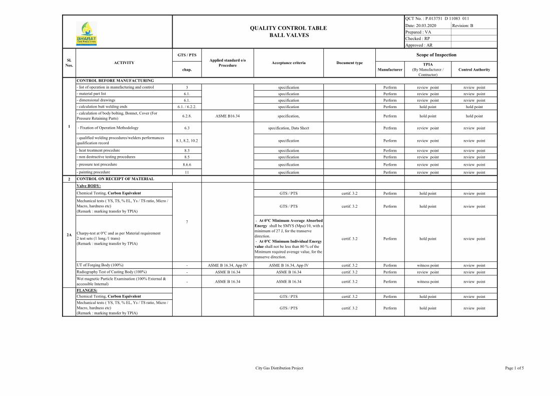
Date: 20.03.2020 Revision: B
Prepared : VA
Checked : RP
Approved : AR
GTS / PTS
chap. Manufacturer
TPIA
(By Manufacturer /
Contractor)
Control Authority
3 specification Perform review point review point
6.1. specification Perform review point review point
6.1. specification Perform review point review point
6.1. / 6.2.2. specification Perform hold point hold point
6.2.8. ASME B16.34 specification, Perform hold point hold point
6.3 specification, Data Sheet Perform review point review point
8.1, 8.2, 10.2 specification Perform review point review point
8.3 specification Perform review point review point
8.5 specification Perform review point review point
8.6.6 specification Perform review point review point
11 specification Perform review point review point
2
GTS / PTS certif. 3.2 Perform hold point review point
GTS / PTS certif. 3.2 Perform hold point review point
- At 0°C Minimum Average Absorbed
Energy shall be SMYS (Mpa)/10, with a
minimum of 27 J, for the transerve
direction.
- At 0°C Minimum Individual Energy
value shall not be less than 80 % of the
Minimum required average value, for the
transerve direction.
certif. 3.2 Perform hold point review point
- ASME B 16.34, App IV ASME B 16.34, App IV certif. 3.2 Perform witness point review point
- ASME B 16.34 ASME B 16.34 certif. 3.2 Perform review point review point
- ASME B 16.34 ASME B 16.34 certif. 3.2 Perform witness point review point
GTS / PTS certif. 3.2 Perform hold point review point
GTS / PTS certif. 3.2 Perform hold point review point
QCT No. : P.013751 D 11083 011
QUALITY CONTROL TABLE
BALL VALVES
CONTROL ON RECEIPT OF MATERIAL
- Fixation of Operation Methodology
Valve BODY:
Chemical Testing, Carbon Equivalent
7
Mechanical tests ( YS, TS, % EL, Ys / TS ratio, Micro /
Macro, hardness etc)
(Remark : marking transfer by TPIA)
-
Radiography Test of Casting Body (100%)
FLANGES:
Chemical Testing, Carbon Equivalent
Sl.
Nos.
- calculation of body bolting, Bonnet, Cover (For
Pressure Retaining Parts)
ACTIVITY
- pressure test procedure
1
CONTROL BEFORE MANUFACTURING
- material part list
- dimensional drawings
Document type
- list of operation in manufacturing and control
- calculation butt welding ends
Acceptance criteriaApplied standard e/o
Procedure
- qualified welding procedures/welders performances
qualification record
Scope of Inspection
- non destructive testing procedures
- painting procedure
- heat treatment procedure
Wet magnetic Particle Examination (100% External &
accessible Internal)
Charpy-test at 0°C and as per Material requirement
2 test sets (1 long./1 trans)
(Remark : marking transfer by TPIA)
UT of Forging Body (100%)
2A
2B
Mechanical tests ( YS, TS, % EL, Ys / TS ratio, Micro /
Macro, hardness etc)
(Remark : marking transfer by TPIA)
City Gas Distribution Project Page 1 of 5

Date: 20.03.2020 Revision: B
Prepared : VA
Checked : RP
Approved : AR
GTS / PTS
chap. Manufacturer
TPIA
(By Manufacturer /
Contractor)
Control Authority
QCT No. : P.013751 D 11083 011
QUALITY CONTROL TABLE
BALL VALVES
Sl.
Nos.ACTIVITY
1
CONTROL BEFORE MANUFACTURING
Document typeAcceptance criteriaApplied standard e/o
Procedure
Scope of Inspection
- At 0°C Minimum Average Absorbed
Energy shall be SMYS (Mpa)/10, with a
minimum of 27 J, for the transerve
direction.
- At 0°C Minimum Individual Energy
value shall not be less than 80 % of the
Minimum required average value, for the
transerve direction.
certif. 3.2 Perform hold point review point
- ASME B 16.34, App IV ASME B 16.34, App IV certif. 3.2 Perform witness point review point
- ASME B 16.34 ASME B 16.34 certif. 3.2 Perform review point review point
ASME B 16.34 ASME B 16.34 certif. 3.2 Perform witness point review point
GTS / PTS certif. 3.2 Perform hold point review point
GTS / PTS certif. 3.2 Perform hold point review point
- At 0°C Minimum Average Absorbed
Energy shall be SMYS (Mpa)/10, with a
minimum of 27 J, for the transerve
direction.
- At 0°C Minimum Individual Energy
value shall not be less than 80 % of the
Minimum required average value, for the
transerve direction.
certif. 3.2 Perform hold point review point
- ASME B 16.34, App IV ASME B 16.34, App IV certif. 3.2 Perform witness point review point
- ASME B 16.34 ASME B 16.34 certif. 3.2 Perform review point review point
- ASME B 16.34 ASME B 16.34 certif. 3.2 Perform witness point review point
- at 0°C, for Base - 40J/cm²(Avg.),
32J/cm²(Ind.),
- at 0°C, for Weld/HAZ -
27J/cm²(Avg.), 22J/cm²(Ind.)
certif. 3.2 Perform hold point review point
GTS / PTS certif. 3.2 Perform hold point RW
GTS / PTS certif. 3.2 Perform hold point RW
certif. 3.2 hold point review point
LATERAL CONNECTIONS:
GTS / PTS
7
7
7
-
Radiography Test of Casting Body (100%)
Wet magnetic Particle Examination (100% External &
accessible Internal)
Wet magnetic Particle Examination (100% External &
accessible Internal)
Chemical Test, Carbon Equivalent
Chemical Testing, Carbon Equivalent
Charpy-test at 0°C and as per Material requirement
2 test sets (1 long./1 trans.)
(Remark : marking transfer by TPIA)
Mechanical tests
(Remark : marking transfer by TPIA)
EXTENSION PIPE PIECES AS PER DATA SHEET
Chemical Testing, Carbon Equivalent
Charpy-test at 0°C and as per Material requirement
2 test sets (1 long./1 trans.)
(Remark : marking transfer by TPIA)
Mechanical tests ( YS, TS, % EL, Ys / TS ratio, Micro /
Macro, hardness etc)
(Remark : marking transfer by TPIA)
UT of Forging Body (100%)
Radiography Test of Casting Body (100%)
UT of Forging Body (100%)
2B
2C
2D
2E
Perform
Charpy-test at 0°C and as per Material requirement
2 test sets (1 long./1 trans.)
(Remark : marking transfer by TPIA)
BALL / OBTURATOR (Note -7):
- Mechanical tests ( YS, TS, % EL, Ys / TS ratio, Micro /
Macro, hardness etc)
(Remark : marking transfer by TPIA)
City Gas Distribution Project Page 2 of 5

Date: 20.03.2020 Revision: B
Prepared : VA
Checked : RP
Approved : AR
GTS / PTS
chap. Manufacturer
TPIA
(By Manufacturer /
Contractor)
Control Authority
QCT No. : P.013751 D 11083 011
QUALITY CONTROL TABLE
BALL VALVES
Sl.
Nos.ACTIVITY
1
CONTROL BEFORE MANUFACTURING
Document typeAcceptance criteriaApplied standard e/o
Procedure
Scope of Inspection
ASME B 16.34, App IV ASME B 16.34, App IV certif. 3.2 Perform witness point review point
ASME B 16.34 ASME B 16.34 certif. 3.2 Perform review point review point
GTS / PTS
GTS / PTS
- ASME B 16.34 ASME B 16.34 certif. 3.2 Perform witness point review point
GTS / PTS certif. 3.1 Perform review point review point
GTS / PTS certif. 3.1 Perform hold point review point
- ASME B 16.34, App IV ASME B 16.34, App IV certif. 3.2 Perform witness point review point
- ASME B 16.34 ASME B 16.34 certif. 3.2 Perform witness point review point
GTS / PTS
GTS / PTS certif. 3.1 Perform review point review point
GTS / PTS certif. 3.1 Perform hold point review point
GTS / PTS
GTS / PTS
GTS / PTS
GTS / PTS
GTS / PTS
GTS / PTS
GTS / PTS
GTS / PTS
GTS / PTS
GTS / PTS
GTS / PTS
STEM & SEAT SEALING CONNECTION :
-Chemical Testing, Carbon Equivalent
-Chemical Testing, Carbon equivalent
- Mechanical tests ( YS, TS, % EL, Ys / TS ratio, Micro /
Macro, hardness etc)
(Remark : marking transfer by TPIA),
- Chemical tests, Carbon equivalent
VENT/BLEED PLUG:
- 'Chemical test,''Mechanical tests
review point
review point
review point
certif. 3.1
hold point (Mech.)
review(Others)
STEM:
hold point (Mech.)
review(Others)
review point
certif. 3.1
OTHER VALVE PARTS INCLUDING PIPE PUP
PIECE7
hold point (Mech.)
review(Others)- 'Chemical Test, Mechanical tests
certif. 3.1hold point (Mech.)
review(Others)7
- 'Chemical test, mechanical tests
DRAIN: UPPER BALL VALVE & NEEDLE
VALVE:
certif. 3.1
7
7
7
7
7
STUDS/NUTS (With Xylan Coating)
review point
hold point (Mech.)
review(Others)review pointcertif. 3.1
certif. 3.1
7DRAIN: OPEN BLOCK VALVE AT DRAIN TAP:
- Chemical Test, Mechanical tests
7
- Mechanical tests ( YS, TS, % EL, Ys / TS ratio, Micro /
Macro, hardness etc)
(Remark : marking transfer by TPIA)
SEAT:
-Mechanical tests ( YS, TS, % EL, Ys / TS ratio, Micro /
Macro, hardness etc)
(Remark : marking transfer by TPIA)
2E
2H
2I
Perform
Perform
Perform
Perform
Perform
Perform review point
2J
2K
2L
2M
UT of Forging Body (100%) OR
Radiography Test of Casting Body (100%)
Wet magnetic Particle Examination (All accessible area)
UT of Forging Body (100%)
Wet magnetic Particle Examination (All accessible area)
2F
2G
- Mechanical and Chemical tests
City Gas Distribution Project Page 3 of 5

Date: 20.03.2020 Revision: B
Prepared : VA
Checked : RP
Approved : AR
GTS / PTS
chap. Manufacturer
TPIA
(By Manufacturer /
Contractor)
Control Authority
QCT No. : P.013751 D 11083 011
QUALITY CONTROL TABLE
BALL VALVES
Sl.
Nos.ACTIVITY
1
CONTROL BEFORE MANUFACTURING
Document typeAcceptance criteriaApplied standard e/o
Procedure
Scope of Inspection
3
3.1 8.1 - 8.2 ASME IX + spec. ASME IX + spec.Welding Procedure
Specification (WPS)Perform hold point review & approval point
3.2 8.3 ASME VIII Div.1 ASME VIII Div.1 review CTT/TT curves Perform review report review report
3.3 8.4.1 ASTM A370 GTS / PTS certif. 3.2 Perform hold point review point
3.4 8.4.2 ISO 148 or ASTM A370
- At 0°C Minimum Average Absorbed
Energy shall be SMYS (Mpa)/10, with a
minimum of 27 J, for the transerve
direction.
- At 0°C Minimum Individual Energy
value shall not be less than 80 % of the
Minimum required average value, for the
transerve direction.
certif. 3.2 Perform hold point review point
8.5.1 ASME SECT V art. 2 ASME SECT. VIII, div.1, UW 51. (RT-Test report) Perform witness point review point
8.5.1 ASME SECT V art. 5 ASME SECT. VIII, div.1, App.12 UT-Test report Perform witness point review point
3.6 8.5.1 MSS-SP-54 (RT-Test report) Perform witness point review point
3.7 8.5.1 ASME SECT V art. 5 ASME SECT. VIII, dic.1, App.12 UT-Test report Perform witness point review point
3.8 8.5.1 ASME SECT V art. 7 ASME SECT. VIII App.6 MPE-Test report Perform witness point review point
3.9 8.5.1 Sec 8 proc.7 MSS-SP-55 report Perform hold point review point
3.10 8.5.1 Sec 8 proc.24 DWG ** report Perform witness point review point
4 Finished bevel end pipe used for field welding :
4.1 8.5.1ASME SECT V art. 7
ASME SECT V art. 6
unacceptable defects : defects not
parallel to the surface extending into the
bevel + defect extending into the bevel
provided the lamination is parallel to the
surface and has a transverse dimension
exceeding 6.35 mm
MPE/ LPE-Test report Perform witness point review point
4.2 8.5.1 ASME SECT V art. 5 ASME SECT. VIII, div.1, App.12 UT-Test report Perform witness point review point
4.3 8.5.1 ASME SECT V art. 2 ASME SECT. VIII, div.1, UW 51. RT-Film & report Perform witness point review point
4.4 8.5.1 Sec 8 proc.7 MSS-SP-55 +DWG** report Perform witness point review point
5
5.1 8.6.2 API 6D + GTS / PTS @ 1.5 x Design Pr.,
30 Min(NPS>18") / 15 Min(NPS<16").certif. 3.2 Perform witness point hold point
5.2 8.6.3 API 6D + GTS / PTS @ 1.1 x Design Pr., 5 Min. certif. 3.2 Perform witness point hold point
5.3 8.6.5 GTS / PTS @ 95 barg for 5 min. certif. 3.2 Perform witness point hold point
5.4 8.6.4 GTS / PTS @ 6 bar certif. 3.2 Perform witness point hold point
5.5 8.6.5 GTS / PTS @ 7 bar, 5 Min. certif. 3.2 Perform hold point hold point
Heat treatment fully welded valve and test pieces
FINAL INSPECTION TEST
Visual examination
Dimensional examination
(if feasable) RT on butt welds
Magnetic Particule Examination on valve body
10 % valves < 6"
100% valves ≥ 6"
FABRICATION AND TESTS
Visual and dimensional examination
(if not feasable & thk. > 15mm) UT on butt welds
RT examination on 25 mm of base material
Butt welding ends on cast bodies shall be examined
before fabrication welding end by radiography (Over a
width of 70 mm)(not applicable for forged bodies)
External leak testing (with Soup suds)
UT inspection on 25 mm of base material
Welds and repair welds shall be performed according to
written qualified procedures
Mechanical tests
(Remark : marking transfer by TPIA)
Charpy-test at 0°C and as per Material requirement
2 test sets (1 long./1 trans.)
(Remark : marking transfer by TPIA)
3.5
UT on 25 mm of base mat. (at each side) and each
weld(100%)
Magnetic Particule Examination / Liquid Penetrant
Examination
Pneumatic Test (with nitrogen) ( Shell & Seat)
Hydrostatic Shell Test
Hydrostatic Seat Test
Air seat test
City Gas Distribution Project Page 4 of 5

Date: 20.03.2020 Revision: B
Prepared : VA
Checked : RP
Approved : AR
GTS / PTS
chap. Manufacturer
TPIA
(By Manufacturer /
Contractor)
Control Authority
QCT No. : P.013751 D 11083 011
QUALITY CONTROL TABLE
BALL VALVES
Sl.
Nos.ACTIVITY
1
CONTROL BEFORE MANUFACTURING
Document typeAcceptance criteriaApplied standard e/o
Procedure
Scope of Inspection
5.6 8.6.5ASME Sec.V, Subsection A,
Art.10, Appendix IV.@ 25% of Rated Pressure for 30 mins. certif. 3.2 Perform hold point hold point
5.7 x API 6D/API 598 + GTS / PTS API 6D/ API 598 certif. 3.2 Perform hold point hold point
5.8 x API 6D/API 598 + GTS / PTS API 6D/ API 599 certif. 3.3 Perform hold point hold point
5.9 x BS 5351 + GTS / PTS BS 5351 + specification certif. 3.2 Perform hold point hold point
5.10 8.7 API 6D report Perform witness point hold point
5.11 8.8 API 6FA API6FA report Perform review report review report
5.12 8.10 Sec 8 proc.7 MSS-SP-55 / GTS / PTS report Perform hold point review report
5.13 8.10 Sec 8 proc.24 DWG ** report Perform witness point review report
6 9 section 9 of specification section 9 specification X Perform witness point review report
6.1 9.1.2 section 9 of specification section 9 specification X X X X
7 11 SIS055900 SA2.5, Cl.11 of Specification report Perform witness point review report
8 10 section 10 of specification section 10 of specification certif. 3.2 Perform hold point review report
RT: Radiographic test PT:Liquid penetrant test MT: Magnetic particle test TPIA: Third Party Inspection Agency; . Control Authority : Owner / Owner's representatives
P: Performed R:Review W: Witness RW: Random Witness
Hold point = No further steps may be undertaken before the intervention of the appointed responsible takes place.
Witness point = The appointed responsible has to be notified of the operation in advance, but production will continue whether the intervention took place or not.
Note: 1
2
3
4
5
6
7
8
9
10
11
12
13
Heat treatment start and stop temperature chart shall be witnessed & signed by TPIA. Power failure log book / sheet shall be maintained
LEGENDS:
Certification requirements shall comply with European Standard EN 10204 (latest edition)
In case of conflict between purchase specification, contract documents and QAP, more stringent conditions shall be applicable.
Marking
Operational torque Test
Fire Safe Test
Helium Leak Test
TPIA shall ensure that Ball and Stem are Electroless Nickel Plated (ENP) with minimum thickness of 75 microns as per data sheet requirement.
Inspector's stamp
Control of all certificates & Final Certificate
The supplier shall submit their own detailed QAP prepared on the basis of the above for approval of Owner/Owner's representative and TPIA.
Contractor in coordination with Supplier/Sub vendor shall issue detailed Production and Inspection schedule indicating the dates and the locations to facilitate Owner/Owner's representative and TPIA to organise Inspection.
Supplier shall submit Calibration certificates of all Instruments/Equipment to be used for Inspection and Testing to TPIA with relavant procedures and updated standards for TPIA reveiew/Approval.
TPIA will have Right to Inspect minimum 10% of all manufacturing activities on each day or as specified above.
TPIA along with Owner/Owner representative shall review/approve all the documents related to QAP/Quality manuals/Drawings etc.submitted by supplier.
TPIA shall also Review the Test certificates submitted by the Actuator manufacturer.
The above testing and acceptance critera are minimum requirements, however, equipment supplier shall ensure and that the product also comply to the additional requirements as per Technical specifications and data sheets.
Dimensional examination
Visual examination
Double Block and Bleed Test
Antistatic Test
Functional Test (10 Opening / Closing with Operator
mounted on the valve at 95 barg)
For All Forging Materials, The Specimen Shall Be Taken From The Integral Part of The Forging.
The hold points in this QAP pertains to mechanical tests and hydro test. These tests on all the components can be clubbed together to be performed during a single visit of TPIA
Painting And Coating
City Gas Distribution Project Page 5 of 5

PAINTING SYSTEM & COLOUR
CODE FOR FINAL LAYER
P.013751
M 11071
003
A 06.01.2020 Issued as Standard Specification VA RP GSS
Rev. Date Description Prepared By Checked By Approved By
BHARAT GAS RESOURCES LIMITED (BGRL)
CITY GAS DISTRIBUTION
SUPPLY OF VALVES FOR AHMEDNAGAR – AURANGABAD AND SATARA – SANGLI (MAHARASHTRA STATE)
PAINTING SYSTEM & COLOUR CODE FOR FINAL LAYER

PAINTING SYSTEM & COLOUR
CODE FOR FINAL LAYER
P.013751
M 11071
003
Rev. A – 06.01.2020 City Gas Distribution Page 1 of 2
The color codes for final layer of Station Pipe Work & Metering Shed shall be as under:
S. No. DESCRIPTION FINAL LAYER
COLOUR SHADE
RAL CODE
1 Pipe Work Yellow RAL 1004
2 Piping Support Grey RAL 7043
3 Hand Rail Grey RAL 7043
4 Gas O/L Actuator Blue RAL 5015
5 Valve Handle/Wheel Black RAL 9005
6 All Valves Grey RAL 7038
7 IJ Grey RAL 7038
8 Filter Grey RAL 7038
9 Pig launcher & Receiver Grey RAL 7038
10 Bolts & Nuts Grey RAL 7038
11 Grating Hot Galvanized
12 Metering Station Shed
12.1 Steel Frame Beige RAL 1018
12.2 Roof / Vertical Shed Grey RAL 7030
12.3 Control Panel Grey RAL 7032
The recommended painting system should be of Category C5 – I Very high (Industrial) as specified in the Standard ISO
12944 Part 1 to 8. The proposed Painting system shall conform to Table A 5 of ISO 12944 – 5 Standard.

PAINTING SYSTEM & COLOUR
CODE FOR FINAL LAYER
P.013751
M 11071
003
Rev. A – 06.01.2020 City Gas Distribution Page 2 of 2