OWNER'S MANUAL - TVS Motor
58
OWNER’S MANUAL
-
Upload
khangminh22 -
Category
Documents
-
view
1 -
download
0
Transcript of OWNER'S MANUAL - TVS Motor
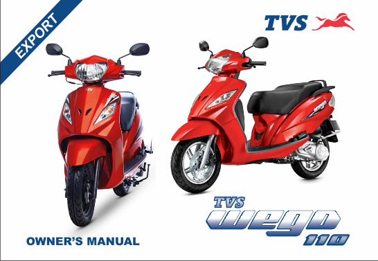
OWNER’S MANUAL
FOREWORD
1
FO
REW
OR
D
Dear WEGO Owner,
Thank you for choosing TVS WEGO , a Multi-User friendly, scooter with Body Balance Technology, CVT-i Engine &
many class-leading features. With its aerodynamic stance, unrivaled comfort and best in class mileage, Wego
represents a new direction in the class of scooters. Hand-crafted for dual usage and urban mobility, Wego is the
luxury scooter that adapts to your needs and personality.
It's more than a scooter. It is a statement, an intelligent choice. As a proud owner of TVS WEGO, you are now part of
a family of millions of satisfied TVS customers.
This manual explains the features and operations of your TVS WEGO. Kindly read it carefully and follow the
instructions to enjoy years of safe riding. To ensure reliable performance, we urge you to get your TVS WEGO
serviced only at TVS Motor Company Authorised Dealers / Authorised Service Centers at specified Distributor or
regular periodic intervals.
We welcome you once more to a world of comfortable and easy riding!
TVS MOTOR COMPANY LIMITED
NOTICE
2
All information, illustrations, photographs and specifications contained in this owner‘s manual are based on the
latest product information available at the time of this publication. TVS Motor Company Limited may, however
incorporate modifications or improvements on its vehicles at any time without notice and therefore, in such
events it is possible that the relevant part of the owner‘s manual does not apply to your vehicle.
Prior permission of TVS Motor Company Limited is required for quoting, copying or reproducing any part of this
owner‘s manual.
Part number:- K6210560 Revision 0, July 2014
Accessories shown in the picture may not be part of the standard equipment.
This mannual is applicable for TVS WEGO Drum & Disc versions and TVS WEGO Refresh.
NO
TIC
E
Note
CONTENTS
3
CO
NTEN
TS
Information 04
Safe Riding Tips 05
Know your TVS WEGO 08
Riding your TVS WEGO 29
Maintenance 33
Service Record Sheet 52
Technical Specifications 54
4
INFO
RM
ATIO
N
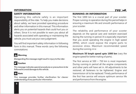
Operating this vehicle safely is an important
responsibility of the rider. To help you make decisions
about safety, we have provided operating procedure
and other information in this manual. This information
alerts you on potential hazards that could hurt you or
others. Since it is not possible to warn you about all
hazards associated with operating or maintaining the
vehicle, you must use your own judgement.
You will find important safety information in following
form in this manual. These words carry the following
connotations:
Disregarding this message might result in injury to the rider.
This message indicates special procedures or precautions to be followed to avoid damage to the vehicle.
This message provides further clarification for clearer understanding of any particular information.
Warning
Caution
Note
INFORMATION
SAFETY INFORMATION
The first 1000 km is a crucial part of your scooter.
Proper running-in operation during this period helps in
ensuring a maximum life and smooth performance of
your scooter.
The reliability and performance of your scooter
depends on the special care and restraint exercised
during the running-in period. It is especially important
that you avoid operating the engine in high speed
(RPM), which could expose the engine parts to
excessive stress. Maximum recommended speed
during the running-in is:
Maximum 50 kmph speed upto 1000 km (vary the
engine speed for better mating of parts).
The first service at 500 ~ 750 km is most important.
During running-in period all the engine components
and other parts will have set in. All adjustments to be
restored, all fasteners to be tightened. Engine and
transmission oil to be replaced. Timely performance of
the first free service will ensure optimum service life
and performance from the engine.
RUNNING-IN INFORMATION
5
SA
FE
RID
ING
TIP
S
SAFE RIDING TIPS
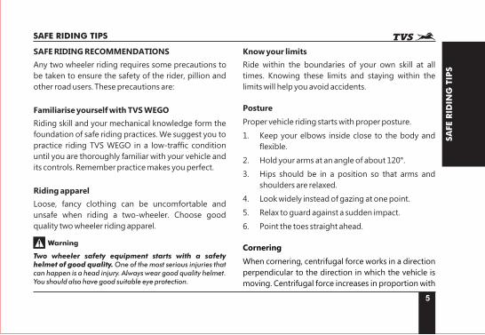
SAFE RIDING RECOMMENDATIONS
Any two wheeler riding requires some precautions to
be taken to ensure the safety of the rider, pillion and
other road users. These precautions are:
Familiarise yourself with TVS WEGO
Riding skill and your mechanical knowledge form the
foundation of safe riding practices. We suggest you to
practice riding TVS WEGO in a low-traffic condition
until you are thoroughly familiar with your vehicle and
its controls. Remember practice makes you perfect.
Riding apparel
Loose, fancy clothing can be uncomfortable and
unsafe when riding a two-wheeler. Choose good
quality two wheeler riding apparel.
Two wheeler safety equipment starts with a safety helmet of good quality. One of the most serious injuries that can happen is a head injury. Always wear good quality helmet. You should also have good suitable eye protection.
Warning
Know your limits
Ride within the boundaries of your own skill at all
times. Knowing these limits and staying within the
limits will help you avoid accidents.
Posture
Proper vehicle riding starts with proper posture.
1. Keep your elbows inside close to the body and
flexible.
2. Hold your arms at an angle of about 120°.
3. Hips should be in a position so that arms and
shoulders are relaxed.
4. Look widely instead of gazing at one point.
5. Relax to guard against a sudden impact.
6. Point the toes straight ahead.
Cornering
When cornering, centrifugal force works in a direction
perpendicular to the direction in which the vehicle is
moving. Centrifugal force increases in proportion with
6
SA
FE
RID
ING
TIP
S
SAFE RIDING TIPS
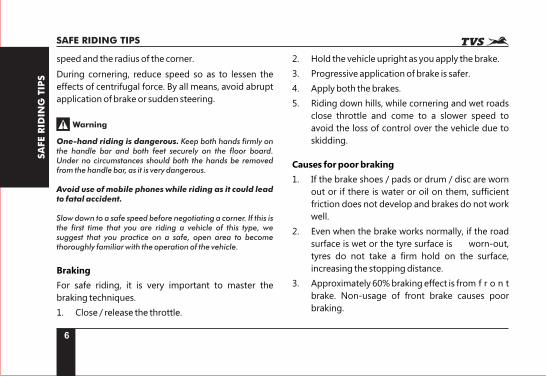
speed and the radius of the corner.
During cornering, reduce speed so as to lessen the
effects of centrifugal force. By all means, avoid abrupt
application of brake or sudden steering.
Warning
One-hand riding is dangerous. Keep both hands firmly on the handle bar and both feet securely on the floor board. Under no circumstances should both the hands be removed from the handle bar, as it is very dangerous.
Avoid use of mobile phones while riding as it could lead to fatal accident.
Slow down to a safe speed before negotiating a corner. If this is the first time that you are riding a vehicle of this type, we suggest that you practice on a safe, open area to become thoroughly familiar with the operation of the vehicle.
Braking
For safe riding, it is very important to master the
braking techniques.
1. Close / release the throttle.
2. Hold the vehicle upright as you apply the brake.
3. Progressive application of brake is safer.
4. Apply both the brakes.
5. Riding down hills, while cornering and wet roads
close throttle and come to a slower speed to
avoid the loss of control over the vehicle due to
skidding.
Causes for poor braking
1. If the brake shoes / pads or drum / disc are worn
out or if there is water or oil on them, sufficient
friction does not develop and brakes do not work
well.
2. Even when the brake works normally, if the road
surface is wet or the tyre surface is worn-out,
tyres do not take a firm hold on the surface,
increasing the stopping distance.
3. Approximately 60% braking effect is from f r o n t
brake. Non-usage of front brake causes poor
braking.
7
SA
FE
RID
ING
TIP
S
SAFE RIDING TIPS
Warning
As the vehicle speed increases, the stopping distance also increases progressively. Be sure that, you have sufficient distance between you and the vehicle or obstruction ahead of you.
Using only the front or rear brake is dangerous and can cause skidding and loss of control. Apply both the brakes together and with great care on a wet road or other slippery surfaces. Any abrupt braking on slippery or irregular roads can cause loss of rider control.
ACCESSORY INSTALLATION AND SAFETY TIPS
Use extreme caution while selecting and installing the
accessories for your scooter.
The addition of unsuitable accessories can lead to
unsafe operating conditions. Your friendly Dealer will
assist you in selecting quality accessories and
installing them correctly.
While selecting the accessories, make sure the
accessories should not obstruct lighting, steerability,
suspension level and ground clearance.
Additional electrical equipments and controls should
not exceed the specified electrical system load of the
vehicle (capacity of battery and magneto).
EMISSION CONTROL
All the TVS vehicles are tested in the factory for
optimum fuel efficiency and lowest possible CO levels.
Do not disturb the Carburettor settings as this may
lead to higher fuel consumption and also higher CO
levels.
If the vehicle needs any adjustments, please consult
nearest TVS Motor Company Authorised Distributor
or Dealer / Authorised Service Centers.
While adequate care is exercised at the factory to
ensure that the emissions are within the limits, it is
essential for the owner to always maintain the scooter
in good condition by getting it periodically checked
and serviced by TVS Motor Company Authorised
Distributor or Dealer / Authorised Service Centers so
that the emission and fuel consumption levels are
maintained as per norms.
8
KN
OW
YO
UR
TV
SW
EG
O
KNOW YOUR TVS WEGO
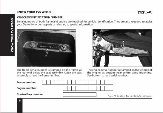
VEHICLE IDENTIFICATION NUMBER
Serial numbers of both frame and engine are required for vehicle identification. They are also required to assist your Dealer for ordering parts or referring to special information.
The engine serial number is stamped on the left side of the engine, at bottom, near centre stand mounting. See bottom to read serial number.
The frame serial number is stamped on the frame, at the rear end below the seat assembly. Open the seat assembly to read the frame number.
Frame number
Engine number
Control key numberPlease fill the above box now for future reference
9
KN
OW
YO
UR
TV
SW
EG
O
KNOW YOUR TVS WEGO
87
6
5
4
3
2
1
9 10 11 12
13
14
15
16
17
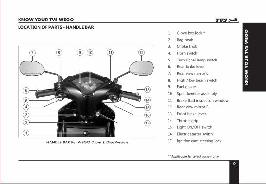
LOCATION OF PARTS - HANDLE BAR
HANDLE BAR For WEGO Drum & Disc Version
1. Glove box lock**
2. Bag hook
3. Choke knob
4. Horn switch
5. Turn signal lamp switch
6. Rear brake lever
7. Rear view mirror L
8. High / low beam switch
9. Fuel gauge
10. Speedometer assembly
11. Brake fluid inspection window
12. Rear view mirror R
13. Front brake lever
14. Throttle grip
15. Light ON/OFF switch
16. Electric starter switch
17. Ignition cum steering lock
** Applicable for select variant only
10
KN
OW
YO
UR
TV
SW
EG
O
KNOW YOUR TVS WEGO
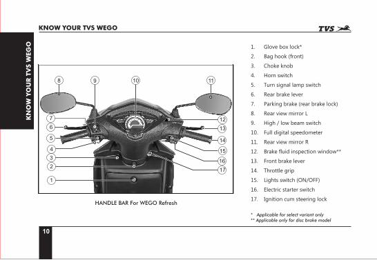
HANDLE BAR For WEGO Refresh
* Applicable for select variant only** Applicable only for disc brake model
1. Glove box lock*
2. Bag hook (front)
3. Choke knob
4. Horn switch
5. Turn signal lamp switch
6. Rear brake lever
7. Parking brake (rear brake lock)
8. Rear view mirror L
9. High / low beam switch
10. Full digital speedometer
11. Rear view mirror R
12. Brake fluid inspection window**
13. Front brake lever
14. Throttle grip
15. Lights switch (ON/OFF)
16. Electric starter switch
17. Ignition cum steering lock
1
8 9 11
12
13
14
15
16
17
10
2
5
3
6
4
7
10 11
123456789
11
KN
OW
YO
UR
TV
SW
EG
O
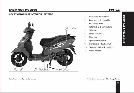
KNOW YOUR TVS WEGO
LOCATION OF PARTS - VEHICLE LEFT SIDE1. Rear brake adjuster nut
2. Lady foot rest - foldable
3. Kickstarter lever
4. Patented E-Z centre stand
5. Side stand*
6. Pillion foot rest L
7. Floor mat
8. Speedometer cable
9. Front brake adjusting nut
10. Seat cum fuel tank cap lock
11. Pillion handle
Vehicle shown is drum brake version * Mandatory accessory will be charged extra
123456
7 8
12
KN
OW
YO
UR
TV
SW
EG
O
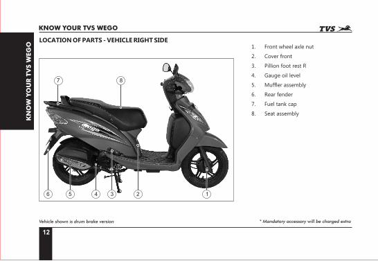
KNOW YOUR TVS WEGO
LOCATION OF PARTS - VEHICLE RIGHT SIDE
Vehicle shown is drum brake version * Mandatory accessory will be charged extra
1. Front wheel axle nut
2. Cover front
3. Pillion foot rest R
4. Gauge oil level
5. Muffler assembly
6. Rear fender
7. Fuel tank cap
8. Seat assembly
1
2
3
45
6
8
9
10
11
12
13
7
13
KN
OW
YO
UR
TV
SW
EG
O
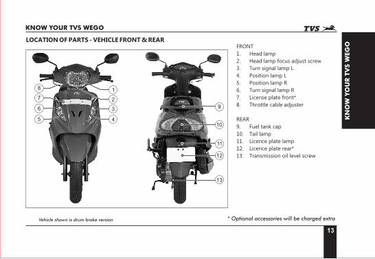
KNOW YOUR TVS WEGO
Vehicle shown is drum brake version
FRONT
1. Head lamp
2. Head lamp focus adjust screw
3. Turn signal lamp L
4. Position lamp L
5. Position lamp R
6. Turn signal lamp R
7. License plate front*
8. Throttle cable adjuster
REAR
9. Fuel tank cap
10. Tail lamp
11. Licence plate lamp
12. Licence plate rear*
13. Transmission oil level screw
LOCATION OF PARTS - VEHICLE FRONT & REAR
* Optional accessories will be charged extra
14
KN
OW
YO
UR
TV
SW
EG
O
KNOW YOUR TVS WEGO
CONTROL KEY
TVS WEGO comes with a pair of identical control keys.
These keys are to operate ignition cum steering lock,
seat lock, fuel tank cap and glove box(optional).
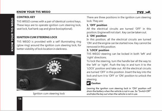
IGNITION CUM STEERING LOCK
TVS WEGO is provided with a self illuminating ring
(glow ring) around the ignition cum steering lock, for
better visibility of lock location in darkness.
Ignition cum steering lock
There are three positions in the ignition cum steering
lock. They are:
1. ‘OFF’ position
All the electrical circuits are turned ‘OFF‘ in this
position. Engine will not start . Key can be taken out.
2. ‘ON’ position
In this position, all the electrical circuits are turned
‘ON’ and the engine can be started now. Key cannot be
removed in this position.
3. ‘LOCK’ position
TVS WEGO steering can be locked in both ‘left’ and
‘right’ directions.
To lock the steering, turn the handle bar all the way to
the ‘left’ or ‘right’. Push the key in and turn it to the
‘LOCK’ position and take out. All the electrical circuits
are turned ‘OFF’ in this position. Insert the key into the
lock and turn it to ‘OFF’ or ‘ON’ position to unlock the
steering.
Leaving the ignition cum steering lock in ‘ON’ position will drain the battery when the vehicle is not in use. So “Switch Off” and take the key out when the vehicle is not in use.
Caution
15
KN
OW
YO
UR
TV
SW
EG
O
KNOW YOUR TVS WEGO
Never attempt to move the vehicle when the steering is locked, you may lose balance.
When the ignition lock is turned ‘ON’, the speedometer performs self test and the back light of the speedometer glows continuously. Wait till the self test cycle of speedometer gets over.
Warning
Note
2
1
3 4 5
6
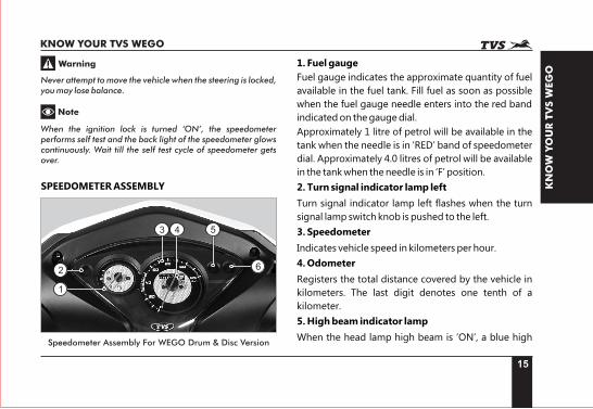
SPEEDOMETER ASSEMBLY
1. Fuel gauge
Fuel gauge indicates the approximate quantity of fuel
available in the fuel tank. Fill fuel as soon as possible
when the fuel gauge needle enters into the red band
indicated on the gauge dial.
Approximately 1 litre of petrol will be available in the
tank when the needle is in ‘RED’ band of speedometer
dial. Approximately 4.0 litres of petrol will be available
in the tank when the needle is in ‘F’ position.
2. Turn signal indicator lamp left
Turn signal indicator lamp left flashes when the turn
signal lamp switch knob is pushed to the left.
3. Speedometer
Indicates vehicle speed in kilometers per hour.
4. Odometer
Registers the total distance covered by the vehicle in
kilometers. The last digit denotes one tenth of a
kilometer.
5. High beam indicator lamp
When the head lamp high beam is ‘ON’, a blue high Speedometer Assembly For WEGO Drum & Disc Version
16
KN
OW
YO
UR
TV
SW
EG
O
KNOW YOUR TVS WEGO
beam indicator lamp will glow.
6. Turn signal indicator lamp right
Turn signal indicator lamp right flashes when the turn
signal lamp switch knob is pushed to the right.
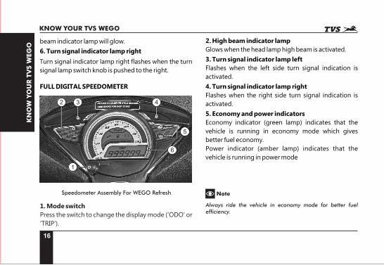
FULL DIGITAL SPEEDOMETER
3 4
6
2
5
1. Mode switch
Press the switch to change the display mode (‘ODO’ or
‘TRIP’).
2. High beam indicator lamp
Glows when the head lamp high beam is activated.
3. Turn signal indicator lamp left
Flashes when the left side turn signal indication is
activated.
4. Turn signal indicator lamp right
Flashes when the right side turn signal indication is
activated.
5. Economy and power indicators
Economy indicator (green lamp) indicates that the
vehicle is running in economy mode which gives
better fuel economy.
Power indicator (amber lamp) indicates that the
vehicle is running in power mode
Always ride the vehicle in economy mode for better fuel efficiency.
NoteSpeedometer Assembly For WEGO Refresh
1
17
KN
OW
YO
UR
TV
SW
EG
O
KNOW YOUR TVS WEGO
Note
When the engine is started first time and restarting of engine from switch off condition, the power mode indicator blinks. If the engine remains running in idle condition for approximately 110 seconds and informs you that the fuel is getting wasted and the engine needs to be switch ‘OFF’ to save the fuel.
Similarly, during running, if the engine is kept more than 20 seconds in idling condition, the power mode indicator blinks and warns again.
If the battery voltage is very low, power mode lamp will glow once you switch ‘ON’ the ignition key till you start the vehicle. Electric starter will not work in this condition. Use kick starter only. Contact TVS Motor Company Authorised Distributor or Dealer / Authorised Service Centers for assistance.
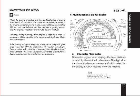
6. Multi functional digital display
E
F
ab
c
d
e
a. Odometer / trip meter
Odometer registers and displays the total distance
covered by the vehicle in kilometers. The digit after
the dot mark denotes one tenth of a kilometer. Set
the display in ‘ODO’ mode to know the reading.
18
KN
OW
YO
UR
TV
SW
EG
O
KNOW YOUR TVS WEGO
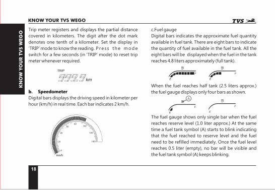
Trip meter registers and displays the partial distance
covered in kilometers. The digit after the dot mark
denotes one tenth of a kilometer. Set the display in
‘TRIP’ mode to know the reading. P re s s the mode
switch for a few seconds (in ‘TRIP’ mode) to reset trip
meter whenever required.
b. Speedometer
Digital bars displays the driving speed in kilometer per
hour (km/h) in real time. Each bar indicates 2 km/h.
c. Fuel gauge
Digital bars indicates the approximate fuel quantity
available in fuel tank. There are eight bars to indicate
the quantity of fuel available in the fuel tank. All the
eight bars will be displayed when the fuel in the tank
reaches 4.8 liters approximately (full tank).
When the fuel reaches half tank (2.5 liters approx.)
the fuel gauge displays only four bars as shown.
The fuel gauge shows only single bar when the fuel
reaches reserve level (1.0 liter approx.) At the same
time a fuel tank symbol (A) starts to blink indicating
that the fuel reached to reserve level and the fuel
need to be refilled immediately. Once the fuel level
reaches 0.5 liter (empty), no bar will be visible and
the fuel tank symbol (A) keeps blinking.
E
F
E
F
E
F
E
F
A
19
KN
OW
YO
UR
TV
SW
EG
O
KNOW YOUR TVS WEGO
Please note that, the fuel gauge is not a mileage calculating medium and it should not be used for calculating the mileage.
d. Service reminder
If the service is due, whenever the ignition switch is
turned ‘ON’, an icon with spanner symbol ‘ ’
blinks for 10 seconds after the self test cycle of
speedometer and continues to glow till the vehicle is
serviced and reset. Get the vehicle serviced at TVS
Motor Company Authorised Distributor or Dealer /
Authorised Service Centers.
e. Low battery indicator
An icon with battery symbol ‘ ’ glows when the
battery charge is too low. Contact your nearest TVS
Motor Company Authorised Distributor or Dealer /
Authorised Service Centers.
Service reminder indicator lamp works only based on the distance (km) covered by the vehicle. This is only a reminder indicator. Customers are advised to keep track and follow the service schedule.
Note
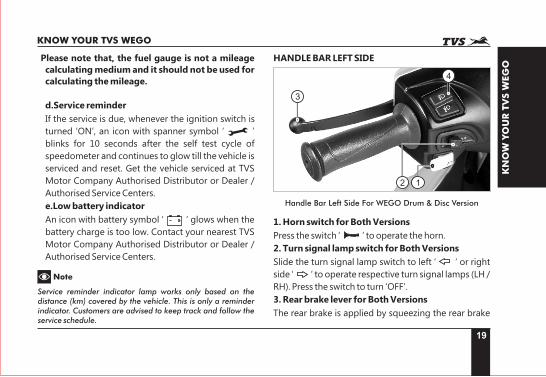
HANDLE BAR LEFT SIDE
3
4
12
Handle Bar Left Side For WEGO Drum & Disc Version
1. Horn switch for Both Versions
Press the switch ‘ ’ to operate the horn.
2. Turn signal lamp switch for Both Versions
Slide the turn signal lamp switch to left ‘ ’ or right
side ‘ ’ to operate respective turn signal lamps (LH /
RH). Press the switch to turn ‘OFF’.
3. Rear brake lever for Both Versions
The rear brake is applied by squeezing the rear brake
20
KN
OW
YO
UR
TV
SW
EG
O
KNOW YOUR TVS WEGO
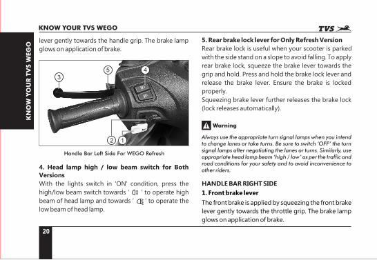
lever gently towards the handle grip. The brake lamp
glows on application of brake.
12
35 4
Handle Bar Left Side For WEGO Refresh
4. Head lamp high / low beam switch for Both Versions
With the lights switch in ‘ON’ condition, press the
high/low beam switch towards ‘ ’ to operate high
beam of head lamp and towards ‘ ’ to operate the
low beam of head lamp.
5. Rear brake lock lever for Only Refresh Version
Rear brake lock is useful when your scooter is parked
with the side stand on a slope to avoid falling. To apply
rear brake lock, squeeze the brake lever towards the
grip and hold. Press and hold the brake lock lever and
release the brake lever. Ensure the brake is locked
properly.
Squeezing brake lever further releases the brake lock
(lock releases automatically).
Always use the appropriate turn signal lamps when you intend to change lanes or take turns. Be sure to switch ‘OFF’ the turn signal lamps after negotiating the lanes or turns. Similarly, use appropriate head lamp beam ‘high / low’ as per the traffic and road conditions for your safety and to avoid inconvenience to other riders.
Warning
HANDLE BAR RIGHT SIDE
1. Front brake lever
The front brake is applied by squeezing the front brake
lever gently towards the throttle grip. The brake lamp
glows on application of brake.
21
KN
OW
YO
UR
TV
SW
EG
O
KNOW YOUR TVS WEGO
1
24 3
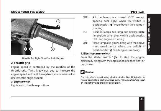
Handle Bar Right Side For Both Version
2. Throttle grip
Engine speed is controlled by the rotation of the
throttle grip. Twist it towards you to increase the
engine speed and twist it away from you or release it to
decrease the engine speed.
3. Lights switch
Lights switch has three positions.
OFF: All the lamps are turned ‘OFF’ (except
speedo back light) when the switch is
positioned at ‘ ’ even though the engine is
running.
PO: Position lamps, tail lamp and license plate
lamp glows when the switch is positioned at
‘ ‘ and engine is running.
ON: Head lamp also glows along with the above
mentioned lamps when the switch is
positioned at ‘ ‘ and engine is running.
4. Electric starter switch
Press the starter switch ‘ ’ to start the engine
electrically along with the application of either front or
rear brake.
For cold starts, avoid using electric starter. Use kickstarter. A typical example is early morning start. This would reduce load on the battery and prevents quick drain.
Caution
22
KN
OW
YO
UR
TV
SW
EG
O
KNOW YOUR TVS WEGO
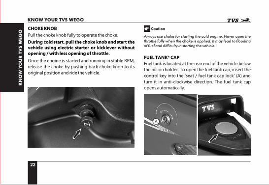
CHOKE KNOB
Pull the choke knob fully to operate the choke.
During cold start, pull the choke knob and start the vehicle using electric starter or kicklever without opening / with less opening of throttle.
Once the engine is started and running in stable RPM,
release the choke by pushing back choke knob to its
original position and ride the vehicle.
Always use choke for starting the cold engine. Never open the throttle fully when the choke is applied. It may lead to flooding of fuel and difficulty in starting the vehicle.
Caution
FUEL TANK CAP*
Fuel tank is located at the rear end of the vehicle below
the pillion holder. To open the fuel tank cap, insert the
control key into the ‘seat / fuel tank cap lock’ (A) and
turn it in anti-clockwise direction. The fuel tank cap
opens automatically.
A
23
KN
OW
YO
UR
TV
SW
EG
O
KNOW YOUR TVS WEGO
To close the cap, gently press the cap in its position
and ensure locking by hearing ‘click’ sound.
Never refill fuel near open flame. Do not smoke while refueling. Do not use cell phones while refueling.
Warning
* The fuel tank is not a measuring instrument and the capacity of the fuel tank may slightly vary from the indicated capacity.
Ensure that the fuel gun is inserted fully in the tank neck while refueling.
Whenever refueling, fill upto the bottom of neck portion (insert level) of the fuel tank. Filling above the neck may result in improper breathing of fuel tank and seepage of fuel.
While refueling, avoid spillage of petrol on the tyre. If fuel spills on tyre, the tyre will loose its grip on the road. Ensure to close fuel tank cap without fail to avoid fuel spillage.
Caution
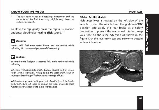
KICKSTARTER LEVER
Kickstarter lever is located on the left side of the
vehicle. To start the vehicle, keep the ignition in ‘ON’
position and apply the rear brake as a safety
precaution to prevent the rear wheel rotation. Keep
your foot on the lever extension as shown in the
figure. Kick the lever from top and stroke to bottom
with rapid motion.
24
KN
OW
YO
UR
TV
SW
EG
O
KNOW YOUR TVS WEGO
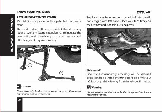
PATENTED E-Z CENTRE STAND
TVS WEGO is equipped with a patented E-Z centre
stand.
The centre stand (1) has a pivoted flexible spring
loaded lever arm (stand extension) (2) to increase the
lever ratio, which enables parking on centre stand
effortlessly and very conveniently.
1
2
Never sit on vehicle when it is supported by stand. Always park the vehicle on a flat, firm surface.
Caution
To place the vehicle on centre stand, hold the handle
bar left grip with left hand. Place your foot firmly on
the centre stand extension (2) and press.
Side stand*
Side stand (*mandatory accessory will be charged
extra) can be operated by sitting on vehicle with your
left foot by pushing it away from the vehicle till it stops.
Always release the side stand to its full up position before moving the vehicle.
Warning
25
KN
OW
YO
UR
TV
SW
EG
O
KNOW YOUR TVS WEGO
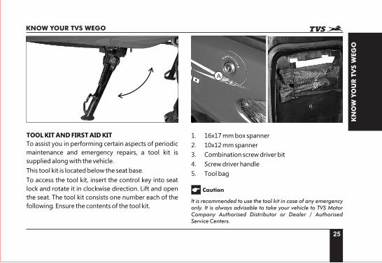
TOOL KIT AND FIRST AID KIT
To assist you in performing certain aspects of periodic
maintenance and emergency repairs, a tool kit is
supplied along with the vehicle.
This tool kit is located below the seat base.
To access the tool kit, insert the control key into seat
lock and rotate it in clockwise direction. Lift and open
the seat. The tool kit consists one number each of the
following. Ensure the contents of the tool kit.
A
1. 16x17 mm box spanner
2. 10x12 mm spanner
3. Combination screw driver bit
4. Screw driver handle
5. Tool bag
It is recommended to use the tool kit in case of any emergency only. It is always advisable to take your vehicle to TVS Motor Company Authorised Distributor or Dealer / Authorised Service Centers.
Caution
26
KN
OW
YO
UR
TV
SW
EG
O
KNOW YOUR TVS WEGO
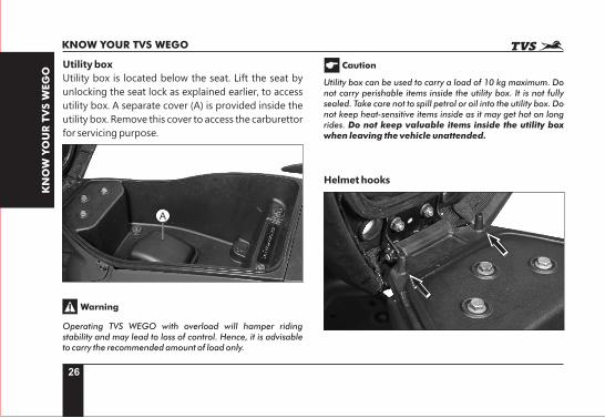
Utility box
Utility box is located below the seat. Lift the seat by
unlocking the seat lock as explained earlier, to access
utility box. A separate cover (A) is provided inside the
utility box. Remove this cover to access the carburettor
for servicing purpose.
A
Operating TVS WEGO with overload will hamper riding stability and may lead to loss of control. Hence, it is advisable to carry the recommended amount of load only.
Warning
Caution
Utility box can be used to carry a load of 10 kg maximum. Do not carry perishable items inside the utility box. It is not fully sealed. Take care not to spill petrol or oil into the utility box. Do not keep heat-sensitive items inside as it may get hot on long rides. Do not keep valuable items inside the utility box when leaving the vehicle unattended.
Helmet hooks
27
KN
OW
YO
UR
TV
SW
EG
O
KNOW YOUR TVS WEGO
Two helmet hooks are provided under the seat
assembly at front end near the seat hinge to secure
your helmet. Open the seat assembly (refer page no.
25) to access the helmet hooks. Hook the helmet strap
in the helmet hook properly and close the seat
assembly.
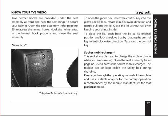
Glove box**
Lock
Unlock
** Applicable for select variant only
To open the glove box, insert the control key into the
glove box lid lock, rotate it in clockwise direction and
gently pull out the lid. Close the lid without fail after
keeping your things inside.
To close the lid, push back the lid to its original
position and lock the glove box by rotating the control
key in anti-clockwise direction. Take out the control
key.
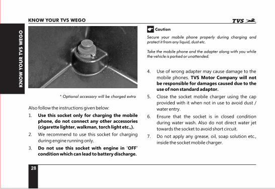
Socket mobile charger*
This socket enables you to charge the mobile phone
when you are traveling. Open the seat assembly (refer
page no. 25) to access the socket mobile charger. The
mobile can be kept inside the utility box during
charging.
Please go through the operating manual of the mobile
and use a suitable adaptor for the battery operation
recommended by the mobile manufacturer for that
particular model.
28
KN
OW
YO
UR
TV
SW
EG
O
KNOW YOUR TVS WEGO
* Optional accessory will be charged extra
Also follow the instructions given below:
1. Use this socket only for charging the mobile
phone, do not connect any other accessories (cigarette lighter, walkman, torch light etc.,).
2. We recommend to use this socket for charging
during engine running only.
3. Do not use this socket with engine in ‘OFF’
condition which can lead to battery discharge.
Secure your mobile phone properly during charging and protect it from any liquid, dust etc.
Take the mobile phone and the adapter along with you while the vehicle is parked or unattended.
Caution
4. Use of wrong adapter may cause damage to the
mobile phones. TVS Motor Company will not
be responsible for damages caused due to the use of non standard adaptor.
5. Close the socket mobile charger using the cap
provided with it when not in use to avoid dust /
water entry.
6. Ensure that the socket is in closed condition
during water wash. Also do not direct water jet
towards the socket to avoid short circuit.
7. Do not apply any grease, oil, soap solution etc.,
inside the socket mobile charger.
29
RID
ING
YO
UR
TV
S W
EG
O
RIDING YOUR TVS WEGO
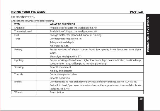
PRE RIDE INSPECTION
Check the following items before riding.
ITEM WHAT TO CHECK FOR
Engine oil Availability of oil upto the level (page no. 40)
Transmission oil Availability of oil upto the level (page no. 40)
Fuel Enough fuel for the planned distance of running
Tyres Correct pressure (page no. 46)
Adequate tread depth
No cracks or cuts.
Battery Proper working of electric starter, horn, fuel gauge, brake lamp and turn signal
lamps.
Electrolyte level (page no. 37)
Lighting Proper working of head lamp high / low beam, high beam indicator, position lamp,
speedometer lamp, tail lamp and number plate lamp.
Steering Smooth movement
No play or looseness
Throttle Correct free play of cable
Smooth operation
Brakes Correct front and rear brake lever play incase of drum brake (page no. 41,44 & 45)
Brake fluid level / pad wear in front and correct lever play in rear incase of disc brake
(page no. 43 & 44)
Wheels Free rotation
30
RID
ING
YO
UR
TV
S W
EG
ORIDING YOUR TVS WEGO
Starting the engine
Ensure availability of fuel in the fuel tank. Insert the
control key into the ignition cum steering lock and
turn it to the ‘ON’ position.
Apply any one of the brake and press the electric
starter switch to start electrically or kick start the
engine.
When the engine is cold
r Pull the choke knob fully and start the engine
with no opening / very less opening of throttle.
r Once the engine is started and running stable,
release the choke by pushing choke knob to its
original position and ride the vehicle (when the
engine is warm/ hot do not use choke).
Setting the vehicle in motion
1. Twist the throttle grip slowly towards you and
simultaneously release the brake lever gently and
smoothly. The vehicle starts moving forward.
2. As the vehicle picks up speed, increase the
throttle slowly.
Do not run the engine indoors where little or no ventilation available. Exhaust gas is extremely poisonous.
Do not raise the throttle rapidly so that the vehicle moves forward suddenly and lead to loss of control.
Warning
Caution
Do not keep the engine in idling rpm for long and do not open excessive throttle when engine is idling, it leads to overheating of the engine and damage to internal components, also waste of fuel.
Stopping and parking
1. Close the throttle completely and apply both the
brakes simultaneously.
2. Turn ‘OFF’ the ignition.
3. Park the vehicle on a firm, flat surface.
4. Lock the steering and take out the control key.
Reduce speed to a safe limit before turning / cornering. It is not advisable to apply brakes while turning / cornering.
Warning
31
RID
ING
YO
UR
TV
S W
EG
O
RIDING YOUR TVS WEGO
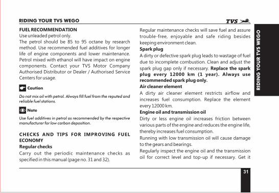
FUEL RECOMMENDATION
Use unleaded petrol only.
The petrol should be 85 to 95 octane by research
method. Use recommended fuel additives for longer
life of engine components and lower maintenance.
Petrol mixed with ethanol will have impact on engine
components. Contact your TVS Motor Company
Authorised Distributor or Dealer / Authorised Service
Centers for usage.
Do not mix oil with petrol. Always fill fuel from the reputed and reliable fuel stations.
Use fuel additives in petrol as recommended by the respective manufacturer for low carbon deposition.
Caution
Note
CHECKS AND TIPS FOR IMPROVING FUEL ECONOMY
Regular checks
Carry out the periodic maintenance checks as
specified in this manual (page no. 31 and 32).
Regular maintenance checks will save fuel and assure
trouble-free, enjoyable and safe riding besides
keeping environment clean.
Spark plug
A dirty or defective spark plug leads to wastage of fuel
due to incomplete combustion. Clean and adjust the
spark plug gap only if necessary. Replace the spark
plug every 12000 km (1 year). Always use recommended spark plug only.
Air cleaner element
A dirty air cleaner element restricts airflow and
increases fuel consumption. Replace the element
every 12000 km.
Engine oil and transmission oil
Dirty or less engine oil increases friction between
various parts of the engine and reduces the engine life,
thereby increases fuel consumption.
Running with low transmission oil will cause damage
to the gears and bearings.
Regularly inspect the engine oil and the transmission
oil for correct level and top-up if necessary. Get it
32
RID
ING
YO
UR
TV
S W
EG
ORIDING YOUR TVS WEGO
replaced at regular intervals as per the maintenance
schedule.
Fuel leak
Check and arrest fuel leaks if any from tank,
carburettor and fuel lines. Loss of fuel due to leak may
drain the fuel tank completely.
Evaporation
Vehicle parked in the hot sun leads to wastage of fuel
through evaporation. Also lower fuel levels in the tank
will have increased evaporation and condensation of
moisture inside.
Ensure to close the fuel tank cap after every filling. If
the fuel tank cap kept open for long time, it leads to
safety and fuel loss.
Tyres
Low tyre pressure has adverse effect on the vehicle.
The drag on the vehicle increases resulting decreased
fuel economy. Further more, handling may be
adversely affected.
Inspect the tyre pressure regularly (weekly) and inflate
it to the recommended pressure (refer page no. 43).
Never use tyres which are wornout beyond the
permissible limit.
Wheel freeness
Inspect and ensure the wheel freeness by rotating with
the wheels at least once a week to avoid wastage of
fuel.
Avoid unnecessary idling
While waiting for someone or stopping in signals for
long time, if the engine is kept running at idle speed, it
causes unnecessary wastage of fuel.
Avoid frequent braking
Anticipate corners and slopes as well as the traffic
conditions. Unnecessary and frequent braking will
reduce the fuel economy. Never accelerate and apply
brake simultaneously. It leads to clutch shoes wear
and wastage of fuel.
33
MA
INTEN
AN
CE
MAINTENANCE
MAINTENANCE SCHEDULE
The maintenance schedule indicates the intervals between periodic services. At the end of each interval, be sure to
inspect, check, replace, adjust, lubricate and service as instructed. If the maintenance is not done periodically, it
will result in rapid wear and severe damage to the vehicle. If the vehicle is used under high stress conditions such
as continuous full throttle operation or if used / operated in dusty climate, certain jobs should be performed more
often to ensure reliability of the vehicle. Cylinder head, steering components, suspension and wheel components
etc., are key items and they require very special and careful servicing. TVS Motor Company Limited strongly
recommends that the jobs as per the maintenance schedule be performed by your TVS Motor Company
Authorised Distributor or Dealer / Authorised Service Centers.
Periodic inspections may reveal one or more parts that may need replacement. It is recommended to use only the
TVS Motor Company Genuine parts for replacement.
Proper running-in and maintenance are mandatory to ensure that your vehicle is reliable and gives optimum performance throughout times. Be sure that the periodic maintenance is performed thoroughly in accordance with the instructions given in this owner’s manual.
Caution
34
MA
INTEN
AN
CE
MAINTENANCE
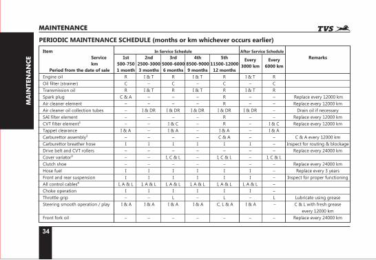
PERIODIC MAINTENANCE SCHEDULE (months or km whichever occurs earlier)
Item In Service Schedule After Service Schedule
Service 1st 2nd 3rd 4th 5th RemarksEvery Every km 500-750 2500-3000 5000-6000 8500-9000 11500-12000 3000 km 6000 km Period from the date of sale 1 month 3 months 6 months 9 months 12 months
Engine oil R I & T R I & T R I & T R
Oil filter (strainer) C – C – C – C
Transmission oil R I & T R I & T R I & T R
Spark plug C & A – – – R – – Replace every 12000 km
Air cleaner element – – – – R – – Replace every 12000 km
Air cleaner oil collection tubes – I & DR I & DR I & DR I & DR I & DR – Drain oil if necessary
SAI filter element – – – – R – – Replace every 12000 km
CVT filter element¹ – – I & C – R – I & C Replace every 12000 km
Tappet clearance I & A – I & A – I & A – I & A
Carburettor assembly² – – – – C & A – – C & A every 12000 km
Carburettor breather hose I I I I I I – Inspect for routing & blockage
Drive belt and CVT rollers – – – – – – – Replace every 24000 km
Cover variator³ – – I, C & L – I, C & L – I, C & L
Clutch shoe – – – – – – – Replace every 24000 km
Hose fuel I I I I I I – Replace every 3 years
Front and rear suspension I I I I I I – Inspect for proper functioning
All control cables⁴ I, A & L I, A & L I, A & L I, A & L I, A & L I, A & L –
Choke operation I I I I I I –
Throttle grip – – L – L – L Lubricate using grease
Steering smooth operation / play I & A I & A I & A I & A C, L & A I & A – C & L with fresh grease
every 12000 km
Front fork oil – – – – – – – Replace every 24000 km
35
MA
INTEN
AN
CE
MAINTENANCE
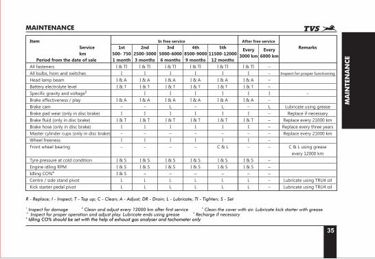
Item In free service After free service
Service 1st 2nd 3rd 4th 5th RemarksEvery Every
km 500- 750 2500-3000 5000-6000 8500-9000 11500-12000 3000 km 6000 kmPeriod from the date of sale 1 month 3 months 6 months 9 months 12 months
All fasteners I & TI I & TI I & TI I & TI I & TI I & TI –
All bulbs, horn and switches I I I I I I – Inspect for proper functioning
Head lamp beam I & A I & A I & A I & A I & A I & A –
Battery electrolyte level I & T I & T I & T I & T I & T I & T –
Specific gravity and voltage⁵ I I I I I I –
Brake effectiveness / play I & A I & A I & A I & A I & A I & A –
Brake cam – – L – L – L Lubricate using grease
Brake pad wear (only in disc brake) I I I I I I – Replace if necessary
Brake fluid (only in disc brake) I & T I & T I & T I & T I & T I & T – Replace every 21000 km
Brake hose (only in disc brake) I I I I I I – Replace every three years
Master cylinder cups (only in disc brake) – – – – – – – Replace every 21000 km
Wheel freeness I I I I I I –
Front wheel bearing – – – – C & L – – C & L using grease
every 12000 km
Tyre pressure at cold condition I & S I & S I & S I & S I & S I & S –
Engine idling RPM I & S I & S I & S I & S I & S I & S –
Idling CO%⁶ I & S – – – – – –
Centre / side stand pivot L L L L L L – Lubricate using TRU4 oil
Kick starter pedal pivot L L L L L L – Lubricate using TRU4 oil
R - Replace; I - Inspect; T - Top up; C - Clean; A - Adjust; DR - Drain; L - Lubricate; TI - Tighten; S - Set 1 2 3 Inspect for damage Clean and adjust every 12000 km after first service Clean the cover with air. Lubricate kick starter with grease
4 5 Inspect for proper operation and adjust play. Lubricate ends using grease Recharge if necessary6 Idling CO% should be set with the help of exhaust gas analyser and tachometer only
36
MA
INTEN
AN
CE
MAINTENANCE
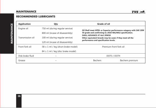
RECOMMENDED LUBRICANTS
Application Qty Grade of oil
Engine oil 750 ml (during regular service)
800 ml (incase of disassembly)
Transmission oil 100 ml (during regular service)
120 ml (incase of disassembly)
Front fork oil 58 ± 1 ml / leg (drum brake model) Premium front fork oil
84 ± 1 ml / leg (disc brake model)
Disk brake fluid – DOT3 / DOT4
Grease – Bechem Bechem premium
Oil Shall meet APISL or Superior performance category with SAE 20W 50 grade and confirming to JASO MA/MA2 specification.
SHELL ADVANCE 4T Ax5 20W50
Other equivalent brands may be used, if they meet all the performance and specification levels.

37
MA
INTEN
AN
CE
MAINTENANCE
SELF - MAINTENANCE PROCEDURES
BATTERY
Battery is located at the front end of utility box below
the seat and covered by the cover front. The cover
front must be removed to access the battery. Follow
the procedure for removal:
1. Take out the floor mat. Remove the bottom
mounting screws (A) of cover front.
2. Open the seat and remove the top mounting
screws (B) from both the sides of cover front.
A
A
B
3. Gently pull out the cover front by dislocating its
lugs.
4. Inspect the battery electrolyte level. It should be
between minimum and maximum level.
5. If the electrolyte level is below minimum level,
add only distilled water upto the maximum level
by removing the filler caps.
6. Reinstall the filler caps and clean the battery
thoroughly, apply petroleum jelly to the battery
terminals to protect from corrosion.
Incase of any abnormality or for removal of battery
from the vehicle, contact TVS Motor Company
Authorised Distributor or Dealer / Authorised Service
Centers.
Once the battery is charged initially, never add diluted sulphuric acid. Use only distilled water for topping up. Never add tap water. Never check the battery charge by shorting terminals. Always connect the positive terminals first and the negative to avoid sparking. Do not obstruct, bend or change the routing of the battery vent tube. Make sure that the vent tube is firmly attached to the battery and the other end is open and clear.
Caution
38
MA
INTEN
AN
CE
MAINTENANCE
Maximum
Minimum
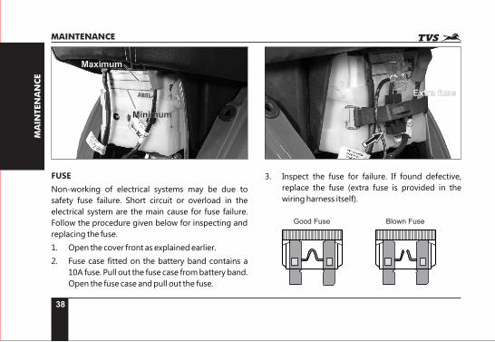
FUSE
Non-working of electrical systems may be due to
safety fuse failure. Short circuit or overload in the
electrical system are the main cause for fuse failure.
Follow the procedure given below for inspecting and
replacing the fuse.
1. Open the cover front as explained earlier.
2. Fuse case fitted on the battery band contains a
10A fuse. Pull out the fuse case from battery band.
Open the fuse case and pull out the fuse.
Extra fuse
3. Inspect the fuse for failure. If found defective,
replace the fuse (extra fuse is provided in the
wiring harness itself).
Good Fuse Blown Fuse
39
MA
INTEN
AN
CE
MAINTENANCE
4. Close the fuse case and re-fix it in the battery
band.
5. Turn ‘ON’ the ignition switch and check for proper
functioning of electrical systems. Incase the fuse
fails again, consult the nearest TVS Motor
Company Authorised Distributor or Dealer /
Authorised Service Centers.
Do not use vehicle by shorting the wires without a fuse. This may result in overheating of electrical / wiring and may result in fire. Do not use fuse of higher amperage than specified for the safety of electrical system.
Caution
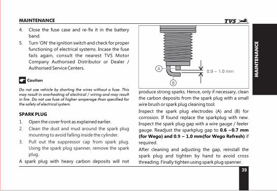
SPARK PLUG
1. Open the cover front as explained earlier.
2. Clean the dust and mud around the spark plug
mounting to avoid falling inside the cylinder.
3. Pull out the suppressor cap from spark plug.
Using the spark plug spanner, remove the spark
plug.
A spark plug with heavy carbon deposits will not
0.9 ~ 1.0 mmA
B
produce strong sparks. Hence, only if necessary, clean
the carbon deposits from the spark plug with a small
wire brush or spark plug cleaning tool.
Inspect the spark plug electrodes (A) and (B) for
corrosion. If found replace the sparkplug with new.
Inspect the spark plug gap with a wire gauge / feeler
gauge. Readjust the sparkplug gap to 0.6 ~0.7 mm
(for Wego) and 0 ~ 1.0 mm(for Wego Refresh) if .9
required.
After cleaning and adjusting the gap, reinstall the
spark plug and tighten by hand to avoid cross
threading. Finally tighten using spark plug spanner.
40
MA
INTEN
AN
CE
MAINTENANCE
Always use only recommended make and type of spark plug. Replace the spark plug every 12000 km. Cover the spark plug hole with cloth when the plug is removed to prevent dust / water entry. It is advisable to tighten the new spark plug by hand till the end and then tighten using plug spanner again loose and re-tight the spark plug by 1/8 of rotation.
Caution
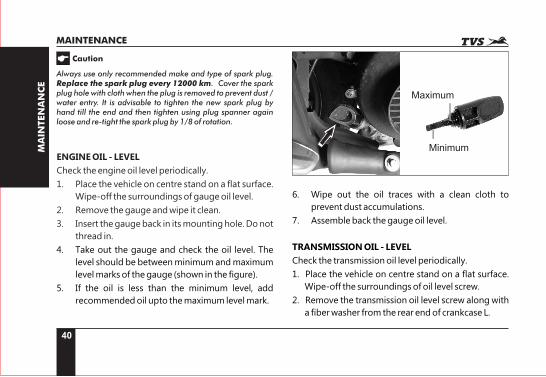
ENGINE OIL - LEVEL
Check the engine oil level periodically.
1. Place the vehicle on centre stand on a flat surface.
Wipe-off the surroundings of gauge oil level.
2. Remove the gauge and wipe it clean.
3. Insert the gauge back in its mounting hole. Do not
thread in.
4. Take out the gauge and check the oil level. The
level should be between minimum and maximum
level marks of the gauge (shown in the figure).
5. If the oil is less than the minimum level, add
recommended oil upto the maximum level mark.
Maximum
Minimum
6. Wipe out the oil traces with a clean cloth to
prevent dust accumulations.
7. Assemble back the gauge oil level.
TRANSMISSION OIL - LEVEL
Check the transmission oil level periodically.
1. Place the vehicle on centre stand on a flat surface.
Wipe-off the surroundings of oil level screw.
2. Remove the transmission oil level screw along with
a fiber washer from the rear end of crankcase L.
41
MA
INTEN
AN
CE
MAINTENANCE
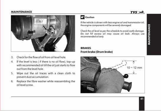
3. Check for the flow of oil from oil level hole.
4. If the level is less ( if there is no oil flow), top-up
with recommended oil till the oil just starts to flow
out from the level hole.
5. Wipe out the oil traces with a clean cloth to
prevent dust accumulation.
6. Replace the fibre washer while reassembling the
oil level screw.
If the vehicle is driven with less engine oil and transmission oil, the engine components will be severely damaged.
Check the oil level as per the schedule to avoid costly damage. Do not fill excess oil may cause oil leak. Always use recommended oil only.
Caution
BRAKES
Front brake (Drum brake)
10 ~ 12 mm
42
MA
INTEN
AN
CE
MAINTENANCE
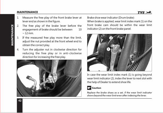
1. Measure the free play of the front brake lever at
lever end as shown in the figure.
2. The free play of the brake lever before the
engagement of brake should be between 10
~ 12 mm.
3. If the measured free play more than the limit,
adjust the nut provided at the front wheel end to
obtain the correct play.
4. Turn the adjuster nut in clockwise direction for
reducing the free play or in anti-clockwise
direction for increasing the free play.
Brake shoe wear indicator (Drum brake)
When brake is applied, wear limit index mark (1) on the
front brake cam should be within the wear limit
indicator (2) on the front brake panel.
1
2
In case the wear limit index mark (1) is going beyond
wear limit indicator (2), index the lever to next slot with
the help of Dealer to extend shoe life.
Caution
Replace the brake shoes as a set, if the wear limit indicator shows beyond the wear limit even after indexing the lever.
43
MA
INTEN
AN
CE
MAINTENANCE
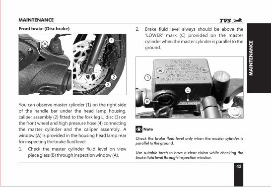
Front brake (Disc brake)
A
2
3
4
You can observe master cylinder (1) on the right side
of the handle bar under the head lamp housing,
caliper assembly (2) fitted to the fork leg L, disc (3) on
the front wheel and high pressure hose (4) connecting
the master cylinder and the caliper assembly. A
window (A) is provided in the housing head lamp rear
for inspecting the brake fluid level.
1. Check the master cylinder fluid level on view
piece glass (B) through inspection window (A).
2. Brake fluid level always should be above the
‘LOWER’ mark (C) provided on the master
cylinder when the master cylinder is parallel to the
ground.
1
B
C
Note
Check the brake fluid level only when the master cylinder is parallel to the ground.
Use suitable torch to have a clear vision while checking the brake fluid level through inspection window.
44
MA
INTEN
AN
CE
MAINTENANCE
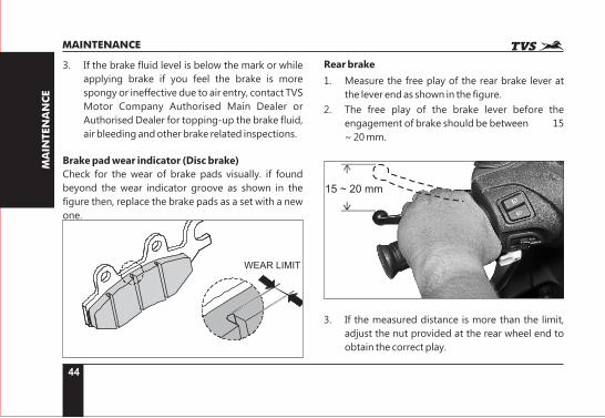
3. If the brake fluid level is below the mark or while
applying brake if you feel the brake is more
spongy or ineffective due to air entry, contact TVS
Motor Company Authorised Main Dealer or
Authorised Dealer for topping-up the brake fluid,
air bleeding and other brake related inspections.
Brake pad wear indicator (Disc brake)
Check for the wear of brake pads visually. if found
beyond the wear indicator groove as shown in the
figure then, replace the brake pads as a set with a new
one.
Rear brake
1. Measure the free play of the rear brake lever at
the lever end as shown in the figure.
2. The free play of the brake lever before the
engagement of brake should be between 15
~ 20 mm.
15 ~ 20 mm
3. If the measured distance is more than the limit,
adjust the nut provided at the rear wheel end to
obtain the correct play.
45
MA
INTEN
AN
CE
MAINTENANCE
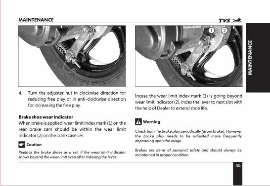
4. Turn the adjuster nut in clockwise direction for
reducing free play or in anti-clockwise direction
for increasing the free play.
Brake shoe wear indicator
When brake is applied, wear limit index mark (1) on the
rear brake cam should be within the wear limit
indicator (2) on the crankcase LH.
Replace the brake shoes as a set, if the wear limit indicator shows beyond the wear limit even after indexing the lever.
Caution
21
Incase the wear limit index mark (1) is going beyond
wear limit indicator (2), index the lever to next slot with
the help of Dealer to extend shoe life.
Check both the brake play periodically (drum brake). However the brake play needs to be adjusted more frequently depending upon the usage.
Brakes are items of personal safety and should always be maintained in proper condition.
Warning
46
MA
INTEN
AN
CE
MAINTENANCE
TYRES
Tyre pressure:
Check the tyre pressure atleast once in a week if not
more frequently. Insufficient air pressure in the tyres
not only hasten tyre wear, but also seriously affects the
stability of the vehicle.
Under inflated tyres make smooth cornering difficult
and over inflated tyres decreases the tyre contact with
the ground which can lead to skidding and loss of
control. Be sure that the tyre pressure is within the
specified limit at all times.
Tyre pressure in cold condition:
Solo Dual
Front 1.69 kg/cm² (24 PSI) 1.69 kg/cm² (24 PSI)
Rear 2.00 kg/cm² (28 PSI) 2.25 kg/cm² (32 PSI)
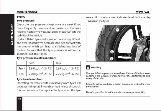
Tyre tread condition
Operating the vehicle with excessively worn tyres will
decrease riding stability and can lead to loss of control.
It is recommended to replace the tyre when the tyre
wears off to the tyre wear indicator level (indicated by
TWI (A) on the tyre).
TW
I
RE
AR
FR
ON
T
A
C
B
Warning
The tyre inflation pressure in cold condition and the tyre tread condition are extremely important for the performance and safety of the rider.
Check tyres frequently for inflation pressure as well as the wear pattern on it.
Use of a tyre other than the standard may cause instability.
47
MA
INTEN
AN
CE
MAINTENANCE
Tyre rotation direction
While reassembling the tyres, after removing from the
wheel rim, ensure that the arrow mark ‘FRONT’ facing
the direction of wheel rotation while fixing the tyre on
the front wheel rim. Similarly, arrow mark ‘REAR’ on
the tyre facing the direction of wheel rotation while
fixing the tyre on the rear wheel rim.
Tyre puncture
Your scooter is fitted with a tubeless tyre on both front
and rear wheel. Incase of any puncture / tyre damage,
it is advised to visit the nearest tyre manufacturer
Dealer or the tyre repair shops who knows the
repairing method of tubeless tyre. It is not necessary
to remove the tyre from wheel rim always to attend a
puncture.
Caution
Side walls of the tubeless tyre which in contact with the wheel rim are only seals the air inside the wheel assembly. Hence care should be taken not to damage the side walls of the tyres during removal / reassembly.
If there is a need for tyre removal, it is strongly
recommended to use a tyre removal / fitment
machine. If at all tyre levers needs to be used, the
levers should be free from sharp edges. Care should
be taken not to damage the tyres and rims.
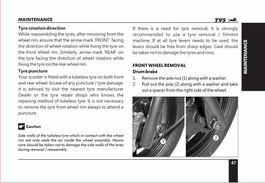
FRONT WHEEL REMOVAL
Drum brake
1. Remove the axle nut (1) along with a washer.
2. Pull out the axle (2) along with a washer and take
out a spacer from the right side of the wheel.
12
48
MA
INTEN
AN
CE
MAINTENANCE
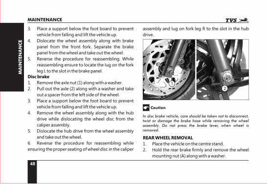
3. Place a support below the foot board to prevent
vehicle from falling and lift the vehicle up.
4. Dislocate the wheel assembly along with brake
panel from the front fork. Separate the brake
panel from the wheel and take out the wheel.
5. Reverse the procedure for reassembling. While
reassembling ensure to locate the lug on the fork
leg L to the slot in the brake panel.
Disc brake
1. Remove the axle nut (1) along with a washer.
2. Pull out the axle (2) along with a washer and take
out a spacer from the left side of the wheel.
3. Place a support below the foot board to prevent
vehicle from falling and lift the vehicle up.
4. Remove the wheel assembly along with the hub
drive while dislocating the wheel disc from the
caliper assembly.
5. Dislocate the hub drive from the wheel assembly
and take out the wheel.
6. Reverse the procedure for reassembling while
ensuring the proper seating of wheel disc in the caliper
12
assembly and lug on fork leg R to the slot in the hub
drive.
In disc brake vehicle, care should be taken not to disconnect, twist or damage the brake hose while removing the wheel assembly. Do not press the brake lever, when wheel is removed.
Caution
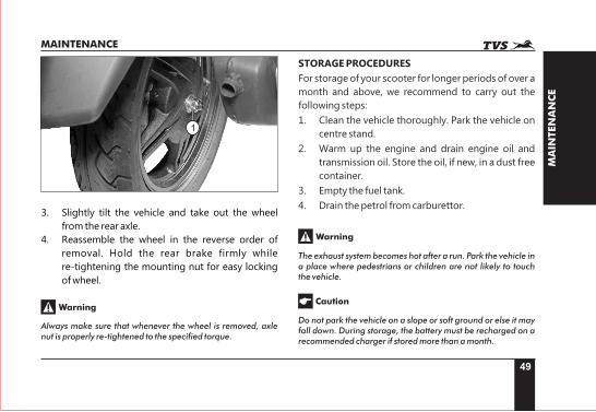
REAR WHEEL REMOVAL
1. Place the vehicle on the centre stand.
2. Hold the rear brake firmly and remove the wheel
mounting nut (A) along with a washer.
49
MA
INTEN
AN
CE
MAINTENANCE
3. Slightly tilt the vehicle and take out the wheel
from the rear axle.
4. Reassemble the wheel in the reverse order of
removal. Hold the rear brake firmly while
re-tightening the mounting nut for easy locking
of wheel.
1
Always make sure that whenever the wheel is removed, axle nut is properly re-tightened to the specified torque.
Warning
STORAGE PROCEDURES
For storage of your scooter for longer periods of over a
month and above, we recommend to carry out the
following steps:
1. Clean the vehicle thoroughly. Park the vehicle on
centre stand.
2. Warm up the engine and drain engine oil and
transmission oil. Store the oil, if new, in a dust free
container.
3. Empty the fuel tank.
4. Drain the petrol from carburettor.
Warning
Caution
The exhaust system becomes hot after a run. Park the vehicle in a place where pedestrians or children are not likely to touch the vehicle.
Do not park the vehicle on a slope or soft ground or else it may fall down. During storage, the battery must be recharged on a recommended charger if stored more than a month.
50
MA
INTEN
AN
CE
MAINTENANCE
5. Remove the spark plug and feed in several drops
of engine oil through spark plug hole. Crank the
engine few times and reinstall the spark plug.
6. Remove the battery, store it away from direct
sunlight and freezing temperatures.
7. Place a suitable support at the bottom of the foot
board so that both the tyres are off the ground.
This will ensure better tyre life.
8. Cover up the vehicle completely with a clean
tarpaulin or any other suitable cover. Store the
vehicle inside a garage or similar area to avoid
damage due to dust and rain. Make sure that the
storage area is well ventilated and free from any
source of flame of spark.
TAKING THE VEHICLE OUT OF STORAGE FOR REGULAR USE
1. Take the vehicle out of the garage and clean it
thoroughly.
2. Remount the battery after bench charging if
required.
3. Fill the engine oil (recommended oil) and check
the oil level using gauge oil level.
4. Fill the transmission oil (recommended oil) and
check the oil level at the oil level inspection screw.
5. Lubricate the parts as instructed in the periodic
maintenance schedule.
6. Fill up fresh petrol in the fuel tank.
7. Check and inflate the tyres to the specified tyre
pressure.
8. Check and correct the points mentioned in page
no. 29.
9. Turn the ignition switch to ‘ON’ position. Start the
engine with choke ‘ON’ for a few minutes and ride
on.
Avoid using alkaline solution like detergent soaps for washing. This may damage head lamp and other lamp assemblies.
Caution
51
MA
INTEN
AN
CE
MAINTENANCE
RECOMMENDED TIPS WHEN TAKING A LONG TRIP:
A) Please keep the following items for use in case of
emergency:
1. Tool kit complete.
2. Recommended spark plug one number.
3. Head lamp and turn signal lamp bulb each
one.
4. Throttle, front and rear brake each one.
5. First aid kit.
B) Precautions to be taken for the journey:
1. Ensure engine oil, transmission oil and brake
fluid* are up to the level.
2. Adequate fuel in fuel tank.
C) Check your scooter for the following:
1. Tightness of all bolts and nuts with correct
torque value.
2. Fitness of tyres and tubes / tyre pressure /
tread depth.
3. All bulbs, indicator lamps and horn
functioning.
4. Smooth functioning of all cables and their
free play.
5. Smoothness of steering operation.
6. Front / rear brake function and rear brake
lamp working.
7. Front fork for any abnormality.
8. Spark plug gap and condition of spark plug.
9. Air filter element cleanliness.
10. Correct idling speed.
11. Lubrication of all items mentioned in the
periodic maintenance schedule.
12. Any other job as necessary.
13. Have your vehicle checked at any TVS Motor
Company Authorised Distributor or Dealer /
Authorised Service Centers.
Long journey are to be taken only after the running-in period of 1000 km.
Warning
*Applicable only for Disc brake model
52
SER
VIC
E R
EC
OR
D S
HEET
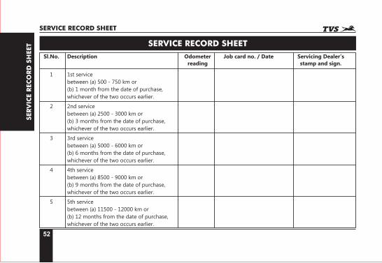
SERVICE RECORD SHEET
Sl.No. Description Odometer Job card no. / Date Servicing Dealer’s reading stamp and sign.
1 1st service
between (a) 500 - 750 km or
(b) 1 month from the date of purchase,
whichever of the two occurs earlier.
2 2nd service
between (a) 2500 - 3000 km or
(b) 3 months from the date of purchase,
whichever of the two occurs earlier.
3 3rd service
between (a) 5000 - 6000 km or
(b) 6 months from the date of purchase,
whichever of the two occurs earlier.
4 4th service
between (a) 8500 - 9000 km or
(b) 9 months from the date of purchase,
whichever of the two occurs earlier.
5 5th service
between (a) 11500 - 12000 km or
(b) 12 months from the date of purchase,
whichever of the two occurs earlier.
SERVICE RECORD SHEET
53
SER
VIC
E R
EC
OR
D S
HEET
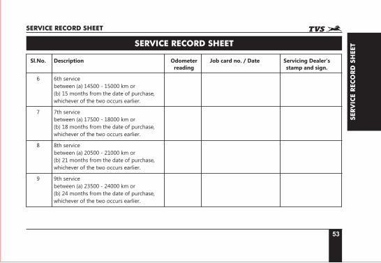
SERVICE RECORD SHEET
Sl.No. Description Odometer Job card no. / Date Servicing Dealer’s reading stamp and sign.
6 6th service
between (a) 14500 - 15000 km or
(b) 15 months from the date of purchase,
whichever of the two occurs earlier.
7 7th service
between (a) 17500 - 18000 km or
(b) 18 months from the date of purchase,
whichever of the two occurs earlier.
8 8th service
between (a) 20500 - 21000 km or
(b) 21 months from the date of purchase,
whichever of the two occurs earlier.
9 9th service
between (a) 23500 - 24000 km or
(b) 24 months from the date of purchase,
whichever of the two occurs earlier.
SERVICE RECORD SHEET
54
TEC
HN
ICA
L S
PEC
IFIC
ATIO
NS
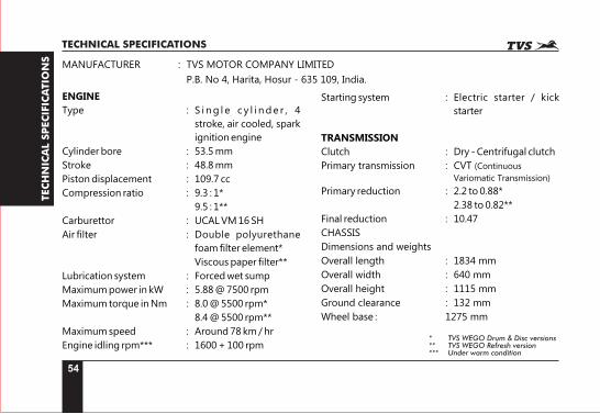
TECHNICAL SPECIFICATIONS
MANUFACTURER : TVS MOTOR COMPANY LIMITED
P.B. No 4, Harita, Hosur - 635 109, India.
ENGINE
Type : S i n g l e c y l i n d e r , 4
stroke, air cooled, spark
ignition engine
Cylinder bore : 53.5 mm
Stroke : 48.8 mm
Piston displacement : 109.7 cc
Compression ratio : 9.3 : 1*
9.5 : 1**
Carburettor : UCAL VM 16 SH
Air filter : Double polyurethane
foam filter element*
Viscous paper filter**
Lubrication system : Forced wet sump
Maximum power in kW : 5.88 @ 7500 rpm
Maximum torque in Nm : 8.0 @ 5500 rpm*
8.4 @ 5500 rpm**
Maximum speed : Around 78 km / hr
Engine idling rpm*** : 1600 + 100 rpm
Starting system : Electric starter / kick
starter
TRANSMISSION
Clutch : Dry - Centrifugal clutch
Primary transmission : CVT (Continuous
Variomatic Transmission)
Primary reduction : 2.2 to 0.88*
2.38 to 0.82**
Final reduction : 10.47
CHASSIS
Dimensions and weights
Overall length : 1834 mm
Overall width : 640 mm
Overall height : 1115 mm
Ground clearance : 132 mm
Wheel base : 1275 mm
* TVS WEGO Drum & Disc versions** TVS WEGO Refresh version*** Under warm condition
55
TEC
HN
ICA
L S
PEC
IFIC
ATIO
NS
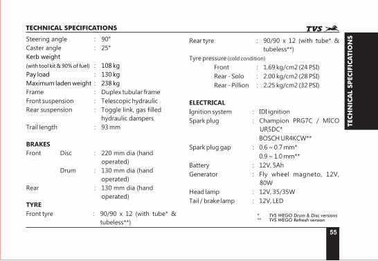
TECHNICAL SPECIFICATIONS
Steering angle : 90°
Caster angle : 25°
Kerb weight
(with tool kit & 90% of fuel) : 108 kg
Pay load : 130 kg
Maximum laden weight : 238 kg
Frame : Duplex tubular frame
Front suspension : Telescopic hydraulic
Rear suspension : Toggle link, gas filled
hydraulic dampers
Trail length : 93 mm
BRAKES
Front Disc : 220 mm dia (hand
operated)
Drum : 130 mm dia (hand
operated)
Rear : 130 mm dia (hand
operated)
TYRE
Front tyre : 90/90 x 12 (with tube* &
tubeless**)
Rear tyre : 90/90 x 12 (with tube* &
tubeless**)
Tyre pressure (cold condition)
Front : 1.69 kg/cm2 (24 PSI)
Rear - Solo : 2.00 kg/cm2 (28 PSI)
Rear - Pillion : 2.25 kg/cm2 (32 PSI)
ELECTRICAL
Ignition system : IDI ignition
Spark plug : Champion PRG7C / MICO
UR5DC*
BOSCH UR4KCW**
Spark plug gap : 0.6 ~ 0.7 mm*
0.9 ~ 1.0 mm**
Battery : 12V, 5Ah
Generator : Fly wheel magneto, 12V,
80W
Head lamp : 12V, 35/35W
Tail / brake lamp : 12V, LED
* TVS WEGO Drum & Disc versions** TVS WEGO Refresh version
56
TEC
HN
ICA
L S
PEC
IFIC
ATIO
NS
TECHNICAL SPECIFICATIONS
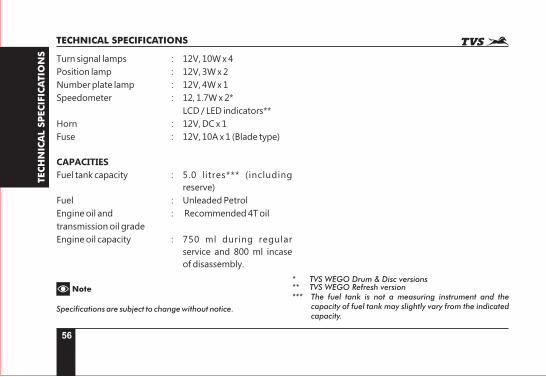
Turn signal lamps : 12V, 10W x 4
Position lamp : 12V, 3W x 2
Number plate lamp : 12V, 4W x 1
Speedometer : 12, 1.7W x 2*
LCD / LED indicators**
Horn : 12V, DC x 1
Fuse : 12V, 10A x 1 (Blade type)
CAPACITIES
Fuel tank capacity : 5.0 litres*** (including
reserve)
Fuel : Unleaded Petrol
Engine oil and : Recommended 4T oil
transmission oil grade
Engine oil capacity : 750 ml during regular
service and 800 ml incase
of disassembly.
Specifications are subject to change without notice.
Note* TVS WEGO Drum & Disc versions** TVS WEGO Refresh version*** The fuel tank is not a measuring instrument and the
capacity of fuel tank may slightly vary from the indicated capacity.