Owner's Manual - Generac Mobile Products
68
SAVE THIS MANUAL FOR FUTURE REFERENCE For technical assistance contact: www.generacmobileproducts.com Technical Support 1-800-926-9768 Owner’s Manual Diesel Generator MDG150DF4 • MDG175DF4 • MDG250DF4 SN ____________ and higher 003574
-
Upload
khangminh22 -
Category
Documents
-
view
2 -
download
0
Transcript of Owner's Manual - Generac Mobile Products

SAVE THIS MANUAL FOR FUTURE REFERENCE
For technical assistance contact:
www.generacmobileproducts.comTechnical Support1-800-926-9768
Owner’s ManualDiesel Generator
MDG150DF4 • MDG175DF4 • MDG250DF4
SN ____________ and higher
003574
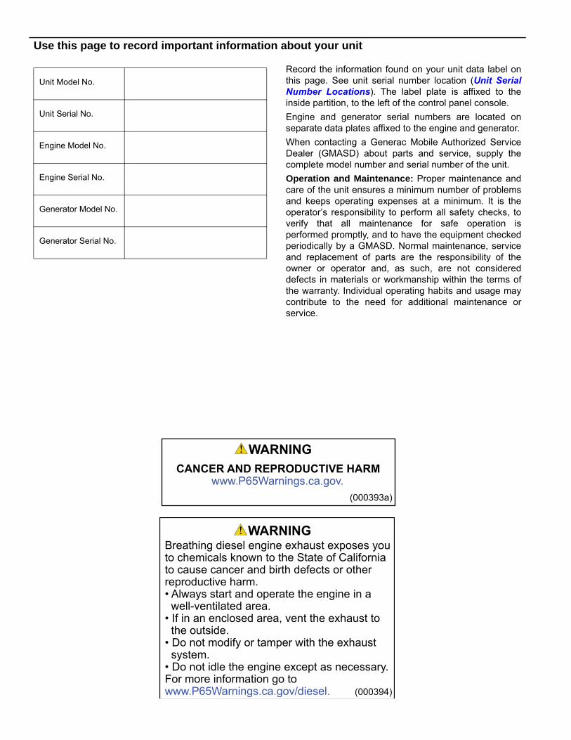
Use this page to record important information about your unit
Record the information found on your unit data label onthis page. See unit serial number location (Unit SerialNumber Locations). The label plate is affixed to theinside partition, to the left of the control panel console.
Engine and generator serial numbers are located onseparate data plates affixed to the engine and generator.
When contacting a Generac Mobile Authorized ServiceDealer (GMASD) about parts and service, supply thecomplete model number and serial number of the unit.
Operation and Maintenance: Proper maintenance andcare of the unit ensures a minimum number of problemsand keeps operating expenses at a minimum. It is theoperator’s responsibility to perform all safety checks, toverify that all maintenance for safe operation isperformed promptly, and to have the equipment checkedperiodically by a GMASD. Normal maintenance, serviceand replacement of parts are the responsibility of theowner or operator and, as such, are not considereddefects in materials or workmanship within the terms ofthe warranty. Individual operating habits and usage maycontribute to the need for additional maintenance orservice.
Unit Model No.
Unit Serial No.
Engine Model No.
Engine Serial No.
Generator Model No.
Generator Serial No.
(000394)
WARNINGBreathing diesel engine exhaust exposes you to chemicals known to the State of Californiato cause cancer and birth defects or other reproductive harm.• Always start and operate the engine in a well-ventilated area.• If in an enclosed area, vent the exhaust to the outside.• Do not modify or tamper with the exhaust system.• Do not idle the engine except as necessary.For more information go to www.P65Warnings.ca.gov/diesel.
(000393a)
WARNING
CANCER AND REPRODUCTIVE HARMwww.P65Warnings.ca.gov.
Table of Contents
Section 1: Introduction and Safety
Introduction ..................................................................1Read This Manual Thoroughly ....................................1
How to Obtain Service .................................................1
Safety Rules .................................................................1
Safety Symbols and Meanings ...................................1
General Hazards ...........................................................2
Trailer Hazards .............................................................2
Electrical Hazards ........................................................3
Explosion and Fire Hazards ........................................3
Battery Hazards ............................................................4
Fuel Hazards .................................................................4
Engine Safety ...............................................................4
Operating Safety ..........................................................5Positioning the Unit .....................................................5
Starting the Unit ...........................................................5
Towing Safety ...............................................................5Hitch and Coupling ......................................................5
Safe Towing Techniques .............................................5
Reporting Trailer Safety Defects ................................5
Safety and Operating Decals ......................................6
Section 2: General Information
Specifications .............................................................11
Unit Dimensions .........................................................14
Unit ID and VIN Tag Locations ..................................15
Altitude and Temperature Limitations .....................15Component Locations ...............................................16
Exterior ......................................................................16
Interior .......................................................................17
Connection Panel ......................................................18
Control Panel ..............................................................19
Genset Controller .......................................................20Controller Modes .......................................................22
Operator Pages .........................................................22
Maintenance Alarms ..................................................24
Diesel Exhaust Fluid (DEF) .......................................25DEF Specification ......................................................25
DEF Warning .............................................................25
DEF Storage Guidelines ............................................25
Refilling DEF Tank ....................................................26
Selective Catalytic Reduction (SCR) Monitoring ....26
Voltage Selector Switch ............................................27Lockout Function .......................................................27
Section 3: Operation
Pre-start Checklist .....................................................29
Manually Starting the Unit .........................................29
AUTO (Remote) Starting the Unit .............................30
Parallel Setup and Operation (If Equipped) .............31Manual Parallel ..........................................................31
Automatic Parallel .....................................................31
Shutting Down the Units in MANUAL Mode ..............31
Low Idle Switch ..........................................................31
Wet Stacking ..............................................................31
Cold Weather Operation ............................................31
Using a Booster Battery or Charger (If Equipped) ..32
Generator Output Connections ................................33
Generator Cam Lock Connections (If Equipped) ....34
Using Voltage Selector Switch .................................34
Fine Voltage Adjustment ...........................................35
Voltage Regulator ......................................................35
Customer Convenience Receptacles .......................35
Main Circuit Breaker ..................................................36
DOC and SCR Cleaning Operations .........................36Disabling Automatic (AUTO) Exhaust After-Treatment Cleaning ....................................................................36
Force a Manual Exhaust After-Treatment Cleaning ..36
Enable Exhaust After-Treatment Cleaning ................37
Transfer Switch ..........................................................37
Changing Exercise Timers ........................................38
Shutting Down the Unit .............................................38
Emergency Stop Switch ............................................38
Using the ECU Override Switch ................................38
Towing the Unit ..........................................................39
Lifting the Unit ............................................................39
Section 4: Maintenance
Emissions Information ..............................................43
Maintenance ...............................................................43
Daily Walk Around Inspection ..................................43
Belt Tensioners ..........................................................43
General Maintenance .................................................43
Engine Oil Recommendations ..................................44Recommended Oil Types ..........................................44
Coolant Recommendation ........................................44
Basic Maintenance Schedule ....................................44
Engine Break-In Requirements .................................46
Owner’s Manual for Mobile Generator iii
Resetting the Maintenance Alarms .......................... 46
Testing DEF ................................................................ 46
DEF Tank Cleaning .................................................... 47
Disposal of DEF ......................................................... 47
Checking Generator Drive Plate Torque ................. 47
Jack Maintenance ...................................................... 47Side-Wind Models ..................................................... 47
Top-Wind Models ...................................................... 47
Trailer Wheel Bearings .............................................. 47
Section 5: Troubleshooting
General Troubleshooting .......................................... 49
Section 6: Wiring Diagrams
Wiring Diagrams ........................................................ 51
iv Owner’s Manual for Mobile Generator
Section 1: Introduction and Safety
IntroductionThank you for purchasing a Generac Mobile product. Thisunit has been designed to provide high performance,efficient operation, and years of use when maintainedproperly.
The information in this manual is accurate based onproducts produced at the time of publication. The manu-facturer reserves the right to make technical updates,corrections, and product revisions at any time withoutnotice.
Read This Manual Thoroughly
If any section of this manual is not understood, contact yournearest GMASD, or contact Generac Mobile TechnicalService at 1-800-926-9768 orwww.generacmobileproducts.com with any questions orconcerns.
The owner is responsible for proper maintenance and safeuse of the equipment. Comply with regulations theOccupational Safety and Health Administration (OSHA)has established, or with equivalent standards. Also, verifythat the unit is applied, used, and maintained in accordancewith the manufacturer's instructions and recommendations.Do nothing that might alter safe application/usage andrender the unit in noncompliance with the aforementionedcodes, standards, laws, and regulations.
Save these instructions for future reference. This manualcontains important instructions for the unit that should befollowed during setup, operation and maintenance of theunit and battery. ALWAYS supply this manual to anyindividual that will use this machine.
How to Obtain Service
When the unit requires servicing or repairs, contact aGMASD for assistance. Service technicians are factory-trained and are capable of handling all service needs. Forassistance locating a dealer, go to https://www.gener-acmobileproducts.com/parts-service/find-service.
When contacting a GMASD about parts and service,always supply the complete model and serial number ofthe unit as given on the data decal located on the unit.Record the model and serial numbers in the spaces pro-vided on the front cover of this manual.
Safety RulesThe manufacturer cannot anticipate every possiblecircumstance that might involve a hazard. The warnings inthis manual, and on tags and decals affixed to the unit are,therefore, not all inclusive. If using a procedure, workmethod or operating technique that the manufacturer doesnot specifically recommend, verify it is safe for others. Alsomake sure the procedure, work method or operatingtechnique utilized does not render the equipment unsafe.
Safety Symbols and MeaningsThroughout this publication, and on tags and decals affixedto the unit, DANGER, WARNING, CAUTION and NOTEblocks are used to alert personnel to special instructionsabout a particular operation that may be hazardous ifperformed incorrectly or carelessly. Observe themcarefully. Their definitions are as follows:
NOTE: Notes contain additional information important toa procedure and will be found within the regular text ofthis manual.
These safety alerts cannot eliminate the hazards that theyindicate. Common sense and strict compliance with thespecial instructions while performing the action or serviceare essential to preventing accidents.
(000100a)
Consult Manual. Read and understand manualcompletely before using product. Failure to completely understand manual and product could result in death or serious injury.
WARNING
(000001)
DANGER
Indicates a hazardous situation which, if not avoided, will result in death or serious injury.
(000002)
WARNING
Indicates a hazardous situation which, if not avoided,could result in death or serious injury.
(000003)
CAUTION
Indicates a hazardous situation which, if not avoided,could result in minor or moderate injury.
Owner’s Manual for Mobile Generator 1
Introduction and Safety
General Hazards
Trailer Hazards
(000103)
Asphyxiation. Running engines produce carbon monoxide, a colorless, odorless, poisonous gas. Carbon monoxide, if not avoided, will result in death or serious injury.
DANGER
DANGER
Asphyxiation. Do not operate unit without a properly functioning exhaust system. Doing so will result in death or serious injury.
(000340)
(000209b)
WARNING
Loss of life. This product is not intended to be used in a critical life support application. Failure to adhere to this warning could result in death or serious injury.
(000107)
Hearing Loss. Hearing protection is recommended when using this machine. Failure to wear hearing protection could result in permanant hearing loss.
WARNING
(000181)
WARNING
Vision Loss. Eye protection is required to avoid spray from spark plug hole when cranking engine. Failure to do so could result in vision loss.
(000111)
WARNING
Moving Parts. Keep clothing, hair, and appendages away from moving parts. Failure to do so could result in death or serious injury.
(000108)
WARNING
Hot Surfaces. When operating machine, do not touch hot surfaces. Keep machine away from combustibles during use. Hot surfaces could result in severe burns or fire.
WARNING
Equipment damage. Do not attempt to start or operate a unit in need of repair or scheduled maintenance. Doing so could result in serious injury, death, or equipment failure or damage. (000291)
WARNING
Risk of injury. Do not operate or service this machine if not fully alert. Fatigue can impair the ability to service this equipment and could result in death or serious injury. (000215)
(000182a)
WARNING
Equipment damage. Only qualified service personnel may install, operate, and maintain this equipment. Failure to follow proper installation requirements could result in death, serious injury, and equipment or property damage.
CAUTION
(000229)
Equipment or property damage. Do not block air intake or restrict proper air flow. Doing so could result in unsafe operation or damage to unit.
WARNING
(000233a)
Personal injury. Trailer must be securely coupled to the hitch with the chains correctly attached. Uncoupled or unchained towing could result in death or serious injury.
(000231a)
Personal injury. Do not operate unit during transport. Doing so could result in death, serious injury, or property damage.
WARNING
(000234a)
Crushing hazard. Verify unit is properly secured and on level ground. An unsecured unit can suddenly roll or move, causing death or serious injury.
WARNING
WARNING
Property or Equipment Damage. Tighten wheel lug nuts after first 50 miles to factory specifications. Failure to do so could result in death, serious injury, property or equipment damage. (000235)
2 Owner’s Manual for Mobile Generator
Introduction and Safety
Electrical Hazards Lifting Hazards
Explosion and Fire Hazards
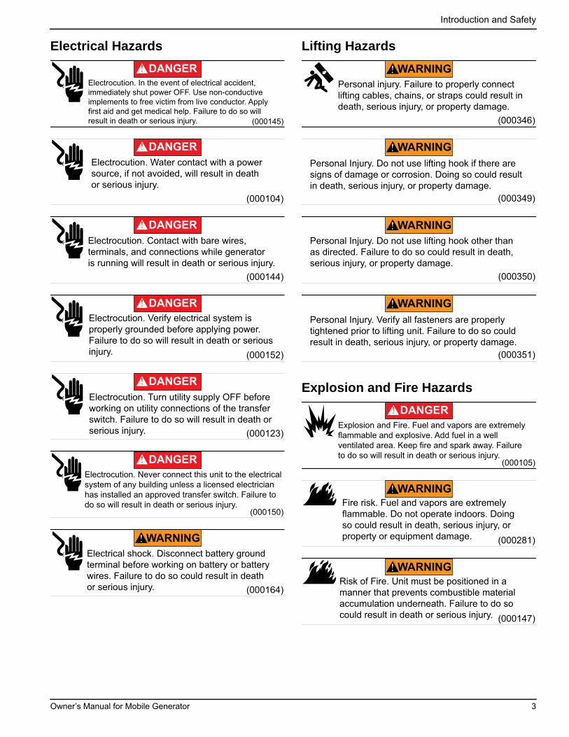
(000145)
DANGER
Electrocution. In the event of electrical accident, immediately shut power OFF. Use non-conductive implements to free victim from live conductor. Apply first aid and get medical help. Failure to do so will result in death or serious injury.
(000104)
DANGER
Electrocution. Water contact with a power source, if not avoided, will result in death or serious injury.
(000144)
DANGER
Electrocution. Contact with bare wires, terminals, and connections while generator is running will result in death or serious injury.
(000152)
DANGER
Electrocution. Verify electrical system isproperly grounded before applying power.Failure to do so will result in death or seriousinjury.
(000123)
DANGER
Electrocution. Turn utility supply OFF before working on utility connections of the transfer switch. Failure to do so will result in death or serious injury.
(000150)
Electrocution. Never connect this unit to the electrical system of any building unless a licensed electrician has installed an approved transfer switch. Failure to do so will result in death or serious injury.
DANGER
(000164)
WARNING
Electrical shock. Disconnect battery groundterminal before working on battery or batterywires. Failure to do so could result in death or serious injury.
Personal injury. Failure to properly connect lifting cables, chains, or straps could result in death, serious injury, or property damage.
(000346)
WARNING
WARNING
(000349)
Personal Injury. Do not use lifting hook if there are signs of damage or corrosion. Doing so could result in death, serious injury, or property damage.
(000350)
WARNING
Personal Injury. Do not use lifting hook other than as directed. Failure to do so could result in death, serious injury, or property damage.
(000351)
Personal Injury. Verify all fasteners are properly tightened prior to lifting unit. Failure to do so could result in death, serious injury, or property damage.
WARNING
(000105)
Explosion and Fire. Fuel and vapors are extremely flammable and explosive. Add fuel in a well ventilated area. Keep fire and spark away. Failure to do so will result in death or serious injury.
DANGER
WARNING
(000281)
Fire risk. Fuel and vapors are extremely flammable. Do not operate indoors. Doing so could result in death, serious injury, or property or equipment damage.
(000147)
WARNING
Risk of Fire. Unit must be positioned in amanner that prevents combustible materialaccumulation underneath. Failure to do socould result in death or serious injury.
Owner’s Manual for Mobile Generator 3
Introduction and Safety
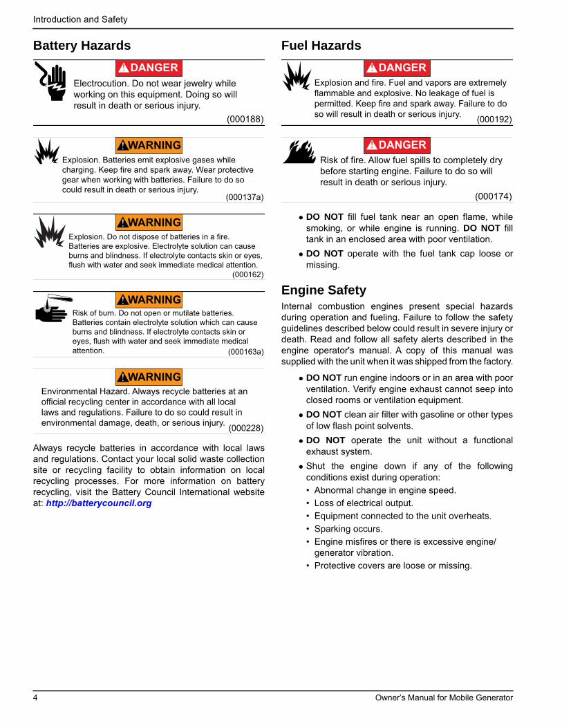
Battery Hazards
Always recycle batteries in accordance with local lawsand regulations. Contact your local solid waste collectionsite or recycling facility to obtain information on localrecycling processes. For more information on batteryrecycling, visit the Battery Council International websiteat: http://batterycouncil.org
Fuel Hazards
• DO NOT fill fuel tank near an open flame, whilesmoking, or while engine is running. DO NOT filltank in an enclosed area with poor ventilation.
• DO NOT operate with the fuel tank cap loose ormissing.
Engine SafetyInternal combustion engines present special hazardsduring operation and fueling. Failure to follow the safetyguidelines described below could result in severe injury ordeath. Read and follow all safety alerts described in theengine operator's manual. A copy of this manual wassupplied with the unit when it was shipped from the factory.
• DO NOT run engine indoors or in an area with poorventilation. Verify engine exhaust cannot seep intoclosed rooms or ventilation equipment.
• DO NOT clean air filter with gasoline or other typesof low flash point solvents.
• DO NOT operate the unit without a functionalexhaust system.
• Shut the engine down if any of the followingconditions exist during operation:
• Abnormal change in engine speed.
• Loss of electrical output.
• Equipment connected to the unit overheats.
• Sparking occurs.
• Engine misfires or there is excessive engine/generator vibration.
• Protective covers are loose or missing.
(000188)
DANGER
Electrocution. Do not wear jewelry while working on this equipment. Doing so will result in death or serious injury.
(000137a)
WARNING
Explosion. Batteries emit explosive gases while charging. Keep fire and spark away. Wear protective gear when working with batteries. Failure to do so could result in death or serious injury.
(000162)
Explosion. Do not dispose of batteries in a fire. Batteries are explosive. Electrolyte solution can cause burns and blindness. If electrolyte contacts skin or eyes, flush with water and seek immediate medical attention.
WARNING
(000163a)
Risk of burn. Do not open or mutilate batteries. Batteries contain electrolyte solution which can cause burns and blindness. If electrolyte contacts skin or eyes, flush with water and seek immediate medical attention.
WARNING
WARNING
(000228)
Environmental Hazard. Always recycle batteries at an official recycling center in accordance with all local laws and regulations. Failure to do so could result in environmental damage, death, or serious injury.
(000192)
DANGER
Explosion and fire. Fuel and vapors are extremelyflammable and explosive. No leakage of fuel ispermitted. Keep fire and spark away. Failure to doso will result in death or serious injury.
(000174)
DANGER
Risk of fire. Allow fuel spills to completely dry before starting engine. Failure to do so will result in death or serious injury.
4 Owner’s Manual for Mobile Generator
Introduction and Safety
Operating Safety
Positioning the Unit
• The area immediately surrounding the unit shouldbe dry, clean, and free of debris.
• If the unit is equipped with a frame grounding stud,follow any local, state, and National Electrical Code(NEC) guidelines when connecting.
Starting the Unit
• DO NOT start a unit in need of repair.
Towing SafetyTowing a trailer requires care. Both the trailer and vehiclemust be in good condition and securely fastened to eachother to reduce the possibility of an accident. Some statesrequire that large trailers be registered and licensed.Contact your local Department of Transportation office tocheck on license requirements for your particular unit.
Hitch and Coupling
• Verify the hitch and coupling on the towing vehicleare rated equal to, or greater than, the trailer'sGross Vehicle Weight Rating (GVWR).
• Verify the trailer hitch and the coupling arecompatible. Verify the coupling is securelyfastened to the vehicle.
• DO NOT tow trailer using defective parts. Inspectthe hitch and coupling for wear or damage.
• Connect safety chains in a crossing pattern underthe tongue.
• Before towing the trailer, verify the weight of thetrailer is equal across all tires. On trailers withadjustable height hitches, adjust the angle of thetrailer tongue to keep the trailer as level aspossible.
Safe Towing Techniques
• Practice turning, stopping and backing up in anarea away from heavy traffic prior to transportingthe unit.
• Maximum recommended speed for highway towingis 45 mph (72 km/h). Recommended off-roadtowing speed is 10 mph (16 km/h) or less,depending on terrain.
• When towing, maintain extra space betweenvehicles and avoid soft shoulders, curbs andsudden lane changes.
Reporting Trailer Safety DefectsIf you believe your trailer has a defect which could causea crash or could cause injury or death, you shouldimmediately inform the National Highway Traffic SafetyAdministration (NHTSA) in addition to notifying GeneracMobile.
If NHTSA receives similar complaints, it may open aninvestigation; and if it finds that a safety defect exists in agroup of vehicles, it may order a recall and remedycampaign. However, NHTSA cannot become involved inan individual problem between you, your GMASD, orGenerac Mobile.
To contact NHTSA, you may either call the Auto SafetyHotline toll-free at 1-888-327-4236 (TTY:1-800-424-9153),go to http://www.safercar.gov; or write to:
AdministratorNHTSA1200 New Jersey Avenue S.E.Washington, DC 20590
You can also obtain other information about motor vehiclesafety from http://www.safercar.gov.
(000234a)
Crushing hazard. Verify unit is properly secured and on level ground. An unsecured unit can suddenly roll or move, causing death or serious injury.
WARNING
DANGER
Electrocution. DO NOT use the unit ifelectrical cord is cut or worn through. Doingso will result in death or serious injury.
(000263a)
Owner’s Manual for Mobile Generator 5
Introduction and Safety
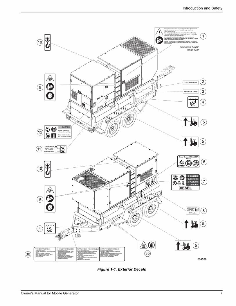
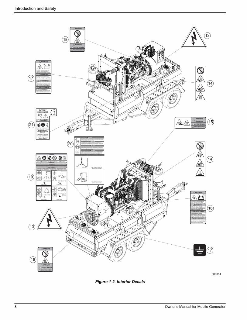
Safety and Operating DecalsThis unit features numerous safety and operating decals.These decals provide important operating instructions andwarn of dangers and hazards. The following diagramsillustrate decal locations and descriptions.
Replace any missing or hard-to-read decals and use carewhen washing or cleaning the unit. Decal part numberscan be found in the parts manual atwww.generacmobileproducts.com.
ID Description ID Description
1 Owner’s Manual 18 Hot Surface Warning: Do Not Remove Grille
2 Coolant Drain 19 Terminal Connections (Voltage Selector Switch)*
3 Engine Oil 20 Terminal Connections (Link Board)**
4 Tie-Down Location 21 Battery Disconnect Caution (if equipped)
5 Forklift Pocket 22 Electrical Backfeed Danger
6 Diesel Exhaust Fluid (DEF) Only 23 Cam Lock Connections
7 Diesel Fuel 24 Remote Start Terminal Connections
8 Ultra Low Sulfur Diesel 25 Ground Output Connection
9 See Manual 26 Neutral
10 Lifting Point 27 Connection Terminal Lugs
11 Open Upper Door First to Access Connections 28 Electrical Output
12 Do Not Open Door with Engine Running 29 Neutral Bonded to Frame
13 Electric Shock Hazard 30 Towing Instructions
14 Radiator, Entanglement, Cutting, Hot Surface Hazard 31 Starting and Stopping Generator
15 Hot Coolant Under Pressure, Hot Surface 32 Consult Manual
16 Generator Can Start Automatically 33 Buttons Below Controller
17 Electrical Ground 34 Voltage Regulation
35 Hot Surface
* Standard in MDG150/175; optional in MDG250.** Equipped in MDG250; not equipped in MDG150/175.
6 Owner’s Manual for Mobile Generator
Introduction and Safety
Figure 1-1. Exterior Decals
DANGER
GEFAHR
PELIGRO
DANGER
DIESEL
ULTRA LOWSULFUR
FUEL ONLY
OPEN UPPER
DOOR FIRST
on manual holderinside door
004539
7
1
5
6
10
4
3
2
11
12
9
35
9
4
5
30
5
5
10
8
Owner’s Manual for Mobile Generator 7
Introduction and Safety
Figure 1-2. Interior Decals
BATTERY
DISCONNECT
WAIT AT LEAST TWO (2)
MINUTES BEFORE
DISCONNECTING THE
BATTERY.
2 MIN
DC power is required
to purge the SCR lines
and save operating
data to the ECU.
Optional 4th Position on Voltage Selector Switch
T1L1
T4T7
T10N
T2
L2
T8 T5T9
T6
T3L3
T11T12
L-N
L-L
L1 - L2 = 480V L1 - N = 277VL2 - L3 = 480V L2 - N = 277VL3 - L1 = 480V L3 - N = 277VN =
T4
T7
T10
T1
L1
L2T8
T2T9
T3
T6 T11
L3
T5T12 N
L-N
L-L
L1 - L2 = 208V L1 - N = 120VL2 - L3 = 208V L2 - N = 120VL3 - L1 = 208V L3 - N = 120VN =
T1
L1
T4T7
T10T2 L2T8 T5
T9T6
T3
L3 T11
T12
L-LN
L-N
L-N
T4 T1
T6 T2
T12 T8 T5T3
T10 T7T11T9L3
N L1
120V120V
240V
TERMINAL CONNECTIONS / KLEMMENBELEGUNG / CONEXIONES DE TERMINALES / BRANCHEMENTS AU TERMINAL
L1 - L2 = 240V L1 - N = 120VL2 - L3 = 240V L2 - N = 208VL3 - L1 = 240V L3 - N = 120VN =
120/240V 3PH
277/480V
120/208V
120/240V 1PH
120/240V 3-PHASE
120/240 V
3Ø
277/480 V
120/208 V
120/240 V
1Ø
480277
208120
277/480V 3-PHASE 120/208V 3-PHASE
120/240V 1-PHASE
240120
480277
208120
240120
208120
277/4803Ø
120/2083Ø 120/240
1Ø277/480
3Ø
120/2083Ø 120/240
1Ø
277/4803Ø
120/2083Ø 120/240
1ØL1 - L3 = 240V L1 - N = 120V L2 - N = ------- L3 - N = 120VN=
Never change switch position with engine running. Results in damage to machine.
Bei laufendem Motor darf die Schalterstellung nicht verändert werden. Dies führt zur Beschädigung der Maschine.
Nunca cambie la posición del interruptor con el motor en funcionamiento. Puede causar daños a la máquina.
Ne jamais changer la position du commutateur lorsque le moteur fonctionne. Vous pourriez endommager l’appareil.
AVERTISSEMENT
208120
480277
240120
ADVERTENCIA
WARNUNG
WARNING
208120
480277
240120
WARNUNG
ADVERTENCIA
AVERTISSEMENT
WARNING
WARNUNG
ADVERTENCIA
AVERTISSEMENT
WARNING
La génératrice peut démarrer automatiquement, ce qui peut entraîner des blessures graves. Débrancher la batterie avant de faire l’entretien.
Generator can automatically startwhich can cause serious injury. Disconnect battery before servicing.
Der Generator kann automatisch anspringen und schwere Verletzungen verursachen. Vor der Instandsetzung die Batterieverbindungen lösen.
El generador puede arrancar automáticamente, lo que puede causar graves lesiones. Desconecte la batería antes de realizar el servicio técnico.
006351
17
16
14
15
14
13
18
19
21
17
18
20
13
8 Owner’s Manual for Mobile Generator

Introduction and Safety
Figure 1-3. Connection Panel Decals
Improper connection of generator to a building’s electrical system can allow electrical current from
the generator to backfeed into utility lines. This may result in electrocution of utility workers, fire or
explosion. Connections to a building’s electrical system must be made by a qualified electrician
and comply with all applicable laws and electrical codes.
Der unsachgemäße Anschluss eines Generators an das Stromnetz eines Gebäudes kann eine
Rückführung des elektrischen Stroms vom Generator in die Stromleitungen verursachen. Dies kann u.
U. zu tödlichem Stromschlag bei EVU-Mitarbeitern, Brand oder Explosion führen. Anschlüsse an das
Gebäudestromnetz müssen von einem Elektriker vorgenommen werden und es müssen dabei alle
einschlägigen Gesetze und elektrischen Vorschriften eingehalten werden.
La conexión inadecuada del generador al sistema eléctrico de un edificio puede hacer que la corriente
eléctrica del generador se retroalimente en las líneas de servicios públicos. Esto puede provocar la
electrocución de los trabajadores de servicios públicos, incendios o explosiones. Las conexiones al
sistema eléctrico de un edificio deben ser realizadas por un electricista calificado, y cumplir con todas
las leyes y todos los códigos de electricidad aplicables.
Le raccordement inadéquat de la génératrice au système électrique d’un immeuble peut permettre au
courant électrique produit par la génératrice de refouler dans le réseau public. Les ouvriers de la
compagnie d’électricité pourraient subir une électrocution, et un feu ou une explosion pourraient
survenir. Le raccordement au système électrique d’un immeuble doit être confié à un électricien
compétent et respecter l’ensemble des lois et codes en vigueur en matière d’électricité.
L1 Black L2 Red L3 Blue N White G Green
NEUTRAL (L0) BONDED TO FRAME
NULLLEITER (L0) AM RAHMEN ANGESCHLOSSEN
NEUTRO (L0) CONECTADO AL BASTIDOR
POSITION NEUTRE (L0) LORSQUE FIXÉ AU CADRE
REMOTE START/TERMINAL CONNECTIONS
FERNSTART/KLEMMENBELEGUNG
ARRANQUE REMOTO/CONEXIONES DE TERMINALES
DÉMARRAGE À DISTANCE ET BRANCHEMENTS AU TERMINAL
004708
2727 27 26 25 24
29
28
22
23
Owner’s Manual for Mobile Generator 9
Introduction and Safety
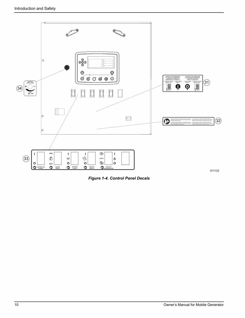
Figure 1-4. Control Panel Decals
011133
STARTING THE GENERATORDAS STARTEN DES GENERATORS
COMIENZO DEL GENERADOR
COMMENCEMENT DU GÉNÉRATEUR
STOPPING THE GENERATORDAS AUFHÖREN DES GENERATORS
PARADA DEL GENERADOR
ARRÊT DU GÉNÉRATEUR
CONTROLLER
POWER
CONTROLLER
POWER
2. PUSH ENGINE
START “I”
1. CONTROL POWER
SWITCH “ON”
1. PUSH ENGINE
STOP “O”
2. CONTROL POWER
SWITCH “OFF”
Lire et comprendre le manuel de l’utilisateur fourni avec
l’appareil avant de l’utiliser. L’omission de le faire augmente
le risque de blessure pour vous et pour les autres.
Lea y asegúrese de comprender el manual del operador
proporcionado antes de operar esta máquina. De lo contrario,
aumenta el riesgo de lesiones a usted y a otras personas.
Vor dem Betrieb dieser Maschine muss das Bedienerhandbuch
gelesen und verstanden worden sein. Ein Unterlassen erhöht das
eigene Verletzungsrisiko und das anderer.
Read and understand the supplied operator’s manual before
operating this machine. Failure to do so increases the risk
of injury to yourself or others.
CONTROLLER
POWER
ENGINE
SPEED
RUN
IDLE
SERVICE
SWITCH
EXHAUST
REGENERATION
INTERIOR
LIGHTS
VOLTAGE
REGULATION 31
32
33
34
10 Owner’s Manual for Mobile Generator
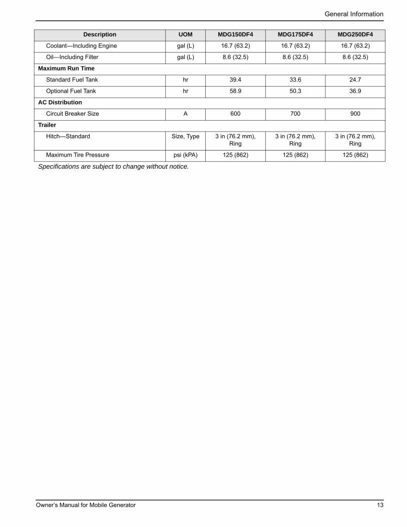
Section 2: General Information
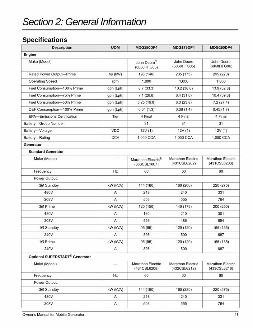
SpecificationsDescription UOM MDG150DF4 MDG175DF4 MDG250DF4
Engine
Make (Model) — John Deere® (6068HFG05)
John Deere (6068HFG05)
John Deere (6068HFG06)
Rated Power Output—Prime hp (kW) 196 (146) 235 (175) 295 (220)
Operating Speed rpm 1,800 1,800 1,800
Fuel Consumption—100% Prime gph (Lph) 8.7 (33.3) 10.2 (38.6) 13.9 (52.8)
Fuel Consumption—75% Prime gph (Lph) 7.1 (26.8) 8.4 (31.8) 10.4 (39.3)
Fuel Consumption—50% Prime gph (Lph) 5.25 (19.8) 6.3 (23.8) 7.2 (27.4)
DEF Consumption—100% Prime gph (Lph) 0.34 (1.3) 0.36 (1.4) 0.45 (1.7)
EPA—Emissions Certification Tier 4 Final 4 Final 4 Final
Battery—Group Number — 31 31 31
Battery—Voltage VDC 12V (1) 12V (1) 12V (1)
Battery—Rating CCA 1,000 CCA 1,000 CCA 1,000 CCA
Generator
Standard Generator
Make (Model) — Marathon Electric® (363CSL1607)
Marathon Electric (431CSL6202)
Marathon Electric (431CSL6206)
Frequency Hz 60 60 60
Power Output:
3Ø Standby kW (kVA) 144 (180) 160 (200) 220 (275)
480V A 218 240 331
208V A 503 555 764
3Ø Prime kW (kVA) 120 (150) 140 (175) 200 (250)
480V A 180 210 301
208V A 416 486 694
1Ø Standby kW (kVA) 95 (95) 120 (120) 165 (165)
240V A 395 500 687
1Ø Prime kW (kVA) 95 (95) 120 (120) 165 (165)
240V A 395 500 687
Optional SUPERSTART® Generator
Make (Model) — Marathon Electric (431CSL6208)
Marathon Electric (432CSL6212)
Marathon Electric (433CSL6216)
Frequency Hz 60 60 60
Power Output:
3Ø Standby kW (kVA) 144 (180) 160 (220) 220 (275)
480V A 218 240 331
208V A 503 555 764
Owner’s Manual for Mobile Generator 11

General Information
3Ø Prime kW (kVA) 120 (150) 140 (175) 200 (250)
480V A 180 210 301
208V A 416 486 694
1Ø Standby kW (kVA) 120 (120) 140 (140) 200 (200)
240V A 500 583 833
1Ø Prime kW (kVA) 120 (120) 140 (140) 200 (200)
240V A 500 583 833
Optional VFLEX Generator
Make (Model) — Marathon Electric (431PSL6611)
Marathon Electric (431PSL6612)
Marathon Electric (432PSL6613)
Frequency Hz 60 60 60
Power Output:
3Ø Standby kW (kVA) 144 (180) 160 (200) 220 (275)
480V A 218 240 331
208V A 503 555 764
3Ø Prime kW (kVA) 120 (150) 140 (175) 200 (250)
480V A 180 210 301
208V A 416 486 694
1Ø Standby kW (kVA) 73 (73) 90 (90) 109 (109)
240V A 304 375 454
1Ø Prime kW (kVA) 73 (73) 90 (90) 109 (109)
240V A 304 375 454
Weights
Equipped With Standard Fuel Tank
Dry—Skid Mounted lb (kg) 6,219 (2,820) 6,480 (2,939) 6,898 (3,129)
Operating—Skid Mounted lb (kg) 9,075 (4,116) 9,335 (4,234) 9,411 (4,269)
Dry —Trailer Mounted lb (kg) 8,184 (3,712) 8,444 (3,830) 8,863 (4,020)
Operating—Trailer Mounted lb (kg) 11,040 (5,007) 11,300 (5,125) 11,376 (5,160)
Equipped With Optional Fuel Tank
Dry—Skid Mounted lb (kg) 6,479 (2,938) 6,740 (3,057) 7,158 (3,246)
Operating—Skid Mounted lb (kg) 10,033 (4,550) 10,294 (4,669) 10,712 (4,858)
Dry—Trailer Mounted lb (kg) 8,444 (3,830) 8,705 (3,948) 9,123 (4,138)
Operating—Trailer Mounted lb (kg) 11,998 (5,442) 12,259 (5,560) 12,677 (5,750)
Capacities
Standard Fuel Tank—Total gal (L) 358 (1,355) 358 (1,355) 358 (1,355)
Standard Fuel Tank—Usable gal (L) 343 (1,297) 343 (1,297) 343 (1,297)
Optional Fuel Tank—Total gal (L) 529 (2,002) 529 (2,002) 529 (2,002)
Optional Fuel Tank—Usable gal (L) 513 (1,914) 513 (1,914) 513 (1,914)
DEF Tank—Total gal (L) 34.4 (130.4) 34.4 (130.4) 34.4 (130.4)
DEF Tank—Usable gal (L) 28 (106) 28 (106) 28 (106)
Description UOM MDG150DF4 MDG175DF4 MDG250DF4
12 Owner’s Manual for Mobile Generator
General Information
Coolant—Including Engine gal (L) 16.7 (63.2) 16.7 (63.2) 16.7 (63.2)
Oil—Including Filter gal (L) 8.6 (32.5) 8.6 (32.5) 8.6 (32.5)
Maximum Run Time
Standard Fuel Tank hr 39.4 33.6 24.7
Optional Fuel Tank hr 58.9 50.3 36.9
AC Distribution
Circuit Breaker Size A 600 700 900
Trailer
Hitch—Standard Size, Type 3 in (76.2 mm), Ring
3 in (76.2 mm), Ring
3 in (76.2 mm), Ring
Maximum Tire Pressure psi (kPA) 125 (862) 125 (862) 125 (862)
Specifications are subject to change without notice.
Description UOM MDG150DF4 MDG175DF4 MDG250DF4
Owner’s Manual for Mobile Generator 13

General Information
Unit Dimensions
Figure 2-1. Unit Dimensions
L W H
Equipped With Standard Fuel Tank
Skid Mounted 145 in (3.7 m) 60 in (1.5 m) 85 in (2.2 m)
Trailer Mounted 208 in (5.3 m) 86 in (2.2 m) 104 in (2.6 m)
Equipped With Optional Fuel Tank
Skid Mounted 145 in (3.7 m) 60 in (1.5 m) 92 in (2.3 m)
Trailer Mounted 208 in (5.3 m) 86 in (2.2 m) 111 in (2.8 m)
H
W
L
H
W
L
004418
14 Owner’s Manual for Mobile Generator

General Information
Unit ID and VIN Tag LocationsSee Figure 2-2 to locate the unit ID tag (A) and vehicleidentification number (VIN) tag (B). Important informationsuch as the unit model number, serial number, VIN, andtire loading information are listed on the tags. Record theinformation from the tags in the event the tags are lost ordamaged. When ordering parts or requesting assistance,information from the tags may be needed.
Figure 2-2. Unit ID and VIN Tag Locations
Altitude and Temperature LimitationsAll units are subject to derating for altitude andtemperature as it relates to engine cooling capacity andother capabilities. Derating reduces the available powerfor operating tools and accessories connected to theoutlets. For the MDG250/175/150, the engine canprovide full prime power up to an altitude of 10,000 ft(3,048 m). There will be a limitation in power output of 5%if the unit is operated 1,000 ft (305 m) above themaximum altitude indicated.
The maximum air temperature at which the unit canprovide full prime power is defined in the table below. Ifthe unit is operated beyond this limit at full power, thecoolant temperature will exceed the maximum allowablelimit of 235 °F (113 °C) and cause the engine to shutdown.
NOTE: For information specific to generator derating,see the OEM generator manual included with the unit.
ModelAltitude Limit: ft (m) Air Temp.
Limit: °F (°C)Prime Standby
MDG250 10,000 (3,048) 10,000 (3,048) 108(42)
MDG175 10,000 (3,048) 4,500 (1,371) 120 (49)
MDG150 10,000 (3,048) 10,000 (3,048) 120 (49)
006429
B
A
Owner’s Manual for Mobile Generator 15
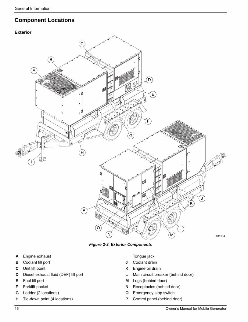
General Information
Component Locations
Exterior
Figure 2-3. Exterior Components
A Engine exhaust I Tongue jack
B Coolant fill port J Coolant drain
C Unit lift point K Engine oil drain
D Diesel exhaust fluid (DEF) fill port L Main circuit breaker (behind door)
E Fuel fill port M Lugs (behind door)
F Forklift pocket N Receptacles (behind door)
G Ladder (2 locations) O Emergency stop switch
H Tie-down point (4 locations) P Control panel (behind door)
011134
E
JK
D
F
A
H
I
C
B
G
L
MN
O
P
16 Owner’s Manual for Mobile Generator
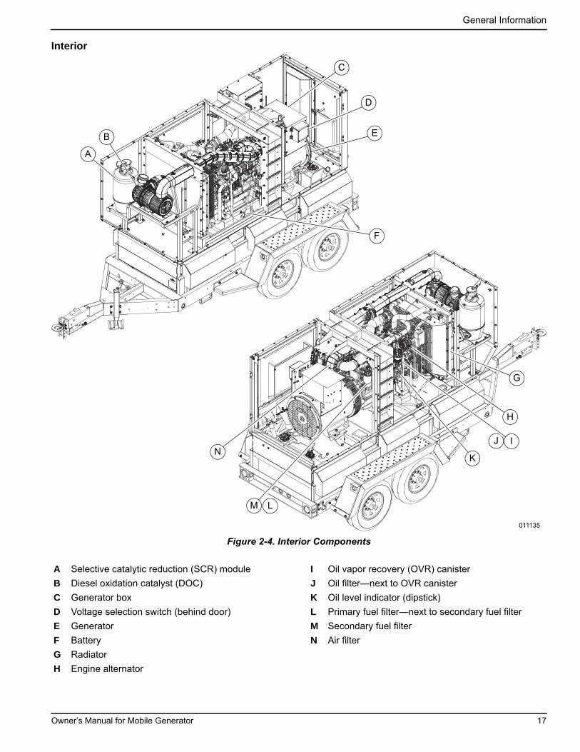
General Information
Interior
Figure 2-4. Interior Components
A Selective catalytic reduction (SCR) module I Oil vapor recovery (OVR) canister
B Diesel oxidation catalyst (DOC) J Oil filter—next to OVR canister
C Generator box K Oil level indicator (dipstick)
D Voltage selection switch (behind door) L Primary fuel filter—next to secondary fuel filter
E Generator M Secondary fuel filter
F Battery N Air filter
G Radiator
H Engine alternator
011135
G
D
F
A
B E
C
H
J
M
IN
K
L
Owner’s Manual for Mobile Generator 17

General Information
Connection Panel
Figure 2-5. Connection Panel Components
A 20A circuit breakers I Terminal lugs
B 50A circuit breaker (3 locations) J Cam lock receptacle (10 locations) (if equipped)
C Lug door safety switch K Engine block heater plug (if equipped)
D Main circuit breaker L 120V GFCI receptacle (2 locations)
E Paralleling CAN receptacle (2 locations) (if equipped)
M Battery charger plug (if equipped)
F Breaker panel switch N 120/240V twist-lock receptacle (3 locations)
G Neutral bonding bar O Emergency stop switch
H Ground terminal
003580
DA B A C E
F
G
H
I
JK
O
N
M L
18 Owner’s Manual for Mobile Generator
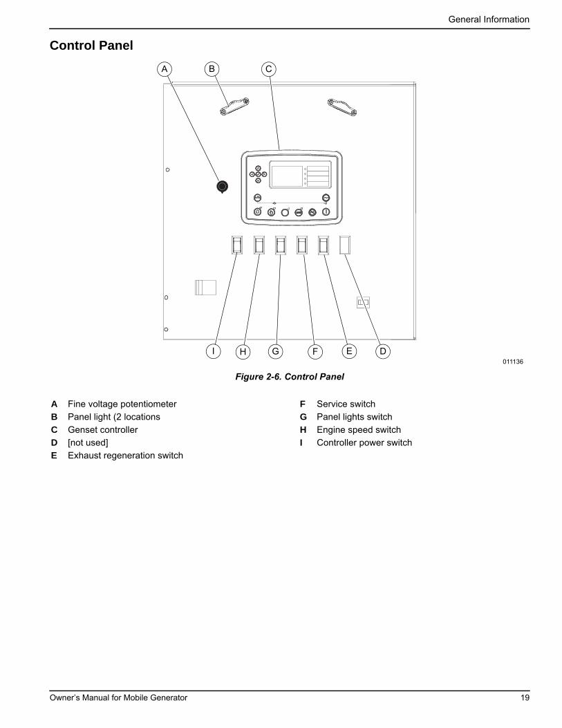
General Information
Control Panel
Figure 2-6. Control Panel
A Fine voltage potentiometer F Service switch
B Panel light (2 locations G Panel lights switch
C Genset controller H Engine speed switch
D [not used] I Controller power switch
E Exhaust regeneration switch
011136
A B C
FGH E DI
Owner’s Manual for Mobile Generator 19
General Information
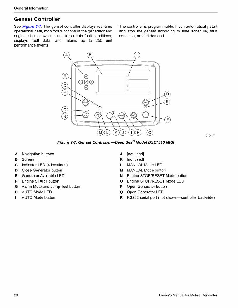
Genset ControllerSee Figure 2-7. The genset controller displays real-timeoperational data, monitors functions of the generator andengine, shuts down the unit for certain fault conditions,displays fault data, and retains up to 250 unitperformance events.
The controller is programmable. It can automatically startand stop the genset according to time schedule, faultcondition, or load demand.
Figure 2-7. Genset Controller—Deep Sea® Model DSE7310 MKII
A Navigation buttons J [not used]
B Screen K [not used]
C Indicator LED (4 locations) L MANUAL Mode LED
D Close Generator button M MANUAL Mode button
E Generator Available LED N Engine STOP/RESET Mode button
F Engine START button O Engine STOP/RESET Mode LED
G Alarm Mute and Lamp Test button P Open Generator button
H AUTO Mode LED Q Open Generator LED
I AUTO Mode button R RS232 serial port (not shown—controller backside)
010417
D
F
GI
N
P
A B C
M K HL
O
E
Q
J
R
20 Owner’s Manual for Mobile Generator
General Information
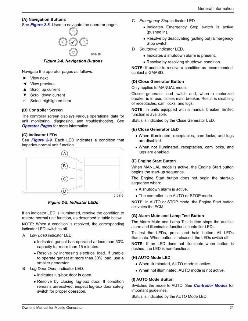
(A) Navigation ButtonsSee Figure 2-8. Used to navigate the operator pages.
Figure 2-8. Navigation Buttons
Navigate the operator pages as follows.
(B) Controller Screen
The controller screen displays various operational data forunit monitoring, diagnosing, and troubleshooting. SeeOperator Pages for more information.
(C) Indicator LEDsSee Figure 2-9. Each LED indicates a condition thatimpedes normal unit function.
Figure 2-9. Indicator LEDs
If an indicator LED is illuminated, resolve the condition torestore normal unit function, as described in table below.
NOTE: When a condition is resolved, the correspondingindicator LED switches off.
NOTE: If unable to resolve a condition as recommended,contact a GMASD.
(D) Close Generator Button
Only applies to MANUAL mode.
Closes generator load switch and, when a motorizedbreaker is in use, closes main breaker. Result is disablingof receptacles, cam locks, and lugs.
NOTE: In units equipped with a manual breaker, limitedfunction is available.
Status is indicated by the Close Generator LED.
(E) Close Generator LED
• When illuminated, receptacles, cam locks, and lugsare disabled
• When not illuminated, receptacles, cam locks, andlugs are enabled
(F) Engine Start Button
When MANUAL mode is active, the Engine Start buttonbegins the start-up sequence.
The Engine Start button does not begin the start-upsequence when:
• A shutdown alarm is active.
• The controller is in AUTO or STOP mode.
NOTE: In AUTO or STOP mode, the Engine Start buttonactivates the ECM.
(G) Alarm Mute and Lamp Test Button
The Alarm Mute and Lamp Test button stops the audiblealarm and illuminates functional controller LEDs.
To test the LEDs, press and hold button. All LEDsilluminate. When button is released, the LEDs switch off.
NOTE: If an LED does not illuminate when button ispushed, the LED is non-functional.
(H) AUTO Mode LED
• When illuminated, AUTO mode is active.
• When not illuminated, AUTO mode is not active.
(I) AUTO Mode Button
Switches the mode to AUTO. See Controller Modes forimportant guidelines.
Status is indicated by the AUTO Mode LED.
► View next
◄ View previous
▲ Scroll up current
▼ Scroll down current
Select highlighted item
A Low Load indicator LED.
• Indicates genset has operated at less than 30%capacity for more than 15 minutes.
• Resolve by increasing electrical load. If unableto operate genset at more than 30% load, use asmaller generator.
B Lug Door Open indicator LED.
• Indicates lug-box door is open.
• Resolve by closing lug-box door. If conditionremains unresolved, inspect lug-box door safetyswitch for proper operation.
010418
010419
A
B
C
D
C Emergency Stop indicator LED.
• Indicates Emergency Stop switch is active(pushed in).
• Resolve by deactivating (pulling out) EmergencyStop switch.
D Shutdown indicator LED.
• Indicates a shutdown alarm is present.
• Resolve by resolving shutdown condition.
Owner’s Manual for Mobile Generator 21
General Information
(J) [not used]
This button is inactive.
(K) [not used]
This LED is inactive.
(L) MANUAL Mode LED
• When illuminated, MANUAL mode is active.
• When not illuminated, MANUAL mode is not active.
(M) MANUAL Mode Button
Switches the mode to MANUAL. See Controller Modesfor important guidelines.
Status is indicated by the MANUAL Mode LED.
(N) Engine STOP/RESET Mode Button
Switches the mode to STOP. See Controller Modes forimportant guidelines.
Status is indicated by the STOP/RESET Mode LED.
(O) Engine STOP/RESET Mode LED
• When illuminated STOP mode is active.
• When not illuminated, STOP mode is not active.
(P) Open Generator Button
Only applies to MANUAL mode.
Opens the generator load switch and, when a motorizedbreaker is in use. Result is enabling of receptacles, camlocks, and lugs.
NOTE: In units equipped with a manual breaker, limitedfunction is available.
Status is indicated by the Open Generator LED.
(Q) Open Generator LED
• When illuminated, receptacles, cam locks, and lugsare enabled.
• When not illuminated, receptacles, cm locks, andlugs are disabled.
Controller Modes
MANUAL Mode
MANUAL mode is distinguished by full operator control ofunit start-up and shut-down functions, and by full operatorcontrol of generator load and unload functions.
AUTO Mode
AUTO mode is distinguished by automation of unit start-upand shut-down functions, and by automation of generatorload and unload functions.
AUTO mode utilizes the remote start connections. Forremote starting procedures, see Section 3, Operation.
AUTO mode utilizes a programmed schedule, which canbe modified.
NOTE: To modify the AUTO mode programmed schedule,use the Deep Sea Configuration Suite software.
STOP Mode
STOP mode is distinguished by the following:
• Unloads the generator.
• Clears active alarms—if alarm conditions have beenresolved.
• Shuts down the unit.
• Deactivates the Engine Start button.
• Stops all AUTO mode automation (if applicable).
• Controller power remain ON.
Switching Mode
1. Verify controller is ON.
NOTE: The engine can be running but it is not required.
2. Stop drawing power from the unit: Stop usingequipment plugged into receptacles, cam locks,and anything connected to the lugs.
3. See Figure 2-7. Press the desired Mode button.The unit immediately changes to the selectedmode.
Operator Pages
Operator pages contain various data for unit monitoring,diagnosing, and troubleshooting. The pages are:
• Status page
• Engine page
• Generator page
• Alarm page
• ECU DTC page
• Event Log page
• Serial Port page
• Program File Information page
• About page
NOTE: Operator pages are available after normal unitstart-up.
NOTE: Operator pages are view-only. No settings can beadded, modified, or deleted.
22 Owner’s Manual for Mobile Generator
General Information
Generator Page
Figure 2-10. Generator Page
The Generator page displays the following generatordata, in real time (press ▲ or ▼ to scroll).
• Voltage (ph-N)
• Voltage (ph-ph)
• Frequency
• Current (A)
• Load ph-N (kW)
• Total load (kW)
• Load ph-N (kVA)
• Total load (kVA)
• Single phase power factors
• Power factor average
• Load ph-N (kvar)
• Total load (kvar)
• Accumulated load (kWh, kVAh, kvarh)
• Loading scheme
• Phase rotation
• Nominal
• Active configuration
NOTE: The list above varies, according to generatormake, model, and features.
NOTE: As possible, distribute electrical loads equallyamong generator lines. Minor load imbalances (10% orless) usually do not cause problems. When loadinggenerator, observe the load (amperage) on each line.
Alarms Page
Figure 2-11. Alarm Page
The Alarms page displays active warnings and activealarms, including engine DTCs.
ECU DTC Page
Figure 2-12. ECU DTC Page—Current DTCs
The ECU Current DTC page displays active ECU DTCs.Press ► to view previous ECU DTCs.
NOTE: See engine manual for information on ECM DTCs.
NOTE: All DTCs display on the ECU DTC page. SomeDTCs may also display in the Event Log, with similardescriptions as those displayed on the ECU DTC page.
Event Log Page
Figure 2-13. Event Log Page
The Event Log page displays current and previousalarms.
• Event Log capacity is 250 alarm events. After 250events are logged, each new event overwrites theoldest.
• Only alarms are logged.
• Newest event displays at top of log; oldest at bottom.
010422
010423
010424
010425
Owner’s Manual for Mobile Generator 23
General Information
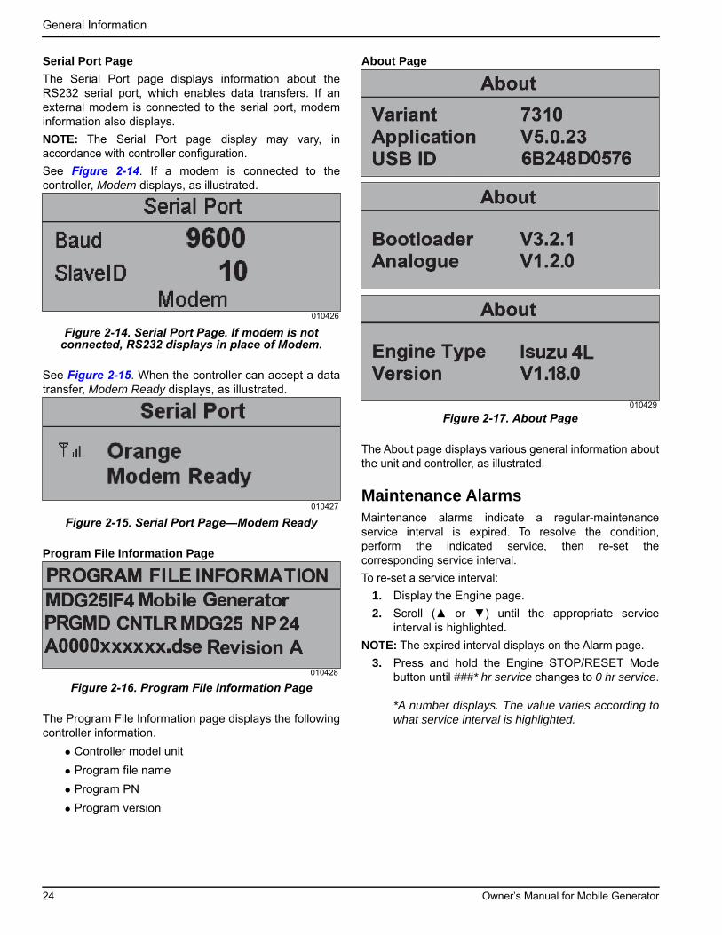
Serial Port Page
The Serial Port page displays information about theRS232 serial port, which enables data transfers. If anexternal modem is connected to the serial port, modeminformation also displays.
NOTE: The Serial Port page display may vary, inaccordance with controller configuration.
See Figure 2-14. If a modem is connected to thecontroller, Modem displays, as illustrated.
Figure 2-14. Serial Port Page. If modem is not connected, RS232 displays in place of Modem.
See Figure 2-15. When the controller can accept a datatransfer, Modem Ready displays, as illustrated.
Figure 2-15. Serial Port Page—Modem Ready
Program File Information Page
Figure 2-16. Program File Information Page
The Program File Information page displays the followingcontroller information.
• Controller model unit
• Program file name
• Program PN
• Program version
About Page
Figure 2-17. About Page
The About page displays various general information aboutthe unit and controller, as illustrated.
Maintenance AlarmsMaintenance alarms indicate a regular-maintenanceservice interval is expired. To resolve the condition,perform the indicated service, then re-set thecorresponding service interval.
To re-set a service interval:
1. Display the Engine page.
2. Scroll (▲ or ▼) until the appropriate serviceinterval is highlighted.
NOTE: The expired interval displays on the Alarm page.
3. Press and hold the Engine STOP/RESET Modebutton until ###* hr service changes to 0 hr service.
*A number displays. The value varies according towhat service interval is highlighted.
010426
010427
010428
010429
24 Owner’s Manual for Mobile Generator
General Information
Diesel Exhaust Fluid (DEF)NOTE: Unit does not ship from factory with DEF in tank.
DEF Specification
Diesel exhaust fluid (DEF) is a high-purity liquid that isinjected into the exhaust system of SCR engines.Maintaining the purity of DEF is important to avoidingmalfunctions in the SCR system. Engines requiring DEFshall use a quality product that meets the requirementsfor Aqueous Urea Solution 32 (AUS 32) according to ISO22241-1. The use of John Deere DEF is recommended.
If John Deere DEF is not available, use DEF certified bythe American Petroleum Institute (API) Diesel ExhaustFluid Certification Program, or by the AdBlue™ DieselExhaust Fluid Certification program. Look for the APIcertification symbol or the AdBlue name on the container.
NOTE: Do not create DEF by mixing agricultural gradeurea with water. Do not use additives, as this candamage the after treatment system.
DEF Warning
DEF can be corrosive to material such as steel, iron,zinc, nickel, copper, aluminum, and magnesium. Therecommended material for transport and storage of DEFis made of polyethylene, polypropylene, or stainlesssteel. These are not all-inclusive lists. For additionalinformation, see ISO 22241 or contact a DEF supplier.
DEF Storage Guidelines
NOTE: See the Materials Safety Data Sheet (MSDS) foradditional information.
DEF freezes at temperatures below 12 °F (-11 °C). Donot use additives to reduce the freezing temperature.Additives currently available are more corrosive thanDEF, and will cause component and system degradationand negatively impact reliability. For more information,see the operator manual, or contact a DEF supplier.
DEF quality degrades rapidly at temperatures above 140 °F (60 °C). To maintain emissions compliance, theurea concentration must remain between 31.8–33.2%.
Ideal conditions for storage of DEF are:
• Store at temperatures between 23–86 °F (-5–30 °C)
• Store in sealed dedicated containers to avoidcontamination and evaporation
Under these conditions, DEF is expected to remainusable for a minimum of 18 months. Storing DEF athigher temperatures can reduce its useful life byapproximately six months for every 9 °F (5 °C) above 86 °F (30 °C). Long-term storage in the DEF tank (over12 months) is not recommended. If long-term storage isnecessary, test DEF prior to operating engine. SeeTesting DEF.
(000337)
CAUTION
Equipment damage. Do not alter DEF. Use approved DEF only. Failure to do so could cause equipment damage.
WARNING
Risk of poisoning. Do not ingest diesel exhaust fluid.Seek medical attention immediately if consumed.Failure to do so could result in serious injury.
(000334)
WARNING
Personal injury. Do not inhale diesel exhaust fluid fumes. If breathing becomes difficult, move to an area with fresh air and seek medical attention immediately. Failure to do so could result in serious injury.
(000335a)
WARNING
Personal injury. Avoid contact with eyes. Flush eyesthoroughly with water and seek medical attention immediately. Failure to do so could result in serious injury. (000336)
Owner’s Manual for Mobile Generator 25
General Information
Refilling DEF Tank
IMPORTANT NOTE: If DEF is filled into engine fueltank or other fluid compartment, do not operateengine until system is properly purged of DEF.Contact your John Deere dealer immediately todetermine how to clean and purge the system.
NOTE: Use only distilled water to rinse components thatare used to deliver DEF. Tap water can contaminate DEF.If distilled water is not available, rinse with clean tapwater, then thoroughly rinse with ample amounts of DEF.
Reasonable care should be taken when refilling the DEFtank. Verify the DEF tank cap area is free of debris beforeremoving the cap. Wipe clean with a lint free cloth toremove debris from tank cap. Seal DEF containersbetween use to prevent contamination and evaporation.Avoid splashing DEF, and do not allow DEF to come intocontact with skin, eyes, or mouth.
DEF can be corrosive to materials such as steel, iron,zinc, nickel, copper, aluminum, and magnesium. Usesuitable containers to transport and store DEF.Containers made of polyethylene, polypropylene, orstainless steel are recommended.
NOTE: Keep anything used to store or dispense DEFclean of dirt and dust. Wash and rinse containers orfunnels thoroughly with distilled water to removecontaminants.
If an unapproved fluid, such as diesel fluid or coolant isadded to the DEF tank, contact your John Deeredealer immediately to determine how to clean andpurge the system.
If water has been added to the DEF tank, a tank cleaningis necessary. After refilling the tank, check the DEFconcentration. See Testing DEF. The operator mustmaintain appropriate DEF levels at all times. Check theDEF level daily and refill the tank as needed. The fillingport is identified by a blue colored cap embossed with theDEF symbol.
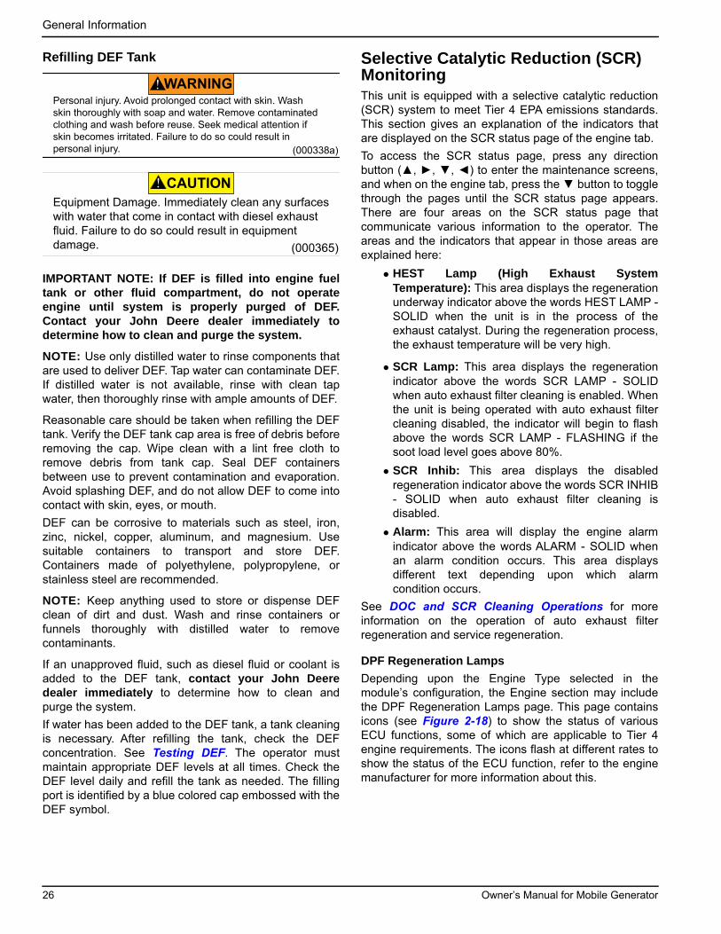
Selective Catalytic Reduction (SCR) MonitoringThis unit is equipped with a selective catalytic reduction(SCR) system to meet Tier 4 EPA emissions standards.This section gives an explanation of the indicators thatare displayed on the SCR status page of the engine tab.
To access the SCR status page, press any directionbutton (▲, ►, ▼, ◄) to enter the maintenance screens,and when on the engine tab, press the ▼ button to togglethrough the pages until the SCR status page appears.There are four areas on the SCR status page thatcommunicate various information to the operator. Theareas and the indicators that appear in those areas areexplained here:
• HEST Lamp (High Exhaust SystemTemperature): This area displays the regenerationunderway indicator above the words HEST LAMP -SOLID when the unit is in the process of theexhaust catalyst. During the regeneration process,the exhaust temperature will be very high.
• SCR Lamp: This area displays the regenerationindicator above the words SCR LAMP - SOLIDwhen auto exhaust filter cleaning is enabled. Whenthe unit is being operated with auto exhaust filtercleaning disabled, the indicator will begin to flashabove the words SCR LAMP - FLASHING if thesoot load level goes above 80%.
• SCR Inhib: This area displays the disabledregeneration indicator above the words SCR INHIB- SOLID when auto exhaust filter cleaning isdisabled.
• Alarm: This area will display the engine alarmindicator above the words ALARM - SOLID whenan alarm condition occurs. This area displaysdifferent text depending upon which alarmcondition occurs.
See DOC and SCR Cleaning Operations for moreinformation on the operation of auto exhaust filterregeneration and service regeneration.
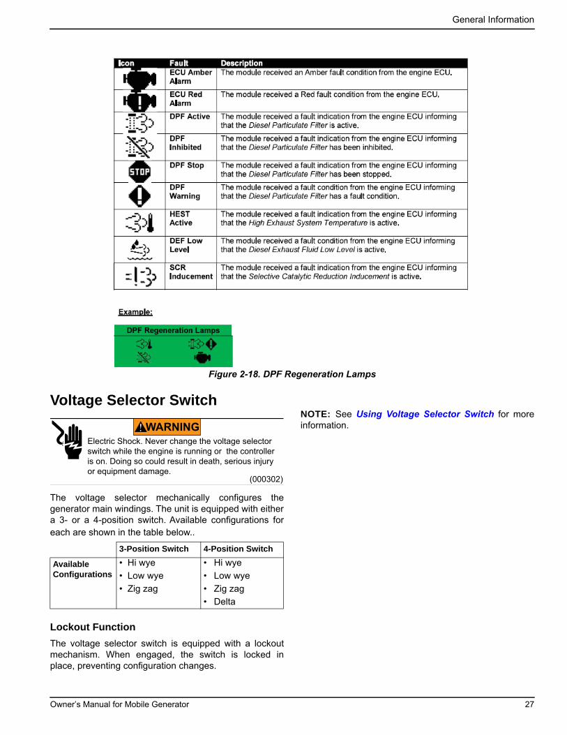
DPF Regeneration Lamps
Depending upon the Engine Type selected in themodule’s configuration, the Engine section may includethe DPF Regeneration Lamps page. This page containsicons (see Figure 2-18) to show the status of variousECU functions, some of which are applicable to Tier 4engine requirements. The icons flash at different rates toshow the status of the ECU function, refer to the enginemanufacturer for more information about this.
WARNINGPersonal injury. Avoid prolonged contact with skin. Wash skin thoroughly with soap and water. Remove contaminated clothing and wash before reuse. Seek medical attention if skin becomes irritated. Failure to do so could result in personal injury. (000338a)
CAUTION
Equipment Damage. Immediately clean any surfaces with water that come in contact with diesel exhaust fluid. Failure to do so could result in equipment damage. (000365)
26 Owner’s Manual for Mobile Generator
General Information
Figure 2-18. DPF Regeneration Lamps
Voltage Selector Switch
The voltage selector mechanically configures thegenerator main windings. The unit is equipped with eithera 3- or a 4-position switch. Available configurations foreach are shown in the table below..
Lockout Function
The voltage selector switch is equipped with a lockoutmechanism. When engaged, the switch is locked inplace, preventing configuration changes.
NOTE: See Using Voltage Selector Switch for moreinformation.
3-Position Switch 4-Position Switch
Available Configurations
• Hi wye
• Low wye
• Zig zag
• Hi wye
• Low wye
• Zig zag
• Delta
(000302)
WARNING
Electric Shock. Never change the voltage selector switch while the engine is running or the controller is on. Doing so could result in death, serious injury or equipment damage.
Owner’s Manual for Mobile Generator 27

General Information
This page intentionally left blank.
28 Owner’s Manual for Mobile Generator

Section 3: Operation
Pre-start ChecklistAll items in the pre-start checklist must be completedbefore starting the unit. This checklist applies to bothmanual and remote starting of the unit.
Verify all maintenance procedures are up to date. Formore information, see General Maintenance andBasic Maintenance Schedule.
Verify the unit is level.
Verify there is no water inside, on, or near the unit;dry if needed.
For grounding requirements, follow any local, state,or National Electrical Code (NEC) guidelines.
Verify the control power switch is OFF (O).
Verify all circuit breakers are OFF (O).
Inspect all electrical cords; repair or replace any thatare cut, worn, or bare.
Verify oil, coolant, and fuel levels are correct, per theengine manufacturer’s manual.
Verify battery connections are secure.
Turn the battery disconnect switch ON, if equipped.
Check engine fan belt tension and condition.
Check engine fan belt guard.
Check engine exhaust system for loose or rustedcomponents.
Verify all covers are in place and secure.
Verify all electrical connections at the connectionlugs, if equipped, are tight and wired correctly.
Verify the voltage selector switch is set to the desiredvoltage and locked.
Verify the emergency stop switch is pulled out.
Verify the radiator and surrounding shroud are clearof debris.
Manually Starting the Unit
Proceed as follows to start the generator in MANUALmode:
1. Set the control power switch to ON (I).
2. The display screen will show the pre-startdiagnosis, and the controller will load the unitmanagement software.
3. The home screen will be displayed when thesoftware is loaded, and the controller will be inSTOP mode as indicated at the top of the screen.
Press the AUTO/MANUAL mode ( ) button toenter MANUAL mode.
Figure 3-1. Home Screen
(000100a)
Consult Manual. Read and understand manualcompletely before using product. Failure to completely understand manual and product could result in death or serious injury.
WARNING
WARNING
Equipment damage. Do not attempt to start or operate a unit in need of repair or scheduled maintenance. Doing so could result in serious injury, death, or equipment failure or damage. (000291)
(000147)
WARNING
Risk of Fire. Unit must be positioned in amanner that prevents combustible materialaccumulation underneath. Failure to do socould result in death or serious injury.
(000103)
Asphyxiation. Running engines produce carbon monoxide, a colorless, odorless, poisonous gas. Carbon monoxide, if not avoided, will result in death or serious injury.
DANGER
(000108)
WARNING
Hot Surfaces. When operating machine, do not touch hot surfaces. Keep machine away from combustibles during use. Hot surfaces could result in severe burns or fire.
WARNING
(000281)
Fire risk. Fuel and vapors are extremely flammable. Do not operate indoors. Doing so could result in death, serious injury, or property or equipment damage.
011068
StatusGenerator at Rest
Stop Mode
22:31
Owner’s Manual for Mobile Generator 29

Operation
NOTE: The controller can be started from any screenwhen it is in MANUAL mode.
4. Pressing the green engine start (I) button on thecontroller will initiate the startup procedure andstart the engine, if there are no engine faultspreventing the unit from starting.
NOTE: It may take a few seconds for the engine to runsmoothly and reach its governed operating speed. Duringthis time, the screen will show a voltage different from thevoltage set with the voltage selector switch.
5. If the engine does not start after the first crankingattempt, the engine will pause for 15 seconds toallow the starter to cool. The display screen willshow MANUAL MODE - CRANK REST at the topof the screen. The engine will make two moreattempts to start for a total of three crank cycles.
6. If the engine does not start and run within threecrank cycles, the display screen will show the fail tostart alarm. The starting sequence can be repeatedafter the starter has had a minimum of two minutesto cool. Pressing the ENTER () button will clearthe alarm and reset the controller.
NOTE: The engine controller may skip the preheatengine steps on some of the larger models.
7. Once the engine starts, it begins speeding up to aconstant 1800 RPM. The engine may hunt orchange speeds until operating speed is reached.The engine will be warmed up and the operatorscreens will show engine and generator operatingparameters after a few minutes of operation.
8. Check the generator for excessive noise orvibration and any coolant, oil, or fuel leaks beforeapplying any loads.
9. Verify the AC output voltage is correct. See FineVoltage Adjustment.
10. Verify the frequency (Hz) is correct on thegenerator screen. The frequency should readapproximately 60 Hz with no loads connected tothe generator, depending on the type of enginegoverning used.
11. If all wiring connections have been made correctly,switch the main circuit breaker to ON (I), and thenadd any loads attached to the receptacles byswitching the respective circuit breaker to the ON(I) position. A slight change in engine sound whena load is applied to the unit is normal.
AUTO (Remote) Starting the UnitAUTO mode is used when the unit is started from alocation other than the control panel by using a transferswitch. AUTO (remote start) is the normal setting whenthe unit is being used as a standby power supply. Reviewthe Pre-start Checklist and Manually Starting the Unit
before putting the unit in AUTO mode. Follow all safetywarnings and review all information on isolating thegenerator with a transfer switch if the unit is to be used asa standby power supply. See Changing ExerciseTimers, then proceed as follows:
1. Perform a manual start of the unit at least once toverify the engine is operating correctly.
2. To check the remote start circuit, remove the wiresfrom the remote start terminal block. Press the
AUTO/MANUAL mode ( ) button, and the displayscreen will show auto mode at the top of thescreen.
3. Attach a jumper wire (minimum 16 gauge) acrossthe two terminals on the remote start terminalblock. This applies a ground to the controller toclose the starting circuit contacts. The engine willcrank, start, and run.
4. Remove the jumper wire from the remote startterminal block and the engine will stop. Reconnectany necessary wires from the remote start switch(transfer switch) to the remote start terminal block.
5. Verify the unit is in AUTO mode. The displayscreen should show AUTO mode at the top of thescreen.
6. Secure the unit by closing and locking all accessdoors.
7. The unit is now ready for remote starting.
See Figure 3-2. The remote start terminal block providesa connection for installation of a remote start switchwhich will allow the unit to be started by a remote dry-contact closure switch. For location of the remote startterminal block, see Genset Controller.
Before entering AUTO mode, verify the contacts on anyremote switch linked to the unit are open. If the contactson a remote switch are closed, the engine will crank andstart when AUTO mode is entered. Attach the switchleads to the two unused terminals (A) on the unit’sremote start terminal block.
Figure 3-2. Remote Start Terminal Block
A002806
30 Owner’s Manual for Mobile Generator
Operation
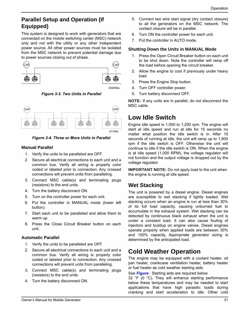
Parallel Setup and Operation (If Equipped)This system is designed to work with generators that areconnected on the mobile switching center (MSC) networkonly and not with the utility or any other independentpower source. All other power sources must be isolatedfrom the MSC network to prevent potential damage dueto power sources closing out of phase.
Figure 3-3. Two Units in Parallel
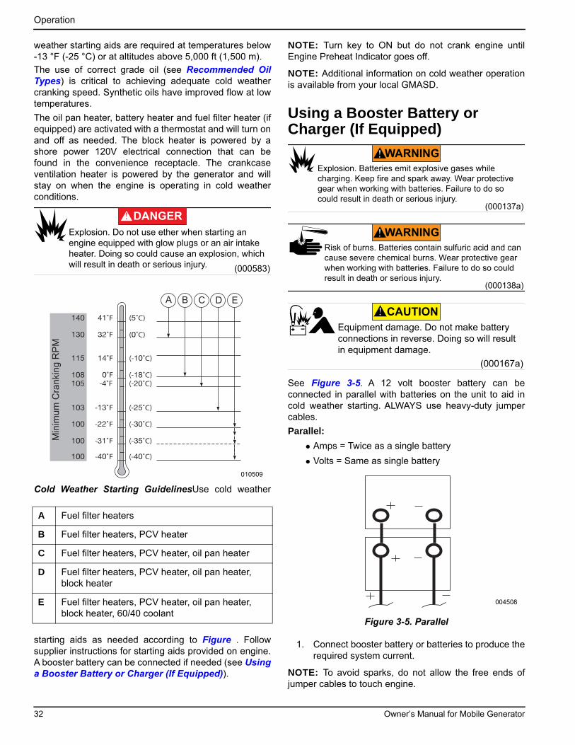
Figure 3-4. Three or More Units in Parallel
Manual Parallel
1. Verify the units to be paralleled are OFF.
2. Secure all electrical connections to each unit and acommon bus. Verify all wiring is properly colorcoded or labeled prior to connection. Any crossedconnections will prevent units from paralleling.
3. Connect MSC cable(s) and terminating plugs(resistors) to the end units.
4. Turn the battery disconnect ON.
5. Turn on the controller power for each unit.
6. Put the controller in MANUAL mode (lower leftbutton).
7. Start each unit to be paralleled and allow them towarm up.
8. Press the Close Circuit Breaker button on eachunit.
Automatic Parallel
1. Verify the units to be paralleled are OFF.
2. Secure all electrical connections to each unit and acommon bus. Verify all wiring is properly colorcoded or labeled prior to connection. Any crossedconnections will prevent units from paralleling.
3. Connect MSC cable(s) and terminating plugs(resistors) to the end units.
4. Turn the battery disconnect ON.
5. Connect two wire start signal (dry contact closure)to all the generators on the MSC network. Thecontact closure will be in parallel.
6. Turn ON the controller power for each unit.
7. Put the controller in AUTO mode.
Shutting Down the Units in MANUAL Mode
1. Press the Open Circuit Breaker button on each unitto be shut down. Note the controller will ramp offthe load before opening the circuit breaker.
2. Allow the engine to cool if previously under heavyload.
3. Press the Engine Stop button.
4. Turn OFF controller power.
5. Turn battery disconnect OFF.
NOTE: If any units are in parallel, do not disconnect theMSC cable.
Low Idle SwitchEngine idle speed is 1,000 to 1,200 rpm. The engine willstart at idle speed and run at idle for 15 seconds nomatter what position the idle switch is in. After 15seconds of running at idle, the unit will ramp up to 1,800rpm if the idle switch is OFF. Otherwise the unit willcontinue to idle if the idle switch is ON. When the engineis at idle speed (1,000 RPM), the voltage regulator willnot function and the output voltage is dropped out by thevoltage regulator.
IMPORTANT NOTE: Do not apply load to the unit when the engine is running at idle speed.
Wet StackingThe unit is powered by a diesel engine. Diesel enginesare susceptible to wet stacking if lightly loaded. Wetstacking occurs when an engine is run at less than 30%of its full load capacity, causing unburned fuel toaccumulate in the exhaust system. Wet stacking can bedetected by continuous black exhaust when the unit isunder a constant load. It can also cause fouling ofinjectors and buildup on engine valves. Diesel enginesoperate properly when applied loads are between 30%and 100% capacity. Appropriate generator sizing isdetermined by the anticipated load.
Cold Weather OperationThe engine may be equipped with a coolant heater, oilpan heater, crankcase ventilation heater, battery heateror fuel heater as cold weather starting aids.
See Figure . Starting aids are required below 32 °F (0 °C). They will enhance starting performancebelow these temperatures and may be needed to startapplications that have high parasitic loads duringcranking and start acceleration to idle. Other cold
CAP CAP
002858a
011064
CAP CAP
Owner’s Manual for Mobile Generator 31
Operation
weather starting aids are required at temperatures below-13 °F (-25 °C) or at altitudes above 5,000 ft (1,500 m).
The use of correct grade oil (see Recommended OilTypes) is critical to achieving adequate cold weathercranking speed. Synthetic oils have improved flow at lowtemperatures.
The oil pan heater, battery heater and fuel filter heater (ifequipped) are activated with a thermostat and will turn onand off as needed. The block heater is powered by ashore power 120V electrical connection that can befound in the convenience receptacle. The crankcaseventilation heater is powered by the generator and willstay on when the engine is operating in cold weatherconditions.
Cold Weather Starting GuidelinesUse cold weather
starting aids as needed according to Figure . Followsupplier instructions for starting aids provided on engine.A booster battery can be connected if needed (see Usinga Booster Battery or Charger (If Equipped)).
NOTE: Turn key to ON but do not crank engine untilEngine Preheat Indicator goes off.
NOTE: Additional information on cold weather operationis available from your local GMASD.
Using a Booster Battery or Charger (If Equipped)
See Figure 3-5. A 12 volt booster battery can beconnected in parallel with batteries on the unit to aid incold weather starting. ALWAYS use heavy-duty jumpercables.
Parallel:
• Amps = Twice as a single battery
• Volts = Same as single battery
Figure 3-5. Parallel
1. Connect booster battery or batteries to produce therequired system current.
NOTE: To avoid sparks, do not allow the free ends ofjumper cables to touch engine.
A Fuel filter heaters
B Fuel filter heaters, PCV heater
C Fuel filter heaters, PCV heater, oil pan heater
D Fuel filter heaters, PCV heater, oil pan heater, block heater
E Fuel filter heaters, PCV heater, oil pan heater, block heater, 60/40 coolant
(000583)
DANGER
Explosion. Do not use ether when starting an engine equipped with glow plugs or an air intake heater. Doing so could cause an explosion, which will result in death or serious injury.
A B C D E
Min
imum
Cra
nkin
g R
PM
010509
(000137a)
WARNING
Explosion. Batteries emit explosive gases while charging. Keep fire and spark away. Wear protective gear when working with batteries. Failure to do so could result in death or serious injury.
(000138a)
WARNING
Risk of burns. Batteries contain sulfuric acid and can cause severe chemical burns. Wear protective gear when working with batteries. Failure to do so could result in death or serious injury.
(000167a)
Equipment damage. Do not make battery connections in reverse. Doing so will result in equipment damage.
CAUTION
004508
32 Owner’s Manual for Mobile Generator
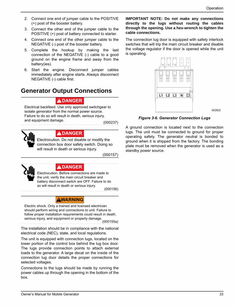
Operation
2. Connect one end of jumper cable to the POSITIVE(+) post of the booster battery.
3. Connect the other end of the jumper cable to thePOSITIVE (+) post of battery connected to starter.
4. Connect one end of the other jumper cable to theNEGATIVE (-) post of the booster battery.
5. Complete the hookup by making the lastconnection of the NEGATIVE (-) cable to a goodground on the engine frame and away from thebattery(ies).
6. Start the engine. Disconnect jumper cablesimmediately after engine starts. Always disconnectNEGATIVE (-) cable first.
Generator Output Connections
The installation should be in compliance with the nationalelectrical code (NEC), state, and local regulations.
The unit is equipped with connection lugs, located on thelower portion of the control box behind the lug box door.The lugs provide connection points to attach externalloads to the generator. A large decal on the inside of theconnection lug door details the proper connections forselected voltages.
Connections to the lugs should be made by running thepower cables up through the opening in the bottom of thebox.
IMPORTANT NOTE: Do not make any connectionsdirectly to the lugs without routing the cablesthrough the opening. Use a hex-wrench to tighten thecable connections.
The connection lug door is equipped with safety interlockswitches that will trip the main circuit breaker and disablethe voltage regulator if the door is opened while the unitis operating.
Figure 3-6. Generator Connection Lugs
A ground connection is located next to the connectionlugs. The unit must be connected to ground for properoperating safety. The generator neutral is bonded toground when it is shipped from the factory. The bondingplate must be removed when the generator is used as astandby power source.
(000237)
DANGER
Electrical backfeed. Use only approved switchgear to isolate generator from the normal power source.Failure to do so will result in death, serious injury, and equipment damage.
(000157)
DANGER
Electrocution. Do not disable or modify theconnection box door safety switch. Doing sowill result in death or serious injury.
(000156)
DANGER
Electrocution. Before connections are made tothe unit, verify the main circuit breaker andbattery disconnect switch are OFF. Failure to do so will result in death or serious injury.
(000155a)
WARNING
Electric shock. Only a trained and licensed electrician should perform wiring and connections to unit. Failure to follow proper installation requirements could result in death, serious injury, and equipment or property damage.
002822
Owner’s Manual for Mobile Generator 33
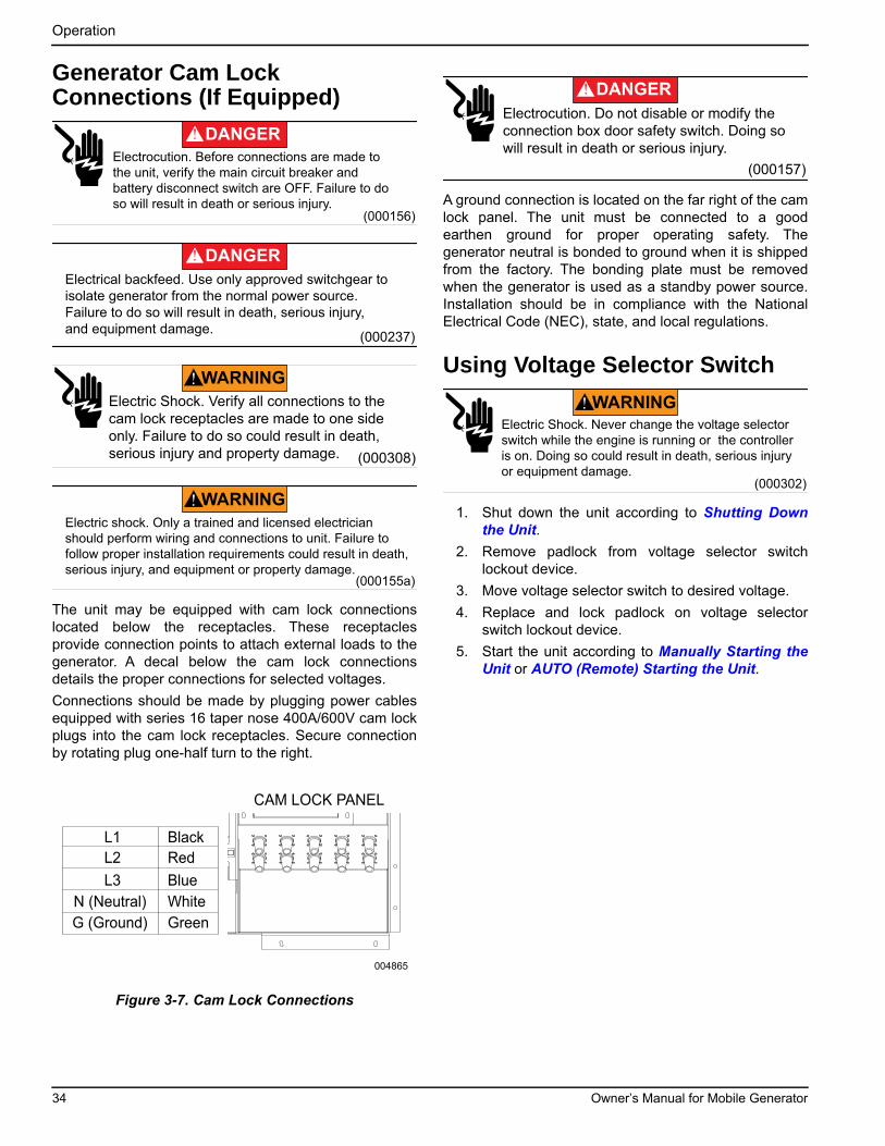
Operation
Generator Cam Lock Connections (If Equipped)
The unit may be equipped with cam lock connectionslocated below the receptacles. These receptaclesprovide connection points to attach external loads to thegenerator. A decal below the cam lock connectionsdetails the proper connections for selected voltages.
Connections should be made by plugging power cablesequipped with series 16 taper nose 400A/600V cam lockplugs into the cam lock receptacles. Secure connectionby rotating plug one-half turn to the right.
Figure 3-7. Cam Lock Connections
A ground connection is located on the far right of the camlock panel. The unit must be connected to a goodearthen ground for proper operating safety. Thegenerator neutral is bonded to ground when it is shippedfrom the factory. The bonding plate must be removedwhen the generator is used as a standby power source.Installation should be in compliance with the NationalElectrical Code (NEC), state, and local regulations.
Using Voltage Selector Switch
1. Shut down the unit according to Shutting Downthe Unit.
2. Remove padlock from voltage selector switchlockout device.
3. Move voltage selector switch to desired voltage.
4. Replace and lock padlock on voltage selectorswitch lockout device.
5. Start the unit according to Manually Starting theUnit or AUTO (Remote) Starting the Unit.
(000156)
DANGER
Electrocution. Before connections are made tothe unit, verify the main circuit breaker andbattery disconnect switch are OFF. Failure to do so will result in death or serious injury.
(000237)
DANGER
Electrical backfeed. Use only approved switchgear to isolate generator from the normal power source.Failure to do so will result in death, serious injury, and equipment damage.
WARNING
(000308)
Electric Shock. Verify all connections to thecam lock receptacles are made to one sideonly. Failure to do so could result in death,serious injury and property damage.
(000155a)
WARNING
Electric shock. Only a trained and licensed electrician should perform wiring and connections to unit. Failure to follow proper installation requirements could result in death, serious injury, and equipment or property damage.
L1L2L3
N (Neutral)G (Ground)
BlackRedBlueWhiteGreen
CAM LOCK PANEL
004865
(000157)
DANGER
Electrocution. Do not disable or modify theconnection box door safety switch. Doing sowill result in death or serious injury.
(000302)
WARNING
Electric Shock. Never change the voltage selector switch while the engine is running or the controller is on. Doing so could result in death, serious injury or equipment damage.
34 Owner’s Manual for Mobile Generator
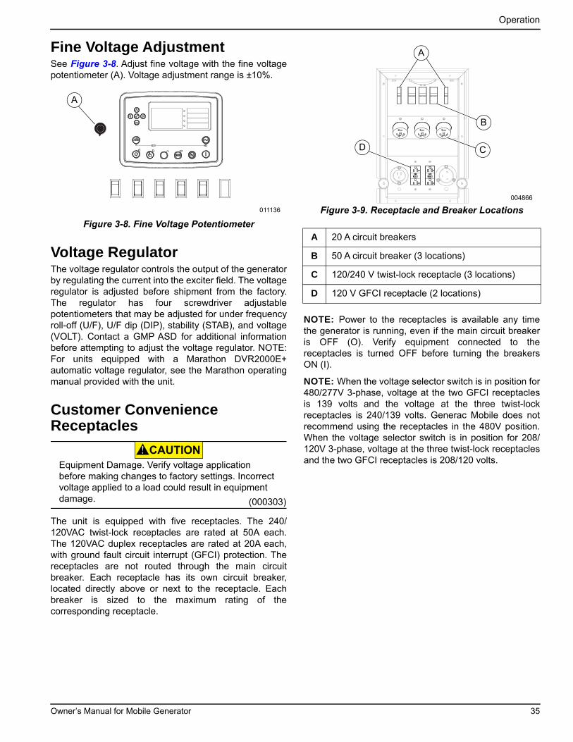
Operation
Fine Voltage AdjustmentSee Figure 3-8. Adjust fine voltage with the fine voltagepotentiometer (A). Voltage adjustment range is ±10%.
Figure 3-8. Fine Voltage Potentiometer
Voltage RegulatorThe voltage regulator controls the output of the generatorby regulating the current into the exciter field. The voltageregulator is adjusted before shipment from the factory.The regulator has four screwdriver adjustablepotentiometers that may be adjusted for under frequencyroll-off (U/F), U/F dip (DIP), stability (STAB), and voltage(VOLT). Contact a GMP ASD for additional informationbefore attempting to adjust the voltage regulator. NOTE:For units equipped with a Marathon DVR2000E+automatic voltage regulator, see the Marathon operatingmanual provided with the unit.
Customer Convenience Receptacles
The unit is equipped with five receptacles. The 240/120VAC twist-lock receptacles are rated at 50A each.The 120VAC duplex receptacles are rated at 20A each,with ground fault circuit interrupt (GFCI) protection. Thereceptacles are not routed through the main circuitbreaker. Each receptacle has its own circuit breaker,located directly above or next to the receptacle. Eachbreaker is sized to the maximum rating of thecorresponding receptacle.
Figure 3-9. Receptacle and Breaker Locations
NOTE: Power to the receptacles is available any timethe generator is running, even if the main circuit breakeris OFF (O). Verify equipment connected to thereceptacles is turned OFF before turning the breakersON (I).
NOTE: When the voltage selector switch is in position for480/277V 3-phase, voltage at the two GFCI receptaclesis 139 volts and the voltage at the three twist-lockreceptacles is 240/139 volts. Generac Mobile does notrecommend using the receptacles in the 480V position.When the voltage selector switch is in position for 208/120V 3-phase, voltage at the three twist-lock receptaclesand the two GFCI receptacles is 208/120 volts.
A
011136
CAUTION
(000303)
Equipment Damage. Verify voltage application before making changes to factory settings. Incorrect voltage applied to a load could result in equipment damage.
A 20 A circuit breakers
B 50 A circuit breaker (3 locations)
C 120/240 V twist-lock receptacle (3 locations)
D 120 V GFCI receptacle (2 locations)
004866
A
B
CD
Owner’s Manual for Mobile Generator 35
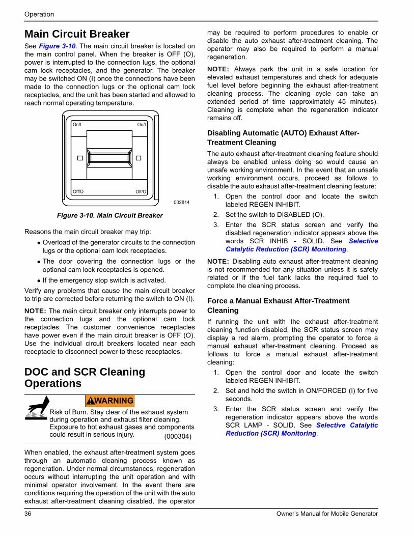
Operation
Main Circuit BreakerSee Figure 3-10. The main circuit breaker is located onthe main control panel. When the breaker is OFF (O),power is interrupted to the connection lugs, the optionalcam lock receptacles, and the generator. The breakermay be switched ON (I) once the connections have beenmade to the connection lugs or the optional cam lockreceptacles, and the unit has been started and allowed toreach normal operating temperature.
Figure 3-10. Main Circuit Breaker
Reasons the main circuit breaker may trip:
• Overload of the generator circuits to the connectionlugs or the optional cam lock receptacles.
• The door covering the connection lugs or theoptional cam lock receptacles is opened.
• If the emergency stop switch is activated.
Verify any problems that cause the main circuit breakerto trip are corrected before returning the switch to ON (I).
NOTE: The main circuit breaker only interrupts power tothe connection lugs and the optional cam lockreceptacles. The customer convenience receptacleshave power even if the main circuit breaker is OFF (O).Use the individual circuit breakers located near eachreceptacle to disconnect power to these receptacles.
DOC and SCR Cleaning Operations
When enabled, the exhaust after-treatment system goesthrough an automatic cleaning process known asregeneration. Under normal circumstances, regenerationoccurs without interrupting the unit operation and withminimal operator involvement. In the event there areconditions requiring the operation of the unit with the autoexhaust after-treatment cleaning disabled, the operator
may be required to perform procedures to enable ordisable the auto exhaust after-treatment cleaning. Theoperator may also be required to perform a manualregeneration.
NOTE: Always park the unit in a safe location forelevated exhaust temperatures and check for adequatefuel level before beginning the exhaust after-treatmentcleaning process. The cleaning cycle can take anextended period of time (approximately 45 minutes).Cleaning is complete when the regeneration indicatorremains off.
Disabling Automatic (AUTO) Exhaust After-Treatment Cleaning
The auto exhaust after-treatment cleaning feature shouldalways be enabled unless doing so would cause anunsafe working environment. In the event that an unsafeworking environment occurs, proceed as follows todisable the auto exhaust after-treatment cleaning feature:
1. Open the control door and locate the switchlabeled REGEN INHIBIT.
2. Set the switch to DISABLED (O).
3. Enter the SCR status screen and verify thedisabled regeneration indicator appears above thewords SCR INHIB - SOLID. See SelectiveCatalytic Reduction (SCR) Monitoring.
NOTE: Disabling auto exhaust after-treatment cleaningis not recommended for any situation unless it is safetyrelated or if the fuel tank lacks the required fuel tocomplete the cleaning process.
Force a Manual Exhaust After-Treatment Cleaning
If running the unit with the exhaust after-treatmentcleaning function disabled, the SCR status screen maydisplay a red alarm, prompting the operator to force amanual exhaust after-treatment cleaning. Proceed asfollows to force a manual exhaust after-treatmentcleaning:
1. Open the control door and locate the switchlabeled REGEN INHIBIT.
2. Set and hold the switch in ON/FORCED (I) for fiveseconds.
3. Enter the SCR status screen and verify theregeneration indicator appears above the wordsSCR LAMP - SOLID. See Selective CatalyticReduction (SCR) Monitoring.
On/I On/I
Off/O Off/O
002814
WARNING
Risk of Burn. Stay clear of the exhaust systemduring operation and exhaust filter cleaning.Exposure to hot exhaust gases and components could result in serious injury. (000304)
36 Owner’s Manual for Mobile Generator
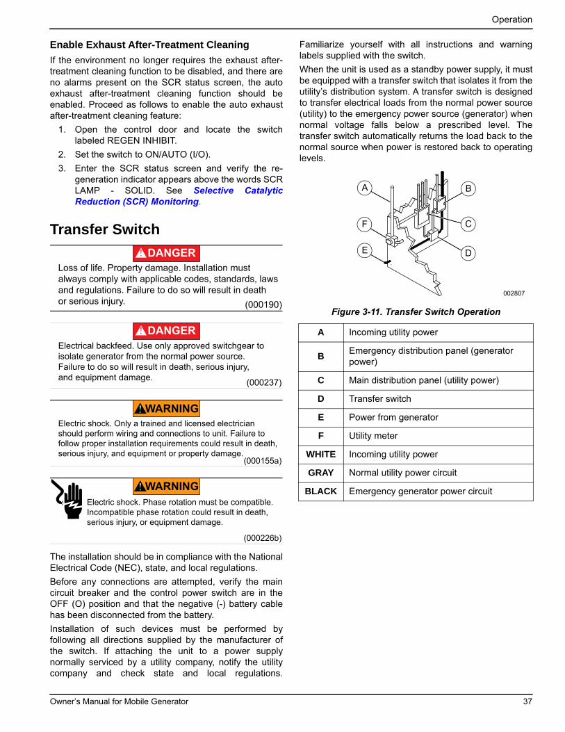
Operation
Enable Exhaust After-Treatment Cleaning
If the environment no longer requires the exhaust after-treatment cleaning function to be disabled, and there areno alarms present on the SCR status screen, the autoexhaust after-treatment cleaning function should beenabled. Proceed as follows to enable the auto exhaustafter-treatment cleaning feature:
1. Open the control door and locate the switchlabeled REGEN INHIBIT.
2. Set the switch to ON/AUTO (I/O).
3. Enter the SCR status screen and verify the re-generation indicator appears above the words SCRLAMP - SOLID. See Selective CatalyticReduction (SCR) Monitoring.
Transfer Switch
The installation should be in compliance with the NationalElectrical Code (NEC), state, and local regulations.
Before any connections are attempted, verify the maincircuit breaker and the control power switch are in theOFF (O) position and that the negative (-) battery cablehas been disconnected from the battery.
Installation of such devices must be performed byfollowing all directions supplied by the manufacturer ofthe switch. If attaching the unit to a power supplynormally serviced by a utility company, notify the utilitycompany and check state and local regulations.
Familiarize yourself with all instructions and warninglabels supplied with the switch.
When the unit is used as a standby power supply, it mustbe equipped with a transfer switch that isolates it from theutility’s distribution system. A transfer switch is designedto transfer electrical loads from the normal power source(utility) to the emergency power source (generator) whennormal voltage falls below a prescribed level. Thetransfer switch automatically returns the load back to thenormal source when power is restored back to operatinglevels.
Figure 3-11. Transfer Switch Operation(000190)
DANGER
Loss of life. Property damage. Installation must always comply with applicable codes, standards, laws and regulations. Failure to do so will result in death or serious injury.
(000237)
DANGER
Electrical backfeed. Use only approved switchgear to isolate generator from the normal power source.Failure to do so will result in death, serious injury, and equipment damage.
(000155a)
WARNING
Electric shock. Only a trained and licensed electrician should perform wiring and connections to unit. Failure to follow proper installation requirements could result in death, serious injury, and equipment or property damage.
(000226b)
WARNING
Electric shock. Phase rotation must be compatible. Incompatible phase rotation could result in death, serious injury, or equipment damage.
A Incoming utility power
BEmergency distribution panel (generator power)
C Main distribution panel (utility power)
D Transfer switch
E Power from generator
F Utility meter
WHITE Incoming utility power
GRAY Normal utility power circuit
BLACK Emergency generator power circuit
002807
A B
E
F
D
C
Owner’s Manual for Mobile Generator 37

Operation
Changing Exercise TimersIf exercise timers or scheduled runs are needed, contacta GMASD for assistance.
Shutting Down the UnitPrior to shutting down the unit, check with personnelusing power supplied by the generator and let them knowthe power is going to be turned off. Verify the power shutdown will not create any hazards by accidentally turningoff equipment that needs to be kept on (pumps,compressors, lights, etc.).
1. Remove all loads from the generator by opening allcircuit breakers (turn OFF (O)).
2. Allow engine to run for approximately five minutesto allow it to cool down.
3. Press the red engine STOP/RESET (O) button onthe controller. This will result in the generator goinginto the shutdown cycle and starting a 15 secondshutdown timer. If the unit does not shut downwithin 15 seconds, a stop fail alarm will bedisplayed on the display screen.
4. After the unit shuts down, wait two minutes afterengine shutdown for controller actuated actions tocomplete and then set the control power switch toOFF (O).
NOTE: The ECU needs to run for 90 seconds aftershutdown to purge the DEF.
NOTE: Turning off the control panel before the controllerfinishes updating could cause a loss of data.
NOTE: For extended storage time, disconnect thebattery. See the engine operator’s manual for extendedstorage requirements.
Emergency Stop Switch
See Figure 3-12. The unit is equipped with oneemergency stop switch. The red button is clearly labeledEMERGENCY STOP. The switch can be accessed andactivated with all doors closed and locked.
Figure 3-12. Emergency Stop Switch
Activate the emergency stop switch by pushing thebutton in until it locks down. This trips the main circuitbreaker which then opens the contact, disconnecting theload to the connection lugs. This will also open the fuelcircuit, shutting down the engine. The emergency stopfault will be displayed on the control panel. The switchwill remain closed until it is pulled out.
Using the ECU Override Switch
IMPORTANT NOTE: Starting the engine with theECU override switch ON will not allow the engine toshut down properly using the Engine STOP/RESETButton. This must only be used when the engine isOFF.
See Genset Controller for location of the ECU overrideswitch. This toggle switch powers up the ECU withouthaving to start the engine. Use the ECU override switchto turn the ECU OFF. If the unit needs to be shut downimmediately, use the emergency stop switch. SeeEmergency Stop Switch.
CAUTION
(000246b)
Equipment Damage. The emergency stop switch is not to be used to power down the unit under normal operating circumstances. Doing so could result in equipment damage.
EMERGENCY
STOP
003575
CAUTION
Equipment Damage. Do not start the engine with the Engine Control Unit (ECU) override switch ON. Doing so will damage the ECU.
(000305)
38 Owner’s Manual for Mobile Generator
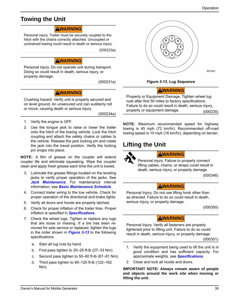
Operation
Towing the Unit
1. Verify the engine is OFF.
2. Use the tongue jack to raise or lower the traileronto the hitch of the towing vehicle. Lock the hitchcoupling and attach the safety chains or cables tothe vehicle. Release the jack locking pin and rotatethe jack into the travel position. Verify the lockingpin snaps into place.
NOTE: A film of grease on the coupler will extendcoupler life and eliminate squeaking. Wipe the couplerclean and apply fresh grease each time the unit is towed.
3. Lubricate the grease fittings located on the levelingjacks to verify proper operation of the jacks. SeeJack Maintenance. For maintenance intervalinformation, see Basic Maintenance Schedule.
4. Connect trailer wiring to the tow vehicle. Check forproper operation of the directional and brake lights.
5. Verify all doors and hoods are properly latched.
6. Check for proper inflation of the trailer tires. Properinflation is specified in Specifications.
7. Check the wheel lugs. Tighten or replace any lugsthat are loose or missing. If a tire has been re-moved for axle service or replaced, tighten the lugsin the order shown in Figure 3-13 to the followingspecifications:
Figure 3-13. Lug Sequence
NOTE: Maximum recommended speed for highwaytowing is 45 mph (72 km/hr). Recommended off-roadtowing speed is 10 mph (16 km/hr), depending on terrain.
Lifting the Unit
1. Verify the equipment being used to lift the unit is ingood condition and has sufficient capacity. Forapproximate weights, see Specifications.
2. Close and lock all hoods and doors.
IMPORTANT NOTE: Always remain aware of peopleand objects around the work site when moving orlifting the unit.
a. Start all lug nuts by hand.
b. First pass tighten to 20–25 ft-lb (27–33 Nm).
c. Second pass tighten to 50–60 ft-lb (67–81 Nm).
d. Third pass tighten to 90–120 ft-lb (122–162 Nm).
WARNING
(000233a)
Personal injury. Trailer must be securely coupled to the hitch with the chains correctly attached. Uncoupled or unchained towing could result in death or serious injury.
(000231a)
Personal injury. Do not operate unit during transport. Doing so could result in death, serious injury, or property damage.
WARNING
(000234a)
Crushing hazard. Verify unit is properly secured and on level ground. An unsecured unit can suddenly roll or move, causing death or serious injury.
WARNING
18 6
7
43
25
001441
WARNING
Property or Equipment Damage. Tighten wheel lug nuts after first 50 miles to factory specifications. Failure to do so could result in death, serious injury, property or equipment damage. (000235)
Personal injury. Failure to properly connect lifting cables, chains, or straps could result in death, serious injury, or property damage.
(000346)
WARNING
(000350)
WARNING
Personal Injury. Do not use lifting hook other than as directed. Failure to do so could result in death, serious injury, or property damage.
(000351)
Personal Injury. Verify all fasteners are properly tightened prior to lifting unit. Failure to do so could result in death, serious injury, or property damage.
WARNING
Owner’s Manual for Mobile Generator 39
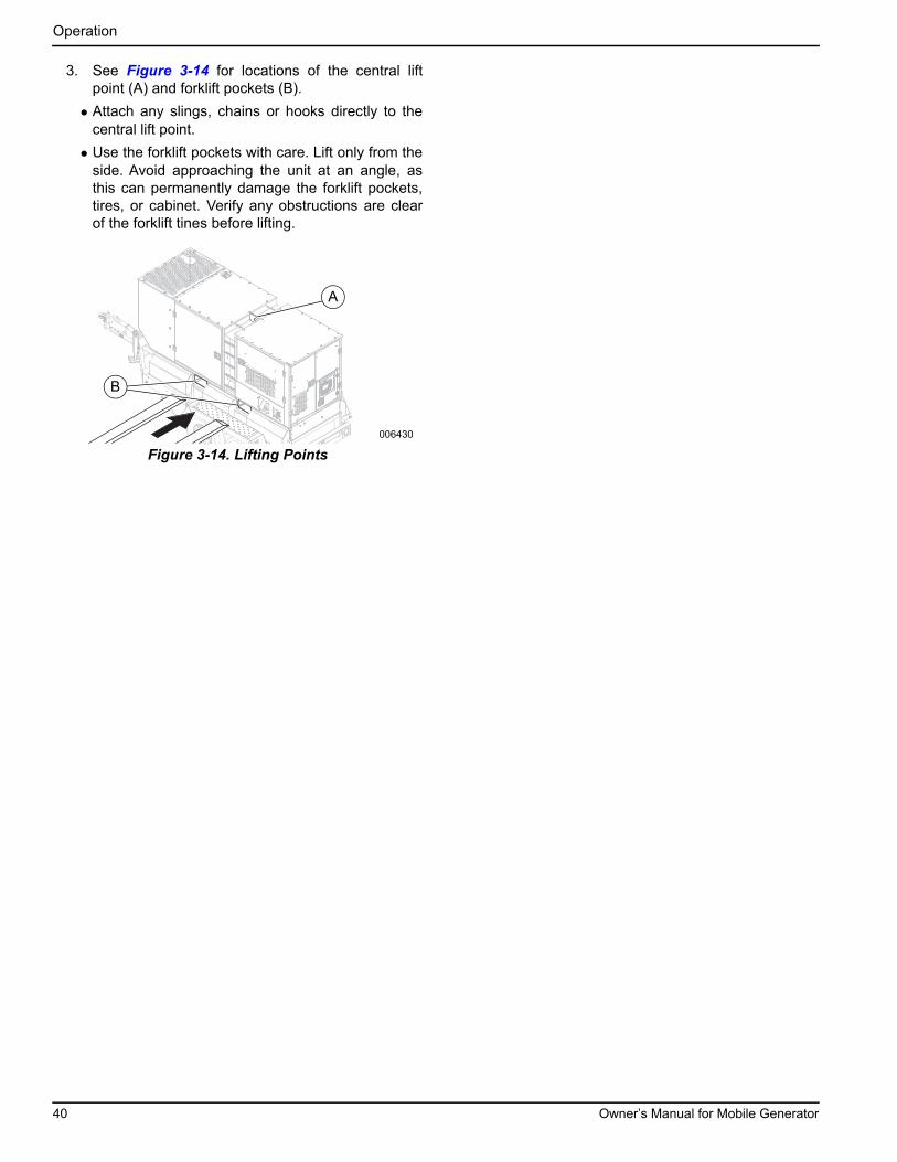
Operation
3. See Figure 3-14 for locations of the central liftpoint (A) and forklift pockets (B).
• Attach any slings, chains or hooks directly to thecentral lift point.
• Use the forklift pockets with care. Lift only from theside. Avoid approaching the unit at an angle, asthis can permanently damage the forklift pockets,tires, or cabinet. Verify any obstructions are clearof the forklift tines before lifting.
Figure 3-14. Lifting Points
006430
A
B
40 Owner’s Manual for Mobile Generator
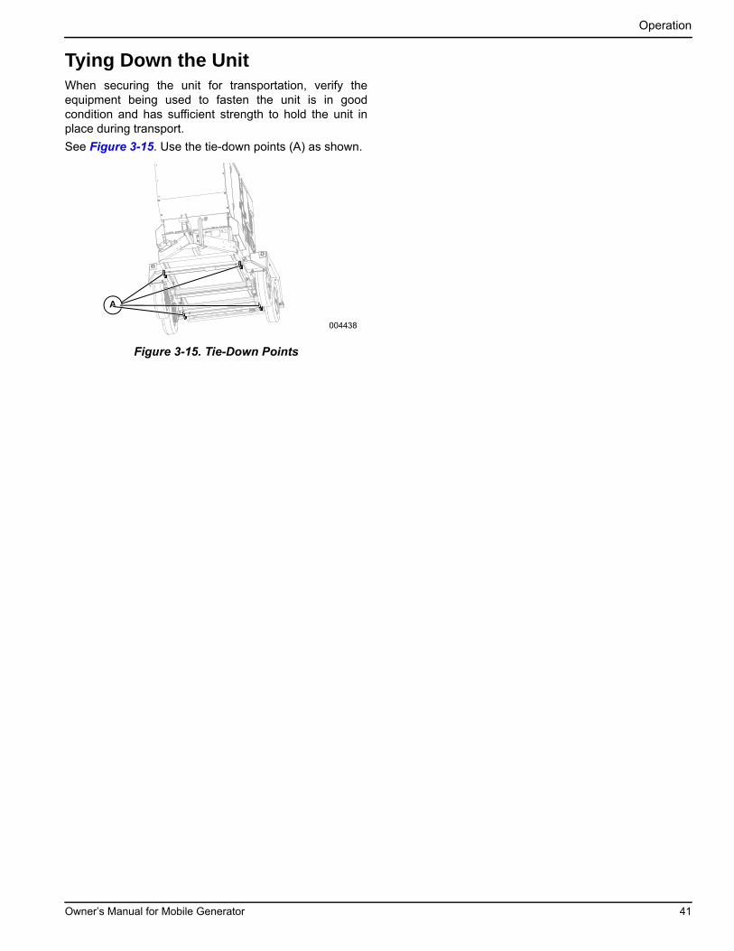
Operation
Tying Down the UnitWhen securing the unit for transportation, verify theequipment being used to fasten the unit is in goodcondition and has sufficient strength to hold the unit inplace during transport.
See Figure 3-15. Use the tie-down points (A) as shown.
Figure 3-15. Tie-Down Points
A
004438
Owner’s Manual for Mobile Generator 41

Operation
This page intentionally left blank.
42 Owner’s Manual for Mobile Generator

Section 4: Maintenance
Emissions InformationFor emissions information, see the OEM diesel enginemanual.
MaintenanceRegular maintenance will improve performance andextend engine/equipment life. Generac Mobile Products,LLC recommends that all maintenance work be per-formed by a Generac Mobile Authorized Service Dealer(GMASD). Regular maintenance, replacement, or repairof the emissions control devices and systems may beperformed by any repair shop or person of the owner’schoosing. To obtain emissions control warranty servicefree of charge, the work must be performed by aGMASD. See the emissions warranty.
Daily Walk Around Inspection
Inspect for conditions that could hinder performance orsafety, such as (but not limited to) oil, coolant, and fuelleakage, blocked vents, loose or missing hardware, andimproper electrical connections.
Inspect the fan belt for signs of cracking, fraying, andstretching, and verify the belt is properly seated in thepulley grooves. Replace the belt according to themanufacturer’s recommendations.
NOTE: At the 500 hour or 12 month service interval, it isrecommended that the belt be removed and checked forwear. While the belt is removed, inspect pulleys andbearings. Rotate and feel for hard turning or unusualsounds. Contact the engine manufacturer if pulleys orbearings need replacement.
Belt TensionersJohn Deere engines use two types of belt tensioners:manual and automatic. Adjust the belt using the manualtensioner according to the manufacturer’s specifications.The automatic tensioner cannot be adjusted or repairedand is designed to maintain proper tension over the belt’slife. Units with an automatic belt tensioner must beinspected according to the manufacturer’s specifications.
General MaintenancePoorly maintained equipment can become a safetyhazard. Periodic maintenance and occasional repairs arenecessary in order for the equipment to operate safelyand properly over a long period of time. Never performany routine service (oil and oil filter changes, cleaning,etc.) unless all electrical components are shut off. Beforeservicing the unit, always follow the instructions listedbelow.
• Verify the control power switch is turned OFF (O).
• Verify the circuit breakers are turned OFF (O).
• Activate (push in) the emergency stop switch.
• Disconnect the negative (-) terminal on the battery.
• Attach a DO NOT USE sign to the control panel.This signifies that the unit is being serviced andreduces the chance of someone inadvertentlytrying to start the unit.
• Do not wash the unit with a high pressure hose orwith any kind of power washer.
• Do not wash the engine block or fuel tank with apower washer or steam cleaner. Water may enterthe cabinet and collect in the generator windings orother electrical parts, causing damage.
• Inspect for water inside the cabinet and generatorbefore each use if the unit is stored outside. If wet,dry the unit thoroughly before starting.
• Inspect condition of electrical cords. DO NOT usethe unit if insulation is cut or worn through.
• Verify the condition of the air filter by viewing thelevel of the vacuum draw on the filter mindergauge. Replace the air filter when the yellow centerbar reaches the red section on the gauge (20 in.H2O).
• Inspect wheel lugs. See Towing the Unit.
• Inspect wheel bearings. See Trailer WheelBearings.
• Inspect the wheel bearings for unusual wear.
• Inspect coolant level daily. See the engineoperator’s manual for coolant recommendationsand proper mixture.
– Visually inspect the level in the coolant overflowtank located near the radiator.
– Normal operating level is between the FULL andADD markings on the overflow jug.
– When engine is stopped and completely cool,coolant may be added directly to the coolantoverflow container.
CAUTION
Equipment Damage. Failure to perform a daily inspection could result in damage to the unit.
(000306)
Owner’s Manual for Mobile Generator 43
Maintenance
• Check the oil level daily. See the engine operator’smanual for the proper viscosity grade of oil,including special operating conditions such as achange in season or climate.
– DO NOT start the unit if the engine oil level isbelow the add mark on the dipstick.
– Normal operating level is in the cross-hatchpattern between the FULL and ADD markings onthe dipstick.
– Add oil only if the oil level is below the ADD markon the bottom of the cross-hatch pattern on thedipstick.
– DO NOT OVERFILL the crankcase.
• Verify the fuel level.
• Verify the remote switch is also off and tagged ifthe unit is connected to a remote start or transferswitch.
NOTE: If the engine was run out of fuel, or the fuel tankwas drained, it may be necessary to purge the fuel lines.See the engine operator’s manual supplied with the unitfor more information.
Engine Oil RecommendationsThe engine oil should be serviced in accordance with therecommendations of this manual to maintain the productwarranty.
The engine has been filled with factory engine oil of agrade recommended by the engine supplier.
Use a high quality detergent oil with an appropriateclassification and viscosity for the engine type andambient temperature conditions. Contact a GMASD orrefer to the applicable engine service manual for moreinformation.
Recommended Oil Types
• Plus-50™ Oils: John Deere Plus-50, John DeerePlus-50 II
• Other Oils: John Deere Torq-Gard™ Supreme, APICJ-4, API CI-4 PLUS, API CI-4, API CH-4, ACEAE9, ACEA E7, ACEA E6, ACEA E5, ACEA E4
NOTE: The 500 hour extended oil and filter changeinterval is only allowed if all of the following conditionsare met:
• Use of John Deere Plus-50™ II or John DeerePlus-50™ oil.
• Use of an approved John Deere oil filter.
Coolant Recommendation
Contact a GMASD or refer to the applicable engineservice manual for engine coolant recommendations.See table below for mixtures:
* Maximum freeze protection is at 60%.
Basic Maintenance ScheduleSee the original equipment manufacturer’s operatingmanual for a complete list of maintenance requirements.Failure to comply with the procedures as described in theengine operator’s manual will nullify the warranty,decrease performance, and cause equipment damage orpremature equipment failure. Maintenance records maybe required to complete a warranty request.
NOTE: Refer to the engine operator’s manual for addi-tional maintenance information
Freezing Point °F (°C)-12
(-24)-34
(-36)-54
(-48)-90
(-67)
Water (% Volume) 50 40 40 40
Anitfreeze (% Volume) 50 60 60 60*
(000149)
DANGER
Risk of poisoning. Do not use mouth to siphon coolant. Doing so will result in death or serious injury.
(000154)
WARNING
Risk of burns. Do not open coolant systemuntil engine has completely cooled. Doing so could result in serious injury.
Risk of overheating. Do not use any chromate base rust inhibitor with propylene glycol base antifreeze, boosters, or additives. Doing so will cause overheating and possible equipment damage. (000165a)
CAUTION
44 Owner’s Manual for Mobile Generator
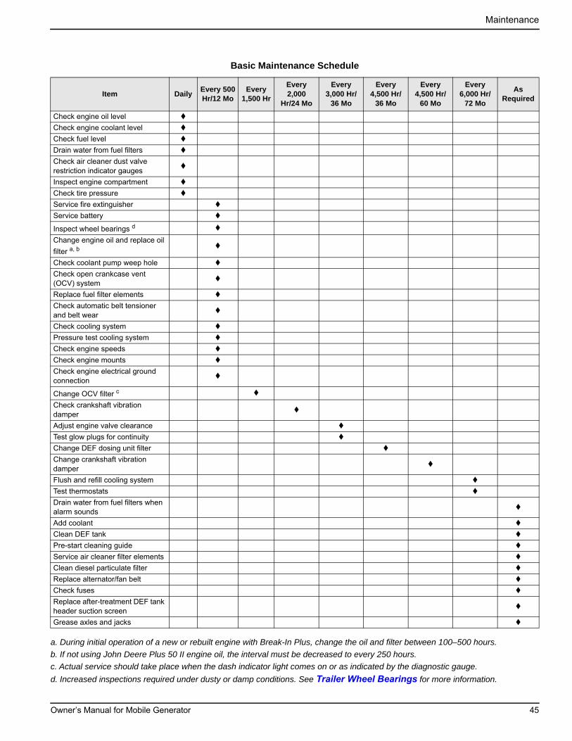
Maintenance
a. During initial operation of a new or rebuilt engine with Break-In Plus, change the oil and filter between 100–500 hours.
b. If not using John Deere Plus 50 II engine oil, the interval must be decreased to every 250 hours.
c. Actual service should take place when the dash indicator light comes on or as indicated by the diagnostic gauge.
d. Increased inspections required under dusty or damp conditions. See Trailer Wheel Bearings for more information.
Basic Maintenance Schedule
Item DailyEvery 500Hr/12 Mo
Every 1,500 Hr
Every 2,000
Hr/24 Mo
Every 3,000 Hr/
36 Mo
Every 4,500 Hr/
36 Mo
Every 4,500 Hr/
60 Mo
Every 6,000 Hr/
72 Mo
As Required
Check engine oil level
Check engine coolant level
Check fuel level
Drain water from fuel filters
Check air cleaner dust valve restriction indicator gauges
Inspect engine compartment
Check tire pressure
Service fire extinguisher
Service battery
Inspect wheel bearings d
Change engine oil and replace oil
filter a, b
Check coolant pump weep hole
Check open crankcase vent (OCV) system
Replace fuel filter elements
Check automatic belt tensioner and belt wear
Check cooling system
Pressure test cooling system
Check engine speeds
Check engine mounts
Check engine electrical ground connection
Change OCV filter c
Check crankshaft vibration damper
Adjust engine valve clearance
Test glow plugs for continuity
Change DEF dosing unit filter
Change crankshaft vibration damper
Flush and refill cooling system
Test thermostats
Drain water from fuel filters when alarm sounds
Add coolant
Clean DEF tank
Pre-start cleaning guide
Service air cleaner filter elements
Clean diesel particulate filter
Replace alternator/fan belt
Check fuses
Replace after-treatment DEF tank header suction screen
Grease axles and jacks
Owner’s Manual for Mobile Generator 45
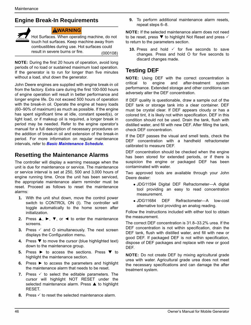
Maintenance
Engine Break-In Requirements
NOTE: During the first 20 hours of operation, avoid longperiods of no load or sustained maximum load operation.If the generator is to run for longer than five minuteswithout a load, shut down the generator.
John Deere engines are supplied with engine break-in oilfrom the factory. Extra care during the first 100-500 hoursof engine operation will result in better performance andlonger engine life. Do not exceed 500 hours of operationwith the break-in oil. Operate the engine at heavy loads(60–90% of maximum) as much as possible. If the enginehas spent significant time at idle, constant speed(s), orlight load, or if makeup oil is required, a longer break inperiod may be needed. Refer to the engine operator’smanual for a full description of necessary procedures onthe addition of break-in oil and extension of the break-inperiod. For more information on regular maintenanceintervals, refer to Basic Maintenance Schedule.
Resetting the Maintenance AlarmsThe controller will display a warning message when theunit is due for maintenance or service. The maintenanceor service interval is set at 250, 500 and 3,000 hours ofengine running time. Once the unit has been serviced,the appropriate maintenance alarm reminder must bereset. Proceed as follows to reset the maintenancealarms:
1. With the unit shut down, move the control powerswitch to CONTROL ON (I). The controller willtoggle automatically to the home screen afterinitialization.
2. Press ▲, ►, ▼, or ◄ to enter the maintenancescreens.
3. Press and O simultaneously. The next screendisplays the Configuration menu.
4. Press to move the cursor (blue highlighted text)down to the maintenance group.
5. Press ► to access the sections. Press tohighlight the maintenance section.
6. Press ► to access the parameters and highlightthe maintenance alarm that needs to be reset.
7. Press to select the editable parameters. Thecursor will highlight NOT RESET under theselected maintenance alarm. Press to highlightRESET.
8. Press to reset the selected maintenance alarm.
9. To perform additional maintenance alarm resets,repeat steps 6–8.
NOTE: If the selected maintenance alarm does not needto be reset, press to highlight Not Reset and press to return to the parameters section.
10. Press and hold for five seconds to savechanges. Press and hold O for five seconds todiscard changes made.
Testing DEFNOTE: Using DEF with the correct concentration iscritical to engine and after-treatment systemperformance. Extended storage and other conditions canadversely alter the DEF concentration.
If DEF quality is questionable, draw a sample out of theDEF tank or storage tank into a clear container. DEFmust be crystal clear. If DEF appears cloudy or has acolored tint, it is likely not within specification. DEF in thiscondition should not be used. Drain the tank, flush withdistilled water, and fill with new DEF. After filling the tank,check DEF concentration.
If the DEF passes the visual and smell tests, check theDEF concentration with a handheld refractometercalibrated to measure DEF.
DEF concentration should be checked when the enginehas been stored for extended periods, or if there issuspicion the engine or packaged DEF has beencontaminated with water.
Two approved tools are available through your JohnDeere dealer:
• JDG11594 Digital DEF Refractometer—A digitaltool providing an easy to read concentrationmeasurement.
• JDG11684 DEF Refractometer—A low-costalternative tool providing an analog reading.
Follow the instructions included with either tool to obtainthe measurement.
The correct DEF concentration is 31.8–33.2% urea. If theDEF concentration is not within specification, drain theDEF tank, flush with distilled water, and fill with new orgood DEF. If packaged DEF is not within specification,dispose of DEF packages and replace with new or goodDEF.
NOTE: Do not create DEF by mixing agricultural gradeurea with water. Agricultural grade urea does not meetthe necessary specifications and can damage the aftertreatment system.
(000108)
WARNING
Hot Surfaces. When operating machine, do not touch hot surfaces. Keep machine away from combustibles during use. Hot surfaces could result in severe burns or fire.
46 Owner’s Manual for Mobile Generator
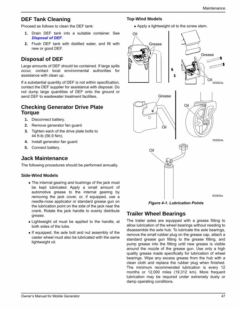
Maintenance
DEF Tank CleaningProceed as follows to clean the DEF tank:
1. Drain DEF tank into a suitable container. SeeDisposal of DEF.
2. Flush DEF tank with distilled water, and fill withnew or good DEF.
Disposal of DEFLarge amounts of DEF should be contained. If large spillsoccur, contact local environmental authorities forassistance with clean up.
If a substantial quantity of DEF is not within specification,contact the DEF supplier for assistance with disposal. Donot dump large quantities of DEF onto the ground orsend DEF to wastewater treatment facilities.
Checking Generator Drive Plate Torque
1. Disconnect battery.
2. Remove generator fan guard.
3. Tighten each of the drive plate bolts to 44 ft-lb (56.9 Nm).
4. Install generator fan guard.
5. Connect battery.
Jack MaintenanceThe following procedures should be performed annually.
Side-Wind Models
• The internal gearing and bushings of the jack mustbe kept lubricated. Apply a small amount ofautomotive grease to the internal gearing byremoving the jack cover, or, if equipped, use aneedle-nose applicator or standard grease gun onthe lubrication point on the side of the jack near thecrank. Rotate the jack handle to evenly distributegrease.
• Lightweight oil must be applied to the handle, atboth sides of the tube.
• If equipped, the axle bolt and nut assembly of thecaster wheel must also be lubricated with the samelightweight oil.
Top-Wind Models
• Apply a lightweight oil to the screw stem.
Figure 4-1. Lubrication Points
Trailer Wheel BearingsThe trailer axles are equipped with a grease fitting toallow lubrication of the wheel bearings without needing todisassemble the axle hub. To lubricate the axle bearings,remove the small rubber plug on the grease cap, attach astandard grease gun fitting to the grease fitting, andpump grease into the fitting until new grease is visiblearound the nozzle of the grease gun. Use only a highquality grease made specifically for lubrication of wheelbearings. Wipe any excess grease from the hub with aclean cloth and replace the rubber plug when finished.The minimum recommended lubrication is every 12months or 12,000 miles (19,312 km). More frequentlubrication may be required under extremely dusty ordamp operating conditions.
Oil
Grease
Oil
Grease
002823a
Grease
Oil
Oil
002824a
Oil
002825a
Owner’s Manual for Mobile Generator 47

Maintenance
This page intentionally left blank.
48 Owner’s Manual for Mobile Generator
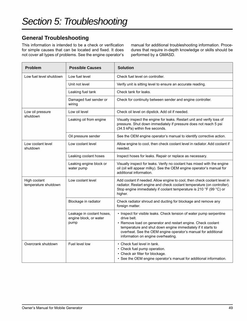
Section 5: Troubleshooting
General TroubleshootingThis information is intended to be a check or verificationfor simple causes that can be located and fixed. It doesnot cover all types of problems. See the engine operator’s
manual for additional troubleshooting information. Proce-dures that require in-depth knowledge or skills should beperformed by a GMASD.
Problem Possible Causes Solution
Low fuel level shutdown Low fuel level Check fuel level on controller.
Unit not level Verify unit is sitting level to ensure an accurate reading.
Leaking fuel tank Check tank for leaks.
Damaged fuel sender or wiring
Check for continuity between sender and engine controller.
Low oil pressure shutdown
Low oil level Check oil level on dipstick. Add oil if needed.
Leaking oil from engine Visually inspect the engine for leaks. Restart unit and verify loss of pressure. Shut down immediately if pressure does not reach 5 psi (34.5 kPa) within five seconds.
Oil pressure sender See the OEM engine operator’s manual to identify corrective action.
Low coolant level shutdown
Low coolant level Allow engine to cool, then check coolant level in radiator. Add coolant if needed.
Leaking coolant hoses Inspect hoses for leaks. Repair or replace as necessary.
Leaking engine block or water pump
Visually inspect for leaks. Verify no coolant has mixed with the engine oil (oil will appear milky). See the OEM engine operator’s manual for additional information.
High coolant temperature shutdown
Low coolant level Add coolant if needed. Allow engine to cool, then check coolant level in radiator. Restart engine and check coolant temperature (on controller). Stop engine immediately if coolant temperature is 210 °F (99 °C) or higher.
Blockage in radiator Check radiator shroud and ducting for blockage and remove any foreign matter.
Leakage in coolant hoses, engine block, or water pump
• Inspect for visible leaks. Check tension of water pump serpentine drive belt.
• Remove load on generator and restart engine. Check coolant temperature and shut down engine immediately if it starts to overheat. See the OEM engine operator’s manual for additional information on engine overheating.
Overcrank shutdown Fuel level low • Check fuel level in tank.• Check fuel pump operation.• Check air filter for blockage.• See the OEM engine operator’s manual for additional information.
Owner’s Manual for Mobile Generator 49

Troubleshooting
This page intentionally left blank.
50 Owner’s Manual for Mobile Generator

Section 6: Wiring Diagrams
Wiring Diagrams
Owner’s Manual for Mobile Generator 51
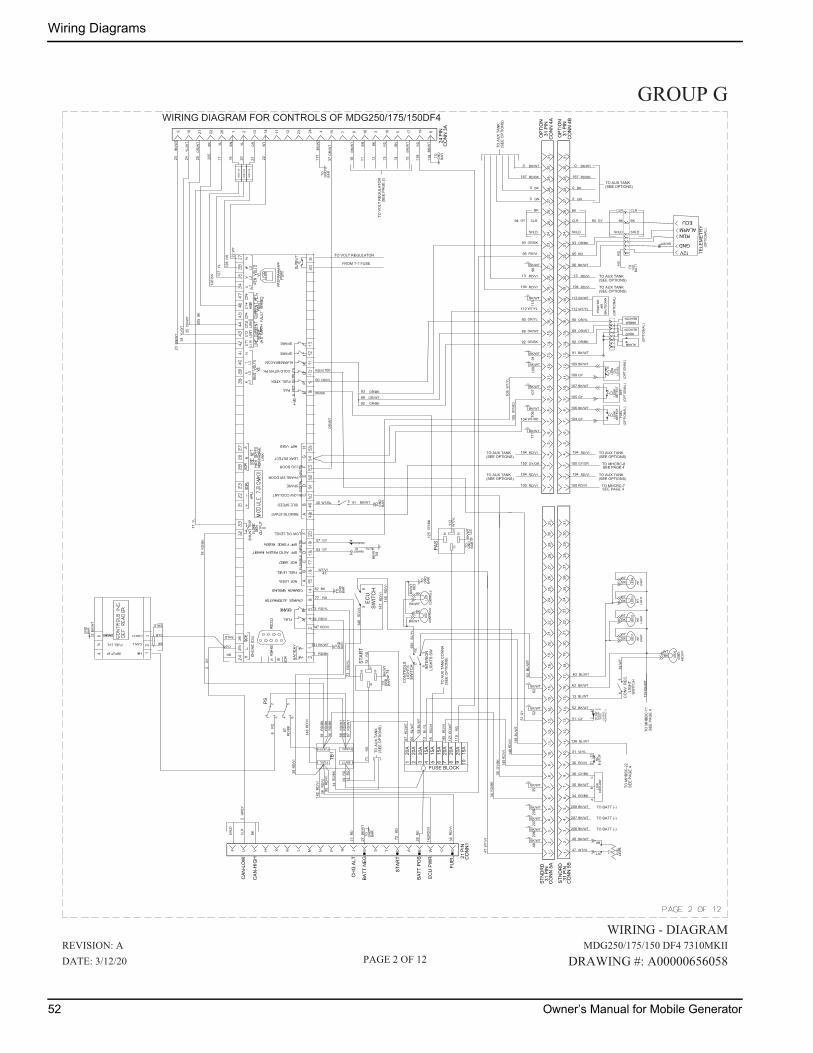
Wiring Diagrams
WIRING DIAGRAM FOR CONTROLS OF MDG250/175/150DF4
BN
YL
OR
BN/W
T YL/W
T OR
/WT
BKCLR
SHLD
87
86
3085
STAR
TR
D
RD
/VI
TO GN
DBA
R
BK/W
T
BATT
FUSEDFU&SW1
20A
20A
15A
RD
/WT
RD
RD
RD
/WT
15A
WT
1 2 3 4
TB1
FUEL
TO GN
DBA
RBK
/WT
X
T CA WM
N P R SH
JK LU E BV DF G
515
A6
BAR
GN
DTO
BK/W
T
RD
/BK
RD
13 18 1916 1712 23 42 1514 1120 51 3 610 219
118
174
112
2221
293
2827
265
610
1225
137
3124
1630
89
1920
2315
14
BK/WT
2
65
432
1
NC
CO
NTR
OLS
SWIT
CH
56
LIG
HTS
BK
BK/WT
BAR
GN
DTO
INTE
RIO
RLI
GH
TS S
W
BAR
GN
DTO
2
6
OR
/WT
10 11 12 13 1514
18
17
18
126
127
128
2219 20 21 22
2324
25
23 24 25
27 28
29
145
146
BK
WT
PH S
WD
OO
R
CN
O
(HEL
DC
LOSE
DN
OR
MAL
LY)BK/WT
118
174
112
2221
293
2827
265
610
1225
137
3124
1630
89
1920
2315
14
3436
3437
47
48
51
13
BL/W
T
BAR
GN
D
CAN H
CAN L
INPUT #1
FUEL LVL
5
67
6968
7172
74
38
38
39
C
77
87
87
14
112
35
610
1213
78
915
14
14
112
35
610
1213
78
915
14
1817
2221
2928
2726
2531
2416
3019
2023
1817
2221
2928
2726
2531
2416
3019
2023
20A
105
118
1
117
56
CO
NV.
REC
.
SWIT
CH
LIG
HT
WTBK
119
YRTE
MELET
69
TO 12V
BATT
BK/WT
BK
CLR
SHLD
CLR
BK
SHLD
94
95
INHIBIT
MANUAL
AUTO
54
6 5
FUSE BLOCK
87
86
3085
PAS
TO GN
DBA
RBK
/WT
20A
20A
15A
7 8 9 1020
A
65
64
121
123
112
125
119
SWIT
CH
ECU
600V
5A
600V
5A
600V
5A
148
147
146
142
BK
BK/WT
RD
RD
/WT
RD
/WT
RD
/BK
RD
/BK
148
RD
/BK
BL/Y
L
RD
/WT
RD
BL/W
T
RD
/VI
RD
/VI R
D/V
I
BK/W
T
RD
BN/W
T
BNRDBKBN
BN/W
T
BK/W
T
WT
ORYLBNYL
OR
/WT
YL/W
T
BN/W
T
GN
DBA
R
TO
BK/WT
GN
DBA
R
TO
41
BK/W
T
GR
EY
RD
/BK
WT/
VI
RD
/BK
GY/
BK
RD
/VI
RD
/VI
GY
BL/W
T
WT/
YL
OR
/BK
WT/
RD
GY
89 OR/WT
92 OR/BK
OR/BK
142R
D/V
I
661
BL/Y
L
93 OR/BK
94 GY
145
RD
/VI
TO MHCRC-7SEE PAGE 4
95 RD
96 BK/WT
90 OR/YL
92 OR/BK
89 OR/WT
91 BK/WT
109 BK/WT
108 GY
107 BK/WT
105 GY
106 BK/WT
104 GY
100 RD/VI
63 BL/WT
62 BK/WT
13 BL/WT
52 BK/WT
51 GY
138 BL/WT
31 VI/YL
30 RD/VI
36 GY/BK
35 BK/WT
34 RD/BK
48 BK/WT
47 WT/VI
BK/WT
BK/WT
BK/WT
BK/WT
BK/WT
BK/WT
BK/WT
BK/WT
BK/WT
BK/WT
3552
6211
110
610
710
991
113
96
RD
RD
/VI
RD
/VI
RD
/VI
RD
/VI
GY
BK/W
T66
3
PS
1 RD/BK
141 BK/WT
147 RD/VI
39 RD/VI
73 RD/YL
47WT/VI
82 BK
40 WT/BL
53 GY
57 GY
OR/BK
90 OR/YL
TO M
HBB
C-1
1
TO M
HBB
C-2
2SE
E PA
GE
4
22 24
63
RD
/YL
73
RD
72
RD/VI
108
WT/
YL
87
65
138
BL/W
T
GY/OR 150 GY/OR TO MHCRC-8SEE PAGE 4
BK
CLR
SHLD
BK
CLR
SHLD
139
BK/W
T
(OPT
ION
AL)
(OPT
ION
AL)
(OPT
ION
AL)
(OPT
ION
AL)
(OPT
ION
AL)
WTBK
WTBK
WTBK
WTBK
TO V
OLT
REG
ULA
TOR
(SEE
PAG
E 2)
93
104 WT/RD
112 WT/YL
90 OR/YL
89 OR/WT
92 OR/BK
93 OR/BK
95 RD/VI
150
100
YL17
TO A
UX
TAN
K(S
EE O
PTIO
NS)
TO AUX TANK(SEE OPTIONS)
RD/VI194
RD/VI194
TO AUX TANK(SEE OPTIONS)
113 BK/WT
112 WT/YL
(OPT
ION
AL)
RD/VI194
RD/VI13
GN0
BK0
RD/BK167
BK/WT0
TO A
UX
TAN
K(S
EE O
PTIO
NS)
RD
/BK
14
RD
13
TO AUX TANK(SEE OPTIONS)
TO AUX TANK(SEE OPTIONS)
TO A
UX
TAN
K C
ON
N4
(SEE
OPT
ION
S)
15R
D/V
I
RD/VI194
RD/VI194
RD/VI194
RD/VI13
GN0
BK0
RD/BK167
BK/WT0
TO AUX TANK(SEE OPTIONS)
207 BK/WT
SEE
PAG
E 4
TO AUX TANK(SEE OPTIONS)
TO AUX TANK(SEE OPTIONS)
TO BATT (-)
SHLD
CLR
BK
BK
CLR
SHLD
BK20
5
BK20
5
GN
DBA
R
TO
BK/WT
207
BK/WT
206
BK/WT
208
206 BK/WT TO BATT (-)
208 BK/WT TO BATT (-)
65
4
BL/W
TR
D14
0
RD
/VI
GROUP G
WIRING - DIAGRAM
MDG250/175/150 DF4 7310MKII
DRAWING #: A00000656058
REVISION: A
DATE: 3/12/20 PAGE 2 OF 12
SPARE
LOW COOLANT
REMOTE START
PAS
LUG DOOR
LOW OIL LEVEL
SHU
NT
TRIP
FUEL XFER
COLD WTHR PK
ALARM/BEACON
LEAK DETECT
SPARE
AB
AB
CD
EF
GH
JI
HG
FE
IDLE SPEED
SPARE
PHASE SW DOOR
AB
CD
EF
RD77
OR
/WT
100RD/VI
TO VOLT REGULATOR
FROM T-7 FUSE
52 Owner’s Manual for Mobile Generator
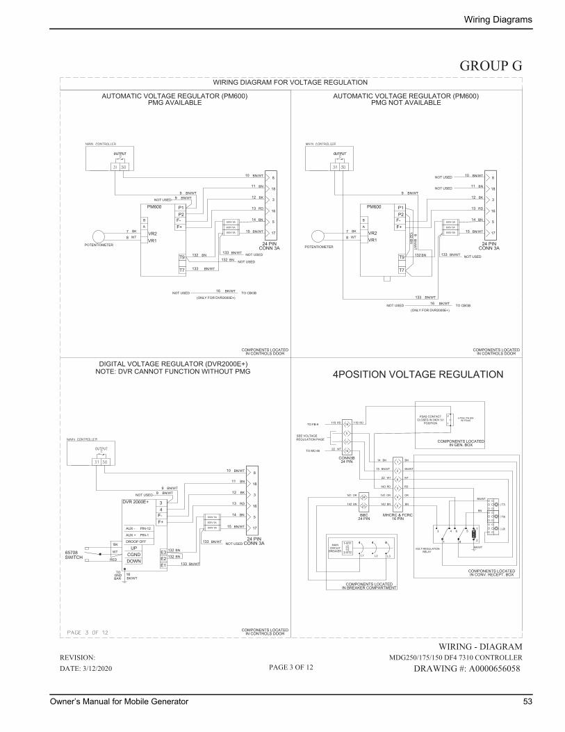
Wiring Diagrams
WIRING DIAGRAM FOR VOLTAGE REGULATION
AUTOMATIC VOLTAGE REGULATOR (PM600)
DIGITAL VOLTAGE REGULATOR (DVR2000E+)
18
16
17
5
3
9
10
11
12
13
132
133
15
14
16BARGNDTO
600V 5A
600V 5A
600V 5A BN/WT
BN
RD
BK
BN
BN/WT
BN/WT
BN
BN/WT
BK/WT
8
BK
WT
133 BN/WT NOT USED
9 BN/WTNOT USED
132 BN
18
16
17
5
3
87
9
10
11
12
13
132
133
14600V 5A
600V 5A
600V 5A
BN
RD
BK
BN
BN/WT
BN/WT
BN
BN/WT
8
16
17
5
3
912
13
132
15
14600V 5A
600V 5A
600V 5A BN/WT
BN
RD
BK
BN
NOT USED
132BN
9BN
/WT
BN/WT133
BK
WT 87 BK
WT
18
8
11 BNNOT USEDBN/WT
10 BN/WT
133 BN/WT NOT USED
9 BN/WTNOT USED
132 BN NOT USED
16 BK/WT TO CBGBNOT USED(ONLY FOR DVR2000E+)
16 BK/WT TO CBGBNOT USED(ONLY FOR DVR2000E+)
15 BN/WT
133 BN/WT NOT USED
NOTE: DVR CANNOT FUNCTION WITHOUT PMG
PMG AVAILABLEAUTOMATIC VOLTAGE REGULATOR (PM600)
PMG NOT AVAILABLE
4POSITION VOLTAGE REGULATION
BK/WT
3 4 6 57
81 2
1
2
3
4
5
24
23
L3L2L1
1-ST1
2-ST2
BN
OR
142
141
19
4 POS. PH SWW/ PSAS
TO FB-9
RD143
BN/WT15
BN14
14
5SEE VOLTAGE
RD119
BN
OR
BN
BN/WT
BN
REGULATION PAGE
BN
OR
142
141
RD119
BN/WT
RD
6WT22 WT
17
TO MC-46 WT22
GROUP G
WIRING - DIAGRAM
MDG250/175/150 DF4 7310 CONTROLLER
DRAWING #: A0000656058
REVISION:
DATE: 3/12/2020 PAGE 3 OF 12
POTENTIOMETER POTENTIOMETER
RED
Owner’s Manual for Mobile Generator 53
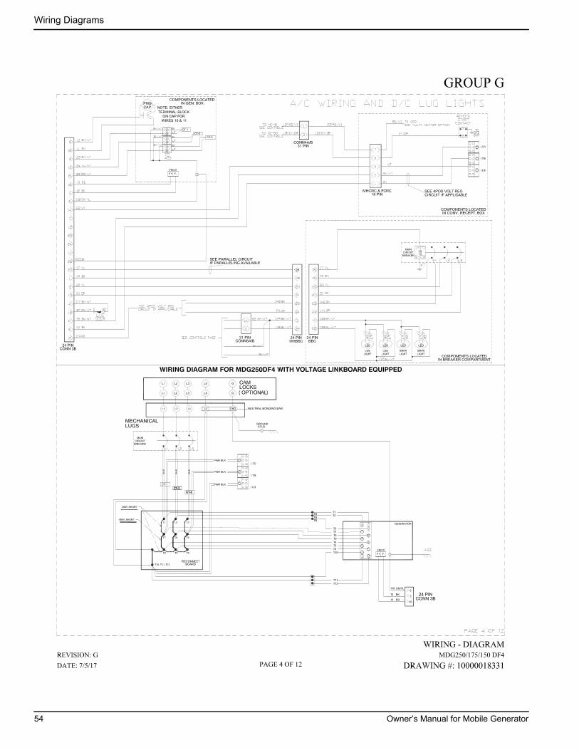
Wiring Diagrams
54 Owner’s Manual for Mobile Generator
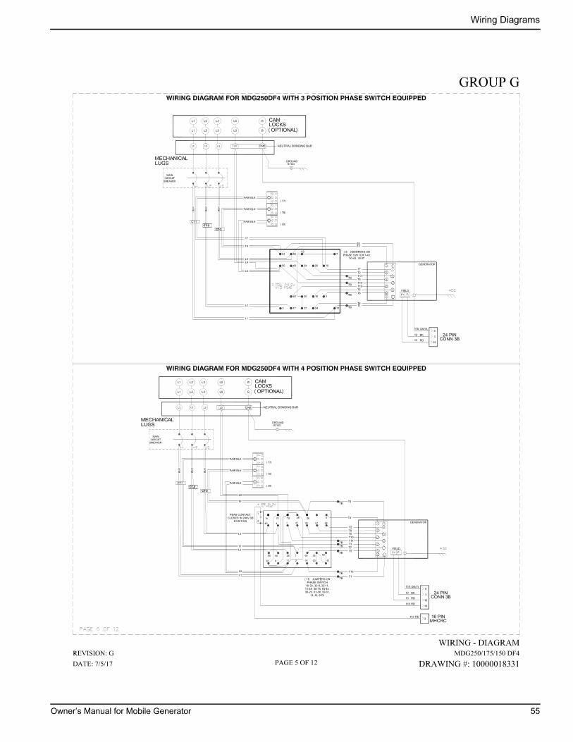
Wiring Diagrams
Owner’s Manual for Mobile Generator 55
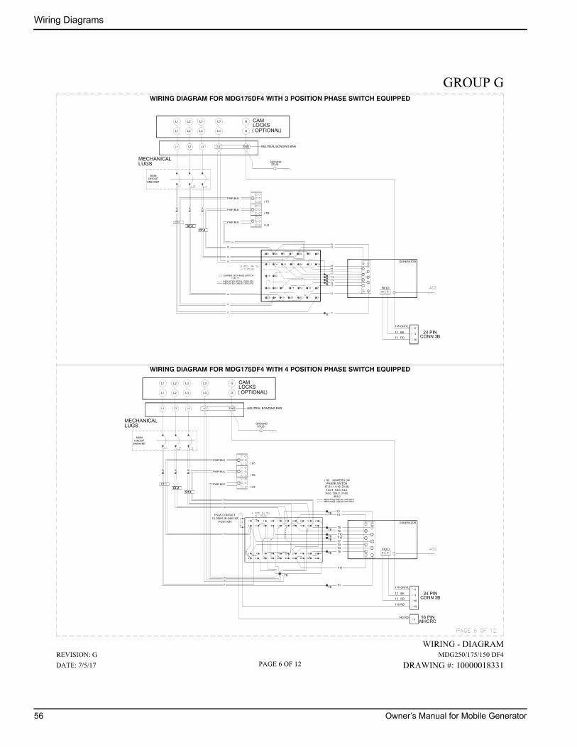
Wiring Diagrams
56 Owner’s Manual for Mobile Generator

Wiring Diagrams
Owner’s Manual for Mobile Generator 57

Wiring Diagrams
58 Owner’s Manual for Mobile Generator
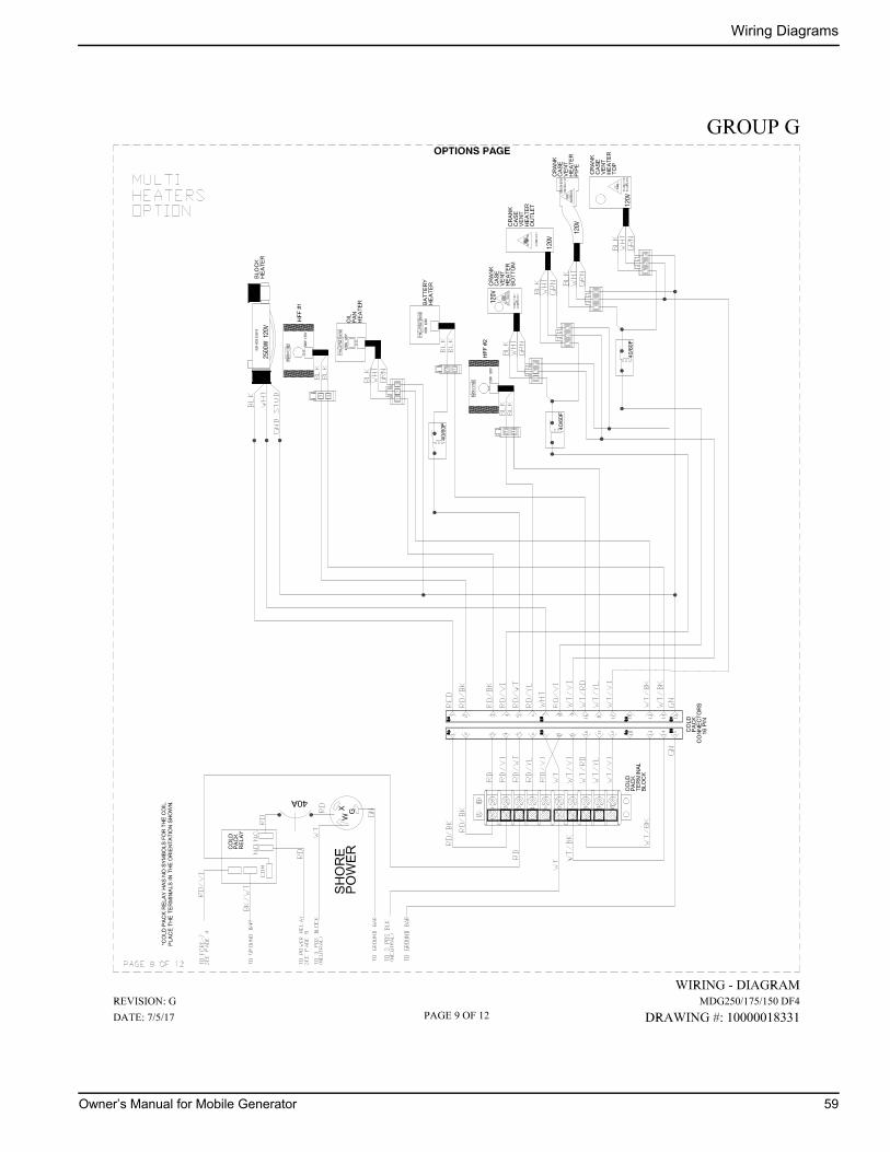
Wiring Diagrams
Owner’s Manual for Mobile Generator 59
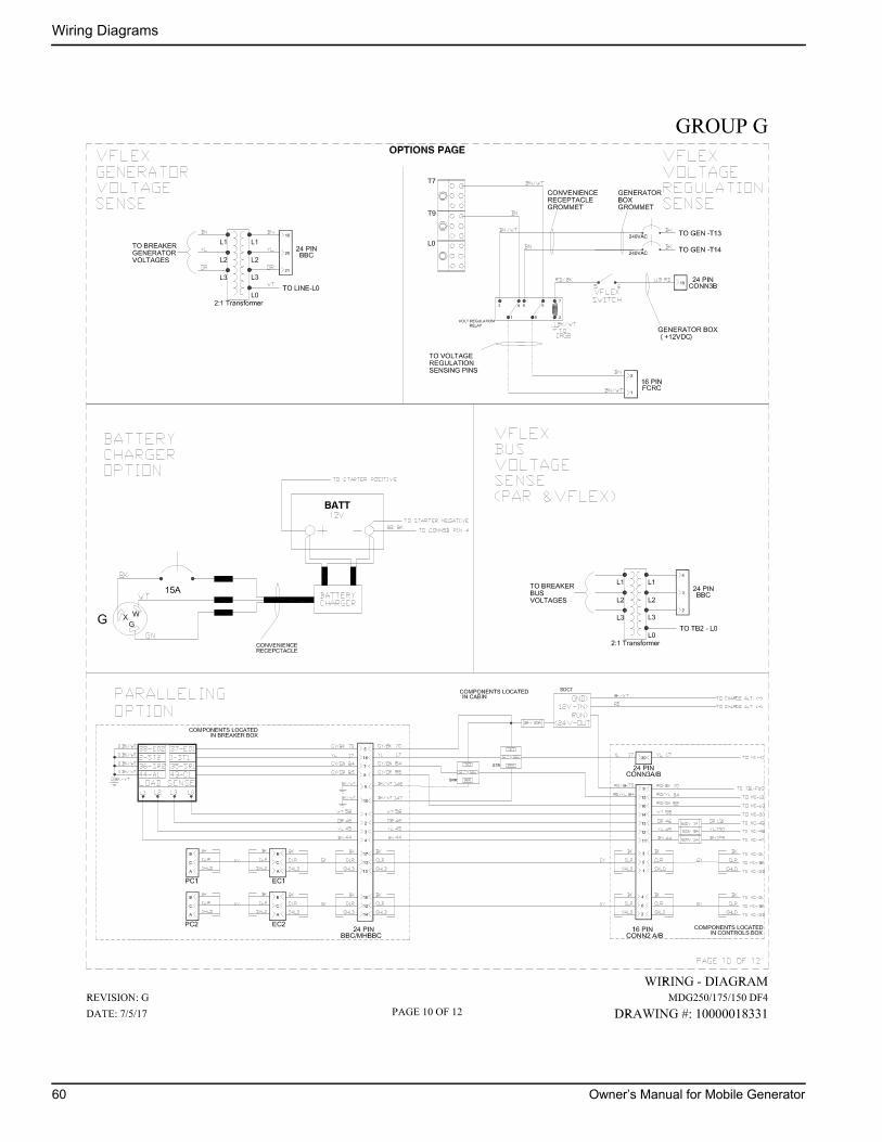
Wiring Diagrams
60 Owner’s Manual for Mobile Generator
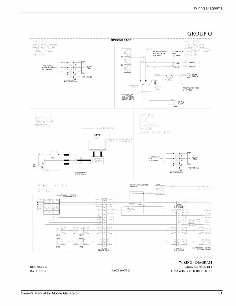
Wiring Diagrams
Owner’s Manual for Mobile Generator 61
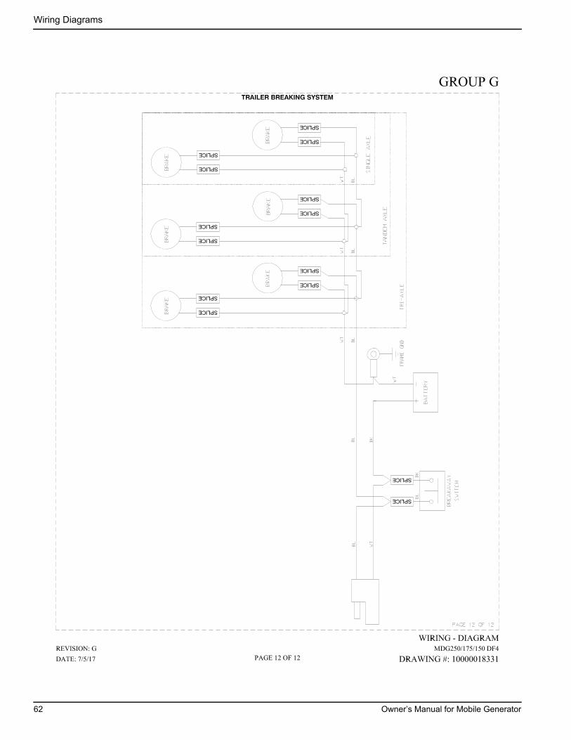
Wiring Diagrams
62 Owner’s Manual for Mobile Generator


Part No. A0000393893 Rev. A 05/18/2020
©2020 Generac Mobile Products, LLCAll rights reserved.Specifications are subject to change without notice.No reproduction allowed in any form without prior written consent from Generac Mobile Products, LLC.
Generac Mobile Products, LLC215 Power Drive, Berlin, WI 54923
GeneracMobileProducts.com │800-926-9768 │920-361-4442