OWNER'S MANUAL 2018 1090 Adventure R - KTMSHOP.se
307
OWNER'S MANUAL 2018 1090 Adventure R Art. no. 3213756en
-
Upload
khangminh22 -
Category
Documents
-
view
1 -
download
0
Transcript of OWNER'S MANUAL 2018 1090 Adventure R - KTMSHOP.se

OWNER'S MANUAL 2018
1090 Adventure RArt. no. 3213756en

DEAR KTM CUSTOMER
*3213756en*3213756en
10/2017
DEAR KTM CUSTOMER
Congratulations on your decision to purchase a KTM motorcycle. You are now the owner of a state-of-the-artsports motorcycle that will give you enormous pleasure if you service and maintain it properly.
We hope you enjoy riding this motorcycle!
Please enter the serial numbers of your vehicle below.
Chassis number ( p. 26) Dealer's stamp
Engine number ( p. 28)
Key number ( p. 27)
The Owner's Manual contained the latest information for this model series at the time of going to print. However,minor differences due to further developments in design cannot be ruled out completely.
All specifications are non-binding. KTM Sportmotorcycle GmbH specifically reserves the right to modify or deletetechnical specifications, prices, colors, forms, materials, services, designs, equipment, etc., without prior noticeand without specifying reasons, to adapt these to local conditions, as well as to stop production of a particularmodel without prior notice. KTM accepts no liability for delivery options, deviations from figures and descriptions,misprints, and other errors. The models portrayed partly contain special equipment that does not belong to theregular scope of supply.
© 2017 KTM Sportmotorcycle GmbH, Mattighofen AustriaAll rights reserved
DEAR KTM CUSTOMER
2
Reproduction, even in part, as well as copying of all kinds, is permitted only with the express written permissionof the copyright owner.
ISO 9001(12 100 6061)According to the international quality management standard ISO 9001, KTM uses quality assur-ance processes that lead to the maximum possible quality of the products.Issued by: TÜV Management Service
KTM Sportmotorcycle GmbHStallhofnerstraße 35230 Mattighofen, Austria
This document is valid for the following models:
1090 Adventure R EU (F9903RD)
1090 Adventure R CN (F9987RD)
TABLE OF CONTENTS
3
TABLE OF CONTENTS
1 MEANS OF REPRESENTATION .................... 10
1.1 Symbols used .................................. 101.2 Formats used................................... 11
2 SAFETY ADVICE.......................................... 12
2.1 Use definition – intended use............ 122.2 Misuse............................................ 122.3 Safety advice................................... 122.4 Degrees of risk and symbols .............. 132.5 Tampering warning........................... 142.6 Safe operation ................................. 142.7 Protective clothing ........................... 162.8 Work rules....................................... 162.9 Environment.................................... 172.10 Owner's Manual ............................... 17
3 IMPORTANT NOTES.................................... 18
3.1 Warranty ......................................... 183.2 Operating and auxiliary substances .... 183.3 Spare parts, accessories ................... 183.4 Service ........................................... 193.5 Figures ........................................... 193.6 Customer service.............................. 19
4 VIEW OF VEHICLE ...................................... 22
4.1 View of vehicle, front left (example) ... 224.2 View of vehicle, rear right
(example)........................................ 24
5 SERIAL NUMBERS ..................................... 26
5.1 Chassis number ............................... 265.2 Type label ....................................... 265.3 Key number..................................... 275.4 Engine number ................................ 285.5 Fork part number ............................. 285.6 Shock absorber article number .......... 29
6 CONTROLS................................................. 30
6.1 Clutch lever..................................... 306.2 Hand brake lever.............................. 306.3 Throttle grip .................................... 316.4 Switches on the left side of the
handlebar........................................ 316.4.1 Combination switch...................... 316.4.2 Light switch ................................ 326.4.3 Hazard warning flasher switch....... 336.4.4 Menu switch................................ 346.4.5 Turn signal switch........................ 346.4.6 Horn button ................................ 35
TABLE OF CONTENTS
4
6.5 Switches on the right side of thehandlebar........................................ 36
6.5.1 Emergency OFF switch ................. 366.5.2 Electric starter button .................. 366.6 Ignition/steering lock........................ 376.7 Immobilizer ..................................... 386.8 Locking the steering......................... 396.9 Unlocking the steering...................... 406.10 Opening the filler cap....................... 406.11 Closing the filler cap ........................ 426.12 Fuel cocks....................................... 446.13 Opening the storage compartment ..... 446.14 Closing the storage compartment....... 456.15 Seat lock......................................... 456.16 Grab handles ................................... 466.17 Luggage rack plate ........................... 466.18 Case holders.................................... 476.19 Passenger footrest............................ 486.20 Shift lever ....................................... 486.21 Foot brake lever ............................... 496.22 Side stand....................................... 50
7 COMBINATION INSTRUMENT ..................... 51
7.1 Overview ......................................... 517.2 Activation and test ........................... 517.3 Matrix display .................................. 53
7.4 Segment display .............................. 537.5 Fuel level display ............................. 547.6 Indicator lamps................................ 557.7 Message on the matrix display........... 577.8 Shift warning light ........................... 597.9 service display ................................. 607.10 Matrix display menu......................... 607.10.1 "Favorites"................................... 607.10.2 "Trip 1"....................................... 617.10.3 "Trip 2"....................................... 627.10.4 "General Info" .............................. 637.10.5 "Set Favorites" ............................. 637.10.6 "Settings" .................................... 647.10.7 "Warning".................................... 647.10.8 "Heating" (optional)...................... 657.10.9 "MTC/ABS".................................. 657.10.10 "Drive Mod" ................................. 667.10.11 menu overview............................. 687.10.12 "Language".................................. 697.10.13 "Distance" ................................... 707.10.14 "Temp" ....................................... 707.10.15 "Pressure" ................................... 717.10.16 "Fuel Cons" ................................. 717.10.17 "Clock/Date" ................................ 727.10.18 "Shift Light" ................................ 727.10.19 "Heat Grip".................................. 73
TABLE OF CONTENTS
5
7.10.20 "DRL" ......................................... 74
8 ERGONOMICS ............................................ 76
8.1 Handlebar position........................... 768.2 Adjusting the handlebar position .... 768.3 Adjusting the wind shield ................. 788.4 Adjusting basic position of clutch
lever ............................................... 808.5 Adjusting the basic position of the
hand brake lever .............................. 818.6 Rider footrests ................................. 818.7 Adjusting the footrests .................. 828.8 Checking the basic position of the
shift lever........................................ 858.9 Adjusting the basic position of the
shift lever .................................... 868.10 Adjusting the basic position of the
foot brake lever ............................ 88
9 PREPARING FOR USE................................. 89
9.1 Advice on preparing for first use ........ 899.2 Running in the engine ...................... 919.3 Loading the vehicle .......................... 91
10 RIDING INSTRUCTIONS.............................. 94
10.1 Checks and maintenance measureswhen preparing for use ..................... 94
10.2 Starting the vehicle .......................... 9510.3 Starting off...................................... 9710.4 Shifting, riding ................................ 9810.5 Applying the brakes........................ 10310.6 Stopping, parking........................... 10610.7 Transporting .................................. 10810.8 Refueling ...................................... 109
11 SERVICE SCHEDULE ................................ 112
11.1 Additional information.................... 11211.2 Required work ............................... 11211.3 Recommended work ....................... 115
12 SUSPENSION SETTING............................. 116
12.1 Fork/shock absorber ....................... 11612.2 Adjusting the compression
damping of the fork........................ 11612.3 Adjusting the rebound damping of
the fork......................................... 11812.4 Adjusting the spring pretension of
the fork......................................... 119
TABLE OF CONTENTS
6
12.5 Compression damping of the shockabsorber........................................ 120
12.6 Adjusting the low-speedcompression damping of the shockabsorber........................................ 121
12.7 Adjusting the high-speedcompression damping of the shockabsorber........................................ 122
12.8 Adjusting the rebound damping ofthe shock absorber ......................... 124
12.9 Adjusting the spring pretension ofthe shock absorber ......................... 125
13 SERVICE WORK ON THE CHASSIS............. 126
13.1 Raising the motorcycle with therear lifting gear .............................. 126
13.2 Removing the rear of motorcyclefrom the lifting gear ....................... 126
13.3 Lifting the motorcycle with thefront lifting gear............................. 127
13.4 Taking the motorcycle off the frontlifting gear .................................... 128
13.5 Raising the motorcycle with thework stand (inserted) .................. 129
13.6 Removing the motorcycle from thework stand (inserted) .................. 131
13.7 Removing the seat ......................... 13313.8 Mounting the seat .......................... 13313.9 Checking for chain dirt ................... 13413.10 Cleaning the chain ......................... 13413.11 Checking the chain tension ............. 13613.12 Adjusting the chain tension............. 13713.13 Checking the chain, rear sprocket,
and engine sprocket ....................... 13913.14 Checking/correcting the fluid level
of the hydraulic clutch.................... 14213.15 Checking the play of the steering
head bearing ................................. 14413.16 Removing the bottom triple clamp
cover ............................................ 14613.17 Installing the bottom triple clamp
cover ............................................ 14713.18 Removing the front side cover ......... 14813.19 Installing the front side cover .......... 14913.20 Removing the mask spoiler .......... 15013.21 Installing the mask spoiler .......... 15413.22 Removing front fender .................... 15713.23 Installing front fender..................... 15713.24 Cleaning the dust boots of the fork
legs ........................................... 15813.25 Removing the tank cover................. 16013.26 Installing the tank cover ................. 162
TABLE OF CONTENTS
7
13.27 Removing the wind shield ............... 16413.28 Installing the wind shield................ 16413.29 Removing the engine guard............. 16513.30 Installing the engine guard ............. 16513.31 Removing the crash bar .............. 16613.32 Installing the crash bar ............... 168
14 BRAKE SYSTEM ....................................... 172
14.1 Antilock brake system (ABS) ........... 17214.2 Checking the brake discs ................ 17514.3 Checking the front brake fluid
level ............................................. 17614.4 Adding front brake fluid .............. 17714.5 Checking the front brake linings ...... 18014.6 Checking the rear brake fluid
level ............................................. 18114.7 Adding rear brake fluid ............... 18214.8 Checking the rear brake linings ....... 185
15 WHEELS, TIRES ....................................... 186
15.1 Removing the front wheel ............ 18615.2 Installing the front wheel ............ 18815.3 Removing the rear wheel ............. 19215.4 Installing the rear wheel .............. 19515.5 Checking the rear hub rubber
dampers .................................... 198
15.6 Checking the tire condition ............. 20015.7 Checking the tire air pressure.......... 20215.8 Checking spoke tension .................. 20315.9 Tubeless tire system....................... 205
16 ELECTRICAL SYSTEM ............................... 206
16.1 Daytime running light ..................... 20616.2 Removing the battery .................. 20716.3 Installing the battery ................... 20916.4 Recharging the battery ................ 21216.5 Changing the main fuse.................. 21716.6 Changing the fuses in the fuse
box ............................................... 22016.7 Removing the headlight mask with
the headlight ................................. 22316.8 Installing the headlight mask with
the headlight ................................. 22416.9 Changing the low beam bulb ........... 22616.10 Changing the high beam bulb.......... 22816.11 Changing the turn signal bulb ......... 23016.12 Checking the headlight setting ........ 23116.13 Adjusting the headlight range.......... 23216.14 Activating/deactivating the ignition
key ............................................... 23316.15 Diagnostics connector .................... 23916.16 Front ACC1 and ACC2 .................... 240
TABLE OF CONTENTS
8
16.17 ACC1 and ACC2 rear ...................... 240
17 COOLING SYSTEM.................................... 241
17.1 Checking the coolant level in thecompensating tank......................... 241
17.2 Correcting the coolant level in thecompensating tank......................... 243
18 TUNING THE ENGINE............................... 245
18.1 "Drive Mod" ................................... 24518.2 Traction control (TC) ...................... 246
19 SERVICE WORK ON THE ENGINE .............. 247
19.1 Checking the engine oil level........... 24719.2 Changing the engine oil and oil
filter, cleaning the oil screens ...... 24819.3 Adding engine oil ........................... 255
20 CLEANING, CARE ..................................... 258
20.1 Cleaning motorcycle ....................... 25820.2 Checks and maintenance steps for
winter operation............................. 261
21 STORAGE................................................. 263
21.1 Storage ......................................... 26321.2 Preparing for use after storage......... 264
22 TROUBLESHOOTING ................................ 265
23 TECHNICAL DATA..................................... 268
23.1 Engine .......................................... 26823.2 Engine tightening torques ............... 27023.3 Capacities ..................................... 27523.3.1 Engine oil ................................. 27523.3.2 Coolant ..................................... 27523.3.3 Fuel ......................................... 27523.4 Chassis ......................................... 27623.5 Electrical system............................ 27723.6 Tires ............................................. 27823.7 Fork.............................................. 27923.8 Shock absorber .............................. 28023.9 Chassis tightening torques .............. 282
24 SUBSTANCES .......................................... 287
25 AUXILIARY SUBSTANCES ......................... 291
26 STANDARDS ............................................ 293
27 INDEX OF SPECIAL TERMS ....................... 294
28 LIST OF ABBREVIATIONS.......................... 295
29 LIST OF SYMBOLS.................................... 296
29.1 Red symbols.................................. 296
TABLE OF CONTENTS
9
29.2 Yellow and orange symbols.............. 29629.3 Green and blue symbols.................. 297
INDEX ............................................................. 298
1 MEANS OF REPRESENTATION
10
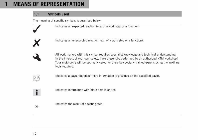
1.1 Symbols used
The meaning of specific symbols is described below.
Indicates an expected reaction (e.g. of a work step or a function).
Indicates an unexpected reaction (e.g. of a work step or a function).
All work marked with this symbol requires specialist knowledge and technical understanding.In the interest of your own safety, have these jobs performed by an authorized KTM workshop!Your motorcycle will be optimally cared for there by specially trained experts using the auxiliarytools required.
Indicates a page reference (more information is provided on the specified page).
Indicates information with more details or tips.
Indicates the result of a testing step.
MEANS OF REPRESENTATION 1
11
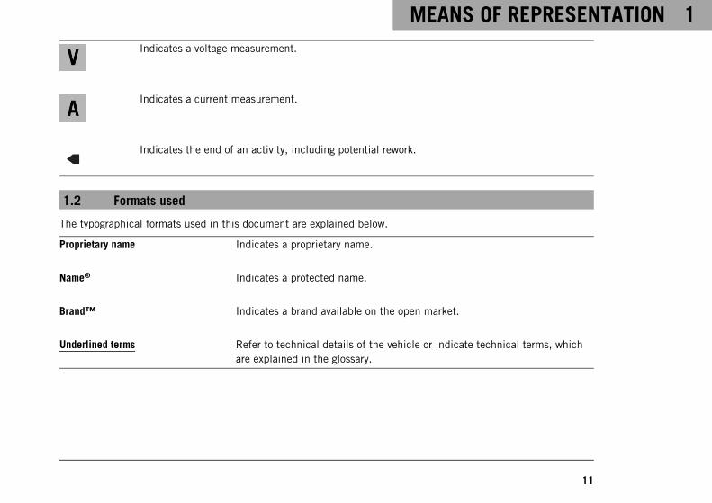
Indicates a voltage measurement.
Indicates a current measurement.
Indicates the end of an activity, including potential rework.
1.2 Formats used
The typographical formats used in this document are explained below.
Proprietary name Indicates a proprietary name.
Name® Indicates a protected name.
Brand™ Indicates a brand available on the open market.
Underlined terms Refer to technical details of the vehicle or indicate technical terms, whichare explained in the glossary.
2 SAFETY ADVICE
12
2.1 Use definition – intended use
The vehicle is designed and constructed to withstand the usual demands of regular traffic and use on gentle ter-rain (unpaved roads). This vehicle is not suitable for use on race tracks.
InfoThis vehicle is only authorized for operation on public roads in its homologated version.
2.2 Misuse
The vehicle must only be used as intended.Dangers can arise for people, property and the environment through use not as intended.Any use of the vehicle beyond the intended and defined use constitutes misuse.Misuse also includes the use of operating and auxiliary fluids which do not meet the required specification for therespective use.
2.3 Safety advice
A number of safety instructions need to be followed to operate the model described safely. Therefore read thisinstruction and all further instructions included carefully. The safety instructions are highlighted in the text andare referred to at the relevant passages.
SAFETY ADVICE 2
13
InfoVarious information and warning labels are attached in prominent locations on the model described. Donot remove any information or warning labels. If they are missing, you or others may not recognize dangersand may therefore be injured.
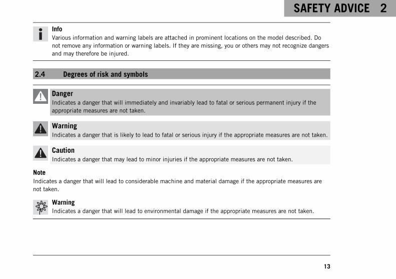
2.4 Degrees of risk and symbols
DangerIndicates a danger that will immediately and invariably lead to fatal or serious permanent injury if theappropriate measures are not taken.
WarningIndicates a danger that is likely to lead to fatal or serious injury if the appropriate measures are not taken.
CautionIndicates a danger that may lead to minor injuries if the appropriate measures are not taken.
NoteIndicates a danger that will lead to considerable machine and material damage if the appropriate measures arenot taken.
WarningIndicates a danger that will lead to environmental damage if the appropriate measures are not taken.
2 SAFETY ADVICE
14
2.5 Tampering warning
Tampering with the noise control system is prohibited. Federal law prohibits the following acts or the causingthereof:
1 The removal or rendering inoperative by any person other than for purposes of maintenance, repair, or replace-ment, of any device or element of design incorporated into any new vehicle for the purpose of noise controlprior to its sale or delivery to the ultimate purchaser or while it is in use, or
2 the use of the vehicle after such device or element of design has been removed or rendered inoperative by anyperson.
Among those acts presumed to constitute tampering are the acts listed below:
1 Removal or puncturing of the main silencer, baffles, header pipes or any other components which conductexhaust gases.
2 Removal or puncturing of parts of the intake system.
3 Lack of proper maintenance.
4 Replacing moving part of the vehicle, or parts of the exhaust or intake system, with parts other than thosespecified by the manufacturer.
2.6 Safe operation
DangerDanger of accidents A rider who is not fit to ride poses a danger to him or herself and others.
– Do not operate the vehicle if you are not fit to ride due to alcohol, drugs or medication.
– Do not operate the vehicle if you are physically or mentally impaired.
SAFETY ADVICE 2
15
DangerDanger of poisoning Exhaust gases are toxic and inhaling them may result in unconsciousness and death.
– Always make sure there is sufficient ventilation when running the engine.
– Use an effective exhaust extraction system when starting or running the engine in an enclosed space.
WarningDanger of burns Some vehicle components become very hot when the vehicle is operated.
– Do not touch any parts such as the exhaust system, radiator, engine, shock absorber, or brake systembefore the vehicle parts have cooled down.
– Let the vehicle parts cool down before you perform any work on the vehicle.
Only operate the vehicle when it is in perfect technical condition, in accordance with its intended use, and in asafe and environmentally compatible manner.The vehicle should only be used by trained persons. An appropriate driver's license is needed to ride the vehicleon public roads.Have malfunctions that impair safety promptly eliminated by an authorized KTM workshop.Adhere to the information and warning labels on the vehicle.
2 SAFETY ADVICE
16
2.7 Protective clothing
WarningRisk of injury Missing or poor protective clothing presents an increased safety risk.
– Wear appropriate protective clothing such as helmet, boots, gloves as well as trousers and a jacketwith protectors on all rides.
– Always wear protective clothing that is in good condition and meets the legal regulations.
In the interest of your own safety, KTM recommends that you only operate the vehicle while wearing protectiveclothing.
2.8 Work rules
Special tools are necessary for some of the work. These are not included with the vehicle and can be orderedunder the number in parentheses. Ex: valve spring mounter (59029019000)During assembly, non-reusable parts (e.g. self-locking screws and nuts, seals and seal rings, O-rings, pins, lockwashers) must be replaced by new parts.Where thread lockers are used on screw connections (e.g., Loctite®), follow the instructions for use from the man-ufacturer.Parts that you want to reuse following repairs and servicing should be cleaned and checked for damage and wear.Change damaged or worn parts.Following repairs or servicing, the vehicle must be checked for roadworthiness.
SAFETY ADVICE 2
17
2.9 Environment
If you use your motorcycle responsibly, you can ensure that problems and conflicts do not occur. To protect thefuture of the motorcycle sport, make sure that you use your motorcycle legally, display environmental conscious-ness, and respect the rights of others.When disposing of used oil, other operating and auxiliary fluids, and used components, comply with the laws andregulations of the respective country.Because motorcycles are not subject to the EU regulations governing the disposal of used vehicles, there are nolegal regulations that pertain to the disposal of an end-of-life motorcycle. Your authorized KTM dealer will be gladto advise you.
2.10 Owner's Manual
It is important that you read this Owner's Manual carefully and completely before making your first trip. The Own-er's Manual contains useful information and many tips on how to operate, handle, and maintain your motorcycle.Only then will you find out how to customize the vehicle ideally for your own use and how you can protect yourselffrom injury.Keep the Owner's Manual in an accessible place to enable you to refer to it as needed.If you would like to know more about the vehicle or have questions on the material you read, please contact anauthorized KTM dealer.The Owner's Manual is an important component of the vehicle and must be handed over to the new owner if thevehicle is sold.
The Owner's Manual is also available for download from your authorized KTM dealer and on the KTM website.International KTM Website: http://www.ktm.com
3 IMPORTANT NOTES
18
3.1 Warranty
The work specified in the service schedule may only be performed in an authorized KTM workshop and must berecorded in both the Service & Warranty Booklet and in KTM Dealer.net, otherwise any warranty coverage willbecome void. No warranty claims can be considered for damage resulting from manipulations and/or alterations tothe vehicle.Additional information on the manufacturer or implied warranty and the procedures involved can be found in theservice & warranty booklet.
3.2 Operating and auxiliary substances
WarningEnvironmental hazard Improper handling of fuel is a danger to the environment.
– Do not allow fuel to enter the groundwater, the soil, or the sewage system.
Use operating and auxiliary substances in accordance with the Owner's Manual and specification.
3.3 Spare parts, accessories
For your own safety, only use spare parts and accessory products that are approved and/or recommended by KTMand have them installed by an authorized KTM workshop. KTM accepts no liability for other products and anyresulting damage or loss.Certain spare parts and accessory products are specified in parentheses in the descriptions. Your authorized KTMdealer will be glad to advise you.
IMPORTANT NOTES 3
19
The current KTM PowerParts for your vehicle can be found on the KTM website.International KTM Website: http://www.ktm.com
3.4 Service
A prerequisite for perfect operation and prevention of premature wear is that the service, care and tuning work onthe engine and chassis are properly carried out as described in the owner's manual. Poor adjustment and tuningof the engine and suspension can lead to damage and breakage of components.Using the motorcycle in extreme operating conditions, e.g. on very muddy and wet roads or in a dusty and dryenvironment, can lead to above-average wear of components, such as the drive train, brakes or air filter. For thisreasons, it may be necessary to service or replace worn parts before the interval listed in the service schedule isreached.It is imperative that you adhere to the stipulated run-in times and service intervals. If you observe these exactly,you will ensure a much longer service life for your motorcycle.
3.5 Figures
The figures contained in the manual may depict special equipment.In the interest of clarity, some components may be shown disassembled or may not be shown at all. It is notalways necessary to disassemble the component to perform the activity in question. Please follow the instructionsin the text.
3.6 Customer service
Your authorized KTM dealer will be happy to answer any questions you may have on your vehicle and KTM.
3 IMPORTANT NOTES
20
A list of authorized KTM dealers can be found on the KTM website.International KTM Website: http://www.ktm.com

3 IMPORTANT NOTES
21
4 VIEW OF VEHICLE
22
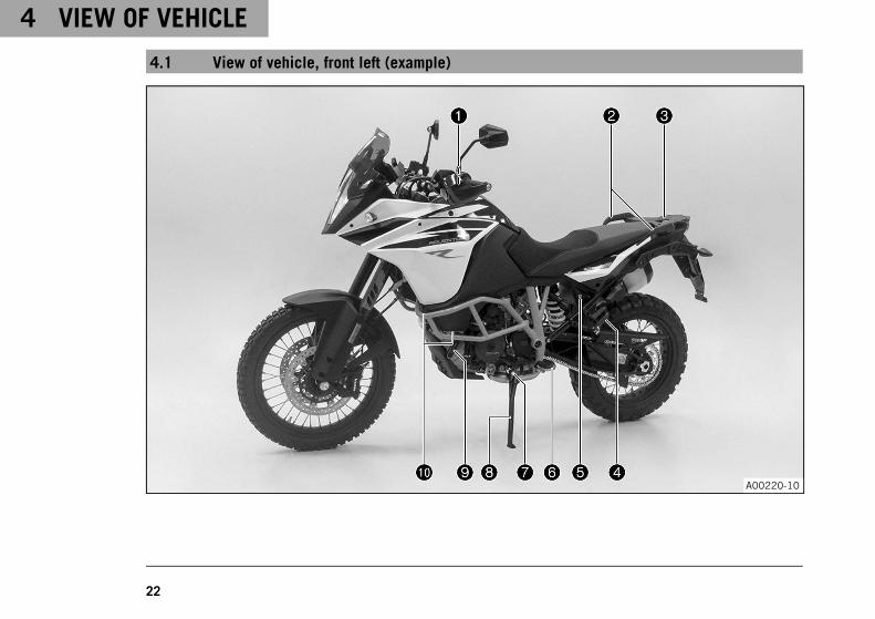
4.1 View of vehicle, front left (example)
A00220-10
VIEW OF VEHICLE 4
23
1 Clutch lever ( p. 30)
2 Grab handles ( p. 46)
3 Luggage rack plate ( p. 46)
4 Passenger footrest ( p. 48)
5 Seat lock ( p. 45)
6 Rider footrests ( p. 81)
7 Shift lever ( p. 48)
8 Side stand ( p. 50)
9 Engine oil level viewer
bk Fuel cocks ( p. 44)
4 VIEW OF VEHICLE
24
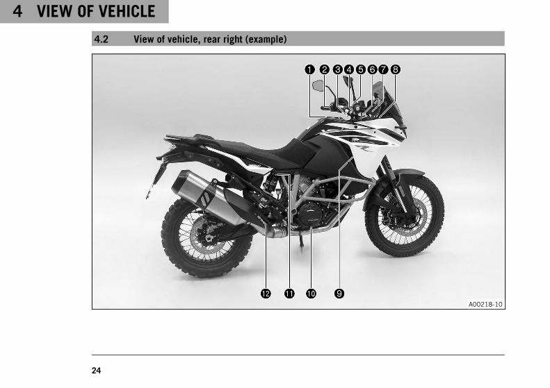
4.2 View of vehicle, rear right (example)
A00218-10
VIEW OF VEHICLE 4
25
1 Filler cap
2 Combination switch ( p. 31)
3 Fork compression adjustment
4 Electric starter button ( p. 36)
5 Emergency OFF switch ( p. 36)
6 Fork rebound adjustment
7 Hand brake lever ( p. 30)
8 Storage compartment
9 Cooling system compensating tank
bk Foot brake lever ( p. 49)
bl Shock absorber compression adjustment
bm Shock absorber rebound adjustment
5 SERIAL NUMBERS
26
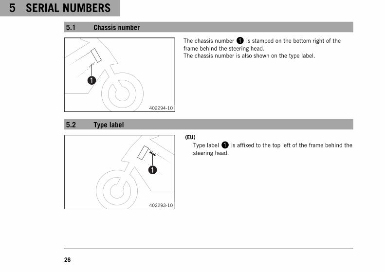
5.1 Chassis number
402294-10
The chassis number1 is stamped on the bottom right of theframe behind the steering head.The chassis number is also shown on the type label.
5.2 Type label
402293-10
(EU)Type label1 is affixed to the top left of the frame behind thesteering head.
SERIAL NUMBERS 5
27
0011
402174-10
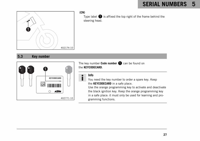
(CN)Type label1 is affixed the top right of the frame behind thesteering head.
5.3 Key number
402771-10
The key number Code number1 can be found onthe KEYCODECARD.
InfoYou need the key number to order a spare key. Keepthe KEYCODECARD in a safe place.Use the orange programming key to activate and deactivatethe black ignition key. Keep the orange programming keyin a safe place: it must only be used for learning and pro-gramming functions.
5 SERIAL NUMBERS
28
5.4 Engine number
402296-10
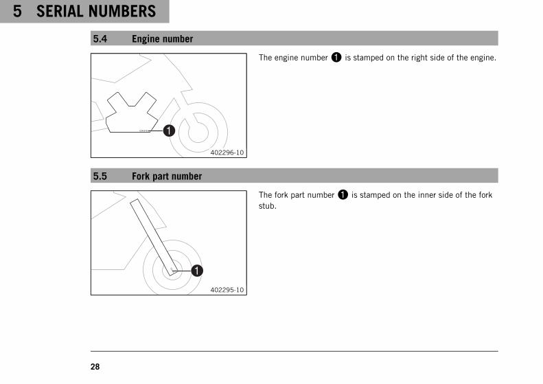
The engine number1 is stamped on the right side of the engine.
5.5 Fork part number
402295-10
The fork part number1 is stamped on the inner side of the forkstub.
SERIAL NUMBERS 5
29
5.6 Shock absorber article number
402339-10
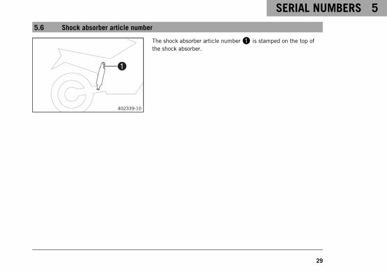
The shock absorber article number1 is stamped on the top ofthe shock absorber.
6 CONTROLS
30
6.1 Clutch lever
M00546-10
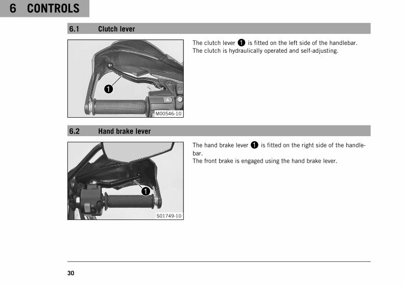
The clutch lever1 is fitted on the left side of the handlebar.The clutch is hydraulically operated and self-adjusting.
6.2 Hand brake lever
S01749-10
The hand brake lever1 is fitted on the right side of the handle-bar.The front brake is engaged using the hand brake lever.
CONTROLS 6
31
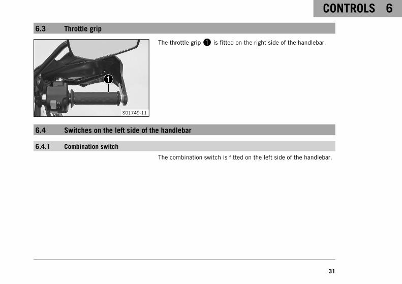
6.3 Throttle grip
S01749-11
The throttle grip1 is fitted on the right side of the handlebar.
6.4 Switches on the left side of the handlebar
6.4.1 Combination switch
The combination switch is fitted on the left side of the handlebar.
6 CONTROLS
32
M00547-10
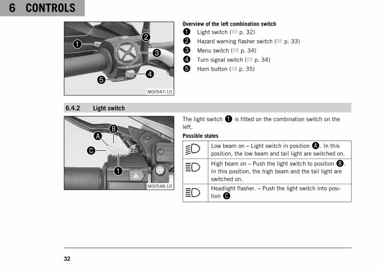
Overview of the left combination switch
1 Light switch ( p. 32)
2 Hazard warning flasher switch ( p. 33)
3 Menu switch ( p. 34)
4 Turn signal switch ( p. 34)
5 Horn button ( p. 35)
6.4.2 Light switch
M00548-10
The light switch1 is fitted on the combination switch on theleft.
Possible states
Low beam on – Light switch in positionA. In thisposition, the low beam and tail light are switched on.
High beam on – Push the light switch to positionB.In this position, the high beam and the tail light areswitched on.
Headlight flasher. – Push the light switch into posi-tionC.
CONTROLS 6
33
6.4.3 Hazard warning flasher switch
602606-10
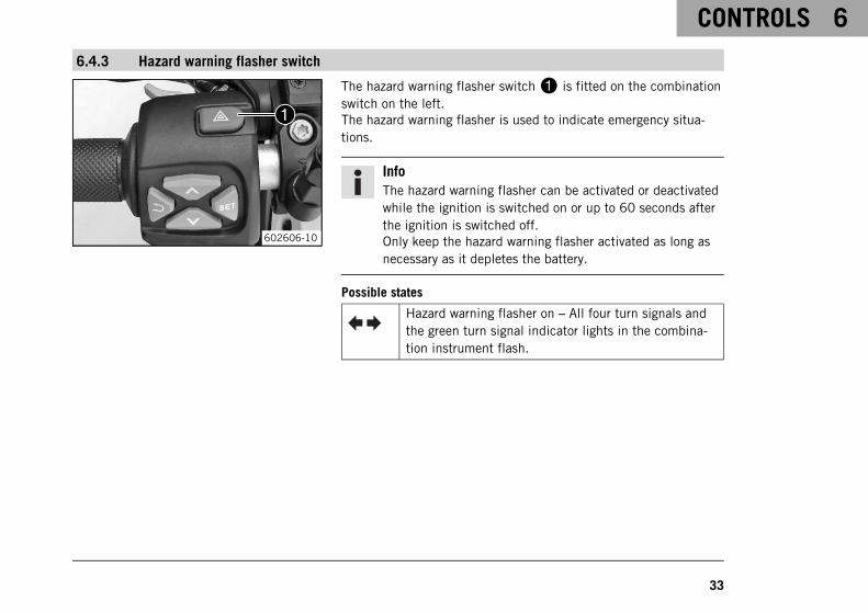
The hazard warning flasher switch1 is fitted on the combinationswitch on the left.The hazard warning flasher is used to indicate emergency situa-tions.
InfoThe hazard warning flasher can be activated or deactivatedwhile the ignition is switched on or up to 60 seconds afterthe ignition is switched off.Only keep the hazard warning flasher activated as long asnecessary as it depletes the battery.
Possible states
Hazard warning flasher on – All four turn signals andthe green turn signal indicator lights in the combina-tion instrument flash.
6 CONTROLS
34
6.4.4 Menu switch
S00224-11
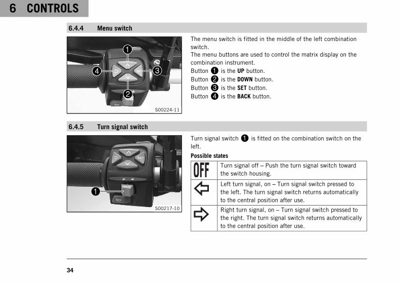
The menu switch is fitted in the middle of the left combinationswitch.The menu buttons are used to control the matrix display on thecombination instrument.Button1 is the UP button.Button2 is the DOWN button.Button3 is the SET button.Button4 is the BACK button.
6.4.5 Turn signal switch
S00217-10
Turn signal switch1 is fitted on the combination switch on theleft.
Possible states
Turn signal off – Push the turn signal switch towardthe switch housing.
Left turn signal, on – Turn signal switch pressed tothe left. The turn signal switch returns automaticallyto the central position after use.
Right turn signal, on – Turn signal switch pressed tothe right. The turn signal switch returns automaticallyto the central position after use.

CONTROLS 6
35
InfoAn automatic turn signal switch-off function (ATIR) is avail-able as an optional software feature.The ATIR function uses a time and distance counter.If the turn signal has been on for at least 10 seconds and150 meters of riding distance, the turn signal is switchedoff.If the vehicle is stationary, both counters are stopped.If the turn signal switch is reactivated, both counters arereset.
6.4.6 Horn button
S00218-10
The horn button1 is fitted on the combination switch on theleft.
Possible states• Horn button in basic position.• Horn button pressed – The horn is operated in this posi-
tion.
6 CONTROLS
36
6.5 Switches on the right side of the handlebar
6.5.1 Emergency OFF switch
S01750-10
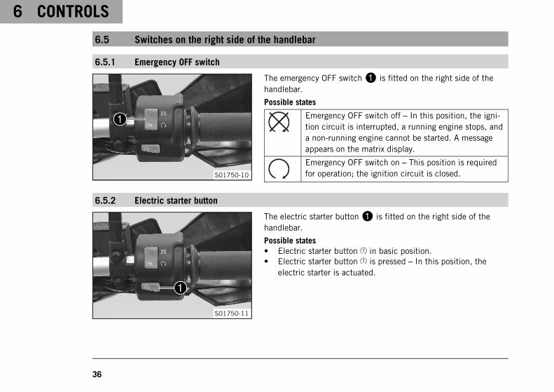
The emergency OFF switch1 is fitted on the right side of thehandlebar.
Possible states
Emergency OFF switch off – In this position, the igni-tion circuit is interrupted, a running engine stops, anda non-running engine cannot be started. A messageappears on the matrix display.
Emergency OFF switch on – This position is requiredfor operation; the ignition circuit is closed.
6.5.2 Electric starter button
S01750-11
The electric starter button1 is fitted on the right side of thehandlebar.
Possible states• Electric starter button in basic position.• Electric starter button is pressed – In this position, the
electric starter is actuated.
CONTROLS 6
37
6.6 Ignition/steering lock
S01751-10
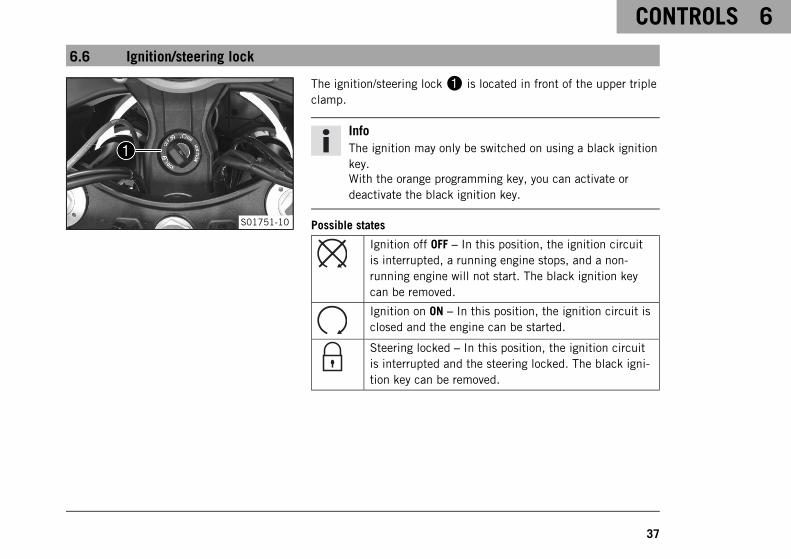
The ignition/steering lock1 is located in front of the upper tripleclamp.
InfoThe ignition may only be switched on using a black ignitionkey.With the orange programming key, you can activate ordeactivate the black ignition key.
Possible states
Ignition off OFF – In this position, the ignition circuitis interrupted, a running engine stops, and a non-running engine will not start. The black ignition keycan be removed.
Ignition on ON – In this position, the ignition circuit isclosed and the engine can be started.
Steering locked – In this position, the ignition circuitis interrupted and the steering locked. The black igni-tion key can be removed.
6 CONTROLS
38
6.7 Immobilizer
401815-10
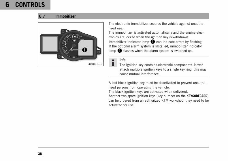
The electronic immobilizer secures the vehicle against unautho-rized use.The immobilizer is activated automatically and the engine elec-tronics are locked when the ignition key is withdrawn.Immobilizer indicator lamp1 can indicate errors by flashing.If the optional alarm system is installed, immobilizer indicatorlamp1 flashes when the alarm system is switched on.
InfoThe ignition key contains electronic components. Neverattach multiple ignition keys to a single key ring; this maycause mutual interference.
A lost black ignition key must be deactivated to prevent unautho-rized persons from operating the vehicle.The black ignition keys are activated when delivered.Another two spare ignition keys (key number on the KEYCODECARD)can be ordered from an authorized KTM workshop; they need to beactivated for use.
CONTROLS 6
39
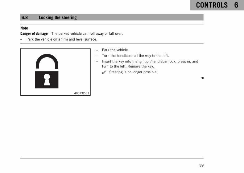
6.8 Locking the steering
NoteDanger of damage The parked vehicle can roll away or fall over.
– Park the vehicle on a firm and level surface.
400732-01
– Park the vehicle.
– Turn the handlebar all the way to the left.
– Insert the key into the ignition/handlebar lock, press in, andturn to the left. Remove the key.
Steering is no longer possible.
6 CONTROLS
40
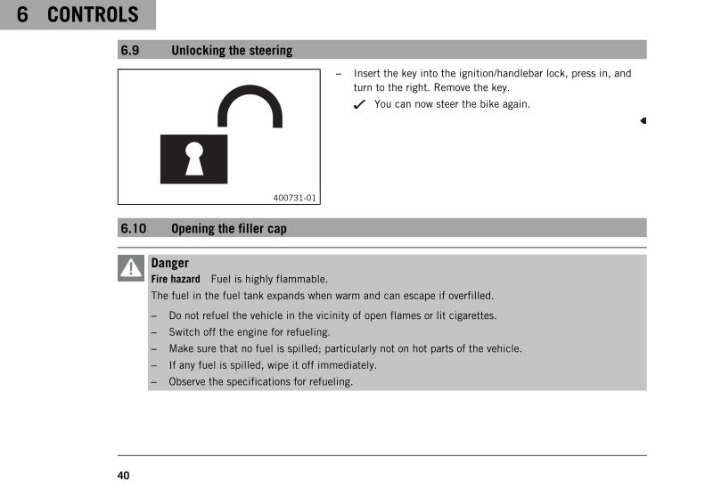
6.9 Unlocking the steering
400731-01
– Insert the key into the ignition/handlebar lock, press in, andturn to the right. Remove the key.
You can now steer the bike again.
6.10 Opening the filler cap
DangerFire hazard Fuel is highly flammable.
The fuel in the fuel tank expands when warm and can escape if overfilled.
– Do not refuel the vehicle in the vicinity of open flames or lit cigarettes.
– Switch off the engine for refueling.
– Make sure that no fuel is spilled; particularly not on hot parts of the vehicle.
– If any fuel is spilled, wipe it off immediately.
– Observe the specifications for refueling.
CONTROLS 6
41
WarningDanger of poisoning Fuel is poisonous and a health hazard.
– Avoid skin, eye and clothing contact with fuel.
– Immediately consult a doctor if you swallow fuel.
– Do not inhale fuel vapors.
– In case of skin contact, rinse the affected area with plenty of water.
– Rinse the eyes thoroughly with water, and consult a doctor in case of fuel contact with the eyes.
– Change your clothing in case of fuel spills on them.
– Keep fuels correctly in a suitable canister, and out of the reach of children.
WarningEnvironmental hazard Improper handling of fuel is a danger to the environment.
– Do not allow fuel to enter the groundwater, the soil, or the sewage system.
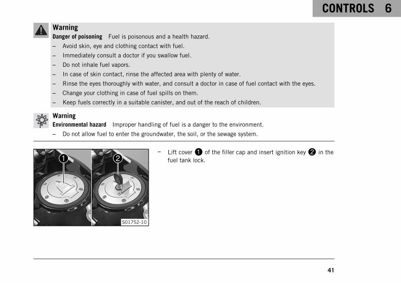
S01752-10
– Lift cover1 of the filler cap and insert ignition key2 in thefuel tank lock.
6 CONTROLS
42
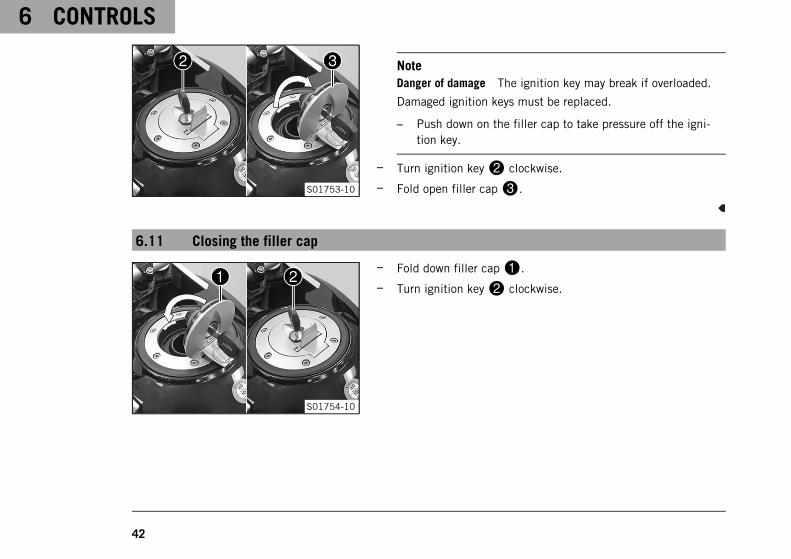
S01753-10
NoteDanger of damage The ignition key may break if overloaded.
Damaged ignition keys must be replaced.
– Push down on the filler cap to take pressure off the igni-tion key.
– Turn ignition key2 clockwise.
– Fold open filler cap3.
6.11 Closing the filler cap
S01754-10
– Fold down filler cap1.
– Turn ignition key2 clockwise.
CONTROLS 6
43
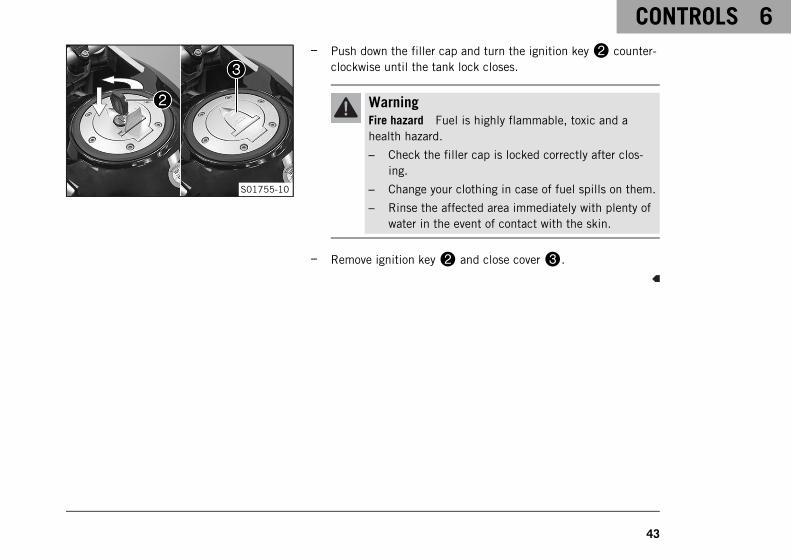
S01755-10
– Push down the filler cap and turn the ignition key2 counter-clockwise until the tank lock closes.
WarningFire hazard Fuel is highly flammable, toxic and ahealth hazard.
– Check the filler cap is locked correctly after clos-ing.
– Change your clothing in case of fuel spills on them.
– Rinse the affected area immediately with plenty ofwater in the event of contact with the skin.
– Remove ignition key2 and close cover3.
6 CONTROLS
44
6.12 Fuel cocks
D03209-10
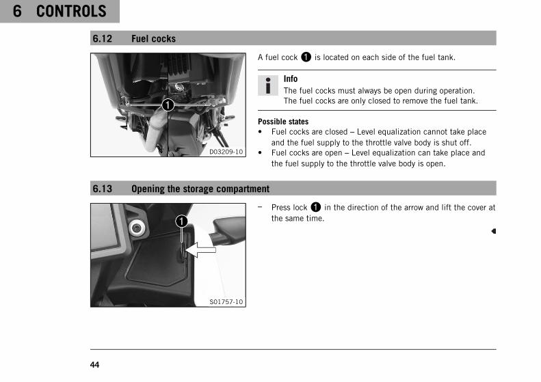
A fuel cock1 is located on each side of the fuel tank.
InfoThe fuel cocks must always be open during operation.The fuel cocks are only closed to remove the fuel tank.
Possible states• Fuel cocks are closed – Level equalization cannot take place
and the fuel supply to the throttle valve body is shut off.• Fuel cocks are open – Level equalization can take place and
the fuel supply to the throttle valve body is open.
6.13 Opening the storage compartment
S01757-10
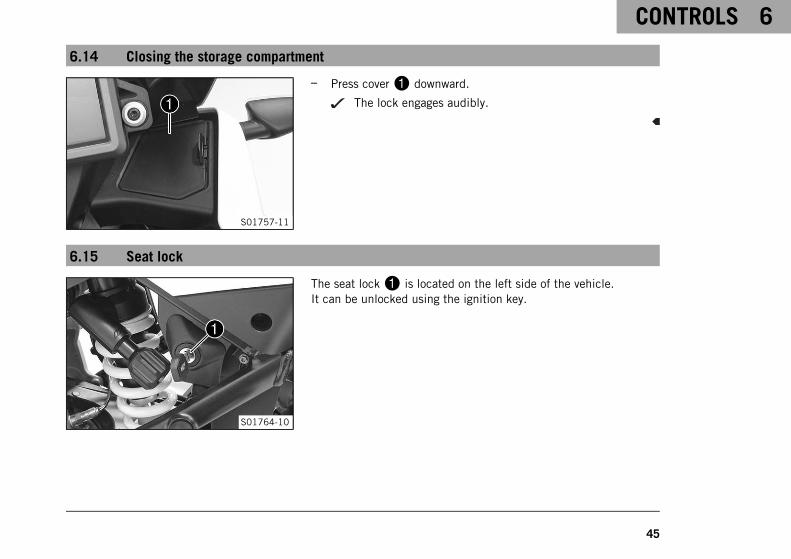
– Press lock1 in the direction of the arrow and lift the cover atthe same time.
CONTROLS 6
45
6.14 Closing the storage compartment
S01757-11
– Press cover1 downward.
The lock engages audibly.
6.15 Seat lock
S01764-10
The seat lock1 is located on the left side of the vehicle.It can be unlocked using the ignition key.
6 CONTROLS
46
6.16 Grab handles
S01765-10
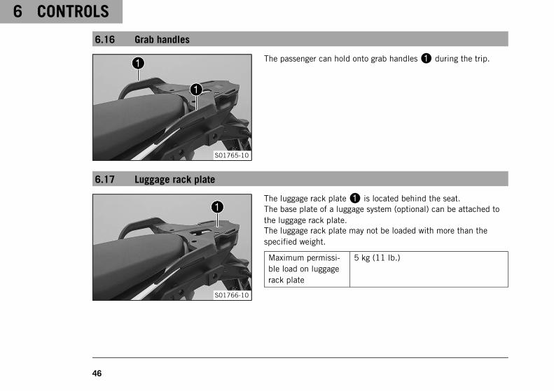
The passenger can hold onto grab handles1 during the trip.
6.17 Luggage rack plate
S01766-10
The luggage rack plate1 is located behind the seat.The base plate of a luggage system (optional) can be attached tothe luggage rack plate.The luggage rack plate may not be loaded with more than thespecified weight.
Maximum permissi-ble load on luggagerack plate
5 kg (11 lb.)
CONTROLS 6
47
InfoNote the information provided by the luggage manufac-turer.
6.18 Case holders
E01057-10
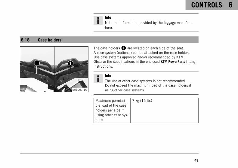
The case holders1 are located on each side of the seat.A case system (optional) can be attached on the case holders.Use case systems approved and/or recommended by KTM.Observe the specifications in the enclosed KTM PowerParts fittinginstructions.
InfoThe use of other case systems is not recommended.Do not exceed the maximum load of the case holders ifusing other case systems.
Maximum permissi-ble load of the caseholders per side ifusing other case sys-tems
7 kg (15 lb.)
6 CONTROLS
48
6.19 Passenger footrest
S01767-10
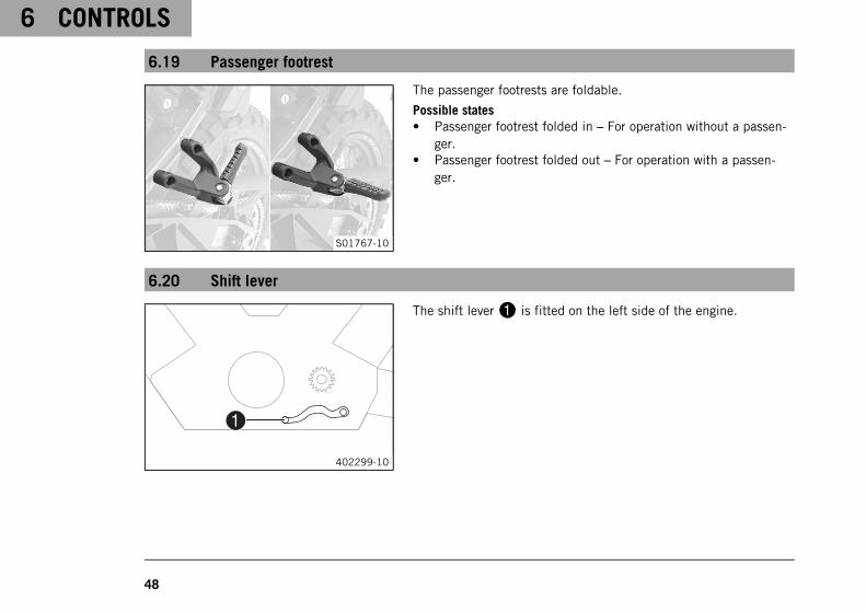
The passenger footrests are foldable.
Possible states• Passenger footrest folded in – For operation without a passen-
ger.• Passenger footrest folded out – For operation with a passen-
ger.
6.20 Shift lever
402299-10
The shift lever1 is fitted on the left side of the engine.
CONTROLS 6
49
402299-11
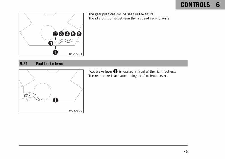
The gear positions can be seen in the figure.The idle position is between the first and second gears.
6.21 Foot brake lever
402301-10
Foot brake lever1 is located in front of the right footrest.The rear brake is activated using the foot brake lever.
6 CONTROLS
50
6.22 Side stand
402029-10
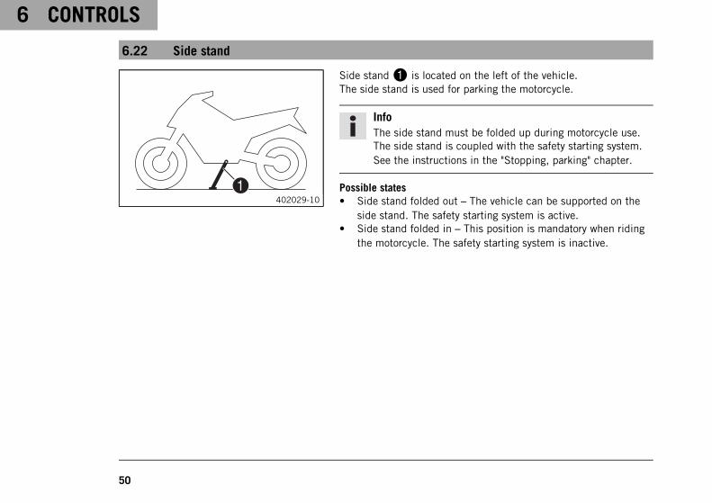
Side stand1 is located on the left of the vehicle.The side stand is used for parking the motorcycle.
InfoThe side stand must be folded up during motorcycle use.The side stand is coupled with the safety starting system.See the instructions in the "Stopping, parking" chapter.
Possible states• Side stand folded out – The vehicle can be supported on the
side stand. The safety starting system is active.• Side stand folded in – This position is mandatory when riding
the motorcycle. The safety starting system is inactive.
COMBINATION INSTRUMENT 7
51
7.1 Overview
402341-10
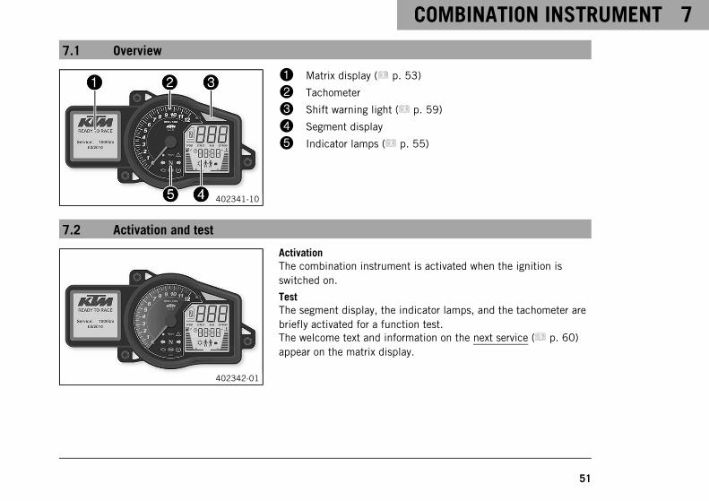
1 Matrix display ( p. 53)
2 Tachometer
3 Shift warning light ( p. 59)
4 Segment display
5 Indicator lamps ( p. 55)
7.2 Activation and test
402342-01
ActivationThe combination instrument is activated when the ignition isswitched on.
TestThe segment display, the indicator lamps, and the tachometer arebriefly activated for a function test.The welcome text and information on the next service ( p. 60)appear on the matrix display.
7 COMBINATION INSTRUMENT
52
InfoIf the battery was disconnected, the time and date must beset.The brightness of the displays is controlled by a brightnesssensor in the combination instrument.The malfunction indicator lamp always lights up as long asthe engine is not running. If the engine is running and themalfunction indicator lamp lights up, stop (taking care notto endanger yourself or other road users in the process) andcontact an authorized KTM workshop.The oil pressure warning lamp always lights up as long asthe engine is not running. If the engine is running and theoil pressure warning lamp lights up, stop immediately (tak-ing care not to endanger yourself or other road users in theprocess) and switch off the engine.The ABS indicator lamp and TC indicator lamp light upuntil a speed of approx. 6 km/h (approx. 4 mph) or morehas been reached.
COMBINATION INSTRUMENT 7
53
7.3 Matrix display
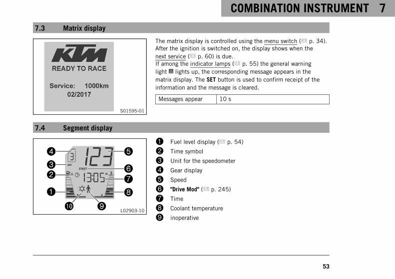
S01595-01
The matrix display is controlled using the menu switch ( p. 34).After the ignition is switched on, the display shows when thenext service ( p. 60) is due.If among the indicator lamps ( p. 55) the general warninglight lights up, the corresponding message appears in thematrix display. The SET button is used to confirm receipt of theinformation and the message is cleared.
Messages appear 10 s
7.4 Segment display
L02903-10
1 Fuel level display ( p. 54)
2 Time symbol
3 Unit for the speedometer
4 Gear display
5 Speed
6 "Drive Mod" ( p. 245)
7 Time
8 Coolant temperature
9 inoperative
7 COMBINATION INSTRUMENT
54
bk Ice warning
7.5 Fuel level display
402710-01
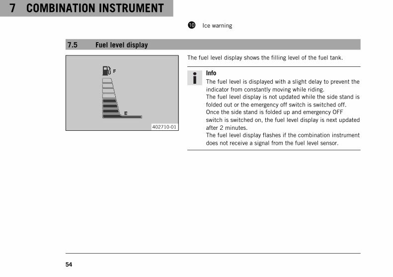
The fuel level display shows the filling level of the fuel tank.
InfoThe fuel level is displayed with a slight delay to prevent theindicator from constantly moving while riding.The fuel level display is not updated while the side stand isfolded out or the emergency off switch is switched off.Once the side stand is folded up and emergency OFFswitch is switched on, the fuel level display is next updatedafter 2 minutes.The fuel level display flashes if the combination instrumentdoes not receive a signal from the fuel level sensor.
COMBINATION INSTRUMENT 7
55
7.6 Indicator lamps
402343-01
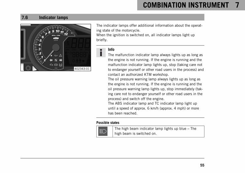
The indicator lamps offer additional information about the operat-ing state of the motorcycle.When the ignition is switched on, all indicator lamps light upbriefly.
InfoThe malfunction indicator lamp always lights up as long asthe engine is not running. If the engine is running and themalfunction indicator lamp lights up, stop (taking care notto endanger yourself or other road users in the process) andcontact an authorized KTM workshop.The oil pressure warning lamp always lights up as long asthe engine is not running. If the engine is running and theoil pressure warning lamp lights up, stop immediately (tak-ing care not to endanger yourself or other road users in theprocess) and switch off the engine.The ABS indicator lamp and TC indicator lamp light upuntil a speed of approx. 6 km/h (approx. 4 mph) or morehas been reached.
Possible states
The high beam indicator lamp lights up blue – Thehigh beam is switched on.

7 COMBINATION INSTRUMENT
56
The immobilizer indicator lamp lights up or flashesred – Status or error message for immobilizer/alarmsystem.
The oil pressure warning lamp lights up red – Engineoil pressure is too low. Stop immediately, taking carenot to endanger yourself or other road users in theprocess, and switch off the engine.
The general warning lamp lights up yellow – An oper-ating safety (warning note) message was detected.This is also shown on the matrix display.
The left turn signal lamp flashes green with a steadyrhythmic flash – The left turn signal is switched on.
The idle indicator lamp lights up green – The trans-mission is in idle.
The right turn signal lamp flashes green with a steadyrhythmic flash – The right turn signal is switched on.
Malfunction indicator lamp lights up yellow – Theengine control unit has detected an error.
ABS indicator lamp lights up/flashes yellow – ABS isnot active. The ABS indicator lamp also lights up if anerror is detected.
COMBINATION INSTRUMENT 7
57
TC indicator lamp lights up/flashes yellow – Trac-tion control is not enabled or is currently interven-ing. The TC Indicator lamp also lights up if an error isdetected.
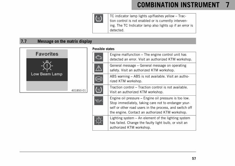
7.7 Message on the matrix display
401850-01
Possible states
Engine malfunction – The engine control unit hasdetected an error. Visit an authorized KTM workshop.
General message – General message on operatingsafety. Visit an authorized KTM workshop.
ABS warning – ABS is not available. Visit an autho-rized KTM workshop.
Traction control – Traction control is not available.Visit an authorized KTM workshop.
Engine oil pressure – Engine oil pressure is too low.Stop immediately, taking care not to endanger your-self or other road users in the process, and switch offthe engine. Contact an authorized KTM workshop.
Lighting system – An element of the lighting systemhas failed. Change the faulty light bulb, or visit anauthorized KTM workshop.
7 COMBINATION INSTRUMENT
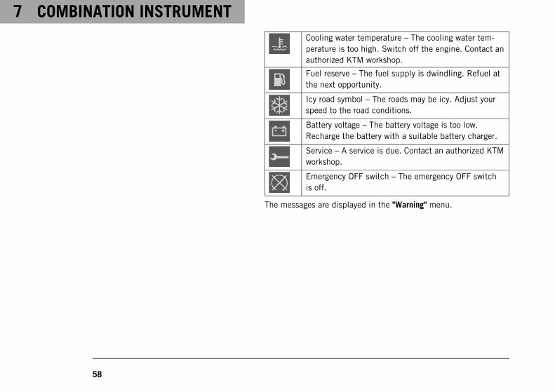
58
Cooling water temperature – The cooling water tem-perature is too high. Switch off the engine. Contact anauthorized KTM workshop.
Fuel reserve – The fuel supply is dwindling. Refuel atthe next opportunity.
Icy road symbol – The roads may be icy. Adjust yourspeed to the road conditions.
Battery voltage – The battery voltage is too low.Recharge the battery with a suitable battery charger.
Service – A service is due. Contact an authorized KTMworkshop.
Emergency OFF switch – The emergency OFF switchis off.
The messages are displayed in the "Warning" menu.
COMBINATION INSTRUMENT 7
59
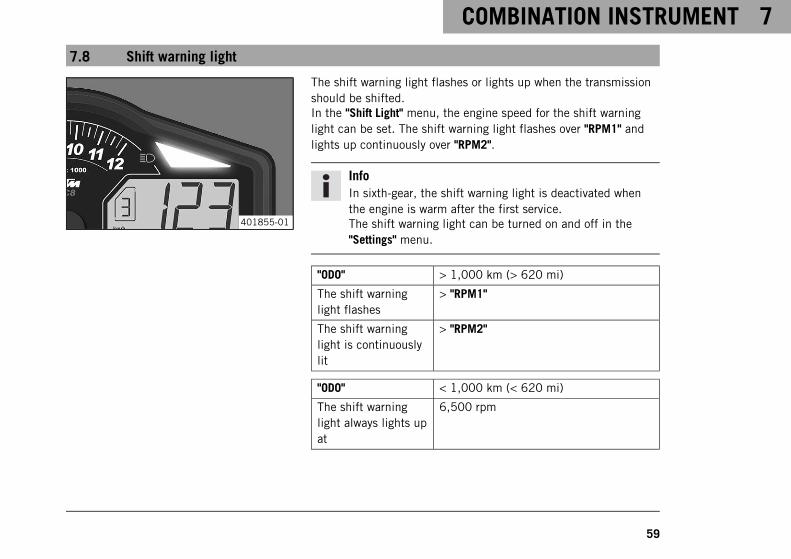
7.8 Shift warning light
401855-01
The shift warning light flashes or lights up when the transmissionshould be shifted.In the "Shift Light" menu, the engine speed for the shift warninglight can be set. The shift warning light flashes over "RPM1" andlights up continuously over "RPM2".
InfoIn sixth-gear, the shift warning light is deactivated whenthe engine is warm after the first service.The shift warning light can be turned on and off in the"Settings" menu.
"ODO" > 1,000 km (> 620 mi)
The shift warninglight flashes
> "RPM1"
The shift warninglight is continuouslylit
> "RPM2"
"ODO" < 1,000 km (< 620 mi)
The shift warninglight always lights upat
6,500 rpm
7 COMBINATION INSTRUMENT
60
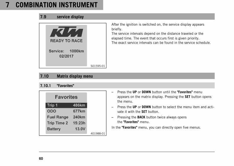
7.9 service display
S01595-01
After the ignition is switched on, the service display appearsbriefly.The service intervals depend on the distance traveled or theelapsed time. The event that occurs first is given priority.The exact service intervals can be found in the service schedule.
7.10 Matrix display menu
7.10.1 "Favorites"
401988-01
– Press the UP or DOWN button until the "Favorites" menuappears on the matrix display. Pressing the SET button opensthe menu.
– Press the UP or DOWN button to select the menu item and acti-vate it with the SET button.
– Pressing the BACK button twice always opensthe "Favorites" menu.
In the "Favorites" menu, you can directly open five menus.
COMBINATION INSTRUMENT 7
61
In the "Set Favorites" menu, the "Favorites" menu can be config-ured.
7.10.2 "Trip 1"
L02906-01
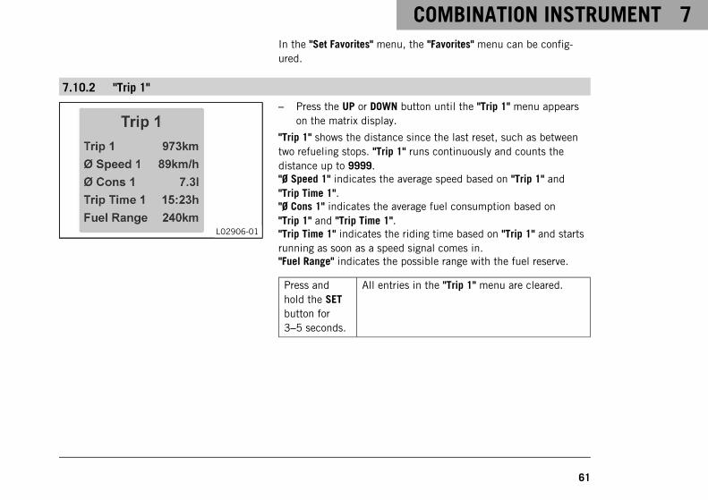
– Press the UP or DOWN button until the "Trip 1" menu appearson the matrix display.
"Trip 1" shows the distance since the last reset, such as betweentwo refueling stops. "Trip 1" runs continuously and counts thedistance up to 9999."Ø Speed 1" indicates the average speed based on "Trip 1" and"Trip Time 1"."Ø Cons 1" indicates the average fuel consumption based on"Trip 1" and "Trip Time 1"."Trip Time 1" indicates the riding time based on "Trip 1" and startsrunning as soon as a speed signal comes in."Fuel Range" indicates the possible range with the fuel reserve.
Press andhold the SETbutton for3–5 seconds.
All entries in the "Trip 1" menu are cleared.
7 COMBINATION INSTRUMENT
62
7.10.3 "Trip 2"
L02907-01
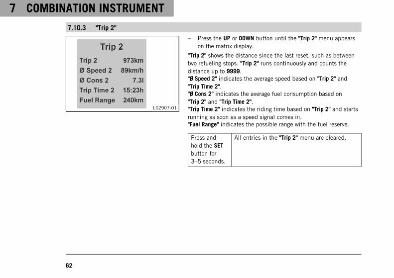
– Press the UP or DOWN button until the "Trip 2" menu appearson the matrix display.
"Trip 2" shows the distance since the last reset, such as betweentwo refueling stops. "Trip 2" runs continuously and counts thedistance up to 9999."Ø Speed 2" indicates the average speed based on "Trip 2" and"Trip Time 2"."Ø Cons 2" indicates the average fuel consumption based on"Trip 2" and "Trip Time 2"."Trip Time 2" indicates the riding time based on "Trip 2" and startsrunning as soon as a speed signal comes in."Fuel Range" indicates the possible range with the fuel reserve.
Press andhold the SETbutton for3–5 seconds.
All entries in the "Trip 2" menu are cleared.
COMBINATION INSTRUMENT 7
63
7.10.4 "General Info"
F00705-01
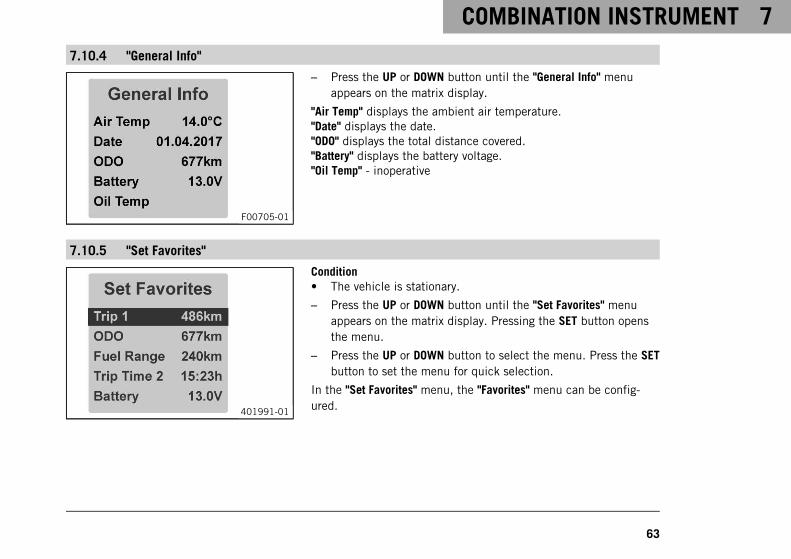
– Press the UP or DOWN button until the "General Info" menuappears on the matrix display.
"Air Temp" displays the ambient air temperature."Date" displays the date."ODO" displays the total distance covered."Battery" displays the battery voltage."Oil Temp" - inoperative
7.10.5 "Set Favorites"
401991-01
Condition• The vehicle is stationary.
– Press the UP or DOWN button until the "Set Favorites" menuappears on the matrix display. Pressing the SET button opensthe menu.
– Press the UP or DOWN button to select the menu. Press the SETbutton to set the menu for quick selection.
In the "Set Favorites" menu, the "Favorites" menu can be config-ured.
7 COMBINATION INSTRUMENT
64
7.10.6 "Settings"
402431-10
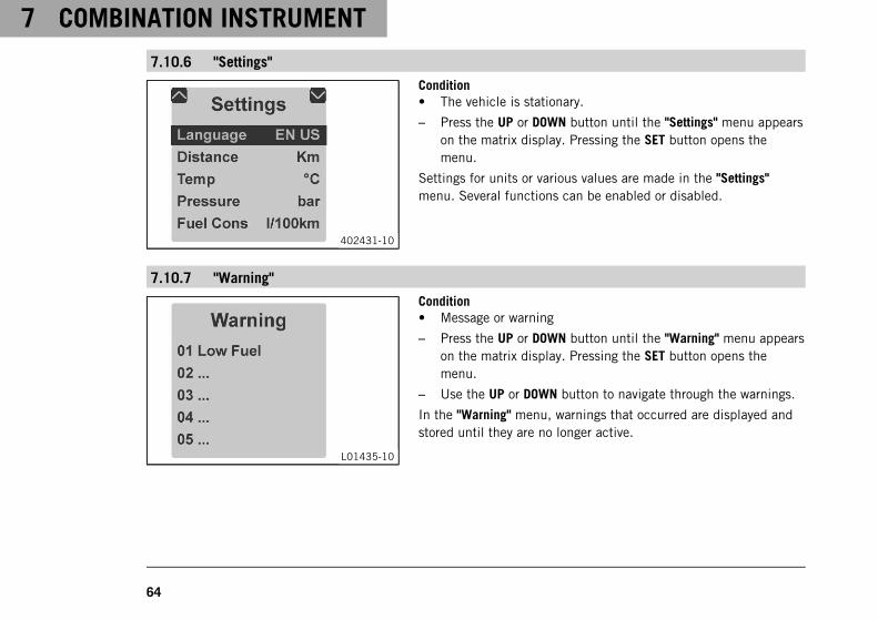
Condition• The vehicle is stationary.
– Press the UP or DOWN button until the "Settings" menu appearson the matrix display. Pressing the SET button opens themenu.
Settings for units or various values are made in the "Settings"menu. Several functions can be enabled or disabled.
7.10.7 "Warning"
L01435-10
Condition• Message or warning
– Press the UP or DOWN button until the "Warning" menu appearson the matrix display. Pressing the SET button opens themenu.
– Use the UP or DOWN button to navigate through the warnings.
In the "Warning" menu, warnings that occurred are displayed andstored until they are no longer active.
COMBINATION INSTRUMENT 7
65
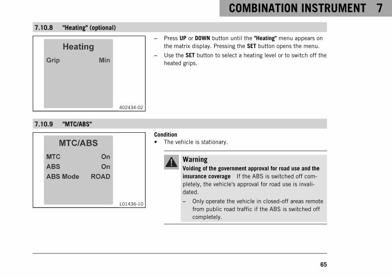
7.10.8 "Heating" (optional)
402434-02
– Press UP or DOWN button until the "Heating" menu appears onthe matrix display. Pressing the SET button opens the menu.
– Use the SET button to select a heating level or to switch off theheated grips.
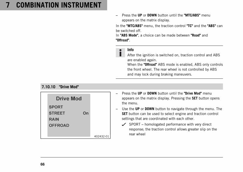
7.10.9 "MTC/ABS"
L01436-10
Condition• The vehicle is stationary.
WarningVoiding of the government approval for road use and theinsurance coverage If the ABS is switched off com-pletely, the vehicle's approval for road use is invali-dated.
– Only operate the vehicle in closed-off areas remotefrom public road traffic if the ABS is switched offcompletely.
7 COMBINATION INSTRUMENT
66
– Press the UP or DOWN button until the "MTC/ABS" menuappears on the matrix display.
In the "MTC/ABS" menu, the traction control "TC" and the "ABS" canbe switched off.In "ABS Mode", a choice can be made between "Road" and"Offroad".
InfoAfter the ignition is switched on, traction control and ABSare enabled again.When the "Offroad" ABS mode is enabled, ABS only controlsthe front wheel. The rear wheel is not controlled by ABSand may lock during braking maneuvers.
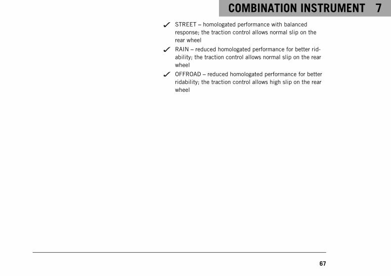
7.10.10 "Drive Mod"
402432-01
– Press the UP or DOWN button until the "Drive Mod" menuappears on the matrix display. Pressing the SET button opensthe menu.
– Use the UP or DOWN button to navigate through the menu. TheSET button can be used to select engine and traction controlsettings that are coordinated with each other.
SPORT – homologated performance with very directresponse; the traction control allows greater slip on therear wheel
COMBINATION INSTRUMENT 7
67
STREET – homologated performance with balancedresponse; the traction control allows normal slip on therear wheel
RAIN – reduced homologated performance for better rid-ability; the traction control allows normal slip on the rearwheel
OFFROAD – reduced homologated performance for betterridability; the traction control allows high slip on the rearwheel
7 COMBINATION INSTRUMENT
68
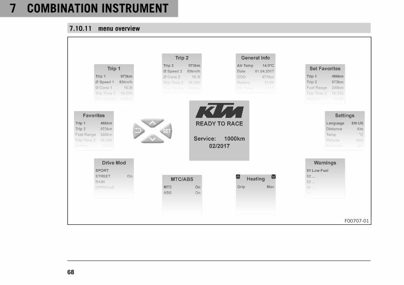
7.10.11 menu overview
F00707-01
COMBINATION INSTRUMENT 7
69
"KTM" start screenMenu buttons"Favorites""Trip 1""Trip 2""General info""Set Favorites""Settings""Warning" (only active if there are messages)"Heating" (optional)"MTC/ABS""Drive Mod"
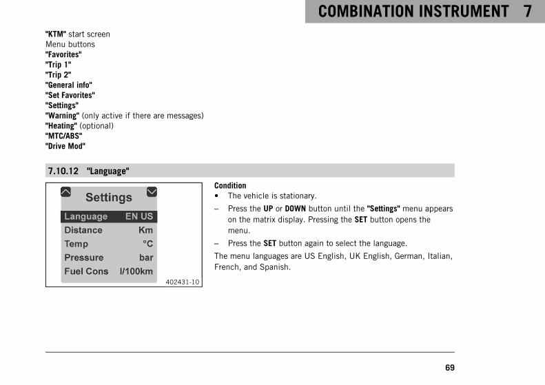
7.10.12 "Language"
402431-10
Condition• The vehicle is stationary.
– Press the UP or DOWN button until the "Settings" menu appearson the matrix display. Pressing the SET button opens themenu.
– Press the SET button again to select the language.
The menu languages are US English, UK English, German, Italian,French, and Spanish.
7 COMBINATION INSTRUMENT
70
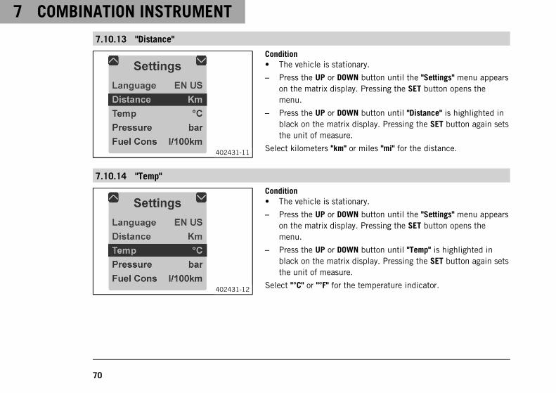
7.10.13 "Distance"
402431-11
Condition• The vehicle is stationary.
– Press the UP or DOWN button until the "Settings" menu appearson the matrix display. Pressing the SET button opens themenu.
– Press the UP or DOWN button until "Distance" is highlighted inblack on the matrix display. Pressing the SET button again setsthe unit of measure.
Select kilometers "km" or miles "mi" for the distance.
7.10.14 "Temp"
402431-12
Condition• The vehicle is stationary.
– Press the UP or DOWN button until the "Settings" menu appearson the matrix display. Pressing the SET button opens themenu.
– Press the UP or DOWN button until "Temp" is highlighted inblack on the matrix display. Pressing the SET button again setsthe unit of measure.
Select "°C" or "°F" for the temperature indicator.
COMBINATION INSTRUMENT 7
71
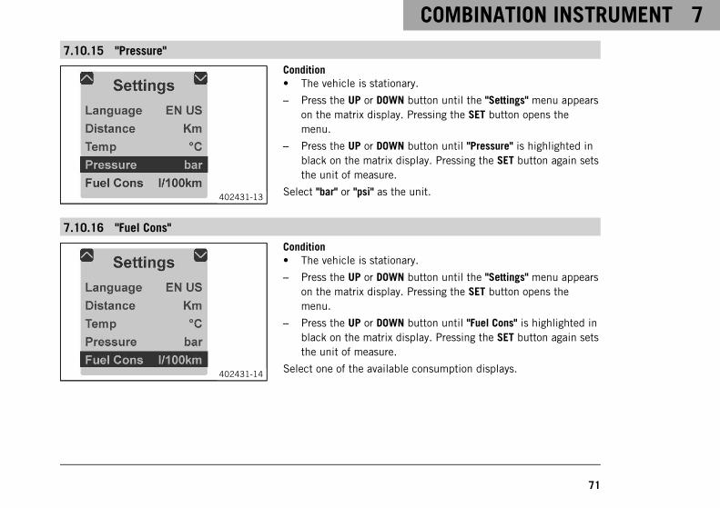
7.10.15 "Pressure"
402431-13
Condition• The vehicle is stationary.
– Press the UP or DOWN button until the "Settings" menu appearson the matrix display. Pressing the SET button opens themenu.
– Press the UP or DOWN button until "Pressure" is highlighted inblack on the matrix display. Pressing the SET button again setsthe unit of measure.
Select "bar" or "psi" as the unit.
7.10.16 "Fuel Cons"
402431-14
Condition• The vehicle is stationary.
– Press the UP or DOWN button until the "Settings" menu appearson the matrix display. Pressing the SET button opens themenu.
– Press the UP or DOWN button until "Fuel Cons" is highlighted inblack on the matrix display. Pressing the SET button again setsthe unit of measure.
Select one of the available consumption displays.
7 COMBINATION INSTRUMENT
72
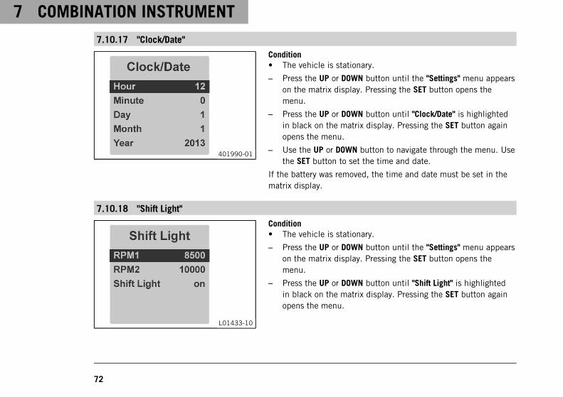
7.10.17 "Clock/Date"
401990-01
Condition• The vehicle is stationary.
– Press the UP or DOWN button until the "Settings" menu appearson the matrix display. Pressing the SET button opens themenu.
– Press the UP or DOWN button until "Clock/Date" is highlightedin black on the matrix display. Pressing the SET button againopens the menu.
– Use the UP or DOWN button to navigate through the menu. Usethe SET button to set the time and date.
If the battery was removed, the time and date must be set in thematrix display.
7.10.18 "Shift Light"
L01433-10
Condition• The vehicle is stationary.
– Press the UP or DOWN button until the "Settings" menu appearson the matrix display. Pressing the SET button opens themenu.
– Press the UP or DOWN button until "Shift Light" is highlightedin black on the matrix display. Pressing the SET button againopens the menu.
COMBINATION INSTRUMENT 7
73
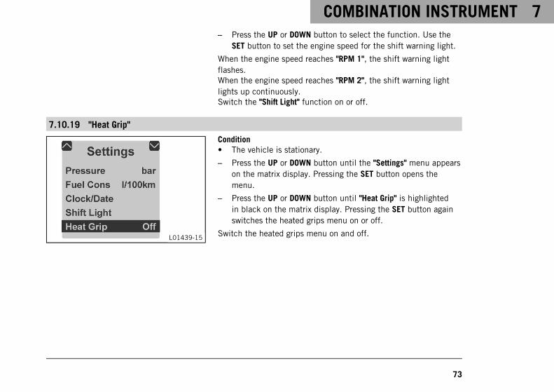
– Press the UP or DOWN button to select the function. Use theSET button to set the engine speed for the shift warning light.
When the engine speed reaches "RPM 1", the shift warning lightflashes.When the engine speed reaches "RPM 2", the shift warning lightlights up continuously.Switch the "Shift Light" function on or off.
7.10.19 "Heat Grip"
L01439-15
Condition• The vehicle is stationary.
– Press the UP or DOWN button until the "Settings" menu appearson the matrix display. Pressing the SET button opens themenu.
– Press the UP or DOWN button until "Heat Grip" is highlightedin black on the matrix display. Pressing the SET button againswitches the heated grips menu on or off.
Switch the heated grips menu on and off.
7 COMBINATION INSTRUMENT
74
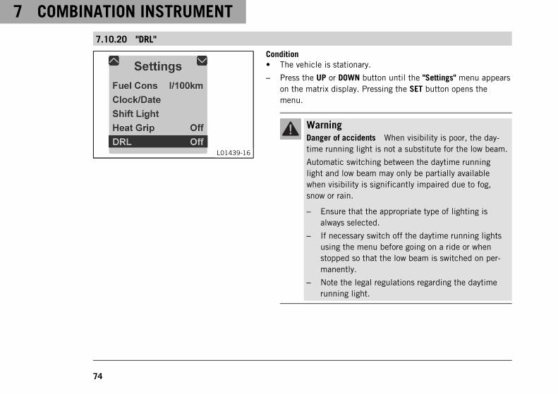
7.10.20 "DRL"
L01439-16
Condition• The vehicle is stationary.
– Press the UP or DOWN button until the "Settings" menu appearson the matrix display. Pressing the SET button opens themenu.
WarningDanger of accidents When visibility is poor, the day-time running light is not a substitute for the low beam.
Automatic switching between the daytime runninglight and low beam may only be partially availablewhen visibility is significantly impaired due to fog,snow or rain.
– Ensure that the appropriate type of lighting isalways selected.
– If necessary switch off the daytime running lightsusing the menu before going on a ride or whenstopped so that the low beam is switched on per-manently.
– Note the legal regulations regarding the daytimerunning light.
COMBINATION INSTRUMENT 7
75
– Press the UP or DOWN button until "DRL" is highlighted in blackon the matrix display. Pressing the SET button again switchesthe daytime running light on or off.
Switch the daytime running light on or off.
8 ERGONOMICS
76
8.1 Handlebar position
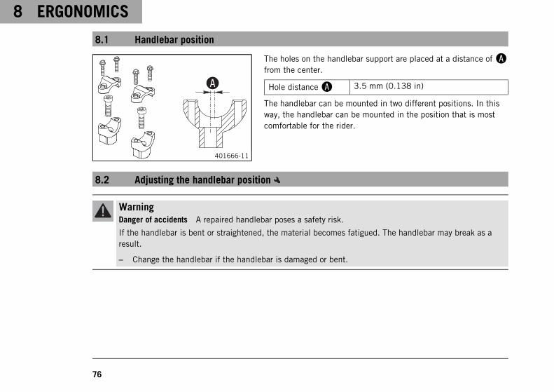
401666-11
The holes on the handlebar support are placed at a distance ofAfrom the center.
Hole distanceA 3.5 mm (0.138 in)
The handlebar can be mounted in two different positions. In thisway, the handlebar can be mounted in the position that is mostcomfortable for the rider.
8.2 Adjusting the handlebar position
WarningDanger of accidents A repaired handlebar poses a safety risk.
If the handlebar is bent or straightened, the material becomes fatigued. The handlebar may break as aresult.
– Change the handlebar if the handlebar is damaged or bent.
ERGONOMICS 8
77
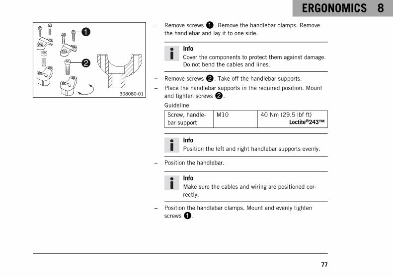
308080-01
– Remove screws1. Remove the handlebar clamps. Removethe handlebar and lay it to one side.
InfoCover the components to protect them against damage.Do not bend the cables and lines.
– Remove screws2. Take off the handlebar supports.
– Place the handlebar supports in the required position. Mountand tighten screws2.
Guideline
Screw, handle-bar support
M10 40 Nm (29.5 lbf ft)Loctite®243™
InfoPosition the left and right handlebar supports evenly.
– Position the handlebar.
InfoMake sure the cables and wiring are positioned cor-rectly.
– Position the handlebar clamps. Mount and evenly tightenscrews1.
8 ERGONOMICS
78
Guideline
Screw, handlebarclamp
M8 20 Nm (14.8 lbf ft)
InfoMake sure the gap widths are even.
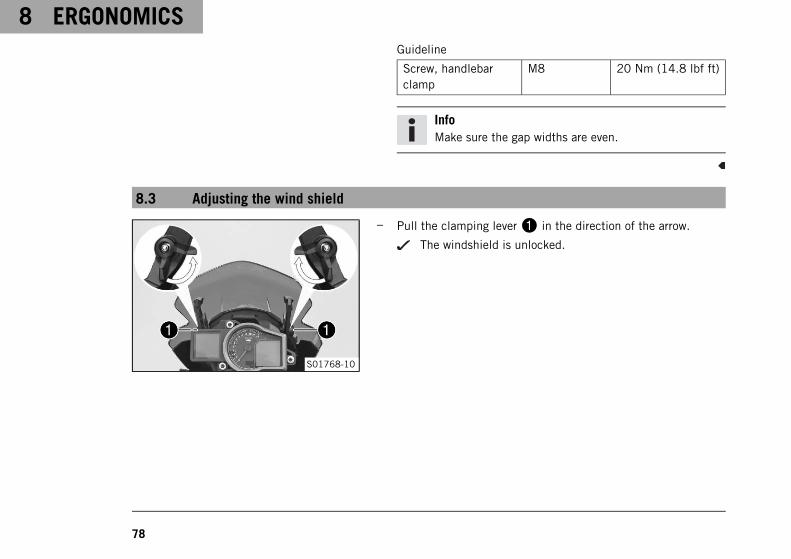
8.3 Adjusting the wind shield
S01768-10
– Pull the clamping lever1 in the direction of the arrow.
The windshield is unlocked.
ERGONOMICS 8
79
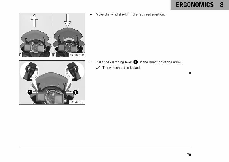
S01769-10
– Move the wind shield in the required position.
S01768-11
– Push the clamping lever1 in the direction of the arrow.
The windshield is locked.

8 ERGONOMICS
80
8.4 Adjusting basic position of clutch lever
M00551-10
– Adjust the basic setting of the clutch lever to your hand size byturning adjusting screw1.
InfoTurn the adjusting screw clockwise to increase thedistance between the clutch lever and the handlebar.Turn the adjusting screw counterclockwise to decreasethe distance between the clutch lever and the handle-bar.The range of adjustment is limited.Turn the adjusting screw by hand only, and do notapply any force.Do not make any adjustments while riding!
ERGONOMICS 8
81
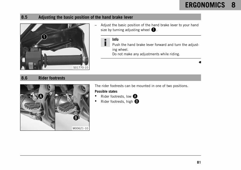
8.5 Adjusting the basic position of the hand brake lever
S01770-10
– Adjust the basic position of the hand brake lever to your handsize by turning adjusting wheel1.
InfoPush the hand brake lever forward and turn the adjust-ing wheel.Do not make any adjustments while riding.
8.6 Rider footrests
M00621-10
The rider footrests can be mounted in one of two positions.
Possible states• Rider footrests, lowA• Rider footrests, highB
8 ERGONOMICS
82
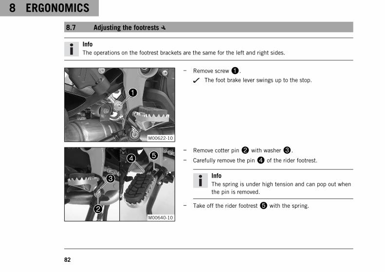
8.7 Adjusting the footrests
InfoThe operations on the footrest brackets are the same for the left and right sides.
M00622-10
– Remove screw1.
The foot brake lever swings up to the stop.
M00640-10
– Remove cotter pin2 with washer3.
– Carefully remove the pin4 of the rider footrest.
InfoThe spring is under high tension and can pop out whenthe pin is removed.
– Take off the rider footrest5 with the spring.
ERGONOMICS 8
83
M00641-10
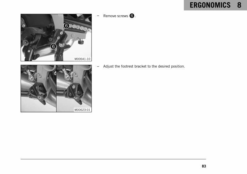
– Remove screws6.
M00623-01
– Adjust the footrest bracket to the desired position.
8 ERGONOMICS
84
M00641-10
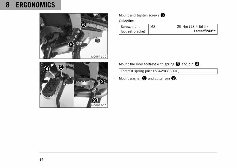
– Mount and tighten screws6.
Guideline
Screw, frontfootrest bracket
M8 25 Nm (18.4 lbf ft)Loctite®243™
M00642-10
– Mount the rider footrest with spring5 and pin4.
Footrest spring plier (58429083000)
– Mount washer3 and cotter pin2.
ERGONOMICS 8
85
M00622-10
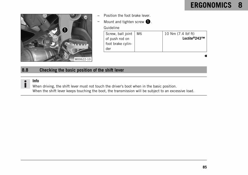
– Position the foot brake lever.
– Mount and tighten screw1.
Guideline
Screw, ball jointof push rod onfoot brake cylin-der
M6 10 Nm (7.4 lbf ft)Loctite®243™
8.8 Checking the basic position of the shift lever
InfoWhen driving, the shift lever must not touch the driver's boot when in the basic position.When the shift lever keeps touching the boot, the transmission will be subject to an excessive load.
8 ERGONOMICS
86
000AA
400692-10
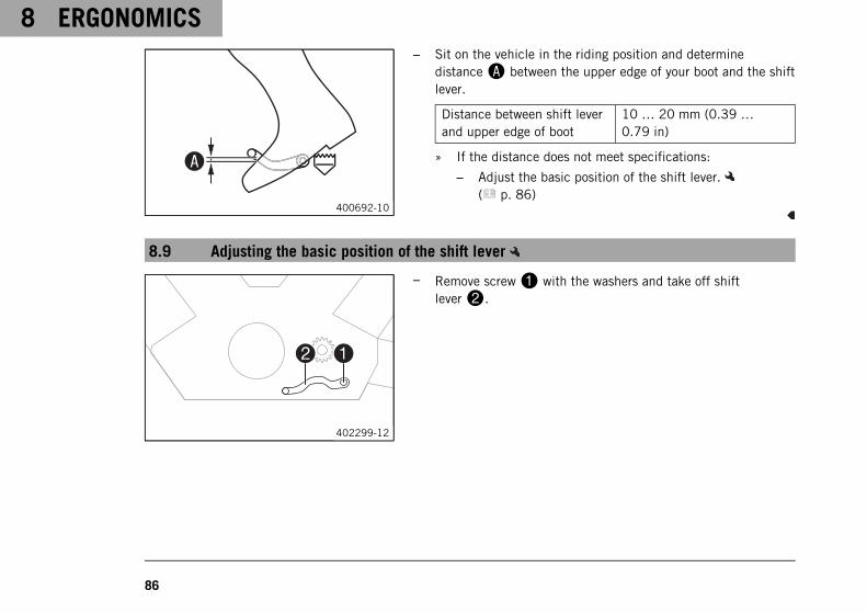
– Sit on the vehicle in the riding position and determinedistanceA between the upper edge of your boot and the shiftlever.
Distance between shift leverand upper edge of boot
10 … 20 mm (0.39 …0.79 in)
» If the distance does not meet specifications:
– Adjust the basic position of the shift lever.( p. 86)
8.9 Adjusting the basic position of the shift lever
402299-12
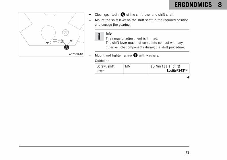
– Remove screw1 with the washers and take off shiftlever2.
ERGONOMICS 8
87
00AA402300-10
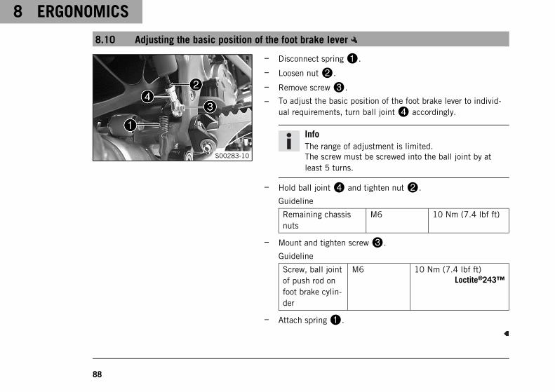
– Clean gear teethA of the shift lever and shift shaft.
– Mount the shift lever on the shift shaft in the required positionand engage the gearing.
InfoThe range of adjustment is limited.The shift lever must not come into contact with anyother vehicle components during the shift procedure.
– Mount and tighten screw1 with washers.
Guideline
Screw, shiftlever
M6 15 Nm (11.1 lbf ft)Loctite®243™
8 ERGONOMICS
88
8.10 Adjusting the basic position of the foot brake lever
S00283-10
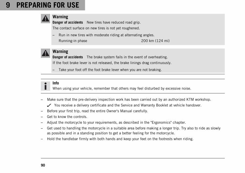
– Disconnect spring1.
– Loosen nut2.
– Remove screw3.
– To adjust the basic position of the foot brake lever to individ-ual requirements, turn ball joint4 accordingly.
InfoThe range of adjustment is limited.The screw must be screwed into the ball joint by atleast 5 turns.
– Hold ball joint4 and tighten nut2.
Guideline
Remaining chassisnuts
M6 10 Nm (7.4 lbf ft)
– Mount and tighten screw3.
Guideline
Screw, ball jointof push rod onfoot brake cylin-der
M6 10 Nm (7.4 lbf ft)Loctite®243™
– Attach spring1.

PREPARING FOR USE 9
89
9.1 Advice on preparing for first use
DangerDanger of accidents A rider who is not fit to ride poses a danger to him or herself and others.
– Do not operate the vehicle if you are not fit to ride due to alcohol, drugs or medication.
– Do not operate the vehicle if you are physically or mentally impaired.
WarningRisk of injury Missing or poor protective clothing presents an increased safety risk.
– Wear appropriate protective clothing such as helmet, boots, gloves as well as trousers and a jacketwith protectors on all rides.
– Always wear protective clothing that is in good condition and meets the legal regulations.
WarningDanger of crashing Different tire tread patterns on the front and rear wheel impair the handling charac-teristic.
Different tire tread patterns can make the vehicle significantly more difficult to control.
– Make sure that only tires with a similar tire tread pattern are fitted to the front and rear wheel.
WarningDanger of accidents Non-approved or non-recommended tires and wheels impact the handling character-istic.
– Only use tires/wheels approved by KTM with the corresponding speed index.
9 PREPARING FOR USE
90
WarningDanger of accidents New tires have reduced road grip.
The contact surface on new tires is not yet roughened.
– Run in new tires with moderate riding at alternating angles.
Running-in phase 200 km (124 mi)
WarningDanger of accidents The brake system fails in the event of overheating.
If the foot brake lever is not released, the brake linings drag continuously.
– Take your foot off the foot brake lever when you are not braking.
InfoWhen using your vehicle, remember that others may feel disturbed by excessive noise.
– Make sure that the pre-delivery inspection work has been carried out by an authorized KTM workshop.
You receive a delivery certificate and the Service and Warranty Booklet at vehicle handover.
– Before your first trip, read the entire Owner's Manual carefully.
– Get to know the controls.
– Adjust the motorcycle to your requirements, as described in the "Ergonomics" chapter.
– Get used to handling the motorcycle in a suitable area before making a longer trip. Try also to ride as slowlyas possible and in a standing position to get a better feeling for the motorcycle.
– Hold the handlebar firmly with both hands and keep your feet on the footrests when riding.
PREPARING FOR USE 9
91
– Run the engine in. ( p. 91)
9.2 Running in the engine
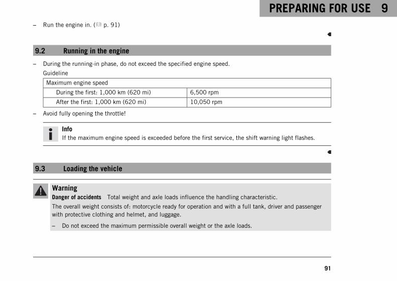
– During the running-in phase, do not exceed the specified engine speed.
Guideline
Maximum engine speed
During the first: 1,000 km (620 mi) 6,500 rpm
After the first: 1,000 km (620 mi) 10,050 rpm
– Avoid fully opening the throttle!
InfoIf the maximum engine speed is exceeded before the first service, the shift warning light flashes.
9.3 Loading the vehicle
WarningDanger of accidents Total weight and axle loads influence the handling characteristic.
The overall weight consists of: motorcycle ready for operation and with a full tank, driver and passengerwith protective clothing and helmet, and luggage.
– Do not exceed the maximum permissible overall weight or the axle loads.
9 PREPARING FOR USE
92
WarningDanger of accidents Improper mounting of cases or the tank rucksack impairs the handling characteris-tic.
– Mount and secure cases and tank rucksack according to the manufacturer's instructions.
WarningDanger of accidents Unstable handling characteristics at high speed.
– Adapt your speed according to your payload. Ride more slowly if your motorcycle is loaded with casesor other baggage.
Maximum speed with luggage 150 km/h (93.2 mph)
WarningDanger of accidents The luggage system will be damaged if it is overloaded.
– Read the manufacturer information on maximum payload when mounting cases.
WarningDanger of accidents Luggage which has slipped impairs visibility.
If the tail light is covered, you are less visible to traffic behind you, especially when it is dark.
– Check that your luggage is fixed properly at regular intervals.
WarningDanger of accidents A high payload alters the handling characteristic and increases the stoppingdistance.
– Adapt your speed to your payload.
PREPARING FOR USE 9
93
WarningDanger of accidents Pieces of luggage which have slipped impair the handling characteristic.
– Check that your luggage is fixed properly at regular intervals.
WarningFire hazard The hot exhaust system may burn luggage.
– Fasten your luggage in such a way that it cannot be burned or singed by the hot exhaust system.
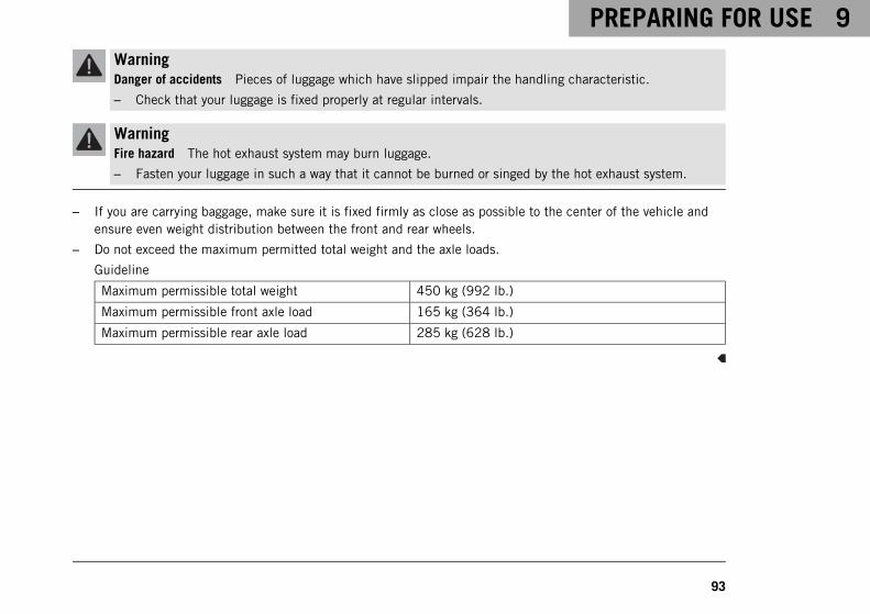
– If you are carrying baggage, make sure it is fixed firmly as close as possible to the center of the vehicle andensure even weight distribution between the front and rear wheels.
– Do not exceed the maximum permitted total weight and the axle loads.
Guideline
Maximum permissible total weight 450 kg (992 lb.)
Maximum permissible front axle load 165 kg (364 lb.)
Maximum permissible rear axle load 285 kg (628 lb.)
10 RIDING INSTRUCTIONS
94
10.1 Checks and maintenance measures when preparing for use
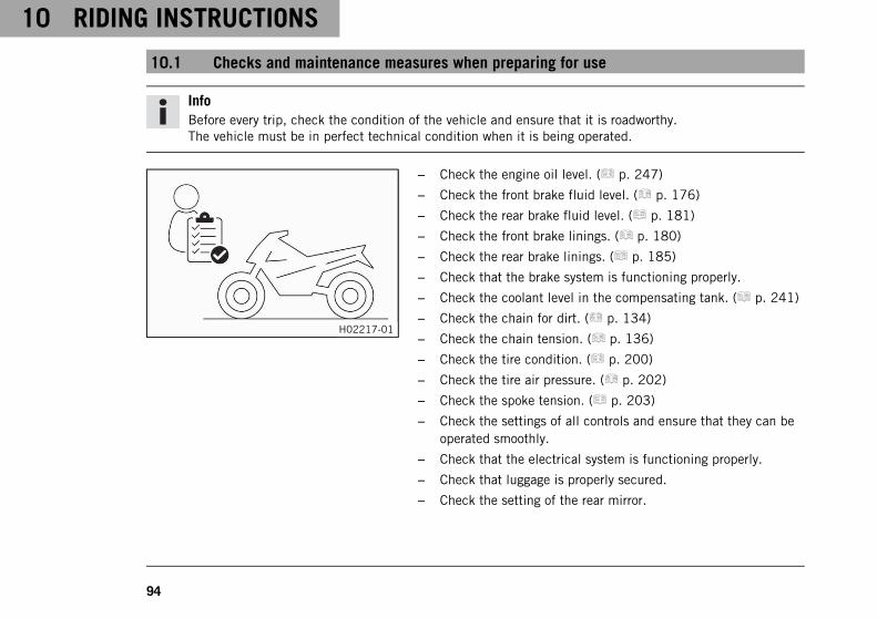
InfoBefore every trip, check the condition of the vehicle and ensure that it is roadworthy.The vehicle must be in perfect technical condition when it is being operated.
H02217-01
– Check the engine oil level. ( p. 247)
– Check the front brake fluid level. ( p. 176)
– Check the rear brake fluid level. ( p. 181)
– Check the front brake linings. ( p. 180)
– Check the rear brake linings. ( p. 185)
– Check that the brake system is functioning properly.
– Check the coolant level in the compensating tank. ( p. 241)
– Check the chain for dirt. ( p. 134)
– Check the chain tension. ( p. 136)
– Check the tire condition. ( p. 200)
– Check the tire air pressure. ( p. 202)
– Check the spoke tension. ( p. 203)
– Check the settings of all controls and ensure that they can beoperated smoothly.
– Check that the electrical system is functioning properly.
– Check that luggage is properly secured.
– Check the setting of the rear mirror.
RIDING INSTRUCTIONS 10
95
– Check the fuel level.
10.2 Starting the vehicle
DangerDanger of poisoning Exhaust gases are toxic and inhaling them may result in unconsciousness and death.
– Always make sure there is sufficient ventilation when running the engine.
– Use an effective exhaust extraction system when starting or running the engine in an enclosed space.
CautionDanger of accidents Electronic components and safety devices will be damaged if the battery isdischarged or missing.
– Never operate the vehicle with a discharged battery or without a battery.
NoteEngine damage High revving speed with a cold engine negatively impacts the lifespan of the engine.
– Always run the engine warm at a low speed.

10 RIDING INSTRUCTIONS
96
S01777-01
– Press the emergency OFF switch to the position ON .
– Switch on the ignition by turning the black ignition key to theposition ON .
After you switch on the ignition, you can hear the fuelpump working for about two seconds. The function checkof the combination instrument is run at the same time.
The ABS indicator lamp lights up and goes back out afterstarting off.
– Shift the transmission to idle .
The green idling speed indicator lamp lights up.
S01776-01
– Press the electric starter button .
RIDING INSTRUCTIONS 10
97
InfoDo not press the electric starter button until the combi-nation instrument function check is finished.When starting, DO NOT open the throttle. If you openthe throttle during the starting procedure, fuel is notinjected by the engine management system and theengine cannot start.Press the electric starter button for at most 5 sec-onds. Wait for a least 5 seconds before trying again.This motorcycle is equipped with a safety starting sys-tem. You can only start the engine if the transmissionis in neutral or if the clutch lever is pulled when a gearis engaged. If the side stand is folded out and you shiftinto gear, the engine stops.
– Remove the motorcycle from the side stand.
10.3 Starting off
– Pull the clutch lever, engage 1st gear, release the clutch lever slowly and simultaneously open the throttlecarefully.
10 RIDING INSTRUCTIONS
98
10.4 Shifting, riding
WarningDanger of accidents Abrupt load alterations can cause the vehicle to get out of control.
– Avoid abrupt load alterations and sudden braking actions.
– Adapt your speed to the road conditions.
WarningDanger of accidents If you change down at high engine speed, the rear wheel blocks and the engineraces.
– Do not change into a low gear at high engine speed.
WarningDanger of accidents An incorrect ignition key position causes malfunctions.
– Do not change the ignition key position while driving.
WarningDanger of accidents Adjustments to the vehicle distract attention from traffic activity.
– Make all adjustments when the vehicle is at a standstill.

RIDING INSTRUCTIONS 10
99
WarningRisk of injury The passenger may fall from the motorcycle if they conduct themselves incorrectly.
– Ensure that the passenger sits correctly on the passenger seat, places his or her feet on the passengerfoot rest and holds on to the rider or the grab handles.
– Note the regulations governing the minimum age of passengers in your country.
WarningDanger of accidents A risky riding style constitutes a major risk.
– Comply with traffic regulations and ride defensively and with foresight to detect sources of danger asearly as possible.
WarningDanger of accidents Cold tires have reduced road grip.
– Ride the first miles carefully on every journey at moderate speed until the tires reach operating tem-perature.
WarningDanger of accidents New tires have reduced road grip.
The contact surface on new tires is not yet roughened.
– Run in new tires with moderate riding at alternating angles.
Running-in phase 200 km (124 mi)
10 RIDING INSTRUCTIONS
100
WarningDanger of accidents Total weight and axle loads influence the handling characteristic.
The overall weight consists of: motorcycle ready for operation and with a full tank, driver and passengerwith protective clothing and helmet, and luggage.
– Do not exceed the maximum permissible overall weight or the axle loads.
WarningDanger of accidents Pieces of luggage which have slipped impair the handling characteristic.
– Check that your luggage is fixed properly at regular intervals.
WarningDanger of accidents A fall can damage the vehicle more seriously than it may first appear.
– Check the vehicle after a fall as you do when preparing for use.
NoteEngine damage Unfiltered intake air has a negative effect on the service life of the engine.
Dust and dirt will enter the engine without an air filter.
– Never start to use the vehicle without an air filter.
RIDING INSTRUCTIONS 10
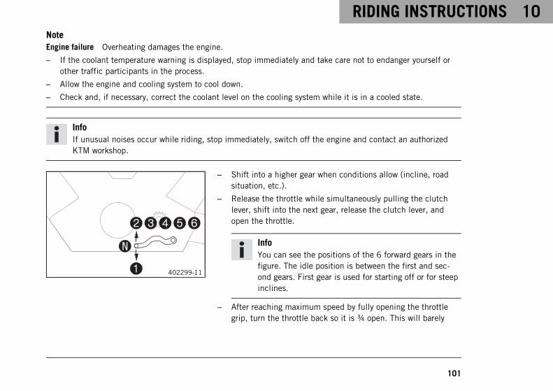
101
NoteEngine failure Overheating damages the engine.
– If the coolant temperature warning is displayed, stop immediately and take care not to endanger yourself orother traffic participants in the process.
– Allow the engine and cooling system to cool down.
– Check and, if necessary, correct the coolant level on the cooling system while it is in a cooled state.
InfoIf unusual noises occur while riding, stop immediately, switch off the engine and contact an authorizedKTM workshop.
402299-11
– Shift into a higher gear when conditions allow (incline, roadsituation, etc.).
– Release the throttle while simultaneously pulling the clutchlever, shift into the next gear, release the clutch lever, andopen the throttle.
InfoYou can see the positions of the 6 forward gears in thefigure. The idle position is between the first and sec-ond gears. First gear is used for starting off or for steepinclines.
– After reaching maximum speed by fully opening the throttlegrip, turn the throttle back so it is ¾ open. This will barely
10 RIDING INSTRUCTIONS
102
reduce the speed but fuel consumption will be considerablylower.
– Accelerate only up to a speed suitable for the road surface andweather conditions. Particularly in bends, do not shift, andaccelerate very carefully.
– Brake if necessary and close the throttle at the same time inorder to shift down.
– Pull the clutch lever and shift into a lower gear, release theclutch lever slowly, and open the throttle or shift again.
– If the engine stalls (e.g. at a crossroads), just pull the clutchlever and press the electric starter button. You do not have toshift into neutral.
– Switch off the engine if running at idle or stationary for a longtime.
– If the oil pressure warning lamp lights up during a trip, stopimmediately and switch off the engine. Contact an authorizedKTM workshop.
– If the malfunction indicator lamp lights up during a trip,please contact an authorized KTM workshop as soon as possi-ble.
RIDING INSTRUCTIONS 10
103
InfoYou can deduce a two-digit number from the flashrhythm – the so-called blink code. The blink code tellsyou which component is affected by a malfunction.
– If the general warning lamp lights up during a trip, thematrix display shows a message for 10 seconds.
InfoVery important messages are stored in the "Warning"menu.
– If the icy road symbol appears in the combination instru-ment, the roads may be icy. Adjust your speed to the road con-ditions.
10.5 Applying the brakes
WarningDanger of accidents Moisture and dirt impair the brake system.
– Brake carefully several times to dry out and remove dirt from the brake linings and the brake discs.
10 RIDING INSTRUCTIONS
104
WarningDanger of accidents A spongy pressure point on the front or rear brake reduces braking efficiency.
– Check the brake system and do not continue riding until the problem is eliminated. (Your authorizedKTM workshop will be glad to help.)
WarningDanger of accidents The brake system fails in the event of overheating.
If the foot brake lever is not released, the brake linings drag continuously.
– Take your foot off the foot brake lever when you are not braking.
WarningDanger of accidents Higher total weight increases the stopping distance.
– Take the longer stopping distance into account when carrying a passenger or luggage with you.
WarningDanger of accidents Salt on the roads impairs the brake system.
– Brake carefully several times to remove salt from the brake linings and the brake discs.
WarningDanger of accidents ABS may increase the stopping distance in certain situations.
– Adjust application of the brakes to the respective riding situation and riding surface conditions.
RIDING INSTRUCTIONS 10
105
WarningDanger of accidents Excessively forceful application of the brakes blocks the wheels.
The ABS effectiveness is only ensured if it is switched on.
– Leave the ABS switched on in order to benefit from the protective effect.
WarningDanger of accidents Driving aids can only prevent a rollover within the physical limitations.
It is not always possible to compensate for extreme riding situations, for example with luggage loadedwith a high center of gravity, varying road surfaces, steep descents or full braking without disengagingthe gear.
– Adapt your riding style to the road conditions and your driving ability.
– When braking, release the throttle and apply the front and rear brakes at the same time.
InfoWhen the ABS is enabled, you can achieve maximum braking power even on low grip surfaces such assandy, wet, or slippery terrain without locking of the wheels.
WarningDanger of accidents The rear wheel can lock due to the engine braking effect.
– Pull in the clutch, if you perform emergency or full braking, or if you brake on a slippery ground.
10 RIDING INSTRUCTIONS
106
WarningDanger of accidents Banked or laterally sloping ground reduces the maximum possible delay.
– If possible finish braking before going into a bend.
– Braking should always be completed before you go into a bend. Change down to a lower gear appropriate toyour road speed.
– On long downhill stretches, use the braking effect of the engine. Change down one or two gears, but do notover-rev the engine. In this way, you have to brake far less and the brakes do not overheat.
10.6 Stopping, parking
WarningRisk of injury People who act without authorization endanger themselves and others.
– Do not leave the vehicle unattended if the engine is running.
– Protect the vehicle against access by unauthorized persons.
– Lock the steering and remove the ignition key if you leave the vehicle unattended.
WarningDanger of burns Some vehicle components become very hot when the vehicle is operated.
– Do not touch any parts such as the exhaust system, radiator, engine, shock absorber, or brake systembefore the vehicle parts have cooled down.
– Let the vehicle parts cool down before you perform any work on the vehicle.
RIDING INSTRUCTIONS 10
107
NoteFire hazard Hot vehicle components pose a fire hazard and explosion risk.
– Do not park the vehicle near to materials which are highly flammable or explosive.
– Allow the vehicle to cool down before covering it.
NoteMaterial damage The vehicle may be damaged by incorrect procedure when parking.
Significant damage may be caused if the vehicle rolls away or falls over.The components for parking the vehicle are designed only for the weight of the vehicle.
– Park the vehicle on a firm and level surface.
– Ensure that nobody sits on the vehicle when the vehicle is parked on a stand.
– Apply the brakes on the motorcycle.
– Shift the transmission to idle .
– Switch off the ignition by turning the black ignition key to the position OFF .
InfoIf the engine is switched off with the emergency OFF switch and the ignition remains switched on atthe ignition lock, power continues to flow to most power consumers. This discharges the battery. Youshould therefore always switch off the engine with the ignition lock – the emergency OFF switch isintended for emergencies only.
– Park the motorcycle on a firm surface.
– Swing the side stand forward with your foot as far as it will go and lean the vehicle on it.

10 RIDING INSTRUCTIONS
108
– Lock the steering by turning the handlebar to the left, pressing the black ignition key down in theposition OFF and turning it to the position LOCK . To make the steering lock engage more easily, move thehandlebar a little to the left and right. Remove the black ignition key.
10.7 Transporting
NoteDanger of damage The parked vehicle can roll away or fall over.
– Park the vehicle on a firm and level surface.
NoteFire hazard Hot vehicle components pose a fire hazard and explosion risk.
– Do not park the vehicle near to materials which are highly flammable or explosive.
– Allow the vehicle to cool down before covering it.
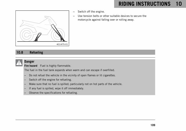
RIDING INSTRUCTIONS 10
109
401475-01
– Switch off the engine.
– Use tension belts or other suitable devices to secure themotorcycle against falling over or rolling away.
10.8 Refueling
DangerFire hazard Fuel is highly flammable.
The fuel in the fuel tank expands when warm and can escape if overfilled.
– Do not refuel the vehicle in the vicinity of open flames or lit cigarettes.
– Switch off the engine for refueling.
– Make sure that no fuel is spilled; particularly not on hot parts of the vehicle.
– If any fuel is spilled, wipe it off immediately.
– Observe the specifications for refueling.
10 RIDING INSTRUCTIONS
110
WarningDanger of poisoning Fuel is poisonous and a health hazard.
– Avoid skin, eye and clothing contact with fuel.
– Immediately consult a doctor if you swallow fuel.
– Do not inhale fuel vapors.
– In case of skin contact, rinse the affected area with plenty of water.
– Rinse the eyes thoroughly with water, and consult a doctor in case of fuel contact with the eyes.
– Change your clothing in case of fuel spills on them.
NoteMaterial damage Inadequate fuel quality causes the fuel filter to quickly become clogged.
In some countries and regions, the available fuel quality and cleanliness may not be sufficient. This will result inproblems with the fuel system.
– Refuel only with clean fuel that meets the specified standards. (Your authorized KTM workshop will be glad tohelp.)
WarningEnvironmental hazard Improper handling of fuel is a danger to the environment.
– Do not allow fuel to enter the groundwater, the soil, or the sewage system.
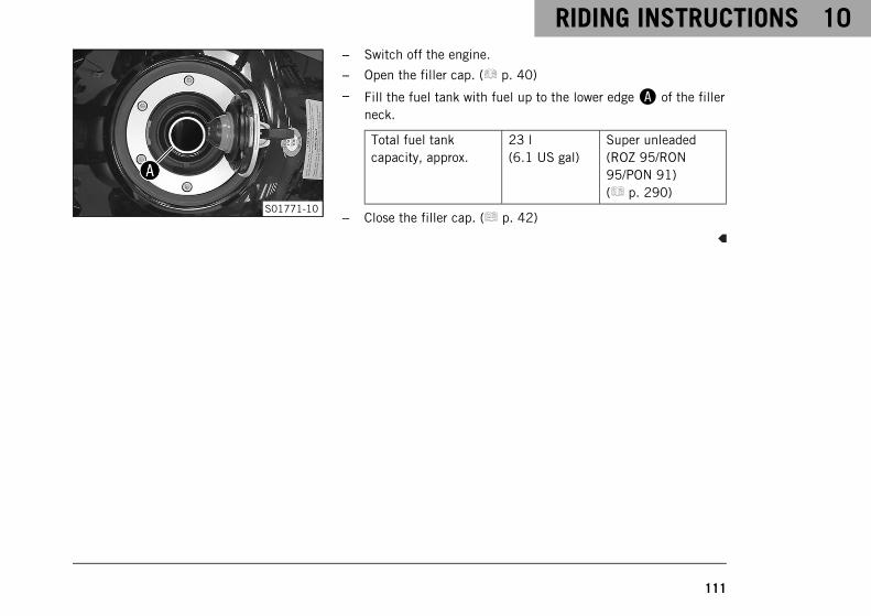
RIDING INSTRUCTIONS 10
111
S01771-10
– Switch off the engine.
– Open the filler cap. ( p. 40)
– Fill the fuel tank with fuel up to the lower edgeA of the fillerneck.
Total fuel tankcapacity, approx.
23 l(6.1 US gal)
Super unleaded(ROZ 95/RON95/PON 91)( p. 290)
– Close the filler cap. ( p. 42)
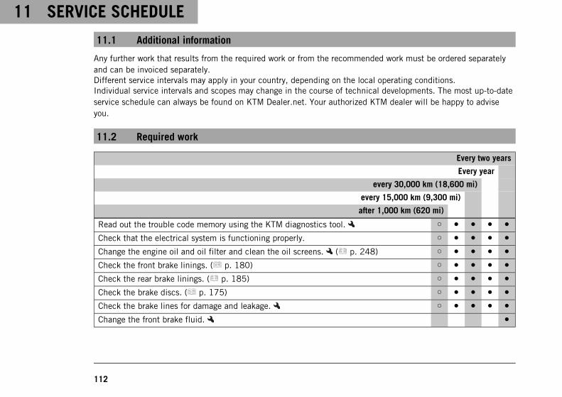
11 SERVICE SCHEDULE
112
11.1 Additional information
Any further work that results from the required work or from the recommended work must be ordered separatelyand can be invoiced separately.Different service intervals may apply in your country, depending on the local operating conditions.Individual service intervals and scopes may change in the course of technical developments. The most up-to-dateservice schedule can always be found on KTM Dealer.net. Your authorized KTM dealer will be happy to adviseyou.
11.2 Required work
Every two years
Every year
every 30,000 km (18,600 mi)
every 15,000 km (9,300 mi)
after 1,000 km (620 mi)
Read out the trouble code memory using the KTM diagnostics tool. ○ ● ● ● ●
Check that the electrical system is functioning properly. ○ ● ● ● ●
Change the engine oil and oil filter and clean the oil screens. ( p. 248) ○ ● ● ● ●
Check the front brake linings. ( p. 180) ○ ● ● ● ●
Check the rear brake linings. ( p. 185) ○ ● ● ● ●
Check the brake discs. ( p. 175) ○ ● ● ● ●
Check the brake lines for damage and leakage. ○ ● ● ● ●
Change the front brake fluid. ●
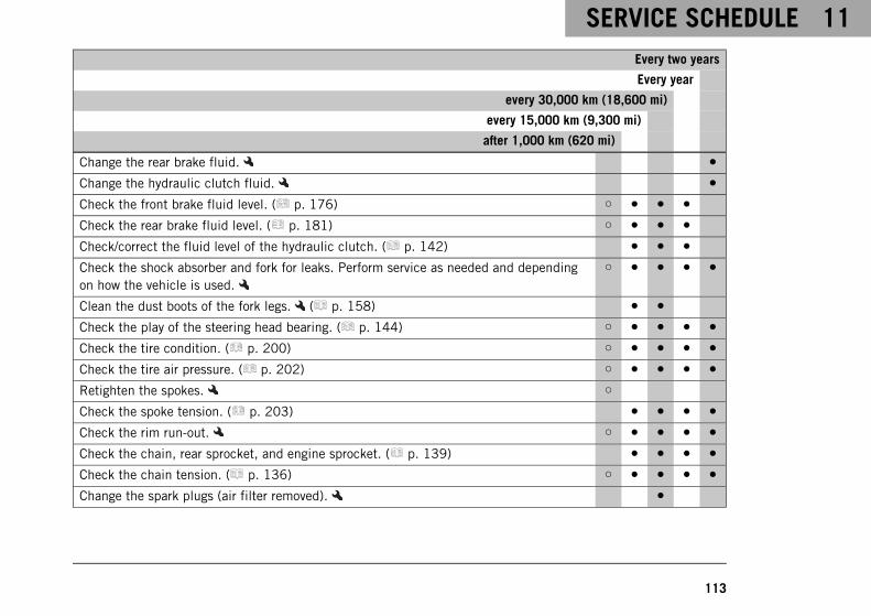
SERVICE SCHEDULE 11
113
Every two years
Every year
every 30,000 km (18,600 mi)
every 15,000 km (9,300 mi)
after 1,000 km (620 mi)
Change the rear brake fluid. ●
Change the hydraulic clutch fluid. ●
Check the front brake fluid level. ( p. 176) ○ ● ● ●
Check the rear brake fluid level. ( p. 181) ○ ● ● ●
Check/correct the fluid level of the hydraulic clutch. ( p. 142) ● ● ●
Check the shock absorber and fork for leaks. Perform service as needed and dependingon how the vehicle is used.
○ ● ● ● ●
Clean the dust boots of the fork legs. ( p. 158) ● ●
Check the play of the steering head bearing. ( p. 144) ○ ● ● ● ●
Check the tire condition. ( p. 200) ○ ● ● ● ●
Check the tire air pressure. ( p. 202) ○ ● ● ● ●
Retighten the spokes. ○
Check the spoke tension. ( p. 203) ● ● ● ●
Check the rim run-out. ○ ● ● ● ●
Check the chain, rear sprocket, and engine sprocket. ( p. 139) ● ● ● ●
Check the chain tension. ( p. 136) ○ ● ● ● ●
Change the spark plugs (air filter removed). ●
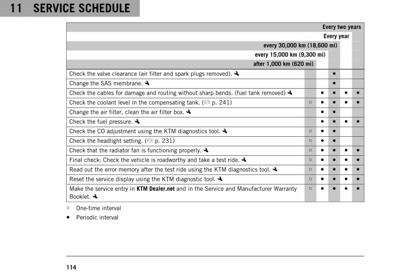
11 SERVICE SCHEDULE
114
Every two years
Every year
every 30,000 km (18,600 mi)
every 15,000 km (9,300 mi)
after 1,000 km (620 mi)
Check the valve clearance (air filter and spark plugs removed). ●
Change the SAS membrane. ●
Check the cables for damage and routing without sharp bends. (fuel tank removed) ● ● ● ●
Check the coolant level in the compensating tank. ( p. 241) ○ ● ● ● ●
Change the air filter, clean the air filter box. ● ●
Check the fuel pressure. ● ● ● ●
Check the CO adjustment using the KTM diagnostics tool. ○ ● ●
Check the headlight setting. ( p. 231) ○ ● ●
Check that the radiator fan is functioning properly. ○ ● ● ● ●
Final check: Check the vehicle is roadworthy and take a test ride. ○ ● ● ● ●
Read out the error memory after the test ride using the KTM diagnostics tool. ○ ● ● ● ●
Reset the service display using the KTM diagnostic tool. ○ ● ● ● ●
Make the service entry in KTM Dealer.net and in the Service and Manufacturer WarrantyBooklet.
○ ● ● ● ●
○ One-time interval
● Periodic interval
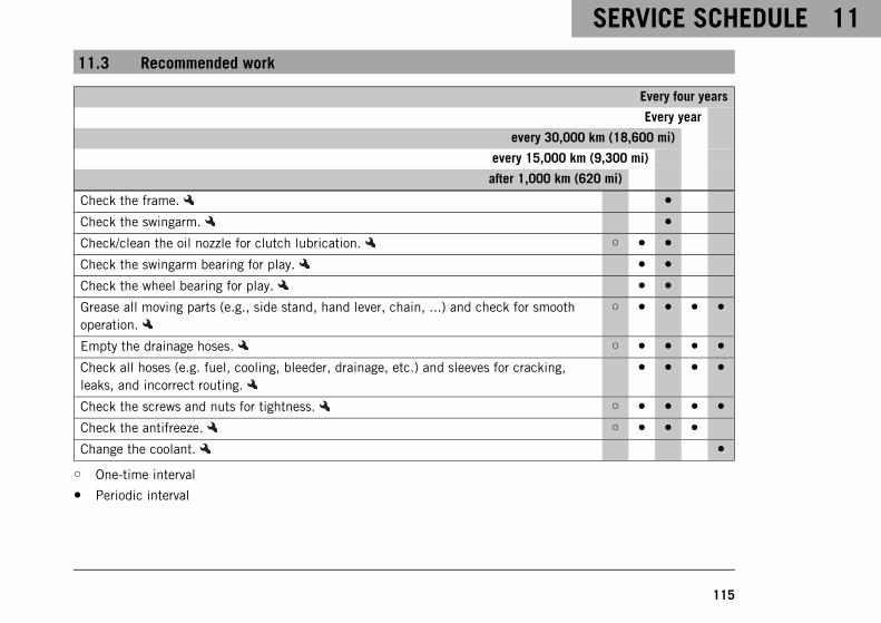
SERVICE SCHEDULE 11
115
11.3 Recommended work
Every four years
Every year
every 30,000 km (18,600 mi)
every 15,000 km (9,300 mi)
after 1,000 km (620 mi)
Check the frame. ●
Check the swingarm. ●
Check/clean the oil nozzle for clutch lubrication. ○ ● ●
Check the swingarm bearing for play. ● ●
Check the wheel bearing for play. ● ●
Grease all moving parts (e.g., side stand, hand lever, chain, ...) and check for smoothoperation.
○ ● ● ● ●
Empty the drainage hoses. ○ ● ● ● ●
Check all hoses (e.g. fuel, cooling, bleeder, drainage, etc.) and sleeves for cracking,leaks, and incorrect routing.
● ● ● ●
Check the screws and nuts for tightness. ○ ● ● ● ●
Check the antifreeze. ○ ● ● ●
Change the coolant. ●
○ One-time interval
● Periodic interval
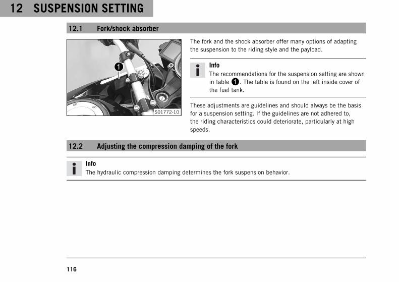
12 SUSPENSION SETTING
116
12.1 Fork/shock absorber
S01772-10
The fork and the shock absorber offer many options of adaptingthe suspension to the riding style and the payload.
InfoThe recommendations for the suspension setting are shownin table1. The table is found on the left inside cover ofthe fuel tank.
These adjustments are guidelines and should always be the basisfor a suspension setting. If the guidelines are not adhered to,the riding characteristics could deteriorate, particularly at highspeeds.
12.2 Adjusting the compression damping of the fork
InfoThe hydraulic compression damping determines the fork suspension behavior.
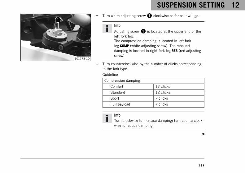
SUSPENSION SETTING 12
117
S01773-10
– Turn white adjusting screw1 clockwise as far as it will go.
InfoAdjusting screw1 is located at the upper end of theleft fork leg.The compression damping is located in left forkleg COMP (white adjusting screw). The rebounddamping is located in right fork leg REB (red adjustingscrew).
– Turn counterclockwise by the number of clicks correspondingto the fork type.
Guideline
Compression damping
Comfort 17 clicks
Standard 12 clicks
Sport 7 clicks
Full payload 7 clicks
InfoTurn clockwise to increase damping; turn counterclock-wise to reduce damping.
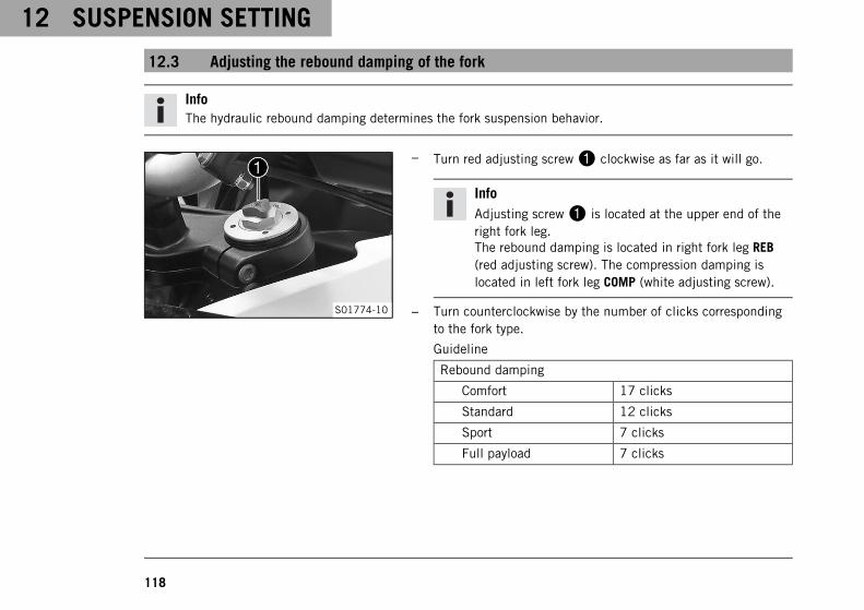
12 SUSPENSION SETTING
118
12.3 Adjusting the rebound damping of the fork
InfoThe hydraulic rebound damping determines the fork suspension behavior.
S01774-10
– Turn red adjusting screw1 clockwise as far as it will go.
InfoAdjusting screw1 is located at the upper end of theright fork leg.The rebound damping is located in right fork leg REB(red adjusting screw). The compression damping islocated in left fork leg COMP (white adjusting screw).
– Turn counterclockwise by the number of clicks correspondingto the fork type.
Guideline
Rebound damping
Comfort 17 clicks
Standard 12 clicks
Sport 7 clicks
Full payload 7 clicks
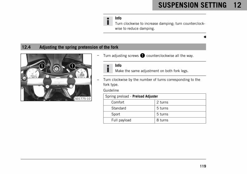
SUSPENSION SETTING 12
119
InfoTurn clockwise to increase damping; turn counterclock-wise to reduce damping.
12.4 Adjusting the spring pretension of the fork
S01775-10
– Turn adjusting screws1 counterclockwise all the way.
InfoMake the same adjustment on both fork legs.
– Turn clockwise by the number of turns corresponding to thefork type.
Guideline
Spring preload - Preload Adjuster
Comfort 2 turns
Standard 5 turns
Sport 5 turns
Full payload 8 turns
12 SUSPENSION SETTING
120
InfoTurn clockwise to increase the spring pretension; turncounterclockwise to reduce the spring pretension.Adjusting the spring pretension has no influence on theabsorption setting of the rebound damping.Basically, however, you should set the rebound damp-ing higher with a higher spring pretension.
12.5 Compression damping of the shock absorber
The compression damping of the shock absorber is divided into two ranges: high-speed and low-speed.High-speed and low-speed refer to the compression speed of the rear wheel suspension and not to the vehiclespeed.The high-speed setting, for example, has an effect when riding over an asphalt edge: the rear wheel suspensioncompresses quickly.The low-speed setting, for example, has an effect when riding over long ground swells: the rear wheel suspensioncompresses slowly.These two ranges can be adjusted separately, although the transition between high-speed and low-speed is grad-ual. Thus, changes in the high-speed range affect the compression damping in the low-speed range and viceversa.
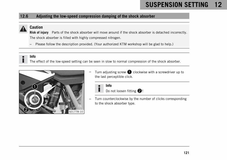
SUSPENSION SETTING 12
121
12.6 Adjusting the low-speed compression damping of the shock absorber
CautionRisk of injury Parts of the shock absorber will move around if the shock absorber is detached incorrectly.
The shock absorber is filled with highly compressed nitrogen.
– Please follow the description provided. (Your authorized KTM workshop will be glad to help.)
InfoThe effect of the low-speed setting can be seen in slow to normal compression of the shock absorber.
S01778-10
– Turn adjusting screw1 clockwise with a screwdriver up tothe last perceptible click.
InfoDo not loosen fitting2!
– Turn counterclockwise by the number of clicks correspondingto the shock absorber type.
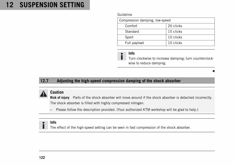
12 SUSPENSION SETTING
122
Guideline
Compression damping, low-speed
Comfort 20 clicks
Standard 15 clicks
Sport 10 clicks
Full payload 10 clicks
InfoTurn clockwise to increase damping; turn counterclock-wise to reduce damping.
12.7 Adjusting the high-speed compression damping of the shock absorber
CautionRisk of injury Parts of the shock absorber will move around if the shock absorber is detached incorrectly.
The shock absorber is filled with highly compressed nitrogen.
– Please follow the description provided. (Your authorized KTM workshop will be glad to help.)
InfoThe effect of the high-speed setting can be seen in fast compression of the shock absorber.
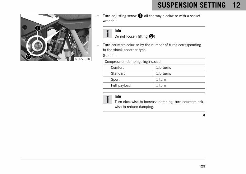
SUSPENSION SETTING 12
123
S01779-10
– Turn adjusting screw1 all the way clockwise with a socketwrench.
InfoDo not loosen fitting2!
– Turn counterclockwise by the number of turns correspondingto the shock absorber type.
Guideline
Compression damping, high-speed
Comfort 1.5 turns
Standard 1.5 turns
Sport 1 turn
Full payload 1 turn
InfoTurn clockwise to increase damping; turn counterclock-wise to reduce damping.
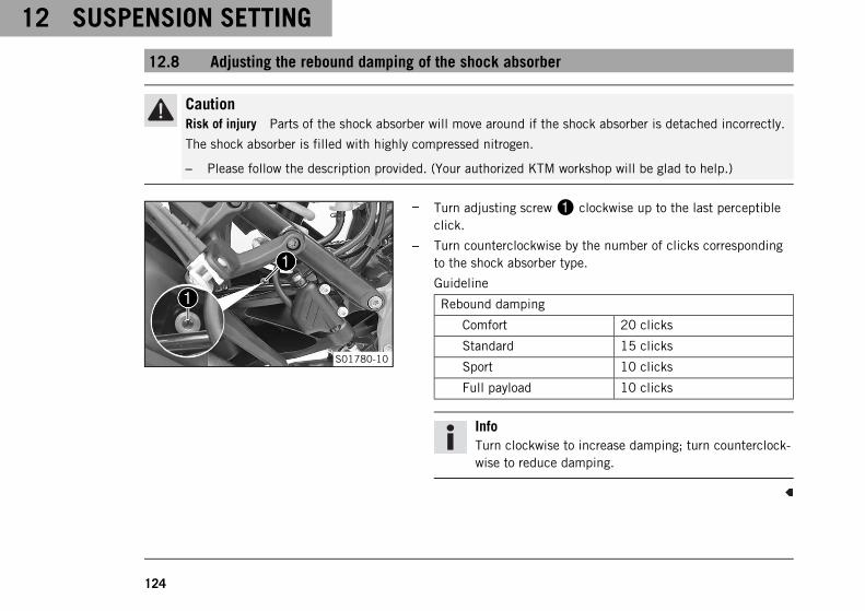
12 SUSPENSION SETTING
124
12.8 Adjusting the rebound damping of the shock absorber
CautionRisk of injury Parts of the shock absorber will move around if the shock absorber is detached incorrectly.
The shock absorber is filled with highly compressed nitrogen.
– Please follow the description provided. (Your authorized KTM workshop will be glad to help.)
S01780-10
– Turn adjusting screw1 clockwise up to the last perceptibleclick.
– Turn counterclockwise by the number of clicks correspondingto the shock absorber type.
Guideline
Rebound damping
Comfort 20 clicks
Standard 15 clicks
Sport 10 clicks
Full payload 10 clicks
InfoTurn clockwise to increase damping; turn counterclock-wise to reduce damping.
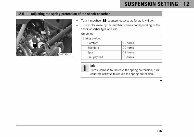
SUSPENSION SETTING 12
125
12.9 Adjusting the spring pretension of the shock absorber
S01781-10
– Turn handwheel1 counterclockwise as far as it will go.
– Turn it clockwise by the number of turns corresponding to theshock absorber type and use.
Guideline
Spring preload
Comfort 12 turns
Standard 12 turns
Sport 12 turns
Full payload 18 turns
InfoTurn clockwise to increase the spring pretension; turncounterclockwise to reduce the spring pretension.
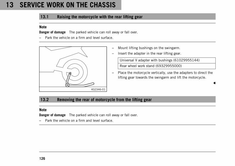
13 SERVICE WORK ON THE CHASSIS
126
13.1 Raising the motorcycle with the rear lifting gear
NoteDanger of damage The parked vehicle can roll away or fall over.
– Park the vehicle on a firm and level surface.
402346-01
– Mount lifting bushings on the swingarm.
– Insert the adapter in the rear lifting gear.
Universal V adapter with bushings (61029955144)
Rear wheel work stand (69329955000)
– Place the motorcycle vertically, use the adapters to direct thelifting gear towards the swingarm and lift the motorcycle.
13.2 Removing the rear of motorcycle from the lifting gear
NoteDanger of damage The parked vehicle can roll away or fall over.
– Park the vehicle on a firm and level surface.
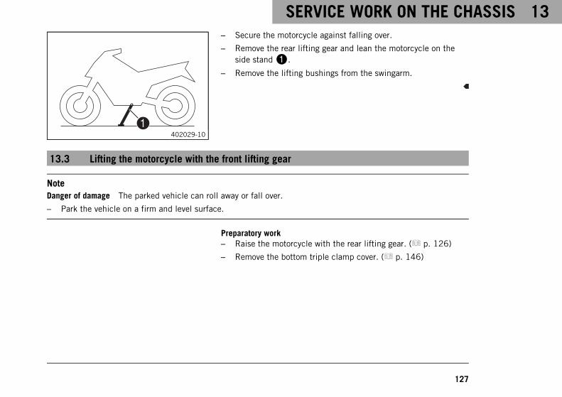
SERVICE WORK ON THE CHASSIS 13
127
402029-10
– Secure the motorcycle against falling over.
– Remove the rear lifting gear and lean the motorcycle on theside stand1.
– Remove the lifting bushings from the swingarm.
13.3 Lifting the motorcycle with the front lifting gear
NoteDanger of damage The parked vehicle can roll away or fall over.
– Park the vehicle on a firm and level surface.
Preparatory work– Raise the motorcycle with the rear lifting gear. ( p. 126)
– Remove the bottom triple clamp cover. ( p. 146)

13 SERVICE WORK ON THE CHASSIS
128
402345-01
Main work– Move the handlebar to the straight-ahead position.
– Attach the front lifting gear with the adapter on the steeringstem.
Mounting pin (69329965040)
Front wheel work stand, large (69329965000)
– Align the front lifting gear with the fork legs.
InfoAlways raise the motorcycle at the rear first.
– Lift the motorcycle at the front.
13.4 Taking the motorcycle off the front lifting gear
NoteDanger of damage The parked vehicle can roll away or fall over.
– Park the vehicle on a firm and level surface.
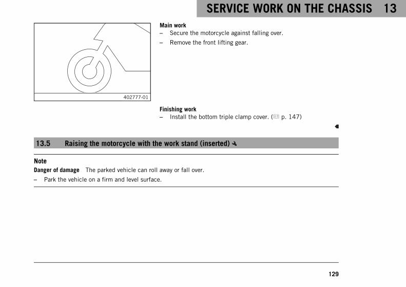
SERVICE WORK ON THE CHASSIS 13
129
402777-01
Main work– Secure the motorcycle against falling over.
– Remove the front lifting gear.
Finishing work– Install the bottom triple clamp cover. ( p. 147)
13.5 Raising the motorcycle with the work stand (inserted)
NoteDanger of damage The parked vehicle can roll away or fall over.
– Park the vehicle on a firm and level surface.
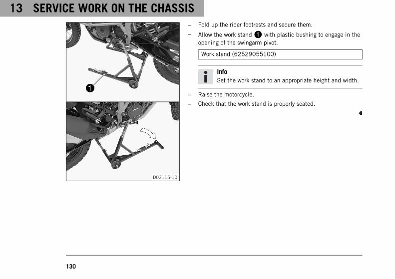
13 SERVICE WORK ON THE CHASSIS
130
D03115-10
– Fold up the rider footrests and secure them.
– Allow the work stand1 with plastic bushing to engage in theopening of the swingarm pivot.
Work stand (62529055100)
InfoSet the work stand to an appropriate height and width.
– Raise the motorcycle.
– Check that the work stand is properly seated.
SERVICE WORK ON THE CHASSIS 13
131
13.6 Removing the motorcycle from the work stand (inserted)
NoteDanger of damage The parked vehicle can roll away or fall over.
– Park the vehicle on a firm and level surface.
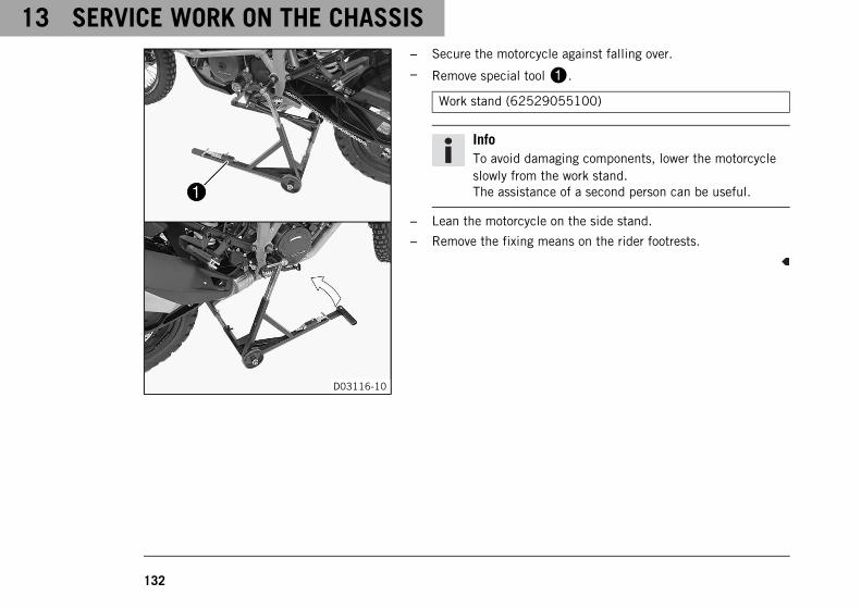
13 SERVICE WORK ON THE CHASSIS
132
D03116-10
– Secure the motorcycle against falling over.
– Remove special tool1.
Work stand (62529055100)
InfoTo avoid damaging components, lower the motorcycleslowly from the work stand.The assistance of a second person can be useful.
– Lean the motorcycle on the side stand.
– Remove the fixing means on the rider footrests.
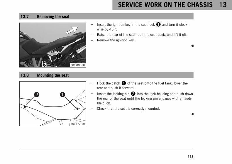
SERVICE WORK ON THE CHASSIS 13
133
13.7 Removing the seat
S01782-10
– Insert the ignition key in the seat lock1 and turn it clock-wise by 45 °.
– Raise the rear of the seat, pull the seat back, and lift it off.
– Remove the ignition key.
13.8 Mounting the seat
0022 0011
401677-10
– Hook the catch1 of the seat onto the fuel tank, lower therear and push it forward.
– Insert the locking pin2 into the lock housing and push downthe rear of the seat until the locking pin engages with an audi-ble click.
– Check that the seat is correctly mounted.
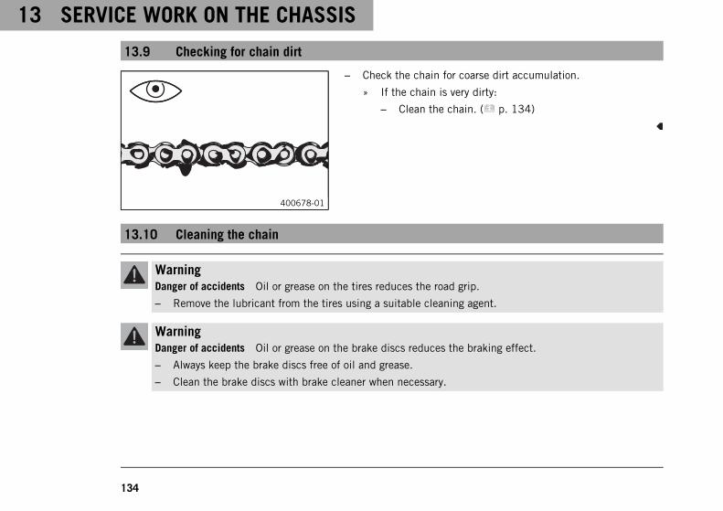
13 SERVICE WORK ON THE CHASSIS
134
13.9 Checking for chain dirt
400678-01
– Check the chain for coarse dirt accumulation.
» If the chain is very dirty:
– Clean the chain. ( p. 134)
13.10 Cleaning the chain
WarningDanger of accidents Oil or grease on the tires reduces the road grip.
– Remove the lubricant from the tires using a suitable cleaning agent.
WarningDanger of accidents Oil or grease on the brake discs reduces the braking effect.
– Always keep the brake discs free of oil and grease.
– Clean the brake discs with brake cleaner when necessary.
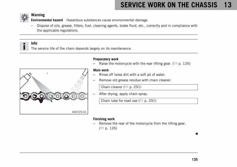
SERVICE WORK ON THE CHASSIS 13
135
WarningEnvironmental hazard Hazardous substances cause environmental damage.
– Dispose of oils, grease, filters, fuel, cleaning agents, brake fluid, etc., correctly and in compliance withthe applicable regulations.
InfoThe service life of the chain depends largely on its maintenance.
Preparatory work– Raise the motorcycle with the rear lifting gear. ( p. 126)
400725-01
Main work– Rinse off loose dirt with a soft jet of water.
– Remove old grease residue with chain cleaner.
Chain cleaner ( p. 291)
– After drying, apply chain spray.
Chain lube for road use ( p. 291)
Finishing work– Remove the rear of the motorcycle from the lifting gear.
( p. 126)
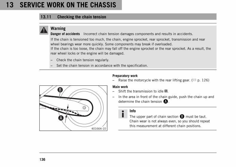
13 SERVICE WORK ON THE CHASSIS
136
13.11 Checking the chain tension
WarningDanger of accidents Incorrect chain tension damages components and results in accidents.
If the chain is tensioned too much, the chain, engine sprocket, rear sprocket, transmission and rearwheel bearings wear more quickly. Some components may break if overloaded.If the chain is too loose, the chain may fall off the engine sprocket or the rear sprocket. As a result, therear wheel locks or the engine will be damaged.
– Check the chain tension regularly.
– Set the chain tension in accordance with the specification.
Preparatory work– Raise the motorcycle with the rear lifting gear. ( p. 126)
401664-10
Main work– Shift the transmission to idle .
– In the area in front of the chain guide, push the chain up anddetermine the chain tensionA.
InfoThe upper part of chain sectionB must be taut.Chain wear is not always even, so you should repeatthis measurement at different chain positions.
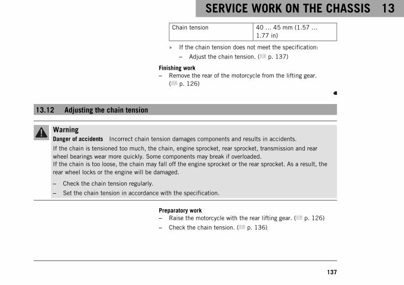
SERVICE WORK ON THE CHASSIS 13
137
Chain tension 40 … 45 mm (1.57 …1.77 in)
» If the chain tension does not meet the specification:
– Adjust the chain tension. ( p. 137)
Finishing work– Remove the rear of the motorcycle from the lifting gear.
( p. 126)
13.12 Adjusting the chain tension
WarningDanger of accidents Incorrect chain tension damages components and results in accidents.
If the chain is tensioned too much, the chain, engine sprocket, rear sprocket, transmission and rearwheel bearings wear more quickly. Some components may break if overloaded.If the chain is too loose, the chain may fall off the engine sprocket or the rear sprocket. As a result, therear wheel locks or the engine will be damaged.
– Check the chain tension regularly.
– Set the chain tension in accordance with the specification.
Preparatory work– Raise the motorcycle with the rear lifting gear. ( p. 126)
– Check the chain tension. ( p. 136)
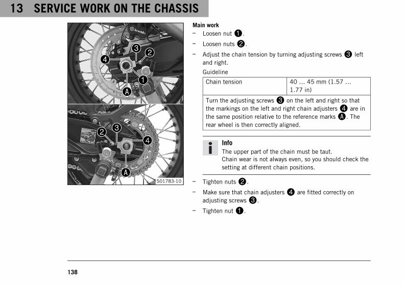
13 SERVICE WORK ON THE CHASSIS
138
S01783-10
Main work– Loosen nut1.
– Loosen nuts2.
– Adjust the chain tension by turning adjusting screws3 leftand right.
Guideline
Chain tension 40 … 45 mm (1.57 …1.77 in)
Turn the adjusting screws3 on the left and right so thatthe markings on the left and right chain adjusters4 are inthe same position relative to the reference marksA. Therear wheel is then correctly aligned.
InfoThe upper part of the chain must be taut.Chain wear is not always even, so you should check thesetting at different chain positions.
– Tighten nuts2.
– Make sure that chain adjusters4 are fitted correctly onadjusting screws3.
– Tighten nut1.
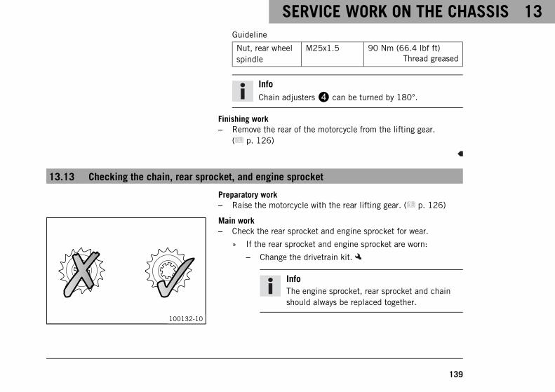
SERVICE WORK ON THE CHASSIS 13
139
Guideline
Nut, rear wheelspindle
M25x1.5 90 Nm (66.4 lbf ft)Thread greased
InfoChain adjusters4 can be turned by 180°.
Finishing work– Remove the rear of the motorcycle from the lifting gear.
( p. 126)
13.13 Checking the chain, rear sprocket, and engine sprocket
Preparatory work– Raise the motorcycle with the rear lifting gear. ( p. 126)
100132-10
Main work– Check the rear sprocket and engine sprocket for wear.
» If the rear sprocket and engine sprocket are worn:
– Change the drivetrain kit.
InfoThe engine sprocket, rear sprocket and chainshould always be replaced together.
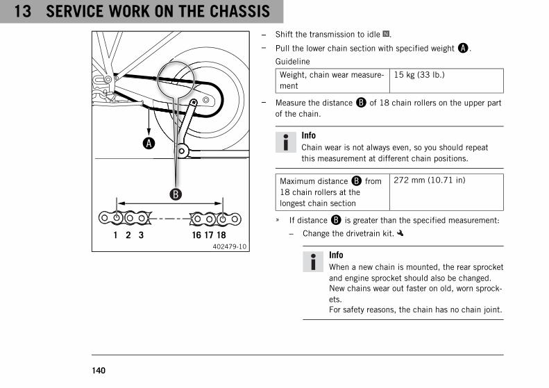
13 SERVICE WORK ON THE CHASSIS
140
000
402479-10
– Shift the transmission to idle .
– Pull the lower chain section with specified weightA.
Guideline
Weight, chain wear measure-ment
15 kg (33 lb.)
– Measure the distanceB of 18 chain rollers on the upper partof the chain.
InfoChain wear is not always even, so you should repeatthis measurement at different chain positions.
Maximum distanceB from18 chain rollers at thelongest chain section
272 mm (10.71 in)
» If distanceB is greater than the specified measurement:
– Change the drivetrain kit.
InfoWhen a new chain is mounted, the rear sprocketand engine sprocket should also be changed.New chains wear out faster on old, worn sprock-ets.For safety reasons, the chain has no chain joint.
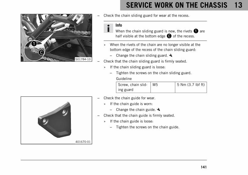
SERVICE WORK ON THE CHASSIS 13
141
S01784-10
– Check the chain sliding guard for wear at the recess.
InfoWhen the chain sliding guard is new, the rivets1 arehalf visible at the bottom edgeC of the recess.
» When the rivets of the chain are no longer visible at thebottom edge of the recess of the chain sliding guard:
– Change the chain sliding guard.
– Check that the chain sliding guard is firmly seated.
» If the chain sliding guard is loose:
– Tighten the screws on the chain sliding guard.
Guideline
Screw, chain slid-ing guard
M5 5 Nm (3.7 lbf ft)
401670-01
– Check the chain guide for wear.
» If the chain guide is worn:
– Change the chain guide.
– Check that the chain guide is firmly seated.
» If the chain guide is loose:
– Tighten the screws on the chain guide.
13 SERVICE WORK ON THE CHASSIS
142
Guideline
Screw, chainguide
M6 5 Nm (3.7 lbf ft)
Finishing work– Remove the rear of the motorcycle from the lifting gear.
( p. 126)
13.14 Checking/correcting the fluid level of the hydraulic clutch
InfoThe fluid level rises with increasing wear of the clutch facing discs.Never use DOT 5 brake fluid. It is silicone-based and purple in color. Oil seals and clutch lines are notdesigned for DOT 5 brake fluid.Avoid contact between brake fluid and painted parts. Brake fluid attacks paint.Only use clean brake fluid from a sealed container.

SERVICE WORK ON THE CHASSIS 13
143
S01785-10
– Move the clutch fluid reservoir mounted on the handlebar to ahorizontal position.
– Remove screws1.
– Remove cover2 with membrane3.
– Check the fluid level.
Fluid level below containerrim
4 mm (0.16 in)
» If the fluid level does not meet specifications:
– Correct the fluid level of the hydraulic clutch.
Brake fluid DOT 4 / DOT 5.1 ( p. 287)
– Position the cover with the membrane. Mount and tighten thescrews.
InfoClean up overflowed or spilled brake fluid immediatelywith water.
13 SERVICE WORK ON THE CHASSIS
144
13.15 Checking the play of the steering head bearing
WarningDanger of accidents Incorrect steering head bearing play impairs the handling characteristic and dam-ages components.
– Correct incorrect steering head bearing play immediately. (Your authorized KTM workshop will be gladto help.)
InfoIf the vehicle is operated for a lengthy period with play in the steering head bearing, the bearings and thebearing seats in the frame can become damaged over time.
Preparatory work– Raise the motorcycle with the work stand (inserted).
( p. 129)
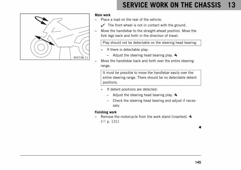
SERVICE WORK ON THE CHASSIS 13
145
400738-11
Main work– Place a load on the rear of the vehicle.
The front wheel is not in contact with the ground.
– Move the handlebar to the straight-ahead position. Move thefork legs back and forth in the direction of travel.
Play should not be detectable on the steering head bearing.
» If there is detectable play:
– Adjust the steering head bearing play.
– Move the handlebar back and forth over the entire steeringrange.
It must be possible to move the handlebar easily over theentire steering range. There should be no detectable detentpositions.
» If detent positions are detected:
– Adjust the steering head bearing play.
– Check the steering head bearing and adjust if neces-sary.
Finishing work– Remove the motorcycle from the work stand (inserted).
( p. 131)
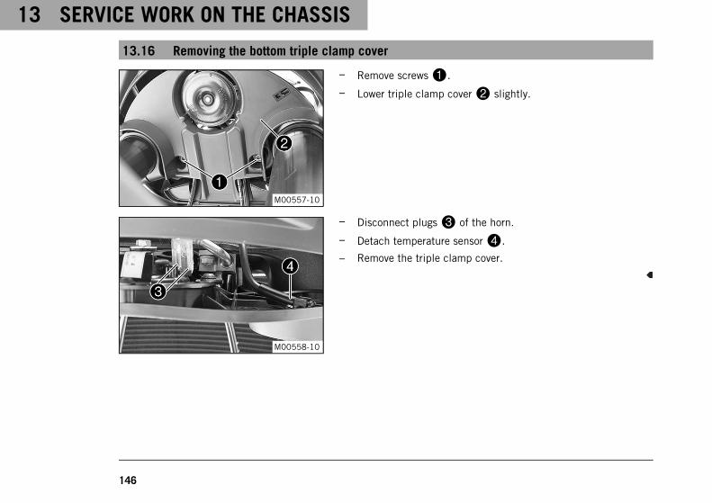
13 SERVICE WORK ON THE CHASSIS
146
13.16 Removing the bottom triple clamp cover
M00557-10
– Remove screws1.
– Lower triple clamp cover2 slightly.
M00558-10
– Disconnect plugs3 of the horn.
– Detach temperature sensor4.
– Remove the triple clamp cover.
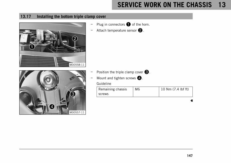
SERVICE WORK ON THE CHASSIS 13
147
13.17 Installing the bottom triple clamp cover
M00558-11
– Plug in connectors1 of the horn.
– Attach temperature sensor2.
M00557-11
– Position the triple clamp cover3.
– Mount and tighten screws4.
Guideline
Remaining chassisscrews
M6 10 Nm (7.4 lbf ft)
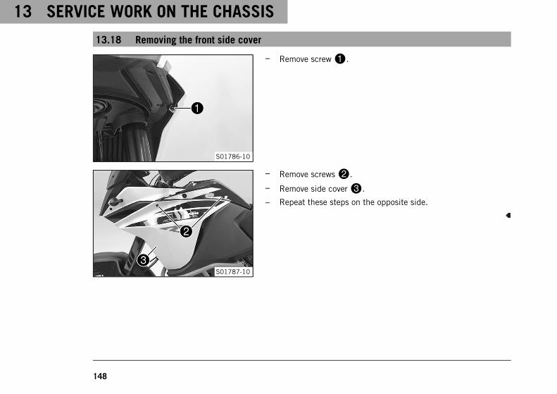
13 SERVICE WORK ON THE CHASSIS
148
13.18 Removing the front side cover
S01786-10
– Remove screw1.
S01787-10
– Remove screws2.
– Remove side cover3.
– Repeat these steps on the opposite side.
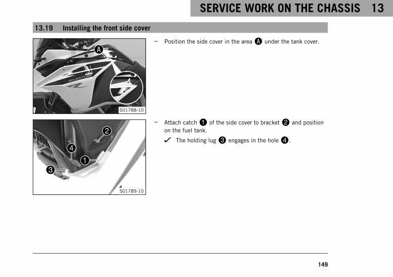
SERVICE WORK ON THE CHASSIS 13
149
13.19 Installing the front side cover
S01788-10
– Position the side cover in the areaA under the tank cover.
S01789-10
– Attach catch1 of the side cover to bracket2 and positionon the fuel tank.
The holding lug3 engages in the hole4.
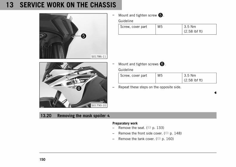
13 SERVICE WORK ON THE CHASSIS
150
S01786-11
– Mount and tighten screw5.
Guideline
Screw, cover part M5 3.5 Nm(2.58 lbf ft)
S01790-10
– Mount and tighten screws6.
Guideline
Screw, cover part M5 3.5 Nm(2.58 lbf ft)
– Repeat these steps on the opposite side.
13.20 Removing the mask spoiler
Preparatory work– Remove the seat. ( p. 133)
– Remove the front side cover. ( p. 148)
– Remove the tank cover. ( p. 160)
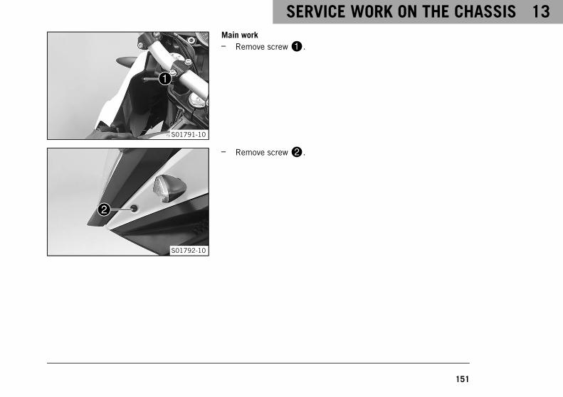
SERVICE WORK ON THE CHASSIS 13
151
S01791-10
Main work– Remove screw1.
S01792-10
– Remove screw2.
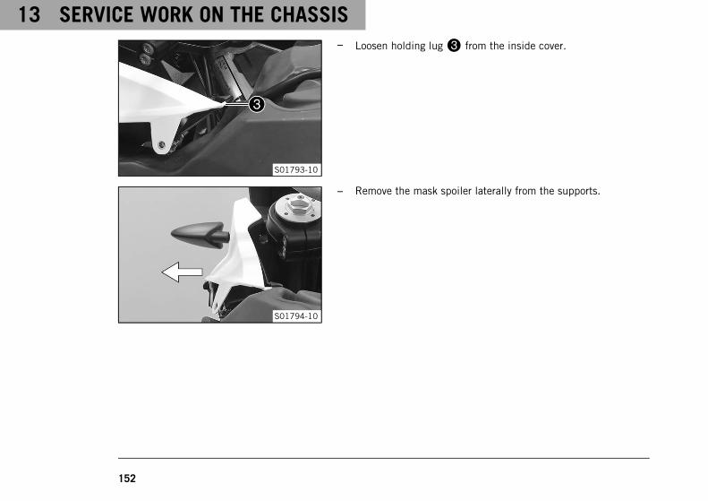
13 SERVICE WORK ON THE CHASSIS
152
S01793-10
– Loosen holding lug3 from the inside cover.
S01794-10
– Remove the mask spoiler laterally from the supports.
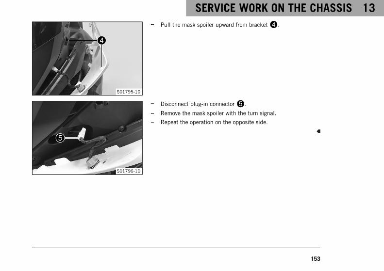
SERVICE WORK ON THE CHASSIS 13
153
S01795-10
– Pull the mask spoiler upward from bracket4.
S01796-10
– Disconnect plug-in connector5.
– Remove the mask spoiler with the turn signal.
– Repeat the operation on the opposite side.
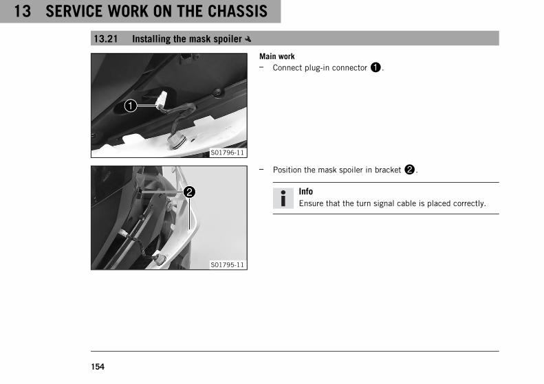
13 SERVICE WORK ON THE CHASSIS
154
13.21 Installing the mask spoiler
S01796-11
Main work– Connect plug-in connector1.
S01795-11
– Position the mask spoiler in bracket2.
InfoEnsure that the turn signal cable is placed correctly.
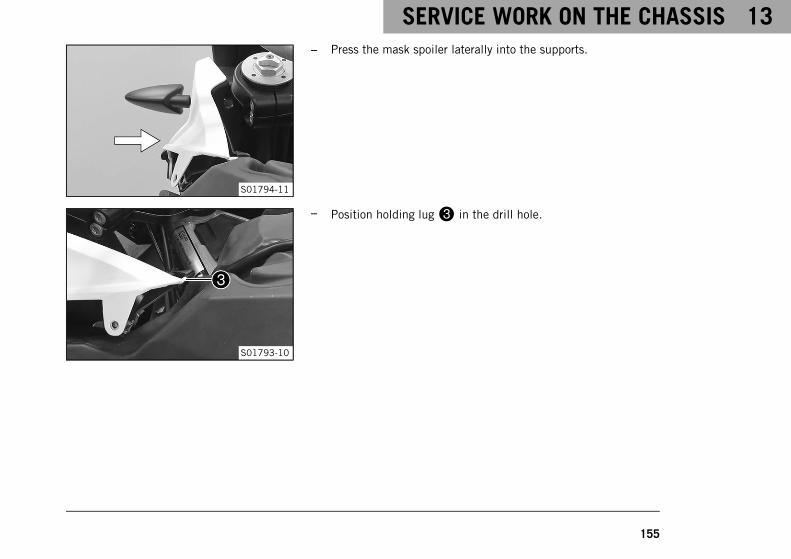
SERVICE WORK ON THE CHASSIS 13
155
S01794-11
– Press the mask spoiler laterally into the supports.
S01793-10
– Position holding lug3 in the drill hole.
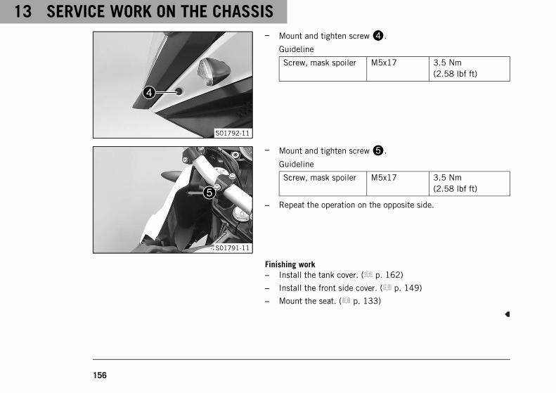
13 SERVICE WORK ON THE CHASSIS
156
S01792-11
– Mount and tighten screw4.
Guideline
Screw, mask spoiler M5x17 3.5 Nm(2.58 lbf ft)
S01791-11
– Mount and tighten screw5.
Guideline
Screw, mask spoiler M5x17 3.5 Nm(2.58 lbf ft)
– Repeat the operation on the opposite side.
Finishing work– Install the tank cover. ( p. 162)
– Install the front side cover. ( p. 149)
– Mount the seat. ( p. 133)
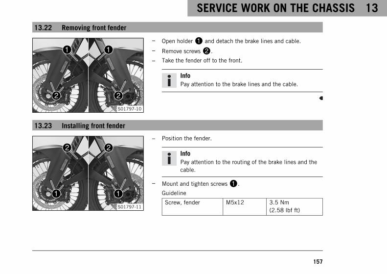
SERVICE WORK ON THE CHASSIS 13
157
13.22 Removing front fender
S01797-10
– Open holder1 and detach the brake lines and cable.
– Remove screws2.
– Take the fender off to the front.
InfoPay attention to the brake lines and the cable.
13.23 Installing front fender
S01797-11
– Position the fender.
InfoPay attention to the routing of the brake lines and thecable.
– Mount and tighten screws1.
Guideline
Screw, fender M5x12 3.5 Nm(2.58 lbf ft)
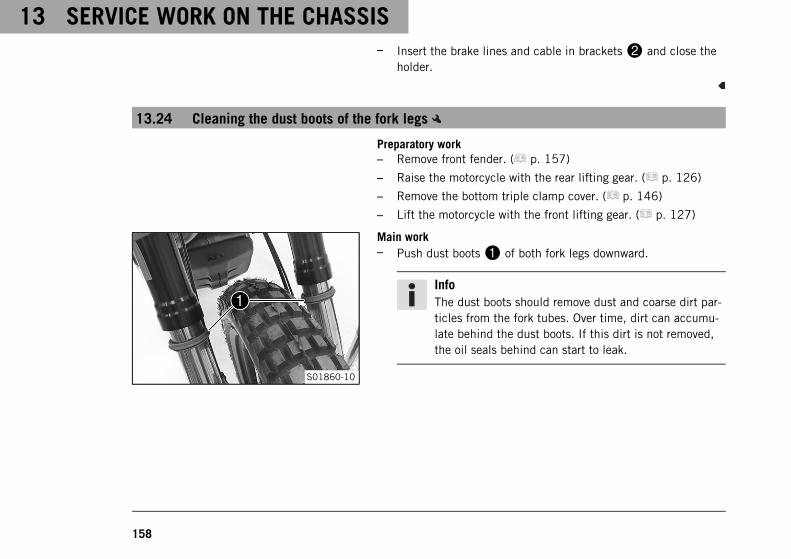
13 SERVICE WORK ON THE CHASSIS
158
– Insert the brake lines and cable in brackets2 and close theholder.
13.24 Cleaning the dust boots of the fork legs
Preparatory work– Remove front fender. ( p. 157)
– Raise the motorcycle with the rear lifting gear. ( p. 126)
– Remove the bottom triple clamp cover. ( p. 146)
– Lift the motorcycle with the front lifting gear. ( p. 127)
S01860-10
Main work– Push dust boots1 of both fork legs downward.
InfoThe dust boots should remove dust and coarse dirt par-ticles from the fork tubes. Over time, dirt can accumu-late behind the dust boots. If this dirt is not removed,the oil seals behind can start to leak.
SERVICE WORK ON THE CHASSIS 13
159
WarningDanger of accidents Oil or grease on the brake discsreduces the braking effect.
– Always keep the brake discs free of oil and grease.
– Clean the brake discs with brake cleaner when nec-essary.
– Clean and oil the dust boots and inner fork tubes of both forklegs.
Universal oil spray ( p. 292)
– Press the dust boots back into their installation position.
– Remove excess oil.
Finishing work– Take the motorcycle off the front lifting gear. ( p. 128)
– Install the bottom triple clamp cover. ( p. 147)
– Remove the rear of the motorcycle from the lifting gear.( p. 126)
– Install front fender. ( p. 157)
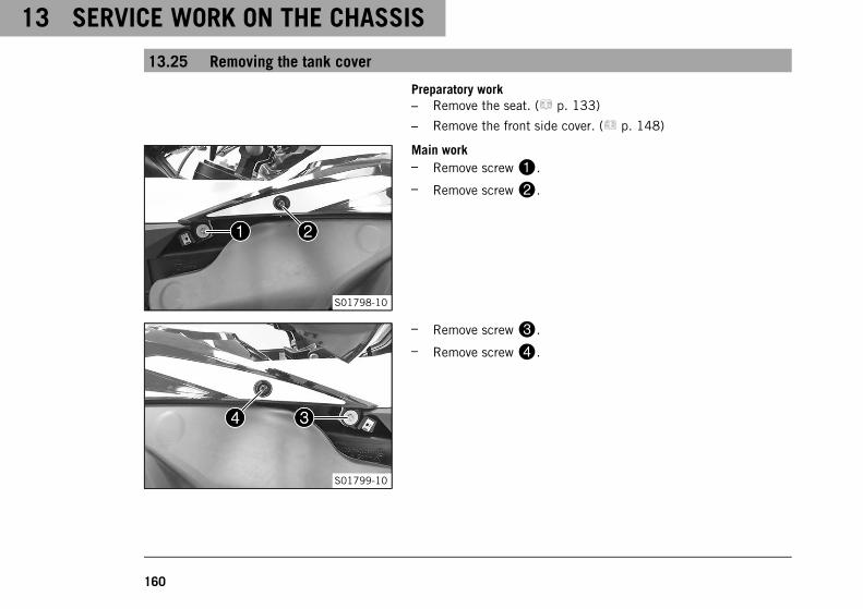
13 SERVICE WORK ON THE CHASSIS
160
13.25 Removing the tank cover
Preparatory work– Remove the seat. ( p. 133)
– Remove the front side cover. ( p. 148)
S01798-10
Main work– Remove screw1.
– Remove screw2.
S01799-10
– Remove screw3.
– Remove screw4.
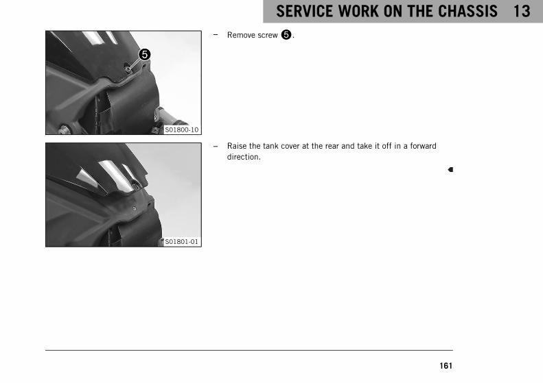
SERVICE WORK ON THE CHASSIS 13
161
S01800-10
– Remove screw5.
S01801-01
– Raise the tank cover at the rear and take it off in a forwarddirection.

13 SERVICE WORK ON THE CHASSIS
162
13.26 Installing the tank cover
S01802-10
Main work– Position the tank cover.
The catch1 engages under the tank2.
InfoPay attention to the sealing lip and the bleeder hose.
S01800-11
– Mount and tighten screw3.
Guideline
Screw, cover part M5 3.5 Nm(2.58 lbf ft)
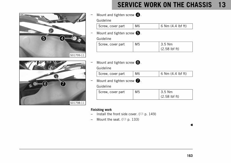
SERVICE WORK ON THE CHASSIS 13
163
S01799-11
– Mount and tighten screw4.
Guideline
Screw, cover part M6 6 Nm (4.4 lbf ft)
– Mount and tighten screw5.
Guideline
Screw, cover part M5 3.5 Nm(2.58 lbf ft)
S01798-11
– Mount and tighten screw6.
Guideline
Screw, cover part M6 6 Nm (4.4 lbf ft)
– Mount and tighten screw7.
Guideline
Screw, cover part M5 3.5 Nm(2.58 lbf ft)
Finishing work– Install the front side cover. ( p. 149)
– Mount the seat. ( p. 133)
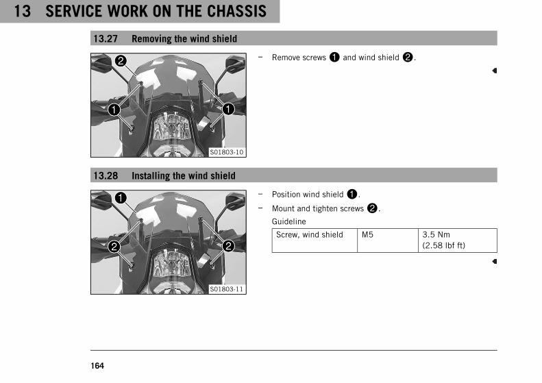
13 SERVICE WORK ON THE CHASSIS
164
13.27 Removing the wind shield
S01803-10
– Remove screws1 and wind shield2.
13.28 Installing the wind shield
S01803-11
– Position wind shield1.
– Mount and tighten screws2.
Guideline
Screw, wind shield M5 3.5 Nm(2.58 lbf ft)
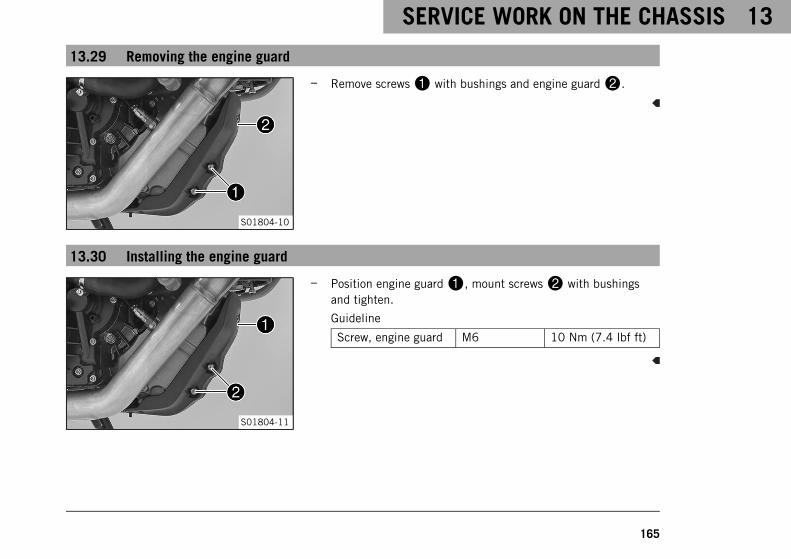
SERVICE WORK ON THE CHASSIS 13
165
13.29 Removing the engine guard
S01804-10
– Remove screws1 with bushings and engine guard2.
13.30 Installing the engine guard
S01804-11
– Position engine guard1, mount screws2 with bushingsand tighten.
Guideline
Screw, engine guard M6 10 Nm (7.4 lbf ft)
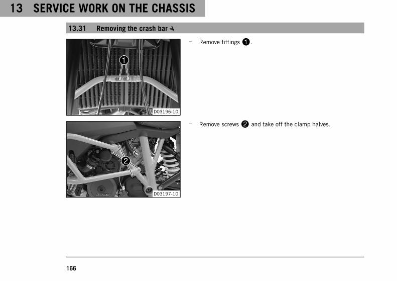
13 SERVICE WORK ON THE CHASSIS
166
13.31 Removing the crash bar
D03196-10
– Remove fittings1.
D03197-10
– Remove screws2 and take off the clamp halves.
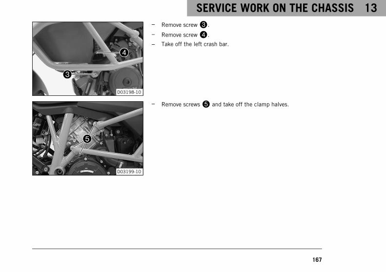
SERVICE WORK ON THE CHASSIS 13
167
D03198-10
– Remove screw3.
– Remove screw4.
– Take off the left crash bar.
D03199-10
– Remove screws5 and take off the clamp halves.
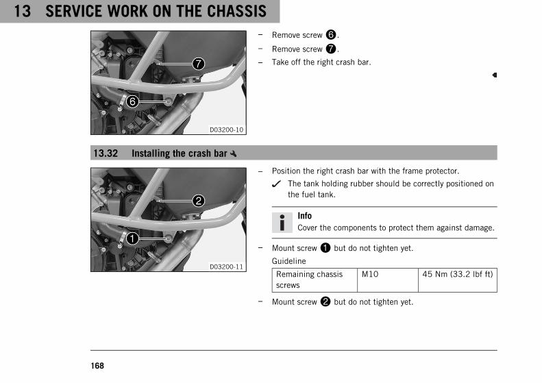
13 SERVICE WORK ON THE CHASSIS
168
D03200-10
– Remove screw6.
– Remove screw7.
– Take off the right crash bar.
13.32 Installing the crash bar
D03200-11
– Position the right crash bar with the frame protector.
The tank holding rubber should be correctly positioned onthe fuel tank.
InfoCover the components to protect them against damage.
– Mount screw1 but do not tighten yet.
Guideline
Remaining chassisscrews
M10 45 Nm (33.2 lbf ft)
– Mount screw2 but do not tighten yet.
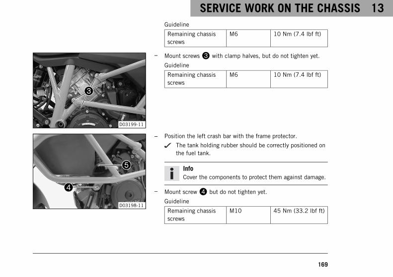
SERVICE WORK ON THE CHASSIS 13
169
Guideline
Remaining chassisscrews
M6 10 Nm (7.4 lbf ft)
D03199-11
– Mount screws3 with clamp halves, but do not tighten yet.
Guideline
Remaining chassisscrews
M6 10 Nm (7.4 lbf ft)
D03198-11
– Position the left crash bar with the frame protector.
The tank holding rubber should be correctly positioned onthe fuel tank.
InfoCover the components to protect them against damage.
– Mount screw4 but do not tighten yet.
Guideline
Remaining chassisscrews
M10 45 Nm (33.2 lbf ft)
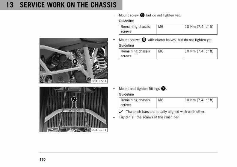
13 SERVICE WORK ON THE CHASSIS
170
– Mount screw5 but do not tighten yet.
Guideline
Remaining chassisscrews
M6 10 Nm (7.4 lbf ft)
D03197-11
– Mount screws6 with clamp halves, but do not tighten yet.
Guideline
Remaining chassisscrews
M6 10 Nm (7.4 lbf ft)
D03196-11
– Mount and tighten fittings7.
Guideline
Remaining chassisscrews
M6 10 Nm (7.4 lbf ft)
The crash bars are equally aligned with each other.
– Tighten all the screws of the crash bar.
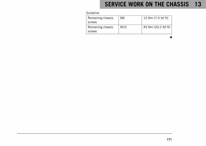
SERVICE WORK ON THE CHASSIS 13
171
Guideline
Remaining chassisscrews
M6 10 Nm (7.4 lbf ft)
Remaining chassisscrews
M10 45 Nm (33.2 lbf ft)
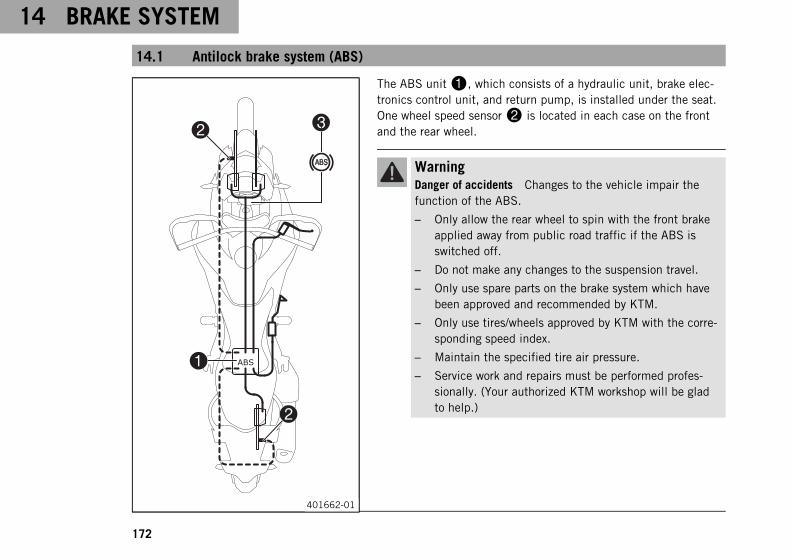
14 BRAKE SYSTEM
172
14.1 Antilock brake system (ABS)
0033
0022
0011
0022
401662-01
The ABS unit1, which consists of a hydraulic unit, brake elec-tronics control unit, and return pump, is installed under the seat.One wheel speed sensor2 is located in each case on the frontand the rear wheel.
WarningDanger of accidents Changes to the vehicle impair thefunction of the ABS.
– Only allow the rear wheel to spin with the front brakeapplied away from public road traffic if the ABS isswitched off.
– Do not make any changes to the suspension travel.
– Only use spare parts on the brake system which havebeen approved and recommended by KTM.
– Only use tires/wheels approved by KTM with the corre-sponding speed index.
– Maintain the specified tire air pressure.
– Service work and repairs must be performed profes-sionally. (Your authorized KTM workshop will be gladto help.)
BRAKE SYSTEM 14
173
WarningVoiding of the government approval for road use and theinsurance coverage If the ABS is switched off completely,the vehicle's approval for road use is invalidated.
– Only operate the vehicle in closed-off areas remotefrom public road traffic if the ABS is switched off com-pletely.
ABS is a safety system that prevents locking of the wheels whendriving straight ahead without the influence of lateral forces.
WarningDanger of accidents Driving aids can only prevent arollover within the physical limitations.
It is not always possible to compensate for extreme ridingsituations, for example with luggage loaded with a highcenter of gravity, varying road surfaces, steep descents orfull braking without disengaging the gear.
– Adapt your riding style to the road conditions and yourdriving ability.
ABS has two operating modes: the Road and OffroadABS modes.In the Road ABS mode, the ABS controls both wheels.
14 BRAKE SYSTEM
174
There is no ABS intervention on the rear wheel in ABS controlOffroad. The ABS indicator lamp3 flashes slowly to remind youthat the Offroad ABS mode is enabled.
InfoIn the Offroad ABS mode, the rear wheel may lock andthere is a risk of falling.
The ABS operates with two independent brake circuits (front andrear brakes). When the brake electronics control unit detects alocking tendency in a wheel, ABS begins regulating the brakepressure. The control function causes a slight pulsing of the handand foot brake levers.The ABS indicator lamp3 must light up after the ignition isswitched on and go out after starting off. If it does not go out afterstarting off or if it is lit while riding, this indicates a fault in theABS system. In this case, the ABS is no longer enabled and thewheels may lock during braking. The brake system itself staysfunctional; only ABS control is not available.The ABS indicator lamp may also light up if the rotating speeds ofthe front and rear wheels differ greatly under extreme riding con-ditions, for example when making "wheelies" or if the rear wheelspins. This causes the ABS to switch off.To reactivate the ABS, stop the vehicle and switch off the ignition.The ABS is reactivated when the vehicle is switched on again. TheABS indicator lamp goes out when you start off.
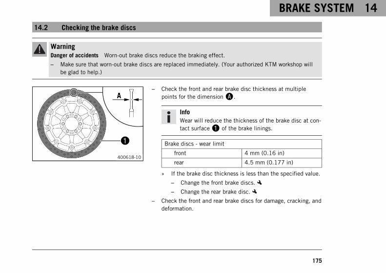
BRAKE SYSTEM 14
175
14.2 Checking the brake discs
WarningDanger of accidents Worn-out brake discs reduce the braking effect.
– Make sure that worn-out brake discs are replaced immediately. (Your authorized KTM workshop willbe glad to help.)
400618-10
– Check the front and rear brake disc thickness at multiplepoints for the dimensionA.
InfoWear will reduce the thickness of the brake disc at con-tact surface1 of the brake linings.
Brake discs - wear limit
front 4 mm (0.16 in)
rear 4.5 mm (0.177 in)
» If the brake disc thickness is less than the specified value.
– Change the front brake discs.
– Change the rear brake disc.
– Check the front and rear brake discs for damage, cracking, anddeformation.
14 BRAKE SYSTEM
176
» If the brake disc exhibits damage, cracking, or deforma-tion:
– Change the front brake discs.
– Change the rear brake disc.
14.3 Checking the front brake fluid level
WarningDanger of accidents An insufficient brake fluid level will cause the brake system to fail.
If the brake fluid level drops below the specified marking or the specified value, the brake system isleaking or the brake linings are worn down.
– Check the brake system and do not continue riding until the problem is eliminated. (Your authorizedKTM workshop will be glad to help.)
WarningDanger of accidents Old brake fluid reduces the braking effect.
– Make sure that brake fluid for the front and rear brake is changed in accordance with the serviceschedule. (Your authorized KTM workshop will be glad to help.)

BRAKE SYSTEM 14
177
S01805-10
– Move the brake fluid reservoir mounted on the handlebar to ahorizontal position.
– Check the brake fluid level in brake fluid reservoir1.
» If an air bubble is visible at the markingA:
– Add front brake fluid. ( p. 177)
14.4 Adding front brake fluid
WarningDanger of accidents An insufficient brake fluid level will cause the brake system to fail.
If the brake fluid level drops below the specified marking or the specified value, the brake system isleaking or the brake linings are worn down.
– Check the brake system and do not continue riding until the problem is eliminated. (Your authorizedKTM workshop will be glad to help.)
14 BRAKE SYSTEM
178
WarningSkin irritation Brake fluid causes skin irritation.
– Keep brake fluid out of the reach of children.
– Wear suitable protective clothing and safety glasses.
– Do not allow brake fluid to come into contact with the skin, the eyes or clothing.
– Consult a doctor immediately if brake fluid has been swallowed.
– Rinse the affected area with plenty of water in the event of contact with the skin.
– Rinse eyes thoroughly with water immediately and consult a doctor if brake fluid comes into contactwith the eyes.
– If brake fluid spills on to your clothing, change the clothing.
WarningDanger of accidents Old brake fluid reduces the braking effect.
– Make sure that brake fluid for the front and rear brake is changed in accordance with the serviceschedule. (Your authorized KTM workshop will be glad to help.)
WarningEnvironmental hazard Hazardous substances cause environmental damage.
– Dispose of oils, grease, filters, fuel, cleaning agents, brake fluid, etc., correctly and in compliance withthe applicable regulations.

BRAKE SYSTEM 14
179
InfoNever use DOT 5 brake fluid. It is silicone-based and purple in color. Oil seals and brake lines are notdesigned for DOT 5 brake fluid.Avoid contact between brake fluid and painted parts. Brake fluid attacks paint.Only use clean brake fluid from a sealed container.
Preparatory work– Check the front brake linings. ( p. 180)
S01806-10
Main work– Move the brake fluid reservoir mounted on the handlebar to a
horizontal position.
– Remove screws1.
– Remove cover2 with membrane3.
– Add brake fluid to levelA.
Guideline
LevelA 7 mm (0.28 in)
Brake fluid DOT 4 / DOT 5.1 ( p. 287)
– Position cover2 with membrane3.
– Mount and tighten screws1.
14 BRAKE SYSTEM
180
InfoClean up overflowed or spilled brake fluid immediatelywith water.
14.5 Checking the front brake linings
WarningDanger of accidents Worn-out brake linings reduce the braking effect.
– Ensure that worn-out brake linings are replaced immediately. (Your authorized KTM workshop will beglad to help.)
WarningDanger of accidents Damaged brake discs reduce the braking effect.
If the brake linings are not changed in time, the brake lining carriers grind against the brake disc. As aconsequence, the braking effect is greatly reduced and the brake discs are destroyed.
– Check the brake linings regularly.
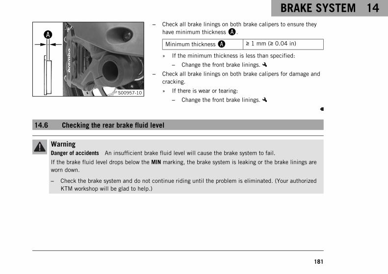
BRAKE SYSTEM 14
181
S00957-10
– Check all brake linings on both brake calipers to ensure theyhave minimum thicknessA.
Minimum thicknessA ≥ 1 mm (≥ 0.04 in)
» If the minimum thickness is less than specified:
– Change the front brake linings.
– Check all brake linings on both brake calipers for damage andcracking.
» If there is wear or tearing:
– Change the front brake linings.
14.6 Checking the rear brake fluid level
WarningDanger of accidents An insufficient brake fluid level will cause the brake system to fail.
If the brake fluid level drops below the MIN marking, the brake system is leaking or the brake linings areworn down.
– Check the brake system and do not continue riding until the problem is eliminated. (Your authorizedKTM workshop will be glad to help.)
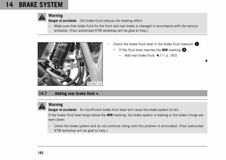
14 BRAKE SYSTEM
182
WarningDanger of accidents Old brake fluid reduces the braking effect.
– Make sure that brake fluid for the front and rear brake is changed in accordance with the serviceschedule. (Your authorized KTM workshop will be glad to help.)
S01807-10
– Check the brake fluid level in the brake fluid reservoir1.
» If the fluid level reaches the MIN markingA:
– Add rear brake fluid. ( p. 182)
14.7 Adding rear brake fluid
WarningDanger of accidents An insufficient brake fluid level will cause the brake system to fail.
If the brake fluid level drops below the MIN marking, the brake system is leaking or the brake linings areworn down.
– Check the brake system and do not continue riding until the problem is eliminated. (Your authorizedKTM workshop will be glad to help.)
BRAKE SYSTEM 14
183
WarningSkin irritation Brake fluid causes skin irritation.
– Keep brake fluid out of the reach of children.
– Wear suitable protective clothing and safety glasses.
– Do not allow brake fluid to come into contact with the skin, the eyes or clothing.
– Consult a doctor immediately if brake fluid has been swallowed.
– Rinse the affected area with plenty of water in the event of contact with the skin.
– Rinse eyes thoroughly with water immediately and consult a doctor if brake fluid comes into contactwith the eyes.
– If brake fluid spills on to your clothing, change the clothing.
WarningDanger of accidents Old brake fluid reduces the braking effect.
– Make sure that brake fluid for the front and rear brake is changed in accordance with the serviceschedule. (Your authorized KTM workshop will be glad to help.)
WarningEnvironmental hazard Hazardous substances cause environmental damage.
– Dispose of oils, grease, filters, fuel, cleaning agents, brake fluid, etc., correctly and in compliance withthe applicable regulations.
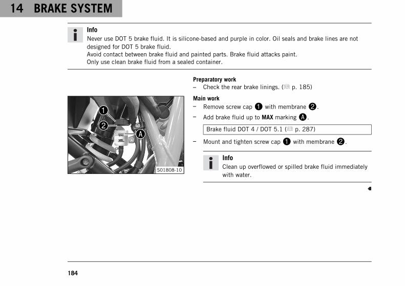
14 BRAKE SYSTEM
184
InfoNever use DOT 5 brake fluid. It is silicone-based and purple in color. Oil seals and brake lines are notdesigned for DOT 5 brake fluid.Avoid contact between brake fluid and painted parts. Brake fluid attacks paint.Only use clean brake fluid from a sealed container.
Preparatory work– Check the rear brake linings. ( p. 185)
S01808-10
Main work– Remove screw cap1 with membrane2.
– Add brake fluid up to MAX markingA.
Brake fluid DOT 4 / DOT 5.1 ( p. 287)
– Mount and tighten screw cap1 with membrane2.
InfoClean up overflowed or spilled brake fluid immediatelywith water.
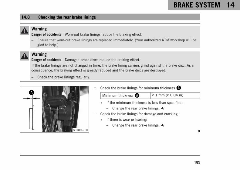
BRAKE SYSTEM 14
185
14.8 Checking the rear brake linings
WarningDanger of accidents Worn-out brake linings reduce the braking effect.
– Ensure that worn-out brake linings are replaced immediately. (Your authorized KTM workshop will beglad to help.)
WarningDanger of accidents Damaged brake discs reduce the braking effect.
If the brake linings are not changed in time, the brake lining carriers grind against the brake disc. As aconsequence, the braking effect is greatly reduced and the brake discs are destroyed.
– Check the brake linings regularly.
S01809-10
– Check the brake linings for minimum thicknessA.
Minimum thicknessA ≥ 1 mm (≥ 0.04 in)
» If the minimum thickness is less than specified:
– Change the rear brake linings.
– Check the brake linings for damage and cracking.
» If there is wear or tearing:
– Change the rear brake linings.
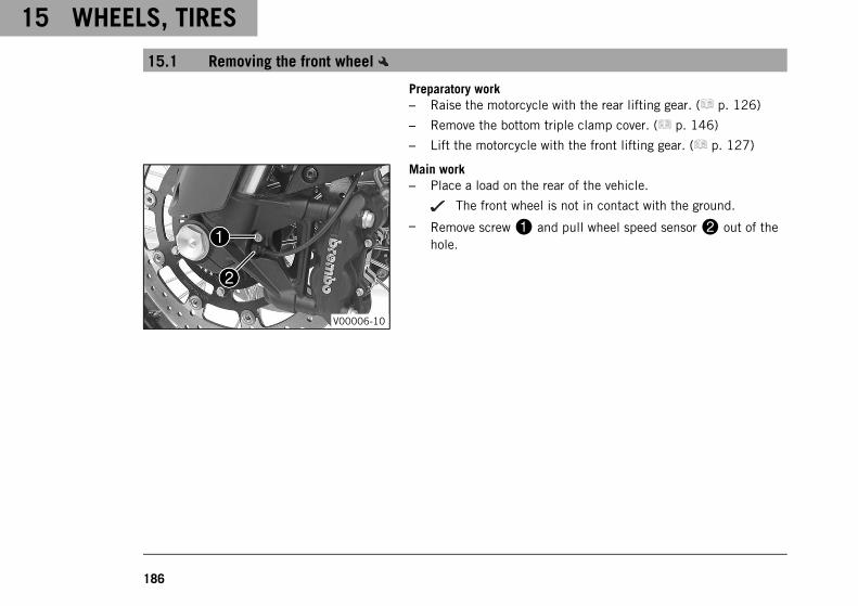
15 WHEELS, TIRES
186
15.1 Removing the front wheel
Preparatory work– Raise the motorcycle with the rear lifting gear. ( p. 126)
– Remove the bottom triple clamp cover. ( p. 146)
– Lift the motorcycle with the front lifting gear. ( p. 127)
V00006-10
Main work– Place a load on the rear of the vehicle.
The front wheel is not in contact with the ground.
– Remove screw1 and pull wheel speed sensor2 out of thehole.
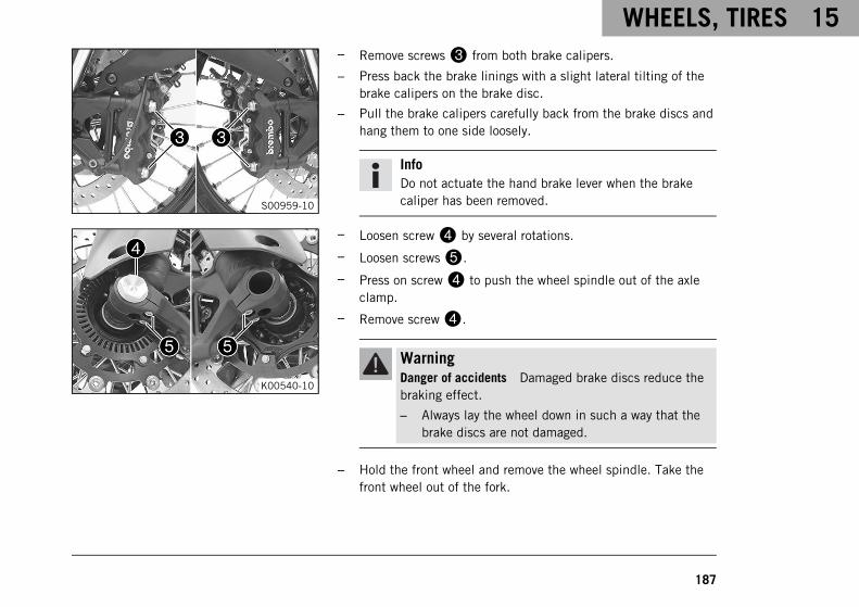
WHEELS, TIRES 15
187
S00959-10
– Remove screws3 from both brake calipers.
– Press back the brake linings with a slight lateral tilting of thebrake calipers on the brake disc.
– Pull the brake calipers carefully back from the brake discs andhang them to one side loosely.
InfoDo not actuate the hand brake lever when the brakecaliper has been removed.
K00540-10
– Loosen screw4 by several rotations.
– Loosen screws5.
– Press on screw4 to push the wheel spindle out of the axleclamp.
– Remove screw4.
WarningDanger of accidents Damaged brake discs reduce thebraking effect.
– Always lay the wheel down in such a way that thebrake discs are not damaged.
– Hold the front wheel and remove the wheel spindle. Take thefront wheel out of the fork.
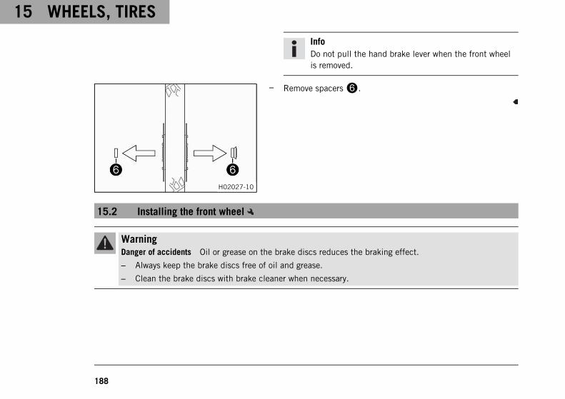
15 WHEELS, TIRES
188
InfoDo not pull the hand brake lever when the front wheelis removed.
H02027-10
– Remove spacers6.
15.2 Installing the front wheel
WarningDanger of accidents Oil or grease on the brake discs reduces the braking effect.
– Always keep the brake discs free of oil and grease.
– Clean the brake discs with brake cleaner when necessary.
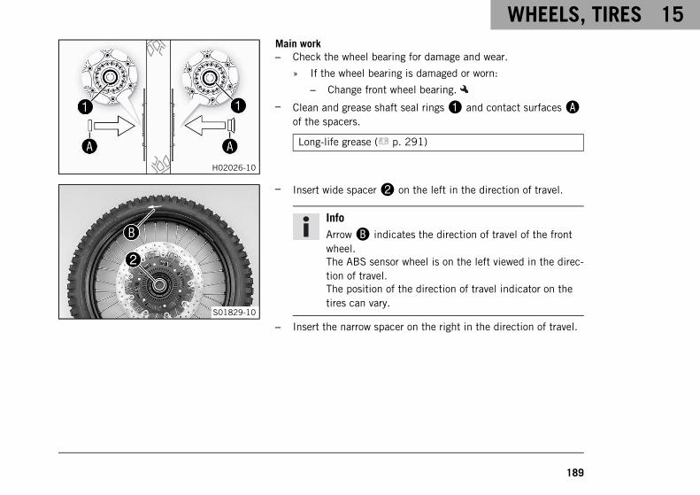
WHEELS, TIRES 15
189
H02026-10
Main work– Check the wheel bearing for damage and wear.
» If the wheel bearing is damaged or worn:
– Change front wheel bearing.
– Clean and grease shaft seal rings1 and contact surfacesAof the spacers.
Long-life grease ( p. 291)
S01829-10
– Insert wide spacer2 on the left in the direction of travel.
InfoArrowB indicates the direction of travel of the frontwheel.The ABS sensor wheel is on the left viewed in the direc-tion of travel.The position of the direction of travel indicator on thetires can vary.
– Insert the narrow spacer on the right in the direction of travel.
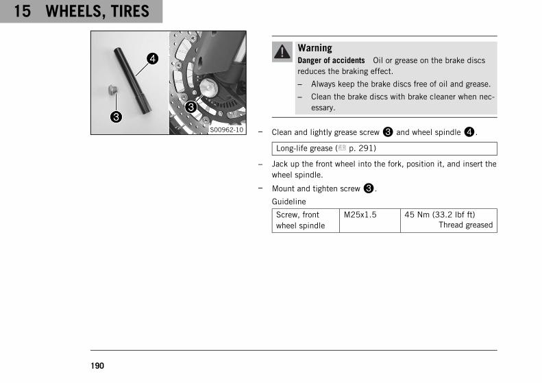
15 WHEELS, TIRES
190
S00962-10
WarningDanger of accidents Oil or grease on the brake discsreduces the braking effect.
– Always keep the brake discs free of oil and grease.
– Clean the brake discs with brake cleaner when nec-essary.
– Clean and lightly grease screw3 and wheel spindle4.
Long-life grease ( p. 291)
– Jack up the front wheel into the fork, position it, and insert thewheel spindle.
– Mount and tighten screw3.
Guideline
Screw, frontwheel spindle
M25x1.5 45 Nm (33.2 lbf ft)Thread greased
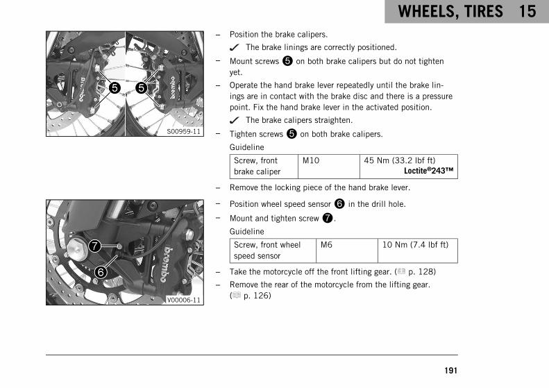
WHEELS, TIRES 15
191
S00959-11
– Position the brake calipers.
The brake linings are correctly positioned.
– Mount screws5 on both brake calipers but do not tightenyet.
– Operate the hand brake lever repeatedly until the brake lin-ings are in contact with the brake disc and there is a pressurepoint. Fix the hand brake lever in the activated position.
The brake calipers straighten.
– Tighten screws5 on both brake calipers.
Guideline
Screw, frontbrake caliper
M10 45 Nm (33.2 lbf ft)Loctite®243™
– Remove the locking piece of the hand brake lever.
V00006-11
– Position wheel speed sensor6 in the drill hole.
– Mount and tighten screw7.
Guideline
Screw, front wheelspeed sensor
M6 10 Nm (7.4 lbf ft)
– Take the motorcycle off the front lifting gear. ( p. 128)
– Remove the rear of the motorcycle from the lifting gear.( p. 126)
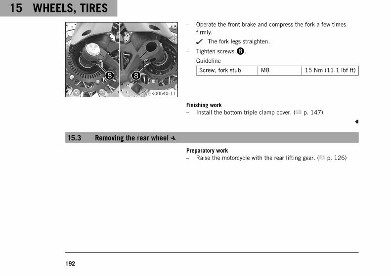
15 WHEELS, TIRES
192
K00540-11
– Operate the front brake and compress the fork a few timesfirmly.
The fork legs straighten.
– Tighten screws8.
Guideline
Screw, fork stub M8 15 Nm (11.1 lbf ft)
Finishing work– Install the bottom triple clamp cover. ( p. 147)
15.3 Removing the rear wheel
Preparatory work– Raise the motorcycle with the rear lifting gear. ( p. 126)
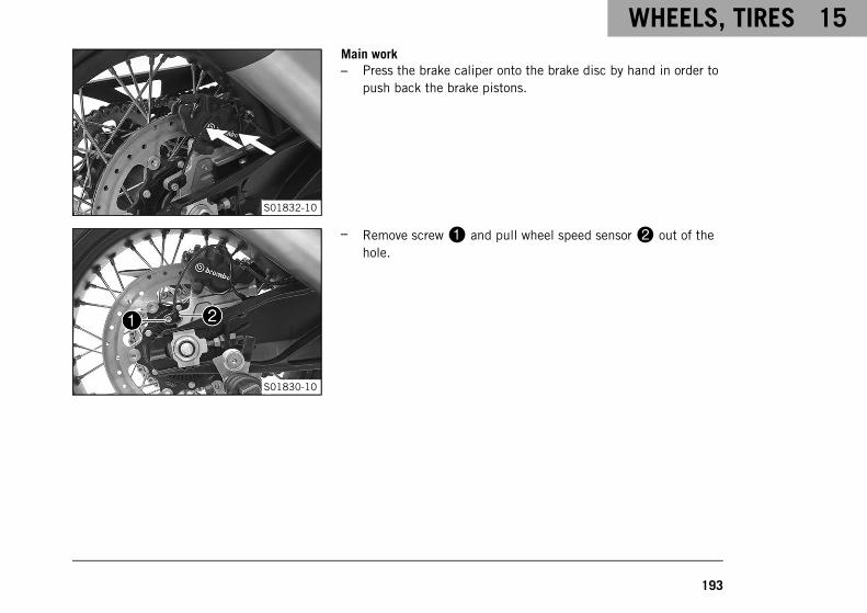
WHEELS, TIRES 15
193
S01832-10
Main work– Press the brake caliper onto the brake disc by hand in order to
push back the brake pistons.
S01830-10
– Remove screw1 and pull wheel speed sensor2 out of thehole.
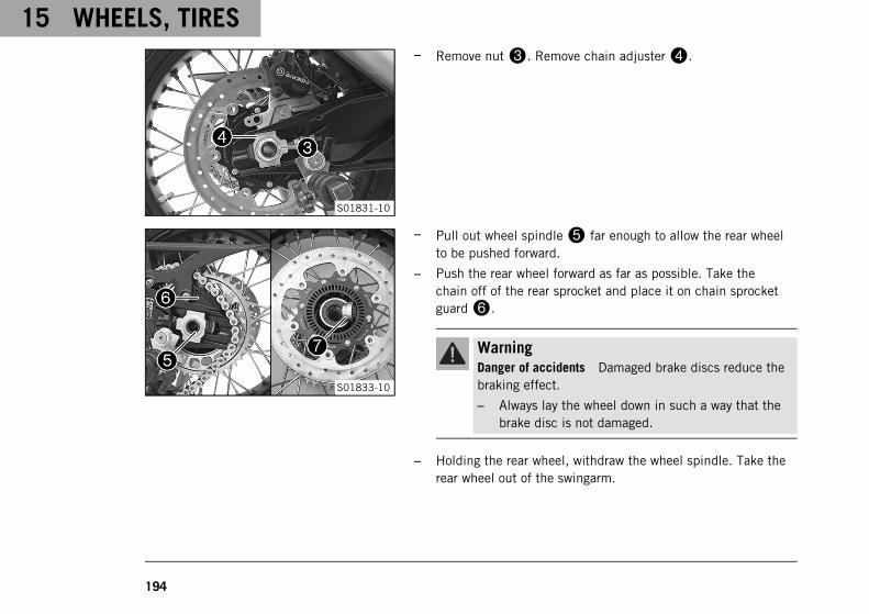
15 WHEELS, TIRES
194
S01831-10
– Remove nut3. Remove chain adjuster4.
S01833-10
– Pull out wheel spindle5 far enough to allow the rear wheelto be pushed forward.
– Push the rear wheel forward as far as possible. Take thechain off of the rear sprocket and place it on chain sprocketguard6.
WarningDanger of accidents Damaged brake discs reduce thebraking effect.
– Always lay the wheel down in such a way that thebrake disc is not damaged.
– Holding the rear wheel, withdraw the wheel spindle. Take therear wheel out of the swingarm.
WHEELS, TIRES 15
195
InfoDo not operate the foot brake when the rear wheel isremoved.
– Remove spacer7.
15.4 Installing the rear wheel
WarningDanger of accidents Oil or grease on the brake discs reduces the braking effect.
– Always keep the brake discs free of oil and grease.
– Clean the brake discs with brake cleaner when necessary.
WarningDanger of accidents There is no braking effect to start with at the rear brake after installing the rearwheel.
– Actuate the foot brake several times before going on a ride until you can feel a firm pressure point.
Main work– Check the rear hub rubber dampers. ( p. 198)
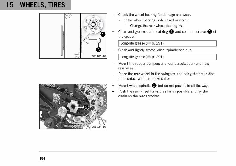
15 WHEELS, TIRES
196
D03109-10
– Check the wheel bearing for damage and wear.
» If the wheel bearing is damaged or worn:
– Change the rear wheel bearing.
– Clean and grease shaft seal ring1 and contact surfaceA ofthe spacer.
Long-life grease ( p. 291)
– Clean and lightly grease wheel spindle and nut.
Long-life grease ( p. 291)
– Mount the rubber dampers and rear sprocket carrier on therear wheel.
– Place the rear wheel in the swingarm and bring the brake discinto contact with the brake caliper.
S01834-10
– Mount wheel spindle2 but do not push it in all the way.
– Push the rear wheel forward as far as possible and lay thechain on the rear sprocket.
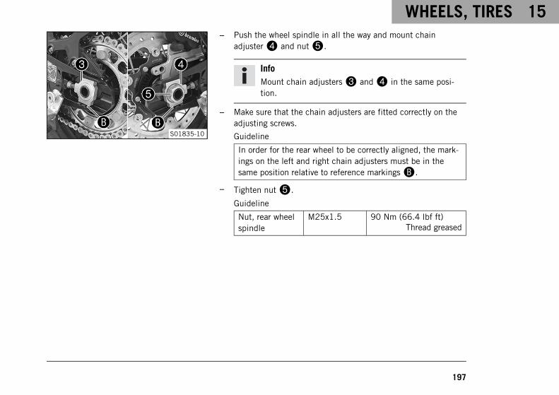
WHEELS, TIRES 15
197
S01835-10
– Push the wheel spindle in all the way and mount chainadjuster4 and nut5.
InfoMount chain adjusters3 and4 in the same posi-tion.
– Make sure that the chain adjusters are fitted correctly on theadjusting screws.
Guideline
In order for the rear wheel to be correctly aligned, the mark-ings on the left and right chain adjusters must be in thesame position relative to reference markingsB.
– Tighten nut5.
Guideline
Nut, rear wheelspindle
M25x1.5 90 Nm (66.4 lbf ft)Thread greased
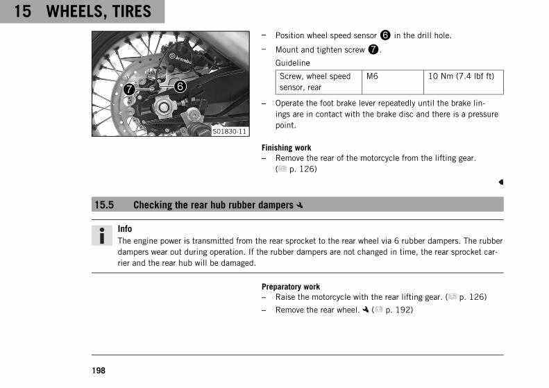
15 WHEELS, TIRES
198
S01830-11
– Position wheel speed sensor6 in the drill hole.
– Mount and tighten screw7.
Guideline
Screw, wheel speedsensor, rear
M6 10 Nm (7.4 lbf ft)
– Operate the foot brake lever repeatedly until the brake lin-ings are in contact with the brake disc and there is a pressurepoint.
Finishing work– Remove the rear of the motorcycle from the lifting gear.
( p. 126)
15.5 Checking the rear hub rubber dampers
InfoThe engine power is transmitted from the rear sprocket to the rear wheel via 6 rubber dampers. The rubberdampers wear out during operation. If the rubber dampers are not changed in time, the rear sprocket car-rier and the rear hub will be damaged.
Preparatory work– Raise the motorcycle with the rear lifting gear. ( p. 126)
– Remove the rear wheel. ( p. 192)
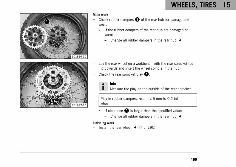
WHEELS, TIRES 15
199
S01836-10
Main work– Check rubber dampers1 of the rear hub for damage and
wear.
» If the rubber dampers of the rear hub are damaged orworn:
– Change all rubber dampers in the rear hub.
S01837-10
– Lay the rear wheel on a workbench with the rear sprocket fac-ing upwards and insert the wheel spindle in the hub.
– Check the rear sprocket playA.
InfoMeasure the play on the outside of the rear sprocket.
Play in rubber dampers, rearwheel
≤ 5 mm (≤ 0.2 in)
» If clearanceA is larger than the specified value:
– Change all rubber dampers in the rear hub.
Finishing work– Install the rear wheel. ( p. 195)
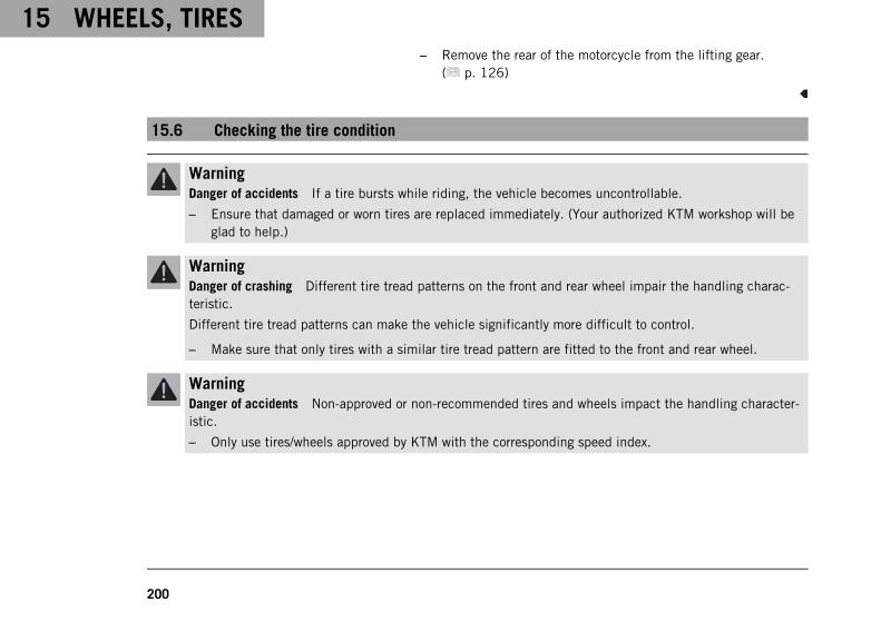
15 WHEELS, TIRES
200
– Remove the rear of the motorcycle from the lifting gear.( p. 126)
15.6 Checking the tire condition
WarningDanger of accidents If a tire bursts while riding, the vehicle becomes uncontrollable.
– Ensure that damaged or worn tires are replaced immediately. (Your authorized KTM workshop will beglad to help.)
WarningDanger of crashing Different tire tread patterns on the front and rear wheel impair the handling charac-teristic.
Different tire tread patterns can make the vehicle significantly more difficult to control.
– Make sure that only tires with a similar tire tread pattern are fitted to the front and rear wheel.
WarningDanger of accidents Non-approved or non-recommended tires and wheels impact the handling character-istic.
– Only use tires/wheels approved by KTM with the corresponding speed index.
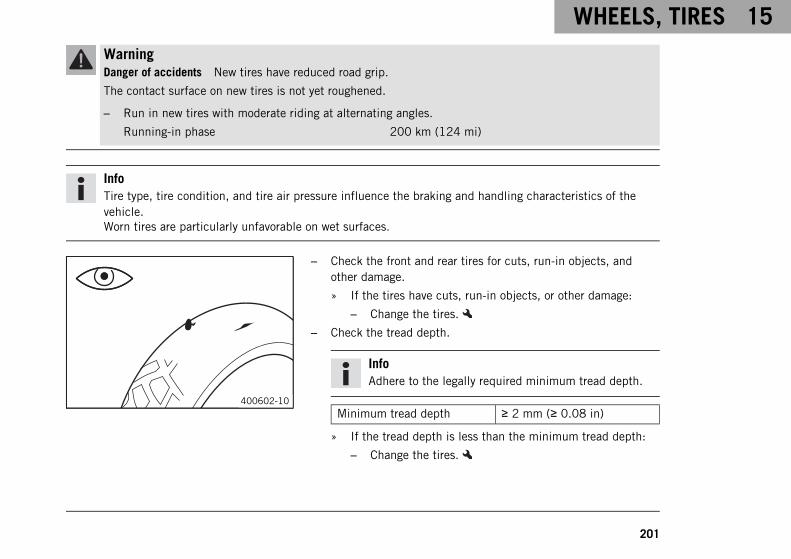
WHEELS, TIRES 15
201
WarningDanger of accidents New tires have reduced road grip.
The contact surface on new tires is not yet roughened.
– Run in new tires with moderate riding at alternating angles.
Running-in phase 200 km (124 mi)
InfoTire type, tire condition, and tire air pressure influence the braking and handling characteristics of thevehicle.Worn tires are particularly unfavorable on wet surfaces.
400602-10
– Check the front and rear tires for cuts, run-in objects, andother damage.
» If the tires have cuts, run-in objects, or other damage:
– Change the tires.
– Check the tread depth.
InfoAdhere to the legally required minimum tread depth.
Minimum tread depth ≥ 2 mm (≥ 0.08 in)
» If the tread depth is less than the minimum tread depth:
– Change the tires.

15 WHEELS, TIRES
202
H01144-10
– Check the tire age.
InfoThe tire date of manufacture is usually contained in thetire label and is indicated by the last four digits of theDOT number. The first two digits indicate the week ofmanufacture and the last two digits the year of manu-facture.KTM recommends that the tires be changed after 5years at the latest, regardless of the actual state ofwear.
» If the tires are more than 5 years old:
– Change the tires.
15.7 Checking the tire air pressure
InfoLow tire air pressure leads to abnormal wear and overheating of the tire.Correct tire air pressure ensures optimal riding comfort and maximum tire service life.
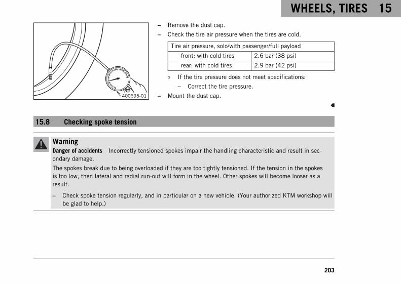
WHEELS, TIRES 15
203
400695-01
– Remove the dust cap.
– Check the tire air pressure when the tires are cold.
Tire air pressure, solo/with passenger/full payload
front: with cold tires 2.6 bar (38 psi)
rear: with cold tires 2.9 bar (42 psi)
» If the tire pressure does not meet specifications:
– Correct the tire pressure.
– Mount the dust cap.
15.8 Checking spoke tension
WarningDanger of accidents Incorrectly tensioned spokes impair the handling characteristic and result in sec-ondary damage.
The spokes break due to being overloaded if they are too tightly tensioned. If the tension in the spokesis too low, then lateral and radial run-out will form in the wheel. Other spokes will become looser as aresult.
– Check spoke tension regularly, and in particular on a new vehicle. (Your authorized KTM workshop willbe glad to help.)
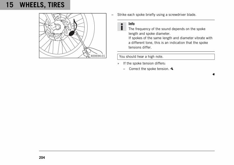
15 WHEELS, TIRES
204
400694-01
– Strike each spoke briefly using a screwdriver blade.
InfoThe frequency of the sound depends on the spokelength and spoke diameter.If spokes of the same length and diameter vibrate witha different tone, this is an indication that the spoketensions differ.
You should hear a high note.
» If the spoke tension differs:
– Correct the spoke tension.

WHEELS, TIRES 15
205
15.9 Tubeless tire system
310767-10
This vehicle makes use of a tubeless tire system in which a tube-less sealing profile1 is used instead of the conventional tube.The advantage of the tubeless system is that there is no risk of adefective tube. This greatly reduces the risk of a sudden loss inpressure.The masses and moments of inertia of these wheels are smallerthan in conventional spoke wheels with a tube. This results in bet-ter handling and riding comfort.The rigid rim design results in a spoke wheel that is almostentirely maintenance-free.KTM recommends that the tubeless sealing profile be changedafter 5 years at the latest, regardless of the actual state of wear.
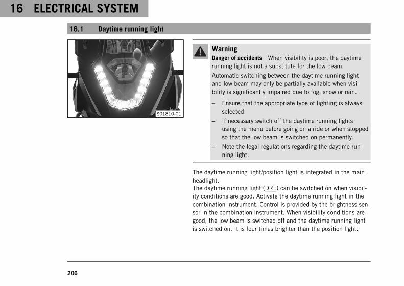
16 ELECTRICAL SYSTEM
206
16.1 Daytime running light
S01810-01
WarningDanger of accidents When visibility is poor, the daytimerunning light is not a substitute for the low beam.
Automatic switching between the daytime running lightand low beam may only be partially available when visi-bility is significantly impaired due to fog, snow or rain.
– Ensure that the appropriate type of lighting is alwaysselected.
– If necessary switch off the daytime running lightsusing the menu before going on a ride or when stoppedso that the low beam is switched on permanently.
– Note the legal regulations regarding the daytime run-ning light.
The daytime running light/position light is integrated in the mainheadlight.The daytime running light (DRL) can be switched on when visibil-ity conditions are good. Activate the daytime running light in thecombination instrument. Control is provided by the brightness sen-sor in the combination instrument. When visibility conditions aregood, the low beam is switched off and the daytime running lightis switched on. It is four times brighter than the position light.
ELECTRICAL SYSTEM 16
207
When the daytime running light is switched off, it serves as a posi-tion light.
16.2 Removing the battery
WarningRisk of injury Battery acid and battery gases cause serious chemical burns.
– Keep batteries out of the reach of children.
– Wear suitable protective clothing and safety glasses.
– Avoid contact with battery acid and battery gases.
– Keep sparks or open flames away from the battery.
– Only charge batteries in well-ventilated rooms.
– Rinse the affected area immediately with plenty of water in the event of contact with the skin.
– Rinse eyes with water for at least 15 minutes and consult a doctor immediately if battery acid andbattery gases get into the eyes.
CautionDanger of accidents Electronic components and safety devices will be damaged if the battery isdischarged or missing.
– Never operate the vehicle with a discharged battery or without a battery.
Preparatory work– Switch off the ignition by turning the black ignition key to the
position OFF .
– Remove the seat. ( p. 133)
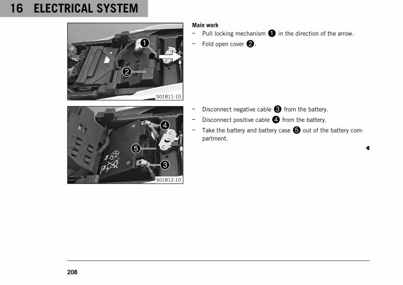
16 ELECTRICAL SYSTEM
208
S01811-10
Main work– Pull locking mechanism1 in the direction of the arrow.
– Fold open cover2.
S01812-10
– Disconnect negative cable3 from the battery.
– Disconnect positive cable4 from the battery.
– Take the battery and battery case5 out of the battery com-partment.
ELECTRICAL SYSTEM 16
209
16.3 Installing the battery
WarningRisk of injury Battery acid and battery gases cause serious chemical burns.
– Keep batteries out of the reach of children.
– Wear suitable protective clothing and safety glasses.
– Avoid contact with battery acid and battery gases.
– Keep sparks or open flames away from the battery.
– Only charge batteries in well-ventilated rooms.
– Rinse the affected area immediately with plenty of water in the event of contact with the skin.
– Rinse eyes with water for at least 15 minutes and consult a doctor immediately if battery acid andbattery gases get into the eyes.
CautionDanger of accidents Electronic components and safety devices will be damaged if the battery isdischarged or missing.
– Never operate the vehicle with a discharged battery or without a battery.
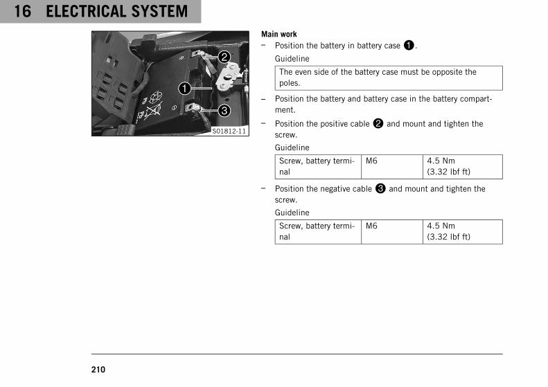
16 ELECTRICAL SYSTEM
210
S01812-11
Main work– Position the battery in battery case1.
Guideline
The even side of the battery case must be opposite thepoles.
– Position the battery and battery case in the battery compart-ment.
– Position the positive cable2 and mount and tighten thescrew.
Guideline
Screw, battery termi-nal
M6 4.5 Nm(3.32 lbf ft)
– Position the negative cable3 and mount and tighten thescrew.
Guideline
Screw, battery termi-nal
M6 4.5 Nm(3.32 lbf ft)
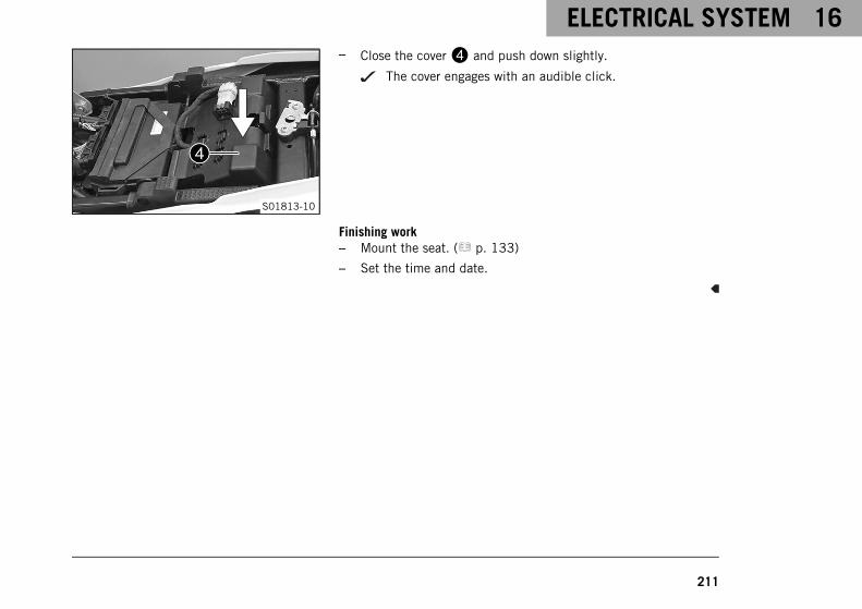
ELECTRICAL SYSTEM 16
211
S01813-10
– Close the cover4 and push down slightly.
The cover engages with an audible click.
Finishing work– Mount the seat. ( p. 133)
– Set the time and date.
16 ELECTRICAL SYSTEM
212
16.4 Recharging the battery
WarningRisk of injury Battery acid and battery gases cause serious chemical burns.
– Keep batteries out of the reach of children.
– Wear suitable protective clothing and safety glasses.
– Avoid contact with battery acid and battery gases.
– Keep sparks or open flames away from the battery.
– Only charge batteries in well-ventilated rooms.
– Rinse the affected area immediately with plenty of water in the event of contact with the skin.
– Rinse eyes with water for at least 15 minutes and consult a doctor immediately if battery acid andbattery gases get into the eyes.
WarningEnvironmental hazard Batteries contain environmentally-hazardous materials.
– Do not dispose of batteries as household waste.
– Dispose of batteries at a collection point for used batteries.
WarningEnvironmental hazard Hazardous substances cause environmental damage.
– Dispose of oils, grease, filters, fuel, cleaning agents, brake fluid, etc., correctly and in compliance withthe applicable regulations.
ELECTRICAL SYSTEM 16
213
InfoEven when there is no load on the battery, it discharges steadily.The charge state and the type of charge are very important for the service life of the battery.Rapid recharging with a high charging current shortens the service life of the battery.If the charging current, charging voltage, and charging time are exceeded, electrolyte escapes through thesafety valves. This reduces the battery capacity.If the battery is depleted from starting the vehicle repeatedly, the battery must be charged immediately.If the battery is left in a discharged state for an extended period, over-discharge and sulfating occurs,destroying the battery.The battery is maintenance-free, i.e., the acid level does not have to be checked.If the battery is not charged using the KTM battery charger, the battery must be removed for charging.Otherwise, overvoltage may damage electronic components. Charge the battery according to the instruc-tions on the battery housing.
Preparatory work– Switch off all power consumers and switch off the engine.
– Remove the seat. ( p. 133)
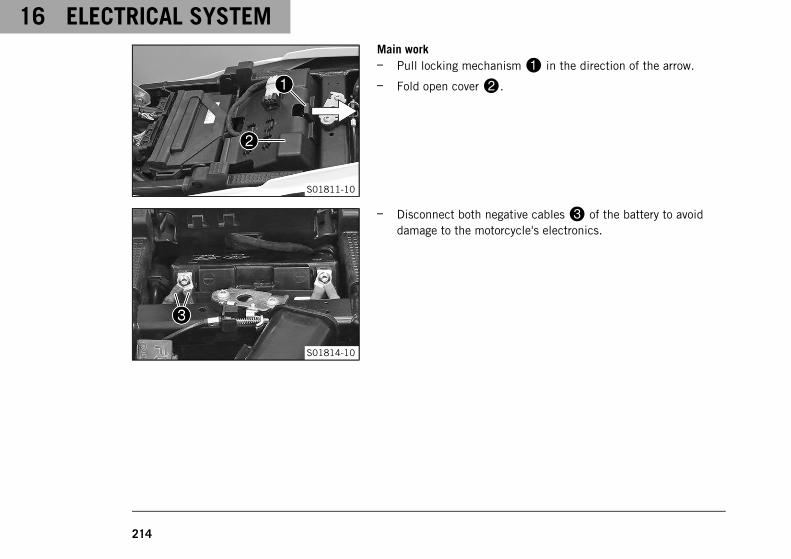
16 ELECTRICAL SYSTEM
214
S01811-10
Main work– Pull locking mechanism1 in the direction of the arrow.
– Fold open cover2.
S01814-10
– Disconnect both negative cables3 of the battery to avoiddamage to the motorcycle's electronics.
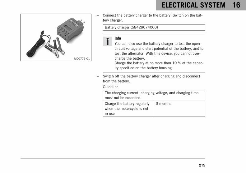
ELECTRICAL SYSTEM 16
215
M00775-01
– Connect the battery charger to the battery. Switch on the bat-tery charger.
Battery charger (58429074000)
InfoYou can also use the battery charger to test the open-circuit voltage and start potential of the battery, and totest the alternator. With this device, you cannot over-charge the battery.Charge the battery at no more than 10 % of the capac-ity specified on the battery housing.
– Switch off the battery charger after charging and disconnectfrom the battery.
Guideline
The charging current, charging voltage, and charging timemust not be exceeded.
Charge the battery regularlywhen the motorcycle is notin use
3 months
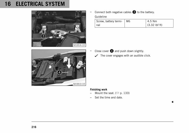
16 ELECTRICAL SYSTEM
216
S01814-10
– Connect both negative cables3 to the battery.
Guideline
Screw, battery termi-nal
M6 4.5 Nm(3.32 lbf ft)
S01813-10
– Close cover4 and push down slightly.
The cover engages with an audible click.
Finishing work– Mount the seat. ( p. 133)
– Set the time and date.
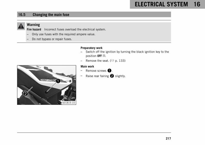
ELECTRICAL SYSTEM 16
217
16.5 Changing the main fuse
WarningFire hazard Incorrect fuses overload the electrical system.
– Only use fuses with the required ampere value.
– Do not bypass or repair fuses.
Preparatory work– Switch off the ignition by turning the black ignition key to the
position OFF .
– Remove the seat. ( p. 133)
S01815-10
Main work– Remove screws1.
– Raise rear fairing2 slightly.
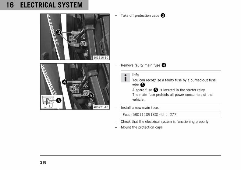
16 ELECTRICAL SYSTEM
218
S01816-10
– Take off protection caps3.
A00221-10
– Remove faulty main fuse4.
InfoYou can recognize a faulty fuse by a burned-out fusewireA.A spare fuse5 is located in the starter relay.The main fuse protects all power consumers of thevehicle.
– Install a new main fuse.
Fuse (58011109130) ( p. 277)
– Check that the electrical system is functioning properly.
– Mount the protection caps.
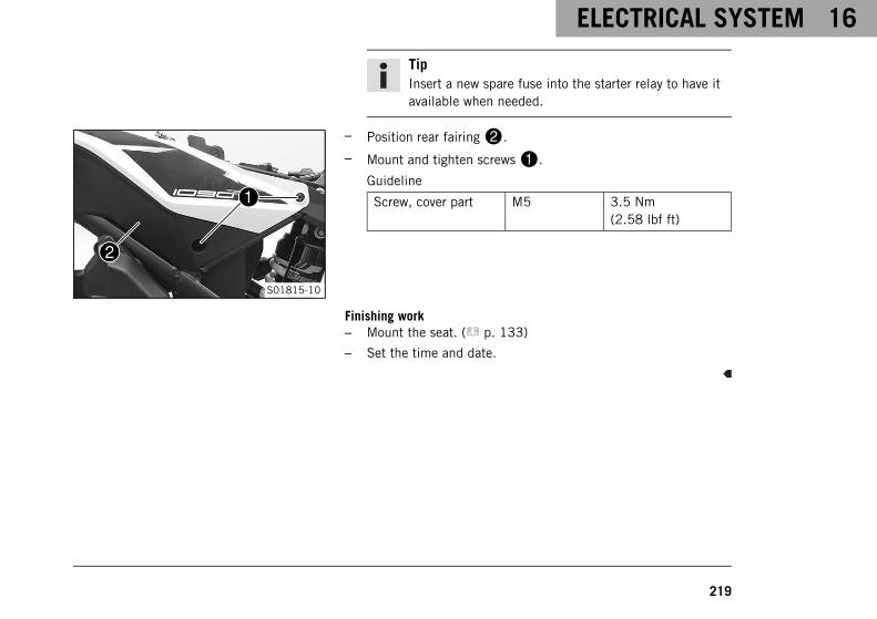
ELECTRICAL SYSTEM 16
219
TipInsert a new spare fuse into the starter relay to have itavailable when needed.
S01815-10
– Position rear fairing2.
– Mount and tighten screws1.
Guideline
Screw, cover part M5 3.5 Nm(2.58 lbf ft)
Finishing work– Mount the seat. ( p. 133)
– Set the time and date.

16 ELECTRICAL SYSTEM
220
16.6 Changing the fuses in the fuse box
WarningFire hazard Incorrect fuses overload the electrical system.
– Only use fuses with the required ampere value.
– Do not bypass or repair fuses.
InfoThe fuse box containing the fuses of individual power consumers is located under the seat.
Preparatory work– Switch off the ignition by turning the black ignition key to the
position OFF .
– Remove the seat. ( p. 133)
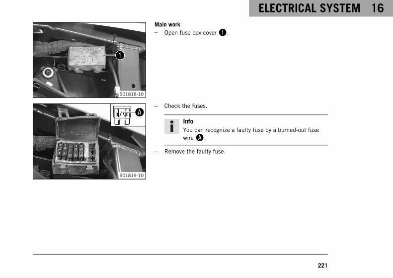
ELECTRICAL SYSTEM 16
221
S01818-10
Main work– Open fuse box cover1.
S01819-10
– Check the fuses.
InfoYou can recognize a faulty fuse by a burned-out fusewireA.
– Remove the faulty fuse.
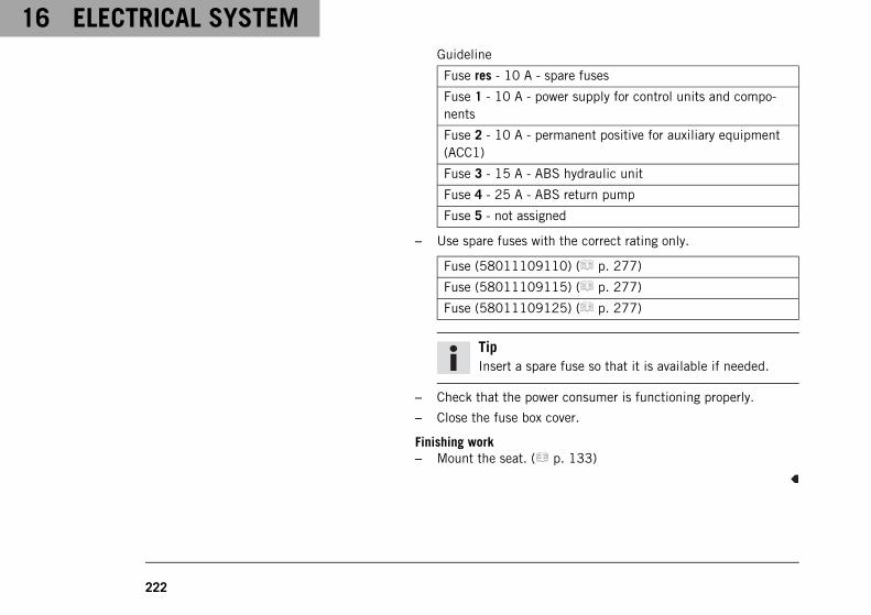
16 ELECTRICAL SYSTEM
222
Guideline
Fuse res - 10 A - spare fuses
Fuse 1 - 10 A - power supply for control units and compo-nents
Fuse 2 - 10 A - permanent positive for auxiliary equipment(ACC1)
Fuse 3 - 15 A - ABS hydraulic unit
Fuse 4 - 25 A - ABS return pump
Fuse 5 - not assigned
– Use spare fuses with the correct rating only.
Fuse (58011109110) ( p. 277)
Fuse (58011109115) ( p. 277)
Fuse (58011109125) ( p. 277)
TipInsert a spare fuse so that it is available if needed.
– Check that the power consumer is functioning properly.
– Close the fuse box cover.
Finishing work– Mount the seat. ( p. 133)
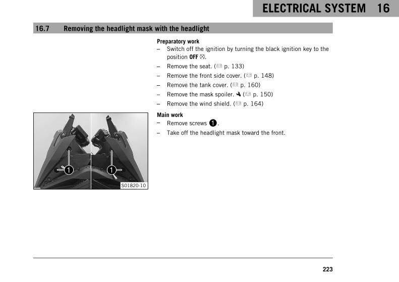
ELECTRICAL SYSTEM 16
223
16.7 Removing the headlight mask with the headlight
Preparatory work– Switch off the ignition by turning the black ignition key to the
position OFF .
– Remove the seat. ( p. 133)
– Remove the front side cover. ( p. 148)
– Remove the tank cover. ( p. 160)
– Remove the mask spoiler. ( p. 150)
– Remove the wind shield. ( p. 164)
S01820-10
Main work– Remove screws1.
– Take off the headlight mask toward the front.
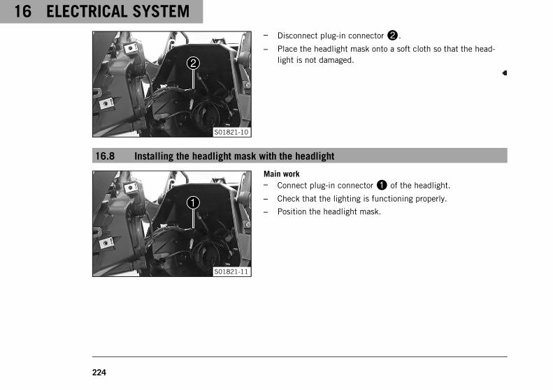
16 ELECTRICAL SYSTEM
224
S01821-10
– Disconnect plug-in connector2.
– Place the headlight mask onto a soft cloth so that the head-light is not damaged.
16.8 Installing the headlight mask with the headlight
S01821-11
Main work– Connect plug-in connector1 of the headlight.
– Check that the lighting is functioning properly.
– Position the headlight mask.
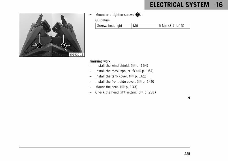
ELECTRICAL SYSTEM 16
225
S01820-11
– Mount and tighten screws2.
Guideline
Screw, headlight M6 5 Nm (3.7 lbf ft)
Finishing work– Install the wind shield. ( p. 164)
– Install the mask spoiler. ( p. 154)
– Install the tank cover. ( p. 162)
– Install the front side cover. ( p. 149)
– Mount the seat. ( p. 133)
– Check the headlight setting. ( p. 231)
16 ELECTRICAL SYSTEM
226
16.9 Changing the low beam bulb
NoteDamage to reflector Grease on the reflector reduces the brightness.
Grease on the bulb will evaporate due to the heat and be deposited on the reflector.
– Clean and degrease the bulbs before mounting.
– Do not touch the bulbs with your bare hands.
Preparatory work– Switch off the ignition by turning the black ignition key to the
position OFF .
– Remove the seat. ( p. 133)
– Remove the front side cover. ( p. 148)
– Remove the tank cover. ( p. 160)
– Remove the mask spoiler. ( p. 150)
– Remove the wind shield. ( p. 164)
– Remove the headlight mask with the headlight. ( p. 223)
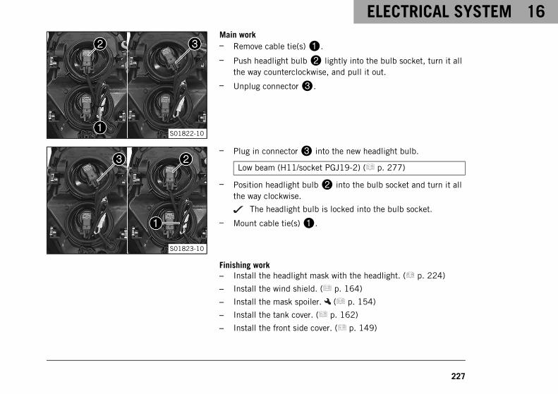
ELECTRICAL SYSTEM 16
227
S01822-10
Main work– Remove cable tie(s)1.
– Push headlight bulb2 lightly into the bulb socket, turn it allthe way counterclockwise, and pull it out.
– Unplug connector3.
S01823-10
– Plug in connector3 into the new headlight bulb.
Low beam (H11/socket PGJ19-2) ( p. 277)
– Position headlight bulb2 into the bulb socket and turn it allthe way clockwise.
The headlight bulb is locked into the bulb socket.
– Mount cable tie(s)1.
Finishing work– Install the headlight mask with the headlight. ( p. 224)
– Install the wind shield. ( p. 164)
– Install the mask spoiler. ( p. 154)
– Install the tank cover. ( p. 162)
– Install the front side cover. ( p. 149)
16 ELECTRICAL SYSTEM
228
– Mount the seat. ( p. 133)
– Check the headlight setting. ( p. 231)
16.10 Changing the high beam bulb
NoteDamage to reflector Grease on the reflector reduces the brightness.
Grease on the bulb will evaporate due to the heat and be deposited on the reflector.
– Clean and degrease the bulbs before mounting.
– Do not touch the bulbs with your bare hands.
Preparatory work– Switch off the ignition by turning the black ignition key to the
position OFF .
– Remove the seat. ( p. 133)
– Remove the front side cover. ( p. 148)
– Remove the tank cover. ( p. 160)
– Remove the mask spoiler. ( p. 150)
– Remove the wind shield. ( p. 164)
– Remove the headlight mask with the headlight. ( p. 223)
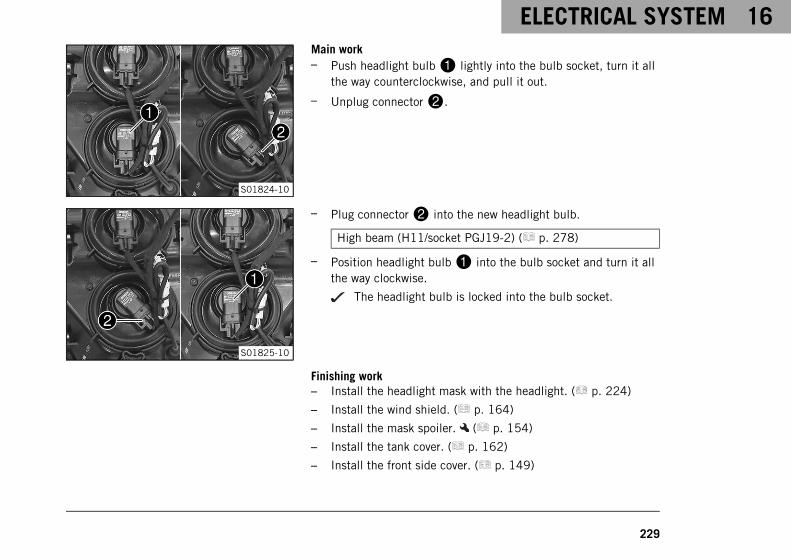
ELECTRICAL SYSTEM 16
229
S01824-10
Main work– Push headlight bulb1 lightly into the bulb socket, turn it all
the way counterclockwise, and pull it out.
– Unplug connector2.
S01825-10
– Plug connector2 into the new headlight bulb.
High beam (H11/socket PGJ19-2) ( p. 278)
– Position headlight bulb1 into the bulb socket and turn it allthe way clockwise.
The headlight bulb is locked into the bulb socket.
Finishing work– Install the headlight mask with the headlight. ( p. 224)
– Install the wind shield. ( p. 164)
– Install the mask spoiler. ( p. 154)
– Install the tank cover. ( p. 162)
– Install the front side cover. ( p. 149)
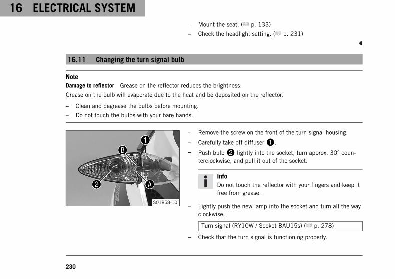
16 ELECTRICAL SYSTEM
230
– Mount the seat. ( p. 133)
– Check the headlight setting. ( p. 231)
16.11 Changing the turn signal bulb
NoteDamage to reflector Grease on the reflector reduces the brightness.
Grease on the bulb will evaporate due to the heat and be deposited on the reflector.
– Clean and degrease the bulbs before mounting.
– Do not touch the bulbs with your bare hands.
S01858-10
– Remove the screw on the front of the turn signal housing.
– Carefully take off diffuser1.
– Push bulb2 lightly into the socket, turn approx. 30° coun-terclockwise, and pull it out of the socket.
InfoDo not touch the reflector with your fingers and keep itfree from grease.
– Lightly push the new lamp into the socket and turn all the wayclockwise.
Turn signal (RY10W / Socket BAU15s) ( p. 278)
– Check that the turn signal is functioning properly.
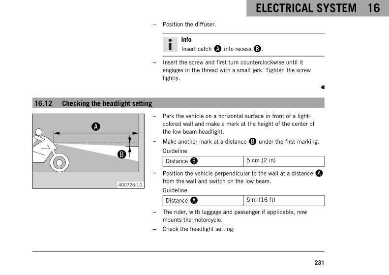
ELECTRICAL SYSTEM 16
231
– Position the diffuser.
InfoInsert catchA into recessB.
– Insert the screw and first turn counterclockwise until itengages in the thread with a small jerk. Tighten the screwlightly.
16.12 Checking the headlight setting
400726-10
– Park the vehicle on a horizontal surface in front of a light-colored wall and make a mark at the height of the center ofthe low beam headlight.
– Make another mark at a distanceB under the first marking.
Guideline
DistanceB 5 cm (2 in)
– Position the vehicle perpendicular to the wall at a distanceAfrom the wall and switch on the low beam.
Guideline
DistanceA 5 m (16 ft)
– The rider, with luggage and passenger if applicable, nowmounts the motorcycle.
– Check the headlight setting.
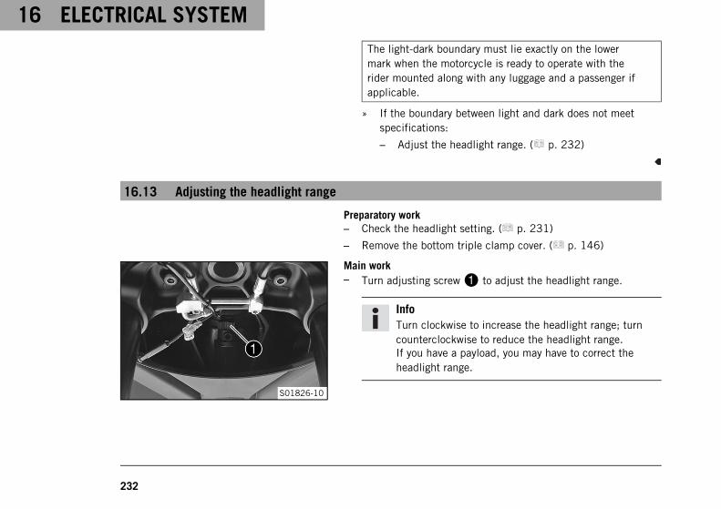
16 ELECTRICAL SYSTEM
232
The light-dark boundary must lie exactly on the lowermark when the motorcycle is ready to operate with therider mounted along with any luggage and a passenger ifapplicable.
» If the boundary between light and dark does not meetspecifications:
– Adjust the headlight range. ( p. 232)
16.13 Adjusting the headlight range
Preparatory work– Check the headlight setting. ( p. 231)
– Remove the bottom triple clamp cover. ( p. 146)
S01826-10
Main work– Turn adjusting screw1 to adjust the headlight range.
InfoTurn clockwise to increase the headlight range; turncounterclockwise to reduce the headlight range.If you have a payload, you may have to correct theheadlight range.
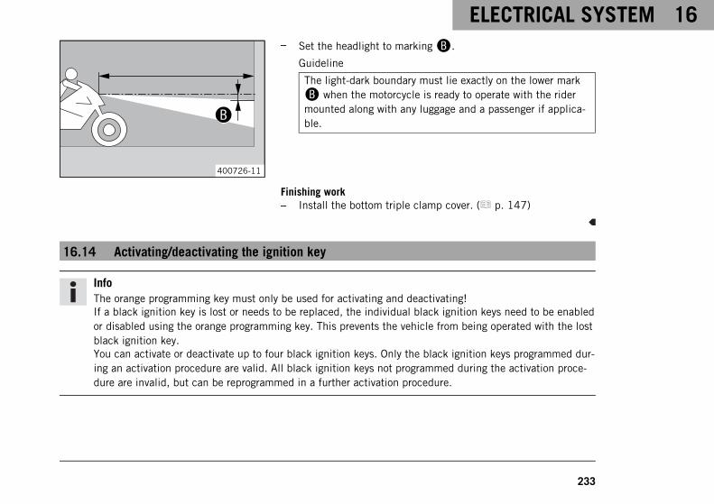
ELECTRICAL SYSTEM 16
233
400726-11
– Set the headlight to markingB.
Guideline
The light-dark boundary must lie exactly on the lower mark
B when the motorcycle is ready to operate with the ridermounted along with any luggage and a passenger if applica-ble.
Finishing work– Install the bottom triple clamp cover. ( p. 147)
16.14 Activating/deactivating the ignition key
InfoThe orange programming key must only be used for activating and deactivating!If a black ignition key is lost or needs to be replaced, the individual black ignition keys need to be enabledor disabled using the orange programming key. This prevents the vehicle from being operated with the lostblack ignition key.You can activate or deactivate up to four black ignition keys. Only the black ignition keys programmed dur-ing an activation procedure are valid. All black ignition keys not programmed during the activation proce-dure are invalid, but can be reprogrammed in a further activation procedure.
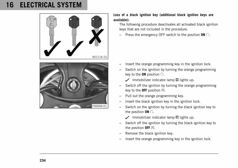
16 ELECTRICAL SYSTEM
234
401114-10
Loss of a black ignition key (additional black ignition keys areavailable):
The following procedure deactivates all activated black ignitionkeys that are not included in the procedure.
– Press the emergency OFF switch to the position ON .
F00694-01
– Insert the orange programming key in the ignition lock.
– Switch on the ignition by turning the orange programmingkey to the ON position .
Immobilizer indicator lamp lights up.
– Switch off the ignition by turning the orange programmingkey to the OFF position .
– Pull out the orange programming key.
– Insert the black ignition key in the ignition lock.
– Switch on the ignition by turning the black ignition key tothe position ON .
Immobilizer indicator lamp lights up.
– Switch off the ignition by turning the black ignition key tothe position OFF .
– Remove the black ignition key.
– Insert the orange programming key in the ignition lock.
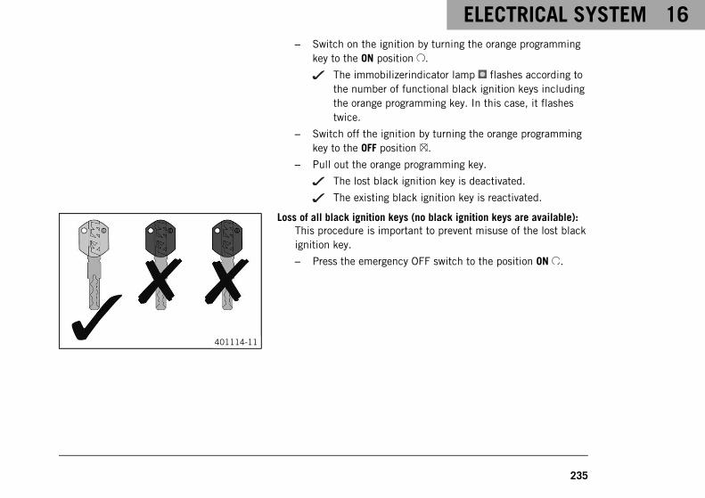
ELECTRICAL SYSTEM 16
235
– Switch on the ignition by turning the orange programmingkey to the ON position .
The immobilizerindicator lamp flashes according tothe number of functional black ignition keys includingthe orange programming key. In this case, it flashestwice.
– Switch off the ignition by turning the orange programmingkey to the OFF position .
– Pull out the orange programming key.
The lost black ignition key is deactivated.
The existing black ignition key is reactivated.
401114-11
Loss of all black ignition keys (no black ignition keys are available):This procedure is important to prevent misuse of the lost blackignition key.
– Press the emergency OFF switch to the position ON .
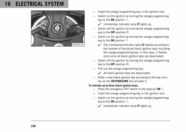
16 ELECTRICAL SYSTEM
236
F00694-01
– Insert the orange programming key in the ignition lock.
– Switch on the ignition by turning the orange programmingkey to the ON position .
Immobilizer indicator lamp lights up.
– Switch off the ignition by turning the orange programmingkey to the OFF position .
– Switch on the ignition by turning the orange programmingkey to the ON position .
The immobilizerindicator lamp flashes according tothe number of functional black ignition keys includingthe orange programming key. In this case, it flashesonce since all black ignition keys are deactivated.
– Switch off the ignition by turning the orange programmingkey to the OFF position .
– Pull out the orange programming key.
All black ignition keys are deactivated.
– Order a new black ignition key according to the key num-ber on the KEYCODECARD and activate it.
To activate up to three black ignition keys:– Press the emergency OFF switch to the position ON .
– Insert the orange programming key in the ignition lock.
– Switch on the ignition by turning the orange programmingkey to the ON position .
Immobilizer indicator lamp lights up.
ELECTRICAL SYSTEM 16
237
– Switch off the ignition by turning the orange programmingkey to the OFF position .
– Pull out the orange programming key.
– Insert the black ignition key in the ignition lock.
– Switch on the ignition by turning the black ignition key tothe position ON .
Immobilizer indicator lamp lights up.
– Switch off the ignition by turning the black ignition key tothe position OFF .
– Remove the black ignition key.
– If two other black ignition keys are to be activated, repeatthe last steps with the respective ignition key.
– If the last black ignition key was activated, insert theorange programming key into the ignition lock.
– Switch on the ignition by turning the orange programmingkey to the ON position .
The immobilizerindicator lamp flashes according tothe number of functional black ignition keys includingthe orange programming key.
– Switch off the ignition by turning the orange programmingkey to the OFF position .
– Pull out the orange programming key.
16 ELECTRICAL SYSTEM
238
InfoActivation of the ignition key is finished.
To activate four black ignition keys:– Press the emergency OFF switch to the position ON .
– Insert the orange programming key in the ignition lock.
– Switch on the ignition by turning the orange programmingkey to the ON position .
Immobilizer indicator lamp lights up.
– Switch off the ignition by turning the orange programmingkey to the OFF position .
– Pull out the orange programming key.
– Insert the black ignition key in the ignition lock.
– Switch on the ignition by turning the black ignition key tothe position ON .
Immobilizer indicator lamp lights up.
– Switch off the ignition by turning the black ignition key tothe position OFF .
– Remove the black ignition key.
– If three other black ignition keys are to be activated, repeatthe last steps with the respective ignition key.
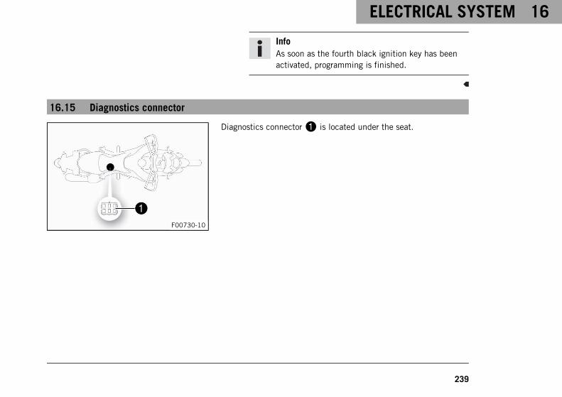
ELECTRICAL SYSTEM 16
239
InfoAs soon as the fourth black ignition key has beenactivated, programming is finished.
16.15 Diagnostics connector
F00730-10
Diagnostics connector1 is located under the seat.

16 ELECTRICAL SYSTEM
240
16.16 Front ACC1 and ACC2
A00223-10
Installation location– The front power supplies ACC11 and ACC22 are located
behind the headlight.
InfoThe power supplies are protected by a fuse, however thisfuse also protects other power consumers.The maximum continuous load is therefore significantlylower than the value of the fuse.Do not use a stronger fuse.
16.17 ACC1 and ACC2 rear
A00224-10
Installation location– The rear power supplies ACC11 and ACC22 are located
under the luggage rack plate.
InfoThe power supplies are protected by a fuse, however thisfuse also protects other power consumers.The maximum continuous load is therefore significantlylower than the value of the fuse.Do not use a stronger fuse.

COOLING SYSTEM 17
241
17.1 Checking the coolant level in the compensating tank
WarningDanger of scalding During motorcycle operation, the coolant gets very hot and is under pressure.
– Do not open the radiator, the radiator hoses or other cooling system components if the engine or thecooling system are at operating temperature.
– Allow the cooling system and the engine to cool down before you open the radiator, the radiator hosesor other components of the cooling system.
– In the event of scalding, rinse the area affected immediately with lukewarm water.
WarningDanger of poisoning Coolant is toxic and a health hazard.
– Keep coolant out of the reach of children.
– Do not allow coolant to come into contact with the skin, the eyes and clothing.
– Consult a doctor immediately if coolant is swallowed.
– Rinse the affected area immediately with plenty of water in the event of contact with the skin.
– Rinse eyes thoroughly with water and consult a doctor immediately if coolant gets into the eyes.
– Change clothing if coolant spills onto your clothing.
ConditionThe engine is cold.The radiator is completely full.
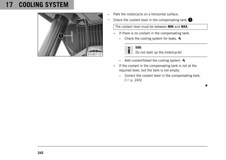
17 COOLING SYSTEM
242
S01827-10
– Park the motorcycle on a horizontal surface.
– Check the coolant level in the compensating tank1.
The coolant level must be between MIN and MAX.
» If there is no coolant in the compensating tank:
– Check the cooling system for leaks.
InfoDo not start up the motorcycle!
– Add coolant/bleed the cooling system.
» If the coolant in the compensating tank is not at therequired level, but the tank is not empty:
– Correct the coolant level in the compensating tank.( p. 243)
COOLING SYSTEM 17
243
17.2 Correcting the coolant level in the compensating tank
WarningDanger of scalding During motorcycle operation, the coolant gets very hot and is under pressure.
– Do not open the radiator, the radiator hoses or other cooling system components if the engine or thecooling system are at operating temperature.
– Allow the cooling system and the engine to cool down before you open the radiator, the radiator hosesor other components of the cooling system.
– In the event of scalding, rinse the area affected immediately with lukewarm water.
WarningDanger of poisoning Coolant is toxic and a health hazard.
– Keep coolant out of the reach of children.
– Do not allow coolant to come into contact with the skin, the eyes and clothing.
– Consult a doctor immediately if coolant is swallowed.
– Rinse the affected area immediately with plenty of water in the event of contact with the skin.
– Rinse eyes thoroughly with water and consult a doctor immediately if coolant gets into the eyes.
– Change clothing if coolant spills onto your clothing.
ConditionThe engine is cold.The radiator is completely full.
Preparatory work– Check the coolant level in the compensating tank. ( p. 241)
– Remove the front side cover. ( p. 148)
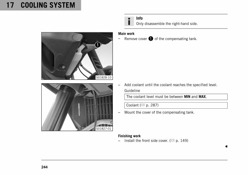
17 COOLING SYSTEM
244
InfoOnly disassemble the right-hand side.
S01828-10
Main work– Remove cover1 of the compensating tank.
S01827-01
– Add coolant until the coolant reaches the specified level.
Guideline
The coolant level must be between MIN and MAX.
Coolant ( p. 287)
– Mount the cover of the compensating tank.
Finishing work– Install the front side cover. ( p. 149)
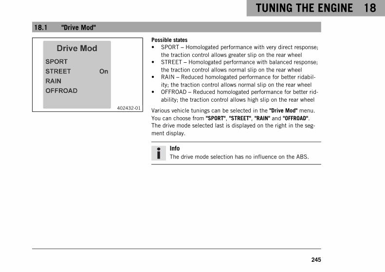
TUNING THE ENGINE 18
245
18.1 "Drive Mod"
402432-01
Possible states• SPORT – Homologated performance with very direct response;
the traction control allows greater slip on the rear wheel• STREET – Homologated performance with balanced response;
the traction control allows normal slip on the rear wheel• RAIN – Reduced homologated performance for better ridabil-
ity; the traction control allows normal slip on the rear wheel• OFFROAD – Reduced homologated performance for better rid-
ability; the traction control allows high slip on the rear wheel
Various vehicle tunings can be selected in the "Drive Mod" menu.You can choose from "SPORT", "STREET", "RAIN" and "OFFROAD".The drive mode selected last is displayed on the right in the seg-ment display.
InfoThe drive mode selection has no influence on the ABS.
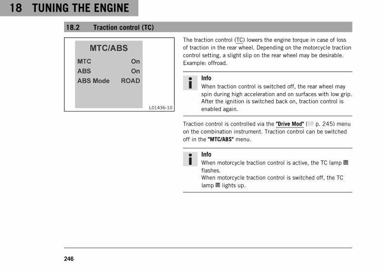
18 TUNING THE ENGINE
246
18.2 Traction control (TC)
L01436-10
The traction control (TC) lowers the engine torque in case of lossof traction in the rear wheel. Depending on the motorcycle tractioncontrol setting, a slight slip on the rear wheel may be desirable.Example: offroad.
InfoWhen traction control is switched off, the rear wheel mayspin during high acceleration and on surfaces with low grip.After the ignition is switched back on, traction control isenabled again.
Traction control is controlled via the "Drive Mod" ( p. 245) menuon the combination instrument. Traction control can be switchedoff in the "MTC/ABS" menu.
InfoWhen motorcycle traction control is active, the TC lampflashes.When motorcycle traction control is switched off, the TClamp lights up.
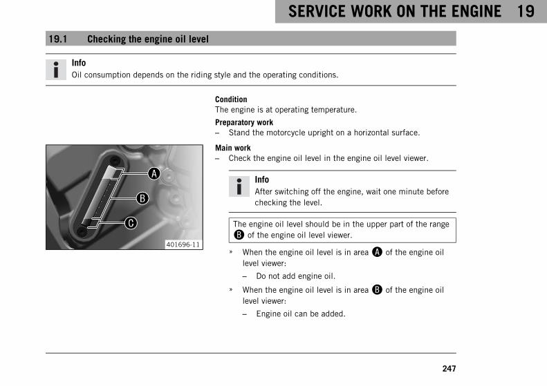
SERVICE WORK ON THE ENGINE 19
247
19.1 Checking the engine oil level
InfoOil consumption depends on the riding style and the operating conditions.
ConditionThe engine is at operating temperature.
Preparatory work– Stand the motorcycle upright on a horizontal surface.
401696-11
Main work– Check the engine oil level in the engine oil level viewer.
InfoAfter switching off the engine, wait one minute beforechecking the level.
The engine oil level should be in the upper part of the range
B of the engine oil level viewer.
» When the engine oil level is in areaA of the engine oillevel viewer:
– Do not add engine oil.
» When the engine oil level is in areaB of the engine oillevel viewer:
– Engine oil can be added.
19 SERVICE WORK ON THE ENGINE
248
» When the engine oil level is in areaC of the engine oillevel viewer:
– Add engine oil. ( p. 255)
19.2 Changing the engine oil and oil filter, cleaning the oil screens
WarningDanger of scalding Engine and gear oil get very hot when the motorcycle is ridden.
– Wear suitable protective clothing and safety gloves.
– In the event of scalding, rinse the area affected immediately with lukewarm water.
WarningEnvironmental hazard Hazardous substances cause environmental damage.
– Dispose of oils, grease, filters, fuel, cleaning agents, brake fluid, etc., correctly and in compliance withthe applicable regulations.
Preparatory work– Remove the engine guard. ( p. 165)
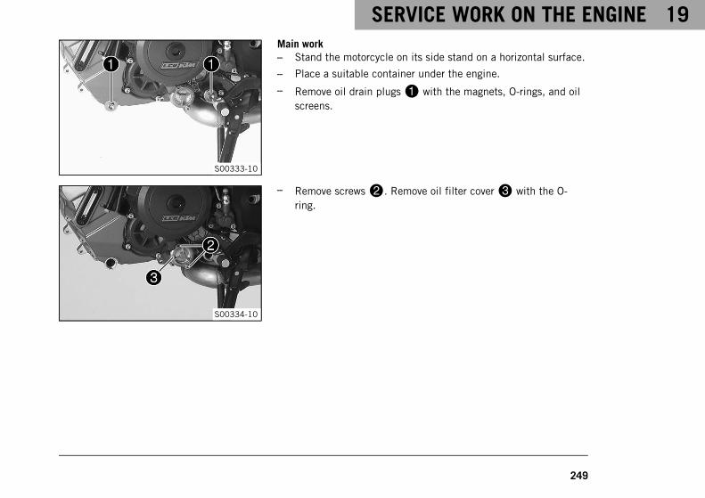
SERVICE WORK ON THE ENGINE 19
249
S00333-10
Main work– Stand the motorcycle on its side stand on a horizontal surface.
– Place a suitable container under the engine.
– Remove oil drain plugs1 with the magnets, O-rings, and oilscreens.
S00334-10
– Remove screws2. Remove oil filter cover3 with the O-ring.
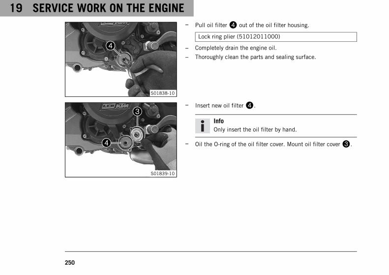
19 SERVICE WORK ON THE ENGINE
250
S01838-10
– Pull oil filter4 out of the oil filter housing.
Lock ring plier (51012011000)
– Completely drain the engine oil.
– Thoroughly clean the parts and sealing surface.
S01839-10
– Insert new oil filter4.
InfoOnly insert the oil filter by hand.
– Oil the O-ring of the oil filter cover. Mount oil filter cover3.
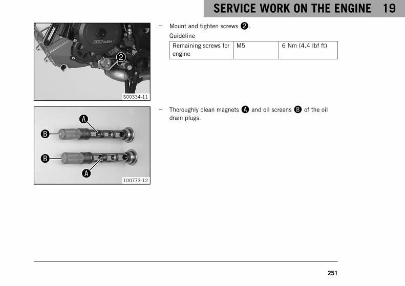
SERVICE WORK ON THE ENGINE 19
251
S00334-11
– Mount and tighten screws2.
Guideline
Remaining screws forengine
M5 6 Nm (4.4 lbf ft)
100773-12
– Thoroughly clean magnetsA and oil screensB of the oildrain plugs.
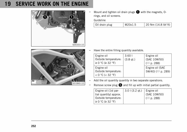
19 SERVICE WORK ON THE ENGINE
252
S00333-10
– Mount and tighten oil drain plugs1 with the magnets, O-rings, and oil screens.
Guideline
Oil drain plug M20x1.5 20 Nm (14.8 lbf ft)
S01840-10
– Have the entire filling quantity available.
Engine oilOutside temperature:≥ 0 °C (≥ 32 °F)
3.60 l(3.8 qt.)
Engine oil(SAE 10W/50)( p. 288)
Engine oilOutside temperature:< 0 °C (< 32 °F)
Engine oil (SAE5W/40) ( p. 289)
– Add the oil quantity quantity in two separate operations.
– Remove screw plug5 and fill up with initial partial quantity.
Engine oil (1st par-tial quantity) approx.Outside temperature:≥ 0 °C (≥ 32 °F)
3.0 l (3.2 qt.) Engine oil(SAE 10W/50)( p. 288)
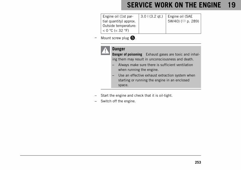
SERVICE WORK ON THE ENGINE 19
253
Engine oil (1st par-tial quantity) approx.Outside temperature:< 0 °C (< 32 °F)
3.0 l (3.2 qt.) Engine oil (SAE5W/40) ( p. 289)
– Mount screw plug5.
DangerDanger of poisoning Exhaust gases are toxic and inhal-ing them may result in unconsciousness and death.
– Always make sure there is sufficient ventilationwhen running the engine.
– Use an effective exhaust extraction system whenstarting or running the engine in an enclosedspace.
– Start the engine and check that it is oil-tight.
– Switch off the engine.
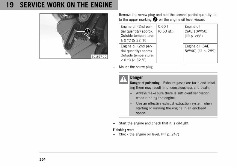
19 SERVICE WORK ON THE ENGINE
254
S01857-10
– Remove the screw plug and add the second partial quantity upto the upper markingA on the engine oil level viewer.
Engine oil (2nd par-tial quantity) approx.Outside temperature:≥ 0 °C (≥ 32 °F)
0.60 l(0.63 qt.)
Engine oil(SAE 10W/50)( p. 288)
Engine oil (2nd par-tial quantity) approx.Outside temperature:< 0 °C (< 32 °F)
Engine oil (SAE5W/40) ( p. 289)
– Mount the screw plug.
DangerDanger of poisoning Exhaust gases are toxic and inhal-ing them may result in unconsciousness and death.
– Always make sure there is sufficient ventilationwhen running the engine.
– Use an effective exhaust extraction system whenstarting or running the engine in an enclosedspace.
– Start the engine and check that it is oil-tight.
Finishing work– Check the engine oil level. ( p. 247)
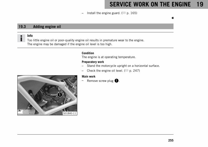
SERVICE WORK ON THE ENGINE 19
255
– Install the engine guard. ( p. 165)
19.3 Adding engine oil
InfoToo little engine oil or poor-quality engine oil results in premature wear to the engine.The engine may be damaged if the engine oil level is too high.
ConditionThe engine is at operating temperature.
Preparatory work– Stand the motorcycle upright on a horizontal surface.
– Check the engine oil level. ( p. 247)
S01840-11
Main work– Remove screw plug1.
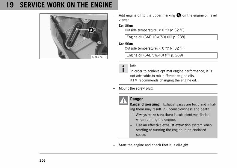
19 SERVICE WORK ON THE ENGINE
256
S00329-10
– Add engine oil to the upper markingA on the engine oil levelviewer.
ConditionOutside temperature: ≥ 0 °C (≥ 32 °F)
Engine oil (SAE 10W/50) ( p. 288)
ConditionOutside temperature: < 0 °C (< 32 °F)
Engine oil (SAE 5W/40) ( p. 289)
InfoIn order to achieve optimal engine performance, it isnot advisable to mix different engine oils.KTM recommends changing the engine oil.
– Mount the screw plug.
DangerDanger of poisoning Exhaust gases are toxic and inhal-ing them may result in unconsciousness and death.
– Always make sure there is sufficient ventilationwhen running the engine.
– Use an effective exhaust extraction system whenstarting or running the engine in an enclosedspace.
– Start the engine and check that it is oil-tight.
SERVICE WORK ON THE ENGINE 19
257
Finishing work– Check the engine oil level. ( p. 247)
20 CLEANING, CARE
258
20.1 Cleaning motorcycle
NoteMaterial damage Components become damaged or destroyed if a pressure cleaner is used incorrectly.
The high pressure forces water into the electrical components, connectors, throttle cables, and bearings, etc.Pressure which is too high causes malfunctions and destroys components.
– Do not direct the water jet directly on to electrical components, connectors, throttle cables or bearings.
– Maintain a minimum distance between the nozzle of the pressure cleaner and the component.
Minimum clearance 60 cm (23.6 in)
WarningEnvironmental hazard Hazardous substances cause environmental damage.
– Dispose of oils, grease, filters, fuel, cleaning agents, brake fluid, etc., correctly and in compliance withthe applicable regulations.
InfoIf you clean the motorcycle regularly, its value and appearance will be maintained over a long period.Avoid direct sunshine on the motorcycle during cleaning.
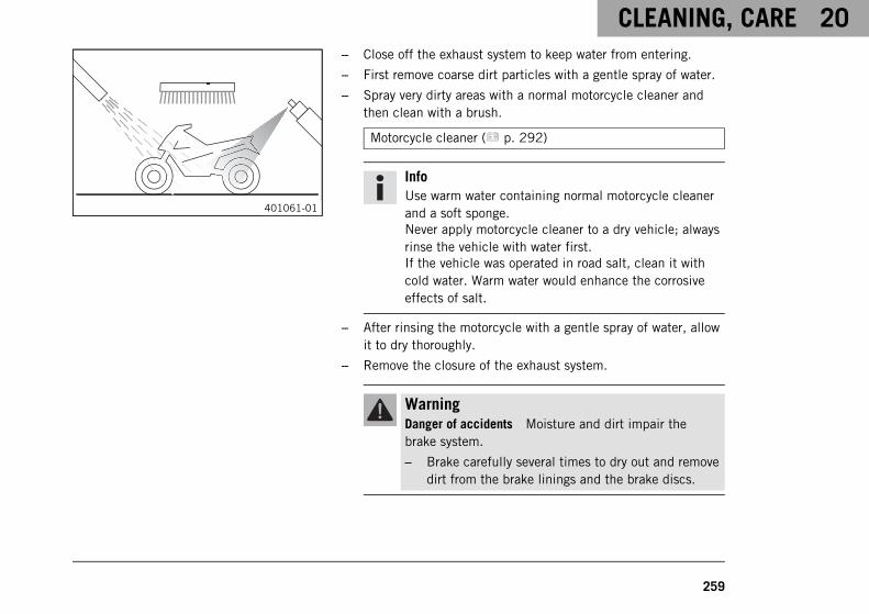
CLEANING, CARE 20
259
401061-01
– Close off the exhaust system to keep water from entering.
– First remove coarse dirt particles with a gentle spray of water.
– Spray very dirty areas with a normal motorcycle cleaner andthen clean with a brush.
Motorcycle cleaner ( p. 292)
InfoUse warm water containing normal motorcycle cleanerand a soft sponge.Never apply motorcycle cleaner to a dry vehicle; alwaysrinse the vehicle with water first.If the vehicle was operated in road salt, clean it withcold water. Warm water would enhance the corrosiveeffects of salt.
– After rinsing the motorcycle with a gentle spray of water, allowit to dry thoroughly.
– Remove the closure of the exhaust system.
WarningDanger of accidents Moisture and dirt impair thebrake system.
– Brake carefully several times to dry out and removedirt from the brake linings and the brake discs.
20 CLEANING, CARE
260
– After cleaning, ride the vehicle a short distance until theengine warms up.
InfoThe heat produced causes water at inaccessible loca-tions in the engine and on the brake system to evapo-rate.
– Push back the protection caps of the handlebar controls toallow any water that has penetrated to evaporate.
– After the motorcycle has cooled off, lubricate all moving partsand bearings.
– Clean the chain. ( p. 134)
– Treat bare metal parts (except for brake discs and exhaust sys-tem) with corrosion inhibitor.
Preserving materials for paints, metal and rubber( p. 292)
– Treat the painted parts with a mild paint polish.
Perfect Finish and high gloss polish for paints ( p. 292)
InfoDo not polish plastic parts that are matte when thevehicle is delivered as this would seriously impair thematerial quality.
CLEANING, CARE 20
261
– Treat the plastic parts and powder-coated parts with a mildcleaning and care product.
Special cleaner for glossy and matte paint finishes, metaland plastic surfaces ( p. 292)
– Oil the ignition/steering lock, tank lock, and seat lock.
Universal oil spray ( p. 292)
20.2 Checks and maintenance steps for winter operation
InfoIf you use the motorcycle in winter, you must expect salt on the roads. You should therefore take precau-tions against aggressive road salt.If the vehicle was operated in road salt, clean it with cold water after riding. Warm water would enhancethe corrosive effects of salt.
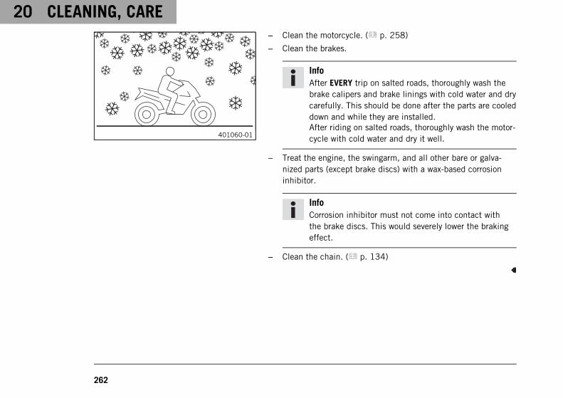
20 CLEANING, CARE
262
401060-01
– Clean the motorcycle. ( p. 258)
– Clean the brakes.
InfoAfter EVERY trip on salted roads, thoroughly wash thebrake calipers and brake linings with cold water and drycarefully. This should be done after the parts are cooleddown and while they are installed.After riding on salted roads, thoroughly wash the motor-cycle with cold water and dry it well.
– Treat the engine, the swingarm, and all other bare or galva-nized parts (except brake discs) with a wax-based corrosioninhibitor.
InfoCorrosion inhibitor must not come into contact withthe brake discs. This would severely lower the brakingeffect.
– Clean the chain. ( p. 134)
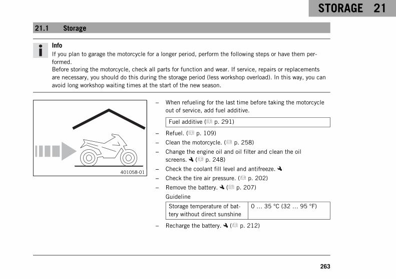
STORAGE 21
263
21.1 Storage
InfoIf you plan to garage the motorcycle for a longer period, perform the following steps or have them per-formed.Before storing the motorcycle, check all parts for function and wear. If service, repairs or replacementsare necessary, you should do this during the storage period (less workshop overload). In this way, you canavoid long workshop waiting times at the start of the new season.
401058-01
– When refueling for the last time before taking the motorcycleout of service, add fuel additive.
Fuel additive ( p. 291)
– Refuel. ( p. 109)
– Clean the motorcycle. ( p. 258)
– Change the engine oil and oil filter and clean the oilscreens. ( p. 248)
– Check the coolant fill level and antifreeze.
– Check the tire air pressure. ( p. 202)
– Remove the battery. ( p. 207)
Guideline
Storage temperature of bat-tery without direct sunshine
0 … 35 °C (32 … 95 °F)
– Recharge the battery. ( p. 212)
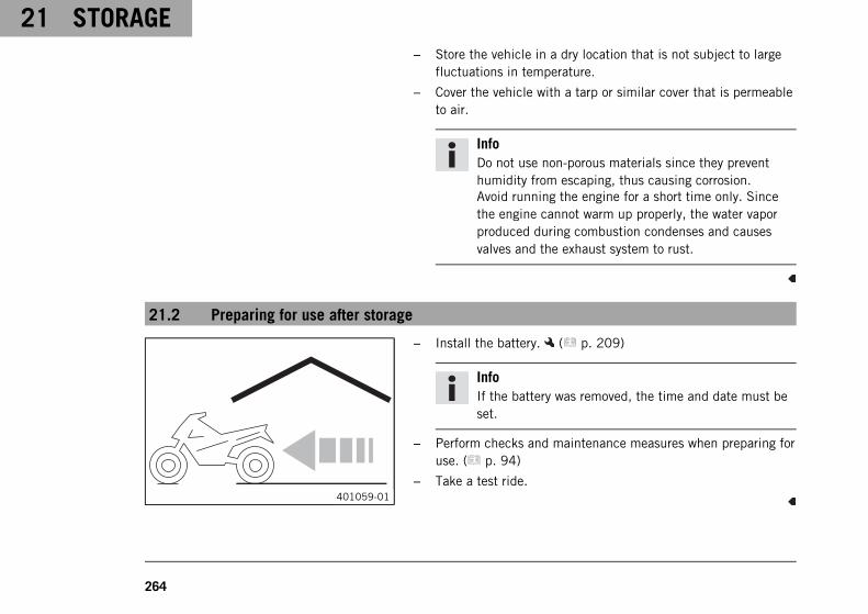
21 STORAGE
264
– Store the vehicle in a dry location that is not subject to largefluctuations in temperature.
– Cover the vehicle with a tarp or similar cover that is permeableto air.
InfoDo not use non-porous materials since they preventhumidity from escaping, thus causing corrosion.Avoid running the engine for a short time only. Sincethe engine cannot warm up properly, the water vaporproduced during combustion condenses and causesvalves and the exhaust system to rust.
21.2 Preparing for use after storage
401059-01
– Install the battery. ( p. 209)
InfoIf the battery was removed, the time and date must beset.
– Perform checks and maintenance measures when preparing foruse. ( p. 94)
– Take a test ride.
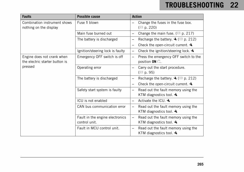
TROUBLESHOOTING 22
265
Faults Possible cause Action
Combination instrument showsnothing on the display
Fuse 1 blown – Change the fuses in the fuse box.( p. 220)
Main fuse burned out – Change the main fuse. ( p. 217)
The battery is discharged – Recharge the battery. ( p. 212)
– Check the open-circuit current.
Ignition/steering lock is faulty – Check the ignition/steering lock.
Engine does not crank whenthe electric starter button ispressed
Emergency OFF switch is off – Press the emergency OFF switch to theposition ON .
Operating error – Carry out the start procedure.( p. 95)
The battery is discharged – Recharge the battery. ( p. 212)
– Check the open-circuit current.
Safety start system is faulty – Read out the fault memory using theKTM diagnostics tool.
ICU is not enabled – Activate the ICU.
CAN bus communication error – Read out the fault memory using theKTM diagnostics tool.
Fault in the engine electronicscontrol unit.
– Read out the fault memory using theKTM diagnostics tool.
Fault in MCU control unit. – Read out the fault memory using theKTM diagnostics tool.
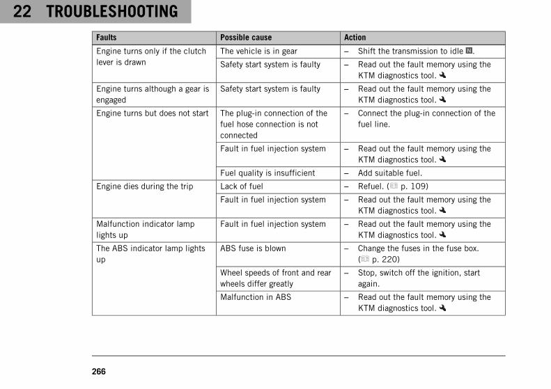
22 TROUBLESHOOTING
266
Faults Possible cause Action
Engine turns only if the clutchlever is drawn
The vehicle is in gear – Shift the transmission to idle .
Safety start system is faulty – Read out the fault memory using theKTM diagnostics tool.
Engine turns although a gear isengaged
Safety start system is faulty – Read out the fault memory using theKTM diagnostics tool.
Engine turns but does not start The plug-in connection of thefuel hose connection is notconnected
– Connect the plug-in connection of thefuel line.
Fault in fuel injection system – Read out the fault memory using theKTM diagnostics tool.
Fuel quality is insufficient – Add suitable fuel.
Engine dies during the trip Lack of fuel – Refuel. ( p. 109)
Fault in fuel injection system – Read out the fault memory using theKTM diagnostics tool.
Malfunction indicator lamplights up
Fault in fuel injection system – Read out the fault memory using theKTM diagnostics tool.
The ABS indicator lamp lightsup
ABS fuse is blown – Change the fuses in the fuse box.( p. 220)
Wheel speeds of front and rearwheels differ greatly
– Stop, switch off the ignition, startagain.
Malfunction in ABS – Read out the fault memory using theKTM diagnostics tool.
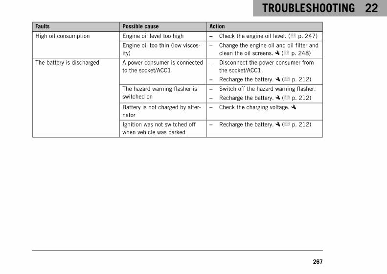
TROUBLESHOOTING 22
267
Faults Possible cause Action
High oil consumption Engine oil level too high – Check the engine oil level. ( p. 247)
Engine oil too thin (low viscos-ity)
– Change the engine oil and oil filter andclean the oil screens. ( p. 248)
The battery is discharged A power consumer is connectedto the socket/ACC1.
– Disconnect the power consumer fromthe socket/ACC1.
– Recharge the battery. ( p. 212)
The hazard warning flasher isswitched on
– Switch off the hazard warning flasher.
– Recharge the battery. ( p. 212)
Battery is not charged by alter-nator
– Check the charging voltage.
Ignition was not switched offwhen vehicle was parked
– Recharge the battery. ( p. 212)
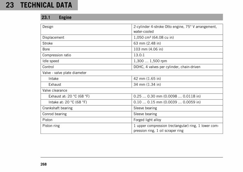
23 TECHNICAL DATA
268
23.1 Engine
Design 2-cylinder 4-stroke Otto engine, 75° V arrangement,water-cooled
Displacement 1,050 cm³ (64.08 cu in)
Stroke 63 mm (2.48 in)
Bore 103 mm (4.06 in)
Compression ratio 13.0:1
Idle speed 1,300 … 1,500 rpm
Control DOHC, 4 valves per cylinder, chain-driven
Valve - valve plate diameter
Intake 42 mm (1.65 in)
Exhaust 34 mm (1.34 in)
Valve clearance
Exhaust at: 20 °C (68 °F) 0.25 … 0.30 mm (0.0098 … 0.0118 in)
Intake at: 20 °C (68 °F) 0.10 … 0.15 mm (0.0039 … 0.0059 in)
Crankshaft bearing Sleeve bearing
Conrod bearing Sleeve bearing
Piston Forged light alloy
Piston ring 1 upper compression (rectangular) ring, 1 lower com-pression ring, 1 oil scraper ring
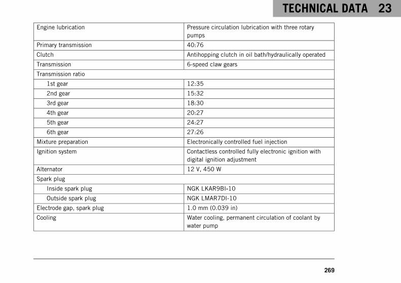
TECHNICAL DATA 23
269
Engine lubrication Pressure circulation lubrication with three rotarypumps
Primary transmission 40:76
Clutch Antihopping clutch in oil bath/hydraulically operated
Transmission 6-speed claw gears
Transmission ratio
1st gear 12:35
2nd gear 15:32
3rd gear 18:30
4th gear 20:27
5th gear 24:27
6th gear 27:26
Mixture preparation Electronically controlled fuel injection
Ignition system Contactless controlled fully electronic ignition withdigital ignition adjustment
Alternator 12 V, 450 W
Spark plug
Inside spark plug NGK LKAR9BI‑10
Outside spark plug NGK LMAR7DI-10
Electrode gap, spark plug 1.0 mm (0.039 in)
Cooling Water cooling, permanent circulation of coolant bywater pump
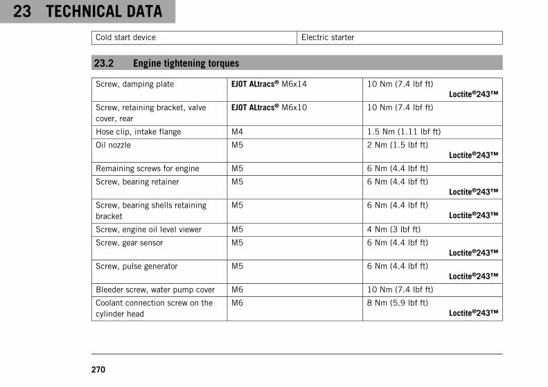
23 TECHNICAL DATA
270
Cold start device Electric starter
23.2 Engine tightening torques
Screw, damping plate EJOT ALtracs® M6x14 10 Nm (7.4 lbf ft)Loctite®243™
Screw, retaining bracket, valvecover, rear
EJOT ALtracs® M6x10 10 Nm (7.4 lbf ft)
Hose clip, intake flange M4 1.5 Nm (1.11 lbf ft)
Oil nozzle M5 2 Nm (1.5 lbf ft)Loctite®243™
Remaining screws for engine M5 6 Nm (4.4 lbf ft)
Screw, bearing retainer M5 6 Nm (4.4 lbf ft)Loctite®243™
Screw, bearing shells retainingbracket
M5 6 Nm (4.4 lbf ft)Loctite®243™
Screw, engine oil level viewer M5 4 Nm (3 lbf ft)
Screw, gear sensor M5 6 Nm (4.4 lbf ft)Loctite®243™
Screw, pulse generator M5 6 Nm (4.4 lbf ft)Loctite®243™
Bleeder screw, water pump cover M6 10 Nm (7.4 lbf ft)
Coolant connection screw on thecylinder head
M6 8 Nm (5.9 lbf ft)Loctite®243™
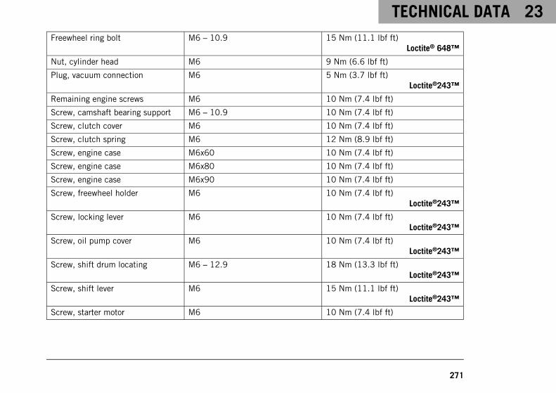
TECHNICAL DATA 23
271
Freewheel ring bolt M6 – 10.9 15 Nm (11.1 lbf ft)Loctite® 648™
Nut, cylinder head M6 9 Nm (6.6 lbf ft)
Plug, vacuum connection M6 5 Nm (3.7 lbf ft)Loctite®243™
Remaining engine screws M6 10 Nm (7.4 lbf ft)
Screw, camshaft bearing support M6 – 10.9 10 Nm (7.4 lbf ft)
Screw, clutch cover M6 10 Nm (7.4 lbf ft)
Screw, clutch spring M6 12 Nm (8.9 lbf ft)
Screw, engine case M6x60 10 Nm (7.4 lbf ft)
Screw, engine case M6x80 10 Nm (7.4 lbf ft)
Screw, engine case M6x90 10 Nm (7.4 lbf ft)
Screw, freewheel holder M6 10 Nm (7.4 lbf ft)Loctite®243™
Screw, locking lever M6 10 Nm (7.4 lbf ft)Loctite®243™
Screw, oil pump cover M6 10 Nm (7.4 lbf ft)Loctite®243™
Screw, shift drum locating M6 – 12.9 18 Nm (13.3 lbf ft)Loctite®243™
Screw, shift lever M6 15 Nm (11.1 lbf ft)Loctite®243™
Screw, starter motor M6 10 Nm (7.4 lbf ft)

23 TECHNICAL DATA
272
Screw, stator M6 10 Nm (7.4 lbf ft)Loctite®243™
Screw, valve cover M6 10 Nm (7.4 lbf ft)
Screw, water pump cover M6 10 Nm (7.4 lbf ft)
Screw, water pump wheel M6 10 Nm (7.4 lbf ft)Loctite®243™
Stud, chain shaft M6 8 Nm (5.9 lbf ft)
Vacuum connection M6 5 Nm (3.7 lbf ft)
Nozzle 100 M6x0.75 4 Nm (3 lbf ft)Loctite®243™
Plug, crankshaft retainer M8 15 Nm (11.1 lbf ft)
Screw, camshaft bearing support M8 – 10.9 Step 110 Nm (7.4 lbf ft)Step 218 Nm (13.3 lbf ft)
Screw, camshaft bearing support M8 – 10.9 Step 18.5 Nm (6.27 lbf ft)Step 214.5 Nm (10.7 lbf ft)Only applies when using:Hexagon socket bit(61229025000)
Screw, engine case Expansion screw M8 18 Nm (13.3 lbf ft)
Screw, heat exchanger M8 15 Nm (11.1 lbf ft)
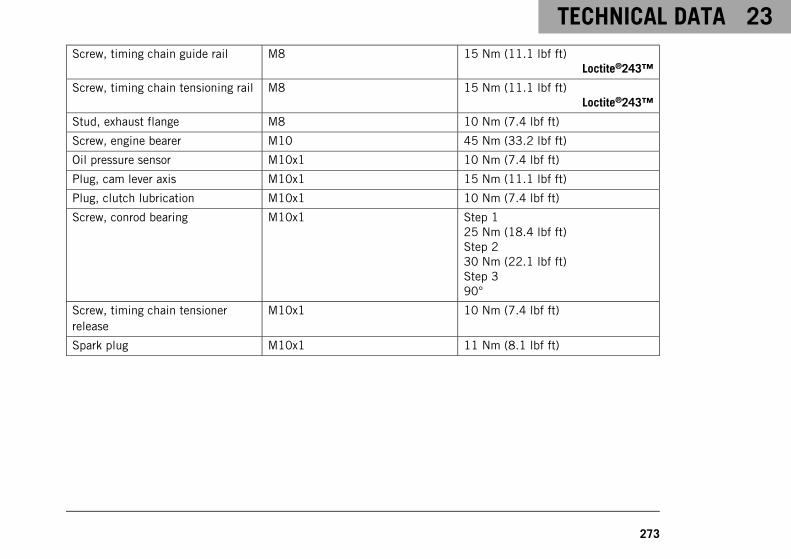
TECHNICAL DATA 23
273
Screw, timing chain guide rail M8 15 Nm (11.1 lbf ft)Loctite®243™
Screw, timing chain tensioning rail M8 15 Nm (11.1 lbf ft)Loctite®243™
Stud, exhaust flange M8 10 Nm (7.4 lbf ft)
Screw, engine bearer M10 45 Nm (33.2 lbf ft)
Oil pressure sensor M10x1 10 Nm (7.4 lbf ft)
Plug, cam lever axis M10x1 15 Nm (11.1 lbf ft)
Plug, clutch lubrication M10x1 10 Nm (7.4 lbf ft)
Screw, conrod bearing M10x1 Step 125 Nm (18.4 lbf ft)Step 230 Nm (22.1 lbf ft)Step 390°
Screw, timing chain tensionerrelease
M10x1 10 Nm (7.4 lbf ft)
Spark plug M10x1 11 Nm (8.1 lbf ft)
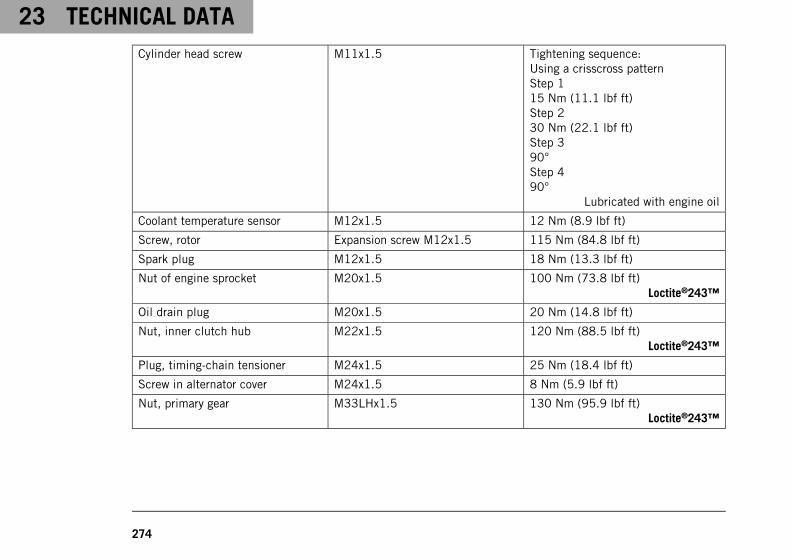
23 TECHNICAL DATA
274
Cylinder head screw M11x1.5 Tightening sequence:Using a crisscross patternStep 115 Nm (11.1 lbf ft)Step 230 Nm (22.1 lbf ft)Step 390°Step 490°
Lubricated with engine oil
Coolant temperature sensor M12x1.5 12 Nm (8.9 lbf ft)
Screw, rotor Expansion screw M12x1.5 115 Nm (84.8 lbf ft)
Spark plug M12x1.5 18 Nm (13.3 lbf ft)
Nut of engine sprocket M20x1.5 100 Nm (73.8 lbf ft)Loctite®243™
Oil drain plug M20x1.5 20 Nm (14.8 lbf ft)
Nut, inner clutch hub M22x1.5 120 Nm (88.5 lbf ft)Loctite®243™
Plug, timing-chain tensioner M24x1.5 25 Nm (18.4 lbf ft)
Screw in alternator cover M24x1.5 8 Nm (5.9 lbf ft)
Nut, primary gear M33LHx1.5 130 Nm (95.9 lbf ft)Loctite®243™
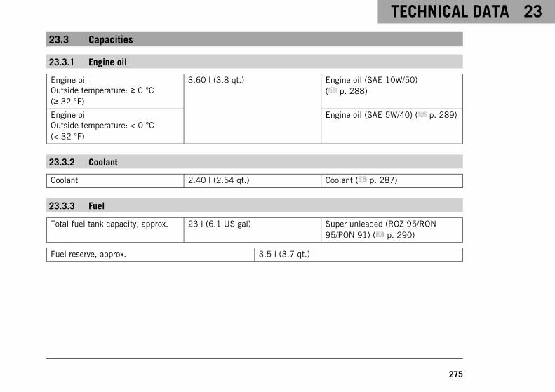
TECHNICAL DATA 23
275
23.3 Capacities
23.3.1 Engine oil
Engine oilOutside temperature: ≥ 0 °C(≥ 32 °F)
3.60 l (3.8 qt.) Engine oil (SAE 10W/50)( p. 288)
Engine oilOutside temperature: < 0 °C(< 32 °F)
Engine oil (SAE 5W/40) ( p. 289)
23.3.2 Coolant
Coolant 2.40 l (2.54 qt.) Coolant ( p. 287)
23.3.3 Fuel
Total fuel tank capacity, approx. 23 l (6.1 US gal) Super unleaded (ROZ 95/RON95/PON 91) ( p. 290)
Fuel reserve, approx. 3.5 l (3.7 qt.)
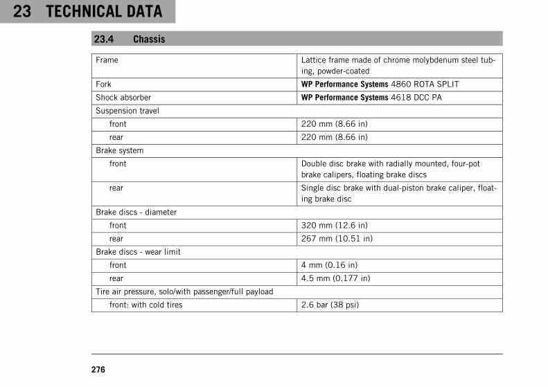
23 TECHNICAL DATA
276
23.4 Chassis
Frame Lattice frame made of chrome molybdenum steel tub-ing, powder-coated
Fork WP Performance Systems 4860 ROTA SPLIT
Shock absorber WP Performance Systems 4618 DCC PA
Suspension travel
front 220 mm (8.66 in)
rear 220 mm (8.66 in)
Brake system
front Double disc brake with radially mounted, four-potbrake calipers, floating brake discs
rear Single disc brake with dual-piston brake caliper, float-ing brake disc
Brake discs - diameter
front 320 mm (12.6 in)
rear 267 mm (10.51 in)
Brake discs - wear limit
front 4 mm (0.16 in)
rear 4.5 mm (0.177 in)
Tire air pressure, solo/with passenger/full payload
front: with cold tires 2.6 bar (38 psi)
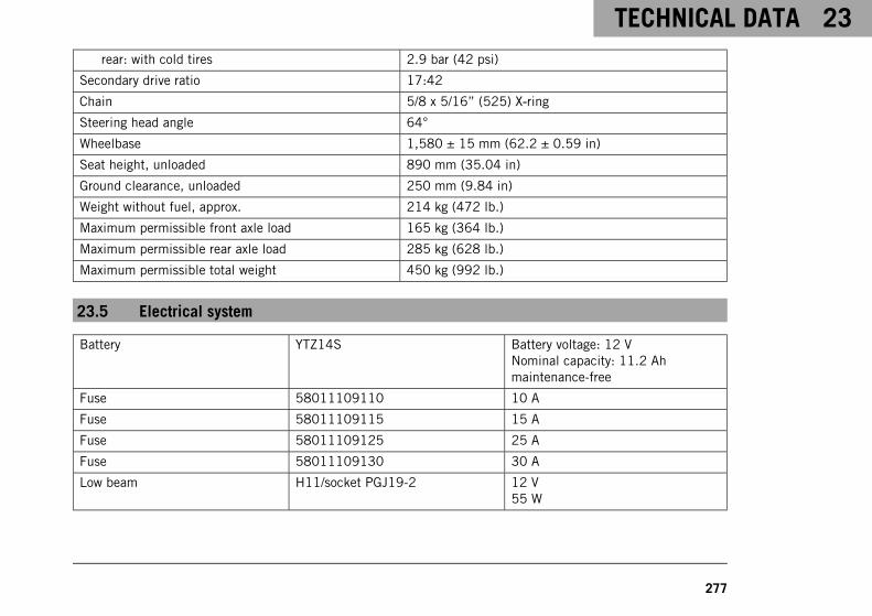
TECHNICAL DATA 23
277
rear: with cold tires 2.9 bar (42 psi)
Secondary drive ratio 17:42
Chain 5/8 x 5/16” (525) X‑ring
Steering head angle 64°
Wheelbase 1,580 ± 15 mm (62.2 ± 0.59 in)
Seat height, unloaded 890 mm (35.04 in)
Ground clearance, unloaded 250 mm (9.84 in)
Weight without fuel, approx. 214 kg (472 lb.)
Maximum permissible front axle load 165 kg (364 lb.)
Maximum permissible rear axle load 285 kg (628 lb.)
Maximum permissible total weight 450 kg (992 lb.)
23.5 Electrical system
Battery YTZ14S Battery voltage: 12 VNominal capacity: 11.2 Ahmaintenance-free
Fuse 58011109110 10 A
Fuse 58011109115 15 A
Fuse 58011109125 25 A
Fuse 58011109130 30 A
Low beam H11/socket PGJ19-2 12 V55 W
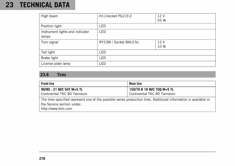
23 TECHNICAL DATA
278
High beam H11/socket PGJ19-2 12 V55 W
Position light LED
Instrument lights and indicatorlamps
LED
Turn signal RY10W / Socket BAU15s 12 V10 W
Tail light LED
Brake light LED
License plate lamp LED
23.6 Tires
Front tire Rear tire
90/90 - 21 M/C 54T M+S TLContinental TKC 80 Twinduro
150/70 B 18 M/C 70Q M+S TLContinental TKC 80 Twinduro
The tires specified represent one of the possible series production tires. Additional information is available inthe Service section under:http://www.ktm.com
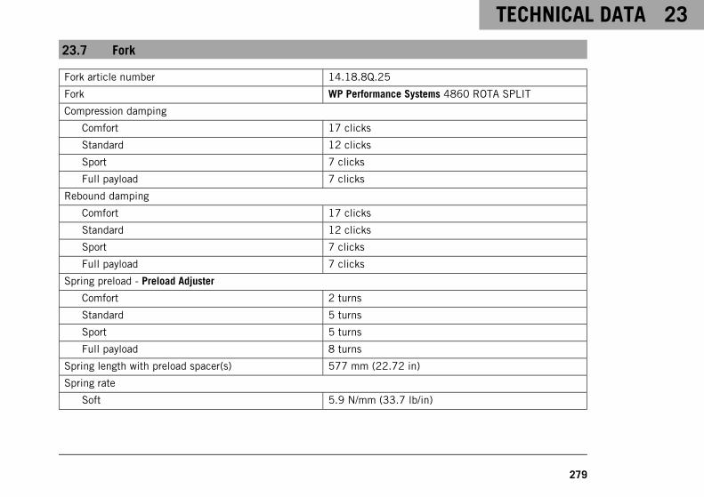
TECHNICAL DATA 23
279
23.7 Fork
Fork article number 14.18.8Q.25
Fork WP Performance Systems 4860 ROTA SPLIT
Compression damping
Comfort 17 clicks
Standard 12 clicks
Sport 7 clicks
Full payload 7 clicks
Rebound damping
Comfort 17 clicks
Standard 12 clicks
Sport 7 clicks
Full payload 7 clicks
Spring preload - Preload Adjuster
Comfort 2 turns
Standard 5 turns
Sport 5 turns
Full payload 8 turns
Spring length with preload spacer(s) 577 mm (22.72 in)
Spring rate
Soft 5.9 N/mm (33.7 lb/in)
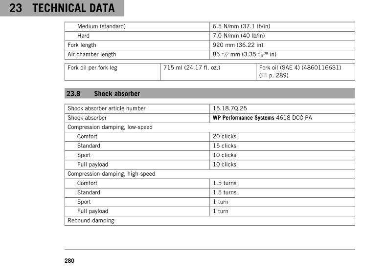
23 TECHNICAL DATA
280
Medium (standard) 6.5 N/mm (37.1 lb/in)
Hard 7.0 N/mm (40 lb/in)
Fork length 920 mm (36.22 in)
Air chamber length 85 + 35− 0 mm (3.35 + 1.38
− 0 in)
Fork oil per fork leg 715 ml (24.17 fl. oz.) Fork oil (SAE 4) (48601166S1)( p. 289)
23.8 Shock absorber
Shock absorber article number 15.18.7Q.25
Shock absorber WP Performance Systems 4618 DCC PA
Compression damping, low-speed
Comfort 20 clicks
Standard 15 clicks
Sport 10 clicks
Full payload 10 clicks
Compression damping, high-speed
Comfort 1.5 turns
Standard 1.5 turns
Sport 1 turn
Full payload 1 turn
Rebound damping
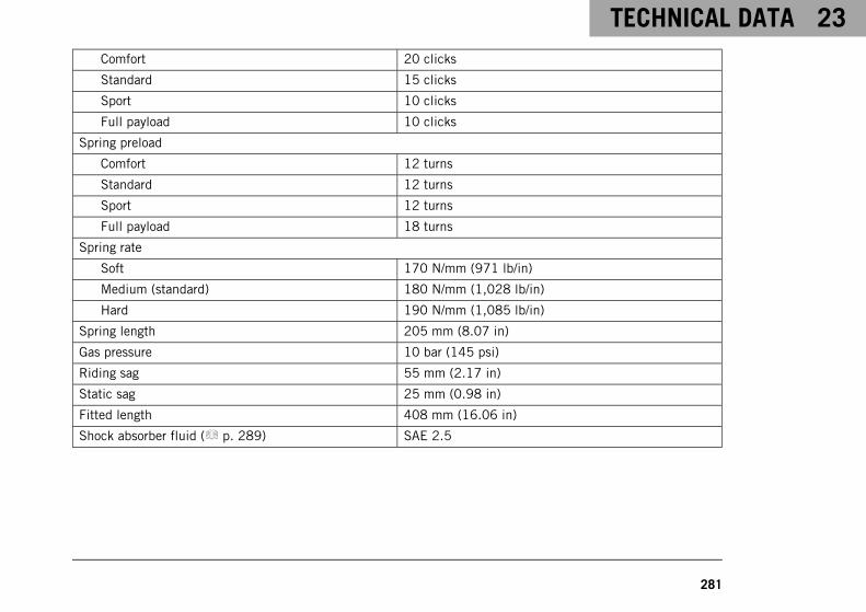
TECHNICAL DATA 23
281
Comfort 20 clicks
Standard 15 clicks
Sport 10 clicks
Full payload 10 clicks
Spring preload
Comfort 12 turns
Standard 12 turns
Sport 12 turns
Full payload 18 turns
Spring rate
Soft 170 N/mm (971 lb/in)
Medium (standard) 180 N/mm (1,028 lb/in)
Hard 190 N/mm (1,085 lb/in)
Spring length 205 mm (8.07 in)
Gas pressure 10 bar (145 psi)
Riding sag 55 mm (2.17 in)
Static sag 25 mm (0.98 in)
Fitted length 408 mm (16.06 in)
Shock absorber fluid ( p. 289) SAE 2.5
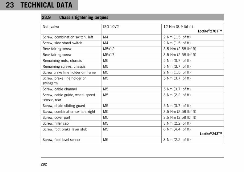
23 TECHNICAL DATA
282
23.9 Chassis tightening torques
Nut, valve ISO 10V2 12 Nm (8.9 lbf ft)Loctite®2701™
Screw, combination switch, left M4 2 Nm (1.5 lbf ft)
Screw, side stand switch M4 2 Nm (1.5 lbf ft)
Rear fairing screw M5x12 3.5 Nm (2.58 lbf ft)
Rear fairing screw M5x17 3.5 Nm (2.58 lbf ft)
Remaining nuts, chassis M5 5 Nm (3.7 lbf ft)
Remaining screws, chassis M5 5 Nm (3.7 lbf ft)
Screw brake line holder on frame M5 2 Nm (1.5 lbf ft)
Screw, brake line holder onswingarm
M5 5 Nm (3.7 lbf ft)
Screw, cable channel M5 5 Nm (3.7 lbf ft)
Screw, cable guide, wheel speedsensor, rear
M5 3 Nm (2.2 lbf ft)
Screw, chain sliding guard M5 5 Nm (3.7 lbf ft)
Screw, combination switch, right M5 3.5 Nm (2.58 lbf ft)
Screw, cover part M5 3.5 Nm (2.58 lbf ft)
Screw, filler cap M5 3 Nm (2.2 lbf ft)
Screw, foot brake lever stub M5 6 Nm (4.4 lbf ft)Loctite®243™
Screw, fuel level sensor M5 3 Nm (2.2 lbf ft)
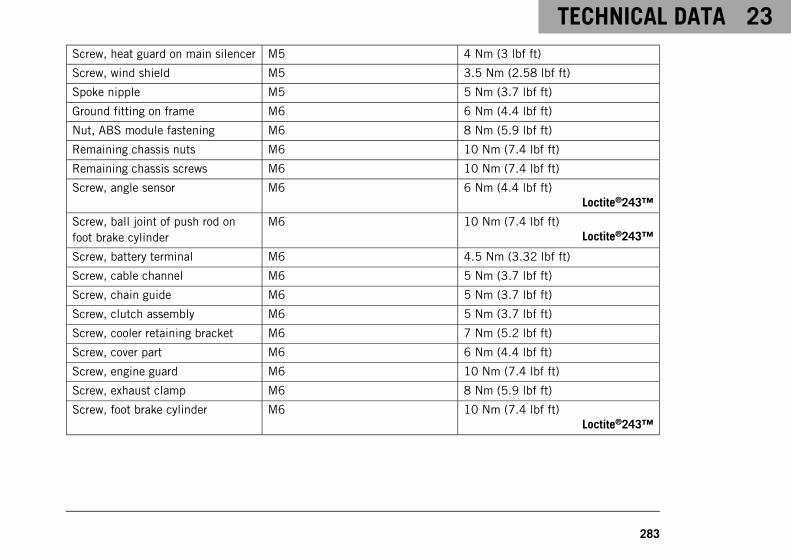
TECHNICAL DATA 23
283
Screw, heat guard on main silencer M5 4 Nm (3 lbf ft)
Screw, wind shield M5 3.5 Nm (2.58 lbf ft)
Spoke nipple M5 5 Nm (3.7 lbf ft)
Ground fitting on frame M6 6 Nm (4.4 lbf ft)
Nut, ABS module fastening M6 8 Nm (5.9 lbf ft)
Remaining chassis nuts M6 10 Nm (7.4 lbf ft)
Remaining chassis screws M6 10 Nm (7.4 lbf ft)
Screw, angle sensor M6 6 Nm (4.4 lbf ft)Loctite®243™
Screw, ball joint of push rod onfoot brake cylinder
M6 10 Nm (7.4 lbf ft)Loctite®243™
Screw, battery terminal M6 4.5 Nm (3.32 lbf ft)
Screw, cable channel M6 5 Nm (3.7 lbf ft)
Screw, chain guide M6 5 Nm (3.7 lbf ft)
Screw, clutch assembly M6 5 Nm (3.7 lbf ft)
Screw, cooler retaining bracket M6 7 Nm (5.2 lbf ft)
Screw, cover part M6 6 Nm (4.4 lbf ft)
Screw, engine guard M6 10 Nm (7.4 lbf ft)
Screw, exhaust clamp M6 8 Nm (5.9 lbf ft)
Screw, foot brake cylinder M6 10 Nm (7.4 lbf ft)Loctite®243™

23 TECHNICAL DATA
284
Screw, front brake disc M6 14 Nm (10.3 lbf ft)Loctite®243™
Screw, front wheel speed sensor M6 10 Nm (7.4 lbf ft)
Screw, fuel pump M6 6 Nm (4.4 lbf ft)
Screw, fuel tank M6 10 Nm (7.4 lbf ft)
Screw, fuel tap M6 6 Nm (4.4 lbf ft)
Screw, headlight M6 5 Nm (3.7 lbf ft)
Screw, lower rear part M6 6 Nm (4.4 lbf ft)
Screw, magnetic holder on sidestand
M6 6 Nm (4.4 lbf ft)Loctite®243™
Screw, rear brake disc M6 14 Nm (10.3 lbf ft)Loctite®243™
Screw, retaining bracket, anglesensor
M6 10 Nm (7.4 lbf ft)Loctite®243™
Screw, voltage regulator M6 6 Nm (4.4 lbf ft)
Screw, wheel speed sensor, rear M6 10 Nm (7.4 lbf ft)
Remaining chassis nuts M8 25 Nm (18.4 lbf ft)
Remaining chassis screws M8 25 Nm (18.4 lbf ft)
Screw, bottom triple clamp M8 12 Nm (8.9 lbf ft)
Screw, exhaust clamp M8 25 Nm (18.4 lbf ft)
Screw, foot brake lever M8 25 Nm (18.4 lbf ft)Loctite®243™
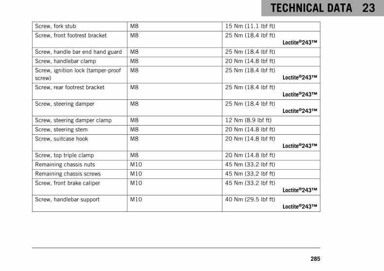
TECHNICAL DATA 23
285
Screw, fork stub M8 15 Nm (11.1 lbf ft)
Screw, front footrest bracket M8 25 Nm (18.4 lbf ft)Loctite®243™
Screw, handle bar end hand guard M8 25 Nm (18.4 lbf ft)
Screw, handlebar clamp M8 20 Nm (14.8 lbf ft)
Screw, ignition lock (tamper-proofscrew)
M8 25 Nm (18.4 lbf ft)Loctite®243™
Screw, rear footrest bracket M8 25 Nm (18.4 lbf ft)Loctite®243™
Screw, steering damper M8 25 Nm (18.4 lbf ft)Loctite®243™
Screw, steering damper clamp M8 12 Nm (8.9 lbf ft)
Screw, steering stem M8 20 Nm (14.8 lbf ft)
Screw, suitcase hook M8 20 Nm (14.8 lbf ft)Loctite®243™
Screw, top triple clamp M8 20 Nm (14.8 lbf ft)
Remaining chassis nuts M10 45 Nm (33.2 lbf ft)
Remaining chassis screws M10 45 Nm (33.2 lbf ft)
Screw, front brake caliper M10 45 Nm (33.2 lbf ft)Loctite®243™
Screw, handlebar support M10 40 Nm (29.5 lbf ft)Loctite®243™
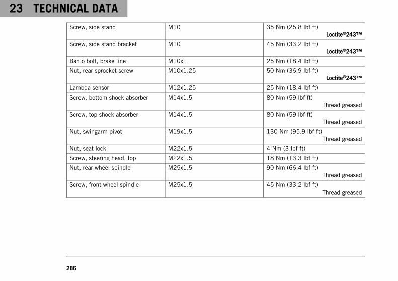
23 TECHNICAL DATA
286
Screw, side stand M10 35 Nm (25.8 lbf ft)Loctite®243™
Screw, side stand bracket M10 45 Nm (33.2 lbf ft)Loctite®243™
Banjo bolt, brake line M10x1 25 Nm (18.4 lbf ft)
Nut, rear sprocket screw M10x1.25 50 Nm (36.9 lbf ft)Loctite®243™
Lambda sensor M12x1.25 25 Nm (18.4 lbf ft)
Screw, bottom shock absorber M14x1.5 80 Nm (59 lbf ft)Thread greased
Screw, top shock absorber M14x1.5 80 Nm (59 lbf ft)Thread greased
Nut, swingarm pivot M19x1.5 130 Nm (95.9 lbf ft)Thread greased
Nut, seat lock M22x1.5 4 Nm (3 lbf ft)
Screw, steering head, top M22x1.5 18 Nm (13.3 lbf ft)
Nut, rear wheel spindle M25x1.5 90 Nm (66.4 lbf ft)Thread greased
Screw, front wheel spindle M25x1.5 45 Nm (33.2 lbf ft)Thread greased
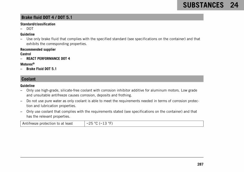
SUBSTANCES 24
287
Brake fluid DOT 4 / DOT 5.1Standard/classification– DOT
Guideline– Use only brake fluid that complies with the specified standard (see specifications on the container) and that
exhibits the corresponding properties.
Recommended supplierCastrol– REACT PERFORMANCE DOT 4
Motorex®
– Brake Fluid DOT 5.1
CoolantGuideline– Only use high-grade, silicate-free coolant with corrosion inhibitor additive for aluminum motors. Low grade
and unsuitable antifreeze causes corrosion, deposits and frothing.
– Do not use pure water as only coolant is able to meet the requirements needed in terms of corrosion protec-tion and lubrication properties.
– Only use coolant that complies with the requirements stated (see specifications on the container) and thathas the relevant properties.
Antifreeze protection to at least −25 °C (−13 °F)
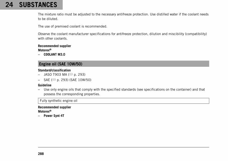
24 SUBSTANCES
288
The mixture ratio must be adjusted to the necessary antifreeze protection. Use distilled water if the coolant needsto be diluted.
The use of premixed coolant is recommended.
Observe the coolant manufacturer specifications for antifreeze protection, dilution and miscibility (compatibility)with other coolants.
Recommended supplierMotorex®
– COOLANT M3.0
Engine oil (SAE 10W/50)Standard/classification– JASO T903 MA ( p. 293)
– SAE ( p. 293) (SAE 10W/50)
Guideline– Use only engine oils that comply with the specified standards (see specifications on the container) and that
possess the corresponding properties.
Fully synthetic engine oil
Recommended supplierMotorex®
– Power Synt 4T
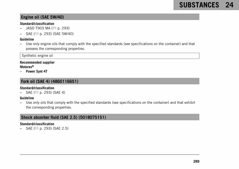
SUBSTANCES 24
289
Engine oil (SAE 5W/40)Standard/classification– JASO T903 MA ( p. 293)
– SAE ( p. 293) (SAE 5W/40)
Guideline– Use only engine oils that comply with the specified standards (see specifications on the container) and that
possess the corresponding properties.
Synthetic engine oil
Recommended supplierMotorex®
– Power Synt 4T
Fork oil (SAE 4) (48601166S1)Standard/classification– SAE ( p. 293) (SAE 4)
Guideline– Use only oils that comply with the specified standards (see specifications on the container) and that exhibit
the corresponding properties.
Shock absorber fluid (SAE 2.5) (50180751S1)Standard/classification– SAE ( p. 293) (SAE 2.5)
24 SUBSTANCES
290
Guideline– Use only oils that comply with the specified standards (see specifications on the container) and that exhibit
the corresponding properties.
Super unleaded (ROZ 95/RON 95/PON 91)Standard/classification– DIN EN 228 (ROZ 95/RON 95/PON 91)
Guideline– Only use unleaded super fuel that matches or is equivalent to the specified fuel grade.
– Fuel with an ethanol content of up to 10 % (E10 fuel) is safe to use.
InfoDo not use fuel containing methanol (e. g. M15, M85, M100) or more than 10 % ethanol (e. g. E15,E25, E85, E100).
AUXILIARY SUBSTANCES 25
291
Chain cleanerRecommended supplierMotorex®
– Chain Clean
Chain lube for road useGuideline
Recommended supplierMotorex®
– Chainlube Road
Fuel additiveRecommended supplierMotorex®
– Fuel Stabilizer
Long-life greaseRecommended supplierMotorex®
– Bike Grease 2000
25 AUXILIARY SUBSTANCES
292
Motorcycle cleanerRecommended supplierMotorex®
– Moto Clean
Perfect Finish and high gloss polish for paintsRecommended supplierMotorex®
– Moto Polish & Shine
Preserving materials for paints, metal and rubberRecommended supplierMotorex®
– Moto Protect
Special cleaner for glossy and matte paint finishes, metal and plastic surfacesRecommended supplierMotorex®
– Quick Cleaner
Universal oil sprayRecommended supplierMotorex®
– Joker 440 Synthetic
STANDARDS 26
293
JASO T903 MADifferent technical development directions required a separate specification for motorcycles – the JASO T903 MAstandard.Earlier, engine oils from the automobile industry were used for motorcycles because there was no separate motor-cycle specification.Whereas long service intervals are demanded for automobile engines, the focus for motorcycle engines is on highperformance at high engine speeds.In most motorcycle engines, the transmission and clutch are lubricated with the same oil.The JASO MA standard meets these special requirements.
SAEThe SAE viscosity classes were defined by the Society of Automotive Engineers and are used for classifying oilsaccording to their viscosity. The viscosity describes only one property of oil and says nothing about quality.
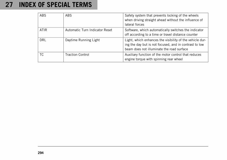
27 INDEX OF SPECIAL TERMS
294
ABS ABS Safety system that prevents locking of the wheelswhen driving straight ahead without the influence oflateral forces
ATIR Automatic Turn Indicator Reset Software, which automatically switches the indicatoroff according to a time or travel distance counter
DRL Daytime Running Light Light, which enhances the visibility of the vehicle dur-ing the day but is not focused, and in contrast to lowbeam does not illuminate the road surface
TC Traction Control Auxiliary function of the motor control that reducesengine torque with spinning rear wheel
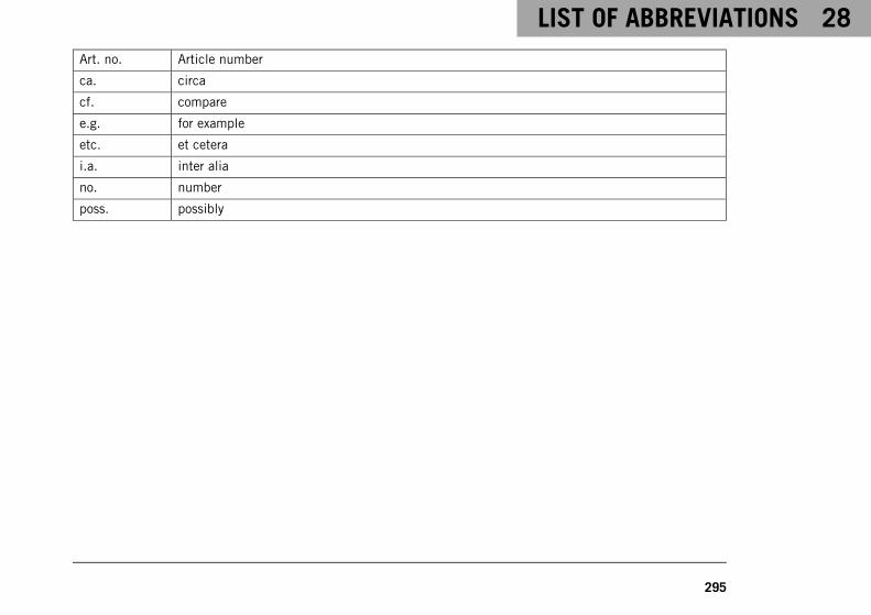
LIST OF ABBREVIATIONS 28
295
Art. no. Article number
ca. circa
cf. compare
e.g. for example
etc. et cetera
i.a. inter alia
no. number
poss. possibly
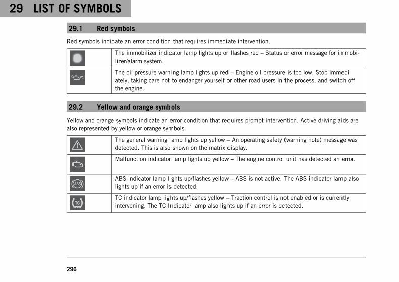
29 LIST OF SYMBOLS
296
29.1 Red symbols
Red symbols indicate an error condition that requires immediate intervention.
The immobilizer indicator lamp lights up or flashes red – Status or error message for immobi-lizer/alarm system.
The oil pressure warning lamp lights up red – Engine oil pressure is too low. Stop immedi-ately, taking care not to endanger yourself or other road users in the process, and switch offthe engine.
29.2 Yellow and orange symbols
Yellow and orange symbols indicate an error condition that requires prompt intervention. Active driving aids arealso represented by yellow or orange symbols.
The general warning lamp lights up yellow – An operating safety (warning note) message wasdetected. This is also shown on the matrix display.
Malfunction indicator lamp lights up yellow – The engine control unit has detected an error.
ABS indicator lamp lights up/flashes yellow – ABS is not active. The ABS indicator lamp alsolights up if an error is detected.
TC indicator lamp lights up/flashes yellow – Traction control is not enabled or is currentlyintervening. The TC Indicator lamp also lights up if an error is detected.
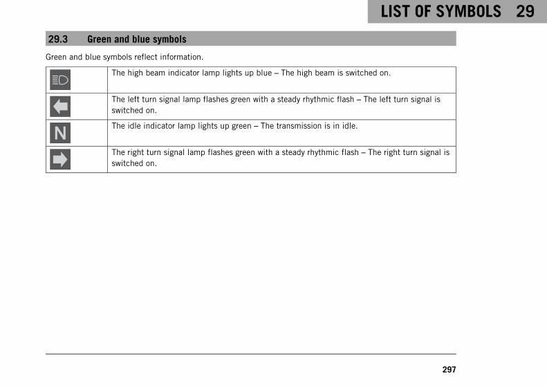
LIST OF SYMBOLS 29
297
29.3 Green and blue symbols
Green and blue symbols reflect information.
The high beam indicator lamp lights up blue – The high beam is switched on.
The left turn signal lamp flashes green with a steady rhythmic flash – The left turn signal isswitched on.
The idle indicator lamp lights up green – The transmission is in idle.
The right turn signal lamp flashes green with a steady rhythmic flash – The right turn signal isswitched on.
INDEX
298
INDEX
A
ABS . . . . . . . . . . . . . . . . . . . . . . . . . . . . . . . 172
ACC1front . . . . . . . . . . . . . . . . . . . . . . . . . . . . 240rear . . . . . . . . . . . . . . . . . . . . . . . . . . . . 240
ACC2front . . . . . . . . . . . . . . . . . . . . . . . . . . . . 240rear . . . . . . . . . . . . . . . . . . . . . . . . . . . . 240
Accessories . . . . . . . . . . . . . . . . . . . . . . . . . . . 18Antilock brake system . . . . . . . . . . . . . . . . . . . 172Auxiliary substances . . . . . . . . . . . . . . . . . . . . . 18
B
Batteryinstalling . . . . . . . . . . . . . . . . . . . . . . . . . 209recharging . . . . . . . . . . . . . . . . . . . . . . . . 212removing . . . . . . . . . . . . . . . . . . . . . . . . . 207
Brake discschecking . . . . . . . . . . . . . . . . . . . . . . . . . 175
Brake fluidfront brake, adding . . . . . . . . . . . . . . . . . . 177rear brake, adding . . . . . . . . . . . . . . . . . . 182
Brake fluid levelfront brake, checking . . . . . . . . . . . . . . . . 176rear brake, checking . . . . . . . . . . . . . . . . . 181
Brake liningsfront brake, checking . . . . . . . . . . . . . . . . 180rear brake, checking . . . . . . . . . . . . . . . . . 185
Brake system . . . . . . . . . . . . . . . . . . . . . . 172-185Brakes . . . . . . . . . . . . . . . . . . . . . . . . . . . . . 103Brakes, applying . . . . . . . . . . . . . . . . . . . . . . . 103
C
Capacitycoolant . . . . . . . . . . . . . . . . . . . . . . . . . . 275engine oil . . . . . . . . . . . . . . . . . . . . 252, 275fuel . . . . . . . . . . . . . . . . . . . . . . . . 111, 275
Case holders . . . . . . . . . . . . . . . . . . . . . . . . . . 47
Chainchecking . . . . . . . . . . . . . . . . . . . . . . . . . 139checking for dirt . . . . . . . . . . . . . . . . . . . . 134cleaning . . . . . . . . . . . . . . . . . . . . . . . . . 134
Chain tensionadjusting . . . . . . . . . . . . . . . . . . . . . . . . . 137checking . . . . . . . . . . . . . . . . . . . . . . . . . 136
Chassis number . . . . . . . . . . . . . . . . . . . . . . . . 26
INDEX
299
Clutchfluid level, checking/correcting . . . . . . . . . . 142
Clutch lever . . . . . . . . . . . . . . . . . . . . . . . . . . . 30basic position, adjusting . . . . . . . . . . . . . . . 80
Combination instrument . . . . . . . . . . . . . . . . 51-75"ABS" . . . . . . . . . . . . . . . . . . . . . . . . . . . . 65activation and test . . . . . . . . . . . . . . . . . . . 51"Clock/Date" . . . . . . . . . . . . . . . . . . . . . . . . 72"Distance" . . . . . . . . . . . . . . . . . . . . . . . . . 70"Drive Mod" . . . . . . . . . . . . . . . . . . . . 66, 245"DRL" . . . . . . . . . . . . . . . . . . . . . . . . . . . . 74"Favorites" . . . . . . . . . . . . . . . . . . . . . . . . . 60"Fuel Cons" . . . . . . . . . . . . . . . . . . . . . . . . . 71"General info" . . . . . . . . . . . . . . . . . . . . . . . 63"Heat Grips" . . . . . . . . . . . . . . . . . . . . . . . . 73"heating" menu . . . . . . . . . . . . . . . . . . . . . . 65indicator lamps . . . . . . . . . . . . . . . . . . . . . 55"Language" . . . . . . . . . . . . . . . . . . . . . . . . . 69matrix display . . . . . . . . . . . . . . . . . . . . . . 53menu overview . . . . . . . . . . . . . . . . . . . . . . 68message on the matrix display . . . . . . . . . . . 57"MTC" . . . . . . . . . . . . . . . . . . . . . . . . . . . . 65overview . . . . . . . . . . . . . . . . . . . . . . . . . . 51"Pressure" . . . . . . . . . . . . . . . . . . . . . . . . . 71segment display . . . . . . . . . . . . . . . . . . . . . 53
service display . . . . . . . . . . . . . . . . . . . . . . 60"Set Favorites" . . . . . . . . . . . . . . . . . . . . . . . 63"Settings" . . . . . . . . . . . . . . . . . . . . . . . . . . 64shift warning light . . . . . . . . . . . . . . . . . . . . 59"Shift Light" . . . . . . . . . . . . . . . . . . . . . . . . 72"Temp" . . . . . . . . . . . . . . . . . . . . . . . . . . . 70"Trip 1" . . . . . . . . . . . . . . . . . . . . . . . . . . . 61"Trip 2" . . . . . . . . . . . . . . . . . . . . . . . . . . . 62"Warning" . . . . . . . . . . . . . . . . . . . . . . . . . 64
Combination switch . . . . . . . . . . . . . . . . . . . . . . 31overview . . . . . . . . . . . . . . . . . . . . . . . . . . 32
Coolant levelcompensating tank, checking . . . . . . . . . . . 241compensating tank, correcting . . . . . . . . . . 243
Crash barinstalling . . . . . . . . . . . . . . . . . . . . . . . . . 168removing . . . . . . . . . . . . . . . . . . . . . . . . . 166
Customer service . . . . . . . . . . . . . . . . . . . . . . . 19
D
Diagnostics connector . . . . . . . . . . . . . . . . . . . 239Driving . . . . . . . . . . . . . . . . . . . . . . . . . . . . . . 98
E
Electric starter button . . . . . . . . . . . . . . . . . . . . 36
INDEX
300
Emergency OFF switch . . . . . . . . . . . . . . . . . . . . 36
Enginerunning in . . . . . . . . . . . . . . . . . . . . . . . . . 91
Engine guardinstalling . . . . . . . . . . . . . . . . . . . . . . . . . 165removing . . . . . . . . . . . . . . . . . . . . . . . . . 165
Engine number . . . . . . . . . . . . . . . . . . . . . . . . . 28
Engine oiladding . . . . . . . . . . . . . . . . . . . . . . . . . . 255changing . . . . . . . . . . . . . . . . . . . . . . . . . 248
Engine oil levelchecking . . . . . . . . . . . . . . . . . . . . . . . . . 247
Engine sprocketchecking . . . . . . . . . . . . . . . . . . . . . . . . . 139
Environment . . . . . . . . . . . . . . . . . . . . . . . . . . . 17
F
Figures . . . . . . . . . . . . . . . . . . . . . . . . . . . . . . 19
Filler capclosing . . . . . . . . . . . . . . . . . . . . . . . . . . . 42opening . . . . . . . . . . . . . . . . . . . . . . . . . . . 40
Foot brake lever . . . . . . . . . . . . . . . . . . . . . . . . 49basic position, adjusting . . . . . . . . . . . . . . . 88
Footrestsadjusting . . . . . . . . . . . . . . . . . . . . . . . . . . 82
Fork . . . . . . . . . . . . . . . . . . . . . . . . . . . . . . . 116compression damping, adjusting . . . . . . . . . 116dust boots, cleaning . . . . . . . . . . . . . . . . . 158rebound, adjusting . . . . . . . . . . . . . . . . . . 118spring pretension, adjusting . . . . . . . . . . . . 119
Fork part number . . . . . . . . . . . . . . . . . . . . . . . 28
Front fenderinstalling . . . . . . . . . . . . . . . . . . . . . . . . . 157removing . . . . . . . . . . . . . . . . . . . . . . . . . 157
Front side coverinstalling . . . . . . . . . . . . . . . . . . . . . . . . . 149removing . . . . . . . . . . . . . . . . . . . . . . . . . 148
Front wheelinstalling . . . . . . . . . . . . . . . . . . . . . . . . . 188removing . . . . . . . . . . . . . . . . . . . . . . . . . 186
Fuel cocks . . . . . . . . . . . . . . . . . . . . . . . . . . . 44Fuel level display . . . . . . . . . . . . . . . . . . . . . . . 54
Fusesin fuse box, changing . . . . . . . . . . . . . . . . 220
G
Grab handles . . . . . . . . . . . . . . . . . . . . . . . . . . 46
INDEX
301
H
Hand brake lever . . . . . . . . . . . . . . . . . . . . . . . 30basic position, adjusting . . . . . . . . . . . . . . . 81
Handlebar position . . . . . . . . . . . . . . . . . . . . . . 76adjusting . . . . . . . . . . . . . . . . . . . . . . . . . . 76
Hazard warning flasher . . . . . . . . . . . . . . . . . . . 33Hazard warning flasher switch . . . . . . . . . . . . . . . 33
Headlightdaytime running light . . . . . . . . . . . . . . . . 206headlight range, adjusting . . . . . . . . . . . . . 232
Headlight mask with headlightinstalling . . . . . . . . . . . . . . . . . . . . . . . . . 224removing . . . . . . . . . . . . . . . . . . . . . . . . . 223
Headlight settingchecking . . . . . . . . . . . . . . . . . . . . . . . . . 231
High beam bulbchanging . . . . . . . . . . . . . . . . . . . . . . . . . 228
Horn button . . . . . . . . . . . . . . . . . . . . . . . . . . . 35
I
Ignition keyactivating/deactivating . . . . . . . . . . . . . . . . 233
Ignition lock . . . . . . . . . . . . . . . . . . . . . . . . . . 37
Immobilizer . . . . . . . . . . . . . . . . . . . . . . . . . . . 38Intended use . . . . . . . . . . . . . . . . . . . . . . . . . . 12
K
Key number . . . . . . . . . . . . . . . . . . . . . . . . . . . 27
L
Light switch . . . . . . . . . . . . . . . . . . . . . . . . . . . 32
Low beam bulbchanging . . . . . . . . . . . . . . . . . . . . . . . . . 226
Luggage . . . . . . . . . . . . . . . . . . . . . . . . . . . . . 91Luggage rack plate . . . . . . . . . . . . . . . . . . . . . . 46
M
Main fusechanging . . . . . . . . . . . . . . . . . . . . . . . . . 217
Mask spoilerinstalling . . . . . . . . . . . . . . . . . . . . . . . . . 154removing . . . . . . . . . . . . . . . . . . . . . . . . . 150
Matrix displaymenu . . . . . . . . . . . . . . . . . . . . . . . . . . . . 60
Misuse . . . . . . . . . . . . . . . . . . . . . . . . . . . . . . 12
Motorcyclecleaning . . . . . . . . . . . . . . . . . . . . . . . . . 258lifting with front lifting gear . . . . . . . . . . . . 127
INDEX
302
raising with the rear lifting gear . . . . . . . . . 126raising with work stand (inserted) . . . . . . . . 129removing from the work stand (inserted) . . . 131removing the rear from the lifting gear . . . . . 126taking off front lifting gear . . . . . . . . . . . . . 128
O
Oil filterchanging . . . . . . . . . . . . . . . . . . . . . . . . . 248
Oil screenscleaning . . . . . . . . . . . . . . . . . . . . . . . . . 248
Operating substances . . . . . . . . . . . . . . . . . . . . . 18Owner's Manual . . . . . . . . . . . . . . . . . . . . . . . . 17
P
Parking . . . . . . . . . . . . . . . . . . . . . . . . . . . . 106Passenger footrest . . . . . . . . . . . . . . . . . . . . . . 48
Preparing for useadvice on preparing for first use . . . . . . . . . . 89after storage . . . . . . . . . . . . . . . . . . . . . . 264checks and maintenance measures whenpreparing for use . . . . . . . . . . . . . . . . . . . . 94
Protective clothing . . . . . . . . . . . . . . . . . . . . . . 16
R
Rear hub rubber damperschecking . . . . . . . . . . . . . . . . . . . . . . . . . 198
Rear sprocketchecking . . . . . . . . . . . . . . . . . . . . . . . . . 139
Rear wheelinstalling . . . . . . . . . . . . . . . . . . . . . . . . . 195removing . . . . . . . . . . . . . . . . . . . . . . . . . 192
Refuelingfuel . . . . . . . . . . . . . . . . . . . . . . . . . . . . 109
Rider footrests . . . . . . . . . . . . . . . . . . . . . . . . . 81
Ridingstarting off . . . . . . . . . . . . . . . . . . . . . . . . 97
S
Safe operation . . . . . . . . . . . . . . . . . . . . . . . . . 14
Seatmounting . . . . . . . . . . . . . . . . . . . . . . . . 133removing . . . . . . . . . . . . . . . . . . . . . . . . . 133
Seat lock . . . . . . . . . . . . . . . . . . . . . . . . . . . . 45Service . . . . . . . . . . . . . . . . . . . . . . . . . . . . . . 19Service schedule . . . . . . . . . . . . . . . . . . . 112-115
INDEX
303
Shift lever . . . . . . . . . . . . . . . . . . . . . . . . . . . . 48basic position, adjusting . . . . . . . . . . . . . . . 86basic position, checking . . . . . . . . . . . . . . . 85
Shifting . . . . . . . . . . . . . . . . . . . . . . . . . . . . . 98
Shock absorber . . . . . . . . . . . . . . . . . . . . . . . 116compression damping . . . . . . . . . . . . . . . . 120high-speed compression damping, adjusting . 122low-speed compression damping, adjusting . 121rebound damping, adjusting . . . . . . . . . . . . 124spring pretension, adjusting . . . . . . . . . . . . 125
Shock absorber article number . . . . . . . . . . . . . . 29Side stand . . . . . . . . . . . . . . . . . . . . . . . . . . . . 50Spare parts . . . . . . . . . . . . . . . . . . . . . . . . . . . 18
Spoke tensionchecking . . . . . . . . . . . . . . . . . . . . . . . . . 203
Starting . . . . . . . . . . . . . . . . . . . . . . . . . . . . . 95
Steeringlocking . . . . . . . . . . . . . . . . . . . . . . . . . . . 39unlocking . . . . . . . . . . . . . . . . . . . . . . . . . 40
Steering head bearing playchecking . . . . . . . . . . . . . . . . . . . . . . . . . 144
Steering lock . . . . . . . . . . . . . . . . . . . . . . . . . . 37Stopping . . . . . . . . . . . . . . . . . . . . . . . . . . . . 106
Storage . . . . . . . . . . . . . . . . . . . . . . . . . . . . 263
Storage compartmentclosing . . . . . . . . . . . . . . . . . . . . . . . . . . . 45opening . . . . . . . . . . . . . . . . . . . . . . . . . . . 44
Suspension setting . . . . . . . . . . . . . . . . . . 116-125
Switchon the left side of the handlebar . . . . . . . . . . 31on the right side of the handlebar . . . . . . . . . 36
T
Tank coverinstalling . . . . . . . . . . . . . . . . . . . . . . . . . 162removing . . . . . . . . . . . . . . . . . . . . . . . . . 160
TC . . . . . . . . . . . . . . . . . . . . . . . . . . . . . . . . 246
Technical datacapacities . . . . . . . . . . . . . . . . . . . . . . . . 275chassis . . . . . . . . . . . . . . . . . . . . . . . . . . 276chassis tightening torques . . . . . . . . . . . . . 282electrical system . . . . . . . . . . . . . . . . . . . 277engine . . . . . . . . . . . . . . . . . . . . . . . 268-286engine tightening torques . . . . . . . . . . . . . 270fork . . . . . . . . . . . . . . . . . . . . . . . . . . . . 279shock absorber . . . . . . . . . . . . . . . . . . . . . 280tires . . . . . . . . . . . . . . . . . . . . . . . . . . . . 278
INDEX
304
Throttle grip . . . . . . . . . . . . . . . . . . . . . . . . . . . 31
Tire air pressurechecking . . . . . . . . . . . . . . . . . . . . . . . . . 202
Tire conditionchecking . . . . . . . . . . . . . . . . . . . . . . . . . 200
Traction control . . . . . . . . . . . . . . . . . . . . . . . 246Transporting . . . . . . . . . . . . . . . . . . . . . . . . . 108
Triple clamp cover, bottominstalling . . . . . . . . . . . . . . . . . . . . . . . . . 147removing . . . . . . . . . . . . . . . . . . . . . . . . . 146
Troubleshooting . . . . . . . . . . . . . . . . . . . . 265-267Tubeless tire system . . . . . . . . . . . . . . . . . . . . 205
Turn signal bulbchanging . . . . . . . . . . . . . . . . . . . . . . . . . 230
Turn signal switch . . . . . . . . . . . . . . . . . . . . . . . 34Type label . . . . . . . . . . . . . . . . . . . . . . . . . . . . 26
U
Use definition . . . . . . . . . . . . . . . . . . . . . . . . . 12
V
Vehicleloading . . . . . . . . . . . . . . . . . . . . . . . . . . . 91
View of vehiclefront left . . . . . . . . . . . . . . . . . . . . . . . . . . 22rear right . . . . . . . . . . . . . . . . . . . . . . . . . . 24
W
Warranty . . . . . . . . . . . . . . . . . . . . . . . . . . . . . 18
Wind shieldadjusting . . . . . . . . . . . . . . . . . . . . . . . . . . 78installing . . . . . . . . . . . . . . . . . . . . . . . . . 164removing . . . . . . . . . . . . . . . . . . . . . . . . . 164
Winter operationchecks and maintenance steps . . . . . . . . . . 261
Work rules . . . . . . . . . . . . . . . . . . . . . . . . . . . 16

*3213756en*3213756en
10/2017
KTM Sportmotorcycle GmbH5230 Mattighofen/Austriahttp://www.ktm.com
Photo: Mitterbauer/KTM