Supramolecular Organization of Heteroxylan-Dehydrogenation Polymers (Synthetic Lignin) Nanoparticles
Journal of Catalysis 289 (2012) 266–271
Contents lists available at SciVerse ScienceDirect
Journal of Catalysis
journal homepage: www.elsevier .com/locate / jcat
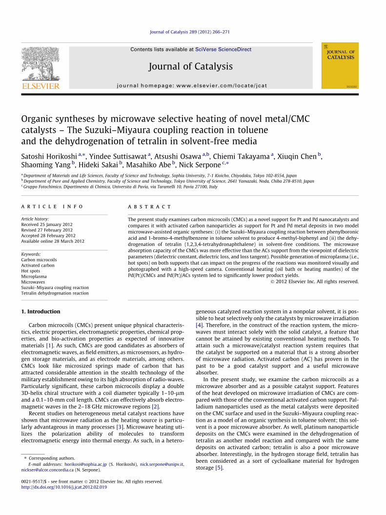
Organic syntheses by microwave selective heating of novel metal/CMCcatalysts – The Suzuki–Miyaura coupling reaction in tolueneand the dehydrogenation of tetralin in solvent-free media
Satoshi Horikoshi a,⇑, Yindee Suttisawat a, Atsushi Osawa a,b, Chiemi Takayama a, Xiuqin Chen b,Shaoming Yang b, Hideki Sakai b, Masahiko Abe b, Nick Serpone c,⇑a Department of Materials and Life Sciences, Faculty of Science and Technology, Sophia University, 7-1 Kioicho, Chiyodaku, Tokyo 102-8554, Japanb Department of Pure and Applied Chemistry, Faculty of Science and Technology, Tokyo University of Science, 2641 Yamazaki, Noda, Chiba 278-8510, Japanc Gruppo Fotochimico, Dipartimento di Chimica, Universita di Pavia, via Taramelli 10, Pavia 27100, Italy
a r t i c l e i n f o
Article history:Received 25 January 2012Revised 27 February 2012Accepted 28 February 2012Available online 28 March 2012
Keywords:Carbon microcoilsActivated carbonHot spotsMicroplasmaMicrowavesSuzuki–Miyaura coupling reactionTetralin dehydrogenation reaction
0021-9517/$ - see front matter � 2012 Elsevier Inc. Ahttp://dx.doi.org/10.1016/j.jcat.2012.02.019
⇑ Corresponding authors.E-mail addresses: [email protected] (S. Horik
[email protected] (N. Serpone).
a b s t r a c t
The present study examines carbon microcoils (CMCs) as a novel support for Pt and Pd nanocatalysts andcompares it with activated carbon nanoparticles as support for Pt and Pd metal deposits in two modelmicrowave-assisted organic syntheses: (i) the Suzuki–Miyaura coupling reaction between phenylboronicacid and 1-bromo-4-methylbenzene in toluene solvent to produce 4-methyl-biphenyl and (ii) the dehy-drogenation of tetralin (1,2,3,4-tetrahydronaphthalene) in solvent-free conditions. The microwaveabsorption capacity of the CMCs was more effective than the ACs support from the viewpoint of dielectricparameters (dielectric constant, dielectric loss, and loss tangent). Possible generation of microplasma (i.e.,hot spots) on both supports that can impact on the progress of the reactions was monitored visually andphotographed with a high-speed camera. Conventional heating (oil bath or heating mantles) of thePd(Pt)/CMCs and Pd(Pt)/ACs system led to significantly lower product yields.
� 2012 Elsevier Inc. All rights reserved.
1. Introduction geneous catalyzed reaction system in a nonpolar solvent, it is pos-
Carbon microcoils (CMCs) present unique physical characteris-tics, electric properties, electromagnetic properties, chemical prop-erties, and bio-activation properties as expected of innovativematerials [1]. As such, CMCs are good candidates as absorbers ofelectromagnetic waves, as field emitters, as microsensors, as hydro-gen storage materials, and as electrode materials, among others.CMCs look like microsized springs made of carbon that hasattracted considerable attention in the stealth technology of themilitary establishment owing to its high absorption of radio-waves.Particularly significant, these carbon microcoils display a double3D-helix chiral structure with a coil diameter typically 1–10-lmand a 0.1–10-mm coil length. CMCs can effectively absorb electro-magnetic waves in the 2–18 GHz microwave regions [2].
Recent studies on heterogeneous metal catalyst reactions haveshown that microwave radiation as the heating source is particu-larly advantageous in many processes [3]. Microwave heating uti-lizes the polarization ability of molecules to transformelectromagnetic energy into thermal energy. As such, in a hetero-
ll rights reserved.
oshi), [email protected],
sible to heat selectively only the catalysts by microwave irradiation[4]. Therefore, in the construct of the reaction system, the micro-waves must interact solely with the solid catalyst, a feature thatcannot be attained by existing conventional heating methods. Toattain such a microwave/catalyst reaction system requires thatthe catalyst be supported on a material that is a strong absorberof microwave radiation. Activated carbon (AC) has proven in thepast to be a good catalyst support and a useful microwaveabsorber.
In the present study, we examine the carbon microcoils as amicrowave absorber and as a possible catalyst support. Featuresof the heat developed on microwave irradiation of CMCs are com-pared with those of the conventional activated carbon support. Pal-ladium nanoparticles used as the metal catalysts were depositedon the CMC surface and used in the Suzuki–Miyaura coupling reac-tion as a model of an organic synthesis in toluene solvent; this sol-vent is a poor microwave absorber. As well, platinum nanoparticledeposits on the CMCs were examined in the dehydrogenation oftetralin as another model reaction and compared with the samedeposits on activated carbon; tetralin is also a poor microwaveabsorber. Interestingly, in the hydrogen storage field, tetralin hasbeen considered as a sort of cycloalkane material for hydrogenstorage [5].

S. Horikoshi et al. / Journal of Catalysis 289 (2012) 266–271 267
2. Experimental section
2.1. Preparation of metal deposits on carbon microcoils
A sample of carbon microcoils was a gift from Dr. Motojima ofthe Toyota Physical and Chemical Research Institute. CMCs wereprepared by a thermal chemical vapor deposition (CVD) methodat a temperature of 770 �C using Ni powder as the catalyst placedon a graphite substrate setting within a horizontal quartz reactiontube into which a gas mixture consisting of C2H2, H2, H2S, and N2
was introduced that ultimately led to the growth of the carbonmicrocoils [6]. Granular activated carbon particles of ca.0.95 mm in size were used for comparison with the CMCs. Theparticle size of the ACs was greater than the size of the CMCs(see Fig. 2 for the size of CMCs). BET measurements (Bel Japan,Micrometrics Tristar surface analyzer) revealed that the activatedcarbon sample had a specific surface area (ca. 1095 m2 g�1) nearlyfivefold greater than the surface area of the as-prepared CMCs (ca.231 m2 g�1).
In the case where the Pd/CMCs catalyst was used in the reac-tions, the surface of the CMCs (1 g) was washed in an aqueousHNO3 solution (10 M, 100 mL) with stirring for 3 h at an 80 �Ctemperature. Note that CMCs were synthesized using nickel asthe catalyst, such that the initial CMCs contained 1.2% nickel thatupon washing with the HNO3 solution fell to 0.095% Ni content.The microcoils were subsequently washed further with ultrapurewater and quantities of NaOH (2 M, 50 mL) for 24 h under roomtemperature conditions, after which the CMCs were washed onceagain with ultrapure water and dried for a few hours at 100 �C.The so-washed CMCs (1 g) were introduced into an aqueous PdCl2
B(OH)2 Br
K2CO 3
Pd/CMCtoluene, ΔCH3 CH3
1-Bromo-4-methyl-benzenePhenylboronic acid 4-Methyl-biphenyl
ð1Þ
(0.034 g) and HCl (1 M) solution (50 mL), following which thesolution was brought to pH 14 by addition of NaOH. Subse-quently, NaBH4 (0.016 M) was added to the solution and stirredfor 3 h; stirring was then continued for an additional 2 h at60 �C. Finally, the colloidal Pd/CMC solids in the solution were fil-tered, washed with ultrapure water, and then dried at 100 �Covernight. In the preparation of Pt/CMCs, the aqueous 50 mL solu-tion contained H2PtCl6�H2O. The quantity of Pd deposited on theCMC and on the AC was ca. 0.7 and 1.5 wt.%, respectively,ascertained by atomic emission spectroscopy using the ShimadzuICPE-9000 apparatus.
Three-stub tunerIris
Power monitor
Short plunger
MW
MW generator
IsolatorCondenser
Optical fiber thermometer
TE103 mode
Fig. 1. Details of the experimental setup and position of the reaction samples in thesingle-mode microwave resonator. Sample set at the maximal E field position.
2.2. Chemical model reactions and microwave apparatus
2.2.1. Suzuki–Miyaura coupling reactionThe synthesis of 4-methylbiphenyl by the Suzuki–Miyaura
coupling reaction was carried out by a procedure similar to theone given earlier [7]. The Pd/CMCs and Pd/ACs catalyst(150 mg), phenylboronic acid (0.80 mmol; 0.0975 g), 1-bromo-4-methylbenzene (0.60 mmol; 0.1026 g), K2CO3 as the base(1.2 mmol; 0.165 g), and the nonpolar toluene solvent (5 mL)were mixed and subsequently added under an Ar atmosphere to
a quartz cylindrical reactor (height, 24 mm; diameter, 16 mm).Since the dielectric loss factor of toluene (e00 = 0.07) is significantlysmaller than that of pure distilled water (e00 = 9.4), so that bycomparison, toluene solvent was not heated by the microwaveradiation. Nonetheless, microwaving the toluene solution in theabsence of the catalyst led to a 7 �C increase in temperature after30 min of irradiation. Therefore, this reactive system can be takenas a solvent-free system from the viewpoint of absorption ofmicrowave radiation. A condenser was connected to the micro-wave cylindrical reactor. Reaction yields of 4-methylbiphenyl(reaction (1)) were determined by gas chromatographic analyses(Shimadzu model 2014 equipped with Ultra alloy-1 capillarycolumns) from samples appropriately prepared from the variousdispersions; a sample of 4-methylbiphenyl was used as the cali-bration standard (Wako Pure Chemical Industries, Ltd., 100% GCstandard).Tetralin dehydrogenation: The dehydrogenation of tetralin(1,2,3,4-tetrahydronaphthalene; reaction (2)) was carried out bya procedure similar to the one given earlier [8]. Accordingly, thePt/CMCs powder (150 mg) and a pure tetralin sample (5 mL) wereintroduced, under an Ar atmosphere, into a quartz cylindricalreactor (height, 24 mm; diameter, 16 mm). Note that since thedielectric loss factor of tetralin (e00) is 0.12, it too is a poor micro-wave absorber when compared to water. Microwave irradiationof the tetralin system in the absence of the Pt/CMCs catalyst in-creased the temperature by only 33 �C after a 30-min period.The extent of tetralin conversion was also determined by gaschromatography using a Shimadzu Model 2014 Chromatographequipped with a Zebron ZB-624 column.
Pt/CMC+ 4H2
(Tetralin)1,2,3,4-Tetrahydro-naphthalene Naphthalene
ð2Þ
0
20
40
60
80
100
120
0 100 200
Tem
pera
ture
(ºC
)
Irradation time (sec)
Pd/CMCs
Pd/AC(0.6mm)
Pd/ACs(0.95mm)
Fig. 3. Temperature–time profiles in the heating microwave heating of a toluenesolution (5 mL) containing dispersed Pd/CMCs and Pd/ACs (150 mg; 0.6 mm and0.95 mm diameter) under continuous microwave irradiation at a 50-W microwaveinput power.
0
10
20
30
40
0 50 100 150
Prod
uct y
ield
of M
B (%
)
Irradiation time (min)
Fig. 4. Product yields of 4-methylbiphenyl (MB) at 110 �C in toluene solvent undermicrowaves heating (MW) and conventional oil bath heating (CH). Closed circle, Pd/CMC-MW; open circle, Pd/CMC-CH; solid triangle, Pd/AC-MW; open triangle, Pd/AC-CH.
30μm
(a)
50nm
Pt
(b)
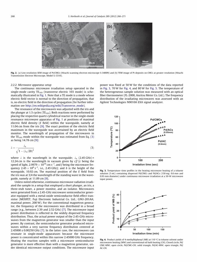
Fig. 2. (a) Low-resolution SEM image of Pt/CMCs (Hitachi scanning electron microscope S-3400N) and (b) TEM image of Pt deposits on CMCs at greater resolution (HitachiTransmission Electron Microscope, Model U-3310).
268 S. Horikoshi et al. / Journal of Catalysis 289 (2012) 266–271
2.2.2. Microwave apparatus setupThe continuous microwave irradiation setup operated in the
single-mode cavity TE103 (transverse electric 103 mode) is sche-matically illustrated in Fig. 1. Note that a TE mode is a mode whoseelectric field vector is normal to the direction of propagation, thatis, no electric field in the direction of propagation (for further infor-mation see http://en.wikipedia.org/wiki/Transverse_mode).
The resonance of the microwaves was adjusted with the iris andthe plunger at 1.5 cycles (TE103). Both reactions were performed byplacing the respective quartz cylindrical reactor in the single-moderesonance microwave apparatus of Fig. 1 at positions of maximalelectric field density (E field) within the waveguide, namely at11.04 cm from the iris [9]. The exact position of the electric fieldmaximum in the waveguide was ascertained by an electric fieldmonitor. The wavelength of propagation of the microwaves inthe TE103 mode within the waveguide was estimated from Eq. (3)as being 14.78 cm [9]:
k ¼ koffiffiffiffiffiffiffiffiffiffiffiffiffiffiffiffiffiffiffiffiffiffiffiffiffiffiffi1� ðko=2bÞ2
q ð3Þ
where k is the wavelength in the waveguide; ko (2.45 GHz) =12.24 cm is the wavelength in vacuum given by c/f {c being thespeed of light, 2.9979 � 1010 cm s–1, and f being the microwave fre-quency 2.45 � 109 s–1, i.e., 2.45 GHz}; and b is the height of thewaveguide, 10.92 cm. The maximal position of the E field fromthe iris was at 3/4 the wavelength of the standing wave in the wave-guide, namely at 11.09 cm [9].
Unless noted otherwise, continuous microwave radiation irradi-ated the sample in a setup that employed a short plunger, an iris, athree-stub tuner, a power monitor, and an isolator. Microwaveswere generated from a 2.45-GHz microwave semiconductor gener-ator equipped with a metal-oxide semiconductor field-effect tran-sistor (MOSFET; Fuji Electronic Industrial Co. Ltd.; GNU-201AA;maximal power, 200 W). For the conventional magnetron genera-tor, the frequency of the microwaves was distributed in a broadrange (e.g., between 2.39 and 2.52 GHz) [7]. The microwave inputpower distribution is reflected in the widely dispersed frequencydistribution. Thus, the actual power output of the 2.45-GHz micro-waves from the magnetron generator was smaller than the inputpower. By contrast, the semiconductor generator produced micro-waves within a very narrow frequency distribution centered at2.45000 ± 0.00250 GHz [7]. In the latter case, the microwaves canresonate in single-mode apparatuses because the microwavepower is concentrated within this narrow 2.45000 GHz frequency.Heating the reaction samples with a microwave semiconductorgenerator is more effective than with a magnetron generator, un-der identical microwave output conditions. The microwave input
power was fixed at 50 W for the conditions of the data reportedin Fig. 3, 70 W for Fig. 4, and 80 W for Fig. 5. The temperature ofthe heterogeneous sample solution was measured with an opticalfiber thermometer (FL-2000, Anritsu Meter Co. Ltd.). The frequencydistribution of the irradiating microwaves was assessed with anAgilent Technologies N9010A EXA signal analyzer.

Table 1Dielectric constants (e0), dielectric loss (e00), and loss tangent (e00r =e0r = tand) of carbonmicrocoils (CMCs) and activated carbon particles (ACs) at a microwave frequency of2.45 GHz.
Support Dielectricconstant (e0r)
Dielectricloss (e00r )
Loss tangent(tand)
Carbon microcoil (CMC) 53 107 2.0Activated carbon (AC) 35 36 1.1
Fig. 5. High-speed camera photographs of the electrical arc discharge occurring onthe Pd/AC catalyst surface during the Suzuki–Miyaura coupling reaction undermicrowave irradiation.
S. Horikoshi et al. / Journal of Catalysis 289 (2012) 266–271 269
3. Results and discussion
3.1. Morphology of metal deposits on the CMCs
An SEM image of the carbon microcoils with the Pt deposits (Pt/CMCs) is shown in Fig. 2a. The morphology of the CMCs has bothhelical and twisted forms with small and large coil pitch in accordwith earlier reported SEMs [2]. Some broken-up CMCs were alsocontained in the sample. A TEM image of the tip of Pt/CMCs is re-ported in Fig. 2b, which shows the Pt nanoparticles nicely dis-persed about the CMC surface. Close examination of (on average)50 such Pt nanodeposits in the TEM images indicated an averageparticle size of ca. 3 nm. In some cases, we also observed largeraggregated Pt nanoparticles. In the case of Pd/CMC systems, TEMobservations also showed that Pd/CMC is in the same state as Pt/CMC, that is, adsorbed state and particle size. The highly dispersedPt nanoparticles (ca. 4 nm) on the activated carbon support werealso examined by TEM microscopy.
3.2. Microwave selective heating of dispersed CMCs in nonpolarsolvent
Microwave heating processes of substances can be classified asdielectric loss heating, conductive loss heating, and magnetic lossheating for a magnetic molecule [10]. On absorption of microwaveradiation by polar molecules, the electric field component (E) of themicrowaves causes the permanent and induced dipoles to rotate asthey align themselves with the alternating E field. The resultingmolecular motion of the molecules has, in effect, converted micro-wave energy into heat through dipolar polarization. By contrast,charged particles in dielectric solids free to move within a delim-ited region of the solid, for example, p-electrons as found in carbo-naceous materials, induce a current that travels in phase with themicrowaves’ E field [12,13]. Along similar lines, Ohgushi andcoworkers have investigated microwave heating of three differentzeolites-A containing Na+, K+, and Na+/Ca2+ cations and found thatthe zeolite-A with the lower activation energy of cation movement(i.e., the more mobile cations) was more easily heated by micro-wave radiation [11].
In carbonaceous materials, the electrons do not couple with thephase changes of the E field, so that the microwave energy is dissi-pated into heat through the Maxwell–Wagner effect. In somecases, free-to-move electrons on the surface of carbon materials re-ceive enough kinetic energy that they induce a current flowthrough normally nonconductive media such as air causing anelectrical breakdown observed as a plasma discharge (arcing) [14].
In the model reactions examined in this study, both the toluenesolvent and tetralin are poor microwave absorber such that theyare not heated by the microwaves. As a result, the heating of thereaction systems must be left to the capacity of microwave heatingof the CMCs and AC catalyst supports. In this regard, a heatingprofile of dispersed CMCs and ACs in pure toluene solvent wasassessed under microwave irradiation; the microwave input powerwas 50 W of continuous irradiation. We hasten to note, and weconfirmed that the heating rate of pure AC was unaltered in thepresence of metal deposits on the AC surface. Powder-activatedcarbon particles with size less than 0.6 mm were also used forcomparison to assess the particle size effect.
The CMCs were promptly heated at a rate of 0.43 �C s–1 or about30% greater than the heating rate (0.33 �C s�1) of AC particleswhose size was ca. 0.95 mm, which in turn was 50% greater thanthe heating rate (0.22 �C s–1) of the 0.6-mm AC particles (seeFig. 3). Thus, the microwave heating of CMCs was more efficientthan of the ACs. Hence, the smaller the particle size of the ACs is,the slower is the microwave heating rate. However, although thecarbon microcoils are smaller than the activated carbon particles(Fig. 2), the heating efficiency was nevertheless higher than forthe ACs. That is, conduction loss heating of the coil structure ofthe CMCs is remarkably greater than that of AC particles. It isknown that electrical resistance is generated by the coil structureunder an alternating current [15]. Accordingly, since the frequencyof the microwave radiation (f) is remarkably high (2.45 GHz), theensuing electric current (I) is relatively small:
I ¼ V2pfL
ð4Þ
where V is the voltage (the electric field) and L is the inductance.The dielectric constants (e0r) and dielectric loss factors (e00r ) of
naked CMCs and ACs were measured by the resonant-cavity meth-od; results are summarized in Table 1. The loss tangent (tand) wascalculated by the ratio of dielectric loss (e00r ) to dielectric constant(e0r). The dielectric constant of the carbon microcoils was 1.5-foldgreater than for the activated carbon particles, while the dielectricloss of the CMCs was ca. 1.5-fold greater than that of the ACs. Thisbrought the loss tangent of CMCs to be 3.0-fold greater than forACs. Clearly, from the viewpoint of dielectric parameters, the CMCsshould prove far better catalyst supports for the microwave-as-sisted catalyzed organic syntheses. Note that even if the metal cat-alysts were deposited on CMCs and ACs supports, the difference inthe dielectric parameters was less than 5%, nearly the error in mea-suring the dielectric parameters of CMC and AC. No enhancementof the heating efficiency occurred by the presence of a metal cata-lyst on the supports.
The characteristics of CMCs as catalyst supports in the organicsynthesis were evaluated by examining the Suzuki–Miyaura cou-pling reaction. After microwave irradiation of the reactants for150 min, the chemical yield of the 4-methylbiphenyl (4-MB) prod-uct using the Pd/CMCs catalysts was 1.7-fold greater than with thePd/ACs catalysts. For the case of Pd/CMCs, the solution temperaturereached the boiling point (110 �C) of toluene in about 2.5 min; ittook 4.8 min to reach the boiling point of toluene in the case ofPd/ACs. No correlation exists between the heating rates and the
270 S. Horikoshi et al. / Journal of Catalysis 289 (2012) 266–271
product yields. Heating the reaction mixture by the conventionalmethod of an oil bath (CH), the chemical yield of 4-MB with Pd/ACs was 1.2-fold higher compared to the Pd/CMCs (Fig. 4).Evidently, no selective heating of the catalysts occurred by theCH method. Therefore, we ascribe the greater yield of the productwith the Pd/ACs relative to Pd/CMCs from conventional heating tothe larger surface area of the AC support.
An interesting contradiction to expectations is worth noting inFig. 4, as we expected the ACs support to be more effective thanthe CMCs support under otherwise identical temperature condi-tions by microwave irradiation of Pd/CMCs catalyst and Pd/ACscatalyst. As the Fig. 4 emphasizes, the Pd/CMCs catalyst was farmore effective. In an earlier study [7], we observed formation ofhot spots (i.e., arcing or so-called microplasma) on the Pd/ACs sur-face for the Suzuki–Miyaura coupling reaction in the toluene sol-vent under high microwave electric field conditions. Related tothese observations, Menéndez and coworkers [14] identified twodifferent types of microplasmas formed on microwave heating ofactivated carbon: ball lightning plasma and arc discharge plasma.Apparently, ball lightning plasmas were more abundant initiallywhen the temperature of the carbon bed was still relatively low(<400 �C), whereas arc discharge plasmas were seen at highertemperatures (400–700 �C) in accord with our observations [7].
The high-temperature hot spots had a deleterious effect on theproduct yields from the Suzuki–Miyaura coupling reaction as theycaused the metal catalyst Pd on the ACs support to aggregate andreduce reaction efficiency [7]. In the current study, generation ofhot spots was confirmed through photographs taken with a high-speed camera for the Pd/ACs system (see Fig. 5). By contrast, noarc discharge plasma was observed for the Pd/CMCs system. It isplausible that the smaller electrical conductivity of the CMCs(6.4-fold smaller) relative to the ACs (see Table 1) controls thegeneration of such microplasma. Another factor that could impactformation of the plasmas is the helical structure of the CMCs thatmay be unsuitable in forming the hot spots. The dielectric polariza-tion induced by the microwaves’ E field on the CMCs with low elec-trical conductivity is smaller than that of the ACs and thusmoderates the electric discharge. Additionally, the generation ofhot spots on the Pd/AC catalyst can cause the aggregation of themetal catalyst on the support (Fig. 5), so that hot spots can havea negative influence on the progress of the reaction [7].
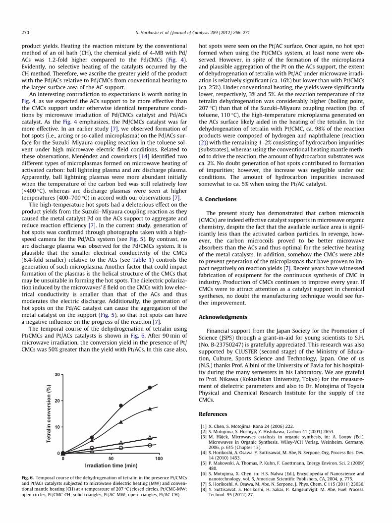
The temporal course of the dehydrogenation of tetralin usingPt/CMCs and Pt/ACs catalysts is shown in Fig. 6. After 90 min ofmicrowave irradiation, the conversion yield in the presence of Pt/CMCs was 50% greater than the yield with Pt/ACs. In this case also,
0
10
20
30
0 50 100
Tetr
alin
con
vers
ion
(%)
Irradiation time (min)
Fig. 6. Temporal course of the dehydrogenation of tetralin in the presence Pt/CMCsand Pt/ACs catalysts subjected to microwave dielectric heating (MW) and conven-tional mantle heating (CH) at a temperature of 207 �C (closed circles, Pt/CMC-MW;open circles, Pt/CMC-CH; solid triangles, Pt/AC-MW; open triangles, Pt/AC-CH).
hot spots were seen on the Pt/AC surface. Once again, no hot spotformed when using the Pt/CMCs system, at least none were ob-served. However, in spite of the formation of the microplasmaand plausible aggregation of the Pt on the ACs support, the extentof dehydrogenation of tetralin with Pt/AC under microwave irradi-ation is relatively significant (ca. 16%) but lower than with Pt/CMCs(ca. 25%). Under conventional heating, the yields were significantlylower, respectively, 3% and 5%. As the reaction temperature of thetetralin dehydrogenation was considerably higher (boiling point,207 �C) than that of the Suzuki–Miyaura coupling reaction (bp. oftoluene, 110 �C), the high-temperature microplasma generated onthe ACs surface likely aided in the heating of the tetralin. In thedehydrogenation of tetralin with Pt/CMC, ca. 98% of the reactionproducts were composed of hydrogen and naphthalene (reaction(2)) with the remaining 1–2% consisting of hydrocarbon impurities(substrates), whereas using the conventional heating mantle meth-od to drive the reaction, the amount of hydrocarbon substrates wasca. 2%. No doubt generation of hot spots contributed to formationof impurities; however, the increase was negligible under ourconditions. The amount of hydrocarbon impurities increasedsomewhat to ca. 5% when using the Pt/AC catalyst.
4. Conclusions
The present study has demonstrated that carbon microcoils(CMCs) are indeed effective catalyst supports in microwave organicchemistry, despite the fact that the available surface area is signif-icantly less than the activated carbon particles. In revenge, how-ever, the carbon microcoils proved to be better microwaveabsorbers than the ACs and thus optimal for the selective heatingof the metal catalysts. In addition, somehow the CMCs were ableto prevent generation of the microplasmas that have proven to im-pact negatively on reaction yields [7]. Recent years have witnessedfabrication of equipment for the continuous synthesis of CMC inindustry. Production of CMCs continues to improve every year. IfCMCs were to attract attention as a catalyst support in chemicalsyntheses, no doubt the manufacturing technique would see fur-ther improvement.
Acknowledgments
Financial support from the Japan Society for the Promotion ofScience (JSPS) through a grant-in-aid for young scientists to S.H.(No. B-23750247) is gratefully appreciated. This research was alsosupported by CLUSTER (second stage) of the Ministry of Educa-tion, Culture, Sports Science and Technology, Japan. One of us(N.S.) thanks Prof. Albini of the University of Pavia for his hospital-ity during the many semesters in his Laboratory. We are gratefulto Prof. Nikawa (Kokushikan University, Tokyo) for the measure-ment of dielectric parameters and also to Dr. Motojima of ToyotaPhysical and Chemical Research Institute for the supply of theCMCs.
References
[1] X. Chen, S. Motojima, Kona 24 (2006) 222.[2] S. Motojima, S. Hoshiya, Y. Hishikawa, Carbon 41 (2003) 2653.[3] M. Hájek, Microwaves catalysis in organic synthesis, in: A. Loupy (Ed.),
Microwaves in Organic Synthesis, Wiley-VCH Verlag, Weinheim, Germany,2006, p. 615 (Chapter 13).
[4] S. Horikoshi, A. Osawa, Y. Suttisawat, M. Abe, N. Serpone, Org. Process Res. Dev.14 (2010) 1453.
[5] P. Makowski, A. Thomas, P. Kuhn, F. Goettmann, Energy Environ. Sci. 2 (2009)480.
[6] S. Motojima, X. Chen, in: H.S. Nalwa (Ed.), Encyclopedia of Nanoscience andnanotechnology, vol. 6, American Scientific Publishers, CA, 2004, p. 775.
[7] S. Horikoshi, A. Osawa, M. Abe, N. Serpone, J. Phys. Chem. C 115 (2011) 23030.[8] Y. Suttisawat, S. Horikoshi, H. Sakai, P. Rangsunvigit, M. Abe, Fuel Process.
Technol. 95 (2012) 27.

S. Horikoshi et al. / Journal of Catalysis 289 (2012) 266–271 271
[9] S. Horikoshi, A. Matsubara, S. Takayama, M. Sato, F. Sakai, M. Kajitani, M. Abe,N. Serpone, Appl. Catal. B: Environ. 91 (2009) 362.
[10] S. Horikoshi, N. Serpone, J. Photochem. Photobiol. C: Photochem. Rev. 10(2009) 96.
[11] T. Ohgushi, Y. Sakai, Y. Adachi, H. Satoh, J. Phys. Chem. C 113 (2009) 8206.[12] J.A. Menéndez, A. Arenillas, B. Fidalgo, Y. Fernández, L. Zubizarreta, E.G. Calvo,
J.M. Bermúdez, Fuel Process. Technol. 91 (2010) 1.
[13] S. Mutyala, C. Fairbridge, J.R.J. Paré, J.M.R. Bélanger, Fuel Process. Technol. 91(2010) 127.
[14] J.A. Menéndez, E.J. Juárez-Pérez, E. Ruisánchez, J. Bermúdez, A. Arenillas,Carbon 49 (2011) 346.
[15] R. Powell, Introduction to Electric Circuits (Essential Electronics Series),Hodder Headline Group, 1995, pp. 28, 74.
Copyright © 2022 FDOKUMEN