oracle spatial database with mapviewer - CiteSeerX
72
ORACLE SPATIAL DATABASE WITH MAPVIEWER AND MAP BUILDER FOR DESIGNING SPATIAL APPLICATION OF PATIALA Thesis submitted in partial fulfillment of the requirements for the award of degree of Master of Engineering in Computer Science and Engineering Submitted By Dipti Sharma (Roll No. 800932007) Under the supervision of: Mr. Parteek Bhatia Assistant Professor, CSED COMPUTER SCIENCE AND ENGINEERING DEPARTMENT THAPAR UNIVERSITY PATIALA – 147004 June 2011
-
Upload
khangminh22 -
Category
Documents
-
view
4 -
download
0
Transcript of oracle spatial database with mapviewer - CiteSeerX
ORACLE SPATIAL DATABASE WITH MAPVIEWER
AND MAP BUILDER FOR DESIGNING SPATIAL
APPLICATION OF PATIALA
Thesis submitted in partial fulfillment of the requirements for the award of degree of
Master of Engineering
in
Computer Science and Engineering
Submitted By
Dipti Sharma
(Roll No. 800932007)
Under the supervision of:
Mr. Parteek Bhatia
Assistant Professor, CSED
COMPUTER SCIENCE AND ENGINEERING DEPARTMENT
THAPAR UNIVERSITY
PATIALA – 147004
June 2011

i

ii
Acknowledgement
First of all, I would like to express my gratitude towards THAPAR UNIVERSITY, for
providing me a platform to do my thesis work at such an esteemed institute.
I wish to express my deep gratitude to Mr. Parteek Bhatia, Assistant Professor, Computer
Science and Engineering Department, Thapar University, Patiala for his valuable advice and
guidance in carrying out my thesis.
I would like to thank Dr. Maninder Singh, Head, Computer Science and Engineering
Department, Thapar University, Patiala who has been a constant source of inspiration for me
throughout this work.
I am also thankful to all the staff members of the Department for their full cooperation and help.
I am Thankful to my parents, brother and all my friends for their blessing and moral support.
Thanks for boosting me with their constant encouragement, support and confidence.
Last but not the least, I am thankful to God for providing me with the strength and ability to
complete my work.
Dipti Sharma
iii
Abstract
There is a need to manage geometric, geographic or spatial data related to space in various fields.
In case of traditional databases it was not possible to store, analyze, visualize and integrate
spatial data in business and government applications. GIS systems store spatial and non-spatial
data separately. This split data model has several drawbacks, as it is difficult to maintain data
integrity between spatial data and attribute data, programmers also have to deal with two data
streams one file based and one database based. Oracle spatial provides a completely open and
standards-based architecture for the management of spatial data within a database management
system. Oracle Spatial is an integrated set of functions and procedures for handling spatial data
stored in an Oracle database. Spatial data can be processed, retrieved and related to all the other
data stored in the database using the Oracle Spatial. The things become clearer when they are
presented in maps. The MapViewer is a server-side component that constructs maps by reading
appropriate database views and tables. MapViewer provides web application developers a
versatile means to integrate and visualize spatial data with maps. The MapViewer is supported
by the Oracle Map Builder tool which is used to create and manage the Map Viewer mapping
metadata which includes styles, themes and base maps. Besides handling the metadata, the tool
provides interfaces to preview the metadata and display the original spatial information from the
spatial tables without creating Map Viewer metadata. The condition of spatial application
development is not much satisfactory in India. Most of the application development works are
still approaching the traditional framework of application development and avoiding the
powerful features of spatial technologies. In this thesis work, a spatial application for Patiala city
has been designed and developed. This application shows the map of Patiala city and is featured
with various map options like navigation panel and distance tools etc. Our developed system has
the provision to view the nearby hospitals, banks and colleges to Thapar University and some
important locations of Patiala city. It has also a feature to find the distance between the two
locations in the map.
iv
Table of Contents
Certificate …………………………………………………………………………………….... i
Acknowledgement …………………………………………………………………………….. ii
Abstract ………………………………………………………………………………………... iii
Table of Contents ……………………………………………………………………………... iv
List of Figures …………………………………………………………………………………. vi
List of Tables ………………………………………………………………………………….. x
Chapter 1: Introduction ……………………………………………………………………..… 1
1.1 Introduction to Spatial Database …………………………………………………………1
1.2 Oracle Spatial Technology …....………………………………………………………….2
1.2.1 Oracle Spatial Capabilities .………………………………………………………4
1.2.2 Advantages of using Oracle Spatial ……...……………………………………...5
1.2.3 Oracle 10 g Locator and Spatial …………………………………………………5
1.3 Visualization of Spatial Data.….…………………………………………………………6
Chapter 2: Literature Review ………………………………………………………………… 6
2.1 Modeling of Spatial Database...…………………………………………………………..8
2.1.1 Geometry Types …………………………………………………………………..8
2.1.2 Data Model ……..…………………………………………………………………9
2.1.3 Query Model ……………………………………………………………………..10
2.1.4 Indexing of Spatial Database…………………………………………………......11
2.1.5 Spatial Relationships and Filtering ………………………………………………12
2.1.6 Spatial Java Programming Interface ……………………………………………. 14
2.1.7 MDDATA Schema .…………………………………………………………….. 14
2.2 Oracle Mapviewer .…………………………………………………………………….. 15
2.2.1 Communication of Mapping Client with Mapviewer ….……………………….. 15
2.2.2 Mapviewer Architecture ..…..……….………………………………………….. 16
2.2.3 Mapviewer Mapping Metadata …………………………………….…………... 17
2.2.4 Data Sources .………………..…………………………………………………. 20
2.2. 5 Map Generation Process ………………………………………………………. 21
2.2.6 Oracle Maps …………………………………………………………………… 22
2.3 Oracle Map Builder ……………………………………………………………………. 23
2.4 Existing System ………………………………………………………………………... 24
v
Chapter 3: Problem Statement ………………………………………………………………. 28
3.1 Problem Statement …………………………………………………………………….. 28
3.2 Objectives ……………………………………………………………………………… 28
3.3 Methodology ….……………………………………………………………………….. 29
Chapter 4: Design and Implementation of Spatial Application for Patiala city …………...30
4.1 Spatial Database Designing …………………………………………………………… 30
4.2 Working with the SQL Plus: Table Creation and Record Insertion …………………… 32
4.2.1 Creation of User and Tables …………………………………………………….. 32
4.2.2 Metadata and Index Entries ……………………………………………………... 33
4.2.3 Insertion into Spatial Tables …………………………………………………….. 33
4.3 Working with the Oracle Map Builder Tool ……………………………………………36
4.3.1 Style Creation …………………………………………………………………… 37
4.3.2 Theme Creation …………………………………………………………………. 39
4.3.3 Base Map Generation …………………………………………………………… 44
4.4 Working with MapViewer …………………………………………………………….. 47
4.5 Design and Development of Spatial Application ……………………………………… 50
Chapter 5: Testing and Results ……………………………………………………………53
Chapter 6: Conclusion and Future Scope ...………………………………………………58
6.1 Conclusion …………………………………………………………………………….. 58
6.2 Future Scope …………………………………………………………………………... 58
References…………………………………………………………………………………. 60
List of Research Papers Published /Communicated ………………………………….. 62

vi
List of Figures
Figure 1.1: Evolution of Spatial Technology in Oracle
2
Figure 1.2: Oracle 10g core spatial capabilities 4
Figure 1.3: Map generated by Map Viewer 6
Figure 1.4: Map Builder User Interface 7
Figure 2.1: Geometric types 9
Figure 2.2: Query model 11
Figure 2.3: Topological relationships 13
Figure 2.4: Distance buffers for points, lines, and polygons 13
Figure 2.5: Mapping Client and MapViewer communication 16
Figure 2.6: Architecture of MapViewer 16
Figure 2.7: Same Geometry, different Line Styles 18
Figure 2.8: A simple thematic map 19
Figure 2.9: Architecture for oracle maps applications 22
Figure 2.10: Oracle Map Builder Diagram 24
Figure 4.1: Road map of Patiala 32
Figure 4.2: Create Queries running in SQL Plus for table CLG_ROAD 33
Figure 4.3: Insert Queries running in SQL Plus for table STBL_CLG 34
vii
Figure 4.4: Insert Queries running in SQL Plus for table CLG_ROAD
34
Figure 4.5: Insert Queries running in SQL Plus for table STBL_BANK 35
Figure 4.6: Insert Queries running in SQL Plus for table STBL_HOS 35
Figure 4.7: Insert Queries running in SQL Plus for table THAPAR1 36
Figure 4.8: Creating database creation using add connection option 36
Figure 4.9: Selection of create color style option 37
Figure 4.10: Definition of color style for THAPAR UNIVERSITY Theme 38
Figure 4.11: Definition of line style for road 39
Figure 4.12: Selection of create geometry option 40
Figure 4.13: Specifying theme parameters 41
Figure 4.14: Style picker dialog window 41
Figure 4.15: Specifying feature style 42
Figure 4.16: Specifying style parameters 42
Figure 4.17: Summary box for geometry theme 43
Figure 4.18: CLG_ROAD_THEME preview in Map Builder 43
Figure 4.19: STBL_CLG_THEME preview in Map Builder 44
Figure 4.20: Specifying base map parameters 45
Figure 4.21: Selection of themes base map 45
viii
Figure 4.22: Base map of Patiala 46
Figure 4.23: Preview of base map for colleges and hospitals 46
Figure 4.24: MapViewer initialization screen 47
Figure 4.25: MapViewer home page 47
Figure 4.26: Login screen of MapViewer 48
Figure 4.27: Creation of data source 48
Figure 4.28: Creation of map tile layer 49
Figure 4.29: Patiala map in MapViewer 50
Figure 4.30: Spatial applicaton of Patiala in running mode 51
Figure 4.31: Thapar University in zoom mode 51
Figure 4.32: Showing the query result returned by SDO_NN operator 52
Figure 5.1: Spatial applicaton of Patiala in running mode.
53
Figure 5.2: Showing Thapar University in zoom mode
54
Figure 5.3: Spatial application showing distance between ICICI bank and Bikram
College of Commerce
54
Figure 5.4: Spatial application showing distance between Mandeep clinic and Thapar
University
55
Figure 5.5: Showing the nearest college to Thapar University 56
Figure 5.6: Showing nearest hospitals in order of proximity to Thapar University 56
Figure 5.7: Showing nearest colleges in order of proximity to Thapar University 57
ix
List of Tables
Table 4.1: Schema of the table STBL_HOS 31
Table 4.2: Schema of the table STBL_CLG 31
Table 4.3: Schema of the table STBL_ROAD 31
Table 4.4: Schema of the table CLG_BANK 31
Table 4.5: Schema of the table THAPAR1 32
1
Chapter 1
Introduction
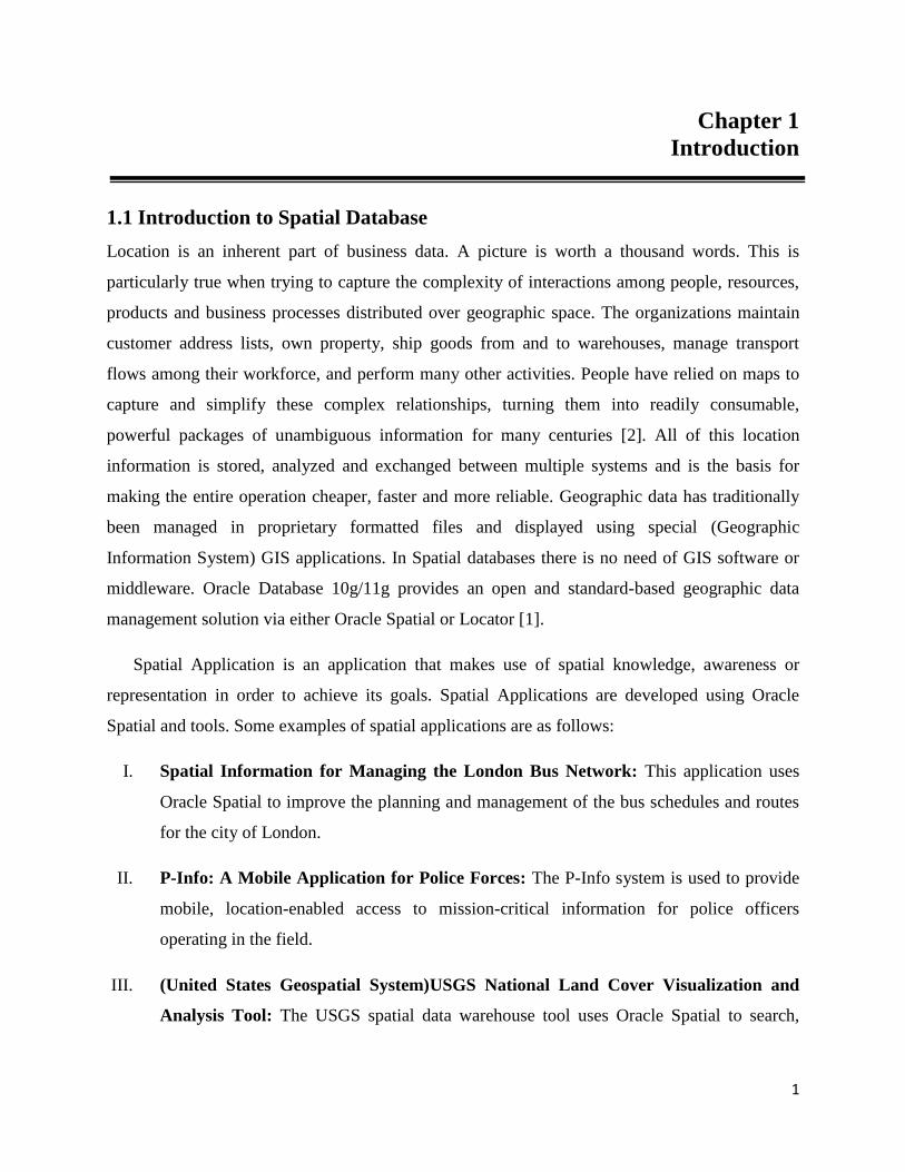
1.1 Introduction to Spatial Database
Location is an inherent part of business data. A picture is worth a thousand words. This is
particularly true when trying to capture the complexity of interactions among people, resources,
products and business processes distributed over geographic space. The organizations maintain
customer address lists, own property, ship goods from and to warehouses, manage transport
flows among their workforce, and perform many other activities. People have relied on maps to
capture and simplify these complex relationships, turning them into readily consumable,
powerful packages of unambiguous information for many centuries [2]. All of this location
information is stored, analyzed and exchanged between multiple systems and is the basis for
making the entire operation cheaper, faster and more reliable. Geographic data has traditionally
been managed in proprietary formatted files and displayed using special (Geographic
Information System) GIS applications. In Spatial databases there is no need of GIS software or
middleware. Oracle Database 10g/11g provides an open and standard-based geographic data
management solution via either Oracle Spatial or Locator [1].
Spatial Application is an application that makes use of spatial knowledge, awareness or
representation in order to achieve its goals. Spatial Applications are developed using Oracle
Spatial and tools. Some examples of spatial applications are as follows:
I. Spatial Information for Managing the London Bus Network: This application uses
Oracle Spatial to improve the planning and management of the bus schedules and routes
for the city of London.
II. P-Info: A Mobile Application for Police Forces: The P-Info system is used to provide
mobile, location-enabled access to mission-critical information for police officers
operating in the field.
III. (United States Geospatial System)USGS National Land Cover Visualization and
Analysis Tool: The USGS spatial data warehouse tool uses Oracle Spatial to search,
2
visualize and analyze land-cover data for the (United States) U.S. Oracle Spatial is used
to locate and geocode information and how to provide street navigation to users [14].
IV. U.S. Department of Defense Military Home Front Location Based System (LBS):
LBS assist users to make more informed decisions regarding services available on and
near military facilities installations worldwide. The user interface, modeled on the latest
web mapping technologies, provides an intuitive interface for non-GIS users [1].
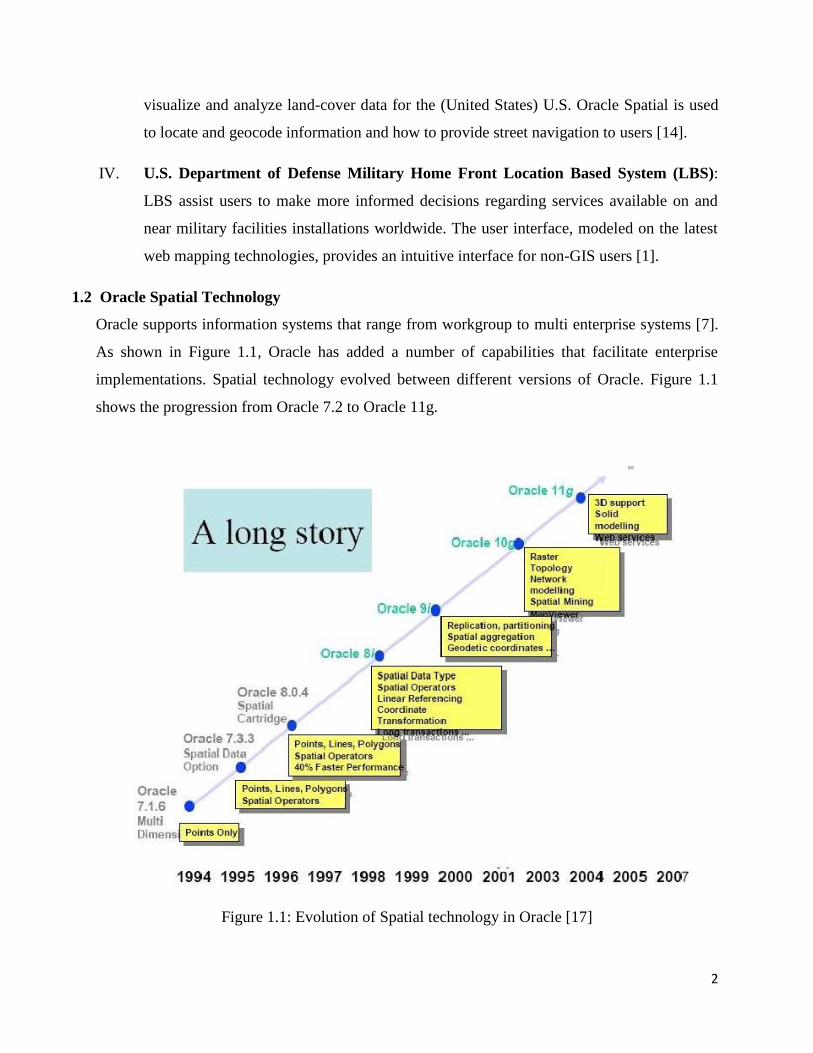
1.2 Oracle Spatial Technology
Oracle supports information systems that range from workgroup to multi enterprise systems [7].
As shown in Figure 1.1, Oracle has added a number of capabilities that facilitate enterprise
implementations. Spatial technology evolved between different versions of Oracle. Figure 1.1
shows the progression from Oracle 7.2 to Oracle 11g.
Figure 1.1: Evolution of Spatial technology in Oracle [17]
3
Spatial technology was first introduced in Oracle 7.2 under the name Oracle MultiDimensional
(MD). Later, the product name changed to Oracle Spatial Data Option (SDO) and to Spatial Data
Cartridge in Oracle 8. Since objects were not supported in these releases, the coordinates of a
geometry were stored as multiple rows in an associated table. Managing spatial (geometry) data
in these prior versions was inefficient and cumbersome. Starting with Oracle 8i, the
SDO_GEOMETRY data type was introduced to store spatial data. Even in the latest versions
(Oracle 11g, Oracle 10g, and Oracle 9i), the same SDO_GEOMETRY model is used to store
spatial data in Oracle. In Oracle 9i (and Oracle 10g), the geometry data also included support for
coordinate systems information specified using the Spatial Reference ID(SRID) attribute in the
SDO_GEOMETRY data type. In Oracle 10g, additional functionality (that exists in the
Advanced Spatial Engine) such as the Network Data Model is introduced in the Spatial option of
Oracle. In Oracle 10g Release 2, the European Petroleum Survey Group (EPSG) Coordinate
Systems model was added to the Locator option. In Oracle 11g, several new features such as 3D
geometry support and Spatial Web Services have been introduced. Oracle Spatial, referred to as
spatial, is an integrated set of functions and procedures that enables spatial data to be stored,
accessed, and analyzed quickly and efficiently in an Oracle database. Oracle Spatial provides a
SQL schema and functions that facilitate the storage, retrieval, update, and query of collections
of spatial features in an Oracle database.
Spatial consists of the following:
A schema, Multidimensional System (MDSYS) that prescribes the storage, syntax, and
semantics of supported geometric data types.
A spatial indexing mechanism.
Operators, functions, and procedures for performing area-of-interest queries, spatial join
queries, and other spatial analysis operations.
Functions and procedures for utility and tuning operations.
Topology data model for working with data about nodes, edges, and faces in a topology
[4, 18].
Network data model for representing capabilities or objects that are modeled as nodes
and links in a network [4, 18].
GeoRaster, a feature that make possible to store, index, query, analyze and deliver GeoRaster
data, that is, raster image and gridded data and its associated metadata [4, 15].

4
1.2.1 Oracle Spatial Capabilities
Oracle has rolled most spatial features into Oracle 10g Enterprise and Oracle 10g
Standard as a no-cost feature set called Oracle Locator. Spatial Data types, Spatial
Analysis and Spatial Indexing core spatial capabilities, provided by Oracle Spatial have
been shown in Figure 1.2. Many applications can be spatially enabled using standard
components that are present at no additional cost in every Oracle database and
application server. Specific Locator features include:
Object types that describe and support geospatial features such as points, lines and
polygons.
User-selectable R-tree and quad tree indexing that is integrated into Oracle‟s database
servers.
Support spatial operators that use spatial index to perform spatial queries.
Support for storage, management and use of geodetic data.
Support Open, standard SQL, Extended Mark up Language (XML) and XQuery access to
spatial operations and data. [16]
Figure 1.2: Oracle 10g core spatial capabilities [6]
5
1.2.2 Advantages of using Oracle Spatial
Advantages of Oracle Spatial are as follows:
It eliminates the need for dual architectures, because all data can be stored in the same
way. Unified data storage means that all types of data (text, maps, and multimedia)
are stored together, instead of each type being stored separately.
It uses SQL, a standard language for accessing relational databases, thus removing the
need for specific languages to handle spatial data.
It defines the SDO_GEOMETRY data type, which is essentially equivalent to the
spatial types (Structured Query Language Multimedia) SQL/MM standards.
It implements SQL/MM “well-known” formats for specifying spatial data. This
implies that any solution that adheres to the SQL/MM specifications can easily store
the data in Oracle Spatial, and vice versa, without the need for third-party converters.
It is the de facto standard for storing and accessing data in Oracle and is fully
supported by the world‟s leading geospatial data, tools, and applications vendors,
including Tele Atlas, Digital Globe, 1Spatial, Autodesk, Bentley, Environmental
Systems Research Institute(ESRI), Small world, Intergraph, Manifold,
Pitney/Bowes/MapInfo, Safe Software, Skyline, and many others.
It provides scalability, integrity, security, recoverability, and advanced user
management features for handling spatial data that are the norm in Oracle databases
but are not necessarily so in other spatial management tools.
It removes the need for separate organizations to maintain a spatial data
infrastructure (hardware, software, support, and so on), and it eliminates the need for
specific tools and skills for operating spatial data.[6]
Through the application server, Oracle Spatial allows almost any application to benefit from the
availability of spatial information and intelligence, reducing the costs and complexity of spatial
applications.
1.2.3 Oracle 10g Locator and Spatial
Oracle Locator is best suited for spatially enabling the majority of enterprise applications that
have relatively straightforward geospatial requirements. Oracle 10g Standard Edition with
6
Locator provides foundation-level geospatial data management. For more complex applications,
such as GIS, Oracle recommends Oracle Spatial, an option to Oracle 10g Enterprise Edition.
Oracle Spatial Option provides advanced spatial functionality, such as spatial functions
(including area, buffer and centroid calculations), advanced coordinate systems support, linear
referencing systems, topology, aggregate functions, network data models/operations, routing as
well as geocoding. Oracle Spatial also supports direct interfaces with all major GIS systems,
including those from Environmental Systems Research Institute (ESRI), Autodesk, Intergraph
and MapInfo [3].
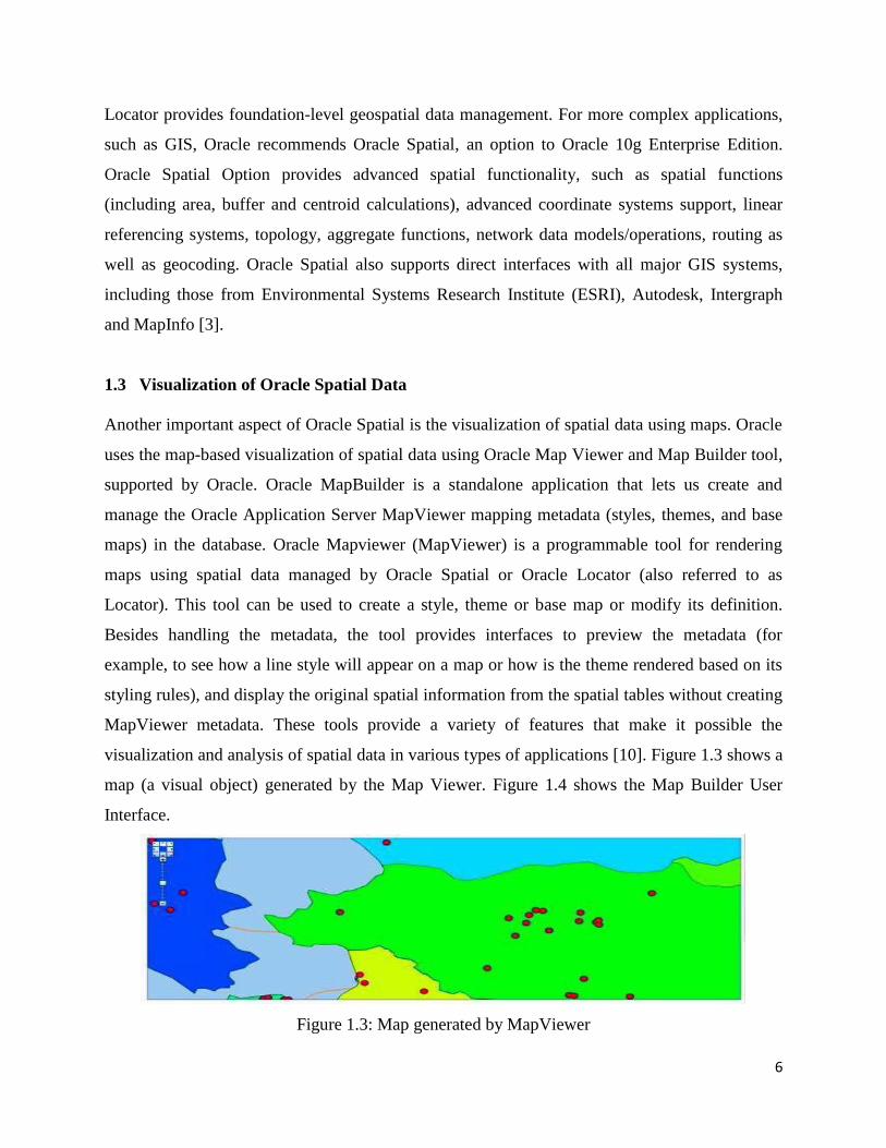
1.3 Visualization of Oracle Spatial Data
Another important aspect of Oracle Spatial is the visualization of spatial data using maps. Oracle
uses the map-based visualization of spatial data using Oracle Map Viewer and Map Builder tool,
supported by Oracle. Oracle MapBuilder is a standalone application that lets us create and
manage the Oracle Application Server MapViewer mapping metadata (styles, themes, and base
maps) in the database. Oracle Mapviewer (MapViewer) is a programmable tool for rendering
maps using spatial data managed by Oracle Spatial or Oracle Locator (also referred to as
Locator). This tool can be used to create a style, theme or base map or modify its definition.
Besides handling the metadata, the tool provides interfaces to preview the metadata (for
example, to see how a line style will appear on a map or how is the theme rendered based on its
styling rules), and display the original spatial information from the spatial tables without creating
MapViewer metadata. These tools provide a variety of features that make it possible the
visualization and analysis of spatial data in various types of applications [10]. Figure 1.3 shows a
map (a visual object) generated by the Map Viewer. Figure 1.4 shows the Map Builder User
Interface.
Figure 1.3: Map generated by MapViewer

7
Figure 1.4: Map Builder user interface
8
Chapter 2
Literature Review
2.1 Modeling of Spatial Database
Spatial supports the object-relational model for representing geometries [3]. This model stores an
entire geometry in the Oracle native spatial data type for vector data, SDO_GEOMETRY [1]. An
Oracle table can contain one or more SDO_GEOMETRY columns. The object-relational model
corresponds to a "SQL with Geometry Types" implementation of spatial feature tables in the
Open GIS Object Database Connectivity (ODBC)/SQL specification for geospatial features [3].
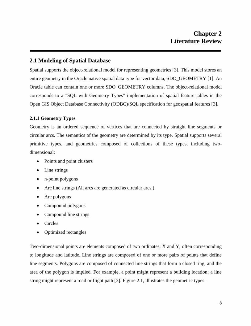
2.1.1 Geometry Types
Geometry is an ordered sequence of vertices that are connected by straight line segments or
circular arcs. The semantics of the geometry are determined by its type. Spatial supports several
primitive types, and geometries composed of collections of these types, including two-
dimensional:
Points and point clusters
Line strings
n-point polygons
Arc line strings (All arcs are generated as circular arcs.)
Arc polygons
Compound polygons
Compound line strings
Circles
Optimized rectangles
Two-dimensional points are elements composed of two ordinates, X and Y, often corresponding
to longitude and latitude. Line strings are composed of one or more pairs of points that define
line segments. Polygons are composed of connected line strings that form a closed ring, and the
area of the polygon is implied. For example, a point might represent a building location; a line
string might represent a road or flight path [3]. Figure 2.1, illustrates the geometric types.
9
Figure 2.1: Geometric types [1]
Spatial also supports the storage and indexing of three-dimensional and four dimensional
geometric types.
2.1.2 Data Model
The Spatial data model is a hierarchical structure consisting of elements, geometries, and layers.
Layers are composed of geometries, which in turn are made up of elements [3].
Element: An element is the basic building block of geometry. The supported spatial element
types are points, line strings, and polygons. For example, elements might model star
constellations (point clusters), roads (line strings) and county boundaries (polygons).
Geometry: A geometry (or geometry object) is the representation of a spatial feature, modeled
as an ordered set of primitive elements. Geometry can consist of a single element, which is an
instance of one of the supported primitive types, or a homogeneous or heterogeneous collection
of elements. An example of geometry might describe the buildable land in a town. This could be
represented as a polygon with holes where water or zoning prevents construction.
Layer: A layer is a collection of geometries having the same attribute set. For example, one
layer in a GIS might include topographical features, while another describes population density
and a third describes the network of roads and bridges in the area (lines and points). The
geometries and associated spatial index for each layer are stored in the database in standard
tables [3].

10
Coordinate System: A coordinate system (also called a spatial reference system) is a means of
assigning coordinates to a location and establishing relationships between sets of such
coordinates. It enables the interpretation of a set of coordinates as a representation of a position
in a real world space. Spatial data can be associated with a Cartesian, geodetic (geographical),
projected or local coordinate system:
Cartesian coordinates are coordinates that measure the position of a point from a defined
origin along axes that are perpendicular in the represented two dimensional or three-
dimensional spaces. If a coordinate system is not explicitly associated with geometry, a
Cartesian coordinate system is assumed.
Geodetic coordinates (sometimes called geographic coordinates) are angular coordinates
(longitude and latitude), closely related to spherical polar coordinates, and are defined
relative to a particular Earth geodetic datum. (A geodetic datum is a means of
representing the figure of the Earth and is the reference for the system of geodetic
coordinates.)
Projected coordinates are planar Cartesian coordinates that result from performing a
mathematical mapping from a point on the Earth‟s surface to a plane. There are many
such mathematical mappings, each used for a particular purpose [3].
Local coordinates are Cartesian coordinates in a non-Earth (non georeferenced)
coordinate system. Local coordinate systems are often used for CAD applications and
local surveys [3].
When performing operations on geometries, Spatial uses either a Cartesian or curvilinear
computational model, as appropriate for the coordinate system associated with the spatial data.
Tolerance: Tolerance is used to associate a level of precision with spatial data. Tolerance
reflects the distance that two points can be apart and still be considered the same (for example, to
accommodate rounding errors) [3].
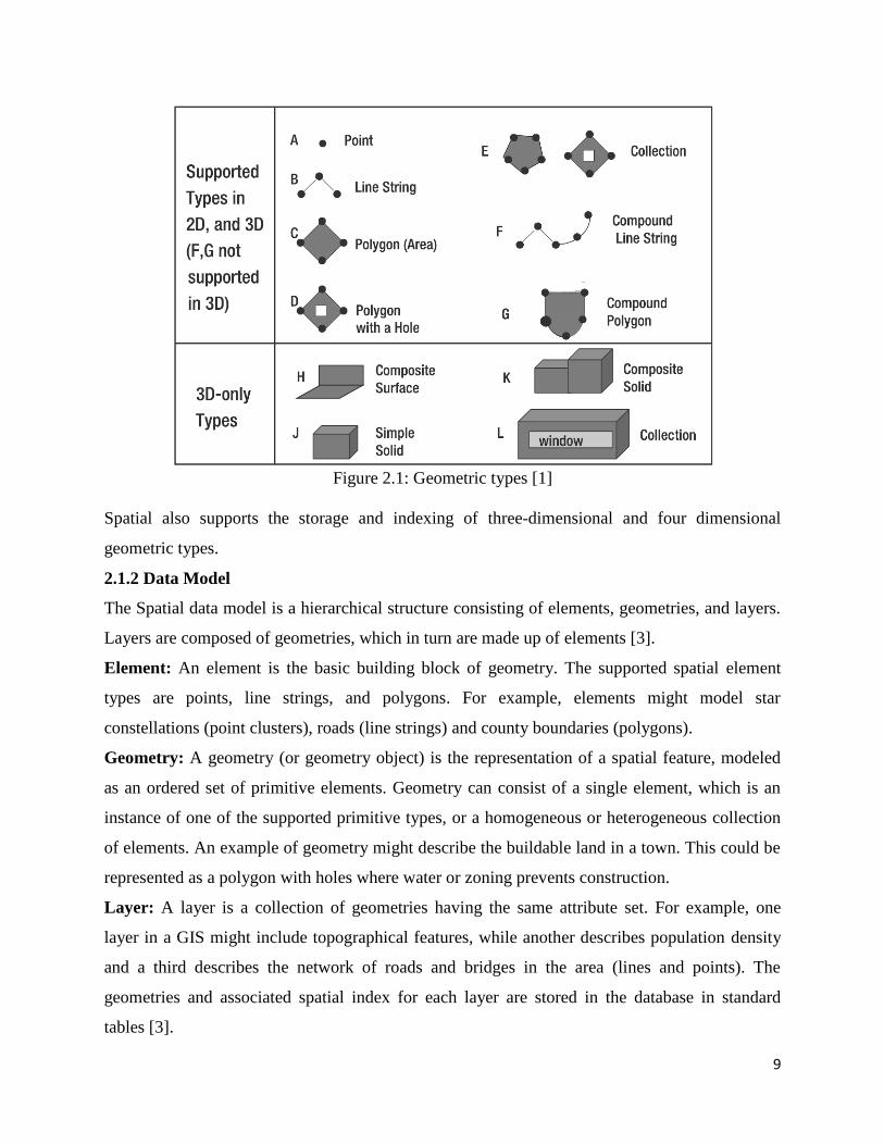
2.1.3 Query Model
Spatial uses a two-tier query model to resolve spatial queries and spatial joins. The term is used
to indicate that two distinct operations are performed to resolve queries. The output of the two
combined operations yields the exact result set.
11
Figure 2.2: Query model [3]
The two operations are referred to as primary and secondary filter operations.
The primary filter permits fast selection of candidate records to pass along to the
secondary filter. The primary filter compares geometry approximations to reduce
computation complexity and is considered a lower-cost filter. Because the primary filter
compares geometric approximations, it returns a superset of the exact result set.
The secondary filter applies exact computations to geometries that result from the
primary filter. The secondary filter yields an accurate answer to a spatial query. The
secondary filter operation is computationally expensive, but it is only applied to the
primary filter results, not the entire data set. Figure 2.2 shows the complete process
sequentially.
The primary filter operation on a large input data set produces a smaller candidate set, which
contains at least the exact result set and may contain more records. The secondary filter operation
on the smaller candidate set produces the exact result set. Spatial uses a spatial index to
implement the primary filter [3].
2.1.4 Indexing of Spatial Data
The introduction of spatial indexing capabilities into the Oracle database engine is a key feature
of the spatial product. A spatial index, like any other index, provides a mechanism to limit
searches, but in this case the mechanism is based on spatial criteria such as intersection and
containment. A spatial index is needed to:
12
Find objects within an indexed data space that interact with a given point or area of
interest (window query).
Find pairs of objects from within two indexed data spaces that interact spatially with each
other (spatial join).
A spatial index is considered as a logical index [19, 3]. The entries in the spatial index are
dependent on the location of the geometries in a coordinate space, but the index values are in a
different domain. Index entries may be ordered using a linearly ordered domain and the
coordinates for geometry may be pairs of integer, floating-point, or double-precision numbers.
2.1.5 Spatial Relationships and Filtering
Spatial uses secondary filters to determine the spatial relationship between entities in the
database. The spatial relationship is based on geometry locations. The most common spatial
relationships are based on topology and distance. For example, the boundary of an area consists
of a set of curves that separates the area from the rest of the coordinate space. The interior of an
area consists of all points in the area that are not on its boundary. Given this, two areas are said
to be adjacent if they share part of a boundary but do not share any points in their interior. The
distance between two spatial objects is the minimum distance between any points in them. Two
objects are said to be within a given distance of one another if their distance is less than the given
distance. Some of the secondary filter methods used by Oracle Spatial to determine topological
relationships are as follows:
The SDO_RELATE operator evaluates topological criteria.
The SDO_WITHIN_DISTANCE operator determines if two spatial objects are within a
specified distance of each other.
The SDO_NN operator identifies the nearest neighbors for a spatial object [5].
The SDO_RELATE operator implements a nine-intersection model for categorizing binary
topological relationships between points, lines, and polygons. Some of the topological
relationships (as shown in figure 2.3) have been described below. Spatial uses the following
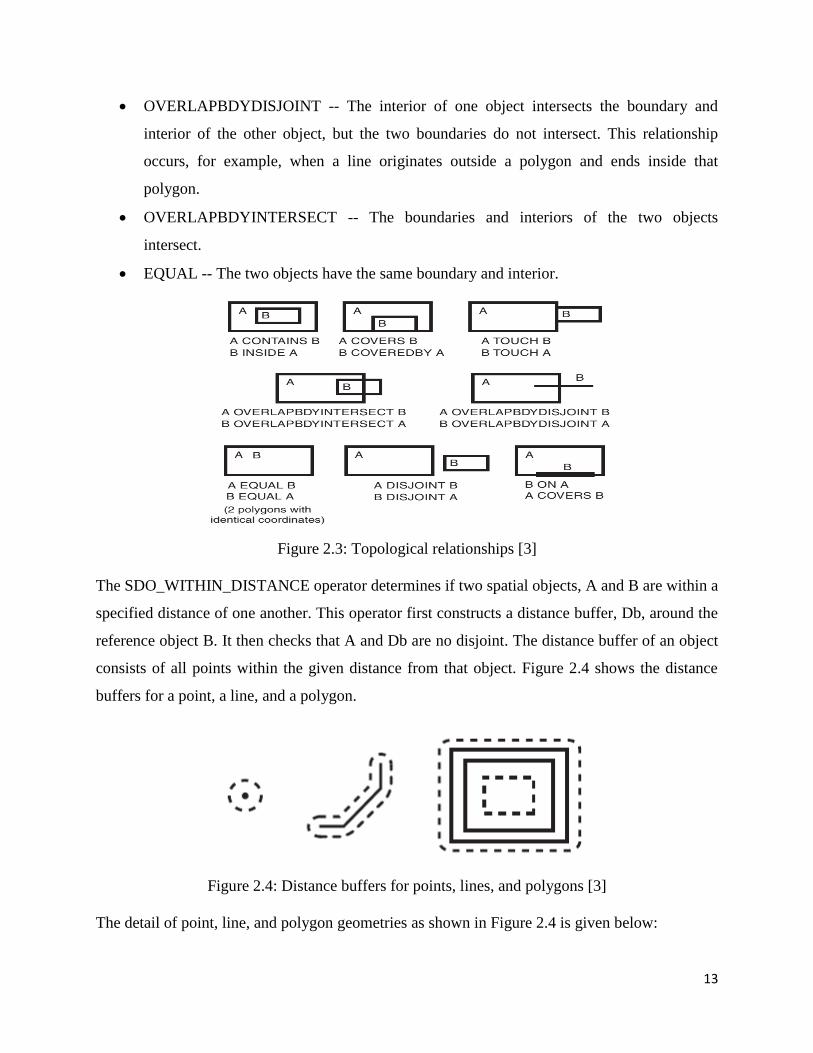
names:
DISJOINT -- The boundaries and interiors do not intersect.
TOUCH -- The boundaries intersect but the interiors do not intersect.
13
OVERLAPBDYDISJOINT -- The interior of one object intersects the boundary and
interior of the other object, but the two boundaries do not intersect. This relationship
occurs, for example, when a line originates outside a polygon and ends inside that
polygon.
OVERLAPBDYINTERSECT -- The boundaries and interiors of the two objects
intersect.
EQUAL -- The two objects have the same boundary and interior.
Figure 2.3: Topological relationships [3]
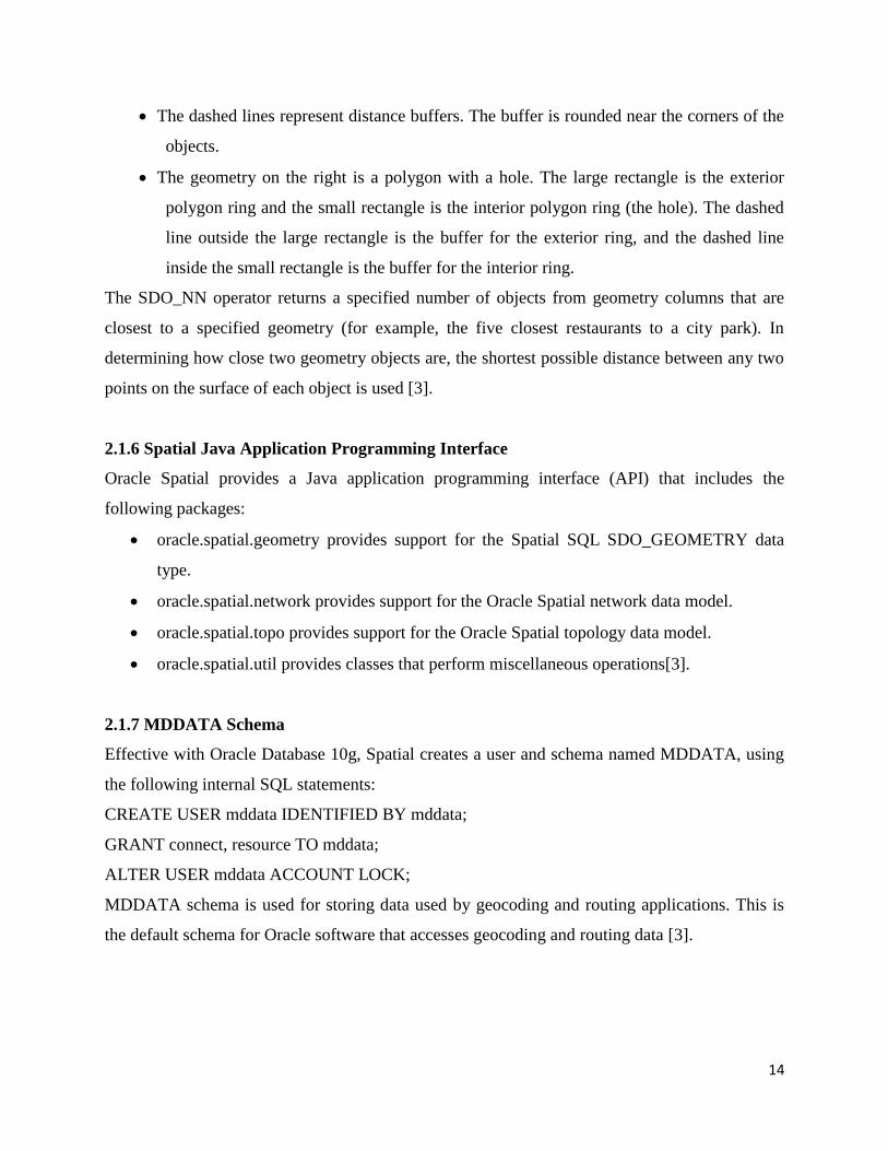
The SDO_WITHIN_DISTANCE operator determines if two spatial objects, A and B are within a
specified distance of one another. This operator first constructs a distance buffer, Db, around the
reference object B. It then checks that A and Db are no disjoint. The distance buffer of an object
consists of all points within the given distance from that object. Figure 2.4 shows the distance
buffers for a point, a line, and a polygon.
Figure 2.4: Distance buffers for points, lines, and polygons [3]
The detail of point, line, and polygon geometries as shown in Figure 2.4 is given below:
14
The dashed lines represent distance buffers. The buffer is rounded near the corners of the
objects.
The geometry on the right is a polygon with a hole. The large rectangle is the exterior
polygon ring and the small rectangle is the interior polygon ring (the hole). The dashed
line outside the large rectangle is the buffer for the exterior ring, and the dashed line
inside the small rectangle is the buffer for the interior ring.
The SDO_NN operator returns a specified number of objects from geometry columns that are
closest to a specified geometry (for example, the five closest restaurants to a city park). In
determining how close two geometry objects are, the shortest possible distance between any two
points on the surface of each object is used [3].
2.1.6 Spatial Java Application Programming Interface
Oracle Spatial provides a Java application programming interface (API) that includes the
following packages:
oracle.spatial.geometry provides support for the Spatial SQL SDO_GEOMETRY data
type.
oracle.spatial.network provides support for the Oracle Spatial network data model.
oracle.spatial.topo provides support for the Oracle Spatial topology data model.
oracle.spatial.util provides classes that perform miscellaneous operations[3].
2.1.7 MDDATA Schema
Effective with Oracle Database 10g, Spatial creates a user and schema named MDDATA, using
the following internal SQL statements:
CREATE USER mddata IDENTIFIED BY mddata;
GRANT connect, resource TO mddata;
ALTER USER mddata ACCOUNT LOCK;
MDDATA schema is used for storing data used by geocoding and routing applications. This is
the default schema for Oracle software that accesses geocoding and routing data [3].

15
2.2 Oracle Map Viewer
Map Viewer [11, 13] is a Java-based visualization tool that is used to render, in map form,
location based content and spatial data stored using the spatial feature of Oracle Database. It can
also render map and related content from Environmental Systems Research Institute(ESRI)
Shape Files, real-time XML feeds and geographic web services including themes from Open
Geospatial Consortium Web Feature Services.
Map Viewer can be used to:
Create customized maps that show geographic features such as roads, city areas,
waterways and other transportation networks.
Display map themes such as national, state and local boundaries.
Visualize business data (e.g. population demographics, psycho demographics, sales
metrics, etc.), to portray and explore relationships that can often best be expressed
graphically as geographic maps.
Complement an applications workflow, providing interaction with mapped data.
Deliver custom maps over the Internet as a component of Java Developer (JDeveloper) or
as a standalone tool [9].
2.2.1 Communication of Mapping Client with Map Viewer
As shown in Figure 2.5, there are two steps for communication of client with Map Viewer;
regardless of whether or not the client requests a map or some Map Viewer administrative action.
For a map request:
The client requests a map, passing in the map name, data source, centre location, map
size, and, optionally, other data to be plotted on top of a map.
The server returns the map image (or a URL for the image) and the minimum bounding
rectangle (MBR) of the map, and the status of the request.
For a Map Viewer administrative request:
The client requests a Map Viewer administrative action, passing in the specific type of
request and appropriate input values.
The server returns the status of the request and the requested information.
16
Figure 2.5: Mapping client and MapViewer communication [10].
2.2.2 Map Viewer Architecture
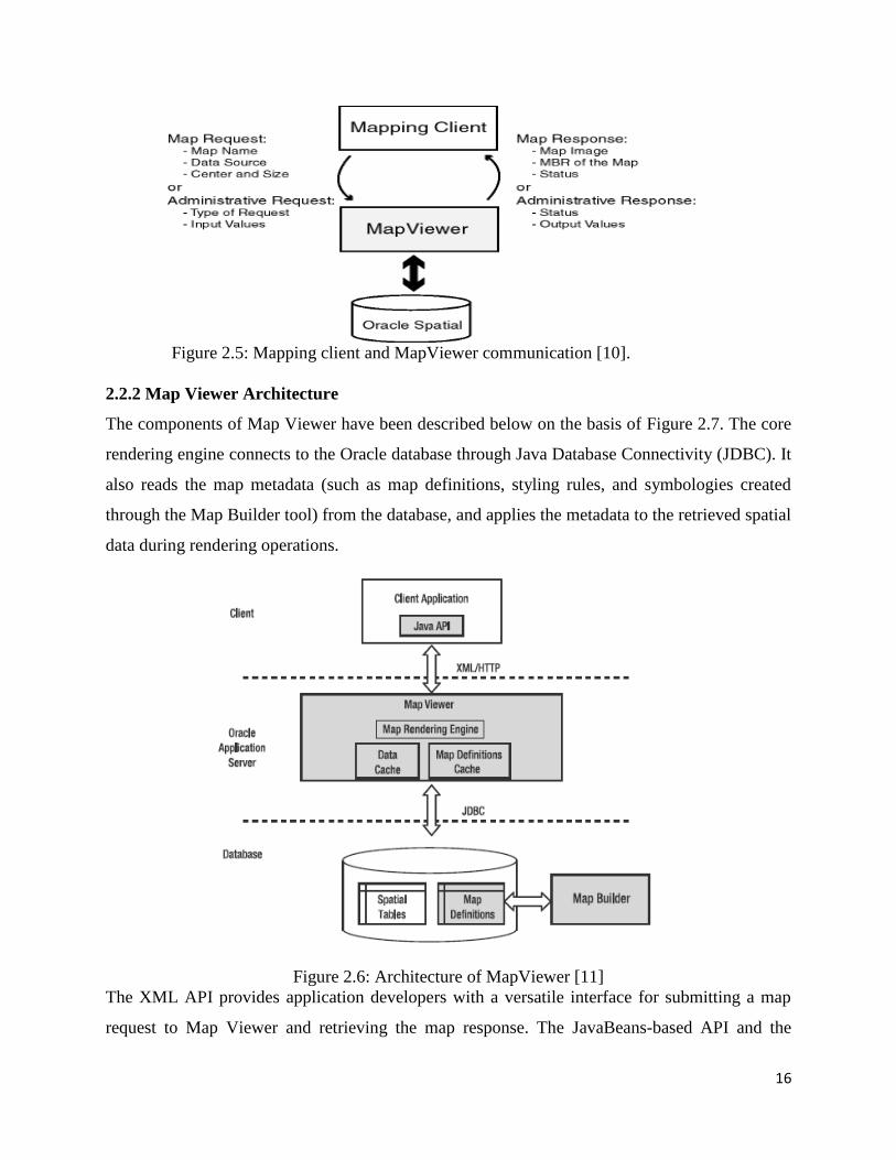
The components of Map Viewer have been described below on the basis of Figure 2.7. The core
rendering engine connects to the Oracle database through Java Database Connectivity (JDBC). It
also reads the map metadata (such as map definitions, styling rules, and symbologies created
through the Map Builder tool) from the database, and applies the metadata to the retrieved spatial
data during rendering operations.
Figure 2.6: Architecture of MapViewer [11]
The XML API provides application developers with a versatile interface for submitting a map
request to Map Viewer and retrieving the map response. The JavaBeans-based API and the
17
PL/SQL API provide access to Map Viewer's rendering capabilities. The JavaScript API enables
us to create highly interactive web applications that use the Oracle Maps feature of Map Viewer.
The Map Builder tool simplifies the process of creating and managing map, theme and
symbology metadata in a spatial database [8]. Oracle Maps, built on core Map Viewer features,
uses a map tile server that caches map image tiles, and a Feature Of Interest (FOI) server that
streams live data out of a database to be displayed as interactive features on a map. We can use
the AJAX based JavaScript API with Oracle Maps to provide sophisticated mapping solutions.
Oracle Maps also allows for advanced customization and querying capabilities. The primary
benefit of Map Viewer is its integration with Oracle Spatial, Oracle Locator and other Oracle
Fusion Middleware components. Map Viewer supports two dimensional vector geometries
stored in Oracle Spatial, as well as Geo Raster data and data in the Oracle Spatial topology and
network data models. Oracle Map Viewer is also an Open Geospatial Consortium (OGC)-
compliant Web Map Service (WMS) server.
2.2.3 Map Viewer Mapping Metadata
In Map Viewer, a map conceptually consists of one or more themes. Each theme consists of a set
of individual geographic features that share certain common attributes. Each feature is rendered
and (optionally) labeled with specific styles. Themes can be predefined inside a database user‟s
schema, or can be dynamically defined as part of a map request. Predefined themes can be
grouped to form a predefined base map that can also be stored in a user‟s schema. Styles,
predefined themes, and base maps are collectively called mapping metadata for Map Viewer.
This scheme provides a clear separation between the presentation of data and the spatial data
itself. For example, any mistake made while manipulating the mapping metadata will have no
effect on the corresponding spatial data, and vice versa.
Styles: A style is a visual attribute that can be used to represent a spatial feature [11]. The basic
map symbols and labels for representing point, line and area features are defined and stored as
individual styles. Each style has a unique name and defines one or more graphical elements in
XML syntax. Each style is of one of the following types:
COLOR: a color for the fill or the stroke (border), or both.
MARKER: a shape with a specified fill and stroke color, or an image. Markers are often
icons for representing point features, such as airports, ski resorts and historical

18
attractions. When a marker style is specified for a line feature, the rendering engine
selects a suitable point on the line and applies the marker style to that point.
LINE: a line style (width, color, end style, join style) and optionally a centre line, edges,
and hash mark. Lines are often used for linear features such as highways, rivers,
pipelines and electrical transmission lines.
AREA: a color or texture, and optionally a stroke color. Areas are often used for
polygonal features such as counties and census tracts.
TEXT: a font specification (size and family) and optionally highlighting (bold,italic) and
a foreground color. Text is often used for annotation and labeling (such as names of
cities and rivers).
ADVANCED: a composite used primarily for thematic mapping. The core advanced
style is Bucket Style, which defines a mapping from a set of simple styles to a set of
buckets. Any geographic feature, such as a road, can be displayed differently if alternate
styles are assigned or applied, even though the underlying geometric structure of the
feature itself is identical. Figure 2.7 is an example of a single road being rendered using
three different line styles [11].
Figure 2.7: Same geometry, different line styles [12]
Themes: A theme is a visual representation of a particular data layer. Conceptually, a theme is a
collection of geographic features that share similar attributes, plus the rendering and labeling
19
rules that tell MapViewer what styles to use to render and label the features. When a theme is
defined, actually the following information is provided to Map Viewer: where and how to get the
data, and how to render and label the data [11].
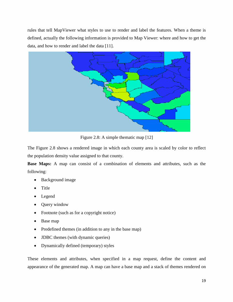
Figure 2.8: A simple thematic map [12]
The Figure 2.8 shows a rendered image in which each county area is scaled by color to reflect
the population density value assigned to that county.
Base Maps: A map can consist of a combination of elements and attributes, such as the
following:
Background image
Title
Legend
Query window
Footnote (such as for a copyright notice)
Base map
Predefined themes (in addition to any in the base map)
JDBC themes (with dynamic queries)
Dynamically defined (temporary) styles
These elements and attributes, when specified in a map request, define the content and
appearance of the generated map. A map can have a base map and a stack of themes rendered on
20
top of each other in a window. A map has an associated coordinate system that all themes in the
map must share. Themes can be added to a map by specifying a base map name or by using the
programming interface to add themes. The order in which the themes are added determines the
order in which they are rendered, with the last specified theme on top, so be sure we know which
themes we want in the background and foreground. Predefined themes can be grouped together
to form a base map. This provides a convenient way to include multiple themes in a map request.
Only predefined themes can be included in a base map. The base map definitions are stored in a
user‟s USER_SDO_MAPS view. A minimum and maximum map scale can be provided for each
theme listed in a base map. This provides a powerful mechanism that is used to selectively reveal
themes based on the current map‟s scale [11].
Tile Layers: The fourth type of mapping metadata is Map Tile Layer metadata. This metadata is
primarily used by the Oracle Maps JavaScript API. It provides the JavaScript API with
information about a draggable map tile layer, including its geographic boundary, coordinate
system, number of discrete zoom levels and the size and format of individual map tiles at each
zoom level. A map tile layer is typically associated with a Map Viewer base map. This type of
map tile layer is often called “Internal Map Tile Layer”.
2.2.4 Data Sources
A data source corresponds to a database schema or user. Before we can draw any spatial data in a
database schema, we must first define (create) a data source for the schema, either permanently
or dynamically:
We can define a data source permanently by specifying its connection information and
user login credentials in the Map Viewer configuration file named as
mapViewerConfig.xml.
We can define or modify a data source dynamically using the Map Viewer administration
(Admin) page [11].
Each map request must specify a master data source. We can, however, specify a different data
source for individual themes added to the map request. This makes it easy to aggregate data
stored across different database schemas. If a theme has no specified data source, it is associated
with the master data source. A base map (and thus the themes included in it) is always associated
with the master data source. When a theme is processed, all of its underlying data, as well as the
21
styles referenced in its definition, must be accessible from the data source or sources associated
with the theme. Each data source has its own internal metadata cache. The metadata cache holds
the definitions of all accessed styles, as well as of all predefined themes that originate from the
data source. This eliminates the need to query the database repeatedly for the definition of a style
or predefined theme whenever it is needed.
2.2.5 Map Generation Process
When a map request arrives at the MapViewer server, the server picks a free renderer associated
with the master data source in the request. This section describes the process that the MapViewer
server follows to generate a map. In brief, MapViewer performs the following steps:
Parse and process the incoming XML map request.
Prepare the data for each theme (executed in parallel).
Render and label each theme.
Generate final images or files.
Each map generated by MapViewer results from its receiving a valid XML map request. (If we
use the JavaBeans based API, the request is automatically converted to an XML document and
passed to the MapViewer server.) The XML map request is parsed and its content is validated.
MapViewer then creates any dynamic styles specified in the XML request. It builds a theme list
from all themes included in the base map (if a base map is specified), as well as any specified
predefined or Java Database Connectivity (JDBC) themes. All individual features in the request
are grouped into a single temporary theme. In other words, after parsing the incoming request, all
data that must be shown on the map is presented in a list of themes to the MapViewer rendering
engine. The ordering of the themes in the list is important, because it determines the order in
which the themes are rendered. All themes included in the base map (when present) are added to
the list first, followed by all specified themes (predefined or JDBC). The theme that contains all
the individual features is added as the last theme on the list. Any other requested features of a
map (such as legend, map title, or footnote), are created and saved for rendering later. For each
theme in the request, MapViewer then creates a separate execution thread to prepare its data, so
that preparation of the themes takes place in parallel. For a predefined theme, this means
formulating a query based on the theme's definition and any other information, such as the
22
current map request window. This query is sent to the database for execution, and the result set is
returned. MapViewer creates individual render able objects based on the result set [11].
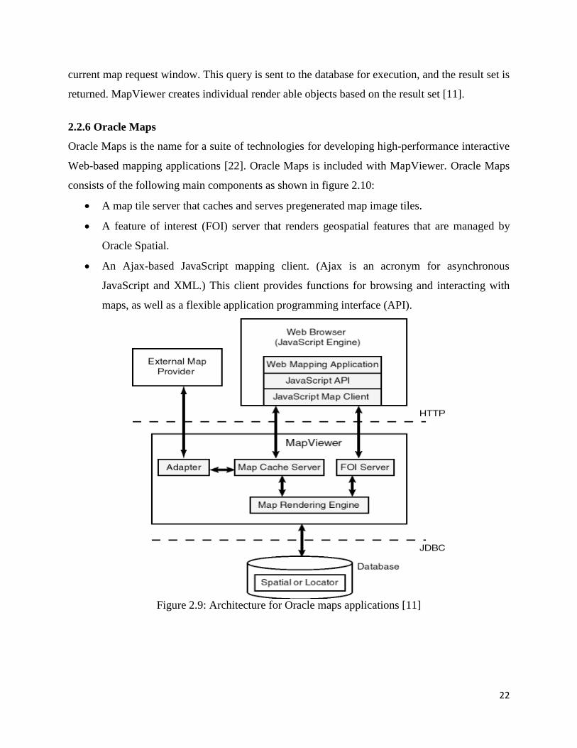
2.2.6 Oracle Maps
Oracle Maps is the name for a suite of technologies for developing high-performance interactive
Web-based mapping applications [22]. Oracle Maps is included with MapViewer. Oracle Maps
consists of the following main components as shown in figure 2.10:
A map tile server that caches and serves pregenerated map image tiles.
A feature of interest (FOI) server that renders geospatial features that are managed by
Oracle Spatial.
An Ajax-based JavaScript mapping client. (Ajax is an acronym for asynchronous
JavaScript and XML.) This client provides functions for browsing and interacting with
maps, as well as a flexible application programming interface (API).
Figure 2.9: Architecture for Oracle maps applications [11]

23
Applications interact with the Oracle Maps architecture as follows:
The application is developed using JavaScript, and it runs inside the JavaScript engine of
the Web browser.
The application invokes the JavaScript map client to fetch the map image tiles from the
map tile server, and then it displays the map in the Web browser.
The application invokes the JavaScript map client to fetch dynamic spatial features from
the FOI server and display them on top of the map tiles.
The JavaScript map client controls map-related user interaction for the application.
When the map tile server receives a map image tile request, it first checks to see if the
requested tile is already cached. If the tile is cached, the cached tile is returned to the
client. If the tile is not cached, the map tile server fetches the tile into the cache and
returns it to the client. Tiles can be fetched either directly from the MapViewer map
rendering engine or from an external Web map services provider.
When the FOI server receives a request, it uses the MapViewer map rendering engine to
generate the feature images and to send these images, along with feature attributes, to the
client.
2.3 Oracle Map Builder
Oracle MapBuilder is a standalone application that lets us create and manage the Oracle
Application Server MapViewer mapping metadata (styles, themes, and base maps) in the
database. Figure 2.11 is explaining the role of Map Builder. For example, we can use this tool to
create a style, theme or base map or modify its definition. Besides handling the metadata, the
tool provides interfaces to preview the metadata (for example, to see how a line style will appear
on a map or how is the theme rendered based on its styling rules), and display the original spatial
information from the spatial tables without creating MapViewer metadata. A set of wizards is
also available to create metadata based on database table contents. Existing metadata can be
edited and previewed, existing spatial tables can be previewed directly, spatial table contents can
be used in wizards to generate MapViewer metadata (advanced styles and themes), and import
tools can be used to store metadata (True type fonts as style information) and also to generate
new spatial tables (shape files generate tables with SDO_GEOMETRY type, image files
generate tables with SDO_GEORASTER type). [1, 16]

24
Figure 2.10: Oracle Map Builder diagram [1]
2.4 Existing Systems
Spatial Application is an application that makes use of spatial knowledge, awareness or
representation in order to achieve its goals. There are a number of Spatial Applications that have
been deployed successfully using Oracle Spatial and Oracle tools [21]. The systems, where
spatial applications have been developed using Oracle spatial are discussed as below:
1. Spatial information for managing the London Bus Network
London‟s transport system is one of the most comprehensive, complex, and articulate urban
transport systems in the world. The London bus system plays a crucial role in getting and
keeping London moving. About 6,500 buses are scheduled every day on more than 700 different
routes, amounting to about 1.5 billion passengers per year. Transport For London (TFL) is the
body responsible for managing the London transport system [20]. TFL is accountable for the
planning and delivery of transport facilities, including London Buses, London Underground and
London Trams. London Buses manages the bus services in London and, along with London
Underground, is the primary provider of urban public transport for the city. The tasks of London
Buses include bus route planning, service-level definition, and quality of service monitoring.
25
Each route is competitively tendered every five years. London Buses is a success story of public
transport that has been reshaped to meet the needs of 21st-century urban life. It is due to a more
modern, punctual, and customer-focused network, the buses of London are now carrying the
highest number of passengers in more than 40 years. These results can be achieved only with the
sophisticated management of the bus network and an appropriate information system. London
Buses needs to manage and maintain a complex bus network that adapts continuously in
response to changes in London‟s growth, spatial pattern, and economic and social developments.
On average, half of the network is subject to some level of review each year. Oracle Spatial has
been introduced by London Buses as the core spatial component of BusNet, the information
system that supports the route network management [1].
2. P-Info: A Mobile Application for Police Forces
In the year 2000, the Dutch police started investigating the use of wireless technology and
location services to address the needs of officers in the field and of those in the control rooms.
The result of this process is the P-Info system, currently implemented by several Dutch police
regions and adopted by the national police organization in support of mobile police workers. The
application focuses on mobile officers, those who operate in the field to provide citizen security,
response services, and investigative capabilities. In the Netherlands, about 20,000 police
personnel operate in the field either full-time or part-time. A special group of these officers
operates almost exclusively in the field and performs systematic patrol and policing in urban and
rural areas. By focusing on crime prevention and mobilizing citizens‟ support locally, their work
reduces the distance between citizens and the police while increasing mutual trust and
cooperation. They are assigned to, and operate in, a small area with the support and coordination
of regional police offices. They operate mostly outside of the office, and the goal of the police
organization was to maximize their presence in the field. Hence, these officers suffered
particularly from the lack of proper information availability. In several cases, they were forced to
interrupt their field work and return to the office simply to gather information that was useful to
the field operations. The P-Info system contains three functionality groups:
• Database and data services
• Location services
• Office automation

26
The central component of P-Info is the database and data services module. It provides integrated
access to the whole range of regional, national, and international police databases. The
information sources were the same as those available at the office, while information search and
information provision was optimized for mobile users. The main purpose of the location services
was to provide location-enabled searches, such as proximity or area searches, to provide the
visualization of results on a map, and in general to location-enable the P-Info content. Oracle
Spatial was used by P-Info to store and retrieve spatial information, perform proximity analysis,
and support overlay and spatial selections. The results showed that P-Info increased the time
spent by officers in the field by about 20 percent. This means the same amount of fieldwork
could be carried out by four rather than five agents or, alternatively, that a 20 percent larger area
could be patrolled at the same quality level. Efficiency increased by 50 percent using P-Info.
There is clear evidence that P-Info improves the effectiveness and efficiency of police forces [1].
3. United States Geospatial System (USGS) National Land Cover Visualization and
Analysis Tool
Land-cover data is a largely untapped information resource. With increasing population and the
challenging prospect of climate change, comprehensive information about the condition of our
land and how it is changing becomes more and more vital. Land cover, the pattern of natural
vegetation, agriculture, and urban areas, is shaped by both natural processes and human
influences. Information about land cover is needed by managers of public and private lands,
urban planners, agricultural experts, and scientists for studying such issues as climate change or
invasive species. The U.S. National Land Cover Dataset 1992 (NLCD 1992) was derived from
the early to mid-1990s.Land-cover data is useful in many operational settings and for strategic
decisions:
Fire danger monitoring and forecasting: Based on land-cover data as well as other data
sources, the effects of fire can be consistently measured in terms of burn severity.
Biodiversity conservation: Land cover is an essential indicator of the ability of a land to
sustain ecosystems.
Land-use planning: In densely populated areas, land use is often the result of conflicting
claims, with land contended between transportation, urban areas, agriculture, nature, or
industrial areas.
27
Climate change: Land-cover data is used to understand and analyze the stocks and
fluxes of carbon on the landscape (soils and biomass) to predict the impacts of future land
management decisions on the global carbon cycle.
Flood and natural risk prevention: Land-cover data, combined with simulation tools,
serves to predict the risk and impact of events such as floods, hurricanes, or landslides.
The USGS National Land Cover Visualization and Analysis Tool provide to both expert
and non expert users access to the USGS Land Cover data. The geographic data are
stored in Oracle as SDO_GEOMETRY and SDO_GEORASTER data types. Original
ESRI shapefiles are loaded into Oracle Spatial [1].
28
Chapter 3
Problem Statement
3.1 Problem Statement
The things become clearer when presented in the form of a picture or map rather than in the form
of coordinates or textual format. Using the capabilities of Oracle Spatial concepts, Map Viewer
and Map Builder, such spatial applications which incorporate the maps as main part of the whole
can be developed. In India, the scene of spatial applications is not satisfactory; developers are
still designing and developing traditional applications at very large scale. Also, the developers
are not much aware of spatial applications and process of developing such applications as well.
So, in this thesis work a spatial application of Patiala has been designed and developed and it
shows hospitals, banks, colleges and some important locations of Patiala. In this spatial
application, we have shown the nearby hospitals, colleges and banks to Thapar University. The
Zoom Tool option allows to view Thapar University. The Distance Measure option is used to
find the distance between any two locations. In this thesis work, each step regarding spatial
application development has been clearly elaborated.
3.2 Objectives
The main Objectives of Design and Implementation of Spatial Application for Patiala city are
discussed as below:
To gather data about various locations in Patiala city.
To create database schema, identified by a particular username and password.
To create tables for storing data about hospitals, banks and colleges in Patiala city.
To insert data into the tables created for hospitals, banks and colleges in Patiala.
To define metadata for the Patiala map using Map Builder tool.
To build a map using Map Builder tool.
To create a spatial application for Patiala city with navigation, zoom and distance
measure options.
To retrieve spatial data from spatial application through SQL queries.
29
3.3 Methodology
The methodology used for the design and development of spatial application for Patiala city is as
follows:
Design a spatial database for the application with the use of Google maps tool to retrieve
the coordinate information of Patiala.
Storage of spatial data into the database with the use of SQL Plus tool.
Usage of Oracle Map Builder tool to define mapping metadata for Patiala city.
Usage of Map Viewer for creating data source for spatial database and creating map tile
layer for the application.
Design and Development of the application with the use of HTML and JavaScript.
This methodology smoothly explores all the steps underlying the map-generation process (for
any real world spatial object as Patiala) like database creation, metadata creation, map server
activation, and application building.
30
Chapter 4
Design and Implementation of Spatial
Application for Patiala City
Spatial data does not mean only storage of data in databases and queried by its users, it also
includes other hidden capabilities. One of them is the visualization of spatial data by means of
maps. Therefore, not only created a spatial database has been created but a spatial application has
also been developed to explore the visualization capability of spatial database. This application
includes various map features in it. The process of developing such an application includes the
use of various powerful applications and tools at different stages according to the requirement.
As described in previous chapter, „Patiala‟ city has been used as a case study for designing and
developing a spatial application. The description of tools and applications used are as follows:
Oracle 11g: We have installed Oracle 11g and used SQL Plus component of this
database management system for creating spatial database for Patiala.
Oracle Map Builder Tool: This tool has been used for creating and managing the
mapping metadata for Patiala city spatial database.
Oracle Map Viewer: Map Viewer is basically a map server. It handles all the map
requests from the client applications.
4.1 Spatial Database Designing
A spatial database is designed by categorizing the identified locations of Patiala under the heads
given below:
1. Hospitals
2. Colleges
3. Roads
4. Banks
5. Thapar
The database contains spatial tables for each of these categories. Each table has three columns,
each for Id, Name and Shape attributes. Shape attribute is used to define the type of geometry.
The schema of each table that describes each of the attributes is defined as follows:

31
Table 4.1: Schema of STBL_HOS
Table 4.2: Schema of Table STBL_CLG
Table 4.3: Schema of Table CLG_ROAD
Table 4.4: Schema of Table STBL_BANK
S.No. Column Name Datatype
1. Id Number (Primary Key)
2. Name varchar2(50)
3. Shape SDO_GEOMETRY
S.No. Column Name Datatype
1. Hos_id Number(Primary Key)
2. Hos_name varchar2(50)
3. Hos_shape SDO_GEOMETRY
S.No. Column Name Datatype
1. Clg_id Number (Primary Key)
2. Clg_name varchar2(40)
3. Clg_shape SDO_GEOMETRY
S.No. Column Name Datatype
1. Clg_road_id Number (Primary Key)
2. Clg_name varchar2(40)
3. Road_shape SDO_GEOMETRY
32
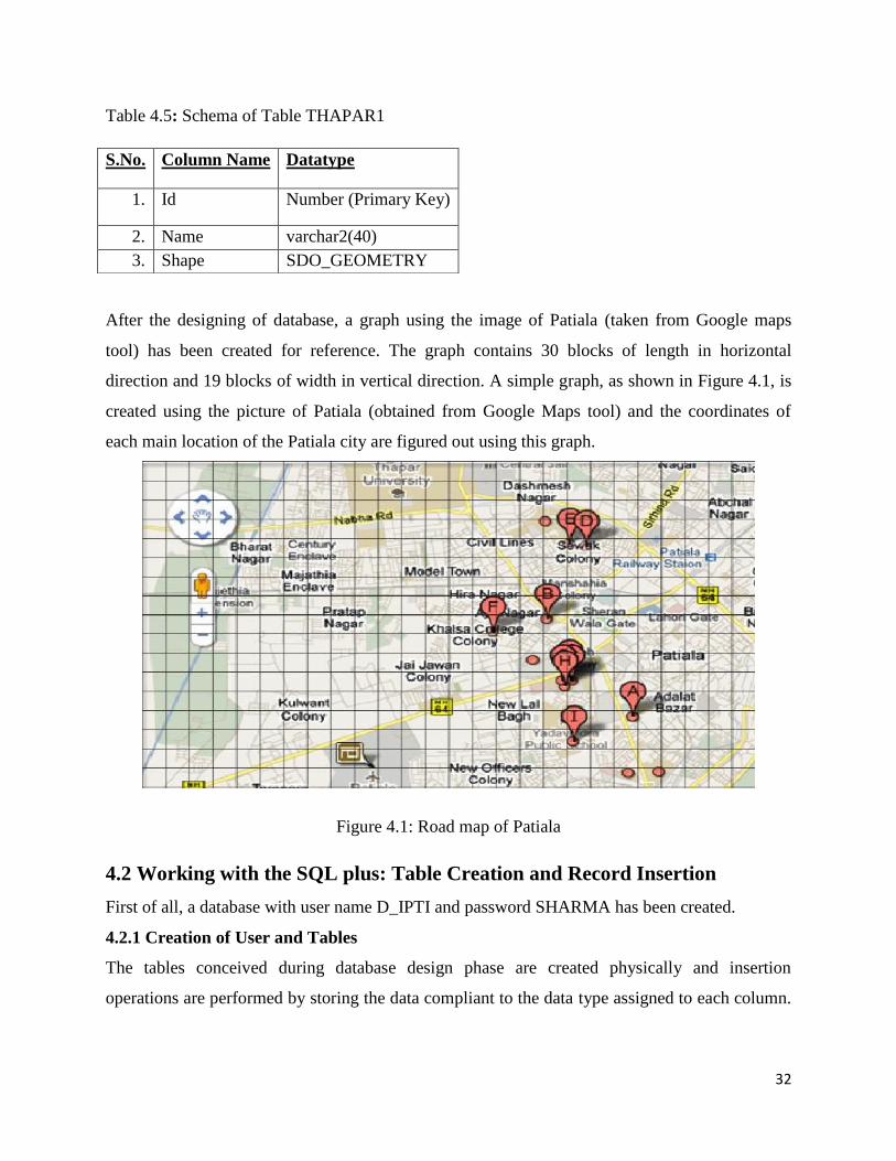
Table 4.5: Schema of Table THAPAR1
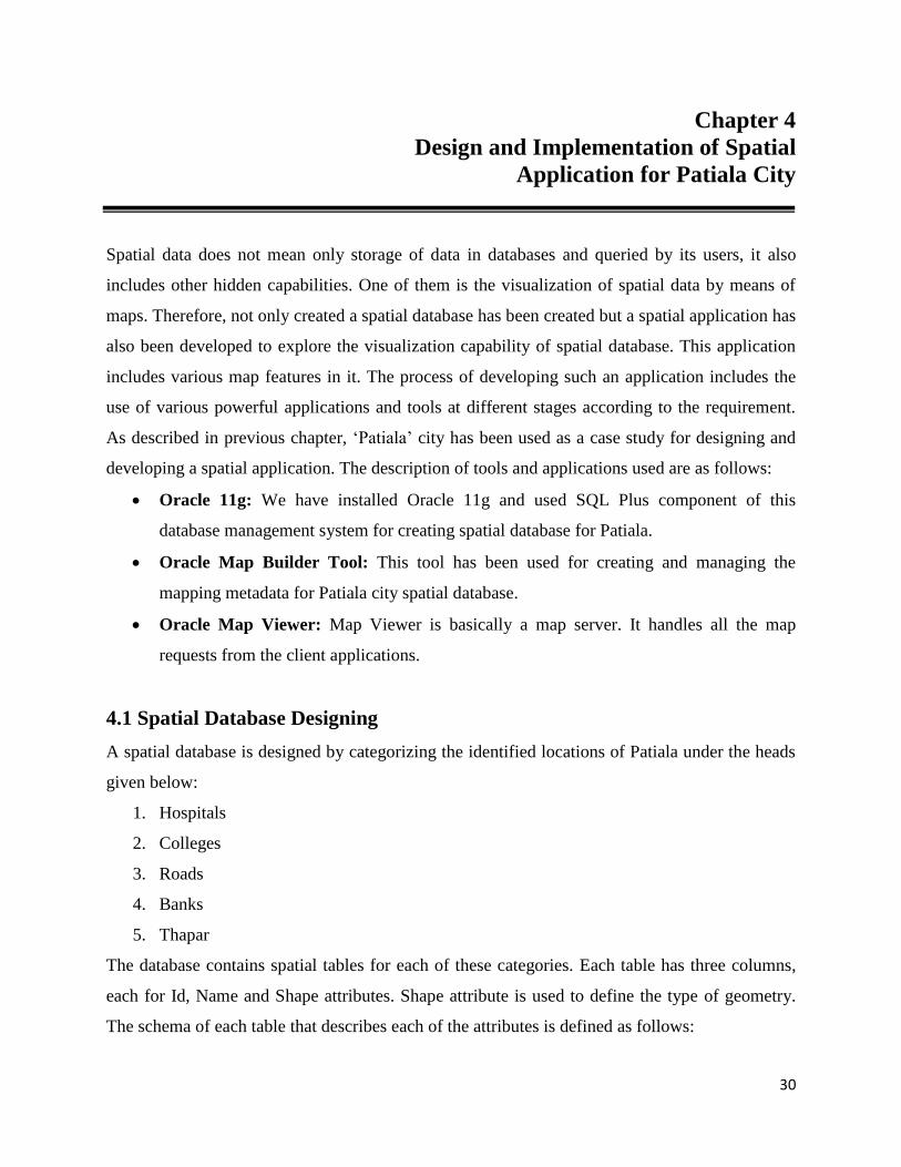
After the designing of database, a graph using the image of Patiala (taken from Google maps
tool) has been created for reference. The graph contains 30 blocks of length in horizontal
direction and 19 blocks of width in vertical direction. A simple graph, as shown in Figure 4.1, is
created using the picture of Patiala (obtained from Google Maps tool) and the coordinates of
each main location of the Patiala city are figured out using this graph.
Figure 4.1: Road map of Patiala
4.2 Working with the SQL plus: Table Creation and Record Insertion
First of all, a database with user name D_IPTI and password SHARMA has been created.
4.2.1 Creation of User and Tables
The tables conceived during database design phase are created physically and insertion
operations are performed by storing the data compliant to the data type assigned to each column.
S.No. Column Name Datatype
1. Id Number (Primary Key)
2. Name varchar2(40)
3. Shape SDO_GEOMETRY
33
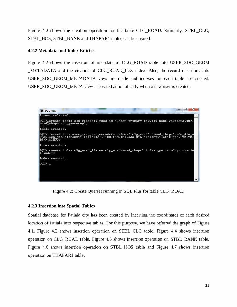
Figure 4.2 shows the creation operation for the table CLG_ROAD. Similarly, STBL_CLG,
STBL_HOS, STBL_BANK and THAPAR1 tables can be created.
4.2.2 Metadata and Index Entries
Figure 4.2 shows the insertion of metadata of CLG_ROAD table into USER_SDO_GEOM
_METADATA and the creation of CLG_ROAD_IDX index. Also, the record insertions into
USER_SDO_GEOM_METADATA view are made and indexes for each table are created.
USER_SDO_GEOM_META view is created automatically when a new user is created.
Figure 4.2: Create Queries running in SQL Plus for table CLG_ROAD
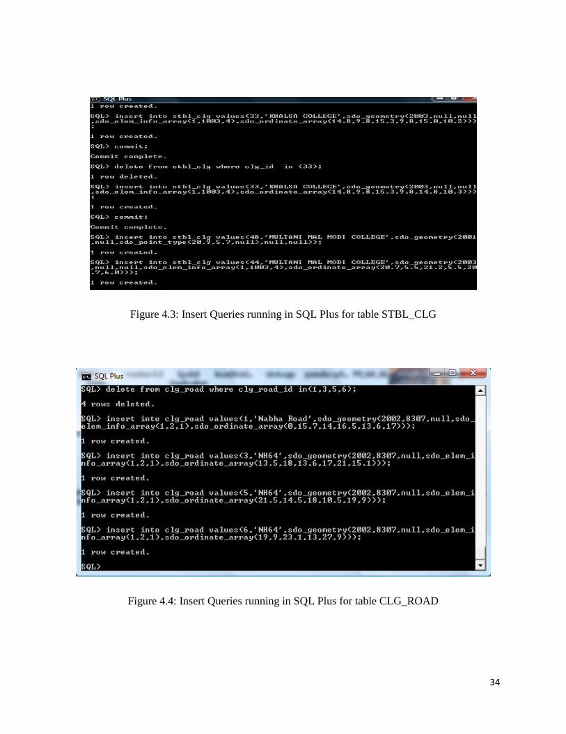
4.2.3 Insertion into Spatial Tables
Spatial database for Patiala city has been created by inserting the coordinates of each desired
location of Patiala into respective tables. For this purpose, we have referred the graph of Figure
4.1. Figure 4.3 shows insertion operation on STBL_CLG table, Figure 4.4 shows insertion
operation on CLG_ROAD table, Figure 4.5 shows insertion operation on STBL_BANK table,
Figure 4.6 shows insertion operation on STBL_HOS table and Figure 4.7 shows insertion
operation on THAPAR1 table.
34
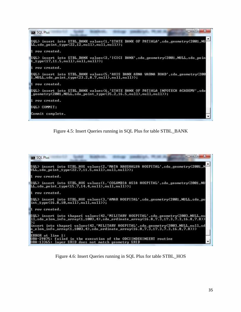
Figure 4.3: Insert Queries running in SQL Plus for table STBL_CLG
Figure 4.4: Insert Queries running in SQL Plus for table CLG_ROAD
35
Figure 4.5: Insert Queries running in SQL Plus for table STBL_BANK
Figure 4.6: Insert Queries running in SQL Plus for table STBL_HOS
36
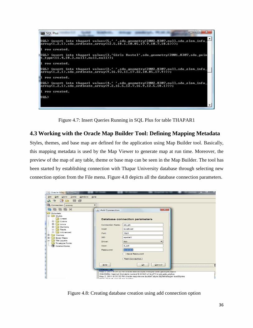
Figure 4.7: Insert Queries Running in SQL Plus for table THAPAR1
4.3 Working with the Oracle Map Builder Tool: Defining Mapping Metadata
Styles, themes, and base map are defined for the application using Map Builder tool. Basically,
this mapping metadata is used by the Map Viewer to generate map at run time. Moreover, the
preview of the map of any table, theme or base map can be seen in the Map Builder. The tool has
been started by establishing connection with Thapar University database through selecting new
connection option from the File menu. Figure 4.8 depicts all the database connection parameters.
Figure 4.8: Creating database creation using add connection option
37
4.3.1 Style Creation
A style is a visual attribute that can be used to represent a spatial feature. The basic map symbols
and legends for representing point, line, and area features are defined and stored as individual
styles. Each style has a unique name and defines one or more graphical elements in XML syntax.
User defined styles can be created. There are six types of styles that can be created and used in
themes. These styles include areas, colors, lines, markers, texts, and advanced styles. For
generating themes, colors, texts, and line styles were used for spatial tables. For example, we
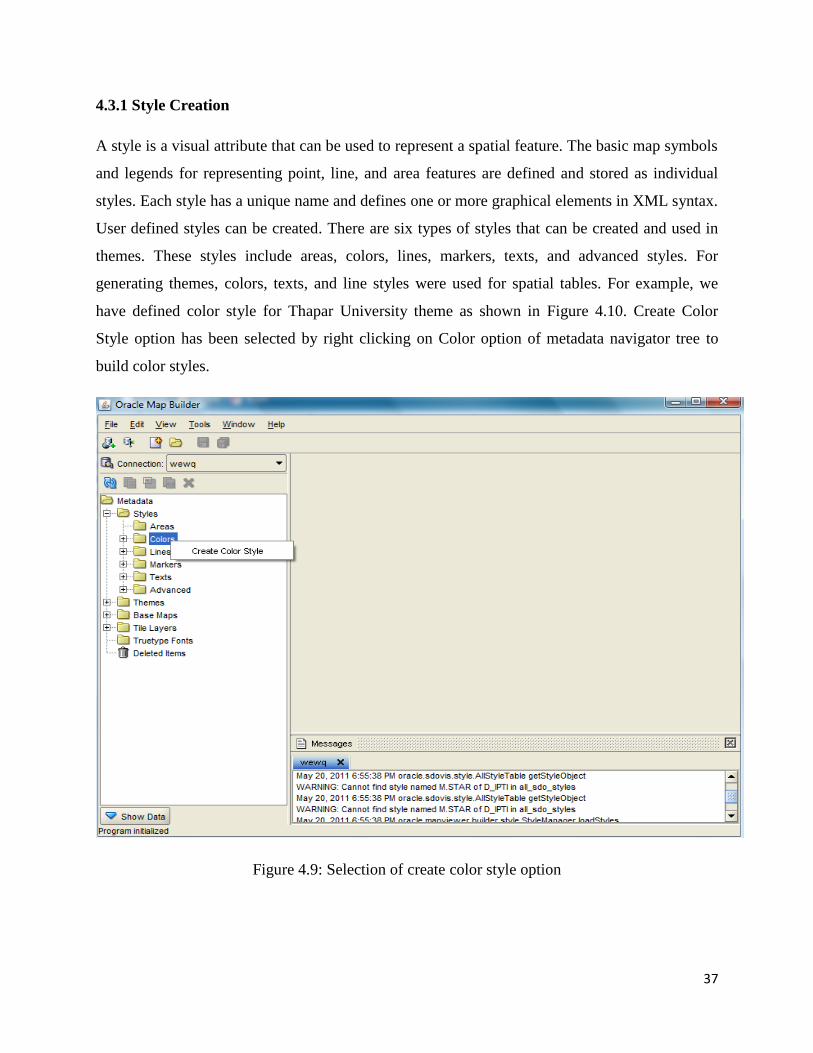
have defined color style for Thapar University theme as shown in Figure 4.10. Create Color
Style option has been selected by right clicking on Color option of metadata navigator tree to
build color styles.
Figure 4.9: Selection of create color style option
38
After this, the color parameters like color name, description, and style options like Fill and
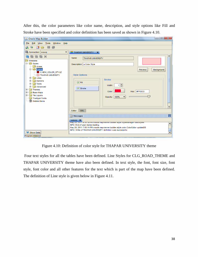
Stroke have been specified and color definition has been saved as shown in Figure 4.10.
Figure 4.10: Definition of color style for THAPAR UNIVERSITY theme
Four text styles for all the tables have been defined. Line Styles for CLG_ROAD_THEME and
THAPAR UNIVERSITY theme have also been defined. In text style, the font, font size, font
style, font color and all other features for the text which is part of the map have been defined.
The definition of Line style is given below in Figure 4.11.

39
Figure 4.11: Definition of line style for road
4.3.2 Theme Creation
A theme is a visual representation of a particular data layer. By combining different styles, a
theme is created. The procedure of creating geometry theme for table CLG_ROAD has been
explained using Figures. Themes for the remaining tables can be created by following the same
procedure. In order to create a block theme we have selected the required table from spatial table
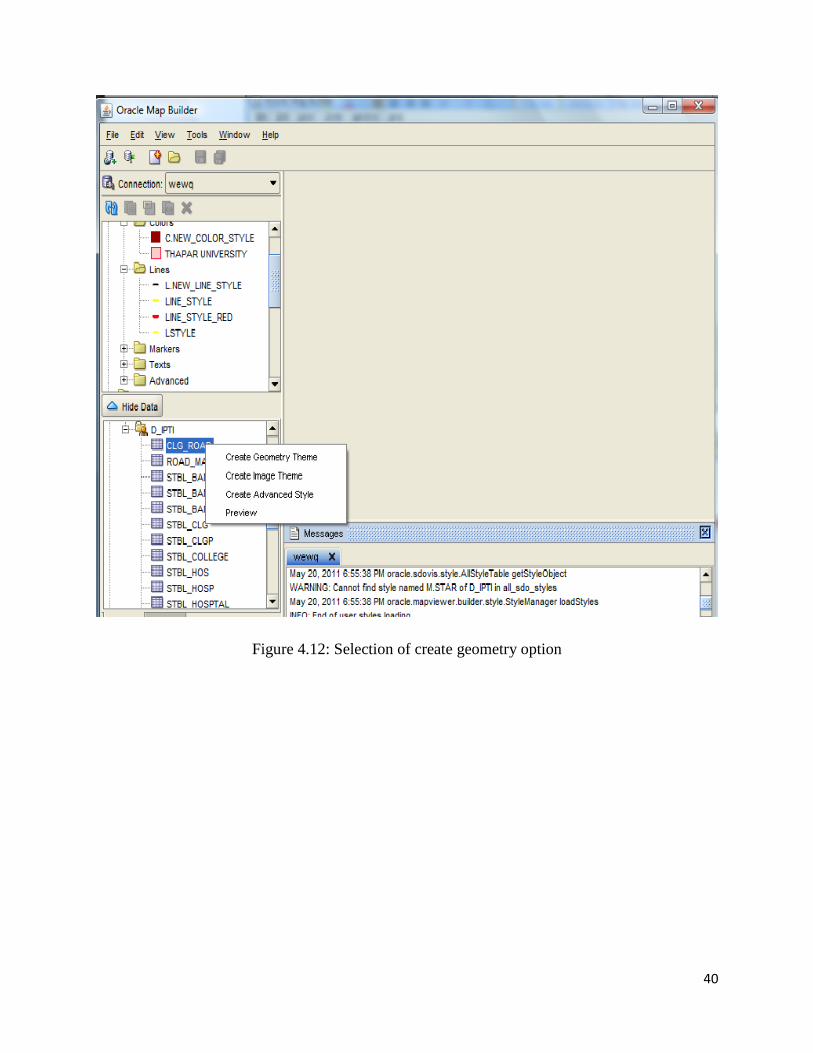
navigator tree and right clicked on it. Then selected the Create Geometry Theme option as shown
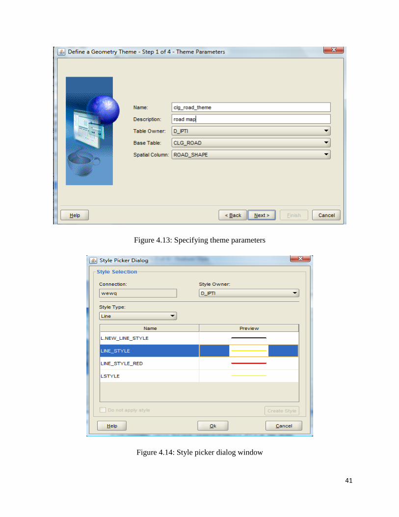
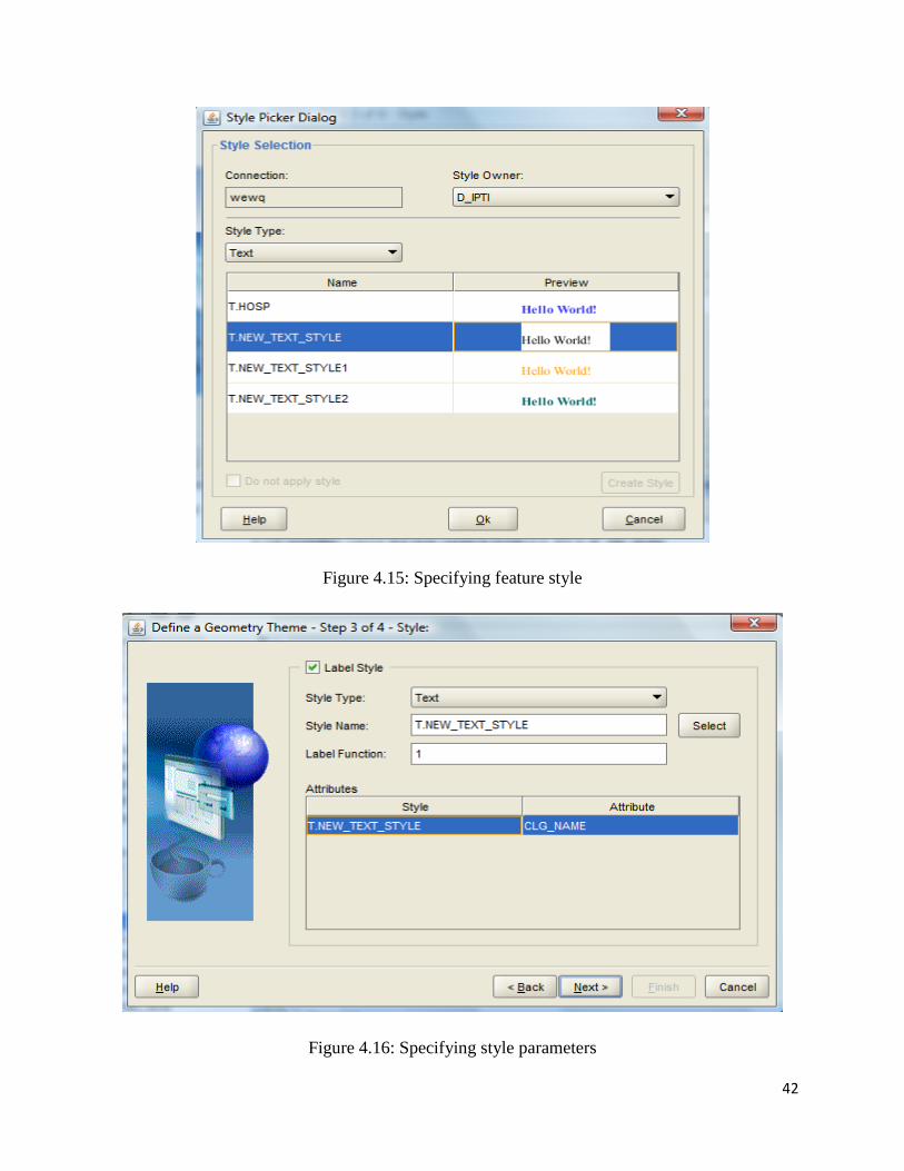
in Figure 4.12, and further, followed the steps described in Figure 4.13, Figure 4.14, Figure 4.15,
Figure 4.16 and Figure 4.17 respectively. Figure 4.13 shows the details of theme parameters.
Figure 4.14 shows the color picking for the theme. Figure 4.15 shows the feature style selection.
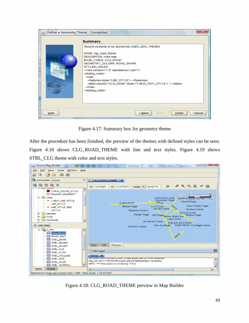
Figure 4.16 shows the details of style parameters. At last, Figure 4.17 shows summary box for
geometry theme.
40
Figure 4.12: Selection of create geometry option
41
Figure 4.13: Specifying theme parameters
Figure 4.14: Style picker dialog window
42
Figure 4.15: Specifying feature style
Figure 4.16: Specifying style parameters
43
Figure 4.17: Summary box for geometry theme
After the procedure has been finished, the preview of the themes with defined styles can be seen.
Figure 4.18 shows CLG_ROAD_THEME with line and text styles. Figure 4.19 shows
STBL_CLG theme with color and text styles.
Figure 4.18: CLG_ROAD_THEME preview in Map Builder
44
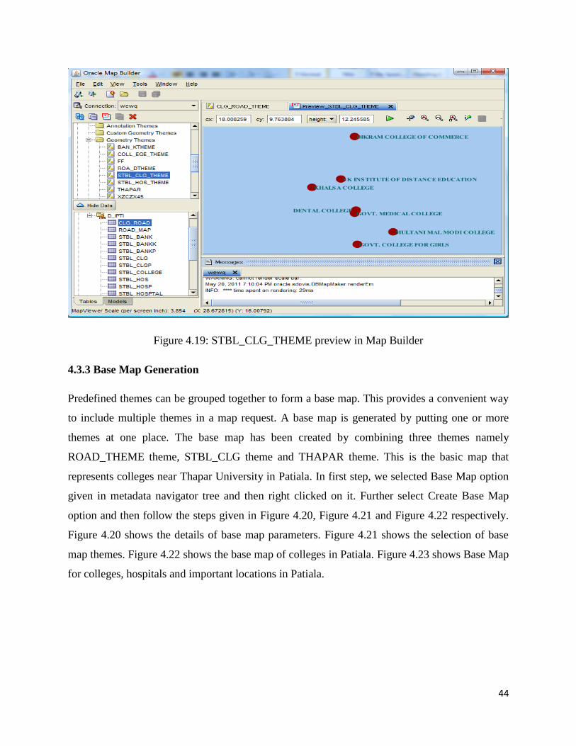
Figure 4.19: STBL_CLG_THEME preview in Map Builder
4.3.3 Base Map Generation
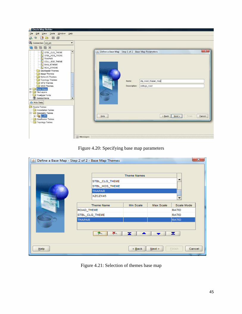
Predefined themes can be grouped together to form a base map. This provides a convenient way
to include multiple themes in a map request. A base map is generated by putting one or more
themes at one place. The base map has been created by combining three themes namely
ROAD_THEME theme, STBL_CLG theme and THAPAR theme. This is the basic map that
represents colleges near Thapar University in Patiala. In first step, we selected Base Map option
given in metadata navigator tree and then right clicked on it. Further select Create Base Map
option and then follow the steps given in Figure 4.20, Figure 4.21 and Figure 4.22 respectively.
Figure 4.20 shows the details of base map parameters. Figure 4.21 shows the selection of base
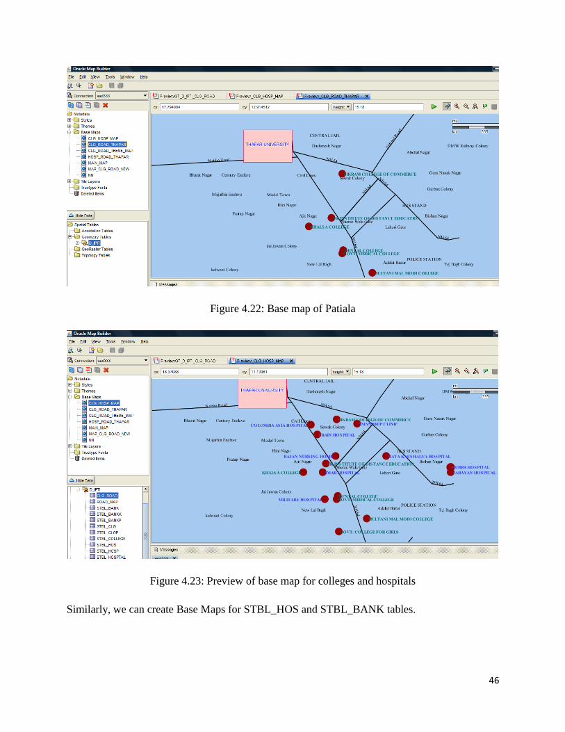
map themes. Figure 4.22 shows the base map of colleges in Patiala. Figure 4.23 shows Base Map
for colleges, hospitals and important locations in Patiala.
45
Figure 4.20: Specifying base map parameters
Figure 4.21: Selection of themes base map
46
Figure 4.22: Base map of Patiala
Figure 4.23: Preview of base map for colleges and hospitals
Similarly, we can create Base Maps for STBL_HOS and STBL_BANK tables.
47
4.4 Working with Map Viewer: Data Source and Tile Layer Creation
Oracle Map Viewer works as a map server. Whenever any application requires any activity
related to map like map-generation, and map-processing, it is all done by the Map Viewer. The
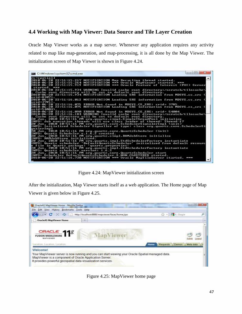
initialization screen of Map Viewer is shown in Figure 4.24.
Figure 4.24: MapViewer initialization screen
After the initialization, Map Viewer starts itself as a web application. The Home page of Map
Viewer is given below in Figure 4.25.
Figure 4.25: MapViewer home page

48
Login page of Map Viewer is opened by clicking on the Admin link for user authorization. The
login page is shown in Figure 4.26.
Figure 4.26: Login screen of MapViewer
A data source for Patiala spatial database has been created. Creation of data source is shown in
Figure 4.27.
Figure 4.27: Creation of data source

49
Further, a Map Tile Layer for our spatial application has been created. It is a very important task
in order to run any application successfully. Figure 4.28 shows the creation of map tile layer.
Figure 4.28: Creation of map tile layer
The map of Patiala city is generated by selecting Demo_Map Map Tile Layer and then clicking
on View map/Manage Tile link, as shown in Figure 4.29.
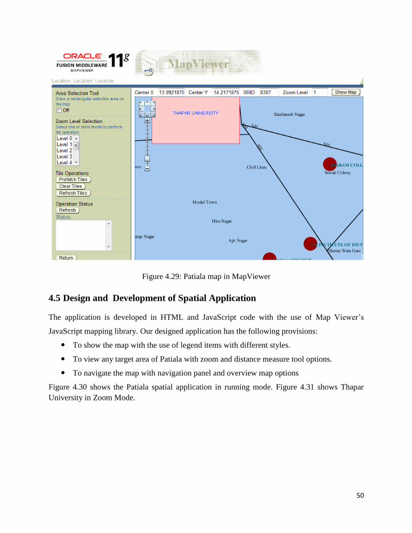
50
Figure 4.29: Patiala map in MapViewer
4.5 Design and Development of Spatial Application
The application is developed in HTML and JavaScript code with the use of Map Viewer‟s
JavaScript mapping library. Our designed application has the following provisions:
To show the map with the use of legend items with different styles.
To view any target area of Patiala with zoom and distance measure tool options.
To navigate the map with navigation panel and overview map options
Figure 4.30 shows the Patiala spatial application in running mode. Figure 4.31 shows Thapar
University in Zoom Mode.
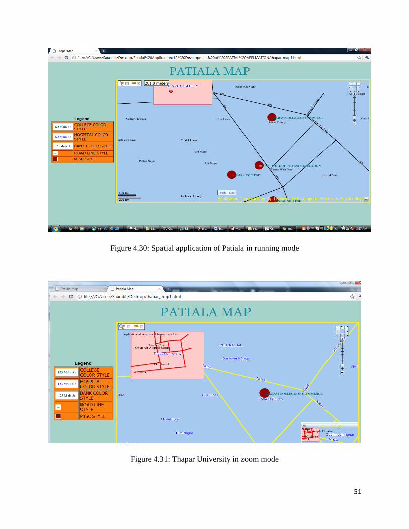
51
Figure 4.30: Spatial application of Patiala in running mode
Figure 4.31: Thapar University in zoom mode
52
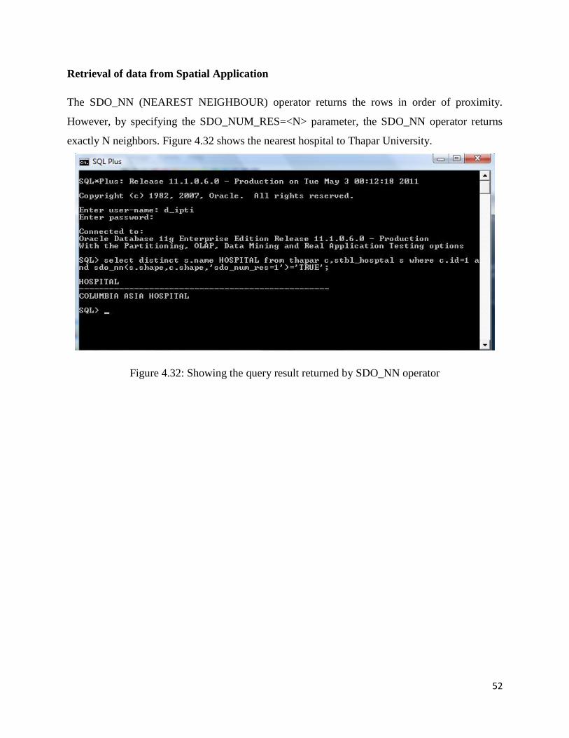
Retrieval of data from Spatial Application
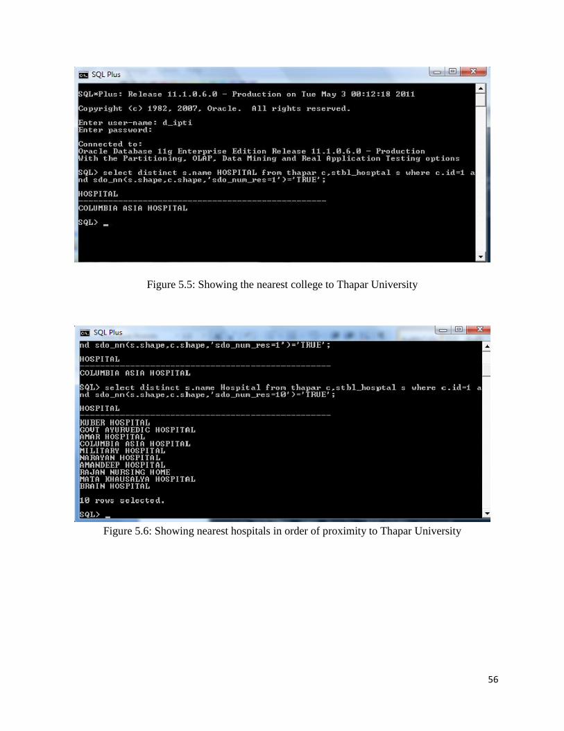
The SDO_NN (NEAREST NEIGHBOUR) operator returns the rows in order of proximity.
However, by specifying the SDO_NUM_RES=<N> parameter, the SDO_NN operator returns
exactly N neighbors. Figure 4.32 shows the nearest hospital to Thapar University.
Figure 4.32: Showing the query result returned by SDO_NN operator

53
Chapter 5
Testing and Results
The application is developed in HTML and JavaScript code with the use of Map Viewer‟s
JavaScript mapping library. Our designed application has the following provisions:
To show the map with the use of legend items with different styles.
To view any target area of Patiala with zoom and distance measure tool options.
To navigate the map with navigation panel and overview map options
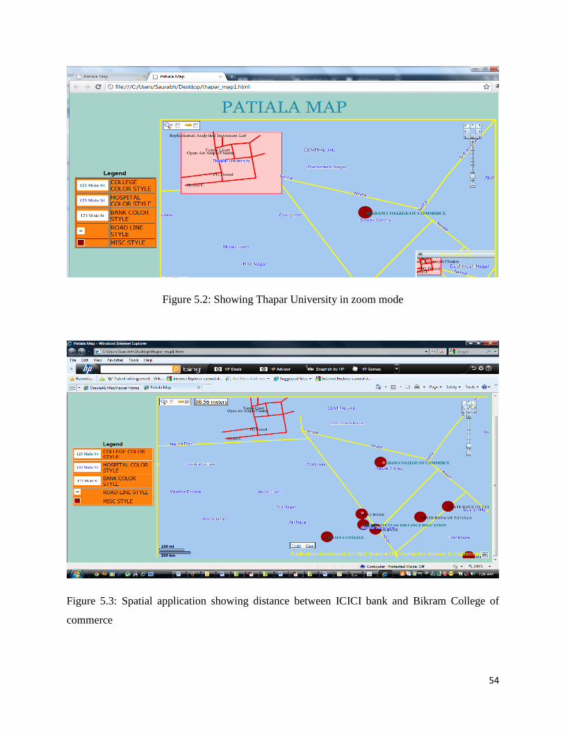
Figure 5.1 shows the Patiala spatial application in running mode. Figure 5.2: shows Thapar
University in Zoom Mode. Figure 5.3: shows distance between ICICI bank and Bikram College
of Commerce. Figure 5.4: shows distance between Mandeep clinic and Thapar University.
Figure 5.1: Spatial application of Patiala in running mode.
54
Figure 5.2: Showing Thapar University in zoom mode
Figure 5.3: Spatial application showing distance between ICICI bank and Bikram College of
commerce
55
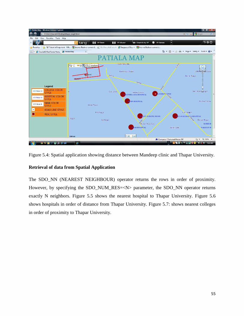
Figure 5.4: Spatial application showing distance between Mandeep clinic and Thapar University.
Retrieval of data from Spatial Application
The SDO_NN (NEAREST NEIGHBOUR) operator returns the rows in order of proximity.
However, by specifying the SDO_NUM_RES=<N> parameter, the SDO_NN operator returns
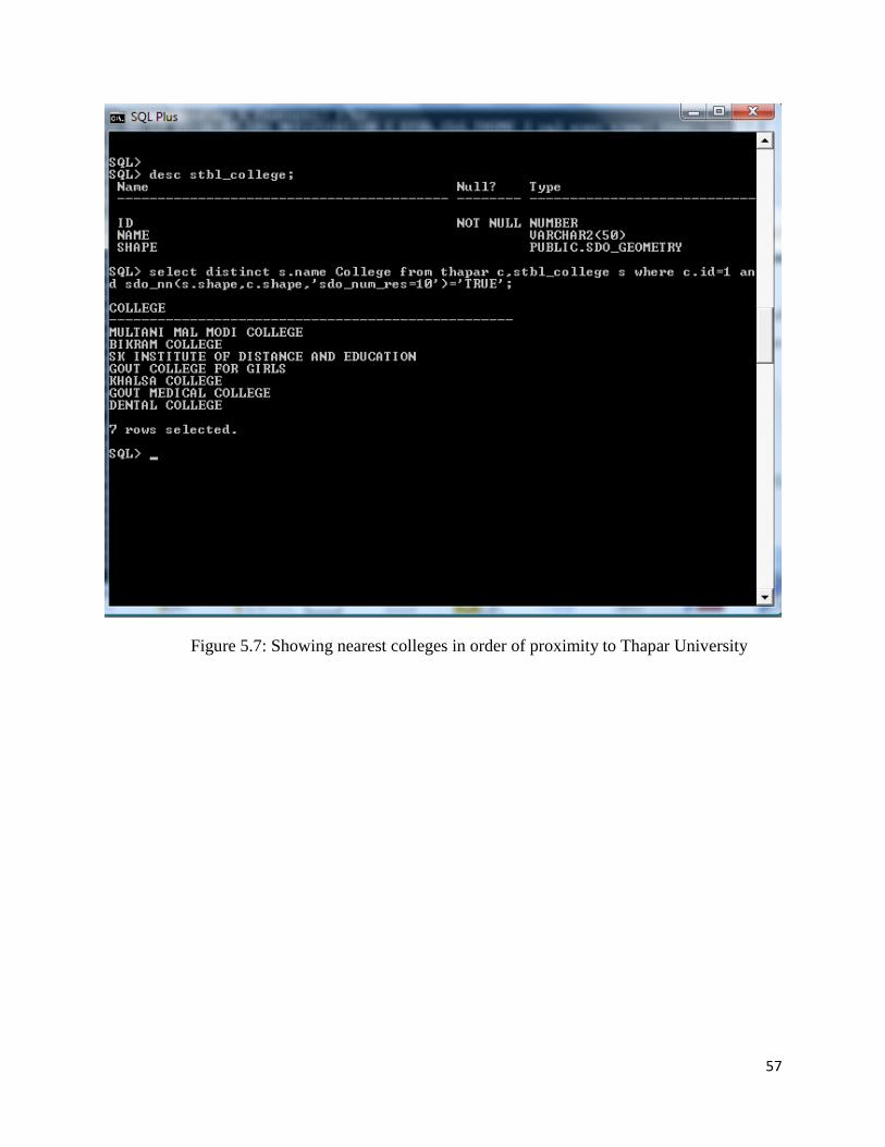
exactly N neighbors. Figure 5.5 shows the nearest hospital to Thapar University. Figure 5.6
shows hospitals in order of distance from Thapar University. Figure 5.7: shows nearest colleges
in order of proximity to Thapar University.
56
Figure 5.5: Showing the nearest college to Thapar University
Figure 5.6: Showing nearest hospitals in order of proximity to Thapar University
57
Figure 5.7: Showing nearest colleges in order of proximity to Thapar University
58
Chapter 6
Conclusion and Future Scope
6.1 Conclusion
Oracle Spatial can be used to design very powerful and robust spatial applications. It was not
possible in case of traditional database to store, analyze, visualize, and integrate spatial data in
spatial applications. Oracle Spatial is used to store and retrieve all spatial data used in the
applications, and the spatial analysis performed in these applications is based on the methods and
tools. There is a need to manage geometric, geographic or spatial data related to space in various
fields. GIS systems store spatial and non-spatial data separately. This split data model has several
drawbacks. Oracle spatial provides a completely open and standards-based architecture for the
management of spatial data within a database management system. Spatial data can be
processed, retrieved and related to all the other data stored in the database using the Oracle
Spatial. The condition of spatial application development is not much satisfactory in India. Most
of the application development works are still approaching the traditional framework of
application development and avoiding the powerful features of spatial technologies. In the design
and implementation phase we have presented the overall process of making the Patiala city
spatial application. In that process, the spatial database for the Patiala city has been created. This
stored spatial data is used by Map Builder and MapViewer in various steps of application
development. At last, the spatial application generates the map of Patiala showing the nearby
hospital, colleges and banks to Thapar University. Spatial application for Patiala possesses
features like navigation panel, distance tool, marquee-zoom tool etc. which make the application
more interactive. Finally, it can be concluded that Oracle Spatial is armed with very big concepts
and suit of technologies that make it easier to draw our invisible thoughts in form of visible
maps.
6.2 Future Scope
The application is designed using 2-d geometries in the map but further 3-d geometries
can be used to draw locations in the Patiala city map. Any real world location can be
59
considered as a collection of 3-d geometries and special queries can be used to store those
3-d geometries into the database.
This application can be featured with more tools in order to make it more versatile. The
examples of other features include theme-based FOI layer, Event Listeners for a Theme
Based FOI layer, Add/Remove and Show/Hide FOI, Red Lining, Map Event Listeners,
Multiple Base Maps, Circle Tool and Rectangle Tool.
The feature of positioning and searching can be added to the application. In positioning,
the map can be positioned on user given location. Searching feature searches the different
types of locations around any given location and within the given range as well.
The extension of data warehouses in order to support spatial information opens up a new
spectrum of possibilities, since this allows the inherent semantics of spatial information
to be taken into account. For example, this could allow one to monitor the evolution of
urban green areas and their impact on biodiversity.
Extracting interesting and useful patterns from spatial datasets is more difficult than
extracting the corresponding patterns from traditional numeric and categorical data due to
the complexity of spatial data types, spatial relationships, and spatial autocorrelation.
Spatial data mining can be used in location prediction, spatial outlier detection and co-
location mining.
60
References
[1] Ravi Kothuri, Albert Godfrind and Euro Beinat,”Pro Oracle Spatial for Oracle Database
11g”, Apress publishers, 2007.
[2] Shashi Shekar and Sanjay Chawala, “Spatial Database A Tour” Book, Prentice Hall, 2003.
[3] “Oracle spatial users‟ guide and reference 10g” Release 2 (10.2) B14255-01, June, 2005.
[Online]. Available:
http://youngcow.net/doc/oracle10g/appdev.102/b14255.pdf
[4] Siva Ravada and Xavier Lopez, "Oracle Spatial10g". [Online].Available:
www.nyoug.org/Presentations/2003/10gspatial.pdf
[5] N. Roussopoulos, S. Kelley, and F. Vincent, Nearest neighbor queries, Proceeding of ACM
SIGMOD, pp. 71–79, San Jose, CA, May 1995.
[6] Dan Geringer and Siva Ravada, “Oracle‟s Spatial Technologies”. [Online].Available:
http://download.oracle.com/otndocs/products/spatial/pdf/spatial_features_jsirev.pdf
[7] David Sonnen and Henry D. Morris, “Oracle 10g: Spatial Capabilities for Enterprise
Solutions”, January, 2005. [Online].Available:
images.autodesk.com/adsk/files/IDCOracle_Spatial_Capabilities_Enterprise_Solns.pdf
[8] Matt Bauer, ”Mapping Geometric Data with Oracle Spatial” Article. [Online].Available:
http://www.oreillynet.com/pub/a/network/2003/11/10/oracle_spatial.html
[9] “Oracle Fusion Middleware, FMW MapViewer11g FAQ”, July 1, 2009. [Online].Available:
http://www.oracle.com/technology/products/mapviewer/index.html/mapviewer_faq_11gr1.pdf
[10] “Introduction to MapViewer”, Oracle Documentation. [Online].Available:
http://download.oracle.com/docs/cd/B10464_05/web.904/b10559/vis_star.htm
[11] Oracle Fusion Middleware User's Guide for Oracle MapViewer 11g Release 1(11.1.1)
E10145-01, May, 2009. [Online].Available:
www.oracle.com/technology/products/mapviewer/pdf/mapviewer11gr1_ug.pdf
[12] Oracle Fusion Middleware MapViewer 11g Technical Overview, July, 2009.
[Online].Available:
http://www.oracle.com/technology/products/mapviewer/index.html/mapviewer11gr1_twp.pdf
61
[13] “Oracle Fusion Middleware, MapViewer11g Data Sheet”, July, 2009.
http://www.oracle.com/technology/prpoducts/maviewer/index.html/mapviewer_datasheet_11gr1.
[14] "Oracle Spatial 11g Geocoder", October, 2009. [Online].Available:
http://www.oracle.com/technology/products/spatial/pdf/11gr2_collateral/spatial11gr2_geocoder_
twp.pdf
[15] "Oracle Spatial 11g GeoRaster", September, 2009. [Online].Available:
http://www.oracle.com/technology/products/spatial/pdf/11gr2_collateral/spatial11gr2_georaster_
twp.pdf
[16] "Oracle Locator and Oracle Spatial 11g Best Practices", January, 2009. [Online].Available:
http://www.oracle.com/technology/products/spatial/pdf/spatial_wp09_bestprac.pdf
[17] "Oracle Location Based Services" . [Online].Available:
www.people.cis.ksu.edu/~hankley/d764/Slides08/764_23_Gudelli_OracleSpatial.ppt
[18] "Advance Spatial Data Management for Enterprise Applications", September, 2009.
[Online].Available:
http://www.oracle.com/technology/products/spatial/pdf/11gr2_collateral/spatial11gr2_wp_0922.
[19] P. Rigaux, M. Scholl and A. Voisard, “Spatial Databases with applications to GIS”, Morgan
Kaufmann Publishers, 2002.
[20] C. Dondo and U. Rivett, “Spatial information systems in managing public transport
information”, South African Journal of Information Management, vol.6, June. 2004.
[21] Liujian (LJ) Qian, “Developing spatial applications using Oracle Spatial and MapViewer”,
Spatial Group, Oracle.
www.ucgis.org/visualization/whitepapers/qia2.pdf
[22] Sangho Kim, Shashi Shekhar and Manki Min, “Contraflow Transportation Network
Reconfiguration for Evacuation Route Planning”, IEEE, vol. 20, no. 8, August. 2008.

62
Research Publications
Research Paper Communicated
Dipti Sharma, Parteek Bhatia, “Spatial Application of Patiala using Oracle Spatial Database,
MapViewer, and Map Builder, communicated to Sigmod Journal of Research.