Optimum overhang geometry for high rise office building energy saving in tropical climates
33
vii TABLE OF CONTENTS CHAPTER TITLE PAGE THESIS TITLE i DECLARATION ii DEDICATION iii ACKNOWLEDGEMENT iv ABSTRACT (ENGLISH) v ABSTRAK (BAHASA MELAYU) vi TABLE OF CONTENTS vii LIST OF TABLES xvi LIST OF FIGURES xxi LIST OF ABBREVIATIONS xxx LIST OF SYMBOLS xxxiii LIST OF APPENDIXES xxxix 1 GENERAL INTRODUCTION 1.1 Introduction 1 1.2 The Problem Statement 4 1.3 Research Hypothesis 5 1.4 Research Questions 6 1.5 Research Gap 6 1.6 Research Objective 9 1.7 Scope and Limitations 10 1.8 Importance of the Research 12
-
Upload
independent -
Category
Documents
-
view
0 -
download
0
Transcript of Optimum overhang geometry for high rise office building energy saving in tropical climates

vii
TABLE OF CONTENTS CHAPTER TITLE PAGE
THESIS TITLE i
DECLARATION ii
DEDICATION iii
ACKNOWLEDGEMENT iv
ABSTRACT (ENGLISH) v
ABSTRAK (BAHASA MELAYU) vi
TABLE OF CONTENTS vii
LIST OF TABLES xvi
LIST OF FIGURES xxi
LIST OF ABBREVIATIONS xxx
LIST OF SYMBOLS xxxiii
LIST OF APPENDIXES xxxix
1 GENERAL INTRODUCTION
1.1 Introduction 1
1.2 The Problem Statement
4
1.3 Research Hypothesis
5
1.4 Research Questions
6
1.5 Research Gap
6
1.6 Research Objective
9
1.7 Scope and Limitations
10
1.8 Importance of the Research
12

viii
1.9 Thesis Organization 13
2 SOLAR RADIATION AND ANALYSIS OF MALAYSIAN SKY CONDITIONS
2.1 Solar Radiation: Source of Heat and Light 17
2.2 Solar Geometry
18
2.3 Solar Distribution
19
2.3.1 Solar Intensity
20
2.3.2 Components of Solar Radiation: Direct,
Diffuse and Reflected Radiation
20
2.4 Solar Radiation Calculation
22
2.4.1 Calculation of Clear Sky Solar Radiation
23
2.4.2 Solar Radiation Calculations on Horizontal Surfaces
24
2.4.3 Solar Radiation Calculations on Vertical Surfaces
25
2.5 Analysis of Kuala Lumpur Sky Conditions
26
2.5.1 Sky Condition
27
2.5.2 Solar Radiation Analysis
30
2.5.3 Outdoor Design Temperature Analysis
37
2.5.4 Exterior Illuminance Analysis
40
2.6 Summary
47
3 ENERGY USE IN HIGH-RISE BUILDING, HEAT GAIN AND SOLAR SHADING
3.1 Energy Consumption Pattern in Malaysia 50
3.1.1 Energy Consumption in Buildings
51
3.1.1.1 Energy Efficient Building Codes and
Standards
52
ix
3.1.2 Basic Principles of Energy Efficiency in High-rise Buildings
54
3.1.2.1 Climate Rejecting Building
55
3.1.2.2 Climate Adapted Building
56
3.1.2.3 Combination of Climate Adapted and
Climate Rejected Building
57
3.1.3 Review Related Research on High-Rise
Office Building
59
3.1.3.1 High-rise Building Form and
Orientation
60
3.1.3.2 High-Rise Building Core
62
3.1.3.3 The Floor Plan
64
3.1.3.4 Building Envelope
66
3.1.3.5 Court Yards, Atria, Wind Scoops and
Open Corridors
68
3.2 Heat Gains
69
3.2.1 Modes of Heat Transfer in Buildings
69
3.2.1.1 Conduction
69
3.2.1.2 Convection
70
3.2.1.3 Radiation
70
3.2.2 Types of Heat Transfer in Buildings
71
3.2.2.1 Heat Transfer through Building Fabric
71
3.2.2.2 Heat Gain through Window
72
3.2.2.3 Infiltration
78
3.2.2.4 Impact of Electric Lighting
79
3.2.2.5 Occupants Heat Gains
81
3.2.2.6 Equipment Heat Gains
81
3.3 Solar Shading
82

x
3.3.1 Analysis of Types of Shading Devices 84
3.3.1.1 Orientation
84
3.3.1.2 Vegetation
85
3.3.1.3 Internal Devices
86
3.3.1.4 External Devices
88
3.3.2 Method of Designing a Shading Device
90
3.3.2.1 Shadow Angles
90
3.3.2.2 Shading Mask and Sun-Path Diagram
91
3.3.2.3 Awning Geometry
94
3.3.3 Heat Gain through Externally Shaded Window
96
3.3.4 Effectiveness of External Shading Device
98
3.3.5 Factors Affecting the Effectiveness of Shading
Device
99
3.3.5.1 Geometry of External Shading Device
99
3.3.5.2 Surface Properties and Color
103
3.3.5.3 Location of Shading Device
104
3.3.5.4 Effectiveness of Different External
Horizontal Shading Methods
105
3.3.5.5 Shading Device Optical Properties
105
3.3.6 External Shading Device and Side-lit Daylight
Concept
109
3.3.6.1 Adequate Illuminance on the Work
Surface
111
3.3.6.2 Daylight Factor and Sun Illuminance
Ratio
112
3.3.6.3 Daylight –Electric Light Integration
116
3.3.7 Research on Solar Shading
119

xi
3.3.7.1 Shading Strategies and Solar Radiation 119
3.3.7.2 Shading Strategies and Daylight
121
3.3.7.3 Solar Shading and Energy Related
Experiments
124
3.3.7.4 Solar Shading Design Methods
127
3.3.7.5 Solar Shading and Human Perception
128
3.4 Summary
129
4 METHODOLOGY
4.1 The Need for the Experiment 132
4.2 Development of Simplified Office Room
Configuration
133
4.2.1 Office Room Geometry
134
4.2.2 Window Size and Work Plane Height
134
4.2.3 External Overhang
135
4.2.4 Office Room Characteristics
137
4.3 Methods of Energy Evaluation
137
4.3.1 Simplified Energy Calculation Methods
138
4.3.2 Detailed Energy Calculation Methods
139
4.4 Methods of Studying Energy in Buildings
141
4.4.1 Manual Calculation Methods
142
4.4.2 Field Experiment or Full Scale Method
142
4.4.3 Computer Simulation
143
4.5 Selection of Computer Program
144
4.5.1 Experimental Requirement
145
4.5.2 Review of Energy Simulation Programs
146

xii
4.6 The eQUEST-3 Computer Simulation Program
147
4.6.1 Simulation Procedure
148
4.6.1.1 Step I: Data Requirement
149
4.6.1.2 Step II: Preparation of the Models
149
4.6.1.3 Step III: Detailed Interface-Selecting
Simulation Parameters and Perform Simulation
155
4.6.1.4 Step IV: Review Simulation Results
157
4.6.2 Simulation Limitations
158
4.6.3 Simulation Design Conditions
160
4.6.3.1 Office Room Characteristics
160
4.6.3.2 Indoor Design Conditions
160
4.6.3.3 Internal Load
162
4.6.3.4 Operating Schedules
163
4.6.3.5 Outdoor Design Conditions
163
4.7 Simulation Analysis Criteria
165
4.8 Summary
169
5 RESULTS, ANALYSIS AND FINDINGS: SOLAR RADIATION AND WORK PLANE ILLUMINANCE
5.1 Incident and Transmitted Solar Radiation 171
5.1.1 East Orientation
172
5.1.2 West orientation
175
5.1.3 North Orientation
179
5.1.4 South Orientation
182
5.1.5 Influence of Solar Radiation Components on
Base Case Model
184
xiii
5.1.6 Impact of Overhang on Direct Solar Radiation Incident on Window
188
5.1.7 Impact of Overhang on Diffuse Solar
Radiation Incident on Window
190
5.1.8 Impact of Overhang on Transmitted and Re-
Transmitted Solar Heat Gain through Window System
191
5.1.8.1 Hourly Variation of Transmitted and
Re-Transmitted Solar Heat Gain through Window System
193
5.2 Absolute Work Plane Illuminance
197
5.2.1 East Orientation
198
5.2.1.1 Window Height to Room Depth Ratio-
East Orientation
203
5.2.2 West Orientation
206
5.2.2.1 Window Height to Room Depth Ratio-
West Orientation
211
5.2.3 North Orientation
213
5.2.3.1 Window Height to Room Depth Ratio-
North Orientation
218
5.2.4 South Orientation
219
5.2.4.1 Window Height to Room Depth Ratio-
South Orientation
224
5.2.5 Hourly Variation of Work Plane Illuminance
226
5.2.6 External Horizontal Overhang and Work Plane
Illuminance
229
5.2.6.1 Impact of Overhang on Target
Illuminance Level (500lux)
229
5.2.6.2 Window Height to Room Depth Ratio
231
5.3 Summary
232

xiv
6 RESULTS, ANALYSIS AND FINDINGS: ENERGY PERFORMANCE
6.1 Energy Evaluation 234
6.2. Building Component Cooling Loads
235
6.2.1 Base Case Generic Office Room and Building
Component Cooling Loads
235
6.2.2 Influence of External Horizontal Overhang on
Building Component Cooling Loads
237
6.3 Electricity Consumption
245
6.3.1 Annual Electricity Consumption- Base Case
245
6.3.1.1 Influence of Orientation on Annual
Electricity Consumption- Base Case
248
6.3.2 External Horizontal Overhang and Annual
Electricity Consumption
250
6.3.2.1 Incremental Electricity Use
254
6.3.2.2 Influence of External Horizontal
Overhang on Annual Electricity Consumption
266
6.4 Summary
269
7 CONCLUSION
7.1 Review of Thesis Objectives and Research Questions 271
7.2 Thesis Conclusion
272
7.2.1 External Horizontal Overhang and Solar Radiation
273
7.2.2 External Horizontal Overhang and Work Plane
Illuminance
275
7.2.3 Base-case Generic Office Room: Building
Component Cooling Loads
277
7.2.4 External Horizontal Overhang and Building
Component Cooling Loads
278

xv
7.2.5 Base-case Generic Office Room and Energy Consumption
280
7.2.6 External Horizontal Overhang and Building
Energy Consumption
281
7.2.7 Optimum Overhang Ratios for Hot Humid
Tropical Climate
283
7.3 Application of the eQUEST-3 (DOE 2.2) Energy
Simulation in Malaysian Conditions
285
7.4 Suggestions for Further Research
286
BIBLIOGRAPHY 289 APPENDICES 305
A
Summary of Energy Related Research
306
C
Summary of High-rise Office Building and Energy Use
Review
C1
Office Buildings Energy Database, Kuala Lumpur Malaysia
309
C2
South East Asian Office Buildings Information
312
C3
Design of Shading Device Considering the Windows Solar Angle Dependent Properties: With Special Reference to Kuala Lumpur Hot Humid Tropical Climate
315
D
Review of Computer Simulation Programs
329
E
Simulation Data and Results
E1
Sample of Input Data
333
E2
Summary: Direct and Diffused Incident Solar Radiation and Transmitted Heat Gains
338
E3
Summary: Work Plane Illuminance at Ref.Pt:01 and Ref.Pt:02
344
F
F1
Summary: Building Cooling Load Data
347
F2
Summary: End Use Energy Consumption Data with
Natural-light utilization
350

xvi
LIST OF TABLES TABLE NO.
TITLE PAGE
1.1 Summary of previous research related to solar shading, daylight and energy use
8
2.1
ASHRAE (1999) clear sky model data for 21 day of each month
24
2.2
Different Sky types according to Nebulosity Index, Subang Jaya Malaysia
29
2.3
Comparison of measured SMS and DOE-weather file data for hourly horizontal solar radiation for Kuala Lumpur (2001) (Latitude: 3.120 , Longitude: +101.60,Time zone: +7)
31
2.4
Monthly mean global horizontal solar radiations (W/m2) and MBE & RMSE values for SMS and DOE.wf (Kuala Lumpur)
32
2.5
Hourly direct normal solar radiations (x cloud cover) and diffuse horizontal solar radiation (x cloud cover) - DOE. wf. (Kuala Lumpur); (W/m2)
34
2.6
Percentage of direct normal solar radiation and diffused horizontal solar radiation, DOE.wf for Kuala Lumpur (2001)
34
2.7
Monthly mean values of DBT, WBT and DewPT and correspondence Mean Bias Error (MBE) values
40
2.8
Horizontal exterior diffuse illuminance values (clear sky & overcast sky) on 21 March, 22 June, 24 September and 21 December, DOE.wf (Kuala Lumpur)
45
2.9
Hourly maximum global exterior illuminance for 21 March, 22 June, 24 September and 21 December, DOE.wf. (Kuala Lumpur)
45

xvii
2.10 Monthly maximum exterior illuminance values from clear sky, overcast sky and direct sun, DOE.wf, (Kuala Lumpur)
46
3.1
Electricity intensity averages for ASEAN countries
52
3.2
Electricity consumption percentages by building components for ASEAN countries
52
3.3
Optimum overhang ratio to intercept maximum direct incident solar radiation; Latitude: 3.120, Longitude: + 101.60- East, West, North and South
101
3.4
Recommended average illuminance levels for office buildings
112
3.5
Standard lowest exterior diffuse illuminance (lux) from Sky for different climatic regions
114
4.1
Description of tested overhang depths of the experiment
136
4.2
Summary of shading strategy with design variables and performance variables
151
4.3
Variables and constants of the study
165
4.4
Data analysis indicators and their interpretation
166
5.1
Summary of cumulative direct and diffuse solar radiation incident and total transmitted heat gain for base case model with percentage values compared to total incident solar radiation on bare window
185
5.2
Summary of maximum intensity of direct and diffuse solar radiation incident and total transmitted heat gain through bare window on east, west, north and south orientations
187
5.3a
Maximum, minimum and mean work plane illuminance values at ref. pt: 01, ref. pt: 02, and total solar heat gain- 21 March and 22 June, East orientation
202
5.3b
Maximum, minimum and mean work plane illuminance values at ref. pt: 01, ref. pt: 02, and total solar heat gain- 24 September and 21 December, East orientation
203
5.4a
Maximum, minimum and mean work plane illuminance values at ref. pt: 01, ref. pt: 02, and total solar heat gain- 21 March and 22 June, West orientation
209

xviii
5.4b Maximum, minimum and mean work plane illuminance values at ref. pt: 01, ref. pt: 02, and total solar heat gain- 24 September and 21 December, West orientation
210
5.5a
Maximum, minimum and mean work plane illuminance values at ref. pt: 01, ref. pt: 02, and total solar heat gain- 21 March and 22 June, North orientation
216
5.5b
Maximum, minimum and mean work plane illuminance values at ref. pt: 01, ref. pt: 02, and total solar heat gain- 24 September and 21 December, North orientation
217
5.6a
Maximum, minimum and mean work plane illuminance values at ref. pt: 01, ref. pt: 02, and total solar heat gain- 21 March and 22 June, South orientation
223
5.6b
Maximum, minimum and mean work plane illuminance values at ref. pt: 01, ref. pt: 02, and total solar heat gain- 24 September and 21 December, South orientation
224
5.7
Reduction percentages of cumulative direct, diffuse and transmitted solar radiation for optimum overhang ratio for target work plane illuminance level
231
5.8
Summary of optimum overhang ratio for incident solar radiations, transmitted heat gains and work plane illuminance
232
6.1
Annual cooling load (MWh) with natural-light utilization and reduction percentage values as compared to base-case model, for tested OHR-East orientation
238
6.2
Annual cooling load (MWh) with natural-light utilization and reduction percentage values as compared to base-case model, for tested OHR-West orientation
239
6.3
Annual cooling load (MWh) with natural-light utilization and reduction percentage values as compared to base-case model, for tested OHR-North orientation
240
6.4
Annual cooling load (MWh) with natural-light utilization and reduction percentage values as compared to base-case model, for tested OHR-South orientation
240
6.5
Summary of building cooling loads and reduction percentages for optimum overhang ratio compared to base-case model, East, West, North and South orientations
242

xix
6.6 The annual total cooling load (MWh) with and without natural-light utilization for base-case model and maximum overhang option, East, West, North and South orientations
245
6.7
The annual electricity consumption for base case (w/o shading devices) model, with and without natural-light utilization, East, West, North and South orientations
247
6.8
Summary of impact of artificial lighting on space cooling energy consumption for base-case generic office room, East, West, North and South orientations
250
6.9
Regression coefficients as a function of overhang ratio for incremental electricity use for area lighting (IEULt) - East, West, North and South orientations
259
6.10
Regression coefficients as a function of overhang ratio for incremental electricity use for space cooling (IEUCL) - East, West, North and South orientations
260
6.11
Regression coefficients as a function of overhang ratio for total incremental electricity use (IEUTOT) - East, West, North and South orientations
261
6.12
Comparison of simulated (e-QUEST-3) to interpolated (regression equation) IEUCL (kWh/m2, yr) for tested overhang ratio
262
6.13
Comparison of simulated (e-QUEST-3) to interpolated (regression equation) IEULt (kWh/m2, yr) for tested overhang ratio
262
6.14
Comparison of simulated (e-QUEST-3) to interpolated (regression equation) IEUTOT (kWh/m2, yr) for tested overhang ratio
263
6.15
Summary of total energy saving and respective work plane illuminance for optimum overhang ratio, East, West, North and South orientations
267
6.16
Summary of energy saving for space cooling and respective work plane illuminance for optimum overhang ratio, East, West, North and South orientations
268
6.17
Summary of lighting energy consumption for optimum overhang ratio for space cooling, East, West, North and South orientations
269

xx
6.18 Summary of lighting energy consumption for optimum overhang ratio for total energy consumption, East, West, North and South orientations
269
7.1
Influence of maximum overhang ratio on direct, diffused solar radiation and total transmitted heat gain, East, West, North and South orientations
274
7.2
Trade-Off between optimum overhang ratios and performance variables for direct incident solar radiation, transmittance heat gain and mean work plane illuminance, East, West, North and South orientations
277
7.3
Trade-Off between optimum overhang ratio and building cooling load components, East, West, North and South orientations
279
7.4
Summary of optimum overhang ratio for total energy consumption and space cooling energy consumption
282
7.5
Summary of optimum overhang ratio for various performance variables on east, west, north and south orientations for tropical climate
283

xxi
LIST OF FIGURES FIGURE
NO TITLE PAGE
1.1 The Problem: A typical fully glazed office space section 5
1.2 The Proposition: Optimum shading during over heated period to reduce total heat gain and obtain target illuminance
5
1.3
User requirements for solar shading systems
13
1.4
The flow of research process and thesis structure
16
2.1
Comparison of global horizontal solar radiation between SMS (measured) and DOE-wf (simulated) for Kuala Lumpur- 21 March, 22 June, 24 September and 21 December
33
2.2
Hourly total solar radiations (direct & diffuse) on vertical surface on 21 March
35
2.3
Hourly total solar radiations (direct & diffuse) on vertical surface on 22 June
35
2.4
Hourly total solar radiations (direct & diffuse) on vertical surface on 24 September
36
2.5
Hourly total solar radiations (direct & diffuse) on vertical surface on 21 December
36
2.6
Hourly variations of dry bulb temperature (DBT) for 21 March, 22 June, 24 September and 21 December, DOE. wf. for Kuala Lumpur
37
2.7
Hourly variations of wet bulb temperature (WBT) for 21 March, 22 June, 24 September and 21 December, DOE. wf. for Kuala Lumpur
38
2.8
Comparison of monthly mean DBT (0C) data from SMS and DOE.wf
38
xxii
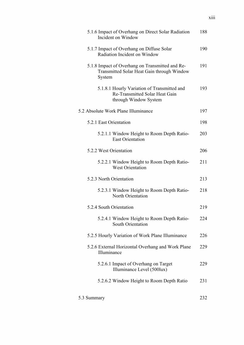
2.9 Comparison of monthly mean WBT (0C) data from SMS and DOE.wf
39
2.10
Monthly variation of Dew Point Temperatures (0C) data from SMS and DOE.wf
39
2.11
Exterior horizontal illuminance for 21 March, DOE.wf data for Kuala Lumpur
41
2.12
Exterior horizontal illuminance for 22 June, DOE.wf data for Kuala Lumpur
42
2.13
Exterior horizontal illuminance for 24 September, DOE.wf data for Kuala Lumpur
42
2.14
Exterior horizontal illuminance for 21 December, DOE.wf data for Kuala Lumpur
43
2.15
Total exterior horizontal illuminance, DOE.wf data for Kuala Lumpur
44
2.16
Calculated global luminous efficacies (lm/W), DOE.wf data for Kuala Lumpur
44
2.17
Monthly maximum exterior illuminance values from clear sky, overcast sky and direct sun, DOE.wf (Kuala Lumpur)
46
3.1
Examples of climate rejecting high-rise buildings in Malaysia
56
3.2
Example of climate adapted building: Public Works Department (PWD or JKR) building, Kuala Lumpur
57
3.3
Combination of climate adapted and rejected buildings in Malaysia
58
3.4
Optimum high-rise building form according to climatic zones
61
3.5
Arrangement of vertical core according to climatic zones
63
3.6
Core plan and annual cooling loads
63
3.7
Instantaneous heat balances through sunlit glazing material
73
3.8
External solar shading devices horizontal overhang, vertical shading devices and egg-crate devices
89
3.9
Horizontal shadow angle (HSA)
90

xxiii
3.10 Vertical shadow angle (VSA) 91
3.11 The shadow angle protractor
92
3.12
Stereographic projections for Kuala Lumpur (Latitude 3.120, Longitude +101.60, and Time zone 7)
92
3.13
Relationship between horizontal shading depth, window height and vertical shadow angle (VSA)
93
3.14
Sideway extension of external horizontal shading device
94
3.15
Relationship between vertical fin’s depth, window width and horizontal shadow angle (HSA)
94
3.16
Awning geometry
95
3.17
Relationship between external overhang depth, window height and overhang ratio
100
3.18
Overhang ratio for side extension of horizontal shading device
102
3.19
Effect of overhang on daylight distribution in a room
110
4.1
Base case office room configuration
135
4.2
Office room with overhang design
136
4.3
Sequential simulation approach
140
4.4
Simultaneous simulation approach
141
4.5
DOE 2.2 Simulation engine structure
148
4.6
Calculation procedure of loads from heat gains
149
4.7
Typical eQUEST-3 building wizard screen
150
4.8
The eQUEST-3 exterior window shades and blinds wizard screen
152
4.9
The eQUEST-3 daylight zoning wizard screen
153
4.10
The eQUEST-3 HVAC system wizard screen
154
4.11
The eQUEST-3 detail interface screen
156
4.12
The eQUEST-3 hourly results selection screen
156

xxiv
4.13 The eQUEST-3 results screen of annual end use energy consumption
157
4.14
The eQUEST-3 simulation procedures
157
4.15
Daylight photo sensor positions in office room model
161
4.16
Overall simulation procedures with design variables and performance variables
168
5.1
Direct, diffuse solar radiation incident on window, and transmitted and re-conducted solar heat gain (W/m2), as a function of overhang ratio- 21 March, East orientation
173
5.2
Direct, diffuse solar radiation incident on window, and transmitted and re-conducted solar heat gain (W/m2), as a function of overhang ratio- 22 June, East orientation
173
5.3
Direct, diffuse solar radiation incident on window, and transmitted and re-conducted solar heat gain (W/m2), as a function of overhang ratio- 24 September, East Orientation
174
5.4
Direct, diffuse solar radiation incident on window, and transmitted and re-conducted solar heat gain (W/m2), as a function of overhang ratio- 21 December, East Orientation
174
5.5
Direct, diffuse solar radiation incident on window, and transmitted and re-conducted solar heat gain (W/m2), as a function of overhang ratio- 21 March, West orientation
176
5.6
Direct, diffuse solar radiation incident on window, and transmitted and re-conducted solar heat gain (W/m2), as a function of overhang ratio- 22 June, West orientation
177
5.7
Direct, diffuse solar radiation incident on window, and transmitted and re-conducted solar heat gain (W/m2), as a function of overhang ratio- 24 September, West orientation
177
5.8
Direct, diffuse solar radiation incident on window, and transmitted and re-conducted solar heat gain (W/m2), as a function of overhang ratio- 21 December, West orientation
178
5.9
Direct, diffuse solar radiation incident on window, and transmitted and re-conducted solar heat gain (W/m2), as a function of overhang ratio- 21 March, North orientation
179
5.10
Direct, diffuse solar radiation incident on window, and transmitted and re-conducted solar heat gain (W/m2), as a function of overhang ratio- 22 June, North orientation
180

xxv
5.11 Direct, diffuse solar radiation incident on window, and transmitted and re-conducted solar heat gain (W/m2), as a function of overhang ratio- 24 September, North orientation
180
5.12
Direct, diffuse solar radiation incident on window, and transmitted and re-conducted solar heat gain (W/m2), as a function of overhang ratio- 21 December, North orientation
181
5.13
Direct, diffuse solar radiation incident on window, and transmitted and re-conducted solar heat gain (W/m2), as a function of overhang ratio- 21 March, South orientation
182
5.14
Direct, diffuse solar radiation incident on window, and transmitted and re-conducted solar heat gain (W/m2), as a function of overhang ratio- 22 June, South orientation
183
5.15
Direct, diffuse solar radiation incident on window, and transmitted and re-conducted solar heat gain (W/m2), as a function of overhang ratio- 24 September, South orientation
183
5.16
Direct, diffuse solar radiation incident on window, and transmitted and re-conducted solar heat gain (W/m2), as a function of overhang ratio- 21 December, South orientation
184
5.17
Cumulative direct, diffuse and total incident solar radiation and total transmitted heat gains for base-case model with bare window on east, west, north and south orientations
186
5.18
Maximum intensity of direct and diffuse incident solar radiation and total transmitted heat gain for base-case model- East, West, North and South orientations
188
5.19
Reduction percentage (%) of cumulative amount of direct solar radiation incident on window surface as function of horizontal overhang ratio- East, West, North and South
189
5.20
Reduction percentage (%) of cumulative amount of diffuse solar radiation incident on window surface as function of horizontal overhang ratio- East, West, North and South
191
5.21
Reduction percentage (%) of cumulative transmitted and re-conducted solar heat gain in an office room space as function of horizontal overhang ratio- East, West, North and South
192
5.22
Maximum hourly total solar heat gains for tested overhang ratios- East orientation
193
5.23
Maximum hourly total solar heat gains for tested overhang ratios- West orientation
194
xxvi
5.24 Maximum hourly total solar heat gains for tested overhang ratios- North orientation
194
5.25
Maximum hourly total solar heat gains for tested overhang ratios- South orientation
195
5.26
Absolute work plane illuminance (lux) at ref.pt:01, ref.pt:02, and solar heat gain (W/m2), as a function of overhang ratio- 21 March, East orientation
198
5.27
Absolute work plane illuminance (lux) at ref.pt:01, ref.pt:02, and solar heat gain (W/m2), as a function of overhang ratio- 22 June, East orientation.
198
5.28
Absolute work plane illuminance (lux) at ref.pt:01, ref.pt:02, and solar heat gain (W/m2), as a function of overhang ratio- 24 September, East orientation
199
5.29
Absolute work plane illuminance (lux) at ref.pt:01, ref.pt:02, and solar heat gain (W/m2), as a function of overhang ratio- 21 December, East orientation
199
5.30
Mean work plane illuminance (lux) at reference point 01 for tested overhang ratio- 21 March, 22 June, 24 September, and 21 December- East orientation.
204
5.31
Mean work plane illuminance (lux) at reference point 02 for tested overhang ratio- 21 March, 22 June, 24 September, and 21 December- East orientation
204
5.32
Effect of overhang on natural light distribution in perimeter office room- East orientation
205
5.33
Absolute work plane illuminance (lux) at ref.pt:01, ref.pt:02, and solar heat gain (W/m2), as a function of overhang ratio- 21 March, West orientation
206
5.34
Absolute work plane illuminance (lux) at ref.pt:01, ref.pt:02, and solar heat gain (W/m2), as a function of overhang ratio- 22 June, West orientation
206
5.35
Absolute work plane illuminance (lux) at ref.pt:01, ref.pt:02, and solar heat gain (W/m2), as a function of overhang ratio- 24 September, West orientation
207
5.36
Absolute work plane illuminance (lux) at ref.pt:01, ref.pt:02, and solar heat gain (W/m2), as a function of overhang ratio- 21 December, West orientation
207

xxvii
5.37 Mean work plane illuminance (lux) at reference point 01 for tested overhang ratio- 21 March, 22 June, 24 September and 21 December for West orientation.
211
5.38
Mean work plane illuminance (lux) at reference point 02 for tested overhang ratio- 21 March, 22 June, 24 September and 21 December for West orientation
212
5.39
Effect of overhangs on natural light distribution in perimeter office room- West orientation
212
5.40
Absolute work plane illuminance (lux) at ref.pt:01, ref.pt:02, and solar heat gain (W/m2), as a function of overhang ratio- 21 March, North orientation
213
5.41
Absolute work plane illuminance (lux) at ref.pt:01, ref.pt:02, and solar heat gain (W/m2), as a function of overhang ratio- 22 June, North orientation
213
5.42
Absolute work plane illuminance (lux) at ref.pt:01, ref.pt:02, and solar heat gain (W/m2), as a function of overhang ratio- 24 September, North orientation
214
5.43
Absolute work plane illuminance (lux) at ref.pt:01, ref.pt:02, and solar heat gain (W/m2), as a function of overhang ratio- 21 December, North orientation
214
5.44
Mean work plane illuminance (lux) at reference point 01 for tested overhang ratio- 21 March, 22 June, 24 September, and 21 December for North orientation
218
5.45
Mean work plane illuminance (lux) at reference point 02 for tested overhang ratio- 21 March, 22 June, 24 September and 21 December for North orientation.
218
5.46
Effect of overhangs on natural-light distribution in perimeter office room- North orientation
219
5.47
Absolute work plane illuminance (lux) at ref.pt:01, ref.pt:02, and solar heat gain (W/m2), as a function of overhang ratio- 21 March, South orientation
221
5.48
Absolute work plane illuminance (lux) at ref.pt:01, ref.pt:02, and solar heat gain (W/m2), as a function of overhang ratio- 22 June, South orientation.
221
5.49
Absolute work plane illuminance (lux) at ref.pt:01, ref.pt:02, and solar heat gain (W/m2), as a function of overhang ratio- 24 September, South orientation
222

xxviii
5.50 Absolute work plane illuminance (lux) at ref.pt:01, ref.pt:02, and solar heat gain (W/m2), as a function of overhang ratio- 21 December, South orientation.
222
5.51
Mean work plane illuminance (lux) at reference point 01 for tested overhang ratio- 21 March, 22 June, 24 September and 21 December for South orientation.
225
5.52
Mean work plane illuminance (lux) at reference point 02 for tested overhang ratio- 21 March, 22 June, 24 September and 21 December for South orientation.
225
5.53
Effect of overhangs on natural-light distribution in perimeter office room- South orientation
226
5.54
Minimum hourly work plane illuminance at reference point 02, East orientation
227
5.55
Minimum hourly work plane illuminance at reference point 02, West orientation
227
5.56
Minimum hourly work plane illuminance at reference point 02, North orientation
228
5.57
Minimum hourly work plane illuminance at reference point 02, South orientation
228
6.1
Breakdown of annual cooling load (MWh) with natural-light utilization and without natural-light for a base-case generic office room- East, West, North and South orientations
236
6.2
Total envelop and internal component cooling loads (MWh) for tested external horizontal overhang ratio, East, West, North and South orientations
241
6.3
Total building space cooling load (MWh) for tested external horizontal overhang ratio, East, West, North and South orientations
242
6.4
Breakdown of annual cooling load (MWh) without natural-light utilization; for base-case model and maximum overhang option, East, West, North and South orientations
243
6.5
The annual total cooling load (MWh) with and without natural-light utilization for base-case model and maximum overhang option, East, West, North and South orientations
244
6.6
Breakdown of annual electricity consumption for base case model, with and without natural-light utilization- East, West, North and South orientations
246

xxix
6.7 Total energy consumption with and without natural-light scheme for base case model, East, West, North and South orientations
247
6.8
(a & b)
Electricity consumption (kWh/m2, yr) for space cooling, area lighting and total energy for tested overhang ratios, East & West orientations
251
6.8
(c & d)
Electricity consumption (kWh/m2, yr) for space cooling, area lighting and total energy for tested overhang ratios, North & South orientations
252
6.9
Total annual electricity consumption for space cooling and annual electricity consumption for cooling to remove the heat gain from artificial lighting for different overhang ratio tested- East, West, North and South orientations
253
6.10
(a & b)
Incremental energy use (kWh/m2, yr) for cooling, lighting and total energy for tested overhang ratios- East and West orientations
256
6.10
(c & d)
Incremental energy uses (kWh/m2, yr) for cooling, lighting and total energy for tested overhang ratios- North and South orientations
257
6.11
Energy saving percentage for space cooling and area lighting incremental energy use as a function of overhang ratio, East, West, North and South orientations
264
6.12
Energy saving percentage for total incremental energy use as a function of overhang ratio, East, West, North and South orientations
265
7.1
Several design option of external horizontal overhang shading device
284
xxx
LIST OF ABBREVIATIONS
ASEAN - Association of South East Asian Nations
ASEAM - A Simplified Energy Analysis Method
ASHRAE - American Society of Heating, Refrigerating and Air Conditioning Engineers
BC - Base Case
BDL - Building Description Language
BLAST - Building Loads Analysis and System Thermodynamics
CAD - Computer Aided Design
CBIP - Commercial Building Incentive Program
CIBS - Charted Institute of Building Service
CIBSE - Chartered Institution of Building Services Engineers
CIE - International Illumination Commission
COSLAM - Conference of Sri Lankan Malays
CTBUH - Council on Tall Building and Urban Habitat
DBT - Dry Bulb Temperature
DDM - Degree-Day Method
DewPT - Dew Point Temperature
DEU CL - Differential Energy Use (cooling)
DOE - Department of Energy (United States)
DOE.wf - Department of Energy weather file
EC LT - Energy Consumption (lighting)
EC CL - Energy Consumption (cooling)
EC TOT - Energy Consumption (total)
EEM - Energy Efficient Measures
eQUEST - Quick Energy Simulation Tool
GFA - Gross Floor Area
GIA - Gross Internal Area
xxxi
HVAC - Heating, Ventilation & Air-Conditioning
HSA - Horizontal Shadow Angle
IB - Intelligent Building
IES - Illuminating engineers society of North America
IES - International Energy Standards
IES - Integrated environmental Solutions
IEU - Incremental Energy Use
IEUCL - Incremental Energy Use (cooling)
IEULT - Incremental Energy Use (lighting)
IEUTOT - Incremental Energy Use (total)
LEO - Low Energy Office
LEED - Leadership in Energy and Environmental Design
MBE - Mean Bias Error
MDD - Modified Degree-Day method
MECM - Ministry of Energy, Communications & Multimedia (Malaysia)
MEWC - Ministry of Energy, Water and Communication (Malaysia)
MS - Malaysian Standards
NFRC - National Fenestration Rating Council
NI - Nebulosity Index
NRA - Net Rentable Area
OHR - Overhang Ratio
OHRé - Overhang Ratio (Side extension é)
OHRfin - Overhang Ratio vertical fins
ORI - Façade Orientation
OTTV - Overall Thermal Transfer Value
PC - Personal Computer
PF - Projection Factor
PSALI - Permanent Supplementary Artificial Lighting of Interiors
PWD - Public Works Department
RMSE - Root Mean Square Error
SHGF - Solar Heat Gain Factor
SHGFv - Solar Heat Gain Factor vertical surface

xxxii
SHGFsh - Solar Heat Gain Factor shaded window
SMS - Subang Meteorological Station
SIR - Sun Illuminance Ratio
TMY - Typical Metrological Year
THG - Total Heat Gain
TRY - Test Reference Year
UMNO - United Malaya National Organization
USAID - Unite States Agency for International Development
UTM - Universiti Teknologi Malaysia
VE - Virtual Environment
VSA - Vertical Shadow Angle
WBT - Wet Bulb Temperature
WWR - Window-to-Wall Ratio
WYEC - Weather Year for Energy Calculations

xxxiii
LIST OF SYMBOLS
A - Surface Area (m2)
α - Absorptance (dimensionless)
A1, A2, A3 - Coefficients of absorptions (constants)
A4, A5, A6 - Coefficients of absorptions (constants)
Acog - Projected area center of glass (m2)
Aeog - Projected area edge of glass (m2)
Aframe - Projected area of frame (m2)
AG - Fraction of window area exposed to the sun (m2)
Ar - Rayleigh scattering coefficient
Asun - Area of window exposed to the sun (m2)
αb - Absorptance of reference glazing for direct beam
αdiff - Absorptance of reference glazing for diffuse radiation
B - Atmospheric extinction coefficient (dimensionless)
β - Solar altitude angle above the horizontal (0)
C - Diffuse sky factor
C1, C2, C3 - Coefficients of transmission (constants)
C4, C5, C6 - Coefficients of transmission (constants)
Cd - Compensation factor for window dirt (DF calculation)
Cf - Compensation factor for frame (DF calculation)
Cg - Compensation factor for glazing (DF calculation)
Cn - Clearness number of the atmosphere (dimensionless)
CR - Cloud Ratio
D - Depth of the horizontal projection (m)
δ - Solar declination angle (0)
d - Horizontal projection of the distance between the awning’s lower corner and its shadow on the vertical wall (m)
DF - Daylight Factor

xxxiv
Ėdiff,cl - Clear sky diffuse illuminance (lux)
Edsky - Direct illuminance from sky (lux)
Er(ext)sky - External reflected component from sky illuminance (lux)
Er(int)sky - Internal reflected component from sky illuminance (lux)
Eidsun - Internal direct illuminance from sunlight (lux)
Eirsun - Internal reflected illuminance from sunlight (lux)
Eo,sun - Exterior illuminance from sunlight (lux)
Eo,sky - Exterior illuminance from sky (lux)
Ei - Interior illuminance (lux)
Eo - Exterior illuminance (lux)
Et - Equation of time
e - Projection side ways from the window vertical edge (m)
e1 - Length of the shading device over the window (m)
é - Awning width exceeding window width on each side (m)
φ - Latitude of the location (0)
Ffl - Flue loss factor, equipment
Fra - Radiation factor, equipment
Fs - Lighting special allowance factor
Fsg - Angle factor between the surface and the sky
Fss - Angle factor between the surface and the sky
Fu - Light use factor, lighting
Fua - Use factor, equipment
f - Depth of the vertical fin (m)
fr - Fraction of diffuse radiation obstructed by the shading device
γ - Surface solar azimuth (0)
G-value - Total fraction of incident solar energy transmitted (dimensionless)
Gref - Reflectance of the ground
Gsunshade - G-value for corresponding shading device (dimensionless)
Gsystem - G-value for corresponding window system with shading (dimensionless)
Gwindow - G-value for window (dimensionless)
η1, η2 - Regression coefficients for total energy (dimensionless)
Hfen - Height of fenestration (m)
Hi - Inside air enthalpy, (kJ/kg) (dry air)
xxxv
Ho - Outside air enthalpy, (kJ/kg) (dry air)
h - Horizontal projection of the awning (m)
hi - Heat transfer coefficient, inside glazing surface (W/m2 K)
ho - Heat transfer coefficient, outside glazing surface(W/m2 K)
Isc - Solar constant
Io - Extraterrestrial solar radiation (W/m2)
Ibn - Direct beam normal solar radiation (W/m2)
Ibh - Direct beam solar radiation on horizontal surface (W/m2)
Ibv - Direct beam solar radiation on vertical surface (W/m2)
Idiff,h - Diffused solar radiation on horizontal surface (W/m2)
Idiff,v - Diffused sky radiation on vertical surface (W/m2)
IGh - Global irradiance horizontal surface (W/m2)
IGv - Global irradiance vertical surface (W/m2)
Ir - Ground reflected radiation (W/m2)
It,θ - Total horizontal radiation strikes the ground surface (W/m2)
Itot,h - Total solar radiation on horizontal surface (W/m2)
Itot,v - Total solar radiation on vertical surface
Icl,diff - Diffused solar radiation clear sky (W/m2)
İdv - Diffused & reflected radiation on vertical glazing (W/m2)
İbv - Direct beam radiation on vertical plane (W/m2)
Ї - Apparent extraterrestrial irradiance (W/m2)
Ídr - Direct solar radiation transmitted through standard 3mm clear glass
Ídf - Diffused solar radiation transmitted through standard 3mm clear glass Ítot - Total (direct + diffused) solar radiation transmitted
through standard 3mm clear glass
ϕ - Awning slope (0)
K - Luminous efficacy (lm/W)
KB - Beam luminous efficacy (lm/W)
Kcc - Cloud cover ratio
KD - Diffused luminous efficacy (lm/W)
KG - Global luminous efficacy (lm/W)
k - Fraction of diffuse radiation obstructed by the shading device

xxxvi
L - Awning length (m)
λ1 - Regression coefficient for lighting energy (dimensionless)
L edge - Length of window frame edge (m)
Lloc - Longitude of the location (in degree)
Lstd - Standard meridian for the local time zone (Longitude of the time zone)
Ltot - Total Length (m)
m - Optical air mass
µ1, µ2 - Regression coefficients for cooling energy (dimensionless)
N - Cloud amount
Ni - Inward flowing fraction of the absorbed radiation
No - Number of people
Nt - Cloud type
n - Daily sunshine duration
no - Maximum possible sunshine duration
pa - Atmospheric pressure
Q - Ventilation air flow (L/s)
θ - Incident angle (0)
θh - Angle of incidence on horizontal surface (0)
θv - Angle of incidence on vertical surface (0)
Qc - Conduction heat flow rate (w)
Qcl - Cooling energy use (W/m2)
Qel - Heat gain from electric lighting (w)
Qeq - Appliances heat gain (w)
Qi - Occupants heat gain (w)
Qs,win - Total solar heat gain flow rate, window (w)
Qv - Convection heat flow rate (w)
Qwin - Thermal heat gain, window (W/m2K)
ρ - Reflectance (dimensionless)
Rgap - Thermal resistance of gap between panes (m2K/W)
Rgl - Thermal resistance of glass pane (m2K/W)
Rsi - Internal surface resistance (m2K/W)
Rse - External surface resistance (m2K/W)
Rtot - Total thermal resistance (m2K/W)

xxxvii
R2 - Coefficient of determination
S - Relative sunshine duration
SC - Shading coefficient
SC clearglass - Shading coefficient of clear glass
SCshadingdevice - Shading coefficient of shading device
SC net - Net shading coefficient for partially shaded window
Sdf - Sky diffusive factor
Sec - Solar extinction coefficient
∆T - Temperature difference (0C)
τ - Τransmittance (dimensionless)
Td - Dew point temperature (0C)
Tdt - Out door dry-bulb temperature (0C)
Tsol - Local solar time
Tstd - Local standard time
Twt - Out door wet-bulb temperature (0C)
τa - Secondary heat transmittance (dimensionless)
τb - Transmittance of reference glazing for direct beam (dimensionless)
τdiff - Transmittance of reference glazing for diffuse radiation
ti - Daily mean indoor temperature (0C)
to - Daily mean out door temperature (0C)
U - Thermal transmittance value (W/m2K)
Ucog - Thermal transmittance center of glass (W/m2K)
Ueog - Thermal transmittance edge of glass (W/m2K)
Uframe - Thermal transmittance frame (W/m2K)
UPD - Average lighting unit power density (W/m2)
Uwin - Thermal transmittance of window (W/m2K)
Vd - Wind direction
Vs - Wind speed
v - Vertical projection of the awning/ horizontal shading device (m)
W - Total light wattage
ω - Solar hour angle (0)
Wawn - Width of the awning (m)

xxxviii
Wfen - Width of fenestration (m)
Wo - Outside humidity ratio, kg (water)/ kg (dry air)
Wi - Inside humidity ratio, kg (water)/ kg (dry air)
ψedge - Linear heat transmittance coefficient (W/mK)
ζ - Surface tilt angle (0)

xxxix
LIST OF APPENDICES
APPENDIX TITLE PAGE
A Summary of Energy Related Research 306
C Summary of High-Rise Office Building and Energy Use Review
C1. Office Buildings Energy Data Base
Kuala Lumpur, Malaysia
309
C2. South East Asian Office Building
Information
312
C3. Design of Shading Device Considering the
Windows Solar Angle Dependent Properties: With Special Reference to Kuala Lumpur Hot and Humid Tropical Climates
315
D
Review of Computer Simulation Programs
329
E
Simulation Data and Results
E1. Sample of Input Data
333
E2. Summary: Direct and Diffused Incident
Solar Radiation and Transmitted Heat Gains
338
E3. Summary: Work Plane Illuminance at
Ref.Pt:01 and Ref.Pt:02
344
F
Summary Building Energy Use
F1. Summary: Building Cooling Load Data
347
F2. Summary: End Use Energy Consumption
Data with Natural-light utilization
350