Optical Mineralogy and Economic Geology - eGyanKosh
85
BGYCT – 133 CRYSTALLOGRAPHY, MINERALOGY AND ECONOMIC GEOLOGY Vol. 2 Indira Gandhi National Open University School of Sciences Optical Mineralogy and Economic Geology
-
Upload
khangminh22 -
Category
Documents
-
view
0 -
download
0
Transcript of Optical Mineralogy and Economic Geology - eGyanKosh
BGYCT – 133 CRYSTALLOGRAPHY,
MINERALOGY AND ECONOMIC GEOLOGY
Vol. 2
Indira Gandhi National Open University
School of Sciences
Optical Mineralogy and Economic Geology

1
Volume
2 OPTICAL MINERALOGY
BLOCK 3
OPTICAL MINERALOGY 7
BLOCK 4
ECONOMIC GEOLOGY 85
BGYCT - 133 CRYSTALLOGRAPHY,
MINERALOGY AND ECONOMIC GEOLOGY
Indira Gandhi National Open University
School of Sciences
AND ECONOMIC GEOLOGY

2
Course Design Committee
Prof. Vijayshri Former Director School of Sciences IGNOU, New Delhi
Prof. V. K. Verma (Retd.) Department of Geology University of Delhi, Delhi
Late Prof. Pramendra Dev School of Studies in Earth Sciences Vikram University Ujjain, MP
Prof. P. Madhusudhana Reddy (Retd.) Department of Geology Dr. B.R. Ambedkar Open University Hyderabad
Late Prof. G. Vallinayagam Department of Geology Kurukshetra University Kurukshetra, Haryana
Prof. J. P. Shrivastava Centre of Advanced Study in Geology University of Delhi, Delhi
Prof. M. A. Malik Department of Geology University of Jammu Jammu, J & K
Prof. D. C. Srivastava Department of Earth Science Indian Institute of Technology Roorkee Roorkee, Uttarkhand
Prof. L. S. Chamyal Department of Geology M.S. University of Baroda Vadodara, Gujarat
Prof. H. B. Srivastava Centre of Advanced Study in Geology Banaras Hindu University Varanasi, UP
Prof. Arun Kumar Department of Earth Sciences Manipur University Imphal, Manipur
Prof. (Mrs.) Madhumita Das Department of Geology Utkal University Bhubaneshwar, Odisha
Prof. K. R. Hari School of Studies in Geology & Water Resources Management Pt. Ravishankar Shukla University Raipur, Chhattisgarh
Prof. S.J. Sangode Department of Geology Savitribai Phule Pune University Pune, Maharashtra
Dr. K. Anbarasu Department of Geology National College Tiruchirapalli, Tamilnadu
Faculty of Geology Discipline School of Sciences, IGNOU
Prof. Meenal Mishra
Prof. Benidhar Deshmukh
Dr. M. Prashanth
Dr. Kakoli Gogoi
Dr. Omkar Verma
Volume Preparation Team
Course Contributors
Dr. S.D. Shukla (Retd.) (Units 8 & 9) Department of Geology SGRR(PG) College, Dehradun
Dr. Nishi Rani (Units 11 to 14) Centre of Advanced Study in Geology University of Delhi, Delhi
Prof. Meenal Mishra (Units 10 to 12) School of Sciences IGNOU, New Delhi
Dr. Kakoli Gogoi (Unit 15) School of Sciences IGNOU, New Delhi
Content and Language EditorsProf. Pankaj Srivastava (Units 8 to10) Department of Geology Jammu University, Jammu
Prof. J. P. Shrivastava (Units 11 to 15) Centre of Advanced Study in Geology University of Delhi, Delhi
Transformation: Prof. Meenal Mishra
Course Coordinators: Prof. Meenal Mishra and Prof. Benidhar Deshmukh
Audio Visual Materials
Dr. Amitosh Dubey Prof. Meenal Mishra and Prof. Benidhar Deshmukh Producer, EMPC, IGNOU Content Coordinators
Production
Mr. Rajiv Girdhar Mr. Sunil Kumar Mr. Hemant Kumar A.R. (P), MPDD, IGNOU A.R. (P), SOS, IGNOU S.O. (P), MPDD, IGNOU
Acknowledgement: Ms. Savita Sharma for assistance in preparation of CRC and some of the figures. December, 2019 © Indira Gandhi National Open University, 2019 ISBN: Disclaimer: Any material adapted from web-based resources or any other sources in this block are being used only for educational purposes only and not for commercial purposes and their copyrights rest with the original authors. All rights reserved. No part of this work may be reproduced in any form, by mimeograph or any other means, without permission in writing from the Indira Gandhi National Open University. Further information on the Indira Gandhi National Open University courses may be obtained from the University’s office at Maidan Garhi, New Delhi-110 068 or the official website of IGNOU at www.ignou.ac.in. Printed and published on behalf of Indira Gandhi National Open University, New Delhi by the Registrar, MPDD, IGNOU. Printed by : Chandra Prabhu Offset Printing Works Pvt. Ltd., C-40, Sector-8, Noida-201301 (U.P.)
978-93-89969-65-8

3
BGYCT-133: CRYSTALLOGRAPHY, MINERALOGY AND ECONOMIC GEOLOGY
Block 1 Basic Concepts of Crystallography
Unit 1 Crystal Properties
Unit 2 Crystal Symmetry Unit 3 Crystal Systems
Block 2 Mineralogy
Unit 4 Minerals: The Building Blocks of Rocks
Unit 5 Classification of Minerals
Unit 6 Rock-Forming Minerals-I
Unit 7 Rock-Forming Minerals-II
Block 3 Optical Mineralogy
Unit 8 Polarising Microscope
Unit 9 Optical Properties of Minerals
Unit 10 Optical Properties of Rock-Forming Minerals
Block 4 Economic Geology
Unit 11 Ore and Ore Deposits
Unit 12 Processes of Ore Formation
Unit 13 Metallic Minerals
Unit 14 Non-Metallic Minerals
Unit 15 Coal and Petroleum
3

4
List of audio / video materials related to this course
1. Geology at IGNOU -1
Link: http://egyankosh.ac.in/youtubevideo.jsp?src=YRFrgUyDWXw&title =Geology%20at%20IGNOU%20-1
2. Geology Around Us - 1
Link: http://egyankosh.ac.in//handle/123456789/63948
3. Minerals and Their Uses
Link: http://egyankosh.ac.in//handle/123456789/53487
4. Microscopic Study of Basaltic Rocks
Link: https://www.youtube.com/watch?v=2RGL3XB2x3E&t=2s
5. Introduction to Ore Deposits
Link: http://egyankosh.ac.in//handle/123456789/53454
6. Classifications of Ore Deposits
Link: http://egyankosh.ac.in//handle/123456789/53455
7. Early Magmatic Deposits
Link: http://egyankosh.ac.in//handle/123456789/53456
8. Late Magmatic Deposits
Link: http://egyankosh.ac.in//handle/123456789/53457
9. Contact Metasomatic and Contact Metamorphic Deposits
Link: http://egyankosh.ac.in//handle/123456789/53458
10. Hydrothermal Mineralisation
Link: http://egyankosh.ac.in//handle/123456789/53461
11. Textures Related to zoning in Igneous rocks
Link: https://www.youtube.com/watch?v=Wrbw0MQzSQU
Development of audio/video programmes is a continuous process. For recent materials
pertaining to the course you may visit Youtube page of the School of Sciences, IGNOU.
Alternatively, you can visit eGyankosh website at
http://egyankosh.ac.in/handle/123456789/36575
4

5
VOLUME 2: OPTICAL MINERALOGY AND ECONOMIC GEOLOGY
The course BGYCT-133 Crystallography, Mineralogy and Economic Geology consists of
four blocks, which have been packaged in two volumes. The Volume 1 consists of two blocks
namely, crystallography and mineralogy. The Volume 2 consists of two blocks namely, Optical
Mineralogy and Economic Geology.
The first block of this volume, Block 3: Optical Mineralogy will introduce you to the parts and
functions of polarising microscope, optical properties of minerals under plane polarised light
and between cross nicol and optical properties of common rock-forming minerals.
After studying about optical properties of common rock-forming minerals in Block-3, you shall
learn about economic geology and metallic and non-metallic minerals in the next block.
Minerals are the building blocks of rocks, and their study is important for geologists to locate
potential mineral deposits. Block 4: Economic Geology introduces you to the basic concepts
of economic geology. In this block, you will learn about the basic concepts of ores and ore
deposits, processes of ore formation, metallic minerals, non-metallic minerals deposits and
coal and petroleum.
Expected Learning Outcomes After studying this volume, you should be able to:
• examine properties of light used in mineral identification;
• elaborate the parts and functions of polarising microscope;
• recognise optical properties used for mineral identification and explain optical properties of
common rock-forming minerals under ordinary light, polarised light and between cross nicol;
• discuss basic concepts of ore and ore deposits and processes of their formation;
• describe different types of minerals of economic significance used in different industries viz..
building and construction; refractory, fertiliser, chemical, paints and pigments, abrasive,
ceramic and glass manufacturing industries, and
• discuss origin, mode of occurrence, formation of coal and petroleum and their Indian
occurrences.
After studying this volume, you will be equipped with the basic knowledge of optical mineralogy
and economic geology. In the next core course, you would learn about different types of rocks,
their textures and structures, process of their formation and their megascopic and microscopic
characteristics.
We wish you all success in this endeavour!
5

6
6

7
Block
3 OPTICAL MINERALOGY
UNIT 8
Polarising Microscope 11
UNIT 9
Optical Properties of Minerals 31
UNIT 10
Optical Properties of Rock-Forming Minerals 57
Glossary 83
BGYCT - 133 CRYSTALLOGRAPHY,
MINERALOGY AND ECONOMIC GEOLOGY
Indira Gandhi National Open University
School of Sciences
7

8
Course Design Committee Prof. Vijayshri Former Director School of Sciences IGNOU, New Delhi
Prof. V. K. Verma (Retd.) Department of Geology University of Delhi, Delhi
Late Prof. Pramendra Dev School of Studies in Earth Sciences Vikram University Ujjain, MP
Prof. P. Madhusudhana Reddy (Retd.) Department of Geology Dr. B.R. Ambedkar Open University Hyderabad
Late Prof. G. Vallinayagam Department of Geology Kurukshetra University Kurukshetra, Haryana
Prof. J. P. Shrivastava Centre of Advanced Study in Geology University of Delhi, Delhi
Prof. M. A. Malik Department of Geology University of Jammu Jammu, J & K
Prof. D. C. Srivastava Department of Earth Science Indian Institute of Technology Roorkee Roorkee, Uttarkhand
Prof. L. S. Chamyal Department of Geology M.S. University of Baroda Vadodara, Gujarat
Prof. H. B. Srivastava Centre of Advanced Study in Geology Banaras Hindu University Varanasi, UP
Prof. Arun Kumar Department of Earth Sciences Manipur University Imphal, Manipur
Prof. (Mrs.) Madhumita Das Department of Geology Utkal University Bhubaneshwar, Odisha
Prof. K. R. Hari School of Studies in Geology & Water Resources Management Pt. Ravishankar Shukla University Raipur, Chhattisgarh
Prof. S.J. Sangode Department of Geology Savitribai Phule Pune University Pune, Maharashtra
Dr. K. Anbarasu Department of Geology National College Tiruchirapalli, Tamilnadu
Faculty of Geology Discipline School of Sciences, IGNOU
Prof. Meenal Mishra
Prof. Benidhar Deshmukh
Dr. M. Prashanth
Dr. Kakoli Gogoi
Dr. Omkar Verma
Block Preparation Team
Course Contributors Content and Language EditorDr. S. D. Shukla (Retd.) (Units 8 & 9) Department of Geology SGRR (PG) College, Dehradun
Prof. Meenal Mishra (Unit 10) School of Sciences IGNOU, New Delhi
Prof. Pankaj Srivastava Department of Geology Jammu University, Jammu
Transformation: Prof. Meenal Mishra
Course Coordinators: Prof. Meenal Mishra and Prof. Benidhar Deshmukh
Audio Visual Materials
Dr. Amitosh Dubey Prof. Meenal Mishra and Prof. Benidhar Deshmukh Producer, EMPC, IGNOU Content Coordinators
Production
Mr. Rajiv Girdhar Mr. Sunil Kumar Mr. Hemant Kumar A.R. (P), MPDD, IGNOU A.R. (P), SOS, IGNOU S.O. (P), MPDD, IGNOU
Acknowledgement: Ms. Savita Sharma for assistance in preparation of CRC and some of the figures.
December, 2019 © Indira Gandhi National Open University, 2019
ISBN:
Disclaimer: Any material adapted from web-based resources or any other sources in this block are being used only for educational purposes only and not for commercial purposes and their copyrights rest with the original authors.
All rights reserved. No part of this work may be reproduced in any form, by mimeograph or any other means, without permission in writing from the Indira Gandhi National Open University.
Further information on the Indira Gandhi National Open University courses may be obtained from the University’s office at Maidan Garhi, New Delhi-110 068 or the official website of IGNOU at www.ignou.ac.in. Printed and published on behalf of Indira Gandhi National Open University, New Delhi by the Registrar, MPDD, IGNOU.
Printed by : Chandra Prabhu Offset Printing Works Pvt. Ltd., C-40, Sector-8, Noida-201301 (U.P.)
8
978-93-89969-65-8

9
BGYCT-133: CRYSTALLOGRAPHY, MINERALOGY AND ECONOMIC GEOLOGY
Block 1 Basic Concepts of Crystallography
Unit 1 Crystal Properties
Unit 2 Crystal Symmetry Unit 3 Crystal Systems
Block 2 Mineralogy
Unit 4 Minerals: The Building Blocks of Rocks
Unit 5 Classification of Minerals
Unit 6 Rock-Forming Minerals-I
Unit 7 Rock-Forming Minerals-II
Block 3 Optical Mineralogy
Unit 8 Polarising Microscope
Unit 9 Optical Properties of Minerals
Unit 10 Optical properties of Rock-Forming Minerals
Block 4 Economic Geology
Unit 11 Ore and Ore Deposits
Unit 12 Processes of Ore Formation
Unit 13 Metallic Minerals
Unit 14 Non-Metallic Minerals
Unit 15 Coal and Petroleum
9

10
BLOCK 3: OPTICAL MINERALOGY
Optical mineralogy deals with the microscopic study of minerals. It is the study of the
interaction of light with the minerals under the polarising microscope or petrological
microscope. Optical mineralogy is the study of the interaction of light with minerals which is
commonly limited to visible light. The optical properties of the minerals are studied in
transmitted light under the polarising microscope. Microscopic examination of a mineral
or/and rock specimens is the principal technique used for mineralogical identification of
geological materials (minerals and rocks) by the mineralogists and petrologists. This helps us
in identification and understanding their genesis. Polarising microscope is used to determine
the nature of rock(s) and its constituent minerals. The polarised light passes through mineral
and rock thin sections and optical properties are observed leading to the identification of
these mineral.
This block comprises three units, wherein we will be introduced to the parts and functioning
of polarising microscope, optical properties of minerals under plane polarised light and
between cross nicol and optical properties of common rock-forming minerals.
Unit 8 Polarising Microscope is an introduction to the fundamental concepts of light, parts
and functioning of polarising/petrological microscope. In Unit 9 Optical Properties of
Minerals you will be introduced to basic concepts of microscopic study of minerals and the
optical properties under ordinary light, plane polarised light and between the cross nicols. In
Unit 10 Optical properties of Rock-Forming Minerals you will learn to identify common
rock-forming minerals under plane polarised light and between cross nicols.
Expected Learning Outcomes
After studying this block, you should be able to:
• describe the properties of light used in polarising microscope for mineral identification;
• list different parts of a polarising microscope;
• discuss the functioning of polarising microscope;
• list and discuss the optical properties of minerals used for their identification under
ordinary light and under polarised light;
• list and identify the optical properties of minerals used for their identification between
cross nicol;
• recognise the optical properties of common rock-forming minerals under polarised light;
• explain the optical properties of various rock-forming minerals between cross nicol; and
• identify the diagnostic optical properties of different rock-forming minerals
We hope that after studying this block you will be able to get understand of the parts and
functioning of polarising microscope, know the optical properties used for identification of
minerals under the polarising microscope and identify the rock-forming minerals under the
polarising microscope.
Wishing you success in this endeavour!
10

11
UNIT8
POLARISING MICROSCOPE
StructureStructureStructureStructure________________________________________________________________________________________________________________________________________________________________________________________________________________
8.1 Introduction
Expected Learning Outcomes
8.2 Preparation of Thin Section
8.3 Properties of Light
Nature of Light
Polarised light
Double Refraction
Construction of Nicol Prism
Isotropic and Anisotropic Minerals
8.4 Polarising Microscope
Parts of Polarising Microscope
Functioning of Polarising Microscope
8.5 Summary
8.6 Activity
8.7 Terminal Questions
8.8 References
8.9 Further/Suggested Readings
8.10 Answer
8.1 INTRODUCTION
We have discussed about the physical properties of the minerals used in the identification of
minerals in Unit 4 Minerals of this course. We had also discussed the physical properties of the
common rock-forming minerals in Unit 6 Rock-Forming Minerals-I and Unit 7 Rock-Forming
Minerals-II. The techniques used in the identification of minerals have evolved with time due to
invention of sophisticated instruments. The studies of optical properties of minerals are carried
using basic properties of light and response of the minerals to polarising light under a special kind
of microscope known as petrological microscope or polarising microscope. This microscope is
different than commonly used microscopes. Optical mineralogy is the study of the interaction of
light with minerals which is commonly limited to visible light. Optical mineralogy is used to identify
the mineralogical composition of geological materials (rocks/minerals) to know and understand
their origin and evolution. In this unit, you will be introduced to the working of polarising
microscope. A petrologist uses microscopes to determine the nature of rocks and minerals.
Microscopic examination of a mineral and rock sample mounted on a thin section (glass slide) is
the principle technique used for mineralogical identification.
11

.................................................................................................................................................................................
12
Optical Mineralogy Block 3
Expected Learning OutcomesExpected Learning OutcomesExpected Learning OutcomesExpected Learning Outcomes_____________________________
After reading this unit, you should be able to:
� recognise the importance of microscopic study;
� describe the properties of light used for microscopic study;
� list different parts of a polarising microscope; and
� discuss the functioning of polarising microscope.
8.2 PREPARATION OF THIN SECTION
You have read that rock is an aggregate of minerals. It becomes difficult to
identify the constituent minerals especially when the rock is fine or medium
grained in hand specimen. You have read in earlier section that petrological
microscope is also referred as polarising microscope because polarised light is
used in the identification of the minerals. Optical properties are studied in
transmitted light. In polarising microscope, as the name suggests the
specially transformed rays known as polarised light are passed through rock /
minerals thin sections and optical properties are observed leading to mineral
identification. In polarised light the vibrations take place only in one plane.
This is distinct from ordinary light in which the vibrations take place in all
directions perpendicular to the direction of propagation of the ray. Thin sections
of the minerals or rocks are prepared by grinding the thin chip of the mineral or
rock specimen to study optical properties of a mineral/rock. Both sides of the
specimen are grinded. Then the sample is grinded to ~0.03 mm thickness and
mounted on a glass slide with transparent cement (Canada balsam), with or
without cover slip. At this thickness most of the non-opaque minerals permit
the light to pass through them. Canada balsam is a resin, viscous, sticky,
colourless or yellowish liquid that turns to a transparent yellowish mass when
the essential oils in which it is dissolved, are allowed to evaporate. The thin
sections of minerals are placed over the stage of polarising microscope and
studied. The optical properties vary in different minerals. We will be discussing
optical properties of various rock forming minerals in the next Unit 9, which are
helpful in identification of minerals. The minerals which do not permit the light
to pass through thin sections are said to opaque minerals. Especially treated
sections of opaque minerals are studied in reflected light with the help of
reflecting microscope popularly known as ore microscope. This study is called
ore microscopy.
Let us read about the properties of light before discussing about the parts and
functioning of polarising microscope.
8.3 PROPERTIES OF LIGHT
We have discussed that the microscopic studies of thin sections or small grains
of minerals are dependent on light therefore it is important to introduce you to
some behavioural characters of light. Let us briefly go through the basic
principles of optics before studying about the parts and functioning of the
polarising microscope.
12

............................................................................................................................................................
13
Polarising Microscope Unit 8
8.3.1 The Nature of Light
You might have read that light is an electromagnetic vibration due to periodic
variation in the energy given off by moving electrons. Light has properties of
waves. Visible light is the portion of the electromagnetic spectrum that
possesses the properties of both wave and a particle. The wave theory and
corpuscular theory are two theories that explain all the properties of light. The
light can be considered as simply the transfer of energy by vibrating particles
along a path from the source to the observer for transmitted and reflected light
microscopy. White light consists of many rays ranging in wavelength through
the visible range from 400 nm to 700 nm of electromagnetic spectrum (Fig.
8.1a). The wave motion is like those waves that move out from a central point
when a pebble is thrown into still water, where water merely rise and fall, and
the wave front moves forward. These are propagated by motion of water
particles which is transverse to the direction in which wave travels. The
wavelength (λ) of such wave motion is the distance between successive crests
and troughs. Amplitude is the maximum displacement of particle from its
original position. Oscillatory motion of particles in a light wave is called as
periodic motion because it repeats itself at regular intervals. It is distance C-D
in Fig. 8.1b. The distance between any particle and the next, which is in like
position or like phase, as A and B is the wavelength and the time required is
the vibration period (Fig. 8.1b). A wavelength is the shortest distance
between two points in exactly similar positions on a wave that move in the
same direction.
(a)
(b)
Fig. 8.1: a) Visible range of electromagnetic spectrum (Source:
www.guweb2.gonzaga.edu); and b) Harmonic curve of light waves
(Source: Dana and Ford 1962). C-D is the Amplitude and A-B is the
wavelength ‘λλλλ’.
13

.................................................................................................................................................................................
14
Optical Mineralogy Block 3
8.3.2 Polarised Light
You have read that the wave motion takes place with vibrations in all the
directions at right angles to the direction of propagation. In ordinary light (Fig.
8.2a) the wave motion is confined to the vibrations in a single plane at right
angles to the propagation of ray, the light is said to be plane polarised
(Fig.8.2b) or simply polarised.
Fig. 8.2: Polarisation of light: a) Ordinary light vibrating in all direction
perpendicular to the ray of light; and b) Polarised light vibrating only in
one direction perpendicular to the ray.
There are the three principal phenomena of generating polarising light:
• Absorption: In the anisotropic crystals, the polarised rays of light are
divided and may be differentially absorbed. If one ray suffers nearly
complete absorption and the emerging light will be plane polarised (Fig.
8.3a).
• Reflection: Light reflected from a smooth, non-metallic surface is
partially polarised with the vibration directions parallel to the reflecting
surface. The extent of polarisation depends on the angle of incidence
and the index of refraction of the reflecting surface (Fig. 8.3b).
• Double refraction: We will discuss in detail about double refraction
(Fig. 8.3c) in the next section.
14

............................................................................................................................................................
15
Polarising Microscope Unit 8
(a)
(b)
(c)
Fig. 8.3: Generation of polarised light by: a) Absorption; b) Reflection; and
c) Double refraction.
15

.................................................................................................................................................................................
16
Optical Mineralogy Block 3
8.3.3 Double Refraction
Let us discuss about the phenomenon of double refraction.
Double refraction is the phenomenon of splitting of the beam of ordinary light
into two rays (ordinary and extraordinary rays see Fig. 8.4a) on passing
through anisotropic medium. Ordinary ray (O-ray) consists of light vibrating
parallel to long diagonal of the rhomb face, whereas Extraordinary ray (E-ray)
of light vibrates parallel to short diagonal (as seen in Fig. 8.4b). Both the O-ray
and E-ray travel with different velocities. O-ray does not bend or get refracted
when it travels through the medium whereas E-ray is bent or refracted at an
angle as it travels through the medium. They produce characteristic optical
effects that can be recognised with proper instruments or, in some cases, they
can be observed by naked eye. This phenomenon is very prominently visible
with the help of colourless transparent variety of calcite called iceland spar
(Fig. 8.4c). It is rhombohedron in shape with the composition of calcium
carbonate. If the calcite rhomb/iceland spar is placed over a dot, two images of
the dot are visible. If you rotate the rhomb over the dot you will notice that one
of these images remains stationary and the other moves around the stationary
dot. The image formed by the ordinary ray does not move and it is called
ordinary or real image. The image of the dot which appears to move around
the stationary dot is formed by extraordinary ray and is termed extraordinary
or virtual image. The path of two rays is shown in figures 8.3a and b. It is seen
that though the incident light is perpendicular to the lower surface of the rhomb,
the extraordinary ray is refracted there, and is again refracted when it leaves
the rhomb.
8.3.4 Nicol Prism
Nicol prism is used in the polarising/petrological microscope. The first efficient
polariser called the Nicol Prism was named after the inventor William Nicol.
You have read about double refraction in the previous section. Let us recall,
what you have read?
(a) (b)
16

............................................................................................................................................................
17
Polarising Microscope Unit 8
(c)
Fig. 8.4: a) Path of Ordinary and Extraordinary rays; b) Directions of vibrations of
Ordinary ray ’O’ and Extraordinary ray ‘E’ (Source: Gribble, 1991); and c)
Iceland spar. (Source: www.gsi.gov.in).
The phenomenon of double refraction involves the splitting of the beam of
Ordinary light into two rays (i.e., O and E rays). The O-ray vibrates parallel to
long diagonal of the rhomb face and E-ray of light vibrates parallel to short
diagonal. The principle of Nicol prism is based on the elimination of one of
these two rays. The crystalline material used in the construction of Nicol prism
is iceland spar, which is optically clear variety of calcite (Fig. 8.5b). Calcite has
such a strong double refraction that each ray produces a separate image when
an object is viewed through a cleavage fragment. The long transparent rhombs
of iceland spar are used. The ends of the crystal are ground till they make an
angle of 68° to the long edge. Now the rhomb is cut into two parts through the
plane which has three obtuse angles. After that the two halves are cemented at
90º angle and fixed back with the Canada balsam (refractive index: 1.54). The
basic purpose of cutting and re-cementing is to put a thin film of the Canada
balsam between the two halves of the rhomb. The sides of the nicol are
surrounded by a black matt surface which will absorb any unwanted light. The
inclination of this thin film of the Canada balsam is such that there is total
reflection of O-ray. Thus, the grinding of the side to an angle of 68° with the
long edge and the inclination of the Canada balsam thin film is crucial.
On entering the prism, light is resolved into two: O-ray and E-ray. The O-ray is
totally reflected at the Canada balsam surface because of the greater
refraction. The E-ray with refractive index close to that of the balsam proceeds
essentially undeviated through the prism and emerges as plane polarised light
(Fig. 8.5b). This phenomenon depends on the double refraction of the mineral
calcite. Refractive Index (denoted as n) of a material can be expressed as ratio
between velocity in air (V) and its velocity in denser material (v) that is:
n = V/v
The vibration direction of the polarised light is parallel to the short diagonal of
the rhomb face at the end of the Nicol prism (Fig. 8.5b).
17

.................................................................................................................................................................................
18
Optical Mineralogy Block 3
(a)
(b)
Fig. 8.5: a) Iceland spar crystal exhibiting double refraction (Source:
www.itp.unihannover.de/fileadmin/arbeitsgruppen/zawischa/static_html/kalcal.
html); and b) Construction of Nicol prism. CB = the plane through which
rhomb is cut and recemented, IR = incident ray enters the rhomb, OR =
Ordinary ray is totally reflected out from the film of the Canada balsam
and ER = extraordinary ray comes out as plane polarised light.
8.3.5 Isotropic and Anisotropic Minerals
Let us differentiate between isotropic and anisotropic minerals before
proceeding further. All transparent substances, for optical considerations can
be divided into two groups: isotropic and anisotropic.
1. Isotropic substance transmits light with equal velocity in all the directions as
all the three axes are equal and interchangeable (Fig. 8.6a).
2. Anisotropic crystals transmit light with different velocities in different
directions (Fig. 8.6b).
Isotropic substances: This group includes those materials whose refractive
index is not dependent on the direction in which the light travels. The isotropic
substances possess a single and constant refractive index for each
wavelength. Highest degree of symmetry is present in the minerals crystallising
in the isometric/cubic system as all the three axes are equal and
interchangeable. Thus, minerals crystallising in cubic/isometric system are
isotropic. Isotropic materials include noncrystalline substances such as glass,
amorphous solids, liquids, and gases. Since air is a gas so it is isotropic.
18

............................................................................................................................................................
19
Polarising Microscope Unit 8
Usually air has refractive index 1.0. If you mount a blank glass slide and view
under plane polarised light, you will find that the field of view will be bright.
When you rotate the stage, it will remain bright. When you cross the nicol by
bringing the analyser in and view it again, the field of view will be completely
dark. On 360° rotation of stage the darkness will persist. The glass is isotropic;
therefore, it has no optical activity and double refraction. The minerals of cubic
system and basal sections of uniaxial minerals behave like glass. Thus, in case
of isotropic minerals as soon as nicols are crossed, the field of view appears
totally dark and remains so when the stage is rotated.
Anisotropic substances: All the crystals except those of isometric system fall
in this group. Minerals of tetragonal, orthorhombic, monoclinic, trigonal and
hexagonal and triclinic systems are anisotropic. Anisotropic minerals because
of their double refraction properties behave differently under crossed nicols.
They transmit light in different directions with different velocities. The velocity of
light in anisotropic substances varies with crystallographic direction. The light
passing through anisotropic crystal splits into two polarised rays, i.e., O-ray and
E-ray. These two rays vibrate in mutually perpendicular planes. Thus, a crystal
has two indices of refraction, one associated with each polarised ray for a given
orientation. Anisotropic substances can be further divided into uniaxial and
biaxial minerals. The uniaxial minerals possess two refractive indices and
biaxial minerals are characterised by three refractive indices. On rotation of the
stage through 360o, you can make two important observations such as
polarisation of colours and extinction. You will notice that on rotation of stage
four times a mineral becomes extinct and between two extinction positions it
shows range of polarisation colours.
Imagine, if all the minerals were isotropic optical mineralogy would have been a
very dull branch of geology.
(a) (b)
Fig. 8.6: a) Isotropic mineral under cross nicol remains dark on rotation; and b) Anisotropic mineral under cross nicol displays different colours and becomes dark four times in one complete rotation.
In the previous sections we have learnt about the properties of light. Before
going to the next section spend 5 minutes to check your progress.
19
.................................................................................................................................................................................
20
Optical Mineralogy Block 3
SSSSAAAAQ Q Q Q 1
a) What is polarised light?
b) What is double refraction?
c) Which variety of calcite is used in Nicol prism?
d) What is the function of Nicol prism?
e) What are isotropic substances?
8.4 POLARISING MICROSCOPE
You have read that the optical properties of minerals are studied with the help
of polarising or petrological microscope in the transmitted light. The polarising
microscope differs from a compound microscope (used in life science
laboratory) in its basic principle of working. However, both of them have similar
basic function that is to yield an enlarged image of an object placed on the
stage. The basic components of compound microscope are:
• a base to provide stability to the instrument;
• a rotating stage with clips to hold the specimen under study and main
optical system in the tube with objective and an eye piece; and
• coarse and fine adjustments screws are present to adjust the objectives,
illuminating device or some artificial source of light.
You can convert a compound microscope to a polarising or petrological
microscope by introducing two special devices analyser and polariser. The
analyser is placed above the stage whereas polariser is placed below the
stage. The stage holds the mineral specimen in the form of a thin transparent
slice or thin section fixed to a glass plate.
Now let us get acquainted with the parts and functioning of polarising
microscope (Fig. 8.7, Fig. 8.8a and b).
You have read above that a polarising microscope is different from other
microscopes. The polarising microscope is equipped with one analyser and
polariser. They are oriented at right angles to each other so that their
polarisation directions are perpendicular to one another. Functionally the lower
one is called as the polariser and the upper as analyser as it aids analysis.
Polarising microscopes can be monocular with one eye peice/ocular (Fig. 8.7),
binocular microscope with two eye peices/ocular (Fig. 8.8a) and trinocular (with
three eye peices/ocular; Fig. 8.8b). Binocular microscopes are more
comfortable to look through for longer periods of time than a monocular
microscope. A trinocular microscope has two eyepieces just like the binocular
microscope but it also has a third eyetube for connecting a microscope camera
(Fig. 8.8b).
20

............................................................................................................................................................
21
Polarising Microscope Unit 8
Fig. 8.7: Sketch of monocular (one eye piece) polarising microscope.
(a)
21

.................................................................................................................................................................................
22
Optical Mineralogy Block 3
(b)
Fig. 8.8: Photographs of polarising microscope: a) Binocular microscope; and
b) Trinocular microscopes, notice the camera attachment.
8.4.1 Parts of Polarising Microscope
Now let us illustrate and get acquainted with the parts and functioning of
polarising microscope with the help of Fig. 8.7 and 8.8, which illustrates
different parts of polarising microscope.
• Light source: The light source can be natural like sunlight; a concave
mirror is present near the base of the polarising microscope which reflects
the ordinary light upwards (Fig. 8.7). In case of an artificial light, it is an
electric device. The lamp is present which is built into the microscope base
(Fig. 8.8a and b). The bulb with tungsten filament or halogen bulb is used. It
gives yellowish tint to the field view. Therefore, a blue filter is inserted
above the light source to change the colour of light to that of daylight.
• Polariser: The light consisting of electromagnetic vibrations moves outward
in every direction from a point source of white light, such as a microscope
bulb or natural sunlight. The initially unpolarised ordinary light becomes
polarised after passing through the polariser and vibrates in a single plane.
The polariser is usually inserted in the path of light and is present below the
graduated rotating stage. The light is polarised on passing through the
polariser.
• Condensing Lens: It is also called as condenser or convergent lens. It is
a small hemispherical lens attached to a swivel bar. Condenser can be
inserted into the optical train when required. It serves to direct a cone of
light on the thin section and give optimum resolution for the objectives
used. The entire lens system below the microscope stage, including
polariser, aperture diaphragm and condenser, can often be racked upwards
or downward in order to optimise the quality of illumination. Condenser lens
22

............................................................................................................................................................
23
Polarising Microscope Unit 8
is used when Bertrand lens is inserted. Both Bertrand lens and condensing
lens are used in case of conoscopic illumination (Fig. 8.9b and 8.10b).
• Substage diaphragm(s): One or two diaphragms may be located below
the stage. They are used to reduce the area of light entering the thin
section. They should be in focus at the same position as the thin section.
The aperture diaphragm is closed to increase resolution, it can be seen
when the Bertrand’s lens is inserted.
• Graduated Rotating Stage: The graduated rotatable stage lies in between
the two Nicols (polariser and analyser). Thin section of the mineral or rock
is placed over this stage. The microscopic stage or disc is flat. It is capable
of rotation and can be locked at any point. The vernier scale is attached to
the stage. The rotation can be accurately measured with the help of vernier
scale. It is employed for precise angular measurement. The mineral/rock
thin section is attached to the centre of the stage by metal spring clips.
• Objective lens: It is placed at lower end of microscope tube / barrel. The
function of objective lens is to produce an image which is sharp and clear.
The objectives of three power for image magnification are used for
mineralogical work: low, medium and high. These objectives are mounted
on nose piece and can be successively rotated into position. The important
properties of the objectives are magnification, numerical aperture and the
degree of aberration correction. The quality of the intermediate image is
determined by numerical aperture and the degree of aberration correction.
The accessory plates can be inserted in the slot in the microscopic barrel
just above the objective lens.
• Microscope tube / barrel: This sits above the microscopic stage. The
microscope is focused either by moving the microscope stage up or down
(newer models) or by moving the upper microscope tube up or down (older
models) using focusing screws. Both coarse and fine adjusting knobs are
present.
• Accessory slot: There is accessory slot below the analyser into which
accessory plates, e.g. quartz wedge, or gypsum plate, can be inserted. The
slot is oriented so that accessory plates are inserted at 45o to the cross
wires.
• Analyser: It is the second polariser called analyser mounted within the
microscope tube. It can be pushed in and out so that it can be in the light
path (inserted position) or out of the light path (analyser out position). The
analyser is similar to the polariser; it is also made of polarising film but
oriented in a North-South direction, i.e. at right angles to the polariser.
When the analyser is inserted into the optical train, it receives light vibrating
in an East-West direction from the polariser and cannot transmit it; thus, the
field of view is dark and the microscope is said to have crossed polars (CP
or XP). With the analyser out, the polariser only is in position; plane
polarised light is being used and the field of view appears bright.
• Ocular/Eye piece: It is placed at upper end of microscope tube. The eye
piece merely enlarges the image including any imperfection resulting from
poor quality objective. Ocular (or eyepiece) contains microscope cross
wires which can be independently focused by rotating its uppermost lens.
23
.................................................................................................................................................................................
24
Optical Mineralogy Block 3
Eyepieces of different magnification are available. Monocular heads are
standard on student microscopes whereas Binocular heads are used in
advanced microscopes.
• Bertrand lens: It is used for studying minerals in convergent light. It is
inserted into the upper microscope tube. This lens is used to produce and
examine interference figures which fills the field of view, provided that the
convergent lens (condenser) is also inserted into the optical path train. If
the microscope does not possess a Bertrand Lens the entire eye piece
should be removed to examine the interference figures.
• Optical Accessories:
a) Quartz wedge is used for the determination of interference colour, optical
sign and the nature of vibration-direction of the mineral.
b) Mica plate is also known as quarter-wave plate. It which gives a pale
neutral gray interference colour, when it is put into the slot of the tube. It is
used for determining the optical sign of a mineral.
c) Gypsum plate also known as sensitive-tint plate because it produces
sensitive violet red interference colour of first order. It is used for
determining the optical sign of a mineral.
d) Bereck compensator is an optical device made of calcite mineral.
(a) (b)
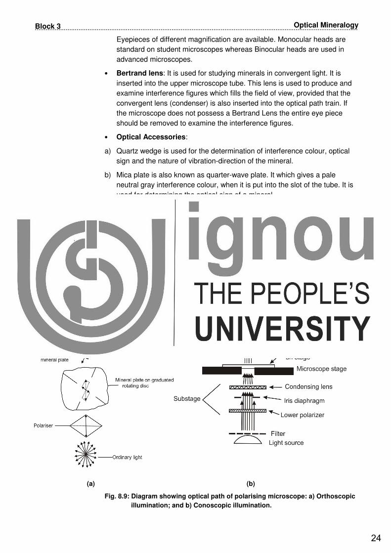
Fig. 8.9: Diagram showing optical path of polarising microscope: a) Orthoscopic
illumination; and b) Conoscopic illumination.
24

............................................................................................................................................................
25
Polarising Microscope Unit 8
8.4.2 Functioning of Polarising Microscope
We have discussed about the parts of a polarising microscope in the above
section, now let us learn about the functioning of the polarising microscope.
The light source is placed below the stage of the microscope. The light is
initially unpolarised. We have learnt in the previous section that the light
entering the polariser is resolved into two vibration directions which are at right
angles to one another. The light first passes through the lower polariser called
the polariser. It becomes polarised such that it is vibrating from the users right
to left. When the light leaves the polariser it starts vibrating parallel to the short
diagonal of the Nicol prism. These directions are referred to as East (right) and
West (left). They are parallel to the vibration direction of the mineral. This is
called Plane Polarised Light or abbreviated as PPL. We have discussed
earlier that the rays leaving the mineral plate are broken into two vibrations.
One ray is parallel to long diagonal which is reflected out. Another one is
parallel to short diagonal of the analyser and reaches to the eyepiece.
The light passing through a hole in the rotatable stage of the microscope enters
the lower lens, called the objective lens (Fig. 8.9a and 8.10a).
Fig. 8.10: Diagram showing: a) Orthoscopic; and b) Conoscopic illumination in
polarising microscope.
If the analyser is out that means it is not in the light path, then the polarised light will be transmitted through the ocular lens. If the analyser is in, then the
plane polarised light coming from the lower polariser will be blocked, hence no
light will be transmitted though the ocular lens above. However, the analyser is similar to polariser but is oriented at right angle to polariser. It has a
polarisation direction exactly perpendicular to that of the lower polariser. These
directions are usually referred to as North-South. When the analyser is inserted, without a mineral specimen then the field of view becomes dark. The
analyser receives light vibrating in an East-West direction from the polariser but
because of orientation cannot transmit it, as it is absorbed. The above arrangement of analyser to polariser is referred as Crossed Polars and is abbreviated as XP.
25

.................................................................................................................................................................................
26
Optical Mineralogy Block 3
The important requirement for microscopic studies is that the vibration
directions of these two nicols should be properly crossed, i.e. should be exactly
at 90°. If the nicols are properly crossed the field of view should be perfectly
dark. If not, rotate the polariser gently with one hand till a maximum position of
darkness is achieved (Fig. 8.11).
(a) (b)
Fig. 8.11: Sketch showing: a) incorrectly; and b) correctly crossed Nicol.
We will further discuss in unit 9 the optical properties in minerals studied both
under plane polarised light (PPL) and between cross nicols (XP).
The polarising microscope may be assembled either for orthoscopic or
conoscopic illumination (Fig. 8.9b and 8.10b). The orthoscopic illumination
provides the eye with a realistic virtual image with a flat field showing object on
the microscopic stage. It is carried using single polarising device or with cross
polars. Orthoscopic illumination uses weakly converging light and allows the
mineral sample to be examined with the upper polariser filter either in the cross
polar condition or under plane polarised light. These observations in the
conoscopic illumination or convergent light are carried using arrangement
such as Bertrand lens and the condensing lens (Fig. 8.9b and 8.10b).
Conoscopic illumination uses strongly converging light to produce optical
phenomenon called interference figures which are observed at the upper focal
plane of the objective lens. The interference figure allows determination of
optical class, optic sign, dispersion characteristics, 2V angle and indicatrix
orientation. Thus in orthoscopic illumination we make observations under plane
polarised light or cross nicols whereas in case of conoscopic illumination
Bertrand lens and condenser are inserted in the optical path.
We hope that now you are now familiar with the working of the polarising
microscope. It is possible to study the minerals and rocks with the help of
polarising microscope in details and identify them in orthoscopic and
conoscopic illumination.
In the previous sections we have studied about the parts and functioning of
polarising microscope. Before going to the next section spend 5 minutes to
check how you are progressing.
26
............................................................................................................................................................
27
Polarising Microscope Unit 8
SAQ 2SAQ 2SAQ 2SAQ 2
a) How is analyser different from polariser?
b) PPL is the abbreviation used for _______ _______ _____.
c) What is conoscopic illumination?
d) What is the function of substage diaphragm?
8.7 SUMMARY
In this unit, we have discussed about the parts, principle and functioning of
Polarising microscope. Let us now summarise:
• The objective of optical mineralogy is microscopic study of the minerals
with the help of polarising microscope. Thin sections of the minerals or
rocks are prepared by grinding a chip of minerals and rocks till it thins down
to a thickness of about 0.03 mm.
• Double refraction is shown by all anisotropic minerals, other than cubic
system. This property is shown by colourless transparent variety of calcite
called iceland spar.
• Nicol prism is constructed using iceland spar. This is an important device
used in the polarising microscope. It functions on the principle/property of
double refraction of calcite mineral.
• Ordinary and extraordinary rays travel with different velocities. In polarising
microscope the ordinary light passes through polariser and mineral plate
placed on the stage. Two rays leave the mineral plate. Analyser is at right
angle to the lower polariser. Two rays come out and these two emergent
rays interfere as they differ in phase.
8.8 ACTIVITY
Take a crystal of iceland spar and put it on a dot on a paper. Rotate the crystal
and observe two images of the dot. It is because of double refraction as
explained in Section 8.3.2.
8.9 TERMINAL QUESTIONS
1. Discuss the various parts of polarising microscope.
2. Describe the functioning of polarising microscope.
3. Discuss about the phenomenon of double refraction and the principle used
in the construction of nicol prism.
4. What is difference between isotropic and anisotropic substances?
8.10 REFERENCES
• Dana, J.D. and Ford, W.E. (1962), A Text book of Mineralogy, Asia
Publishing House, New Delhi.
27

.................................................................................................................................................................................
28
Optical Mineralogy Block 3
• Gribble, C.D. (1991) Rutley’s Elements of Mineralogy, 27th Edition. CBS
Publishers and Distributors, Delhi.
• www.gsi.gov.in
• www.guweb2.gonzaga.edu
(websites accessed on 2nd February 2019)
8.11 FURTHER /SUGGESTED READINGS
• Dana, J.D. and Ford, W.E. (1962) A Text book of Mineralogy, Asia
Publishing House, New Delhi.
• Gribble, C.D. (1991) Rutley’s Elements of Mineralogy, 27th Edition. CBS
Publishers and Distributors, Delhi.
• Mahapatra, G.B. (2012, Reprinted) A Textbook of Geology, CBS
Publishers, Delhi
• Singh, P. (2013) Engineering and General Geology, S.K. Kataria & Sons,
Delhi.
8.12 ANSWERS
Self Assessment Questions
1 a) In plane polarised light, the vibrations take place in all directions.
b) Double refraction is the splitting of the beam of ordinary light into two
beams which traverse the crystals at different speeds- Ordinary (O-ray)
and extraordinary (E-ray) rays. Ordinary ray consists of light vibrating
parallel to long diagonal of the rhomb face and the extraordinary ray of
light vibrates parallel to short diagonal of the rhomb (calcite var. Iceland
spar), which is generally used to produce polarised light.
c) Iceland spar.
d) Nicol is an important device and used in the polarising microscope. It
functions on the phenomenon double refraction of mineral calcite.
e) Isotropic substance transmits light with equal velocity in all the
directions as all the three axes are equal and interchangeable
2. a) In both of these nicol prisms are used. The difference is of position, one
is at right angle to another. Nicol below the disc or microscopic stage is
called polariser and that in the microscopic tube as analyser. While
studying the optical properties under plane polarised light only polariser
is used whereas for cross nicol position both analyser and polariser are
used.
b) Plane polarised light.
c) In the conoscopic illumination in the assembly of microscope the
Bertrand lens is not inserted.
28

............................................................................................................................................................
29
Polarising Microscope Unit 8
d) Substage diaphragm is located below the stage. Its function is to reduce
the area of light entering the thin section.
Terminal Questions
1. Please refer subsection 8.4.1.
2. Please refer subsection 8.4.2.
3. Please refer subsection 8.3.4.
4. Please refer subsection 8.3.5.
29

.................................................................................................................................................................................
30
Optical Mineralogy Block 3
30

UNIT 9
OPTICAL PROPERTIES OF
MINERALS
StructureStructureStructureStructure____________________________________________________________________________________________________________________________________________________________________________________________________________
9.1 Introduction
Expected Learning Outcomes
9.2 Study of Optical Properties of Minerals
9.3 Optical Properties under Ordinary Light
Form
Colour
Relief
Refractive Index
Cleavage
Inclusion and Alteration
9.4 Optical Properties under Plane
Polarised Light
Pleochroism
Twinkling
9.5 Optical Properties between Cross Nicol
Isotropism/Anisotropism
Interference colors
Extinction
Twinning
Zoning
9.6 Summary
9.7 Activity
9.8 Terminal Questions
9.9 References
9.10 Further/Suggested Readings
9.11 Answers
9.1 INTRODUCTION
We have learnt the identification of physical properties of minerals in hand specimen in Unit 4
Minerals. Now in this unit we will study the optical properties used in the identification of minerals
under the polarising microscope. We have already discussed about the parts and functioning of
polarising microscope in the previous unit. The optical properties of the minerals are immensely
helpful in mineral identification. The microscopic or optical study of minerals and rocks in
transmitted and polarised light to this day remains one of the classic and indispensable method for
identification of mineralogy. Polarised light microscopy is a nondestructive way of identification of
mineral phases wherein they can be studied within their textural framework. It allows an estimate
of chemical compositions and provides clues to the history of formation of the mineral and rock,
using specific textural characteristics such as structure, fabric, mineral assemblage textures.
31

.............................................................................................................................................................................
32
Optical Properties of Minerals Block 3
Now let us discuss the optical properties of minerals that you would study under
ordinary light, plane polarised light and between the cross nicols.
Expected Learning OutcomesExpected Learning OutcomesExpected Learning OutcomesExpected Learning Outcomes____________________
After reading this unit you should be able to:
� discuss the optical properties of minerals under ordinary light;
� explain the optical properties of minerals under polarised light; and
� identify the optical properties of minerals between cross nicols.
9.2 STUDY OF OPTICAL PROPERTIES OF
MINERALS
We have discussed petrological microscope and its working in previous unit. The
common practice is to use a lower power objective, i.e. 2.5 x or 5 x depending
upon the microscope you are using. This gives a wider view and better illumination.
Higher magnification objectives say 10 x or 40 x could be used later. The polarising
microscope you use has the provision either to include or exclude the use of
analyser. In that case you can study the optical properties of minerals in two
positions, namely:
• Properties under plane polarised Light (analyser in and polariser out )
• Properties between crossed nicols (both analyser in and polariser in)
But if we assume you have the provision of including or excluding the use of
polariser and analyser then you can carry three types of optical studies. In that
case properties of the minerals in thin sections can be examined by you in the
following three positions:
• Properties under ordinary light (polariser and analyser out )
• Properties under Plane polarised light (analyser in and polariser out )
• Properties between Crossed Nicol(both polariser and analyser in)
If the polariser is not removable from the optical system of the microscope,
the properties under ordinary light are to be studied under plane polarised
light only.
Let us list optical properties of minerals studied under ordinary light, plane
polarised light and between cross nicol (Table 9.1).
9.3 OPTICAL PROPERTIES UNDER ORDINARY
LIGHT
Now let us now describe the optical properties of minerals observed under ordinary
light. We have discussed that while observing the optical properties under ordinary
32

..........................................................................................................................................................................
33
Optical Properties of Minerals Unit 9
light polariser and analyser are excluded from the optical system of the
microscope. Again you are reminded that if you do not have the facility or provision
of excluding polariser from that optical assembly of the microscope, in that case the
properties discussed under ordinary light are studied under Plane polarised light.
Let us elaborate on the optical properties studied and observations made under the
ordinary light.
Table 9.1: Optical properties of minerals under plane ordinary light,
polarised light and between cross nicol.
9.3.1 Form
The form is related to crystalline nature of the mineral and it can be regular or
irregular. We shall consider two aspects in this study:
A) Shape: We can observe the fundamental shapes of the minerals under the
microscope. They may be following types:
• Euhedral: Complete outline or boundary of the mineral grain can be seen like
hexagonal, rectangular, etc (Fig. 9.1a).
• Subhedral: Only the partial outline or boundary of the mineral grain is
observed (Fig. 9.1b).
• Anhedral: The minerals grains are irregular in shape and the grain boundaries
are not visible (Fig. 9.1c).
Fig. 9.1: Shapes of mineral grains: a) Euhedral; b) Subhedral; and c) Anhedral.
Ordinary Light (both
polariser and
analyser out)
Plane Polarised
Light
(PPL)-analyser out
Between Cross Nicol
(XP)-analyser in
Form/Habit Pleochroism Isotropism/Anisotropism
Colour Pleochroic haloes Polarisation/Interference
colours
Transparency Twinkling Extinction and extinction
angle
Refractive Index (R.I.)
Relief
Cleavage
Twinning
Zoning
Alteration
Inclusion and
Alteration
33
.............................................................................................................................................................................
34
Optical Properties of Minerals Block 3
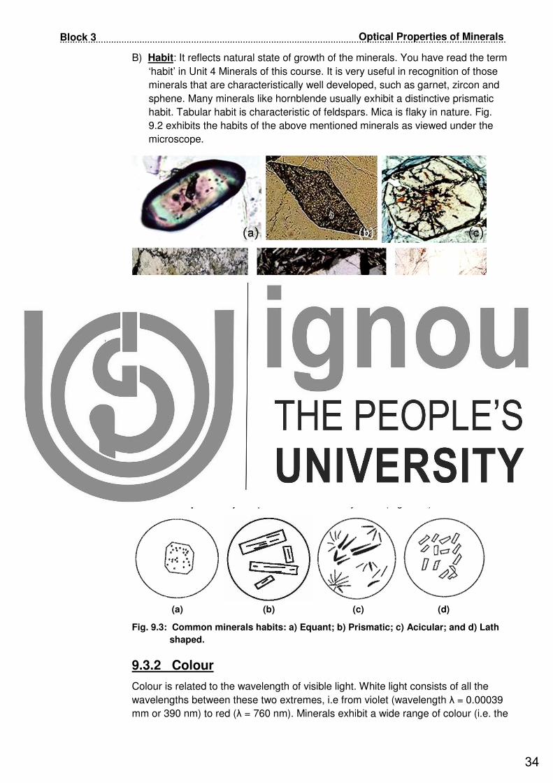
B) Habit: It reflects natural state of growth of the minerals. You have read the term
‘habit’ in Unit 4 Minerals of this course. It is very useful in recognition of those
minerals that are characteristically well developed, such as garnet, zircon and
sphene. Many minerals like hornblende usually exhibit a distinctive prismatic
habit. Tabular habit is characteristic of feldspars. Mica is flaky in nature. Fig.
9.2 exhibits the habits of the above mentioned minerals as viewed under the
microscope.
Fig. 9.2: Common minerals habits as viewed under the microscope: a) Zircon; b)
Sphene; c) Garnet; d) Hornblende; e) Feldspar; and f) Muscovite.
Let us now list the commonly recognised habits:
• Equant: The length and width of a mineral are nearly equal (Fig. 9.3a).
• Prismatic or columnar: The length is more than the width of the mineral (Fig.
9.3b).
• Acicular: They exhibit needle shaped crystals which may be radiating or
otherwise (Fig. 9.3c).
• Lath shaped: They are prismatic but are very small (Fig. 9.3d).
(a) (b) (c) (d)
Fig. 9.3: Common minerals habits: a) Equant; b) Prismatic; c) Acicular; and d) Lath
shaped.
9.3.2 Colour
Colour is related to the wavelength of visible light. White light consists of all the
wavelengths between these two extremes, i.e from violet (wavelength λ = 0.00039
mm or 390 nm) to red (λ = 760 nm). Minerals exhibit a wide range of colour (i.e. the
34

..........................................................................................................................................................................
35
Optical Properties of Minerals Unit 9
natural or body colour of a mineral), ranging from colorless minerals to colored
minerals (e.g. brown biotite and green hornblende). Minerals like quartz and calcite
show different colours in hand specimen but in thin section at thickness of 0.30mm,
they appear colourless. Minerals like biotite and hornblende display their typical
diagnostic colours even at this thickness. Biotite will exhibit shades of yellow/brown
while hornblende appears in shades of green and blue. However you cannot
identify the minerals only with the help of colour in ordinary or plane polarised light.
In order to confirm its identification other supporting optical properties are required.
We will study about this in the following sections. Coloured minerals generally
show different shades of colour depending on their orientation. You will find listed
in Table 9.2 few commonly coloured minerals.
In the thin section mineral can appear as opaque or non-opaque.
• Non-opaque minerals: If a mineral is transparent or translucent first its colour
is determined. Most of the minerals acquire transparency at 0.03 mm. The
coloured minerals in thin section are much less diverse than those in hand
specimen. Many minerals that appear pink, green, yellow, blue or even black
may be completely colourless or nearly so in normal thin section. Some
minerals that appear colourless are quartz, feldspar, etc. More strongly
coloured minerals are hornblende, biotite, etc.
• Opaque minerals: Mostly metallic minerals are opaque like hematite (Fe2O3),
magnetite (Fe3O4), pyrite (FeS2). They have sharp boundaries and appear
black or brownish black under PPL.
Table 9.2: Commonly coloured minerals. (Source: Alexander, 2009)
Colour in Thin Section Minerals
Pale yellow/brown Biotite
Pink Hypersthene,few garnet, andalusite
Green Hornblende, actinolite, chlorite,
hypersthene, tourmaline, aegerine
Strong yellow Staurolite
Pale brown Augite, hornblende
Blue/Brown Tourmaline
9.3.3 Relief
The thin sections of mineral/rocks are trapped between two thin layers of resin or
cementing material to which the glass slide and the cover slip are attached. The
surface relief of a mineral is basically constant except for carbonate minerals. This
depends on the difference between the Refractive Index (RI) of the mineral and the
RI of the enclosing resin. If the difference between the RI of the mineral and the
resin is greater then the surface of mineral will appear rougher. The surfaces of the
mineral in thin section are made up of tiny elevations and depressions, which
reflect and refract the light. If the RI’s of the mineral and resin are similar the
surface appears smooth. Certain minerals stand out more sharply as compared to
others when observed in the thin section. Relief is the distinctness with which a
mineral stands out from the embedding medium when observed in plane polarised
light under the microscope. Relief is the degree of visibility of the mounted mineral
35

.............................................................................................................................................................................
36
Optical Properties of Minerals Block 3
specimen. Most commonly Canada balsam, with refractive index of 1.54, is used
as the mounting medium. If any mineral has a RI exactly similar to Canada Balsam,
for example halite (RI-1.54); it is visible as it is totally lost or camouflaged by
Canada balsam. Relief is dependent on the difference between the Refractive
Index (RI) of the mineral and the medium on which it is mounted. It is linked to the
refractive index of the mineral (speed at which light passes through) relative to the
speed it passes through the mounting medium used to prepare the thin section.
The term negative relief is used when the refractive index of the mineral is lower
than the mounting medium. Conversely it is positive relief when the mineral has
higher refractive index than the mounting medium. Greater the difference in
refractive index between the mineral and mounting medium, higher is relief. Relief
may be categorised as (Fig. 9.4):
• Poor relief: Minerals with similar R.I. to Canada balsam show indistinct borders
which tend to merge with the mounting medium, e.g. quartz, feldspars
(Fig. 9.4a);
• Negative relief: Mineral with lower R.I. to Canada balsam show poor outline,
e.g. leucite, augite (Fig. 9.4a);
• Positive, high or strong relief: Mineral with higher R.I. than Canada balsam
will have well marked borders and the cleavage cracks, e.g. garnet,zircon
(Fig. 9.4a and b).
(a)
(b)
Fig. 9.4: a) Sketches showing various category of relief (i) Poor, (ii) Negative, and (iii)
Positive; and b) Mineral quartz (red arrow) and zircon (black arrow) showing
low and very high relief, respectively under plane polarised light. (Photo
credit: Dr. Meenal Mishra)
36

..........................................................................................................................................................................
37
Optical Properties of Minerals Unit 9
9.3.3 Refractive Index
When rays of light travel from a source through a medium of higher RI into a
medium of lower RI medium, they are partly reflected back into the higher RI
medium. We have learnt that relief depends on the refractive index of the mineral
and the medium in which it is embedded. Now we shall discuss the determination
of refractive index (n) using petrological microscope. If the mineral has more
refractive index than Canada balsam it will appear to be raised up. It will indicate
that the mineral has positive relief and higher refractive index. On the other hand, if
the mineral appears to be depressed it is said to have negative relief and lower
refractive index than the embedded medium, i.e. Canada balsam. The descriptive
scheme for the relief of minerals with reference to their refractive indices is given in
Table 9.3. The relative refractive indices of two minerals or one mineral and the
mounting medium can be observed by studying the Becke’s effect. The Becke’s
Line method also known as Central illumination method is commonly employed for
determination of refractive index of a mineral. This can be performed with the help
of petrological microscope easily by using high power objective field of microscope
should not too illuminated. You could do this by cutting down the unnecessary light
by partially closing down the iris diaphragm located below the stage so that only
the desired field of view is brightly seen.
Table 9.3: Descriptive scheme for relief of minerals with
reference to their refractive indices.
Becke’s test: This technique allows you to judge the value of the refractive index
of the mineral with respect to that of the oil. The mounting material may be Canada
balsam (RI=1.54) or epoxy (RI=1.51). Care must be taken to make sure that the
objective movements should be very small otherwise the image will become
defocused completely and no useful purpose would then be served in such case.
The principle involved is the total reflection of light incident at more than the critical
angle when passing from a mineral of greater RI to that of lesser index in thin
section. Please refer to Fig. 9.5 and follow the following steps to perform Becke’s
test.
• The edge of the mineral in contact with the mounted medium, is sharply
focused after reducing the illuminated area (iris diaphragm has to be partially
closed).
• A sharp line visible just inside the boundary of the mineral is known as Becke’s
line. It is a bright narrow band which appears at the mineral-liquid interface and
moves towards the material with the higher RI.
• Focusing tube is raised by increasing the distance between mineral and the
objective and movement of bright Becke’s line is carefully observed.
Refractive Index (RI) Description of relief
1.40 – 1.50 Very low
1.50 – 1.58 Low
1.58 – 1.67 Moderate
1.67 – 1.76 High
> 1.76 Very high
37

.............................................................................................................................................................................
38
Optical Properties of Minerals Block 3
• If Becke line moves towards the mineral body, the mineral has more refractive
index which means that it has positive relief, i.e. (nmineral>nliquid) (Fig. 9.5a).
• Now focusing tube is lowered by decreasing the distance between mineral and
the objective and movement of bright Becke’s line is carefully observed.
• If it moves away from the margin towards outside, the mineral has less
refractive index than the mounting medium (Fig. 9.5b). It will indicate that the
mineral is negative in relief (nmineral<nliquid).
In general as a rule when objective is raised Becke line moves towards higher
refractive index.
Fig. 9.5: Formation of Becke’s line. Becke’s test performed to determine
a) Positive relief (nmineral>nliquid); and b) Negative relief (nmineral<nliquid).
9.3.4 Cleavage
You have read the definition of cleavage in Unit 4 of this course while discussing about the physical properties of minerals.
Let us recapitulate what we had learnt? Cleavage is an ability of the mineral to crack or break along well-defined crystallographic planes within the lattice structure. It is quite clear in hand specimens but it becomes even more revealing in thin sections. Cleavage appears as parallel straight lines. Under the microscope the cleavages appear as parallel lines in the mineral grain, which may be distinct faint or absent. Cleavage is not haphazard but has definite crystallographic orientation. If you look at the thin section of olivine you will find cracks. On examining thin section of mica or hornblende you will find perfect one set or two set cleavage. Now try to differentiate between the two. If there are more than one set of cleavages then the angle between the cleavages is measured to identify the minerals. The set of visible cleavage depends on the direction in which section is cut. Prismatic sections of hornblende, augite will show only one direction of cleavage, whereas in their basal section shows 2 sets are discernible. Minerals belonging to pyroxenes and amphibole groups have one directional cleavage in sections, cut parallel to ‘C’ axis while excellent two directional cleavages in basal sections. In pyroxenes the angle between two sets of cleavages is nearly 90o while amphiboles it is 120o.
38

..........................................................................................................................................................................
39
Optical Properties of Minerals Unit 9
Let us illustrate the method to find out the cleavage angle? Keep one set of
cleavage parallel to the cross wire and reading ‘a’ is taken on the scale of the
microscopic stage. Now rotate the stage till the second set of cleavage becomes
parallel to the same cross wire. In this position reading ‘b’ is taken. The difference
between these two readings is the cleavage angle.
Some of the important minerals and the cleavage sets exhibited by the minerals
include:
• One set: Muscovite, biotite (Fig. 9.6a), etc.
• Two sets: Found in minerals like hornblende (at an angle of 56o and 124o) and
orthoclase has cleavage angle of 900 (Fig. 9.6b), augite has 2 set of cleavage
intersecting at 87o and 93°, etc.
• Three sets: Calcite shows 3 set perfect rhombohedral cleavage.
• Absent: Cleavage is absent in minerals like quartz and olivine.
Minerals may have even four directional cleavages in an octahedral pattern, e.g.
fluorite or six (sphalerite) sets of cleavages. However, the number of sets visible
under the microscope depends on the orientation of the section. Minerals like
olivine, nepheline, garnet and leucite are examples with imperfect or poor cleavage
developments.
Fig. 9.6: Cleavage as visible under microscope: a) One set of cleavage in muscovite
or biotite; and b) Two sets of cleavages at 900 in orthoclase, plagioclase or
microcline.
9.3.5 Inclusion and Alteration
You should mention in the optical properties about the inclusions, if seen. Olivine
has numerous inclusions of opaque iron oxides. You will also find several tiny
inclusions of quartz, mica and zircon.
Alteration of minerals in thin section usually gives turbid or cloudy areas within the
mineral. The most common cause of alteration is by water or carbon dioxide
coming into contact with a mineral. They chemically react with some of its
elements, and produce a new mineral phase(s). For example, water reacts with the
feldspars and produces clay minerals which give cloudy appearance to the
colourless feldspar grain in PPL. The alteration may be so advanced that the
mineral is completely replaced by a new mineral. Quartz appears clear as it does
39

.............................................................................................................................................................................
40
Optical Properties of Minerals Block 3
not readily undergo alteration. Olivine crystals show severe effects of alteration and
a secondary mineral called serpentine originates (Fig. 9.7).
Fig. 9.7: Replacement seen in olivine mineral along the cracks by secondary mineral,
serpentine (brown in colour and fibrous form) in PPL: left panel; and
Crossed polars: right panel. (Photo credit: Dr. Amit Kumar)
Following three types of inclusions are commonly seen in the minerals (Fig. 9.8 to
9.10).
• Regular: These inclusions are of well defined crystals (Fig. 9.8a and b).
• Irregular: These are generally of fluid inclusions and are irregularly distributed
(Fig. 9.9).
• Acicular: These inclusions are needle shaped which may be simple or
radiating (Fig. 9.10a and b).
(a) (b)
Fig. 9.8: a) Sketch showing regular inclusion; and b) Microphotograph of zircon
(zoned colourful mineral) as inclusion in quartz. Notice regular fluid
inclusions distributed in quartz crystal. (Photo credit: Dr. Meenal Mishra)
Fig. 9.9: Irregular inclusions.
Zircon
40

..........................................................................................................................................................................
41
Optical Properties of Minerals Unit 9
(a) (b)
Fig. 9.10: Acicular inclusions: a) Sketch; and b) Photomicrograph of needle like
inclusions and regular fluid inclusions in quartz. (Photo credit: Dr. Meenal
Mishra)
9.4 OPTICAL PROPERTIES UNDER PLANE
POLARISED LIGHT
It is important to note that the above optical properties can be studied in
ordinary light as well as plane polarised light (in case the analyser is not
removable) but for the properties described below can only be observed in
polarised light only. Thus theoritical properties under plane polarised
lightform/habit, colour, transparency, relief, refractive index (R.I.), cleavage,
inclusion and alteration, apart from pleochroism and pleochroic halos about
which we have already discussed in detail in the above section.
Thus optical properties studied under plane polarised light are listed below:
• Form/habit
• Colour and Transparency
• Relief
• Refractive Index (R.I.)
• Cleavage
• Inclusion and alteration
• Pleochrism and pleochroic haloes
• Twinkling
9.4.1 Pleochroism
Pleochroism is one of the most characteristic and significant property of anisotropic
minerals. The word ‘Pleo’ means many and ‘chroism’ refers to colours. This means
that this phenomenon has to do with more than one colour. You should remember
that colourless mineral do not show pleochroism. In some minerals the change in
quality and quantity of colour is observed on rotation of the microscopic stage. The
change in colour (light to dark) results from the absorption of certain colours
(wavelength) from the incident white light. You can define pleochroism as the
41

.............................................................................................................................................................................
42
Optical Properties of Minerals Block 3
variation in colour resulting from differential absorption of wavelength in different
directions. It is exhibited by coloured minerals when the stage is rotated in the
plane polarised light. The change can be both in intensity and shade. When the
change is only in two shades the phenomenon is called dichroism. The minerals
of the tetragonal, trigonal and hexagonal systems (uniaxial minerals) exhibit
dichroism. The uniaxial minerals contain only two polarised light components in
mutually perpendicular directions. The minerals belonging to orthorhombic,
monoclinic and triclinic systems, i.e. biaxial category exhibit more than two
changes in their absorption of colours. Pleochroism is exhibited by some of the
coloured anisotropic minerals, e.g. biotite shows light yellowish brown to greenish
and dark brown (Fig.9.11a) and hornblende exhibits light green to dark green
(Fig.9.11b).
Biotite is the best example of pleochroic (dichroic) mineral. Its section cut
perpendicular to cleavage change from straw yellow to dark brown. The extremes
of colours are observable at an interval of 90o. Dark brown colour is achieved when
cleavage is parallel to E-W cross wires, i.e. vibration direction to the polariser. It is
pale yellow when the cleavage coincides with N-S cross wires. This has two-fold
variations with respect to the ordinary ray and extraordinary ray in dichroic
mineral is known as pleochroic scheme.
Minerals belonging to orthorhombic, monoclinic and triclinic systems, i.e. biaxial
category exhibit three main possible vibration directions (X, Y and Z). Hypersthene
and hornblende present best example. Pleochroic scheme of hornblende is pale
green, dark green and brown whereas for hypersthene it is pink, yellow and light
green. You can observe these changes in a single mineral grain but in mineral thin
section this difference in three shades is clearly noticed in a number of different
crystals. You will note that not all the doubly refracting minerals are pleochroic or
so distinct as biotite and hornblende. However you can study the minerals in two
groups:
• Pleochroic: It can be divided into two groups:
1. Strongly pleochroic: Biotite, hornblende, tourmaline, hornblende, aegerine
augite, staurolite
2. Faintly pleochroic: Few augite, andalusite
• Non-Pleochroic: Quartz, feldspars (orthoclase, microcline, plagioclase),
feldspathoids, olivine, apatite.
You should remember that both uniaxial and biaxial minerals when cut
perpendicular to their optic axis/ axes will not show any pleochoism as along the
optic axis they will not be doubly refracting.
Pleochroic haloes are circular little areas,characteristically present in few
minerals, that tend to be strongly pleochroic. Biotite, tourmaline, hornblende,
chlorite, muscovite, cordierite and fluorite often contain pleochroic haloes. They
result due to the presence of radioactive inclusions in these minerals. These
inclusions are the product of radioactive disintegration resulting in alpha particles.
Generally, these inclusions are zircon, apatite or sphene.
42

..........................................................................................................................................................................
43
Optical Properties of Minerals Unit 9
(a)
(b)
Fig. 9.11: Minerals showing strong pleochroism: a) Biotite exhibiting pleochroism-
dark brown to green colour. Notice the pleochroic haloes in biotite; and b)
Hornblende mineral shows pleochroism-light green to dark green colour.
(Photo credit: Mageswarii Gayu)
9.4.2 Twinkling
We can observe twinkling in anisotropic minerals with widely varying refractive
indices (in contrast to R.I. of Canada balsam) on rapidly rotating stage under plane
polarised light, e.g. calcite and dolomite. The twinkling effect is caused by rapid
change in relief of minerals. Let us discuss an example of calcite. The refractive
index of ordinary ray in calcite mineral is 1.66 and for extraordinary ray is 1.49.
Refractive index of Canada balsam is 1.54. Thus, in one case relief will be positive
and in another case it will be negative. Calcite is doubly refracting; it possesses two
vibration directions for transmitted light. When the stage is rapidly rotated the
mineral shows, in one position, a rough surface, well defined borders and
conspicuous cleavages while in other position, a smooth surface, faintly defined
Pleochroic halos
43

.............................................................................................................................................................................
44
Optical Properties of Minerals Block 3
borders and in conspicuous cleavages are visible. In these two extreme situations
the contrasting relief are exhibited when the two vibration directions of calcite in a
section are parallel in turn with the vibration direction of the light emerging from the
polariser. This means that each of the two-vibration direction has its own R.I. A
rapid rotation of the stage produces a rapid change of the relief which is described
as twinkling. This effect is similar to those of stars.
In the previous sections we have studied about the optical properties under
ordinary and plane polarised light. Before going to the next section spend 5
minutes to check how you are progressing.
SAQ SAQ SAQ SAQ 1
a) List the optical properties studied under plane polarised light and cross polars.
b) List types of inclusions.
c) What is the purpose of Becke’s test?
d) Define pleochroism.
9.5 OPTICAL PROPERTIES BETWEEN CROSS
NICOLS
We have read the optical properties of minerals in plane polarised light in the
previous section. Now let us study the optical properties observed between cross
nicols. In order to bring the microscope in this position (between cross polars) you
have to insert polariser in the microscopic tube. Earlier also we have seen that in
this position the short diagonal of lower nicol (polariser) is at right angle to the
inserted upper nicol (analyser). Also, while making observations between cross
nicols, if the mineral slide is not kept on the microscopic stage between the two
nicols, the field will be completely dark. Let us go through the optical properties
between cross nicols:
9.5.1 Isotropism/Anisotropism
Minerals may be either:
• Isotropic: Some minerals become dark when viewed under cross nicols and
remain completely dark on the rotation of the stage. They are isotropic. The
minerals crystallising in the cubic/isometric system and amorphous substances
such as glass, Canada balsam show this property (Fig. 9.12a and b).
(a)
44

..........................................................................................................................................................................
45
Optical Properties of Minerals Unit 9
(b)
Fig.9.12: Isotropic mineral between cross nicols: a) Sketch; and b) Microphotograph
of octahedral garnet (black) showing isotropism (MagnX20, Cross Nicol).
(Photo credit: Dr. Meenal Mishra)
• Anisotropic: In the field of view, minerals become completely dark four times
in one complete rotation. They include the minerals belonging to orthorhombic,
monoclinic, triclinic, tetragonal, trigonal and hexagonal systems (Fig. 9.13).
(a)
(b)
Fig. 9.13: Anisotropism in different minerals: a) Plagioclase mineral shows different
colours and becomes dark four times in one complete rotation; and b)
Microphotograph showing quartz (shades of grey) and colourful zircon,
between cross nicol. (Photo credit: Dr. Meenal Mishra)
Zircon
45

.............................................................................................................................................................................
46
Optical Properties of Minerals Block 3
9.5.2 Interference Colors
Optical mineralogy becomes colourful because of the interference colours. These
colours fascinate the beginner. When the white light passes through an anisotropic
mineral, all wavelengths are split into two polarised rays (O-ray and E-ray) which
vibrate at 90o to each other (about which we have discussed in earlier sections).
The phase difference between the two rays will match the wavelength of same
colour in the spectrum. Different colours have different wavelengths, so when the
rays leave the crystal, some colours may be retarded, but most will not.
Anisotropic minerals in the intermediate positions between the positions of
extinction show various colours. These colours are the outcome of the interference
of the two rays of lights having the same vibration plane (after their emergence
from analyser) of which one is retarded with reference to the other. Interference
colours reach their maximum intensity midway between two extinct positions, i.e.
45o position.
Let us now examine and list the order of the colours along with the examples
(Table 9.4).
Table 9.4: List of orders of interference colours.
Birefringence is a measure of the difference between the maximum and minimum refractive indices of particular mineral. In other words, it is the difference between refractive index of two rays, i.e. extraordinary ray and ordinary ray. Calcite shows highest birefringence. Thin section of quartz with standard thickness may vary from grey to white; olivine may show a wide range of colours from Newton`s scale of interference colours.
The colours depend upon the thickness, birefringence and crystallographic orientation of the section. Let us study the relationship between the degree of birefringence, the optical path difference, and the thickness of a specimen on thin section. Birefringence is the amount that the two rays are out of phase. They can be assigned a numerical value, or �1−�2. Thus, birefringence is the difference between the principal refractive indices. The optical path difference is the difference in distance that each ray had to travel. It is also sometimes referred to as the retardation. The interference colors are the visible effect of this optical path difference. You can find out the numerical value for isotropic materials by multiplying the specimen thickness by the single refractive index of that mineral. However, in anisotropic materials, the numerical value for birefringence is substituted for the refractive index value, for example:
Optical path difference = (����1 − ����2) ∗∗∗∗ t(thickness of thin section)
Spectrum Colours Example
First Order Grey, white, light yellow or
sometimes light orange
Quartz, plagioclase,
orthoclase,
hypersthene, chlorite
Second Order VIBGYOR- sharp, distinct rainbow
colors, i.e. violet, indigo, blue,
green, yellow, orange and red
Augite, hornblende,
Third Order VIBGYOR- repeated but faint
rainbow colors
Muscovite, biotite
Fourth and
Higher Orders
Pale green and pink- very faint Calcite zircon
46

..........................................................................................................................................................................
47
Optical Properties of Minerals Unit 9
This relationship is more clearly shown on the Michel-Lévy chart (Fig. 9.14).
Interference colours can be first order, second order, and so on. Colour bands
progress initially from shades of grey and white to yellow, orange, pink, red, purple,
blue, green, back to yellow, and so on. This is similar to the colour order of a
rainbow. If the interference colour and thickness of specimen is known, then the
numerical value of birefringence can be determined with the help of blue arrows, as
shown in Fig. 9.14.
Fig. 9.14: Michel - Lévy birefringence chart.
9.5.3 Extinction
When the vibration direction of the ordinary and extraordinary rays of isotropic
minerals are parallel to vibration directions of nicols in a petrological microscope,
no light reaches the eye and the mineral is said to be in extinction position. This
is because the light passing the polariser also passes through the mineral but is
stopped by the analyser, as it has a vibration direction perpendicular to that of the
polariser. This phenomenon occurs four times during the rotation of the stage of
microscope, through an angle of 360° between crossed nicols. The isotropic
mineral is always in the position of extinction between the cross nicols. In case of
anisotropic mineral, the two adjacent position of extinction are separated from each
other by 90°.
There is a definite relationship between extinction position and interference
(polarisation) colours. The brightest interference colours are seen midway between
two extinction position (45o from the extinction position). As we rotate the stage
from its first extinction position, darkness will slowly start disappearing and
polarisation colours will appear at their brightest at 45o from their extinction
position. Now rotate the stage in reverse direction, polarisation colours disappear
and it gradually becomes extinct.
Extinction angle is the angle between crystallographic direction and position of
maximum extinction. This angle is measured with reference to cleavage crystal
outline prominent crack, twin plane.
Types of Extinction: The extinction position is normally referred with respect to
the outer edges of the crystal or its prominent cleavage direction. We have to keep
47

.............................................................................................................................................................................
48
Optical Properties of Minerals Block 3
the cleavage or crack parallel to a cross wire between cross nicol. On rotation of
the stage the mineral becomes dark called as extinction position. On this basis
there are four types of extinction recognised:
• Straight or parallel extinction: You will observe that the mineral becomes
dark parallel to cross wire, without any further rotation of the stage, it is called
as straight or parallel extinction (Fig. 9.15a and b).
• Oblique or Inclined extinction: You will find that when the mineral does not
appear dark parallel to the cross wire but on rotation of the stage at a certain
angle. This type of extinction is known as oblique extinction (Fig. 9.16a and
b). In case of oblique extinction you can measure the extinction angle. Take
the initial reading with cleavage parallel to cross wire. Then rotate the stage till
the mineral grain becomes dark or extinct. The difference in angle will give you
the extinction angle. Hornblende, augite shows oblique extinction.
(a)
(b)
Fig. 9.15: a) Sketch showing straight extinction; and b) Parallel extinction seen in
hypersthene mineral (black). Extinction is parallel to one set of cleavage.
Note that hypersthene shows low First order interference colours and 2
sets cleavage at 90o.
(Source: http://minerva.union.edu/hollochk/c_petrology/ig_minerals.htm)
48

..........................................................................................................................................................................
49
Optical Properties of Minerals Unit 9
(a)
(b)
Fig. 9.16: Oblique extinction: a) Sketch; and b) Note the oblique extinction in
plagioclase. (Photo credit: Prof. J. P. Shrivastava)
• Symmetrical extinction: This type of extinction is shown by minerals with
square outline or rhombic cross section. The mineral section becomes extinct
parallel to diagonal of rhombic pattern, e.g. calcite (Fig. 9.17a).
Fig. 9.17a: Symmetrical extinction.
• Wavy or undulose extinction: This type of extinction appears as a band or
series of bands of darkness crossing a single crystal unit during rotation of the
stage. This may be due to strain and deformation. Mineral never extinguishes
completely, e.g. quartz (Fig. 9.17b).
49

.............................................................................................................................................................................
50
Optical Properties of Minerals Block 3
Fig. 9.17b: Wavy or undulose extinction seen in quartz. (Photo credit: Dr. Meenal
Mishra)
9.5.4 Twinning
We have read in previous unit that the variation in habit of minerals is due to
significant variations in the conditions during crystallisation including pressure,
temperature, etc. Two or more crystals of the same or related mineral species may
intergrow with each other. Such crystals are called twinned crystals. Twinning is
very commonly seen in feldspars.
Following types of twinning are recognised.
• Carlsbad twinning: This type of twinning shows one set of dark and bright
bands (Fig.9.18). They alternate their position on rotation of the stage, e.g.
orthoclase (K feldspar).
• Polysynthetic twinning: It consists of many thin dark and alternating bright
bands, e.g. plagioclase feldspars (Fig. 9.19). The bands alternate their position
on rotation.
(a) (b)
Fig. 9.18: Carlsbad twinning: a) Sketch; and b) Photomicrograph of orthoclase
showing Carlsbad twinning (simple banding).
50

..........................................................................................................................................................................
51
Optical Properties of Minerals Unit 9
(a)
(b)
Fig. 9.19: Polysynthetic twinning: a) Sketch; and b) Photomicrograph of plagioclase
showing polysynthetic twinning. (Photo credit: Prof. J. P. Shrivastava)
• Cross hatch twinning: In this polysynthetic twinning is closely present in two
directions at right angles, e.g. microcline is a K-feldspar (Fig.9.20)
(a) (b)
Fig. 9.20: Cross hatch twinning: a) Sketch; and b) Photomicrograph of microcline
showing cross hatch twinning. (Photo credit: Dr. Meenal Mishra)
51

.............................................................................................................................................................................
52
Optical Properties of Minerals Block 3
9.5.5 Zoning
Zoning is typical of minerals which form continuous solid solution series. It appears
in form of concentric bands from centre outwards. Zoning reflects that mineral is
compositionally not uniform throughout. Plagioclase is the best example of
concentric zoning, in this we observe number of shells arranged concentrically
around a central point (Fig. 9.21). Another type of zoning is hour glass zoning
which you can observe in augite. Prismatic zoning is observed in tourmaline.
Fig. 9.21: Zoning seen in plagioclase feldspar between cross nicols. (Photo credit:
Prof. J. P. Shrivastava)
• Watch the following video to know more about zoning and twinning.
Microscopic Study of Basaltic Rocks
Link: https://www.youtube.com/watch?v=2RGL3XB2x3E&t=2s
In the previous sections we have studied about the optical properties between
cross nicols. Before going to the next section spend 5 minutes to check how you
are progressing.
SAQ 2
a) What do you understand by angle of extinction and identify the types of
extinction.
b) List the types of twinning exhibited by feldspars.
c) ________ mineral exhibits hourglass zoning.
d) Name the minerals exhibiting following optical properties.
Pleochroism, Twinkling, Rhombohedral cleavage, 2 sets cleavage at 90o,
Isotropism, Parallel extinction, Oblique extinction, Symmetrical extinction, Undulose
extinction, Carlsbad twinning, Cross hatch twinning.
52

..........................................................................................................................................................................
53
Optical Properties of Minerals Unit 9
9.6 SUMMARY
In this unit we have learnt about basic concepts of optical mineralogy and the
properties observed and studied under polarising microscope. Now let us
summarise:
• Thin sections are examined in three positions: (1) ordinary light, (2) under
plane polarised light, and (3) between cross nicols.
• Under plane polarised light (PPL) we study colour, pleochroism, form,
cleavage, relief, twinkling, and alteration and inclusions.
• Between cross nicols or crossed polars (XP) the study of
isotropism/anisotropism, interference colours, extinction, twinning and zoning
are carried out.
• The minerals have their individual diagnostic characteristics which are
collectively used for identification.
• Pleochroism is the variation in colour resulting from differential absorption of
wavelength in different directions. The twinkling effect is caused by rapid
change in relief of minerals.
• When the vibration direction of the ordinary and extraordinary rays of isotropic
minerals are parallel to vibration directions of nicols in a polarising microscope,
no light reaches the eye and the mineral is said to be in extinction position.
• Extinction can be straight or parallel, oblique or inclined, symmetrical, wavy or
undulose.
• Twinning is very commonly seen in feldspars.
• Birefringence is a measure of the difference between the maximum and
minimum refractive indices of particular mineral.
9.7 ACTIVITY
1. List the diagnostic properties of the minerals you have studied.
9.8 TERMINAL QUESTIONS
1. Describe the optical properties studied under plane polarised light, with the
help of neat well labeled diagrams.
2. Describe the optical properties studied between cross nicols with the help of
neat well labeled diagrams.
3. Write a short note on interference colours.
Audio/video material based questions
• Which mineral exhibits rhythmic zoning?
• What is hourglass structure?
• Why do you get twinning in minerals?
53

.............................................................................................................................................................................
54
Optical Properties of Minerals Block 3
9.9 REFERENCES
• Alexander, P.O., (2009) A Handbook of Minerals, Crystals Rocks and Ores.
New India Publishing Agency, New Delhi, 676p.
• http://minerva.union.edu/hollochk/c_petrology/ig_minerals.htm
(website accessed between 25th and 30thJanuary 2019)
9.10 FURTHER/SUGGESTED READINGS
• Dana, J.D. and Ford. W.E. (1962) A Text book of Mineralogy, Asia Publishing
House, New Delhi.
• Gribble, C.D. (2001) Rutley’s Elements of Mineralogy. 27th Edition. CBS
Publishers and Distributors, Delhi.
• Mahapatra. G.B, (2012 Reprinted) A Textbook of Geology, CBS Publishers,
New Delhi.
• Singh, P. (2013) Engineering and General Geology, S.K. Kataria & Sons, Delhi.
9.11 ANSWERS
Self Assessment Questions
1 a) Please refer Table 9.1.
b) Pleochroism as the variation in colour resulting from differential absorption
of wavelength in different directions. It is exhibited by coloured minerals
when the stage is rotated in the plane polarised light.
c) Thin sections are mounted in the medium of Canada balsam which has
refractive index (RI) 1.54. The difference in the RI of balsam and mineral
determines the relief. Becke test indicates as to whether the mineral has
more RI (positive) or less RI (negative) than the balsam.
d) Regular, irregular, accicular
2 a) Extinction angle is the angle between crystallographic direction and position
of maximum extinction is called extinction angle. This angle is measured
with reference to cleavage crystal outline or crack, twin plane. Four types of
extinction are: (1) Straight extinction; (2) Oblique or Inclined; (3)
Symmetrical extinction; (4) Wavy or undulose.
b) Carlsbad, polysynthetic and cross hatch
c) Augite
d) Pleochroism- hornblende, biotite, augite, hypersthene; twinkling- calcite,
muscovite; rhombohedral cleavage –calcite; 2 sets cleavage at 90o-
orthoclase, plagioclase, microcline, hypersthene; isotropism-garnet; parallel
extinction-biotite, muscovite, hypersthene; oblique extinction-hornblende,
54

..........................................................................................................................................................................
55
Optical Properties of Minerals Unit 9
augite, orthoclase, plagioclase, microcline; symmetrical extinction- calcite;
undulose extinction-quartz; carlsbad twinning- orthoclase, plagioclase;
cross hatch twinning-microcline.
Terminal Questions
1. Please refer to section 9.3 and 9.4.
2. Please refer to section 9.5.
3. Please refer to subsection 9.5.2.
55

.............................................................................................................................................................................
56
Optical Properties of Minerals Block 3
56

UNIT 10
OPTICAL PROPERTIES OF
ROCK-FORMING MINERALS
Structure___________________________________________________
10.1 Introduction
Expected Learning Outcomes
10.2 What are Rock-Forming Minerals?
10.3 Optical Properties of Quartz
10.4 Optical Properties of Feldspar Group
Orthoclase
Microcline
Plagioclase
10.5 Optical Properties of Mica Group
Muscovite
Biotite
10.6 Optical Properties of Pyroxene Group Minerals
Augite
Hypersthene
10.7 Optical Properties of Hornblende
10.8 Optical Properties of Olivine and Garnet
Olivine
Garnet
10.9 Optical Properties of Calcite
10.10 Summary
10.11 Activity
10.12 Terminal Questions
10.13 References
10.14 Further/Suggested Readings
10.15 Answers
10.1 INTRODUCTION
We have already discussed that the physical properties of minerals are important tools for their
identification in hand specimens Unit 4 Minerals. Then in Unit 6 Megascopic study of Minerals we
identified the common rock-forming minerals with the help of physical properties. Now in this unit
we will learn to identify the common rock-forming minerals using optical properties. These studies
are carried out using polarising microscope. The optical properties of the minerals are immensely
helpful in their identification.
57

………………………………………………………………………………………………………………………………………....................................
58
Optical Mineralogy Block 3
Expected Learning OutcomesExpected Learning OutcomesExpected Learning OutcomesExpected Learning Outcomes____________________
After reading this unit you should be able to:
� recognise the optical properties of rock-forming minerals under polarised
light;
� explain the optical properties of rock-forming minerals between cross nicol,
and
� identify the rock-forming minerals using their diagnostic optical properties.
10.2 WHAT ARE ROCK-FORMING MINERALS?
You have read about rock-forming minerals in Units 6 and 7 of this course.
Let us recall!
Rocks are naturally occurring, coherent solids consisting of aggregate of
minerals. In other words minerals are the building blocks of rocks. Rock-forming
minerals are the essential components of rocks commonly occurring in the
Earth's crust. About 25 minerals are usually considered to play an important
role in the composition of the crustal rocks. Rock-forming minerals are those
minerals that make up the major components of a rock and they are used in the
classification of rock types viz. igneous, sedimentary and metamorphic. Igneous
rocks are formed from the cooling and crystallisation of magma. Sedimentary
rocks are formed on decomposition and disintegration of the pre-existing rocks-
igneous, metamorphic or even earlier formed sedimentary rocks. Metamorphic
rocks are formed when a pre-existing rocks or protolith; undergoes a solid-state
change in response to the modification of its environment, i.e. temperature
and/or pressure. We will study in detail about rocks in BGYCT-135 course on
Petrology.
About 92 percent of the minerals found on Earth’s crust are silicates (Fig. 10.1,
Ronov, and Yaroshevsky, 1969). Silicates are regarded as building blocks of
the common rock-forming minerals. Silicates are minerals that contain silicon
and oxygen and usually one or more other elements. The silicate minerals are
of great importance because 27% of the known minerals and 40% of the
common minerals are silicates. With few exceptions all the igneous rocks make
up approximately 95% of the upper 16 km of the Earth’s crust. Each group of
rocks mentioned above characteristically has their own rock-forming minerals.
Though many minerals are found in the igneous rocks, but those called rock-
forming minerals are comparatively few. Common rock forming minerals in
igneous rocks are quartz, feldspars (orthoclase, microcline, plagioclase), mica
(muscovite, biotite), pyroxene (augite, hypersthene), amphibole (hornblende),
olivine and garnet, nepheline. The rock- forming minerals of sedimentary rocks
are quartz, orthoclase, plagioclase, muscovite, biotite, calcite, dolomite,
anhydrite and clay minerals. The metamorphic rocks dominantly comprise rock
forming silicate minerals like kyanite, andalusite, sillimanite, staurolite, chlorite,
serpentine, garnet, wollastonite and glaucophane.
58

……………….……………………………………………………………………………………………………..……………….................................
59
Properties of Rock-Forming Minerals Unit 10
Fig. 10.1: Estimated volume percentages for common rock forming minerals in
the Earth’s crust, inclusive of continental and oceanic crust. Ninety two percent are silicates. (Source: Ronov, A.B and Yaroshevsky, A.A. 1969)
We have already discussed the physical properties of common rock-forming
minerals in unit 6 of this course. Now let us discuss the optical properties of the
common rock-forming minerals. We will discuss the silicate minerals like quartz,
orthoclase, microcline, plagioclase, muscovite, biotite, augite, hypersthene,
hornblende, olivine and garnet. Calcite is the common rock forming mineral
from carbonate group that we shall be discussing.
Let us now examine the optical properties of some rock forming minerals
summarised in Table 10.1a and 10.1b. Figures 10.2 to 10.14, show optical
properties of minerals both in sketch and photomicrograph. In all the figures
abbreviations used are as:
• Under Plane Polarised Light - PPL
• Between Cross Polars or between Cross Nicol - XP
10.3 OPTICAL PROPERTIES OF QUARTZ
Let us recall the physical properties of quartz that we learnt in Unit 6 of this
course.
Quartz is the dominant mineral present on Earth’s crust. It is a tectosilicate and
occurs in wide range of colours such as white, grey, purple, yellow, brown,
black, and pink, green, red in hand specimen. The diagnostic characters of
quartz are conchoidal fracture, vitreous or glassy lustre, hardness 7 and
absence of cleavage.
We will refer to Figure 10.2 while studying optical properties of quartz.
Under Plane Polarised Light
Colour- Usually colourless and clear in thin sections
Pleochroism- Non pleochroic
Form-Typically anhedral but may be euhedral prismatic
59

………………………………………………………………………………………………………………………………………....................................
60
Optical Mineralogy Block 3
Cleavage-Absent
Relief- Low
Between Cross Polars
Isotropism/Anisotropism-Anisotropic
Interference colours- Maximum interference colours are first-order white and
grey and yellow
Extinction- Undulose or wavy extinction common, often with a fan-like pattern
Twinning-Not seen in thin section
Diagnostic features-Colourless and clear, display First order white or weak
yellow interference colours, lack of cleavage, lack of alteration and often shows
undulatory extinction.
(a)
(b)
60

……………….……………………………………………………………………………………………………..……………….................................
61
Properties of Rock-Forming Minerals Unit 10
(c)
Fig 10.2: Quartz in thin section: a) Sketch of quartz with low relief in PPL and XP; and b) Photomicrograph of quartz under PPL and between XP; and c) Wavy extinction in quartz. Notice the elongated quartz (Qtz) grain along with flaky muscovite (Musc).
Please note that it is important for you to learn the diagnostic optical properties
of quartz in order to identify it under the microscope.
10.4 OPTICAL PROPERTIES OF FELDSPAR
GROUP MINERALS
Commonly the feldspar group minerals include orthoclase, microcline and
plagioclase. Feldspars are group of rock-forming tectosilicate minerals that
make up about 51% of the Earth's continental crust by weight (Ronov and
Yaroshevsky,1969). We will discuss the optical properties of these three
minerals.
10.4.1 Orthoclase
Let us recall the physical properties of orthoclase that we learnt in Unit 6 of this
course.
Orthoclase is tectosilicate and potassium feldspar (KAlSi3O8) in composition.
Orthoclase in hand specimen can be flesh red, colourless and light grey in hand
specimen. The diagnostic features of orthoclase are tabular habit, flesh red
colour, 6 hardness, two set cleavage at 90o.
We will refer to Figure 10.3 while studying optical properties of orthoclase.
Under Plane Polarised Light
Colour- Usually colourless in thin sections but can be cloudy or turbid or pale
brown in thin section because of alteration
61

………………………………………………………………………………………………………………………………………....................................
62
Optical Mineralogy Block 3
Pleochroism- Non pleochroic
Form-Subhedral or anhedral crystals
Cleavage- Two set cleavage at 90o; one set perfect cleavage and one set imperfect
Relief- Low
Between Cross Polars
Isotropism/Anisotropism-Anisotropic
Interference colours- Maximum interference colours are first-order grey and
white
Extinction- Oblique extinction, angle varies from 0o to 12o
Twinning- Carlsbad twinning present
Diagnostic features- Orthoclase is colourless and cloudy or turbid, display
first-order interference colours and usually show one or two set distinct
cleavage at 90o; exhibits Carlsbad twinning
(a)
(b)
Fig.10.3: Orthoclase in thin section; a) Sketch of orthoclase with two set cleavage
in PPL and XP; and b) Photomicrograph of orthoclase in PPL and
Carlsbad twinning in XP. (Source: www.gsi.gov.in)
Please note that it is important for you to learn the diagnostic optical properties
of orthoclase in order to identify it under the microscope.
62

……………….……………………………………………………………………………………………………..……………….................................
63
Properties of Rock-Forming Minerals Unit 10
10.4.2 Microcline
Let us recall the physical properties of microcline that we learnt in Unit 6 of this
course.
Microcline is tectosilicate and potassium feldspar (KAlSi3O8) in composition. It
can be white, grey, greyish yellow, yellowish, tan, salmon-pink, bluish green,
green colour in hand specimen. The diagnostic features of microcline are
tabular habit, green colour, 6-6.5 hardness, two set cleavage at 90o.
We will refer to Figure 10.4 while studying optical properties of microcline.
Under Plane Polarised Light
Colour- Usually colourless but can be cloudy in thin sections
Pleochroism- Non pleochroic
Form- Normally subhedral or anhedral plates or laths
Cleavage- Two set cleavage at 90o; one set perfect and one set poor
Relief- Low
Between Cross Polars
Isotropism/Anisotropism-Anisotropic
Interference colours- Maximum interference colours are first order light grey
Extinction- Oblique extinction, angle varies upto 15o
Twinning- Microcline has a distinctive cross hatch twinning pattern
Diagnostic features- Microcline is colourless, display first-order interference
colours and usually shows one or two cleavages; exhibits typical cross hatch
twinning.
(a)
63

………………………………………………………………………………………………………………………………………....................................
64
Optical Mineralogy Block 3
(b)
Fig. 10.4: Microcline in thin section: a) Sketch of microcline with cleavage at 90o
in PPL and XP; and b) Photomicrograph of microcline in PPL and XP showing cross hatched twinning.
(Source: http://minerva.union.edu/hollochk/c_petrology/ig_minerals.htm).
Please note that it is important for you to learn the diagnostic optical properties
of microcline in order to identify it under the microscope.
10.4.3 Plagioclase
Let us recall the physical properties of plagioclase that we learnt in Unit 6 of this
course.
Plagioclase is sodic-calcic feldspar (NaAlSi3O8 to CaAl2Si2O8) in composition.
The diagnostic properties of plagioclase in hand specimen are its pale grey or
white colour, two set of distinct cleavage at 90o. The presence of striations on
crystal faces is its special property.
We will refer to Figure 10.5 while studying optical properties of plagioclase.
Under Plane Polarised Light
Colour- Usually colourless but can be cloudy in thin sections
Pleochroism- Non pleochroic
Form- Normally subhedral or anhedral plates or laths
Cleavage- Two set cleavage at 90o; one set perfect and one set poor
Relief- Low
Between Cross Polars
Isotropism/Anisotropism-Anisotropic
Interference colours- Maximum interference colours are of First order light
yellow
Extinction- Oblique extinction, angle varies with composition
64

……………….……………………………………………………………………………………………………..……………….................................
65
Properties of Rock-Forming Minerals Unit 10
Twinning- Often polysynthetic twins give striped appearance present or
sometimes Carlsbad twinning
Diagnostic features- Plagioclase is colourless, display First-order interference
colours and usually shows one or two set cleavages. It exhibits oblique
extinction and typical polysynthetic or sometimes Carlsbad twinning.
The feldspar shows concentric black-grey-white patterns when viewed between
crossed polars called zoning. It is due to compositional heterogeneity in
plagioclase (Fig. 10.6).
(a)
(b)
Fig.10.5: Plagioclase in thin section: a) Sketch of plagioclase with two set
cleavage in PPL and XP; and b) Photomicrograph of plagioclase in PPL
and notice polysynthetic twinning under XP. (Source:
http://minerva.union.edu/hollochk/c_petrology/ig_minerals.htm)
65

………………………………………………………………………………………………………………………………………....................................
66
Optical Mineralogy Block 3
Fig. 10.6: Zoning seen in plagioclase feldspar between cross nicols. (Source:
http://minerva.union.edu/hollochk/c_petrology/ig_minerals.htm)
Please note that it is important for you to learn the diagnostic optical properties
of plagioclase in order to identify it under the microscope.
• Watch the following video to know more about zoning and twinning in
plagioclase mineral.
Microscopic Study of Basaltic Rocks
Link: https://www.youtube.com/watch?v=2RGL3XB2x3E&t=2s
Textures Related to zoning in Igneous rocks
Link: https://www.youtube.com/watch?v=Wrbw0MQzSQU
10.5 OPTICAL PROPERTIES OF MICA GROUP MINERALS
We will discuss the optical properties of muscovite and biotite in mica group
minerals. They are phyllosilicates and crystallise in monoclinic system.
10.5.1 Muscovite
Let us recall the physical properties of muscovite that we learnt in Unit 6 of this
course.
Muscovite has chemical composition KAl2(Si3AlO10)(OH)2. In hand specimen it
is colourless or shinning white, silver with brownish tint, with sheet like form, 1
set perfect cleavage showing vitreous and pearly lustre. Muscovite exhibits
special character called asterism.
We will refer to Figure 10.7 while studying optical properties of muscovite.
Under Plane Polarised Light
Colour- Usually colourless
Pleochroism- Usually non pleochroic,may be pale green pleochroic
Form-Tabular crystals, lamellar, flaky
Cleavage- One set perfect micaceous cleavage
Relief- Moderate
66

……………….……………………………………………………………………………………………………..……………….................................
67
Properties of Rock-Forming Minerals Unit 10
Between Cross Polars
Isotropism/Anisotropism- Anisotropic
Interference colours- Upto second order yellow or red
Extinction- Normally shows parallel extinction
Twinning- Twins may be present but hard to detect
Diagnostic features- Colourless to pale green under plane polarised light,
flaky form, one set perfect cleavage, exhibiting Second order interference
colours and parallel extinction
(a)
(b)
Fig.10.7: Muscovite in thin section: a) Sketch of muscovite with one set cleavage in PPL and XP showing straight or parallel extinction; and b) Muscovite (Musc) in PPL and XP. Notice quartz (Qtz) grain. (Source:http://minerva.union.edu/hollochk/c_petrology/ig_minerals.htm)
Please note that it is important for you to learn the diagnostic optical properties
of muscovite in order to identify it under the microscope.
67

………………………………………………………………………………………………………………………………………....................................
68
Optical Mineralogy Block 3
10.5.2 Biotite
Biotite is a phyllosilicate with chemical composition K(Mg,Fe)2-3Al1-2Si2-
3O10(OH,F)2.
Let us recall the physical properties of biotite that we learnt in Unit 6 of this
course.
In hand specimen biotite is black, dark green, dark brown in colour, one set
perfect cleavage. Thin cleavage flakes are elastic and flexible and sheet like or
lamellar form, lustre vitreous and pearly. Biotite exhibits special character called
asterism.
We will refer to Figure 10.8 while studying optical properties of biotite.
Under Plane Polarised Light
Colour- Pale green, light brown, red brown or greenish brown.
Pleochroism- Exhibits strong pleochroism from light brown/green to dark
brown/green (Fig. 10.8)
Form- May be in hexagonal plates or tabs or may occur more commonly as
elongate flakes.
Cleavage- One set distinct (Fig. 10.8 and 10.9)
Relief- Moderate
Between Cross Polars
Isotropism/Anisotropism- Anisotropic
Interference colours- Strong interference colours range up to Second order
red
Extinction- Parallel extinction
Twinning- Not easily observable
Diagnostic features- Brown to yellowish green, reddish brown or green, flaky
form, strongly pleochroic, one set distinct cleavage and parallel extinction.
Pleochroic haloes (Fig. 10.8 and 10.9) may be present
(a)
68

……………….……………………………………………………………………………………………………..……………….................................
69
Properties of Rock-Forming Minerals Unit 10
(b)
Fig.10.8: Biotite in thin section: a) Sketch of biotite with one set cleavage and pleochroic haloes in PPL and XP showing straight or parallel extinction; and b) Photomicrograph of biotite (Btt) in PPL and XP. Also notice microcline and quartz (Qtz).
(Source: http://minerva.union.edu/hollochk/c_petrology/ig_minerals.htm)
Let us recall we have learnt about pleochroic haloes in previous unit. They are circular little areas characteristically present in few minerals that tend to be strongly pleochroic (Fig. 10.9). These result due to the presence of radioactive inclusions (zircon, apatite or sphene) which are the product of radioactive disintegration.
Fig. 10.9: Pleochroic haloes in biotite, notice small circular patches marked by red arrow. Notice one set cleavage and strong pleochroism displayed by biotite mineral.
(Source: http://minerva.union.edu/hollochk/c_petrology/ig_minerals.htm)
Please note that it is important for you to learn the diagnostic optical properties
of biotite in order to identify it under the microscope.
69

………………………………………………………………………………………………………………………………………....................................
70
Optical Mineralogy Block 3
In the previous sections we have discussed the optical properties of quartz,
orthoclase, plagioclase, microcline, biotite and muscovite. Before going to the
next section spend 5 minutes to check how you are progressing.
SAQSAQSAQSAQ 1
a) What are rock-forming minerals?
b) Write the diagnostic characteristics of quartz mineral.
c) List the diagnostic twinning of orthoclase, microcline and plagioclase.
d) List the diagnostic optical properties of orthoclase, microcline and muscovite.
10.6 OPTICAL PROPERTIES OF PYROXENE GROUP MINERALS
The pyroxenes are a group of important rock-forming inosilicate minerals found
in many igneous and metamorphic rocks. Pyroxenes that crystallise in the
monoclinic system are known as clinopyroxenes and those crystallising in the
orthorhombic system are known as orthopyroxenes.
We will read learn optical properties of augite in clinopyroxene and hypersthene
in orthopyroxene.
10.6.1 Augite
The chemical composition of augite is (Ca,Na)(Mg,Fe,Al)(Si,Al)2O6.
Let us recall the physical properties of augite that we learnt in Unit 6 of this
course.
Augite is green, greyish-green, greenish brown, dark brown, black in hand
specimen; form is prismatic with stubby crystals having two set of cleavage at
angles 87º and 93º.
We will refer to Figure 10.10 while studying optical properties of augite.
Under Plane Polarised Light
Colour- Pale green or purplish brown colour
Pleochroism- Slightly pleochroic
Form- Augite appears as short prismatic crystals with four or eight-sided cross
sections
Cleavage- Two set good cleavages at 87o and 93o
Relief- High
Between Cross Polars
Isotropism/Anisotropism- Anisotropic
Interference colours- Maximum colours are middle Second order
Extinction- Oblique extinction, the maximum extinction angle varies from about
36o to 45o
70

……………….……………………………………………………………………………………………………..……………….................................
71
Properties of Rock-Forming Minerals Unit 10
Twinning- Simple or polysynthetic twins
Diagnostic features- Normally colourless, pale green or purplish brown, high
relief, middle Second-order interference colours, two set distinct cleavages at
87o and 93oand extinction angle at 36o to 45o.
(a)
(b)
Fig.10.10: Augite in thin section: a) Sketch of augite in PPL and XP showing
cleavage; and b) Photomicrograph of augite in PPL and XP showing second order interference colours. Augite has two set cleavage. Also notice plagioclase grain (Plag). (Source: http://minerva.union.edu/hollochk/c_petrology/ig_minerals.htm)
Please note that it is important for you to learn the diagnostic optical properties
of augite in order to identify it under the microscope.
• Watch the following video to know more about augite mineral.
Microscopic Study of Basaltic Rocks
Link: https://www.youtube.com/watch?v=2RGL3XB2x3E&t=2s
71

………………………………………………………………………………………………………………………………………....................................
72
Optical Mineralogy Block 3
10.6.2 Hypersthene
The chemical composition of hypersthene is (Mg,Fe)Si2O6.
Let us recall the physical properties of hypersthene that we learnt in Unit 6 of
this course.
In hand specimen, hypersthene is grey, green, dark yellow, yellow-brown, and
greenish-brown, brown, black in colour. Lustre is waxy, sub metallic and streak
islight brown to greyish-white, form is prismatic with stubby crystals.It has two
set of cleavage at angles 87º and 93º.
We will refer to Fig. 10.11 while studying optical properties of hypersthene.
Under Plane Polarised Light
Colour- Usually colourless or pale pink to green
Pleochroism- Strongly pleochroic
Form- Typically anhedral but may be euhedral, prismatic
Cleavage- Two set of cleavage at right angles
Relief- Moderately high to high
Between Cross Polars
Isotropism/Anisotropism- Anisotropic
Interference colours- Maximum interference colours are mid to upper First
order, rarely upto second order blue
Extinction- Parallel extinction
Diagnostic features- High relief; light green pleochroic (light green-light pink);
low birefringence; 90o cleavage; parallel extinction.
Hypersthene shows schiller structure. This phenomenon is due to presence of
regular and oriented inclusions of minute (sometimes microscopic), platy
crystals in a regular manner along two or more intersecting planes.
Fig. 10.11: Hyperthene showing 2 set cleavage and pleochroism under PPL.
Parallel extinction seen between XP. (Source:
http://geolab.unc.edu/Petunia/IgMetAtlas/minerals/hypersthene.UX.html).
72

……………….……………………………………………………………………………………………………..……………….................................
73
Properties of Rock-Forming Minerals Unit 10
Please note that it is important for you to learn the diagnostic optical properties
of hypersthene in order to identify it under the microscope.
10.7 OPTICAL PROPERTIES OF HORNBLENDE
Hornblende is inosilicate (double chain). The chemical composition of
hornblende is Ca Na)2-3(Mg Fe Al)5 Si6(Si Al)2O22(OH)2.
Let us recall the physical properties of hornblende that we learnt in Unit 6 of this
course.
Hornblende is black, dark green, dark brown, dark grey in colour. It occurs as
prismatic or tabular crystals sometimes as columnar, radiating, acicular, fibrous
and massive. It has two set perfect prismatic at cleavage angles of 56o and
124o.
We will refer to Fig.10.12 while studying optical properties of hornblende.
Under Plane Polarised Light
Colour- Various shades of green and brown shows pleochroism yellowish
green to dark brown
Pleochroism- Strongly pleochroic
Form- Prismatic crystals with imperfect diamond-shaped cross sections
Cleavage- Two distinct cleavages at 56o and 124o
Relief- Moderate to high.
Between Cross Polars
Isotropism/Anisotropism- Anisotropic
Interference colours- Maximum colours are about middle second order but
may be masked by dark green or brown colour of the mineral.
Extinction- Oblique extinction, the maximum extinction angle varies from about
12o to 30o depending on composition.
Twinning- Commonly simple twins
Diagnostic features- Greencolour and strong pleochroism and characteristic
prismatic form with 2 set cleavage (124o to 56o).
(a)
73

………………………………………………………………………………………………………………………………………....................................
74
Optical Mineralogy Block 3
(b)
Fig.10.12: Hornblende in thin section: a) Sketch of hornblende in PPL and XP
showing 2 sets of cleavage at 56o
and 124o; and b) Photomicrograph of
hornblende (with hexagonal shape) in PPL and XP. (Source:
http://www.science.smith.edu/geosciences/petrology/petrography/hor
nblende/CrossPolars.html)
Please note that it is important for you to learn the diagnostic optical properties
of hornblende in order to identify it under the microscope.
10.8 OPTICAL PROPERTIES OF OLIVINE AND GARNET
In this section we will discuss about olivine and garnet. They are nesosilicates.
10.8.1 Olivine
Olivine is having chemical composition of (Mg Fe)2SiO4.
Let us recall the physical properties of olivine that we learnt in Unit 6 of this
course.
In hand specimen olivine is usually olive green, but can be yellow-green to
bright green. It occurs as granular masses. Cleavage is absent.
Now we will refer to Figure 10.13 while studying optical properties of olivine.
Under Plane Polarised Light
Colour- Colourless, occasionally very light yellowish or greenish
Pleochroism- Non pleochroic
Form- Normally anhedral but grains have six-sided polygonal outline
Cleavage- Absent but internal fracturing of grains common
Relief- Moderately high relief
Between Cross Polars
Isotropism/Anisotropism- Anisotropic
Interference colours- Bright second and Third-order interference colors
Extinction- Parallel to cleavage and crystal outlines
74

……………….……………………………………………………………………………………………………..……………….................................
75
Properties of Rock-Forming Minerals Unit 10
Twinning- Rare and poorly developed
Diagnostic features- Colourless, bright Second-order interference colours,
high relief, irregular fracturing, lack of cleavage. It is commonly rimmed with
brownish or greenish alteration products, often serpentine
(a)
(b)
Fig.10.13: Olivine in thin section: a) Sketch of olivine in PPL and XP showing cracks filled with altered products; and b) Microphotograph of olivine in PPL and XP. (Source: http://minerva.union.edu/hollochk/c_petrology/ig_minerals.htm)
Please note that it is important for you to learn the diagnostic optical properties
of olivine in order to identify it under the microscope.
10.6.2 Garnet
The chemical composition of garnet is A3B2(SiO4)3
where,
A can be Ca, Mg, Fe2+ or Mn2+,
B can be Al, Fe3+, Mn3+, V3+ or Cr3+
75

………………………………………………………………………………………………………………………………………....................................
76
Optical Mineralogy Block 3
Let us recall the physical properties of garnet that we learnt in Unit 6 of this
course.
Garnet is often red, reddish brown or black in colours. It typically occurs as
perfect crystal rhomb dodecahedron crystal habit. It is also found as granular
masses. Cleavage is absent. Hardness is 7-8.
We will refer to Figure 10.14 while studying optical properties of garnet.
Under Plane Polarised Light
Colour- Colourless or pink and light shades of red, brown, green or sometimes
darker colours.
Pleochroism- Very slightly pleochroic
Form- Euhedral crystals are six or eight sided; irregular polygons or subhedral
to anhedral crystals are also common
Cleavage- None, but irregular fractures are common
Relief- Very high
Between Cross Polars
Isotropism/Anisotropism- Garnet is isotropic
Diagnostic features- Very high relief, isotropic, colourless but often having a
pale tinge, irregular fracture with inclusion present.
(a)
(b)
Fig.10.13: Garnet in thin section: a) Sketch of garnet showing cracks in PPL and isotropism XP altered products; and b) Photomicrograph of garnet in PPL and XP. Garnet shows isotropism. (Photo credit : Dr. Divya Prakash)
76

……………….……………………………………………………………………………………………………..……………….................................
77
Properties of Rock-Forming Minerals Unit 10
Please note that it is important for you to learn the diagnostic optical properties of
garnet in order to identify it under the microscope.
10.8 OPTICAL PROPERTIES OF CALCITE
Let us recall the physical properties of calcite that we learnt in unit 6 of this course.
The colour of calcite in hand specimen is extremely variable but generally white or
colourless or with light shades of yellow, orange, blue, pink, red, brown, green, black
and grey. It possesses 3 set of perfect, rhombohedral cleavage. Hardness is 3.
We will refer to Figure 10.15 while studying optical properties of calcite.
Under Plane Polarised Light
Colour- Usually colourless and be cloudy in thin sections. Calcite tends to be grainy
in appearance and shows pastel hues or twinkling effects
Pleochroism- Non pleochroic
Form- Typically fine to coarse grained subhedral to euhedral aggregates
Cleavage- 3 set perfect rhombohedral cleavage
Relief- High to Low, variable relief
Between Cross Polars
Isotropism/Anisotropism- Anisotropic
Interference colours- Interference colours are fourth or fifth order colour
Extinction- Symmetrical to cleavages
Twinning- Polysynthetic twinning
Twinkling: It is very prominent. When a thin section of an anisotropic mineral with
widely differing refractive indices is rotated rapidly on the stage twinkling is the effect
observed in plane polarised light. The 'twinkling' appearance is caused by the rapid
changes in relief
Diagnostic features- Colourless, extreme birefringence, extremely high order
interference colors and has a pearly appearance because of tiny patches of color;
variable relief with stage rotation twinkling is observed. 3 set rhombohedral cleavage
and polysythetic twinning seen.
(a)
77
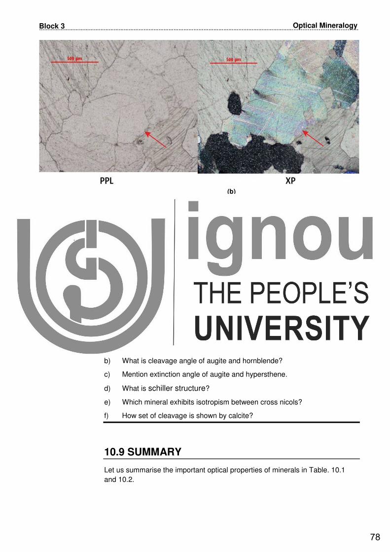
………………………………………………………………………………………………………………………………………....................................
78
Optical Mineralogy Block 3
(b)
Fig.10.15: Calcite in thin section: a) Sketch of calcite with three set rhombohedral cleavage in PPL and XP; and b) Microphotograph of calcite. Notice twinkling and 3 set of cleavage in PPL and third order interference colours under XP. (Source: www.science.smith.edu/geosciences/petrology/petrography/calcite/calcite
2.html)
Please note that it is important for you to learn the diagnostic optical properties
of calcite in order to identify it under the microscope.
In the previous sections we have discussed the optical properties few more
minerals. Before summarising what we have learnt in this unit spend 5 minutes
to check how you are progressing.
SAQSAQSAQSAQ 2222
a) Mention one example of each orthopyroxene and clinopyroxene.
b) What is cleavage angle of augite and hornblende?
c) Mention extinction angle of augite and hypersthene.
d) What is schiller structure?
e) Which mineral exhibits isotropism between cross nicols?
f) How set of cleavage is shown by calcite?
10.9 SUMMARY
Let us summarise the important optical properties of minerals in Table. 10.1
and 10.2.
78

……………….……………………………………………………………………………………………………..……………….................................
79
Properties of Rock-Forming Minerals Unit 10
Table 10.1: Optical properties of minerals - 1.
A. OPTICAL PROPERTIES UNDER PLANE POLARISED LIGHT (PPL)
Properties Quartz Orthoclase Microcline Plagioclase Muscovite Biotite
Colour Colorless, clear
Colorless, cloudy
Colorless, cloudy Colorless cloudy
Colorless Brown to light yellow
Pleochroism Absent
Absent Absent
Absent
Slightly to pale green
Present, dark brown to light yellow
Cleavage Absent 2 sets at 900
2 sets at 900
2 sets at 900
One set perfect One set perfect
Form
Subhedral Subhedral or anhedral
Subbhedral to anhedral
Subbhedral to anhedral
Tabular crystals, flakes or laths
Lath shaped
Relief Very low Low Low Low Moderate Moderate
B. OPTICAL PROPERTIES BETWEEN CROSS NICOLS (XP)
Properties Quartz Orthoclase Microcline Plagioclase Muscovite Biotite
Isotropic / Anisotropic
Anisotropic
Anisotropic
Anisotropic Anisotropic
Anisotropic
Anisotropic
Interference Colors
First order white and grey
First order white and grey
First order white and grey
First order white and grey
Up to Second order yellow or red
Second order red
Extinction Undulose or wavy
Oblique varies from 0
o to 12
o
Oblique varies upto 15
o
Oblique, angle varies with composition
Parallel Parallel
Twinning Not detected
Carlsbad twinning
Cross hatch twinning
Polysynthetic twinning
Hard to detect Poorly developed
Special properties
__ __ __ Zoning __
Pleochroic haloes
Table 10.2: Optical properties of minerals - 2.
A. OPTICAL PROPERTIES UNDER PLANE POLARISED LIGHT (PPL)
Calcite Augite Hypersthene Hornblende Olivine Garnet Properties
Colorless Colorless Colourless or pale pink to green
Shades of green and brown
Mostly colorless
Pinkish to colorless
Colour
Absent Present, pale green or purplish brown colour
Present Present, yellowish green to dark green
Absent Absent
Pleochroism
Rhombohedral 2 or 3 sets,
2 sets at 870&
930
2 sets at 900 2 sets at 56
0&
1240
Not seen, many cracks present
Absent, cracks Present
Cleavage
Euhedral to subhedral
Prismatic crystals
Mostly anhedral
Prismatic
Anhedral grains with polygonal outline
Eubhedral to anhedral
Form
Moderate
High Moderate to high Moderate to high Moderately high
Very high Relief
B. OPTICAL PROPERTIES BETWEEN CROSS NICOLS (XP)
Calcite Augite Hypersthene Hornblende Olivine Garnet Properties
Anisotropic Anisotropic
Anisotropic
Anisotropic
Anisotropic
Isotropic Isotropic / Anisotropic
Up to Second order yellow or red
Mostly middle Second order
Upper First- order to Second order red
Mostly middle Second order
Bright Second and third order
Interference Colors
Parallel Oblique, 360
to 450
Parallel Oblique, 120 to
300
Straight
Extinction
Hard to detect
Simple or polysynthetic
_ Simple twins Poorly developed
Twinning
Twinkling present
_ Schiller structure
_ Cracks present
Cracks present
Special properties
79

………………………………………………………………………………………………………………………………………....................................
80
Optical Mineralogy Block 3
10.10 ACTIVITY
1. Find out the rock forming minerals in granite and basalt and write down their
diagnostic optical properties.
10.11 TERMINAL QUESTIONS
1. Discuss the optical properties of feldspar group minerals.
2. Discuss the optical properties of mica group minerals.
3. Discuss the optical properties of pyroxene group minerals.
10.12 REFERENCES
• Deer, W. A., Howie, R. A. and Zussman, J., (1992) An Introduction to Rock
-Forming Minerals, Longman Scientific & Technical. 696 p.
• Ronov, A.B. and Yaroshevsky, A.A., (1969) In: Chemical composition of the
Earth's crust. American Geophy. Union, WashingtonD.C.. 13: 2-7.
• www.geolab.unc.edu/Petunia/IgMetAtlas/minerals/hypersthene.UX.html
• www.gsi.gov.in
• www.minerva.union.edu/hollochk/c_petrology/ig_minerals.htm
• www.science.smith.edu/geosciences/petrology/petrography/calcite/calcite2.
htm
• www.science.smith.edu/geosciences/petrology/petrography/hornblende/Cro
ssPolars.html
(Websites accessed between 15th and 21
st March 2019)
10.13 FURTHER/SUGGESTED READINGS
• Dana, J.D. and Ford, W.E. (1962) A Text book of Mineralogy, Asia
Publishing House, New Delhi.
• Gribble, C.D. (2001) Rutley’s Elements of Mineralogy, 27th Edition, CBS
Publishers and Distributors, Delhi.
• Mahapatra, G.B. (2012) A Textbook of Geology, CBS Publishers, New Delhi
• Singh, P. (2013) Engineering and General Geology, S.K. Kataria & Sons,
Delhi.
Audio/video material based questions
• Explain two types of zoning present in plagioclase.
• Name the types of twinning found in feldspar minerals, explain them.
• How do you identify augite in thin section?
80

……………….……………………………………………………………………………………………………..……………….................................
81
Properties of Rock-Forming Minerals Unit 10
10.14 ANSWERS
Self Assessment Questions
1 a) Rock- forming minerals are those minerals that make up the major
components of a rock and they are used in the classification of rock types.
b) Colourless and clear, display First-order white or weak yellow interference
colours, lack of cleavage, lack of alteration and often shows undulatory
extinction. Rarely contains inclusions of other minerals.
c) Orthoclase-simple carlsbad twinning; microcline-cross hatch twinning;
plagioclase-polysynthetic twinning.
d) Colourless to pale green under plane polarised light, form is flaky,
Second-order interference colours; one set cleavage perfect; parallel
extinction.
2 a) Augite and hypersthene.
b) Two good cleavages at 87o and 93o(in case of augite);124
o and 56
o (in case of
hornblende) .
c) 36o to 45o (in case of augite) and parallel (in case of hypersthene).
d) Schiller structure is exhibited is due to presence of regular and oriented
inclusions of minute size (sometimes microscopic), platy crystals in a
regular manner along two or more intersecting planes.
e) Garnet.
f) 3 set Perfect rhombohedral cleavage.
Terminal Questions
1. Please refer Section 10.4.
2. Please refer Section 10.5.
3. Please refer Section 10.6.
81

………………………………………………………………………………………………………………………………………....................................
82
Optical Mineralogy Block 3
82

……………….……………………………………………………………………………………………………..……………….................................
83
Properties of Rock-Forming Minerals Unit 10
GLOSSARY
Accessory minerals : These minerals are present in less quantities in a
rock. Their presence and absence do not affect
the definition and classification of a rock.
Accessory slot Below the analyser, accessory slot is there into
which accessory plates, e.g. quartz wedge, or
gypsum plate, can be inserted. The slot is
oriented so that accessory plates are inserted at
45o to the cross wires.
Alteration : This involves the process of physical or chemical
change in the rocks or minerals after their
formation.
Amorphous : This term is used for those rocks, minerals and
materials which have no form and definite crystal
structure.
Anisotropic All the crystals except those of isometric system
fall in this group. Minerals of tetragonal,
orthorhombic, monoclinic, trigonal and hexagonal
and triclinic systems are anisotropic.
Axial angle : It is the angle between two optical axis of a biaxial
crystal.
Biaxial : Crystals crystallising in orthorhombic, monoclinic
and triclinic system consisting of two optical axis.
Canada balsam Canada balsam is a resin, viscous, sticky,
colourless or yellowish liquid that turns to a
transparent yellowish mass when the essential
oils in which it is dissolved, are allowed to
evaporate.
Conchoidal : This term is used to describe nature of the
fracture
Euhedral : It is concerned with a form which is partially
comprises of its own crystal faces in
crystallography.
Double refraction Double refraction is the phenomenon of splitting
of the beam of ordinary light into on passing
through anisotropic medium.
Extinction angle When the anisotropic minerals are studied under
the microscope in cross nicol, it is the angle
between crystallographic structural direction and
optical direction in which the mineral is in the
condition of complete darkness.
Glassy : It is the term used for glassy texture developed in
volcanic rocks.
83

………………………………………………………………………………………………………………………………………....................................
84
Optical Mineralogy Block 3
Iceland spar The phenomenon of double refraction is very
prominently visible with the help of colourless
transparent variety of calcite called iceland spar.
Isotropic : This group includes those materials whose
refractive index is not dependent on the direction
in which the light travels. The isotropic
substances possess a single and constant
refractive index for each wavelength.
Non-opaque Non-opaque minerals permit the light to pass
through them.
Opaque Minerals which do not permit the light to pass
through thin sections are said to opaque minerals.
Optical mineralogy Optical mineralogy is the study of the interaction
of light with minerals which is commonly limited to
visible light.
Rock-forming
minerals
Rock-forming minerals are those minerals that
make up the major components of a rock and
they are used in the classification of rock types
viz. igneous, sedimentary and metamorphic.
Subhedral : It is concerned with a form which is partially
comprises of its own crystal faces in
crystallography.
Twinning : Formation of twinned crystals.
Twinning law : It is the law governing the relation between
different parts of a plane. It is based on following
factors:
Axis of twinning or plane of twinning
Internal of twinned plane
Nature of twinned plane
Few laws of twinning are: Albite law, Baveno law,
Carlsbad law etc.
Uniaxial : Consisting only of one optical axis.
84