OPERATIONAL PLANS - Norfolk County
108
NORFOLK COUNTY’S QUALITY MANAGEMENT SYSTEM OPERATIONAL PLANS FOR DELHI WATER SYSTEM PORT DOVER WATER SYSTEM PORT ROWAN WATER SYSTEM SIMCOE WATER SYSTEM WATERFORD WATER SYSTEM (PUBLIC COPY) Annual Printed Version - 7.0 (Public Copy) Print Date: Feb. 01, 2016 1
-
Upload
khangminh22 -
Category
Documents
-
view
0 -
download
0
Transcript of OPERATIONAL PLANS - Norfolk County

NORFOLK COUNTY’S
QUALITY MANAGEMENT SYSTEM
OPERATIONAL PLANS
FOR
DELHI WATER SYSTEM
PORT DOVER WATER SYSTEM
PORT ROWAN WATER SYSTEM
SIMCOE WATER SYSTEM
WATERFORD WATER SYSTEM
(PUBLIC COPY)
Annual Printed Version - 7.0 (Public Copy) Print Date: Feb. 01, 2016
1

Table of Contents – List of Operational Plans Documents by Element DWQMS Element 1 - DWQMS-1-Quality Management System …………….……….…..4 DWQMS Element 2 -DWQMS-2-Quality Management System Policy …...…..…………8 DWQMS Element 3 - DWQMS-3-Commitment and Endorsement………………………10 DWQMS Element 4 - DWQMS-4- QMS Representative…………………………………12 DWQMS Element 5 - DWQMS-5- Document and Records Control…………….………..15 - DWQMS-5-1 -Records Control Matrix DWQMS Element 6 - DWQMS-6- Drinking-Water System………………………………22 -DWQMS-6-A-Delhi Water System Description -DWQMS-6-A-1 -Wells 1&2 Process Flow Diagram -DWQMS-6-A-2 - WTP process Flow Diagram -DWQMS-6-A-3 - Courtland Reservoir Flow diagram -DWQMS-6-A-4 - Delhi Distribution Plan (Delhi) -DWQMS-6-A-5 - Delhi Distribution Plan (Courtland) -DWQMS-6B - Port Dover Water System Description -DWQMS-6-B-1 - Port Dover WTP Process Flow Diagram -DWQMS-6-B-2 - Port Dover Distribution Plan -DWQMS-6-C -Port Rowan Water System Description -DWQMS-6-C-1 -Port Rowan WTP Process Flow Diagram -DWQMS-6-C-2 -Port Rowan Distribution Plan (Port Rowan) -DWQMS-6-C-3 -Port Rowan Distribution Plan (St. William’s) -DWQMS-6-C-4 -Port Rowan St. William Booster Process Flow Diagram -DWQMS-6D -Simcoe Water System Description -DWQMS-6-D-1 -Simcoe NW Wells & WTP Process Flow Diagram -DWQMS-6-D-2 -Simcoe Chapel Well Process Flow Diagram -DWQMS-6-D-3 -Simcoe Cedar St. Wells & Gallery Process Flow Diagram -DWQMS-6-D-4 -Simcoe Distribution Plan -DWQMS-6E -Waterford Water System Description -DWQMS-6-E-1 -Waterford WTP Process Flow Diagram -DWQMS-6-E-2 -Waterford Distribution Plan DWQMS Element 7 -DWQMS-7 -Risk Assessment Procedure……………………….……53 DWQMS Element 8 -DWQMS 8-Risk Assessment and Risk Assessment Outcomes……...59
Annual Printed Version - 7.0 (Public Copy) Print Date: Feb. 01, 2016
2

DWQMS Element 9 -DWQMS-9 -Organizational Roles, Responsibilities & Authorities..63 -DWQMS-9-1 -Organizational Chart -DWQMS-9-2 -Job Descriptions – (Not In Public Version) -DWQMS-9-3 -Authority By Position Chart DWQMS Element 10 -DWQMS -10-Competencies …………………………..….………68 DWQMS Element 11 -DWQMS-11-Personnel Coverage……………………..…………73 DWQMS Element 12 -DWQMS-12- Communications……………………….…..………76 DWQMS Element 13 -DWQMS-13-Essential Supplies and Services……………………..79 DWQMS Element 14 -DWQMS-14-Review and Provision of Infrastructure…………….84 DWQMS Element 15 -DWQMS-15-Infrastructure Maintenance, Rehabilitation and Renewal………………………………….……..87 DWQMS Element 16 -DWQMS-16-Sampling, Testing and Monitoring………….………91 DWQMS Element 17 -DWQMS-17-Measurement and Recording Equipment Calibration and Maintenance………………………..94 DWQMS Element 18 -DWQMS-18-Emergency Management……………………………96 DWQMS Element 19 -DWQMS-19-Internal Audits……………………………………...99 -DWQMS-19-1-Internal Audit Schedule DWQMS Element 20 -DWQMS-20-Management………………………………………...103 DWQMS Element 21 -DWQMS-21-Continual Improvement…………………………….106 NOTES: 1) APPENDICES ARE NOT AVAILABLE FOR PUBLIC DUE TO CONFIDENTIAL & SECURITY INFORMATION. 2) DOCUMENTS REFERENCED IN PLAN (LEVEL 3 DOCUMENTS) ARE AVAILABLE TO STAFF ONLY THROUGH THE SPRINGBOARD ONLINE SOFTWARE.
Annual Printed Version - 7.0 (Public Copy) Print Date: Feb. 01, 2016
3

DWQMS
ELEMENT - 1
QUALITY MANAGEMENT
SYSTEM
Annual Printed Version - 7.0 (Public Copy) Print Date: Feb. 01, 2016
4

PUBLIC WORKS AND ENVIRONMENTAL SERVICES
Operational Plan Document No.: DWQMS-1 Effective Date: Jan. 28/2009 Authority: Environmental Services
Manager Last Revision Date: Nov. 6, 2014 Revision No.: 2
Subject: Operational Plan Document for Norfolk County 1.0 Purpose
1.1 The Corporation of Norfolk County as Owner and the Environmental Services Division as the operating authority, are required to attain conformance to the Drinking Water Quality Management Standard (DWQMS) developed by the Ministry of the Environment. This document has been developed to help articulate the process approach to its design.
2.0. Scope
2.1 This managed approach to water quality will be applied to the extent outlined and drawn by the quality policy.
3.0 Policy
3.1 A Managed Approach
3.1.1 The ultimate goal of achieving DWQMS conformance must be fully understood, and activities must strive to meet the requirements of the standard. An organization is a network of interdependent, value-adding processes, and improvement is achieved through understanding and changing these processes to enhance the total system. To facilitate long-term improvements, a mindset of prevention rather than correction must be applied to eliminate the root causes of non-conformance. Decisions are made based upon measured data, internal and external comparisons, and an understanding of the cause and effect mechanisms at work, not simply on the basis of instinct, authority or anecdotal data. A focus on continuous improvement is the cornerstone for breakthrough thinking and innovation. No matter how much improvement has been accomplished, there are always practical and innovative ways of doing even better, and of providing improved water quality to the customer.
Annual Printed Version - 7.0 (Public Copy) Print Date: Feb. 01, 2016
5

3.2 Managed Approach Model:
3.2.1
3.3 The Design of a Managed Approach:
3.3.1 The successful implementation of the DWQMS does not only depend on
meeting the intent of the Standard’s 21 elements, but also on the inputs and outputs of those elements and their interdependency. The result is a series of processes that impart efficiency and effectiveness with their interaction.
PLAN / DO [1] Quality Management System [2] QMS Policy [3] Commitment & Endorsement [4] QMS Representative [5] Document & Records Control [6] Drinking-Water System [7] Risk Assessment [8] Risk Assessment Outcomes [9] Organizational Structure, Roles, Responsibilities & Authorities [10] Competencies [11] Personnel Coverage [12] Communications [13] Essential Supplies & Services [14] Review & Provision of Infrastructure [15] Infrastructure Maintenance, Rehabilitation & Renewal [16] Sampling, Testing & Monitoring [17] Measurement & Recording Equipment Calibration & Maintenance [18] Emergency Management
IMPROVE [21] Continual Improvement
CHECK [19] Internal Audits [20] Management Review
Annual Printed Version - 7.0 (Public Copy) Print Date: Feb. 01, 2016
6

QMS Relationships:
Annual Printed Version - 7.0 (Public Copy) Print Date: Feb. 01, 2016
7

DWQMS
ELEMENT - 2
SYSTEM POLICY
Annual Printed Version - 7.0 (Public Copy) Print Date: Feb. 01, 2016
8

PUBLIC WORKS AND ENVIRONMENTAL SERVICES
Operational Plan Document No.: DWQMS-2 Effective Date: March 1/2009 Authority: Environmental Services
Manager Last Revision Date: July 24/2013
Revision No.: 4
Subject: Quality Management System Policy Quality Management System Policy Norfolk County and its Public Works and Environmental Services Department is committed to providing a safe, clean supply of drinking water to all customers serviced by our municipal drinking water systems while also meeting or surpassing applicable regulations and legislation. Through this policy Norfolk County will strive to continually improve on how the drinking water systems are operated and managed. This policy confirms Norfolk County’s commitment to the maintenance of a Quality Management System (QMS), which includes the following components: policies, procedures, risk assessment management, incident response measures, contingency plans, and staff competency. Norfolk County Public Works and Environmental Services Department will ensure that this policy is understood and communicated to Norfolk County staff and will be available to the public on the Norfolk County website. Norfolk County will also ensure that the QMS is maintained and continually improved by performing audits and scheduled reviews.
Annual Printed Version - 7.0 (Public Copy) Print Date: Feb. 01, 2016
9

DWQMS
ELEMENT - 3
COMMITMENT AND
ENDORSEMENT
Annual Printed Version - 7.0 (Public Copy) Print Date: Feb. 01, 2016
10

Annual Printed Version - 7.0 (Public Copy) Print Date: Feb. 01, 2016
11

DWQMS
ELEMENT - 4
QMS REPRESENTATIVE
Annual Printed Version - 7.0 (Public Copy) Print Date: Feb. 01, 2016
12

PUBLIC WORKS AND ENVIRONMENTAL SERVICES
Operational Plan Document No.: DWQMS-4 Effective Date: Jan. 28/2009 Authority: Environmental Services
Manager Last Revision Date:
Sept. 11/2012
Revision No.: 4 Subject: Quality Management System Representative Procedure 1.0 Purpose
1.1 This policy identifies the individual who will serve as the Quality Management System (QMS)
Representative for Norfolk County and outlines the specific responsibilities associated with this role to ensure the ongoing operation of the drinking water Quality Management System (QMS).
2.0 Scope
2.1 This policy applies to the role of the QMS Representative and all aspects of the QMS with
which this role is associated.
3.0 Policy
3.1 Identification and Responsibility
3.1.1 The QMS Representative, currently Ron Armstrong, has been appointed as the QMS Representative for Norfolk County by Top Management. The QMS Representative is authorized and responsible for administering all processes associated with the operation and performance of the QMS. This individual will also report on the performance of the system and the need for improvement to the General Manager of Public Works and Environmental Services through regular meetings or as required. 3.1.1.1 In the event of any prolonged absence of the QMS Representative, the General
Manager of Public Works and Environmental Services will assign a temporary lead to perform the duties of the QMS Representative inclusive of their existing responsibilities.
3.1.2 Details on the performance of the QMS and the need for improvement will be
communicated to the General Manager of Public Works and Environmental Services, who will then share the details with the management team or Council as appropriate. This communication will be conducted according to the established Management Review and the Communications procedures.
3.1.3 Springboard software will be used to ensure that all personnel have access to the most current documentation used as part of the QMS. These processes are outlined in the Document and Records Control procedure. Where possible, the currency of paper and externally controlled documents will also be managed through Springboard software.
Annual Printed Version - 7.0 (Public Copy) Print Date: Feb. 01, 2016
13

3.1.4 Along with the Water & Wastewater Compliance supervisor and the Water Facilities
Supervisor and Water & Wastewater Systems Supervisor, the QMS Representative will be involved in the identification of legislative and regulatory requirements that apply to the operation of the QMS. The availability of current documentation that supports this awareness will be managed using Springboard software.
3.1.5 The awareness of the QMS will be promoted to personnel through staff meetings,
annual information meetings, internal audits, and to management through management review meetings. Springboard software will also be used to promote awareness to the employees of Norfolk County.
4.0 Responsibilities
4.1 The QMS Representative will be responsible for:
Establishment and maintenance of processes and procedures required for the ongoing operation of the QMS;
Reporting the performance of and any need for improvement to the General Manager of Public Works and Environmental Services;
Ensuring that employees of Norfolk County are aware of the requirements that apply to their responsibilities in association with the QMS;
Ensuring current versions of all documents required by the QMS are being used at all times; and
Ensure employee awareness of applicable legislative and regulatory requirements.
4.2 All employees will be responsible for:
Being aware of and complying with appropriate policies and procedures that outline their responsibilities for the operation of the QMS.
5.0 References
o Management Review procedure o Communications procedure o Document and Records Control procedure
Annual Printed Version - 7.0 (Public Copy) Print Date: Feb. 01, 2016
14

DWQMS
ELEMENT - 5
DOCUMENT &
RECORDS CONTROL
Annual Printed Version - 7.0 (Public Copy) Print Date: Feb. 01, 2016
15
Page 1 of 4
Printed documents are considered non-controlled as the controlled versions are maintained electronically. This copy printed: 2015-02-18
EPUBLIC WORKS AND ENVIRONMENTAL SERVICES
Operational Plan Document No.: DWQMS-5 Effective Date: January 28/2009 Authority: Manager of Environmental
Services Last Revision Date: June 4 , 2014 Revision No.: 10
Subject: Document and Records Control
1.0 Purpose:
1.1 This procedure outlines the process by which Norfolk County manages documents and records related to the Quality Management System (QMS) and controls the information and data they contain.
2.0 Scope:
2.1 This procedure applies to all documents and records related to Norfolk County’s QMS.
3.0 Procedure:
3.1 Document and Records Control
3.1.1 Documents and records that are controlled according to this procedure include,
but are not limited to: 3.1.1.1 The Operational Plan for the QMS; 3.1.1.2 Policies and Procedures associated with the Operational Plan; 3.1.1.3 Documents and records that ensure the effective planning, operation,
and control of Norfolk County’s operations; 3.1.1.4 Results of internal and external audits; and 3.1.1.5 Documents and records created as a result of management review
meetings (e.g. minutes).
Electronic documents and procedures related to the QMS will be managed using Springboard software to maintain ongoing currency and legibility. To ensure that documents are readily identifiable and legible, each document is saved in the appropriate corporate software program and is assigned a unique name as well as a corresponding description, approval date, effective date, and last revision date, where appropriate. Documents and procedures also have the following statement & date stamp at the bottom of each page: “Printed documents are considered non-controlled as the controlled versions are maintained electronically. This copy printed: 2015-02-18” The Springboard software is a online Web based program therefore backed up on a secure remote server. Springboard documents are called Training Elements (T.E’s) and assigned to staff based on job requirements and position and each user has a unique name and password. Staff receive an e-mail when T.E’s. are required to be read, and the frequency they are required to be read depends on the document
Annual Printed Version - 7.0 (Public Copy) Print Date: Feb. 01, 2016
16

Page 2 of 4
Document No.: DWQMS-5 Last Revision Date: June. /2014 Subject: Document and Record Control
Procedure Revision No.: 10
Printed documents are considered non-controlled as the controlled versions are maintained electronically. This copy printed: 2015-02-18
type. T.E.’s may also be revised at any time due to changes in processes or regulations.
If a minor change is made, details are recorded in software which can be viewed by the user, if a major change is made, one that relates directly to an important job function, a new T.E. version is created and saved and automatically sent to all required users to read. The software records the details of the revision and the old versions status changes to ‘obsolete” and the new or current version will have a “live” status. The obsolete versions are still available for reference if required.
3.0.1 To ensure that documents related to the QMS contain accurate and complete information, the QMS Representative will use Springboard software to facilitate a review and approval process prior to the distribution of the information. Documents are reviewed at specific intervals depending on document type and details of the review are noted in the T.E. description. Appropriate management personnel will be selected and assigned these responsibilities, as required.
3.0.2 Access to current documentation related to the QMS is available to personnel according to their individual roles and responsibilities. Documents managed in Springboard software are distributed through the system to personnel as required to maintain the integrity of the information.
3.0.3 The Operational Plan (O.P.) is issued to staff through Springboard Software by requiring them to read only the Elements that are related to their position but also have access to all the 21 Elements. The O.P. is a living document that changes constantly due to the fact that documents are revised as required and staff are required to read any changes if it relates to their position. The hard copy that is kept in the Delhi office and Norfolk County Web site PDF copy are only updated annually and are not used by staff and are intended only for public viewing purposes.
3.0.4 Access to externally controlled documents related to the QMS will be
facilitated by Springboard software, the County Internal network, County Intranet or hard copy filing systems, as required. Details of each Springboard document will indicate the location of the information including the URL..
Annual Printed Version - 7.0 (Public Copy) Print Date: Feb. 01, 2016
17

Page 3 of 4
Document No.: DWQMS-5 Last Revision Date: June. /2014 Subject: Document and Record Control
Procedure Revision No.: 10
Printed documents are considered non-controlled as the controlled versions are maintained electronically. This copy printed: 2015-02-18
3.1 Records Control: 3.1.1 Records and documents stored on the internal network are saved to the
Environmental Services W: drive in the appropriate folder. Documents are filed in folders and subfolders by subject and then by year. The network is backed up every night and is protected by security software. Documents saved on the Intranet are the Public Works tab in the Document section under Water &Sanitary Sewer Inventory. Location of hard copy documents are list below or in the Records Control Matrix.
3.1.2 Records are kept legible, readily identifiable by staff following the requirements listed in Ontario Regulation 128-04, Section 27 -Record-Keeping Re: Operation of Subsystem. Records are retrievable through the methods of file storage listed below: 3.1.2.1 Plant specific records required by the MOE, such as SCADA Reports
and the Daily Logs are maintained at the facility in a binder then transfer to labelled binding cases.
3.1.2.2 Annual Reports required by the MOE are maintained on the internal network and displayed on the Norfolk County website for public viewing.
3.1.2.3 Laboratory reports related to the drinking water systems are maintained on the internal network electronically.
3.1.2.4 Records related to work orders completed by the distribution personnel are maintained within the Service Request software program which is administered by Delhi Administration Building support staff and maintained on the internal network.
3.1.2.5 Records related to maintenance of the distribution system, not generated by work orders, are stored at the Cedar Street location. As necessary, electronic records are maintained using the Intranet and the internal network and hard copies are stored in labelled filing cabinets.
3.1.2.6 Records from internal or external audits, and management reviews related to the QMS will be maintained within the Springboard Software and internal network.
3.1.2.7 Forms used for records are maintained in the Springboard Software to ensure that the most current versions are used by staff.
Note: Access to password protected computers is determined by position held by County staff and includes computers connected to either the Corporate Internal Network and Intranet Site or the Plant SCADA Network. Hard copies of records are also retrievable by staff depending on their position and the location of the file system.
Annual Printed Version - 7.0 (Public Copy) Print Date: Feb. 01, 2016
18

Page 4 of 4
Document No.: DWQMS-5 Last Revision Date: June. /2014 Subject: Document and Record Control
Procedure Revision No.: 10
Printed documents are considered non-controlled as the controlled versions are maintained electronically. This copy printed: 2015-02-18
3.1.3 Plant records are archived annually according to date and stored at each
facility for up to five years and records older than 5 years are stored at the Cedar Street location.
3.1.4 Records maintained at the Delhi Administration Building, and the Cedar Street location, are listed in the Records Control Matrix.
3.2 Retention and Disposition :
3.2.1 All records related to the QMS, including those that and governed by
legislated requirements and maintained according to the applicable legislation, are listed in the Records Control Matrix. The Matrix lists the filing method, storage location, retention time and disposal method for each specific type of record.
3.2.2 General filing system records related to the water production and distribution system are stored and disposed of under the current version of the Norfolk County By-Law for Records Retention.
3.2.3 Retention of records not governed by applicable legislative requirements
will be managed according to the Records Control Matrix which outlines document types, legally or internally mandated retention periods, and appropriate methods of disposal or destruction
3.2.4 All Records are kept indefinitely or until storage capacities are reached at
which time the records will be disposed of by recycling paper files or recording electronic files on network drives to discs or deleting files.
4.0 References: Records Control Matrix Norfolk County Record Retention By-Law
Annual Printed Version - 7.0 (Public Copy) Print Date: Feb. 01, 2016
19

Document # - DWQMS-5-2Revision Date: 25/08/2015
RecordRetention
ByIndexing Method
Filing Method
Storage Location
Retention TimeDisposal Method
Legislative Requirement
Internal Audit Notes / Reports QMS Rep. YearFiling Cabeinet or
Network Drive /Springboard
Delhi Office /Springboard Server >15 yrs
Shred / **Electronic Files
Deleted-
External Audit Reports QMS Rep. Year Springboard Springboard Server >15 yrs **Electronic Files Deleted -
Management Review QMS Rep. Year Springboard Springboard Server >15 yrs **Electronic Files Deleted -
Risk Assessment Outcomes, Summaries & Reviews. QMS Rep. Year Springboard Springboard Server >15 yrs **Electronic Files
Deleted
Training Matrices Supervisors Year Network Drive Intranet/Sharepoint >15 yrs **Electronic Files Deleted 5
* Plant Daily Logs Facilities Staff Date File box Treatment Facility / Cedar St. >15 yrs Shred 5
* Printed Daily SCADA Reports Facilities Staff Date File box Treatment Facility / Cedar St. >15 yrs Shred 5
MOE Required Water Results Technical Staff Date Network Drive / File
County Server / Cedar St Office >15 yrs **Electronic Files
Deleted 2 - 15
Annual Drinking Water Reports Technical Staff Year Network Drive County Server >15 yrs **Electronic Files Deleted 2
Annual Drinking Water Summary Reports Technical Staff Year Network Drive County Server >15 yrs **Electronic Files Deleted 2
Work Order Forms Delhi Clerical Staff Year Network Drive County Server /
Delhi Office >15 yrs **Electronic Files Deleted -
Distribution Maintenance Records Facilities Staff Town Network Drive / Filing cabinet
Intranet-Sharepoint / Cedar St. >15 yrs **Electronic Files
Deleted -
Distribution O & M Technical Staff Type of Manual Network Drive /Springboard
County Server /Springboard Server N/A N/A -
Treatment Maintenance Records Facilities Staff Date File box Treatment Facility / Cedar St. >15 yrs Shred -
Treatment O & M's Technical Staff Type of Manual Network Drive / SCADA / Binder
County Server / SCADA Network/ Treatment Facility
N/A N/A -
External Maintenance Records (well rehab. etc)Facilities
Supervisor Facility Filing Cabinet Cedar St. >15 yrs Shred -
General Files in County Filing System Admin. Assistant Year Filing Cabinet Delhi Office Records Retention By-Law # 2007-214 Shred -
Calibration Records QMS Rep. Year Network Drive County Server / Cedar St Office >15 yrs **Electronic Files
Deleted 2
Corrective Action Forms & Log QMS Rep. Year Network Drive County Server >15 yrs **Electronic Files Deleted -
Chemical Suppliers Certification Records E.S. TechnologistMOE Inspection
DataNetwork Drive County Server >15 yrs **Electronic Files
Deleted -Mock Emergency Notes / Mock Emergency Procedures
QMS Rep. Year /Mock Procedures
Network Drive /Springboard
County Server /Springboard Server >15 yrs Electronic Files
Deleted -
NORFOLK COUNTY RECORDS CONTROL MATRIX
Annual Printed Version - 7.0 (Public Copy) Print Date: Feb. 01, 2016
20

RecordRetention
ByIndexing Method
Filing Method
Storage Location
Retention TimeDisposal Method
Legislative Requirement
MOE Forms 1 & 2 - Required under DWWP QMS Rep. Town Network Drive/ Binder
County Server / Delhi Office >15 yrs Shred /
**Electronic Files 10
Operator Procedures QMS Rep. By TypeNetwork Drive / SCADA / Binder
Springboard Server/ SCADA Network/ Ceda St binder
N/A N/A -
* Note: P lant Records Are Stored At Each Facility For At Least 5 Years and then moved to the Cedar St. Location.** Electronic Files are stored indefinitely at this time, until notified by I .S. Dept. or Springboard.
Annual Printed Version - 7.0 (Public Copy) Print Date: Feb. 01, 2016
21
DWQMS
ELEMENT - 6
DRINKING WATER
SYSTEMS
Annual Printed Version - 7.0 (Public Copy) Print Date: Feb. 01, 2016
22

PUBLIC WORKS AND ENVIRONMENTAL SERVICES
Operational Plan Document No.: DWQMS-6 Effective Date: Jan. 28/2009 Authority: Manager of
Environmental Services Last Revision Date: April 25 /2012
Revision No.: 3
Subject: Drinking Water Description Procedure 1.0 Purpose:
1.1 This procedure outlines the details of the drinking-water systems owned and operated by
Norfolk County and all associated components.
2.0 Scope:
2.1 This policy applies to all facilities and systems owned and operated by Norfolk County.
3.0 Procedure:
3.1 Description of Subject System: 3.1.1 Norfolk County is composed of five drinking-water systems including two
surface-water facilities (i.e. Port Dover and Port Rowan), two ground water facilities (i.e. Simcoe and Waterford), and one combination surface and groundwater system (Delhi). Each of these systems is described individually in Drinking-Water System and Distribution System Summaries located in documents listed in section 4.0 below.
3.1.2 The individual descriptions of the drinking-water and distribution systems will identify: 3.1.2.1 The Owner and Operating Authority; 3.1.2.2 All treatment processes; 3.1.2.3 Characteristics of sources of water supply and common event-driven
variations and corresponding operational challenges; and 3.1.2.4 Any critical upstream or downstream processes as referred to in the
Source Water Protection Plans.
3.1.3 The flow of water from its entry into the system to its distribution will be documented in a Drinking-Water Process Flow Chart, and Distribution System Drawings which are reviewed regularly to ensure its continued accuracy.
Annual Printed Version - 7.0 (Public Copy) Print Date: Feb. 01, 2016
23

3.1.4 Changes made to drinking water and distribution systems will be reviewed by the Water and Wastewater compliance officer on an annual basis to ensure that documentation remains up-to-date. As required, changes will be made to the Drinking-Water System and Distribution System Summaries.
4.0 Associated Records: Drinking-Water System Summary for Delhi (DWQMS-6-A)
Drinking-Water System Summary for Port Dover (DWQMS-6-B)
Drinking-Water System Summary for Port Rowan (DWQMS-6-C)
Drinking-Water System Summary for Simcoe (DWQMS-6-D)
Drinking-Water System Summary for Waterford (DWQMS-6-E)
Detailed Process Flow Drawings
Distribution System Diagrams
Annual Printed Version - 7.0 (Public Copy) Print Date: Feb. 01, 2016
24

PUBLIC WORKS AND ENVIRONMENTAL SERVICES
Operational Plan Document No.: DWQMS-6-A Effective Date: Jan. 28/2009 Authority: Manager of
Environmental Services Last Revision Date: July 20 /2015 Revision No.: 7
Subject: Delhi – Drinking Water System Description 1.0 Delhi - Drinking Water System Process Description:
The Delhi drinking water system supplies water to the communities of Delhi and Courtland, and also the Delhi bulk water depot. The system is owned by Norfolk County and the operating authority is the County’s Environmental Services Division. The system is supplied by three water sources: the Lehman Dam Treatment Plant, Well #1 & Well #2. The Delhi waterworks system, including Courtland, currently serves a population of approximately 6,262 including 222 commercial and industrial service connections and 2,179 residential connections. 2.0 Source Water:
The Water Filtration Plant is supplied by a surface water source, the Lehman dam reservoir, which is fed by North Creek and South Creek. The raw water normally has low turbidity levels but does experience higher levels during heavy rain falls and also experiences higher levels of Total Coliform and E. Coli during the warmer summer months and after rainfalls. The Water Filtration Plant has had Nitrate levels in the past that are approximately 30% of the Maximum Acceptable concentration of 10 mg/L, and are monitored quarterly. The other two sources of water are groundwater wells, which draw from an aquifer at a depth of approximately 40 meters. Both wells are located approximately 5 Km South of Delhi on the East Quarter Line Road, a concession north of Highway # 3. The groundwater source is very consistent and meets all MOE standards but hardness levels (related to naturally occurring minerals in the water) are on the high side of the spectrum, which is typical of groundwater sources. Both wells are classified as Groundwater Under Direct Influence (GUDI) with effective in-situ filtration. As a result of known fluctuations in the source water, operators will monitor the quality of the incoming water (before treatment) and make necessary adjustments as required given the existing quality of the incoming water. 3.0 Treatment Process- The Lehman Dam Water Filtration Plant:
The Water Filtration Plant has a rated capacity of 4543 m3 /day. The inlet structure, which is located 30 metres offshore, is equipped with several intake pipes, which can withdraw from different elevations, based on water level in the reservoir. There are 25 mm openings on the intake structure, which stops large debris from entering the water intake pipe. The raw water flows by gravity into the plant and the flowrate is controlled by a motorized valve (raw water inlet valve) based on the level in the high lift suction well (wet well) and an operator entered level setpoint. As the raw water enters the plant the flow is measured with a magnetic flow meter and turbidity is measured with an online analyzer. The next step in the process is the addition of sodium hypochlorite (chlorine, for prechlorination). After disinfection, Poly Aluminum Chloride (PAC) is added for the purpose of flocculation followed by an inline flash mixer. The water then flows through a series of flocculation channels, which promote the formation of floc. Water then enters a single sedimentation
Annual Printed Version - 7.0 (Public Copy) Print Date: Feb. 01, 2016
25

tank, which has tube settlers to improve the solids removal and reduce carryover of settleable material (floc), the water then enters the wet well. At this point the water is pumped from the wet well by three constant speed, vertical turbine, high lift pumps, and fluoride is added prior to entering three horizontal pressure filters which contain anthracite, silica sand and silica gravel. All three filters have online analysers for measuring effluent turbidity. Distribution water is used to backwash the three filters, the filters are backwashed manually based on head loss, preset turbidity level and elapsed run time. The backwash process is a reverse flow through the filters and then filter-to-waste for a pre-set time period. After the water leaves the filters a magnetic flow meter measures the treated flow before entering one of two Ultraviolet (UV) Disinfection Reactors (one duty, one standby). The final stage of the treatment process is the addition of sodium hypochlorite (a second application for post chlorination purposes and distribution system chlorine residual maintenance) to insure proper disinfection is obtained. Treated water is monitored before leaving the plant by three online analyzers, which measure pH & chlorine residual. The high lift pumps will automatically shut off when: a) The treated water chlorine residual analyzer reads above or below set point levels. b) The filter turbidity’s are over the alarm set point. c) The raw water turbidity is above the alarm set point. d) The duty UV unit has a critical alarm or the unit is not on or ready. e) The Coagulant flow is below the alarm set point. or f) The water tower reaches the high level set point. 4.0 Treatment Process- Delhi Wells 1 and 2:
Water from each well is pumped by a vertical turbine pump with a rated capacity of 2300m3 /day. When the well pump starts, the waste valve opens and the water is pumped to waste for approximately 3 minutes and the valve then closes. The outlet valve then opens and the water flows through an inline magnetic flow meter that measures the flow. The next step is the disinfection process, which consists of two UV disinfection units (one duty, one standby) and then the addition of sodium hypochlorite (chlorine). Hydrofluosilicic acid is then added for fluoridation followed by sodium silicate, which is added for iron suspension purposes (iron sequestering). The water from Well #1 flows through a contact chamber prior to entering the distribution main and the water from Well #2 flows directly into the 300 mm water main which connects into the south end of the Delhi distribution system on Wilson Ave. The wells pumps automatically shut off when: a) The U.V. units reach any critical or major alarm set points. b) The treated water chlorine residual analyzer reads above or below alarm set point levels. c) The treated water turbidity analyzer reads above the alarm set point level. or d) The water tower reaches the high level set point. 5.0 Distribution:
The water distribution system includes a 3,950-m3 standpipe, which acts as a reservoir when the system requires larger amounts of water than the sources can supply (such as firefighting) and also helps to maintain a constant system pressure. The system piping includes the following lengths & diameters - 3,493 m of 150 mm or less, 21,448 m of 150 mm, 15,950 m of 200mm, 6,708 m of 250, 18,910 m of 300 mm & 97 m of 400 mm. The approximate age of these pipes is 31% is over 50 yrs old, 30% is 25 – 50 yrs & 39% is less than 25yrs old. The piping consists of the following materials - cast iron, Polyvinyl Chloride (PVC) and ductile iron pipe along with approximately 276 fire hydrants and 473 main valves.
Annual Printed Version - 7.0 (Public Copy) Print Date: Feb. 01, 2016
26

The system is also protected by Backflow Prevention Devices on Industrial and Commercial services as required by the building code. The community of Courtland is also part of the Delhi system and is connected by a watermain that is 13.3 km long and 300 mm in diameter. The water flows into a 1000 m3 reservoir that has a motorized valve that controls the quantity of water entering based on the level set points. The flow of water entering and exiting the reservoir is measured by magmeters. The chlorination system provides re-chlorination of the drinking water from the Delhi system entering the reservoir and post-chlorination of water leaving the reservoir to maintain a chlorine residual in the distribution system. 6.0 SCADA:
The Supervisory Control and Data Acquisition (SCADA) system is a computerized control system that monitors all of Norfolk County’s water facilities. One of the SCADA functions is to send alarms for all operational parameters, which have preset minimum and/or maximum levels. These alarms are sent to Norfolk County’s answering service, who in turn contacts the afterhours on call operator by pager or cell phone, who must immediately respond to the call.
Annual Printed Version - 7.0 (Public Copy) Print Date: Feb. 01, 2016
27

Annual Printed Version - 7.0 (Public Copy) Print Date: Feb. 01, 2016
28

Annual Printed Version - 7.0 (Public Copy) Print Date: Feb. 01, 2016
29

Annual Printed Version - 7.0 (Public Copy) Print Date: Feb. 01, 2016
30

PUBLIC WORKS AND ENVIRONMENTAL SERVICES
Operational Plan Document No.: DWQMS-6-B Effective Date: Jan.28/2009 Authority: Manager of
Environmental Services Last Revision Date: July 20 /2015
Revision No.: 9
Subject: Port Dover – Drinking Water System Description
1.0 Port Dover - Drinking Water System Process Description: The Port Dover water system supplies drinking water to the community of Port Dover & the bulk water depot. The system is owned by Norfolk County and the operating authority is Norfolk County’s Environmental Services Division. The drinking water system, currently serves a population of approximately 7,089 including 176 commercial and industrial service connections and 3,248 residential connections. 2.0 Source Water:
Port Dover water filtration plant is fed from a surface water source, which is Lake Erie. The water enters a 500 mm intake pipe that is located approximately 450m offshore in about 4.3m of water. The turbidity and DOC (dissolved organic carbon), Total Coliform and E. Coli levels can vary from low to very high depending on lake conditions, which can change due to weather conditions or seasonal turnovers. As a result of known fluctuations in the source water, operators will monitor the quality of the incoming water (before treatment) and make necessary adjustments as required given the existing quality of the incoming water. 3.0 Treatment Process:
The raw water is treated at the water filtration plant, located at # 603 Nelson St. W. in Port Dover. The water from the intake flows into the lowlift building wet well and is pumped from one or two of the three lowlift pumps to either the old plant or new plant, which are two separate treatment trains. The first step in the process is the injection of Carbon Dioxide (CO2) into the discharge side of the pumps to lower the pH as needed and then the addition of sodium hypochlorite for pre-chlorination which is added on the discharge side of the lowlift pumps during the winter and at the intake for Zebra Mussel control during the summer. The new plant was built in 1975 with upgrades completed in 2007, which included the installation of new filters. The raw water enters the new plant and the flow is measured with a magnetic flow meter. The next step in the process is the addition of Poly Aluminum Chloride (PAC) as a coagulant followed by an inline rapid mixer, which starts the formation of the floc. The water then flows into a recirculating reactivator type flocculation /clarifier where the floc settles and is automatically removed by the blowdown function to the backwash wastewater tank. The clarifier produces water with reduced solids, which is more suitable for further treatment by the three BCA gravity filters. As the water leaves the clarifier an online analyzer measures the pre-filter turbidity. Each of the filters has a rated capacity of 2,353 m3/day and has dual media (silica sand and activated carbon) filters with a layer of gravel at the bottom to support the media. The water flows down through the media, which removes any remaining particulate matter. The filters are designed to backwash automatically based on head loss, preset turbidity level and preset elapsed run time. The backwash sequence includes an air scour followed by a reverse flushing water flow (water from highlift discharge header) and a filter-to-waste function before directing treated water to the clear well.
Annual Printed Version - 7.0 (Public Copy) Print Date: Feb. 01, 2016
31

Both backwash and filter-to-waste flows enter the backwash wastewater storage tank and are then pumped to the sanitary sewer. The final step in the treatment process is post-chlorination with the addition of sodium hypochlorite prior to the water entering the clear wells. There is an online chlorine analyzer mid way through the clear well and as well as one on the effluent water leaving the plant. The final effluent is also monitored with online instruments for pH, turbidity, pressure and flow. The old plant, built in 1954 is not in use currently. It has a recirculating reactivator type flocculation /clarifier and the treatment process is the same as the new plant up until the water enters the two “traditional” deep gravity type dual media filters. The old plant backwash is fed from the backwash pump, which draws from the clear well. The combined rated capacity of the filters is 3,110 m3/day. The low lift pumps will automatically shut off when: a) The filter(s) or treated water turbidity’s are over the alarm set points. b) The pre-filter turbidity is above the set point. c) The Coagulant flow drops below the set point. d) The clearwell is full. e) The wetwell level is below setpoint. or f) The lowlift pump flows are below the set point. The high lift pumps will automatically shut off when: a) The post chlorine residual analyzer reads above or below the alarm set points. b) A filter effluent turbidity is over the alarm set point. c) The mid reservoir chlorine residual analyzer reads above or below the alarm set points. or d) The water tower reaches the high level set point. 4.0 Distribution:
The water distribution system includes a 5,000 m3 elevated tank, which acts as a reservoir when the system requires larger amounts of water than the water filtration plant can supply (such as firefighting and peakflows) and also helps to maintain a constant system pressure. The system piping includes the following lengths and diameters – 9,406 m of 150 mm or less, 28,439 m of 150 mm, 10,496 of 200 mm, 966 m of 250 mm, 10,215 m of 300 mm and 2,193 m of 400 mm. The approximate age of these pipes in years is 24% is over 50 yrs old, 29% is 25 – 50 yrs & 47% is less than 25yrs old. The piping consists of the following materials - cast iron, PVC & ductile iron pipe along with approximately 360 fire hydrants and 569 main valves. The system is also protected by Backflow Prevention Devices on Industrial and Commercial services as required by the building code. 5.0 SCADA:
The Supervisory Control and Data Acquisition (SCADA) system is a computerized control system that also monitors all of the County’s water facilities and one of its functions is to send alarms for all operational parameters, which have preset minimum and/or maximum levels. These alarms are sent to Norfolk County’s answering service, who then pages the afterhours on call operator, who must immediately respond to the call.
Annual Printed Version - 7.0 (Public Copy) Print Date: Feb. 01, 2016
32

Annual Printed Version - 7.0 (Public Copy) Print Date: Feb. 01, 2016
33

Annual Printed Version - 7.0 (Public Copy) Print Date: Feb. 01, 2016
34

PUBLIC WORKS AND ENVIRONMENTAL SERVICES
Operational Plan Document No.: DWQMS-6-C Effective Date: Jan. 28/2009 Authority: Manager of
Environmental Services Last Revision Date: July 20 /2015
Revision No.: 7
Subject: Port Rowan – Drinking Water System Description
1.0 Port Rowan - Drinking Water System Process Description: The Port Rowan water system supplies drinking water to the communities of Port Rowan & St. Williams and the bulk water depot located in Port Rowan. The system also provides drinking water to a private distribution system, which is owned and operated by Booth’s Harbour. This system services approximately 450 people, which includes a small subdivision and a Marina. The Port Rowan system is owned by Norfolk County and the operating authority is Norfolk County’s Environmental Services Division. The drinking water system, which includes the community of St. Williams, currently serves a population of approximately 2,312 including 90 commercial and industrial service connections and 924 residential connections. 2.0 Source Water:
Port Rowan’s water filtration plant obtains water from a surface water source, which is Lake Erie’s Long Point Inner Bay. The water enters a 250 mm intake pipe which is located approximately 365m off shore and the intake crib is submerged about 0.5m below the water level. The levels vary seasonally especially during high wind eventsThe turbidity and DOC (dissolved organic carbon), Total Coliform and E. Coli levels can vary from low to very high depending on lake conditions, which can change due to weather conditions or seasonal turnovers. The pH also changes due to seasonal variations and typically increases during warm summer months. The turbidity & pH are monitored by online analyzers. The operators use these analyzer readings to adjust Poly Aluminum Chloride (PAC), the coagulant dosages, according to turbidity levels and Carbon Dioxide (CO2) dosage according to pH levels during periods of event-driven fluctuations. 3.0 Treatment Process:
The water is treated at the water filtration plant, located at 4 Archibald Drive in Port Rowan. The plant has a rated capacity of 3,040 m3/day. The raw water from the intake pipe flows by gravity into a wet well in the low lift pumping station, where it is pumped by two centrifugal pumps up to the treatment plant. Carbon Dioxide (CO2) is injected into the discharge side of the pumps to lower the pH as needed. The low lift pumps are controlled by the water level in the water filtration plant’s clearwell. Online analyzers that measure chlorine, turbidity & pH monitor raw water entering the plant. (During winter months the chlorine & pH analyzer feed lines are fed from the Ecodyne mixing chambers). The water is then injected with Poly Aluminum Chloride (PAC) to aid in the coagulation process, and Sodium Hypochlorite is also added for pre-chlorination. During summer months (when water temperature is above 12 degrees Celsius) pre-chlorination takes place at the mouth of the intake pipe for Zebra Mussel control. During winter months the pre-chlorination injection point is just before the raw water enters the filters.
Annual Printed Version - 7.0 (Public Copy) Print Date: Feb. 01, 2016
35

After the chemical addition the water passes through a static mixer prior to entering one of two Ecodyne Monoplant package treatment plants. The first stage in the filtration process occurs when the water enters the flocculation chamber, where a slow moving mixer helps the coagulant form a settleable and filterable floc, which consists of suspended solids, including bacteria and viruses. Automatic blowdown valves located on the bottom of the settling compartment remove the solids or floc, which have settled. The water then flows through the settling compartment and up through settling tubes and over the collector weirs to the distribution box. The water then flows into, the dual media filters, (anthracite/sand). Each Ecodyne unit has two separate filter compartments, which can be backwashed separately. The backwash is done automatically and is initiated if the effluent turbidity exceeds the set point, a loss of head is recorded or the filter run time elapses. The backwash water is stored in a compartment above the filters and is refilled after the backwash cycle is finished, using filtered water along with distribution water. The filters are also equipped with air scouring equipment, which enhances the backwash process. The filtered water leaving each filter is monitored by an on-line turbidity analyzer and then flows through a common header, where sodium hypochlorite is injected before entering the underground clearwell. The water is then pumped by one or two of three high lift vertical turbine pumps to the two high pressure GAC (granular activated carbon) filters. Prior to the water entering the GAC’s it is monitored for free chlorine (clearwell residual) These filters provide further filtration and also help to control taste and odour problems. The water from the GAC’s then flows through one of two UV disinfection units (1 duty, 1 standby) The UV units are interlocked with the high lift pumps which will not come on until the UV units are finished their warm up cycle. The water is then post chlorinated with sodium hypochlorite and monitored for free chlorine residual. The water then passes through the chlorine contact pipe and is monitored for pH, turbidity & free and total chlorine before entering the distribution system. The low lift pumps will automatically shut off when: a) The filter turbidity’s are over the alarm set point. b) The clearwell is full. c) The lowlift wetwell level is below the set point. d) The PAC flowrate drops below the set point. e) The lowlift pump flows are below the set point. orf) The pH is over the set point. The high lift pumps will automatically shut off when: a) The mid reservoir chlorine analyzer, post chlorine analyzer or the point of entry chlorine analyzer reads above or below the alarm set points. b) The U.V. units reach any critical or major alarm set points. c) The water tower reaches the high level set point. or d) The filter turbidity’s are over the alarm set point. 4.0 Distribution:
The water distribution system includes a 1,816 m3 elevated tank, which acts as a reservoir when the system requires larger amounts of water than the WTP can supply (such as firefighting and peakflows) and also helps to maintain a constant system pressure. The system piping includes the following lengths and diameters – 307 m of less than 150 mm, 12,007 m of 150 mm, 7,212 m of 200 mm, 2,966 m of 250 mm and 1,005 m of 300 mm. The approximate age of these pipes in years is 4% is 25 – 50 yrs & 96% is less than 25yrs old. The piping consists of the following materials - PVC & ductile iron pipe along with approximately 85 fire hydrants and 171 main valves. The system is also protected by Backflow Prevention Devices on Industrial and Commercial services as required by the building code. St. Williams and Booth’s Harbour are connected to the Port Rowan system by a watermain that follows the Front Road. The community of St. Williams has a booster station, which increases the system pressure and also boosts the chlorine residual if required.
Annual Printed Version - 7.0 (Public Copy) Print Date: Feb. 01, 2016
36

5.0 SCADA:
The Supervisory Control and Data Acquisition (SCADA) system is a computerized control system that also monitors all of Norfolk County’s water facilities and one of its functions is to send alarms for all operational parameters, which have preset minimum and/or maximum levels. These alarms are sent to Norfolk County’s answering service, who then pages the afterhours on call operator, who must immediately respond to the call.
Annual Printed Version - 7.0 (Public Copy) Print Date: Feb. 01, 2016
37

Annual Printed Version - 7.0 (Public Copy) Print Date: Feb. 01, 2016
38

Annual Printed Version - 7.0 (Public Copy) Print Date: Feb. 01, 2016
39

Annual Printed Version - 7.0 (Public Copy) Print Date: Feb. 01, 2016
40

Annual Printed Version - 7.0 (Public Copy) Print Date: Feb. 01, 2016
41
PUBLIC WORKS AND ENVIRONMENTAL SERVICES
Operational Plan Document No.: DWQMS-6-D Effective Date: Jan. 28/2009 Authority: Manager of
Environmental Services Last Revision Date: July 20/2015
Revision No.: 7
Subject: Simcoe – Drinking Water System Description
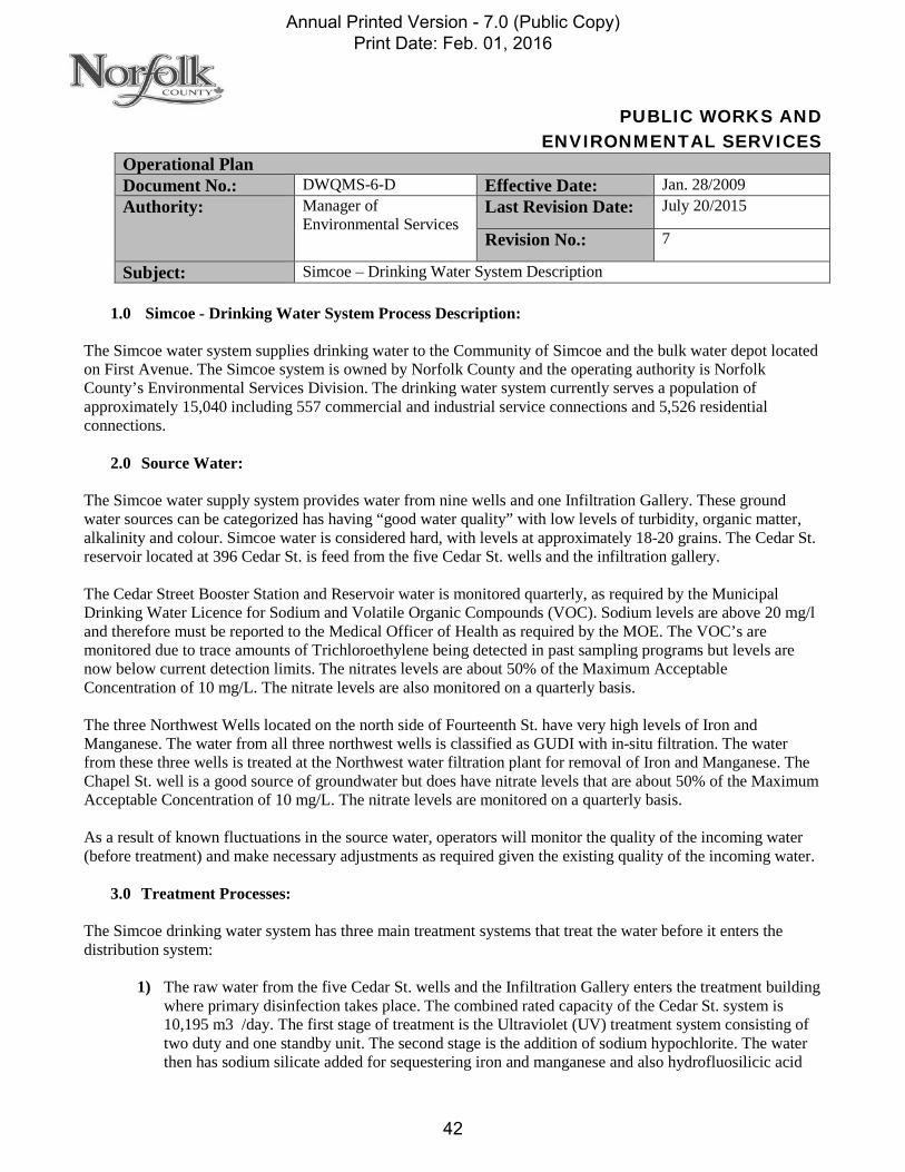
1.0 Simcoe - Drinking Water System Process Description: The Simcoe water system supplies drinking water to the Community of Simcoe and the bulk water depot located on First Avenue. The Simcoe system is owned by Norfolk County and the operating authority is Norfolk County’s Environmental Services Division. The drinking water system currently serves a population of approximately 15,040 including 557 commercial and industrial service connections and 5,526 residential connections.
2.0 Source Water: The Simcoe water supply system provides water from nine wells and one Infiltration Gallery. These ground water sources can be categorized has having “good water quality” with low levels of turbidity, organic matter, alkalinity and colour. Simcoe water is considered hard, with levels at approximately 18-20 grains. The Cedar St. reservoir located at 396 Cedar St. is feed from the five Cedar St. wells and the infiltration gallery. The Cedar Street Booster Station and Reservoir water is monitored quarterly, as required by the Municipal Drinking Water Licence for Sodium and Volatile Organic Compounds (VOC). Sodium levels are above 20 mg/l and therefore must be reported to the Medical Officer of Health as required by the MOE. The VOC’s are monitored due to trace amounts of Trichloroethylene being detected in past sampling programs but levels are now below current detection limits. The nitrates levels are about 50% of the Maximum Acceptable Concentration of 10 mg/L. The nitrate levels are also monitored on a quarterly basis. The three Northwest Wells located on the north side of Fourteenth St. have very high levels of Iron and Manganese. The water from all three northwest wells is classified as GUDI with in-situ filtration. The water from these three wells is treated at the Northwest water filtration plant for removal of Iron and Manganese. The Chapel St. well is a good source of groundwater but does have nitrate levels that are about 50% of the Maximum Acceptable Concentration of 10 mg/L. The nitrate levels are monitored on a quarterly basis. As a result of known fluctuations in the source water, operators will monitor the quality of the incoming water (before treatment) and make necessary adjustments as required given the existing quality of the incoming water.
3.0 Treatment Processes: The Simcoe drinking water system has three main treatment systems that treat the water before it enters the distribution system:
1) The raw water from the five Cedar St. wells and the Infiltration Gallery enters the treatment building where primary disinfection takes place. The combined rated capacity of the Cedar St. system is 10,195 m3 /day. The first stage of treatment is the Ultraviolet (UV) treatment system consisting of two duty and one standby unit. The second stage is the addition of sodium hypochlorite. The water then has sodium silicate added for sequestering iron and manganese and also hydrofluosilicic acid
Annual Printed Version - 7.0 (Public Copy) Print Date: Feb. 01, 2016
42

for the addition of fluoride. Prior to the water entering the reservoir it is monitored for free chorine residual. Water leaving the Reservoir is monitored again for Free Chlorine residual which is used to calculate the Chlorine Contact Time and then Sodium Hypochlorite is added again if required to ensure secondary disinfection in the distribution system. The final treated water is then monitored for Turbidity and Free Chlorine prior to entering the distribution System. The above ground reservoir consists of two large cells with a capacity of 4,500 m3. Water from the reservoir is pumped from one or more of the three Booster Station pumps and provides treated water to the distribution system and to fill the elevated storage tank. The level in the elevated tank controls the booster pumps based on control set points.
The Infiltration Gallery and Well pumps shut off automatically when: a) The U.V. units reach any critical or major alarm set points. b) The pre-reservoir chlorine residual analyzer reads above or below the alarm set points. or c) The Reservoir high level set point is reached.
The Booster Station pumps automatically shut off when: a) The post-reservoir chlorine residual analyzer reads above or below the alarm set points. b) The post-reservoir turbidity analyzer reads above the alarm set point. c) The elevated storage tank reaches the high level set point. or d) The reservoir reaches the low level set point.
2) The Chapel St. well is equipped with a vertical turbine pump which has rated a capacity of 2,298 m3
/day. When the well pump starts, the waste valve opens and the water is pumped to waste for approximately 3 minutes and the valve then closes. The outlet valve then opens and the water flows through an inline magnetic flow meter that measures the flow. The first step in the treatment process is the addition of sodium hypochlorite for primary disinfection.
Hydrofluosilicic acid is then added for fluoridation. The water then flows through the chlorine contact chamber, which consists of a 36m x 1.35m pipe with inlet and outlet baffles, and then enters the distribution system. The well pump shuts off automatically when: a) The pre or post contact chamber chlorine analyzers read above or below alarm set points. b) The raw water turbidity analyzer reads above the alarm set point. or c) The elevated storage tank reaches the high level set point.
3) The Northwest Water Filter Plant is supplied water directly from the three Northwest wells. N.W.
well 2 & 3 are normally the duty wells because the water quality of these wells is superior to N.W. well 1. Well 1 is the only well of the three that has sodium hypochlorite and sodium permanganate added to assist in the filtration process, due to the high levels of iron and manganese. When the variable speed well pumps start, the waste valve opens and the water is pumped to waste for approximately 3 minutes and the valve then closes. The outlet valve then opens and the water flows through an inline magnetic flow meter that measures the flow. The water then enters the water filtration plant and the first stage of the process is the addition of Poly Aluminum Chloride (PAC), which is a polymer that enhances the filtering process. Then sodium hypochlorite is added for pre-filter disinfection and as a primary oxidant, followed by sodium permanganate as a secondary oxidant. The next step in the process is the reaction tank where the oxidation of the iron and manganese takes place. The water then flows into the filtration system, which consists of three steel high-pressure filters. The filter system is designed on a two duty filter system with one standby filter. If two wells are pumping, one filter is in operation, if all three wells are on, two filters are in operation. The filters
Annual Printed Version - 7.0 (Public Copy) Print Date: Feb. 01, 2016
43

contain approximately 0.6m of mesh ceramic filter media and are equipped with air scouring system to assist in backwashing. The filter backwash is initiated if the effluent turbidity exceeds a pre-set point, a loss of head is recorded or the filter run time elapses. The filters automatically filter to waste before starting each filter run. The backwash and “filter to waste” water is discharged to the wastewater holding tank and then pumped to the sanitary sewer. The filtered water leaving each filter is monitored by an online turbidity analyzer and then has Hydrofluosilicic acid added for fluoridation and sodium hypochlorite for post-filter disinfection. The water then flows into the Northwest Reservoir where necessary chlorine contact time is achieved. After the water is pumped from the reservoir it is monitored by an online free chlorine residual analyzer prior to post chlorination with sodium hypochlorite and is then monitored again by online analyzers for free chlorine residual and turbidity before entering the distribution system. The Northwest wells (water filtration plant feed) will automatically shut off when: a) The filter turbidity’s are over the alarm set point. b) The pre-contact (post filter) chlorine residual analyzer reads above or below alarm set points.c) The PAC flowrate drops below the set point. or d) The Northwest Reservoir reaches the high level set point.
The reservoir high lift pumps will automatically shut off when: a) The reservoir treated water chlorine residual analyzers reads above or below alarm set point levels. b) The reservoir treated water turbidity analyzer reads above the alarm set point. c) The elevated storage tank reaches the high level set point. or d) The Northwest Reservoir reaches the low level set point.
4.0 Distribution:
The water distribution system includes a 3,400 m3 elevated storage tank, which acts as a reservoir when the system requires larger amounts of water than the wells can supply (such as firefighting and peakflows) and also helps to maintain a constant system pressure. The system piping includes the following lengths and diameters –4,157 m of 150 mm or less, 46,387 m of 150 mm, 31,688 of 200 mm, 586 m of 250 mm, 20,506 m of 300 mm and 5,164 m of 400 mm. The approximate age of these pipes in years, is approximately 37% are over 50 yrs old, 35% is 25 – 50 yrs & 28% are less than 25yrs old. The piping consists of the following materials - cast iron, PVC & ductile iron pipe along with approximately 523 fire hydrants and 1,119 main valves. The system is also protected by Backflow Prevention Devices on Industrial and Commercial services as required by the building code.
5.0 SCADA: The Supervisory Control and Data Acquisition (SCADA) system is a computerized control system that also monitors all of Norfolk County’s water facilities and one of its functions is to send alarms for all operational parameters, which have preset minimum and/or maximum levels. These alarms are sent to Norfolk County’s answering service, who then pages the afterhours on call operator, who must immediately respond to the call.
Annual Printed Version - 7.0 (Public Copy) Print Date: Feb. 01, 2016
44

Annual Printed Version - 7.0 (Public Copy) Print Date: Feb. 01, 2016
45

Document # DWQMS-6-D-2 Version – 4 Revision Date: Oct. 01, 2014
Printed documents are considered non-controlled as the controlled versions are maintained electronically. This copy printed: 2015-02-18
Annual Printed Version - 7.0 (Public Copy) Print Date: Feb. 01, 2016
46

Document # DWQMS-6-D-3 Version – 4 Revision Date: Oct. 01, 2014
Printed documents are considered non-controlled as the controlled versions are maintained electronically. This copy printed: 2015-02-18
Annual Printed Version - 7.0 (Public Copy) Print Date: Feb. 01, 2016
47

Annual Printed Version - 7.0 (Public Copy) Print Date: Feb. 01, 2016
48

PUBLIC WORKS AND ENVIRONMENTAL SERVICES
Operational Plan Document No.: DWQMS-6-E Effective Date: Jan. 28/2009 Authority: Manager of
Environmental Services Last Revision Date: July 20/2015
Revision No.: 6
Subject: Waterford – Drinking Water System Description
1.0 Waterford – Drinking Water System Process Description: The Waterford water system supplies drinking water to a community of approximately 3,315 residents including 87 commercial and industrial service connections and 1,373 residential connections. The system is owned by Norfolk County and the operating authority is Norfolk County’s Environmental Services Division. The system is a well-based supply consisting of two groundwater well sources, an iron and manganese removal plant, a reservoir and a water standpipe.
2.0 Source Water: The groundwater source can be categorized as “good water quality” with low turbidity, organic matter, alkalinity and colour. The levels of iron are high and levels of manganese are very high. Hardness levels are on the high side of the spectrum, which is typical of groundwater sources. Both wells are classified as GUDI with effective in-situ filtration. As a result of known fluctuations in the source water, operators will monitor the quality of the incoming water (before treatment) and make necessary adjustments as required given the existing quality of the incoming water.
3.0 Treatment Processes: The water treatment plant which is located on Regional Road Number 9 (Thompson Road) is fed by two groundwater well sources. A manganese & iron removal plant was put into operation in 2004 to eliminate problems experienced in the distribution system due to the high levels of manganese. The wells are both equipped with one vertical turbine pump, each rated at 34L/sec with a variable frequency drive and a magnetic flow meter at the discharge header. Normal process operates with one well pump as main duty and one as a standby. The treatment system has a rated capacity of 68 L/s. Water flows from the well(s) into the water treatment plant where Poly Aluminum Chloride (PAC - coagulant), sodium permanganate and sodium hypochlorite are added prior to a reaction chamber to help oxidize the iron and manganese. After sufficient reaction time in the chamber, the water then passes through one of the three pressure filters at a rated capacity of 24 L/s. The filters contain approximately 0.9m of mesh ceramic filter media and are equipped with air scouring system to assist in backwashing. The filter backwash is initiated if the effluent turbidity exceeds a pre-set point, a loss of head is recorded or the filter run time elapses. The filters automatically filter to waste before starting each filter run. The backwash and “filter to waste” water is discharged to the wastewater holding tank and then pumped to the sanitary sewer. The filtration system is designed to also run two filters at one time if the demand in the distribution system requires it. The filters are all automated with the following instrumentation: inlet, filtered and backwash turbidity meters, differential pressure switches, backwash flow meters and pressure gauges. From the filters, water then passes through a common header where sodium hypochlorite is injected.
Annual Printed Version - 7.0 (Public Copy) Print Date: Feb. 01, 2016
49

he water then travels to a 725 m3 clearwell where primary disinfection and contact time is achieved. The clearwell is a two-celled reservoir with baffled walls which is designed to aid in the chlorine contact time. It is equipped with an ultrasonic flow level transmitter, which monitors the liquid level in the clearwell and sends its signal to operate the well pumps. The three high lift pumps, rated at 24 L/s pump water from the clearwell to the water distribution system. There are also two backwash pumps, which pump water from the clearwell to the filters when the backwash is required. The water standpipe level activates the high lift pumps and their flow is measured by a flow meter leaving the plant to the distribution system. In the event of a power failure the plant is equipped with a 395kW diesel generator, which provides standby power to the plant. The groundwater wells (filter plant feed) will automatically shut off when: a) The filter turbidity’s are over the alarm set point. b) The pre-contact (post filter) chlorine residual analyzers reads above or below alarm set points. c) The PAC flowrate drops below the set point. or d) The reservoir reaches the high level set point. The reservoir high lift pumps will automatically shut off when: a) The treated water (final) chlorine residual analyzer reads above or below alarm set point levels. or b) The water standpipe reaches the high level set point.
4.0 Distribution: The water distribution system includes a 3,160 m3 water standpipe, which acts as a reservoir when the system requires larger amounts of water than the wells can supply (such as firefighting and peakflows) and also helps to maintain a constant system pressure. The system piping includes the following lengths and diameters – 3,640 m of 150 mm or less, 13,795 m of 150 mm, 6,337 m of 200 mm, 689 m of 250 mm and 5,780 m of 300 mm. The approximate age of these pipes in years is 12% is over 50 yrs old, 29% is 25 – 50 yrs & 54% is less than 25yrs old. The piping consists of the following materials - Asbestos-Cement, PVC and Ductile Iron piping along with approximately 172 fire hydrants and 318 main valves. The system is also protected by Backflow Prevention Devices on Industrial and Commercial services as required by the building code.
5.0 SCADA: The Supervisory Control and Data Acquisition (SCADA) system is a computerized control system that also monitors all of Norfolk County’s water facilities and one of its functions is to send alarms for all operational parameters, which have preset minimum and/or maximum levels. These alarms are sent to Norfolk County’s answering service, who then pages the afterhours on call operator, who must immediately respond to the call.
Annual Printed Version - 7.0 (Public Copy) Print Date: Feb. 01, 2016
50

Annual Printed Version - 7.0 (Public Copy) Print Date: Feb. 01, 2016
51

Annual Printed Version - 7.0 (Public Copy) Print Date: Feb. 01, 2016
52

DWQMS
ELEMENT - 7
RISK ASSESSMENT
Annual Printed Version - 7.0 (Public Copy) Print Date: Feb. 01, 2016
53

PUBLIC WORKS AND ENVIRONMENTAL SERVICES
Operational Plan Document No.: DWQMS-7 Effective Date: April 02/2009 Authority: Manager of
Environmental Services Last Revision Date: Jan. 16/2016
Revision No.: 11
Subject: Risk Assessment Procedure
1.0 Purpose: 1.1. The purpose of performing a DWQMS risk assessment is to identify all potential hazards associated
with the provision of safe drinking water to the customers supplied by Norfolk County. The risk assessment will identify hazards, the cause of hazard, the risk the hazard presents to the drinking water system, and describe what controls are in place to protect the drinking water system.
1.2. Risk Assessment is an orderly methodology of identifying hazards or hazardous events that may affect the safety of the drinking water and evaluating their significance.
2.0 Scope: 2.1. This work instructions applies to all risk assessments conducted by Norfolk County and any
documentation associated with these assessments.
3.0 Definitions: 3.1. Hazard: Any source of danger or a property that may cause drinking water to be unsafe for human
consumption.
3.2. Hazardous Event: An incident or situation that can lead to the presence of the hazard.
3.3. Risk: The probability of a hazard to cause harm, including the magnitude of that harm or its consequences.
3.4. Control: Any process or contingencies that have been put in place to prevent or reduce the potential for a hazard to occur. These include monitoring and measuring devices and equipment.
4.0 General: 4.1. An orientation session will be presented to team members unfamiliar with the Risk Assessment process
in order to explain the purpose of conducting risk assessments and the steps involved in the process.
5.0 Process: 5.1. A risk assessment team is created to conduct the risk assessments:
5.1.1. A designated Risk Assessment Team will conduct risk assessments. Team members will include
Water Treatment Facilities and Water Distribution Systems personnel who are familiar with the business practices and processes being assessed and have sufficient knowledge and expertise to evaluate the tasks accurately. The team may include experienced operators or other personnel as required.
Annual Printed Version - 7.0 (Public Copy) Print Date: Feb. 01, 2016
54

5.2. The Risk Assessment team describes each process.
5.2.1. All elements and process steps related to the drinking-water systems are considered from the source to the point of delivery. The process flow charts from DWQMS-6 (A-E) may be referenced. The participants in the hazard identification will include representation from Water Facility Operations, Distribution System Operations, and Senior Management. Additional representatives may participate as needed.
5.2.2. The Risk Assessment Team will identify all elements and processes steps in Norfolk County’s water systems. First selecting an area of the organization to assess and having a team member with practical knowledge in that area, describe all the activities that are completed within the area. After identifying the activities, personnel will further describe all the process steps to complete the activity.
5.2.3. The information gathered should be collected on an Excel spreadsheet and formatted with the headings Element or Process Step, Description of Hazard, Consequence & Risk Type, Critical Control Points, Risk rates and Preventative Control Measures.
5.2.4. The following elements or process steps have been systematically identified and risk will be assessed:
Source Water Filtration Power Supply Intakes Disinfection (Cl,UV & CT) Transmission Mains
Well Components Reservoirs (Storage) Hydrant Use Rechorination Secondary Infection Distribution
Lowlift Pumps Highlift Pumps Elevated Storage Coagulation Fluoride Addition Sodium Silicate Addition
5.3. Risk assessment team identifies risk Categories and Factors:
5.3.1. It was decided by the risk assessment team that the following 4 common categories - biological,
chemical, physical or radiological could potentially expose risks to the water supplied to the customer. So systematically each of these categories will be analyzed against each process step in the system.
5.3.2. The four different risk categories that are assessed to every element or process step identified are listed below:
5.3.2.1. Biological (BIO): biological pathogens are usually the most significant drinking water health risk because the effects are acute, if ingested, pathogens can cause gastrointestinal illness within a period of hours or days. Waterborne biological hazards include bacterial, viral and parasitic organisms.
Annual Printed Version - 7.0 (Public Copy) Print Date: Feb. 01, 2016
55

5.3.2.2. Chemical (CHEM): Chemical contaminants may occur naturally or may be added or created during water processing. Harmful chemicals at high levels have been associated with acute cases of waterborne illnesses and can be responsible for chronic illness at lower levels of exposure. Chemical hazards in drinking water may come from the source water or occur in the treatment and distribution system.
5.3.2.3. Physical (PHY): Physical hazards can result from contamination and/or poor procedures at different points in the chain from source to customer. Sediments are the most common physical hazard associated with drinking water and are of concern as they may carry with them microbiological hazards and interfere with disinfection system efficacy. Monitoring turbidity levels is an essential precursor activity to control measures in the treatment system. Control measures at the source can include grass strips on all water/land interfaces. Other physical hazards include biofilms, pipe materials or sloughed metal.
5.3.2.4. Radiological (RAD): Radiological hazards may arise from man-made or natural sources, with naturally occurring chemicals (uranium, radon, etc.) most frequently being found in groundwater. If there is the potential for the accidental release of man-made radiologicals, such as tritium or other radionuclides, these sources should also be considered. With accidental releases, surface waters are generally at a greater risk.
5.3.3. Norfolk County’s risk assessment team will ensure that every element or process step in each system is systematically checked for 7 different factors under each of the 4 risk categories listed above.
5.3.3.1. (1) – System / Mechanical 5.3.3.2. (2) – Environmental Conditions 5.3.3.3. (3) – Process Failure 5.3.3.4. (4) – Operator Error 5.3.3.5. (5) – Surrounding Environment 5.3.3.6. (6) – Terrorism 5.3.3.7. (7) – Vandalism
5.3.4. This following analysis summarizes the risk assessments completed for each Norfolk County Area. These results are referenced in the Risk Assessment Outcomes (element 8) section of the operational plan.
5.3.5. The risk assessment process must consider the reliability and redundancy of equipment for every risk assessed. If reliability and redundancy lowers a potential risk rating it will be documented in the Risk Assessment Outcomes Summary as a Preventative Control Measure.
Annual Printed Version - 7.0 (Public Copy) Print Date: Feb. 01, 2016
56

5.4. Risk Assessment Ratings are determined by adding the values assessed by the team, on the basis of severity, likelihood and detectability, as listed below.
5.5. 5.5.1. Maintenance records are used to predict equipment reliability and the requirement for appropriate
maintenance activities. As appropriate back up equipment is available in the event that equipment failure occurs. Back-up generators are started up on an ongoing basis to ensure that the equipment will function in an emergency.
5.5.2. The threshold or cut-off point is defined as the established limit for the potential risk level below which the hazardous events and associated hazards are not considered critical. The threshold will be established by the risk assessment team.
5.5.3. Severity: Severity is the expected consequence of an event in terms of overall impact. The rating corresponds to the highest potential impact. The severity for each hazard identified was rated using the 0-5 point scale listed below:
Characteristic Public Health Capacity Population Effected N/A
1 No Health Risk Minor Reduction Minimal Exposure 2 Minor Health Risk 25% Reduction 25% of Residents 3 Report of Sickness 50% Reduction 50% of Residents 4 Hospitalizations 75% Reduction 75% of Residents 5 Death(s) No Capacity Entire Water System 5.5.4. Likelihood: Likelihood is the probability that a hazard or hazardous event will occur. It takes into
account hazards or hazardous events that have occurred in the past and the likelihood of their reoccurrence. Likelihood also takes into account hazards or hazardous events that have yet to occur. Emergency events as well as predictable events are considered. The likelihood for each hazard identified was rated using the 0-5 point scale listed below:
Characteristic Frequency N/A
1 Not Likely to Occur 2 Every 5-10 Years 3 Yearly 4 More than once / year 5 Monthly, or less
5.5.5. Detectability: Detectability is the ability to detect a hazard. As the ability to detect the hazard
decreases the associated risk increases. The Detectability for each hazard identified was rated using the 0-5 point scale listed below:
Characteristic Detectability N/A
1 Easily Detectable (by anyone or online monitoring) 2 Apparent (by Qualified / trained person – lab test, audible alarm) 3 Routinely Inspected / Maintained (rounds or regular inspection) 4 Not Inspected / Maintained (Random Detection) 5 Not Detectable
Annual Printed Version - 7.0 (Public Copy) Print Date: Feb. 01, 2016
57

5.6. Communicating the Risk Assessment :
5.6.1. Communication regarding the risk assessment outcomes will be facilitated by Springboard software, which is designed to forward new and updated information to the appropriate individuals within Norfolk County. It will be the responsibility of the employees of Norfolk County to access the information in the system
5.6.2. Understanding where Norfolk County’s high risk activities exist in the system and relative to each other are important results to understand. Below is a summary that illustrates using risk assessments where focus should be placed.
5.7. Document Major Events and Accidents:
5.7.1. If an incident occurs it must be documented through the e corrective action process which is covered under the Continual Improvement Procedure DWQMS-21. As a result of an accident the risk value will increase, if the increase exceeds the acceptable level the system will flag the high value. Norfolk County will decide if further controls are needed to reduce the risk to an acceptable level.
5.8. Risk Assessment Review & Completion Frequencies: 5.7.1 The QMS representative will conduct an annual review of the Risk Assessments to verify the currency and validity of assumptions used by interviewing staff responsible for Water Treatment, Distribution and Source Water Protection and then make any appropriate changes to the outcomes and communicate to appropriate staff through Springboard software. 5.7.2 The entire Risk Assessment process will be conducted again at least once every thirty-six months, using the same process as described above with any appropriate changes the team feels may improve the process. 6.0 Records:
6.1. Records generated from this procedure are maintained by the Water and Wastewater Compliance
Officer for Norfolk County, as required under DWQMS-5 Document Control.
Annual Printed Version - 7.0 (Public Copy) Print Date: Feb. 01, 2016
58

DWQMS
ELEMENT - 8
RISK ASSESSMENT OUTCOMES
Annual Printed Version - 7.0 (Public Copy) Print Date: Feb. 01, 2016
59

Page 1 of 3
Printed documents are considered non-controlled as the controlled versions are maintained electronically. This copy printed: 2015-02-18
PUBLIC WORKS AND ENVIRONMENTAL SERVICES
Operational Plan Document No.: DWQMS-8 Effective Date: Feb. 09/2009 Authority: Manager of
Environmental Services Last Revision Date: Dec 15, 2014
Revision No.: 8
Subject: Risk Assessment Outcomes
1.0 Purpose: 1.1. The purpose of this document is to summarize risk assessment outcomes.
1.2. The Risk Assessment Outcomes include:
1.2.1. Identified potential hazardous events and associated hazards; 1.2.2. Assessed risks associated with the occurrence of hazardous events; 1.2.3. Ranked hazardous events; 1.2.4. Identified control measures to address the potential hazards and hazardous events; 1.2.5. Identified critical control points and their respective critical control limits; 1.2.6. Procedures and/or processes to monitor the critical control limits; 1.2.7. Procedures to respond to deviations from the critical control limits; and 1.2.8. Procedures for reporting and recording deviations from the critical control limits.
2.0 Scope:
2.1. This procedure is applicable to all municipal drinking-water systems operated by Norfolk County.
3.0 References:
3.1. MOE DWQMS Element 8
4.0 Definitions:
4.1. Critical control limit (CCL) - The point at which a critical control point response procedure is initiated. 4.2. Critical control point (CCP) - An essential step or point in the subject system (process) at which
control can be applied by the operating authority to prevent or eliminate a drinking-water health hazard or to reduce it to an acceptable level.
4.3. Hazard – A source of danger or a characteristic that may cause drinking water to be unsafe for human consumption. The hazard may be biological, chemical, physical or radiological in nature.
4.4. Hazardous Event – Is an incident or situation that can lead to the present of a hazard.
5.0 Outcomes: For each Risk identified, the Risk Assessment Outcome spreadsheets will document the Element or Process Step, the Risk Category, the Risk rating, Critical Control Points (CCP) if applicable and the Controls and procedures in place.
5.1.1.1.
Annual Printed Version - 7.0 (Public Copy) Print Date: Feb. 01, 2016
60

Page 2 of 3 Document No.: DWQMS-8 Last Revision Date: Dec. ?15, 2014 Subject: Risk Assessment Outcomes Revision No.: 8
Printed documents are considered non-controlled as the controlled versions are maintained electronically. This copy printed: 2015-02-18
5.2. Assessment of Risk:
5.2.1. Risk Assessments were completed for all subject systems and documented in the following appendices:
5.2.1.1. Delhi Water System: Appendix A 5.2.1.2. Port Dover Water Treatment Plant: Appendix B 5.2.1.3. Port Rowan Water Treatment Plant: Appendix C 5.2.1.4. Simcoe Well Supply: Appendix D 5.2.1.5. Waterford Well Supply: Appendix E 5.2.1.6. Distribution Systems for all Norfolk County Systems: Appendix F 5.2.1.7. Risk Assessment Outcomes Summary (all Systems): Appendix G
5.3. Critical Control Point determination:
5.3.1. Control Points, whether critical or not, were identified and documented within the appendices.
5.4. Process for Identifying Control Measures:
5.4.1. The Risk Assessment Team will identify the controls in place for each of the identified hazards
and risks determined by the water treatment facility and water distribution system employees should they exist. All current documentation (procedures etc) that are related to the controls are identified at this time. The risk assessment team will identify the critical controls required to ensure the provision of safe drinking water.
5.4.2. A control is defined as a place at which something is checked or inspected or from which something is directed. For drinking water system, controls are used to ensure the quality of the drinking water being supplied, used, and consumed.
5.4.2.1. NOTE: Hazards that cannot be controlled are mitigated through contingency procedures, also known as emergency procedures, as referenced under element 18.
5.4.3. Recommended Minimum Critical Control Points – are the control points required by regulation to meet minimum treatment requirements for disinfection as outlined in O. Reg. 170/03 and the Procedure for Disinfection of Drinking Water in Ontario.
5.4.4. The process for identifying critical controls is as follows:
5.4.4.1. Identify critical control points (CCP). A critical control point (CCP) is a point, step, or procedure at which control can be applied to prevent or eliminate a drinking-water health hazard or to reduce the hazard to an acceptable level. Note: Not all controlls are considered critical controls.
5.4.4.2. Establish critical limits for each critical control point (CCM). A critical limit is the
maximum or minimum value to which a physical, biological, radiological or chemical hazard must be controlled at a critical control point to prevent, eliminate, or reduce to an acceptable level.
5.4.4.2.1. NOTE: The CCM should be at a level that enables action to be taken to control a risk before it reaches the level required by legislation.
Annual Printed Version - 7.0 (Public Copy) Print Date: Feb. 01, 2016
61

Page 3 of 3 Document No.: DWQMS-8 Last Revision Date: Dec. ?15, 2014 Subject: Risk Assessment Outcomes Revision No.: 8
Printed documents are considered non-controlled as the controlled versions are maintained electronically. This copy printed: 2015-02-18
5.4.4.3. Establish critical control point monitoring requirements (CCMO). Monitoring activities are necessary to ensure that the process is under control at each critical control point. Procedure W-34 is followed for Responding to Deviation from Critical Control Points.
5.4.4.4. Establish corrective actions. (CCA) These are actions to be taken when monitoring indicates a deviation from an established critical limit. Corrective actions are intended to ensure documented formalized actions are followed by all personnel within the organization in the event a critical control limit is exceeded.
5.4.4.5. Establish record keeping procedures. (CCR) Are the actions to be taking in the event that a control limit is exceeded. Formalized procedures for reporting and recording the deviations are established, at a minimim, for each of the contols deem critical.
5.5. High Risk Items under review:
5.5.1. The high risk items that are under review for further evaluation for planning action to control, mitigate or otherwise address the risk are documented within the Appendices.
6.0 Associated Forms, Procedures and/or Work Instructions: 6.1. The following forms, procedures and records are related to this procedure:
6.1.1. Risk Assessment Procedure, DWQMS-7; 6.1.2. Continual Improvement, DWQMS-21; 6.1.3. Procedure for Responding to Deviations from Critical Control Set Points, W-34.
7.0 Records:
7.1. Records generated from this procedure are maintained by the Water and Wastewater compliance officer
for Norfolk County, as required under DWQMS-5 Document Control.
Annual Printed Version - 7.0 (Public Copy) Print Date: Feb. 01, 2016
62

DWQMS
ELEMENT - 9
ORGANIZATIONAL STRUCTURE
ROLES RESPONSIBILITIES
& AUTHORITIES
Annual Printed Version - 7.0 (Public Copy) Print Date: Feb. 01, 2016
63

Page 1 of 2
Printed documents are considered non-controlled as the controlled versions are maintained electronically. This copy printed: 2015-02-18
PUBLIC WORKS AND ENVIRONMENTAL SERVICES
Operational Plan Document No.: DWQMS-9 Effective Date: March 22/2009 Authority: Manager of
Environmental Services Last Revision Date: June 23/2014
Revision No.: 9
Subject: Organizational Roles, Responsibilities & Authorities Procedure 1.0 Purpose:
1.1 This policy outlines the organizational structure of Norfolk County as well as the associated
roles, responsibilities, and authorities that relate to the operation and performance of its drinking-water system.
2.0 Scope:
2.1 This policy applies to all Norfolk County personnel and the processes used to administer the
roles and responsibilities associated with the management of the drinking-water system.
3.0 Policy: 3.1. Definition of Responsibility:
3.1.1. Norfolk County Mayor and Council are the Owner of the drinking water QMS, while
the Environmental Services Division is the Operating Authority of the drinking water QMS.
3.1.2. The reporting structure of Environmental Services Division is outlined in the Organizational Chart. The roles, responsibilities, and authorities of each position are aligned with the duties outlined by individual licenses and are documented in job descriptions.
3.1.3. The General Manager of Public Works and Environmental Services, The Manager of Environmental Services and the Water & Wastewater Compliance Supervisor complete Top Management responsibilities.
3.1.4. To ensure the currency of the system and efficiency of its operation, personnel within Norfolk County that have responsibilities that affect Drinking Water Quality will be aware of their specific job responsibilities. This will be facilitated through the communication of up-to-date job descriptions using Springboard software.
3.1.5. The Human Resources & Staff Development Division of the Employee and Business Services Department will maintain documentation outlining Norfolk County’s organizational structure and the respective roles, responsibilities, and authorities.
Annual Printed Version - 7.0 (Public Copy) Print Date: Feb. 01, 2016
64

Page 2 of 2
Document No.: DWQMS-9 Last Revision Date: June 23/2014 Subject: Organizational Roles, responsibilities
& Authorities Procedure Revision No.: 9
Printed documents are considered non-controlled as the controlled versions are maintained electronically. This copy printed: 2015-02-18
3.1.6. Employees of Norfolk County with management responsibilities are identified as
members of Top Management. The individual’s responsible for participating in the management review process include:
General Manager of Public Works and Environmental Services;
Manager of Environmental Services; and
Water & Wastewater Compliance Supervisor.
3.1.7. The specific responsibilities of Environmental Services Staff are outlined in the respective job descriptions. These responsibilities will also include: Endorsing the implementation and maintenance of the drinking-water QMS;
Ensuring the implementation of the drinking-water QMS according to established procedures;
Reviewing and approving documentation related to the QMS;
Providing updates to Council, as appropriate; and
Communicating information to the appropriate personnel, as needed.
3.1.8. The specific authorities of Environmental Services Staff are outlined in the Authority by Position Table.
5.0 References:
Organizational chart Job descriptions Authority By Position Table Management Review procedure Communications procedure
Annual Printed Version - 7.0 (Public Copy) Print Date: Feb. 01, 2016
65
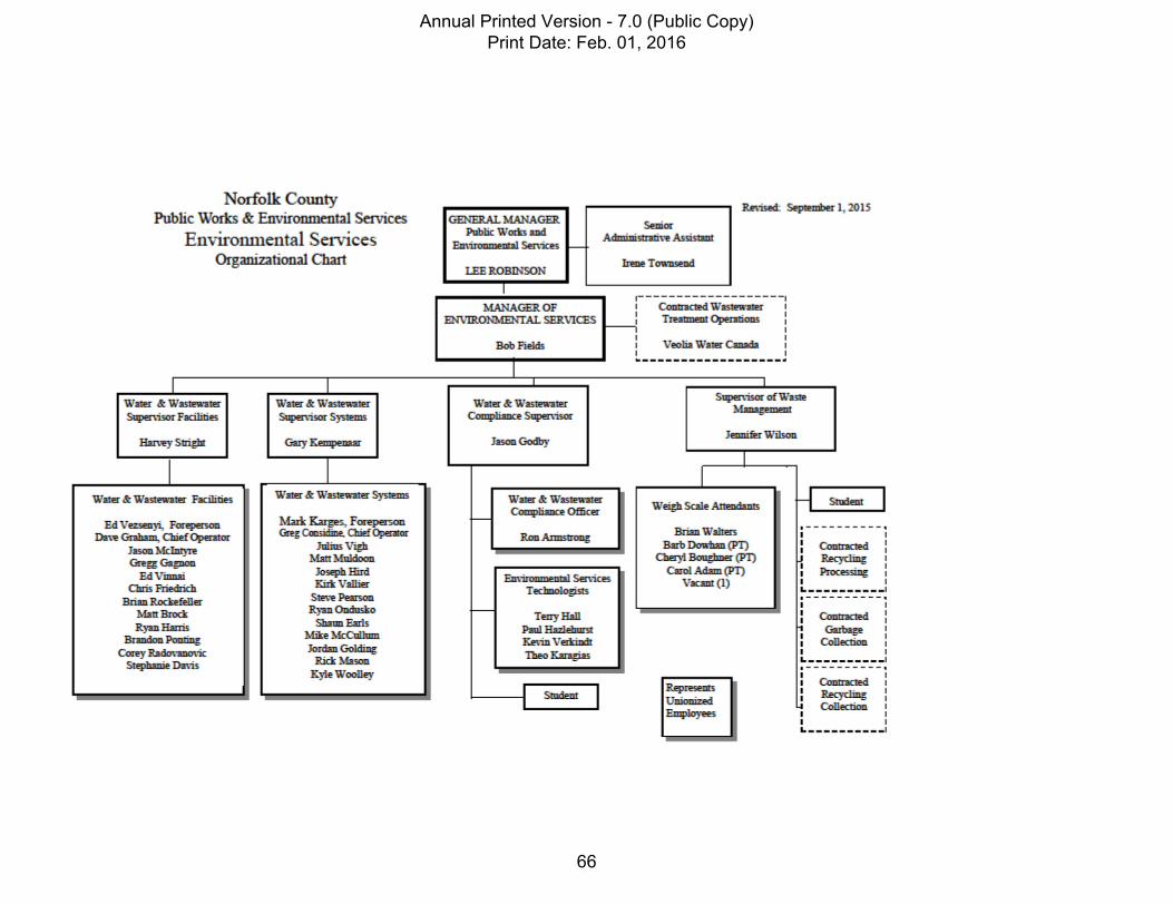
Annual Printed Version - 7.0 (Public Copy) Print Date: Feb. 01, 2016
66

Document # ‐ DWQMS – 9 – 3 Version ‐ 1.0 Revision Date ‐ July 24, 2014.
Printed documents are considered non‐controlled as the controlled versions are maintained electronically. This copy printed: 2015‐02‐18
Authority by Position Table
Position Authority of Position
General Manager of Public Works ‐ to approve and sign Environmental Services reports to Council related to the operation of the 5 County Water systems. ‐spending authority of $3,000,000
Environmental Services Manager ‐ to approve and sign E.S. reports to Council related to the operation of the 5 County Water Systems. ‐ to give direction to water supervisors on operation of 5 drinking water systems. ‐spending authority of $500,000
Facilities & Systems Supervisors ‐ give direction to operators on operations & maintenance of 5 water systems ‐ designated as Overall Operator In‐Charge as per section 25 of O.Reg. 128/04. ‐spending authority of $50,000
Facilities & Systems Foreman & Chief Operator ‐ to delegate daily tasks to operators and authorized to perform duties as per section 25 of O.Reg. 128/04. (set operational parameters etc.)
Licensed Operators Class I ‐ IV ‐ if designated as Operator In Charge by management – authorized to perform duties as per section 25 of O.Reg. 128/04. . (set operational parameters etc.)
Licensed Operator In Training ‐ no authority
Annual Printed Version - 7.0 (Public Copy) Print Date: Feb. 01, 2016
67

DWQMS
ELEMENT - 10
COMPETENCIES
Annual Printed Version - 7.0 (Public Copy) Print Date: Feb. 01, 2016
68

PUBLIC WORKS AND ENVIRONMENTAL SERVICES
Operational Plan Document No.: DWQMS-10 Effective Date: Feb.09/2009 Authority: Manager of
Environmental Services Last Revision Date: Aug. 20/2013
Revision No.: 4
Subject: Competencies
1.0 Purpose: 1.1. This procedure identifies how Norfolk County ensures that personnel whose roles and responsibilities
affect drinking-water quality remain competent in order to ensure the ongoing operation of its drinking-water system.
2.0 Scope: 2.1. This procedure applies to the performance and management of all Norfolk County personnel who are
involved in the operation of the drinking-water system.
3.0 Procedure: 3.1. Identification, Development and Maintenance of Competencies:
3.1.1. In order to ensure the use of competent individuals to manage and maintain the drinking-water
QMS, Norfolk County requires employees to have the appropriate licensing to complete the responsibilities they perform. The Operators-in-Training (OIT) designation is the minimum requirement for working with the drinking-water system. Specific requirements are outlined in the appropriate job descriptions and are enforced when hiring new employees.
3.1.2. All personnel must be aware of and are responsible for complying with policies and procedures related to the operation of the system. Springboard software will be used to provide employees with access to this documentation.
3.1.3. The Water Treatment Facilities Supervisor and the Water Distribution Systems Supervisor maintain copies of required certifications for all employees.
3.1.4. The development and maintenance of competencies and skills is facilitated through the following methods: 3.1.4.1 A training summary is kept for each operator, which identifies the minimum required
or recommended training for performing specific duties. These summaries also provide record of completed training and if individuals require training. Training is provided according to Ministry of the Environment (MOE) specifications and includes training related to an employee’s responsibilities including but not limiting, training for the DWQMS, treatment processes, equipment operation - maintenance & repair, SCADA, Springboard and Microsoft computer software.
3.1.4.2 The use of on-line tests through Springboard Software for Specific Procedures relevant to employees roles and responsibilities, which helps verify knowledge and understanding.
Annual Printed Version - 7.0 (Public Copy) Print Date: Feb. 01, 2016
69

3.1.4.3 New employees and OIT’s work with experienced staff in the field to learn job related
skills until Foreman, Chief Operator and Supervisor feel they are confident that new employees are capable of performing duties of the job.
3.1.4.4 All staff are encourage to attend job related conferences and seminars.
3.1.5. Awareness of the importance of employee responsibilities and its impact on drinking-water quality will be promoted through the following activities:
3.1.5.1. Regular review of relevant policies and procedures; 3.1.5.2. Communication of relevant legislative and regulatory requirements including MOE
technical updates and annual reports through formal meetings and/or Springboard Software. (as outlined in the Communications Procedure);
3.1.5.3. Communication of roles and responsibilities (as outlined in Organizational Structure, Roles, Responsibilities, and Authorities Procedure); and
3.1.5.4. Internal and external training, specifically the MOE mandatory course taken every 3 years.
4.0 References: 4.1. Training Summary Sheet; 4.2. Job descriptions; 4.3. Organizational Structure, Roles, Responsibilities, and Authorities Procedure; 4.4. Communication Procedure.
Annual Printed Version - 7.0 (Public Copy) Print Date: Feb. 01, 2016
70

Distribution Operator Training Summary
Operator Name -
Date Course Provider Course Name
* Continuing Education
HoursOn The Job
Hours2010
2011
2012
2013
TotalTotal Hours To Date 0 0 0
* * Required as per Reg. 128 (3 Year Total for Class II System) 36 72 105Name/Signature of Supervisor Tiltle of Supervisor Date
Note: * To calculate CEU's divide hours by 10. ** Continuing Education(CE) hours are the minimum required but can be substituted for On-The -Job (OTJ) hours the OTJ required hours are the max. that can be apply to the total for certificate renewal. The CE hours must include the MOE Mandatory Course which must be taken every 3 years.
Annual Printed Version - 7.0 (Public Copy) Print Date: Feb. 01, 2016
71

Treatment Operator Training Summary
Operator Name -
Date Course Provider Course Name
* Continuing Education
HoursOn The Job
Hours2010
2011
2012
2013
TotalTotal Hours To Date 0 0 0
* * Required as per Reg. 128 (3 Year Total for Class III System) 42 78 120Name/Signature of Supervisor Tiltle of Supervisor Date
Note: * To calculate CEU's divide hours by 10. ** Continuing Education(CE) hours are the minimum required but can be substituted for On-The -Job (OTJ) hours the OTJ required hours are the max. that can be apply to the total for certificate renewal. The CE hours must include the MOE Mandatory Course which must be taken every 3 years.
Annual Printed Version - 7.0 (Public Copy) Print Date: Feb. 01, 2016
72

DWQMS
ELEMENT - 11
PERSONNEL COVERAGE
Annual Printed Version - 7.0 (Public Copy) Print Date: Feb. 01, 2016
73

PUBLIC WORKS AND ENVIRONMENTAL SERVICES
Operational Plan Document No.: DWQMS-11 Effective Date: Feb. 09/2009 Authority: Manager of
Environmental Services Last Revision Date: Aug. 19/2013
Revision No.: 5
Subject: Personnel Coverage
1.0 Purpose: 1.1. This procedure identifies how Norfolk County ensures that competent individuals are available to fulfill
the responsibilities needed for the ongoing operation of its drinking-water system.
2.0 Scope: 2.1. This procedure applies to all personnel involved in the operation of Norfolk County’s drinking-water
system.
3.0 Procedure: 3.1. Establishment of Personnel Coverage:
3.1.1. Water Treatment Facilities:
3.1.1.1. Water Treatment Facilities have regular operating hours of 7:30 AM until 4:00 PM from
Monday to Friday, during which all water treatment facilities are adequately staffed with a competent operator. The staff complement is sufficient to allow adequate coverage when up to half the staff are in training, sick or injured. Vacation requests are only approved if sufficient coverage is available. If staff are on extended leave of absence, temporary staff are hired. If a pandemic or other County wide emergency takes place, the County’s Peace Time Emergency Preparedness Plan will be implemented.
3.1.1.2. An on-call operator as per the Pager Schedule developed by the Water Treatment Facility Supervisor at the beginning of the year is assigned the responsibilities to respond to SCADA alarms (relayed through the after-hours call centre) after regular working hours, as well as weekends and statutory holidays.
3.1.1.3. Regular rounds during weekends and statutory holidays are completed by an additional operator as per Treatment Facility Rounds Schedule developed by the Water Treatment Facility Supervisor at the beginning of the year.
3.1.2. Water Distribution System:
3.1.2.1. Water Distribution System employees have regular operating hours of 7:30 AM until 4:00 PM from Monday to Friday. The staff complement is sufficient to allow adequate coverage when up to half the staff are in training, sick or injured. Vacation requests are only approved if sufficient coverage is available. If staff are on extended leave of absence, temporary staff are hired. If a pandemic or other County wide emergency takes place, the County’s Peace Time Emergency Preparedness Plan will be implemented.
Annual Printed Version - 7.0 (Public Copy) Print Date: Feb. 01, 2016
74

3.1.2.2. An on-call operator as per the Pager Schedule developed by the Water Distribution System Supervisor at the beginning of the year is assigned the responsibilities to respond to Service Calls taken by the after-hours call centre for Norfolk County after regular working hours, as well as weekends and statutory holidays.
3.1.2.3. It is the responsibility of the operator on-call to contact the designated after-hours answering service each week, with their contact information. Detailed instructions and the call out lists are provided to the answering service and updated as required.
3.1.2.4. Norfolk County will ensure that all personnel included in the Pager Schedule have the
necessary skills and knowledge to perform the required responsibilities. These expectations are defined in the Competencies procedure.
3.1.3
3.1.5 3.1.4 Labour Disruptions :
3.1.3.1 The Public Works and Environmental Services (PW & ES) section of the County’s Peace Time Emergency Preparedness Plan and also the PW & ES Business Continuity Guide include plans, measures and arrangements to ensure the continuous delivery of
critical services which include operating treatment and distribution facilities. In the event of a strike by union staff, the use of non-union licenced staff and external resources will be used when required and the following MOE guideline would be followed - No. 5.2 – “Obtaining Director’s Direction To use Non-Certified Operators In The Event of A Strike Or Lock-Out”.
4.0 References:
4.1. Competencies procedure (DWQMS-10); 4.2. Pager Schedules 4.3. Answering Service call out list & instructions 4.4. Peace Time Emergency Preparedness Plan (P.W. & E.S. Volume 7) 4.5. Business Continuity Guide For P.W. & E.S.
Annual Printed Version - 7.0 (Public Copy) Print Date: Feb. 01, 2016
75

DWQMS
ELEMENT - 12
COMMUNICATION
Annual Printed Version - 7.0 (Public Copy) Print Date: Feb. 01, 2016
76

Page 1 of 2
Printed documents are considered non-controlled as the controlled versions are maintained electronically. This copy printed: 2015-02-18
PUBLIC WORKS AND ENVIRONMENTAL SERVICES
Operational Plan Document No.: DWQMS-12 Effective Date: Feb. 09/2009 Authority: Manager of
Environmental Services Last Revision Date: Apr. 24/2014
Revision No.: 8
Subject: Communications
1.0 Purpose: 1.1. This procedure identifies the process for communicating information related to the QMS to the
appropriate internal and external parties, and outlines the method for receiving and processing related communication.
2.0 Scope: 2.1. This procedure applies to all internal and external communication related to Norfolk County’s QMS.
3.0 Procedure:
3.1. Internal Communication:
3.1.1. The QMS Operational Plan will be made available to all Norfolk County operating authority
personnel including new employees. Access will be provided through Springboard software.
3.1.2. In order to communicate the QMS Policy and Statement of Commitment and Endorsement to personnel, printed copies of these documents will also be posted onsite at the Delhi Administrative Building and at the Simcoe Cedar Street Operations Centre.
3.1.3. Information related to the QMS is communicated to the appropriate personnel as needed. This is done both verbally and via email. Meetings are also used to share and discuss relevant details and follow up on information communicated via email. These meetings will include:
3.1.3.1. Monthly facilities and distribution meetings; 3.1.3.2. Monthly Supervisor meetings; and 3.1.3.3. Monthly management meeting
3.1.4. Meeting minutes will be recorded to capture topics that have been discussed and decisions that
have been made. Input and feedback regarding the QMS is encouraged and will also be documented in meeting minutes as well as through email communication.
3.1.5. Communication of relevant information will also be facilitated through Springboard software, which will provide employees with access to relevant documentation and details about required training.
Annual Printed Version - 7.0 (Public Copy) Print Date: Feb. 01, 2016
77

Page 2 of 2
Document No.: DWQMS-12 Last Revision Date: Apr. 24/2014 Subject: Communications Revision No.: 8
Printed documents are considered non-controlled as the controlled versions are maintained electronically. This copy printed: 2015-02-18
3.1.6. Communication between the Operating Authority and the Owner is accomplished through
monthly management meetings and planned council meetings. Also, details on the operation of the water system are shared with the Owner through various reports including:
3.1.6.1. Ontario Regulation 170/03 Drinking-Water Systems Annual Reports; 3.1.6.2. Annual Summary Reports; 3.1.6.3. Council Reports or Information Memo
3.2. External Communication:
3.2.1. Relevant aspects of the QMS will be communicated to suppliers and service providers through one of the following methods, phone, mail or email correspondence.
3.2.2. Information related to the QMS that is appropriate to share with the public will be made available at the Delhi Administration Building as well as through the County’s website and/or billing inserts.
3.2.3. The QMS Representative will ensure that components of the Operational Plan containing personal information or information that could expose system vulnerabilities remain confidential and inaccessible by unauthorized individuals.
3.2.4. To ensure that current information is accessible to interested parties, revisions or updates to the Operational Plan that are appropriate to share with the public will be made available on Norfolk County’s website.
4.0 References: 4.1. QMS Policy; 4.2. Statement of Commitment and Endorsement; 4.3. Ontario Regulation 170/03 Drinking-Water Systems Annual Reports; 4.4. Annual Summary Reports; and 4.5. Council Reports / Information Memo 4.6. Norfolk County Web Site: www.norfolkcounty.ca/
Annual Printed Version - 7.0 (Public Copy) Print Date: Feb. 01, 2016
78

DWQMS
ELEMENT - 13
ESSENTIAL SUPPLIES
& SERVICES
Annual Printed Version - 7.0 (Public Copy) Print Date: Feb. 01, 2016
79

Page 1 of 2
Printed documents are considered non-controlled as the controlled versions are maintained electronically. This copy printed: 2012-02-01
PUBLIC WORKS AND
ENVIRONMENTAL SERVICES Operational Plan Document No.: DWQMS-13 Effective Date: Feb. 17/2009 Authority: Manager of
environmental Services Last Revision Date: June 18/2010
Revision No.: 5
Subject: Essential Supplies & Services
1. Purpose: 1.1. This procedure outlines how Norfolk County identifies all supplies and services essential to the delivery
of safe drinking water and ensures their procurement and quality.
2. Scope: 2.1. This procedure applies to all supplies and services that are essential to the operation and maintenance of
Norfolk County’s drinking-water system and to all providers of these supplies and services.
3. Procedure: 3.1. Identification:
3.1.1. All essential supplies and services for the operation and maintenance of the drinking-water system
have been identified and documented in the Essential Supplies and Services Procurement List, which outlines vendors for each item and specific guidelines to help ensure procurement and quality requirements.
3.2. Expectations and Quality:
3.2.1 Expectations for purchasing supplies and services are documented in the Norfolk County Purchasing Policy (CRS-02). Guidelines related to the purchasing of supplies and services are found in the Norfolk County Design Criteria, which outlines Norfolk County’s expectations for new developments. 3.2.2 Services and supplies must be provided to Norfolk County according to relevant legislative and regulatory requirements.
3.2.2.1 Chemicals All chemicals must meet applicable standards set forth by both the American Water Works Association (AWWA) and the American National Standards Institution (ANSI) safety criteria standards NSF/60 and NSF/61. A copy of the NSF Certification for each Chemical used is kept on file.
3.2.2.2. Materials Materials must meet Norfolk County’s Design Criteria and meet AWWA specifications.
Annual Printed Version - 7.0 (Public Copy) Print Date: Feb. 01, 2016
80

Page 2 of 2
Document No.: DWQMS-13 Last Revision Date: June 10, 2010 Subject: Essential Supplies & Services Revision No.: 5
Printed documents are considered non-controlled as the controlled versions are maintained electronically. This copy printed: 2012-02-01
3.2.2.3 Services
All service providers must meet MOE requirements and accreditations required to perform services.
3.2.3 To help ensure the quality of the chemicals and materials used by Norfolk County to maintain and operate their drinking-water system, all providers will be required to supply Norfolk County with proper documentation upon delivery of chemicals and materials.
3.3 Procurement
3.3.1 All supplies and services must be purchased in accordance with Norfolk County’s Purchasing Policy. Materials and services are order as required and majority of these are available from more than one supplier or contractor. Chemicals are ordered at an appropriate frequency to maintain at least a 7 day supply at the chemical storage facility. The County also has bulk chlorine storage at the Cedar Street Facility and the Northwest Wells Filtration plant and other chemicals can be moved from one facility to another in the event of a shortage or emergency.
• References: 1. Essential Supplies and Services Procurement List located in each Systems Contingency Plan; 2. Norfolk County Purchasing Policy; 3. Norfolk County Design Criteria.
Annual Printed Version - 7.0 (Public Copy) Print Date: Feb. 01, 2016
81

ESSENTIAL SUPPLIES AND SERVICES LIST P.1
ESSENTIAL SUPPLY OR SERVICE PRIMARY SUPPLIER SECONDARY SUPPLIER
Sodium Hypochlorite (Chlorine) Dutch Chemicals 1-800-661-4975
Cleartech 1-800-387-7503 Also back-up supply - Bulk Storage @ N.W WTP
Hydrofluorosilic acid, Sodium Silicate, Citric Acid & NaMn04.
Canada Colours and Chemicals Ltd 1-905-454-7000
Cleartech 1-800-387-7503 Also back-up Supplies available from County Facilities (5-Systems)
Carbon Dioxide Praxair 1-800-361-3874 Only Source PAC – Poly Aluminum Chloride
Control Chem 905-319-2234
Bulk Storage @ Port Dover & Delhi & Port Rowan WTP’s
Lab Supplies & Reagents VWR 1-800-932-5000 Cleartech 1-800-387-7503 Mechanical Services @ Treatment Facilities & Wells
Rassaun Steel 519-426-3917 Dover Mechanical 519-583-2901
Mechanical Services @ Treatment Facilities & Wells (Continued)
IWS Well & Pump Maintenance 1-705-733-0111
Lotowater Inc. 519-442-4011
UV Units Parts & Maintenance
H2FLOW 1-905-660-9775 Trojan Technologies 1-519-457-3400
Diesel Maintenance / Service Dover Diesel 519-427-4669 Wilson Truck & Trailer 519-428-0501
Fuel
McDougal Corp. 800-263-6156
Norfolk County Fleet & Facilities Office 519-426-1523 Steve’s cell 519-427-4404
Distribution Repairs / Maintenance
-Chuck Morris Trucking & Excavating Office – 519-428-9292 Cell – 519-861-0831
-Simon Construction Office - 519-443-4113 Chris cell – 519-802-0151 Brian’s cell – 519-428-4731
Distribution Repairs / Maintenance (Continued)
- G. Burnett – 519-688-2133 -Bill’s Septic – 519-426-7108 Ed Dove – 519-420-0266
Distribution Parts & Supply’s Corix Water Products 519-652-5555
Underground Specialities 519-622-3185 Marks Cell-519-581-3734
Distribution Parts & Supply’s (Continued)
Evans Supply 519-453-6515
Sandale Utilities Products 519-754-1366 Dennis Cell-519-750-3670
Distribution Parts & Supply’s (Continued)
South Brant Excavating 519-446-2915 Cell-519-751-9739
Distribution Parts & Supply’s (Continued)
HM Pipe Products 519-872-4677 (Rick Henry)
Emco 519-965-5515
Annual Printed Version - 7.0 (Public Copy) Print Date: Feb. 01, 2016
82

P.2
SCADA Services
Hollen Controls – 519-766-1152 Pager 519-829-6530 Scott Cell 519-993-1621 Kyle Cell 519-831-7551 Chris Szigatti Cell 519-993-1617 Chris Stops Cell 519-820-0571 Ryan Costello Cell 519-831-0239
Summa Engineering 905-678-3388
Communications Norfolk County ISS Department 519-429-3534 Ext.2611
OR - Bell Canada 611 OR - Hollen Controls(above)
Answering / Pager Service WTP Alarms – API Communications 1-800-268-6870
Distribution Collection – Spectrum Communications 1-877-277-1401
DWQMS Software Springboard Management Inc. 1-800-507-0158
Only Provider (but all Documents saved on County Network)
Electrical Service / Repairs Savory Electric 519-429-9203 Allberg Electric - 519-443-7802 Cell - 519-429-2350
Electric Supply Norfolk Power 519-426-4440 OR Hydro One 1-800-265-8064 Laboratory Services SGS Lakefield Research
Bacteriological – 1-519-672-4500 (After Hours –1-519-870-7345) Chemical – 1-705-652-2116
Maxxam Analytics 1-905-817-5700 (Courier – Jack 519-429-9114)
Annual Printed Version - 7.0 (Public Copy) Print Date: Feb. 01, 2016
83

DWQMS
ELEMENT - 14
REVIEW AND PROVISION
OF INFRASTRUCTURE
Annual Printed Version - 7.0 (Public Copy) Print Date: Feb. 01, 2016
84

PUBLIC WORKS AND ENVIRONMENTAL SERVICES
Operational Plan Document No.: DWQMS-14 Effective Date: Feb.09/2009 Authority: Manager of Environmental
Services Last Revision Date: Aug 14/2013 Revision No.: 5
Subject: Review & Provision of Infrastructure
1.0 Purpose: 1.1. This procedure outlines how Norfolk County will review the adequacy of the infrastructure needed for the
efficient operation and maintenance of its drinking-water system and ensure the provision of this infrastructure.
2.0 Scope: 2.1. This procedure applies to all processes associated with the review and provision of infrastructure needed for
the operation of the drinking-water system, and to all Norfolk County personnel involved in these processes.
3.0 Procedure: 3.1. Infrastructure Review:
3.1.1. Norfolk County will review infrastructure used for the operation and maintenance of the drinking-
water system on an annual basis. The Manager of Environmental Services completes this review with input from the Water Treatment Facility Supervisor and the Water Distribution Systems Supervisor as needed.
3.1.2. The appropriate personnel will monitor trends in the performance of existing drinking-water system infrastructure in order to create a plan for infrastructure management. Other inputs for the review will include:
3.1.2.1. Performance Measures 3.1.2.2. Engineering consultant reports; 3.1.2.3. Ministry of Environment (MOE) orders; 3.1.2.4. Input from operators / public.
3.1.3. Summaries of infrastructure reviews are documented and stored electronically on the internal
network .
3.2. Report and Action:
3.2.1. Upon the completion of the infrastructure review, the Manager of Environmental Services and Engineering Division will prepare a year-end budget report that summarizes findings based on the review and outlines infrastructure needs. These needs are to be organized into three categories: maintenance, operations, and capital. This report is presented to Council during annual budget deliberations.
3.2.2. Based on the infrastructure needs outlined in the year-end budget report, the Council will be responsible for reviewing the findings and recommendations. Council will use this information to make the appropriate decisions related to the provision of required infrastructure and granting approval for purchases.
Annual Printed Version - 7.0 (Public Copy) Print Date: Feb. 01, 2016
85

4.0 References: 4.1. Treasurers Report: 4.2. Operating and Capital Budgets; 4.3. MOE Orders; 4.4. Engineering consultant reports; and 4.5. Ontario Regulation 170/03 Drinking-Water Systems Annual Reports. 4.6. Infrastructure Review Meeting Summary
Annual Printed Version - 7.0 (Public Copy) Print Date: Feb. 01, 2016
86

DWQMS
ELEMENT - 15
INFRASTRUCTURE MAINTENANCE
REHABILITATION &
RENEWAL
Annual Printed Version - 7.0 (Public Copy) Print Date: Feb. 01, 2016
87

Page 1 of 3
Printed documents are considered non-controlled as the controlled versions are maintained electronically. This copy printed: 2015-02-18
PUBLIC WORKS AND ENVIRONMENTAL SERVICES
Operational Plan Document No.: DWQMS-15 Effective Date: March
3/2009 Authority: Manager of Environmental Services Last Revision
Date: Sept. 11,
2014 Revision No.: 4
Subject: Infrastructure Maintenance, Rehabilitation & Renewal
1.0 Purpose: 1.1. This procedure outlines the infrastructure maintenance, rehabilitation, and renewal programs
established for Norfolk County’s drinking-water system.
2.0 Scope: 2.1. This procedure applies to all infrastructure used for the operation of the drinking-water system, and to
all Norfolk County personnel with responsibilities associated with the maintenance, rehabilitation, and renewal of this infrastructure.
3.0 Procedure: 3.1. Programs:
3.1.1. Designated employees of the Water Treatment Facilities and Water Distribution Systems carry
out the infrastructure maintenance, rehabilitation, and renewal programs for Norfolk County’s drinking-water system. These programs are influenced by the following:
3.1.1.1. Manufacturer guidelines; 3.1.1.2. Equipment manuals; 3.1.1.3. Distribution and Maintenance Operations Manual; 3.1.1.4. Water Treatment Facilities Maintenance Summary; 3.1.1.5. Distribution System Maintenance Summary 3.1.1.6. Incoming customer service calls; 3.1.1.7. Operator input based on daily rounds; and 3.1.1.8. Yearly budgets and reports.
3.1.2. The Engineering Division is responsible for administering capital programs related to Norfolk
County’s drinking-water system infrastructure. This includes collaborating with the Manager of Environmental Services to plan and prepare for maintenance, rehabilitation and renewal activities and corresponding budgets.
3.1.3. Either Water Treatment Facility or Water Distribution System personnel perform maintenance of drinking-water system infrastructure . Support and assistance from external resources is used when required. Regularly scheduled preventative maintenance is summarized in the Distribution and Treatment Maintenance Summaries which can be found in DWQMS 15-1 &2 in the following sections. Unscheduled or emergency rehabilitation or renewal may include replacement of hydrants, valves and short lengths of watermain pipe in the distribution system and replacement of treatment pumps, analyzers, and other treatment equipment or facilities.
Annual Printed Version - 7.0 (Public Copy) Print Date: Feb. 01, 2016
88

Page 2 of 3
Document No.: DWQMS-15 Last Revision Date:
Sept. 11, 2014
Subject: Infrastructure Maintenance, Rehabilitation & Renewal
Revision No.: 4
Printed documents are considered non-controlled as the controlled versions are maintained electronically. This copy printed: 2015-02-18
3.1.4. Maintenance, rehabilitation and renewal programs for infrastructure used for the operation of the drinking-water system are outlined in the Annual Capital Budget & Capital Forecast. Norfolk County reviews this report on a regular basis to ensure the continued appropriateness of the maintenance projects. The typical projects covered by the Capital Budget are: watermain replacement or relining, treatment facility upgrades, treatment equipment replacement or rehabilitation, well inspection and rehabilitation, reservoir/tower inspection and/or painting, water meter replacement, SCADA software, development and equipment replacement.
3.1.5. The General Manager of Public Works and Environmental Services communicates the maintenance, rehabilitation and renewal programs to Council. Council reviews the program details and endorses their delivery as a means of promoting the efficiency of the QMS.
3.2. Program Monitoring:
3.2.1. Performance measures will be identified for each infrastructure maintenance, rehabilitation, and
renewal program to ensure that these programs are running as efficiently and effectively as possible. These indicators will include:
3.2.1.1. Capital Budget - (Treasurers Report); 3.2.1.2. Drinking Water Summary Reports; 3.2.1.3. Operating Budget. 3.2.1.4. E.S. Division Business Plan – (Performance Measures)
3.2.2. The Engineering Division is responsible for monitoring of major capital projects and
communicates to the General Manager of Public Works and Environmental Services any variances from the proposed budget. The General Manager will then communicate these variances to Council. These communications will be managed in accordance with the Communications Procedure.
3.2.3. The Environmental Services Division is responsible for monitoring of minor capital or projects that are related to infrastructure maintenance, rehabilitation, and renewal programs. The Manager of Environmental Services will review this documentation and present the results to the General Manager. This communication will be managed in accordance with the Communications Procedure.
3.2.4. The effectiveness and efficiency of infrastructure maintenance, rehabilitation and renewal programs will be assessed annually. Yearly comparisons will be used to determine the need for updates and improvements. An annual summary of the maintenance, rehabilitation, and renewal programs will be documented and stored electronically on the internal network .
Annual Printed Version - 7.0 (Public Copy) Print Date: Feb. 01, 2016
89

Page 3 of 3
Document No.: DWQMS-15 Last Revision Date:
Sept. 11, 2014
Subject: Infrastructure Maintenance, Rehabilitation & Renewal
Revision No.: 4
Printed documents are considered non-controlled as the controlled versions are maintained electronically. This copy printed: 2015-02-18
4.0 References: 4.1. Annual Capital Budget & Capital Forecast; 4.2. Communications Procedure; 4.3. Continual Improvement Procedure: 4.4. Annual Summary of Maintenance, Rehabilitation, and Renewal Programs 4.5. Water Treatment Facilities Maintenance Summary;(DWQMS 15-1) 4.6. Distribution System Maintenance Summary;-(DWQMS 15-2). 4.7. Reservoir/Wells & Towers Maintenance Schedule
Annual Printed Version - 7.0 (Public Copy) Print Date: Feb. 01, 2016
90

DWQMS
ELEMENT - 16
SAMPLING TESTING
& MONITORING
Annual Printed Version - 7.0 (Public Copy) Print Date: Feb. 01, 2016
91

PUBLIC WORKS AND ENVIRONMENTAL SERVICES
Operational Plan Document No.: DWQMS-16 Effective Date: Feb.09/2009 Authority: Manager of Environmental
Services Last Revision Date:
May 25, 2015
Revision No.: 3 Subject: Sampling, Testing & Monitoring
1.0 Purpose:
1.1. This procedure outlines the activities used by Norfolk County to sample, test, and monitor drinking-
water quality to ensure its safety and quality.
2.0 Scope: 2.1. This procedure applies to all Norfolk County’s drinking-water systems and all personnel performing
duties related to the sampling, testing, and monitoring of drinking water.
3.0 Procedure: 3.1. Sampling, Testing, and Monitoring Activities:
3.1.1. Norfolk County’s water treatment facilities and water distribution systems perform sampling,
testing, and monitoring activities in accordance with regulatory and legislative requirements to ensure the safety and quality of drinking water for their consumers. Details of these activities are outlined in the Monitoring Plan.
3.1.2. The frequency of sampling, testing, and monitoring will be increased during times of adverse water conditions and high risk to drinking-water quality. The process for addressing these situations is outlined in the Monitoring Plan.
3.1.3. All collected samples are sent to a certified laboratory for testing. Norfolk County will request copies of accreditation licenses from all laboratories that are used. This documentation is kept on file for reference purposes.
3.1.4. If sampling, testing, and monitoring activities indicate that results exceed acceptable limits; Norfolk County will follow established reactive plans to address the situation. Norfolk County will also ensure that its actions comply with requirements and guidelines put forth by the Ministry of the Environment (MOE).
3.2. Communication of Results:
3.2.1. Results of sampling, testing, and monitoring activities are documented in a Summary Report and included in the Ontario Regulation 170/03 Drinking-Water Systems Annual Report. The Summary Report is submitted to Council; while the Annual Reports are posted to the Norfolk County website for the general public.
3.2.2. In the event of an adverse water quality situation, the results of sampling, testing, and monitoring activities will be presented to the Manager of Environmental Services during the Corrective Action Process.
Annual Printed Version - 7.0 (Public Copy) Print Date: Feb. 01, 2016
92

4.0 References: 4.1. Monitoring Plan; 4.2. Summary Reports for all Treatment Facilities and Distribution Systems; and 4.3. Ontario Regulation 170/03 Drinking Water Systems Annual Reports.
Annual Printed Version - 7.0 (Public Copy) Print Date: Feb. 01, 2016
93

DWQMS
ELEMENT - 17
MEASUREMENT &
RECORDING EQUIPMENT
Annual Printed Version - 7.0 (Public Copy) Print Date: Feb. 01, 2016
94

PUBLIC WORKS AND ENVIRONMENTAL SERVICES
Operational Plan Document No.: DWQMS-17 Effective Date: Feb.17/2009 Authority: Manager of Environmental
Services Last Revision Date:
Nov. 28/2013
Revision No.: 4 Subject: Measurement & Recording Equipment Calibration
1.0 Purpose: 1.1. This procedure outlines the process by which Norfolk County calibrates and maintains the measurement
and recording equipment used as part of its drinking-water system.
2.0 Scope: 2.1. This procedure applies to all measurement and recording equipment used by Norfolk County and all
personnel with responsibilities related to this equipment.
3.0 Procedure: 3.1. Calibration and Maintenance Activities:
3.1.1. Norfolk County’s Water Treatment Facilities and Water Distribution Systems calibrate and
maintain measurement and recording equipment to ensure their continued operation.
3.1.2. The measurement and recording equipment used by Norfolk County and associated calibration and maintenance requirements are outlined in the Calibration List for each Water Treatment Facility and Water Distribution System. This document is reviewed regularly and updated as required.
3.1.3. All measurement and recording equipment on the Calibration List is calibrated on an annual basis.
3.1.4. Internal personnel perform daily calibration and routine maintenance activities as per WT-15 (Procedure for Monitoring, Maintaining and Calibrating Continuous Analyzers). If external support is required, calibration and maintenance is performed by the Original Equipment Manufacturer (OEM) or by a certified contractor.
3.1.5. Norfolk County maintains records documenting calibration and maintenance performed by external resources. These records are stored at the Cedar Street Operations Centre and on the County network.
4.0 References: 4.1. WT-15 – Procedure for Monitoring, Maintaining and Calibrating Continuous Analyzers; 4.2. DWQMS 17-1 - Norfolk Instrumentation Calibration List
Annual Printed Version - 7.0 (Public Copy) Print Date: Feb. 01, 2016
95

DWQMS
ELEMENT - 18
EMERGENCY MANAGEMENT
Annual Printed Version - 7.0 (Public Copy) Print Date: Feb. 01, 2016
96

PUBLIC WORKS AND ENVIRONMENTAL SERVICES
Operational Plan Document No.: DWQMS-18 Effective Date: Feb. 23/2009 Authority: Manager of Environmental
Services Last Revision Date: Nov. 01/2013 Revision No.: 9
Subject: Emergency Management
1.0 Purpose: 1.1. This procedure outlines the process used by Norfolk County to identify emergency situations within its
drinking-water system and to manage its response to these events.
2.0 Scope: 2.1. This procedure applies to all business operations and all employees of Norfolk County’s drinking-water
system.
3.0 Procedure: 3.1. Emergency Preparedness and Response:
3.1.1. Norfolk County has documented contingency plans, which identify possible response to
emergency events related to water quality, and detail contacts specific to incidents. Contingency plans are in Appendix H-L.
3.1.2. The Norfolk County Emergency Preparedness Plan (EPP) documents a standardized process for emergency response and recovery and outlines specific responsibilities and details for handling an emergency that occurs. The binder containing the EPP is located in the Delhi Public Works office.
3.1.3. The Overall Responsible Operator (ORO) would determine employee direction during an emergency situation. Norfolk County also has an Emergency Contact List and Essential Supplies and Services List to ensure that the appropriate individuals will be contacted in the event of an emergency. These lists are in each of the Contingence Plans and are reviewed on a regular basis to ensure that it remains current.
3.1.4. Emergency training is completed on a yearly basis according to regulatory requirements. Through this training, Norfolk County will ensure that all appropriate personnel working within the drinking-water system are aware of:
3.1.4.1. Individual roles and responsibilities; 3.1.4.2. Relevant procedures; 3.1.4.3. Existing threats and hazards, and associated protective actions; and 3.1.4.4. Information related to emergency equipment.
Annual Printed Version - 7.0 (Public Copy) Print Date: Feb. 01, 2016
97

3.1.5. At least one Mock Emergency test will be carried out each year using a procedure developed specifically for that Mock Emergency. All appropriate Staff will be trained on the specific procedure prior to the Mock Test. County Staff involved will assess Mock test and make changes to the related procedure if required. If Environmental Services staff participates in a Mock Emergency co-ordinated by the County’s Emergency Control Group (required by County EPP), a procedure will not be followed, as these are normally surprise Mock’s where only senior management are aware of details. The QMS representative will document the entire process and also complete the Corrective Action Forms and Log if required.
3.1.6. Mock emergencies are used to identify gaps and opportunities for improvement and corresponding corrective actions. The Corrective Action Form is used to record action required to address the identified gaps and the Corrective Action Log tracks progress to verify that corrective actions are performed and implemented effectively.
3.1.7. Following the occurrence of an emergency event, samples will be taken to evaluate water quality if required. Sampling will be completed according to regulatory requirements.
3.0 References:
3.1. Contingency Plan – Delhi Water System;(Appendix-H) 3.2. Contingency Plan – Port Dover Treatment Plant; ;(Appendix-I) 3.3. Contingency Plan – Port Rowan Treatment Plant; ;(Appendix-J) 3.4. Contingency Plan – Simcoe Well Supply; ;(Appendix-K) 3.5. Contingency Plan – Waterford Well Supply; ;(Appendix-L) 3.6. Norfolk County Emergency Preparedness Plan; 3.7. Corrective Action Form; and 3.8. Corrective Action Log. 3.9. Specific Procedure for Emergency Event.
Annual Printed Version - 7.0 (Public Copy) Print Date: Feb. 01, 2016
98

DWQMS
ELEMENT - 19
INTERNAL AUDITS
Annual Printed Version - 7.0 (Public Copy) Print Date: Feb. 01, 2016
99

PUBLIC WORKS AND ENVIRONMENTAL SERVICES
Operational Plan Document No.: DWQMS-19 Approval Date: Feb. 23/2009 Authority: Manager of Environmental
Services Last Revision Date:
Jun.16/2014
Revision No.: 6 Subject: Internal Audits
1.0 Purpose:
1.1. This procedure outlines the method for performing internal audits of Norfolk County’s Quality
Management System (QMS) to ensure that it has been properly implemented and continues to conform to the requirements of the DWQMS.
2.0 Scope: 2.1. This procedure applies to all components of Norfolk County’s drinking water QMS.
3.0 Procedure:
3.1. Audit Program:
3.1.1. Norfolk County will conduct internal audits of its QMS on a regular basis to ensure that it
continues to perform according to established policies and procedures. These audits will evaluate the performance of the QMS against the specific requirements of the DWQMS.
3.1.2. An Audit Schedule will be defined by the QMS Representative to ensure that the entire QMS is audited at least once every twelve months. The development of the schedule will consider the results of previous audits, and the schedule may also be amended based on audit results.
3.1.3. Audits will be performed by the qualified auditors, who will be internal resources of Norfolk County, or other qualified Auditors with the appropriate training and knowledge, and who are independent of the areas that will be audited.
3.1.4. An audit scope that describes the physical locations, organizational units, activities and processes, and time period covered in the internal audit will be developed and distributed for each audit before it is performed. Note: At least one treatment facility will be audited per year until all facilities are completed.
3.2. Audit Results:
3.2.1. Audit results will be determined by comparing audit findings against the audit criteria defined within the DWQMS.
3.2.2. The internal auditor will compile the results of the audits into a final Audit Report, which will include the Audit Checklist and Corrective Action Form. This report will be submitted to the General Manager of Public Works and Environmental Services, the Manager of Environmental Services, and the QMS Representative for review.
Annual Printed Version - 7.0 (Public Copy) Print Date: Feb. 01, 2016
100

3.2.3. A summary of audit results will be communicated to Top Management to ensure awareness of the internal audit process, the status of recent audits, and the health of the overall management system.
3.2.4. The QMS Representative will communicate the results outlined in the Audit Report to managers and personnel of the audited area(s). These results will also be shared with related areas in order to ensure that identified issues are addressed elsewhere, if appropriate.
3.2.5. Non-conformances will be identified in the Audit Report to indicate where corrective action is needed. If repeated non-conformances occur the corrective action(s) will be reviewed and the cause determined to eliminate reoccurrence of the same N.C. Norfolk County will follow a formalize procedure for performing corrective actions and verifying the effectiveness of the action taken. This process is outlined in the Continual Improvement Procedure.
3.2.6. The QMS Representative will be responsible for maintaining the audit results.
4.0 References: 4.1. Internal Audit Schedule; 4.2. Corrective Action Form; 4.3. Corrective Action Log; 4.4. Continual Improvement Procedure; 4.5. Internal Audit Checklist-Findings Template.
Annual Printed Version - 7.0 (Public Copy) Print Date: Feb. 01, 2016
101

Last Revised Date: Sept. 18, 2015
Process to be Audited:
QM
S Policy
Comm
itment &
Endorsement
QM
S Representative
Document &
Record Control
Drinking Water System
Risk Assessment
Risk Assessment O
utcomes
Organizational Structure, Roles,
Responsibilities & Authorities
Competencies
Personnel Coverage
Comm
unication
Essential Supplies & Services
Infrastructure Review
Infrastructure Maintenance,
Rehabilitation & Renew
al
Sampling, Testing &
Monitoring
Measurem
ent & Recording
Equipment Claibration &
Maintenance
Emergency M
anagement
* Internal Auditing
Managem
ent Review
Continual Improvem
ent
Scheduled Audit Dates (Note- 2016 Dates
Tentative as Audit to be completed as part of a
training session)
Management x x x x x x x x x x x Feb. 22-Mar. 4 /2016
Distribution x x x x x x x x x x x x x x x x Feb. 22-Mar. 4 /2016
Treatment x x x x x x x x x x x x x x x x Feb. 22-Mar. 4 /2016
* Audit QMS Representative for this element
Printed documents are considered non-controlled as the controlled versions are maintained electronically. This copy printed:
Internal Audit Schedule
DWQMS Requirements
DWQMS- Document # 19-1
29/01/2016 15:40
Annual Printed Version - 7.0 (Public Copy) Print Date: Feb. 01, 2016
102

DWQMS
ELEMENT - 20
MANAGEMENT REVIEW
Annual Printed Version - 7.0 (Public Copy) Print Date: Feb. 01, 2016
103

PUBLIC WORKS AND ENVIRONMENTAL SERVICES
Operational Plan Document No.: DWQMS-20 Approval Date: March 3/2009 Authority: Manager of Environmental
Services Last Revision Date: Jun. 6 , 2014 Revision No.: 4
Subject: Management Review
1.0 Purpose:
1.1. This procedure identifies the process by which the Norfolk County periodically reviews the
performance of its Quality Management System (QMS).
2.0 Scope: 2.1. This procedure applies to the review of Norfolk County’s QMS by members of the management team
and any associated documentation.
3.0 Procedure: 3.1. Review Process:
3.1.1. Over the course of twelve months, members of the Top Management team will review the
appropriate information in order to evaluate the operation of the QMS and its continued suitability, adequacy, and effectiveness.
3.1.2. Members of Top Management and supervisors meet on a Monthly basis to discuss and address any issues. Concerns related to Norfolk County’s drinking water system and QMS are also presented during these meetings or at QMS meetings which are scheduled as required. Agendas and meeting minutes are developed to document the proceedings of these meetings.
3.1.3. Members of Top Management will meet with Overall Responsible Operators (ORO) at least once per year or as required, to discuss information related to the operation of the drinking-water system. Information that may be addressed at these meetings includes, but is not limited to:
3.1.3.1. Incidents of regulatory non-compliance; 3.1.3.2. Incidents of adverse drinking-water tests; and 3.1.3.3. Deviations from critical control limits and response actions.
3.1.4. Meetings between members of Top Management and the General Manager of Public Works and
Environmental Services are arranged as needed. Reports to Council are created to document the results of management discussions and share information about deficiencies and decisions related to the management system. These reports are submitted to Council by the General Manager of Public Works and Environmental Services as they are developed.
Annual Printed Version - 7.0 (Public Copy) Print Date: Feb. 01, 2016
104

3.2. Review Process:
3.2.1. At a minimum, inputs to the Management Review Agenda, which is prepared by Top Management and submitted to the Owner on an annual basis, will include:
3.2.1.1. Incidents of non-compliance with applicable regulations; 3.2.1.2. Incidents of adverse drinking-water tests; 3.2.1.3. Deviations from critical control point limits and corresponding actions taken; 3.2.1.4. The effectiveness of the risk assessment process; 3.2.1.5. Findings from internal and external audits; 3.2.1.6. Results of emergency response testing; 3.2.1.7. Operational performance; 3.2.1.8. Trends in the quality of raw water supply and drinking-water; 3.2.1.9. Follow up on action items from previous management reviews; 3.2.1.10. The status of management action items identified between management review
meetings; 3.2.1.11. Changes to services, activities, regulations, etc. that could impact the QMS; 3.2.1.12. Consumer feedback; 3.2.1.13. Resources needed for QMS maintenance; 3.2.1.14. Results of the infrastructure review; 3.2.1.15. The currency of the Operational Plan; and 3.2.1.16. Comments and suggestions made by personnel.
3.2.2. All meeting minutes will be documented and include, at a minimum, the:
3.2.2.1. List of attendees; 3.2.2.2. Summary of issues discussed and decisions made; and 3.2.2.3. Record of new and outstanding action items including an indication of responsibility and proposed timeline.
4.0 References: 4.1. Summary Reports; 4.2. Management Review Agenda; and 4.3. Management Review Minutes.
Annual Printed Version - 7.0 (Public Copy) Print Date: Feb. 01, 2016
105

DWQMS
ELEMENT - 21
CONTINUAL IMPROVEMENT
Annual Printed Version - 7.0 (Public Copy) Print Date: Feb. 01, 2016
106

PUBLIC WORKS AND ENVIRONMENTAL SERVICES
Operational Plan Document No.: DWQMS-21 Effective Date: March 5/2009 Authority: Manager of Environmental
Services Last Revision Date: July 21/2014 Revision No.: 7
Subject: Continual Improvement 1.0 Purpose:
1.1. This procedure outlines the process by which Norfolk County improves the effectiveness of its Quality
Management System through the use of corrective actions.
2.0 Scope: 2.1. This procedure applies to all components of the QMS and all Norfolk County personnel involved with
Drinking Water Operations and the QMS program.
3.0 Definitions: 3.1. Corrective Action Process: The process described in the “Corrective Action Work Instructions” where
by a Corrective Action (C.A.) is implemented to address a weakness or solve a problem that is identified within a management system and initiated to prevent future recurrences.
3.2. Correction: A change implemented to address a non-conformance (NC) that does not require going through the Corrective Action Process (CAP.) due to the N.C. been closed by a simple correction and does not have potential to reoccur.
3.3. Non-Conformance: Failure to conform to specified management system requirements, or may also be any deviation or quality related problem; the subject of the non-conformity may include supplies, services, processes, procedures, systems, structures, or water quality.
3.4. Preventative Action: Processes to remove the cause(s) of potential non-conformances to prevent it from occurring.
4.0 Procedure: 4.1. Corrective Actions:
When a (N.C.) is identified, it will be evaluated to determine whether a Correction or Corrective Action is required. This will be carried out by individuals familiar with the (NC) and the QMS Rep. Through the use of Corrective Actions, Norfolk County will continually improve the effectiveness of our QMS by taking the necessary action to eliminate the cause of these non-conformities in order to prevent reoccurrences.
4.1.1. Non-conformances are identified through the following:
4.1.1.1. The internal audit process; 4.1.1.2. The regular review of process data and logbooks by operations and technical staff; and 4.1.1.3. Ministry of Environment (MOE) Orders. 4.1.1.4. Mock Emergencies 4.1.1.5. Adverse samples or conditions
Annual Printed Version - 7.0 (Public Copy) Print Date: Feb. 01, 2016
107

4.1.2. Investigations in response to non-conformances will be documented on the Corrective Action
Request Form and the QMS Rep. shall ensure that all Corrective Action Forms are duly completed and followed up until completion or if necessary, re-issued.
4.1.3. For full details of Corrective Action procedure, refer to DWQMS-21-5 (L3) Corrective Action
Work Instruction.
4.2. QMS Improvement:
4.2.1. Should the corrective action taken be effective in preventing recurrence of similar (NC) as addressed in the CAR, it shall be incorporated into the Operational Plan or related QMS documentation. This should be recorded in the CAR form.
4.2.2. Training shall be conducted, if required, for revisions to ensure that all personnel concerned are aware of the changes.
4.2.3. In addition to the above, Managers and other personnel are encouraged to offer suggestions and
identify opportunities for improvement to the QMS and its performance. The employee suggestion forms are available at the Cedar St. office and should be directed to the Manager of Environmental Services, who will respond to staff on whether the suggestions will be implemented. Personnel can also submit suggestions, on documents reviewed in QMS software and a response is provided to all suggestions by the QMS Rep.
4.2.4. Opportunities for improvement will also be identified through a review of customer complaints and comments examined as part of the management review process. Procedure W-13 explains the customer complaint process and the Action Request Form documents the process.
4.2.5. Continual improvements are addressed in the formal Annual Capital Budget and Capital Forecast, which outlines suggestions for addressing situations such as staffing issues and upgrade requirements to water distribution and water treatment facilities.
5.0 References: 5.1. Process log books; 5.2. Corrective Action Request Form; 5.3. Corrective Action Log; 5.4. Management Review procedure; 5.5. Work Order Form; 5.6. W-13 Customer Complaint Procedure; 5.7. Corrective Action Work Instruction (DWQMS 21-5)
Annual Printed Version - 7.0 (Public Copy) Print Date: Feb. 01, 2016
108