
operation manual - model:gs-2000/l & gs-3000/l
564
Original Instructions OPERATION MANUAL MODEL:GS-2000/L & GS-3000/L HEADQUARTERS: No.13, 5TH ROAD, TAICHUNG INDUSTRIAL PARK, TAICHUNG, TAIWAN, R.O.C. TEL:886-4-23591226 FAX:886-4-23590536 CENTRAL TAIWAN SCIENCE PARK BRANCH: No.38, KEYUAN ROAD, CENTRAL TAIWAN SCIENCE PARK, SITUN DISTRICT, TAICHUNG CITY, 40763, TAIWAN, R.O.C. TEL:886-4-24636000 FAX:886-4-24630038
-
Upload
khangminh22 -
Category
Documents
-
view
0 -
download
0
Transcript of operation manual - model:gs-2000/l & gs-3000/l

Original Instructions
OPERATION MANUAL MODEL:GS-2000/L & GS-3000/L
HEADQUARTERS:
No.13, 5TH ROAD, TAICHUNG INDUSTRIAL PARK, TAICHUNG, TAIWAN, R.O.C. TEL:886-4-23591226 FAX:886-4-23590536
CENTRAL TAIWAN SCIENCE PARK BRANCH:
No.38, KEYUAN ROAD, CENTRAL TAIWAN SCIENCE PARK, SITUN DISTRICT, TAICHUNG CITY, 40763, TAIWAN, R.O.C. TEL:886-4-24636000 FAX:886-4-24630038

EC Declaration of Conformity
Manufacturer: Goodway Machine Corp.
Address:
No. 38, Keyuan Road, Central Taiwan Science Park.Taichung, Taichung City, 407,Taiwan, R.O.C. TEL: +886-4-2463-6000 FAX: +886-4-2463-9600
Authorized to compile the technical file:
Safenet Limited, Peter McNicol Denford Garage, Denford, Kettering, Northamptonshire, NN14 4EQ, UK. TEL: +44 1832 732 174
Declares that the machinery described:
Name: CNC Lathes Model: Serial No.:
Conforms to the following directives:
Machinery Directive 2006/42/EC Low voltage Directive 2006/95/EC Electromagnetic Compatibility Directive 2004/108/EC
Refers to the following standards: EN ISO 12100: 2010 EN 60204-1: 2006+A1:2009 EN ISO 13857: 2008
EN ISO 23125: 2010 EN ISO 14121-2: 2007 EN ISO 13850: 2008
EN ISO 13849-1: 2008 EN 50370-1: 2005 EN 50370-2: 2003
EN ISO 4413:2010 EN ISO 4414:2010 EN 953: 1997+A1: 2009
Signed by (Signature) on (Date)
Signed at Taiwan (Place) Position


INSTRUCTION MANUAL FOR CNC TURNING CENTER GS-2000/L & GS-3000/L-Series
Thank you for your selection and purchase of our precision GS-2000/L & GS-3000/L
CNC Turning Center. This instruction manual describes the instructions and
cautions as to the installation, operation and maintenance in order to use this
machine for longer years while exerting full performance of the delivered machine.
Accordingly, it is hope to make perusal of this manual not only by the persons in
charge but also by the actual operators.
In addition to this manual, refer to the instruction manuals and maintenance
manuals issued by NC-maker for exact operation and maintenance of this machine.
* The specifications and descriptions given herein are subject to change without
previous notice.
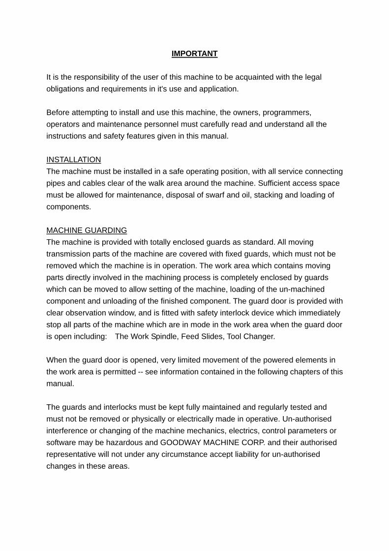
IMPORTANT It is the responsibility of the user of this machine to be acquainted with the legal obligations and requirements in it's use and application. Before attempting to install and use this machine, the owners, programmers, operators and maintenance personnel must carefully read and understand all the instructions and safety features given in this manual. INSTALLATION The machine must be installed in a safe operating position, with all service connecting pipes and cables clear of the walk area around the machine. Sufficient access space must be allowed for maintenance, disposal of swarf and oil, stacking and loading of components. MACHINE GUARDING The machine is provided with totally enclosed guards as standard. All moving transmission parts of the machine are covered with fixed guards, which must not be removed which the machine is in operation. The work area which contains moving parts directly involved in the machining process is completely enclosed by guards which can be moved to allow setting of the machine, loading of the un-machined component and unloading of the finished component. The guard door is provided with clear observation window, and is fitted with safety interlock device which immediately stop all parts of the machine which are in mode in the work area when the guard door is open including: The Work Spindle, Feed Slides, Tool Changer. When the guard door is opened, very limited movement of the powered elements in the work area is permitted -- see information contained in the following chapters of this manual. The guards and interlocks must be kept fully maintained and regularly tested and must not be removed or physically or electrically made in operative. Un-authorised interference or changing of the machine mechanics, electrics, control parameters or software may be hazardous and GOODWAY MACHINE CORP. and their authorised representative will not under any circumstance accept liability for un-authorised changes in these areas.
I
CONTENT
Page
1. Safety Precaution ............................................................................................... 1-1 1.1. General Safety Reminders ....................................................................... 1-1
1.2. Safety precaution for this machine............................................................ 1-2
1.3. Safety precaution for electricity................................................................. 1-4
1.4. Safety signs on this machine (for CE machine only)................................. 1-6
1.5. Potentially dangerous area ....................................................................... 1-8
1.6. Stopping the machine ............................................................................. 1-12
1.7. Check and maintenance of safety critical item........................................ 1-13
2. Overall description............................................................................................. 2-1 2.1. Machine description.................................................................................. 2-1
2.2. Specifications............................................................................................ 2-2 2.2.1. Machine Specifications ................................................................... 2-2
2.2.2. NC control Specification FANUC system 0i-TD model.................. 2-15
2.3. 0verall drawing series ............................................................................. 2-20 2.3.1. Belt type headstock model............................................................ 2-20
2.3.2. Built-in type headstock model ....................................................... 2-22
2.4. Main units ............................................................................................... 2-23
2.5. Power diagram of spindle motor ............................................................. 2-24
2.6. Dimension of spindle nose...................................................................... 2-27 2.6.1. Belt type headstock spindle nose ................................................. 2-27
2.6.2. Built-in type headstock spindle nose............................................. 2-37
2.6.3. Spindle nose of sub spindle .......................................................... 2-43
2.7. Tools information..................................................................................... 2-47 2.7.1. Turret head dimensional drawing.................................................. 2-47
2.7.2. Standard turret tooling system ...................................................... 2-51
2.7.3. Power turret tooling system .......................................................... 2-56
2.8. Tooling interference ................................................................................ 2-69 2.8.1. GS-2000/GS-3000 Tooling interference (Belt type headstock) ..... 2-69
2.8.2. GS-2000&GS-3000S/M/MS Tooling interference (Belt type headstock)
............................................................................................... 2-70
2.8.3. GS-2000&GS-3000Y/YS Tooling interference (Belt type headstock)
............................................................................................... 2-73

II
2.8.4. GS-2000 Tooling interference (Buil-in type headstock)................. 2-76
2.9. Travels and working area........................................................................ 2-82 2.9.1. GS-2000 Travels and working area (Belt type headstock)............ 2-82
2.9.2. GS-2000L Travels and working area (Belt type headstock) .......... 2-91
2.9.3. GS-3000 Travels and working area (Belt type headstock)............ 2-99
2.9.4. GS-3000L Travels and working area (Belt type headstock) ........ 2-107
2.9.5. GS-2000/L Travels and working area (Built-in type headstock) .. 2-115
2.10. Jaw information..................................................................................... 2-125
3. Preparation for reception................................................................................... 3-1 3.1. Requirements of the space and operating position................................... 3-1
3.2. Requirements of the foundation................................................................ 3-3 3.2.1. Foundation of belt type headstock model ...................................... 3-4
3.2.2. Foundation of built-in type model................................................... 3-6
3.2.3. Foundation work ............................................................................. 3-8
3.3. Installation and storage requirements of the environment ........................ 3-9
3.4. Requirements of power source ............................................................... 3-10 3.4.1. Power consumption ...................................................................... 3-10
3.4.2. Required input voltage.................................................................. 3-10
3.4.3. No fuse breaker of main power switch.......................................... 3-11
3.4.4. Wire size for power supply cable .................................................. 3-12
3.4.5. Check the supply voltage to the machine ..................................... 3-13
3.5. Oil requirement ................................................................................ 3-14 4. Handling、storage and installation .................................................................. 4-1
4.1. Handling and storage................................................................................ 4-1 4.1.1. Safety regulation moved by crane .................................................. 4-1
4.1.2. Safety regulation moved by fork lift................................................. 4-1
4.1.3. Wooden Transportation................................................................... 4-2
4.1.4. Transportation and lifting of machine .............................................. 4-3
4.1.5. Position of fixed plates.................................................................. 4-11
4.2. Installation of leveling bolt....................................................................... 4-12
4.3. Connection of power supply ................................................................... 4-13
4.4. Dismantle................................................................................................ 4-14
5. Preparation for commissioning......................................................................... 5-1 5.1. Machine level adjusting ............................................................................ 5-1
5.2. Cleaning and oil supply............................................................................. 5-3

III
5.2.1. Cleaning ......................................................................................... 5-3
5.2.2. Oil supply before starting operation ................................................ 5-3
5.3. Safety checking procedure ....................................................................... 5-4 5.3.1. Before Power ON:........................................................................... 5-4
5.3.2. After Power ON:.............................................................................. 5-4
6. Manual operation................................................................................................ 6-1 6.1. Safety device and warming-up.................................................................. 6-1
6.1.1. Safety device .................................................................................. 6-1
6.1.2. Warming-up .................................................................................... 6-3
6.2. Switch and button on the operation panel................................................. 6-4 6.2.1. Buttons and switches (for standard function) .................................. 6-6
6.2.2. Buttons and Switches (For optional functions).............................. 6-16
6.3. M.D.I. (Manual Data Input) Keyboard function........................................ 6-22
6.4. How to opening / closing the electrical cabinet door ............................... 6-23 6.4.1. Open the Electrical Cabinet Door ................................................. 6-23
6.4.2. Closing the Electrical Cabinet Door .............................................. 6-25
6.5. How to turn on the power........................................................................ 6-26
6.6. How to stop the machine ........................................................................ 6-27
6.7. Manual Data Input (operation.) ............................................................... 6-28
6.8. How to move the X, Y and Z-axis slides. ................................................ 6-31
6.9. How to perform the manual zero return .................................................. 6-34
6.10. How to operate the spindle ..................................................................... 6-35
6.11. How to operate the turret indexing.......................................................... 6-38
6.12. How to move the tailstock ....................................................................... 6-40
6.13. How to turn off the power........................................................................ 6-41
6.14. Procedure for the automatic operations.................................................. 6-42
7. Preparation of the actual machining................................................................. 7-1 7.1 Tooling (Procedure of fixing the tool) ........................................................ 7-1
7.1.1 How to mount the tool holder ............................................................. 7-2
7.1.2 How to fix a cutting tool ...................................................................... 7-2
7.1.3 LF-3004 turret head tool holder.......................................................... 7-3
7.1.4 LG-3004 turret head tool holder ....................................................... 7-13
7.1.5 LF-3104 turret head tool holder........................................................ 7-29
7.1.6 CR-3004 turret head tool holder....................................................... 7-40
7.1.7 Sockets ............................................................................................ 7-58

IV
7.2 Chuck (Jaw chuck & Collet chuck).......................................................... 7-65 7.2.1 How to mount the chuck................................................................... 7-65
7.2.2 Chucking pressure adjustment......................................................... 7-68
7.2.3 Allowable maximum chuck pressure and speed .............................. 7-69
7.2.4 Chuck gripping force ........................................................................ 7-70
7.2.5 Selection of chuck clamping direction .............................................. 7-72
7.2.6 Chuck interlock switch adjustment ................................................... 7-74
7.2.7 Boring soft jaws................................................................................ 7-75
8. Tool offset ........................................................................................................... 8-1 8.1. Determining start position of machining.................................................... 8-1
8.2. Manual OFS/SET method......................................................................... 8-5
8.3. The OFS/SET method of reference tool. ................................................ 8-11
8.4. Tool setter (option) .................................................................................. 8-16 8.4.1. Introduction................................................................................... 8-16
8.4.2. Tool setter construction................................................................. 8-17
8.4.3. Specification ................................................................................. 8-18
8.4.4. Operation...................................................................................... 8-22
8.5. Tool wear offset....................................................................................... 8-33
9. Machining (Actual Cutting)................................................................................ 9-1 9.1. Program registration ................................................................................. 9-1
9.1.1. Registration form MDI/LCD panel (Manual registration). ................ 9-1
9.2. Program Edit............................................................................................. 9-3
9.3. Program Check......................................................................................... 9-5
9.4. Automatic operation without workpiece .................................................... 9-7
9.5. Actual Cutting ........................................................................................... 9-9
9.6. Measuring cutting size and other operations during automatic cycle...... 9-10
9.7. Sub-spindle operation (OP.).................................................................... 9-12 9.7.1. Note for operating sub-spindle...................................................... 9-12
9.7.2. Sample program of sub-spindle operation .................................... 9-14
9.8. M72 Workpiece ejector out for sub-spindle model (OP.) ......................... 9-24 9.8.1. Command ..................................................................................... 9-24
9.8.2. Programming using M72............................................................... 9-25
9.9. C axis operation for power turret model (OP.)......................................... 9-26 9.9.1. Command of c axis ....................................................................... 9-26
9.9.2. Canned cycle for drilling ............................................................... 9-28

V
9.9.3. G84 / G184 Format....................................................................... 9-37
9.9.4. G07.1 (G107) Cylindrical Interpolation.......................................... 9-41
9.9.5. G12.1 (G112), G13.1 (G113) Polar Coordinate Interpolation ........ 9-48
9.10. Power Turret Operation (OP.) ................................................................. 9-52 9.10.1. Rotary Tool holder Direction.......................................................... 9-52
9.10.2. Command of Power Turret............................................................ 9-53
9.10.3. How to offset Rotary Tool holder ................................................... 9-54
9.11. Y-AXIS operation (OP.) ........................................................................... 9-58 9.11.1. Polar coordinate interpolation on c-x plane................................... 9-58
9.11.2. Cylindrical interpolation................................................................. 9-62
10. Setting and Adjustment ............................................................................... 10-1 10.1. Hydraulic pressure setting and adjustment............................................. 10-1
10.2. Supplying Oil to the Lubricating Oil Tank ................................................ 10-6
10.3. Belts of Spindle Adjustment (Belt type headstock model) ....................... 10-7
10.4. Timing Belt Adjustment (Belt type headstock model) .............................. 10-9
10.5. Main Spindle Center Adjustment........................................................... 10-10
10.6. Turret Adjustment.................................................................................. 10-11
10.7. Tapered gibs adjustment....................................................................... 10-12
10.8. Tailstock Adjustment ............................................................................. 10-13
10.9. Backlash Adjustment ............................................................................ 10-14 10.9.1. Backlash Measurement .............................................................. 10-14
10.9.2. Input of backlash compensation value........................................ 10-16
10.10. Reference Position Adjustment .......................................................... 10-18
10.11. Machine Level Check ......................................................................... 10-20
11. Maintenance ................................................................................................. 11-1 11.1. General notes ......................................................................................... 11-1
11.2. Maintenance cycle .................................................................................. 11-2 11.2.1. Daily maintenance ........................................................................ 11-2
11.2.2. Weekly maintenance .................................................................... 11-2
11.2.3. Half-yearly maintenance ............................................................... 11-2
11.2.4. Yearly maintenance ...................................................................... 11-2
11.3. Lubrication system.................................................................................. 11-3
11.4. Hydraulic system .................................................................................... 11-5
11.5. Chuck ..................................................................................................... 11-6 11.5.1. Lubrication .................................................................................... 11-6

VI
11.5.2. Disassembly and cleaning ............................................................ 11-6 11.6. Milling axle(For power-driven turret) .................................................. 11-7
11.7. Oil maintenance chart............................................................................. 11-9
11.8. Replacement of battery (For FANUC control) ....................................... 11-10
11.9. Cleaning of heat-exchanger.................................................................. 11-12
11.10. List of Maintenance Check Point........................................................ 11-13 11.10.1. Main spindle ........................................................................... 11-13
11.10.2. Main spindle drive unit ............................................................ 11-15
11.10.3. Hydraulic unit.......................................................................... 11-16
11.10.4. Main turret slide ...................................................................... 11-16
11.10.5. Slide cover.............................................................................. 11-19
11.10.6. Lubricating unit ....................................................................... 11-19
11.10.7. Coolant unit ............................................................................ 11-20
11.10.8. NC control unit........................................................................ 11-20
11.10.9. Other ...................................................................................... 11-21
11.10.10. Optional accessoriesl accessories.......................................... 11-22
12. Trouble shooting .......................................................................................... 12-1 12.1 Alarms and remedies.............................................................................. 12-1
12.1.1 PCDGN (PC diagnosis) ................................................................ 12-1
12.2 LCD not display ...................................................................................... 12-4
12.3 Remedies when alarm is not indicated ................................................... 12-5
12.4 Cycle start can not execute..................................................................... 12-6
12.5 Main spindle hydraulic chuck not work ................................................... 12-7
12.6 Tailstock is not works or (Sub-spindle chuck is not works) ..................... 12-8
12.7 Coolant pump can not execute ............................................................... 12-9
12.8 Lubrication system out of order............................................................... 12-9
12.9 Reset reference point ( when change battery ) ..................................... 12-10
Appendix A.................................................................................................................A 1 ALARM MESSAGE (For FANUC 0i-TD Controller).......................................A-1
1-1 Various alarms and trouble shutting ...................................................A-1
2 Turret resetting procedure...........................................................................A-13 Appendix B G、M、T、K- Code function for 18I/0I ................................................B
1 G-Code and M-Code function .......................................................................B-1 1-1 G-Code function.................................................................................B-1
1-2 M-Code function.................................................................................B-5

VII
2 T-Code function.............................................................................................B-7
3 K-Code function ............................................................................................B-9
Appendix C TAILSTOCK ...........................................................................................C 1 Programmingable Tailstock Offset Setting and Operation.............................C-1
1.1 Adjusting of the tailstock quill pressure ..............................................C-9
2 Operation of Sever Tailstock .......................................................................C-10 2.1 Description for setting the tailstock...................................................C-10
2.2 Instructions description: ...................................................................C-12
2.3 Program example.............................................................................C-14
Appendix D OPTIONAL TOOL HOLDERS................................................................D D. Optional tool holders .....................................................................................D-1
D-1 Tool holders for CR-3004 turret head .................................................D-1
D-2 Tool holders for LF-3004 turret head................................................D-11
D-3 Tool holders for LG-3004 turret head ...............................................D-18
Appendix E ...............................................................................................................E Questions & Answers of CEN-03 Type lubrication system ................................E-1


1-1
1. Safety Precaution 1.1. General Safety Reminders
1. The operator to operate the machine should be properly trained.
2. Operation of the machine should not contradict with the instructions in operation
manual.
3. The area where the machine is to be used should be well lit.
4. Keep the machine and work area neat, clean and orderly.
5. Do not store any articles around the machine that will impede the safety of the
operation.
6. The operator should wear safety shoes to protect the feet and avoid slipping.
7. The operator operating the machine should wear safety glasses to protect the
eyes.
8. Do not work with long hair that can be caught injury by the machine, tie it up at
the back or wear a hat.
9. Do not operate the machine with gloves on.
10. Necklace and necktie should be taken off or put inside of clothes before
operating the machine.
11. After drinking alcohol or if the body is not in good condition, do not operate or
maintain the machine.
12. Do not clamber on to the machine, use the ladder if necessary.
13. Do not touch the turning part of the machine with hands or body.
14. Do not touch the turning part of the machine with handtools or the other article.
15. Do not open the electrical cabinet, wire terminal or any other protection covers.
16. Do not use screwdriver or handtools to hammer or pry.
17. Do not use air compressor to clean the machine, electrical cabinet or NC
control.
18. Do not pull the chip by hand.
19. Do not wear magnetic accessory, which could influence the control unit of the
machine.

1-2
1.2. Safety precaution for this machine
This machine is provided with a number of safety devices to protect personal and
equipment from injuries and damages. So, the operator must fully under stand
what special precautions to take.
It is assumed that the operator has been properly trained, has the requisite skill
and is authorized to operate the machine. The following safety regulations which
should be observed:
1. Before operating the machine, be sure people who are not operating the machine
are kept away from the area which may caused danger during machine running.
2. Before operating the machine the operation manual should be peruse contact the
manufactory for more details, if anything is unclear.
3. Please follow the instructions of the operation manual to check and maintain the
machine.
4. Don't take off any protection covers or interlock functions.
5. Don't take off any warning plate on the machine, if discard or ambiguous please
contact with manufacturer.
6. Before starting the machine, be sure of the ways to can stop the machine in case
of emergency.
7. Before starting the machine, be sure which function will be executed after
pressing the push button on the machine.
8. Be sure the illumination of halogen lamp exceeds 500 lux. Change the lamp if it is
fail or broken.
9. Don't touch the tools and workpiece while the spindle motor and feed motors are
running.
10. Don't use obtuse or damaged tools.
11. Don't clean or load/unload the workpiece while the spindle motor and feed motors
are running.
12. Don't open the door while the spindle motor is running.
13. Before operating the machine, be sure the workpiece is properly clamped in the
hydraulic chuck and running in a balance condition.
14. Be sure the tools are fixed in correct way fastened tightly.

1-3
15. Don't use the coolant with a low flash point.
16. Before starting the program, be sure there is no mistake in the program with the
Dry Run function.
17. Use the quill to help clamp long workpieces.
18. Don't release the quill before the hand catches the long shaft workpiece while the
spindle is stopped.
19. If the weight of workpiece is over 10 kg then handling equipment should be used
to assist loading and unloading.
20. Please follow the operation manual to remove the hydraulic chuck while using 2
centers to clamp the workpiece.
21. Don't cut the workpiece from spindle side to quill side while using two centers to
clamp the workpiece between the spindle and quill, it may caused the center quill
to retract and drop out the workpiece.
22. Before cutting the workpiece, be sure of the cutting condition between tools and
workpiece.
23. Please don't try to use the hands to stop the spindle while it has not come to a
complete stop.
24. Don't lean on the machine or operation panel which may caused the wrong
operation.
25. Please don't try to maintain the machine without proper training or permission.
26. There should be a support for the shaft workpiece extending beyond the chuck
cylinder, during operation, all people should keep away from this area.
27. The Max. speed is 3,000 rpm (12" chuck) or 2,500 rpm(15" chuck) , don't run
the spindle at Max. speed if the spindle has not rotated in a long period.
28. There is a limitation in the hydraulic chuck pressure and spindle speed, it
depends on the chuck, the weight and measurement of workpiece.
29. Don't use this machine to cut Magnesium material.
30. Don't use this machine in an explosive environment.
31. Replacement is necessary if coolant deterioration occurs.

1-4
1.3. Safety precaution for electricity
1. The required electrical source for the machine is 220V AC 3 Phase.
2. If the power supply voltage of the building where the machine is installed is
higher than above voltage, transformer shall be used to get required voltage.
3. Enough space should be reserved to open the electrical cabinet for
maintenance. There is an earth plate inside of the cabinet which should be
connected with the earth line outside of the machine.
4. All maintenance and adjustment related with the electrical control should be
executed by properly trained personal.
5. Before opening the electrical cabinet, the main power should be turned off.
6. Before replacing the electrical elements, be sure the power has been turned off.
7. To avoid turning the power on during the maintenance, put a warning plate in
front of the machine.
8. Don't remove the connections which are related with the safety interlock
functions.
9. Before operating the machine, be sure to peruse all warning plates and wire
connection.
10. During the maintenance, be sure the power has been turned off and use tools
with insulated material.
11. Replace any wires only if corresponding with the original standard specifications
and colors.
12. Before turning on the power after completing the maintenance, be sure there is
nobody on the machine for any operation.
13. Install an earth connection and connect to the machine, if there is no earth
connection in public electrical source.
14. Don't put any article ( food .... ) inside of the electrical cabinet and on operation
panel.

1-5
15. Electric leakage or a malfunction may occur if liquid enters electric parts of the
machine. Do not splash the machine whit liquid when clean, etc.
16. Make sure to contact GOODWAY before modifying the control unit and circuit.
Follow our instructions to avoid serious damage to the control system.
17. High voltage current flows inside the cabinet and operation panel. Receiving an
electric shock may result in personal injury or death. The qualified servicing
personnel always keep the cabinet keys and opens the cabinet door if need. In
case of opening the cabinet door and removing the operation panel cover,
always the qualified servicing personnel need to do them.
18. Keep the control unit away from any shocks or vibrations.
19. Do not give strong force to the connecting parts.
20. Please do not lean against the operation panel.

1-6
1.4. Safety signs on this machine (for CE machine only)
Fig. 1.4.1

1-7
Fig. 1.4.2

1-8
1.5. Potentially dangerous area
Under normal operation the area ( see drawing 1.5.1 ) will not caused any
dangerous but the area which have rotating part and electrical elements might be
dangerous under abnormal operation.
Fig. 1.5.1

1-9
AREA POTENTIAL HAZARDS UNDER NORMAL OPERATING.
1 The belt is running to cause the entanglement hazard.
2 Touch the Z axis motor with high voltage to cause the electrical hazard.
3 The saddle and turret head is moving to cause the crushing and impact
hazard
4 Touch the X axis motor with high voltage to cause the electrical hazard.
5 Touch the Y axis motor with high voltage to cause the electrical hazard.
6 Touch the Z2 motor with high voltage cause the electrical hazard.
7 Chain and wheel can cause hand hazard.
8 Touch the LCD with high voltage to cause the electrical hazard.
9 The sub-spindle or tailstock is moving to cause the crushing and impact
hazard.
10 The chuck is rotating to cause the impact hazard and ejection hazard of
workpiece.
11 The turret is rotating to cause the impact hazard and cause the stabbing
hazard by tools.
12 The chuck is rotating to cause the impact hazard and ejection hazard of
workpiece.
13 Touch the lubricating pump with high voltage to cause the electrical hazard.
14 Touch the spindle motor with high voltage cause the electrical hazard.
15 The splashing plate is moving to cause the crushing hazard.
16 Touch the coolant pump with high voltage to cause the electrical hazard.
17 Touch hydraulic pump with high voltage to cause the electrical hazard.
18 Open the main switch or cabinet to cause the electrical hazard.

1-10
OPERATING POTENTIAL HAZARDS
When using the machine be FULLY AWARE of the following operating hazards
detailed under the following instructions:
A) Problem of the skin caused by oil Problem of the skin may be produced by continuous contact with oil;
particularly with straight cutting oils, but also with soluble oils.
The following precautions should be taken:
1. Avoid unnecessary contact with oil.
2. Wear protective clothing.
3. Use protective shields and guards.
4. Do not wear oil soaked or contaminated clothing.
5. After work thoroughly wash all parts of the body that have come into
contact with oils.
B) Safe operation of lathe chucks Where details of operating speeds and of maximum recommended operating
speeds are supplied these are intended only as a guide. Such details must
be regarded as for general guidance only for the following reasons:
They apply only to chucks in sound condition.
If a chuck has sustained damage, high speeds may be dangerous. This
applies particularly to chucks with gray cast iron bodies wherein fractures
may occur.
The gripping power required for any given application is not known in
advance.
The actual gripping power being used for any given application is not known
by the chuck manufacturer.
There is the possibility of the workpiece becoming insecurely gripped due to
the influence of centrifugal force under certain conditions. The factors
involved include:
(a) Too high a speed for a particular application.
(b) Weight and type of gripping jaws if non-standard.
(c) Radius at which gripping jaws are operating.
(d) Condition of chuck - inadequate lubrication.
(e) State of balance.
(f) The gripping force applied to the workpiece in the static condition.

1-11
(g) Magnitude of the cutting forces involved.
(h) Whether the workpiece is gripped externally of internally.
Careful attention must be paid to these factors. As they vary with each
particular application, a manufacturer cannot provide specific figures for
general use, the factors involved being outside his control.
IF IN DOUBT CONTACT THE GOODWAY MACHINE CO.
TECHNICAL SALES DEPARTMENT.

1-12
1.6. Stopping the machine
The machining cycle can be stopped in a variety of ways under normal conditions
for various reasons, such as checking the surface finish of the workpiece etc., in
the normal manner of machining. This can be a achieved by a variety of methods
as detailed below.
OBJECTIVE PROCEDURE RESULT
1. To stop machine at
any point.
a) Depress 'Feed hold'
Button then the led
lamp of “Feed hold”
lights up.
All axes motions cease, unless thread cutting is active.
2. To resume cycle .
a) Depress 'Cycle Start'
button on control
panel.
Machine operation continues.
3. To resume
operation after any
programmed stop
has been initiated.
a) Move the curser to
desired start block.
b) Press “cycle start”
button.
The lamp above 'cycle start' button should illuminate. The cycle should continue.
4. Emergency Stop
If a potentially dangerous condition begins, the machine can be stopped
most easily by depressing the large red push button. This suspends all
active commands. The spindle stops and all machine motion ceases. If,
you want to start the machine, please referent the operating manual. 5. Sliding Guard
The sliding guard is interlocked during automatic operation by means of a
solenoid operated shot bolt. This is a safety device to prevent the guard
being opened during cycle.
When the spindle comes to rest the shot bolt solenoid releases allowing
the guard to be opened. To resume automatic operation close the guard
and push cycle start. This will remove the interrupt condition, the spindle
will start and the cycle will continue immediately.

1-13
1.7. Check and maintenance of safety critical item
It is important to make sure some of the critical safety devices are well
functioned.
We strongly recommend that the function of following items to be checked prior to
start machining work each day. If they are not functioned, maintenance will be
required. 1. Emergency stop switch on control panel.
2. Door interlock switch.
3. Cabinet door interlock switch.
4. Emergency stop switch on chip conveyor.
Maintenance procedure. 1. Check wiring.
2. Check switch, replace if necessary.
3. contact local agency.

2-1
2. Overall description
2.1. Machine description
The machine is a numerically controlled lathe of horizontal configuration. Both
axes are driven by A.C. servo motors. The main slideways are induction hardened
and ground. Lubrication of all surfaces is automatic. Manual jogging of the slides is
effected using push button or handwheel.
The machine is equipped with auto. hydraulic clamp, it's main performance is
chuck. Though the tailstock can clip workpiece auxiliary, user must not cut
workpiece from main spindle side to tailstock in Z-axis direction. Because that will
affect the precision or cause even hazard of projection of workpiece.
The machine has two operating models, i.e. AUTO, MANUAL, each has their own
subfunction. Please don't change randomly operating model during cutting.
Before operating the machine, please peruse the instruction manual by the NC
control manufacture and the operation manual provide by the manufacturer.
With regarding to cutting fluid, lubricant, hydraulic oil, all are contained in
containers. the throwing away liquid depends on the local low to deal with.
Note 1. The material which can be machined in the machine are: Iron, casting iron,
aluminum, copper, stainless steel and alloy steel. Please don't machine
graphite, wood which may caused dust, and plastic, magnesium which may
caused toxic or burning.
Note 2. Don't operate the machine without authorization.
2-2
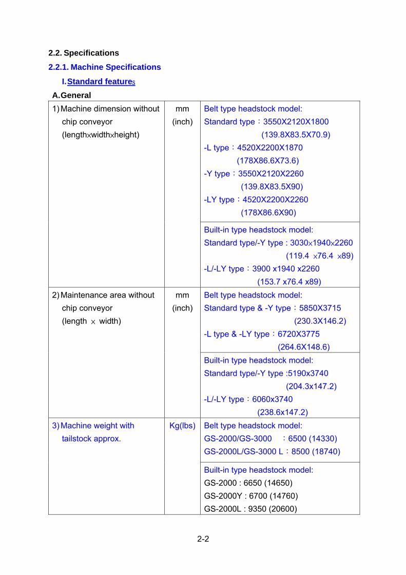
2.2. Specifications 2.2.1. Machine Specifications
I. Standard features A. General
Belt type headstock model: Standard type:3550X2120X1800 (139.8X83.5X70.9) -L type:4520X2200X1870 (178X86.6X73.6) -Y type:3550X2120X2260 (139.8X83.5X90) -LY type:4520X2200X2260 (178X86.6X90)
1) Machine dimension without chip conveyor (length×width×height)
mm (inch)
Built-in type headstock model: Standard type/-Y type : 3030×1940×2260 (119.4 ×76.4 ×89) -L/-LY type:3900 x1940 x2260 (153.7 x76.4 x89) Belt type headstock model: Standard type & -Y type:5850X3715 (230.3X146.2) -L type & -LY type:6720X3775 (264.6X148.6)
2) Maintenance area without chip conveyor (length × width)
mm (inch)
Built-in type headstock model: Standard type/-Y type :5190x3740 (204.3x147.2) -L/-LY type:6060x3740 (238.6x147.2) Belt type headstock model: GS-2000/GS-3000 :6500 (14330) GS-2000L/GS-3000 L:8500 (18740)
3) Machine weight with tailstock approx.
Kg(lbs)
Built-in type headstock model: GS-2000 : 6650 (14650) GS-2000Y : 6700 (14760) GS-2000L : 9350 (20600)

2-3
GS-2000LY : 9500 (20930)
4) Noise level measured at 1.6M high from floor and 1.0M aside from machine
dBA Less than 78
B. Capacity
i. Belt type headstock model 1) Chuck dia. inch 8 /10 / 12 / 15
2) Swing over saddle mm (inch)
ψ800 (ψ31.5)
3) Standard turning dia. mm (inch)
Standard turret:ψ250(9.8) Power driven turret:ψ278 (10.9)
4) Swing over front door mm (inch)
ψ630 (24.8)
5) Max. turning dia mm (inch)
Standard turret:ψ570 (22.4) Power driven turret:ψ440 (17.3)
6) Max. turning length mm (inch)
Standard type : 780 (30.7) -L type: 1530 (60.2) GS-3600/L:746 / 1496 (29.4/58.9)
7) Max. workpiece weight Kg(lbs) 340 (749.6)
8) Distance between
main spindle nose and
turret face
Refer to 2.9Travels and working area
9) Distance between
main spindle nose and
sub-spindle nose (op.)
Refer to 2.9Travels and working area
ii. Built-in headstock model 10) Chuck dia. inch 8 /10 / 12
11) Swing over saddle mm (inch)
ψ750 (29.5)
12) Standard turning dia. mm (inch)
ψ280 (11)
13) Swing over front door mm (inch)
ψ630 (24.8)
14) Max. turning dia mm ψ400 (15.7) (Built-in turret)

2-4
(inch) ψ460 (18.1)(Belt type turret) GS-2000 / L with GS-2000 Turret: 8” Chuck:691 ( 27.2) / 1441 ( 56.7) 10” Chuck:664 ( 26.1) / 1414 ( 55.7) 12” Chuck:595 ( 23.4) /1345 ( 53)
15) Max. turning length mm (inch)
GS-2000 / L with GS-200 Turret: 8” Chuck:800 ( 31.5) / 1550 ( 61) 10” Chuck:779 ( 30.7) /1 529 ( 60.2) 12” Chuck:710 ( 28) / 1460 ( 57.5)
16) Max. workpiece weight Kg(lbs) 330 (7295)
17) Distance between
main spindle nose and
turret face
Refer to 2.9Travels and working area
18) Distance between
main spindle nose and
sub-spindle nose (op.)
Refer to 2.9Travels and working area
C. Main Spindle (Belt type)
1) Designation rpm direct designation
GS-3300 GS-3600
2) Chuck size inch 12 15
3) Spindle nose A2-8 A2-11
4) Hole through spindle mm (inch)
ψ101 (ψ4)
ψ121 (ψ4.8)
5) Hole through draw tube mm (inch)
ψ90.5 (ψ3.6)
ψ105.5 (ψ4.2)
6) Front bearing inner dia. mm (inch)
ψ140 (ψ5.5)
ψ160 (ψ6.3)
7) Spindle speed (High winding )
rpm 3000 2500
8) Speed range rpm 30~3000 25~2500
Constant output area rpm 403~2415 261~1567 Constant torque area rpm 30~403 25~261
9) Spindle speed (Low winding )
rpm 750 650

2-5
10) Speed range rpm 10~750 7~650
Constant output area rpm 280~700 182~454 Constant torque area rpm 10~280 7~182
11) Drive motor
continuous/30min. rating
KW (HP) αP40/6000i (FANUC) 18.5 (25.2) / 22 (29.9)
GS-2000 GS-2600 GS-2800
12) Chuck size inch 8 10 10
13) Spindle nose A2-6 A2-8 A2-8
14) Hole through spindle mm(inch) ψ66 (ψ2.6)
ψ76 (ψ3)
ψ90 (ψ3.5)
15) Hole through draw tube mm(inch) ψ52.5 (ψ2.1)
ψ65.5 (ψ2.6)
ψ75.5 (ψ3)
16) Front bearing inner dia. mm(inch) ψ100 (ψ3.9)
ψ120 (ψ4.7)
ψ130 (ψ5.1)
17) Spindle speed (High speed winding )
rpm 4800 4000 3500
18) Speed range rpm 48~4800 40~4000 35~3000
Constant output area rpm 460~2760 383~2300 335~2100 Constant torque area rpm 48~460 40~383 35~335
19) Spindle speed (Low speed winding )
rpm 1200 1000 875
20) Speed range rpm 12~1200 10~1000 10~875
Constant output area rpm 330~800 267~667 233~583 Constant torque area rpm 12~330 10~267 10~233
21) Drive motor
continuous/30min. rating
KW (HP) αP30/6000i (FANUC) 15 (20.4) / 18.5(25.2)
22) Center height from floor mm(inch) 1000(39.4)
23) Standard chuck cylinder operation power = piston thrust
8" Chuck max. at 25kg / cm2 (355psi) ----3985kgf * at 90% efficiency (KITAKAWA) min. at 4kg / cm2 (55psi) ------- 580kgf * at 90% efficiency 10" Chuck max. at 25kg / cm2 (355psi)------4455kgf *at 90% efficiency (KITAKAWA) min. at 4kg / cm2 (55psi)------713kgf * at 90% efficiency 12" Chuck max. at 25kg / cm2 (355psi)---- 5670kgf *at 90% efficiency (KITAKAWA) min. at 4kg / cm2 (55psi)-------907kgf *at 90% efficiency 15" Chuck max. at 40.8kg / cm2 (580psi)----11471kgf *at 90% efficiency

2-6
(KITAKAWA) min. at 4kg / cm2 (55psi)------1128kgf *at 90% efficiency
24) Safety interlock for chucking failure D. Main Spindle (Built-in type)
1) Designation rpm direct designation 2) Number of steps 1 step (1:1 Direct drive)
GS-2000 GS-2600 GS-2800 3) Chuck size inch 8 10 10 4) Spindle nose A2-6 A2-8 A2-8 5) Hole through spindle mm(inch) ψ62
(ψ2.4) ψ77 (ψ3)
ψ92 (ψ3.6)
6) Hole through draw tube mm(inch) ψ52.5 (ψ2)
ψ65.5 (ψ2.6)
ψ76 (ψ3)
7) Front bearing inner dia. mm(inch) ψ100 (ψ3.9)
ψ120 (ψ4.7)
ψ130 (ψ5.1)
8) Spindle speed rpm 4800 4000 3500 9) Speed range rpm 48~4800 40~4000 35~3000 Constant output area rpm 760~4800 500~4000 438~3500 Constant torque area rpm 48~760 40~500 35~438 10) Drive motor continuous/30min. rating
KW (HP) BiI200S/6000 (FANUC) 15 (20.4) / 18.5(25.2)
Center height from floor mm(inch) 1000(39.4)
25) Standard chuck cylinder operation power = piston thrust
8" Chuck max. at 25kg / cm2 (355psi) ----3985kgf * at 90% efficiency (KITAKAWA) min. at 4kg / cm2 (55psi) ------- 580kgf * at 90% efficiency 10" Chuck max. at 25kg / cm2 (355psi)------4455kgf *at 90% efficiency (KITAKAWA) min. at 4kg / cm2 (55psi)------713kgf * at 90% efficiency 12" Chuck max. at 25kg / cm2 (355psi)---- 5670kgf *at 90% efficiency (KITAKAWA) min. at 4kg / cm2 (55psi)-------907kgf *at 90% efficiency
26) Safety interlock for chucking failure

2-7
E. Saddle
1) Configuration 30° angle bed + flat saddle
X axis AC 2.7(3.7) (α12B/4000is) AC4.5 (6)(α22B/4000is) (Built-in headstock)
Z1 axis AC 4.5(6) (α22/4000is) X:AC 4.5(6.1) (α22B/4000is) Y:AC 4 (5.4) (α22B/3000i)
Y axis (op)
AC4.5(6) (α22B/3000i) (Built-in headstock)
2) Feed motors
Z2 axis (op)
KW (HP)
AC 3 (4) (α12/3000i)
X axis 1409 1410.6 (Built-in headstock)
Z1 axis Standard type & -L type:1409 1410.6 (Built-in headstock) X:1409 Y:1761
Y axis (op)
961.6 (Built-in headstock)
3) Thrust
Z2 axis (op)
kgf
Standard type/-L type :768/640 769.4 (Built-in headstock)
X axis 300 (11.8) 280 (11) (Built-in headstock)
Z1 axis Standard type/-L type 780 (30.7)/1530 (60.2) 800 (31.5)/1550(61) (Built-in headstock)
Y axis (op)
X/Y:280 (11)/100 (3.9) 100(3.9) (Built-in headstock) 6” Chuck: Standard type :750(29.5) -L type:1500(59.1) 8” Chuck: Standard type :680(26.8) -L type:1430(56.3)
4) Effective slide
travel
Z2 axis (op)
mm (inch)
Built-in headstock GS-2000/L:760(29.9)/1510(59.4).sub-spindleGS-2000/L:740(79.1)/1490( 58.7)..tailstock

2-8
X axis 30 (1181.1) Z1 axis 30 (1181.1) Y axis (op)
10 (393.7)
5) Rapid traverse
Z2 axis (op)
m/min(ipm)
30 (1181.1)……............for sub-spindle 7 (275)..........................for tailstock
X axis ψ36 ( 1.42) XP 10 (0.4) Z1 axis Standard type :ψ36(1.42) X P10 (0.34)
-L type:ψ40(1.57) X P10 (0.34) Y axis (op)
ψ32 (1.26) × P8 (0.3)
6) Ball screw dia. /
pitch
Z2 axis (op)
mm (inch)
Standard type :ψ36(1.42) X P10 (0.34) -L type:ψ40(1.57) X P10 (0.34)
F. Standard Turret
1)Turret head type Drum 2)No. of tool stations St. 12 3)Tool size square □25 (1) □25 (1) round
mm (inch) φ40 (1.5) φ50 (2)
4)Index motor KW (HP) AC 1.8 (2.4) (β12/3000is)
AC 1.2 (1.6) (β8/3000is)
5)Indexing drive with direction logic
gear + servo motor
6)Indexing time * measured when hydraulic fluid gets 50°C for one station approx. 0.3 0.3 for 180 degree approx.
sec. 0.5 0.8
7)Curvic coupling dia. mm (inch)
φ250 (9.8) φ250 ( 9.8)
8)Turret clamping force Kgf (lbs)
5495 (12114) 3993( 8803)
G. Hydraulic Unit
1) Pump motor KW(HP) AC 1.5 (2) ( 4 poles)
2) Tank capacity L Belt type headstock model:45 Built-in type headstock model:30

2-9
3) Line pressure in normal
cutting kg/cm2
(psi) 35 ( 498)
4) Pump delivery 50Hz / 60Hz liters/min 21/25
5) Pressure switch for power
fault
H. Coolant (Cutting fluid) Unit
1) Pump motor KW(HP) 0.55 (0.75)
2) Tank capacity L GS-2000/GS-3000 Series:280 GS-2000L/GS-3000L Series:360
I. Lubrication unit 1) Pump motor KW(HP) 0.012 (0.016) AC 110V
2) Tank capacity L 2.5
3) Dispose volume c.c./min 135
4) Max. delivery pressure kg/cm2 15
J. Machine Work Light 1pc 13 watts AC 220V
K. Splash Guards With Safety Door Interlock L. Environment Conditions 1) Power supply V AC 200/220 + 10% to -15%
AC 380/415/440/460/480 ( Through a transformer to AC 220 volts)
2) Total power connected KVA 40 Refer to CH3.4.1 for more details.
3) Temperature ∘C 10 to 35
4) Humidity relative less than 75%

2-10
II. Optional Attachments A. Interface for LNS/SAMECA Bar feed * Control voltage DC24 volts
B. Tailstock (Programmable type)
1)Quill center
GS-2000 Series:MT#3: built-in center MT#4:Live center GS-3000 Series:MT#4: built-in center MT#5:Live center
2)Quill dia. mm(inch)
MT#3:ψ85(3.3) MT#4:ψ85(3.3) MT#4:ψ110 (4.3) MT#5:ψ120 (4.7)
3)Effective quill travel mm(inch)GS-2000 Series:120(4.7) GS-3000 Series:150(5.9)
4)Effective slide travel mm(inch)GS-2000/L Series: 780(30.7) / 1530(60.2)GS-3000/L Series:650(25.6) /1400(55.1)
5)Quill thrust kgf
MT#3:69.4~260 MT#4:69.4~260 (Live center) MT#4:109~410 (built-in center) MT#5:163~612
C. Tailstock (Servo type)
1)Quill center MT-3: built-in center MT-4:Live center
2)Quill dia. mm(inch)MT#3:ψ80(3.2) MT#4:ψ80(3.2)
3)Effective quill travel mm(inch) N/A
4)Effective slide travel mm(inch)GS-2000/L:740(29.1) /1490(58.7) GS-3000/L:700 (27.6)/1450 (57.1)

2-11
D. Power-driven turret (Belt type) 1)Turret head type Drum 2)No. of tool stations st 12 3)Tool size square 25 ( 1) round
mm (inch) φ40 (1.5)
4)Index motor KW (HP) AC 1.2 (1.6) (β8/3000is) 5)Live tooling shank size ER-32 6)Live tooling RPM range rpm 40~4000
7)Live tooling drive motor AC 4.5(6.1)
(α22/4000is) 8)Indexing drive with direction logic
gear + servo motor
9)Indexing time * measured when hydraulic fluid gets 50°
C for one station approx. sec. 0.2 for 180 degree approx. sec. 1.0 10)Curvic coupling dia. mm(inch) φ220 (8.7) φ280(11) 11)Turret clamping force Kgf(lbs) 3956.4(8722) 3950(8700)
E. Power-driven turret (Built-in type)
1)Turret head type Drum 2)No. of tool stations st 12 3)Tool size square 25 ( 1) round
mm (inch) φ50 (1.5)
4)Index motor KW (HP) AC 1.2 (1.6) (β8/3000is) 5)Live tooling shank size ER-40 6)Live tooling RPM range rpm 60~6000 7)Live tooling drive motor KW (HP) AC 5.5(7.5)/3.7(5) (BiI100SS/12000) 8)Indexing drive with direction logic
gear + servo motor
9)Indexing time * measured when hydraulic fluid gets 50°C for one station approx. sec. 0.2 for 180 degree approx. sec. 1.0 10)Curvic coupling dia. mm(inch) φ250 (9.8) 11)Turret clamping force Kgf 3993

2-12
F. Sub-spindle
1) Designation rpm direct designation
2) Chuck size Inch 6 8
3) Hole through spindle mm(inch) φ46 (1.81) φ55 ( 2.17)
4) Hole through draw tube mm(inch) φ39 (1.54) φ46 (1.81)
5) Front bearing inner dia. mm(inch) φ80 (3.15) φ100 (3.94)
6) Spindle nose A2-5 A2-6
7) Drive motor continuous/ rating
KW (HP)AC5.5 (7.5)/ 7.5 (10.2)
(BiI 112M/15000i)
AC18.5(25.2)/ 22 (29.9)
(BiI 112L/15000i)
8) Speed range rpm 60~6000 48~4800
Constant output rpm 1500~6000 ----
Constant torque rpm 60~1500 48~4800
9) KITAKAWA standard
chuck cylinder operation power = piston thrust
6" Chuck max. at 25kg / cm2 (355psi)----1971kgf * at 90% efficiency (KITAKAWA) min. at 4kg / cm2 (55psi)---- 315kgf * at 90% efficiency 8" Chuck max. at 25kg / cm2 (355psi)---- 3623kgf *at 90% efficiency (KITAKAWA) min. at 4kg / cm2 (55psi)------ 580kgf * at 90% efficiency
G. Chip conveyor * without chip collection bin to be supplied locally.
1) Drive motor KW(HP ) 0.2(0.25) AC 220 V(4P)
2) Outlet height from floor mm(inch)Belt type headstock: 1400(55.1) Built-in headstock: Standard/-L:1300 (51.2)/1720(67.7)
H. C Axis (Belt type headstock) 1)Type Cf axis 2)Drive Motor GS-3000:
α4/5000is GS-2000: α2/5000i
3)Output kW(HP) 1 (1.3) 0.75(1) 4)Torque Nm 4 2 5)Center type Straight Taper 6)Spindle drive ratio 1:120 1:120

2-13
I. Steady rest (Manual type) 1)Type C-from Manual 2)Max. work piece size mm(inch) 60~200 (2.4~7.9)
J. Steady rest (Hydraulic type) 1)Type Hydraulic SLU-3.2 SLU-3 2)Max. work piece size mm(inch) 30~180
(1.9~7.1)50~200 (2~7.9)
12~152 (0.5~6)
K. Tool tip probing touch sensor
L. Automatic call up of alternate tool station
M. Automatic measuring system
N. Robot interface type of Robot shall be specified
O. Auto. doors
P. Air blow off for chuck
Q. Spindle locking device (Disk brake type) * This is to facilitate chuck mounting only in set-ups.
R. Cycle stop alarm light and buzzer

2-14
III. .Suggestive Equipment:(prepared by user) A. Rake removing chip(without chip conveyor)

2-15
2.2.2. NC control Specification FANUC system 0i-TD model * The specifications and descriptions given herein are subject to change without
previous notice. I. Standard Features
A. Controlled Axis
1) Controlled axis 2~5 axis (X ,Z1 ,ZB ,Y ,C ) simultaneous Manually 1 axis at a time
2) Least input increment X,Z,ZB and Y axis
0.001mm 0.0001"
C axis 0.001∘ 3) Least command increment X ,Y axis 0.0005mm/p (0.001mm where radius
programming on X axis is selected) Z axis 0.001mm C axis 0.001∘ 4) Max. programmable dimension /-9999.999mm +/-999.9999"
B. Interpolation Functions
1)Positioning G00 2)Linear interpolation G01 3)Multi-quadrant circular interpolation G02 Clockwise (CW)
G03 Counterclockwise (CCW)
C. Feed Functions 1) Rapid traverse varies with machine models 2) Rapid traverse override F0 , 25%, 50% and 100% 3) Tool manual pulse generator 4) Manual continuous feed 1 axis at a time 5) Cutting feed rate G98(mm/min), G99(mm/rev.) 6) Cutting feed rate clamp 7) Feed rate override 0 to 150% at 10% increment 8) Tangential speed constant control 9) Automatic acceleration deceleration linear for rapid traverse exponential for
cutting feed 10) Dwell G04 0 to 9999.999 sec.

2-16
11) Dry run 12) Feed hold 13) Reference point return
Manual/automatic G27 and G28
14) Second reference point return G30 15) Exact stop G09
D. Spindle Functions
1)Spindle speed command S-4 digit direct RPM designation 2)Constant surface speed control G96 and G97
E. Tool Functions
1) T-function 2 digit tool No. + 2 digit offset No.
2) Tool offset memory +/-6 digits 16 pairs in memory
3) Tool nose radius compensation G40, G41, and G42
4) Direct input of measured offset value A
5) Incremental offset amount input
6) Counter input of offset amount
7) Tool geometry and wear offsets
8) Skip function G31
F. Miscellaneous Functions
1)M-functions 3 digits
G. Programming Functions
1) Coordinate system setting G50
2) Coordinate system shift
3) Automatic coordinate system setting
4) Work coordinate system shift
5) Direct input of measured work coordinate system shift value
6) Combined use of absolute and incremental programming in the same block
7) Decimal point programming
8) X axis diameter or radius programming
9) Chamfering and corner R
10) Circular interpolation by radius programming

2-17
11) Canned cycles G90, G92 and G94
12) Multiple repetitive cycles G70 to G76
13) Thread cutting G32
14) Program number 0 (EIA code) or (ISO) 4 digits
15) Program number search
16) Main program and sub programs
17) Sequence number display N 4 digits
18) Sequence number search
19) Reader/punch interface
Program code
for FANUC cassette FANUC PPR Portable tape reader EIA(RS-244A)/ISO(R-840) Automatic recognition
20) Optional block skip
21) Buffer register
22) Program stop M00
23) Optional stop M01
24) Program end M02 or M30
25) Single block
26) Part program storage & editing 512k byte
27) Registrable programs 400 programs
28) Program protect key switch
H. Safety Functions
1) Emergency stop
2) Stored stroke check 1
3) Machine lock
4) Door interlock
I. Others
1)Manual data input (MDI) Keyboard type 2)8.4" color LCD character display 3)Self diagnosis functions 4)Programmable controller 0i-D PMC
Max. inputs 144

2-18
Max. outputs 96 No. of steps 24000 steps
5)Language of display English, German or French to be specified on order
Notes: 1)Power supply Local voltage transformed to AC 220
volts through a transformer 2)Temperature 0 to 45∘C 3)Humidity relative less than 75%

2-19
II. Optional Functions 1)Portable tape reader without-reel type 250/300 ch/sec(50/60Hz)
Tape code EIA(RS-244A)/ISO(R-840) Automatic recognition *This is to store the program punched on a paper tape in the NC memory. The operation by commands on NC tape is not possible.
2)FANUC PPR Punch out / print out / tape reader B1 80M 264ft 3)FANUC bubble cassette B2 160M 528ft
4)External workpiece number search up to 9999 works
5)Spindle orientation A at one position 6)Graphic display with Conversational programming *Displays tool paths for checkups *Graphic scaling is possible *Sequence number comparison and stop *MDI soft keys 5 + 2 7)lnch/metric conversion G20 and G21 8)Display of run hour and no. of parts
*not available for machine with two 9)Play back foot switches for chuck open/close
10)Menu programming G code menu 11)Registrable programs 125 12)Offset value input by programming G10 (Programmable data input)
13)External tool compensation *This is used for automatic off-machine measuring system. 14)Automatic tool offset G36 and G37
*This is used for automatic tool probing touch sensor. *This is not available on machine with Goodway setter. 15)64 pairs tool offset in memory 16)Common variables #100~#199 , #500~#999 17)Special G codes 18)Thread cutting retract (thread cutting feed hold)

2-20
2.3. 0verall drawing series 2.3.1. Belt type headstock model
Fig. 2.3.1 GS-2000/Y & GS-3000/Y Machine Size

2-21
Fig. 2.3.2 GS-2000L/LY& GS-3000L/LY Machine Size

2-22
2.3.2. Built-in type headstock model
Fig. 2.3.3 GS-2000/L

2-23
2.4. Main units
This machine is composed mainly of the parts and units shown below.
Fig. 2.4.1 Name of Parts and Units No. Name No. Name 1 Chuck pressure gauge 15 Lubrication pump 2 Chuck cylinder 16 Spindle headstock 3 Front door 17 Spindle nose 4 Turret head 18 Chuck 5 Door interlock 19 Tailstock or sub-spindle(option)6 LCD Display 20 Machine control panel 7 NC Control Panel 21 Leveling block 8 Frame 22 Sub-chuck pressure gauge 9 Chip conveyor (option) 23 Coolant tank
10 Slide 24 Coolant pump 11 Y-axis Saddle 25 X-axis Saddle 12 Y-axis Servo Motor 26 X-axis Servo Motor 13 Power control box 27 Hydraulic unit 14 Spindle motor
(Belt type headstock only)

2-24
2.5. Power diagram of spindle motor
Fig. 2.5.1 Belt type spindle speed / output / Torque Diagram

2-25
Fig. 2.5.2 Belt type spindle speed / output / Torque Diagram

2-26
Fig. 2.5.3 Built-in type spindle speed / output / Torque Diagram

2-27
2.6. Dimension of spindle nose 2.6.1. Belt type headstock spindle nose
I. Spindle nose of main spindle
Unit:mm
Bar Capacity φ52mm (Part No. LG-2405) Fig. 2.6.1 Spindle nose dimensional drawing (A2-6)

2-28
Unit:mm
Bar Capacity φ65mm (Part No. LG-2305) Fig. 2.6.2 Spindle nose dimensional drawing (A2-8)

2-29
Unit:mm
Bar Capacity φ75mm (Part No. CJ-2013) Fig. 2.6.3 Spindle nose dimensional drawing (A2-8)

2-30
Unit:mm
Bar Capacity φ90mm (Part No. CS-2613)
Fig. 2.6.4 Spindle nose dimensional drawing (A2-8)

2-31
Unit:mm
Bar Capacity φ105mm (Part No. CS-2713)
Fig. 2.6.5 Spindle nose dimensional drawing (A2-11)

2-32
II. Relational diagram of chuck and cylinder
Fig. 2.6.6 GS-2000 Spindle (Bar Capacity φ52mm)

2-33
Fig. 2.6.7 GS-2600 Spindle (Bar Capacity φ65mm)

2-34
Fig. 2.6.8 GS-2800 Spindle (Bar Capacity φ75mm)

2-35
Fig. 2.6.9 GS-3300 Spindle(Bar Capacity φ90mm)

2-36
Fig. 2.6.10 GS-3600 Spindle (Bar Capacity φ105mm)

2-37
2.6.2. Built-in type headstock spindle nose I. Spindle nose of main spindle
Unit:mm
Bar Capacity φ52mm (Part No. LG-2105) Fig. 2.6.11 Spindle nose dimensional drawing (A2-6)

2-38
Unit:mm
Bar Capacity φ65mm (Part No. LG-2005) Fig. 2.6.12 Spindle nose dimensional drawing (A2-8)

2-39
Unit:mm
Bar Capacity φ75mm (Part No. LG-2205) Fig. 2.6.13 Spindle nose dimensional drawing (A2-8)
2-40
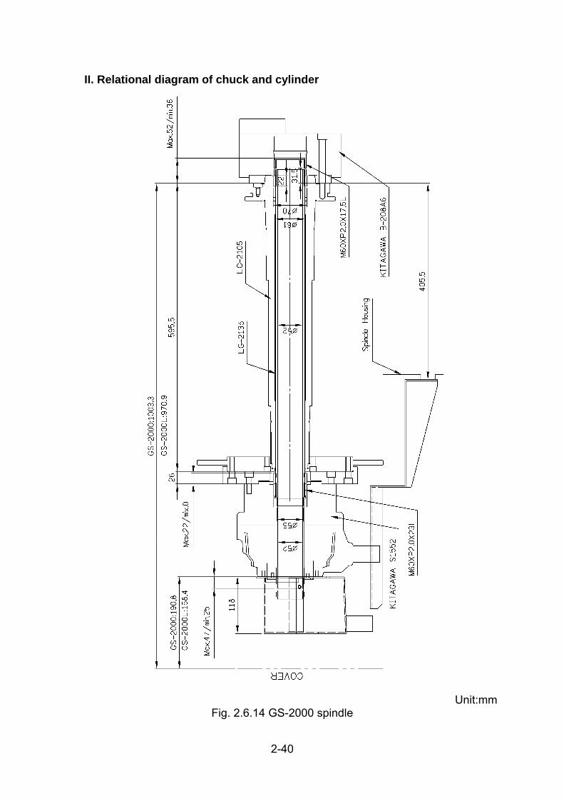
II. Relational diagram of chuck and cylinder
Unit:mm
Fig. 2.6.14 GS-2000 spindle

2-41
Unit:mm
Fig. 2.6.15 GS-2600 spindle

2-42
Unit:mm
Fig. 2.6.16 GS-2800 spindle

2-43
2.6.3. Spindle nose of sub spindle I. Spindle nose of main spindle
Unit:mm
Bar Capacity φ39mm (Part No. LG-9613) Fig. 2.6.17 Sub-spindle nose dimensional drawing (A2-5)

2-44
Unit:mm
Bar Capacity φ45mm (Part No. LE-9613) Fig. 2.6.18 Sub-spindle nose dimensional drawing (A2-6)

2-45
II. Relational diagram of chuck and cylinder
Fig. 2.6.19 GS-2000 Sub-spindle

2-46
Fig. 2.6.20 GS-3000 Sub-spindle

2-47
2.7. Tools information 2.7.1. Turret head dimensional drawing
Fig. 2.7.1 12 Stations standard turret (LF-3004)
Unit: mm

2-48
Fig. 2.7.2 12 Stations power driven turret (LF-3104) (Belt type)
Unit: mm

2-49
Fig. 2.7.3 12 Stations standard turret (CR-3004) (Belt type)
Unit: mm

2-50
Fig. 2.7.4 12 St. power driven turret (LG-3004)(Built-in type)
Unit: mm

2-51
2.7.2. Standard turret tooling system
Fig. 2.7.5 12 st tooling system (LF-3004 turret head)
*The information of tooling system please refer to Ch. 7.1.2

2-52
12 Stations Metric British
No. Part Name Part No. Spec. (mm)
Qty. Part No. Spec. (inch)
Qty.
1 Clamp piece CJ-3046 □25 6 CJ-3046 □1 6
2 Clamp piece CJ-3045 □25 6 CJ-3045 □1 6
3 O.D. Cutting Tool Holder CS-3448 □25 2 -- - -
4 Face Cutting Tool Holder CS-3407 □25 1 CS-34A7 □1 1
Boring Holder CS-34A6 ψ1.5 4 5
Throw-away Drill Holder CS-3446 ψ40 6
CS-34A8 ψ1.5 2
CJ-3014A ψ20 1 CJ-3110A ψ0.75 1
CJ-3014B ψ25 1 CJ-3110B ψ1 1
CJ-3014C ψ32 1 CJ-3110C ψ1.25 1
CJ-3016A ψ12 1 CJ-3112A ψ0.5 1
CJ-3016B ψ16 1 CJ-3112B ψ0.625 1
CJ-3016C ψ8 1 -- - -
CJ-3016D ψ10 1 -- - -
6 Boring Socket
CJ-3016E ψ6 OP -- - -
CJ-3010 MT-2 1 CJ-3107 MT-2 1 7 Throw-away Drill Socket
CJ-3011 MT-3 1 CJ-3113 MT-3 1
CV-3203A ψ16 OP -- - -
CV-3203B ψ20 OP -- - -
CV-3203C ψ25 OP CV-3204A ψ1 OP8 Boring Bush
CV-3203D ψ32 OP CV-3204B ψ1.25 OP
9 Coolant block CS-3430 - 6 CS-3430 - 6

2-53
Fig. 2.7.6 12 St.Tooling system (LG-3004 Turret head)
*The information of tooling system please refer to Ch. 7.1.2

2-54
Metric Standard -S No. Part Name Part No. Spec.(mm) Qty. Qty. 1 O.D. Cutting Tool Holder LG-3095 □25 6 4 2 O.D. Cutting Tool Holder LG-3095A □25 OP OP 3 Double O.D. Cutting Tool Holder LG-3096 □25 - 2 4 Face and ID Cutting Tool Holder LG-3097 □25 1 1 5 Boring Bar Holder / Throw-away Drill Holder LG-3094 ψ40 4 4 6 Boring Bar Holder / Throw-away Drill Holder LG-3092 ψ50 2 2 7 Double Boring Bar Holder LG-3093 ψ32 - 2 8 Cut-off Tool Holder LG-3098 □25 1 1 9 Cut off-Tool Holder (Grooving type) LG-3099 3 - 1
CJ-3014A ψ20 1 1 CJ-3014B ψ25 1 1 CJ-3014C ψ32 1 1 CJ-3016A ψ12 1 1 CJ-3016B ψ16 1 1 CJ-3016C ψ8 1 1 CJ-3016D ψ10 1 1
10 Boring Bush (ODψ40mm )
CJ-3016E ψ6 1 1 CJ-3010 MT-2 1 1
11 Boring Bush (ODψ40mm ) CJ-3011 MT-3 1 1 CV-3203A φ16 1 1 CV-3203B φ20 1 1 CV-3203C φ25 1 1
12 Throw-away Drill Socket (ODψ40mm)
CV-3203D φ32 1 1
CJ-3080A ψ20 1 1 CJ-3080B ψ25 1 1 CJ-3080C ψ32 1 1
13 Throw-away Drill Socket
(ODψ50mm )
CJ-3080D ψ40 1 1 CF-3052A φ12 - 1 CF-3052B φ10 - 1 CF-3052C φ16 - 1 CF-3052D φ8 - 1 CF-3052E φ6 - 1 CF-3055A φ20 - 1 CF-3055B φ25 - 1 CF-3053 MT2 1 1
14 Boring Bush (ODψ32mm )
CF-3054 MT1 1 1
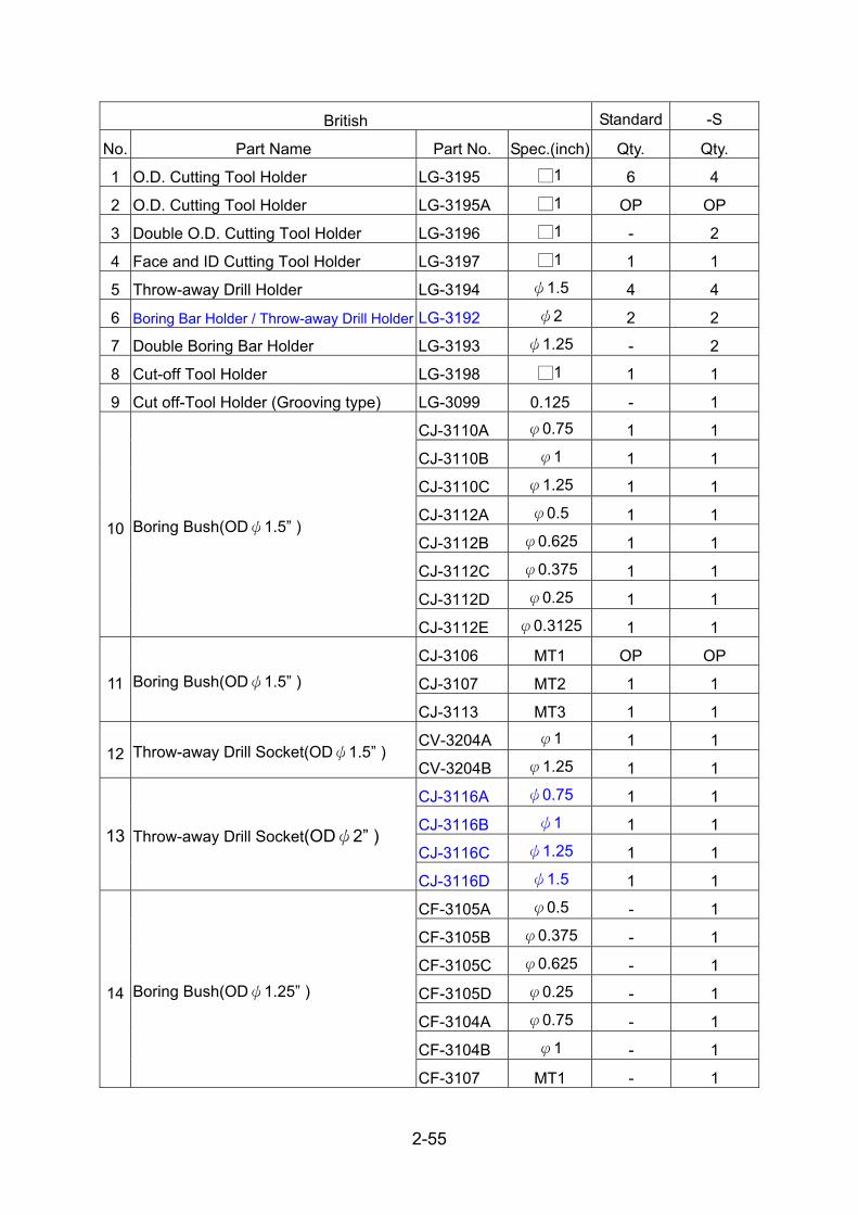
2-55
British Standard -S
No. Part Name Part No. Spec.(inch) Qty. Qty.
1 O.D. Cutting Tool Holder LG-3195 □1 6 4
2 O.D. Cutting Tool Holder LG-3195A □1 OP OP
3 Double O.D. Cutting Tool Holder LG-3196 □1 - 2
4 Face and ID Cutting Tool Holder LG-3197 □1 1 1
5 Throw-away Drill Holder LG-3194 ψ1.5 4 4
6 Boring Bar Holder / Throw-away Drill Holder LG-3192 ψ2 2 2
7 Double Boring Bar Holder LG-3193 ψ1.25 - 2
8 Cut-off Tool Holder LG-3198 □1 1 1
9 Cut off-Tool Holder (Grooving type) LG-3099 0.125 - 1
CJ-3110A φ0.75 1 1
CJ-3110B φ1 1 1
CJ-3110C φ1.25 1 1
CJ-3112A φ0.5 1 1
CJ-3112B φ0.625 1 1
CJ-3112C φ0.375 1 1
CJ-3112D φ0.25 1 1
10 Boring Bush(ODψ1.5” )
CJ-3112E φ0.3125 1 1
CJ-3106 MT1 OP OP
CJ-3107 MT2 1 1 11 Boring Bush(ODψ1.5” )
CJ-3113 MT3 1 1
CV-3204A φ1 1 1 12 Throw-away Drill Socket(ODψ1.5” )
CV-3204B φ1.25 1 1
CJ-3116A ψ0.75 1 1
CJ-3116B ψ1 1 1
CJ-3116C ψ1.25 1 1 13 Throw-away Drill Socket(ODψ2” )
CJ-3116D ψ1.5 1 1
CF-3105A φ0.5 - 1
CF-3105B φ0.375 - 1
CF-3105C φ0.625 - 1
CF-3105D φ0.25 - 1
CF-3104A φ0.75 - 1
CF-3104B φ1 - 1
14 Boring Bush(ODψ1.25” )
CF-3107 MT1 - 1

2-56
2.7.3. Power turret tooling system
Fig. 2.7.7 12 st Tooling system (LF-3104 turret head) (Belt type)
*The information of tooling system please refer to Ch. 7.1.2

2-57
Metric -M/-Y -MS/-YS
No. Part Name Part No. Spec.
(mm)Qty. Qty.
1 Face Cutting Tool Holder LF-3197 □25 1 1
2 Cut-off Tool Holder (Grooving Tool)
CB-4797 3 1 1
3 O.D. Cutting Tool Holder LF-3195 □25 6 --
4 Boring Bar Holder/ Throw-away Drill Holder
LF-3191 φ40 6 4
5 Double Boring Bar Holder LF-3193 φ32 -- 2 6 Double O.D. Cutting Tool Holder LF-3196 □25 -- 6
CJ-3014A ψ20 1 1 CJ-3014B ψ25 1 1 CJ-3014C ψ32 1 1 CJ-3016A ψ12 1 1 CJ-3016B ψ16 1 1 CJ-3016C ψ8 1 1
CJ-3016D ψ10 1 1
7 Boring Socket (OD:φ40)
CJ-3016E ψ6 OP. OP.
CJ-3010 MT-2 1 1 8
Throw-away Drill Socket (OD:φ40) CJ-3011 MT-3 1 1
CF-3055A ψ20 -- 1
CF-3055B ψ25 -- 1 9 Boring Bar Sleeve (OD:φ32)
CF-3052C ψ16 -- 1
10 90° Power driven tool CB-4783B ER-32 OP. OP. 11 0° Power driven tool CB-4782B ER-32 OP. OP.

2-58
British -M/-Y -MS/-YS
No. Part Name Part No. Spec.
(inch)Qty. Qty.
1 Face Cutting Tool Holder LF-31A7 □1 1 1
2 Cut-off Tool Holder (Grooving Tool)
CB-4797 3mm 1 1
3 O.D. Cutting Tool Holder LF-31A5 □1 6 --
4 Boring Bar Holder/ Throw-away Drill Holder
LF-31A1 φ1.5 6 4
5 Double Boring Bar Holder LF-31A3 φ1.25 -- 2 6 Double O.D. Cutting Tool Holder LF-31A6 □1 -- 6
CJ-3110A ψ0.75 1 1 CJ-3110B ψ1 1 1 CJ-3110C ψ1.25 1 1 CJ-3112A ψ0.5 1 1
7 Boring Socket (OD:φ1.5)
CJ-3112B ψ0.625 1 1
CJ-3107 MT-2 1 1 8
Throw-away Drill Socket (OD:φ1.5) CJ-3113 MT-3 1 1
CF-3104A 0.75 -- 1
CF-3104B 1 -- 1 9 Boring Bar Sleeve (OD:φ1.25)
CF-3105C 0.625 -- 1
10 90° Power driven tool CB-4783B ER-32 OP. OP. 11 0° Power driven tool CB-4782B ER-32 OP. OP.

2-59
Fig. 2.7.8 Tooling system (CR-3004 Turret Head) (Belt type)
*The information of tooling system please refer to Ch. 7.1.2

2-60
Metric -M/-Y -MS/-YSNo. Part Name Part No. Spec.(mm) Qty. Qty. 1 Block CR-3077 6 6
Clamp piece CV-3046 8 6 2
Clamp piece CV-3045 8 6 3 O.D. Cutting Tool Holder CR-3085 □25 2 - 4 Double O.D. Cutting Tool Holder CR-3074 □25 - 2 5 Face Cutting Tool Holder CR-3079 □25 - - 6 Face Tool Holder CR-3080 □25 1 1 7 Boring Bar Holder / Throw-away Drill Holder CR-3078 ψ40 - - 8 Throw-away Drill Holder CR-3076 ψ40 6 4 9 Double Boring Bar Holder CR-3073 ψ32 - -
10 Double Boring Bar Holder CR-3084 ψ32 - 2 11 Cut-off Tool Holder CR-3075 □25 1 1 12 Cut off-Tool Holder (Grooving type) CR-3096A 3 OP 1
CJ-3014A ψ20 1 1 CJ-3014B ψ25 1 1 CJ-3014C ψ32 1 1 CJ-3016A ψ12 1 1 CJ-3016B ψ16 1 1 CJ-3016C ψ8 1 1 CJ-3016D ψ10 1 1
13 Boring Bush (ODψ40mm)
CJ-3016E ψ6 1 1 CJ-3010 MT2 1 1
14 Boring Bush (ODψ40mm) CJ-3011 MT3 1 1
CV-3203A ψ16 1 1 CV-3203B ψ20 1 1 CV-3203C ψ25 1 1
15 Boring Bush (ODψ40mm)
CV-3203D ψ32 1 1 CF-3055A ψ20 -- 1 CF-3055B ψ25 -- 1 CF-3052A ψ12 - 1 CF-3052B ψ10 - 1 CF-3052C ψ16 - 1
16 Boring Bush (ODψ32mm)
CF-3052D ψ8 - 1

2-61
Metric -M/-Y -MS/-YSCF-3052E ψ6 - 1 CF-3053 MT2 - 1 CF-3054 MT1 - 1
17 0° Power driven tool CR-3680 ER32 OP OP 18 90° Power driven tool CR-3660 ER32 OP OP

2-62
British -M/-Y -MS/-YS
No. Part Name Part No. Spec.(inch) Qty. Qty.
1 Block CR-3077 6 6
Clamp piece CV-3046 8 6 2
Clamp piece CV-3045 8 6
3 O.D. Cutting Tool Holder CR-3115 □1 2 -
4 Double O.D. Cutting Tool Holder CR-3110 □1 - 2
5 Face Cutting Tool Holder CR-3111 □1 - -
6 Face Cutting Tool Holder CR-3112 □1 1 1
7 Boring Bar Holder / Throw-away Drill Holder CR-3106 ψ1.5 - -
8 Throw-away Drill Holder CR-3109 ψ1.5 6 4
9 Double Boring Bar Holder CR-3107 ψ1.25 - -
10 Double Boring Bar Holder CR-3114 ψ1.25 - 2
11 Cut-off Tool Holder CR-3105 □1 1 1
12 Cut off-Tool Holder (Grooving type) CR-3096A 3mm OP 1
CJ-3110A ψ0.75 1 1 CJ-3110B ψ1 1 1 CJ-3110C ψ1.25 1 1 CJ-3112A ψ0.5 1 1 CJ-3112B ψ0.625 1 1 CJ-3112C 0.375 1 1 CJ-3112D 0.25 1 1
13 Boring Bush (ODψ1.5”)
CJ-3112E 0.3125 1 1 CJ-3106 MT1 OP OP CJ-3107 MT2 1 1 14 Boring Bush (ODψ1.5”) CJ-3113 MT3 1 1 CV-3204B ψ1.25 1 1
15 Boring Bush (ODψ1.5”) CV-3204A ψ1 1 1 CF-3104A ψ0.75 -- 1 CF-3104B ψ1 -- 1 CF-3105A ψ0.5 - 1 CF-3105B ψ0.375 - 1 CF-3105C ψ0.625 - 1
16 Boring Bush (ODψ1.25”)
CF-3105D ψ0.25 - 1

2-63
British -M/-Y -MS/-YS
17 0° Power driven tool CR-3680 ER32 OP OP
18 90° Power driven tool CR-3660 ER32 OP OP

2-64
Fig. 2.7.9 Power tooling system (Built-in type)(LG-3004 Turret Head)
*The information of tooling system please refer to Ch. 7.1.2

2-65
Metric -M/-Y -MS/-YS
No. Part Name Part No. Spec.(mm) Qty. Qty.
1 O.D. Cutting Tool Holder LG-3095 □25 6 4
2 O.D. Cutting Tool Holder LG-3095A □25 OP OP
3 Double O.D. Cutting Tool Holder LG-3096 □25 - 2
4 Face and ID Cutting Tool Holder LG-3097 □25 1 1
5 Boring Bar Holder / Throw-away Drill Holder LG-3094 ψ40 4 4
6 Boring Bar Holder / Throw-away Drill Holder LG-3092 ψ50 2 2
7 Double Boring Bar Holder LG-3093 ψ32 - 2
8 Cut-off Tool Holder LG-3098 □25 1 1
9 Cut off-Tool Holder (Grooving type) LG-3099 3 - 1
CJ-3014A ψ20 1 1
CJ-3014B ψ25 1 1
CJ-3014C ψ32 1 1
CJ-3016A ψ12 1 1
CJ-3016B ψ16 1 1
CJ-3016C ψ8 1 1
CJ-3016D ψ10 1 1
10 Boring Bush (ODψ40mm)
CJ-3016E ψ6 1 1
CJ-3010 MT-2 1 1 11 Boring Bush (ODψ40mm)
CJ-3011 MT-3 1 1
CV-3203A φ16 1 1
CV-3203B φ20 1 1
CV-3203C φ25 1 1 12 Throw-away Drill Socket (ODψ40mm)
CV-3203D φ32 1 1
CJ-3080A φ20 1 1
CJ-3080B φ25 1 1
CJ-3080C φ32 1 1 13 Boring Bush (ODψ50mm)
CJ-3080D φ40 1 1
CF-3052A φ12 - 1
CF-3052B φ10 - 1
CF-3052C φ16 - 1
CF-3052D φ8 - 1
14 Boring Bush (ODψ32mm)
CF-3052E φ6 - 1

2-66
Metric -M/-Y -MS/-YS
CF-3055A φ20 - 1
CF-3055B φ25 - 1
CF-3053 MT2 1 1
CF-3054 MT1 1 1
15 90° Power driven tool LG-3692 ER-40 OP OP
16 0° Power driven tool LG-3691 ER-40 OP OP

2-67
British -M/-Y -MS/-YS
No. Part Name Part No. Spec.(inch) Qty. Qty.
1 O.D. Cutting Tool Holder LG-3195 □1 6 4
2 O.D. Cutting Tool Holder LG-3195A □1 OP OP
3 Double O.D. Cutting Tool Holder LG-3196 □1 - 2
4 Face and ID Cutting Tool Holder LG-3197 □1 1 1
5 Throw-away Drill Holder LG-3194 ψ1.5 4 4
6 Boring Bar Holder / Throw-away Drill Holder LG-3192 ψ2 2 2
7 Double Boring Bar Holder LG-3193 ψ1.25 - 2
8 Cut-off Tool Holder LG-3198 □1 1 1
9 Cut off-Tool Holder (Grooving type) LG-3099 3mm - 1
CJ-3110A φ0.75 1 1
CJ-3110B φ1 1 1
CJ-3110C φ1.25 1 1
CJ-3112A φ0.5 1 1
CJ-3112B φ0.625 1 1
CJ-3112C φ0.375 1 1
CJ-3112D φ0.25 1 1
10 Boring Bush (ODψ1.5”)
CJ-3112E φ0.3125 1 1
CJ-3106 MT1 OP OP
CJ-3107 MT2 1 1 11 Boring Bush (ODψ1.5”)
CJ-3113 MT3 1 1
CV-3204A φ1 1 1 12 Boring Bush (ODψ1.5”)
CV-3204B φ1.25 1 1
CJ-3116A φ0.75 1 1
CJ-3116B φ1 1 1
CJ-3116C φ1.25 1 1 13 Boring Bush (ODψ2”)
CJ-3116D φ1.5 1 1
CF-3105A φ0.5 - 1
CF-3105B φ0.375 - 1
CF-3105C φ0.625 - 1
CF-3105D φ0.25 - 1
CF-3104A φ0.75 - 1
14 Boring Bush (ODψ1.25”)
CF-3104B φ1 - 1

2-68
British -M/-Y -MS/-YS
CF-3107 MT1 - 1
15 90° Power driven tool LG-3692 ER-40 OP OP
16 0° Power driven tool LG-3691 ER-40 OP OP

2-69
2.8. Tooling interference
Tooling interference may occur depending on a tool holder mounted to the turret
head, cutting tool overhang amount, or tool combination.
The following points must be especially taken care of. 2.8.1. GS-2000/GS-3000 Tooling interference (Belt type headstock)
Fig. 2.8.1

2-70
2.8.2. GS-2000&GS-3000S/M/MS Tooling interference (Belt type headstock)
Fig. 2.8.2

2-71
Fig. 2.8.3

2-72
Fig. 2.8.4

2-73
2.8.3. GS-2000&GS-3000Y/YS Tooling interference (Belt type headstock)
Fig. 2.8.5

2-74
Fig. 2.8.6

2-75
Fig. 2.8.7

2-76
2.8.4. GS-2000 Tooling interference (Buil-in type headstock) I. GS-2000 with CR-3004 turret head
Fig. 2.8.8

2-77
Fig. 2.8.9

2-78
Fig. 2.8.10

2-79
II. GS-2000 with LG-3004 turret head
Fig. 2.8.11

2-80
Fig. 2.8.12

2-81
Fig. 2.8.13

2-82
2.9. Travels and working area 2.9.1. GS-2000 Travels and working area (Belt type headstock)
Fig. 2.9.1.1 GS-2000

2-83
Fig. 2.9.1.2 GS-2000M

2-84
Fig. 2.9.1.3 GS-2000M

2-85
Fig. 2.9.1.4 GS-2000M

2-86
Fig. 2.9.1.5 GS-2000MS

2-87
Fig. 2.9.1.6 GS-2000Y
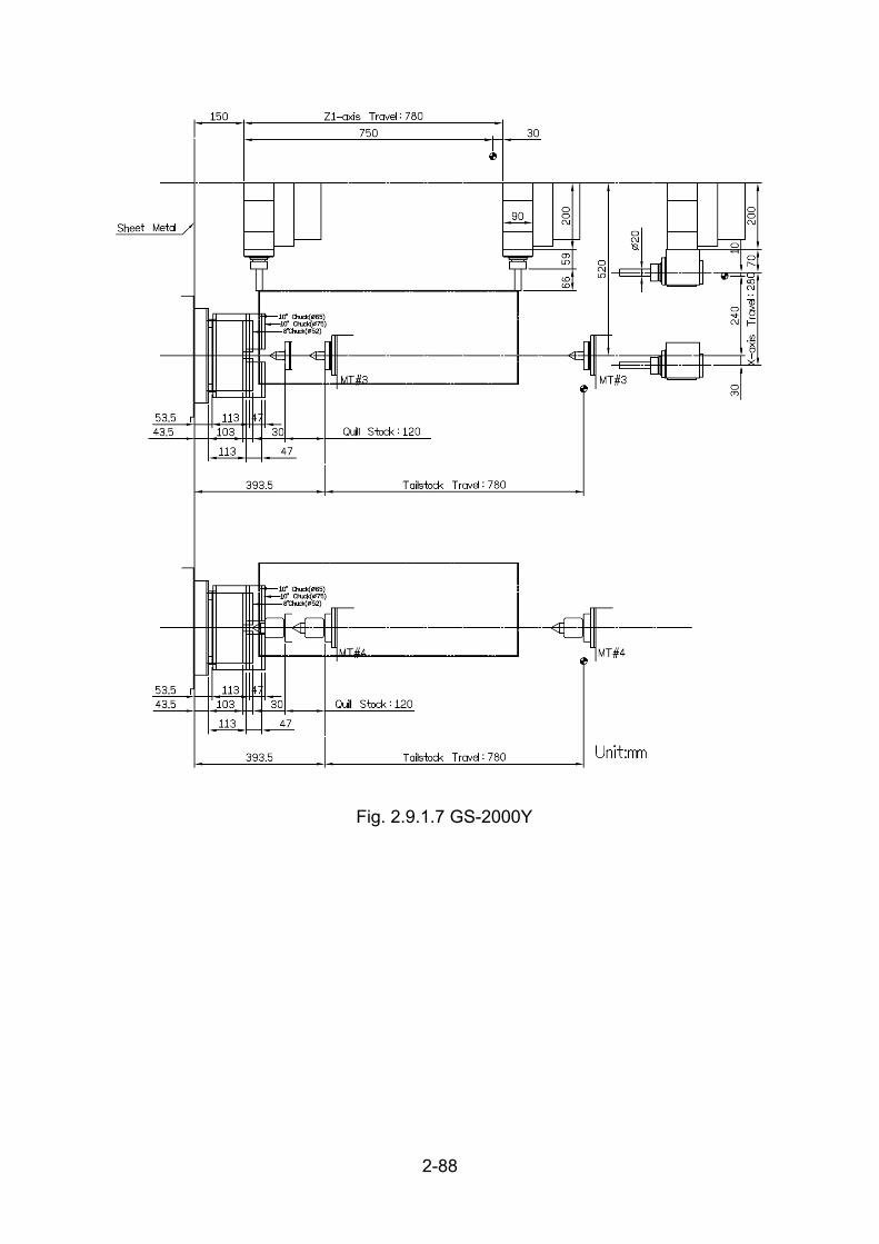
2-88
Fig. 2.9.1.7 GS-2000Y

2-89
Fig. 2.9.1.8 GS-2000YS

2-90
Fig. 2.9.1.9 GS-2000M(Built-in milling axis)
Fig. 2.9.1.10 GS-2000YS(Built-in milling axis)

2-91
2.9.2. GS-2000L Travels and working area (Belt type headstock)
Fig. 2.9.2.1 GS-2000L

2-92
Fig. 2.9.2.2 GS-2000LM
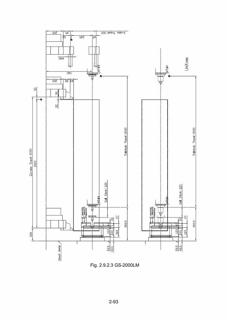
2-93
Fig. 2.9.2.3 GS-2000LM
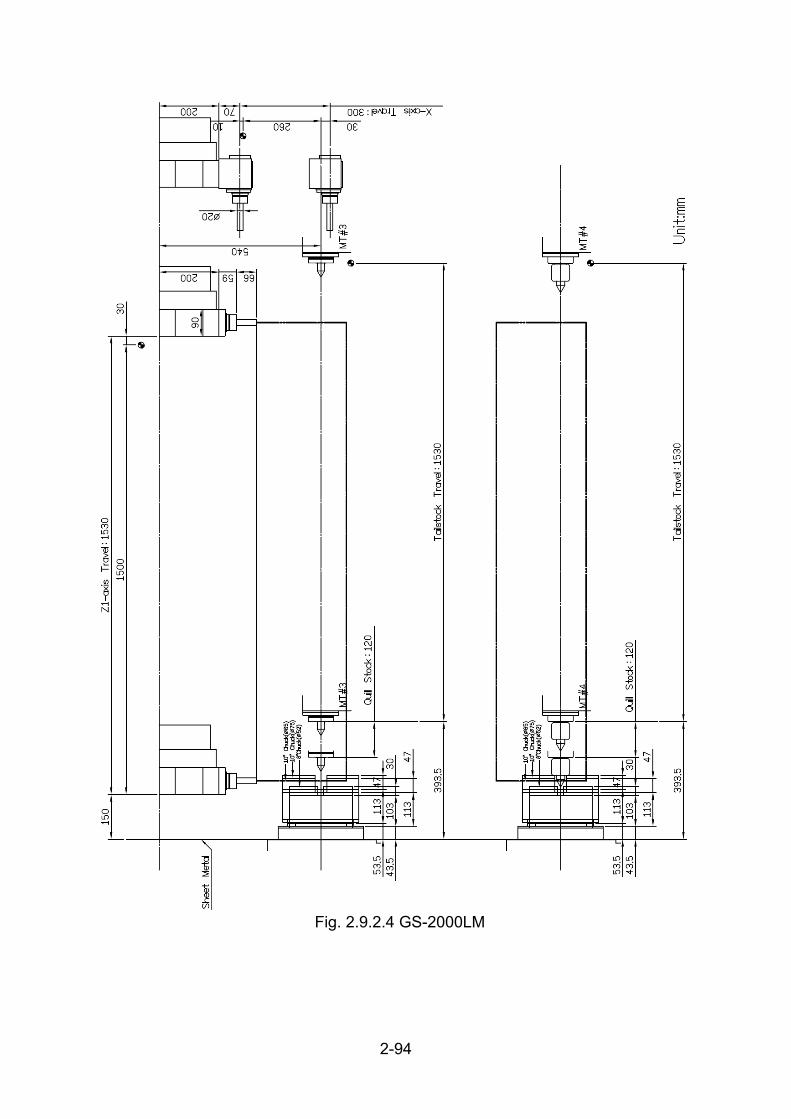
2-94
Fig. 2.9.2.4 GS-2000LM

2-95
Fig. 2.9.2.5 GS-2000LMS

2-96
Fig. 2.9.2.6 GS-2000LY
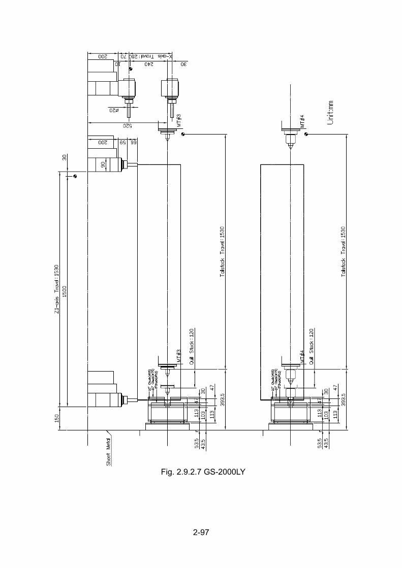
2-97
Fig. 2.9.2.7 GS-2000LY

2-98
Fig. 2.9.2.8 GS-2000LYS

2-99
2.9.3. GS-3000 Travels and working area (Belt type headstock)
Fig. 2.9.3.1 GS-3000

2-100
Fig. 2.9.3.2 GS-3000M

2-101
Fig. 2.9.3.3 GS-3000M

2-102
Fig. 2.9.3.4 GS-3000M

2-103
Fig. 2.9.3.5 GS-3000S/MS

2-104
Fig. 2.9.3.6 GS-3000Y

2-105
Fig. 2.9.3.7 GS-3000Y

2-106
Fig. 2.9.3.8 GS-3000YS

2-107
2.9.4. GS-3000L Travels and working area (Belt type headstock)
Fig. 2.9.4.1 GS-3000L

2-108
Fig. 2.9.4.2 GS-3000LM

2-109
Fig. 2.9.4.3 GS-3000LM

2-110
Fig. 2.9.4.4 GS-3000LM

2-111
Fig. 2.9.4.5 GS-3000LS/LMS

2-112
Fig. 2.9.4.6 GS-3000LY
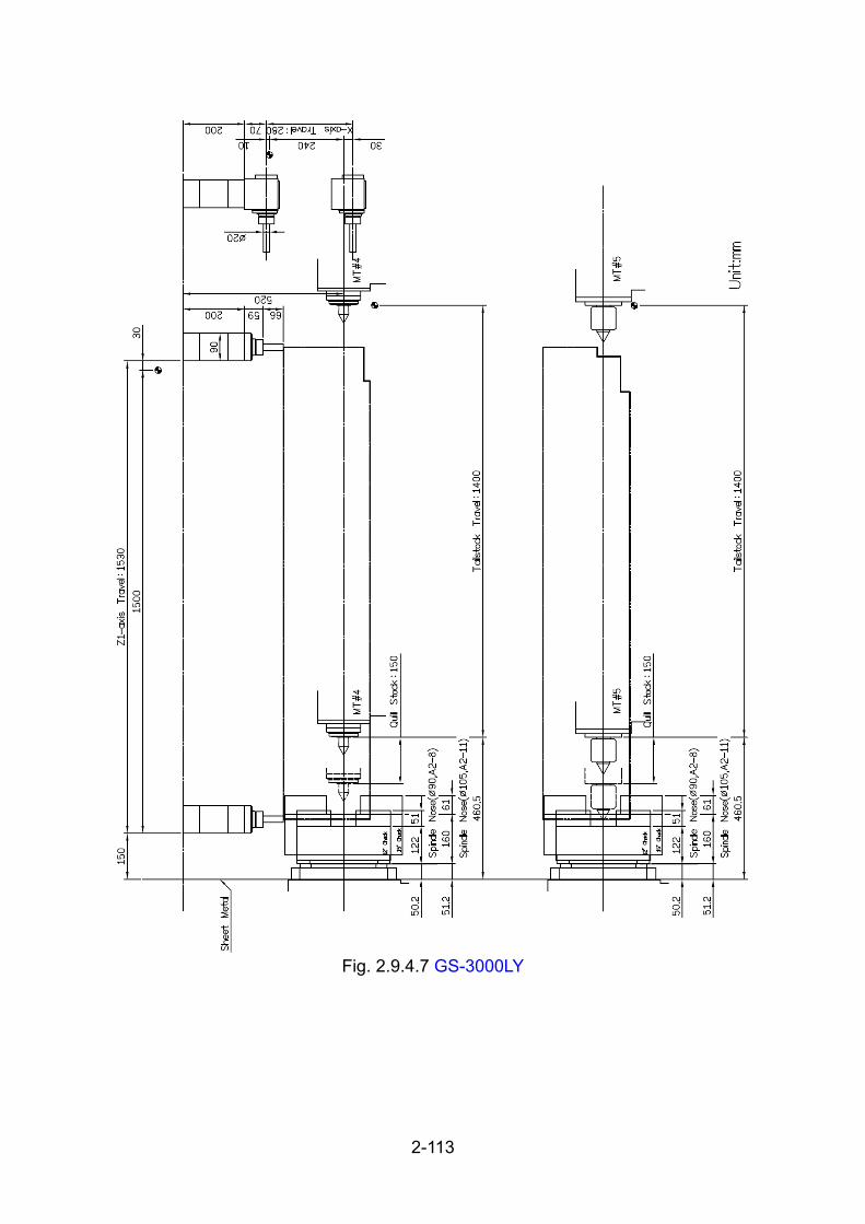
2-113
Fig. 2.9.4.7 GS-3000LY

2-114
Fig. 2.9.4.8 GS-3000LYS

2-115
2.9.5. GS-2000/L Travels and working area (Built-in type headstock)
I. GS-2000/L series with CR-3004 turret head
Fig. 2.9.5.1 For GS-2000,GS-2000M,GS-2000Y
*For Servo tailstock type.

2-116
Fig. 2.9.5.2 For GS-2000M,GS-2000Y
*For Servo tailstock type.

2-117
Fig. 2.9.5.3 For GS-2000,GS-2000M,GS-2000Y
*For Programmable tailstock type.

2-118
Fig. 2.9.5.4 GS-2000M,GS-2000Y
*For Programmable tailstock type.

2-119
Fig. 2.9.5.5 For GS-2000S,GS-2000MS,GS-2000YS
Fig. 2.9.5.6 For GS-2000MS,GS-2000YS

2-120
II. GS-2000/L series with LG-3004 turret head
Fig. 2.9.5.7 For GS-2000,GS-2000M,GS-2000Y
*For Servo tailstock type.

2-121
Fig. 2.9.5.8 For GS-2000M,GS-2000Y
*For Servo tailstock type.

2-122
Fig. 2.9.5.9 GS-2000, GS-2000M,GS-2000Y
*For Programmable tailstock type.

2-123
Fig. 2.9.5.10 For GS-2000M,GS-2000Y
*For Programmable tailstock type.

2-124
Fig. 2.9.5.11 For GS-2000S,GS-2000MS,GS-200YS
Fig. 2.9.5.12 For GS-2000S,GS-2000MS,GS-200YS

2-125
2.10. Jaw information
Dimensions of standard Top Jaw.
Standard soft blank jaw it:
Chuck Size 8” 10” 12” 15”
J1 31 40 50 62
J2 32 43 51 55
J3 72 110 111 165
J4 37 50 60 85
J5 20 30 30 43
J6 15 30 21 37
Aeration Pitch 1.5 1.5 1.5 1.5

3-1
3. Preparation for reception 3.1. Requirements of the space and operating position
Fig. 3.1.1 Belt type headstock

3-2
Fig. 3.1.2 Belt type headstock

3-3
3.2. Requirements of the foundation The foundation has great effects on the accuracy of the machine, and machining
accuracy by machine installation.
Therefore, a foundation site must be selected with full care.
Refer to Fig. 3.2.5 to make foundation.
*Dimension should be according to the conditions of the ground.
*Foundation strength:
a. Belt type headstock model
GS-2000/GS-3000: 35.8 KPa over
GS-2000L/GS-3000L: 37.6 KPa over
b. Built-in type headstock model
GS-2000.: 30.6 KPa over
GS-2000L: 33.8 KPa over

3-4
3.2.1. Foundation of belt type headstock model
Fig. 3.2.1 GS-2000/GS-3000 Requirements of the foundation

3-5
Fig. 3.2.2 GS-2000L/GS-3000L Requirements of the foundation

3-6
3.2.2. Foundation of built-in type model
Fig. 3.2.3 GS-2000 Requirements of the foundation

3-7
Fig. 3.2.4 GS-2000L Requirements of the foundation

3-8
3.2.3. Foundation work
1) The foundation box is a hard cardboard tube. The shape of the foundation box is shown as the diagram.
2) The construction of Foundation :
1. Concrete : strength ---refer to 3.2, slump value ---9. 2. Rubble size : 50 ~ 150 mm. 3. Filling ballast : approximately 25 mm dia.
Fig. 3.2.5

3-9
3.3. Installation and storage requirements of the environment 1) Do not install the machine where it may be exposed to direct sunlight
2)Chips or other refuse, water, oil, etc. from other equipment.
3)Ambient temperature 0-45∘C
4)Humidity less than 30-95% (non-condensing)
5)Altitude sea level -1000M
6)Vibration undesirable effect of vibration, shock, bump
7)Electromagnetic compatibility less than IEC 810 level 3

3-10
3.4. Requirements of power source 3.4.1. Power consumption
1)Refer to below for built-in headstock model.
Model GS-2000/L GS-2000M/LM
GS-2000S/LS GS-2000MS/LMS
GS-2000Y/LY GS-2000YS/LYS
Power consumption (KVA) 40 50 55
2) Refer to below for belt type headstock model.
Model GS-2000/L GS-2000M/ML
GS-2000S/LS
GS-2000MS/LMS
GS-2000Y/LY
Power consumption
(KVA) 40 45 50
Model GS-2000YS/LYS
Power consumption
(KVA) 55
Model GS-3000/L GS-3000M/ML
GS-3000S/LS
GS-3000Y/LY
GS-3000MS/LMS
Power consumption
(KVA) 40 50 50
Model GS-3000YS/LYS
Power consumption
(KVA) 55
3.4.2. Required input voltage
3-Phase AC 200/220v ±10% 50/60 Hz ±1%
If the power supply voltage of the building where the machine is installed is higher
than above voltage, however, transformer shall be used to get required voltage
as shown in the universal transformer connecting chart.
(Fig. 4.3.1)

3-11
3.4.3. No fuse breaker of main power switch
Amperes of fuses which shall be provided in the factory main power switch for the
machine refer to below:
1)Refer to below for built-in headstock model.
Fuses GS-2000 GS-2000L
GS-2000M/ GS-2000LM
GS-2000Y GS-2000LY
220V 125A 125A 125A
380V 63A 80A 80A
Fuses GS-2000MS GS-2000LMS
GS-2000S GS-2000LS
GS-2000YS GS-2000LYS
220V 160A 160A 160A
380V 80A 80A 100A
2) Refer to below for belt type headstock model.
Fuses GS-2000 GS-2000M GS-2000S/Y GS-2000MS GS-2000YS
220V 100A 125A 125A 160A 160A
380V 63A 63A 80A 80A 80A
Fuses GS-3000 GS-3000M GS-3000S/Y GS-3000MS GS-3000YS
220V 125A 160A 200A 250A 250A
380V 80A 80A 125A 125A 125A

3-12
3.4.4. Wire size for power supply cable
A. Power cable Wire size shall be selected depending on power supply voltage of machine shop.
[Recommended wire size] Wire size mm2(in2) 100A 125A
In case of 200-230V 22(0.034)
Wire size mm2(in2) 160A 200A 250A
In case of 200-230V 38(0.059)
B. Grounding The machine should be ground by the power supply cable connected to the PE
terminal as shown in Fig. 4.3.1.
(1) Recommended grounding wire size Wire size mm2(in2) 100A 125A
In case of 200-230V 22(0.034) Wire size mm2(in2) 160A 200A 250A
In case of 200-230V 38(0.059)
(2)If it is not possible Ground the machine to the earth system and the grounding
resistance is less than 100 OHMS.

3-13
3.4.5. Check the supply voltage to the machine
(A) Check the supply voltage to the machine
Measure the voltage across the phase wires.
Permissible supply voltage are within plus 10% and minus 15% to rated voltage.
If voltage is low, however, it will result in malfunctioning or trouble with controls.
Therefore it is better to maintain the voltage plus 10% and minus 0% to the rated
voltage.
(B) Check the phase
In order to check a phase, fill the hydraulic tank and lubrication tank with the oil
recommended first.
Then turn 'ON' the main power switch which is located at the electric cabinet and
press the POWER ON button on the operation panel.
When the power is turned on to the NC unit, the hydraulic pump will start rotating
by pressing "HYDRAULIC START" button.
If the power cable is connected properly, the indication of the pump pressure
gauge will increase and point at 30-35kg/cm2 (430-500 PSI).
But if the indication of the pump pressure gauge does not increase, press the
POWER OFF button on the operation panel immediately.
Then, turn off the main power switch and measure the connections of the power
cables, L1, L3 & L5, which are connected to the main power switch if connected.
If there is no input, please check the plant power.
If with input, it maybe the wrong motor and need to be adjusted the phase.

3-14
3.5. Oil requirement
Fig. 3.5.1
Name of oil by company
No. Type of oil Place of oil supply Capacity
Shell Mobil ESSO ISO VG
1 Lubrication oil
Lubrication oil tank 2.5L Tonna T
No.68 Vactra No.2
FEBIS K-68 68
2 Grease Chuck 5g Molykote EP grease
3 Grease Chuck/Quill 5g Molykote EP grease
4 Grease Milling axle --- Shell Retinax AM
5 Grease Turret Gear --- Shell Retinax AM
6 Coolant Coolant tank *1 Depends on the cutting material but
don't use the oil with law flash point.
7 Hydraulic oil Hydraulic tank *2 Tellus
No.32 DTE24 NUTO H32 32
8 Coolant (op.)
Oil Cooling Unit
20L Tellus No.32
DTE24 NUTO H32
32
*1. GS-2000/GS-3000:280L;GS-2000L/GS-3000L:360L.
*2. Belt type headstock: 45L
Built-in headstock: 30L

4-1
4. Handling、storage and installation
4.1. Handling and storage 4.1.1. Safety regulation moved by crane
1. The operator of crane equipment should have been trained.
2. Before the slinging and moving procedure, be sure of the followings: The
weight and the center of gravity of the machine. Suitable lifting hooks and
rope should be selected. Are there enough space for slinging and moving by
crane. During the slinging and moving, take precaution not to damage the
machine.
3. Be sure the safety of crane equipment before use.
4. Be sure all wire connections have been removed before slinging and moving.
5. Don't stand below the machine while slinging and moving by crane.
4.1.2. Safety regulation moved by fork lift
1. The operator of fork lift should have been trained.
2. Select the suitable fork lift.
3. Make sure the weight and the center of gravity of the machine.
4. The forks should extend under the full length of the machine body during
transportation.
5. Be sure the balance and don't lift too high.
6. Be careful when climbing or descending down a slope.
7. Be sure all wire connections have been removed before moving.
8. Someone should to guide the operator of the fork lift.

4-2
4.1.3. Wooden Transportation
Machine weight approx:
*Belt type headstock model:
GS-2000 & GS-3000------- 7500 kgs (16535 lbs) GS-2000L & GS-3000L-------- 9500 kgs (20945lbs)
Built-in headstock model:
GS-2000/L ---7700 kgs (16980lbs) /10500 kgs (23130 lbs)
A. Moved by crane
Fig. 4.1.1
B. Moved by fork lift
Fig. 4.1.2

4-3
4.1.4. Transportation and lifting of machine
When transporting the machine, be careful not to give vibrations or shocks to it.
The fix block must to be mounted and locked. Please refer to Ch.4.1.5.
(Note)
Machine weight Approx.
*Belt type headstock model:
GS-2000 & GS-3000: 6500kgs (14330 lbs)
GS-2000L & GS-3000L: Approx. 8500kgs (18740lbs)
*Built-in headstock model:
GS-2000/L: 6700 kgs (14760lbs) / 9500 kgs (20930 lbs)
A. Slinging and moving by crane
(1) Move the slides to the proper position, turn off the power and remove power
cable.
* Tailstock slide is most retracted position.
(2) Slinging and moving of the machine to its selected floor should be made with
due care.
Slings (Wire ropes) which show any sign of external or internal deterioration
should never be used to avoid accidents.
(3) Place the slings through lifting hooks & frame of machine and put some
protective pads such as rubber or rag between the slings and machine to
avoid the damages before lifting.
(4) Lift the machine slightly up and stop to check if the balance is correct and the
slings are in good position, then move the machine.
Finally place the machine carefully on its selected floor.
(Note) Slinging angle ...... 60 degree or less

4-4
(Note)
Before lifting the machine, need to recover the top and left side covers to
prevent damage.
The steps of removing covers are as below.
1. Remove the left cover.
2. Remove the top cover.
3. Remove the rail of anti-plate and assemble the hook.
4. After transportation of machine, be sure to assemble the rail, top and left
cover.
Fig. 4.1.3

4-5
Fig. 4.1.4 GS-2000/GS-3000

4-6
Fig. 4.1.5 GS-2000L/GS-3000L

4-7
Fig. 4.1.6 GS-2000(Built-in Headstock)

4-8
Fig. 4.1.7 GS-2000L(Built-in Headstock)

4-9
B. When using a fork lift (1) Fork lift truck must be a minimum of 7 (9) tons capacity.
(2) Fork the right position (under "fork here" signs) and make sure machine is in
balance to avoid injury and the damage to the machine .
(3) Make sure that forks do not touch any delicate part of the machine, include
the base of spindle motor.
Fig. 4.1.8 Belt type headstock model

4-10
Fig. 4.1.9 Built-in type headstock model

4-11
4.1.5. Position of fixed plates
Mount the fixed plates and tighten screws before transport
Fig. 4.1.10
Note: Before the first time putting the machine in use, please remove these
plates

4-12
4.2. Installation of leveling bolt
Put the machine down slowly when the machine in the correct position, mount
the leveling bolts ( LG-1022, CA-1029 ) on the machine and be sure the
leveling blocks ( LG-1021, CA-1030 ) are supporting the machine.
Fig. 4.2.1 GS-2000/GS-3000
Fig. 4.2.2 GS-2000L/GS-3000L

4-13
4.3. Connection of power supply
A. Power Cable connections (Refer to Fig. 4.3.1) 1. The cable from main power switch(R1,S1,T1) should be connected to the
filter(op.).
2. The cable from filter (op.) (R2,S2,T2 ) should be connected to the main power
transformer.
3. The primary cable (R3,S3,T3) should be connected to the terminal block.
4. The cable from terminal block (R4,S4,T4) shall be connected to the main
Power Switch of NC control cabinet.
Fig. 4.3.1

4-14
4.4. Dismantle
When removing this machine, reverse the installation procedure.
Fig. 4.4.1

5-1
5. Preparation for commissioning 5.1. Machine level adjusting
Make machine properly leveled because machining accuracy and machine life
is affected by poor leveling.
[Leveling] 1) Mount the leveling base to the turret head. (For standard turret model, refer
to Fig. 5.1.1 As power driven turret, refer to Fig. 5.1.2.) 2) Place a spirit level gauge on the leveling base.
(At this procedure, do not rotate the turret head.) 3) Use a level with graduations in 0.02mm/m (0.00025 inch per foot). 4) Adjust level of X axis and Z axis direction with leveling bolts. 5) Finally, The permissible level value must under 0.02mm/m. When adjust
mend is complete, secured all the bolts.
Fig. 5.1.1

5-2
Fig. 5.1.2

5-3
5.2. Cleaning and oil supply 5.2.1. Cleaning
Do not move the saddle and tailstock until they have been completely
removed.
1) Wipe off with a rag soaked in toluene the painted anti-rustive spread over
each slide way carefully. Therefore, apply lubricating oil thinly.
2) Wipe off carefully moisture stuck to the machine. Do not use compressed air for cleaning the machine. If used, a foreign substance may be blown in a joint by the compressed air, and as a result, joint surfaces may be damaged.
5.2.2. Oil supply before starting operation
It is necessary to supply the recommended oil to the following units.
(Refer to chapter 3.4)
1. Hydraulic tank
2. Hydraulic pump (*)
3. Lubrication tank
(Note) (*)-- Before starting the hydraulic pump, fill the pump case with a little
hydraulic oil initially to prevent an abnormal sound, vibrations and damaging the pump.

5-4
5.3. Safety checking procedure 5.3.1. Before Power ON:
1. Be sure the power source is 3 phase 220V AC, if not the transformer must be used.
2. The power connection wires should refer to ch.3.3.4 A. 3. Be sure the earth wire has been connected. (refer to ch. 3.3.4 B) 4. Be sure the fix block on machine has been removed. (refer to ch. 4.1.5) 5. Be sure the screws in hydraulic chuck has been tighten. 6. Be sure the leveling bolts and nuts have been fixed. (refer to ch. 4.2) 7. Be sure the coolant is in normal level. 8. Be sure the coolant hydraulic tubes and connection are in good condition. 9. Be sure the protection cover and door are in good condition. 10. Be sure the connection of lubrication is in good condition. 11. Check the hydraulic oil level in hydraulic oil tank. 12. Be sure there is nothing loose in turret disk. 13. Be sure the spindle drive belts have been installed and are in good
condition. 14. Be sure there is no articles around the machine which will effect the
operation.
5.3.2. After Power ON:
1. Be sure the hydraulic pump works and the hydraulic pressure is in normal condition.
2. Be sure the Emergency switch is in good condition. 3. Be sure the functions of the buttons for NC power on and power off. 4. Be sure all functions of push button works normally in manual mode. 5. Use manual mode to move the slide way to check if the lubrication oil is
working properly. 6. Use manual mode to move the X, Y, Z axes to check the functions of the
over travel switch

6-1
6. Manual operation 6.1. Safety device and warming-up 6.1.1. Safety device
The following devices have been equipped to maintain the safety operation.
Please check the Emergency stop button and door interlock switch is available
before operating
Fig. 6.1.1
No Name of devices Function Location
1 Chuck interlock device (Proximity switches)
To confirm proper gripping of workpiece
Rear of chuck cylinder
2 C-axis reference point switch and connecting switch
For C-axis confirm connecting and reference zero switch
Aside main spindle
3 Front door (guard) To prevent flashing out cutting chip and coolant
Front side of machine
4 Turret clamp/Unclamp device (proximity switches)
To check turret clamp/Unclamp state
Rear of turret
5 Door interlock switch To prevent electrical accident Above the front door
6 Lub. Alarm lamp To indicate the shortage of the lubrication oil
Operation panel
7 Lubricant float switch To check lubricant oil level Front side of machine
8 Parts catcher confirm switch (proximity switches)
To confirm parts catcher position and execution
Front side of machine
9 Pressure switch To confirm Hydraulic system pressure
Aside electric cabinet

6-2
No Name of devices Function Location
10 Tailstock interlock To confirm proper Rear of tailstock
11 Emergency button To stop operation in emergency condition
Operation panel
12 Chuck barrier (Option)
Turret interference between chuck and tools
NC software
13 X & Z Axis soft limit To determine the stroke of slide
NC software

6-3
6.1.2. Warming-up
There might be some possibility of faulty or damage of the machine if the machine
is operated without warming-up after long period of machine stop for vacation, etc.
Therefore, warming-up shall be performed before machine is operated every day
to maintain along life of machine.
INSTRUCTION OF WARMING-UP
1)Performed of warming-up : Minimum 15 minute
2)Spindle speed (5 min. each) : 500rpm -- 1000rmp -- Max. speed
3)Movement of slide : Max. stroke on each axis.
4)Turret indexing.
Remarks
(1)Check the distribution of lubrication oil during warming-up.
(2)Warming-up shall be performed for longer period in cold
season.
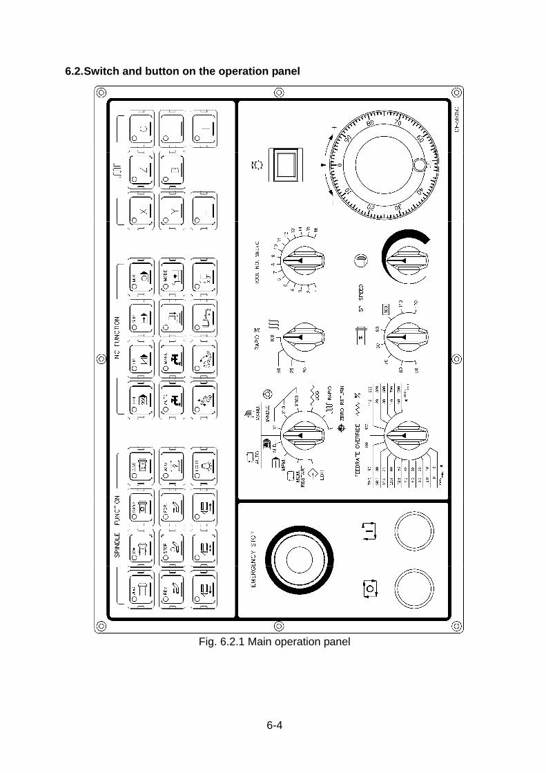
6-4
6.2. Switch and button on the operation panel
Fig. 6.2.1 Main operation panel

6-5
Fig. 6.2.2 Sub operation panel

6-6
6.2.1. Buttons and switches (for standard function)
1. POWER ON button NC unit can be turned on by depressing
"POWER ON" button and machine can be
operated after approx. a few seconds.
2. POWER OFF button NC unit can be turned off by depressing
"POWER OFF" button.
3. MACHINE READY button
When press the " NC POWER ON " Button and
release the " EMERG. STOP " button then press "
MACHINE READY " button, the NC system will get
ready if without any abnormal condition. ( Machine
Alarm ).
4. MODE switch Use this switch to select the mode of machine
operation.
(A) AUTO mode
[ EDIT]
Select this mode when loading NC tape data to
the memory, punch out the NC data or editing
the data in the memory.

6-7
[MEMORY RESTART]
Select this mode when continuous cycle memory
operation is needed, using the bar feeder or
other automatic loading device.
[MEMORY]
Select this mode when single cycle memory
operation is needed, using the bar feeder or
other automatic loading device.
[M.D.I.]
Select this mode when machine operation by
manual data input is needed.
(B) MANU. Mode
[HANDLE]
Select this mode when moving the slide by the
handle (Pulse generator).
x1 --- Incremental movement: 0.001mm/pulse
x10 --- Incremental movement: 0.01 mm/pulse
x100 --- Incremental movement: 0.1 mm/pulse
[JOG]
Select this mode when moving the slide by JOG
buttons ( +-X , +-Z ). Speed of slide movement
can be selected by changing "FEEDRATE
OVERRIDE" switch.
[RAPID]
Select this mode when moving the slide with
rapid speed by JOG buttons ( +-X , +-Z ). Rapid
speed can be selected by "RAPID OVERRIDE"
switch.

6-8
[ZERO RETURN]
Select this mode when moving manually the
slide to the "ZERO RETURN " position.
5. TOOL NO. SELECT switch This switch selects needed No.of tool.
6. HANDLE (Manual Pulse Generator)
By turning this handle with the mode switch
selected either to HANDLE×1, HANDLE×10 or
HANDLE×100, the slide can be moved at a fine
speed in the direction to a corresponding to a
selected axis.
7. JOG button By operating JOG button, the slide will travel in
the direction selected by it. If the mode switch
has been selected to JOG, the slide travels at a
rate set by the FEEDRATE OVERRIDE switch,
and if the mode switch has been selected to
RAPID, the slide travel at a rapid traverse rate.

6-9
8. FEEDRATE OVERRIDE switch
The feed rate of the slide can be set by this
rotary switch.
[INCREMENTAL device (%)]
The switch can apply an override (%) to the
feedrate specified by F-command in automatic
operation by every 10% step within a range of
0--150%.
[EXTERNAL division (mm/min.)]
The switch can apply the feedrate of slide by
using JOG button in
(NOTE)
1. Feedrate JOG mode. Feedrate can be adjusted within a range of
0--1260mm/min.e with external division (mm/min.) can be effective when
DRY RUN switch is selected to "ON" position.
2. Feedrate can not be changed by turning this switch during threading cycle.
9. RAPID OVERRIDE switch Rapid traverse rate can be adjusted by 3 step of
LOW, 25% and 100% adjust a standard speed.
* LOW --- 400mm/min
10. Spindle override The switch can apply an override to the turning
rate of spindle by using manual and automatic
operation within a range of 50% - 120%.
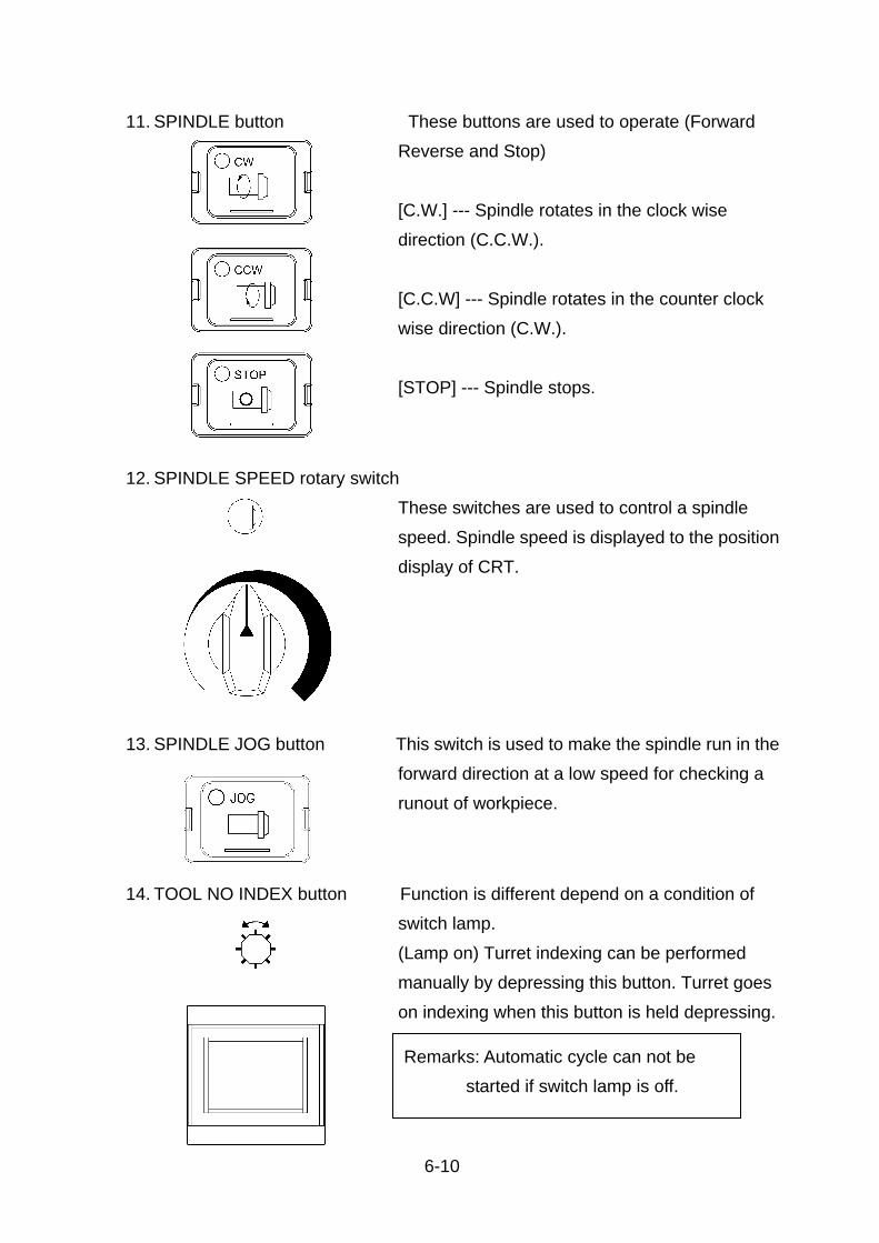
6-10
11. SPINDLE button These buttons are used to operate (Forward
Reverse and Stop)
[C.W.] --- Spindle rotates in the clock wise
direction (C.C.W.).
[C.C.W] --- Spindle rotates in the counter clock
wise direction (C.W.).
[STOP] --- Spindle stops.
12. SPINDLE SPEED rotary switch
These switches are used to control a spindle
speed. Spindle speed is displayed to the position
display of CRT.
13. SPINDLE JOG button This switch is used to make the spindle run in the
forward direction at a low speed for checking a
runout of workpiece.
14. TOOL NO INDEX button Function is different depend on a condition of
switch lamp.
(Lamp on) Turret indexing can be performed
manually by depressing this button. Turret goes
on indexing when this button is held depressing.
Remarks: Automatic cycle can not be started if switch lamp is off.

6-11
15. CYCLE START button Automatic cycle can be started by depressing
this button in AUTO mode and its lamp lights up
at the same time.
16. FEED HOLD button Press this button to stop the machine feed
temporarily during automatic operation. The
slide stops moving and its lamp lights up.
17. EMERG. STOP button If this button is depressed, NC unit will
immediately stop. Use this button when an
abnormality takes place while operating the
machines.
NOTE: The NC unit remains an emergency stop
mode unless the button is turned in the
arrow indicated direction for resetting after
the button was pressed.
(NOTE) Automatic cycle can not be
started unless the INDEX lamp and chuck close lamp lit up.
(NOTE) M, S and T functions kept
executed even if this button is
depressed.

6-12
18. COOLANT button
[MANU] - Coolant is discharged by selecting this
MANU. position.
[AUTO]-- Discharging and stopping of coolant is
controlled by programming command in
the AUTO mode.
19. SINGLE BLOCK button
[ON] - Program commands can be executed
block by block in auto mode.
[OFF] - Program commands can be executed
continuously.
20. DRY RUN button
[ON]--Slide moves at the feedrate (mm/min or
inch/min) set by the FEEDRATE
OVERRIDE switch instead of the
feedrate (mm/rev. or inch/rev.) set by the
programming F-command. Also, effective
to the rapid traverse.
[OFF] ---Slide moves at the feedrate (mm/rev.
orinch/rev.) set by the programming
F-command and FEEDRATE
OVERRIDE (%).
21. OPTIONAL STOP button (M01 stop)
[ON]---The machine will temporary stop when
M01 command is read and the red lamp
lights up.
* Also, spindle rotating and coolant discharging
stop.
[OFF] ---The machine will not stop even if M01
has been commanded in the program.
NOTE: This switch can be effective only when M01
has been commanded in the program.

6-13
22. BLOCK DELETE button
[ON] --A block having "/" (Slash code) at its
beginning will be ignored and next block
will be executed.
[OFF] --A block having "/" at its beginning will be
also executed.
(NOTE) This switch can not be effective unless a
block has "/" (Slash code).
23. EDIT key switch When this switch is turned off the following
operations can not be executed.
1. TV check (Tape vertical check).
2. Selection of ISO/EIA and INCH/MM.
3. Memorizing and editing a machining program.
24. MODE LOCK switch When this switch is turned off all buttons and
switches on main operation board or
sub-operation board can not be executed. Also,
NC unit will not be executed.
25. LAMP button Turn on the light during necessay,for
instance,tool setting,measurement & trouble
shoting.
Turning off the light is important in need-less
time for extending it's life.

6-14
26. APO button AUTOMATIC POWER-OFF button
1). Function of the button and the lamp:
1, When the button is "ON", it means power-off
function starts. When the button is "OFF", it
means power-off function stops.
2, When the button is "ON", the lamp lights on.
When the button is "OFF", the light will turn off.
3, Lubrication unit starts after NC being ready,
The lamp won't light on.
4, The button will keep pressed, when the finger
is off the button. The lamp keeps lighting on.
5, Under automation status, the automatic
power-off but ton is useful.
2).Automatic power-off motion:
1,When the button is on, machine finishes
working, and it doesn't reach T1 Time, machine
will turn off automatically if there is no further
action. (set T1 = 20min.)
2,This button is useful in any condition.
27. MACHINE ALARM lamp This lamp will light up when the machine becomes
emergency condition.
28. SPINDLE ALARM lamp The lamp will light up when an alarm signal is
emitted from the spindle servo amplifier.
29. LUB. ALARM lamp This lamp will light up when quantity of
lubrication oil is short.
(NOTE) Refer to the Ch. 12 and electric manual
when the machine becomes above alarm
conditions.
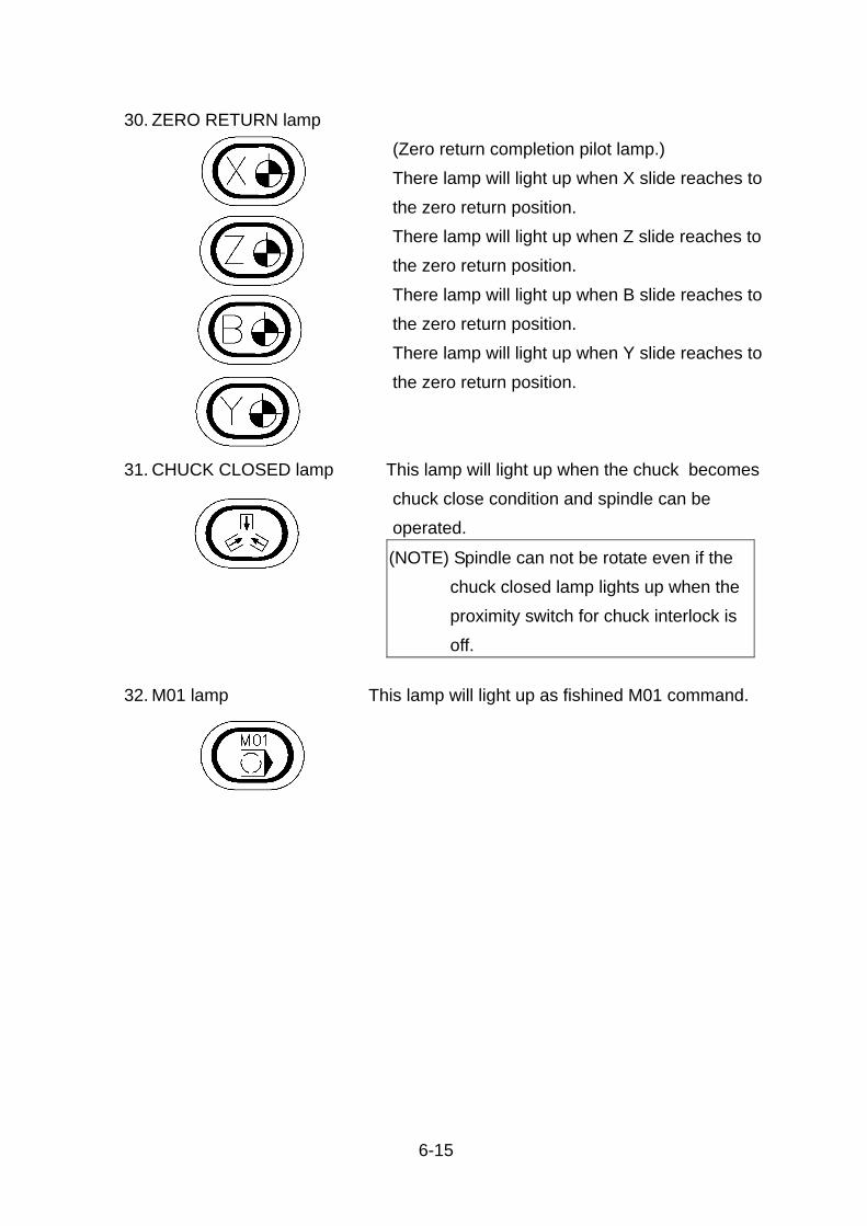
6-15
30. ZERO RETURN lamp
(Zero return completion pilot lamp.)
There lamp will light up when X slide reaches to
the zero return position.
There lamp will light up when Z slide reaches to
the zero return position.
There lamp will light up when B slide reaches to
the zero return position.
There lamp will light up when Y slide reaches to
the zero return position.
31. CHUCK CLOSED lamp This lamp will light up when the chuck becomes
chuck close condition and spindle can be
operated.
(NOTE) Spindle can not be rotate even if the
chuck closed lamp lights up when the
proximity switch for chuck interlock is
off.
32. M01 lamp This lamp will light up as fishined M01 command.

6-16
6.2.2. Buttons and Switches (For optional functions)
1. QUILL IN/OUT Button
These buttons are used to operate the tailstock
quill advancing and retracting in manual mode.
The button is used to operate the tailstock quill
advancing with JOG in manual mode.
2. Tailstock move forward / backward button
Servo tailstock (OP):
Press this button to move the tailstock go forward.
Press this button to move the tailstock go backward.
3. Tailstock connection button
Pin type(OP.):
This button is used to operate the tailstock pin
advancing and retracting in manual mode. Press
this button once to connect tailstock and slide.
And LED lamp on, pin will advance. Press it
(NOTE) Normally the quill can not be operated
during spindle run. However, the quill can
be operated by changing the
PC-parameter setting (D300-6) during
spindle run.

6-17
again and LED lamp off, pin will retract. (This
button is enable under tailstock mode on only)
When this button is "ON" under manual mode,
LED lamp on and tailstock mode turned on.
4. Sub-spindle move button
By pressing “+ or -“, “ B ” button, the sub-spindle will
travel in the direction selected by it. If the mode
switch has been selected to AXIS DIRECTION, the
slide travels at a rate set by the FEEDRATE
OVERRIDE switch, and if the mode switch has been
selected to RAPID, the slide travel at a rapid
traverse rate.
5. AUTOMATIC DOOR CLOSE button
When this button is "ON" under manual mode,
the automatic door will close and the lamp will
become "ON".
6. AUTOMATIC DOOR OPEN button
When this button is "ON" under manual mode,
the automatic door will open and the lamp will
become "ON".
7. PARTS CATCHER button Catcher comes near to spindle if push the
button, and it will retract when push again for
setup usually.

6-18
8. TOOL SETTER button Make the arm of tool setter send out or retrieve.
9. WORK SHIFT switch/input Perform manual X and Z axis refefence point
return by turnning on the switch, making tool
nose toutch the workpiece face and pressing
"INPUT" button in "HANDLE FEED" mode
10. CF-AXIS MANUALLY ENGAGE button
[ON] --When this button is "ON" under manual
mode, the CF-AXIS will be active and the
lamp will become "ON".
[OFF] --When this button is "OFF" under manual
mode, the CF-AXIS will be cancel and
the lamp will become "OFF".
11. CF-AXIS MANUALLY ON button
[ON] --- When this button is "ON" under manual
mode, the CF-AXIS motor will search
reference position and engage the
driven gear. After engage the driven
gear, the lamp will become "ON".
[OFF] -- When this button is "OFF" under manual
mode, the CF-AXIS driven gear will be
disconnected. After disengage the CF-

6-19
AXIS driven gear, the lamp will become
"OFF".
12. CHIP CONVEYOR REVERSE button 1) Function of the button and the lamp:
1. The chip conveyor reverses when the
button is pressed "ON". The chip conveyor
will stop working when the but ton isn't
pressed.
2. The lamp lights on, when the button is
pressed "ON". The light will disappear
when the button isn't pressed.
3. Lubrication unit starts after NC being ready,
the lamp of the function button will not
shine.
4. The button won't keep pressed, so the chip
conveyor stop when the button isn't
pressed.
5. Under automation status, the reverse
button isn't useful. 2) Reverse motion of the chip conveyor:
1. Reverse function isn't useful when the door
is opened.
2. Under automation status, the chip conveyor
reverses when M62 is working.
3. This button is controlled by manual.
13. CHIP CONVEYOR STOP button 1) Function of the button and the lamp:
1. The chip conveyor stops immediately when
the button is "ON".
2. The lamp lights on when the button is "ON".
The lamp keeps lighting on after the finger
leaving the button.
3. Lubrication unit starts after NC being ready,
the lamp of the function button will shine.

6-20
4. The button will keep pressed, so the chip
conveyor stop when the button isn't
pressed.
5. Under automation status, the stop button is
useful. 2) Stop motion of the chip conveyor:
1. The chip conveyor won't stop working when
the door is opened.
2. Under automation status, the chip conveyor
stops when M63 is working.
3. This button is controlled by manual.
14. CHP CONVEYOR TURN button 1) Function of the button and the lamp:
1. The chip conveyor turns forward, when the
button is ressed "ON". The chip conveyor
will keep turning when the button is
pressed.
2. The lamp lights on when the button is "ON".
The lamp keeps lighting on after the finger
leaving the button.
3. Lubrication unit starts after NC being ready,
the lamp of the function button will not
shine.
4. The button keep pressed, so the chip
conveyor keep working when the button
isn't pressed.
5. Under automation status, the turn button is
useful. 2) Turning motion of the chip conveyor:
1. When the chip conveyor turns forward, it
turns for a while and then stops
temperately, till the stop button is "ON". T1,
T2 = set by manual.

6-21
2. When the door is opened, the motion stops,
The chip conveyor works when the door is
closed.
3. Under automation status, conveyor turns
when M61 is working .
4. This button is controlled by manual.
5. As to the different machines, the settings of
T1 and T2 are as following:
ADV. Time.
Parameter NO.
ADV. Stop Time
Parameter No.
Remark
Timer NO. 15 Timer NO. 16 Use18I-TB or 0I-TC, TD controller
15. G / H lamp When the spindle switches to high speed level,
the lamp will become "ON".
16. G / L lamp When the spindle switches to low speed level, the
lamp will become "ON".
17. SPINDLE NEUTRAL button
When the spindle switches to neutral level, the
lamp will become "ON".

6-22
6.3. M.D.I. (Manual Data Input) Keyboard function
The keyboard functions shall be understood for the key operations and automatic
operations.
The LCD/MDI panel, consists of a LCD display (8.4" color) and keyboard as in the
following illustration.
Refer to the FANUC USER'S MANUAL for more details.
Fig. 6.3.1 MDI & LCD panel for FANUC SYSTEM 0i-TD

6-23
6.4. How to opening / closing the electrical cabinet door
To open the electrical cabinet door for maintenance, follow the procedure
indicated below. 6.4.1. Open the Electrical Cabinet Door
I. Steps for how to open the cabinet door in power off (1) Turn off the power.
(2) Turn off the power supply at the shop
power distribution board.
(3) Turn the key on the electrical cabinet
door to release the electrical cabinet door lock.
(4) Place the main switch in the OPEN /RESET
position.
(5) Open the electrical cabinet door.

6-24
II. Steps for how to open the cabinet in an uninterruptible power situation
(1) Turn the key on the electrical cabinet door to release the electrical cabinet door lock.
(2) Release the screw of main power switch with a screwdriver.
(3) Open the electrical cabinet door. (NOTE)
1. Before attempting maintenance and inspection inside the electrical cabinet, be
sure to turn OFF the power at the circuit breaker for the entire plant. Even when
the main power switch on the electrical cabinet is turned OFF, parts of the
cabinet may still have potential and may give an electric shock if accidentally
touched. If it is necessary to conduct maintenance with the power being supplied,
confirm the state of power supply by checking the electrical circuit diagram and
exercise extreme caution.
2. In order to open the electrical cabinet door, you must place the main switch in the
OPEN RESET position. If the main switch is at a position other than OPEN
TESET it will not be possible to open the door. Attempting to force the door open
in this situation could damage the electrical cabinet door or the main switch.

6-25
TRIP
OFF
EEAS
R LE
ON
TRIP ON
OFF
6.4.2. Closing the Electrical Cabinet Door
1) Place the main switch in the OFF position.
2) Close the electrical cabinet door.
3) Turn the key on the electrical cabinet door
to lock the electrical cabinet door.
NOTE:
1.When the electrical cabinet door is completely closed , a click is heard.
2.If the electrical cabinet door is not completely closed, engage the position of
the main switch on the inside of the electrical cabinet door with the position
of the main breaker in the electrical cabinet, and then close the electrical
cabinet door.

6-26
6.5. How to turn on the power
Control power can be turned on as following steps.
1)
Turn in the arrow-indicated direction for resetting direction for resetting.
2)
Cooling for motor of spindle motor and control cabinet will rotate.
3)
*Hydraulic pump by pressing MACHINE READY button. *Check the main pressure gauge *Confirm that the pressure gauge indicates normal pressure in the range of 30~35 kgf/cm2
4)
Reset the [EMERGENCY] button
Turn on the [MAIN POWER SWITCH ] on the electric cabinet
READY TO OPERATE
Turn on the [NC POWER] button on the operation panel.

6-27
6.6. How to stop the machine
Use the following button switches or key to stop the operation in case of
emergency.
[FEED HOLD] button
This is effective during automatic operation. The
slides will stop by pressing this button. However,
spindle and M-function will kept executing.
[RESET] key
This button is effective regardless of any mode.
Spindle, slide and M-functions will stop by pressing
this key However, coolant will be kept flowing in
case of manual operation
[EMERGENCY] button
This button is effective regardless of any mode. NC
unit will immediately stop and all functions will come
to a complete stop.
Note : Pressing RESET will delete relevant setting. For more information
please refer to FANUC User's manual.

6-28
6.7. Manual Data Input (operation.)
The command of single block or multiple blocks can be input from the MDI/CRT
panel to the MDI buffer memory, and can be executed as same as automatic
cycle.
(The capacity of the MDI buffer memory is 200 characters)
< Procedure of MDI operation for the sample below. >
Fig. 6.7.1
(NOTE) Precautions for starting operation.
1.Check the data registered to the MDI buffer memory.
2.Set the "RAPID OVERRIDE" switch to the "LOW" .
3.Set the "FEEDRATE OVERRIDE" switch to the "0%".
4.Press "START" key and change the "FEEDRATE OVERRIDE" switch to
the required speed.
This MDI operation can be used for the following.
* Forming of the soft jaws. * Simple machining of the workpiece.

6-29
*** DATA ***
Spindle rotation and turret indexing S1000 M03 T0500 Rapid feed (A→B) G00 U-200. W-100. Cutting feed (B→C) G01 W-50. F0.3
1)Command of spindle rotation and turret indexing.
(1)Set the "MODE" switch to the " MDI " position.
(2)Press the "PROG” key
(3)Input data using data keys and
INPUT key as follows.
S1000 INSERT
M03 INSERT
T0500 INSERT
(4) Press the CYCLE START” button
* The turret starts indexing to station No.5.
* Spindle start to rotate at 1000 rpm.
* The turret starts indexing to station No.5.
* Spindle starts to rotate at 1000 rpm.
MANU.AUTO.
M.D.I.
MEM.
RESTARTMEM.
EDIT
HANDLE
X10
X100
X1
JOG
RAPID
ZERORETURN

6-30
2) Command of the rapid feed from A to B.
(1)
(2)
3) Command of the cutting feed from B to C.
(1)
(2)
Input data using data keysand INPUT key as follows.G00 INPUT U-200. INPUT W-100 INPUT
Press the "CYCLE START" Button
X and Z-axis slide start to move from A to B at rapid speed. * Confirm the position of slides on the CRT screen.
Input data using data keysand INPUT key as follows.G01 INPUT W-50 INPUT F0.3 INPUT
Press the "CYCLE START" Button
Z-axis slide start to move from B to C at cutting speed of 0.3mm/rev. * Confirm the position of slides on the CNC screen.

6-31
6.8. How to move the X, Y and Z-axis slides.
X and Z axis slide can be moved as the following operation.
And operate the slides with attention as shown in below.
(1)Interference between the turret (or tool) and the chuck.
(2)Interference between the turret (or tool) and the tailstock.
(3)If the position of the slide is very close to the stroke end, move the slide in the
opposite friction.
A. Operation by [G] buttons 1)Set the [ MODE ] switch to the
" JOG " or " RAPID " position.
2)Move the slide by depressing " JOG " button.
* The slide is held moving during
depressing [ JOG ] button.

6-32
**** Slide traverse ****
1) Before manual zero return is performed the slide will not move in the [ JOG ]
and [ RAPID ] mode.
2) After manual zero return is performed.
* [ JOG ] mode --- Controlled by setting " FEEDRATE OVERRIDE "
switch in the range of 0--1260mm/min.
* [ RAPID ] mode --- Controlled by setting " RAPID OVERRIDE " switch.
(F0 , 25 , 50 , 100%)
X-axis: 30m/min. at 100%
Y-axis: 10m/min, at 100%
Z-axis: 30m/min. at 100%

6-33
B. Operating by "HANDLE (Manual Pulse Generator)"
1)Set the "MODE" switch to the "HANDLE" (x1, x10, x100)
2)Select the axis (X, Y or Z) by toggle switch.
3)Turn the wheel in the direction required.
Use the [HANDLE] mode for the following * Forming for the soft jaws. * Machining of the workpiece with simple figure. * etc.
[x1] -- 0.001 mm/div 0.1 mm/rev.[x10] -- 0.01 mm/div. 1.0 mm/rev.[x100] -- 0.1 mm/div. 10.0 mm/rev

6-34
6.9. How to perform the manual zero return
Manual zero return must be performed after the Machine lock switch is used or
MLK function is performed. Perform the manual zero return operation as shown in
the following.
1)Set the "MODE" switch to the "ZERO RETURN" position.
2)Depress the " JOG " button. (+X, -Y and +Z)
3)Completion of zero return
The green lamps will light up when ZERO RETURN is completed.
(NOTE) Move the slide in the opposite (-X,-Y, -Z)
direction of zero return once if slide locates near the zero return position.
If the both of +X and +Z are depressed at same time,the both axis move together.

6-35
6.10. How to operate the spindle
Operate the spindle without the workpiece for safety unless actual machining.
1)Step the chuck foot switch to close the chuck
2) Set the "MODE" switch to the "MANU".
3)Turn the "SPINDLE SPEED" adjusting
knob counter-clockwise to prevent the accidental
acceleration of spindle.
To the next page
(NOTE) Confirm that the proximity switch for chuck
interlock has been staying on.
* The chuck can be operated (Open and Close) by stepping the chuck foot switch. * "CHUCK CLOSE" lamp will light up for confirming the chuck close condition.
Refer to 7.2.6 Chuck closed confirmation PS-4 for REAR END position.

6-36
4)Hit the " FWD. " or " RVS " button to rotate the spindle.
The spindle speed can be changed by
turning the " SPINDLE SPEED " knob.

6-37
* How to operate the "SPINDLE JOG" button.
The spindle rotates counter-clockwise at slow speed during this button is
depressed.
Standard JOG speed..... 140rpm for 8” chuck
120rpm for 10”chuck.
100 rpm for 12” chuck
90 rpm for 15”chuck.
* How to operate the C axis by manual pluse generator. 1)
2)
Input "M19" code by M.D.I operation (refer to Ch. 6.7) to enter the status of C axis control .
Set the "AXIS" switch to "C" and the other procedures are same as CH. 6.8 B. (refer to CH. 6.8 B )

6-38
6.11. How to operate the turret indexing
Check the following items before the turret indexing is performed.
* Interference between the turret (or tool) and the chuck (or tailstock).
* Overhang of cutting tools from the holder or turret.
1)
2)
3)
Set the "MODE" switch to the " JOG " position.
* Select the " MANU. " mode.
Move the X, Y and Z-axis slide to the
safe area for indexing by using the " JOG
" button.
Hit the " INDEX " button on the operation
panel.
To the next page

6-39
4)
* Every time the " INDEX " button is pressed, turret does indexing to the next
station.
* The turret does indexing forward direction.
* The "FEED HOLE" button is held pressing, than press
"INDEX" key, turret does counter rotating to the next station.
Hit the " INDEX " button again for move indexing.

6-40
6.12. How to move the tailstock
1.Turn on the power. Move turret to X-axis
reference position.
2.Set the "MODE" switch to the "MANU".
3.Press “ TAILSTOCK MODE” button. Press “+Z”
button to, the tailstock will move to connecting
position automatically.
4.Press “tailstock pin” button therefore
tailstock connects to slide.
5.Move Z-aixs to bring the tailstock to the
destination.
6.Press “tailstock pin” button again to
disconnect the pin B.
7.Press “MODE” button again to cancel the tailstock mode.
8.Tailstock moving finished。
Note
Make sure the moving turret and tailstock won’t collide to any
equipments or persons, especially pay attention to throw-away
drill tool, or it may course damage.

6-41
6.13. How to turn off the power
Turn off the power as the following steps.
1)Move the X and Z-axis slides away from the chuck and tailstock.
2)Confirm that all motion have been stopped.
3)Depress the "EMERGENCY" button.
4)Depress the NC power "OFF" button.
5)Turn off the main power switch on the electric cabinet.
6)Turn off the main power switch of the machine shop.
7)Completion of turning off the power.
(NOTE) Clean up the machine when the job is finished.

6-42
6.14. Procedure for the automatic operations
The following procedure shall be executed for the automatic operations.
1)Manual zero return of X and Z-axis shall be executed.
* Refer to the item 6.8 for the manual zero return.
* It is not necessary to execute this operation if the
green pilot lamps have been lit already.
* It is not necessary to execute this operation if this
operation has been finished already.
2)Close the chuck by foot switch.
* Refer to the Ch. 6.10 for this operation.
* It is not necessary to execute this operation if the
chuck closed lamp has been lit already.
3)Make the "Turret indexing ready".
* Refer to the Ch. 6.11 for this operation.
* It is not necessary to execute this operation if the
index lamp has been lit already.
(NOTE)
Other operations are needed for actual machining in addition to the above. Therefore, refer to the item 8.4 for actual machining.

7-1
7. Preparation of the actual machining
7.1 Tooling (Procedure of fixing the tool)
Prepare the all toolings used for the machining.
Mount the tool holders first, then fix the tools.
Pay attention to the followings for safety operations.
* Make sure of fixing the tool holder and tools.
* Check the tool interference between the tool and the followings due to a tool
overhang amount and tooling location.
-- The slide cover or the chuck side cover.
-- The workpiece or the chuck.
* A balanced tooling on the turret shall be taken for the indexing mechanism.

7-2
7.1.1 How to mount the tool holder
Locate the tool holder on the outer face of the turret and fix the tool holder with the
cap screws (4 pcs) as shown in the layout below.
The tool holder is not needed for the turning tool.
7.1.2 How to fix a cutting tool
Mount a cutting tool determining a overhang amount by using the tool setting
gauge or measuring instrument (Slide calipers, etc) in accordance with the tooling
layout.
Then tighten the tool by the wrench.

7-3
7.1.3 LF-3004 turret head tool holder 1) In case of the Turning Tool is mounted on the Turret head directly.
Fig. 7.1.1
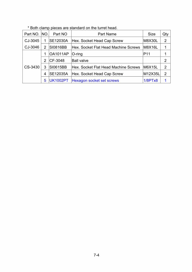
7-4
* Both clamp pieces are standard on the turret head. Part NO. NO. Part NO Part Name Size Qty
1 SE12030A Hex. Socket Head Cap Screw M8X30L 2 CJ-3045
CJ-3046 2 SI0816BB Hex. Socket Flat Head Machine Screws M8X16L 1
1 OA1011AP O-ring P11 1
2 CF-3048 Ball valve 2
3 SI0615BB Hex. Socket Flat Head Machine Screws M6X15L 2
4 SE12035A Hex. Socket Head Cap Screw M12X35L 2
CS-3430
5 UK1002PT Hexagon socket set screws 1/8PTx8 1

7-5
2) O.D. Cutting Tool Holder
Part NO A
CS-3448 50mm

7-6
NO. Part NO Part Name Size Qty
1 SE12035A Hex. Socket Head Cap Screw M12X35L 4
3 SI0612BB Hex. Socket Flat Head Machine Screws M6X12L 2
4 CF-3048 Ball valve 2
5 OA1016AP O-ring P16 1
6 OA1009AP O-ring P9 2
7 CJ-3045 Clamp piece 1
8 CJ-3046 Clamp piece 1
9 SE12030A Hex. Socket Head Cap Screw M12X30L 2
10 SI0816BB Hex. Socket Flat Head Machine Screws M8X16L 1
11 UK1002PT Hexagon socket set screws 1/8PT 2

7-7
3) Face cutting tool holder
Part NO A
CS-3407 50mm
CS-34A7 2”

7-8
NO. Part NO Part Name Size Qty
1 SE12050A Hex. Socket Head Cap Screw M12X50L 4
2 SF1030JA Hex. Socket Headless Set Screws M10X30L 6
3 SI0810BB Hex. Socket Flat Head Machine Screws M8X10L 2
4 CV-3047 Ball valve 2
5 OA1016AP O-ring P16 3
6 UK1004PS Hexagon socket set screws 1/4PT 1
7 CV-3093 Block 1

7-9
4) Boring Bar Holder / Throw-away Drill Holder

7-10
Part NO A
CS-3446 ψ40mm
NO. Part NO Part Name Size Qty
1 SE12070A Hex. Socket Head Cap Screw M12X70L 4
2 SF1035JA Hex. Socket Headless Set Screws M10X35L 6
3 CV-3047 Ball valve 2
4 SI0810BB Hex. Socket Flat Head Machine Screws M8X10L 2
5 UK1002PT Hexagon socket set screws 1/8PT 4
6 OA1016AP O-ring P16 3
7 CS-3220 Cover 1
8 SF0615JA Hex. Socket Headless Set Screws M6X15L 3
Part NO A
CS-34A6 ψ1.5”
NO. Part NO Part Name Size Qty
1 SE12070A Hex. Socket Head Cap Screw M12X70L 4
2 SF1035JA Hex. Socket Headless Set Screws M10X35L 6
3 CV-3047 Ball valve 2
4 SI0810BB Hex. Socket Flat Head Machine Screws M8X10L 2
5 UK1004PS Hexagon socket set screws 1/4PT 1
6 OA1016AP O-ring P16 3

7-11
Part NO A
CS-34A8 ψ1.5”

7-12
NO. Part NO Part Name Size Qty
1 SE12070A Hex. Socket Head Cap Screw M12X70L 4
2 SF1035JA Hex. Socket Headless Set Screws M10X35L 6
3 SF1020JA Hex. Socket Headless Set Screws M10X20L 1
4 UK1002PT Hexagon socket set screws 1/8PT 4
5 OA1016AP O-ring P16 3
6 CS-3220 Cover 1
7 SF0615JA Hex. Socket Headless Set Screws M6X15L 3

7-13
7.1.4 LG-3004 turret head tool holder 1) O.D. Cutting Tool Holder
Part NO A
LG-3095 50mm
LG-3195 2”

7-14
NO. Part NO. Part Name Size Qty
1 SE12065C Hex. Socket Head Cap Screw M12X65L 4
2 CF-3048 Ball valve 2
3 SF0830JA Hex. Socket Headless Set Screws M8X30L 6
4 SI0616BB Hex. Socket Flat Head Machine Screws M6X16L 2
5 OA1010AP O ring P10 1
6 SE08030A Hex. Socket Head Cap Screw M8X.30L 3
7 UK1004PS Hexagon socket set screws PT1/4 3
8 UK1002PT Hexagon socket set screws PT1/8 1

7-15
Part NO A
LG-3095A 50mm
LG-3195A 2”

7-16
NO. Part NO. Part Name Size Qty
1 SE12065C Hex. Socket Head Cap Screw M12X65L 4
2 CF-3048 Ball valve 2
3 SF0830JA Hex. Socket Headless Set Screws M8X30L 6
4 SI0616BB Hex. Socket Flat Head Machine Screws M6X16L 2
5 OA1010AP O ring P10 1
6 SE08030A Hex. Socket Head Cap Screw M8X.30L 3
7 UK1004PS Hexagon socket set screws PT1/4 2

7-17
2) Double O.D. Cutting Tool Holder
Part NO A
LG-3096 50mm
LG-3196 2”

7-18
NO. Part NO. Part Name Size Qty
1 SE12075C Hex. Socket Head Cap Screw M12X75L 4
2 CF-3048 Ball valve 2
3 SF0825JA Hex. Socket Headless Set Screws M8X25L 12
4 SI0616BB Hex. Socket Flat Head Machine Screws M6X16L 4
5 OA1010AP O ring P10 1
6 CV-3093 Block 2
7 UK1004PS Hexagon socket set screws PT1/4 1
8 UK1002PT Hexagon socket set screws PT1/8 3

7-19
3) Face cutting Tool Holder
Part NO A
LG-3097 50mm
LG-3197 2”

7-20
NO. Part NO. Part Name Size Qty
1 SE12100C Hex. Socket Head Cap Screw M12X100L 2
2 SE12070C Hex. Socket Head Cap Screw M12X70L 2
3 CV-3047 Ball valve 2
4 SF0830JA Hex. Socket Headless Set Screws M8X30L 6
5 SI0825BB Hex. Socket Flat Head Machine Screws M8X25L 2
6 CV-3093 Block 1
7 OA1010AP O ring P10 1
8 UK1004PS Hexagon socket set screws PT1/4 3
9 UK1002PT Hexagon socket set screws PT1/8 1

7-21
4) Boring Bar Holder/Throw-away Drill Holder
Part NO A
LG-3092 50mm
LG-3192 2”
NO. Part NO. Part Name Size Qty
1 SE12065C Hex. Socket Head Cap Screw M12X65L 4
2 CV-3047 Ball valve 2
3 SF0820JA Hex. Socket Headless Set Screws M8X20L 6
4 SI0825BB Hex. Socket Flat Head Machine Screws M8X25L 2
5 OA1009AP O ring P9 1
6 CZ-31B1 Cover 1
7 SE05010A Hex. Socket Head Cap Screw M5X10 3
8 UK1004PS Hexagon socket set screws PT1/4 3
9 UK1002PT Hexagon socket set screws PT1/8 1

7-22
Part NO A
LG-3094 40mm
LG-3194 1.5”
NO. Part NO. Part Name Size Qty
1 SE12065C Hex. Socket Head Cap Screw M12X65L 4
2 CV-3047 Ball valve 2
3 SF0825JA Hex. Socket Headless Set Screws M8X25L 6
4 SI0825BB Hex. Socket Flat Head Machine Screws M8X25L 2
5 CV-3097 Cover 1
6 OA1009AP O ring P9 1
7 UK1004PS Hexagon socket set screws PT1/4 4
8 UK1002PT Hexagon socket set screws PT1/8 1

7-23
5) Double I.D. Cutting Tool Holder
Part NO A
LG-3093 32mm
LG-3193 1.25”
NO. Part NO. Part Name Size Qty
1 SE12115C Hex. Socket Head Cap Screw M12X115L 4
2 CF-3048 Ball valve 2
3 SF0814JA Hex. Socket Headless Set Screws M8X14L 6
4 SI0616BB Hex. Socket Flat Head Machine Screws M6X16L 2
5 OA1010AP O ring P10 1
6 SF0840JA Hex. Socket Headless Set Screws M8X40L 6
7 UK1004PS Hexagon socket set screws PT1/4 2
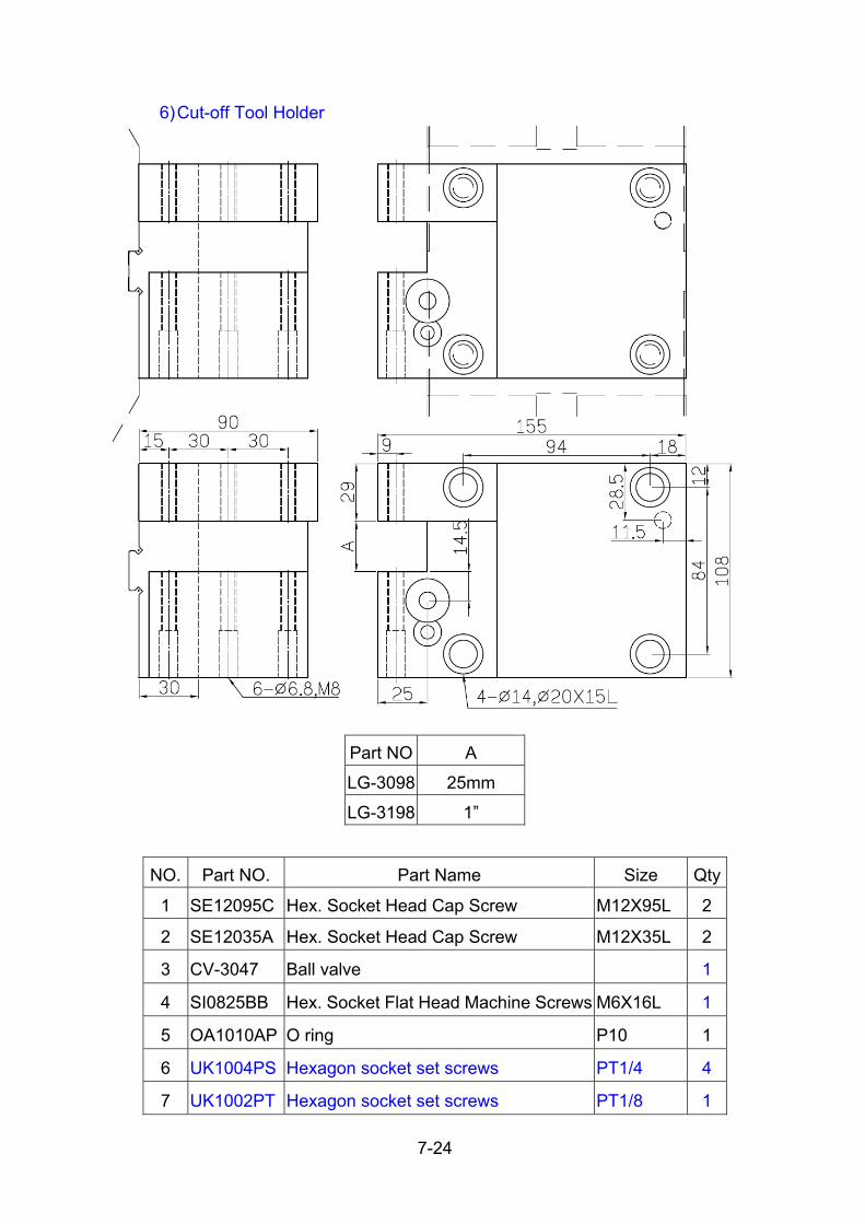
7-24
6) Cut-off Tool Holder
Part NO A
LG-3098 25mm
LG-3198 1”
NO. Part NO. Part Name Size Qty
1 SE12095C Hex. Socket Head Cap Screw M12X95L 2
2 SE12035A Hex. Socket Head Cap Screw M12X35L 2
3 CV-3047 Ball valve 1
4 SI0825BB Hex. Socket Flat Head Machine Screws M6X16L 1
5 OA1010AP O ring P10 1
6 UK1004PS Hexagon socket set screws PT1/4 4
7 UK1002PT Hexagon socket set screws PT1/8 1

7-25
7) Cut-off Tool Holder (Grooving type)
Part NO A
LG-3099 42.5mm

7-26
NO. Part NO. Part Name Size Qty
1 SE12035A Hex. Socket Head Cap Screw M12X35L 4
2 SE04025A Hex. Socket Head Cap Screw M4X25L 2
3 SE04030C Hex. Socket Head Cap Screw M4X30L 1
4 UK1004PS Hexagon socket set screws PT 1/4” 3
5 UK1002PT Hexagon socket set screws PT 1/8” 2
6 LG-3099B Cover 1
7 SI0508BB Hex. Socket Flat Head Machine Screws M5X8L 4
8 LG-3099A Block 1
9 GC120804 Ball valve 1
10 UK1004PS Hexagon socket set screws PT1/4 3
11 UK1002PT Hexagon socket set screws PT1/8 1

7-27
8) 0° Power driven tool
Parts no A
LG-3691 ψ23.8mm

7-28
9) 90° Power driven tool
Parts no A
LG-3692 ψ23.8mm

7-29
7.1.5 LF-3104 turret head tool holder 1) Face Cutting Tool Holder
Part NO A
LF-3197 50mm
LF-31A7 2”
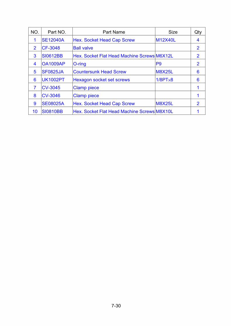
7-30
NO. Part NO. Part Name Size Qty
1 SE12040A Hex. Socket Head Cap Screw M12X40L 4
2 CF-3048 Ball valve 2
3 SI0612BB Hex. Socket Flat Head Machine Screws M6X12L 2
4 OA1009AP O-ring P9 2
5 SF0825JA Countersunk Head Screw M8X25L 6
6 UK1002PT Hexagon socket set screws 1/8PT×8 6
7 CV-3045 Clamp piece 1
8 CV-3046 Clamp piece 1
9 SE08025A Hex. Socket Head Cap Screw M8X25L 2
10 SI0810BB Hex. Socket Flat Head Machine Screws M8X10L 1

7-31
2) Cut-off Tool Holder
Part NO. A
CB-4797 42.5mm

7-32
NO. Part NO. Part Name Size Qty
1 SE12030A Hex. Socket Head Cap Screw M12X30L 4
2 SH0406BB Cross Recessed Button Head Cap Screws M4X6L 4
3 GC120804 Ball valve φ12 M4 1
4 OA1009AP O-ring P9 1
5 SE05030A Hex. Socket Head Cap Screw M5X30L 3
6 UK1001PS Hexagon socket set screws 1/16PT 1
7 UK1002PT Hexagon socket set screws 1/8PT×8 1
8 CX-4527 Clamp piece 1
9 CB-4528 Cover 1

7-33
3) O.D. Cutting Tool Holder
Part NO A
LF-3195 50mm
LF-31A5 2”

7-34
NO. Part NO. Part Name Size Qty
1 SE12055A Hex. Socket Head Cap Screw M12X55L 4
2 CF-3048 Ball valve M8 2
3 SI0616BB Hex. Socket Button Head Cap Screws M6X16L 2
4 OA1009AP O-ring P9 2
5 SF0825JA Countersunk Head Screw M8X25L 6
6 UK1002PT Hexagon socket set screws 1/8PT×8 2
7 CV-3045 Clamp piece 1
8 CV-3046 Clamp piece 1
9 SE08025A Hex. Socket Head Cap Screw M8X25L 2
10 SI0810BB Hex. Socket Flat Head Machine Screws M8X10L 1
11 UK1004PS Hexagon socket set screws 1/4pTX9L 2

7-35
4) Boring Bar Holder/ Throw-away Drill Holder
Part NO A
LF-3191 40mm
LF-31A1 1.5”

7-36
NO. Part NO. Part Name Size Qty
1 SE12080C Hex. Socket Head Cap Screw M12X80L 4
2 CF-3048 Ball valve 2
3 SI0612BB Hex. Socket Flat Head Machine Screws M6X12L 2
4 SF0814JA Hex. Socket Headless Set Screws M8X14L 6
5 OA1009AP O-ring P9 1
6 UK1002PT Hexagon socket set screws 1/8PT×8 3
7 CB-4598A Cover 1
8 SE05010A Hex. Socket Head Cap Screw M5X10L 3

7-37
5) Double Boring Bar Holder
Part NO A
LF-3193 φ32mm
LF-31A3 φ1.25”

7-38
NO. Part NO. Part Name Size Qty
1 SE12040A Hex. Socket Head Cap Screw M12X40L 4
2 CF-3048 Ball valve 4
3 SI0612BB Hex. Socket Button Head Cap Screws M6X12L 1
4 OA1009AP O-ring P9 1
5 SF0810JA Countersunk Head Screw M8X10L 12
6 UK1002PT Hexagon socket set screws 1/8PT×8 5

7-39
6) Double O.D. Cutting Tool Holder
Part NO A
LF-3196 50mm
LF-31A6 φ2”
NO. Part NO. Part Name Size Qty
1 SE12070C Hex. Socket Head Cap Screw M12X70L 4
2 CF-3048 Ball valve 4
3 SI0612BB Hex. Socket Button Head Cap Screws M6X12L 4
4 OA1009AP O-ring P9 1
5 SF0825JA Countersunk Head Screw M8X25L 12
6 UK1002PT Hexagon socket set screws 1/8PT×8 2
7 UK1004PS Hexagon socket set screws 1/4PTX9 1

7-40
7.1.6 CR-3004 turret head tool holder
1) In case of the Turning Tool is mounted on the Turret head directly.
Tool size is 25× 25mm
* Both clamp pieces are standard on the turret head.

7-41
Part NO. NO. Part NO Part Name Size Qty
1 SE08030A Hex. Socket Head Cap Screw M8X30 2 CV-3045
CV-3046 2 SI0810BB Hex. Socket Flat Head Machine Screws M8X10 1
1 CF-3048 Ball valve 2
2 SI1016BB Hex. Socket Flat Head Machine Screws M10X16L 2
3 OA1110AP O-ring P11 1 CR-3077
4 SE08055A Hex. Socket Head Cap Screw M8X55L 1

7-42
2) Face Cutting Tool Holder
Part NO A
CR-3079 50mm
CR-3111 2”

7-43
NO. Part NO Part Name Size Qty
1 SE12070C Hex. Socket Head Cap Screw M12x70L 4
2 SF1030JA Hex. Socket Headless Set Screws M10x30L 6
3 CV-3047 Ball valve 2
4 SI0820BB Hex. Socket Flat Head Machine Screws M8x20L 2
5 UK1004PS Hexagon socket set screws 1/4PT 1

7-44
Part NO A
CR-3080 50mm
CR-3112 2”
NO. Part NO Part Name Size Qty
1 SE12075C Hex. Socket Head Cap Screw M12x75L 4
2 SF1030JA Hex. Socket Headless Set Screws M10x30L 6
3 SI0820BB Hex. Socket Flat Head Machine Screws M8x20L 2
4 CV-3047 Ball valve 2
5 UK1004PS Hexagon socket set screws 1/4PT 1

7-45
3) Double O.D. Cutting Tool Holder
Part NO A
CR-3074 50mm
CR-3110 2”

7-46
NO. Part NO Part Name Size Qty1 SE12055C Hex. Socket Head Cap Screw M12x55L 4 2 CF-3048 Ball valve 2 3 SI0616BB Hex. Socket Flat Head Machine Screws M6x16L 2 4 SF0830JA Hex. Socket Headless Set Screws M8x30L 8 5 CV-3093 Clamp piece 1 6 UK1002PT Hexagon socket set screws 1/8PT 3
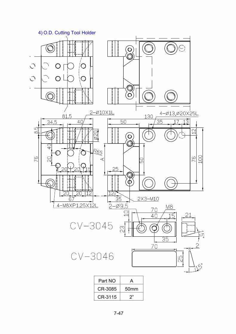
7-47
4) O.D. Cutting Tool Holder
Part NO A
CR-3085 50mm
CR-3115 2”

7-48
NO. Part NO Part Name Size Qty
1 SE12035A Hex. Socket Head Cap Screw M12X35 4
2 SE08030A Hex. Socket Head Cap Screw M8X30 2
3 CF-3048 Ball valve 2
4 SI0616BB Hex. Socket Flat Head Machine Screws M6X16 2
5 CV-3045 Clamp piece 1
6 CV-3046 Clamp piece 1
7 SE08025A Hex. Socket Head Cap Screw M8X25 2
8 SF1025JA Hex. Socket Headless Set Screws M10x25 6
9 UK1002PT Hexagon socket set screws 1/8PT 3

7-49
5) Cut off tool Holder
Part NO A
CR-3075 25.5mm
CR-3105 1.02”
NO. Part NO Part Name Size Qty
1 SE12030A Hex. Socket Head Cap Screw M12X30 2
2 SE12085C Hex. Socket Head Cap Screw M12X85L 2
3 SF0830JA Hex. Socket Headless Set Screws M8X30L 5
4 UK1002PT Hexagon socket set screws 1/8PT 2

7-50
Part NO A
CR-3096A 42.5mm

7-51
NO. Part NO Part Name Size Qty
1 SE12035A Hex. Socket Head Cap Screw M12X35L 4
2 SE04025A Hex. Socket Head Cap Screw M4X25L 1
3 SF0525JA Hex. Socket Headless Set Screws M5X25L 2
4 GC120804 Ball valve 1
5 UK1002PT Hexagon socket set screws 1/8PT 2
6 CR-3096B Cover 1
7 SE04008A Hex. Socket Head Cap Screw M4X8L 4

7-52
6) Boring Holder /Throw-away Drill Holder
Part NO A
CR-3078 ψ40mm
CR-3106 ψ1.5”

7-53
NO. Part NO Part Name Size Qty1 SE12070C Hex. Socket Head Cap Screw M12x70L 4 2 SF1030JA Hex. Socket Headless Set Screws M10x30L 6 3 CV-3047 Ball valve 2 4 SI0816BB Hex. Socket Flat Head Machine Screws M8x16L 2 5 CV-3097 Cover 1 6 SE05010A Hex. Socket Head Cap Screw M5X10L 3 7 UK1004PS Hexagon socket set screws 1/4PT 1

7-54
7) Throw-away Drill Holder
Part NO A
CR-3076 ψ40mm
CR-3109 ψ1.5”
NO. Part NO Part Name Size Qty1 SE12070C Hex. Socket Head Cap Screw M12x70 4 2 SF1020JA Hex. Socket Headless Set Screws M10x20 4 3 SF1030JA Hex. Socket Headless Set Screws M10x30 2 4 CF-3048 Ball valve 2 5 SI0616BB Hex. Socket Flat Head Machine Screws M6x16 2 6 UK1002PT Hexagon socket set screws 1/8PT 1 7 UK1004PS Hexagon socket set screws 1/4PT 2

7-55
8) Double Boring Holder
Part NO A
CR-3073 ψ32mm
CR-3107 ψ1.25”

7-56
NO. Part NO Part Name Size Qty1 SE12100C Hex. Socket Head Cap Screw M12x100L 4 2 CF-3048 Ball valve 2 3 SI0616BB Hex. Socket Flat Head Machine Screws M6x16L 2 4 SF0820JA Hex. Socket Headless Set Screws M8x20L 6 5 SF0810JA Hex. Socket Headless Set Screws M8x10L 6 6 UK1002PT Hexagon socket set screws 1/8PT 3

7-57
Part NO A
CR-3084 ψ32mm
CR-3114 ψ1.26”
NO. Part NO Part Name Size Qty1 SE12080C Hex. Socket Head Cap Screw M12x80L 2 2 SE12040A Hex. Socket Head Cap Screw M12x40L 4 3 CF-3048 Ball valve 3 4 SI0616BB Hex. Socket Flat Head Machine Screws M6x16L 3 5 SF0820JA Hex. Socket Headless Set Screws M8x20L 6 6 SF0810JA Hex. Socket Headless Set Screws M8x10L 6 7 UK1002PT Hexagon socket set screws 1/8PT 4

7-58
7.1.7 Sockets
1)Boring Socket
Part NO. C D E F G CJ-3016A 39mm 44.5mm φ12mm φ13mm φ40mm CJ-3016B 39mm 44.5mm φ16mm φ17mm φ40mm CJ-3112A 37mm 44.05mm φ0.5” φ14mm φ1.5” CJ-3112B 37mm 44.05mm φ0.625” φ17mm φ1.5”
NO. Part NO. Part Name Size Qty
1 SF0816JA Hex. Socket Headless Set Screws M8X16L 1
2 SF0812JA Hex. Socket Headless Set Screws M8X12L 2
Part NO. CJ-3016C CJ-3016D CJ-3016E
A 8mm 10mm 6mm
B 35mm 35mm 35mm
C 89mm 84mm 94mm
NO. Part NO. Part Name Size Qty
1 SF0612JA Hex. Socket Headless Set Screws M6X12L 1
2 SF0608JA Hex. Socket Headless Set Screws M6X8L 1

7-59
Part NO. CF-3052A CF-3052B CF-3052C CF-3052D CF-3052E
A ∅12mm ∅10mm ∅16mm ∅8mm ∅6mm
B ∅13mm ∅17mm ∅11mm ∅10mm ∅7mm
C 40mm 40mm 40mm 60mm 60mm
D 100mm 100mm 100mm 85mm 85mm
E ∅32mm ∅32mm ∅32mm ∅32mm ∅32mm
F 12mm 12mm 12mm 12mm 12mm
Part NO. CF-3105A CF-3105B CF-3105C CF-3105D
A ∅0.5” ∅0.375” ∅0.625” ∅0.25”
B ∅14mm ∅11mm ∅17mm ∅8mm
C 40mm 40mm 40mm 40mm
D 100mm 100mm 100mm 100mm
E ∅1.25” ∅1.25” ∅1.25” ∅1.25”
F 15mm 15mm 15mm 15mm
NO. Part NO Part Name Size Qty
1 SF0612JA Countersunk Head Screw M6×L12 1
2 SF0608JA Countersunk Head Screw M6XL8 1

7-60
Part NO. CJ-3112C CJ-3112D CJ-3112E
E ψ0.375” ψ0.25” ψ0.3125”
F 11mm 8mm 9.5mm
H 55mm 60mm 55mm
NO. Part NO Part Name Size Qty
1 SF0816JA Countersunk Head Screw M8X16L 1
2 SF0812JA Countersunk Head Screw M8X12L 2

7-61
2) Boring Bush
Part NO. CJ-3080A CJ-3080B CJ-3080C CJ-3080D
D φ20mm φ25mm φ32mm φ40mm
NO. Part NO. Part Name Size Qty
1 SF0806JA Hex. Socket Headless Set Screws M8X6L 3
2 SF0808JA Hex. Socket Headless Set Screws M8X8L 1
Part NO. CJ-3116A CJ-3116B CJ-3116C CJ-3116D
D φ0.75” φ1” φ1.25” φ1.5”
NO. Part NO. Part Name Size Qty
1 SF0825JA Hex. Socket Headless Set Screws M8X25L 1

7-62
3)Boring Bar Sleeve
Part NO. A B C D E
CJ-3014A 20mm 39mm 40mm 79mm 4mm
CJ-3014B 25mm 39mm 40mm 79mm 4mm
CJ-3014C 32mm 39mm 40mm 79mm 4mm
CJ-3110A 0.75” 48mm 1.5” 73mm 5mm
CJ-3110B 1” 48mm 1.5” 73mm 5mm
CJ-3110C 1.25” 48mm 1.5” 73mm 5mm
NO. Part NO. Part Name Size Qty
1 SF0808JA Hex. Socket Headless Set Screws M8X8L 1
Part
NO. CV-3203A CV-3203B CV-3203C CV-3203D
A φ16mm φ20mm φ25mm φ32mm
B φ40mm φ40mm φ40mm φ40mm
C 85mm 85mm 85mm 85mm
Part NO. Part Name Size Qty
SF0808JA Hex. Socket Headless Set Screws M8X8L 1

7-63
Part NO. D NO. Part NO. Part Name Size QtyCV-3204A φ1”
CV-3204B φ1.25” 1 SF0808JA
Hex. Socket Headless Set
Screws M8X8L 1
Part NO. A Part NO. Part Name Size Qty
CF-3055A φ20
CF-3055B φ25 SF0808JA Hex. Socket Headless Set Screws M8X8L 1
Part NO. A Part NO. Part Name Size Qty
CF-3104A φ0.75
CF-3104B φ1 SF0808JA Hex. Socket Headless Set Screws M8X8L 1

7-64
4) Drill Socket
Unit: mm
Part No. Taper A B C D E F G
CJ-3010 MT-2 40mm 37mm 46mm 7mm 14.9mm 63mm 67mm
CJ-3011 MT-3 40mm 37mm 46mm 9mm 20.2mm 78mm 83.2mm
CJ-3107 MT-2 1.5” 35.1mm 45mm 7mm 14.9mm 63mm 67mm
CJ-3113 MT-3 1.5” 36mm 45.05mm 9mm 20.2mm 78mm 83.2mm
Part No. Taper/B A
CF-3107 MT-1/1.25” 85 mm
CF-3053 MT-2/32 mm 85 mm
CF-3054 MT-1/32 mm 85 mm
CJ-3106 MT-1/1.5“ 90 mm

7-65
7.2 Chuck (Jaw chuck & Collet chuck)
(Chuck size)
CHUCK MODEL A B C
8” B-208A6 210 103 142
10” B-210A8 254 113 156
12” B-212A8 304 122 173
15” B-15A11 381 160 230
7.2.1 How to mount the chuck
Mounting methods are slightly different depending on type of chuck.
Refer to the following instructions and disassembled parts list when mounting the
chuck.
Refer to the own instructions manual for other manufactures chuck.

7-66
KITAGAWA Chuck type 1)
2)
3)
4)
5)
6)
7)
8)
9)
Remove the soft jaws [6] and cover [4] from the chuck [2].
Advance the draw tube in the spindle by stepping the chuck foot switch.
Screw the joint tube [1] into the draw nut of the chuck [2].
Insert the joint tube [1] into the spindle lifting the chuck [2] by hand.
Turn the draw nut of the chuck by using the wrench [9] to connect the joint tube [1] to the draw tube in the spindle, supporting the chuck body [2].
Fix the chuck body [2] onto the spindle with the cap screws [3].
Check a runout of the chuck.
Attach the cover [4] with the screw [5].
Attach the soft jaws [6] and T-nuts [7] with the cap screws [8]. Then tighten the cap screws [8] completely.

7-67
Fig. 7.2.1
NO. PARTS NAME QTY
1 JOINT TUBE 1
2 CHUCK BODY 1
3 CAP SCREW 6
4 COVER 1
5 CAP SCREW 3
6 SOFT JAW 3
7 T-NUT 3
8 CAP SCREW 6
9 WRENCH 1

7-68
7.2.2 Chucking pressure adjustment
When adjustment of chucking pressure is needed, adjust the pressure regulator
valve which is located at left of the machine. Turn the adjust knob after loosening
the lock nut as shown below.
* Turning clockwise ---- Increase the pressure
* Turning counterclockwise ---- Decrease the pressure
* Adjusting range of pressure: 4-- 25 kgf/cm2

7-69
7.2.3 Allowable maximum chuck pressure and speed
The chuck pressure and spindle speed is limited as shown in the following table
depending on a chuck to be used.
Type Max. chuck pres.
kgf / cm2
Max. chuck RPM
8” B-208A6 27.5 5000
10” B-210A8 27.5 4200
12” B-212A8 27.5 3300
15” B-15A11 23.5 2500
(NOTE) Maximum spindle speed must be reduced depending on the size of
workpiece and chucking condition for safety.

7-70
7.2.4 Chuck gripping force
The centrifugal force effect, which diminishes gripping force as speed increases,
and the consequent maximum speed recommendation are affect by initial gripping
force, jaw assembly mass and the position of the jaws when gripping the
workpiece.
Refer to the Fig. 7.2.2 "CHARACTERISTIC GRAPH" of chuck.
(NOTE) The piston area of the cylinder Specification Effective piston area (cm2)
Chuck size Type EXTRND RETRACT
8” S1552 161 150
10" S1875 198 183
12” S2091 252 234
15” F2511H 348 336
* "CHARACTERISTIC GRAPH" shows the experimental valves of the gripping
force per three (3) jaws at the max. operating chuck pressure when the outside end
of standard soft jaws are positioned at the peripheral dia. of the chuck.

7-71
Fig. 7.2.2

7-72
7.2.5 Selection of chuck clamping direction
Use the OPR. Selection to select the chuck clamping position as shown in the
following. 1) Unclamp the chuck.
2) Press key.
3) Press or .
4) Until OPR appers, press . .
Next Page

7-73
5) Move cursor to [CHUCK IO], and select OFF (INSIDE CLAMP) or ON
(OUTSIDE CLAMP).
(NOTE) 1.Clamping over of clamping direction should not be performed when
the workpiece has been clamped.
2. Clamping over of clamping direction can not be completely by
shifting the chuck clamp switch unless NC power is turn off once and
Chuck IO off Chuck IO ON

7-74
7.2.6 Chuck interlock switch adjustment
Two proximity switches have been attached in the rear of the chuck cylinder and
the dog has been attached on the end of draw tube as shown in the following
sketch.
The switch PS4 is for confirming the chuck cylinder piston retracted andthe switch
PS3 is for confirming the chuck cylinder piston advanced.
It is necessary to adjust location of switches in accordance with clamping stroke of
the chuck and diameter of the workpiece.
Chuck closed confirmation PS3 Check closed confirmation PS4 for FRONT END
position for REAR END position.
In case [OUTSIDE] is selected on the chuck clamp switch:
PS4 becomes effective and adjust its position so that switch is turned on when the
workpiece is clamped.
In case [INSIDE] is selected on the chuck clamp switch:
PS3 becomes effective and adjust its position so that switch is turned on when the
workpiece is clamped.
(NOTE) 1. Spindle rotation and automatic cycle can not be started even if the
chuck closed lamp lights up unless the proximity switch is turned on. 2.The machine becomes the "FEED HOLD" mode and the
spindle stops when the proximity switch is turned off during
automatic cycle.

7-75
7.2.7 Boring soft jaws
The soft jaws are designed to be bored on the machine to provide the maximum
accuracy possible.
They are normally used for second operations where relatively light finish cuts are
being taken.
They are also of benefit when marring of the workpiece surface by the teeth of a
hardened jaw in undesirable.
The soft jaws can be bored by the following operations.
*** Using the manual pulse generator HANDLE or JOG feed buttons.
*** Using an automatic cycle or MDI operations.
(NOTE)
(1.) Do not permit jaws mounting to extend beyond the out side diameter of the
chuck, and mount the jaws to the chuck without runout.
(2.) Bore the soft jaws under some chuck pressure as actual machining.
(3.) For external work, load the chuck jaws by gripping on a plug and bore to the
dimension of the workpiece 0.05-0.1mm larger.
(4.) For extra heavy duty gripping force, it is advisable to bore to the dimension of
the workpiece 0.5-1mm smaller or to finish the gripping surface slightly
tapered.

7-76
(5.) Check contact between gripping surfaces of the jaws and the workpiece by
inserting pieces of thin paper, etc. Full contact will give the best results.
(6.) Stamping the Number (1,2 and 3) on the soft jaws to match the master jaws.

8-1
8. Tool offset 8.1. Determining start position of machining
It is very important to check a start position of the tools before starting actual
cutting to prevent machine collision.
There are two ways to determine the start position of the tools, which are
"Automatic coordinate system setting (G50)" functions.
At first it is necessary to figure out the start position (G50 amount) of the each tools
to be used.
G50 amount of each tools can be figured out as following steps.
A. How to figure out the start position (G50 X (A) Z (B))
1)
2)
3)
4)
Move the X and Z-axis slide to the zero return position.
* X=0, Z=0 shall be shown in the MACHINE position display.
Call up the total to be used by indexing.
Load the workpiece on the chuck.
Turn the face of workpiece by using "HANDLE" mode.
* Skin cutting

8-2
5)
6)
7)
8)
9)
10)
11)
Move the tool in the direction of +X away from the workpiece and stop the spindle. (Do not move in the direction of Z-axis after turning.)
Read the Z-amount of [MACHINE] on the position display. Let [a] = Z amount When finishing allowance still remains on the face, Let [d] = finishing allowance.
Turn the outer diameter (or inner diameter) of workpiece.
Move the tool in the direction of Z away from the workpiece and stop the spindle.
Read the X-amount of [MACHINE] on the position display. Let[b] = X amount
Measure the actual turning diameter. Let[c] = Actual turning diameter.
* In case of using reference position as start position. Let [b] + [c] = X amount of G50, [a] + [d] = Z amount of G50 G50 X [b + c] Z [a + d]
Normally closer position to the workpiece is used as start position instead of reference position to reduce the idle time.

8-3
12)
13)
* X and Z amount of G50 will become coordinate amount of each tools start
position.
* In case of using close position where is shifted 100mm/dia. in X-axis and 200mm in Z-axis away from zero return position. Let ([b + c] – 100. ) = X amount of G50, ([a + d ] – 200. ) = Z amount of G50. G50 X [b + c - 100.] Z [a + d - 200.]
Find out G50 X,Z of other tools as above procedure (2) --- (12).
Sample program: % O1234 N100 G28 U0. W0. T100 G50 X[b1 + c1] Z[a1 + d1] G99G0G97Sssss G0 Xxxx Zzzz : Cutting : N200 G28 U0. W0. T200 G50 X[b2 + c2] Z[a2 + d2] G99G0G97Sssss G0 Xxxx Zzzz : Cutting : N300 G28 U0. W0. T300 G50 X[b3 + c3] Z[a3 + d3] : M5 G28 U0. W0. M30 %

8-4
B. How to move the slide to the start position. There are two ways to move the slide to the start position
Which are by manual operation and automatic operation.
The following shows the way using automatic operation.
* Perform the program for moving the slide to the position when the power is
turned on or start position is not correct.
(Example program for moving the slide to the start position.) O1000; / G28 U0; / G28 W0; / G00 W-200.; / U-100.; / M00;
NOTE This program can be executed when " BLOCK DELETE " switch has been turned off.
(Example program for machining.) N100 G50 XA ZB S3000; A = ([b] + [c]) - 100. N101 G96 G40 S150 T0101 M03; B = ([a] + [d]) - 200. : : N200 G50 XA' ZB'; A ‘= ([a'] + [b']) - 100. N201 G97 S1000 T0202 M03; B ‘= ([a'] + [d']) - 200. : :
(NOTE) When G50 (Coordinate setting) is used in the program, X and Z amount for return position shall be same as start position. Therefore, actual position of each tools for indexing is always same regardless of tool stations.

8-5
To clear the value of work shift, then do zero return of x-axis and z-axis.
To install the required tools. (the interference when processing and the balance of turret disc should be considered.
To clamp the work piece with proper pressure and to rotate it with proper speed.
T0101
○1 ○2 ○3
8.2. Manual OFS/SET method * OD TOOL (imagine nose of tool direction=3):
(1)
(2)
(3)
(4)
(5)
(6)
(7)
Index to the designate tool no. (For example: T0101)
Switch to “HANDLE” mode, to move the tool to the 2mm outside of the work piece then move to touch the work piece slowly.
Switch to “HANDLE X10 “ mode, to downward the nose of tool to touch the OD of the work piece.( see ○1 in below )
Cutting the rough part by proper feedrate in “–Z button” under JOG mode or to use “HANDLE X10” mode.( ○2 in below route)
Continue
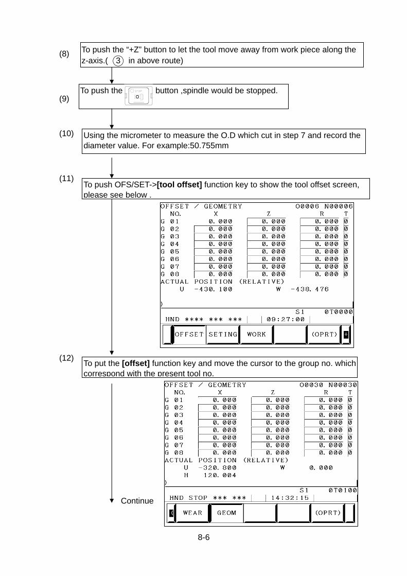
8-6
(8)
(9)
(10)
(11)
(12)
To push the “+Z” button to let the tool move away from work piece along the z-axis.( ○3 in above route)
To push the button ,spindle would be stopped.
Using the micrometer to measure the O.D which cut in step 7 and record the diameter value. For example:50.755mm
To push OFS/SET->[tool offset] function key to show the tool offset screen, please see below .
To put the [offset] function key and move the cursor to the group no. which correspond with the present tool no.
Continue

8-7
To push the “X” then input the value which you measure from the step 10. Then push the [MEASUR] key; machine would input the value automatically to the computer, the X-axis tool offset of T01 is completed.
Switch to “HANDLE” mode to move the tool to the 1mm right side of the work piece. Then using “HANDLE X10” to move the nose of tool to the left to make the nose touch the right side of work piece, please refer to below drawing.
T0101
○1
○2
(13)
(14)
(15)
(16)
To rotate the spindle with proper speed.
To cut the right side of work piece a little bit by proper feedrate. To move the nose of tool along with the +X direction until away from the O.D of work piece.
Continue

8-8
To move the turret to the suitable position (base on the no interference location when doing x-axis zero return);then doing x-axis zero return.
(17)
(18)
(19)
To move the cursor to the group no. which correspond to the present tool no.
To push the “Z0” first then push the[MEASUR]; machine would input the value automatically to the computer, the Z-axis tool offset of T01 is completed.
Continue

8-9
(20)
(21)
Choosing the next tool no. and repeat the step 4~step 19; until all tools are set completed. Please see below.
To check if the processing program is correct or not, if the processing parts are without problem then can be mass production.
END

8-10
<NOTE>
Tool compensation can be executed by commanding T-code as following.
Tool offset number : 01 -- 64
Turret station number: 01 -- 12
When the position of tool is shifted by changing insert by using input the offset
value as following procedure.
< Example >
The position of tool attached to the turret was shifted 0.04 mm
(0.08mm in dia) in the direction of -X axis ,and
0.07mm in the direction of + Z axis.
Therefore, the input offset value will be in the followings.
T

8-11
8.3. The OFS/SET method of reference tool. I. Setting the reference tool.
(1)
(2)
(3)
Choosing one tool as the reference tool , for example T0101.
To clamp the work piece first then rotate the spindle with proper speed; to move the reference tool to touch the right end of work piece, please refer to below drawing.
T0303
T0202
T0101
To move tool to touch the surface of work piece
To push the [POS] function key many times until the relative coordinates screen appeared.
Continue

8-12
(4)
(5)
(6)
(7)
(8)
To push the “W” key then push [ORIGIN] soft key to zero the W to record the present position
After pushing the [ORIGIN] key, the value of W will be zero, please see below drawing.
To move the turret to exact location (based on no interference when changing tools) ; spindle stop.
Index to the next tools, for example: T0202.
To rotate the spindle with proper speed; to move the nose of tool to touch the right end of work piece.
Continue
W be zero

8-13
(9)
(10)
(11)
(12)
(13)
(14)
Changing screen to [OFFSET/SET].
To push the [OFFSET] key then below drawing will appeared.
To push the [GEOM] key to next screen.
To move the cursor to the Z axis of G02.
Pushing “Z” key then “INP.C”.
Computer will input the difference which between T02 and reference tool into the Z-axis tool offset. Please see below drawing.
Continue

8-14
(15)
(16)
(17)
(18)
To repeat step 6~13 until all tools are set completely.
To move the reference tool (only the tools which designated in step 1) to touch the right end surface of work piece, please see below drawing.
T0303
T0202
T0101
To move tool to touch the surface of work piece
To move the cursor to the [MEASUREMENT].
Changing to [OFS/SET] screen then push “ “ many times to find
[ WORK SHIFT ].
Continue

8-15
(19)
To push Z0. then push [INPUT], the computer would calculated automatically and input the value to the work shift column. The tool offset procedure is finished.
END

8-16
8.4. Tool setter (option) 8.4.1. Introduction
This Manual is composed of specification of the tool setter, operations, and caution
of operations.
Therefore, the operator is requested to thoroughly read the following precautions
and operate the machine without overestimating the safety devices.
*The specifications, illustrations and descriptions given herein are subject to change without previous notice.

8-17
8.4.2. Tool setter construction
Fig 8.4.2 Tool setter construction

8-18
8.4.3. Specification
A. Outline of the setter Setter is composed of tool nose touch sensor mainly, and, it is equipped with tool
setter function and tool offset function when the tool tip is changed.
1. Function of the tool setter.
When the tool setter is provided, the tool offset value is automatically settable to
the tool offset memory simply by moving the tool to make contact with the swing
type touch sensor (3 point sensor) in manual operation.
Therefore, the work coordinate system, setting command (G50) IS unnecessary to
use in program.
Fig. 8.4.1

8-19
B. Tool setter limitation of tool overhang length 1) Turning tools
2) Facing & grooving tools
3) Boring tools
Fig. 8.4.2

8-20
C. Specification of the touch sensor 1) Type RENISHAW HPRA / HPMA Contacts 15 x 15 x 4 tungsten carbide stylus tip Contact stroke 1.5mm
2) Sense directions 4 directions (+/-X and + /-Z)
3) Offset increment X axis 0.005mm (on Rad.) Z axis 0.005mm
4) Measuring frequency at point 5) Static repeatability X axis 0.010mm (on dia.) Z axis 0.010mm
* Measured via 10 time trials at 10 mm/min 0.4 ipm slide speed
* This is not a figure for machining dimensions. 6) Chuck size 8”/10” /12” / 15”
max. overall length of chuck 8” -----142mm ( 5.6”)
and jaws 10”-----156mm (6.1”) 12” ----173mm (6.8”) 15” ---- 230mm (9.1”)
7) Tool size square □25 (1)
round ψ40 (1.5) /ψ50 (2)
* overhang length limited 8) Setting accuracy ±0.01mm 9) Others
* Air blow off for the sensor is furnished.
* NC function Direct input of measured valve B (tool setter) is furnished.
* On machine with tailstock, the distance between main spindle nose and
quill center shall be kept over A (refer to CH 2.9 Travels and working area
for distance A).
* On machine with tailstock, where boring or drilling tools are measured, the
overhang length will be limited by location of tailstock and/or mounting of
quill center: Ex. where tailstock is located at the most retracted position
and quill retracted (refer to CH 2.9 Travels and working area for distance
B).

8-21

8-22
8.4.4. Operation
A. Confirmation of the machine conditions Following descriptions are required to confirm before start to operate the tool
setter.
(1) The spindle shall be stopped.
(2) Tailstock and Quill shall be retracted position.
(3) Tool overhand length shall be set to suitable length as showing on Fig. 8.4.2.
(4) X and Y-axis shall be return to reference position.
Note: The cover must be mounted completely , or the electric parts willburn down while coolant water get into the base.(type 1)
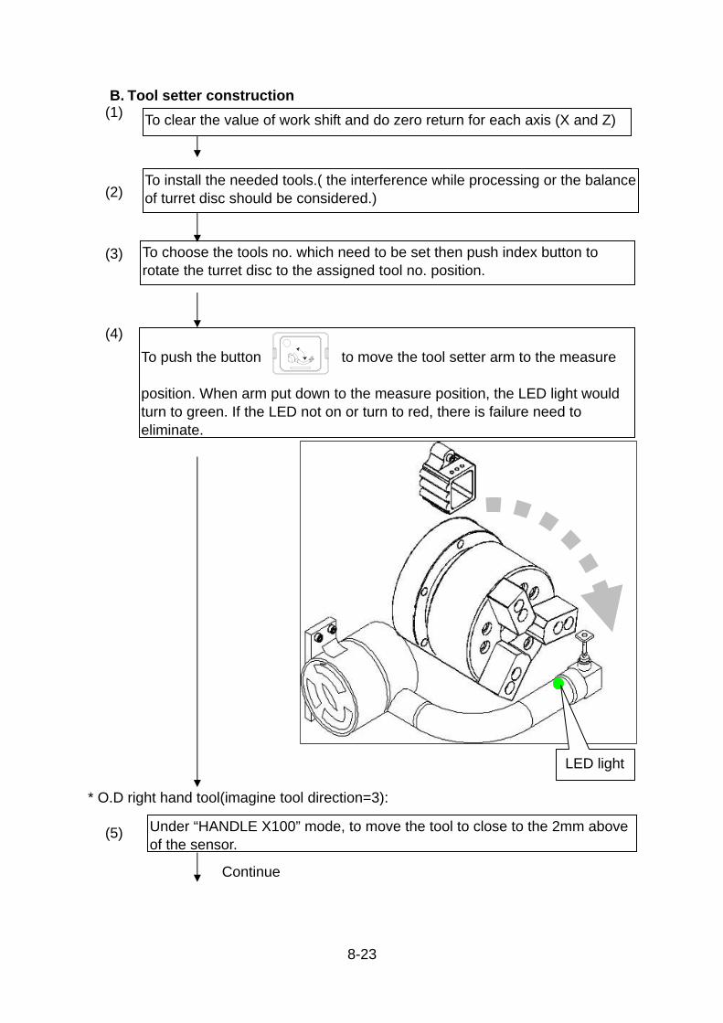
8-23
B. Tool setter construction (1)
(2)
(3)
(4)
* O.D right hand tool(imagine tool direction=3):
(5)
To install the needed tools.( the interference while processing or the balance of turret disc should be considered.)
To choose the tools no. which need to be set then push index button to rotate the turret disc to the assigned tool no. position.
To push the button to move the tool setter arm to the measure position. When arm put down to the measure position, the LED light would turn to green. If the LED not on or turn to red, there is failure need to eliminate.
Under “HANDLE X100” mode, to move the tool to close to the 2mm above of the sensor.
LED light
Continue
To clear the value of work shift and do zero return for each axis (X and Z)

8-24
(6)
(7)
(8)
(9)
(10)
Changing to JOG mode and choosing feedrate as 12.6 mm/Min.
To push “–X” button to move the tool closed to the sensor until tool touch the sensor. The LED light would change to red and X-axis offset value of tool will be input to the computer automatically.
After the x-axis offset value of tool input completely, please push “+X” to let the tool leave the sensor until the LED turn to green.
Changing to Handle X100 by mode selected button and moving the nose of tool to the 2mm right side of center of sensor.
To push –Z button to let the nose of tool close to the sensor until nose of tool touch the sensor. When the LED on the arm turn to red , machine will input the calculated coordinate value to the computer automatically.
Continue

8-25
OD TOOL
drill ID TOOL
(11)
(12)
(13)
(14)
(15)
After the tool offset value setting completely, to push the “+Z” to let the nose of tool leave the sensor until the LED turn to green.
Under HANDLE X100 mode, to move the turret to suitable position (based on there is no interference when doing zero return).
Zero return of X-axis.
To repeat the step 3-13 until all tools are set completed. (the routes of kinds of tool are showed below.)
To push the arm active button to let the arm move to the upper position.
Continue

8-26
T0101
To move tool to touch the surface of workpiece
(16)
(17)
(18)
To clamp the work piece with the chuck and rotate spindle with proper speed.
To choose any one of the tools as reference tool and use HANDLE mode to approach the surface (right end) of the work piece and cut the surface a little
To push the “WORK SHIFT MODE” button (old panel: to switch on the DIP switch ) , screen will turn to WORK SHIFT.
Continue

8-27
(19)
(20)
(21)
OR
When work shift screen appears then push “WORKSHIFT INPUT”, machine will input the work shift value to computer.
After inputting the work shift value, please switch off the [work shift mode] button to avoid crash which due to touch the work shift input key accidentally during processing.
After work shift value input completely then machine can run the processing program to machine work piece.
NEW
OLD
WORK SHIFT
OLD
WORK SHIFT
OR
NEW
END

8-28
C. Automatic OFS/SET: (1)
(2)
(3)
(4)
The tool setter arm could downward to the measure position by command M35.
The tool setter arm could be retraction position by M36.
To install the needed tools.(the interference when processing and balance of turret disc should be considered.)
Move X-axis to reference position.To put the tool setter arm down to the measure position , the LED is green. If the LED not on or turn to red, there is failure need to trouble shoot.
Continue

8-29
(5)
(6)
(7)
According to the step of “OFS/SET of tool setter arm” to set the tool length for each tool.
Choosing one tool as reference tool (for example:T0101), to move the tool nose to 6mm within the tool setter sensor by HANDLE mode.
Continue
To execute following programs to calibrate and measure stylus position. (Following programs should be under MDI mode and execute by single block mode.) G65 P9011 K2. T1. H3 ----to calibrate stylus position M30 G65 P9011 T1. H3. ----(without Kk) to measure the stylus position. :

8-30
(8)
Zero return X-axis, and retract the tool setter arm.
Explanation: P9011 --Login the sensor program K2. --Login the position of side of
sensor and its subtense. enter the K1. or K2. Input to indicate that a calibration cycle is required:
K1--calibrate by two tool with imagination tool direction H1and H3 or H2 and H4.
K2--calibrate by calculate with stylus dimension. Before use of K2 , to input correct stylus dimensions in #530 and #531 is necessary.
T1. --tool no.(only two digit no. is
acceptable) H3. --Imagine nose of tool direction,
H3=OD TOOL (please refer to below drawing)
Continue

8-31
(9)
AUTOMATIC OFS/SET:
O1024 G28 U0. ----------- X axis zero return
T0101 ----------- Choosing tool no. 1
M35 ------------ put the arm down
G65P9012 H3. ----------- Call sub-command O9012 to execute tool length and assign the shape as OD TOOL.
G28U0. ------------ X axis zero return
M36 ------------ To withdraw the tool setter arm M30
%
Note: Operator should input the tool length to the geometry screen by manual mode before doing automatic tool length OFS/SET.
Continue

8-32
(10)
Example program :before using variable #500~#599, operator must confirm that the variable in system can’t be taken up.
(Before setting #500,please execute program from N99) (Every 10 work piece do OFS/SET) (CURRENT MACHINED PART If processing q’ty is over #100 then execute auto tooTool length OFS/Set. tool no.2 OFS/SET (T2=tool no. 2, H3= imagination tool nose directionc for OD tool. Tool no.4 OFS/SET (T4tool no. 4,H2imagination tool nose direction c for OD tool. #500=current counter value, #501 would be zero) (Cutting-1) (Cutting-2)
O4096 #100=10 #501=[#3901-#500] IF[#501LT#100]GOTO1000 -------- N100(MEASURE 1ST-TOOL) T0202 G28U0. G30W0. M35 G65P9012T2.H3. G28U0. G30W0. N200(MEASURE 2ND-TOOL) G28U0. G30W0. T0404 M35 G65P9012T4.H2. N99 #500=#3901 G28U0. G30W0. M36 N1000
: (Cutting-1) M01 N2000
: (Cutting-2) M01 M30 %
END

8-33
8.5. Tool wear offset
★The tool insert may be worn and dimensions of work piece would have
difference after period of cutting. Operator can use “wear compensation” function
to correct the work piece size when tool is still can be used. (1)
(2)
(3)
(3-1)
To measure the work piece dimension and compare with the drawing. Tool no.:T0303 ; The work piece dimension is 0.007mm smaller than the drawing. (offset value=+0.007)
To push [OFS/SET] function key to display the tool offset screen .
To move the cursor to the OFS/SET position. (W03, X-axis),to input 0.007。
Increment OFS/SET: to push [+input], machine would plus the input value and original value together and input to the OFS/SET position.
Continue

8-34
(3-2)
(4)
(5)
Absolute OFS/SET: to put [input], machine would input the value to the OFS/SET .
OD OFS/SET completed, using the same way to do OFS/SET of Z-axis.
To repeat step 2~4 for all tool need to do OFS/SET; then can continue processing.
END

9-1
9. Machining (Actual Cutting)
It is very dangerous to start actual cutting without precaution.
Therefore start the actual cutting is accordance with the following procedure for
safety.
9.1. Program registration
Operator can create a NC program through MDI/LCD panel.
9.1.1. Registration form MDI/LCD panel (Manual registration).
1)
2)
3)
EDIT KEY
X1M.D.I.
ZERORETURN
RAPID
RESTART
EDIT
MEM.
MEM.
X100
JOG
X10
AUTO.
HANDLE
MANU.
Set the " EDIT KEY" key switch to " OFF " position.
Set the "MODE" switch to " EDIT " position.
Press "PROGRAM" key and display "PROGRAM" page.
To the next page.

9-2
4)
5)
6)
7)
8)
Key in Program No.(O ) by using "ADDRESS" and " NUMERICAL" key.
Do not press [EOB] key. (EX.) Key in [O1000]
Press "INSERT" key.
Press "INSERT" key.
Key in program to be stored by using "ADDRESS" and "NUMERICAL" key. Press “EOB” key in end of each block.
(EX.) N100
Repeat operation 6), 7) for more program input.

9-3
9.2. Program Edit
Editing the program stored can be made by following procedure.
1)
2)
3)
4)
EDIT KEY
X1M.D.I.
ZERORETURN
RAPID
RESTART
EDIT
MEM.
MEM.
X100
JOG
X10
AUTO.
HANDLE
MANU.
Set the " EDIT " key switch to " OFF " position.
Set the " MODE " switch to " EDIT ".
Press the " PRGRM " key to display " PROGRAM " page.
Move the CURSOR to the WORD to be edited by using " CURSOR SHIFT " keys.
To the next page.

9-4
* Editing operation
Alteration of word ? Deletion of word ? Insertion of word ?
Key in word to be altered.
Key in word to be inserted.
Press "DELETE" key
Press "ALTER" key. Press "INSERT" key.
Editing is finished
Note: The following variables have already been used in macro program of machine tool builder. When editting thr program, please don't use or change those variables. Otherwise, it will occur an unpredictable damage or injury.
Goodway Used: #503, #504, #505, #506, #507,#517, #518, #519, #520, #521
Renishaw Tool Setter Used: #509, #522, #523, #524, #525, #530, #531

9-5
9.3. Program Check
Check the program stored in the NC memory by following procedure.
1)
2)
3)
4)
5)
6)
Set the machine to automatic operating condition.
Refer to 6.14
Clamp the chuck without workpiece by stepping the chuck foot switch.
Set the "MODE" switch to the " MEM ".
Turn on the " MLK " (machine lock ) soft switch and " SINGLE BLOCK " switch.
Press "PROGRAM" key to display the "PROGRAM" page.
Press "O" (Oh not zero) key. Input the desired program number.
To the next page.
BDT SBK
DRN

9-6
7)
8)
9)
Press down side cursor key or [O SRCH] soft key to load program.(Upper side cursor key does not work)
* Confirm the cursor locates at begin of program.
Press" CYCLE START " button to start cycle.
Confirm the motion and position display comparing with the program sheet.
Program check is finished.

9-7
9.4. Automatic operation without workpiece
Start automatic cycle without workpiece by using program for actual cutting after
confirming all functions to be performed and the following conditions.
1)
2)
(ITEMS TO BE CONFIRMED)
* Tool mounting condition and tool stations, * Setting amount of tool offset. * Setting of "FEEDRATE OVERRIDE" switch.(100% shall be set) * Condition of switches. "SINGLE BLOCK" & "OPTIONAL STOP" ---to be "ON" "DRY RUN" ---to be "ON" "MLK" soft switch of [OPR] screen. ---to be "ON" * Location of tailstock slide. * Starting position of tool. * Starting block of program to be executed.
Set the "MODE" switch to " MEM " position
Press "PROGRAM" key.
Display the program to be executed on the LCD monitor.
To the next page.
X1M.D.I.
ZERORETURN
RAPID
RESTART
EDIT
MEM.
MEM.
X100
JOG
X10
AUTO.
HANDLE
MANU.

9-8
3)
4)
Confirm the program has been returned to the starting block.
If the program has not been returned. set the mode switch to "EDIT" and press "RESET" key to make the cursor return to the begin of program.
Press " CYCLE START " button to execute single block.
Repeat pressing " CYCLE START" button until all blocks are executed.
Operation is finished

9-9
9.5. Actual Cutting
Try to make actual cutting with workpiece in accordance with the following
procedure after all functions are confirmed.
1)
2)
3)
4)
Confirm the all items shown in 9.4 are performed.
Confirm chuck pressure and mounting condition of chuck jaws.
Grip the workpiece and check a run-out of the workpiece by using " SPINDLE JOG " button.
Set the "MODE" switch to " MEM " position.
Press " CYCLE START "button to execute single block and cycle start lamp will light up.
Cycle start lamp will light off when single block is executed.
*Repeat pressing "CYCLE START" button until all programms are executed.
Cutting is finished
SP. JOG
X1M.D.I.
ZERORETURN
RAPID
RESTART
EDIT
MEM.
MEM.
X100
JOG
X10
AUTO.
HANDLE
MANU.

9-10
9.6. Measuring cutting size and other operations during automatic cycle.
Optional stop (M01) function can be used to stop the cycle in the middle of
operation for measuring cutting size and removing cutting chips as following
procedure.
1)
2)
3)
4)
Set the " OPTIONAL STOP " switch to "ON" position
Press" CYCLE START " button.
Operation will stop when M01 (Optional stop) command is executed, and optional lamp will light up.
*Remove cutting chips *Measure cutting size.
Press " RESET" key.
Start the cycle again?
All programs were executed?
To the next page To the next page
From next page
NO
NO
YES
M01
M01
YES

9-11
5)
6)
7)
Execute last operation again?
YES
NO
Input offset value to be compensated.
Refer to the Ch. 8.3
Move the tool to the start position.
Search a starting sequence No. to be performed.
Cycle is finished
From previous page
To previous page
From previous page

9-12
9.7. Sub-spindle operation (OP.) 9.7.1. Note for operating sub-spindle
1) The data sheet of M code please refer to Appendix A
2) While work piece is in the sub-spindle for second process, please use
M203(C.W.) or M204 (C.C.W.) for sub-spindle rotation.
Ex:
N2 G0 G97 S1500 T101 M3;
:
:
:
G0 G97 S2000 T816 M203;
M205;
M30;
3) Don't let both spindles camp the work piece simultaneously before main
spindle & sub-spindle are synchronized (M43, M44) or stop (M45), or it may
damage work piece. (The spindle and sub-spindle may be rotate in opposite
direction and make scrapping on workpiece surface during synchronization. ).
Therefore, please synchroze (M43 or M44) first. Then sub-spindle can camps
the work piece
Ex:
N1 M11;
N2 M5;
:
N8 M210; Sub-spindle keep unclamp
N9 M43 S0; Synchronization with 0 RPM
N10 S1000; Rotate by desired speed
N11 M211; Sub-spindle chuck clamp
4) When a work piece is machined in main spindle and would like to transfer to
sub-spindle. Please make sure the following.
(1) Before moving, please do G28 U0 first to the home position.
(2) Make sure sub-spindle is unclamp to avoid collision during workpiece
transfer from main spindle to sub-spindle.

9-13
(3) Moving B-Axis (sub-spindle) to your setting point and give G01 to the
position to take work piece.
(4) After sub-spindle chuck is clamp (M211), please give G04 U2.; (Dwell 2
sec.) to make sure clamping process is finished for safety.
When a work piece is machined in main spindle and would like to transfer to
sub-spindle. Coolant pump must stop working (M09).When it equipped air blow
(M20, M220), please rotate main & sub-spindle very slowly to help air blow clean
chuck. However, if it doesn't have air blow, please rotate the main or sub-spindle
in a high speed to clean the chuck which can make sure high accuracy
machining.
When there has power turret and sub-spindle in same system of controller (when
it is signal system), both cannot work (rotation) at the same time but one. For
instance, sub-spindle is working (M203 or M204), power turret will not activate.
When power turret is working (M73 or M74), sub-spindle can not do M203 or
M204 and indexing.

9-14
9.7.2. Sample program of sub-spindle operation
1. work piece
2. Working process 1)process 1:
Machining 1st (right) side process.(a finished work piece has
been gripped at sub-spindle last time)
O2001 (program NO.)
︰
︰
︰
M01;

9-15
2)process 2:
Return to the home position first, sub-spindle moves to the position of
unloading part. Then the parts catcher activated. Eject part with part
ejector.
Assuming: part ejecting position = B-450.
Sub-spindle approaching position = B-630.
Sub-spindle clamping position = B-660.
N9000 (PART UNLOAD)
G28 U0 B0 M09; Move X and B to reference position.
G0 B-450. part ejecting position = B-450.
M68; Part catcher active.
G04 X1. ;
3)process 3:
Sub-spindle chuck unclamp, and dwell to ensure unclamping
completely. Active the part ejector, part falls into the parts catcher and
the catcher returns.

9-16
M210; sub-spindle chuck unclamp
G04 X2.; Dwell time 2 sec.
M72 eject the part.
M69; part catcher retract.
G04 X2. ;
M01;
4)process 4:
Air blow of main spindle enable to clear work piece. Then sub-spindle's
enable to clear the chuck.
N9 (Cutoff)
G28 U0;
.
.
M20; (Air blow of main spindle on)
M03 S20;
B-630. ; (Sub-spindle moves to the position of
synchronous control.)
Sub-spindle approaching position
M05;
M21; (Air blow stop)
M220; (Air blow of sub-spindle on)
M203 S20;
G04 X3. ;
M205; (Sub-spindle stop)
M221; (Air blow stop)

9-17
5)process 5:
Both spindle in synchronous control and the sub-spindle grips the work
piece.
M44 S0; Main spindle and sub-spindle synchronized
G98 G01 B-660. F600; Move sub-spindle to clamping position.
M211 G99;
G04 X2.;
6)process 6:
The work piece is cut off and the sub-spindle home return.
G50 S1500; (Setting spindle speed)
G96 S120;
G0 X44.; (Tool moves to preparatory position of
cutting off)
M08; (coolant on)
G75 X-1. P3000 F0.12; (Cut off)
G0 X44.; (Tool return)
G28 B0 M45; (Sub-spindle home return, and
synchronous control off)
M09; (coolant off)
G30 U0 W0; (2nd reference point return)
M01;

9-18
7)process 7:
Machining 2nd (left) side of work piece process.
N10
︰
︰

9-19
3. Program O2345
G40C22.F500; Process 1
G113;
G0X5.M18;
G28U0M75;
M01;
N9000(UNLOADER); Process 2
G28B0U0M9;
G0B-450.; part ejecting position = B-450.
M68;
G4X1.;
M210; Process 3
G4X2.;
M72;
M69;
G4X2.;
M01;
N9(CUTOFF) Process4
G28U0;
T828M210; Use offset #21~#32 for sub-spindle
G0Z-48.6;
M20
M03S20;
B-630.M21; Tool offset for axis B is not available.
Sub-spindle approaching position = M203 S20;

9-20
M220;
G04X3.;
M205;
M221;
M44S0; Process 5
G98G1B-660.F600; Specify clamping position at this block.
Sub-spindle clamping position = B-660. M221G99;
G4X2.;
G50S1500; Process 6
G96S120;
G0X44.;M08;
G75X-1.P3000F0.12
G0X44.
G28U0M45;M09;
G28B0;
G30U0W0;
M1;
N10(FACE); Process 7
G28B0;
G50S3000;
G0G96S300T0121M8;
M204;
X44.Z1.5;
G1X40.F0.2;
Z0.R1.F0.15;
X-1.F0.1;
G0X150.Z-100.;

9-21
M1;
N11(Center);
G0G97S2000T1030M8;
M204;
X0Z-1.5;
G1Z2.7F0.08;
G0Z-50.;
M1;
N12(5.0D DRILL);
G0G97S2000T1232M8;
M204;
X0Z-1.5;
G1Z27.F0.09;
G0Z-5.;
X150.Z-50.M205;
M1;
N13(4-4.5D PCD 32) (center) Process (only for Power driven turret)
G0G97S1800T1131M8;
M73
X32.Z-1.5;
M219;
G28 C0.
G0C0;
M98P2002; to subprogram for center drilling
C90.;

9-22
M98P2002;
C180.;
M98P2002;
C270.;
M98P2002;
M218;
G0Z-50;
M1;
N14(4.5D DRILL);
G0T0929G97S2000M73;
X32.Z-1.5;
M219;
G28C0.
G0C0;
M98P2003; to subprogram for drilling
C90.;
M98P2003;
C180.;
M98P2003;
C270.;
M98P2003;
M218;
G30U0W0;
M30;
%

9-23
% %
O2002(02001 Sub-program) (Center) (N13)
O2003(02001 Sub-program) (4.5D Drill) (N14)
M237; M237;
G4X0.5; G4X0.5;
G98G1Z2.3F[0.08*1800]; G98G1Z8.F[0.1*2000];
G99G0Z-2.2; G99G0Z-1.4;
M238; M238;
M99 M99;
% %

9-24
9.8. M72 Workpiece ejector out for sub-spindle model (OP.) 9.8.1. Command
The M72 command is used to eject the
workpiece, finish in the spindle 2,
from the chuck.
M72; .........Specifies the workpiece ejector OUT.
(Note) (1) The M72 command can be used only for the sub-spindle series
machines.
(2) Usually, the M72 command is used in combination with the M68 parts
catcher OUT command and M69 parts catcher in command. For the
machine equipped with the loader, these M codes (M72, M68 and M69) are optional.
(Note) (1) When specifying the M72 command, it is necessary to stop spindle 2
by specifying the M205 command. The workpiece ejector does not
start if the spindle is not stopped.
(2) The chuck on spindle 2 is M210 unclamped before the M72 command is specified.

9-25
9.8.2. Programming using M72
O0001;
:
: Machining program
:
: (machining of a workpiece in spindle 2)
M205 ; ........................................Stopping spindle 2
(G28 B0;)....................................Returning the B-axis to zero point
(G30 U0;)....................................Returning the X-axis to the 2nd zero point
G00 B--- workpiece is dropped into the parts catcher
M68 ............................................Parts catcher OUT
M210 ..........................................sub-spindle unclamp
M72 ............................................Workpiece ejector OUT
G04 U_; .....................................Dwell
G28 B0; ......................................Moving sub-spindle to the machine zero point
(G28 U0;) ...................................Returning the X-axis to the machine zero
point
M69 ............................................Parts catcher IN
M220 ...........................................sub-spindle air blow ON (sub-spindle)
G04 U-; .......................................Dwell
M221 .............................................sub-spindle air blow OFF (sub-spindle)
:
(Note) The parts catcher operates disregarding of the turret position.
For the coordinate value of the B-axis, specify the position where the parts
catcher can receive the workpiece correctly without causing interference
between the moved out parts catcher and sub-spindle , turret head, etc.
Note that parts catcher OUT operation is not possible If the B-axis is at a
position 40 mm or more in the negative side in the machine coordinate
system.

9-26
9.9. C axis operation for power turret model (OP.) 9.9.1. Command of c axis
1. Command of c-axis status
Before living tool executes milling or drilling/tapping, change the spindle status
to C-axis status.
Command Function
M18/218 Spindle/sub-spindle c-axis function off (select
spindle mode)
M19/219 Spindle/sub-spindle select C axis mode
EX.
O0123;
N3 M19; G28 C0.
T_____ S_____ M_____ ;
G00 X60. Z2. M8;
M01 ;
N6 M18 ;
T_____ S_____ M_____ ;
G00 X60. Z2. M8 ;
M30 ;
2. Command of tool rotating.
(1) command
S_____
(2) limit of speed depend on the turret type
3. Direction of tool rotating.
Direction of tool rotating depend on the live tooling type, so must dry run the live
tooling to confirm the rotating direction before the first time in use.
M73 ...... Rotary tool FWD. run M74 ......Rotary tool RVS. run
T: Tool No. S: Rotary tool speed. M: M73/M74/M75Rotary tool direction
T: Tool No. S: Rotary tool speed. M: M73/M74/M75Rotary tool direction

9-27
M75 ......Rotary tool STOP
4. M code function for c axis operation
Command Function
M18/218 Spindle/Sub-spindle status (C-axis status cancel)
M19/219 C-axis status
M22 Living tool free (just for servo motor)
M37/237 Main spindle /Sub-spindle brake on
M38/238 Main spindle /Sub-spindle brake off
M73 Rovolving tool FWD. run
M74 Revolving tool RVS. run
M75 Revolving tool stop
5. G code for c axis traverse
(1) G00.....................rapid traverse
format :
G00 C_______ (absolute)
G00 H_______ (incremental)
(2) G01.....................feed traverse
format ;
G98 G01 C_______ F_______ (absolute mm/min)
G98 G01 H_______ F_______ (incremental mm/min)

9-28
9.9.2. Canned cycle for drilling
The canned cycle for drilling simplifies the program normally by directing the
machining operation commanded with a few blocks, using one block including
G-function.
If depth (Q____) of cut is not specified for each drilling, the normal
drilling cycle is used. If depth (Q___) is specified, the peck drilling
cycle is used.
G Code Drilling
Axis
Hole Machin-
ing operation
Operation in
the bottom
hole position
Retraction
operation Application
G80 ---- ---- ---- ---- Cancel
G83 Z axis Cutting feed/
intermittent Dwell
Rapid
traverse
Front drilling
cycle
G84/
G184 Z axis Cutting feed
Dwell→
spindle CCW Cutting feed
Front tapping
cycle
G85 Z axis Cutting feed ---- Cutting feed Front boring
cycle
G87 X axis Cutting feed/
intermittent Dwell
Rapid
traverse
Side drilling
cycle
G88/
G188 X axis Cutting feed
Dwell→
spindle CCW Cutting feed
Side tapping
cycle
G89 X axis Cutting feed Dwell Cutting feed Side boring
cycle

9-29
1) Drilling cycle (G83~G85)
2) Side tapping cycle (G87~G89)

9-30
EX1 Drilling on end face <Part drawing>
<Cutting conditions>
Process T code Tool mame Spindle speed(rpm) Feedrate (mm/min)
N1 101 NC center drill 2000 150
N2 303 6.8 mm dia. drill 1500 200
N3 505 M8×P1.25 Tap 600 750
Program No. Model
O1234 -YS SERIES
O2234 -M / -YSERIES

9-31
O1234 ;........................................ Program number
N1 (NC CENTER DRILL) ;.......... Drilling with center drilling
G98 ; ........................................... Specifying the feed per minute mode.
M19 ;. .......................................... Spindle 1 as the C-axis
G28 H0. ;..................................... Returning the C-axis to the machine zero point
G00 T0101 ; ................................ Selecting the No. 1 tool
G97 S2000 M74 ; ........................ Starting the rotary tool spindle in the normal
X120. Z20.C0. ;. .......................... Positioning at the hole machining start position
.................................................... at a rapid traverse rate
G83 H60. Z-5. R-17. F150 K6 M37; .Executing the face spot drilling cycle (G83)
H60 ................................Incremental value
Present position →B→C→D→E→F→A
* Z-5 ...............................Z coordinate value of the point Z (hole bottom)
* R-17 .............................Distance and direction from the initial point to
the point R
* F150 ............................Feedrate of 150 mm/min
* K6 ................................Number of repetitions : 6 times
*M37...............................M code for C–axis clamp (When it is needed.)
G80 ; ........................................... Canceling hole machining canned cycle
G00 X200. Z100. M75 ; ............... Stopping the rotary tool spindle
M18 ; ........................................... .Canceling the C-axis connection
G99 ; ........................................... Specifying the feed per revolution mode
M01 ; ........................................... Optional stop
N2 (6.8 DRILL) ;.......................... Drilling with 6.8 mm dia. drill
G98 ; ........................................... Specifying the feed per minute mode
M19 ; ........................................... Spindle 1 as the C-axis
G28 H0. ;..................................... Returning the C-axis to the machine zero point
G00 T0303 ; ................................ Selecting the No. 3 tool
G97 S1500 M74 ; ........................ Starting the rotary tool spindle in the normal.
.................................................... direction at 1500 rpm
X120. Z20.C0. ; ........................... Positioning at the hole machining start position
.................................................... at a rapid traverse rate
G83 H60. Z-25. R-17. F200 K6 M37; .................................................... Executing the face spot drilling cycle (G83)
* H60. .............................Incremental value

9-32
Present position →B→C→D→E→F→A
* Z-25 .............................Z coordinate value of the point Z (hole bottom)
* R-17 .............................Distance and direction from the
initial point to the point R
* F150... .........................Feedrate of 150 mm/min
* K6 ................................Number of repetitions : 6 times
*M37...............................M code for C–axis clamp (When it is needed.)
G80 ; ........................................... Canceling hole machining canned cycle
G00 X200. Z100. M75 ; ............... Stopping the rotary tool spindle
M18 ;.. ......................................... Canceling the C-axis connection
G99 ; ........................................... Specifying the feed per revolution mode
M01 ;. .......................................... Optional stop
N3 (M8 P1.25 TAP) ;................... Tapping with M8×P1.25 tap G98 ; ........................................... Specifying the feed per minute mode M19 ; ........................................... Spindle as the C-axis G28 H0. ;..................................... Returning the C-axis to the machine zero point
G00 T0505 ; ................................ Selecting the No. 5 tool G97 S800 M74;. .......................... Starting the rotary tool spindle in the
normal
X120. Z20.C0 ; ............................ Positioning at the hole machining start
position at a rapid traverse rate
M37 ; ........................................... M code for C–axis clamp (When it is needed.) G184 Z-20. R-15. Q100 E0 T2 F1.25; Executing the face tapping cycle
* Z-20. ........................... Z coordinate value of the point
Z (hole bottom) * R-15. ........................... Distance and direction from the initial point to the point R
* Q100 … ...................... Dwell time
* E0 ............................... Specifies the in-position check
* T2 ............................... Specifies the direction of tapping.
* F ................................. Feedrate
M38 ; ........................................... Spindle brake off G0 H60. (60 deg.) ; M37 ; G184 Z-20. R-15. Q100 E0 T2 F1.25;

9-33
M38 ; G0 H60. (120 deg.); M37 G184 Z-20. R-15. Q100 E0 T2 F1.25; M38 ; G0 H60. (180 deg.); M37 G184 Z-20. R-15. Q100 E0 T2 F1.25; M38 ; G0 H60. (240 deg.); M37 G184 Z-20. R-15. Q100 E0 T2 F1.25; M38 ; G0 H60. (300 deg.); M37 ; G184 Z-20. R-15. Q100 E0 T2 F1.25; M38 ; G00 X200. Z100. M75 ; ............... Stopping the rotary tool spindle M01 ; ........................................... Optional stop M30 ; ........................................... .Program end ;

9-34
O2234 ;. Program number
N1 (NC CENTER DRILL) ;.......... Drilling with center drilling
G98 ; ........................................... Specifying the feed per minute mode.
M19 ;. .......................................... Spindle 1 as the C-axis
G28 H0. ;..................................... Returning the C-axis to the machine zero point
G00 T0101 ; ................................ Selecting the No. 1 tool
G97 S2000 M74 ; ........................ Starting the rotary tool spindle in the normal
X120. Z20.C0. ;. .......................... Positioning at the hole machining start position
at a rapid traverse rate
G83 H60. Z-5. R-17. F150 K6 M37; .Executing the face spot drilling cycle (G83) H60 ............................... Incremental value
Present position →B→C→D→E→F→A
* Z-5 .............................. Z coordinate value of the point Z (hole bottom)
* R-17 ............................ Distance and direction from the initial point to
the point R
* F150 ........................... Feedrate of 150 mm/min
* K6 ............................... Number of repetitions : 6 times
*M37.............................. M code for C–axis clamp (When it is needed.)
G80 ; ........................................... Canceling hole machining canned cycle
G00 X200. Z100. M75 ; ............... Stopping the rotary tool spindle
M18 ; ........................................... .Canceling the C-axis connection
G99 ; ........................................... Specifying the feed per revolution mode
M01 ; ........................................... Optional stop
N2 (6.8 DRILL) ;.......................... Drilling with 6.8 mm dia. drill
G98 ; ........................................... Specifying the feed per minute mode
M19 ; ........................................... Spindle 1 as the C-axis
G28 H0. ;..................................... Returning the C-axis to the machine zero point
G00 T0303 ; ................................ Selecting the No. 3 tool
G97 S1500 M74 ; ........................ Starting the rotary tool spindle in the normal.
.................................................... direction at 1500 rpm
X120. Z20.C0. ; ........................... Positioning at the hole machining start position
.................................................... at a rapid traverse rate
G83 H60. Z-18. R-17. F200 K6 M37; .................................................... Executing the face spot drilling cycle (G83)
* H60. .............................Incremental value

9-35
Present position →B→C→D→E→F→A
* Z-5 ...............................Z coordinate value of the point Z (hole bottom)
* R-17 .............................Distance and direction from the
initial point to the point R
* F150... .........................Feedrate of 150 mm/min
* K6 ................................Number of repetitions : 6 times
*M373.............................M code for C–axis clamp (When it is needed.)
G80 ; ........................................... Canceling hole machining canned cycle
G00 X200. Z100. M75 ; ............... Stopping the rotary tool spindle
M18 ;.. ......................................... Canceling the C-axis connection
G99 ; ........................................... Specifying the feed per revolution mode
M01 ;. .......................................... Optional stop
N3 (M8 P1.25 TAP) ;................... Tapping with M8×P1.25 tap
G99 ; ........................................... Specifying the feed per revolution mode
M19 ; ........................................... Spindle 1 as the C-axis
G28 H0. ;..................................... Returning the C-axis to the machine zero point
G00 T0505 ;. ............................... Selecting the No. 5 tool
G97 ;. .......................................... Specifying the constant spindle speed
.................................................... command
X120. Z20.C0 ; ............................ .Positioning at the hole machining start
.................................................... position at a rapid traverse rate
M29 S300;................................... Rigid taping on G84 Z-20. H60. R-15. F150 K6 M37; Executing the face tapping cycle (G84)
H60. ...............................Incremental value
Present position →B→C→D→E→F→A
* Z-20. ............................Z coordinate value of the point Z (hole bottom)
* R-15. ............................Distance and direction from the initial point to
the point R
* F150. ...........................Feedrate of 150 mm/min
* K6 ................................Number of repetitions : 6 times
*M37...............................M code for C–axis clamp (When it is needed.)
G80. ; .......................................... Canceling hole machining canned cycle
G0 X200. Z100. M75 ; ................. Stopping the rotary tool spindle
M18 ; ........................................... Canceling the C-axis connection
M30 ; ........................................... .Program end

9-36
; ;

9-37
9.9.3. G84 / G184 Format I.G84 Front (Z-axis) Tapping Cycle, G88 Front (X-axis) Tapping Cycle
This cycle performs tapping. In this tapping cycle, when the bottom of the hole
has been reached, the A-AXIS is rotated in the reverse direction.
Format
G84 Z (W)_R_P_F_K_M_; or G88 X(U)_R_P_F_K_M_; Z(W)_or X(U) : The distance from point R to the bottom of the hole. R_ :The distance from the initial level to point R level. P_ :Dwell time at the bottom of a hole. F_ :Cutting feedrate K_ :Number of repeats (When it is needed.) M_ :M code for C-axis clamp (when it is needed.)
G84 G88

9-38
Example:
Main-program Sub-program % O1436(-M Series) G99 M11 M19 G4X1. G28C0. G0C45. G0X0.Z10. M74 M98P1437 M18 G80 G0Z10. M75 G28U0.W0. M30 %
% O1437(-M Series) M37 G4X2. M74 M29S800 G84Z-20.R-5.P2000H60.K6F1.25 G80 G0Z10. M38 M75 M99 %

9-39
II. G184 Front (Z-axis) Tapping Cycle, G188 Front (X-axis) Tapping Cycle This cycle performs tapping.In this tapping cycle, when the bottom of the hole
has been reached, the A-AXIS is rotated in the reverse direction.
Format G184 Z (W)_R_Q_F_E_T_; or G188 X(U)_R_Q_F_E_T_;
Z(W)_or X(U) : The distance from point Rto the bottom of the hole. R_ :The distance from the initial level to point R level. Q_ :Dwell time at the bottom of a hole. F_ :Pitch (mm). E_ :Specifies the in-position check.(E0→Valid. E1→Invalid.) T_ :Specifies the direction of tapping.( T1→X-axis direction, side tapping, left thread. T2→Z-axis direction, face tapping, right thread. T3→X-axis direction, side tapping, right thread. T4→Z-axis direction, face tapping, left thread.)
G184 G184

9-40
Example: Main-program Sub-program
% O1438(-YS Series) G99 M19 G4X1. G28C0. G0C0. G0X0.Y0.Z10. M98P1439 M18 G80 G0Z10. G28U0.W0. M75 M30 %
% O1439(-YS Series) M37 G4X2. M74 S600 G184Z-20.Q2000F1.25T4 G80 G0Z10. M38 M75 M99 %

9-41
9.9.4. G07.1 (G107) Cylindrical Interpolation
In some of applications, it is required to mill a straight or curve groove on O.D of
workpiece. However, to unroll a cylinder into a plane is complex and may cause
mistakes. The cylindrical interpolation function can convert the travel amount of
rotary axis specified by angle into a distance of a linear axis along the
circumference of workpiece. The linear interpolation or circular interpolation on
outer surface of cylinder can be performed with a linear axis. To use of
cylindrical interpolation can make curve or circular grooving on circumference of
workpiece easily.
1) Format of cylindrical interpolation function: G07.1 (107) C_ (or H__ );
·G07.1 (G107) …Switch cylindrical interpolation mode ON.
·C (or H__)………Specify the radius at groove bottom of the workpiece.
Specify C0. means switching cylindrical interpolation mode OFF.
(Note) The G07.1 (G107) command can be used only with the “M” and “Y” type specification machines. With the models other than MC type specification, these G codes cannot be used.

9-42
(Note) (1) The circular interpolation G02 or G03 is available in cylindrical mode.
Before performing circular interpolation in cylindrical interpolation mode, select a correct work plane is necessary. The above work plane is depending on setting of rotary axis (C axis) of parameter P1022: If the C axis of P1022 is set as 5 (parallel to X-axis) the work plane should be set as G18 Z__ C__ If the C axis of P1022 is set as 6 (parallel to Y-axis) the work plane should be set as G19 Z__ C__
(2) In cylindrical interpolation mode, radius of arc must be specified with R and can not be specified with I, J, K. The unit of radius is length (mm or inch) not degree (DEG. ) for example:
G02 Z_ C_ R5.0; (radius 5 mm)
(3) If specify cylindrical interpolation in automatic tool nose compensation mode, the circular interpolation is not execute correctly!
(4) To specify circular interpolation, automatic tool nose compensation in cylindrical interpolation mode, specifying a correct work plane is necessary.
(5) Positioning operations (G0, G28 and cycles with rapid travel like G80~G89) is not available under cylindrical interpolation mode.
(6) It is not correct to perform cylindrical interpolation under automatic tool nose compensation mode. To perform automatic tool nose compensation in cylindrical interpolation, cancel automatic tool nose compensation first then specify automatic tool nose compensation after calling cylindrical interpolation.
(7) In cylindrical interpolation mode, all of work coordinate systems (G50, G54 - G59), machine coordinate system (G53), and local coordinate system (G52) are not available.

9-43
2) Cylindrical interpolation Programming G07.1 (G107)
(Note) 1. Fig. 2 is a unrolled drawing of Fig. 1. 2. The cylindrical interpolation command position is determined from the unrolled drawing (Fig. 2) of shape on circumference of workpiece. 3. The Fig.2 is unrolled drawing of the cylinder circumference that is specifying in the Z-C plane. 4. After performing the cylindrical interpolation mode with the G07.1 (G107)command, specify the command positions according to ‧mark.
Fig.4

9-44
Fig.5
If the position value of points Ca ~ Cd be determined, the program can be
created.
The radius of corners in the tool path is 5.0 mm.
Calculate position Ca ~ Cd in "mm" then convert
them into angles (°).
Convert position A (120°) and position B (240°)
into “mm” for calculation with 5mm radius of
corners in the tool path.
Fig.6
Command
Point
Z (mm) C(°)
○1 -10 0
○2 -10 Ca
○3 -15 120
○4 -35 120
○5 -40 Cb
○6 -40 Cc
○7 -35 240
○8 -15 240
○9 -10 Cd
○10 -10 360
Command values of point ○1 to point ○10 in Fig. 5 are determined as below.
Assume: Work piece diameter =130. mm The groove depth=5. mm The diameter of groove bottom = 120. mm The end mill diameter = 10. mm

9-45
Length on circumference of the workpiece:
ψ120 × π = 376.991 (mm)
This means 376.991 (mm) corresponds to 360°.
Converting position A (120°) )(664.125
360120991.376 mm=
°°
×
Converting position B (240°) )(327.251
360240991.376 mm=
°°
×
Calculate values of position Ca ~ Cd in "mm" as fowling:
Ca = 125.664 - 5 = 120.664 (mm)
Cb = 125.664 + 5 = 130.664 (mm)
Cc = 251.327 - 5 = 246.327 (mm)
Cd = 251.327 + 5 = 256.327 (mm)
Now, the position Ca ~ Cd are known in mm. But, in cylindrical interpolation, the
unit of C-axis have to be angle (degree). So, convert position Ca ~ Cd into angle
is necessary. Convert the points Ca ~ Cd into degree (angle) as following.
Ca mmmmCa
991.376664.120
360=
°° Ca=115.225°
Cb mmmmCb
991.376664.130
360=
°° Cb=124.775°
Cc mmmmCc
991.376327.246
360=
°° Cc=235.225°
Cd mmmmCd
991.376327.256
360=
°° Cd=244.775°
Fig.7

9-46
After determine the value of point Ca ~ Cd, finish the program as fowling:
O1234;
N100;
M19;
G28 H0;
G00 T0101;
G97 S200 M73;
X125.0 Z-10.0 S800;............................................................................1.
G98 G01 X120.0 F80...........................................................................2.
G19 W0 H0;.........................................................................................3.
G07.1 (G107) C60.0;............................................................................4.
G01C115.225;...............................................……………..Point “Ca”...5.
G02 Z-15.0 C120.0 R5.0;...............................................…...................6.
G01 Z-35.0;.....................................................................…...................7.
G03 Z-40.0 C124.775 R5.0;.............................................Point “Cb”......8.
G01 C235.225;.................................................................Point “Cc”......9.
G03 Z-35.0 C240.0 R5.0;.....................................................................10.
G01 Z-15.0;..........................................................................................11.
G02 Z-10.0 C224.775 R5.0;..............................................Point “Cd”...12.
G01 C360.0;.........................................................................................13.
G07.1 (G107) C0.;.................................................................................14.
G98 G1 X125.0 F500 M09;
G99 G00 X250.0 Z120.0 M75;
G18
M18;
M01;
1) Block 1. Positioning to the start point of grooving.
2) Block 2. Start grooving.
3) Block 2. Specify the feedrate 80 mm/min in G98 mode (feed per minute).
4) Block 3. Selecting Z-C plane as the machining plane. To select a correct
machining plane is necessary for performing circular command (G02 or G03)
between the rotary axis (C-axis) and linear axis (Z-axis) in the cylindrical
interpolation mode.

9-47
5) Perform “G19 W0 H0;” if the Z and C-axis movements are not required.
6) Block 4. Specifying the cylindrical interpolation mode. The argument C (or H)
follow G7.1 command should specify as radius of workpiece. For example, the
workpiece diameter is 120 mm, the radius “C” (or H) is 60.
7) Block 5.~13. Groove milling is performing by synchronizing spindle (workpiece)
rotation and Z-axis (tool) movement.
8) Block 14. Cancel the cylindrical interpolation mode by performing “G7.1 C0.”
(G7.1 C0. means cancel the cylindrical interpolation mode)

9-48
9.9.5. G12.1 (G112), G13.1 (G113) Polar Coordinate Interpolation
The Polar Coordinate Interpolation function is
using a linear axis (X-axis as radius of the
specified position) and a rotary axis (C-axis as
angle of the specified position) in synchronize
control mode to emulate a virtual work plane like
X-Y. It can make square, arc… on face of
workpiece without Y-axis. In polar coordinate
interpolation mode, just specify the X and C-axis according to the drawing as two
linear axes (Cartesian coordinate). The angle of workpiece will be rotate
according to the virtual work plane (that simulated with X and C-axis)
automatically by controller.
1) Format of polar coordinate interpolation function:
G12.1 (G112);……… Enable the polar coordinate interpolation mode.
G13.1 (G113);……… Cancel the polar coordinate interpolation mode.
(Note) The G12.1 (G112) and G13.1 (G113) command are for power turret model (model name with M or Y) only. The G12.1 (G112) and G13.1 (G113) command is not available for model name without “M” and “Y”

9-49
(Note) 1. The G12.1 (G112) and G13.1 (G113) must be performed in a block without
other commands. 2. The linear axis and rotation axis of polar coordinate interpolation have to be
set in parameter P5460 and P5461 (for FANUC i -series controller). 3. If the program is terminated in G12.1 mode, the program can not be restart
from terminated block. 4. Before use of polar coordinate interpolation, the center (on linear axis) of
axial direction rotary tool must be aim at spindle center. If the center of axial direction rotary tool is not aim at spindle center, the straightness of a straight line will be off.
5. In the polar coordinate interpolation mode, X-axis value have to be specified in diameter and C-axis value should be specified in "mm” or “inch" in radius, not in angle.
6. In polar coordinate interpolation mode, the coordinate system G50, G52, G53 and G54 ~G59 must not be changed.
7. It is not correct to perform cylindrical interpolation in automatic tool nose compensation mode. To perform automatic tool nose compensation in cylindrical interpolation, cancel automatic tool nose compensation first then specify automatic tool nose compensation after calling cylindrical interpolation.
8. Positioning operations (G0, G28 and cycles with rapid travel like G80~G89) is not available in polar coordinate interpolation mode. Only G01, G02, G03, G04, G40, G41, G42, G65, G66, G67, G98, G99 can be performed in G12.1 mode.
9. To perform a circular interpolation in the polar coordinate interpolation mode, the addresses for specifying the radius of arc is determined according to the linear axis following: If the linear axis is X-axis : The circular interpolation be performed in the X-Y plane, use addresses I and J to specify the arc radius (default setting). If the linear axis is Z-axis : The circular interpolation be performed in the Z-X plane, use addresses K and I to specify the arc radius. The arc radius can be specified using address R.

9-50
2) Ex. Programming using G12.1 (G112) and G13.1 (G113)
%
O1235;
N100
N101 G28 U0.
N102 G00 G97 T1010 S600;
N103 M73
N104 G40 X54. Z2. M8;
N105 M19;
N106 G28 H0;
N107 G50 C0;
N108 G112;
N109 G98 G42 G01 X54. C-12.F1500;---*Start
N110 Z-10.;
N111 G02 X30. C0. R12. F75; -----------1
N112 G01 C8.66; --------------------2
N113 X0 C17.32; --------------------3
N114 X-30. C8.66; --------------------4
N115 C-8.66; --------------------5
N116 X0 C-17.32; --------------------6
N117 X30. C-8.66; -----------7
N118 C0; -----------8
N119 G02 X54. C12. R12.; -----------9
N120 G01 G40 X64. C12. F1500;----------*End
N121 G113;
N122 G99 G00 Z2. M9;
N123 X200. Z100. M18;
N124 M01;
N125 M75
M30;
%
X64. C12. *End
2
6
3
7
1, 8
X54. C-12. *Start
*9
4
5
+
+X
30mm

9-51
N108 : G12.1 (G112) Performing the polar coordinate interpolation mode
N109 : Positioning to the point where milling is started tool nose
compensation mode G42 turned ON.
N110 : Cutting into Z-10.
N111 : Start milling according the following tool path:
START 1 2 3 4 5 6 7 8 *9 END. The spindle rotates
synchronized with the feedrate of the cutting tool.
N120 : automatic tool nose compensation mode OFF. Move tool to X46.
C12.
N121 : G13.1 (G113) Cancel the polar coordinate interpolation mode
N123 : Cancel C-axis mode, switch to spindle mode. Retract to X200. Z100.
N125 : Stop the rotary tool.

9-52
9.10. Power Turret Operation (OP.) 9.10.1. Rotary Tool holder Direction
When use rotary tool holder to make machining, please make sure the direction
is correct to maximum the machining power and avoid damage. The 0 deg.
rotary tool holder C.W. is in commend M73.and C.C.W is in commend M74. The
90 deg. rotary tool holder is opposite, C.W. is in commend M74 and C.C.W. is in
commend M73. Please see the drawing as below for more information.
0 Deg. M73 G88 X(U)_R_P_F_K_M_. C.W.
0 Deg. M74 G88 X(U)_R_P_F_K_M_ C.C.W.
90 Deg. M74 G84 Z (W)_R_P_F_K_M_. C.W.
90 Deg. M73 G84 Z (W)_R_P_F_K_M_ C.C.W.

9-53
9.10.2. Command of Power Turret
Commend Function M73 Milling axis FOR.
M74 Milling axis REV.
M75 Milling axis STOP
M22 Living tool free(just for servo motor) *1
G84 / G184 Front (Z-axis) Tapping Cycle*2
G88 / G184 Side (X-axis) Tapping Cycle*2
Remark:
*1. In some models such as GLS-200M, GLS-150M, GTS-200M and GA-2000M, owing to the different design, the motor will keep power on which is not possible to rotate and release tooling by hand. Operator can gives M22 to power off motor and release tooling (it will shown ALARM in monitor). After change tooling, please press “RESET” to cancel M22. Then the turret can start indexing.
*2. For 0I-TD controller, because the different design, in some models such as -M
series model, GTX-150MMX and GTS-150XY should use G84/G88 to do tapping , however, GTS-200XY and -YS series model should use G184/188 to do tapping.

9-54
9.10.3. How to offset Rotary Tool holder
A. Axial Direction (0 Deg) Rotary tool holder Resetting Procedures
1. Please make a light cut on the surface of workpiece and measure the outer diameter.
2. Please hold the main spindle disk brake.
3. Index to the designate tool no.
4. Please select milling axis on spindle selection and press spindle forward or reverse to make it rotates.
5. By use milling tool or drilling tool and touch workpiece lightly.
6. Change the monitor to [OFFSET] and input the value that get from procedure 1 to X and press [measure]. Now X-axis offset is done.
7. Move milling tool or drilling tool to the end of workpiece and touch lightly.
To next page

9-55
8. Press Z and input radius value of tool (ex: 8mm drilling tool=4mm, input “Z4.”). Press [Measure]. Now Z-axis offset is done.
○2
○1

9-56
B. Radial Direction (90 Deg)Rotary tool holder Offsetting Procedures
1) Please make a light cut on the surface of workpiece and measure the outer diameter.
2) Please hold the main spindle disk brake
3) Index to the designate tool no.
4) Please move tool on the rotary tool holder and align it to the spindle center. ex: X-370 and key in –370 to X-axis offset. Press INPUT. Now the X-axis offset is done.
5) Please select milling axis on spindle selection and press spindle forward or reverse to make it rotates.
6) Please move tool to the right end of workpiece and touch it lightly.
To next page

9-57
7) Press “Z0” and [MEASURE]. Now the Z-axis reset is done.
○2
○1

9-58
9.11. Y-AXIS operation (OP.) 9.11.1. Polar coordinate interpolation on c-x plane
I. Polar coordinate active and cancel: Active: G112 (or G12.1) active polar coordinate.
Cancel : G113 (or G13.1) cancel polar coordinate.
Example:
M19 ;
G28 H0
G0 X100. Z2. M74;
G112 ;
G98 G42 G1 X60. C25. F250 ;
.
.
G113 ;
II. Coordinate
X-AXIS: Horizontal,diameter programming.
C-AXIS: Vertical, radius programming.
Position 1 2 3 4 5 6 7 8 9
X20 X-20 X-20 X20 X20 X0 X-20 X0 X0 Coordinate
C10 C10 C-10 C-10 C0 C10 C0 C-10 C0

9-59
SAMPLE 1: USE TOOL T0101(END MILL ,RADIUS: R5.0 T0)
P1: X1=100. ; C1=50.
P2: X2=-X1= -100. ; C2=C1=50.
P3: X3=-X1= -100. ; C3=-C1= -50.
P4: X4=X1 =100. ; C4=-C1= -50.
N3 (Polar coordinate interpolation);
◎G0 G40 G97 S1000 T0101;
M19 ; (Turn on c-axis mode)
G28 H0. ;
◎G0 X140. Z10. ; (Approach position:depend on p1 position)
◎M74 (Rotate dirtion, specify m73/m74 depend on 0˚. or 90˚. tool holder)
M37 (Turn on spindle brake to avoid vibration whendrilling or milling)
M8 (Coolant on)
G112 (G12.1) (Polar coordinate on)
◎G98 G42 G1 X100. C50. Z2. F1200 (USE “G01 G98 (mm/Min.)” Feed command
only in polar interpolation mode. If use g00 in polar interpolation mode, Alarm
No.146 will be appear)----move to P1
◎G1 Z-1. F120(F=Flute*RPM*mm/REV)
(For example: 4 flutes, 0.03mm/FLUTE: F=1000*4*0.03=120mm/Min.)
M38 (Spindle brake off)
◎X-100. C50 F120.; (P2,)
※X-100. C-50. ;(P3)
※X100. C-50. ;(P4)
※X100. C50.; (P1)
※X99.;(TOOL Radius compensation end position)
※G40;( Cancel tool radius compensation)
Side length of square L=100mm Endmill diameter=10mm Use C-X plane, X-AXIS programming in diameter/ ;C-AXIS programming in radius
C
P1 P2
P3 P4

9-60
◎G1 Z2. F1000 (Move tool away from workpiece)
G113 (G13.1)(Cancel polar coordinate mode)
M75 (Rotary tool stop)
◎G99 G0 X200. Z100.
M18
M1
M30
NOTE: ◎Means decide milling tool speed, feedrate and tool number by user. ※Means decide position according to shape of workpiece.
PLEASE NOTE: 1.USE M18 to cancel M19 mode 2.USE M38 to cancel M37 3.USE G113(G13.1) to cancel G112 (G12.1) 4.USE G99 to cancel G98 mode ※If feeding mode is not return to G99 after milling cycle, alarm NO.011 will be appear when turning cycle is performed.※

9-61
SAMPLE 2: N5 G00 G97 T1010 S600; G40 X54. Z2. M8; M19; /G28 H0; G50 C0; M74 ; G112 (G12.1); G98 G42 G01 X54. C-12.F1500;----*Start Z-8.;------------------------------------------cutting depth G02 X30. C0 R12. F75 ;-----------------1 G01 C8.66 ;---------------------------------2 X0 C17.32 ;----------------------------------3 X-30. C8.66 ;--------------------------------4 C-8.66 ;---------------------------------------5 X0 C-17.32 ;---------------------------------6 X30. C-8.66 ;--------------------------------7 C0;---------------------------------------------8 G02 X54. C12. R12.;----------------------9 G01 G40 X64. C12. F1500 ;------------*End G113 (G13.1); G00 Z2.; X200. Z100.; M01; . M30;

9-62
9.11.2. Cylindrical interpolation For Y model, select plane before using cylindrical interpolation. Beside G18
and G19 mentioned in 9.9.4, G17 can use to set X-Y plane。
G17 = X-Y plane
G18 = X-Z plane
G19 = Y-Z plane
Select c-z plane for cylindrical interpolation. (Z-axis parallel to C-axis)
Convert angle from rad. To deg. Before use cylindrical interpolation.
.)(180
)(
DEGANGLE
radrSS
=×
=
=
πθ
θ
θr
S
θ r

9-63
ø100 *π=314.1593mm (360° =314.1593mm)
A(100° ):314.1593*100/360=87.266mm
B(200° ):314.1593*200/360=174.533mm
Position Calculation Length Calculation Angle
C1 87.266 - 4 83.266 mm C1:360° :314.1593=C1:83.266 95.416°
C2 87.266 + 4 91.266 mm C2:360° :314.1593=C2:91.266 104.583°
C3 174.533 - 4 170.533 mm C3:360° :314.1593=C3:170.533 195.416°
C4 174.533 + 4 178.533 mm C4:360° :314.1593=C4:178.533 204.584°
POSITION Z(mm) C(º)
1 -10 0
2 -10 C1
3 -14 100
4 -36 100
5 -40 C2
6 -40 C3
7 -36 200
8 -14 200
9 -10 C4
10 -10 360

9-64
O2346;
.
M01;
N6 (Cylindrical interpolation);
M19;
G28 H0.;
G00 T0101;
G97 S1000 M73;
X115. Z-10. S500;
G98 G01 X100. F50;
G19 W0 H0;
G107(G07.1) C50.;
C95.416;
G02 Z-14. C100. R4.;
G01 Z-36.;
G03 Z-40. C104.583 R4.;
G01.C195.416;
G03 Z-36. C200. R4.;
G01 Z-14;
G02 Z-10. C204.584 R4.;
G01 C360.;
G107(G07.1) C0;
X115.;
G00 G99 X200. Z100. M75;
G18 M18;
M01;
. .
M30;

9-65
Functio
n Instruction Description
C-AXIS
ABSOLUTE: C INCREMENTAL: H CW : + CCW: -
G40,
G41,
G42
Tool
nose
compe
nsation
1 G40 : Cancel tool nose compensation 2 G41 Left side compensation 3 G42 Right side compensation
1 Please be careful of start position and end position of tool nose compensation2 Please be careful of tool nose radius (or tool radius)

9-66
Function Instruction Description
G17,G18,G
19
Plane
selection
G17 X-Y plane G18 X-Z plane G19 Y-Z plane
Use tool nose compensation as necessary When the power is turned on, G18 (ZX plane) is selected . Parameter No. 1022 specifies whether each axis is a basic axis (X–axis, Y–axis, or Z–axis) or an axis parallel to a basic axis
Milling 1 G01,G02,G03 2 Programming in G98 mode
Keyway
milling
1 Rough milling 2 Fine milling both side
WIDTH OF SLOT、symmetry
Driven tool drilling
G83 Face drilling G87 Side drilling G80 Cancel drilling cycle
In general, the drilling cycle consists of the following six operation sequences. Operation 1 Positioning of X (Z) and C axis Operation 2 Rapid traverse up to point R level Operation 3 Hole machining Operation 4 Operation at the bottom of a hole Operation 5 Retraction to point R levelOperation 6 Rapid traverse up to the initial point
1. Use M37 (spindle brake) if necessary. 2Maximum drilling size: Ø12 3Sample: :0102 N1G40G98T0909 G97S2500M73 G0X52.Z-35.Y10.M8 G87X-5.R-5.Q7000F120 Z-55.Y10.Q4000 Z-55.Y-10.Q4000 Z-35.Y-10.Q4000 G28U0V0M9 G30W0M75 M30 %_

9-67
Function Instruction Description
Driven tool tapping
G84 Face tapping G88 Side tapping Refer to9.9.3 G84 / G184 Format for program of G84/G88
1 M29 Command is unnecessary 2 Maximum size: M20*P2.5 3 Specify pitch by mm/REV. Sample: N9 (M6*P1.0 tapping)(X AXIS) G0G40G99G97S300T808 M19 C180. X106. Z28.5M37 Y28.5 M16 G88X75.R8000F1.0 Z-28.5 G88X75.R8000F1.0 G0X172. M75 M38 M18 G30U0W0 M30

9-68
Function Instruction Description Outer (inner) circle interpolation
1 Full circle interpolation 2 Helical interpolation steps: Inner(outer)side of circle—another arc.—start cutting position—circle interpolation—arc—exit.
Tool radius< r arc. radius< r machining radius SAMPLE: N7(20D endmill)(finishing) G0G40G98G97S600T606 X170.Z55.Y0 M19 G50C0 M37 G19 Z0 M73 G1X118.F1000 G1G41Z38.F100 G3K-38. G40G1Z0. G0X170. Z55.M75 G0Y0 G18 G30U0W0 M30 O0001; N1; G98; M45; (G28 U0 W0;) G28 H0; (M321;) G00 T0101; G97 S500 M13; G00 X10.0 Y10.0; G01 Z-_ F100; G17 X17.072 Y13.536; G42 Y23.536; G02 X31.214 Y20.607 R10.0; I-21.214 J-10.607; X37.072 Y13.536 R10.0; G40 G01 X17.072; G00 X10.0 Y10.0; Z20.0; (G28 U0 W0;) M05; (M320;) M01;

9-69
EXAMPLE:
Drilling Tapping N4 (DRILL 2.5) G0 G98 G97 S2500 T303 M8 M19 G28 H0 C0 M74 X30. Z10. G83 Z-22. R-8. Q5000 F100 M37 C90. X45. C135. X30. C270. G80 M38 G99 G0 X200. Z100. M75 /M18 M9 M1
N5 (TAP M3*0.7) G0 G99 G97 S1000 T303 M8 M19 G28 H0 C0 X30. Z2. M29 S500; G84 Z-16. P1000 F0. C90. M29 S500; G84 Z-16. P1000 F0. X45. C135. M29 S500; G84 Z-16. P1000 F0. X30. C270. M29 S500; G84 Z-16. P1000 F0. G99 G0 X200. Z100. G99 G0 Z100. M75 M18 M9 M1

9-70
Milling a square
N8 (End mill) G0 G40 G98 G97 S1400 T707 M8 X70. Z2. M19 G28 H0. G0 Z-4. M74 G112 G1 G42 X12.C0. F1000 X8. C4. F1000 X-8. F150 C-4. X8. C4. X15. C20. F1500 G40 G113 G0 G40 X80. M75 Z30. M18 M1

9-71
2.
Main-program
O2345 . . . N3(ø13 END MILLING) G98M19 G30 U0 W0 H0 G00 T303 C0 M37 G97 S600 M73 X50. Z20. M8 Y11. M98 P2233 M38 C180. M37 M98 P2233 G00 G99 X50.Z20. M38 G28V0 X200.Z100.M75 M01 .
N5(ø8.0 DRILL) G98 M19 G00 T505 C0 M37 G97 S1200 M73 X50. Z20. M8 G01 X40.Z-20.F600 G87 X-38. Y8. R-7. Q4000 F144 W-20. Q4000 Y-8. Q4000 W20.Q4000 G99 G00 X50. Z20. M9 G28V0 X200. Z100. M75 M38 M18 M1 . . . M30

9-72
Sub-program O2233 (Sub program --- O2345) G01 X34. Z10. F500 Z-53.5 F75 Y0 Z10. Y-11. Z-53.5 Y20. G0 X35. Z10. Y9. G1 X30. F500 Z-53.5 F75 Y-3. Z10. Y-15. Z-53.5 Y20. G00 X50. Z20. Y11. M99

10-1
10. Setting and Adjustment 10.1. Hydraulic pressure setting and adjustment
The hydraulic chuck, turret are driven by the hydraulic unit. The hydraulic tank
located the right side of the machine. Before operate the machine, please refer to
the circuit diagram of hydraulic system ( Fig. 10.1.1, Fig. 10.1.2 ) and be sure the
following:
1 The main hydraulic pressure can be adjusted at hydraulic pump unit, the
hydraulic pressure has been fixed at 35 kg/cm2 for normal operation.
2 The clamp force of Turret is supplied by main hydraulic pressure directly which can't be adjusted.
3 The clamp force of chuck which relate with the hydraulic pressure of chuck cylinder, the hydraulic pressure of chuck which can be adjusted by pressure reducing valve of chuck, the hydraulic pressure can be adjusted from 4~25 kg/cm2 depends on the parts requirement. Please refer to Chapter 7.2.2.
Warring: Don't cut the workpiece from spindle side to quill side while use two centers to clamp the workpiece between the spindle and quill, it may caused the center quill backward and drop out the workpiece.
4 Fill up the hydraulic oil into tank when the level indicator of hydraulic oil below
the low level mark . Please refer to the Chapter 3.5 to fill the oil. Warring: It can be caused the damage of workpiece and the dangerous which
drop out the workpiece if the workpiece not clamp properly while spindle is running, Be sure the door is closed while spindle running.

10-2
Fig. 10.1.1 Circuit diagram of hydraulic system(Belt type headstock model)

10-3
No. Parts Name Size Qty
1 Oil Tank 50 L 1
2 Oil level indicator LS-3" 1
3 Lubricator AB1163 1
4 Motor 3HP/4P 220V/60HZ 1
5 Cooler AW608-CA2 1
6 Pump HPP-P16-A0-F 1
7 Filter CF-06G 1
8 Directional Control Valves 0
9 Pressure Gauge LA-63-100 10Mpa 1
10 Directional Control Valves CV-04 3
11 Pressure Switch PME-20A 10/20 1
12 Solenoid valve DSV-G02-2A-D24-20 3
13 Directional Control Valves MCV-02-P-1-10 2
14 Pressure Reducing Valve MGV-02-P-1-10H4L 2
15 Solenoid valve DSV-02-2C-D24-20 1
16 Solenoid valve DSV-02-2N-D24-20 3
17 Pressure Gauge LR-63-50 5Mpa 2
18 Flow control valve MTC-02-W0-10 2
19 Manifold SD G02X1 1
20 Manifold SD G02X4 1
21 Filter SFF-08 1
22 Manifold SD G02X2 2
23 Directional Control Valves MPC-02-W-1-10 1
24 Pressure Reducing Valve MGV-02-P-1-10H 1

10-4
Fig. 10.1.2 Circuit diagram of hydraulic system (Built-in type headstock model)

10-5
NO. Name Spec. Qty
1 Oil Tank HF-45L 1
2 Motor 2HP-4P-5623 1
3 Piston Pump P16-A 1
4 Oil Filter MFC-06 1
5 Oil Squirt HY-08A 1
6 Oil level indicator LS-3" 1
7 Pressure Gauge AT-100 kg/cm2 1
8 Filter FPC-06 1
9 Pressure Switch 100K 1
10 Coolant system K00-06-A2 1
11 Check Valves CV-043 1
12 Pressure Reducing Valves MBR-02-P 3
13 Direction valve BB-02-2B3-D24 2
14 Throttle Valve MTC-02-W 1
15 Direction valve BB-02-2D2-D24 2
16 Check Valves MCV-02-P 1

10-6
10.2. Supplying Oil to the Lubricating Oil Tank
If oil level in the lubricating oil tank is lowered, an alarm indicating is given. If low
lubricating oil level alarm is given, supply the lubricating oil.
1) Check the lubricating oil tank volume with
the oil level gage installed on the lubricating oil tank.
2) Remove the cap on the oil supply port.
3) Supply the specified lubricating oil by
using the oil jug while checking the oil
level with the oil level gage.

10-7
10.3. Belts of Spindle Adjustment (Belt type headstock model)
It will caused the low efficiency of transmission, increase the heat of friction,
reduce the life of belts, increase the load of spindle bearings and effect the
accuracy when the belts are too tight between the spindle and drive motor. The
belts will slip during the heavy cutting if the belts are too loose between the
spindle and drive motor. The correct tension is required. Replace the new belts
or tighten the belts which under long period of operation.
There is an adjustment device on the spindle motor base which can adjust the
tension of the belts between the spindle and drive motor.
Please follow the below instruction to adjust: 1) Turn off the power and lock the power switch in off position.
2) Remove the cover of spindle motor.
3) Release the Hex. Socket Head Cap screws of spindle motor base a little.
( Don't take out the screws )
4) Release the Adjusting Nut and adjusted the Adjusting Screws in the Adjusting
Bracket to make the belts in correct tension. (Refer to Fig. 10.3.1). Model V Belt P(Kg) E (mm)
GS-2000 LA1M1950G-D 6 10 GS-2600 LA1M2000G-D 6 10 GS-2800 LA1M2240E-D 8 10 GS-3300 LA1M2240E-D 8 10 GS-3600 LA5V0900 8 10
5) Tighten the Hex. Socket Head Cap screws of spindle motor base.
6) Fix the Adjusting Nut of Adjusting Bracket.
7) Check the parallel of pulleys between spindle and drive motor.
8) Put on the cover of spindle motor.
9) Be sure there is nothing will caused the dangerous around the machine before
turn on the power and rotate the spindle.
Warring: During the replacement and adjustment, be sure the power switch is
turned off and should avoid the other people to turn on the power.
Warring: Be sure the cover has been mounted before turn on the power, after
completed the adjustment.

10-8
Fig. 10.3.1

10-9
10.4. Timing Belt Adjustment (Belt type headstock model)
1. Turn off the power and lock the power switch in off position.
2. Remove the cover.
3. Release the Hex. socket head cap screws of Adjusting bracket a little.
( Don't take out the screws )
4. Adjusted the adjusting screw to make the timing belts in correct tension. (Refer
to Fig. 10.4.1)
Model V Belt E (mm) GS-2000 LB11201B 4.5 GS-2600 LB11201B 4.5 GS-2800 LB11840A 5 GS-3300 LB11840A 5 GS-3600 LB12640A 5
5. Put on the cover.
6. Be sure there is nothing will caused the dangerous around the machine before
turn on the power and rotate the spindle.
7. Tighten the 4pcs Hex. socket head cap screws of Adjusting bracket.
Fig. 10.4.1

10-10
10.5. Main Spindle Center Adjustment
When colliding shock between turret head and rotating work piece or chuck is
particularly great, adjustment of spindle headstock may be necessary as
following procedures. 1) Loosed down the chucks and clean the spindle nose.
2) Attach the inspecting fixture and spindle test bar and line it up with spindle.
3) Attach the test indicator with base. Move the slides and putting test indicator
into contact with side of spindle test bar as shown in the Fig. 10.5.1.
4) Move the slide along Z-axis for about 300mm (12") and check the difference
of indicator readings. Set the indicator zero at the end of test bar and if the
reading at other end closer to the spindle is positive or more than 0.01mm
(0.0004inch) negative, then it requires adjustment.
5) Loosing the fixing bolts of the headstock and adjust the alignment by adjust
screws.
6) Check the alignment again as step 4) and adjust it until the reading becomes
not positive and within 0.01mm (0.0004inch) negative.
7) Tighten the fixing bolts of the headstock firmly and loosen adjust screw.
Fig. 10.5.1

10-11
10.6. Turret Adjustment
When Turret head collides with the chuck, work piece or tailstock, adjustment of
alignments of turret may be necessary.
In usual collision, the index unit slip around the fulcrum pin as a center.
Alignment of turret is adjusted as following procedures. (1) Remove Cover. (2) There are two M10 Hex. Socket screws and two M10 set screws located at
left end of turret base for adjusting the parallelism of turret head. (3) Attach a dial gauge base to the spindles nose and mount a test indicator. (4) Move the turret head by jog feed or handle feed and put the test indicator
into contact with the face of turret head. (5) Move the turret head along Z-axis for full disk surface and check the
difference of indicator readings. If the difference is more than 0.01mm, it requires adjustment.
(6) Loosen nuts of turret fix bolts a little. ( Don't take out the screws) (7) Adjusted the turret adjusting screws until the difference of indicator reading
become within 0.01mm (0.0004 inch) for full disk surface. (8) Tighten the nuts of turret fix bolts. (9) Put on the Cover.
Fig. 10.6.1 Turret Adjustment

10-12
10.7. Tapered gibs adjustment
1) To take up wear of slide guide ways, which will be inevitable after the machine has been used for a long time, one each Tapered gib for X, Z axis.
2) Whenever necessary, adjust these Tapered gibs in the following manner. 3) Loosen the adjusting screw (A) of Tapered gib by three or four turns. 4) Tighten the adjusting screw (B) of Tapered gib until the tapered gib is fully
working. 5) Loosen the adjusting screw (B) of Tapered gib by about one turn. 6) Tighten the adjusting screw (A) of Tapered gib.
[ CAUTION ]
1) Only qualified person allowed to maintain. 2) If the tapered gib is tightened too strongly, it will cause lost lub-oil film and as
a result in quick wear of ways.
Note:
Interval of gib adjustment
Requirement of gib adjustment will depend on how the machine is run.
As a general thumb rule, please check, and if necessary, adjust gibs:
1) at the time of machine installation.
2) three months after installation.
3) six months after installation, and after that,
4) once every 12 months.
*X-axis Tapered gib adjusting screw (B) is located at the front of the Slide as
locked from the front of the machine.
*Z-axis Tapered gib adjusting screw (B) is located at the right side of the Saddle
as locked from the front of the machine.

10-13
10.8. Tailstock Adjustment
1) Insert a standard test bar into taper hole of tailstock 2) Release the fix screws of tailstock. 3) Measure the value of test bar by indicator. 4) There is a fix block and gib in under the tailstock. Normally, the parallelism
controlled by the fix block and will not be off. If the parallelism of tailstock is off, it needs to scrap the gib of tailstock to adjust the parallelism of tailstock.
5) There are two adjust screw in front side and rear side of tailstock. The front on is for pulling the tailstock move down. The rear one is for pulling the tailstock move up.
6) Place a set of center and test bar between spindle and tailstock. Measure the horizontal direction difference between center of spindle and tailstock with the test bar.
7) Adjust the adjusting screw to correspond the accuracy (see the accuracy report), tighten the fix screws of tailstock.
Fig. 10.8.1

10-14
10.9. Backlash Adjustment
When the slide of the NC machine moves, it is necessary to adjust backlash in
order to compensate the mechanical lost motion (backlash) of a required drive
mechanism.
Although this backlash adjustment is normally not require, backlash check and
setting may be necessary when carrying out maintenance or adjustment on a
slide drive unit.
10.9.1. Backlash Measurement
Measure a backlash amount in the following procedure and Fig. 10.9.1
1) Move the turret slide to a position where has been usually more frequency
used. 2) Put a dial gauge into contact with the turret head from the stationary section
of this machine in order to measure X-axis and Z-axis shifts. (For the dial gauge to be used, its measuring unit is preferably of 0.001m)
3) Select the MODE switch to HANDLE-X1 and shift the axis select toggle switch to X or Z to make X-axis and Z-axis measurements and settings.
4) After shifting the X axis and Z axis by about 0.5mm (0.02inch) continuously in the minus direction by handle feed, set a dial gauge indicator to 0.
5) Next, shift the handle one graduation by one graduation (one pulse by one pulse) in the plus direction. If backlash has been properly set, the indicator of the dial gauge will shifts by the minimum travel amount (X axis: 0.0005mm 0.00005", Z axis: 0.001mm 0.0001") of each axis when the handle is turned by one graduation in the plus direction. If the indicator of the dial gauge does not shift when the handle is turned by one graduation until the indicator of the dial gauge has shifted by the minimum travel amount. Take note graduations required to set a backlash compensation value by adding this graduation number to an NC unit parameter for backlash adjustment. (Unit of parameter setting is always 0.001mm) When turning the handle in the plus direction by initial one graduation, if the indicator of the dial gauge shifted more than the minimum travel amount, it indicates that the backlash compensation value is too large. in this case, make a backlash compensation value setting by subtracting a

10-15
surplus from a value currently set for the NC unit backlash adjustment parameter
Fig. 10.9.1

10-16
10.9.2. Input of backlash compensation value
Measure value of backlash can be compensated through set to parameter as
fowling steps.
A.NC controller for 0i-T or 18i-T
X-axis: PRM 1851
Z-axis: PRM 1851
Set the parameter in the following procedure. 1) Select the mode switch to MDI mode 2) Set the parameter data PWE=0 (For 0iT or 18i ) to "1" to enable the parameter
setting. 3) Select the backlash compensation parameter using the page and cursor keys. 4) Input the backlash compensation value to the parameter and press INPUT. 5) After completion of the parameter setting, make sure to set the parameter data
PWE=1 (For 0iT or 18i ) to "0"

10-17
B.NC controller for M700
X-axis: PRM 2011
Z-axis: PRM 2011
Set the parameter in the following procedure. 1) Select the mode switch to MDI mode. 2) Set the parameter data PASSWORD =MPARA. 3) Select the backlash compensation parameter using the page and cursor keys. 4) Input the backlash compensation value to the parameter and press INPUT.

10-18
10.10. Reference Position Adjustment
When adjusting the parallelism of headstock, dimensions from the spindle end
face, the distance between spindle center and the reference position may
change. It can cause the drill bit damaged during Z-axis direction drilling with
spindle rotation. In this case, making an adjustment as follows to correct the
reference position is necessary.
A. Setting X-axis (and Y-axis) reference position: 1) Install an ID (internal) tool holder onto turret 2) Place a dial meter on chuck to locate turret center. 3) Adjust X direction (horizontal) first, let the difference of indicator reading
between face to +X and face to –X direction less than 0.01mm; now I.D holder is line up to spindle center.
4) Repeat Step 3 until difference of indicator’s reading keep less than 0.01mm. 5) After finding the turret center (Both tool holder and spindle centers are in-line),
press “U” and [Origin]. Now the screen will show U=0 6) Move X-axis to position U(A).mm. (Refer to CH2.8 to find out value A) 7) Set parameter 1815.4(APZ) X to 0 (alarm display on screen now), set
Parameter 1815.4(APZ) X to 1 (Now X-axis machine position will turn to 0) 8) Restart machine. 9) X-axis home position setting completed. 10) Repeat step 3)~5), and select Y direction. Set V=0. 11) Set parameter 1815.4(APZ) Y to 0 (alarm display on screen now), set
Parameter 1815.4(APZ) Y to 1 (Now Y-axis machine position will turn to 0) 12) Restart machine. 13) Y-axis home position setting completed.

10-19
B. Setting Z-axis reference position: 1) Move the Z-axis to make the red mark of Z-axis way cover matching to red
mark of tailstock waycover. 2) Set parameter 1815.4(APZ) Z = 0 (alarm display on screen now) , 3) Set parameter 1815.4(APZ) Z = 1 (Now Z-axis machine position will turn to 0) 4) Restart machine. 5) Z-axis home position setting completed.
Move Z-axis to match the arrow (Zero position)

10-20
10.11. Machine Level Check
The level of the bed has effects on the machining accuracy of the machine. If the
leveling of machine is not correct, it may cause the accuracy and stability off.
Therefore, pay full attention to maintain the level of the bed.
For first 6 months after installation of the machine, check the level at least once a
month. Adjust the level if necessary to keep, the machine in good operating
condition.
After 6 months, extend a check period gradually depending on its condition. If a
level change does not occur frequently, check it once or twice a year periodically.
As shown in the Fig. 5.1.1, put a precision leveling gauge on the Z-axis slide. Part No. LF-3004 CR-3004 LG-3004 LF-3104
Leveling block CY-3604 CY-3604 LG-9315 LF-9315
Clamp piece CP-3503B CP-3503B -- --
Then, check the level of the machine in the parallel direction and right angle
direction against the spindle.
For measurement, use a precision leveling gauge with accuracy of 2/100mm
(8/10000") per 1m (39.73") and set the level of the bed within accuracy of 4/100
mm (16/10000") per 1m (39.73").
If the level of the machine bed is not within accuracy of 4/100 mm (16/10000")
per 1m (39.73" ). Then it requires adjustment. Please refer to Ch.5.1 Machine
level adjusting.
The leveling base

11-1
11. Maintenance 11.1. General notes
1) Place of installation should avoid the direct sunshine and heating to ensure
the accuracy.
2) Place of installation should be selected at dry and ventilation.
3) Place of installation should away keep from the crane equipment, electrical
welding machine and electrical arc area.
4) Place of installation should away from the water vapor.
5) Don't use the irregular lubrication oil.
6) Don't hit the workpiece or machine during loading.
7) Be sure turn off the power and clean the machine after finish the job.
8) Turn on the "MACHINE LOCK" switch before adjustment and maintenance.
Take away the key to prevent people from operating machine.

11-2
11.2. Maintenance cycle 11.2.1. Daily maintenance
1) Clean the machine and apply antirust oil after daily used.
2) Check the oil level and fill up according to the oil table (see 3.5) before start the
operation.
3)Pressure-relief type electric lubricator works at Max.15kg/cm2. Max. discharge
volume is 135 C.C/min.
4) Use manual to pump the lubrication oil before start the operation while the
machine power off for a long period of time.
11.2.2. Weekly maintenance
Clean and wash the filter of electrical cabinet each week, shorten the clean period
if the surrounding full of dust.
11.2.3. Half-yearly maintenance
1) Check all cables connectors inside of cabinet if loosen.
2) Be sure the battery of NC control in function which to keep all memory data,
replace the new battery when alarm shows the low battery. Note: Must replace the battery in NC ready status otherwise all data in memory will be
lost.
11.2.4. Yearly maintenance
1) It should be adjust the machine leveling after 3 months of new installation then
each year the leveling should be readjusted.
2) Replace the new coolant while the color of coolant is changed
3) Change the hydraulic oil if the hydraulic oil became inferior.
4) Clean the filter of coolant pump.
5) Be sure all oil seal still in good condition otherwise replace the new one.
6) Open the hydraulic units to release the air in hydraulic circuit to avoid the noise
and vibration.

11-3
11.3. Lubrication system
In order to maintain the service life and performance of the machine and to make
the most of its performance, pay special attention to oil supply and carry out daily
maintenance work.
For oil supply to each section of the machine, be sure to use specified oils or
equivalent ones. (Refer to Ch.3.5)
As a part of daily maintenance, the condition of lubrication on slides and ball
screws shall be checked every day. If there is any sign of lubrication problem, first
check the lubrication pump, piping and flow proper unit. The flow proper units are
located on the lubrication oil distribution panel right above the X-axis feed motor on
back of the machine. If any one of them is faulty, replace it immediately.
If lubrication is used with much dust and dirt, it can make lubrication problem.
Clean lubrication tank may be necessary. As follow process:
< Cleaning interval>
Every 1000 hours of operation for the lubricating oil tank.
Every 500 hours of operation for the suction filter and the oil supply port.
<Procedure> 1) Turn off the power.
2) Remove the lubricating oil tank. (Be careful
to avoid spilling the lubricant oil when removing the tank.)
3) Clean and remove chipping of the lubricating
oil tank inside with the detergent.
4) Remove the suction filter from the suction pipe.
5) Clean the suction filter with kerosene.

11-4
6) Clean the suction filer with compressed air.
7) Mount the suction filter to the suction pipe.
8) Remove the filter of the oil supply port.
9) Clean the filter of the oil supply port.
10) Mount the filter of the oil supply port.
11) Mount the lubricating oil tank.
12) Fill the lubricating oil in the tank according
to the oil level gage.

11-5
11.4. Hydraulic system
To perform a test run after installing, hydraulic oil replacing. Fill up the hydraulic
pump with the hydraulic oil through the oil inlet port of the hydraulic pump located
on the hydraulic unit in the rear of this machine and start the hydraulic pump. The
oil supply amount is approximately 300cc.
If air is mixed inside the pump and pipe, it may cause vibrations and drop of
pressure. Therefore cleaning in side of the pump and perform inching operation to
remove the air from hydraulic system is necessary.
For the hydraulic oil, use a specified one and never let dust, etc. mix with it.
1. CPC circulation oil R32 is used for this machine. The different oil can't be
mixed. Unless change the oil completely. Refer to Ch.3.5
2. Check the oil gauge everyday.
3. Clean filter every three months.
4. Change new oil and clean impurities every year.
5. The density of oil filter is 10u, and the paper can't clean. It needs to change
new one after machine is used for first 100 hours. And then change new one
every 500 hours to keep oil clean.
Fig 11.4.1

11-6
11.5. Chuck 11.5.1. Lubrication
The most frequent cause of chuck failure is insufficient or improper lubrication. If
lubrication is insufficient or if a non-specified lubricant is used, not only will wear be
accelerated, the gripping force will be inadequate, with the possibility of the
workpiece coming off during the cutting operation.
Fill grease about 2-3c.c. for each jaw of the chuck after every 8 hours operation.
The usable grease could be MOBILE Temp 78 and SHELL Alvania EP grease2
Fig. 11.5.1
11.5.2. Disassembly and cleaning
Even with proper lubrication, fine chips or scale can enter the chuck to jam the
area of the master jaw guide or wedge plunger, thus preventing smooth operation.
Disassembly and cleaning must be done on a regular basis every 1000 hours.
When doing so, inspect carefully for parts wear and breakage, replacing as
necessary.
Dismantling and reassembly of chuck please refer to the menu of chuck supplier.

11-7
11.6. Milling axle(For power-driven turret)
The milling axis will lose some grease during high speed running,regular grease
supplement can extend machine life and also increase stability of machine。
Please prepare M6 and M5 Alan Key for lose cover before you fill in grease and
the procedure is as below:
1. Lose 6 pcs M6 screws of cover.
2. Take off cover.
3. Lose 6 pcs M6 fix screws.
(4 pcs M4 screws set to built-in turret.)
4. Take off plate and seal. Now you will
see driven gear。
Attention: After take off cover, please keep O-ring with it all the time to avoid any damage or lost.
Next page

11-8
5. Apply some grease all over the driven gear.
6. Put the plate and seal back. Then tight fix screws.
7. Put the cover back and tight 6 pcs M6 screws.
8. Completed
Attention: Please check the O-ring and replace if any damage.

11-9
11.7. Oil maintenance chart
Note:
1) The oil requirement please refer to Ch. 3.5.1
2) Inspection and renewal cycle are based on 8 hours a day. These cycle
should be adjust in according to actual operation hours.
3) Do not mix the oil with different grades and brands.
D: Day, W: Week, M: Month
No. Type of Oil Place of oil
supply
Method of oil
supply
Inspection
cycle
Filter
cleaning
cycle
Renewal cycle
1 Lubrication
oil Lubrication oil Manual 1W 1M Lower level
2 Grease Chuck Manual 1D --- 1D
3 Grease Chuck/Quill Manual 1D --- 1D
4 Grease Milling axle Manual 1W --- 1W
5 Grease Turret Gear Manual --- ----
When
executing
maintenance
6 Coolant Coolant Tank Manual 1D 1W Deterioration
7 Hydraulic
Oil
Hydraulic
Tank Manual 1M 3M 6M
8 Coolant
(op.) Oil Cooling
Unit Manual 1D 1M Lower level

11-10
11.8. Replacement of battery (For FANUC control)
Memory backup battery replacement
When replacing the memory backup batteries, keep the power to the machine
(CNC) turned on, and apply an emergency stop to the machine. Because this work
is performed with the power on and the cabinet open, only those personnel who
have received approved safety and maintenance training may perform this work.
When replacing the batteries, be careful not to touch the high–voltage circuits
(marked and fitted with an insulating cover).
Touching the uncovered high–voltage circuits presents an extremely dangerous
electric shock hazard. NOTE: The backup battery is mounted on the control unit at shipping. This battery can
maintain the contents of memory for about a year. Thus, recommends that the battery be replaced periodically, once a year, regardless of whether a battery alarm is issued
NOTE: The CNC uses batteries to preserve the contents of its memory, because it must retain data such as programs, offsets, and parameters even while external power is not applied. If the battery voltage drops, a low battery voltage alarm is displayed on the machine operator’s panel or LCD screen. When a low battery voltage alarm is displayed, replace the batteries within a week. Otherwise, the contents of the CNC’s memory will be lost.
1. To replace the battery please contact your Local Dealer or FANUC
2. Procedure:
1) Preparing FANUC 3V battery.
2) Loosen the two set screws on right side of operation panel to open the
operation panel. (Replace the battery must in NC ready status otherwise all
data in memory will be lost.)
3) Remove the battery from battery case of NC unit (on back side of LCD
display).
4) Install new battery into the battery case.
5) Close the operation panel.
Fig. 11.8.1 Back side of LCD.( 0I-TD )

11-11
Replacing the battery of servo unit:
The absolute pulse coder uses batteries to preserve its absolute position.
If the battery voltage drops, a low battery voltage alarm is displayed on the
machine operator’s panel or LCD screen. When a low battery voltage alarm is
displayed, replace the batteries within a week. Otherwise, the absolute position
data held by the pulse coder will be lost.
1. To replace the battery please contact your Local Dealer or FANUC
2. Procedure:
1) Preparing 4 1.5V batteries.
2) Turn on the NC power. (Replace the battery must in power on status
otherwise reference position data of each axes will be lost.)
3) Remove the cover of battery box and disconnect the connector, put the new
battery on and reconnect. (Be sure the pole of battery must correct.)
4) Mount the cover.
Note : When replacing the memory backup batteries, keep the power to the machine (CNC) turned on, and apply an emergency stop to the machine. Because this work is performed with the power on and the cabinet open, only those personnel who have received approved safety and maintenance training may perform this work. When replacing the batteries, be careful not to touch the high–voltage circuits (marked and fitted with an insulating cover). Touching the uncovered high–voltage circuits presents an extremely dangerous electric shock hazard.

11-12
11.9. Cleaning of heat-exchanger
For this cooling unit, the only driving part is the fan, thus reducing the need of the
maintenance to the minimum; but regularly carry out the following maintenance /
inspections.
Cleaning interval
Parts Position Procedure
Every 50 hours of operation
Air filter 1) Electrical cabinet
1) Turn off the power. 2) Remove the filter cover. 3) Clean the filter using neutral detergent. 4) Dry the filter. 5) Mount the filter cover to the electrical cabinet 6) Turn on the power.
Every 1000 hours of operation
Fan 1) Electrical 2) Machine side cover3) Hydraulic pump
1) Turn off the power. 2) Remove the fan cover. 3) Apply compressed air to the fan.

11-13
11.10. List of Maintenance Check Point 11.10.1. Main spindle
ENFORCEMENT POINT PLACE ITEM
METHOD OF INSPECTION & ADJUSTMENT
INSPECTION
CYCLE
CHECK BY OPERATOR-O
SERVICE-S
STANDARD OF JUDGMENT
METHOD OF REPAIRING OR ADJUSTMENT, WHEN ABNORMAL BY SERVICER
Abnormal noise at running
Hearing check Daily O,S Compare with noise when the machine was installed
Abnormal heat rise
Touch check Daily S After running at 3000 rpm, temperature should stay within room temperature + 59∘F(15∘C)
Radial clearance
Check with dial gauge
1 year S Within 0.00008" (2um)
Front bearing
Thrust clearance
Check with dial gauge
1 year S Within 0.00008" (2um)
Replacement of bearing
Abnormal noise at running
Hearing check Daily O,S Compare with noise when the machine was installed
Abnormal heat rise
Touch check Daily S After running at 3000 rpm, temperature should stay within room temperature + 59∘F(15∘C)
Replacement of bearing Rear bearing
Radial clearance
Check with dial gauge
1 year S Within 0.00008" (2um)

11-14
Runout of outer diameter
Runout of spindle nose Runout of face
Check with dial gauge
6 months S Max. 0.0004" (10um) Overhaul
Wear of chuck Visual check and accuracy of workpiece
1 month S No one-side wear when disassembled
Replacement
Wear of chuck sleeve
Visual check and accuracy of workpiece
6 months S No one-side wear when disassembled
Replacement
Wear of chuck cap
Visual check and accuracy of workpiece
6 months S No one-side wear when disassembled
Replacement
Collet system
(OPTION)
Chuck opening and closing time
Use stop watch 1 month S Within 1.0 sec. under 72 lb/in2 (5kgf/cm')chucking pressure
Disassembling and cleaning
Abnormal noise at running
Hearing check Daily O,S No abnormal noise Disassembling and replacement of parts
Abnormal heat rise
Touch check Daily S Within 167∘F(75∘C) Disassembling and replacement of parts
Chuck cylinder
Oil level in drain Visual check 1 month O Compare with oil level at installation. 0.4 Gal/min. (1.5l/min)122∘F(75∘C),362 lb/in2 (25 kgf/cm2)
Disassembling and replacement of parts

11-15
Tension of synchro belt
Visual and touch check
1 year S Should be no play Adjustment
Wear of synchro belt
Visual check 1 year S No damage or break Replacement
Abnormal noise at running
Hearing check Daily O,S Compare with noise then the machine was installed
Disassembling and replacement of parts
Position coder
Abnormal heat rise
Touch check 1 year S After running at 3000 rpm, temperature should stay within the room temperature + 59∘F (15∘C)
Disassembling and replacement of parts
11.10.2. Main spindle drive unit
ENFORCEMENT POINT PLACE ITEM
METHOD OF INSPECTION & ADJUSTMENT
INSPECTION CYCLE
CHECK BY OPERATOR-O
SERVICE-S
standard of judgment METHOD OF REPAIRING OR ADJUSTMENT, WHEN ABNORMAL BY SERVICER
Tension of belts 6 MONTHS S Not loosened compared with the time of delivery of the machine
Adjustment Belt tensions is given by fare weight of motor
Belts
Wear Visual check 6 MONTHS S No damage or break Replacement of parts Pulley Wear Visual check 6 months S No abnormal wear Replacement of parts
Rotating sound Hearing check Daily O,S No abnormal noise Contact with GOODWAY AC variable Speed motor
Function of cooling fan motor
Touch check Daily S Proper ventilation to motor
Clean up or replacement of fan motor

11-16
11.10.3. Hydraulic unit
ENFORCEMENT POINT PLACE ITEM
METHOD OF INSPECTION & ADJUSTMENT
INSPECTION
CYCLE
CHECK BY OPERATOR-OSERVICE-S
STANDARD OF JUDGMENT
METHOD OF REPAIRING OR ADJUSTMENT, WHEN ABNORMAL BY SERVICER
Abnormal noise under operation
Hearing check Daily O,S No abnormal noise inspection of strainer and pump
Pump
Variation of pump pressure
Pressure gauge Weekly O No fluctuation. Confirm pressure setting
Disassemble and check. Adjust pressure
Solenoid valve
Confirmation of operation
Neon lamp Daily O Neon lamp should be lit when its on
Replacement of parts
Reducing valve
Variation of pressure
Pressure gauge
6 months S Confirmation of pressure setting. Lock nut is not loosen
Replacement of parts. Cleaning. Readjustment
Piping Oil leak Visual check Daily O Is there oil leak from piping and joints?
Tightening
11.10.4. Main turret slide
ENFORCEMENT POINT PLACE ITEM
METHOD OF INSPECTION & ADJUSTMENT
INSPECTION
CYCLE
CHECK BY OPERATOR-OSERVICE-S
STANDARD OF JUDGMENT
METHOD OF REPAIRING OR ADJUSTMENT, WHEN ABNORMAL BY SERVICER
Turret Indexing
Mechanism
Indexing motion Visual check Hearing check
Daily O,S Smooth indexing motion Adjustment
X-axis slide
Slide clearance Measure with dial gauge
1 year S Within 0.00008" (2um). Adjustment of gib

11-17
Backlash of driving system
Measure with dial gauge
1 year S Resetting of parameter
Confirmation of reference point of the machine
Measure with dial gauge
1 year S Set a plain head on the turret position and move it to the center of main spindle. Measure the difference between spindle center and turret center
Contact with GOODWAY
Abnormal noise of SERVO motor
Hearing check Daily O,S No abnormal noise Contact with FANUC or GOODWAY
Loosen connector
Touch check 3 months O,S No loosening Tightening
Abnormal noise when slide is moving
Hearing check Daily S No abnormal noise Contact with GOODWAY
Right angle degree between movement of slide and main spindle center line
Measure with dial gauge
1 year S Max. 0.0004"(10um). Refer to "Machine accuracy test report.
Contact with GOODWAY
X-axis slide
Repeating accuracy
Measure with dial gauge
1 year S Max. 0.0004"(10um). Refer to "Machine accuracy test report.
Contact with GOODWAY

11-18
X-axis slide
Positioning accuracy
Measure with dial gauge
1 year S Max. 0.0004" (10um). Refer to "Machine accuracy test report."
Contact with GOODWAY
Slide clearance Measure with dial gauge
1 year S Within 0.00008" (2um). Adjustment of gib
Backlash of driving system
Measure with dial indicator
1 year S Reset parameter
Abnormal noise of Servo motor
Hearing check Daily O,S No abnormal noise Contact with FANUC or GOODWAY
Loosen connector
Touch check 3 months S Not loose Tightening
Z-axis slide
Abnormal noise from moving slide
Hearing check Daily O,S No abnormal noise Contact with GOODWAY
Parallelism between movement of slide and main spindle center
Assume by workpiece accuracy.(A taper is provided.)
1 year S Refer to "Machine accuracy test report."
Contact with GOODWAY
Repeating accuracy
Measure with dial gauge
1 year S Max. 0.0002" (5um). Refer to "Machine accuracy test report."
Contact with GOODWAY
Z-axis slide
Positioning accuracy
Measure with dial gauge
1 year S Max. 0.0004" (10um). Refer to "Machine accuracy test report."
Contact with GOODWAY

11-19
Others Turret indexing
repeating accuracy
Accuracy of workpiece
1 year S Refer to "Machine accuracy test report."
Contact with GOODWAY
11.10.5. Slide cover
ENFORCEMENT POINT PLACE ITEM
METHOD OF INSPECTION & ADJUSTMENT
INSPECTION
CYCLE
CHECK BY OPERATOR-OS
ERVICE-S
STANDARD OF JUDGMENT
METHOD OF REPAIRING OR ADJUSTMENT, WHEN
ABNORMAL BY SERVICER Bolt Loosen bolt Touch check 6 months S Not loose Tightening
Wiper Wear of wiper Visual check 6 months S No abnormal wear Replacement of parts 11.10.6. Lubricating unit
ENFORCEMENT POINT PLACE ITEM
METHOD OF INSPECTION & ADJUSTMENT
INSPECTION
CYCLE
CHECK BY OPERATOR-O
SERVICE-S
STANDARD OF JUDGMENT
METHOD OF REPAIRING OR ADJUSTMENT, WHEN ABNORMAL BY SERVICER
Consumption rate
Visual check Weekly O Whether being more or less as compared with the time of delivery of machine
Adjustment of discharge rate
Condition of oil supply to lubricating points
Visual check 3 months O Oil supply condition of each lubricating points
Replacement of flow proper unit. Replacement of pipings
Lubricatingoil unit
Oil level Visual check Weekly O
Oil level should be above the center of oil gauge
Oil supply

11-20
Check of flow proper unit
1 year S Flow proper unit should not be clogged
Replacement of flow proper unit
11.10.7. Coolant unit
ENFORCEMENT POINT PLACE ITEM
METHOD OF INSPECTION & ADJUSTMENT
INSPECTION
CYCLE
CHECK BY OPERATOR-O
SERVICE-S
STANDARD OF JUDGMENT
METHOD OF REPAIRING OR ADJUSTMENT, WHEN ABNORMAL BY SERVICER
Filter Clogged filter Visual check Weekly O Cleaning of filter Cutting oil Quality of cutting
oil Visual check Weekly O Not deteriorated as
compared with new oil Replacement
Contamination of inside tank
Visual check 3 months O No chip to be accumulated
Regular cleaning Others
Confirmation of discharge rate
Visual check Daily O With cock fully open Replacement of pump piping. Check filter
11.10.8. NC control unit
ENFORCEMENT POINT PLACE ITEM
METHOD OF INSPECTION & ADJUSTMENT
INSPECTION
CYCLE
CHECK BY OPERATOR-OSE
RVICE-S
STANDARD OF JUDGMENT
METHOD OF REPAIRING OR ADJUSTMENT, WHEN ABNORMAL BY SERVICER
Battery for memory
Battery alarm Replace it when power supply is connected
Every one year
S Battery alarm is lit Replacement of battery
Electrical control unit
Loosen screws of terminals
Check with the power supply disconnected
6 months S Not be loosen Tightening

11-21
11.10.9. Other
ENFORCEMENT POINT PLACE ITEM
METHOD OF INSPECTION & ADJUSTMENT
INSPECTION
CYCLE
CHECK BY OPERATOR-O
SERVICE-S
STANDARD OF JUDGMENT
METHOD OF REPAIRING OR ADJUSTMENT, WHEN ABNORMAL BY SERVICER
Deformation Wear
Visual check 3 months S No deformation or wear Replacement of parts Handtools
Quantity Visual check 3 months S Whole number must be present
Replacement of parts
Steel-Wire Hose
Wear of parts Visual check 6 months O No abnormal wear Replacement
Loosen bolt Touch check 3 months S No loosening Tightening

11-22
11.10.10. Optional accessories
ENFORCEMENT POINT PLACE ITEM
METHOD OF INSPECTION & ADJUSTMENT
INSPECTION
CYCLE
CHECK BY OPERATOR-O
SERVICE-S
STANDARD OF JUDGMENT
METHOD OF REPAIRING OR ADJUSTMENT, WHEN ABNORMAL BY SERVICER
Chip Conveyor
Abnormal noise
Hearing check Daily O,S No abnormal noise Check by reversed rotation
Parts Catcher
Motion Visual check Daily O,S Smooth operation Cleaning
Volume of discharged air
Touch check Daily S Is there any difference as compared with the time of machine delivery ?
Adjustment. Inspection of piping
Air Below
Air leakage of Piping
Touch check 3 months O,S No air leakage from piping and fittings
Tightening Replacement of hose

12-1
12. Trouble shooting 12.1 Alarms and remedies 12.1.1 PCDGN (PC diagnosis)
The machine is controlled by control device called PC. Cause of a trouble can be quickly detected by the self-diagnostic function of PC, which is called as PCDGN (PC diagnosis). PC parameter number is consisted of an address number which includes alphabet and numerics and bit number. X0 1 2. 3 Bit number (0 to 7) Address number (alphabet and numerics) The alphabet of address number is determined as follows.
X: Signal from push button switch and limit switch to PC Y: Signal from PC to indicator lamp, relay, etc. F: Signal from NC to PC G: Signal from PC to NC R: Internal relay D: Data of maintaining type memory (PC parameter, timer, etc.)
Refer to the maintenance section for address of input signal of push button switch and limit switch and output signal of lamp, relay, etc. Refer to the maintenance section for detail of PC parameter. For other addresses, refer to the ladder diagram in the drawing bag of NC box. this paragraph, leading 0 of address of PCDGN is omitted. In addition, in actual operation, it can be omitted. For example, X012.3 represented as X12.3.

12-2
An address and bit number of internal relay can be seen from the ladder diagram of ELECTRICAL MANUAL. ON or OFF condition can be judged from the screen. Display method: 1. Turn on the power.
2. Press SYSTEM button to enter PATARMETER screen.
3. Press for 3 times and find the softkey, PMCMNT. to next page
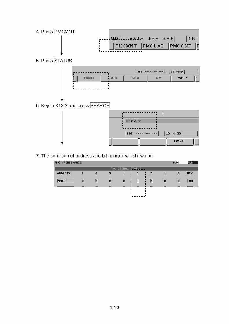
12-3
4. Press PMCMNT.
5. Press STATUS.
6. Key in X12.3 and press SEARCH.
7. The condition of address and bit number will shown on.

12-4
12.2 LCD not display ITEM TROUBLE CHECKING SOLUTION
1 Without 3 phase 220V AC source
Use voltmeter to check the power source
Check power line
2 Without DC24V input
1. Check if DC 24V power is
output from AC 220V
DC24V power supplier
(G4)
2. Be sure if there is DC24V
output from power supply
3. Check if there is DC24V
input into LCD module.
1. Replace the AC220V
to DC24V power
supply (G4). 2. Reconnection
3 Fuses burn down
Check if the fuse (FU 7) of AC 220V to DC 24V power supplier is broken?
Replace the new fuse (FU 7)
4 Display not turned ON after power ON.
1. Check if the relay KA 32 is
active.
2. Check if the wires
ON/OFF/COM of power
ON push button are
connected correctly?
3. Check if the pin X22 on
relay board is connected
correctly?
1. Replace the relay KA
32.
2. Reconnect the wire of
power ON button.
3. Reconnect the X22 pin
of relay board of
electric cabinet.

12-5
12.3 Remedies when alarm is not indicated (A) Machine alarm when press the indexing button
ITEM TROUBLE CHECKING SOLUTION 1 Tool not indexing. 1. Dgn. X7.0 / X7.1 (0I-TD,
31I, Mate-TD) must in 1
when turret head in
clamp position.
2. Dgn. X7.0 / X7.1 (0I-TD,
31I, Mate-TD) must in 1
when turret head in
unclamp position.
Correct the wiring of proximity switch X7.0, X7.1 and readjust the proximity switch X7.0, X7.1
(B) Tool N0.1 search after abnormal stopping.
ITEM TROUBLE CHECKING 1 Tool No. resetting (if the
tool number is off) 1. Press “FEEDHOLD” & “SPINDLE STOP” at
the same time in manual mode to unclamp
turret disk.
2. Change K7.5 to 1.
3. Press + / - button and JOG button at the
same time to set the current tool as tool
No.1.
4. Change K7.5 to 0.
5. Select mode switch in “Zero Return” mode.
6. Press RESET button to clamp the turret disk.2 Turret return operation 1. Press HYDRAULIC START button.
2. Rotating TOOL NO. SELECT switch to
needed No. of tool.
3. Press TOOL NO INDEX button

12-6
12.4 Cycle start can not execute
ITEM TROUBLE CHECKING SOLUTION 1 Mode error 1. Is mode switch selected
according to operation?
2. Is wiring of mode switch
connected correct?
1. Select correct operation
mode. (“AUTO” for
memory start. /
“HANDLE” for JOG,
Rapid…)
2. Connect the cable
exactly. 2 Push button out of
order 3. Be sure Dgn.X100.0 in
1 when press cycle
start button.
4. Check if wiring is OK?
1. Replace the push
button.
2. Reconnect the signal
wire. 3 Interlock function 1. Turret index no ready
2. Chuck unclamp 3. Tool setter down 4. Parts catcher in chuck
position 5. Lubrication alarm 6. Feed hold 7. Door interlock 8. No zero return 9. Spindle alarm 10. Machine alarm
1. Index turret 2. Clamp Chuck 3. Retract tool setter 4. Retract parts catcher 5. Fill up lubrication oil 6. Release feed hold 7. Close door 8. Make X/Z Axes Zero
return. 9. Check FANUC alarm
message. 10. Check PMC program
ladder.

12-7
12.5 Main spindle hydraulic chuck not work ITEM TROUBLE CHECKING SOLUTION
1 Foot switch out of order
Be sure Dgn.X12.4 (0i-TD, 31i, Mate-TD) in 1 when step the foot switch.
Reconnect the signal wire or replace the foot switch.
2 Solenoid valve out of order
1. Be sure there is DC24V
power on Y1.0 (wire
No.6, No.209 ) and
Y1.1 (wire No.6,
No.210).
2. Check if the solenoid
valve is clog?
1. Reconnect the wire or
replace relay.
2. Clean the valve or
replace coil of solenoid.3 Broken of draw
tube 1. Be sure the function of
chuck cylinder and no
function in chuck side.
2. Check if the pressure of
hydraulic cylinder is
exceeds the limit?
1. Replace draw tube
2. Correct the operation
pressure of hydraulic
cylinder.

12-8
12.6 Tailstock is not works or (Sub-spindle chuck is not works) ITEM TROUBLE CHECKING SOLUTION
1 Tailstock interlock
1. Check if the tailstock is
operated during spindle
running?
2. Check if X-AXIS is not in
ZERO position?
1. Stop the spindle. 2. Perform X-axis zero
return before
operating tailstock. 2 Tailstock is not push
the workpiece correctly. *Only for servo tailstock.
Check if the THRUST function active ?
Press [THRUST ON] after tailstock move to thrust position.
3 The thrust force is not held during turning workpiece. *Only for servo tailstock.
Check if the thrust tolerance is correct?
Setting of exact tolerance value (range 0~30mm).
4 Sub-spindle solenoid valve out of order
1. Be sure there is DC24V
power on Y1.2 (wire No.6,
No.211) and Y1.3 (wire
No.6, No.210).
2. Check if the solenoid valve
is clog?
1. Reconnect the wire
or replace relay.
2. Clean the valve or
replace coil of
solenoid.
5 Broken of draw tube 1. Be sure the function of
chuck cylinder and no
function in chuck side.
2. Check if the pressure of
hydraulic cylinder is
1. Replace draw tube
2. Correct the
operation pressure
of hydraulic
cylinder.

12-9
12.7 Coolant pump can not execute ITEM TROUBLE CHECKING SOLUTION
1. Check if the capacity of
thermo relay [KM 3] is
exact.
2. Be sure thermal relay is
in normal position.
1. Replace the thermo
relay [KM 3].
2. Preset over load button.
1 Over load trip
After preset the over load relay [FR 3] and it trip again after switch on.
Replace coolant pump.
2 No coolant out and no alarm message.
1. Check if the coolant is
enough.
2. Be sure the coolant motor
is rotating in correct
direction.
Fill up coolant to pump and try switch on again or change the phase of power line.
12.8 Lubrication system out of order
ITEM TROUBLE CHECKING SOLUTION
1 Without lubrication oil flow
1. Motor without rotating 2. Low level of oil 3. clog of filter 4. Fill wrong type of oil 5. Worm and gear
engaged and can not rotating.
6. O-ring of piston is broken .
1. Check the power connection.
2. Fill up oil. 3. Clean the filler. 4. Replace the correct
lubrication oil. 5. Clean and repair. 6. Replace the O-ring.
2 Leakage of oil Brake of oil tank. Repair or replace the oil tank.
3 With alarm after the low oil level
Check the wire connection or check the floater switch.
Connected wire or replace floater switch.

12-10
12.9 Reset reference point ( when change battery ) When replace four 1.5 V batteries, the set machinery origin of coordinate and limit would be eliminated, so have to reset it. <Condition 1>Red arrow exist in machine (X-axis located on the turret, Z-axis located in back of the machine, please open the cover of maintenance.) And list steps of adjusting below:
Trouble shooting (1)Parameter setting <1-1> 1.Press the key "SYSTEM" on the board. And then the
"PARAM" located on the left corner, 2.Press "PARAM" key . <1-2> 1.Key in "1815". 2.And then the "NO.SRH" located on the left corner
Press "NO.SRH" key . <1-3> Move the cursor to the "APZ" . <1-4> Set the "MODE" switch to the " M.D.I." position. <1-5> Press the key "ON.1" on the left corner. (2)Set the MODE switch to the "HANDLE" position.

12-11
Trouble shooting (3)Select " Control axis" to be X-axis. (4)By turning "Handle" to make two arrows aim at
each other. (5)Select " Control axis" to be Z-axis. (6)By turning hand wheel to make two arrows of
Z1-axis to aim at each other. (The red arrow of Z1-axis located on the antichip plate of Z axis.)
(7) Parameter Setting <7-1> 1.Press the key "SYS TEM" on the board. And then the
"PARAM" located on the left corner, 2.Press "PARAM" key . <7-2> 1.Key in "1815". 2.And then the "NO.SRH" located on the left corner
Press "NO.SRH" key.

12-12
Trouble shooting <7-3> Move the cursor to the "APZ" . <7-4> Set the "MODE" switch to the " M.D.I." position. <7-5> Press the key "OFF:0" on the left corner to set X、Z to be 0. (8)Power off and power on. <8-1> Repeat <7-1>~<7-4> <8-2> Press the key "ON:1" on the left corner to set X、Z to be 1. (9)Power off and power on, now will be able to do "H1 ZERO RETURN".

12-13
<Condition 2>The plate have took off or lose that could not aim at each other. List steps for adjusting below:
Trouble shooting (1)Install the internal tool holder on the turret (take
the station 1 as center). (2)Install the indicator/dia gauge on the chuck (3)Move X1-axis and Z1-axis to the indicator and
Z1-axis must allow the top of indicator into to contact with the bore of tool holder.
(4)Put top of indicator/ dia gauge into to contact
with he bore of tool holder, and rotate spindle to the half difference of indicator reading (please adjust at horizontally)
------------------------------------------------- For model with Y axis, follow the steps(5)~(6). (5)Parameter Setting <5-1> 1.Press the key "POS" on the keyboard, and a
coordinate will appear on the LCD character display.
2.After pressing the key "REL". 3.Press the key "V" on the keyboard. Now the "V" on
the LCD character display would flash. <5-2> Press the key "ORIGIN" so that "V" value would be
eliminated to be zero.

12-14
Trouble shooting (6)Parameter Setting <6-1> 1.Press the key "SYSTEM" on the board. And then
the "PARAM" located on the left corner, 2.Press "PARAM" key . <6-2> 1.Key in "1815". 2.And then the "NO. SRH" located on the left corner
Press "NO. SRH" key . <6-3> Move the cursor to the "APZ" and set Y to be 0 by using cursor shift key. And then set Y to be 1 again. ---------------------------------------------------------- (7)Parameter Setting <7-1> 1.Press the key "POS" on the keyboard, and a
coordinate will appear on the LCD character display.
2.After pressing the key "REL". 3.Press the key "U" on the keyboard. Now the "U" on
the LCD character display would flash. <7-2> Press the key "ORIGIN" so that "U" value would be eliminated to be zero.

12-15
Trouble shooting (8)Shaft X1-axis up about A mm. Refer to Ch2.8 for A value. (9)Shaft Z1-axis to the distance of A mm for from
the spindle cover. (Take the surface of turret as reference). Refer to Ch2.9 for A value.
(10)Parameter Setting <10-1> 1.Press the key "POS" on the keyboard, and a
coordinate will appear on the LCD character display.2.After pressing the key "REL". 3.Press the key "W" on the keyboard. Now the "W" on
the LCD character display would flash. <10-2> Press the key "ORIGIN" so that "W" value would be
eliminated to be zero. (11)Shaft Z1-axis up about B mm. Refer to Ch2.9 for
A value.
Refer to 2.8 Tooling interference
Refer to 2.9 Travels and working area
Refer to 2.9 Travels and working area

12-16
Trouble shooting (12)Set the MODE to the "M.D.I." position. (13)Parameter Setting <13-1> 1.Press the key "SYSTEM" on the board. And then the
"PARAM" located on the left corner, 2.Press "PARAM" key . <13-2> 1.Key in "1815". 2.And then the "NO.SRH" located on the left corner
Press "NO.SRH" key . <13-3> Move the cursor to the "APZ" and set X、Z to be 0 by using cursor shift key. And then set X、Z to be 1 again. (14)Power off and power on and then do "H1 Zero
Return". (15)Shaft ZS-axis up about A mm. Refer to Ch2.9 for
A value.(Take nose of sub-spindle as reference) A as below: ψ75 Headstock:A is about 927mm ψ90 Headstock:A is about 930mm ψ105 Headstock:A is about 928mm (Only -S series need to set ZS reference point.)
Refer to 2.8 Tooling interference

12-17
Trouble shooting (16)Set the MODE to the "M.D.I." position. (17)Parameter Setting <17-1> 1.Press the key "SYSTEM" on the board. And then the
"PARAM" located on the left corner, 2.Press "PARAM" key . <17-2> 1.Key in "1815". 2.And then the "NO.SRH" located on the left corner
Press "NO.SRH" key . <17-3> Move the cursor to the "APZ" and set B to be 0 by using cursor shift key. And then set B to be 1 again. (18)Power off and power on and then do X, Y and Z
axis Zero Return".


A
Appendix A.
Content 1 ALARM MESSAGE (For FANUC 0i-TD Controller) ..........................A-1
1-1 Various alarms and trouble shutting ............................A-1 2 Turret resetting procedure ..............................................................A-13


A-1
1 ALARM MESSAGE (For FANUC 0i-TD Controller) 1-1 Various alarms and trouble shutting
ADDRESS ALARM NUMBER DESCRIPTION CHECKING POINT &
TROUBLESHOOTING
A0.0 1000 T-CODE ERROR (A0.0)
T CODE COMMAND .> D50 T code command must be under than D50(D50=amount of tool +1 )
A0.1 1001 OVER LOAD ALARM (A0.1)
Check Hyd/Coolant MCC overload switch
A0.2 1002 PRESSURE ERROR (A0.2)
Check the value of hyd. Pressure is 35kg/mm2 or the pressure switch is normal.
A0.3 1003 SPINDLE ALARM (A0.3)
Contrast to the alarm No. on the amplifier LED display for alarm reason.
A0.4 1004 EMERGENCY STOP (A0.4) Emergency stop signal (X8.4=1)
A0.5 1005 NO PRESSURE CHECK SIGNAL (A0.5)
Check Pressure switch signal
A0.6 1006 SET K4.2=0 (A0.6) Set K4.2=0 after Install chip conveyor
A0.7 1007 SAUTER TURRET ALARM (A0.7) Sauter turret alarm

A-2
ADDRESS ALARM
NUMBER DESCRIPTION CHECKING POINT & TROUBLESHOOTING
A2.0 2000 MANUAL ERROR (A2.0)
Auto mode or manual mode select error for operation.
A2.1 2001 INDEX NO READY (A2.1)
Check turret is clamped or tool number index is correct and tool select button is to “ON”.
A2.2 2002 NO ZERO RETURN (A2.2)
Check servo axis at home position and home position light will shine
A2.3 2003 DOOR INTERLOCK (A2.3)
Safe-door is not closed indeed. (*X4.1(**X5.4=1)when safe-door is closed)
A2.4 2004 TOOL SETTER (A2.4)
Check tool setter arm in up position and signal *X3.6=0(**X7.6=0), *X3.5=0(**X7.5=1).
A2.5 2005 FEED HOLD ERROR (A2.5) Feed hold push button signal is off.
A2.6 2006 SPINDLE CHUCK NO CLOSE (A2.6)
Chuck is not closed. Check signal *X0.1=1(**X8.0=1) when chuck is inside closed. Check signal *X0.2=1(**X8.1=1) when chuck is outside closed.
A2.7 2007 TOOL SETTER USE JOG MODE (A2.7)
To operate Renishaw tool setter just only in JOG mode.
ADDRES
S ALARM
NUMBER DESCRIPTION CHECKING POINT & TROUBLESHOOTING
A3.0 2008 SPINDLE STOP OPEN (A3.0)
Spindle stop push button signal was off.
A3.1 2009 LUB ALARM (A3.1) Lubrication oil empty.
A3.2 2010 MACHINE LOCK ACTIVE (A3.2) Check if machine lock switch “on”.
A3.3 2011 BATTERY ALARM (A3.3) NC’s battery low alarm.
A3.4 2012 COUNTER ARRIVAL (A3.4)
Arrival at the counter of setting parts.Reset the counter.
A3.5 2013 OPEN EDIT KEY (A3.5) Turn the edit key to off position.
A3.6 2014 PARTS CATCHER ERROR (A3.6)
Return the parts catcher and check signal *X1.7=1(**X5.7=1).
A3.7 2015 SPINDLE RUN LOCK (A3.7)
Spindle in run status. Command is lock.
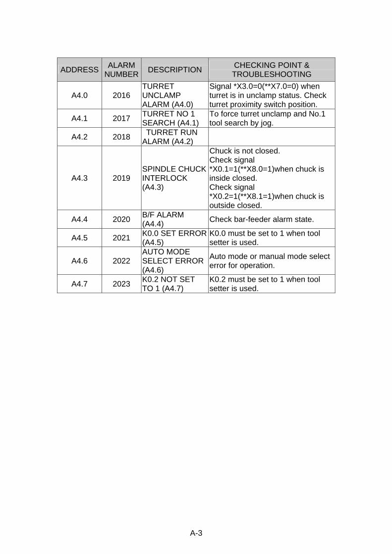
A-3
ADDRESS ALARM NUMBER DESCRIPTION CHECKING POINT &
TROUBLESHOOTING
A4.0 2016 TURRET UNCLAMP ALARM (A4.0)
Signal *X3.0=0(**X7.0=0) when turret is in unclamp status. Check turret proximity switch position.
A4.1 2017 TURRET NO 1 SEARCH (A4.1)
To force turret unclamp and No.1 tool search by jog.
A4.2 2018 TURRET RUN ALARM (A4.2)
A4.3 2019 SPINDLE CHUCK INTERLOCK (A4.3)
Chuck is not closed. Check signal *X0.1=1(**X8.0=1)when chuck is inside closed. Check signal *X0.2=1(**X8.1=1)when chuck is outside closed.
A4.4 2020 B/F ALARM (A4.4) Check bar-feeder alarm state.
A4.5 2021 K0.0 SET ERROR(A4.5)
K0.0 must be set to 1 when tool setter is used.
A4.6 2022 AUTO MODE SELECT ERROR (A4.6)
Auto mode or manual mode select error for operation.
A4.7 2023 K0.2 NOT SET TO 1 (A4.7)
K0.2 must be set to 1 when tool setter is used.
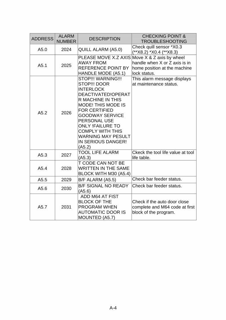
A-4
ADDRESS ALARM
NUMBER DESCRIPTION CHECKING POINT & TROUBLESHOOTING
A5.0 2024 QUILL ALARM (A5.0) Check quill sensor *X0.3 (**X8.2) *X0.4 (**X8.3)
A5.1 2025
PLEASE MOVE X.Z AXIS AWAY FROM REFERENCE POINT BY HANDLE MODE (A5.1)
Move X & Z axis by wheel handle when X or Z axis is in home position at the machine lock status.
A5.2 2026
STOP!!! WARNING!!! STOP!!! DOOR INTERLOCK DEACTIVATED!OPERATR MACHINE IN THIS MODE! THIS MODE IS FOR CERTIFIED GOODWAY SERVICE PERSONAL USE ONLY !FAILURE TO COMPLY WITH THIS WARNING MAY PESULT IN SERIOUS DANGER! (A5.2)
This alarm message displays at maintenance status.
A5.3 2027 TOOL LIFE ALARM (A5.3)
Ckeck the tool life value at tool life table.
A5.4 2028 T CODE CAN NOT BE WRITTEN IN THE SAME BLOCK WITH M30 (A5.4)
A5.5 2029 B/F ALARM (A5.5) Check bar feeder status.
A5.6 2030 B/F SIGNAL NO READY (A5.6)
Check bar feeder status.
A5.7 2031
ADD M64 AT FIST BLOCK OF THE PROGRAM WHEN AUTOMATIC DOOR IS MOUNTED (A5.7)
Check if the auto door close complete and M64 code at first block of the program.

A-5
ADDRESS ALARM
NUMBER DESCRIPTION CHECKING POINT & TROUBLESHOOTING
A6.0 2032 LOAD ALARM (A6.0)Check if spindle load setting values too small. Check if tool was worn.
A6.1 2033 TAILSTOCK +OT (A6.1)
Please push reset key and move negative direction by jog.
A6.2 2034 TAILSTOCK -OT (A6.2)
Please push reset key and move positive direction by jog.
A6.3 2035 Z AXIS NOT IN CLAMP POINT (A6.3)
Check if the pin position is correct with the pin hold on z-axis.
A6.4 2036 TAILSTOCK PIN BACK OVERTIME (A6.4)
Check if the pin had interfered with pin hold and couldn’t to draw out.
A6.5 2037 TAILSTOCK –OT SETTING ON (A6.5)
This alarm message displays when need to set the negative direction max travel of PMC tailstock. Please exit this mode when setting complete.
A6.6 2038 X AXIS NOT IN ZERO POINT (A6.6)
Check if x axis is at home position.
A6.7 2039 QUILL OUT LOCK (A6.7)
Pin and quill can’t be at stretch out position at the same time.

A-6
ADDRESS ALARM
NUMBER DESCRIPTION CHECKING POINT &
TROUBLESHOOTING
A7.0 2040 C AXIS MODE CAN NOT RUN SPINDLE (A7.0)
Please cancel (turn off) the CF-axis mode before spindle turnning.
A7.1 2041 TAILSTOCK QUILL OUT LOCK (A7.1)
Please retract the quill before using the tailstock driven pin.
A7.2 2042 TAILSTOCK PIN OUT LOCK (A7.2)
Please unclamp the tailstock driven pin before using the quill.
A7.3 2043 MILLING INTERLOCK (A7.3)
Please check if the live tooling is rotating.
A7.4 2044
(WARNING):THE MACHINE IS MANUFACTURE FOR WELL-TRAINED OPERATOR. TO AVOID IN-JURY, DO NOT OPERATE THE MACHINE UNLESS YOU HAD UNDERSTAND ALL INFORMATIONS IN THE MANUALS.BEING AWARE OF THIS WARNING PRESS[RESET]KEY
A7.5 2045 MODE LOCK (A7.5) Check if the mode lock keyswitch is released.
A7.6 2046 LUB PRESSURE LOW (A7.6)
Please check if the pressure of LUB. System is too low.
A7.7 2047 STEADY PRESSURE LOW (A7.7)
Please check if the pressure of steady-rest is too low.

A-7
ADDRESS ALARM
NUMBER DESCRIPTION CHECKING POINT & TROUBLESHOOTING
A8.0 2048 TAILSTOCK OVER TRAVEL (A8.0)
Check if the distance between steady rest and tailstock is to short. Please press “RESET” to cancel the alarm then move the tailstock to positive direction.
A8.1 2049 HYD.MOTOR NO START (A8.1)
The hydraulic pump is not active. Please press hyd. ST button to active the hydraulic system.
A8.2 2050 STEADY PIN OUT LOCK (A8.2)
Check if the pin of steady rest unclamp complete.
A8.3 2051 PMC AXIS PIN OUT LOCK (A8.3)
Inexact operation (for example: cycle start, quill out,…) after tailstock pin out, it may cause machine damage.
A8.4 2052 MUST RUN QUILL ADV.AFTER RUN QUILL JOG (A8.4)
Please press quill ADV. Button.
A8.5 2053 STEADY OVERTRAVEL (A8.5)
Check if the steady is too close to the tailstock press “RESET” key to cancel the alarm then move the steady rest to negative direction.
A8.6 2054 AIR PRESSURE LOW (A8.6)
Check if the air pressure is too low. Check the air pressure switch. Check if the air pressure signal *X1.5=0(**X5.5=0).
A8.7 2055 SPINDLE BRAKE ON (A8.7)
Check if spindle brake is “ON”. Please release spindle brake before run spindle.

A-8
ADDRESS ALARM
NUMBER DESCRIPTION CHECKING POINT & TROUBLESHOOTING
A9.0 2056 MILLING S CODE ERROR (A9.0)
Live tool rotating speed is over limit, please reduce live tool rotating speed.
A9.1 2057 TURRET CLAMP ERROR (A9.1)
Check the turret clamp sensor signal *X3.0(**X7 0). Check if turret was combined completely.
A9.2 2058
PARTS CATCHER OUT/TOOL SETTER DOWN PLEASE OPERATE ON SINGAL BLOCK MODE (A9.2)
Parts catcher out or tool setter arm down on MDI operation mode must run in single block mode, please setting it.
A9.3 2059 SPINDLE SYNCHRONOUS INTERLOCK (A9.3)
When spindle synchronous is running, it can not change rotate direction, please cancel spindle synchronous command at first.
A9.4 2060 TOOL SET DOWN (A9.4)
Tool setter can not use with part catcher at the same time , please to turn back the tool setter before using the part catcher.
A9.5 2061 PARTS CATCHER OUT (A9.5)
Part catcher can not use with tool setter at the same time, please to turn back the parts catcher before using the tool setter.
A9.6 2062
"MILLING SERVO OFF".PLEASE PUSH RESET FOR MILLING SERVO ON (A9.6)
A9.7 2063 SUB SPINDLE CHUCK CLOSE(A9.7)
Can not use the bar pusher when sub spindle chuck clamp, please to unclamp the sub spindle chuck at first.

A-9
ADDRESS ALARM
NUMBER DESCRIPTION CHECKING POINT &
TROUBLESHOOTING
A10.0 2064 SUB SPINDLE CHUCK OPEN (A10.0)
Sub spindle can not running when chuck was unclamped , please to clamp the sub spindle chuck at first.
A10.1 2065 SUB SPINDLE RUN LOCK (A10.1)
Sub spindle running and locking , please stop sub spindle before running others.
A10.2 2066 SUB SPINDLE CHUCK INTERLOCK (A10.2)
Sub spindle chuck interlock, please check if the chuck sensor is normal.
A10.3 2067
SUB SPINDLE C AXIS MODE CAN NOT RUN SPINDLE (A10.3)
When sub spindle running on c axis mode, others sub spindle function can not run, please to turn off the c axis mode first.
A10.4 2068 SUB SPINDLE BRAKE ON (A10.4)
When sub spindle brake was clamped, other sub spindle function can not run, please to release the brake at first.
A10.5 2069 SPINDLE SYNCHRONOUS RUN LOCK (A10.5)
When spindle synchronous is running the any other function about spindle can not run. Please stop spindle synchronous running.
A10.6 2070
SPINDLE SYNCHRONOUS CHUCK CAN NOT ALL OPEN(A10.6)
When spindle synchronous is running the chuck of spindle and sub spindle can not unclamp at the same time.
A10.7 2071 GEAR NO READY (A10.7)
The gear position of speed change did not confirm, please check if the sensor is normal.

A-10
ADDRESS ALARM
NUMBER DESCRIPTION CHECKING POINT &
TROUBLESHOOTING
A11.0 2072 LUB AIR PRESSURE ERROR (A11.0)
Check air pressure value of lubricator. Check signal *X10.4(**X24.4) and *X10.6(**X24.6).
A11.1 2073
*X0.6=1(**X8.6=1) PLEASE SETTING TAILSTOCK MODE (A11.1)
Tailstock connect pin is at out position, please to turn back the connect pin.
A11.2 2074 TAILSTOCK PIN OUT ALARM (A11.2)
Tailstock connect pin is acting, please set to the tailstock mode.
A11.3 2075 PLEASE TURN ON COOLANT (A11.3)
Sub-SP. coolant using(k24.4=1),must turn coolant ON.
A11.4 2076
TAILSTOCK BRAKE CLAMP, PLEASE CHECK TAILSTOCK BRAKE RELEASED ON NOT!(A11.4)
A11.5 2077 COOLANT LEVEL LOW ALARM (A11.5)
A11.6 2078 CHUCK PRESSURE ERROR (A11.6)
A11.7 2079 AIR CHUCK SENSOR ERROR (A11.7)

A-11
ADDRESS ALARM
NUMBER DESCRIPTION CHECKING POINT &
TROUBLESHOOTING
A12.0 2080 SP TOOL LIFE VALUE OVER (A12.0)
A12.1 2081 SP TOOL BREAK VALUE OVER (A12.1)
A12.2 2082 X-AXIS TOOL LIFE VALUE OVER (A12.2)
A12.3 2083 X-AXIS TOOL BREAK VALUE OVER (A12.3)
A12.4 2084 Z-AXIS TOOL LIFE VALUE OVER (A12.4)
A12.5 2085 Z-AXIS TOOL BREAK VALUE OVER (A12.5)
A12.6 2086 SP2 TOOL LIFE VALUE OVER (A12.6)
A12.7 2087 SP2 TOOL BREAK VALUE OVER (A12.7)
ADDRESS ALARM
NUMBER DESCRIPTION CHECKING POINT &
TROUBLESHOOTING
A13.0 2088 SP3 TOOL LIFE VALUE OVER (A13.0)
A13.1 2089 SP3 TOOL BREAK VALUE OVER (A13.1)
A13.2 2090 SP1 TOOL MISSING VALUE ARRIVAL (A13.2)
A13.3 2091 SP2 TOOL MISSING VALUE ARRIVAL (A13.3)
A13.4 2092 SP3 TOOL MISSING VALUE ARRIVAL (A13.4)
A13.5 2093 X-AXIS TOOL MISSING VALUE ARRIVAL (A13.5)
A13.6 2094 Z-AXIS TOOL MISSING VALUE ARRIVAL (A13.6)
A13.7 2095 C-AXIS TOOL MISSING VALUE ARRIVAL (A13.7)

A-12
ADDRESS ALARM
NUMBER DESCRIPTION CHECKING POINT &
TROUBLESHOOTING
A14.0 2096 Y-AXIS TOOL MISSING VALUE ARRIVAL (A14.0)
A14.1 2097 C-AXIS TOOL LIFE VALUE OVER (A14.1)
A14.2 2098 C-AXIS TOOL BREAK VALUE OVER (A14.2)
A14.3 2099 Y-AXIS TOOL LIFE VALUE OVER (A14.3)
A14.4 2100 Y-AXIS TOOL BREAK VALUE OVER (A14.4)
A14.5 2101
PLEASE SELECT QUILL DIRECTION BY PUSH BUTTON ON MANUAL MODE AFTER HYD.MOTOR STARTED (A14.5)
A14.6 2102 END OF WORKPICE LOADING WITHOUT MATERIAL
A14.7 2103 M48 INTERRUPTION LOADING OR UNLOADING IS BREAK OFF
ADDRESS ALARM
NUMBER DESCRIPTION CHECKING POINT &
TROUBLESHOOTING
A15.0 2104 LOADING TIME OVER
LOADING OR UNLOADING IS OVERTIME
A15.1 A15.2 A15.3 A15.4 A15.5 A15.6 A15.7

A-13
2 Turret resetting procedure I. Resetting turret reference position:
The turret indexing operation might be interrupted by following: (1) Press EMERGENCY STOP button. (2) Power OFF. (3) Collision.
If the turret indexing operation is interrupted, it may cause the turret index incorrect or incomplete. The turret index button light becomes OFF and the turret is not ready for indexing. It is necessary to perform “Resetting turret reference position” procedure as following:
1. Set K7.5 to 1 (Switch turret into JOG mode)as following steps:
Fig.1
Fig.2

A-14
Fig.3.
Set K7#5=1
Fig.4.

A-15
2. Set the “MODE” switch to “HANDLE”
posititon.
3. Press “FEED HOLD” and “SPINDLE STOP” at the same time. Then turret is unclamp.
4. Press +X button(CW)or –X button (CCW) to rotate the turret to TOOL NO. 1.

A-16
5. After the red arrow which are on cover and turret match each other,
press [RESET] key to clamp the turret head. Fig.5

A-17
6. Set K7.5 to 0(return to normal mode). The turret reference position is set, please perform the “Tool No Resetting” procedure as following:
7. Press “FEED HOLD” and “SP. STOP” button at the same time. Then turret head is unclamping.
8. Set the “MODE” switch to “ZERO RETURN” position.
9. Press “FEEDHOLD” and “+X” button. (To set the current tool as tool no.1)

A-18
10. Press “RESET” to clamp the turret.
11. Restart the machine.

A-19
II. Tool number resetting
If the tool no. is incorrect, it may cause collision between tool and workpiece or chuck. It is necessary to perform “tool number resetting procedure” as following:
1. Set the “MODE” to “HANDLE” position.
2. Rotate turret to TOOL NO.1 (the nameplate shows NO.1 but the “TOOL NO. SELECT” switch may not select NO.1)
3. Press “FEED HOLD” and “SP. STOP.” at the same time. (Press the right side “FEED HOLD” to operator thr right turret.)
4. Set the “MODE” switch to “ZRN” position.

A-20
5. Select TOOL NO.1.
6. Press “INDEXING” button. Then turret rotates to TOOL NO.1.
7. Press “RESET” key to clamp the turret.
8. The tool no. resetting procedure is completed.

B
Appendix B. G、M、T、K- Code function (for FANUC 0I-TD Controller)
Content 1 G-Code and M-Code function...........................................................B-1
1-1 G-Code function ..........................................................B-1 1-2 M-Code function ..........................................................B-5
2 T-Code function ................................................................................B-7 3 K-Code function................................................................................B-9


B-1
1 G-Code and M-Code function 1-1 G-Code function
G code system(Note 7)
A B C Group Function
◤G00 ◤G00 ◤G00 Positioning (rapid traverse)
G01 G01 G01 Linear Interpolation (Cutting feed)
G02 G02 G02 Circular interpolation CW
G03 G03 G03
01
Circular interpolation CCW
G04 G04 G04 Dwell G07.1 (G107)
G07.1 (G107)
G07.1 (G107) Cylindrical interpolation
G08 G08 G08 Look –head control
G10 G10 G10 Programmable data input
G11 G11 G11
00
Programmable data input mode cancel G12.1 (G112)
G12.1 (G112)
G12.1 (G112) Polar coordinate interpolation mode
◤G13.1 (G113)
◤G13.1(G113)
◤G13.1 (G113)
21 Polar coordinate interpolation cancel mode
G17 G17 G17 XpYp plane selection
◤G18 ◤G18 ◤G18 ZpXp plane selection
G19 G19 G19
16
YpZp plane selection
G20 G20 G70 Inch data input
G21 G21 G71 06
Metric data input
G22 G22 G22 Stored stroke check function on
G23 G23 G23 09
Stored stroke check function off
G25 G25 G25 Spindle speed fluctuation detection off
G26 G26 G26 08
Spindle speed fluctuation detection on
G27 G27 G27 Reference point return check
G28 G28 G28 Return to reference point return
G30 G30 G30 2nd, 3rd, 4th reference point return
G31 G31 G31
00
Skip function

B-2
G code system(Note 7)
A B C Group Function
G32 G33 G33 Thread cutting
G34 G34 G34 01
Variable–lead thread cutting
G36 G36 G36 Automatic tool compensation X (When the bit 3 (G36) of parameter No. 3405 is set to 0)
G37 G37 G37 Automatic tool compensation Z
G37.1 G37.1 G37.1 Automatic tool compensation X
G37.2 G37.2 G37.2 Automatic tool compensation Z
G39 G39 G39
00
Corner circular interpolation
◤G40 ◤G40 ◤G40 Tool nose radius compensation cancel
G41 G41 G41 Tool nose radius compensation left
G42 G42 G42
07
Tool nose radius compensation right
G50 G92 G92 Coordinate system setting, max. spindle speed setting
G50.3 G92.1 G92.1 00
Workpiece coordinate system preset ◤G50.2 (G250)
◤G50.2(G250)
◤G50.2 (G250) Polygonal turning cancel
G51.2 (G251)
G51.2 (G251)
G51.2 (G251)
20 Polygonal turning
G52 G52 G52 Local coordinate system setting G53 G53 G53 00
Machine coordinate system setting ◤G54 ◤G54 ◤G54 Workpiece coordinate system 1 selection G55 G55 G55 Workpiece coordinate system 2 selection G56 G56 G56 Workpiece coordinate system 3 selection G57 G57 G57 Workpiece coordinate system 4 selection G58 G58 G58 Workpiece coordinate system 5 selection G59 G59 G59
14
Workpiece coordinate system 6 selection G60 G60 G60 Single direction positioning G65 G65 G65 00
Macro calling G66 G66 G66 Macro modal call ◤G67 ◤G67 ◤G67 12
Macro modal call cancel

B-3
G code system(Note 7)
A B C Group Function
G70 G70 G72 Finishing cycle
G71 G71 G73 Stock removal in turning
G72 G72 G74 Stock removal in facing
G73 G73 G75 Pattern repeating
G74 G74 G76 End face peck drilling
G75 G75 G77 Outer diameter/internal diameter drilling
G76 G76 G78
00
Multiple threading cycle
G71 G71 G72 Traverse grinding cycle (for grinding machine)
G72 G72 G73 Traverse direct constant–dimension grinding cycle (for grinding machine)
G73 G73 G74 Oscilation grinding cycle (for grinding machine)
G74 G74 G75
01
Oscilation direct constant–dimension grinding cycle (for grinding machine)
◤G80 ◤G80 ◤G80 Canned cycle for drilling cancel
G83 G83 G83 Cycle for face drilling
G84 G84 G84 Cycle for face tapping
G86 G86 G86 Cycle for face boring
G87 G87 G87 Cycle for side drilling
G88 G88 G88 Cycle for side tapping
G89 G89 G89
10
Cycle for side boring
G90 G77 G20 Outer diameter/internal diameter cutting cycle
G92 G78 G21 Thread cutting cycle
G94 G79 G24
01
End face turning cycle
G96 G96 G96 Constant surface speed control ◤G97 ◤G97 ◤G97
02 Constant surface speed control cancel
G98 G94 G94 Per minute feed ◤G99 ◤G95 ◤G95
05 Per revolution feed
- ◤G90 ◤G90 Absolute programming
- G91 G91 03
Incremental programming
- G98 G98 Return to initial level
- G99 G99 11
Return to R point level

B-4
(Note 1) G codes marked " ◤" are initial G codes when turning power on.For G20 and G21, the G code before turning power off remains. G00 or G01 can be selected by parameter setting.
(Note 2) G codes of group 00 are not modal. They are only effective in the block in which they are specified.
(Note 3) If a G code not listed on the table of G codes is inputted, or optional Gcode not specified in the system is commanded, an alarm (No. 010) is displayed.
(Note 4) A number of G codes can be specified in the same block. When more than one G code of the same group is specified, the G code specified later is effective.
(Note 5) If any G code of group 01 is specified in a canned cycle mode, the canned cycle is automatically cancelled and the G80 condition is entered. However a G code of group -1 is not affected by any of the canned cycle G codes.
(Note 6) A G code is displayed from each group. (Note 7) G code system B and C are options. Whether G code system B
or C is set by parameter No.0036 : GSPC. (Note 8) The earlier program has executed command G50 coordinate
system setting. When program is not completely executed like stopped during program execution, and operator does not execute reference point return, will cause error positioning in the next program that leads to collision.

B-5
1-2 M-Code function M-
code DESCRIPTION M-
codeDESCRIPTION
M00 Program stop M41 Spindle low speed gear M01 Option stop M42 Spindle high speed gear M02 End of program M43 Spindle synchronous on clockwise
M03 Main spindle rotate on clockwise M44 Spindle synchronous on counter-clockwise
M04 Main spindle rotate on counter-clockwise M45 Spindle synchronous stop
M05 Main spindle stop M46 Call b/f allow M08 Coolant on M47 Bar feeder m code M09 Coolant off M48 Bar feeder mcode (loading) M10 Main chuck unclamp M49 Bar feeder mcode M11 Main chuck clamp M50 Bar feeder mcode M12 Tailstock forward M58 Option hight- pressure pump on M13 Tailstock backward M59 Option hight- pressure pump off M14 Tailstock quill forward M60 Pmc tailstock mode M15 Tailstock quill backward M61 Chip conveyor forward
M16 Tailstock quill forward on pressure #2 M63 Chip conveyor stop
M17 Tailstock quill backward on pressure #2 M64 Auto door close
M18 C-axis function off M65 Auto door open M19 C-axis function on M68 Parts catcher out M20 Main air blow on M69 Parts catcher in M21 Main air blow off M70 Spindle center air blow off
M22 Living tool free(just for servo motor) M71 Spindle center air blow on
M23 Chamfering on M73 Living tool rotate on clockwise
M24 Chamfering off M74 Living tool rotate on counter-clockwise
M25 In-position check valid M75 Living tool stop
M26 In-position check invalid M76 Living tool control from pmc trans to nc
M27 Check on of chuck air seal M77 Living tool control from nc trans to pmc
M28 Check off of chuck air seal M80 Two-sides of pneumatic chuck simultaneity on
M29 Rigid taping on M81 Two-sides of pneumatic chuck simultaneity off
M30 End of program & reset M82 Spindle chuck unclamp pressure #2M35 Auto toolset down M83 Spindle chuck clamp pressure #2 M36 Auto toolset up M84 Steady rests #1 clamp M37 Main spindle brake clamp M85 Steady rests #1 unclamp M38 Main spindle brake unclamp M86 Steady rests #2 clamp M40 Spindle in neutral gear M87 Steady rests #2 unclamp

B-6
M- code
DESCRIPTION M- code
DESCRIPTION
M88 Steady rests #3 clamp M272 Sub spindle push bar
M89 Steady rests #3 unclamp M282 Sub spindle chuck unclamp pressure #2
M90 Out-side pneumatic chuck simultaneity on M283 Sub spindle chuck clamp pressure
#2
M91 Out-side pneumatic chuck simultaneity off
M300 -M399
Communication between head 1 and head 2.
M97 Same with m0, and chuck stop M500 –M599 Spindle load setting
M98 Call sub program M1000 –M1360 1 degree indexing of main spindle
M99 Sub program end M10000 –M14096
0.088 degree indexing of main spindle
M108 Spray washing on M2000 –M2360 1 degree indexing of sub-spindle
M109 Spray washing off M20000-M24096
0.088 degree indexing of sub-spindle
M138 PMC TAILSTOCK PIN CLAMP M139 PMC tailstock pin unclamp M159-M166 8 m code M196 Load monitor function on
M197 Load monitor function off
M203 Sub spindle rotate on clockwise
M204 Sub spindle rotate on counter-clockwise
M205 Sub spindle stop M210 Sub chuck unclamp M211 Sub chuck clamp M218 Sub spindle c-axis function off M219 Sub spindle c-axis function on M220 Sub air blow on M221 Sub air blow off
M227 Sub-spindle center jet out water on
M228 Sub-spindle center jet out water off
M237 Sub spindle brake clamp M238 Sub spindle brake unclamp M270 Sub spindle through air blow off M271 Sub spindle through air blow on

B-7
2 T-Code function No. DATA
ADDRESS OUTPUT
ADDRESS DESCRIPTION
1 T00 R812.2 PARTS CONVERYOR TIME.
2 T02 R103.3 CHUCK PROXIMITY SWITCH CHECK TIME.
3 T04 R53.6 AIRBLOW TIME WHEN CONNECTION PIN OUT. (TAILSTOCK BY PMC CONTROL)
4 T06 A7.4 POWER “ON” ALM DISPLAY DELAY TIME.
5 T08 R51.7 THE CHECKING TIME AFTER QUILL ADV.
6 T10 R1033.6 SPINDLE LOAD DETECTION DELAY TIME.
7 T12 R1032.5 SPINDLE LOAD DETECTION CONFIRM TIME.
8 T14 R816.7 THE STOP TIME OF LUBRICATOR OIL OF PRESSURE RELIEF TYPE
9 T16 R816.6 THE ON TIME OF LUBRICATOR OIL OF PRESSURE RELIEF TYPE
10 T18 R813.7 LUB. PRESSURE DELAY CHECKING TIME OF PRESSURE RELIEF TYPE.
11 T20 R826.2 DH-65 B/F –Z DELAY
12 T22 R826.3 DH-65 B/F –Z TIMER
13 T24 R826.4 DH-65 B/F –Z FINISH DELAY
14 T26 R826.5 DH-65 LOADING FINISH DELAY

B-8
No. DATA ADDRESS
OUTPUT ADDRESS DESCRIPTION
15 T28 R22.4 CHIP CONVEYOR C.W. TIME
16 T30 R22.5 CHIP CONVEYOR C.W. STOP TIME
17 T32 R52.6 M15 FINISH TIME (JUST FOR GS-200 SERIES)
18 T34 R52.7 M14 FINISH TIME (JUST FOR GS-200 SERIES)
19 T36 R703.3 PROXIMITY SIGNAL DELAY CHECKING TIME OF SUB-CHUCK.
20 T38 R75.7 HYDRAULIC PROGRAMABLE TAILSTOCK ADV. DELAY TIME.
21 T40 R76.7 HYDRAULIC PROGRAMABLE TAILSTOCK BRAKE DELAY TIME.
22 T42 R160.5 LUBRICATION OIL SPRAY ACTION TIMER (JUST FOR GS-400 SERIES)
23 T44 R160.6 LUBRICATION OIL SPRAY STOP TIMER (JUST FOR GS-400 SERIES)
24 T46 R845.2 1ST PNEUMATIC CHUCK UNCLAMP DELAY FINISH TIME
25 T48 R845.6 1ST PNEUMATIC CHUCK CLAMP DELAY FINISH TIME
26 T50 R849.2 2ND PNEUMATIC CHUCK UNCLAMP DELAY FINISH TIME
27 T52 R849.6 2ND PNEUMATIC CHUCK CLAMP DELAY FINISH TIME
28 T54 R403.2 I/O TURRET UNCLAMP DELAY FINISH TIME
29 T56 TMR40 ~TMR73 LOAD MONITOR FUNTION

B-9
3 K-Code function < KEEP RELAY >
K00 7 6 5 4 3 2 1 0 DRLK HYDSW CKPS SPDRN HYDST PTCH STCK TLSTEP
NAME&BIT DESCRIPTION
BIT 0 1: TOOL SETTER IS EQUIPPED. 0: TOOL SETTER IS NOT EQUIPPED.
BIT 1 1: ENABLE “CYCLE START” WHEN CHUCK IS UNCLAMP 0: DISABLES “CYCLE START” WHEN CHUCK IS UNCLAMP
BIT 2 1: PARTS CATCHER IS EQUIPPED. 0: PARTS CATCHER IS NOT EQUIPPED.
BIT 3 1: HYD. PUMP START BUTTON IS UNUSED 0: HYD. PUMP START BUTTON IS USED
BIT 4
1: THE SPINDLE WILL NOT ROTATE WHEN PROGRAM IS RUNNING IN “ DRY RUN “ CONDITION. 0: THE SPINDLE RUNNING ENABLEIN “ DRY RUN “ CONDITION.
BIT 5
1: CHUCK CLAMP/UNCLAMP CONFIRMATION SWITCH IS EQUIPPED. 0: CHUCK CLAMP/UNCLAMP CONFIRMATION PROXIMITY SWITCH IS NOT EQUIPPED.
BIT 6
1: I/O LINK TURRET CLAMP/UNCLAMP CONFIRMATION IS EQUIPPED WITH SINGLE PROXIMITY. 0: I/O LINK TURRET CLAMP/UNCLAMP CONFIRMATION IS EQUIPPED WITH TWIN PROXIMITY.
BIT 7

B-10
< KEEP RELAY > K01 7 6 5 4 3 2 1 0
DH65 SPNCKM SPNM QLPS LTCO
NAME&BIT DESCRIPTION
BIT 0 1: USER COUNTER IS EQUIPPED, USE M-CODE (M30). 0: USER COUNTER IS EQUIPPED, USE M-CODE (M69).
BIT 1
1: LIVETOOL CONFIRM THE ORIGINAL POSITION BEFORE TOOL CHANGE. 0: LIVETOOL DISCONFIRM THE ORIGINAL POSITION BEFORE TOOL CHANGE.
BIT 2 1: QUILL PROXIMITY IS EQUIPPED. 0: QUILL PROXIMITY IS NOT EQUIPPED.
BIT 3 1: THE AUTO DOOR IS EQUIPPED. 0: THE AUTO DOOR IS NOT EQUIPPED.
BIT 4
1: CHUCK COMMAND M10/M11 IS EFFECTIVE ,WHEN THE SPINDLE IS ROTATING. 0: CHUCK COMMAND M10/M11 IS NOT EFFECTIVE , WHEN THE SPINDLE IS ROTATING.
BIT 5 1: LUBRICATOR IS PRESSURE RELIEF TYPE. 0: LUBRICATOR IS MICROELECTROMIC TYPE.
BIT 6
1: THE AIRBLOW CONFIRMATION SWITCH IS NOT EQUIPPED ON THE TAILSTOCK BY PMC AXIS CONTROL. 0: THE AIRBLOW CONFIRMATION SWITCH IS EQUIPPED ON THE TAILSTOCK BY PMC AXIS CONTROL.
BIT 7 1: SPINDLE SPEED ARRIVAL SIGNAL IS CHECKED. 0: SPINDLE SPEED ARRIVAL SIGNAL IS NOT CHECKED.

B-11
< KEEP RELAY > K02 7 6 5 4 3 2 1 0
MR BFM48
NAME&BIT DESCRIPTION
BIT 0 1: PARTS CATCHER OF GS-200 TYPE. 0: STANDARD PARTS CATCHER TYPE.
BIT 1 1: QUILL OF GS-200 TYPE. 0: STANDARD QUILL TYPE.
BIT 2
1: FOUR PROXIMITY ON PARTS CATCHER FOR GS-200 SERIES. 0: TWO PROXIMITY ON PARTS CATCHER FOR GS-200 SERIES.
BIT 3 1: 0I-T AUTO DOOR KEY SELECT. 0: 18I-T AUTO DOOR KEY SELECT.
BIT 4 1: USE COOLANT LOW LEVEL DETECTION 0: UNUSE COOLANT LOW LEVEL DETECTION
BIT 5
1: SIGNAL IS TRIGGERED WHEN CHUCK CLAMPED FOR LNS B/F. 0: SIGNAL IS TRIGGERED WHEN CHUCK UNCLAMPED FOR LNS B/F.
BIT 6 1: TAILSTOCK SETTING OF GCL-2 PLUS TYPE. 0: OTHER TAILSTOCK SETTING.
BIT 7 1: MEMORY RESTART IS NOT EECTIVE. 0: MEMORY RESTART IS EECTIVE.

B-12
< KEEP RELAY > K03 7 6 5 4 3 2 1 0
NAME&BIT DESCRIPTION
BIT 0 1: SUB-CHUCK PROXIMITY IS EQUIPPED. 0: SUB-CHUCK PROXIMITY IS NOT EQUIPPED.
BIT 1 1: SUB-SPINDLE SPEED ARRIVAL SIGNAL CHECKING. 0: SUB-SPINDLE SPEED ARRIVAL SIGNAL NOT CHECKING.
BIT 2 1: GS-400 STEADY REST PIN SET 0: STANDARD
BIT 3 1: PNEUMATIC CHUCK. 0: STANDARD HYDRAULIC CHUCK.
BIT4
1: PNEUMATIC CHUCK CONFIRMATION PROXIMITY SWITCH SIGNAL CHECK ON OUTSIDE AND INSIDE (TWIN CHUCK). 0: PNEUMATIC CHUCK CONFIRMATION PROXIMITY SWITCH SIGNAL CHECK ONLY ON THE INSIDE.
BIT 5
1: PNEUMATIC CHUCK CONFIRMATION PROXIMITY SWITCH IS NOT EQUIPPED. 0: PNEUMATIC CHUCK CONFIRMATION PROXIMITY SWITCH IS EQUIPPED.
BIT 6 1: NON-INDUCTION CHECK OF CHUCK PROXIMITY SWITCH. 0 INDUCTION CHECK OFCHUCK PROXIMITY SWITCH.
BIT 7 1: CHUCK AND SUB-CHUCK IS CONTROLLED RESPECTIVELY. 0: CHUCK AND SUB-CHUCK IS CONTROLLED TOGETHER.

B-13
< KEEP RELAY > K04 7 6 5 4 3 2 1 0
NAME&BIT DESCRIPTION
BIT 0
1: X-AXIS ZERO RETURN IS UNNECESSARY WHEN TOOL SETTER IS USED. 0: X-AXIS ZERO RETURN IS NECESSARY WHEN TOOL SETTER IS USED.
BIT 1
1: TOOL SETTER WITH AUTOMATIC. 0: TOOL SETTER WITH MANUAL.
BIT 2 1: EMERGENCY STOP ON CHIP CONVEYOR IS NOT EQUIPPED. 0: EMERGENCY STOP ON CHIP CONVEYOR IS EQUIPPED.
BIT 3 1: 0I-T STEADY REST KEY SELECT. 0: 18I-T STEADY REST KEY SELECT.
BIT 4 1: USE PUSH BUTTON WITH MANUAL SPINDLE SELECT. 0: USE ROTARY SWITH WITH MANUAL SPINDLE SELECT.
BIT 5 1: THE KEY CAN CONTROL THE LED OF AXES DIRECTION.0: PLC CONTROL THE LED OF AXES DIRECTION.
BIT 6 1: TO SET KIRIU COOLANT 0: TO SET 10 BAR COOLANT
BIT 7 1: TOOL CHANGE BEFORE Y AXIS MUST IN ORIGIN POINT0: TOOL CHANGE THAT Y AXIS DO NOT NEED TO BACK ORIGIN POINT
TLHPMA TLTND

B-14
< KEEP RELAY > K05 7 6 5 4 3 2 1 0
NAME&BIT DESCRIPTION
BIT 0 1: EXTERNAL HANDWHEEL IS EQUIPPED. 0: EXTERNAL HANDWHEEL IS NOT EQUIPPED.
BIT 1 1: 2nd STEADY REST 0: WITHOUT 2nd STEADY REST
BIT 2
1: M02 CODE IS HOLDING PROGRAM AND NOT RETURN TO PROGRAM HEAD. 0: M02 CODE IS HOLDING PROGRAM AND RETURN TO PROGRAM HEAD.
BIT 3 POSITION SELECTION OF THE BOTTON OF OIL PRESSURE PROGRAMMABLE TAILSTOCK KEY
BIT 4 1: AFTER SUB-SPINDLE BRAKED, SECOND C AXIS OFF. 0: AFTER SUB-SPINDLE BRAKED, SECOND C AXIS NOT OFF.
BIT 5
1: AFTER SUB-SPINDLE BRAKED, SECOND C AXIS POSITION MEMORY 0: AFTER SUB-SPINDLE BRAKED, SECOND C AXIS POSITION NOT MEMORY
BIT 6
BIT 7
1: WHEN SECOND PNEUMATIC CHUCK(OUTSIDE) UNCLAMP, THE SPINDLE CAN’T RUN. 0: WHEN SECOND PNEUMATIC CHUCK(OUTSIDE) UNCLAMP, THE SPINDLE CAN RUN.
PAT

B-15
< KEEP RELAY > K06 7 6 5 4 3 2 1 0
NAME&BIT DESCRIPTION
BIT 0 1: LOAD MONITOR WITH TOOL LIFE MANAGEMENT. 0: LOAD MONITOR WITHOUT TOOL LIFE MANAGEMENT .
BIT 1
BIT 2
1: THE STATE OF OPERATE KEY WILL KEEPING WHEN DO RESTART 0: THE STATE OF OPERATE KEY WILL CAN NOT KEEPING WHEN DO RESTART
BIT 3 SPINDLE RIGID TAPPING DIRECTION SETTING (FOR BZ SENSOR) (UNNECESSARY CHANGE).
BIT 4 1:C AXIS SERVO OFF AFTER SPINDLE BRAKED. 0: C AXIS SERVO NOT OFF AFTER SPINDLE BRAKED.
BIT 5
1: C AXIS SERVO POSITION MEMORY AFTER SPINDLE BRAKED. 0: C AXIS SERVO POSITION NOT MEMORY AFTER SPINDLE BRAKED.
BIT 6 SPINDLE DIRECTION SET (UNNECESSARY CHANGE).
BIT 7
1: SPINDLE ORIENTATION CANCEL BY “RST” IS EFFECTIVE. 0: SPINDLE ORIENTATION CANCEL BY ”RST” IS NOT EFFECTIVE.
SPORC CSRD

B-16
< KEEP RELAY > K07 7 6 5 4 3 2 1 0
NAME&BIT DESCRIPTION
BIT 0 TURRECT ERROR STATE ( UNNESSARY CHANGE )
BIT 1
BIT 2
1:THE SPINDLE NOT STOP WHEN BREAK VALUE ARRIVE. (FOR LOAD MONITOR FUNCTION) 0:THE SPINDLE STOP WHEN BREAK VALUE ARRIVE. (FOR LOAD MONITOR FUNCTION)
BIT 3
BIT 4 1: THE SET FROM JAPANESE CUSTOMER REQUEST (NO DISPLAY EMG ALARM) 0: STANDARED
BIT 5
1: I/O LINK TURRET MANUAL ADJUST BY JOG IS EFFECTIVE. 0: I/O LINK TURRET MANUAL ADJUST BY JOG IS NOT EFFECTIVE.
BIT 6
BIT 7
LNKJG TE

B-17
< KEEP RELAY > K08 7 6 5 4 3 2 1 0
NAME&BIT DESCRIPTION
BIT 0
BIT 1
BIT 2
BIT 3
BIT 4
BIT 5
BIT 6
BIT 7

B-18
< KEEP RELAY > K09 7 6 5 4 3 2 1 0
NAME&BIT DESCRIPTION
BIT 0 1: SPINDLE RUNING COMMAND M10 (CHUCK UNCLAMP ) ,SPEED RANGE B 0: STANDARD SETTING
BIT 1 1: SPINDLE RUNING COMMAND M10 (CHUCK UNCLAMP ) ,SPEED RANGE C 0: STANDARD SETTING
BIT 2 1: SPINDLE RUNING COMMAND M10 (CHUCK UNCLAMP ) ,SPEED RANGE D 0: STANDARD SETTING
BIT 3 1: SPINDLE RUNING COMMAND M10 (CHUCK UNCLAMP ) ,SPEED RANGE E 0: STANDARD SETTING
BIT 4 1: SPINDLE RUNING COMMAND M10 (CHUCK UNCLAMP ) ,SPEED RANGE F 0: STANDARD SETTING
BIT 5 1: SPINDLE RUNING COMMAND M10 (CHUCK UNCLAMP ) ,SPEED RANGE G 0: STANDARD SETTING
BIT 6 1: SPINDLE RUNING COMMAND M10 (CHUCK UNCLAMP ) ,SPEED RANGE H 0: STANDARD SETTING
BIT 7 1: SPINDLE RUNING COMMAND M10 (CHUCK UNCLAMP ) ,SPEED RANGE I 0: STANDARD SETTING
SPRNMSH SPRNMSG SPRNMSF SPRNMSE SPRNMSD SPRNMSC SPRNMSB SPRNMSA

B-19
< KEEP RELAY > K10 7 6 5 4 3 2 1 0
NAME&BIT DESCRIPTION
BIT 0 1: STANDAR B/F (542) IS NOT EQUIPPED, 0: STANDAR B/F (542) IS EQUIPPED.
BIT 1 1: DH-65 B/F WITH PLC CONTROL IS EQUIPPED. 0: DH-65 B/F WITH PLC CONTROL IS NOT EQUIPPED.
BIT 2 1: IEMCA B/F IS EQUIPPED. 0: IEMCA B/F IS NOT EQUIPPED.
BIT 3 1: ARGENTINA B/F IS EQUIPPED. 0: ARGENTINA B/F IS NOT EQUIPPED .
BIT 4 1: MAGAZINE B/F IS EQUIPPED. 0: MAGAZINE B/F IS NOT EQUIPPED .
BIT 5 1: LNS B/F IS EQUIPPED. 0: LNS B/F IS NOT EQUIPPED .
BIT 6 1: USE TOPTEK’S LOADING & UNLOADING 0: NOT USE TOPTEK’S LOADING & UNLOADING
BIT 7
LNS MEG IEMCA SBOTS 65WP BF542

B-20
< KEEP RELAY > K11 7 6 5 4 3 2 1 0
NAME&BIT DESCRIPTION
BIT 0 1: SAUTER TURRET ORIENTATION MODE SELECT. 0: SAUTER TURRET STANDARD MODE SELECT.
BIT 1
BIT 2
BIT 3
BIT 4
BIT 5
BIT 6 1: FOR SPINDLE RUNNING TEST 0: STANDARD SETTING
BIT 7 1: SPINDLE TOTAL RUNNING TIME RESET IS EFFECTIVE. 0: SPINDLE TOTAL RUNNING TIME RESET IS NOT EFFECTIVE.
SRT

B-21
< KEEP RELAY > K20 7 6 5 4 3 2 1 0
NAME&BIT DESCRIPTION
BIT 0 1: STANDAR TAILSTOCK IS NOT EQUIPPED. 0: STANDAR TAILSTOCK IS EQUIPPED.
BIT 1 1: I/O LINK TURRET IS NOT EQUIPPED. 0: I/O LINK TURRET IS EQUIPPED.
BIT 2 1: TAILSTOCK BY PMC AXIS CONTROL IS NOT EQUIPPED.0: TAILSTOCK BY PMC AXIS CONTROL IS EQUIPPED.
BIT 3 1: SPINDLE LOAD MONIT IS EFFECTIVE. 0: SPINDLE LOAD MONIT IS NOT EFFECTIVE.
BIT 4 1:BAR FEEDER IS EQUIPPED. 0: BAR FEEDER IS NOT EQUIPPED.
BIT 5 1: LOAD MONITOR FUNCTION IS EQUIPPED. 0: LOAD MONITOR FUNCTION IS NOT EQUIPPED
BIT 6
BIT 7 1: M159~M166 CODE IS USED. 0: M159~M166 CODE IS NOT USED.
M159 M151 BF SPLD PMCTS IOLNK STTS

B-22
< KEEP RELAY > K21 7 6 5 4 3 2 1 0
NAME&BIT DESCRIPTION
BIT 0 1:DH-65 B/F WITHOUT PLC CONTROL IS EQUIPPED. 0: DH-65 B/F WITHOUT PLC CONTROL IS NOT EQUIPPED.
BIT 1
BIT 2 1:STEADY IS EQUIPPED. 0: STEADY NOT EQUIPPED.
BIT 3 1:SAUETR TURRET IS EQUIPPED. 0: SAUETR TURRET IS NOT EQUIPPED.
BIT 4
1: HYDRAULIC PROGRAMABLE TAILSTOCK IS EQUIPPED.0: HYDRAULIC PROGRAMABLE TAILSTOCK IS NOT QUIPPED.
BIT 5 1:EXTERNAL COUNTER IS EQUIPPED. 0: EXTERNAL COUNTER IS NOT EQUIPPED.
BIT 6 1:10 BAR COOLANT IS EQUIPPED. 0: 10 BAR COOLANT IS NOT EQUIPPED.
BIT 7
STD OPB 65WOP

B-23
< KEEP RELAY > K22 7 6 5 4 3 2 1 0
NAME&BIT DESCRIPTION
BIT 0 1:SUB-SPINDLE IS EQUIPPED. 0: SUB-SPINDLE IS NOT EQUIPPED.
BIT 1 1:LIVE TOOLING BY SERVO MOTOR. 0: LIVE TOOLING BY SPINDLE MOTOR.
BIT 2 1: CS AXIS CONTROL IS EQUIPPED. 0: CS AXIS CONTROL IS NOT EQUIPPED.
BIT 3 1: CF AXIS CONTROL IS EQUIPPED. 0: CF AXIS CONTROL IS NOT EQUIPPED.
BIT 4 1: LIVE TOOLING (E) IN 3TH. 0:OTHERS
BIT 5 1: LIVE TOOLING (E) IN 4TH. 0: OTHERS
BIT 6 1: LIVE TOOLING (E) IN 5TH. 0: OTHERS
BIT 7 1: LIVE TOOLING (E) IN 6TH. 0: OTHERS
E6 E5 E4 E3 CF CS SVSP

B-24
< KEEP RELAY > K23 7 6 5 4 3 2 1 0
NAME&BIT DESCRIPTION
BIT 0 1: B AXIS DEFINE IN 3TH. 0: OTHERS
BIT 1 1: B AXIS DEFINE IN 4TH. 0: OTHERS
BIT 2 1: B AXIS DEFINE IN 3TH. 0: OTHERS
BIT 3 1: B AXIS DEFINE IN 4TH. 0: OTHERS
BIT 4 1: B AXIS DEFINE IN 3TH. 0: OTHERS
BIT 5 1: B AXIS DEFINE IN 4TH. 0: OTHERS
BIT 6 1: B AXIS DEFINE IN 3TH. 0: OTHERS
BIT 7 1: B AXIS DEFINE IN 4TH. 0: OTHERS

B-25
< KEEP RELAY > K24 7 6 5 4 3 2 1 0
NAME&BIT DESCRIPTION
BIT 0 1:HYDRAULIC TURRET IS EQUIPPED. 0: HYDRAULIC TURRET IS NOT EQUIPPED.
BIT 1 1:GS-400 SERIES SPINDLE HIGH/LOW SPEED IS EQUIPPED. 0: OTHERS.
BIT 2 1:PARTS CATCHER IS EQUIPPED. 0: PARTS CATCHER IS NOT EQUIPPED.
BIT 3 1: SPINDLE CHUCK SECOND PRESSURE IS EQUPPID. 0: SPINDLE CHUCK SECOND PRESSURE IS NOT EQUPPID.
BIT 4 1:SUB-SPINDLE COOLANT IS EQUPPID. 0: SUB-SPINDLE COOLANT IS NOT EQUPPID.
BIT 5 1: SECOND PNEUMATIC CHUCK(OUTSIDE) IS EQUIPPED. 0: SECOND PNEUMATIC CHUCK(OUTSIDE) IS NOT EQUIPPED.
BIT 6
BIT 7

B-26
< KEEP RELAY > K25 7 6 5 4 3 2 1 0
NAME&BIT DESCRIPTION
BIT 0 1:SECOND C AXIS DEFINE AT 5TH. 0:OTHERS.
BIT 1 1: SECOND C AXIS DEFINE AT 6TH. 0: OTHERS.
BIT 2 1: SECOND C AXIS DEFINE AT 7TH. 0: OTHERS.
BIT 3 1: SECOND C AXIS DEFINE AT 8TH. 0: OTHERS.
BIT 4
BIT 5
BIT 6
BIT 7

B-27
< KEEP RELAY > K30 7 6 5 4 3 2 1 0
NAME&BIT DESCRIPTION
BIT 0
BIT 1
1:TAILSTOCK CONNECTION PIN CAN BE OUT AT ANY POSITION Z-AXIS. 0: TAILSTOCK CONNECTION PIN CAN NOT BE OUT AT ANY POSITION , JUST ONLY AT MEMORY POSITION FOR Z-AXIS.
BIT 2 1:TAILSTOCK PIN-OUT SENSOR IS EFFECTIVE. 0: TAILSTOCK PIN-OUT SENSOR IS NOT EFFECTIVE.
BIT 3 1: PMC TAILSTOCK BRAKE WITH PROXIMITY SWITCH. 0: PMC TAILSTOCK BRAKE WITHOUT PROXIMITY SWITCH.
BIT 4
BIT 5
BIT 6
BIT 7
PMCOF PMCPO

B-28
< COUNTER >
No. DATA ADDRESS DESCRIPTION
1 C1 THE SETTING OF LUB. FIRST RUN TIME AFTER POWER “ON”.
2 C2 THE SETTING TIME OF BEFORE AUTO POWER TRIP.
3
4
5
6
7
8
9
10
11
12
13
14

C
Appendex C. TAILSTOCK
Content
1 Programmingable Tailstock Offset Setting and Operation ............... C-1 1.1 Adjusting of the tailstock quill pressure........................C-9
2 Operation of Sever Tailstock.......................................................... C-10 2.1 Description for setting the tailstock ............................C-10 2.2 Instructions description: .............................................C-12 2.3 Program example ......................................................C-14


C-1
1 Programmingable Tailstock Offset Setting and Operation *Moving by connection with Z-AXIS
1. Tailstock offset by manual operation:
The setting by manual procedure
Switch to manual mode and moveZ-axis to connection position that pin and hole as aim as possible
Set K30.1 to be 1.
Push TSMOD button
Push TSPIN button
Push TSPIN button
Slight move Z-axis by handwheel tohelp pin and hole connected
Pin stretch sensor Xxx=* ?
Check or adjust Pin stretch sensor Xxx until signal be confirmed
NO
by JOG、RAPID or HANDWHEEL
Pin will be activated in any position
Light On Pin can stretch or retract
Light On Pin stretch
Light On PIN retract
YES
Press RESET Key will clear message when signal be confirmed
*For FANUC 18i controller,X8.6(=1) For FANUC 0i controller, X0.6(=1)
A

C-2
Push TSPIN button
Push TSMOD button
Push the button of Z-axis(+or-direction)or use handwheel to move off from Setting point.
Push the button of Z-axis(+or-direction) to get into PMC control axis mode
Push TSTMOD button
Set K30.1 to be 0.
Tailstock position setting complete
Light On Pin retract
Light Off
Light On
Z-axis will back to tailstock setting position
Light Off TSMOD OFF
Following procedure is necessary to confirm tailstock setting position
Light On Pin stretch
Pin stretch sensor Xxx=* ? Setting fail, please setting again from first step
NO
YES
Push TSMOD button
Push TSPIN button
A

C-3
2. Tailstock -O.T.(Minus Over Traverse) setting:
Tailstock travel limit setting
Tailstock -O.T. setting
Change the screen to OPR.
Choose 'TAIL -O.T.' and set it to be 'ON'
Change to Manual Mode
Push TSMOD button
Push the button for Z-axis(+ or - direction) and back the connecting position
Push TSPIN button
Move the Z-axis to desirous end position
Push TSPIN button
Tailstock +O.T. setting (fixed setting value 2000)
Display alarm message: GS-200 series, 18i or 0i, without power turret: 2061 Tailstock -O.T. setting ON GS-200 series, 18i, with power turret: 2060 Tailstock -O.T. setting ON GA-2000 series, 0i: 2065 Tailstock -O.T. setting ON GS-400 series: 2024 Tailstock -O.T. set enable
Light On
Z-axis back to connecting position
Light On Pin stretch
Light On Pin retract
B

C-4
Push TSMOD button
Push TSPIN button 3 seconds
If light Off means the end position(-O.T.) setting complete
Push TSMOD button
Push TSPIN button
Move +direction by Manual mode, Z-axis move away from this setting point
Change the screen to OPR.
Choose 'TAIL-O.T.'and set it to 'OFF'
-O.T. setting complete
Light Off
Light blink will keep 3 seconds
Light On
Light On Pin stretch to connect
B

C-5
3. Tailstock manual operation:
Tailstock manual operation procedure
Switch to manual mode
Push TSMOD button
Push the button for Z-axis(+or-direction)
Push TSPIN button
Move Z-axis to desirous position
Push TSPIN button
Push TSMOD button
Tailstock moving complete
by JOG、RAPID or HANDWHEEL
Light On Pin stretch to connect
Light On
Z-axis move to connecting position
1. Use handwheel 2. Use RAPID mode
1.Push TSMOD button,light Off. 2.Push the button for Z-axis(+or-direction) to desirous position. 3.Push TSMOD button,light On.
Light On Pin retract
Light Off

C-6
4. Tailstock Operation in AUTO Mode:
1.M60: Call Sub-program O9020.
2. V: Tailstock move to desirous position (Machine coordinate).
EXAMPLE:
O0001;
:
:
.......
.......
M60 V-100; (tailstock move to -100 machine coordinate)
:
:
.......
.......
M30;

C-7
5. Tailstock over traverse release:
The procedures of tailstock over traverse release
Choose 'RAPID' Mode
Push [+Z] or [-Z]
O.T. release complete
+O.T. Over Traverse, push [-Z].
-O.T. Over Traverse, push [+Z].

C-8
6. Tailstock O.T. Setting Function Button (TAIL OT-) Monitor:
Push [OFFSET/SETTING] key
Hit soft-key
Choose the screen of operation panel
Choose [TAIL OT-]
Select OPR.
Press PAGE
Press right & left key
Operation Complete
Press right key [TAIL OT-] ON Press left key[TAIL OT-]OFF
Press up & down key

C-9
1.1 Adjusting of the tailstock quill pressure When adjustment of quill pressure is needed, adjust the pressure regulator
valve which is located above the hydraulic unit.
* Adjusting range of pressure :4--10 kgf/cm2
(55--140PSI)
Turn the adjust knob after loosening the lock nut as shown below.
* Turning clockwise --- Increase the pressure.
* Turning counterclockwise --- Decrease the pressure.
Proper quill pressure shall be set accordance with the work rigidity or cutting
conditions.
Tighten the lock nut slightly after adjusting pressure.
The relation between the quill pressure and quill thrust force is shown in the following graph.

C-10
2 Operation of Sever Tailstock 2.1 Description for setting the tailstock
T---user setting thrust force:There is one set of thrust values can be set.
A---return position:This place is set far away to the object and safe position that
avoided interfere with turret.
B---approach position:From Return Position to Approach Position is moved by
speed of G00(small then F12000). From Approach Position to Thrust Position is
moved by speed of (small then F12000). (RAPID in 100%)
C---thrust position:Setting the position before thrust the work piece. (The
distance which not approach the work piece)
D---tolerance position:Setting the parts is short or long can be allow range, this
value must small then thrust position.
E---return to approach feed rate:This value is setting return position to approach
position of feed rate, the user can be set range is 1~12000mm/min.
F---approach to thrust feed rate:This value is setting approach position to thrust
position of feed rate, the user can be set range is 1~12000mm/min.
G---thrust to tolerance feed rate:This value is setting thrust position to tolerance
position of feed rate, the user can be set range is 1~100mm/min.
Note: Before use the tailstock in automatic mode, X and Y axis zero return is
necessary!

C-11
F1 F2 F3 F4 F5 F6 F7 F8 F9 F10

C-12
2.2 Instructions description: 1) M Code for forward and backward of tailstock:
M225; … Tailstock forward to the thrust position and you set thrust force.
M226; ….Tailstock backward to the return position.
M Code noted:
1) M225 is control the tailstock forward command. In any position, the tailstock can move to return position approach position thrust position finial you set thrust force position.
2) M226 is control the tailstock backward command that can move to return position in any position.
【Using the M225 and M226 code】:
M05; . . . . . . . . . . . . . Stop spindle rotation
M01;
G28 U0. V0.; . . . . . . . Return X and Y axis to Zero, else have ALARM.
M225; . . . . . . . . . . . . . Tailstock forward and thrust the work piece
G00 X60. Z20.;
M03 S500;
.
.
M05; . . . . . . . . . . . . . . Stop spindle rotation
M226; . . . . . . . . . . . . . Tailstock backward to Return position
M30;
2) G Code for Value of Tailstock:
G326 T_ A_ B_ C_ D_ E_ F_ G_ ;
• G326 . . . . . . . . . . . . . . . Revised the value.
• T . . . . . . . . . . . . . . . . . . Setting the thrust force
• A. . . . . . . . . . . . . . . . . . .Return position(mm)
• B . . . . . . . . . . . . . . .. . . .Approach position(mm)
• C. . . . . . . . . . . . . . . . . . .Thrust position(mm)
• D. . . . . . . . . . . . . . . . . . .Tolerance position(mm)
• E . . . . . . . . . . . Setting Return to approach position of feed rate
(MM/MIN)
• F . . . . . . . . . . . Setting approach to thrust position of feed rate
(MM/MIN)

C-13
• G . . . . . . . . . . . Setting thrust to tolerance position of feed rate
(MM/MIN)
Note: 1) The value of tailstock and G326 are the same and workable and all the input
value must set or error would appear to cause tailstock can’t work.
2) Please note if the location input correct or not(Tolerance Position.【D】
<Thrust Position.【C】<Approach Position.【B】<Return Position.【A】),
if you input wrong number that will be some warning message.

C-14
2.3 Program example 【Manufacture program】
For one manufacture example to discussion:
O1050 (TAILSTOCK THRUST TEST);
G326 T38. A0. B-590. C-600. D-620. E12000. F3000. G50.;
M11;
G28 U0. V0.;
M5;
M225 (MOVE FORWARD AND THRUST ON);
G20 U0.;
T0101;
G50 S60;
G97 S60 M3;
G01 X-10. Z-20. F100;
G4 X1.;
G00 X0. Z0.;
M5;
M226 (MOVE BACKWARD TO RETURN POSITION);
M30;
%
※Must be care that the work system input format.
※G326 every function code must have a point after the number.
M225 move to set position and thrust force.
M226 from thrust force position to return position.
XY axis zero return
Spindle stop
G326 setting parameter and status

D
Appendix D OPTIONAL TOOL HOLDERS
Content
D. Optional tool holders .................................................................... D-1 D-1 Tool holders for CR-3004 turret head ..........................D-1 D-2 Tool holders for LF-3004 turret head .........................D-11 D-3 Tool holders for LG-3004 turret head.........................D-18
*Please refer to Ch 2.8 Tooling interference to avoid damage of machine or oprator when chosing optional tool holders.


D-1
D. Optional tool holders D-1 Tool holders for CR-3004 turret head
Part NO CR-3093 Part Name Double Boring Bar Holder
Part NO CR-3083 Part Name Double Boring Bar Holder

D-2
Part NO CR-3113 Part Name Double Boring Bar Holder
Part NO CR-3084D Part Name Double Boring Bar Holder

D-3
Part NO CR-3084C Part Name Double Boring Bar Holder
Part NO CR-30F7 Part Name Double Boring Bar Holder

D-4
Part NO CR-30F3 Part Name Double Boring Bar Holder
Part NO CR-3071 Part Name Boring Bar Holder

D-5
Part NO CR-3071A Part Name Boring Bar Holder
Part NO CR-3078A Part Name Boring Bar Holder

D-6
Part NO CR-3087 Part Name Boring Bar Holder
Part NO CR-3089 Part Name Boring Bar Holder

D-7
Part NO CR-3084B Part Name Boring Bar Holder
Part NO CR-30F8 Part Name Boring Bar Holder

D-8
Part NO CR-30F9 Part Name Boring Bar Holder
Part NO CR-3081 Part Name Double O.D. Cutting Tool Holder

D-9
Part NO CR-3085B Part Name O.D. Cutting Tool Holder
Part NO CR-3115A Part Name O.D. Cutting Tool Holder

D-10
Part NO CR-3105A Part Name Cut-off Tool Holder
Part NO CR-3111A Part Name Face Tool Holder

D-11
D-2 Tool holders for LF-3004 turret head
Part NO CS-3448A Part Name O.D. Cutting Tool Holder
Part NO CS-34L8 Part Name O.D. Cutting Tool Holder

D-12
Part NO CS-3406 Part Name Boring Bar Holder
Part NO CS-3408 Part Name Boring Bar Holder / Throw-away Drill Holder

D-13
Part NO CS-3415 Part Name Throw-away Drill Holder
Part NO CS-3420 Part Name Boring Bar Holder

D-14
Part NO CS-34A9 Part Name Boring Bar Holder
Part NO CS-34B0 Part Name Boring Bar Holder / Throw-away Drill Holder

D-15
Part NO CS-34B1 Part Name Throw-away Drill Holder
Part NO CS-34H0 Part Name Boring Bar Holder
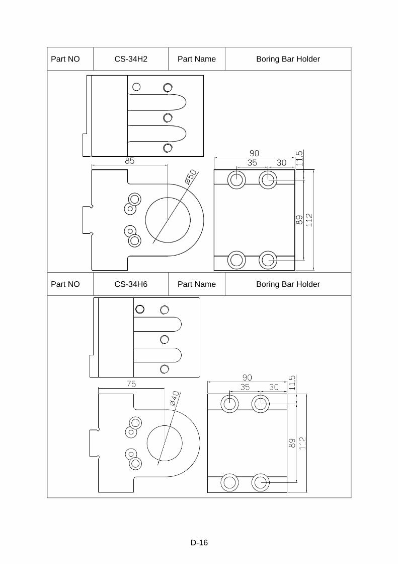
D-16
Part NO CS-34H2 Part Name Boring Bar Holder
Part NO CS-34H6 Part Name Boring Bar Holder

D-17
Part NO CS-34H1 Part Name Boring Bar Holder / Throw-away Drill Holder
Part NO Part Name

D-18
D-3 Tool holders for LG-3004 turret head
Part NO LG-30B3 Part Name Boring Bar Holder
Part NO LG-3191 Part Name Boring Bar Holder

D-19
Part NO LG-3091 Part Name Boring Bar Holder
Part NO LG-3195A Part Name O.D. Cutting Tool Holder

D-20
Part NO LG-30B5 Part Name O.D. Cutting Tool Holder
Part NO Part Name

E
Appendix E Content
Questions & Answers of CEN-03 Type lubrication system...................E-1