Operating manual eviro vibration motors Series G70/GE70 G71/GE71
26
1 Operating manual eviro vibration motors Series G70/GE70 G71/GE71 ID no.: 18.80.000.170101 Issue date: 04.12.2018 Rev. no.: 1
-
Upload
khangminh22 -
Category
Documents
-
view
0 -
download
0
Transcript of Operating manual eviro vibration motors Series G70/GE70 G71/GE71
1
Operating manual
eviro vibration motors Series G70/GE70 G71/GE71
ID no.: 18.80.000.170101 Issue date: 04.12.2018 Rev. no.: 1

eviro vibration motors series G70/GE70/G71/GE71
2
1. Content
1.1. Table of contents
1. Content ........................................................................................................................ 2 1.1. Table of contents ................................................................................................... 2 1.2. List of figures ......................................................................................................... 2 1.3. Annexes ................................................................................................................ 3 1.4. Explanation of the symbols used in the operating manual .................................... 3
2. Identification ................................................................................................................ 4 2.1. Name and address of the manufacturer ................................................................ 4 2.2. Type designation ................................................................................................... 4
2.3. Declaration of conformity ....................................................................................... 5 3. Product description ...................................................................................................... 5
3.1. General functions and application area, intended use .......................................... 5 3.2. Technical data ....................................................................................................... 6
3.2.1 Data sheet - Technical data G70/GE70 series 6 3.2.2 Data sheet - Technical data G71/GE71 series 9
3.3. Ambient conditions for storage and operation ..................................................... 12 3.4. Safety information ............................................................................................... 12
4. Preparing the product for use .................................................................................... 13 4.1. Transport and storage ......................................................................................... 13
4.2. Safety measures before use ............................................................................... 14 4.3. Installing and mounting ....................................................................................... 14
4.3.1. Mechanical installation 14 4.3.2. Electrical installation 15
5. Operating manual ...................................................................................................... 19 5.1. Safe operation / safe function .............................................................................. 19 5.2. Normal function ................................................................................................... 20
5.3. Adjustment of the centrifugal force of the vibration motor ................................... 20 6. Maintenance and repair ............................................................................................. 21 7. Decommissioning of the product ............................................................................... 23
1.2. List of figures
Figure 1 Type plate ........................................................................................................... 4
Figure 2 Motor dimensions G70/GE70 series ................................................................... 8
Figure 3 Motor dimensions G71/GE71 series ................................................................. 11
Figure 4 G7x/GE7x Terminal box allocation 3 ~ 400 V / Y- switching, with termal protector Thermistor PTC 120 ........................................................................ 16
Figure 5 G7x/GE7x Terminal box allocation 3 ~ 400 V / Y- switching ............................ 16
Figure 6 G7x/GE7x Terminal box allocation 3 ~ 230 V / Δ- switching, with termal protector Thermistor PTC 120 ......................................................................... 16
Figure 7 G7x/GE7x Terminal box allocation 3 ~ 230 V / Δ- switching ........................... 16
Figure 8 Execution of the electrical connections in the terminal box .............................. 17
Figure 9 Cable installation connection line ..................................................................... 18
Figure 10 G(E)70/G(E)71 Adjustment of centrifugal force .............................................. 20
Figure 11 Verifying radial clearance ............................................................................... 22

eviro vibration motors series G70/GE70/G71/GE71
3
1.3. Annexes
Annex 1 – Declaration of conformity Annex 2 – Exploded view Annex 3 – Spare parts list
1.4. Explanation of the symbols used in the operating manual
NOTE This symbol identifies instructions and notes for the intended use of the product. These instructions and notes have to be observed by the user of the product.
WARNING
This symbol indicates the possibility of severe or irreversible injuries caused by possible dangerous situations.
DANGER
This symbol indicates the possibility of mortal, severe or irreversible injuries caused by the direct hazard of touching high voltage-carrying parts.
DANGER
This symbol indicates the possibility of mortal, severe or irreversible injuries caused by the direct hazard when operating the product in an explosion-prone environment.
This symbol requests the user of the product to interrupt the mains connections before carrying out any work at the product or machines, plants and devices which are connected to the product, and to secure the connection against unintended reconnection.
eviro vibration motors series G70/GE70/G71/GE71
4
2. Identification
2.1. Name and address of the manufacturer
eviro Elektromaschinenbau & Metall GmbH Eibenstock Muldenhammer Straße 5 D-08309 Eibenstock Phone: +49 (0) 37752 / 3013 +49 (0) 37752 / 3035 Fax: +49 (0) 37752 / 3057 Email: [email protected] Internet: www.eviro.com For many years, the company eviro Elektromaschinenbau & Metall GmbH Eibenstock has been developing and producing vibration motors as well as complete modules for electrical drives which live up to the highest quality standards. Its reputation as an innovative and flexible manufacturing company is valued by the customers and many users of the products made by eviro.
2.2. Type designation
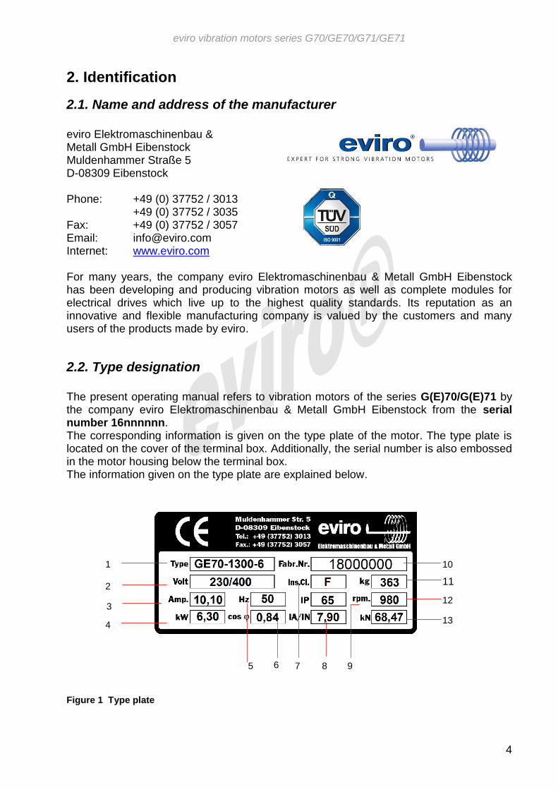
The present operating manual refers to vibration motors of the series G(E)70/G(E)71 by the company eviro Elektromaschinenbau & Metall GmbH Eibenstock from the serial number 16nnnnnn. The corresponding information is given on the type plate of the motor. The type plate is located on the cover of the terminal box. Additionally, the serial number is also embossed in the motor housing below the terminal box. The information given on the type plate are explained below.
Figure 1 Type plate
12
13
11
10
5
1
2
3
4
6 7 8 9

eviro vibration motors series G70/GE70/G71/GE71
5
1 - Type designation G Stator housing made of grey cast casting GE enhanced bearings 70 Designation of the series 1300 Working torque in kgcm 6 6-pole K Connection cable mounted at the factory 2 - Rated voltage in V (∆ / Y ) 3 - Rated current at rated speed in A 4 - Power consumption in kW 5 - Rated frequency in Hz 6 - Power factor cosφ 7 - Heat insulation class H (180°C )
8 - Ratio starting current – rated current 9 - Type of protection IP65 10 - Serial number 11 - Weight in kg 12 - Rated speed in rpm 13 - Centrifugal force at rated speed in kN
2.3. Declaration of conformity
Details on the conformity with the applicable European guidelines and harmonized standards are enclosed to this operating manual in Annex 3. Vibrating motors do not comply with Article 1, subsection 2, point "k" of Directive 2006/42/EC (Machinery Directive).
3. Product description
3.1. General functions and application area, intended use
The vibration motors of the types G(E)70/G(E)71 are intended for the special use in machines and devices, in which centrifugal forces have to generate vibrations with frequencies of up to 60 Hz. They are characterized by their compact construction and they have particularly wear-resistant and knock-out-safe bearing shields made of steel, and a grey cast stator housing. Therefore, they can be used in a wide operating temperature range. During use, it must be ensured that the effective value and the frequency of the operating voltage of the motor must not exceed the values stated on the respective type plate (see 2.2. Type designation) at any time!
Vibration motors must not be operated alienated to drive rotating machine or plant components!
NOTE
Machines or devices into which the motors of the series G(E)70/G(E)71 are installed, may only be put on the market if their conformity with the guideline 2006/42/EC (machinery directive) or equivalent technical guidelines or national regulations in the applicable version was proven.
Inappropriate use and disregarding of the instructions in this manual is considered an abuse and is not permitted. In this case, the manufacturer is free from any direct or indirect responsibility.

eviro vibration motors series G70/GE70/G71/GE71
6
3.2. Technical data
3.2.1 Data sheet - Technical data G70/GE70 series
Rüttelmotoren/vibration motors G70
Typ
Typ
e
Arb
eit
s-
mo
men
t
Wo
rkin
g
torq
ue
Flieh
kra
ft
Cen
trif
ug
al
fo
rce
Nen
n-
sp
an
nu
ng
Rate
d
vo
ltag
e
Leis
tun
gs
-
au
fnah
me
Po
wer
co
nsu
mp
tio
n
Nen
nstr
om
Rate
d c
urr
en
t
Leis
tun
gs
-
fakto
r
Po
wer
facto
r
Verh
ält
nis
An
lau
f- /
Nen
nstr
om
Rati
o
sta
rtin
g-
/
rate
d c
urr
en
t
Netz
nen
n-
freq
uen
z
Rate
d m
ain
s
freq
uen
cy
Max.
Dre
hzah
l
(bei f N
)
Max.
sp
eed
(at
f N)
An
zah
l P
ole
Nu
mb
er
of
po
les
Mass
e
Co
mp
ou
nd
Mo
torl
än
ge
Mo
tor
len
gth
MA F UN P IN cosφ IA/IN fN n m X [kgcm] [kN] [V] [kW] [A] [Hz] [min
-1] [kg] [mm]
G70-905-8 905,1 38,43 400 5,88 11,04 0,77 6,20 60 880 8 319,0 790 G70-1300-8 1300,0 37,99 400 4,90 9,20 0,77 6,20 50 730 8 319,0 790 G70-1090-8 1091,0 46,32 400 5,88 11,04 0,77 6,20 60 880 8 331,0 790 G70-1550-8 1555,8 45,46 400 4,90 9,20 0,77 6,20 50 730 8 331,0 790 G70-1210-8 1207,2 51,26 400 5,88 11,04 0,77 6,20 60 880 8 341,0 890 G70-1750-8 1765,0 51,57 400 4,90 9,20 0,77 6,20 50 730 8 341,0 890 G70-695-6 694,2 52,64 400 6,91 11,88 0,84 7,90 60 1176 6 304,0 690 G70-1000-6 1021,3 53,78 400 5,76 9,90 0,84 7,90 50 980 6 304,0 690 G70-905-6 905,1 68,63 400 6,91 11,88 0,84 7,90 60 1176 6 319,0 790 G70-1300-6 1300,0 68,47 400 5,76 9,90 0,84 7,90 50 980 6 319,0 790 G70-350-4 351,1 58,96 400 10,26 16,44 0,90 7,20 60 1750 4 269,0 690 G70-500-4 504,1 58,91 400 8,55 13,70 0,90 7,20 50 1460 4 269,0 690

eviro vibration motors series G70/GE70/G71/GE71
7
Rüttelmotoren/vibration motors GE70 T
yp
Typ
e
Arb
eit
s-
mo
men
t
Wo
rkin
g
torq
ue
Flieh
kra
ft
Cen
trif
ug
al
fo
rce
Nen
n-
sp
an
nu
ng
Rate
d
vo
ltag
e
Leis
tun
gs
-
au
fnah
me
Po
wer
co
nsu
mp
tio
n
Nen
nstr
om
Rate
d c
urr
en
t
Leis
tun
gs
-
fakto
r
Po
wer
facto
r
Verh
ält
nis
An
lau
f- /
Nen
nstr
om
Rati
o
sta
rtin
g-
/
rate
d c
urr
en
t
Netz
nen
n-
freq
uen
z
Rate
d m
ain
s
freq
uen
cy
Max.
Dre
hzah
l
(bei f N
)
Max.
sp
eed
(at
f N)
An
zah
l P
ole
Nu
mb
er
of
po
les
Mass
e
Co
mp
ou
nd
Mo
torl
än
ge
Mo
tor
len
gth
MA F UN P IN cosφ IA/IN fN n m X [kgcm] [kN] [V] [kW] [A] [Hz] [min
-1] [kg] [mm]
GE70-1090-8 1091,0 46,32 400 5,88 11,04 0,77 6,20 60 880 8 375,0 890 GE70-1550-8 1555,8 45,46 400 4,90 9,20 0,77 6,20 50 730 8 375,0 890 GE70-1210-8 1207,2 51,26 400 5,88 11,04 0,77 6,20 60 880 8 385,0 890 GE70-1750-8 1765,0 51,57 400 4,90 9,20 0,77 6,20 50 730 8 385,0 890 GE70-1390-8 1393,1 59,15 400 5,88 11,04 0,77 6,20 60 880 8 397,0 890 GE70-2000-8 2020,7 59,04 400 4,90 9,20 0,77 6,20 50 730 8 397,0 890 GE70-1740-8 1741,7 73,96 400 5,88 11,04 0,77 6,20 60 880 8 447,0 970 GE70-2500-8 2508,7 73,30 400 4,90 9,20 0,77 6,20 50 730 8 447,0 970 GE70-905-6 905,1 68,63 400 7,56 12,12 0,84 7,90 60 1176 6 363,0 790 GE70-1300-6 1300,0 68,47 400 6,30 10,10 0,84 7,90 50 980 6 363,0 790 GE70-1090-6 1091,0 82,73 400 7,56 12,12 0,84 7,90 60 1176 6 375,0 890 GE70-1550-6 1555,8 81,93 400 6,30 10,10 0,84 7,90 50 980 6 375,0 890 GE70-1210-6 1207,2 91,54 400 7,56 12,12 0,84 7,90 60 1176 6 385,0 890 GE70-1750-6 1765,0 92,94 400 6,30 10,10 0,84 7,90 50 980 6 385,0 890 GE70-1390-6 1393,1 105,64 400 7,56 12,12 0,84 7,90 60 1176 6 397,0 890 GE70-2000-6 2020,7 106,41 400 6,30 10,10 0,84 7,90 50 980 6 397,0 890 GE70-350-4 351,1 58,96 400 12,00 19,20 0,90 7,20 60 1750 4 298,0 690 GE70-500-4 504,1 58,91 400 10,00 16,00 0,90 7,20 50 1460 4 298,0 690 GE70-415-4 414,6 69,61 400 12,00 19,20 0,90 7,20 60 1750 4 303,0 790 GE70-600-4 605,5 70,77 400 10,00 16,00 0,90 7,20 50 1460 4 303,0 790 GE70-485-4 485,2 81,48 400 12,00 19,20 0,90 7,20 60 1750 4 308,0 790 GE70-700-4 707,0 82,63 400 10,00 16,00 0,90 7,20 50 1460 4 308,0 790 GE70-550-4 553,3 92,90 400 12,00 19,20 0,90 7,20 60 1750 4 313,0 790 GE70-800-4 812,1 94,91 400 10,00 16,00 0,90 7,20 50 1460 4 313,0 790 GE70-150-2 152,7 97,91 400 8,86 13,44 0,95 9,50 60 3420 2 279,0 690 GE70-220-2 221,4 98,60 400 7,38 11,20 0,95 9,50 50 2850 2 279,0 690
Table 1 Technical data G70/GE70 series

eviro vibration motors series G70/GE70/G71/GE71
8
Figure 2 Motor dimensions G70/GE70 series

eviro vibration motors series G70/GE70/G71/GE71
9
3.2.2 Data sheet - Technical data G71/GE71 series
Rüttelmotoren/vibration motors G71
Typ
Typ
e
Arb
eit
s-
mo
men
t
Wo
rkin
g
torq
ue
Flieh
kra
ft
Cen
trif
ug
al
fo
rce
Nen
n-
sp
an
nu
ng
Rate
d
vo
ltag
e
Leis
tun
gs
-
au
fnah
me
Po
wer
co
nsu
mp
tio
n
Nen
nstr
om
Rate
d c
urr
en
t
Leis
tun
gs
-
fakto
r
Po
wer
facto
r
Verh
ält
nis
An
lau
f- /
Nen
nstr
om
Rati
o
sta
rtin
g-
/
rate
d c
urr
en
t
Netz
nen
n-
freq
uen
z
Rate
d m
ain
s
freq
uen
cy
Max.
Dre
hzah
l
(bei f N
)
Max.
sp
eed
(at
f N)
An
zah
l P
ole
Nu
mb
er
of
po
les
Mass
e
Co
mp
ou
nd
Mo
torl
än
ge
Mo
tor
len
gth
MA F UN P IN cosφ IA/IN fN n m X [kgcm] [kN] [V] [kW] [A] [Hz] [min
-1] [kg] [mm]
G71-905-8 905,1 38,43 400 5,88 11,04 0,77 6,20 60 880 8 319,0 790 G71-1300-8 1300,0 37,99 400 4,90 9,20 0,77 6,20 50 730 8 319,0 790 G71-1090-8 1091,0 46,32 400 5,88 11,04 0,77 6,20 60 880 8 331,0 790 G71-1550-8 1555,8 45,46 400 4,90 9,20 0,77 6,20 50 730 8 331,0 790 G71-1210-8 1207,2 51,26 400 5,88 11,04 0,77 6,20 60 880 8 341,0 890 G71-1750-8 1765,0 51,57 400 4,90 9,20 0,77 6,20 50 730 8 341,0 890 G71-695-6 694,2 52,64 400 6,91 11,88 0,84 7,90 60 1176 6 304,0 690 G71-1000-6 1021,3 53,78 400 5,76 9,90 0,84 7,90 50 980 6 304,0 690 G71-905-6 905,1 68,63 400 6,91 11,88 0,84 7,90 60 1176 6 319,0 790 G71-1300-6 1300,0 68,47 400 5,76 9,90 0,84 7,90 50 980 6 319,0 790 G71-350-4 351,1 58,96 400 10,26 16,44 0,90 7,20 60 1750 4 269,0 690 G71-500-4 504,1 58,91 400 8,55 13,70 0,90 7,20 50 1460 4 269,0 690

eviro vibration motors series G70/GE70/G71/GE71
10
Rüttelmotoren/vibration motors GE71 T
yp
Typ
e
Arb
eit
s-
mo
men
t
Wo
rkin
g
torq
ue
Flieh
kra
ft
Cen
trif
ug
al
fo
rce
Nen
n-
sp
an
nu
ng
Rate
d
vo
ltag
e
Leis
tun
gs
-
au
fnah
me
Po
wer
co
nsu
mp
tio
n
Nen
nstr
om
Rate
d c
urr
en
t
Leis
tun
gs
-
fakto
r
Po
wer
facto
r
Verh
ält
nis
An
lau
f- /
Nen
nstr
om
Rati
o
sta
rtin
g-
/
rate
d c
urr
en
t
Netz
nen
n-
freq
uen
z
Rate
d m
ain
s
freq
uen
cy
Max.
Dre
hzah
l
(bei f N
)
Max.
sp
eed
(at
f N)
An
zah
l P
ole
Nu
mb
er
of
po
les
Mass
e
Co
mp
ou
nd
Mo
torl
än
ge
Mo
tor
len
gth
MA F UN P IN cosφ IA/IN fN n m X [kgcm] [kN] [V] [kW] [A] [Hz] [min
-1] [kg] [mm]
GE71-1090-8 1091,0 46,32 400 5,88 11,04 0,77 6,20 60 880 8 375,0 890 GE71-1550-8 1555,8 45,46 400 4,90 9,20 0,77 6,20 50 730 8 375,0 890 GE71-1210-8 1207,2 51,26 400 5,88 11,04 0,77 6,20 60 880 8 385,0 890 GE71-1750-8 1765,0 51,57 400 4,90 9,20 0,77 6,20 50 730 8 385,0 890 GE71-1390-8 1393,1 59,15 400 5,88 11,04 0,77 6,20 60 880 8 397,0 890 GE71-2000-8 2020,7 59,04 400 4,90 9,20 0,77 6,20 50 730 8 397,0 890 GE71-1740-8 1741,7 73,96 400 5,88 11,04 0,77 6,20 60 880 8 447,0 970 GE71-2500-8 2508,7 73,30 400 4,90 9,20 0,77 6,20 50 730 8 447,0 970 GE71-905-6 905,1 68,63 400 7,56 12,12 0,84 7,90 60 1176 6 363,0 790 GE71-1300-6 1300,0 68,47 400 6,30 10,10 0,84 7,90 50 980 6 363,0 790 GE71-1090-6 1091,0 82,73 400 7,56 12,12 0,84 7,90 60 1176 6 375,0 890 GE71-1550-6 1555,8 81,93 400 6,30 10,10 0,84 7,90 50 980 6 375,0 890 GE71-1210-6 1207,2 91,54 400 7,56 12,12 0,84 7,90 60 1176 6 385,0 890 GE71-1750-6 1765,0 92,94 400 6,30 10,10 0,84 7,90 50 980 6 385,0 890 GE71-1390-6 1393,1 105,64 400 7,56 12,12 0,84 7,90 60 1176 6 397,0 890 GE71-2000-6 2020,7 106,41 400 6,30 10,10 0,84 7,90 50 980 6 397,0 890 GE71-350-4 351,1 58,96 400 12,00 19,20 0,90 7,20 60 1750 4 298,0 690 GE71-500-4 504,1 58,91 400 10,00 16,00 0,90 7,20 50 1460 4 298,0 690 GE71-415-4 414,6 69,61 400 12,00 19,20 0,90 7,20 60 1750 4 303,0 790 GE71-600-4 605,5 70,77 400 10,00 16,00 0,90 7,20 50 1460 4 303,0 790 GE71-485-4 485,2 81,48 400 12,00 19,20 0,90 7,20 60 1750 4 308,0 790 GE71-700-4 707,0 82,63 400 10,00 16,00 0,90 7,20 50 1460 4 308,0 790 GE71-550-4 553,3 92,90 400 12,00 19,20 0,90 7,20 60 1750 4 313,0 790 GE71-800-4 812,1 94,91 400 10,00 16,00 0,90 7,20 50 1460 4 313,0 790 GE71-150-2 152,7 97,91 400 8,86 13,44 0,95 9,50 60 3420 2 279,0 690 GE71-220-2 221,4 98,60 400 7,38 11,20 0,95 9,50 50 2850 2 279,0 690
Table 2 Technical data G71/GE71 series
eviro vibration motors series G70/GE70/G71/GE71
11
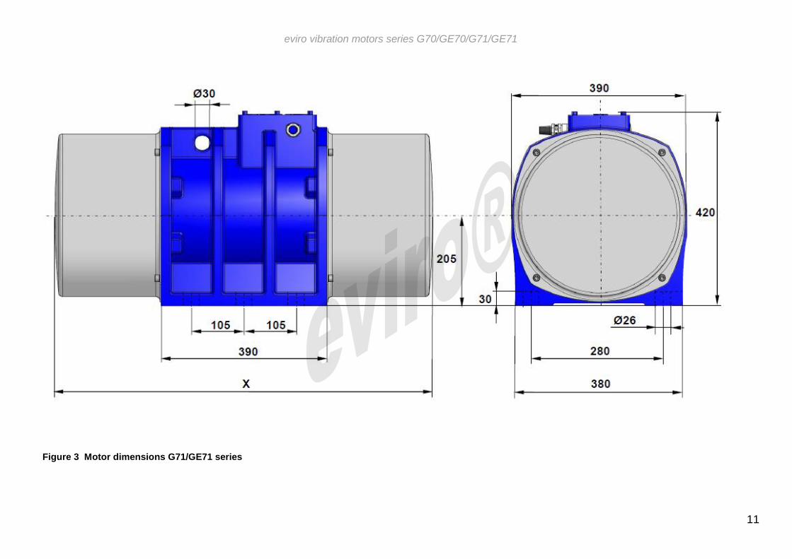
Figure 3 Motor dimensions G71/GE71 series
eviro vibration motors series G70/GE70/G71/GE71
12
3.3. Ambient conditions for storage and operation
Storage Operation
Temperature min. -20°C -20°C
Temperature max. 60°C 40°C
Rel. humidity max. 60% 80%
Table3 Permissible ambient conditions for storage and operation
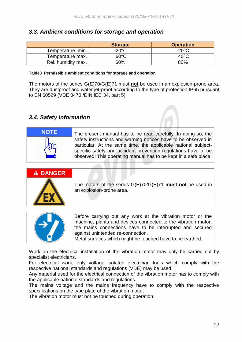
The motors of the series G(E)70/G(E)71 must not be used in an explosion-prone area. They are dustproof and water jet-proof according to the type of protection IP65 pursuant to EN 60529 (VDE 0470 /DIN IEC 34, part 5).
3.4. Safety information
NOTE The present manual has to be read carefully. In doing so, the safety instructions and warning notices have to be observed in particular. At the same time, the applicable national subject-specific safety and accident prevention regulations have to be observed! This operating manual has to be kept in a safe place!
DANGER
The motors of the series G(E)70/G(E)71 must not be used in an explosion-prone area.
Before carrying out any work at the vibration motor or the machine, plants and devices connected to the vibration motor, the mains connections have to be interrupted and secured against unintended re-connection. Metal surfaces which might be touched have to be earthed.
Work on the electrical installation of the vibration motor may only be carried out by specialist electricians. For electrical work, only voltage isolated electrician tools which comply with the respective national standards and regulations (VDE) may be used. Any material used for the electrical connection of the vibration motor has to comply with the applicable national standards and regulations. The mains voltage and the mains frequency have to comply with the respective specifications on the type plate of the vibration motor. The vibration motor must not be touched during operation!

eviro vibration motors series G70/GE70/G71/GE71
13
WARNING While plant components are active, avoid areas in which contact with moving parts of the machine might occur. Before entering such an area, the plant has to be switched off and a switch-off or securing process has to be carried out in accordance with the specifications of the plant manufacturer. Staying on plant components subject to vibration is strictly forbidden. Vibration motors can reach an operating temperature of 90 °C during operation. The vibration motor must not be touched during operation. Before touching it, switch off the motor and allow it to cool down! Risk of burning!
NOTE Every intervention in the vibration motor which was not described in this manual will void the safety of the vibration motor and its conformity with the applicable guidelines, standards and rules. This leads to a loss of guarantee and releases the manufacturer from any liability for possibly occurred damages.
4. Preparing the product for use Before carrying out any work at the vibration motor or the machine at which the motor is mounted or shall be mounted, it must be ensured that neither the vibration motor nor the machine is damaged.
4.1. Transport and storage
The vibration motor has to be checked for visible transport damages upon delivery.
NOTE If the motor shows visible external damages, it must not be taken into operation under any circumstances and must be returned to the manufacturer for inspection and repair. Unauthorised interventions in the motor, except the ones described in this manual, are prohibited!
Storage may only be effected in dry rooms. For the storage, the allowed ground and bearing loads of the storage location have to be observed. It is not allowed to pile up motors or to store other items on the motor. The allowed ambient conditions for the storage of the vibration motors are described in table 3 of this manual on page 12. In order to transport individual motors by hand, or within the framework of the assembly process of the motor, it may only be lifted at the stator housing in order to avoid deformations of the protective covers or other components.

eviro vibration motors series G70/GE70/G71/GE71
14
DANGER
The motor must not be lifted at already assembled electrical connection cables under any circumstances. This can cause unsafe electrical connections and cable breaks.
4.2. Safety measures before use
Before use, the motor has to be checked for external damages.
NOTE If the motor shows visible external damages, it must not be taken into operation under any circumstances and must be returned to the manufacturer for inspection and repair. Unauthorised interventions in the motor in this regard are forbidden!
For a cable connection which was pre-assembled by the manufacturer, the cable has to be checked for possible damages caused by the transport, and the fixed mounting of the connection line in the terminal box gland of the vibration motor has to be verified.
4.3. Installing and mounting
4.3.1. Mechanical installation In compliance with the generally known principles of function and operation modes of rotating unbalance vibration exciters, the installation position of the eviro vibration motors is arbitrary. The surface provided for the assembly has to be level and torsion-resistant. For the assembly of the motor at the mounting surface, only use screws M 24 of the quality 8.8 or better according to DIN EN ISO 4014 (DIN 931), DIN EN ISO 4017 (DIN 933) or DIN EN ISO 4762 (DIN 912), and if required, hex nuts of the quality 8.8 or better according to DIN EN ISO 4032 (DIN 934). 6 screw points of the motor have to be used respectively. The screwing has to be effected regularly, and alternately crossed using a torque wrench. The tightening torques according to table 4 have to be applied.
Table 4 Required tightening torques for screws (quality 8.8)
Thread marking Tightening torque in
Nm Mounting of
M24 650 Motor
M20 385 Centrifugal Weights
M16 196 End shield
M8 23 Protective covers , Bearing covers, Terminal box cover
M5 4,5 Electrical connections

eviro vibration motors series G70/GE70/G71/GE71
15
For a direct screw connection with the mounting surface, the effective thread length in the un-tempered underground structure (St37) has to be at least twice the screw diameter in mm. The screw connections have to be mechanically secured against unintended loosening (e.g. by attaching a Schnorr lock washer S24). The tight fit of the screws has to be checked in particular during the initial operating time. Alternative mounting methods have to be agreed with the manufacturer and are only allowed after the written consent of the manufacturer.
4.3.2. Electrical installation
DANGER
Work on electrical equipment may only be carried out by respectively instructed specialist personnel. Only voltage isolated tools may be used.
In order to establish the electrical connections of the vibration motor, only use flexible cables HO7RN-F 4G2.5 or equivalent. When operating the vibration motor at an electronic frequency converter, the cable specified by the manufacturer of the frequency converter has to be used. Possibly required shielding has to be connected at the earthing point of the earth wire. The connections have to implement pursuant to DIN VDE 0100. The connecting cable has to be guided into the terminal box by means of the cable gland. The sheath insulation has to project into the terminal box. In doing so, ensure the tight fit of the cable sheath in the screw connection in order to prevent a rubbing of the cores at the thread hole! In order to connect the individual cable cores, they have to be stripped to approx. 8 mm. Using special crimping pliers, the crimp terminals M4 have to be crimped for a core cross-section ≥ 2.5mm² (blue). The installation of the wires in the terminal box has to be effected in such a way that they do not contact the terminal box housing and that they are guided to the terminal board bolt in short arches in order to prevent self-oscillations of the cables as far as possible.
NOTE
It is forbidden to coat the cable cord with tin for contacting, or to solder on cable lugs!
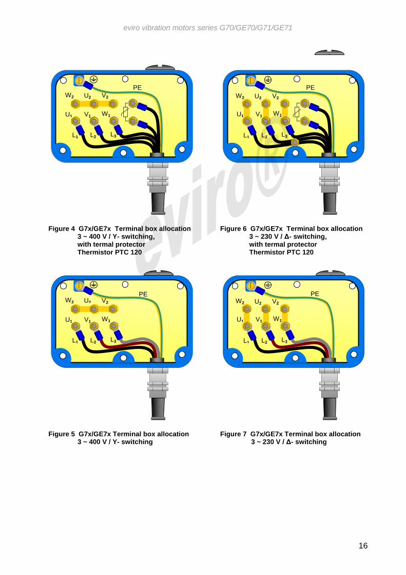
The green-yellow earth wire (USA: single colour green) has to be mounted on the clamping point marked with the earth symbol. The required small parts for the establishment of the electrical connections are packed in the connection bag which is located in the terminal box upon delivery. With the terminal box wiring shown in the figures 4 to 7, a positive rotation of the motor results (counter-clockwise rotation).
eviro vibration motors series G70/GE70/G71/GE71
16
Figure 4 G7x/GE7x Terminal box allocation
3 ~ 400 V / Y- switching, with termal protector Thermistor PTC 120
Figure 5 G7x/GE7x Terminal box allocation
3 ~ 400 V / Y- switching
Figure 6 G7x/GE7x Terminal box allocation
3 ~ 230 V / Δ- switching, with termal protector Thermistor PTC 120
Figure 7 G7x/GE7x Terminal box allocation
3 ~ 230 V / Δ- switching
V2
W
2 U
2
U2 W2 V2
U1 V1 W1
L1 L2 L3
PE
V2
W
2 U
2
U2 W2 V2
U1 V1 W1
L1 L2 L3
PE
V2
W
2 U
2
U2 W2 V2
U1 V1 W1
L1 L2 L3
PE
V2
W
2 U
2
U2 W2 V2
U1 V1 W1
L1 L2 L3
PE
eviro vibration motors series G70/GE70/G71/GE71
17
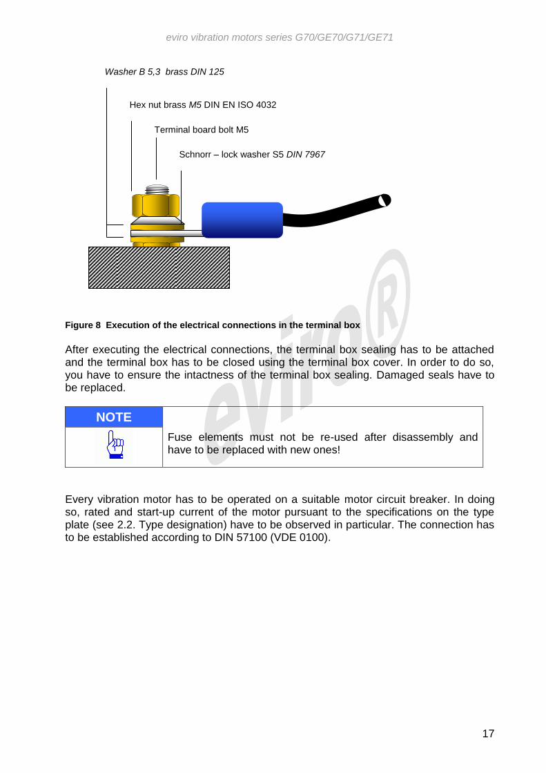
Figure 8 Execution of the electrical connections in the terminal box
After executing the electrical connections, the terminal box sealing has to be attached and the terminal box has to be closed using the terminal box cover. In order to do so, you have to ensure the intactness of the terminal box sealing. Damaged seals have to be replaced.
NOTE Fuse elements must not be re-used after disassembly and have to be replaced with new ones!
Every vibration motor has to be operated on a suitable motor circuit breaker. In doing so, rated and start-up current of the motor pursuant to the specifications on the type plate (see 2.2. Type designation) have to be observed in particular. The connection has to be established according to DIN 57100 (VDE 0100).
Hex nut brass M5 DIN EN ISO 4032
Anlaufstrom in A
Terminal board bolt M5
Anlaufstrom in A
Schnorr – lock washer S5 DIN 7967
Anlaufstrom in A
Washer B 5,3 brass DIN 125
Anlaufstrom in A

eviro vibration motors series G70/GE70/G71/GE71
18
Figure 9 Cable installation connection line
The cable installation at the machine or plant on which the motor is assembled has to be effected in such a way that no self-oscillations of the connection line can occur when operating the motor. The cable has to be protected against contact with sharp components. When operating the motor on an electrical frequency converter, the respective manual has to be observed. If necessary, suitable measures in order to observe the applicable EMC regulations have to be taken. If the frequency converter contains the motor protection function, the use of a motor circuit breaker is not necessary. In particular, it has to be ensured that the effective value and the frequency of the operating voltage of the motor do not exceed the values stated on the type plate (see 2.2. Type designation) at any time!
ca. 300 mm
ca. 300 mm
Motor circuit breaker, distributor or other mounting, e g. by means of cable clamp
Cable installation and fixing unfavourable! Risk of cable breakage due to high self-oscillation at the fixing points!
eviro vibration motors series G70/GE70/G71/GE71
19
WARNING Effective values and frequencies of the operating voltage which are higher the values specified on the type plate can cause the destruction of the motor or the machine on which the motor is assembled.
5. Operating manual
5.1. Safe operation / safe function
WARNING Vibration motors may only be put into operation when
The motors were securely attached on a mechanically stable surface acc. to section 4.3.1 of this manual,
The electrical connections were installed securely according to section 4.3.2 of this manual
The mechanical safety devices were mounted properly. Do not touch the vibration motors during operation! Allow motors to cool down after switch-off! Risk of burning!
The tight fit of the screws has to be checked regularly during operation, for the first time after an operating time of approx. 24 hours. When commissioning the motor, the power consumption and the housing temperature have to be monitored. If the motor current exceeds the value specified on the type plate (see 2.2. Type designation), or if the housing temperature exceeds a value of 90 °C after a warm-up time of 30 minutes, it is likely that there is a disharmony in the dynamic system of the vibration unit due to which the vibration motor is unable to reach its rated speed. The electric driving power and the set centrifugal force of the vibration motor, as well as the vibration behaviour of the vibration unit have to be synchronized. The vibration behaviour of the vibration unit is mainly determined by its spring damping system and its mass. By means of suitable constructional measures, the resonance behaviour of the overall system has to be designed in such a way that the drive can reach its rated speed. If necessary, the set centrifugal force of the vibration motor has to be decreased (see 5.3. Adjustment of the centrifugal force of the vibration motor). If these measures are unsuccessful, the manufacturer will be happy to provide support with the handling of such issues. Interventions in the motor which are not described in this manual are prohibited. The protective covers provided by the manufacturer serve the protection against touching the rotating centrifugal weights during the operation of the vibration motor. In general, it is forbidden to operate the motor without special protective devices against the touching of rotating parts. If it is necessary to operate the vibration motor without protective covers for plant-specific reasons, the user has to take suitable constructional measures which achieve a protective effect similar to the covers.

eviro vibration motors series G70/GE70/G71/GE71
20
5.2. Normal function
WARNING Due to the properties and the operating conditions of the machine at which the vibration motor is assembled, the allowed noise levels according to the national regulations might be exceeded. In this case, the operating personnel have to wear suitable ear protection.
Due to construction, the rated speed of the vibration motor depends on the frequency of the operating voltage. Therefore, it is possible to adjust the frequency, working torque and centrifugal force of the generated vibrations to the operating conditions via a variation of the frequency of the operating voltage using a frequency converter. In doing so, the values indicated on the type plate (see 2.2. Type designation) specify the allowed maximum values. It must be ensured that the maximum values of operating voltage and supply frequency specified on the type plate are never exceeded!
5.3. Adjustment of the centrifugal force of the vibration motor
Upon delivery, the centrifugal weights are factory-adjusted to the maximum centrifugal force specified on the type plate. If it is necessary to change this presetting centrifugal force generated by the vibration motor can be adjusted. In order to do so, the protective covers of the drive have to be removed on both sides. For G(E)70/G(E)71 –series the adjustment of centrifugal force is done by skewing both of the inboard (next to the end shields) centrifugal weights. To do so, the fixing screws of these centrifugal weights have to be unfastened. It must be observed that the centrifugal weights at both sides of the motor have to be skewed counterwise to the same value. Actual value is to be read on scale (see figure 10 G(E)70/G(E)71 Adjustment of centrifugal force )
Figure 10 G(E)70/G(E)71 Adjustment of centrifugal force
80 90
0
100
80 90
0
100
View from right
View from left

eviro vibration motors series G70/GE70/G71/GE71
21
After adjustment the fixing screws of the centrifugal weights have to be fastened again, and the protective covers have to be attached. Before attaching the protective covers, the intactness of the sealing rings has to be ensured. Damaged seals have to be replaced. The tightening torques of the screw connections of centrifugal weights and convers have to be observed (see Table 4 Required tightening torques for screws).
NOTE
Safety elements must not be re-used after their disassembly and have to be replaced with new ones!
6. Maintenance and repair
WARNING While plant components are active, avoid areas in which contact with moving parts of the machine might occur. Before entering such an area, the plant has to be switched off and a switch-off or securing process has to be carried out in accordance with the specifications of the plant manufacturer. Staying on plant components subject to vibration is strictly forbidden. Vibration motors can reach an operating temperature of 90 °C during operation. The vibration motor must not be touched during operation. Before touching it, switch off the motor and allow it to cool down! Risk of burning!
Before carrying out any work at the vibration motor or the machine, plants and devices connected to the vibration motor, the mains connections have to be interrupted and secured against unintended re-connection. Metal surfaces which might be touched have to be earthed.
NOTE The properties and the tight fit of all screw connections and fixtures at the vibration motor have to be checked regularly (min. after 24 operating hours). In order to do so, a suitable, calibrated torque wrench has to be used. The intactness of the electric cables and the safety of all electrical connections have to be checked as well.
NOTE The vibration motor has to be cleaned from dirt and depositions at regular time intervals in order to ensure sufficient cooling. Overheating caused by insufficient cooling can lead to the destruction of the vibration motor.
eviro vibration motors series G70/GE70/G71/GE71
22
When observing the provisions of this manual, the operation of the vibration motors of the series G(E)70/G(E)71 is nearly maintenance-free. The cylindrical roller bearings are equipped with lifetime lubrication. Fittings for re-lubrication during the life cycle of the bearing are not required in this construction and therefore, not provided. The life cycle of the bearing depends on the operating conditions the vibration motor is exposed to. It is mainly influenced by ambient temperatures during operation, the mass ratios of the vibration unit, the loads due to interactions (vibration superimpositions) with other vibration motors (group operation), and rebound impacts of unaccelerated masses in the contact moment to the vibrating system. Therefore, the actual bearing life cycle can strongly deviate from the determined theoretical life cycle. The bearings have to be considered as wear parts whose life cycle depends on the operating loads. The dimensioning of the bearings is constructed in such a way that 5000 operating hours should be achieved without problems. The theoretical life cycle is exceeded significantly in a large number of applications.
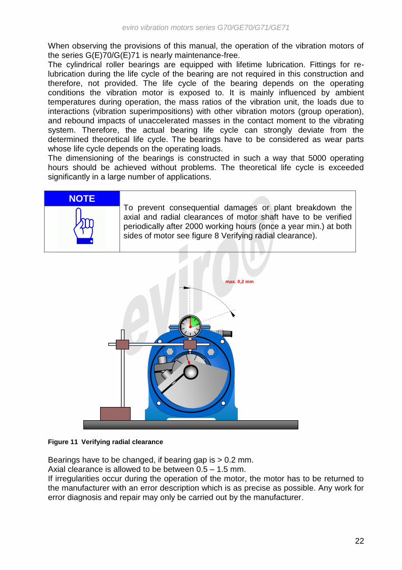
NOTE To prevent consequential damages or plant breakdown the axial and radial clearances of motor shaft have to be verified periodically after 2000 working hours (once a year min.) at both sides of motor see figure 8 Verifying radial clearance).
Figure 11 Verifying radial clearance
Bearings have to be changed, if bearing gap is > 0.2 mm. Axial clearance is allowed to be between 0.5 – 1.5 mm. If irregularities occur during the operation of the motor, the motor has to be returned to the manufacturer with an error description which is as precise as possible. Any work for error diagnosis and repair may only be carried out by the manufacturer.
W
max. 0,2 mm
1
0
0
9
0
8
0
0

eviro vibration motors series G70/GE70/G71/GE71
23
NOTE Every intervention in the vibration motor which was not described in this manual will void the safety of the vibration motor and its conformity with the applicable guidelines, standards and rules. This leads to a loss of guarantee and releases the manufacturer from any liability for possibly occurred damages.
7. Decommissioning of the product
NOTE
Eviro vibration motors entirely consist of recyclable materials. Hence, at the end of the life cycle, the motors have to be recycled in a proper and professional manner, or returned to the manufacturer.
© eviro Elektromaschinenbau & Metall GmbH Eibenstock All rights reserved, especially the rights of reproduction, distribution and translation. No part of this publication may be reproduced or processed using electronic systems, copied or distributed in any form without written permission of eviro Elektromaschinenbau & Metall GmbH Eibenstock.

eviro vibration motors series G70/GE70/G71/GE71
24
Annex 1 Declaration of conformity
eviro vibration motors series G70/GE70/G71/GE71
25
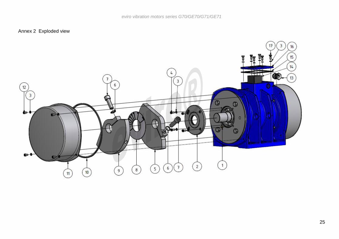
Annex 2 Exploded view
eviro vibration motors series G70/GE70/G71/GE71
26
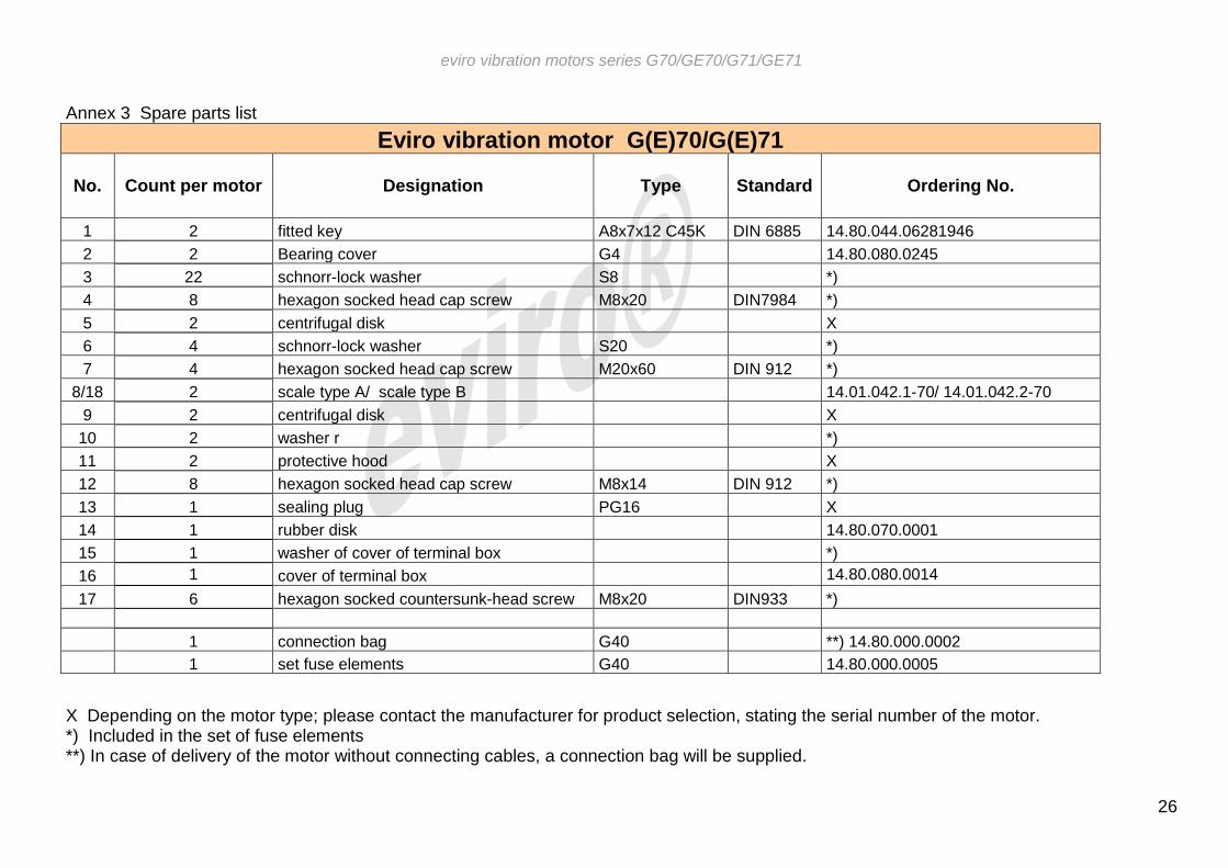
Annex 3 Spare parts list
X Depending on the motor type; please contact the manufacturer for product selection, stating the serial number of the motor. *) Included in the set of fuse elements **) In case of delivery of the motor without connecting cables, a connection bag will be supplied.
Eviro vibration motor G(E)70/G(E)71
No. Count per motor Designation Type Standard Ordering No.
1 2 fitted key A8x7x12 C45K DIN 6885 14.80.044.06281946
2 2 Bearing cover G4 14.80.080.0245
3 22 schnorr-lock washer S8 *)
4 8 hexagon socked head cap screw M8x20 DIN7984 *)
5 2 centrifugal disk X
6 4 schnorr-lock washer S20 *)
7 4 hexagon socked head cap screw M20x60 DIN 912 *)
8/18 2 scale type A/ scale type B 14.01.042.1-70/ 14.01.042.2-70
9 2 centrifugal disk X
10 2 washer r *)
11 2 protective hood X
12 8 hexagon socked head cap screw M8x14 DIN 912 *)
13 1 sealing plug PG16 X
14 1 rubber disk 14.80.070.0001
15 1 washer of cover of terminal box *)
16 1 cover of terminal box 14.80.080.0014
17 6 hexagon socked countersunk-head screw M8x20 DIN933 *)
1 connection bag G40 **) 14.80.000.0002
1 set fuse elements G40 14.80.000.0005