Operating instructions Flow meter compressed air SD6020 ...
47
Operating instructions Flow meter compressed air SD6020 80282583 / 01 09 / 2020 UK
-
Upload
khangminh22 -
Category
Documents
-
view
0 -
download
0
Transcript of Operating instructions Flow meter compressed air SD6020 ...

Operating instructions Flow meter compressed air
SD6020
8028
2583
/ 01
09
/ 20
20
UK

2
Contents1 Preliminary note ���������������������������������������������������������������������������������������������������4
1�1 Symbols used ������������������������������������������������������������������������������������������������41�2 Warnings used �����������������������������������������������������������������������������������������������4
2 Safety instructions �����������������������������������������������������������������������������������������������53 Functions and features ����������������������������������������������������������������������������������������6
3�1 Pressure Equipment Directive (PED) ������������������������������������������������������������64 Function ���������������������������������������������������������������������������������������������������������������7
4�1 Processing of the measured signals ��������������������������������������������������������������74�2 Switching output ��������������������������������������������������������������������������������������������84�3 Analogue output ���������������������������������������������������������������������������������������������94�4 Consumed quantity monitoring [ImP] ���������������������������������������������������������� 11
4�4�1 Meter reading ������������������������������������������������������������������������������������� 114�4�2 Counter reset ������������������������������������������������������������������������������������ 114�4�3 Consumed quantity monitoring via pulse signals �������������������������������124�4�4 Consumed quantity monitoring via preset counter �����������������������������12
4�5 Measured value damping ����������������������������������������������������������������������������134�6 Low flow cut-off �������������������������������������������������������������������������������������������134�7 Simulation ����������������������������������������������������������������������������������������������������134�8 Colour of the characters in the display ��������������������������������������������������������144�9 IO-Link ���������������������������������������������������������������������������������������������������������15
4�9�1 Additional functions via IO-Link ����������������������������������������������������������155 Installation����������������������������������������������������������������������������������������������������������15
5�1 Installation location ��������������������������������������������������������������������������������������165�2 Installation position ��������������������������������������������������������������������������������������16
5�2�1 Inlet and outlet pipe lengths ����������������������������������������������������������������165�2�2 Orientation �����������������������������������������������������������������������������������������17
5�3 Installation in pipes ��������������������������������������������������������������������������������������176 Electrical connection ������������������������������������������������������������������������������������������187 Operating and display elements ������������������������������������������������������������������������208 Menu ������������������������������������������������������������������������������������������������������������������21
8�1 Process value display (RUN) �����������������������������������������������������������������������218�2 Main menu ���������������������������������������������������������������������������������������������������228�3 Extended functions (EF) ������������������������������������������������������������������������������23

3
UK
8�4 Submenu OUT1 �������������������������������������������������������������������������������������������248�5 Submenu OUT2 �������������������������������������������������������������������������������������������268�6 Submenu CFG ���������������������������������������������������������������������������������������������288�7 Submenus MEM, DIS ����������������������������������������������������������������������������������308�8 Submenus COLR, SIM ��������������������������������������������������������������������������������32
9 Set-up ����������������������������������������������������������������������������������������������������������������3410 Parameter setting ��������������������������������������������������������������������������������������������34
10�1 Parameter setting in general ���������������������������������������������������������������������3510�1�1 Select submenu ��������������������������������������������������������������������������������3510�1�2 Change to the process value display (RUN mode) ��������������������������3510�1�3 Lock / unlock �������������������������������������������������������������������������������������3510�1�4 Timeout ���������������������������������������������������������������������������������������������36
10�2 Settings for volumetric flow monitoring ������������������������������������������������������3610�2�1 Limit monitoring OUT1 or OUT2 / hysteresis function ����������������������3610�2�2 Limit monitoring OUT1 or OUT2 / window function ��������������������������3610�2�3 Analogue signal volumetric flow OUT2 ���������������������������������������������36
10�3 Settings for consumed quantity monitoring �����������������������������������������������3710�3�1 Quantity monitoring by pulse signal OUT1 or OUT2 ������������������������3710�3�2 Quantity monitoring by preset counter OUT1 or OUT2 ��������������������3710�3�3 Manual counter reset ������������������������������������������������������������������������3710�3�4 Time-controlled counter reset �����������������������������������������������������������3710�3�5 Deactivation of the counter reset ������������������������������������������������������3710�3�6 Counter reset using an external signal ���������������������������������������������38
10�4 Settings for temperature monitoring ����������������������������������������������������������3810�4�1 Limit monitoring OUT1 or OUT2 / hysteresis function ����������������������3810�4�2 Limit monitoring OUT1 or OUT2 / window function ��������������������������3810�4�3 Analogue signal temperature OUT2 �������������������������������������������������38
10�5 User settings (optional) ������������������������������������������������������������������������������3910�5�1 Standard display �������������������������������������������������������������������������������3910�5�2 Standard unit of measurement for volumetric flow ���������������������������3910�5�3 Standard unit of measurement for temperature ��������������������������������3910�5�4 Measured value damping �����������������������������������������������������������������3910�5�5 Output logic ��������������������������������������������������������������������������������������3910�5�6 Low flow cut-off ���������������������������������������������������������������������������������4010�5�7 Standard conditions ��������������������������������������������������������������������������4010�5�8 Colour of the characters in the display ���������������������������������������������40

4
10�5�9 Switch-on /switch-off delay ���������������������������������������������������������������4010�5�10 Error behaviour of the outputs ��������������������������������������������������������4110�5�11 Restore factory setting ��������������������������������������������������������������������41
10�6 Diagnostic functions ����������������������������������������������������������������������������������4210�6�1 Read min/max values �����������������������������������������������������������������������4210�6�2 Simulation �����������������������������������������������������������������������������������������42
11 Operation ���������������������������������������������������������������������������������������������������������4312 Error correction ������������������������������������������������������������������������������������������������4313 Maintenance, repair and disposal ��������������������������������������������������������������������4514 Factory setting �������������������������������������������������������������������������������������������������46
1 Preliminary noteDetailed instructions, technical data, approvals and other information via the QR code on the unit / on the packaging or at www�ifm�com�
1.1 Symbols used► Instructions> Reaction, result[…] Designation of keys, buttons or indications→ Cross-reference
Important note Non-compliance may result in malfunction or interference�Information Supplementary note�
1.2 Warnings used
CAUTION!Warning of personal injury� Slight reversible injuries may result�

5
UK
2 Safety instructions• The device described is a subcomponent for integration into a system�
- The manufacturer is responsible for the safety of the system� - The system manufacturer undertakes to perform a risk assessment and to create a documentation in accordance with legal and normative requirements to be provided to the operator and user of the system� This documentation must contain all necessary information and safety instructions for the operator, the user and, if applicable, for any service personnel authorised by the manu-facturer of the system�
• Read this document before setting up the product and keep it during the entire service life�
• The product must be suitable for the corresponding applications and environ-mental conditions without any restrictions�
• Only use the product for its intended purpose (→ Functions and features).• Only use the product for permissible media (→ Technical data). • If the operating instructions or the technical data are not adhered to, personal
injury and/or damage to property may occur� • The manufacturer assumes no liability or warranty for any consequences
caused by tampering with the product or incorrect use by the operator�• Installation, electrical connection, set-up, operation and maintenance of the unit
must be carried out by qualified personnel authorised by the machine operator�• Protect units and cables against damage�

6
3 Functions and featuresThe unit monitors the standard volume flow of compressed air in industrial use�It detects the 4 process variables flow velocity, volumetric flow quantity, consumed quantity and medium temperature� All indications apply to standard volume flow to DIN ISO 2533, i�e� volume flow at 1013 mbar, 15 °C and 0 % relative air humidity� The unit can be set to different standard conditions (→ 10.5.7)�
This is a class A product� This product may cause radio interference in domestic areas�
► If required, take appropriate EMC screening measures�
3.1 Pressure Equipment Directive (PED)The units comply with the Pressure Equipment Directive� They are designed for stable gases of group 2 fluids and manufactured in accordance with sound engi-neering practice�

7
UK
4 Function• The volumetric flow is monitored by a calorimetric measuring system, the
measured signals are evaluated by the electronics�• The unit detects the media temperature of the volumetric flow as additional
process value�• The unit features an IO-Link interface• The unit displays the current process values�• The unit has many self-diagnostic options�• A simulation mode allows simplified set-up of the sensor�
4.1 Processing of the measured signalsThe unit generates 2 output signals according to the parameter setting: OUT1: 6 selection options
- switching signal for volumetric flow quantity limit - switching signal for temperature limit - switching signal for preset counter - pulse signal for quantity meter - IO-Link - OFF (output switched to high impedance)
OUT2: 8 selection options - switching signal for volumetric flow quantity limit - switching signal for temperature limit - switching signal for preset counter - switching signal for quantity meter - analogue signal for volumetric flow quantity - analogue signal for temperature - input for external counter reset signal (InD) - OFF (output switched to high impedance)
8
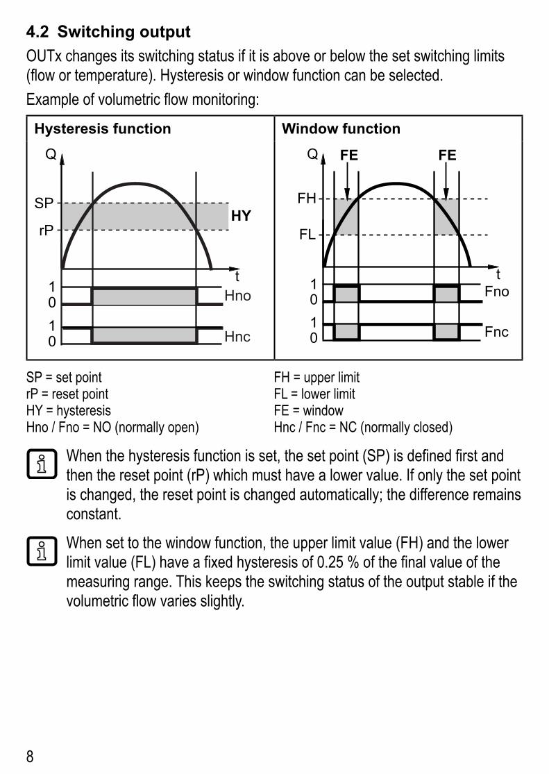
4.2 Switching outputOUTx changes its switching status if it is above or below the set switching limits (flow or temperature)� Hysteresis or window function can be selected� Example of volumetric flow monitoring:
Hysteresis function Window function
SP
rP FL
FH
SP = set pointrP = reset pointHY = hysteresisHno / Fno = NO (normally open)
FH = upper limit FL = lower limit FE = windowHnc / Fnc = NC (normally closed)
When the hysteresis function is set, the set point (SP) is defined first and then the reset point (rP) which must have a lower value� If only the set point is changed, the reset point is changed automatically; the difference remains constant�
When set to the window function, the upper limit value (FH) and the lower limit value (FL) have a fixed hysteresis of 0�25 % of the final value of the measuring range� This keeps the switching status of the output stable if the volumetric flow varies slightly�

9
UK
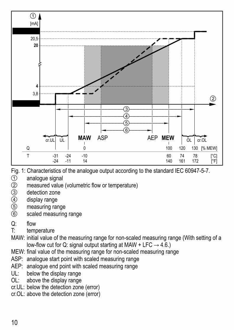
4.3 Analogue outputThe unit provides an analogue signal that is proportional to the volumetric flow quantity or the medium temperature�Within the measuring range the analogue signal is 4���20 mA� The measuring range is scalable: • [ASP2] determines at which measured value the output signal is 4 mA�• [AEP2] determines at which measured value the output signal is 20 mA�
Minimum distance between [ASP2] and [AEP2] = 20 % of the final value of the measuring range�
If the measured value is outside the measuring range or in the event of an internal error, the current signal indicated in Fig� 1 is provided�For measured values outside the display range or in case of a fault, messages are displayed (cr�UL, UL, OL, cr�OL, Err; → 12)�The analogue signal in case of a fault is adjustable (→ 10.5.10):• [FOU] = On determines that the analogue signal goes to the upper final value
(21�5 mA) in case of an error�• [FOU] = OFF determines that the analogue signal goes to the lower final value
(3�5 mA) in case of an error�• [FOU] = OU defines that in case of a fault the analogue signal reacts as defined
by the current parameters�
10
MEWMAW AEPASPQ [% MEW]
[°C]T -24 -10 60 74 78-31[°F]-11 14 140 161 172-24
1201000 130
43,8
3,5FOU=OFF
2020,521,5[mA]
FOU=On
1
2
6
cr�UL UL OL cr�OL
345
Fig� 1: Characteristics of the analogue output according to the standard IEC 60947-5-7�1 analogue signal2 measured value (volumetric flow or temperature)3 detection zone4 display range5 measuring range6 scaled measuring range
Q: flowT: temperatureMAW: initial value of the measuring range for non-scaled measuring range (With setting of a
low-flow cut for Q: signal output starting at MAW + LFC → 4.6�)MEW: final value of the measuring range for non-scaled measuring rangeASP: analogue start point with scaled measuring rangeAEP: analogue end point with scaled measuring rangeUL: below the display rangeOL: above the display rangecr�UL: below the detection zone (error)cr�OL: above the detection zone (error)
11
UK
4.4 Consumed quantity monitoring [ImP]The unit has an internal quantity meter (totaliser)� It continuously sums up the consumed quantity and provides this process value both on the display and via the IO-Link interface� Pulse signals or a switching signal (preset counter) can be used to monitor the consumed quantity� → 4.4.3 Consumed quantity monitoring via pulse signals → 4.4.4 Consumed quantity monitoring via preset counter
4.4.1 Meter readingThe current quantity meter count can be indicated (→ 8.1)�In addition, the value before the last reset is saved� This value and the time since the last reset can also be displayed (→ 8.1)�
The meter saves the totalled volumetric flow quantity every 10 minutes� After a power failure this value is available as the current meter reading� If a time-controlled reset is set, the elapsed time of the set reset interval is also saved� So the possible data loss can be at most 10 minutes�
4.4.2 Counter reset There are different ways to reset the quantity meter� → 10.3.3 Manual counter reset → 10.3.4 Time-controlled counter reset → 10.3.6 Counter reset using an external signal → Counter reset via the IO-Link interfaceIf the quantity meter is not reset by applying one of the above-mentioned methods, an automatic reset takes place when the maximum volumetric flow quantity that can be displayed is exceeded (overflow)�
OUT1 and OUT2 cannot be used simultaneously for the consumed quantity monitoring�
The accuracy of the consumed quantity measurement depends on the accuracy of the flow measurement�

12
4.4.3 Consumed quantity monitoring via pulse signalsEvery time the flow rate set with [ImPS] has been reached (pulse value), the output provides a pulse signal�
OUT1 and OUT2 cannot be used simultaneously for the pulse output�
4.4.4 Consumed quantity monitoring via preset counterWhen the flow rate set under [ImPS] has been reached, the output provides a switching signal� The setting of the parameter [rTo] defines if the volumetric flow quantity has to be reached irrespective of the time (1) or within a set time (2) so that the output switches:
[rTo] Output Counter reset(1) OFF
(→ 10.3.5)• The output switches when the
volumetric flow quantity set with [ImPS] has been reached�
• The output remains switched until the counter reset�
• The preset counter is only reset - when a manual reset is made (→ 10.3.3) or
- when the maximum display range has been exceeded (overflow)�
(2) 1, 2,��� h1, 2,��� d1, 2,��� w(→ 10.3.4)
• The output switches only when the volumetric flow quantity set with [ImPS] is reached within the set time�
• The output remains switched until the counter reset�
• If the output is not switched, the preset counter is automati-cally reset when the time has elapsed and the count starts again (→ 10.3.4 Time-con-trolled counter reset)
• If the output is switched, the preset counter is only reset� - when a manual reset is made (→ 10.3.3) or
- when the maximum display range has been exceeded (overflow)�

13
UK
4.5 Measured value dampingThe damping time [dAP�F] allows to set after how many seconds the output signal has reached 63 % of the final value if the flow value changes suddenly� The set damping time stabilises the switching outputs, the display and the process value transfer via the IO-Link interface� The damping time is added to the response time of the sensor (→ Technical data)� The signals [UL] and [OL] (→ 12) are defined under consideration of the damping time�
4.6 Low flow cut-off With the function low flow cut-off [LFC] it is possible to suppress small volumet-ric flow quantities� Flows below the LFC value are evaluated by the sensor as standstill (Q = 0)�
4.7 SimulationWith this function, the process values flow, temperature and meter reading of the totaliser are simulated and their signal chain is reviewed� When the parameters cr�UL, UL, OL und cr�OL are set, the process values that lead to an error message or warning can be simulated (→ 12)�When the simulation is started, the values of the totaliser are frozen and the simulated totaliser is set to 0� The simulated flow value then has an effect on the simulated totaliser� When the simulation is ended, the initial totaliser values are restored�
The simulation does not have any effect on the currently existing process values� The outputs operate as previously set�During the simulation the original totaliser value remains saved without any changes even if there is a real flow�During the simulation operation, no error message of the currently real application is available� They are suppressed by the simulation�
14
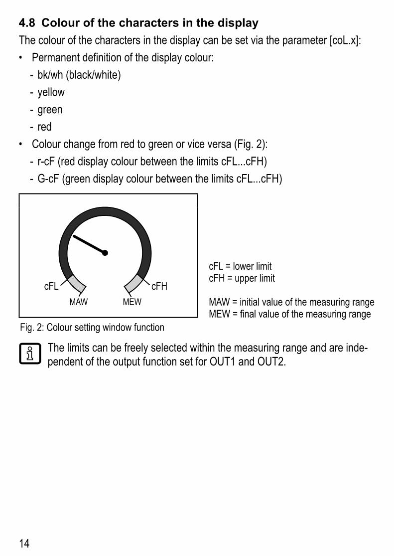
4.8 Colour of the characters in the displayThe colour of the characters in the display can be set via the parameter [coL�x]: • Permanent definition of the display colour:
- bk/wh (black/white) - yellow - green - red
• Colour change from red to green or vice versa (Fig� 2): - r-cF (red display colour between the limits cFL���cFH) - G-cF (green display colour between the limits cFL���cFH)
cFL cFHMAW MEW
cFL = lower limitcFH = upper limit
MAW = initial value of the measuring rangeMEW = final value of the measuring range
Fig� 2: Colour setting window function
The limits can be freely selected within the measuring range and are inde-pendent of the output function set for OUT1 and OUT2�

15
UK
4.9 IO-LinkThis unit has an IO-Link communication interface which enables direct access to process and diagnostic data� In addition it is possible to set the parameters of the unit while it is in operation� Operation of the unit via an IO-Link interface requires an IO-Link master�With a PC, suitable IO-Link software and an IO-Link adapter cable communication is possible when the system is not in operation�The IODDs necessary for the configuration of the unit, detailed information about process data structure, diagnostic information, parameter addresses and the necessary information about the required IO-Link hardware and software can be found at www�ifm�com�4.9.1 Additional functions via IO-LinkThe following functions are only available via the IO-Link interface by means of a parameter setting software:Flash on / Flash off
Standard command for localising the sensor in the system� When activated:
> switching status indicating LEDs are flashing > display: "IO-Link" (green, flashes)
5 Installation
CAUTION!If the medium temperature is above 50 °C (122 °F), parts of the housing can increase in temperature to over 65 °C (149 °F)�
> Risk of burns� ► Protect the housing against contact with flammable substances and unintentional contact�
► Apply the supplied warning label to the sensor cable�
► Ensure that the system is free of pressure during installation� ► The rules and regulations for the installation and operation of com-pressed air equipment must be observed�

16
5.1 Installation location ► Install the unit downstream of the cold dryer� ► Install the unit near the load� ► The unit can be installed downstream of a maintenance unit� ► If oil is used for the loads: install the unit upstream of the oiler�
5.2 Installation position5.2.1 Inlet and outlet pipe lengthsStructures in the pipe, bends, valves, reducing pieces and the like affect the function of the unit�
► Adhere to the distances between sensor and interference:
Interference Distance to the sensor
changes to the pipe diameter 10 x pipe diameter
90° elbow 10 x pipe diameter
two 90° elbows, one plane 15 x pipe diameter
two 90° elbows, two planes 25 x pipe diameter
valve, slide 40 x pipe diameter
Shut-off valves and control devices are not allowed directly in front of the unit�
► Avoid diameter changes between the inlet pipe length and the unit�If a diameter change cannot be prevented, make sure that the diameter of the inlet pipe length is greater than the diameter at the unit�

17
UK
5.2.2 Orientation
1 2 3
4
Fig� 1: Orientation of the pipe length and the unit1: pipe length vertical, unit any2: pipe length horizontal, unit vertical3: pipe length right, unit on side 4: avoid: pipe length left, unit on side
5.3 Installation in pipes ► Fit the unit in the pipe in accordance with the flow direction (arrow on the unit):
IN OUT
► Tighten both adapters in opposite direction by applying the defined tightening torque� Tightening torque: 100 Nm

18
6 Electrical connectionThe device must be connected by a qualified electrician� Voltage supply according to EN 50178, SELV, PELV�
► Disconnect power� ► Connect the unit as follows:
BN
WH
BK
BU
4
1
3
2 OUT2
L+
L
OUT1
Colours to DIN EN 60947-5-2BK: black; BN: brown; BU: blue; WH: white
Pin Connection4 (OUT1)
• switching signal for volumetric flow• switching signal for temperature• switching signal for preset counter• pulse signal for quantity meter• IO-Link• OFF
2 (OUT2/InD)
• switching signal for volumetric flow• switching signal for temperature• switching signal for preset counter• pulse signal for quantity meter• analogue signal for volumetric flow• analogue signal for temperature• input for external counter reset signal (InD)• OFF

19
UK
Circuit examples:
2 x positive switching 2 x negative switching
L
L+
3 BU
4 BK
2 WH
1 BN
L
L+
3 BU
4 BK
2 WH
1 BN
1 x positive switching / 1 x analogue 1 x negative switching / 1 x analogue
L+
L3 BU
4 BK
2 WH
1 BNL+
L3 BU
4 BK
2 WH
1 BN

20
7 Operating and display elements
3
1 2
45
1 and 2: Switching status LEDs• LED 1 = switching status OUT1 (on if output 1 is switched)• LED 2 = switching status OUT2 (on if output 2 is switched)3: TFT display• Display of the current process values (volumetric flow quantity, temperature, totaliser)• Display of the parameters and parameter values4: [▲] and [▼] buttons• Select parameter• Change parameter value (hold button pressed)• Change of the display unit in the normal operating mode (RUN mode)• Lock / Unlock (buttons pressed simultaneously > 10 seconds)5: [●] = Enter button• Change from the RUN mode to the main menu• Change to the setting mode• Acknowledge the set parameter value
Display illumination:• unit temperature > 70°C: brightness automatically reduced�• unit temperature ≥ 100°C: display automatically switched off.

21
UK
8 Menu8.1 Process value display (RUN)It is possible to select three process value indications during operation:► Press [▲] or [▼].
> The display changes between the standard indication and two other views� > After 30 s, the device returns to the standard display�
Running���
20�0l/min
1
Totalizer
Running���100
l
Last Totalizer 0.00l
Time since reset---
3
Running���20.0
l/min
30.0°C
100l
2
1: standard display as set under [diS�L] (→ 10.5.1)2: overview of all process values3: overview totaliser values
22
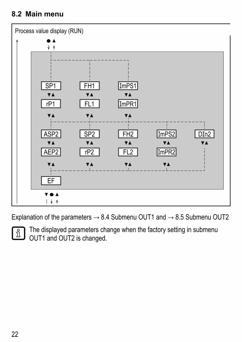
8.2 Main menu
Process value display (RUN)
EF
rP1
SP1 FH1
FL1
EF rES, rTo, Info, OUT1, OUT2, CFG, MEM, DIS, COLR, SIM
ImPS1
ImPR1
AEP2
ASP2 SP2
rP2
FH2
FL2
ImPS2
ImPR2
DIn2
Explanation of the parameters → 8.4 Submenu OUT1 and → 8.5 Submenu OUT2The displayed parameters change when the factory setting in submenu OUT1 and OUT2 is changed�

23
UK
8.3 Extended functions (EF)
Main menu
rES
rTo
Info
OUT1
OUT2
CFG
MEM
DIS
COLR
SIM
- - - -
EF
1 hrES.T
2 h 3 h4 h 5 h ...
OFF
- - - -
Parameter Explanation and setting options
rES restore factory setting
rTo reset of the totaliser
Info display device information
OUT1 configuration output 1
OUT2 configuration output 2
CGF configuration basic settings
MEM display min�/max� process values
DIS configuration display view
COLR configuration display colour
SIM configuration simulation mode

24
8.4 Submenu OUT1
Main menu
rES
rTo
Info
OUT1
OUT2
CFG
MEM
DIS
COLR
SIM
EF
SEL1
ou1
dS1
dr1
FOU1 OUT1OU On OFF
Hno Hnc Fno Fnc ImP OFF
TEMPFLOW
rP1
SP1 FH1
FL1
ImPS1
ImPR1

25
UK
Explanations submenu OUT1
Parameter Explanation and setting optionsSEL1 standard unit of measurement for evaluation by OUT1:
FLOW (volumetric flow) or TEMP (temperature) ou1 output function for OUT1:
• flow Hno, Hnc, Fno, Fnc, ImP• temperature: Hno, Hnc, Fno, FncHno = switching signal with hysteresis function normally openHnc = switching signal with hysteresis function normally closedFno = switching signal with window function normally openFnc = switching signal with window function normally closedImP = consumed quantity monitoring (totaliser function)OFF = output OFF (of high impedance)
SP1 set point for OUT1 rP1 reset point for OUT1 FH1 upper limit value for OUT1 FL1 lower limit for OUT1ImPS1 pulse value = volumetric flow quantity at which 1 pulse is delivered�ImPR1 configuration of OUT1 for consumed quantity monitoring:
YES (pulse signal), no (switching signal)�dS1 switching delay on OUT1dr1 switch-off delay on OUT1FOU1 response of OUT1 / OUT2 in case of an internal fault:
OU = output reacts as in normal caseOn = output switches ON / analogue signal goes to 21�5 mA�OFF = output switches OFF / analogue signal goes to 3�5 mA�
FOU1 is not available if ou1 = ImP was selected�

26
8.5 Submenu OUT2
Main menu
rES
rTo
Info
OUT1
OUT2
CFG
MEM
DIS
COLR
SIM
EF
SEL2
ou2
FOU2 OUT2OU On OFF
Hno Hnc Fno Fnc In.DImP IOFF
TEMPFLOW
AEP2
ASP2 SP2
rP2
FH2
FL2
ImPS2
ImPR2
DIn2
dS2
dr2

27
UK
Explanation submenu OUT2
Parameter Explanation and setting optionsSEL2 standard measured variable for evaluation by OUT2:
FLOW (volumetric flow) or TEMP (temperature) ou2 output function for OUT2:
• flow Hno, Hnc, Fno, Fnc, I, ImP• temperature: Hno, Hnc, Fno, Fnc, IHno = switching signal with hysteresis function normally openHnc = switching signal with hysteresis function normally closedFno = switching signal with window function normally openFnc = switching signal with window function normally closedImP = consumed quantity monitoring (totaliser function)I = analogue signal 4���20 mA�In.D = input for external counter reset signalOFF = output OFF (of high impedance)
ASP2 analogue start point for OUT2AEP2 analogue end point for OUT2SP2 set point for OUT2 rP2 reset point for OUT2 FH2 upper limit value for OUT2 FL2 lower limit for OUT2ImPS2 pulse value = volumetric flow quantity at which 1 pulse is provided�ImPR2 configuration of OUT2 for consumed quantity monitoring: YES (pulse
signal), no (switching signal)�DIn2 reset of the totaliser via external signal: +EDG, -EDG, HIGH, LOWdS2 switching delay on OUT2dr2 switch-off delay on OUT2FOU2 response of OUT2 in case of an internal fault:
OU = output reacts as in normal caseOn = output switches ON / analogue signal goes to 21�5 mA�OFF = output switches OFF / analogue signal goes to 3�5 mA�
FOU2 is not available if ou2 = ImP was selected�

28
8.6 Submenu CFG
Main menu
rES
rTo
Info
OUT1
OUT2
CFG
MEM
DIS
COLR
SIM
EF
CFG
uni.T °C °F
LFC - - -
rEF.P - - -
rEF.T - - -
dAP.F - - -
uni.F l/min m/s ft3/h ft3/min ft/sm3/h
P-n PnP nPn

29
UK
Explanation submenu CFG
Parameter Explanation and setting optionsuni�F standard unit of measurement for volumetric flowuni�T standard unit of measurement for temperaturedAP�F measured value damping for volumetric flow P-n output logicLFC low flow cut-offrEF�P standard pressure to which the measured and display values for volumet-
ric flow referrEF�T standard temperature to which the measured and display values for
volumetric flow refer

30
8.7 Submenus MEM, DIS
Main menu
rES
rTo
Info
OUT1
OUT2
CFG
MEM
DIS
COLR
SIM
EF
DIS
diS�L L2�Temp L2.TotlL1 L3
diS�U d1 d2 d3
diS�R 0 90 180 270
diS�B 25 50 75 100 OFF
Lo�T ���
Hi�F ���
Hi�T ���
Lo�F ���
MEM
31
UK
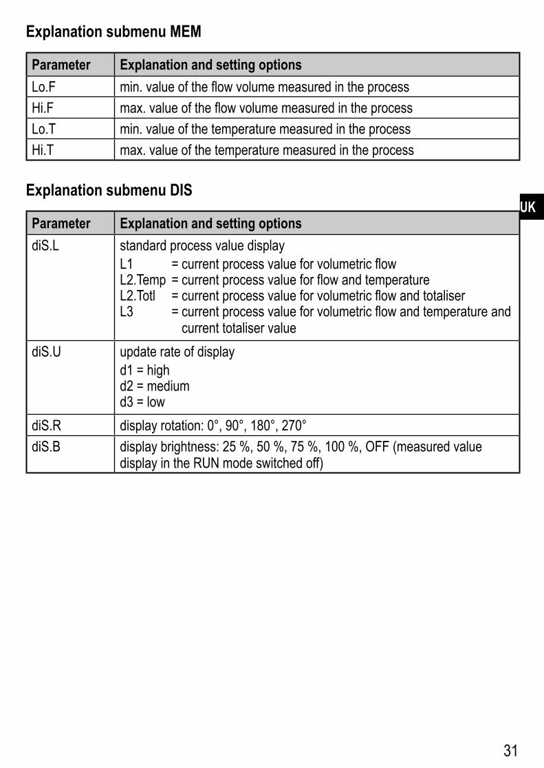
Explanation submenu MEM
Parameter Explanation and setting optionsLo�F min� value of the flow volume measured in the processHi�F max� value of the flow volume measured in the processLo�T min� value of the temperature measured in the processHi�T max� value of the temperature measured in the process
Explanation submenu DIS
Parameter Explanation and setting optionsdiS�L standard process value display
L1 = current process value for volumetric flowL2�Temp = current process value for flow and temperatureL2�Totl = current process value for volumetric flow and totaliserL3 = current process value for volumetric flow and temperature and
current totaliser valuediS�U update rate of display
d1 = highd2 = mediumd3 = low
diS�R display rotation: 0°, 90°, 180°, 270°diS�B display brightness: 25 %, 50 %, 75 %, 100 %, OFF (measured value
display in the RUN mode switched off)

32
8.8 Submenus COLR, SIM
Main menu
rES
rTo
Info
OUT1
OUT2
CFG
MEM
DIS
COLR
SIM
EF
COLR
- - -cFH�T
cFH�F - - -
- - -cFL�F
- - -cFL�T
coL�F bk/wh red green yellow r-cF G-cF
bk/wh red green yellow r-cF G-cFcoL�T
coL�V bk/wh red green yellow
SIM
S�TMPOL cr�OL cr�UL UL
- - -
S�FLW - - -OL cr�OL
S�Tim 1 2 3 4 5 10 ���
S.on OFF On

33
UK
Explanation submenu COLRThe displayed parameters change when the factory setting in submenu OUT1 and OUT2 is changed�
Parameter Explanation and setting optionscoL�F colour of the characters in the display for the flow rate valuecFH�F upper limit of the colour change for flow rate measurementcFL�F lower limit of the colour change for flow rate measurementcoL�T colour of the characters in the display for the temperature valuecFH�T upper limit of the colour change for temperature measurementcFL�T lower limit of the colour change for temperature measurementcoL�V colour of the characters in the display for the totaliser value
bk/wh permanently black/whiteyellow permanently yellowgreen permanently green
red permanently redr-cF display colour between limits cFL���cFH red, outside green�
G-cF display colour between limits cFL���cFH green, outside red�
Explanation submenu SIM
Parameter Explanation and setting optionsS�FLW simulated flow coefficientS�TMP simulated temperature value
cr�UL measured value below the detection zone → error messageUL measured value below the display range → warningOL measured value above the display range → warning
cr�OL measured value above the detection zone → error messageS�Tim simulation time in minutesS�On simulation status: OFF, On

34
9 Set-upAfter power on and expiry of the power-on delay time of approx� 1 s, the unit is in the Run mode (= normal operating mode)� It carries out its measurement and eval-uation functions and generates output signals according to the set parameters�• During the power-on delay time the outputs are switched as programmed:
- ON with normally open function (Hno / Fno) - OFF with normally closed function (Hnc / Fnc) - OFF for consumed quantity monitoring (ImP)
• If output 2 is configured as analogue output, the output signal is at 20 mA during the power-on delay time�
10 Parameter setting
CAUTION!The housing can heat up considerably�> Risk of burns
► Do not touch the device with your hands� ► Use another object (e�g� a ballpoint pen) to carry out settings on the unit�
Parameters can be set before installation and set-up of the unit or during opera-tion�
If you change parameters during operation, this will influence the function of the plant�
► Ensure that there will be no malfunctions in your plant�During parameter setting the unit remains in the operating mode� It continues to monitor with the existing parameter until the parameter setting has been complet-ed�
The parameters can also be set via the IO-Link interface�
Functions which can only be set via the IO-Link interface: → 4.9.1�

35
UK
10.1 Parameter setting in general
1� Change from the RUN mode to the main menu [●]
2� Select the requested parameter [▲] or [▼]
3� Change to the setting mode [●]
4� Change the parameter value [▲] or [▼] > 1 s
5� Acknowledge the set parameter value [●]
6� Return to the RUN mode > 30 seconds (timeout)
If [🔒 Locked via Communication] is displayed when an attempt is made to modify a parameter value, an IO-Link communication is active (temporary locking)� If [🔒 Locked via system] is displayed, the sensor is permanently locked via software� This locking can only be removed with a parameter setting software�
10.1.1 Select submenu1� Press [●] to change from the process value display to the main menu�2� Press [▼] to select the menu EF and press [●]�3� Press [▼] to select the submenu and press [●]�
10.1.2 Change to the process value display (RUN mode)There are 2 possibilities:1� Wait for 30 seconds (→ 10.1.4 Timeout)�2� Press [▲] or [▼] to go to the end of the menu and change to the next higher
menu�
10.1.3 Lock / unlockThe unit can be locked electronically to prevent unintentional settings� On delivery: not locked�Locking:
► Make sure that the unit is in the normal operating mode� ► Press [▲] and [▼] simultaneously for 10 s until [🔒 Set Menu lock] is displayed�

36
During operation: [🔒 Lock via key] is displayed if you try to change param-eter values�
Unlocking: ► Make sure that the unit is in the normal operating mode� ► Press [▲] and [▼] simultaneously for 10 s until [Reset menu lock] is displayed.
10.1.4 TimeoutIf no button is pressed for 30 s during parameter setting, the unit returns to the operating mode with unchanged values�
10.2 Settings for volumetric flow monitoring10.2.1 Limit monitoring OUT1 or OUT2 / hysteresis function
► Select [uni�F] and set the unit of measurement� ► Select [SELx] and set FLOW� ► Select [oux] and adjust the switching signal:
- Hno = hysteresis function / normally open - Hnc = hysteresis function / normally closed
► Select [SPx] and set the value at which the output is set� ► Select [rPx] and set the value at which the output is reset�
Menu OUTx:[SELx][oux][SPx][rPx]
10.2.2 Limit monitoring OUT1 or OUT2 / window function ► Select [uni�F] and set the unit of measurement� ► Select [SELx] and set FLOW� ► Select [oux] and adjust the switching signal:
- Fno = window function / normally open - Fnc = window function / normally closed
► Select [FHx] and set the upper limit of the window section� ► Select [FLx] and set the lower limit for the window section�
Menu OUTx:[SELx][oux][FHx][FLx]
10.2.3 Analogue signal volumetric flow OUT2 ► Select [uni�F] and set the unit of measurement� ► Select [SEL2] and set FLOW� ► Select [ou2] and select analogue signal: I (4...20 mA) ► Select [ASP2] and set the value at which 4 mA is provided� ► Select [AEP2] and set the value at which 20 mA is provided�
Menu OUT2:[SEL2][ou2][ASP2][AEP2]

37
UK
10.3 Settings for consumed quantity monitoring10.3.1 Quantity monitoring by pulse signal OUT1 or OUT2
► Select [uni�F] and set the unit of measurement� ► Select [SELx] and set FLOW� ► Select [oux] and adjust the pulse output: ImP ► Select [ImPSx] and set pulse value (= volumetric flow quantity at which a pulse is provided):1� Press [▲] or [▼] to select the setting range�2� Briefly press [●] to confirm the setting range�3� Press [▲] or [▼] to set the requested numeric value�4� Briefly press [●] to apply the value�
► Select [ImPRx] and set YES�
Menu OUTx:[SELx][oux][ImPSx][ImPRx]
10.3.2 Quantity monitoring by preset counter OUT1 or OUT2 ► Select [uni�F] and set the unit of measurement� ► Select [SELx] and set FLOW� ► Select [oux] and adjust the pulse output: ImP ► Select [ImPSx] and set the volumetric flow quantity at which output x switches�
► Select [ImPRx] and set NO�
Menu OUTx:[SELx][oux][ImPSx][ImPRx]
10.3.3 Manual counter reset ► Select [rTo] and set rES�T�
> The totaliser is reset to zero�Menu EF:[rTo]
10.3.4 Time-controlled counter reset ► Select [rTo] and set the requested value (intervals of hours, days or weeks)�
> The totaliser is reset automatically with the value now set�
Menu EF:[rTo]
10.3.5 Deactivation of the counter reset ► Select [rTo] and set OFF�
> The totaliser is only reset after overflow�Menu EF:[rTo]

38
10.3.6 Counter reset using an external signal ► Select [ou2] and set In.D. ► Select [DIn2] and set counter reset signal:
- HIGH = reset for high signal - LOW = reset for low signal - +EDG = reset for rising edge - –EDG = reset for falling edge
> The totaliser is reset to zero�
Menu OUT2:[ou2][DIn2]
10.4 Settings for temperature monitoring10.4.1 Limit monitoring OUT1 or OUT2 / hysteresis function
► Select [uni�T] and set the unit of measurement� ► Select [SELx] and set TEMP� ► Select [oux] and adjust the switching signal:
- Hno = hysteresis function / normally open - Hnc = hysteresis function / normally closed
► Select [SPx] and set the value at which the output is set� ► Select [rPx] and set the value at which the output is reset�
Menu OUTx:[SELx][oux][SPx][rPx]
10.4.2 Limit monitoring OUT1 or OUT2 / window function ► Select [uni�T] and set the unit of measurement� ► Select [SELx] and set TEMP� ► Select [oux] and adjust the switching signal:
- Fno = window function / normally open - Fnc = window function / normally closed
► Select [FHx] and set the upper limit of the window section� ► Select [FLx] and set the lower limit of the window sector�
Menu OUTx:[SELx][oux][FHx][FLx]
10.4.3 Analogue signal temperature OUT2 ► Select [uni�T] and set the unit of measurement� ► Select [SEL2] and set TEMP� ► Select [ou2] and select analogue signal: I (4...20 mA) ► Select [ASP2] and set the value at which 4 mA is provided� ► Select [AEP2] and set the value at which 20 mA is provided�
Menu OUT2:[SEL2][ou2][ASP2][AEP2]

39
UK
10.5 User settings (optional)10.5.1 Standard display
► Select [diS�L] and set process value display: - L1 = current process value for volumetric flow - L2�Temp = current process value for flow and temperature - L2�Totl = current process value for volumetric flow and totaliser - L3 = current process value for volumetric flow and
temperature and current totaliser value ► Select [diS�U] and set refresh rate of the display:
- d1 = high - d2 = medium - d3 = low
► Select [diS�R] and set the orientation of the display: 0°, 90°, 180°, 270°
► Select [diS�B] and set the brightness of the display: 25 %, 50 %, 75 %, 100 % or OFF (= energy-saving mode� The display is switched off in the operating mode� Error messages are displayed even if the display is deactivated� Display activation by pressing any key�)
Menu DIS:[diS�L][diS�U][diS�R][diS�B]
10.5.2 Standard unit of measurement for volumetric flow ► Select [uni�F] and set unit of measurement for standard display (→ 8.1): l/min, m3/h, m/s, ft3/min, ft3/h, ft/s�
Set [uni�F] prior to configurating the outputs�
The consumed quantity (meter reading) is automatically displayed in the unit of measurement providing the highest accuracy�
Menu CFG:[uni�F]
10.5.3 Standard unit of measurement for temperature ► Select [uni�T] and set unit of measurement for standard display (→ 8.1): °C or °F�
Set [uni�T] prior to configurating the outputs�
Menu CFG:[uni�T]
10.5.4 Measured value damping ► Select [dAP.F] and set damping constant in seconds (τ value 63 %). Menu CFG:
[dAP�F]

40
10.5.5 Output logic ► Select [P-n] and set PnP or nPn� Menu CFG:
[P-n]
10.5.6 Low flow cut-off ► Select [LFC] and set limit, below which a current is evaluated as standstill�
Menu CFG:[LFC]
10.5.7 Standard conditions ► Select [rEF�P] and set the standard pressure� ► Select [rEF�T] and set the standard temperature�
Menu CFG:[rEF�P][rEF�T]
10.5.8 Colour of the characters in the display ► Select [coL�F] for volumetric flow or [coL�T] for temperature and set the colour of the characters for the process value in the standard display: - bk/wh = permanently black/white - yellow = permanently yellow - green = permanently green - red = permanently red - r-cF = display colour red between the limits cFL���cFH, outside
colour change to green - G-cF = display colour green between the limits cFL���cFH, outside
colour change to red ► Select [cFH�x] and [cFL�x] and set the limits for the colour window:
- cFH�F = upper limit for volumetric flow - cFL�F = lower limit value for volumetric flow - cFH�T = upper limit value for temperature - cFL�T = lower limit value for temperature
► Select [coL�V] and set the colour of the characters for totaliser: - bk/wh = permanently black/white - yellow = permanently yellow - green = permanently green - red = permanently red
Menu COLR:[coL�x][cFH�x][cFL�x][coL�V]

41
UK
10.5.9 Switch-on /switch-off delay ► Select [dSx] and set the delay for setting OUTx in seconds� ► Select [drx] and set the delay for resetting OUTx in seconds�
Menu OUTx:[dSx][drx]
10.5.10 Error behaviour of the outputs ► Select [FOU1] and set error behaviour for output 1:switching output - On = output 1 switches ON in case of an error - OFF = output 1 switches OFF in case of an error - OU = output 1 switches irrespective of the error as defined with the
parameters ► Select [FOU2] and set error behaviour for output 2:switching output - On = output 1 switches ON in case of an error - OFF = output 1 switches OFF in case of an error - OU = output 1 switches irrespective of the error as defined with the
parametersAnalogue output - On = the analogue signal goes to the upper error value (→ 4.3) - OFF = the analogue value goes to the lower error value (→ 4.3) - OU = the analogue signal corresponds to the measured value
The parameter [FOUx] is not available if [ou] = Imp (consumed quantity monitoring) was selected� The pulses are provided inde-pendent of the fault�
Menu OUT1:[FOU1]Menu OUT2:[FOU2]
10.5.11 Restore factory setting ► Select [rES]� ► Briefly press [●]]� ► Keep [▲] or [▼] pressed.
> [----] is displayed� ► Briefly press [●]�
> The device carries out a reboot�→ 14 Factory setting� We recommend taking down your own set-tings in that table before carrying out a reset�
Menu EF:[rES]

42
10.6 Diagnostic functions10.6.1 Read min/max values
► Select [Lo�x] or [Hi�x] to display the highest or lowest process value measured: - [Lo�F] = min� value of the flow volume measured in the process - [Hi�F] = max� value of the flow volume measured in the process - [Lo�T] = min� value of the temperature measured in the process - [Hi�T] = max� value of the temperature measured in the process
Delete memory: ► Select [Lo�x] or [Hi�x]� ► Keep [▲] and [▼] pressed.
> [----] is displayed� ► Briefly press [●]]�
It is recommended to delete the memories as soon as the unit oper-ates under normal operating conditions for the first time�
Menu MEM:[Lo�x][Hi�x]
10.6.2 Simulation ► Select [S�FLW] and set the flow value to be simulated� ► Select [S�TMP] and set the temperature value to be simulated� ► Select [S�Tim] and set the time of the simulation in minutes� ► Select [S�On] and set the function:
- On = The simulation starts� The values are simulated for the time set with [S�Tim]� Cancel by pressing any button�
- OFF = The simulation is not active�
Menu SIM:[S�FLW][S�TMP][S�Tim][S�On]

43
UK
11 OperationThe process values to be displayed permanently can be preset (→ 10.5.1 Standard display)� A standard unit measurement can be defined for the flow rate measurement and the temperature measurement (→ 10.5.2 and → 10.5.3)�In addition to the preset standard display, the display can be changed by pressing [▲] or [▼] → 8.1 Process value display (RUN)�
12 Error correctionThe unit has many self-diagnostic options� It monitors itself automatically during operation� Warnings and error states are displayed, even when the display is switched off� Error indications are also available via IO-Link�The status signals are classified according to NAMUR recommendation NE107�If several diagnostic events occur simultaneously, only the diagnostic message of the result with the highest priority is displayed�If one process value fails, the other process values continue to be available�
Additional diagnostic functions are available via IO-Link → IODD interface description at www�ifm�com
Proc
ess
valu
e lin
e
Title
line
Stat
us
LED
Type Description
Outp
ut
resp
onse
Error correction
ERROR ERROR --- Unit faulty / mal-function
FOU Replace device�
Off Off --- Supply voltage too low
Off Check the supply voltage� Change [diS�B] setting (→ 10�5�1)�
PArA Param-eter Error
--- Parameter setting outside the valid range
FOU Repeat parameter setting�
ERROR Flow Error
--- Error in flow meas-urement
FOU Check flow meas-urement� Replace device�

44
Proc
ess
valu
e lin
e
Title
line
Stat
us
LED
Type Description
Outp
ut
resp
onse
Error correction
ERROR Temp Error
--- Error in temperature measurement
FOU Check temperature measurement� Re-place device�
cr�OL Critical over limit
--- Detection zone* exceeded
FOU Check flow range / temperature range�
cr�UL Critical under limit
--- Detection zone* not reached
FOU Check temperature range�
--- Short circuit OUT1/OUT2
OUT1 OUT2
Short circuit OUT1 and OUT2
--- Check switching outputs OUT1 and OUT2 for short-circuit or excessive current�
--- Short circuit OUT1
OUT1 Short circuit OUT1 --- Check switching output OUT1 for short-circuit or exces-sive current�
--- Short circuit OUT2
OUT2 Short circuit OUT2 --- Check switching output OUT2 for short-circuit or exces-sive current�
OL Over limit
--- Detection zone* exceeded�
OU Check flow range / temperature range�
UL Under limit
--- Detection zone* not reached
OU Check flow range / temperature range�
Lock via key
--- --- Setting buttons on the unit locked, parameter change rejected
OU Unlock unit → 10.1.3
Lock via commu-nication
--- --- Parameter setting locked via push-buttons, parameter setting is active via IO-Link communi-cation
OU Finish parameter setting via IO-Link communication�

45
UK
Proc
ess
valu
e lin
e
Title
line
Stat
us
LED
Type Description
Outp
ut
resp
onse
Error correction
Lock via system
--- --- Setting buttons locked via parameter software, parameter change rejected
OU Unlock the unit via IO-Link interface using the parameter setting software�
IO-Link IO-Link flash
OUT1 OUT2
IO-Link function for optical identification of the unit active
OU Deactivate IO-Link function�
* Detection zone → 4.3, Figure 1�Error In the event of an error, the outputs react according to the setting under
[FOU1] and [FOU2] (→ 10.5.10)�WarningLED flashesLED flashes quickly
13 Maintenance, repair and disposalAs a rule, no measures for maintenance are necessary�
► Define regular calibration intervals according to the process requirements�Recommendation: every 12 months�
Only the manufacturer is allowed to repair the unit� ► After use dispose of the unit in an environmentally friendly way in accordance with the applicable national regulations�

46
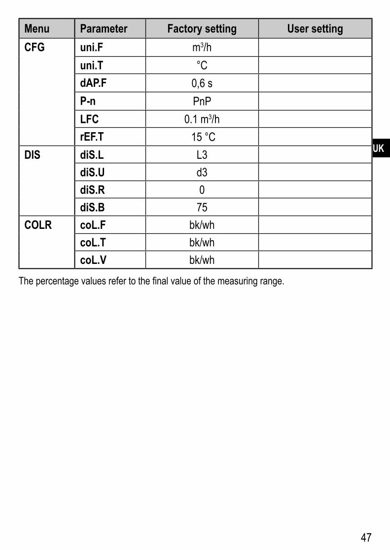
14 Factory setting
Menu Parameter Factory setting User setting EF rTo OFFOUT1 SEL1 FLOW
ou1 HnoSP1 / FH1 20 %rP1 / FL1 19 %ImPS1 0�0001 m3
ImPR1 YESdS1 0dr1 0FOU1 OFF
OUT2 SEL2 FLOWou2 IASP2 0 %AEP2 100 %SP2 / FH2 40 %rP2 / FL2 39 %ImPS2 0�0001 m3
ImPR2 YESDIn2 +EDGdS2 0dr2 0FOU2 OFF
47
UK
Menu Parameter Factory setting User setting CFG uni.F m3/h
uni.T °CdAP.F 0,6 sP-n PnPLFC 0�1 m3/hrEF.T 15 °C
DIS diS.L L3diS.U d3diS.R 0diS.B 75
COLR coL.F bk/whcoL.T bk/whcoL.V bk/wh
The percentage values refer to the final value of the measuring range�